REUSABLE COUPLINGS • DAYCO CRIMPERS • DAYCO MEDIUM PRESSURE HOSE • DAYCO SE • DAYCO SPIRAL WIRE REINFORCED HOSE • DAYCO PERMANENT CRIMP COUPLINGS REUSABLE COUPLINGS • DAYCO CRIMPERS • DAYCO MEDIUM PRESSURE HOSE • DAYCO SE • DAYCO SPIRAL WIRE REINFORCED HOSE • DAYCO PERMANENT CRIMP COUPLINGS REUSABLE COUPLINGS • DAYCO CRIMPERS • DAYCO MEDIUM PRESSURE HOSE • DAYCO SE • DAYCO SPIRAL WIRE REINFORCED HOSE • DAYCO PERMANENT CRIMP COUPLINGS REUSABLE COUPLINGS • DAYCO CRIMPERS • DAYCO MEDIUM PRESSURE HOSE • DAYCO SE • DAYCO SPIRAL WIRE REINFORCED HOSE • DAYCO PERMANENT CRIMP COUPLINGS REUSABLE COUPLINGS • DAYCO CRIMPERS • DAYCO MEDIUM PRESSURE HOSE • DAYCO SE • DAYCO SPIRAL WIRE REINFORCED HOSE • DAYCO PERMANENT CRIMP COUPLINGS REUSABLE COUPLINGS • DAYCO CRIMPERS • DAYCO MEDIUM PRESSURE HOSE • DAYCO SE • DAYCO SPIRAL WIRE REINFORCED HOSE • DAYCO PERMANENT CRIMP COUPLINGS SE • DAYCO SPIRAL WIRE REINFORCED HOSE • DAYCO PERMANENT CRIMP COUPLINGS REUSABLE COUPLINGS • DAYCO CRIMPERS • DAYCO MEDIUM PRESSURE HOSE • DAYCO SE • DAYCO SPIRAL WIRE REINFORCED HOSE • DAYCO PERMANENT CRIMP COUPLINGS REUSABLE COUPLINGS • DAYCO CRIMPERS • DAYCO MEDIUM PRESSURE HOSE • DAYCO SE • DAYCO SPIRAL WIRE REINFORCED HOSE • DAYCO PERMANENT CRIMP COUPLINGS REUSABLE COUPLINGS • DAYCO CRIMPERS • DAYCO MEDIUM PRESSURE HOSE • DAYCO SE • DAYCO SPIRAL WIRE REINFORCED HOSE • DAYCO PERMANENT CRIMP COUPLINGS REUSABLE COUPLINGS • DAYCO CRIMPERS • DAYCO MEDIUM PRESSURE HOSE • DAYCO SE • DAYCO SPIRAL WIRE REINFORCED HOSE • DAYCO PERMANENT CRIMP COUPLINGS REUSABLE COUPLINGS • DAYCO CRIMPERS • DAYCO MEDIUM PRESSURE HOSE • DAYCO SE • DAYCO SPIRAL WIRE REINFORCED HOSE • DAYCO PERMANENT CRIMP COUPLINGS REUSABLE COUPLINGS • DAYCO CRIMPERS • DAYCO MEDIUM PRESSURE HOSE • DAYCO SE • DAYCO SPIRAL WIRE REINFORCED HOSE • DAYCO PERMANENT CRIMP COUPLINGS SE • DAYCO SPIRAL WIRE REINFORCED HOSE • DAYCO PERMANENT CRIMP COUPLINGS REUSABLE COUPLINGS • DAYCO CRIMPERS • DAYCO MEDIUM PRESSURE HOSE • DAYCO SE • DAYCO SPIRAL WIRE REINFORCED HOSE • DAYCO PERMANENT CRIMP COUPLINGS REUSABLE COUPLINGS • DAYCO CRIMPERS • DAYCO MEDIUM PRESSURE HOSE • DAYCO SE • DAYCO SPIRAL WIRE REINFORCED HOSE • DAYCO PERMANENT CRIMP COUPLINGS REUSABLE COUPLINGS • DAYCO CRIMPERS • DAYCO MEDIUM PRESSURE HOSE • DAYCO SE • DAYCO SPIRAL WIRE REINFORCED HOSE • DAYCO PERMANENT CRIMP COUPLINGS REUSABLE COUPLINGS • DAYCO CRIMPERS • DAYCO MEDIUM PRESSURE HOSE • DAYCO SE • DAYCO SPIRAL WIRE REINFORCED HOSE • DAYCO PERMANENT CRIMP COUPLINGS REUSABLE COUPLINGS • DAYCO CRIMPERS • DAYCO MEDIUM PRESSURE HOSE • DAYCO SE • DAYCO SPIRAL WIRE REINFORCED HOSE • DAYCO PERMANENT CRIMP COUPLINGS REUSABLE COUPLINGS • DAYCO CRIMPERS • DAYCO MEDIUM PRESSURE HOSE • DAYCO SE • DAYCO SPIRAL WIRE REINFORCED HOSE • DAYCO PERMANENT CRIMP COUPLINGS SE • DAYCO SPIRAL WIRE REINFORCED HOSE • DAYCO PERMANENT CRIMP COUPLINGS REUSABLE COUPLINGS • DAYCO CRIMPERS • DAYCO MEDIUM PRESSURE HOSE • DAYCO SE • DAYCO SPIRAL WIRE REINFORCED HOSE • DAYCO PERMANENT CRIMP COUPLINGS REUSABLE COUPLINGS • DAYCO CRIMPERS • DAYCO MEDIUM PRESSURE HOSE • DAYCO SE • DAYCO SPIRAL WIRE REINFORCED HOSE • DAYCO PERMANENT CRIMP COUPLINGS REUSABLE COUPLINGS • DAYCO CRIMPERS • DAYCO MEDIUM PRESSURE HOSE • DAYCO SE • DAYCO SPIRAL WIRE REINFORCED HOSE • DAYCO PERMANENT CRIMP COUPLINGS REUSABLE COUPLINGS • DAYCO CRIMPERS • DAYCO MEDIUM PRESSURE HOSE • DAYCO SE • DAYCO SPIRAL WIRE REINFORCED HOSE • DAYCO PERMANENT CRIMP COUPLINGS REUSABLE COUPLINGS • DAYCO CRIMPERS • DAYCO MEDIUM PRESSURE HOSE • DAYCO Hydraulic Hose & Couplings

Welcome message from author
This document is posted to help you gain knowledge. Please leave a comment to let me know what you think about it! Share it to your friends and learn new things together.
Transcript
DAYCO LOW PRESSURE HOSE • DAYCO MEDIUM PRESSURE HOSE • DAYCO HIGH PRESSURE HOSE • DAYCO SPIRAL WIRE REINFORCED HOSE • DAYCO PERMANENT CRIMP COUPLINGSQUIPMENT• DAYCO PERMANENT CRIMP COUPLINGS • DAYCO SPECIALITY COUPLINGS • DAYCO REUSABLE COUPLINGS • DAYCO CRIMPERS • DAYCO MEDIUM PRESSURE HOSE • DAYCODAYCO LOW PRESSURE HOSE • DAYCO MEDIUM PRESSURE HOSE • DAYCO HIGH PRESSURE HOSE • DAYCO SPIRAL WIRE REINFORCED HOSE • DAYCO PERMANENT CRIMP COUPLINGSQUIPMENT• DAYCO PERMANENT CRIMP COUPLINGS • DAYCO SPECIALITY COUPLINGS • DAYCO REUSABLE COUPLINGS • DAYCO CRIMPERS • DAYCO MEDIUM PRESSURE HOSE • DAYCODAYCO LOW PRESSURE HOSE • DAYCO MEDIUM PRESSURE HOSE • DAYCO HIGH PRESSURE HOSE • DAYCO SPIRAL WIRE REINFORCED HOSE • DAYCO PERMANENT CRIMP COUPLINGSQUIPMENT• DAYCO PERMANENT CRIMP COUPLINGS • DAYCO SPECIALITY COUPLINGS • DAYCO REUSABLE COUPLINGS • DAYCO CRIMPERS • DAYCO MEDIUM PRESSURE HOSE • DAYCODAYCO LOW PRESSURE HOSE • DAYCO MEDIUM PRESSURE HOSE • DAYCO HIGH PRESSURE HOSE • DAYCO SPIRAL WIRE REINFORCED HOSE • DAYCO PERMANENT CRIMP COUPLINGSQUIPMENT• DAYCO PERMANENT CRIMP COUPLINGS • DAYCO SPECIALITY COUPLINGS • DAYCO REUSABLE COUPLINGS • DAYCO CRIMPERS • DAYCO MEDIUM PRESSURE HOSE • DAYCODAYCO LOW PRESSURE HOSE • DAYCO MEDIUM PRESSURE HOSE • DAYCO HIGH PRESSURE HOSE • DAYCO SPIRAL WIRE REINFORCED HOSE • DAYCO PERMANENT CRIMP COUPLINGSQUIPMENT• DAYCO PERMANENT CRIMP COUPLINGS • DAYCO SPECIALITY COUPLINGS • DAYCO REUSABLE COUPLINGS • DAYCO CRIMPERS • DAYCO MEDIUM PRESSURE HOSE • DAYCODAYCO LOW PRESSURE HOSE • DAYCO MEDIUM PRESSURE HOSE • DAYCO HIGH PRESSURE HOSE • DAYCO SPIRAL WIRE REINFORCED HOSE • DAYCO PERMANENT CRIMP COUPLINGSQUIPMENT• DAYCO PERMANENT CRIMP COUPLINGS • DAYCO SPECIALITY COUPLINGS • DAYCO REUSABLE COUPLINGS • DAYCO CRIMPERS • DAYCO MEDIUM PRESSURE HOSE • DAYCODAYCO LOW PRESSURE HOSE • DAYCO MEDIUM PRESSURE HOSE • DAYCO HIGH PRESSURE HOSE • DAYCO SPIRAL WIRE REINFORCED HOSE • DAYCO PERMANENT CRIMP COUPLINGSDAYCO LOW PRESSURE HOSE • DAYCO MEDIUM PRESSURE HOSE • DAYCO HIGH PRESSURE HOSE • DAYCO SPIRAL WIRE REINFORCED HOSE • DAYCO PERMANENT CRIMP COUPLINGSQUIPMENT• DAYCO PERMANENT CRIMP COUPLINGS • DAYCO SPECIALITY COUPLINGS • DAYCO REUSABLE COUPLINGS • DAYCO CRIMPERS • DAYCO MEDIUM PRESSURE HOSE • DAYCODAYCO LOW PRESSURE HOSE • DAYCO MEDIUM PRESSURE HOSE • DAYCO HIGH PRESSURE HOSE • DAYCO SPIRAL WIRE REINFORCED HOSE • DAYCO PERMANENT CRIMP COUPLINGSQUIPMENT• DAYCO PERMANENT CRIMP COUPLINGS • DAYCO SPECIALITY COUPLINGS • DAYCO REUSABLE COUPLINGS • DAYCO CRIMPERS • DAYCO MEDIUM PRESSURE HOSE • DAYCODAYCO LOW PRESSURE HOSE • DAYCO MEDIUM PRESSURE HOSE • DAYCO HIGH PRESSURE HOSE • DAYCO SPIRAL WIRE REINFORCED HOSE • DAYCO PERMANENT CRIMP COUPLINGSQUIPMENT• DAYCO PERMANENT CRIMP COUPLINGS • DAYCO SPECIALITY COUPLINGS • DAYCO REUSABLE COUPLINGS • DAYCO CRIMPERS • DAYCO MEDIUM PRESSURE HOSE • DAYCODAYCO LOW PRESSURE HOSE • DAYCO MEDIUM PRESSURE HOSE • DAYCO HIGH PRESSURE HOSE • DAYCO SPIRAL WIRE REINFORCED HOSE • DAYCO PERMANENT CRIMP COUPLINGSQUIPMENT• DAYCO PERMANENT CRIMP COUPLINGS • DAYCO SPECIALITY COUPLINGS • DAYCO REUSABLE COUPLINGS • DAYCO CRIMPERS • DAYCO MEDIUM PRESSURE HOSE • DAYCODAYCO LOW PRESSURE HOSE • DAYCO MEDIUM PRESSURE HOSE • DAYCO HIGH PRESSURE HOSE • DAYCO SPIRAL WIRE REINFORCED HOSE • DAYCO PERMANENT CRIMP COUPLINGSQUIPMENT• DAYCO PERMANENT CRIMP COUPLINGS • DAYCO SPECIALITY COUPLINGS • DAYCO REUSABLE COUPLINGS • DAYCO CRIMPERS • DAYCO MEDIUM PRESSURE HOSE • DAYCODAYCO LOW PRESSURE HOSE • DAYCO MEDIUM PRESSURE HOSE • DAYCO HIGH PRESSURE HOSE • DAYCO SPIRAL WIRE REINFORCED HOSE • DAYCO PERMANENT CRIMP COUPLINGSQUIPMENT• DAYCO PERMANENT CRIMP COUPLINGS • DAYCO SPECIALITY COUPLINGS • DAYCO REUSABLE COUPLINGS • DAYCO CRIMPERS • DAYCO MEDIUM PRESSURE HOSE • DAYCODAYCO LOW PRESSURE HOSE • DAYCO MEDIUM PRESSURE HOSE • DAYCO HIGH PRESSURE HOSE • DAYCO SPIRAL WIRE REINFORCED HOSE • DAYCO PERMANENT CRIMP COUPLINGSDAYCO LOW PRESSURE HOSE • DAYCO MEDIUM PRESSURE HOSE • DAYCO HIGH PRESSURE HOSE • DAYCO SPIRAL WIRE REINFORCED HOSE • DAYCO PERMANENT CRIMP COUPLINGSQUIPMENT• DAYCO PERMANENT CRIMP COUPLINGS • DAYCO SPECIALITY COUPLINGS • DAYCO REUSABLE COUPLINGS • DAYCO CRIMPERS • DAYCO MEDIUM PRESSURE HOSE • DAYCODAYCO LOW PRESSURE HOSE • DAYCO MEDIUM PRESSURE HOSE • DAYCO HIGH PRESSURE HOSE • DAYCO SPIRAL WIRE REINFORCED HOSE • DAYCO PERMANENT CRIMP COUPLINGSQUIPMENT• DAYCO PERMANENT CRIMP COUPLINGS • DAYCO SPECIALITY COUPLINGS • DAYCO REUSABLE COUPLINGS • DAYCO CRIMPERS • DAYCO MEDIUM PRESSURE HOSE • DAYCODAYCO LOW PRESSURE HOSE • DAYCO MEDIUM PRESSURE HOSE • DAYCO HIGH PRESSURE HOSE • DAYCO SPIRAL WIRE REINFORCED HOSE • DAYCO PERMANENT CRIMP COUPLINGSQUIPMENT• DAYCO PERMANENT CRIMP COUPLINGS • DAYCO SPECIALITY COUPLINGS • DAYCO REUSABLE COUPLINGS • DAYCO CRIMPERS • DAYCO MEDIUM PRESSURE HOSE • DAYCODAYCO LOW PRESSURE HOSE • DAYCO MEDIUM PRESSURE HOSE • DAYCO HIGH PRESSURE HOSE • DAYCO SPIRAL WIRE REINFORCED HOSE • DAYCO PERMANENT CRIMP COUPLINGSQUIPMENT• DAYCO PERMANENT CRIMP COUPLINGS • DAYCO SPECIALITY COUPLINGS • DAYCO REUSABLE COUPLINGS • DAYCO CRIMPERS • DAYCO MEDIUM PRESSURE HOSE • DAYCODAYCO LOW PRESSURE HOSE • DAYCO MEDIUM PRESSURE HOSE • DAYCO HIGH PRESSURE HOSE • DAYCO SPIRAL WIRE REINFORCED HOSE • DAYCO PERMANENT CRIMP COUPLINGSQUIPMENT• DAYCO PERMANENT CRIMP COUPLINGS • DAYCO SPECIALITY COUPLINGS • DAYCO REUSABLE COUPLINGS • DAYCO CRIMPERS • DAYCO MEDIUM PRESSURE HOSE • DAYCODAYCO LOW PRESSURE HOSE • DAYCO MEDIUM PRESSURE HOSE • DAYCO HIGH PRESSURE HOSE • DAYCO SPIRAL WIRE REINFORCED HOSE • DAYCO PERMANENT CRIMP COUPLINGSQUIPMENT• DAYCO PERMANENT CRIMP COUPLINGS • DAYCO SPECIALITY COUPLINGS • DAYCO REUSABLE COUPLINGS • DAYCO CRIMPERS • DAYCO MEDIUM PRESSURE HOSE • DAYCODAYCO LOW PRESSURE HOSE • DAYCO MEDIUM PRESSURE HOSE • DAYCO HIGH PRESSURE HOSE • DAYCO SPIRAL WIRE REINFORCED HOSE • DAYCO PERMANENT CRIMP COUPLINGSDAYCO LOW PRESSURE HOSE • DAYCO MEDIUM PRESSURE HOSE • DAYCO HIGH PRESSURE HOSE • DAYCO SPIRAL WIRE REINFORCED HOSE • DAYCO PERMANENT CRIMP COUPLINGSQUIPMENT• DAYCO PERMANENT CRIMP COUPLINGS • DAYCO SPECIALITY COUPLINGS • DAYCO REUSABLE COUPLINGS • DAYCO CRIMPERS • DAYCO MEDIUM PRESSURE HOSE • DAYCODAYCO LOW PRESSURE HOSE • DAYCO MEDIUM PRESSURE HOSE • DAYCO HIGH PRESSURE HOSE • DAYCO SPIRAL WIRE REINFORCED HOSE • DAYCO PERMANENT CRIMP COUPLINGSQUIPMENT• DAYCO PERMANENT CRIMP COUPLINGS • DAYCO SPECIALITY COUPLINGS • DAYCO REUSABLE COUPLINGS • DAYCO CRIMPERS • DAYCO MEDIUM PRESSURE HOSE • DAYCODAYCO LOW PRESSURE HOSE • DAYCO MEDIUM PRESSURE HOSE • DAYCO HIGH PRESSURE HOSE • DAYCO SPIRAL WIRE REINFORCED HOSE • DAYCO PERMANENT CRIMP COUPLINGSQUIPMENT• DAYCO PERMANENT CRIMP COUPLINGS • DAYCO SPECIALITY COUPLINGS • DAYCO REUSABLE COUPLINGS • DAYCO CRIMPERS • DAYCO MEDIUM PRESSURE HOSE • DAYCODAYCO LOW PRESSURE HOSE • DAYCO MEDIUM PRESSURE HOSE • DAYCO HIGH PRESSURE HOSE • DAYCO SPIRAL WIRE REINFORCED HOSE • DAYCO PERMANENT CRIMP COUPLINGSQUIPMENT• DAYCO PERMANENT CRIMP COUPLINGS • DAYCO SPECIALITY COUPLINGS • DAYCO REUSABLE COUPLINGS • DAYCO CRIMPERS • DAYCO MEDIUM PRESSURE HOSE • DAYCODAYCO LOW PRESSURE HOSE • DAYCO MEDIUM PRESSURE HOSE • DAYCO HIGH PRESSURE HOSE • DAYCO SPIRAL WIRE REINFORCED HOSE • DAYCO PERMANENT CRIMP COUPLINGSQUIPMENT• DAYCO PERMANENT CRIMP COUPLINGS • DAYCO SPECIALITY COUPLINGS • DAYCO REUSABLE COUPLINGS • DAYCO CRIMPERS • DAYCO MEDIUM PRESSURE HOSE • DAYCODAYCO LOW PRESSURE HOSE • DAYCO MEDIUM PRESSURE HOSE • DAYCO HIGH PRESSURE HOSE • DAYCO SPIRAL WIRE REINFORCED HOSE • DAYCO PERMANENT CRIMP COUPLINGS
Hydraulic Hose& Couplings
102690 (REV) 1999 © Dayco Products, Inc.
Dayco Products, Inc.1 Prestige PlaceP.O.Box 1004Dayton, OH 45401-1004
Distributed BY:
Hyd
rau
lic H
ose
& C
ou
plin
gs

Dayco Eastman products are part of an engineered system which must be assembled and used inaccordance with Dayco Eastman instructions and limitations.
Dayco Eastman hose, couplings and crimping machines are designed as an effective and reliableassembly system and the use of other than Dayco Eastman products may produce hose assemblies thatwill not meet rated performance. Failure to follow Dayco Eastman instructions and limitations could leadto premature hose failures resulting in property damage, serious injury or death.
Dayco Eastman’s limited warranty shall apply only if the customer uses hose, fittings, hose fitting com-ponents and crimp equipment specifically engineered, designed and produced to Dayco Eastmanprocess specifications.
DAYCO EASTMAN DISCLAIMS ANY RESPONSIBILITY OR LIABILITY FOR ANY CRIMPED HOSEASSEMBLIES NOT PRODUCED FROM GENUINE DAYCO EASTMAN HOSE FITTINGS, HOSE ANDEQUIPMENT, IN CONFORMANCE WITH DAYCO EASTMAN PROCESS SPECIFICATIONS FOR EACHSPECIFIC HOSE ASSEMBLY.
DO NOT USE A DAYCO EASTMAN CRIMPING MACHINE WITHOUT DIES!
m WARNING
How the Kwikrimp® System works
The Kwikrimp® system is like having a miniature hose assembly “factory” at your disposal. In just minutes, theKwikrimp® hose coupling system produces the exact hose and coupling combination needed, in an assemblythat meets original equipment manufacturer specifications.
Utilizing the proven principle of much larger factory equipment, eight segmented crimping dies apply tons offorce on the coupling, making an attachment that is stronger than the hose itself. The segmented dies areforced against the coupling shell by a tapered die actuator, powered by heavy duty hydraulic rams. Self cen-tering feature assures equal force distribution through all the dies, producing a uniform crimp pressure on thefull shell circumference.
Unique, easily adjusted settings provide the operator with accurate control of the crimping operation.Approximate settings are preset for the type of hose and coupling used, providing approximate crimp diame-ters. (verification of proper crimp diameter with calipers or other measuring device is required).
NOTE: Hose and coupling compatabilites noted in this catalog are for reference purposes only. DaycoEastman Crimping Specifications is the official guide for selecting appropriate hose and coupling combinationsand determining crimper compatibility.
Dayco Eastman products are part of an engineered system which must be assembled and used inaccordance with Dayco Eastman instructions and limitations.
Dayco Eastman hose, couplings and crimping machines are designed as an effective and reliableassembly system and the use of other than Dayco Eastman products may produce hose assemblies thatwill not meet rated performance. Failure to follow Dayco Eastman instructions and limitations could leadto premature hose failures resulting in property damage, serious injury or death.
Dayco Eastman’s limited warranty shall apply only if the customer uses hose, fittings, hose fitting com-ponents and crimp equipment specifically engineered, designed and produced to Dayco Eastmanprocess specifications.
DAYCO EASTMAN DISCLAIMS ANY RESPONSIBILITY OR LIABILITY FOR ANY CRIMPED HOSEASSEMBLIES NOT PRODUCED FROM GENUINE DAYCO EASTMAN HOSE FITTINGS, HOSE ANDEQUIPMENT, IN CONFORMANCE WITH DAYCO EASTMAN PROCESS SPECIFICATIONS FOR EACHSPECIFIC HOSE ASSEMBLY.
DO NOT USE A DAYCO EASTMAN CRIMPING MACHINE WITHOUT DIES!
m WARNING
BRAIDED
HOSE
SPIRAL
HOSE
1
GENERAL
INFORMATION
SPECIALTY
HOSE
COUPLINGS
MISC
EQUIPMENT
Table of ContentsGENERAL INFORMATION
GENERAL INFORMATIONPAGE
The Kwikrimp® Concept.....................................................................................................................................5Recommended Practices For Hydraulic Hose Assemblies ................................................................................6–12Safety Awareness Factors .................................................................................................................................13,78How To Read Part Numbers...............................................................................................................................14End Style Designation Charts.............................................................................................................................15–18Thread Standards ...............................................................................................................................................19–23Hose Products ....................................................................................................................................................24Selecting Hose Style by Working Pressure and Hose I.D..................................................................................25–26Hose Assembly Part Numbers............................................................................................................................27Hose For Marine Applications.............................................................................................................................28Selecting Hose Style by Flow Capacity..............................................................................................................29Hose Selection by Flow Rate .............................................................................................................................30Four Bolt Split Flange Dimensions .....................................................................................................................31Reusable Couplings Assembly Instructions........................................................................................................32Chemical Resistance Charts ..............................................................................................................................287–290Index ...................................................................................................................................................................291-296
DAYCO EASTMAN RUBBER HOSE PRODUCTSLOW PRESSURE
Style C and U4 ...................................................................................................................................................33Style U3 and A6..................................................................................................................................................34Style A2 and HAW ..............................................................................................................................................35Style B9 and B7..................................................................................................................................................36Style B7S and TC4 .............................................................................................................................................37Style DL5 and DL6 .............................................................................................................................................38
MEDIUM PRESS
Style D1 and T1 ..................................................................................................................................................39Style T4 and GL..................................................................................................................................................40Style Y9 and R5..................................................................................................................................................41Style M and D8 ...................................................................................................................................................42Style MX and E7A ..............................................................................................................................................43Style E9 and S7..................................................................................................................................................44Style S7E and NR7.............................................................................................................................................45Style NR7E and C2 ............................................................................................................................................46Style ST and AX .................................................................................................................................................47Style HFS and HR1C..........................................................................................................................................48Style AM and H6.................................................................................................................................................49Style D6 and R6 .................................................................................................................................................50
HIGH PRESSURE
Style BA and BXX...............................................................................................................................................51Style BXP and RT2.............................................................................................................................................52Style J4 and J4A.................................................................................................................................................53Style J9 and S8 ..................................................................................................................................................54Style S8E and FX ...............................................................................................................................................55Style HFS2 and HR2C........................................................................................................................................56Style DT and SNK2 ............................................................................................................................................57Style F2 and HTB ...............................................................................................................................................58Style HRK ...........................................................................................................................................................59
SPIRAL WIRE REINFORCED
Style QX and L1 .................................................................................................................................................60Style CE and M7.................................................................................................................................................61Style M8 and CZ.................................................................................................................................................62Style CN and N3.................................................................................................................................................63Style NH and N6.................................................................................................................................................64Style HT6 and N2 ...............................................................................................................................................65Style H7 ..............................................................................................................................................................66
BRAIDED
HOSE
SPIRAL
HOSE
2
GENERAL
INFORMATION
SPECIALTY
HOSE
COUPLINGS
MISC
EQUIPMENT
Table of ContentsGENERAL INFORMATION
SPECIALTY HOSEPAGE
Style BH and BCH .......................................................................................................................................67Style C6 and Y1 ...........................................................................................................................................68Style Y7 and W5 ..........................................................................................................................................69Style HLB and HSH2 ...................................................................................................................................70Style HPC and HPS.....................................................................................................................................71Style P3 and S6 ...........................................................................................................................................72Style S9 ...................................................................................................................................................73Style S5 and HJK.........................................................................................................................................74Style WB and W7.........................................................................................................................................75Style W8 ...................................................................................................................................................76
HYTRON® HOSE
Style TC, TNR7E,TNR7,TS7E,TS7, TS8E and TS8....................................................................................77
DAYCO EASTMAN COUPLINGS
PERMANENT CRIMP COUPLINGS
BC Series .........................................................................................................................................79-81BW Series .........................................................................................................................................81-91CW Series .........................................................................................................................................91CY Series .........................................................................................................................................92-96ER Series .........................................................................................................................................97GB Series .........................................................................................................................................97-100GD Series .........................................................................................................................................101-103GF Series .........................................................................................................................................104-107GH Series .........................................................................................................................................108-110GR Series .........................................................................................................................................111-113GW Series .........................................................................................................................................114-118HF Series .........................................................................................................................................119-122HR Series .........................................................................................................................................123-125HT Series .........................................................................................................................................126HW Series .........................................................................................................................................127-131HY Series .........................................................................................................................................132-167JJ Series .........................................................................................................................................168-183KC Series .........................................................................................................................................184KW Series .........................................................................................................................................184-189NB Series .........................................................................................................................................190-194SQ Series .........................................................................................................................................195SU Series .........................................................................................................................................195-202
SPECIALTY COUPLINGS
BL Series .........................................................................................................................................203-211GS Series .........................................................................................................................................212-214GT Series .........................................................................................................................................215-218KA Series .........................................................................................................................................219-221KF Series .........................................................................................................................................222-226

GENERAL
INFORMATION
SPECIALTY
HOSE
COUPLINGS
MISC
EQUIPMENT
BRAIDED
HOSE
SPIRAL
HOSE
Table of ContentsGENERAL INFORMATION
3
DAYCO EASTMAN COUPLINGS
REUSABLE COUPLINGS PAGEBA Series ..........................................................................................................................................................227-229BB Series ..........................................................................................................................................................230BE Series ..........................................................................................................................................................231BG Series ..........................................................................................................................................................232-233BM Series ..........................................................................................................................................................233-236BN Series ..........................................................................................................................................................237-241BQ Series ..........................................................................................................................................................241BU Series ..........................................................................................................................................................242-243CA Series ..........................................................................................................................................................244-246CB Series ..........................................................................................................................................................246-247GL Series ..........................................................................................................................................................248-251
MISCELLANEOUS PRODUCTS
HOSE ASSEMBLY SLEEVING
Style USY and HMG..................................................................................................................................................2521700 and NG Series ..................................................................................................................................................253
STRAIN RELIEVERS and SPRING GUARDS
1800, 1900, PG, 30 and 40 Series............................................................................................................................2541400 Series and Style GO.........................................................................................................................................255Style EC, GOC, HJK and (Open Wound) 1800 Series ............................................................................................2561500 Series and Style GA .........................................................................................................................................257Style1700 (Plastic) and BOG.....................................................................................................................................258
FLANGE HEAD KITS
Style PA and PH ........................................................................................................................................................259
TRUK-COIL® and NYLO-SEAL®
300, 160N, 160NS, and 178NS Series and Styles NS-S and NS.............................................................................260-261
QD QUICK DISCONNECT COUPLERSAll Styles ....................................................................................................................................................................262-263
O-RINGS..................................................................................................................................................264
BRAIDED
HOSE
SPIRAL
HOSE
GENERAL
INFORMATION
SPECIALTY
HOSE
COUPLINGS
MISC
EQUIPMENT
Table of ContentsGENERAL INFORMATION
4
FIELD SUPPORT EQUIPMENT
PAGE
S-16 Porta SwagerTM ...................................................................................................................................266SQ-101-SW Swager ....................................................................................................................................267
Kwikrimp® Crimpers
EC30 Portable Crimper.................................................................................................................................268K-16-LP Kwikrimp® Crimper ..........................................................................................................................269K-501-LP Kwikrimp® Crimper ........................................................................................................................270K-24-EP Kwikrimp® Crimper..........................................................................................................................271K-601-LP Kwikrimp® Crimper ........................................................................................................................272NP60 Crimper .......................................................................................................................................273WB60 Crimper .......................................................................................................................................274KK125 Kwikrimp® Crimper ............................................................................................................................275KK250 Kwikrimp® Crimper ............................................................................................................................276NP100A Crimper .......................................................................................................................................277
Support Equipment
Pumps....................................................................................................................................................278-279Hose Cleaning System .................................................................................................................................280Cut-Off Saws and Blades ......................................................................................................................281-282
Field Equipment
Calipers .......................................................................................................................................283Skiving Tools and Vise Blocks ...............................................................................................................283-285Ferrule Vises .......................................................................................................................................286

GENERAL
INFORMATION
SPECIALTY
HOSE
COUPLINGS
MISC
EQUIPMENT
BRAIDED
HOSE
SPIRAL
HOSE
5
General InformationThe Kwikrimp® Concept
THE KWIKRIMP® CONCEPT IS AN ENGINEERED PROGRAM, DESIGNED TO INCORPORATE DAYCO EASTMAN HOSE, FITTINGSAND CRIMPERS INTO ONE EFFECTIVE AND RELIABLE ASSEMBLY SYSTEM.
The Kwikrimp® Concept is an affirmation to all Dayco Eastman Distributors, OEM's and users of the Kwikrimp®
system that Dayco Eastman will support only those who use Dayco Eastman hose and couplings in theKwikrimp® assembly system. However, the Kwikrimp® Concept is also a statement that serves to warn thatDayco Eastman will not be responsible when interchanging a Dayco Eastman hose and/or couplings with hoseand/or couplings of any other manufacturer.
Dayco Eastman products are part of an engineered system which must be assembled and used in accordancewith Dayco Eastman instructions and limitations.
Dayco Eastman hose, couplings and crimping machines are designed into an effective and reliable assemblysystem and the use of other than Dayco Eastman products may produce hose assemblies that will not meetrated performance. Failure to follow Dayco Eastman instructions and limitations could lead to premature hosefailures resulting in property damage, serious injury or death.
Dayco Eastman's Limited warranty shall apply only if the customer uses hose, fittings, hose fitting componentsand crimp equipment specifically engineered, designed and produced to Dayco Eastman process specifica-tions.
DAYCO EASTMAN DISCLAIMS ANY RESPONSIBILITY OR LIABILITY FOR ANY CRIMPED HOSE ASSEM-BLIES NOT PRODUCED FROM GENUINE DAYCO EASTMAN HOSE FITTINGS, HOSE AND EQUIPMENT,IN CONFORMANCE WITH DAYCO EASTMAN PROCESS SPECIFICATIONS FOR EACH SPECIFIC HOSEASSEMBLY.
The argument that hoses branded with identical SAE numbers are the same and can be interchanged with ourcouplings is not true! Hose with identical brands can only be expected to perform to the requirements of SAEwhen assembled with compatible couplings. SAE recognizes this fact as shown by the following statementtaken from SAE J1273, October, 1996.
6.3 Hose and Fitting Compatibility–Care must be taken to determine proper compatibilitybetween the hose and fitting. Base selection on the manufacturer’s recommendations substantiated bytesting to industry standards such as SAE J517. Hose from one manufacturer is not usually compati-ble with fittings from another. Do not intermix hose and fittings from two manufacturers withoutapproval from both manufacturers.
All Dayco Eastman distributors, OEM's and Kwikrimp® users must recognize that the following points are criti-cal when considering any and all aspects of the Kwikrimp® program:
1. The data supplied with each crimper was developed after extensive impulse testing with Dayco Eastman hose and couplings. All Dayco Eastman hose styles are tested with the proper Dayco Eastman couplings before they are added to our Approved List.
2. Our Kwikrimp® data does not apply to all hose and couplings, only those products bearing the DaycoEastman identification with the proper Dayco Eastman catalog number.
3. Dayco Eastman couplings used with other than Dayco Eastman branded hose will not necessarily produce a good assembly. Identical hose styles, made by different suppliers, are not the same, when it comes to performance with Dayco Eastman couplings.
4. Dayco Eastman crimpers can only be used to crimp Dayco Eastman couplings and hose where crimp data is provided.
5. The minimal burst pressure in our catalog is for reference and design purposes only and is no indication that the product should be used above the indicated working pressure.
6. Dayco Eastman liability ends and yours begins when Dayco Eastman data is ignored or altered andproducts(hose and couplings), other than Dayco Eastman, are assembled with a Dayco Eastman crimper. Product liability responsibility for such hose assemblies becomes the personal responsibility of the assembler or company endorsing these practices.

BRAIDED
HOSE
SPIRAL
HOSE
GENERAL
INFORMATION
SPECIALTY
HOSE
COUPLINGS
MISC
EQUIPMENT
6
SAE J1273RECOMMENDED PRACTICES FORHYDRAULIC HOSE ASSEMBLIES
Foreword — This SAE Recommended Practice is intended as a guide to consider when selecting, routing, fabricating,installing, replacing, maintaining and storing hose for fluid-power systems. It is subject to change to keep pace with experi-ence and technical advances. For those new to hose use in fluid-power systems, this guide outlines practices to note dur-ing each phase of system design and use. Experienced designers and users skilled in achieving proper results, as well asthe less experienced, can use this outline as a list of considerations to keep in mind.
Fluid power systems are complex and require extensive knowledge of both the system requirements and the various typesof hose. Therefore, all-inclusive, detailed, step-by-step instructions are not practical and are beyond the scope of this docu-ment. Less experienced designers and user's who need more information can consult specialists such as hose suppliersand manufacturers. This guide can improve the communication process.
Safety Considerations — These recommended practices involve safety considerations; note these carefully during allphases of design and use of hose systems. Improper selection, fabrication, installation or maintenance of hose and hoseassemblies for fluid-power systems may result in serious personal injury or property damage. These recommended prac-tices can reduce the likelihood of component or system failure, thereby reducing the risk of injury or damage.
1. Scope – SAE J1273 provides guidelines for selection, routing, fabrication, installation, replacement, maintenanceand storage of hose and hose assemblies for fluid-power systems. Many of these SAE Recommended Practices also may be suitable for other hose and systems.
2. References
2.1 Applicable Documents – The following publications form a part of this specification to the extent specified herein. Unless otherwise specified, the latest issue of SAEpublications shall apply.SAE J343 – Test and Procedures for SAE 100 R Series Hydraulic Hose and Hose Assemblies.SAE J514 – Hydraulic Tube FittingsSAE J517 – Hydraulic HoseSAE J1927 – Cumulative Damage Analysis for Hydraulic Hose Assemblies
2.1.2 ISO Publication – Available from ANSI, 11 West 42nd Street, New York, NY 10036-8002.ISO 3457 – Earth Moving Machinery–Guards and Shields–Definitions and Specifications
3. Explanation of Terms – These explanations serve only toclarify this document and are not intended to stand alone. They are presented sequentially, with the former helping to explain the latter.
3.1 Fluid Power – Energy transmitted and controlled using pressurized hydraulic fluids or compressed air.
3.2 Hose – Flexible conductor. In this document, the term hose may also refer to a hose assembly with related accessories used in fluid power applications.
3.3 Hose Fitting or Fitting – Connector which can be attached to the end of a hose.
3.4 Hose Assembly – Hose with hose fittings attached.
3.5 Hose Failure – Occurrence in which a hose stops meeting system requirements.
3.6 Hose Service Life – Length of time a hose meetssystem requirements without needing replacement.
4. Safety Considerations – Listed in 4.1 to 4.7 are some potential conditions and situations that may lead topersonal injury and/or property damage. The list is not
necessarily all inclusive. Consider reasonable and feasiblemeans, including those described in this section, to reduce the risk of injuries or property damage.
4.1 Fluid Injections – Fine streams of escapingpressurized fluid can penetrate skin and enter a human body. These fluid injections may cause severe tissue damage and loss of limb. Consider various means to reduce the risk of fluid injections, particularly in areasnormally occupied by operators. Consider careful routing, adjacent components, warnings, guards, shields andtraining programs. Relieve pressure before disconnecting hydraulic or other lines. Tighten all connections before applying pressure. Avoid contact with escaping fluids. Treat all leaks as though pressurized and hot enough to burn skin. Never use any part of your body to check for hose leaks. If a fluid-injection accident occurs, see adoctor immediately. DO NOT DELAY OR TREAT AS A SIMPLE CUT! Any fluid injected into the skin must besurgically removed within a few hours or gangrene may result. Doctors unfamiliar with this type of injury should consult a knowledgeable medical source.
4.2 Whipping Hose – If a pressurized hose assembly blows apart, the fittings can be thrown off at high speed, and the loose hose can flail or whip with great force. This is especially true in compressible-fluid systems. When thisrisk exists, consider guards and restraints to protect against injury.
4.3 Burns from Conveyed Fluids – Fluid-power media may reach temperatures that can burn human skin. If there is risk of burns from escaping fluid, consider guards and shields to prevent injury, particularly in areas normallyoccupied by operators.
4.4 Fire and Explosion from Conveyed Fluids – Most fluid-power media, including fire-resistant hydraulic fluids, will burn under certain conditions. Fluids which escape from pressurized systems may form a mist or fine spray which can flash or explode upon contact with an ignition source. Consider selecting, guarding, and routing hose tominimize the risk of combustion. (See Section 5 and ISO3457).
BRAIDED
HOSE
SPIRAL
HOSE
7
GENERAL
INFORMATION
SPECIALTY
HOSE
COUPLINGS
MISC
EQUIPMENT
Copyright 1996 Society of Automotive Engineers, Inc.All rights reserved.
SAE J1273RECOMMENDED PRACTICES FORHYDRAULIC HOSE ASSEMBLIES
4.5 Fire and Explosions from Static-Electric Discharge –Fluid passing through hose can generate static electricity, resulting in static-electric discharge. This may create sparks that can ignite system fluids or gases in thesurrounding atmosphere. When this potential exists, select hose specifically designed to carry thestatic-electric charge to ground.
4.6 Electrical Shock – Electrocution could occur if hose conducts electricity through a person. Most hoses are conductive. Many contain metal or have metal fittings. Even nonconductive hoses can be conduits for electricity if they carry conductive fluids. Be aware of routing or using hose near electrical sources. When this cannot be avoided, select appropriate hose. Nonconductive hoses should be considered. SAE J517–100R7 and 100R8 hoses, with orange covers marked “Nonconductive” are available for applications requiring nonconductive hose.
4.7 Mechanisms Controlled by Fluid Power – Mechanismscontrolled by fluid in hoses can become hazardous when a hose fails. For example, when a hose bursts, objects supported by fluid pressure may fall, or vehicles or machines may lose their brakes or steering. Ifmechanisms are controlled by fluid power, consider safe modes of failure that minimize risks of injury or damage.
5. Hose Selection and Routing – A wide variety ofinteracting factors influence hose service life and theability of each fluid-power system to operate satisfactorily, and the combined effects of these factors on service life are often unpredictable. Therefore, these documents should not be construed as design standards. Forapplications outside the the specifications in SAE J517, SAE J514, or other relevant design standards,performance of hose assemblies should be determined byappropriate testing. Carefully analyze each system. Then design routings and select hose and related components to meet the system-performance and hose-service-life requirements, and to minimize the risks of personal injury and/or property damage. Consider the following factors:
5.1 System Pressures – Excessive pressure canaccelerate hose assembly failure. Analyze the steady-state pressures, and the frequency and the amplitude of pressure surges, such as pulses and spikes. These are rapid and transient rises in pressure which may not be indicated on many common pressure gauges and can be identified best on high-frequency-response electronic measuring instruments. For maximum hose service life, hose selection should be based on a system pressure, including surges, that is less than the hose maximum working pressure. Hose may be used above its maximum working pressure where reduced life expectancy is acceptable. SAE J1927 provides on method to helppredict wire-reinforced hose service for a given hydraulic application, where the surge pressure peaks vary, and/or the highest pressure peaks occur infrequently.
5.2 Suction – For suction applications, such as inlet flow to pumps, select hose to withstand both the negative and positive pressures the system imposes on the hose.
5.3 External Pressure – In certain applications, such as in autoclaves or under water, the external environmental pressures may exceed the fluid pressure inside the hose.In these applications, consider the external pressures, and, if necessary, consult the manufacturers.
5.4 Temperature – Exceeding hose temperature ratings may significantly reduce hose life.. Select hose so the fluid and ambient temperatures, both static and transient,fall within the hose ratings. The effects of external heat sources should not raise the temperature of the hose above its maximum operating temperature. Select hose, heat shields, sleeving, and other methods for these requirements, and route or shield hose to avoid hose damage from external heat sources.
5.5 Permeation – Permeation, or effusion, is seepage offluid through the hose. Certain materials in hoseconstruction are more permeable than others. Consider the effects of permeation when selecting hose, especiallywith gaseous fluids. Consult the hose and fluidmanufacturers for permeability information.
5.6 Hose-Material Compatibility – Variables that can affect compatibility of system fluids with hose materials include, but are not limited to:A. Fluid PressureB. TemperatureC. ConcentrationD. Duration of exposureBecause of permeation (see 5.5), consider compatibility of system fluids with the hose, tube, cover,reinforcement, and fittings. Consult the fluid and hose manufacturers for compatibility information.NOTE–Many fluid/elastomer compatibility tables inmanufacturers’ catalogs show ratings based on fluids at 21˚ C, room temperature. These ratings may change at other temperatures. Carefully read the notes on thecompatibility tables, and if in doubt, consult themanufacturer.NOTE–See pages 287-290 for chemical resistance information.5.7 Environment – Environmental conditions can cause hose and fitting degradation. Conditions to evaluate include, but are not limited to:A. Ultraviolet lightB. Salt waterC. Air pollutantsD. TemperatureE. OzoneF. ChemicalsG. ElectricityH. AbrasionIf necessary, consult the manufacturers for moreinformation.
5.8 Static-Electric Discharge – Fluid passing through hose can generate static electricity resulting in static-electric discharge. This may create sparks that canpuncture hose. If this potential exists, select hose with sufficient conductivity to carry the static-electric charge tothe ground.

BRAIDED
HOSE
SPIRAL
HOSE
8
GENERAL
INFORMATION
SPECIALTY
HOSE
COUPLINGS
MISC
EQUIPMENT
SAE J1273RECOMMENDED PRACTICES FORHYDRAULIC HOSE ASSEMBLIES
5.9 Sizing – The power transmitted by pressurized fluid varies with pressure and rate of flow. Select hose with adequate size to minimize pressure loss, and to avoid hose damage from heat generation or excessive velocity. Conduct calculations, or consult the manufacturers forsizing at flow velocities.
5.10 Unintended Uses – Hose assemblies are designed for the internal forces of conducted fluids. Do not pull hose or use it for purposes that may apply external forces for which the hose or fittings were not designed.
5.11 Specifications and Standards – When selecting hose and fittings for specific applications, refer toapplicable government, industry, and manufacturer’s specifications and standards.
5.12 Unusual Applications – Applications not addressed by the manufacturer or by industry standards may require special testing prior to selecting hose.
5.13 Hose Cleanliness – The cleanliness requirements of system components, other than hose, will determine the cleanliness requirements of the application. Consult the component manufacturers’ cleanliness information for all components in the system. Hose assemblies vary in cleanliness levels; therefore, specify hose assemblies with adequate cleanliness for the system.
5.14 Hose Fittings – Selection of the proper hosefittings for the hose and application is essential forproper operation and safe use of hose and related assembly equipment. Hose fittings are qualified with the hose. Therefore, select only hose fittings compatible with the hose for the applications.
Improper selection of hose fittings or related assembly equipment for the application can result in injury ordamage from leaks, or from hose assemblies blowing apart (see 4.2, 6.2, 6.3 and 6.4).
5.15 Vibration – Vibration can reduce hose service life. If required, conduct tests to evaluate the frequency and amplitude of system vibration. Clamps or other means may be used to reduce the effects of vibration. Consider the vibration requirements when selecting hose andpredicting service life.
5.16 Hose Cover Protection – Protect the hose cover from abrasion, erosion, snagging and cutting. Special abrasion-resistant hoses and hose guards are available for additional protection. Route hose to reduce abrasion from hose rubbing other hose or objects that may abrade it.
5.17 External Physical Abuse – Route hose to avoid:A. Tensile loadsB. Side loadsC. FlatteningD. Thread damageE. KinkingF. Damage to sealing surfacesG. AbrasionH. Twisting
5.18 Swivel-Type Adapters – Swivel-type fittings or adapters do not transfer torque to hose while beingtightened. Use these as needed to prevent twisting duringinstallation.
5.19 Live Swivels – If two components in the system are rotating in relation to each other, live swivels may benecessary. These connectors reduce the torquetransmitted to the hose.
5.20 Slings and Clamps – Use slings and clamps tosupport heavy or long hose and to keep it away from moving parts. Use clamps that prevent hose movement that will cause abrasion.
5.21 Minimum Bend Radius – The minimum bend radiusis defined in SAE J343 and is specified in other SAEstandards and hose manufaturer’s product literature. Routing at less than minimum bend radius may reduce hose life. Sharp bending at the hose/fitting juncture may result in leaking, hose rupturing, or the hose assembly blowing apart (see 4.2 and Figure 1).
FIGURE 1 — MINIMUM BEND RADIUS
5.22 Elbows and Adapters – In special cases, use elbows and adapters to relieve hose strain (see Figure 2).
Incorrect Correct

BRAIDED
HOSE
SPIRAL
HOSE
9
GENERAL
INFORMATION
SPECIALTY
HOSE
COUPLINGS
MISC
EQUIPMENT
SAE J1273RECOMMENDED PRACTICES FORHYDRAULIC HOSE ASSEMBLIES
FIGURE 2 — ELBOWS AND ADAPTERS
5.23 Lengths – Unnecessarily long hose can increase pressure drop and affect system performance. When pressurized, hose that is too short may pull loose from its fittings, or stress the fitting connections, causingpremature metallic or seal failures. When establishing hose length, refer to Figures 3, 4, and 5; and use thefollowing practices:
5.23.1 Motion Absorption – Provide adequate hose length to distribute movement and prevent bends smaller than the minimum bend radius.
FIGURE 3 — MOTION ABSORPTION
5.23.2 Hose and Machine Tolerances – Design hose to allow for changes in length due to machine motion and tolerances.
FIGURE 4 — HOSE AND MACHINE TOLERANCES
5.23.3 Hose Length Due To Pressure – Design hose to accommodate length changes from changing pressures. Do not cross or clamp together high- and low-pressure hoses. The difference in length changes could wear the hose covers.
FIGURE 5 — HOSE LENGTH DUE TO PRESSURE
5.24 Hose Movement and Bending – Hose allowsrelative motion between system components. Analyze thismotion when designing hose systems. The number of cycles per day may significantly affect hose life. Also avoid multiple planes of motion and twisting motion. Consider the motion of the hose when selecting hose and predicting service life. In applications that require hose to move or bend, refer to Figures 6 and 7; and use these practices:
5.24.1 Bend in Only One Plane to Avoid Twisting
FIGURE 6 — BEND IN ONLY ONE PLANE TO AVOID TWISTING
5.24.2 Prevent Hose Bending in More Than One Plane – If hose follows a compound bend, couple it into separate segments, or clamp into segments that flex in only one plane.
FIGURE 7 — PREVENT HOSE BENDING INMORE THAN ONE PLANE
Incorrect Correct
Incorrect Correct
Incorrect
Correct
Incorrect
Correct
Incorrect
Correct
BRAIDED
HOSE
SPIRAL
HOSE
10
GENERAL
INFORMATION
SPECIALTY
HOSE
COUPLINGS
MISC
EQUIPMENT
SAE J1273RECOMMENDED PRACTICES FORHYDRAULIC HOSE ASSEMBLIES
6. Hose-Assembly Fabrication – Persons fabricating hose assemblies should be trained in the proper use of equipment and materials. The manufacturers’ instructions and the practices listed as follows must be followed. Properly assembled fittings are vital to the integrity of a hose assembly. Improperly assembled fittings can separate from the hose and may cause serious injury or property damage from whipping hose, or from fire or explosion of vapor expelled from the hose.
6.1 Component Inspection – Prior to assembly, examinecomponents for:
A. Style or typeB. CleanlinessC. Loose coversD. NicksE. SizeF. Inside obstructionsG. Visible defectsH. DamageI. LengthJ. BlistersK. Burrs
6.2 Hose Fittings – Hose fitting components from one manufacturer are not usually compatible with fittingscomponents supplied by another manufacturer. For example, do not use a hose fitting nipple from onemanufacturer with a hose socket from another manufacturer. It is the responsibility of the fabricator to consult the manufacturer’s written instructions or the manufacturer directly for information on proper fitting components.
6.3 Hose and Fitting Compatibility – Care must be taken to determine proper compatibility between the hose and fitting. Base selection on the manufacturers’recommendations substantiated by testing to industry standards such as SAE J517. Hose from onemanufacturer is not usually compatible with fittings from another. Do not intermix hose and fittings from twomanufacturers without approval from both manufacturers.
6.4 Hose Assembly Equipment – Assembly equipment from one manufacturer is usually not interchangeable withthat from another manufacturer. Hoses and fittings from one manufacturer should not generally be assembled withthe equipment of another manufacturer.
6.5 Safety Equipment – During fabrication, use proper safety equipment, including eye protection, breathing apparatus, and adequate ventilation.
6.6 Reuse of Hose and Fittings – When fabricating hoseassemblies, do not reuse:
A. Field-attachable fittings that have blown or pulled offhose.
B. Any part of hose fittings that were permanently crimped or swaged to hose.
C. Hose that has been in service after system checkout (see 7.7).
6.7 Cleanliness of Hose Assemblies – Hoseassemblies may be contaminated during fabrication. Clean hoses to specified cleanliness levels (see 5.13).
7. Hose Installation and Replacement – Use the following practices when installing hose assemblies in new systems or replacing hose assemblies in existing systems:
7.1 Pre-Installation Inspection – Before installing hose assemblies, examine:
A. Hose length and routing for compliance withoriginal design.
B. Assemblies for correct style, size, length andvisible nonconformities.
C. Fitting sealing surfaces for burrs, nicks, or other damage.
NOTE: When replacing hose assemblies in existingsystems, verify that the replacement is of equal quality to the original assembly.
7.2 Handling During Installation – Handle hose with care during installation. Kinking hose, or bending at less than minimum bend radius may reduce hose life. Avoid sharp bending at the hose/fitting juncture (see 5.21).
7.3 Twist Angle and Orientation – Pressure applied to a twisted hose may shorten the life of the hose or loosen the connections. To avoid twisting, use the hose lay line or marking as a reference (see Figure 8).

BRAIDED
HOSE
SPIRAL
HOSE
11
GENERAL
INFORMATION
SPECIALTY
HOSE
COUPLINGS
MISC
EQUIPMENT
SAE J1273RECOMMENDED PRACTICES FORHYDRAULIC HOSE ASSEMBLIES
FIGURE 8 — TWIST ANGLE AND ORIENTATION
7.4 Securement and Protection – Install necessary restraints and protective devices. Determine that such devices do not create additional stress or wear points.
7.5 Routing – Review proper routing practices provided in Section 5 and make appropriate corrections to obtain optimum performance.
7.6 Assembly Torque – The connection end of a hose is normally threaded to obtain a tight pressure seal when attached to a port, an adapter, or another fitting. Sometimes bolts or screws provide the threadedconnection. Each size and type of connection requires different torque values, and these may vary due to type of material or exterior coating.
7.7 System Checkouts – In hydraulic or other liquidsystems, eliminate all air entrapment after completing the installation. Follow manufacturers’ instructions to test the system for possible malfunctions and leaks.
7.7.1 To avoid injury during system checkouts:
A. Do not touch any part of the system when checking for leaks (see 4.1).
B. Stay out of potentially hazardous areas while testing hose systems (see Section 4).
C. Relieve system pressure before tightening connections.
8. Maintenance Inspection – A hose and fitting maintenance program may reduce equipment downtime, maintain peak operating performance, and reduce the risk of personal injury and/or property damage. The user should design and implement a maintenance program that suits the specific application and each specific hose in that application.
8.1 Inspection Frequency – Evaluate factors such as thenature and severity of the application, past history, and manufacturers’ information to establish the frequency of visual inspections and functional tests.
8.2 Visual Inspection (Hose and Fittings) – Visually inspect hose and fittings for:
A. Leaks at hose fitting or in hose.B. Damaged, cut or abraded cover.C. Exposed reinforcement.D. Kinked, crushed, flattened, or twisted hose.E. Hard, stiff, heat cracked, or charred hose.F. Blistered, soft, degraded, or loose cover.G. Cracked, damaged, or badly corroded fittings.H. Fitting slippage on hose.I. Other signs of significant deterioration.
If any of these conditions exist, evaluate the hoseassemblies for correction or replacement.
8.3 Visual Inspection (All Other Components) – When visually inspecting hose and fittings, inspect for related items including:
A. Leaking ports.B. Damaged or missing hose clamps, guards or shields.C. Excessive dirt and debris around hose.D. System fluid: Level, type, contamination, condition
and air entrainment.If any of these are found, address them appropriately.
8.4 Functional Test – Functional tests determine ifsystems are leak free and operating properly. Carry out functional tests per information from equipmentmanufacturers.
9. Hose Storage – Age control and the manner of storage can affect hose life. Use the following practices when storing hose.
9.1 Age Control – Maintain a system of age control to determine that hose is used before its shelf life has expired. Shelf life is the period of time when it isreasonable to expect the hose to retain full capabilities forrendering the intended service.Store hose in a manner that facilitates age control and first-in, first-out usage based on manufacturing date on hose or hose assembly. Per SAE J517:
A. Shelf life of rubber hose in bulk form, or in hose assemblies passing visual inspection and proof test,is forty quarters (ten years) from the date ofvulcanization.
B. Shelf life of thermoplastic andpolytetrafluoroethylene hose is considered to be unlimited.
Incorrect Correct
BRAIDED
HOSE
SPIRAL
HOSE
12
GENERAL
INFORMATION
SPECIALTY
HOSE
COUPLINGS
MISC
EQUIPMENT
SAE J1273RECOMMENDED PRACTICES FORHYDRAULIC HOSE ASSEMBLIES
9.2 Storage – Store hose and hose assemblies in a cool, dark, dry area with the ends capped. When storing hose, take care to avoid damage that could reduce hose life, and follow the manufacturers’ information for storage and shelf life. Examples of factors that can adversely affect hose product in storage are:
A. TemperatureB. OzoneC. OilsD. Corrosive liquids and fumesE. RodentsF. HumidityG. Ultraviolet lightH. SolventsI. InsectsJ. Radioactive materials
If there are any questions regarding the quality or usabilityof hose or hose assemblies, evaluate appropriately:
A. Flex the hose to the minimum bend radius and compare it with new hose. After flexing, examine the cover and tube for cracks. If any appear, no matter how small, reject the hose.
B. If the hose is wire reinforced, and the hose is unusually stiff, or a cracking sound is heard during flexing, check for rust by cutting away a section of the cover from a sample. Rust would be another reason for rejection.
C. If doubt still persists, contact hose assembler to conduct proof-pressure tests or any other tests needed to verify hose quality.
Prepared by the SAE Fluid Conductors and Connectors Technical CommitteeSC3–Training and Education Subcommittee
BRAIDED
HOSE
SPIRAL
HOSE
13
GENERAL
INFORMATION
SPECIALTY
HOSE
COUPLINGS
MISC
EQUIPMENT
General InformationSafety Awareness Factors Affecting
Dayco Eastman Hose
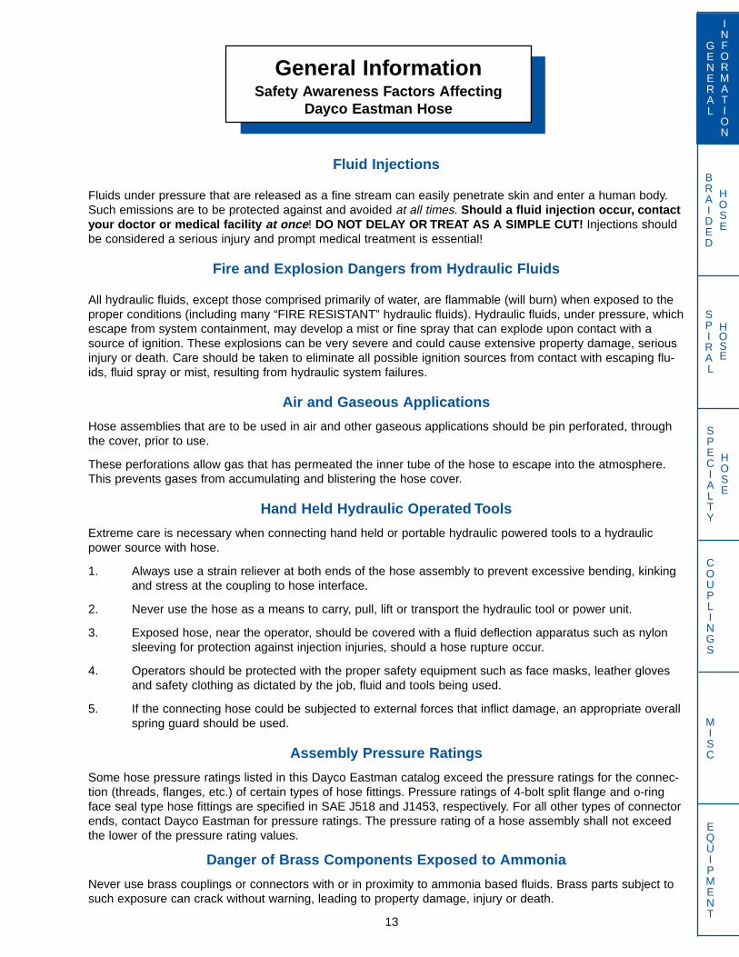
Fluid Injections
Fluids under pressure that are released as a fine stream can easily penetrate skin and enter a human body.Such emissions are to be protected against and avoided at all times. Should a fluid injection occur, contactyour doctor or medical facility at once! DO NOT DELAY OR TREAT AS A SIMPLE CUT! Injections shouldbe considered a serious injury and prompt medical treatment is essential!
Fire and Explosion Dangers from Hydraulic Fluids
All hydraulic fluids, except those comprised primarily of water, are flammable (will burn) when exposed to theproper conditions (including many “FIRE RESISTANT” hydraulic fluids). Hydraulic fluids, under pressure, whichescape from system containment, may develop a mist or fine spray that can explode upon contact with asource of ignition. These explosions can be very severe and could cause extensive property damage, seriousinjury or death. Care should be taken to eliminate all possible ignition sources from contact with escaping flu-ids, fluid spray or mist, resulting from hydraulic system failures.
Air and Gaseous Applications
Hose assemblies that are to be used in air and other gaseous applications should be pin perforated, throughthe cover, prior to use.
These perforations allow gas that has permeated the inner tube of the hose to escape into the atmosphere.This prevents gases from accumulating and blistering the hose cover.
Hand Held Hydraulic Operated Tools
Extreme care is necessary when connecting hand held or portable hydraulic powered tools to a hydraulicpower source with hose.
1. Always use a strain reliever at both ends of the hose assembly to prevent excessive bending, kinkingand stress at the coupling to hose interface.
2. Never use the hose as a means to carry, pull, lift or transport the hydraulic tool or power unit.
3. Exposed hose, near the operator, should be covered with a fluid deflection apparatus such as nylonsleeving for protection against injection injuries, should a hose rupture occur.
4. Operators should be protected with the proper safety equipment such as face masks, leather glovesand safety clothing as dictated by the job, fluid and tools being used.
5. If the connecting hose could be subjected to external forces that inflict damage, an appropriate overallspring guard should be used.
Assembly Pressure Ratings
Some hose pressure ratings listed in this Dayco Eastman catalog exceed the pressure ratings for the connec-tion (threads, flanges, etc.) of certain types of hose fittings. Pressure ratings of 4-bolt split flange and o-ringface seal type hose fittings are specified in SAE J518 and J1453, respectively. For all other types of connectorends, contact Dayco Eastman for pressure ratings. The pressure rating of a hose assembly shall not exceedthe lower of the pressure rating values.
Danger of Brass Components Exposed to Ammonia
Never use brass couplings or connectors with or in proximity to ammonia based fluids. Brass parts subject tosuch exposure can crack without warning, leading to property damage, injury or death.
BRAIDED
HOSE
SPIRAL
HOSE
General InformationHow To Read Part Numbers
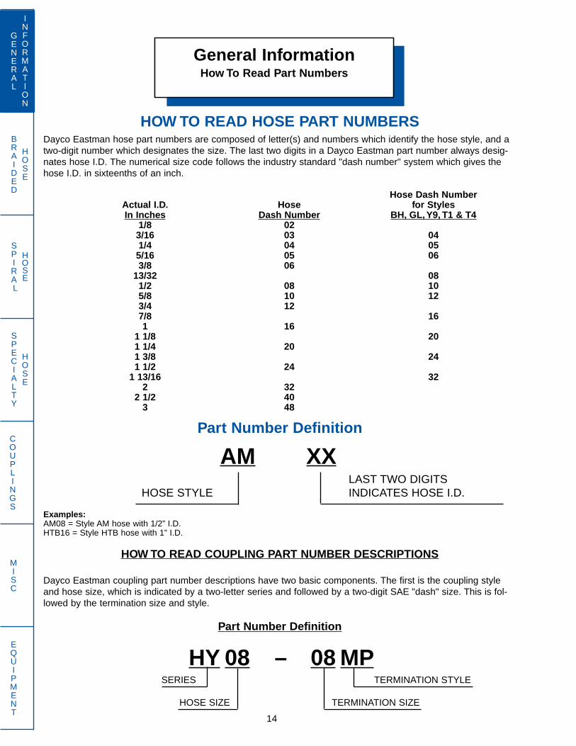
HOW TO READ HOSE PART NUMBERSDayco Eastman hose part numbers are composed of letter(s) and numbers which identify the hose style, and atwo-digit number which designates the size. The last two digits in a Dayco Eastman part number always desig-nates hose I.D. The numerical size code follows the industry standard "dash number" system which gives thehose I.D. in sixteenths of an inch.
Hose Dash NumberActual I.D. Hose for StylesIn Inches Dash Number BH, GL, Y9, T1 & T4
1/8 023/16 03 041/4 04 055/16 05 063/8 06
13/32 081/2 08 105/8 10 123/4 127/8 161 16
1 1/8 201 1/4 201 3/8 241 1/2 24
1 13/16 322 32
2 1/2 403 48
Part Number Definition
AM XXLAST TWO DIGITS
HOSE STYLE INDICATES HOSE I.D.
Examples:AM08 = Style AM hose with 1/2” I.D.HTB16 = Style HTB hose with 1” I.D.
HOW TO READ COUPLING PART NUMBER DESCRIPTIONS
Dayco Eastman coupling part number descriptions have two basic components. The first is the coupling styleand hose size, which is indicated by a two-letter series and followed by a two-digit SAE "dash" size. This is fol-lowed by the termination size and style.
Part Number Definition
HY 08 – 08 MPSERIES TERMINATION STYLE
HOSE SIZE TERMINATION SIZE
14
GENERAL
INFORMATION
SPECIALTY
HOSE
COUPLINGS
MISC
EQUIPMENT
BRAIDED
HOSE
SPIRAL
HOSE
15
GENERAL
INFORMATION
SPECIALTY
HOSE
COUPLINGS
MISC
EQUIPMENT
General InformationEnd Style Designation Chart
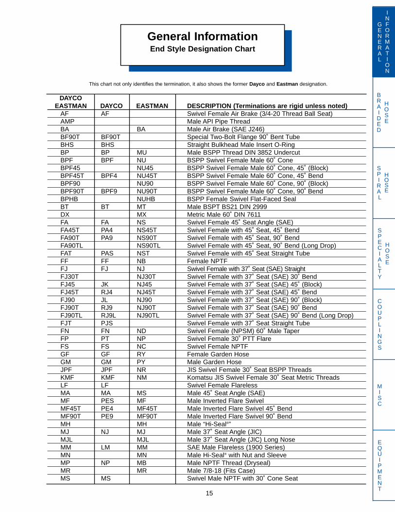
This chart not only identifies the termination, it also shows the former Dayco and Eastman designation.
DAYCOEASTMAN DAYCO EASTMAN DESCRIPTION (Terminations are rigid unless noted)
AF AF Swivel Female Air Brake (3/4-20 Thread Ball Seat)AMP Male API Pipe ThreadBA BA Male Air Brake (SAE J246)BF90T BF90T Special Two-Bolt Flange 90˚ Bent TubeBHS BHS Straight Bulkhead Male Insert O-RingBP BP MU Male BSPP Thread DIN 3852 UndercutBPF BPF NU BSPP Swivel Female Male 60˚ ConeBPF45 NU45 BSPP Swivel Female Male 60˚ Cone, 45˚ (Block)BPF45T BPF4 NU45T BSPP Swivel Female Male 60˚ Cone, 45˚ BendBPF90 NU90 BSPP Swivel Female Male 60˚ Cone, 90˚ (Block)BPF90T BPF9 NU90T BSPP Swivel Female Male 60˚ Cone, 90˚ BendBPHB NUHB BSPP Female Swivel Flat-Faced SealBT BT MT Male BSPT BS21 DIN 2999DX MX Metric Male 60˚ DIN 7611FA FA NS Swivel Female 45˚ Seat Angle (SAE)FA45T PA4 NS45T Swivel Female with 45˚ Seat, 45˚ BendFA90T PA9 NS90T Swivel Female with 45˚ Seat, 90˚ BendFA90TL NS90TL Swivel Female with 45˚ Seat, 90˚ Bend (Long Drop)FAT PAS NST Swivel Female with 45˚ Seat Straight TubeFF FF NB Female NPTFFJ FJ NJ Swivel Female with 37˚ Seat (SAE) StraightFJ30T NJ30T Swivel Female with 37˚ Seat (SAE) 30˚ BendFJ45 JK NJ45 Swivel Female with 37˚ Seat (SAE) 45˚ (Block)FJ45T RJ4 NJ45T Swivel Female with 37˚ Seat (SAE) 45˚ BendFJ90 JL NJ90 Swivel Female with 37˚ Seat (SAE) 90˚ (Block)FJ90T RJ9 NJ90T Swivel Female with 37˚ Seat (SAE) 90˚ BendFJ90TL RJ9L NJ90TL Swivel Female with 37˚ Seat (SAE) 90˚ Bend (Long Drop)FJT PJS Swivel Female with 37˚ Seat Straight TubeFN FN ND Swivel Female (NPSM) 60˚ Male TaperFP PT NP Swivel Female 30˚ PTT FlareFS FS NC Swivel Female NPTFGF GF RY Female Garden HoseGM GM PY Male Garden HoseJPF JPF NR JIS Swivel Female 30˚ Seat BSPP ThreadsKMF KMF NM Komatsu JIS Swivel Female 30˚ Seat Metric ThreadsLF LF Swivel Female FlarelessMA MA MS Male 45˚ Seat Angle (SAE)MF PES MF Male Inverted Flare SwivelMF45T PE4 MF45T Male Inverted Flare Swivel 45˚ BendMF90T PE9 MF90T Male Inverted Flare Swivel 90˚ BendMH MH Male “Hi-Seal®”MJ NJ MJ Male 37˚ Seat Angle (JIC)MJL MJL Male 37˚ Seat Angle (JIC) Long NoseMM LM MM SAE Male Flareless (1900 Series)MN MN Male Hi-Seal® with Nut and SleeveMP NP MB Male NPTF Thread (Dryseal)MR MR Male 7/8-18 (Fits Case)MS MS Swivel Male NPTF with 30˚ Cone Seat
BRAIDED
HOSE
SPIRAL
HOSE
16
GENERAL
INFORMATION
SPECIALTY
HOSE
COUPLINGS
MISC
EQUIPMENT
General InformationEnd Style Designation Chart
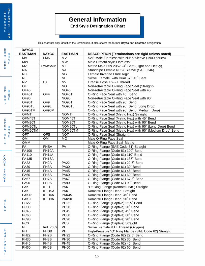
This chart not only identifies the termination, it also shows the former Dayco and Eastman designation.
DAYCOEASTMAN DAYCO EASTMAN DESCRIPTION (Terminations are rigid unless noted)
MV LMN MV SAE Male Flareless with Nut & Sleeve (1900 series)MW MW Male Ermeto-style FlarelessMZ LMM/SMM MZ Metric Male DIN 2352 24˚ Seat (Light and Heavy)NA NA Standpipe Female Nut & Sleeve (SAE J246)NG NG Female Inverted Flare RigidNL NL Swivel Female with Dual 37˚/ 45˚ SeatNV FX NV Grease Hose 1/2-27 ThreadOF NO Non-retractable O-Ring Face Seal (Straight)OF45 NO45 Non-retractable O-Ring Face Seal with 45˚OF45T OF4 NO45T O-Ring Face Seal with 45˚ BendOF90 NO90 Non-retractable O-Ring Face Seal with 90˚OF90T OF9 NO90T O-Ring Face Seal with 90˚ BendOF90TL OF9L NO90TL O-Ring Face Seal with 90˚ Bend (Long Drop)OF90TM OF90M O-Ring Face Seal with 90˚ Bend (Medium Drop)OFMT NOMT O-Ring Face Seal (Metric Hex) StraightOFM45T NOM45T O-Ring Face Seal (Metric Hex) with 45˚ BendOFM90T NOM90T O-Ring Face Seal (Metric Hex) with 90˚ BendOFM90TL NOM90TL O-Ring Face Seal (Metric Hex) with 90˚ (Long Drop) BendOFM90TM NOM90TM O-Ring Face Seal (Metric Hex) with 90˚ (Medium Drop) BendOFT OFS NOT O-Ring Face Seal (Straight)OM OM MO Male O-Ring Face SealOMM Male O-Ring Face Seal–MetricPA FHSA PA O-Ring Flange (SAE Code 61) StraightPA100 FH10A O-Ring Flange (Code 61) 100˚ BendPA110 FH11A O-Ring Flange (Code 61) 110˚ BendPA135 FH13A O-Ring Flange (Code 61) 135˚ BendPA22 FH2A PA22 O-Ring Flange (Code 61) 22.5˚ BendPA30 FH3A PA30 O-Ring Flange (Code 61) 30˚ BendPA45 FH4A PA45 O-Ring Flange (Code 61) 45˚ BendPA60 FH6A PA60 O-Ring Flange (Code 61) 60˚ BendPA67 FH7A PA67 O-Ring Flange (Code 61) 67.5˚ BendPA90 FH9A PA90 O-Ring Flange (Code 61) 90˚ BendPAK KFH PAK “O” Ring Flange (Komatsu 5/8”) StraightPAK KFHSA PAK Komatsu Flange Head, StraightPAK45 KFH4A PAK45 Komatsu Flange Head, 45˚ BendPAK90 KFH9A PAK90 Komatsu Flange Head, 90˚ BendPC22 PC22 O-Ring Flange (Captive) 22.5˚ BendPC30 PC30 O-Ring Flange (Captive) 30˚ BendPC45 PC45 O-Ring Flange (Captive) 45˚ BendPC60 PC60 O-Ring Flange (Captive) 60˚ BendPC90 PC90 O-Ring Flange (Captive) 90˚ BendPCS PCS O-Ring Flange (Captive) StraightPE Ind. 7639 PE Swivel Female R.H. Thread (Oxygen)PH FHSB PH High-Pressure “O” Ring Flange (SAE Code 62) StraightPH22 FH2B PH22 O-Ring Flange (Code 62) 22.5˚ BendPH30 FH3B PH30 O-Ring Flange (Code 62) 30˚ BendPH45 FH4B PH45 O-Ring Flange (Code 62) 45˚ BendPH60 FH6B PH60 O-Ring Flange (Code 62) 60˚ Bend

BRAIDED
HOSE
SPIRAL
HOSE
17
GENERAL
INFORMATION
SPECIALTY
HOSE
COUPLINGS
MISC
EQUIPMENT
General InformationEnd Style Designation Chart
This chart not only identifies the termination, it also shows the former Dayco and Eastman designation.
DAYCOEASTMAN DAYCO EASTMAN DESCRIPTION (Terminations are rigid unless noted)
PH67 FH7B PH67 O-Ring Flange (Code 62) 67.5˚ BendPH90 FH9B PH90 O-Ring Flange (Code 62) 90˚ BendPHC22 FH2C O-Ring Flange (Fits CAT) 22.5˚ BendPHC30 FH3C O-Ring Flange (Fits CAT) 30˚ BendPHC45 FH4C O-Ring Flange (Fits CAT) 45˚ BendPHC60 FH6C O-Ring Flange (Fits CAT) 60˚ BendPHC67 FH7C O-Ring Flange (Fits CAT) 67.5˚ BendPHC90 FH9C O-Ring Flange (Fits CAT) 90˚ BendPHCS FHSC O-Ring Flange (Fits CAT) StraightPR PR Male NPT Thread (Non-Dryseal)PS PS Male PTF ThreadPS45 PS45 Male PTF Thread 45˚PS90 PS90 Male PTF Thread 90˚PV PV Male NPSM Straight ThreadPWM PWM Pressure Washer Metric Female SwivelPWMM PWMM Pressure Washer Metric MaleRA OR RA “O” Ring BossRC OS RC Swivel Male “O” Ring BossRC45 OK RC45 Swivel Male 45˚ “O” Ring Boss (Block)RC90 OL RC90 Swivel Male 90˚ “O” Ring Boss (Block)RD RD Female O-Ring BossRE Ind. 7639 RE Swivel Female L.H. Thread (Acetylene)RL RL Stand Pipe (Inch Tube Sizes)RM FC RM Hose MenderRO(*) FSM RO Metric Female Swivel 24˚ Cone with O-Ring, StraightRO(*)45T FSM4 Metric Female Swivel 24˚ Cone with O-Ring, 45˚ BendRO(*)90T FSM9 RO90T Metric Female Swivel 24˚ Cone with O-Ring, 90˚ BendRU FLM RU Metric Female Swivel Universal 24/60˚ Cone, StraightRU45T FLM4 RU45T Metric Female Swivel Universal 24/60˚ Cone, 45˚ BendRU90T FLM9 RU45T Metric Female Swivel Universal 24/60˚ Cone, 90˚ BendRV RV Swivel Female NPSMRY RY GAZ Metric Female Swivel Universal 24/60˚ ConeRZ SP RZ Metric O.D. Standpipe, StraightRZ45 SP4 RZ45 Metric O.D. Standpipe, 45˚ BendRZ45LT RZ45L Standpipe Metric “Light” 45˚ TubeRZ45ST RZ45S Standpipe Metric “Standard” 45˚ TubeRZ90 SP9 RZ90 Metric O.D. Standpipe, 90˚ BendRZ90LT RZ90L Standpipe Metric “Light” 90˚ TubeRZ90ST RZ90S Standpipe Metric “Standard” 90˚ TubeRZLST Standpipe Metric Standard/Light Straight TubeRZLS45T Standpipe Metric Standard/Light 45˚ TubeRZLS90T Standpipe Metric Standard/Light 90˚ TubeRZLT RZ L Standpipe Metric “Light” StraightRZST RZ S Standpipe Metric “Standard” StraightSP MC Swivel Male NPTF without 30˚ SeatSP45 NK MC45 Swivel Male NPTF 45˚ (Block)SP90 MC90 Swivel Male NPTF 90˚ (Block)SSM SSM “Super” Stecko Male

BRAIDED
HOSE
SPIRAL
HOSE
18
GENERAL
INFORMATION
SPECIALTY
HOSE
COUPLINGS
MISC
EQUIPMENT
General InformationEnd Style Designation Chart
This chart not only identifies the termination, it also shows the former Dayco and Eastman designation.
DAYCOEASTMAN DAYCO EASTMAN DESCRIPTION (Terminations are rigid unless noted)
TA45T TA4 Male 45˚ Flare Swivel, 45˚ BendTA90T TA9 Male 90˚ Flare Swivel, 90˚ BendTAST TAS Male 45˚ Flare Swivel, Straight TubeTF45P TF4P Swivel Female Tube ‘O’ 45˚ Bend with R134a Service PortTF45PV TF4P Swivel Female Tube ‘O’ 90˚ Bend w/R134a Charge Port at 180˚TF45T TF4 Swivel Female Tube 'O' Refrigerant (217 Series Nut) 45˚ BendTF90P TF9P Swivel Female Tube ‘O’ 90˚ Bend with R143a Service PortTF90PV TF9P Swivel Female Tube ‘O’ 45˚ Bend w/R134a Charge Port at 180˚TF90T TF9 Swivel Female Tube 'O' Refrigerant (217 Series Nut) 90˚ BendTFS TFS NE Swivel Female Tube 'O' Refrigerant (217 Series Nut)TFSP TFSP Swivel Female Tube ’O’ Straight Tube with R134a Service PortTMSP TMSP Swivel Male Tube ’O’ Straight Tube with Charge Port for R134aTM45P TM4P Swivel Male Tube ‘O’ 45˚ Bend w/Charge Port at 180˚ for R134aTM90P TM9P Swivel Male Tube ‘O’ 90˚ Bend w/Charge Port at 180˚ for R134aTM90RX TM9PV Swivel Male Tube ‘O’ 90˚ Bend w/Charge Port at 270˚ for R134aTM45T TM4 Swivel Male Tube 'O' Refrigerant (216 Series Nut) 45˚ BendTM90T TM9 Swivel Male Tube 'O' Refrigerant (216 Series Nut) 90˚ BendTMS TMS MA Swivel Male Tube 'O' Freon (216 Series Nut)TOF90P TOF9 90˚ Female Tube ‘O’ Steel with R134a Service Port
NOTE: All steel parts are zinc plated with a yellow dichromate finish, unlessotherwise noted. This finish passes the 72 hour SAE J516 Salt Spray TestRequirement in accordance with ASTM B117.
* Metric tube and thread size must be identified in the part number, i.e. BW12-25RO36B.

BRAIDED
HOSE
SPIRAL
HOSE
SAE J514, 37˚ Flare
Commonly referred to as 37˚ JIC, this connection is widely used inhydraulic systems,. When the straight threads are engaged, the37˚ male seat seals on the 37˚ female flare seat. Most thread sizesare identical to the 45˚ SAE connection as noted below. Care mustbe taken not to confuse these two connectors which have differentseating angles.
Dash Inch Male Thread O.D. Female Thread I.D.Size Size Thread mm in. mm in.
-2 1/8 5/16–24* 7.9 .31 6.9 .27-3 3/16 3/8–24* 9.6 .38 8.6 .34-4 1/4 7/16–20* 11.2 .44 9.9 .39-5 5/16 1/2–20* 12.7 .50 11.4 .45-6 3/8 9/16–18 14.2 .56 12.9 .51-8 1/2 3/4–16* 19.0 .75 17.0 .67
-10 5/8 7/8–14* 22.3 .88 20.3 .80-12 3/4 1-1/16–12 26.9 1.06 24.9 .98-14 7/8 1-3/16–12 30.0 1.18 27.7 1.09-16 1 1-5/16–12 33.3 1.31 31.0 1.22-20 1-1/4 1-5/8–12 41.4 1.63 39.1 1.54-24 1-1/2 1-7/8–12 47.7 1.88 45.5 1.79-32 2 2-1/2–12 63.5 2.50 61.2 2.41
*Same thread as SAE 45˚ flare
SAE J514 Straight Thread O-Ring Boss
This straight thread connection uses the same threads as the JIC37˚ flare shown above. However, the 37˚ flare has been removedand an o-ring added. When mated with a female o-ring boss portthe o-ring is trapped in a special tapered counterbore to effect theseal.
Dash Inch Male Thread O.D. Female Thread I.D.Size Size Thread mm in. mm in.
-2 1/8 5/16–24 7.9 .31 6.9 .27-3 3/16 3/8–24 9.6 .38 8.6 .34-4 1/4 7/16–20 11.2 .44 9.9 .39-5 5/16 1/2–20 12.7 .50 11.4 .45-6 3/8 9/16–18 14.2 .56 12.9 .51-8 1/2 3/4–16 19.0 .75 17.0 .67
-10 5/8 7/8–14 22.3 .88 20.3 .80-12 3/4 1-1/16–12 26.9 1.06 24.9 .98-14 7/8 1-3/16–12 30.0 1.18 27.7 1.09-16 1 1-5/16–12 33.3 1.31 31.0 1.22-20 1-1/4 1-5/8–12 41.4 1.63 39.1 1.54-24 1-1/2 1-7/8–12 47.7 1.88 45.5 1.79-32 2 2-1/2–12 63.5 2.50 61.2 2.41
General InformationThread Standards
19
GENERAL
INFORMATION
SPECIALTY
HOSE
COUPLINGS
MISC
EQUIPMENT
How to measure threads
By using a combination of three tools, identifying connectors is easyto do.
A caliper is used to measure the O.D. of a male thread and I.D. of afemale thread.
NOTE: When comparing your measurements with those on the fol-lowing pages it should be remembered that threads can becomeworn and distorted from use and you may not compare exactly tothe figures in the tables.
For your convenience, dimensions are in both millimeters and inches.The thread pitch gauge measures the threads per inch.
The thread pitch gauge measures the threads per inch. For metricthreads the gauge will identify the distance between the threads.
The seat angle gauge is used by placing the gauge angle on thesealing surface. The centerline of the end fitting and the gaugeshould be parallel.
In the English system the thread size and pitch (number of threadsper inch) are given, along with the thread type.
1/2–18 NPTF
Thread Pitch NPTFSize 18 threads/inch Dryseal pipe
MALE 37° (MJ)
FEMALE 37° (FJ)
MALE O-RING (RA, RC)
FEMALE O-RING PORT (RD)
Caliper
Thread Pitch Gauge
Seat Angle Gauge
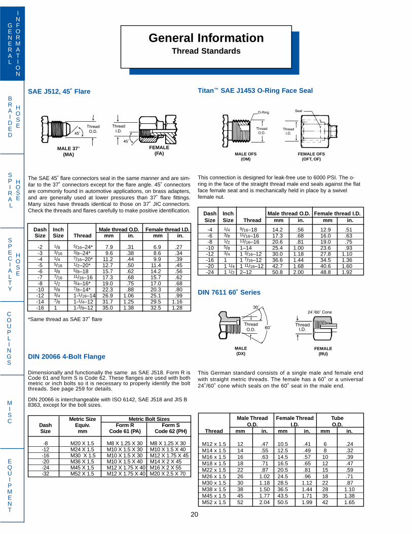
SAE J512, 45˚ Flare
The SAE 45˚ flare connectors seal in the same manner and are sim-ilar to the 37˚ connectors except for the flare angle. 45˚ connectorsare commonly found in automotive applications, on brass adapters,and are generally used at lower pressures than 37˚ flare fittings.Many sizes have threads identical to those on 37˚ JIC connectors.Check the threads and flares carefully to make positive identification.
Dash Inch Male thread O.D. Female thread I.D.Size Size Thread mm in. mm in.
-2 1/8 5/16–24* 7.9 .31 6.9 .27-3 3/16 3/8–24* 9.6 .38 8.6 .34-4 1/4 7/16–20* 11.2 .44 9.9 .39-5 5/16 1/2–20* 12.7 .50 11.4 .45-6 3/8 5/8–18 15.7 .62 14.2 .56-7 7/16 11/16–16 17.3 .68 15.7 .62-8 1/2 3/4–16* 19.0 .75 17.0 .68
-10 5/8 7/8–14* 22.3 .88 20.3 .80-12 3/4 1-1/16–14 26.9 1.06 25.1 .99-14 7/8 1-1/4–12 31.7 1.25 29.5 1.16-16 1 1-3/8–12 35.0 1.38 32.5 1.28
*Same thread as SAE 37˚ flare
DIN 20066 4-Bolt Flange
Dimensionally and functionally the same as SAE J518. Form R isCode 61 and form S is Code 62. These flanges are used with bothmetric or inch bolts so it is necessary to properly identify the boltthreads. See page 259 for details.
DIN 20066 is interchangeable with ISO 6142, SAE J518 and JIS B8363, except for the bolt sizes.
Metric Size Metric Bolt SizesDash Equiv. Form R Form SSize mm Code 61 (PA) Code 62 (PH)
-8 M20 X 1.5 M8 X 1.25 X 30 M8 X 1.25 X 30-12 M24 X 1.5 M10 X 1.5 X 30 M10 X 1.5 X 40-16 M30 X 1.5 M10 X 1.5 X 30 M12 X 1.75 X 45-20 M36 X 1.5 M10 X 1.5 X 40 M14 X 2 X 45-24 M45 X 1.5 M12 X 1.75 X 40 M16 X 2 X 55-32 M52 X 1.5 M12 X 1.75 X 40 M20 X 2.5 X 70
Titan™ SAE J1453 O-Ring Face Seal
This connection is designed for leak-free use to 6000 PSI. The o-ring in the face of the straight thread male end seals against the flatface female seat and is mechanically held in place by a swivelfemale nut.
Dash Inch Male thread O.D. Female thread I.D.Size Size Thread mm in. mm in.
-4 1/4 9/16–18 14.2 .56 12.9 .51-6 3/8 11/16–16 17.3 .68 16.0 .63-8 1/2 13/16–16 20.6 .81 19.0 .75
-10 5/8 1–14 25.4 1.00 23.6 .93-12 3/4 1 3/16–12 30.0 1.18 27.8 1.10-16 1 1 7/16–12 36.6 1.44 34.5 1.36-20 1 1/4 1 11/16–12 42.7 1.68 40.6 1.60-24 1 1/2 2–12 50.8 2.00 48.8 1.92
DIN 7611 60˚ Series
This German standard consists of a single male and female endwith straight metric threads. The female has a 60˚ or a universal24˚/60˚ cone which seals on the 60˚ seat in the male end.
Male Thread Female Thread TubeO.D. I.D. O.D.
Thread mm in. mm in. mm in.
M12 x 1.5 12 .47 10.5 .41 6 .24M14 x 1.5 14 .55 12.5 .49 8 .32M16 x 1.5 16 .63 14.5 .57 10 .39M18 x 1.5 18 .71 16.5 .65 12 .47M22 x 1.5 22 .87 20.5 .81 15 .59M26 x 1.5 26 1.02 24.5 .96 18 .71M30 x 1.5 30 1.18 28.5 1.12 22 .87M38 x 1.5 38 1.50 36.5 1.44 28 1.10M45 x 1.5 45 1.77 43.5 1.71 35 1.38M52 x 1.5 52 2.04 50.5 1.99 42 1.65
General InformationThread Standards
20
GENERAL
INFORMATION
SPECIALTY
HOSE
COUPLINGS
MISC
EQUIPMENT
BRAIDED
HOSE
SPIRAL
HOSE
MALE 37° (MA)
FEMALE (FA) MALE OFS
(OM)FEMALE OFS
(OFT, OF)
MALE (DX)
FEMALE (RU)
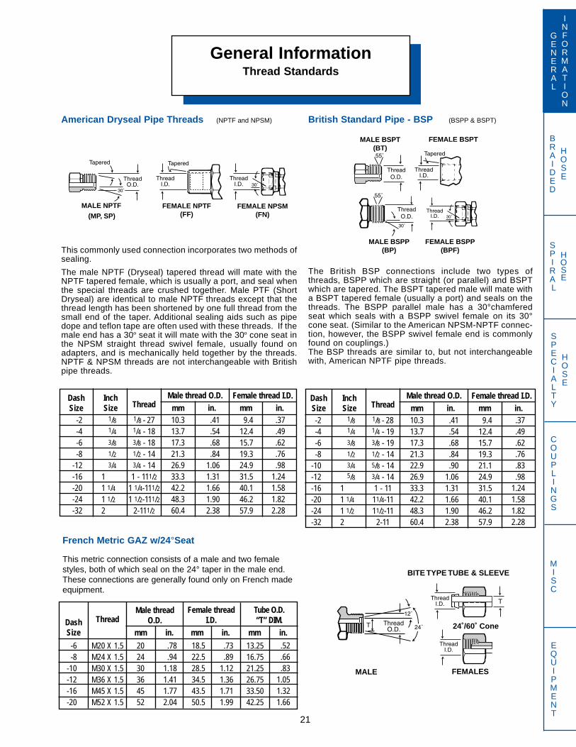
General InformationThread Standards
21
GENERAL
INFORMATION
SPECIALTY
HOSE
COUPLINGS
MISC
EQUIPMENT
BRAIDED
HOSE
SPIRAL
HOSE
French Metric GAZ w/24°Seat
This metric connection consists of a male and two femalestyles, both of which seal on the 24° taper in the male end.These connections are generally found only on French madeequipment.
British Standard Pipe - BSP (BSPP & BSPT)
The British BSP connections include two types ofthreads, BSPP which are straight (or parallel) and BSPTwhich are tapered. The BSPT tapered male will mate witha BSPT tapered female (usually a port) and seals on thethreads. The BSPP parallel male has a 30°chamferedseat which seals with a BSPP swivel female on its 30°cone seat. (Similar to the American NPSM-NPTF connec-tion, however, the BSPP swivel female end is commonlyfound on couplings.)The BSP threads are similar to, but not interchangeablewith, American NPTF pipe threads.
1/8 - 281/4 - 193/8 - 191/2 - 145/8 - 143/4 - 141 - 1111/4-1111/2-11
2-11
Male thread O.D.DashSize
1/81/43/81/23/45/8
11 1/41 1/22
9.412.415.719.321.124.931.540.146.257.9
.41
.54
.68
.84
.901.061.311.661.902.38
10.313.717.321.322.926.933.342.248.360.4
in..37.49.62.76.83.98
1.241.581.822.28
InchSize Thread
Female thread I.D.mm
-2-4-6-8
-10-12-16-20-24-32
mm in.
BITE TYPE TUBE & SLEEVE
MALE FEMALES
24˚/60˚ Cone
M20 X 1.5M24 X 1.5M30 X 1.5M36 X 1.5M45 X 1.5M52 X 1.5
Male threadO.D.Dash
Size
.73
.891.121.361.711.99
18.522.528.534.543.550.5
.78
.941.181.411.772.04
in.
.52
.66
.831.051.321.66
ThreadFemale thread
I.D.mm
-6-8
-10-12-16-20
mm in. mm in.
13.2516.7521.2526.7533.5042.25
Tube O.D.“T” DIM.
202430364552
1/8 - 271/4 - 183/8 - 181/2 - 143/4 - 141 - 111/2
1 1/4-111/21 1/2-111/2
2-111/2
American Dryseal Pipe Threads (NPTF and NPSM)
This commonly used connection incorporates two methods ofsealing.
The male NPTF (Dryseal) tapered thread will mate with theNPTF tapered female, which is usually a port, and seal whenthe special threads are crushed together. Male PTF (ShortDryseal) are identical to male NPTF threads except that thethread length has been shortened by one full thread from thesmall end of the taper. Additional sealing aids such as pipedope and teflon tape are often used with these threads. If themale end has a 30º seat it will mate with the 30º cone seat inthe NPSM straight thread swivel female, usually found onadapters, and is mechanically held together by the threads.NPTF & NPSM threads are not interchangeable with Britishpipe threads.
Male thread O.D.DashSize
1/81/43/81/23/4
11 1/41 1/22
9.412.415.719.324.931.540.146.257.9
.41
.54
.68
.841.061.311.661.902.38
10.313.717.321.326.933.342.248.360.4
in..37.49.62.76.98
1.241.581.822.28
InchSize Thread
Female thread I.D.mm
-2-4-6-8
-12-16-20-24-32
mm in.
FEMALE NPTF (FF)
FEMALE NPSM (FN)
MALE NPTF
(MP, SP)
MALE BSPT (BT)
FEMALE BSPT
MALE BSPP (BP)
FEMALE BSPP (BPF)
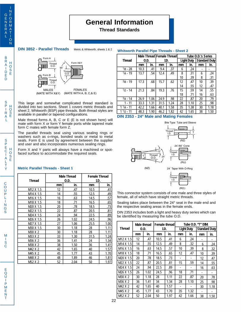
BRAIDED
HOSE
SPIRAL
HOSE DIN 2353 - 24° Male and Mating Females
This connector system consists of one male and three styles offemale, all of which have straight metric threads.
Sealing takes place between the 24° seat in the male end andthe respective sealing areas in the female ends.
DIN 2353 includes both a light and heavy duty series which canbe identified by measuring the tube O.D.
General InformationThread Standards
22
GENERAL
INFORMATION
SPECIALTY
HOSE
COUPLINGS
MISC
EQUIPMENT
Male Thread Female Thread Tube O.D.’s SeriesThread O.D. I.D. Light Duty Standard Duty
mm in. mm in. mm in. mm in.1/8 - 28 10.3 .41 9.4 .37 6 .24 - -1/4 - 19 13.7 .54 12.4 .49 8 .31 6 .24
10 .39 8 .313/8 - 19 17.3 .68 15.7 .62 12 .47 10 .39
14 .55 12 .471/2 - 14 21.3 .84 19.3 .76 15 .59 14 .55
18 .71 16 .633/4 - 14 26.9 1.06 24.9 .98 22 .87 20 .79
1 - 11 33.3 1.31 31.5 1.24 28 1.10 25 .981 1/4 - 11 42.2 1.66 40.1 1.58 35 1.38 30 1.181 1/2 - 11 48.3 1.90 46.2 1.82 42 1.65 38 1.50
Thread
-.24.32.39.47.55.63-.78.98
1.18-
1.50
mm in.-68
10121416-
202530-
38
Tube O.D. “T” DIM.
68
1012-
15-
182228-
3542
DIN 3852 - Parallel Threads Metric & Whitworth, sheets 1 & 2
This large and somewhat complicated thread standard isdivided into two sections. Sheet 1 covers metric threads andsheet 2, Whitworth (BSP) pipe threads. Both thread styles areavailable in parallel or tapered configurations.
Male thread forms A, B, C or E (E is not shown here) willmate with form X or form Y female ports while tapered maleform C mates with female form Z.
The parallel threads seal using various sealing rings orwashers such as o-rings, bonded seals or metal to metalseals. Form E is used by agreement between the supplierand user and also incorporates numerous sealing rings.
Form X and Y parts will always have a machined or spot-faced surface to accommodate the required seals.
Male Thread Female ThreadThread O.D. I.D.
mm in. mm in.M12 X 1.5 12 .47 10.5 .41M14 X 1.5 14 .55 12.5 .49M16 X 1.5 16 .63 14.5 .57M18 X 1.5 18 .71 16.5 .65M20 X 1.5 20 .78 18.5 .73M22 X 1.5 22 .87 20.5 .81M24 X 1.5 24 .94 22.5 .89M26 X 1.5 26 1.02 24.5 .96M27 X 1.5 27 1.06 25.5 1.00M30 X 1.5 30 1.18 28 1.11M30 X 2 30 1.18 28 1.11M33 X 2 33 1.30 31.5 1.24M36 X 2 36 1.41 24 1.34M38 X 2 38 1.50 36 1.41M42 X 2 42 1.65 40 1.57M45 X 2 45 1.77 43 1.70M48 X 2 48 1.89 46 1.81M52 X 2 52 2.04 50 1.97
M12 X 1.5M14 X 1.5M16 X 1.5M18 X 1.5M20 X 1.5M22 X 1.5M24 X 1.5M26 X 1.5M30 X 2M36 X 2M42 X 2M45 X 2M52 X 2
Male threadO.D.
.41
.49
.57
.65
.73
.81
.89
.961.111.341.571.701.97
10.512.514.516.518.520.522.524.52834404350
.47
.55
.63
.71
.78
.87
.941.021.181.411.651.772.04
in..24.32.39.47-
.59-
.71
.871.10
-1.321.66
Female threadI.D.
mm mm in. mm in.Light Duty Standard Duty
12141618202224263036424552
Metric Parallel Threads - Sheet 1
Whitworth Parallel Pipe Threads - Sheet 2

BRAIDED
HOSE
SPIRAL
HOSE
JIS 30° Male Inverted Seat with Parallel Pipe Threads
This JIS connector is similar to, and can be interchanged withBSPP parallel connections. Thread conforms to JIS B 0202.
General InformationThread Standards
23
GENERAL
INFORMATION
SPECIALTY
HOSE
COUPLINGS
MISC
EQUIPMENT
-6-8
-10-12-16-20-24
18222430333642
JIS Tapered Pipe Thread (PT)
The JIS tapered pipe thread (PT) is identical to and interchange-able with the British BSPT tapered pipe thread. However, themale end does not have a 60° chamfer and will only seal whenthe threads are crushed together in an appropriate JIS or BSPport.
1/8 - 281/4 - 193/8 - 191/2 - 145/8 - 143/4 - 141 - 11
1 1/4-111 1/2-11
2
Male Thread O.D.DashSize
1/81/43/81/25/83/4
11 1/41 1/22
8.112.416.019.820.625.431.840.446.258.2
.37
.53
.68
.84
.911.061.341.681.902.37
9.413.717.221.523.126.934.042.648.560.4
in.
.32
.49
.62
.77
.811.001.251.591.812.29
InchSize Thread
Female Thread I.D.mm
-2-4-6-8
-10-12-16-20-24-32
mm in.
JIS 30° Flare with Parallel Pipe Threads (PF)
This Japanese connector is similar to the American 37° JICflare except for the 30° seat angle. The straight (parallel) pipethreads are the same as BSPP.
1/8 - 281/4 - 193/8 - 191/2 - 145/8 - 143/4 - 141 - 11
1 1/4-111 1/2-11
2
Male Thread O.D.DashSize
1/81/43/81/25/83/4
11 1/41 1/22
8.112.416.019.820.625.431.840.446.258.2
.37
.53
.68
.84
.911.061.341.681.902.37
9.413.717.221.523.126.934.042.648.560.4
in.
.32
.49
.62
.77
.811.001.251.591.812.29
InchSize Thread
Female Thread I.D.mm
-2-4-6-8
-10-12-16-20-24-32
mm in.
1/4 - 193/8 - 191/2 - 143/4 - 141 - 11
1 1/4-111 1/2-11
2
Male Thread O.D. Female Thread I.D.DashSize
1/43/81/23/4
11 1/41 1/22
12.416.019.825.431.840.446.258.2
.54
.68
.851.061.341.681.912.38
13.717.221.526.934.042.648.560.4
in.
.49
.63
.781.001.251.591.822.29
InchSize Thread mm
-4-6-8
-12-16-20-24-32
mm in.
Japanese Komatsu 30° Flare with Metric Threads
Used extensively on Komatsu equipment, this 30° flare con-nector has parallel metric threads and is sometimes confusedwith JIS 30° flare which has parallel pipe threads.
M18 X 1.5M22 X 1.5M24 X 1.5M30 X 1.5M33 X 1.5M36 X 1.5M42 X 1.5
Male Thread O.D. Female Thread I.D.DashSize
9121619253238
16.520.522.528.531.534.540.5
.71
.87
.941.181.301.421.65
in.
.65
.82
.881.121.241.361.59
MetricSize Equiv.
MetricThread mm mm in.
MALE FEMALE (BPF)
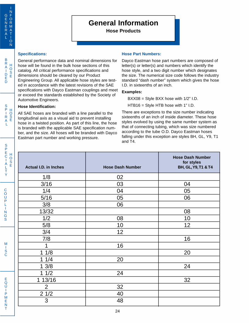
BRAIDED
HOSE
SPIRAL
HOSE
General InformationHose Products
24
GENERAL
INFORMATION
SPECIALTY
HOSE
COUPLINGS
MISC
EQUIPMENT
Hose Dash Numberfor styles
Actual I.D. in Inches Hose Dash Number BH, GL,Y9,T1 & T4
1/8 023/16 03 041/4 04 05
5/16 05 063/8 06
13/32 081/2 08 105/8 10 123/4 127/8 161 16
1 1/8 201 1/4 201 3/8 241 1/2 24
1 13/16 322 32
2 1/2 403 48
Specifications:
General performance data and nominal dimensions forhose will be found in the bulk hose sections of thiscatalog. All critical performance specifications anddimensions should be cleared by our ProductEngineering Group. All applicable hose styles are test-ed in accordance with the latest revisions of the SAEspecifications with Dayco Eastman couplings and meetor exceed the standards established by the Society ofAutomotive Engineers.
Hose Identification:
All SAE hoses are branded with a line parallel to thelongitudinal axis as a visual aid to prevent installinghose in a twisted position. As part of this line, the hoseis branded with the applicable SAE specification num-ber, and the size. All hoses will be branded with DaycoEastman part number and working pressure.
Hose Part Numbers:
Dayco Eastman hose part numbers are composed ofletter(s) or letter(s) and numbers which identify thehose style, and a two digit number which designatesthe size. The numerical size code follows the industrystandard “dash number” system which gives the hoseI.D. in sixteenths of an inch.
Examples:
BXX08 = Style BXX hose with 1/2” I.D.
HTB16 = Style HTB hose with 1” I.D.
There are exceptions to the size number indicatingsixteenths of an inch of inside diameter. These hosestyles evolved by using the same number system asthat of connecting tubing, which was size numberedaccording to the tube O.D. Dayco Eastman hosesfalling under this exception are styles BH, GL, Y9, T1and T4.
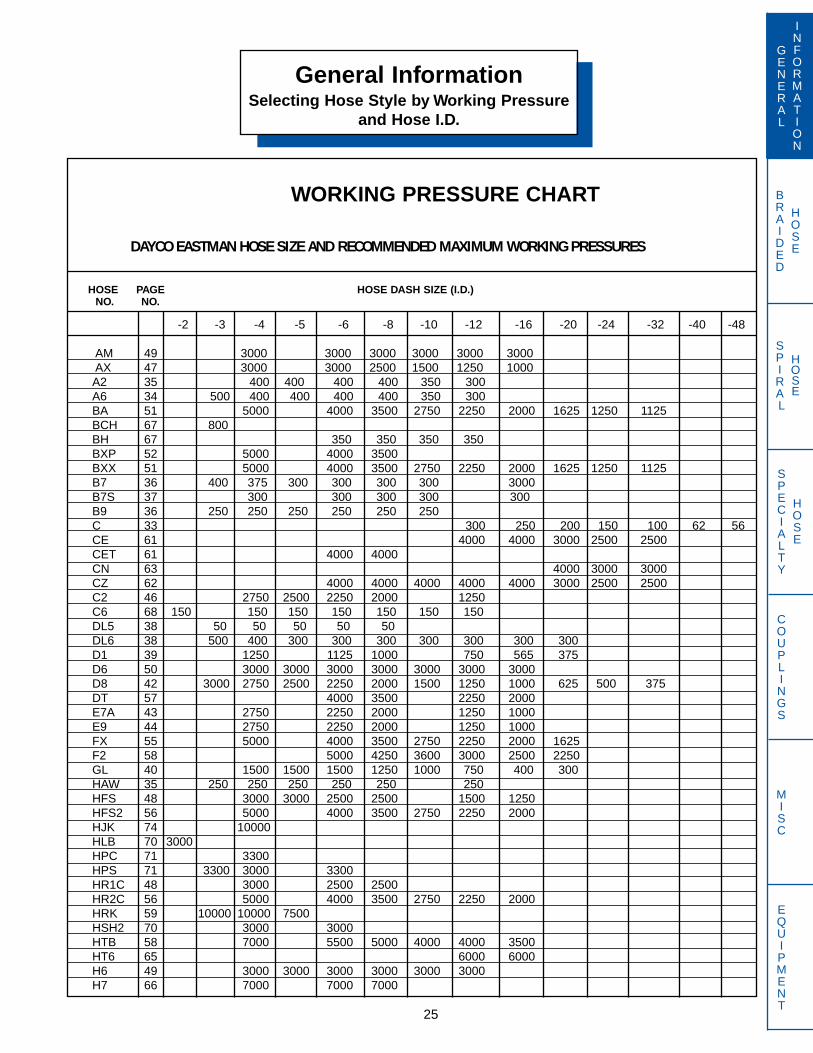
BRAIDED
HOSE
SPIRAL
HOSE
General InformationSelecting Hose Style by Working Pressure
and Hose I.D.
25
GENERAL
INFORMATION
SPECIALTY
HOSE
COUPLINGS
MISC
EQUIPMENT
WORKING PRESSURE CHART
DAYCO EASTMAN HOSE SIZE AND RECOMMENDED MAXIMUM WORKING PRESSURES
HOSE PAGE HOSE DASH SIZE (I.D.) NO. NO.
-2 -3 -4 -5 -6 -8 -10 -12 -16 -20 -24 -32 -40 -48
AM 49 3000 3000 3000 3000 3000 3000AX 47 3000 3000 2500 1500 1250 1000A2 35 400 400 400 400 350 300A6 34 500 400 400 400 400 350 300BA 51 5000 4000 3500 2750 2250 2000 1625 1250 1125BCH 67 800BH 67 350 350 350 350BXP 52 5000 4000 3500BXX 51 5000 4000 3500 2750 2250 2000 1625 1250 1125B7 36 400 375 300 300 300 300 3000B7S 37 300 300 300 300 300B9 36 250 250 250 250 250 250C 33 300 250 200 150 100 62 56CE 61 4000 4000 3000 2500 2500CET 61 4000 4000CN 63 4000 3000 3000CZ 62 4000 4000 4000 4000 4000 3000 2500 2500C2 46 2750 2500 2250 2000 1250C6 68 150 150 150 150 150 150 150DL5 38 50 50 50 50 50DL6 38 500 400 300 300 300 300 300 300 300D1 39 1250 1125 1000 750 565 375D6 50 3000 3000 3000 3000 3000 3000 3000D8 42 3000 2750 2500 2250 2000 1500 1250 1000 625 500 375DT 57 4000 3500 2250 2000E7A 43 2750 2250 2000 1250 1000E9 44 2750 2250 2000 1250 1000FX 55 5000 4000 3500 2750 2250 2000 1625F2 58 5000 4250 3600 3000 2500 2250GL 40 1500 1500 1500 1250 1000 750 400 300HAW 35 250 250 250 250 250 250HFS 48 3000 3000 2500 2500 1500 1250HFS2 56 5000 4000 3500 2750 2250 2000HJK 74 10000HLB 70 3000HPC 71 3300HPS 71 3300 3000 3300HR1C 48 3000 2500 2500HR2C 56 5000 4000 3500 2750 2250 2000HRK 59 10000 10000 7500HSH2 70 3000 3000HTB 58 7000 5500 5000 4000 4000 3500HT6 65 6000 6000H6 49 3000 3000 3000 3000 3000 3000H7 66 7000 7000 7000

BRAIDED
HOSE
SPIRAL
HOSE
General InformationSelecting Hose Style by Working Pressure
and Hose I.D.
26
GENERAL
INFORMATION
SPECIALTY
HOSE
COUPLINGS
MISC
EQUIPMENT
DAYCO EASTMAN HOSE AND RECOMMEMDED MAXIMUM WORKING PRESSURES
HOSE PAGE HOSE DASH SIZE (I.D.) NO. NO.
-2 -3 -4 -5 -6 -8 -10 -12 -16 -20 -24 -32 -40 -48
J4 53 1625 1250 1125J9 54 5000 4000 3500 2250 2000J4A 53 5000 4000 3500 2250 2000L1 60 4500 4000 3000 3000 2500M 42 3000 2750 2250 2000 1500 1250 1000 625 500 375MX 43 3000 2750 2500 2250 2000 1500 1250 1000 625 500 375M7 61 4000 4000 4000 4000 4000 3000 2500 2500M8 62 4000 4000 4000 4000NH 64 5000 5000 5000 5000 5000NR7 45 3000 3000 2750 2500 2250 2000 1250 1000NR7E 46 3000 3000 2750 2500 2250 2000 1250 1000N2 65 6000 6000 6000 6000 6000N3 63 6400 6000 6000 6000 5500 5000 4200 3800N6 64 5000 5000 5000 5000 5000P3 72 3000QX 60 4500 4000 3000 3000 2500 2000 2000R5 41 2000 1875R6 50 3000 3000 3000 3000 3000 3000RT2 52 5000 4000 3500 2750 2250 2000 1625 1250 1125SN2K 57 5800 4800 4000 3625 3200 2400 1800 1300 1160ST 47 2750 2250 2000 1250 1000S5 74 4000 4000S6 72 2500 2500 2500 2500S7 44 3000 3000 2750 2500 2250 2000 1250 1000S8 54 5000 5000 4000 3500 2250 2000S7E 45 3000 3000 2750 2500 2250 2000 1250 1000S8E 55 5000 5000 4000 3500 2250 2000S9 73 3000 3000T1 39 1500 1500 1500 1000 800 800 800T4 40 1500 1500 1500 1000 800 800 800TC4 37 250 250 250 250 250 250U3 34 300 250 200 150 100 62 56U4 33 300 250 200 150 100 62 56WB 75 7500 7500W5 69 350W7 75 10000 10000 10000W8 76 18000 15000Y1 68 225 225 225Y7 69 1500Y9 41 3000 3000 2250 2000 1750 1500 800 625 500 350
After you have determined the I.D. of hose that is needed, locate the pressure that is required and to the left of the page you willsee the hose and page number to find the hose. Turn to that page to determine if the hose meets the other criteria for your use.
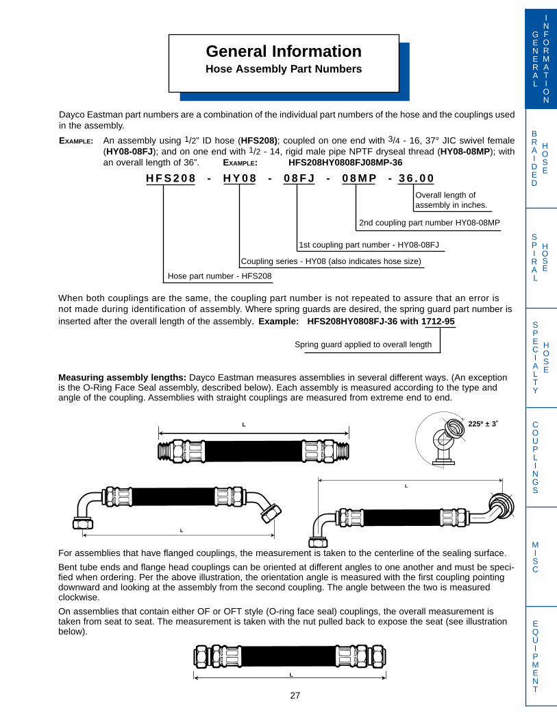
BRAIDED
HOSE
SPIRAL
HOSE
Measuring assembly lengths: Dayco Eastman measures assemblies in several different ways. (An exceptionis the O-Ring Face Seal assembly, described below). Each assembly is measured according to the type andangle of the coupling. Assemblies with straight couplings are measured from extreme end to end.
For assemblies that have flanged couplings, the measurement is taken to the centerline of the sealing surface.
Bent tube ends and flange head couplings can be oriented at different angles to one another and must be speci-fied when ordering. Per the above illustration, the orientation angle is measured with the first coupling pointingdownward and looking at the assembly from the second coupling. The angle between the two is measuredclockwise.
On assemblies that contain either OF or OFT style (O-ring face seal) couplings, the overall measurement istaken from seat to seat. The measurement is taken with the nut pulled back to expose the seat (see illustrationbelow).
General InformationHose Assembly Part Numbers
27
GENERAL
INFORMATION
SPECIALTY
HOSE
COUPLINGS
MISC
EQUIPMENT
Hose part number - HFS208
Dayco Eastman part numbers are a combination of the individual part numbers of the hose and the couplings usedin the assembly.
EXAMPLE: An assembly using 1/2” ID hose (HFS208); coupled on one end with 3/4 - 16, 37° JIC swivel female (HY08-08FJ); and on one end with 1/2 - 14, rigid male pipe NPTF dryseal thread (HY08-08MP); withan overall length of 36”. EXAMPLE: HFS208HY0808FJ08MP-36
H F S 2 0 8 - H Y 0 8 - 0 8 F J - 0 8 M P - 3 6 . 0 0
2nd coupling part number HY08-08MP
1st coupling part number - HY08-08FJ
Coupling series - HY08 (also indicates hose size)
Overall length ofassembly in inches.
When both couplings are the same, the coupling part number is not repeated to assure that an error isnot made during identification of assembly. Where spring guards are desired, the spring guard part number isinserted after the overall length of the assembly. Example: HFS208HY0808FJ-36 with 1712-95
Spring guard applied to overall length
L
L
L
L
225º ± 3˚
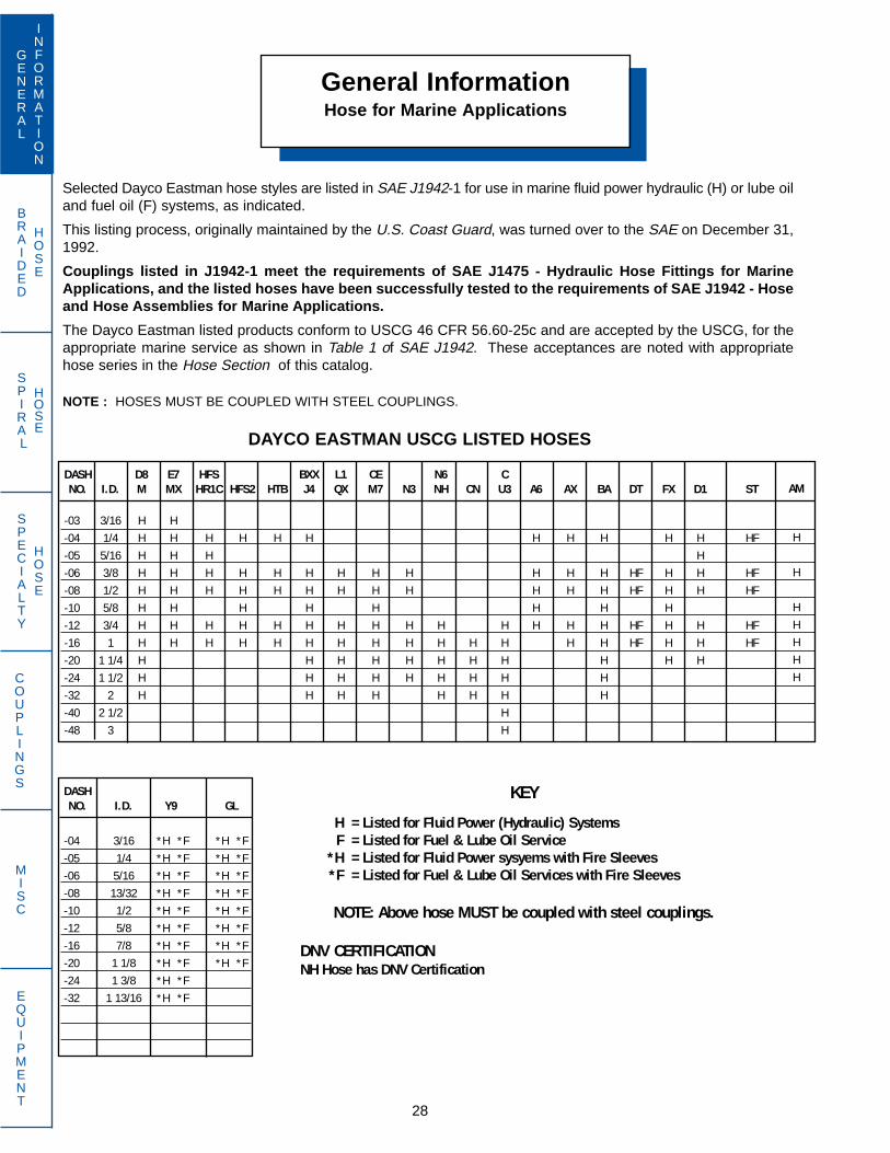
BRAIDED
HOSE
SPIRAL
HOSE
General InformationHose for Marine Applications
28
GENERAL
INFORMATION
SPECIALTY
HOSE
COUPLINGS
MISC
EQUIPMENT
Selected Dayco Eastman hose styles are listed in SAE J1942-1 for use in marine fluid power hydraulic (H) or lube oiland fuel oil (F) systems, as indicated.
This listing process, originally maintained by the U.S. Coast Guard, was turned over to the SAE on December 31,1992.
Couplings listed in J1942-1 meet the requirements of SAE J1475 - Hydraulic Hose Fittings for MarineApplications, and the listed hoses have been successfully tested to the requirements of SAE J1942 - Hoseand Hose Assemblies for Marine Applications.
The Dayco Eastman listed products conform to USCG 46 CFR 56.60-25c and are accepted by the USCG, for theappropriate marine service as shown in Table 1 of SAE J1942. These acceptances are noted with appropriatehose series in the Hose Section of this catalog.
NOTE : HOSES MUST BE COUPLED WITH STEEL COUPLINGS.
DASH D8 E7 HFS BXX L1 CE N6 CNO. I.D. M MX HR1C HFS2 HTB J4 QX M7 N3 NH CN U3 A6 AX BA DT FX D1 ST
-03 3/16 H H-04 1/4 H H H H H H H H H H H HF-05 5/16 H H H H-06 3/8 H H H H H H H H H H H H HF H H HF-08 1/2 H H H H H H H H H H H H HF H H HF-10 5/8 H H H H H H H H-12 3/4 H H H H H H H H H H H H H H HF H H HF-16 1 H H H H H H H H H H H H H H HF H H HF-20 1 1/4 H H H H H H H H H H H-24 1 1/2 H H H H H H H H H-32 2 H H H H H H H H-40 2 1/2 H-48 3 H
DASHNO. I.D. Y9 GL
-04 3/16 *H *F *H *F-05 1/4 *H *F *H *F-06 5/16 *H *F *H *F-08 13/32 *H *F *H *F-10 1/2 *H *F *H *F-12 5/8 *H *F *H *F-16 7/8 *H *F *H *F-20 1 1/8 *H *F *H *F-24 1 3/8 *H *F-32 1 13/16 *H *F
KEY
H = Listed for Fluid Power (Hydraulic) SystemsF = Listed for Fuel & Lube Oil Service
*H = Listed for Fluid Power sysyems with Fire Sleeves*F = Listed for Fuel & Lube Oil Services with Fire Sleeves
NOTE: Above hose MUST be coupled with steel couplings.
DNV CERTIFICATIONNH Hose has DNV Certification
DAYCO EASTMAN USCG LISTED HOSES
AM
H
H
HHHHH
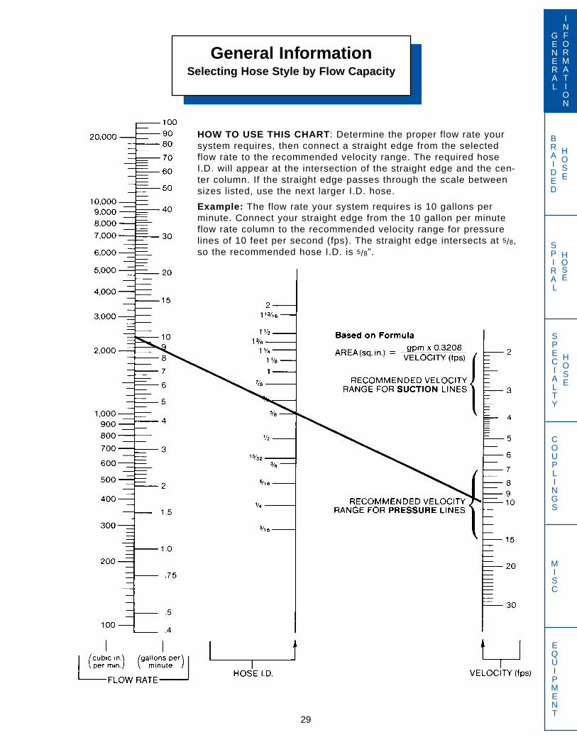
BRAIDED
HOSE
SPIRAL
HOSE
General InformationSelecting Hose Style by Flow Capacity
29
GENERAL
INFORMATION
SPECIALTY
HOSE
COUPLINGS
MISC
EQUIPMENT
HOW TO USE THIS CHART: Determine the proper flow rate yoursystem requires, then connect a straight edge from the selectedflow rate to the recommended velocity range. The required hoseI.D. will appear at the intersection of the straight edge and the cen-ter column. If the straight edge passes through the scale betweensizes listed, use the next larger I.D. hose.
Example: The flow rate your system requires is 10 gallons perminute. Connect your straight edge from the 10 gallon per minuteflow rate column to the recommended velocity range for pressurelines of 10 feet per second (fps). The straight edge intersects at 5/8,so the recommended hose I.D. is 5/8”.

General InformationHose Selection by Flow Rate
30
GENERAL
INFORMATION
SPECIALTY
HOSE
COUPLINGS
MISC
EQUIPMENT
BRAIDED
HOSE
SPIRAL
HOSE
The following table represents the maximum flow rate in gallons per minute (GPM) by hose I.D. for pressurelines and suction lines.
Recommended RecommendedMaximum Maximum
Hose I.D. Flow (GPM) Flow (GPM)in Pressure Suction
Inches Lines Lines
3/16 1.29 .351/4 2.30 .615/16 3.59 .963/8 5.16 1.38
13/32 6.06 1.621/2 9.18 2.455/8 14.35 3.833/4 20.66 5.517/8 28.12 7.501 36.72 9.79
1-1/8 46.48 12.391-1/4 57.38 15.301-3/8 69.43 18.511-1/2 82.63 22.03
1-13/16 120.64 32.172 146.89 39.17
15 feet per second (FPS) is the recommended maximum fluid velocity for hydraulic systems. Under certainconditions, velocity in pressure lines can be increased. Please contact Dayco Eastman with specific applica-tion information.
Recommendations are for oils having a maxi-mum viscosity of 315 S.S.U. at 100 F, operatingat temperatures between 65 and 155 F.
V = .408 x GPM
D2
GPM = V x D2________.408
D = .408 x GPMV
V = Velocity in FPS
GPM = Flow Rate in gallons perminute
D = Hose I.D. in inches

BRAIDED
HOSE
SPIRAL
HOSE
General InformationFour Bolt Split Flange
Dimensions
31
GENERAL
INFORMATION
SPECIALTY
HOSE
COUPLINGS
MISC
EQUIPMENT
SAE J518 Code 61 and Code 62 4-Bolt FlangesThis connection is commonly used world wide to connect larger sizes of hose and tubing ( 3/4” to 3” ) in fluid powersystems.An o-ring, inserted into a ring groove in the flange head seals on a smooth faces female port, and is held in placeby two clamp halves (or a one piece clamp) which are held tight by four bolts located in a rectangular pattern.
J518 flanges come in two pressure classes. The standard series, Code 61, which goes to 5,000 psi and the highpressure series, Code 62, where all sizes are rated at 6,000 psi.
J518 is interchangeable with ISO 6141, DIN 20066 and JIS B 8363, except for the bolt sizes.
SAE Code 61-Standard Series (Style PA)
SAE Code 62-High Pressure Series (Style PH)
* Non SAE Size, common on Komatsu Equipment (Dayco Eastman Style PAK)
Recommended Code 61 Flange O.D. Bolt Spacing Bolt SpacingDash Port Bolt Working Pressure “F” ± .010 “A” ± .010 “B” ± .010Size Size Size PSI MPa MM In. MM In. MM In.
-08 1/2 5/16-18 x 1 1/4 5,000 34.5 30.2 1.19 38.1 1.50 17.5 .69
-10 *5/8 M8 x 1.25 x 30 5,000 34.5 34.0 1.34 42.9 1.69 19.8 .78
-12 3/4 3/8-16 x 1 1/4 5,000 34.5 38.1 1.50 47.6 1.88 22.4 .88
-16 1 3/8-16 x 1 1/4 5,000 34.5 44.4 1.75 52.4 2.06 26.2 1.03
-20 1 1/4 7/16-14 x 1 1/2 4,000 27.6 50.8 2.00 58.7 2.31 30.2 1.19
-24 1 1/2 1/2-13 x 1 1/2 3,000 20.7 60.3 2.38 69.8 2.75 35.8 1.41
-32 2 1/2-13 x 1 3/4 3,000 20.7 71.4 2.81 77.8 3.06 42.9 1.69
-40 2 1/2 1/2-13 x 1 3/4 2,500 17.2 84.1 3.31 88.9 3.50 50.8 2.00
-48 3 5/8-11 x 1 3/4 2,000 13.8 101.6 4.00 106.4 4.19 62.0 2.44
Recommended Code 62 Flange O.D. Bolt Spacing Bolt SpacingDash Port Bolt Working Pressure “F” ± .010 “A” ± .010 “B” ± .010Size Size Size PSI MPa MM In. MM In. MM In.-08 1/2 5/16-18 x 1 1/4 6,000 41.4 31.7 1.25 40.5 1.59 18.3 .72
-12 3/4 3/8-16 x 1 1/2 6,000 41.4 41.3 1.63 50.8 2.00 23.9 .94
-16 1 7/16-14 x 1 3/4 6,000 41.4 47.6 1.88 57.1 2.25 27.7 1.09
-20 1 1/4 1/2-13 x 1 3/4 6,000 41.4 54.0 2.13 66.7 2.63 31.8 1.25
-24 1 1/2 5/8-11 x 2 1/4 6,000 41.4 63.5 2.50 79.4 3.13 36.6 1.44
-32 2 3/4-10 x 2 3/4 6,000 41.4 79.4 3.13 96.8 3.81 44.5 1.75
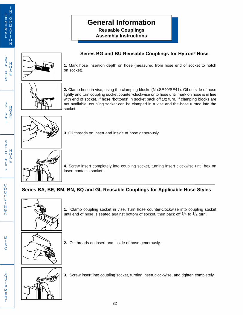
BRAIDED
HOSE
SPIRAL
HOSE
32
GENERAL
INFORMATION
SPECIALTY
HOSE
COUPLINGS
MISC
EQUIPMENT
General InformationReusable Couplings
Assembly Instructions
Series BA, BE, BM, BN, BQ and GL Reusable Couplings for Applicable Hose Styles
1. Clamp coupling socket in vise. Turn hose counter-clockwise into coupling socketuntil end of hose is seated against bottom of socket, then back off 1/4 to 1/2 turn.
2. Oil threads on insert and inside of hose generously.
3. Screw insert into coupling socket, turning insert clockwise, and tighten completely.
Series BG and BU Reusable Couplings for Hytron® Hose
1. Mark hose insertion depth on hose (measured from hose end of socket to notchon socket).
2. Clamp hose in vise, using the clamping blocks (No.SE40/SE41). Oil outside of hoselightly and turn coupling socket counter-clockwise onto hose until mark on hose is in linewith end of socket. If hose “bottoms” in socket back off 1/2 turn. If clamping blocks arenot available, coupling socket can be clamped in a vise and the hose turned into thesocket.
3. Oil threads on insert and inside of hose generously
4. Screw insert completely into coupling socket, turning insert clockwise until hex oninsert contacts socket.
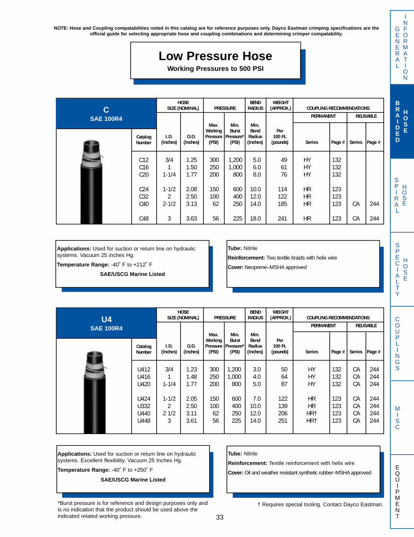
SPIRAL
HOSE
GENERAL
INFORMATION
BRAIDED
HOSE
SPECIALTY
HOSE
COUPLINGS
MISC
EQUIPMENT
Low Pressure HoseWorking Pressures to 500 PSI
33
NOTE: Hose and Coupling compatabilities noted in this catalog are for reference purposes only. Dayco Eastman crimping specifications are the official guide for selecting appropriate hose and coupling combinations and determining crimper compatability.
CSAE 100R4
Applications: Used for suction or return line on hydraulic systems. Vacuum 25 inches Hg.
Temperature Range: -40˚ F to +212˚ F
SAE/USCG Marine Listed
Tube: Nitrile
Reinforcement: Two textile braids with helix wire
Cover: Neoprene–MSHA approved
HOSE BEND WEIGHTSIZE (NOMINAL) PRESSURE RADIUS (APPROX.) COUPLING RECOMMENDATIONS
PERMANENT REUSABLE
CatalogNumber
C12C16C20
C24C32C40
C48
Max. Min. Min.Working Burst Bend Per
I.D. O.D. Pressure Pressure* Radius 100 Ft.(Inches) (Inches) (PSI) (PSI) (Inches) (pounds) Series Page # Series Page #
3/4 1.25 300 1,200 5.0 49 HY 1321 1.50 250 1,000 6.0 61 HY 132
1-1/4 1.77 200 800 8.0 76 HY 132
1-1/2 2.08 150 600 10.0 114 HR 1232 2.50 100 400 12.0 122 HR 123
2-1/2 3.13 62 250 14.0 185 HR 123 CA 244
3 3.63 56 225 18.0 241 HR 123 CA 244
U4SAE 100R4
Applications: Used for suction or return line on hydraulic systems. Excellent flexibility. Vacuum 25 Inches Hg.
Temperature Range: -40˚ F to +250˚ F
SAE/USCG Marine Listed
Tube: Nitrile
Reinforcement: Textile reinforcement with helix wire
Cover: Oil and weather resistant synthetic rubber–MSHA approved
HOSE BEND WEIGHTSIZE (NOMINAL) PRESSURE RADIUS (APPROX.) COUPLING RECOMMENDATIONS
PERMANENT REUSABLE
CatalogNumber
U412U416U420
U424U332U440U448
Max. Min. Min.Working Burst Bend Per
I.D. O.D. Pressure Pressure* Radius 100 Ft.(Inches) (Inches) (PSI) (PSI) (Inches) (pounds) Series Page # Series Page #
3/4 1.23 300 1,200 3.0 50 HY 132 CA 2441 1.48 250 1,000 4.0 64 HY 132 CA 244
1-1/4 1.77 200 800 5.0 87 HY 132 CA 244
1-1/2 2.05 150 600 7.0 122 HR 123 CA 2442 2.50 100 400 10.0 139 HR 123 CA 244
2 1/2 3.11 62 250 12.0 206 HR† 123 CA 2443 3.61 56 225 14.0 251 HR† 123 CA 244
*Burst pressure is for reference and design purposes only andis no indication that the product should be used above theindicated related working pressure.
† Requires special tooling. Contact Dayco Eastman.
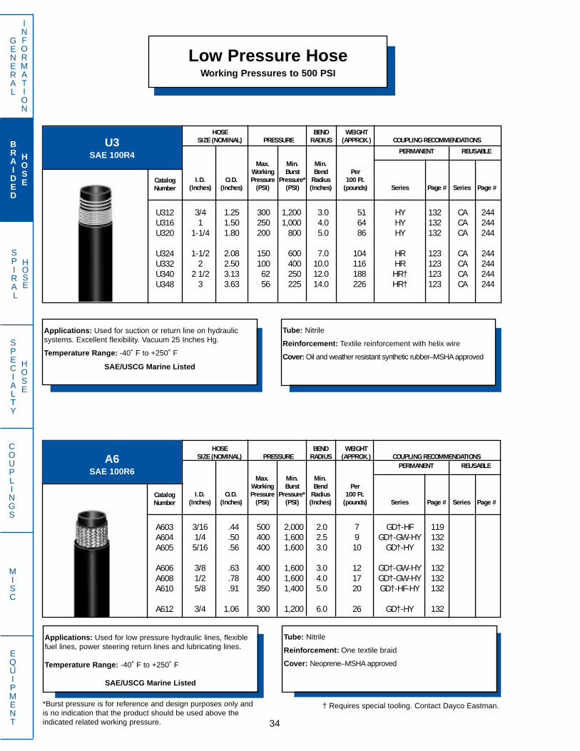
SPIRAL
HOSE
Low Pressure HoseWorking Pressures to 500 PSI
GENERAL
INFORMATION
BRAIDED
HOSE
SPECIALTY
HOSE
COUPLINGS
MISC
EQUIPMENT 34
A6SAE 100R6
Applications: Used for low pressure hydraulic lines, flexiblefuel lines, power steering return lines and lubricating lines.
Temperature Range: -40˚ F to +250˚ F
SAE/USCG Marine Listed
Tube: Nitrile
Reinforcement: One textile braid
Cover: Neoprene–MSHA approved
HOSE BEND WEIGHTSIZE (NOMINAL) PRESSURE RADIUS (APPROX.) COUPLING RECOMMENDATIONS
PERMANENT REUSABLE
CatalogNumber
A603A604A605
A606A608A610
A612
Max. Min. Min.Working Burst Bend Per
I.D. O.D. Pressure Pressure* Radius 100 Ft.(Inches) (Inches) (PSI) (PSI) (Inches) (pounds) Series Page # Series Page #
3/16 .44 500 2,000 2.0 7 GD†-HF 1191/4 .50 400 1,600 2.5 9 GD†-GW-HY 1325/16 .56 400 1,600 3.0 10 GD†-HY 132
3/8 .63 400 1,600 3.0 12 GD†-GW-HY 1321/2 .78 400 1,600 4.0 17 GD†-GW-HY 1325/8 .91 350 1,400 5.0 20 GD†-HF-HY 132
3/4 1.06 300 1,200 6.0 26 GD†-HY 132
U3SAE 100R4
Applications: Used for suction or return line on hydraulic systems. Excellent flexibility. Vacuum 25 Inches Hg.
Temperature Range: -40˚ F to +250˚ F
SAE/USCG Marine Listed
Tube: Nitrile
Reinforcement: Textile reinforcement with helix wire
Cover: Oil and weather resistant synthetic rubber–MSHA approved
HOSE BEND WEIGHTSIZE (NOMINAL) PRESSURE RADIUS (APPROX.) COUPLING RECOMMENDATIONS
PERMANENT REUSABLE
CatalogNumber
U312U316U320
U324U332U340U348
Max. Min. Min.Working Burst Bend Per
I.D. O.D. Pressure Pressure* Radius 100 Ft.(Inches) (Inches) (PSI) (PSI) (Inches) (pounds) Series Page # Series Page #
3/4 1.25 300 1,200 3.0 51 HY 132 CA 2441 1.50 250 1,000 4.0 64 HY 132 CA 244
1-1/4 1.80 200 800 5.0 86 HY 132 CA 244
1-1/2 2.08 150 600 7.0 104 HR 123 CA 2442 2.50 100 400 10.0 116 HR 123 CA 244
2 1/2 3.13 62 250 12.0 188 HR† 123 CA 2443 3.63 56 225 14.0 226 HR† 123 CA 244
*Burst pressure is for reference and design purposes only andis no indication that the product should be used above theindicated related working pressure.
† Requires special tooling. Contact Dayco Eastman.

SPIRAL
HOSE
GENERAL
INFORMATION
BRAIDED
HOSE
SPECIALTY
HOSE
COUPLINGS
MISC
EQUIPMENT35
*Burst pressure is for reference and design purposes only andis no indication that the product should be used above theindicated related working pressure.
A2SAE 100R6
High Temperature
Applications: Used for high temperature, low pressurehydraulic lines, flexible fuel lines, power steering return lines,lubricating lines, and hot transmission lines.
Temperature Range: -40˚ F to +300˚ F
Tube: Chlorinated Polyethylene
Reinforcement: One textile braid
Cover: Chlorinated Polyethylene
PERMANENT REUSABLE
HOSE BEND WEIGHTSIZE (NOMINAL) PRESSURE RADIUS (APPROX.) COUPLING RECOMMENDATIONS
CatalogNumber
A204A205A206
A208A210A212
Max. Min. Min.Working Burst Bend Per
I.D. O.D. Pressure Pressure* Radius 100 Ft.(Inches) (Inches) (PSI) (PSI) (Inches) (pounds) Series Page # Series Page #
1/4 .50 400 1,600 2.5 10 GD†-GW-HY 1325/16 .56 400 1,600 3.0 11 GD†-HY 1323/8 .63 400 1,600 3.0 13 GD†-GW-HY-KF 132
1/2 .78 400 1,600 4.0 18 GD†-GW-HY 1325/8 .91 350 1,400 5.0 21 GD†-HF-HY 1323/4 1.09 300 1,200 6.0 31 GD†-HY 132
Low Pressure HoseWorking Pressures to 500 PSI
Applications: Used for low pressure air and water applica-tions where pressures do not exceed 250 PSI
Not recommended for use with petroleum based fluidsTemperature Range: -15˚ F to +150˚ FKA series push-on coupling is not recommended where pres-
sure and/or temperature exceeds +100˚F and 100 PSI
Tube: PVC
Reinforcement: One braid of polyester fiber
Cover: PVC, pin-pricked. Colors: Grey (all sizes); Red and Blue(sizes -04, -06 and -08)
HAWHytron® Push-On
HOSE BEND WEIGHTSIZE (NOMINAL) PRESSURE RADIUS (APPROX.) COUPLING RECOMMENDATIONS
PERMANENT REUSABLE
CatalogNumber
HAW03HAW04HAW05
HAW06HAW08HAW12
Max. Min. Min.Working Burst Bend Per
I.D. O.D. Pressure Pressure* Radius 100 Ft.(Inches) (Inches) (PSI) (PSI) (Inches) (pounds) Series Page # Series Page #
3/16 .35 250 1,000 .5 4 GH†-SU 1951/4 .44 250 1,000 .6 6 HY-KF 132 KA 2195/16 .50 250 1,000 .8 8 HY-KF 132 KA 219
3/8 .63 250 1,000 .9 11 HY-KF 132 KA 2191/2 .78 250 1,000 1.2 16 HY-KF 132 KA 2193/4 1.10 250 1,000 2.5 28 GD†-HY 132 KA 219
† Requires special tooling. Contact Dayco Eastman.

SPIRAL
HOSE
GENERAL
INFORMATION
BRAIDED
HOSE
SPECIALTY
HOSE
COUPLINGS
MISC
EQUIPMENT 36
Low Pressure HoseWorking Pressures to 500 PSI
Applications: Used for low pressure transmission of oil, gaso-line, air, water, coolants, etc. Should not be used on impulseapplications
Temperature Range: -40˚F to +212˚F-40˚F to +160˚F for gaseous applications
**NOTE: Do not exceed 250 PSI working pressure whenusing KA style push-on couplings.
Tube: Nitrile
Reinforcement: One textile braid (except B716 is four spiral layers)
Cover: Black oil and weather resistant synthetic rubber –MSHA approved
B7Push-On Low Pressure PERMANENT REUSABLE
HOSE BEND WEIGHTSIZE (NOMINAL) PRESSURE RADIUS (APPROX.) COUPLING RECOMMENDATIONS
CatalogNumber
B703B704B705
B706B708B710B716
Max. Min. Min.Working Burst Bend Per
I.D. O.D. Pressure Pressure* Radius 100 Ft.(Inches) (Inches) (PSI) (PSI) (Inches) (pounds) Series Page # Series Page #
3/16 .36 400 1,600 1.0 4 GH†-KF 2221/4 .50 375 1,500 3.0 9 GD†-HY-KF 132 KA 2195/16 .56 300 1,200 3.0 10 GD†-HY-KF 132 KA 219
3/8 .62 300 1,200 3.0 11 GD†-HY-KF 132 KA 2191/2 .75 300 1,200 5.0 15 GD†-HY-KF 132 KA 2195/8 .91 300 1,200 6.0 20 GD†-HY-KF 132 KA 2191 1.44 300 1,200 8.0 26 HY 132
Applications: Used for low pressure transmission of gaso-line, oil, air, water and coolants where operation pressures donot exceed 250 PSI
Temperature Range: -40˚F to +200˚F(130˚F maximum with water)
KA series push-on coupling is not recommended where pres-sure and/or temperature exceeds +100˚F and 100 PSI
Tube: Red polyurethane
Reinforcement: One braid of polyester fiber
Cover: Red abrasion resistant polyurethane
B9Hytron® Push-On
HOSE BEND WEIGHTSIZE (NOMINAL) PRESSURE RADIUS (APPROX.) COUPLING RECOMMENDATIONS
PERMANENT REUSABLE
CatalogNumber
B903B904B905
B906B908B910
Max. Min. Min.Working Burst Bend Per
I.D. O.D. Pressure Pressure* Radius 100 Ft.(Inches) (Inches) (PSI) (PSI) (Inches) (pounds) Series Page # Series Page #
3/16 .38 250 1,000 1.0 4 GH†-KF 2221/4 .45 250 1,000 1.5 5 KF 222 KA 2195/16 .54 250 1,000 2.0 8 KF 222 KA 219
3/8 .63 250 1,000 3.0 9 GD†-KF 222 KA 2191/2 .77 250 1,000 3.0 13 KF 222 KA 2195/8 .92 250 1,000 4.0 20 KF 222 KA 219
*Burst pressure is for reference and design purposes only andis no indication that the product should be used above theindicated related working pressure.
† Requires special tooling. Contact Dayco Eastman.
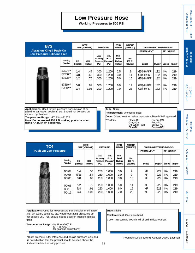
SPIRAL
HOSE
GENERAL
INFORMATION
BRAIDED
HOSE
SPECIALTY
HOSE
COUPLINGS
MISC
EQUIPMENT37
Applications: Used for low pressure transmission of oil, gasoline, air, water, coolants, etc. Should not be used onimpulse applicationsTemperature Range: -40˚ F to +212˚ FNote: Do not exceed 250 PSI working pressure whenusing KA push-on couplings.
Tube: Nitrile
Reinforcement: One textile braid
Cover: Oil and weather resistant synthetic rubber–MSHA approved**Colors: Black–BK Green–GN
Gray–GY Red–RDOff White–WH Yellow–YLBlue–BL Brown–BR
B7SAbrasion King® Push-On
Low Pressure Silicone FreePERMANENT REUSABLE
HOSE BEND WEIGHTSIZE (NOMINAL) PRESSURE RADIUS (APPROX.) COUPLING RECOMMENDATIONS
CatalogNumber
B7S04**B7S06**B7S08**
B7S10**B7S12**
Max. Min. Min.Working Burst Bend Per
I.D. O.D. Pressure Pressure* Radius 100 Ft.(Inches) (Inches) (PSI) (PSI) (Inches) (pounds) Series Page # Series Page #
1/4 .49 300 1,200 2.5 9 GD†-HY-KF 132 KA 2193/8 .62 300 1,200 3.0 11 GD†-HY-KF 132 KA 2191/2 .75 300 1,200 5.0 15 GD†-HY-KF 132 KA 219
5/8 .91 300 1,200 6.0 19 GD†-HY-KF 132 KA 2193/4 1.03 300 1,200 7.0 23 GD†-HY-KF 132 KA 219
Low Pressure HoseWorking Pressures to 500 PSI
Applications: Used for low pressure transmission of oil, gaso-line, air, water, coolants, etc. where operating pressures donot exceed 250 PSI. Should not be used on impulse applica-tions.
Temperature Range: -40˚ F to +200˚ F-40˚ F to +160˚ F (for gaseous applications)
Tube: Nitrile
Reinforcement: One textile braid
Cover: Impregnated textile braid, oil and mildew resistant
TC4Push-On Low Pressure PERMANENT REUSABLE
HOSE BEND WEIGHTSIZE (NOMINAL) PRESSURE RADIUS (APPROX.) COUPLING RECOMMENDATIONS
CatalogNumber
TC404TC405TC406
TC408TC410TC412
Max. Min. Min.Working Burst Bend Per
I.D. O.D. Pressure Pressure* Radius 100 Ft.(Inches) (Inches) (PSI) (PSI) (Inches) (pounds) Series Page # Series Page #
1/4 .50 250 1,000 3.0 9 KF 222 KA 2195/16 .54 250 1,000 3.0 9 KF 222 KA 2193/8 .63 250 1,000 3.0 10 KF 222 KA 219
1/2 .75 250 1,000 5.0 14 KF 222 KA 2195/8 .91 250 1,000 6.0 19 KF 222 KA 2193/4 1.03 250 1,000 7.0 23 KF 222 KA 219
*Burst pressure is for reference and design purposes only andis no indication that the product should be used above theindicated related working pressure.
† Requires special tooling. Contact Dayco Eastman.

SPIRAL
HOSE
GENERAL
INFORMATION
BRAIDED
HOSE
SPECIALTY
HOSE
COUPLINGS
MISC
EQUIPMENT 38
Low Pressure HoseWorking Pressures to 500 PSI
Applications: Used for low pressure transmission of oil, gaso-line, air and water.
Temperature Range: -40˚ F to +212˚ F
NOTE: -12 and -16 are similar to SAE 30R2,T2
Tube: Nitrile
Reinforcement: One textile braid**Two textile braids
Cover: Oil and weather resistant synthetic rubber–MSHA approved -03, -04, -05, -12 and -16 only
DL6SAE Fuel Line Hose PERMANENT REUSABLE
HOSE BEND WEIGHTSIZE (NOMINAL) PRESSURE RADIUS (APPROX.) COUPLING RECOMMENDATIONS
CatalogNumber
DL603DL604DL605
DL606DL608DL610
DL612**DL616**
Max. Min. Min.Working Burst Bend Per SAE
I.D. O.D. Pressure Pressure* Radius 100 Ft. SPEC(Inches) (Inches) (PSI) (PSI) (Inches) (pounds) Series Page # Series Page #
3/16 .36 500 2,000 2.5 5 KF 222 30R31/4 .42 400 1,600 2.7 6 KF 222 30R35/16 .52 300 1,200 3.0 8 KF 222 30R3
3/8 .60 300 1,200 4.0 11 KF 222 30R2,T11/2 .75 300 1,200 4.5 16 KF 222 30R2,T15/8 .88 300 1,200 5.0 19 KF 222 30R2,T1
3/4 1.22 300 1,200 6.0 46 KF 222 30R2,T21 1.52 300 1,200 8.0 66 HY 132 30R2,T2
Applications: Low pressure fuel and oil hose for use withgasoline and diesel fuel, lube oil and related vapors
Temperature Range: -40˚ F to +250˚ F
Tube: Nitrile
Reinforcement: One textile braid
Cover: Oil and weather resistant synthetic rubber
DL5SAE 30R7 Fuel Line PERMANENT REUSABLE
HOSE BEND WEIGHTSIZE (NOMINAL) PRESSURE RADIUS (APPROX.) COUPLING RECOMMENDATIONS
CatalogNumber
DL503DL504DL505
DL506DL508
Max. Min. Min.Working Burst Bend Per
I.D. O.D. Pressure Pressure* Radius 100 Ft.(Inches) (Inches) (PSI) (PSI) (Inches) (pounds) Series Page # Series Page #
3/16 .41 50 250 2.0 7 KF 2221/4 .50 50 250 2.5 9 GD†-KF 2225/16 .56 50 250 2.8 11 KF 222
3/8 .63 50 250 3.0 12 GD†-KF 2221/2 .78 35 175 4.0 17 GD†-KF 222
*Burst pressure is for reference and design purposes only andis no indication that the product should be used above theindicated related working pressure.
† Requires special tooling. Contact Dayco Eastman.
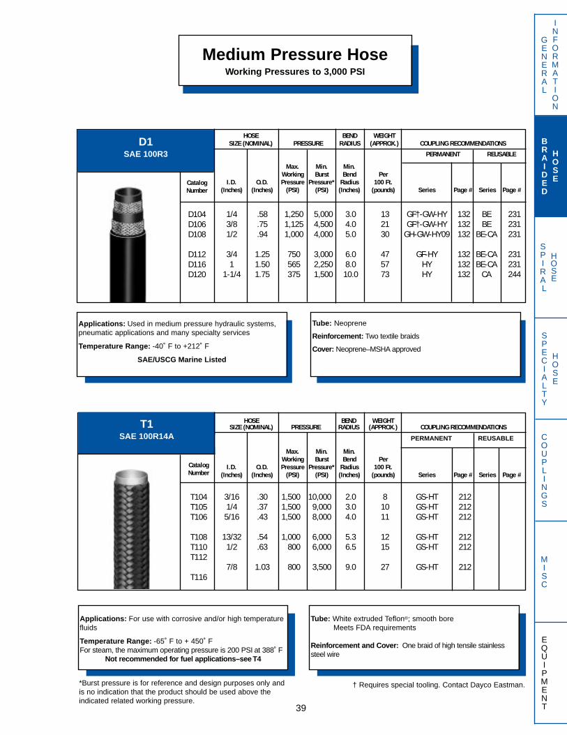
SPIRAL
HOSE
GENERAL
INFORMATION
BRAIDED
HOSE
SPECIALTY
HOSE
COUPLINGS
MISC
EQUIPMENT
Medium Pressure HoseWorking Pressures to 3,000 PSI
39
D1SAE 100R3
Applications: Used in medium pressure hydraulic systems,pneumatic applications and many specialty services
Temperature Range: -40˚ F to +212˚ F
SAE/USCG Marine Listed
Tube: Neoprene
Reinforcement: Two textile braids
Cover: Neoprene–MSHA approved
HOSE BEND WEIGHTSIZE (NOMINAL) PRESSURE RADIUS (APPROX.) COUPLING RECOMMENDATIONS
PERMANENT REUSABLE
CatalogNumber
D104D106D108
D112D116D120
Max. Min. Min.Working Burst Bend Per
I.D. O.D. Pressure Pressure* Radius 100 Ft.(Inches) (Inches) (PSI) (PSI) (Inches) (pounds) Series Page # Series Page #
1/4 .58 1,250 5,000 3.0 13 GF†-GW-HY 132 BE 2313/8 .75 1,125 4,500 4.0 21 GF†-GW-HY 132 BE 2311/2 .94 1,000 4,000 5.0 30 GH-GW-HY09 132 BE-CA 231
3/4 1.25 750 3,000 6.0 47 GF-HY 132 BE-CA 2311 1.50 565 2,250 8.0 57 HY 132 BE-CA 231
1-1/4 1.75 375 1,500 10.0 73 HY 132 CA 244
Applications: For use with corrosive and/or high temperaturefluids
Temperature Range: -65˚ F to + 450˚ FFor steam, the maximum operating pressure is 200 PSI at 388˚ F
Not recommended for fuel applications–see T4
Tube: White extruded Teflon®; smooth boreMeets FDA requirements
Reinforcement and Cover: One braid of high tensile stainlesssteel wire
T1SAE 100R14A PERMANENT REUSABLE
HOSE BEND WEIGHTSIZE (NOMINAL) PRESSURE RADIUS (APPROX.) COUPLING RECOMMENDATIONS
CatalogNumber
T104T105T106
T108T110T112
T116
Max. Min. Min.Working Burst Bend Per
I.D. O.D. Pressure Pressure* Radius 100 Ft.(Inches) (Inches) (PSI) (PSI) (Inches) (pounds) Series Page # Series Page #
3/16 .30 1,500 10,000 2.0 8 GS-HT 2121/4 .37 1,500 9,000 3.0 10 GS-HT 2125/16 .43 1,500 8,000 4.0 11 GS-HT 212
13/32 .54 1,000 6,000 5.3 12 GS-HT 2121/2 .63 800 6,000 6.5 15 GS-HT 212
7/8 1.03 800 3,500 9.0 27 GS-HT 212
*Burst pressure is for reference and design purposes only andis no indication that the product should be used above theindicated related working pressure.
† Requires special tooling. Contact Dayco Eastman.

SPIRAL
HOSE
Medium Pressure HoseWorking Pressures to 3,000 PSI
GENERAL
INFORMATION
BRAIDED
HOSE
SPECIALTY
HOSE
COUPLINGS
MISC
EQUIPMENT 40
*Burst pressure is for reference and design purposes only andis no indication that the product should be used above theindicated related working pressure.
GLSAE J1402
Type AI and DOT FMVSS-106
Applications: Used for high temperature truck and bus appli-cations, diesel fuel, gasoline, hot oil, air brakes andhydraulics.
Temperature Range: -40˚ F to +300˚ F
SAE/USCG Marine Listed
Tube: Chlorinated polyethylene
Reinforcement: Textile inner braid and a high tensile steel wirebraid
Cover: Oil and mildew resistant black textile braid
HOSE BEND WEIGHTSIZE (NOMINAL) PRESSURE RADIUS (APPROX.) COUPLING RECOMMENDATIONS
PERMANENT REUSABLE
CatalogNumber
GL04GL05GL06
GL08GL10GL12
GL16GL20
Max. Min. Min.Working Burst Bend Per
I.D. O.D. Pressure Pressure* Radius 100 Ft.(Inches) (Inches) (PSI) (PSI) (Inches) (pounds) Series Page # Series Page #
3/16 .49 1,500 6,000 3.0 11 HF03 119 GL** 2481/4 .55 1,500 6,000 3.4 13 HY04 132 GL** 2485/16 .62 1,500 6,000 4.0 15 HY05 132 GL** 248
13/32 .74 1,250 5,000 4.6 19 HY07** 132 GL** 2481/2 .83 1,000 4,000 5.5 21 HY08** 132 GL** 2485/8 .96 750 3,000 6.5 26 HY10** 132 GL** 248
7/8 1.21 400 1,600 7.4 34 HY14 132 GL 2481-1/8 1.49 300 1,250 9.0 45 HY18 132 GL 248
Applications: For use with fuels and corrosive and/or hightemperature fluids where static electricity may be generated.
Temperature Range: -65˚ F to +450˚ FFor steam, the maximum operating pressure is 200 PSI at 388˚ F
Tube: Black conductive extruded Teflon®; smooth bore
Reinforcement and Cover: One braid of high tensile stainlesssteel wire
T4SAE 100R14B PERMANENT REUSABLE
HOSE BEND WEIGHTSIZE (NOMINAL) PRESSURE RADIUS (APPROX.) COUPLING RECOMMENDATIONS
CatalogNumber
T404T405T406
T408T410T412
T416
Max. Min. Min.Working Burst Bend Per
I.D. O.D. Pressure Pressure* Radius 100 Ft.(Inches) (Inches) (PSI) (PSI) (Inches) (pounds) Series Page # Series Page #
3/16 .30 1,500 10,000 2.0 8 GS-HT 2121/4 .37 1,500 9,000 3.0 10 GS-HT 2125/16 .43 1,500 8,000 4.0 11 GS-HT 212
13/32 .54 1,000 6,000 5.3 12 GS-HT 2121/2 .63 800 6,000 6.5 15 GS-HT 2125/8 .76 800 5,000 7.8 17 GS-HT 212
7/8 1.03 800 3,500 9.0 27 GS-HT 212
**Suitable for SAE J1402, Type AI and FMVSS-106 assemblies.
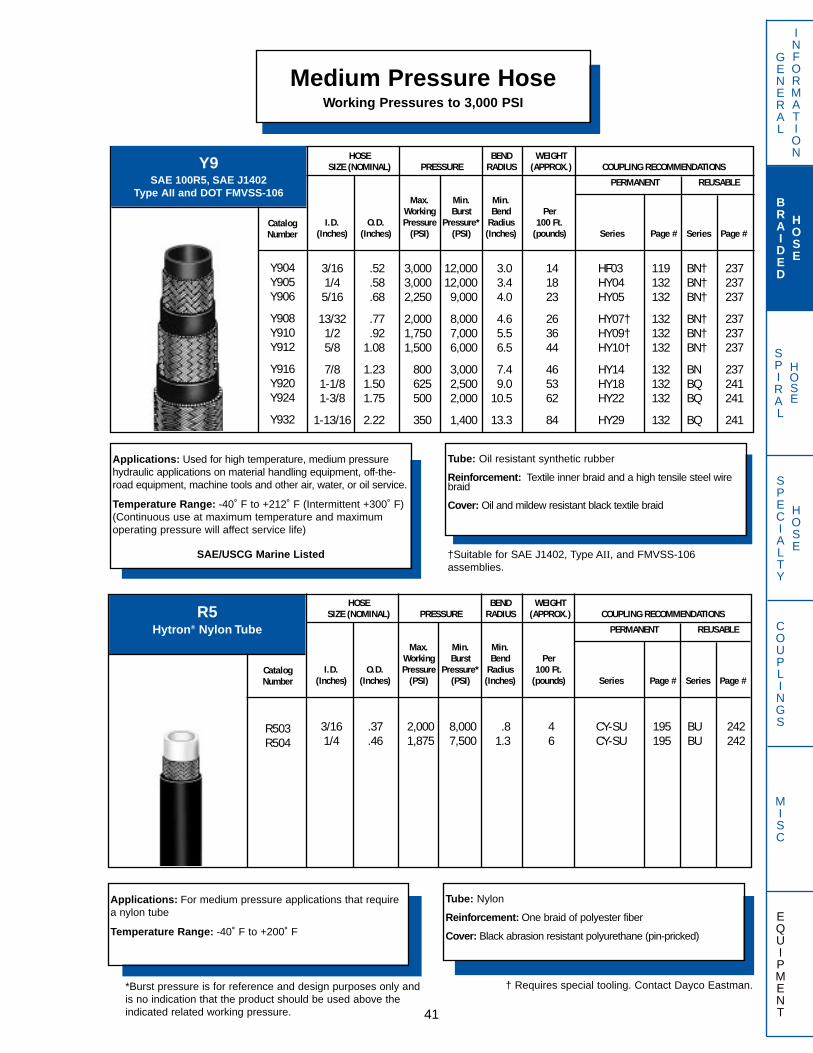
SPIRAL
HOSE
GENERAL
INFORMATION
BRAIDED
HOSE
SPECIALTY
HOSE
COUPLINGS
MISC
EQUIPMENT
Medium Pressure HoseWorking Pressures to 3,000 PSI
41
Y9SAE 100R5, SAE J1402
Type AII and DOT FMVSS-106
Applications: Used for high temperature, medium pressurehydraulic applications on material handling equipment, off-the-road equipment, machine tools and other air, water, or oil service.
Temperature Range: -40˚ F to +212˚ F (Intermittent +300˚ F)(Continuous use at maximum temperature and maximumoperating pressure will affect service life)
SAE/USCG Marine Listed
Tube: Oil resistant synthetic rubber
Reinforcement: Textile inner braid and a high tensile steel wirebraid
Cover: Oil and mildew resistant black textile braid
†Suitable for SAE J1402, Type AII, and FMVSS-106 assemblies.
HOSE BEND WEIGHTSIZE (NOMINAL) PRESSURE RADIUS (APPROX.) COUPLING RECOMMENDATIONS
PERMANENT REUSABLE
CatalogNumber
Y904Y905Y906
Y908Y910Y912
Y916Y920Y924
Y932
Max. Min. Min.Working Burst Bend Per
I.D. O.D. Pressure Pressure* Radius 100 Ft.(Inches) (Inches) (PSI) (PSI) (Inches) (pounds) Series Page # Series Page #
3/16 .52 3,000 12,000 3.0 14 HF03 119 BN† 2371/4 .58 3,000 12,000 3.4 18 HY04 132 BN† 2375/16 .68 2,250 9,000 4.0 23 HY05 132 BN† 237
13/32 .77 2,000 8,000 4.6 26 HY07† 132 BN† 2371/2 .92 1,750 7,000 5.5 36 HY09† 132 BN† 2375/8 1.08 1,500 6,000 6.5 44 HY10† 132 BN† 237
7/8 1.23 800 3,000 7.4 46 HY14 132 BN 2371-1/8 1.50 625 2,500 9.0 53 HY18 132 BQ 2411-3/8 1.75 500 2,000 10.5 62 HY22 132 BQ 241
1-13/16 2.22 350 1,400 13.3 84 HY29 132 BQ 241
Applications: For medium pressure applications that requirea nylon tube
Temperature Range: -40˚ F to +200˚ F
Tube: Nylon
Reinforcement: One braid of polyester fiber
Cover: Black abrasion resistant polyurethane (pin-pricked)
R5Hytron® Nylon Tube
HOSE BEND WEIGHTSIZE (NOMINAL) PRESSURE RADIUS (APPROX.) COUPLING RECOMMENDATIONS
PERMANENT REUSABLE
CatalogNumber
R503R504
Max. Min. Min.Working Burst Bend Per
I.D. O.D. Pressure Pressure* Radius 100 Ft.(Inches) (Inches) (PSI) (PSI) (Inches) (pounds) Series Page # Series Page #
3/16 .37 2,000 8,000 .8 4 CY-SU 195 BU 2421/4 .46 1,875 7,500 1.3 6 CY-SU 195 BU 242
*Burst pressure is for reference and design purposes only andis no indication that the product should be used above theindicated related working pressure.
† Requires special tooling. Contact Dayco Eastman.
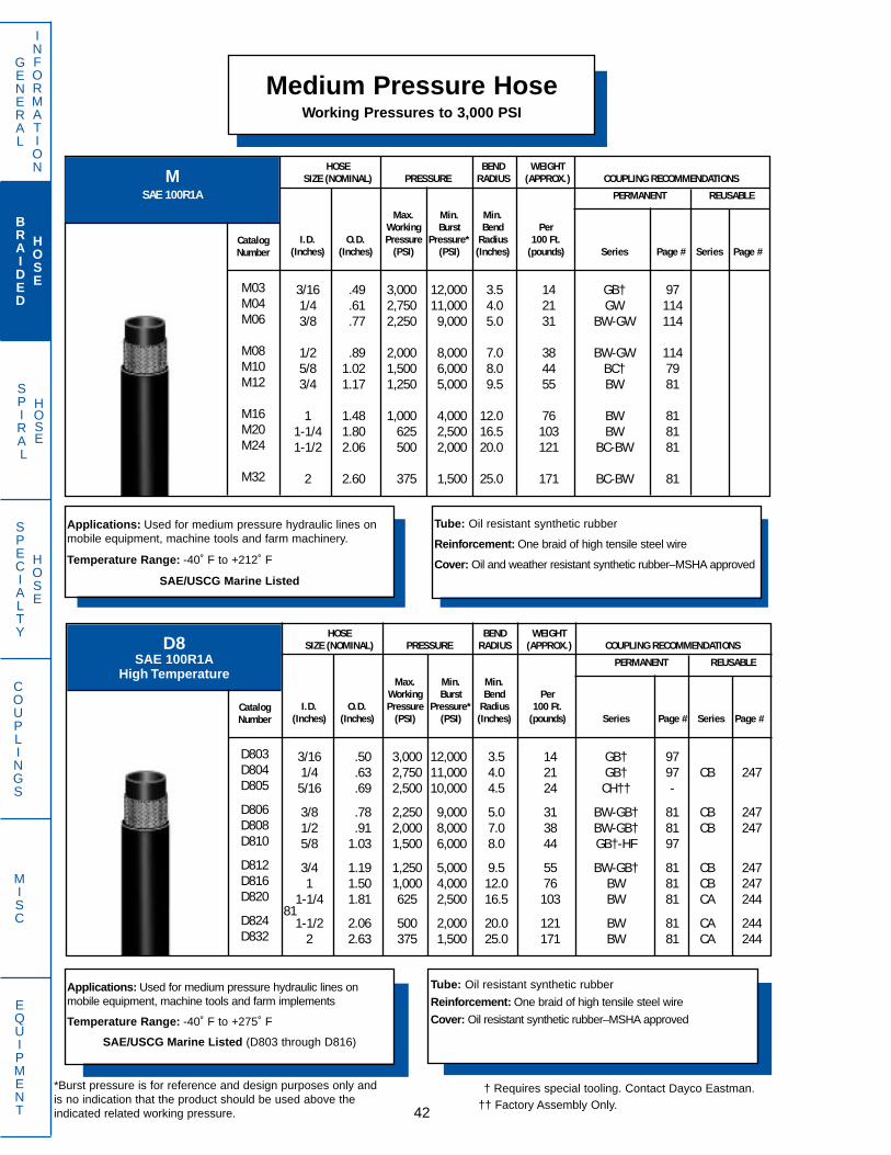
SPIRAL
HOSE
Medium Pressure HoseWorking Pressures to 3,000 PSI
GENERAL
INFORMATION
BRAIDED
HOSE
SPECIALTY
HOSE
COUPLINGS
MISC
EQUIPMENT 42
D8SAE 100R1A
High Temperature
Applications: Used for medium pressure hydraulic lines onmobile equipment, machine tools and farm implements
Temperature Range: -40˚ F to +275˚ F
SAE/USCG Marine Listed (D803 through D816)
Tube: Oil resistant synthetic rubber
Reinforcement: One braid of high tensile steel wire
Cover: Oil resistant synthetic rubber–MSHA approved
HOSE BEND WEIGHTSIZE (NOMINAL) PRESSURE RADIUS (APPROX.) COUPLING RECOMMENDATIONS
PERMANENT REUSABLE
CatalogNumber
D803D804D805
D806D808D810
D812D816D820
D824D832
Max. Min. Min.Working Burst Bend Per
I.D. O.D. Pressure Pressure* Radius 100 Ft.(Inches) (Inches) (PSI) (PSI) (Inches) (pounds) Series Page # Series Page #
3/16 .50 3,000 12,000 3.5 14 GB† 971/4 .63 2,750 11,000 4.0 21 GB† 97 CB 2475/16 .69 2,500 10,000 4.5 24 CH†† -
3/8 .78 2,250 9,000 5.0 31 BW-GB† 81 CB 2471/2 .91 2,000 8,000 7.0 38 BW-GB† 81 CB 2475/8 1.03 1,500 6,000 8.0 44 GB†-HF 97
3/4 1.19 1,250 5,000 9.5 55 BW-GB† 81 CB 2471 1.50 1,000 4,000 12.0 76 BW 81 CB 247
1-1/4 1.81 625 2,500 16.5 103 BW 81 CA 24481
1-1/2 2.06 500 2,000 20.0 121 BW 81 CA 2442 2.63 375 1,500 25.0 171 BW 81 CA 244
Applications: Used for medium pressure hydraulic lines onmobile equipment, machine tools and farm machinery.
Temperature Range: -40˚ F to +212˚ F
SAE/USCG Marine Listed
Tube: Oil resistant synthetic rubber
Reinforcement: One braid of high tensile steel wire
Cover: Oil and weather resistant synthetic rubber–MSHA approved
MSAE 100R1A
HOSE BEND WEIGHTSIZE (NOMINAL) PRESSURE RADIUS (APPROX.) COUPLING RECOMMENDATIONS
PERMANENT REUSABLE
CatalogNumber
M03M04M06
M08M10M12
M16M20M24
M32
Max. Min. Min.Working Burst Bend Per
I.D. O.D. Pressure Pressure* Radius 100 Ft.(Inches) (Inches) (PSI) (PSI) (Inches) (pounds) Series Page # Series Page #
3/16 .49 3,000 12,000 3.5 14 GB† 971/4 .61 2,750 11,000 4.0 21 GW 1143/8 .77 2,250 9,000 5.0 31 BW-GW 114
1/2 .89 2,000 8,000 7.0 38 BW-GW 1145/8 1.02 1,500 6,000 8.0 44 BC† 793/4 1.17 1,250 5,000 9.5 55 BW 81
1 1.48 1,000 4,000 12.0 76 BW 811-1/4 1.80 625 2,500 16.5 103 BW 811-1/2 2.06 500 2,000 20.0 121 BC-BW 81
2 2.60 375 1,500 25.0 171 BC-BW 81
*Burst pressure is for reference and design purposes only andis no indication that the product should be used above theindicated related working pressure.
† Requires special tooling. Contact Dayco Eastman.†† Factory Assembly Only.

SPIRAL
HOSE
GENERAL
INFORMATION
BRAIDED
HOSE
SPECIALTY
HOSE
COUPLINGS
MISC
EQUIPMENT
Medium Pressure HoseWorking Pressures to 3,000 PSI
43
Applications: Used for medium pressure hydraulic lines onmobile equipment, machine tools and farm machinery.
Temperature Range: -40˚ F to +212˚ F
SAE/USCG Marine Listed (except MX05 and MX10)
Tube: Oil resistant synthetic rubber
Reinforcement: One braid of high tensile steel wire
Cover: Oil and weather resistant synthetic rubber–MSHA approved
MXSAE 100R1AT
HOSE BEND WEIGHTSIZE (NOMINAL) PRESSURE RADIUS (APPROX.) COUPLING RECOMMENDATIONS
PERMANENT REUSABLE
CatalogNumber
MX03MX04
MX05MX06
MX08
MX10MX12
MX16MX20MX24MX32
Max. Min. Min.Working Burst Bend Per
I.D. O.D. Pressure Pressure* Radius 100 Ft.(Inches) (Inches) (PSI) (PSI) (Inches) (pounds) Series Page Series Page
# #
3/16 .47 3,000 12,000 3.5 13 GB†-HF 1191/4 .53 2,750 11,000 4.0 16 GB†-GW-HY 132 BA 227
5/16 .59 2,500 10,000 4.5 19 HY 1323/8 .69 2,250 9,000 5.0 25 BW-GB†-GW-HY 132 BA 227
1/2 .81 2,000 8,000 7.0 29 BW-GB†-GW-HY 132 BA 227
5/8 .94 1,500 6,000 8.0 36 HY 1323/4 1.09 1,250 5,000 9.5 44 BW-GB†-HY 132 BA 227
1 1.44 1,000 4,000 12.0 66 BW-HY 1321-1/4 1.72 625 2,500 16.5 88 BW 811-1/2 1.97 500 2,000 20.0 100 BW 81
2 2.50 375 1,500 25.0 144 BW 81
E7ASAE 100R1 Type AT
Applications: Used for medium pressure hydraulic lines onmobile equipment, machine tools and farm machinery.
Temperature Range: -40˚ F to +212˚ F
Tube: Polyester
Reinforcement: One braid of high tensile steel wire
Cover: Neoprene–MSHA approved
HOSE BEND WEIGHTSIZE (NOMINAL) PRESSURE RADIUS (APPROX.) COUPLING RECOMMENDATIONS
PERMANENT REUSABLE
CatalogNumber
E704AE706AE708A
E712AE716A
Max. Min. Min.Working Burst Bend Per
I.D. O.D. Pressure Pressure* Radius 100 Ft.(Inches) (Inches) (PSI) (PSI) (Inches) (pounds) Series Page # Series Page #
1/4 .54 2,750 11,000 4.0 15 GB†-HY 1323/8 .70 2,250 9,000 5.0 23 GB†-HY 1321/2 .84 2,000 8,000 7.0 29 GB†-HY 132
3/4 1.10 1,250 5,000 9.5 40 GB†-HY 1321 1.40 1,000 4,000 12.0 51 HY 132
*Burst pressure is for reference and design purposes only andis no indication that the product should be used above theindicated related working pressure.
† Requires special tooling. Contact Dayco Eastman.

SPIRAL
HOSE
Medium Pressure HoseWorking Pressures to 3,000 PSI
GENERAL
INFORMATION
BRAIDED
HOSE
SPECIALTY
HOSE
COUPLINGS
MISC
EQUIPMENT 44
Applications: Used for medium pressure hydraulic service onagricultural equipment and machine tools
Temperature Range: -40˚ F to +200˚ F
For twin or multiple line configurations, refer to page 77
Tube: Polyester
Reinforcement: One braid of polyester fiber
Cover: Black abrasion resistant polyurethane (pin-pricked)
S7SAE 100R7
Hytron® Hose
†Requires special tooling. Contact Dayco Eastman.††SU series couplings may be swaged (with S-16 swager) or
crimped onto this hose series.
HOSE BEND WEIGHTSIZE (NOMINAL) PRESSURE RADIUS (APPROX.) COUPLING RECOMMENDATIONS
PERMANENT REUSABLE
CatalogNumber
S702S703S704
S705S706S708
S712S716
Max. Min. Min.Working Burst Bend Per
I.D. O.D. Pressure Pressure* Radius 100 Ft.(Inches) (Inches) (PSI) (PSI) (Inches) (pounds) Series Page Series Page
# #
1/8 .32 3,000 12,000 0.5 3 CY-GH† 923/16 .45 3,000 12,000 0.8 7 HF-SU†† 195 BG 2321/4 .50 2,750 11,000 1.3 7 CY-GH†-SU†† 195 BG 232
5/16 .58 2,500 10,000 1.8 10 CY-HY-SU†† 195 BG 2323/8 .65 2,250 9,000 2.0 11 CY-GH†-HY-SU†† 195 BG 2321/2 .82 2,000 8,000 3.0 17 GH†-HY-SU†† 195 BG 232
3/4 1.10 1,250 5,000 5.0 27 HY 1321 1.38 1,000 4,000 8.0 34 HY 132
E9SAE 100R1AT
High Temperature
Applications: Used for high temperature, medium pressurehydraulic lines on mobile equipment, machine tools and farmmachinery.
Temperature Range: -40˚ F to +275˚ F
Tube: Polyester
Reinforcement: One braid of high tensile steel wire
Cover: Neoprene–MSHA approved
HOSE BEND WEIGHTSIZE (NOMINAL) PRESSURE RADIUS (APPROX.) COUPLING RECOMMENDATIONS
PERMANENT REUSABLE
CatalogNumber
E904E906E908
E912E916
Max. Min. Min.Working Burst Bend Per
I.D. O.D. Pressure Pressure* Radius 100 Ft.(Inches) (Inches) (PSI) (PSI) (Inches) (pounds) Series Page # Series Page #
1/4 .54 2,750 11,000 4.0 15 HY 1323/8 .70 2,250 9,000 5.0 23 HY 1321/2 .84 2,000 8,000 7.0 29 HY 132
3/4 1.10 1,250 5,000 9.5 40 HY 1321 1.40 1,000 4,000 12.0 51 HY 132
*Burst pressure is for reference and design purposes only andis no indication that the product should be used above theindicated related working pressure.
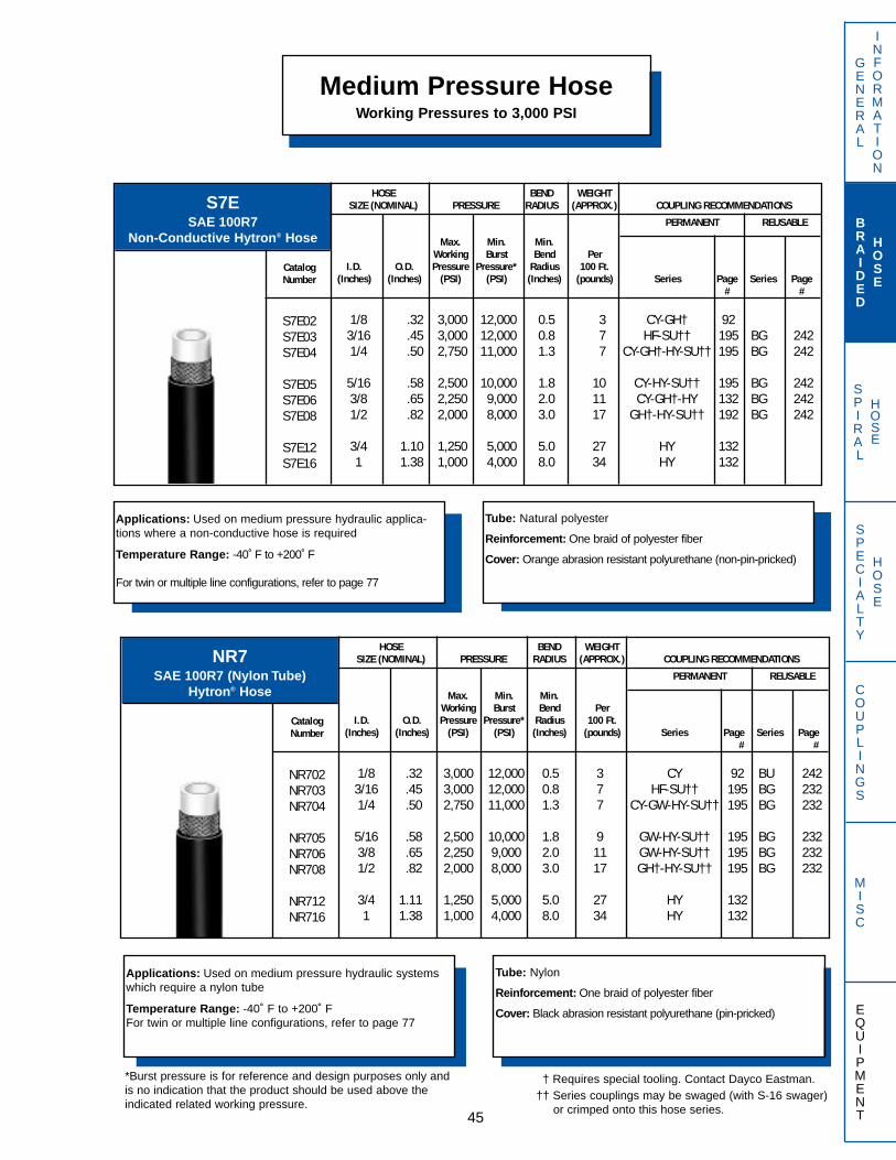
SPIRAL
HOSE
GENERAL
INFORMATION
BRAIDED
HOSE
SPECIALTY
HOSE
COUPLINGS
MISC
EQUIPMENT
Medium Pressure HoseWorking Pressures to 3,000 PSI
45
Applications: Used on medium pressure hydraulic applica-tions where a non-conductive hose is required
Temperature Range: -40˚ F to +200˚ F
For twin or multiple line configurations, refer to page 77
Tube: Natural polyester
Reinforcement: One braid of polyester fiber
Cover: Orange abrasion resistant polyurethane (non-pin-pricked)
S7ESAE 100R7
Non-Conductive Hytron® Hose
HOSE BEND WEIGHTSIZE (NOMINAL) PRESSURE RADIUS (APPROX.) COUPLING RECOMMENDATIONS
PERMANENT REUSABLE
CatalogNumber
S7E02S7E03S7E04
S7E05S7E06S7E08
S7E12S7E16
Max. Min. Min.Working Burst Bend Per
I.D. O.D. Pressure Pressure* Radius 100 Ft.(Inches) (Inches) (PSI) (PSI) (Inches) (pounds) Series Page Series Page
# #
1/8 .32 3,000 12,000 0.5 3 CY-GH† 923/16 .45 3,000 12,000 0.8 7 HF-SU†† 195 BG 2421/4 .50 2,750 11,000 1.3 7 CY-GH†-HY-SU†† 195 BG 242
5/16 .58 2,500 10,000 1.8 10 CY-HY-SU†† 195 BG 2423/8 .65 2,250 9,000 2.0 11 CY-GH†-HY 132 BG 2421/2 .82 2,000 8,000 3.0 17 GH†-HY-SU†† 192 BG 242
3/4 1.10 1,250 5,000 5.0 27 HY 1321 1.38 1,000 4,000 8.0 34 HY 132
Applications: Used on medium pressure hydraulic systemswhich require a nylon tube
Temperature Range: -40˚ F to +200˚ FFor twin or multiple line configurations, refer to page 77
Tube: Nylon
Reinforcement: One braid of polyester fiber
Cover: Black abrasion resistant polyurethane (pin-pricked)
NR7SAE 100R7 (Nylon Tube)
Hytron® Hose
HOSE BEND WEIGHTSIZE (NOMINAL) PRESSURE RADIUS (APPROX.) COUPLING RECOMMENDATIONS
PERMANENT REUSABLE
CatalogNumber
NR702NR703NR704
NR705NR706NR708
NR712NR716
Max. Min. Min.Working Burst Bend Per
I.D. O.D. Pressure Pressure* Radius 100 Ft.(Inches) (Inches) (PSI) (PSI) (Inches) (pounds) Series Page Series Page
# #
1/8 .32 3,000 12,000 0.5 3 CY 92 BU 2423/16 .45 3,000 12,000 0.8 7 HF-SU†† 195 BG 2321/4 .50 2,750 11,000 1.3 7 CY-GW-HY-SU†† 195 BG 232
5/16 .58 2,500 10,000 1.8 9 GW-HY-SU†† 195 BG 2323/8 .65 2,250 9,000 2.0 11 GW-HY-SU†† 195 BG 2321/2 .82 2,000 8,000 3.0 17 GH†-HY-SU†† 195 BG 232
3/4 1.11 1,250 5,000 5.0 27 HY 1321 1.38 1,000 4,000 8.0 34 HY 132
*Burst pressure is for reference and design purposes only andis no indication that the product should be used above theindicated related working pressure.
† Requires special tooling. Contact Dayco Eastman.†† Series couplings may be swaged (with S-16 swager)
or crimped onto this hose series.
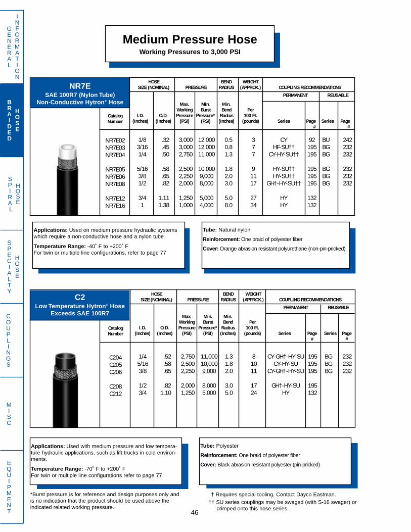
SPIRAL
HOSE
Medium Pressure HoseWorking Pressures to 3,000 PSI
GENERAL
INFORMATION
BRAIDED
HOSE
SPECIALTY
HOSE
COUPLINGS
MISC
EQUIPMENT 46
Applications: Used with medium pressure and low tempera-ture hydraulic applications, such as lift trucks in cold environ-ments.
Temperature Range: -70˚ F to +200˚ FFor twin or multiple line configurations refer to page 77
Tube: Polyester
Reinforcement: One braid of polyester fiber
Cover: Black abrasion resistant polyester (pin-pricked)
C2Low Temperature Hytron® Hose
Exceeds SAE 100R7
HOSE BEND WEIGHTSIZE (NOMINAL) PRESSURE RADIUS (APPROX.) COUPLING RECOMMENDATIONS
PERMANENT REUSABLE
CatalogNumber
C204C205C206
C208C212
Max. Min. Min.Working Burst Bend Per
I.D. O.D. Pressure Pressure* Radius 100 Ft.(Inches) (Inches) (PSI) (PSI) (Inches) (pounds) Series Page Series Page
# #
1/4 .52 2,750 11,000 1.3 8 CY-GH†-HY-SU 195 BG 2325/16 .58 2,500 10,000 1.8 10 CY-HY-SU 195 BG 2323/8 .65 2,250 9,000 2.0 11 CY-GH†-HY-SU 195 BG 232
1/2 .82 2,000 8,000 3.0 17 GH†-HY-SU 1953/4 1.10 1,250 5,000 5.0 24 HY 132
Applications: Used on medium pressure hydraulic systemswhich require a non-conductive hose and a nylon tube
Temperature Range: -40˚ F to +200˚ FFor twin or multiple line configurations, refer to page 77
Tube: Natural nylon
Reinforcement: One braid of polyester fiber
Cover: Orange abrasion resistant polyurethane (non-pin-pricked)
NR7ESAE 100R7 (Nylon Tube)
Non-Conductive Hytron® Hose
HOSE BEND WEIGHTSIZE (NOMINAL) PRESSURE RADIUS (APPROX.) COUPLING RECOMMENDATIONS
PERMANENT REUSABLE
CatalogNumber
NR7E02NR7E03NR7E04
NR7E05NR7E06NR7E08
NR7E12NR7E16
Max. Min. Min.Working Burst Bend Per
I.D. O.D. Pressure Pressure* Radius 100 Ft.(Inches) (Inches) (PSI) (PSI) (Inches) (pounds) Series Page Series Page
# #
1/8 .32 3,000 12,000 0.5 3 CY 92 BU 2423/16 .45 3,000 12,000 0.8 7 HF-SU†† 195 BG 2321/4 .50 2,750 11,000 1.3 7 CY-HY-SU†† 195 BG 232
5/16 .58 2,500 10,000 1.8 9 HY-SU†† 195 BG 2323/8 .65 2,250 9,000 2.0 11 HY-SU†† 195 BG 2321/2 .82 2,000 8,000 3.0 17 GH†-HY-SU†† 195 BG 232
3/4 1.11 1,250 5,000 5.0 27 HY 1321 1.38 1,000 4,000 8.0 34 HY 132
†† SU series couplings may be swaged (with S-16 swager) or crimped onto this hose series.
*Burst pressure is for reference and design purposes only andis no indication that the product should be used above theindicated related working pressure.
† Requires special tooling. Contact Dayco Eastman.

SPIRAL
HOSE
GENERAL
INFORMATION
BRAIDED
HOSE
SPECIALTY
HOSE
COUPLINGS
MISC
EQUIPMENT
Medium Pressure HoseWorking Pressures to 3,000 PSI
47
ST Blue Lightning®
Exceeds SAE 100R1ATHigh Temperature
Applications: Used for petroleum based and fire resistant fluids. Fire resis-tant fluids may have limitations and should be discussed with DaycoEastman Applications Engineering DepartmentTemperature Range: -40˚ F to +300˚ F (Petroleum based fluids**)
-40˚ F to +250˚ F (Water/Oil emulsions)-40˚ F to +250˚ F (Water/Glycol solutions)-40˚ F to +180˚ F (Phosphate Ester fluids)
**Use fluid manufacturer’s recommendationsSAE/USCG Marine Listed
Tube: Chlorinated polyethylene
Reinforcement: One braid of high tensile steel wire
Cover: Oil, ozone and abrasion resistant blue synthetic rubber–MSHA approved.
HOSE BEND WEIGHTSIZE (NOMINAL) PRESSURE RADIUS (APPROX.) COUPLING RECOMMENDATIONS
PERMANENT REUSABLE
CatalogNumber
ST04ST06ST08
ST12ST16
Max. Min. Min.Working Burst Bend Per
I.D. O.D. Pressure Pressure* Radius 100 Ft.(Inches) (Inches) (PSI) (PSI) (Inches) (pounds) Series Page # Series Page #
1/4 .53 2,750 11,000 4.0 16 GW-HY 1323/8 .67 2,250 9,000 5.0 24 BW-GW-HY 1321/2 .80 2,000 8,000 7.0 29 BW-GW-HY 132
3/4 1.09 1,250 5,000 9.5 43 BW-HY 1321 1.41 1,000 4,000 12.0 66 BW-HY 132
AX E-Z Flex® 150Exceeds
SAE 100R1AT
Applications: Used for medium pressure hydraulic lines onmobile equipment, machine tools and farm machinery. Moreflexible, higher WP and higher temperature range than SAE 100R1
Temperature Range: -40˚ F to +250˚ F
SAE/USCG Marine Listed
Tube: Neoprene
Reinforcement: One braid of high tensile steel wire
Cover: Oil and weather resistant synthetic rubber–MSHA approved
HOSE BEND WEIGHTSIZE (NOMINAL) PRESSURE RADIUS (APPROX.) COUPLING RECOMMENDATIONS
PERMANENT REUSABLE
CatalogNumber
AX04AX06AX08
AX10AX12AX16
Max. Min. Min.Working Burst Bend Per
I.D. O.D. Pressure Pressure* Radius 100 Ft.(Inches) (Inches) (PSI) (PSI) (Inches) (pounds) Series Page # Series Page #
1/4 .50 3,000 12,000 1.5 14 GW-HY 1323/8 .62 3,000 12,000 2.0 18 GW-HY 1321/2 .75 2,500 10,000 3.0 22 GW-HY 132
5/8 .88 1,500 6,000 3.5 29 HY 1323/4 1.01 1,250 5,000 4.3 31 HY 1321 1.29 1,000 4,000 5.5 40 HY 132
*Burst pressure is for reference and design purposes only andis no indication that the product should be used above theindicated related working pressure.
† Requires special tooling. Contact Dayco Eastman.
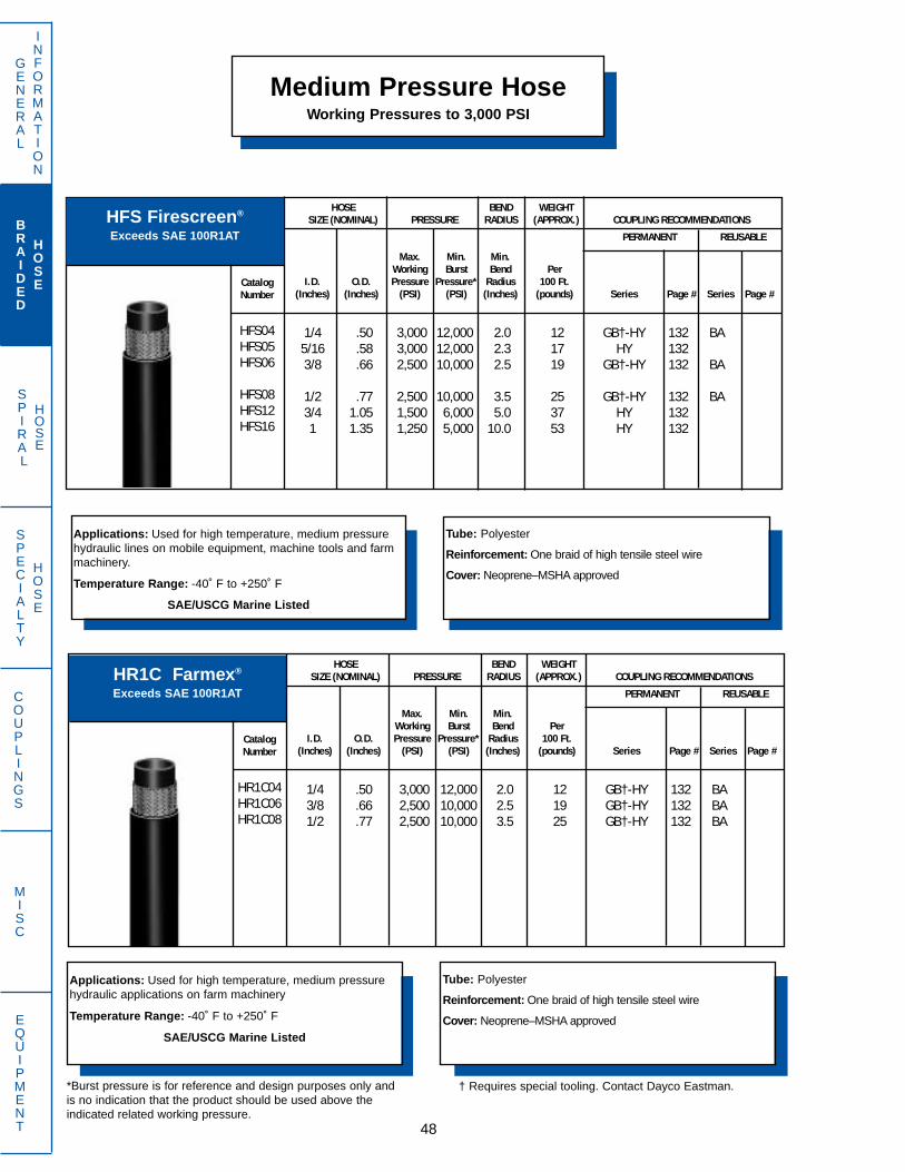
SPIRAL
HOSE
Medium Pressure HoseWorking Pressures to 3,000 PSI
GENERAL
INFORMATION
BRAIDED
HOSE
SPECIALTY
HOSE
COUPLINGS
MISC
EQUIPMENT 48
HR1C Farmex®
Exceeds SAE 100R1AT
Applications: Used for high temperature, medium pressurehydraulic applications on farm machinery
Temperature Range: -40˚ F to +250˚ F
SAE/USCG Marine Listed
Tube: Polyester
Reinforcement: One braid of high tensile steel wire
Cover: Neoprene–MSHA approved
HOSE BEND WEIGHTSIZE (NOMINAL) PRESSURE RADIUS (APPROX.) COUPLING RECOMMENDATIONS
PERMANENT REUSABLE
CatalogNumber
HR1C04HR1C06HR1C08
Max. Min. Min.Working Burst Bend Per
I.D. O.D. Pressure Pressure* Radius 100 Ft.(Inches) (Inches) (PSI) (PSI) (Inches) (pounds) Series Page # Series Page #
1/4 .50 3,000 12,000 2.0 12 GB†-HY 132 BA3/8 .66 2,500 10,000 2.5 19 GB†-HY 132 BA1/2 .77 2,500 10,000 3.5 25 GB†-HY 132 BA
HFS Firescreen®
Exceeds SAE 100R1AT
Applications: Used for high temperature, medium pressurehydraulic lines on mobile equipment, machine tools and farmmachinery.
Temperature Range: -40˚ F to +250˚ F
SAE/USCG Marine Listed
Tube: Polyester
Reinforcement: One braid of high tensile steel wire
Cover: Neoprene–MSHA approved
HOSE BEND WEIGHTSIZE (NOMINAL) PRESSURE RADIUS (APPROX.) COUPLING RECOMMENDATIONS
PERMANENT REUSABLE
CatalogNumber
HFS04HFS05HFS06
HFS08HFS12HFS16
Max. Min. Min.Working Burst Bend Per
I.D. O.D. Pressure Pressure* Radius 100 Ft.(Inches) (Inches) (PSI) (PSI) (Inches) (pounds) Series Page # Series Page #
1/4 .50 3,000 12,000 2.0 12 GB†-HY 132 BA5/16 .58 3,000 12,000 2.3 17 HY 1323/8 .66 2,500 10,000 2.5 19 GB†-HY 132 BA
1/2 .77 2,500 10,000 3.5 25 GB†-HY 132 BA3/4 1.05 1,500 6,000 5.0 37 HY 1321 1.35 1,250 5,000 10.0 53 HY 132
*Burst pressure is for reference and design purposes only andis no indication that the product should be used above theindicated related working pressure.
† Requires special tooling. Contact Dayco Eastman.

SPIRAL
HOSE
GENERAL
INFORMATION
BRAIDED
HOSE
SPECIALTY
HOSE
COUPLINGS
MISC
EQUIPMENT
Medium Pressure HoseWorking Pressures to 3,000 PSI
49
AM E-Z Flex® PlusExceeds SAE 100R17
Applications: Used in timber processing and handling, agri-cultural, and construction industries requiring an extra toughrubber cover for abrasion resistant applications.
Temperature Range: -40˚ F to +250˚ F
SAE/USCG Marine Listed
Tube: Neoprene
Reinforcement: One braid of high tensile steel wire** Two braids of high tensile steel wire
Cover: Abrasion resistant Neoprene–MSHA approved
HOSE BEND WEIGHTSIZE (NOMINAL) PRESSURE RADIUS (APPROX.) COUPLING RECOMMENDATIONS
PERMANENT REUSABLE
CatalogNumber
AM04AM06AM08
AM10**AM12**AM16**
Max. Min. Min.Working Burst Bend Per
I.D. O.D. Pressure Pressure* Radius 100 Ft.(Inches) (Inches) (PSI) (PSI) (Inches) (pounds) Series Page # Series Page #
1/4 .50 3,000 12,000 1.5 14 GW-HY 1323/8 .63 3,000 12,000 2.0 19 GW-HY 1321/2 .78 3,000 12,000 3.5 27 GW-HY 132
5/8 .93 3,000 12,000 4.0 43 HY 1323/4 1.14 3,000 12,000 4.8 65 BW-HY 1321 1.48 3,000 12,000 6.0 108 BW 81
Applications: For use on medium pressure hydraulic applica-tions at low and high temperatures. Polyester cover providesexcellent abrasion resistance.
Temperature Range: -70˚ F to +250˚ F (H604 through H608)-50˚ F to +250˚ F (H610 and H612)
Tube: Polyester
Reinforcement: One braid of high tensile steel wire** Two braids of high tensile steel wire
Cover: Polyester
H63,000 PSI Working Pressure
HOSE BEND WEIGHTSIZE (NOMINAL) PRESSURE RADIUS (APPROX.) COUPLING RECOMMENDATIONS
PERMANENT REUSABLE
CatalogNumber
H604H605H606
H608H610**H612**
Max. Min. Min.Working Burst Bend Per
I.D. O.D. Pressure Pressure* Radius 100 Ft.(Inches) (Inches) (PSI) (PSI) (Inches) (pounds) Series Page # Series Page #
1/4 .48 3,000 12,000 2.0 12 GB-HY 1325/16 .55 3,000 12,000 2.3 14 HY 1323/8 .64 3,000 12,000 2.5 19 GB-HY 132
1/2 .77 3,000 12,000 3.5 29 GB-HY 1325/8 .99 3,000 12,000 4.0 47 HF 1193/4 1.16 3,000 12,000 4.8 69 HY 132
*Burst pressure is for reference and design purposes only andis no indication that the product should be used above theindicated related working pressure.
† Requires special tooling. Contact Dayco Eastman.
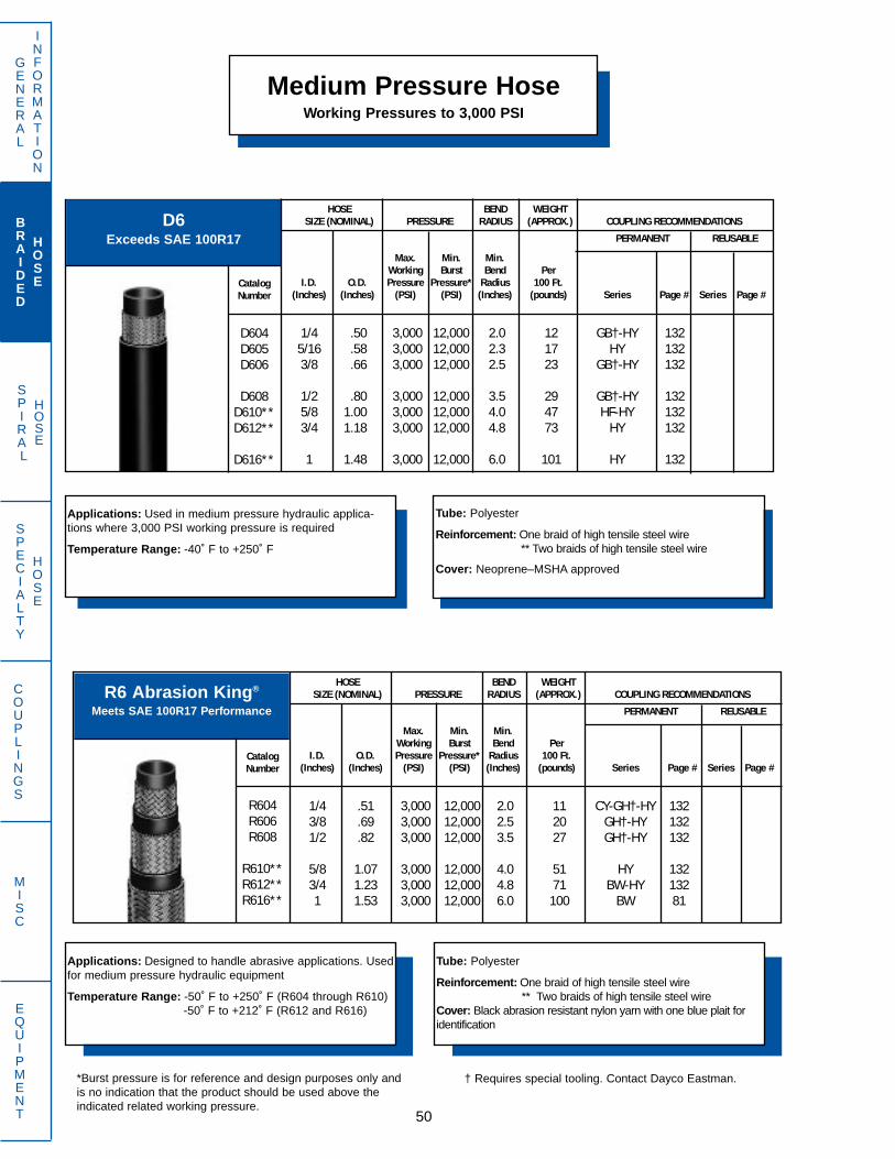
SPIRAL
HOSE
Medium Pressure HoseWorking Pressures to 3,000 PSI
GENERAL
INFORMATION
BRAIDED
HOSE
SPECIALTY
HOSE
COUPLINGS
MISC
EQUIPMENT 50
R6 Abrasion King®
Meets SAE 100R17 Performance
HOSE BEND WEIGHTSIZE (NOMINAL) PRESSURE RADIUS (APPROX.) COUPLING RECOMMENDATIONS
PERMANENT REUSABLE
CatalogNumber
R604R606R608
R610**R612**R616**
Max. Min. Min.Working Burst Bend Per
I.D. O.D. Pressure Pressure* Radius 100 Ft.(Inches) (Inches) (PSI) (PSI) (Inches) (pounds) Series Page # Series Page #
1/4 .51 3,000 12,000 2.0 11 CY-GH†-HY 1323/8 .69 3,000 12,000 2.5 20 GH†-HY 1321/2 .82 3,000 12,000 3.5 27 GH†-HY 132
5/8 1.07 3,000 12,000 4.0 51 HY 1323/4 1.23 3,000 12,000 4.8 71 BW-HY 1321 1.53 3,000 12,000 6.0 100 BW 81
Applications: Designed to handle abrasive applications. Usedfor medium pressure hydraulic equipment
Temperature Range: -50˚ F to +250˚ F (R604 through R610)-50˚ F to +212˚ F (R612 and R616)
Tube: Polyester
Reinforcement: One braid of high tensile steel wire** Two braids of high tensile steel wire
Cover: Black abrasion resistant nylon yarn with one blue plait foridentification
D6Exceeds SAE 100R17
Applications: Used in medium pressure hydraulic applica-tions where 3,000 PSI working pressure is required
Temperature Range: -40˚ F to +250˚ F
Tube: Polyester
Reinforcement: One braid of high tensile steel wire** Two braids of high tensile steel wire
Cover: Neoprene–MSHA approved
HOSE BEND WEIGHTSIZE (NOMINAL) PRESSURE RADIUS (APPROX.) COUPLING RECOMMENDATIONS
PERMANENT REUSABLE
CatalogNumber
D604D605D606
D608D610**D612**
D616**
Max. Min. Min.Working Burst Bend Per
I.D. O.D. Pressure Pressure* Radius 100 Ft.(Inches) (Inches) (PSI) (PSI) (Inches) (pounds) Series Page # Series Page #
1/4 .50 3,000 12,000 2.0 12 GB†-HY 1325/16 .58 3,000 12,000 2.3 17 HY 1323/8 .66 3,000 12,000 2.5 23 GB†-HY 132
1/2 .80 3,000 12,000 3.5 29 GB†-HY 1325/8 1.00 3,000 12,000 4.0 47 HF-HY 1323/4 1.18 3,000 12,000 4.8 73 HY 132
1 1.48 3,000 12,000 6.0 101 HY 132
*Burst pressure is for reference and design purposes only andis no indication that the product should be used above theindicated related working pressure.
† Requires special tooling. Contact Dayco Eastman.
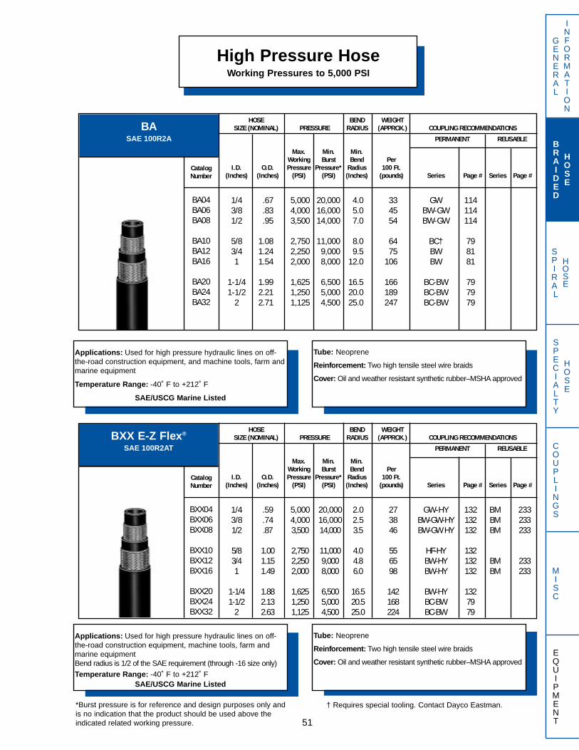
SPIRAL
HOSE
BASAE 100R2A
BXX E-Z Flex®
SAE 100R2AT
GENERAL
INFORMATION
BRAIDED
HOSE
SPECIALTY
HOSE
COUPLINGS
MISC
EQUIPMENT
High Pressure HoseWorking Pressures to 5,000 PSI
Applications: Used for high pressure hydraulic lines on off-the-road construction equipment, and machine tools, farm andmarine equipment
Temperature Range: -40˚ F to +212˚ F
SAE/USCG Marine Listed
Tube: Neoprene
Reinforcement: Two high tensile steel wire braids
Cover: Oil and weather resistant synthetic rubber–MSHA approved
Applications: Used for high pressure hydraulic lines on off-the-road construction equipment, machine tools, farm andmarine equipmentBend radius is 1/2 of the SAE requirement (through -16 size only)
Temperature Range: -40˚ F to +212˚ FSAE/USCG Marine Listed
Tube: Neoprene
Reinforcement: Two high tensile steel wire braids
Cover: Oil and weather resistant synthetic rubber–MSHA approved
51
HOSE BEND WEIGHTSIZE (NOMINAL) PRESSURE RADIUS (APPROX.) COUPLING RECOMMENDATIONS
PERMANENT REUSABLE
CatalogNumber
BA04BA06BA08
BA10BA12BA16
BA20BA24BA32
Max. Min. Min.Working Burst Bend Per
I.D. O.D. Pressure Pressure* Radius 100 Ft.(Inches) (Inches) (PSI) (PSI) (Inches) (pounds) Series Page # Series Page #
1/4 .67 5,000 20,000 4.0 33 GW 1143/8 .83 4,000 16,000 5.0 45 BW-GW 1141/2 .95 3,500 14,000 7.0 54 BW-GW 114
5/8 1.08 2,750 11,000 8.0 64 BC† 793/4 1.24 2,250 9,000 9.5 75 BW 811 1.54 2,000 8,000 12.0 106 BW 81
1-1/4 1.99 1,625 6,500 16.5 166 BC-BW 791-1/2 2.21 1,250 5,000 20.0 189 BC-BW 79
2 2.71 1,125 4,500 25.0 247 BC-BW 79
HOSE BEND WEIGHTSIZE (NOMINAL) PRESSURE RADIUS (APPROX.) COUPLING RECOMMENDATIONS
PERMANENT REUSABLE
CatalogNumber
BXX04BXX06BXX08
BXX10BXX12BXX16
BXX20BXX24BXX32
Max. Min. Min.Working Burst Bend Per
I.D. O.D. Pressure Pressure* Radius 100 Ft.(Inches) (Inches) (PSI) (PSI) (Inches) (pounds) Series Page # Series Page #
1/4 .59 5,000 20,000 2.0 27 GW-HY 132 BM 2333/8 .74 4,000 16,000 2.5 38 BW-GW-HY 132 BM 2331/2 .87 3,500 14,000 3.5 46 BW-GW HY 132 BM 233
5/8 1.00 2,750 11,000 4.0 55 HF-HY 1323/4 1.15 2,250 9,000 4.8 65 BW-HY 132 BM 2331 1.49 2,000 8,000 6.0 98 BW-HY 132 BM 233
1-1/4 1.88 1,625 6,500 16.5 142 BW-HY 1321-1/2 2.13 1,250 5,000 20.5 168 BC-BW 79
2 2.63 1,125 4,500 25.0 224 BC-BW 79
*Burst pressure is for reference and design purposes only andis no indication that the product should be used above theindicated related working pressure.
† Requires special tooling. Contact Dayco Eastman.

SPIRAL
HOSE
High Pressure HoseWorking Pressures to 5,000 PSI
GENERAL
INFORMATION
BRAIDED
HOSE
SPECIALTY
HOSE
COUPLINGS
MISC
EQUIPMENT 52
Applications: Used for high pressure hydraulic lines on off-the-road construction, farm, and mining equipment operatingin an abrasive and restricted environment
Temperature Range: -40˚ F to +212˚ F
Tube: Neoprene
Reinforcement: Two braids of high tensile steel wire
Cover: Abrasion, oil and weather resistant ultra high molecularweight polyethylene–MSHA approved
Applications: Used for high pressure hydraulic lines on off-the-road construction, farm, and mining equipment operatingin an abrasive and restricted environment
Bend radius is 1/2 of the SAE requirement (through size -16 only)
Temperature Range: -40˚ F to +212˚ F
Tube: Neoprene
Reinforcement: Two braids of high tensile wire
Cover: Abrasion, oil and water resistant Neoprene – MSHAapproved
RT2 E-Z Flex®
SAE 100R2ATVery High Abrasion Resistance
BXP IroncladTM
SAE 100R2ATExceptional High Abrasion Resistance
HOSE BEND WEIGHTSIZE (NOMINAL) PRESSURE RADIUS (APPROX.) COUPLING RECOMMENDATIONS
PERMANENT REUSABLE
CatalogNumber
BXP04BXP06BXP08
Max. Min. Min.Working Burst Bend Per
I.D. O.D. Pressure Pressure* Radius 100 Ft.(Inches) (Inches) (PSI) (PSI) (Inches) (pounds) Series Page # Series Page #
1/4 .59 5,000 20,000 4.0 27 BW-GW 1143/8 .74 4,000 16,000 5.0 36 BW-GW 1141/2 .87 3,500 14,000 7.0 46 BW-GW 114
HOSE BEND WEIGHTSIZE (NOMINAL) PRESSURE RADIUS (APPROX.) COUPLING RECOMMENDATIONS
PERMANENT REUSABLE
CatalogNumber
RT204RT206RT208
RT210RT212RT216
RT220RT224RT232
Max. Min. Min.Working Burst Bend Per
I.D. O.D. Pressure Pressure* Radius 100 Ft.(Inches) (Inches) (PSI) (PSI) (Inches) (pounds) Series Page # Series Page #
1/4 .59 5,000 20,000 2.0 27 BW-GW-HY 1323/8 .74 4,000 16,000 2.5 38 BW-GW-HY 1321/2 .87 3,500 14,000 3.5 46 BW-GW-HY 132
5/8 1.00 2,750 11,000 4.0 55 HY 1323/4 1.15 2,250 9,000 4.8 65 BW-HY 1321 1.49 2,000 8,000 6.0 98 BW-HY 132
1 1/4 1.88 1,625 6,500 16.5 142 BW-HY 1321 1/2 2.13 1,250 5,000 20.5 168 BC-BW 79
2 2.63 1,125 4,500 25.0 224 BC-BW 79
*Burst pressure is for reference and design purposes only andis no indication that the product should be used above theindicated related working pressure.

SPIRAL
HOSE
GENERAL
INFORMATION
BRAIDED
HOSE
SPECIALTY
HOSE
COUPLINGS
MISC
EQUIPMENT
High Pressure HoseWorking Pressures to 6,600 PSI
53
Applications: Used for high pressure hydraulic lines on off-the-road construction equipment, machine tools, farm andmarine equipment
Temperature Range: -40 ̊F to +212 ̊FSAE/USCG Marine Listed
Tube: Nitrile
Reinforcement: Two braid of high tensile steel wire
Cover: Oil and weather resistant synthetic rubber–MSHA approved
J4SAE 100R2AT
HOSE BEND WEIGHTSIZE (NOMINAL) PRESSURE RADIUS (APPROX.) COUPLING RECOMMENDATIONS
PERMANENT REUSABLE
CatalogNumber
J420J424J432
Max. Min. Min.Working Burst Bend Per
I.D. O.D. Pressure Pressure* Radius 100 Ft.(Inches) (Inches) (PSI) (PSI) (Inches) (pounds) Series Page # Series Page #
1-1/4 1.88 1,625 6,600 16.5 129 BW-HY-JJ 811-1/2 2.16 1,250 5,000 20.0 150 BW-JJ 81
2 2.66 1,125 4,500 25.0 187 BC-BW-JJ 81
Applications: Used for high pressure hydraulic lines on off-the-road construction equipment, machine tools, farm andmarine equipment.
Temperature Range: -40 ̊F to +212 ̊F
Tube: Polyester
Reinforcement: Two braids of high tensile steel wire
Cover: Neoprene–MSHA approved
J4ASAE 100R2AT
HOSE BEND WEIGHTSIZE (NOMINAL) PRESSURE RADIUS (APPROX.) COUPLING RECOMMENDATIONS
PERMANENT REUSABLE
CatalogNumber
J404AJ406AJ408A
J412AJ416A
Max. Min. Min.Working Burst Bend Per
I.D. O.D. Pressure Pressure* Radius 100 Ft.(Inches) (Inches) (PSI) (PSI) (Inches) (pounds) Series Page # Series Page #
1/4 .59 5,000 20,000 2.0 28 HY 1323/8 .75 4,000 16,000 2.5 39 BW-HY 1321/2 .88 3,500 14,000 3.5 45 BW-HY 132
3/4 1.15 2,250 9,000 4.8 62 BW-HY 1321 1.50 2,000 8,000 6.0 87 BW-HY 132
*Burst pressure is for reference and design purposes only andis no indication that the product should be used above theindicated related working pressure.
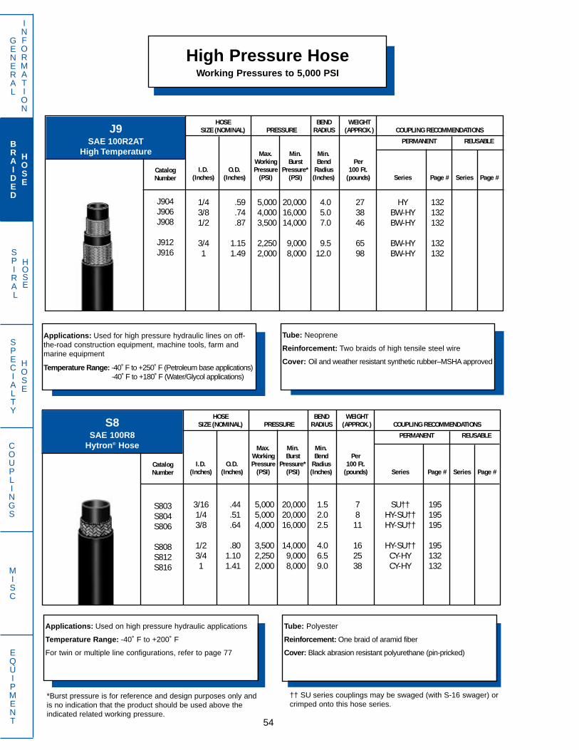
SPIRAL
HOSE
High Pressure HoseWorking Pressures to 5,000 PSI
GENERAL
INFORMATION
BRAIDED
HOSE
SPECIALTY
HOSE
COUPLINGS
MISC
EQUIPMENT 54
Applications: Used for high pressure hydraulic lines on off-the-road construction equipment, machine tools, farm andmarine equipment
Temperature Range: -40 ̊F to +250 ̊F (Petroleum base applications)-40 ̊F to +180 ̊F (Water/Glycol applications)
Tube: Neoprene
Reinforcement: Two braids of high tensile steel wire
Cover: Oil and weather resistant synthetic rubber–MSHA approved
J9SAE 100R2AT
High Temperature
HOSE BEND WEIGHTSIZE (NOMINAL) PRESSURE RADIUS (APPROX.) COUPLING RECOMMENDATIONS
PERMANENT REUSABLE
CatalogNumber
J904J906J908
J912J916
Max. Min. Min.Working Burst Bend Per
I.D. O.D. Pressure Pressure* Radius 100 Ft.(Inches) (Inches) (PSI) (PSI) (Inches) (pounds) Series Page # Series Page #
1/4 .59 5,000 20,000 4.0 27 HY 1323/8 .74 4,000 16,000 5.0 38 BW-HY 1321/2 .87 3,500 14,000 7.0 46 BW-HY 132
3/4 1.15 2,250 9,000 9.5 65 BW-HY 1321 1.49 2,000 8,000 12.0 98 BW-HY 132
Applications: Used on high pressure hydraulic applications
Temperature Range: -40˚ F to +200˚ F
For twin or multiple line configurations, refer to page 77
Tube: Polyester
Reinforcement: One braid of aramid fiber
Cover: Black abrasion resistant polyurethane (pin-pricked)
S8SAE 100R8
Hytron® Hose
HOSE BEND WEIGHTSIZE (NOMINAL) PRESSURE RADIUS (APPROX.) COUPLING RECOMMENDATIONS
PERMANENT REUSABLE
CatalogNumber
S803S804S806
S808S812S816
Max. Min. Min.Working Burst Bend Per
I.D. O.D. Pressure Pressure* Radius 100 Ft.(Inches) (Inches) (PSI) (PSI) (Inches) (pounds) Series Page # Series Page #
3/16 .44 5,000 20,000 1.5 7 SU†† 1951/4 .51 5,000 20,000 2.0 8 HY-SU†† 1953/8 .64 4,000 16,000 2.5 11 HY-SU†† 195
1/2 .80 3,500 14,000 4.0 16 HY-SU†† 1953/4 1.10 2,250 9,000 6.5 25 CY-HY 1321 1.41 2,000 8,000 9.0 38 CY-HY 132
†† SU series couplings may be swaged (with S-16 swager) orcrimped onto this hose series.
*Burst pressure is for reference and design purposes only andis no indication that the product should be used above theindicated related working pressure.

SPIRAL
HOSE
GENERAL
INFORMATION
BRAIDED
HOSE
SPECIALTY
HOSE
COUPLINGS
MISC
EQUIPMENT
High Pressure HoseWorking Pressures to 5,000 PSI
55
*Burst pressure is for reference and design purposes only andis no indication that the product should be used above theindicated related working pressure.
†† SU series couplings may be swaged (with S-16swager) or crimped onto this hose series.
Applications: Used on high pressure hydraulic applicationsrequiring a non-conductive hose
Temperature Range: -40˚ F to +200˚ F
For twin or multiple line configurations, refer to page 77
Tube: Natural polyester
Reinforcement: One braid of aramid fiber
Cover: Orange abrasion resistant polyurethane (non-pin-pricked)
S8ESAE 100R8
Non-Conductive Hytron® Hose
HOSE BEND WEIGHTSIZE (NOMINAL) PRESSURE RADIUS (APPROX.) COUPLING RECOMMENDATIONS
PERMANENT REUSABLE
CatalogNumber
S8E03S8E04S8E06
S8E08S8E12S8E16
Max. Min. Min.Working Burst Bend Per
I.D. O.D. Pressure Pressure* Radius 100 Ft.(Inches) (Inches) (PSI) (PSI) (Inches) (pounds) Series Page # Series Page #
3/16 .44 5,000 20,000 1.5 7 SU†† 1951/4 .51 5,000 20,000 2.0 8 HY-SU†† 1953/8 .64 4,000 16,000 2.5 11 HY-SU†† 195
1/2 .80 3,500 14,000 4.0 16 HY-SU†† 1953/4 1.10 2,250 9,000 6.5 25 CY-HY 1321 1.41 2,000 8,000 9.0 38 CY-HY 132
Applications: Used as a replacement for SAE 100R2 highpressure hydraulic lines on off-the-road construction equip-ment, machine tools and mining equipment
Temperature Range: -40˚ F to +250˚ F
SAE/USCG Marine Listed
Tube: Neoprene
Reinforcement: Two high tensile steel wire braids
Cover: Oil and weather resistant synthetic rubber–MSHAapproved
FX E-Z Flex® 250SAE 100R16
HOSE BEND WEIGHTSIZE (NOMINAL) PRESSURE RADIUS (APPROX.) COUPLING RECOMMENDATIONS
PERMANENT REUSABLE
CatalogNumber
FX04FX06FX08
FX10FX12FX16
FX20
Max. Min. Min.Working Burst Bend Per
I.D. O.D. Pressure Pressure* Radius 100 Ft.(Inches) (Inches) (PSI) (PSI) (Inches) (pounds) Series Page # Series Page #
1/4 .55 5,000 20,000 2.0 23 GW-HY 1323/8 .67 4,000 16,000 2.5 28 BW-GW-HY 1321/2 .81 3,500 14,000 3.5 36 BW-GW-HY 132
5/8 .93 2,750 11,000 4.0 42 HF-HY 1323/4 1.07 2,250 9,000 4.8 51 BW-HY 1321 1.37 2,000 8,000 6.0 72 BW-HY 132
1-1/4 1.69 1,625 6,500 8.3 102 BC-BW-HY 132

SPIRAL
HOSE
High Pressure HoseWorking Pressures to 5,000 PSI
GENERAL
INFORMATION
BRAIDED
HOSE
SPECIALTY
HOSE
COUPLINGS
MISC
EQUIPMENT 56
Applications: Used as a replacement for SAE 100R2 highpressure hydraulic lines on off-the-road construction equip-ment, machine tools and mining equipment
Temperature Range: -40˚ F to +212˚ F
SAE/USCG Marine Listed
Tube: Polyester
Reinforcement: One braid of high tensile steel wire**Two braids of high tensile steel wire
Cover: Neoprene–MSHA approved
HFS2 Firescreen II®
SAE 100R16
HOSE BEND WEIGHTSIZE (NOMINAL) PRESSURE RADIUS (APPROX.) COUPLING RECOMMENDATIONS
PERMANENT REUSABLE
CatalogNumber
HFS204**HFS206HFS208
HFS210HFS212HFS216**
Max. Min. Min.Working Burst Bend Per
I.D. O.D. Pressure Pressure* Radius 100 Ft.(Inches) (Inches) (PSI) (PSI) (Inches) (pounds) Series Page # Series Page #
1/4 .56 5,000 20,000 2.0 21 HY 132 BA 2273/8 .66 4,000 16,000 2.5 23 GB†-HY 132 BA 2271/2 .80 3,500 14,000 3.5 29 GB†-HY 132 BA 227
5/8 .95 2,750 11,000 4.0 38 GB†-HF-HY 1323/4 1.08 2,250 9,000 4.8 45 GB†-HY 132 BA 2271 1.43 2,000 8,000 6.0 80 HY 132 BA 227
Applications: Used as a replacement for SAE 100R2 highpressure hydraulic lines on agriculture equipment
Temperature Range: -40˚ F to +212˚ F
Tube: Polyester
Reinforcement: One braid of high tensile steel wire**Two braids of high tensile steel wire
Cover: Neoprene–MSHA approved
HR2C – Farmex II®
SAE 100R16
HOSE BEND WEIGHTSIZE (NOMINAL) PRESSURE RADIUS (APPROX.) COUPLING RECOMMENDATIONS
PERMANENT REUSABLE
CatalogNumber
HR2C04**HR2C06HR2C08
HR2C10HR2C12HR2C16**
Max. Min. Min.Working Burst Bend Per
I.D. O.D. Pressure Pressure* Radius 100 Ft.(Inches) (Inches) (PSI) (PSI) (Inches) (pounds) Series Page # Series Page #
1/4 .56 5,000 20,000 2.0 21 HY 132 BA 2273/8 .66 4,000 16,000 2.5 23 GB†-HY 132 BA 2271/2 .80 3,500 14,000 3.5 29 GB†-HY 132 BA 227
5/8 .95 2,750 11,000 4.0 38 GB†-HF-HY 1323/4 1.08 2,250 9,000 4.8 45 GB†-HY 132 BA 2271 1.43 2,000 8,000 6.0 80 HY 132 BA 227
*Burst pressure is for reference and design purposes only andis no indication that the product should be used above theindicated related working pressure.
† Requires special tooling. Contact Dayco Eastman.

SPIRAL
HOSE
GENERAL
INFORMATION
BRAIDED
HOSE
SPECIALTY
HOSE
COUPLINGS
MISC
EQUIPMENT
High Pressure HoseWorking Pressures to 10,000 PSI
57
Applications: Used for petroleum based and fire resistant fluids. Fire resis-tant fluids may have limitations and should be discussed with DaycoEastman Applications Engineering DepartmentTemperature Range: -40˚ F to +300˚ F (Petroleum based fluids)
-40˚ F to +250˚ F (Water/Oil emulsions)-40˚ F to +250˚ F (Water/Glycol solutions)-40˚ F to +180˚ F (Phosphate Ester fluids)
SAE/USCG Marine Listed
Tube: Chlorinated polyethylene
Reinforcement: Two high tensile steel wire braids
Cover: Oil, ozone and abrasion resistant blue syntheticrubber–MSHA approved
DT Blue Lightning®
Exceeds SAE 100R2High Temperature
HOSE BEND WEIGHTSIZE (NOMINAL) PRESSURE RADIUS (APPROX.) COUPLING RECOMMENDATIONS
PERMANENT REUSABLE
CatalogNumber
DT06DT08DT12DT16
Max. Min. Min.Working Burst Bend Per
I.D. O.D. Pressure Pressure* Radius 100 Ft.(Inches) (Inches) (PSI) (PSI) (Inches) (pounds) Series Page # Series Page #
3/8 .74 4,000 16,000 5.0 35 BW-GW 811/2 .87 3,500 14,000 7.0 45 BW 813/4 1.15 2,250 9,000 9.5 65 BW 811 1.48 2,000 8,000 12.0 96 BW 81
Applications: Used for high pressure hydraulic lines on off-the-road construction, farm and mining equipment operating inan abrasive and restricted environment.
Temperature Range: -40 ̊to 212 ̊F
Tube: Neoprene
Reinforcement: Two braids of high tensile wire
Cover: Abrasion, oil and water resistant Neoprene – MSHA approved
SN2KAbrasion King®
DIN 20022-2SN
HOSE BEND WEIGHTSIZE (NOMINAL) PRESSURE RADIUS (APPROX.) COUPLING RECOMMENDATIONS
PERMANENT REUSABLE
CatalogNumber
SN2K04SN2K06SN2K08
SN2K10SN2K12SN2K16
SN2K20SN2K24SN2K32
Max. Min. Min.Working Burst Bend Per
I.D. O.D. Pressure Pressure* Radius 100 Ft.(Inches) (Inches) (PSI) (PSI) (Inches) (pounds) Series Page # Series Page #
1/4 .59 5,800 23,200 4.0 27 BW 813/8 .74 4,800 19,200 5.0 38 BW 811/2 .87 4,000 16,000 7.0 46 BW 81
5/8 1.00 3,625 14,500 8.0 55 HY 1323/4 1.15 3,200 12,800 9.6 65 BW 811 1.49 2,400 9,600 12.0 98 BW 81
1 1/4 1.88 1,800 7,200 16.5 142 BW 811 1/2 2.13 1,300 5,200 20.5 168 BC-BW 79
2 2.63 1,160 4,640 25.0 224 BC-BW 79
*Burst pressure is for reference and design purposes only andis no indication that the product should be used above theindicated related working pressure.
DINNumber
DN06DN10DN12
DN16DN20DN25
DN32DN40DN50
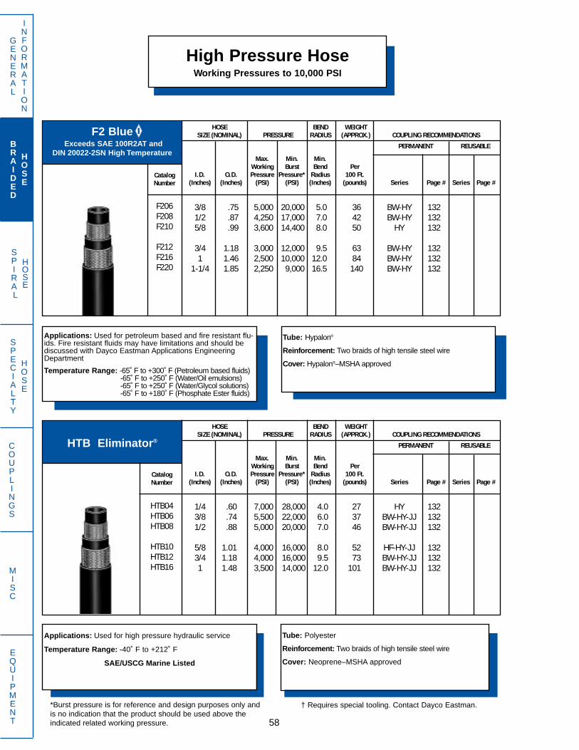
SPIRAL
HOSE
F2 BlueExceeds SAE 100R2AT and
DIN 20022-2SN High Temperature
High Pressure HoseWorking Pressures to 10,000 PSI
GENERAL
INFORMATION
BRAIDED
HOSE
SPECIALTY
HOSE
COUPLINGS
MISC
EQUIPMENT 58
Applications: Used for petroleum based and fire resistant flu-ids. Fire resistant fluids may have limitations and should bediscussed with Dayco Eastman Applications EngineeringDepartment
Temperature Range: -65˚ F to +300˚ F (Petroleum based fluids)-65˚ F to +250˚ F (Water/Oil emulsions)-65˚ F to +250˚ F (Water/Glycol solutions)-65˚ F to +180˚ F (Phosphate Ester fluids)
Tube: Hypalon®
Reinforcement: Two braids of high tensile steel wire
Cover: Hypalon®–MSHA approved
HOSE BEND WEIGHTSIZE (NOMINAL) PRESSURE RADIUS (APPROX.) COUPLING RECOMMENDATIONS
PERMANENT REUSABLE
CatalogNumber
F206F208F210
F212F216F220
Max. Min. Min.Working Burst Bend Per
I.D. O.D. Pressure Pressure* Radius 100 Ft.(Inches) (Inches) (PSI) (PSI) (Inches) (pounds) Series Page # Series Page #
3/8 .75 5,000 20,000 5.0 36 BW-HY 1321/2 .87 4,250 17,000 7.0 42 BW-HY 1325/8 .99 3,600 14,400 8.0 50 HY 132
3/4 1.18 3,000 12,000 9.5 63 BW-HY 1321 1.46 2,500 10,000 12.0 84 BW-HY 132
1-1/4 1.85 2,250 9,000 16.5 140 BW-HY 132
Applications: Used for high pressure hydraulic service
Temperature Range: -40˚ F to +212˚ F
SAE/USCG Marine Listed
Tube: Polyester
Reinforcement: Two braids of high tensile steel wire
Cover: Neoprene–MSHA approved
HTB Eliminator®
HOSE BEND WEIGHTSIZE (NOMINAL) PRESSURE RADIUS (APPROX.) COUPLING RECOMMENDATIONS
PERMANENT REUSABLE
CatalogNumber
HTB04HTB06HTB08
HTB10HTB12HTB16
Max. Min. Min.Working Burst Bend Per
I.D. O.D. Pressure Pressure* Radius 100 Ft.(Inches) (Inches) (PSI) (PSI) (Inches) (pounds) Series Page # Series Page #
1/4 .60 7,000 28,000 4.0 27 HY 1323/8 .74 5,500 22,000 6.0 37 BW-HY-JJ 1321/2 .88 5,000 20,000 7.0 46 BW-HY-JJ 132
5/8 1.01 4,000 16,000 8.0 52 HF-HY-JJ 1323/4 1.18 4,000 16,000 9.5 73 BW-HY-JJ 1321 1.48 3,500 14,000 12.0 101 BW-HY-JJ 132
*Burst pressure is for reference and design purposes only andis no indication that the product should be used above theindicated related working pressure.
† Requires special tooling. Contact Dayco Eastman.
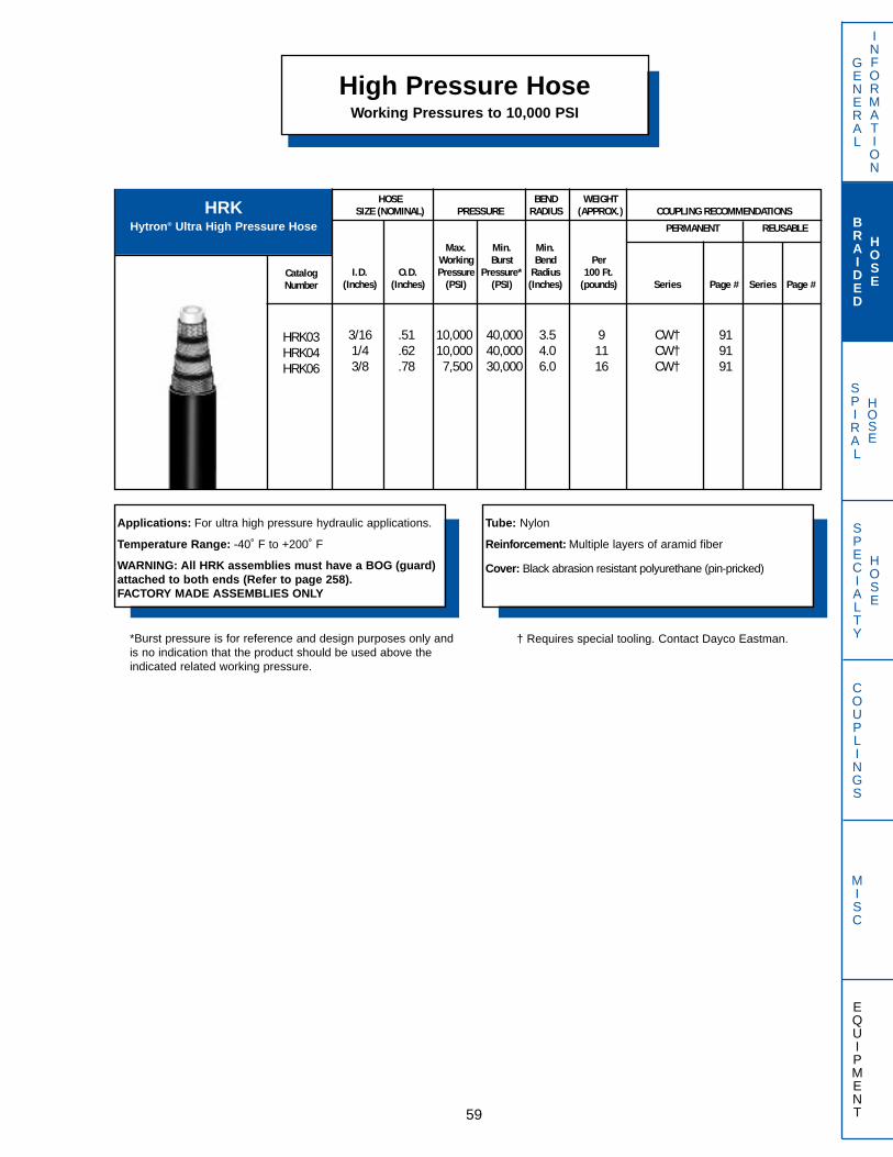
SPIRAL
HOSE
GENERAL
INFORMATION
BRAIDED
HOSE
SPECIALTY
HOSE
COUPLINGS
MISC
EQUIPMENT
High Pressure HoseWorking Pressures to 10,000 PSI
59
Applications: For ultra high pressure hydraulic applications.
Temperature Range: -40˚ F to +200˚ F
WARNING: All HRK assemblies must have a BOG (guard)attached to both ends (Refer to page 258).FACTORY MADE ASSEMBLIES ONLY
Tube: Nylon
Reinforcement: Multiple layers of aramid fiber
Cover: Black abrasion resistant polyurethane (pin-pricked)
HRKHytron® Ultra High Pressure Hose
HOSE BEND WEIGHTSIZE (NOMINAL) PRESSURE RADIUS (APPROX.) COUPLING RECOMMENDATIONS
PERMANENT REUSABLE
CatalogNumber
HRK03HRK04HRK06
Max. Min. Min.Working Burst Bend Per
I.D. O.D. Pressure Pressure* Radius 100 Ft.(Inches) (Inches) (PSI) (PSI) (Inches) (pounds) Series Page # Series Page #
3/16 .51 10,000 40,000 3.5 9 CW† 911/4 .62 10,000 40,000 4.0 11 CW† 913/8 .78 7,500 30,000 6.0 16 CW† 91
*Burst pressure is for reference and design purposes only andis no indication that the product should be used above theindicated related working pressure.
† Requires special tooling. Contact Dayco Eastman.
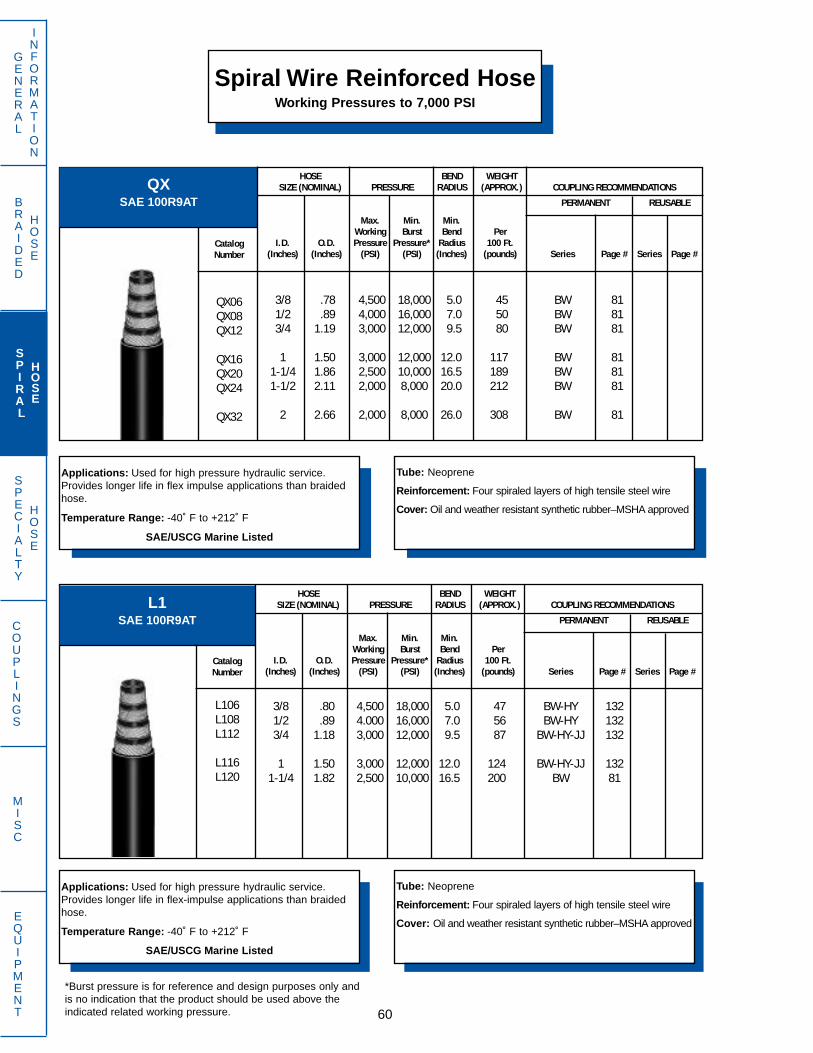
GENERAL
INFORMATION
BRAIDED
HOSE
SPIRAL
HOSE
SPECIALTY
HOSE
COUPLINGS
MISC
EQUIPMENT 60
Spiral Wire Reinforced HoseWorking Pressures to 7,000 PSI
Applications: Used for high pressure hydraulic service.Provides longer life in flex impulse applications than braidedhose.
Temperature Range: -40˚ F to +212˚ F
SAE/USCG Marine Listed
Tube: Neoprene
Reinforcement: Four spiraled layers of high tensile steel wire
Cover: Oil and weather resistant synthetic rubber–MSHA approved
QXSAE 100R9AT
HOSE BEND WEIGHTSIZE (NOMINAL) PRESSURE RADIUS (APPROX.) COUPLING RECOMMENDATIONS
PERMANENT REUSABLE
CatalogNumber
QX06QX08QX12
QX16QX20QX24
QX32
Max. Min. Min.Working Burst Bend Per
I.D. O.D. Pressure Pressure* Radius 100 Ft.(Inches) (Inches) (PSI) (PSI) (Inches) (pounds) Series Page # Series Page #
3/8 .78 4,500 18,000 5.0 45 BW 811/2 .89 4,000 16,000 7.0 50 BW 813/4 1.19 3,000 12,000 9.5 80 BW 81
1 1.50 3,000 12,000 12.0 117 BW 811-1/4 1.86 2,500 10,000 16.5 189 BW 811-1/2 2.11 2,000 8,000 20.0 212 BW 81
2 2.66 2,000 8,000 26.0 308 BW 81
Applications: Used for high pressure hydraulic service.Provides longer life in flex-impulse applications than braidedhose.
Temperature Range: -40˚ F to +212˚ F
SAE/USCG Marine Listed
Tube: Neoprene
Reinforcement: Four spiraled layers of high tensile steel wire
Cover: Oil and weather resistant synthetic rubber–MSHA approved
L1SAE 100R9AT
HOSE BEND WEIGHTSIZE (NOMINAL) PRESSURE RADIUS (APPROX.) COUPLING RECOMMENDATIONS
PERMANENT REUSABLE
CatalogNumber
L106L108L112
L116L120
Max. Min. Min.Working Burst Bend Per
I.D. O.D. Pressure Pressure* Radius 100 Ft.(Inches) (Inches) (PSI) (PSI) (Inches) (pounds) Series Page # Series Page #
3/8 .80 4,500 18,000 5.0 47 BW-HY 1321/2 .89 4.000 16,000 7.0 56 BW-HY 1323/4 1.18 3,000 12,000 9.5 87 BW-HY-JJ 132
1 1.50 3,000 12,000 12.0 124 BW-HY-JJ 1321-1/4 1.82 2,500 10,000 16.5 200 BW 81
*Burst pressure is for reference and design purposes only andis no indication that the product should be used above theindicated related working pressure.

GENERAL
INFORMATION
SPECIALTY
HOSE
COUPLINGS
MISC
EQUIPMENT61
Spiral Wire Reinforced HoseWorking Pressures to 7,000 PSI
Applications: Used for high pressure hydraulic service.Provides longer life under the higher temperatures and pres-sures of modern hydraulically operated equipmentBend radius is 1/2 of SAE requirements for sizes -12, -16, and -20Temperature Range: -40˚ F to +250˚ F
SAE/USCG Marine Listed
Tube: Neoprene
Reinforcement: Four spiraled layers of high tensile steel wire
Cover: Oil and weather resistant synthetic rubber – gray color –MSHA approved
CEE-Z Flex® Spiral
SAE 100R12
HOSE BEND WEIGHTSIZE (NOMINAL) PRESSURE RADIUS (APPROX.) COUPLING RECOMMENDATIONS
PERMANENT REUSABLE
CatalogNumber
CET06CET08CE12
CE16CE20CE24
CE32
Max. Min. Min.Working Burst Bend Per
I.D. O.D. Pressure Pressure* Radius 100 Ft.(Inches) (Inches) (PSI) (PSI) (Inches) (pounds) Series Page # Series Page #
3/8 .78 4,000 16,000 5.0 45 BW-JJ 811/2 .89 4,000 16,000 7.0 50 BW-JJ 813/4 1.21 4,000 16,000 4.8 89 BW-JJ 81
1 1.50 4,000 16,000 6.0 136 BW-JJ 811-1/4 1.85 3,000 12,000 8.3 182 BW-JJ 811-1/2 2.11 2,500 10,000 20.0 207 BW-JJ 81
2 2.63 2,500 10,000 25.0 296 BW-JJ 81
Applications: Used for high pressure hydraulic service.Provides longer life under the higher temperatures and pres-sures of modern hydraulically operated equipment
Temperature Range: -40˚ F to +250˚ F
SAE/USCG Marine Listed
Tube: Neoprene
Reinforcement: Four spiraled layers of high tensile steel wire
Cover: Oil and weather resistant synthetic rubber–graycolor–MSHA approved
M7SAE 100R12
HOSE BEND WEIGHTSIZE (NOMINAL) PRESSURE RADIUS (APPROX.) COUPLING RECOMMENDATIONS
PERMANENT REUSABLE
CatalogNumber
M706M708M710
M712M716M720
M724M732
Max. Min. Min.Working Burst Bend Per
I.D. O.D. Pressure Pressure* Radius 100 Ft.(Inches) (Inches) (PSI) (PSI) (Inches) (pounds) Series Page # Series Page #
3/8 .79 4,000 16,000 5.0 42 BW-JJ 811/2 .94 4,000 16,000 7.0 54 BW-JJ 815/8 1.07 4,000 16,000 8.0 71 BW-JJ 81
3/4 1.21 4,000 16,000 9.5 82 BW-JJ 811 1.50 4,000 16,000 12.0 138 BW-JJ 81
1-1/4 1.85 3,000 12,000 16.5 189 BW-JJ 81
1-1/2 2.11 2,500 10,000 20.0 223 BW-JJ 812 2.63 2,500 10,000 25.0 311 BW-HW-JJ 81
BRAIDED
HOSE
SPIRAL
HOSE
*Burst pressure is for reference and design purposes only andis no indication that the product should be used above theindicated related working pressure.
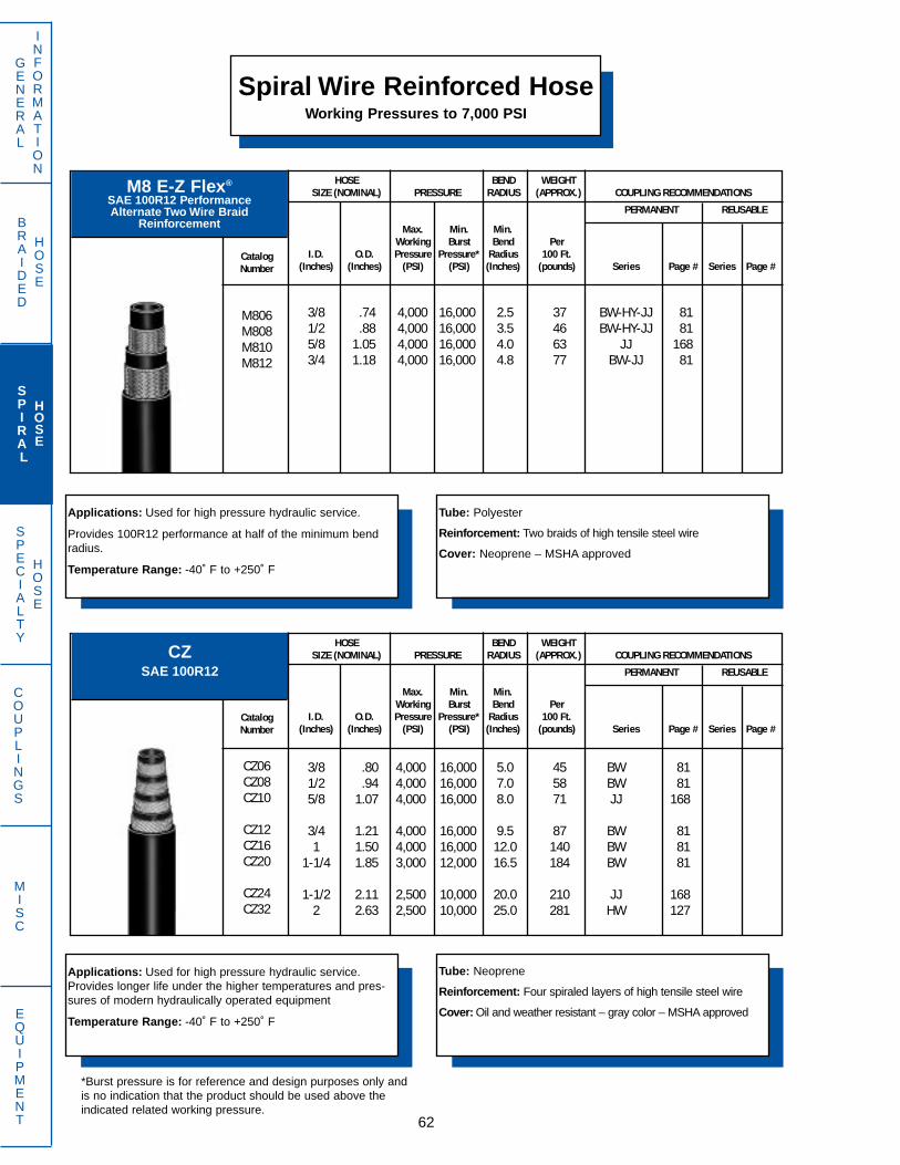
Spiral Wire Reinforced HoseWorking Pressures to 7,000 PSI
GENERAL
INFORMATION
SPECIALTY
HOSE
COUPLINGS
MISC
EQUIPMENT 62
Applications: Used for high pressure hydraulic service.
Provides 100R12 performance at half of the minimum bendradius.
Temperature Range: -40˚ F to +250˚ F
Tube: Polyester
Reinforcement: Two braids of high tensile steel wire
Cover: Neoprene – MSHA approved
M8 E-Z Flex®
SAE 100R12 PerformanceAlternate Two Wire Braid
Reinforcement
HOSE BEND WEIGHTSIZE (NOMINAL) PRESSURE RADIUS (APPROX.) COUPLING RECOMMENDATIONS
PERMANENT REUSABLE
CatalogNumber
M806M808M810M812
Max. Min. Min.Working Burst Bend Per
I.D. O.D. Pressure Pressure* Radius 100 Ft.(Inches) (Inches) (PSI) (PSI) (Inches) (pounds) Series Page # Series Page #
3/8 .74 4,000 16,000 2.5 37 BW-HY-JJ 811/2 .88 4,000 16,000 3.5 46 BW-HY-JJ 815/8 1.05 4,000 16,000 4.0 63 JJ 1683/4 1.18 4,000 16,000 4.8 77 BW-JJ 81
Applications: Used for high pressure hydraulic service.Provides longer life under the higher temperatures and pres-sures of modern hydraulically operated equipment
Temperature Range: -40˚ F to +250˚ F
Tube: Neoprene
Reinforcement: Four spiraled layers of high tensile steel wire
Cover: Oil and weather resistant – gray color – MSHA approved
CZSAE 100R12
HOSE BEND WEIGHTSIZE (NOMINAL) PRESSURE RADIUS (APPROX.) COUPLING RECOMMENDATIONS
PERMANENT REUSABLE
CatalogNumber
CZ06CZ08CZ10
CZ12CZ16CZ20
CZ24CZ32
Max. Min. Min.Working Burst Bend Per
I.D. O.D. Pressure Pressure* Radius 100 Ft.(Inches) (Inches) (PSI) (PSI) (Inches) (pounds) Series Page # Series Page #
3/8 .80 4,000 16,000 5.0 45 BW 811/2 .94 4,000 16,000 7.0 58 BW 815/8 1.07 4,000 16,000 8.0 71 JJ 168
3/4 1.21 4,000 16,000 9.5 87 BW 811 1.50 4,000 16,000 12.0 140 BW 81
1-1/4 1.85 3,000 12,000 16.5 184 BW 81
1-1/2 2.11 2,500 10,000 20.0 210 JJ 1682 2.63 2,500 10,000 25.0 281 HW 127
BRAIDED
HOSE
SPIRAL
HOSE
*Burst pressure is for reference and design purposes only andis no indication that the product should be used above theindicated related working pressure.
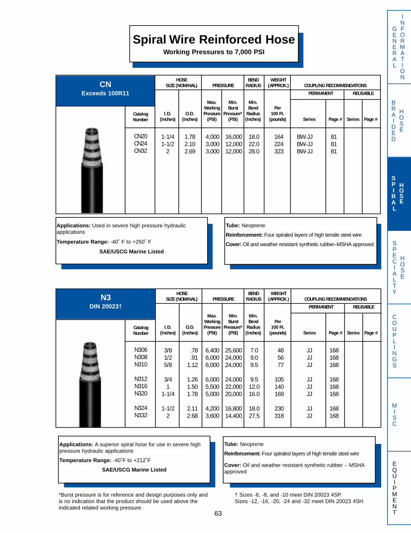
GENERAL
INFORMATION
SPECIALTY
HOSE
COUPLINGS
MISC
EQUIPMENT
Spiral Wire Reinforced HoseWorking Pressures to 7,000 PSI
63
Applications: Used in severe high pressure hydraulic applications
Temperature Range: -40˚ F to +250˚ F
SAE/USCG Marine Listed
Tube: Neoprene
Reinforcement: Four spiraled layers of high tensile steel wire
Cover: Oil and weather resistant synthetic rubber–MSHA approved
CNExceeds 100R11
HOSE BEND WEIGHTSIZE (NOMINAL) PRESSURE RADIUS (APPROX.) COUPLING RECOMMENDATIONS
PERMANENT REUSABLE
CatalogNumber
CN20CN24CN32
Max. Min. Min.Working Burst Bend Per
I.D. O.D. Pressure Pressure* Radius 100 Ft.(Inches) (Inches) (PSI) (PSI) (Inches) (pounds) Series Page # Series Page #
1-1/4 1.78 4,000 16,000 18.0 164 BW-JJ 811-1/2 2.10 3,000 12,000 22.0 224 BW-JJ 81
2 2.69 3,000 12,000 28.0 323 BW-JJ 81
Applications: A superior spiral hose for use in severe highpressure hydraulic applications
Temperature Range: -40˚F to +212˚F
SAE/USCG Marine Listed
Tube: Neoprene
Reinforcement: Four spiraled layers of high tensile steel wire
Cover: Oil and weather resistant synthetic rubber – MSHAapproved
N3DIN 20023†
† Sizes -6, -8, and -10 meet DIN 20023 4SP.Sizes -12, -16, -20, -24 and -32 meet DIN 20023 4SH
HOSE BEND WEIGHTSIZE (NOMINAL) PRESSURE RADIUS (APPROX.) COUPLING RECOMMENDATIONS
PERMANENT REUSABLE
CatalogNumber
N306N308N310
N312N316N320
N324N332
Max. Min. Min.Working Burst Bend Per
I.D. O.D. Pressure Pressure* Radius 100 Ft.(Inches) (Inches) (PSI) (PSI) (Inches) (pounds) Series Page # Series Page #
3/8 .78 6,400 25,600 7.0 48 JJ 1681/2 .91 6,000 24,000 9.0 56 JJ 1685/8 1.12 6,000 24,000 9.5 77 JJ 168
3/4 1.26 6,000 24,000 9.5 105 JJ 1681 1.50 5,500 22,000 12.0 140 JJ 168
1-1/4 1.78 5,000 20,000 16.0 169 JJ 168
1-1/2 2.11 4,200 16,800 18.0 230 JJ 1682 2.68 3,600 14,400 27.5 318 JJ 168
BRAIDED
HOSE
SPIRAL
HOSE
*Burst pressure is for reference and design purposes only andis no indication that the product should be used above theindicated related working pressure.
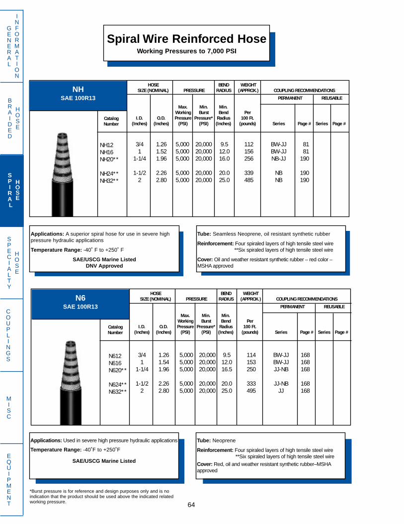
Spiral Wire Reinforced HoseWorking Pressures to 7,000 PSI
GENERAL
INFORMATION
SPECIALTY
HOSE
COUPLINGS
MISC
EQUIPMENT 64
*Burst pressure is for reference and design purposes only and is noindication that the product should be used above the indicated relatedworking pressure.
Applications: A superior spiral hose for use in severe highpressure hydraulic applications
Temperature Range: -40˚ F to +250˚ F
SAE/USCG Marine ListedDNV Approved
Tube: Seamless Neoprene, oil resistant synthetic rubber
Reinforcement: Four spiraled layers of high tensile steel wire**Six spiraled layers of high tensile steel wire
Cover: Oil and weather resistant synthetic rubber – red color –MSHA approved
NHSAE 100R13
HOSE BEND WEIGHTSIZE (NOMINAL) PRESSURE RADIUS (APPROX.) COUPLING RECOMMENDATIONS
PERMANENT REUSABLE
CatalogNumber
NH12NH16NH20**
NH24**NH32**
Max. Min. Min.Working Burst Bend Per
I.D. O.D. Pressure Pressure* Radius 100 Ft.(Inches) (Inches) (PSI) (PSI) (Inches) (pounds) Series Page # Series Page #
3/4 1.26 5,000 20,000 9.5 112 BW-JJ 811 1.52 5,000 20,000 12.0 156 BW-JJ 81
1-1/4 1.96 5,000 20,000 16.0 256 NB-JJ 190
1-1/2 2.26 5,000 20,000 20.0 339 NB 1902 2.80 5,000 20,000 25.0 485 NB 190
Applications: Used in severe high pressure hydraulic applications
Temperature Range: -40˚F to +250˚F
SAE/USCG Marine Listed
Tube: Neoprene
Reinforcement: Four spiraled layers of high tensile steel wire**Six spiraled layers of high tensile steel wire
Cover: Red, oil and weather resistant synthetic rubber–MSHAapproved
N6SAE 100R13
HOSE BEND WEIGHTSIZE (NOMINAL) PRESSURE RADIUS (APPROX.) COUPLING RECOMMENDATIONS
PERMANENT REUSABLE
CatalogNumber
N612N616N620**
N624**N632**
Max. Min. Min.Working Burst Bend Per
I.D. O.D. Pressure Pressure* Radius 100 Ft.(Inches) (Inches) (PSI) (PSI) (Inches) (pounds) Series Page # Series Page #
3/4 1.26 5,000 20,000 9.5 114 BW-JJ 1681 1.54 5,000 20,000 12.0 153 BW-JJ 168
1-1/4 1.96 5,000 20,000 16.5 250 JJ-NB 168
1-1/2 2.26 5,000 20,000 20.0 333 JJ-NB 1682 2.80 5,000 20,000 25.0 495 JJ 168
BRAIDED
HOSE
SPIRAL
HOSE

SPECIALTY
HOSE
BRAIDED
HOSE
GENERAL
INFORMATION
COUPLINGS
MISC
EQUIPMENT
Spiral Wire Reinforced HoseWorking Pressures to 6,000 PSI
65
Applications: A compact, lighter hose for use in severe highpressure hydraulic applications including hydrostatic drives.
Temperature Range: -40˚ F to +250˚ F
Tube: Neoprene
Reinforcement: Four Spiraled layers of high tensile steel wire
Cover: Oil and weather resistant synthetic rubber–MSHA approved
HT6
HOSE BEND WEIGHTSIZE (NOMINAL) PRESSURE RADIUS (APPROX.) COUPLING RECOMMENDATIONS
PERMANENT REUSABLE
CatalogNumber
HT612HT616
Max. Min. Min.Working Burst Bend Per
I.D. O.D. Pressure Pressure* Radius 100 Ft.(Inches) (Inches) (PSI) (PSI) (Inches) (pounds) Series Page # Series Page #
3/4 1.33 6,000 24,000 9.5 120 BW-JJ 1681 1.59 6,000 24,000 12.0 162 JJ-KW 168
*Burst pressure is for reference and design purposes only andis no indication that the product should be used above theindicated related working pressure.
Applications: A compact, lighter hose for use in severe highpressure hydraulic applications including hydrostatic drives.
Temperature Range: -40˚ F to +250˚ F
Tube: Neoprene
Reinforcement: Four spiraled layers of high tensile steel wire** Six spiraled layers of high tensile steel wire
Cover: Oil and weather resistant synthetic rubber–MSHA approved
N2SAE 100R15
HOSE BEND WEIGHTSIZE (NOMINAL) PRESSURE RADIUS (APPROX.) COUPLING RECOMMENDATIONS
PERMANENT REUSABLE
CatalogNumber
N212N216N220N224**
Max. Min. Min.Working Burst Bend Per
I.D. O.D. Pressure Pressure* Radius 100 Ft.(Inches) (Inches) (PSI) (PSI) (Inches) (pounds) Series Page # Series Page #
3/4 1.23 6,000 24,000 10.5 100 JJ 1681 1.50 6,000 24,000 10.5 142 JJ 168
1 1/4 1.90 6,000 24,000 10.5 242 JJ 1681-1/2 2.25 6,000 24,000 12.5 343 JJ 168
SPIRAL
HOSE

SPECIALTY
HOSE
Spiral Wire Reinforced HoseWorking Pressures to 7,000 PSI
GENERAL
INFORMATION
BRAIDED
HOSE
COUPLINGS
MISC
EQUIPMENT 66
H7Extra High Pressure
Applications: A compact, lighter hose for use in servere highpressure hydraulic applications.
Temperature Range: -40˚ F to +250˚ F
Tube: Neoprene
Reinforcement: Four spiraled layers of high tensile steel wire
Cover: Oil and weather resistant synthetic rubber–MSHA approved
HOSE BEND WEIGHTSIZE (NOMINAL) PRESSURE RADIUS (APPROX.) COUPLING RECOMMENDATIONS
PERMANENT REUSABLE
CatalogNumber
H704H706H708
Max. Min. Min.Working Burst Bend Per
I.D. O.D. Pressure Pressure* Radius 100 Ft.(Inches) (Inches) (PSI) (PSI) (Inches) (pounds) Series Page # Series Page #
1/4 .79 7,000 28,000 4.0 55 KC 1843/8 .81 7,000 28,000 6.0 59 JJ 1681/2 1.00 7,000 28,000 8.0 82 JJ 168
SPIRAL
HOSE
*Burst pressure is for reference and design purposes only andis no indication that the product should be used above theindicated related working pressure.

SPIRAL
HOSE
BRAIDED
HOSE
GENERAL
INFORMATION
SPECIALTY
HOSE
COUPLINGS
MISC
EQUIPMENT
Specialty Hose
67
BHBarrier Refrigerant Hose
Exceeds SAE J51Meets SAE J2064
Applications: Specifically designed for use in R12 andR134A refrigerant systems only.
Temperature Range: -22˚ F to +257˚ F
Tube: Neoprene/nylon barrier/nitrile barrier construction
Reinforcement: Textile reinforcement
Cover: Black, abrasion, ozone and heat resistant EPDM
† Requires special tooling. Contact Dayco Eastman.
PERMANENT REUSABLE
HOSE BEND WEIGHTSIZE (NOMINAL) PRESSURE RADIUS (APPROX.) COUPLING RECOMMENDATIONS
CatalogNumber
BH06BH08BH10
BH12
Max. Min. Min.Working Burst Bend Per
I.D. O.D. Pressure Pressure* Radius 100 Ft.(Inches) (Inches) (PSI) (PSI) (Inches) (pounds) Series Page # Series Page #
5/16 .75 350 2,000 4.0 19 BL† 20313/32 .91 350 2,000 4.7 27 BL† 2031/2 1.00 350 2,000 5.5 32 BL† 203
5/8 1.13 350 1,750 6.5 37 BL† 203
†† Bulk hose sales only, no coupling.
Applications: Specifically designed for use in R12 andR134A refrigerant systems only.
Temperature Range: -22˚ F to +203˚ F
Tube: Neoprene/nylon barrier/nitrile barrier construction
Reinforcement: One textile braid
Cover: Abrasion, ozone and heat resistant EPDMColors: Black - BK Red - RD
Blue - BL Yellow - YL
BCHBarrier Charging Hose
Meets SAE J2196PERMANENT REUSABLE
HOSE BEND WEIGHTSIZE (NOMINAL) PRESSURE RADIUS (APPROX.) COUPLING RECOMMENDATIONS
CatalogNumber
BCH03
Max. Min. Min.Working Burst Bend Per
I.D. O.D. Pressure Pressure* Radius 100 Ft.(Inches) (Inches) (PSI) (PSI) (Inches) (pounds) Series Page # Series Page #
7/32 .48 800 4,000 4.0 9 ††
*Burst pressure is for reference and design purposes only andis no indication that the product should be used above theindicated related working pressure.
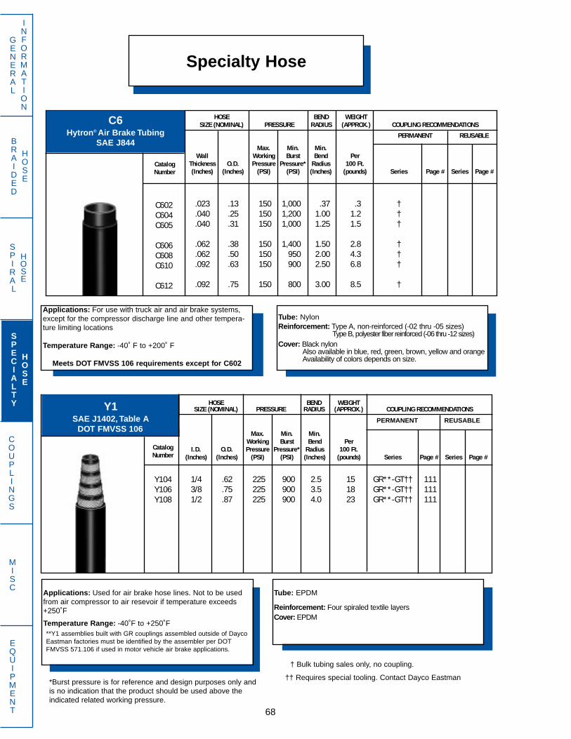
SPECIALTY
HOSE
SPIRAL
HOSE
GENERAL
INFORMATION
COUPLINGS
MISC
EQUIPMENT 68
Specialty Hose
Applications: For use with truck air and air brake systems,except for the compressor discharge line and other tempera-ture limiting locations
Temperature Range: -40˚ F to +200˚ F
Meets DOT FMVSS 106 requirements except for C602
Tube: NylonReinforcement: Type A, non-reinforced (-02 thru -05 sizes)
Type B, polyester fiber reinforced (-06 thru -12 sizes)Cover: Black nylon
Also available in blue, red, green, brown, yellow and orangeAvailability of colors depends on size.
C6Hytron® Air Brake Tubing
SAE J844
HOSE BEND WEIGHTSIZE (NOMINAL) PRESSURE RADIUS (APPROX.) COUPLING RECOMMENDATIONS
PERMANENT REUSABLE
CatalogNumber
C602C604C605
C606C608C610
C612
Max. Min. Min.Wall Working Burst Bend Per
Thickness O.D. Pressure Pressure* Radius 100 Ft.(Inches) (Inches) (PSI) (PSI) (Inches) (pounds) Series Page # Series Page #
.023 .13 150 1,000 .37 .3 †
.040 .25 150 1,200 1.00 1.2 †
.040 .31 150 1,000 1.25 1.5 †
.062 .38 150 1,400 1.50 2.8 †
.062 .50 150 950 2.00 4.3 †
.092 .63 150 900 2.50 6.8 †
.092 .75 150 800 3.00 8.5 †
Applications: Used for air brake hose lines. Not to be usedfrom air compressor to air resevoir if temperature exceeds+250˚F
Temperature Range: -40˚F to +250˚F
Tube: EPDM
Reinforcement: Four spiraled textile layersCover: EPDM
Y1SAE J1402, Table A
DOT FMVSS 106
**Y1 assemblies built with GR couplings assembled outside of DaycoEastman factories must be identified by the assembler per DOTFMVSS 571.106 if used in motor vehicle air brake applications.
PERMANENT REUSABLE
HOSE BEND WEIGHTSIZE (NOMINAL) PRESSURE RADIUS (APPROX.) COUPLING RECOMMENDATIONS
CatalogNumber
Y104Y106Y108
Max. Min. Min.Working Burst Bend Per
I.D. O.D. Pressure Pressure* Radius 100 Ft.(Inches) (Inches) (PSI) (PSI) (Inches) (pounds) Series Page # Series Page #
1/4 .62 225 900 2.5 15 GR**-GT†† 1113/8 .75 225 900 3.5 18 GR**-GT†† 1111/2 .87 225 900 4.0 23 GR**-GT†† 111
BRAIDED
HOSE
† Bulk tubing sales only, no coupling.
*Burst pressure is for reference and design purposes only andis no indication that the product should be used above theindicated related working pressure.
†† Requires special tooling. Contact Dayco Eastman
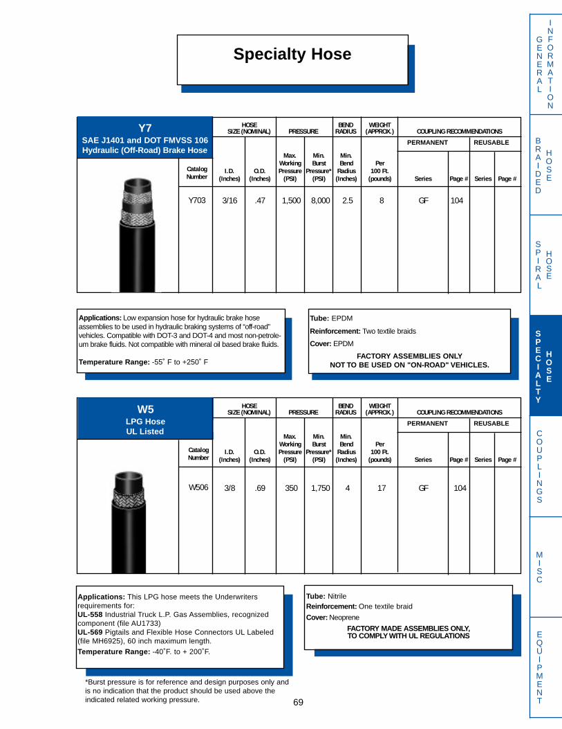
SPIRAL
HOSE
BRAIDED
HOSE
GENERAL
INFORMATION
COUPLINGS
MISC
EQUIPMENT
Specialty Hose
69
Applications: Low expansion hose for hydraulic brake hoseassemblies to be used in hydraulic braking systems of “off-road”vehicles. Compatible with DOT-3 and DOT-4 and most non-petrole-um brake fluids. Not compatible with mineral oil based brake fluids.
Temperature Range: -55˚ F to +250˚ F
Tube: EPDM
Reinforcement: Two textile braids
Cover: EPDM
FACTORY ASSEMBLIES ONLYNOT TO BE USED ON "ON-ROAD" VEHICLES.
Y7SAE J1401 and DOT FMVSS 106Hydraulic (Off-Road) Brake Hose
PERMANENT REUSABLE
HOSE BEND WEIGHTSIZE (NOMINAL) PRESSURE RADIUS (APPROX.) COUPLING RECOMMENDATIONS
CatalogNumber
Y703
Max. Min. Min.Working Burst Bend Per
I.D. O.D. Pressure Pressure* Radius 100 Ft.(Inches) (Inches) (PSI) (PSI) (Inches) (pounds) Series Page # Series Page #
3/16 .47 1,500 8,000 2.5 8 GF 104
Applications: This LPG hose meets the Underwritersrequirements for:UL-558 Industrial Truck L.P. Gas Assemblies, recognizedcomponent (file AU1733) UL-569 Pigtails and Flexible Hose Connectors UL Labeled(file MH6925), 60 inch maximum length.
Temperature Range: -40˚F. to + 200˚F.
Tube: NitrileReinforcement: One textile braid
Cover: Neoprene
FACTORY MADE ASSEMBLIES ONLY,TO COMPLY WITH UL REGULATIONS
W5LPG HoseUL Listed
PERMANENT REUSABLE
HOSE BEND WEIGHTSIZE (NOMINAL) PRESSURE RADIUS (APPROX.) COUPLING RECOMMENDATIONS
CatalogNumber
W506
Max. Min. Min.Working Burst Bend Per
I.D. O.D. Pressure Pressure* Radius 100 Ft.(Inches) (Inches) (PSI) (PSI) (Inches) (pounds) Series Page # Series Page #
3/8 .69 350 1,750 4 17 GF 104
SPECIALTY
HOSE
*Burst pressure is for reference and design purposes only andis no indication that the product should be used above theindicated related working pressure.

Specialty HoseGENERAL
INFORMATION
BRAIDED
HOSE
COUPLINGS
MISC
EQUIPMENT 70
Applications: Used for lubrication lines and grease whiphose. Use with hand grease guns only.
Temperature Range: -40˚ F to +120˚ F
WARNING: Do not use as whip hose on power grease guns!
Tube: Polyester
Reinforcement: One braid of polyester fiber
Cover: Black abrasion resistant polyurethane
HLBHytron® Grease Hose
HOSE BEND WEIGHTSIZE (NOMINAL) PRESSURE RADIUS (APPROX.) COUPLING RECOMMENDATIONS
PERMANENT REUSABLE
CatalogNumber
HLB02
Max. Min. Min.Working Burst Bend Per
I.D. O.D. Pressure Pressure* Radius 100 Ft.(Inches) (Inches) (PSI) (PSI) (Inches) (pounds) Series Page # Series Page #
1/8 .32 3,000 12,000 1.5 3 CY-GH† 92 BU 242
Applications: Used for medium pressure hot water sprayapplications including car and power washers
Temperature Range: -30˚ F to +225˚ F
Tube: Thermoplastic rubber
Reinforcement: One braid of high tensile steel wireCover: Non-marking synthetic rubber
Colors: Red - RD; Blue - BL; Black - BKNote: HSH204 available red cover only.
HSH2 Tempest II®
Hot Water Spray PERMANENT REUSABLE
HOSE BEND WEIGHTSIZE (NOMINAL) PRESSURE RADIUS (APPROX.) COUPLING RECOMMENDATIONS
CatalogNumber
HSH204HSH206
Max. Min. Min.Working Burst Bend Per
I.D. O.D. Pressure Pressure* Radius 100 Ft.(Inches) (Inches) (PSI) (PSI) (Inches) (pounds) Series Page # Series Page #
1/4 .52 3,000 12,000 4.0 13 CY-GH† 923/8 .67 3,000 12,000 5.0 20 CY-GH† 92 BA-BB 227
SPECIALTY
HOSE
SPIRAL
HOSE
† Requires special tooling. Contact Dayco Eastman.*Burst pressure is for reference and design purposes only andis no indication that the product should be used above theindicated related working pressure.
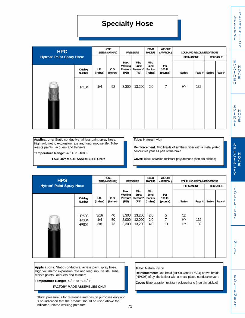
SPIRAL
HOSE
BRAIDED
HOSE
GENERAL
INFORMATION
COUPLINGS
MISC
EQUIPMENT
Specialty Hose
71
Applications: Static conductive, airless paint spray hose.High volumetric expansion rate and long impulse life. Tuberesists paints, lacquers and thinners
Temperature Range: -40˚ F to +180˚ F
FACTORY MADE ASSEMBLIES ONLY
Tube: Natural nylon
Reinforcement: Two braids of synthetic fiber with a metal platedconductive yarn as part of the braid
Cover: Black abrasion resistant polyurethane (non-pin-pricked)
Applications: Static conductive, airless paint spray hose.High volumetric expansion rate and long impulse life. Tuberesists paints, lacquers and thinners
Temperature Range: -40˚ F to +180˚ F
FACTORY MADE ASSEMBLIES ONLY
Tube: Natural nylon
Reinforcement: One braid (HPS03 and HPS04) or two braids(HPS06) of synthetic fiber with a metal plated conductive yarn.
Cover: Black abrasion resistant polyurethane (non-pin-pricked)
HPSHytron® Paint Spray Hose
HPCHytron® Paint Spray Hose
HOSE BEND WEIGHTSIZE (NOMINAL) PRESSURE RADIUS (APPROX.) COUPLING RECOMMENDATIONS
PERMANENT REUSABLE
CatalogNumber
HPC04
Max. Min. Min.Working Burst Bend Per
I.D. O.D. Pressure Pressure* Radius 100 Ft.(Inches) (Inches) (PSI) (PSI) (Inches) (pounds) Series Page # Series Page #
1/4 .52 3,300 13,200 2.0 7 HY 132
HOSE BEND WEIGHTSIZE (NOMINAL) PRESSURE RADIUS (APPROX.) COUPLING RECOMMENDATIONS
PERMANENT REUSABLE
CatalogNumber
HPS03HPS04HPS06
Max. Min. Min.Working Burst Bend Per
I.D. O.D. Pressure Pressure* Radius 100 Ft.(Inches) (Inches) (PSI) (PSI) (Inches) (pounds) Series Page # Series Page #
3/16 .40 3,300 13,200 2.0 5 CD1/4 .50 3,000 12,000 2.0 7 HY 1323/8 .73 3,300 13,200 4.0 13 HY 132
SPECIALTY
HOSE
*Burst pressure is for reference and design purposes only andis no indication that the product should be used above theindicated related working pressure.
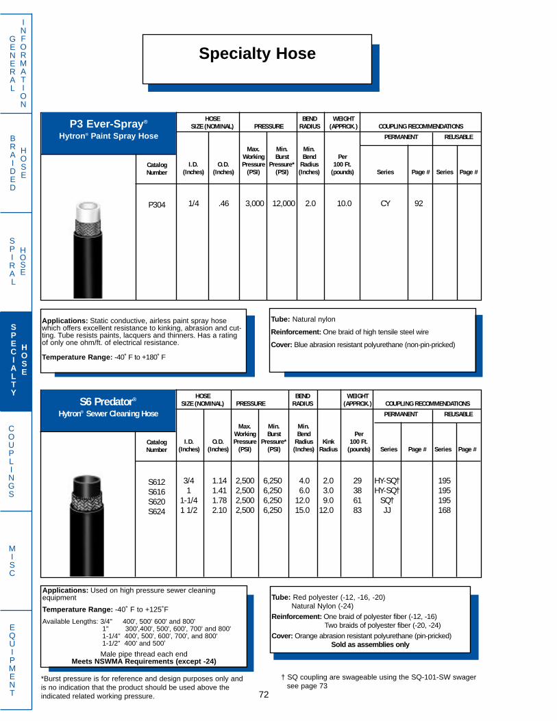
SPIRAL
HOSE
Specialty HoseGENERAL
INFORMATION
BRAIDED
HOSE
COUPLINGS
MISC
EQUIPMENT 72
*Burst pressure is for reference and design purposes only andis no indication that the product should be used above theindicated related working pressure.
Applications: Static conductive, airless paint spray hosewhich offers excellent resistance to kinking, abrasion and cut-ting. Tube resists paints, lacquers and thinners. Has a ratingof only one ohm/ft. of electrical resistance.
Temperature Range: -40˚ F to +180˚ F
Tube: Natural nylon
Reinforcement: One braid of high tensile steel wire
Cover: Blue abrasion resistant polyurethane (non-pin-pricked)
P3 Ever-Spray®
Hytron® Paint Spray Hose
HOSE BEND WEIGHTSIZE (NOMINAL) PRESSURE RADIUS (APPROX.) COUPLING RECOMMENDATIONS
PERMANENT REUSABLE
CatalogNumber
P304
Max. Min. Min.Working Burst Bend Per
I.D. O.D. Pressure Pressure* Radius 100 Ft.(Inches) (Inches) (PSI) (PSI) (Inches) (pounds) Series Page # Series Page #
1/4 .46 3,000 12,000 2.0 10.0 CY 92
Applications: Used on high pressure sewer cleaning equipment
Temperature Range: -40˚ F to +125˚F
Available Lengths: 3/4" 400', 500' 600' and 800'1" 300',400', 500', 600', 700' and 800'1-1/4" 400', 500', 600', 700', and 800'1-1/2” 400’ and 500’
Male pipe thread each endMeets NSWMA Requirements (except -24)
Tube: Red polyester (-12, -16, -20)Natural Nylon (-24)
Reinforcement: One braid of polyester fiber (-12, -16)Two braids of polyester fiber (-20, -24)
Cover: Orange abrasion resistant polyurethane (pin-pricked)Sold as assemblies only
S6 Predator®
Hytron® Sewer Cleaning Hose
† SQ coupling are swageable using the SQ-101-SW swagersee page 73
HOSE BEND WEIGHTSIZE (NOMINAL) PRESSURE RADIUS (APPROX.) COUPLING RECOMMENDATIONS
PERMANENT REUSABLE
CatalogNumber
S612S616S620S624
Max. Min. Min.Working Burst Bend Per
I.D. O.D. Pressure Pressure* Radius Kink 100 Ft.(Inches) (Inches) (PSI) (PSI) (Inches) Radius (pounds) Series Page # Series Page #
3/4 1.14 2,500 6,250 4.0 2.0 29 HY-SQ† 1951 1.41 2,500 6,250 6.0 3.0 38 HY-SQ† 195
1-1/4 1.78 2,500 6,250 12.0 9.0 61 SQ† 1951 1/2 2.10 2,500 6,250 15.0 12.0 83 JJ 168
SPECIALTY
HOSE
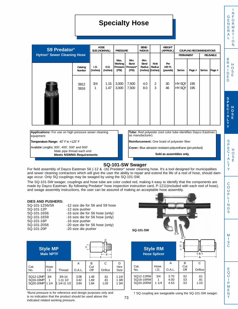
SPECIALTY
HOSE
BRAIDED
HOSE
GENERAL
INFORMATION
COUPLINGS
MISC
EQUIPMENT
Specialty Hose
73
Applications: For use on high pressure sewer cleaningequipment
Temperature Range: -40 ̊F to +125 ̊F
Available Lengths: 300', 400', 500' and 600'Male pipe thread each endMeets NSWMA Requirements
Tube: Red polyester (red color tube identifies Dayco Eastmanas manufacturer)
Reinforcement: One braid of polyester fiber
Cover: Blue abrasion resistant polyurethane (pin-pricked)
Sold as assemblies only.
S9 Predator®
Hytron® Sewer Cleaning Hose
SQ-101-SW SwagerFor field assembly of Dayco Eastman S6 (-12 & -16) Predator® sewer cleaning hose. It's a tool designed for municipalitiesand sewer cleaning contractors which will give the user the ability to repair and extend the life of a reel of hose, should dam-age occur. Only SQ couplings may be swaged by using the SQ-101-SW.The SQ-101-SW swager, couplings and hose tube are color coded red, making it easy to identify that the components aremade by Dayco Eastman. By following Predator® hose inspection instruction card, P-1211(included with each reel of hose),and swage assembly instructions, the user can be assured of making an acceptable hose assembly.
DIES AND PUSHERS:SQ-101-12S6/S9 -12 size die for S6 and S9 hoseSQ-101-12P -12 size pusherSQ-101-16S6 -16 size die for S6 hose (only)SQ-101-16S9 -16 size die for S6 hose (only)SQ-101-16P -16 size pusherSQ-101-20S6 -20 size die for S6 hose (only)SQ-101-20P -20 size die pusher SQ-101-SW
A B C DCat. Hose Cut HexNo. I.D. Thread O.A.L. Off Orifice Size
SQ12-12MP 3/4 3/4-14 3.08 1.48 .61 1 1/4SQ16-16MP 1 1-11 1/2 3.42 1.69 .81 1 3/8SQ20-20MP 1 1/4 1 1/4-11 1/2 3.84 1.84 1.03 1 3/4
Style MPMale NPTF
A B CCat. Hose CutNo. I.D. O.A.L. Off Orifice
SQ12-12RM 3/4 3.70 .52 .61SQ16-16RM 1 4.00 .53 .81SQ20-20RM 1 1/4 4.53 .53 1.03
Style RMHose Splicer
HOSE BEND WEIGHTSIZE (NOMINAL) PRESSURE RADIUS (APPROX.) COUPLING RECOMMENDATIONS
PERMANENT REUSABLE
CatalogNumber
S912S916
Max. Min. Min.Working Burst Bend Kink Per
I.D. O.D. Pressure Pressure* Radius Radius 100 Ft.(Inches) (Inches) (PSI) (PSI) (Inches) (Inches) (pounds) Series Page # Series Page #
3/4 1.15 3,000 7,500 4.0 2 30 HY-SQ† 1951 1.47 3,000 7,500 8.0 3 46 HY-SQ† 195
SPECIALTY
HOSE
† SQ coupling are swageable using the SQ-101-SW swager. *Burst pressure is for reference and design purposes only andis no indication that the product should be used above theindicated related working pressure.
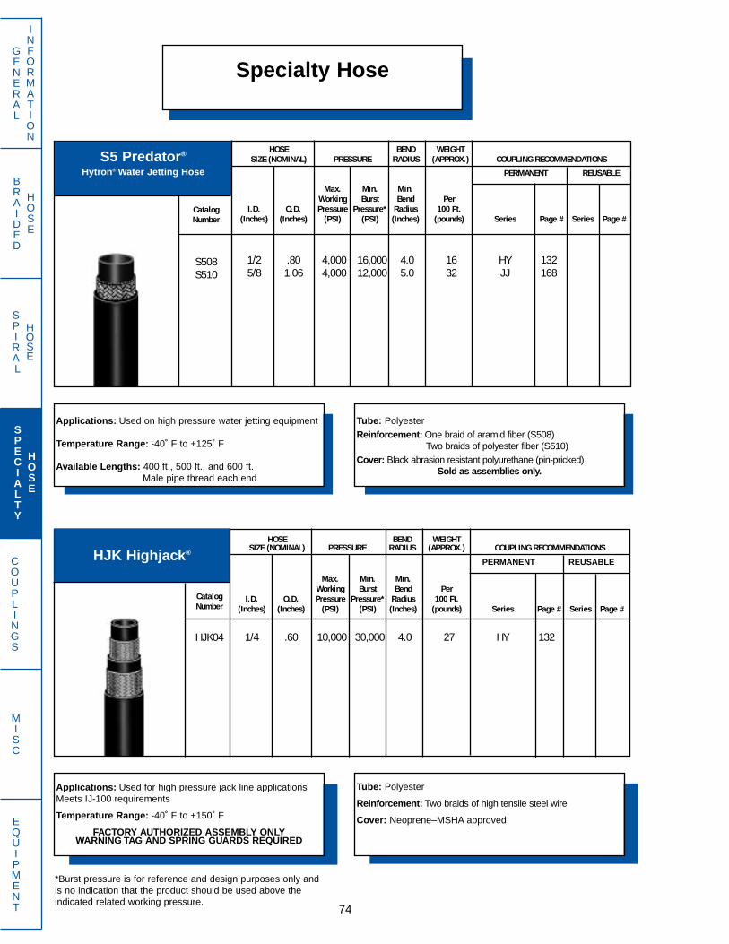
SPIRAL
HOSE
GENERAL
INFORMATION
BRAIDED
HOSE
COUPLINGS
MISC
EQUIPMENT 74
Specialty Hose
Applications: Used on high pressure water jetting equipment
Temperature Range: -40˚ F to +125˚ F
Available Lengths: 400 ft., 500 ft., and 600 ft.Male pipe thread each end
Tube: Polyester
Reinforcement: One braid of aramid fiber (S508)Two braids of polyester fiber (S510)
Cover: Black abrasion resistant polyurethane (pin-pricked)Sold as assemblies only.
S5 Predator®
Hytron® Water Jetting Hose
HOSE BEND WEIGHTSIZE (NOMINAL) PRESSURE RADIUS (APPROX.) COUPLING RECOMMENDATIONS
PERMANENT REUSABLE
CatalogNumber
S508S510
Max. Min. Min.Working Burst Bend Per
I.D. O.D. Pressure Pressure* Radius 100 Ft.(Inches) (Inches) (PSI) (PSI) (Inches) (pounds) Series Page # Series Page #
1/2 .80 4,000 16,000 4.0 16 HY 1325/8 1.06 4,000 12,000 5.0 32 JJ 168
Applications: Used for high pressure jack line applicationsMeets IJ-100 requirements
Temperature Range: -40˚ F to +150˚ F
FACTORY AUTHORIZED ASSEMBLY ONLYWARNING TAG AND SPRING GUARDS REQUIRED
Tube: Polyester
Reinforcement: Two braids of high tensile steel wire
Cover: Neoprene–MSHA approved
HJK Highjack®PERMANENT REUSABLE
HOSE BEND WEIGHTSIZE (NOMINAL) PRESSURE RADIUS (APPROX.) COUPLING RECOMMENDATIONS
CatalogNumber
HJK04
Max. Min. Min.Working Burst Bend Per
I.D. O.D. Pressure Pressure* Radius 100 Ft.(Inches) (Inches) (PSI) (PSI) (Inches) (pounds) Series Page # Series Page #
1/4 .60 10,000 30,000 4.0 27 HY 132
SPECIALTY
HOSE
*Burst pressure is for reference and design purposes only andis no indication that the product should be used above theindicated related working pressure.
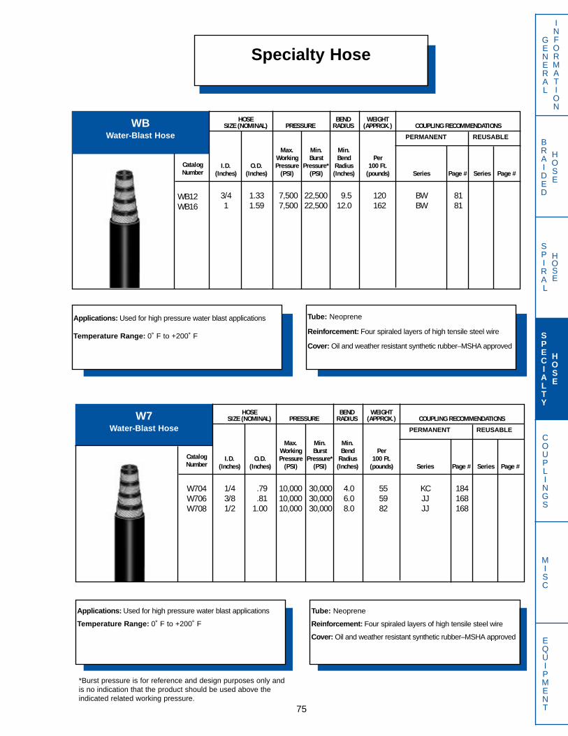
SPIRAL
HOSE
BRAIDED
HOSE
GENERAL
INFORMATION
COUPLINGS
MISC
EQUIPMENT75
Specialty Hose
Applications: Used for high pressure water blast applications
Temperature Range: 0˚ F to +200˚ F
Tube: Neoprene
Reinforcement: Four spiraled layers of high tensile steel wire
Cover: Oil and weather resistant synthetic rubber–MSHA approved
WBWater-Blast Hose PERMANENT REUSABLE
HOSE BEND WEIGHTSIZE (NOMINAL) PRESSURE RADIUS (APPROX.) COUPLING RECOMMENDATIONS
CatalogNumber
WB12WB16
Max. Min. Min.Working Burst Bend Per
I.D. O.D. Pressure Pressure* Radius 100 Ft.(Inches) (Inches) (PSI) (PSI) (Inches) (pounds) Series Page # Series Page #
3/4 1.33 7,500 22,500 9.5 120 BW 811 1.59 7,500 22,500 12.0 162 BW 81
Applications: Used for high pressure water blast applications
Temperature Range: 0˚ F to +200˚ F
Tube: Neoprene
Reinforcement: Four spiraled layers of high tensile steel wire
Cover: Oil and weather resistant synthetic rubber–MSHA approved
W7Water-Blast Hose PERMANENT REUSABLE
HOSE BEND WEIGHTSIZE (NOMINAL) PRESSURE RADIUS (APPROX.) COUPLING RECOMMENDATIONS
CatalogNumber
W704W706W708
Max. Min. Min.Working Burst Bend Per
I.D. O.D. Pressure Pressure* Radius 100 Ft.(Inches) (Inches) (PSI) (PSI) (Inches) (pounds) Series Page # Series Page #
1/4 .79 10,000 30,000 4.0 55 KC 1843/8 .81 10,000 30,000 6.0 59 JJ 1681/2 1.00 10,000 30,000 8.0 82 JJ 168
SPECIALTY
HOSE
*Burst pressure is for reference and design purposes only andis no indication that the product should be used above theindicated related working pressure.

SPIRAL
HOSE
GENERAL
INFORMATION
BRAIDED
HOSE
COUPLINGS
MISC
EQUIPMENT 76
Specialty Hose
Applications: Used for ultra-high pressure water blast applications
Temperature Range: +40˚ F to +150˚ F
FACTORY ASSEMBLY ONLY
Tube: Neoprene
Reinforcement: Four spiraled layers of high tensile steel wire
Cover: Oil and weather resistant synthetic rubber–MSHA approved
W8Water-Blast
Ultra-High PressurePERMANENT REUSABLE
HOSE BEND WEIGHTSIZE (NOMINAL) PRESSURE RADIUS (APPROX.) COUPLING RECOMMENDATIONS
CatalogNumber
W806W808
Max. Min. Min.Working Burst Bend Per
I.D. O.D. Pressure Pressure* Radius 100 Ft.(Inches) (Inches) (PSI) (PSI) (Inches) (pounds) Series Page # Series Page #
3/8 .94 18,000 45,000 9.5 78 ER 971/2 1.06 15,000 37,500 10.0 91 ER 97
SPECIALTY
HOSE
*Burst pressure is for reference and design purposes only andis no indication that the product should be used above theindicated related working pressure.

SPIRAL
HOSE
BRAIDED
HOSE
GENERAL
INFORMATION
COUPLINGS
MISC
EQUIPMENT77
Hytron® HoseTwin and Multi-Line Hytron® Hose
“Twin” Hytron® hoses are available in the sizes and styles shown below. Basictwin line construction consists of two pieces of hose joined together to offer acompact and flexible system. Minimum order quantity is 250 feet for these partnumbers and hose is shipped bulk packed.
“Multi-Line” Hytron® hoses are also available upon quotation. These lines mayconsist of two or more Hytron® hoses joined together, including multi-lines of dif-ferent Hytron® hose styles. Minimum purchase quantities are required.
Dayco Eastman is also pleased to quote your specific assembly and lengthrequirements. Please note that minimum order quantities apply to these specialorder items.
Part Number Description
TC204 Twin-Line C2, SAE 100R7 Low temperature; 1/4” I.D. (inches)TC205 Twin-Line C2, SAE 100R7 Low temperature; 5/16” I.D. (inches)TC206 Twin-Line C2, SAE 100R7 Low temperature; 3/8” I.D. (inches)
TNR7E04 Twin-Line NR7E, SAE 100R7 Nylon tube, Non-conductive; 1/4” I.D. (inches)TNR7E06 Twin-Line NR7E, SAE 100R7 Nylon tube, Non-conductive; 3/8” I.D. (inches)TNR7E08 Twin-Line NR7E, SAE 100R7 Nylon tube, Non-conductive; 1/2” I.D. (inches)
TNR704 Twin-Line NR7, SAE 10R7 Nylon tube; 1/4” I.D. (inches)TNR706 Twin-Line NR7, SAE 10R7 Nylon tube; 3/8” I.D. (inches)TNR708 Twin-Line NR7, SAE 10R7 Nylon tube; 1/2” I.D. (inches)
TS7E04 Twin-Line S7E, SAE 100R7, Non-conductive; 1/4” I.D. (inches)TS7E05 Twin-Line S7E, SAE 100R7, Non-conductive; 5/16” I.D. (inches)TS7E06 Twin-Line S7E, SAE 100R7, Non-conductive; 3/8” I.D. (inches)TS7E08 Twin-Line S7E, SAE 100R7, Non-conductive; 1/2” I.D. (inches)
TS704 Twin-Line S7, SAE 100R7; 1/4” I.D. (inches)TS705 Twin-Line S7, SAE 100R7; 5/16” I.D. (inches)TS706 Twin-Line S7, SAE 100R7; 3/8” I.D. (inches)TS708 Twin-Line S7, SAE 100R7; 1/2” I.D. (inches)
TS8E04 Twin-Line S8E, SAE 100R8, Non-conductive; 1/4” I.D. (inches)TS8E06 Twin-Line S8E, SAE 100R8, Non-conductive; 3/8” I.D. (inches)TS8E08 Twin-Line S8E, SAE 100R8, Non-conductive; 1/2” I.D. (inches)
TS804 Twin-Line S8, SAE 100R8; 1/4” I.D. (inches)TS806 Twin-Line S8, SAE 100R8; 3/8” I.D. (inches)TS808 Twin-Line S8, SAE 100R8; 1/2” I.D. (inches)
SPECIALTY
HOSE

SPIRAL
HOSE
GENERAL
INFORMATION
BRAIDED
HOSE
COUPLINGS
MISC
EQUIPMENT 78
Safety Awareness FactorsAffecting Dayco Eastman Hose and Coupling
Assemblies
Hose and coupling compatibilities noted in this catalog are for reference pur-poses only. Dayco Eastman crimping specifications are the official guide forselecting appropriate hose and coupling combinations and determining crimpercompatibility.
Any modifications made by the user to Dayco Eastman hose and couplings maydamage the capability of the products to meet performance of applicationsdescribed in this catalog. Dayco Eastman does not condone this practice andthe user assumes all liability incurred.
Assembly Pressure RatingsSome hose pressure ratings listed in this Dayco Eastman catalog exceed thepressure ratings for the connection (threads, flanges, etc.) of certain types ofhose fittings. Pressure ratings of 4-bolt split flange and o-ring face seal typehose fittings are specified in SAE J518 and J1453, respectively. For all othertypes of connector ends, contact Dayco Eastman for pressure ratings. Thepressure rating of a hose assembly should not exceed the lower of the pres-sure rating values.
Danger of Brass Components Exposed to Ammonia
Never use brass couplings or connectors with or in proximity to ammonia basedfluids. Brass parts subject to such exposure can crack without warning, leadingto property damage, injury or death.
Note: All steel parts are zinc plated with a yellow dichromate finish, unlessotherwise noted. This finish passes the 72 hour SAE J516 Salt Spray TestRequirement in accordance with ASTM B117.
SPECIALTY
HOSE
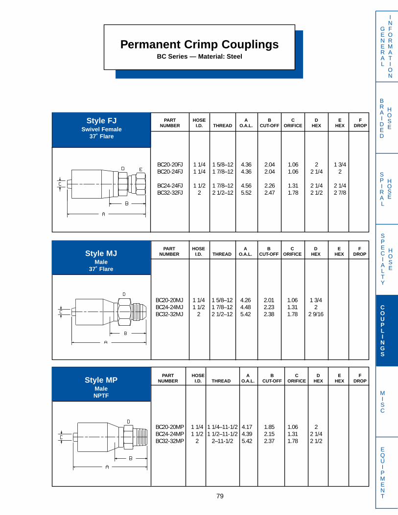
SPECIALTY
HOSE
BRAIDED
HOSE
SPIRAL
HOSE
GENERAL
Style MJMale
37˚ Flare
INFORMATION
COUPLINGS
MISC
EQUIPMENT
PART HOSE A B C D E FNUMBER I.D. THREAD O.A.L. CUT-OFF ORIFICE HEX HEX DROP
BC20-20MP 1 1/4 1 1/4–11-1/2 4.17 1.85 1.06 2BC24-24MP 1 1/2 1 1/2–11-1/2 4.39 2.15 1.31 2 1/4BC32-32MP 2 2–11-1/2 5.42 2.37 1.78 2 1/2
Style MPMaleNPTF
PART HOSE A B C D E FNUMBER I.D. THREAD O.A.L. CUT-OFF ORIFICE HEX HEX DROP
BC20-20MJ 1 1/4 1 5/8–12 4.26 2.01 1.06 1 3/4BC24-24MJ 1 1/2 1 7/8–12 4.48 2.23 1.31 2BC32-32MJ 2 2 1/2–12 5.42 2.38 1.78 2 9/16
PART HOSE A B C D E FNUMBER I.D. THREAD O.A.L. CUT-OFF ORIFICE HEX HEX DROP
BC20-20FJ 1 1/4 1 5/8–12 4.36 2.04 1.06 2 1 3/4BC20-24FJ 1 1/4 1 7/8–12 4.36 2.04 1.06 2 1/4 2
BC24-24FJ 1 1/2 1 7/8–12 4.56 2.26 1.31 2 1/4 2 1/4BC32-32FJ 2 2 1/2–12 5.52 2.47 1.78 2 1/2 2 7/8
Style FJSwivel Female
37˚ Flare
Permanent Crimp CouplingsBC Series — Material: Steel
79

SPECIALTY
HOSE
BRAIDED
HOSE
SPIRAL
HOSE
GENERAL
INFORMATION
COUPLINGS
MISC
EQUIPMENT
Permanent Crimp CouplingsBC Series — Material: Steel
PART HOSE A B C D E FNUMBER I.D. THREAD O.A.L. CUT-OFF ORIFICE HEX HEX DROP
BC20-20OFT 1 1/4 1 11/16–12 4.27 1.95 1.07 1 3/4 1 7/8
Style OFTSwivel Female
O-Ring Face Seal
80
PART HOSE FLANGE A B C D E FNUMBER I.D. O.D. O.A.L. CUT-OFF ORIFICE HEX HEX DROP
BC20-20PA 1 1/4 2.00 4.33 2.09 1.06BC20-24PA 1 1/4 2.38 4.39 2.15 1.06
BC24-24PA 1 1/2 2.38 4.42 2.18 1.31BC32-32PA 2 2.81 5.37 2.42 1.78
Style PAFlange
SAE Code 61
PART HOSE FLANGE A B C D E FNUMBER I.D. O.D. O.A.L. CUT-OFF ORIFICE HEX HEX DROP
BC20-20PA45 1 1/4 2.00 5.24 3.00 1.06 1.10BC20-24PA45 1 1/4 2.38 5.28 3.04 1.06 1.14
BC24-24PA45 1 1/2 2.38 5.92 3.86 1.31 1.38BC32-32PA45 2 2.81 7.70 4.88 1.78 1.81
Style PA4545˚ Elbow Flange
SAE Code 61
PART HOSE FLANGE A B C D E FNUMBER I.D. O.D. O.A.L. CUT-OFF ORIFICE HEX HEX DROP
BC20-20PA90 1 1/4 2.00 5.40 3.16 1.06 2.53BC20-24PA90 1 1/4 2.38 5.40 3.15 1.06 2.59
BC24-24PA90 1 1/2 2.38 5.85 3.62 1.31 3.05BC32-32PA90 2 2.81 7.80 5.03 1.78 4.46
Style PA9090˚ Elbow Flange
SAE Code 61
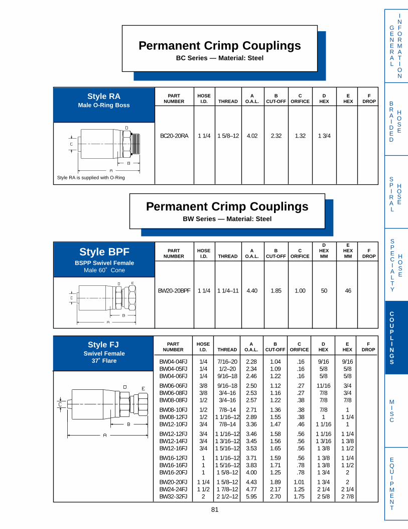
SPECIALTY
HOSE
BRAIDED
HOSE
SPIRAL
HOSE
Permanent Crimp CouplingsBC Series — Material: Steel
81
PART HOSE A B C D E FNUMBER I.D. THREAD O.A.L. CUT-OFF ORIFICE HEX HEX DROP
BW04-04FJ 1/4 7/16–20 2.28 1.04 .16 9/16 9/16BW04-05FJ 1/4 1/2–20 2.34 1.09 .16 5/8 5/8BW04-06FJ 1/4 9/16–18 2.46 1.22 .16 5/8 5/8
BW06-06FJ 3/8 9/16–18 2.50 1.12 .27 11/16 3/4BW06-08FJ 3/8 3/4–16 2.53 1.16 .27 7/8 3/4BW08-08FJ 1/2 3/4–16 2.57 1.22 .38 7/8 7/8
BW08-10FJ 1/2 7/8–14 2.71 1.36 .38 7/8 1BW08-12FJ 1/2 1 1/16–12 2.89 1.55 .38 1 1 1/4BW12-10FJ 3/4 7/8–14 3.36 1.47 .46 1 1/16 1
BW12-12FJ 3/4 1 1/16–12 3.46 1.58 .56 1 1/16 1 1/4BW12-14FJ 3/4 1 3/16–12 3.45 1.56 .56 1 3/16 1 3/8BW12-16FJ 3/4 1 5/16–12 3.53 1.65 .56 1 3/8 1 1/2
BW16-12FJ 1 1 1/16–12 3.71 1.59 .56 1 3/8 1 1/4BW16-16FJ 1 1 5/16–12 3.83 1.71 .78 1 3/8 1 1/2BW16-20FJ 1 1 5/8–12 4.00 1.25 .78 1 3/4 2
BW20-20FJ 1 1/4 1 5/8–12 4.43 1.89 1.01 1 3/4 2BW24-24FJ 1 1/2 1 7/8–12 4.77 2.17 1.25 2 1/4 2 1/4BW32-32FJ 2 2 1/2–12 5.95 2.70 1.75 2 5/8 2 7/8
Style FJSwivel Female
37˚ Flare
D EPART HOSE A B C HEX HEX F
NUMBER I.D. THREAD O.A.L. CUT-OFF ORIFICE MM MM DROP
BW20-20BPF 1 1/4 1 1/4–11 4.40 1.85 1.00 50 46
Style BPFBSPP Swivel Female
Male 60˚ Cone
Permanent Crimp CouplingsBW Series — Material: Steel
PART HOSE A B C D E FNUMBER I.D. THREAD O.A.L. CUT-OFF ORIFICE HEX HEX DROP
BC20-20RA 1 1/4 1 5/8–12 4.02 2.32 1.32 1 3/4
Style RAMale O-Ring Boss
Style RA is supplied with O-Ring
GENERAL
INFORMATION
COUPLINGS
MISC
EQUIPMENT
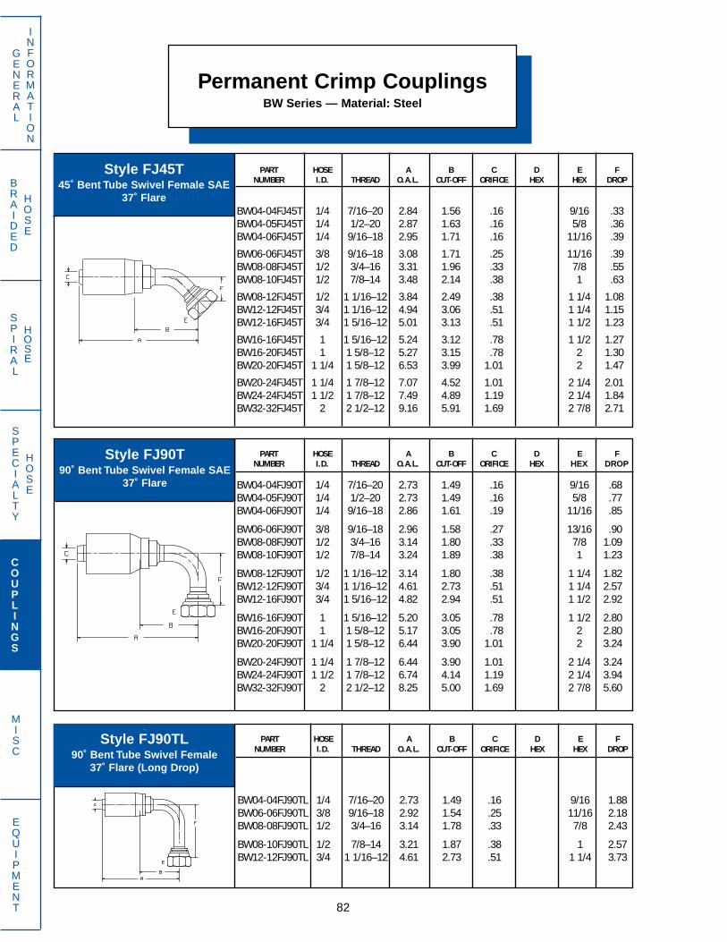
SPECIALTY
HOSE
BRAIDED
HOSE
SPIRAL
HOSE
Style FJ45T45˚ Bent Tube Swivel Female SAE
37˚ Flare
GENERAL
INFORMATION
COUPLINGS
MISC
EQUIPMENT 82
PART HOSE A B C D E FNUMBER I.D. THREAD O.A.L. CUT-OFF ORIFICE HEX HEX DROP
BW04-04FJ90T 1/4 7/16–20 2.73 1.49 .16 9/16 .68BW04-05FJ90T 1/4 1/2–20 2.73 1.49 .16 5/8 .77BW04-06FJ90T 1/4 9/16–18 2.86 1.61 .19 11/16 .85
BW06-06FJ90T 3/8 9/16–18 2.96 1.58 .27 13/16 .90BW08-08FJ90T 1/2 3/4–16 3.14 1.80 .33 7/8 1.09BW08-10FJ90T 1/2 7/8–14 3.24 1.89 .38 1 1.23
BW08-12FJ90T 1/2 1 1/16–12 3.14 1.80 .38 1 1/4 1.82BW12-12FJ90T 3/4 1 1/16–12 4.61 2.73 .51 1 1/4 2.57BW12-16FJ90T 3/4 1 5/16–12 4.82 2.94 .51 1 1/2 2.92
BW16-16FJ90T 1 1 5/16–12 5.20 3.05 .78 1 1/2 2.80BW16-20FJ90T 1 1 5/8–12 5.17 3.05 .78 2 2.80BW20-20FJ90T 1 1/4 1 5/8–12 6.44 3.90 1.01 2 3.24
BW20-24FJ90T 1 1/4 1 7/8–12 6.44 3.90 1.01 2 1/4 3.24BW24-24FJ90T 1 1/2 1 7/8–12 6.74 4.14 1.19 2 1/4 3.94BW32-32FJ90T 2 2 1/2–12 8.25 5.00 1.69 2 7/8 5.60
Style FJ90T90˚ Bent Tube Swivel Female SAE
37˚ Flare
PART HOSE A B C D E FNUMBER I.D. THREAD O.A.L. CUT-OFF ORIFICE HEX HEX DROP
BW04-04FJ90TL 1/4 7/16–20 2.73 1.49 .16 9/16 1.88BW06-06FJ90TL 3/8 9/16–18 2.92 1.54 .25 11/16 2.18BW08-08FJ90TL 1/2 3/4–16 3.14 1.78 .33 7/8 2.43
BW08-10FJ90TL 1/2 7/8–14 3.21 1.87 .38 1 2.57BW12-12FJ90TL 3/4 1 1/16–12 4.61 2.73 .51 1 1/4 3.73
.
Style FJ90TL90˚ Bent Tube Swivel Female
37˚ Flare (Long Drop)
Permanent Crimp CouplingsBW Series — Material: Steel
PART HOSE A B C D E FNUMBER I.D. THREAD O.A.L. CUT-OFF ORIFICE HEX HEX DROP
BW04-04FJ45T 1/4 7/16–20 2.84 1.56 .16 9/16 .33BW04-05FJ45T 1/4 1/2–20 2.87 1.63 .16 5/8 .36BW04-06FJ45T 1/4 9/16–18 2.95 1.71 .16 11/16 .39
BW06-06FJ45T 3/8 9/16–18 3.08 1.71 .25 11/16 .39BW08-08FJ45T 1/2 3/4–16 3.31 1.96 .33 7/8 .55BW08-10FJ45T 1/2 7/8–14 3.48 2.14 .38 1 .63
BW08-12FJ45T 1/2 1 1/16–12 3.84 2.49 .38 1 1/4 1.08BW12-12FJ45T 3/4 1 1/16–12 4.94 3.06 .51 1 1/4 1.15BW12-16FJ45T 3/4 1 5/16–12 5.01 3.13 .51 1 1/2 1.23
BW16-16FJ45T 1 1 5/16–12 5.24 3.12 .78 1 1/2 1.27BW16-20FJ45T 1 1 5/8–12 5.27 3.15 .78 2 1.30BW20-20FJ45T 1 1/4 1 5/8–12 6.53 3.99 1.01 2 1.47
BW20-24FJ45T 1 1/4 1 7/8–12 7.07 4.52 1.01 2 1/4 2.01BW24-24FJ45T 1 1/2 1 7/8–12 7.49 4.89 1.19 2 1/4 1.84BW32-32FJ45T 2 2 1/2–12 9.16 5.91 1.69 2 7/8 2.71
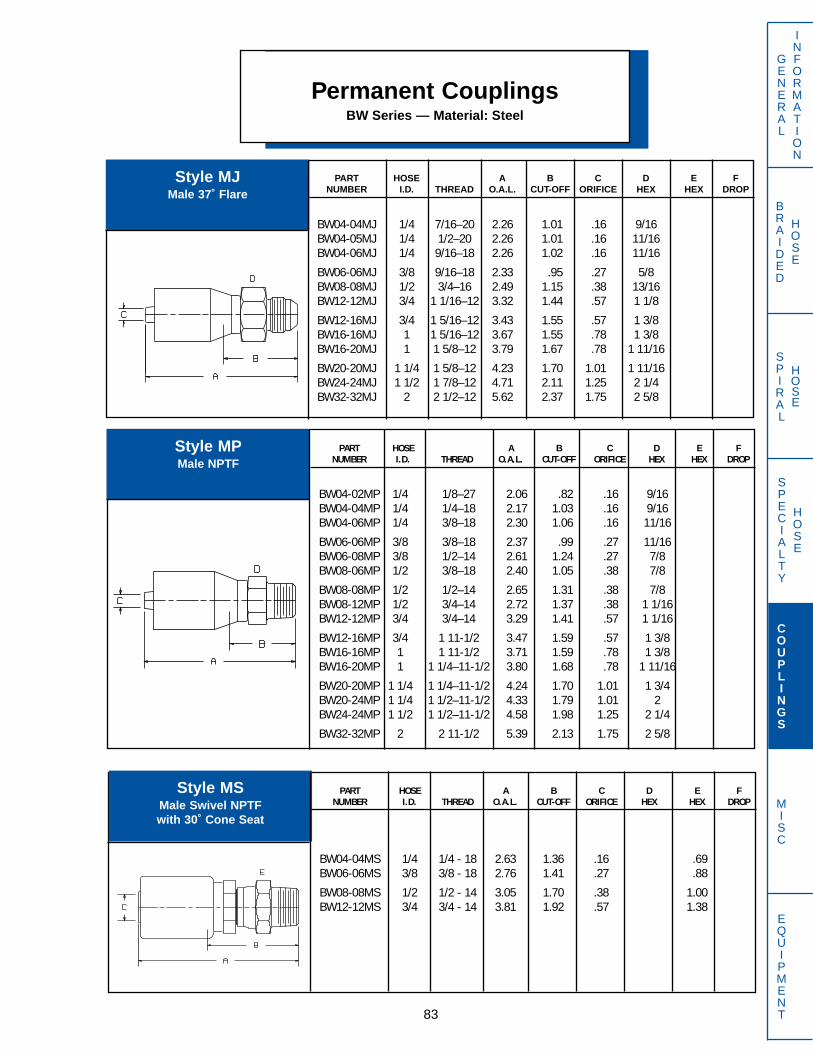
SPECIALTY
HOSE
BRAIDED
HOSE
SPIRAL
HOSE
GENERAL
INFORMATION
COUPLINGS
MISC
EQUIPMENT
Permanent CouplingsBW Series — Material: Steel
83
PART HOSE A B C D E FNUMBER I.D. THREAD O.A.L. CUT-OFF ORIFICE HEX HEX DROP
BW04-04MJ 1/4 7/16–20 2.26 1.01 .16 9/16BW04-05MJ 1/4 1/2–20 2.26 1.01 .16 11/16BW04-06MJ 1/4 9/16–18 2.26 1.02 .16 11/16
BW06-06MJ 3/8 9/16–18 2.33 .95 .27 5/8BW08-08MJ 1/2 3/4–16 2.49 1.15 .38 13/16BW12-12MJ 3/4 1 1/16–12 3.32 1.44 .57 1 1/8
BW12-16MJ 3/4 1 5/16–12 3.43 1.55 .57 1 3/8BW16-16MJ 1 1 5/16–12 3.67 1.55 .78 1 3/8BW16-20MJ 1 1 5/8–12 3.79 1.67 .78 1 11/16
BW20-20MJ 1 1/4 1 5/8–12 4.23 1.70 1.01 1 11/16BW24-24MJ 1 1/2 1 7/8–12 4.71 2.11 1.25 2 1/4BW32-32MJ 2 2 1/2–12 5.62 2.37 1.75 2 5/8
Style MJMale 37˚ Flare
PART HOSE A B C D E FNUMBER I.D. THREAD O.A.L. CUT-OFF ORIFICE HEX HEX DROP
BW04-02MP 1/4 1/8–27 2.06 .82 .16 9/16BW04-04MP 1/4 1/4–18 2.17 1.03 .16 9/16BW04-06MP 1/4 3/8–18 2.30 1.06 .16 11/16
BW06-06MP 3/8 3/8–18 2.37 .99 .27 11/16BW06-08MP 3/8 1/2–14 2.61 1.24 .27 7/8BW08-06MP 1/2 3/8–18 2.40 1.05 .38 7/8
BW08-08MP 1/2 1/2–14 2.65 1.31 .38 7/8BW08-12MP 1/2 3/4–14 2.72 1.37 .38 1 1/16BW12-12MP 3/4 3/4–14 3.29 1.41 .57 1 1/16
BW12-16MP 3/4 1 11-1/2 3.47 1.59 .57 1 3/8BW16-16MP 1 1 11-1/2 3.71 1.59 .78 1 3/8BW16-20MP 1 1 1/4–11-1/2 3.80 1.68 .78 1 11/16
BW20-20MP 1 1/4 1 1/4–11-1/2 4.24 1.70 1.01 1 3/4BW20-24MP 1 1/4 1 1/2–11-1/2 4.33 1.79 1.01 2BW24-24MP 1 1/2 1 1/2–11-1/2 4.58 1.98 1.25 2 1/4
BW32-32MP 2 2 11-1/2 5.39 2.13 1.75 2 5/8
Style MPMale NPTF
PART HOSE A B C D E FNUMBER I.D. THREAD O.A.L. CUT-OFF ORIFICE HEX HEX DROP
BW04-04MS 1/4 1/4 - 18 2.63 1.36 .16 .69BW06-06MS 3/8 3/8 - 18 2.76 1.41 .27 .88
BW08-08MS 1/2 1/2 - 14 3.05 1.70 .38 1.00BW12-12MS 3/4 3/4 - 14 3.81 1.92 .57 1.38
Style MSMale Swivel NPTFwith 30˚ Cone Seat
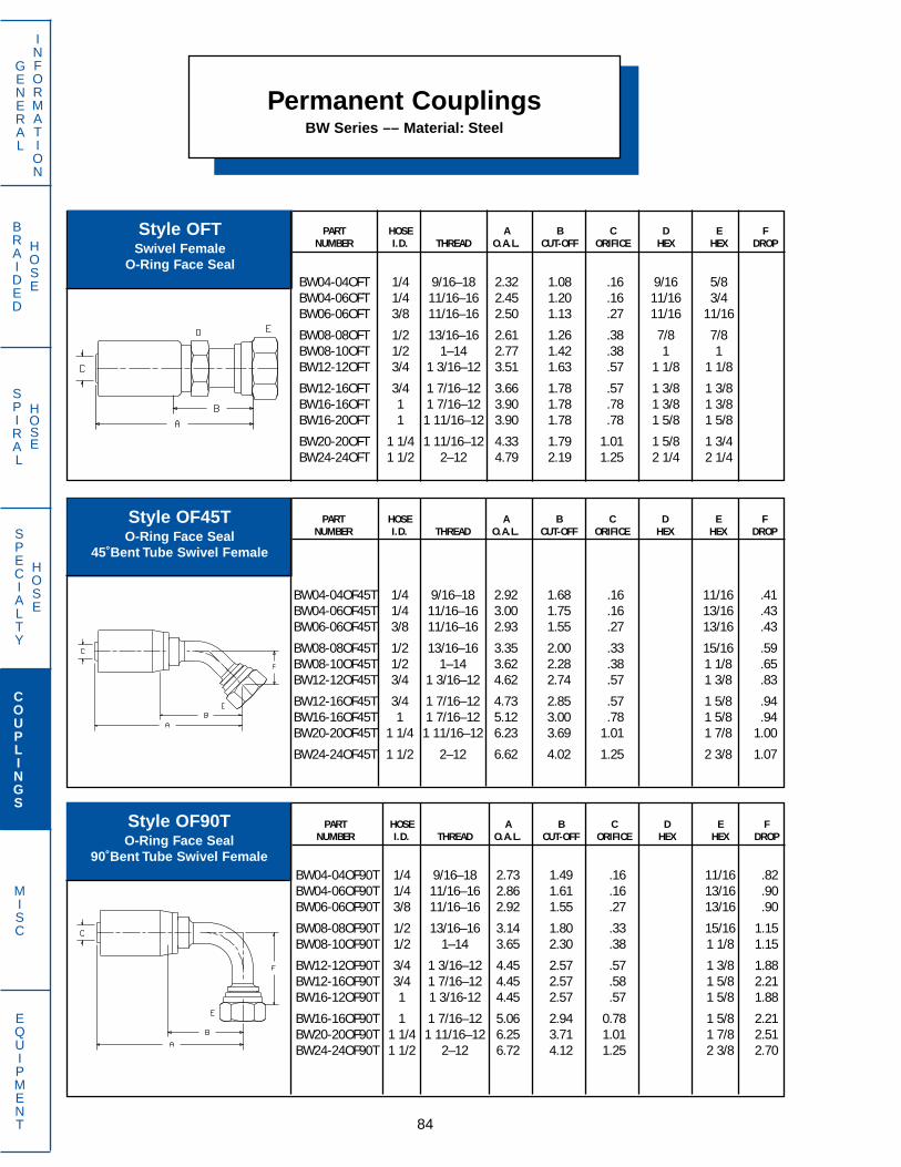
SPECIALTY
HOSE
BRAIDED
HOSE
SPIRAL
HOSE
GENERAL
INFORMATION
COUPLINGS
MISC
EQUIPMENT
Permanent CouplingsBW Series –– Material: Steel
84
PART HOSE A B C D E FNUMBER I.D. THREAD O.A.L. CUT-OFF ORIFICE HEX HEX DROP
BW04-04OF45T 1/4 9/16–18 2.92 1.68 .16 11/16 .41BW04-06OF45T 1/4 11/16–16 3.00 1.75 .16 13/16 .43BW06-06OF45T 3/8 11/16–16 2.93 1.55 .27 13/16 .43
BW08-08OF45T 1/2 13/16–16 3.35 2.00 .33 15/16 .59BW08-10OF45T 1/2 1–14 3.62 2.28 .38 1 1/8 .65BW12-12OF45T 3/4 1 3/16–12 4.62 2.74 .57 1 3/8 .83
BW12-16OF45T 3/4 1 7/16–12 4.73 2.85 .57 1 5/8 .94BW16-16OF45T 1 1 7/16–12 5.12 3.00 .78 1 5/8 .94BW20-20OF45T 1 1/4 1 11/16–12 6.23 3.69 1.01 1 7/8 1.00
BW24-24OF45T 1 1/2 2–12 6.62 4.02 1.25 2 3/8 1.07
Style OF45TO-Ring Face Seal
45˚Bent Tube Swivel Female
PART HOSE A B C D E FNUMBER I.D. THREAD O.A.L. CUT-OFF ORIFICE HEX HEX DROP
BW04-04OF90T 1/4 9/16–18 2.73 1.49 .16 11/16 .82BW04-06OF90T 1/4 11/16–16 2.86 1.61 .16 13/16 .90BW06-06OF90T 3/8 11/16–16 2.92 1.55 .27 13/16 .90
BW08-08OF90T 1/2 13/16–16 3.14 1.80 .33 15/16 1.15BW08-10OF90T 1/2 1–14 3.65 2.30 .38 1 1/8 1.15
BW12-12OF90T 3/4 1 3/16–12 4.45 2.57 .57 1 3/8 1.88BW12-16OF90T 3/4 1 7/16–12 4.45 2.57 .58 1 5/8 2.21BW16-12OF90T 1 1 3/16-12 4.45 2.57 .57 1 5/8 1.88
BW16-16OF90T 1 1 7/16–12 5.06 2.94 0.78 1 5/8 2.21BW20-20OF90T 1 1/4 1 11/16–12 6.25 3.71 1.01 1 7/8 2.51BW24-24OF90T 1 1/2 2–12 6.72 4.12 1.25 2 3/8 2.70
Style OF90TO-Ring Face Seal
90˚Bent Tube Swivel Female
PART HOSE A B C D E FNUMBER I.D. THREAD O.A.L. CUT-OFF ORIFICE HEX HEX DROP
BW04-04OFT 1/4 9/16–18 2.32 1.08 .16 9/16 5/8BW04-06OFT 1/4 11/16–16 2.45 1.20 .16 11/16 3/4BW06-06OFT 3/8 11/16–16 2.50 1.13 .27 11/16 11/16
BW08-08OFT 1/2 13/16–16 2.61 1.26 .38 7/8 7/8BW08-10OFT 1/2 1–14 2.77 1.42 .38 1 1BW12-12OFT 3/4 1 3/16–12 3.51 1.63 .57 1 1/8 1 1/8
BW12-16OFT 3/4 1 7/16–12 3.66 1.78 .57 1 3/8 1 3/8BW16-16OFT 1 1 7/16–12 3.90 1.78 .78 1 3/8 1 3/8BW16-20OFT 1 1 11/16–12 3.90 1.78 .78 1 5/8 1 5/8
BW20-20OFT 1 1/4 1 11/16–12 4.33 1.79 1.01 1 5/8 1 3/4BW24-24OFT 1 1/2 2–12 4.79 2.19 1.25 2 1/4 2 1/4
Style OFTSwivel Female
O-Ring Face Seal
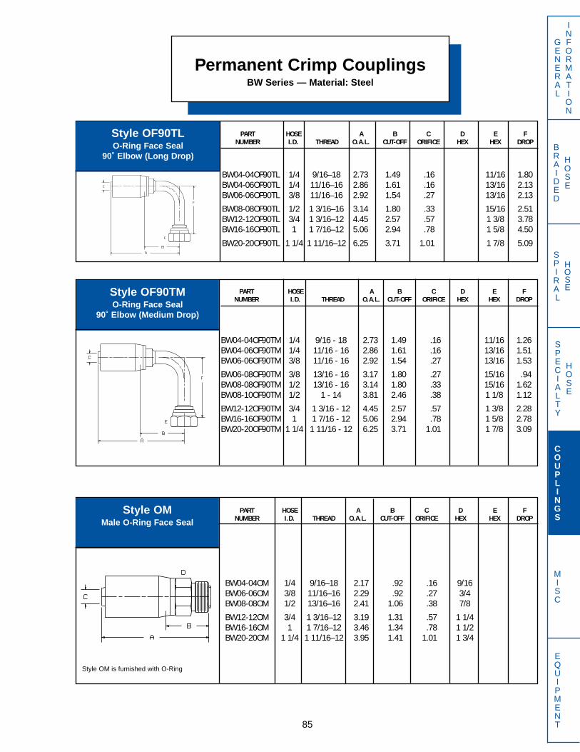
SPECIALTY
HOSE
BRAIDED
HOSE
SPIRAL
HOSE
GENERAL
INFORMATION
COUPLINGS
MISC
EQUIPMENT
Permanent Crimp CouplingsBW Series — Material: Steel
85
PART HOSE A B C D E FNUMBER I.D. THREAD O.A.L. CUT-OFF ORIFICE HEX HEX DROP
BW04-04OF90TL 1/4 9/16–18 2.73 1.49 .16 11/16 1.80BW04-06OF90TL 1/4 11/16–16 2.86 1.61 .16 13/16 2.13BW06-06OF90TL 3/8 11/16–16 2.92 1.54 .27 13/16 2.13
BW08-08OF90TL 1/2 1 3/16–16 3.14 1.80 .33 15/16 2.51BW12-12OF90TL 3/4 1 3/16–12 4.45 2.57 .57 1 3/8 3.78BW16-16OF90TL 1 1 7/16–12 5.06 2.94 .78 1 5/8 4.50
BW20-20OF90TL 1 1/4 1 11/16–12 6.25 3.71 1.01 1 7/8 5.09
Style OF90TLO-Ring Face Seal
90˚ Elbow (Long Drop)
PART HOSE A B C D E FNUMBER I.D. THREAD O.A.L. CUT-OFF ORIFICE HEX HEX DROP
BW04-04OF90TM 1/4 9/16 - 18 2.73 1.49 .16 11/16 1.26BW04-06OF90TM 1/4 11/16 - 16 2.86 1.61 .16 13/16 1.51BW06-06OF90TM 3/8 11/16 - 16 2.92 1.54 .27 13/16 1.53
BW06-08OF90TM 3/8 13/16 - 16 3.17 1.80 .27 15/16 .94BW08-08OF90TM 1/2 13/16 - 16 3.14 1.80 .33 15/16 1.62BW08-10OF90TM 1/2 1 - 14 3.81 2.46 .38 1 1/8 1.12
BW12-12OF90TM 3/4 1 3/16 - 12 4.45 2.57 .57 1 3/8 2.28BW16-16OF90TM 1 1 7/16 - 12 5.06 2.94 .78 1 5/8 2.78BW20-20OF90TM 1 1/4 1 11/16 - 12 6.25 3.71 1.01 1 7/8 3.09
Style OF90TMO-Ring Face Seal
90˚ Elbow (Medium Drop)
PART HOSE A B C D E FNUMBER I.D. THREAD O.A.L. CUT-OFF ORIFICE HEX HEX DROP
BW04-04OM 1/4 9/16–18 2.17 .92 .16 9/16BW06-06OM 3/8 11/16–16 2.29 .92 .27 3/4BW08-08OM 1/2 13/16–16 2.41 1.06 .38 7/8
BW12-12OM 3/4 1 3/16–12 3.19 1.31 .57 1 1/4BW16-16OM 1 1 7/16–12 3.46 1.34 .78 1 1/2BW20-20OM 1 1/4 1 11/16–12 3.95 1.41 1.01 1 3/4
Style OMMale O-Ring Face Seal
Style OM is furnished with O-Ring
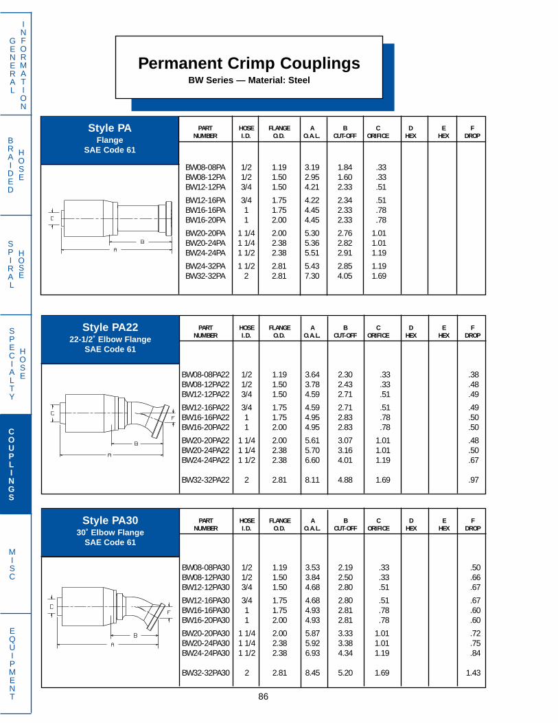
Permanent Crimp CouplingsBW Series — Material: Steel
86
GENERAL
INFORMATION
COUPLINGS
MISC
EQUIPMENT
SPECIALTY
HOSE
BRAIDED
HOSE
SPIRAL
HOSE
PART HOSE FLANGE A B C D E FNUMBER I.D. O.D. O.A.L. CUT-OFF ORIFICE HEX HEX DROP
BW08-08PA22 1/2 1.19 3.64 2.30 .33 .38BW08-12PA22 1/2 1.50 3.78 2.43 .33 .48BW12-12PA22 3/4 1.50 4.59 2.71 .51 .49
BW12-16PA22 3/4 1.75 4.59 2.71 .51 .49BW16-16PA22 1 1.75 4.95 2.83 .78 .50BW16-20PA22 1 2.00 4.95 2.83 .78 .50
BW20-20PA22 1 1/4 2.00 5.61 3.07 1.01 .48BW20-24PA22 1 1/4 2.38 5.70 3.16 1.01 .50BW24-24PA22 1 1/2 2.38 6.60 4.01 1.19 .67
BW32-32PA22 2 2.81 8.11 4.88 1.69 .97
PART HOSE FLANGE A B C D E FNUMBER I.D. O.D. O.A.L. CUT-OFF ORIFICE HEX HEX DROP
BW08-08PA30 1/2 1.19 3.53 2.19 .33 .50BW08-12PA30 1/2 1.50 3.84 2.50 .33 .66BW12-12PA30 3/4 1.50 4.68 2.80 .51 .67
BW12-16PA30 3/4 1.75 4.68 2.80 .51 .67BW16-16PA30 1 1.75 4.93 2.81 .78 .60BW16-20PA30 1 2.00 4.93 2.81 .78 .60
BW20-20PA30 1 1/4 2.00 5.87 3.33 1.01 .72BW20-24PA30 1 1/4 2.38 5.92 3.38 1.01 .75BW24-24PA30 1 1/2 2.38 6.93 4.34 1.19 .84
BW32-32PA30 2 2.81 8.45 5.20 1.69 1.43
PART HOSE FLANGE A B C D E FNUMBER I.D. O.D. O.A.L. CUT-OFF ORIFICE HEX HEX DROP
BW08-08PA 1/2 1.19 3.19 1.84 .33BW08-12PA 1/2 1.50 2.95 1.60 .33BW12-12PA 3/4 1.50 4.21 2.33 .51
BW12-16PA 3/4 1.75 4.22 2.34 .51BW16-16PA 1 1.75 4.45 2.33 .78BW16-20PA 1 2.00 4.45 2.33 .78
BW20-20PA 1 1/4 2.00 5.30 2.76 1.01BW20-24PA 1 1/4 2.38 5.36 2.82 1.01BW24-24PA 1 1/2 2.38 5.51 2.91 1.19
BW24-32PA 1 1/2 2.81 5.43 2.85 1.19BW32-32PA 2 2.81 7.30 4.05 1.69
Style PAFlange
SAE Code 61
Style PA2222-1/2˚ Elbow Flange
SAE Code 61
Style PA3030˚ Elbow Flange
SAE Code 61

SPECIALTY
HOSE
BRAIDED
HOSE
SPIRAL
HOSE
Style PA6060˚ Elbow Flange
SAE Code 61
GENERAL
Permanent Crimp CouplingsBW Series — Material: Steel
87
INFORMATION
COUPLINGS
MISC
EQUIPMENT
PART HOSE FLANGE A B C D E FNUMBER I.D. O.D. O.A.L. CUT-OFF ORIFICE HEX HEX DROP
BW08-08PA45 1/2 1.19 3.54 2.20 .33 .78BW08-12PA45 1/2 1.50 3.58 2.24 .33 .82BW12-12PA45 3/4 1.50 4.65 2.77 .51 .86
BW12-16PA45 3/4 1.75 4.65 2.77 .51 .86BW16-16PA45 1 1.75 4.83 2.71 .78 1.13BW16-20PA45 1 2.00 4.92 2.80 .78 .95
BW20-20PA45 1 1/4 2.00 6.18 3.65 1.01 1.17BW20-24PA45 1 1/4 2.38 6.23 3.67 1.01 1.21BW24-24PA45 1 1/2 2.38 7.04 4.45 1.19 1.40
BW32-32PA45 2 2.81 8.70 5.45 1.69 2.26
PART HOSE FLANGE A B C D E FNUMBER I.D. O.D. O.A.L. CUT-OFF ORIFICE HEX HEX DROP
BW08-08PA60 1/2 1.19 3.47 2.13 .33 1.05BW08-12PA60 1/2 1.50 3.57 2.22 .33 1.12BW12-12PA60 3/4 1.50 4.79 2.91 .51 1.41
BW12-16PA60 3/4 1.75 4.79 2.91 .51 1.41BW16-16PA60 1 1.75 5.62 3.50 .78 1.77BW16-20PA60 1 2.00 5.60 3.49 .78 1.60
BW20-20PA60 1 1/4 2.00 6.66 4.11 1.01 1.72BW20-24PA60 1 1/4 2.38 6.60 4.05 1.01 1.74BW24-24PA60 1 1/2 2.38 7.42 4.82 1.19 2.13
BW32-32PA60 2 2.81 8.75 5.50 1.69 3.18
PART HOSE FLANGE A B C D E FNUMBER I.D. O.D. O.A.L. CUT-OFF ORIFICE HEX HEX DROP
BW08-08PA67 1/2 1.19 3.45 2.10 .33 1.25BW08-12PA67 1/2 1.50 3.47 2.12 .33 1.31BW12-12PA67 3/4 1.50 5.01 3.13 .51 1.71
BW12-16PA67 3/4 1.75 5.01 3.13 .51 1.71BW16-16PA67 1 1.75 5.37 3.25 .78 2.04BW16-20PA67 1 2.00 5.34 3.22 .78 1.85
BW20-20PA67 1 1/4 2.00 6.49 3.89 1.01 1.94BW20-24PA67 1 1/4 2.38 6.45 3.91 1.01 1.99
BW24-24PA67 1 1/2 2.38 7.48 4.88 1.19 2.44BW32-32PA67 2 2.81 8.69 5.44 1.69 3.55
Style PA4545˚ Elbow Flange
SAE Code 61
Style PA6767-1/2˚ Elbow Flange
SAE Code 61

Permanent Crimp CouplingsBW Series — Material: Steel
88
GENERAL
INFORMATION
COUPLINGS
MISC
EQUIPMENT
SPECIALTY
HOSE
BRAIDED
HOSE
SPIRAL
HOSE
PART HOSE FLANGE A B C D E FNUMBER I.D. O.D. O.A.L. CUT-OFF ORIFICE HEX HEX DROP
BW08-08PH 1/2 1.25 3.35 2.00 .33BW12-12PH 3/4 1.63 4.35 2.47 .51BW16-16PH 1 1.88 4.70 2.58 .78
BW20-20PH 1 1/4 2.13 5.74 3.20 1.01BW24-24PH 1 1/2 2.50 5.98 3.38 1.19BW32-32PH 2 3.13 7.78 4.53 1.69
PART HOSE FLANGE A B C D E FNUMBER I.D. O.D. O.A.L. CUT-OFF ORIFICE HEX HEX DROP
BW12-12PH22 3/4 1.63 4.71 2.83 .51 .54BW16-16PH22 1 1.88 5.19 3.07 .78 .60
PART HOSE FLANGE A B C D E FNUMBER I.D. O.D. O.A.L. CUT-OFF ORIFICE HEX HEX DROP
BW08-08PA90 1/2 1.19 3.14 1.80 .33 1.63BW08-12PA90 1/2 1.50 3.52 2.17 .33 1.69BW12-12PA90 3/4 1.50 4.82 2.94 .51 2.40
BW12-16PA90 3/4 1.75 4.83 2.95 .51 2.42BW16-16PA90 1 1.75 5.20 3.08 .78 2.80BW16-20PA90 1 2.00 4.92 2.80 .78 2.24
BW20-20PA90 1 1/4 2.00 6.47 3.93 1.01 2.68BW20-24PA90 1 1/4 2.38 6.47 3.93 1.01 2.74BW24-24PA90 1 1/2 2.38 6.74 4.14 1.19 3.31BW24-32PA90 1 1/2 2.81 6.73 4.13 1.19 3.22
BW32-32PA90 2 2.81 8.25 5.00 1.69 4.94
Style PA9090˚ Elbow Flange
SAE Code 61
Style PHFlange
SAE Code 62
Style PH2222-1/2˚ Elbow Flange
SAE Code 62
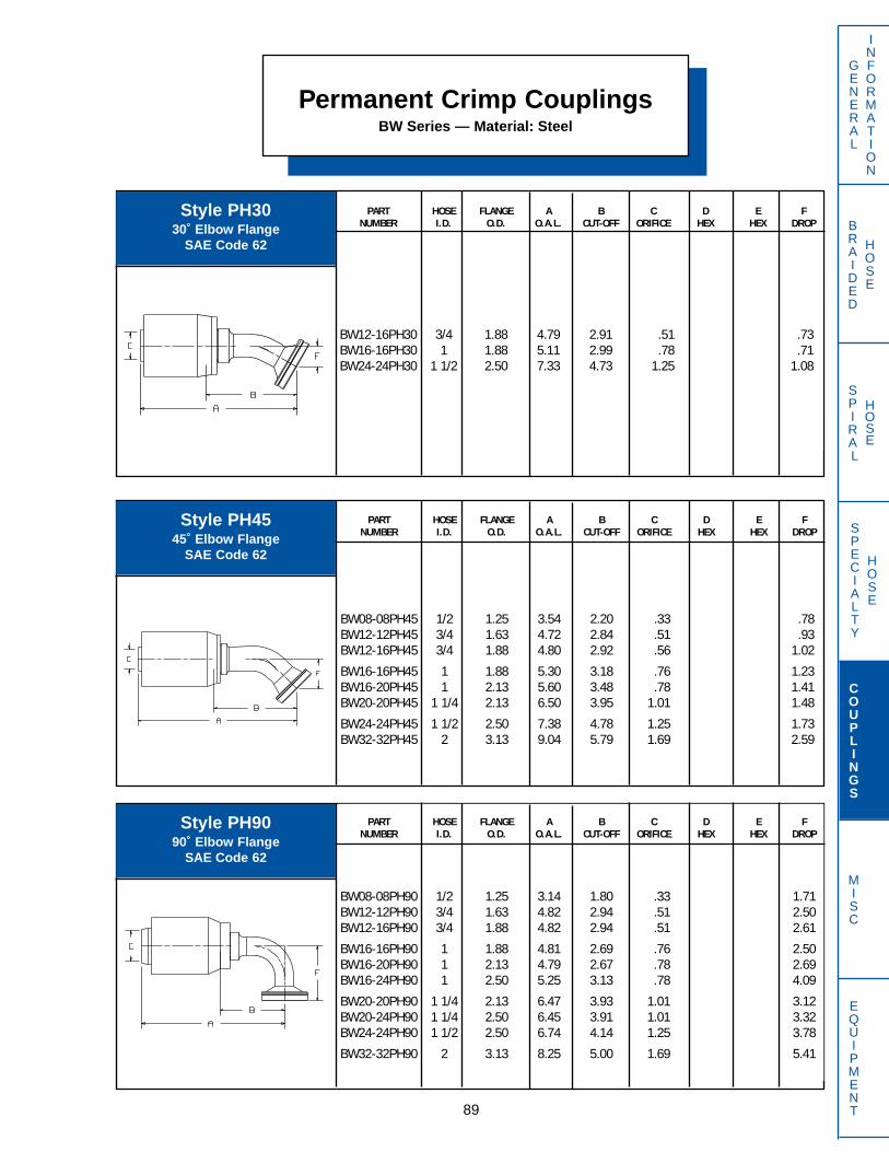
SPECIALTY
HOSE
BRAIDED
HOSE
SPIRAL
HOSE
Permanent Crimp CouplingsBW Series — Material: Steel
89
PART HOSE FLANGE A B C D E FNUMBER I.D. O.D. O.A.L. CUT-OFF ORIFICE HEX HEX DROP
BW12-16PH30 3/4 1.88 4.79 2.91 .51 .73BW16-16PH30 1 1.88 5.11 2.99 .78 .71BW24-24PH30 1 1/2 2.50 7.33 4.73 1.25 1.08
PART HOSE FLANGE A B C D E FNUMBER I.D. O.D. O.A.L. CUT-OFF ORIFICE HEX HEX DROP
BW08-08PH45 1/2 1.25 3.54 2.20 .33 .78BW12-12PH45 3/4 1.63 4.72 2.84 .51 .93BW12-16PH45 3/4 1.88 4.80 2.92 .56 1.02
BW16-16PH45 1 1.88 5.30 3.18 .76 1.23BW16-20PH45 1 2.13 5.60 3.48 .78 1.41BW20-20PH45 1 1/4 2.13 6.50 3.95 1.01 1.48
BW24-24PH45 1 1/2 2.50 7.38 4.78 1.25 1.73BW32-32PH45 2 3.13 9.04 5.79 1.69 2.59
PART HOSE FLANGE A B C D E FNUMBER I.D. O.D. O.A.L. CUT-OFF ORIFICE HEX HEX DROP
BW08-08PH90 1/2 1.25 3.14 1.80 .33 1.71BW12-12PH90 3/4 1.63 4.82 2.94 .51 2.50BW12-16PH90 3/4 1.88 4.82 2.94 .51 2.61
BW16-16PH90 1 1.88 4.81 2.69 .76 2.50BW16-20PH90 1 2.13 4.79 2.67 .78 2.69BW16-24PH90 1 2.50 5.25 3.13 .78 4.09
BW20-20PH90 1 1/4 2.13 6.47 3.93 1.01 3.12BW20-24PH90 1 1/4 2.50 6.45 3.91 1.01 3.32BW24-24PH90 1 1/2 2.50 6.74 4.14 1.25 3.78
BW32-32PH90 2 3.13 8.25 5.00 1.69 5.41
Style PH3030˚ Elbow Flange
SAE Code 62
Style PH4545˚ Elbow Flange
SAE Code 62
Style PH9090˚ Elbow Flange
SAE Code 62
GENERAL
INFORMATION
COUPLINGS
MISC
EQUIPMENT
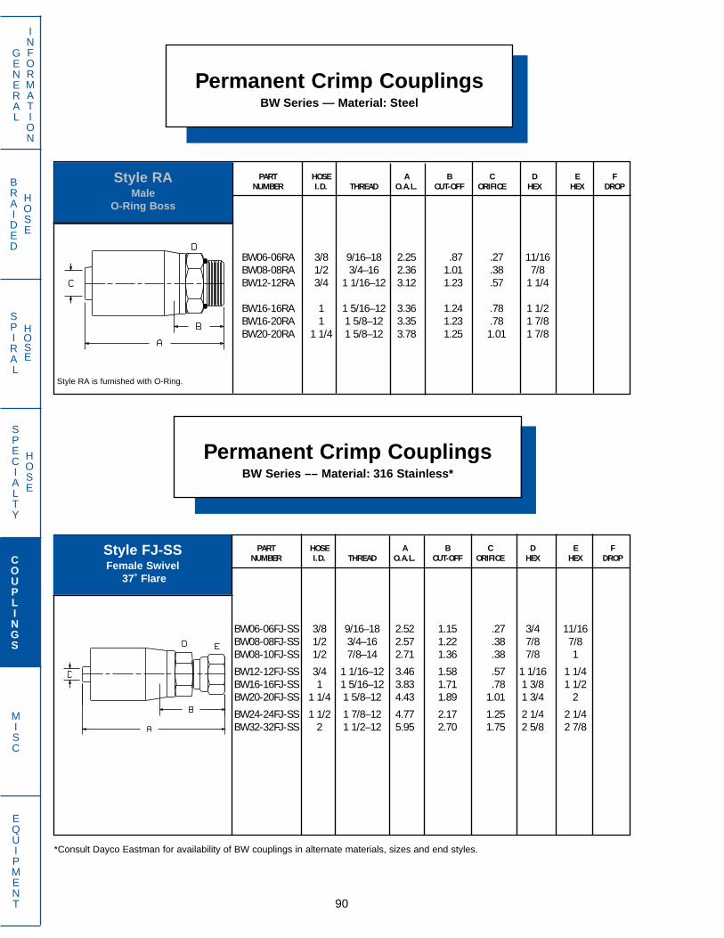
Permanent Crimp CouplingsBW Series –– Material: 316 Stainless*
90
GENERAL
INFORMATION
COUPLINGS
MISC
EQUIPMENT
SPECIALTY
HOSE
BRAIDED
HOSE
SPIRAL
HOSE
PART HOSE A B C D E FNUMBER I.D. THREAD O.A.L. CUT-OFF ORIFICE HEX HEX DROP
BW06-06RA 3/8 9/16–18 2.25 .87 .27 11/16BW08-08RA 1/2 3/4–16 2.36 1.01 .38 7/8BW12-12RA 3/4 1 1/16–12 3.12 1.23 .57 1 1/4
BW16-16RA 1 1 5/16–12 3.36 1.24 .78 1 1/2BW16-20RA 1 1 5/8–12 3.35 1.23 .78 1 7/8BW20-20RA 1 1/4 1 5/8–12 3.78 1.25 1.01 1 7/8
Style RA is furnished with O-Ring.
Style RAMale
O-Ring Boss
Permanent Crimp CouplingsBW Series — Material: Steel
PART HOSE A B C D E FNUMBER I.D. THREAD O.A.L. CUT-OFF ORIFICE HEX HEX DROP
BW06-06FJ-SS 3/8 9/16–18 2.52 1.15 .27 3/4 11/16BW08-08FJ-SS 1/2 3/4–16 2.57 1.22 .38 7/8 7/8BW08-10FJ-SS 1/2 7/8–14 2.71 1.36 .38 7/8 1
BW12-12FJ-SS 3/4 1 1/16–12 3.46 1.58 .57 1 1/16 1 1/4BW16-16FJ-SS 1 1 5/16–12 3.83 1.71 .78 1 3/8 1 1/2BW20-20FJ-SS 1 1/4 1 5/8–12 4.43 1.89 1.01 1 3/4 2
BW24-24FJ-SS 1 1/2 1 7/8–12 4.77 2.17 1.25 2 1/4 2 1/4BW32-32FJ-SS 2 1 1/2–12 5.95 2.70 1.75 2 5/8 2 7/8
Style FJ-SSFemale Swivel
37˚ Flare
*Consult Dayco Eastman for availability of BW couplings in alternate materials, sizes and end styles.

SPECIALTY
HOSE
BRAIDED
HOSE
SPIRAL
HOSE
PART HOSE A B C D E FNUMBER I.D. THREAD O.A.L. CUT-OFF ORIFICE HEX HEX DROP
BW06-06MP-SS 3/8 3/8–18 237 .99 .27 11/16BW08-08MP-SS 1/2 1/2–14 2.65 1.31 .38 7/8BW12-12MP-SS 3/4 3/4–14 3.29 1.41 .57 11/16
BW16-16MP-SS 1 1 11-1/2 3.71 1.59 .78 1 3/8BW20-20MP-SS 1 1/4 1 1/4 11-1/2 4.24 1.70 1.01 1 3/4BW24-24MP-SS 1 1/2 1 1/2 11-1/2 4.58 1.98 1.25 2 1/4
BW32-32MP-SS 2 2 11–1/2 5.39 2.13 1.75 2 5/8
91
GENERAL
INFORMATION
COUPLINGS
MISC
EQUIPMENT
Style MP-SSMale NPTF
Permanent Crimp CouplingsBW Series –– Material: 316 Stainless*
*Consult Dayco Eastman for availability of BW couplings in alternate materials, sizes and end styles.
PART HOSE A B C D E FNUMBER I.D. THREAD O.A.L. CUT-OFF ORIFICE HEX HEX DROP
CW03-02MP 3/16 1/8 - 27 2.03 .91 .11 5/8CW03-04MP 3/16 1/4 - 18 2.22 1.09 .11 5/8CW03-06MP 3/16 3/8 - 18 2.28 1.16 .11 3/4
CW04-04MP 1/4 1/4 - 18 2.41 1.22 .16 11/16CW04-06MP 1/4 3/8 - 18 2.41 1.22 .16 3/4CW06-06MP 3/8 3/8 - 18 2.31 1.31 .28 7/8
Permanent Crimp CouplingsCW Series — Material: Steel
PART HOSE A B C D E FNUMBER I.D. THREAD O.A.L. CUT-OFF ORIFICE HEX HEX DROP
CW03-04FJ 3/16 7/16 - 20 2.28 1.16 .11 5/8 9/16CW04-04FJ 1/4 7/16 - 20 2.48 1.28 .16 11/16 9/16CW06-06FJ 3/8 9/16 - 18 2.44 1.44 .28 7/8 3/4
Style MPMale NPTF
Style FJSwivel Female
37˚ Flare
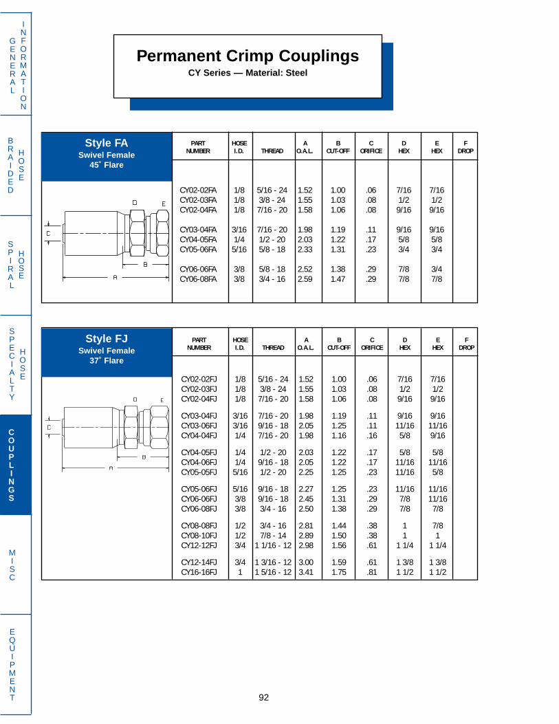
SPECIALTY
HOSE
BRAIDED
HOSE
SPIRAL
HOSE
92
GENERAL
INFORMATION
COUPLINGS
MISC
EQUIPMENT
Permanent Crimp CouplingsCY Series — Material: Steel
PART HOSE A B C D E FNUMBER I.D. THREAD O.A.L. CUT-OFF ORIFICE HEX HEX DROP
CY02-02FA 1/8 5/16 - 24 1.52 1.00 .06 7/16 7/16CY02-03FA 1/8 3/8 - 24 1.55 1.03 .08 1/2 1/2CY02-04FA 1/8 7/16 - 20 1.58 1.06 .08 9/16 9/16
CY03-04FA 3/16 7/16 - 20 1.98 1.19 .11 9/16 9/16CY04-05FA 1/4 1/2 - 20 2.03 1.22 .17 5/8 5/8CY05-06FA 5/16 5/8 - 18 2.33 1.31 .23 3/4 3/4
CY06-06FA 3/8 5/8 - 18 2.52 1.38 .29 7/8 3/4CY06-08FA 3/8 3/4 - 16 2.59 1.47 .29 7/8 7/8
PART HOSE A B C D E FNUMBER I.D. THREAD O.A.L. CUT-OFF ORIFICE HEX HEX DROP
CY02-02FJ 1/8 5/16 - 24 1.52 1.00 .06 7/16 7/16CY02-03FJ 1/8 3/8 - 24 1.55 1.03 .08 1/2 1/2CY02-04FJ 1/8 7/16 - 20 1.58 1.06 .08 9/16 9/16
CY03-04FJ 3/16 7/16 - 20 1.98 1.19 .11 9/16 9/16CY03-06FJ 3/16 9/16 - 18 2.05 1.25 .11 11/16 11/16CY04-04FJ 1/4 7/16 - 20 1.98 1.16 .16 5/8 9/16
CY04-05FJ 1/4 1/2 - 20 2.03 1.22 .17 5/8 5/8CY04-06FJ 1/4 9/16 - 18 2.05 1.22 .17 11/16 11/16CY05-05FJ 5/16 1/2 - 20 2.25 1.25 .23 11/16 5/8
CY05-06FJ 5/16 9/16 - 18 2.27 1.25 .23 11/16 11/16CY06-06FJ 3/8 9/16 - 18 2.45 1.31 .29 7/8 11/16CY06-08FJ 3/8 3/4 - 16 2.50 1.38 .29 7/8 7/8
CY08-08FJ 1/2 3/4 - 16 2.81 1.44 .38 1 7/8CY08-10FJ 1/2 7/8 - 14 2.89 1.50 .38 1 1CY12-12FJ 3/4 1 1/16 - 12 2.98 1.56 .61 1 1/4 1 1/4
CY12-14FJ 3/4 1 3/16 - 12 3.00 1.59 .61 1 3/8 1 3/8CY16-16FJ 1 1 5/16 - 12 3.41 1.75 .81 1 1/2 1 1/2
Style FASwivel Female
45˚ Flare
Style FJSwivel Female
37˚ Flare

SPECIALTY
HOSE
BRAIDED
HOSE
SPIRAL
HOSE
93
GENERAL
INFORMATION
COUPLINGS
MISC
EQUIPMENT
PART HOSE A B C D E FNUMBER I.D. THREAD O.A.L. CUT-OFF ORIFICE HEX HEX DROP
CY03-04FJ45T 3/16 7/16 - 20 1.84 1.06 .11 9/16 .33CY05-06FJ45T 5/16 9/16 - 18 2.19 1.19 .18 11/16 .39CY06-06FJ45T 3/8 9/16 - 18 2.44 1.31 .26 11/16 .39
Permanent Crimp CouplingsCY Series — Material: Steel
PART HOSE A B C D E FNUMBER I.D. THREAD O.A.L. CUT-OFF ORIFICE HEX HEX DROP
CY05-06FJ90TL 5/16 9/16 - 18 2.08 1.06 .18 11/16 2.19CY08-10FJ90TL 1/2 7/8 - 14 3.08 1.69 .34 1 2.58
PART HOSE A B C D E FNUMBER I.D. THREAD O.A.L. CUT-OFF ORIFICE HEX HEX DROP
CY03-04FJ90T 3/16 7/16 - 20 1.73 .94 .11 9/16 .69CY04-04FJ90T 1/4 7/16 - 20 1.80 .97 .14 9/16 .69CY04-05FJ90T 1/4 1/2 - 20 1.92 1.09 .14 5/8 .77
CY05-06FJ90T 5/16 9/16 - 18 2.08 1.06 .18 11/16 .86CY06-06FJ90T 3/8 9/16 - 18 2.33 1.19 .26 11/16 .86CY06-08FJ90T 3/8 3/4 - 16 2.55 1.40 .26 7/8 1.09
Style FJ45T45˚ Bent Tube Swivel Female
37˚ Flare
Style FJ90T90˚ Bent Tube Swivel Female
37˚ Flare
Style FJ90TL45˚ Bent Tube Swivel Female
37˚ Flare (Long Drop)
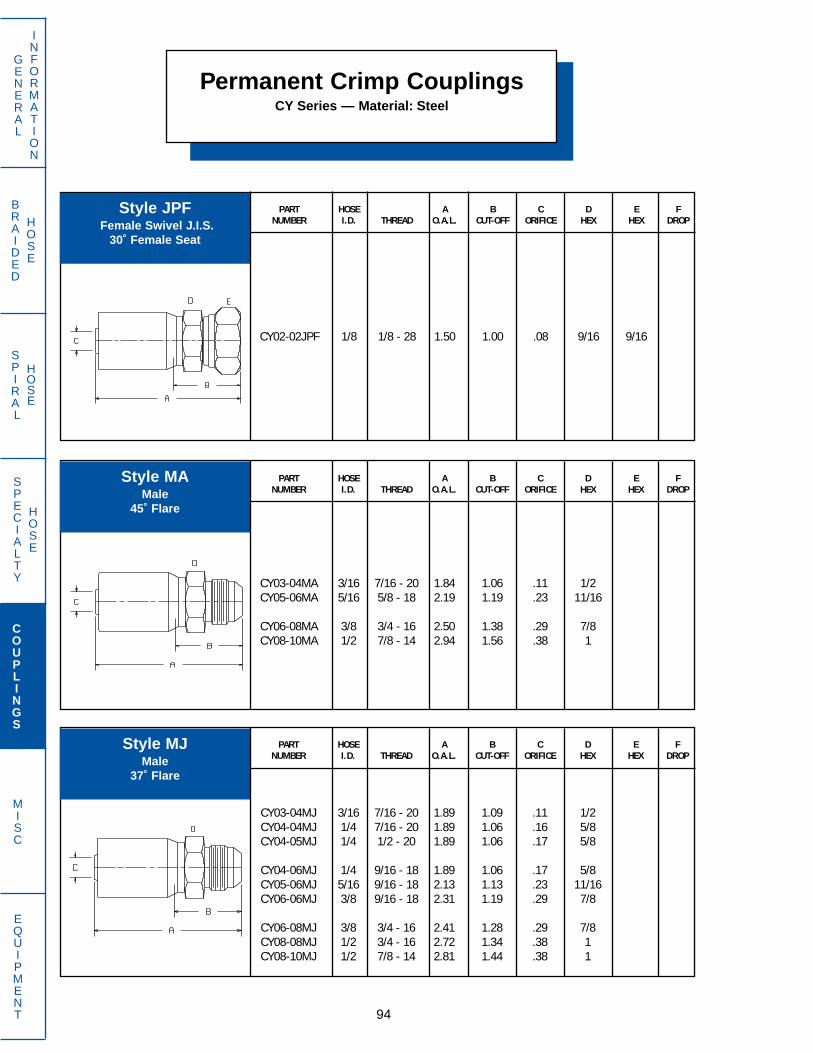
SPECIALTY
HOSE
BRAIDED
HOSE
SPIRAL
HOSE
94
GENERAL
INFORMATION
COUPLINGS
MISC
EQUIPMENT
Permanent Crimp CouplingsCY Series — Material: Steel
PART HOSE A B C D E FNUMBER I.D. THREAD O.A.L. CUT-OFF ORIFICE HEX HEX DROP
CY02-02JPF 1/8 1/8 - 28 1.50 1.00 .08 9/16 9/16
PART HOSE A B C D E FNUMBER I.D. THREAD O.A.L. CUT-OFF ORIFICE HEX HEX DROP
CY03-04MJ 3/16 7/16 - 20 1.89 1.09 .11 1/2CY04-04MJ 1/4 7/16 - 20 1.89 1.06 .16 5/8CY04-05MJ 1/4 1/2 - 20 1.89 1.06 .17 5/8
CY04-06MJ 1/4 9/16 - 18 1.89 1.06 .17 5/8CY05-06MJ 5/16 9/16 - 18 2.13 1.13 .23 11/16CY06-06MJ 3/8 9/16 - 18 2.31 1.19 .29 7/8
CY06-08MJ 3/8 3/4 - 16 2.41 1.28 .29 7/8CY08-08MJ 1/2 3/4 - 16 2.72 1.34 .38 1CY08-10MJ 1/2 7/8 - 14 2.81 1.44 .38 1
PART HOSE A B C D E FNUMBER I.D. THREAD O.A.L. CUT-OFF ORIFICE HEX HEX DROP
CY03-04MA 3/16 7/16 - 20 1.84 1.06 .11 1/2CY05-06MA 5/16 5/8 - 18 2.19 1.19 .23 11/16
CY06-08MA 3/8 3/4 - 16 2.50 1.38 .29 7/8CY08-10MA 1/2 7/8 - 14 2.94 1.56 .38 1
Style JPFFemale Swivel J.I.S.
30˚ Female Seat
Style MAMale
45˚ Flare
Style MJMale
37˚ Flare

SPECIALTY
HOSE
BRAIDED
HOSE
SPIRAL
HOSE
95
GENERAL
INFORMATION
COUPLINGS
MISC
EQUIPMENT
PART HOSE A B C D E FNUMBER I.D. THREAD O.A.L. CUT-OFF ORIFICE HEX HEX DROP
CY02-02MP 1/8 1/8 - 27 1.31 .81 .08 7/16CY03-02MP 3/16 1/8 - 27 1.72 .94 .11 1/2CY03-04MP 3/16 1/4 - 18 1.91 1.13 .11 9/16
CY04-02MP 1/4 1/8 - 27 1.72 .91 .17 5/8CY04-04MP 1/4 1/4 - 18 1.91 1.09 .17 5/8CY04-06MP 1/4 3/8 - 18 1.91 1.09 .17 3/4
CY05-04MP 5/16 1/4 - 18 2.13 1.13 .23 11/16CY05-06MP 5/16 3/8 - 18 2.13 1.13 .23 3/4CY06-04MP 3/8 1/4 - 18 2.31 1.19 .29 7/8
CY06-06MP 3/8 3/8 - 18 2.31 1.19 .29 7/8CY06-08MP 3/8 1/2 - 14 2.50 1.38 .29 7/8CY08-08MP 1/2 1/2 - 14 2.81 1.44 .38 1
CY12-12MP 3/4 3/4 - 14 2.84 1.44 .61 1 1/4CY16-16MP 1 1 11 1/2 3.38 1.72 .86 1 1/2
Permanent Crimp CouplingsCY Series — Material: Steel
Style MPMaleNPTF
PART HOSE A B C D E FNUMBER I.D. THREAD O.A.L. CUT-OFF ORIFICE HEX HEX DROP
CY03-04RA 3/16 7/16 - 20 1.70 1.00 .11 9/16CY04-05RA 1/4 1/2 - 20 1.70 .88 .17 5/8CY04-06RA 1/4 9/16 - 18 1.73 .94 .17 11/16
CY05-06RA 5/16 9/16 - 18 1.95 .94 .23 11/16CY06-06RA 3/8 9/16 - 18 2.27 1.13 .29 7/8
O-Ring not supplied with coupling. See page 264 for O-ring information.
Style RAMale
O-Ring Boss
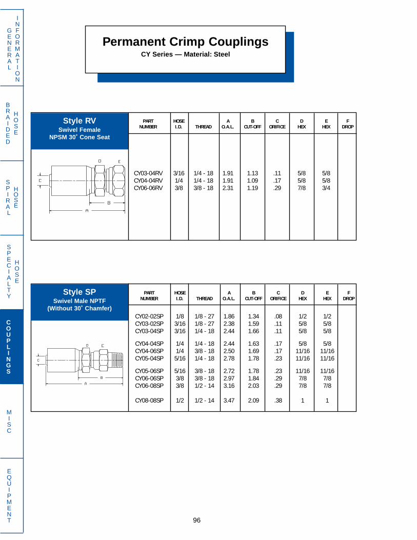
SPECIALTY
HOSE
BRAIDED
HOSE
SPIRAL
HOSE
96
GENERAL
INFORMATION
COUPLINGS
MISC
EQUIPMENT
Permanent Crimp CouplingsCY Series — Material: Steel
PART HOSE A B C D E FNUMBER I.D. THREAD O.A.L. CUT-OFF ORIFICE HEX HEX DROP
CY03-04RV 3/16 1/4 - 18 1.91 1.13 .11 5/8 5/8CY04-04RV 1/4 1/4 - 18 1.91 1.09 .17 5/8 5/8CY06-06RV 3/8 3/8 - 18 2.31 1.19 .29 7/8 3/4
Style RVSwivel Female
NPSM 30˚ Cone Seat
PART HOSE A B C D E FNUMBER I.D. THREAD O.A.L. CUT-OFF ORIFICE HEX HEX DROP
CY02-02SP 1/8 1/8 - 27 1.86 1.34 .08 1/2 1/2CY03-02SP 3/16 1/8 - 27 2.38 1.59 .11 5/8 5/8CY03-04SP 3/16 1/4 - 18 2.44 1.66 .11 5/8 5/8
CY04-04SP 1/4 1/4 - 18 2.44 1.63 .17 5/8 5/8CY04-06SP 1/4 3/8 - 18 2.50 1.69 .17 11/16 11/16CY05-04SP 5/16 1/4 - 18 2.78 1.78 .23 11/16 11/16
CY05-06SP 5/16 3/8 - 18 2.72 1.78 .23 11/16 11/16CY06-06SP 3/8 3/8 - 18 2.97 1.84 .29 7/8 7/8CY06-08SP 3/8 1/2 - 14 3.16 2.03 .29 7/8 7/8
CY08-08SP 1/2 1/2 - 14 3.47 2.09 .38 1 1
Style SPSwivel Male NPTF
(Without 30˚ Chamfer)
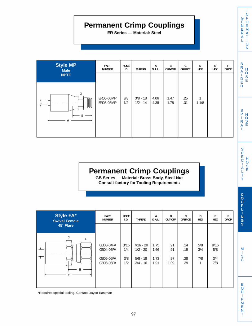
SPECIALTY
HOSE
BRAIDED
HOSE
SPIRAL
HOSE
97
GENERAL
INFORMATION
COUPLINGS
MISC
EQUIPMENT
PART HOSE A B C D E FNUMBER I.D. THREAD O.A.L. CUT-OFF ORIFICE HEX HEX DROP
ER06-06MP 3/8 3/8 - 18 4.06 1.47 .25 1ER08-08MP 1/2 1/2 - 14 4.38 1.78 .31 1 1/8
Permanent Crimp CouplingsER Series — Material: Steel
Style MPMaleNPTF
PART HOSE A B C D E FNUMBER I.D. THREAD O.A.L. CUT-OFF ORIFICE HEX HEX DROP
GB03-04FA 3/16 7/16 - 20 1.75 .91 .14 5/8 9/16GB04-05FA 1/4 1/2 - 20 1.66 .91 .19 3/4 5/8
GB06-06FA 3/8 5/8 - 18 1.73 .97 .28 7/8 3/4GB08-08FA 1/2 3/4 - 16 1.91 1.09 .39 1 7/8
Permanent Crimp CouplingsGB Series — Material: Brass Body, Steel Nut
Consult factory for Tooling Requirements
*Requires special tooling. Contact Dayco Eastman
Style FA*Swivel Female
45˚ Flare

SPECIALTY
HOSE
BRAIDED
HOSE
SPIRAL
HOSE
98
GENERAL
INFORMATION
COUPLINGS
MISC
EQUIPMENT
PART HOSE A B C D E FNUMBER I.D. THREAD O.A.L. CUT-OFF ORIFICE HEX HEX DROP
GB03-03FJ 3/16 3/8 - 24 1.66 .81 .13 5/8 1/2GB03-04FJ 3/16 7/16 - 20 1.75 .84 .14 5/8 9/16GB04-04FJ 1/4 7/16 - 20 1.61 .84 .19 3/4 9/16
GB04-05FJ 1/4 1/2 - 20 1.66 .91 .19 3/4 5/8GB04-06FJ 1/4 9/16 - 18 1.67 .91 .19 3/4 11/16GB06-04FJ 3/8 7/16 - 20 1.61 .84 .27 7/8 9/16
GB06-06FJ 3/8 9/16 - 18 1.67 .91 .28 7/8 11/16GB06-08FJ 3/8 3/4 - 16 1.72 .97 .28 7/8 7/8GB08-06FJ 1/2 9/16 - 18 1.86 1.03 .39 1 11/16
GB08-08FJ 1/2 3/4 - 16 1.91 1.09 .39 1 7/8GB08-10FJ 1/2 7/8 - 14 1.98 1.16 .39 1 1GB12-12FJ 3/4 1 1/16 - 12 2.76 1.31 .61 1 5/16 1 1/4
Permanent Crimp CouplingsGB Series — Material: Brass Body, Steel Nut
Consult factory for Tooling Requirements
PART HOSE A B C D E FNUMBER I.D. THREAD O.A.L. CUT-OFF ORIFICE HEX HEX DROP
GB04-04FF 1/4 1/4 - 18 1.53 .75 .19 3/4GB06-06FF 3/8 3/8 - 18 1.61 .84 .28 7/8GB08-08FF 1/2 1/2 - 14 1.95 1.16 .39 1
PART HOSE A B C D E FNUMBER I.D. THREAD O.A.L. CUT-OFF ORIFICE HEX HEX DROP
GB03-04MA 3/16 7/16 - 20 1.61 .75 .14 5/8GB06-06MA 3/8 5/8 - 18 1.59 .84 .28 7/8GB06-08MA 3/8 3/4 - 16 1.72 .97 .28 7/8
*Requires special tooling. Contact Dayco Eastman
Style FF*Female NPTF
Style FJ*Swivel Female
37˚ Flare
Style MA*Male
45˚ Flare

SPECIALTY
HOSE
BRAIDED
HOSE
SPIRAL
HOSE
99
GENERAL
INFORMATION
COUPLINGS
MISC
EQUIPMENT
PART HOSE A B C D E FNUMBER I.D. THREAD O.A.L. CUT-OFF ORIFICE HEX HEX DROP
GB03-04MJ 3/16 7/16 - 20 1.60 .75 .14 5/8GB04-04MJ 1/4 7/16 - 20 1.52 .72 .19 3/4GB04-06MJ 1/4 9/16 - 18 1.53 .75 .19 3/4
GB06-06MJ 3/8 9/16 - 18 1.53 .78 .28 7/8GB06-08MJ 3/8 3/4 - 16 1.53 .88 .28 7/8GB08-08MJ 1/2 3/4 - 16 1.81 .97 .39 1
GB08-10MJ 1/2 7/8 - 14 1.91 1.06 .39 1
Permanent Crimp CouplingsGB Series — Material: Brass Body, Steel Nut
Consult factory for Tooling Requirements
PART HOSE A B C D E FNUMBER I.D. THREAD O.A.L. CUT-OFF ORIFICE HEX HEX DROP
GB04-04OF 1/4 9/16 - 18 1.61 .53 .16 3/4 11/16GB06-06OF 3/8 11/16 - 16 1.69 .56 .27 7/8 13/16GB08-08OF 1/2 13/16 - 16 1.96 .72 .36 1 15/16
PART HOSE A B C D E FNUMBER I.D. THREAD O.A.L. CUT-OFF ORIFICE HEX HEX DROP
GB03-02MP 3/16 1/8 - 27 1.42 .56 .14 5/8GB03-04MP 3/16 1/4 - 18 1.67 .81 .14 5/8GB04-02MP 1/4 1/8 - 27 1.34 .56 .19 3/4
GB04-04MP 1/4 1/4 - 18 1.53 .75 .19 3/4GB04-06MP 1/4 3/8 - 18 1.53 .75 .19 3/4GB04-08MP 1/4 1/2 - 14 1.72 .94 .19 7/8
GB06-04MP 3/8 1/4 - 18 1.53 .78 .28 7/8GB06-06MP 3/8 3/8 - 18 1.53 .78 .28 7/8GB06-08MP 3/8 1/2 - 14 1.72 .97 .28 7/8
GB08-06MP 1/2 3/8 - 18 1.72 .88 .39 1GB08-08MP 1/2 1/2 - 14 1.97 1.16 .39 1GB10-08MP 5/8 1/2 - 14 2.31 1.16 .55 1 1/8
GB12-12MP 3/4 3/4 - 14 2.63 1.19 .67 1 3/8
*Requires special tooling. Contact Dayco Eastman.
Style MJ*Male
37˚ Flare
Style MP*Male NPTF
Style OF*Swivel Female
O-Ring Face Seal

SPECIALTY
HOSE
BRAIDED
HOSE
SPIRAL
HOSE
100
GENERAL
INFORMATION
COUPLINGS
MISC
EQUIPMENT
Permanent Crimp CouplingsGB Series — Material: Brass Body, Steel Nut
Consult factory for Tooling Requirements
PART HOSE A B C D E FNUMBER I.D. THREAD O.A.L. CUT-OFF ORIFICE HEX HEX DROP
GB06-06RA 3/8 9/16 - 18 1.49 .72 .28 7/8GB06-08RA 3/8 3/4 - 16 1.41 .66 .28 7/8
GB08-08RA 1/2 3/4 - 16 1.66 .84 .39 1GB08-10RA 1/2 7/8 - 14 1.72 .91 .39 1
PART HOSE A B C D E FNUMBER I.D. THREAD O.A.L. CUT-OFF ORIFICE HEX HEX DROP
GB03-02SP 3/16 1/8 - 27 2.14 1.28 .14 5/8 5/8GB04-04SP 1/4 1/4 - 18 2.19 1.44 .19 3/4 11/16GB06-06SP 3/8 3/8 - 18 2.19 1.44 .28 7/8 7/8
GB06-08SP 3/8 1/2 - 14 2.38 1.63 .28 7/8 7/8GB08-08SP 1/2 1/2 - 14 2.56 1.75 .39 1 1GB12-12SP 3/4 3/4 - 14 3.31 1.94 .67 1 1/4 1 1/4
PART HOSE A B C D E FNUMBER I.D. THREAD O.A.L. CUT-OFF ORIFICE HEX HEX DROP
GB06-06RC 3/8 9/16 - 18 2.16 1.34 .27 7/8 11/16
Style RA is furnished with O-ring.
Style RC is furnished with O-ring.
*Requires special tooling. Contact Dayco Eastman.
Style RA*Male
O-Ring Boss
Style RC*Swivel Male O-Ring Boss
Style SP*Swivel Male NPTF
(Without 30˚ Chamfer)
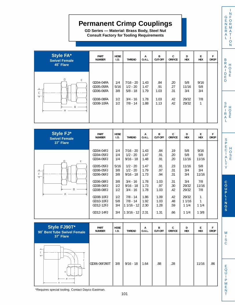
SPECIALTY
HOSE
BRAIDED
HOSE
SPIRAL
HOSE
101
GENERAL
INFORMATION
COUPLINGS
MISC
EQUIPMENT
PART HOSE A B C D E FNUMBER I.D. THREAD O.A.L. CUT-OFF ORIFICE HEX HEX DROP
GD04-04FA 1/4 7/16 - 20 1.43 .84 .20 5/8 9/16GD05-05FA 5/16 1/2 - 20 1.47 .91 .27 11/16 5/8GD06-06FA 3/8 5/8 - 18 1.79 1.03 .31 3/4 3/4
GD08-08FA 1/2 3/4 - 16 1.78 1.03 .42 29/32 7/8GD08-10FA 1/2 7/8 - 14 1.88 1.13 .42 29/32 1
PART HOSE A B C D E FNUMBER I.D. THREAD O.A.L. CUT-OFF ORIFICE HEX HEX DROP
GD06-06FJ90T 3/8 9/16 - 18 1.64 .88 .28 11/16 .86
PART HOSE A B C D E FNUMBER I.D. THREAD O.A.L. CUT-OFF ORIFICE HEX HEX DROP
GD04-04FJ 1/4 7/16 - 20 1.43 .84 .19 5/8 9/16GD04-05FJ 1/4 1/2 - 20 1.47 .91 .20 5/8 5/8GD04-06FJ 1/4 9/16 - 18 1.48 .91 .20 11/16 11/16
GD05-05FJ 5/16 1/2 - 20 1.47 .91 .23 11/16 5/8GD06-05FJ 3/8 1/2 - 20 1.79 .97 .31 3/4 3/4GD06-06FJ 3/8 9/16 - 18 1.73 .94 .31 3/4 11/16
GD06-08FJ 3/8 3/4 - 16 1.78 1.03 .31 3/4 7/8GD08-06FJ 1/2 9/16 - 18 1.73 .97 .30 29/32 11/16GD08-08FJ 1/2 3/4 - 16 1.78 1.03 .42 29/32 7/8
GD08-10FJ 1/2 7/8 - 14 1.86 1.09 .42 29/32 1GD10-10FJ 5/8 7/8 - 14 1.92 1.03 .48 1 1/16 1GD12-12FJ 3/4 1 1/16 - 12 2.30 1.28 .59 1 1/4 1 1/4
GD12-14FJ 3/4 1 3/16 - 12 2.31 1.31 .66 1 1/4 1 3/8
Permanent Crimp CouplingsGD Series — Material: Brass Body, Steel Nut
Consult Factory for Tooling Requirements
*Requires special tooling. Contact Dayco Eastman.
Style FA*Swivel Female
45˚ Flare
Style FJ*Swivel Female
37˚ Flare
Style FJ90T*90˚ Bent Tube Swivel Female
37˚ Flare

SPECIALTY
HOSE
BRAIDED
HOSE
SPIRAL
HOSE
102
GENERAL
INFORMATION
COUPLINGS
MISC
EQUIPMENT
Permanent Crimp CouplingsGD Series — Material: Brass Body, Steel Nut
Consult Factory for Tooling Requirements
PART HOSE A B C D E FNUMBER I.D. THREAD O.A.L. CUT-OFF ORIFICE HEX HEX DROP
GD03-03MF 3/16 3/8 - 24 1.41 .84 .13 9/16 3/8GD03-04MF 3/16 7/16 - 24 1.41 .84 .13 9/16 7/16GD04-04MF 1/4 7/16 - 24 1.50 .84 .20 5/8 1/2
GD04-05MF 1/4 1/2 - 20 1.41 .94 .20 5/8 7/16GD05-05MF 5/16 1/2 - 20 1.56 1.00 .23 11/16 1/2GD08-08MF 1/2 3/4 - 16 2.03 1.28 .31 29/32 3/4
PART HOSE A B C D E FNUMBER I.D. THREAD O.A.L. CUT-OFF ORIFICE HEX HEX DROP
GD03-02MP 3/16 1/8 - 27 1.16 .59 .20 9/16GD04-02MP 1/4 1/8 - 27 1.16 .59 .20 5/8GD04-04MP 1/4 1/4 - 18 1.34 .78 .20 5/8
GD05-04MP 5/16 1/4 - 18 1.34 .78 .27 11/16GD06-04MP 3/8 1/4 - 18 1.59 .84 .31 3/4GD06-06MP 3/8 3/8 - 18 1.59 .84 .31 3/4
GD08-04MP 1/2 1/4 - 18 1.59 .84 .30 29/32GD08-06MP 1/2 3/8 - 18 1.59 .84 .42 29/32GD08-08MP 1/2 1/2 - 14 1.78 1.03 .42 29/32
GD12-12MP 3/4 3/4 - 14 2.16 1.16 .66 1 1/4
PART HOSE A B C D E FNUMBER I.D. THREAD O.A.L. CUT-OFF ORIFICE HEX HEX DROP
GD04-05MJ 1/4 1/2 - 20 1.33 .78 .20 5/8GD06-06MJ 3/8 9/16 - 18 1.59 .84 .30 3/4GD08-08MJ 1/2 3/4 - 16 1.69 .94 .39 29/32
*Requires special tooling. Contact Dayco Eastman.
Style MF*Swivel Male
45˚ Inverted Flare
Style MJ*Male
37˚ Flare
Style MP*Male NPTF
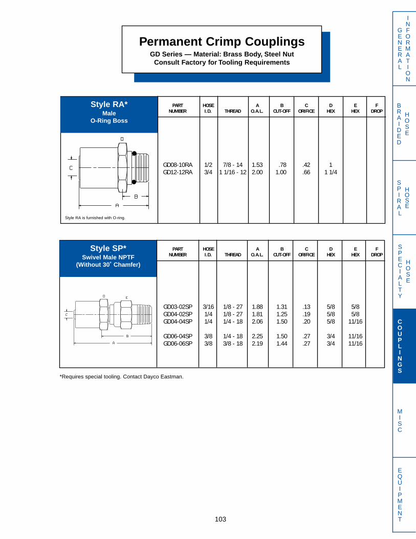
SPECIALTY
HOSE
BRAIDED
HOSE
SPIRAL
HOSE
103
GENERAL
INFORMATION
COUPLINGS
MISC
EQUIPMENT
PART HOSE A B C D E FNUMBER I.D. THREAD O.A.L. CUT-OFF ORIFICE HEX HEX DROP
GD08-10RA 1/2 7/8 - 14 1.53 .78 .42 1GD12-12RA 3/4 1 1/16 - 12 2.00 1.00 .66 1 1/4
PART HOSE A B C D E FNUMBER I.D. THREAD O.A.L. CUT-OFF ORIFICE HEX HEX DROP
GD03-02SP 3/16 1/8 - 27 1.88 1.31 .13 5/8 5/8GD04-02SP 1/4 1/8 - 27 1.81 1.25 .19 5/8 5/8GD04-04SP 1/4 1/4 - 18 2.06 1.50 .20 5/8 11/16
GD06-04SP 3/8 1/4 - 18 2.25 1.50 .27 3/4 11/16GD06-06SP 3/8 3/8 - 18 2.19 1.44 .27 3/4 11/16
Permanent Crimp CouplingsGD Series — Material: Brass Body, Steel Nut
Consult Factory for Tooling Requirements
*Requires special tooling. Contact Dayco Eastman.
Style RA is furnished with O-ring.
Style RA*Male
O-Ring Boss
Style SP*Swivel Male NPTF
(Without 30˚ Chamfer)
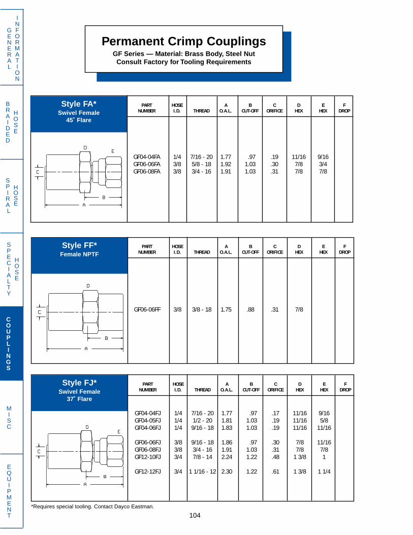
SPECIALTY
HOSE
BRAIDED
HOSE
SPIRAL
HOSE
104
GENERAL
INFORMATION
COUPLINGS
MISC
EQUIPMENT
Permanent Crimp CouplingsGF Series — Material: Brass Body, Steel NutConsult Factory for Tooling Requirements
PART HOSE A B C D E FNUMBER I.D. THREAD O.A.L. CUT-OFF ORIFICE HEX HEX DROP
GF04-04FA 1/4 7/16 - 20 1.77 .97 .19 11/16 9/16GF06-06FA 3/8 5/8 - 18 1.92 1.03 .30 7/8 3/4GF06-08FA 3/8 3/4 - 16 1.91 1.03 .31 7/8 7/8
PART HOSE A B C D E FNUMBER I.D. THREAD O.A.L. CUT-OFF ORIFICE HEX HEX DROP
GF04-04FJ 1/4 7/16 - 20 1.77 .97 .17 11/16 9/16GF04-05FJ 1/4 1/2 - 20 1.81 1.03 .19 11/16 5/8GF04-06FJ 1/4 9/16 - 18 1.83 1.03 .19 11/16 11/16
GF06-06FJ 3/8 9/16 - 18 1.86 .97 .30 7/8 11/16GF06-08FJ 3/8 3/4 - 16 1.91 1.03 .31 7/8 7/8GF12-10FJ 3/4 7/8 - 14 2.24 1.22 .48 1 3/8 1
GF12-12FJ 3/4 1 1/16 - 12 2.30 1.22 .61 1 3/8 1 1/4
PART HOSE A B C D E FNUMBER I.D. THREAD O.A.L. CUT-OFF ORIFICE HEX HEX DROP
GF06-06FF 3/8 3/8 - 18 1.75 .88 .31 7/8
*Requires special tooling. Contact Dayco Eastman.
Style FA*Swivel Female
45˚ Flare
Style FF*Female NPTF
Style FJ*Swivel Female
37˚ Flare

SPECIALTY
HOSE
BRAIDED
HOSE
SPIRAL
HOSE
105
GENERAL
INFORMATION
COUPLINGS
MISC
EQUIPMENT
PART HOSE A B C D E FNUMBER I.D. THREAD O.A.L. CUT-OFF ORIFICE HEX HEX DROP
GF03-03MA 3/16 3/8 - 24 1.50 .72 .13 5/8GF04-04MA 1/4 7/16 - 20 1.63 .84 .19 11/16
GF06-06MA 3/8 5/8 - 18 1.78 .91 .28 7/8GF06-08MA 3/8 3/4 - 16 1.91 1.03 .31 7/8
PART HOSE A B C D E FNUMBER I.D. THREAD O.A.L. CUT-OFF ORIFICE HEX HEX DROP
GF04-04MF45T 1/4 7/16 - 24 2.40 1.59 .19 7/16 .78
PART HOSE A B C D E FNUMBER I.D. THREAD O.A.L. CUT-OFF ORIFICE HEX HEX DROP
GF03-03MF 3/16 3/8 - 24 1.69 .91 .11 5/8 3/8GF03-04MF 3/16 7/16 - 24 1.69 .91 .14 5/8 7/16
GF04-04MF 1/4 7/16 - 24 1.75 .97 .16 11/16 7/16GF04-05MF 1/4 1/2 - 20 1.84 1.06 .19 11/16 1/2
Permanent Crimp CouplingsGF Series — Material: Brass Body, Steel NutConsult Factory for Tooling Requirements
*Requires special tooling. Contact Dayco Eastman.
Style MA*Male
45˚ Flare
Style MF*Swivel Male
Inverted Flare
Style MF45T*45˚ Bent Tube Swivel Male
Inverted Flare

SPECIALTY
HOSE
BRAIDED
HOSE
SPIRAL
HOSE
106
GENERAL
INFORMATION
COUPLINGS
MISC
EQUIPMENT
Permanent Crimp CouplingsGF Series — Material: Brass Body, Steel NutConsult Factory for Tooling Requirements
PART HOSE A B C D E FNUMBER I.D. THREAD O.A.L. CUT-OFF ORIFICE HEX HEX DROP
GF04-04MJ 1/4 7/16 - 20 1.68 .88 .17 11/16GF06-06MJ 3/8 9/16 - 18 1.71 .84 .30 7/8GF12-12MJ 3/4 1 1/16 - 12 2.28 1.28 .61 1 3/8
PART HOSE A B C D E FNUMBER I.D. THREAD O.A.L. CUT-OFF ORIFICE HEX HEX DROP
GF04-04NG 1/4 7/16 - 24 1.31 .53 .19 11/16
PART HOSE A B C D E FNUMBER I.D. THREAD O.A.L. CUT-OFF ORIFICE HEX HEX DROP
GF04-02MP 1/4 1/8 - 27 1.50 .72 .19 11/16GF04-04MP 1/4 1/4 - 18 1.69 .91 .19 11/16GF04-06MP 1/4 3/8 - 18 1.69 .91 .19 11/16
GF06-04MP 3/8 1/4 - 18 1.72 .84 .30 7/8GF06-06MP 3/8 3/8 - 18 1.72 .84 .31 7/8GF06-08MP 3/8 1/2 - 14 1.91 1.03 .31 7/8
GF12-12MP 3/4 3/4 - 14 2.16 1.16 .66 1 3/8
*Requires special tooling. Contact Dayco Eastman.
Style MJ*Male
37˚ Flare
Style MP*Male NPTF
Style NG*Female
Inverted Flare
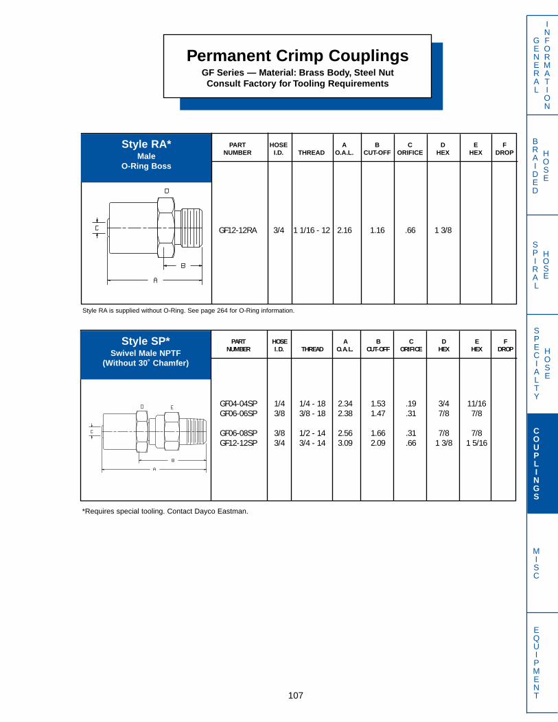
SPECIALTY
HOSE
BRAIDED
HOSE
SPIRAL
HOSE
107
GENERAL
INFORMATION
COUPLINGS
MISC
EQUIPMENT
PART HOSE A B C D E FNUMBER I.D. THREAD O.A.L. CUT-OFF ORIFICE HEX HEX DROP
GF12-12RA 3/4 1 1/16 - 12 2.16 1.16 .66 1 3/8
PART HOSE A B C D E FNUMBER I.D. THREAD O.A.L. CUT-OFF ORIFICE HEX HEX DROP
GF04-04SP 1/4 1/4 - 18 2.34 1.53 .19 3/4 11/16GF06-06SP 3/8 3/8 - 18 2.38 1.47 .31 7/8 7/8
GF06-08SP 3/8 1/2 - 14 2.56 1.66 .31 7/8 7/8GF12-12SP 3/4 3/4 - 14 3.09 2.09 .66 1 3/8 1 5/16
Permanent Crimp CouplingsGF Series — Material: Brass Body, Steel NutConsult Factory for Tooling Requirements
Style RA*Male
O-Ring Boss
Style SP*Swivel Male NPTF
(Without 30˚ Chamfer)
*Requires special tooling. Contact Dayco Eastman.
Style RA is supplied without O-Ring. See page 264 for O-Ring information.
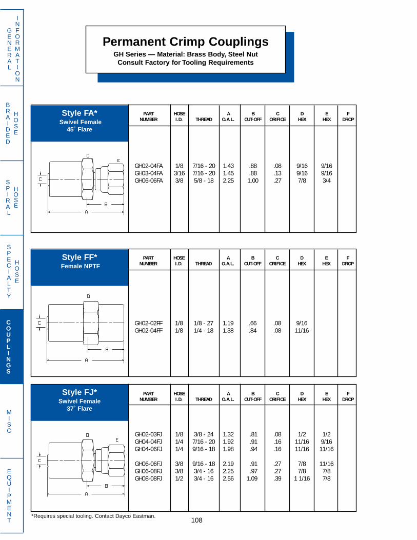
SPECIALTY
HOSE
BRAIDED
HOSE
SPIRAL
HOSE
108
GENERAL
INFORMATION
COUPLINGS
MISC
EQUIPMENT
Permanent Crimp CouplingsGH Series — Material: Brass Body, Steel Nut
Consult Factory for Tooling Requirements
PART HOSE A B C D E FNUMBER I.D. THREAD O.A.L. CUT-OFF ORIFICE HEX HEX DROP
GH02-04FA 1/8 7/16 - 20 1.43 .88 .08 9/16 9/16GH03-04FA 3/16 7/16 - 20 1.45 .88 .13 9/16 9/16GH06-06FA 3/8 5/8 - 18 2.25 1.00 .27 7/8 3/4
PART HOSE A B C D E FNUMBER I.D. THREAD O.A.L. CUT-OFF ORIFICE HEX HEX DROP
GH02-03FJ 1/8 3/8 - 24 1.32 .81 .08 1/2 1/2GH04-04FJ 1/4 7/16 - 20 1.92 .91 .16 11/16 9/16GH04-06FJ 1/4 9/16 - 18 1.98 .94 .16 11/16 11/16
GH06-06FJ 3/8 9/16 - 18 2.19 .91 .27 7/8 11/16GH06-08FJ 3/8 3/4 - 16 2.25 .97 .27 7/8 7/8GH08-08FJ 1/2 3/4 - 16 2.56 1.09 .39 1 1/16 7/8
PART HOSE A B C D E FNUMBER I.D. THREAD O.A.L. CUT-OFF ORIFICE HEX HEX DROP
GH02-02FF 1/8 1/8 - 27 1.19 .66 .08 9/16GH02-04FF 1/8 1/4 - 18 1.38 .84 .08 11/16
Style FA*Swivel Female
45˚ Flare
Style FF*Female NPTF
Style FJ*Swivel Female
37˚ Flare
*Requires special tooling. Contact Dayco Eastman.

SPECIALTY
HOSE
BRAIDED
HOSE
SPIRAL
HOSE
109
GENERAL
INFORMATION
COUPLINGS
MISC
EQUIPMENT
PART HOSE A B C D E FNUMBER I.D. THREAD O.A.L. CUT-OFF ORIFICE HEX HEX DROP
GH04-04MJ 1/4 7/16 - 20 1.83 .78 .16 11/16GH04-06MJ 1/4 9/16 - 18 1.84 .81 .16 11/16GH08-10MJ 1/2 7/8 - 14 2.56 1.09 .39 1 1/16
PART HOSE A B C D E FNUMBER I.D. THREAD O.A.L. CUT-OFF ORIFICE HEX HEX DROP
GH02-02PR 1/8 1/8 - 27 1.09 .56 .08 1/2GH03-02PR 3/16 1/8 - 27 1.09 .53 .13 9/16
PART HOSE A B C D E FNUMBER I.D. THREAD O.A.L. CUT-OFF ORIFICE HEX HEX DROP
GH03-02MP 3/16 1/8 - 27 1.16 .59 .13 9/16GH04-04MP 1/4 1/4 - 18 1.84 .84 .16 11/16GH04-06MP 1/4 3/8 - 18 1.84 .81 .16 11/16
GH05-06MP 5/16 3/8 - 18 1.94 .78 .20 13/16GH06-04MP 3/8 1/4 - 18 2.06 .78 .27 7/8GH06-06MP 3/8 3/8 - 18 2.06 .78 .27 7/8
GH06-08MP 3/8 1/2 - 14 2.25 .97 .27 7/8GH08-06MP 1/2 3/8 - 18 2.38 .91 .39 1 1/16GH08-08MP 1/2 1/2 - 14 2.56 1.09 .39 1 1/16
Permanent Crimp CouplingsGH Series — Material: Brass Body, Steel Nut
Consult Factory for Tooling Requirements
Style MJ*Male
37˚ Flare
Style MP*Male NPTF
Style PR*Male PTF
*Requires special tooling. Contact Dayco Eastman.
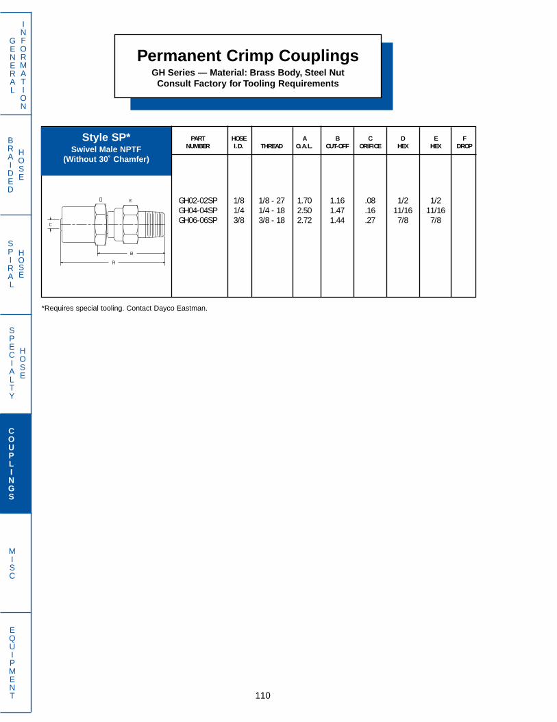
SPECIALTY
HOSE
BRAIDED
HOSE
SPIRAL
HOSE
110
GENERAL
INFORMATION
COUPLINGS
MISC
EQUIPMENT
Permanent Crimp CouplingsGH Series — Material: Brass Body, Steel Nut
Consult Factory for Tooling Requirements
PART HOSE A B C D E FNUMBER I.D. THREAD O.A.L. CUT-OFF ORIFICE HEX HEX DROP
GH02-02SP 1/8 1/8 - 27 1.70 1.16 .08 1/2 1/2GH04-04SP 1/4 1/4 - 18 2.50 1.47 .16 11/16 11/16GH06-06SP 3/8 3/8 - 18 2.72 1.44 .27 7/8 7/8
Style SP*Swivel Male NPTF
(Without 30˚ Chamfer)
*Requires special tooling. Contact Dayco Eastman.

SPECIALTY
HOSE
BRAIDED
HOSE
SPIRAL
HOSE
111
GENERAL
INFORMATION
COUPLINGS
MISC
EQUIPMENT
PART HOSE A B C D E FNUMBER I.D. THREAD O.A.L. CUT-OFF ORIFICE HEX HEX DROP
GR06-08AF 3/8 3/4 - 20 1.46 .83 .31 7/8 7/8GR08-08AF 1/2 3/4 - 20 1.60 .85 .34 1 7/8
Permanent Crimp CouplingsGR Series — Material: Brass Body, Steel Nut
WARNING! Assemblies made using the above data must comply with Federal Regulations specified in FMVSS-106. It is theresponsibility of the assembly maker to meet the FMVSS requirements dealing with assembly, marking and testing of air brakehose assemblies. Failure to comply with FMVSS-106 could result in fines and product recalls to the assembler.
Style AFSwivel Female
Air Brake (3/4-20 Thread)
PART HOSE A B C D E FNUMBER I.D. THREAD O.A.L. CUT-OFF ORIFICE HEX HEX DROP
GR04-04FA 1/4 7/16 - 20 1.52 .83 .20 3/4 9/16GR06-06FA 3/8 5/8 - 18 1.64 1.01 .28 7/8 3/4GR08-08FA 1/2 3/4 - 16 1.78 1.03 .42 1 7/8
Style FASwivel Female
45˚ Flare

SPECIALTY
HOSE
BRAIDED
HOSE
SPIRAL
HOSE
112
GENERAL
INFORMATION
COUPLINGS
MISC
EQUIPMENT
Permanent Crimp CouplingsGR Series — Material: Brass Body, Steel Nut
PART HOSE A B C D E FNUMBER I.D. THREAD O.A.L. CUT-OFF ORIFICE HEX HEX DROP
GR06-06MJ 3/8 9/16 - 18 1.41 .78 .28 7/8
PART HOSE A B C D E FNUMBER I.D. THREAD O.A.L. CUT-OFF ORIFICE HEX HEX DROP
GR04-04FJ 1/4 7/16 - 20 1.46 .83 .20 3/4 9/16GR04-06FJ 1/4 9/16 - 18 1.60 .98 .20 3/4 11/16GR06-06FJ 3/8 9/16 - 18 1.61 .98 .28 7/8 11/16
GR06-08FJ 3/8 3/4 - 16 1.64 1.01 .31 7/8 7/8GR08-08FJ 1/2 3/4 - 16 1.78 1.03 .42 1 7/8GR08-10FJ 1/2 7/8 - 14 1.98 1.16 .42 1 1
Style FJSwivel Female
37˚ Flare
Style MJMale
37˚ Flare
PART HOSE A B C D E FNUMBER I.D. THREAD O.A.L. CUT-OFF ORIFICE HEX HEX DROP
GR04-04MP 1/4 1/4 - 18 1.41 .79 .20 3/4GR06-04MP 3/8 1/4 - 18 1.42 .79 .20 7/8GR06-06MP 3/8 3/8 - 18 1.42 .79 .31 7/8
GR06-08MP 3/8 1/2 - 14 1.63 1.00 .31 7/8GR08-04MP 1/2 1/4 - 18 1.56 .81 .20 1GR08-06MP 1/2 3/8 - 18 1.57 .82 .31 1
GR08-08MP 1/2 1/2 - 14 1.75 1.00 .42 1
Style MPMale NPTF
WARNING! Assemblies made using the above data must comply with Federal Regulations specified in FMVSS-106. It is theresponsibility of the assembly maker to meet the FMVSS requirements dealing with assembly, marking and testing of air brakehose assemblies. Failure to comply with FMVSS-106 could result in fines and product recalls to the assembler.
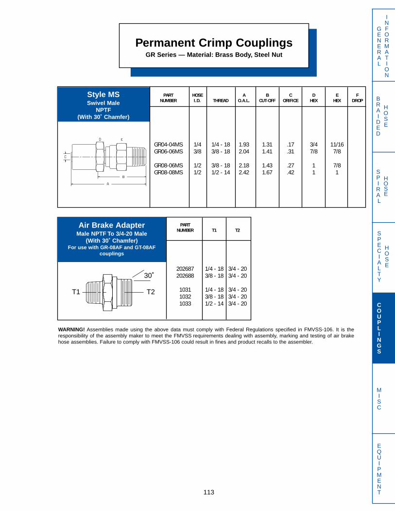
SPECIALTY
HOSE
BRAIDED
HOSE
SPIRAL
HOSE
113
GENERAL
INFORMATION
COUPLINGS
MISC
EQUIPMENT
Permanent Crimp CouplingsGR Series — Material: Brass Body, Steel Nut
PARTNUMBER T1 T2
202687 1/4 - 18 3/4 - 20202688 3/8 - 18 3/4 - 20
1031 1/4 - 18 3/4 - 201032 3/8 - 18 3/4 - 201033 1/2 - 14 3/4 - 20
Air Brake AdapterMale NPTF To 3/4-20 Male
(With 30˚ Chamfer)For use with GR-08AF and GT-08AF
couplings
PART HOSE A B C D E FNUMBER I.D. THREAD O.A.L. CUT-OFF ORIFICE HEX HEX DROP
GR04-04MS 1/4 1/4 - 18 1.93 1.31 .17 3/4 11/16GR06-06MS 3/8 3/8 - 18 2.04 1.41 .31 7/8 7/8
GR08-06MS 1/2 3/8 - 18 2.18 1.43 .27 1 7/8GR08-08MS 1/2 1/2 - 14 2.42 1.67 .42 1 1
Style MSSwivel Male
NPTF(With 30˚ Chamfer)
30˚
T1 T2
WARNING! Assemblies made using the above data must comply with Federal Regulations specified in FMVSS-106. It is theresponsibility of the assembly maker to meet the FMVSS requirements dealing with assembly, marking and testing of air brakehose assemblies. Failure to comply with FMVSS-106 could result in fines and product recalls to the assembler.
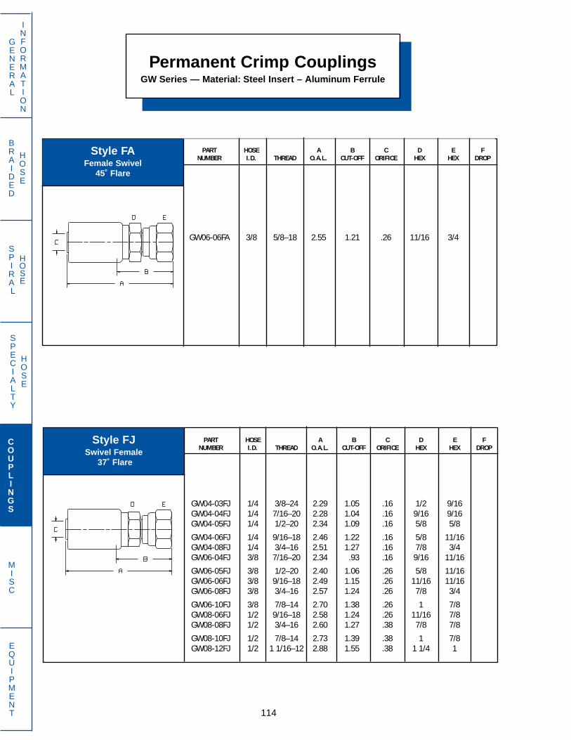
SPECIALTY
HOSE
BRAIDED
HOSE
SPIRAL
HOSE
114
GENERAL
INFORMATION
COUPLINGS
MISC
EQUIPMENT
PART HOSE A B C D E FNUMBER I.D. THREAD O.A.L. CUT-OFF ORIFICE HEX HEX DROP
GW04-03FJ 1/4 3/8–24 2.29 1.05 .16 1/2 9/16GW04-04FJ 1/4 7/16–20 2.28 1.04 .16 9/16 9/16GW04-05FJ 1/4 1/2–20 2.34 1.09 .16 5/8 5/8
GW04-06FJ 1/4 9/16–18 2.46 1.22 .16 5/8 11/16GW04-08FJ 1/4 3/4–16 2.51 1.27 .16 7/8 3/4GW06-04FJ 3/8 7/16–20 2.34 .93 .16 9/16 11/16
GW06-05FJ 3/8 1/2–20 2.40 1.06 .26 5/8 11/16GW06-06FJ 3/8 9/16–18 2.49 1.15 .26 11/16 11/16GW06-08FJ 3/8 3/4–16 2.57 1.24 .26 7/8 3/4
GW06-10FJ 3/8 7/8–14 2.70 1.38 .26 1 7/8GW08-06FJ 1/2 9/16–18 2.58 1.24 .26 11/16 7/8GW08-08FJ 1/2 3/4–16 2.60 1.27 .38 7/8 7/8
GW08-10FJ 1/2 7/8–14 2.73 1.39 .38 1 7/8GW08-12FJ 1/2 1 1/16–12 2.88 1.55 .38 1 1/4 1
Permanent Crimp CouplingsGW Series — Material: Steel Insert – Aluminum Ferrule
Style FJSwivel Female
37˚ Flare
PART HOSE A B C D E FNUMBER I.D. THREAD O.A.L. CUT-OFF ORIFICE HEX HEX DROP
GW06-06FA 3/8 5/8–18 2.55 1.21 .26 11/16 3/4
Style FAFemale Swivel
45˚ Flare
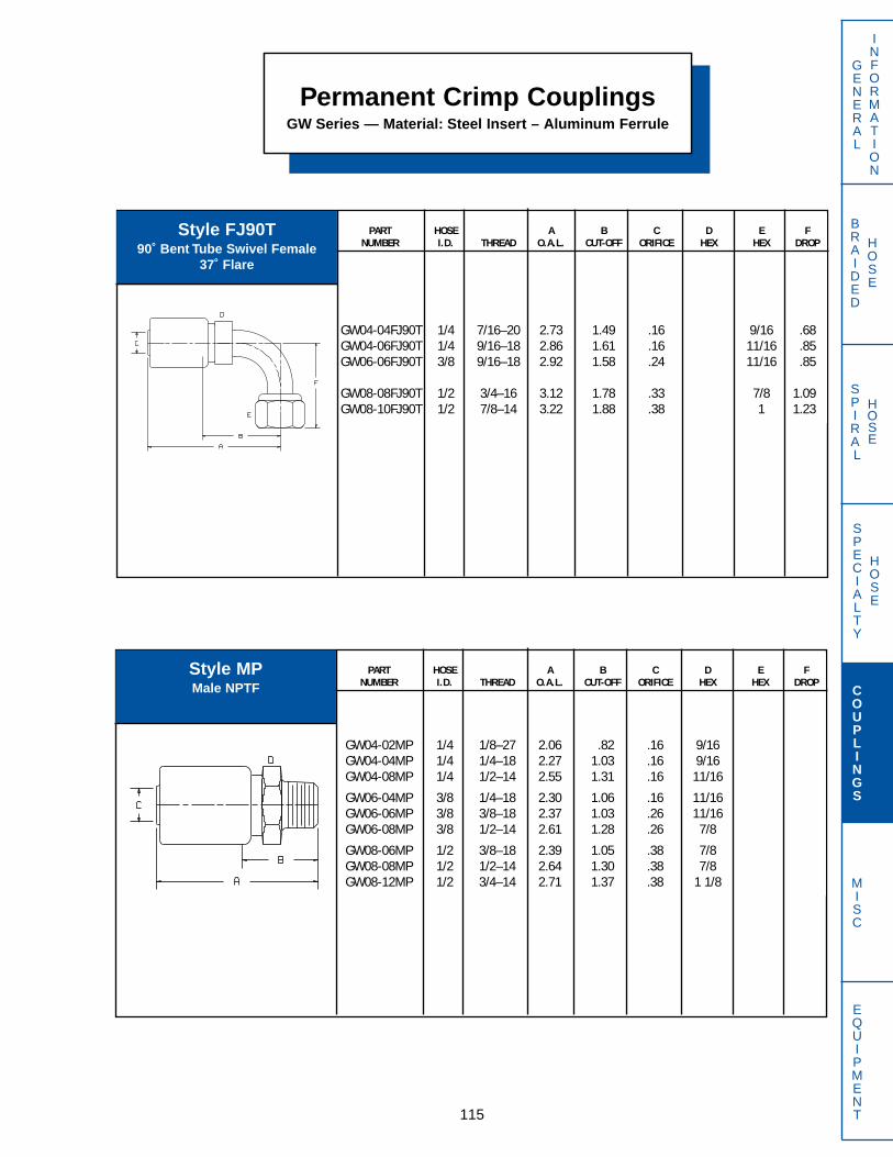
SPECIALTY
HOSE
BRAIDED
HOSE
SPIRAL
HOSE
115
GENERAL
INFORMATION
COUPLINGS
MISC
EQUIPMENT
Permanent Crimp CouplingsGW Series — Material: Steel Insert – Aluminum Ferrule
PART HOSE A B C D E FNUMBER I.D. THREAD O.A.L. CUT-OFF ORIFICE HEX HEX DROP
GW04-02MP 1/4 1/8–27 2.06 .82 .16 9/16GW04-04MP 1/4 1/4–18 2.27 1.03 .16 9/16GW04-08MP 1/4 1/2–14 2.55 1.31 .16 11/16
GW06-04MP 3/8 1/4–18 2.30 1.06 .16 11/16GW06-06MP 3/8 3/8–18 2.37 1.03 .26 11/16GW06-08MP 3/8 1/2–14 2.61 1.28 .26 7/8
GW08-06MP 1/2 3/8–18 2.39 1.05 .38 7/8GW08-08MP 1/2 1/2–14 2.64 1.30 .38 7/8GW08-12MP 1/2 3/4–14 2.71 1.37 .38 1 1/8
PART HOSE A B C D E FNUMBER I.D. THREAD O.A.L. CUT-OFF ORIFICE HEX HEX DROP
GW04-04FJ90T 1/4 7/16–20 2.73 1.49 .16 9/16 .68GW04-06FJ90T 1/4 9/16–18 2.86 1.61 .16 11/16 .85GW06-06FJ90T 3/8 9/16–18 2.92 1.58 .24 11/16 .85
GW08-08FJ90T 1/2 3/4–16 3.12 1.78 .33 7/8 1.09GW08-10FJ90T 1/2 7/8–14 3.22 1.88 .38 1 1.23
Style FJ90T90˚ Bent Tube Swivel Female
37˚ Flare
Style MPMale NPTF

SPECIALTY
HOSE
BRAIDED
HOSE
SPIRAL
HOSE
116
GENERAL
INFORMATION
COUPLINGS
MISC
EQUIPMENT
Permanent Crimp CouplingsGW Series — Material: Steel Insert – Aluminum Ferrule
PART HOSE A B C D E FNUMBER I.D. THREAD O.A.L. CUT-OFF ORIFICE HEX HEX DROP
GW06-06MV 3/8 9/16–18 2.23 .90 .26 11/16 11/16
PART HOSE A B C D E FNUMBER I.D. THREAD O.A.L. CUT-OFF ORIFICE HEX HEX DROP
GW04-02NV 1/4 1/2–27 2.18 .94 .16 11/16GW06-02NV 3/8 1/2–27 2.24 .91 .26 11/16
PART HOSE A B C D E FNUMBER I.D. THREAD O.A.L. CUT-OFF ORIFICE HEX HEX DROP
GW04-04MS 1/4 1/4 - 18 2.63 1.38 .16 9/16GW06-04MS 3/8 1/4 - 18 2.63 1.39 .16 11/16GW06-06MS 3/8 3/8 - 18 2.79 1.45 .26 7/8GW08-08MS 1/2 1/2 - 14 3.05 1.72 .38 1
Style MSSwivel Male NPTFwith 30˚ Chamfer
Style MVMale Flareless
(With Nut and Sleeve)
Style NVFemale
(Grease Hose Thread)

SPECIALTY
HOSE
BRAIDED
HOSE
SPIRAL
HOSE
117
GENERAL
INFORMATION
COUPLINGS
MISC
EQUIPMENT
Permanent Crimp CouplingsGW Series — Material: Steel Insert – Aluminum Ferrule
PART HOSE A B C D E FNUMBER I.D. THREAD O.A.L. CUT-OFF ORIFICE HEX HEX DROP
GW04-04OFT 1/4 9/16–18 2.32 1.08 .16 9/16 11/16GW04-06OFT 1/4 11/16–16 2.45 1.20 .16 11/16 13/16GW04-08OFT 1/4 13/16–16 2.51 1.27 .16 3/4 15/16
GW06-06OFT 3/8 11/16–16 2.51 1.17 .26 11/16 13/16GW06-08OFT 3/8 13/16–16 2.57 1.24 .26 3/4 15/16GW08-08OFT 1/2 13/16–16 2.60 1.27 .38 7/8 15/16
GW08-10OFT 1/2 1–14 2.84 1.51 .38 15/16 1 1/8GW08-12OFT 1/2 1 3/16–12 2.94 1.61 .38 1 1/8 1 3/8
PART HOSE A B C D E FNUMBER I.D. THREAD O.A.L. CUT-OFF ORIFICE HEX HEX DROP
GW08-08OF90T 1/2 13/16–16 3.12 1.78 .33 15/16 1.15
Style OFTSwivel Female
O-Ring Face Seal
Style OF90T90˚ Bent Tube Swivel Female
O-Ring Face Seal

SPECIALTY
HOSE
BRAIDED
HOSE
SPIRAL
HOSE
118
GENERAL
INFORMATION
COUPLINGS
MISC
EQUIPMENT
Permanent Crimp CouplingsGW Series — Material: Steel Insert – Aluminum Ferrule
PART HOSE A B C D E FNUMBER I.D. THREAD O.A.L. CUT-OFF ORIFICE HEX HEX DROP
GW04-04RC 1/4 7/16–20 2.75 1.51 .16 11/16GW06-06RC 3/8 9/16–18 2.89 1.56 .26 7/8
PART HOSE A B C D E FNUMBER I.D. THREAD O.A.L. CUT-OFF ORIFICE HEX HEX DROP
GW04-04RA 1/4 7/16–20 2.02 .78 .16 9/16GW06-06RA 3/8 9/16–18 2.25 .92 .26 9/16
Style RA is furnished with O-Ring
Style RC is furnished with O-Ring
Style RAMale
O-Ring Boss
Style RCSwivel Male O-Ring Boss

SPECIALTY
HOSE
BRAIDED
HOSE
SPIRAL
HOSE
119
GENERAL
INFORMATION
COUPLINGS
MISC
EQUIPMENT
Permanent Crimp CouplingsHF Series — Material: Steel
PART HOSE A B C D E FNUMBER I.D. THREAD O.A.L. CUT-OFF ORIFICE HEX HEX DROP
HF03-04FA 3/16 7/16–20 2.14 1.16 .09 9/16 9/16HF10-10FA 5/8 7/8–14 3.06 1.66 .50 1 1/8 1
PART HOSE A B C D E FNUMBER I.D. THREAD O.A.L. CUT-OFF ORIFICE HEX HEX DROP
HF10-10FJ90T 5/8 7/8–14 3.39 1.97 .50 1 1.23HF10-12FJ90T 5/8 1 1/16–12 3.89 2.47 .50 1 1/4 1.83
PART HOSE A B C D E FNUMBER I.D. THREAD O.A.L. CUT-OFF ORIFICE HEX HEX DROP
HF03-04FJ 3/16 7/16–20 2.14 1.16 .09 9/16 5/8HF03-06FJ 3/16 9/16–18 2.20 1.22 .09 5/8 11/16
HF10-10FJ 5/8 7/8–14 3.08 1.66 .48 1 1/8 1HF10-12FJ 5/8 1 1/16–12 3.12 1.72 .50 1 1/8 1 1/4
Style FASwivel Female
45˚ Flare
Style FJSwivel Female
37˚ Flare
Style FJ90T90˚Bent Tube Swivel Female
37˚ Flare

SPECIALTY
HOSE
BRAIDED
HOSE
SPIRAL
HOSE
120
GENERAL
INFORMATION
COUPLINGS
MISC
EQUIPMENT
Permanent Crimp CouplingsHF Series — Material: Steel
PART HOSE A B C D E FNUMBER I.D. THREAD O.A.L. CUT-OFF ORIFICE HEX HEX DROP
HF03-04FN 3/16 1/4–18 2.19 1.22 .09 9/16 11/16
PART HOSE A B C D E FNUMBER I.D. THREAD O.A.L. CUT-OFF ORIFICE HEX HEX DROP
HF03-04MJ 3/16 7/16–20 2.05 1.06 .09 9/16HF10-10MJ 5/8 7/8–14 2.98 1.56 .48 1 1/8HF10-12MJ 5/8 1 1/16–12 3.09 1.69 .50 1 1/8
Style FNSwivel Female NPSM
30˚ Seat
Style MJMale
37˚ Flare

SPECIALTY
HOSE
BRAIDED
HOSE
SPIRAL
HOSE
121
GENERAL
INFORMATION
COUPLINGS
MISC
EQUIPMENT
Permanent Crimp CouplingsHF Series — Material: Steel
PART HOSE A B C D E FNUMBER I.D. THREAD O.A.L. CUT-OFF ORIFICE HEX HEX DROP
HF10-10OFT 5/8 1–14 3.72 1.75 .50 1-1/8 1-1/8HF10-12OFT 5/8 1 3/16–12 3.20 1.88 .50 1-1/8 1-3/8
PART HOSE A B C D E FNUMBER I.D. THREAD O.A.L. CUT-OFF ORIFICE HEX HEX DROP
HF03-02MP 3/16 1/8–27 1.88 .91 .09 9/16HF03-04MP 3/16 1/4–18 2.06 1.09 .09 9/16
HF10-08MP 5/8 1/2–14 2.98 1.56 .50 1 1/8HF10-12MP 5/8 3/4–14 2.98 1.56 .50 1 1/8
Style MPMale NPTF
Style OFTSwivel Female
O-Ring Face Seal
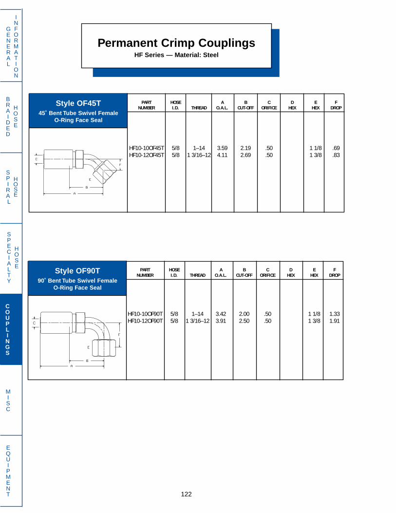
SPECIALTY
HOSE
BRAIDED
HOSE
SPIRAL
HOSE
122
GENERAL
INFORMATION
COUPLINGS
MISC
EQUIPMENT
Permanent Crimp CouplingsHF Series — Material: Steel
PART HOSE A B C D E FNUMBER I.D. THREAD O.A.L. CUT-OFF ORIFICE HEX HEX DROP
HF10-10OF90T 5/8 1–14 3.42 2.00 .50 1 1/8 1.33HF10-12OF90T 5/8 1 3/16–12 3.91 2.50 .50 1 3/8 1.91
PART HOSE A B C D E FNUMBER I.D. THREAD O.A.L. CUT-OFF ORIFICE HEX HEX DROP
HF10-10OF45T 5/8 1–14 3.59 2.19 .50 1 1/8 .69HF10-12OF45T 5/8 1 3/16–12 4.11 2.69 .50 1 3/8 .83
Style OF45T45˚ Bent Tube Swivel Female
O-Ring Face Seal
Style OF90T90˚ Bent Tube Swivel Female
O-Ring Face Seal

SPECIALTY
HOSE
BRAIDED
HOSE
SPIRAL
HOSE
123
GENERAL
INFORMATION
COUPLINGS
MISC
EQUIPMENT
Permanent Crimp CouplingsHR Series –– Material: Steel
Style FJSwivel Female 37˚ Flare
PART HOSE FLANGE A B C D E FNUMBER I.D. O.D. O.A.L. CUT-OFF ORIFICE HEX HEX DROP
HR32-32PA 2 2.81 4.88 3.28 1.75HR40-40PA 2 1/2 3.31 5.13 3.04 2.29HR40-48PA 2 1/2 4.00 5.13 3.04 2.29HR48-48PA 3 4.00 6.62 3.41 2.78
PART HOSE A B C D E FNUMBER I.D. THREAD O.A.L. CUT-OFF ORIFICE HEX HEX DROP
HR24-24FJ 1 1/2 1 7/8 - 12 3.41 2.13 1.25 2 1/4 2 1/4HR32-32FJ 2 2 1/2 - 12 4.15 2.55 1.75 2 1/2 2 7/8
PART HOSE A B C D E FNUMBER I.D. THREAD O.A.L. CUT-OFF ORIFICE HEX HEX DROP
HR24-24MP 1 1/2 1 1/2 - 11 1/2 3.10 1.81 1.25 2 1/4HR32-32MP 2 2 - 11 1/2 3.52 1.92 1.75 2 1/2
PART HOSE A B C D E FNUMBER I.D. THREAD O.A.L. CUT-OFF ORIFICE HEX HEX DROP
HR24-24MJ 1 1/2 1 7/8 - 12 3.18 1.88 1.25 2 1/4HR32-32MJ 2 2 1/2 - 12 3.82 2.22 1.75 2 1/2
Style MJMale 37˚ Flare
Style MPMale NPTF
Style PAFlange
SAE Code 61

SPECIALTY
HOSE
BRAIDED
HOSE
SPIRAL
HOSE
124
GENERAL
INFORMATION
COUPLINGS
MISC
EQUIPMENT
Permanent Crimp CouplingsHR Series –– Material: Steel
PART HOSE FLANGE A B C D E FNUMBER I.D. O.D. O.A.L. CUT-OFF ORIFICE HEX HEX DROP
HR40-40PA30 2 1/2 3.31 5.97 3.88 2.29 .94HR40-48PA30 2 1/2 4.00 5.97 3.88 2.29 .94
PART HOSE FLANGE A B C D E FNUMBER I.D. O.D. O.A.L. CUT-OFF ORIFICE HEX HEX DROP
HR40-40PA22 2 1/2 3.31 5.63 3.57 2.29 .62HR40-48PA22 2 1/2 4.00 5.63 3.38 2.29 .62HR48-48PA22 3 4.00 7.38 4.17 2.78 .76
Style PA2222 1/2˚ Elbow Flange
SAE Code 61
Style PA3030˚ Elbow Flange
SAE Code 61
Style PA4545° Elbow Flange
SAE Code 61
PART HOSE FLANGE A B C D E FNUMBER I.D. O.D. O.A.L. CUT-OFF ORIFICE HEX HEX DROP
HR32-32PA45 2 2.81 5.93 4.33 1.75 2.00HR40-40PA45 2 1/2 3.31 6.65 4.57 2.29 1.72
HR40-48PA45 2 1/2 4.00 6.65 4.57 2.29 1.77HR48-48PA45 3 4.00 9.05 5.79 2.78 2.09
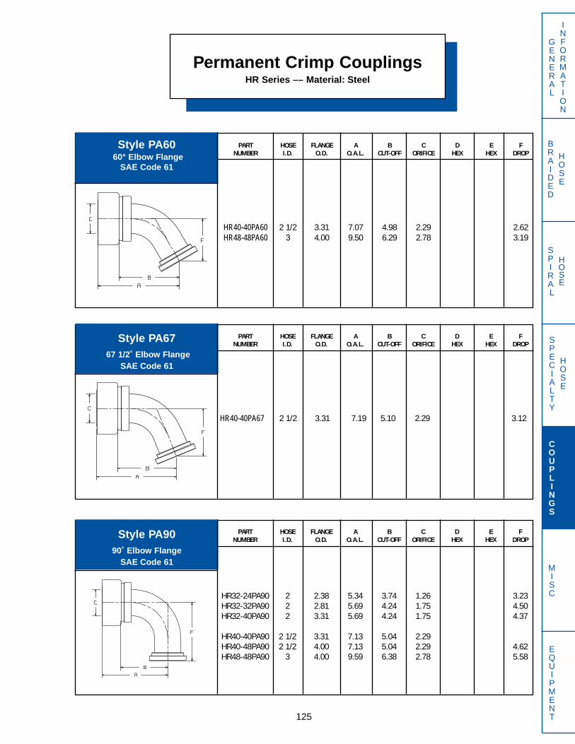
SPECIALTY
HOSE
BRAIDED
HOSE
SPIRAL
HOSE
125
GENERAL
INFORMATION
COUPLINGS
MISC
EQUIPMENT
Permanent Crimp CouplingsHR Series –– Material: Steel
PART HOSE FLANGE A B C D E FNUMBER I.D. O.D. O.A.L. CUT-OFF ORIFICE HEX HEX DROP
HR32-24PA90 2 2.38 5.34 3.74 1.26 3.23HR32-32PA90 2 2.81 5.69 4.24 1.75 4.50HR32-40PA90 2 3.31 5.69 4.24 1.75 4.37
HR40-40PA90 2 1/2 3.31 7.13 5.04 2.29HR40-48PA90 2 1/2 4.00 7.13 5.04 2.29 4.62HR48-48PA90 3 4.00 9.59 6.38 2.78 5.58
Style PA6060° Elbow Flange
SAE Code 61
PART HOSE FLANGE A B C D E FNUMBER I.D. O.D. O.A.L. CUT-OFF ORIFICE HEX HEX DROP
HR40-40PA60 2 1/2 3.31 7.07 4.98 2.29 2.62HR48-48PA60 3 4.00 9.50 6.29 2.78 3.19
PART HOSE FLANGE A B C D E FNUMBER I.D. O.D. O.A.L. CUT-OFF ORIFICE HEX HEX DROP
HR40-40PA67 2 1/2 3.31 7.19 5.10 2.29 3.12
Style PA6767 1/2˚ Elbow Flange
SAE Code 61
Style PA9090˚ Elbow Flange
SAE Code 61

SPECIALTY
HOSE
BRAIDED
HOSE
SPIRAL
HOSE
126
GENERAL
INFORMATION
COUPLINGS
MISC
EQUIPMENT
Permanent Crimp CouplingsHT Series –– Material: 303 Stainless Steel
PART HOSE A B C D E FNUMBER I.D. THREAD O.A.L. CUT-OFF ORIFICE HEX HEX DROP
HT04-04MP 3/16 1/4–18 1.64 1.06 .13 9/16HT05-04MP 1/4 1/4–18 1.64 1.06 .19 5/8HT06-06MP 5/16 3/8–18 1.67 1.06 .23 11/16
HT08-08MP 13/32 1/2–14 1.94 1.25 .31 7/8HT10-08MP 1/2 1/2–14 1.97 1.28 .41 7/8HT12-12MP 5/8 3/4–14 2.03 1.34 .52 1 1/8
HT16-16MP 7/8 1 11-1/2 2.34 1.53 .75 1 3/8
PART HOSE A B C D E FNUMBER I.D. THREAD O.A.L. CUT-OFF ORIFICE HEX HEX DROP
HT04-04FJ 3/16 7/16–20 1.66 1.09 .13 9/16 9/16HT05-05FJ 1/4 1/2–20 1.77 1.19 .19 5/8 5/8HT06-06FJ 5/16 9/16–18 1.81 1.22 .23 11/16 11/16
HT08-08FJ 13/32 3/4–16 1.94 1.25 .31 7/8 7/8HT10-10FJ 1/2 7/8–14 2.13 1.44 .41 7/8 1HT12-12FJ 5/8 1 1/16–12 2.17 1.50 .52 1 1/8 1 1/4
HT16-16FJ 7/8 1 5/16–12 2.38 1.56 .75 1 3/8 1 1/2
Style FJSwivel Female
37˚ Flare
Style MPMale NPTF
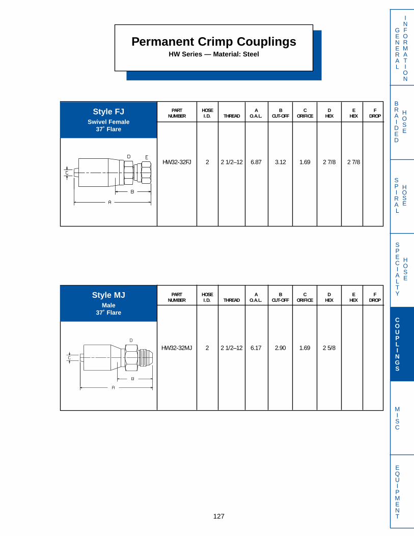
SPECIALTY
HOSE
BRAIDED
HOSE
SPIRAL
HOSE
127
GENERAL
INFORMATION
COUPLINGS
MISC
EQUIPMENT
PART HOSE A B C D E FNUMBER I.D. THREAD O.A.L. CUT-OFF ORIFICE HEX HEX DROP
HW32-32MJ 2 2 1/2–12 6.17 2.90 1.69 2 5/8
PART HOSE A B C D E FNUMBER I.D. THREAD O.A.L. CUT-OFF ORIFICE HEX HEX DROP
HW32-32FJ 2 2 1/2–12 6.87 3.12 1.69 2 7/8 2 7/8
Style FJSwivel Female
37˚ Flare
Permanent Crimp CouplingsHW Series — Material: Steel
Style MJMale
37˚ Flare

SPECIALTY
HOSE
BRAIDED
HOSE
SPIRAL
HOSE
128
GENERAL
INFORMATION
COUPLINGS
MISC
EQUIPMENT
Permanent Crimp CouplingsHW Series — Material: Steel
PART HOSE A B C D E FNUMBER I.D. THREAD O.A.L. CUT-OFF ORIFICE HEX HEX DROP
HW32-32MP 2 2 11-1/2 5.87 2.37 1.69 2 1/2
PART HOSE FLANGE A B C D E FNUMBER I.D. O.D. O.A.L. CUT-OFF ORIFICE HEX HEX DROP
HW32-24PA 2 2.38 6.43 3.18 1.27HW32-32PA 2 2.81 7.31 4.06 1.69
Style MPMale NPTF
Style PAFlange
SAE Code 61
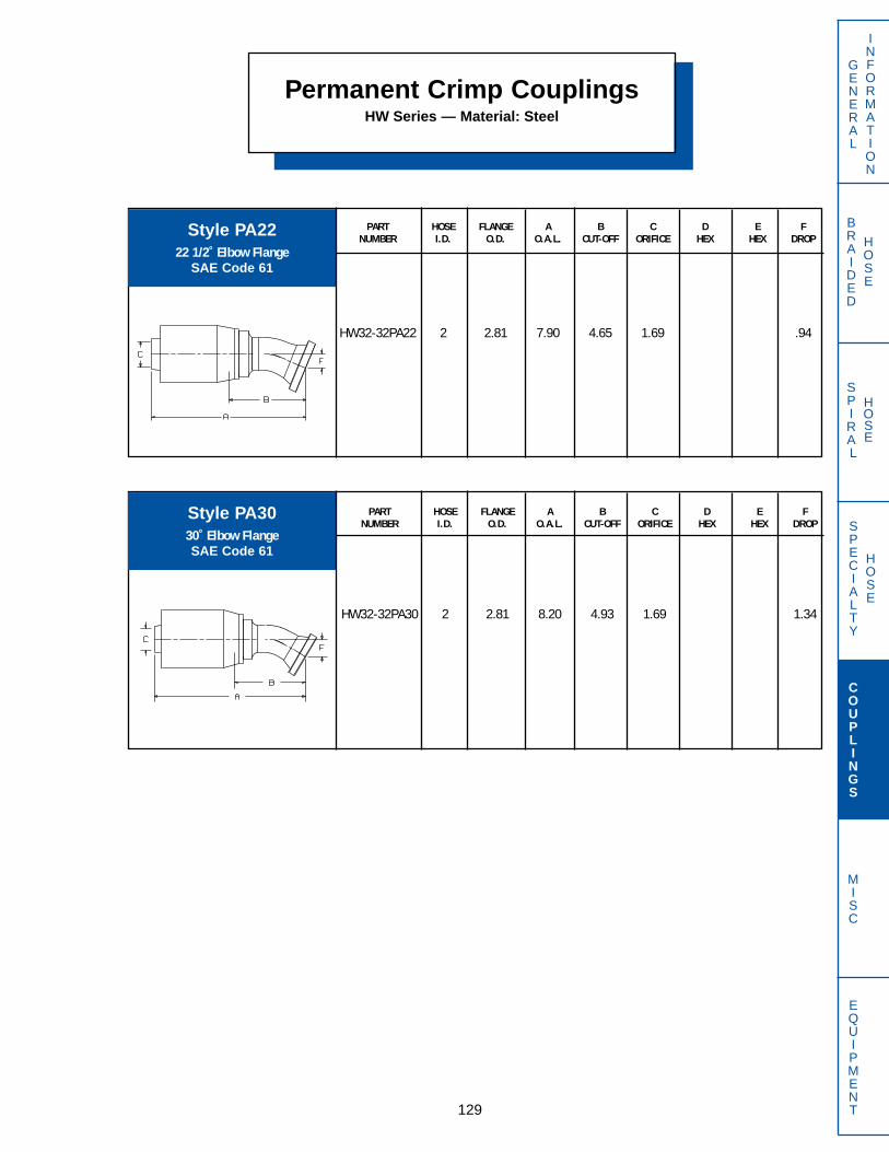
SPECIALTY
HOSE
BRAIDED
HOSE
SPIRAL
HOSE
129
GENERAL
INFORMATION
COUPLINGS
MISC
EQUIPMENT
Permanent Crimp CouplingsHW Series — Material: Steel
PART HOSE FLANGE A B C D E FNUMBER I.D. O.D. O.A.L. CUT-OFF ORIFICE HEX HEX DROP
HW32-32PA22 2 2.81 7.90 4.65 1.69 .94
PART HOSE FLANGE A B C D E FNUMBER I.D. O.D. O.A.L. CUT-OFF ORIFICE HEX HEX DROP
HW32-32PA30 2 2.81 8.20 4.93 1.69 1.34
Style PA2222 1/2˚ Elbow Flange
SAE Code 61
Style PA3030˚ Elbow FlangeSAE Code 61
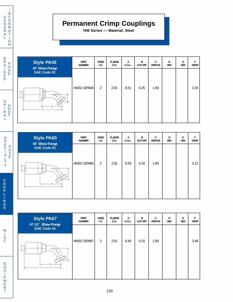
SPECIALTY
HOSE
BRAIDED
HOSE
SPIRAL
HOSE
130
GENERAL
INFORMATION
COUPLINGS
MISC
EQUIPMENT
Permanent Crimp CouplingsHW Series — Material: Steel
PART HOSE FLANGE A B C D E FNUMBER I.D. O.D. O.A.L. CUT-OFF ORIFICE HEX HEX DROP
HW32-32PA60 2 2.81 8.59 5.34 1.69 3.12
PART HOSE FLANGE A B C D E FNUMBER I.D. O.D. O.A.L. CUT-OFF ORIFICE HEX HEX DROP
HW32-32PA67 2 2.81 8.40 5.15 1.69 3.48
PART HOSE FLANGE A B C D E FNUMBER I.D. O.D. O.A.L. CUT-OFF ORIFICE HEX HEX DROP
HW32-32PA45 2 2.81 8.51 5.25 1.69 2.20
Style PA4545˚ Elbow FlangeSAE Code 61
Style PA6060˚ Elbow FlangeSAE Code 61
Style PA6767 1/2˚ Elbow Flange
SAE Code 61

SPECIALTY
HOSE
BRAIDED
HOSE
SPIRAL
HOSE
131
GENERAL
INFORMATION
COUPLINGS
MISC
EQUIPMENT
Permanent Crimp CouplingsHW Series — Material: Steel
PART HOSE FLANGE A B C D E FNUMBER I.D. O.D. O.A.L. CUT-OFF ORIFICE HEX HEX DROP
HW32-32PA90 2 2.81 8.06 4.81 1.69 4.87
Style PA9090˚ Elbow FlangeSAE Code 61

SPECIALTY
HOSE
BRAIDED
HOSE
SPIRAL
HOSE
132
GENERAL
INFORMATION
COUPLINGS
MISC
EQUIPMENT
Permanent Crimp CouplingsHY Series –– Material: Steel
PART HOSE A B C D E FNUMBER I.D. THREAD O.A.L. CUT-OFF ORIFICE HEX HEX DROP
HY06-06BA 3/8 17/32–24 2.43 1.06 .27 11/16
Style BAMale Air Brake
SAE J246
13⁄167⁄8
1 1⁄16
7⁄87⁄8
1 1⁄16
7⁄81 1⁄161 1⁄8
1 5⁄161 5⁄161 9⁄16
1⁄41⁄41⁄4
5⁄163⁄83⁄8
1/21/25⁄8
5⁄83⁄41
HY04-04BPHY04-06BPHY04-08BP
HY05-06BPHY06-06BPHY06-08BP
HY08-06BPHY08-08BPHY10-10BP
HY10-12BPHY12-12BPHY16-16BP
1⁄4 - 193⁄8 - 191/2 - 14
3⁄8 - 193⁄8 - 191/2 - 14
3⁄8 - 191/2 - 145⁄8 - 14
3⁄4 - 143⁄4 - 141 - 11
2.402.542.64
2.572.552.65
2.732.832.98
2.983.093.31
1.031.191.28
1.281.191.28
1.381.471.59
1.591.501.69
.16
.16
.16
.20
.27
.27
.38
.38
.50
.50
.61
.81
PART HOSE A B C D E FNUMBER I.D. THREAD O.A.L. CUT-OFF ORIFICE HEX HEX DROP
Style BPMale BSPP DIN 3852
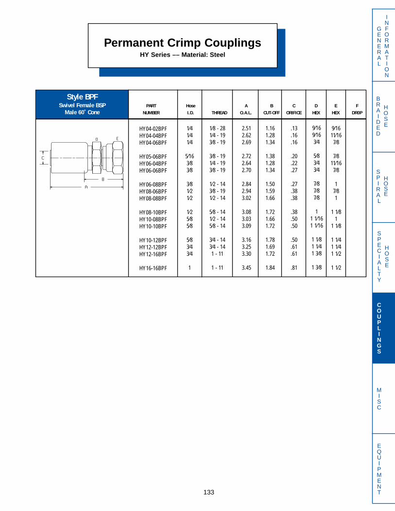
SPECIALTY
HOSE
BRAIDED
HOSE
SPIRAL
HOSE
133
GENERAL
INFORMATION
COUPLINGS
MISC
EQUIPMENT
PART Hose A B C D E FNUMBER I.D. THREAD O.A.L. CUT-OFF ORIFICE HEX HEX DR0P
Permanent Crimp CouplingsHY Series –– Material: Steel
1.161.281.34
1.381.281.34
1.501.591.66
1.721.661.72
1.781.691.72
1.84
.13
.16
.16
.20
.22
.27
.27
.38
.38
.38
.50
.50
.50
.61
.61
.81
9⁄1611⁄167⁄8
7⁄811⁄167⁄8
17⁄81
1 1⁄81
1 1⁄8
1 1⁄41 1⁄41 1⁄2
1 1⁄2
9⁄169⁄163⁄4
5⁄83⁄43⁄4
7⁄87⁄87⁄8
11 1⁄161 1⁄16
1 1⁄81 1⁄41 3⁄8
1 3⁄8
1⁄8 - 281⁄4 - 193⁄8 - 19
3⁄8 - 191⁄4 - 193⁄8 - 19
1⁄2 - 143⁄8 - 191⁄2 - 14
5⁄8 - 141⁄2 - 145⁄8 - 14
3⁄4 - 143⁄4 - 141 - 11
1 - 11
Style BPFSwivel Female BSP
Male 60˚ Cone
HY04-02BPFHY04-04BPFHY04-06BPF
HY05-06BPFHY06-04BPFHY06-06BPF
HY06-08BPFHY08-06BPFHY08-08BPF
HY08-10BPFHY10-08BPFHY10-10BPF
HY10-12BPFHY12-12BPFHY12-16BPF
HY16-16BPF
1⁄41⁄41⁄4
5⁄163⁄83⁄8
3⁄81⁄21⁄2
1⁄25⁄85⁄8
5⁄83⁄43⁄4
1
2.512.622.69
2.722.642.70
2.842.943.02
3.083.033.09
3.163.253.30
3.45
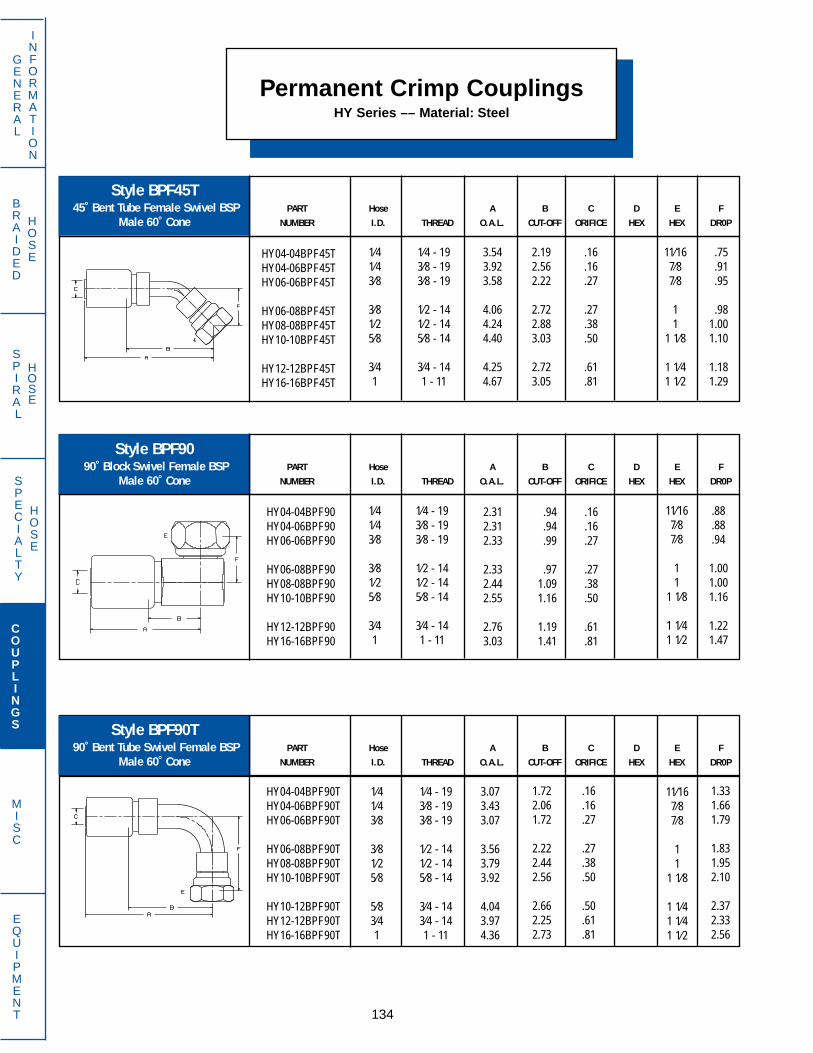
SPECIALTY
HOSE
BRAIDED
HOSE
SPIRAL
HOSE
134
GENERAL
INFORMATION
COUPLINGS
MISC
EQUIPMENT
PART Hose A B C D E FNUMBER I.D. THREAD O.A.L. CUT-OFF ORIFICE HEX HEX DR0P
PART Hose A B C D E FNUMBER I.D. THREAD O.A.L. CUT-OFF ORIFICE HEX HEX DR0P
PART Hose A B C D E FNUMBER I.D. THREAD O.A.L. CUT-OFF ORIFICE HEX HEX DR0P
Permanent Crimp CouplingsHY Series –– Material: Steel
Style BPF90T90˚ Bent Tube Swivel Female BSP
Male 60˚ Cone
Style BPF9090˚ Block Swivel Female BSP
Male 60˚ Cone
Style BPF45T45˚ Bent Tube Female Swivel BSP
Male 60˚ Cone
HY04-04BPF90THY04-06BPF90THY06-06BPF90T
HY06-08BPF90THY08-08BPF90THY10-10BPF90T
HY10-12BPF90THY12-12BPF90THY16-16BPF90T
1⁄41⁄43⁄8
3⁄81⁄25⁄8
5⁄83⁄41
1⁄4 - 193⁄8 - 193⁄8 - 19
1⁄2 - 141⁄2 - 145⁄8 - 14
3⁄4 - 143⁄4 - 141 - 11
3.073.433.07
3.563.793.92
4.043.974.36
1.722.061.72
2.222.442.56
2.662.252.73
.16
.16
.27
.27
.38
.50
.50
.61
.81
11⁄167⁄87⁄8
11
1 1⁄8
1 1⁄41 1⁄41 1⁄2
1.331.661.79
1.831.952.10
2.372.332.56
HY04-04BPF45THY04-06BPF45THY06-06BPF45T
HY06-08BPF45THY08-08BPF45THY10-10BPF45T
HY12-12BPF45THY16-16BPF45T
1⁄41⁄43⁄8
3⁄81⁄25⁄8
3⁄41
1⁄4 - 193⁄8 - 193⁄8 - 19
1⁄2 - 141⁄2 - 145⁄8 - 14
3⁄4 - 141 - 11
3.543.923.58
4.064.244.40
4.254.67
2.192.562.22
2.722.883.03
2.723.05
.16
.16
.27
.27
.38
.50
.61
.81
11⁄167⁄87⁄8
11
1 1⁄8
1 1⁄41 1⁄2
.75
.91
.95
.981.001.10
1.181.29
HY04-04BPF90HY04-06BPF90HY06-06BPF90
HY06-08BPF90HY08-08BPF90HY10-10BPF90
HY12-12BPF90HY16-16BPF90
1⁄41⁄43⁄8
3⁄81⁄25⁄8
3⁄41
1⁄4 - 193⁄8 - 193⁄8 - 19
1⁄2 - 141⁄2 - 145⁄8 - 14
3⁄4 - 141 - 11
2.312.312.33
2.332.442.55
2.763.03
.94
.94
.99
.971.091.16
1.191.41
.16
.16
.27
.27
.38
.50
.61
.81
11⁄167⁄87⁄8
11
1 1⁄8
1 1⁄41 1⁄2
.88
.88
.94
1.001.001.16
1.221.47

SPECIALTY
HOSE
BRAIDED
HOSE
SPIRAL
HOSE
135
GENERAL
INFORMATION
COUPLINGS
MISC
EQUIPMENT
PART Hose A B C D E FNUMBER I.D. THREAD O.A.L. CUT-OFF ORIFICE HEX HEX DR0P
PART Hose A B C D E FNUMBER I.D. THREAD O.A.L. CUT-OFF ORIFICE HEX HEX DR0P
PART Hose A B C D E FNUMBER I.D. THREAD O.A.L. CUT-OFF ORIFICE HEX HEX DR0P
(MM)
Permanent Crimp CouplingsHY Series –– Material: Steel
Style DXMale Metric 60˚
DIN 7611
Style BTMale BSPTDIN 2999
HY04-02BTHY04-04BTHY04-06BT
HY05-06BTHY06-06BTHY06-08BT
HY08-06BTHY08-08BTHY10-12BT
HY12-12BTHY16-16BT
1⁄41⁄41⁄4
5⁄163⁄83⁄8
1/21/25⁄8
3⁄41
1⁄8 - 281⁄4 - 193⁄8 - 19
3⁄8 - 193⁄8 - 191/2 - 14
3⁄8 - 191/2 - 143⁄4 - 14
3⁄4 - 141 - 11
2.342.532.53
2.562.552.73
2.722.912.92
3.083.42
1.001.191.19
1.221.191.38
1.381.561.59
1.501.82
.16
.16
.16
.20
.27
.27
.38
.38
.50
.61
.81
9⁄169⁄1611⁄16
3⁄411⁄167⁄8
7⁄87⁄8
1 1⁄8
1 1⁄41 3⁄8
Style BPHBSwivel Female BSP
Flat Faced Seat
HY06-08BPHBHY08-08BPHB
HY08-12BPHBHY12-12BPHB
3⁄81⁄2
1⁄23⁄4
1⁄2 - 141⁄2 - 14
3⁄4 - 143⁄4 - 14
2.842.95
3.143.25
1.501.67
1.781.67
.27
.38
.38
.61
11
1 1⁄41 1⁄4
7⁄87⁄8
1 1⁄81 1⁄4
HY06-10DX16AHY06-12DX18AHY10-18DX26A
HY12-22DX30AHY16-20DX38A
3⁄83⁄85⁄8
3⁄41
M16 X 1.5M18 X 1.5M26 X 1.5
M30 X 1.5M38 X 1.5
2.382.382.71
2.803.04
1.031.031.34
1.221.44
.27
.27
.50
.61
.81
192227
3241

SPECIALTY
HOSE
BRAIDED
HOSE
SPIRAL
HOSE
136
GENERAL
INFORMATION
COUPLINGS
MISC
EQUIPMENT
PART Hose A B C D E FNUMBER I.D. THREAD O.A.L. CUT-OFF ORIFICE HEX HEX DR0P
PART Hose A B C D E FNUMBER I.D. THREAD O.A.L. CUT-OFF ORIFICE HEX HEX DR0P
PART Hose A B C D E FNUMBER I.D. THREAD O.A.L. CUT-OFF ORIFICE HEX HEX DR0P
Permanent Crimp CouplingsHY Series –– Material: Steel
Style FA45T45˚ Bent Tube Swivel Female
45˚ Flare
Style FATStraight Tube Swivel Female
45˚ Flare
Style FASwivel Female
45˚ Flare
HY04-04FAHY04-05FAHY04-06FA
HY05-05FAHY05-06FAHY06-06FA
HY06-08FAHY07-06FAHY07-08FA
HY08-08FAHY08-10FAHY10-10FA
HY10-12FAHY12-08FAHY12-12FA
1⁄41⁄41⁄4
5⁄165⁄163⁄8
3⁄813⁄3213⁄32
1⁄21⁄25⁄8
5⁄83⁄43⁄4
7⁄16 - 201⁄2 - 205⁄8 - 18
1⁄2 - 205⁄8 - 185⁄8 - 18
3⁄4 - 165⁄8 - 183⁄4 - 16
3⁄4 - 167⁄8 - 147⁄8 - 14
1 1⁄16 - 143⁄4 - 16
1 1⁄16 - 14
2.602.662.73
2.682.762.75
2.732.752.73
2.902.983.06
3.333.173.41
1.261.311.38
1.341.411.41
1.381.411.47
1.561.631.69
1.941.591.84
.16
.16
.16
.20
.20
.27
.27
.31
.31
.38
.38
.50
.50
.61
.61
9⁄165⁄83⁄4
5⁄83⁄43⁄4
7⁄83⁄47⁄8
7⁄811
1 1⁄47⁄8
1 1⁄4
9⁄169⁄1611⁄16
5⁄85⁄8
11⁄16
13⁄167⁄87⁄8
7⁄81
1 1⁄8
1 1⁄81 1⁄41 1⁄4
HY06-04FATHY06-05FATHY06-06FAT
3⁄83⁄83⁄8
7⁄16 - 201⁄2 - 205⁄8 - 18
3.113.173.73
1.751.812.38
.19
.27
.27
9⁄165⁄83⁄4
11⁄1611⁄1611⁄16
HY06-04FA45THY06-05FA45THY06-06FA45T
HY07-06FA45THY10-12FA45THY12-12FA45T
3⁄83⁄83⁄8
13⁄325⁄83⁄4
7⁄16 - 201⁄2 - 205⁄8 - 18
5⁄8 - 181 1⁄16 - 141 1⁄16 - 14
3.193.283.33
3.333.944.03
1.841.941.97
1.972.562.44
.19
.27
.27
.31
.50
.61
9⁄165⁄83⁄4
3⁄41 1⁄41 1⁄4
.33
.36
.39
.39
.77
.77

SPECIALTY
HOSE
BRAIDED
HOSE
SPIRAL
HOSE
137
GENERAL
INFORMATION
COUPLINGS
MISC
EQUIPMENT
PART Hose A B C D E FNUMBER I.D. THREAD O.A.L. CUT-OFF ORIFICE HEX HEX DR0P
PART Hose A B C D E FNUMBER I.D. THREAD O.A.L. CUT-OFF ORIFICE HEX HEX DR0P
Permanent Crimp CouplingsHY Series –– Material: Steel
PART Hose A B C D E FNUMBER I.D. THREAD O.A.L. CUT-OFF ORIFICE HEX HEX DR0P
Style FA90T90˚ Bent Tube Swivel Female
45˚ Flare
Style FFFemale NPTF
Style FA90TL90˚ Bent Tube Swivel Female
(Long Drop) 45˚ Flare
1.001.131.13
1.131.131.41
1.501.251.25
1.66
1⁄41⁄41⁄4
3⁄83⁄83⁄8
1/23⁄43⁄4
1
1⁄8 - 271⁄4 - 183⁄8 - 18
1⁄4 - 183⁄8 - 181/2 - 14
1/2 - 141/2 - 143⁄4 - 14
1 - 11 1/2
2.342.472.47
2.482.482.75
2.842.832.83
3.27
.16
.16
.16
.27
.27
.27
.38
.61
.61
.81
5⁄811⁄167⁄8
11⁄167⁄81
1 1 1⁄41 1⁄4
1 1/2
HY05-06FA90THY06-04FA90THY06-05FA90T
HY06-06FA90THY07-06FA90THY10-12FA90THY12-12FA90T
5⁄163⁄83⁄8
3⁄813⁄32
5⁄83⁄4
5⁄8 - 187⁄16 - 201⁄2 - 20
5⁄8 - 185⁄8 - 18
1 1⁄16 - 141 1⁄16 - 14
3.253.083.17
3.233.233.893.98
1.911.721.81
1.881.882.502.39
.20
.19
.27
.27
.31
.50
.61
3⁄49⁄165⁄8
3⁄43⁄4
1 1⁄41 1⁄4
.86
.69
.77
.86
.861.831.83
HY06-06FA90TL 3⁄8 5⁄8 - 18 3.23 1.88 .27 3⁄4 2.19
HY04-02FFHY04-04FFHY04-06FF
HY06-04FFHY06-06FFHY06-08FF
HY08-08FFHY12-08FFHY12-12FF
HY16-16FF
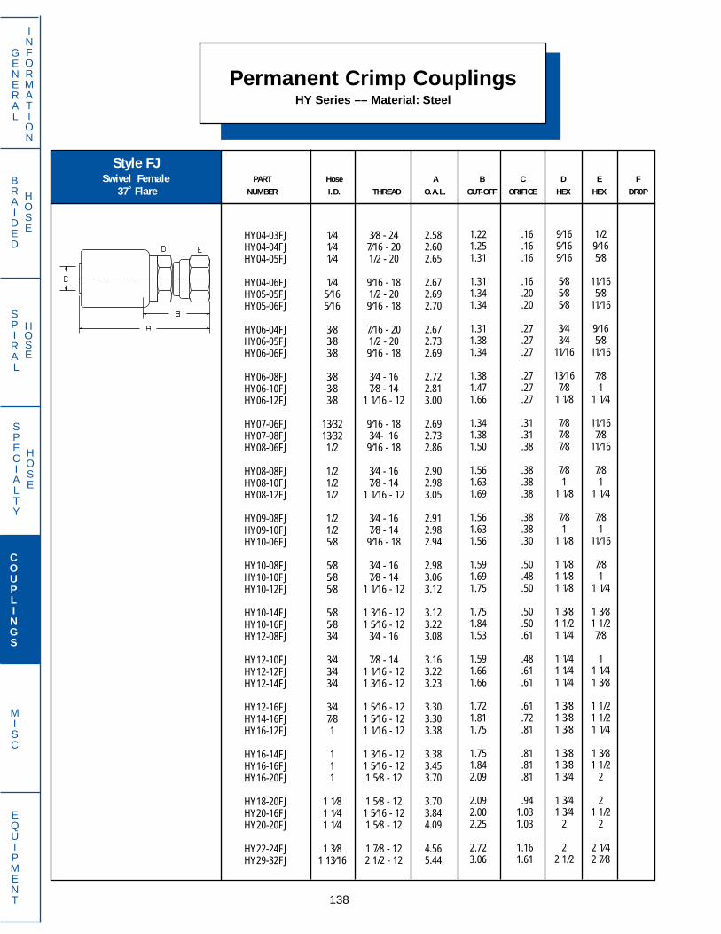
SPECIALTY
HOSE
BRAIDED
HOSE
SPIRAL
HOSE
138
GENERAL
INFORMATION
COUPLINGS
MISC
EQUIPMENT
PART Hose A B C D E FNUMBER I.D. THREAD O.A.L. CUT-OFF ORIFICE HEX HEX DR0P
Permanent Crimp CouplingsHY Series –– Material: Steel
Style FJSwivel Female
37˚ Flare
HY04-03FJHY04-04FJHY04-05FJ
HY04-06FJHY05-05FJHY05-06FJ
HY06-04FJHY06-05FJHY06-06FJ
HY06-08FJHY06-10FJHY06-12FJ
HY07-06FJHY07-08FJHY08-06FJ
HY08-08FJHY08-10FJHY08-12FJ
HY09-08FJHY09-10FJHY10-06FJ
HY10-08FJHY10-10FJHY10-12FJ
HY10-14FJHY10-16FJHY12-08FJ
HY12-10FJHY12-12FJHY12-14FJ
HY12-16FJHY14-16FJHY16-12FJ
HY16-14FJHY16-16FJHY16-20FJ
HY18-20FJHY20-16FJHY20-20FJ
HY22-24FJHY29-32FJ
1⁄41⁄41⁄4
1⁄45⁄165⁄16
3⁄83⁄83⁄8
3⁄83⁄83⁄8
13⁄3213⁄321/2
1/21/21/2
1/21/25⁄8
5⁄85⁄85⁄8
5⁄85⁄83⁄4
3⁄43⁄43⁄4
3⁄47⁄81
111
1 1⁄81 1⁄41 1⁄4
1 3⁄81 13⁄16
3⁄8 - 247⁄16 - 201/2 - 20
9⁄16 - 181/2 - 209⁄16 - 18
7⁄16 - 201/2 - 209⁄16 - 18
3⁄4 - 167⁄8 - 14
1 1⁄16 - 12
9⁄16 - 183⁄4- 16
9⁄16 - 18
3⁄4 - 167⁄8 - 14
1 1⁄16 - 12
3⁄4 - 167⁄8 - 14
9⁄16 - 18
3⁄4 - 167⁄8 - 14
1 1⁄16 - 12
1 3⁄16 - 121 5⁄16 - 12
3⁄4 - 16
7⁄8 - 141 1⁄16 - 121 3⁄16 - 12
1 5⁄16 - 121 5⁄16 - 121 1⁄16 - 12
1 3⁄16 - 121 5⁄16 - 121 5⁄8 - 12
1 5⁄8 - 121 5⁄16 - 121 5⁄8 - 12
1 7⁄8 - 122 1/2 - 12
2.582.602.65
2.672.692.70
2.672.732.69
2.722.813.00
2.692.732.86
2.902.983.05
2.912.982.94
2.983.063.12
3.123.223.08
3.163.223.23
3.303.303.38
3.383.453.70
3.703.844.09
4.565.44
1.221.251.31
1.311.341.34
1.311.381.34
1.381.471.66
1.341.381.50
1.561.631.69
1.561.631.56
1.591.691.75
1.751.841.53
1.591.661.66
1.721.811.75
1.751.842.09
2.092.002.25
2.723.06
.16
.16
.16
.16
.20
.20
.27
.27
.27
.27
.27
.27
.31
.31
.38
.38
.38
.38
.38
.38
.30
.50
.48
.50
.50
.50
.61
.48
.61
.61
.61
.72
.81
.81
.81
.81
.941.031.03
1.161.61
1/29⁄165⁄8
11⁄165⁄8
11⁄16
9⁄165⁄8
11⁄16
7⁄81
1 1⁄4
11⁄167⁄8
11⁄16
7⁄81
1 1⁄4
7⁄81
11⁄16
7⁄81
1 1⁄4
1 3⁄81 1/27⁄8
11 1⁄41 3⁄8
1 1/21 1/21 1⁄4
1 3⁄81 1/2
2
21 1/2
2
2 1⁄42 7⁄8
9⁄169⁄169⁄16
5⁄85⁄85⁄8
3⁄43⁄4
11⁄16
13⁄167⁄8
1 1⁄8
7⁄87⁄87⁄8
7⁄81
1 1⁄8
7⁄81
1 1⁄8
1 1⁄81 1⁄81 1⁄8
1 3⁄81 1/21 1⁄4
1 1⁄41 1⁄41 1⁄4
1 3⁄81 3⁄81 3⁄8
1 3⁄81 3⁄81 3⁄4
1 3⁄41 3⁄4
2
22 1/2

SPECIALTY
HOSE
BRAIDED
HOSE
SPIRAL
HOSE
139
GENERAL
INFORMATION
COUPLINGS
MISC
EQUIPMENT
PART Hose A B C D E FNUMBER I.D. THREAD O.A.L. CUT-OFF ORIFICE HEX HEX DR0P
PART Hose A B C D E FNUMBER I.D. THREAD O.A.L. CUT-OFF ORIFICE HEX HEX DR0P
Permanent Crimp CouplingsHY Series –– Material: Steel
Style FJ9090˚ Block Swivel Female
37˚ Flare
Style FJ45T45˚ Bent Tube Swivel Female
37˚ Flare
1.881.912.00
2.001.972.31
2.412.062.31
2.562.312.78
2.312.692.94
3.413.66
HY04-04FJ45THY04-05FJ45THY04-06FJ45T
HY05-06FJ45THY06-06FJ45THY06-08FJ45T
HY08-08FJ45THY08-10FJ45THY10-10FJ45T
HY10-12FJ45THY12-12FJ45THY12-16FJ45T
HY16-12FJ45THY16-16FJ45THY18-20FJ45T
HY20-20FJ45THY22-24FJ45T
1⁄41⁄41⁄4
5⁄163⁄83⁄8
1/21/25⁄8
5⁄83⁄43⁄4
11
1 1⁄8
1 1⁄41 3⁄8
7⁄16 - 201/2 - 209⁄16 - 18
9⁄16 - 189⁄16 - 183⁄4 - 16
3⁄4 - 167⁄8 - 147⁄8 - 14
1 1⁄16 - 121 1⁄16 - 121 5⁄16 - 12
1 1⁄16 - 121 5⁄16 - 121 5⁄8 - 12
1 5⁄8 - 121 7⁄8 - 12
3.243.273.34
3.343.333.66
3.773.413.69
3.943.894.35
3.924.314.83
5.235.98
.16
.16
.16
.20
.27
.27
.38
.38
.50
.50
.61
.61
.81
.81
.94
1.031.16
9⁄165⁄83⁄4
11⁄1611⁄167⁄8
7⁄811
1 1⁄81 1⁄41 1/2
1 1⁄41 1/2
2
22 1⁄4
.33
.36
.39
.39
.39
.54
.54
.63
.63
.77
.77
.89
.77
.891.11
1.111.56
HY04-05FJ90HY04-06FJ90HY06-06FJ90
HY06-08FJ90HY08-08FJ90HY08-10FJ90
HY10-10FJ90HY12-10FJ90HY12-12FJ90
HY12-16FJ90
1⁄41⁄43⁄8
3⁄81/21/2
5⁄83⁄43⁄4
3⁄4
1/2 - 209⁄16 - 189⁄16 - 18
3⁄4 - 163⁄4 - 167⁄8 - 14
7⁄8 - 147⁄8 - 14
1 1⁄16 - 12
1 5⁄16 - 12
2.632.632.33
2.333.003.00
3.113.253.33
3.33
.91
.91
.97
.971.091.09
1.161.191.19
1.19
.16
.16
.27
.27
.38
.38
.50
.61
.61
.61
5⁄83⁄4
11⁄16
7⁄87⁄81
11
1 1⁄4
1 1/2
.66
.7378
82.85.89
.98
.96
.99
1.09

SPECIALTY
HOSE
BRAIDED
HOSE
SPIRAL
HOSE
140
GENERAL
INFORMATION
COUPLINGS
MISC
EQUIPMENT
PART Hose A B C D E FNUMBER I.D. THREAD O.A.L. CUT-OFF ORIFICE HEX HEX DR0P
PART Hose A B C D E FNUMBER I.D. THREAD O.A.L. CUT-OFF ORIFICE HEX HEX DR0P
Permanent Crimp CouplingsHY Series –– Material: Steel
Style FJ90TL90˚ Bent Tube Swivel Female
(Long Drop) 37˚ Flare
Style FJ90T90˚ Bent Tube Swivel Female
37˚ Flare
HY04-04FJ90THY04-05FJ90THY04-06FJ90T
HY05-05FJ90THY05-06FJ90THY06-06FJ90T
HY06-08FJ90THY07-08FJ90THY08-06FJ90T
HY08-08FJ90THY08-10FJ90THY08-12FJ90T
HY09-08FJ90THY10-10FJ90THY10-12FJ90T
HY12-10FJ90THY12-12FJ90THY12-16FJ90T
HY14-16FJ90THY16-16FJ90THY18-20FJ90T
HY20-20FJ90THY22-24FJ90T
1⁄41⁄41⁄4
5⁄165⁄163⁄8
3⁄813⁄321/2
1/21/21/2
1/25⁄85⁄8
3⁄43⁄43⁄4
7⁄81
1 1⁄8
1 1⁄41 3⁄8
7⁄16 - 201/2 - 209⁄16 - 18
1/2 - 209⁄16 - 189⁄16 - 18
3⁄4 - 163⁄4 - 16
9⁄16 - 18
3⁄4 - 167⁄8 - 14
1 1⁄16 - 12
3⁄4 - 167⁄8 - 14
1 1⁄16 - 12
7⁄8 - 141 1⁄16 - 121 5⁄16 - 12
1 5⁄16 - 121 5⁄16 - 121 5⁄8 - 12
1 5⁄8 - 121 7⁄8 - 12
3.133.163.25
3.193.253.23
3.483.033.41
3.593.113.61
3.593.393.89
3.253.844.33
3.974.314.81
5.585.80
1.781.811.91
1.841.911.88
2.131.692.06
2.251.752.25
2.252.002.50
1.692.282.78
2.502.692.94
3.753.56
.16
.16
.16
.20
.20
.27
.27
.31
.38
.38
.38
.38
.38
.50
.50
.61
.61
.61
.72
.81
.99
1.031.16
9⁄165⁄83⁄4
5⁄811⁄1611⁄16
7⁄87⁄8
11⁄16
7⁄81
1 1⁄4
7⁄81
1 1⁄4
11 1⁄41 1/2
1 1/21 1/2
2
22 1⁄4
.69
.77
.86
.77
.86
.86
1.121.09
.86
1.131.231.83
1.121.231.83
1.231.832.14
2.142.312.58
2.583.67
HY04-04FJ90TLHY04-05FJ90TLHY04-06FJ90TL
HY05-06FJ90TLHY06-06FJ90TLHY06-08FJ90TL
HY07-08FJ90TLHY08-06FJ90TLHY08-08FJ90TL
HY08-10FJ90TLHY08-12FJ90TLHY12-12FJ90TL
HY16-16FJ90TL
1⁄41⁄41⁄4
5⁄163⁄83⁄8
13⁄321/21/2
1/21/23⁄4
1
7⁄16 - 201/2 - 209⁄16 - 18
9⁄16 - 189⁄16 - 183⁄4 - 16
3⁄4 - 169⁄16 - 183⁄4 - 16
7⁄8 - 141 1⁄16 - 121 1⁄16 - 12
1 5⁄16 - 12
3.133.163.22
3.253.233.48
3.163.413.59
3.363.613.59
4.56
1.781.811.88
1.911.882.13
1.812.062.25
2.002.252.03
2.94
.16
.16
.16
.20
.27
.27
.31
.38
.38
.38
.38
.61
.81
9⁄165⁄8
11⁄16
11⁄1611⁄167⁄8
7⁄811⁄167⁄8
11 1⁄41 1⁄4
1 1/2
1.801.772.19
2.192.192.44
2.442.192.44
2.583.733.73
4.33
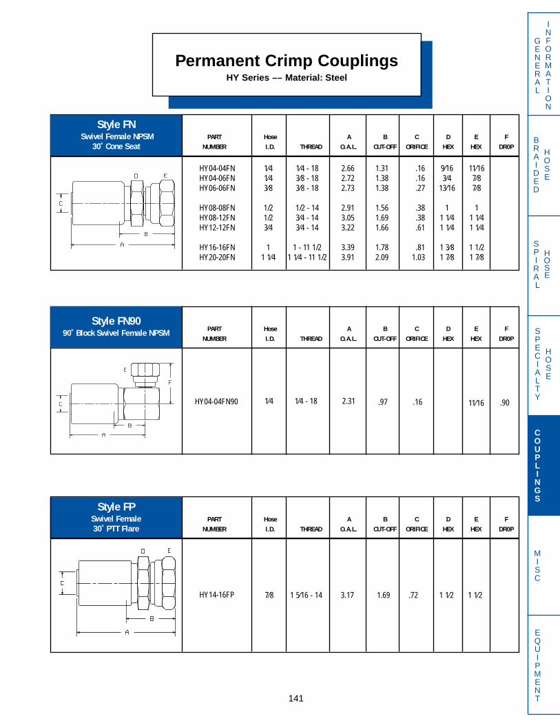
SPECIALTY
HOSE
BRAIDED
HOSE
SPIRAL
HOSE
HY04-04FN90 1⁄4 1⁄4 - 18 2.31 .97 .16 11⁄16 .90
141
GENERAL
INFORMATION
COUPLINGS
MISC
EQUIPMENT
PART Hose A B C D E FNUMBER I.D. THREAD O.A.L. CUT-OFF ORIFICE HEX HEX DR0P
PART Hose A B C D E FNUMBER I.D. THREAD O.A.L. CUT-OFF ORIFICE HEX HEX DR0P
Permanent Crimp CouplingsHY Series –– Material: Steel
Style FPSwivel Female 30˚ PTT Flare
PART Hose A B C D E FNUMBER I.D. THREAD O.A.L. CUT-OFF ORIFICE HEX HEX DR0P
Style FN9090˚ Block Swivel Female NPSM
Style FNSwivel Female NPSM
30˚ Cone Seat
HY04-04FNHY04-06FNHY06-06FN
HY08-08FNHY08-12FNHY12-12FN
HY16-16FNHY20-20FN
1⁄41⁄43⁄8
1/21/23⁄4
11 1⁄4
1⁄4 - 183⁄8 - 183⁄8 - 18
1/2 - 143⁄4 - 143⁄4 - 14
1 - 11 1/21 1⁄4 - 11 1/2
2.662.722.73
2.913.053.22
3.393.91
1.311.381.38
1.561.691.66
1.782.09
.16
.16
.27
.38
.38
.61
.811.03
11⁄167⁄87⁄8
11 1⁄41 1⁄4
1 1/21 7⁄8
9⁄163⁄4
13⁄16
11 1⁄41 1⁄4
1 3⁄81 7⁄8
HY14-16FP 7⁄8 1 5⁄16 - 14 3.17 1.69 .72 1 1⁄2 1 1⁄2
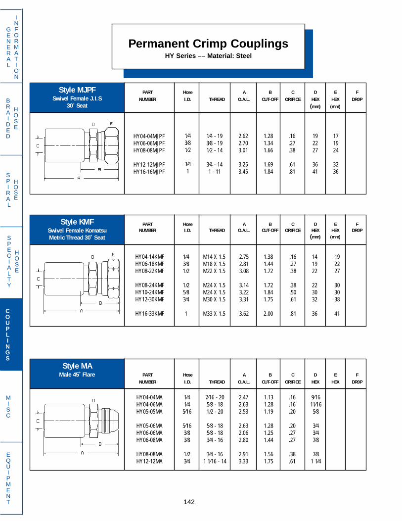
SPECIALTY
HOSE
BRAIDED
HOSE
SPIRAL
HOSE
142
GENERAL
INFORMATION
COUPLINGS
MISC
EQUIPMENT
PART Hose A B C D E FNUMBER I.D. THREAD O.A.L. CUT-OFF ORIFICE HEX HEX DR0P
(mm) (mm)
PART Hose A B C D E FNUMBER I.D. THREAD O.A.L. CUT-OFF ORIFICE HEX HEX DR0P
(mm) (mm)
Permanent Crimp CouplingsHY Series –– Material: Steel
Style MAMale 45˚ Flare PART Hose A B C D E F
NUMBER I.D. THREAD O.A.L. CUT-OFF ORIFICE HEX HEX DR0P
Style KMFSwivel Female Komatsu Metric Thread 30˚ Seat
Style MJPFSwivel Female J.I.S
30˚ Seat
HY04-04MJPFHY06-06MJPFHY08-08MJPF
HY12-12MJPFHY16-16MJPF
1⁄43⁄81⁄2
3⁄41
1⁄4 - 193⁄8 - 191⁄2 - 14
3⁄4 - 141 - 11
2.622.703.01
3.253.45
1.281.341.66
1.691.84
.16
.27
.38
.61
.81
171924
3236
192227
3641
HY04-14KMFHY06-18KMFHY08-22KMF
HY08-24KMFHY10-24KMFHY12-30KMF
HY16-33KMF
1⁄43⁄81/2
1/25⁄83⁄4
1
M14 X 1.5M18 X 1.5M22 X 1.5
M24 X 1.5M24 X 1.5M30 X 1.5
M33 X 1.5
2.752.813.08
3.143.223.31
3.62
1.381.441.72
1.721.841.75
2.00
.16
.27
.38
.38
.50
.61
.81
192227
303038
41
141922
223032
36
HY04-04MAHY04-06MAHY05-05MA
HY05-06MAHY06-06MAHY06-08MA
HY08-08MAHY12-12MA
1⁄41⁄4
5⁄16
5⁄163⁄83⁄8
1/23⁄4
7⁄16 - 205⁄8 - 181/2 - 20
5⁄8 - 185⁄8 - 183⁄4 - 16
3⁄4 - 161 1⁄16 - 14
2.472.632.53
2.632.062.80
2.913.33
1.131.281.19
1.281.251.44
1.561.75
.16
.16
.20
.20
.27
.27
.38
.61
9⁄1611⁄165⁄8
3⁄43⁄47⁄8
7⁄81 1⁄4

BRAIDED
HOSE
SPECIALTY
HOSE
SPIRAL
HOSE
PART Hose A B C D E FNUMBER I.D. THREAD O.A.L. CUT-OFF ORIFICE HEX HEX DR0P
PART Hose A B C D E FNUMBER I.D. THREAD O.A.L. CUT-OFF ORIFICE HEX HEX DR0P
HY04-03MF90THY04-04MF90THY04-05MF90T
HY05-06MF90THY06-04MF90THY06-05MF90T
HY06-06MF90THY06-07MF90THY06-08MF90T
HY08-08MF90T
1⁄41⁄41⁄4
5⁄163⁄83⁄8
3⁄83⁄83⁄8
1/2
3⁄8 - 247⁄16 - 241/2 - 20
5⁄8 - 187⁄16 - 241/2 - 20
5⁄8 - 1811⁄16 - 183⁄4 - 16
3⁄4 - 16
3.093.283.52
4.053.113.34
4.034.164.05
4.09
1.751.942.16
2.691.752.00
2.692.812.72
2.75
3⁄87⁄161⁄2
5⁄87⁄161⁄2
5/811⁄163⁄4
3⁄4
.16
.16
.16
.20
.19
.27
.27
.27
.27
.38
PART Hose A B C D E FNUMBER I.D. THREAD O.A.L. CUT-OFF ORIFICE HEX HEX DR0P
GENERAL
INFORMATION
COUPLINGS
MISC
EQUIPMENT143
Style MF90T90˚ Bent Tube Swivel Male
Inverted Flare
Style MF45T45˚ Bent Tube Swivel Male
Inverted Flare
HY04-03MF45THY04-04MF45THY04-05MF45T
HY05-06MF45THY06-04MF45THY06-05MF45T
HY06-06MF45THY06-08MF45THY08-08MF45T
1⁄41⁄41⁄4
5⁄163⁄83⁄8
3⁄83⁄81/2
3⁄8 - 247⁄16 - 241/2 - 20
5⁄8 - 187⁄16 - 241/2 - 20
5⁄8 - 183⁄4 - 163⁄4 - 16
3.033.313.55
4.173.143.38
4.164.174.22
Permanent Crimp CouplingsHY Series — Material: Steel
1.751.942.00
2.062.411.75
1.812.382.38
2.062.31
Style MFSwivel Male
Inverted Flare
HY04-03MFHY04-04MFHY04-05MF
HY05-05MFHY05-06MFHY06-04MF
HY06-05MFHY06-06MFHY06-07MF
HY06-08MFHY08-08MF
1⁄41⁄41⁄4
5⁄165⁄163⁄8
3⁄83⁄83⁄8
3⁄81/2
3⁄8 - 247⁄16 - 241⁄2 - 20
1⁄2 - 205⁄8 - 187⁄16 - 24
1⁄2 - 205⁄8 - 18
11⁄16 - 18
3⁄4 - 163⁄4 - 16
3.093.283.34
3.413.753.11
3.173.733.73
3.423.66
.16
.16
.16
.20
.20
.19
.27
.27
.27
.27
.38
3⁄87⁄161⁄2
1⁄25⁄8
7⁄16
1⁄25⁄8
11⁄16
3⁄43/4
1.691.972.19
2.811.782.03
2.812.812.88
.16
.16
.16
.20
.19
.27
.27
.27
.38
3⁄87⁄161⁄2
5⁄87⁄161⁄2
5⁄83⁄43⁄4
.72
.78
.88
.94
.78
.88
.941.061.06
1.381.471.66
1.691.471.66
1.691.691.88
1.88
For mating nut and sleeve, refer tostyles 760-FS and 761-FS on page 145

BRAIDED
HOSE
SPECIALTY
HOSE
SPIRAL
HOSE
PART Hose A B C D E FNUMBER I.D. THREAD O.A.L. CUT-OFF ORIFICE HEX HEX DR0P
PART Hose A B C D E FNUMBER I.D. THREAD O.A.L. CUT-OFF ORIFICE HEX HEX DR0P
GENERAL
INFORMATION
COUPLINGS
MISC
EQUIPMENT
Permanent Crimp CouplingsHY Series — Material: Steel
144
Style MJMale 37˚ Flare
Style MHMale Hi-Seal®
5⁄85⁄8
11⁄16
5⁄811⁄1611⁄16
13⁄161
7⁄8
7⁄87⁄81
1 1⁄87⁄8
1 1⁄8
1 1⁄81 1⁄41 1⁄4
1 1⁄41 3⁄81 3⁄8
1 3⁄81 3⁄41 3⁄4
1⁄41⁄41⁄4
5⁄165⁄163⁄8
3⁄83⁄8
13⁄32
1/21/21/2
1/21/25⁄8
5⁄83⁄43⁄4
3⁄43⁄47⁄8
11
1 1⁄4
7⁄16 - 201/2 - 209⁄16 - 18
1/2 - 209⁄16 - 189⁄16 - 18
3⁄4 - 167⁄8 - 143⁄4 - 16
9⁄16 - 183⁄4 - 167⁄8 - 14
1 1⁄16 - 123⁄4 - 167⁄8 - 14
1 1⁄16 - 127⁄8 - 14
1 1⁄16 - 12
1 3⁄16 - 121 5⁄16 - 121 5⁄16 - 12
1 5⁄16 - 121 5⁄8 - 121 5⁄8 - 12
HY04-04MHHY04-05MHHY06-04MH
HY06-05MHHY06-06MHHY06-08MH
HY08-08MHHY08-10MHHY12-12MH
1⁄41⁄43⁄8
3⁄83⁄83⁄8
1/21/23⁄4
1/2 - 209⁄16 - 181/2 - 20
9⁄16 - 185⁄8 - 183⁄4 - 16
3⁄4 - 1615⁄16 - 161 1⁄16 - 16
2.312.312.33
2.332.382.48
2.592.632.80
.97
.97
.97
.971.031.13
1.251.281.28
.16
.16
.27
.27
.27
.27
.38
.38
.61
9⁄165⁄83⁄4
3⁄411⁄167⁄8
7⁄81
1 1⁄4
HY04-04MJHY04-05MJHY04-06MJ
HY05-05MJHY05-06MJHY06-06MJ
HY06-08MJHY06-10MJHY07-08MJ
HY08-06MJHY08-08MJHY08-10MJ
HY08-12MJHY09-08MJHY10-10MJ
HY10-12MJHY12-10MJHY12-12MJ
HY12-14MJHY12-16MJHY14-16MJ
HY16-16MJHY16-20MJHY20-20MJ
2.522.522.53
2.552.562.54
2.642.812.64
2.722.812.91
3.022.812.98
3.093.083.19
3.193.233.24
3.393.443.83
1.191.191.19
1.191.221.19
1.281.471.28
1.381.471.56
1.661.471.59
1.721.501.63
1.631.661.75
1.781.812.00
.16
.16
.16
.20
.20
.27
.27
.27
.31
.30
.38
.38
.38
.38
.50
.50
.61
.61
.61
.61
.72
.81
.811.03
For mating nut and sleeve information,refer to styles 760-FS and 761-FS onpage 145
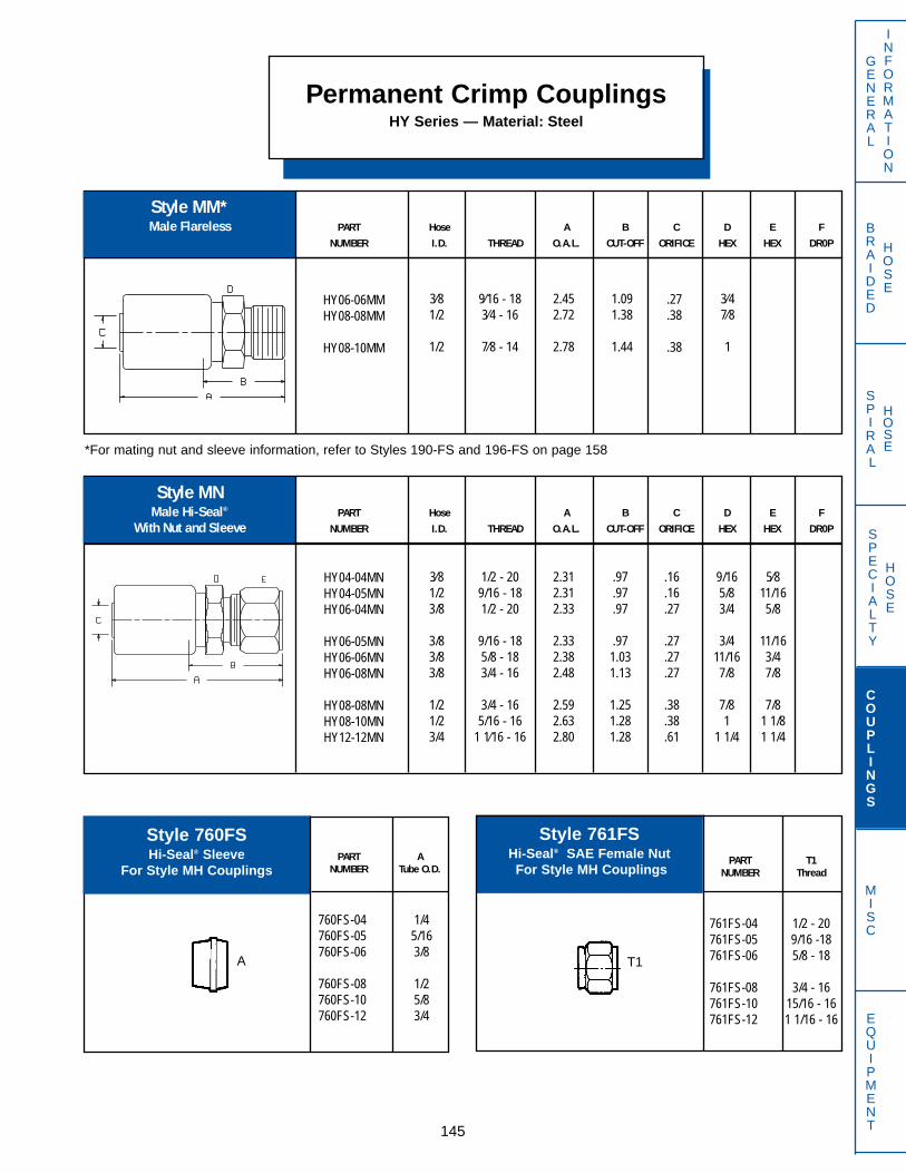
PART T1NUMBER Thread
761FS-04 1/2 - 20761FS-05 9/16 -18761FS-06 5/8 - 18
761FS-08 3/4 - 16761FS-10 15/16 - 16761FS-12 1 1/16 - 16
PART ANUMBER Tube O.D.
760FS-04 1/4760FS-05 5/16760FS-06 3/8
760FS-08 1/2760FS-10 5/8760FS-12 3/4
BRAIDED
HOSE
SPECIALTY
HOSE
SPIRAL
HOSE
HY06-06MMHY08-08MM
HY08-10MM
3⁄81/2
1/2
9⁄16 - 183⁄4 - 16
7⁄8 - 14
2.452.72
2.78
1.091.38
1.44
.27
.38
.38
3⁄47⁄8
1
HY04-04MNHY04-05MNHY06-04MN
HY06-05MNHY06-06MNHY06-08MN
HY08-08MNHY08-10MNHY12-12MN
3⁄81/23/8
3/83/83/8
1/21/23/4
1/2 - 209/16 - 181/2 - 20
9/16 - 185/8 - 183/4 - 16
3/4 - 165/16 - 16
1 1⁄16 - 16
2.312.312.33
2.332.382.48
2.592.632.80
.97
.97
.97
.971.031.13
1.251.281.28
.16
.16
.27
.27
.27
.27
.38
.38
.61
9/165/83/4
3/411/167/8
7/81
1 1/4
5⁄811/165/8
11/163/47/8
7/81 1/81 1/4
PART Hose A B C D E FNUMBER I.D. THREAD O.A.L. CUT-OFF ORIFICE HEX HEX DR0P
Permanent Crimp CouplingsHY Series — Material: Steel
145
Style MM*Male Flareless
GENERAL
INFORMATION
COUPLINGS
MISC
EQUIPMENT
*For mating nut and sleeve information, refer to Styles 190-FS and 196-FS on page 158
PART Hose A B C D E FNUMBER I.D. THREAD O.A.L. CUT-OFF ORIFICE HEX HEX DR0P
Style MNMale Hi-Seal®
With Nut and Sleeve
Style 760FSHi-Seal® Sleeve
For Style MH Couplings
Style 761FSHi-Seal® SAE Female NutFor Style MH Couplings
A T1
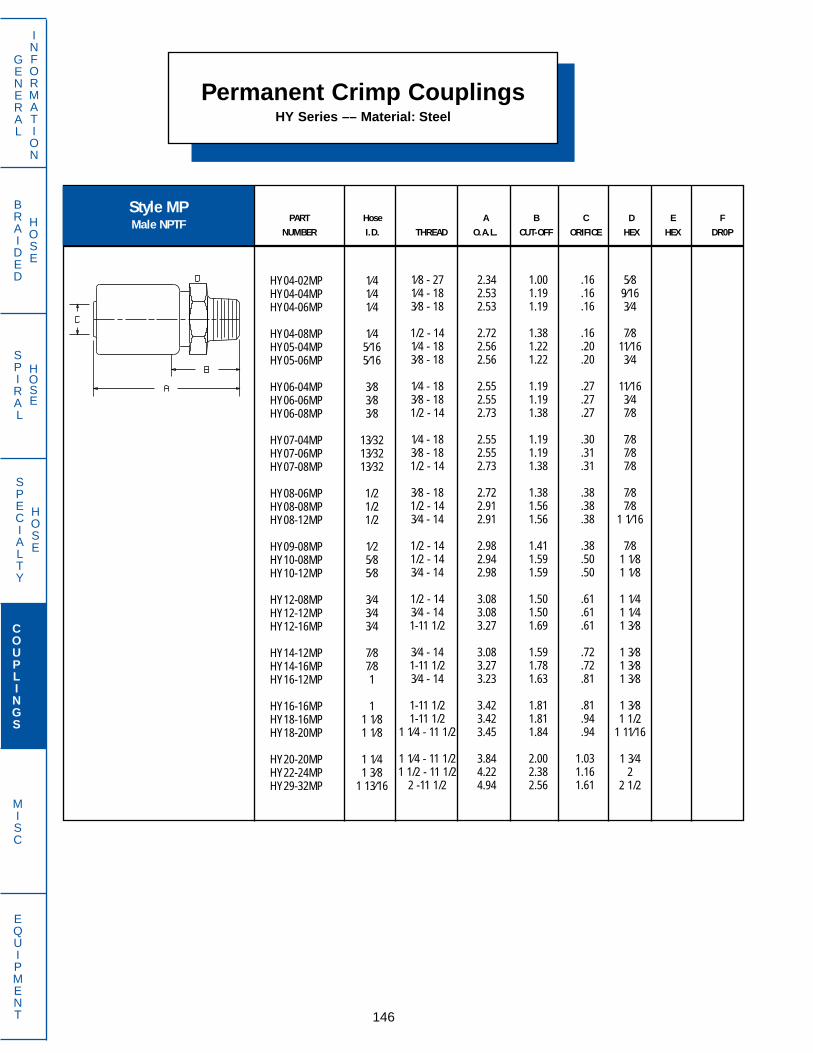
Permanent Crimp CouplingsHY Series –– Material: Steel
146
GENERAL
INFORMATION
COUPLINGS
MISC
EQUIPMENT
SPECIALTY
HOSE
BRAIDED
HOSE
SPIRAL
HOSE
PART Hose A B C D E FNUMBER I.D. THREAD O.A.L. CUT-OFF ORIFICE HEX HEX DR0P
Style MPMale NPTF
5⁄89⁄163⁄4
7⁄811⁄163⁄4
11⁄163⁄47⁄8
7⁄87⁄87⁄8
7⁄87⁄8
1 1⁄16
7⁄81 1⁄81 1⁄8
1 1⁄41 1⁄41 3⁄8
1 3⁄81 3⁄81 3⁄8
1 3⁄81 1/2
1 11⁄16
1 3⁄42
2 1/2
1⁄41⁄41⁄4
1⁄45⁄165⁄16
3⁄83⁄83⁄8
13⁄3213⁄3213⁄32
1/21/21/2
1⁄25⁄85⁄8
3⁄43⁄43⁄4
7⁄87⁄81
11 1⁄81 1⁄8
1 1⁄41 3⁄8
1 13⁄16
1⁄8 - 271⁄4 - 183⁄8 - 18
1/2 - 141⁄4 - 183⁄8 - 18
1⁄4 - 183⁄8 - 181/2 - 14
1⁄4 - 183⁄8 - 181/2 - 14
3⁄8 - 181/2 - 143⁄4 - 14
1/2 - 141/2 - 143⁄4 - 14
1/2 - 143⁄4 - 141-11 1/2
3⁄4 - 141-11 1/23⁄4 - 14
1-11 1/21-11 1/2
1 1⁄4 - 11 1/2
1 1⁄4 - 11 1/21 1/2 - 11 1/2
2 -11 1/2
HY04-02MPHY04-04MPHY04-06MP
HY04-08MPHY05-04MPHY05-06MP
HY06-04MPHY06-06MPHY06-08MP
HY07-04MPHY07-06MPHY07-08MP
HY08-06MPHY08-08MPHY08-12MP
HY09-08MPHY10-08MPHY10-12MP
HY12-08MPHY12-12MPHY12-16MP
HY14-12MPHY14-16MPHY16-12MP
HY16-16MPHY18-16MPHY18-20MP
HY20-20MPHY22-24MPHY29-32MP
2.342.532.53
2.722.562.56
2.552.552.73
2.552.552.73
2.722.912.91
2.982.942.98
3.083.083.27
3.083.273.23
3.423.423.45
3.844.224.94
1.001.191.19
1.381.221.22
1.191.191.38
1.191.191.38
1.381.561.56
1.411.591.59
1.501.501.69
1.591.781.63
1.811.811.84
2.002.382.56
.16
.16
.16
.16
.20
.20
.27
.27
.27
.30
.31
.31
.38
.38
.38
.38
.50
.50
.61
.61
.61
.72
.72
.81
.81
.94
.94
1.031.161.61
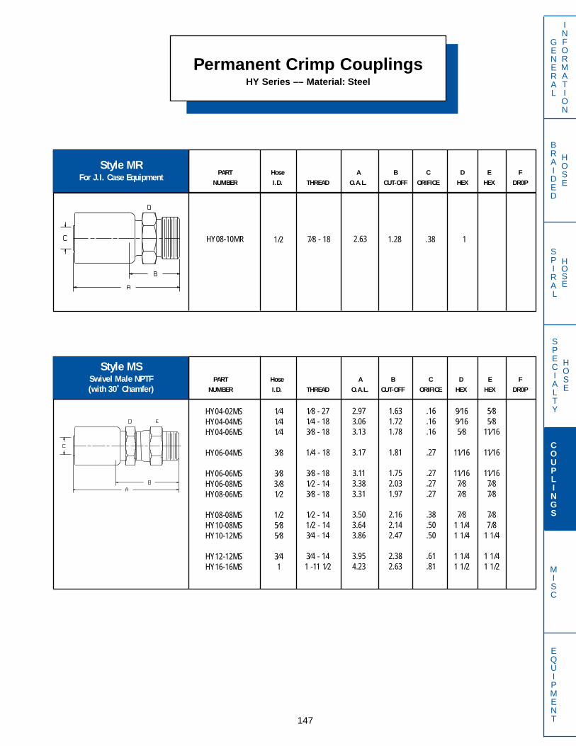
HY08-10MR 1/2 7⁄8 - 18 2.63 1.28 .38 1
PART Hose A B C D E FNUMBER I.D. THREAD O.A.L. CUT-OFF ORIFICE HEX HEX DR0P
Permanent Crimp CouplingsHY Series –– Material: Steel
147
GENERAL
INFORMATION
COUPLINGS
MISC
EQUIPMENT
SPECIALTY
HOSE
BRAIDED
HOSE
SPIRAL
HOSE
Style MSSwivel Male NPTF(with 30˚ Chamfer)
PART Hose A B C D E FNUMBER I.D. THREAD O.A.L. CUT-OFF ORIFICE HEX HEX DR0P
9⁄169⁄165⁄8
11⁄16
11⁄167⁄87⁄8
7⁄81 1/41 1/4
1 1/41 1/2
5⁄85⁄8
11⁄16
11⁄16
11⁄167⁄87⁄8
7⁄87/8
1 1/4
1 1/41 1/2
1⁄41⁄41⁄4
3⁄8
3⁄83/81⁄2
1/25⁄85⁄8
3⁄41
Style MRFor J.I. Case Equipment
1⁄8 - 271⁄4 - 183⁄8 - 18
1/4 - 18
3⁄8 - 181⁄2 - 143⁄8 - 18
1⁄2 - 141/2 - 143⁄4 - 14
3⁄4 - 141 -11 1⁄2
HY04-02MSHY04-04MSHY04-06MS
HY06-04MS
HY06-06MSHY06-08MSHY08-06MS
HY08-08MSHY10-08MSHY10-12MS
HY12-12MSHY16-16MS
2.973.063.13
3.17
3.113.383.31
3.503.643.86
3.954.23
1.631.721.78
1.81
1.752.031.97
2.162.142.47
2.382.63
.16
.16
.16
.27
.27
.27
.27
.38
.50
.50
.61
.81
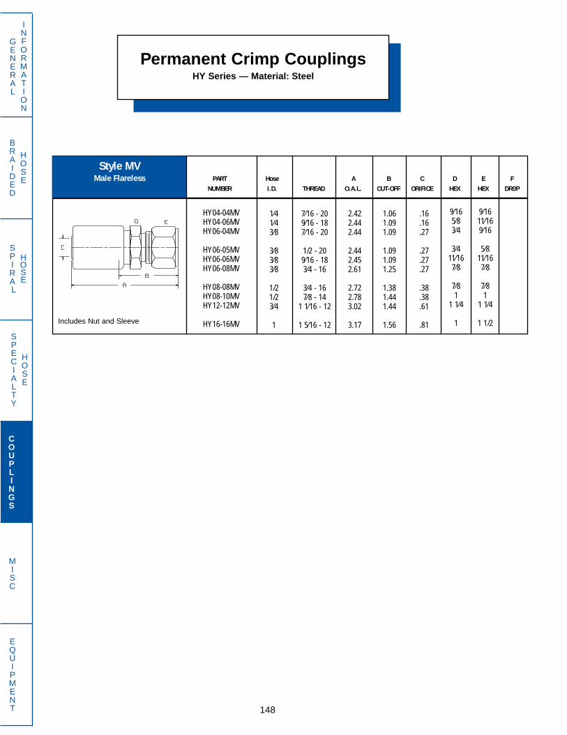
BRAIDED
HOSE
SPECIALTY
HOSE
SPIRAL
HOSE
PART Hose A B C D E FNUMBER I.D. THREAD O.A.L. CUT-OFF ORIFICE HEX HEX DR0P
GENERAL
INFORMATION
COUPLINGS
MISC
EQUIPMENT
Permanent Crimp CouplingsHY Series — Material: Steel
148
Style MVMale Flareless
HY04-04MVHY04-06MVHY06-04MV
HY06-05MVHY06-06MVHY06-08MV
HY08-08MVHY08-10MVHY12-12MV
HY16-16MV
1⁄41⁄43⁄8
3⁄83⁄83⁄8
1/21/23⁄4
1
7⁄16 - 209⁄16 - 187⁄16 - 20
1/2 - 209⁄16 - 183⁄4 - 16
3⁄4 - 167⁄8 - 14
1 1⁄16 - 12
1 5⁄16 - 12
2.422.442.44
2.442.452.61
2.722.783.02
3.17
1.061.091.09
1.091.091.25
1.381.441.44
1.56
.16
.16
.27
.27
.27
.27
.38
.38
.61
.81
9⁄1611⁄169⁄16
5⁄811⁄167⁄8
7⁄81
1 1⁄4
1 1/2
9⁄165⁄83⁄4
3⁄411⁄167⁄8
7⁄81
1 1⁄4
1Includes Nut and Sleeve

BRAIDED
HOSE
SPECIALTY
HOSE
SPIRAL
HOSE
PART Hose A B C D E FNUMBER I.D. THREAD O.A.L. CUT-OFF ORIFICE HEX HEX DR0P
PART Hose A B C D E L & SNUMBER I.D. THREAD O.A.L. CUT-OFF ORIFICE HEX HEX Tube O.D.
(mm) (mm)
GENERAL
INFORMATION
COUPLINGS
MISC
EQUIPMENT
Permanent Crimp CouplingsHY Series — Material: Steel
149
Style NGFemale Inverted Flare
Style MZMetric Male 24˚ DIN 2353
Light and Standard
HY04-04NGHY04-05NGHY05-05NG
HY06-06NGHY06-08NGHY08-08NG
HY12-12NG
1⁄41⁄4
5⁄16
3⁄83⁄81/2
3⁄4
7⁄16 - 241/2 - 201/2 - 20
5⁄8 - 183⁄4 - 183⁄4 - 18
1 1⁄16 - 16
2.162.252.25
2.252.302.41
2.61
.81
.91
.91
.91
.941.06
1.03
.16
.16
.20
.27
.27
.38
.61
9⁄165⁄85⁄8
7⁄811
1 1⁄4
L06L08S08
L10S10L10
S10L12S12
S08L10S10
L12S12S14
L15L15S16
L18S20L22
S25L28S30
HY04-06MZ12AHY04-08MZ14AHY04-08MZ16A
HY04-10MZ16AHY04-10MZ18AHY05-10MZ16A
HY05-10MZ18AHY05-12MZ18AHY05-12MZ20A
HY06-08MZ16AHY06-10MZ16AHY06-10MZ18A
HY06-12MZ18AHY06-12MZ20AHY06-14MZ22A
HY06-15MZ22AHY08-15MZ22AHY08-16MZ24A
HY10-18MZ26AHY10-20MZ30BHY12-22MZ30B
HY12-25MZ36BHY16-28MZ36BHY16-30MZ42B
1⁄41⁄41⁄4
1⁄41⁄4
5⁄16
5⁄165⁄165⁄16
3⁄83⁄83⁄8
3⁄83⁄83⁄8
3⁄81/21/2
5⁄85⁄83⁄4
3⁄411
M12 X 1.5M14 X 1.5M16 X 1.5
M16 X 1.5M18 X 1.5M16 X 1.5
M18 X 1.5M18 X 1.5M20 X 1.5
M16 X 1.5M16 X 1.5M18 X 1.5
M18 X 1.5M20 X 1.5M22 X 1.5
M22 X 1.5M22 X 1.5M24 X 1.5
M26 X 1.5M30 X 2.0M30 X 2.0
M36 X 2.0M36 X 2.0M42 X 2.0
2.362.362.44
2.402.442.43
2.472.432.47
2.462.422.46
2.422.462.54
2.522.632.71
2.712.862.88
3.043.043.27
1.001.001.09
1.031.091.06
1.131.061.13
1.091.061.13
1.061.091.19
1.161.281.34
1.311.471.31
1.471.411.28
.16
.16
.16
.16
.16
.20
.20
.20
.20
.27
.27
.27
.27
.27
.27
.27
.38
.38
.50
.50
.61
.61
.81
.81
141717
192219
222224
191919
222424
242427
273232
414146
For mating nut and sleeve, referto page 164

BRAIDED
HOSE
SPECIALTY
HOSE
SPIRAL
HOSE
PART Hose A B C D E FNUMBER I.D. THREAD O.A.L. CUT-OFF ORIFICE HEX HEX DR0P
PART Hose A B C D E FNUMBER I.D. THREAD O.A.L. CUT-OFF ORIFICE HEX HEX DR0P
PART Hose A B C D E FNUMBER I.D. THREAD O.A.L. CUT-OFF ORIFICE HEX HEX DR0P
GENERAL
INFORMATION
COUPLINGS
MISC
EQUIPMENT
Permanent Crimp CouplingsHY Series — Material: Steel
150
Style OFTSwivel Female
O-Ring Face Seal
Style OFSwivel Female
O-Ring Face Seal
Style NVSpecial Grease Hose End
HY04-08NV 1⁄4 1⁄2 - 27 2.41 1.06 .16 3⁄4
HY04-04OFTHY04-06OFTHY05-06OFT
HY06-06OFTHY06-08OFTHY08-06OFT
HY08-08OFTHY08-10OFTHY10-10OFT
HY10-12OFTHY12-10OFTHY12-12OFT
HY12-16OFTHY14-12OFTHY14-16OFT
HY16-16OFTHY16-20OFTHY18-20OFT
HY20-20OFT
1⁄41⁄4
5⁄16
3⁄83⁄81/2
1/21/25⁄8
5⁄83⁄43⁄4
3⁄47⁄87⁄8
11
1 1⁄8
1 1⁄4
9⁄16 - 1811⁄16 - 1611⁄16 - 16
11⁄16 - 1613⁄16 - 1611⁄16 - 16
13⁄16 - 161 - 141 - 14
1 3⁄16 - 121 - 14
1 3⁄16 - 12
1 7⁄16 - 121 3⁄16 - 121 7⁄16 - 12
1 7⁄16 - 121 11⁄16 - 121 11⁄16 - 12
1 11⁄16 - 12
2.592.672.70
2.752.842.87
2.953.163.17
3.203.273.30
3.443.303.44
3.593.473.47
3.98
1.251.311.34
1.341.501.53
1.591.811.78
1.811.691.72
1.881.811.97
1.972.311.84
2.16
.16
.16
.33
.27
.27
.38
.38
.38
.45
.50
.45
.55
.61
.55
.72
.81
.81
.94
1.02
11⁄1613⁄1613⁄16
13⁄1615⁄1615⁄16
15⁄161 1⁄81 1⁄8
1 3⁄81 1⁄81 3⁄8
1 5⁄81 3⁄81 5⁄8
1 5⁄81 7⁄81 7⁄8
1 7⁄8
9⁄165⁄85⁄8
11⁄167⁄87⁄8
7⁄815⁄161 1⁄8
1 1⁄81 1⁄41 1⁄4
1 3⁄81 3⁄81 3⁄8
1 3⁄81 5⁄81 5⁄8
1 3⁄4
HY04-04OFHY06-06OF
HY08-08OFHY12-12OF
1⁄43⁄8
1/23⁄4
9⁄16 - 1811⁄16 - 16
13⁄16 - 161 3⁄16 - 12
2.612.69
2.913.31
.94
.94
1.131.13
.16
.27
.38
.55
11⁄1613⁄16
15⁄161 3⁄8
9⁄1611⁄16
7⁄81 1⁄4
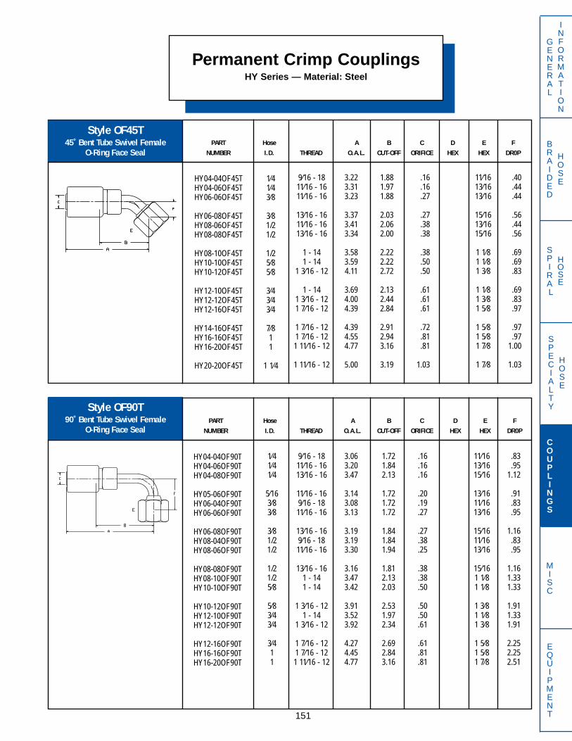
BRAIDED
HOSE
SPECIALTY
HOSE
SPIRAL
HOSE
PART Hose A B C D E FNUMBER I.D. THREAD O.A.L. CUT-OFF ORIFICE HEX HEX DR0P
PART Hose A B C D E FNUMBER I.D. THREAD O.A.L. CUT-OFF ORIFICE HEX HEX DR0P
GENERAL
INFORMATION
COUPLINGS
MISC
EQUIPMENT
Permanent Crimp CouplingsHY Series — Material: Steel
151
Style OF90T90˚ Bent Tube Swivel Female
O-Ring Face Seal
Style OF45T45˚ Bent Tube Swivel Female
O-Ring Face Seal
HY04-04OF45THY04-06OF45THY06-06OF45T
HY06-08OF45THY08-06OF45THY08-08OF45T
HY08-10OF45THY10-10OF45THY10-12OF45T
HY12-10OF45THY12-12OF45THY12-16OF45T
HY14-16OF45THY16-16OF45THY16-20OF45T
HY20-20OF45T
1⁄41⁄43⁄8
3⁄81/21/2
1/25⁄85⁄8
3⁄43⁄43⁄4
7⁄811
1 1⁄4
9⁄16 - 1811⁄16 - 1611⁄16 - 16
13⁄16 - 1611⁄16 - 1613⁄16 - 16
1 - 141 - 14
1 3⁄16 - 12
1 - 141 3⁄16 - 121 7⁄16 - 12
1 7⁄16 - 121 7⁄16 - 121 11⁄16 - 12
1 11⁄16 - 12
3.223.313.23
3.373.413.34
3.583.594.11
3.694.004.39
4.394.554.77
5.00
1.881.971.88
2.032.062.00
2.222.222.72
2.132.442.84
2.912.943.16
3.19
.16
.16
.27
.27
.38
.38
.38
.50
.50
.61
.61
.61
.72
.81
.81
1.03
11⁄1613⁄1613⁄16
15⁄1613⁄1615⁄16
1 1⁄81 1⁄81 3⁄8
1 1⁄81 3⁄81 5⁄8
1 5⁄81 5⁄81 7⁄8
1 7⁄8
.40
.44
.44
.56
.44
.56
.69
.69
.83
.69
.83
.97
.97
.971.00
1.03
HY04-04OF90THY04-06OF90THY04-08OF90T
HY05-06OF90THY06-04OF90THY06-06OF90T
HY06-08OF90THY08-04OF90THY08-06OF90T
HY08-08OF90THY08-10OF90THY10-10OF90T
HY10-12OF90THY12-10OF90THY12-12OF90T
HY12-16OF90THY16-16OF90THY16-20OF90T
1⁄41⁄41⁄4
5⁄163⁄83⁄8
3⁄81/21/2
1/21/25⁄8
5⁄83⁄43⁄4
3⁄411
9⁄16 - 1811⁄16 - 1613⁄16 - 16
11⁄16 - 169⁄16 - 1811⁄16 - 16
13⁄16 - 169⁄16 - 1811⁄16 - 16
13⁄16 - 161 - 141 - 14
1 3⁄16 - 121 - 14
1 3⁄16 - 12
1 7⁄16 - 121 7⁄16 - 121 11⁄16 - 12
3.063.203.47
3.143.083.13
3.193.193.30
3.163.473.42
3.913.523.92
4.274.454.77
1.721.842.13
1.721.721.72
1.841.841.94
1.812.132.03
2.531.972.34
2.692.843.16
.16
.16
.16
.20
.19
.27
.27
.38
.25
.38
.38
.50
.50
.50
.61
.61
.81
.81
11⁄1613⁄1615⁄16
13⁄1611⁄1613⁄16
15⁄1611⁄1613⁄16
15⁄161 1⁄81 1⁄8
1 3⁄81 1⁄81 3⁄8
1 5⁄81 5⁄81 7⁄8
.83
.951.12
.91
.83
.95
1.16.83.95
1.161.331.33
1.911.331.91
2.252.252.51
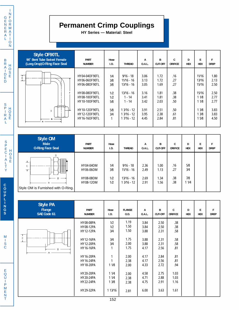
PART Hose FLANGE A B C D E FNUMBER I.D. O.D. O.A.L. CUT-OFF ORIFICE HEX HEX DR0P
PART Hose A B C D E FNUMBER I.D. THREAD O.A.L. CUT-OFF ORIFICE HEX HEX DR0P
1⁄43⁄8
1/21/2
9⁄16 - 1811⁄16 - 16
13⁄16 - 161 3⁄16 - 12
2.362.49
2.692.91
1.001.13
1.341.56
.16
.27
.38
.38
5⁄83⁄4
7⁄81 1⁄4
PART Hose A B C D E FNUMBER I.D. THREAD O.A.L. CUT-OFF ORIFICE HEX HEX DR0P
Permanent Crimp CouplingsHY Series — Material: Steel
152
GENERAL
INFORMATION
COUPLINGS
MISC
EQUIPMENT
SPECIALTY
HOSE
BRAIDED
HOSE
SPIRAL
HOSE
Style OF90TL90˚ Bent Tube Swivel Female(Long Drop)O-Ring Face Seal
Style PAFlange
SAE Code 61
Style OMMale
O-Ring Face Seal
HY04-04OF90TLHY06-06OF90TLHY06-08OF90TL
HY08-08OF90TLHY08-10OF90TLHY10-10OF90TL
HY10-12OF90TLHY12-12OF90TLHY16-16OF90TL
1⁄43⁄83⁄8
1/21/25⁄8
5⁄83⁄41
9⁄16 - 1811⁄16 - 1613⁄16 - 16
13⁄16 - 161 - 141 - 14
1 3⁄16 - 121 3⁄16 - 121 7⁄16 - 12
3.063.133.05
3.163.413.42
3.913.954.45
1.721.721.69
1.811.812.03
2.512.382.84
.16
.27
.27
.38
.38
.50
.50
.61
.81
11⁄1613⁄1615⁄16
15⁄161 1⁄81 1⁄8
1 3⁄81 3⁄81 5⁄8
1.802.132.50
2.502.772.77
3.833.834.50
HY04-04OMHY06-06OM
HY08-08OMHY08-12OM
HY08-08PAHY08-12PAHY12-12PA
HY12-16PAHY12-20PAHY16-16PA
HY16-20PAHY16-24PAHY18-20PA
HY20-20PAHY20-24PAHY22-24PA
HY29-32PA
1⁄21⁄23⁄4
3⁄43⁄41
11
1 1⁄8
1 1⁄41 1⁄41 3⁄8
1 13⁄16
1.191.501.50
1.752.001.75
2.002.382.00
2.002.382.38
2.81
3.843.843.88
3.883.884.17
4.174.174.33
4.584.714.75
6.00
2.502.502.31
2.312.312.56
2.842.562.72
2.752.882.91
3.63
.38
.38
.58
.58
.58
.81
.81
.81
.94
1.031.031.16
1.61
Style OM is Furnished with O-Ring.

PART Hose FLANGE A B C D E FNUMBER I.D. O.D. O.A.L. CUT-OFF ORIFICE HEX HEX DR0P
PART Hose FLANGE A B C D E FNUMBER I.D. O.D. O.A.L. CUT-OFF ORIFICE HEX HEX DR0P
PART Hose FLANGE A B C D E FNUMBER I.D. O.D. O.A.L. CUT-OFF ORIFICE HEX HEX DR0P
Permanent Crimp CouplingsHY Series — Material: Steel
153
GENERAL
INFORMATION
COUPLINGS
MISC
EQUIPMENT
SPECIALTY
HOSE
BRAIDED
HOSE
SPIRAL
HOSE
Style PA6767 1/2˚ Elbow Flange
SAE Code 61
Style PA4545˚ Elbow Flange
SAE Code 61
Style PA3030˚ Elbow Flange
SAE Code 61
HY08-08PA45HY08-12PA45HY12-12PA45
HY12-16PA45HY12-20PA45HY16-16PA45
HY16-24PA45HY20-20PA45HY20-24PA45
HY22-24PA45HY29-32PA45
1⁄21⁄23⁄4
3⁄43⁄41
11 1⁄41 1⁄4
1 3⁄81 13⁄16
1.191.501.50
1.752.001.75
2.382.002.38
2.382.81
4.524.524.11
4.113.884.47
4.475.055.14
5.457.33
2.722.722.53
2.532.532.84
2.843.223.31
3.594.94
.38
.38
.56
.56
.58
.81
.811.031.03
1.161.61
.77
.771.02
1.021.021.06
1.061.161.25
1.371.98
HY12-16PA30 3⁄4 1.75 4.19 2.63 .61 .62
HY16-12PA67 1 1.50 4.52 2.91 .81 1.75

PART Hose FLANGE A B C D E FNUMBER I.D. O.D. O.A.L. CUT-OFF ORIFICE HEX HEX DR0P
PART Hose FLANGE A B C D E FNUMBER I.D. O.D. O.A.L. CUT-OFF ORIFICE HEX HEX DR0P
PART Hose FLANGE A B C D E FNUMBER I.D. O.D. O.A.L. CUT-OFF ORIFICE HEX HEX DR0P
Permanent Crimp CouplingsHY Series — Material: Steel
154
GENERAL
INFORMATION
COUPLINGS
MISC
EQUIPMENT
SPECIALTY
HOSE
BRAIDED
HOSE
SPIRAL
HOSE
Style PAKKomatsu Flange
Style PA9090˚ Elbow Flange
SAE Code 61
Style PAK4545˚Elbow Komatsu Flange
HY08-08PA90HY08-12PA90HY12-12PA90
HY12-20PA90HY16-16PA90HY16-20PA90
HY18-20PA90HY20-20PA90HY20-24PA90
HY22-24PA90HY29-32PA90
1⁄21⁄23⁄4
3⁄411
1 1⁄81 1⁄41 1⁄4
1 3⁄81 13⁄16
1.191.501.50
2.001.752.00
2.002.002.38
2.382.81
3.813.813.83
3.834.554.54
5.085.345.34
5.537.13
2.472.472.25
2.252.942.94
3.473.503.50
3.694.75
.38
.38
.59
.59
.81
.81
.941.031.03
1.151.61
1.631.632.17
2.172.402.40
2.622.622.75
3.134.50
HY10-10PAK 5⁄8 1.34 3.63 2.25 .50
HY10-10PAK45 5⁄8 1.34 4.34 2.38 .50 .88

BRAIDED
HOSE
SPECIALTY
HOSE
SPIRAL
HOSE
PART Hose FLANGE A B C D E FNUMBER I.D. O.D. O.A.L. CUT-OFF ORIFICE HEX HEX DR0P
PART Hose FLANGE A B C D E FNUMBER I.D. O.D. O.A.L. CUT-OFF ORIFICE HEX HEX DR0P
PART Hose FLANGE A B C D E FNUMBER I.D. O.D. O.A.L. CUT-OFF ORIFICE HEX HEX DR0P
Permanent Crimp CouplingsHY Series — Material: Steel
155
Style PC2222 1/2˚ Elbow
Captive 4 Bolt Flange SAE Code 61
Style PC9090˚ Elbow
Captive 4 Bolt Flange SAE Code 61
Style PAK9090˚ Elbow Komatsu Flange
HY10-10PAK90 5⁄8 1.34 3.61 2.22 .50 1.91
HY16-16PC22 1.751 4.22 2.59 .81
HY16-16PC90 1 1.75 5.00 2.84 .81 2.41
.47
GENERAL
INFORMATION
COUPLINGS
MISC
EQUIPMENT

PART Hose A B C D E FNUMBER I.D. THREAD O.A.L. CUT-OFF ORIFICE HEX HEX DR0P
PART Hose A B C D E FNUMBER I.D. THREAD O.A.L. CUT-OFF ORIFICE HEX HEX DR0P
Permanent Crimp CouplingsHY Series — Material: Steel
156
GENERAL
INFORMATION
COUPLINGS
MISC
EQUIPMENT
SPECIALTY
HOSE
BRAIDED
HOSE
SPIRAL
HOSE
Style RCSwivel Male O-Ring Boss
Style RAMale O-Ring Boss
HY04-04RAHY04-05RAHY04-06RA
HY06-06RAHY06-08RAHY06-10RA
HY08-08RAHY08-10RAHY08-12RA
HY10-08RAHY10-10RAHY10-12RA
HY12-12RAHY12-16RAHY16-14RA
HY16-16RA
1⁄41⁄41⁄4
3⁄83⁄83⁄8
1⁄21⁄21⁄2
5⁄85⁄85⁄8
3⁄43⁄41
1
7⁄16 - 201⁄2 - 20
9⁄16 - 18
9⁄16 - 183⁄4 - 167⁄8 - 14
3⁄4 - 167⁄8 - 14
1 1⁄16 - 12
3⁄4 - 167⁄8 - 14
1 1⁄16 - 12
1 1⁄16 - 121 5⁄16 - 121 3⁄16 - 12
1 5⁄16 - 12
2.332.332.42
2.382.422.55
2.592.662.81
2.732.802.83
2.922.923.08
3.08
.97
.971.06
1.031.061.19
1.251.311.47
1.341.411.44
1.341.341.47
1.47
.16
.16
.16
.27
.27
.27
.38
.38
.38
.42
.50
.50
.61
.61
.81
.81
9⁄165⁄8
11⁄16
11⁄167⁄81
7⁄81
1 1⁄4
1 1⁄81 1⁄81 1⁄4
1 1⁄41 1⁄21 3⁄8
1 1⁄2
HY04-04RCHY04-05RCHY04-06RC
HY06-06RCHY06-08RCHY08-08RC
HY08-10RCHY08-12RCHY10-10RC
HY12-12RCHY12-14RCHY16-16RC
1⁄41⁄41⁄4
3⁄83⁄81⁄2
1⁄21⁄25⁄8
3⁄43⁄41
7⁄16 - 201⁄2 - 20
9⁄16 - 18
9⁄16 - 183⁄4 - 163⁄4 - 16
7⁄8 - 141 1⁄16 - 12
7⁄8 - 14
1 1⁄16 - 121 3⁄16 - 121 5⁄16 - 12
3.003.003.16
3.143.243.36
3.443.663.58
3.893.923.95
1.661.661.81
1.781.882.00
2.092.312.19
2.312.342.34
.16
.16
.16
.27
.27
.38
.38
.38
.48
.61
.61
.81
5⁄85⁄8
11⁄16
11⁄167⁄87⁄8
11 1⁄4
1
1 1⁄41 3⁄81 1⁄2
9⁄169⁄165⁄8
11⁄1613⁄16
7⁄8
11 1⁄41 1⁄8
1 1⁄41 1⁄41 3⁄8
Style RC is furnished with O-Ring
Style RA is furnished with O-Ring

PART Hose A B C D E FNUMBER I.D. THREAD O.A.L. CUT-OFF ORIFICE HEX HEX DR0P
PART Hose A B C D E FNUMBER I.D. THREAD O.A.L. CUT-OFF ORIFICE HEX HEX DR0P
PART Hose A B C D E FNUMBER I.D. THREAD O.A.L. CUT-OFF ORIFICE HEX HEX DR0P
Permanent Crimp CouplingsHY Series — Material: Steel
157
GENERAL
INFORMATION
COUPLINGS
MISC
EQUIPMENT
SPECIALTY
HOSE
BRAIDED
HOSE
SPIRAL
HOSE
Style RDFemale O-Ring Boss
Style RC9090˚Block Swivel Male
O-Ring Boss
Style RC4545˚ Block Swivel Male
O-Ring Boss
HY04-04RC90HY04-06RC90HY04-08RC90
HY06-04RC90HY06-06RC90HY06-08RC90
HY06-10RC90HY08-08RC90HY08-10RC90
HY12-12RC90HY12-14RC90HY16-16RC90
HY08-10RC45 1⁄2 7⁄8 - 14 3.31 2.00 .38 1 1.25
1⁄41⁄41⁄4
3⁄83⁄83⁄8
3⁄81⁄21⁄2
3⁄43⁄41
7⁄16 - 209⁄16 - 183⁄4 - 16
7⁄16 - 209⁄16 - 183⁄4 - 16
7⁄8 - 143⁄4 - 167⁄8 - 14
1 1⁄16 - 121 3⁄16 - 121 5⁄16 - 12
2.312.312.31
2.332.332.33
2.333.003.00
2.772.773.03
.97
.97
.94
.97
.97
.97
.971.091.09
1.191.191.41
.16
.16
.16
.27
.27
.27
.27
.38
.38
.61
.61
.78
11⁄167⁄87⁄8
11⁄1611⁄167⁄8
17⁄81
1 1⁄41 3⁄81 1⁄2
1.631.661.75
1.601.661.73
1.841.801.88
2.232.282.40
HY06-08RDHY08-08RDHY08-10RD
3⁄81⁄21⁄2
3⁄4 - 163⁄4 - 167⁄8 - 14
2.642.752.84
1.281.411.50
.27
.38
.38
17⁄81
Style RC45 is furnished with O-Ring
Style RC90 is furnished with O-Ring
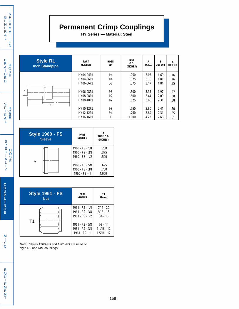
1960 - FS - 1⁄41960 - FS - 3⁄81960 - FS - 1⁄2
1960 - FS - 5⁄81960 - FS - 3⁄41960 - FS - 1
.250
.375
.500
.625
.7501.000
Permanent Crimp CouplingsHY Series — Material: Steel
158
GENERAL
INFORMATION
COUPLINGS
MISC
EQUIPMENT
SPECIALTY
HOSE
BRAIDED
HOSE
SPIRAL
HOSE
Style 1961 - FSNut
Style 1960 - FSSleeve
Style RLInch Standpipe
HY04-04RLHY04-06RLHY06-06RL
HY06-08RLHY08-08RLHY08-10RL
HY10-12RLHY12-12RLHY16-16RL
1⁄41⁄43⁄8
3⁄81⁄21⁄2
5⁄83⁄41
.250
.375
.375
.500
.500
.625
.750
.7501.000
3.033.163.17
3.333.443.66
3.803.894.23
1.691.811.81
1.972.092.31
2.412.312.63
.16
.16
.25
.27
.38
.38
.50
.55
.81
AO.A.L.
BCUT-OFF
PARTNUMBER
HOSEI.D.
TUBEO.D.
(INCHES)
PARTNUMBER
ATUBE O.D.(INCHES)
PARTNUMBER
T1Thread
1961 - FS - 1⁄41961 - FS - 3⁄81961 - FS - 1⁄2
1961 - FS - 5⁄81961 - FS - 3⁄41961 - FS - 1
7⁄16 - 209⁄16 - 183⁄4 - 16
7⁄8 - 141 1⁄16 - 121 5⁄16 - 12
CORIFICE
Note: Styles 1960-FS and 1961-FS are used onstyle RL and MM couplings.
A
T1

PART Hose A B C D E F L & SNUMBER I.D. THREAD O.A.L. CUT-OFF ORIFICE HEX HEX DROP TUBE
O.D.(mm) (mm)
PART Hose A B C D E L & SNUMBER I.D. THREAD O.A.L. CUT-OFF ORIFICE HEX HEX TUBE O.D.
(mm) (mm) (mm)
PART Hose A B C D E FNUMBER I.D. THREAD O.A.L. CUT-OFF ORIFICE HEX HEX DR0P
Permanent Crimp CouplingsHY Series — Material: Steel
159
GENERAL
INFORMATION
COUPLINGS
MISC
EQUIPMENT
SPECIALTY
HOSE
BRAIDED
HOSE
SPIRAL
HOSE
Style RO90T90˚ Bent Tube Female Metric
24˚ Cone with O-Ring
Style ROSwivel Female Metric24˚ Cone with O-Ring
Style RMHose Splicer
(For New Hose Only)
HY06-06RMHY08-08RM
HY12-12RMHY16-16RM
3⁄81⁄2
3⁄41
3.313.50
3.704.47
.63
.81
.531.16
.27
.38
.61
.81
HY08-15RO22AHY08-16RO24AHY12-22RO30B
1⁄21⁄23⁄4
M22 X 1.5M24 X 1.5M30 X 2.0
2.793.023.23
1.631.661.66
.38
.38
.61
273036
222230
L15S16L22
HY08-15RO22A90THY08-16RO24A90T
1⁄21⁄2
M22 X 1.5M24 X 1.5
3.463.46
2.132.09
.38
.382730
2.052.10
L15S16

Part Hose A B C D E L & SNumber I.D. Thread O.A.L. Cut-Off Orifice Hex Hex TUBE O.D.
(mm) (mm) (mm)
Permanent Crimp CouplingsHY Series — Material: Steel
160
GENERAL
INFORMATION
COUPLINGS
MISC
EQUIPMENT
SPECIALTY
HOSE
BRAIDED
HOSE
SPIRAL
HOSE
Style RUSwivel Female Universal
Metric 24˚/60˚ Cone
HY04-06RU12AHY04-08RU14AHY04-08RU16A
HY04-10RU16AHY04-10RU18AHY05-10RU16A
HY05-10RU18AHY05-12RU18AHY05-12RU20A
HY06-08RU16AHY06-10RU16AHY06-12RU18A
HY06-12RU20AHY06-14RU20AHY06-14RU22A
HY08-12RU20AHY08-15RU22AHY08-16RU24A
HY10-18RU26AHY10-20RU30BHY12-20RU30B
HY12-22RU30AHY12-22RU30BHY12-25RU36B
HY16-28RU36BHY16-30RU42B
1⁄41⁄41⁄4
1⁄41⁄4
5⁄16
5⁄165⁄165⁄16
3⁄83⁄83⁄8
3⁄83⁄83⁄8
1⁄21⁄21⁄2
5⁄85⁄83⁄4
3⁄43⁄43⁄4
11
M12 X 1.5M14 X 1.5M16 X 1.5
M16 X 1.5M18 X 1.5M16 X 1.5
M18 X 1.5M18 X 1.5M20 X 1.5
M16 X 1.5M16 X 1.5M18 X 1.5
M20 X 1.5M20 X 1.5 M22 X 1.5
M20 X 1.5M22 X 1.5M24 X 1.5
M26 X 1.5M30 X 2.0M30 X 2.0
M30 X 1.5M30 X 2.0M36 X 2.0
M36 X 2.0M42 X 2.0
2.712.712.74
2.742.742.77
2.772.772.80
2.752.752.75
2.792.792.80
2.962.973.02
3.043.143.23
3.113.233.30
3.463.73
1.341.341.38
1.381.411.41
1.441.411.41
1.411.441.44
1.441.591.63
1.661.661.75
1.661.531.66
1.721.841.72
1.842.13
.16
.16
.16
.16
.16
.20
.20
.20
.20
.27
.27
.27
.27
.27
.27
.38
.38
.38
.50
.50
.61
.61
.61
.61
.81
.81
171719
192219
222224
191922
242427
242730
323636
363641
4150
171717
171717
171717
191919
191919
222222
272732
303030
3641
L06L08S08
L10S10L10
S10L12
L/S12
S08L10L12
S12L14S14
S12L15S16
L18S20S20
L/S22L22S25
L28S30

Permanent Crimp CouplingsHY Series — Material: Steel
161
GENERAL
INFORMATION
COUPLINGS
MISC
EQUIPMENT
SPECIALTY
HOSE
BRAIDED
HOSE
SPIRAL
HOSE
Part Hose A B C D E FNumber I.D. Thread O.A.L. Cut-Off Orifice Hex Hex Drop
(mm)
Style RU45T45˚ Bent Tube Swivel FemaleUniversal Metric 24˚/60˚ Cone
HY04-08RU14A45THY04-08RU16A45THY04-10RU16A45T
HY04-10RU18A45THY05-10RU16A45THY05-10RU18A45T
HY05-12RU18A45THY05-12RU20A45THY06-10RU16A45T
HY06-12RU18A45THY06-12RU20A45THY06-14RU22A45T
HY08-15RU22A45THY08-16RU24A45THY10-18RU26A45T
HY10-20RU30B45THY12-22RU30A45THY12-22RU30B45T
HY12-25RU36B45THY16-28RU36B45THY16-30RU42B45T
1⁄41⁄41⁄4
1⁄45⁄165⁄16
5⁄165⁄163⁄8
3⁄83⁄83⁄8
1⁄21⁄25⁄8
5⁄83⁄43⁄4
3⁄411
M14 X 1.5M16 X 1.5M16 X 1.5
M18 X 1.5M16 X 1.5M18 X 1.5
M18 X 1.5M20 X 1.5M16 X 1.5
M18 X 1.5M20 X 1.5M22 X1.5
M22 X 1.5M24 X 1.5M26 X 1.5
M30 X 2.0M30 X 1.5M30 X 2.0
M36 X 2.0M36 X 2.0M42 X 2.0
3.603.633.63
3.633.713.71
3.714.044.02
4.024.024.08
4.294.294.43
4.434.254.25
4.304.724.84
1.342.252.28
2.282.282.34
2.342.342.66
2.662.662.66
2.722.942.94
3.063.063.16
3.223.884.03
.16
.16
.16
.16
.20
.20
.20
.20
.27
.27
.27
.27
.38
.38
.50
.50
.61
.61
.61
.81
.81
171919
221922
222419
222427
273032
363636
414150
.81
.84
.84
.84
.84
.84
.84
.991.13
1.131.161.17
1.221.261.29
1.241.301.30
1.471.581.78

BRAIDED
HOSE
SPECIALTY
HOSE
SPIRAL
HOSE
3⁄8 3⁄8 - 18 2.55 1.19 .27 3⁄4 3⁄4
162
GENERAL
INFORMATION
COUPLINGS
MISC
EQUIPMENT
Part Hose A B C D E FNumber I.D. Thread O.A.L. Cut-Off Orifice Hex Hex Drop
Permanent Crimp CouplingsHY Series — Material: Steel
Style RU90T90˚ Bent Tube Swivel FemaleUniversal Metric 24˚/60˚ Cone
HY04-08RU14A90THY04-08RU16A90THY04-10RU16A90T
HY04-10RU18A90THY05-10RU16A90THY05-10RU18A90T
HY05-12RU18A90THY05-12RU20A90THY06-10RU16A90T
HY06-12RU18A90THY06-12RU20A90THY06-14RU22A90T
HY08-15RU22A90THY08-16RU24A90THY10-18RU26A90T
HY10-20RU30B90THY12-20RU30B90THY12-22RU30A90T
HY12-22RU30B90THY12-25RU36B90THY16-28RU36B90T
HY16-30RU42B90T
1⁄41⁄41⁄4
1⁄45⁄165⁄16
5⁄165⁄163⁄8
3⁄83⁄83⁄8
1⁄21⁄25⁄8
5⁄83⁄43⁄4
3⁄43⁄41
1
M14 X 1.5M16 X 1.5M16 X 1.5
M18 X 1.5M16 X 1.5M18 X 1.5
M18 X 1.5M20 X 1.5M16 X 1.5
M18 X 1.5M20 X 1.5M22 X 1.5
M22 X 1.5M24 X 1.5M26 X 1.5
M30 X 2.0M30 X 2.0M30 X 1.5
M30 X 2.0M36 X 2.0M36 X 2.0
M42 X 2.0
3.073.073.07
3.073.723.22
3.223.463.44
3.443.443.79
3.793.793.92
3.923.973.97
3.973.974.36
4.36
1.721.721.72
1.721.881.88
1.882.092.09
2.092.222.44
2.442.532.53
2.412.692.41
2.693.413.41
3.41
.16
.16
.16
.16
.20
.20
.20
.20
.27
.27
.27
.27
.38
.38
.50
.50
.61
.61
.61
.61
.81
.81
171919
221922
222419
222427
273032
363636
364141
50
1.421.451.45
1.451.451.54
1.541.781.98
1.982.012.14
2.262.312.37
2.472.682.55
2.682.742.97
3.25
Part Hose A B C D E FNumber I.D. Thread O.A.L. Cut-Off Orifice Hex Hex Drop
Style RVSwivel Female NPSM 30˚ Cone Seat Pipe Thread
HY06-06RV

BRAIDED
HOSE
SPECIALTY
HOSE
SPIRAL
HOSE
163
GENERAL
INFORMATION
COUPLINGS
MISC
EQUIPMENT
Permanent Crimp CouplingsHY Series — Material: Steel
HY06-13RY20AHY08-17RY24AHY10-21RY30A
3⁄81⁄25⁄8
M20 X 1.5M24 X 1.5M30 X 1.5
2.793.023.22
1.441.691.85
.27
.38
.50
243038
192227
Part Hose A B C D E FNumber I.D. Thread O.A.L. Cut-Off Orifice Hex Hex Drop
(mm) (mm)
Style RYSwivel Female GAZ
Universal Metric 24˚/60˚ Cone
CONSISTS OF:HOSE TUBE THREAD
I.D. DIAMETER STAND PIPE NUT SLEEVECOUPLING
Style RZ AssemblyMethod**
For DIN 2353L and 7606/8
1⁄41⁄41⁄4
3⁄83⁄83⁄8
1⁄21⁄25⁄8
5⁄83⁄43⁄4
11
L08L10S10
L10L12S14
L15S16L18
S20L22S25
L28S30
HY04-08RZLSTHY04-10RZLSTHY05-10RZLST
HY06-10RZLSTHY06-12RZLSTHY06-14RZST
HY08-15RZLTHY08-16RZSTHY10-18RZLT
HY10-20RZSTHY12-22RZSTHY12-25RZST
HY16-28RZLTHY16-30RZST
M08LS-73M10LS-73M10LS-73
M10LS-73M12LS-73M14S-73
M15L-73M16S-73M18L-73
M20S-73M22L-73M25S-73
M28L-73M30S-73
M08L-56M10L-56M10S-56
M10L-56M12L-56M14S-56
M15L-56M16S-56M18L-56
M20S-56M22L-56M25S-56
M28L-56M30S-56
** Metric female 24° cone is made up by assembling the proper standpipe nut and sleeve. Refer to chart above for order information.
M14 X 1.5M16 X 1.5M16 X 1.5
M16 X 1.5M18 X 1.5M22 X 1.5
M22 X 1.5M24 X 1.5M26 X 1.5
M30 X 2.0M30 X 2.0M36 X 2.0
M36 X 2.0M42 X 2.0

68
10
121518
2228
68
10
121416
202530
M06LS-73M08LS-73M10LS-73
M12LS-73M15L-73M18L-73
M22L-73M28L-73
M06LS-73M08LS-73M10LS-73
M12LS-73M14S-73M16S-73
M20S-73M25S-73M30S-73
M12 X 1.5M14 X 1.5M16 X 1.5
M18 X 1.5M22 X 1.5M26 X 1.5
M30 X 2.0M36 X 2.0
M14 X 1.5M16 X 1.5M18 X 1.5
M20 X 1.5M22 X 1.5M24 X 1.5
M30 X 2.0M36 X 2.0M42 X 2.0
M06L-56M08L-56M10L-56
M12L-56M15L-56M18L-56
M22L-56M28L-56
M06S-56M08S-56M10S-56
M12S-56M14S-56M16S-56
M20S-56M25S-56M30S-56
BRAIDED
HOSE
SPECIALTY
HOSE
SPIRAL
HOSE
68
10
101210
121415
161818
202022
252528
30
3.013.093.16
3.203.233.18
3.223.303.33
3.533.333.34
3.623.753.44
3.794.063.72
4.15
1.661.721.81
1.841.881.81
1.881.941.97
2.161.971.97
2.222.121.88
2.222.442.09
2.53
.12
.16
.16
.20
.20
.24
.27
.27
.38
.38
.38
.50
.50
.53
.61
.61
.73
.81
.81
HY04-06RZLSTHY04-08RZLSTHY04-10RZLST
HY05-10RZLSTHY05-12RZLSTHY06-10RZLST
HY06-12RZLSTHY06-14RZSTHY08-15RZLT
HY08-16RZSTHY08-18RZLTHY10-18RZST
HY10-20RZSTHY12-20RZSTHY12-22RZLT
HY12-25RZSTHY16-25RZSTHY16-28RZLT
HY16-30RZST
1⁄41⁄41⁄4
5⁄165⁄163⁄8
3⁄83⁄81⁄2
1⁄21⁄25⁄8
5⁄83⁄43⁄4
3⁄411
1
164
GENERAL
INFORMATION
COUPLINGS
MISC
EQUIPMENT
Permanent Crimp CouplingsHY Series — Material: Steel
Style M - 73Sleeve for Style MZ Coupling
and Style RZ Metric Standpipe
Style M - 56Nut for Style MZ Coupling
and Style RZ Metric Standpipe
PARTNUMBER
T1THREAD PART
NUMBER
ATUBE O.D.
(MM)
Part Hose A B C D E FNumber I.D. Tube O.D. O.A.L. Cut-Off Orifice Hex Hex Drop
Style RZTMetric O.D. Stand Pipe
Note: Style RZT requires the use of theM-56 Nut and M-73 Sleeve. Refer tochart above for more information.

BRAIDED
HOSE
SPECIALTY
HOSE
SPIRAL
HOSE
165
GENERAL
INFORMATION
COUPLINGS
MISC
EQUIPMENT
TubePart Hose O.D. A B C D E F
Number I.D. (mm) O.A.L. Cut-Off Orifice Hex Hex Drop
Permanent Crimp CouplingsHY Series — Material: Steel
Style RZ45T45˚ Bent Tube
Metric O.D. Stand Pipe
HY04-06RZ45LSTHY04-08RZ45LSTHY04-10RZ45LST
HY05-10RZ45LSTHY05-12RZ45LSTHY06-10RZ45LST
HY06-12RZ45LSTHY06-14RZ45STHY08-15RZ45LT
HY08-16RZ45STHY10-18RZ45LTHY10-20RZ45ST
HY12-22RZ45LTHY12-25RZ45STHY16-28RZ45LT
HY16-30RZ45ST
1⁄41⁄41⁄4
5⁄165⁄163⁄8
3⁄83⁄81⁄2
1⁄25⁄85⁄8
3⁄43⁄41
1
68
10
101210
121415
161820
222528
30
3.403.543.68
3.713.953.69
3.934.074.18
4.354.314.58
4.574.965.22
5.61
2.062.192.31
2.342.592.34
2.562.722.81
2.002.943.19
3.003.383.59
4.00
.12
.16
.16
.20
.20
.24
.27
.27
.38
.38
.50
.50
.61
.61
.81
.81
.66
.75
.84
.84
.90
.84
.90
.99
.96
1.111.011.24
1.081.381.18
1.52
Note: Style RZ45T requires the use ofthe M-56 Nut and M-73 Sleeve. Refer tochart on page 164 for more information
TubePart Hose O.D. A B C D E F
Number I.D. (mm) O.A.L. Cut-Off Orifice Hex Hex Drop
Style RZ90T90˚ Bent Tube
Metric O.D. Stand Pipe
HY04-06RZ90LSTHY04-08RZ90LSTHY04-10RZ90LST
HY05-10RZ90LSTHY05-12RZ90LSTHY06-10RZ90LST
HY06-12RZ90LSTHY06-14RZ90STHY08-15RZ90LT
HY08-16RZ90STHY10-18RZ90LTHY10-20RZ90ST
HY12-22RZ90LTHY12-25RZ90STHY16-28RZ90LT
HY16-30RZ90ST
1⁄41⁄41⁄4
5⁄165⁄163⁄8
3⁄83⁄81⁄2
1⁄25⁄85⁄8
3⁄43⁄41
1
68
10
101210
121415
161820
222528
30
2.953.073.18
3.223.463.20
3.443.563.75
3.793.924.04
4.254.455.01
5.13
1.591.721.84
1.882.091.83
2.092.222.41
2.442.532.66
2.692.883.41
3.50
.12
.16
.16
.20
.20
.24
.27
.27
.38
.38
.50
.50
.61
.61
.81
.81
1.141.341.54
1.541.691.54
1.691.891.89
2.132.052.44
2.282.842.64
3.19
Note: Style RZ90T requires the use ofthe M-56 Nut and M-73 Sleeve. Refer tochart on page 164 for more information
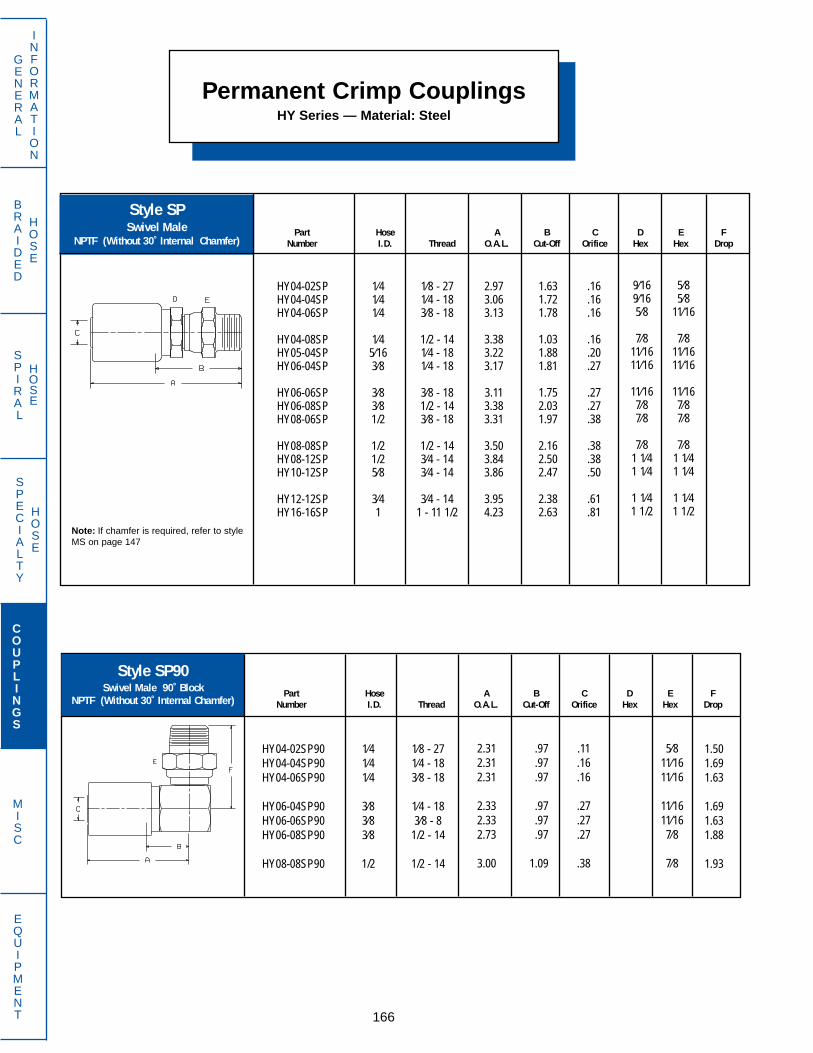
BRAIDED
HOSE
SPECIALTY
HOSE
SPIRAL
HOSE
166
GENERAL
INFORMATION
COUPLINGS
MISC
EQUIPMENT
Part Hose A B C D E FNumber I.D. Thread O.A.L. Cut-Off Orifice Hex Hex Drop
Permanent Crimp CouplingsHY Series — Material: Steel
Style SPSwivel Male
NPTF (Without 30˚ Internal Chamfer)
HY04-02SPHY04-04SPHY04-06SP
HY04-08SPHY05-04SPHY06-04SP
HY06-06SPHY06-08SPHY08-06SP
HY08-08SPHY08-12SPHY10-12SP
HY12-12SPHY16-16SP
1⁄41⁄41⁄4
1⁄45⁄163⁄8
3⁄83⁄81/2
1/21/25⁄8
3⁄41
1⁄8 - 271⁄4 - 183⁄8 - 18
1/2 - 141⁄4 - 181⁄4 - 18
3⁄8 - 181/2 - 143⁄8 - 18
1/2 - 143⁄4 - 143⁄4 - 14
3⁄4 - 141 - 11 1/2
2.973.063.13
3.383.223.17
3.113.383.31
3.503.843.86
3.954.23
1.631.721.78
1.031.881.81
1.752.031.97
2.162.502.47
2.382.63
.16
.16
.16
.16
.20
.27
.27
.27
.38
.38
.38
.50
.61
.81
5⁄85⁄8
11⁄16
7⁄811⁄1611⁄16
11⁄167⁄87⁄8
7⁄81 1⁄41 1⁄4
1 1⁄41 1/2
9⁄169⁄165⁄8
7⁄811⁄1611⁄16
11⁄167⁄87⁄8
7⁄81 1⁄41 1⁄4
1 1⁄41 1/2
Note: If chamfer is required, refer to styleMS on page 147
Part Hose A B C D E FNumber I.D. Thread O.A.L. Cut-Off Orifice Hex Hex Drop
Style SP90Swivel Male 90˚ Block
NPTF (Without 30˚ Internal Chamfer)
HY04-02SP90HY04-04SP90HY04-06SP90
HY06-04SP90HY06-06SP90HY06-08SP90
HY08-08SP90
1⁄41⁄41⁄4
3⁄83⁄83⁄8
1/2
1⁄8 - 271⁄4 - 183⁄8 - 18
1⁄4 - 183⁄8 - 8
1/2 - 14
1/2 - 14
2.312.312.31
2.332.332.73
3.00
.97
.97
.97
.97
.97
.97
1.09
.11
.16
.16
.27
.27
.27
.38
5⁄811⁄1611⁄16
11⁄1611⁄167⁄8
7⁄8
1.501.691.63
1.691.631.88
1.93

BRAIDED
HOSE
SPECIALTY
HOSE
SPIRAL
HOSE
167
GENERAL
INFORMATION
COUPLINGS
MISC
EQUIPMENT
Part Hose A B C D E FNumber I.D. Thread O.A.L. Cut-Off Orifice Hex Hex Drop
Permanent Crimp CouplingsHY Series — Material: 303 Stainless Steel*
Style FJ-SSSwivel Female
37˚ Flare
HY04-04FJ-SSHY06-06FJ-SSHY08-08FJ-SS
HY12-12FJ-SSHY16-16FJ-SS
1⁄43⁄81⁄2
3⁄41
7⁄16 - 209⁄16 - 183⁄4 - 16
1 1⁄16 - 121 5⁄16 - 12
2.602.692.90
3.223.45
1.251.341.56
1.661.84
.16
.27
.38
.61
.81
9⁄1611⁄167⁄8
1 1⁄41 3⁄8
9⁄1611⁄167⁄8
1 1⁄41 1⁄2
Part Hose A B C D E FNumber I.D. Thread O.A.L. Cut-Off Orifice Hex Hex Drop
Style MP-SSMale NPTF
HY04-04MP-SSHY06-06MP-SSHY08-08MP-SS
HY12-12MP-SSHY16-16MP-SS
1⁄43⁄81⁄2
3⁄41
1⁄4 - 183⁄8 - 181⁄2 - 14
3⁄4 - 141- 11 1⁄2
2.532.552.91
3.083.42
1.191.191.56
1.501.81
.16
.27
.38
.61
.81
9⁄163⁄47⁄8
1 1⁄41 3⁄8
* Consult Dayco Eastman for availability of BW couplings in alternate materials, sizes and styles.
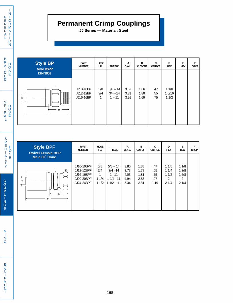
BRAIDED
HOSE
SPECIALTY
HOSE
SPIRAL
HOSE
168
GENERAL
INFORMATION
COUPLINGS
MISC
EQUIPMENT
PART HOSE A B C D E FNUMBER I.D. THREAD O.A.L. CUT-OFF ORIFICE HEX HEX DROP
JJ10-10BP 5/8 5/8 – 14 3.57 1.66 .47 1 1/8JJ12-12BP 3/4 3/4 –14 3.81 1.88 .55 1 5/16JJ16-16BP 1 1 – 11 3.91 1.69 .75 1 1/2
PART HOSE A B C D E FNUMBER I.D. THREAD O.A.L. CUT-OFF ORIFICE HEX HEX DROP
JJ10-10BPF 5/8 5/8 – 14 3.80 1.88 .47 1 1/8 1 1/8JJ12-12BPF 3/4 3/4 –14 3.73 1.78 .55 1 1/4 1 3/8JJ16-16BPF 1 1 –11 4.03 1.81 .75 1 1/2 1 5/8JJ20-20BPF 1 1/4 1 1/4 –11 4.94 2.53 .97 2 2JJ24-24BPF 1 1/2 1 1/2 – 11 5.34 2.81 1.19 2 1/4 2 1/4
Permanent Crimp CouplingsJJ Series — Material: Steel
Style BPMale BSPPDIN 3852
Style BPFSwivel Female BSP
Male 60˚ Cone

BRAIDED
HOSE
SPECIALTY
HOSE
SPIRAL
HOSE
169
GENERAL
INFORMATION
COUPLINGS
MISC
EQUIPMENT
PART HOSE A B C D E FNUMBER I.D. THREAD O.A.L. CUT-OFF ORIFICE HEX HEX DROP
JJ12-12BPHB 3/4 3/4 –14 3.73 1.78 .55 1 1/4 1 3/8
PART HOSE A B C D E FNUMBER I.D. THREAD O.A.L. CUT-OFF ORIFICE HEX HEX DROP
JJ12-12BPF45T 3/4 3/4 –14 5.53 3.59 .53 1-3/8 1.57JJ16-16BPF45T 1 1–11 5.65 3.44 .75 1-5/8 1.37
PART HOSE A B C D E FNUMBER I.D. THREAD O.A.L. CUT-OFF ORIFICE HEX HEX DROP
JJ12-12BPF90 3/4 3/4 –14 3.25 1.31 .55 1 3/8 1.22JJ16-16BPF90 1 1–11 3.62 1.41 .75 1 5/8 1.47
PART HOSE A B C D E FNUMBER I.D. THREAD O.A.L. CUT-OFF ORIFICE HEX HEX DROP
JJ12-12BPF90T 3/4 3/4 – 14 4.69 2.75 .53 1 3/8 2.95JJ16-16BPF90T 1 1 – 11 5.19 2.97 .75 1 5/8 3.25JJ20-20BPF90T 1 1/4 1 1/4 – 11 6.38 3.97 .95 2 3.61JJ24-24BPF90T 1 1/2 1 1/2 – 11 6.31 3.78 1.19 2 1/4 4.51
Style BPF45T45˚Bent Tube Swivel Female BSP
Male 60˚ Cone
Style BPF9090˚ Block Swivel Female
Male 60˚ Cone
Style BPF90T90˚ Bent Tube Swivel Female
BSP Male 60˚ Cone
Style BPHBSwivel Female BSP
Flat Face Seat
Permanent Crimp CouplingsJJ Series — Material: Steel

BRAIDED
HOSE
SPECIALTY
HOSE
SPIRAL
HOSE
PART HOSE A B C D E FNUMBER I.D. THREAD O.A.L. CUT-OFF ORIFICE HEX HEX DROP
JJ06-06FJ 3/8 9/16–18 3.52 1.53 .25 13/16 3/4JJ06-08FJ 3/8 3/4–16 3.75 1.78 .25 1 1JJ08-08FJ 1/2 3/4–16 3.75 1.78 .31 1 7/8JJ08-10FJ 1/2 7/8–14 3.83 1.91 .31 1 1 1/16
JJ08-12FJ 1/2 1 1/16–12 3.89 1.94 .31 1-1/4 1 3/8JJ10-10FJ 5/8 7/8 - 14 3.73 1.84 .47 1 1/8 1 1/16JJ10-12FJ 5/8 1 1/16 - 12 3.79 1.88 .47 1 3/8 1 3/8JJ12-10FJ 3/4 7/8–14 3.67 1.72 .55 1-1/4 1 1/16
JJ12-12FJ 3/4 1 1/16–12 3.73 1.88 .55 1-3/8 1 3/8JJ12-14FJ 3/4 1 3/16–12 3.74 1.75 .55 1-1/2 1 1/2JJ12-16FJ 3/4 1 5/16–12 3.81 1.81 .55 1-3/8 1 5/8JJ16-12FJ 1 1 1/16–12 4.25 2.03 .75 1-1/2 1 3/8
JJ16-16FJ 1 1 5/16–12 4.26 2.09 .75 1-5/8 1 5/8JJ16-20FJ 1 1 5/8–12 4.51 2.28 .75 1 5/8 2JJ20-16FJ 1 1/4 1 5/16 - 12 4.68 2.28 .84 2 1 5/8JJ20-20FJ 1 1/4 1 5/8–12 4.94 2.53 .97 2 2
JJ20-24FJ 1 1/4 1 7/8–12 5.38 2.84 .97 2-1/4 2 1/4JJ24-24FJ 1 1/2 1 7/8–12 5.38 2.84 1.17 2-1/4 2 1/4JJ32-32FJ 2 2 1/2–12 6.92 3.34 1.53 2-7/8 2 7/8
170
GENERAL
INFORMATION
COUPLINGS
MISC
EQUIPMENT
Permanent Crimp CouplingsJJ Series — Material: Steel
PART HOSE A B C D E FNUMBER I.D. THREAD O.A.L. CUT-OFF ORIFICE HEX HEX DROP
JJ12-12BT 3/4 3/4 –14 3.81 1.88 .55 1 1/4JJ16-16BT 1 1 –11 4.25 2.03 .75 1 1/2
PART HOSE A B C D E FNUMBER I.D. THREAD O.A.L. CUT-OFF ORIFICE HEX HEX DROP
(mm)
JJ12-22DX30A 3/4 M30 X 1.5 2.80 1.34 .55 32JJ16-28DX38A 1 M38 X 1.5 3.69 1.47 .75 41
Style BTMale BSPTDIN 2999
Style DXMale 60˚DIN 7611
Style FJSwivel Female
37˚ Flare
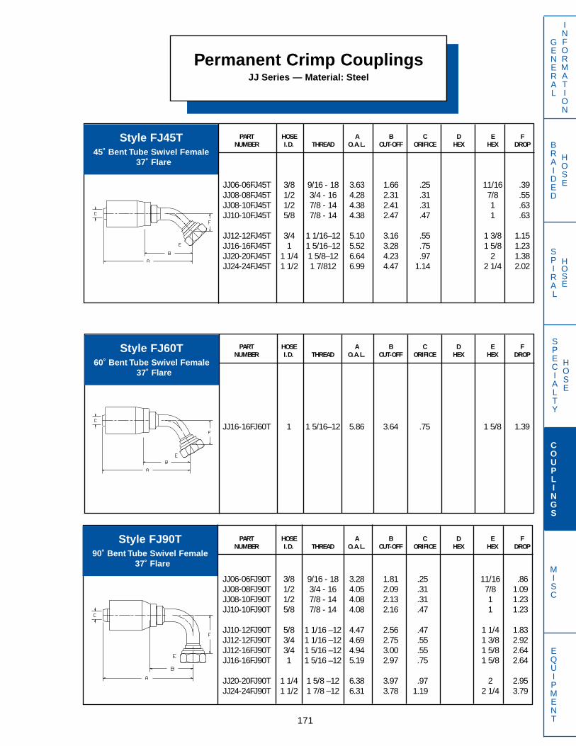
BRAIDED
HOSE
SPECIALTY
HOSE
SPIRAL
HOSE
171
GENERAL
INFORMATION
COUPLINGS
MISC
EQUIPMENT
Permanent Crimp CouplingsJJ Series — Material: Steel
PART HOSE A B C D E FNUMBER I.D. THREAD O.A.L. CUT-OFF ORIFICE HEX HEX DROP
JJ06-06FJ90T 3/8 9/16 - 18 3.28 1.81 .25 11/16 .86JJ08-08FJ90T 1/2 3/4 - 16 4.05 2.09 .31 7/8 1.09JJ08-10FJ90T 1/2 7/8 - 14 4.08 2.13 .31 1 1.23JJ10-10FJ90T 5/8 7/8 - 14 4.08 2.16 .47 1 1.23
JJ10-12FJ90T 5/8 1 1/16 –12 4.47 2.56 .47 1 1/4 1.83JJ12-12FJ90T 3/4 1 1/16 –12 4.69 2.75 .55 1 3/8 2.92JJ12-16FJ90T 3/4 1 5/16 –12 4.94 3.00 .55 1 5/8 2.64JJ16-16FJ90T 1 1 5/16 –12 5.19 2.97 .75 1 5/8 2.64
JJ20-20FJ90T 1 1/4 1 5/8 –12 6.38 3.97 .97 2 2.95JJ24-24FJ90T 1 1/2 1 7/8 –12 6.31 3.78 1.19 2 1/4 3.79
PART HOSE A B C D E FNUMBER I.D. THREAD O.A.L. CUT-OFF ORIFICE HEX HEX DROP
JJ06-06FJ45T 3/8 9/16 - 18 3.63 1.66 .25 11/16 .39JJ08-08FJ45T 1/2 3/4 - 16 4.28 2.31 .31 7/8 .55JJ08-10FJ45T 1/2 7/8 - 14 4.38 2.41 .31 1 .63JJ10-10FJ45T 5/8 7/8 - 14 4.38 2.47 .47 1 .63
JJ12-12FJ45T 3/4 1 1/16–12 5.10 3.16 .55 1 3/8 1.15JJ16-16FJ45T 1 1 5/16–12 5.52 3.28 .75 1 5/8 1.23JJ20-20FJ45T 1 1/4 1 5/8–12 6.64 4.23 .97 2 1.38JJ24-24FJ45T 1 1/2 1 7/812 6.99 4.47 1.14 2 1/4 2.02
PART HOSE A B C D E FNUMBER I.D. THREAD O.A.L. CUT-OFF ORIFICE HEX HEX DROP
JJ16-16FJ60T 1 1 5/16–12 5.86 3.64 .75 1 5/8 1.39
Style FJ45T45˚ Bent Tube Swivel Female
37˚ Flare
Style FJ60T60˚ Bent Tube Swivel Female
37˚ Flare
Style FJ90T90˚ Bent Tube Swivel Female
37˚ Flare

BRAIDED
HOSE
SPECIALTY
HOSE
SPIRAL
HOSE
172
GENERAL
INFORMATION
COUPLINGS
MISC
EQUIPMENT
Perment Crimp CouplingsJJ Series — Material: Steel
PART HOSE A B C D E FNUMBER I.D. THREAD O.A.L. CUT-OFF ORIFICE HEX HEX DROP
JJ08-08FJ90TL 1/2 3/4 - 16 4.17 2.19 .31 7/8 2.44JJ12-12FJ90TL 3/4 1 1/16–12 4.69 2.75 .55 1 3/8 3.73
JJ12-16FJ90TL 3/4 1 5/16–12 5.38 3.44 .55 1 5/8 4.33JJ16-16FJ90TL 1 1 5/16–12 5.19 3.03 .75 1 5/8 4.33
PART HOSE A B C D E FNUMBER I.D. THREAD O.A.L. CUT-OFF ORIFICE HEX HEX DROP
(mm) (mm)
JJ10-24KMF 5/8 M24 X 1.5 3.80 1.88 .47 30 30JJ12-30KMF 3/4 M30 X 1.5 3.98 2.03 .55 32 38JJ16-33KMF 1 M33 X 1.5 4.44 2.22 .75 36 41
JJ20-36KMF 1 1/4 M36 X 1.5 4.97 2.56 .97 48 48JJ24-42KMF 1 1/2 M42 X 1.5 5.38 2.84 1.00 54 51
PART HOSE A B C D E FNUMBER I.D. THREAD O.A.L. CUT-OFF ORIFICE HEX HEX DROP
JJ12-12JPF 3/4 3/4–14 3.73 1.78 .55 1 1/4 1 3/8JJ16-16JPF 1 1–11 4.03 1.81 .75 1 1/2 1 5/8
Style FJ90TL90˚ Bent Tube Swivel Female
37˚ Flare (Long Drop)
Style JPFSwivel Female J.I.S.
30˚ Female Seat
Style KMFSwivel Female Komatsu
Metric Thread 30˚ Female Seat
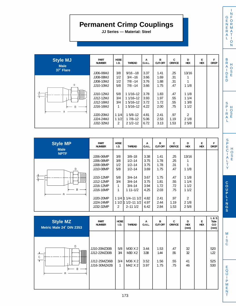
PART HOSE A B C D E FNUMBER I.D. THREAD O.A.L. CUT-OFF ORIFICE HEX HEX DROP
JJ06-06MJ 3/8 9/16 –18 3.37 1.41 .25 13/16JJ08-08MJ 1/2 3/4 –16 3.66 1.69 .31 1JJ08-10MJ 1/2 7/8 –14 3.76 1.88 .31 1JJ10-10MJ 5/8 7/8 –14 3.66 1.75 .47 1 1/8
JJ10-12MJ 5/8 1 1/16–12 3.78 1.83 .47 1 1/8JJ12-12MJ 3/4 1 1/16–12 3.93 1.97 .55 1 1/4JJ12-16MJ 3/4 1 5/16–12 3.72 1.72 .55 1 3/8JJ16-16MJ 1 1 5/16–12 4.22 2.00 .75 1 1/2
JJ20-20MJ 1 1/4 1 5/8–12 4.81 2.41 .97 2JJ24-24MJ 1 1/2 1 7/8–12 5.06 2.53 1.19 2 1/8JJ32-32MJ 2 2 1/2–12 6.72 3.13 1.53 2 5/8
BRAIDED
HOSE
SPECIALTY
HOSE
SPIRAL
HOSE
173
GENERAL
INFORMATION
COUPLINGS
MISC
EQUIPMENT
Permanent Crimp CouplingsJJ Series — Material: Steel
PART HOSE A B C D E FNUMBER I.D. THREAD O.A.L. CUT-OFF ORIFICE HEX HEX DROP
JJ06-06MP 3/8 3/8–18 3.38 1.41 .25 13/16JJ06-08MP 3/8 1/2–14 3.75 1.78 .25 1JJ08-08MP 1/2 1/2–14 3.75 1.78 .31 1JJ10-08MP 5/8 1/2–14 3.69 1.75 .47 1 1/8
JJ10-12MP 5/8 3/4–14 3.67 1.75 .47 1 1/8JJ12-12MP 3/4 3/4–14 3.75 1.81 .55 1 1/4JJ16-12MP 1 3/4–14 3.94 1.72 .72 1 1/2JJ16-16MP 1 1 11–1/2 4.25 2.03 .75 1 1/2
JJ20-20MP 1 1/4 1 1/4–11 1/2 4.82 2.41 .97 2JJ24-24MP 1 1/2 1 1/2–11 1/2 4.97 2.44 1.19 2 1/8JJ32-32MP 2 2–11 1/2 6.42 2.84 1.53 2 5/8
L & SPART HOSE A B C D E Tube
NUMBER I.D. THREAD O.A.L. CUT-OFF ORIFICE HEX HEX O.D(mm) (mm)
JJ10-20MZ30B 5/8 M30 X 2 3.44 1.53 .47 32 S20JJ12-22MZ30B 3/4 M30 X 2 3.38 1.44 .55 32 L22
JJ12-25MZ36B 3/4 M36 X 2 3.52 1.56 .55 41 S25JJ16-30MZ42B 1 M42 X 2 3.97 1.75 .75 46 S30
Style MJMale
37˚ Flare
Style MPMaleNPTF
Style MZMetric Male 24˚ DIN 2353

BRAIDED
HOSE
SPECIALTY
HOSE
SPIRAL
HOSE
174
GENERAL
INFORMATION
COUPLINGS
MISC
EQUIPMENT
Permanent Crimp CouplingsJJ Series — Material: Steel
PART HOSE A B C D E FNUMBER I.D. THREAD O.A.L. CUT-OFF ORIFICE HEX HEX DROP
JJ06-06OFT 3/8 11/16–16 3.52 1.55 .25 13/16 13/16JJ08-08OFT 1/2 13/16–16 3.86 1.89 .31 1 15/16JJ10-10OFT 5/8 1–14 3.84 1.94 .45 1 1/8 1 1/8
JJ12-10OFT 3/4 1–14 3.75 1.81 .55 1 1/4 1 1/4JJ12-12OFT 3/4 1 3/16–12 3.78 1.84 .55 1 1/4 1 3/8JJ12-16OFT 3/4 1 7/16–12 3.92 1.95 .55 1 3/8 1 5/8
JJ16-12OFT 1 1 3/16–12 4.03 1.81 .75 1 3/8 1 3/8JJ16-16OFT 1 1 7/16–12 4.17 1.94 .75 1 1/2 1 5/8JJ20-20OFT 1 1/4 1 11/16–12 4.40 2.00 .97 1 13/16 1 7/8
JJ24-24OFT 1 1/2 2–12 4.84 2.31 1.19 2 1/4 2 1/4
PART HOSE A B C D E FNUMBER I.D. THREAD O.A.L. CUT-OFF ORIFICE HEX HEX DROP
JJ06-06OF90T 3/8 11/16–16 3.83 1.84 .25 13/16 .95JJ08-08OF90T 1/2 13/16–16 3.75 1.78 .31 15/16 1.16JJ10-10OF90T 5/8 1–14 4.00 2.09 .47 1 1/8 1.33
JJ12-12OF90T 3/4 1 3/16–12 4.69 2.75 .55 1 3/8 2.50JJ12-16OF90T 3/4 1 7/16–12 4.69 2.75 .55 1 5/8 2.83JJ16-16OF90T 1 1 7/16–12 5.19 2.97 .75 1 5/8 2.21
JJ20-20OF90T 1 1/4 1 11/16–12 5.65 3.25 .97 1 7/8 2.91JJ24-24OF90T 1 1/2 2–12 6.31 3.78 1.19 2 1/4 3.62
PART HOSE A B C D E FNUMBER I.D. THREAD O.A.L. CUT-OFF ORIFICE HEX HEX DROP
JJ06-06OF45T 3/8 11/16–16 3.94 1.97 .25 13/16 .44JJ08-08OF45T 1/2 13/16–16 3.94 1.97 .31 15/16 .56JJ10-10OF45T 5/8 1–14 4.17 2.25 .47 1 1/8 .69
JJ12-12OF45T 3/4 1 3/16–12 5.21 3.28 .55 1 3/8 1.25JJ12-16OF45T 3/4 1 7/16–12 5.26 3.31 .55 1 5/8 1.31JJ16-16OF45T 1 1 7/16–12 5.65 3.44 .75 1 5/8 1.37
JJ20-20OF45T 1 1/4 1 11/16–12 5.99 3.59 .97 1 7/8 1.34JJ20-24OF45T 1 1/4 2–12 6.75 4.34 .97 2 1/4 1.72JJ24-24OF45T 1 1/2 2–12 6.87 4.34 1.19 2 1/4 1.72
Style OFTSwivel Female
O-Ring Face Seal
Style OF45T45˚ Bent Tube Swivel Female
O-Ring Face Seal
Style OF90T90˚ Bent Tube Swivel Female
O-Ring Face Seal

BRAIDED
HOSE
SPIRAL
HOSE
175
GENERAL
INFORMATION
SPECIALTY
HOSE
COUPLINGS
MISC
EQUIPMENT
Permanent Crimp CouplingsJJ Series — Material: Steel
PART HOSE A B C D E FNUMBER I.D. THREAD O.A.L. CUT-OFF ORIFICE HEX HEX DROP
JJ10-10OF90TL 5/8 1–14 4.00 2.09 .47 1 1/8 2.77JJ12-12OF90TL 3/4 1 3/16–12 4.69 2.75 .55 1 3/8 3.83JJ16-16OF90TL 1 1 7/16–12 5.19 2.97 .75 1 5/8 4.50
PART HOSE FLANGE A B C D E FNUMBER I.D. O.D. O.A.L. CUT-OFF ORIFICE HEX HEX DROP
JJ12-12PA 3/4 1.50 4.81 2.88 .55JJ12-16PA 3/4 1.75 5.03 3.09 .55JJ16-16PA 1 1.75 5.28 3.06 .75
JJ16-20PA 1 2.00 5.10 2.88 .75JJ20-16PA 1 1/4 1.75 5.56 3.16 .97JJ20-20PA 1 1/4 2.00 5.39 2.97 .97
JJ20-24PA 1 1/4 2.38 5.76 3.34 .97JJ24-20PA 1 1/2 2.00 5.50 2.97 1.19JJ24-24PA 1 1/2 2.38 6.09 3.56 1.19
JJ24-32PA 1 1/2 2.81 6.91 4.38 1.19JJ32-24PA 2 2.38 7.26 3.66 1.53JJ32-32PA 2 2.81 8.08 4.47 1.53
JJ32-40PA 2 3.31 8.08 4.50 1.53
PART HOSE A B C D E FNUMBER I.D. THREAD O.A.L. CUT-OFF ORIFICE HEX HEX DROP
JJ12-12OM 3/4 1 3/16–12 3.74 1.78 .55 1 1/4JJ16-16OM 1 1 7/16–12 4.00 1.78 .75 1 1/2
Style OM is furnished with O-Ring
Style OF90TL90˚ Bent Tube Swivel FemaleO-Ring Face Seal (Long Drop)
Style OMMale
O-Ring Face Seal
Style PAFlange
SAE Code 61
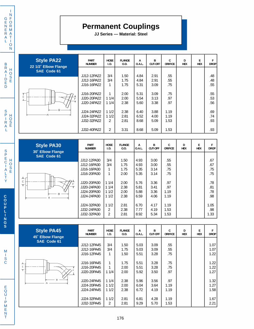
BRAIDED
HOSE
SPIRAL
HOSE
176
GENERAL
INFORMATION
SPECIALTY
HOSE
COUPLINGS
MISC
EQUIPMENT
PART HOSE FLANGE A B C D E FNUMBER I.D. O.D. O.A.L. CUT-OFF ORIFICE HEX HEX DROP
JJ12-12PA45 3/4 1.50 5.03 3.09 .55 1.07JJ12-16PA45 3/4 1.75 5.03 3.09 .55 1.07JJ16-12PA45 1 1.50 5.51 3.28 .75 1.22
JJ16-16PA45 1 1.75 5.51 3.28 .75 1.22JJ16-20PA45 1 2.00 5.51 3.28 .75 1.22JJ20-20PA45 1 1/4 2.00 5.92 3.50 .97 1.27
JJ20-24PA45 1 1/4 2.38 5.96 3.56 .97 1.32JJ24-20PA45 1 1/2 2.00 6.04 3.64 1.19 1.27JJ24-24PA45 1 1/2 2.38 6.72 4.19 1.19 1.58
JJ24-32PA45 1 1/2 2.81 6.81 4.28 1.19 1.67JJ32-32PA45 2 2.81 9.29 5.70 1.53 2.21
Style PA4545˚ Elbow Flange
SAE Code 61
Permanent CouplingsJJ Series — Material: Steel
PART HOSE FLANGE A B C D E FNUMBER I.D. O.D. O.A.L. CUT-OFF ORIFICE HEX HEX DROP
JJ12-12PA30 3/4 1.50 4.93 3.00 .55 .67JJ12-16PA30 3/4 1.75 4.93 3.00 .55 .67JJ16-16PA30 1 1.75 5.35 3.14 .75 .75JJ16-20PA30 1 2.00 5.35 3.14 .75 .75
JJ20-20PA30 1 1/4 2.00 5.76 3.36 .97 .78JJ20-24PA30 1 1/4 2.38 5.81 3.41 .97 .81JJ24-20PA30 1 1/2 2.00 5.88 3.36 1.19 .78JJ24-24PA30 1 1/2 2.38 6.59 4.06 1.19 .98
JJ24-32PA30 1 1/2 2.81 6.70 4.17 1.19 1.05JJ32-24PA30 2 2.38 7.77 4.19 1.53 .98JJ32-32PA30 2 2.81 8.92 5.34 1.53 1.33
PART HOSE FLANGE A B C D E FNUMBER I.D. O.D. O.A.L. CUT-OFF ORIFICE HEX HEX DROP
JJ12-12PA22 3/4 1.50 4.84 2.91 .55 .48JJ12-16PA22 3/4 1.75 4.84 2.91 .55 .48JJ16-16PA22 1 1.75 5.31 3.09 .75 .55
JJ16-20PA22 1 2.00 5.31 3.09 .75 .55JJ20-20PA22 1 1/4 2.00 5.54 3.13 .97 .53JJ20-24PA22 1 1/4 2.38 5.60 3.38 .97 .56
JJ24-24PA22 1 1/2 2.38 6.40 3.88 1.19 .69JJ24-32PA22 1 1/2 2.81 6.52 4.00 1.19 .74JJ32-32PA22 2 2.81 8.68 5.09 1.53 .93
JJ32-40PA22 2 3.31 8.68 5.09 1.53 .93
Style PA2222 1/2˚ Elbow Flange
SAE Code 61
Style PA3030˚ Elbow Flange
SAE Code 61

BRAIDED
HOSE
SPIRAL
HOSE
177
GENERAL
INFORMATION
SPECIALTY
HOSE
COUPLINGS
MISC
EQUIPMENT
Permanent Crimp CouplingsJJ Series — Material: Steel
PART HOSE FLANGE A B C D E FNUMBER I.D. O.D. O.A.L. CUT-OFF ORIFICE HEX HEX DROP
JJ12-12PA60 3/4 1.50 5.02 3.09 .55 1.49JJ12-16PA60 3/4 1.75 5.02 3.09 .55 1.49JJ16-16PA60 1 1.75 5.54 3.31 .75 1.72
JJ16-20PA60 1 2.00 5.54 3.31 .75 1.72JJ20-20PA60 1 1/4 2.00 5.94 3.53 .97 1.79JJ20-24PA60 1 1/4 2.38 5.97 3.56 .97 1.84
JJ24-24PA60 1 1/2 2.38 7.54 4.04 1.19 2.21JJ24-32PA60 1 1/2 2.81 7.61 5.09 1.19 2.32JJ32-32PA60 2 2.81 9.35 5.77 1.53 3.12
PART HOSE FLANGE A B C D E FNUMBER I.D. O.D. O.A.L. CUT-OFF ORIFICE HEX HEX DROP
JJ12-12PA67 3/4 1.50 4.98 3.03 .55 1.70JJ12-16PA67 3/4 1.75 4.98 3.05 .55 1.70JJ16-16PA67 1 1.75 5.50 3.28 .75 1.97
JJ16-20PA67 1 2.00 5.50 3.28 .75 1.97JJ20-20PA67 1 1/4 2.00 5.94 3.53 .97 2.07JJ20-24PA67 1 1/4 2.38 5.96 3.56 .97 2.12
JJ24-20PA67 1 1/2 2.00 6.52 4.00 1.19 2.08JJ24-24PA67 1 1/2 2.38 6.70 4.17 1.19 2.53JJ24-32PA67 1 1/2 2.81 6.75 4.23 1.19 2.65
JJ32-32PA67 2 2.81 9.15 5.56 1.53 3.48
Style PA6060˚ Elbow Flange
SAE Code 61
Style PA6767 1/2˚ Elbow Flange
SAE Code 61
PART HOSE FLANGE A B C D E FNUMBER I.D. O.D. O.A.L. CUT-OFF ORIFICE HEX HEX DROP
JJ12-12PA90 3/4 1.50 4.69 2.75 .55 2.25JJ12-16PA90 3/4 1.75 4.69 2.75 .55 2.25JJ16-16PA90 1 1.75 5.19 2.97 .75 2.62
JJ16-20PA90 1 2.00 5.19 2.97 .75 2.62JJ16-24PA90 1 2.38 5.37 3.16 .75 2.88JJ20-16PA90 1 1/4 1.75 5.65 3.25 .97 2.87
JJ20-20PA90 1 1/4 2.00 5.65 3.25 .97 2.80JJ20-24PA90 1 1/4 2.38 5.65 3.25 .97 2.87JJ20-32PA90 1 1/4 2.81 6.19 3.78 .97 3.53
JJ24-20PA90 1 1/2 2.00 5.77 3.38 1.19 2.80JJ24-24PA90 1 1/2 2.38 6.31 3.78 1.19 3.41JJ24-32PA90 1 1/2 2.81 6.31 3.78 1.19 3.53
JJ32-24PA90 2 2.38 7.48 3.89 1.53 3.41JJ32-32PA90 2 2.81 8.83 5.25 1.53 4.88JJ32-40PA90 2 3.31 8.83 5.25 1.53 4.88
Style PA9090˚ Elbow Flange
SAE Code 61

BRAIDED
HOSE
SPIRAL
HOSE
178
GENERAL
INFORMATION
SPECIALTY
HOSE
COUPLINGS
MISC
EQUIPMENT
Permanent Crimp CouplingsJJ Series — Material: Steel
PART HOSE FLANGE A B C D E FNUMBER I.D. O.D. O.A.L. CUT-OFF ORIFICE HEX HEX DROP
JJ16-16PC45 1 1.75 5.51 3.30 .75 1.22
PART HOSE FLANGE A B C D E FNUMBER I.D. O.D. O.A.L. CUT-OFF ORIFICE HEX HEX DROP
JJ16-16PC 1 1.75 5.28 3.06 .75JJ20-20PC 1-1/4 2.00 5.39 2.98 .97
Style PCCaptive 4 Bolt Flange
SAE Code 61
Style PC4545˚ Elbow Captive
4 Bolt Flange SAE Code 61
PART HOSE FLANGE A B C D E FNUMBER I.D. O.D. O.A.L. CUT-OFF ORIFICE HEX HEX DROP
JJ16-16PA100 1 1.75 5.18 2.97 .75 2.81JJ20-20PA100 1 1/4 2.00 5.99 3.25 .97 3.03
Style PA100100˚ Elbow Flange
SAE Code 61

BRAIDED
HOSE
SPIRAL
HOSE
179
Permanent Crimp CouplingsJJ Series — Material: Steel
PART HOSE FLANGE A B C D E FNUMBER I.D. O.D. O.A.L. CUT-OFF ORIFICE HEX HEX DROP
JJ16-16PC60 1 1.75 5.54 3.31 .75 1.72
PART HOSE FLANGE A B C D E FNUMBER I.D. O.D. O.A.L. CUT-OFF ORIFICE HEX HEX DROP
JJ16-16PC90 1 1.75 5.19 2.97 .75 2.62JJ20-20PC90 1 1/4 2.00 5.65 3.25 .97 2.80
GENERAL
INFORMATION
SPECIALTY
HOSE
COUPLINGS
MISC
EQUIPMENT
Style PC6060˚ Elbow Captive
4 Bolt Flange SAE Code 61
Style PC9090˚ Elbow Captive
4 Bolt Flange SAE Code 61
PART HOSE FLANGE A B C D E FNUMBER I.D. O.D. O.A.L. CUT-OFF ORIFICE HEX HEX DROP
JJ08-08PH 1/2 1.25 4.31 2.34 .31JJ12-12PH 3/4 1.63 4.81 2.88 .55JJ12-16PH 3/4 1.88 4.81 2.88 .55
JJ16-12PH 1 1.63 5.06 2.84 .75JJ16-16PH 1 1.88 5.28 3.06 .75JJ16-20PH 1 2.13 5.59 3.38 .75
JJ16-24PH 1 2.50 5.66 3.44 .75JJ20-16PH 1 1/4 1.88 5.56 3.16 .97JJ20-20PH 1 1/4 2.13 5.88 3.47 .97
JJ20-24PH 1 1/4 2.50 5.94 3.53 .97JJ20-32PH 1 1/4 3.13 5.94 3.49 .97JJ24-20PH 1 1/2 2.13 6.00 3.47 1.19
JJ24-24PH 1 1/2 2.50 6.06 3.53 1.19JJ24-32PH 1 1/2 3.13 6.56 3.99 1.19JJ32-32PH 2 3.13 8.58 4.97 1.53
Style PHFlange
SAE Code 62
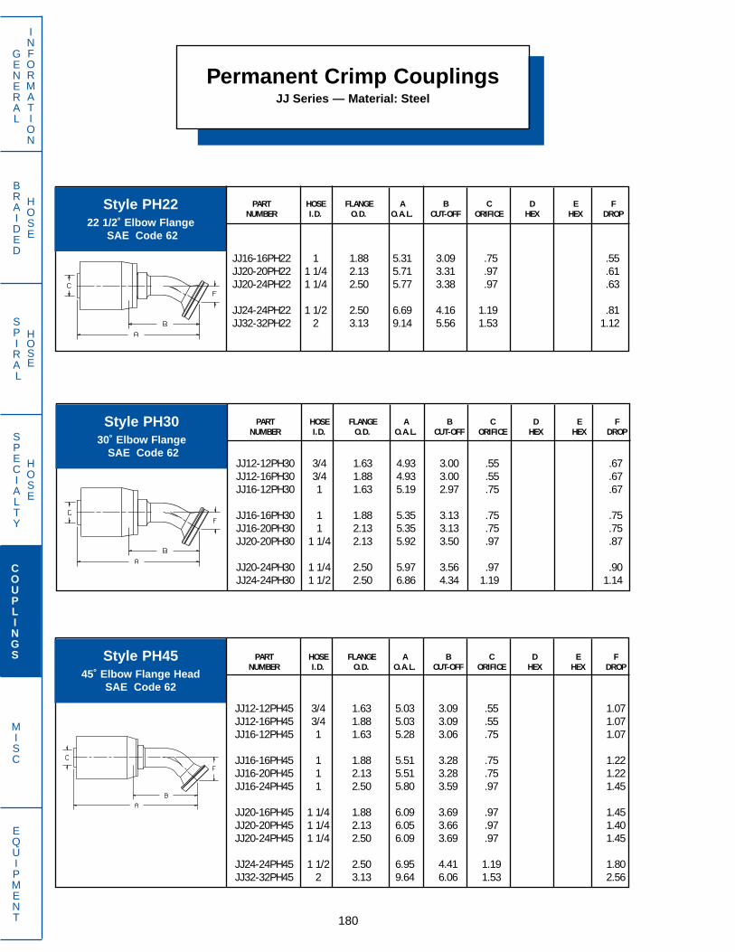
BRAIDED
HOSE
SPIRAL
HOSE
180
GENERAL
INFORMATION
SPECIALTY
HOSE
COUPLINGS
MISC
EQUIPMENT
Permanent Crimp CouplingsJJ Series — Material: Steel
PART HOSE FLANGE A B C D E FNUMBER I.D. O.D. O.A.L. CUT-OFF ORIFICE HEX HEX DROP
JJ12-12PH30 3/4 1.63 4.93 3.00 .55 .67JJ12-16PH30 3/4 1.88 4.93 3.00 .55 .67JJ16-12PH30 1 1.63 5.19 2.97 .75 .67
JJ16-16PH30 1 1.88 5.35 3.13 .75 .75JJ16-20PH30 1 2.13 5.35 3.13 .75 .75JJ20-20PH30 1 1/4 2.13 5.92 3.50 .97 .87
JJ20-24PH30 1 1/4 2.50 5.97 3.56 .97 .90JJ24-24PH30 1 1/2 2.50 6.86 4.34 1.19 1.14
PART HOSE FLANGE A B C D E FNUMBER I.D. O.D. O.A.L. CUT-OFF ORIFICE HEX HEX DROP
JJ12-12PH45 3/4 1.63 5.03 3.09 .55 1.07JJ12-16PH45 3/4 1.88 5.03 3.09 .55 1.07JJ16-12PH45 1 1.63 5.28 3.06 .75 1.07
JJ16-16PH45 1 1.88 5.51 3.28 .75 1.22JJ16-20PH45 1 2.13 5.51 3.28 .75 1.22JJ16-24PH45 1 2.50 5.80 3.59 .97 1.45
JJ20-16PH45 1 1/4 1.88 6.09 3.69 .97 1.45JJ20-20PH45 1 1/4 2.13 6.05 3.66 .97 1.40JJ20-24PH45 1 1/4 2.50 6.09 3.69 .97 1.45
JJ24-24PH45 1 1/2 2.50 6.95 4.41 1.19 1.80JJ32-32PH45 2 3.13 9.64 6.06 1.53 2.56
PART HOSE FLANGE A B C D E FNUMBER I.D. O.D. O.A.L. CUT-OFF ORIFICE HEX HEX DROP
JJ16-16PH22 1 1.88 5.31 3.09 .75 .55JJ20-20PH22 1 1/4 2.13 5.71 3.31 .97 .61JJ20-24PH22 1 1/4 2.50 5.77 3.38 .97 .63
JJ24-24PH22 1 1/2 2.50 6.69 4.16 1.19 .81JJ32-32PH22 2 3.13 9.14 5.56 1.53 1.12
Style PH2222 1/2˚ Elbow Flange
SAE Code 62
Style PH3030˚ Elbow Flange
SAE Code 62
Style PH4545˚ Elbow Flange Head
SAE Code 62

BRAIDED
HOSE
SPIRAL
HOSE
181
GENERAL
INFORMATION
SPECIALTY
HOSE
COUPLINGS
MISC
EQUIPMENT
PART HOSE FLANGE A B C D E FNUMBER I.D. O.D. O.A.L. CUT-OFF ORIFICE HEX HEX DROP
JJ12-12PH60 3/4 1.63 5.02 3.09 .55 1.49JJ12-16PH60 3/4 1.88 5.02 3.09 .55 1.49JJ16-16PH60 1 1.88 5.54 3.31 .75 1.72
JJ16-20PH60 1 2.13 5.54 3.31 .75 1.72JJ20-20PH60 1 1/4 2.13 6.03 3.53 .97 1.95JJ20-24PH60 1 1/4 2.50 6.06 3.66 .97 2.00
Permanent Crimp CouplingsJJ Series — Material: Steel
PART HOSE FLANGE A B C D E FNUMBER I.D. O.D. O.A.L. CUT-OFF ORIFICE HEX HEX DROP
JJ12-12PH67 3/4 1.63 4.98 3.03 .55 1.70JJ16-16PH67 1 1.88 5.50 3.28 .75 1.97
JJ20-20PH67 1 1/4 2.13 6.01 3.59 .97 2.24JJ24-24PH67 1 1/2 2.50 6.82 4.28 1.19 2.82
Style PH6060˚ Elbow Flange
SAE Code 62
Style PH6767 1/2˚ Elbow Flange
SAE Code 62
PART HOSE FLANGE A B C D E FNUMBER I.D. O.D. O.A.L. CUT-OFF ORIFICE HEX HEX DROP
JJ12-12PH90 3/4 1.63 4.69 2.75 .55 2.25JJ12-16PH90 3/4 1.88 4.69 2.75 .55 2.25JJ16-16PH90 1 1.88 5.19 2.97 .75 2.63
JJ16-20PH90 1 2.13 5.19 2.97 .75 2.63JJ16-24PH90 1 2.50 5.37 3.16 .75 3.06JJ20-16PH90 1 1/4 1.88 5.65 3.25 .97 3.06
JJ20-20PH90 1 1/4 2.13 5.65 3.25 .97 2.99JJ20-24PH90 1 1/4 2.50 5.65 3.25 .97 3.06JJ24-24PH90 1 1/2 2.50 6.31 3.78 1.19 3.72
JJ24-32PH90 1 1/2 3.13 6.31 3.78 1.19 3.72JJ32-32PH90 2 3.13 8.83 5.22 1.53 5.38
Style PH9090˚ Elbow Flange
SAE Code 62

BRAIDED
HOSE
SPIRAL
HOSE
182
GENERAL
INFORMATION
SPECIALTY
HOSE
COUPLINGS
MISC
EQUIPMENT
Permanent Crimp CouplingsJJ Series — Material: Steel
PART HOSE A B C D E TUBENUMBER I.D. THREAD O.A.L. CUT-OFF ORIFICE HEX HEX O.D.
(mm) (mm)
JJ08-16RO24A 1/2 M24 X 1.5 3.86 1.88 .31 24 30JJ10-20RO30B 5/8 M30 X 2.0 4.06 2.16 .47 30 38JJ12-20RO30B 3/4 M30 X 2.0 3.72 1.75 .55 32 38
JJ12-22RO30A 3/4 M30 X 1.5 3.98 2.03 .55 30 38JJ12-25RO36B 3/4 M36 X 2.0 3.98 2.03 .55 36 41JJ16-30RO42B 1 M42 X 2.0 4.57 2.34 .75 41 50
JJ20-30RO42B 1 1/4 M42 X 2.0 4.97 2.56 .97 46 50JJ20-35RO45B 1 1/4 M45 X 2.0 4.86 2.44 .97 46 55JJ20-38RO52B 1 1/4 M52 X 2.0 5.05 2.63 .97 50 60
PART HOSE A B C E F TUBENUMBER I.D. THREAD O.A.L. CUT-OFF ORIFICE HEX DROP O.D.
(mm)
JJ10-20RO30B90T 5/8 M30 X 2.0 4.44 2.53 .47 38 2.22JJ12-22RO30A90T 3/4 M30 X 1.5 4.69 2.75 .55 38 2.96JJ12-25RO36B90T 3/4 M36 X 2.0 4.69 2.75 .55 41 2.75
JJ20-35RO45B90T 1 1/4 M45 X 2.0 6.38 3.97 .97 52 3.17JJ20-38RO52B90T 1 1/4 M52 X 2.0 6.38 3.97 .97 60 3.25
PART HOSE A B C D E FNUMBER I.D. THREAD O.A.L. CUT-OFF ORIFICE HEX HEX DROP
JJ12-12RA 3/4 1 1/16–12 3.66 1.72 .55 1 1/4JJ16-16RA 1 1 5/16–12 3.78 1.56 .75 1 1/2JJ20-20RA 1 1/4 1 5/8–12 4.44 2.03 .97 1 7/8
Style RAMale
O-Ring Boss
Style ROSwivel Female Metric24˚ Cone with O-Ring
Style RO90T 90˚ Elbow Metric Swivel Female
24˚ Cone with O-Ring
Style RA is furnished with O-Ring

BRAIDED
HOSE
SPIRAL
HOSE
183
GENERAL
INFORMATION
SPECIALTY
HOSE
COUPLINGS
MISC
EQUIPMENT
Permanent Crimp CouplingsJJ Series — Material: Steel
PART HOSE A B C D E FNUMBER I.D. THREAD O.A.L. CUT-OFF ORIFICE HEX HEX DROP
(mm) (mm)
JJ10-20RU30B 5/8 M30 X 2.0 4.01 1.94 .47 30 38JJ12-22RU30A 3/4 M30 X 1.5 3.98 2.03 .55 38 38JJ12-25RU36B 3/4 M36 X 2.0 3.97 2.03 .55 36 41
JJ16-28RU36B 1 M36 X 2.0 4.22 2.00 .75 36 41
Style RUSwivel Female
Universal Metric 24˚/60˚ Cone
PART HOSE A B C D E FNUMBER I.D. THREAD O.A.L. CUT-OFF ORIFICE HEX HEX DROP
(mm)
JJ12-22RU30A90T 3/4 M30 X 1.5 4.69 2.72 .55 38 2.76JJ12-22RU30B90T 3/4 M30 X 2.0 4.69 2.72 .55 38 2.76JJ12-25RU36B90T 3/4 M36 X 2.0 4.69 2.72 .55 41 2.67
JJ16-28RU36B90T 1 M36 X 2.0 5.19 2.97 .75 41 2.92JJ16-30RU42B90T 1 M42 X 2.0 5.19 2.97 .75 50 3.09
PART HOSE A B C D E FNUMBER I.D. THREAD O.A.L. CUT-OFF ORIFICE HEX HEX DROP
(mm)
JJ12-22RU30A45T 3/4 M30 X 1.5 5.58 3.63 .55 38 1.62JJ12-22RU30B45T 3/4 M30 X 2.0 5.22 3.56 .55 38 1.56JJ12-25RU36B45T 3/4 M36 X 2.0 5.57 3.63 .55 41 1.61
JJ16-28RU36A45T 1 M36 X 1.5 5.95 3.72 .77 41 1.67JJ16-28RU36B45T 1 M36 X 2.0 5.95 3.72 .75 41 1.67JJ16-30RU42B45T 1 M42 X 2.0 6.15 3.94 .75 50 1.87
Style RU45T45˚ Bent Tube Swivel FemaleUniversal Metric 24˚/60˚ Cone
Style RU90T90˚ Bent Tube Swivel FemaleUniversal Metric 24˚/60˚ Cone
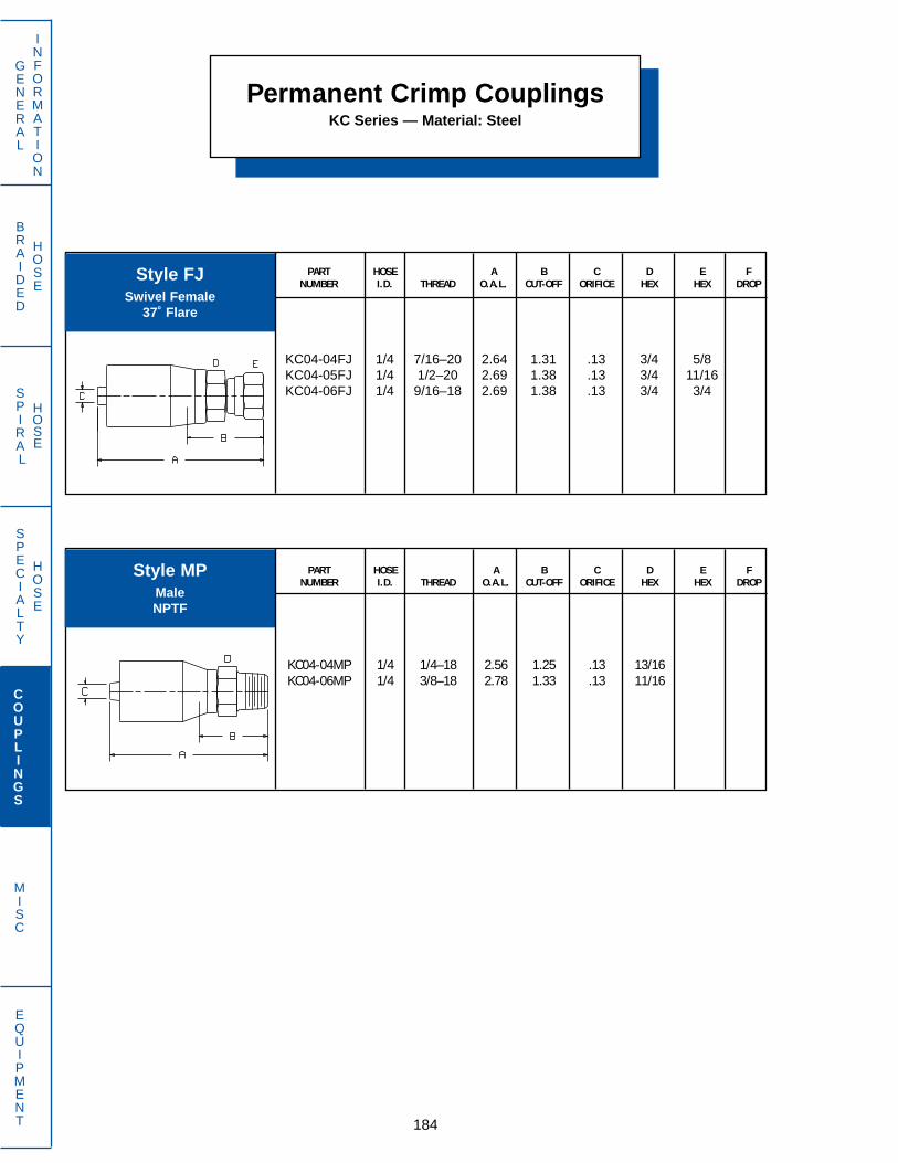
BRAIDED
HOSE
SPIRAL
HOSE
184
GENERAL
INFORMATION
SPECIALTY
HOSE
COUPLINGS
MISC
EQUIPMENT
Permanent Crimp CouplingsKC Series — Material: Steel
PART HOSE A B C D E FNUMBER I.D. THREAD O.A.L. CUT-OFF ORIFICE HEX HEX DROP
KC04-04FJ 1/4 7/16–20 2.64 1.31 .13 3/4 5/8KC04-05FJ 1/4 1/2–20 2.69 1.38 .13 3/4 11/16KC04-06FJ 1/4 9/16–18 2.69 1.38 .13 3/4 3/4
Style FJSwivel Female
37˚ Flare
PART HOSE A B C D E FNUMBER I.D. THREAD O.A.L. CUT-OFF ORIFICE HEX HEX DROP
KC04-04MP 1/4 1/4–18 2.56 1.25 .13 13/16KC04-06MP 1/4 3/8–18 2.78 1.33 .13 11/16
Style MPMaleNPTF
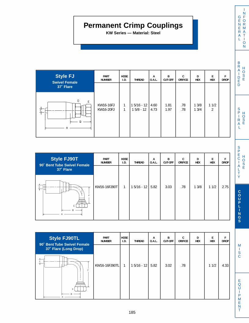
BRAIDED
HOSE
SPIRAL
HOSE
185
Permanent Crimp CouplingsKW Series — Material: Steel
Style FJSwivel Female
37˚ Flare
PART HOSE A B C D E FNUMBER I.D. THREAD O.A.L. CUT-OFF ORIFICE HEX HEX DROP
KW16-16FJ 1 1 5/16 - 12 4.60 1.81 .78 1 3/8 1 1/2KW16-20FJ 1 1 5/8 - 12 4.73 1.97 .78 1 3/4 2
PART HOSE A B C D E FNUMBER I.D. THREAD O.A.L. CUT-OFF ORIFICE HEX HEX DROP
KW16-16FJ90T 1 1 5/16 - 12 5.82 3.03 .78 1 3/8 1 1/2 2.75
Style FJ90T90˚ Bent Tube Swivel Female
37˚ Flare
GENERAL
INFORMATION
COUPLINGS
MISC
EQUIPMENT
SPECIALTY
HOSE
PART HOSE A B C D E FNUMBER I.D. THREAD O.A.L. CUT-OFF ORIFICE HEX HEX DROP
KW16-16FJ90TL 1 1 5/16 - 12 5.82 3.02 .78 1 1/2 4.33
Style FJ90TL90˚ Bent Tube Swivel Female
37˚ Flare (Long Drop)

BRAIDED
HOSE
SPIRAL
HOSE
186
GENERAL
INFORMATION
SPECIALTY
HOSE
COUPLINGS
MISC
EQUIPMENT
Permanent Crimp CouplingsKW Series — Material: Steel
PART HOSE A B C D E FNUMBER I.D. THREAD O.A.L. CUT-OFF ORIFICE HEX HEX DROP
KW16-16OFT 1 1 7/16 - 12 4.67 1.88 .78 1 3/8 1 5/8
PART HOSE A B C D E FNUMBER I.D. THREAD O.A.L. CUT-OFF ORIFICE HEX HEX DROP
KW16-16MP 1 1 11-1/2 4.48 1.69 .78 1 1/2
Style MPMaleNPTF
Style OFTSwivel Female
O-Ring Face Seal
PART HOSE A B C D E FNUMBER I.D. THREAD O.A.L. CUT-OFF ORIFICE HEX HEX DROP
KW16-16MJ 1 1 5/16 - 12 4.45 1.66 .78 1 3/8KW16-20MJ 1 1 5/8 - 12 4.57 1.78 .78 1 11/16
Style MJMale 37˚ Flare
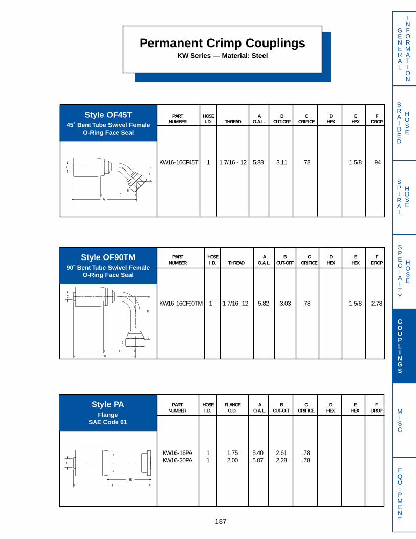
Permanent Crimp CouplingsKW Series — Material: Steel
GENERAL
INFORMATION
SPECIALTY
HOSE
COUPLINGS
MISC
EQUIPMENT187
BRAIDED
HOSE
SPIRAL
HOSE
PART HOSE A B C D E FNUMBER I.D. THREAD O.A.L. CUT-OFF ORIFICE HEX HEX DROP
KW16-16OF45T 1 1 7/16 - 12 5.88 3.11 .78 1 5/8 .94
Style OF45T45˚ Bent Tube Swivel Female
O-Ring Face Seal
PART HOSE A B C D E FNUMBER I.D. THREAD O.A.L. CUT-OFF ORIFICE HEX HEX DROP
KW16-16OF90TM 1 1 7/16 -12 5.82 3.03 .78 1 5/8 2.78
PART HOSE FLANGE A B C D E FNUMBER I.D. O.D. O.A.L. CUT-OFF ORIFICE HEX HEX DROP
KW16-16PA 1 1.75 5.40 2.61 .78KW16-20PA 1 2.00 5.07 2.28 .78
Style OF90TM90˚ Bent Tube Swivel Female
O-Ring Face Seal
Style PAFlange
SAE Code 61

Permanent Crimp CouplingsKW Series — Material: Steel
GENERAL
INFORMATION
SPECIALTY
HOSE
COUPLINGS
MISC
EQUIPMENT 188
BRAIDED
HOSE
SPIRAL
HOSE
PART HOSE FLANGE A B C D E FNUMBER I.D. O.D. O.A.L. CUT-OFF ORIFICE HEX HEX DROP
KW16-16PH 1 1.88 5.46 2.67 .78KW16-20PH 1 2.13 5.51 2.72 .78
Style PHFlange
SAE Code 62
PART HOSE FLANGE A B C D E FNUMBER I.D. O.D. O.A.L. CUT-OFF ORIFICE HEX HEX DROP
KW16-16PH22 1 1.88 5.83 3.04 .78 .59
Style PH2222 1/2˚ Elbow Flange
SAE Code 62
PART HOSE FLANGE A B C D E FNUMBER I.D. O.D. O.A.L. CUT-OFF ORIFICE HEX HEX DROP
KW16-16PA90 1 1.75 5.57 2.78 .78 2.75
Style PA9090˚ Elbow Flange
SAE Code 61
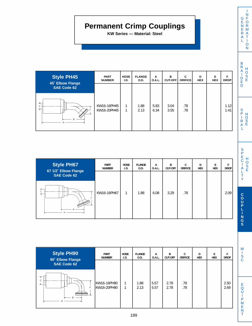
Permanent Crimp CouplingsKW Series — Material: Steel
GENERAL
INFORMATION
SPECIALTY
HOSE
COUPLINGS
MISC
EQUIPMENT189
BRAIDED
HOSE
SPIRAL
HOSE
PART HOSE FLANGE A B C D E FNUMBER I.D. O.D. O.A.L. CUT-OFF ORIFICE HEX HEX DROP
KW16-16PH45 1 1.88 5.83 3.04 .78 1.12KW16-20PH45 1 2.13 6.34 3.55 .78 1.41
Style PH4545˚ Elbow Flange
SAE Code 62
PART HOSE FLANGE A B C D E FNUMBER I.D. O.D. O.A.L. CUT-OFF ORIFICE HEX HEX DROP
KW16-16PH90 1 1.88 5.57 2.78 .78 2.50KW16-20PH90 1 2.13 5.57 2.78 .78 2.69
PART HOSE FLANGE A B C D E FNUMBER I.D. O.D. O.A.L. CUT-OFF ORIFICE HEX HEX DROP
KW16-16PH67 1 1.88 6.08 3.29 .78 2.09
Style PH6767 1/2˚ Elbow Flange
SAE Code 62
Style PH9090˚ Elbow Flange
SAE Code 62

Permanent Crimp CouplingsNB Series — Material: Steel
GENERAL
INFORMATION
SPECIALTY
HOSE
COUPLINGS
MISC
EQUIPMENT 190
BRAIDED
HOSE
SPIRAL
HOSE
PART HOSE A B C D E FNUMBER I.D. THREAD O.A.L. CUT-OFF ORIFICE HEX HEX DROP
NB20-20FJ 1 1/4 1 5/8–12 5.37 2.00 1.06 2 2NB24-24FJ 1 1/2 1 7/8–12 6.24 2.22 1.25 2 1/4 2 1/4NB32-32FJ 2 2 1/2–12 6.02 2.99 1.68 2 7/8 2 1/4
PART HOSE A B C D E FNUMBER I.D. THREAD O.A.L. CUT-OFF ORIFICE HEX HEX DROP
NB20-20MJ 1 1/4 1 5/8–12 5.36 1.97 1.06 2NB24-24MJ 1 1/2 1 7/8–12 6.37 2.35 1.25 2 1/8NB32-32MJ 2 2 1/2–12 5.81 2.80 1.68 2 5/8
PART HOSE A B C D E FNUMBER I.D. THREAD O.A.L. CUT-OFF ORIFICE HEX HEX DROP
NB20-20MP 1 1/4 1 1/4–11-1/2 5.61 2.24 1.06 2NB24-24MP 1 1/2 1 1/2–11-1/2 6.29 2.27 1.25 2 1/4NB32-32MP 2 2–11-1/2 5.51 2.49 1.68 2 5/8
Style FJSwivel Female
37˚ Flare
Style MJMale
37˚ Flare
Style MPMaleNPTF

BRAIDED
HOSE
SPIRAL
HOSE
191
Permanent Crimp CouplingsNB Series — Material: Steel
GENERAL
INFORMATION
SPECIALTY
HOSE
COUPLINGS
MISC
EQUIPMENT
PART HOSE A B C D E FNUMBER I.D. THREAD O.A.L. CUT-OFF ORIFICE HEX HEX DROP
NB20-20OFT 1 1/4 1 11/16 - 12 5.36 1.99 1.01 2 1 7/8NB24-24OFT 1 1/2 2 - 12 6.25 2.23 1.25 2 1/4 2 3/8
PART HOSE FLANGE A B C D E FNUMBER I.D. O.D. O.A.L. CUT-OFF ORIFICE HEX HEX DROP
NB20-20PA 1 1/4 2.00 6.07 2.70 1.01
PART HOSE FLANGE A B C D E FNUMBER I.D. O.D. O.A.L. CUT-OFF ORIFICE HEX HEX DROP
NB20-16PA90 1 1/4 1.75 6.30 2.96 .78 2.25
Style OFTSwivel Female
O-Ring Face Seal
Style PAFlange
SAE Code 61
Style PA9090˚ Elbow Flange
SAE Code 61

BRAIDED
HOSE
SPIRAL
HOSE
192
GENERAL
INFORMATION
SPECIALTY
HOSE
COUPLINGS
MISC
EQUIPMENT
Permanent Crimp CouplingsNB Series — Material: Steel
PART HOSE FLANGE A B C D E FNUMBER I.D. O.D. O.A.L. CUT-OFF ORIFICE HEX HEX DROP
NB20-24PH22 1 1/4 2.50 6.92 3.55 1.01 .72
PART HOSE FLANGE A B C D E FNUMBER I.D. O.D. O.A.L. CUT-OFF ORIFICE HEX HEX DROP
NB20-16PH 1 1/4 1.88 6.03 2.66 .78NB20-20PH 1 1/4 2.13 6.46 3.08 1.01NB20-24PH 1 1/4 2.50 6.65 3.27 1.01
NB24-20PH 1 1/2 2.13 7.10 3.09 1.01NB24-24PH 1 1/2 2.50 7.29 3.29 1.19NB24-32PH 1 1/2 3.13 7.76 3.75 1.19
NB32-32PH 2 3.13 7.47 4.45 1.68
PART HOSE FLANGE A B C D E FNUMBER I.D. O.D. O.A.L. CUT-OFF ORIFICE HEX HEX DROP
NB20-20PH30 1 1/4 2.13 6.93 3.56 1.01 .94NB24-20PH30 1 1/2 2.13 7.57 3.56 1.01 .94NB24-24PH30 1 1/2 2.50 8.60 4.59 1.19 1.05
NB24-32PH30 1 1/2 3.13 9.07 5.06 1.19 1.27NB32-32PH30 2 3.13 8.45 5.46 1.68 1.61
Style PHFlange
SAE Code 62
Style PH2222 1/2˚ Elbow Flange
SAE Code 62
Style PH3030˚ Elbow Flange
SAE Code 62

PART HOSE FLANGE A B C D E FNUMBER I.D. O.D. O.A.L. CUT-OFF ORIFICE HEX HEX DROP
NB20-16PH45 1 1/4 1.88 6.56 3.18 .78 1.12NB20-20PH45 1 1/4 2.13 7.19 3.82 1.01 1.48NB20-24PH45 1 1/4 2.50 7.36 3.99 1.01 1.62
NB24-20PH45 1 1/2 2.13 7.17 3.80 1.01 1.48NB24-24PH45 1 1/2 2.50 8.69 4.68 1.19 1.73NB32-32PH45 2 3.13 8.66 5.64 1.68 2.58
BRAIDED
HOSE
SPIRAL
HOSE
193
GENERAL
INFORMATION
SPECIALTY
HOSE
COUPLINGS
MISC
EQUIPMENT
Permanent Crimp CouplingsNB Series –– Material: Steel
PART HOSE FLANGE A B C D E FNUMBER I.D. O.D. O.A.L. CUT-OFF ORIFICE HEX HEX DROP
NB20-20PH60 1 1/4 2.13 7.38 4.01 1.01 2.08NB20-24PH60 1 1/4 2.50 7.47 4.09 1.01 2.23NB24-20PH60 1 1/2 2.13 7.38 4.01 1.01 2.08
NB24-24PH60 1 1/2 2.50 8.95 4.94 1.19 2.50NB32-32PH60 2 3.13 7.69 5.68 1.68 3.58
Style PH4545˚ Elbow Flange
SAE Code 62
Style PH6060˚ Elbow Flange
SAE Code 62

BRAIDED
HOSE
SPIRAL
HOSE
194
GENERAL
INFORMATION
SPECIALTY
HOSE
COUPLINGS
MISC
EQUIPMENT
Permanent Crimp CouplingsNB Series –– Material: Steel
PART HOSE FLANGE A B C D E FNUMBER I.D. O.D. O.A.L. CUT-OFF ORIFICE HEX HEX DROP
NB20-20PH90 1 1/4 2.13 7.16 3.79 1.01 3.13NB20-24PH90 1 1/4 2.50 7.19 3.82 1.01 3.32NB24-20PH90 1 1/2 2.13 7.79 3.78 1.01 3.14
NB24-24PH90 1 1/2 2.50 8.05 4.04 1.19 3.78NB32-32PH90 2 3.13 7.96 4.95 1.68 5.43
Style PH9090˚ Elbow Flange
SAE Code 62
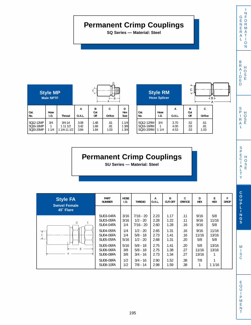
PART HOSE A B C D E FNUMBER I.D. THREAD O.A.L. CUT-OFF ORIFICE HEX HEX DROP
SU03-04FA 3/16 7/16 - 20 2.23 1.17 .11 9/16 5/8SU03-05FA 3/16 1/2 - 20 2.28 1.22 .11 9/16 11/16SU04-04FA 1/4 7/16 - 20 2.60 1.28 .16 9/16 5/8
SU04-05FA 1/4 1/2 - 20 2.65 1.31 .16 9/16 11/16SU04-06FA 1/4 5/8 - 18 2.73 1.41 .16 11/16 13/16SU05-05FA 5/16 1/2 - 20 2.68 1.31 .20 5/8 5/8
SU05-06FA 5/16 5/8 - 18 2.75 1.41 .20 5/8 13/16SU06-06FA 3/8 5/8 - 18 2.75 1.38 .27 11/16 13/16SU06-08FA 3/8 3/4 - 16 2.73 1.34 .27 13/16 1
SU08-08FA 1/2 3/4 - 16 2.90 1.52 .38 7/8 1SU08-10FA 1/2 7/8 - 14 2.98 1.59 .38 1 1 1/16
Permanent Crimp CouplingsSQ Series — Material: Steel
195
GENERAL
INFORMATION
SPECIALTY
HOSE
COUPLINGS
MISC
EQUIPMENT
BRAIDED
HOSE
SPIRAL
HOSE
A B C DCat. Hose Cut HexNo. I.D. Thread O.A.L. Off Orifice Size
SQ12-12MP 3/4 3/4-14 3.08 1.48 .61 1 1/4SQ16-16MP 1 1 11 1/2 3.42 1.69 .81 1 3/8SQ20-20MP 1 1/4 1 1/4-11 1/2 3.84 1.84 1.03 1 3/4
Style MPMale NPTF
A B CCat. Hose CutNo. I.D. O.A.L. Off Orifice
SQ12-12RM 3/4 3.70 .52 .61SQ16-16RM 1 4.00 .53 .81SQ20-20RM 1 1/4 4.53 .53 1.03
Style RMHose Splicer
Permanent Crimp CouplingsSU Series — Material: Steel
Style FASwivel Female
45˚ Flare

Permanent Crimp CouplingsSU Series — Material: Steel
PART HOSE A B C D E FNUMBER I.D. THREAD O.A.L. CUT-OFF ORIFICE HEX HEX DROP
SU03-04FJ45T 3/16 7/16 - 20 2.87 1.97 .11 9/16 .33SU04-04FJ45T 1/4 7/16 - 20 3.23 1.91 .16 9/16 .33SU04-05FJ45T 1/4 1/2 - 20 3.27 1.94 .16 5/8 .36
SU05-06FJ45T 5/16 9/16 - 18 3.34 2.00 .20 11/16 .39SU06-06FJ45T 3/8 9/16 - 18 3.33 1.94 .27 11/16 .39SU06-08FJ45T 3/8 3/4 - 16 3.66 2.28 .27 7/8 .54
SU08-08FJ45T 1/2 3/4 - 16 3.77 1.53 .38 7/8 .54SU08-10FJ45T 1/2 7/8 - 14 3.41 2.03 .38 1 .63
196
GENERAL
INFORMATION
SPECIALTY
HOSE
COUPLINGS
MISC
EQUIPMENT
BRAIDED
HOSE
SPIRAL
HOSE
PART HOSE A B C D E FNUMBER I.D. THREAD O.A.L. CUT-OFF ORIFICE HEX HEX DROP
SU03-04FJ 3/16 7/16 - 20 2.23 1.17 .11 9/16 5/8SU03-05FJ 3/16 1/2 - 20 2.28 1.22 .11 9/16 11/16SU04-04FJ 1/4 7/16 - 20 2.61 1.28 .16 9/16 5/8
SU04-05FJ 1/4 1/2 - 20 2.65 1.31 .16 9/16 11/16SU04-06FJ 1/4 9/16 - 18 2.67 1.34 .16 5/16 3/4SU05-05FJ 5/16 1/2 - 20 2.68 1.31 .20 5/8 5/8
SU05-06FJ 5/16 9/16 - 18 2.70 1.34 .20 5/8 3/4SU06-05FJ 3/8 1/2 - 20 2.73 1.34 .27 3/4 5/8SU06-06FJ 3/8 9/16 - 18 2.69 1.31 .27 11/16 3/4
SU06-08FJ 3/8 3/4 - 16 2.72 1.34 .27 13/16 1SU08-06FJ 1/2 9/16 - 18 2.86 1.47 .38 7/8 11/16SU08-08FJ 1/2 3/4 - 16 2.90 1.53 .38 7/8 1
SU08-10FJ 1/2 7/8 - 14 2.98 1.59 .38 1 1 1/16SU08-12FJ 1/2 1 1/16 - 12 3.05 1.66 .38 1 1/8 1 3/8
PART HOSE A B C D E FNUMBER I.D. THREAD O.A.L. CUT-OFF ORIFICE HEX HEX DROP
SU03-04FF 3/16 1/4 - 18 2.09 1.03 .11 11/16SU04-04FF 1/4 1/4 - 18 2.47 1.03 .16 11/16SU04-06FF 1/4 3/8 - 18 2.47 1.03 .16 7/8
SU06-06FF 3/8 3/8 - 18 2.48 1.02 .27 7/8SU06-08FF 3/8 1/2 - 14 2.75 1.28 .27 1SU08-08FF 1/2 1/2 - 14 2.84 1.34 .38 1
Style FFFemale NPTF
Style FJSwivel Female
37˚Flare
Style FJ45T45˚ Bent Tube Swivel Female
37˚Flare

PART HOSE A B C D E FNUMBER I.D. THREAD O.A.L. CUT-OFF ORIFICE HEX HEX DROP
SU03-04FN 3/16 1/4 - 18 2.28 1.38 .11 9/16 11/16SU04-04FN 1/4 1/4 - 18 2.65 1.34 .16 9/16 11/16SU06-06FN 3/8 3/8 - 18 2.73 1.34 .27 13/16 7/8
Permanent Crimp CouplingsSU Series — Material: Steel
197
GENERAL
INFORMATION
SPECIALTY
HOSE
COUPLINGS
MISC
EQUIPMENT
BRAIDED
HOSE
SPIRAL
HOSE
PART HOSE A B C D E FNUMBER I.D. THREAD O.A.L. CUT-OFF ORIFICE HEX HEX DROP
SU05-06MA 5/16 5/8 - 18 2.63 1.28 .20 3/4SU06-06MA 3/8 5/8 - 18 2.61 1.28 .27 3/4SU08-08MA 1/2 3/4 - 16 2.91 1.53 .38 7/8
PART HOSE A B C D E FNUMBER I.D. THREAD O.A.L. CUT-OFF ORIFICE HEX HEX DROP
SU03-04FJ90T 3/16 7/16 - 20 2.75 1.84 .11 9/16 .69SU04-04FJ90T 1/4 7/16 - 20 3.13 1.81 .16 9/16 .69SU04-05FJ90T 1/4 1/2 - 20 3.16 1.84 .16 5/8 .77
SU05-06FJ90T 5/16 9/16 - 18 3.25 1.91 .20 11/16 .86SU06-06FJ90T 3/8 9/16 - 18 3.23 1.84 .27 11/16 .86SU06-08FJ90T 3/8 3/4 - 16 3.48 2.09 .27 7/8 1.13
SU08-08FJ90T 1/2 3/4 - 16 3.59 2.22 .38 7/8 1.12SU08-10FJ90T 1/2 7/8 - 14 3.11 1.72 .38 1 1.23
PART HOSE A B C D E FNUMBER I.D. THREAD O.A.L. CUT-OFF ORIFICE HEX HEX DROP
SU04-04FJ90TL 1/4 7/16 - 20 3.13 1.81 .16 9/16 1.80SU04-05FJ90TL 1/4 1/2 - 20 3.16 1.84 .16 5/8 1.77SU05-06FJ90TL 5/16 9/16 - 18 3.25 1.91 .20 11/16 2.19
SU06-08FJ90TL 3/8 3/4 - 16 3.48 2.09 .27 7/8 2.44SU08-08FJ90TL 1/2 3/4 - 16 3.59 2.22 .38 7/8 2.44SU08-10FJ90TL 1/2 7/8 - 14 3.36 1.97 .38 1 2.58
Style FJ90TL90˚ Elbow Swivel Female SAE 37˚Flare (Long Drop)
Style FJ90T90˚ Bent Tube Swivel Female
37˚Flare
Style FNSwivel Female NPSM
30˚ Cone Seat
Style MAMale
45˚ Flare

PART HOSE A B C D E FNUMBER I.D. THREAD O.A.L. CUT-OFF ORIFICE HEX HEX DROP
SU03-04MF90T 3/16 7/16 - 24 2.92 2.00 .11 7/16 1.47SU04-04MF90T 1/4 7/16 - 24 3.28 1.97 .16 9/16 1.47SU06-06MF90T 3/8 5/8 - 18 4.03 2.67 .27 5/8 1.69
Permanent Crimp CouplingsSU Series — Material: Steel
PART HOSE A B C D E FNUMBER I.D. THREAD O.A.L. CUT-OFF ORIFICE HEX HEX DROP
SU06-06MF45T 3/8 5/8 - 18 4.16 2.78 .27 5/8 .94
198
GENERAL
INFORMATION
SPECIALTY
HOSE
COUPLINGS
MISC
EQUIPMENT
BRAIDED
HOSE
SPIRAL
HOSE
PART HOSE A B C D E FNUMBER I.D. THREAD O.A.L. CUT-OFF ORIFICE HEX HEX DROP
SU03-04MJ 3/16 7/16 - 20 2.15 1.09 .11 9/16SU04-04MJ 1/4 7/16 - 20 2.52 1.22 .16 5/8SU04-05MJ 1/4 1/2 - 20 2.52 1.22 .16 5/8
SU04-06MJ 1/4 9/16 - 18 2.53 1.22 .16 11/16SU05-05MJ 5/16 1/2 - 20 2.55 1.19 .20 5/8SU05-06MJ 5/16 9/16 - 18 2.56 1.19 .20 11/16
SU06-06MJ 3/8 9/16 - 18 2.54 1.16 .27 3/4SU06-08MJ 3/8 3/4 - 16 2.64 1.17 .27 13/16SU08-08MJ 1/2 3/4 - 16 2.81 1.44 .38 7/8
SU08-10MJ 1/2 7/8 - 14 2.91 1.53 .38 15/16
PART HOSE A B C D E FNUMBER I.D. THREAD O.A.L. CUT-OFF ORIFICE HEX HEX DROP
SU03-04MF 3/16 3/8 - 24 2.92 2.00 .11 9/16
Style MFSwivel Male
Inverted Flare
Style MF45T45˚ Bent Tube Swivel Male
Inverted Flare
Style MF90T90˚ Bent Tube
Swivel Male Inverted Flare
Style MJMale
37˚ Flare
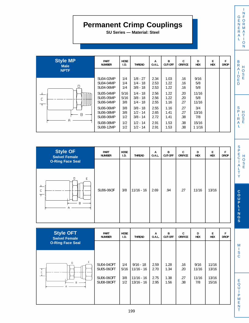
PART HOSE A B C D E FNUMBER I.D. THREAD O.A.L. CUT-OFF ORIFICE HEX HEX DROP
SU04-04OFT 1/4 9/16 - 18 2.59 1.28 .16 9/16 11/16SU05-06OFT 5/16 11/16 - 16 2.70 1.34 .20 11/16 13/16
SU06-06OFT 3/8 11/16 - 16 2.75 1.38 .27 11/16 13/16SU08-08OFT 1/2 13/16 - 16 2.95 1.56 .38 7/8 15/16
PART HOSE A B C D E FNUMBER I.D. THREAD O.A.L. CUT-OFF ORIFICE HEX HEX DROP
SU06-06OF 3/8 11/16 - 16 2.69 .94 .27 11/16 13/16
PART HOSE A B C D E FNUMBER I.D. THREAD O.A.L. CUT-OFF ORIFICE HEX HEX DROP
SU04-02MP 1/4 1/8 - 27 2.34 1.03 .16 9/16SU04-04MP 1/4 1/4 - 18 2.53 1.22 .16 5/8SU04-06MP 1/4 3/8 - 18 2.53 1.22 .16 5/8
SU05-04MP 5/16 1/4 - 18 2.56 1.22 .20 11/16SU05-05MP 5/16 3/8 - 18 2.56 1.22 .20 5/8SU06-04MP 3/8 1/4 - 18 2.55 1.16 .27 11/16
SU06-06MP 3/8 3/8 - 18 2.55 1.16 .27 3/4SU06-08MP 3/8 1/2 - 14 2.65 1.41 .27 13/16SU08-06MP 1/2 3/8 - 14 2.72 1.41 .38 7/8
SU08-08MP 1/2 1/2 - 14 2.91 1.53 .38 15/16SU08-12MP 1/2 1/2 - 14 2.91 1.53 .38 1 1/16
Permanent Crimp CouplingsSU Series — Material: Steel
199
GENERAL
INFORMATION
SPECIALTY
HOSE
COUPLINGS
MISC
EQUIPMENT
BRAIDED
HOSE
SPIRAL
HOSE
Style MPMaleNPTF
Style OFSwivel Female
O-Ring Face Seal
Style OFTSwivel Female
O-Ring Face Seal

Permanent Crimp CouplingsSU Series — Material: Steel
PART HOSE A B C D E FNUMBER I.D. THREAD O.A.L. CUT-OFF ORIFICE HEX HEX DROP
SU04-04OF45T 1/4 9/16 - 18 3.22 1.91 .16 11/16 .40SU06-06OF45T 3/8 11/16 - 16 3.23 1.84 .27 13/16 .44SU08-08OF45T 1/2 13/16 - 16 3.34 1.97 .38 15/16 .56
200
GENERAL
INFORMATION
SPECIALTY
HOSE
COUPLINGS
MISC
EQUIPMENT
BRAIDED
HOSE
SPIRAL
HOSE
PART HOSE A B C D E FNUMBER I.D. THREAD O.A.L. CUT-OFF ORIFICE HEX HEX DROP
SU04-04OF90TL 1/4 9/16 - 18 3.06 1.75 .16 11/16 1.80SU05-06OF90TL 5/16 11/16 - 16 3.14 1.78 .20 13/16 2.13
SU06-06OF90TL 3/8 11/16 - 16 3.13 1.75 .27 13/16 2.13SU08-08OF90TL 1/2 13/16 - 16 3.16 1.78 .38 15/16 2.50
PART HOSE A B C D E FNUMBER I.D. THREAD O.A.L. CUT-OFF ORIFICE HEX HEX DROP
SU04-04OF90T 1/4 9/16 - 18 3.06 1.91 .16 11/16 .83SU05-06OF90T 5/16 11/16 - 16 3.14 1.78 .20 13/16 .95
SU06-06OF90T 3/8 11/16 - 16 3.13 1.75 .27 13/16 .95SU08-08OF90T 1/2 13/16 - 16 3.16 1.78 .38 15/16 1.16
Style OF45T45˚ Bent Tube Swivel Female
O-Ring Face Seal
Style OF90T90˚ Bent Tube Swivel Female
O-Ring Face Seal
Style OF90TL90˚ Bent Tube Swivel Female
O-Ring Face Seal (Long Drop)

PART HOSE A B C D E FNUMBER I.D. THREAD O.A.L. CUT-OFF ORIFICE HEX HEX DROP
SU03-04RA 3/16 7/16 - 20 1.96 .90 .11 9/16SU04-04RA 1/4 7/16 - 20 2.33 1.00 .16 5/8SU04-05RA 1/4 1/2 - 20 2.33 1.00 .16 5/8
SU04-06RA 1/4 9/16 - 18 2.42 1.09 .16 11/16SU05-05RA 5/16 1/2 - 20 2.36 1.00 .20 5/8SU06-06RA 3/8 9/16 - 18 2.38 1.00 .27 3/4
SU06-08RA 3/8 3/4 - 16 2.42 1.03 .27 7/8SU08-08RA 1/2 3/4 - 16 2.59 1.22 .38 7/8SU08-10RA 1/2 7/8 - 14 2.66 1.28 .38 1
Permanent Crimp CouplingsSU Series — Material: Steel
201
GENERAL
INFORMATION
SPECIALTY
HOSE
COUPLINGS
MISC
EQUIPMENT
BRAIDED
HOSE
SPIRAL
HOSE
PART HOSE A B C D E FNUMBER I.D. THREAD O.A.L. CUT-OFF ORIFICE HEX HEX DROP
SU04-04RM 1/4 3.82 1.13 .16SU05-05RM 5/16 3.31 .63 .20
SU06-06RM 3/8 3.31 .63 .27SU08-08RM 1/2 3.50 .75 .38
PART HOSE A B C D E FNUMBER I.D. THREAD O.A.L. CUT-OFF ORIFICE HEX HEX DROP
SU04-04RC 1/4 7/16 - 20 3.03 1.72 .16 9/16 5/8SU05-06RC 5/16 9/16 - 18 3.19 1.84 .20 5/8 11/16SU06-06RC 3/8 9/16 - 18 3.14 1.75 .27 11/16 11/16
Style RA is furnished with O-Ring.
Style RAMale
O-Ring Boss
Style RC is furnished with O-Ring.
Style RCSwivel MaleO-Ring Boss
Style RMHose Splicer
(For New Hose Only)

Permanent Crimp CouplingsSU Series — Material: Steel
PART HOSE A B C D E FNUMBER I.D. THREAD O.A.L. CUT-OFF ORIFICE HEX HEX DROP
SU03-04SP 3/16 1/4 - 18 2.69 1.63 .11 9/16 11/16SU04-04SP 1/4 1/4 - 18 3.06 1.75 .16 9/16 11/16SU05-04SP 5/16 1/4 - 18 3.22 1.84 .20 11/16 11/16
SU06-06SP 3/8 3/8 - 18 3.11 1.72 .27 11/16 3/4SU06-08SP 3/8 1/2 - 14 3.38 2.00 .27 13/16 7/8SU08-08SP 1/2 1/2 - 14 3.50 2.13 .38 7/8 15/16
202
GENERAL
INFORMATION
SPECIALTY
HOSE
COUPLINGS
MISC
EQUIPMENT
BRAIDED
HOSE
SPIRAL
HOSE
PART HOSE A B C D E FNUMBER I.D. THREAD O.A.L. CUT-OFF ORIFICE HEX HEX DROP
SU04-04SP90 1/4 1/4 - 18 2.31 1.00 .16 11/16 1.69
Style SPSwivel Male NPTF
(Without 30˚ Chamfer)
Style SP9090˚ Block Swivel Male NPTF
(Without 30˚ Chamfer)

PART HOSE A B C D E FNUMBER I.D. THREAD O.A.L. CUT-OFF ORIFICE HEX HEX DROP
BL06-06BHS 5/16 5/8 - 18 2.50BL08-08BHS 13/32 3/4 - 16 2.75BL10-10BHS 1/2 7/8 - 14 2.94
Specialty CouplingsBL Series — Material: Aluminum Insert, Steel Ferrule & Nut
Requires Special Dies — Contact Dayco Eastman
203
GENERAL
INFORMATION
SPECIALTY
HOSE
COUPLINGS
MISC
EQUIPMENT
BRAIDED
HOSE
SPIRAL
HOSE
PART HOSE A B C D E FNUMBER I.D. THREAD O.A.L. CUT-OFF ORIFICE HEX HEX DROP
BL06-06FAT 5/16 5/8 - 18 1.00BL08-08FAT 13/32 3/4 - 16 1.19
BL10-10FAT 1/2 7/8 - 14 1.50BL12-12FAT 5/8 1 1/16 - 14 1.75
PART HOSE A B C D E FNUMBER I.D. THREAD O.A.L. CUT-OFF ORIFICE HEX HEX DROP
BL06-06BH90 5/16 5/8 - 18 1.63 2.12BL08-08BH90 13/32 3/4 - 16 1.75 2.44BL10-10BH90 1/2 7/8 - 14 2.00 2.50
Style BHSStraight Bulkhead Male
Insert O-Ring
Style BH9090˚ Bulkhead Male
Insert O-Ring
Style FATSwivel Female 45˚ Flare
with Straight Tube
B
B
F
B

Specialty CouplingsBL Series — Material: Aluminum Insert, Steel Ferrule & Nut
Requires Special Dies — Contact Dayco Eastman
PART HOSE A B C D E FNUMBER I.D. THREAD O.A.L. CUT-OFF ORIFICE HEX HEX DROP
BL06-06FA45T 5/16 5/8 - 18 .81 .56BL08-08FA45T 13/32 3/4 - 16 .94 .63
BL10-10FA45T 1/2 7/8 - 14 1.25 .88BL12-12FA45T 5/8 1 1/16 - 14 1.50 1.00
204
GENERAL
INFORMATION
SPECIALTY
HOSE
COUPLINGS
MISC
EQUIPMENT
BRAIDED
HOSE
SPIRAL
HOSE
PART HOSE A B C D E FNUMBER I.D. THREAD O.A.L. CUT-OFF ORIFICE HEX HEX DROP
BL06-06MV 5/16 5/8 - 18 1.19BL08-08MV 13/32 3/4 - 16 1.38
BL10-10MV 1/2 7/8 - 14 1.50BL12-12MV 5/8 1 1/16 - 14 1.75
PART HOSE A B C D E FNUMBER I.D. THREAD O.A.L. CUT-OFF ORIFICE HEX HEX DROP
BL06-06FA90T 5/16 5/8 - 18 1.06 1.06BL08-08FA90T 13/32 3/4 - 16 1.25 1.25
BL10-10FA90T 1/2 7/8 - 14 1.50 1.50BL12-12FA90T 5/8 1 1/16 - 14 1.75 1.50
Style FA45TSwivel Female with45˚ Seat, 45˚ Bend
Style FA90TSwivel Female with90˚ Seat, 90˚ Bend
Style MV*SAE Male Flarelesswith Nut & Sleeve
B
F
B
F
B
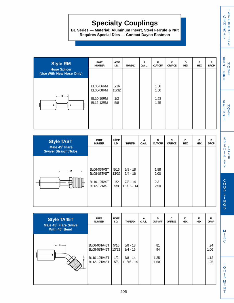
PART HOSE A B C D E FNUMBER I.D. THREAD O.A.L. CUT-OFF ORIFICE HEX HEX DROP
BL06-06RM 5/16 1.50BL08-08RM 13/32 1.50
BL10-10RM 1/2 1.63BL12-12RM 5/8 1.75
PART HOSE A B C D E FNUMBER I.D. THREAD O.A.L. CUT-OFF ORIFICE HEX HEX DROP
BL06-06TA45T 5/16 5/8 - 18 .81 .94BL08-08TA45T 13/32 3/4 - 16 .94 1.06
BL10-10TA45T 1/2 7/8 - 14 1.25 1.12BL12-12TA45T 5/8 1 1/16 - 14 1.50 1.25
PART HOSE A B C D E FNUMBER I.D. THREAD O.A.L. CUT-OFF ORIFICE HEX HEX DROP
BL06-06TAST 5/16 5/8 - 18 1.88BL08-08TAST 13/32 3/4 - 16 2.00
BL10-10TAST 1/2 7/8 - 14 2.31BL12-12TAST 5/8 1 1/16 - 14 2.50
Specialty CouplingsBL Series — Material: Aluminum Insert, Steel Ferrule & Nut
Requires Special Dies — Contact Dayco Eastman
205
GENERAL
INFORMATION
SPECIALTY
HOSE
COUPLINGS
MISC
EQUIPMENT
BRAIDED
HOSE
SPIRAL
HOSE
Style RMHose Splicer
(Use With New Hose Only)
Style TASTMale 45˚ Flare
Swivel Straight Tube
Style TA45TMale 45˚ Flare Swivel
With 45˚ Bend
B
B
B
F

PART HOSE A B C D E FNUMBER I.D. THREAD O.A.L. CUT-OFF ORIFICE HEX HEX DROP
BL06-06TFS 5/16 5/8 - 18 1.38BL08-08TFS 13/32 3/4 - 16 1.50
BL10-10TFS 1/2 7/8 - 14 1.69BL12-12TFS 5/8 1 1/16 - 14 1.81
Specialty CouplingsBL Series — Material: Aluminum Insert, Steel Ferrule & Nut
Requires Special Dies — Contact Dayco Eastman
PART HOSE A B C D E FNUMBER I.D. THREAD O.A.L. CUT-OFF ORIFICE HEX HEX DROP
BL06-06TA90T 5/16 5/8 - 18 1.06 1.75BL08-08TA90T 13/32 3/4 - 16 1.25 1.81
BL10-10TA90T 1/2 7/8 - 14 1.50 2.19BL12-12TA90T` 5/8 1 1/16 - 14 1.75 2.25
206
GENERAL
INFORMATION
SPECIALTY
HOSE
COUPLINGS
MISC
EQUIPMENT
BRAIDED
HOSE
SPIRAL
HOSE
PART HOSE A B C D E FNUMBER I.D. THREAD O.A.L. CUT-OFF ORIFICE HEX HEX DROP
BL06-06TFSP 5/16 5/8 - 18 1.88BL08-08TFSP 13/32 3/4 - 16 1.88
BL10-10TFSP 1/2 7/8 - 14 2.12BL12-12TFSP 5/8 1 1/16 - 14 2.25
Style TA90TMale 45˚ Flare Swivel
With 90˚ Bend
Style TFSSwivel Female Tube "O"
Straight Tube
Style TFSPSwivel Female Tube "O"
Straight Tube With R134a Service Port
B
F
B
B
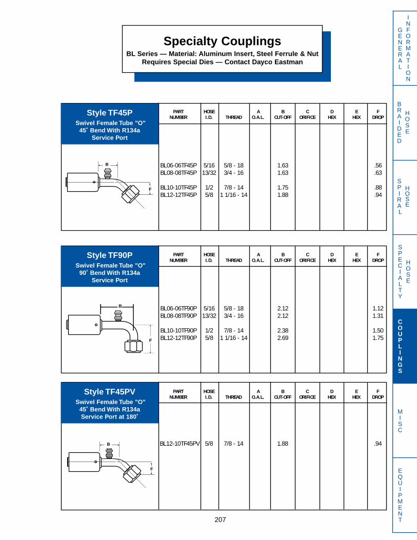
PART HOSE A B C D E FNUMBER I.D. THREAD O.A.L. CUT-OFF ORIFICE HEX HEX DROP
BL06-06TF45P 5/16 5/8 - 18 1.63 .56BL08-08TF45P 13/32 3/4 - 16 1.63 .63
BL10-10TF45P 1/2 7/8 - 14 1.75 .88BL12-12TF45P 5/8 1 1/16 - 14 1.88 .94
PART HOSE A B C D E FNUMBER I.D. THREAD O.A.L. CUT-OFF ORIFICE HEX HEX DROP
BL12-10TF45PV 5/8 7/8 - 14 1.88 .94
PART HOSE A B C D E FNUMBER I.D. THREAD O.A.L. CUT-OFF ORIFICE HEX HEX DROP
BL06-06TF90P 5/16 5/8 - 18 2.12 1.12BL08-08TF90P 13/32 3/4 - 16 2.12 1.31
BL10-10TF90P 1/2 7/8 - 14 2.38 1.50BL12-12TF90P 5/8 1 1/16 - 14 2.69 1.75
Specialty CouplingsBL Series — Material: Aluminum Insert, Steel Ferrule & Nut
Requires Special Dies — Contact Dayco Eastman
207
GENERAL
INFORMATION
SPECIALTY
HOSE
COUPLINGS
MISC
EQUIPMENT
BRAIDED
HOSE
SPIRAL
HOSE
Style TF45PSwivel Female Tube "O"
45˚ Bend With R134a Service Port
Style TF90PSwivel Female Tube "O"
90˚ Bend With R134a Service Port
Style TF45PVSwivel Female Tube "O"
45˚ Bend With R134a Service Port at 180˚
B
F
B
F
B
F
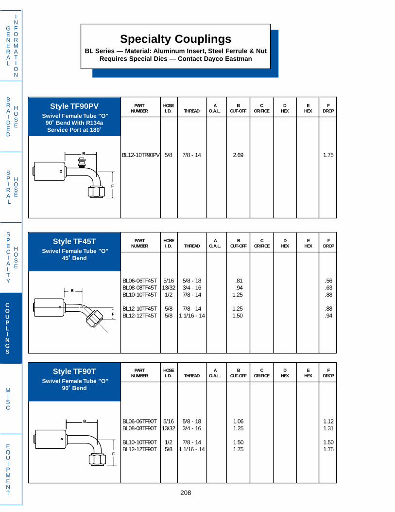
Specialty CouplingsBL Series — Material: Aluminum Insert, Steel Ferrule & Nut
Requires Special Dies — Contact Dayco Eastman
PART HOSE A B C D E FNUMBER I.D. THREAD O.A.L. CUT-OFF ORIFICE HEX HEX DROP
BL12-10TF90PV 5/8 7/8 - 14 2.69 1.75
208
GENERAL
INFORMATION
SPECIALTY
HOSE
COUPLINGS
MISC
EQUIPMENT
BRAIDED
HOSE
SPIRAL
HOSE
PART HOSE A B C D E FNUMBER I.D. THREAD O.A.L. CUT-OFF ORIFICE HEX HEX DROP
BL06-06TF90T 5/16 5/8 - 18 1.06 1.12BL08-08TF90T 13/32 3/4 - 16 1.25 1.31
BL10-10TF90T 1/2 7/8 - 14 1.50 1.50BL12-12TF90T 5/8 1 1/16 - 14 1.75 1.75
PART HOSE A B C D E FNUMBER I.D. THREAD O.A.L. CUT-OFF ORIFICE HEX HEX DROP
BL06-06TF45T 5/16 5/8 - 18 .81 .56BL08-08TF45T 13/32 3/4 - 16 .94 .63BL10-10TF45T 1/2 7/8 - 14 1.25 .88
BL12-10TF45T 5/8 7/8 - 14 1.25 .88BL12-12TF45T 5/8 1 1/16 - 14 1.50 .94
Style TF90PVSwivel Female Tube "O"
90˚ Bend With R134a Service Port at 180˚
Style TF45TSwivel Female Tube "O"
45˚ Bend
Style TF90TSwivel Female Tube "O"
90˚ Bend
B
F
B
F
B
F

PART HOSE A B C D E FNUMBER I.D. THREAD O.A.L. CUT-OFF ORIFICE HEX HEX DROP
BL06-06TMS 5/16 5/8 - 18 1.69BL08-08TMS 13/32 3/4 - 18 1.75
BL10-10TMS 1/2 7/8 - 18 1.88BL12-12TMS 5/8 1 1/16 - 14 2.38
PART HOSE A B C D E FNUMBER I.D. THREAD O.A.L. CUT-OFF ORIFICE HEX HEX DROP
BL12-10TM45P 5/8 7/8 - 14 1.88 .94
PART HOSE A B C D E FNUMBER I.D. THREAD O.A.L. CUT-OFF ORIFICE HEX HEX DROP
BL12-10TMSP 5/8 7/8 - 14 2.25
Specialty CouplingsBL Series — Material: Aluminum Insert, Steel Ferrule & Nut
Requires Special Dies — Contact Dayco Eastman
209
GENERAL
INFORMATION
SPECIALTY
HOSE
COUPLINGS
MISC
EQUIPMENT
BRAIDED
HOSE
SPIRAL
HOSE
Style TMSSwivel Male Tube "O"
Straight Tube
Style TMSPSwivel Male Tube "O"
Straight Tube WithService Port for R134a
Style TM45PSwivel Male Tube "O"
45˚ Bend WithService Port for R134a
B
B
B
F

Specialty CouplingsBL Series — Material: Aluminum Insert, Steel Ferrule & Nut
Requires Special Dies — Contact Dayco Eastman
PART HOSE A B C D E FNUMBER I.D. THREAD O.A.L. CUT-OFF ORIFICE HEX HEX DROP
BL12-10TM90P 5/8 7/8 - 14 2.69 1.75
210
GENERAL
INFORMATION
SPECIALTY
HOSE
COUPLINGS
MISC
EQUIPMENT
BRAIDED
HOSE
SPIRAL
HOSE
PART HOSE A B C D E FNUMBER I.D. THREAD O.A.L. CUT-OFF ORIFICE HEX HEX DROP
BL06-06TM45T 5/16 5/8 - 18 0.81 0.88BL08-08TM45T 13/32 3/4 - 18 0.94 1.00
BL10-10TM45T 1/2 7/8 - 18 1.25 1.06BL12-12TM45T 5/8 1 1/16 - 16 1.50 1.19
PART HOSE A B C D E FNUMBER I.D. THREAD O.A.L. CUT-OFF ORIFICE HEX HEX DROP
BL12-12TM90PX 5/8 7/8 - 14 2.69 1.75
Style TM90PSwivel Male Tube "O"
90˚ Bend WithService Port for R134a
Style TM90PXSwivel Male Tube "O"
90˚ Bend WithService Port at 270˚ for R134a
Style TM45TSwivel Male Tube "O"
45˚ Bend
B
F
B
F
B
F
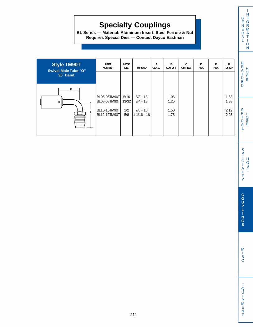
PART HOSE A B C D E FNUMBER I.D. THREAD O.A.L. CUT-OFF ORIFICE HEX HEX DROP
BL06-06TM90T 5/16 5/8 - 18 1.06 1.63BL08-08TM90T 13/32 3/4 - 18 1.25 1.88
BL10-10TM90T 1/2 7/8 - 18 1.50 2.12BL12-12TM90T 5/8 1 1/16 - 16 1.75 2.25
Specialty CouplingsBL Series — Material: Aluminum Insert, Steel Ferrule & Nut
Requires Special Dies — Contact Dayco Eastman
211
GENERAL
INFORMATION
SPECIALTY
HOSE
COUPLINGS
MISC
EQUIPMENT
BRAIDED
HOSE
SPIRAL
HOSE
Style TM90TSwivel Male Tube "O"
90˚ Bend
B
F

Specialty CouplingsGS Series — Material: Brass Body, Steel Nut
PART HOSE A B C D E FNUMBER I.D. THREAD O.A.L. CUT-OFF ORIFICE HEX HEX DROP
GS08-08BA 13/32 11/16 - 20 1.72 1.03 .28 3/4GS10-10BA 1/2 13/16 - 18 1.81 1.13 .38 7/8GS12-12BA 5/8 1 - 18 1.94 1.25 .47 1 1/8
212
GENERAL
INFORMATION
SPECIALTY
HOSE
COUPLINGS
MISC
EQUIPMENT
BRAIDED
HOSE
SPIRAL
HOSE
PART HOSE A B C D E FNUMBER I.D. THREAD O.A.L. CUT-OFF ORIFICE HEX HEX DROP
GS04-04FJ 3/16 7/16 - 20 1.72 1.16 .09 9/16 9/16GS05-05FJ 1/4 1/2 - 20 1.77 1.19 .16 5/8 5/8GS06-06FJ 5/16 9/16 - 18 1.81 1.22 .20 11/16 11/16
GS08-08FJ 13/32 3/4 - 16 1.94 1.25 .28 7/8 7/8GS10-10FJ 1/2 7/8 - 14 2.05 1.38 .38 7/8 1GS12-12FJ 5/8 1 1/16 - 12 2.17 1.50 .47 1 1/8 1 1/4
GS16-16FJ 7/8 1 5/16 - 12 2.39 1.59 .69 1 3/8 1 1/2
PART HOSE A B C D E FNUMBER I.D. THREAD O.A.L. CUT-OFF ORIFICE HEX HEX DROP
GS06-06FA 5/16 5/8 - 18 1.88 1.28 .20 11/16 3/4GS10-10FA 1/2 7/8 - 14 2.05 1.38 .38 7/8 1GS12-12FA 5/8 1 1/16 - 14 2.38 1.69 .47 1 1/8 1 1/4
Style BAMale Air Brake
SAE J246
Style FASwivel Female
45˚ Flare
Style FJSwivel Female
37˚ Flare
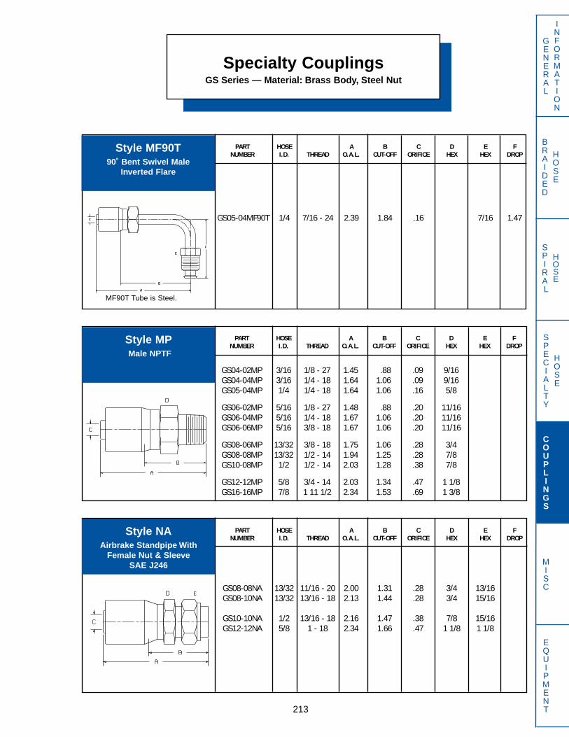
PART HOSE A B C D E FNUMBER I.D. THREAD O.A.L. CUT-OFF ORIFICE HEX HEX DROP
GS05-04MF90T 1/4 7/16 - 24 2.39 1.84 .16 7/16 1.47
PART HOSE A B C D E FNUMBER I.D. THREAD O.A.L. CUT-OFF ORIFICE HEX HEX DROP
GS08-08NA 13/32 11/16 - 20 2.00 1.31 .28 3/4 13/16GS08-10NA 13/32 13/16 - 18 2.13 1.44 .28 3/4 15/16
GS10-10NA 1/2 13/16 - 18 2.16 1.47 .38 7/8 15/16GS12-12NA 5/8 1 - 18 2.34 1.66 .47 1 1/8 1 1/8
PART HOSE A B C D E FNUMBER I.D. THREAD O.A.L. CUT-OFF ORIFICE HEX HEX DROP
GS04-02MP 3/16 1/8 - 27 1.45 .88 .09 9/16GS04-04MP 3/16 1/4 - 18 1.64 1.06 .09 9/16GS05-04MP 1/4 1/4 - 18 1.64 1.06 .16 5/8
GS06-02MP 5/16 1/8 - 27 1.48 .88 .20 11/16GS06-04MP 5/16 1/4 - 18 1.67 1.06 .20 11/16GS06-06MP 5/16 3/8 - 18 1.67 1.06 .20 11/16
GS08-06MP 13/32 3/8 - 18 1.75 1.06 .28 3/4GS08-08MP 13/32 1/2 - 14 1.94 1.25 .28 7/8GS10-08MP 1/2 1/2 - 14 2.03 1.28 .38 7/8
GS12-12MP 5/8 3/4 - 14 2.03 1.34 .47 1 1/8GS16-16MP 7/8 1 11 1/2 2.34 1.53 .69 1 3/8
Specialty CouplingsGS Series — Material: Brass Body, Steel Nut
213
GENERAL
INFORMATION
SPECIALTY
HOSE
COUPLINGS
MISC
EQUIPMENT
BRAIDED
HOSE
SPIRAL
HOSE
Style MF90T90˚ Bent Swivel Male
Inverted Flare
Style MPMale NPTF
Style NAAirbrake Standpipe With
Female Nut & SleeveSAE J246
MF90T Tube is Steel.

Specialty CouplingsGS Series — Material: Brass Body, Steel Nut
PART HOSE A B C D E FNUMBER I.D. THREAD O.A.L. CUT-OFF ORIFICE HEX HEX DROP
GS05-04NG 1/4 7/16 - 24 1.23 .66 .16 9/16
214
GENERAL
INFORMATION
SPECIALTY
HOSE
COUPLINGS
MISC
EQUIPMENT
BRAIDED
HOSE
SPIRAL
HOSE
PART HOSE TUBE A B C D E FNUMBER I.D. O.D. O.A.L. CUT-OFF ORIFICE HEX HEX DROP
GS10-10RL 1/2 5/8 2.16 1.47 .38 7/8
*Style RL requires 1961-FS Nut and 1960-FS Sleeve. Refer to page 158 for more information.
Style NGFemale
Inverted Flare
Style RL*Inch Standpipe

BRAIDED
HOSE
SPIRAL
HOSE
215
GENERAL
INFORMATION
SPECIALTY
HOSE
COUPLINGS
MISC
EQUIPMENT
PART HOSE A B C D E FNUMBER I.D. THREAD O.A.L. CUT-OFF ORIFICE HEX HEX DROP
GT04-04FJ 1/4 7/16 - 20 1.45 .79 .19 3/4 9/16GT04-05FJ 1/4 1/2 - 20 1.46 .81 .20 3/4 5/8GT04-06FJ 1/4 9/16 - 18 1.48 .82 .20 3/4 11/16
GT06-06FJ 3/8 9/16 - 18 1.48 .82 .30 7/8 11/16GT08-08FJ 1/2 3/4 - 16 1.53 .87 .41 7/8 7/8
Specialty CouplingsGT Series — Material: Brass Body, Steel NutConsult Factory for Tooling Requirements
Style FJ*Swivel Female
37˚ Flare
PART HOSE A B C D E FNUMBER I.D. THREAD O.A.L. CUT-OFF ORIFICE HEX HEX DROP
GT06-08AF 3/8 3/4 - 20 1.45 .83 .31 7/8GT08-08AF 1/2 3/4 - 20 1.51 .83 .42 7/8
Style AF*Swivel Female (Air-Brake)
Ball End
PART HOSE A B C D E FNUMBER I.D. THREAD O.A.L. CUT-OFF ORIFICE HEX HEX DROP
GT04-04FA 1/4 7/16 - 20 1.45 .79 .20 3/4 9/16GT04-05FA 1/4 1/2 - 20 1.46 .85 .20 3/4 5/8GT04-06FA 1/4 5/8 - 18 1.51 .85 .20 3/4 3/4
GT06-06FA 3/8 5/8 - 18 1.51 .85 .30 7/8 3/4GT08-08FA 1/2 3/4 - 16 1.71 1.00 .42 1 7/8GT08-10FA 1/2 7/8 - 14 1.78 1.06 .42 1 1
GT10-10FA 3/8 7/8 - 14 1.90 1.06 .50 1 1/4 1
Style FA*Swivel Female
45˚ Flare
*Special tooling and DOT registration required to supply air brake assemblies.
See page 113 for air brake adapters.
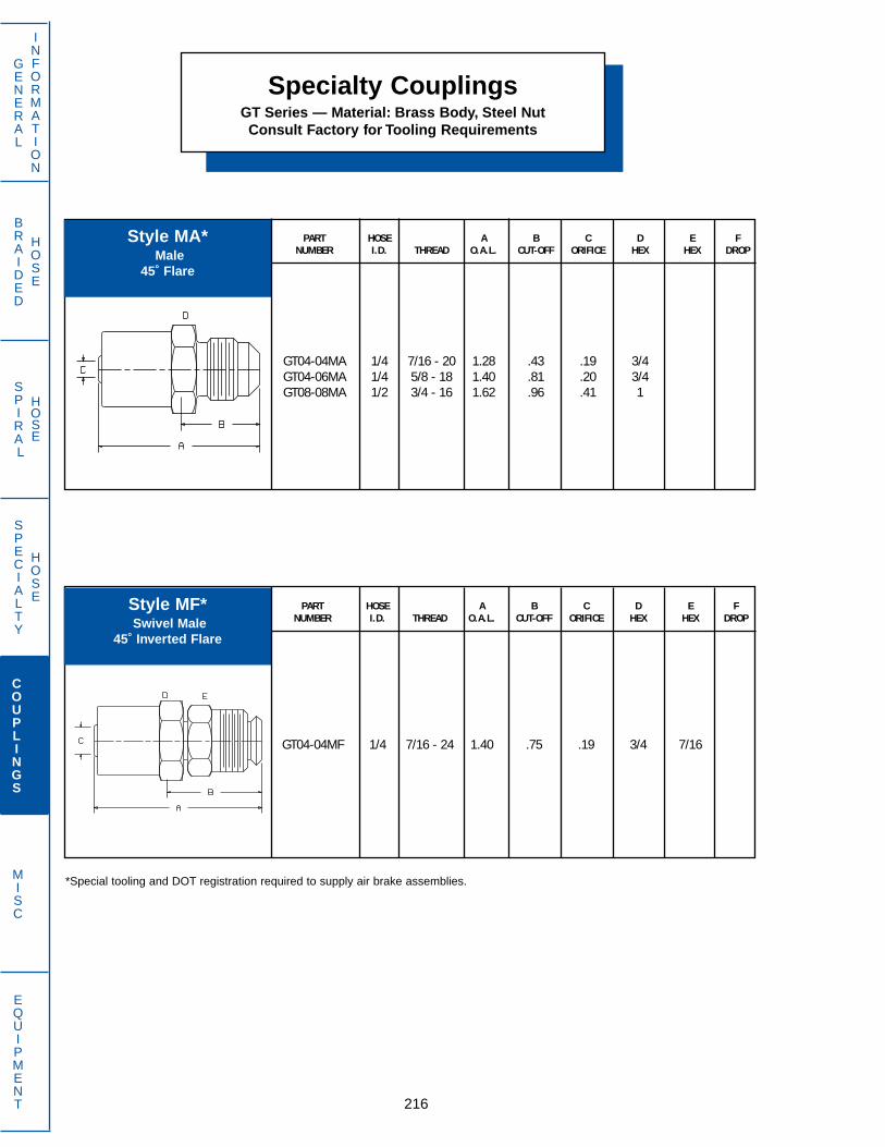
BRAIDED
HOSE
SPIRAL
HOSE
216
GENERAL
INFORMATION
SPECIALTY
HOSE
COUPLINGS
MISC
EQUIPMENT
Specialty CouplingsGT Series — Material: Brass Body, Steel NutConsult Factory for Tooling Requirements
PART HOSE A B C D E FNUMBER I.D. THREAD O.A.L. CUT-OFF ORIFICE HEX HEX DROP
GT04-04MF 1/4 7/16 - 24 1.40 .75 .19 3/4 7/16
PART HOSE A B C D E FNUMBER I.D. THREAD O.A.L. CUT-OFF ORIFICE HEX HEX DROP
GT04-04MA 1/4 7/16 - 20 1.28 .43 .19 3/4GT04-06MA 1/4 5/8 - 18 1.40 .81 .20 3/4GT08-08MA 1/2 3/4 - 16 1.62 .96 .41 1
Style MA*Male
45˚ Flare
Style MF*Swivel Male
45˚ Inverted Flare
*Special tooling and DOT registration required to supply air brake assemblies.
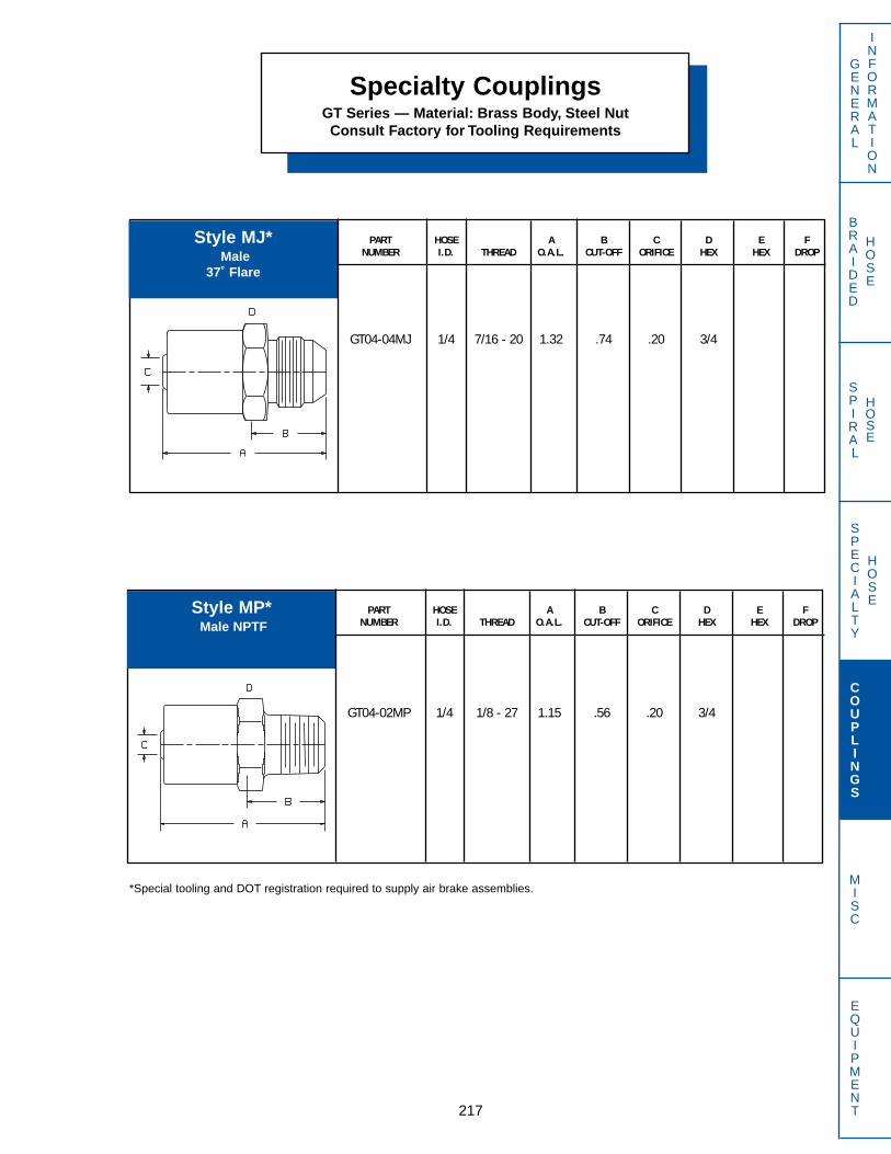
BRAIDED
HOSE
SPIRAL
HOSE
217
GENERAL
INFORMATION
SPECIALTY
HOSE
COUPLINGS
MISC
EQUIPMENT
Specialty CouplingsGT Series — Material: Brass Body, Steel NutConsult Factory for Tooling Requirements
PART HOSE A B C D E FNUMBER I.D. THREAD O.A.L. CUT-OFF ORIFICE HEX HEX DROP
GT04-04MJ 1/4 7/16 - 20 1.32 .74 .20 3/4
PART HOSE A B C D E FNUMBER I.D. THREAD O.A.L. CUT-OFF ORIFICE HEX HEX DROP
GT04-02MP 1/4 1/8 - 27 1.15 .56 .20 3/4
Style MJ*Male
37˚ Flare
Style MP*Male NPTF
*Special tooling and DOT registration required to supply air brake assemblies.
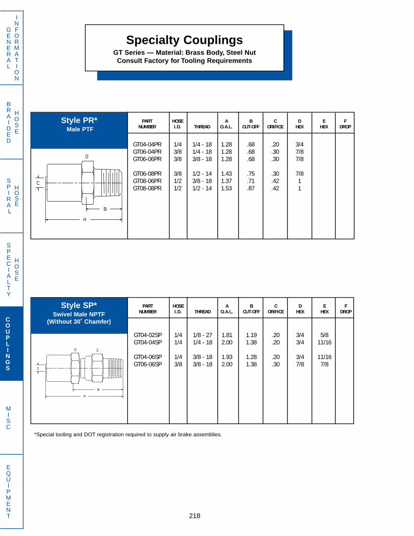
BRAIDED
HOSE
SPIRAL
HOSE
218
GENERAL
INFORMATION
SPECIALTY
HOSE
COUPLINGS
MISC
EQUIPMENT
Specialty CouplingsGT Series — Material: Brass Body, Steel NutConsult Factory for Tooling Requirements
PART HOSE A B C D E FNUMBER I.D. THREAD O.A.L. CUT-OFF ORIFICE HEX HEX DROP
GT04-02SP 1/4 1/8 - 27 1.81 1.19 .20 3/4 5/8GT04-04SP 1/4 1/4 - 18 2.00 1.38 .20 3/4 11/16
GT04-06SP 1/4 3/8 - 18 1.93 1.28 .20 3/4 11/16GT06-06SP 3/8 3/8 - 18 2.00 1.38 .30 7/8 7/8
PART HOSE A B C D E FNUMBER I.D. THREAD O.A.L. CUT-OFF ORIFICE HEX HEX DROP
GT04-04PR 1/4 1/4 - 18 1.28 .68 .20 3/4GT06-04PR 3/8 1/4 - 18 1.28 .68 .30 7/8GT06-06PR 3/8 3/8 - 18 1.28 .68 .30 7/8
GT06-08PR 3/8 1/2 - 14 1.43 .75 .30 7/8GT08-06PR 1/2 3/8 - 18 1.37 .71 .42 1GT08-08PR 1/2 1/2 - 14 1.53 .87 .42 1
Style PR*Male PTF
Style SP*Swivel Male NPTF
(Without 30˚ Chamfer)
*Special tooling and DOT registration required to supply air brake assemblies.

PART HOSE A B C D E FNUMBER I.D. THREAD O.A.L. CUT-OFF ORIFICE HEX HEX DROP
KA05-06FA 5/16 5/8 - 18 1.61 .80 .19 3/4KA06-06FA 3/8 5/8 - 18 1.16 .73 .30 3/4KA12-12FA 3/4 1 1/16 - 14 2.61 1.16 .66 1
PART HOSE A B C D E FNUMBER I.D. THREAD O.A.L. CUT-OFF ORIFICE HEX HEX DROP
KA04-04MA 1/4 7/16 - 20 1.56 .75 .19 7/16KA04-05MA 1/4 1/2 - 20 1.66 .84 .19 1/2KA06-06MA 3/8 5/8 - 18 1.75 .94 .28 5/8
PART HOSE A B C D E FNUMBER I.D. THREAD O.A.L. CUT-OFF ORIFICE HEX HEX DROP
KA06-06FJ 3/8 9/16 - 18 1.55 .70 .30 3/4KA12-12FJ 3/4 1 1/16 - 12 2.55 1.09 .66 1 1/4
Specialty CouplingsKA Series Low Pressure Push-On —
Material: Brass Body, Steel Nut
219
GENERAL
INFORMATION
SPECIALTY
HOSE
COUPLINGS
MISC
EQUIPMENT
BRAIDED
HOSE
SPIRAL
HOSE
Style FASwivel Female
45˚ Flare
Style FJSwivel Female
37˚ Flare
Style MAMale
45˚ Flare
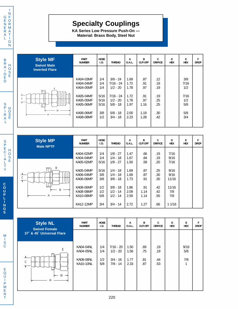
Specialty CouplingsKA Series Low Pressure Push-On —
Material: Brass Body, Steel Nut
PART HOSE A B C D E FNUMBER I.D. THREAD O.A.L. CUT-OFF ORIFICE HEX HEX DROP
KA04-03MF 1/4 3/8 - 24 1.69 .87 .12 3/8KA04-04MF 1/4 7/16 - 24 1.72 .91 .19 7/16KA04-05MF 1/4 1/2 - 20 1.78 .97 .19 1/2
KA05-04MF 5/16 7/16 - 24 1.72 .91 .19 7/16KA05-05MF 5/16 1/2 - 20 1.78 .97 .25 1/2KA05-06MF 5/16 5/8 - 18 1.97 1.16 .25 5/8
KA06-06MF 3/8 5/8 - 18 2.00 1.19 .30 5/8KA08-08MF 1/2 3/4 - 18 2.23 1.28 .42 3/4
220
GENERAL
INFORMATION
SPECIALTY
HOSE
COUPLINGS
MISC
EQUIPMENT
BRAIDED
HOSE
SPIRAL
HOSE
PART HOSE A B C D E FNUMBER I.D. THREAD O.A.L. CUT-OFF ORIFICE HEX HEX DROP
KA04-04NL 1/4 7/16 - 20 1.50 .69 .19 9/16KA04-05NL 1/4 1/2 - 20 1.56 .75 .19 5/8
KA08-08NL 1/2 3/4 - 16 1.77 .81 .44 7/8KA10-10NL 5/8 7/8 - 14 2.33 .87 .53 1
PART HOSE A B C D E FNUMBER I.D. THREAD O.A.L. CUT-OFF ORIFICE HEX HEX DROP
KA04-02MP 1/4 1/8 - 27 1.47 .66 .19 7/16KA04-04MP 1/4 1/4 - 18 1.67 .84 .19 9/16KA05-02MP 5/16 1/8 - 27 1.50 .58 .20 7/16
KA05-04MP 5/16 1/4 - 18 1.69 .87 .25 9/16KA06-04MP 3/8 1/4 - 18 1.69 .87 .30 9/16KA06-06MP 3/8 3/8 - 18 1.73 .91 .30 11/16
KA08-06MP 1/2 3/8 - 18 1.86 .91 .42 11/16KA08-08MP 1/2 1/2 - 14 2.09 1.14 .42 7/8KA10-08MP 5/8 1/2 - 14 2.59 1.14 .55 7/8
KA12-12MP 3/4 3/4 - 14 2.72 1.27 .66 1 1/16
Style MFSwivel Male
Inverted Flare
Style MPMale NPTF
Style NLSwivel Female
37˚ & 45˚ Universal Flare
E
D
E

PART HOSE TUBE A B C D E FNUMBER I.D. O.D. O.A.L. CUT-OFF ORIFICE HEX HEX DROP
KA04-03RL 1/4 3/16 1.94 1.12 .13KA04-04RL 1/4 1/4 2.00 1.19 .19KA04-05RL 1/4 5/16 2.03 1.22 .19
KA06-06RL 3/8 3/8 2.16 1.34 .30KA08-08RL 1/2 1/2 2.44 1.48 .44
PART HOSE A B C D E FNUMBER I.D. THREAD O.A.L. CUT-OFF ORIFICE HEX HEX DROP
KA04-04RM 1/4 1.87 .25 .20KA05-05RM 5/16 1.87 .25 .25KA06-06RM 3/8 1.91 .28 .30
KA08-08RM 1/2 2.22 .28 .42KA12-12RM 3/4 3.37 .47 .66
Specialty CouplingsKA Series Low Pressure Push-On —
Material: Brass Body, Steel Nut
221
GENERAL
INFORMATION
SPECIALTY
HOSE
COUPLINGS
MISC
EQUIPMENT
BRAIDED
HOSE
SPIRAL
HOSE
*Style RL requires 1961-FS Nut and 1960-FS Sleeve. Refer to page 158 for further information.
Style RL*Inch Standpipe
Style RMHose Splicer
(Use with new hose only)

Specialty CouplingsKF Series Low Pressure Barbed Inserts
Material: Brass body,Steel Nut
PART HOSE A B C D E FNUMBER I.D. THREAD O.A.L. CUT-OFF ORIFICE HEX HEX DROP
KF04-06FA 1/4 5/8 - 18 1.66 .69 .18 3/4KF06-06FA 3/8 5/8 - 18 1.66 .69 .28 3/4
222
GENERAL
INFORMATION
SPECIALTY
HOSE
COUPLINGS
MISC
EQUIPMENT
BRAIDED
HOSE
SPIRAL
HOSE
PART HOSE A B C D E FNUMBER I.D. THREAD O.A.L. CUT-OFF ORIFICE HEX HEX DROP
KF04-04MA 1/4 7/16 - 20 1.71 .75 .19 7/16KF06-06MA 3/8 5/8 - 18 1.84 .87 .28 5/8
PART HOSE A B C D E FNUMBER I.D. THREAD O.A.L. CUT-OFF ORIFICE HEX HEX DROP
KF06-12GF 3/8 3/4 - 11 1/2 1.65 .68 .28 1 3/16KF08-12GF 1/2 3/4 - 11 1/2 1.65 .68 .41 1 3/16KF10-12GF 5/8 3/4 - 11 1/2 1.65 .68 .53 1 3/16
*See page 226 for KFA and KFB Ferrules.
Style FA*Swivel Female
45˚ Flare
Style GF*Swivel Female
Garden Hose Thread
Style MA*Rigid Male45˚ Flare
E
E
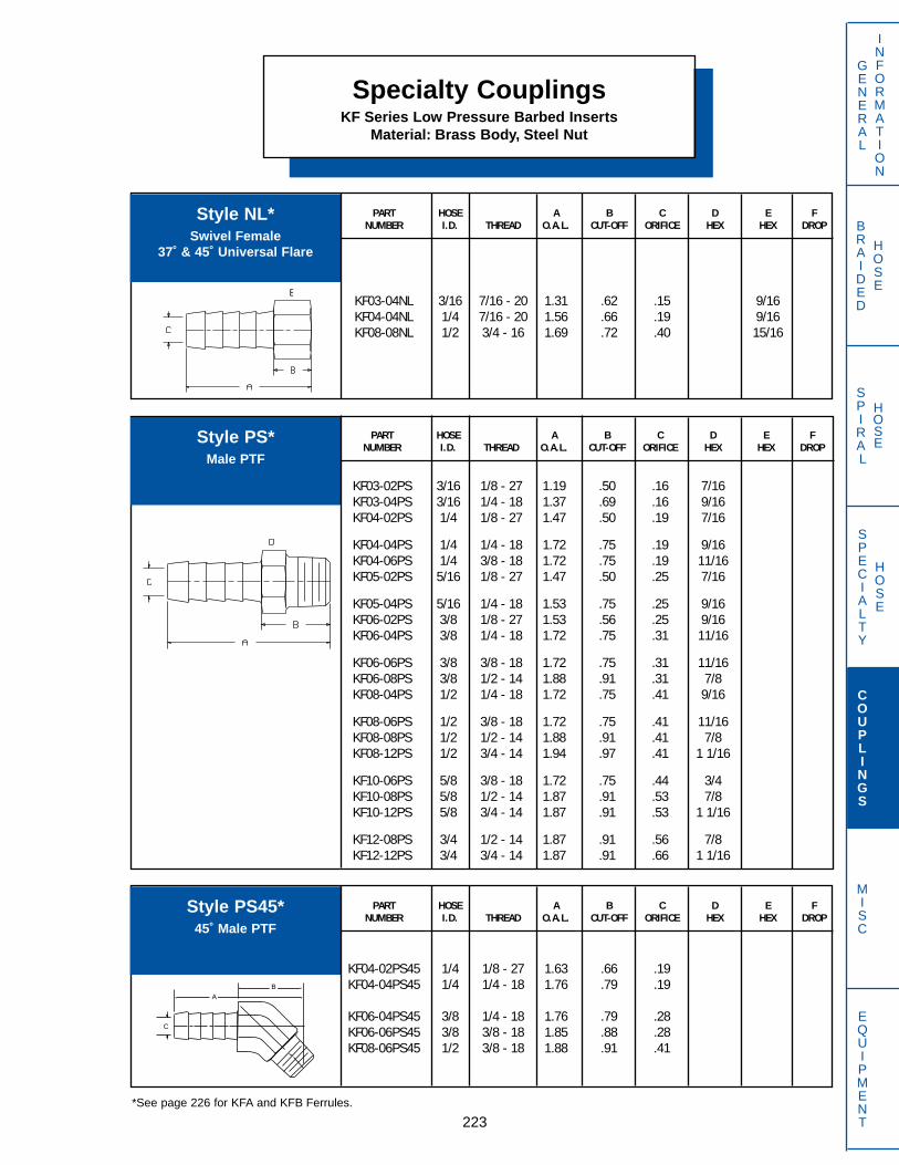
PART HOSE A B C D E FNUMBER I.D. THREAD O.A.L. CUT-OFF ORIFICE HEX HEX DROP
KF03-04NL 3/16 7/16 - 20 1.31 .62 .15 9/16KF04-04NL 1/4 7/16 - 20 1.56 .66 .19 9/16KF08-08NL 1/2 3/4 - 16 1.69 .72 .40 15/16
Specialty CouplingsKF Series Low Pressure Barbed Inserts
Material: Brass Body, Steel Nut
223
GENERAL
INFORMATION
SPECIALTY
HOSE
COUPLINGS
MISC
EQUIPMENT
BRAIDED
HOSE
SPIRAL
HOSE
PART HOSE A B C D E FNUMBER I.D. THREAD O.A.L. CUT-OFF ORIFICE HEX HEX DROP
KF03-02PS 3/16 1/8 - 27 1.19 .50 .16 7/16KF03-04PS 3/16 1/4 - 18 1.37 .69 .16 9/16KF04-02PS 1/4 1/8 - 27 1.47 .50 .19 7/16
KF04-04PS 1/4 1/4 - 18 1.72 .75 .19 9/16KF04-06PS 1/4 3/8 - 18 1.72 .75 .19 11/16KF05-02PS 5/16 1/8 - 27 1.47 .50 .25 7/16
KF05-04PS 5/16 1/4 - 18 1.53 .75 .25 9/16KF06-02PS 3/8 1/8 - 27 1.53 .56 .25 9/16KF06-04PS 3/8 1/4 - 18 1.72 .75 .31 11/16
KF06-06PS 3/8 3/8 - 18 1.72 .75 .31 11/16KF06-08PS 3/8 1/2 - 14 1.88 .91 .31 7/8KF08-04PS 1/2 1/4 - 18 1.72 .75 .41 9/16
KF08-06PS 1/2 3/8 - 18 1.72 .75 .41 11/16KF08-08PS 1/2 1/2 - 14 1.88 .91 .41 7/8KF08-12PS 1/2 3/4 - 14 1.94 .97 .41 1 1/16
KF10-06PS 5/8 3/8 - 18 1.72 .75 .44 3/4KF10-08PS 5/8 1/2 - 14 1.87 .91 .53 7/8KF10-12PS 5/8 3/4 - 14 1.87 .91 .53 1 1/16
KF12-08PS 3/4 1/2 - 14 1.87 .91 .56 7/8KF12-12PS 3/4 3/4 - 14 1.87 .91 .66 1 1/16
*See page 226 for KFA and KFB Ferrules.
Style NL*Swivel Female
37˚ & 45˚ Universal Flare
Style PS*Male PTF
PART HOSE A B C D E FNUMBER I.D. THREAD O.A.L. CUT-OFF ORIFICE HEX HEX DROP
KF04-02PS45 1/4 1/8 - 27 1.63 .66 .19KF04-04PS45 1/4 1/4 - 18 1.76 .79 .19
KF06-04PS45 3/8 1/4 - 18 1.76 .79 .28KF06-06PS45 3/8 3/8 - 18 1.85 .88 .28KF08-06PS45 1/2 3/8 - 18 1.88 .91 .41
Style PS45*45˚ Male PTF
E
AB
C

Specialty CouplingsKF Series Low Pressure Barbed Inserts
Material: Brass Body, Steel Nut
PART HOSE A B C D E FNUMBER I.D. THREAD O.A.L. CUT-OFF ORIFICE HEX HEX DROP
KF04-02PS90 1/4 1/8 - 27 1.41 .44 .19KF04-04PS90 1/4 1/4 - 18 1.41 .44 .19KF05-02PS90 5/16 1/8 - 27 1.41 .44 .25
KF06-04PS90 3/8 1/4 - 18 1.41 .47 .28KF06-06PS90 3/8 3/8 - 18 1.50 .54 .28KF08-06PS90 1/2 3/8 - 18 1.53 .56 .41
KF10-06PS90 5/8 3/8 - 18 1.50 .53 .53
224
GENERAL
INFORMATION
SPECIALTY
HOSE
COUPLINGS
MISC
EQUIPMENT
BRAIDED
HOSE
SPIRAL
HOSE
PART HOSE A B C D E FNUMBER I.D. THREAD O.A.L. CUT-OFF ORIFICE HEX HEX DROP
KF06-04RN 3/8 1/4 - 18 1.59 .62 .26 5/8KF06-06RN 3/8 3/8 - 18 1.50 .53 .28 3/4
PART HOSE A B C D E FNUMBER I.D. THREAD O.A.L. CUT-OFF ORIFICE HEX HEX DROP
KF03-03RM 3/16 1.43 .06 .16KF04-04RM 1/4 2.00 .06 .19KF05-05RM 5/16 2.00 .06 .25
KF06-06RM 3/8 2.00 .06 .28KF08-08RM 1/2 2.00 .06 .41
*See page 226 for KFA and KFB Ferrules.
Style PS90*90˚ Block Male PTF
Style RM*Hose Splicer
(For new hose only)
Style RN*Swivel Female
NPSM Flat Seat with Washer

PART HOSE A B C D E FNUMBER I.D. THREAD O.A.L. CUT-OFF ORIFICE HEX HEX DROP
KF03-02RS 3/16 1/8 - 27 1.10 .42 .16 1/2KF04-02RS 1/4 1/8 - 27 1.39 .42 .19 1/2KF04-04RS 1/4 1/4 - 18 1.59 .62 .19 5/8
KF06-04RS 3/8 1/4 - 18 1.59 .62 .28 5/8KF06-06RS 3/8 3/8 - 14 1.62 .66 .28 25/32KF08-08RS 1/2 1/2 - 14 1.76 .80 .41 15/16
PART HOSE A B C D E FNUMBER I.D. THREAD O.A.L. CUT-OFF ORIFICE HEX HEX DROP
KF03-04RV 3/16 1/4 - 18 1.22 .53 .16 5/8KF04-04RV 1/4 1/4 - 18 1.53 .53 .19 5/8KF05-04RV 5/16 1/4 - 18 1.53 .53 .25 5/8
KF06-04RV 3/8 1/4 - 18 1.59 .62 .25 5/8KF06-06RV 3/8 3/8 - 18 1.53 .53 .28 3/4KF08-08RV 1/2 1/2 - 14 1.66 .69 .41 29/32
KF12-12RV 3/4 3/4 - 14 1.66 .69 .66 1 1/8
Specialty CouplingsKF Series Low Pressure Barbed Inserts
Material: Brass Body, Steel Nut
225
GENERAL
INFORMATION
SPECIALTY
HOSE
COUPLINGS
MISC
EQUIPMENT
BRAIDED
HOSE
SPIRAL
HOSE
*See page 226 for KFA and KFB Ferrules.
Style RS*Female Pipe
PTF
Style RV*Swivel Female
NPSM Paint Spray
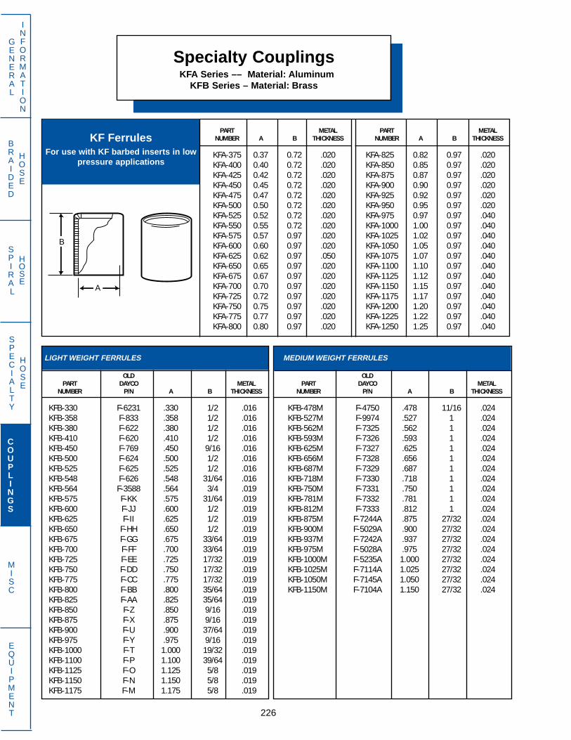
Specialty CouplingsKFA Series –– Material: Aluminum
KFB Series – Material: Brass
PART METAL PART METALNUMBER A B THICKNESS NUMBER A B THICKNESS
KFA-375 0.37 0.72 .020 KFA-825 0.82 0.97 .020KFA-400 0.40 0.72 .020 KFA-850 0.85 0.97 .020KFA-425 0.42 0.72 .020 KFA-875 0.87 0.97 .020KFA-450 0.45 0.72 .020 KFA-900 0.90 0.97 .020KFA-475 0.47 0.72 .020 KFA-925 0.92 0.97 .020KFA-500 0.50 0.72 .020 KFA-950 0.95 0.97 .020KFA-525 0.52 0.72 .020 KFA-975 0.97 0.97 .040KFA-550 0.55 0.72 .020 KFA-1000 1.00 0.97 .040KFA-575 0.57 0.97 .020 KFA-1025 1.02 0.97 .040KFA-600 0.60 0.97 .020 KFA-1050 1.05 0.97 .040KFA-625 0.62 0.97 .050 KFA-1075 1.07 0.97 .040KFA-650 0.65 0.97 .020 KFA-1100 1.10 0.97 .040KFA-675 0.67 0.97 .020 KFA-1125 1.12 0.97 .040KFA-700 0.70 0.97 .020 KFA-1150 1.15 0.97 .040KFA-725 0.72 0.97 .020 KFA-1175 1.17 0.97 .040KFA-750 0.75 0.97 .020 KFA-1200 1.20 0.97 .040KFA-775 0.77 0.97 .020 KFA-1225 1.22 0.97 .040KFA-800 0.80 0.97 .020 KFA-1250 1.25 0.97 .040
KF FerrulesFor use with KF barbed inserts in low
pressure applications
226
GENERAL
INFORMATION
SPECIALTY
HOSE
COUPLINGS
MISC
EQUIPMENT
BRAIDED
HOSE
SPIRAL
HOSE
LIGHT WEIGHT FERRULES
OLDPART DAYCO METAL
NUMBER P/N A B THICKNESS
KFB-330 F-6231 .330 1/2 .016KFB-358 F-833 .358 1/2 .016KFB-380 F-622 .380 1/2 .016KFB-410 F-620 .410 1/2 .016KFB-450 F-769 .450 9/16 .016KFB-500 F-624 .500 1/2 .016KFB-525 F-625 .525 1/2 .016KFB-548 F-626 .548 31/64 .016KFB-564 F-3588 .564 3/4 .019KFB-575 F-KK .575 31/64 .019KFB-600 F-JJ .600 1/2 .019KFB-625 F-II .625 1/2 .019KFB-650 F-HH .650 1/2 .019KFB-675 F-GG .675 33/64 .019KFB-700 F-FF .700 33/64 .019KFB-725 F-EE .725 17/32 .019KFB-750 F-DD .750 17/32 .019KFB-775 F-CC .775 17/32 .019KFB-800 F-BB .800 35/64 .019KFB-825 F-AA .825 35/64 .019KFB-850 F-Z .850 9/16 .019KFB-875 F-X .875 9/16 .019KFB-900 F-U .900 37/64 .019KFB-975 F-Y .975 9/16 .019KFB-1000 F-T 1.000 19/32 .019KFB-1100 F-P 1.100 39/64 .019KFB-1125 F-O 1.125 5/8 .019KFB-1150 F-N 1.150 5/8 .019KFB-1175 F-M 1.175 5/8 .019
MEDIUM WEIGHT FERRULES
OLDPART DAYCO METAL
NUMBER P/N A B THICKNESS
KFB-478M F-4750 .478 11/16 .024KFB-527M F-9974 .527 1 .024KFB-562M F-7325 .562 1 .024KFB-593M F-7326 .593 1 .024KFB-625M F-7327 .625 1 .024KFB-656M F-7328 .656 1 .024KFB-687M F-7329 .687 1 .024KFB-718M F-7330 .718 1 .024KFB-750M F-7331 .750 1 .024KFB-781M F-7332 .781 1 .024KFB-812M F-7333 .812 1 .024KFB-875M F-7244A .875 27/32 .024KFB-900M F-5029A .900 27/32 .024KFB-937M F-7242A .937 27/32 .024KFB-975M F-5028A .975 27/32 .024KFB-1000M F-5235A 1.000 27/32 .024KFB-1025M F-7114A 1.025 27/32 .024KFB-1050M F-7145A 1.050 27/32 .024KFB-1150M F-7104A 1.150 27/32 .024
B
A

PART HOSE A B C D E FNUMBER I.D. THREAD O.A.L. CUT-OFF ORIFICE HEX HEX DROP
BA06-06FA 3/8 5/8 - 18 2.83 1.41 .27 3/4 3/4
PART HOSE A B C D E FNUMBER I.D. THREAD O.A.L. CUT-OFF ORIFICE HEX HEX DROP
BA06-08FJ45T 3/8 3/4 - 16 3.09 1.69 .27 3/4 7/8 .55BA08-10FJ45T 1/2 7/8 - 14 3.53 1.94 .39 7/8 1 .63BA12-12FJ45T 3/4 1 1/16 - 12 3.75 2.13 .63 1 1/8 1 1/4 .77
PART HOSE A B C D E FNUMBER I.D. THREAD O.A.L. CUT-OFF ORIFICE HEX HEX DROP
BA04-04FJ 1/4 7/16 - 20 2.52 1.22 .16 5/8 9/16BA04-05FJ 1/4 1/2 - 20 2.56 1.34 .16 5/8 5/8BA04-06FJ 1/4 9/16 - 18 2.58 1.28 .16 11/16 11/16
BA06-05FJ 3/8 1/2 - 20 2.75 1.34 .27 3/4 5/8BA06-06FJ 3/8 9/16 - 18 2.77 1.34 .27 3/4 11/16BA06-08FJ 3/8 3/4 - 16 2.81 1.41 .27 7/8 7/8
BA08-08FJ 1/2 3/4 - 16 3.16 1.56 .39 1 7/8BA08-10FJ 1/2 7/8 - 14 3.24 1.63 .39 1 1BA12-12FJ 3/4 1 1/16 - 12 3.33 1.69 .63 1 1/4 1 1/4
BA12-14FJ 3/4 1 3/16 - 12 3.34 1.72 .63 1 3/8 1 3/8BA16-16FJ 1 1 5/16 - 12 3.72 2.10 .81 1 1/2 1 1/2
Non-Skive Reusable CouplingsBA Series — Material: Steel
227
GENERAL
INFORMATION
SPECIALTY
HOSE
COUPLINGS
MISC
EQUIPMENT
BRAIDED
HOSE
SPIRAL
HOSE
Style FASwivel Female
45˚ Flare
Style FJSwivel Female
37˚ Flare
Style FJ45T45˚ Bent Tube Swivel Female
37˚ Flare

Non-Skive Reusable CouplingsBA Series — Material: Steel
PART HOSE A B C D E FNUMBER I.D. THREAD O.A.L. CUT-OFF ORIFICE HEX HEX DROP
BA04-05FJ90T 1/4 1/2 - 20 2.39 1.09 .16 5/8 5/8 .77BA06-06FJ90T 3/8 9/16 - 18 2.70 1.31 .26 3/4 11/16 .86BA06-08FJ90T 3/8 3/4 - 16 2.86 1.44 .27 3/4 7/8 1.09
BA08-08FJ90T 1/2 3/4 - 16 3.20 1.59 .39 7/8 7/8 1.09BA08-10FJ90T 1/2 7/8 - 14 3.23 1.63 .39 7/8 1 1.23BA12-12FJ90T 3/4 1 1/16 - 12 3.70 2.06 .63 1 1/8 1 1/4 1.83
BA16-16FJ90T 1 1 5/16 - 12 4.39 2.75 .81 1 1/2 1 1/2 2.14
228
GENERAL
INFORMATION
SPECIALTY
HOSE
COUPLINGS
MISC
EQUIPMENT
BRAIDED
HOSE
SPIRAL
HOSE
PART HOSE A B C D E FNUMBER I.D. THREAD O.A.L. CUT-OFF ORIFICE HEX HEX DROP
BA04-05MJ 1/4 1/2 - 20 2.42 1.13 .16 5/8BA06-06MJ 3/8 9/16 - 18 2.63 1.22 .27 3/4BA06-08MJ 3/8 3/4 - 16 2.72 1.31 .27 3/4
BA08-10MJ 1/2 7/8 - 14 3.16 1.56 .39 1BA12-12MJ 3/4 1 1/16 - 12 3.30 1.66 .63 1 1/8BA16-16MJ 1 1 5/16 - 12 3.66 2.03 .81 1 1/2
PART HOSE A B C D E FNUMBER I.D. THREAD O.A.L. CUT-OFF ORIFICE HEX HEX DROP
BA12-12FJ90TL 3/4 1 1/16 - 12 3.94 2.31 .63 1 1/8 1 1/4 3.73
Style FJ90T90˚ Bent Tube Swivel Female
37˚ Flare
Style FJ90TL90˚ Bent Tube Swivel Female
37˚ Flare (long Drop)
Style MJMale
37˚ Flare

PART HOSE A B C D E FNUMBER I.D. THREAD O.A.L. CUT-OFF ORIFICE HEX HEX DROP
BA04-02MP 1/4 1/8 - 27 2.25 .97 .16 5/8BA04-04MP 1/4 1/4 - 18 2.44 1.16 .16 5/8BA04-06MP 1/4 3/8 - 18 2.44 1.16 .16 3/4
BA06-04MP 3/8 1/4 - 18 2.63 1.22 .27 3/4BA06-06MP 3/8 3/8 - 18 2.63 1.22 .27 3/4BA06-08MP 3/8 1/2 - 14 2.81 1.41 .27 7/8
BA08-08MP 1/2 1/2 - 14 3.16 1.56 .39 7/8BA12-12MP 3/4 3/4 - 14 3.19 1.53 .63 1 1/8BA16-16MP 1 1-11 1/2 3.69 2.06 .81 1 1/2
Non-Skive Reusable CouplingsBA Series — Material: Steel
229
GENERAL
INFORMATION
SPECIALTY
HOSE
COUPLINGS
MISC
EQUIPMENT
BRAIDED
HOSE
SPIRAL
HOSE
Style MPMale NPTF
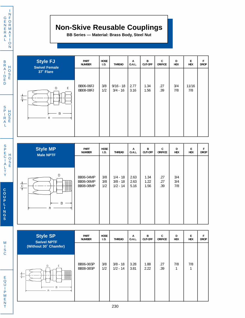
Non-Skive Reusable CouplingsBB Series — Material: Brass Body, Steel Nut
PART HOSE A B C D E FNUMBER I.D. THREAD O.A.L. CUT-OFF ORIFICE HEX HEX DROP
BB06-06FJ 3/8 9/16 - 18 2.77 1.34 .27 3/4 11/16BB08-08FJ 1/2 3/4 - 16 3.16 1.56 .39 7/8 7/8
230
GENERAL
INFORMATION
SPECIALTY
HOSE
COUPLINGS
MISC
EQUIPMENT
BRAIDED
HOSE
SPIRAL
HOSE
PART HOSE A B C D E FNUMBER I.D. THREAD O.A.L. CUT-OFF ORIFICE HEX HEX DROP
BB06-06SP 3/8 3/8 - 18 3.28 1.88 .27 7/8 7/8BB08-08SP 1/2 1/2 - 14 3.81 2.22 .39 1 1
PART HOSE A B C D E FNUMBER I.D. THREAD O.A.L. CUT-OFF ORIFICE HEX HEX DROP
BB06-04MP 3/8 1/4 - 18 2.63 1.34 .27 3/4BB06-06MP 3/8 3/8 - 18 2.63 1.22 .27 3/4BB08-08MP 1/2 1/2 - 14 5.16 1.56 .39 7/8
Style FJSwivel Female
37˚ Flare
Style MPMale NPTF
Style SPSwivel NPTF
(Without 30˚ Chamfer)

PART HOSE A B C D E FNUMBER I.D. THREAD O.A.L. CUT-OFF ORIFICE HEX HEX DROP
BE04-04FJ 1/4 7/16 - 20 2.52 1.44 .16 5/8 9/16BE04-05FJ 1/4 1/2 - 20 2.56 1.38 .16 5/8 5/8BE04-06FJ 1/4 9/16 - 18 2.58 1.25 .16 11/16 11/16
BE06-05FJ 3/8 1/2 - 20 2.75 1.50 .27 3/4 5/8BE06-06FJ 3/8 9/16 - 18 2.77 1.50 .27 3/4 11/16BE06-08FJ 3/8 3/4 - 16 2.81 1.56 .27 7/8 7/8
BE08-08FJ 1/2 3/4 - 16 3.16 1.50 .39 1 7/8BE08-10FJ 1/2 7/8 - 14 3.24 1.72 .39 1 1BE12-12FJ 3/4 1 1/16 - 12 3.33 1.63 .63 1 1/4 1 1/4
BE16-16FJ 1 1 5/16 - 12 3.72 1.91 .81 1 1/2 1 1/2
PART HOSE A B C D E FNUMBER I.D. THREAD O.A.L. CUT-OFF ORIFICE HEX HEX DROP
BE04-02MP 1/4 1/8 - 27 2.25 1.06 .16 5/8BE04-04MP 1/4 1/4 - 18 2.44 1.25 .16 5/8BE04-06MP 1/4 3/8 - 18 2.44 1.25 .16 3/4
BE06-04MP 3/8 1/4 - 18 2.63 1.36 .27 3/4BE06-06MP 3/8 3/8 - 18 2.63 1.36 .27 3/4BE08-08MP 1/2 1/2 - 14 3.16 1.50 .39 7/8
BE12-12MP 3/4 3/4 - 14 3.19 1.50 .63 1 1/8BE16-16MP 1 1-11 1/2 3.69 1.88 .81 1 1/2
PART HOSE A B C D E FNUMBER I.D. THREAD O.A.L. CUT-OFF ORIFICE HEX HEX DROP
BE04-05MJ 1/4 1/2 - 20 2.42 1.25 .16 5/8BE06-06MJ 3/8 9/16 - 18 2.63 1.36 .27 3/4BE06-08MJ 3/8 3/4 - 16 2.72 1.47 .27 3/4
BE08-10MJ 1/2 7/8 - 14 3.16 1.50 .39 1BE12-12MJ 3/4 1 1/16 - 12 3.30 1.59 .63 1 1/8
Non-Skive Reusable CouplingsBE Series — Material: Steel
231
GENERAL
INFORMATION
SPECIALTY
HOSE
COUPLINGS
MISC
EQUIPMENT
BRAIDED
HOSE
SPIRAL
HOSE
Style FJSwivel Female
37˚ Flare
Style MJMale
37˚ Flare
Style MPMale NPTF

Non-Skive Reusable CouplingsBG Series — Material: Steel
PART HOSE A B C D E FNUMBER I.D. THREAD O.A.L. CUT-OFF ORIFICE HEX HEX DROP
BG03-04FJ 3/16 7/16 - 20 2.05 1.08 .13 9/16 9/16BG04-04FJ 1/4 7/16 - 20 2.14 1.14 .17 5/8 9/16BG04-05FJ 1/4 1/2 - 20 2.19 1.19 .17 5/8 5/8
BG05-06FJ 5/16 9/16 - 18 2.52 1.39 .23 11/16 11/16BG06-06FJ 3/8 9/16 - 18 2.77 1.45 .27 7/8 11/16BG06-08FJ 3/8 3/4 - 16 2.81 1.50 .27 7/8 7/8
BG08-08FJ 1/2 3/4 - 16 3.06 1.56 .39 1 7/8
232
GENERAL
INFORMATION
SPECIALTY
HOSE
COUPLINGS
MISC
EQUIPMENT
BRAIDED
HOSE
SPIRAL
HOSE
PART HOSE A B C D E FNUMBER I.D. THREAD O.A.L. CUT-OFF ORIFICE HEX HEX DROP
BG03-02MP 3/16 1/8 - 27 1.78 .81 .13 1/2BG03-04MP 3/16 1/4 - 18 1.97 1.00 .13 5/8BG04-04MP 1/4 1/4 - 18 2.06 1.06 .17 5/8
BG05-04MP 5/16 1/4 - 18 2.38 1.25 .23 5/8BG06-06MP 3/8 3/8 - 18 2.63 1.31 .27 7/8BG08-08MP 1/2 1/2 - 14 3.13 1.63 .39 1
PART HOSE A B C D E FNUMBER I.D. THREAD O.A.L. CUT-OFF ORIFICE HEX HEX DROP
BG03-04MJ 3/16 7/16 - 20 1.96 1.00 .13 1/2BG04-04MJ 1/4 7/16 - 20 2.05 1.06 .17 5/8BG04-05MJ 1/4 1/2 - 20 2.05 1.06 .17 5/8
BG05-06MJ 5/16 9/16 - 18 2.37 1.25 .23 5/8BG06-06MJ 3/8 9/16 - 18 2.62 1.31 .27 7/8BG06-08MJ 3/8 3/4 - 16 2.72 1.41 .27 7/8
BG08-08MJ 1/2 3/4 - 16 3.03 1.53 .39 1BG08-10MJ 1/2 7/8 - 14 3.13 1.63 .39 1
Style FJSwivel Female
37˚ Flare
Style MJMale
37˚ Flare
Style MPMale NPTF

PART HOSE A B C D E FNUMBER I.D. THREAD O.A.L. CUT-OFF ORIFICE HEX HEX DROP
BG03-02SP 3/16 1/8 - 27 2.44 1.47 .13 5/8 5/8BG03-04SP 3/16 1/4 - 18 2.50 1.53 .13 5/8 5/8BG04-04SP 1/4 1/4 - 18 2.59 1.59 .17 5/8 5/8
BG05-04SP 5/16 1/4 - 18 3.03 1.91 .23 11/16 11/16BG06-06SP 3/8 3/8 - 18 3.28 1.97 .27 7/8 7/8BG08-08SP 1/2 1/2 - 14 3.78 2.28 .39 1 1
PART HOSE A B C D E FNUMBER I.D. THREAD O.A.L. CUT-OFF ORIFICE HEX HEX DROP
BM04-04FJ 1/4 7/16 - 20 2.52 1.25 .16 5/8 9/16BM04-05FJ 1/4 1/2 -20 2.56 1.31 .16 5/8 5/8BM04-06FJ 1/4 9/16 - 18 2.58 1.31 .16 11/16 11/16
BM06-05FJ 3/8 1/2 - 20 2.75 1.38 .27 3/4 5/8BM06-06FJ 3/8 9/16 - 18 2.77 1.38 .27 3/4 11/16BM06-08FJ 3/8 3/4 - 16 2.81 1.44 .27 7/8 7/8
BM08-08FJ 1/2 3/4 - 16 3.16 1.66 .39 7/8 7/8BM08-10FJ 1/2 7/8 - 14 3.24 1.56 .39 1 1BM12-12FJ 3/4 1 1/16 - 12 3.33 1.69 .63 1 1/4 1 1/4
BM12-14FJ 3/4 1 3/16 - 12 3.34 1.72 .63 1 3/8 1 3/8BM16-16FJ 1 1 5/16 - 12 3.72 1.84 .81 1 1/2 1 1/2
Non-Skive Reusable CouplingsBG Series — Material: Steel
233
GENERAL
INFORMATION
SPECIALTY
HOSE
COUPLINGS
MISC
EQUIPMENT
BRAIDED
HOSE
SPIRAL
HOSE
Non-Skive Reusable CouplingsBM Series — Material: Steel
Style SPSwivel Male NPTF
(Without 30˚ Chamfer)
Style FJSwivel Female
37˚ Flare
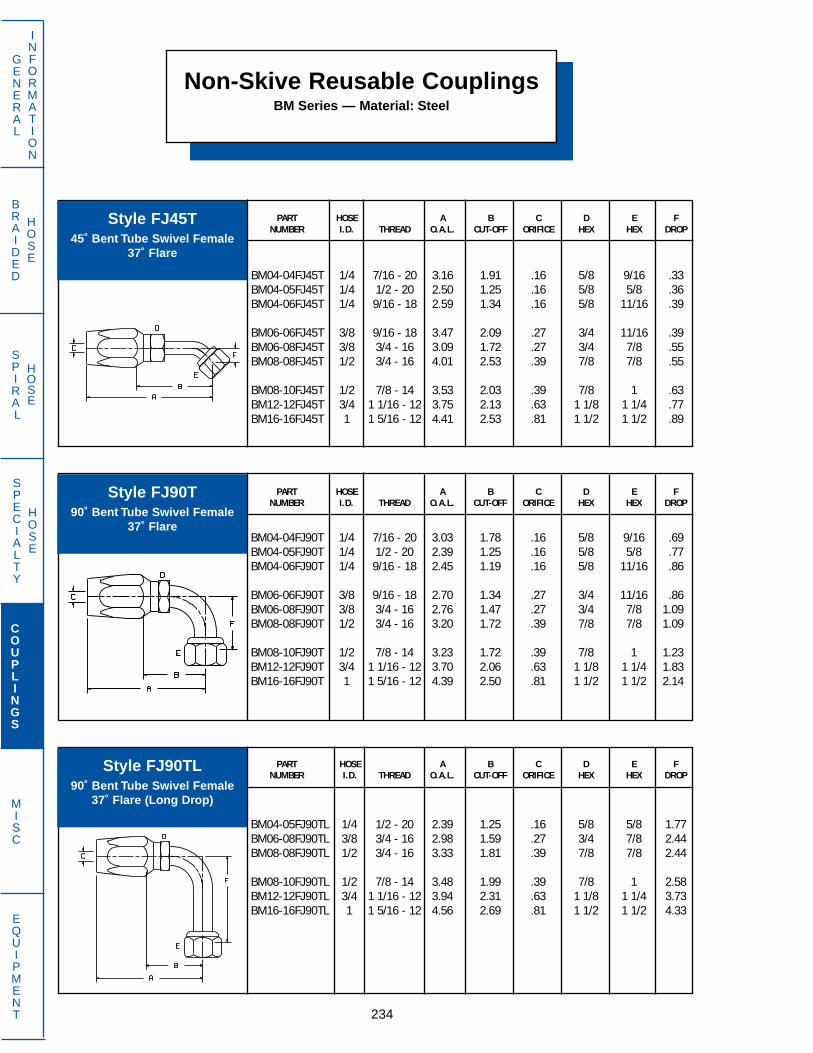
Non-Skive Reusable CouplingsBM Series — Material: Steel
PART HOSE A B C D E FNUMBER I.D. THREAD O.A.L. CUT-OFF ORIFICE HEX HEX DROP
BM04-04FJ45T 1/4 7/16 - 20 3.16 1.91 .16 5/8 9/16 .33BM04-05FJ45T 1/4 1/2 - 20 2.50 1.25 .16 5/8 5/8 .36BM04-06FJ45T 1/4 9/16 - 18 2.59 1.34 .16 5/8 11/16 .39
BM06-06FJ45T 3/8 9/16 - 18 3.47 2.09 .27 3/4 11/16 .39BM06-08FJ45T 3/8 3/4 - 16 3.09 1.72 .27 3/4 7/8 .55BM08-08FJ45T 1/2 3/4 - 16 4.01 2.53 .39 7/8 7/8 .55
BM08-10FJ45T 1/2 7/8 - 14 3.53 2.03 .39 7/8 1 .63BM12-12FJ45T 3/4 1 1/16 - 12 3.75 2.13 .63 1 1/8 1 1/4 .77BM16-16FJ45T 1 1 5/16 - 12 4.41 2.53 .81 1 1/2 1 1/2 .89
234
GENERAL
INFORMATION
SPECIALTY
HOSE
COUPLINGS
MISC
EQUIPMENT
BRAIDED
HOSE
SPIRAL
HOSE
PART HOSE A B C D E FNUMBER I.D. THREAD O.A.L. CUT-OFF ORIFICE HEX HEX DROP
BM04-05FJ90TL 1/4 1/2 - 20 2.39 1.25 .16 5/8 5/8 1.77BM06-08FJ90TL 3/8 3/4 - 16 2.98 1.59 .27 3/4 7/8 2.44BM08-08FJ90TL 1/2 3/4 - 16 3.33 1.81 .39 7/8 7/8 2.44
BM08-10FJ90TL 1/2 7/8 - 14 3.48 1.99 .39 7/8 1 2.58BM12-12FJ90TL 3/4 1 1/16 - 12 3.94 2.31 .63 1 1/8 1 1/4 3.73BM16-16FJ90TL 1 1 5/16 - 12 4.56 2.69 .81 1 1/2 1 1/2 4.33
PART HOSE A B C D E FNUMBER I.D. THREAD O.A.L. CUT-OFF ORIFICE HEX HEX DROP
BM04-04FJ90T 1/4 7/16 - 20 3.03 1.78 .16 5/8 9/16 .69BM04-05FJ90T 1/4 1/2 - 20 2.39 1.25 .16 5/8 5/8 .77BM04-06FJ90T 1/4 9/16 - 18 2.45 1.19 .16 5/8 11/16 .86
BM06-06FJ90T 3/8 9/16 - 18 2.70 1.34 .27 3/4 11/16 .86BM06-08FJ90T 3/8 3/4 - 16 2.76 1.47 .27 3/4 7/8 1.09BM08-08FJ90T 1/2 3/4 - 16 3.20 1.72 .39 7/8 7/8 1.09
BM08-10FJ90T 1/2 7/8 - 14 3.23 1.72 .39 7/8 1 1.23BM12-12FJ90T 3/4 1 1/16 - 12 3.70 2.06 .63 1 1/8 1 1/4 1.83BM16-16FJ90T 1 1 5/16 - 12 4.39 2.50 .81 1 1/2 1 1/2 2.14
Style FJ45T45˚ Bent Tube Swivel Female
37˚ Flare
Style FJ90T90˚ Bent Tube Swivel Female
37˚ Flare
Style FJ90TL90˚ Bent Tube Swivel Female
37˚ Flare (Long Drop)
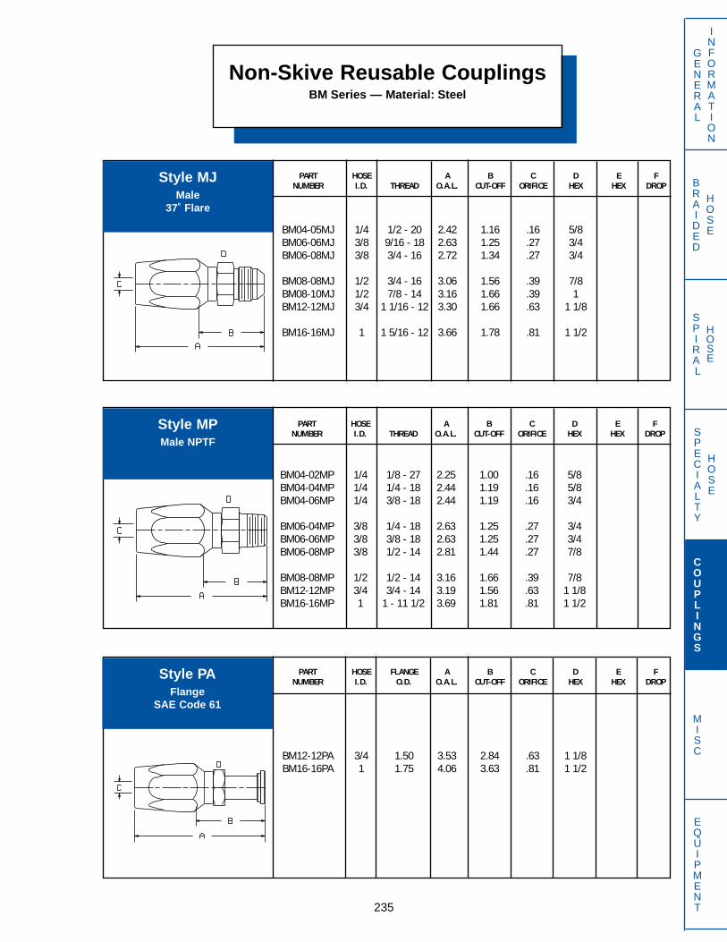
PART HOSE A B C D E FNUMBER I.D. THREAD O.A.L. CUT-OFF ORIFICE HEX HEX DROP
BM04-05MJ 1/4 1/2 - 20 2.42 1.16 .16 5/8BM06-06MJ 3/8 9/16 - 18 2.63 1.25 .27 3/4BM06-08MJ 3/8 3/4 - 16 2.72 1.34 .27 3/4
BM08-08MJ 1/2 3/4 - 16 3.06 1.56 .39 7/8BM08-10MJ 1/2 7/8 - 14 3.16 1.66 .39 1BM12-12MJ 3/4 1 1/16 - 12 3.30 1.66 .63 1 1/8
BM16-16MJ 1 1 5/16 - 12 3.66 1.78 .81 1 1/2
PART HOSE FLANGE A B C D E FNUMBER I.D. O.D. O.A.L. CUT-OFF ORIFICE HEX HEX DROP
BM12-12PA 3/4 1.50 3.53 2.84 .63 1 1/8BM16-16PA 1 1.75 4.06 3.63 .81 1 1/2
PART HOSE A B C D E FNUMBER I.D. THREAD O.A.L. CUT-OFF ORIFICE HEX HEX DROP
BM04-02MP 1/4 1/8 - 27 2.25 1.00 .16 5/8BM04-04MP 1/4 1/4 - 18 2.44 1.19 .16 5/8BM04-06MP 1/4 3/8 - 18 2.44 1.19 .16 3/4
BM06-04MP 3/8 1/4 - 18 2.63 1.25 .27 3/4BM06-06MP 3/8 3/8 - 18 2.63 1.25 .27 3/4BM06-08MP 3/8 1/2 - 14 2.81 1.44 .27 7/8
BM08-08MP 1/2 1/2 - 14 3.16 1.66 .39 7/8BM12-12MP 3/4 3/4 - 14 3.19 1.56 .63 1 1/8BM16-16MP 1 1 - 11 1/2 3.69 1.81 .81 1 1/2
Non-Skive Reusable CouplingsBM Series — Material: Steel
235
GENERAL
INFORMATION
SPECIALTY
HOSE
COUPLINGS
MISC
EQUIPMENT
BRAIDED
HOSE
SPIRAL
HOSE
Style MJMale
37˚ Flare
Style MPMale NPTF
Style PAFlange
SAE Code 61

Non-Skive Reusable CouplingsBM Series — Material: Steel
PART HOSE FLANGE A B C D E FNUMBER I.D. O.D. O.A.L. CUT-OFF ORIFICE HEX HEX DROP
BM12-12PA45 3/4 1.50 4.47 2.84 .63 1 1/8 .98BM16-16PA45 1 1.75 4.94 3.63 .81 1 1/2 1.06
236
GENERAL
INFORMATION
SPECIALTY
HOSE
COUPLINGS
MISC
EQUIPMENT
BRAIDED
HOSE
SPIRAL
HOSE
PART HOSE FLANGE A B C D E FNUMBER I.D. O.D. O.A.L. CUT-OFF ORIFICE HEX HEX DROP
BM12-12PA90 3/4 1.50 4.19 2.56 .63 1 1/8 2.13BM16-16PA90 1 1.75 4.78 3.31 .81 1 1/2 2.41
Style PA4545˚ Elbow Flange
SAE Code 61
Style PA9090˚ Elbow Flange
SAE Code 61

PART HOSE A B C D E FNUMBER I.D. THREAD O.A.L. CUT-OFF ORIFICE HEX HEX DROP
BN04-04FA 3/16 7/16 - 20 1.98 1.23 .13 9/16 9/16BN05-05FA 1/4 1/2 - 20 2.16 1.36 .17 5/8 5/8BN06-06FA 5/16 5/8 - 18 2.39 1.44 .23 3/4 3/4
BN06-08FA 5/16 3/4 - 16 2.38 1.42 .23 7/8 7/8BN08-08FA 13/32 3/4 - 16 2.69 1.53 .36 7/8 7/8BN10-10FA 1/2 7/8 - 14 3.05 1.75 .45 1 1
BN12-12FA 5/8 1 1/16 - 14 3.56 2.00 .55 1 1/4 1 1/4
PART HOSE A B C D E FNUMBER I.D. THREAD O.A.L. CUT-OFF ORIFICE HEX HEX DROP
BN06-06FA90T 5/16 5/8 - 18 2.17 1.22 .23 3/4 1/2 .86BN12-12FA90T 5/8 1 1/16 - 14 3.78 2.22 .55 1 1/4 1 1/4 1.83
PART HOSE A B C D E FNUMBER I.D. THREAD O.A.L. CUT-OFF ORIFICE HEX HEX DROP
BN06-06FA45T 5/16 5/8 - 18 2.28 1.33 .23 3/4 1/2 .39BN12-12FA45T 5/8 1 1/16 - 14 3.73 2.17 .55 7/8 3/4 .77
Non-Skive Reusable CouplingsBN Series (Non-Mandrel) –– Material: Steel
237
GENERAL
INFORMATION
SPECIALTY
HOSE
COUPLINGS
MISC
EQUIPMENT
BRAIDED
HOSE
SPIRAL
HOSE
Style FASwivel Female
45˚ Flare
Style FA45T45˚ Bent Tube Swivel Female
45˚ Flare
Style FA90T90˚ Bent Tube Swivel Female
45˚ Flare
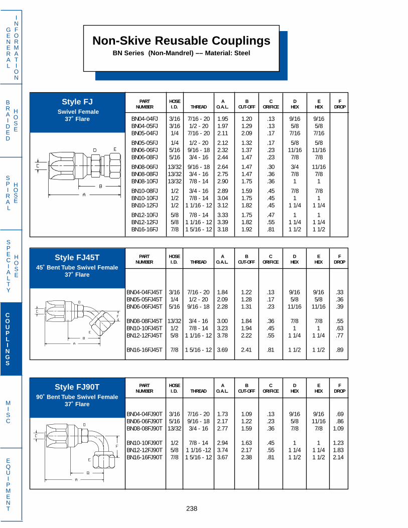
Non-Skive Reusable CouplingsBN Series (Non-Mandrel) –– Material: Steel
PART HOSE A B C D E FNUMBER I.D. THREAD O.A.L. CUT-OFF ORIFICE HEX HEX DROP
BN04-04FJ 3/16 7/16 - 20 1.95 1.20 .13 9/16 9/16BN04-05FJ 3/16 1/2 - 20 1.97 1.29 .13 5/8 5/8BN05-04FJ 1/4 7/16 - 20 2.11 2.09 .17 7/16 7/16
BN05-05FJ 1/4 1/2 - 20 2.12 1.32 .17 5/8 5/8BN06-06FJ 5/16 9/16 - 18 2.32 1.37 .23 11/16 11/16BN06-08FJ 5/16 3/4 - 16 2.44 1.47 .23 7/8 7/8
BN08-06FJ 13/32 9/16 - 18 2.64 1.47 .30 3/4 11/16BN08-08FJ 13/32 3/4 - 16 2.75 1.47 .36 7/8 7/8BN08-10FJ 13/32 7/8 - 14 2.90 1.75 .36 1 1
BN10-08FJ 1/2 3/4 - 16 2.89 1.59 .45 7/8 7/8BN10-10FJ 1/2 7/8 - 14 3.04 1.75 .45 1 1BN10-12FJ 1/2 1 1/16 - 12 3.12 1.82 .45 1 1/4 1 1/4
BN12-10FJ 5/8 7/8 - 14 3.33 1.75 .47 1 1BN12-12FJ 5/8 1 1/16 - 12 3.39 1.82 .55 1 1/4 1 1/4BN16-16FJ 7/8 1 5/16 - 12 3.18 1.92 .81 1 1/2 1 1/2
238
GENERAL
INFORMATION
SPECIALTY
HOSE
COUPLINGS
MISC
EQUIPMENT
BRAIDED
HOSE
SPIRAL
HOSE
PART HOSE A B C D E FNUMBER I.D. THREAD O.A.L. CUT-OFF ORIFICE HEX HEX DROP
BN04-04FJ90T 3/16 7/16 - 20 1.73 1.09 .13 9/16 9/16 .69BN06-06FJ90T 5/16 9/16 - 18 2.17 1.22 .23 5/8 11/16 .86BN08-08FJ90T 13/32 3/4 - 16 2.77 1.59 .36 7/8 7/8 1.09
BN10-10FJ90T 1/2 7/8 - 14 2.94 1.63 .45 1 1 1.23BN12-12FJ90T 5/8 1 1/16 -12 3.74 2.17 .55 1 1/4 1 1/4 1.83BN16-16FJ90T 7/8 1 5/16 - 12 3.67 2.38 .81 1 1/2 1 1/2 2.14
PART HOSE A B C D E FNUMBER I.D. THREAD O.A.L. CUT-OFF ORIFICE HEX HEX DROP
BN04-04FJ45T 3/16 7/16 - 20 1.84 1.22 .13 9/16 9/16 .33BN05-05FJ45T 1/4 1/2 - 20 2.09 1.28 .17 5/8 5/8 .36BN06-06FJ45T 5/16 9/16 - 18 2.28 1.31 .23 11/16 11/16 .39
BN08-08FJ45T 13/32 3/4 - 16 3.00 1.84 .36 7/8 7/8 .55BN10-10FJ45T 1/2 7/8 - 14 3.23 1.94 .45 1 1 .63BN12-12FJ45T 5/8 1 1/16 - 12 3.78 2.22 .55 1 1/4 1 1/4 .77
BN16-16FJ45T 7/8 1 5/16 - 12 3.69 2.41 .81 1 1/2 1 1/2 .89
Style FJSwivel Female
37˚ Flare
Style FJ45T45˚ Bent Tube Swivel Female
37˚ Flare
Style FJ90T90˚ Bent Tube Swivel Female
37˚ Flare

PART HOSE A B C D E FNUMBER I.D. THREAD O.A.L. CUT-OFF ORIFICE HEX HEX DROP
BN04-04FJ90TL 3/16 7/16 - 20 1.73 1.09 .13 9/16 9/16 1.80BN06-06FJ90TL 5/16 9/16 - 18 2.18 1.22 .23 1/2 11/16 2.19BN08-08FJ90TL 13/32 3/4 - 16 2.89 1.72 .36 7/8 7/8 2.44
BN10-10FJ90TL 1/2 7/8 - 14 3.19 1.88 .45 1 1 2.58BN16-16FJ90TL 7/8 1 5/16 - 12 3.84 2.57 .81 1 1/2 1 1/2 4.33
Non-Skive Reusable CouplingsBN Series (Non-Mandrel) –– Material: Steel
239
GENERAL
INFORMATION
SPECIALTY
HOSE
COUPLINGS
MISC
EQUIPMENT
BRAIDED
HOSE
SPIRAL
HOSE
PART HOSE A B C D E FNUMBER I.D. THREAD O.A.L. CUT-OFF ORIFICE HEX HEX DROP
BN04-04MF 3/16 7/16 - 24 2.47 1.72 .13 3/8 7/16BN04-05MF 3/16 1/2 - 20 2.55 1.80 .13 9/16 1/2BN05-05MF 1/4 1/2 - 20 2.65 1.88 .17 7/16 1/2
BN06-06MF 5/16 5/8 - 18 2.81 1.86 .23 1/2 5/8BN08-08MF 13/32 3/4 - 18 3.01 1.88 .36 5/8 3/4
PART HOSE A B C D E FNUMBER I.D. THREAD O.A.L. CUT-OFF ORIFICE HEX HEX DROP
BN04-04MA 3/16 7/16 - 20 1.78 1.03 .13 9/16BN05-05MA 1/4 1/2 - 20 1.97 1.17 .17 5/8BN06-06MA 5/16 5/8 - 18 2.20 1.13 .23 11/16
BN08-08MA 13/32 3/4 - 18 2.66 1.50 .36 7/8BN10-10MA 1/2 7/8 - 14 2.98 1.68 .45 1BN10-12MA 1/2 1 1/16 - 14 3.11 1.81 .45 1 1/8
BN12-12MA 5/8 1 1/16 - 14 3.47 1.91 .55 1 1/8
Style FA90TL90˚ Bent Tube Swivel Female
37˚ Flare (Long Drop)
Style MAMale 45˚
Flare
Style MFSwivel Male 45˚Inverted Flare

Non-Skive Reusable CouplingsBN Series (Non-Mandrel) –– Material: Steel
PART HOSE A B C D E FNUMBER I.D. THREAD O.A.L. CUT-OFF ORIFICE HEX HEX DROP
BN08-08MF45T 13/32 3/4 - 18 3.91 2.75 .36 5/8 3/4 1.06
240
GENERAL
INFORMATION
SPECIALTY
HOSE
COUPLINGS
MISC
EQUIPMENT
BRAIDED
HOSE
SPIRAL
HOSE
PART HOSE A B C D E FNUMBER I.D. THREAD O.A.L. CUT-OFF ORIFICE HEX HEX DROP
BN04-04MJ 3/16 7/16 - 20 1.89 1.08 .13 9/16BN05-05MJ 1/4 1/2 - 20 1.95 1.16 .17 5/8BN06-06MJ 5/16 9/16 - 18 2.16 1.20 .23 11/16
BN08-08MJ 13/32 3/4 - 16 2.56 1.41 .36 7/8BN10-10MJ 1/2 7/8 - 14 2.86 1.56 .45 1BN10-12MJ 1/2 1 1/16 - 12 3.03 1.73 .45 1 1/8
BN12-12MJ 5/8 1 1/16 - 12 3.33 1.77 .55 1 1/4BN16-16MJ 7/8 1 5/16 - 12 2.94 1.67 .81 1 3/8
PART HOSE A B C D E FNUMBER I.D. THREAD O.A.L. CUT-OFF ORIFICE HEX HEX DROP
BN04-04MF90T 3/16 7/16 - 24 2.66 1.91 .13 3/8 7/16 1.47BN05-05MF90T 1/4 1/2 - 20 2.83 2.05 .17 7/16 1/2 1.66
BN06-06MF90T 5/16 5/8 - 18 3.11 2.16 .23 1/2 5/8 1.69BN08-08MF90T 13/32 3/4 - 18 2.84 1.69 .36 5/8 3/4 1.88
Style MF45T45˚ Bent Tube Swivel Male
Inverted Flare
Style MF90T90˚ Bent Tube Swivel Male
Inverted Flare
Style MJMale
37˚ Flare
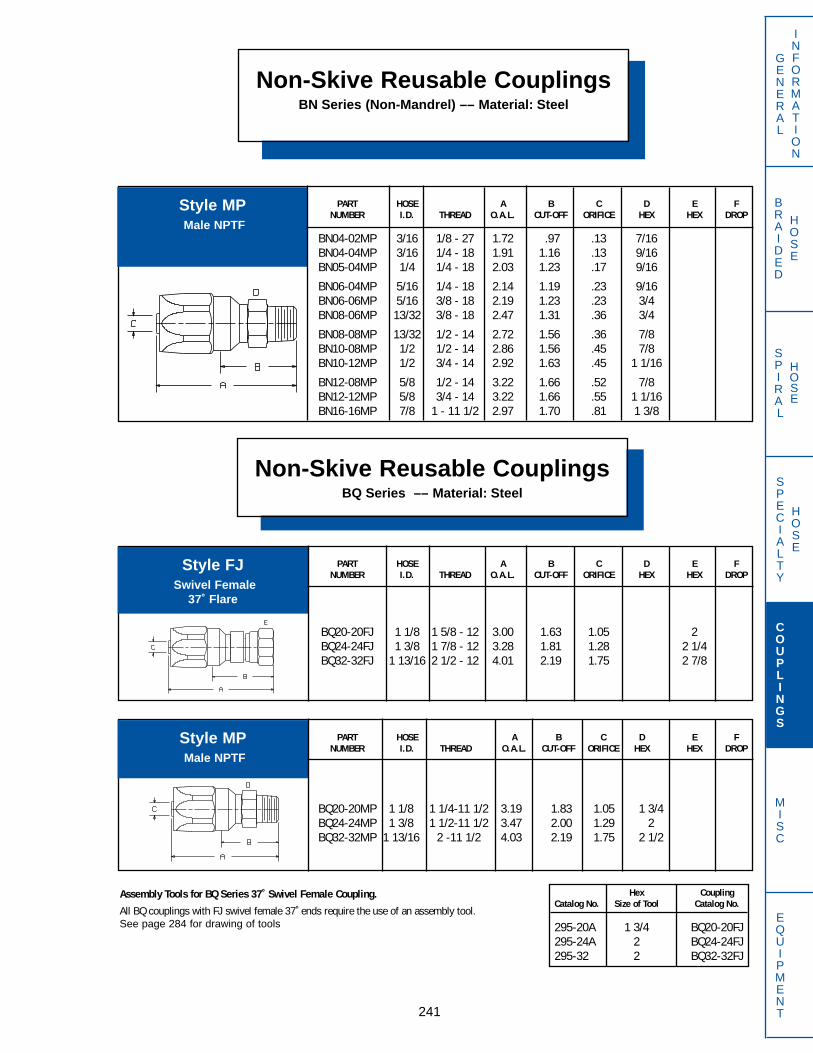
Hex CouplingCatalog No. Size of Tool Catalog No.
295-20A 1 3/4 BQ20-20FJ295-24A 2 BQ24-24FJ295-32 2 BQ32-32FJ
PART HOSE A B C D E FNUMBER I.D. THREAD O.A.L. CUT-OFF ORIFICE HEX HEX DROP
BN04-02MP 3/16 1/8 - 27 1.72 .97 .13 7/16BN04-04MP 3/16 1/4 - 18 1.91 1.16 .13 9/16BN05-04MP 1/4 1/4 - 18 2.03 1.23 .17 9/16
BN06-04MP 5/16 1/4 - 18 2.14 1.19 .23 9/16BN06-06MP 5/16 3/8 - 18 2.19 1.23 .23 3/4BN08-06MP 13/32 3/8 - 18 2.47 1.31 .36 3/4
BN08-08MP 13/32 1/2 - 14 2.72 1.56 .36 7/8BN10-08MP 1/2 1/2 - 14 2.86 1.56 .45 7/8BN10-12MP 1/2 3/4 - 14 2.92 1.63 .45 1 1/16
BN12-08MP 5/8 1/2 - 14 3.22 1.66 .52 7/8BN12-12MP 5/8 3/4 - 14 3.22 1.66 .55 1 1/16BN16-16MP 7/8 1 - 11 1/2 2.97 1.70 .81 1 3/8
Non-Skive Reusable CouplingsBN Series (Non-Mandrel) –– Material: Steel
241
GENERAL
INFORMATION
SPECIALTY
HOSE
COUPLINGS
MISC
EQUIPMENT
BRAIDED
HOSE
SPIRAL
HOSE
Non-Skive Reusable CouplingsBQ Series –– Material: Steel
PART HOSE A B C D E FNUMBER I.D. THREAD O.A.L. CUT-OFF ORIFICE HEX HEX DROP
BQ20-20FJ 1 1/8 1 5/8 - 12 3.00 1.63 1.05 2BQ24-24FJ 1 3/8 1 7/8 - 12 3.28 1.81 1.28 2 1/4BQ32-32FJ 1 13/16 2 1/2 - 12 4.01 2.19 1.75 2 7/8
PART HOSE A B C D E FNUMBER I.D. THREAD O.A.L. CUT-OFF ORIFICE HEX HEX DROP
BQ20-20MP 1 1/8 1 1/4-11 1/2 3.19 1.83 1.05 1 3/4BQ24-24MP 1 3/8 1 1/2-11 1/2 3.47 2.00 1.29 2BQ32-32MP 1 13/16 2 -11 1/2 4.03 2.19 1.75 2 1/2
Style MPMale NPTF
Style FJSwivel Female
37˚ Flare
Style MPMale NPTF
Assembly Tools for BQ Series 37˚ Swivel Female Coupling.
All BQ couplings with FJ swivel female 37˚ ends require the use of an assembly tool.See page 284 for drawing of tools
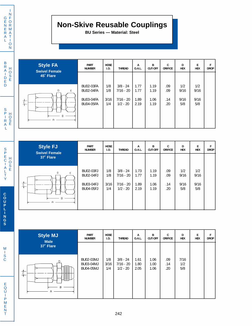
Non-Skive Reusable CouplingsBU Series — Material: Steel
PART HOSE A B C D E FNUMBER I.D. THREAD O.A.L. CUT-OFF ORIFICE HEX HEX DROP
BU02-03FA 1/8 3/8 - 24 1.77 1.19 .09 1/2 1/2BU02-04FA 1/8 7/16 - 20 1.77 1.19 .09 9/16 9/16
BU03-04FA 3/16 7/16 - 20 1.89 1.06 .14 9/16 9/16BU04-05FA 1/4 1/2 - 20 2.19 1.19 .20 5/8 5/8
242
GENERAL
INFORMATION
SPECIALTY
HOSE
COUPLINGS
MISC
EQUIPMENT
BRAIDED
HOSE
SPIRAL
HOSE
PART HOSE A B C D E FNUMBER I.D. THREAD O.A.L. CUT-OFF ORIFICE HEX HEX DROP
BU02-03MJ 1/8 3/8 - 24 1.61 1.06 .09 7/16BU03-04MJ 3/16 7/16 - 20 1.80 1.00 .14 1/2BU04-05MJ 1/4 1/2 - 20 2.05 1.06 .20 5/8
PART HOSE A B C D E FNUMBER I.D. THREAD O.A.L. CUT-OFF ORIFICE HEX HEX DROP
BU02-03FJ 1/8 3/8 - 24 1.73 1.19 .09 1/2 1/2BU02-04FJ 1/8 7/16 - 20 1.77 1.19 .09 9/16 9/16
BU03-04FJ 3/16 7/16 - 20 1.89 1.06 .14 9/16 9/16BU04-05FJ 1/4 1/2 - 20 2.19 1.19 .20 5/8 5/8
Style FASwivel Female
45˚ Flare
Style FJSwivel Female
37˚ Flare
Style MJMale
37˚ Flare
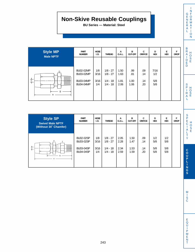
PART HOSE A B C D E FNUMBER I.D. THREAD O.A.L. CUT-OFF ORIFICE HEX HEX DROP
BU02-02MP 1/8 1/8 - 27 1.50 .99 .09 7/16BU03-02MP 3/16 1/8 - 27 1.63 .81 .14 1/2
BU03-04MP 3/16 1/4 - 18 1.81 1.00 .14 5/8BU04-04MP 1/4 1/4 - 18 2.06 1.06 .20 5/8
Non-Skive Reusable CouplingsBU Series — Material: Steel
243
GENERAL
INFORMATION
SPECIALTY
HOSE
COUPLINGS
MISC
EQUIPMENT
BRAIDED
HOSE
SPIRAL
HOSE
PART HOSE A B C D E FNUMBER I.D. THREAD O.A.L. CUT-OFF ORIFICE HEX HEX DROP
BU02-02SP 1/8 1/8 - 27 2.05 1.50 .09 1/2 1/2BU03-02SP 3/16 1/8 - 27 2.28 1.47 .14 5/8 5/8
BU03-04SP 3/16 1/4 - 18 2.34 1.53 .14 5/8 5/8BU04-04SP 1/4 1/4 - 18 2.59 1.59 .20 5/8 5/8
Style MPMale NPTF
Style SPSwivel Male NPTF
(Without 30˚ Chamfer)
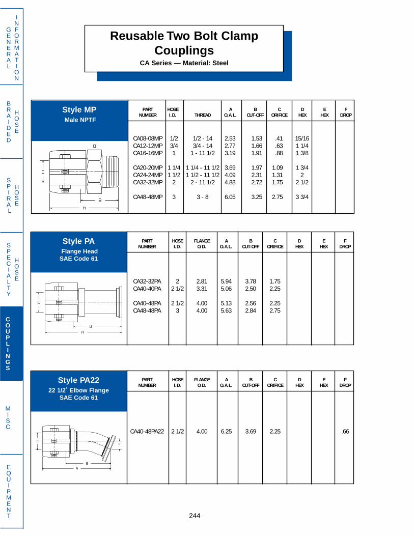
Reusable Two Bolt ClampCouplings
CA Series — Material: Steel
PART HOSE A B C D E FNUMBER I.D. THREAD O.A.L. CUT-OFF ORIFICE HEX HEX DROP
CA08-08MP 1/2 1/2 - 14 2.53 1.53 .41 15/16CA12-12MP 3/4 3/4 - 14 2.77 1.66 .63 1 1/4CA16-16MP 1 1 - 11 1/2 3.19 1.91 .88 1 3/8
CA20-20MP 1 1/4 1 1/4 - 11 1/2 3.69 1.97 1.09 1 3/4CA24-24MP 1 1/2 1 1/2 - 11 1/2 4.09 2.31 1.31 2CA32-32MP 2 2 - 11 1/2 4.88 2.72 1.75 2 1/2
CA48-48MP 3 3 - 8 6.05 3.25 2.75 3 3/4
244
GENERAL
INFORMATION
SPECIALTY
HOSE
COUPLINGS
MISC
EQUIPMENT
BRAIDED
HOSE
SPIRAL
HOSE
PART HOSE FLANGE A B C D E FNUMBER I.D. O.D. O.A.L. CUT-OFF ORIFICE HEX HEX DROP
CA40-48PA22 2 1/2 4.00 6.25 3.69 2.25 .66
PART HOSE FLANGE A B C D E FNUMBER I.D. O.D. O.A.L. CUT-OFF ORIFICE HEX HEX DROP
CA32-32PA 2 2.81 5.94 3.78 1.75CA40-40PA 2 1/2 3.31 5.06 2.50 2.25
CA40-48PA 2 1/2 4.00 5.13 2.56 2.25CA48-48PA 3 4.00 5.63 2.84 2.75
Style MPMale NPTF
Style PAFlange Head
SAE Code 61
Style PA2222 1/2˚ Elbow Flange
SAE Code 61

PART HOSE FLANGE A B C D E FNUMBER I.D. O.D. O.A.L. CUT-OFF ORIFICE HEX HEX DROP
CA40-40PA30 2 1/2 3.31 6.53 3.97 2.25 .94
Reusable Two Bolt ClampCouplings
CA Series — Material: Steel
245
GENERAL
INFORMATION
SPECIALTY
HOSE
COUPLINGS
MISC
EQUIPMENT
BRAIDED
HOSE
SPIRAL
HOSE
PART HOSE FLANGE A B C D E FNUMBER I.D. O.D. O.A.L. CUT-OFF ORIFICE HEX HEX DROP
CA32-32PA90 2 2.81 7.06 4.91 1.75 4.50CA40-40PA90 2 1/2 3.31 7.66 5.09 2.25 4.63CA40-48PA90 2 1/2 4.00 7.66 5.09 2.25 4.69
CA48-48PA90 3 4.00 8.78 6.00 2.75 5.50CA48-64PA90 3 5.00 8.78 6.00 2.75 5.50
PART HOSE FLANGE A B C D E FNUMBER I.D. O.D. O.A.L. CUT-OFF ORIFICE HEX HEX DROP
CA32-32PA45 2 2.81 7.25 5.09 1.75 1.94CA40-40PA45 2 1/2 3.31 7.19 4.63 2.25 1.72CA48-48PA45 3 4.00 8.19 5.41 2.75 2.03
Style PA3030˚ Elbow Flange
SAE Code 61
Style PA4545˚ Elbow Flange
SAE Code 61
Style PA9090˚ Elbow Flange
SAE Code 61
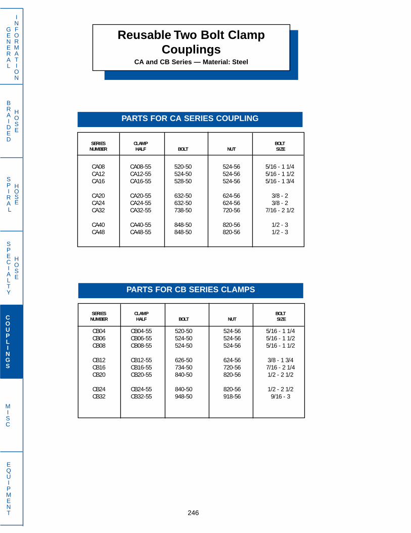
BRAIDED
HOSE
SPIRAL
HOSE
SERIES CLAMP BOLT NUMBER HALF BOLT NUT SIZE
CA08 CA08-55 520-50 524-56 5/16 - 1 1/4CA12 CA12-55 524-50 524-56 5/16 - 1 1/2CA16 CA16-55 528-50 524-56 5/16 - 1 3/4
CA20 CA20-55 632-50 624-56 3/8 - 2CA24 CA24-55 632-50 624-56 3/8 - 2CA32 CA32-55 738-50 720-56 7/16 - 2 1/2
CA40 CA40-55 848-50 820-56 1/2 - 3CA48 CA48-55 848-50 820-56 1/2 - 3
246
GENERAL
INFORMATION
SPECIALTY
HOSE
COUPLINGS
MISC
EQUIPMENT
SERIES CLAMP BOLT NUMBER HALF BOLT NUT SIZE
CB04 CB04-55 520-50 524-56 5/16 - 1 1/4CB06 CB06-55 524-50 524-56 5/16 - 1 1/2CB08 CB08-55 524-50 524-56 5/16 - 1 1/2
CB12 CB12-55 626-50 624-56 3/8 - 1 3/4CB16 CB16-55 734-50 720-56 7/16 - 2 1/4CB20 CB20-55 840-50 820-56 1/2 - 2 1/2
CB24 CB24-55 840-50 820-56 1/2 - 2 1/2CB32 CB32-55 948-50 918-56 9/16 - 3
Reusable Two Bolt ClampCouplings
CA and CB Series — Material: Steel
PARTS FOR CA SERIES COUPLING
PARTS FOR CB SERIES CLAMPS
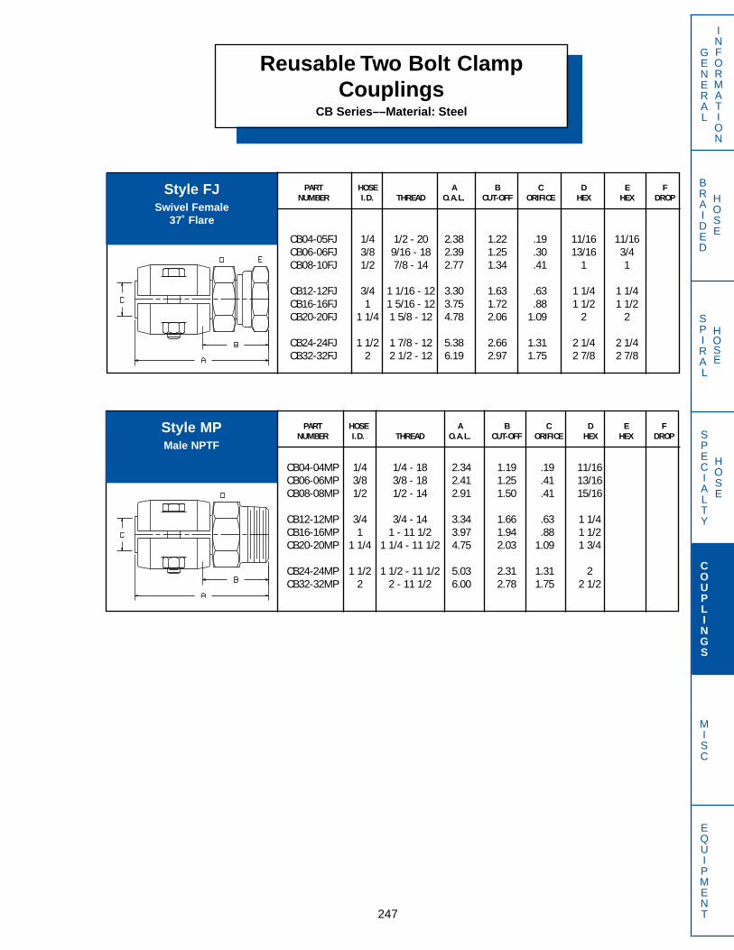
PART HOSE A B C D E FNUMBER I.D. THREAD O.A.L. CUT-OFF ORIFICE HEX HEX DROP
CB04-05FJ 1/4 1/2 - 20 2.38 1.22 .19 11/16 11/16CB06-06FJ 3/8 9/16 - 18 2.39 1.25 .30 13/16 3/4CB08-10FJ 1/2 7/8 - 14 2.77 1.34 .41 1 1
CB12-12FJ 3/4 1 1/16 - 12 3.30 1.63 .63 1 1/4 1 1/4CB16-16FJ 1 1 5/16 - 12 3.75 1.72 .88 1 1/2 1 1/2CB20-20FJ 1 1/4 1 5/8 - 12 4.78 2.06 1.09 2 2
CB24-24FJ 1 1/2 1 7/8 - 12 5.38 2.66 1.31 2 1/4 2 1/4CB32-32FJ 2 2 1/2 - 12 6.19 2.97 1.75 2 7/8 2 7/8
Reusable Two Bolt ClampCouplings
CB Series––Material: Steel
247
GENERAL
INFORMATION
SPECIALTY
HOSE
COUPLINGS
MISC
EQUIPMENT
BRAIDED
HOSE
SPIRAL
HOSE
PART HOSE A B C D E FNUMBER I.D. THREAD O.A.L. CUT-OFF ORIFICE HEX HEX DROP
CB04-04MP 1/4 1/4 - 18 2.34 1.19 .19 11/16CB06-06MP 3/8 3/8 - 18 2.41 1.25 .41 13/16CB08-08MP 1/2 1/2 - 14 2.91 1.50 .41 15/16
CB12-12MP 3/4 3/4 - 14 3.34 1.66 .63 1 1/4CB16-16MP 1 1 - 11 1/2 3.97 1.94 .88 1 1/2CB20-20MP 1 1/4 1 1/4 - 11 1/2 4.75 2.03 1.09 1 3/4
CB24-24MP 1 1/2 1 1/2 - 11 1/2 5.03 2.31 1.31 2CB32-32MP 2 2 - 11 1/2 6.00 2.78 1.75 2 1/2
Style FJSwivel Female
37˚ Flare
Style MPMale NPTF
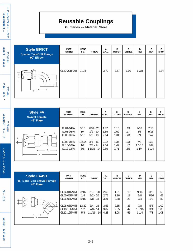
Reusable CouplingsGL Series –– Material: Steel
PART HOSE A B C D E FNUMBER I.D. THREAD O.A.L. CUT-OFF ORIFICE HEX HEX DROP
GL20-20BF90T 1 1/8 3.79 2.67 1.00 1 3/8 2.34
248
GENERAL
INFORMATION
SPECIALTY
HOSE
COUPLINGS
MISC
EQUIPMENT
BRAIDED
HOSE
SPIRAL
HOSE
PART HOSE A B C D E FNUMBER I.D. THREAD O.A.L. CUT-OFF ORIFICE HEX HEX DROP
GL04-04FA45T 3/16 7/16 - 20 2.63 1.91 .13 9/16 3/8 .58GL05-05FA45T 1/4 1/2 - 20 2.75 1.96 .17 5/8 7/16 .67GL06-06FA45T 5/16 5/8 - 18 3.21 2.38 .23 3/4 1/2 .80
GL08-08FA45T 13/32 3/4 - 16 3.53 2.55 .33 7/8 5/8 1.00GL10-10FA45T 1/2 7/8 - 14 3.62 2.55 .42 1 1/16 3/4 1.08GL12-12FA45T 5/8 1 1/16 - 14 4.23 3.08 .55 1 1/4 7/8 1.08
PART HOSE A B C D E FNUMBER I.D. THREAD O.A.L. CUT-OFF ORIFICE HEX HEX DROP
GL04-04FA 3/16 7/16 - 20 1.82 1.10 .13 9/16 7/16GL05-05FA 1/4 1/2 - 20 1.89 1.09 .17 5/8 9/16GL06-06FA 5/16 5/8 - 18 2.14 1.31 .23 3/4 3/4
GL08-08FA 13/32 3/4 - 16 2.32 1.34 .33 7/8 3/4GL10-10FA 1/2 7/8 - 14 2.54 1.47 .42 1 1/16 7/8GL12-12FA 5/8 1 1/16 - 14 2.86 1.71 .55 1 1/4 1 1/4
Style BF90TSpecial Two-Bolt Flange
90˚ Elbow
Style FASwivel Female
45˚ Flare
Style FA45T45˚ Bent Tube Swivel Female
45˚ Flare

PART HOSE A B C D E FNUMBER I.D. THREAD O.A.L. CUT-OFF ORIFICE HEX HEX DROP
GL04-04FA90T 3/16 7/16 - 20 2.27 1.55 .13 3/8 9/16 1.19GL05-05FA90T 1/4 1/2 - 20 2.28 1.49 .17 7/16 5/8 1.19GL06-06FA90T 5/16 5/8 - 18 2.79 1.96 .23 1/2 3/4 1.56
GL08-08FA90T 13/32 3/4 - 16 3.26 2.29 .33 5/8 7/8 1.88GL10-10FA90T 1/2 7/8 - 14 3.86 2.79 .42 3/4 1 1/16 2.38GL12-12FA90T 5/8 1 1/16 - 14 4.12 2.97 .55 7/8 1 1/4 2.56
Reusable CouplingsGL Series — Material: Steel
249
GENERAL
INFORMATION
SPECIALTY
HOSE
COUPLINGS
MISC
EQUIPMENT
BRAIDED
HOSE
SPIRAL
HOSE
PART HOSE A B C D E FNUMBER I.D. THREAD O.A.L. CUT-OFF ORIFICE HEX HEX DROP
GL04-04MF 3/16 7/16 - 24 3.44 2.72 .13 7/16 7/16GL04-05MF 3/16 1/2 - 20 3.44 2.76 .13 1/2 7/16GL05-05MF 1/4 1/2 - 20 3.46 2.76 .17 1/2 7/16
GL06-06MF 5/16 5/8 - 18 3.73 2.90 .23 5/8 1/2GL06-08MF 5/16 3/4 - 18 3.86 3.03 .23 3/4 5/8GL08-08MF 13/32 3/4 - 18 4.00 3.03 .33 3/4 5/8
GL10-10MF 1/2 7/8 - 18 4.10 3.03 .42 7/8 3/4GL12-12MF 5/8 1 1/16 - 16 4.31 3.15 .55 1 1/16 7/8
PART HOSE A B C D E FNUMBER I.D. THREAD O.A.L. CUT-OFF ORIFICE HEX HEX DROP
GL20-20FP 1 1/8 1 5/8 - 14 3.06 1.93 1.00 2 2
Style FA90T90˚ Bent Tube Swivel Female
45˚ Flare
Style FPSwivel Female30˚ Flare PTT
Style MFSwivel Male
Inverted Flare
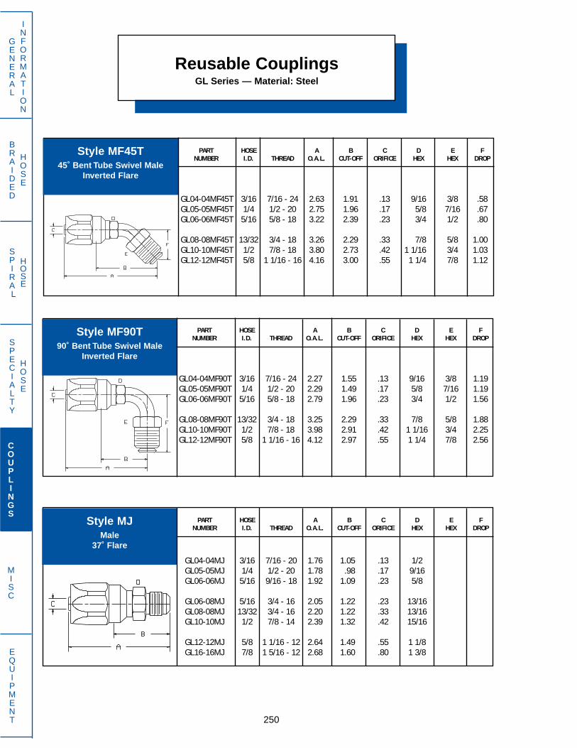
Reusable CouplingsGL Series — Material: Steel
PART HOSE A B C D E FNUMBER I.D. THREAD O.A.L. CUT-OFF ORIFICE HEX HEX DROP
GL04-04MF45T 3/16 7/16 - 24 2.63 1.91 .13 9/16 3/8 .58GL05-05MF45T 1/4 1/2 - 20 2.75 1.96 .17 5/8 7/16 .67GL06-06MF45T 5/16 5/8 - 18 3.22 2.39 .23 3/4 1/2 .80
GL08-08MF45T 13/32 3/4 - 18 3.26 2.29 .33 7/8 5/8 1.00GL10-10MF45T 1/2 7/8 - 18 3.80 2.73 .42 1 1/16 3/4 1.03GL12-12MF45T 5/8 1 1/16 - 16 4.16 3.00 .55 1 1/4 7/8 1.12
250
GENERAL
INFORMATION
SPECIALTY
HOSE
COUPLINGS
MISC
EQUIPMENT
BRAIDED
HOSE
SPIRAL
HOSE
PART HOSE A B C D E FNUMBER I.D. THREAD O.A.L. CUT-OFF ORIFICE HEX HEX DROP
GL04-04MJ 3/16 7/16 - 20 1.76 1.05 .13 1/2GL05-05MJ 1/4 1/2 - 20 1.78 .98 .17 9/16GL06-06MJ 5/16 9/16 - 18 1.92 1.09 .23 5/8
GL06-08MJ 5/16 3/4 - 16 2.05 1.22 .23 13/16GL08-08MJ 13/32 3/4 - 16 2.20 1.22 .33 13/16GL10-10MJ 1/2 7/8 - 14 2.39 1.32 .42 15/16
GL12-12MJ 5/8 1 1/16 - 12 2.64 1.49 .55 1 1/8GL16-16MJ 7/8 1 5/16 - 12 2.68 1.60 .80 1 3/8
PART HOSE A B C D E FNUMBER I.D. THREAD O.A.L. CUT-OFF ORIFICE HEX HEX DROP
GL04-04MF90T 3/16 7/16 - 24 2.27 1.55 .13 9/16 3/8 1.19GL05-05MF90T 1/4 1/2 - 20 2.29 1.49 .17 5/8 7/16 1.19GL06-06MF90T 5/16 5/8 - 18 2.79 1.96 .23 3/4 1/2 1.56
GL08-08MF90T 13/32 3/4 - 18 3.25 2.29 .33 7/8 5/8 1.88GL10-10MF90T 1/2 7/8 - 18 3.98 2.91 .42 1 1/16 3/4 2.25GL12-12MF90T 5/8 1 1/16 - 16 4.12 2.97 .55 1 1/4 7/8 2.56
Style MF45T45˚ Bent Tube Swivel Male
Inverted Flare
Style MF90T90˚ Bent Tube Swivel Male
Inverted Flare
Style MJMale
37˚ Flare

PART HOSE A B C D E FNUMBER I.D. THREAD O.A.L. CUT-OFF ORIFICE HEX HEX DROP
GL04-02MP 3/16 1/8 - 24 1.54 .92 .13 7/16GL04-04MP 3/16 1/4 - 18 1.76 1.11 .13 9/16GL05-04MP 1/4 1/4 - 18 1.78 1.19 .17 9/16
GL06-04MP 5/16 1/4 - 18 1.91 1.23 .23 9/16GL06-06MP 5/16 3/8 - 18 1.94 1.27 .23 11/16GL08-06MP 13/32 3/8 - 18 2.09 1.33 .33 11/16
GL08-08MP 13/32 1/2 - 14 2.34 1.56 .33 7/8GL10-08MP 1/2 1/2 - 14 2.43 1.54 .42 7/8GL10-12MP 1/2 3/4 - 14 2.50 1.44 .42 1 1/16
GL12-12MP 5/8 3/4 - 14 2.58 1.67 .55 1 1/16GL16-12MP 7/8 3/4 - 14 2.47 1.53 .80 1 1/16GL16-16MP 7/8 1 - 11 1/2 2.66 1.72 .80 1 3/8
GL20-20MP 1 1/8 1 1/4 - 11 1/2 2.92 1.80 1.01 1 11/16
Reusable CouplingsGL Series — Material: Steel
251
GENERAL
INFORMATION
SPECIALTY
HOSE
COUPLINGS
MISC
EQUIPMENT
BRAIDED
HOSE
SPIRAL
HOSE
PART HOSE A B C D E FNUMBER I.D. THREAD O.A.L. CUT-OFF ORIFICE HEX HEX DROP
GL04-04MV 3/16 7/16 - 20 1.66 .94 .13 9/16 1/2GL04-06MV 3/16 9/16 - 18 1.70 .98 .13 11/16 5/8GL06-06MV 5/16 9/16 - 18 1.84 1.02 .23 11/16 5/8
GL06-08MV 5/16 3/4 - 16 1.94 1.11 .23 7/8 13/16GL08-08MV 13/32 3/4 - 16 2.10 1.12 .33 7/8 13/16GL10-10MV 1/2 7/8 - 14 2.31 1.24 .42 1 13/16
GL12-12MV 5/8 1 1/16 - 12 2.47 1.32 .55 1 1/4 1 1/8GL16-16MV 7/8 1 5/16 - 12 2.42 1.37 .80 1 1/2 1 3/8
Style MPMale NPTF
Style MVMale Flareless
(With Nut & Sleeve)

Hose Assembly SleevingStyles USY and HMG
PART A NOMINAL WALL USUAL SERVICE ANDNUMBER I.D. (INCHES) THICKNESS (INCHES) TEMPERATURE RANGE
USY-568 .568 .045USY-603 .603 .045USY-668 .668 .045
USY-723 .723 .045USY-768 .768 .045 Application: Used over hose for
protection of cover where highUSY-838 .838 .045 abrasion may exist.
USY-856 .856 .045 Temperature Range: -40˚F to +250˚FUSY-943 .943 .045 Ultraviolet resistantUSY-1094 1.094 .045
Material: PolyurethaneUSY-1168 1.168 .045USY-1223 1.123 .045 Color: Industrial yellowUSY-1328 1.328 .045
Lengths: Available in 10 ft. lengths
USY-1523 1.523 .045USY-1672 1.672 .045USY-2125 2.125 .060
Style USYPolyurethane Sleeving
252
GENERAL
INFORMATION
SPECIALTY
HOSE
COUPLINGS
MISC
EQUIPMENT
BRAIDED
HOSE
SPIRAL
HOSE
PART A NOMINAL WALL USUAL SERVICE ANDNUMBER I.D. (INCHES) THICKNESS (INCHES) TEMPERATURE RANGE
HMG-668 .668 .045HMG-723 .723 .045HMG-858 .858 .045 Application: Used over hose in mining
applications for protection of cover where high abrasion may exist.
HMG-933 .933 .045HMG-1133 1.133 .045HMG-1243 1.243 .045 Temperature range: –40˚F to + 250˚F
Ultravioletresistant
HMG-1303 1.303 .045HMG-1523 1.523 .045 Material: Flame retardant
polyurethaneHMG-1604 1.604 .045
Color: BlackHMG-1975 1.975 .060
Lengths: Available in 10 ft. lengths
Style HMGFlame Retardant
Polyurethane SleevingMSHA Approved
A
A

A B CFLAT INSIDE NOMINAL WALL
PART WIDTH DIAMETER THICKNESSNUMBER (INCHES) (INCHES) (INCHES)
1776-12 1.12 .71 .0451776-16 1.58 1.00 .0451776-20 1.97 1.25 .045
1776-24 2.56 1.59 .0451776-28 2.75 1.75 .0451776-32 3.25 2.07 .045
1776-40 4.00 2.54 .0451776-42 4.25 2.70 .045
NG2 1.50 0.93 .090NG3 1.88 1.13 .090NG4 2.13 1.22 .090
NG6 2.50 1.42 .090NG8 3.00 1.81 .090NG9 3.50 2.19 .090
NG12 3.78 2.38 .090NG14 4.75 2.88 .090NG15 5.13 3.12 .090
NG16 5.50 3.38 .090
Nylogard™
Protective SleevingMSHA Approved
Hose Assembly Sleeving1776 Series Nylogard™
253
GENERAL
INFORMATION
SPECIALTY
HOSE
COUPLINGS
MISC
EQUIPMENT
BRAIDED
HOSE
SPIRAL
HOSE
Applications: Ideal for abrasion protection or bundling small hose assemblies, tubing or wires.
Temperature Range: -60˚F to +250˚F
Material: Nylon
Color: Black
Available Lengths: 300 ft. coils
A B
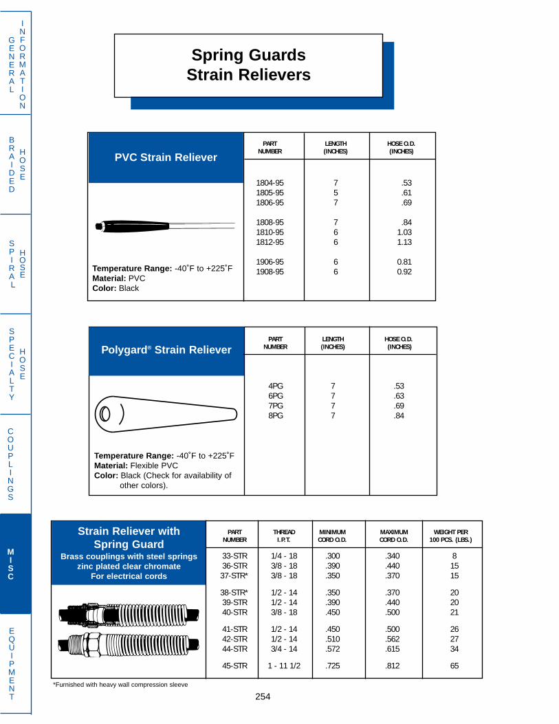
Spring GuardsStrain Relievers
PART LENGTH HOSE O.D.NUMBER (INCHES) (INCHES)
1804-95 7 .531805-95 5 .611806-95 7 .69
1808-95 7 .841810-95 6 1.031812-95 6 1.13
1906-95 6 0.811908-95 6 0.92
PVC Strain Reliever
254
GENERAL
INFORMATION
SPECIALTY
HOSE
COUPLINGS
MISC
EQUIPMENT
BRAIDED
HOSE
SPIRAL
HOSE
PART THREAD MINIMUM MAXIMUM WEIGHT PERNUMBER I.P.T. CORD O.D. CORD O.D. 100 PCS. (LBS.)
33-STR 1/4 - 18 .300 .340 836-STR 3/8 - 18 .390 .440 1537-STR* 3/8 - 18 .350 .370 15
38-STR* 1/2 - 14 .350 .370 2039-STR 1/2 - 14 .390 .440 2040-STR 3/8 - 18 .450 .500 21
41-STR 1/2 - 14 .450 .500 2642-STR 1/2 - 14 .510 .562 2744-STR 3/4 - 14 .572 .615 34
45-STR 1 - 11 1/2 .725 .812 65
Strain Reliever withSpring Guard
Brass couplings with steel springszinc plated clear chromate
For electrical cords
PART LENGTH HOSE O.D.NUMBER (INCHES) (INCHES)
4PG 7 .536PG 7 .637PG 7 .698PG 7 .84
Polygard® Strain Reliever
Temperature Range: -40˚F to +225˚FMaterial: PVCColor: Black
Temperature Range: -40˚F to +225˚FMaterial: Flexible PVCColor: Black (Check for availability of
other colors).
*Furnished with heavy wall compression sleeve
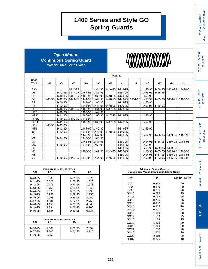
Additional Spring GuardsDayco Open Wound Continuous Spring Guard
P/N I.D. Length Pattern
GO7 0.438 20’GO8 0.500 20’GO9 0.685 20’GO10 0.675 25’GO11 0.738 25’GO12 0.785 25’GO13 0.852 20’GO14 0.915 20’GO15 0.977 25’GO16 1.040 20’GO17 1.109 25’GO18 1.183 25’GO19 1.278 20’GO20 1.340 20’GO24 1.600 20’GO25 1.660 20’GO32 2.110 20’GO37 2.375 10’
1400 Series and Style GOSpring Guards
255
GENERAL
INFORMATION
SPECIALTY
HOSE
COUPLINGS
MISC
EQUIPMENT
BRAIDED
HOSE
SPIRAL
HOSE
Open WoundContinuous Spring Guard
Material: Steel, Zinc Plated
HOSE I.D.
HOSESTYLE -03 -04 -05 -06 -08 -10 -12 -14 -16 -20 -24 -32
BXX 1442-95 1444-95 1446-95 1449-95 1453-95 1456-95 1459-95 1462-95D1 1441-95 1443-95 1444-95 1447-95 1450-95 1453-95 1455-95D6 1440-95 1441-95 1466-95 1465-95 1448-95 1449-95 1453-95D8 1440-95 1442-95 1443-95 1444-95 1446-95 1448-95 1449-95 1451-95 1453-95 1455-95 1458-95 1462-95E9 1440-95 1443-95 1465-95 1448-95 1452-95F2 1442-95 1444-95 1445-95 1448-95 1499-95 1452-95 1456-95H6 1440-95 1441-95 1466-95 1444-95 1447-95 1449-95HFS 1440-95 1466-95 1444-95HFS2 1441-95 1466-95 1465-95 1447-95 1448-95 1452-95HR1C 1440-95 1466-95 1444-95HR2C 1441-95 1466-95 1465-95 1447-95 1448-95 1452-95HRK 1440-95 1442-95HTB 1442-95 1444-95 1446-95 1449-95 1453-95J9 1442-95 1444-95 1446-95 1448-95 1449-95L1 1445-95 1447-95 1450-95 1454-95 1456-95 1459-95 1463-95M2 1444-95 1446-95 1448-95M7 1445-95 1447-95 1450-95 1454-95 1456-95 1459-95 1463-95MX 1440-95 1443-95 1465-95 1448-95 1452-95N2 1450-95 1453-95 1456-95 1460-95N3 1465-95 1447-95 1449-95 1450-95 1453-95 1455-95 1459-95 1463-95N6 1450-95 1454-95 1457-95 1460-95 1464-95Y9 1440-95 1441-95 1443-95 1444-95 1446-95 1448-95 1450-95 1453-95 1455-95 1460-95
AVAILABLE IN 25’ LENGTHSP/N I.D. P/N I.D.
1440-95 0.560 1451-95 1.3751441-95 0.625 1452-95 1.5201442-95 0.671 1453-95 1.5781443-95 0.750 1454-95 1.6421444-95 0.820 1455-95 1.8901445-95 0.953 1459-95 2.1501446-95 0.953 1459-95 2.2501447-95 1.031 1462-95 2.7501448-95 1.150 1465-95 0.8651449-95 1.234 1466-95 0.7001450-95 1.328 1469-95 0.725
AVAILABLE IN 10’ LENGTHSP/N I.D. P/N I.D.
1456-95 2.000 1463-95 2.8591457-95 2.100 1464-95 3.1251460-95 2.359
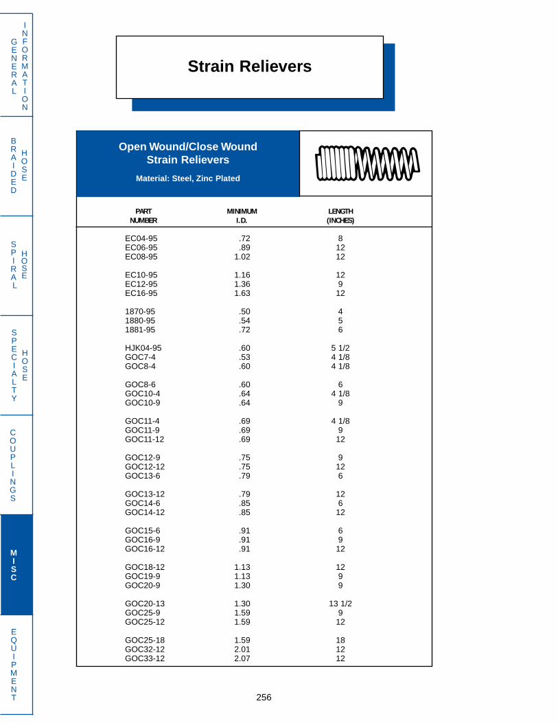
Strain Relievers
256
GENERAL
INFORMATION
SPECIALTY
HOSE
COUPLINGS
MISC
EQUIPMENT
BRAIDED
HOSE
SPIRAL
HOSE
Open Wound/Close WoundStrain Relievers
Material: Steel, Zinc Plated
PART MINIMUM LENGTHNUMBER I.D. (INCHES)
EC04-95 .72 8EC06-95 .89 12EC08-95 1.02 12
EC10-95 1.16 12EC12-95 1.36 9EC16-95 1.63 12
1870-95 .50 41880-95 .54 51881-95 .72 6
HJK04-95 .60 5 1/2GOC7-4 .53 4 1/8GOC8-4 .60 4 1/8
GOC8-6 .60 6GOC10-4 .64 4 1/8GOC10-9 .64 9
GOC11-4 .69 4 1/8GOC11-9 .69 9GOC11-12 .69 12
GOC12-9 .75 9GOC12-12 .75 12GOC13-6 .79 6
GOC13-12 .79 12GOC14-6 .85 6GOC14-12 .85 12
GOC15-6 .91 6GOC16-9 .91 9GOC16-12 .91 12
GOC18-12 1.13 12GOC19-9 1.13 9GOC20-9 1.30 9
GOC20-13 1.30 13 1/2GOC25-9 1.59 9GOC25-12 1.59 12
GOC25-18 1.59 18GOC32-12 2.01 12GOC33-12 2.07 12
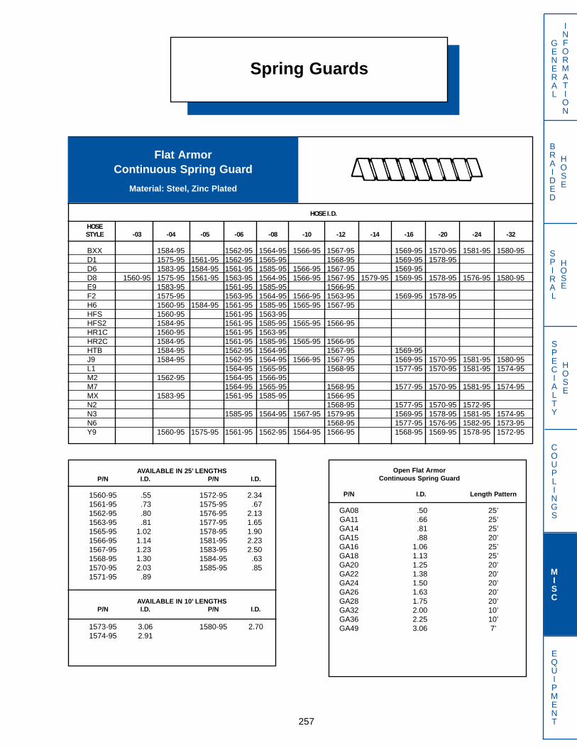
Spring Guards
257
GENERAL
INFORMATION
SPECIALTY
HOSE
COUPLINGS
MISC
EQUIPMENT
BRAIDED
HOSE
SPIRAL
HOSE
HOSE I.D.
HOSESTYLE -03 -04 -05 -06 -08 -10 -12 -14 -16 -20 -24 -32
BXX 1584-95 1562-95 1564-95 1566-95 1567-95 1569-95 1570-95 1581-95 1580-95D1 1575-95 1561-95 1562-95 1565-95 1568-95 1569-95 1578-95D6 1583-95 1584-95 1561-95 1585-95 1566-95 1567-95 1569-95D8 1560-95 1575-95 1561-95 1563-95 1564-95 1566-95 1567-95 1579-95 1569-95 1578-95 1576-95 1580-95E9 1583-95 1561-95 1585-95 1566-95F2 1575-95 1563-95 1564-95 1566-95 1563-95 1569-95 1578-95H6 1560-95 1584-95 1561-95 1585-95 1565-95 1567-95HFS 1560-95 1561-95 1563-95HFS2 1584-95 1561-95 1585-95 1565-95 1566-95HR1C 1560-95 1561-95 1563-95HR2C 1584-95 1561-95 1585-95 1565-95 1566-95HTB 1584-95 1562-95 1564-95 1567-95 1569-95J9 1584-95 1562-95 1564-95 1566-95 1567-95 1569-95 1570-95 1581-95 1580-95L1 1564-95 1565-95 1568-95 1577-95 1570-95 1581-95 1574-95M2 1562-95 1564-95 1566-95M7 1564-95 1565-95 1568-95 1577-95 1570-95 1581-95 1574-95MX 1583-95 1561-95 1585-95 1566-95N2 1568-95 1577-95 1570-95 1572-95N3 1585-95 1564-95 1567-95 1579-95 1569-95 1578-95 1581-95 1574-95N6 1568-95 1577-95 1576-95 1582-95 1573-95Y9 1560-95 1575-95 1561-95 1562-95 1564-95 1566-95 1568-95 1569-95 1578-95 1572-95
AVAILABLE IN 25’ LENGTHSP/N I.D. P/N I.D.
1560-95 .55 1572-95 2.341561-95 .73 1575-95 .671562-95 .80 1576-95 2.131563-95 .81 1577-95 1.651565-95 1.02 1578-95 1.901566-95 1.14 1581-95 2.231567-95 1.23 1583-95 2.501568-95 1.30 1584-95 .631570-95 2.03 1585-95 .851571-95 .89
AVAILABLE IN 10’ LENGTHSP/N I.D. P/N I.D.
1573-95 3.06 1580-95 2.701574-95 2.91
Open Flat ArmorContinuous Spring Guard
P/N I.D. Length Pattern
GA08 .50 25’GA11 .66 25’GA14 .81 25’GA15 .88 20’GA16 1.06 25’GA18 1.13 25’GA20 1.25 20’GA22 1.38 20’GA24 1.50 20’GA26 1.63 20’GA28 1.75 20’GA32 2.00 10’GA36 2.25 10’GA49 3.06 7’
Flat ArmorContinuous Spring Guard
Material: Steel, Zinc Plated

BRAIDED
HOSE
SPIRAL
HOSE
Plastic Protective Coil Sleeving
258
GENERAL
INFORMATION
SPECIALTY
HOSE
COUPLINGS
MISC
EQUIPMENT
Plastic Protective Coil FITSPART HOSE
NUMBER O.D. LENGTH
1704-95 .255 - .3801706-95 .381 - .5101708-95 .511 - .635
Continuous1710-95 .636 - .760 200 ft.1712-95 .761 - .910 lengths1714-95 .944 - 1.45
1722-95 1.46 - 2.50
Constructed of a tough, lightweightthermoplastic which offers excel-lent resistance to abrasion and isunaffected by water, air, gasoline,hydraulic fluids and most chemi-cals. In addition to offering resis-tance to hose kinking and coverabrasion, flat plastic protectivecoils may also be used for low-costbundling of plastic tubing and hoselines.Temperature Range: -40˚F. to
+250˚ F.Material: NylonColor: Black
Blow Out Guard for HRK Hose
Style BOGBlow Out Guard
PART HOSENUMBER I.D.
BOG04 3/16 & 1/4BOG06 3/8
BOG includes:(2) 14” lengths of stainless steel double braided wire(4) Aluminum ferrules(4) 3” lengths of heat shrink plastic tubing(2) “Patent Pending” aluminum tags(1) Application instruction book
BOG is required for all HRK hose assemblies

Flange Head Kits
259
GENERAL
INFORMATION
SPECIALTY
HOSE
COUPLINGS
MISC
EQUIPMENT
BRAIDED
HOSE
SPIRAL
HOSE
There are two types of SAE Split Flanges, code 61 and the code 62.These flanges are non-interchangeable. The code 61 or standard splitflange, is designed for hydraulic systems which operate at maximumpressures of 3,000 to 5,000 PSI, depending upon size. The code 62or high pressure split flange, is designed for hydraulic systems whichoperate at 6,000 PSI maximums regardless of size. The table belowspecifies the maximum recommended working pressures of code 61and code 62 split flanges.
FLANGE MAX. RECOMMENDED W.P. FOR CODE 61 MAX. RECOMMENDED W.P. FOR CODE 62
DASH SIZE PSI MPa PSI MPa
8 5000 34.5 6000 41.412 5000 34.5 6000 41.416 5000 34.5 6000 41.420 4000 27.8 6000 41.424 3000 20.7 6000 41.432 3000 20.7 6000 41.4
Style PASAE J518 Standard Pressure
Code 61 Flange Kits
O-RING FOR FLANGE HEADFLANGE CLAMP (ONE REQUIRED)
HALF HEX HEAD BOLT LOCK WASHER MATERIAL: NITRILE(Two Required) (Four Required) (Four Required) Durometer: Shore Hardness A90
NOMINALFLANGE FLANGE FLANGE PART PART PART PART
KITS SIZE O.D. NUMBER NUMBER SIZE NUMBER SIZE NUMBER I.D. WALL O.D.
08PA 1/2 1 3/16 08PA-75 HHB5 - 20 5/16 - 18 X 1 1/4 LW-5 5/16 08PA-77 0.734 0.139 1.01212PA 3/4 1 1/2 12PA-75 HHB6 - 20 3/8 - 16 X 1 1/4 LW-6 3/8 12PA-77 0.984 0.139 1.26216PA 1 1 3/4 16PA-75 HHB6 - 20 3/8 - 16 X 1 1/4 LW-6 3/8 16PA-77 1.296 0.139 1.574
20PA 1 1/4 2 20PA-75 HHB7 - 24 7/16 - 14 X 1 1/2 LW-7 7/16 20PA-77 1.484 0.139 1.76224PA 1 1/2 2 3/8 24PA-75 HHB8 - 24 1/2 - 13 X 1 1/2 LW-8 1/2 24PA-77 1.859 0.139 2.13732PA 2 2 13/16 32PA-75 HHB8 - 24 1/2 - 13 X 1 1/2 LW-8 1/2 32PA-77 2.234 0.139 2.512
Style PHSAE J518
Code 62 Flange KitsO-RING FOR FLANGE HEAD
FLANGE CLAMP (ONE REQUIRED)HALF HEX HEAD BOLT LOCK WASHER MATERIAL: NITRILE
(Two Required) (Four Required) (Four Required) Durometer: Shore Hardness A90
NOMINALFLANGE FLANGE FLANGE PART PART PART PART
KITS SIZE O.D. NUMBER NUMBER SIZE NUMBER SIZE NUMBER I.D. WALL O.D.
08PH 1/2 1 1/4 08PH-75 HHB5 - 20 5/16 - 18 X 1 1/4 LW-5 5/16 08PA-77 0.734 0.139 1.01212PH 3/4 1 5/8 12PH-75 HHB6 - 24 3/8 - 16 X 1 1/2 LW-6 3/8 12PA-77 0.984 0.139 1.26216PH 1 1 7/8 16PH-75 HHB7 - 28 7/16 - 14 X 1 3/4 LW-7 7/16 16PA-77 1.296 0.138 1.574
20PH 1 1/4 2 1/8 20PH-75 HHB8 - 28 1/2 - 13 X 1 3/4 LW-8 1/2 20PA-77 1.484 0.138 1.76224PH 1 1/2 2 1/2 24PH-77 HHB10 - 36 5/8 - 11 X 2 1/4 LW-10 5/8 24PA-77 1.859 0.139 2.13732PH 2 3 1/8 32PH-75 HHB12 - 44 3/4 - 10 X 2 3/4 LW-12 3/4 32PA-77 2.234 0.139 2.512
NOTE: Grade 8 bolts are recommended on Code 61 and Code 62 flanges. Lock washers are required with all bolts.
NOTE: See page 264 for additional O-Ring information.Bolt Identification
Grade 5
Grade 8 Code 61& 62

TUBETUBE MALE NPTF COIL BURST WALL
PART I.D. THREAD LINEAR I.D. PRESSURE THICKNESSNUMBER (INCHES) SIZE FT. (INCHES) (PSI) (INCHES)
NS04-12 1/4 1/4 12 3 1/2 700 .030NS04-25 1/4 1/4 25 3 1/2 700 .030NS04-50 1/4 1/4 50 3 1/2 700 .030
NS06-12 3/8 3/8 12 6 700 .045NS06-25 3/8 3/8 25 6 700 .045NS06-50 3/8 3/8 50 6 700 .045
Truk-Coil® and Nylo-Seal®
260
GENERAL
INFORMATION
SPECIALTY
HOSE
COUPLINGS
MISC
EQUIPMENT
BRAIDED
HOSE
SPIRAL
HOSE
Truk-Coil® air brake assemblies comply with DOT requirements covering coiled nylon brake tubing as described in FMVSS 106, SAE J844,and Federal Highway Administration Title 49, Chapter III, Subpart C, paragraph 393.45 and are intended for service (blue) and emergency(red) hook-up between heavy duty truck tractors and trailers.
Colors: One red and one blue assembly included with each part number.Material: Nylon 11
TRUK-COIL®
Air Brake Assemblies
Male NPTFMAXIMUM GLAD HAND THREAD SIZEWORKING PIGTAIL NUMBER TUBE
PART LENGTH LENGTH VALVE GLAD HAND OF O.D.NUMBER (FEET) (INCHES) END END COILS (INCHES)
306-AB-06 12 6 3/8 1/2 19 1/2 3/8306-AB-08 12 6 1/2 1/2 19 1/2 1/2
312-AB-06 15 12 3/8 1/2 22 1/2 3/8312-AB-08 15 12 1/2 1/2 22 1/2 1/2
340-AB-06 15 40 3/8 1/2 22 1/2 3/8340-AB-08 15 40 1/2 1/2 22 1/2 1/2
Style NSNylo-Seal®
Self Coiling Assemblies
Style NS-SNylo-Seal®
Self Coiling Assemblies
TUBEASSEMBLY TUBE MALE COIL BURST WALL
PART I.D. THREAD LINEAR I.D. PRESSURE THICKNESSNUMBER (INCHES) SIZE FT. (INCHES) (PSI) (INCHES)
NS04S-12 1/4 1/4 12 3 1/2 700 .030NS04S-25 1/4 1/4 25 3 1/2 700 .030NS04S-50 1/4 1/4 50 3 1/2 700 .030
NS06S-12 3/8 3/8 12 6 700 .045NS06S-25 3/8 3/8 25 6 700 .045NS06S-50 3/8 3/8 50 6 700 .045
NS08S-12 1/2 1/2 12 8 600 .062NS08S-25 1/2 1/2 25 8 600 .062NS08S-50 1/2 1/2 50 8 600 .062
Temperature Range: -40˚F to +150˚FMaterial: NylonColor: Black
ValveEnd
Glad HandEnd
Temperature Range: -40˚ F. to + 150˚ F.Material: NylonColor: Black
Nylo-Seal® style NS assembly lengths supplied with style 168-NS male pipe connector on both ends.
Style NS-S supplied with style 168-NS male pipe connector on one end and 178-NS male pipe swivel connector on the other end.
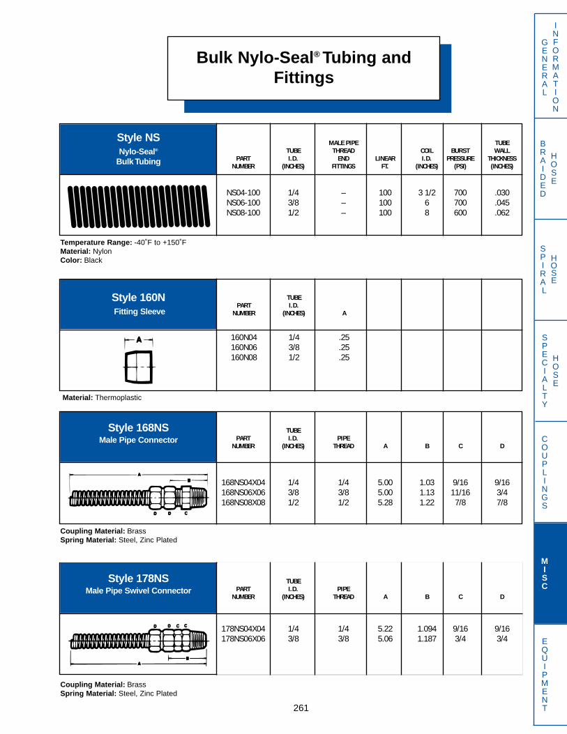
Bulk Nylo-Seal® Tubing andFittings
261
GENERAL
INFORMATION
SPECIALTY
HOSE
COUPLINGS
MISC
EQUIPMENT
BRAIDED
HOSE
SPIRAL
HOSE
Style NSNylo-Seal®
Bulk Tubing
MALE PIPE TUBETUBE THREAD COIL BURST WALL
PART I.D. END LINEAR I.D. PRESSURE THICKNESSNUMBER (INCHES) FITTINGS FT. (INCHES) (PSI) (INCHES)
NS04-100 1/4 – 100 3 1/2 700 .030NS06-100 3/8 – 100 6 700 .045NS08-100 1/2 – 100 8 600 .062
Temperature Range: -40˚F to +150˚FMaterial: NylonColor: Black
Style 160NFitting Sleeve
TUBEPART I.D.
NUMBER (INCHES) A
160N04 1/4 .25160N06 3/8 .25160N08 1/2 .25
Style 168NSMale Pipe Connector
TUBEPART I.D. PIPE
NUMBER (INCHES) THREAD A B C D
168NS04X04 1/4 1/4 5.00 1.03 9/16 9/16168NS06X06 3/8 3/8 5.00 1.13 11/16 3/4168NS08X08 1/2 1/2 5.28 1.22 7/8 7/8
Coupling Material: BrassSpring Material: Steel, Zinc Plated
Style 178NSMale Pipe Swivel Connector
TUBEPART I.D. PIPE
NUMBER (INCHES) THREAD A B C D
178NS04X04 1/4 1/4 5.22 1.094 9/16 9/16178NS06X06 3/8 3/8 5.06 1.187 3/4 3/4
Coupling Material: BrassSpring Material: Steel, Zinc Plated
Material: Thermoplastic

QD Series Quick DisconnectCouplers
262
GENERAL
INFORMATION
SPECIALTY
HOSE
COUPLINGS
MISC
EQUIPMENT
BRAIDED
HOSE
SPIRAL
HOSE
Style QD1Industrial Coupler Full FlowPoppet Type (Not for NH3)
Overall Max. Rec. Body Half Male Tip BreakComplete Thread Size Length W.P. Part Part Away DustCoupler And Type (Inches) (PSI) Number Number Clamp Plug Cap Dust
QD1-4 1/4”NPTF 2.80 5000 QD15-4 QD11-4 N/A N/A N/AQD1-6 3/8”NPTF 3.17 4000 QD15-6 QD11-6 N/A N/A N/AQD1-8 1/2”NPTF 3.63 4000 QD15-8 QD11-8 N/A N/A N/A
QD1-12 3/4”NPTF 4.37 2500 QD15-12 QD11-12 N/A N/A N/AQD1-16 1”NPTF 5.06 2500 QD15-16 QD11-16 N/A N/A N/A
Style QD2One Way Sleeve Coupler
(Full Flow Coupler)
Overall Max. Rec. Body Half Male Tip BreakComplete Thread Size Length W.P. Part Part Away DustCoupler And Type (Inches) (PSI) Number Number Clamp Plug Cap Dust
QD2-12 3/4”-16ORB 3.64 2500 QD25-12 QD21-12 QD42-8 QD44-8 QD49-8QD2F-12 3/4”NPTF 4.56 2200 QD25F-12 QD21F-12 N/A N/A N/A
Style QD3Industrial High Pressure Coupler
(Screw Together Type)
Overall Max. Rec. Body Half Male Tip BreakComplete Thread Size Length W.P. Part Part Away DustCoupler And Type (Inches) (PSI) Number Number Clamp Plug Cap Dust
QD3-4 1/4”NPTF 2.68 10000 QD35-4 QD31-4 N/A N/A N/AQD3-6 3/8”NPTF 3.31 10000 QD35-6 QD31-6 N/A N/A QD39-6
Style QD4Agricultural Coupler
Two Way Sleeve Coupler
Overall Max. Rec. Body Half Male Tip BreakComplete Thread Size Length W.P. Part Part Away DustCoupler And Type (Inches) (PSI) Number Number Clamp Plug Cap Dust
QD4-4 1/4”NPTF 2.50 4000 QD45-4 QD41-4 N/A QD44-4 QD49-4QD4-6 3/8”NPTF 3.30 3000 QD45-6 QD41-6 N/A QD44-6 QD49-6
QD4-8 1/2”NPTF 3.64 3000 QD45-8 QD41-8 QD42-8 QD44-8 QD49-8QD4-12 3/4”NPTF 3.83 2500 QD45-12 QD41-12 QD42-8 QD44-8 QD49-8
Style QD7Full Pressure Coupler
Overall Max. Rec. Body Half Male Tip BreakComplete Thread Size Length W.P. Part Part Away DustCoupler And Type (Inches) (PSI) Number Number Clamp Plug Cap Dust
QD7-8 1/2”NPSF 3.41 3625 QD75-8 N/A QD42-8 QD44-8 N/A

QDM and QDA Series QuickDisconnect Couplers
263
GENERAL
INFORMATION
SPECIALTY
HOSE
COUPLINGS
MISC
EQUIPMENT
BRAIDED
HOSE
SPIRAL
HOSE
Style QDM11John Deere Style
Male Tip
PART THREAD CHECK DESIGNEDNUMBER AND TYPE TYPE FOR
QDM11-8 1/2”NPTF BALLQDM11-12 3/4”-16ORB BALL John Deere Castings
Style QDM12International Harvester Style
Male Tip
PART THREAD CHECK DESIGNEDNUMBER AND TYPE TYPE FOR
InternationalQDM12-8 1/2”NPTF BALL Harvester CastingsQDM12-14 7/8”-14ORB BALL
Style QDM71 PART THREAD CHECK DESIGNEDNUMBER AND TYPE TYPE FOR
QDM71-8P 1/2”NPTF POPPET Ford CastingsQDM71-15 3/4”-16ORB BALL Deere (new styles)
Long Massey Ferguson
AdaptersStyle QDA25
PART MALE TIP COUPLER DESIGNEDNUMBER STYLE BODY STYLE FOR
QDA25-8-1 JOHN DEERE Will accept Standard Adapts the standardSAE and ASAE style QDM71 series male
male tip tip to a John Deerefemale coupler
AdaptersStyle QDA25
PART MALE TIP COUPLER DESIGNEDNUMBER STYLE BODY STYLE FOR
QDA25-8-3 Standard SAE Will accept John Deere Adapts John Deereand ASAE type style male tip male tip to Standard
SAE and ASAEfemale coupler
AdaptersStyle QDA25
PART MALE TIP COUPLER DESIGNEDNUMBER STYLE BODY STYLE FOR
QDA25-8-2 International Will accept Standard Adapts the standardHarvester SAE and ASAE style QDM71 series male
male tip tip to a John Deerefemale coupler
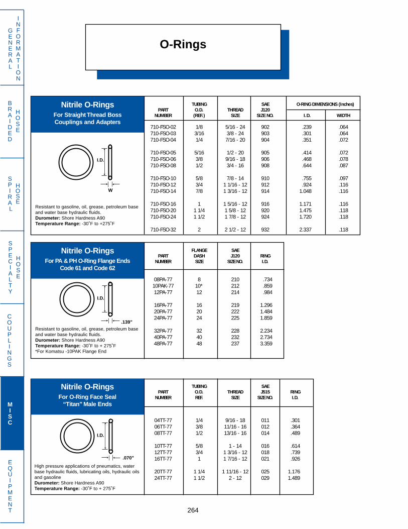
BRAIDED
HOSE
SPIRAL
HOSE
O-Rings
264
GENERAL
INFORMATION
SPECIALTY
HOSE
COUPLINGS
MISC
EQUIPMENT
Nitrile O-RingsFor Straight Thread BossCouplings and Adapters
TUBING SAE O-RING DIMENSIONS (Inches)PART O.D. THREAD J120
NUMBER (REF.) SIZE SIZE NO. I.D. WIDTH
710-FSO-02 1/8 5/16 - 24 902 .239 .064710-FSO-03 3/16 3/8 - 24 903 .301 .064710-FSO-04 1/4 7/16 - 20 904 .351 .072
710-FSO-05 5/16 1/2 - 20 905 .414 .072710-FSO-06 3/8 9/16 - 18 906 .468 .078710-FSO-08 1/2 3/4 - 16 908 .644 .087
710-FSO-10 5/8 7/8 - 14 910 .755 .097710-FSO-12 3/4 1 1/16 - 12 912 .924 .116710-FSO-14 7/8 1 3/16 - 12 914 1.048 .116
710-FSO-16 1 1 5/16 - 12 916 1.171 .116710-FSO-20 1 1/4 1 5/8 - 12 920 1.475 .118710-FSO-24 1 1/2 1 7/8 - 12 924 1.720 .118
710-FSO-32 2 2 1/2 - 12 932 2.337 .118
Resistant to gasoline, oil, grease, petroleum baseand water base hydraulic fluids.Durometer: Shore Hardness A90Temperature Range: -30˚F to +275˚F
Nitrile O-RingsFor PA & PH O-Ring Flange Ends
Code 61 and Code 62
FLANGE SAEPART DASH J120 RING
NUMBER SIZE SIZE NO. I.D.
08PA-77 8 210 .73410PAK-77 10* 212 .85912PA-77 12 214 .984
16PA-77 16 219 1.29620PA-77 20 222 1.48424PA-77 24 225 1.859
32PA-77 32 228 2.23440PA-77 40 232 2.73448PA-77 48 237 3.359
Resistant to gasoline, oil, grease, petroleum baseand water base hydraulic fluids.Durometer: Shore Hardness A90Temperature Range: -30˚F to + 275˚F*For Komatsu -10PAK Flange End
Nitrile O-RingsFor O-Ring Face Seal
“Titan” Male Ends
TUBING SAEPART O.D. THREAD J515 RING
NUMBER REF. SIZE SIZE NO. I.D.
04TT-77 1/4 9/16 - 18 011 .30106TT-77 3/8 11/16 - 16 012 .36408TT-77 1/2 13/16 - 16 014 .489
10TT-77 5/8 1 - 14 016 .61412TT-77 3/4 1 3/16 - 12 018 .73916TT-77 1 1 7/16 - 12 021 .926
20TT-77 1 1/4 1 11/16 - 12 025 1.17624TT-77 1 1/2 2 - 12 029 1.489
High pressure applications of pneumatics, waterbase hydraulic fluids, lubricating oils, hydraulic oilsand gasolineDurometer: Shore Hardness A90Temperature Range: -30˚F to + 275˚F
W
.139"
I.D.
I.D.
I.D.
.070"

Field Support EquipmentWarning Statement
265
GENERAL
INFORMATION
SPECIALTY
HOSE
COUPLINGS
MISC
EQUIPMENT
BRAIDED
HOSE
SPIRAL
HOSE
Dayco Eastman products are part of an engineered system which must be assembled and used inaccordance with Dayco Eastman instructions and limitations.
Dayco Eastman hose, couplings and crimping machines are designed as an effective and reliableassembly system and the use of other than Dayco Eastman products may produce hose assemblies thatwill not meet rated performance. Failure to follow Dayco Eastman instructions and limitations could leadto premature hose failures resulting in property damage, serious injury or death.
Dayco Eastman’s limited warranty shall apply only if the customer uses hose, fittings, hose fitting com-ponents and crimp equipment specifically engineered, designed and produced to Dayco Eastmanprocess specifications.
DAYCO EASTMAN DISCLAIMS ANY RESPONSIBILITY OR LIABILITY FOR ANY CRIMPED HOSEASSEMBLIES NOT PRODUCED FROM GENUINE DAYCO EASTMAN HOSE FITTINGS, HOSE ANDEQUIPMENT, IN CONFORMANCE WITH DAYCO EASTMAN PROCESS SPECIFICATIONS FOR EACHSPECIFIC HOSE ASSEMBLY.
DO NOT USE A DAYCO EASTMAN CRIMPING MACHINE WITHOUT DIES!
m WARNING
How the Kwikrimp® System works
The Kwikrimp® system is like having a miniature hose assembly “factory” at your disposal. In just minutes, theKwikrimp® hose coupling system produces the exact hose and coupling combination needed, in an assemblythat meets original equipment manufacturer specifications.
Utilizing the proven principle of much larger factory equipment, eight segmented crimping dies apply tons offorce on the coupling, making an attachment that is stronger than the hose itself. The segmented dies areforced against the coupling shell by a tapered die actuator, powered by heavy duty hydraulic rams. Self cen-tering feature assures equal force distribution through all the dies, producing a uniform crimp pressure on thefull shell circumference.
Unique, easily adjusted settings provide the operator with accurate control of the crimping operation.Approximate settings are preset for the type of hose and coupling used, providing approximate crimp diame-ters. (verification of proper crimp diameter with calipers or other measuring device is required).
NOTE: Hose and coupling compatabilites noted in this catalog are for reference purposes only. DaycoEastman Crimping Specifications is the official guide for selecting appropriate hose and coupling combinationsand determining crimper compatibility.

PARTNUMBER DIE PUSHER
SU03-02MP SU303 SUM001SU03-02SP N/A N/ASU03-02SP90 N/A N/ASU03-040FA SU303 SUF011SU03-04FF N/A N/ASU03-04FJ SU303 SUF011SU03-04FJ45T SU303 SUT001SU03-04FJ90T N/A N/ASU03-04FN N/A N/ASU03-04MF N/A N/ASU03-04MF90T N/A N/ASU03-04MJ SU303 SUM001SU03-04MP SU303 SUM004SU03-04RA SU303 SUM001SU03-04SP SU303 SUM003SU03-05FA SU303 SUF001SU03-05FJ SU303 SUF001SU03-06MP SU303 SUM005SU04-02MP SU304 SUM002SU04-04FA SU304 SUF012SU04-04FF SU304 SUF002SU04-04FJ SU304 SUF012SU04-04FJ45T SU304 SUT001SU04-04FJ90T SU304 SUT001SU04-04FJ90TL SU304 SUT001SU04-04FN N/A N/ASU04-04MF90T N/A N/ASU04-04MJ SU304 SUM002SU04-04MP SU304 SUM004SU04-04OF45T SU304 SUT001SU04-04OF90T SU304 SUT001SU04-04OF90TL SU304 SUT001SU04-04OFT SU304 SUT003SU04-04RA SU304 SUM002SU04-04RC N/A N/ASU04-04RM N/A N/ASU04-04SP SU304 SUM003SU04-04SP90 N/A N/ASU04-05FA SU304 SUF013SU04-05FJ SU304 SUF013SU04-05FJ45T SU304 SUT002SU04-05FJ90T SU304 SUT002SU04-05FJ90TL SU304 SUT002SU04-05MJ SU304 SUM002SU04-05MV SU304 SUM002SU04-05RA SU304 SUM002SU04-06FA SU304 SUF003SU04-06FJ SU304 SUF013SU04-06MJ SU304 SUM004SU04-06MP SU304 SUM005SU04-06RA SU304 SUM002SU05-04MP SU305 SUM004SU05-04SP SU305 SUM003SU05-05FA SU305 SUF013SU05-05FJ SU305 SUF013SU05-05MJ SU305 SUM002SU05-05RA N/A N/ASU05-05RM N/A N/ASU05-06FA SU305 SUF003SU05-06FJ SU305 SUF013SU05-06FJ45T SU305 SUT003SU05-06FJ90T SU305 SUT003SU05-06FJ90TL SU305 SUT003SU05-06MA SU305 SUM005SU05-06MJ SU305 SUM004SU05-06MP SU305 SUM005
PARTNUMBER DIE PUSHER
SU05-06OF90T SU305 SUT002SU05-06OF90TL SU305 SUT003SU05-06OFT SU305 SUT004SU05-06RC N/A N/ASU06-04MP SU306 SUM004SU06-05FJ N/A N/ASU06-06FA SU306 SUF014SU06-06FF SU306 SUF004SU06-06FJ SU306 SUF013SU06-06FJ45T SU306 SUT003SU06-06FJ90T SU306 SUT003SU06-06FJ90TL SU306 SUT003SU06-06FN N/A N/ASU06-06MA SU306 SUM005SU06-06MF45T N/A N/ASU06-06MF90T N/A N/ASU06-06MJ SU306 SUM005SU06-06MP SU306 SUM005SU06-06MV SU306 SUM004SU06-06OF N/A N/ASU06-06OF45T SU306 SUT003SU06-06OF90T SU306 SUT003SU06-06OF90TL SU306 SUT003SU06-06OFT SU306 SUT004SU06-06RA SU306 SUM004SU06-06RC SU306 SUM020SU06-06RM N/A N/ASU06-06SP SU306 SUM006SU06-08FA SU306 SUF014SU06-08FJ SU306 SUF005SU06-08FJ45T SU306 SUT004SU06-08FJ90T SU306 SUT004SU06-08FJ90TL SU306 SUT004SU06-08MJ SU306 SUM007SU06-08MP SU306 SUM008SU06-08RA SU306 SUM008SU06-08SP SU306 SUM010SU08-06FJ SU308 SUF005SU08-06MP SU308 SUM008SU08-08FA SU308 SUF016SU08-08FF SU308 SUF007SU08-08FJ SU308 SUF016SU08-08FJ45T SU308 SUT004SU08-08FJ90T SU308 SUT004SU08-08FJ90TL SU308 SUT004SU08-08FN N/A N/ASU08-08MA N/A N/ASU08-08MJ SU308 SUM008SU08-08MP SU308 SUM009SU08-08MV SU308 SUM008SU08-08OF45T SU308 SUT004SU08-08OF90T SU308 SUT004SU08-08OF90TL SU308 SUT004SU08-08OFT SU308 SUT005SU08-08RA SU308 SUM008SU08-08RM N/A N/ASU08-08SP SU308 SUM010SU08-10FA SU308 SUF006SU08-10FJ SU308 SUF006SU08-10FJ45T SU308 SUT005SU08-10FJ90T SU308 SUT005SU08-10FJ90TL SU308 SUT005SU08-10MJ SU308 SUM009SU08-10RA SU308 SUM008SU08-12FJ SU308 SUF008SU08-12MP N/A N/A
Swager
266
GENERAL
INFORMATION
SPECIALTY
HOSE
COUPLINGS
MISC
EQUIPMENT
BRAIDED
HOSE
SPIRAL
HOSE
S-16 PORTA-SWAGE™
Lightweight and easy to carry, the S-16 Porta-Swage™ can swage SU series only couplings onNR7, NR7E, S7 &, S7E, S8 and S8E style hoses.Dies and pushers listed below are sold separately.
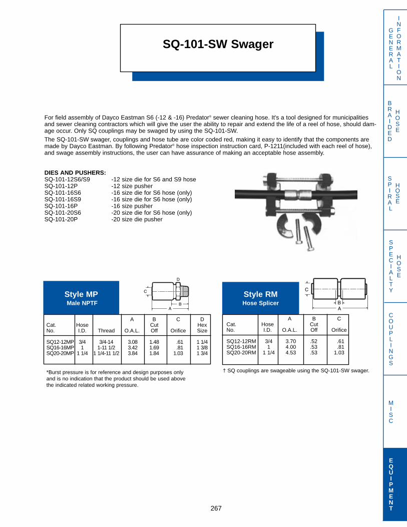
SQ-101-SW Swager
267
GENERAL
INFORMATION
SPECIALTY
HOSE
COUPLINGS
MISC
EQUIPMENT
BRAIDED
HOSE
SPIRAL
HOSE
*Burst pressure is for reference and design purposes onlyand is no indication that the product should be used abovethe indicated related working pressure.
For field assembly of Dayco Eastman S6 (-12 & -16) Predator® sewer cleaning hose. It's a tool designed for municipalitiesand sewer cleaning contractors which will give the user the ability to repair and extend the life of a reel of hose, should dam-age occur. Only SQ couplings may be swaged by using the SQ-101-SW.The SQ-101-SW swager, couplings and hose tube are color coded red, making it easy to identify that the components aremade by Dayco Eastman. By following Predator® hose inspection instruction card, P-1211(included with each reel of hose),and swage assembly instructions, the user can have assurance of making an acceptable hose assembly.
DIES AND PUSHERS:SQ-101-12S6/S9 -12 size die for S6 and S9 hoseSQ-101-12P -12 size pusherSQ-101-16S6 -16 size die for S6 hose (only)SQ-101-16S9 -16 size die for S6 hose (only)SQ-101-16P -16 size pusherSQ-101-20S6 -20 size die for S6 hose (only)SQ-101-20P -20 size die pusher
A B C DCat. Hose Cut HexNo. I.D. Thread O.A.L. Off Orifice Size
SQ12-12MP 3/4 3/4-14 3.08 1.48 .61 1 1/4SQ16-16MP 1 1-11 1/2 3.42 1.69 .81 1 3/8SQ20-20MP 1 1/4 1 1/4-11 1/2 3.84 1.84 1.03 1 3/4
Style MPMale NPTF
A B CCat. Hose CutNo. I.D. O.A.L. Off Orifice
SQ12-12RM 3/4 3.70 .52 .61SQ16-16RM 1 4.00 .53 .81SQ20-20RM 1 1/4 4.53 .53 1.03
Style RMHose Splicer
† SQ couplings are swageable using the SQ-101-SW swager.
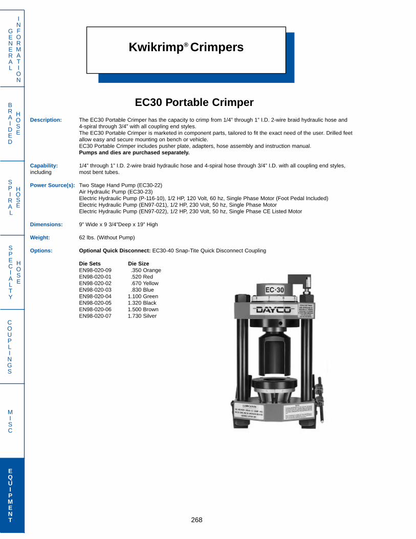
Kwikrimp® Crimpers
268
GENERAL
INFORMATION
SPECIALTY
HOSE
COUPLINGS
MISC
EQUIPMENT
BRAIDED
HOSE
SPIRAL
HOSE
EC30 Portable CrimperDescription: The EC30 Portable Crimper has the capacity to crimp from 1/4” through 1” I.D. 2-wire braid hydraulic hose and
4-spiral through 3/4” with all coupling end styles.The EC30 Portable Crimper is marketed in component parts, tailored to fit the exact need of the user. Drilled feet allow easy and secure mounting on bench or vehicle.EC30 Portable Crimper includes pusher plate, adapters, hose assembly and instruction manual.Pumps and dies are purchased separately.
Capability: 1/4” through 1” I.D. 2-wire braid hydraulic hose and 4-spiral hose through 3/4” I.D. with all coupling end styles,including most bent tubes.
Power Source(s): Two Stage Hand Pump (EC30-22)Air Hydraulic Pump (EC30-23)Electric Hydraulic Pump (P-116-10), 1/2 HP, 120 Volt, 60 hz, Single Phase Motor (Foot Pedal Included)Electric Hydraulic Pump (EN97-021), 1/2 HP, 230 Volt, 50 hz, Single Phase MotorElectric Hydraulic Pump (EN97-022), 1/2 HP, 230 Volt, 50 hz, Single Phase CE Listed Motor
Dimensions: 9” Wide x 9 3/4”Deep x 19” High
Weight: 62 lbs. (Without Pump)
Options: Optional Quick Disconnect: EC30-40 Snap-Tite Quick Disconnect Coupling
Die Sets Die SizeEN98-020-09 .350 OrangeEN98-020-01 .520 RedEN98-020-02 .670 YellowEN98-020-03 .830 BlueEN98-020-04 1.100 GreenEN98-020-05 1.320 BlackEN98-020-06 1.500 BrownEN98-020-07 1.730 Silver
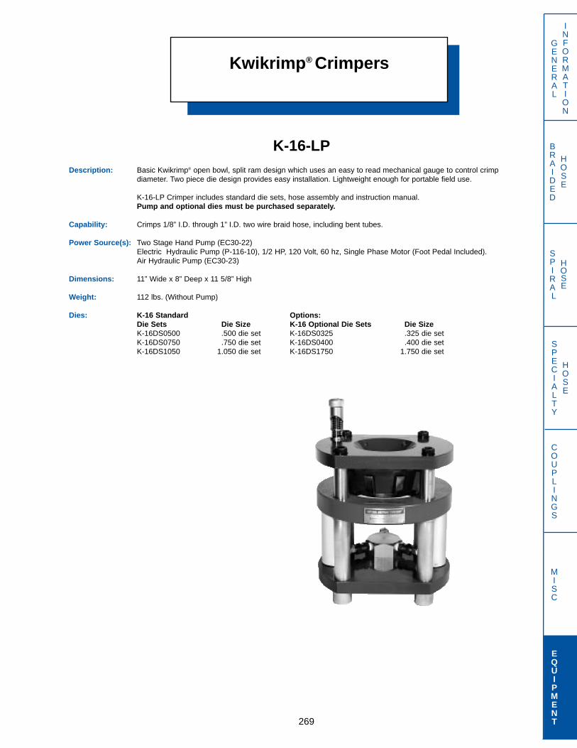
Kwikrimp® Crimpers
269
GENERAL
INFORMATION
SPECIALTY
HOSE
COUPLINGS
MISC
EQUIPMENT
BRAIDED
HOSE
SPIRAL
HOSE
K-16-LPDescription: Basic Kwikrimp® open bowl, split ram design which uses an easy to read mechanical gauge to control crimp
diameter. Two piece die design provides easy installation. Lightweight enough for portable field use.
K-16-LP Crimper includes standard die sets, hose assembly and instruction manual.Pump and optional dies must be purchased separately.
Capability: Crimps 1/8” I.D. through 1” I.D. two wire braid hose, including bent tubes.
Power Source(s): Two Stage Hand Pump (EC30-22)Electric Hydraulic Pump (P-116-10), 1/2 HP, 120 Volt, 60 hz, Single Phase Motor (Foot Pedal Included).Air Hydraulic Pump (EC30-23)
Dimensions: 11” Wide x 8” Deep x 11 5/8” High
Weight: 112 lbs. (Without Pump)
Dies: K-16 Standard Options:Die Sets Die Size K-16 Optional Die Sets Die SizeK-16DS0500 .500 die set K-16DS0325 .325 die setK-16DS0750 .750 die set K-16DS0400 .400 die setK-16DS1050 1.050 die set K-16DS1750 1.750 die set

Kwikrimp® Crimpers
270
GENERAL
INFORMATION
SPECIALTY
HOSE
COUPLINGS
MISC
EQUIPMENT
BRAIDED
HOSE
SPIRAL
HOSE
K-501-LPDescription: Open bowl, split ram design Kwikrimp® machine that is ideal as a portable or on-site machine for shop applications
that require a versatile crimper.K-501-LP Crimper includes standard die sets, hose assembly and instruction manual.Pump and optional dies must be purchased separately.
Capability: Crimps 1/8” I.D. through 1 1/4” I.D. SAE 100R9 hose, including most bent tube couplings.
Power Source(s): Two Stage Hand Pump (EC30-22)Electric Hydraulic Pump (P-126-10),1/2 HP, 120 Volt, 60 hz, Single Phase Motor (Foot Pedal Included).Air Hydraulic Pump (EC30-23)
Dimensions: 11” wide x 8” deep x 17” high
Weight: 180 lbs. (without pump)
Dies: K-501 Options:Standard Die Sets Die Size K-501 Optional Die Sets Die Size
K-401DS0500 .500 die set K-501DS0325 .325 die setK-401DS0750 .750 die set K-501DS0400 .400 die setK-401DS1050 1.050 die setK-401DS1550 1.550 die setK-401DS1750 1.750 die set
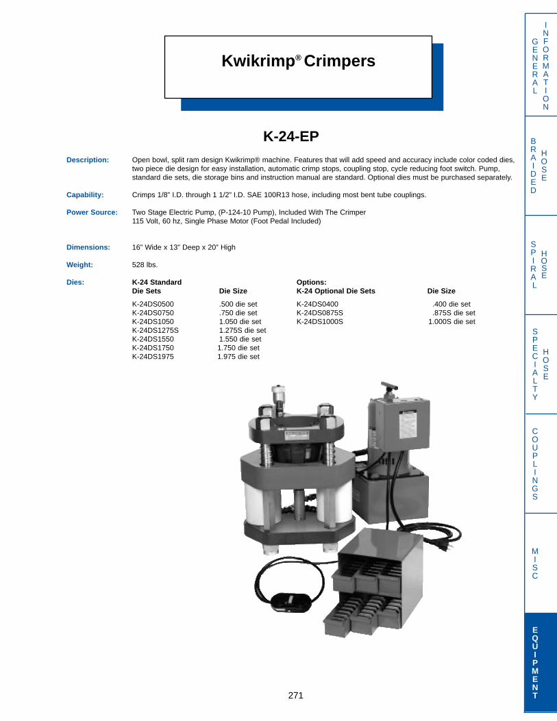
Kwikrimp® Crimpers
271
GENERAL
INFORMATION
SPECIALTY
HOSE
COUPLINGS
MISC
EQUIPMENT
BRAIDED
HOSE
SPIRAL
HOSE
K-24-EPDescription: Open bowl, split ram design Kwikrimp® machine. Features that will add speed and accuracy include color coded dies,
two piece die design for easy installation, automatic crimp stops, coupling stop, cycle reducing foot switch. Pump, standard die sets, die storage bins and instruction manual are standard. Optional dies must be purchased separately.
Capability: Crimps 1/8” I.D. through 1 1/2” I.D. SAE 100R13 hose, including most bent tube couplings.
Power Source: Two Stage Electric Pump, (P-124-10 Pump), Included With The Crimper115 Volt, 60 hz, Single Phase Motor (Foot Pedal Included)
Dimensions: 16” Wide x 13” Deep x 20” High
Weight: 528 lbs.
Dies: K-24 Standard Options:Die Sets Die Size K-24 Optional Die Sets Die Size
K-24DS0500 .500 die set K-24DS0400 .400 die setK-24DS0750 .750 die set K-24DS0875S .875S die setK-24DS1050 1.050 die set K-24DS1000S 1.000S die setK-24DS1275S 1.275S die setK-24DS1550 1.550 die setK-24DS1750 1.750 die setK-24DS1975 1.975 die set

Kwikrimp® Crimpers
272
GENERAL
INFORMATION
SPECIALTY
HOSE
COUPLINGS
MISC
EQUIPMENT
BRAIDED
HOSE
SPIRAL
HOSE
K-601-LPDescription: Open bowl, split ram design Kwikrimp® machine that will handle high pressure hose applications with versatility
and dependability.K-601-LP Crimper includes standard die sets, hose assembly, die storage bins and instruction manual.Pump and optional dies must be purchased separately.
Capability: Crimps 1/8” I.D. through 2” I.D. SAE 100R12 4-Spiral Hose, Including Most Bent Tube Couplings.
Power Source: Two Stage Electric Pump (P-125-10), 115 Volt, 60hz, Single Phase Motor (Foot Pedal Included).
Dimensions: 18 1/2” Wide x 12 1/2” Deep x 22 1/2” High
Weight: 527 lbs. (Without Pump)
Dies: K-601 Options: Die SetsStandard Die Sets Die Size K-601 Optional Die Size
K-601DS0500 .500 die set K-601DS0325 .325 die setK-601DS0750 .750 die set K-601DS0400 .400 die setK-601DS1050 1.050 die set K-601DS0875S .875S die setK-601DS1275 1.275 die set K-601DS1000S 1.000S die setK-601DS1550 1.550 die setK-601DS1750 1.750 die setK-601DS1975 1.975 die setK-601DS2500 2.500 die set
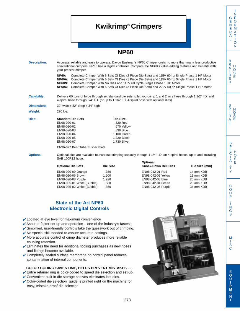
Kwikrimp® Crimpers
273
GENERAL
INFORMATION
SPECIALTY
HOSE
COUPLINGS
MISC
EQUIPMENT
BRAIDED
HOSE
SPIRAL
HOSE
NP60Description: Accurate, reliable and easy to operate, Dayco Eastman’s NP60 Crimper costs no more than many less productive
conventional crimpers. NP60 has a digital controller. Compare the NP60’s value-adding features and benefits with your present crimper.
NP60: Complete Crimper With 6 Sets Of Dies (2 Piece Die Sets) and 115V 60 hz Single Phase 1 HP MotorNP60A: Complete Crimper With 6 Sets Of Dies (1 Piece Die Sets) and 115V 60 hz Single Phase 1 HP MotorNP60N: Complete Crimper With No Dies and 115V 60 Cycle Single Phase 1 HP MotorNP60G: Complete Crimper With 6 Sets Of Dies (2 Piece Die Sets) and 220V 50 hz Single Phase 1 HP Motor
Capability: Delivers 60 tons of force through six standard die sets to let you crimp 1 and 2 wire hose through 1 1/2” I.D. and4-spiral hose through 3/4” I.D. (or up to 1 1/4” I.D. 4-spiral hose with optional dies)
Dimensions: 32” wide x 32” deep x 34” high
Weight: 270 lbs.
Dies: Standard Die Sets Die SizeEN98-020-01 .520 RedEN98-020-02 .670 YellowEN98-020-03 .830 BlueEN98-020-04 1.100 GreenEN98-020-05 1.320 BlackEN98-020-07 1.730 Silver
EN96-027 Bent Tube Pusher Plate
Options: Optional dies are available to increase crimping capacity through 1 1/4” I.D. on 4-spiral hoses, up to and including SAE 100R12 hose.
OptionalOptional Die Sets Die Size Knock-Down Bell Dies Die Size (mm)
EN98-020-09 Orange .350 EN98-042-01 Red 14 mm KDBEN98-020-06 Brown 1.500 EN98-042-02 Yellow 18 mm KDBEN98-020-08 Purple 1.920 EN98-042-03 Blue 20 mm KDBEN98-035-01 White (Bubble) .580 EN98-042-04 Green 28 mm KDBEN98-035-02 White (Bubble) .850 EN98-042-05 Purple 34 mm KDB
State of the Art NP60Electronic Digital Controls
✔ Located at eye level for maximum convenience✔ Assured faster set-up and operation – one of the industry’s fastest✔ Simplified, user-friendly controls take the guesswork out of crimping.✔ No special skill needed to assure accurate settings.✔ More accurate control of crimp diameter produces more reliable
coupling retention.✔ Eliminates the need for additional tooling purchases as new hoses
and fittings become available.✔ Completely sealed surface membrane on control panel reduces
contamination of internal components.
COLOR CODING SAVES TIME, HELPS PREVENT MISTAKES . . .✔ Entire retainer ring is color-coded to speed die selection and set-up.✔ Convenient built-in die storage shelves eliminates lost dies.✔ Color-coded die selection guide is printed right on the machine for
easy, mistake-proof die selection.
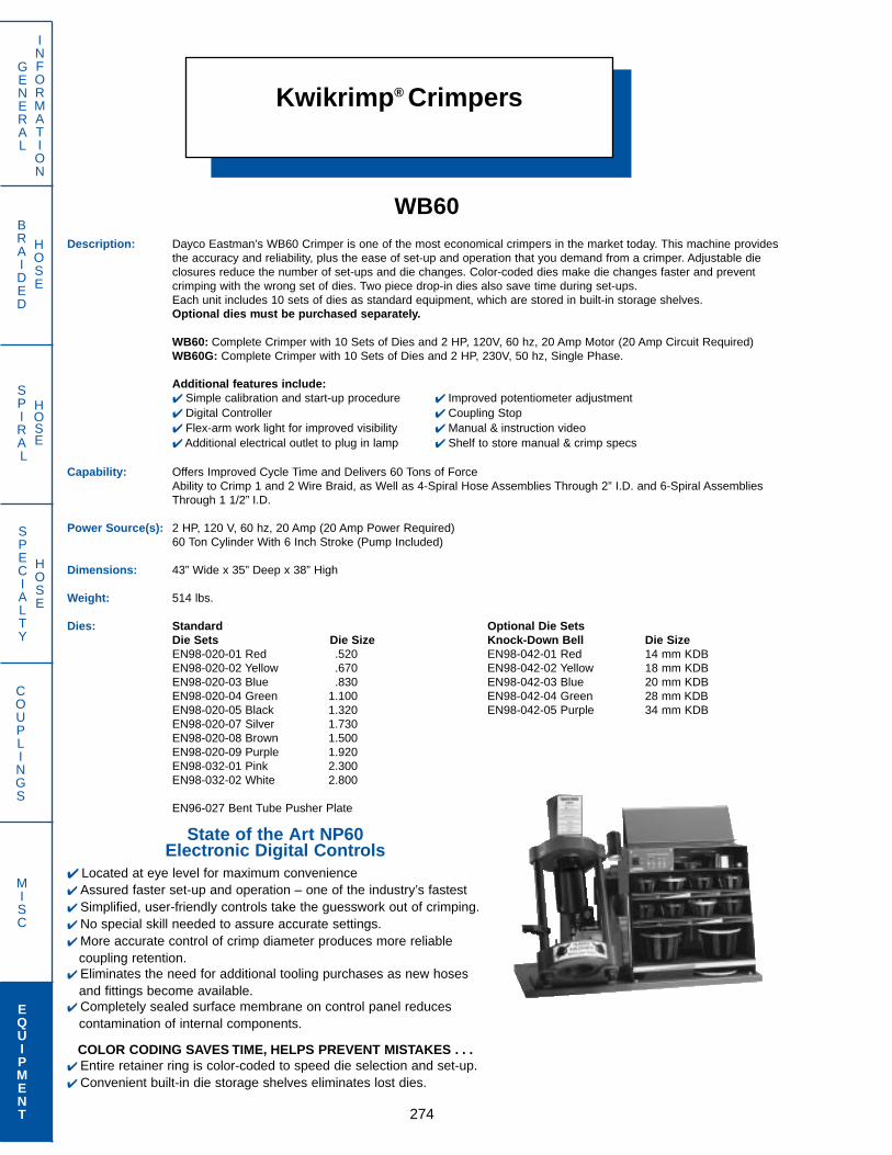
Kwikrimp® Crimpers
274
GENERAL
INFORMATION
SPECIALTY
HOSE
COUPLINGS
MISC
EQUIPMENT
BRAIDED
HOSE
SPIRAL
HOSE
WB60Description: Dayco Eastman’s WB60 Crimper is one of the most economical crimpers in the market today. This machine provides
the accuracy and reliability, plus the ease of set-up and operation that you demand from a crimper. Adjustable dieclosures reduce the number of set-ups and die changes. Color-coded dies make die changes faster and prevent crimping with the wrong set of dies. Two piece drop-in dies also save time during set-ups.Each unit includes 10 sets of dies as standard equipment, which are stored in built-in storage shelves.Optional dies must be purchased separately.
WB60: Complete Crimper with 10 Sets of Dies and 2 HP, 120V, 60 hz, 20 Amp Motor (20 Amp Circuit Required)WB60G: Complete Crimper with 10 Sets of Dies and 2 HP, 230V, 50 hz, Single Phase.
Additional features include:✔ Simple calibration and start-up procedure ✔ Improved potentiometer adjustment✔ Digital Controller ✔ Coupling Stop✔ Flex-arm work light for improved visibility ✔ Manual & instruction video✔ Additional electrical outlet to plug in lamp ✔ Shelf to store manual & crimp specs
Capability: Offers Improved Cycle Time and Delivers 60 Tons of ForceAbility to Crimp 1 and 2 Wire Braid, as Well as 4-Spiral Hose Assemblies Through 2” I.D. and 6-Spiral AssembliesThrough 1 1/2” I.D.
Power Source(s): 2 HP, 120 V, 60 hz, 20 Amp (20 Amp Power Required)60 Ton Cylinder With 6 Inch Stroke (Pump Included)
Dimensions: 43” Wide x 35” Deep x 38” High
Weight: 514 lbs.
Dies: Standard Optional Die SetsDie Sets Die Size Knock-Down Bell Die SizeEN98-020-01 Red .520 EN98-042-01 Red 14 mm KDBEN98-020-02 Yellow .670 EN98-042-02 Yellow 18 mm KDBEN98-020-03 Blue .830 EN98-042-03 Blue 20 mm KDBEN98-020-04 Green 1.100 EN98-042-04 Green 28 mm KDBEN98-020-05 Black 1.320 EN98-042-05 Purple 34 mm KDBEN98-020-07 Silver 1.730EN98-020-08 Brown 1.500EN98-020-09 Purple 1.920EN98-032-01 Pink 2.300EN98-032-02 White 2.800
EN96-027 Bent Tube Pusher Plate
State of the Art NP60Electronic Digital Controls
✔ Located at eye level for maximum convenience✔ Assured faster set-up and operation – one of the industry’s fastest✔ Simplified, user-friendly controls take the guesswork out of crimping.✔ No special skill needed to assure accurate settings.✔ More accurate control of crimp diameter produces more reliable
coupling retention.✔ Eliminates the need for additional tooling purchases as new hoses
and fittings become available.✔ Completely sealed surface membrane on control panel reduces
contamination of internal components.
COLOR CODING SAVES TIME, HELPS PREVENT MISTAKES . . .✔ Entire retainer ring is color-coded to speed die selection and set-up.✔ Convenient built-in die storage shelves eliminates lost dies.

Kwikrimp® Crimpers
275
GENERAL
INFORMATION
SPECIALTY
HOSE
COUPLINGS
MISC
EQUIPMENT
BRAIDED
HOSE
SPIRAL
HOSE
KK125ADescription: New generation KK series Kwikrimp® machine that utilizes microprocessor control for the fastest, most accurate
crimping system available. Easy to use and maintain.Includes manual die change tool, Kwikchange™ die tool, foot pedal, die holder panel, stand and operator’s manual. A total of seven standard die sets are included.
Capability: Crimps 1/8” through 1 1/4” SAE 100R12 hose.
Power Source(s): 230/460 V, 3 Phase11/5.5 Amp (Please specify voltage when ordering crimper).
Dimensions: 26” Wide x 20” Deep x 24” High
Weight: 450 lbs.
Dies: KK125 Standard Die Sets Die SizeKK125DS12-84 1284KK125DS19-84 1984KK125DS24-84 2484KK125DS30-84 3084KK125DS32-84 3284KK125DS39-84 3984KK125DS47-84 4784
Options:Special die sets, automatic back stop switch. Pin Support System (KK125PSS); consult Dayco Eastman for price and availability.

Kwikrimp® Crimpers
276
GENERAL
INFORMATION
SPECIALTY
HOSE
COUPLINGS
MISC
EQUIPMENT
BRAIDED
HOSE
SPIRAL
HOSE
KK250Description: New generation KK series Kwikrimp® machine that utilizes microprocessor control for the fastest, most accurate
crimping system available. Easy to use and maintain.Includes manual die change tool, Kwikchange™ die tool, foot pedal, stand and operator’s manual. A total of 12 standard die sets are included.
Capability: Crimps 1/8” through 2” 6-spiral hose (special dies may be required)
Dimensions: 27” wide x 22” deep x 28” high
Weight: 500 lbs.
PowerSource(s): 230/460 V, 3 Phase
11/5.5 Amp
Dies: KK Standard Die Sets Die SizeKK200DS12-99 1299KK200DS19-99 1999KK200DS24-99 2499KK200DS30-99 3099KK200DS32-99 3299KK200DS39-99 3999KK200DS47-99 4799KK200DS50-99 5099KK200DS53-99 5399KK200DS55-99 5599KK200DS59-99 5999KK200DS66-99 6699
Options: Special Die Sets, Automatic Back Stop Switch. Consult Dayco Eastman for price and availability.
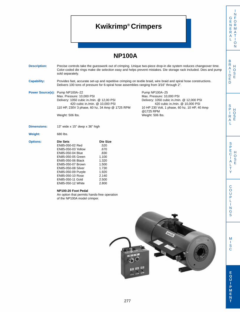
Kwikrimp® Crimpers
277
GENERAL
INFORMATION
SPECIALTY
HOSE
COUPLINGS
MISC
EQUIPMENT
BRAIDED
HOSE
SPIRAL
HOSE
NP100ADescription: Precise controls take the guesswork out of crimping. Unique two-piece drop-in die system reduces changeover time.
Color-coded die rings make die selection easy and helps prevent mistakes. Die storage rack included. Dies and pumpsold separately.
Capability: Provides fast, accurate set-up and repetitive crimping on textile braid, wire braid and spiral hose constructions. Delivers 100 tons of pressure for 6-spiral hose assemblies ranging from 3/16” through 2”.
Power Source(s): Pump NP100A–22 Pump NP100A–25Max. Pressure: 10,000 PSI Max. Pressure: 10,000 PSIDelivery: 1050 cubic in./min. @ 12,00 PSI Delivery: 1050 cubic in./min. @ 12,000 PSI
420 cubic in./min. @ 10,000 PSI 420 cubic in./min. @ 10,000 PSI110 HP, 230V 3 phase, 60 hz, 34 Amp @ 1725 RPM 10 HP 230 Volt, 1 phase, 60 hz, 10 HP, 40 Amp
@1725 RPMWeight: 506 lbs. Weight: 506 lbs.
Dimensions: 13” wide x 15” deep x 36” high
Weight: 680 lbs.
Options: Die Sets Die SizeEN85-050-02 Red .520EN85-050-03 Yellow .670EN85-050-04 Blue .830EN85-050-05 Green 1.100EN85-050-06 Black 1.320EN85-050-07 Brown 1.500EN85-050-08 Silver 1.730EN85-050-09 Purple 1.920EN85-050-10 Rose 2.140EN85-050-11 Gold 2.500EN85-050-12 White 2.800
NP100-20 Foot PedalAn option that permits hands-free operationof the NP100A model crimper.

Support EquipmentPumps
278
GENERAL
INFORMATION
SPECIALTY
HOSE
COUPLINGS
MISC
EQUIPMENT
BRAIDED
HOSE
SPIRAL
HOSE
EC30-22Two Stage Hand Pump
Lightweight and completely portable pump for use with EC30, K-16or K-501 crimpers.
System: 10,000 PSI factory set relief valve
Size: 23” long x 6” wide x 9” high
Weight: 11 lbs.
P-116-10Electro-Hydraulic Pump
Electric driven hydraulic pump for use with EC30 or K-16 crimpers,includes foot pedal.System: 10,000 PSI factory set relief valve
1/2 HP, 115V, 60 cycle, single phase
Size: 9” long x 13” wide x 18” high
Weight: 49 lbs.
EC30-23Air Pump
Air driven hydraulic pump for use with EC30, K-16 or K-501 crimpers,80 to 120 psi required.System: 10,000 PSI factory set relief valve
Size: 22” long x 6 1/2” wide x 5 3/4” high
Weight: 18 lbs.

Support EquipmentPumps
279
GENERAL
INFORMATION
SPECIALTY
HOSE
COUPLINGS
MISC
EQUIPMENT
BRAIDED
HOSE
SPIRAL
HOSE
P-125-10Two Stage Electric Pump
Electric driven hydraulic pump for use with K-601 crimper, includes footpedal.
System: 7,500 PSI factory set relief valveTwo-way hydraulic control valve1 HP, 115V, 60 hz, single phase
Weight: 91 lbs.
P-126-10Two Stage Electric Pump
Electric driven hydraulic pump for use with K-501 crimper, includes footpedal
System: 10,000 PSI factory set relief valveTwo-way hydraulic control valve1 HP, 115V, 60 hz, single phase
Weight: 91 lbs.
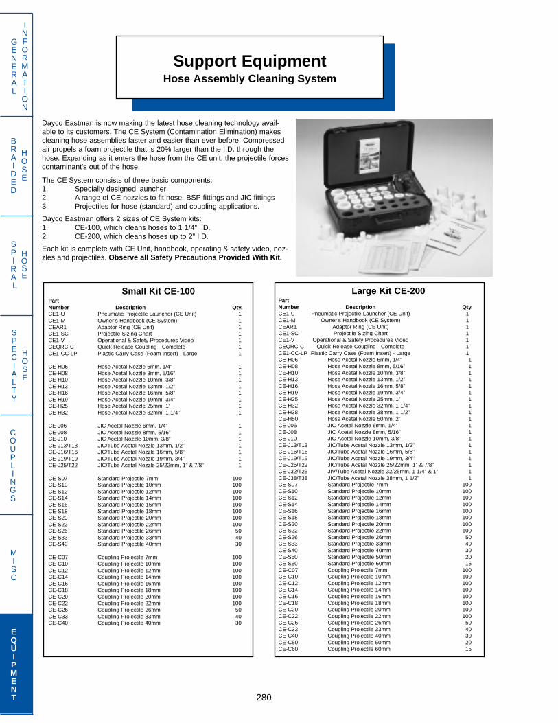
Support EquipmentHose Assembly Cleaning System
280
GENERAL
INFORMATION
SPECIALTY
HOSE
COUPLINGS
MISC
EQUIPMENT
BRAIDED
HOSE
SPIRAL
HOSE
Dayco Eastman is now making the latest hose cleaning technology avail-able to its customers. The CE System (Contamination Elimination) makescleaning hose assemblies faster and easier than ever before. Compressedair propels a foam projectile that is 20% larger than the I.D. through thehose. Expanding as it enters the hose from the CE unit, the projectile forcescontaminant's out of the hose.
The CE System consists of three basic components:1. Specially designed launcher2. A range of CE nozzles to fit hose, BSP fittings and JIC fittings3. Projectiles for hose (standard) and coupling applications.
Dayco Eastman offers 2 sizes of CE System kits:1. CE-100, which cleans hoses to 1 1/4” I.D.2. CE-200, which cleans hoses up to 2” I.D.
Each kit is complete with CE Unit, handbook, operating & safety video, noz-zles and projectiles. Observe all Safety Precautions Provided With Kit.
Small Kit CE-100PartNumber Description Qty.CE1-U Pneumatic Projectile Launcher (CE Unit) 1CE1-M Owner’s Handbook (CE System) 1CEAR1 Adaptor Ring (CE Unit) 1CE1-SC Projectile Sizing Chart 1CE1-V Operational & Safety Procedures Video 1CEQRC-C Quick Release Coupling - Complete 1CE1-CC-LP Plastic Carry Case (Foam Insert) - Large 1
CE-H06 Hose Acetal Nozzle 6mm, 1/4” 1CE-H08 Hose Acetal Nozzle 8mm, 5/16” 1CE-H10 Hose Acetal Nozzle 10mm, 3/8” 1CE-H13 Hose Acetal Nozzle 13mm, 1/2” 1CE-H16 Hose Acetal Nozzle 16mm, 5/8” 1CE-H19 Hose Acetal Nozzle 19mm, 3/4” 1CE-H25 Hose Acetal Nozzle 25mm, 1” 1CE-H32 Hose Acetal Nozzle 32mm, 1 1/4” 1
CE-J06 JIC Acetal Nozzle 6mm, 1/4” 1CE-J08 JIC Acetal Nozzle 8mm, 5/16” 1CE-J10 JIC Acetal Nozzle 10mm, 3/8” 1CE-J13/T13 JIC/Tube Acetal Nozzle 13mm, 1/2” 1CE-J16/T16 JIC/Tube Acetal Nozzle 16mm, 5/8” 1CE-J19/T19 JIC/Tube Acetal Nozzle 19mm, 3/4” 1CE-J25/T22 JIC/Tube Acetal Nozzle 25/22mm, 1” & 7/8” 1
CE-S07 Standard Projectile 7mm 100CE-S10 Standard Projectile 10mm 100CE-S12 Standard Projectile 12mm 100CE-S14 Standard Projectile 14mm 100CE-S16 Standard Projectile 16mm 100CE-S18 Standard Projectile 18mm 100CE-S20 Standard Projectile 20mm 100CE-S22 Standard Projectile 22mm 100CE-S26 Standard Projectile 26mm 50CE-S33 Standard Projectile 33mm 40CE-S40 Standard Projectile 40mm 30
CE-C07 Coupling Projectile 7mm 100CE-C10 Coupling Projectile 10mm 100CE-C12 Coupling Projectile 12mm 100CE-C14 Coupling Projectile 14mm 100CE-C16 Coupling Projectile 16mm 100CE-C18 Coupling Projectile 18mm 100CE-C20 Coupling Projectile 20mm 100CE-C22 Coupling Projectile 22mm 100CE-C26 Coupling Projectile 26mm 50CE-C33 Coupling Projectile 33mm 40CE-C40 Coupling Projectile 40mm 30
Large Kit CE-200PartNumber Description Qty.CE1-U Pneumatic Projectile Launcher (CE Unit) 1CE1-M Owner’s Handbook (CE System) 1CEAR1 Adaptor Ring (CE Unit) 1CE1-SC Projectile Sizing Chart 1CE1-V Operational & Safety Procedures Video 1CEQRC-C Quick Release Coupling - Complete 1CE1-CC-LP Plastic Carry Case (Foam Insert) - Large 1CE-H06 Hose Acetal Nozzle 6mm, 1/4” 1CE-H08 Hose Acetal Nozzle 8mm, 5/16” 1CE-H10 Hose Acetal Nozzle 10mm, 3/8” 1CE-H13 Hose Acetal Nozzle 13mm, 1/2” 1CE-H16 Hose Acetal Nozzle 16mm, 5/8” 1CE-H19 Hose Acetal Nozzle 19mm, 3/4” 1CE-H25 Hose Acetal Nozzle 25mm, 1” 1CE-H32 Hose Acetal Nozzle 32mm, 1 1/4” 1CE-H38 Hose Acetal Nozzle 38mm, 1 1/2” 1CE-H50 Hose Acetal Nozzle 50mm, 2” 1CE-J06 JIC Acetal Nozzle 6mm, 1/4” 1CE-J08 JIC Acetal Nozzle 8mm, 5/16” 1CE-J10 JIC Acetal Nozzle 10mm, 3/8” 1CE-J13/T13 JIC/Tube Acetal Nozzle 13mm, 1/2” 1CE-J16/T16 JIC/Tube Acetal Nozzle 16mm, 5/8” 1CE-J19/T19 JIC/Tube Acetal Nozzle 19mm, 3/4” 1CE-J25/T22 JIC/Tube Acetal Nozzle 25/22mm, 1” & 7/8” 1CE-J32/T25 JIV/Tube Acetal Nozzle 32/25mm, 1 1/4” & 1” 1CE-J38/T38 JIC/Tube Acetal Nozzle 38mm, 1 1/2” 1CE-S07 Standard Projectile 7mm 100CE-S10 Standard Projectile 10mm 100CE-S12 Standard Projectile 12mm 100CE-S14 Standard Projectile 14mm 100CE-S16 Standard Projectile 16mm 100CE-S18 Standard Projectile 18mm 100CE-S20 Standard Projectile 20mm 100CE-S22 Standard Projectile 22mm 100CE-S26 Standard Projectile 26mm 50CE-S33 Standard Projectile 33mm 40CE-S40 Standard Projectile 40mm 30CE-S50 Standard Projectile 50mm 20CE-S60 Standard Projectile 60mm 15CE-C07 Coupling Projectile 7mm 100CE-C10 Coupling Projectile 10mm 100CE-C12 Coupling Projectile 12mm 100CE-C14 Coupling Projectile 14mm 100CE-C16 Coupling Projectile 16mm 100CE-C18 Coupling Projectile 18mm 100CE-C20 Coupling Projectile 20mm 100CE-C22 Coupling Projectile 22mm 100CE-C26 Coupling Projectile 26mm 50CE-C33 Coupling Projectile 33mm 40CE-C40 Coupling Projectile 40mm 30CE-C50 Coupling Projectile 50mm 20CE-C60 Coupling Projectile 60mm 15
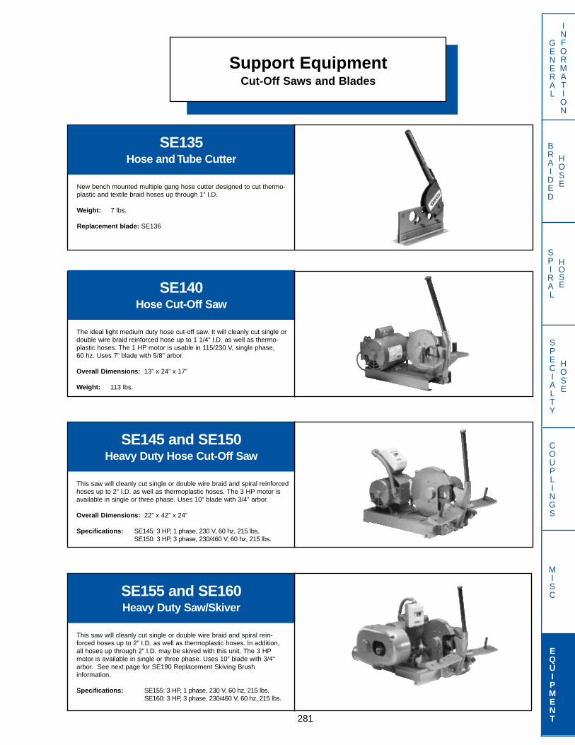
Support EquipmentCut-Off Saws and Blades
281
GENERAL
INFORMATION
SPECIALTY
HOSE
COUPLINGS
MISC
EQUIPMENT
BRAIDED
HOSE
SPIRAL
HOSE
SE135Hose and Tube Cutter
New bench mounted multiple gang hose cutter designed to cut thermo-plastic and textile braid hoses up through 1” I.D.
Weight: 7 lbs.
Replacement blade: SE136
SE140Hose Cut-Off Saw
The ideal light medium duty hose cut-off saw. It will cleanly cut single ordouble wire braid reinforced hose up to 1 1/4” I.D. as well as thermo-plastic hoses. The 1 HP motor is usable in 115/230 V, single phase, 60 hz. Uses 7” blade with 5/8" arbor.
Overall Dimensions: 13” x 24” x 17”
Weight: 113 lbs.
SE155 and SE160Heavy Duty Saw/Skiver
This saw will cleanly cut single or double wire braid and spiral rein-forced hoses up to 2” I.D. as well as thermoplastic hoses. In addition,all hoses up through 2” I.D. may be skived with this unit. The 3 HPmotor is available in single or three phase. Uses 10” blade with 3/4"arbor. See next page for SE190 Replacement Skiving Brush information.
Specifications: SE155: 3 HP, 1 phase, 230 V, 60 hz, 215 lbs.SE160: 3 HP, 3 phase, 230/460 V, 60 hz, 215 lbs.
SE145 and SE150Heavy Duty Hose Cut-Off Saw
This saw will cleanly cut single or double wire braid and spiral reinforcedhoses up to 2” I.D. as well as thermoplastic hoses. The 3 HP motor isavailable in single or three phase. Uses 10” blade with 3/4" arbor.
Overall Dimensions: 22” x 42” x 24”
Specifications: SE145: 3 HP, 1 phase, 230 V, 60 hz, 215 lbs.SE150: 3 HP, 3 phase, 230/460 V, 60 hz, 215 lbs.
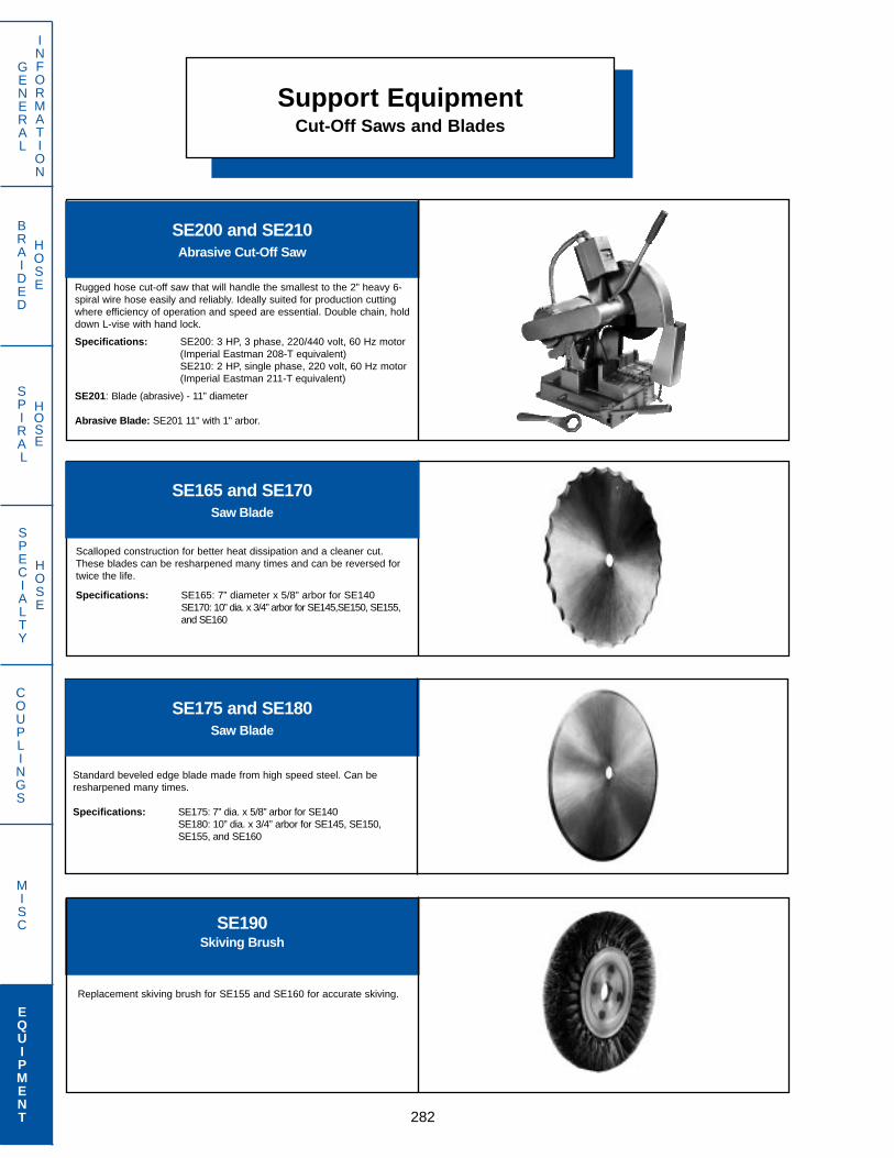
Support EquipmentCut-Off Saws and Blades
282
GENERAL
INFORMATION
SPECIALTY
HOSE
COUPLINGS
MISC
EQUIPMENT
BRAIDED
HOSE
SPIRAL
HOSE
SE200 and SE210Abrasive Cut-Off Saw
Rugged hose cut-off saw that will handle the smallest to the 2” heavy 6-spiral wire hose easily and reliably. Ideally suited for production cuttingwhere efficiency of operation and speed are essential. Double chain, holddown L-vise with hand lock.
Specifications: SE200: 3 HP, 3 phase, 220/440 volt, 60 Hz motor(Imperial Eastman 208-T equivalent)SE210: 2 HP, single phase, 220 volt, 60 Hz motor(Imperial Eastman 211-T equivalent)
SE201: Blade (abrasive) - 11” diameter
Abrasive Blade: SE201 11" with 1" arbor.
SE165 and SE170Saw Blade
Scalloped construction for better heat dissipation and a cleaner cut.These blades can be resharpened many times and can be reversed fortwice the life.
Specifications: SE165: 7” diameter x 5/8” arbor for SE140SE170: 10” dia. x 3/4” arbor for SE145,SE150, SE155,and SE160
SE190Skiving Brush
Replacement skiving brush for SE155 and SE160 for accurate skiving.
SE175 and SE180Saw Blade
Standard beveled edge blade made from high speed steel. Can beresharpened many times.
Specifications: SE175: 7” dia. x 5/8” arbor for SE140SE180: 10” dia. x 3/4” arbor for SE145, SE150, SE155, and SE160

Support Equipment
283
GENERAL
INFORMATION
SPECIALTY
HOSE
COUPLINGS
MISC
EQUIPMENT
BRAIDED
HOSE
SPIRAL
HOSE
KK CaliperCaliper for Measuring
Finished Crimp Dimensions
Specifically designed to measure finished coupling crimp diameters onDayco Eastman hose assemblies. Notched caliper jaws allow measure-ment of crimped coupling “flats”. Easy to use and provides accuratereadings within 0.001 of an inch. Instructions included.
Part Number: KKCALIPER
SE195Spiral Wire Skiving Tool
Easy to use, accurate skiving tool designed especially for spiral wirehose. Can be used on hose through 2” I.D.
Replacement Blade: SE195-1
SSK2Internal Skiving Tool
Internal skiving tool for NH32 hose.
Replacement Blade: EN93-050
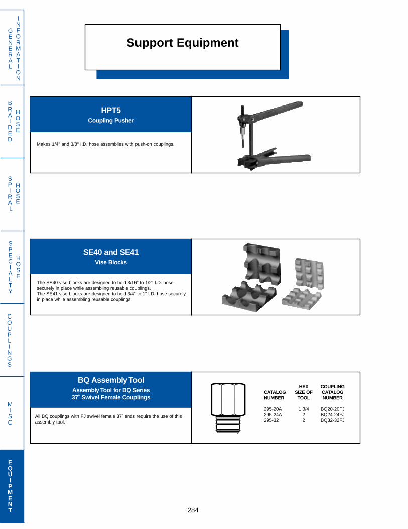
BRAIDED
HOSE
SPIRAL
HOSE
Support Equipment
284
GENERAL
INFORMATION
SPECIALTY
HOSE
COUPLINGS
MISC
EQUIPMENT
BQ Assembly ToolAssembly Tool for BQ Series37˚ Swivel Female Couplings
All BQ couplings with FJ swivel female 37˚ ends require the use of thisassembly tool.
SE40 and SE41Vise Blocks
The SE40 vise blocks are designed to hold 3/16” to 1/2” I.D. hosesecurely in place while assembling reusable couplings.The SE41 vise blocks are designed to hold 3/4” to 1” I.D. hose securelyin place while assembling reusable couplings.
HPT5Coupling Pusher
Makes 1/4" and 3/8" I.D. hose assemblies with push-on couplings.
HEX COUPLINGCATALOG SIZE OF CATALOGNUMBER TOOL NUMBER
295-20A 1 3/4 BQ20-20FJ295-24A 2 BQ24-24FJ295-32 2 BQ32-32FJ
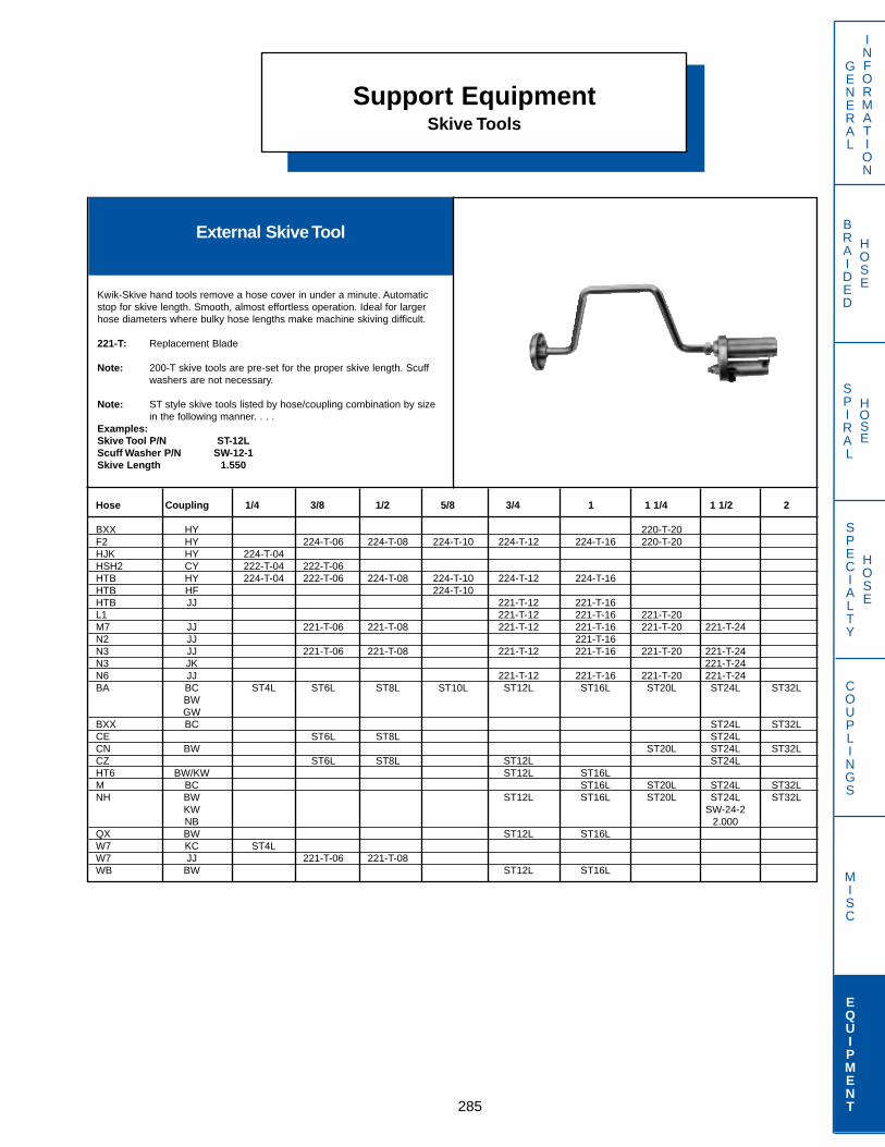
Support EquipmentSkive Tools
285
GENERAL
INFORMATION
SPECIALTY
HOSE
COUPLINGS
MISC
EQUIPMENT
BRAIDED
HOSE
SPIRAL
HOSE
External Skive Tool
Kwik-Skive hand tools remove a hose cover in under a minute. Automaticstop for skive length. Smooth, almost effortless operation. Ideal for largerhose diameters where bulky hose lengths make machine skiving difficult.
221-T: Replacement Blade
Note: 200-T skive tools are pre-set for the proper skive length. Scuff washers are not necessary.
Note: ST style skive tools listed by hose/coupling combination by size in the following manner. . . .
Examples:Skive Tool P/N ST-12LScuff Washer P/N SW-12-1Skive Length 1.550
Hose Coupling 1/4 3/8 1/2 5/8 3/4 1 1 1/4 1 1/2 2
BXX HY 220-T-20F2 HY 224-T-06 224-T-08 224-T-10 224-T-12 224-T-16 220-T-20HJK HY 224-T-04HSH2 CY 222-T-04 222-T-06HTB HY 224-T-04 222-T-06 224-T-08 224-T-10 224-T-12 224-T-16HTB HF 224-T-10HTB JJ 221-T-12 221-T-16L1 221-T-12 221-T-16 221-T-20M7 JJ 221-T-06 221-T-08 221-T-12 221-T-16 221-T-20 221-T-24N2 JJ 221-T-16N3 JJ 221-T-06 221-T-08 221-T-12 221-T-16 221-T-20 221-T-24N3 JK 221-T-24N6 JJ 221-T-12 221-T-16 221-T-20 221-T-24BA BC ST4L ST6L ST8L ST10L ST12L ST16L ST20L ST24L ST32L
BWGW
BXX BC ST24L ST32LCE ST6L ST8L ST24LCN BW ST20L ST24L ST32LCZ ST6L ST8L ST12L ST24LHT6 BW/KW ST12L ST16LM BC ST16L ST20L ST24L ST32LNH BW ST12L ST16L ST20L ST24L ST32L
KW SW-24-2NB 2.000
QX BW ST12L ST16LW7 KC ST4LW7 JJ 221-T-06 221-T-08WB BW ST12L ST16L
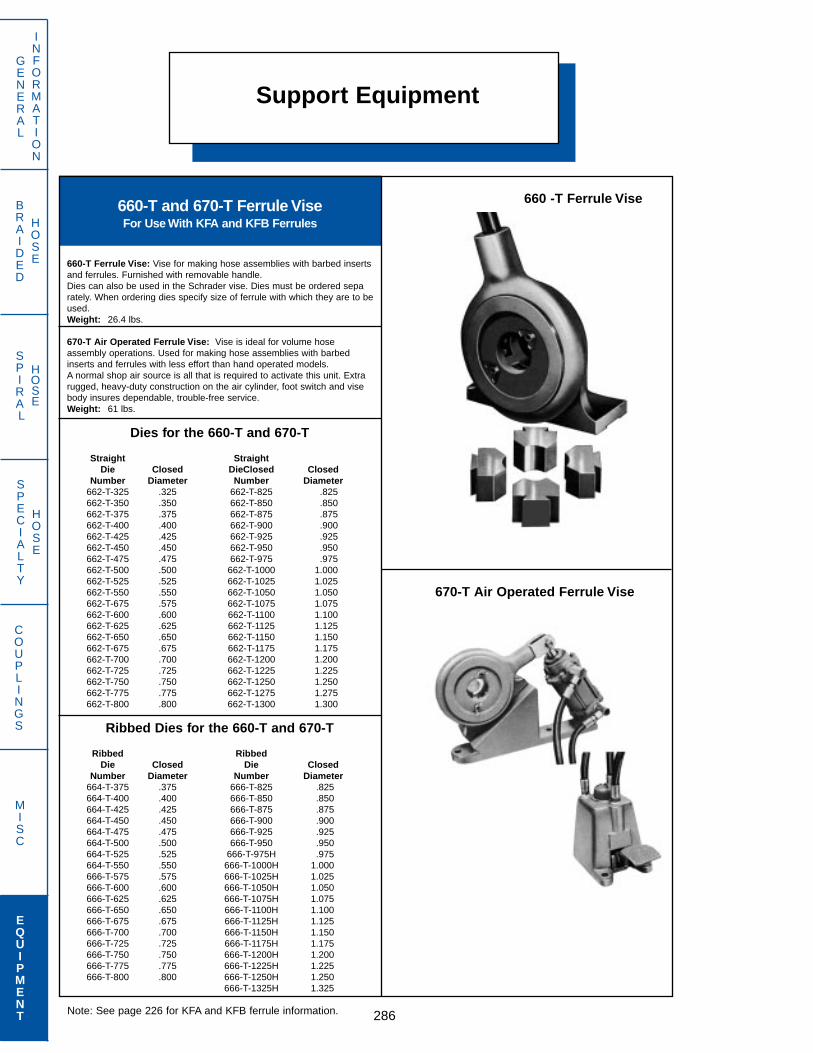
Support Equipment
286
GENERAL
INFORMATION
SPECIALTY
HOSE
COUPLINGS
MISC
EQUIPMENT
BRAIDED
HOSE
SPIRAL
HOSE
660-T and 670-T Ferrule ViseFor Use With KFA and KFB Ferrules
660-T Ferrule Vise: Vise for making hose assemblies with barbed inserts and ferrules. Furnished with removable handle. Dies can also be used in the Schrader vise. Dies must be ordered separately. When ordering dies specify size of ferrule with which they are to be used.Weight: 26.4 lbs.
670-T Air Operated Ferrule Vise: Vise is ideal for volume hose assembly operations. Used for making hose assemblies with barbed inserts and ferrules with less effort than hand operated models.A normal shop air source is all that is required to activate this unit. Extra rugged, heavy-duty construction on the air cylinder, foot switch and vise body insures dependable, trouble-free service.Weight: 61 lbs.
Dies for the 660-T and 670-T
Straight StraightDie Closed DieClosed Closed
Number Diameter Number Diameter662-T-325 .325 662-T-825 .825662-T-350 .350 662-T-850 .850662-T-375 .375 662-T-875 .875662-T-400 .400 662-T-900 .900662-T-425 .425 662-T-925 .925662-T-450 .450 662-T-950 .950662-T-475 .475 662-T-975 .975662-T-500 .500 662-T-1000 1.000662-T-525 .525 662-T-1025 1.025662-T-550 .550 662-T-1050 1.050662-T-675 .575 662-T-1075 1.075662-T-600 .600 662-T-1100 1.100662-T-625 .625 662-T-1125 1.125662-T-650 .650 662-T-1150 1.150662-T-675 .675 662-T-1175 1.175662-T-700 .700 662-T-1200 1.200662-T-725 .725 662-T-1225 1.225662-T-750 .750 662-T-1250 1.250662-T-775 .775 662-T-1275 1.275662-T-800 .800 662-T-1300 1.300
Ribbed Dies for the 660-T and 670-T
Ribbed RibbedDie Closed Die Closed
Number Diameter Number Diameter664-T-375 .375 666-T-825 .825664-T-400 .400 666-T-850 .850664-T-425 .425 666-T-875 .875664-T-450 .450 666-T-900 .900664-T-475 .475 666-T-925 .925664-T-500 .500 666-T-950 .950664-T-525 .525 666-T-975H .975664-T-550 .550 666-T-1000H 1.000666-T-575 .575 666-T-1025H 1.025666-T-600 .600 666-T-1050H 1.050666-T-625 .625 666-T-1075H 1.075666-T-650 .650 666-T-1100H 1.100666-T-675 .675 666-T-1125H 1.125666-T-700 .700 666-T-1150H 1.150666-T-725 .725 666-T-1175H 1.175666-T-750 .750 666-T-1200H 1.200666-T-775 .775 666-T-1225H 1.225666-T-800 .800 666-T-1250H 1.250
666-T-1325H 1.325
660 -T Ferrule Vise
670-T Air Operated Ferrule Vise
Note: See page 226 for KFA and KFB ferrule information.

General InformationChemical Resistance Chart
287
GENERAL
INFORMATION
SPECIALTY
HOSE
COUPLINGS
MISC
EQUIPMENT
BRAIDED
HOSE
SPIRAL
HOSE
Key to Ratings
Blank = No known data availableA = Excellent, little or no swelling or softeningB = Good, swelling or softening is moderateC = Fair, conditional service may be expectedD = Unsatisfactory, not recommended— = Not tested
The table below is based on reliable information. Care should be taken touse this data as a guide only, and to take into account such variables astemperature, concentration and fluid contamination. All ratings are givenat room temperature, unless stated otherwise. For High TemperatureApplications, contact Dayco Eastman.NOTE: Never use brass couplings with any ammonia based fluids.
ACAACBBAADAAAADDAAAAAAADBBADDDDDDDD
AABDCAAD
BCCCCDCCB--DBBDDCADCCADDDBAAABAABBC
CBBBCBBD
DAAADDBDBDAAAADDAAAAADADDBDABBBDDCD
AADDCAAD
BABCCDDAAA-CDADDBDABBBBDCAAAAAAAAB-
BBABBBCD
-AAACDDA-D---ADD-----DADAA-DDDDDD--
--DDD-A-
DDDDDDDDCDADBBDDABDABDDDDDAABABBCBB
ADDD-AAD
DCCDDDDDCDAAAADDBBDAADCDDAAAAAABBBA
AADDDCAD
EPD
MPo
lyes
ter
Neo
pren
eN
ylon
Teflo
nSa
ntop
rene
Ure
than
eN
itrile
AAcetaldehydeAcetic Acid, 10%Acetic Acid, 20%Acetic Acid, 30%Acetic Acid, 50%Acetic Acid, GlacialAcetic AnhydrideAcetoneAcetyleneAcrylonitrileAdipic AcidAlumAluminum Chloride SolutionAluminum Sulfate SolutionAmmonia, GasAmmonia, LiquidAmmonium CarbonateAmmonium ChlorideAmmonium Hydroxide SolutionAmmonium NitrateAmmonium Sulfate SolutionAmyl AcetateAmyl AlcoholAnhydrous AmmoniaAnilineAnimal Oils & FatsArgonASTM Oil No. 1ASTM Oil No. 2ASTM Oil No. 3ASTM Ref. Fuel AASTM Ref. Fuel BASTM Ref. Fuel CAsphaltAviation Gasoline
BBarium ChlorideBarium HydroxideBenzaldehydeBenzeneBenzyl AlcoholBorax SolutionBoric AcidBromine
BAAAAAAAAAAAAADDAAAAAAADAAAAAAAAAAA
AAAAAAAB
CPE
CPE
-AAACCAABS-AAADD-ACAACBDCACAAABCCBC
AACCAAAD
BButaneButanolButanoneButyl Acetate
CCalcium ChlorideCalcium HydroxideCalcium Hypochlorite, 6%Calcium BisulfideCalcium NitrateCarbon DioxideCarbon MonoxideCarbon TetrachlorideCarbonic AcidCastor OilChlorine Gas, DryChlorine Gas, WetChloroacetic AcidChlorobenzeneChloroformChlorosulfonic AcidChromic Acid, 10%Chromic Acid, 50%Citric Acid SolutionCoal OilCopper Chloride SolutionCopper Sulfate SolutionCreosoteCresolCyclohexaneCyclohexanolCyclohexanone
DDDT PreparationsDiammonium PhosphateDibutyl EtherDibutyl PhthalateDichloro BenzeneDichloro EthyleneDiesel FuelDiethyl EtherDiethyl SebacateDioctyl Phthalate
DBAD
AAAAABADABDDBDDDDDADAADDDDC
DACBDDDDBB
ABAB
ACBBAAADDBDDDDDDDDBAABDDACB
-C-BDDBBAB
BCBB
BAABABADBBDDCADDDDBADBDDBBB
AB-BACAB-B
AADD
AACCABACAACDADDDCDABAADDDBD
DADDDDDDDD
AAAA
AAAAAAAAAAABAAAAAAAAAAAAAAA
AAAAAAAAAA
-BD-
-------DD-DDDDD-DDAD--DDDDD
--AADDDAAA
DDDD
ADBCDDADABDDDBDDDDACBCCDB-D
DDDDDCCADD
AADD
AADBAAADBADDDDDDDDAAAACDBCD
DADDDDADDD
EPD
MPo
lyes
ter
Neo
pren
eN
ylon
Teflo
nSa
ntop
rene
Ure
than
eN
itrile
DA-D
AAACAAADAADDBDD-C-AAAABDABC
A-BCD-ACCC

BRAIDED
HOSE
SPIRAL
HOSE
General InformationChemical Resistance Chart
288
GENERAL
INFORMATION
SPECIALTY
HOSE
COUPLINGS
MISC
EQUIPMENT
EEthanolEthyl AcetateEthyl ChlorideEthylene ChlorohydrinEthylene DichlorideEthylene Glycol @ 70º FEthylene Oxide
FFatty Acid EstersFerric ChlorideFerric NitrateFerric SulfateFerrous ChlorideFerrous SulfateFluorineFormaldehydeFormic AcidFreon 12Freon 22Freon 113Freon 502FurfuralFurfuryl Alcohol
GGas, CoalGas, High OctaneGasolineGlycerineGreases
HHeliumHeptanen-HexaneHydrazineHydraulic Fluid (Petroleum)Hydrochloric Acid, 10%Hydrochloric Acid, 20%Hydrocyanic AcidHydroflouric AcidHydrogen GasHydrogen Peroxide, 20%Hydrogen Sulfide, (wet)
IIodine PentafluorideIodoformIsobutyl AlcoholIsooctaneIsopropyl AcetateIsopropyl AlcoholIsopropyl Ether
JJP - 4 Fuel
KKeroseneKetones
LLacquer SolventsLactic AcidLardLead AcetateLead NitrateLime BleachLinoleic AcidLinseed OilLiquified Petrolium GasLubricating Oils (Petroleum)
MMagnesium Chloride (Aq)Magnesium Hydroxide (Aq)Magnesium Sulfate (Aq)Maleic AcidMaleic AnhydrideMercury Chloride (Aq)MethaneMethanolMethyl AcetateMethyl AcrylateMethyl BromideMethyl CellusolveMethyl ChlorideMethyl Ethyl KetoneMethyl Isobutyl KetoneMethyl MethacrylateMethylene Chloride
ABCBDAC
DAAAAADAACDDABB
ADDAD
ADDADAAACACA
CCDDDAA
BBCCACDCDADA-BB
BAAAA
ABADABCDDADA
ADDBDAD
BAAAAADBACAAACD
ADDAD
ABABBABBBADC
AAADCAA
ADAAAADCDAADACA
AAAAA
AABDAABDCAAD
AAAAAAA
AAAAAADAAAAAAAA
-AAAA
AAAAAAAAAAAA
AADDDA-
D-----DAADDDDAA
DD-DD
AAA-DAAAD---
DDCDDBD
DAABBADDDCDC-DD
BCADA
ABBDBBCDDADD
ADADDAD
AAAAAADCDCDABDD
DABAA
AAABACCCDADD
DDADBAD
D
DA
DABAAADCDD
AAABDADAABDBCABDC
---ACC-
A
AD
DDB----BBA
BCB---BCB-D-DBD-D
DDABDBD
D
CD
DABBABDBCB
AAADDBCBDDDCDDDDD
---AAA-
C
AA
AAAA---AAA
ABAC--AAACA-AAACD
A-ABAAA
A
AA
AAAAAAAAAA
AAAAAAAAAAAAAAAAA
---D---
D
DD
--A-------
------DA-DDADDDCD
D-DADDB
C
BD
DBCD---BCB
ADDD--CDDDDDDDDDD
D-BADBB
A
BD
DAABAABAAA
ABADDAAADDBCDDDDD
EPD
MPo
lyes
ter
Neo
pren
eN
ylon
Teflo
nSa
ntop
rene
Ure
than
eN
itrile
EPD
MPo
lyes
ter
Neo
pren
eN
ylon
Teflo
nSa
ntop
rene
Ure
than
eN
itrile
CPE
ACDCCAD
BAAAAADBDCC--BB
BCBAC
ABBBAAABAAAC
CPE
DDBACBB
B
BC
CA
BA-CACA
AAADDAAABDDCDCCCC
Key to Ratings
Blank = No known data availableA = Excellent, little or no swelling or softeningB = Good, swelling or softening is moderateC = Fair, conditional service may be expectedD = Unsatisfactory, not recommended— = Not tested
The table below is based on reliable information. Care should be taken touse this data as a guide only, and to take into account such variables astemperature, concentration and fluid contamination. All ratings are givenat room temperature, unless stated otherwise. For High TemperatureApplications, contact Dayco Eastman.WARNING: Never use brass couplings with any ammonia
based fluids.
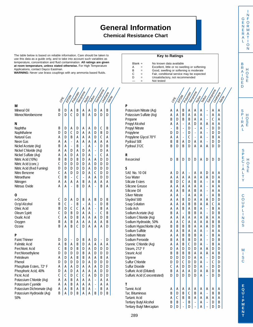
General InformationChemical Resistance Chart
289
GENERAL
INFORMATION
SPECIALTY
HOSE
COUPLINGS
MISC
EQUIPMENT
BRAIDED
HOSE
SPIRAL
HOSE
MMineral OilMonochlorobenzene
NNaphthaNaphthaleneNatural GasNeon GasNickel Acetate (Aq)Nickel Chloride (Aq)Nickel Sulfate (Aq)Nitric Acid (10%)Nitric Acid (conc.)Nitric Acid (Red Fuming)Nitro BenzeneNitroethaneNitrogenNitrous Oxide
On-OctaneOctyl AlcoholOleic AcidOleum SpiritOxalic AcidOxygenOzone
PPaint ThinnerPalmitic AcidPerchloric AcidPerchloroethylenePetroleumPhenolPhosphate Esters, 72º FPhosphoric Acid, 40%Picric AcidPotassium Chloride (Aq)Potassium CyanidePotassium Dichromate (Aq)Potassium Hydroxide (Aq)50%
PPotassium Nitrate (Aq)Potassium Sulfate (Aq)PropanePropyl AlcoholPropyl NitratePropylenePropylene Glycol 70°FPydraul 50EPydraul 312C
RResorcinol
SSAE No. 10 OilSea WaterSilicate EstersSilicone GreaseSilicone OilSilver NitrateSkydrol 500Soap SolutionSoda AshSodium Acetate (Aq)Sodium Chloride (Aq)Sodium Hydroxide, 50%Sodium Hypochlorite (Aq)Sodium SulfideSodium NitrateSodium PeroxideStannic Chloride (Aq)Steam, 212º FStearic AcidStyreneSulfur ChlorideSulfur DioxideSulfuric Acid (Diluted)Sulfuric Acid (Concentrated)
TTannic AcidTar, BituminousTartaric AcidTertiary Butyl AlcoholTertiary Butyl Mercaptan
DD
DDDAAAABDDABAA
DCDDAAA
DBBDDDAACAAAA
AC
ACB--DDDDDD-A-
A-CBDBB
-ADDADADDBBBD
BD
DDAABAABDDDCAB
DBCDBAC
DBBDBDDACAAAB
AB
AAAA-DDDDDD-BD
B-AAAAD
BDDBBDAACAABA
AA
AAAAAAAAAAAAAA
AAAAAAA
AAAAAAAAAAAAA
DD
DDDA---ADDCAA-
B---AAA
DADDADAAD---B
AD
CBCADDCDDDDDAB
DDBCDAA
-ADDBDDDDAABD
BD
BDAABAADDDDDAA
BBABBBD
DADDADDDDAAAB
AADABDABD
B
DADAAAAAAAAABAAAAABDDAAD
ADCBD
BBB----AB
D
AACAB-BAB-ACBBBBBDBDCDAD
ABB--
AABADDCDD
D
-AAAAADBABAABABBCDBDDDAD
ACBBD
AAAD---AA
D
AABABAABBBAAAABDDDAADDDD
ABA--
AAAAAAAAA
A
AAAAAAAAAAAAAAAAAAAAAAAA
AAAAA
---A----A
D
DA----AA--AAA----AA---A-
A-A--
AACADDBDD
D
ADAAAADCBDABDABDBDADCDDD
ABADD
AAAADDADD
D
AABAABDAABABBAABADBDDDBD
ABABD
EPD
MPo
lyes
ter
Neo
pren
eN
ylon
Teflo
nSa
ntop
rene
Ure
than
eN
itrile
EPD
MPo
lyes
ter
Neo
pren
eN
ylon
Teflo
nSa
ntop
rene
Ure
than
eN
itrile
CPE
BD
BDAABAABCDCCAA
CBBCCBB
DACDADADCAAAB
CPE
AABA-DABB
D
AABAAAAAABAABAABADBDDCBD
ABABD
Key to Ratings
Blank = No known data availableA = Excellent, little or no swelling or softeningB = Good, swelling or softening is moderateC = Fair, conditional service may be expectedD = Unsatisfactory, not recommended— = Not tested
The table below is based on reliable information. Care should be taken touse this data as a guide only, and to take into account such variables astemperature, concentration and fluid contamination. All ratings are givenat room temperature, unless stated otherwise. For High TemperatureApplications, contact Dayco Eastman.WARNING: Never use brass couplings with any ammonia based fluids.
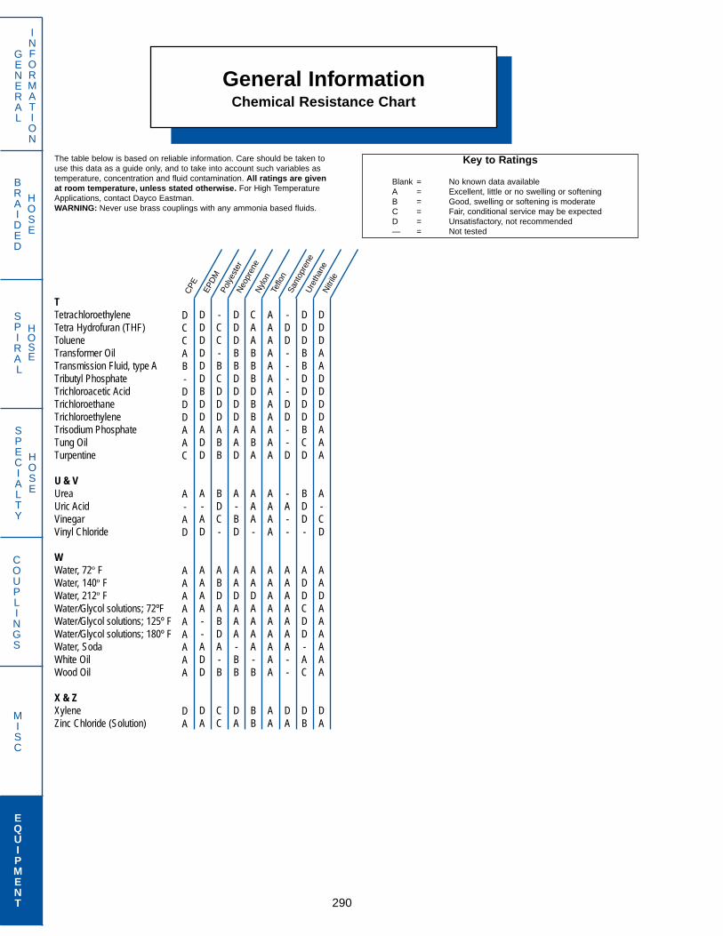
General InformationChemical Resistance Chart
290
GENERAL
INFORMATION
SPECIALTY
HOSE
COUPLINGS
MISC
EQUIPMENT
BRAIDED
HOSE
SPIRAL
HOSE
TTetrachloroethyleneTetra Hydrofuran (THF)TolueneTransformer OilTransmission Fluid, type ATributyl PhosphateTrichloroacetic AcidTrichloroethaneTrichloroethyleneTrisodium PhosphateTung OilTurpentine
U & VUreaUric AcidVinegarVinyl Chloride
WWater, 72º FWater, 140º FWater, 212º FWater/Glycol solutions; 72ºFWater/Glycol solutions; 125º FWater/Glycol solutions; 180º FWater, SodaWhite OilWood Oil
X & ZXyleneZinc Chloride (Solution)
DDDDDDBDDADD
A-AD
AAAA--ADD
DA
-CC-BCDDDABB
BDC-
ABDABDA-B
CC
DDDBBDDDDAAD
A-BD
AADAAA-BB
DA
CAABBBDBBABA
AAA-
AADAAAA-B
BB
AAAAAAAAAAAA
AAAA
AAAAAAAAA
AA
-DD----DD--D
-A--
AAAAAAA--
DA
DDDBBDDDDBCD
BDD-
ADDCDD-AC
DB
DDDAADDDDAAA
A-CD
AADAAAAAA
DA
EPD
MPo
lyes
ter
Neo
pren
eN
ylon
Teflo
nSa
ntop
rene
Ure
than
eN
itrile
CPE
DCCAB-DDDAAC
A-AD
AAAAAAAAA
DA
Key to Ratings
Blank = No known data availableA = Excellent, little or no swelling or softeningB = Good, swelling or softening is moderateC = Fair, conditional service may be expectedD = Unsatisfactory, not recommended— = Not tested
The table below is based on reliable information. Care should be taken touse this data as a guide only, and to take into account such variables astemperature, concentration and fluid contamination. All ratings are givenat room temperature, unless stated otherwise. For High TemperatureApplications, contact Dayco Eastman.WARNING: Never use brass couplings with any ammonia based fluids.

291
IndexHOSE–COUPLINGS–EQUIPMENT
33 – 761FSPAGE
33 Strain Reliever . . . . . . . . . . . . . . .25436 Strain Reliever . . . . . . . . . . . . . . .25437 Strain Reliever . . . . . . . . . . . . . . .25438 Strain Reliever . . . . . . . . . . . . . . .25439 Strain Reliever . . . . . . . . . . . . . . .25440 Strain Reliever . . . . . . . . . . . . . . .25441 Strain Reliever . . . . . . . . . . . . . . .25442 Strain Reliever . . . . . . . . . . . . . . .254 .....44 Strain Reliever . . . . . . . . . . . . . . .25445 Strain Reliever . . . . . . . . . . . . . . .254
160-N Style Sleeve Fitting . . . . . . . . . . . . . . . .261168-NS Style Connectors . . . . . . . . . . . . . . . . .261178-NS Style Connectors . . . . . . . . . . . . . . . . .261
200-T Skivers . . . . . . . . . . . . . . . . . . . . .285221-T Skiver Blade . . . . . . . . . . . . . . . . .285295-20A BQ Installation Tool . . . . . . . . . . .241295-24A BQ Installation Tool . . . . . . . . . . .241295-32 BQ Installation Tool . . . . . . . . . . .241
300 Series
300 Series Truck Coils . . . . . . . . . . . . . . . . . .260
660-T Vise . . . . . . . . . . . . . . . . . . . . . . .286662-T Dies . . . . . . . . . . . . . . . . . . . . . . .286670-T Vise . . . . . . . . . . . . . . . . . . . . . . .286
1000 Series Adapters (Air Brake) . . . . . . . . . .1131400 Series Spring Guards . . . . . . . . . . . . . . .2551500 Series Spring Guards . . . . . . . . . . . . . . .2571700 Series Protective Coil . . . . . . . . . . . . . . .2581776 Sleeving . . . . . . . . . . . . . . . . . . . .2531800 Series Strain Relievers . . . . . . . . . . . . . .2541960-FS Sleeve . . . . . . . . . . . . . . . . . . . . .1581961-FS Nut . . . . . . . . . . . . . . . . . . . . . . . .158
202687 Adapter (Air Brake) . . . . . . . . . . .113202688 Adapter (Air Brake) . . . . . . . . . . .113
760FS Sleeve . . . . . . . . . . . . . . . . . . . . . .145761FS Nut . . . . . . . . . . . . . . . . . . . . . . . .145
A2 – BL-TMSPPAGE
A2 Hose . . . . . . . . . . . . . . . . . . . . . . .35A6 Hose . . . . . . . . . . . . . . . . . . . . . . .34AM Hose . . . . . . . . . . . . . . . . . . . . . . .49AX Hose . . . . . . . . . . . . . . . . . . . . . . .47B7 Hose . . . . . . . . . . . . . . . . . . . . . . .36B7S Hose . . . . . . . . . . . . . . . . . . . . . . .37B9 Hose . . . . . . . . . . . . . . . . . . . . . . .36BA Hose . . . . . . . . . . . . . . . . . . . . . . .51BA-FA . . . . . . . . . . . . . . . . . . . . . . . . . . . . . . . . . . . .227BA-FJ . . . . . . . . . . . . . . . . . . . . . . . . . . . . . . . . . . . .227BA-FJ45T . . . . . . . . . . . . . . . . . . . . . . . . . . . . . . . . .227BA-FJ90T . . . . . . . . . . . . . . . . . . . . . . . . . . . . . . . . .228BA-FJ90TL . . . . . . . . . . . . . . . . . . . . . . . . . . . . . . . .228BA-MJ . . . . . . . . . . . . . . . . . . . . . . . . . . . . . . . . . . .228BA-MP . . . . . . . . . . . . . . . . . . . . . . . . . . . . . . . . . . .229BB-FJ . . . . . . . . . . . . . . . . . . . . . . . . . . . . . . . . . . . .230BB-MP . . . . . . . . . . . . . . . . . . . . . . . . . . . . . . . . . . .230BB-SP . . . . . . . . . . . . . . . . . . . . . . . . . . . . . . . . . . .230BC-FJ . . . . . . . . . . . . . . . . . . . . . . . . . . . . . . . . . . . .79BC-MJ . . . . . . . . . . . . . . . . . . . . . . . . . . . . . . . . . . .79BC-MP . . . . . . . . . . . . . . . . . . . . . . . . . . . . . . . . . . .79BC-OFT . . . . . . . . . . . . . . . . . . . . . . . . . . . . . . . . . .80BC-PA . . . . . . . . . . . . . . . . . . . . . . . . . . . . . . . . . . . .80BC-PA45 . . . . . . . . . . . . . . . . . . . . . . . . . . . . . . . . . .80BC-PA90 . . . . . . . . . . . . . . . . . . . . . . . . . . . . . . . . . .80BC-RA . . . . . . . . . . . . . . . . . . . . . . . . . . . . . . . . . . .81BCH Hose . . . . . . . . . . . . . . . . . . . . . . .67BE-FJ . . . . . . . . . . . . . . . . . . . . . . . . . . . . . . . . . . . .231BE-MJ . . . . . . . . . . . . . . . . . . . . . . . . . . . . . . . . . . .231BE-MP . . . . . . . . . . . . . . . . . . . . . . . . . . . . . . . . . . .231BG-FJ . . . . . . . . . . . . . . . . . . . . . . . . . . . . . . . . . . . .232BG-MJ . . . . . . . . . . . . . . . . . . . . . . . . . . . . . . . . . . .232BG-MP . . . . . . . . . . . . . . . . . . . . . . . . . . . . . . . . . . .232BG-SP . . . . . . . . . . . . . . . . . . . . . . . . . . . . . . . . . . .233BH Hose . . . . . . . . . . . . . . . . . . . . . . .67BL-BHS . . . . . . . . . . . . . . . . . . . . . . . . . . . . . . . . . .203BL-BH90 . . . . . . . . . . . . . . . . . . . . . . . . . . . . . . . . . .203BL-FAT . . . . . . . . . . . . . . . . . . . . . . . . . . . . . . . . . . .203BL-FA45T . . . . . . . . . . . . . . . . . . . . . . . . . . . . . . . . .204BL-FA90T . . . . . . . . . . . . . . . . . . . . . . . . . . . . . . . . .204BL-MV . . . . . . . . . . . . . . . . . . . . . . . . . . . . . . . . . . .204BL-RM . . . . . . . . . . . . . . . . . . . . . . . . . . . . . . . . . . .205BL-TAST . . . . . . . . . . . . . . . . . . . . . . . . . . . . . . . . . .205BL-TA45T . . . . . . . . . . . . . . . . . . . . . . . . . . . . . . . . .205BL-TA90T . . . . . . . . . . . . . . . . . . . . . . . . . . . . . . . . .206BL-TFS . . . . . . . . . . . . . . . . . . . . . . . . . . . . . . . . . . .206BL-TFSP . . . . . . . . . . . . . . . . . . . . . . . . . . . . . . . . . .206BL-TF45P . . . . . . . . . . . . . . . . . . . . . . . . . . . . . . . . .207BL-TF90P . . . . . . . . . . . . . . . . . . . . . . . . . . . . . . . . .207BL-TF45PV . . . . . . . . . . . . . . . . . . . . . . . . . . . . . . . .207BL-TF90PV . . . . . . . . . . . . . . . . . . . . . . . . . . . . . . . .208BL-TF45T . . . . . . . . . . . . . . . . . . . . . . . . . . . . . . . . .208BL-TF90T . . . . . . . . . . . . . . . . . . . . . . . . . . . . . . . . .208BL-TMS . . . . . . . . . . . . . . . . . . . . . . . . . . . . . . . . . .209BL-TMSP . . . . . . . . . . . . . . . . . . . . . . . . . . . . . . . . .209

292
IndexHOSE–COUPLINGS–EQUIPMENT
BL-TM45P – BW-PA60PAGE
BL-TM45P . . . . . . . . . . . . . . . . . . . . . . . . . . . . . . . .209BL-TM90P . . . . . . . . . . . . . . . . . . . . . . . . . . . . . . . .210BL-TM90PX . . . . . . . . . . . . . . . . . . . . . . . . . . . . . . .210BL-TM45T . . . . . . . . . . . . . . . . . . . . . . . . . . . . . . . . .210BL-TM90T . . . . . . . . . . . . . . . . . . . . . . . . . . . . . . . . .211BM-FJ . . . . . . . . . . . . . . . . . . . . . . . . . . . . . . . . . . . .233BM-FJ45T . . . . . . . . . . . . . . . . . . . . . . . . . . . . . . . . .234BM-FJ90T . . . . . . . . . . . . . . . . . . . . . . . . . . . . . . . . .234BM-FJ90TL . . . . . . . . . . . . . . . . . . . . . . . . . . . . . . . .234BM-MJ . . . . . . . . . . . . . . . . . . . . . . . . . . . . . . . . . . .235BM-MP . . . . . . . . . . . . . . . . . . . . . . . . . . . . . . . . . . .235BM-PA . . . . . . . . . . . . . . . . . . . . . . . . . . . . . . . . . . .235BM-PA45 . . . . . . . . . . . . . . . . . . . . . . . . . . . . . . . . .236BM-PA90 . . . . . . . . . . . . . . . . . . . . . . . . . . . . . . . . .236BN-FA . . . . . . . . . . . . . . . . . . . . . . . . . . . . . . . . . . . .237BN-FA45T . . . . . . . . . . . . . . . . . . . . . . . . . . . . . . . . .237BN-FA90T . . . . . . . . . . . . . . . . . . . . . . . . . . . . . . . . .237BN-FJ . . . . . . . . . . . . . . . . . . . . . . . . . . . . . . . . . . . .238BN-FJ45T . . . . . . . . . . . . . . . . . . . . . . . . . . . . . . . . .238BN-FJ90T . . . . . . . . . . . . . . . . . . . . . . . . . . . . . . . . .238BN-FJ90TL . . . . . . . . . . . . . . . . . . . . . . . . . . . . . . . .239BN-MA . . . . . . . . . . . . . . . . . . . . . . . . . . . . . . . . . . .239BN-MF . . . . . . . . . . . . . . . . . . . . . . . . . . . . . . . . . . .239BN-MF45T . . . . . . . . . . . . . . . . . . . . . . . . . . . . . . . .240BN-MF90T . . . . . . . . . . . . . . . . . . . . . . . . . . . . . . . .240BN-MJ . . . . . . . . . . . . . . . . . . . . . . . . . . . . . . . . . . .240BN-MP . . . . . . . . . . . . . . . . . . . . . . . . . . . . . . . . . . .241BOG Blow out Guard . . . . . . . . . . . . . .258BQ-FJ . . . . . . . . . . . . . . . . . . . . . . . . . . . . . . . . . . . .241BQ-MP . . . . . . . . . . . . . . . . . . . . . . . . . . . . . . . . . . .241BQ Assembly Tool . . . . . . . . . . . . . . .241BU-FA . . . . . . . . . . . . . . . . . . . . . . . . . . . . . . . . . . . .242BU-FJ . . . . . . . . . . . . . . . . . . . . . . . . . . . . . . . . . . . .242BU-MJ . . . . . . . . . . . . . . . . . . . . . . . . . . . . . . . . . . .242BU-MP . . . . . . . . . . . . . . . . . . . . . . . . . . . . . . . . . . .243BU-SP . . . . . . . . . . . . . . . . . . . . . . . . . . . . . . . . . . .243BW-BPF . . . . . . . . . . . . . . . . . . . . . . . . . . . . . . . . . .83BW-FJ . . . . . . . . . . . . . . . . . . . . . . . . . . . . . . . . . . .84BW-FJ45T . . . . . . . . . . . . . . . . . . . . . . . . . . . . . . . .82BW-FJ90T . . . . . . . . . . . . . . . . . . . . . . . . . . . . . . . .82BW-FJ90TL . . . . . . . . . . . . . . . . . . . . . . . . . . . . . . . .82BW-MJ . . . . . . . . . . . . . . . . . . . . . . . . . . . . . . . . . . .83BW-MP . . . . . . . . . . . . . . . . . . . . . . . . . . . . . . . . . . .83BW-MS . . . . . . . . . . . . . . . . . . . . . . . . . . . . . . . . . . .83BW-OFT . . . . . . . . . . . . . . . . . . . . . . . . . . . . . . . . . .84BW-OF45T . . . . . . . . . . . . . . . . . . . . . . . . . . . . . . . .84BW-OF90T . . . . . . . . . . . . . . . . . . . . . . . . . . . . . . . .84BW-OF90TL . . . . . . . . . . . . . . . . . . . . . . . . . . . . . . .85BW-OF90TM . . . . . . . . . . . . . . . . . . . . . . . . . . . . . . .85BW-OM . . . . . . . . . . . . . . . . . . . . . . . . . . . . . . . . . . .85BW-PA . . . . . . . . . . . . . . . . . . . . . . . . . . . . . . . . . . .86BW-PA22 . . . . . . . . . . . . . . . . . . . . . . . . . . . . . . . . .86BW-PA30 . . . . . . . . . . . . . . . . . . . . . . . . . . . . . . . . .86BW-PA45 . . . . . . . . . . . . . . . . . . . . . . . . . . . . . . . . .87BW-PA60 . . . . . . . . . . . . . . . . . . . . . . . . . . . . . . . . .87
BW-PA67 – EC30 CRIMPER PAGE
BW-PA67 . . . . . . . . . . . . . . . . . . . . . . . . . . . . . . . . .87BW-PA90 . . . . . . . . . . . . . . . . . . . . . . . . . . . . . . . . .88BW-PH . . . . . . . . . . . . . . . . . . . . . . . . . . . . . . . . . . .88BW-PH22 . . . . . . . . . . . . . . . . . . . . . . . . . . . . . . . . .88BW-PH30 . . . . . . . . . . . . . . . . . . . . . . . . . . . . . . . . .89BW-PH45 . . . . . . . . . . . . . . . . . . . . . . . . . . . . . . . . .89BW-PH90 . . . . . . . . . . . . . . . . . . . . . . . . . . . . . . . . .89BW-RA . . . . . . . . . . . . . . . . . . . . . . . . . . . . . . . . . . .90BW-FJ-SS . . . . . . . . . . . . . . . . . . . . . . . . . . . . . . . . .90BW-MP-SS . . . . . . . . . . . . . . . . . . . . . . . . . . . . . . . .91BXX Hose . . . . . . . . . . . . . . . . . . . . . . .51BXP Hose . . . . . . . . . . . . . . . . . . . . . . .52C Hose . . . . . . . . . . . . . . . . . . . . . . .33C2 Hose . . . . . . . . . . . . . . . . . . . . . . .46C6 Hose . . . . . . . . . . . . . . . . . . . . . . .68CA-MP . . . . . . . . . . . . . . . . . . . . . . . . . . . . . . . . . . .244CA-PA . . . . . . . . . . . . . . . . . . . . . . . . . . . . . . . . . . . .244CA-PA22 . . . . . . . . . . . . . . . . . . . . . . . . . . . . . . . . . .244CA-PA30 . . . . . . . . . . . . . . . . . . . . . . . . . . . . . . . . . .245CA-PA45 . . . . . . . . . . . . . . . . . . . . . . . . . . . . . . . . . .245CA-PA90 . . . . . . . . . . . . . . . . . . . . . . . . . . . . . . . . . .245CA – Parts . . . . . . . . . . . . . . . . . . . . . . . . . . . . . . . .246CB-FJ . . . . . . . . . . . . . . . . . . . . . . . . . . . . . . . . . . . .247CB-MP . . . . . . . . . . . . . . . . . . . . . . . . . . . . . . . . . . .247CB – Parts . . . . . . . . . . . . . . . . . . . . . . . . . . . . . . . .246CE . . . . . . . . . . . . . . . . . . . . . . . . . . . . . . . . . . . . . .61CE-100 Cleaning System . . . . . . . . . . . . . .280CE-200 Cleaning System . . . . . . . . . . . . . .280CET Hose . . . . . . . . . . . . . . . . . . . . . . .61CN . . . . . . . . . . . . . . . . . . . . . . . . . . . . . . . . . . . . . .63CW-FJ . . . . . . . . . . . . . . . . . . . . . . . . . . . . . . . . . . .91CW-MP . . . . . . . . . . . . . . . . . . . . . . . . . . . . . . . . . . .91CY-FA . . . . . . . . . . . . . . . . . . . . . . . . . . . . . . . . . . . .92CY-FJ . . . . . . . . . . . . . . . . . . . . . . . . . . . . . . . . . . . .92CY-FJ45T . . . . . . . . . . . . . . . . . . . . . . . . . . . . . . . . .93CY-FJ90T . . . . . . . . . . . . . . . . . . . . . . . . . . . . . . . . .93CY-FJ90TL . . . . . . . . . . . . . . . . . . . . . . . . . . . . . . . .93CY-JPF . . . . . . . . . . . . . . . . . . . . . . . . . . . . . . . . . . .94CY-MA . . . . . . . . . . . . . . . . . . . . . . . . . . . . . . . . . . .94CY-MJ . . . . . . . . . . . . . . . . . . . . . . . . . . . . . . . . . . . .94CY-MP . . . . . . . . . . . . . . . . . . . . . . . . . . . . . . . . . . .95CY-RA . . . . . . . . . . . . . . . . . . . . . . . . . . . . . . . . . . .95CY-RV . . . . . . . . . . . . . . . . . . . . . . . . . . . . . . . . . . .96CY-SP . . . . . . . . . . . . . . . . . . . . . . . . . . . . . . . . . . . .96CZ Hose . . . . . . . . . . . . . . . . . . . . . . .62D1 Hose . . . . . . . . . . . . . . . . . . . . . . .39D6 Hose . . . . . . . . . . . . . . . . . . . . . . .50D8 Hose . . . . . . . . . . . . . . . . . . . . . . .42DL5 Hose . . . . . . . . . . . . . . . . . . . . . . .38DL6 Hose . . . . . . . . . . . . . . . . . . . . . . .38DT Hose . . . . . . . . . . . . . . . . . . . . . . .57E7A Hose . . . . . . . . . . . . . . . . . . . . . . .43E9 Hose . . . . . . . . . . . . . . . . . . . . . . .44EC Strain Reliever . . . . . . . . . . . . . . .256EC30 Crimper . . . . . . . . . . . . . . . . . . . . .268

IndexHOSE–COUPLINGS–EQUIPMENT
293
EC30-22 – GO PAGE
EC30-22 Hand Pump . . . . . . . . . . . . . . . . . .278EC30-23 Air Pump . . . . . . . . . . . . . . . . . . . .278ER-MP . . . . . . . . . . . . . . . . . . . . . . . . . . . . . . . . . . .97F2 Hose . . . . . . . . . . . . . . . . . . . . . . . . .58FX Hose . . . . . . . . . . . . . . . . . . . . . . . . .55GA Spring Guard . . . . . . . . . . . . . . . . . .257GB-FA . . . . . . . . . . . . . . . . . . . . . . . . . . . . . . . . . . .97GB-FF . . . . . . . . . . . . . . . . . . . . . . . . . . . . . . . . . . .98GB-FJ . . . . . . . . . . . . . . . . . . . . . . . . . . . . . . . . . . . .98GB-MA . . . . . . . . . . . . . . . . . . . . . . . . . . . . . . . . . . .98GB-MJ . . . . . . . . . . . . . . . . . . . . . . . . . . . . . . . . . . .99GB-MP . . . . . . . . . . . . . . . . . . . . . . . . . . . . . . . . . . .99GB-OF . . . . . . . . . . . . . . . . . . . . . . . . . . . . . . . . . . .99GB-RA . . . . . . . . . . . . . . . . . . . . . . . . . . . . . . . . . . .100GB-RC . . . . . . . . . . . . . . . . . . . . . . . . . . . . . . . . . . .100GB-SP . . . . . . . . . . . . . . . . . . . . . . . . . . . . . . . . . . .100GD-FA . . . . . . . . . . . . . . . . . . . . . . . . . . . . . . . . . . .101GD-FJ . . . . . . . . . . . . . . . . . . . . . . . . . . . . . . . . . . . .101GD-FJ90T . . . . . . . . . . . . . . . . . . . . . . . . . . . . . . . . .101GD-MF . . . . . . . . . . . . . . . . . . . . . . . . . . . . . . . . . . .102GD-MJ . . . . . . . . . . . . . . . . . . . . . . . . . . . . . . . . . . .102GD-MP . . . . . . . . . . . . . . . . . . . . . . . . . . . . . . . . . . .102GD-RA . . . . . . . . . . . . . . . . . . . . . . . . . . . . . . . . . . .103GD-SP . . . . . . . . . . . . . . . . . . . . . . . . . . . . . . . . . . .103GF-FA . . . . . . . . . . . . . . . . . . . . . . . . . . . . . . . . . . . .104GF-FF . . . . . . . . . . . . . . . . . . . . . . . . . . . . . . . . . . . .104GF-FJ . . . . . . . . . . . . . . . . . . . . . . . . . . . . . . . . . . . .104GF-MA . . . . . . . . . . . . . . . . . . . . . . . . . . . . . . . . . . .105GF-MF . . . . . . . . . . . . . . . . . . . . . . . . . . . . . . . . . . .105GF-MF45T . . . . . . . . . . . . . . . . . . . . . . . . . . . . . . . .105GF-MJ . . . . . . . . . . . . . . . . . . . . . . . . . . . . . . . . . . .106GF-MP . . . . . . . . . . . . . . . . . . . . . . . . . . . . . . . . . . .106GF-NG . . . . . . . . . . . . . . . . . . . . . . . . . . . . . . . . . . .106GF-RA . . . . . . . . . . . . . . . . . . . . . . . . . . . . . . . . . . .107GF-SP . . . . . . . . . . . . . . . . . . . . . . . . . . . . . . . . . . .107GH-FA . . . . . . . . . . . . . . . . . . . . . . . . . . . . . . . . . . .108GH-FF . . . . . . . . . . . . . . . . . . . . . . . . . . . . . . . . . . .108GH-FJ . . . . . . . . . . . . . . . . . . . . . . . . . . . . . . . . . . . .108GH-MJ . . . . . . . . . . . . . . . . . . . . . . . . . . . . . . . . . . .109GH-MP . . . . . . . . . . . . . . . . . . . . . . . . . . . . . . . . . . .109GH-PR . . . . . . . . . . . . . . . . . . . . . . . . . . . . . . . . . . .109GH-SP . . . . . . . . . . . . . . . . . . . . . . . . . . . . . . . . . . .110GL Hose . . . . . . . . . . . . . . . . . . . . . . . . .40GL-BPF90T . . . . . . . . . . . . . . . . . . . . . . . . . . . . . . .248GL-FA . . . . . . . . . . . . . . . . . . . . . . . . . . . . . . . . . . . .248GL-FA45T . . . . . . . . . . . . . . . . . . . . . . . . . . . . . . . . .248GL-FA90T . . . . . . . . . . . . . . . . . . . . . . . . . . . . . . . . .249GL-FP . . . . . . . . . . . . . . . . . . . . . . . . . . . . . . . . . . . .249GL-MF . . . . . . . . . . . . . . . . . . . . . . . . . . . . . . . . . . .249GL-MF45T . . . . . . . . . . . . . . . . . . . . . . . . . . . . . . . .250GL-MF90T . . . . . . . . . . . . . . . . . . . . . . . . . . . . . . . .250GL-MJ . . . . . . . . . . . . . . . . . . . . . . . . . . . . . . . . . . .250GL-MP . . . . . . . . . . . . . . . . . . . . . . . . . . . . . . . . . . .251GL-MV . . . . . . . . . . . . . . . . . . . . . . . . . . . . . . . . . . .251GO Spring Guard . . . . . . . . . . . . . . . . . .255
GOC – HPT5PAGE
GOC Strain Reliever 256GR-AF . . . . . . . . . . . . . . . . . . . . . . . . . . . . . . . . . . .111GR-FA . . . . . . . . . . . . . . . . . . . . . . . . . . . . . . . . . . .111GR-FJ . . . . . . . . . . . . . . . . . . . . . . . . . . . . . . . . . . . .112GR-MJ . . . . . . . . . . . . . . . . . . . . . . . . . . . . . . . . . . .112GR-MP . . . . . . . . . . . . . . . . . . . . . . . . . . . . . . . . . . .112GR-MS . . . . . . . . . . . . . . . . . . . . . . . . . . . . . . . . . . .113GS-BA . . . . . . . . . . . . . . . . . . . . . . . . . . . . . . . . . . .212GS-FA . . . . . . . . . . . . . . . . . . . . . . . . . . . . . . . . . . .212GS-FJ . . . . . . . . . . . . . . . . . . . . . . . . . . . . . . . . . . . .212GS-MF90T . . . . . . . . . . . . . . . . . . . . . . . . . . . . . . . .213GS-MP . . . . . . . . . . . . . . . . . . . . . . . . . . . . . . . . . . .213GS-NA . . . . . . . . . . . . . . . . . . . . . . . . . . . . . . . . . . .213GS-NG . . . . . . . . . . . . . . . . . . . . . . . . . . . . . . . . . . .214GS-RL . . . . . . . . . . . . . . . . . . . . . . . . . . . . . . . . . . .214GT-AF . . . . . . . . . . . . . . . . . . . . . . . . . . . . . . . . . . . .215GT-FA . . . . . . . . . . . . . . . . . . . . . . . . . . . . . . . . . . . .215GT-FJ . . . . . . . . . . . . . . . . . . . . . . . . . . . . . . . . . . . .215GT-MA . . . . . . . . . . . . . . . . . . . . . . . . . . . . . . . . . . .216GT-MF . . . . . . . . . . . . . . . . . . . . . . . . . . . . . . . . . . .216GT-MJ . . . . . . . . . . . . . . . . . . . . . . . . . . . . . . . . . . .217GT-MP . . . . . . . . . . . . . . . . . . . . . . . . . . . . . . . . . . .217GT-PR . . . . . . . . . . . . . . . . . . . . . . . . . . . . . . . . . . .218GT-SP . . . . . . . . . . . . . . . . . . . . . . . . . . . . . . . . . . .218GW-FA . . . . . . . . . . . . . . . . . . . . . . . . . . . . . . . . . . .114GW-FJ . . . . . . . . . . . . . . . . . . . . . . . . . . . . . . . . . . .114GW-FJ90T . . . . . . . . . . . . . . . . . . . . . . . . . . . . . . . .115GW-MP . . . . . . . . . . . . . . . . . . . . . . . . . . . . . . . . . . .115GW-MS . . . . . . . . . . . . . . . . . . . . . . . . . . . . . . . . . . .116GW-MV . . . . . . . . . . . . . . . . . . . . . . . . . . . . . . . . . . .116GW-NV . . . . . . . . . . . . . . . . . . . . . . . . . . . . . . . . . . .116GW-OFT . . . . . . . . . . . . . . . . . . . . . . . . . . . . . . . . . .117GW-OF90T . . . . . . . . . . . . . . . . . . . . . . . . . . . . . . . .117GW-RA . . . . . . . . . . . . . . . . . . . . . . . . . . . . . . . . . . .118GW-RC . . . . . . . . . . . . . . . . . . . . . . . . . . . . . . . . . . .118H6 Hose . . . . . . . . . . . . . . . . . . . . . . . .49H7 Hose . . . . . . . . . . . . . . . . . . . . . . . .66HAW Hose . . . . . . . . . . . . . . . . . . . . . . . .35HF-FA . . . . . . . . . . . . . . . . . . . . . . . . . . . . . . . . . . . .119HF-FJ . . . . . . . . . . . . . . . . . . . . . . . . . . . . . . . . . . . .119HF-FJ90T . . . . . . . . . . . . . . . . . . . . . . . . . . . . . . . . .119HF-FN . . . . . . . . . . . . . . . . . . . . . . . . . . . . . . . . . . .120HF-MJ . . . . . . . . . . . . . . . . . . . . . . . . . . . . . . . . . . .120HF-MP . . . . . . . . . . . . . . . . . . . . . . . . . . . . . . . . . . .121HF-OFT . . . . . . . . . . . . . . . . . . . . . . . . . . . . . . . . . .121HF-OF45T . . . . . . . . . . . . . . . . . . . . . . . . . . . . . . . .122HF-OF90T . . . . . . . . . . . . . . . . . . . . . . . . . . . . . . . .122HFS Hose . . . . . . . . . . . . . . . . . . . . . . . .48HFS2 Hose . . . . . . . . . . . . . . . . . . . . . . . .56HJK Hose . . . . . . . . . . . . . . . . . . . . . . . .74HLB Hose . . . . . . . . . . . . . . . . . . . . . . . .70HMG Sleeving . . . . . . . . . . . . . . . . . . . . .252HPC Hose . . . . . . . . . . . . . . . . . . . . . . . .71HPS Hose . . . . . . . . . . . . . . . . . . . . . . . .71HPT5 Coupling Pusher . . . . . . . . . . . . . . .284
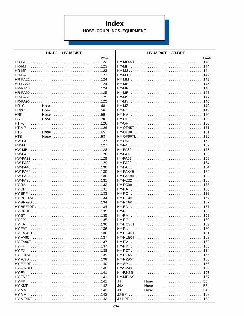
294
IndexHOSE–COUPLINGS–EQUIPMENT
HR-FJ – HY-MF45TPAGE
HR-FJ . . . . . . . . . . . . . . . . . . . . . . . . . . . . . . . . . . . .123HR-MJ . . . . . . . . . . . . . . . . . . . . . . . . . . . . . . . . . . .123HR-MP . . . . . . . . . . . . . . . . . . . . . . . . . . . . . . . . . . .123HR-PA . . . . . . . . . . . . . . . . . . . . . . . . . . . . . . . . . . .123HR-PA22 . . . . . . . . . . . . . . . . . . . . . . . . . . . . . . . . . .124HR-PA30 . . . . . . . . . . . . . . . . . . . . . . . . . . . . . . . . . .124HR-PA45 . . . . . . . . . . . . . . . . . . . . . . . . . . . . . . . . . .124HR-PA60 . . . . . . . . . . . . . . . . . . . . . . . . . . . . . . . . . .125HR-PA67 . . . . . . . . . . . . . . . . . . . . . . . . . . . . . . . . . .125HR-PA90 . . . . . . . . . . . . . . . . . . . . . . . . . . . . . . . . . .125HR1C Hose . . . . . . . . . . . . . . . . . . . . . . .48HR2C Hose . . . . . . . . . . . . . . . . . . . . . . .56HRK Hose . . . . . . . . . . . . . . . . . . . . . . .59HSH2 Hose . . . . . . . . . . . . . . . . . . . . . . .70HT-FJ . . . . . . . . . . . . . . . . . . . . . . . . . . . . . . . . . . . .126HT-MP . . . . . . . . . . . . . . . . . . . . . . . . . . . . . . . . . . .126HT6 Hose . . . . . . . . . . . . . . . . . . . . . . .65HTB Hose . . . . . . . . . . . . . . . . . . . . . . .58HW-FJ . . . . . . . . . . . . . . . . . . . . . . . . . . . . . . . . . . .127HW-MJ . . . . . . . . . . . . . . . . . . . . . . . . . . . . . . . . . . .127HW-MP . . . . . . . . . . . . . . . . . . . . . . . . . . . . . . . . . . .128HW-PA . . . . . . . . . . . . . . . . . . . . . . . . . . . . . . . . . . .128HW-PA22 . . . . . . . . . . . . . . . . . . . . . . . . . . . . . . . . .129HW-PA30 . . . . . . . . . . . . . . . . . . . . . . . . . . . . . . . . .129HW-PA45 . . . . . . . . . . . . . . . . . . . . . . . . . . . . . . . . .130HW-PA60 . . . . . . . . . . . . . . . . . . . . . . . . . . . . . . . . .130HW-PA67 . . . . . . . . . . . . . . . . . . . . . . . . . . . . . . . . .130HW-PA90 . . . . . . . . . . . . . . . . . . . . . . . . . . . . . . . . .131HY-BA . . . . . . . . . . . . . . . . . . . . . . . . . . . . . . . . . . . .132HY-BP . . . . . . . . . . . . . . . . . . . . . . . . . . . . . . . . . . . .132HY-BPF . . . . . . . . . . . . . . . . . . . . . . . . . . . . . . . . . . .133HY-BPF45T . . . . . . . . . . . . . . . . . . . . . . . . . . . . . . . .134HY-BPF90 . . . . . . . . . . . . . . . . . . . . . . . . . . . . . . . . .134HY-BPF90T . . . . . . . . . . . . . . . . . . . . . . . . . . . . . . . .134HY-BPHB . . . . . . . . . . . . . . . . . . . . . . . . . . . . . . . . .135HY-BT . . . . . . . . . . . . . . . . . . . . . . . . . . . . . . . . . . . .135HY-DX . . . . . . . . . . . . . . . . . . . . . . . . . . . . . . . . . . .135HY-FA . . . . . . . . . . . . . . . . . . . . . . . . . . . . . . . . . . . .136HY-FAT . . . . . . . . . . . . . . . . . . . . . . . . . . . . . . . . . . .136HY-FA-45T . . . . . . . . . . . . . . . . . . . . . . . . . . . . . . . .136HY-FA90T . . . . . . . . . . . . . . . . . . . . . . . . . . . . . . . . .137HY-FA90TL . . . . . . . . . . . . . . . . . . . . . . . . . . . . . . . .137HY-FF . . . . . . . . . . . . . . . . . . . . . . . . . . . . . . . . . . . .137HY-FJ . . . . . . . . . . . . . . . . . . . . . . . . . . . . . . . . . . . .138HY-FJ45T . . . . . . . . . . . . . . . . . . . . . . . . . . . . . . . . .139HY-FJ90 . . . . . . . . . . . . . . . . . . . . . . . . . . . . . . . . . .139HY-FJ90T . . . . . . . . . . . . . . . . . . . . . . . . . . . . . . . . .140HY-FJ90TL . . . . . . . . . . . . . . . . . . . . . . . . . . . . . . . .140HY-FN . . . . . . . . . . . . . . . . . . . . . . . . . . . . . . . . . . . .141HY-FN90 . . . . . . . . . . . . . . . . . . . . . . . . . . . . . . . . . .141HY-FP . . . . . . . . . . . . . . . . . . . . . . . . . . . . . . . . . . . .141HY-KMF . . . . . . . . . . . . . . . . . . . . . . . . . . . . . . . . . .142HY-MA . . . . . . . . . . . . . . . . . . . . . . . . . . . . . . . . . . .142HY-MF . . . . . . . . . . . . . . . . . . . . . . . . . . . . . . . . . . .143HY-MF45T . . . . . . . . . . . . . . . . . . . . . . . . . . . . . . . .143
HY-MF90T – JJ-BPFPAGE
HY-MF90T . . . . . . . . . . . . . . . . . . . . . . . . . . . . . . . .143HY-MH . . . . . . . . . . . . . . . . . . . . . . . . . . . . . . . . . . .144HY-MJ . . . . . . . . . . . . . . . . . . . . . . . . . . . . . . . . . . . .144HY-MJPF . . . . . . . . . . . . . . . . . . . . . . . . . . . . . . . . .142HY-MM . . . . . . . . . . . . . . . . . . . . . . . . . . . . . . . . . . .145HY-MN . . . . . . . . . . . . . . . . . . . . . . . . . . . . . . . . . . .145HY-MP . . . . . . . . . . . . . . . . . . . . . . . . . . . . . . . . . . .146HY-MR . . . . . . . . . . . . . . . . . . . . . . . . . . . . . . . . . . .147HY-MS . . . . . . . . . . . . . . . . . . . . . . . . . . . . . . . . . . .147HY-MV . . . . . . . . . . . . . . . . . . . . . . . . . . . . . . . . . . .148HY-MZ . . . . . . . . . . . . . . . . . . . . . . . . . . . . . . . . . . .149HY-NG . . . . . . . . . . . . . . . . . . . . . . . . . . . . . . . . . . .149HY-NV . . . . . . . . . . . . . . . . . . . . . . . . . . . . . . . . . . .150HY-OF . . . . . . . . . . . . . . . . . . . . . . . . . . . . . . . . . . .150HY-OFT . . . . . . . . . . . . . . . . . . . . . . . . . . . . . . . . . .150HY-OF45T . . . . . . . . . . . . . . . . . . . . . . . . . . . . . . . . .151HY-OF90T . . . . . . . . . . . . . . . . . . . . . . . . . . . . . . . . .151HY-OF90TL . . . . . . . . . . . . . . . . . . . . . . . . . . . . . . . .152HY-OM . . . . . . . . . . . . . . . . . . . . . . . . . . . . . . . . . . .152HY-PA . . . . . . . . . . . . . . . . . . . . . . . . . . . . . . . . . . . .152HY-PA30 . . . . . . . . . . . . . . . . . . . . . . . . . . . . . . . . . .153HY-PA45 . . . . . . . . . . . . . . . . . . . . . . . . . . . . . . . . . .153HY-PA67 . . . . . . . . . . . . . . . . . . . . . . . . . . . . . . . . . .153HY-PA90 . . . . . . . . . . . . . . . . . . . . . . . . . . . . . . . . . .154HY-PAK . . . . . . . . . . . . . . . . . . . . . . . . . . . . . . . . . . .154HY-PAK45 . . . . . . . . . . . . . . . . . . . . . . . . . . . . . . . . .154HY-PAK90 . . . . . . . . . . . . . . . . . . . . . . . . . . . . . . . . .155HY-PC22 . . . . . . . . . . . . . . . . . . . . . . . . . . . . . . . . . .155HY-PC90 . . . . . . . . . . . . . . . . . . . . . . . . . . . . . . . . . .155HY-RA . . . . . . . . . . . . . . . . . . . . . . . . . . . . . . . . . . .156HY-RC . . . . . . . . . . . . . . . . . . . . . . . . . . . . . . . . . . .156HY-RC45 . . . . . . . . . . . . . . . . . . . . . . . . . . . . . . . . .157HY-RC90 . . . . . . . . . . . . . . . . . . . . . . . . . . . . . . . . .157HY-RD . . . . . . . . . . . . . . . . . . . . . . . . . . . . . . . . . . .157HY-RL . . . . . . . . . . . . . . . . . . . . . . . . . . . . . . . . . . . .158HY-RM . . . . . . . . . . . . . . . . . . . . . . . . . . . . . . . . . . .159HY-RO . . . . . . . . . . . . . . . . . . . . . . . . . . . . . . . . .159HY-RO90T . . . . . . . . . . . . . . . . . . . . . . . . . . . . . . . .159HY-RU . . . . . . . . . . . . . . . . . . . . . . . . . . . . . . . . .160HY-RU45T . . . . . . . . . . . . . . . . . . . . . . . . . . . . . . . .161HY-RU90T . . . . . . . . . . . . . . . . . . . . . . . . . . . . . . . .162HY-RV . . . . . . . . . . . . . . . . . . . . . . . . . . . . . . . . . . .162HY-RY . . . . . . . . . . . . . . . . . . . . . . . . . . . . . . . . . . .163HY-RZT . . . . . . . . . . . . . . . . . . . . . . . . . . . . . . . . . . .164HY-RZ45T . . . . . . . . . . . . . . . . . . . . . . . . . . . . . . . . .165HY-RZ90T . . . . . . . . . . . . . . . . . . . . . . . . . . . . . . . . .165HY-SP . . . . . . . . . . . . . . . . . . . . . . . . . . . . . . . . . . . .166HY-SP90 . . . . . . . . . . . . . . . . . . . . . . . . . . . . . . . . . .166HY-FJ-SS . . . . . . . . . . . . . . . . . . . . . . . . . . . . . . . . .167HY-MP-SS . . . . . . . . . . . . . . . . . . . . . . . . . . . . . . . .167J4 Hose . . . . . . . . . . . . . . . . . . . . . . .53J4A Hose . . . . . . . . . . . . . . . . . . . . . . .53J9 Hose . . . . . . . . . . . . . . . . . . . . . . .54JJ-BP . . . . . . . . . . . . . . . . . . . . . . . . . . . . . . . . . . . .168JJ-BPF . . . . . . . . . . . . . . . . . . . . . . . . . . . . . . . . . . .168
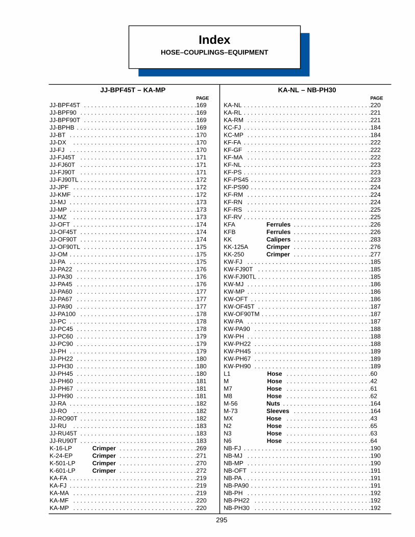
295
JJ-BPF45T – KA-MPPAGE
JJ-BPF45T . . . . . . . . . . . . . . . . . . . . . . . . . . . . . . . .169JJ-BPF90 . . . . . . . . . . . . . . . . . . . . . . . . . . . . . . . . .169JJ-BPF90T . . . . . . . . . . . . . . . . . . . . . . . . . . . . . . . .169JJ-BPHB . . . . . . . . . . . . . . . . . . . . . . . . . . . . . . . . . .169JJ-BT . . . . . . . . . . . . . . . . . . . . . . . . . . . . . . . . . . . .170JJ-DX . . . . . . . . . . . . . . . . . . . . . . . . . . . . . . . . . . .170JJ-FJ . . . . . . . . . . . . . . . . . . . . . . . . . . . . . . . . . . . .170JJ-FJ45T . . . . . . . . . . . . . . . . . . . . . . . . . . . . . . . . .171JJ-FJ60T . . . . . . . . . . . . . . . . . . . . . . . . . . . . . . . . .171JJ-FJ90T . . . . . . . . . . . . . . . . . . . . . . . . . . . . . . . . .171JJ-FJ90TL . . . . . . . . . . . . . . . . . . . . . . . . . . . . . . . . .172JJ-JPF . . . . . . . . . . . . . . . . . . . . . . . . . . . . . . . . . . .172JJ-KMF . . . . . . . . . . . . . . . . . . . . . . . . . . . . . . . . . . .172JJ-MJ . . . . . . . . . . . . . . . . . . . . . . . . . . . . . . . . . . . .173JJ-MP . . . . . . . . . . . . . . . . . . . . . . . . . . . . . . . . . . . .173JJ-MZ . . . . . . . . . . . . . . . . . . . . . . . . . . . . . . . . . . .173JJ-OFT . . . . . . . . . . . . . . . . . . . . . . . . . . . . . . . . . . .174JJ-OF45T . . . . . . . . . . . . . . . . . . . . . . . . . . . . . . . . .174JJ-OF90T . . . . . . . . . . . . . . . . . . . . . . . . . . . . . . . . .174JJ-OF90TL . . . . . . . . . . . . . . . . . . . . . . . . . . . . . . . .175JJ-OM . . . . . . . . . . . . . . . . . . . . . . . . . . . . . . . . . . . .175JJ-PA . . . . . . . . . . . . . . . . . . . . . . . . . . . . . . . . . . . .175JJ-PA22 . . . . . . . . . . . . . . . . . . . . . . . . . . . . . . . . . .176JJ-PA30 . . . . . . . . . . . . . . . . . . . . . . . . . . . . . . . . . .176JJ-PA45 . . . . . . . . . . . . . . . . . . . . . . . . . . . . . . . . . .176JJ-PA60 . . . . . . . . . . . . . . . . . . . . . . . . . . . . . . . . . .177JJ-PA67 . . . . . . . . . . . . . . . . . . . . . . . . . . . . . . . . . .177JJ-PA90 . . . . . . . . . . . . . . . . . . . . . . . . . . . . . . . . . .177JJ-PA100 . . . . . . . . . . . . . . . . . . . . . . . . . . . . . . . . .178JJ-PC . . . . . . . . . . . . . . . . . . . . . . . . . . . . . . . . . . . .178JJ-PC45 . . . . . . . . . . . . . . . . . . . . . . . . . . . . . . . . . .178JJ-PC60 . . . . . . . . . . . . . . . . . . . . . . . . . . . . . . . . . .179JJ-PC90 . . . . . . . . . . . . . . . . . . . . . . . . . . . . . . . . . .179JJ-PH . . . . . . . . . . . . . . . . . . . . . . . . . . . . . . . . . . . .179JJ-PH22 . . . . . . . . . . . . . . . . . . . . . . . . . . . . . . . . . .180JJ-PH30 . . . . . . . . . . . . . . . . . . . . . . . . . . . . . . . . . .180JJ-PH45 . . . . . . . . . . . . . . . . . . . . . . . . . . . . . . . . . .180JJ-PH60 . . . . . . . . . . . . . . . . . . . . . . . . . . . . . . . . . .181JJ-PH67 . . . . . . . . . . . . . . . . . . . . . . . . . . . . . . . . . .181JJ-PH90 . . . . . . . . . . . . . . . . . . . . . . . . . . . . . . . . . .181JJ-RA . . . . . . . . . . . . . . . . . . . . . . . . . . . . . . . . . . . .182JJ-RO . . . . . . . . . . . . . . . . . . . . . . . . . . . . . . . . . . .182JJ-RO90T . . . . . . . . . . . . . . . . . . . . . . . . . . . . . . . . .182JJ-RU . . . . . . . . . . . . . . . . . . . . . . . . . . . . . . . . . . .183JJ-RU45T . . . . . . . . . . . . . . . . . . . . . . . . . . . . . . . . .183JJ-RU90T . . . . . . . . . . . . . . . . . . . . . . . . . . . . . . . . .183K-16-LP Crimper . . . . . . . . . . . . . . . . . . . . . .269K-24-EP Crimper . . . . . . . . . . . . . . . . . . . . . .271K-501-LP Crimper . . . . . . . . . . . . . . . . . . . . . .270K-601-LP Crimper . . . . . . . . . . . . . . . . . . . . . .272KA-FA . . . . . . . . . . . . . . . . . . . . . . . . . . . . . . . . . . . .219KA-FJ . . . . . . . . . . . . . . . . . . . . . . . . . . . . . . . . . . . .219KA-MA . . . . . . . . . . . . . . . . . . . . . . . . . . . . . . . . . . .219KA-MF . . . . . . . . . . . . . . . . . . . . . . . . . . . . . . . . . . .220KA-MP . . . . . . . . . . . . . . . . . . . . . . . . . . . . . . . . . . .220
KA-NL – NB-PH30PAGE
KA-NL . . . . . . . . . . . . . . . . . . . . . . . . . . . . . . . . . . . .220KA-RL . . . . . . . . . . . . . . . . . . . . . . . . . . . . . . . . . . . .221KA-RM . . . . . . . . . . . . . . . . . . . . . . . . . . . . . . . . . . .221KC-FJ . . . . . . . . . . . . . . . . . . . . . . . . . . . . . . . . . . . .184KC-MP . . . . . . . . . . . . . . . . . . . . . . . . . . . . . . . . . . .184KF-FA . . . . . . . . . . . . . . . . . . . . . . . . . . . . . . . . . . . .222KF-GF . . . . . . . . . . . . . . . . . . . . . . . . . . . . . . . . . . .222KF-MA . . . . . . . . . . . . . . . . . . . . . . . . . . . . . . . . . . .222KF-NL . . . . . . . . . . . . . . . . . . . . . . . . . . . . . . . . . . . .223KF-PS . . . . . . . . . . . . . . . . . . . . . . . . . . . . . . . . . . . .223KF-PS45 . . . . . . . . . . . . . . . . . . . . . . . . . . . . . . . . . .223KF-PS90 . . . . . . . . . . . . . . . . . . . . . . . . . . . . . . . . . .224KF-RM . . . . . . . . . . . . . . . . . . . . . . . . . . . . . . . . . . .224KF-RN . . . . . . . . . . . . . . . . . . . . . . . . . . . . . . . . . . .224KF-RS . . . . . . . . . . . . . . . . . . . . . . . . . . . . . . . . . . .225KF-RV . . . . . . . . . . . . . . . . . . . . . . . . . . . . . . . . . . . .225KFA Ferrules . . . . . . . . . . . . . . . . . . . . . .226KFB Ferrules . . . . . . . . . . . . . . . . . . . . . .226KK Calipers . . . . . . . . . . . . . . . . . . . . . .283KK-125A Crimper . . . . . . . . . . . . . . . . . . . . . .276KK-250 Crimper . . . . . . . . . . . . . . . . . . . . . .277KW-FJ . . . . . . . . . . . . . . . . . . . . . . . . . . . . . . . . . . .185KW-FJ90T . . . . . . . . . . . . . . . . . . . . . . . . . . . . . . . .185KW-FJ90TL . . . . . . . . . . . . . . . . . . . . . . . . . . . . . . . .185KW-MJ . . . . . . . . . . . . . . . . . . . . . . . . . . . . . . . . . . .186KW-MP . . . . . . . . . . . . . . . . . . . . . . . . . . . . . . . . . . .186KW-OFT . . . . . . . . . . . . . . . . . . . . . . . . . . . . . . . . . .186KW-OF45T . . . . . . . . . . . . . . . . . . . . . . . . . . . . . . . .187KW-OF90TM . . . . . . . . . . . . . . . . . . . . . . . . . . . . . . .187KW-PA . . . . . . . . . . . . . . . . . . . . . . . . . . . . . . . . . . .187KW-PA90 . . . . . . . . . . . . . . . . . . . . . . . . . . . . . . . . .188KW-PH . . . . . . . . . . . . . . . . . . . . . . . . . . . . . . . . . . .188KW-PH22 . . . . . . . . . . . . . . . . . . . . . . . . . . . . . . . . .188KW-PH45 . . . . . . . . . . . . . . . . . . . . . . . . . . . . . . . . .189KW-PH67 . . . . . . . . . . . . . . . . . . . . . . . . . . . . . . . . .189KW-PH90 . . . . . . . . . . . . . . . . . . . . . . . . . . . . . . . . .189L1 Hose . . . . . . . . . . . . . . . . . . . . . . . .60M Hose . . . . . . . . . . . . . . . . . . . . . . . .42M7 Hose . . . . . . . . . . . . . . . . . . . . . . . .61M8 Hose . . . . . . . . . . . . . . . . . . . . . . . .62M-56 Nuts . . . . . . . . . . . . . . . . . . . . . . . . .164M-73 Sleeves . . . . . . . . . . . . . . . . . . . . . .164MX Hose . . . . . . . . . . . . . . . . . . . . . . . .43N2 Hose . . . . . . . . . . . . . . . . . . . . . . . .65N3 Hose . . . . . . . . . . . . . . . . . . . . . . . .63N6 Hose . . . . . . . . . . . . . . . . . . . . . . . .64NB-FJ . . . . . . . . . . . . . . . . . . . . . . . . . . . . . . . . . . . .190NB-MJ . . . . . . . . . . . . . . . . . . . . . . . . . . . . . . . . . . .190NB-MP . . . . . . . . . . . . . . . . . . . . . . . . . . . . . . . . . . .190NB-OFT . . . . . . . . . . . . . . . . . . . . . . . . . . . . . . . . . .191NB-PA . . . . . . . . . . . . . . . . . . . . . . . . . . . . . . . . . . . .191NB-PA90 . . . . . . . . . . . . . . . . . . . . . . . . . . . . . . . . . .191NB-PH . . . . . . . . . . . . . . . . . . . . . . . . . . . . . . . . . . .192NB-PH22 . . . . . . . . . . . . . . . . . . . . . . . . . . . . . . . . .192NB-PH30 . . . . . . . . . . . . . . . . . . . . . . . . . . . . . . . . .192
IndexHOSE–COUPLINGS–EQUIPMENT
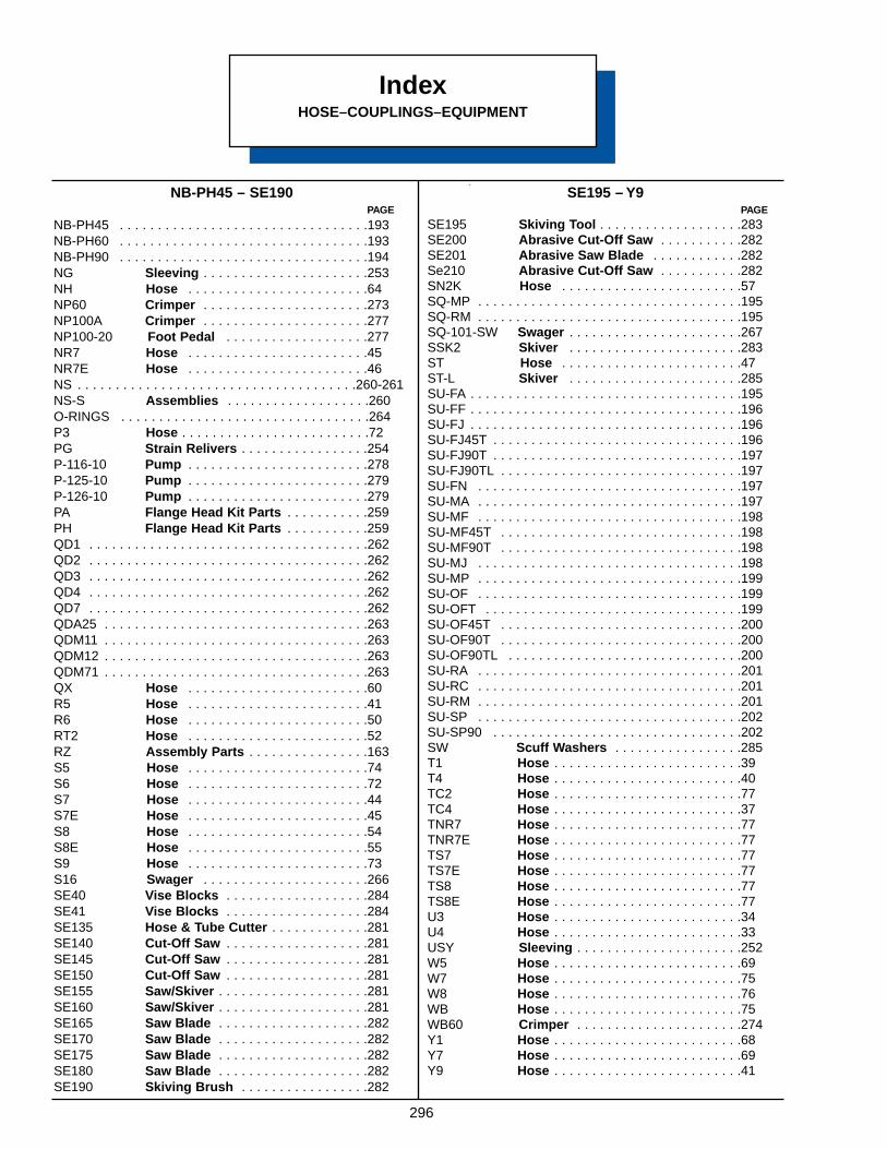
296
IndexHOSE–COUPLINGS–EQUIPMENT
NB-PH45 – SE190 PAGE
NB-PH45 . . . . . . . . . . . . . . . . . . . . . . . . . . . . . . . . .193NB-PH60 . . . . . . . . . . . . . . . . . . . . . . . . . . . . . . . . .193NB-PH90 . . . . . . . . . . . . . . . . . . . . . . . . . . . . . . . . .194NG Sleeving . . . . . . . . . . . . . . . . . . . . . .253NH Hose . . . . . . . . . . . . . . . . . . . . . . . .64NP60 Crimper . . . . . . . . . . . . . . . . . . . . . .273NP100A Crimper . . . . . . . . . . . . . . . . . . . . . .277NP100-20 Foot Pedal . . . . . . . . . . . . . . . . . . .277NR7 Hose . . . . . . . . . . . . . . . . . . . . . . . .45NR7E Hose . . . . . . . . . . . . . . . . . . . . . . . .46NS . . . . . . . . . . . . . . . . . . . . . . . . . . . . . . . . . . . . .260-261NS-S Assemblies . . . . . . . . . . . . . . . . . . .260O-RINGS . . . . . . . . . . . . . . . . . . . . . . . . . . . . . . . . .264P3 Hose . . . . . . . . . . . . . . . . . . . . . . . . .72PG Strain Relivers . . . . . . . . . . . . . . . . .254P-116-10 Pump . . . . . . . . . . . . . . . . . . . . . . . .278P-125-10 Pump . . . . . . . . . . . . . . . . . . . . . . . .279P-126-10 Pump . . . . . . . . . . . . . . . . . . . . . . . .279PA Flange Head Kit Parts . . . . . . . . . . .259PH Flange Head Kit Parts . . . . . . . . . . .259QD1 . . . . . . . . . . . . . . . . . . . . . . . . . . . . . . . . . . . . .262QD2 . . . . . . . . . . . . . . . . . . . . . . . . . . . . . . . . . . . . .262QD3 . . . . . . . . . . . . . . . . . . . . . . . . . . . . . . . . . . . . .262QD4 . . . . . . . . . . . . . . . . . . . . . . . . . . . . . . . . . . . . .262QD7 . . . . . . . . . . . . . . . . . . . . . . . . . . . . . . . . . . . . .262QDA25 . . . . . . . . . . . . . . . . . . . . . . . . . . . . . . . . . . .263QDM11 . . . . . . . . . . . . . . . . . . . . . . . . . . . . . . . . . . .263QDM12 . . . . . . . . . . . . . . . . . . . . . . . . . . . . . . . . . . .263QDM71 . . . . . . . . . . . . . . . . . . . . . . . . . . . . . . . . . . .263QX Hose . . . . . . . . . . . . . . . . . . . . . . . .60R5 Hose . . . . . . . . . . . . . . . . . . . . . . . .41R6 Hose . . . . . . . . . . . . . . . . . . . . . . . .50RT2 Hose . . . . . . . . . . . . . . . . . . . . . . . .52RZ Assembly Parts . . . . . . . . . . . . . . . .163S5 Hose . . . . . . . . . . . . . . . . . . . . . . . .74S6 Hose . . . . . . . . . . . . . . . . . . . . . . . .72S7 Hose . . . . . . . . . . . . . . . . . . . . . . . .44S7E Hose . . . . . . . . . . . . . . . . . . . . . . . .45S8 Hose . . . . . . . . . . . . . . . . . . . . . . . .54S8E Hose . . . . . . . . . . . . . . . . . . . . . . . .55S9 Hose . . . . . . . . . . . . . . . . . . . . . . . .73S16 Swager . . . . . . . . . . . . . . . . . . . . . .266SE40 Vise Blocks . . . . . . . . . . . . . . . . . . .284SE41 Vise Blocks . . . . . . . . . . . . . . . . . . .284SE135 Hose & Tube Cutter . . . . . . . . . . . . .281SE140 Cut-Off Saw . . . . . . . . . . . . . . . . . . .281SE145 Cut-Off Saw . . . . . . . . . . . . . . . . . . .281SE150 Cut-Off Saw . . . . . . . . . . . . . . . . . . .281SE155 Saw/Skiver . . . . . . . . . . . . . . . . . . . .281SE160 Saw/Skiver . . . . . . . . . . . . . . . . . . . .281SE165 Saw Blade . . . . . . . . . . . . . . . . . . . .282SE170 Saw Blade . . . . . . . . . . . . . . . . . . . .282SE175 Saw Blade . . . . . . . . . . . . . . . . . . . .282SE180 Saw Blade . . . . . . . . . . . . . . . . . . . .282SE190 Skiving Brush . . . . . . . . . . . . . . . . .282
SE195 – Y9PAGE
SE195 Skiving Tool . . . . . . . . . . . . . . . . . . .283SE200 Abrasive Cut-Off Saw . . . . . . . . . . .282SE201 Abrasive Saw Blade . . . . . . . . . . . .282Se210 Abrasive Cut-Off Saw . . . . . . . . . . .282SN2K Hose . . . . . . . . . . . . . . . . . . . . . . . .57SQ-MP . . . . . . . . . . . . . . . . . . . . . . . . . . . . . . . . . . .195SQ-RM . . . . . . . . . . . . . . . . . . . . . . . . . . . . . . . . . . .195SQ-101-SW Swager . . . . . . . . . . . . . . . . . . . . . . .267SSK2 Skiver . . . . . . . . . . . . . . . . . . . . . . .283ST Hose . . . . . . . . . . . . . . . . . . . . . . . .47ST-L Skiver . . . . . . . . . . . . . . . . . . . . . . .285SU-FA . . . . . . . . . . . . . . . . . . . . . . . . . . . . . . . . . . . .195SU-FF . . . . . . . . . . . . . . . . . . . . . . . . . . . . . . . . . . . .196SU-FJ . . . . . . . . . . . . . . . . . . . . . . . . . . . . . . . . . . . .196SU-FJ45T . . . . . . . . . . . . . . . . . . . . . . . . . . . . . . . . .196SU-FJ90T . . . . . . . . . . . . . . . . . . . . . . . . . . . . . . . . .197SU-FJ90TL . . . . . . . . . . . . . . . . . . . . . . . . . . . . . . . .197SU-FN . . . . . . . . . . . . . . . . . . . . . . . . . . . . . . . . . . .197SU-MA . . . . . . . . . . . . . . . . . . . . . . . . . . . . . . . . . . .197SU-MF . . . . . . . . . . . . . . . . . . . . . . . . . . . . . . . . . . .198SU-MF45T . . . . . . . . . . . . . . . . . . . . . . . . . . . . . . . .198SU-MF90T . . . . . . . . . . . . . . . . . . . . . . . . . . . . . . . .198SU-MJ . . . . . . . . . . . . . . . . . . . . . . . . . . . . . . . . . . .198SU-MP . . . . . . . . . . . . . . . . . . . . . . . . . . . . . . . . . . .199SU-OF . . . . . . . . . . . . . . . . . . . . . . . . . . . . . . . . . . .199SU-OFT . . . . . . . . . . . . . . . . . . . . . . . . . . . . . . . . . .199SU-OF45T . . . . . . . . . . . . . . . . . . . . . . . . . . . . . . . .200SU-OF90T . . . . . . . . . . . . . . . . . . . . . . . . . . . . . . . .200SU-OF90TL . . . . . . . . . . . . . . . . . . . . . . . . . . . . . . .200SU-RA . . . . . . . . . . . . . . . . . . . . . . . . . . . . . . . . . . .201SU-RC . . . . . . . . . . . . . . . . . . . . . . . . . . . . . . . . . . .201SU-RM . . . . . . . . . . . . . . . . . . . . . . . . . . . . . . . . . . .201SU-SP . . . . . . . . . . . . . . . . . . . . . . . . . . . . . . . . . . .202SU-SP90 . . . . . . . . . . . . . . . . . . . . . . . . . . . . . . . . .202SW Scuff Washers . . . . . . . . . . . . . . . . .285T1 Hose . . . . . . . . . . . . . . . . . . . . . . . . .39T4 Hose . . . . . . . . . . . . . . . . . . . . . . . . .40TC2 Hose . . . . . . . . . . . . . . . . . . . . . . . . .77TC4 Hose . . . . . . . . . . . . . . . . . . . . . . . . .37TNR7 Hose . . . . . . . . . . . . . . . . . . . . . . . . .77TNR7E Hose . . . . . . . . . . . . . . . . . . . . . . . . .77TS7 Hose . . . . . . . . . . . . . . . . . . . . . . . . .77TS7E Hose . . . . . . . . . . . . . . . . . . . . . . . . .77TS8 Hose . . . . . . . . . . . . . . . . . . . . . . . . .77TS8E Hose . . . . . . . . . . . . . . . . . . . . . . . . .77U3 Hose . . . . . . . . . . . . . . . . . . . . . . . . .34U4 Hose . . . . . . . . . . . . . . . . . . . . . . . . .33USY Sleeving . . . . . . . . . . . . . . . . . . . . . .252W5 Hose . . . . . . . . . . . . . . . . . . . . . . . . .69W7 Hose . . . . . . . . . . . . . . . . . . . . . . . . .75W8 Hose . . . . . . . . . . . . . . . . . . . . . . . . .76WB Hose . . . . . . . . . . . . . . . . . . . . . . . . .75WB60 Crimper . . . . . . . . . . . . . . . . . . . . . .274Y1 Hose . . . . . . . . . . . . . . . . . . . . . . . . .68Y7 Hose . . . . . . . . . . . . . . . . . . . . . . . . .69Y9 Hose . . . . . . . . . . . . . . . . . . . . . . . . .41

Dayco Eastman products are part of an engineered system which must be assembled and used inaccordance with Dayco Eastman instructions and limitations.
Dayco Eastman hose, couplings and crimping machines are designed as an effective and reliableassembly system and the use of other than Dayco Eastman products may produce hose assemblies thatwill not meet rated performance. Failure to follow Dayco Eastman instructions and limitations could leadto premature hose failures resulting in property damage, serious injury or death.
Dayco Eastman’s limited warranty shall apply only if the customer uses hose, fittings, hose fitting com-ponents and crimp equipment specifically engineered, designed and produced to Dayco Eastmanprocess specifications.
DAYCO EASTMAN DISCLAIMS ANY RESPONSIBILITY OR LIABILITY FOR ANY CRIMPED HOSEASSEMBLIES NOT PRODUCED FROM GENUINE DAYCO EASTMAN HOSE FITTINGS, HOSE ANDEQUIPMENT, IN CONFORMANCE WITH DAYCO EASTMAN PROCESS SPECIFICATIONS FOR EACHSPECIFIC HOSE ASSEMBLY.
DO NOT USE A DAYCO EASTMAN CRIMPING MACHINE WITHOUT DIES!
m WARNING
How the Kwikrimp® System works
The Kwikrimp® system is like having a miniature hose assembly “factory” at your disposal. In just minutes, theKwikrimp® hose coupling system produces the exact hose and coupling combination needed, in an assemblythat meets original equipment manufacturer specifications.
Utilizing the proven principle of much larger factory equipment, eight segmented crimping dies apply tons offorce on the coupling, making an attachment that is stronger than the hose itself. The segmented dies areforced against the coupling shell by a tapered die actuator, powered by heavy duty hydraulic rams. Self cen-tering feature assures equal force distribution through all the dies, producing a uniform crimp pressure on thefull shell circumference.
Unique, easily adjusted settings provide the operator with accurate control of the crimping operation.Approximate settings are preset for the type of hose and coupling used, providing approximate crimp diame-ters. (verification of proper crimp diameter with calipers or other measuring device is required).
NOTE: Hose and coupling compatabilites noted in this catalog are for reference purposes only. DaycoEastman Crimping Specifications is the official guide for selecting appropriate hose and coupling combinationsand determining crimper compatibility.
Dayco Eastman products are part of an engineered system which must be assembled and used inaccordance with Dayco Eastman instructions and limitations.
Dayco Eastman hose, couplings and crimping machines are designed as an effective and reliableassembly system and the use of other than Dayco Eastman products may produce hose assemblies thatwill not meet rated performance. Failure to follow Dayco Eastman instructions and limitations could leadto premature hose failures resulting in property damage, serious injury or death.
Dayco Eastman’s limited warranty shall apply only if the customer uses hose, fittings, hose fitting com-ponents and crimp equipment specifically engineered, designed and produced to Dayco Eastmanprocess specifications.
DAYCO EASTMAN DISCLAIMS ANY RESPONSIBILITY OR LIABILITY FOR ANY CRIMPED HOSEASSEMBLIES NOT PRODUCED FROM GENUINE DAYCO EASTMAN HOSE FITTINGS, HOSE ANDEQUIPMENT, IN CONFORMANCE WITH DAYCO EASTMAN PROCESS SPECIFICATIONS FOR EACHSPECIFIC HOSE ASSEMBLY.
DO NOT USE A DAYCO EASTMAN CRIMPING MACHINE WITHOUT DIES!
m WARNING

DAYCO LOW PRESSURE HOSE • DAYCO MEDIUM PRESSURE HOSE • DAYCO HIGH PRESSURE HOSE • DAYCO SPIRAL WIRE REINFORCED HOSE • DAYCO PERMANENT CRIMP COUPLINGSQUIPMENT• DAYCO PERMANENT CRIMP COUPLINGS • DAYCO SPECIALITY COUPLINGS • DAYCO REUSABLE COUPLINGS • DAYCO CRIMPERS • DAYCO MEDIUM PRESSURE HOSE • DAYCODAYCO LOW PRESSURE HOSE • DAYCO MEDIUM PRESSURE HOSE • DAYCO HIGH PRESSURE HOSE • DAYCO SPIRAL WIRE REINFORCED HOSE • DAYCO PERMANENT CRIMP COUPLINGSQUIPMENT• DAYCO PERMANENT CRIMP COUPLINGS • DAYCO SPECIALITY COUPLINGS • DAYCO REUSABLE COUPLINGS • DAYCO CRIMPERS • DAYCO MEDIUM PRESSURE HOSE • DAYCODAYCO LOW PRESSURE HOSE • DAYCO MEDIUM PRESSURE HOSE • DAYCO HIGH PRESSURE HOSE • DAYCO SPIRAL WIRE REINFORCED HOSE • DAYCO PERMANENT CRIMP COUPLINGSQUIPMENT• DAYCO PERMANENT CRIMP COUPLINGS • DAYCO SPECIALITY COUPLINGS • DAYCO REUSABLE COUPLINGS • DAYCO CRIMPERS • DAYCO MEDIUM PRESSURE HOSE • DAYCODAYCO LOW PRESSURE HOSE • DAYCO MEDIUM PRESSURE HOSE • DAYCO HIGH PRESSURE HOSE • DAYCO SPIRAL WIRE REINFORCED HOSE • DAYCO PERMANENT CRIMP COUPLINGSQUIPMENT• DAYCO PERMANENT CRIMP COUPLINGS • DAYCO SPECIALITY COUPLINGS • DAYCO REUSABLE COUPLINGS • DAYCO CRIMPERS • DAYCO MEDIUM PRESSURE HOSE • DAYCODAYCO LOW PRESSURE HOSE • DAYCO MEDIUM PRESSURE HOSE • DAYCO HIGH PRESSURE HOSE • DAYCO SPIRAL WIRE REINFORCED HOSE • DAYCO PERMANENT CRIMP COUPLINGSQUIPMENT• DAYCO PERMANENT CRIMP COUPLINGS • DAYCO SPECIALITY COUPLINGS • DAYCO REUSABLE COUPLINGS • DAYCO CRIMPERS • DAYCO MEDIUM PRESSURE HOSE • DAYCODAYCO LOW PRESSURE HOSE • DAYCO MEDIUM PRESSURE HOSE • DAYCO HIGH PRESSURE HOSE • DAYCO SPIRAL WIRE REINFORCED HOSE • DAYCO PERMANENT CRIMP COUPLINGSQUIPMENT• DAYCO PERMANENT CRIMP COUPLINGS • DAYCO SPECIALITY COUPLINGS • DAYCO REUSABLE COUPLINGS • DAYCO CRIMPERS • DAYCO MEDIUM PRESSURE HOSE • DAYCODAYCO LOW PRESSURE HOSE • DAYCO MEDIUM PRESSURE HOSE • DAYCO HIGH PRESSURE HOSE • DAYCO SPIRAL WIRE REINFORCED HOSE • DAYCO PERMANENT CRIMP COUPLINGSDAYCO LOW PRESSURE HOSE • DAYCO MEDIUM PRESSURE HOSE • DAYCO HIGH PRESSURE HOSE • DAYCO SPIRAL WIRE REINFORCED HOSE • DAYCO PERMANENT CRIMP COUPLINGSQUIPMENT• DAYCO PERMANENT CRIMP COUPLINGS • DAYCO SPECIALITY COUPLINGS • DAYCO REUSABLE COUPLINGS • DAYCO CRIMPERS • DAYCO MEDIUM PRESSURE HOSE • DAYCODAYCO LOW PRESSURE HOSE • DAYCO MEDIUM PRESSURE HOSE • DAYCO HIGH PRESSURE HOSE • DAYCO SPIRAL WIRE REINFORCED HOSE • DAYCO PERMANENT CRIMP COUPLINGSQUIPMENT• DAYCO PERMANENT CRIMP COUPLINGS • DAYCO SPECIALITY COUPLINGS • DAYCO REUSABLE COUPLINGS • DAYCO CRIMPERS • DAYCO MEDIUM PRESSURE HOSE • DAYCODAYCO LOW PRESSURE HOSE • DAYCO MEDIUM PRESSURE HOSE • DAYCO HIGH PRESSURE HOSE • DAYCO SPIRAL WIRE REINFORCED HOSE • DAYCO PERMANENT CRIMP COUPLINGSQUIPMENT• DAYCO PERMANENT CRIMP COUPLINGS • DAYCO SPECIALITY COUPLINGS • DAYCO REUSABLE COUPLINGS • DAYCO CRIMPERS • DAYCO MEDIUM PRESSURE HOSE • DAYCODAYCO LOW PRESSURE HOSE • DAYCO MEDIUM PRESSURE HOSE • DAYCO HIGH PRESSURE HOSE • DAYCO SPIRAL WIRE REINFORCED HOSE • DAYCO PERMANENT CRIMP COUPLINGSQUIPMENT• DAYCO PERMANENT CRIMP COUPLINGS • DAYCO SPECIALITY COUPLINGS • DAYCO REUSABLE COUPLINGS • DAYCO CRIMPERS • DAYCO MEDIUM PRESSURE HOSE • DAYCODAYCO LOW PRESSURE HOSE • DAYCO MEDIUM PRESSURE HOSE • DAYCO HIGH PRESSURE HOSE • DAYCO SPIRAL WIRE REINFORCED HOSE • DAYCO PERMANENT CRIMP COUPLINGSQUIPMENT• DAYCO PERMANENT CRIMP COUPLINGS • DAYCO SPECIALITY COUPLINGS • DAYCO REUSABLE COUPLINGS • DAYCO CRIMPERS • DAYCO MEDIUM PRESSURE HOSE • DAYCODAYCO LOW PRESSURE HOSE • DAYCO MEDIUM PRESSURE HOSE • DAYCO HIGH PRESSURE HOSE • DAYCO SPIRAL WIRE REINFORCED HOSE • DAYCO PERMANENT CRIMP COUPLINGSQUIPMENT• DAYCO PERMANENT CRIMP COUPLINGS • DAYCO SPECIALITY COUPLINGS • DAYCO REUSABLE COUPLINGS • DAYCO CRIMPERS • DAYCO MEDIUM PRESSURE HOSE • DAYCODAYCO LOW PRESSURE HOSE • DAYCO MEDIUM PRESSURE HOSE • DAYCO HIGH PRESSURE HOSE • DAYCO SPIRAL WIRE REINFORCED HOSE • DAYCO PERMANENT CRIMP COUPLINGSDAYCO LOW PRESSURE HOSE • DAYCO MEDIUM PRESSURE HOSE • DAYCO HIGH PRESSURE HOSE • DAYCO SPIRAL WIRE REINFORCED HOSE • DAYCO PERMANENT CRIMP COUPLINGSQUIPMENT• DAYCO PERMANENT CRIMP COUPLINGS • DAYCO SPECIALITY COUPLINGS • DAYCO REUSABLE COUPLINGS • DAYCO CRIMPERS • DAYCO MEDIUM PRESSURE HOSE • DAYCODAYCO LOW PRESSURE HOSE • DAYCO MEDIUM PRESSURE HOSE • DAYCO HIGH PRESSURE HOSE • DAYCO SPIRAL WIRE REINFORCED HOSE • DAYCO PERMANENT CRIMP COUPLINGSQUIPMENT• DAYCO PERMANENT CRIMP COUPLINGS • DAYCO SPECIALITY COUPLINGS • DAYCO REUSABLE COUPLINGS • DAYCO CRIMPERS • DAYCO MEDIUM PRESSURE HOSE • DAYCODAYCO LOW PRESSURE HOSE • DAYCO MEDIUM PRESSURE HOSE • DAYCO HIGH PRESSURE HOSE • DAYCO SPIRAL WIRE REINFORCED HOSE • DAYCO PERMANENT CRIMP COUPLINGSQUIPMENT• DAYCO PERMANENT CRIMP COUPLINGS • DAYCO SPECIALITY COUPLINGS • DAYCO REUSABLE COUPLINGS • DAYCO CRIMPERS • DAYCO MEDIUM PRESSURE HOSE • DAYCODAYCO LOW PRESSURE HOSE • DAYCO MEDIUM PRESSURE HOSE • DAYCO HIGH PRESSURE HOSE • DAYCO SPIRAL WIRE REINFORCED HOSE • DAYCO PERMANENT CRIMP COUPLINGSQUIPMENT• DAYCO PERMANENT CRIMP COUPLINGS • DAYCO SPECIALITY COUPLINGS • DAYCO REUSABLE COUPLINGS • DAYCO CRIMPERS • DAYCO MEDIUM PRESSURE HOSE • DAYCODAYCO LOW PRESSURE HOSE • DAYCO MEDIUM PRESSURE HOSE • DAYCO HIGH PRESSURE HOSE • DAYCO SPIRAL WIRE REINFORCED HOSE • DAYCO PERMANENT CRIMP COUPLINGSQUIPMENT• DAYCO PERMANENT CRIMP COUPLINGS • DAYCO SPECIALITY COUPLINGS • DAYCO REUSABLE COUPLINGS • DAYCO CRIMPERS • DAYCO MEDIUM PRESSURE HOSE • DAYCODAYCO LOW PRESSURE HOSE • DAYCO MEDIUM PRESSURE HOSE • DAYCO HIGH PRESSURE HOSE • DAYCO SPIRAL WIRE REINFORCED HOSE • DAYCO PERMANENT CRIMP COUPLINGSQUIPMENT• DAYCO PERMANENT CRIMP COUPLINGS • DAYCO SPECIALITY COUPLINGS • DAYCO REUSABLE COUPLINGS • DAYCO CRIMPERS • DAYCO MEDIUM PRESSURE HOSE • DAYCODAYCO LOW PRESSURE HOSE • DAYCO MEDIUM PRESSURE HOSE • DAYCO HIGH PRESSURE HOSE • DAYCO SPIRAL WIRE REINFORCED HOSE • DAYCO PERMANENT CRIMP COUPLINGSDAYCO LOW PRESSURE HOSE • DAYCO MEDIUM PRESSURE HOSE • DAYCO HIGH PRESSURE HOSE • DAYCO SPIRAL WIRE REINFORCED HOSE • DAYCO PERMANENT CRIMP COUPLINGSQUIPMENT• DAYCO PERMANENT CRIMP COUPLINGS • DAYCO SPECIALITY COUPLINGS • DAYCO REUSABLE COUPLINGS • DAYCO CRIMPERS • DAYCO MEDIUM PRESSURE HOSE • DAYCODAYCO LOW PRESSURE HOSE • DAYCO MEDIUM PRESSURE HOSE • DAYCO HIGH PRESSURE HOSE • DAYCO SPIRAL WIRE REINFORCED HOSE • DAYCO PERMANENT CRIMP COUPLINGSQUIPMENT• DAYCO PERMANENT CRIMP COUPLINGS • DAYCO SPECIALITY COUPLINGS • DAYCO REUSABLE COUPLINGS • DAYCO CRIMPERS • DAYCO MEDIUM PRESSURE HOSE • DAYCODAYCO LOW PRESSURE HOSE • DAYCO MEDIUM PRESSURE HOSE • DAYCO HIGH PRESSURE HOSE • DAYCO SPIRAL WIRE REINFORCED HOSE • DAYCO PERMANENT CRIMP COUPLINGSQUIPMENT• DAYCO PERMANENT CRIMP COUPLINGS • DAYCO SPECIALITY COUPLINGS • DAYCO REUSABLE COUPLINGS • DAYCO CRIMPERS • DAYCO MEDIUM PRESSURE HOSE • DAYCODAYCO LOW PRESSURE HOSE • DAYCO MEDIUM PRESSURE HOSE • DAYCO HIGH PRESSURE HOSE • DAYCO SPIRAL WIRE REINFORCED HOSE • DAYCO PERMANENT CRIMP COUPLINGSQUIPMENT• DAYCO PERMANENT CRIMP COUPLINGS • DAYCO SPECIALITY COUPLINGS • DAYCO REUSABLE COUPLINGS • DAYCO CRIMPERS • DAYCO MEDIUM PRESSURE HOSE • DAYCODAYCO LOW PRESSURE HOSE • DAYCO MEDIUM PRESSURE HOSE • DAYCO HIGH PRESSURE HOSE • DAYCO SPIRAL WIRE REINFORCED HOSE • DAYCO PERMANENT CRIMP COUPLINGSQUIPMENT• DAYCO PERMANENT CRIMP COUPLINGS • DAYCO SPECIALITY COUPLINGS • DAYCO REUSABLE COUPLINGS • DAYCO CRIMPERS • DAYCO MEDIUM PRESSURE HOSE • DAYCODAYCO LOW PRESSURE HOSE • DAYCO MEDIUM PRESSURE HOSE • DAYCO HIGH PRESSURE HOSE • DAYCO SPIRAL WIRE REINFORCED HOSE • DAYCO PERMANENT CRIMP COUPLINGS
Hydraulic Hose& Couplings
102690 (REV) 1999 © Dayco Products, Inc.
Dayco Products, Inc.1 Prestige PlaceP.O.Box 1004Dayton, OH 45401-1004
Distributed BY:
Hyd
rau
lic H
ose
& C
ou
plin
gs
Related Documents