Hydraulic Engineering

Hydraulic Engineering. Water Pump Part (C) System Characteristic Curve Q 1 > Q 2 V 1 > V 2 h f1 > h f2.
Dec 24, 2015
Welcome message from author
This document is posted to help you gain knowledge. Please leave a comment to let me know what you think about it! Share it to your friends and learn new things together.
Transcript
Hydraulic EngineeringHydraulic
Engineering
Water PumpPart (C)

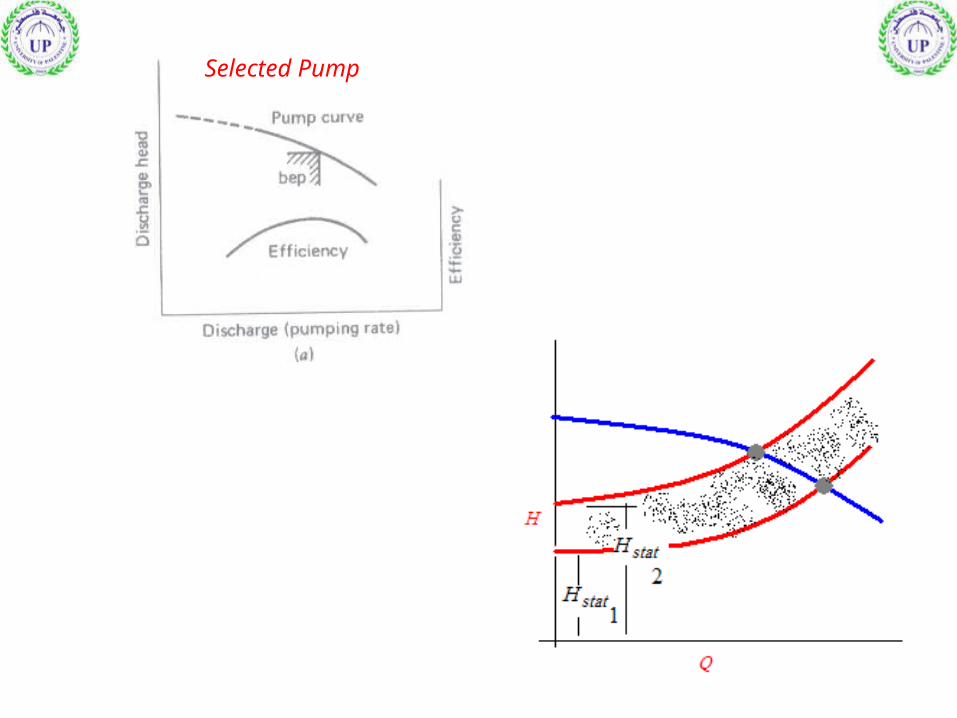
System Characteristic Curve
H H ht stat L
Q1 > Q2
V1 > V2
hf1 > hf2

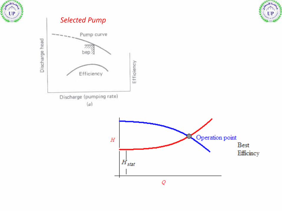
Selected Pump
Q
hf
System Curve
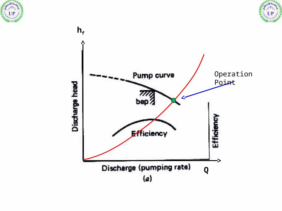
Q
hf
Operation Point

System Characteristic Curve
H H ht stat L
Selected Pump

Elevated Tank
Selected Pump

System Curve & Pump Curve cases
Pump Curve
Pump Curve
Pump Curve
System Curve
System Curve
System Curve
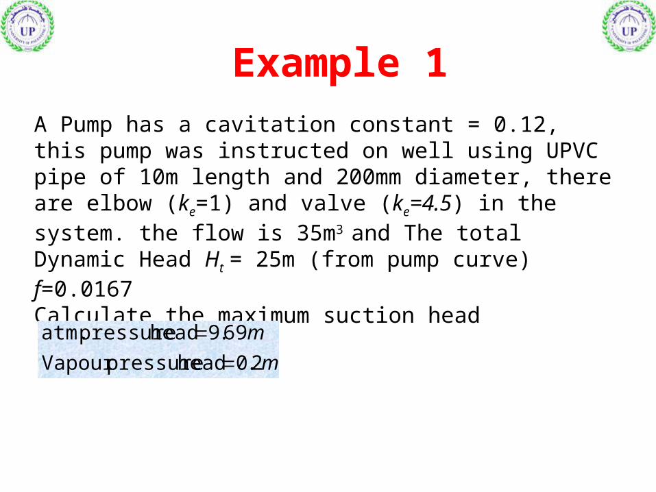
Example 1 A Pump has a cavitation constant = 0.12, this pump was instructed on well using UPVC pipe of 10m length and 200mm diameter, there are elbow (ke=1) and valve (ke=4.5) in the system. the flow is 35m3
and The total Dynamic Head Ht = 25m (from pump curve) f=0.0167Calculate the maximum suction head
m
m
2.0head pressureVapour
69.9head pressure atm.
325120
120
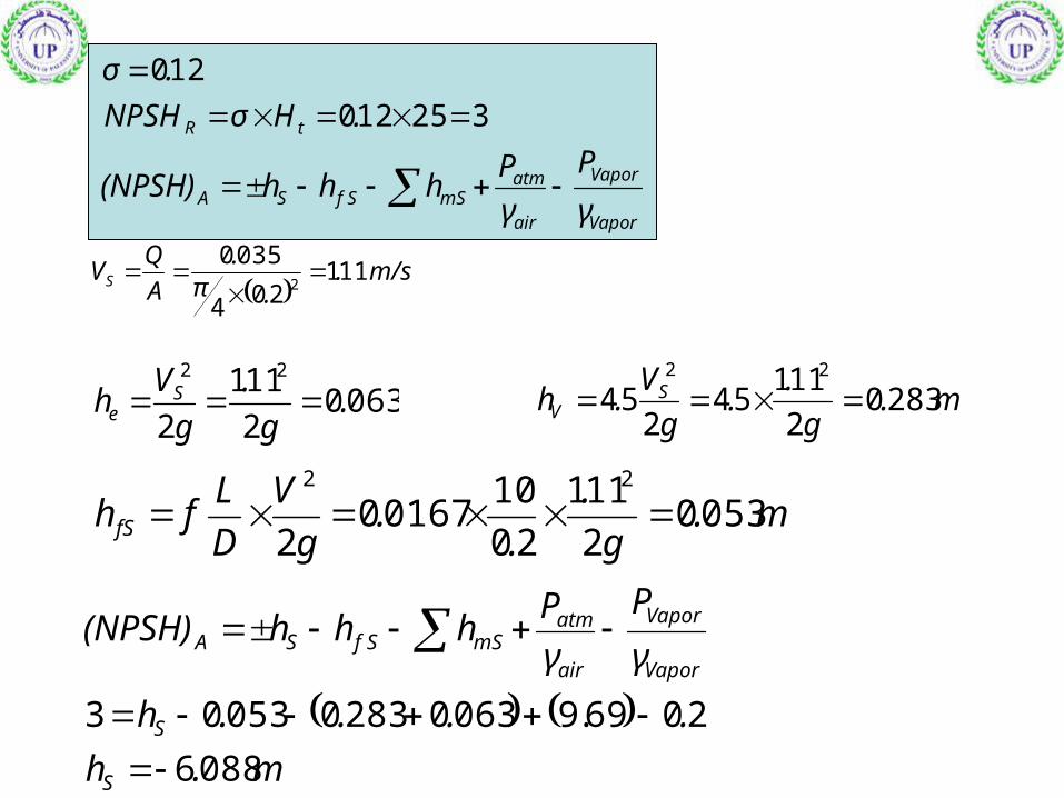
.HσNPSH
.σ
tR
m.g
..
g
V.h S
V 28302
11154
254
22
06302
111
2
22
.g
.
g
Vh S
e
m.g
.
..
g
V
D
Lfh fS 0530
2
111
20
1001670
2
22
m.h
....h
γ
P
γ
Phhh(NPSH)
S
S
Vapor
Vapor
air
atmmSf SSA
0886
2069.90630283005303
Vapor
Vapor
air
atmmSf SSA γ
P
γ
Phhh(NPSH)
m/s .
.π.
A
QVS 111
204
03502
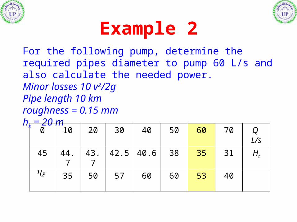
Example 2For the following pump, determine the required pipes diameter to pump 60 L/s and also calculate the needed power.Minor losses 10 v2/2gPipe length 10 kmroughness = 0.15 mmhs = 20 m
Q L/s
706050403020100
Ht31353840.642.543.744.745
40536060575035-P
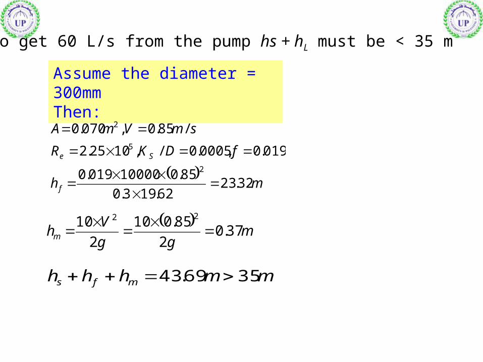
To get 60 L/s from the pump hs + hL must be < 35 m
Assume the diameter = 300mmThen:
mh
fDKR
smVmA
f
Se
32.2362.193.0
85.010000019.0
019.0,0005.0/,1025.2
/85.0,070.0
2
5
2
m
gg
Vhm 37.0
2
85.010
2
10 22
mmhhh mfs 3569.43

Assume the diameter = 350mmThen:
smVmA /624.0,0962.0 2
,48.10
0185.0,00043.0/,1093.1 5
mh
fDKR
f
Se
m
gg
Vhm 2.0
2
624.010
2
10 22
mmhhh mfs 3568.30
kWWHQ
Pp
ti 87.388.38869
53.0
3581.91000 100060

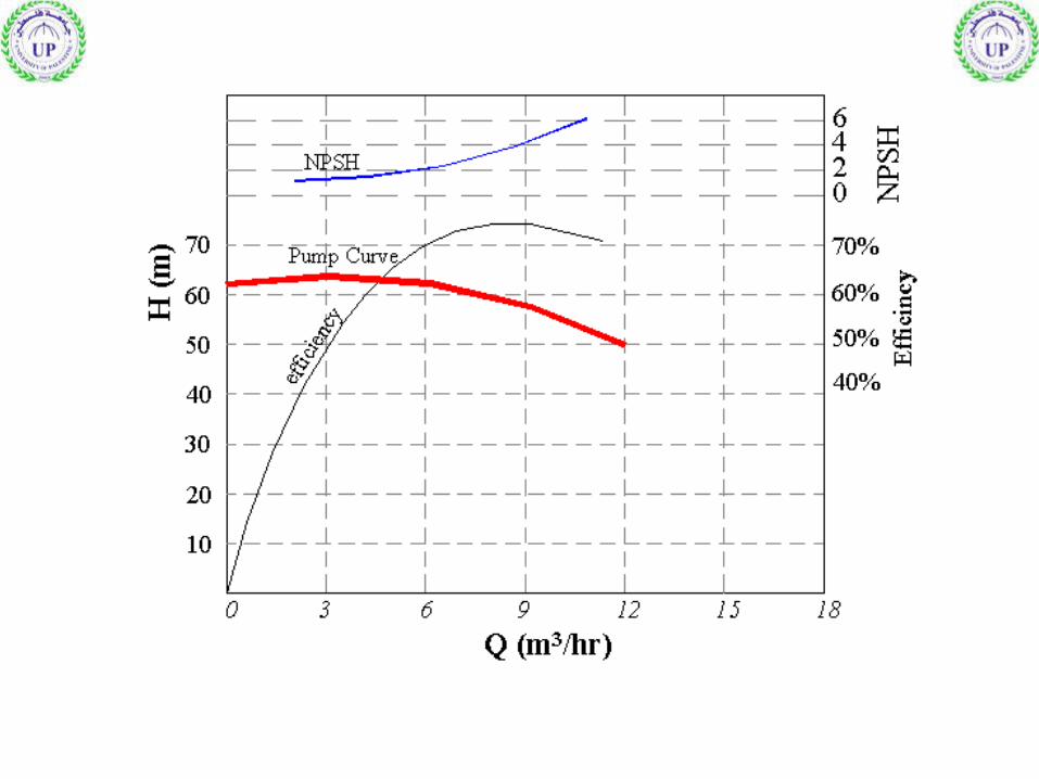
Example 3A pump was designed to satisfy the following system Q (m3/hr)369
hf (m)122038
m
m
25.0head pressureVapour
3.10head pressure atm.
mhd 13
Pipe diameter is 50mm
g
VhL 2
24Partsuction
2
Check whether the pump is suitable or not

1- Draw the system curve and check the operation point
20m713hhH SdSTAT

There are an operation point at:
Q = 9 m3/hr H =58m
NPSHR =4.1Then Check NPSHA
m.
g
.h
m/s..
π/
A
QV
L 022
27124
271050
4
36009
2
2
4.11.05(NPSH)
0.2510.327(NPSH)
γ
P
γ
Phhh(NPSH)
A
A
Vapor
Vapor
air
atmmSS SA
f
pump is not suitable, the cavitation will occur

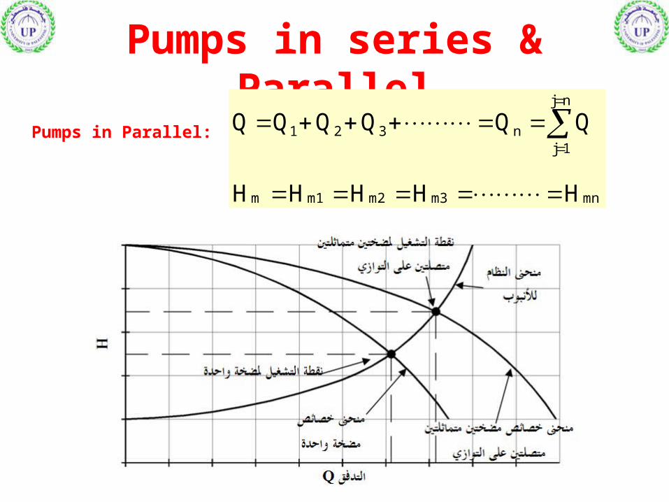
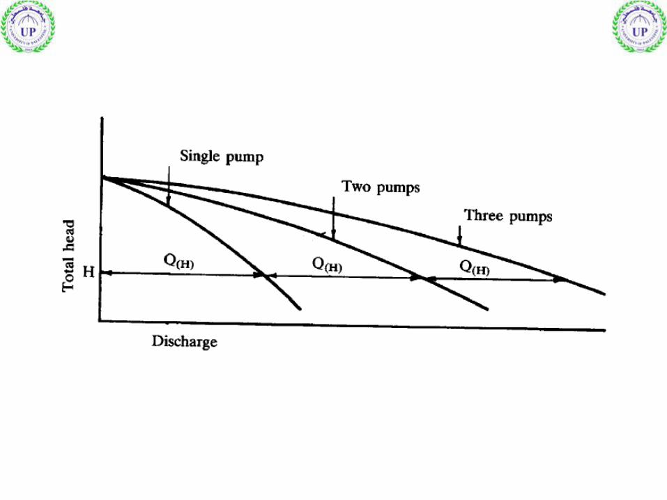
Pumps in series & Parallel
Pumps in Parallel:
mnm3m2m1m
nj
1jn321
HHHHH
QQQQQQ
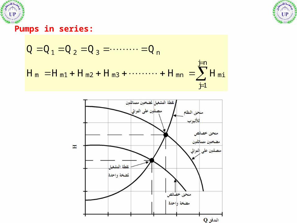
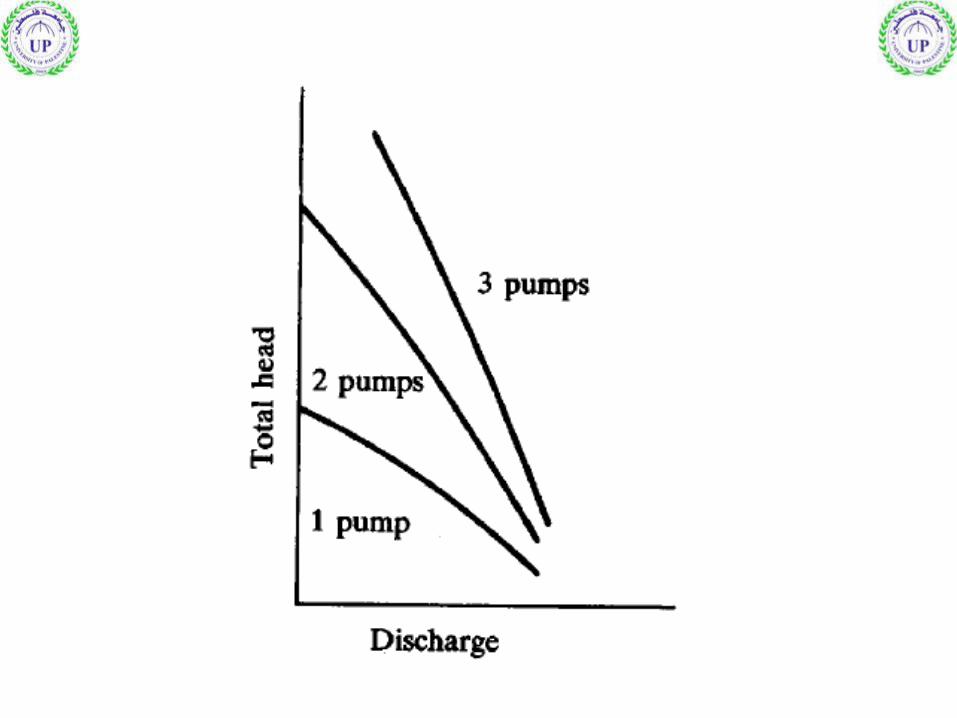
Pumps in series:
nj
1j
mimnm3m2m1m
n321
HHHHHH
QQQQQ

Change in pump speed (constant size)
Q
Q
N
N2
1
2
1
H
H
N
N2
1
2
1
2
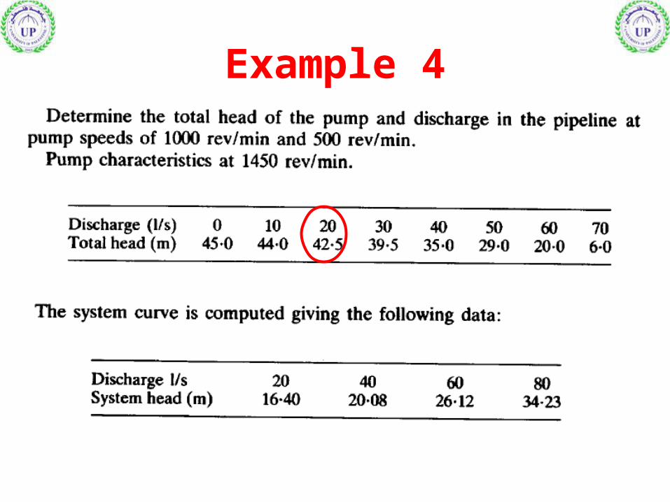
Example 4
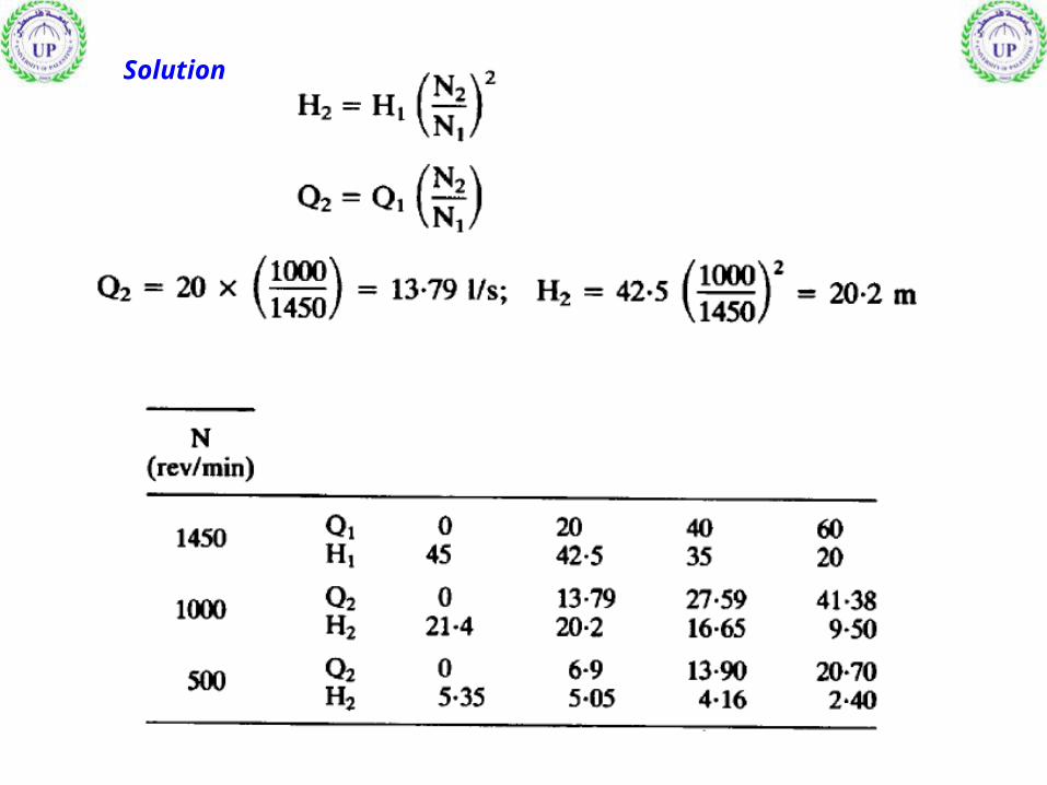
Solution

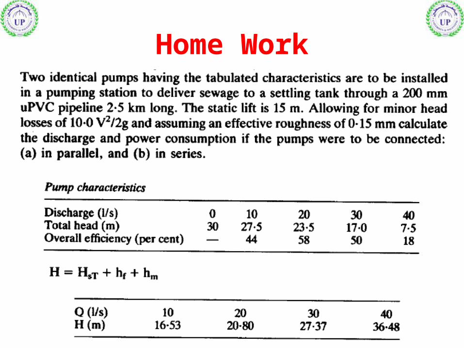
Home Work
Related Documents


![Conference Day 1 Presentations · 1 q h q q q v v v v q w $ 1 q p h g g h u $ v v l h k v k g 1 g h w \ q r] w u o v v](https://static.cupdf.com/doc/110x72/5ffdf9fd499387508f2c961c/conference-day-1-presentations-1-q-h-q-q-q-v-v-v-v-q-w-1-q-p-h-g-g-h-u-v-v-l.jpg)
