© 2013, Her Majesty the Queen in right of the Province of Alberta Hydraulic Disc Brake Systems Parts Technician First Period Material Identification and Calculations 270103m

Hydraulic Disc Brake Systems Parts Technician First Period Material Identification and Calculations 270103m.
Dec 31, 2015
Welcome message from author
This document is posted to help you gain knowledge. Please leave a comment to let me know what you think about it! Share it to your friends and learn new things together.
Transcript

Hydraulic Disc Brake Systems
Parts Technician
First Period
Material Identification and Calculations
270103m

© 2013, Her Majesty the Queen in right of the Province of Alberta
Figure 1 - Major components of a front disc brake system.

© 2013, Her Majesty the Queen in right of the Province of Alberta
Figure 2 - Discs swept area versus similar diameter drum swept area.

© 2013, Her Majesty the Queen in right of the Province of Alberta
Figure 3 - Equal braking force is applied to both sides of the disc.

© 2013, Her Majesty the Queen in right of the Province of Alberta
Figure 4 - Disc mountings.

© 2013, Her Majesty the Queen in right of the Province of Alberta
Figure 5 - Composite discs.

© 2013, Her Majesty the Queen in right of the Province of Alberta
Figure 6 - Solid disc (left) versus vented disc (right).

© 2013, Her Majesty the Queen in right of the Province of Alberta
Figure 7 - Airflow through the rotor.

© 2013, Her Majesty the Queen in right of the Province of Alberta
Figure 8 - Brake pad area versus heat dissipation area.
© 2013, Her Majesty the Queen in right of the Province of Alberta
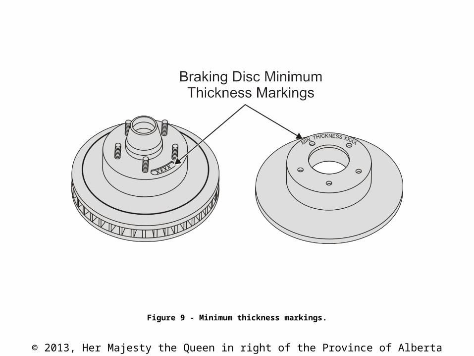
Figure 9 - Minimum thickness markings.

© 2013, Her Majesty the Queen in right of the Province of Alberta
Figure 10 - A disc micrometer used to measure thickness.
© 2013, Her Majesty the Queen in right of the Province of Alberta
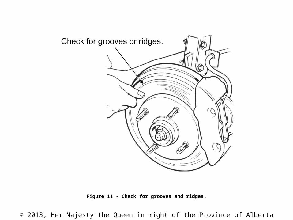
Figure 11 - Check for grooves and ridges.

© 2013, Her Majesty the Queen in right of the Province of Alberta
Figure 12 - Examples of disc damage.

© 2013, Her Majesty the Queen in right of the Province of Alberta
Figure 13 - Disc brake caliper housing.

© 2013, Her Majesty the Queen in right of the Province of Alberta
Figure 14 - An aluminum caliper with fins.

© 2013, Her Majesty the Queen in right of the Province of Alberta
Figure 15 - Caliper clamping forces.

© 2013, Her Majesty the Queen in right of the Province of Alberta
Figure 16 - Fixed calipers.

© 2013, Her Majesty the Queen in right of the Province of Alberta
Figure 17 - Cutaway view of a four-piston fixed caliper.

© 2013, Her Majesty the Queen in right of the Province of Alberta
Figure 18 - Fixed caliper halves showing the O-ring seal and drilled passages.

© 2013, Her Majesty the Queen in right of the Province of Alberta
Figure 19 - Fixed caliper components.
© 2013, Her Majesty the Queen in right of the Province of Alberta
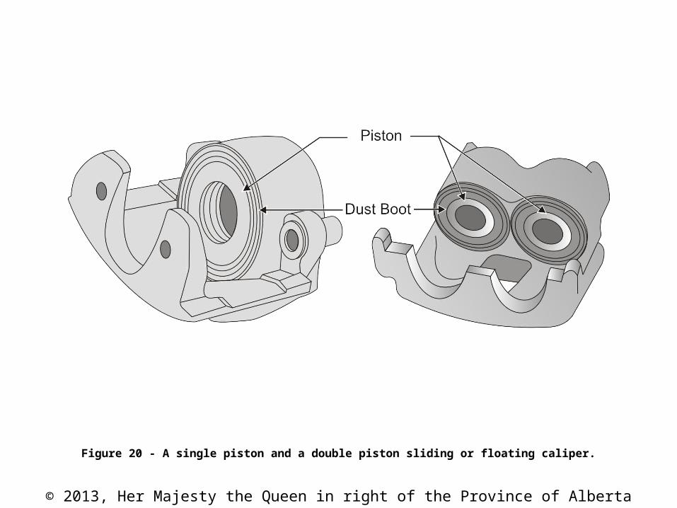
Figure 20 - A single piston and a double piston sliding or floating caliper.

© 2013, Her Majesty the Queen in right of the Province of Alberta
Figure 21 - Caliper mount.
© 2013, Her Majesty the Queen in right of the Province of Alberta
NOTE
The bushings are often supplied with replacement pads. Check the packaging and if the bushings are not included, suggest them as a related sales item. Inform the customer that the caliper must slide freely to operate correctly.
© 2013, Her Majesty the Queen in right of the Province of Alberta
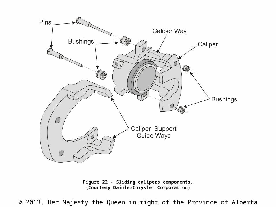
Figure 22 - Sliding calipers components.(Courtesy DaimlerChrysler Corporation)

© 2013, Her Majesty the Queen in right of the Province of Alberta
Figure 23 - Two methods used to retain the floating caliper.

© 2013, Her Majesty the Queen in right of the Province of Alberta
Figure 24 - Floating or sliding caliper.

© 2013, Her Majesty the Queen in right of the Province of Alberta
Figure 25 - Sliding calipers apply force from both sides of the disc in the same fashion as a C-clamp.

© 2013, Her Majesty the Queen in right of the Province of Alberta
Figure 26 - Pistons.

© 2013, Her Majesty the Queen in right of the Province of Alberta
Figure 27 - Exploded view of caliper, seals, bushings and boot.

© 2013, Her Majesty the Queen in right of the Province of Alberta
Figure 28 - Caliper piston seal in the applied and released positions.

© 2013, Her Majesty the Queen in right of the Province of Alberta
Figure 29 - Brake pad.

© 2013, Her Majesty the Queen in right of the Province of Alberta
Figure 30 - Audible pad wear indicator (squealer).
© 2013, Her Majesty the Queen in right of the Province of Alberta
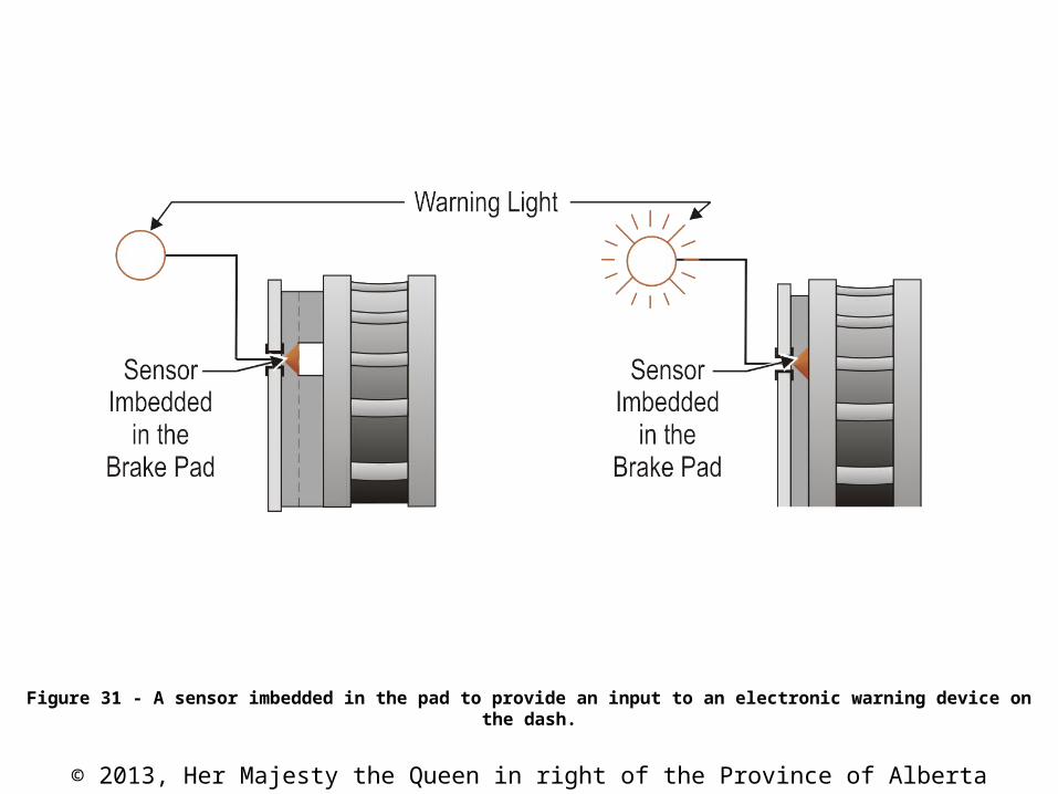
Figure 31 - A sensor imbedded in the pad to provide an input to an electronic warning device on the dash.

© 2013, Her Majesty the Queen in right of the Province of Alberta
Figure 32 - Silencers located on the back of the pad.

© 2013, Her Majesty the Queen in right of the Province of Alberta
Figure 33 - Anti-squeal compound used to reduce brake noise.

© 2013, Her Majesty the Queen in right of the Province of Alberta
Figure 34 - The parking brake foot pedal and a hand lever.

© 2013, Her Majesty the Queen in right of the Province of Alberta
Figure 35 - Graphic symbols used for parking brake and brake warning.

© 2013, Her Majesty the Queen in right of the Province of Alberta
Figure 36 - A complete parking brake set-up.(Courtesy Honda Canada Inc.)

© 2013, Her Majesty the Queen in right of the Province of Alberta
Figure 37 - Parking brake cable construction.

© 2013, Her Majesty the Queen in right of the Province of Alberta
Figure 38 - A drum-in-hat style rear brake system.

© 2013, Her Majesty the Queen in right of the Province of Alberta
Figure 39 - Backing plate and anchor.

© 2013, Her Majesty the Queen in right of the Province of Alberta
Figure 40 - Components found in a drum-in-hat parking brake system.

© 2013, Her Majesty the Queen in right of the Province of Alberta
Figure 41 - The two most common designs of rear calipers.

© 2013, Her Majesty the Queen in right of the Province of Alberta
Figure 42 - Parking brake cable attachment and return spring location.

© 2013, Her Majesty the Queen in right of the Province of Alberta
Table 2 - Common replacement components and related sales.
Failed Component Related Sales
brake disc/rotor wheel bearings seals brake fluid grease
disc brake pads caliper bushings and seals hardware brake quiet brake lubricantgrease
park brake cables levers and struts brake shoes seals wheel bearings grease
© 2013, Her Majesty the Queen in right of the Province of Alberta
NOTE
In most cases, caliper cores must be returned assembled. Some manufacturers also require them to be in the box of the rebuilt caliper.
Related Documents