Max. Lifting Capacities : 80 t x 3.0 m Max. Crane Boom Length : 54.9 m Max. Fixed Jib Combination: 42.7 m + 18.3 m 45.7 m + 12.2 m Hydraulic Crawler Crane Model : CKE800G

Welcome message from author
This document is posted to help you gain knowledge. Please leave a comment to let me know what you think about it! Share it to your friends and learn new things together.
Transcript
Max. Lifting Capacities : 80 t x 3.0 mMax. Crane Boom Length : 54.9 mMax. Fixed Jib Combination: 42.7 m + 18.3 m 45.7 m + 12.2 m
Hydraulic Crawler Crane
Model : CKE800G

3 SPECIFICATIONS
5 GENERAL DIMENSIONS
6 BOOM AND JIB ARRANGEMENTS
7 WORKING RANGES
10 SUPPLEMENTAL DATA
11 LIFTING CAPACITIES
14 TRANSPORTATION PLAN
17 PARTS AND ATTACHMENTS
CKE800GCONTENTS
SPECIFICATIONS
Power Plant
Model: HINO J08E-UVType: 4 cycle, water-cooled, vertical in-line 6, direct injection, turbo-charger, intercoolerComplies with NRMM (Europe) Stage IIIB and US EPA Tier Interim Tier 4Displacement: 7,684 litersRated power: 213 kW/2100 min-1 (285 HP/2,100 rpm)Max. Torque: 1,017 N·m/1,600 min-1
Cooling System: Water-cooledStarter: 24V-5kWRadiator: Corrugated type core, thermostatically controlledAir cleaner: Dry type with replaceable paper elementThrottle: Twist grip type hand throttle, electrically actuatedFuel fi lter: Replaceable paper element Batteries: Two 12V x 136 Ah/5HR capacity batteries, series connectedFuel tank capacity: 400 liters
Hydraulic System
Main pumps: 3 variable displacement piston pumps Control: Full-fl ow hydraulic control system for infi nitely variable pressure to all winches, propel and swing. Controls respond instantly to the touch, delivering smooth function operation.Cooling: Oil-to-air heat exchanger (plate-fi n type)Filtration: Full-fl ow and bypass type with replaceable elementMax. relief valve pressure:
Load hoist, boom hoist and propel system:4,626 psi (31.9 MPa)Swing system: 27.5 MPa (3,989 psi)Control system: 5.4 MPa (783 psi)
Hydraulic Tank Capacity: 440 liters (116.2 US Gal)
Boom Hoisting System
Powered by a hydraulic motor through a planetary reducer.Brake: A spring-set, hydraulically released multiple-disc brake is mounted on the boom hoist motor and operated through a counter-balance valve.Drum Lock: External ratchet for locking drumDrum: Single drum, grooved for 16mm dia. wire ropeLine Speed: Single line on fi rst drum layer
Hoisting/Lowering: 70 to 2 m/minDiameter of wire rope
Main winch: 22 mm x 220 m (7/8 in. x 869 ft.)Aux. winch: 22 mm x 130 m (7/8 in. x 673 ft.)Third winch: 22 mm x 145 m (7/8 in. x 476 ft.) Boom hoisting/lowering: 16 mm x 150 m (5/8 in. x 492 ft)Boom guy line: 30 m (1-3/16 in.)Boom backstops: Required for all boom length
Load Hoisting System
Front and rear drums for load hoist powered by a hydraulic variable plunger motors, driven through planetary reducers.Negative Brake: A spring-set, hydraulically released multiple-disc brake is mounted on the hoist motor and operated through a counter-balance valve. (Positive free fall brake is optional)Drum Lock: External ratchet for locking drumDrums:
Front Drums:550 mm (1 ft 9-21/32 inch) P.C.D x 545 m (1 ft 9-15/32 inch) wide drum, grooved for 22 mm (7/8 inch) wire rope. Rope capacity is 220 m (722 ft) working length and 335 m (1099 ft) storage length.Rear Drum: 550 mm (1 ft 9-21/32 inch) P.C.D x 545 m (1 ft 9-15/32 inch, grooved for 22 mm (7/8 inch) wire rope. Rope capacity is 130 m (427 ft) working length and 335m (1,099 ft) storage length.
Line Speed: Single line on fi rst drum layerHoisting/lowering: 120 to 3 m/min
Line Pull:Max. Line Pull (Single Line): 153 kN (34,400 lbs)(Referential performance) Rated Line Pull: 78.5 kN (17,000 lbs)
Swing System
Swing unit is powered by hydraulic motor driving spur gears through planetary reducers (2 set), the swing system provides 360° rotation.Swing parking brakes: A spring-set, hydraulically released multiple-disc brake is mounted on swing motor.Swing circle: Single-row ball bearing with an integral internally cut swing gear.Swing lock: Manually, four position lock for transportationSwing Speed: 4.0 min-1 (rpm)
Upper Structure
Torsion-free precision machined upper frame. All components are located clearly and service friendly. Engine will with low noise level.Counter weight: 27.2 ton
Cab & Control
Totally enclosed, full vision cab with safety glass, fully adjustable, high backed seat with a headrest and armrests, and intermittent wiper and window washer (skylight and front window).Cab fi ttings: Air conditioner, convenient compartment (for tool), cup holder, ashtray, cigarette lighter, sun visor, roof blind, tinted glass, fl oor mat, footrest, and shoe tray
Controls:Four adjustable levers for front drum, rear drum, boom drum and swing controls.
Lower Structure
Steel-welded carbody with axles. Crawler assemblies are designed with quick disconnect feature for individual removal as a unit from axles. Crawler belt tension is maintained by hydraulic jack force on the track adjusting bearing block.Carbodyweight: 6.5 tonCrawler drive: Independent hydraulic propel drive is built into each crawler side frame. Each drive consists of a hydraulic motor propelling a driving tumbler through a planetary gear box. Hydraulic motor and gear box are built into the crawler side frame within the shoe width.Crawler brakes: Spring-set, hydraulically released parking brakes are built into each propel drive.Steering mechanism: A hydraulic propel system provides both skid steering (driving one track only) and counter-rotating steering (driving each track in opposite directions).Track rollers: Sealed track rollers for maintenance-free operation.Shoe (fl at): 800 mm wide each crawlerMax. gradeability: 40%
Weight
Including upper and lower machine, 27.2 ton counterweight and 6.5 ton carbody weight, basic boom (or basic boom + basic jib), hook, and other accessories.Weight: 75.1 tonGround pressure: 84.7 kPa (10.8 psi)
Attachment
Boom & Jib:Welded lattice construction using tubular, high-tensile steel chords with pin connection between sections.
Boom and Jib length
Min. Length(Min. combination)
Max. Length(Min. combination)
Crane Boom 30 m 54.9 m
Fixed Iib 30.5 m + 6.1 m42.7 m + 18.3 m,45.7 m + 12.2 m
Main Specifi cations (Model: CKE800G) Crane Boom Max. Lifting Capacity 80 t x 3.0 m Max. Length 54.9 m Fixed Jib Max. Lifting Capacity 6.6 t x 20.0 m Max. Combination 42.7 m + 18.3, 45.7 m +12.2 m Main & Aux. Winch Max. Line Speed (1st layer) 120 m/min Rated Line Pull (Single line) 78.5 kN {8.0 tf}Wire Rope Diameter 22 mm x 220 mWire Rope Length 220 m (Main), 130 m (Aux.)Brake Type Wet-type multiple disc brake (Optional)Working Speed Swing Speed 4.0 min-1{rpm}Travel Speed 1.73/1.15 km/hPower Plant Model HINO J08E-UVEngine Output 213 kW/2100 min-1
Fuel Tank 400 liters
Hydraulic System Main Pums 3 variable displacementMax. Pressure 31.9 Mpa {325 kg/cm2}Hydraulic Tank Capacity 440 litersSelf-Removal Device
Counterweight/crawler self-removal device(Option)
Weight Operating Weight 75.1 t *1
Ground Pressure 84.7 kPaCounterweight 27,200 kg Transport Weight 39,850 kg *2
Units are SI units. { } indicates conventional units.Line speeds in table are for light loads. Line speed varies with load. *1 Including upper and lower machine, 27.2 ton counterweight, 6.5 ton carbody
weight, basic boom, hook, and other accessories. *2 Base machine with boom base, gantry, crawlers, and wire ropes (front/boom
hoist)
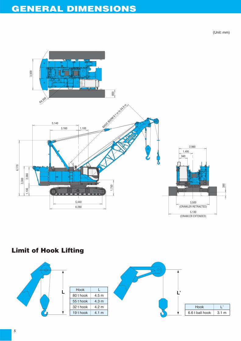
GENERAL DIMENSIONS
3,500(CRAWLER RETRACTED)
5,130(CRAWLER EXTENDED)
390
2,990
1,495
940
5,440
6,280
1,75
0
6,17
0
3,30
0
1,10
02,
080
5,140BASIC BOOM 9.
1 m to
54.9
m
3,160 1,100
800
3,50
0
R4,300
(Unit: mm)
Limit of Hook Lifting
L L’Hook L
80 t hook 4.5 m
55 t hook 4.3 m
32 t hook 4.2 m
19 t hook 4.1 m
Hook L’
6.6 t ball hook 3.1 m

BOOM AND JIB ARRANGEMENTS
Crane Boom Arrangements
Fixed Jib Arrangements
Boomlength m (ft)
Boom arrangement
9.1 (30) ※ B T
12.2 (40) ※ 10 TB
15.2 (50)※
20 TB
TB 10 10
18.3 (60)※
30
10 20 TB
TB
21.3 (70)
※
2020
3010
2010 10
TB
TB
TB
24.4 (80)※ 2010 20
3020
3010 10
TB
TB
TB
27.4 (90)
※ 3010 20
3030
202010 10
TB
TB
TB
30.5 (100)
※
20 20 30
10 30 30
1010 20 30
TB
TB
TB
33.5 (110)
※
20 30 30
10 10 30 30
10 10 30 30 30
2010 20 30
TB
TB
TB
TB
36.6 (120)※
30 30 30
10 20 30 30
201010 20 30
T
T
T
B
B
B
Symbol Boom Length RemarksB 5.2 m Boom Base
T 3.9 m Boom Top10 3.0 m Insert Boom20 6.1 m Insert Boom
20 6.1 m Insert Boom with lug30 9.1 m Insert Boom30 9.1 m Insert Boom with lug
mark shows the guy line installing position when the fi xed jib is used.
※ indicates the most fl exible combination of insert luffi ng booms, which can be modifi ed to form all shorter luffi ng boom arrangements.
Boomlength m (ft)
Boom arrangement
39.6 (130)※
20 20 3030
10 10 20 3030
202010 20 30
10 303030
TB
T
T
T
B
B
B
42.7 (140)
20 3030 30
10 10 3030 30
10 20 3020 30
10 10 20 2020 30
※
TB
TB
TB
TB
45.7 (150)10 20 303030
10 10 20 20 3030
※ TB
TB
48.8 (160)20 20 303030
10 10 20 303030※
TB
TB
51.8 (170)10 2020 303030
10 10 20 2020 3030
※ TB
TB
54.9 (180)10 102020 303030
10 10 2020 303030
※ TB
TB
BOOM
Fixed Jib
Crane boomlength
Jiblength m (ft) Jib arrangement
30.5 m~ 45.7 m 6.1 (20) B T3.0 3.0
30.5 m~ 42.7 m 12.2 (40) B T20
18.3 (60) T20B 20
Symbol Jib Length RemarksB 3.0 m Jib Base
T 3.0 m Jib Top20 6.1 m Insert Jib

Crane Boom
WORKING RANGES
20
25
30
35
40
45
50
55
60
65
54.9m Boom
51.8m Boom
48.8m Boom
45.7m Boom
42.7m Boom
39.6m Boom
36.6m Boom
33.5m Boom
30.5m Boom
27.4m Boom
24.4m Boom
21.3m Boom
18.3m Boom
15.2m Boom
12.2m Boom
9.1m Boom
30˚
35˚
40˚
45˚
50˚
55˚60˚65˚70˚75˚80˚
105
2015 3025 4035 50451.77
m
Hei
gh
t ab
ove
gro
un
d (
m)
Radius from center of rotation (m)
1.1 m
Center ofrotation

Fixed Jib 10°
Center ofrotation
42.7m Boom + 18.3m Jib
45.7m Boom + 12.2m Jib
45.7m Boom + 6.1m Jib
30.5m Boom + 18.3m Jib
30.5m Boom + 12.2m Jib
30.5m Boom + 6.1m Jib
1.75
m
1.1 m
75
10°
70
65
60
55
50
45
40
35
30
25
20
10 15 20 25 30 35 40 45 50
80°
Hei
gh
t ab
ove
gro
un
d (
m)
Radius from center of rotation (m)
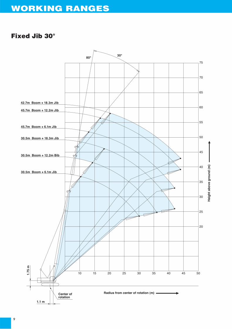
Fixed Jib 30°
WORKING RANGES
42.7m Boom + 18.3m Jib
45.7m Boom + 12.2m Jib
45.7m Boom + 6.1m Jib
30.5m Boom + 18.3m Jib
30.5m Boom + 12.2m Bib
30.5m Boom + 6.1m Jib
1.75
m
Hei
gh
t ab
ove
gro
un
d (
m)
Radius from center of rotation (m)
75
70
65
60
55
50
45
40
35
30
25
20
10 15 20 25 30 35 40 45 50
80°
1.1 m
30°
Center ofrotation
SUPPLEMENTAL DATA
·Ratings according to EN13000.
·Operating radius is the horizontal distance from centerline of rotation to a vertical line through the center of gravity of the load.
·Deduct weight of hook block (s), slings and all other load handling accessories from main boom ratings shown.
·Ratings shown are based on freely suspended loads and make no allowance for such factors as wind effect on lifted load, ground conditions, out-of-level, operating speeds or any other condition that could be detrimental to the safe operation of this equipment.The operator, therefore, has the responsibility to judge the existing conditions and reduce lifted loads and operating speeds accordingly.
·Ratings are for operation on a fi rm and level surface, up to 1 % gradient.
·At radii and boom lengths where no ratings are shown on chart, operation is not intended nor approved.
·Boom inserts and guy lines must be arranged as shown in the "operator's manual".
·Boom hoist reeving is 12 part line.
·Gantry must be in raised position for all conditions.
·Boom backstops are required for all boom lengths.
·The boom should be erected over the front of the crawlers, not laterally.
·Ratings inside of boxes are limited by strength of materials.
·The minimum rated load is 1.1 (ton).
·Crawler frames must be fully extended for all crane operations.
·For the combination of the boom of 54.9 m (180 ft) length and the jib of any length, place blocking steel plates between the ends of the crawlers and the ground.
(Main boom)·The total load that can be lifted is the value for weight of hook block, slings, and all other load handling accessories deducted from main boom ratings shown.
(Main boom with auxiliary sheave frame)·The total load that can be lifted is the value for weight of hook block (s), slings, and all other load handling accessories deducted from main boom with auxiliary sheave ratings shown.
(Auxiliary sheave)·The total load that can be lifted is the value for weight of hook block (s), slings, and all other load handling accessories deducted from auxiliary sheave ratings shown.
·Boom lengths for auxiliary sheave mounting are 9.1 m to51.8 m.
(Main boom with fi xed jib)·The total load that can be lifted is the value for weight of hook block (s), slings, and all other load handling accessories deducted from main boom with fi xed jib ratings shown.
·Only 19 t and 32 t hook block can be used for main hook.
(Fixed jib)·The total load that can be lifted is the value for weight of hook block (s), slings, and all other load handling accessories deducted from fi xed jib ratings shown.
·Boom lengths for fi xed jib mounting are 30.5 m to 45.7 m.However, do not install 18.3 m jib to 45.7 m boom.
Main hoist loadsNo. of Parts of Line 1 2 3 4 5
Maximum Loads (kN) 78 157 235 314 392Maximum Loads (t) 8.0 16.0 24.0 32.0 40.0
No. of Parts of Line 6 7 8 9 10Maximum Loads (kN) 471 549 628 706 785Maximum Loads (t) 48.0 56.0 64.0 72.0 80.0
Auxiliary hoist loadsNo. of Parts of Line 1
Maximum Loads (kN) 78Maximum Loads (t) 8.0
Weight of hook blockHook Block 80 t 50 t 32 t 19 t 6.6 t Ball HookWeight (t) 0.8 0.7 0.5 0.4 0.16
Operation of this equipment in excess of rated loadsor disregard of instruction voids the warranty.
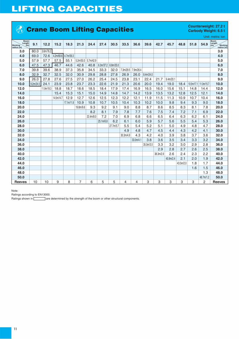
LIFTING CAPACITIES
Boom Length
Working (m)radius (m)
9.1 12.2 15.2 18.3 21.3 24.4 27.4 30.5 33.5 36.6 39.6 42.7 45.7 48.8 51.8 54.9BoomLength(m) Working
radius (m)
3.0 80.0 3.6m/76.2 3.04.0 69.0 72.6 4.2m/69.6 4.7m/59.3 4.05.0 57.9 57.7 57.5 55.1 5.2m/50.0 5.7m/42.9 5.06.0 47.5 47.3 46.7 44.6 42.6 40.8 6.3m/37.2 6.8m/33.0 6.07.0 39.8 39.6 38.9 37.3 35.8 34.5 33.3 32.0 7.3m/29.5 7.9m/26.4 7.08.0 32.9 32.7 32.5 32.0 30.9 29.8 28.8 27.8 26.9 26.0 8.4m/24.0 8.09.0 26.0 27.8 27.6 27.5 27.0 26.2 25.4 24.5 23.8 23.1 22.4 21.7 9.4m/20.1 9.0
10.0 9.2m/24.5 24.1 23.9 23.8 23.7 23.3 22.6 21.9 21.3 20.6 20.0 19.4 19.0 18.4 10.5m/17.1 11.0m/15.7 10.012.0 11.9m/19.3 18.8 18.7 18.6 18.5 18.4 17.9 17.4 16.9 16.5 16.0 15.6 15.1 14.8 14.4 12.014.0 15.4 15.3 15.1 15.0 14.9 14.8 14.7 14.2 13.9 13.5 13.2 12.8 12.5 12.1 14.016.0 14.5m/14.7 12.9 12.7 12.6 12.5 12.3 12.2 12.1 11.9 11.5 11.3 10.9 10.7 10.4 16.018.0 17.1m/11.8 10.9 10.8 10.7 10.5 10.4 10.3 10.2 10.0 9.8 9.4 9.3 9.0 18.020.0 19.8m/9.6 9.3 9.2 9.1 9.0 8.8 8.7 8.6 8.5 8.3 8.1 7.8 20.022.0 8.2 8.1 7.9 7.8 7.7 7.6 7.5 7.4 7.2 7.1 6.9 22.024.0 22.4m/8.0 7.2 7.0 6.9 6.8 6.6 6.5 6.4 6.3 6.2 6.1 24.026.0 25.1m/6.8 6.2 6.1 6.0 5.9 5.7 5.6 5.5 5.4 5.3 26.028.0 27.7m/5.7 5.5 5.4 5.2 5.1 5.0 4.9 4.8 4.7 28.030.0 4.9 4.8 4.7 4.5 4.4 4.3 4.2 4.1 30.032.0 30.3m/4.9 4.3 4.2 4.0 3.9 3.8 3.7 3.6 32.034.0 33.0m/4.1 3.8 3.6 3.5 3.4 3.3 3.2 34.036.0 35.0m/3.5 3.3 3.2 3.0 2.9 2.8 36.038.0 2.9 2.8 2.7 2.6 2.5 38.040.0 38.3m/2.9 2.6 2.4 2.3 2.2 40.042.0 40.9m/2.4 2.1 2.0 1.9 42.044.0 43.5m/2.0 1.8 1.7 44.046.0 1.6 1.5 46.048.0 1.3 48.050.0 48.7m/1.2 50.0
Reeves 10 10 9 8 7 6 5 5 4 4 3 3 3 3 3 2 Reeves
Note: Ratings according to EN13000.Ratings shown in are determined by the strength of the boom or other structural components.
Crane Boom Lifting CapacitiesCounterweight: 27.2 tCarbody Weight: 6.5 t
Unit: metric ton
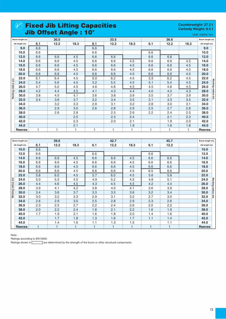
Boom length (m) 30.5 33.5 36.6 Boom length (m)
Jib length (m) 6.1 12.2 18.3 6.1 12.2 18.3 6.1 12.2 18.3 Jib length (m)
9.0 6.6 6.6 9.010.0 6.6 6.6 6.6 10.012.0 6.6 6.6 4.5 6.6 6.6 6.6 6.6 12.014.0 6.6 6.6 4.5 6.6 6.6 4.5 6.6 6.6 4.5 14.016.0 6.6 6.6 4.5 6.6 6.6 4.5 6.6 6.6 4.5 16.018.0 6.6 6.6 4.5 6.6 6.6 4.5 6.6 6.6 4.5 18.020.0 6.6 6.6 4.5 6.6 6.6 4.5 6.6 6.6 4.5 20.022.0 6.1 6.4 4.5 6.0 6.2 4.5 5.9 6.2 4.5 22.024.0 5.4 5.6 4.5 5.2 5.5 4.5 5.1 5.4 4.5 24.026.0 4.7 5.0 4.5 4.6 4.8 4.5 4.5 4.8 4.5 26.028.0 4.2 4.4 4.5 4.1 4.3 4.4 4.0 4.2 4.3 28.030.0 3.8 4.0 4.1 3.6 3.8 3.9 3.5 3.7 3.9 30.032.0 3.4 3.6 3.7 3.2 3.4 3.5 3.1 3.3 3.5 32.034.0 3.2 3.3 2.9 3.1 3.2 2.8 3.0 3.1 34.036.0 2.9 3.0 2.6 2.8 2.9 2.5 2.7 2.8 36.038.0 2.6 2.8 2.5 2.6 2.2 2.4 2.5 38.040.0 2.5 2.3 2.4 2.1 2.3 40.042.0 2.3 2.0 2.1 1.9 2.0 42.044.0 2.1 1.9 1.6 1.8 44.0
Reeves 1 1 1 1 1 1 1 1 1 Reeves
Fixed Jib Lifting CapacitiesJib Offset Angle : 10°
Counterweight: 27.2 tCarbody Weight: 6.5 t
Unit: metric ton
Wo
rkin
g r
adiu
s (m
) Wo
rking
radiu
s (m)
Boom length (m) 39.6 42.7 45.7 Boom length (m)
Jib length (m) 6.1 12.2 18.3 6.1 12.2 18.3 6.1 12.2 Jib length (m)
10.0 6.6 10.012.0 6.6 6.6 6.6 12.014.0 6.6 6.6 4.5 6.6 6.6 4.5 6.6 6.6 14.016.0 6.6 6.6 4.5 6.6 6.6 4.5 6.6 6.6 16.018.0 6.6 6.6 4.5 6.6 6.6 4.5 6.6 6.6 18.020.0 6.6 6.6 4.5 6.6 6.6 4.5 6.5 6.6 20.022.0 5.8 6.0 4.5 5.7 6.0 4.5 5.6 5.8 22.024.0 5.0 5.3 4.5 4.9 5.2 4.5 4.8 5.1 24.026.0 4.4 4.6 4.5 4.3 4.5 4.5 4.2 4.4 26.028.0 3.9 4.1 4.2 3.8 4.0 4.1 3.6 3.9 28.030.0 3.4 3.6 3.7 3.3 3.5 3.6 3.2 3.4 30.032.0 3.0 3.2 3.3 2.9 3.1 3.2 2.7 3.0 32.034.0 2.6 2.9 3.0 2.5 2.8 2.9 2.3 2.6 34.036.0 2.3 2.5 2.7 2.2 2.4 2.6 2.0 2.2 36.038.0 2.0 2.2 2.4 1.8 2.1 2.2 1.6 1.9 38.040.0 1.7 1.9 2.1 1.6 1.8 2.0 1.4 1.6 40.042.0 1.7 1.8 1.3 1.6 1.7 1.1 1.4 42.044.0 1.4 1.6 1.1 1.3 1.5 1.1 44.0
Reeves 1 1 1 1 1 1 1 1 Reeves
Note: Ratings according to EN13000.Ratings shown in are determined by the strength of the boom or other structural components.
Wo
rkin
g r
adiu
s (m
) Wo
rking
radiu
s (m)

LIFTING CAPACITIES
Boom length (m) 30.5 33.5 36.6 Boom length (m)
Jib length (m) 6.1 12.2 18.3 6.1 12.2 18.3 6.1 12.2 18.3 Jib length (m)
12.0 6.6 6.6 6.6 12.014.0 6.6 6.6 6.6 14.016.0 6.6 5.0 6.6 5.0 6.6 5.0 16.018.0 6.6 5.0 3.2 6.6 5.0 3.2 6.6 5.0 18.020.0 6.6 5.0 3.2 6.6 5.0 3.2 6.6 5.0 3.2 20.022.0 6.2 5.0 3.2 6.1 5.0 3.2 6.1 5.0 3.2 22.024.0 5.5 5.0 3.2 5.4 5.0 3.2 5.3 5.0 3.2 24.026.0 4.8 4.9 3.2 4.7 5.0 3.2 4.6 5.0 3.2 26.028.0 4.3 4.6 3.2 4.2 4.5 3.2 4.1 4.4 3.2 28.030.0 3.8 4.1 3.1 3.7 4.0 3.2 3.6 3.9 3.2 30.032.0 3.7 3.0 3.3 3.6 3.0 3.2 3.5 3.1 32.034.0 3.3 2.8 3.2 2.9 2.9 3.1 3.0 34.036.0 3.0 2.7 2.9 2.8 2.8 2.9 36.038.0 2.6 2.6 2.7 2.5 2.7 38.040.0 2.5 2.5 2.2 2.5 40.042.0 2.4 2.3 2.2 42.044.0 2.1 2.0 44.0
Reeves 1 1 1 1 1 1 1 1 1 Reeves
Fixed Jib Lifting CapacitiesJib Offset Angle : 30°
Counterweight: 27.2 tCarbody Weight: 6.5 t
Unit: metric ton
Wo
rkin
g r
adiu
s (m
) Wo
rking
radiu
s (m)
Boom length (m) 39.6 42.7 45.7 Boom length (m)
Jib length (m) 6.1 12.2 18.3 6.1 12.2 18.3 6.1 12.2 Jib length (m)
12.0 6.6 12.014.0 6.6 6.6 6.6 14.016.0 6.6 5.0 6.6 6.6 16.018.0 6.6 5.0 6.6 5.0 6.6 5.0 18.020.0 6.6 5.0 3.2 6.6 5.0 3.2 6.6 5.0 20.022.0 5.9 5.0 3.2 5.9 5.0 3.2 5.8 5.0 22.024.0 5.2 5.0 3.2 5.1 5.0 3.2 5.0 5.0 24.026.0 4.5 4.9 3.2 4.4 4.8 3.2 4.3 4.7 26.028.0 4.0 4.3 3.2 3.9 4.3 3.2 3.8 4.2 28.030.0 3.5 3.8 3.2 3.4 3.8 3.2 3.3 3.7 30.032.0 3.1 3.4 3.2 3.0 3.3 3.2 2.9 3.2 32.034.0 2.7 3.0 3.1 2.6 3.0 3.2 2.4 2.9 34.036.0 2.3 2.7 2.9 2.2 2.6 2.8 2.1 2.5 36.038.0 2.0 2.4 2.6 1.9 2.3 2.5 1.7 2.1 38.040.0 2.1 2.3 1.6 2.0 2.3 1.4 1.8 40.042.0 1.8 2.1 1.7 2.0 1.2 1.5 42.044.0 1.5 1.8 1.4 1.7 1.3 44.0
Reeves 1 1 1 1 1 1 1 1 Reeves
Note: Ratings according to EN13000.Ratings shown in are determined by the strength of the boom or other structural components.
Wo
rkin
g r
adiu
s (m
) Wo
rking
radiu
s (m)

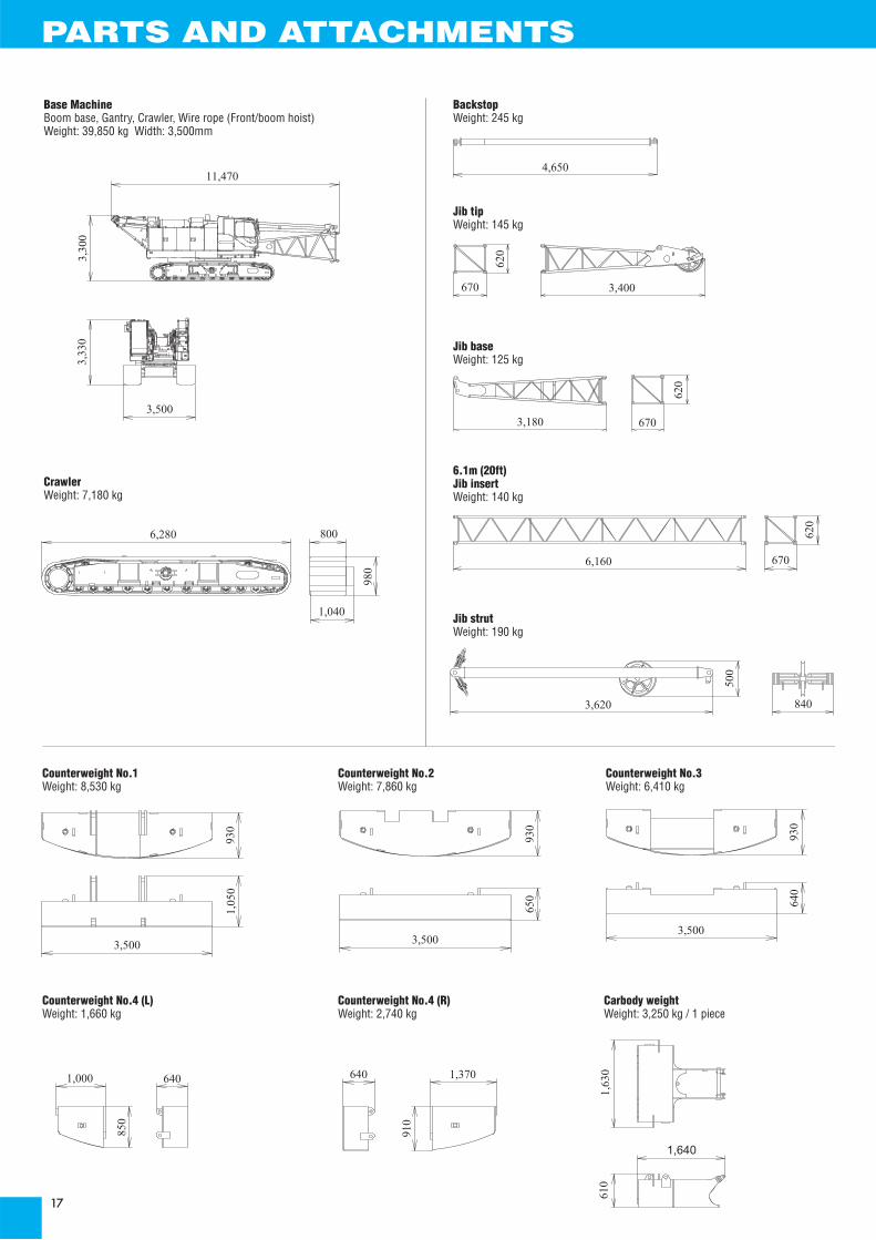
Name Dimension Weight(kg)
Base Machine· Boom base· Gantry· Crawler· Wire rope(Front / boom hoist)
39,850
Base Machine· Gantry· Crawler· Wire rope(Front / rear /boom hoist)
37,880
Base Machine· Boom base· Gantry· Translifter· Wire rope(Front / rear /boom hoist)
· Without crawler
25,490
Base Machine· Gantry· Wire rope(Front / rear /boom hoist)
· Without crawler
23,520
Crawler
7,180
11,470
3,33
0
3,500
3,30
0
2,990
2,990
11,470
2,91
0
4,175
2,94
03,
250
3,500
8,210
3,30
0
2,990
2,890
2,87
0
7,700
3,500
2,94
0
6,280800
980
1,040
TRANSPORTATION PLAN


11,470
3,300
3,330
3,500
6,280 800
980
1,040
930
3,500
1,050
930
650
3,500
930
640
3,500
1,000 640
850
640 1,370
910
6,160
3,180
840
3,400
3,620
500
620
670
620
670
670
620
4,650
1,630
610
1,640
Base MachineBoom base, Gantry, Crawler, Wire rope (Front/boom hoist)Weight: 39,850 kg Width: 3,500mm
BackstopWeight: 245 kg
Counterweight No.1Weight: 8,530 kg
Counterweight No.4 (L)Weight: 1,660 kg
Counterweight No.4 (R)Weight: 2,740 kg
Carbody weightWeight: 3,250 kg / 1 piece
Counterweight No.2Weight: 7,860 kg
Counterweight No.3Weight: 6,410 kg
Jib tipWeight: 145 kg
Jib baseWeight: 125 kg
Jib strutWeight: 190 kg
6.1m (20ft)Jib insertWeight: 140 kg
CrawlerWeight: 7,180 kg
PARTS AND ATTACHMENTS
1,510
1,510
1,510
4,550
5,350
1,870
1,490
3,160
1,510
1,490
6,210
1,510
1,490
6,210 1,490
1,640
9,260
1,510
1,490
9,260
1,640
1,490
Boom tipWeight: 1,110 kg
Auxiliary sheaveWeight: 150 kg
Upper spreaderWeight: 280 kg
Lower spreaderWeight: 170 kg
Ball hookWeight: 160 kg
19t hookWeight: 400 kg
32t hookWeight: 500 kg
50t hookWeight: 650 kg
60t hookWeight: 800 kg
Boom baseWeight: 1,130 kg
3.0m (10ft)Boom insertWeight: 311 kg
6.1m (20ft)Boom insertWeight: 522 kg
6.1m (20ft)Boom insert with lugWeight: 545 kg
9.1m (30ft)Boom insertWeight: 742 kg
9.1m (30ft)Boom insert with lugWeight: 765 kg
1,580
470
1,120
1,090
680
300
870 280
610
820
Φ300 590
1,270 940
390 590330
1,530 1,090
590440
1,470 1,020
600530
1,710 1,150

17-1, Higashigotanda 2-chome, Shinagawa-ku,Tokyo 141-8626 JAPAN
Note: This catalog may contain photographs of machines with specifications, attachments and optional equipment not certified for operation in your country. Please consult KOBELCO for those items you may require. Due to our policy of continual product improvements all designs and specifications are subject to change without advance notice.Copyright by KOBELCO CRANES CO., LTD. No part of this catalog may be reproduced in any manner without notice.
Tel: +81-3-5789-2130 Fax: +81-3-5789-3372URL: http://www.kobelco-cranes.com/
Bulletin No. CKE800G-SPEC-EU1 110401F Printed in Japan
Inquiries To :
KOBELCO is the corporate mark used by Kobe Steel on a variety of productsand in the names of a number of Kobe Steel Group companies.
Related Documents