HYDRAULIC CRAWLER CRANE Max. Max. Max. Max. Max. Lifting Ca Lifting Ca Lifting Ca Lifting Ca Lifting Ca pacity: pacity: pacity: pacity: pacity: 85 85 85 85 85 US US US US US T T T ons ons ons ons ons Max. Boom Length: Max. Boom Length: Max. Boom Length: Max. Boom Length: Max. Boom Length: 200 200 200 200 200 ft ft ft ft ft Max. Boom + Jib Length: Max. Boom + Jib Length: Max. Boom + Jib Length: Max. Boom + Jib Length: Max. Boom + Jib Length: 180 180 180 180 180 ft + ft + ft + ft + ft + 60 60 60 60 60 ft ft ft ft ft CK850-III

Welcome message from author
This document is posted to help you gain knowledge. Please leave a comment to let me know what you think about it! Share it to your friends and learn new things together.
Transcript

HYDRAULIC CRAWLER CRANE
Max.Max.Max.Max.Max. Lifting Ca Lifting Ca Lifting Ca Lifting Ca Lifting Capacity:pacity:pacity:pacity:pacity: 8585858585 US US US US US TTTTTonsonsonsonsons
Max. Boom Length: Max. Boom Length: Max. Boom Length: Max. Boom Length: Max. Boom Length: 200200200200200 ft ft ft ft ft
Max. Boom + Jib Length: Max. Boom + Jib Length: Max. Boom + Jib Length: Max. Boom + Jib Length: Max. Boom + Jib Length: 180180180180180 ft + ft + ft + ft + ft + 6060606060 ft ft ft ft ft
CK850-III
1
1. GENERAL DESCRIPTIONType Crawler mounted, fully revolvingMaximum lifting capacity 170,000 lbs (77,100 kg)
(at 11’ operating radius, with 40’ boom)Basic boom length 40’ (12.2 m)Maximum boom length 200’ (61.0 m)Basic boom & jib length 80’ + 30’ (24.4 m + 9.1 m)Maximum boom & jib length
180’ + 60’ (54.9 m + 18.3 m)Working weight Approx. 162,700 lbs (73,800 kg)Ground bearing pressure Approx. 11.2 psi (77.1 kPa)Gradeability 40 %Calculations to determine working weight, groundpressure and gradeability include the weight of theupper and lower works of the crane, counterweightsand carbody weights, 40’ boom and hook block.
2. GENERAL DIMENSIONSHeight to top of gantry (lowered) 11’ 4” (3.45 m)Width of upper machine with operator’s cab
10’ 6” (3.20 m)Radius of rear end (counterweight) 14’ 1” (4.28 m)Counterweight ground clearance 3’ 7” (1.10 m)Center of rotation to boom foot pin 3’ 7” (1.10 m)Height from ground to boom foot pin 5’ 9” (1.75 m)Height over gantry (raised) 20’ 3” (6.18 m)Overall length of crawler 19’ 8” (5.99 m)Center to center of tumblers 16’ 10” (5.13 m)Overall width of crawlers 16’ 3” (4.94 m)Shoe width 36” (0.91 m)Ground clearance of carbody 15” (0.39 m)
3. WORKING SPEEDHoist line speed (front and rear drum)
390 ~ 10 ft/min (120 ~ 3 m/min)Lowering line speed (front and rear drum)
390 ~ 10 ft/min (120 ~ 3 m/min)Boom hoist line speed
230 ~ 7 ft/min (70 ~ 2 m/min)Boom lowering line speed
230 ~ 7 ft/min (70 ~ 2 m/min)Swing speed 4.0 rpm (4.0 min-1)
Travel speed (High / Low) 1.18 / 0.75 mph (1.9 / 1.2 km/hour)
Line speed based on single line, no load and firstlayer of rope on the drum. Line speed is controlable byDial-type Speed Control System.
4. UPPER MACHINERY4.1 Power plantDiesel engine, make and model
Hino J08E-TM (Comply with EPA “Tier 3”)No. of cylinders 6Bore X stroke 4-13/32” X 5-1/8” (112 mm X 130 mm)Cycles 4Total displacement 469 cu.in (7,684 cm3)Rated output SAE GROSS
213 HP / 2,000 rpm (159 kW / 2,000 min-1)Maximum torque
588 lbs-ft / 1,600 rpm (797 Nm / 1,600 min-1)Starter 24 Volts / 5.0 kWAlternator 24 Volts / 60 AmpBatteries
Two 12 volt, 136 AH capacity series connected.Radiator
Corrugated type core, thermostatically controlled.Throttle
Twist grip type hand throttle, electrically controlled.Air cleaner Dry type with replaceable paper element.Fuel tank capacity 106 US gal. (400 liters)Lube oil filterFull flow and by-pass type with spin off type cartridge.
Fuel filter Heavy duty with spin off type cartridge.Approximate fuel consumption
0.342 lb / HP-hr (208 g / kW-hr)10.53 US gal. / hr at 100 % HP
4.2 Hydraulic pumpsAll driven from heavy duty pump drive.Load hoist, boom hoist and propel 2 Piston pumpsSwing 1 Piston pumpControl system and auxiliary 2 Gear pumpsBreak cooling system 2 Gear pumps
The Kobelco CK850-III Crawler Crane is designed from the ground up for reliable operation, convenient maintenance
and easy transport. Please consult your Kobelco distributor for additional information regarding specifications, operating
parameters and maintenance requirements.
SPECIFICATIONS FOR CK850-III CRAWLER CRANE

2
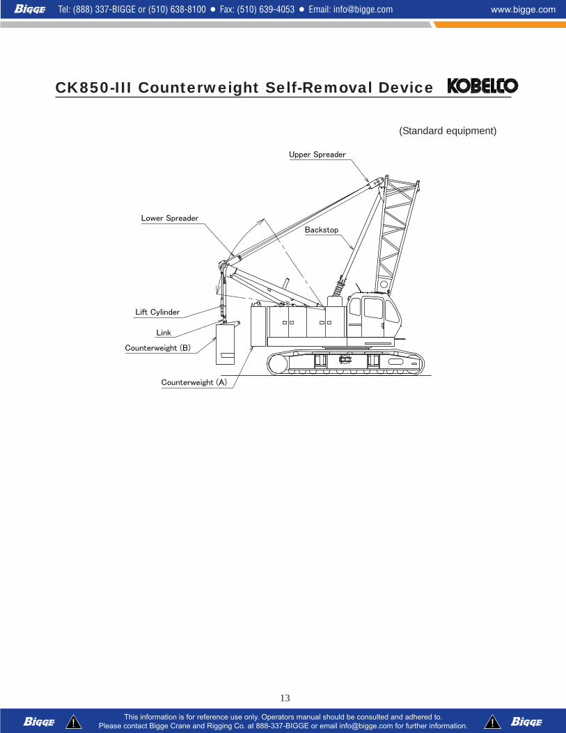
4.3 Counterweight and carbody weightCounterweight (A) 1 x 27,340 lbs (12,400 kg)Counterweight (B) 1 x 27,560 lbs (12,500 kg)
Total weight 54,900 lbs (24,900 kg)Carbody weight 2 x 7,360 lbs (3,340 kg)
Total weight 14,720 lbs (6,680 kg)
4.4 GantryThis high folding type gantry is fitted with a sheaveframe for boom hoist reeving. Hydraulic lift is standard.It provides full up, full down positions with linkage.
4.5 Operator’s cabTotally enclosed from weather, this full-vision cab hassafety glass all around. The adjustable, high-backedseat with armrest is standard, allowing operators tocustomize the position. Auxiliary controls and instru-ments are on a side mounted console. A signal horn,windshield wipers, air conditioner are all standardfeatures.
4.6 ControlsAt operator’s right are console-mounted adjustableshort levers for the front and rear drum and the boomhoist control. Beside the operator’s seat on the rightare two short levers for propel control, individualspeed shifts for front drum, rear drum and boom drum.At the operator’s left are the console mounted swinglever, knobs for front and rear drum, boom drumpawls, engine start / stop key. A swing brake controlswitch and signal horn button are on the swing lever.
4.7 Electric systemAll wiring corded for easy serving, individual fusedbranch circuit.
4.8 Hydraulic systemMaximum pressure rating 4,620 psi (32.0 MPa)Cooling Oil to air heat exchangerFiltrationFull flow filters with replaceable paper elementsReservoir capacity 116 US gal. (440 liters)
4.9 Boom hoistPowered by hydraulic motor through planetary re-ducer.Drum Single drum.
Grooved for 5/8” (16.0 mm) dia. wire rope.BrakeA spring set, hydraulically-released, multiple-discholding brake is mounted inside the boom hoist motorand is operated through a counter-balance valve. Anexternal ratchet is fitted for locking the drum.
4.10 Front drumPowered by hydraulic motor through planetary re-ducer.Drum 21.7” (550 mm) P.C.D. X 21.5” (545 mm) LG.
Grooved for 7/8” (22 mm) dia. wire rope.BrakeA spring set, hydraulically-released, multiple-discholding brake is mounted inside the hoist motor and isoperated through a counter-balance valve. An externalratchet is fitted for locking the drum.Free-Fall (Standard)Wet-type disk brake free-fall is mounted inside the drum.
4.11 Rear drumPowered by hydraulic motor through planetary re-ducer.Drum 21.7” (550 mm) P.C.D. X 21.5” (545 mm) LG.
Grooved for 7/8” (22 mm) dia. wire rope.BrakeA spring set, hydraulically-released, multiple-discholding brake is mounted inside the hoist motor and isoperated through a counter-balance valve. An externalratchet is fitted for locking the drum.Free-Fall (Standard)Wet-type disk brake free-fall is mounted inside the drum.
4.12 Third drum (Optional)Powered by hydraulic motor through planetary re-ducer.Drum 21.7” (550 mm) P.C.D. X 21.5” (545 mm) LG.
Grooved for 7/8” (22.0 mm) dia. wire rope.BrakeA spring set, hydraulically-released, multiple-discholding brake is mounted inside the hoist motor and isoperated through a counter-balance valve. An externalratchet is fitted for locking the drum.Free-Fall (Standard for third drum)Wet-type disk brake free-fall is mounted inside the drum.
4.13 SwingSwing unitHydraulic motor driving through planetary reducer tooutput swing pinion for 360 degree rotation.Swing brakeSpring set hydraulically released multiple disk brakemounted on swing motor.Swing circleSingle row ball bearing with internal, integral swing gear.Swing Lock 2 Position lock for transportation.
5. LOWER MACHINERY5.1 CarbodyThe durable carbody features steel welded construc-tion with extendible axles.

3
5.2 CrawlerCrawler assemblies can be hydraulically extended forwide-track operation or retracted for transportation.Crawler belt tension adjusted with hydraulic jack andmaintained by shims between the idler block andframe.
5.3 Crawler driveThe independent hydraulic propel drive is built intoeach crawler side frame. Each drive consists of ahydraulic motor driving a propel sprocket through aplanetary gear box. The hydraulic motor and gearboxare built into the crawler side frame within the shoewidth.
5.4 Crawler brakesSpring set, hydraulically released, multiple disk-typeparking brakes are built into each propel drive.
5.5 Steering mechanismThe hydraulic propel system provides both skidsteering (driving one track only) and counter-rotatingsteering (driving each track in opposite direction).
5.6 Crawler shoes63 shoes, 36” (914 mm) wide each crawler.
5.7 Track rollersThe track rollers are sealed for maintenance-freeoperation.
6. CRANE ATTACHMENTS6.1 Crane boomThe welded lattice construction uses tubular, high-tension steel chords with pin connections betweensections.Maximum boom length 200’ (61.0 m)Basic boom length 40’ (12.2 m)Boom base section 19’ (5.8 m)Boom tip section 21’ (6.4 m)
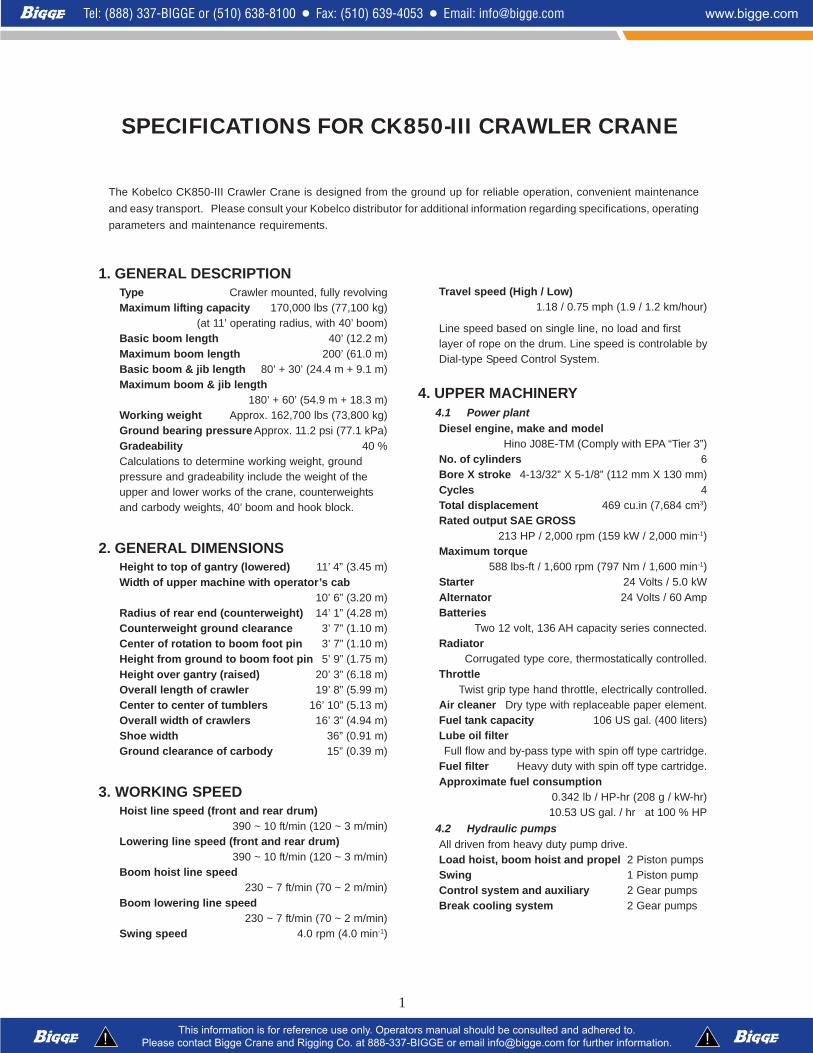
6.2 Boom insert (Optional)An optional boom inserts is available to provideextension capabilities. It also has welded latticeconstruction with tubular, high-tension steel chordsand pin connections.Boom insert 10’ (3.1 m), 20’ (6.1 m), 40’ (12.2 m)
6.3 Jib (Optional)The optional jib employs welded lattice constructionwith tubular, high-tension steel chords with pin con-nections between sections.Maximum jib length 60’ (18.3 m)Basic jib length 30’ (9.1 m)Jib base section 15’ (4.6 m)
Jib tip section 15’ (4.6 m)Jib insert 10’ (3.1 m), 20’ (6.1 m)
Jib inserts are available to provide extension capabilities.They also have welded lattice construction with tubular, high-tension steel chords and pin connections.Jib is extendible on booms of 80’ (24.4 m) through180’ (54.9 m)
6.4 Auxiliary sheave (Optional)Auxiliary sheave is extendible on booms of 40’ (12.2 m) to190’ (57.9 m).
6.5 Boom hoist reevingTwelve (12) parts of 5/8” (16.0 mm) dia. high strength wirerope.
6.6 Boom backstopsTelescopic type with spring bumper.
7. AUXILIARY EQUIPMENT7.1 LightsTow (2) Front flood lightsOne (1) Cab inside light
7.2 Gauges and warning display
GaugesOne (1) TachometerOne (1) Hour meterOne (1) Fuel gaugeOne (1) Water temperature gauge for engine
Warning displayBattery chargeEngine oil pressureAir cleanerEngine oil filterControl main pressureHydraulic oil temperature
7.3 OthersAir conditionerDrum turn indicator (front and rear drum)Foot acceleration pedalElectric fuel pumpCounterweight self-removal device
8. SAFETY SERVICEFunction lock leverBoom over hoist limit switchSignal hornFront and rear hoist drum lockSwing alarm (buzzer and lamps)Over load preventive device (Load Moment Indicator)Hook over hoist shut off (Anti-two-block)

Boom angle indicatorBoom hoist drum lockSwing lockBoom backstops
9. TOOLS AND ACCESSORIESA set of tools and accessories are furnished.
10. OPTIONAL EQUIPMENTHydraulic taglineTravel kitThird drumPillow plate for boom self-erectionCustom color
All specifications are subject to change without notice.
4

5
Line speed and line pull based on Hino J08E-TM at 2,000 rpm.
Line speed and line pull based on single line. Line pull is not based on wire rope strength.
Wire Rope Specifications
Line speed (ft/min)
Layer 1 2 3 4 5 6 7
Line Pull(lbs)
0 394 420 446 472 499 525
Storage only
5,000 394 420 446 472 499 525
10,000 353 353 353 353 353 353
15,000 235 235 235 235 235 235
17,000 208 208 208 208 208 208
20,000 177 177 177 177 179 182
25,000 141 146 148 149 149
32,000 115
Storage Capacity (ft) 130 139 148 156 165 174 183
1. Front and rear drum
2. Third drum (Optional)
Rated Line Pull = 17,000 lbs Maximum Line Pull = 32,000 lbs Total Storage Capacity = 1,095 ft
Rated Line Pull = 17,000 lbs Maximum Line Pull = 32,000 lbs Total Storage Capacity = 1,095 ft
Use Construction No load diameter LengthSafetyFactor
Required minimumbreaking strength
Front drum 6 x 25 Filler IWRC Right hand lay, Regular lay
0.887" to 0.904"(22.54 mm to 22.97 mm)
869'(265 m)
3.5: 159,500 lbs(26,990 kg)
Rear drum 6 x 25 Filler IWRC Right hand lay, Regular lay
0.887" to 0.904"(22.54 mm to 22.97 mm)
673'(205 m)
3.5: 159,500 lbs(26,990 kg)
Third drum(Optional)
6 x 25 Filler IWRC Right hand lay, Regular lay
0.887" to 0.904"(22.54 mm to 22.97 mm)
869'(265 m)
3.5: 159,500 lbs(26,990 kg)
Boom drum 6 x 31 Warrington seal Right hand lay, Regular lay
0.639" to 0.653"(16.24 mm to 16.58 mm)
492'(150 m)
3.5: 141,230 lbs(18,700 kg)
CK850-III Winch Performance Data
Winch Performance Data
47,180 lbs(21,400 kg)

6
CK850-III General Dimensions

7
CK850-III Dimensions and Weight

8
CK850-III Dimensions and Weight

9
CK850-III Dimensions and Weight
10
CK850-III Dimensions and Weight

CK850-III Transportation Plan
Shipping plan for 200 ft Boom and 60 ft Jib
Weight
lbs (kg) #1 #2 #3 #4 Base Machine with Boom Base and Crawlers* 89,980 (40,820) 1 Counterweight (A) 27,340 (12,400) 1 Counterweight (B) 27,560 (12,500) 1 Carbody Weight 7,360 (3,340) 1 1 10 ft Insert Boom and Guy Line 750 (340) 1 1 20 ft Inser Boom and Guy Line 1,230 (560) 1 40 ft Insert Boom and Guy Line 2,190 (990) 1 1 40 ft Insert Boom (w/ Lug) and Guy Line 2,220 (1,010) 1 Boom Tip and Guy Line 2,380 (1,080) 1 Jib Base and Guy Line 1,210 (550) 1 10 ft Inser Jib and Guy Line 290 (130) 1 20 ft Insert Jib and Guy Line 490 (220) 1 Jib Tip 620 (280) 1
lbs 89,980 40,250 37,860 5,830
(kg) (40,820) (18,250) (17,170) (2,650)* Third drum is not included.
Loads for transportation were targeted at 45,000 lbs, 8' 6" wide, 48' long and 13' 6" high from ground. This may vary depending on truck/trailer weight, style of trailer and state low.
Description of ItemTrailer Loads
Approx. Total Shipping Weight
Trailer #1
Trailer #2
Trailer #3
Trailer #4
11

CK850-III Self Assembly Procedure
12
13
(Standard equipment)
CK850-III Counterweight Self-Removal Device

14
CK850-III Boom and Jib ArrangementBoom Arrangement
Insert Boom
Boom 10 ft 20 ft40ft(40)
40 ft(40A)
Aux.Sheave
FixedJib
40 ft – – – – Y150 ft 1 – – – Y160 ft 2 – – – Y170 ft 1 1 – – Y1
2 1 – – Y1– – – 1 Y1 Y21 2 – – Y11 – – 1 Y1 Y22 2 – – Y12 – – 1 Y1 Y2
110 ft 1 1 – 1 Y1 Y2120 ft 2 1 – 1 Y1 Y2130 ft 1 2 – 1 Y1 Y2140 ft 2 2 – 1 Y1 Y2150 ft 1 1 1 1 Y1 Y2160 ft 2 1 1 1 Y1 Y2170 ft 1 2 1 1 Y1 Y2180 ft 2 2 1 1 Y1 Y2190 ft 1 1 2 1 Y1200 ft 2 1 2 1
80 ft
90 ft
100 ft
Jib Arrangement
Insert JibJib 10 ft 20 ft30 ft – –40 ft 1 –50 ft – 160 ft 1 1
Y1: Auxiliary sheave can be attached.Y2: Fixed jib can be attached.To install fixed jib, one 40A (40 ft insert boom with lug) is required.

15
CK850-III Main Boom Working Range
16
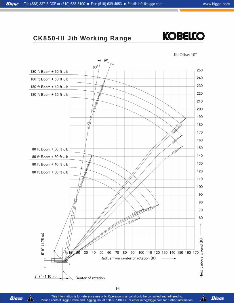
CK850-III Jib Working Range
Jib Offset 10
17
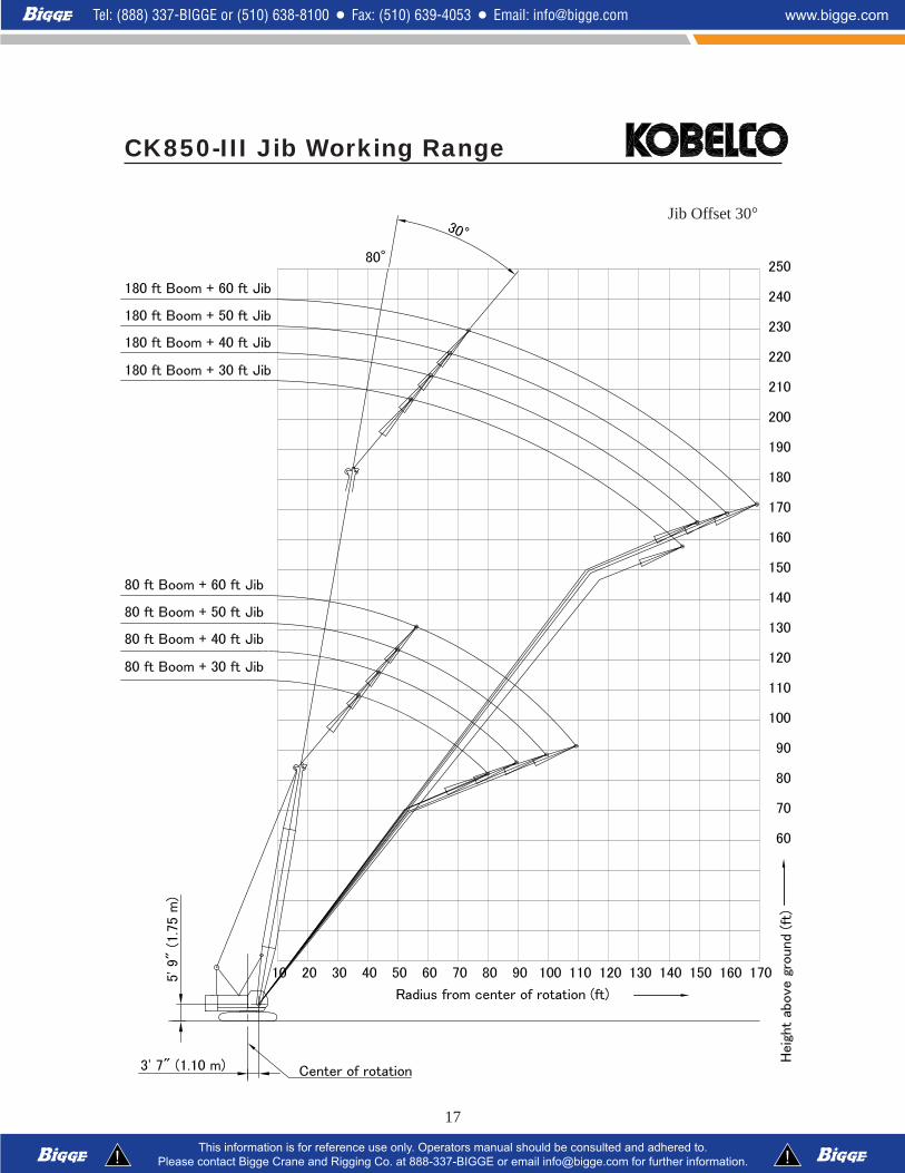
CK850-III Jib Working Range
Jib Offset 30

18
1. Rated loads included in the charts are the maximumallowable freely suspended loads at a given boomlength, boom angle and load radius, and have beendetermined for the machine standing level on firmsupporting surface under ideal operating conditions.The user must limit or de-rate rated loads to allow foradverse conditions (such as soft or uneven ground,out-of-level conditions, wind, side loads, pendulumaction, jerking or sudden stopping of loads, inexperi-ence of personnel, multiple machine lifts, and travelingwith a load).
2. Rated loads do not exceed 75% of minimum tippingloads. Rated loads based on factors other thanmachine stability such as structural competence areshown by asterisk * in the charts.
3. The machine must be reeved and set-up as stated inthe operation manual and all the instruction manuals ifthese manuals are missing, obtain replacements.1) The crane must be leveled to within 1% on a firm
supporting surface.2) Boom backstops are required for all boom
lengths.3) Gantry must be fully raised position for all opera-
tions.4) Crawlers must be fully extended and be locked in
position.5) Counterweight: 54,900 lbs.6) Carbody weight: 14,720 lbs
4. Do not attempt to lift where no radius on load is listedas crane may tip or collapse.
5. Attempting to lift more than rated loads may causemachine to tip or collapse. Do not tip machine todetermine rated loads.
6. Weight of hooks, hook blocks, slings and other liftingdevices are a part of the total load. Their total weightmust be subtracted from the rated load to obtain theweight that can be lifted.
7. When lifting over boom point with jib or auxiliarysheave, rated loads for the boom must be deductedas shown below.
8. The total load that can be lifted by the jib is limited byrated jib loads.
9. Boom lengths for jib mounting are 80 ft (24.4 m) to 180ft (54.9 m).
10. The total load that can be lifted by the auxiliary sheaveis: the rated load for the boom (without auxiliarysheave installed) minus 320 lbs; however, the auxiliarysheave rated load should not exceed 17,000 lbs.
11. Permissible boom lengths for installing auxiliarysheave are from 40 ft (12.2 m) to 190 ft (57.9 m).
12. The boom should be erected over the front of thecrawlers, not laterally.
13. Least stable position is over the side.
14. Maximum hoist load for number of reeving parts of linefor hoist rope.
15. Rated loads listed apply only to the machine asoriginally manufactured and designed by KOBELCOCRANES CO.,LTD. Modifications to this machine oruse of equipment other than that specified can reduceoperating capacity.
16. Designed and rated to comply ANSI code B30.5.
Maximum Load for Main Boom
No. of Parts Line 1 2 3 4 5
Maximum Loads (lbs) 17,000 34,000 51,000 68,000 85,000
No. of Parts Line 6 7 8 9 10
Maximum Loads (lbs) 102,000 119,000 136,000 153,000 170,000
Maximum Load for Fixed Jib
No. of Parts Line 1 2
Maximum Loads (lbs) 17,000 24,000
Maximum Load for Auxiliary Sheave
No. of Parts Line 1
Maximum Loads (lbs) 17,000
Jib Length Aux. Sheave 30 ft 40 ft 50 ft 60 ft
Deduct (lbs) 320 2,400 3,200 4,200 5,200Operation of this equipment in excess of rated loads
or disregard of instruction void the warranty
KOBELCO CK850-III Main Boom Rated Loads in PoundsCounterweight: 54,900 lbs (24,900 kg)Carbody weight: 14,720 lbs (6,680 kg)
Supplemental Data

19
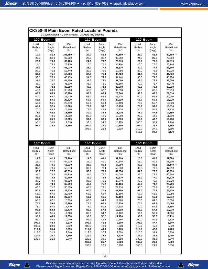
CK850-III Main Boom Rated Loads in Pounds2 Counterweights + 2 Low Weights - Crawlers fully extended
40' Boom 50' Boom 60' Boom
10.0 81.7 170,000 * 12.0 81.1 166,400 * 13.0 81.6 154,200 *11.0 80.3 170,000 * 13.0 79.9 154,400 * 14.0 80.7 143,800 *12.0 78.8 166,600 * 14.0 78.8 144,000 * 15.0 79.7 134,700 *13.0 77.4 154,600 * 15.0 77.6 134,900 * 16.0 78.7 126,700 *14.0 75.9 144,200 * 16.0 76.4 126,900 * 17.0 77.7 119,500 *15.0 74.4 135,100 * 17.0 75.2 119,700 * 18.0 76.8 113,000 *16.0 72.9 127,100 * 18.0 74.0 113,200 * 19.0 75.8 105,46017.0 71.4 119,900 * 19.0 72.8 105,660 20.0 74.8 97,13018.0 69.9 113,400 * 20.0 71.6 97,350 22.0 72.8 83,79019.0 68.3 105,820 22.0 69.2 84,010 24.0 70.8 73,56020.0 66.7 97,500 24.0 66.7 73,810 26.0 68.7 65,49022.0 63.6 84,190 26.0 64.2 65,760 28.0 66.6 58,97024.0 60.3 74,000 28.0 61.6 59,230 30.0 64.5 53,57026.0 56.9 65,980 30.0 58.9 53,850 32.0 62.4 49,03028.0 53.4 59,480 32.0 56.2 49,310 34.0 60.2 45,17030.0 49.7 54,100 34.0 53.3 45,480 36.0 58.0 41,84032.0 45.7 49,580 36.0 50.4 42,150 38.0 55.7 38,95034.0 41.5 45,740 38.0 47.3 39,280 40.0 53.3 36,41036.0 36.9 42,460 40.0 44.1 36,750 45.0 47.0 31,23038.0 31.6 39,590 45.0 34.9 31,590 50.0 40.0 27,29040.0 25.5 34,830 * 50.0 22.7 26,890 * 55.0 31.7 24,200
60.0 20.6 21,600 *
70' Boom 80' Boom 90' Boom
14.0 82.0 143,600 * 16.0 81.6 126,300 * 17.0 81.9 118,820 *15.0 81.2 134,500 * 17.0 80.8 119,100 * 18.0 81.2 112,400 *16.0 80.3 126,500 * 18.0 80.1 112,600 * 19.0 80.6 105,22017.0 79.5 119,300 * 19.0 79.4 105,290 20.0 79.9 96,87018.0 78.7 112,800 * 20.0 78.6 96,930 22.0 78.6 83,48019.0 77.8 105,400 22.0 77.2 83,550 24.0 77.3 73,23020.0 77.0 97,060 24.0 75.7 73,320 26.0 76.0 65,14022.0 75.3 83,700 26.0 74.2 65,230 28.0 74.7 58,57024.0 73.6 73,470 28.0 72.7 58,680 30.0 73.4 53,15026.0 71.9 65,380 30.0 71.2 53,260 32.0 72.0 48,58028.0 70.1 58,840 32.0 69.7 48,690 34.0 70.7 44,70030.0 68.4 53,430 34.0 68.1 44,840 36.0 69.3 41,38032.0 66.6 48,890 36.0 66.6 41,490 38.0 68.0 38,44034.0 64.8 45,030 38.0 65.0 38,580 40.0 66.6 35,89036.0 63.0 41,680 40.0 63.4 36,020 45.0 63.0 30,66038.0 61.1 38,800 45.0 59.3 30,820 50.0 59.4 26,67040.0 59.2 36,240 50.0 55.0 26,820 55.0 55.6 23,52045.0 54.3 31,040 55.0 50.5 23,670 60.0 51.6 20,96050.0 49.0 27,070 60.0 45.6 21,140 65.0 47.4 18,87055.0 43.3 23,960 65.0 40.3 19,060 70.0 42.9 17,10060.0 36.9 21,450 70.0 34.4 17,350 75.0 37.9 15,63065.0 29.3 19,420 75.0 27.3 15,890 80.0 32.3 14,370
85.0 25.7 13,310
Load Radius
(ft)
Boom Angle (deg.)
360° Rated Load
(lbs)
Load Radius
(ft)
Boom Angle (deg.)
360° Rated Load
(lbs)
Load Radius
(ft)
Boom Angle (deg.)
360° Rated Load
(lbs)
Load Radius
(ft)
Boom Angle (deg.)
360° Rated Load
(lbs)
Load Radius
(ft)
Boom Angle (deg.)
360° Rated Load
(lbs)
Load Radius
(ft)
Boom Angle (deg.)
360° Rated Load
(lbs)
20
CK850-III Main Boom Rated Loads in Pounds2 Counterweights + 2 Low Weights - Crawlers fully extended
100' Boom 110' Boom 120' Boom
19.0 81.5 101,850 * 20.0 81.8 92,590 * 22.0 81.5 80,680 *20.0 80.9 96,800 22.0 80.7 83,260 24.0 80.5 72,95022.0 79.8 83,400 24.0 79.7 73,010 26.0 79.6 64,81024.0 78.6 73,120 26.0 78.6 64,900 28.0 78.6 58,24026.0 77.4 65,010 28.0 77.5 58,330 30.0 77.6 52,80028.0 76.3 58,440 30.0 76.5 52,880 32.0 76.6 48,23030.0 75.1 53,020 32.0 75.4 48,320 34.0 75.6 44,33032.0 73.9 48,450 34.0 74.3 44,440 36.0 74.7 40,98034.0 72.7 44,550 36.0 73.2 41,090 38.0 73.7 38,05036.0 71.5 41,200 38.0 72.1 38,160 40.0 72.7 35,47038.0 70.3 38,290 40.0 71.0 35,600 45.0 70.1 30,22040.0 69.0 35,730 45.0 68.2 30,350 50.0 67.6 26,21045.0 65.9 30,480 50.0 65.4 26,340 55.0 65.0 23,01050.0 62.7 26,470 55.0 62.5 23,170 60.0 62.3 20,45055.0 59.5 23,320 60.0 59.5 20,610 65.0 59.5 18,32060.0 56.1 20,740 65.0 56.4 18,490 70.0 56.7 16,53065.0 52.5 18,620 70.0 53.2 16,710 75.0 53.8 15,01070.0 48.8 16,860 75.0 49.9 15,210 80.0 50.8 13,71075.0 44.8 15,360 80.0 46.4 13,910 85.0 47.6 12,58080.0 40.6 14,080 85.0 42.6 12,800 90.0 44.3 11,59085.0 35.9 12,980 90.0 38.6 11,830 95.0 40.7 10,73090.0 30.6 12,010 95.0 34.2 10,970 100.0 36.9 9,96095.0 24.3 11,190 100.0 29.2 10,250 105.0 32.7 9,280
105.0 23.2 9,610 110.0 27.9 8,680115.0 22.2 8,170
130' Boom 140' Boom 150' Boom
24.0 81.3 71,200 * 24.0 81.9 61,720 * 26.0 81.7 52,680 *26.0 80.4 64,610 26.0 81.1 60,840 * 28.0 80.9 51,800 *28.0 79.5 58,020 28.0 80.2 57,980 30.0 80.1 51,140 *30.0 78.6 52,570 30.0 79.4 52,530 32.0 79.3 47,81032.0 77.7 48,010 32.0 78.6 47,950 34.0 78.6 43,89034.0 76.8 44,110 34.0 77.7 44,040 36.0 77.8 40,54036.0 75.9 40,760 36.0 76.9 40,670 38.0 77.0 37,61038.0 74.9 37,830 38.0 76.0 37,740 40.0 76.2 35,03040.0 74.0 35,250 40.0 75.2 35,160 45.0 74.2 29,76045.0 71.7 30,000 45.0 73.1 29,910 50.0 72.2 25,72050.0 69.4 25,970 50.0 70.9 25,880 55.0 70.2 22,53055.0 67.0 22,790 55.0 68.7 22,680 60.0 68.2 19,95060.0 64.6 20,210 60.0 66.5 20,100 65.0 66.1 17,81065.0 62.1 18,070 65.0 64.3 17,960 70.0 64.0 16,00070.0 59.6 16,290 70.0 62.0 16,150 75.0 61.8 14,48075.0 57.0 14,770 75.0 59.6 14,630 80.0 59.6 13,16080.0 54.3 13,470 80.0 57.2 13,310 85.0 57.4 12,01085.0 51.5 12,320 85.0 54.7 12,160 90.0 55.1 11,00090.0 48.6 11,330 90.0 52.2 11,170 95.0 52.7 10,11095.0 45.6 10,440 95.0 49.5 10,290 100.0 50.3 9,320
100.0 42.4 9,670 100.0 46.8 9,500 105.0 47.7 8,640105.0 39.0 8,990 105.0 43.9 8,790 110.0 45.1 8,000110.0 35.4 8,390 110.0 40.8 8,170 115.0 42.3 7,420115.0 31.3 7,840 115.0 37.5 7,620 120.0 39.4 6,920120.0 26.7 7,360 120.0 34.0 7,120 125.0 36.2 6,450125.0 21.2 6,940 125.0 30.1 6,650 130.0 32.8 6,040
130.0 25.7 6,260 135.0 29.1 5,660135.0 20.5 5,900 140.0 24.8 5,330
360° Rated Load
(lbs)
Load Radius
(ft)
Boom Angle (deg.)
360° Rated Load
(lbs)
Load Radius
(ft)
Boom Angle (deg.)
360° Rated Load
(lbs)
Load Radius
(ft)
Boom Angle (deg.)
360° Rated Load
(lbs)
Boom Angle (deg.)
Load Radius
(ft)
Boom Angle (deg.)
360° Rated Load
(lbs)
Load Radius
(ft)
Boom Angle (deg.)
360° Rated Load
(lbs)
Load Radius
(ft)

21
CK850-III Main Boom Rated Loads in Pounds2 Counterweights + 2 Low Weights - Crawlers fully extended
160' Boom 170' Boom 180' Boom
28.0 81.5 44,090 * 28.0 82.0 38,800 * 30.0 81.8 33,730 *30.0 80.7 43,430 * 30.0 81.3 38,130 * 32.0 81.1 33,060 *32.0 80.0 42,760 * 32.0 80.6 37,470 * 34.0 80.5 32,620 *34.0 79.3 42,100 * 34.0 79.9 37,030 * 36.0 79.8 31,960 *36.0 78.6 40,520 36.0 79.2 36,370 * 38.0 79.2 31,520 *38.0 77.8 37,560 38.0 78.6 35,710 * 40.0 78.5 31,080 *40.0 77.1 34,980 40.0 77.9 34,780 45.0 76.9 29,25045.0 75.2 29,710 45.0 76.1 29,510 50.0 75.3 25,22050.0 73.4 25,680 50.0 74.4 25,460 55.0 73.6 22,00055.0 71.5 22,480 55.0 72.6 22,260 60.0 72.0 19,40060.0 69.6 19,880 60.0 70.9 19,660 65.0 70.3 17,26065.0 67.7 17,720 65.0 69.1 17,520 70.0 68.6 15,45070.0 65.7 15,930 70.0 67.2 15,710 75.0 66.8 13,91075.0 63.7 14,390 75.0 65.4 14,170 80.0 65.1 12,56080.0 61.7 13,070 80.0 63.5 12,850 85.0 63.3 11,41085.0 59.7 11,920 85.0 61.6 11,680 90.0 61.5 10,40090.0 57.6 10,910 90.0 59.7 10,670 95.0 59.7 9,50095.0 55.4 10,000 95.0 57.7 9,780 100.0 57.8 8,700
100.0 53.2 9,210 100.0 55.7 8,990 105.0 55.9 8,000105.0 50.9 8,500 105.0 53.6 8,260 110.0 54.0 7,340110.0 48.6 7,870 110.0 51.5 7,620 115.0 52.0 6,760115.0 46.1 7,290 115.0 49.3 7,050 120.0 49.9 6,230120.0 43.6 6,760 120.0 47.0 6,520 125.0 47.8 5,700125.0 40.9 6,280 125.0 44.7 6,040 130.0 45.6 5,220130.0 38.1 5,860 130.0 42.2 5,570 135.0 43.3 4,780135.0 35.0 5,440 135.0 39.6 5,150 140.0 40.9 4,380140.0 31.8 5,070 140.0 36.9 4,760 145.0 38.4 4,030145.0 28.1 4,710 145.0 34.0 4,380 150.0 35.8 3,680150.0 24.0 4,380 150.0 30.8 4,050 155.0 33.0 3,370
155.0 27.3 3,760 160.0 29.9 3,100160.0 23.3 3,500 165.0 26.5 2,840
170.0 22.6 2,620
190' Boom 190' Boom 200' Boom
32.0 81.6 29,540 * 160.0 34.8 3,040 34.0 81.4 25,790 *34.0 81.0 28,880 * 165.0 32.0 2,770 36.0 80.9 25,350 *36.0 80.4 28,430 * 170.0 29.1 2,510 38.0 80.3 24,910 *38.0 79.8 27,990 * 40.0 79.7 24,470 *40.0 79.2 27,550 * 45.0 78.2 23,360 *45.0 77.6 26,450 * 50.0 76.8 22,480 *50.0 76.1 25,300 55.0 75.3 21,380 *55.0 74.5 22,110 60.0 73.8 19,31060.0 72.9 19,510 65.0 72.3 17,15065.0 71.3 17,350 70.0 70.8 15,32070.0 69.7 15,540 75.0 69.3 13,77075.0 68.1 13,990 80.0 67.7 12,43080.0 66.5 12,650 85.0 66.2 11,26085.0 64.8 11,500 90.0 64.6 10,25090.0 63.2 10,470 95.0 63.0 9,34095.0 61.4 9,560 100.0 61.4 8,530
100.0 59.7 8,770 105.0 59.7 7,820105.0 57.9 8,040 110.0 58.1 7,160110.0 56.1 7,400 115.0 56.3 6,560115.0 54.3 6,810 120.0 54.6 5,970120.0 52.4 6,280 125.0 52.8 5,440125.0 50.5 5,750 130.0 51.0 4,960130.0 48.5 5,260 135.0 49.1 4,510135.0 46.4 4,800 140.0 47.2 4,100140.0 44.3 4,400 145.0 45.2 3,700145.0 42.1 4,010 150.0 43.1 3,350150.0 39.8 3,680 155.0 41.0 3,040155.0 37.4 3,350 160.0 38.7 2,730
Load Radius
(ft)
Boom Angle (deg.)
360° Rated Load
(lbs)
Load Radius
(ft)
Boom Angle (deg.)
360° Rated Load
(lbs)
Load Radius
(ft)
Boom Angle (deg.)
360° Rated Load
(lbs)
Load Radius
(ft)
Boom Angle (deg.)
360° Rated Load
(lbs)
Load Radius
(ft)
Boom Angle (deg.)
360° Rated Load
(lbs)
Load Radius
(ft)
Boom Angle (deg.)
360° Rated Load
(lbs)
22
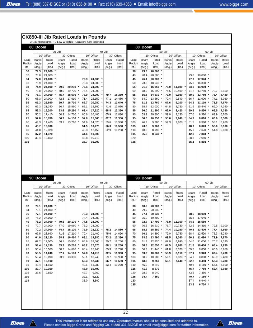
CK850-III Jib Rated Loads in Pounds2 Counterweights + 2 Low Weights - Crawlers fully extended
Boom Angle (deg.)
Boom Angle (deg.)
Boom Angle (deg.)
Boom Angle (deg.)
Boom Angle (deg.)
Boom Angle (deg.)
Boom Angle (deg.)
Boom Angle (deg.)
30 79.3 24,000 * 38 79.3 20,000 *32 78.0 24,000 * 40 78.4 20,000 * 79.8 18,000 *34 77.0 24,000 * 79.3 24,000 * 45 76.1 20,000 * 77.7 17,940 *36 75.9 24,000 * 78.3 24,000 * 50 73.8 18,540 * 75.6 16,330 *38 74.9 24,000 * 79.6 20,230 * 77.4 24,000 * 55 71.3 16,950 * 78.0 11,080 * 73.3 14,900 *40 73.8 24,000 * 78.5 19,730 * 76.4 24,000 * 60 68.9 15,690 * 75.5 10,490 * 71.2 13,750 * 78.7 8,950 *45 71.1 24,000 * 75.7 18,600 * 73.9 24,000 * 79.7 15,360 * 65 66.5 14,610 * 73.0 9,980 * 69.0 12,780 * 76.4 8,480 *50 68.3 24,000 * 72.8 17,610 * 71.4 22,150 * 77.1 14,480 * 70 64.0 13,660 * 70.4 9,540 * 66.7 11,900 * 74.1 8,060 *55 65.3 23,890 69.7 16,710 * 68.7 20,280 * 74.3 13,640 * 75 61.3 12,760 * 67.6 9,100 * 64.2 11,110 * 71.5 7,670 *60 62.3 21,340 66.7 15,960 * 66.1 18,800 * 71.6 12,980 * 80 58.7 12,030 * 64.8 8,730 * 61.9 10,440 * 69.0 7,340 *65 59.3 19,200 63.6 15,290 * 63.4 17,520 * 68.8 12,360 * 85 56.0 11,390 * 62.0 8,420 * 59.5 9,850 * 66.5 7,030 *70 56.2 17,410 60.3 14,700 * 60.6 16,400 * 65.9 11,830 * 90 53.2 10,800 * 59.0 8,130 * 57.0 9,320 * 63.9 6,760 *75 52.8 15,780 56.7 14,150 * 57.6 15,360 * 62.7 11,350 * 95 50.0 10,250 * 55.6 7,840 * 54.2 8,810 * 60.9 6,500 *80 49.3 14,460 53.1 13,710 * 54.6 14,520 * 59.6 10,930 * 100 46.9 9,780 * 52.3 7,620 * 51.5 8,390 * 58.1 6,280 *85 45.7 13,330 51.5 13,470 56.3 10,560 * 105 43.6 9,360 * 48.7 8,020 * 55.0 6,100 *90 41.8 12,320 48.3 12,450 52.9 10,250 * 110 40.0 8,990 * 45.7 7,670 * 51.8 5,930 *95 37.2 11,370 44.6 11,500 115 35.8 8,640 * 42.3 7,340 *
100 32.4 10,600 40.8 10,710 120 38.8 7,050 *105 36.7 10,000 125 35.1 6,810 *
Boom Angle (deg.)
Boom Angle (deg.)
Boom Angle (deg.)
Boom Angle (deg.)
Boom Angle (deg.)
Boom Angle (deg.)
Boom Angle (deg.)
Boom Angle (deg.)
32 79.1 24,000 * 38 80.0 20,000 *34 78.1 24,000 * 40 79.2 20,030 *36 77.1 24,000 * 79.3 24,000 * 45 77.1 20,030 * 78.6 18,000 *38 76.2 24,000 * 78.4 24,000 * 50 75.0 19,400 * 76.6 17,040 *40 75.2 24,000 * 79.5 20,170 * 77.5 24,000 * 55 72.7 17,790 * 78.9 11,300 * 74.5 15,580 *45 72.7 24,000 * 77.0 19,060 * 75.2 24,000 * 60 70.5 16,510 * 76.7 10,730 * 72.5 14,410 * 79.5 9,100 *50 70.2 24,000 * 74.4 18,120 * 72.9 23,320 * 78.2 14,810 * 65 68.3 15,380 * 74.4 10,250 * 70.5 13,400 * 77.4 8,660 *55 67.5 23,690 71.6 17,210 * 70.4 21,400 * 75.6 14,020 * 70 66.1 14,390 * 72.0 9,780 * 68.4 12,520 * 75.3 8,240 *60 64.9 21,120 68.9 16,460 * 68.1 19,880 * 73.2 13,330 * 75 63.6 13,490 * 69.5 9,360 * 66.1 11,680 * 72.9 7,870 *65 62.2 19,000 66.1 15,800 * 65.6 18,560 * 70.7 12,760 * 80 61.3 12,720 * 67.0 8,990 * 64.0 11,000 * 70.7 7,530 *70 59.4 17,190 63.3 15,210 * 63.2 17,370 68.1 12,230 * 85 58.8 12,050 * 64.5 8,680 * 61.8 10,400 * 68.4 7,230 *75 56.4 15,560 60.2 14,660 * 60.4 15,740 65.3 11,720 * 90 56.3 11,440 * 61.8 8,370 * 59.5 9,850 * 66.0 6,960 *80 53.5 14,240 57.1 14,190 * 57.8 14,410 62.5 11,300 * 95 53.6 10,860 * 58.9 8,110 * 57.1 9,320 * 63.4 6,700 *85 50.4 13,090 53.9 13,330 55.1 13,240 59.7 10,930 * 100 50.9 10,380 * 56.1 7,870 * 54.7 8,880 * 60.9 6,480 *90 47.1 12,100 52.3 12,230 56.7 10,580 * 105 48.0 9,850 53.1 7,640 * 52.2 8,480 * 58.3 6,280 *95 43.4 11,150 49.1 11,280 53.4 10,270 * 110 45.0 9,210 49.6 8,110 * 55.5 6,100 *
100 39.7 10,360 46.0 10,490 115 41.7 8,570 46.7 7,760 * 52.4 5,930 *105 35.6 9,650 42.7 9,760 120 38.2 8,040 43.8 7,450 *110 39.1 9,120 125 34.4 7,560 40.7 7,180 *115 35.0 8,500 130 37.4 6,940 *
135 33.8 6,720 *
80' Boom 80' Boom
90' Boom 90' Boom
10° Offset
Rated Load (lbs.)
Rated Load (lbs.)
Rated Load (lbs.)
Load Radius
(ft.)
Load Radius
(ft.)
30° Offset10° Offset 30° Offset 10° Offset 30° Offset 10° Offset30' Jib 40' Jib 50' Jib 60' Jib
30' Jib 40' Jib
Load Radius
(ft.)
Load Radius
(ft.)
50' Jib 60' Jib10° Offset 30° Offset 10° Offset 30° Offset
Rated Load (lbs.)
Rated Load (lbs.)
Rated Load (lbs.)
Rated Load (lbs.)
Rated Load (lbs.)
Rated Load (lbs.)
Rated Load (lbs.)
Rated Load (lbs.)
10° Offset 30° Offset
Rated Load (lbs.)
Rated Load (lbs.)
10° Offset 30° Offset
Rated Load (lbs.)
Rated Load (lbs.)
Rated Load (lbs.)
30° Offset

23
CK850-III Jib Rated Loads in Pounds2 Counterweights + 2 Low Weights - Crawlers fully extended
Boom Angle (deg.)
Boom Angle (deg.)
Boom Angle (deg.)
Boom Angle (deg.)
Boom Angle (deg.)
Boom Angle (deg.)
Boom Angle (deg.)
Boom Angle (deg.)
32 79.9 24,000 * 40 79.9 20,000 *34 79.0 24,000 * 45 78.0 20,000 * 79.3 18,000 *36 78.1 24,000 * 80.0 24,000 * 50 76.0 20,000 * 77.5 17,680 *38 77.2 24,000 * 79.2 24,000 * 55 73.9 18,580 * 79.7 11,500 * 75.5 16,200 *40 76.4 24,000 * 78.4 24,000 * 60 71.9 17,260 * 77.7 10,950 * 73.7 15,030 *45 74.1 24,000 * 78.0 19,480 * 76.3 24,000 * 65 69.9 16,110 * 75.5 10,470 * 71.8 13,990 * 78.3 8,810 *50 71.8 24,000 * 75.7 18,560 * 74.2 24,000 * 79.1 15,100 * 70 67.8 15,120 * 73.4 10,030 * 69.9 13,090 * 76.3 8,420 *55 69.3 23,450 73.2 17,650 * 71.9 22,480 * 76.7 14,320 * 75 65.6 14,170 * 71.1 9,610 * 67.8 12,250 * 74.2 8,040 *60 67.0 20,870 70.7 16,930 * 69.7 20,920 * 74.5 13,660 * 80 63.4 13,380 * 68.8 9,230 * 65.8 11,550 * 72.1 7,710 *65 64.5 18,730 68.2 16,260 * 67.5 18,950 72.2 13,090 * 85 61.2 12,690 * 66.5 8,920 * 63.8 10,910 * 70.0 7,420 *70 62.1 16,930 65.7 15,670 * 65.3 17,150 69.9 12,560 * 90 59.0 12,050 * 64.2 8,610 * 61.7 10,360 * 67.9 7,160 *75 59.4 15,290 62.9 15,100 * 62.8 15,490 67.3 12,050 * 95 56.5 11,130 61.6 8,330 * 59.5 9,810 * 65.5 6,900 *80 56.7 13,970 60.2 14,300 60.4 14,150 64.9 11,640 * 100 54.1 10,310 59.1 8,090 * 57.3 9,340 * 63.2 6,670 *85 54.0 12,830 57.4 13,110 58.0 13,000 62.4 11,260 * 105 51.6 9,590 56.4 7,870 * 55.1 8,920 * 60.9 6,450 *90 51.2 11,810 54.5 12,050 55.5 11,970 59.8 10,910 * 110 49.0 8,950 53.7 7,690 * 52.7 8,550 * 58.4 6,280 *95 48.1 10,860 51.2 11,060 52.8 11,020 56.9 10,580 * 115 46.1 8,310 50.2 8,170 * 55.7 6,100 *
100 45.0 10,070 50.1 10,200 54.0 10,310 * 120 43.2 7,780 47.7 7,820 53.1 5,950 *105 41.7 9,360 47.2 9,500 125 40.2 7,290 45.1 7,340110 38.1 8,730 44.3 8,860 130 36.8 6,830 42.3 6,870115 34.0 8,130 40.9 8,220 135 33.2 6,430 39.4 6,480120 37.4 7,690 140 35.9 6,060125 33.7 7,230 145 32.4 5,730
Boom Angle (deg.)
Boom Angle (deg.)
Boom Angle (deg.)
Boom Angle (deg.)
Boom Angle (deg.)
Boom Angle (deg.)
Boom Angle (deg.)
Boom Angle (deg.)
34 79.8 24,000 45 78.8 20,000 * 80.0 18,000 *36 79.0 24,000 50 76.9 20,000 * 78.3 18,000 *38 78.2 24,000 79.9 24,000 * 55 75.0 19,330 * 76.4 16,820 *40 77.3 24,000 79.2 24,000 * 60 73.1 17,980 * 78.5 11,150 * 74.7 15,600 *45 75.3 24,000 79.0 19,860 * 77.2 24,000 * 65 71.2 16,820 * 76.5 10,670 * 72.9 14,570 * 79.1 8,970 *50 73.2 24,000 76.8 18,930 * 75.3 24,000 * 79.9 15,360 * 70 69.3 15,800 * 74.6 10,250 * 71.1 13,640 * 77.2 8,570 *55 70.9 23,320 74.5 18,070 * 73.2 23,500 * 77.7 14,610 * 75 67.2 14,830 * 72.4 9,830 * 69.2 12,780 * 75.2 8,200 *60 68.7 20,740 72.2 17,350 * 71.2 20,960 75.6 13,970 * 80 65.2 14,020 * 70.4 9,470 * 67.3 12,050 * 73.3 7,890 *65 66.5 18,580 70.0 16,680 * 69.1 18,800 73.5 13,400 * 85 63.2 12,960 68.3 9,140 * 65.5 11,410 * 71.4 7,580 *70 64.3 16,770 67.7 16,090 * 67.1 16,970 71.4 12,870 * 90 61.2 11,920 66.1 8,840 * 63.6 10,840 * 69.4 7,310 *75 61.8 15,140 65.1 15,520 * 64.8 15,340 69.1 12,380 * 95 58.9 10,950 63.8 8,550 * 61.5 10,270 * 67.2 7,050 *80 59.4 13,820 62.7 14,170 62.7 13,990 66.9 11,940 * 100 56.7 10,160 61.5 8,310 * 59.5 9,780 * 65.2 6,830 *85 57.0 12,670 60.2 12,980 60.5 12,830 64.6 11,570 * 105 54.5 9,430 59.2 8,090 * 57.5 9,360 * 63.0 6,630 *90 54.5 11,660 57.6 11,920 58.2 11,810 62.2 11,220 * 110 52.2 8,770 56.7 7,890 * 55.4 8,840 60.9 6,430 *95 51.8 10,710 54.8 10,930 55.7 10,840 59.7 10,890 * 115 49.7 8,130 54.0 7,690 * 53.1 8,200 58.4 6,260 *
100 49.1 9,920 52.0 10,110 53.3 10,050 57.1 10,470 120 47.2 7,600 50.9 7,640 56.1 6,100 *105 46.3 9,210 50.8 9,320 54.5 9,700 125 44.5 7,120 48.6 7,160 53.6 5,970 *110 43.3 8,570 48.2 8,680 51.8 9,010 130 41.8 6,650 46.2 6,700115 39.9 7,950 45.4 8,040 135 38.8 6,260 43.6 6,300120 36.5 7,420 42.5 7,510 140 35.4 5,860 40.8 5,880125 32.7 6,960 39.4 7,050 145 37.9 5,530130 36.1 6,610 150 34.8 5,220135 32.5 6,190
100' Boom 100' Boom30' Jib 40' Jib
30° Offset 10° Offset 30° Offset10° Offset 30° Offset 10° Offset
Rated Load (lbs.)
Rated Load (lbs.)
50' Jib 60' Jib
110' Boom 110' Boom
10° Offset 30° Offset
Load Radius
(ft.)
Rated Load (lbs.)
Rated Load (lbs.)
Rated Load (lbs.)
Rated Load (lbs.)
Load Radius
(ft.)
30' Jib 40' Jib 50' Jib 60' Jib10° Offset 30° Offset 10° Offset 30° Offset 10° Offset 30° Offset
Rated Load (lbs.)
Load Radius
(ft.)
Rated Load (lbs.)
Rated Load (lbs.)
Load Radius
(ft.)
Rated Load (lbs.)
Rated Load (lbs.)
Rated Load (lbs.)
Rated Load (lbs.)
Rated Load (lbs.)
10° Offset 30° Offset
Rated Load (lbs.)
Rated Load (lbs.)

24
CK850-III Jib Rated Loads in Pounds2 Counterweights + 2 Low Weights - Crawlers fully extended
Boom Angle (deg.)
Boom Angle (deg.)
Boom Angle (deg.)
Boom Angle (deg.)
Boom Angle (deg.)
Boom Angle (deg.)
Boom Angle (deg.)
Boom Angle (deg.)
36 79.7 24,000 * 45 79.5 20,000 *38 79.0 24,000 * 50 77.7 20,000 * 78.9 18,000 *40 78.2 24,000 * 79.9 24,000 * 55 75.9 20,000 * 77.2 17,390 *45 76.3 24,000 * 79.7 20,190 * 78.1 24,000 * 60 74.2 18,690 * 79.2 11,330 * 75.6 16,180 *50 74.3 24,000 * 77.7 19,290 * 76.2 24,000 * 65 72.4 17,500 * 77.4 10,860 * 73.9 15,120 * 79.7 9,080 *55 72.2 23,100 75.6 18,450 * 74.3 23,360 78.5 14,880 * 70 70.6 16,440 * 75.6 10,420 * 72.2 14,170 * 78.0 8,700 *60 70.2 20,520 73.5 17,720 * 72.4 20,760 76.6 14,240 * 75 68.7 15,250 73.6 10,030 * 70.4 13,290 * 76.1 8,350 *65 68.2 18,360 71.4 17,080 * 70.5 18,580 74.7 13,690 * 80 66.8 13,910 71.7 9,670 * 68.7 12,560 * 74.4 8,040 *70 66.1 16,550 69.3 16,490 * 68.6 16,770 72.7 13,160 * 85 65.0 12,740 69.7 9,340 * 67.0 11,900 * 72.6 7,730 *75 63.9 14,920 67.0 15,340 66.5 15,100 70.6 12,670 * 90 63.1 11,700 67.8 9,060 * 65.2 11,300 * 70.7 7,470 *80 61.7 13,600 64.8 13,970 64.5 13,770 68.5 12,250 * 95 61.0 10,730 65.6 8,770 * 63.3 10,730 * 68.7 7,230 *85 59.5 12,430 62.6 12,780 62.5 12,610 66.4 11,860 * 100 59.0 9,920 63.6 8,500 * 61.5 9,980 66.8 7,010 *90 57.3 11,410 60.2 11,720 60.5 11,570 64.3 11,500 * 105 57.0 9,190 61.4 8,280 * 59.6 9,250 64.9 6,790 *95 54.8 10,470 57.7 10,730 58.2 10,620 62.0 11,130 110 54.9 8,530 59.3 8,060 * 57.7 8,590 62.9 6,610 *
100 52.4 9,650 55.2 9,890 56.0 9,810 59.7 10,290 115 52.6 7,890 56.8 7,870 * 55.6 7,950 60.7 6,410 *105 49.9 8,950 52.6 9,140 53.8 9,080 57.4 9,520 120 50.4 7,360 54.5 7,690 * 53.6 7,400 58.6 6,260 *110 47.3 8,310 51.5 8,440 55.0 8,840 125 48.1 6,850 52.1 7,250 51.5 6,920 56.4 6,100 *115 44.5 7,690 49.0 7,800 52.3 8,150 130 45.7 6,410 49.3 6,450 54.1 5,970 *120 41.6 7,160 46.5 7,270 135 43.1 5,990 47.1 6,040 51.7 5,860 *125 38.5 6,670 43.8 6,790 140 40.3 5,590 44.6 5,640130 35.3 6,230 41.1 6,320 145 37.4 5,240 42.2 5,290135 31.7 5,840 38.1 5,930 150 34.3 4,910 39.6 4,960140 34.7 5,530 155 36.8 4,650
160 33.6 4,340
Boom Angle (deg.)
Boom Angle (deg.)
Boom Angle (deg.)
Boom Angle (deg.)
Boom Angle (deg.)
Boom Angle (deg.)
Boom Angle (deg.)
Boom Angle (deg.)
38 79.7 24,000 * 45 80.0 20,000 *40 79.0 24,000 * 50 78.4 20,000 * 79.5 18,000 *45 77.1 24,000 * 78.8 24,000 * 55 76.7 20,000 * 77.9 17,920 *50 75.3 24,000 * 78.5 19,620 * 77.1 24,000 * 60 75.1 19,330 * 79.9 11,480 * 76.3 16,710 *55 73.4 22,880 76.5 18,780 * 75.2 23,170 79.3 15,100 * 65 73.4 18,140 * 78.2 11,020 * 74.8 15,630 *60 71.5 20,300 74.6 18,070 * 73.5 20,540 77.5 14,500 * 70 71.7 16,710 76.5 10,620 * 73.2 14,680 * 78.7 8,840 *65 69.6 18,140 72.7 17,430 * 71.7 18,380 75.7 13,930 * 75 69.9 15,030 74.6 10,200 * 71.5 13,800 * 76.9 8,480 *70 67.7 16,330 70.7 16,860 69.9 16,550 73.8 13,420 * 80 68.2 13,690 72.8 9,850 * 69.9 13,050 * 75.3 8,170 *75 65.6 14,680 68.6 15,140 68.0 14,880 71.8 12,940 * 85 66.5 12,520 71.0 9,540 * 68.3 12,360 * 73.6 7,890 *80 63.6 13,350 66.6 13,770 66.2 13,550 69.9 12,520 * 90 64.7 11,480 69.2 9,230 * 66.6 11,570 71.9 7,620 *85 61.6 12,210 64.5 12,580 64.3 12,380 68.0 12,140 * 95 62.8 10,510 67.2 8,950 * 64.8 10,580 70.0 7,360 *90 59.6 11,170 62.4 11,530 62.4 11,350 66.1 11,770 * 100 61.0 9,700 65.3 8,700 * 63.1 9,760 68.3 7,140 *95 57.3 10,220 60.1 10,510 60.3 10,380 63.9 10,950 105 59.1 8,950 63.4 8,480 * 61.4 9,030 66.5 6,940 *
100 55.2 9,430 57.9 9,700 58.3 9,560 61.9 10,090 110 57.2 8,310 61.4 8,260 * 59.6 8,370 64.6 6,740 *105 52.9 8,700 55.6 8,950 56.3 8,860 59.8 9,340 115 55.1 7,670 59.2 8,040 * 57.7 7,730 62.6 6,560 *110 50.6 8,060 53.2 8,260 54.2 8,200 57.6 8,640 120 53.1 7,120 57.1 7,600 55.9 7,180 60.7 6,390 *115 48.1 7,450 51.9 7,560 55.2 7,980 125 51.0 6,630 54.9 7,070 54.0 6,670 58.7 6,230 *120 45.6 6,920 49.7 7,030 52.9 7,400 130 48.8 6,170 52.6 6,590 52.0 6,230 56.6 6,100 *125 43.0 6,430 47.4 6,540 135 46.6 5,750 50.0 5,820 54.5 5,970 *130 40.2 5,990 45.0 6,080 140 44.1 5,350 47.8 5,400 52.2 5,840135 37.3 5,570 42.5 5,680 145 41.7 5,000 45.6 5,040140 33.9 5,200 39.6 5,260 150 39.1 4,670 43.3 4,710145 36.8 4,930 155 36.3 4,360 41.0 4,400150 33.7 4,600 160 33.1 4,030 38.3 4,070
165 35.6 3,760170 32.7 3,480
120' Boom 120' Boom30' Jib 40' Jib
30° Offset10° Offset 30° Offset 10° Offset
Rated Load (lbs.)
Rated Load (lbs.)
50' Jib 60' Jib10° Offset 30° Offset
130' Boom 130' Boom
10° Offset 30° Offset
Load Radius
(ft.)
Rated Load (lbs.)
Rated Load (lbs.)
Rated Load (lbs.)
Rated Load (lbs.)
Load Radius
(ft.)
30' Jib 40' Jib 50' Jib 60' Jib10° Offset 30° Offset 10° Offset 30° Offset 10° Offset 30° Offset
Rated Load (lbs.)
Load Radius
(ft.)
Rated Load (lbs.)
Rated Load (lbs.)
Load Radius
(ft.)
Rated Load (lbs.)
Rated Load (lbs.)
Rated Load (lbs.)
Rated Load (lbs.)
Rated Load (lbs.)
10° Offset 30° Offset
Rated Load (lbs.)
Rated Load (lbs.)

25
CK850-III Jib Rated Loads in Pounds2 Counterweights + 2 Low Weights - Crawlers fully extended
Boom Angle (deg.)
Boom Angle (deg.)
Boom Angle (deg.)
Boom Angle (deg.)
Boom Angle (deg.)
Boom Angle (deg.)
Boom Angle (deg.)
Boom Angle (deg.)
40 79.6 24,000 * 50 79.1 20,000 *45 77.9 24,000 * 79.4 24,000 * 55 77.4 20,000 * 78.5 18,000 *50 76.2 24,000 * 79.2 19,900 * 77.8 24,000 * 60 75.9 19,970 * 77.0 17,210 *55 74.4 22,680 77.4 19,090 * 76.1 22,970 79.9 15,320 * 65 74.3 18,360 78.8 11,170 * 75.6 16,130 *60 72.6 20,080 75.6 18,400 * 74.4 20,340 78.2 14,720 * 70 72.8 16,510 77.2 10,780 * 74.1 15,160 * 79.3 8,950 *65 70.9 17,940 73.8 17,760 * 72.8 18,180 76.5 14,170 * 75 71.1 14,830 75.5 10,380 * 72.5 14,260 * 77.7 8,590 *70 69.1 16,110 72.0 16,680 71.1 16,330 74.8 13,690 * 80 69.4 13,490 73.8 10,030 * 71.0 13,490 * 76.1 8,310 *75 67.2 14,460 70.0 14,960 69.3 14,680 72.9 13,180 * 85 67.8 12,300 72.1 9,720 * 69.4 12,410 74.5 8,020 *80 65.3 13,130 68.1 13,600 67.6 13,330 71.2 12,760 * 90 66.2 11,260 70.4 9,430 * 67.9 11,350 72.9 7,760 *85 63.5 11,970 66.2 12,380 65.9 12,160 69.4 12,380 * 95 64.4 10,290 68.6 9,120 * 66.2 10,380 71.2 7,510 *90 61.6 10,950 64.3 11,330 64.1 11,130 67.6 11,810 100 62.7 9,470 66.8 8,880 * 64.6 9,540 69.5 7,270 *95 59.5 9,980 62.2 10,310 62.2 10,160 65.6 10,780 105 60.9 8,730 65.0 8,660 * 63.0 8,810 67.8 7,070 *
100 57.5 9,190 60.1 9,500 60.3 9,340 63.7 9,920 110 59.2 8,060 63.2 8,440 * 61.4 8,150 66.1 6,870 *105 55.5 8,460 58.1 8,750 58.5 8,610 61.8 9,140 115 57.2 7,420 61.2 8,000 59.6 7,490 64.3 6,700 *110 53.4 7,820 55.9 8,060 56.6 7,950 59.8 8,460 120 55.4 6,900 59.3 7,420 57.9 6,960 62.5 6,520 *115 51.1 7,180 53.5 7,400 54.5 7,340 57.6 7,780 125 53.5 6,390 57.3 6,900 56.1 6,450 60.7 6,370 *120 48.9 6,650 51.3 6,850 52.5 6,790 55.5 7,200 130 51.6 5,930 55.3 6,390 54.3 5,990 58.8 6,230 *125 46.6 6,170 50.4 6,300 53.4 6,670 135 49.5 5,510 53.1 5,950 52.5 5,570 56.9 6,100 *130 44.2 5,730 48.2 5,840 140 47.3 5,090 50.5 5,150 54.7 5,640135 41.7 5,330 46.0 5,420 145 45.1 4,730 48.5 4,800 52.7 5,240140 38.8 4,910 43.5 5,020 150 42.9 4,400 46.5 4,470145 36.0 4,560 41.1 4,670 155 40.5 4,030 44.4 4,100150 32.9 4,210 38.5 4,320 160 37.8 3,680 42.0 3,720155 35.7 3,940 165 35.1 3,370 39.7 3,410160 32.5 3,610 170 32.2 3,080 37.3 3,130
175 34.6 2,840
Boom Angle (deg.)
Boom Angle (deg.)
Boom Angle (deg.)
Boom Angle (deg.)
Boom Angle (deg.)
Boom Angle (deg.)
Boom Angle (deg.)
Boom Angle (deg.)
45 78.6 24,000 * 80.0 24,000 * 50 79.6 20,000 *50 77.0 24,000 * 79.9 20,170 * 78.5 24,000 * 55 78.1 20,000 * 79.1 18,000 *55 75.3 22,530 78.1 19,370 * 76.8 22,810 60 76.6 20,000 * 77.7 17,700 *60 73.6 19,920 76.4 18,690 * 75.3 20,190 78.9 14,920 * 65 75.1 18,200 79.4 11,330 * 76.3 16,600 *65 72.0 17,790 74.8 18,070 * 73.7 18,030 77.3 14,390 * 70 73.7 16,350 77.9 10,930 * 74.9 15,650 * 79.9 9,060 *70 70.3 15,960 73.1 16,550 72.1 16,180 75.7 13,910 * 75 72.1 14,680 76.3 10,530 * 73.4 14,720 * 78.3 8,700 *75 68.5 14,300 71.2 14,830 70.5 14,520 73.9 13,420 * 80 70.5 13,330 74.7 10,200 * 71.9 13,420 76.8 8,420 *80 66.8 12,980 69.5 13,470 68.8 13,180 72.3 13,000 * 85 69.0 12,140 73.1 9,870 * 70.5 12,230 75.3 8,130 *85 65.1 11,810 67.7 12,250 67.2 12,010 70.6 12,630 * 90 67.5 11,110 71.5 9,590 * 69.0 11,190 73.8 7,890 *90 63.3 10,800 65.9 11,190 65.6 10,970 68.9 11,680 95 65.8 10,110 69.8 9,300 * 67.4 10,200 72.2 7,620 *95 61.4 9,830 63.9 10,180 63.8 10,000 67.1 10,670 100 64.2 9,300 68.2 9,060 * 65.9 9,390 70.6 7,400 *
100 59.6 9,010 62.1 9,340 62.1 9,190 65.3 9,810 105 62.6 8,570 66.5 8,810 * 64.4 8,640 69.1 7,200 *105 57.7 8,310 60.2 8,590 60.4 8,460 63.5 9,030 110 60.9 7,910 64.8 8,570 62.9 7,980 67.5 7,010 *110 55.8 7,640 58.2 7,910 58.6 7,800 61.7 8,330 115 59.1 7,270 62.9 7,890 61.2 7,340 65.7 6,830 *115 53.7 7,030 56.1 7,270 56.7 7,160 59.7 7,670 120 57.4 6,720 61.2 7,290 59.6 6,790 64.1 6,650 *120 51.7 6,500 54.0 6,700 54.8 6,610 57.8 7,090 125 55.7 6,210 59.3 6,760 58.0 6,280 62.4 6,500 *125 49.6 5,990 51.8 6,190 52.9 6,120 55.8 6,560 130 53.9 5,750 57.5 6,280 56.3 5,820 60.7 6,370 *130 47.5 5,550 51.0 5,660 53.8 6,080 135 52.0 5,330 55.6 5,820 54.6 5,400 58.9 5,970135 45.3 5,150 49.0 5,260 140 50.0 4,930 53.4 5,350 52.8 4,980 57.0 5,530140 42.8 4,730 46.7 4,850 145 48.1 4,560 51.0 4,620 55.1 5,130145 40.3 4,320 44.6 4,450 150 46.1 4,160 49.2 4,230 53.1 4,760150 37.8 3,940 42.3 4,050 155 43.9 3,790 47.3 3,850155 35.0 3,590 39.9 3,700 160 41.6 3,430 45.2 3,480160 31.8 3,260 37.3 3,350 165 39.3 3,100 43.1 3,170165 34.6 3,040 170 36.8 2,820 41.0 2,860
175 34.2 2,550 38.7 2,600
140' Boom 140' Boom30' Jib 40' Jib
30° Offset10° Offset 30° Offset 10° Offset
Rated Load (lbs.)
Rated Load (lbs.)
50' Jib 60' Jib10° Offset 30° Offset
150' Boom 150' Boom
10° Offset 30° Offset
Load Radius
(ft.)
Rated Load (lbs.)
Rated Load (lbs.)
Rated Load (lbs.)
Rated Load (lbs.)
Load Radius
(ft.)
30' Jib 40' Jib 50' Jib 60' Jib10° Offset 30° Offset 10° Offset 30° Offset 10° Offset 30° Offset
Rated Load (lbs.)
Load Radius
(ft.)
Rated Load (lbs.)
Rated Load (lbs.)
Load Radius
(ft.)
Rated Load (lbs.)
Rated Load (lbs.)
Rated Load (lbs.)
Rated Load (lbs.)
Rated Load (lbs.)
10° Offset 30° Offset
Rated Load (lbs.)
Rated Load (lbs.)

26
CK850-III Jib Rated Loads in Pounds2 Counterweights + 2 Low Weights - Crawlers fully extended
Boom Angle (deg.)
Boom Angle (deg.)
Boom Angle (deg.)
Boom Angle (deg.)
Boom Angle (deg.)
Boom Angle (deg.)
Boom Angle (deg.)
Boom Angle (deg.)
45 79.2 24,000 * 55 78.7 20,000 * 79.6 18,000 *50 77.7 24,000 * 79.0 22,830 * 60 77.3 19,200 * 78.3 17,800 *55 76.1 22,350 78.8 19,640 * 77.5 22,000 * 65 75.9 18,030 80.0 11,440 * 76.9 17,060 *60 74.5 19,750 77.2 18,950 * 76.0 20,030 79.5 15,120 * 70 74.5 16,180 78.5 11,060 * 75.6 16,090 *65 73.0 17,590 75.6 18,290 74.6 17,850 78.0 14,590 * 75 72.9 14,500 77.0 10,670 * 74.2 14,610 78.9 8,810 *70 71.4 15,760 74.0 16,400 73.1 16,000 76.4 14,100 * 80 71.5 13,130 75.5 10,330 * 72.8 13,240 77.5 8,530 *75 69.7 14,100 72.3 14,680 71.5 14,320 74.8 13,640 * 85 70.1 11,940 74.0 10,030 * 71.4 12,050 76.1 8,240 *80 68.1 12,780 70.7 13,290 70.0 12,980 73.2 13,220 * 90 68.6 10,910 72.5 9,740 * 70.0 11,000 74.6 8,000 *85 66.5 11,610 69.0 12,080 68.4 11,810 71.7 12,630 95 67.0 9,920 70.9 9,450 * 68.5 10,000 73.1 7,760 *90 64.8 10,580 67.3 11,020 66.9 10,780 70.1 11,530 100 65.5 9,100 69.3 9,210 * 67.1 9,190 71.6 7,530 *95 63.0 9,630 65.5 10,000 65.2 9,780 68.4 10,510 105 64.0 8,370 67.8 8,970 * 65.7 8,440 70.2 7,310 *
100 61.3 8,810 63.8 9,170 63.6 8,970 66.7 9,650 110 62.5 7,690 66.2 8,420 64.2 7,780 68.7 7,140 *105 59.6 8,090 62.0 8,420 62.0 8,240 65.1 8,880 115 60.8 7,050 64.5 7,730 62.7 7,140 67.0 6,940 *110 57.9 7,450 60.2 7,730 60.4 7,580 63.4 8,170 120 59.2 6,500 62.8 7,140 61.2 6,590 65.5 6,790 *115 55.9 6,810 58.2 7,070 58.6 6,940 61.5 7,490 125 57.6 6,010 61.1 6,610 59.7 6,080 63.9 6,610 *120 54.1 6,280 56.3 6,520 56.9 6,410 59.8 6,920 130 55.9 5,550 59.4 6,100 58.1 5,620 62.3 6,280125 52.2 5,770 54.4 5,990 55.1 5,900 58.0 6,390 135 54.2 5,130 57.6 5,640 56.5 5,180 60.7 5,820130 50.3 5,330 52.4 5,530 53.3 5,440 56.1 5,900 140 52.4 4,670 55.7 5,200 54.8 4,760 58.9 5,350135 48.2 4,890 51.5 5,020 54.2 5,440 145 50.6 4,250 53.8 4,800 53.2 4,320 57.1 4,960140 46.0 4,400 49.5 4,560 52.1 5,000 150 48.7 3,850 51.9 4,430 51.5 3,920 55.4 4,580145 43.9 4,010 47.5 4,140 155 46.8 3,480 49.7 3,540 53.6 4,230150 41.6 3,610 45.5 3,740 160 44.8 3,100 47.8 3,170 51.5 3,810155 39.3 3,260 43.4 3,370 165 42.7 2,790 46.0 2,860160 36.6 2,910 41.1 3,020 170 44.1 2,550165 33.9 2,600 38.8 2,710
Boom Angle (deg.)
Boom Angle (deg.)
Boom Angle (deg.)
Boom Angle (deg.)
Boom Angle (deg.)
Boom Angle (deg.)
Boom Angle (deg.)
Boom Angle (deg.)
45 79.8 23,360 * 55 79.2 18,500 * 80.0 17,000 *50 78.3 22,830 * 79.6 20,800 * 60 77.9 17,800 * 78.8 16,400 *55 76.8 22,150 79.4 19,860 * 78.1 20,000 * 65 76.5 17,100 * 77.5 15,800 *60 75.3 19,550 77.9 19,220 * 76.7 19,200 * 80.0 15,290 * 70 75.2 15,980 79.1 11,170 * 76.2 15,200 *65 73.8 17,370 76.4 18,120 75.3 17,630 78.6 14,770 * 75 73.8 14,280 77.6 10,800 * 74.9 13,980 * 79.4 8,900 *70 72.4 15,560 74.9 16,220 73.9 15,800 77.1 14,300 * 80 72.4 12,940 76.2 10,490 * 73.6 13,050 78.1 8,610 *75 70.8 13,880 73.2 14,500 72.4 14,130 75.6 13,840 * 85 71.0 11,750 74.8 10,180 * 72.3 11,860 76.7 8,350 *80 69.3 12,560 71.7 13,090 71.0 12,760 74.1 13,420 * 90 69.6 10,690 73.4 9,890 * 71.0 10,800 75.4 8,110 *85 67.7 11,390 70.1 11,880 69.5 11,590 72.6 12,450 95 68.2 9,720 71.9 9,610 * 69.5 9,810 73.9 7,870 *90 66.2 10,360 68.6 10,820 68.1 10,560 71.1 11,370 100 66.7 8,880 70.4 9,360 * 68.2 8,970 72.5 7,640 *95 64.5 9,390 66.9 9,810 66.5 9,560 69.5 10,330 105 65.3 8,150 68.9 8,970 66.8 8,220 71.1 7,450 *
100 62.9 8,590 65.2 8,970 65.0 8,750 68.0 9,470 110 63.9 7,470 67.4 8,240 65.5 7,560 69.7 7,250 *105 61.3 7,870 63.6 8,220 63.5 8,020 66.4 8,680 115 62.3 6,830 65.8 7,560 64.0 6,920 68.2 7,050 *110 59.7 7,200 61.9 7,530 61.9 7,360 64.8 8,000 120 60.8 6,280 64.3 6,960 62.6 6,340 66.7 6,900 *115 57.9 6,560 60.1 6,870 60.3 6,720 63.1 7,310 125 59.3 5,770 62.7 6,410 61.1 5,860 65.2 6,610120 56.2 6,040 58.3 6,300 58.7 6,170 61.5 6,720 130 57.7 5,310 61.1 5,930 59.7 5,370 63.7 6,100125 54.4 5,550 56.5 5,790 57.0 5,680 59.8 6,190 135 56.1 4,870 59.5 5,460 58.2 4,960 62.2 5,640130 52.6 5,070 54.7 5,310 55.4 5,220 58.1 5,700 140 54.4 4,360 57.7 5,000 56.6 4,450 60.5 5,180135 50.8 4,560 52.8 4,850 53.7 4,730 56.4 5,260 145 52.8 3,920 56.0 4,620 55.1 4,010 58.9 4,780140 48.8 4,070 51.8 4,230 54.4 4,820 150 51.1 3,520 54.2 4,160 53.5 3,610 57.3 4,380145 46.9 3,650 50.1 3,810 52.6 4,360 155 49.3 3,150 52.4 3,760 51.9 3,240 55.6 3,960150 44.8 3,280 48.2 3,410 160 47.4 2,790 50.2 2,860 53.8 3,540155 42.7 2,930 46.3 3,060 165 48.5 2,530 52.0 3,170160 40.4 2,570 44.2 2,680
160' Boom 160' Boom30' Jib 40' Jib
30° Offset10° Offset 30° Offset 10° Offset
Rated Load (lbs.)
Rated Load (lbs.)
50' Jib 60' Jib10° Offset 30° Offset
170' Boom 170' Boom
10° Offset 30° Offset
Load Radius
(ft.)
Rated Load (lbs.)
Rated Load (lbs.)
Rated Load (lbs.)
Rated Load (lbs.)
Load Radius
(ft.)
30' Jib 40' Jib 50' Jib 60' Jib10° Offset 30° Offset 10° Offset 30° Offset 10° Offset 30° Offset
Rated Load (lbs.)
Load Radius
(ft.)
Rated Load (lbs.)
Rated Load (lbs.)
Load Radius
(ft.)
Rated Load (lbs.)
Rated Load (lbs.)
Rated Load (lbs.)
Rated Load (lbs.)
Rated Load (lbs.)
10° Offset 30° Offset
Rated Load (lbs.)
Rated Load (lbs.)

27
CK850-III Jib Rated Loads in Pounds2 Counterweights + 2 Low Weights - Crawlers fully extended
Boom Angle (deg.)
Boom Angle (deg.)
Boom Angle (deg.)
Boom Angle (deg.)
Boom Angle (deg.)
Boom Angle (deg.)
Boom Angle (deg.)
Boom Angle (deg.)
50 78.9 19,770 * 55 79.7 17,000 *55 77.4 19,240 * 79.9 19,060 * 78.7 18,500 * 60 78.4 16,400 * 79.3 15,000 *60 76.0 18,760 * 78.5 18,580 * 77.3 17,800 * 65 77.1 15,800 * 78.0 14,500 *65 74.6 17,190 77.1 17,960 76.0 17,100 * 79.1 14,740 * 70 75.9 15,200 * 79.6 11,300 * 76.8 14,000 *70 73.2 15,360 75.6 16,070 74.7 15,630 77.7 14,460 * 75 74.5 13,980 * 78.2 10,930 * 75.5 13,500 * 79.9 8,990 *75 71.7 13,710 74.1 14,350 73.2 13,950 76.3 14,020 * 80 73.2 12,760 76.9 10,600 * 74.3 12,870 78.6 8,700 *80 70.3 12,360 72.6 12,940 71.9 12,580 74.9 13,580 85 71.9 11,570 75.5 10,310 * 73.0 11,680 77.3 8,460 *85 68.8 11,190 71.2 11,720 70.5 11,410 73.5 12,320 90 70.6 10,510 74.2 10,030 * 71.8 10,620 76.0 8,200 *90 67.4 10,180 69.7 10,640 69.1 10,360 72.1 11,220 95 69.2 9,520 72.7 9,740 * 70.4 9,630 74.6 7,950 *95 65.8 9,190 68.1 9,630 67.6 9,390 70.5 10,180 100 67.8 8,700 71.4 9,500 * 69.2 8,790 73.3 7,760 *
100 64.3 8,390 66.5 8,790 66.2 8,570 69.1 9,320 105 66.5 7,950 70.0 8,810 67.9 8,040 72.0 7,530 *105 62.8 7,670 65.0 8,040 64.8 7,820 67.6 8,550 110 65.1 7,290 68.5 8,110 66.6 7,360 70.7 7,360 *110 61.3 7,010 63.4 7,360 63.3 7,160 66.1 7,840 115 63.6 6,630 67.0 7,400 65.2 6,720 69.2 7,160 *115 59.6 6,370 61.7 6,670 61.8 6,520 64.5 7,160 120 62.2 6,080 65.6 6,810 63.8 6,170 67.8 7,010 *120 58.0 5,840 60.1 6,120 60.3 5,970 63.0 6,560 125 60.8 5,570 64.1 6,260 62.5 5,660 66.4 6,480125 56.4 5,310 58.4 5,590 58.8 5,460 61.4 6,040 130 59.3 5,090 62.6 5,770 61.1 5,180 65.0 5,970130 54.7 4,780 56.7 5,110 57.2 4,960 59.8 5,550 135 57.8 4,580 61.1 5,310 59.7 4,670 63.6 5,480135 53.0 4,270 55.0 4,580 55.6 4,450 58.2 5,090 140 56.2 4,070 59.4 4,850 58.2 4,160 62.0 5,020140 51.2 3,790 53.1 4,070 53.9 3,940 56.4 4,580 145 54.7 3,630 57.8 4,380 56.8 3,720 60.5 4,620145 49.4 3,370 51.3 3,610 52.3 3,520 54.7 4,120 150 53.1 3,240 56.2 3,940 55.3 3,320 59.0 4,160150 47.6 2,970 50.6 3,130 53.0 3,680 155 51.5 2,860 54.5 3,520 53.8 2,930 57.5 3,740155 45.7 2,600 48.8 2,750 160 52.7 3,100 52.2 2,550 55.8 3,320
165 54.1 2,950170 52.4 2,600
180' Boom 180' Boom30' Jib 40' Jib 50' Jib 60' Jib
10° Offset 30° Offset 10° Offset 30° Offset 10° Offset 30° Offset
Rated Load (lbs.)
Load Radius
(ft.)
Rated Load (lbs.)
Rated Load (lbs.)
Load Radius
(ft.)
Rated Load (lbs.)
Rated Load (lbs.)
Rated Load (lbs.)
Rated Load (lbs.)
Rated Load (lbs.)
10° Offset 30° Offset
28
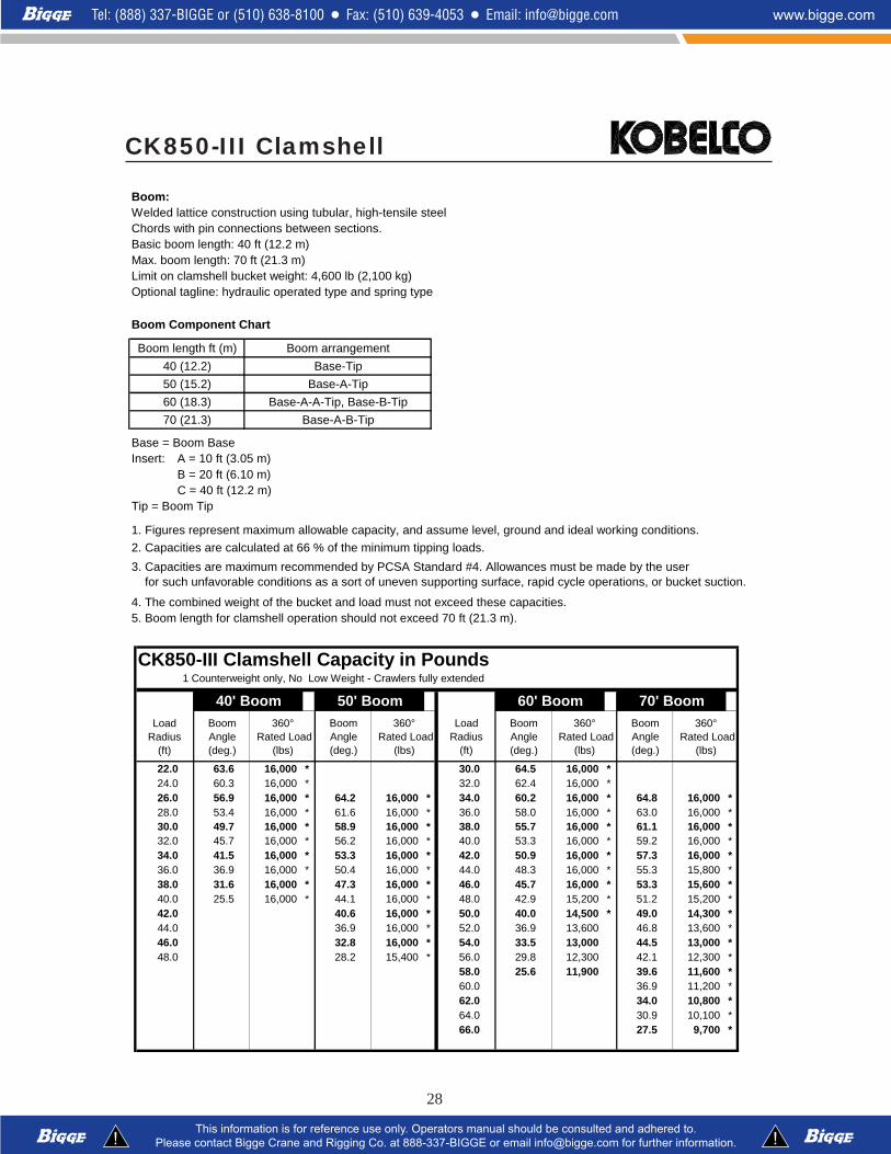
Boom:Welded lattice construction using tubular, high-tensile steelChords with pin connections between sections.Basic boom length: 40 ft (12.2 m)Max. boom length: 70 ft (21.3 m)Limit on clamshell bucket weight: 4,600 lb (2,100 kg)Optional tagline: hydraulic operated type and spring type
Boom Component Chart
Boom length ft (m) Boom arrangement
40 (12.2) Base-Tip
50 (15.2) Base-A-Tip
60 (18.3) Base-A-A-Tip, Base-B-Tip
70 (21.3) Base-A-B-Tip
Base = Boom BaseInsert: A = 10 ft (3.05 m)
B = 20 ft (6.10 m)C = 40 ft (12.2 m)
Tip = Boom Tip
2. Capacities are calculated at 66 % of the minimum tipping loads.
4. The combined weight of the bucket and load must not exceed these capacities.5. Boom length for clamshell operation should not exceed 70 ft (21.3 m).
3. Capacities are maximum recommended by PCSA Standard #4. Allowances must be made by the user for such unfavorable conditions as a sort of uneven supporting surface, rapid cycle operations, or bucket suction.
1. Figures represent maximum allowable capacity, and assume level, ground and ideal working conditions.
CK850-III Clamshell
CK850-III Clamshell Capacity in Pounds1 Counterweight only, No Low Weight - Crawlers fully extended
40' Boom 50' Boom 60' Boom 70' Boom
22.0 63.6 16,000 * 30.0 64.5 16,000 *24.0 60.3 16,000 * 32.0 62.4 16,000 *26.0 56.9 16,000 * 64.2 16,000 * 34.0 60.2 16,000 * 64.8 16,000 *28.0 53.4 16,000 * 61.6 16,000 * 36.0 58.0 16,000 * 63.0 16,000 *30.0 49.7 16,000 * 58.9 16,000 * 38.0 55.7 16,000 * 61.1 16,000 *32.0 45.7 16,000 * 56.2 16,000 * 40.0 53.3 16,000 * 59.2 16,000 *34.0 41.5 16,000 * 53.3 16,000 * 42.0 50.9 16,000 * 57.3 16,000 *36.0 36.9 16,000 * 50.4 16,000 * 44.0 48.3 16,000 * 55.3 15,800 *38.0 31.6 16,000 * 47.3 16,000 * 46.0 45.7 16,000 * 53.3 15,600 *40.0 25.5 16,000 * 44.1 16,000 * 48.0 42.9 15,200 * 51.2 15,200 *42.0 40.6 16,000 * 50.0 40.0 14,500 * 49.0 14,300 *44.0 36.9 16,000 * 52.0 36.9 13,600 46.8 13,600 *46.0 32.8 16,000 * 54.0 33.5 13,000 44.5 13,000 *48.0 28.2 15,400 * 56.0 29.8 12,300 42.1 12,300 *
58.0 25.6 11,900 39.6 11,600 *60.0 36.9 11,200 *62.0 34.0 10,800 *64.0 30.9 10,100 *66.0 27.5 9,700 *
Boom Angle (deg.)
Load Radius
(ft)
360° Rated Load
(lbs)
Boom Angle (deg.)
360° Rated Load
(lbs)
Boom Angle (deg.)
Boom Angle (deg.)
360° Rated Load
(lbs)
Load Radius
(ft)
360° Rated Load
(lbs)
CK850-IIICK850-IIICK850-IIICK850-IIICK850-III
Note: Due to our policy of continual product improvement, all designs and specifications are subject to change without advance notice.
Pictures inside this publication may show machines with optional equipment. This manual and the specifications herein were prepared for
the market served by Kobelco Cranes North America Inc. including North America and Latin America. Kobelco product specifications in
other world markets may differ.
KOBELCO CRANES CO., LTDOval Court Ohsaki Mark West Bldg., 17-1, Higashigotanda 2-chome,
Shinagawa-ku, Tokyo, 141-8626 JAPAN
Tel: ++81 (0) 3-5789-2130 Fax: ++81 (0) 3-5789-3372
KOBELCO CRANES NORTH AMERICA INC.10845 Train Court
Houston Texas 77041 U.S.A
Tel: 713-856-5755 Fax: 713-856-9072
www.kobelcocranesnorthamerica.com
Bulletin No. CK850III-SPECS-US-12/05© 2004 Kobelco Cranes North America Inc.
Related Documents