© 2013, Her Majesty the Queen in right of the Province of Alberta Hydraulic Brake System Fundamentals Parts Technician First Period Material Identification and Calculations 270103k

Hydraulic Brake System Fundamentals Parts Technician First Period Material Identification and Calculations 270103k.
Dec 31, 2015
Welcome message from author
This document is posted to help you gain knowledge. Please leave a comment to let me know what you think about it! Share it to your friends and learn new things together.
Transcript
Hydraulic Brake System Fundamentals
Parts Technician
First Period
Material Identification and Calculations
270103k

© 2013, Her Majesty the Queen in right of the Province of Alberta
Figure 1 - Maximum stopping distances allowed under the conditions indicated.
© 2013, Her Majesty the Queen in right of the Province of Alberta
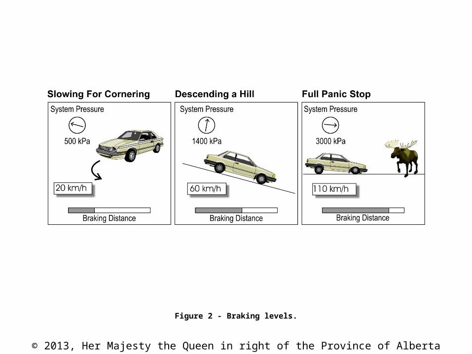
Figure 2 - Braking levels.
© 2013, Her Majesty the Queen in right of the Province of Alberta
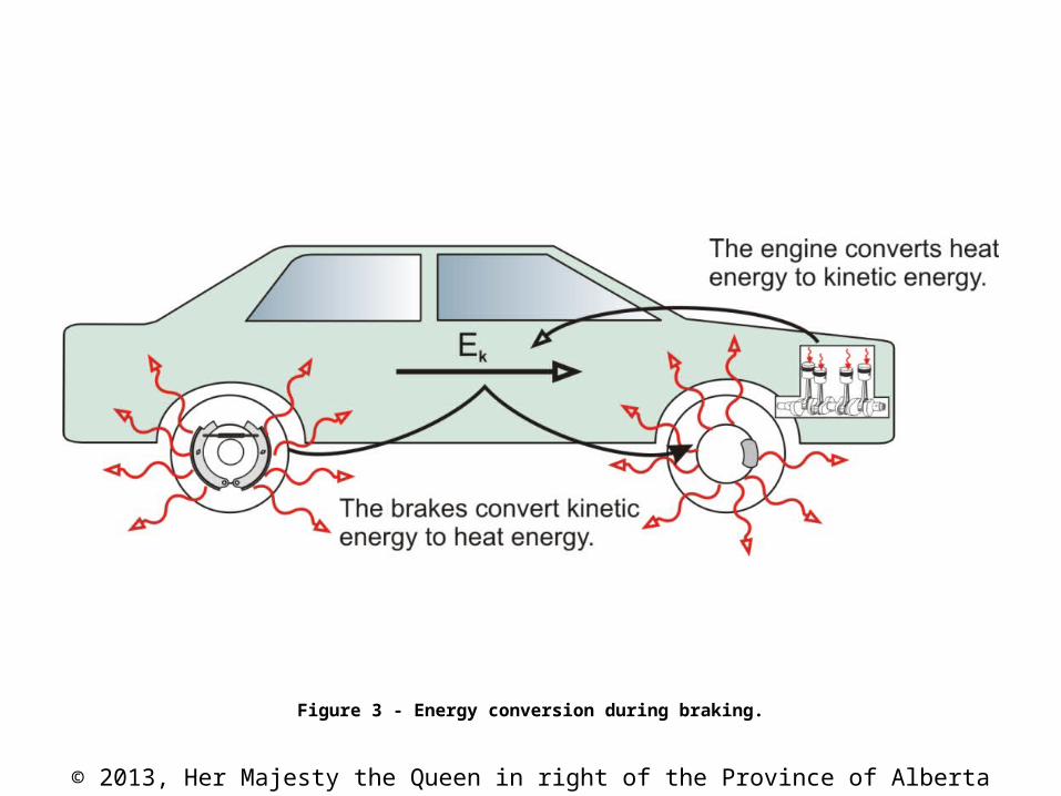
Figure 3 - Energy conversion during braking.
© 2013, Her Majesty the Queen in right of the Province of Alberta
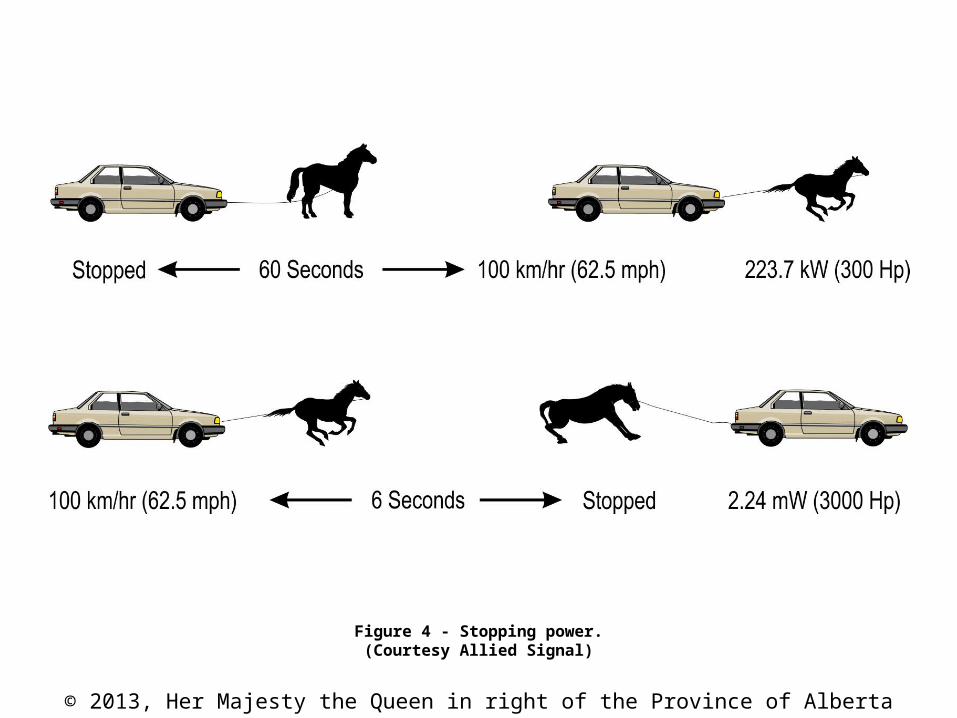
Figure 4 - Stopping power.(Courtesy Allied Signal)
© 2013, Her Majesty the Queen in right of the Province of Alberta
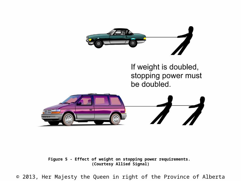
Figure 5 - Effect of weight on stopping power requirements. (Courtesy Allied Signal)
© 2013, Her Majesty the Queen in right of the Province of Alberta
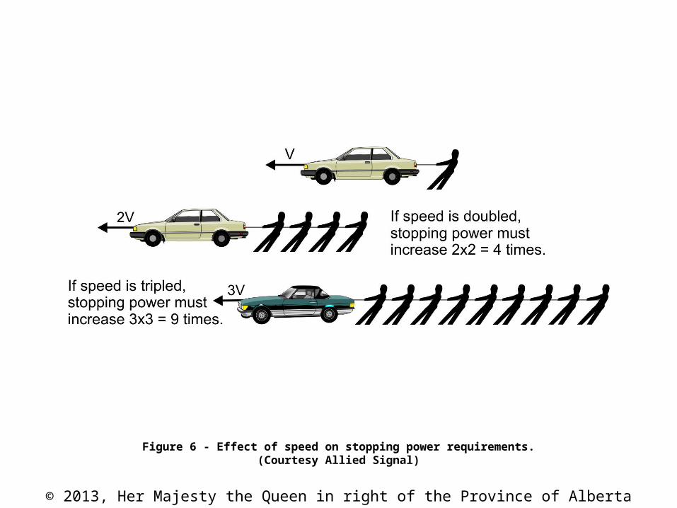
Figure 6 - Effect of speed on stopping power requirements.(Courtesy Allied Signal)
© 2013, Her Majesty the Queen in right of the Province of Alberta
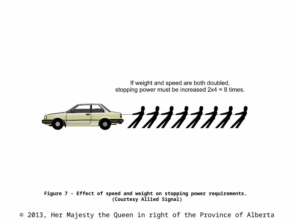
Figure 7 - Effect of speed and weight on stopping power requirements. (Courtesy Allied Signal)
© 2013, Her Majesty the Queen in right of the Province of Alberta
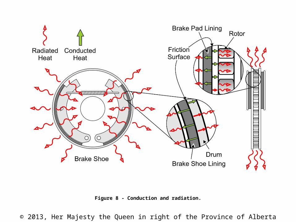
Figure 8 - Conduction and radiation.
© 2013, Her Majesty the Queen in right of the Province of Alberta
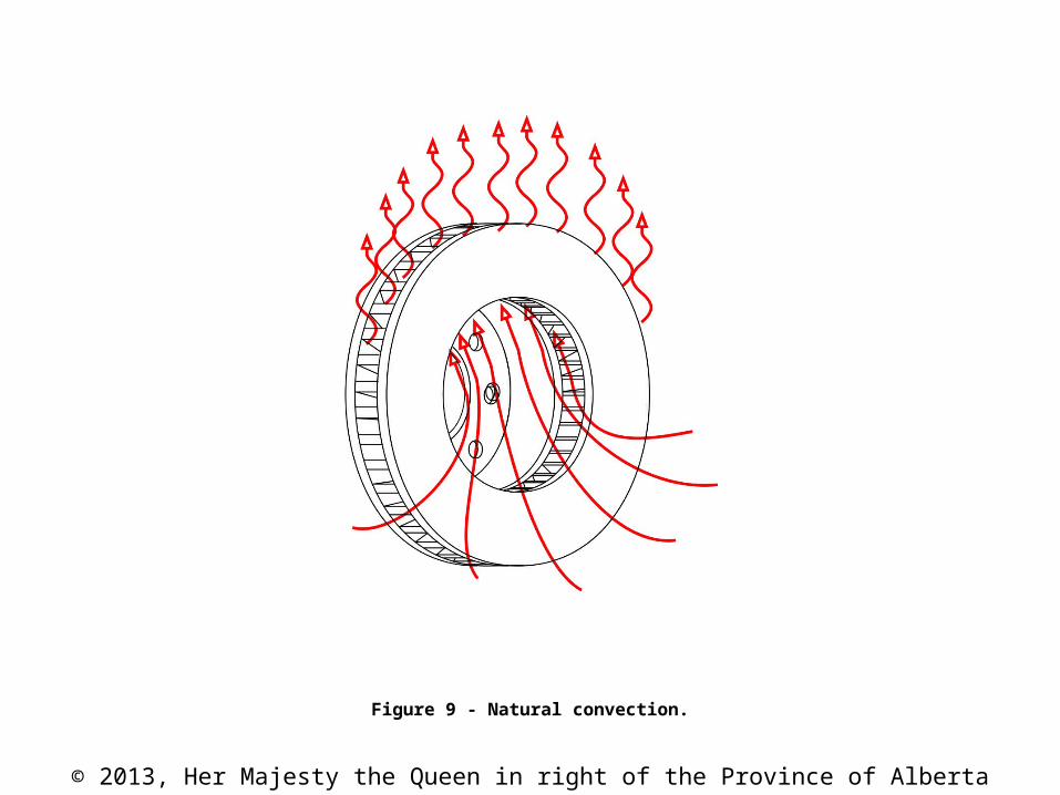
Figure 9 - Natural convection.
© 2013, Her Majesty the Queen in right of the Province of Alberta
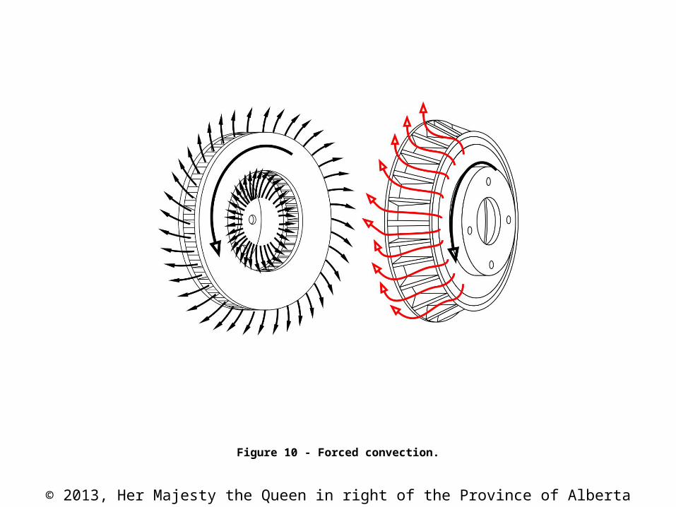
Figure 10 - Forced convection.

© 2013, Her Majesty the Queen in right of the Province of Alberta
CAUTION
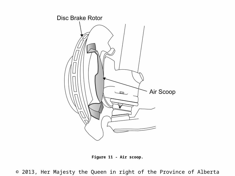
Adequate airflow to the brakes for cooling is vital to their safe operation. Never make modifications to the vehicle that would reduce the amount of airflow to the brakes.
© 2013, Her Majesty the Queen in right of the Province of Alberta
Figure 11 - Air scoop.
© 2013, Her Majesty the Queen in right of the Province of Alberta
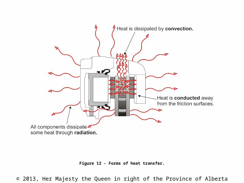
Figure 12 - Forms of heat transfer.
© 2013, Her Majesty the Queen in right of the Province of Alberta
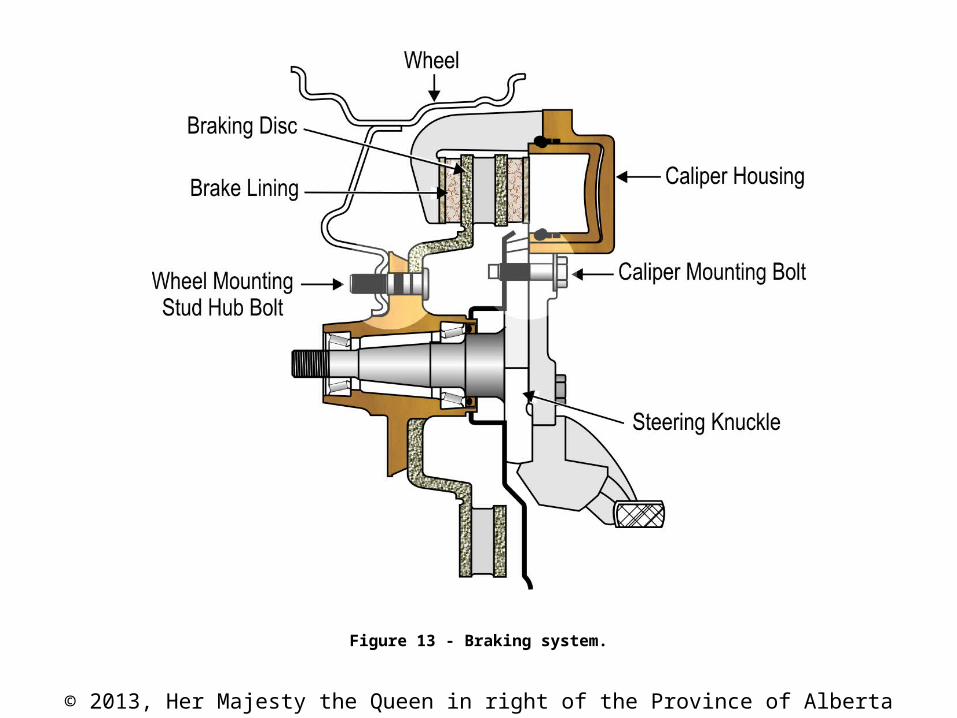
Figure 13 - Braking system.
© 2013, Her Majesty the Queen in right of the Province of Alberta
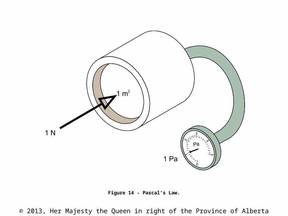
Figure 14 - Pascal’s Law.

© 2013, Her Majesty the Queen in right of the Province of Alberta
Figure 15 - Pascal’s Law helpful hints (Tradesperson’s Triangle).

© 2013, Her Majesty the Queen in right of the Province of Alberta
Figure 16 - Hydraulics used to multiply force.
© 2013, Her Majesty the Queen in right of the Province of Alberta
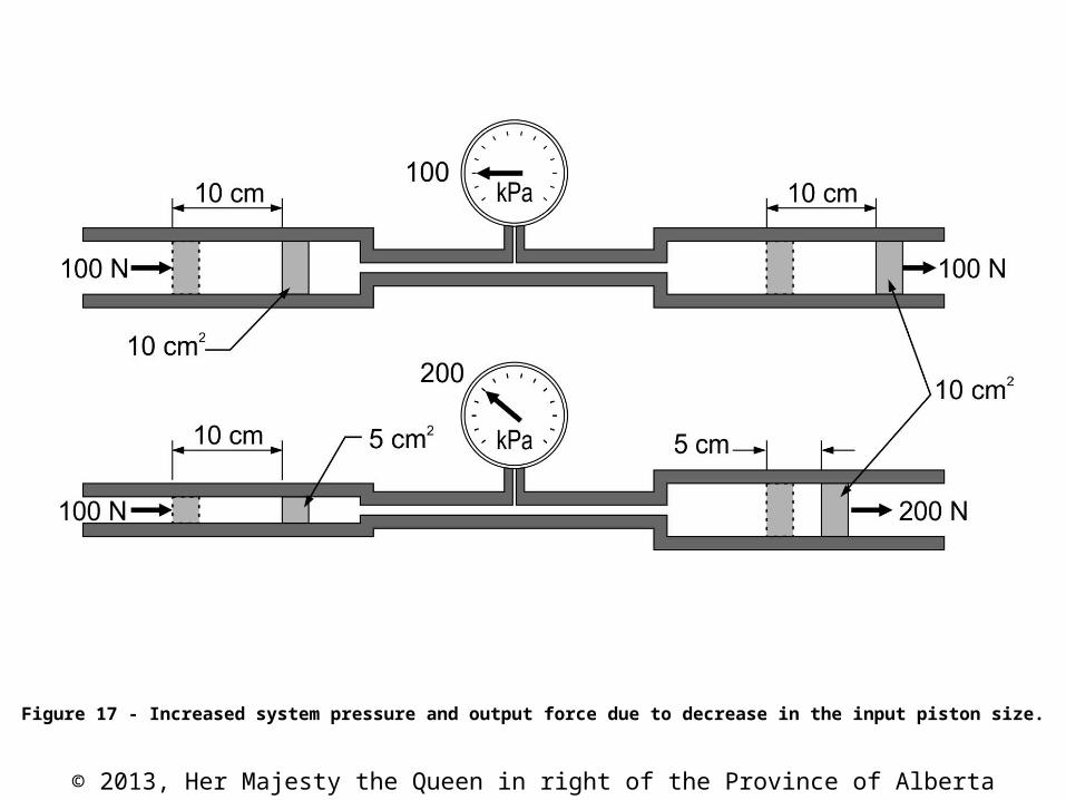
Figure 17 - Increased system pressure and output force due to decrease in the input piston size.
© 2013, Her Majesty the Queen in right of the Province of Alberta
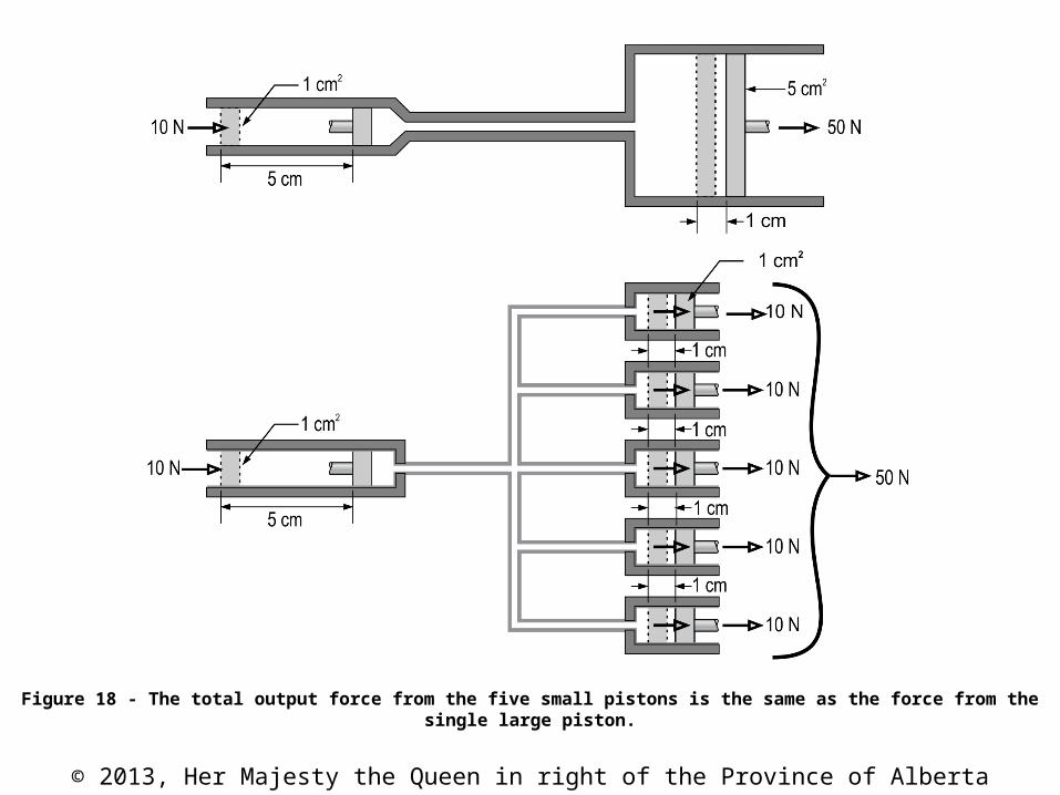
Figure 18 - The total output force from the five small pistons is the same as the force from the single large piston.
© 2013, Her Majesty the Queen in right of the Province of Alberta
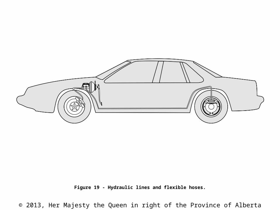
Figure 19 - Hydraulic lines and flexible hoses.
© 2013, Her Majesty the Queen in right of the Province of Alberta
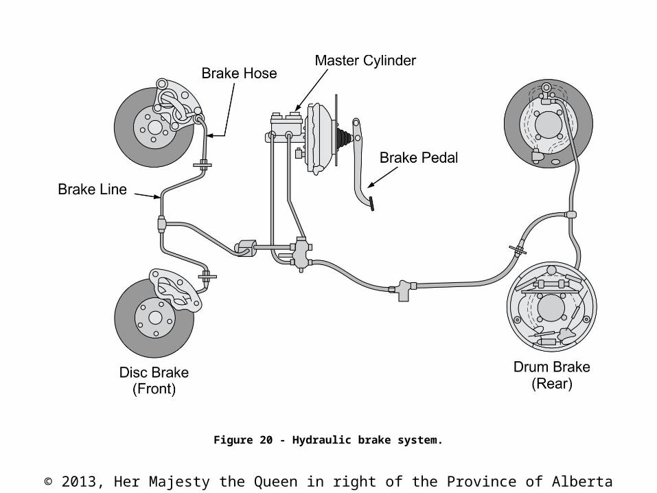
Figure 20 - Hydraulic brake system.
© 2013, Her Majesty the Queen in right of the Province of Alberta
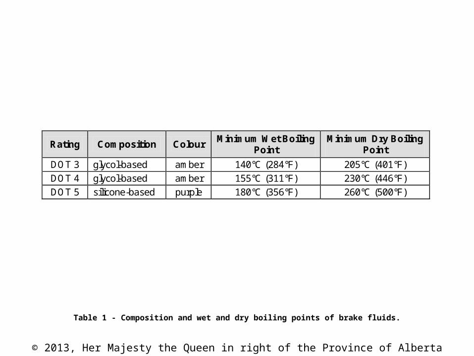
Table 1 - Composition and wet and dry boiling points of brake fluids.
Rating Composition Colour Minimum Wet Boiling
Point Minimum Dry Boiling
Point
DOT 3 glycol-based amber 140°C (284°F) 205°C (401°F)
DOT 4 glycol-based amber 155°C (311°F) 230°C (446°F)
DOT 5 silicone-based purple 180°C (356°F) 260°C (500°F)
© 2013, Her Majesty the Queen in right of the Province of Alberta
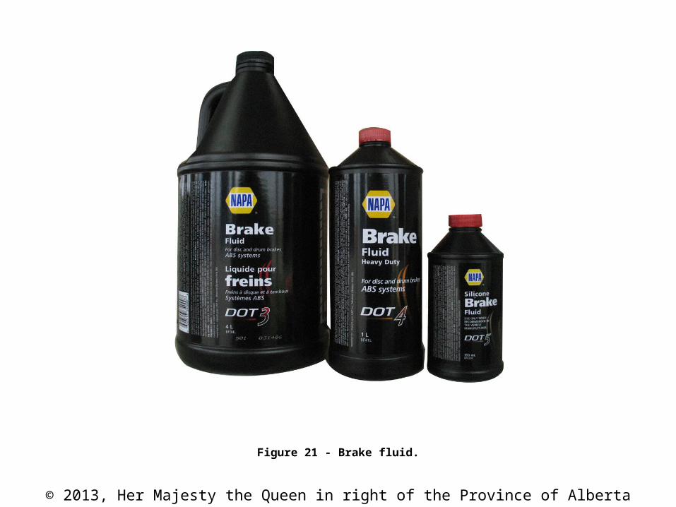
Figure 21 - Brake fluid.
© 2013, Her Majesty the Queen in right of the Province of Alberta
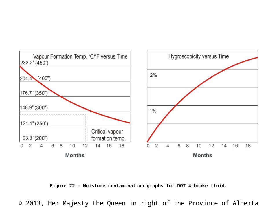
Figure 22 - Moisture contamination graphs for DOT 4 brake fluid.
© 2013, Her Majesty the Queen in right of the Province of Alberta
CAUTION
DOT 5 fluid should never be used in ABS systems. Since DOT 5 fluids do not absorb the water that finds its way into the system, the water can collect in the valves of the ABS system, corroding them and rendering them inoperative.

© 2013, Her Majesty the Queen in right of the Province of Alberta
DANGER
Brake fluid can cause skin irritation, particularly in open wounds and sores. Protective clothing and eyewear should be worn when servicing hydraulic components.

© 2013, Her Majesty the Queen in right of the Province of Alberta
Figure 23 - Complete brake system components.
© 2013, Her Majesty the Queen in right of the Province of Alberta
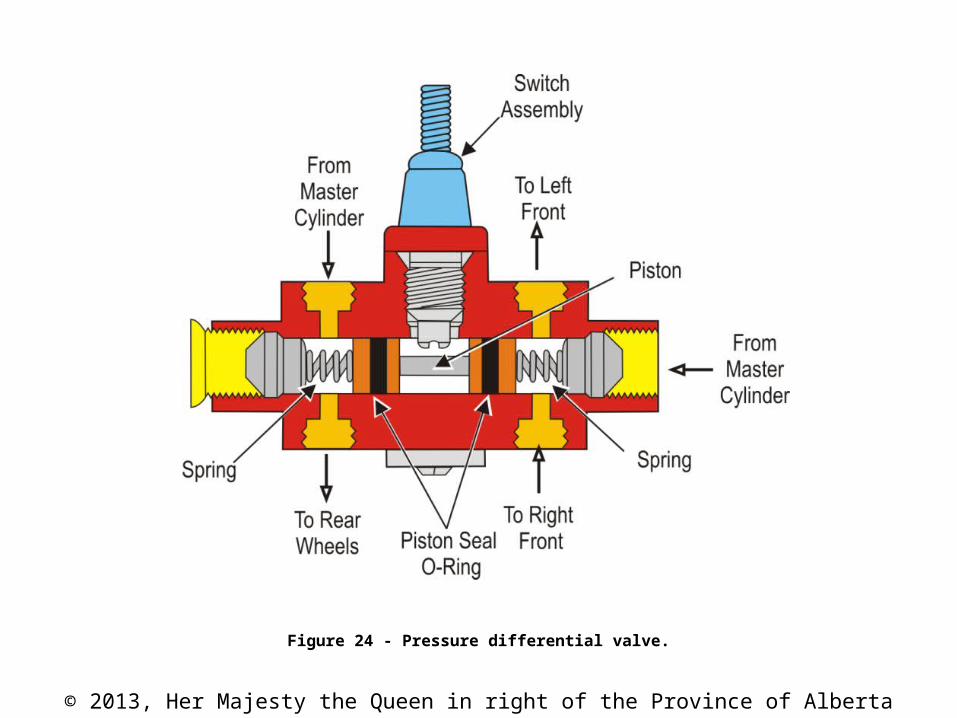
Figure 24 - Pressure differential valve.
© 2013, Her Majesty the Queen in right of the Province of Alberta
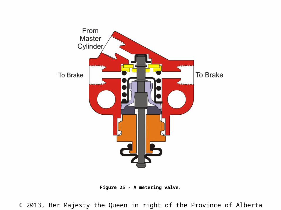
Figure 25 - A metering valve.
© 2013, Her Majesty the Queen in right of the Province of Alberta
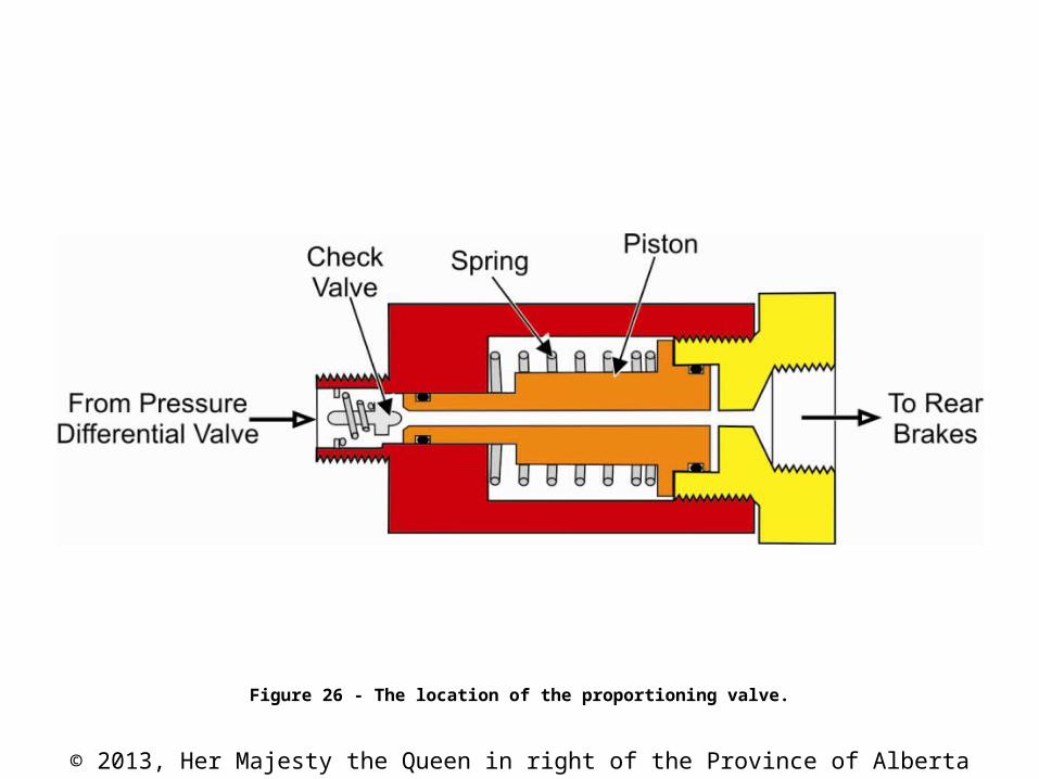
Figure 26 - The location of the proportioning valve.

© 2013, Her Majesty the Queen in right of the Province of Alberta
Figure 27 - A combination valve showing the three separate sections making up the one valve block.
© 2013, Her Majesty the Queen in right of the Province of Alberta
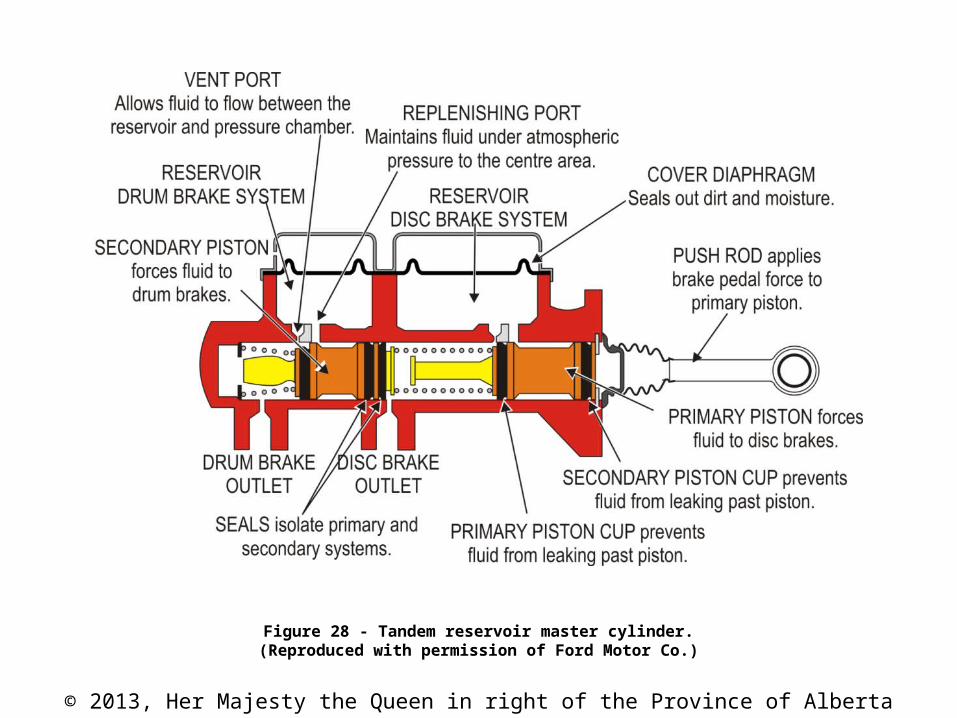
Figure 28 - Tandem reservoir master cylinder.(Reproduced with permission of Ford Motor Co.)
© 2013, Her Majesty the Queen in right of the Province of Alberta
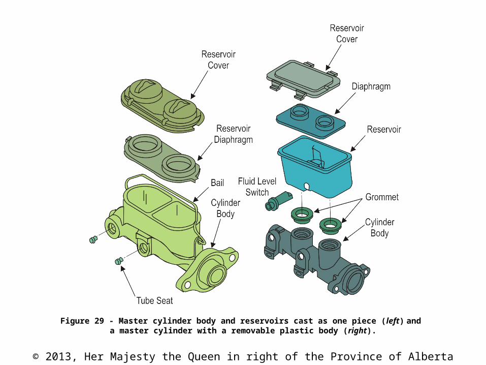
Figure 29 - Master cylinder body and reservoirs cast as one piece (left) and a master cylinder with a removable plastic body (right).

© 2013, Her Majesty the Queen in right of the Province of Alberta
Figure 30 - Exploded view of a master cylinder.(Courtesy General Motors of Canada Limited)

© 2013, Her Majesty the Queen in right of the Province of Alberta
Figure 31 - Mechanical linkage of a master cylinder mounted on the bulkhead/firewall.(Courtesy Motor Information Systems)
© 2013, Her Majesty the Queen in right of the Province of Alberta
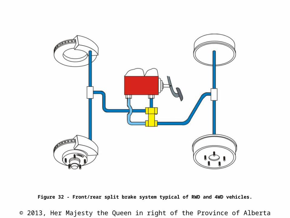
Figure 32 - Front/rear split brake system typical of RWD and 4WD vehicles.
© 2013, Her Majesty the Queen in right of the Province of Alberta
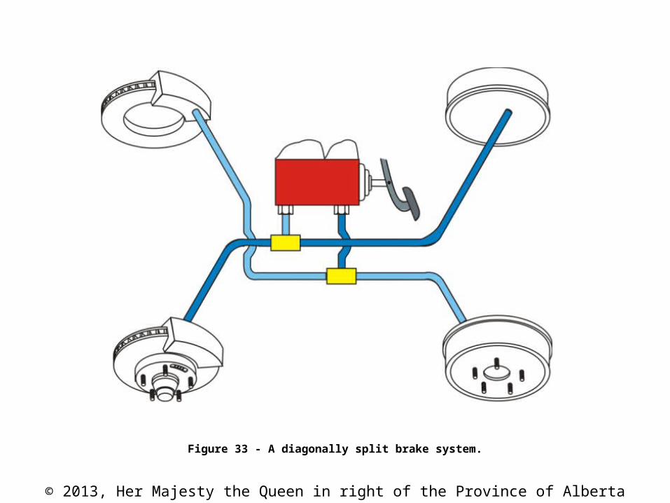
Figure 33 - A diagonally split brake system.

© 2013, Her Majesty the Queen in right of the Province of Alberta
Figure 34 - Different size brake reservoirs. (Courtesy Motor Information Systems)

© 2013, Her Majesty the Queen in right of the Province of Alberta
Figure 35 - Master cylinder brake fluid switch.(Courtesy General Motors of Canada Limited)

© 2013, Her Majesty the Queen in right of the Province of Alberta
CAUTION
Copper tubing must never be used in brake hydraulic circuits because it will become work hardened from vibration much more readily than steel and cannot withstand the high pressures in the brake system.

© 2013, Her Majesty the Queen in right of the Province of Alberta
Figure 36 - A double-lap flare (SAE) and an ISO flare.
© 2013, Her Majesty the Queen in right of the Province of Alberta
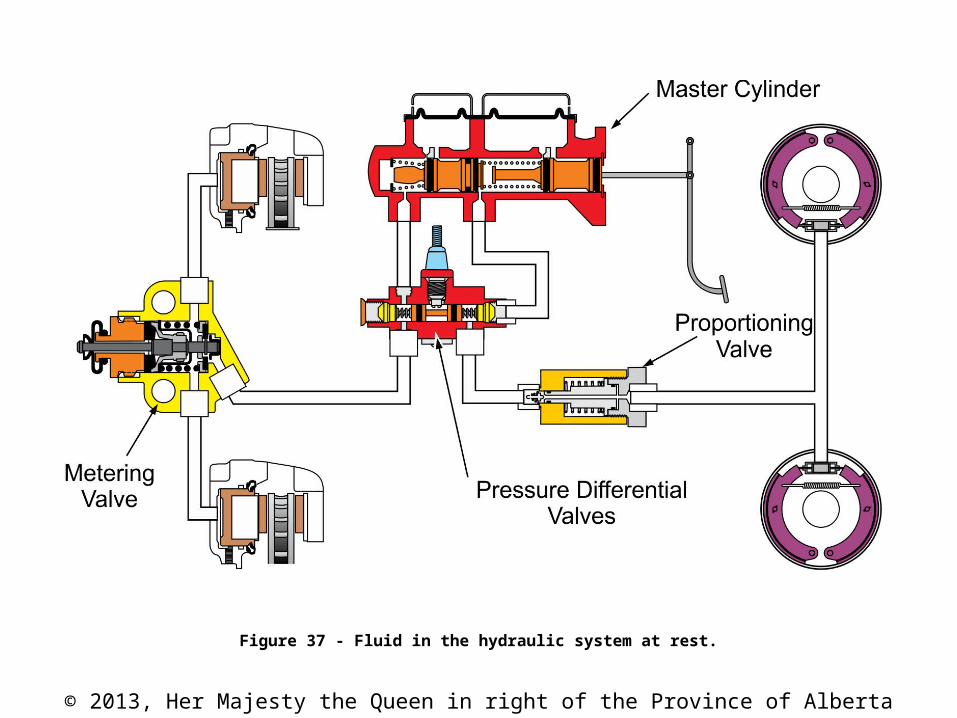
Figure 37 - Fluid in the hydraulic system at rest.
© 2013, Her Majesty the Queen in right of the Province of Alberta
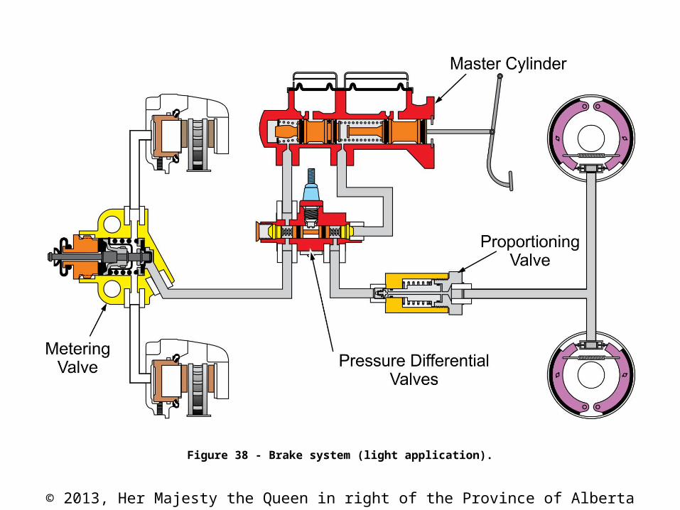
Figure 38 - Brake system (light application).
© 2013, Her Majesty the Queen in right of the Province of Alberta
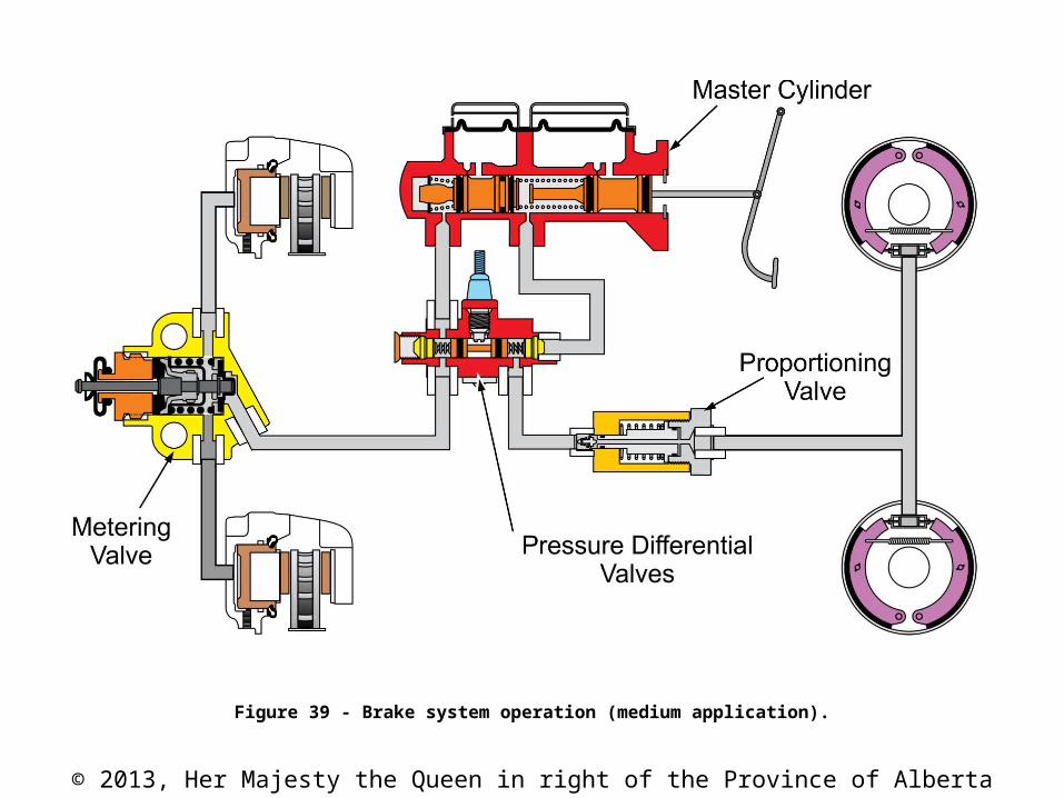
Figure 39 - Brake system operation (medium application).
© 2013, Her Majesty the Queen in right of the Province of Alberta
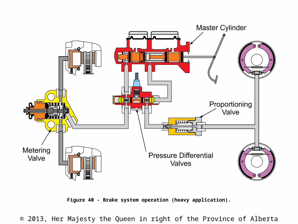
Figure 40 - Brake system operation (heavy application).
© 2013, Her Majesty the Queen in right of the Province of Alberta
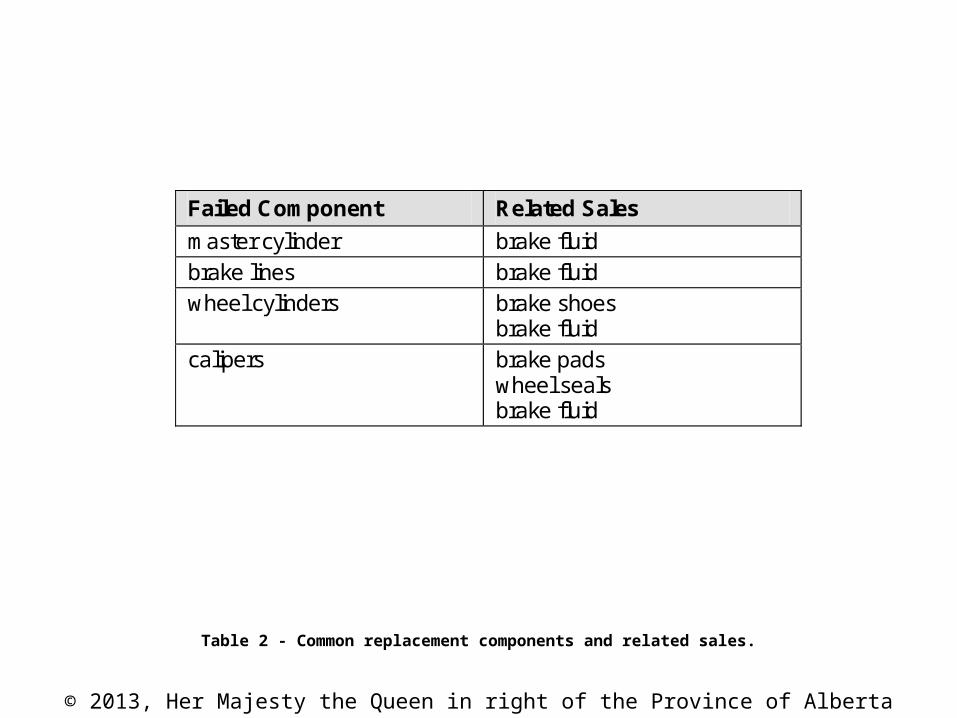
Table 2 - Common replacement components and related sales.
Failed Component Related Sales
master cylinder brake fluid brake lines brake fluid wheel cylinders brake shoes
brake fluid calipers brake pads
wheel seals brake fluid
© 2013, Her Majesty the Queen in right of the Province of Alberta
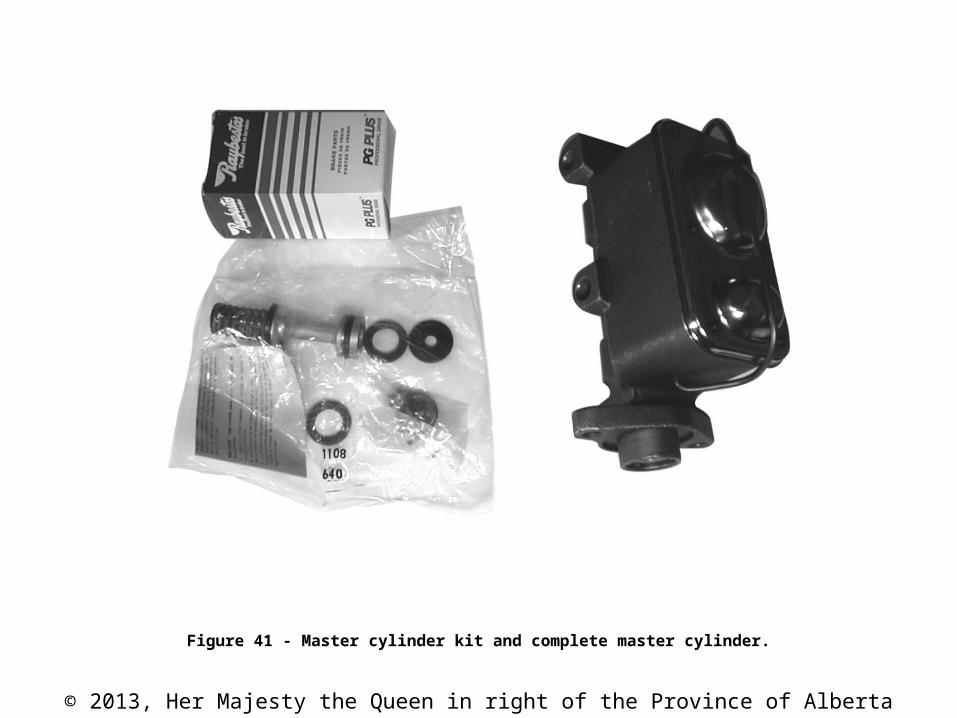
Figure 41 - Master cylinder kit and complete master cylinder.
Related Documents