Hydraulic Accessories Valves, Clamps & Reservoir Accessories

Welcome message from author
This document is posted to help you gain knowledge. Please leave a comment to let me know what you think about it! Share it to your friends and learn new things together.
Transcript

Hydraulic AccessoriesValves, Clamps & Reservoir Accessories

About HYDAC
Mobile MarketThe aim of our engineers has always been to reduce volume and weight, resulting in increased product performance. HYDAC provides compact high perfor-mance accumulators for the Mobile Market, HYDAC accumulators can be found on all types of construc-tion, forestry, and agricultural equipment.
Process TechnologyWorldwide HYDAC accumulators can be found in paper mills, steel mills and manufacturing plants, foundries, power plants, and in the chemical, petro-chemical and plastics industries. For more than 36 years HYDAC has been supplying accumulators to companies who require the most advanced process technology.
Industrial EngineeringSince we began, HYDAC has been involved in many industrial applications. Our knowledge and exper-tise of many industries provides a comprehensive range of versatile hydraulic accumulators. HYDAC offers many solutions for machine tools, plastic in-jection molding machines, test equipment, presses, and metal forming machines. Other industrial ap-plications include: steel and heavy industry, power transmission, and paper mills.
HYDAC Products
HYDAC Quality
HYDAC Customer Service
Our internal staff and worldwide distribution network take care of the important mat-ter of customer service. HYDAC values high standards, professional ethics, and mu-tual respect in all transactions with customers, vendors, and employees. We invest in our relationships by providing expertise, quality, dependability, and accessibility to foster growth and a sense of partnership. Our customer service representatives are committed to serving the customers’ needs.
Part Numbers and Model Codes
Every HYDAC Product has a Model Code and an eight digit Part Number. A Part Number is simply a unique, computer generated number that identifies a product. A Model Code is a sequence of codes that contains a complete description of the product, with each portion of the code defining some variable or option. BOTH Model Code and Part Number are listed in this catalog, whenever possible. It is recommended that you use BOTH Model Code and Part Number when communicating with HYDAC.
When options are limited, we have created charts that contain ALL possible combinations, or available products. In cases where the options create too many combinations to list, we have provided a Model Code Tree, which is used to create a complete Model Code which specifies the product as well as all options that are desired. Part Number are subject to change if HYDAC processes change, or design revisions are implemented by HYDAC. In this case, HYDAC Customer Service will refer you to the new part number.
Standard vs. Non-standard Products
Since HYDAC offers such a vast number of options for many product lines, it becomes necessary to differentiate between Standard and Non-standard configurations. Standard products are the most common configurations, which are continually supported by HYDAC in regular production. Non-standard configurations are less commonly ordered, and may require minimum orders and/or extended delivery times.
Throughout this catalog we have distinguished Non-standard products or options from the Standard, by listing the them in red. In model code trees, any red option selected will cause that configuration to be considered Non-standard. In charts that contain complete model codes, the entire model code will be in red for Non-standard products.
HYDAC stands for quality and customer satisfaction. To ensure that our products are as innovative as possible, they are developed, manufactured, and tested by qualified personnel using state of the art equipment and technology.
The Valves, Clamps, & Accessories group manufactures highly engineered high pressure ball valves, which guarantee safe and reliable operation. A complete range of DIN 3015 clamps for mounting hoses, tubes, and pipes is complimented by our specialty and completely custom mounting solutions. Reservoir accessories round out our product line, and put the finishing touches on your system.
HYDAC stands for worldwide presence and accessibility to the customer. HYDAC has over 1000 distributors worldwide and more than 40 wholly owned branches. The HYCON Division of HYDAC is an industry leader in the manufacture of hydraulic valves, clamps, reservoir accessories, filters, and elements for both mobile and industrial applications. The HYCON Division has been providing standard products and custom solutions to the fluid power industry for more than 30 years.
HYDAC has over 40 years of global experience in applying hydraulic components in both mobile and industrial systems. The industries served includes, but is in no way limited to:
Please review the information below to familiarize yourself with the conventions used in this catalog, as well as some general information about ordering the HYDAC products within.
Applications
About this Catalog
Mobile HydraulicsConstruction vehicles•
Agricultural vehicles•
Aerospace•
Lift equipment•
Shipbuilding •
Industrial HydraulicsPulp & paper mills•
Steel mills.& heavy industry•
Plastics•
Power generation & wind energy•
Offshore oil•
Chemical processing•
Food processing•

All information is subject to change without notice.
Table of Contents
Accessories Catalog
ValvesOverview . . . . . . . . . . . . . . . . . . . . . . . . . . . . . . . 1
High Pressure Ball ValvesOverview . . . . . . . . . . . . . . . . . . . . . . . . . . . . . . . 32-way SAE & NPT Threaded [KHB, KHM] . . . . . 52-way Split Flange [KHB, KHM] . . . . . . . . . . . . . 7Specialty Ball Valves Overview . . . . . . . . . . . . . 92-way BSPP Threaded [KHB, KHM] . . . . . . . . 102-way Steel Ball Seals [KHB, KHM] . . . . . . . . . 112-way Stainless Steel [KHM] . . . . . . . . . . . . . . 123-way Diverter [KHB3K] . . . . . . . . . . . . . . . . . . 132-way Manifold Mount [KHP] . . . . . . . . . . . . . . 15Multiway Threaded [KH3, KH4] . . . . . . . . . . . . 17Actuators [EDA] . . . . . . . . . . . . . . . . . . . . . . . . 19Locking Devices & Limit Switches . . . . . . . . . . 21Seal Kits . . . . . . . . . . . . . . . . . . . . . . . . . . . . . . 23Handles . . . . . . . . . . . . . . . . . . . . . . . . . . . . . . . 24Engineering Data . . . . . . . . . . . . . . . . . . . . . . . 24Direct Mount SAE Flange [KHF3/6] . . . . . . . . . 25Direct Mount SAE Flange [KHF3] . . . . . . . . . . . 263 Piece Ball Valve [KHM3H] . . . . . . . . . . . . . . . 27
Process & Automated ValvesOverview . . . . . . . . . . . . . . . . . . . . . . . . . . . . . . 29Low Pressure Stainless Steel [KHNVN] . . . . . . 30Inline Isolation Valve + Actuator [HVA] . . . . . . . 31Angle Seat Valve [ASV] . . . . . . . . . . . . . . . . . . . 33Automated 2 Piece Ball Valve [KHL] . . . . . . . . 35Automated 3 Piece Ball Valve [KHM3L] . . . . . . 37Solenoid Valves . . . . . . . . . . . . . . . . . . . . . . . . 39
Flow Control ValvesOverview . . . . . . . . . . . . . . . . . . . . . . . . . . . . . . 41Needle Valves [DV, DVE, DVP] . . . . . . . . . . . . . 43Flow Control Valves [DVR, DRVP] . . . . . . . . . . 47Pressure Compensated Flow Ctrls [SRVR] . . . 51Check Valves [RV, RVP] . . . . . . . . . . . . . . . . . . 53Stainless Steel Flow Control Valves [DV, DRV, RV] . . . . . . . . . . . . . . . . . . . . . . . . . . . . . . . . . . 55
Cartridge ValvesOverview . . . . . . . . . . . . . . . . . . . . . . . . . . . . . . 56Hose Break Valves [RB} . . . . . . . . . . . . . . . . . . 57Shuttle Valves [WVE} . . . . . . . . . . . . . . . . . . . . 61Automatic Air Vent Valves [AEV} . . . . . . . . . . . 622-way Solenoid [WSM} . . . . . . . . . . . . . . . . . . . 633-way Solenoid [WSE3} . . . . . . . . . . . . . . . . . . 67Pressure Relief [DB4} . . . . . . . . . . . . . . . . . . . . 69
ClampsOverview . . . . . . . . . . . . . . . . . . . . . . . . . . . . . . 71
DIN 3015 ClampsOverview . . . . . . . . . . . . . . . . . . . . . . . . . . . . . . 73Technical Specifications . . . . . . . . . . . . . . . . . 74Standard Duty [HRL] . . . . . . . . . . . . . . . . . . . . 75Heavy Duty [HRS] . . . . . . . . . . . . . . . . . . . . . . . 77Twin [HRZ] . . . . . . . . . . . . . . . . . . . . . . . . . . . . 79Std. Duty w/Rubber Inserts [HREL] . . . . . . . . . 81Heavy Duty w/Rubber Inserts [HRES] . . . . . . . 83S.S. Metal Components [HRL, HRS] . . . . . . . . 85Parts for Standard Duty [HRL] . . . . . . . . . . . . . 87Parts for Heavy Duty [HRS] . . . . . . . . . . . . . . . 88Parts for Twin [HRZ] . . . . . . . . . . . . . . . . . . . . . 89
Standard ClampsHOM Series . . . . . . . . . . . . . . . . . . . . . . . . . . . . .Cushion Clamps [CUSH] . . . . . . . . . . . . . . . . . 91Buegu Clamps [HRBGS] . . . . . . . . . . . . . . . . . 93U-bolt Clamps [HRRBS] . . . . . . . . . . . . . . . . . . 95HUB Series . . . . . . . . . . . . . . . . . . . . . . . . . . . . 96Oval Clamps [HROS] . . . . . . . . . . . . . . . . . . . . 97HSPN Series . . . . . . . . . . . . . . . . . . . . . . . . . . . 98Quick Release Swivel Bolt [HRGKSM] . . . . . . . 99
Custom ClampsSeries Strip [HRRL, HRRLE] . . . . . . . . . . . . . 101Band Straps . . . . . . . . . . . . . . . . . . . . . . . . . . 102
AccessoriesOverview . . . . . . . . . . . . . . . . . . . . . . . . . . . . . 103
BreathersOverview . . . . . . . . . . . . . . . . . . . . . . . . . . . . . 105BF Series . . . . . . . . . . . . . . . . . . . . . . . . . . . . 109Spin-on Breathers [BL] . . . . . . . . . . . . . . . . . . 119Drymicron [BD] . . . . . . . . . . . . . . . . . . . . . . . . 121Filler Breathers [ELF] . . . . . . . . . . . . . . . . . . . 127
Other AccessoriesSuction Strainers [SFE, MSS, HTMS] . . . . . . 135Fluid Level Indicators [FSK, FSA] . . . . . . . . . . 139Gauge isolators [MA, MSL, MS] . . . . . . . . . . . 143Test Points . . . . . . . . . . . . . . . . . . . . . . . . . . . 147Gauges and Split Flanges . . . . . . . . . . . . . . . 151

Accessories Catalog1
Valves
OverviewStandard SolutionsHYDAC manufactures a complete line of valves. Our standard product offerig includes:
High Pressure Ball Valves(see pages 3 - 28) Nominal sizes from 1/4” to 2”
Cartridge Valves(see pages 56 - 70) Hose Break Valves, Shuttle Valves, Automatic Air Vent Valves, 2-way Solenoid Cartridge Valves, 3-way Solenoid Cartridge Valves, Pressure Relief Valves
Flow Control Valves(see pages 41 - 55) Needle Valves, Flow Control Valves, Check Valves (Inline, Manifold Mount, Cartridge)
Process / Automated Valves(see pages 29 - 40)

Accessories Catalog 2
Valves
Custom SolutionsHYDAC is also a market leader in providing custom valve solutions. Our engineers work with yours to develop unique solutions that save time and money by simplifying inventory and installation. From simple modifications of standard product to complete custom manifolds, we will provide you a successful solution for your application. For more information on custom solutions, please contact product management at 1-877-GO HYDAC.
HYDAC Accessories GmbH has done significant work in the Automotive Paint Industry. Many custom and product developments are in the works. Contact HYDAC for additional information

High Pressure Ball Valves
Accessories Catalog3
2-way Ball Valves KHM Series (see pages 5 -12) Forged Bodies Sizes 1 1/4” - 2”
3-way Diverter Ball Valves KHB3K Series (see page 13) Sizes 1/4” - 1”
Direct Mount SAE FlangeKHF3/6 Series (see page 25) Sizes 1/2” - 2”
Ball Valve ActuatorsFor KHB & KHM Series (see page 19) Pneumatic Operation
2-way Ball ValvesKHB Series (see pages 5 - 11) Block Bodies Sizes 1/4” - 1”
2-way Manifold Mounted Ball ValvesKHP Series (see page 15) Sizes 3/8” - 2”
Multiway Ball ValvesKH3 & KH4 Series (see page 17) Sizes 1/4” - 3/4”
Direct Mount SAE FlangeKHF3 Series (see page 26) Sizes 2 1/2” - 4”
3 Piece Ball Valves KHM3H Series (see page 27) Designed in accordance with ANSI B16.34 and BS5351 Sizes 1/2” - 4”
Overview

High Pressure Ball Valves
Accessories Catalog 4
Standard Ball Valve Design Features & OptionsKHB, KHM, KHP, KHB3K Series
Product FeaturesFull passage for unrestricted flow of medium•
Floating ball provides positive seal•
Direction of flow indicated by milled slot in control spindle•
Valve positioning controlled by a stop pin and limit washer•
Fluoroelastomer O-rings • (standard)
Phosphate coated carbon steel valve body • (standard)
Available OptionsHYDAC can furnish ball valves with special options including:
Locking devices•
Stainless steel valve bodies•
Pneumatic or electrical actuators•
Limit switch•
Off-set or straight control handles•
Custom solutions - Contact HYDAC•
DescriptionThe HYDAC family of dependable high pressure ball valves provides full, unrestricted flow and positive shut-off of fluids and gases under extreme service conditions. Models are available to accommodate system pressures up to 7,250 PSI. Since a variety of materials are available, HYDAC valves can be used with various fluids and gases including petroleum based oils and some water glycols.
Valve DesignThe design of HYDAC ball valves is based on the “floating ball” principle which allows the ball to turn freely between the ball seals. A positive seal is attained by fluid pressure acting on the upstream surface of the ball and producing a constant uniform contact between the downstream ball seal and the ball. The ball is operated by a sealed spindle with a projecting square end to which the control handle or optional actuator is attached. Ball valves are intended to be used as on/off flow control devices and are not to be used to throttle fluid flow. The valves should always be either fully open or closed.
Housing
O-ring (valve sizes 06-25)O-ring & back-up ring (valve sizes 32-50)
Connection Adapter
Chrome Plated Ball
Ball Seal
Spindle
Thrust Washer
O-Ring with Back-up Ring
Stop Pin
Handle
Limit Washer

High Pressure Ball Valves
Accessories Catalog5
KHB & KHM Series 2-way Ball Valves with SAE & NPT Connections
Model CodeKHB - 16 NPT - 1 1 1 4 - 11X - L
Housing Type KHB = Block Housing, Carbon Steel - Sizes 06 - 25 KHM = Forged Housing, Carbon Steel - Sizes 32 - 50 KHM = Forged Housing, Stainless Steel - Sizes 06 - 50 (see page 12 for details)
Nominal Sizes Nom SAE NPT Size Tube Size Thread Size Pipe Size Pipe øD 06 -4 7/16-20 UNF 1/4” 0.540” 10 -6 9/16-18 UNF 3/8” 0.675” 16 -8 3/4-16 UNF 1/2” 0.840” 20 -12 1-1/16-12 UN 3/4” 1.050” 25 -16 1-5/16-12 UN 1” 1.315” 32 -20 1-5/8-12 UN 1-1/4” 1.660” 40 -24 1-7/8-12 UN 1-1/2” 1.900” 50 -32 2-1/2-12 UN 2” 2.375”
Connection Type NPT = ANSI/ASME 1.20.1 Taper Pipe Thread SAE = SAEJ1926 Ports with ISO 725 Threads and O-Ring Sealing
Body Material 1 = Carbon Steel (phosphate coated) 3 = Stainless Steel (see page 12 for ordering details)
Spindle and Ball Material 1 = Carbon Steel (ball is chrome plated, spindle is zinc plated) 3 = Stainless Steel
Ball Seal Material 1 = Polyacetal (standard) 3 = PTFE (1500 psi max) 8 = PEEK
O-Ring Material 2 = NBR (Buna) 3 = PTFE Spindle Seals and FPM (fluoroelastomer) O-Rings (1500 psi max) 4 = FPM (fluoroelastomer) (standard) 5 = EPR
Handle Codes 09x = Without Handle (see page 24 to order handle separately) 11x = Straight Aluminum, Sizes 06-25 16x = Offset Steel, Sizes 32-50
Locking Device Option L = Locking Device (see page 21 to order locking device separately) LS = Locking Device with 5 amp Limit Switch, Available for sizes 20-50 (Not available with PTFE Spindle Seals)
Model Codes containing selections listed in RED are non-standard items – Minimum quantities will apply – Contact HYDAC for information and availability Not all combinations are available
Specifications1/4” - 2” Full Port Design•
NPT or SAE O-Ring connections•
Polyacetal Ball Seals • (standard)
FPM (Fluoroelastomer) O-Rings • (standard)
Carbon Steel Housing•
Block Housing - Sizes 06 - 25•
Forged Housing - Sizes 32 - 50•
Operating Pressure to 7250 psi Depending •on Valve Size and Seal Materials Selected
Temp Range: 14˚F to 176˚F with Standard materials (1114) up •to max. pressure rating. Extended Temperature range -40˚F to 392˚F on request with special materials and reduced pressure rating (see page 24).
KHB SeriesBlock Housing
KHM SeriesForged Housing
High Pressure Ball Valves
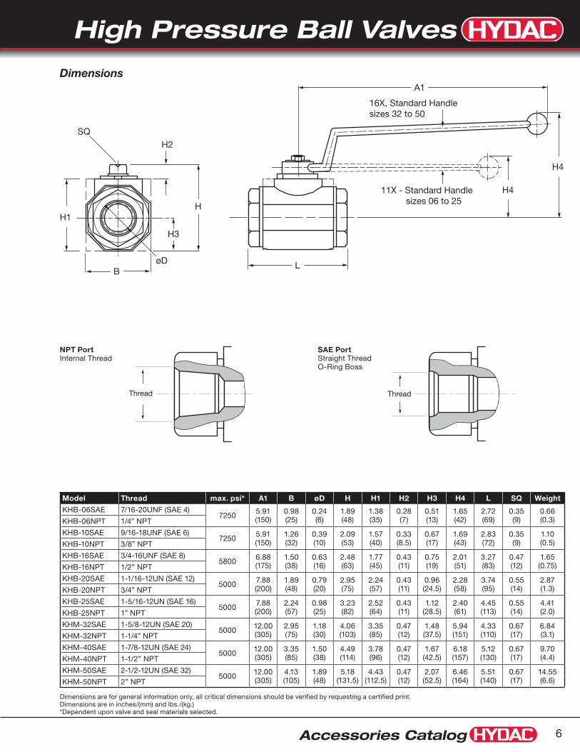
Accessories Catalog 6
Dimensions are for general information only, all critical dimensions should be verified by requesting a certified print.Dimensions are in inches/(mm) and lbs./(kg.)*Dependent upon valve and seal materials selected.
H
H3
SQ
H2
H1
BøD L
A1
11X - Standard Handle sizes 06 to 25
H4
H4
16X, Standard Handlesizes 32 to 50
Dimensions
NPT Port SAE Port Internal Thread Straight Thread O-Ring Boss
Model Thread max. psi* A1 B øD H H1 H2 H3 H4 L SQ Weight
KHB-06SAE 7/16-20UNF (SAE 4)7250 5.91
(150)0.98(25)
0.24(6)
1.89(48)
1.38(35)
0.28(7)
0.51(13)
1.65(42)
2.72(69)
0.35(9)
0.66(0.3)KHB-06NPT 1/4” NPT
KHB-10SAE 9/16-18UNF (SAE 6)7250 5.91
(150)1.26(32)
0.39(10)
2.09(53)
1.57(40)
0.33(8.5)
0.67(17)
1.69(43)
2.83(72)
0.35(9)
1.10(0.5)KHB-10NPT 3/8” NPT
KHB-16SAE 3/4-16UNF (SAE 8)5800 6.88
(175)1.50(38)
0.63(16)
2.48(63)
1.77(45)
0.43(11)
0.75(19)
2.01(51)
3.27(83)
0.47(12)
1.65(0.75)KHB-16NPT 1/2” NPT
KHB-20SAE 1-1/16-12UN (SAE 12)5000 7.88
(200)1.89(48)
0.79(20)
2.95(75)
2.24(57)
0.43(11)
0.96(24.5)
2.28(58)
3.74(95)
0.55(14)
2.87(1.3)KHB-20NPT 3/4” NPT
KHB-25SAE 1-5/16-12UN (SAE 16)5000 7.88
(200)2.24(57)
0.98(25)
3.23(82)
2.52(64)
0.43(11)
1.12(28.5)
2.40(61)
4.45(113)
0.55(14)
4.41(2.0)KHB-25NPT 1” NPT
KHM-32SAE 1-5/8-12UN (SAE 20)5000 12.00
(305)2.95(75)
1.18(30)
4.06(103)
3.35(85)
0.47(12)
1.48(37.5)
5.94(151)
4.33(110)
0.67(17)
6.84(3.1)KHM-32NPT 1-1/4” NPT
KHM-40SAE 1-7/8-12UN (SAE 24)5000 12.00
(305)3.35(85)
1.50(38)
4.49(114)
3.78(96)
0.47(12)
1.67(42.5)
6.18(157)
5.12(130)
0.67(17)
9.70(4.4)KHM-40NPT 1-1/2” NPT
KHM-50SAE 2-1/2-12UN (SAE 32)5000 12.00
(305)4.13(105)
1.89(48)
5.18(131.5)
4.43(112.5)
0.47(12)
2.07(52.5)
6.46(164)
5.51(140)
0.67(17)
14.55(6.6)KHM-50NPT 2” NPT
Thread Thread

High Pressure Ball Valves
Accessories Catalog7
KHB & KHM Series 2-way Ball Valves with Split Flange Connections
Model CodeKHB - 20 F3 - 1 1 1 4 X - 12X - L
Housing Type KHB = Block Housing, Carbon Steel - Sizes 16-25 KHM = Forged Housing, Carbon Steel - Sizes 32-50 KHM = Forged Housing, Stainless Steel - Sizes 06 - 50 (see page 12 for details)
Nominal Sizes Valve Size Nominal Flange Size Flange Dash Size 16 1/2” -8 20 3/4” -12 25 1” -16 32 1-1/4” -20 40 1-1/2” -24 50 2” -32
Connection Type SAE J518 Four bolt split flange type: F3 = Standard Pressure Series, Code 61 F6 = High Pressure Series, Code 62
Body Material 1 = Carbon Steel (phosphate coated) 3 = Stainless Steel (see page 12 for ordering details)
Spindle and Ball Material 1 = Carbon Steel (ball is chrome plated, spindle is zinc plated) 3 = Stainless Steel
Ball Seal Material 1 = Polyacetal (standard) 3 = PTFE (1500 psi max) 8 = PEEK
O-Ring Material 2 = NBR (Buna N) 3 = PTFE Spindle Seals and FPM (fluoroelastomer) O-Rings (1500 psi max) 4 = FPM (fluoroelastomer) (standard) 5 = EPR
Split Flange Material X = Without Split Flanges (order split flanges separately see page 151)
Handle Codes 09X = Without Handle, Sizes 16-50 12X = Offset Aluminum, Sizes 16-25 16X = Offset Steel, Sizes 32-50
Locking Device Option L = Locking Device (see page 21 to order locking device separately) LS = Locking Device with 5 amp Limit Switch, Available for Sizes 20-50 (Not available with PTFE Spindle Seals)
Model Codes containing selections listed in RED are non-standard items – Minimum quantities will apply – Contact HYDAC for information and availability Not all combinations are available
Specifications1/2” - 2” Full Port Design•
SAE Code 61 and 62 Split Flange Connections•
Carbon Steel Housing•
Block Housing - Sizes 16 - 25•
Forged Housing - Sizes 32 - 50•
Polyacetal Ball Seals • (standard)
FPM • (Fluoroelastomer) O-Rings (standard)
Operating Pressure to 5800 psi Depending on•
Valve Size and Seal Materials Selected•
Temp Range: 14˚F to 176˚F with Standard materials (1114) up •to max. pressure rating. Extended Temperature range -40˚F to 392˚F on request with special materials and reduced pressure rating (see page 24).
KHB SeriesBlock Housing
KHM SeriesForged Housing

High Pressure Ball Valves
Accessories Catalog 8
Dimensions are for general information only, all critical dimensions should be verified by requesting a certified print.Dimensions are in inches/(mm) and lbs./(kg.)*Dependent upon valve and seal materials selected.
øD1
øD2
C
H
H3
SQH2
H1
BøD
H4
A1
L
12x standard sizes 16-2516x standard sizes 32-50
Dimensions
SAE Code 61 [...F3]Model max.
psi* Size A1 B C øD øD1 øD2 H H1 H2 H3 H4 L SQ Weight
KHB-16 F3 5000 1/2” 6.42 (163)
1.50 (38)
0.27 (6.8)
0.51 (13)
1.19 (30.2)
0.94 (24)
2.44 (62)
1.77 (45)
0.43 (11)
0.75 (19)
3.27 (83)
5.94 (151)
0.47 (12)
2.4 (1.1)
KHB-20 F3 5000 3/4” 7.20 (183)
1.89 (48)
0.27 (6.8)
0.75 (19)
1.50 (38.1)
1.24 (31.5)
2.95 (75)
2.24 (57)
0.43 (11)
0.96 (24.5)
3.62 (92)
6.69 (170)
0.55 (14)
4.0 (1.8)
KHB-25 F3 5000 1” 7.20 (183)
2.24 (57)
0.31 (8)
0.98 (25)
1.75 (44.45)
1.50 (38)
3.23 (82)
2.52 (64)
0.43 (11)
1.12 (28.5)
3.74 (95)
6.95 (176.5)
0.55 (14)
5.1 (2.3)
KHM-32 F3 4000 1-1/4” 12.01 (305)
2.95 (75)
0.31 (8)
1.18 (30)
2.00 (50.8)
1.69 (43)
4.06 (103)
3.35 (85)
0.47 (12)
1.48 (37.5)
5.94 (151)
7.54 (191.4)
0.67 (17)
9.0 (4.1)
KHM-40 F3 3000 1-1/2” 12.01 (305)
3.35 (85)
0.31 (8)
1.50 (38)
2.38 (60.35)
1.97 (50)
4.49 (114)
3.78 (96)
0.47 (12)
1.67 (42.5)
6.18 (157)
9.09 (231)
0.67 (17)
13.1 (5.9)
KHM-50 F3 3000 2” 12.01 (305)
4.13 (105)
0.38 (9.6)
1.89 (48)
2.81 (71.4)
2.44 (62)
5.18 (131.5)
4.43 (112.5)
0.47 (12)
2.07 (52.5)
6.46 (164)
9.21 (234)
0.67 (17)
19.2 (8.7)
SAE Code 62 [...F6]Model max.
psi* Size A1 B C øD øD1 øD2 H H1 H2 H3 H4 L SQ Weight
KHB-16 F6 5800 1/2” 6.41 (163)
1.50 (38)
0.31 (7.8)
0.51 (13)
1.25 (31.8)
0.94 (24)
2.44 (62)
1.77 (45)
0.43 (11)
0.75 (19)
3.27 (83)
5.94 (151)
0.47 (12)
2.4 (1.1)
KHB-20 F6 5000 3/4” 7.20 (183)
1.89 (48)
0.35 (8.8)
0.75 (19)
1.63 (41.3)
1.26 (32)
2.95 (75)
2.24 (57)
0.43 (11)
0.96 (24.5)
3.62 (92)
6.69 (170)
0.55 (14)
4.0 (1.8)
KHB-25 F6 5000 1” 7.20 (183)
2.24 (57)
0.37 (9.5)
0.98 (25)
1.87 (47.6)
1.50 (38)
3.23 (82)
2.52 (64)
0.43 (11)
1.12 (28.5)
3.72 (95)
7.81 (198.5)
0.55 (14)
5.4 (2.4)
KHM-32 F6 5000 1-1/4” 12.01 (305)
2.95 (75)
0.41 (10.3)
1.18 (30)
2.13 (54)
1.73 (44)
4.06 (103)
3.35 (85)
0.47 (12)
1.48 (37.5)
5.94 (151)
8.80 (223.4)
0.67 (17)
10.6 (4.8)
KHM-40 F6 5000 1-1/2” 12.01 (305)
3.35 (85)
0.50 (12.6)
1.50 (38)
2.50 (63.5)
2.01 (51)
4.49 (114)
3.78 (96)
0.47 (12)
1.67 (42.5)
6.18 (157)
11.06 (281)
0.67 (17)
15.4 (7.0)
KHM-50 F6 5000 2” 12.01 (305)
4.13 (105)
0.50 (12.6)
1.89 (48)
3.13 (79.4)
2.64 (67)
5.18 (131.5)
4.43 (112.5)
0.47 (12)
2.07 (52.5)
6.46 (164)
12.40 (315)
0.67 (17)
22.5 (10.2)
For dimensional information on flanges, see page 151

High Pressure Ball Valves
Accessories Catalog9
New Programs / Specialty Ball ValvesHYDAC has received feedback from customers stating that they prefer charts with model codes and part numbers rather than model code trees. As we release new programs, especially within the KHB and KHM product offering, we will include separate pages with tables including model codes and part numbers provided in tables.
2-way Stainless Steel Ball ValvesKHM Series (see page 12) Nominal Sizes from 1/4” to 2”
Global Replacement Business
In some cases you will call HYDAC customer service and the part number will not be in our computer system. In these cases we will provide you a replacement quote in a few days. For additional details visit www.hydac.com and click on support, downloads, brochures, Accessories and check out the literature.
2-way Ball Valves with BSPP ThreadsKHB & KHM Series (see page 10) Sizes from G1/4” to G2”
2-way Ball Valves with Steel Ball SealsKHB & KHM Series (see page 11) Nominal Sizes from 1/4” to 2”
HYDAC Accessories GmbH is located in Germany and produces Ball Valves for the Global Market. Some of the product that they produce is not listed in this catalog.

High Pressure Ball Valves
Accessories Catalog 10
Dimensions are for general information only, all critical dimensions should be verified by requesting a certified print.Dimensions are in inches/(mm) and lbs./(kg.)*Dependent upon valve and seal materials selected.
Model Codes containing selections listed in RED are non-standard items – Minimum quantities will apply – Contact HYDAC for information and availability
Model Code Part Number
*MAX PSI Thread A1 B øD H H1 H2 H3 H4 L SQ Weight
KHB-G1/8-1112-11X-G 02079550 7250 G1/8” 5.91
(150)0.98 (25)
0.24 (6)
1.89 (48)
1.38 (35)
0.28 (7)
0.51 (13)
1.65 (42)
2.72 (69)
0.35 (9)
0.66 (0.3)
KHB-G1/4-1112-11X-G 02079551 7250 G1/4” 5.91
(150)0.98 (25)
0.24 (6)
1.89 (48)
1.38 (35)
0.28 (7)
0.51 (13)
1.65 (42)
2.72 (69)
0.35 (9)
0.66 (0.3)
KHB-G3/8-1112-11X-G 02079552 7250 G3/8” 5.91
(150)1.26 (32)
0.39 (10)
2.09 (53)
1.57 (40)
0.33 (8.5)
0.67 (17)
1.69 (43)
2.83 (72)
0.35 (9)
1.10 (0.5)
KHB-G1/2-1112-11X-G 02079553 5800 G1/2” 6.88
(175)1.50 (38)
0.63 (16)
2.48 (63)
1.77 (45)
0.43 (11)
0.75 (19)
2.01 (51)
3.27 (83)
47 (12)
1.65 (0.75)
KHB-G3/4-1112-11X-G 02079554 5000 G3/4” 7.88
(200)1.89 (48)
0.79 (20)
2.95 (75)
2.24 (57)
0.43 (11)
0.96 (24.5)
2.28 (58)
3.74 (95)
0.55 (14)
2.87 (1.3)
KHB-G1-1112-11X-G 02079555 5000 G1” 7.88
(200)2.24 (57)
0.98 (25)
3.23 (82)
2.52 (64)
0.43 (11)
1.12 (28.5)
2.40 (61)
4.45 (113)
0.55 (14)
4.41 (2.0)
KHM-G11/4-1112-16X 02079556 5000 G1-1/4” 12.00
(305)2.95 (75)
1.18 (30)
4.06 (103)
3.35 (85)
0.47 (12)
1.48 (37.5)
5.94 (151)
4.33 (110)
0.67 (17)
6.84 (3.1)
KHM-G11/2-1112-16X 02079557 5000 G1-1/2” 12.00
(305)3.35 (85)
1.50 (38)
4.49 (114)
3.78 (96)
0.47 (12)
1.67 (42.5)
6.18 (157)
5.12 (130)
0.67 (17)
9.70 (4.4)
KHM-G2-1112-16X 02079558 5000 G2” 12.00
(305)4.13 (105)
1.89 (48)
5.18 (131.5)
4.43 (112.5)
0.47 (12)
2.07 (52.5)
6.46 (164)
5.51 (140)
0.67 (17)
14.55 (6.6)
Specifications1/8” - 2” Full Port Design•
Whitworth Internal Thread to ISO 228•
Carbon Steel Housing•
1/8” - 1” Zinc Plated• (represented by “- G” at end of model code)
1 1/4” - 2” Phosphate Coated•
Chrome Plated Steel Ball, Zinc Plated Steel Spindle•
Polyacetal Ball Seals and NBR (Buna-N) O-Rings•
Temperature Range: 14˚ to 176˚F at full pressure•
KHB & KHM Series2-way Ball Valves with BSPP Threads
Dimensions
H
H3
SQ
H2
H1
BøD L
A1
11X - Standard Handle sizes 06 to 25
H4
H4
16X, Standard Handlesizes 32 to 50
KHB SeriesBlock Housing
KHM SeriesForged Housing

High Pressure Ball Valves
Accessories Catalog11
Dimensions are for general information only, all critical dimensions should be verified by requesting a certified print.Dimensions are in inches/(mm) and lbs./(kg.)*Dependent upon valve and seal materials selected.
Model Codes containing selections listed in RED are non-standard items – Minimum quantities will apply – Contact HYDAC for information and availability
Part Number Model Code *MAX PSI
NPT Thread A1 B øD H H1 H2 H3 H4 L SQ WGT
KHB-06NPT-111114-11X-G-SF 03203692 7250 1/4” 5.91
(150)0.98 (25)
0.24 (6)
1.89 (48)
1.38 (35)
0.28 (7)
0.51 (13)
1.65 (42)
2.72 (69)
0.35 (9)
0.66 (0.3)
KHB-10NPT-111114-11X-G-SF 03203716 7250 3/8” 5.91
(150)1.26 (32)
0.39 (10)
2.09 (53)
1.57 (40)
0.33 (8.5)
0.67 (17)
1.69 (43)
2.83 (72)
0.35 (9)
1.10 (0.5)
KHB-16NPT-111114-11X-G-SF 03203717 5800 1/2” 6.88
(175)1.50 (38)
0.63 (16)
2.48 (63)
1.77 (45)
0.43 (11)
0.75 (19)
2.01 (51)
3.27 (83)
47 (12)
1.65 (0.75)
KHB-20NPT-111114-11X-G-SF 03203718 5000 3/4” 7.88
(200)1.89 (48)
0.79 (20)
2.95 (75)
2.24 (57)
0.43 (11)
0.96 (24.5)
2.28 (58)
3.74 (95)
0.55 (14)
2.87 (1.3)
KHB-25NPT-111114-11X-G-SF 03203719 5000 1” 7.88
(200)2.24 (57)
0.98 (25)
3.23 (82)
2.52 (64)
0.43 (11)
1.12 (28.5)
2.40 (61)
4.45 (113)
0.55 (14)
4.41 (2.0)
KHM-32NPT-111114-16X-G-SF 03203720 5000 1 1/4” 12.00
(305)2.95 (75)
1.18 (30)
4.06 (103)
3.35 (85)
0.47 (12)
1.48 (37.5)
5.94 (151)
4.33 (110)
0.67 (17)
6.84 (3.1)
KHM-40NPT-111114-16X-G-SF 03203721 5000 1 1/2” 12.00
(305)3.35 (85)
1.50 (38)
4.49 (114)
3.78 (96)
0.47 (12)
1.67 (42.5)
6.18 (157)
5.12 (130)
0.67 (17)
9.70 (4.4)
KHM-50NPT-111114-16X-G-SF 03203722 5000 2” 12.00
(305)4.13 (105)
1.89 (48)
5.18 (131.5)
4.43 (112.5)
0.47 (12)
2.07 (52.5)
6.46 (164)
5.51 (140)
0.67 (17)
14.55 (6.6)
Specifications1/4” - 2” Full Port Design•
NPT Threads•
Carbon Steel Zinc Plated Housing and Spindle•
Chrome Plated Steel Ball•
Steel Ball Seals and Viton O-Rings•
Temperature Range: 14˚ to 176˚F at full pressure•
Silicon Free • (SF in Model Code)
KHB & KHM Series 2-way Ball Valves with Steel Ball Seals For Abrasive Media
KHB SeriesBlock Housing
KHM SeriesForged Housing
Dimensions
H
H3
SQ
H2
H1
BøD L
A1
11X - Standard Handle sizes 06 to 25
H4
H4
16X, Standard Handlesizes 32 to 50
High Pressure Ball Valves
Accessories Catalog 12
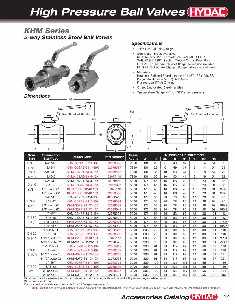
Dimensions are for general information only, all critical dimensions should be verified by requesting a certified print.Dimensions are in mm.For information on stainless steel code 61 & 62 flanges, see page 151.
Model Codes containing selections listed in RED are non-standard items – Minimum quantities will apply – Contact HYDAC for information and availability
Specifications:
1/4” to 2” Full Port Design•
Connection types available: •NPT: Tapered Pipe Threads, ANSI/ASME B.1.20.1 SAE: SAE J1926/1 Straight Thread O-ring Boss Port F3: SAE J518 (Code 61), split flange halves not included. F6: SAE J518 (Code 62), split flange halves not included.
Materials: •Housing, Ball and Spindle made of 1.4571 SS (~316 SS) Polyacetal (POM + MoS2) Ball Seals Flurocarbon (FPM) O-rings
Offset Zinc-plated Steel Handles•
Temperature Range: -4° to 176°F at full pressure•
KHM Series2-way Stainless Steel Ball Valves
Nom. Size
Connection Size/Type Model Code Part Number Press
RatingDimensions in millimeters
A1 B øD H H1 H2 H3 H4 LDN 06
(1/4”)
1/4” NPT KHM-06NPT-3314-16X 02078586 7250 101 28 6 49 37 8 14 54 69SAE-4 KHM-06SAE-3314-16X 02078587 7250 101 28 6 49 37 8 14 54 69
DN 10
(3/8”)
3/8” NPT KHM-10NPT-3314-16X 02078588 7250 101 36 10 53 41 8 18 54 72SAE-6 KHM-10SAE-3314-16X 02077119 7250 101 36 10 53 41 8 18 54 72
DN 16
(1/2”)
1/2” NPT KHM-16NPT-3314-16X 02078589 5800 175 46 16 66 49 8 23 91 83SAE-8 KHM-16SAE-3314-16X 02066415 5800 175 46 16 66 49 11 23 91 83
1/2” code 61 KHM-16F3-3314X-16X 02077118 5000 175 46 16 66 49 11 23 91 150.81/2” code 62 KHM-16F6-3314X-16X 02078590 5800 175 46 16 66 49 11 23 91 150.8
DN 20
(3/4”)
3/4” NPT KHM-20NPT-3314-16X 02066406 5000 175 56 20 78 60 12 28 98 95SAE-12 KHM-20SAE-3314-16X 02078591 5000 175 56 20 78 60 12 28 98 95
3/4” code 61 KHM-20F3-3314X-16X 02078592 5000 175 56 20 78 60 12 28 98 169.83/4” code 62 KHM-20F6-3314X-16X 02068045 5000 175 56 20 78 60 12 28 98 169.8
DN 25
(1”)
1” NPT KHM-25NPT-3314-16X 02078593 5000 175 65 25 83 66 12 30 101 113SAE-16 KHM-25SAE-3314-16X 02078594 5000 175 65 25 83 66 12 30 101 113
1” code 61 KHM-25F3-3314X-16X 02070901 5000 175 65 25 83 66 12 30 101 176.51” code 62 KHM-25F6-3314X-16X 02073032 5000 175 65 25 83 66 12 30 101 198.5
DN 32
(1-1/4”)
1-1/4” NPT KHM-32NPT-3314-16X 02062809 5000 306 78 30 104 86 12 39 151 110SAE-20 KHM-32SAE-3314-16X 02078359 5000 306 78 30 104 86 12 39 151 110
1-1/4” code 61 KHM-32F3-3314X-16X 02077117 4000 306 78 30 104 86 12 39 151 191.41-1/4” code 62 KHM-32F6-3314X-16X 02078595 5000 306 78 30 104 86 12 39 151 223.4
DN 40
(1-1/2”)
1-1/2” NPT KHM-40NPT-3314-16X 02062807 5000 306 91 38 117 99 12 46 157 130SAE-24 KHM-40SAE-3314-16X 02070209 5000 306 91 38 117 99 12 46 157 130
1-1/2” code 61 KHM-40F3-3314X-16X 02069236 3000 306 91 38 117 99 12 46 157 2311-1/2” code 62 KHM-40F6-3314X-16X 02073038 5000 306 91 38 117 99 12 46 157 281
DN 50
(2”)
2” NPT KHM-50NPT-3314-16X 02065778 5000 306 109 48 133 115 12 55 164 140SAE-32 KHM-50SAE-3314-16X 02078596 5000 306 109 48 133 115 12 55 164 140
2” code 61 KHM-50F3-3314X-16X 02078597 3000 306 109 48 133 115 12 55 164 2342” code 62 KHM-50F6-3314X-16X 02072531 5000 306 109 48 133 115 12 55 164 315
Dimensions
H
H3
H2
H1
BøDL
A1
H4
16X, Standard Handle 16X, Standard Handle
L
H4

High Pressure Ball Valves
Accessories Catalog13
Model CodeKHB3K - 16 NPT - L - 1 1 1 4 - 11X - L
Housing Type KHB3K = Three-Way Diverter Ball Valve
Nominal Sizes Nom SAE NPT Size Tube Thread Pipe Size Pipe OD 06 -4 7/16-20 UNF 1/4” 0.540” 10 -6 9/16-18 UNF 3/8” 0.675” 16 -8 3/4-16 UNF 1/2” 0.840” 20 -12 1-1/16-12 UN 3/4” 1.050” 25 -16 1-5/16-12 UN 1” 1.315” 32 -20 1-5/8-12 UN 1-1/4” 1.660” 40 -24 1-7/8-12 UN 1-1/2” 1.900” 50 -32 2-1/2-12 UN 2” 2.375”
Connection Type NPT = ANSI/ASME 1.20.1 Taper Pipe Thread SAE = SAEJ1926 Ports with ISO 725 Threads and O-Ring Sealing
Ball Drilling L = standard
Body Material 1 = Carbon Steel (phosphate coated)
Spindle and Ball Material 1 = Carbon Steel (ball is chrome plated, spindle is zinc-plated) 3 = Stainless Steel
Ball Seal Material 1 = Polyacetal (standard) 3 = PTFE (1500 psi max)
O-Ring Material 2 = NBR (Buna N) 3 = PTFE Spindle Seals and FPM (Fluoroelastomer) O-Rings (1500 psi max) 4 = FPM (Fluoroelastomer) (standard)
Handle Codes 09x = Without Handle 11x = Straight Aluminum, Sizes 06-25 16x = Offset Steel Handle, Sizes 32-50
Locking Device Option L = Locking Device (see page 21 to order locking device separately) LS = Locking Device with 5 amp Limit Switch, Available for Sizes 20-50 (Not available with PTFE Spindle Seals)
Model Codes containing selections listed in RED italics are non-standard items – Minimum quantities will apply – Contact HYDAC for information and availability Not all combinations are available
Specifications1/4” - 1” Full Port Design•
2 Position•
Carbon Steel Housing•
NPT or SAE O-Ring Connections•
Polyacetal Ball Seals • (standard)
FPM • (Fluoroelastomer) O-Rings (standard)
Operating Pressure to 7250 psi Depending on Valve Size and •Seal Materials Selected
Temp Range: 14˚ to 176˚F with Standard materials (1114) up to •max. pressure rating. Extended Temperature range -40˚ to 392˚F on request with special materials and reduced pressure rating (see page 24).
KHB3K Series 3-way Diverter Ball Valves

High Pressure Ball Valves
Accessories Catalog 14
Dimensions are for general information only, all critical dimensions should be verified by requesting a certified print.Dimensions are in inches/(mm) and lbs./(kg.)*Dependent upon valve and seal materials selected.
Model Port Threads Max. psi* A B øD H1 H2 H3 L L1 SQ S Weight
KHB3K-06SAE... 7/16”-20 UNF7250 5.90
(150)1.02 (26)
0.24 (6)
0.51 (13)
1.26 (32)
1.65 (42)
2.72 (69)
1.46(37)
0.35(9)
1.36(34.5)
0.88(0.4)KHB3K-06NPT... 1/4” NPT
KHB3K-10SAE... 9/16”-18 UNF7250 5.90
(150)1.26 (32)
0.39 (10)
0.67 (17)
1.57 (40)
1.69 (47)
2.83(72)
1.65(42)
0.35(9)
1.42(36)
1.32(0.6)KHB3K-10NPT... 3/8” NPT
KHB3K-16SAE... 3/4”-16 UNF5800 6.89
(175)1.50 (38)
0.63 (16)
0.75 (19)
1.77 (45)
2.01 (51)
3.27(83)
1.85(47)
0.47(12)
1.64(41.5)
1.76(0.8)KHB3K-16NPT... 1/2” NPT
KHB3K-20SAE... 1-1/16”-12 UN4500 7.87
(200)1.93 (49)
0.79 (20)
1.08 (27.5)
2.36 (60)
2.28 (58)
3.74(95)
2.36(60)
0.55(14)
1.87(47.5)
3.31(1.5)KHB3K-20NPT... 3/4” NPT
KHB3K-25SAE... 1-5/16”-12 UN4500 7.87
(200)2.28 (58)
0.98 (25)
1.16 (29.5)
2.56 (65)
2.40 (61)
4.45(113)
2.56(65)
0.55(14)
2.22(56.5)
4.85(2.2)KHB3K-25NPT... 1” NPT
KHB3K-32SAE... 1-5/8”-12 UNF5000 9.00
(228)4.35
(110.5)1.18 (30)
1.70 (43.3)
3.54 (90.0)
5.47 (139)
4.53(115)
2.99(76)
0.67(17)
2.76(70)
7.7(3.5)KHB3K-32NPT... 1-1/4” NPT
KHB3K-40SAE... 1-7/8”-12 UN5000 9.00
(228)4.69 (119)
1.38 (35)
1.71 (43.5)
3.79 (96.2)
5.71 (145)
5.31(135)
3.35(85)
0.67(17)
2.95(75)
11(5)KHB3K-40NPT... 1-1/2” NPT
KHB3K-50SAE... 2-1/2”-12 UN5000 9.00
(228)5.73
(145.5)1.73 (44)
2.35 (59.8)
4.72 (120)
6.02 (153)
5.91(150)
4.72(120)
0.67(17)
3.35(85)
16.5(7.5)KHB3K-50NPT... 2” NPT
SQ
SQ
S
SB
B
H2
H2
L1L
L1L
øD
øDH1
H1
H3
H3
AA
SQ
SQ
S
SB
B
H2
H2
L1L
L1L
øD
øDH1
H1
H3
H3
AA
Dimensions
Sizes 06 - 25 Sizes 32 - 50
Ball Drilling Function Diagrams
L L
1
32
L
1
32
1
32
1
32
1
32
1
32
* *undefinedswitchingposition
Notes: Pressure port 1 should always be the highest pressure port
At intermediate position flow will not be completely shut off.Notes: Valve is not designed to be used as a flow control
valve. Valve should not be left in an intermediate position to avoid seal damage.

High Pressure Ball Valves
Accessories Catalog15
Model CodeKHP - 20 - 1 1 1 4 - 12X - L
Housing Type KHP = Block Housing for Manifold mounting
Nominal Sizes Valve Nominal Size Size 10 3/8” 16 1/2” 20 3/4” 25 1” 32 1-1/4” 40 1-1/2” 50 2”
Body Material 1 = Carbon Steel (phosphate coated)
Spindle and Ball Material 1 = Carbon Steel (ball is chrome plated, spindle is zinc-plated) 3 = Stainless Steel
Ball Seal Material 1 = Polyacetal (standard) 3 = PTFE (1500 psi max)
O-Ring Material 2 = NBR (Buna N) 3 = PTFE Spindle Seals and FPM (fluoroelastomer) O-Rings (1500 psi max) 4 = FPM (fluoroelastomer) (standard) 5 = EPR
Handle Codes 09x = Without Handle 12x = Offset Aluminum sizes 10 - 25 16x = Offset Steel sizes 32 - 50
Locking Device Option L = Locking Device (see page 21 to order locking device separately) LS = Locking Device with 5 amp Limit Switch, Available for Sizes 20-50 (Not available with PTFE Spindle Seals)
Model Codes containing selections listed in RED are non-standard items – Minimum quantities may apply – Contact HYDAC for information and availability Not all combinations are available
SpecificationsSizes 3/8” - 2”•
Carbon Steel Housing•
Polyacetal Ball Seals • (standard)
FPM (Fluoroelastomer) O-Rings • (standard)
Operating Pressure to 5000 psi Depending on•
Seal Materials Selected•
Temp Range: 14˚ to 176˚F with Standard materials (1114) up to •max. pressure rating. Extended Temperature range -40˚ to 392˚F on request with special materials and reduced pressure rating (see page 24).
KHP Series 2-way Manifold Mounted Ball Valves

High Pressure Ball Valves
Accessories Catalog 16
Dimensions are for general information only, all critical dimensions should be verified by requesting a certified print. Dimensions are in inches/(mm) and lbs./(kg.)1) Dependent upon valve and seal materials selected. 2) Bolt size and torque provided as reference only. Manifold designs must take all factors (materials, pressure, etc.) into consideration.
Consult HYDAC Engineering for more information
L6 L7
L2
L8L1
B B1
L4 L5
L L3
HA
øD2
øD3
H1
S
øD1
SQ øD
HEX
12x Offset Aluminum Handlefor sizes 10-25
Plug forsizes 10-32
Plate forsizes 40-50
16x Offset Steel Handlefor sizes 32-50
O-ring
Dimensions
Model Max. psi(1 A B B1 ø D ø D1 ø D2 ø D3 HEX H H1 O-ring Weight
KHP-10 5000 0.08 (2)
2.17 (55)
1.575 (40)
0.35 (9)
0.55 (14)
0.374 (9.5)
0.591 (15)
1 3/16 (30)
1.77 (45)
3.58 (91) 10x2.6 2.6
(1.2)
KHP-16 5000 0.08 (2)
2.36 (60)
1.772 (45)
0.35 (9)
0.55 (14)
0.630 (16)
0.984 (25)
1 7/16 (36)
2.17 (55)
4.45 (113) 20.3x2.6 4.6
(2.1)
KHP-20 5000 0.12 (3)
2.76 (70)
2.008 (51)
0.41 (10.5)
0.65 (16.5)
0.787 (20)
1.181 (30)
1 5/8 (41)
2.76 (70)
5.16 (131) 23.4x3.5 8.2
(3.7)
KHP-25 5000 0.12 (3)
3.15 (80)
2.362 (60)
0.41 (10.5)
0.65 (17)
0.925 (23.5)
1.378 (35)
2 (50)
3.15 (80)
5.55 (141) 28.2x3.5 12.3
(5.6)
KHP-32 5000 0.12 (3)
3.94 (100)
3.071 (78)
0.51 (13)
0.75 (19)
1.260 (32)
1.551 (39.4)
2 9/16 (65)
3.94 (100)
8.07 (205) 32.9x3.5 23.4
(10.6)
KHP-40 5000 0.12 (3)
5.12 (130)
3.740 (95)
0.69 (17.5)
1.02 (26)
1.496 (38)
1.906 (48.4) _ 3.94
(100)8.07 (205) 42x3.5 38.6
(17.5)
KHP-50 5000 0.12 (3)
5.91 (150)
4.409 (112)
0.87 (22)
1.30 (33)
1.89 (48)
2.181 (55.4) _ 4.33
(110)8.46 (215) 49x3.5 43.7
(19.8)
Model L L1 L2 L3 L4 L5 L6 L7 L8 S SQ Bolt Size(2 Torque(2
KHP-10 2.76 (70)
0.295 (7.5)
1.083 (27.5)
0.39 (10)
1.14 (29)
5.51 (140)
0.394 (10)
1.732 (44)
2.165 (55)
1.42 (36)
0.35 (9)
5/16” - 18 UNC x 2” 26 ft/lb
KHP-16 3.94 (100)
0.335 (8.5)
1.634 (41.5)
0.39 (10)
1.73 (44)
6.42 (163)
0.669 (17)
2.284 (58)
3.268 (83)
1.81 (46)
0.47 (12)
5/16” - 18 UNC x 2 1/4” 26 ft/lb
KHP-20 4.61 (117)
0.394 (10)
1.909 (48.5)
0.39 (10)
2.01 (51)
7.20 (183)
0.787 (20)
2.717 (69)
3.819 (97)
2.34 (59.5)
0.55 (14)
3/8” - 16 UNC x 3” 45 ft/lb
KHP-25 5.32 (135)
0.394 (10)
2.264 (57.5)
0.39 (10)
2.44 (62)
7.20 (183)
0.945 (24)
3.189 (81)
4.528 (115)
2.72 (69)
0.55 (14)
3/8” - 16 UNC x 3 1/4” 45 ft/lb
KHP-32 6.50 (165)
0.472 (12)
2.677 (68)
0.43 (11)
2.95 (75)
12.00 (305)
1.142 (29)
3.780 (96)
5.354 (136)
3.31 (84)
0.67 (17)
7/16” - 14 UNC x 4” 75 ft/lb
KHP-40 7.09 (180)
1.122 (28.5)
2.205 (56)
0.98 (25)
3.33 (84.6)
12.00 (305)
1.122 (28.5)
4.409 (112)
4.409 (112)
3.25 (82.5)
0.67 (17)
5/8” - 11 UNC x 4 1/4” 220 ft/lb
KHP-50 8.66 (220)
1.496 (38)
2.677 (68)
0.98 (25)
4.17 (106)
12.00 (305)
1.496 (38)
5.354 (136)
5.354 (136)
3.48 (88.5)
0.67 (17)
3/4” - 10 UNC x 4 1/2” 400 ft/lb
High Pressure Ball Valves
Accessories Catalog17
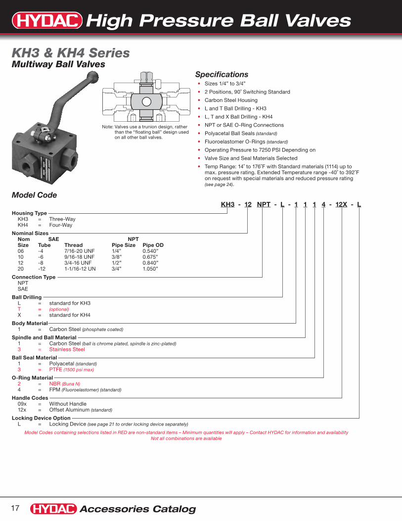
Model CodeKH3 - 12 NPT - L - 1 1 1 4 - 12X - L
Housing Type KH3 = Three-Way KH4 = Four-Way
Nominal Sizes Nom SAE NPT Size Tube Thread Pipe Size Pipe OD 06 -4 7/16-20 UNF 1/4” 0.540” 10 -6 9/16-18 UNF 3/8” 0.675” 12 -8 3/4-16 UNF 1/2” 0.840” 20 -12 1-1/16-12 UN 3/4” 1.050”
Connection Type NPT SAE
Ball Drilling L = standard for KH3 T = (optional) X = standard for KH4
Body Material 1 = Carbon Steel (phosphate coated)
Spindle and Ball Material 1 = Carbon Steel (ball is chrome plated, spindle is zinc-plated) 3 = Stainless Steel
Ball Seal Material 1 = Polyacetal (standard) 3 = PTFE (1500 psi max)
O-Ring Material 2 = NBR (Buna N) 4 = FPM (Fluoroelastomer) (standard)
Handle Codes 09x = Without Handle 12x = Offset Aluminum (standard)
Locking Device Option L = Locking Device (see page 21 to order locking device separately)
Model Codes containing selections listed in RED are non-standard items – Minimum quantities will apply – Contact HYDAC for information and availability Not all combinations are available
SpecificationsSizes 1/4” to 3/4”•
2 Positions, 90˚ Switching Standard•
Carbon Steel Housing•
L and T Ball Drilling - KH3•
L, T and X Ball Drilling - KH4•
NPT or SAE O-Ring Connections•
Polyacetal Ball Seals• (standard)
Fluoroelastomer O-Rings • (standard)
Operating Pressure to 7250 PSI Depending on•
Valve Size and Seal Materials Selected•
Temp Range: 14˚ to 176˚F with Standard materials (1114) up to •max. pressure rating. Extended Temperature range -40˚ to 392˚F on request with special materials and reduced pressure rating (see page 24).
KH3 & KH4 Series Multiway Ball Valves
Note: Valves use a trunion design, rather than the “floating ball” design used on all other ball valves.

High Pressure Ball Valves
Accessories Catalog 18
Dimensions are for general information only, all critical dimensions should be verified by requesting a certified print.Dimensions are in inches/(mm) and lbs./(kg.)*Dependent upon valve and seal materials selected.
Dimensions
L1
L1
H4
HEXøL-T for L & T ball drillingøX for X ball drilling
H3
H1
H5H2
L3
KH4
KH3
L4
A
L4
ød2
SQ
L2
L3
d1
Handle Not Shown
Model d1 Max. psi* A L1 L2 L3 L4 H1 H2 H3 H4 H5 ød2 SQ HEX øL-T øX Weight
KH...06SAE 7/16”-20 UNF1/4” NPT 7250 6.42
(163)3.94(100)
1.67(42.5)
2.76(70)
2.17(55)
2.28(58)
0.51(13)
1.57(40)
0.87(22)
2.48(63)
0.26(6.5)
0.47(12)
0.95(24)
0.20(5)
0.18(4.5)
3.5(1.6)KH...06NPT
KH...10SAE 9/16”-18 UNF3/8” NPT 7250 7.20
(183)4.53(115)
1.81(46)
3.15(80)
2.56(65)
2.72(69)
0.55(14)
1.97(50)
1.06(27)
2.95(75)
0.26(6.5)
0.55(14)
1.18(30)
0.35(9)
0.24(6)
5.3(2.4)KH...10NPT
KH...12SAE 3/4”-16 UNF1/2” NPT 5800 7.20
(183)5.32(135)
2.20(56)
3.94(100)
3.15(80)
3.11(79)
0.55(14)
2.36(60)
1.22(31)
3.46(88)
0.35(9)
0.55(14)
1.42(36)
0.47(12)
0.39(10)
9.5(4.3)KH...12NPT
KH...20SAE 1 1/16”-12 UN3/4” NPT 4500 8.94
(227)5.67(144)
2.26(57.5)
3.94(100)
3.35(85)
3.68(93.5)
0.61(15.5)
2.87(73)
1.42(36)
3.82(97)
0.35(9)
0.67(17)
1.81(46)
0.71(18)
0.55(14)
13.2(6.0)KH...20NPT
Ball Drilling Function DiagramsL
T
X
2
13
2
13
1 3
2
1 3
2
2
4
13
2
4
13
1 3
2 4
1 3
2 4
1 3
2 4
Notes: These are positive overlap valves. At approximately 45° rotation, flow will be blocked to all ports.
For “T” function diagram, contact HYDAC.
3-Way Ball Valve L-Bore 90° Switch
4-Way Ball Valve X-Bore 90° Switch

High Pressure Ball Valves
Accessories Catalog19
* Recommendations for actuator size are based on a typical application: Double acting actuator, 3000 psi max. pressure, mineral based hydraulic fluid, 80-100 psi shop air, and a moderate duty cycle. Applications with Spring Return actuators, higher system pressures, low lubricity fluids, or infrequent cycling (< once/hr.) may require a larger size actuator. Please consult HYDAC Engineering Department for assistance sizing actuators for these applications.
1) See pages 39 - 40 for information on solenoid valves.
Model CodeKHB-25SAE-1114 - A 5 1 A A
Ball Valve Available for both KHB & KHM Series (See pages 5 - 17 for details on ball valve model codes) Note: OMIT the Handle code rather than entering
the code for no handle.
Actuator Type A = Pneumatic - single (ESA) or double acting (EDA)
Size* 1 = 12 (recommended for valves KHB-06... & KHB-10) 2 = 25 (recommended for valves KHB-16... & KHB-20) 3 = 40 4 = 65 5 = 100 (recommended for valves KHB-25... & KHM-32) 6 = 200 7 = 350 (recommended for valves KHM-40... & KHM-50)
Operation 1 = All Double acting (air to A to open, air to B to close) 2 = #2 Spring Set (balances with 40 psi) 3 = #3 Spring Set (balances with 60 psi) 4 = #4 Spring Set (balances with 80 psi) 5 = #5 Spring Set (balances with 100 psi) 6 = #6 Spring Set (balances with 120 psi)
Limit Switches A = none B = Standard Limit Switch Module (2 SPDT)
Additional Options A = none B = Control Valve: 120V AC, Single Acting, 4-way C = Control Valve: 24V DC, Single Acting, 4-way
Model Codes containing selections listed in RED are non-standard items – Minimum quantities will apply -
Contact HYDAC for information and availability Not all combinations are available
DescriptionThe HYDAC dependable rack and pinion pneumatic actuators are compact and efficient components with a trouble-free, high-cycle service life.
The double piston design allows significantly reduced cylinder diameter and overall size as compared to single piston design.
Each piston has a gear rack that applies an equal force at two points directly across the diameter of a common pinion gear.
This feature, combined with the patented suspension system, creates a symmetrically balanced, center-mount actuator with a short, powerful stroke, rapid response, and fully concentric operating loads for optimum life expectancy and performance in control valve applications.
Product Features Reliable rack and pinion design.•
High output torque and compactness•
Integrated air manifold and internal porting•
A solenoid valve can be mounted directly onto actuator body •thus external piping is simplified
Double-acting and single-acting (spring return) models are •available
Self-lubricating bands reduce friction and smooth piston travel, •and increase efficiency
Limit switch available•
Ball Valve Actuators Pneumatic Operation
OrderingPneumatic Actuators (double acting) & Mounting Kits
Valve Size Actuator Model Code
Actuator Part Number
Mounting Kit Part Number
KHB-06 (1/4”) EDA-12 02700204 02061508
KHB-10 (3/8”) EDA-12 02700204 02061508
KHB-16 (1/2”) EDA-25 02700205 02061509
KHB-20 (3/4”) EDA-25 02700205 02061510
KHB-25 (1”) EDA-100 02700206 02061511
KHM-32 (1 1/4”) EDA-100 02700206 02061512
KHM-40 (1 1/2”) EDA-350 02700207 02061513
KHM-50 (2”) EDA-350 02700207 02061513
Optional Accessories (model code / part number)
Limit Switch Box (2 SPDT switches)
ACTUATOR LIMIT SWITCH HDN/2 02700282
Limit Switch Mounting Kit (for EDA-12)
ACTUATOR LIMIT SWITCH MTG KIT MKN-12 02700283
Limit Switch Mounting Kit (for EDA-25 thru EDA-350)
ACTUATOR LIMIT SWITCH MTG KIT MKN-25/350 02700284
Solenoid Control Valve(1 (120 VAC) 3-Way (for ESA) 02082888
4-Way (for EDA) 02082890
Solenoid Control Valve(1 (24 VDC) 3-Way (for ESA) 02082887
4-Way (for EDA) 02082889
Single acting, spring return (air to A to open, spring to close)

High Pressure Ball Valves
Accessories Catalog 20
A
B
Optional Limit Switch2.7"
6.3"
Clearance Requiredto Remove Cover
CLOSED
B2
B1
B3
A
B
Actuator
Visual Indicator(standard)
H4
Mounting Kit
KHM (forged) type valve shownTie Bar DesignUsed With: KHB & KHB3K sizes -06, -10, -16, -20, -25
H32.00"
ø 1.8"1.00"
H2
H1
L1
1/4" NPT(2 places)
1.26"
UNC10-24x.31(4 places)
0.95"
L2
Dimensions are for general information only, all critical dimensions should be verified by requesting a certified print.Dimensions are in inches and lbs.*Dependent upon valve and seal materials selected.
Dimensions
Ball Valve / Actuator Size H1 H2 H3 H4 L1 L2 B1 B2 B3 Operating
Time (sec)Air Cons. (in3/1atm)
Weight (lbs.)
KHB-06 / EDA-12 2.2 2.4 6.6 5.3 2.8 4.1 1.0 2.4 1.9 0.4 4 3.5
KHB-10 / EDA-12 2.2 2.4 6.6 5.3 2.9 4.1 1.3 2.4 1.9 0.4 4 4
KHB-16 / EDA-25 2.5 3.2 7.7 6.2 3.3 6.3 1.5 2.9 1.8 0.5 7 6.5
KHB-20 / EDA-25 3.2 3.2 8.4 6.5 3.8 6.3 1.9 2.9 1.8 0.5 7 8
KHB-25 / EDA-100 3.5 4.7 10.2 8.1 4.5 8.7 2.3 4.3 2.5 1.2 30 14
KHM-32 / EDA-100 3.4 4.7 10.1 8.6 4.4 8.7 3.0 4.3 2.5 1.2 30 16
KHM-40 / EDA-350 3.8 7.1 12.9 11.2 5.2 12.0 3.4 6.8 3.7 3.6 120 37
KHM-50 / EDA-350 4.5 7.1 13.6 11.5 5.6 12.0 4.2 6.8 3.7 3.6 120 42
Enclosure: NEMA 4, includes 2 SPDT switches plus visual indicator.
Switches: up to 250 V AC or DC. Contacts: N/O and N/C
Temperature: -4˚ to 175˚F
Housing Material: Aluminum housing, polyurethane finish.
Operating Pressure: 120 psi max.
Rotation: 90° Pressurize port “A” for counter-clockwise rotation (opening the valve)
Temperature: -4˚ to 175˚F
Materials: Aluminum housing and shaft, polyurethane finish.
Service Life: up to one million cycles
Mounting: Bottom flange and square drive to ISO 5211 Top and solenoid flange to VDE-VDI 3845 NAMUR

High Pressure Ball Valves
Accessories Catalog21
Ball Valve Locking Devices
DescriptionIn situations where the opening or closing of a ball valve can cause severe damage or personal injury, HYDAC recommends the installation of a locking device. Locking devices are available for our entire range of high pressure ball valves. Two different styles are available to accommodate the different valve body styles. All HYDAC high pressure ball valves can be ordered with a locking device. Locking devices can also be ordered separately using the chart below.
Material note: All lock plates and lock bars are made of Zinc plated Steel.
OperationKHM... KHB..., KHP..., KH3..., KH4..., KHB3K... (forged valve bodies) (block valve bodies)
Installation
OrderingTo order a ball valve with a locking device, simply add “-L” to the end of the model code. See the model code page for that particular valve to create a complete code. To order a locking device separately, use the chart below.
Size KHB KHM KHP KH3 & KH4 KHB3K
6 02061169 02061169 N/A 02061172 02061175
10 02061169 02061169 02061169 02061173 02061175
12 N/A N/A N/A 02061173 N/A
16 02061170 02061170 02061170 N/A 02061176
20 02061171 02061171 02061171 02061174 02061177
25 02061171 02061171 02061171 N/A 02061177
32 N/A 02055711 02063434 N/A N/A
40 N/A 02055711 02063434 N/A N/A
50 N/A 02055711 02063434 N/A N/A
OPEN
Apply Pad Lock (not supplied)here to lock in OPEN Postition
CLOSED
Apply Pad Lock (not supplied)here to lock in CLOSED Postition
Apply Pad Lock (not supplied)here to lock in OPEN Postition
Apply Pad Lock (not supplied)here to lock in CLOSED Postition
CLOSED
OPEN
CLOSED
OPEN
Apply Pad Lock (not supplied)here to lock in OPEN Postition
CLOSED
Apply Pad Lock (not supplied)here to lock in CLOSED Postition
Apply Pad Lock (not supplied)here to lock in OPEN Postition
Apply Pad Lock (not supplied)here to lock in CLOSED Postition
CLOSED
OPEN
CLOSED

High Pressure Ball Valves
Accessories Catalog 22
OperationKHB..., KHP..., KH3..., KH4..., KHB3K... (block valve bodies, sizes 20 & 25)
KHM... (forged valve bodies, sizes 32 through 50)
Wiring Details Electrical SpecificationsNEMA 3, 4, 13 and IEC IP 67•
5A-125, 250 VAC•
Temperature range: 14 to 158˚F•
UL listed•
Description:When remote indication of the valve position is required, a limit switch can be added to the valve assembly.•Areliablesinglepole,doublethrow(SPDT)switchtoindicateeither
open or closed position of a two-way valve•Hermeticallysealed•CanbewiredasNormallyOpen(N/O),orNormallyClosed(N/C)•AvailableforHYDACvalvesizes20through50•Mountingbracketsserveaslockingdevices
Ordering:To Order a valve with Limit Switch, Add “-LS” to end of Valve Model Code, i.e.: KHM-32NPT-1114-16X-LS
Ball Valve Locking Devices with Limit Switches
Valve Retrofit kit Part #: 02067694
Valve Retrofit kit Part #: 02063537
Replacement Switch Part #: 02700009

High Pressure Ball Valves
Accessories Catalog23
O-Ring size 06-25O-Ring with Back-up Ring size 32-50
Ball Seal
Thrust Washer
O-Ring with Back-up Ring
Model CodeSEAL KIT KHB - 06 NPT/SAE - XX14
Seal Kit
Valve Body Type KHB = Block Housing KHM = Forged Housing KH3/4 = 3-Way & 4-Way Valves KHP = Manifold Mount
Valve Size 06, 10, 16, 20, 25, 32, 40,50
Connection Type (omit) = Manifold Mount (KHP) NPT/SAE = NPT or SAE F3/F6 = F3 or F6 Split Flange
Materials
Body Material X = Body material does not affect seal kits
Spindle and Ball Material X = Spindle and ball material does not affect seal kits
Ball Seal Material 1 = Polyacetal (standard) 3 = PTFE 8 = PEEK
O-Ring Material 2 = NBR (Buna N) 3 = PTFE Spindle Seals and FPM (Fluoroelastomer) O-Rings 4 = FPM (Fluoroelastomer) (standard) 5 = EPDM
Model Codes containing selections listed in RED are non-standard items – Minimum quantities will apply – Contact HYDAC for information and availability Not all combinations are available
Model Code Part Number
SEAL KIT KHB-06NPT/SAE-XX14 02061479
SEAL KIT KHB-10NPT/SAE-XX14 02061467
SEAL KIT KHB-16F3/F6-XX14 02061469
SEAL KIT KHB-16NPT/SAE-XX14 02061468
SEAL KIT KHB-20F3/F6-XX14 02061471
SEAL KIT KHB-20NPT/SAE-XX14 02061470
SEAL KIT KHB-25F3/F6-XX14 02061473
SEAL KIT KHB-25NPT/SAE-XX14 02061472
SEAL KIT KHM-32F3/F6-XX14 02061481
SEAL KIT KHM-32NPT/SAE-XX14 02061480
SEAL KIT KHM-40F3/F6-XX14 02061483
SEAL KIT KHM-40NPT/SAE-XX14 02061482
SEAL KIT KHM-50F3/F6-XX14 02061485
SEAL KIT KHM-50NPT/SAE-XX14 02061484
SEAL KIT KHP-06-XX14 00554029
SEAL KIT KHP-10-XX14 02061486
SEAL KIT KHP-16-XX14 02061487
SEAL KIT KHP-20-XX14 02061507
SEAL KIT KHP-25-XX14 02061488
SEAL KIT KHP-32-XX14 02061489
SEAL KIT KHP-40-XX14 02061505
SEAL KIT KHP-50-XX14 02061506
Seal Kits
Complete maintenance instructions are available on our web site:

High Pressure Ball Valves
Accessories Catalog 24
Spindle Seal & O-rings
Fluorocarbon (FPM) Standard for hydraulic oils and many acids
Maximum Pressure: to 7250 psi (500 bar)
Temperature Range: -4° to 392°F (-20° to 200°C)
NBR Seal for hydraulic oils, lubricants, greases
Maximum Pressure: to 7250 psi (500 bar)
Temperature Range: -13° to 212°F (-25° to 100°C)
PTFE for corrosive media and bases
Maximum Pressure: to 1500 psi (100 bar)
Temperature Range: -328° to 212°F (-200° to 100°C)
Temperature to 392°F (200°C) at reduced pressure
EPR Ethylene Propylene Rubber for some phosphate esters
Maximum Pressure: to 7250 psi (500 bar)
Temperature Range: -58° to 300°F (-50° to 150°C)
Special Seals Other materials are available for special applications.
Consult HYDAC for your specific application.
Engineering DataHousing
Block Type (KHB) Carbon Steel (standard) 14˚F Min temp
Forged Type (KHM) Forged Steel (standard) 14˚F Min temp
Stainless Steel (optional) -40˚F Min temp
Coatings Standard Models Phosphate Coated (Others available on Request)
Ball Chrome Plated Steel (standard)
Stainless Steel (optional)
Spindle Zinc Plated Steel (standard)
Stainless Steel (optional)
Handles (see above)
11X Straight Aluminum, Red Anodized
12X Offset Aluminum, Red Anodized
16X Offset Steel, Galvanized
Ball Seal
Polyacetal (POM) Standard for Hydraulic Oils, Water Glycol
Maximum Pressure: to 7250 psi (500 bar)
Temperature Range: -22° to 212°F (-30° to 100°C)
PTFE For Corrosive Media
Maximum Pressure: to 1500 psi (100 bar)
Temperature Range: -328° to 212°F (-200° to 100°C)
Temperature to 392°F (200°C) at reduced Pressure(see chart at right for pressure-temperature profile)
NBR For Gaseous Media
Maximum Pressure: to 1500 psi (100 bar)
Temperature Range: -13° to 212°F (-25° to 100°C)(see chart at right for pressure-temperature profile)
PEEK High Temperature Seal
Maximum Pressure: to 7250 psi (500 bar)
Temperature Range: -238° to 212°F (-150° to 100°C)
Better high temperature profile than PTFE Temperature to 482°F (250°C) at reduced Pressure(see chart at right for pressure-temperature profile)
HandlesDN Sizes
DescriptionDesignation
Model Code
Spindle Square Size Model Code Part Number
06, 10 Straight Aluminum 11X SW09 HANDLE STR AL SW09 00270099
06, 10 Offset Aluminum 12X SW09 HANDLE OFS AL SW09 00271423
06, 10 Offset Steel 16X SW09 HANDLE KIT OFS STL SW09 02064265*
16 Straight Aluminum 11X SW12 HANDLE STR AL SW12 00270100
16 Offset Aluminum 12X SW12 HANDLE OFS AL SW12 00270381
16 Offset Steel 16X SW12 HANDLE KIT OFS STL SW12 02064266*
20, 25 Straight Aluminum 11X SW14 HANDLE STR AL SW14 00270101
20, 25 Offset Aluminum 12X SW14 HANDLE OFS AL SW14 00270382
20, 25 Offset Steel 16X SW14 HANDLE KIT OFS STL SW14 02064267*
32, 40, 50 Offset Steel 16X SW17 HANDLE KIT OFS STL SW17 16X 02064268*
32, 40, 50 Offset Aluminum 12X SW17 HANDLE OFS AL SW17 00270383
32, 40, 50 Straight Aluminum 11X SW17 HANDLE STR AL SW17 00270311* These handles require the additional mounting hardware which is included
Press-Temp curve for different Ball Seal materials
0
1000
2000
3000
4000
5000
6000
7000
8000
0 100 200 300 400 Temp (F)
Pre
ssur
e (p
si)
valve size 6-10
valve size 16
valve size 20-50
POM (standard)
PTFE (all sizes)
Buna (all sizes)
Peek

High Pressure Ball Valves
Accessories Catalog25
Size Model Code øB H1 H2 øLW L H C SW (mm) A Weight
1/2” KHF3/6-16-1114-16X-UNC 3.11 1.34 2.81 0.51 2.95 5.08 1.28 12 7.00 5.5
3/4” KHF3/6-20-1114-16X-UNC 3.90 1.73 3.54 0.75 3.15 5.79 1.35 14 7.00 8.6
1” KHF3/6-25-1114-16X-UNC 4.69 1.85 4.02 0.98 3.46 6.30 1.50 14 7.00 13.2
1 1/4” KHF3/6-32-1114-36X-UNC 5.47 2.32 4.88 1.18 3.94 8.31 1.73 17 12.0 25.6
1 1/2” KHF3/6-40-1114-36X-UNC 6.30 2.56 5.51 1.50 4.33 8.94 2.01 17 12.0 36.2
2” KHF3/6-50-1114-36X-UNC 7.05 2.86 6.17 1.89 4.57 9.61 2.13 17 12.0 54.9* Pressure rating listed is valve pressure only. Pressure ratings for available flanges may be less.
Consult flange manufacturer and ISO 6162 for flange pressure rating.Dimensions are for general information only, all critical dimensions should be verified by requesting a certified print.Dimensions are in inches and lbs.
Model Codes containing selections listed in RED are non-standard items – Minimum quantities will apply – Contact HYDAC for information and availability Not all combinations are available
Size Model CodeCode 61 Code 62
K3 G3 øD3 E3 MAWP (psi)* K6 G6 øD6 E6 MAWP (psi)*
1/2” KHF3/6-16-1114-16X-UNC 1.50 0.69 5/16”-18UNC 0.63 5000 1.59 0.72 5/16”-18UNC 0.63 6000
3/4” KHF3/6-20-1114-16X-UNC 1.87 0.88 3/8”-16UNC 0.71 5000 2.00 0.94 3/8”-16UNC 0.71 6000
1” KHF3/6-25-1114-16X-UNC 2.06 1.03 3/8”-16UNC 0.71 5000 2.25 1.09 7/16”-14UNC 0.83 6000
1 1/4” KHF3/6-32-1114-36X-UNC 2.31 1.19 7/16”-14UNC 0.71 4000 2.62 1.25 1/2”-13UNC 0.83 6000
1 1/2” KHF3/6-40-1114-36X-UNC 2.75 1.41 1/2”-13UNC 1.02 3000 3.12 1.44 5/8”-11UNC 1.02 6000
2” KHF3/6-50-1114-36X-UNC 3.06 1.69 1/2”-13UNC 1.02 3000 3.87 1.75 3/4”-10UNC 1.18 6000
FeaturesCompact, space saving design•
Full passage for unrestricted flow of medium•
Floating ball provides positive seal•
Valve positioning controlled by a stop pin and limit washer•
Phosphate coated valve body•
SpecificationsConnection: Dual bolt pattern fits Code 61 and 62 SAE flanges•
Operating Pressure: to 6000 psi•
Ball Seal Material: Polyacetal•
O-ring Material: Fluoroelastomer (FPM)•
Housing Material: Carbon Steel•
Temperature Range: 14˚ to 176˚F•
Dimensions
KHF3/6 Series Direct Mount SAE Flange 1/2” to 2”
ªH
E6
øD6
SW
K3
G6Code 62
Code 61
K6 H2G3
øD3
E3
H1
LøB
øLW
ªA C

High Pressure Ball Valves
Accessories Catalog 26
Size Model Code øLW L J H1 H øD A B UNC T K MAWP (psi)* Weight
2 1/2” KHF3-065-1114-05X-UNC 2.48 5.90 2.95 3.70 10.8 7.80 2.00 3.50 1/2”-13UNC 0.75 36 2500 73
3” KHF3-080-1114-05X-UNC 2.99 5.51 2.76 4.09 11.4 8.27 2.44 4.19 5/8”-11UNC 0.95 36 2000 88
4” KHF3-100-1114-05X-UNC 3.94 6.69 3.35 4.80 13.1 10.16 3.06 5.13 5/8”-11UNC 0.95 36 500 132
* Pressure rating listed is valve pressure only. Pressure ratings for available flanges may be less. Consult flange manufacturer and ISO 6162 for flange pressure rating.Dimensions are for general information only, all critical dimensions should be verified by requesting a certified print.Dimensions are in inches and lbs.
Model Codes containing selections listed in RED are non-standard items – Minimum quantities will apply – Contact HYDAC for information and availability Not all combinations are available
FeaturesCompact, space saving design•
Full passage for unrestricted flow of medium•
Floating ball provides positive seal•
Phosphate coated valve body•
Individually tested for leakage free performance•
SpecificationsConnection: Bolt pattern fits code 61 SAE flanges•
Operating Pressure: to 2500 psi•
Ball Seal Material: Polyacetal•
O-ring Material: Fluoroelastomer (FPM)•
Housing Material: Carbon Steel•
Temperature Range: 14˚ to 176˚F•
KHF3 Series Direct Mount SAE Flange 2 1/2” to 4”
Dimensions
B
H
H1
øD
K
L
J
TøLWA
UNC

High Pressure Ball Valves
Accessories Catalog27
Class 2500
7000
6000
5000
4000
3000
2000
1000
0
400
300
200
100
250200100 1500 50
500400 450300 350200 250100 1500-50 500
Class 1500
bar
°C
°F
psi
PEEK
PEEK
POM
POM
Press
ure
Temperature
120 1000
900
700
700
600
500
400
300
200
100
0
100
80
60
20
40
5000 4000 3000 2000 1000 6000
1/2”
3/4”
1”
1 1/4”
1 1/2”
2”
0
350 300 250 200 150 100 50 0 400
0
Nm
psi
bar
in. lbs.
Torque
Pressure
Model CodeKHM3H - SP - 1 SW - 3 3 1 2
Series Type KHM3H = High Pressure 3 Piece Ball Valve
Port SP = Standard Port
Connection Size (inches) 1/2, 3/4, 1, 1 1/4, 1 1/2, 2, 3, 4
Connection Type SW = Socket Weld NPT = Tapered Pipe Threads
Body Material 1 = Carbon Steel 3 = Stainless Steel
Spindle & Ball Material 3 = Stainless Steel
Ball Seal Material 1 = POM (polyacetal) (standard) 8 = PEEK for higher temperature applications (see chart below)
Body Seal Material 2 = NBR (used with POM ball seal) (standard) 8 = Graphite (used with PEEK ball seal) for higher temperature applications
Model Codes containing selections listed in RED are non-standard items – Minimum quantities may apply – Contact HYDAC for information and availability Not all combinations are available
Pressure/Temperature Graph Torque/Pressure Graph
KHM3H Series3 Piece Ball Valve
Specifications1/2” - 4” Standard Port•
1/2” - 2” Class 2500 ANSI • (up to 6000 psi) 3” - 4” Class 1500 ANSI (up to 3800 psi)
Blow-out proof stem•
Handle operated or actuated•
Applications - Offshore, Oil & Gas, Chemical, Petrochemical, •Refining, Energy
Media - Liquid or Gas•
Material - Stainless Steel, Carbon Steel•
End Connections - Socket weld and threaded. •Other options available (consult factory)

High Pressure Ball Valves
Accessories Catalog 28
Dimensions are for general information only, all critical dimensions should be verified by requesting a certified print.Dimensions are in inches and lbs.
M Across Flat
Size Port A B C G øD H M N S T W L Wgt
1/2” 0.44 3.07 0.81 1.06 1.50 2.76 1.81 0.22 3/8” UNF 7.05 M5 - 1.34 3.5
3/4” 0.56 3.35 0.97 1.18 1.59 3.15 1.89 0.22 3/8” UNF 7.05 M5 0.59 1.34 5.3
1” 0.81 4.25 1.25 1.50 2.22 3.86 2.40 0.30 7/16” UNF 7.56 M5 0.94 1.65 10
1 1/4” 1.00 4.76 1.63 1.69 2.40 4.13 2.60 0.30 7/16” UNF 7.56 M5 0.94 1.65 12
1 1/2” 1.25 5.16 1.91 1.97 2.91 5.12 3.15 0.34 9/16” UNF 11.30 M6 1.42 1.57 21
2” 1.50 5.59 2.22 2.17 3.06 5.71 3.31 0.34 9/16” UNF 11.30 M6 1.57 2.28 29
3” 2.50 8.82 3.28 2.76 5.71 8.46 7.28 0.74 1” UNS 15.75 M12 2.36 5.51 86
4” 3.25 10.55 4.28 3.54 6.34 9.84 7.91 0.74 1” UNS 24.02 M12 2.76 5.91 141
Parts & Materials
DimensionsSize 1/2” - 2”
Size 3” - 4”
Item Description Material
1 Body Stainless Steel 316 / Carbon Steel ASTM A105
2 End Connector Stainless Steel 316 / Carbon Steel ASTM A105
3 Ball Stainless Steel 316 (17-4PH 1/2”-3/4”)
4 Stem Stainless Steel 316 / Stainless Steel 17-4PH
5* Ball Seal POM / PEEK
6* Body Seal NBR / Graphite
7* Stem Thrust Seal PA (Nylon) / PEEK
8 Stop Pin Stainless Steel 316
9* Gland Packing PTFE - 25% Carbon Filled
10 Gland Stainless Steel 316
11 Disc Spring Stainless Steel 17-4PH
12 Gland Nut Stainless Steel 316 / Carbon Steel Zinc Plated
13 Tab Washer Stainless Steel
14 Handle Stainless Steel / Carbon Steel Zinc Plated
15 Serrated Washer Stainless Steel
16 Handle Nut Stainless Steel 316 / Carbon Steel Zinc Plated
17 Body Bolts Stainless Steel 316 / Carbon Steel Zinc Plated
18 Body Nuts Stainless Steel 316 / Carbon Steel Zinc Plated

Process & Automated Valves
Accessories Catalog29
DescriptionHYDAC Automated Valves are pneumatically operated. Actuators allow valves to be operated automatically by a control system or manually from a remote location. Valve automation brings significant advantages to a plant in the areas of process quality, efficiency, safety, and productivity. Electric or hydraulically actuated valves available on special request.
Automated 2 Piece Ball ValvesKHL Series (see page 35) Nominal Sizes from 1/4” to 2”
Automated 3 Piece Ball ValvesKHM3L Series (see page 37) Nominal Sizes from 1/4” to 2”
Solenoid ValvesNamur 3-way & 4-way (see page 39)
IntroductionTraditionally the HYDAC product offering existed of high pressure manual valves. As we grow and are exposed to new industries we are adding to our product offering.
Low Pressure Ball ValvesKHNVN Series (see page 30) Nominal Sizes from 1/4” to 2”
Inline Isolation Valve + ActuatorHVA Series (see page 31) Nominal Sizes from 3/8” to 2”
Angle Seat ValvesASV Series (see page 33) Nominal Sizes from 3/8” to 2”
Overview

Process & Automated Valves
Accessories Catalog 30
Dimensions are for general information only, all critical dimensions should be verified by requesting a certified print.Dimensions are in inches/(mm) and lbs./(kg.)
Model Codes containing selections listed in RED are non-standard items – Minimum quantities will apply – Contact HYDAC for information and availability
KHNVN SeriesLow Pressure Stainless Steel
Pressure vs. Temperature Curve
Temperature in Fahrenheit
Pre
ssur
e in
PS
IG
00
400
200
800
600
1000
100 200 300 400
PTFE
DescriptionThe KHNVN Series manual ball valves are full port, 316 stainless steel, NPT threaded manual ball valves. They are equipped with a manual handle with a locking device.
FeaturesFull port ball drilling for unrestricted flow•
Investment cast 2-piece SS body•
Blow-out proof stem•
Compact assembly•
Locking device•
Materials of ConstructionBody & End Cap
ASTM A351 Cast SS • Grade CF8M
Stem Seals
PTFE•
Seats:
PTFE•
Ball & Stem:
316 SS•
Stem Nut & Washer:
304 SS•
Handle & Locking Device:
304 SS•
Handle Sleeve:
Vinyl•
SpecificationsMax. Temperature:
400°F•
End ConnectionsNPT Threaded • (female)
Max. Pressure:
1000 PSIG (up to 100˚F)•
L
E
øC
H S S
1/4" to 3/8" 1/2" to 2"
S (Conn. Flats)
Dimensions
Size Model Code DN øC E H L S Weight (lbs.)1/4” KHNVN-1/4 NPT-3333 02089401 0.45 3.90 2.03 1.91 0.83 0.543/8” KHNVN-3/8 NPT-3333 02089402 0.49 3.90 2.03 1.91 0.83 0.511/2” KHNVN-1/2 NPT-3333 02089403 0.59 4.13 2.09 2.20 1.06 0.743/4” KHNVN-3/4 NPT-3333 02089404 0.79 4.13 2.20 2.56 1.28 0.981” KHNVN-1 NPT-3333 02089405 0.98 4.76 2.60 2.95 1.57 1.51
1 1/4” KHNVN-1-1/4 NPT-3333 02089406 1.26 5.39 2.91 3.43 1.89 2.381 1/2” KHNVN-1-1/2 NPT-3333 02089407 1.50 6.30 3.27 3.86 2.13 3.75
2” KHNVN-2 NPT-3333 02089408 1.97 7.48 3.62 4.92 2.68 6.39

Process & Automated Valves
Accessories Catalog31
Description The HVA Series combines a pneumatic actuator and isolation •valve into one body, which acts as a automated on/off valve.
Features and BenefitsCompact assembly / Saves space•
High CV / Less restriction • (low pressure drop)
Integrated actuators / Less parts to order and no mounting kits•
Integral NAMUR solenoid mounting pad•
Models Available NC: spring return, normally closed•
NO: spring return, normally open•
DA: double acting•
HVA Series Inline Isolation Valve + Actuator
Model CodeHVA - 3/8 NPT - NO - 24VDC
Series HVA = Valve + Actuator
Port Size (NPT) 3/8”, 1/2”, 3/4”, 1”, 1 1/4”, 1 1/2”, 2”
Function NO = Spring return, Normally open, Air to close NC = Spring return, Normally closed, Air to open DA = Double acting
Solenoid Valve Options (omit) = No solenoid valve included 24VDC = 24 VDC solenoid valve included 120VAC = 120 VAC solenoid valve includedNote: see page 39 - 40 for information on solenoid valves
Model Codes containing selections listed in RED are non-standard items – Minimum quantities will apply –
Contact HYDAC for information and availability
SpecificationsTemperature range: -4° to 302°F (-20° to 83°C)•
Maximum pressure: 225 psi•
Vacuum rating: 740mm Hg (97% vacuum)•
Seats & Seals: VITON = High compatibility with majority of fluids, •not advised for steam.
Air pressure required: 40 to 125 psi for double acting, •60 to 125 psi for spring return
Body and Internals: Electroless Nickel Plated Brass•
Stroke Time (based on 80 psi actuating pressure)
SizeSpring Return Double Acting
Spring Air Opening Air Closing Air
3/8” 20 mS 10 mS 10 mS 10 mS
1/2” 20 mS 10 mS 10 mS 10 mS
3/4” 30 mS 20 mS 20 mS 20 mS
1” 40 mS 20 mS 20 mS 20 mS
1 1/4” 70 mS 40 mS 30 mS 30 mS
1 1/2” 110 mS 60 mS 60 mS 60 mS
2” 130 mS 70 mS 70 mS 70 mS

Process & Automated Valves
Accessories Catalog 32
Dimensions are for general information only, all critical dimensions should be verified by requesting a certified print.Dimensions are in inches and lbs
1/8 NPTPorts
(2 places)
#10-24 UNCThreads
(4 places)
Namur Interface
øB
NPT Ports
E
A
C
Cutaway View
Dimensions
NPT Port Size Cv A B C E Wt Air Consumption
3/8" 8 2.11 1.81 3.60 1.21 1.90 0.73 cu. inches
1/2" 10 2.33 2.00 4.21 1.31 2.30 1.05 cu. inches
3/4" 13 2.76 2.10 4.92 1.51 3.70 1.90 cu. inches
1" 17 3.00 2.72 5.31 1.63 4.15 2.45 cu. inches
1 1/4" 28 3.59 3.39 6.02 1.90 7.50 4.58 cu. inches
1 1/2" 57 4.00 3.78 6.73 2.12 8.15 6.70 cu. inches
2" 81 4.50 4.29 7.51 2.35 12.75 9.50 cu. inches

Process & Automated Valves
Accessories Catalog33
DescriptionThe Angle Seat Valve is a 2-way pneumatically actuated plug valve, which provides for automatic isolation of liquids, gases, steam and some aggressive fluids. Available with stainless steel or bronze bodies with plastic actuator housings.
Features and BenefitsSelf aligning stem seal reduces potential leak points•
High cycle life, provides long service life•
Compact assembly / Saves space•
Internal flow path designed to minimize pressure drop•
NAMUR Solenoid mounting pad•
Easy InstallationThe Angle Seat Valve can be mounted in any position. The actuator rotates 360° allowing for the selective positioning of the pneumatic inlet port.
Models AvailableSpring Return N.C. Bi-directional Flow•
Double Acting Bi-directional Flow•
ASV Series Angle Seat Valve
Model CodeASV - 1 NPT - 3333 - DA - 24DC
Series ASV = Angle Seat Valve
Port Size (NPT) 3/8”, 1/2”, 3/4”, 1”, 1 1/4”, 1 1/2”, 2”
Materials 2333 = Bronze body & SS plug, PTFE seats & seals 3333 = 316SS body & plug, PTFE seats & seals
Function NC = Spring return, normally closed DA = Double acting
Solenoid Valve Options (omit) = No solenoid valve included 24VDC = 24 VDC solenoid valve included 120VAC = 120 VAC solenoid valve includedNote: see page 39 - 40 for information on solenoid valves
Model Codes containing selections listed in RED are non-standard items – Minimum quantities will apply –
Contact HYDAC for information and availability
Cutaway View
SpecificationsTemperature Range
-14º to 358ºF (-25º to 181ºC)•Pressure/Viscosity Ratings
From 0 to 230 psi•Steam to 150 psi, Max 358°F•Max Viscosity 600CST•
ASV...2333Bronze Body & SS Plug•PTFE seats & seals•
ASV...3333316 SS Body & Plug• PTFE seats & seals•
Leakage rateANSI Class VI Shut off•
Stroke TimeValve Size Actuator
FunctionClosed to Open (mS)
Open to Closed (mS)
3/8” NC 15 25
3/8” DA 5 5
1/2” NC 15 25
1/2” DA 5 5
3/4” NC 15 25
3/4” DA 5 5
1” NC 60 100
1” DA 10 10
1 1/4” NC 60 100
1 1/4” DA 10 10
1 1/2” NC 150 225
1 1/2” DA 15 15
2” NC 150 225
2” DA 15 15
ASV...2333 Bronze
ASV...3333 Stainless Steel

Process & Automated Valves
Accessories Catalog 34
øE
G
C B
45°
1/8” BSP**NPT adapter is provided -
If you purchase ASVwithout solenoid valve
M5
1212
16A
Actuator can be rotated 360°
D
F
16
Dimensions are for general information only, all critical dimensions should be verified by requesting a certified print.Dimensions are in inches and lbs
Dimensions
TypeNPT Port Size
CVASV...3333 (316 SS) ASV...2333 (Bronze)
WgtA B C D ø E F G A B C D ø E F G
NC/DA 3/8” 6 7.48 6.14 6.65 1.73 2.76 3.35 0.98 6.42 5.51 6.02 1.73 2.76 2.56 1.06 2.2
NC/DA 1/2” 7 7.48 6.14 6.65 1.73 2.76 3.35 0.98 6.42 5.51 6.02 1.73 2.76 2.56 1.06 2.2
DA 3/4” 12 7.68 6.30 6.93 1.73 2.76 3.74 1.22 6.81 5.79 6.42 1.73 2.76 2.95 1.08 2.6
NC 3/4” 12 8.39 7.00 7.65 1.99 3.32 3.74 1.22 7.52 6.5 7.13 1.99 3.32 2.95 1.08 2.6
DA 1” 23 8.62 7.17 7.95 1.99 3.32 4.13 1.50 8.11 6.93 7.72 1.99 3.32 3.54 1.61 3.5
NC 1” 23 10.20 8.74 9.53 2.61 4.58 4.13 1.50 9.69 8.50 9.29 2.61 4.58 3.54 1.61 3.7
DA 1 1/4” 33 8.90 7.32 8.23 1.99 3.32 4.72 1.85 8.46 7.09 8.07 1.99 3.32 4.33 1.97 4.2
NC 1 1/4” 33 10.47 8.90 9.80 2.61 4.58 4.72 1.85 10.04 8.66 9.65 2.61 4.58 4.33 1.97 6.6
DA 1 1/2” 54 10.67 9.06 10.16 2.61 4.58 5.12 2.13 10.63 9.25 10.39 2.61 4.58 4.72 2.28 7.9
NC 1 1/2” 54 12.09 10.47 11.57 3.05 5.54 5.12 2.13 12.05 10.67 11.81 3.05 5.54 4.72 2.28 8.8
DA 2” 78 11.22 9.45 10.79 2.61 4.58 5.91 2.60 11.02 9.45 10.83 2.61 4.58 5.91 2.76 9.5
NC 2” 78 12.64 10.87 12.20 3.05 5.54 5.91 2.60 12.44 10.87 12.24 3.05 5.54 5.91 2.76 11.7.

Process & Automated Valves
Accessories Catalog35
DescriptionThe KHL is a full port, 316 stainless steel, NPT threaded end automated ball valve.
It can be equipped with a manual handle or with direct mount pneumatic actuators.
Features and Benefits Compact direct mount assembly / Saves space •since there is no bracket
High CV / Less restriction (low pressure drop)•
No stem packing to adjust / Reduces maintenance•
Models AvailableSpring Return Actuator, normally closed•
Double Acting Actuator•
Manual Handle•
ActuatorsCompact direct mount•
Anodized aluminum actuator•
NAMUR solenoid mounting adapter•
ISO 5211 mounting standard•
Visual position indicators•
High duty cycle•
Permanent lubrication•
Pneumatic double acting and spring return•
Min 80 psi air supply required•
Pneumatic solenoid valves sold separately•Note: see page 39 - 40 for information on solenoid valves
Pressure Vs. Temperature Chart
SpecificationsBall Valve 316SS body, ball and stem•
Blow out proof stem•
RPTFE Seats•
PTFE seals•
Viton stem O-ring•
NPT threaded end connection•
Temperature Range-30° to 400°F max•
Pressure Rating1/4” to 1” 2000 psi (-30° to 100°F)•
1 1/4” to 2” 1500 psi (-30° to 100°F)•
0 psi @ 400°F•
KHL Series Automated 2 Piece Ball Valve
32
1500
1000
500
0
2000
104
69
35
0
138p
si
bar
50 350300250200150100 400
0 10 177149121936638 204
Pre
ssur
e R
atin
g
Temperature
1/4" to 1"
1 1/4" to 2"

Process & Automated Valves
Accessories Catalog 36
Dimensionswith normally closed spring return pneumatic actuator (NPT threaded end connection, 2 piece body)
CV Size NPT A B C D E F Wgt. Model Code
Part No.
13 1/4” 2.56 8.62 4.85 2.15 1.65 2.28 3.9 KHL-1/4NPT-3333-NC 02083087
13 3/8” 2.56 8.62 4.85 2.15 1.65 2.34 3.9 KHL-3/8NPT-3333-NC 02083090
23 1/2” 2.95 8.62 4.85 2.15 1.65 2.35 3.9 KHL-1/2NPT-3333-NC 02083093
70 3/4” 3.15 9.36 5.36 2.54 1.77 2.71 5.7 KHL-3/4NPT-3333-NC 02083096
116 1” 3.54 11.47 5.99 2.81 2.05 3.05 7.5 KHL-1NPT-3333-NC 02083099
151 1 1/4” 4.33 11.47 6.22 2.81 2.28 3.63 8.6 KHL-1 1/4NPT-3333-NC 02083102
197 1 1/2” 4.72 12.48 7.32 3.12 2.68 4.33 13.0 KHL-1 1/2NPT-3333-NC 02083105
325 2” 5.51 13.92 8.10 3.51 3.07 4.85 18.5 KHL-2NPT-3333-NC 02083108
with double acting pneumatic actuator (NPT threaded end connection, 2 piece body)
CV Size NPT A B C D E F Wgt. Model Code
Part No.
13 1/4” 2.56 5.07 4.85 2.15 1.65 2.28 3.2 KHL-1/4NPT-3333-DA 02083088
13 3/8” 2.56 5.07 4.85 2.15 1.65 2.34 3.2 KHL-3/8NPT-3333-DA 02083091
23 1/2” 2.95 5.07 4.85 2.15 1.65 2.35 3.3 KHL-1/2NPT-3333-DA 02083094
70 3/4” 3.15 5.07 4.97 2.15 1.77 2.71 3.5 KHL-3/4NPT-3333-DA 02083097
116 1” 3.54 5.62 5.48 2.34 2.05 3.05 5.0 KHL-1NPT-3333-DA 02083100
151 1 1/4” 4.33 5.62 5.71 2.34 2.28 3.63 6.1 KHL-1 1/4NPT-3333-DA 02083103
197 1 1/2” 4.72 6.59 6.62 2.81 2.68 4.33 9.4 KHL-1 1/2NPT-3333-DA 02083106
325 2” 5.51 6.59 7.01 2.81 3.07 4.92 12.4 KHL-2NPT-3333-DA 02083109
with manual handle (NPT threaded end connection, 2 piece body)
CV Size NPT A B C D E F Wgt. Model Code
Part No.
13 1/4” 2.56 4.48 2.80 1.26 1.65 2.28 1.2 KHL-1/4NPT-3333 02083086
13 3/8” 2.56 4.48 2.80 1.38 1.65 2.34 1.2 KHL-3/8NPT-3333 02083089
23 1/2” 2.95 4.48 2.96 1.40 1.65 2.35 1.2 KHL-1/2NPT-3333 02083092
70 3/4” 3.15 5.24 2.96 1.88 1.77 2.71 1.4 KHL-3/4NPT-3333 02083095
116 1” 3.54 5.24 3.00 2.00 2.05 3.05 2.6 KHL-1NPT-3333 02083098
151 1 1/4” 4.33 7.44 3.80 2.70 2.28 3.63 3.7 KHL-1 1/4NPT-3333 02083101
197 1 1/2” 4.72 7.44 4.00 3.30 2.68 4.33 5.7 KHL-1 1/2NPT-3333 02083104
325 2” 5.51 7.44 4.40 3.70 3.07 4.92 8.8 KHL-2NPT-3333 02083107
Dimensions are for general information only, all critical dimensions should be verified by requesting a certified print.Dimensions are in inches and lbs
Model Codes containing selections listed in RED are non-standard items – Minimum quantities will apply – Contact HYDAC for information and availability
A
B
C
E F
D
A
B
C
E F
D
A
B
C
E
F
D
Note: Actuators are sized for 300 psi ∆P

Process & Automated Valves
Accessories Catalog37
Dimensions are for general information only, all critical dimensions should be verified by requesting a certified print.Dimensions are in inches/(mm) and lbs./(kg.)
Model Codes containing selections listed in RED are non-standard items – Minimum quantities will apply – Contact HYDAC for information and availability
DescriptionThe KHM3L is a full port, 316 stainless steel, 3 piece ball valve. It is available with NPT threads or socket weld connectors.
It can be equipped with a manual handle or with direct mount pneumatic actuators.
Features and Benefits Compact direct mount assembly / Saves space •since there is no bracket
High CV / Less restriction • (low pressure drop)
No stem packing to adjust / Reduces maintenance•
3 piece design allows inline maintenance for •socket weld connections
Models AvailableSpring Return Actuator, normally closed•
Double Acting Actuator•
Manual Handle•
ActuatorsCompact direct mount•
Anodized aluminum actuator•
NAMUR solenoid mounting adapter•
ISO 5211 mounting standard•
Visual position indicators•
High duty cycle•
Permanent lubrication•
Pneumatic double acting and spring return•
Min 80 psi air supply required•
Pneumatic solenoid valves sold separately•Note: see page 39 - 40 for information on solenoid valves
Pressure Vs. Temperature Chart
SpecificationsBall Valve 316SS body, ball and stem•
Blow out proof stem•
RPTFE seats•
PTFE seals•
Viton stem o-ring•
Temperature Range
-30° to 400°F max•
Pressure Rating
1000 psi @ -30° to 100°F•
0 psi @ 400°F•
KHM3L Series Automated 3 Piece Ball Valve
1000
800
600
400
200
04003002001000-30 500
1200
Temperature in °F
Pre
ssur
e in
PS
I

Process & Automated Valves
Accessories Catalog 38
Dimensions are for general information only, all critical dimensions should be verified by requesting a certified print.Dimensions are in inches/(mm) and lbs./(kg.)
Model Codes containing selections listed in RED are non-standard items – Minimum quantities will apply – Contact HYDAC for information and availability
Dimensionswith normally closed spring return pneumatic actuator
CV Size A B C D E F Wt Threaded Model Code Part No.
Socket Weld Model Code Part No.
13 1/4” 2.56 8.62 4.85 2.15 1.65 2.60 4.3 KHM3L-1/4NPT-3333-NC 02083039
KHM3L-1/4SW-3333-NC 02083042
13 3/8” 2.56 8.62 4.85 2.15 1.65 2.60 4.3 KHM3L-3/8NPT-3333-NC 02083045
KHM3L-3/8SW-3333-NC 02083048
23 1/2” 2.95 8.62 4.85 2.15 1.65 2.60 4.3 KHM3L-1/2NPT-3333-NC 02083051
KHM3L-1/2SW-3333-NC 02083054
70 3/4” 3.15 9.36 5.36 2.54 1.77 2.75 6.2 KHM3L-3/4NPT-3333-NC 02083057
KHM3L-3/4SW-3333-NC 02083060
116 1” 3.54 11.47 5.99 2.81 2.05 3.32 8.4 KHM3L-1NPT-3333-NC 02083063
KHM3L-1SW-3333-NC 02083066
151 1 1/4” 4.33 11.47 6.22 2.81 2.28 3.68 9.4 KHM3L-1 1/4NPT-3333-NC 02083069
KHM3L-1 1/4SW-3333-NC
02083072
197 1 1/2” 4.72 12.48 7.32 3.12 2.68 4.30 14.3 KHM3L-1 1/2NPT-3333-NC 02083075
KHM3L-1 1/2SW-3333-NC
02083078
325 2” 5.51 13.92 8.10 3.51 3.07 4.85 20.1 KHM3L-2NPT-3333-NC 02083081
KHM3L-2SW-3333-NC 02083084
with double acting pneumatic actuatorCV Size A B C D E F Wt Threaded Model Code
Part No.Socket Weld Model
Code Part No.
13 1/4” 2.56 5.07 4.85 2.15 1.65 2.60 3.5 KHM3L-1/4NPT-3333-DA 02083040
KHM3L-1/4SW-3333-DA 02083043
13 3/8” 2.56 5.07 4.85 2.15 1.65 2.60 3.5 KHM3L-3/8NPT-3333-DA 02083046
KHM3L-3/8SW-3333-DA 02083049
23 1/2” 2.95 5.07 4.85 2.15 1.65 2.60 3.6 KHM3L-1/2NPT-3333-DA 02083052
KHM3L-1/2SW-3333-DA 02083055
70 3/4” 3.15 5.07 4.97 2.15 1.77 2.75 3.9 KHM3L-3/4NPT-3333-DA 02083058
KHM3L-3/4SW-3333-DA 02083061
116 1” 3.54 5.62 5.48 2.34 2.05 3.32 5.9 KHM3L-1NPT-3333-DA 02083064
KHM3L-1SW-3333-DA 02083067
151 1 1/4” 4.33 5.62 5.71 2.34 2.28 3.68 7.2 KHM3L-1 1/4NPT-3333-DA 02083070
KHM3L-1 1/4SW-3333-DA 02083073
197 1 1/2” 4.72 6.59 6.62 2.81 2.68 4.30 10.1 KHM3L-1 1/2NPT-3333-DA 02083076
KHM3L-1 1/2SW-3333-DA 02083079
325 2” 5.51 6.59 7.01 2.81 3.07 4.85 13.5 KHM3L-2NPT-3333-DA 02083082
KHM3L-2SW-3333-DA 02083085
with manual handleCV Size A B C D E F Wt Threaded Model Code
Part No.Socket Weld Model
Code Part No.
13 1/4” 2.56 4.80 3.11 1.92 1.65 2.60 1.5 KHM3L-1/4NPT-3333 02083038
KHM3L-1/4SW-3333 02083041
13 3/8” 2.56 4.80 3.11 1.92 1.65 2.60 1.5 KHM3L-3/8NPT-3333 02083044
KHM3L-3/8SW-3333 02083047
23 1/2” 2.95 4.80 3.23 1.92 1.65 2.60 1.5 KHM3L-1/2NPT-3333 02083050
KHM3L-1/2SW-3333 02083053
70 3/4” 3.15 4.80 3.35 1.98 1.77 2.75 1.7 KHM3L-3/4NPT-3333 02083056
KHM3L-3/4SW-3333 02083059
116 1” 3.54 7.48 3.74 2.52 2.05 3.32 3.1 KHM3L-1NPT-3333 02083062
KHM3L-1SW-3333 02083065
151 1 1/4” 4.33 7.48 3.94 2.89 2.28 3.68 4.4 KHM3L-1 1/4NPT-3333 02083068
KHM3L-1 1/4SW-3333 02083071
197 1 1/2” 4.72 8.07 4.41 3.23 2.68 4.30 6.7 KHM3L-1 1/2NPT-3333 02083074
KHM3L-1 1/2SW-3333 02083077
325 2” 5.51 8.07 4.76 3.71 3.07 4.85 10.0 KHM3L-2NPT-3333 02083080
KHM3L-2SW-3333 02083083
B
C
EF
A
D
B
C
E
F
AD
B
C
E
F
A
D
Note: Actuators are sized for 300 psi ∆P

Process & Automated Valves
Accessories Catalog39
1.99”(50.6mm)
1.24”(31.5mm) 0.89”
(22.5mm)
12mm 12mm
16mm
16mm
(4) Mounting Bolts10-24 or M5
(2) 1/8” or 1/4”for Air Supply
ConnectorWater tight, NEMA 4/4X, mini-DIN, Cord Grip PG9 connection
3-Way
Namur Pattern4-Way
Solenoid Valves Namur 3-way and 4-way
Model Code Use With Connectors Nominal Coil Power Part Number
Solenoid Valve Namur, 3-way, 24 VDC, Mini DIN NO / NC valves with Spring Return
Mini-DIN Cord Grip PG9
AC = 8.5 watts DC = 10.5 watts
02082887
Solenoid Valve Namur, 3-way, 120 VDC, Mini DIN NO / NC valves with Spring Return 02082888
Solenoid Valve Namur, 4-way, 24 VDC, Mini DIN Double Acting valves 02082889
Solenoid Valve Namur, 4-way, 120 VDC, Mini DIN Double Acting valves 02082890

Process & Automated Valves
Accessories Catalog 40
Dimensions are for general information only, all critical dimensions should be verified by requesting a certified print.Dimensions are in inches
0.94
IN
BA
3 4
0.94
1.56
0.381.875.02
0.67
0.58
EA EB
0.58
0.75
1/4” NPT (3 places)
0.47 0.47
1.26
0.15ø 0.228 Locating Hole
0.78
O-Ring (2) Supplied
1.381.59
0.75
Standard Push TypeManual Override
0.25
2.04
1.00
0.53
1.51
1.75
1.94
1.19
0.88
1.570.74
0.25
0.05
0.34
IN
AB
0.67 0.56
1/4 NPT (2) Ports
0.88
1.00
1.94
2.50
O-Ring (2) Supplied
VENT
Dimensions3-way Solenoid Valve used with N.O. or N.C. Valves
2 Sets of bolts provided: #10-24 and M5
4-way Solenoid Valve used with Double Acting Valves
2 Sets of bolts provided: #10-24 and M5

Flow Control Valves
Accessories Catalog41
Flow Control Valves DRV & DRVP Series (see page 47)
Check Valves RV & RVP Series (see page 53)
Needle Valves DV, DVE & DVP Series (see page 43)
Pressure Compensated Flow Control Valves SRVR Series (see page 51)
Stainless Steel Flow Control Valves DV, DRV & RV Series (see page 55)
Overview

Flow Control Valves
Accessories Catalog 42
HYDAC flow control valves include a unique safety spindle design feature. As the valve spindle is turned counter-clockwise, the spindle shoulder will engage the safety screw limiting the travel of the spindle. The hardened, high-strength steel safety screw is sealed in position to discourage tampering.
Product FeaturesPhosphate coated steel valve body•
FPM • (Fluoroelastomer) seals
Slotted control spindle for precise and linear flow adjustments•
Exclusive safety spindle design•
Color coded spindle for accurate flow control•
Guided poppets for smoother, chatter free operation•
Available OptionsPanel mounting kit•
25 and 65 PSI cracking pressure springs • (7 psi standard)
Zinc Plated Body. Consult HYDAC for price and delivery•
IntroductionOur complete line of flow control valves are designed and manufactured by our ISO 9001 certified FLUTEC Division.
Description The HYDAC family of flow control valves permit safe, simple and •repeatable control of hydraulic fluids at operating pressures to 5000 psi.
The standard slotted control spindle allows for a wide range •of infinitely variable flow adjustments with excellent flow characteristics.
Precise adjustment of flow is achieved by a micrometer style •adjustment knob featuring a color coded flow indicator for accurate, easy-to read visual flow reference.
Design modifications and special materials are available for •corrosive fluids such as phosphate ester, acids and caustics.
Valve DesignHYDAC flow control valves can be adjusted easily and precisely by means of the control knob. Increasing the number of turns from the fully closed position provides a steady increase of the flow rate. The colored scale permits accurate repetition of settings and the colored triangle on the rising spindle provides a visual indication of the increasing cross section of the flow area. A set screw on the side locks the knob at the desired setting.
Flow Control Valve Design Features & Options
12345
KnobLockingSet Screw
Color CodedFlowIndicator
SlottedSpindle
B A
NPT, SAE orBSPP Ports
Threaded SpindleHousing for PanelMounting Kit
Safety Screwand Spindle
GuidedPoppet

Flow Control Valves
Accessories Catalog43
A B
DV, DVE, & DVP Series Needle Valves
Model CodeDV - 06 - 01 .X / 5 - S - M
Needle Valve DV = Inline Mounting DVP = Manifold Mounting DVE = Cartridge Valve
Nominal Sizes DV & DVP SAE (DV only) NPTF (DV Only) BSPP (DV Only) Nom. Size Tube Size Thread Size Pipe Size Pipe OD Thread Size 06 = 1/8” 0.405” G1/8 08 = -4 7/16-20 UNF 1/4” 0.540” G1/4 10 = -6 9/16-18 UNF 3/8” 0.675” G3/8 12 = -8 3/4-16 UNF 1/2” 0.840” G1/2 16 = -12 1-1/16-12 UN 3/4” 1.050” G3/4 20 = -16 1-5/16-12 UN 1” 1.315” G1 25 = -20 1-5/8-12 UN 1-1/4” 1.660” G1 1/4 30 = -24 1-7/8-12 UN 1-1/2” 1.900 G1 1/2
DVE Nom Size SAE Cavity BSPP Cavity 08 = 3/4-16 UNF G1/2 10 = 7/8-14 UNF G1/2 12 = 1-1/16-12 UN G3/4 16 = 1-5/16-12 UN G1
Housing Material 01 = Carbon Steel
Modification Number
Port Configuration (omit) = DVP Only 5 = NPTF - ANSI B1.20.3 12 = SAE - SAEJ1926 Ports with ISO 725 Threads and O-Ring Sealing 0 = BSPP to DIN 3852, Part 2-X
Supplementary Details S = Panel Mounting Kit (not available in sizes 20, 25, 30)
Model Codes containing selections listed in RED are non-standard items – Minimum quantities will apply – Contact HYDAC for information and availability Not all combinations are available
Specifications5000 psi operating Pressure•
8 Sizes, 1/8” - 1-1/2”•
SAE O-Ring, NPT or BSPP Threaded Connections; •Manifold Mounting; and Cartridge Type
Flows to 80 gpm•
Carbon steel housing•
FPM • (Fluoroelastomer) O-Rings (standard)
Color coded spindle for accurate flow control•
Provision for panel mounting•
Unique safety spindle design•
Temperature Range: -4˚ to 212˚F at full pressure•
Hydraulic Symbol
DV SeriesInline Mounting
DVP SeriesManifold Mounting
DVE SeriesCartridge Valve
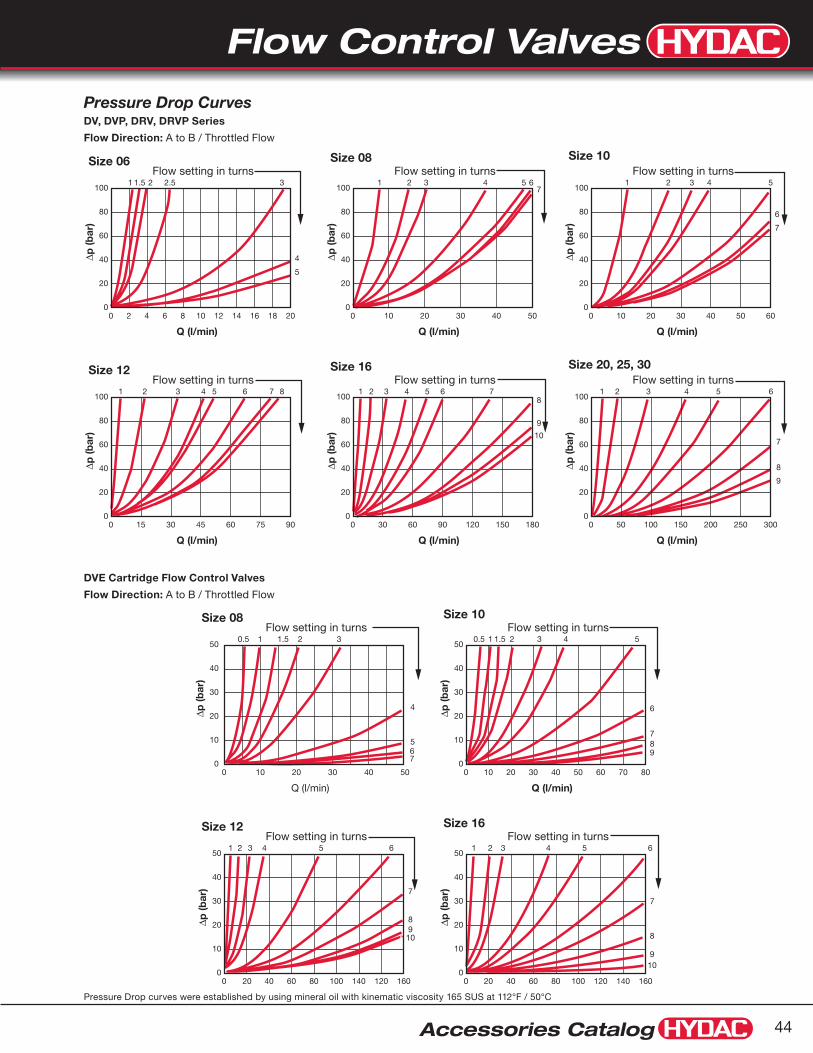
Flow Control Valves
Accessories Catalog 44
40
80
60
40
20
100
0181614 20
5
4
3
∆p (b
ar)
121086420
1 1.5 2 2.5Flow setting in turns
Q (l/min)
Size 06
80
60
40
20
100
075604530150 90
1 2 3 4 5 6 7Flow setting in turns
8
∆p (b
ar)
Q (l/min)
Size 12
80
60
40
20
100
050403020100 60
7
6
1 32 4Flow setting in turns
5
∆p (b
ar)
Q (l/min)
Size 10
80
60
40
20
100
0250200150100500 300
9
8
7
1 4 52 3Flow setting in turns
6
∆p (b
ar)
Q (l/min)
Size 20, 25, 30
80
60
40
20
100
0403020100 50
71 2 3 4
Flow setting in turns5 6
∆p (b
ar)
Q (l/min)
Size 08
80
60
40
20
100
01501209060300 180
10
9
81 2 3 4
Flow setting in turns5 6 7
∆p (b
ar)
Q (l/min)
Size 16
50403020100
0.5 1 1.5 2 3
4
567
Flow setting in turns
Q (l/min)
Size 08
40
30
20
10
50
01201401008060200 160
1 2 3 4 5 6Flow setting in turns
8
7
910
∆p (b
ar)
Q (l/min)
Size 12
40
30
20
10
50
0403020100 706050 80
6
789
0.5 1 1.5 2 3 4Flow setting in turns
5
∆p (b
ar)
40
30
20
10
50
0
∆p (b
ar)
Q (l/min)
Size 10
40
30
20
10
50
0140120100806040200 160
109
8
1 2 3 4Flow setting in turns
5 6
7
∆p (b
ar)
Q (l/min)
Size 16
Pressure Drop curves were established by using mineral oil with kinematic viscosity 165 SUS at 112°F / 50°C
Pressure Drop CurvesDV, DVP, DRV, DRVP Series
Flow Direction: A to B / Throttled Flow
DVE Cartridge Flow Control Valves
Flow Direction: A to B / Throttled Flow

Flow Control Valves
Accessories Catalog45
F
E
Knob forSizes 20-40
has Hex extensionfor wrench
Hex extension
Knob for sizes 6-16 B
closed
Aopen
D
C
J
12345
Thicknessof panel
1/4" max.
Panel Mount Kit(Nut, Washer, Lock Washer)
12345
øH required hole sizein panel
øG
1) Note: Pg style thread per DIN 40430Dimensions are for general information only, all critical dimensions should be verified by requesting a certified print.Dimensions are in inches/(mm) and lbs./(kg.)*Dependent upon valve and seal materials selected.
Model Code
Port SizeA B C D E F øG øH J1) Hex Weight
NPTF SAE
DV-06 1/8” 5/16-24UNF 2.16 (55)
1.97 (50)
0.31 (8)
0.63 (16)
0.75 (19)
1.50 (38)
0.94 (24)
0.51 (13)
Pg 7 thread - 0.26
(0.12)
DV-08 1/4” 7/16-20UNF 2.83 (72)
2.56 (65)
0.49 (12.5)
0.98 (25)
0.94 (24)
1.89 (48)
1.14 (29)
0.75 (19)
Pg 11 thread - 0.55
(0.25)
DV-10 3/8” 9/16-18UNF 2.91 (74)
2.64 (67)
0.59 (15)
1.18 (30)
1.14 (29)
2.28 (58)
1.14 (29)
0.75 (19)
Pg 11 thread - 0.88
(0.40)
DV-12 1/2” 3/4-16UNF 3.62 (92)
3.23 (82)
0.69 (17.5)
1.38 (35)
1.34 (34)
2.68 (68)
1.50 (38)
0.91 (23)
Pg 16 thread - 1.5
(0.70)
DV-16 3/4” 1-1/16-12UN 4.17(105)
3.78 (96)
0.89 (22.5)
1.77 (45)
1.53 (39)
3.07 (78)
1.50 (38)
0.91 (23)
Pg 16 thread - 2.6
(1.2)
DV-20 1” 1-5/16-12UN 5.71 (145)
5.04 (128)
0.98 (25)
1.97 (50)
2.13 (54)
4.25 (108)
1.93 (49)
1.50 (38)
Pg 29 thread
3/4 (19)
4.6 (2.1)
DV-25 1-1/4” 1-5/8-12UN 5.91 (150)
5.24 (133)
1.18 (30)
2.36 (60)
2.13 (54)
4.25 (108)
1.93 (49)
1.50 (38)
Pg 29 thread
3/4 (19)
6.2 (2.8)
DV-30 1-1/2” 1-7/8-12UN 6.10 (155)
5.43 (138)
1.38 (35)
2.76 (70)
2.13 (54)
4.25 (108)
1.93 (49)
1.50 (38)
Pg 29 thread
3/4 (19)
7.7 (3.5)
Dimensions
DV Series Inline Needle Valve
Panel Mount KitsSize Model Code Part Number
6 Kit Panel Mount DV06 00705300
8/10 Kit Panel Mount DV08 00705310
12/16 Kit Panel Mount DV12 00705302
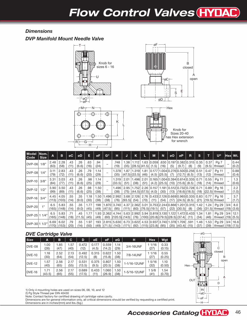
Flow Control Valves
Accessories Catalog 46
Knob forSizes 20-40
has Hex extensionfor wrench
Hex
12345
J
RH
G
KL
M N
øF
øD
S
øC
E
Bclosed
Aopen
Knob forsizes 6 - 16
12345
T
U
øOøP
1) Only 4 mounting holes are used on sizes 06, 08, 10, and 122) Pg Style Thread per DIN 40430 Note: Contact factory for certified drawing of cartridge valve cavity.Dimensions are for general information only, all critical dimensions should be verified by requesting a certified print.Dimensions are in inches/(mm) and lbs./(kg.)
IN
OUT
Hex
D
12345
Cclosed
Bopen
A
øG
øE
H
øF
Model Code
Nom.Size A B øC øD E øF G(1 H J K L M N øO øP R S T U(2 Hex Wt.
DVP-06 1/8” 2.48(63)
2.28(58)
.43(11)
.26(6.6)
.63(16)
.94(24) – .748
(19)1.38(35)
1.112(28.5)
1.63(41.5)
0.059(1.5)
.630(16)
0.197(5)
0.382(9.7)
0.315(8)
0.35(9)
0.37(9.5)
Pg 7thread – 0.44
(0.2)
DVP-08 1/4” 3.11(79)
2.83(72)
.43(11)
.26(6.6)
.79(20)
1.14(29) – 1.378
(35)1.87(47.5)
1.319(33.5)
1.81(46)
0.177(4.5)
1.004(25.5)
0.276(7)
0.500(12.7)
0.256(6.5)
0.51(13)
0.47(12)
Pg 11thread – 0.88
(0.4)
DVP-10 3/8” 3.31(84)
3.03(77)
.43(11)
.26(6.6)
.98(25)
1.14(29) – 1.319
(33.5)2.01(51)
1.496(38)
2.01(51)
0.165(4.2)
1.004(25.5)
0.394(10)
0.614(15.6)
0.335(8.5)
0.71(18)
0.55(14)
Pg 11thread – 1.3
(0.6)
DVP-12 1/2” 3.90(99)
3.50(89)
.43(11)
.26(6.6)
.98(25)
1.50(38) – 1.496
(38)2.95(75)
1.752(44.5)
2.26(57.5)
0.157(4.0)
1.181(30)
0.512(13)
0.732(18.6)
0.728(18.5)
0.71(18)
0.89(22.5)
Pg 16thread – 2.2
(1.0)
DVP-16 3/4” 4.45(113)
4.05(103)
.55(14)
.35(9.0)
1.18(30)
1.50(38)
1.496(38)
2.992(76)
3.68(93.5)
2.126(54)
2.76(70)
0.433(11)
2.126(54)
0.669(17)
0.965(24.5)
0.335(8.5)
0.83(21)
0.77(19.5)
Pg 16thread – 3.7
(1.7)
DVP-20 1” 6.5(165)
5.83(148)
.55(14)
.35(9.0)
1.77(45)
198(49)
1.870(47.5)
3.740(95)
4.37(111)
2.362(60)
3.01(76.5)
0.753(19.1)
2.244(57)
0.866(22)
1.201(30.5)
0.315(8)
1.42(36)
1.24(31.5)
Pg 29thread
3/4(19)
8.0(3.6)
DVP-25 1 1/4” 6.5(165)
5.83(148)
.71(18)
.45(11.5)
1.77(45)
1.93(49)
2.362(60)
4.744(120.5)
5.63(143)
2.992(76)
3.94(100)
0.819(20.8)
3.130(79.5)
1.122(28.5)
1.472(37.4)
0.433(11)
1.34(34)
1.81(46)
Pg 29thread
3/4(19)
12.1(5.5)
DVP-30 1 1/2” 6.69(170)
6.02(153)
.79(20)
.55(14)
1.97(50)
193(49)
2.815(71.5)
5.630(143)
6.73(171)
3.622(92)
4.53(115)
0.937(23.8)
3.740(95)
1.378(35)
1.709(43.4)
.591(15)
1.46(37)
1.53(39)
Pg 29thread
3/4(19)
16.6(7.5)
Dimensions
DVP Manifold Mount Needle Valve
DVE Cartridge ValveSize A B C D øE øF øG H Hex Wgt
DVE-08 1.00(26)
1.85(47)
1.57(40)
0.472(12)
0.177(4.5)
0.559(14.2)
1.14(29) 3/4-16UNF 1 1/16
(27)0.33(0.15)
DVE-10 1.18(30)
2.52(64)
2.13(54)
0.492(12.5)
0.315(8)
0.622(15.8)
1.50(38) 7/8-14UNF 1 1/16
(27)0.55(0.25)
DVE-12 1.57(40)
2.56(65)
2.17(55)
0.531(13.5)
0.375(9.5)
0.807(20.5)
1.50(38) 1-1/16-12UNF 1 5/16
(32)1.10
(0.50)
DVE-16 1.71(43.5)
2.56(65)
2.17(55)
0.689(17.5)
0.433(11)
1.060(26.9)
1.50(38) 1-5/16-12UNF 1 5/8
(41)1.54(0.70)

Flow Control Valves
Accessories Catalog47
A B
Model CodeDRV - 06 - 01 . X / 5 - 25 - S-M
Flow Control Valve DRV = Inline Mounting DRVP = Manifold Mounting
Nominal Sizes Nominal Size SAE (DRV only) NPTF (DRV Only) BSPP (DRV Only) (DRV + DRVP) Tube Size Thread Size Pipe Size Pipe OD Thread Size 06 = -2 5/16-24 UNF 1/8” 0.405” G1/8 08 = -4 7/16-20 UNF 1/4” 0.540” G1/4 10 = -6 9/16-18 UNF 3/8” 0.675” G3/8 12 = -8 3/4-16 UNF 1/2” 0.840” G1/2 16 = -12 1-1/16-12 UN 3/4” 1.050” G3/4 20 = -16 1-5/16-12 UN 1” 1.315” G1 25 = -20 1-5/8-12 UN 1-1/4” 1.660” G1 1/4 30 = -24 1-7/8-12 UN 1-1/2” 1.900” G1 1/2
Housing Material 01 = Carbon Steel
Modification Number
Port Configuration (omit) = DRVP only 0 = BSPP to DIN 3852, Part 2 -X 5 = NPTF (ANSI B1.20.3) 12 = SAE - SAEJ1926 Ports with ISO 725 Threads and O-Ring Sealing
Cracking Pressure (omit) = 7 PSI standard 25 = 25 PSI optional 65 = 65 PSI optional
Supplementary Details S = Panel Mounting Kit (not available in sizes 20, 25, 30)
Model Codes containing selections listed in RED are non-standard items – Minimum quantities will apply – Contact HYDAC for information and availability Not all combinations are available
Specifications5000 psi operating pressure•
8 sizes, 1/8” - 1-1/2”•
NPTF or SAE O-Ring threaded connections, •or manifold mounting
Flows to 80 GPM•
Carbon steel housing•
FPM • (Fluoroelastomer) O-Rings (standard)
Color coded spindle for accurate flow control•
Provision for panel mounting•
Unique safety spindle design•
Temperature Range: -4° to 212°F at full pressure•
Hydraulic Symbol
DRV & DRVP SeriesFlow Control Valves
DRV SeriesInline Mounting
DRVP SeriesManifold Mounting

Flow Control Valves
Accessories Catalog 48
40
80
60
40
20
100
0181614 20
5
4
3
∆p (b
ar)
121086420
1 1.5 2 2.5Flow setting in turns
Q (l/min)
Size 06
80
60
40
20
100
075604530150 90
1 2 3 4 5 6 7Flow setting in turns
8
∆p (b
ar)
Q (l/min)
Size 12
80
60
40
20
100
050403020100 60
7
6
1 32 4Flow setting in turns
5
∆p (b
ar)
Q (l/min)
Size 10
80
60
40
20
100
0250200150100500 300
9
8
7
1 4 52 3Flow setting in turns
6
∆p (b
ar)
Q (l/min)
Size 20, 25, 30
80
60
40
20
100
0403020100 50
71 2 3 4
Flow setting in turns5 6
∆p (b
ar)
Q (l/min)
Size 08
80
60
40
20
100
01501209060300 180
10
9
81 2 3 4
Flow setting in turns5 6 7
∆p (b
ar)
Q (l/min)
Size 16
50403020100
0.5 1 1.5 2 3
4
567
Flow setting in turns
Q (l/min)
Size 08
40
30
20
10
50
01201401008060200 160
1 2 3 4 5 6Flow setting in turns
8
7
910
∆p (b
ar)
Q (l/min)
Size 12
40
30
20
10
50
0403020100 706050 80
6
789
0.5 1 1.5 2 3 4Flow setting in turns
5
∆p (b
ar)
40
30
20
10
50
0
∆p (b
ar)
Q (l/min)
Size 10
40
30
20
10
50
0140120100806040200 160
109
8
1 2 3 4Flow setting in turns
5 6
7
∆p (b
ar)
Q (l/min)
Size 16
8
6
4
2
10
0180160140120100806040200 200
Q (L/min)
∆p (b
ar)
DRV 06 DRV 08 DRV 10 DRV 12
DRV 16
DRV-06-01.X to DRV-16-01.X
8
6
4
2
10
0550500450400350300250200150100500 600
Q (L/min)
∆p (b
ar)
DRV 20 DRV 25
DRV 30
DRV 40
DRV-20-01.X to DRV-40-01.X
8
6
4
2
10
02752502252001751501251007550250 300
Q (L/min)
∆p (b
ar)
DRVP 06 DRVP 08 DRVP 10 DRVP 12 DRVP 16
DRVP 20
DRVP 25
DRVP 30DRVP 40
DRVP-06-01.X to DRVP-40-01.X
Pressure Drop curves were established by using mineral oil with kinematic viscosity 335 SUS at 86°F / 30°C
Flow Direction: B to A / Free Flow Through Check Valve
Pressure Drop CurvesFlow Direction: A to B / Throttled Flow
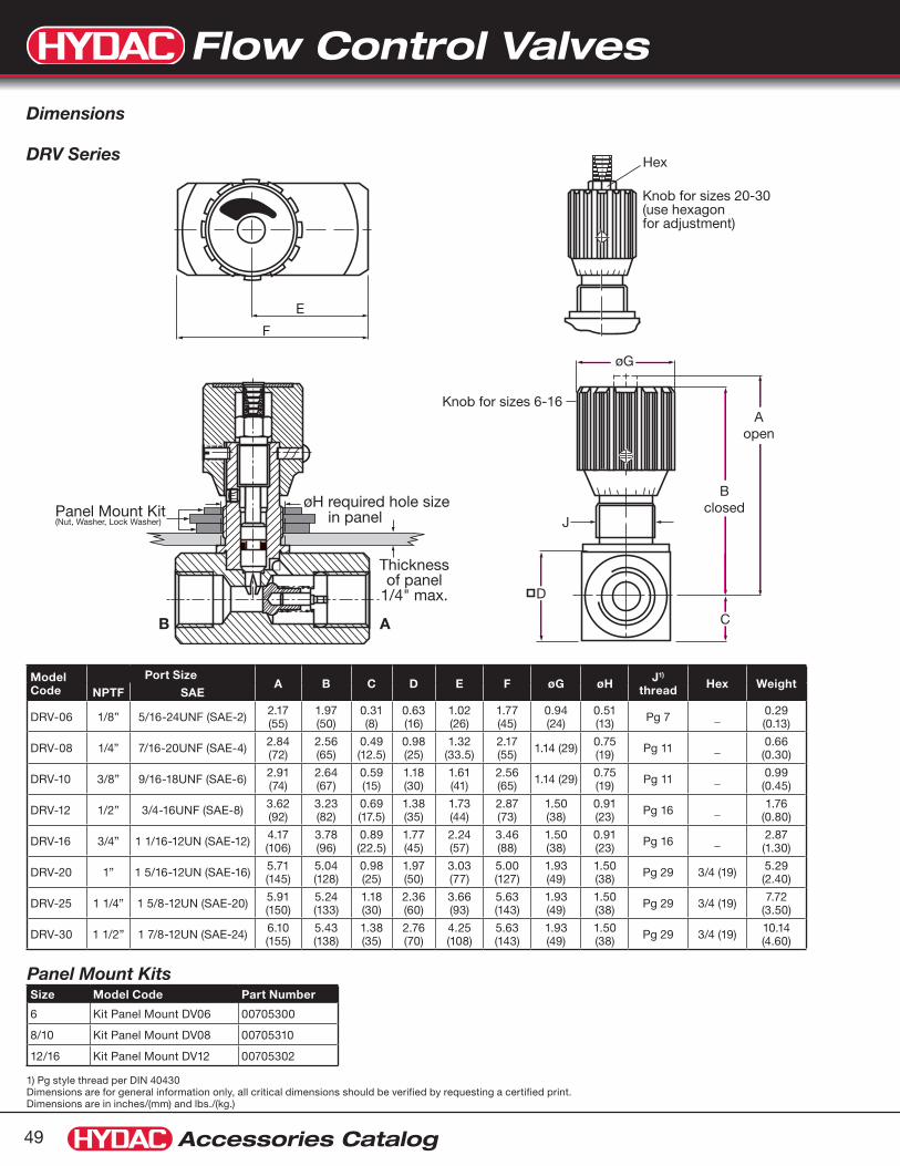
Flow Control Valves
Accessories Catalog49
1) Pg style thread per DIN 40430 Dimensions are for general information only, all critical dimensions should be verified by requesting a certified print.Dimensions are in inches/(mm) and lbs./(kg.)
E
F
Knob for sizes 20-30(use hexagon for adjustment)
Hex123456
Bclosed
Aopen
Knob for sizes 6-16
øG
D
J
C
12345
Panel Mount Kit(Nut, Washer, Lock Washer)
Thicknessof panel
1/4" max.
B A
øH required hole sizein panel
Model Code
Port SizeA B C D E F øG øH J1)
thread Hex WeightNPTF SAE
DRV-06 1/8” 5/16-24UNF (SAE-2) 2.17 (55)
1.97 (50)
0.31 (8)
0.63 (16)
1.02 (26)
1.77 (45)
0.94 (24)
0.51 (13) Pg 7 _ 0.29
(0.13)
DRV-08 1/4” 7/16-20UNF (SAE-4) 2.84 (72)
2.56 (65)
0.49 (12.5)
0.98 (25)
1.32 (33.5)
2.17 (55) 1.14 (29) 0.75
(19) Pg 11 _ 0.66 (0.30)
DRV-10 3/8” 9/16-18UNF (SAE-6) 2.91 (74)
2.64 (67)
0.59 (15)
1.18 (30)
1.61 (41)
2.56 (65) 1.14 (29) 0.75
(19) Pg 11 _ 0.99 (0.45)
DRV-12 1/2” 3/4-16UNF (SAE-8) 3.62 (92)
3.23 (82)
0.69 (17.5)
1.38 (35)
1.73 (44)
2.87 (73)
1.50 (38)
0.91 (23) Pg 16 _ 1.76
(0.80)
DRV-16 3/4” 1 1/16-12UN (SAE-12) 4.17 (106)
3.78 (96)
0.89 (22.5)
1.77 (45)
2.24 (57)
3.46 (88)
1.50 (38)
0.91 (23) Pg 16 _ 2.87
(1.30)
DRV-20 1” 1 5/16-12UN (SAE-16) 5.71 (145)
5.04 (128)
0.98 (25)
1.97 (50)
3.03 (77)
5.00 (127)
1.93 (49)
1.50 (38) Pg 29 3/4 (19) 5.29
(2.40)
DRV-25 1 1/4” 1 5/8-12UN (SAE-20) 5.91 (150)
5.24 (133)
1.18 (30)
2.36 (60)
3.66 (93)
5.63 (143)
1.93 (49)
1.50 (38) Pg 29 3/4 (19) 7.72
(3.50)
DRV-30 1 1/2” 1 7/8-12UN (SAE-24) 6.10 (155)
5.43 (138)
1.38 (35)
2.76 (70)
4.25 (108)
5.63 (143)
1.93 (49)
1.50 (38) Pg 29 3/4 (19) 10.14
(4.60)
Dimensions
DRV Series
Panel Mount KitsSize Model Code Part Number
6 Kit Panel Mount DV06 00705300
8/10 Kit Panel Mount DV08 00705310
12/16 Kit Panel Mount DV12 00705302

Flow Control Valves
Accessories Catalog 50
B c
lose
d
A o
pen
Knob for sizes 6-16
øG
øE
øD
F
UC
Knob for sizes 20-30(use hexagon for adjustment)
Hex123456
T H
O P
JK
L
NM
12345
øRøS
W
X
V
B A
B A
1) Only 4 mounting holes are used on sizes 06, 08, 10, & 122) Pg style thread per DIN 40430Dimensions are for general information only, all critical dimensions should be verified by requesting a certified print.Dimensions are in inches/(mm) and lbs./(kg.)
Model Code
Nominal Size A B C øD øE F øG H(1 J K L
DRVP-06 1/8” 2.48(63)
2.28(58)
0.31(8)
0.43(11)
0.26(6.6)
0.63(16)
0.94(24) _ 7.48
(19)1.63(41.5)
1.81(46)
DRVP-08 1/4” 3.11(79)
2.83(72)
0.39(10)
0.43(11)
0.26(6.6)
0.79(20)
1.14(29) _ 1.378
(35)2.50
(63.5)2.64(67)
DRVP-10 3/8” 3.31(84)
3.03(77)
0.49 (12.5)
0.43(11)
0.26(6.6)
0.98(25)
1.14(29) _ 1.319
(33.5)2.76(70)
2.91(74)
DRVP-12 1/2” 4.17(106)
3.78(96)
0.63(16)
0.43(11)
0.26(6.6)
1.26(32)
1.50(38) _ 1.496
(38)3.15(80)
3.33 (84.5)
DRVP-16 3/4” 5.04(128)
4.65(118)
0.89 (22.5)
0.55(14)
0.35(9)
1.77(45)
1.50(38)
1.496(38)
2.992(76)
4.09(104)
4.31 (109.5)
DRVP-20 1” 6.69(170)
6.02(153)
0.98(25)
0.55(14)
0.35(9)
1.97(50)
1.93(49)
1.870 (47.5)
3.740(95)
5.00(127)
5.24(133)
DRVP-25 1 1/4” 6.89(175)
6.22(158)
1.08(27.5)
0.71(18)
0.45(11.5)
2.16(55)
1.93(49)
2.362(60)
4.744 (120.5)
6.50(165)
6.77(172)
DRVP-30 1 1/2” 7.68(195)
7.01(178)
1.48(37.5)
0.79(20)
0.55(14)
2.95(75)
1.93(49)
2.815 (71.5)
5.630 (143)
7.32(186)
7.72(196)
Model Code
Nominal Size M N O P øR øS T U V W(2
thread Hex Weight
DRVP-06 1/8” 1.122 (28.5)
1.63 (41.5)
0.63(1.6)
0.630 (16)
0.20(5)
0.382 (9.7)
0.252 (6.4)
0.28(7)
0.53 (13.5) Pg 7 _ 0.57
(0.26)
DRVP-08 1/4” 1.319 (33.5)
1.81(46)
0.189 (4.8)
1.004 (25.5)
0.28(7)
0.500 (12.7)
0.559 (14.2)
0.28(7)
1.22(31) Pg 11 _ 1.10
(0.50)
DRVP-10 3/8” 1.496 (38)
2.01(51)
0.157(4)
1.004 (25.5)
0.39(10)
0.614 (15.6)
0.709 (18)
0.28(7)
1.16 (29.5) Pg 11 _ 1.76
(0.80)
DRVP-12 1/2” 1.752 (44.5)
2.26 (57.5)
0.157(4)
1.181 (30)
0.51(13)
0.732 (18.6)
0.827 (21)
0.28(7)
1.44 (36.5) Pg 16 _ 2.42
(1.10)
DRVP-16 3/4” 2.126 (54)
2.76(70)
0.433 (11)
2.126 (54)
0.67(17)
0.965 (24.5)
0.551 (14)
0.35(9)
1.93(49) Pg 16 _ 5.51
(2.50)
DRVP-20 1” 2.362 (60)
3.01 (76.5)
0.748 (19)
2.244 (57)
0.87(22)
1.201 (30.5)
0.630 (16)
0.35(9)
1.93(49) Pg 29 3/4
(19)8.60 (3.90)
DRVP-25 1 1/4” 2.992 (76)
3.94 (100)
0.811 (20.6)
3.130 (79.5)
1.12 (28.5)
1.472 (37.4)
0.591 (15)
0.43(11)
3.03(77) Pg 29 3/4
(19)14.77 (6.70)
DRVP-30 1 1/2” 3.622 (92)
4.53 (115)
0.937 (23.8)
3.740 (95)
1.38(35)
1.709 (43.4)
0.591 (15)
0.51(13)
3.35(85) Pg 29 3/4
(19)24.25 (11.0)
Dimensions
DRVP Series

Flow Control Valves
Accessories Catalog51
Model CodeSRVR - 08 - 01 .X / 5 - S
Pressure Compensated Flow Control Valve SRVR = Flow Control Valve (with internal check valve)
Nominal Size NPTF Only Pipe Size Pipe OD 08 = 1/4” 0.540” 10 = 3/8” 0.675” 12 = 1/2” 0.840” 16 = 3/4” 1.050”
Housing Material 01 = Carbon Steel
Modification Number
Port Configuration 0 = BSPP to DIN 3852, Part 2 -X 5 = NPTF (ANSI B1.20.3)
Supplementary Details S = Panel Mounting Kit
Model Codes containing selections listed in RED are non-standard items – Minimum quantities will apply – Contact HYDAC for information and availability Not all combinations are available
Specifications4 sizes, 1/4” - 3/4”•
Working Pressure: •Inlet: 102 psi min. / 3045 psi max. Outlet: 0 psi min. / 2944 psi max.
Flows to 24 gpm•
NPTF Connections•
Carbon Steel Housing•
FPM • (Fluoroelastomer) O-Rings (standard)
Color coded spindle for accurate flow control•
Provision for panel mounting•
Unique safety spindle design•
Temperature Range: -4˚ to 212˚F at full pressure•
Viscosity Range: 13 SUS min. / 1781 SUS max.•
Hydraulic Symbol
SRVR SeriesPressure Compensated Flow Control Valves
B
A
A B

Flow Control Valves
Accessories Catalog 52
Thicknessof panel
1/4" max.
PanelMountKit
ØHHole requiredin panel
D
øG
Aopen
Bclosed
C EF
Hex
12345
J
A B
Size 10
Q (L
/min
)
∆p (bar)0 15010050 200
20
18
16
14
12
10
8
6
4
2
0
22approx.6.5 turns
approx. 6 turns
approx. 5 turns
approx. 4turns
approx. 3 turns
approx. 2 turns
approx. 1 turns
Size 16
Q (L
/min
)
∆p (bar)0 15010050 200
80
70
60
50
40
30
20
10
0
90 approx.7 turns
approx. 6 turns
approx. 8 turns
approx. 5 turns
approx. 4turns
approx. 3 turns
approx. 2 turns
approx. 1 turns
Size 12
Q (L
/min
)
∆p (bar)0 15010050 200
50
45
40
35
30
25
20
15
10
5
0
55
approx.7 turns
approx. 6 turns
approx. 8 turns
approx. 9 turns
approx. 5 turns
approx. 4turns
approx. 3 turns
approx. 2 turns
approx. 1 turns
Size 08
Q (L
/min
)
∆p (bar)0 15010050 200
10
8
6
4
2
0
12approx. 4.5 turns
approx. 4turns
approx. 3 turns
approx. 2 turns
approx. 1 turns
Size 20
Q (L
/min
)
∆p (bar)0 15010050 200
120
140
100
80
60
20
40
0
160approx. 9 turns
approx. 3 turns
approx. 2 turns
approx. 1 turns
approx. 5 turnsapprox. 6 turnsapprox. 7 turnsapprox. 8 turns
approx. 4 turns
0 90 80 70 60 50 40 30 20 10 100
7
5
3
6
4
2
1
0
Q (L/min)
p (b
ar)
SRVR
-12
SR
VR
-10
SR
VR
-08
SRVR-16
1) Pg style thread per DIN 40430Dimensions are for general information only, all critical dimensions should be verified by requesting a certified print.Dimensions are in inches/(mm) and lbs./(kg.)
Model Code Size A B C D E F Ø G ØH J(1 thread Hex Weight
SRVR-08 1/4” NPTF 2.91(74)
2.64(67)
0.59(15)
1.18(30)
0.69(17.5)
3.62(92)
1.14(29)
0.75(19) Pg 11 0.94
(24)1.3
(0.6)
SRVR-10 3/8” NPTF 3.62(92)
3.23(82)
0.69(17.5)
1.38(35)
0.71(18)
4.13(105)
1.50(38)
0.91(23) Pg 16 1.06
(27)2.0(0.9)
SRVR-12 1/2” NPTF 4.17(106)
3.78(96)
0.89(22.5)
1.77(45)
0.83(21)
4.92(125)
1.50(38)
0.91(23) Pg 16 1.26
(32)3.8(1.7)
SRVR-16 3/4” NPTF 4.27 (108.5)
3.88(98.5)
0.98(25)
1.97(50)
1.02(26)
5.51(140)
1.50(38)
0.91(23) Pg 16 1.61
(41)4.9(2.2)
Flow Direction: B to A / Free Flow Through Check Valve
Pressure Drop Curves Flow Direction: A to B / Throttled Flow
Dimensions
Panel Mount KitsSize Model Code Part Number
08 Kit Panel Mount DV08 00705310
10/12/16 Kit Panel Mount DV12 00705302

Flow Control Valves
Accessories Catalog53
Model CodeRV - 06 - 01 .X / 5 - 25
Check Valve RV = Inline Mounting RVP = Manifold Mounting
Nominal Sizes Nom Size SAE (RV Only) NPTF (RV Only) BSPP (RV Only) (RV + RVP) Tube Size Thread Size Pipe Size Pipe OD Thread Size 06 = -2 5/16-24 UNF 1/8” 0.405” G1/8 08 = -4 7/16-20 UNF 1/4” 0.540” G1/4 10 = -6 9/16-18 UNF 3/8” 0.675” G3/8 12 = -8 3/4-16 UNF 1/2” 0.840” G1/2 16 = -12 1-1/16-12 UN 3/4” 1.050’ G3/4 20 = -16 1-5/16-12 UN 1” 1.315” G1 25 = -20 1-5/8-12 UN 1-1/4” 1.660” G1 1/4 30 = -24 1-7/8-12 UN 1-1/2” 1.900” G1 1/2 40 = -32 2-1/2-12 UN 2” 2.375” G2
Housing Material 01 = Carbon Steel
Modification Number
Port Configuration (omit) = RVP only 0 = BSPP to DIN 3852, Part 2-X 5 = NPTF - ANSI/ASME 1.20.3 Taper Pipe Thread 12 = SAE - SAEJ1926 Ports with ISO 725 Threads and O-Ring Sealing
Cracking Pressure (omit) = 7 psi (standard) 25 = 25 psi 65 = 65 psiNote: Not recommended for high-cycle applications!
Model Codes containing selections listed in RED are non-standard items – Minimum quantities will apply – Contact HYDAC for information and availability Not all combinations are available
Specifications5000 psi operating pressure•
9 Sizes, 1/8” - 2”•
NPT or SAE O-Ring connections and manifold mounting•
Flows to 150 gpm•
Carbon Steel Housing•
FPM • (Fluoroelastomer) O-Rings (for RVP series)
Metal to metal seal design for poppet•
Hardened and ground steel poppet•
3 Cracking Pressures: 7 psi • (standard), 25 psi and 65 psi (optional)
Temperature Range: -4° to 212°F at full pressure•
Hydraulic Symbol
RV & RVP SeriesCheck Valves
RV SeriesInline Mounting
RVP SeriesManifold Mounting
B A

Flow Control Valves
Accessories Catalog 54
1) Only 4 mounting holes are used on sizes 06, 08, 10, & 12Dimensions are for general information only, all critical dimensions should be verified by requesting a certified print.Dimensions are in inches/(mm) and lbs./(kg.)
RV Inline Check ValvesModel Code
Port SizeHex L Weight
NPT SAE
RV-06 1/8” 5/16-24 UNF 11/16 (17)
1.77 (45)
0.22 (0.1)
RV-08 1/4” 7/16-20 UNF 3/4 (19) 2.17 (55)
0.44 (0.2)
RV-10 3/8” 9/16-18 UNF 1 (24) 2.60 (65)
0.44 (0.2)
RV-12 1/2” 3/4-16 UNF 1 1/4 (30)
2.87 (73)
0.66 (0.3)
RV-16 3/4” 1 1/16-12 UN 1 7/16 (36)
3.46 (88)
1.1 (0.5)
RV-20 1” 1 5/16-12 UN 1 13/16 (46)
5.00 (127)
2.4(1.1)
RV-25 1-1/4” 1 5/8-12 UN 2 3/8 (60)
5.63 (143)
4.0 (1.8)
RV-30 1-1/2” 1 7/8-12 UN 2 9/16 (65)
5.63 (143)
5.7 (2.6 )
RV-40 2” 2 1/2-12 UN 3 3/16 (80)
6.50 (165)
9.7 (4.4)
RVP Manifold Mounted Check ValvesModel Code
Port SizeD E F(1 G H J K L M N O R Wgt
A B C
RVP-06 1.63 (41.5)
1.12 (28.5)
1.31 (46)
1.63 (41.5)
0.75 (19) – 0.25
(6.4)0.06 (1.6)
0.63 (16)
0.38 (9.7)
0.2 (5)
0.43 (11)
0.35 (9)
0.63 (16)
0.26 (6.6)
0.4 (0.2)
RVP-08 1.81 (46)
1.32 (33.5)
2.64 (67)
2.5 (63.5)
1.38 (35) – 0.56
(14.2)0.19 (4.8)
1.00 (25.5)
0.50 (12.7)
0.28 (7)
0.43 (11)
0.51 (13)
0.79 (20)
0.26 (6.6)
0.9 (0.4)
RVP-10 2.01 (51)
1.50 (38)
2.81 (74)
2.76 (70)
1.32 (33.5) – 0.71
(18)0.16 (4)
1.00 (25.5)
0.61 (15.6)
0.39 (10)
0.43 (11)
0.71 (18)
0.98 (25)
0.26 (6.6)
1.1 (0.5)
RVP-12 2.26 (57.5)
1.75 (44.5)
3.33 (84.5)
3.15 (80)
1.50 (38) – 0.83
(21)0.16 (4)
1.18 (30)
0.73 (18.6)
0.51 (13)
0.43 (11)
0.98 (25)
1.26 (32)
0.26 (6.6)
2.2 (1.0)
RVP-16 2.76 (70)
2.13 (54)
4.31 (109.5)
4.09 (104)
2.99 (76)
1.50 (38)
0.55 (14)
0.43 (11)
2.13 (54)
0.96 (24.5)
0.67 (17)
0.55 (14)
1.42 (36)
1.77 (45)
0.35 (9)
4.6 (2.1)
RVP-20 3.01 (76.5)
2.36 (60)
5.24 (133)
5.00 (127)
3.74 (95)
1.87 (47.5)
0.63 (16)
0.75 (19)
2.24 (57)
1.20 (30.5)
0.87 (22)
0.55 (14)
1.61 (41)
1.97 (50)
0.35 (9)
7.3 (3.3)
RVP-25 3.94 (100)
2.99 (76)
6.77 (172)
6.50 (165)
4.74 (120.5)
2.36 (60)
0.59 (15)
0.81 (20.6)
3.13 (79.5)
1.47 (37.4)
1.12 (28.5)
0.71 (18)
1.73 (44)
2.17 (55)
0.45 (11.5)
12.8 (5.8)
RVP-30 4.53 (115)
3.62 (92)
7.72 (196)
7.32 (186)
5.63 (143)
2.81 (71.5)
0.59 (15)
0.94 (23.8)
3.74 (95)
1.71 (43.4)
1.38 (35)
0.79 (20)
2.44 (62)
2.95 (75)
0.55 (14)
22.7 (10.3)
RVP-40 5.51 (140)
4.37 (111)
7.91 (201)
7.56 (192)
5.26 (133.5)
2.64 (67)
0.63 (16)
1.00 (25.5)
3.50 (89)
2.25 (57.2)
1.85 (47)
0.79 (20)
3.43 (87)
3.94 (100)
0.55 (14)
39.5 (17.9)
RV-06... to RV-16...
Q (l/min)
∆p (b
ar)
8
6
4
2
08040 1601200 200
10RV-12
RV-16
RV-06 RV-08 RV-10
RV-20... to RV-40...
Q (l/min)
∆p (b
ar)
8
6
4
2
05004003002001000 600
10
RV-25
RV-30
RV-40
RV-20
RVP-06... to RVP-16...
Q (l/min)
∆p (b
ar)
8
6
4
18
16
14
2
0
12
10
16012080400 200
20
RVP-06
RVP-08
RVP-10
RVP-12
RVP-16
RVP-20... to RVP-40...
Q (l/min)
∆p (b
ar)
8
6
4
2
0
10
400200 5003001000 600
RVP-25
RVP-30
RVP-40
RVP-20
Pressure Drop CurvesFlow Direction: B to A / Free Flow Through Check Valve (A to B is Completely Blocked)
Pressure Drop curves were established by using mineral oil with kinematic viscosity 335 SUS at 86°F / 30°C
Dimensions
H
O
Ø M
Ø R
Ø K
Ø L
N
J
A
G FE
DC
BB A
Hex L
B A

Flow Control Valves
Accessories Catalog55
DV, DRV, & RV SeriesStainless Steel Flow Control Valves - Available with BSPP Ports
Model Code Part Number Dimensions
RV-06-30.X/0 00705859
Same as Standard ProductSee Page 53
RV-08-30.X/0 00705861
RV-10-30.X/0 00705863
RV-12-30.X/0 00705865
RV-16-30.X/0 00705867
RV-20-30.X/0 00705869
RV-25-30.X/0 00705895
RV-30-30.X/0 00707521
DV-06-30.X/0 00705134
Same as Standard ProductSee Page 43
DV-08-30.X/0 00705142
DV-10-30.X/0 00705150
DV-12-30.X/0 00705158
DV-16-30.X/0 00705166
DV-20-30.X/0 00705174
DV-25-30.X/0 00707424
DV-30-30.X/0 00705295
DRV-06-30.X/0 00705634
Same as Standard ProductSee Page 47
DRV-08-30.X/0 00705642
DRV-10-30.X/0 00705650
DRV-12-30.X/0 00705658
DRV-16-30.X/0 00705666
DRV-20-30.X/0 00705674
RV SeriesInline MountingCheck valves
DV SeriesInline MountingNeedle Valves
DRV SeriesInline MountingFlow Control Valves
Model Codes containing selections listed in RED are non-standard items – Minimum quantities will apply – Contact HYDAC for information and availability Not all combinations are available

Accessories Catalog 56
Cartridge Valves
2-Way Solenoid Cartridge Valves WSM Series (see pages 63 - 66)
3-Way Solenoid Cartridge Valves WSE Series (see pages 67 - 68)
Pressure Relief Valves DB4 Series (see pages 69 - 70)
Global Replacement Business
In some cases you will call HYDAC customer service and the part number will not be in our computer system. In these cases we will provide you a replacement quote in a few days. For additional details visit www.hydac.com and click on support, downloads, brochures, Compact Hydraulics and check out the literature.
HYDAC Fluidtechnik GmbH is located in Germany and produces Cartridge Valves for the Global Market. The majority of the product that they produce is in the Metric standard. HYDAC Technology Corporation has a division in Chicago, called HHD or the Hydraulic Division, that manufactures Coolers, Power Units, and UNF Cartridge Valves. HYDAC Accessories Bethlehem supports the metric cartridge valve sales in the United States.
Hose Break Valves RB Series & RBE Series (see pages 57 - 60)
Shuttle Valves WVE Series (see page 61)
Automatic Air Vent Valves AEV Series (see page 62)
Overview
For additional information on HYDAC’s UNF Cartridge Valve offering please refer to the HYDAC Cartridge Valve Catalog #02080105.

Cartridge Valves
Accessories Catalog57
RB Series Hose Break Valves
Model CodeRB E - SAE1-1/16-12 - X - 120L/MIN
Hose Break Valve
Housing Type Refer to “code” column below
Size of Connection Refer to “Size of Connection” below
Modification Number X = Latest Revision
Closing Flow Rate XXXL/MIN = Standard
Max. closing flow rate listed below in L/min
XXXGPM = Factory Set Customer specifies closing flow rate in GPM
Hydraulic Symbol1
2
1-2 Free Flow2-1 Operating Direction; Valve
closes if flow exceeds adjusted flow rate.
DescriptionHYDAC Hose Break Valves eliminate uncontrolled movements of the actuator in case of line rupture. They are commonly applied with dead weight cylinders.
These valves are volume limiting flat seat valves.
At normal flow, the poppet is held open by a spring with enough force to counteract the force on the poppet created by the flow.
When the supply line is ruptured, the flow from 2 to 1 exceeds the specified flow rate, the P across the poppet creates a force greater than the spring force and closes the valve. This closing flow rate is adjustable. The valve opens automatically by pressurizing connection 1.
Depending on the pressure P, the leakage rate through the valve is approximately 0 to 6 in3 / min. If this is excessive, the valve threads can be sealed and made leak-free.
The valves are installed between actuators and possible line breakage points.
A cartridge-type valve can be installed into an actuator port.
A housing-type valve can be installed close to the actuator or even directly into the actuator itself.
Type and Size CodesCode Housing Type Connection 1 Connection 2 Size of Connections
Dependent on Desired Closing Flow Rate (see below)
E 1
1
1
1
1
2
2
2
2
2
Cartridge Only – – SAE 9/16-18 SAE 3/4-16 SAE 1 1/16-12
XB
1
1
1
1
1
2
2
2
2
2
Cartridge Valve in
Housings
SAE Straight Thread Port
SAE Straight Thread Stud End SAE 9/16-18 SAE 3/4-16 SAE 1 1/16-12
XB
1
1
1
1
1
2
2
2
2
2
NPT Port NPT Male Connector
NPT 3/8 or NPT 1/2 – NPT 1
XX
1
1
1
1
1
2
2
2
2
2
SAE Straight Thread Port
SAE Straight Thread Port – SAE 1 1/16-12
CC
1
1
1
1
1
2
2
2
2
2 NPT Male Connector
NPT Male Connector – NPT 3/4 –
Closing Flow Rate (min - max)(from 2 to 1)
GPML/min
1-44-15
1.6-126-45
6.5-3225-120
To avoid the activation of hose break valves on flow surges, the closing flow rate should be at least 20% above the normal flow rate.
Valves are shipped with maximum closing flow setting. Closing flow can be adjusted according to curves on next page. If closing flow must be set by factory, please specify when ordering.
RB...
Housing Valves
RBE...
Cartridge Valves

Cartridge Valves
Accessories Catalog 58
0.75"19mm
0.75"19mm
3.25"83mm
1 1/16-12UN2B 1 1/16-12UN2B
Hex 1.5" 38mm
1 2
2.44"62mm
1.00"25mm
1.00"25mm
3/4 NPT 3/4 NPT
Hex 1.25" 32mm
1 2
øKøL
Hex
1 2
CD E
F
øH
øG
øJ
Adjustment Curves for Closing Flow RateThe closing flow rate is dependent on the dimensions “H”.
After loosening the lock nut, set the GAP to dimension “H” with a thickness gauge.
The lock nut must be tightened after adjustment.
After Adjustment,Pinch Thread At PointImmediately Behind Lock Nut
Lock Nut
Adjusting Nut
GaugeGauge Thickness "H"
SA
E 9
/16-
18
SA
E 3
/4-1
6
SAE 1
1/16
-12
0 30252015105
0 12080 100604020
0.04
0.08
0.12
1.0
0
2.0
3.0
Gap
in m
m
Gap
in in
ches
Q in gpm
Q in l/min
The adjustment curves are valid for cartridge RBE...and for all housing valves RB... in accordance with “Type and Size Codes” charts on previous page. For model RB... the cartridge must be removed from the housing for adjustment.
See special tool for installation and removal on page 60.
Valve Type C D E F øG øH øJ øK øL Hex
RBE-SAE 9/16 0.866 (22)
0.453 (11.5)
0.138 (3.5)
0.13 (3) 9/16-18UNF-2B 0.374
(9.5)0.460 (11.7)
0.315 (8)
0.098 (2.5)
0.197 (5)
RBE-SAE 3/4 1.063 (27)
0.531 (13.5)
0.197 (5)
0.14 (3.5) 3/4-16UNF-2B 0.472
(12)0.640 (16.3)
0.394 (10)
0.138 (3.5)
0.217 (5.5)
RBE-SAE 1 1/16 1.614 (41)
0.925 (23.5)
0.256 (6.5)
0.17 (4) 1 1/16-12UNF-2B 0.709
(18)0.930 (23.6)
0.630 (16)
0.256 (6.5)
0.276 (7)
Dimensions are for general information only, all critical dimensions should be verified by requesting a certified print.Dimensions are in inches/(mm) and lbs./(kg.)
RBXX-SAE 1-1/16-12 RBCC-NPT 3/4 Housing Valve
DimensionsCartridges

Cartridge Valves
Accessories Catalog59
CD
EE1 2
Hex
C
D E
F F1 2
Hex
5 10 15
H=
.059
"
H= .
035"
H= .
024"
H= .
016"
H=.
079"
H= .
039"
H= .
028"
H= .
020"
H=.
079"
H
= .108
"
H= .
039"
H= .
020"
H=.
060"
10
0 20
0 1 2 3 4 5
30
40
50
20
0
2.0
3.0
1.0
∆P in
bar
∆P in
psi
Q in l/min
Q in gpm
10
0 10 20 30 5040
0 2 4 6 8 1210
30
40
50
20
0
2.0
3.0
1.0
∆P in
bar
∆P in
psi
Q in l/min
Q in gpm
10
0 20 40 60 80 100 120
0 5 10 15 20 25 30
30
40
50
20
0
2.0
3.0
1.0
∆P in
bar
∆P in
psi
Q in l/min
Q in gpm
Nominal Flow CurvesFlow rate is dependent on operating setting “H”. See “Adjusting Curves for Closing Flow Rates - Settings”. Curves are valid for Cartridges RBE and Housing RB... in accordance with charts on previous page. Limit Lines indicate the maximum closing flow rates. These rates cannot be exceeded. Curves were established at 150 SUS.
Dimensions RBXB-... SAE RBXB-... NPT
Housing Type C D E F Hex
RBXB-SAE 9/16-18 2.13 (54) 0.50 (13) 0.39 (10) 9/16-18UNF-2B 0.75 (19)
RBXB-SAE 3/4-16 2.38 (60) 0.56 (14) 0.44 (11) 3/4-16UNF-2B 1.00 (25)
RBXB-SAE 1 1/16-12 3.25 (83) 0.75 (19) 0.59 (15) 1 1/16-12UNF-2B 1.50 (38)
RBXB-NPT 3/8 2.09 (53) 0.59 (15) 3/8 NPT 0.88 (22)
RBXB-NPT 1/2 2.75 (70) 0.78 (20) 1/2 NPT 1.00 (25)
RBXB-NPT 1 3.31 (84) 0.98 (25) 1 NPT 1.75 (44)
Dimensions are for general information only, all critical dimensions should be verified by requesting a certified print.Dimensions are in inches/(mm)*Dependent upon valve and seal materials selected.
RBE-SAE 9/16 - 18 RBE-SAE 3/4 - 16 RBE-SAE 1-1/16 - 12
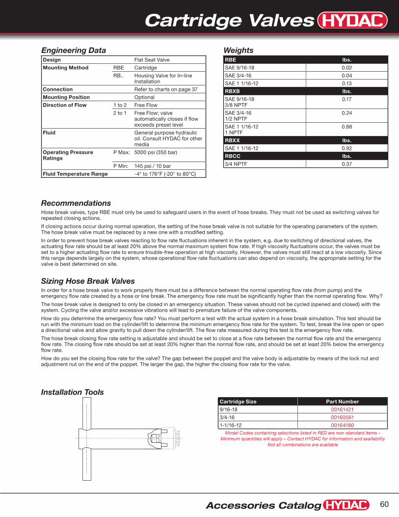
Cartridge Valves
Accessories Catalog 60
RecommendationsHose break valves, type RBE must only be used to safeguard users in the event of hose breaks. They must not be used as switching valves for repeated closing actions.
If closing actions occur during normal operation, the setting of the hose break valve is not suitable for the operating parameters of the system. The hose break valve must be replaced by a new one with a modified setting.
In order to prevent hose break valves reacting to flow rate fluctuations inherent in the system, e.g. due to switching of directional valves, the actuating flow rate should be at least 20% above the normal maximum system flow rate. If high viscosity fluctuations occur, the valves must be set to a higher actuating flow rate to ensure trouble-free operation at high viscosity. However, the valves must still react at a low viscosity. Since this range depends largely on the system, whose operational flow rate fluctuations can also depend on viscosity, the appropriate setting for the valve is best determined on site.
Sizing Hose Break ValvesIn order for a hose break valve to work properly there must be a difference between the normal operating flow rate (from pump) and the emergency flow rate created by a hose or line break. The emergency flow rate must be significantly higher than the normal operating flow. Why?
The hose break valve is designed to only be closed in an emergency situation. These valves should not be cycled (opened and closed) with the system. Cycling the valve and/or excessive vibrations will lead to premature failure of the valve components.
How do you determine the emergency flow rate? You must perform a test with the actual system in a hose break simulation. This test should be run with the minimum load on the cylinder/lift to determine the minimum emergency flow rate for the system. To test, break the line open or open a directional valve and allow gravity to pull down the cylinder/lift. The flow rate measured during this test is the emergency flow rate.
The hose break closing flow rate setting is adjustable and should be set to close at a flow rate between the normal flow rate and the emergency flow rate. The closing flow rate should be set at least 20% higher than the normal flow rate, and should be set at least 20% below the emergency flow rate.
How do you set the closing flow rate for the valve? The gap between the poppet and the valve body is adjustable by means of the lock nut and adjustment nut on the end of the poppet. The larger the gap, the higher the closing flow rate for the valve.
WeightsRBE lbs.
SAE 9/16-18 0.02
SAE 3/4-16 0.04
SAE 1 1/16-12 0.13
RBXB lbs.
SAE 9/16-183/8 NPTF
0.17
SAE 3/4-161/2 NPTF
0.24
SAE 1 1/16-121 NPTF
0.88
RBXX lbs.
SAE 1 1/16-12 0.92
RBCC lbs.
3/4 NPTF 0.37
Engineering DataDesign Flat Seat Valve
Mounting Method RBE Cartridge
RB.. Housing Valve for In-line Installation
Connection Refer to charts on page 37
Mounting Position Optional
Direction of Flow 1 to 2 Free Flow
2 to 1 Free Flow; valve automatically closes if flow exceeds preset level
Fluid General purpose hydraulic oil. Consult HYDAC for other media
Operating Pressure Ratings
P Max: 5000 psi (350 bar)
P Min: 145 psi / 10 bar
Fluid Temperature Range -4° to 176°F (-20° to 80°C)
Installation ToolsCartridge Size Part Number
9/16-18 00161421
3/4-16 00160561
1-1/16-12 00164180Model Codes containing selections listed in RED are non-standard items –
Minimum quantities will apply – Contact HYDAC for information and availability Not all combinations are available

Cartridge Valves
Accessories Catalog61
1.6
1.6
0.1 A
0.1 A
40±0.2
32+1
0
26 0-0.2
Finished Depth
23.5 min.Thread Depth
1/2"-20UNF-2B IN.SAE-5 Port
Ø 5Ø 5
Ø 5
14.5
33+0.5 0
60˚1.6
Ø 11R 0.2 Max.
+0.028 0
Ø 10.8 Min.Predrill
Detail X
X A
Installation DiagramStandard SAE-5 Plug(Not Included)
Torque Cartridge15 +3 Nm
Dimensions are for general information only, all critical dimensions should be verified by requesting a certified print.Dimensions are in mm
Cavity Diagram
Dimensions
Model CodeWVE-1/2-20UNF-0
Part Number00710128
Hydraulic Symbol
DescriptionThe HYDAC WVE series are shuttle valves with two inlets and one outlet. The inlet with the higher pressure is automatically connected to the outlet. The other inlet is closed. This complies with DIN-ISO 1219. The shuttle valves are cartridge type valves for installation into manifolds and control blocks. The shuttle valves are ball-seat type valves without leakage
Technical DataDesign
Seat Valve•
Direction of Flow
Optional•Mounting Method
Cartridge•
Operating Pressure Range
P max. 5000 psi = 350 bar•Nominal Size
(SAE-5) 1/2”-20 UNF•
Temperature Range
-4° to 104°F (-20° to 80°C)•Weight
(SAE-5) 1/2”-20 UNF...12g•
Cross-Over Effect on Shut-off
negligible•Mounting Position
Optional•
Material
Carbon Steel•
Flow Rate
Max flow rate 5 gpm (20 lpm) •∆P approx 175 psi (12 bar) at 5 gpm, 168 SSU, 104°F oil
WVE SeriesShuttle Valves
17
1/2-20UNF-2A
66Hex Socket
23
O-Ring 6x1 O-Ring 9x1
9.5
ø 11ø 10.5
2
1 3

Cartridge Valves
Accessories Catalog 62
Dimensions are for general information only, all critical dimensions should be verified by requesting a certified print.Dimensions are in inches/(mm)
Dimensions
Model CodeAEV - 6 / 5
Part Number00230223
Mounting The inlet port is connected to the pressure line and the outlet port should be connected back into the non-pressurized reservoir.
For ventilation of pumps the valve should be mounted adjacent to the pump outlet. For system ventilation the valve should be mounted at the system’s highest point.
Description The HYDAC Air Vent Valve eliminates air bubbles which accumulate in hydraulic systems immediately after start-up or after long periods of shut-down of the system.
The Air Vent Valve remains open until the valve reaches a 45 psi differential pressure.
Pressure must be maintained above 45 psi to keep valve closed.
This type of operation of the HYDAC Air Vent Valve allows for easy start-up of hydraulic systems.
Due to the compact design the Air Vent Valve requires minimum space.
Technical DataOperating Pressure Range
P min 43 psi (3 bar)•
P max 8700 psi (600 bar)•
Material
Carbon Steel•
Operating Flow Range
Q min 0.25 gpm (1 l/min)•
Q max 15 gpm (57 l/min)•
to achieve higher flow rates, parallel connection is possible
AEV Series Automatic Air Vent Valves
A B
AEV-6
2.28"(58mm)
1/4" NPT(both ports)
0.87"(22mm)
Mounting PositionsOptional - see figures A and B. The return line must be connected to reservoir below the minimum oil level.

Cartridge Valves
Accessories Catalog63
O-Ring
O-RingBack-Up Ring
WSM Series2-Way Solenoid Cartridge Valves
Features Long life and low noise level due to oil-immersed solenoid •armature.
Electro-magnetic actuation in all standard international DC and •AC voltages and many electrical connection types available.
Minimal wear and long life due to hardened and polished control •elements.
In the closed position the flow paths are shut off by means of a •cone seat.
Solenoid coils can be rotated through 360˚ and replaced without •opening the hydraulic system.
Surfaces are zinc-plated.•
Built-in seals protect solenoid coils from water penetration.•
Compact construction enables space-saving installation in •connection housings and control blocks.
SpecificationsOperating Pressure max. 350 bar (see pages 65-66 for limits)
Flow rate max. 40 l/min (see pages 65-66 for limits)
Internal leakage leakfree
Fluid Temperature Range -4° to 248°F (-20° to 120°C)
Ambient Temperature Range -4° to 140°F (-20° to 60°C)
Type of Voltage DC solenoid, AC voltage is rectified using a bridge rectifier built into the coil
Nominal Current Draw (at 20˚C) 1.5 A at 12 V DC 0.8 A at 24 V DC 0.2 A at 115 V AC
Voltage Tolerance -15% to 15%
Switch-on Time 100% (continuous)
Switching Time see pages 65-66
Operating Fluid hydraulic oil to DIN 51524 Part 1 and 2
Viscosity Range 10 mm2/s to 420 mm2/s is recommended
Filtration max. permissible contamination level of the operating fluid
to ISO 4406 Class 21/19/16
Mounting position optional
Materials Valve Body: high tensile steel Closing Elements: hardened and polished steel Seals: NBR (standard) FKM (optional) back-up ring in PTFE
Cavity 06020
Weight Valve Complete: 0.37 kg Coil Only: 0.19 kg Valve w/out Coil: 0.18 kg
Seal KitsIncludes 2 O-rings
1 Back-up Ring
NBR: Part #03119017
FPM: Part #02083918

Cartridge Valves
Accessories Catalog 64
1 2
Dimensions are for general information only, all critical dimensions should be verified by requesting a certified print.Dimensions are in mm
Model CodeWSM 06020 Y - 01 - C - N - 24DG - Z4
Series WSM = Directional 2-Way Solenoid Cartridge Valve
Cavity Designation
Function Code Y, Z, YR, ZR, W, V (see next pages for details)
Modification Number Latest Version Always Supplied
Manual Override (omit) = No manual override M = Manual overide
Configuration C = Cartridge Only SS6 = Steel inline block, Zinc Plated, SAE-6 Ports, 06020 Cavity (see page 70 for more information)
Seal Material N = NBR V = FPM (Special Order Only)
Coil Rating (Male DIN 43650) 12DG = 12V DC (03000489 Replacement Coil Part Number) 24DG = 24V DC (03000249 Replacement Coil Part Number) 115AG = 115V AC (03003156 Replacement Coil Part Number) 230AG = 230V AC (03002594 Replacement Coil Part Number)
DIN 43560 Electrical Connector (omit) = Standard EN 175301-803 (Male DIN 43650) Z4 Plug not included Z4 = With plug (Female DIN 43650) Special Order Only - Part Number 00394287 to order separately
Model Codes containing selections listed in RED are non-standard items – Minimum quantities will apply – Contact HYDAC for information and availability Not all combinations are available
Dimensions Cavity 06020Note:
For Y, YR, W and V: Manual override is standard push button.
For Z and ZR: Remove coil nut and turn knob counterclockwise for manual override.
Plug Connection: DIN 43650
Cartridge Form ToolsTools Stock No.
Countersink (shank MK3) 170033
Reamer (shank MK2) 1000768

Cartridge Valves
Accessories Catalog65
When the solenoid coil is not energized there is free flow through the valve from port 2 to port 1. Flow from port 1 to port 2 is severely restricted in this mode. When the solenoid coil is energized the valve is closed from port 2 to port 1. In the reverse direction there is free flow through the valve when the pressure force on the spool exceeds the solenoid force (approx. 9 to 20 bar).
Switch TimeOn: approx 50ms Up to 40 l/min Off: approx 35ms Up to 350 bar
Hydraulic Symbol2
1
Pressure Drop
When the solenoid coil is not energized the valve is closed from port 2 to port 1. In the reverse direction there is free flow through the valve. The valve spool opens at a differential pressure of approx. 1.5 bar (check function). When the solenoid coil is energized, there is free flow through the valve from port 2 to port 1. Flow from port 1 to port 2 is severely restricted in this mode.
Switch TimeOn: approx 35ms Up to 40 l/min Off: approx 50ms Up to 350 bar
Hydraulic Symbol2
1
Pressure Drop
WSM06020Y-01Normally open, Uni-Directional
WSM06020Z-01Normally closed, Uni-Directional
NOTE: The information in this brochure relates to the operating conditions and applications described. For applications or operating conditions not described, please contact the relevant technical department. Subject to technical modifications.
Flow rate (l/min)
Measured at 34 cStToil = 46°C
0 5 10 15 20 25 30 35 40
Pre
ssur
e d
rop
(bar
) 8
6
4
2
0
2 1 non-energized→
Flow rate (l/min)
Measured at 34 cStToil = 46°C
0 5 10 15 20 25 30 35 40
Pre
ssur
e d
rop
(bar
) 8
6
4
2
0
2 1 energized→
1 2 non-energized→

Cartridge Valves
Accessories Catalog 66
Flow rate (l/min)
Measured at 34 cStToil = 46°C
0 5 10 15 20 25 30 35 40
Pre
ssur
e d
rop
(bar
) 8
6
4
2
0
2 1 non-energized→1 2 non-energized→
Flow rate (l/min)
Measured at 34 mm2/sToil = 46°C
0 5 10 15 20
Pre
ssur
e d
rop
(bar
) 8
6
4
2
0
1 2 non-energized→
2 1 non-energized→
Flow rate (l/min)
Measured at 34 cStToil = 46°C
0 5 10 15 20
Pre
ssur
e d
rop
(bar
)
8101214
6420
2 1 energized→
1 2 energized→
WSM06020V-01Normally open, Bi-directional
When the solenoid coil is not energized there is free flow through the valve in both directions. When the solenoid coil is energized the valve is closed in both directions.
Switch TimeOn: approx 40ms Up to 20 l/min Off: approx 60ms Up to 350 bar
Hydraulic Symbol2
1
Pressure Drop
WSM06020W-01Normally closed, Bi-directional
When the solenoid coil is not energized the valve is closed in both directions. When the solenoid coil is energized there is free flow through the valve in both directions.
Switch TimeOn: approx 35ms Up to 19 l/min Off: approx 50ms Up to 350 bar
Hydraulic Symbol2
1
Pressure Drop
WSM06020YR-01Normally open, with reverse flow
When the solenoid coil is not energized there is free flow through the valve in both directions. When the solenoid coil is energized the valve is closed from port 2 to port1. In the reverse direction there is free flow through the valve when the pressure force on the spool exceeds the solenoid force (approx. 9 to 20 bar).
Switch TimeOn: approx 50ms Up to 40 l/min Off: approx 35ms Up to 350 bar
Hydraulic Symbol2
1
Pressure Drop
WSM06020ZR-01Normally closed, with reverse flow
When the solenoid coil is not energized the valve is closed from port 2 to port 1. In the reverse direction there is free flow through the valve. The valve spool opens at a differential pressure of approx. 1.5 bar (check function). When the solenoid coil is energized there is free flow through the valve in both directions.
Switch TimeOn: approx 35ms Up to 40 l/min Off: approx 50ms Up to 350 bar
Hydraulic Symbol2
1
Pressure Drop
Flow rate (l/min)
Measured at 34 cStToil = 46°C
0 5 10 15 20 25 30 35 40
Pre
ssur
e d
rop
(bar
) 8
6
4
2
0
2 1 energized→
1 2 non-energized→
1 2 energized→

Cartridge Valves
Accessories Catalog67
Normally Open 1-2(Configuration D)
Normally Closed 1-2(Configuration C)
Connections1 = Pressure Line2 = Actuator3 = Tank Line1
2
3 1
2
3
Model CodeWSE 3 E 0 C . X / G12 - Z4 - 1/4 NPT
Directional Control Valve WSE
Size 3 = 3 gpm (12 l/min)
Type of Connection E = Cartridge Valve Only R = Valve with Line Body
Type
Configuration C = Normally Closed Port 1-2 D = Normally Open Port 1-2
Modification Number (latest version always supplied)
Solenoid G12 = 12 VDC G24 = 24 VDC (standard) W110 = 110 VAC (standard) W230 = 230 VAC
Electrical Connections Z4 = DIN 43650 Connector (standard)
Line Body (omit) = None (if E was chosen in Type of Connection above) 1/4 NPT = 1/4” NPT
(if R was chosen in Type of Connection above)
SAE-4 = SAE 4
Model Codes containing selections listed in RED are non-standard items – Minimum quantities will apply – Contact HYDAC for information and availability Not all combinations are available
Specifications Maximum Operating Pressure 7,000 psi (500 bar) P1 ≥ P2 ≥ P3
Nominal Flow 3 gpm (12 l/min) (flow only in direction of arrows shown)
Fluid Temperature Range -4° to 176°F (-20° to 80°C)
Ambient Temperature Range -4° to 104°F (-20° to 40°C)
Recommended Media General Purpose Hydraulic Fluid
Viscosity Range 59 SUS to 1,760 SUS
Filtration Required 20 Micron Absolute Rating
Internal Leakage Leakfree
Duty Cycle Continuous at 110% Rated Voltage
Solenoid Current (nominal) 24 VDC, 1.04 Amps 110 VAC, 0.26 Amps
Solenoid Coil Power (nominal) 26 Watts
Voltage Tolerance +10%, -5%
Materials Valve Body: High Strength Carbon Steel Valve Poppet: Hardened and Polished Alloy Steel Line Body: Carbon Steel
Switch Time On: approx. 40ms Off: approx. 45ms
WSE3 Series3-Way Solenoid Cartridge Valves
Features
Leakfree poppet design•
No dynamic seals•
Excellent heat dissipation•
Low operating noise level•
Fully encapsulated coil•
DIN 43650 connector standard•
Fluoroelastomer seals standard•
Hydraulic Symbols

Cartridge Valves
Accessories Catalog 68
Block with 1/4” NPT Ports: 02056010Block with SAE-4 Ports: 02056012(Blocks are not normally stocked items)Dimensions are for general information only, all critical dimensions should be verified by requesting a certified print.Dimensions are in inches/(mm) and lbs./(kg.)
0.354"(9 mm)
0.118"(3 mm)
1.52"(38.5 mm)
3.03"
After loosening nutcoil can be rotatedthrough 360°
(77 mm)4.55"
(115.5 mm)
ø 1.42"(36 mm)
3.15"(80 mm)
PG1 1connector socket
4 x 90˚ displacable
M20 x 1.5
ø 0.93"(2 3.5 mm)
Hex 0.94"(24 mm)Torque18-22 ft-lbs25-30 Nm
2.36"(60mm)
2.36"(60mm)
1.42"(36mm)
0.47"(12mm)
1
3
2
2 Mounting Holesø 0.34” (8.5mm)
1.18"(30mm)
1.18"(30mm)
CavityCenterline
0.394"(10 mm)
2
0.59"(15mm)
1.00"(25.4mm)
3
1
1.24"(31.5mm)
Port 1/4" NPTor SAE-4(3 places)
1.18"(30mm)
0.59"(15mm)
0.59"(15mm)
10
0
20
30
40
1086420 12
a
b
50
Q - Flow (l/min)
D P
ress
ure
(bar
)
Dp/Q curvesMeasured at v = 34 mm2/sWSE 3 E
DimensionsRef: Install in HYDAC Cavity 03230
Line Body
Pressure Drop vs. FlowConfiguration Flow Direction Curve
C energized 1 to 2 a
– de-energized 2 to 3 a
D de-energized 1 to 2 b
– energized 2 to 3 b
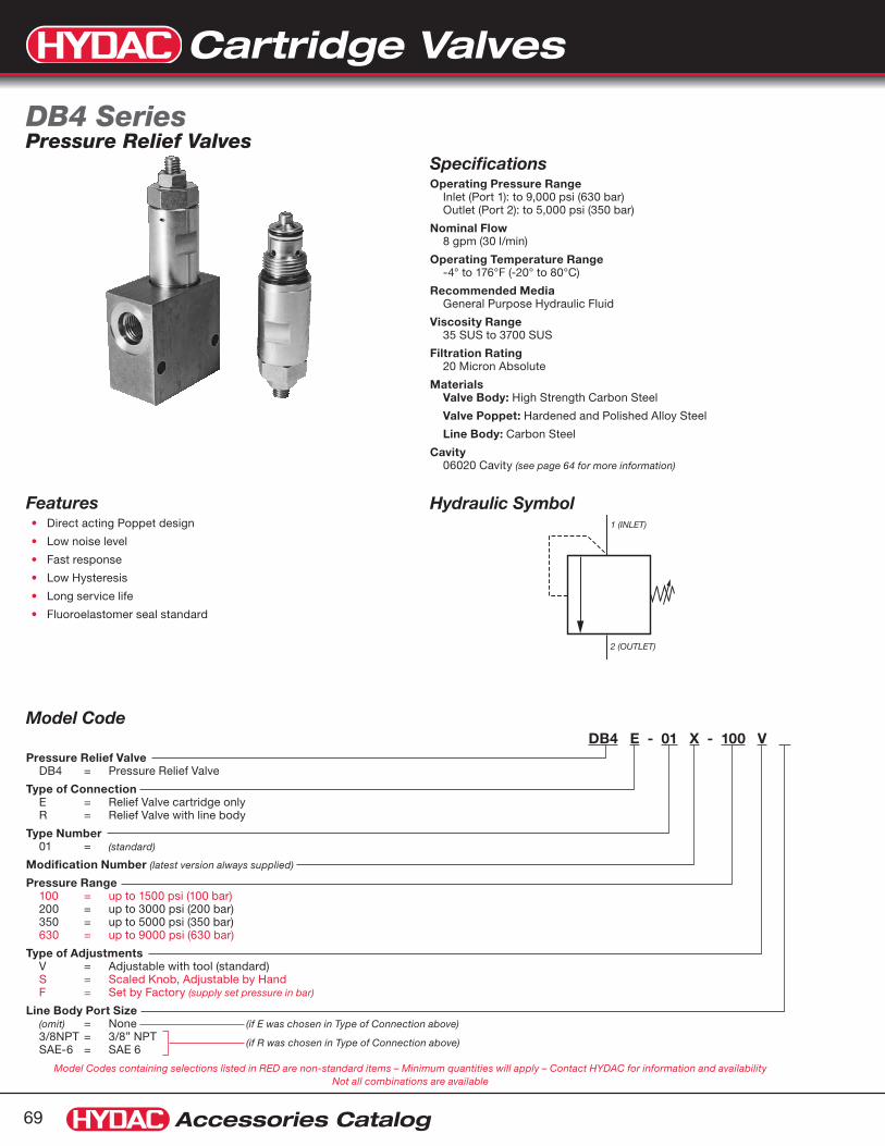
Cartridge Valves
Accessories Catalog69
Model CodeDB4 E - 01 X - 100 V .
Pressure Relief Valve DB4 = Pressure Relief Valve
Type of Connection E = Relief Valve cartridge only R = Relief Valve with line body
Type Number 01 = (standard)
Modification Number (latest version always supplied)
Pressure Range 100 = up to 1500 psi (100 bar) 200 = up to 3000 psi (200 bar) 350 = up to 5000 psi (350 bar) 630 = up to 9000 psi (630 bar)
Type of Adjustments V = Adjustable with tool (standard) S = Scaled Knob, Adjustable by Hand F = Set by Factory (supply set pressure in bar)
Line Body Port Size (omit) = None (if E was chosen in Type of Connection above) 3/8NPT = 3/8” NPT SAE-6 = SAE 6
(if R was chosen in Type of Connection above)
Model Codes containing selections listed in RED are non-standard items – Minimum quantities will apply – Contact HYDAC for information and availability Not all combinations are available
Specifications
Operating Pressure Range Inlet (Port 1): to 9,000 psi (630 bar) Outlet (Port 2): to 5,000 psi (350 bar)
Nominal Flow 8 gpm (30 l/min)
Operating Temperature Range -4° to 176°F (-20° to 80°C)
Recommended Media General Purpose Hydraulic Fluid
Viscosity Range 35 SUS to 3700 SUS
Filtration Rating 20 Micron Absolute
Materials Valve Body: High Strength Carbon Steel
Valve Poppet: Hardened and Polished Alloy Steel
Line Body: Carbon Steel
Cavity 06020 Cavity (see page 64 for more information)
Hydraulic Symbol
DB4 SeriesPressure Relief Valves
Features
Direct acting Poppet design•
Low noise level•
Fast response•
Low Hysteresis•
Long service life•
Fluoroelastomer seal standard•
1 (INLET)
2 (OUTLET)

Cartridge Valves
Accessories Catalog 70
Block with 3/8” NPT Ports: 02056007
Block with SAE-6 Ports: 02580404Dimensions are for general information only, all critical dimensions should be verified by requesting a certified print.Dimensions are in inches/(mm)
0.94"(24 mm)
2.36"(60 mm)
0.12"(3 mm)
0.59"(15 mm)
M20 x 1.50.93"
(23.5 mm)
1.12"(28.5 mm)
ø
0.83"(21 mm)Width
between flatsTorque
18-22 ft-lbs25-30 Nm
2 (outlet)
1 (inlet)
ø
ø
0.51"(13 mm)
Hex
0.16"(4 mm)
Hex Socket
appl
icat
ion
00
300
600
900
1200
1500
1800
0
20
40
60
80
100
120
Inle
t P
ress
ure
(psi
)
Inle
t P
ress
ure
(bar
)
Q - Flow (gpm)
Q - Flow (l/min)
1 2 3 4 5 6 7 8
0 5 10 15 20 25 30
00
3500
3000
2500
2000
1500
1000
500
0
40
80
120
160
200
240
Inle
t P
ress
ure
(psi
)
Inle
t P
ress
ure
(bar
)
Q - Flow (gpm)
Q - Flow (l/min)
1 2 3 4 5 6 7 8
0 5 10 15 20 25 30
00
750
22501500
30003750450052506000
0
100
200
300
400
Inle
t P
ress
ure
(psi
)
Inle
t P
ress
ure
(bar
)
Q - Flow (gpm)
Q - Flow (l/min)
1 2 3 4 5 6 7 8
0 5 10 15 20 25 30
00
10500
9000
7500
6000
4500
3000
1500
0
100
200
300
400
500
600
700
Inle
t P
ress
ure
(psi
)
Inle
t P
ress
ure
(bar
)
Q - Flow (gpm)
Q - Flow (l/min)
1 2 3 4 5 6 7 8
0 5 10 15 20 25 30
1.575"(40 mm)
0.197"(5 mm)
1.26"(32 mm)
1.26"(32 mm)
0.594"(15.1 mm)
1.188(30.2 mm)
1.25"(31.8 mm)
2.00(51 mm)
1
1
2
2
0.594"(15.1 mm)
cavitycenterline
Port 3/8" NPTor SAE-6(2 Places)
0.59"(15 mm)
2 Mounting Holesø 0.25"
(6.35 mm)
Adjustment Curves for Nominal Flow RatesViscosity = 170 SUS @ 120˚F
DimensionsRelief Valve Valve Line Body, 06020 Cavity

Clamps
Accessories Catalog71
U-Bolt Clamps HRRBS Series (see page 95)
Line Sizes from 3/4” to 16” O.D.
U-Bolt with Cushion Clamps HUB Series (see pages 96) Line Sizes from 1/4” to 12” O.D.
Oval Clamps HROS Series (see page 97) Line Sizes from 1/4” to 1” O.D.
“P” Style Clamps HSPN Series (see page 98) Line Sizes from 1/4” to 3” O.D.
Quick Release Swivel Bolt Clamps HRGKSM Series (see pages 99 - 100) Line Sizes from 1.54” to 17.87” O.D.
DIN 3015 Clamps HRL, HRS, HRZ, HREL, & HRES Series (see pages 73 - 89) Line Sizes from 1/4” to 16” O.D.
Flat Cushion Clamps HOM Series (see page 90) Line Sizes from 1/4” to 2” O.D.
Cushion Clamps CUSH Series (see pages 91 - 92) Line Sizes from 1/4” to 3 1/2” O.D. Mount on standard 1 5/8” x 7/8” unistrut mounting rail
Buegu HRBGS Series (see pages 93 - 94) Line Sizes from 1/4” to 3/4” O.D.
OverviewStandard SolutionsHYDAC Manufactures a complete line of hose, tube, and pipe mounting components. For many years, these products have been successfully applied, worldwide. Our standard product offering includes:

Clamps
Accessories Catalog 72
Band Straps (see page 102) Length Ranges from 187 to 1511 mm
Custom Molded Hose Bundle
Cylinder / Tube Clamp
Series Strip Clamps HRRL & HRRLE Series (see page 101) Line Sizes from 6 to 25.4 mm O.D.
Series Strip Clamp &Custom Bracketry
Stacking Series Strip Run
Series Strip Clamp & Custom Mounting Plates
Custom SolutionsHYDAC is also a market leader in providing custom mounting solutions. Our engineers work with yours to develop unique solutions that save time and money by simplifying inventory and installation. From simple modifications of standard product to custom bracketry, we will provide you a successful solution for your application. For more information on custom solutions, please contact product management at 1-877-GO HYDAC.
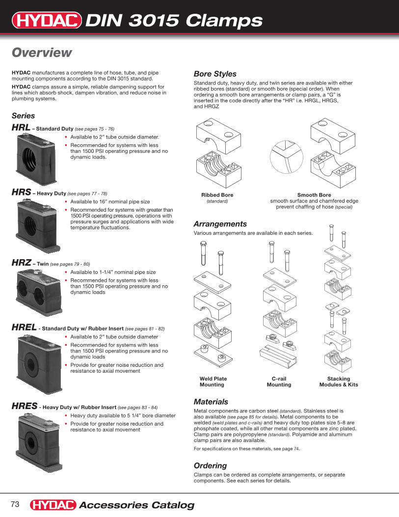
DIN 3015 Clamps
Accessories Catalog73
HYDAC manufactures a complete line of hose, tube, and pipe mounting components according to the DIN 3015 standard.
HYDAC clamps assure a simple, reliable dampening support for lines which absorb shock, dampen vibration, and reduce noise in plumbing systems.
Series
HRL – Standard Duty (see pages 75 - 76)
Available to 2” tube outside diameter.•
Recommended for systems with less •than 1500 PSI operating pressure and no dynamic loads.
HRS – Heavy Duty (see pages 77 - 78)
Available to 16” nominal pipe size•
Recommended for systems with greater than •1500 PSI operating pressure, operations with pressure surges and applications with wide temperature fluctuations.
HRZ – Twin (see pages 79 - 80)
Available to 1-1/4” nominal pipe size•
Recommended for systems with less •than 1500 PSI operating pressure and no dynamic loads
HREL - Standard Duty w/ Rubber Insert (see pages 81 - 82)
Available to 2” tube outside diameter•
Recommended for systems with less •than 1500 PSI operating pressure and no dynamic loads
Provide for greater noise reduction and •resistance to axial movement
HRES - Heavy Duty w/ Rubber Insert (see pages 83 - 84)
Heavy duty available to 5 1/4” bore diameter•
Provide for greater noise reduction and •resistance to axial movement
Overview
Bore StylesStandard duty, heavy duty, and twin series are available with either ribbed bores (standard) or smooth bore (special order). When ordering a smooth bore arrangements or clamp pairs, a “G” is inserted in the code directly after the “HR” i.e. HRGL, HRGS, and HRGZ
Ribbed Bore Smooth Bore (standard) smooth surface and chamfered edge prevent chaffing of hose (special)
ArrangementsVarious arrangements are available in each series.
Weld Plate C-rail Stacking Mounting Mounting Modules & Kits
MaterialsMetal components are carbon steel (standard). Stainless steel is also available (see page 85 for details). Metal components to be welded (weld plates and c-rails) and heavy duty top plates size 5-8 are phosphate coated, while all other metal components are zinc plated. Clamp pairs are polypropylene (standard). Polyamide and aluminum clamp pairs are also available.
For specifications on these materials, see page 74.
OrderingClamps can be ordered as complete arrangements, or separate components. See each series for details.

DIN 3015 Clamps
Accessories Catalog 74
Mounting Guidelines The first clamp should be mounted directly after the threaded •connection or coupling. This protects the connection from vibrations.
Bends in the line should be clamped on BOTH sides of the bend.•
The line should be clamped directly before and after any inline •valves.
Proper Torquing of the clamp bolts is important, and is part of •the DIN 3015 Standard
(see the chart below right for torque information)
Technical Specifications
Properties of Materials (clamp pairs)
Properties Polypropylene PP Polyamide PA Aluminum AL
Mechanical Properties Tensile Strength 4200 psi 7800-11500 psi –
Flexural Yield Strength 7600 psi 20500 psi –
Impact Strength (Izod Method)
No Failure No Failure –
Tensile Test – – 2800 psi
Brinell Hardness No. – – 60 BHN
Modules of Elasticity – – 9.7 x 10⁸ 11.1 x 10⁶ psi
Thermal Properties Continuous Service Temperature Range
-22° to 194°F -30° to 90°C
-40° to 284°F -40° to 140°C
-67° to 500°F -55° to 260°C
Electrical Properties Volume Resistivity 1018 Ohm-cm 1015 Ohm-cm –
Chemical Properties Chemical Resistance
Resistant to most aqueous solutions of inorganic salts, minerals, and organic acids, even at high temperatures.
Resistant to organic solvents, dilute acids, and bases. Resistant to radiation.
Resistant to neutral and sea water, organic acids, esters, oils, and inorganic salt solutions.
Distance Between Clamps
Pipe Size Distance (L) Tube Size Distance (L)
1/4” 4’ 1/16” 3’
1/2” 4’ 1/8” 3’
3/4” 5’ 1/4” 3’
1” 5’ 3/8” 3’
1 1/4” 7’ 1/2” 3’
1 1/2” 8’ 5/8” 4’
2” 10’ 3/4” 4’
2 1/2” 10’ 7/8” 4’
3” 12’ 1” 5’
4” 13’ 1 1/4” 7’
5” 13’ 1 1/2” 7’
6” 14’ 1 3/4” 7’
2” 7’
Bolt Tightening Torque Specifications
Series Size Thread PP PA AL
HRL (Std. Duty) 0 to 6 1/4-20 8 10 12
HRS (Heavy Duty)
1 & 2 3/8-16 12 20 30
3 3/8-16 15 25 35
4 7/16-14 30 40 55
5 5/8-11 45 55 120
6 3/4-10 80 150 220
7 7/8-9 110 200 250
8 M30 180 350 500
9 M30 200 370 500
10 M30 270 470 600
HRZ (Twin)
1 1/4-20 5 6 –
2 to 4 5/16-18 12 12 –
5 5/16-18 8 8 –
Note: Torque is given in Nm (Nm x 0.7376 = Ft-lbs)
L
L
L

DIN 3015 Clamps
Accessories Catalog75
A Single Clamp with
Weld Plate
A1 Single Clamp without
Weld Plate
A1TM Single Clamp for C-Rail Mounting
(order C-Rail separately)
D Single Clamp
Stacking Module (size 1 to 6 only)
A + D Order one A (red) arrangement and
one D (black) arrangement separately.
A maximum of 3 stacking modules is recommended
Parts Legend (see page 87 to order parts separately)
1 Hex Head Bolt 5 Clamp Pair 2 Top Plate 6 Stacking Bolt 3 Weld Plate 7 C-Rail Nut 4 Safety Plate
Model CodeHRL 2 A 12.7 PP UNC
Series HRL = Standard duty single clamp with ribbed bore HRGL = Standard duty single clamp with smooth bore
Size Family 0 to 8 (refer to table A on next page) (size 7 and 8 available in Metric only)
Arrangement A = Single clamp with top plate and weld plate A1 = Single clamp without weld plate A1TM = C-Rail mounted clamp D = Single clamp stacking module (size 1-6 only)
Bore Size (in mm) (refer to table A on next page)
Clamp Material PP = Polypropylene PA = Polyimide AL = Aluminum (not available for size 0) Metal Component Material (omit) = Carbon Steel A2 = 304 Stainless Steel A4 = 316 Stainless Steel (metric threads only)
Thread Type UNC = Standard M = Metric
HRL Series Standard Duty Clamps
Model Codes containing selections listed in RED italics are non-standard items – Minimum quantities will apply – Contact HYDAC for information and availability. Not all combinations are available.
1
2
5
4
6
5
3
D
7

DIN 3015 Clamps
Accessories Catalog 76
Note: Other bore diameters are available — Consult factory for details.Dimensions are for general information only, all critical dimensions should be verified by requesting a certified print. Dimensions are in inches/(mm) and lbs/(kg).
Table A
SizeøD Bore Size Recommended
Nominal Size A1 A2 A3 H1 H2 Bolt Size Arrangement
Weight
in mm Tube O.D. Pipe A B
0
0.24 6 – –
N/A 1.18 (30) 1.10 (28) 0.63 (16) 1.26 (32) 1/4-20 x 1-1/4 (M6 x 30) 0.14 (0.06) 0.12 (0.05)
0.25 6.4 1/4” –0.31 8.0 5/16” –0.37 9.5 3/8” –0.39 10.0 – 1/8”0.47 12.0 – –
1
0.24 6 – –
0.79 (20) 1.42 (36) 1.34 (34) 0.63) (16) 1.26 (32) 1/4-20 x 1-1/4 (M6 x 30) 0.18 (0.08) 0.13 (0.06)
0.25 6.4 1/4” –0.31 8.0 5/16” –0.37 9.5 3/8” –0.39 10.0 – 1/8”0.47 12.0 – –
2
0.50 12.7 1/2” –
1.02 (26) 1.65 (42) 1.57 (40) 0.77 (19.5) 1.53 (39) 1/4-20 x 1-1/2 (M6 x 35) 0.27 (0.12) 0.16 (0.07)
0.54 13.7 – 1/4”0.55 14.0 – –0.59 15.0 – –0.63 16.0 5/8” –0.67 17.1 – 3/8”0.71 18.0 – –
3
0.75 19.0 3/4” –
1.30 (33) 1.97 (50) 1.89 (48) 0.85 (21.5) 1.69 (43) 1/4-20 x 1-1/2 (M6 x 40) 0.31 (0.14) 0.22 (0.10)
0.79 20.0 – –0.84 21.3 – 1/2”0.87 22.0 – –0.91 23.0 – –0.98 25.0 – –1.00 25.4 1” –
41.05 26.6 – 3/4”
1.57 (40) 2.32 (59) 2.24 (57) 0.94 (24) 1.89 (48) 1/4-20 x 1-3/4 (M6 x 45) 0.33 (0.15) 0.27 (0.12)1.10 28.0 – –
1.18 30.0 – –
5
1.26 32.0 1-1/4” –
2.05 (52) 2.83 (72) 2.75 (70) 1.26 (32) 2.52 (64) 1/4-20 x 2-1/2 (M6 x 60) 0.42 (0.19) 0.31 (0.14)
1.33 33.7 – 1”1.38 35.0 – –1.50 38.0 1-1/2” –1.57 40.0 – –1.65 42.0 – 1-1/4”
61.75 44.5 1-3/4” –
2.60 (66) 3.46 (88) 3.38 (86) 1.42 (36) 2.83 (72) 1/4-20 x 2-3/4 (M6 x 70) 0.53 (0.24) 0.40 (0.18)1.90 48.3 – 1-1/2”
2.00 50.8 2” –
7
2.37 60.3 – 2
3.7 (94) 4.8 (122) 4.64 (118) 2.15 (54.5) 4.17 (106) (M6 x 100) – (–) – (–)2.5 63.5 2 1/2” –2.87 73 – 2 1/2”
3 76.1 3” –
8 3.5 88.9 – 3” 4.72 (120) 5.8 (148) 5.67 (143.96) 2.66 (67.6) 5.16 (131) (M6 x 125) – (–) – (–)
DimensionsSize 0 Sizes 1-6 C-Rail Nut C-Rail
A3
ø DH
1
.39(10) .37
(9.5)
A2
.12
(3)
.12
(3)
H2
1.18(30)
ø D
A3
A1
H1
1.18(30)
A2
.12
(3)
.12
(3)
H2
1.10(28)
.43(11)
.43
(11)
ø .39(ø 10)
.20
(5)
.59
(15)
Plastic Cap
.96(24.5)
39 (10)
1/4" -20 UNC
.08
(2)
1.10(28)
.43(11)
.43
(11)
ø .39(ø 10)
.20
(5)
.59
(15)
Plastic Cap
.96(24.5)
39 (10)
1/4" -20 UNC
.08
(2)

DIN 3015 Clamps
Accessories Catalog77
Model CodeHRS 1 S 12.7 PP __ UNC
Series HRS = Heavy duty single clamp with ribbed bore HRGS = Heavy duty single clamp with smooth bore
Size Family 1 to 10 (refer to table B on next page)
Arrangement S = Single clamp with top plate & weld plate S1 = Single clamp without weld plate S1TM = C-Rail mounted clamp (sizes 1-4 only) A = Single clamp stacking module (sizes 1-5 only)
Bore Size (in mm) (refer to table B on next page)
Clamp Material PP = Polypropylene PA = Polyimide AL = Aluminum
Metal Component Material (omit) = Carbon Steel A4 = 316 Stainless Steel (metric threads only)
Thread Type UNC = Standard M = Metric
SSingle Clamp
with Weld Plate
S1Single Clamp
without Weld Plate
S1TM Single Clamp for C-Rail Mounting
(size 1 to 4 only) (order C-Rail separately)
ASingle Clamp
Stacking Module(size 1 to 5 only)
S + AOrder one S (red)
arrangement and one A (black) arrangement
separately.
A maximum of 3 stacking modules is recommended
HRS Series Heavy Duty Clamps
Parts Legend (see page 88 to order parts separately)
1 Hex Head Bolt 5 Clamp Pair 2 Top Plate 6 Stacking Bolt 3 Weld Plate 7 C-Rail Nut 4 Safety Plate
Model Codes containing selections listed in RED italics are non-standard items – Minimum quantities will apply – Contact HYDAC for information and availability. Not all combinations are available.
1
2
5
4
6
5
3
A

DIN 3015 Clamps
Accessories Catalog 78
Note: Other bore diameters are available — Consult factory for details.Dimensions are for general information only, all critical dimensions should be verified by requesting a certified print. Dimensions are in inches/(mm) and lbs/(kg).
Table B
SizeøD Bore Size Recommended Nominal Size
A1 A2 A3 B1 H1 H2 S Bolt Sizein mm Tube O.D. Pipe
1
0.240.250.320.370.390.410.500.540.550.590.630.670.71
6.06.48.09.510.010.312.713.714.015.016.017.118.0
–1/4”
5/16”3/8”
––
1/2”–––
5/8”––
–––––
1/8”–
1/4”–––
3/8”–
1.30 (33)
2.87 (73)
2.17 (55)
1.18 (48)
0.94 (24)
1.89 (48)
0.31 (8)
3/8-16 x 1-3/4 (M10 x 45)
2
0.750.790.840.870.981.001.051.101.18
19.020.021.322.025.025.426.728.030.0
3/4”––
7/8”–1”–––
––
1/2”–––
3/4”––
1.77 (45)
3.35 (85)
2.76 (70)
1.18 (30)
1.26 (32)
2.52 (64)
0.31 (8)
3/8-16x2-1/4(M10 x 60)
3
0.981.181.261.331.381.501.571.65
25.030.032.033.735.038.040.042.0
––
1-1/4”––
1-1/2”––
–––1”–––
1-1/4”
2.36 (60)
3.94 (100)
3.35 (85)
1.18 (30)
1.50 (38)
2.99 (76)
0.31 (8)
3/8-16 x 2-3/4(M10 x 70)
4
1.181.501.651.751.902.002.132.242.372.502.562.75
30.038.042.044.548.350.854.057.060.363.565.070.0
–1-1/2”
–1-3/4”
–2”–
2-1/4”–
2-1/2”–
2-3/4”
––
1-1/4”–
1-1/2”–––2”–––
3.56 (90.5)
5.51 (140)
4.52 (115)
1.77 (45)
2.17 (55)
4.33 (110)
0.39 (10)
7/16-14 x 4(M12 x 100)
5
1.502.602.762.873.003.50
38.066.070.073.076.188.9
1-1/2”–––3”–
–––
2-1/2”–3”
4.80 (122)
7.09 (180)
5.98 (152)
2.36 (60)
2.76 (70)
5.51 (140)
0.39 (10)
5/8-11 x 5-1/2(M16 x 130)
6
2.563.784.004.254.50
65.096.0101.6108.0114.3
––4”
4-1/4”4-1/2”
––
3-1/2”–4”
6.61 (168)
8.86 (225)
8.07 (205)
3.15 (80)
3.94 (100)
7.87 (200)
0.59 (15)
3/4-10x7-1/2(M20 x 190)
7
3.545.355.506.61
90.0136.0139.7168.0
––––
––5”6”
8.07 (205)
10.63 (270)
9.92 (252) 3.54 (90) 4.53
(115)9.06 (230)
0.59 (15)
7/8-9x8-1/2(M20 x 220)
8 7.638.62
193.7219.1
7-5/8”–
7”8”
10.43 (265)
13.39 (340)
12.60 (320)
4.72 (120)
6.30 (160)
12.60 (320)
0.98 (25) M30 x 300
9 10.7512.75
273.0323.9
––
10”12”
15.55 (395)
20.47 (520)
18.35 (466)
6.30 (160)
9.25 (235)
18.50 (470)
1.18 (30) M30 x 450
10 14.0016.00
355.6406.4
––
14”16”
21.06 (535)
26.77 (680)
24.80 (630)
7.09 (180)
11.61 (295)
23.23 (590)
1.18 (30) M30 x 560
DimensionsAll Sizes C-Rail Nut (sizes 1-3) C-Rail Nut (size 4) C-Rail (all sizes)
A3
A1
A2
SS
H2
B1
H1
ø D
7/16" -14 UNC
ø .98(ø 25)
ø .79(ø 20)
.24
(6)
.33
(8.5
)
.91
(23)
.45
(11.5)
.50(12.7)
.20
(5)
.87
(22)
1.57(40)
3/8" -16 UNC
ø .98(ø 25)
ø .71(ø 18)
.24
(6)
.28
(7)
.79
(20)
.45(11.5)

DIN 3015 Clamps
Accessories Catalog79
Model CodeHRZ 1 A 9.5 - 9.5 PP UNC
Series HRZ = Standard duty twin clamp with ribbed bore HRGZ = Standard duty twin clamp with smooth bore
Size Family 0 to 5 (refer to table C on next page)
Arrangement A = Twin clamp with weld plate A1 = Twin clamp without weld plate A1TM = C-Rail mounted twin clamp D = Twin clamp stacking module
Bore Size (in mm) (refer to table C on next page)
Clamp Material PP = Polypropylene PA = Polyimide
Thread Type UNC = Standard M = Metric
ATwin Clamp
with Weld Plate
A1Twin Clamp
without Weld Plate
A1TM Twin Clamp for
C-Rail Mounting(order C-Rail separately)
DTwin Clamp
Stacking Module
A + DOrder one A (red) arrangement and
one D (black) arrangement separately.
A maximum of 3 stacking modules is recommended
HRZ SeriesTwin Clamps
Parts Legend (see page 89 to order parts separately)
1 Hex Head Bolt 5 Clamp Pair 2 Top Plate 6 Stacking Bolt 3 Weld Plate 7 C-Rail Nut 4 Safety Plate
Model Codes containing selections listed in RED italics are non-standard items – Minimum quantities will apply – Contact HYDAC for information and availability. Not all combinations are available.
1
2
5
4
6
5
3
D

DIN 3015 Clamps
Accessories Catalog 80
Note: Other bore diameters are available — Consult factory for details.Dimensions are for general information only, all critical dimensions should be verified by requesting a certified print. Dimensions are in inches/(mm) and lbs/(kg).
Table C
SizeØd Bore Size Recommended
Nominal Size A1 A2 A3 H1 H2 H3 Bolt Sizein mm Tube O.D. Pipe
1
0.24 6.0 – –
0.79 (20)
1.46 (37)
1.42 (36)
0.73 (18.5)
1.06 (27)
1.69 (43)
1/4-20 x 1-1/2 (M6 x 35)
0.25 6.4 1/4” –
0.32 8.0 5/16” –
0.37 9.5 3/8” –
0.39 10.0 – 1/8”
0.41 10.3 – 1/8”
0.47 12.0 – –
2
0.50 12.7 1/2” –
1.14 (29)
2.17 (55)
2.09 (53)
0.71 (18)
1.02 (26)
1.71 (43.5)
5/16-18 x 1-1/4 (M8 x 35)
0.54 13.7 – 1/4”
0.55 14.0 – –
0.59 15.0 – –
0.63 16.0 5/8” –
0.67 17.1 – 3/8”
3
0.75 19.0 3/4” –
1.42 (36)
2.76 (70)
2.64 (67)
0.93 (23.5)
1.46 (37)
2.15 (54.5)
5/16-18 x 1-3/4 (M8 x 45)
0.79 20.0 – –
0.84 21.3 – 1/2”
0.87 22.0 7/8” –
0.91 23.0 – –
0.98 25.0 – –
1.00 25.4 1” –
4
1.05 26.7 – 3/4”1.77 (45)
3.35 (85)
3.23 (82)
1.02 (26)
1.65 (42)
2.34 (59.5)
5/16-18 x 2 (M8 x 50)1.10 28.0 – –
1.18 30.0 – –
5
1.26 32.0 1-1/4” –
2.20 (56)
4.33 (110)
4.17 (106)
1.26 (32)
2.13 (54)
2.81 (71.5)
5/16-18 x 2-1/2 (M8 x 60)
1.33 33.7 – 1”
1.38 35.0 – –
1.50 38.0 1-1/2” –
1.65 40.0 – –
1.65 42.0 – 1-1/4”
DimensionsAll Sizes C-Rail Nut C-Rail
A3
A1
A2
H2H
3
H1
.20
(5)
1.18(30)
ø dø Dø dø D
1.10(28)
.43(11)
.43
(11)
ø .39(ø 10)
.20
(5)
.59
(15)
Plastic Cap
.96(24.5)
39 (10)
1/4" -20 UNC
.08
(2)
1.10(28)
.43(11)
.43
(11)
ø .39(ø 10)
.20
(5)
.59
(15)
Plastic Cap
.96(24.5)
39 (10)
1/4" -20 UNC
.08
(2)
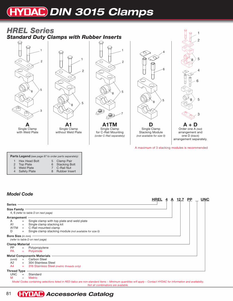
DIN 3015 Clamps
Accessories Catalog81
A Single Clamp
with Weld Plate
A1 Single Clamp
without Weld Plate
A1TM Single Clamp
for C-Rail Mounting (order C-Rail separately)
D Single Clamp
Stacking Module (not available for size 0)
A + D Order one A (red) arrangement and
one D (black) arrangement separately.
A maximum of 3 stacking modules is recommended
Model CodeHREL 4 A 12.7 PP UNC
Series
Size Family 4, 6 (refer to table D on next page)
Arrangement A = Single clamp with top plate and weld plate A1 = Single clamp stacking kit A1TM = C-Rail mounted clamp D = Single clamp stacking module (not available for size 0)
Bore Size (in mm) (refer to table D on next page)
Clamp Material PP = Polypropylene PA = Polyimide
Metal Components Materials (omit) = Carbon Steel A2 = 304 Stainless Steel A4 = 316 Stainless Steel (metric threads only)
Thread Type UNC = Standard M = Metric
HREL Series Standard Duty Clamps with Rubber Inserts
Parts Legend (see page 87 to order parts separately)
1 Hex Head Bolt 5 Clamp Pair 2 Top Plate 6 Stacking Bolt 3 Weld Plate 7 C-Rail Nut 4 Safety Plate 8 Rubber Insert
Model Codes containing selections listed in RED italics are non-standard items – Minimum quantities will apply – Contact HYDAC for information and availability. Not all combinations are available.
1
2
5
4
6
5
3
8
8
8
8
7
8
8

DIN 3015 Clamps
Accessories Catalog 82
KP EE KP EE
HREL 4 KP PPSeries
Size 4, 6 (refer to table above)
Clamp Pair
Clamp Material PP = Polypropylene PA = Polyimide
HRES 2/4 L EE 12Series*
Size 2/4 L, 3/6 L (refer to table above)
Rubber Insert
Bore Size (in mm) (refer to table above)
Parts KP = Clamp Pair
Model Codes containing selections listed in RED italics are non-standard items – Minimum quantities will apply – Contact HYDAC for information and availability.
Note: All other components for these clamps are the same as for HRL series standard duty single clamps. Refer to page 87 for details. * HREL series use the same rubber inserts as the HRES series, therefore the model code for them is HRES.
Note: Other bore diameters are available — Consult factory for details.Dimensions are for general information only, all critical dimensions should be verified by requesting a certified print. Dimensions are in inches/(mm) and lbs/(kg).
Table D
Clamp Size
EE-Rubber Insert Recommended Nominal Size
øD1 øD2 H1 H2 A1 A2 A3 S Bolt SizeSize Bore Size øD Tube O.D.
Pipe Hose O.D.
in mm Min (in) Max (in)
4 2/4 L
0.24 6 – – 0.22 0.24
1.00 (25.5)
1.22 (31)
0.925 (23.5)
1.85 (47)
1.57 (40)
2.32 (59)
2.24 (57)
0.118 (3)
1/4-20 x 1 3/4 (M6 x 45)
0.32 8 5/16” – 0.30 0.32
0.39 10 – 1/8” 0.37 0.39
0.47 12 – – 0.45 0.47
0.50 12.7 1/2” – 0.48 0.50
0.55 14 – – 0.53 0.55
0.59 15 – – 0.57 0.59
0.63 16 5/8” – 0.61 0.63
0.68 17.2 – 3/8” 0.66 0.68
0.75 19 3/4” – 0.73 0.75
6 3/6 L
0.79 20 – 1/2” 0.77 0.79
1.54 (39)
1.81 (46)
1.40 (35.5)
2.80 (71)
2.60 (66)
3.46 (88)
3.39 (86)
0.118 (3)
1/4-20x2 3/4(M6 x 70)
0.87 22 7/8” – 0.85 0.87
0.98 25 1” – 0.96 0.98
1.06 26.9 – 3/4” 1.04 1.06
1.10 28 – – 1.08 1.10
1.18 30 – – 1.16 1.18
1.26 32 1 1/4” – 1.24 1.26
DimensionsAll Sizes C-Rail Nut C-Rail
A1
øD1
S
1.18(30)
øD
A2
H1
A3
H2
S
øD2
1.10(28)
.43(11)
.43
(11)
ø .39(ø 10)
.20
(5)
.59
(15)
Plastic Cap
.96(24.5)
39 (10)
1/4" -20 UNC
.08
(2)
1.10(28)
.43(11)
.43
(11)
ø .39(ø 10)
.20
(5)
.59
(15)
Plastic Cap
.96(24.5)
39 (10)
1/4" -20 UNC
.08
(2)
EE = Rubber Insert (Santoprene TPE 73)

DIN 3015 Clamps
Accessories Catalog83
Model CodeHRES 4 S 35 PP UNC
Series
Size Family 2 to 7 (refer to table E on next page)
Arrangement S = Single clamp with weld plate S1 = Single clamp stacking kit S1TM = C-Rail mounted clamp A = Single clamp stacking module
Bore Size (in mm) (refer to table E on next page)
Clamp Material PP = Polypropylene PA = Polyimide
Metal Component Material (omit) = Carbon Steel A4 = 316 Stainless Steel (metric threads only)
Thread Type UNC = Standard M = Metric
HRES SeriesHeavy Duty Clamps with Rubber Inserts
SSingle Clamp
with Weld Plate
S1Single Clamp
without Weld Plate
S1TM Single Clamp for C-Rail Mounting
(size 1 to 4 only) (order C-Rail separately)
ASingle Clamp
Stacking Module(size 1 to 5 only)
S + AOrder one S (red)
arrangement and one A (black) arrangement
separately.
A maximum of 3 stacking modules is recommended
Parts Legend (see page 88 to order parts separately)
1 Hex Head Bolt 5 Clamp Pair 2 Top Plate 6 Stacking Bolt 3 Weld Plate 7 C-Rail Nut 4 Safety Plate 8 Rubber Insert
Model Codes containing selections listed in RED italics are non-standard items – Minimum quantities will apply – Contact HYDAC for information and availability. Not all combinations are available.
1
2
5
4
5
3
8
8
6
8
88
7
8

DIN 3015 Clamps
Accessories Catalog 84
Note: Other bore diameters are available — Consult factory for details.Dimensions are for general information only, all critical dimensions should be verified by requesting a certified print. Dimensions are in inches/(mm) and lbs/(kg).
KP EE KP EE
HRES 3 KP PPSeries
Size 2 to 7 (refer to table above)
Clamp Pair
Clamp Material PP = Polypropylene PA = Polyimide
HRES 3/6 L EE 26.9Series
Size 2/4 L to 7 (refer to table above)
Rubber Insert
Bore Size (in mm) (refer to table above)
Model Code KP = Clamp Pair
Model Codes containing selections listed in RED italics are non-standard items – Minimum quantities will apply – Contact HYDAC for information and availability. Not all combinations are available.
Note: All other components for these clamps are the same as for HRS series heavy duty single clamps. Refer to page 88 for details. * HREL series use the same rubber inserts as the HRES series, therefore the model code for them is HRES.
EE = Rubber Insert (Santoprene TPE 73)
Table E
Clamp Size
EE-Rubber Insert Recommended Nominal Size
øD1 øD2 B H1 H2 A1 A2 A3 S Bolt SizeSize Bore Size øD Tube O.D.
Pipe Hose O.D.
in mm Min (in) Max (in)
2 2/4 L
0.240.320.390.470.500.550.590.630.680.75
681012
12.7141516
17.219
–5/16”
––
1/2”––
5/8”–
3/4”
––
1/8”–––––
3/8”–
0.220.300.370.450.480.530.570.610.660.73
0.240.320.390.470.500.550.590.630.680.75
1.00 (25.5)
1.22 (31)
1.18 (30)
0.925 (23.5)
1.85 (47)
1.57 (40)
2.32 (59)
2.24 (57)
0.118 (3)
1/4-20 x 1 3/4 (M6 x 45)
3 3/6 L
0.790.870.981.061.101.181.26
202225
26.9283032
–7/8”1”–––
1 1/4”
1/2”––
3/4”–––
0.770.850.961.041.081.161.24
0.790.870.981.061.101.181.26
1.54 (39)
1.81 (46)
1.18 (30)
1.40 (35.5)
2.80 (71)
2.60 (66)
3.46 (88)
3.39 (86)
0.118 (3)
1/4-20x2 3/4(M6 x 70)
4 4
1.331.381.501.581.651.791.892.012.102.22
33.735384042
45.54851
53.456.4
--
1 1/2”----
2”--
1”-----
1 1/2”---
1.311.361.481.561.631.771.871.992.082.20
1.331.381.501.581.651.791.892.012.102.22
2.56(65)
2.91(74)
1.77(45)
2.11(53.5)
4.21(107)
3.56(90.5)
5.51(140)
4.53(115)
0.39(10)
7/16-14x4(M12 x 100)
5 5
2.362.562.762.872.99
6065707376
----
3”
2”--
2 1/2”-
2.342.542.742.852.97
2.362.562.762.872.99
3.50(89)
3.86(98)
2.36(60)
2.70(68.5)
5.39(137)
4.80(122)
7.09(180)
5.98(152)
0.39(10)
5/8-11x5 1/2(M16 x 130)
6 6
3.273.503.703.98
838994101
-3 1/2”
-4”
-3”-
3 1/2”
3.193.433.623.90
3.273.503.703.98
4.57(116)
5.20(132)
3.15(80)
3.88(98.5)
7.76(197)
6.61(168)
8.86(225)
8.07(205)
0.59(15)
3/4-10x7 1/2(M20 x 190)
7 74.264.495.24
108114133
---
-4”-
4.174.415.16
4.264.495.24
6.06(154)
6.61(168)
3.54(90)
4.47(113.5)
8.94(227)
8.07(205)
10.63(270)
9.92(252)
0.59(15)
7/8-9x8 1/2(M20 x 220)
DimensionsAll Sizes C-Rail Nut (sizes 1-3) C-Rail Nut (size 4) C-Rail (all sizes)
7/16" -14 UNC
ø .98(ø 25)
ø .79(ø 20)
.24
(6)
.33
(8.5
)
.91
(23)
.45
(11.5)
.50(12.7)
.20
(5)
.87
(22)
1.57(40)
3/8" -16 UNC
ø .98(ø 25)
ø .71(ø 18)
.24
(6)
.28
(7)
.79
(20)
.45(11.5)
A1
øD1
S
B
øD
A2
H1
A3
H2
S
øD2

DIN 3015 Clamps
Accessories Catalog85
HRL – Standard Duty
HRS – Heavy Duty
DescriptionClamps with stainless steel metal components are available for corrosive environments. Our complete line of DIN 3015 clamps are available in stainless steel. Some models are special order, which may require minimum quantities, and/or extended delivery times. Listed here are the standard duty and heavy duty single clamps with weld plate.
304 Stainless Steel: (A2)
Available from stock •
UNC bolts•
316 Stainless Steel: (A4)
Salt water resistance•
Only metric bolts available•
HRL & HRS Serieswith Stainless Steel Metal Components
Weld Plate(AP)
C-Rail Nuts(TM)
C-Rail(TS)
Clamp Pair(KP)
Top Plate(DP)
Hex Head Bolts(SCREW H)
Typical ArrangementSingle Clamp with Weld Plate (HRL...A...) for Standard Duty (HRS...S...) for Heavy Duty
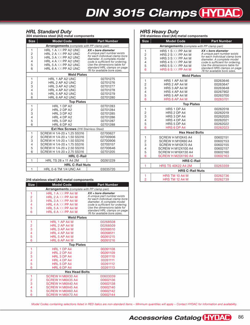
DIN 3015 Clamps
Accessories Catalog 86
HRS Heavy Duty316 stainless steel (A4) metal components
Size Model Code Part Number
Arrangements (complete with PP clamp pair)
123456
HRS 1 S XX PP A4 MHRS 2 S XX PP A4 MHRS 3 S XX PP A4 MHRS 4 S XX PP A4 MHRS 5 S XX PP A4 MHRS 6 S XX PP A4 M
XX = bore diameter A unique part number exists for each individual clamp bore diameter. A complete model code is sufficient for ordering. Use the dimensions table for standard HRS clamps on page 78 for available bore sizes.
Weld Plates
123456
HRS 1 AP A4 MHRS 2 AP A4 MHRS 3 AP A4 MHRS 4 AP A4 MHRS 5 AP A4 MHRS 6 AP A4 M
002636460026364700263648002679020026370000263701
Top Plates
123456
HRS 1 DP A4 HRS 2 DP A4 HRS 3 DP A4 HRS 4 DP A4 HRS 5 DP A4HRS 6 DP A4
002620180026201900262020002620210026202200262023
Hex Head Bolts
123456
SCREW H M10X45 A4SCREW H M10X60 A4SCREW H M10X70 A4SCREW H M12X100 A4SCREW H M16X130 A4SCREW H M20X190 A4
006021510060215300602155006021570060216000602163
HRS C-Rail
1 HRS TS 40X22 A4 2M 00263359
HRS C-Rail Nuts
12
HRS TM 10 A4 MHRS TM 12 A4 M
0026273600262739
HRL Standard Duty304 stainless steel (A2) metal components
Size Model Code Part NumberArrangements (complete with PP clamp pair)
123456
HRL 1 A XX PP A2 UNCHRL 2 A XX PP A2 UNCHRL 3 A XX PP A2 UNCHRL 4 A XX PP A2 UNCHRL 5 A XX PP A2 UNCHRL 6 A XX PP A2 UNC
XX = bore diameter A unique part number exists for each individual clamp bore diameter. A complete model code is sufficient for ordering. Use the dimensions table for standard HRL clamps on page 76 for available bore sizes.
Weld Plates123456
HRL 1 AP A2 UNCHRL 2 AP A2 UNCHRL 3 AP A2 UNCHRL 4 AP A2 UNCHRL 5 AP A2 UNCHRL 6 AP A2 UNC
027012750270127602701277027012780270127902701280
Top Plates123456
HRL 1 DP A2HRL 2 DP A2HRL 3 DP A2HRL 4 DP A2HRL 5 DP A2HRL 6 DP A2
027012830270128402701285027012860270128702701288
Ext Hex Screws (316 Stainless Steel)
123456
SCREW H 1/4-20 x 1.25 SS316SCREW H 1/4-20 x 1.50 SS316SCREW H 1/4-20 x 1.50 SS316SCREW H 1/4-20 x 1.75 SS316SCREW H 1/4-20 x 2.50 SS316SCREW H 1/4-20 x 2.75 SS316
027006270270090602700906027001570270064602701205
HRL C-Rail1 HRL TS 28 x 11 A4 2M 00261229
HRL C-Rail Nuts1 HRL 0-6 TM 1/4 UNC A4 03035720
316 stainless steel (A4) metal components
Size Model Code Part NumberArrangements (complete with PP clamp pair)
123456
HRL 1 A XX PP A4 MHRL 2 A XX PP A4 MHRL 3 A XX PP A4 MHRL 4 A XX PP A4 MHRL 5 A XX PP A4 MHRL 6 A XX PP A4 M
XX = bore diameter A unique part number exists for each individual clamp bore diameter. A complete model code is sufficient for ordering. Use the dimensions table for standard HRL clamps on page 76 for available bore sizes.
Weld Plates123456
HRL 1 AP A4 MHRL 2 AP A4 MHRL 3 AP A4 MHRL 4 AP A4 MHRL 5 AP A4 MHRL 6 AP A4 M
002685080026850900268510002685110026121500261216
Top Plates123456
HRL 1 DP A4HRL 2 DP A4HRL 3 DP A4HRL 4 DP A4HRL 5 DP A4HRL 6 DP A4
002611080026110900261110002611110026111200261113
Hex Head Bolts123456
SCREW H M6X30 A4SCREW H M6X35 A4SCREW H M6X40 A4SCREW H M6X45 A4SCREW H M6X60 A4SCREW H M6X70 A4
006030390060213600602138006021400060214200602144
Model Codes containing selections listed in RED italics are non-standard items – Minimum quantities will apply – Contact HYDAC for information and availability.

DIN 3015 Clamps
Accessories Catalog87
HRL 1 KP 10 PPSeries
Size 0 to 6 (refer to table A, page 76)
Clamp Pair
Bore Size (in mm) (refer to table A, page 76)
Clamp Material PP = Polypropylene PA = Polyimide AL = Aluminum
HRES 2/4 L EE 12Series
Size 2/4 L, 3/6 L (refer to table page 82)
Rubber Insert
Bore Size (in mm) (refer to table page 82)
1
UNC Threads
Metric Hex Head BoltsSize Model Code
0 SCREW H M6 X 30 - 8.8
1 SCREW H M6 X 30 - 8.8
2 SCREW H M6 X 35 - 8.8
3 SCREW H M6 X 40 - 8.8
4 SCREW H M6 X 45 - 8.8
5 SCREW H M6 X 60 - 8.8
6 SCREW H M6 X 70 - 8.8
6AF = Stacking BoltSize Model Code
1 HRL 1 AF ST UNC
2 HRL 2 AF ST UNC
3 HRL 3 AF ST UNC
4 HRL 4 AF ST UNC
5 HRL 5 AF ST UNC
6 HRL 6 AF ST UNC
7 TM = C-Rail NutSize Model Code
0 - 6 HRL 0-6 TM1/4 ST UNC KAP
0 - 6 HRL 0-6 TM ST ZN KAP
TS = C-RailSize Model code
39” HRL TS 28x11 ST BL 1M
78” HRL TS 28x11 ST BL 2M
1
UNC Threads
UNC Hex Head BoltsSize Model Code
0 SCREW H 1/4 - 20 x 1.25 GR2
1 SCREW H 1/4 - 20 x 1.25 GR2
2 SCREW H 1/4 - 20 x 1.50 GR2
3 SCREW H 1/4 - 20 x 1.50 GR2
4 SCREW H 1/4 - 20 x 1.75 GR2
5 SCREW H 1/4 - 20 x 2.50 GR2
6 SCREW H 1/4 - 20 x 2.75 GR2
2
DP = Top PlateSize Model Code
0 HRL 0 DP ST ZN
1 HRL 1 DP ST ZN
2 HRL 2 DP ST ZN
3 HRL 3 DP ST ZN
4 HRL 4 DP ST ZN
5 HRL 5 DP ST ZN
6 HRL 6 DP ST ZN
3
AP = Weld PlateSize Model Code
0 HRL 0 AP ST UNC BL
1 HRL 1 AP ST UNC BL
2 HRL 2 AP ST UNC BL
3 HRL 3 AP ST UNC BL
4 HRL 4 AP ST UNC BL
5 HRL 5 AP ST UNC BL
6 HRL 6 AP ST UNC BL
4 SIP = Safety PlateSize Model Code
0-6 HRL 0-6 SIP ST ZN
HRL SeriesPartsAll metal components are carbon steel. For stainless steel metal components please refer to page 85 - 86. ST = Carbon Steel, BL = Phosphate coated, ZN = Zinc Plated
Parts Legend
1 Hex Head Bolt 5 Clamp Pair2 Top Plate 6 Stacking Bolt3 Weld Plate 7 C-Rail Nut4 Safety Plate 8 Rubber Insert
Model Codes containing selections listed in RED italics are non-standard items – Minimum quantities will apply – Contact HYDAC for information and availability. Not all combinations are available.
Model Code KP = Clamp Pair EE = Rubber Insert (Santoprene TPE 73)
5 8
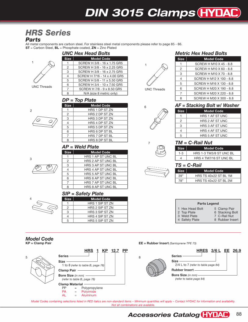
DIN 3015 Clamps
Accessories Catalog 88
1
UNC Threads
Metric Hex Head BoltsSize Model Code
1 SCREW H M10 X 45 - 8.8
2 SCREW H M10 X 60 - 8.8
3 SCREW H M10 X 70 - 8.8
4 SCREW H M12 X 100 - 8.8
5 SCREW H M16 X 130 - 8.8
6 SCREW H M20 X 190 - 8.8
7 SCREW H M20 X 220 - 8.8
8 SCREW H M30 X 300 - 8.8
6 AF = Stacking Bolt w/ WasherSize Model Code
1 HRS 1 AF ST UNC
2 HRS 2 AF ST UNC
3 HRS 3 AF ST UNC
4 HRS 4 AF ST UNC
5 HRS 5 AF ST UNC
7 TM = C-Rail NutSize Model Code
1-3 HRS 1-3 TM3/8 ST UNC BL
4 HRS 4 TM7/16 ST UNC BL
TS = C-RailSize Model Code
39” HRS TS 40x22 ST BL 1M
78” HRS TS 40x22 ST BL 2M
1
UNC Threads
UNC Hex Head BoltsSize Model Code
1 SCREW H 3/8 - 16 x 1.75 GR52 SCREW H 3/8 - 16 x 2.25 GR53 SCREW H 3/8 - 16 x 2.75 GR54 SCREW H 7/16 - 14 x 4.00 GR55 SCREW H 5/8 - 11 x 5.50 GR56 SCREW H 3/4 - 10 x 7.50 GR57 SCREW H 7/8 - 9 x 8.50 GR58 N/A (size 8 metric only)
2
DP = Top PlateSize Model Code
1 HRS 1 DP ST ZN2 HRS 2 DP ST ZN3 HRS 3 DP ST ZN4 HRS 4 DP ST ZN5 HRS 5 DP ST ZN6 HRS 6 DP ST BL7 HRS 7 DP ST BL8 HRS 8 DP ST BL
3
AP = Weld PlateSize Model Code
1 HRS 1 AP ST UNC BL2 HRS 2 AP ST UNC BL3 HRS 3 AP ST UNC BL4 HRS 4 AP ST UNC BL5 HRS 5 AP ST UNC BL6 HRS 6 AP ST UNC BL7 HRS 7 AP ST UNC BL8 HRS 8 AP ST UNC BL
4SIP = Safety Plate
Size Model Code1 HRS 1 SIP ST ZN2 HRS 2 SIP ST ZN3 HRS 3 SIP ST ZN4 HRS 4 SIP ST ZN5 HRS 5 SIP ST ZN
HRS SeriesPartsAll metal components are carbon steel. For stainless steel metal components please refer to page 85 - 86. ST = Carbon Steel, BL = Phosphate coated, ZN = Zinc Plated
HRS 1 KP 12.7 PPSeries
Size 1 to 8 (refer to table B, page 78)
Clamp Pair
Bore Size (in mm) (refer to table B, page 78)
Clamp Material PP = Polypropylene PA = Polyimide AL = Aluminum
HRES 3/6 L EE 26.9Series
Size 2/4 L to 7 (refer to table page 84)
Rubber Insert
Bore Size (in mm) (refer to table page 84)
Parts Legend
1 Hex Head Bolt 5 Clamp Pair2 Top Plate 6 Stacking Bolt3 Weld Plate 7 C-Rail Nut4 Safety Plate 8 Rubber Insert
Model Codes containing selections listed in RED italics are non-standard items – Minimum quantities will apply – Contact HYDAC for information and availability. Not all combinations are available.
Model Code KP = Clamp Pair EE = Rubber Insert (Santoprene TPE 73)
5 8

DIN 3015 Clamps
Accessories Catalog89
1
UNC Threads
Metric Hex Head BoltsSize Model Code
1 SCREW H M6x35 MM - 8.8 DIN 933
2 SCREW H M8x35 MM - 8.8 DIN 933
3 SCREW H M8x45 MM - 8.8 DIN 933
4 SCREW H M8x50 MM - 8.8 DIN 933
5 SCREW H M8x60 MM - 8.8 DIN 933
6 AF = Stacking Bolt w/ WasherSize Model Code
1 HRZ 1 AF ST UNC
2 HRZ 2 AF ST UNC
3 HRZ 3 AF ST UNC
4 HRZ 4 AF ST UNC
5 HRZ 5 AF ST UNC
7 TM = C-Rail NutSize Model Code
1 HRZ 1 TM1/4 ST UNC KAP
2-5 HRZ 2/5 TM5/16 ST UNC O-Ring
TS = C-RailSize Model Code
39” HRL TS 28x11 ST BL 1M
78” HRL TS 28x11 ST BL 2M
1
UNC Threads
UNC Hex Head BoltsSize Model Code
1 SCREW H 1/4 - 20 x 1.5 GR2
2 SCREW H 5/16 - 18 x 1.25 GR2
3 SCREW H 5/16 - 18 x 1.75 GR2
4 SCREW H 5/16 - 18 x 2.00 GR2
5 SCREW H 5/16 - 18 x 2.50 GR2
2
DP = Top PlateSize Model Code
1 HRZ 1 DP ST ZN
2 HRZ 2 DP ST ZN
3 HRZ 3 DP ST ZN
4 HRZ 4 DP ST ZN
5 HRZ 5 DP ST ZN
3
AP = Weld PlateSize Model Code
1 HRZ 1 AP ST UNC BL Anti-Turn
2 HRZ 2 AP ST UNC BL Anti-Turn
3 HRZ 3 AP ST UNC BL Anti-Turn
4 HRZ 4 AP ST UNC BL
5 HRZ 5 AP ST UNC BL
4 SIP = Safety PlateSize Model Code
1 HRZ 1 SIP ST ZN
2-5 HRZ 2/5 SIP ST ZN
HRZ SeriesParts
HRZ 1 KP 9.5-9.5 PPSeries
Size 0 to 5 (refer to table C, page 80)
Clamp Pair
Bore Size (in mm) (refer to table C, page 80)
Clamp Material PP = Polypropylene PA = Polyimide
Parts Legend
1 Hex Head Bolt 5 Clamp Pair2 Top Plate 6 Stacking Bolt3 Weld Plate 7 C-Rail Nut4 Safety Plate
Model Codes containing selections listed in RED italics are non-standard items – Minimum quantities will apply – Contact HYDAC for information and availability. Not all combinations are available.
Model Code KP = Clamp Pair
5

Standard Clamps
Accessories Catalog 90
Model Codes containing selections listed in RED italics are non-standard items – Minimum quantities will apply – Contact HYDAC for information and availability Not all combinations are available
Dimensions are for general information only, all critical dimensions should be verified by requesting a certified print. Dimensions are in inches/(mm) and lbs./(kg.)
A
E
C
B
D
F
Model CodePart
Number
Copper & Steel Tubing
O.D.
Copper Water Pipe
Pipe Size
A B C D E F
HOM 1/4T 020807471/4” – – 0.25” 0.48” 0.60” 0.22” 0.26” 0.78”
HOM 1/4T A2 02080768
HOM 3/8T 020807483/8” 1/4” – 0.37” 0.62” 0.66” 0.31” 0.26” 0.81”
HOM 3/8T A2 02080769
HOM 1/2T - 1/4P 020807491/2” 3/8” 1/4” 0.50” 0.81” 0.83” 0.40” 0.26” 0.98”
HOM 1/2T - 1/4P A2 02080770
HOM 5/8-3/8P 020807505/8” 1/2” 3/8” 0.62” 0.93” 0.85” 0.46” 0.26” 0.98”
HOM 5/8-3/8P A2 02080771
HOM 3/4T 020807513/4” 5/8” – 0.75” 1.02” 0.90” 0.50” 0.26” 0.98”
HOM 3/4T A2 02080772
HOM 7/8 - 1/2P 020807527/8” 3/4” 1/2” 0.87” 1.12” 1.03” 0.53” 0.26” 0.98”
HOM 7/8 - 1/2P A2 02080773
HOM 1T 020807531” – – 1.00” 1.24” 1.04” 0.59” 0.26” 0.98”
HOM 1T A2 02080774
HOM 3/4P 02080754– – 3/4” 1.05” 1.40” 1.11” 0.70” 0.26” 0.98”
HOM 3/4P A2 02080775
HOM 1 1/8T 020807551 1/8” 1” – 1.12” 1.40” 1.17” 0.70” 0.26” 0.98”
HOM 1 1/8T A2 02080776
HOM 1 1/4T 020807561 1/4” – – 1.25” 1.60” 1.20” 0.77” 0.26” 1.56”
HOM 1 1/4 A2 02080777
HOM 1P 02080757– – 1” 1.31” 1.71” 1.28” 0.81” 0.26” 1.56”
HOM 1P A2 02080778
HOM 1 3/8T 020807581 3/8” 1 1/4” – 1.37” 1.71” 1.28” 0.83” 0.26” 1.56”
HOM 1 3/8T A2 02080779
HOM 1 1/2T 020807591 1/2” – – 1.50” 1.85” 1.36” 0.90” 0.26” 1.56”
HOM 1 1/2T A2 02080780
HOM 1 5/8T 020807601 5/8” 1 1/2” – 1.62” 1.95” 1.43” 0.96” 0.26” 1.56”
HOM 1 5/8T A2 02080781
HOM 1 1/4P 02080761– – 1 1/4” 1.66” 2.12” 1.55” 0.99” 0.34” 1.56”
HOM 1 1/4P A2 02080782
HOM 1 3/4T 020807621 3/4” – – 1.75” 2.12” 1.55” 1.02” 0.34” 1.56”
HOM 1 3/4T A2 02080783
HOM 1 7/8T - 1 1/2P 020807631 7/8” – 1 1/2” 1.87” 2.25” 1.64” 1.09” 0.34” 1.56”
HOM 1 7/8T - 1 1/2P A2 02080784
HOM 2T 020807642” – – 2.00” 2.38” 1.69” 1.15” 0.34” 1.56”
HOM 2T A2 02080785
HOM 2 1/8T 020807652 1/8” – – 2.12” 2.62” 1.86” 1.27” 0.34” 1.56”
HOM 2 1/8T A2 02080786
HOM 2 3/8T - 2P 020807662 3/8” – 2” 2.37” 2.88” 1.94” 1.41” 0.34” 1.56”
HOM 2 3/8T - 2P A2 02080787
HOM 5 1/8T 02080767 5 1/8” 5” – 5.12” 5.82” 3.55” 2.84” 0.43” 1.56”
Description The interlock edge insures that the cushion remains in place. The HOM Series clamp assembly retains, guides, protects and uniformly spaces line runs. They go up fast, lines are rigid, and look neat.
Features Attached with two standard* fasteners to any flat surface, the HOM Series clamp eliminates the use of specials channels, providing a savings in both space and cost.
Low profile for limited space •applications.
Materials The Clamp Available in steel (with electro-dichromate finish), and 304 stainless steel (A2 in the model code denotes 304 stainless steel).
The Cushion Manufactured from a thermoplastic elastomer, it’s built tough to withstand the effects of most oils, chemical and industrial cleaning compounds, in temperatures from -50° to 275°F. *Note: Fasteners not provided.
HOM SeriesDimensions
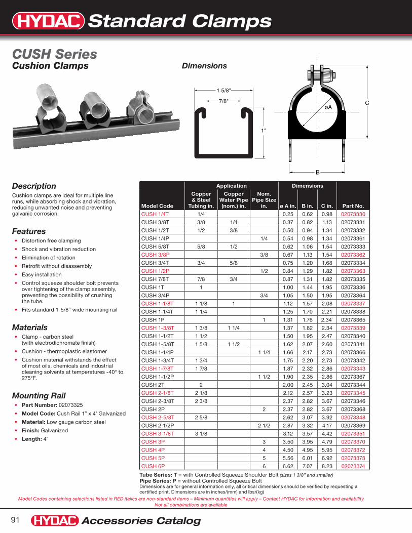
Standard Clamps
Accessories Catalog91
1 5/8"
7/8"
1"
øAC
B
Model Codes containing selections listed in RED italics are non-standard items – Minimum quantities will apply – Contact HYDAC for information and availability Not all combinations are available
Tube Series: T = with Controlled Squeeze Shoulder Bolt (sizes 1 3/8” and smaller)Pipe Series: P = without Controlled Squeeze BoltDimensions are for general information only, all critical dimensions should be verified by requesting a certified print. Dimensions are in inches/(mm) and lbs/(kg)
Model Code
Application Dimensions
Part No.
Copper & Steel
Tubing in.
Copper Water Pipe (nom.) in.
Nom. Pipe Size
in. ø A in. B in. C in.
CUSH 1/4T 1/4 0.25 0.62 0.98 02073330
CUSH 3/8T 3/8 1/4 0.37 0.82 1.13 02073331
CUSH 1/2T 1/2 3/8 0.50 0.94 1.34 02073332
CUSH 1/4P 1/4 0.54 0.98 1.34 02073361
CUSH 5/8T 5/8 1/2 0.62 1.06 1.54 02073333
CUSH 3/8P 3/8 0.67 1.13 1.54 02073362
CUSH 3/4T 3/4 5/8 0.75 1.20 1.68 02073334
CUSH 1/2P 1/2 0.84 1.29 1.82 02073363
CUSH 7/8T 7/8 3/4 0.87 1.31 1.82 02073335
CUSH 1T 1 1.00 1.44 1.95 02073336
CUSH 3/4P 3/4 1.05 1.50 1.95 02073364
CUSH 1-1/8T 1 1/8 1 1.12 1.57 2.08 02073337
CUSH 1-1/4T 1 1/4 1.25 1.70 2.21 02073338
CUSH 1P 1 1.31 1.76 2.34` 02073365
CUSH 1-3/8T 1 3/8 1 1/4 1.37 1.82 2.34 02073339
CUSH 1-1/2T 1 1/2 1.50 1.95 2.47 02073340
CUSH 1-5/8T 1 5/8 1 1/2 1.62 2.07 2.60 02073341
CUSH 1-1/4P 1 1/4 1.66 2.17 2.73 02073366
CUSH 1-3/4T 1 3/4 1.75 2.20 2.73 02073342
CUSH 1-7/8T 1 7/8 1.87 2.32 2.86 02073343
CUSH 1-1/2P 1 1/2 1.90 2.35 2.86 02073367
CUSH 2T 2 2.00 2.45 3.04 02073344
CUSH 2-1/8T 2 1/8 2.12 2.57 3.23 02073345
CUSH 2-3/8T 2 3/8 2.37 2.82 3.67 02073346
CUSH 2P 2 2.37 2.82 3.67 02073368
CUSH 2-5/8T 2 5/8 2.62 3.07 3.92 02073348
CUSH 2-1/2P 2 1/2 2.87 3.32 4.17 02073369
CUSH 3-1/8T 3 1/8 3.12 3.57 4.42 02073351
CUSH 3P 3 3.50 3.95 4.79 02073370
CUSH 4P 4 4.50 4.95 5.95 02073372
CUSH 5P 5 5.56 6.01 6.92 02073373
CUSH 6P 6 6.62 7.07 8.23 02073374
DescriptionCushion clamps are ideal for multiple line runs, while absorbing shock and vibration, reducing unwanted noise and preventing galvanic corrosion.
Features Distortion free clamping•
Shock and vibration reduction•
Elimination of rotation•
Retrofit without disassembly•
Easy installation•
Control squeeze shoulder bolt prevents •over tightening of the clamp assembly, preventing the possibility of crushing the tube.
Fits standard 1-5/8” wide mounting rail•
Materials Clamp - carbon steel •(with electrodichromate finish)
Cushion - thermoplastic elastomer•
Cushion material withstands the effect •of most oils, chemicals and industrial cleaning solvents at temperatures -40° to 275°F.
Mounting RailPart Number:• 02073325
Model Code:• Cush Rail 1” x 4’ Galvanized
Material:• Low gauge carbon steel
Finish:• Galvanized
Length:• 4’
DimensionsCUSH Series Cushion Clamps

Standard Clamps
Accessories Catalog 92
Model Codes containing selections listed in RED italics are non-standard items – Minimum quantities will apply – Contact HYDAC for information and availability Not all combinations are available
Dimensions are for general information only, all critical dimensions should be verified by requesting a certified print. Dimensions are in inches/(mm) and lbs./(kg.)
Model Code Part No. Size A B C
CUSH 1/4T A2 02080701 1/4” 0.25” 0.62” 0.98”
CUSH 3/8T A2 02080702 3/8” 0.37” 0.82” 1.13”
CUSH 1/2T A2 02080703 1/2” 0.50” 0.94” 1.34”
CUSH 5/8T A2 02080704 5/8” 0.62” 1.06” 1.54”
CUSH 3/4T A2 02080705 3/4” 0.75” 1.20” 1.68”
CUSH 7/8T A2 02080706 7/8” 0.87” 1.31” 1.82”
CUSH 1T A2 02080707 1” 1.00” 1.44” 1.95”
CUSH 1 1/8T A2 02080708 1 1/8” 1.12” 1.57” 2.08”
CUSH 1 1/4T A2 02080709 1 1/4” 1.25” 1.70” 2.21”
CUSH 1 3/8T A2 02080710 1 3/8” 1.37” 1.82” 2.34”
CUSH 1 1/2T A2 02080711 1 1/2” 1.50” 1.95” 2.47”
CUSH 1 5/8T A2 02080712 1 5/8” 1.62” 2.07” 2.60”
CUSH 1 3/4T A2 02080713 1 3/4” 1.75” 2.20” 2.73”
CUSH 1 7/8T A2 02080714 1 7/8” 1.87” 2.32” 2.86”
CUSH 2T A2 02080715 2” 2.00” 2.45” 3.04”
CUSH 2 1/8T A2 02080716 2 1/8” 2.12” 2.57” 3.23”
CUSH 2 1/4T A2 02080717 2 1/4” 2.37” 2.82” 3.67”
CUSH 2 3/8T A2 02080718 2 3/8” 2.37” 2.82” 3.67”
CUSH 2 1/2T A2 02080719 2 1/2” 2.50” 2.94” 3.79”
CUSH 2 5/8T A2 02080720 2 5/8” 2.62” 3.07” 3.92”
CUSH 2 7/8T A2 02080721 2 7/8” 2.87” 3.32” 4.17”
CUSH 3T A2 02080722 3” 3.00” 3.57” 4.42”
CUSH 3 1/8T A2 02080723 3 1/8” 3.12” 3.57” 4.42”
CUSH 3 5/16T A2 02080724 3 5/16” 3.31” 3.96” 4.75”
CUSH 3 1/2T A2 02080725 3 1/2” 3.50” 3.95” 4.79”
CUSH 3 5/8T A2 02080726 3 5/8” 3.62” 4.20” 5.11”
CUSH 4T A2 02080727 4” 4.00” 4.45” 5.11”
CUSH 4 1/8T A2 02080728 4 1/8” 4.12” 4.57” 5.54”
CUSH 4 1/2T A2 02080729 4 1/2” 4.50” 4.95” 5.92”
CUSH 5 1/8T A2 02080730 5 1/8” 5.12” 5.57” 6.54”
CUSH 6T A2 02080731 6” 6.12” 6.57” 7.54”
CUSH 6 1/8T A2 02080732 6 1/8” 6.12” 6.57” 7.54”
CUSH 1/4P A2 02080733 1/4” 0.54” 0.98” 1.34”
CUSH 3/8P A2 02080734 3/8” 0.67” 1.13” 1.54”
CUSH 1/2P A2 02080735 1/2” 0.84” 1.29” 1.82”
CUSH 3/4P A2 02080736 3/4” 1.05” 1.57” 2.08”
CUSH 1P A2 02080737 1” 1.31” 1.76” 2.34”
CUSH 1 1/4P A2 02080738 1 1/4” 1.66” 2.17” 2.73”
CUSH 1 1/2P A2 02080739 1 1/2” 1.90” 2.35” 2.86”
CUSH 2P A2 02080740 2” 2.37” 2.82” 3.67”
CUSH 2 1/2P A2 02080741 2 1/2” 2.87” 3.32” 4.17”
CUSH 3P A2 02080742 3” 3.50” 3.95” 4.79”
CUSH 3 1/2P A2 02080743 3 1/2” 4.00” 4.45” 5.11”
CUSH 4P A2 02080744 4” 4.50” 4.95” 5.92”
CUSH 5P A2 02080745 5” 5.56” 6.01” 6.92”
CUSH 6P A2 02080746 6” 6.62” 7.07” 8.23”
Dimensions
øAC
B
1 5/8"
7/8"
13/16"
Materials Clamp - Stainless steel 304•
Cushion - thermoplastic elastomer•
Mounting RailModel Code:• Cush Rail 13/16” x 10’ A2
Part Number:• 02701588
Material:• Stainless steel 304
Length:• 10’0”
Stainless Steel Cushion Clamp

Standard Clamps
Accessories Catalog93
Model Codes containing selections listed in RED italics are non-standard items – Minimum quantities will apply – Contact HYDAC for information and availability Not all combinations are available
Size: 0A & 0B
slotted
A2
A1
D1 H2
H1
0.120"3mm
0.354"9mm
0.120"3mm
Ø
Size: 1 and 2
slotted
A 2
A1
D2D1 H2
H1
0.120"3mm
0.120"3mm 0.780"
20mm
Ø Ø
1) Consult Factory for sizes 1 and 2 with different bore diametersDimensions are for general information only, all critical dimensions should be verified by requesting a certified print. Dimensions are in inches/(mm) and lbs/(kg.)
Clamp Size
Tube Size
Pipe Size
Bore Diameter1
Clamp Assembly Model Code Part No.
Dimensions Hex Head Bolt
øD1 øD2in mm in mm A1 A2 H1 H2
0A
1/4” - 0.250 6.4 - - HRBGS 0A A 6.4 STM 02063638 mm 15 34 10 23
M6 x 25
3/8” - 0.375 9.5 - - HRBGS 0A A 9.5 STM 02063639in 0.59 1.34 0.39 0.91
- 1/8” 0.394 10.0 - - HRBGS 0A A 10.0 STM 02063640
0B
1/2” - 0.500 12.7 - - HRBGS 0B A 12.7 STM 02063641mm 18 39 12 27
- 1/4” 0.540 13.7 - - HRBGS 0B A 13.7 STM 02063642
5/8” - 0.625 16.0 - - HRBGS 0B A 16.0 STM 02063643
in 0.71 1.54 0.47 1.06- 3/8” 0.675 17.1 - - HRBGS 0B A 17.1 STM 02063644
3/4” - 0.750 19.0 - - HRBGS 0B A 19.0 STM 02063645
1
1/4” - 0.250 6.4 0.250 6.4 HRBGS 1 A 6.4-6.4 STM 02063646mm 30 50 10 23
3/8” - 0.375 9.5 0.375 9.5 HRBGS 1 A 9.5-9.5 STM 02063647
-” 1/8” 0.394 10.0 0.394 10.0 HRBGS 1 A 10-10 STM 02063648in 1.18 1.97 0.39 0.91
1/2” - 0.500 12.7 0.500 12.7 HRBGS 1 A 12.7-12.7 STM 02063649
2
5/8” - 0.625 16.0 0.625 16.0 HRBGS 2 A 16-16 STM 02063650mm 35 59 12 27
- 3/8” 0.675 17.1 0.675 17.1 HRBGS 2 A 17.1-17.1 STM 02063651
3/4” - 0.750 19.0 0.750 19.0 HRBGS 2 A 19-19 STM 02063652 in 1.38 2.32 0.47 1.06
DescriptionBuegu clamps are ideal for mobile applications where space is limited. They absorb shock and vibration, and reduce noise.
Features Low Profile Design•
Shock and vibration reduction•
Easy installation•
MaterialsStirrup & Weld Plate - carbon steel •
Clamp Body - thermoplastic elastomer •(Santoprene TPE 73)
Temp Specifications-40° to 257°F (-40° to 125°C)•
DimensionsHRBGS Series Buegu Clamps

Standard Clamps
Accessories Catalog 94
Model Codes containing selections listed in RED italics are non-standard items – Minimum quantities will apply – Contact HYDAC for information and availability Not all combinations are available
Dimensions are for general information only, all critical dimensions should be verified by requesting a certified print. Dimensions are in inches/(mm) and lbs/(kg.)
AP = Weld Plate
HUE= Sleeve
Size 0GT = Rubber Body
Size 1,2
BUE = Stirrup
Hex Head Bolt
Hex Head Bolt for use with Weld Plate
Sizes Model Code Part Number
0A, 0B, 1, 2 SCREW H M6x25-8.8 DIN933 02700852
BUE = Stirrup
Sizes Model Code Part Number
0A HRBGS 0A BUE ST ZN 00263306
0B HRBGS 0B BUE ST ZN 00263307
1 HRBGS 1 BUE ST ZN 00263316
2 HRBGS 2 BUE ST ZN 00263309
Clamp Size
Bore Diameter1
øD1 øD2 GT = Clamp Body
in mm in mm Model Code Part No.
0A
0.250 6.4 - - HRBGS 0A GT 6.4 00268169
0.375 9.5 - - HRBGS 0A GT 9.5 00268170
0.394 10.0 - - HRBGS 0A GT 10.0 00263296
0B
0.500 12.7 - - HRBGS 0B GT 12.7 00268171
0.540 13.7 - - HRBGS 0B GT 13.7 00268172
0.625 16.0 - - HRBGS 0B GT 16.0 00263298
0.675 17.1 - - HRBGS 0B GT 17.1 00268173
0.750 19.0 - - HRBGS 0B GT 19.0 00264713
1
0.250 6.4 0.250 6.4 HRBGS 1 GT 6.4-6.4 00268174
0.375 9.5 0.375 9.5 HRBGS 1 GT 9.5-9.5 00268175
0.394 10.0 0.394 10.0 HRBGS 1 GT 10-10 00263313
0.500 12.7 0.500 12.7 HRBGS 1 GT 12.7-12.7 00264011
2
0.630 16.0 0.625 16.0 HRBGS 2 GT 16-16 00263304
0.675 17.1 0.675 17.1 HRBGS 2 GT 17.1-17.1 00268176
0.750 19.0 0.750 19.0 HRBGS 2 GT 19-19 00268177
1) Consult Factory for sizes 1 and 2 with different bore diameters.
HUE = Sleeve for use with Weld Plate
Sizes Model Code Part Number
0A HRBGS 0A/1 HUE 11.5 ZN 00263418
0B HRBGS 0B/2 HUE 15.5 ZN 00263419
1 HRBGS 0A/1 HUE 11.5 ZN 00263418
2 HRBGS 0B/2 HUE 15.5 ZN 00263419
HUE = Sleeve for use without Weld Plate
0A HRBGS 0A/1 HUE 18 ZN 00263310
0B HRBGS 0B/2 HUE 22 ZN 00263311
1 HRBGS 0A/1 HUE 18 ZN 00263310
2 HRBGS 0B/2 HUE 22 ZN 00263311
AP = Weld Plate
Sizes Model Code Part Number
0A HRBGS 0A AP ST M BL VS 03280090
0B HRBGS 0B AP ST M BL VS 03280089
1 HRBGS 1 AP ST M BL VS 03280087
2 HRBGS 2 AP ST M BL VS 03278493
Buegu Clamp Parts

Standard Clamps
Accessories Catalog95
Model Codes containing selections listed in RED italics are non-standard items – Minimum quantities will apply – Contact HYDAC for information and availability Not all combinations are available
Pipe ø
AH1
B
D1E1
B1
L2
H2H3
Dimensions are for general information only, all critical dimensions should be verified by requesting a certified print. Dimensions are in inches/(mm) and lbs/(kg)
Size Model Code Part No. Pipe or Tube
U-Bolt Pipe support long version
A B D1 E1 H1 H2 H3 L2 B1 Pipe Ø
1 HRRBS 1 L 21.3 PP ST ZN 02072678 1/2” Pipe 23 40 M10 33 65 5 10 60 25 21.3
2 HRRBS 2 L 26.9 PP ST ZN 02065150 3/4” Pipe 30 40 M10 40 70 5 12 75 30 26.9
3 HRRBS 3 L 33.7 PP ST ZN 02065151 1” Pipe 38 40 M10 48 75 5 12 80 30 33.7
4 HRRBS 4 L 42.4 PP ST ZN 02065152 - 46 50 M10 56 86 5 12 90 30 42.4
5 HRRBS 5 L 48.3 PP ST ZN 02065153 1 1/2” Pipe 52 50 M10 62 92 5 15 95 35 48.3
6 HRRBS 6 L 60.3 PP ST ZN 02065154 2” Pipe 64 60 M12 76 109 5 15 110 35 60.3
7 HRRBS 7 L 76.1 PP ST ZN 02065155 3” Tube 82 60 M12 94 125 5 15 135 35 76.1
8 HRRBS 8 L 88.9 PP ST ZN 02065156 3” Pipe 94 60 M12 106 138 10 20 145 40 88.9
9 HRRBS 9 L 108 PP ST ZN 02065157 - 120 80 M16 136 171 10 20 190 40 108
9 HRRBS 9 L 114.3 PP ST ZN 02065158 4” Pipe / 4 1/2” Tube 120 80 M16 136 171 10 20 190 40 114.3
10 HRRBS 10 L 139.7 PP ST ZN 02065159 5” Pipe 148 80 M16 164 191 10 20 220 40 139.7
11 HRRBS 11 L 159 PP ST ZN 02065160 - 176 80 M16 192 217 12 25 250 50 159
11 HRRBS 11 L 168.3 PP ST ZN 02065161 6” Pipe 176 80 M16 192 217 12 25 250 50 168.3
13 HRRBS 13 L 219.1 PP ST ZN 02065162 8” Pipe 228 100 M20 248 283 12 25 315 50 219.1
14 HRRBS 14 L 273 PP ST ZN 02065163 10” Pipe 282 100 M20 302 334 12 25 370 50 273
17 HRRBS 17 L 406.4 PP ST ZN 02068318 16” Pipe 428 100 M24 452 487 15 30 540 60 406.4
DescriptionU-bolt clamps are a simple solution for securing pipes and other cylindrical objects. The clamps consist of a threaded “U” and a contoured saddle.
Features Metric Threads•
Easy installation•
MaterialsThreaded “U” - zinc-plated carbon steel •
Saddle - polypropylene•
DimensionsU-bolt Clamps

Standard Clamps
Accessories Catalog 96
Model Codes containing selections listed in RED italics are non-standard items – Minimum quantities will apply – Contact HYDAC for information and availability Not all combinations are available
Dimensions are for general information only, all critical dimensions should be verified by requesting a certified print. Dimensions are in inches/(mm) and lbs/(kg)
B
C
G
F
E
B
A
Model Code Part Number
Pipe Size ø A B
radius C D E F G H
HUB 1/2P 020807881/2” 0.84” 0.80” 1.60” 1.50” 0.67” 0.68” 1/4 1/4-20
UNC-2BHUB 1/2P A4 02080803
HUB 3/4P 020807893/4” 1.05” 0.90” 1.80” 1.60” 0.78” 0.68” 1/4 1/4-20
UNC-2BHUB 3/4P A4 02080804
HUB 1P 020807901” 1.31” 1.02” 2.05” 1.70” 0.91” 0.68” 1/4 1/4-20
UNC-2BHUB 1P A4 02080805
HUB 1 1/4P 020807911 1/4” 1.66” 1.27” 2.55” 2.10” 1.08” 1.24” 3/8 3/8-16
UNC-2BHUB 1 1/4P A4 02080806
HUB 1 1/2P 020807921 1/2” 1.90” 1.40” 2.80” 2.20” 1.19” 1.24” 3/8 3/8-16
UNC-2BHUB 1 1/2P A4 02080807
HUB 2P 020807932” 2.37” 1.67” 3.35” 2.50” 1.45” 1.24” 3/8 3/8-16
UNC-2BHUB 2P A4 02080808
HUB 2 1/2P 020807942 1/2” 2.87” 1.95” 3.90” 3.00” 1.69” 1.24” 1/2 1/2-13
UNC-2BHUB 2 1/2P A4 02080809
HUB 3P 020807953” 3.50” 2.27” 4.55” 3.30” 2.00” 1.24” 1/2 1/2-13
UNC-2BHUB 3P A4 02080810
HUB 3 1/2P 020807963 1/2” 4.00” 2.52” 5.05” 3.70” 2.25” 1.24” 1/2 1/2-13
UNC-2BHUB 3 1/2P A4 02080811
HUB 4P 020807974” 4.50” 2.75” 5.50” 3.90” 2.50” 1.24” 1/2 1/2-13
UNC-2BHUB 4P A4 02080812
HUB 5P 020807985” 5.56” 3.25” 6.56” 4.50” 3.03” 1.24” 1/2 1/2-13
UNC-2BHUB 5P A4 02080813
HUB 6P 020807996” 6.62” 3.87” 7.75” 5.40” 3.56” 1.44” 5/8 5/8-11
UNC-2BHUB 6P A4 02080814
HUB 8P 020808008” 8.82” 4.85” 9.82” 6.40” 4.56” 1.44” 5/8 5/8-11
UNC-2BHUB 8P A4 02080815
HUB 10P 0208080110” 10.75” 6.08” 12.16” 7.70” 5.68” 1.65” 3/4 3/4-10
UNC-2BHUB 10P A4 02080816
HUB 12P 0208080212” 12.75” 7.13” 14.25” 8.70” 6.68” 1.65” 3/4 3/4-10
UNC-2BHUB 12P A4 02080817
Description Designed for the tough jobs, the HUB Series secures pipe runs to any flat surface. The U-Bolt traps and secures the cushion in place to prevent lateral movement, while nylon insert locknuts provide a positive lock.
FeaturesThe cushion design provides total load distribution, allowing the U-Bolt to become a full contact hanger, eliminating knife-edge loading. Extremely cost effective, especially in larger sizes.
Materials U-Bolt - Steel with electro-galvanized •finish or 316 stainless steel*
Cushion - Thermoplastic elastomer, •rated from -50˚ to 275˚F
* The A4 in the model code denotes 316 stainless steel
HUB SeriesDimensions

Standard Clamps
Accessories Catalog97
Model Codes containing selections listed in RED italics are non-standard items – Minimum quantities will apply – Contact HYDAC for information and availability Not all combinations are available
*D1 and D2 may be different bore sizes. Dimensions listed are standard.Dimensions are for general information only, all critical dimensions should be verified by requesting a certified print. Dimensions are in inches/(mm) and lbs/(kg)
Model Code Part No. Size Tube Size
Pipe Size A1 A2 B øD1* &
øD2*øD1* & øD2* H1
HROS 0a KP 6.0 PP 00264377
0A
– –
9 22.8 76.0 6.4 8.0
6 to 8 13.5HROS 0a KP 6.4 PP 00267926 1/4” –
HROS 0a KP 8 PP 00266455 5/16” –
HROS 0b KP 8 PP 00267982
0B
5/16” –
11 27.2 78.0 9.5 12.7
8 to 12.7 18.5HROS 0b KP 9.5 PP 00267981 3/8” –
HROS 0b KP 12.7 PP 00267931 1/2” –
HROS 0c KP 10 PP 00267993
0C
– 1/8”
15 33.5 6.710
12.7 16
10 to 16 23.6HROS 0c KP 12.7 PP 00267991 1/2” –
HROS 0c KP 16 PP 00264380 5/8” –
HROS 0d KP 14 PP 00268008
0D
– –
19 40 5.7
14 16 19
25.4
14 to 25.4 30.6HROS 0d KP 16 PP 00268004 5/8” 3/8”
HROS 0d KP 19 PP 00267999 3/4” 1/2”
HROS 0d KP 25.4 PP 00268217 1” –
HROS 1 KP 6 - 6 PP 00268231
1
– –
18 32 N/A6-6
6.4-6.4 8-8
6 to 8 13.5HROS 1 KP 6.4 - 6.4 PP 00268230 1/4” –
HROS 1 KP 8 - 8 PP 00268229 5/16” –
HROS 2 KP 8 - 8 PP 00268236
2
5/16” –
22 40.5 N/A8-8
9.5-9.5 12.7-12.7
8 to 12.7 18.5HROS 2 KP 9.5 - 9.5 PP 00268237 3/8” –
HROS 2 KP 12.7 - 12.7 PP 00268241 1/2” –
HROS 3 KP 10 - 10 PP 00268250
3
– 1/8”
30 53.6 N/A10-10
12.7-12.7 16-16
10 to 16 23.6HROS 3 KP 12.7 - 12.7 PP 00268253 1/2” –
HROS 3 KP 16 - 16 PP 00268257 5/8” –
HROS 4 KP 14 - 14 PP 00268270
4
– –
38 68.3 N/A
14-14 16-16 19-19
25.4-25.4
14 to 25.4 30.6HROS 4 KP 16 - 16 PP 00268272 5/8” 3/8”
HROS 4 KP 19 - 19 PP 00268275 3/4” 1/2”
HROS 4 KP 25.4 - 25.4 PP 00268280 1” –
DescriptionOval clamps are ideal for mobile applications where space is limited. One-piece, hinged polypropylene clamp body.
Features Low Profile Design•
Easy installation•
MaterialsPP - Polypropylene (standard)•
PA or others may be available•
Temp Specifications-22° to 194°F (-30° to 90°C)
Oval ClampsA1
øD1B
ø6.5
A2
øD1ø6.5
A2
A1
øD2
H1
14.5
Size 0
Size 1-4
Dimensions

Standard Clamps
Accessories Catalog 98
Dimensions are for general information only, all critical dimensions should be verified by requesting a certified print. Dimensions are in inches/(mm) and lbs/(kg)
Model Codes containing selections listed in RED italics are non-standard items – Minimum quantities will apply – Contact HYDAC for information and availability Not all combinations are available
Dimensions
0.031”(0.8mm)
0.156”(4.0mm)
0.562”(14.3mm)
0.26”(6.6mm)
0.5”(12.7mm)
Dia.0.26
(6.6mm)
E
D
0.156”(4.0mm)
Description P style clamp used for mounting a multitude of light duty applications including cables, pnuematic lines, and conduit.
Features HSPN clamps provide electrical insulation and vibration absorbtion.
Materials EPDM cushion•
Steel clamps are zinc electroplated for •corrosion resistance
Color- Silver with black EPDM cushion •
The A2 in the model code denotes 304 •stainless steel
Model Code Part No. Holding Dia. D E
HSPN-3 02080818 3/16” (4.8) 3/8” (9.5)
HSPN-4 020808191/4” (6.4) 13/32” (10.3)
HSPN-4 A2 02080844
HSPN-5 020808205/16” (7.9) 7/16” (11.1)
HSPN-5 A2 02080845
HSPN-6 020808213/8” (9.5) 15/32” (11.9)
HSPN-6 A2 02080846
HSPN-7 020808227/16” (11.1) 1/2” (12.7)
HSPN-7 A2 02080847
HSPN-8 020808231/2” (12.7) 17/32” (13.5)
HSPN-8 A2 02080848
HSPN-9 020808249/16” (14.30) 9/16” (14.3)
HSPN-9 A2 02080849
HSPN-10 020808255/8” (15.9) 19/32” (15.1)
HSPN-10 A2 02080850
HSPN-11 02080826 11/16” (17.5) 5/8” (15.9)
HSPN-12 020808273/4” (19.1) 3/4” (19.1)
HSPN-12 A2 02080852
HSPN-14 020808297/8” (22.2) 13/16” (20.6)
HSPN-14 A2 02080854
HSPN-16 020808311” (25.4) 7/8” (22.2)
HSPN-16 A2 02080856
HSPN-18 020808321-1/8” (28.6) 15/16” (23.8)
HSPN-18 A2 02080857
HSPN-20 020808331-1/4” (31.8) 1” (25.4)
HSPN-20 A2 02080858
HSPN-22 02080834 1-3/8” (34.9) 1-5/32” (29.3)
HSPN-24 020808351-1/2” (38.1) 1-7/32” (30.9)
HSPN-24 A2 02080860
HSPN-26 02080836 1-5/8” (41.3) 1-9/32” (32.5)
HSPN-28 020808371-3/4” (44.5) 1-11/32” (34.1)
HSPN-28 A2 02080862
HSPN-30 02080838 1-7/8” (47.6) 1-13/32” (35.7)
HSPN-32 020808392” (50.8) 1-15/32” (37.2)
HSPN-32 A2 02080864
HSPN-34 02080840 2-1/8” (54.0) 1-17/32” (38.8)
HSPN-40 02080841 2-1/2” (63.5) 1-23/32” (43.6)
HSPN-48 02080842 3” (76.2) 1-31/32” (50.1)
HSPN Series

Standard Clamps
Accessories Catalog99
MaterialsDescription Material / Coating
Support Base Zinc Plated Steel
Polyethylene Profile Polyethylene
Quick Release Swivel Bolt Zinc-Plated Steel
Band Strap Stainless Steel
HRGKSM vs. HYRAC*Difference HRGKSM HYRAC
Profile Material Polyethylene Rubber
Capability to Rotate Can be rotated 270° Fixed at 90 deg
Fit in clamp Component sits flatTwo nubs ensure H dimension is consistent with other HYDAC
Accumulator Clamps
*HYRAC clamp sizes 96-100 and under have the same construction as the HRGKSM Series
DescriptionThe HRGKS is a clamp designed to mount cylindrical components. It is similar to the HYDAC HYRAC clamp, which is designed for accumulators, with some additional benefits that make it more practical for non-accumulator applications.
Features / Benefits Swivel Assembly Provides for simple •installation and a tight fit
Support Base Provides easy access to •bolts / unit easy to install
The clamp rotates ~270° / Easy access•
Polyethylene profile does not compress •Clamp stays tight over time
HRGKSM Series Quick Release Swivel Bolt Clamps
For more detailed information on the HYRAC Clamps please refer to the
HYDAC Accumulator Catalog
Rot
ates
270
°
L B
D
T Clamping widthX-thickness
PolyethyleneProfile
SupportBase
A
C
H
M
SwivelPoint
S
Easy Accessto Bolts
D
E
Dimensions (continued on next page)
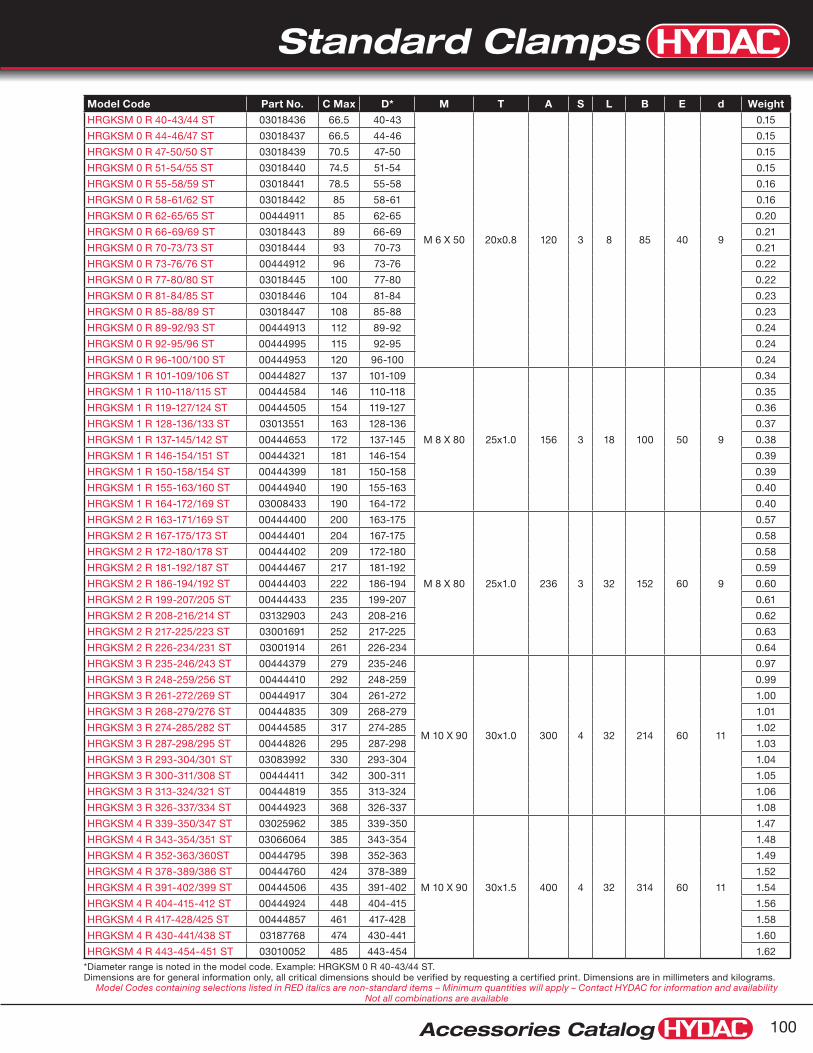
Standard Clamps
Accessories Catalog 100
Model Codes containing selections listed in RED italics are non-standard items – Minimum quantities will apply – Contact HYDAC for information and availability Not all combinations are available
*Diameter range is noted in the model code. Example: HRGKSM 0 R 40-43/44 ST. Dimensions are for general information only, all critical dimensions should be verified by requesting a certified print. Dimensions are in millimeters and kilograms.
Model Code Part No. C Max D* M T A S L B E d Weight
HRGKSM 0 R 40-43/44 ST 03018436 66.5 40-43
M 6 X 50 20x0.8 120 3 8 85 40 9
0.15
HRGKSM 0 R 44-46/47 ST 03018437 66.5 44-46 0.15
HRGKSM 0 R 47-50/50 ST 03018439 70.5 47-50 0.15
HRGKSM 0 R 51-54/55 ST 03018440 74.5 51-54 0.15
HRGKSM 0 R 55-58/59 ST 03018441 78.5 55-58 0.16
HRGKSM 0 R 58-61/62 ST 03018442 85 58-61 0.16
HRGKSM 0 R 62-65/65 ST 00444911 85 62-65 0.20
HRGKSM 0 R 66-69/69 ST 03018443 89 66-69 0.21
HRGKSM 0 R 70-73/73 ST 03018444 93 70-73 0.21
HRGKSM 0 R 73-76/76 ST 00444912 96 73-76 0.22
HRGKSM 0 R 77-80/80 ST 03018445 100 77-80 0.22
HRGKSM 0 R 81-84/85 ST 03018446 104 81-84 0.23
HRGKSM 0 R 85-88/89 ST 03018447 108 85-88 0.23
HRGKSM 0 R 89-92/93 ST 00444913 112 89-92 0.24
HRGKSM 0 R 92-95/96 ST 00444995 115 92-95 0.24
HRGKSM 0 R 96-100/100 ST 00444953 120 96-100 0.24
HRGKSM 1 R 101-109/106 ST 00444827 137 101-109
M 8 X 80 25x1.0 156 3 18 100 50 9
0.34
HRGKSM 1 R 110-118/115 ST 00444584 146 110-118 0.35
HRGKSM 1 R 119-127/124 ST 00444505 154 119-127 0.36
HRGKSM 1 R 128-136/133 ST 03013551 163 128-136 0.37
HRGKSM 1 R 137-145/142 ST 00444653 172 137-145 0.38
HRGKSM 1 R 146-154/151 ST 00444321 181 146-154 0.39
HRGKSM 1 R 150-158/154 ST 00444399 181 150-158 0.39
HRGKSM 1 R 155-163/160 ST 00444940 190 155-163 0.40
HRGKSM 1 R 164-172/169 ST 03008433 190 164-172 0.40
HRGKSM 2 R 163-171/169 ST 00444400 200 163-175
M 8 X 80 25x1.0 236 3 32 152 60 9
0.57
HRGKSM 2 R 167-175/173 ST 00444401 204 167-175 0.58
HRGKSM 2 R 172-180/178 ST 00444402 209 172-180 0.58
HRGKSM 2 R 181-192/187 ST 00444467 217 181-192 0.59
HRGKSM 2 R 186-194/192 ST 00444403 222 186-194 0.60
HRGKSM 2 R 199-207/205 ST 00444433 235 199-207 0.61
HRGKSM 2 R 208-216/214 ST 03132903 243 208-216 0.62
HRGKSM 2 R 217-225/223 ST 03001691 252 217-225 0.63
HRGKSM 2 R 226-234/231 ST 03001914 261 226-234 0.64
HRGKSM 3 R 235-246/243 ST 00444379 279 235-246
M 10 X 90 30x1.0 300 4 32 214 60 11
0.97
HRGKSM 3 R 248-259/256 ST 00444410 292 248-259 0.99
HRGKSM 3 R 261-272/269 ST 00444917 304 261-272 1.00
HRGKSM 3 R 268-279/276 ST 00444835 309 268-279 1.01
HRGKSM 3 R 274-285/282 ST 00444585 317 274-285 1.02
HRGKSM 3 R 287-298/295 ST 00444826 295 287-298 1.03
HRGKSM 3 R 293-304/301 ST 03083992 330 293-304 1.04
HRGKSM 3 R 300-311/308 ST 00444411 342 300-311 1.05
HRGKSM 3 R 313-324/321 ST 00444819 355 313-324 1.06
HRGKSM 3 R 326-337/334 ST 00444923 368 326-337 1.08
HRGKSM 4 R 339-350/347 ST 03025962 385 339-350
M 10 X 90 30x1.5 400 4 32 314 60 11
1.47
HRGKSM 4 R 343-354/351 ST 03066064 385 343-354 1.48
HRGKSM 4 R 352-363/360ST 00444795 398 352-363 1.49
HRGKSM 4 R 378-389/386 ST 00444760 424 378-389 1.52
HRGKSM 4 R 391-402/399 ST 00444506 435 391-402 1.54
HRGKSM 4 R 404-415-412 ST 00444924 448 404-415 1.56
HRGKSM 4 R 417-428/425 ST 00444857 461 417-428 1.58
HRGKSM 4 R 430-441/438 ST 03187768 474 430-441 1.60
HRGKSM 4 R 443-454-451 ST 03010052 485 443-454 1.62

Custom Clamps
Accessories Catalog101
2 Lines / 2 Bolts (HRRL...2 X.../2...)
3 Lines / 2 Bolts (HRRL...3 X.../2...)
4 Lines / 2 Bolts (HRRL...4 X.../2...)
4 Lines / 3 Bolts (HRRL...4 X.../3...)
6 Lines / 3 Bolts (HRRL...6 X.../3...)
10 Lines / 5 Bolts (HRRL...10 X.../5...)
2 Lines / 1 Bolt (HRRLE...2 X.../1...)
2 Lines / 2 Bolts (HRRLE...2 X.../2...)
3 Lines / 2 Bolts (HRRLE...3 X.../2...)
4 Lines / 2 Bolts (HRRLE...4 X.../2...)
4 Lines / 3 Bolts (HRRLE...4 X.../3...)
6 Lines / 3 Bolts (HRRLE...6 X.../3...)
ArrangementsHRRLE Series: Heavy Duty with Rubber Inserts
Weld Plate Mounting C-Rail Mounting
Stacking
Weld Plate Mounting C-Rail Mounting
Stacking
Number of Lines & BoltsHRRLE Series: Heavy Duty with Rubber Inserts (diameter range: 6 to 56.4 mm)
OrderingSeries Strip Clamps are a custom product which must be quoted on an individual project basis. As with DIN 3015 Clamps, the Series Strip Clamps can be ordered as complete arrangements or as individual components. Series Strip Clamps are available with differing bore sizes. Contact HYDAC at 1.877.GO.HYDAC with your specifications to request a quotation.
ArrangementsHRRL Series: Standard Duty
Weld Plate Mounting C-Rail Mounting
Stacking
Weld Plate Mounting C-Rail Mounting
Stacking
Number of Lines & BoltsHRRL Series: Standard Duty (diameter range: 6 to 25.4 mm)
Series Strip ProgramNow ordering a Series Strip Clamp has become easier than ever before. Click on www.hydacusa.com and try out our new Series Strip Sizing Program. When you are finished you will have a model code, drawings and everything you need to place your order.
HRRL & HRRLE Series Series Strip Clamps
Check out my Sizing Program at
www.hydacusa.com2 Lines / 2 Bolts (HRRL...2 X.../2...)
3 Lines / 2 Bolts (HRRL...3 X.../2...)
4 Lines / 2 Bolts (HRRL...4 X.../2...)
4 Lines / 3 Bolts (HRRL...4 X.../3...)
6 Lines / 3 Bolts (HRRL...6 X.../3...)
10 Lines / 5 Bolts (HRRL...10 X.../5...)
2 Lines / 1 Bolt (HRRLE...2 X.../1...)
2 Lines / 2 Bolts (HRRLE...2 X.../2...)
3 Lines / 2 Bolts (HRRLE...3 X.../2...)
4 Lines / 2 Bolts (HRRLE...4 X.../2...)
4 Lines / 3 Bolts (HRRLE...4 X.../3...)
6 Lines / 3 Bolts (HRRLE...6 X.../3...)
DescriptionFor OEM’s requiring solutions for multiple line runs HYDAC offers customized series strips. These clamps reduce inventory and installation time, while providing a more compact solution than multiple DIN 3015 clamps. The design and dimensions are based on the DIN 3015 specifications set forth for single and twin clamps. The Series Strip Program, echoes that of the DIN 3015 Clamps in that it offers similar arrangements, sizes, options, and model coding.

Custom Clamps
Accessories Catalog 102
Item Description/Material
1 Clamping Band, Stainless Steel2 Metric Zinc-Plated Steel Socket Head Bolts (Note: other bolt and connection styles are available based on customer’s specifications)3 Nuts, Zinc Plated Steel4 Swivel Sleeve, Zinc Plated Steel5 Rubber Profile
Dimensions Width x Thickness Length Range (L1)
Light Range 25 x 1 187 - 921 mm
Heavy Range 30 X 1 232 - 1511 mm
Heavy II Range 30 X 1.5 232 - 1511 mm
OrderingBand Straps are a custom product which must be quoted on an individual project basis. Band Straps are available with various lengths, widths, connecting hardware, and with or without rubber profiles. Contact HYDAC at 1-877-GO HYDAC with your specifications to request a quotation.
DescriptionFor OEM’s requiring mounting solutions to secure non-cylindrical objects such as plastic fuel tanks, HYDAC offers steel band straps.
Band Straps
2 51
Width
Length
Thickness
4 3
H = D/2+h
h = 8 to 10
35 ± 15
L1
Diameter Range
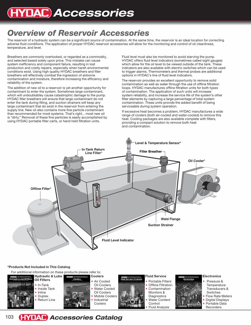
Accessories
Accessories Catalog103
*Products Not Included in This Catalog
For additional information on these products please refer to:Hydraulic & Lube Oil Filters
In-Tank •Inside Tank •Inline •Duplex •Return Line•
Coolers
Air Cooled •Oil Coolers Water Cooled •Oil CoolersMobile Coolers• Industrial •Coolers
Fluid Service
Portable Filters•Offline Filtration• Contamination •Monitors & Diagnostics Water Content •ControlFluid Analysis•
Electronics
Pressure & •Temperature Transducers & SwitchesFlow Rate Meters•Digital Displays• Portable Data •Recorders
Fluid level must also be monitored to avoid starving the pump. HYDAC offers fluid level indicators (sometimes called sight gauges) which allow for the oil level to be viewed outside of the tank. These indicators are also available with electric switches which can be used to trigger alarms. Thermometers and thermal probes are additional options in HYDAC’s line of fluid level indicators.
The reservoir provides an excellent opportunity to remove solid contamination as well as water through the use of offline filtration loops. HYDAC manufactures offline filtration units for both types of contamination. The application of such units will increase system reliability, and increase the service life of the system’s other filter elements by capturing a large percentage of total system contamination. These units provide the added benefit of being serviceable during system operation.
If excessive heat becomes a problem, HYDAC manufactures a wide range of coolers (both air-cooled and water-cooled) to remove this heat. Cooling packages are also available complete with filters, providing a compact solution to remove both heat and contamination.
Breathers are commonly overlooked, or regarded as a commodity, and selected based solely upon price. This mistake can cause system inefficiency and component failure, resulting in lost production and costly repairs, especially when harsh environmental conditions exist. Using high quality HYDAC breathers and filler breathers will effectively combat the ingression of airborne contamination and moisture, therefore increasing the efficiency and reliability of the system.
The addition of new oil to a reservoir is yet another opportunity for contaminant to enter the system. Sometimes large contaminant, which will undoubtabley cause catastrophic damage to the pump. HYDAC filler breathers will ensure that large contaminant do not enter the tank during filling, and suction strainers will keep any large contaminant that do exist in the reservoir from entering the supply line. New oil also contains more fine particle contaminant than recommended for most systems. That’s right... most new oil is “dirty.” Removal of these fine particles is easily accomplished by using HYDAC portable filter carts, or hand held filtration units.
Overview of Reservoir AccessoriesThe reservoir of a hydraulic system can be a significant source of contamination. At the same time, the reservoir is an ideal location for correcting adverse fluid conditions. The application of proper HYDAC reservoir accessories will allow for the monitoring and control of oil cleanliness, temperature, and level.
Offline Filter*
Fluid Level Indicator
Weld Flange
Suction Strainer
Filler Breather
Level & Temperature Sensor*
In-Tank Return Line Filter*
Oil Cooler*

Accessories
Accessories Catalog 104
Gauges
HPG Series (see page 151)
Gauge Isolators MA, MSL & MS Series (see pages 143 - 146)
Split Flanges SAE Code 61 & 62 (see page 151)
Breathers & Filler BreathersBF, BL & BLT, BD, BDR, BDZ, HBRP, HBRM, & ELF Series (see pages 105 - 134)
Air Flow Rates from 80 to 1600 GPM Various connection types Pressurized or free flowing
Suction StrainersSFE, HTMS, MSS Series (see pages 135 - 138)
In-tank models (SFE) mount to an internal fitting on reservoir Tank Mount models (HTMS) mount through the tank wall and act as the external fitting for connecting supply line hoses Flow rates from 3 to 100 GPM NPT and SAE connections models available with bypass
Fluid Level IndicatorsFSK & FSA Series (see pages 139 - 142)
3” to 5” sight tubes Electric level switches available Pressurized or free flowing thermometers and temperature probes available
TestPoints 1620 & 1215 Series (see pages 147 - 150)
Install these for measuring pressure, or fluid sampling while system is in operation, without fluid loss.

Breathers
Accessories Catalog105
Model BF10 ELF10 BF4 ELF4 BF30 ELF30 BF3 ELF3
Page Number 111 122 110 120 112 123 110 120
GPM (liter/min) 80 (300)
80 (300)
80 (300)
80 (300)
200 (750)
200 (750)
250 (950)
250 (950)
CFM (meter³/hr) 10 (17)
10 (17)
10 (17)
10 (17)
25 (42)
25 (42)
35 (60)
35 (60)
Connection Type Threaded Flanged Threaded Flanged Threaded Flanged Threaded Flanged
Connection Size(s)1/2 NPT,
G1/4, M22, SAE-12 male
3 hole flange G1/4 male 3 hole flangeG3/4,
3/4NPT, SAE-12, M42
6 hole flange G3/4, G1/2, G3/8 male 6 hole flange
Element media 3 μm paper 3 μm paper 3 or 10 μm paper
3 or 10 μm paper
3 or 10 μm paper
3 or 10 μm paper
3 or 10 μm paper
3 or 10 μm paper
Replaceable Element No No No No No No No No
Cap material Polyamide Polyamide Steel Steel Polyamide Polyamide Steel Steel
Strainer material N/A Polyamide N/A Polyamide N/A Polyamide N/A Polyamide
Clogging Indicator N/A N/A N/A N/A N/A N/A N/A N/A
OptionsRelief Valve Optional Optional N/A N/A Optional Optional Optional Optional
Anti-Splash Optional Optional N/A N/A Optional Optional N/A N/A
Dipstick Optional Optional N/A N/A Optional Optional Optional Optional
BF10 ELF10 BF4 ELF4 BF30 ELF30 BF3 ELF3 BF7 ELF7 BF72
See other Breather options available on page 107.
OverviewBreather & Filler Breather Product Range
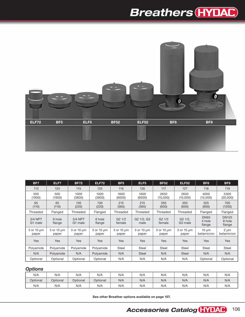
Breathers
Accessories Catalog 106
BF7 ELF7 BF72 ELF72 BF5 ELF5 BF52 ELF52 BF8 BF9
113 124 115 125 116 126 117 127 118 119
500 (1900)
500 (1900)
1000 (3800)
1000 (3800)
1600 (6000)
1600 (6000)
2650 (10,000)
2650 (10,000)
4000 (15,000)
5300 (20,000)
65 (110)
65 (110)
130 (220)
130 (220)
215 (365)
215 (365)
350 (600)
350 (600)
525 (900)
700 (1200)
Threaded Flanged Threaded Flanged Threaded Threaded Threaded Threaded Flanged Flanged
3/4 NPT G1 male
6 hole flange
3/4 NPT G1 male
6 hole flange
G2 1/2 female
G2 1/2, G3 male
G2 1/2 female
G2 1/2, G3 male
DN93 4 hole flange
DN125 8 hole flange
3 or 10 μm paper
3 or 10 μm paper
3 or 10 μm paper
3 or 10 μm paper
3 or 10 μm paper
3 or 10 μm paper
3 or 10 μm paper
3 or 10 μm paper
10 μm betamicron
2 μm betamicron
Yes Yes Yes Yes Yes Yes Yes Yes Yes Yes
Polyamide Polyamide Polyamide Polyamide Steel Steel Steel Steel Steel Steel
N/A Polyamide N/A Polyamide N/A Steel N/A Steel N/A N/A
Optional Optional Optional Optional N/A N/A N/A N/A Optional Optional
OptionsN/A N/A N/A N/A N/A N/A N/A N/A N/A N/A
Optional Optional Optional Optional N/A N/A N/A N/A N/A N/A
N/A N/A N/A N/A N/A N/A N/A N/A N/A N/A
ELF72 BF5 ELF5 BF52 ELF52 BF8 BF9
See other Breather options available on page 107.

Breathers
Accessories Catalog107
BL Series (pages 119-120)
Specifications:Maximum flow rate: 110 SCFM/850 GPM•
3 or 10 micron •
Steel Canister •
10 micron Betamicron• ®
Replaceable element•
BD Series (pages 121-126)
SpecificationsDurable ABS plastic and impact-modified Plexiglas•
2 micron, 100% efficiency•
Airflow up to 100 scfm (750 gpm)•

Breathers
Accessories Catalog 108
Importance of BreathersBreathers are a integral component in any Hydraulic system. Breathers provide protection from contamination found in harsh industrial environments. It is well advised to address both contaminant exclusion and removal. An old rule of thumb states that it cost 10 times as much to REMOVE a particle from your system as it does to EXCLUDE it. Since this is true, it is easy to see that the benefits of using a high quality breather greatly out-weigh the costs.
Recommendations1) HYDAC recommends selecting a breather with a filtration rating (micron rating)
that is equivalent to or finer than your finest system filter.
2) Breathers do get clogged over time. HYDAC recommends the following change-out schedules:
For breathers without pressure gauges • Change your breather annually or with every service interval
For breathers with pressure gauges • Change your breathers at a 3 psi pressure drop, at 7 psi pressure drop the pump can cavitate
HYDAC High Quality BreathersHYDAC Breathers use HIGH quality filtration.
For 3μm breathers: d99.85 = 3 μm The d100 rating means that 100% of 10 μm particles•
For 10μm breathers: d100 = 10 μm are captured by the breather during a standard ISO single pass test.•
Standard elements are made of phenolic resin impregnated paper, which provides resistance to moisture, ensuring proper filtration over the operational service life of your breather.
Pressurized BreathersThe use of pressurized breathers adds certain benefits:
Provides additional protection from moisture which can condense in your tank, •causing oil degradation and tank erosion
Provides positive pressure to pump suction line•
Increased breather service life due to less breathing•
Performs anti-splash function•
Breathers & Filler Breather Technical Overview
It cost 10X as much to REMOVE
a particle from your system,
as it does to
EXCLUDE it.
Tank Pressure Using a Pressurized Breather
Time
Breather Cracking Pressure
Atmospheric Pressure
No Breathing Takes Place
Time
Tank
Pre
ssur
e
Atmospheric Pressure
Vacuum (tank breathes in)
Positive Pressure (tank breathes out)
Vacuum (tank breathes in)
Positive Pressure Above Cracking Pressure (tank breathes out)
Tank
Pre
ssur
e
When fluid level rises, the existing air volume is compressed, and no air is expelled until the cracking pressure is surpassed.
When fluid level lowers, the tank pressure drops until a vacuum is created at which point, air will be drawn in through the breather.
Air is only expelled when the tank pressure is above the cracking pressure, and air is only drawn in below atmospheric pressure. The majority of the operational cycle will take place between these two conditions.
Tank Pressure Using a Standard Breather
Time
Breather Cracking Pressure
Atmospheric Pressure
No Breathing Takes Place
Time
Tank
Pre
ssur
e
Atmospheric Pressure
Vacuum (tank breathes in)
Positive Pressure (tank breathes out)
Vacuum (tank breathes in)
Positive Pressure Above Cracking Pressure (tank breathes out)
Tank
Pre
ssur
e
When fluid level rises, the tank pressure rises and air is immediately expelled through the breather whenever positive pressure exists.
When fluid level lowers, the tank pressure drops and air is immediately drawn in through the breather whenever a vacuum exists.
Air is constantly moving through the breather in order to maintain atmospheric pressure.

Breathers
Accessories Catalog109
Dimensions are for general information only, all critical dimensions should be verified by requesting a certified print.Dimensions are in inches/(mm) and lbs./(kg.)
Dimensions
standard
Hydraulic Symbols
ø D1
H1
H3
D2HEX
with relief valve (BF3 only)
Model CodeBF P 3 G 10 W 1 . 0 / .
Filter Type BF = Breather
Filter Element Material P = Phenolic Resin
Impregnated Paper
Size 3 = 35 SCFM (250 GPM) max. 4 = 10 SCFM (80 GPM) max.
Type of Connection G = Threaded
Filtration Rating (micron) 3 = 3μm Air Filtration 10 = 10μm Air Filtration
Gauge Options W = Without Indicator
Tank Thread Connection (ISO 228) 1 = G 3/4 (BF...3 only) 1 = G 1/4 (BF...4 only) 2 = G 3/8 (BF...3 only) 3 = G 1/2 (BF...3 only) 4 = G 3/4 with RV Relief Valve (Relief Cracking Pressure 10 psi) 5 = G 3/4 with RV Relief Valve (Relief Cracking Pressure 13 psi) 6 = G 3/4 with RV Relief Valve (Relief Cracking Pressure 6 psi)
Modification Number .0 = Standard
Supplementary Details (omit) = standard RV = Relief Valve (for use on pressurized tanks) (BF3 only)
Model Codes containing selections listed in RED italics are non-standard items – Minimum quantities will apply
Contact HYDAC for information and availability
Not all combinations are available
SpecificationsMaximum flow rate - 35 SCFM/250 GPM•
Epoxy coated steel cap•
Zinc-plated internals•
3 or 10 micron •
Threaded connection•
Pressurized breather with relief valve • (optional - BF3 only)
Phenolic resin impregnated filter element•
BF...3 & BF...4 Series
Size ø D1 D2 (male) H1 H3 HEX
BF 3...1.0 BF 3...RV
2.99” (76mm)
G 3/4 (ISO 228)
3.11” (79mm)
0.63” (16mm)
1 7/16” (36mm)
BF 3...2.0 2.99” (76mm)
G 3/8 (ISO 228)
2.83” (72mm)
0.47” (12mm)
7/8” (22mm)
BF 3...3.0 2.99” (76mm)
G 1/2 (ISO 228)
2.99” (76mm)
0.55” (14mm)
1 1/16” (27mm)
BF 4...1.0 1.73” (44mm)
G 1/4 (ISO 228)
2.44” (62mm)
0.53” (13.5mm)
11/16” (17mm)

Breathers
Accessories Catalog 110
Dimensions are for general information only, all critical dimensions should be verified by requesting a certified print.Dimensions are in inches/(mm) and lbs./(kg.)
Dimensions
with relief valve
standard
Hydraulic Symbols
ø 1.93”(49mm)
ø 2.48”(63mm)
ø 0.98”(25mm)
ø 0.53”(13.5mm)
O-Ring
See Type of Connection Below
Model CodeBF P 10 G 3 W 1.0 / - RV0.4
Filter Type BF = Breather
Filter Element Material P = Phenolic Resin
Impregnated Paper
Size 10
Type of Connection G = BSPP N = NPT U = SAE M = Metric threads
Filtration Rating (micron) 3 = 3μm Air Filtration
Gauge Option W = no indicator
Modification Number Connection Type G (BSPP) N (NPT) U (SAE) M (Metric) 1.0 = G 1/4 1/2 NPT – M22x1.5 2.0 = G 1/2 – – M18x1.5 3.0 = – – SAE-12 –
Options (omit) = None RV0.2 = Relief Cracking Pressure 3 psi RV0.4 = Relief Cracking Pressure 6 psi RV0.7 = Relief Cracking Pressure 10 psi AS = Anti-splash protection (only for version without RV)
Model Codes containing selections listed in RED italics are non-standard items – Minimum quantities will apply
Contact HYDAC for information and availability
Not all combinations are available
SpecificationsMaximum Flow Rate 10 SCFM / 80 GPM•
Durable synthetic material (PA6)•
Filtration Rating 3 μm•
Buna N O-Ring•
Optional dipstick (contact factory)•
Optional customer logo (contact factory)•
Optional pressurized breather with relief valve•
Optional anti-splash device•
-22° to 212°F (-30° to 100°C)•
Phenolic resin impregnated filter element•
BF...10 Series

Breathers
Accessories Catalog111
Dimensions are for general information only, all critical dimensions should be verified by requesting a certified print.Dimensions are in inches/(mm) and lbs./(kg.)
with relief valve
standard
Hydraulic Symbols
Dimensions
Anti-Splash
ø 3.27”(83mm)
G 3/4 male(ISO 228)
0.55”(14mm) SW32
O-Ring0.63”
(16mm)
2.36”(60mm)
Air OilOil
Model CodeBF P 30 G 3 W 1.0 / .
Filter Type BF = Breather
Filter Element Material P = Phenolic Resin
Impregnated Paper
Size 30
Type of Connection G = BSPP N = NPT U = SAE
Filtration Rating (micron) 3 = 3μm Air Filtration 10 = 10μm Air Filtration
Gauge Options W = Without Indicator
Modification Number Connection Type G (BSPP) N (NPT) U (SAE) M (Metric) 1.0 = G 3/4 3/4 NPT SAE-12 M42x2 2.0 = – – – M30x1.5
Options (omit) = none RV0.4 = Relief Cracking Pressure 6 psi AS = Anti-Splash protection (only for version without RV)
Model Codes containing selections listed in RED italics are non-standard items – Minimum quantities will apply
Contact HYDAC for information and availability
Not all combinations are available
SpecificationsMaximum flow rate - 25 SCFM/200 GPM•
Durable synthetic material (PA6)•
3 or 10 micron •
Buna N O-Ring•
Threaded breather connection•
Optional dipstick • (contact factory)
Optional customer logo • (contact factory)
Optional pressurized breather with relief valve•
Optional anti-splash device•
-22° to 212°F (-30° to 100°C)•
Phenolic resin impregnated filter element•
BF...30 Series

Breathers
Accessories Catalog 112
Dimensions are for general information only, all critical dimensions should be verified by requesting a certified print.Dimensions are in inches/(mm) and lbs./(kg.)
Dimensions
standard
Hydraulic Symbols
without gauge
Optional Gauge
ø 4.72"(120mm)
ø 4.57"(116mm)ø 1.73"(44mm)
4.33"(110mm)
0.71"(18mm)
1 5/8"(41mm) HEX
G 1"ISO 228male
2.36"(60mm)
Clearance Required forElement Removal
Replacement ElementsMicron Model Code Part No.
3 0007L003P 00310948
10 0007L010P 00310485
Model CodeBF P 7 G 3 K 1.0
Filter Type BF = Breather
Filter Element Material P = Phenolic Resin
Impregnated Paper
Size 7
Type of Connection G = Threaded BSPP N = Threaded NPT (consult factory) U = Threaded SAE (consult factory)
Filtration Rating (micron) 3 = 3μm Air Filtration 10 = 10μm Air Filtration
Gauge Options W = Without Indicator K = With Gauge (Range -14.5 to 9 psi)
Modification Number Connection Type G (BSPP) N (NPT) U (SAE) 1.0 = G 1 3/4 NPT SAE-16
Model Codes containing selections listed in RED italics are non-standard items – Minimum quantities will apply
Contact HYDAC for information and availability
Not all combinations are available
SpecificationsMaximum flow rate - 65 SCFM/500 GPM•
Durable synthetic material (PA6)•
3 or 10 micron •
Replaceable element Phenolic resin impregnated paper•
Threaded breather cap connection•
Differential gauge • (optional)
BF...7 Series

Breathers
Accessories Catalog113
Model CodeBF P 7 F 3 UBM 0 . 0
Filter Type BF = Breather
Filter Element Material P = Phenolic Resin Impregnated Paper
Size 7 (65 cfm / 500 GPM) 72 (130 cfm / 1000 GPM)
Type of Connection F = Flanged G = Threaded
Filtration Rating (micron) 3 = 3μm Air Filtration 10 = 10μm Air Filtration
Gauge Options UBM = Visual Indicator of Vacuum Pressure
with Manual Reset (range to 0.35 bar)
Tank Connection 0 = with 6 hole flange to DIN 24557/2 (F connection) 2 = 3/4” BSPP male (G connection) 3 = 1 1/2-16 UN-2B female (G connection)
(use with BL 160 adapters - see page 118)
Modification Number .0 = Standard
Model Codes containing selections listed in RED italics are non-standard items – Minimum quantities will apply
Contact HYDAC for information and availability
Not all combinations are available
Dimensions are for general information only, all critical dimensions should be verified by requesting a certified print.Dimensions are in inches/(mm) and lbs./(kg.)
with relief valve
standard
Hydraulic Symbols
4.73"120mm
ø
4.57"116 mm
ø
5.12"130mm
ø 3.54"90mm
2.36"60mm
Clearance Required forElement Removal
3.19"81mm
1.81"46mm
ø
SpecificationsMaximum flow rate - up to 130 cfm / 1000 GPM•
Durable synthetic material (PA6)•
3 or 10 micron•
Replaceable element•
Phenolic resin impregnated paper•
Threaded or flanged breather connection•
Visual indicator • (see below)
BF...7/72 SeriesBreathers with Visual Indicator
Replacement ElementsMicron Model Code Part No.
3 0072L003P 03269023
10 0072L010P 03190037
3 0007L003P 00310948
10 0007L010P 00310485
Visual IndicatorThe visual indicator shows by percentage the increase in vacuum pressure drop across the element. The percentage remains visible even when the system is turned off. When the element is changed a manual reset button must be pressed.
Model CodeVMF 0.035 UBM.X
Part Number01279244
DimensionsBFP7F...0.0 version shown with 6 hole flange

Breathers
Accessories Catalog 114
Dimensions are for general information only, all critical dimensions should be verified by requesting a certified print.Dimensions are in inches/(mm) and lbs./(kg.)
Model CodeBF P 72 G 3 W 1 . 0
Filter Type BF = Breather
Filter Element Material P = Phenolic Resin Impregnated Paper
Size 72
Type of Connection G = Threaded BSPP N = Threaded NPT (consult factory)
Filtration Rating (micron) 3 = 3μm Air Filtration 10 = 10μm Air Filtration
Gauge Options W = Without Indicator K = With Gauge (Range: -14.5 to 9 psi)
Tank Thread Connection (ISO 228) 1 = G 1 (1” BSPP)
Modification Number .0 = Standard
Model Codes containing selections listed in RED italics are non-standard items – Minimum quantities will apply
Contact HYDAC for information and availability
Not all combinations are available
Optional Gauge
4.73"120mm
ø
4.57"116mm
ø
6.38"162mm
0.71"18mm
1 5/8"41mm HEX
G 1"ISO 228male
2.36"60mm
Clearance Required forElement Removal
SpecificationsMaximum flow rate - 130 SCFM / 1000 GPM•
Durable synthetic material (PA6)•
3 or 10 micron•
Replaceable element•
Phenolic resin impregnated paper•
Removable lid to access fill port•
Threaded breather cap connection•
Differential gauge • (optional)
-22° to 212°F (-30° to 100°C)•
DimensionsBFP7G...1.0 version shown
Replacement ElementsMicron Model Code Part No.
3 0072L003P 03269023
10 0072L010P 03190037
with relief valve
standard
Hydraulic Symbols
BF...72 Series

Breathers
Accessories Catalog115
Dimensions are for general information only, all critical dimensions should be verified by requesting a certified print.Dimensions are in inches/(mm) and lbs./(kg.)
Dimensions
with relief valve
standard
Hydraulic Symbols
ø 6.97"(177mm)
3.54"(90mm)
Clearance Required for Element Removal
4.21"(107mm)
G 2 1/2" (ISO 228)
female
Replacement ElementsMicron Model Code Part No.
3 0005L003P 00309450
10 0005L010P 00306097
Model CodeBF P 5 G 3 W 1 . 0
Filter Type BF = Breather
Filter Element Material P = Phenolic Resin
Impregnated Paper
Size 5 Type of Connection G = Threaded
Filtration Rating (micron) 3 = 3μm Air Filtration 10 = 10μm Air Filtration
Gauge Options W = Without Indicator
Tank Thread Connection (ISO 228) 1 = G 2 1/2 (standard)
Modification Number .0 = Standard
Model Codes containing selections listed in RED italics are non-standard items – Minimum quantities will apply
Contact HYDAC for information and availability
Not all combinations are available
SpecificationsMaximum flow rate - 220 SCFM/1600 GPM•
Steel housing•
3 or 10 micron •
Replaceable element•
G2 1/2 female threaded connection•
Phenolic resin impregnated filter element•
BF...5 Series

Breathers
Accessories Catalog 116
Dimensions are for general information only, all critical dimensions should be verified by requesting a certified print.Dimensions are in inches/(mm) and lbs./(kg.)
Dimensions
Hydraulic Symbols
Model CodeBF P 52 G 3 W 1 . 0
Filter Type BF = Breather
Filter Element Material P = Phenolic Resin
Impregnated Paper
Size 52
Type of Connection G = Threaded
Filtration Rating (micron) 3 = 3μm Air Filtration 10 = 10μm Air Filtration
Gauge Options W = Without Indicator
Connection Type 1 = G 2 1/2 (standard)
Modification Number .0 = Standard
Model Codes containing selections listed in RED italics are non-standard items – Minimum quantities will apply
Contact HYDAC for information and availability
Not all combinations are available
SpecificationsMaximum flow rate - 350 SCFM / 2650 GPM•
Steel housing•
3 or 10 micron•
Replaceable element •(uses 2 of the standard size 5 elements)
Phenolic resin impregnated paper•
G 2 1/2” female threaded connection•
BF...52 Series
ø 6.97”(177mm)
3.54”(90mm)
ClearanceRequiredfor Element Removal
7.40”(188mm)
G 2 1/2" (ISO 228)
female
Replacement ElementsMicron Model Code Part No. Qty Required
3 0005L003P 00309450 2
10 0005L010P 00306097 2

Breathers
Accessories Catalog117
Dimensions are for general information only, all critical dimensions should be verified by requesting a certified print.Dimensions are in inches/(mm) and lbs./(kg.)
Dimensions
with relief valve
standard
Hydraulic Symbols
Model CodeBF BN 8 F 10 A 1.0
Filter Type BF = Breather
Filter Element Material BN = Betamicron®
Size 8
Type of Connection F = Flanged (DN 93, 4 bolt)
Filtration Rating (micron) 10 = 10μm Betamicron® Filtration
Gauge Options A = Without Indicator K = With Indicator Gauge (-1 bar to 0.6 bar)
Modification Number 1.0 = Standard
Model Codes containing selections listed in RED italics are non-standard items – Minimum quantities will apply
Contact HYDAC for information and availability
Not all combinations are available
SpecificationsMaximum flow rate - 525 SCFM / 4000 GPM•
Steel housing•
10 micron Betamicron• ® element
Replaceable element•
4 bolt DN 93 flange•
BF...8 Series
ø 3.66”(93mm)
ø 7.87”(200mm)
ø 6.30”(160mm)
Bolt Circle
4x ø 0.71”(18mm)
DN 934 Bolt Flange
Indicator(optional)
6.97”(177mm)
19.63”(499mm)
14.37”(365mm)
Replacement ElementsMicron Model Code Part No.
10 0008L010BN 01266598

Breathers
Accessories Catalog 118
Model CodeBF BN 9 F 2 A 1.0
Filter Type BF = Breather
Filter Element Material BN = Betamicron® Element
Size 9
Type of Connection F = Flanged
Filtration Rating (micron) 2 = 2μm Air Filtration
Gauge Options A = Without Indicator K = With Gauge (Range: -14.5 to 9 psi)
Modification Number 1.0 = Standard
Model Codes containing selections listed in RED italics are non-standard items – Minimum quantities will apply
Contact HYDAC for information and availability
Not all combinations are available
Dimensions are for general information only, all critical dimensions should be verified by requesting a certified print.Dimensions are in inches/(mm) and lbs./(kg.)
Dimensions
with relief valve
standard
Hydraulic Symbols SpecificationsMaximum flow rate - 700 SCFM / 5300 GPM•
Steel housing•
Replaceable element•
2 μm absolute Betamicron• ®
8 bolt DN 125 flange•
BF...9 SeriesBreathers with Oil Mist Trap
8.27”(210mm)
ø 9.84”(250mm)
ø 4.92”(125mm)
8x ø 0.71”(18mm)
DN 1258 Hole Flange
Drain
Indicator(optional)
6.30”(160mm)
9.84”(250mm)
13”(330mm)
Clearance Requiredfor Element Removal
6.97”(177mm)
18.66”(474mm)
Replacement ElementsMicron Model Code Part No.
2 0009L002BN 01287471
Oil Mist TrapThe oil mist in the filter is collected in a “drip tray” and is returned safely to the tank, or it can be drained via an oil drain plug.
No oil runs down onto the top of the tank.
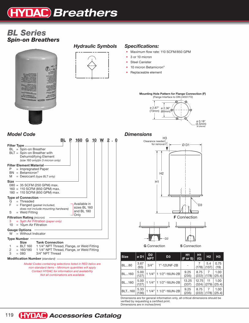
Breathers
Accessories Catalog119
Hydraulic Symbols
Dimensions are for general information only, all critical dimensions should be verified by requesting a certified print.Dimensions are in inches/(mm)
Model CodeBL P 160 G 10 W 2 . 0
Filter Type BL = Spin-on Breather BLT = Spin-on Breather with
Dehumidifying Element (size 160 only)(in 3 micron only)
Filter Element Material P = Impregnated Paper BN = Betamicron® M = Desiccant (type BLT only)
Size 080 = 35 SCFM (250 GPM) max. 160 = 110 SCFM (850 GPM) max. 180 = 110 SCFM (850 GPM) max.
Type of Connection G = Threaded F = Flanged (gasket included, does not include mounting hardware) S = Weld Fitting
Filtration Rating (micron) 3 = 3µm Air Filtration (paper only) 10 = 10µm Air Filtration
Gauge Options W = Without Indicator
Type Number Size Tank Connection 1 = BLT 160 1 1/4” NPT Thread, Flange, or Weld Fitting 2 = 160/180 1 1/4” NPT Thread, Flange, or Weld Fitting 3 = 080 3/4” NPT Thread
Modification Number (standard)
Model Codes containing selections listed in RED italics are non-standard items – Minimum quantities will apply
Contact HYDAC for information and availability Not all combinations are available
Specifications:Maximum flow rate: 110 SCFM/850 GPM•
3 or 10 micron •
Steel Canister •
10 micron Betamicron• ®
Replaceable element•
BL Series Spin-on Breathers
Size ø D1 D2 NPT D3 H1
(F or S)H1 (G) H2 H3
BL...80 3.67 (93) 3/4” 1”-12UNF-2B - 7
(178)5.4
(137)0.75 (19)
BL...160 5.00 (127) 1 1/4” 1 1/2”-16UN-2B 9.25
(235)8.75 (222)
7 (178)
1.00 (25.4)
BL...180 5.00 (127) 1 1/4” 1 1/2”-16UN-2B 13.25
(337)12.75 (324)
11 (279)
1.00 (25.4)
BLT...160 5.33 (136) 1 1/4” 1 1/2”-16UN-2B 9.25
(235)8.75 (222)
7 (178)
1.00 (25.4)
Available in sizes BL 160 and BL 180 Only
ø 2.87"(73mm)
H2
H3Clearance needed
for removal
D3D2
H1
Ø D1
ø 2.36"(60mm)
(6 places)
Mounting Hole Pattern for Flange Connection (F) (Flange Interface to DIN 24557/T2)
ø 0.18"(4.5mm)
F Connection G Connection S Connection
ø 2.87"(73mm)
H2
H3Clearance needed
for removal
D3D2
H1
Ø D1
ø 2.36"(60mm)
(6 places)
Mounting Hole Pattern for Flange Connection (F) (Flange Interface to DIN 24557/T2)
ø 0.18"(4.5mm)
F Connection G Connection S Connection
Dimensions
ø 2.87"(73mm)
H2
H3Clearance needed
for removal
D3D2
H1
Ø D1
ø 2.36"(60mm)
(6 places)
Mounting Hole Pattern for Flange Connection (F) (Flange Interface to DIN 24557/T2)
ø 0.18"(4.5mm)
F Connection G Connection S Connection

Breathers
Accessories Catalog 120
Adapters
Fiber Gasket Sold SeparatelyOrder Part Number 00247102
Size G Threaded Adapter F Flanged Adapter S Welded Adapter
80 ADAPTER BL 080G 3/4” NPT NBR02064393 N/A N/A
160 180
ADAPTER BL 160/180 G 1 1/4” NPT NBR02064394
ADAPTER BL 160/180 F (PHOS)00407646 (w/out Gasket)
02073864 (w/ Gasket)
ADAPTER BL 160/180 S (PHOS)00416311
Replacement Elements
Size 10 micron Paper
3 micron Paper
10 micron Betamicron®
3 micron BLT Desiccant
80 0080MA010P02058058
0080MA003P02058079
0080MA010BN02059424 N/A
160 0160MA010P02058116
0160MA003P02058114
0160MA010BN02059436
0160MU003M01265765
180 0180MA010P02058121
0180MA003P02057912
0180MA010BN02059440 N/A
Breather Components
WeightsModel lbs. kg.
ELF 3 0.55 0.25
ELF E RV 0.66 0.30
ELF 4 0.44 0.20
ELF 5 (type no. 2) 5.95 2.70
ELF 5 (type no. 3) 6.83 3.10
ELF 7 0.84 0.38
BF 3 0.62 0.28
BF 3 RV 0.73 0.33
BF 4 0.18 0.08
BF 5 4.41 2.00
BF 7 0.88 0.40
BL 160 4.63 2.10
BL 80G 1.40 0.60
BL 160G 2.60 1.20
BL 180G 3.48 1.58
BL 160S 3.86 1.75
BL 180S 4.22 1.91
BLT 160 5.31 2.41
Engineering Data for Breathers (Models ELF, BF & BL)
Mounting Position: ELF & BFBL (spin-ons)
Vertical (max. 30° off vertical axis)Vertical or Horizontal
Air Filter Material: Phenolic Resin Impregnated PaperNote: None of the air filter elements can be cleaned.
Temperature Range: -22° to 212°F (-30° to 100°C)Please contact HYDAC for information on extreme low or high temperature applications
Fluid Compatibility: (ISO 2943)
Compatible with all petroleum oils.Contact HYDAC office for information on other fluids.
Spin-on BL80, BL160 and BL180
Adapter Spin-on to Bayonet Part Number 02701342
Bayonet Flange shown on page 128.
Part Number 00002680

Breathers
Accessories Catalog121
Unit Selection Guide (adapters sold separately)
Model Code Part No. Height(A) Weight
Max. H2O Capacity lbs (ltr)
BD 100 X 2 W 0.0 02074253 3.5 (90) 1.3 (0.6) 0.2 (0.1)
BD 200 X 2 W 0.0 02074254 5 (128) 1.9 (0.9) 0.4 (0.2)
BD 400 X 2 W 0.0 02074465 8 (205) 3.3 (1.5) 0.9 (0.4)
BD 800 X 2 W 0.0 02075158 10 (254) 4.9 (2.2) 1.3 (0.6)
Dimensions are for general information only, all critical dimensions should be verified by requesting a certified print.Dimensions are in inches/(mm) and lbs./(kg.)
DescriptionDrymicron breathers use a three-stage filtration design to ensure optimum protection by removing water vapor and solid contaminant before they enter the fluid system.
Drymicron Breathers replace the standard breather cap or vent tube on a tank or reservoir. They are easy to install using one of several adapters designed for different applications.
When the fluid in the system is lowered, or pressure changes occur, air is drawn in through openings under the breather cap. First, air passes through a fine, 2 micron solid particle filter. The air then passes through a diffuser to ensure maximum effectiveness within the silica gel chamber.
Next, water vapor is removed as the air travels through a bed of silica gel — the highest capacity adsorbent available. After being dried, the air passes through a second 2 micron solid particle filter and enters the reservoir clean and dry!
AdvantagesDrymicron Breathers protect expensive equipment, increase operation efficiency, and reduce maintenance costs by:
Eliminating corrosion•
Extending life of hydraulic, lubrication, and process fluids•
Minimizing component wear, downtime, and repairs•
Eliminating oil oxidation, additive depletion, and freezing•
Extending oil filter life•
ApplicationsHydraulic Reservoirs•
Gear Boxes•
Storage Tanks•
Operational FeaturesBi-directional Air Flow
Air entering is cleaned and dried. Expelled air partially •regenerates the silica gel and “backflushes” the particulate filter to prolong the life of the breather.
Durable Construction
DRYMICRON is manufactured from rugged ABS plastic and •impact-modified Plexiglas.
Water Vapor Adsorbent
Silica gel is chemically inert, non-toxic, and non-corrosive. The •internal structure is composed of interconnected microscopic pores that adsorb up to 40% of its weight.
Color Indicator
When maximum adsorption is reached, the silica gel turns from •gold to green to indicate that replacement of the breather is required.
ACTI
VE GOLD
DARK GREENGREEN
REPLAC
E
Safety Sealed
Seals keep moisture from entering the units until they are placed •in service. They are easily removed without tools or sharp instruments.
BD SeriesDrymicron
A
ø 5"(128 mm)
1.25"(32 mm)
BD 100, 200, 400standard 1" friction fit(see adapter selection guide)BD 8002"NPT male only(no adapter needed)
Air Diffuser
Solid ContaminantFilter (2 µm)
Solid ContaminantFilter (2 mm)
CLEAN DRY AIR
360˚ Air Flow
High CapacityWater VaporAdsorbent
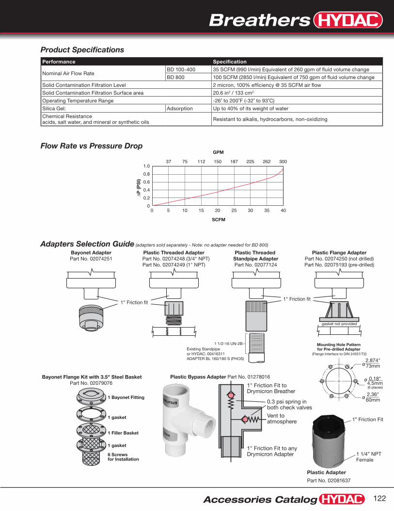
Breathers
Accessories Catalog 122
Adapters Selection Guide (adapters sold separately - Note: no adapter needed for BD 800)
Flow Rate vs Pressure Drop
Product SpecificationsPerformance Specification
Nominal Air Flow RateBD 100-400 35 SCFM (990 l/min) Equivalent of 260 gpm of fluid volume change
BD 800 100 SCFM (2850 l/min) Equivalent of 750 gpm of fluid volume change
Solid Contamination Filtration Level 2 micron, 100% efficiency @ 35 SCFM air flow
Solid Contamination Filtration Surface area 20.6 in2 / 133 cm2
Operating Temperature Range -26˚ to 200˚F (-32˚ to 93˚C)
Silica Gel: Adsorption Up to 40% of its weight of water
Chemical Resistance acids, salt water, and mineral or synthetic oils Resistant to alkalis, hydrocarbons, non-oxidizing
Plastic Bypass Adapter Part No. 01278016Bayonet Flange Kit with 3.5" Steel BasketPart No. 02079076
Bayonet AdapterPart No. 02074251
1 gasket
1 gasket
1 Filler Basket
6 Screwsfor Installation
1 Bayonet Fitting
Vent toatmosphere
0.3 psi spring in both check valves
1" Friction Fit toDrymicron Breather
1" Friction Fit to anyDrymicron Adapter
Plastic Threaded Adapter Part No. 02074248 (3/4" NPT)
Part No. 02074249 (1" NPT)
Plastic Threaded Standpipe AdapterPart No. 02077124
1 1/2-16 UN-2BExisting Standpipeor HYDAC: 00416311ADAPTER BL 160/180 S (PHOS)
Plastic Flange AdapterPart No. 02074250 (not drilled)Part No. 02075193 (pre-drilled)
gasket not provided
ø 2.36"60mm
ø2.874"73mm
(6 places)
Mounting Hole Patternfor Pre-drilled Adapter
(Flange Interface to DIN 24557/T2)
ø 0.18"4.5mm
1" Friction fit1" Friction fit
37 75 112 150 187 225 262 3001.00.80.60.40.2
00 5 10 15 20 25 30 35 40
GPM
SCFM
∆P (P
SI)
Plastic Adapter
Part No. 02081637
1 1/4” NPT Female
1” Friction Fit
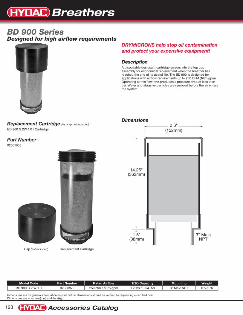
Breathers
Accessories Catalog123
Dimensions are for general information only, all critical dimensions should be verified by requesting a certified print.Dimensions are in inches/(mm) and lbs./(kg.)
Dimensionsø 6"
(152mm)
1.5"(38mm)
3“ MaleNPT
14.25"(362mm)
Model Code Part Number Rated Airflow H2O Capacity Mounting Weight
BD 900 G 2 W 1.0 02080979 250 cfm / 1875 gpm 1.2 lbs / 0.54 liter 3” Male NPT 6.5 (2.9)
DRYMICRONS help stop oil contamination and protect your expensive equipment!
DescriptionA disposable desiccant cartridge screws into the top cap assembly for economical replacement when the breather has reached the end of its useful life. The BD 900 is designed for applications with airflow requirements up to 250 CFM (1875 gpm). Operating at this flow rate produces a pressure drop of less than 1 psi. Water and abrasive particles are removed before the air enters the system.
BD 900 SeriesDesigned for high airflow requirements
Replacement Cartridge (top cap not included)
BD 900 G 2W 1.0 / Cartridge
Part Number02081633
Cap (not included) Replacement Cartridge

Breathers
Accessories Catalog 124
Dimensions
B
D C
AModel Part No. A B C D Air Flow H2O
lbs (ltr) Wgt.
BDR 100 G 2 W 1.0 02080971 5.0” 5.2” 4.0” 5.0” 260 gpm 35 cfm
0.2(0.1) 2.5
BDR 200 G 2 W 1.0 02080972 5.0” 5.2” 5.5” 6.5” 260 gpm 35 cfm
0.4(0.2) 3.2
BDR 400 G 2 W 1.0 02080973 5.0” 5.2” 8.5” 9.5” 260 gpm 35 cfm
0.9(0.4) 4.5
BDR 800 G 2 W 1.0 02080974 5.0” 5.2” 10.5 12.0” 750 gpm 100 cfm
1.3(0.6) 5.5
BDR 100 X 2 W 0.0/Cartridge 02080975 5.0” – 3.75” – 260 gpm 35 cfm
0.2(0.1) 1.8
BDR 200 X 2 W 0.0/Cartridge 02080976 5.0” – 5.0” – 260 gpm 35 cfm
0.4(0.2) 2.0
BDR 400 X 2 W 0.0/Cartridge 02080977 5.0” – 8.0” – 260 gpm 35 cfm
0.9(0.4) 3.3
BDR 800 X 2 W 0.0/Cartridge 02080978 5.0” – 10.0” – 750 gpm 100 cfm
1.3(0.6) 4.6
BDR Series breathers are attached to the reservoir, gearbox, or tank by 1” male NPT(Models BDR 100, BDR 200, & BDR 400), and by a 2” male NPT (Models BDR 800).Dimensions are for general information only, all critical dimensions should be verified by requesting a certified print.Dimensions are in inches and lbs
DRYMICRONS help stop oil contamination and protect your expensive equipment!
DescriptionHYDAC BDR Series breathers are designed for applications where gearboxes and reservoirs are subjected to continuous vibration such as railroad maintenance equipment, off-road vehicles, mining equipment, and many more.
The units are easily attached to the equipment by rugged steel pipe threads.
FeaturesThe metal reinforced base of the unit remains on the gearbox or reservoir, and a replacement cartridge is threaded into the base.
BenefitsMinimize rust & acid corrosion•
Reduce component wear•
Reduce maintenance cost•
Prolong fluid life•
Reduce oil oxidation•
Enhance lubrication•
Components
BDR SeriesMobile DRYMICRON
Replacement Cartridge Re-usable Bottom Cap

Breathers
Accessories Catalog125
Dimensions are for general information only, all critical dimensions should be verified by requesting a certified print.Dimensions are in inches/(mm)
A
CB
ø 5.2"(132mm)
Dimensions
AirIn
AirOut
0.3 PSI 2.1 PSI
Hydraulic Symbols
Model Code Part No. Connection (C)
Height (A)
Clearance (B) Rated Airflow H20 Capacity
(lbs) In (psi) Out (psi)
BDX 200 X 2 W 0.0/RV 0.3/2.1 02084491 1” press fit 7 (178) 1.25 (32) 35 CFM / (260 gpm) 0.4 0.3 2.1
BDX 400 X 2 W 0.0/RV 0.3/2.1 02084492 1” press fit 10 (254) 1.25 (32) 35 CFM / (260 gpm) 0.9 0.3 2.1
BDX 200 G 2 W 1.0/RV 0.3/2.1 02084493 2” male NPT 7 (178) 1.5 (38) 35 CFM / (260 gpm) 0.4 0.3 2.1
BDX 400 G 2 W 1.0/RV 0.3/2.1 02084494 2” male NPT 10 (254) 1.5 (38) 35 CFM / (260 gpm) 0.9 0.3 2.1
BDX 200 X 2 W 0.0/Cartridge 02084495 1” press fit 5 (127) 1.25 (32) 35 CFM / (260 gpm) 0.4 0.3 2.1
BDX 400 X 2 W 0.0/Cartridge 02084496 1” press fit 8 (203) 1.25 (32) 35 CFM / (260 gpm) 0.9 0.3 2.1
BDX 200 G 2 W 1.0/Cartridge 02084497 2” male NPT 5 (127) 1.5 (38) 35 CFM / (260 gpm) 0.4 0.3 2.1
BDX 400 G 2 W 1.0/Cartridge 02084498 2” male NPT 8 (203) 1.5 (38) 35 CFM / (260 gpm) 0.9 0.3 2.1
DRYMICRONS help stop oil contamination and protect your expensive equipment!
DescriptionThe BDX Series is ideal for certain extreme operating environments such as paper mill, steam cleaning rooms, etc. The humidity level far exceeds that which is experienced in normal industrial applications. In these situations, lubricants and other fluids stored in tanks and reservoirs need the protection of a desiccant breather even more. However, small temperature variations draw in the humid air and unnecessarily reduce the life of the breather.
Features Two check valves
One to control airflow into the protected reservoir•
One to control airflow out•
These valves establish thresholds of vacuum and pressure.•
Benefits Reduced breathing cycles extend product life span, air to flow •through the breather only when needed to protect the integrity of the tank
The rugged design includes a reusable top cap which allows •the economic replacement of the desiccant cartridge
Complete Assembly Cartridge Cap
BDX Series Extreme Operating Environment Drymicron

Breathers
Accessories Catalog 126
Dimensions
B
1/2” NPT Female Connection02082356 has 3/4” male connection
A
Dimensions are for general information only, all critical dimensions should be verified by requesting a certified print.Dimensions are in inches and lbs
Model H2O Capacity lbs (ltr) Part Number A B Unit Weight
(lbs)
BDZ 015 G 2 W 1.0 0.032 (0.015) 02080980 2.00” 2.25” 0.19
BDZ 025 G 2 W 1.0 0.056 (0.025) 02080981 2.00” 3.50” 0.27
BDZ 045 G 2 W 1.0 0.104 (0.047) 02080982 3.25” 2.25” 0.50
BDZ 085 G 2 W 1.0 0.180 ( 0.082) 02080983 3.25” 3.50” 0.75
BDZ 085 G 2 W 2.0 0.180 (0.082) 02082356 3.25” 3.50” 0.75
DescriptionHYDAC BDZ Series breathers are designed for applications when space is limited. They can replace all standard breather caps.
HYDAC BDZ Series breathers prevent dirt and water vapor from entering the gearbox or hydraulic system.
Features1/2” NPT female threaded mounting hole• (1.0 models only)
3/4” NPT male fitting • (2.0 model only)
All models are rated for 10 cfm airflow.•
BenefitsMinimize rust & acid corrosion•
Reduce component wear•
Reduce maintenance cost•
Prolong fluid life•
Reduce oil oxidation•
Enhance lubrication•
Rated Airflow - 75 gpm / 10 cfm•
BDZ SeriesMini DRYMICRON

Filler Breathers
Accessories Catalog127
Dimensions are for general information only, all critical dimensions should be verified by requesting a certified print.Dimensions are in inches/(mm) and lbs./(kg.)
Hydraulic Symbols
Tab Thickness0.08"(2mm)
1.22"(31mm)
0.83"(21mm)Ø 0.31”
(8mm)
2.66"(67.5mm)
2.26"(57.5mm)
ø D2
ø D1
H1
H2
H3
ø D3
ø 1.18"(30mm)
ø 1.63"(41.3mm)
ø 0.18"(4.5mm)
(3 places)
ø 0.18"(4.5mm)
(6 places)
ø 2.87"(73mm)
ø 2.36"(60mm)
Self-tapping ScrewM5 x 10 (DIN 963)
Tab Thickness0.08"(2mm)
1.22"(31mm)
0.83"(21mm)Ø 0.31”
(8mm)
2.66"(67.5mm)
2.26"(57.5mm)
ø D2
ø D1
H1
H2
H3
ø D3
ø 1.18"(30mm)
ø 1.63"(41.3mm)
ø 0.18"(4.5mm)
(3 places)
ø 0.18"(4.5mm)
(6 places)
ø 2.87"(73mm)
ø 2.36"(60mm)
Self-tapping ScrewM5 x 10 (DIN 963)
DimensionsELF ELFL (with locking tab)
Mounting Hole PatternsELF 3 ELF4 (flange interface to DIN 24557/T2)
with relief valve (ELF3 only)
standard
Model CodeELF P 3 F 10 W 1 . 0 / .
Filter Type ELF = Filler Breather ELFL = Lockable Filler Breather
(not available for size 4)
Filter Element Material P = Phenolic Resin
Impregnated Paper
Size 3 = 35 SCFM (250 gpm) max. 4 = 10 SCFM (80 gpm) max.
Type of Connection F = Flanged
Filtration Rating (micron) 3 = 3µm Air Filtration 10 = 10µm Air Filtration
Gauge Options W = Without Indicator
Type 1 = ELF 3 and 4 4 = ELF 3 RV; Relief Cracking Pressure 10 psi 5 = ELF 3 RV; Relief Cracking Pressure 13 psi 6 = ELF 3 RV; Relief Cracking Pressure 6 psi
Modification Number .0 = Standard
Supplementary Details RV = Relief Valve (for use on Pressurized Tanks; ELFP3 only) SO169H3.5 = 3.5 inch plated steel filler basket SO169H6 = 6 inch plated steel filler basket
(ELFP3 only)
SO169H8 = 8 inch plated steel filler basket
Model Codes containing selections listed in RED are non-standard items – Minimum quantities will apply
Contact HYDAC for information and availability
Not all combinations are available
SpecificationsMaximum flow rate - 35 SCFM/250 GPM•
Epoxy coated steel cap•
Zinc-plated internals•
3 or 10 micron•
500 micron plastic filler basket•
Bayonet connection to access fill port•
Installs via 3 or 6 bolt circle • (bolts included)
Locking tabs • (optional - ELFL 3 only)
Pressurized breather with relief valve • (optional - ELF3 only)
Phenolic resin impregnated filter element•
ELF...3 & ELF...4 SeriesFiller Breathers
Size ø D1 ø D2 ø D3 H1 H2 H3
ELF 3 2.99” (76mm)
3.27” (83mm)
2.05” (52mm)
6.26” (159mm)
3.80” (96.5mm)
2.46” (62.5mm)
ELF 4 1.73” (44mm)
1.97” (50mm)
1.10” (28mm)
5.32” (135mm)
3.21” (81.5mm)
2.11” (53.5mm)

Filler Breathers
Accessories Catalog 128
ELF 3 Breather CapsPart Model Code Part No.
Breather Cap ELF P 3 CAP 10 W 1.0 W/CHAIN 02080124
Breather Cap with 6 psi relief valve ELF P 3 CAP 10 W 6.0/RV W/CHAIN 02080125
Weld Neck Bayonet FlangePart Model Code Part No.
Weld Neck ELF3 WELD NECK W/CHAIN 02080126
Drop-in Strainer ELF3 WELD NECK STRAINER 02078939
6 bolt Bayonet FlangePart Model Code Part No.
Bayonet Flange Kit ELF3 BAYONET FLANGE KIT ASSY 00002680Note: Parts not sold separately
Part Model Code Part No.
3.5” Steel Filler Basket ELF3 STRAINER BASKET 3.5” PLATED STEEL 02701474
6” Steel Filler Basket ELF3 STRAINER BASKET 6” PLATED STEEL 02701475
8” Steel Filler Basket ELF3 STRAINER BASKET 8” PLATED STEEL 02701441
4” Plastic Filler Basket ELF3 STRAINER BASKET 4” PLASTIC 01202916
ELF 3 Series Filler Breather Parts
Breather Cap
Gaskets1 for under basket1 for on top of basket
6-bolt Filler Basket
Self TappingScrewsM5x10 (DIN 963)
Bayonet Flange
Bay
onet
Fla
nge
Kit
InstallationCross Section
Reservoir WallDrop-in Filler Basket
Weld NeckBayonet Flange

Filler Breathers
Accessories Catalog129
Dimensions are for general information only, all critical dimensions should be verified by requesting a certified print.Dimensions are in inches/(mm) and lbs./(kg.)
Dimensions
Hydraulic Symbols
ø 1.93”(49mm)
ø 2.17”(55mm)
ø 2.76”(70mm)
ø 6.10”(155mm)
ø 0.63”(16mm)ø 0.79”
(20mm)
ø 0.08”(2mm)
ø 0.03”(1mm)
ø 0.03”(1mm)
ø 0.91”(23mm)ø 1.10”(28mm)
ø 2.01”(51mm)
ø 1.18”(30mm)
ø 1.63”(41.3mm)
ø 0.18”(4.5mm)
ø 1.93”(49mm)
ø 2.17”(55mm)
ø 2.76”(70mm)
ø 6.10”(155mm)
ø 0.63”(16mm)ø 0.79”
(20mm)
ø 0.08”(2mm)
ø 0.03”(1mm)
ø 0.03”(1mm)
ø 0.91”(23mm)ø 1.10”(28mm)
ø 2.01”(51mm)
ø 1.18”(30mm)
ø 1.63”(41.3mm)
ø 0.18”(4.5mm)
with relief valve
standard
Model CodeELF P 10 F 3 W 1.0 / - RV0.4
Filter Type ELF = Filler Breather
Filter Element Material P = Phenolic Resin
Impregnated Paper
Size 10
Connection F = Flanged connection
Filtration Rating (micron) 3 = 3µm air filtration
Gauge Option W = without indicator
Type 1 = Flanged connection (see dimensions above)
Modification Number .0 = Standard
Options (omit) = Standard RV0.2 = Relief Cracking Pressure, 3 psi RV0.4 = Relief Cracking Pressure, 6 psi RV0.7 = Relief Cracking Pressure, 10 psi AS = Anti-splash protection (only for version without RV)
Model Codes containing selections listed in RED are non-standard items – Minimum quantities will apply
Contact HYDAC for information and availability
Not all combinations are available
SpecificationsMaximum Flow Rate - 10 SCFM / 80 GPM•
Durable synthetic material (PA6)•
Filtration rating 3 µm•
Buna N O-Ring•
Threaded connection to access fill port•
Optional dipstick • (contact factory)
Optional customer logo • (contact factory)
Optional pressurized breather with relief valve•
Optional anti-splash device•
-22° to 212°F (-30° to 100°C)•
Phenolic resin impregnated filter element•
ELF...10 SeriesFiller Breathers
Mounting Hole Pattern
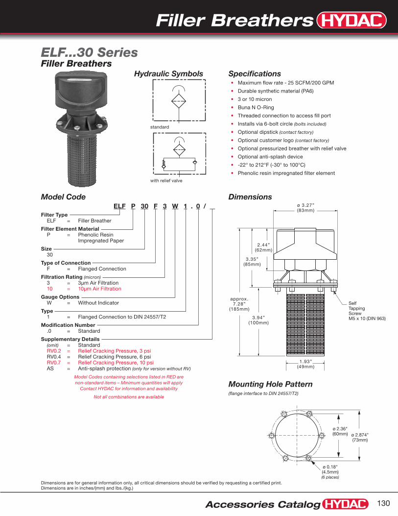
Filler Breathers
Accessories Catalog 130
Dimensions are for general information only, all critical dimensions should be verified by requesting a certified print.Dimensions are in inches/(mm) and lbs./(kg.)
Hydraulic Symbols
with relief valve
standard
1.93”(49mm)
ø 3.27”(83mm)
2.44”(62mm)
3.35”(85mm)
3.94”(100mm)
approx.7.28”
(185mm)SelfTappingScrewM5 x 10 (DIN 963)
ø 2.874"(73mm)
ø 2.36"(60mm)
ø 0.18"(4.5mm)(6 places)
Model CodeELF P 30 F 3 W 1 . 0 / .
Filter Type ELF = Filler Breather
Filter Element Material P = Phenolic Resin
Impregnated Paper
Size 30
Type of Connection F = Flanged Connection
Filtration Rating (micron) 3 = 3µm Air Filtration 10 = 10µm Air Filtration
Gauge Options W = Without Indicator
Type 1 = Flanged Connection to DIN 24557/T2
Modification Number .0 = Standard
Supplementary Details (omit) = Standard RV0.2 = Relief Cracking Pressure, 3 psi RV0.4 = Relief Cracking Pressure, 6 psi RV0.7 = Relief Cracking Pressure, 10 psi AS = Anti-splash protection (only for version without RV)
Model Codes containing selections listed in RED are non-standard items – Minimum quantities will apply
Contact HYDAC for information and availability
Not all combinations are available
SpecificationsMaximum flow rate - 25 SCFM/200 GPM•
Durable synthetic material (PA6)•
3 or 10 micron•
Buna N O-Ring•
Threaded connection to access fill port•
Installs via 6-bolt circle • (bolts included)
Optional dipstick• (contact factory)
Optional customer logo • (contact factory)
Optional pressurized breather with relief valve•
Optional anti-splash device•
-22° to 212°F (-30° to 100°C)•
Phenolic resin impregnated filter element•
ELF...30 SeriesFiller Breathers
Mounting Hole Pattern(flange interface to DIN 24557/T2)
Dimensions

Filler Breathers
Accessories Catalog131
Dimensions are for general information only, all critical dimensions should be verified by requesting a certified print.Dimensions are in inches/(mm) and lbs./(kg.)
with gauge
without gauge
Hydraulic Symbols
Optional Gauge
ø 4.72"(120mm)
ø 4.57"(116mm)
1.73"(44mm)
7.13"(181mm)
3.82"(97mm)
Counter SunkSlotted ScrewM5 x 10 (DIN 963)
2.36"(60mm)
3.31"(84mm)
ø 1.93"(49mm)
ø 2.36"(60mm)
ø 2.87"(73mm)
ø 0.18"(4.5mm)(6 places)
Clearance RequiredFor Element Removal
Replacement ElementsMicron Model Code Part No.
3 0007L003P 00310948
10 0007L010P 00310485
Model CodeELF P 7 F 3 K 1 . 0
Filter Type ELF = Filler Breather
Filter Element Material P = Phenolic Resin Impregnated Paper
Size
7
Type of Connection
F = Flanged
Filtration Rating (micron) 3 = 3µm Air Filtration 10 = 10µm Air Filtration
Gauge Options W = Without Indicator K = With Gauge (Range: -14.5 to 9 psi)
Connection Type 1 = Flange interface to DIN 24557/T2
Modification Number .0 = Standard
Model Codes containing selections listed in RED are non-standard items – Minimum quantities will apply
Contact HYDAC for information and availability
Not all combinations are available
SpecificationsMaximum flow rate - 65 SCFM/500 GPM•
Durable synthetic material (PA6)•
3 or 10 micron•
500 micron plastic filler basket•
Replaceable element Phenolic resin impregnated paper•
Removable lid to access fill port•
Installs via 6-bolt circle • (bolts included)
Differential gauge • (optional)
-22° to 212°F (-30° to 100°C)•
ELF...7 SeriesFiller Breathers
Dimensions
Mounting Hole Pattern(flange interface to DIN 24557/T2

Filler Breathers
Accessories Catalog 132
Dimensions are for general information only, all critical dimensions should be verified by requesting a certified print.Dimensions are in inches/(mm) and lbs./(kg.)
Dimensions
with gauge
without gauge
Hydraulic Symbols
Replacement ElementsMicron Model Code Part No.
3 0072L003P 03269023
10 0072L010P 03190037
Model CodeELF P 72 F 3 W 1 . 0
Filter Type ELF = Filler Breather
Filter Element Material P = Phenolic Resin Impregnated Paper
Size 72
Type of Connection F = Flanged
Filtration Rating (micron) 3 = 3µm Air Filtration 10 = 10µm Air Filtration
Gauge Options W = Without Indicator K = With Gauge (Range: -14.5 to 9 psi)
Connection Type 1 = Flange interface to DIN 24557/T2
Modification Number .0 = Standard
Model Codes containing selections listed in RED are non-standard items – Minimum quantities will apply
Contact HYDAC for information and availability
Not all combinations are available
SpecificationsMaximum flow rate - 130 SCFM / 1000 GPM•
Durable synthetic material (PA6)•
3 or 10 micron•
500 micron plastic filler basket•
Replaceable element•
Phenolic resin impregnated paper•
Removable lid to access fill port•
Installs via 6-bolt circle (bolts included)•
Differential gauge (optional)•
-22° to 212°F (-30° to 100°C)•
ELF...72 SeriesFiller Breathers
Optional Gauge
ø 4.72"(120mm)
ø 4.57"(116mm)
1.73"(44mm)
7.13"(181mm)
3.82"(97mm)
Counter SunkSlotted ScrewM5 x 10 (DIN 963)
2.36"(60mm)
3.31"(84mm)
ø 1.93"(49mm)
ø 2.36"(60mm)
ø 2.87"(73mm)
ø 0.18"(4.5mm)(6 places)
Clearance RequiredFor Element Removal
Mounting Hole PatternFlange Interface to DIN 24557/T2
Replacement ElementsMicron Model Code Part No.
3 0072L003P 03269023
10 0072L010P 03190037
3.82"97mm
1.93"49mm
ø
Optional Gauge
4.73"120mm
ø
4.57"116mm
ø
5.48"139mm
2.36"60mm
Clearance Required forElement Removal
9.30"236mm

Filler Breathers
Accessories Catalog133
Dimensions are for general information only, all critical dimensions should be verified by requesting a certified print.Dimensions are in inches/(mm) and lbs./(kg.)
Dimensions
Hydraulic Symbols
Model CodeELF P 5 G 3 W 2 . 0 / .
Filter Type ELF = Filler Breather
Filter Element Material P = Phenolic Resin Impregnated Paper
Size 5
Type of Connection G = Threaded (matching threaded weld ring
available see supplementary details below)
Filtration Rating (micron) 3 = 3µm Air Filtration 10 = 10µm Air Filtration
Gauge Options W = Without Indicator
Connection Type 2 = G 2 1/2 threaded connection 3 = G 3 threaded connection
Modification Number .0 = Standard
Supplementary Details
NO WELD RING = without weld ring W/ WELD RING = with weld ring
Model Codes containing selections listed in RED are non-standard items – Minimum quantities will apply
Contact HYDAC for information and availability
Not all combinations are available
SpecificationsMaximum flow rate - 220 SCFM/1600 GPM•
Steel element housing•
240 mm Zinc-plated metal filler basket•
3 or 10 micron •
Replaceable element•
Removable Lid to access fill port•
Installs via threaded connection • (weld ring optional)
Phenolic resin impregnated filter element•
ELF...5 SeriesFiller Breathers
G3ELF5...3.0
G2 1/2ELF5...2.0
Clearance Required ForElement Removal
ø 6.97"(177mm)
HEX3.54"
(90mm)
13.78"(350mm)
0.98"(25mm)
3.54"(90mm)
9.45"(240mm)
4.13"(105mm)
ELF5...2.02.56"
(65mm)
ELF5...3.02.80"
(71mm)
ø 2.68"(68mm)
ELF5...2.0ø 3.46"(88mm)
ELF5...3.0ø 3.98"
(101mm)
Reservoir openingfor weld ring
Replacement ElementsMicron Model Code Part No. Qty Required
3 0005L003P 00309450 2
10 0005L010P 00306097 2
Weld RingsSize Model Code Part No.
G 2 1/2 RING WELD ELF 5 G 2 1/2 02065053
G 3 RING WELD ELF 5 G 3 02065054

Filler Breathers
Accessories Catalog 134
Dimensions are for general information only, all critical dimensions should be verified by requesting a certified print.Dimensions are in inches/(mm) and lbs./(kg.)
Dimensions
Hydraulic Symbols
Model CodeELF P 52 G 3 W 1 . 0 / .
Filter Type ELF = Breather
Filter Element Material P = Phenolic Resin
Impregnated Paper
Size 52
Type of Connection G = Threaded
Filtration Rating (micron) 3 = 3µm Air Filtration 10 = 10µm Air Filtration
Gauge Options W = Without Indicator
Connection Type 2 = G 2 1/2 Threaded Connection 3 = G 3 Threaded Connection
Modification Number .0 = Standard
Supplemental Details NO WELD RING = Without Weld Ring W/ WELD RING = With Weld Ring
Model Codes containing selections listed in RED are non-standard items – Minimum quantities will apply
Contact HYDAC for information and availability
Not all combinations are available
SpecificationsMaximum flow rate - 350 SCFM / 2650 GPM•
Steel housing•
3 or 10 micron•
Replaceable element •(uses 2 of the standard size 5 elements)
Phenolic resin impregnated paper•
Installs via threaded connection •(weld ring optional)
ELF...52 SeriesFiller Breathers
G3(ELF5...3.0)
G2 1/2(ELF5...2.0)
HEX3.54"90mm
17.17"436mm
0.98"25mm
9.45"240mm
2.68"68mm
ø 6.97"177mm
3.54"90mm
Clearance RequiredFor Element Removal
7.72"196mm
Replacement ElementsMicron Model Code Part No. Qty Required
3 005L003P 00309450 2
10 005L010P 00306097 2
Weld RingsSize Model Code Part No.
G 2 1/2 Ring Weld ELF 5 G 2 1/2 02065053
G 3 Ring Weld ELF 5 G 3 02065054
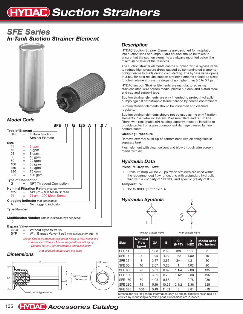
Suction Strainers
Accessories Catalog135
Dimensions are for general information only, all critical dimensions should be verified by requesting a certified print. Dimensions are in inches.
Dimensions
B D Hex
øA
Optional Bypass-Valve
NPT ThreadedConnectionC
Without Bypass-Valve With Bypass-Valve
Model CodeSFE 11 G 125 A 1 .0 / .
Type of Element SFE = In-Tank Suction
Strainer Element
Size 11 = 3 gpm 15 = 5 gpm 25 = 8 gpm 50 = 10 gpm 80 = 20 gpm 100 = 30 gpm 180 = 50 gpm 280 = 75 gpm 380 = 100 gpm
Type of Connection G = NPT Threaded Connection
Nominal Filtration Rating (micron) 125 = 149 µm – 100 Mesh Screen 74 = 74 µm – 200 Mesh Screen
Clogging Indicator (not applicable) A = No clogging indicator
Type Number 1
Modification Number (latest version always supplied) .0
Bypass Valve (omit) = Without Bypass-Valve BYP = With Bypass Valve (3 psi) (not available for size 11)
Model Codes containing selections listed in RED italics are non-standard items – Minimum quantities will apply
Contact HYDAC for information and availability
Not all combinations are available
SizeNominal
Flow (gpm)
ØA B C (NPT)
D HEX
Media Area (Sq. Inches)
SFE 11 3 1.33 2.62 3/8 1.188 3
SFE 15 5 1.95 4.19 1/2 1.00 16
SFE 25 8 2.67 3.55 3/4 1.31 50
SFE 50 10 2.67 5.25 1 1.62 90
SFE 80 20 3.39 6.62 1 1/4 2.00 135
SFE 100 30 3.39 8.76 1 1/2 2.38 195
SFE 180 50 4.03 9.88 2 2.78 230
SFE 280 75 5.19 10.25 2 1/2 3.38 325
SFE 380 100 5.19 11.53 3 3.81 410
Description HYDAC Suction Strainer Elements are designed for installation into suction lines of pumps. Extra caution should be taken to ensure that the suction elements are always mounted below the minimum oil level of the reservoir.
The suction strainer elements can be supplied with a bypass valve to reduce high pressure drops caused by contaminated elements or high viscosity fluids during cold starting. The bypass valve opens at 3 psi. for best results, suction strainer elements should be sized for clean element pressure drops of no higher than 0.5 to 0.7 psi.
HYDAC suction Strainer Elements are manufactured using stainless steel wire screen media, plastic nut cap, and plated steel end cap and support tube.
Suction strainer elements are only intended to protect hydraulic pumps against catastrophic failure caused by coarse contaminant.
Suction strainer elements should be inspected and cleaned regularly.
Suction strainer elements should not be used as the only filtration elements in a hydraulic system. Pressure filters and return line filters, with reasonable dirt holding capacity, must be installed to provide protection against component damage caused by fine contaminants.
Cleaning Procedure
Remove external build-up of contaminant with cleaning fluid in separate tank.
Flush element with clean solvent and blow through wire screen media with air.
Hydraulic DataPressure Drop vs. Flow:
Pressure drop will be < 2 psi when strainers are used within •the recommended flow range, and with a standard hydraulic fluid with a viscosity of 141 SSU and specific gravity of 0.86.
Temperature:
15° to 180°F (59° to 176°C)•
Hydraulic Symbols
SFE SeriesIn-Tank Suction Strainer Element

Suction Strainers
Accessories Catalog 136
Dimensions are for general information only, all critical dimensions should be verified by requesting a certified print.Dimensions are in inches/(mm) and lbs./(kg.)
AC
B Connectionsize
Model Number Part No. Connection Size
Max. Flow gpm (lpm)
∆ psi at Max. gpm
Dimensions
A B B
MSS-1 02082431 1” NPT 15 (55) 0.05 5.25” (133) 3.25” (83) 1.62” (41)
MSS-1 1/4 02082432 1 1/4” NPT 25 (95) 0.05 8.25” (210) 3.50” (89) 3.00” (76)
MSS-1 1/2 02082433 1 1/2” NPT 35 (135) 0.08 8.25” (210) 3.50” (89) 3.00” (76)
MSS-2 02082434 2” NPT 50 (190) 0.10 8.25” (210) 3.50” (89) 3.00” (76)
MSS-3 02082435 3” NPT 100 (380) 0.02 10” (254) 3.50” (89) 4.00” (102)
* B Dimension larger for SS20 versions
DescriptionWith the use of HYDAC’s Magnetic Suction Separators, suction line filtration is provided without starving the pump. They offer unique protection for pumps from all sizes of ferrous particles, some of which have the potential of destroying a pump in a single pass. Large ceramic magnets are spaced along the length of the separator. All hydraulic fluid entering the pump must move at low velocity through a powerful magnetic field. This field traps large quantities of micronic ferrous particles. The viscous properties of the fluid can cause some non-ferrous particles to adhere to the magnetically trapped particles.
The MSS series is available in sizes ranging from one to three inches. The chart below shows the part numbers, specifications, and dimensions of available models.
The standard outer screen has adequate open area (0.079 inch diameter perforations) to eliminate the possibility of pump starvation. All models are also available with a pleated 20 mesh screen (850 micron) by adding SS20 to the model number. (Example MSS-1 SS20).
All units have a removable outer screen that can be cleaned and re-used to extend service life and minimize pressure drop.
Dimensions
MSS SeriesMagnetic Suction Separators
Standard Outer Screen
SS20 Mesh Screen
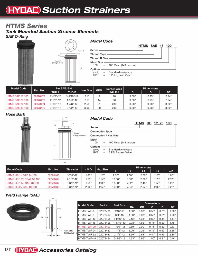
Suction Strainers
Accessories Catalog137
SAE O-Ring
PORT SIZE(PER SAE J514)
C
ØE
D
ØBØA
ø O.D.
L3L2
L
L1
ø E
Thread A(O-Ring Included)
Model CodeHTMS HB 1/1.25 100 .
Series
Connection Type
Connection / Hex Size
Mesh 100 = 100 Mesh (149 micron)
Options (omit) = Standard (no bypass) RV3 = 3 PSI Bypass Valve
Model CodeHTMS SAE 16 100 .
Series
Thread Type
Thread B Size
Mesh Size 100 = 100 Mesh (149 micron)
Options (omit) = Standard (no bypass) RV3 = 3 PSI bypass Valve
Hose Barb
Weld Flange (SAE)
Model Code Part No. Port SizeDimensions
ØA ØB C D ØE
HTMS TWF-6 02078493 9/16”-18 1.50” 0.93” 0.56” 0.31” 1.00”
HTMS TWF-8 02078494 3/4”-16 1.50” 0.93” 0.56” 0.31” 1.00”
HTMS TWF-12 02078495 1-1/16”-12 2.13” 1.38” 0.69” 0.44” 1.44”
HTMS TWF-16 02078496 1-5/16”-12 2.38” 1.66” 0.75” 0.50” 1.75”
HTMS TWF-20 02078497 1-5/8”-12 2.69” 2.00” 0.75” 0.50” 2.13”
HTMS TWF-24 02078482 1-7/8”-12 3.00” 2.25” 0.75” 0.50” 2.38”
HTMS TWF-32 02078483 2-1/2”-12 3.50” 2.63” 0.84” 0.59” 2.88”
HTMS TWF-48 02078484 3-3/8”-12 4.63” 3.66” 1.00” 0.81” 3.94
Model Code Part No. Thread A ø O.D. Hex SizeDimensions
L L1 L2 L3 ø E
HTMS HB 1 / SAE 24 100 02078485 1-7/8”-12 1.00” 1.25” 9.30” 7.30” 2.00” 1.25” 1.65”
HTMS HB 1.25 / SAE 32 100 02078486 2-1/2”-12 1.25” 1.50” 10.00” 8.00” 2.00” 1.25” 2.12”
HTMS HB 1.5 / SAE 48 100 02078487 3-3/8”-12 1.50” 2.00” 10.30” 7.82” 2.48” 1.50” 3.22”
HTMS HB 2 / SAE 48 100 02078488 3-3/8”-12 2.00” 2.50” 10.80” 7.84” 2.97” 2.00” 3.22”
Model CodePart No.
Per SAEJ514Hex Size GPM Screen Area
(Sq. In.)Dimensions
THD A THD B C D ØE
HTMS SAE 16 100 02078472 2-1/2”-12 1-5/16”-12 2.13 9 90 9.00” 0.75” 2.24”
HTMS SAE 20 100 02078473 2-1/2”-12 1-5/8”-12 2.13 14 90 9.00” 0.75” 2.24”
HTMS SAE 24 100 02078474 3-3/8”-12 1-7/8”-12 2.50 21 230 8.80” 0.90” 3.22”
HTMS SAE 32 100 02078475 3-3/8”-12 2-1/2”-12 3.00 39 230 9.30” 0.98” 3.22”
HTMS SeriesTank Mounted Suction Strainer Elements
ø E
D
C
Thread B
Thread A(O-ring Included)

Suction Strainers
Accessories Catalog 138
Dimensions are for general information only, all critical dimensions should be verified by requesting a certified print.Dimensions are in inches/(mm) and lbs./(kg.)
Model CodeHTMS NPTM 2 100 .
Series
Thread Type
Thread B Size
Mesh Size 100 Mesh (149 micron)
Options (omit) = Standard (no bypass) RV3 = 3 PSI bypass Valve
Model CodeHTMS NPT 1/2 100 .
Series
Thread Type
Thread B Size
Mesh 100 Mesh (149 micron)
Options (omit) = Standard (no bypass) RV5 = 5 PSI Bypass Valve
ø E
L2
Thread A
Thread B
L
L1
ø E
D
Thread B
C
Thread A
Male NPT Ports
NPT
Model Code Part No. THD A THD B Hex SizeDimensions
L L1 L2 ø E
HTMS NPTM 2 100 02078480 2” NPT 2” NPT 2.75” 13.50” 10.75” 2.70” 2.12”
Model Code Part No. GPM Screen Area (Sq. In.) THD A THD B Hex Size
Dimensions
C D ø E
HTMS NPT 1/2 100 02078460 5 35 1” NPT 1/2” NPT 1.43 5.38” 1.10” 1.18”
HTMS NPT 3/4 100 02078461 10 64 1 1/4” NPT 3/4” NPT 1.81 7.50” 1.20” 1.14”
HTMS NPT 1 100 02078462 15 86 1 1/2” NPT 1” NPT 2.00 8.25” 1.30” 1.65”
HTMS NPT 1 1/4 100 02078463 25 125 2” NPT 1 1/4” NPT 2.55 10.00” 1.30” 2.12”
HTMS NPT 2 100 02078464 50 260 3” NPT 2” NPT 3.30 10.25” 1.70” 3.03”
HTMS NPT 3 100 02078465 100 315 4” NPT 3” NPT 5.00 11.30” 1.80” 3.78”

Fluid Level Indicators
Accessories Catalog139
Dimensions are for general information only, all critical dimensions should be verified by requesting a certified print.Dimensions are in inches/(mm) and lbs./(kg.)
Electric Level SwitchFSK...C (open at normal level)
1
2ground
FSK...C
FSK...O (closed at normal level)
ground1
2
FSK...O
Electrical SpecificationsContact Ratings
Max. 8W•
Maximum Voltage
50V AC or DC•
Maximum Current
200 mA•
Magnetic Float inside tube trips switch when fluid level drops within 50mm of lower bolt. (see illustration)
1.97”(50mm)
1278.46”
(215mm)
17610.39”
(264mm)
25413.66”
(347mm)
38118.66”
(474mm)
1275.00”
(127mm)
1766.93”
(176mm)
25410.00”
(254mm)
38115.00”
(381mm)
SWITCHLEVEL
2.85”(72.5mm)
2.85”(72.5mm)
1.34”(34.3mm)
0.79”(20mm)
0.12”(3mm)
M 12(torque to
10 Nm)
max. 0.31”max. (8mm)
Clearance Holeø 0.51 (13mm)
1.77”(35mm)
1.93”(49mm)
2.05”(52mm)
0.20”(5mm)
0.83”(21mm)
For SwitchRemoval
Dimensions
Model CodeFSK - 127 - 2 . 4 / 0 / / 12 .
Fluid Level Indicator FSK = Electrical and visual
level indicator
Size (Mounting Hole Centers) 127 = 5 inches 176 = 7 inches 254 = 10 inches 381 = 15 inches
Seals 2 = Fluorocarbon
Modification Number 4 = FSK (Determined by Manufacturer)
Electrical Switch C = Open at Normal Level O = Closed at Normal Level
Thermometer (omit) = No Thermometer (standard) FT 100 = Probe Thermometer (100mm-3.94”LG) FT 200 = Probe Thermometer (200mm-7.87”LG) FT 300 = Probe Thermometer (300mm-11.87”LG) TS... = Thermo Switch (see chart on page 141)
Hex Head Bolt 12 = M12 x 1.75 Bolt
Sight Tube (omit) = Polyimide construction (not suitable for water glycols or high water based fluids) SO14 = Glass tube construction
Model Codes containing selections listed in RED italics are non-standard items – Minimum quantities will apply
Contact HYDAC for information and availability
Not all combinations are available
FSK Series with Electric Level Switch
Contacts CLOSE when fluid level drops BELOW switching level
Contacts OPEN when fluid level drops BELOW switching level

Fluid Level Indicators
Accessories Catalog 140
Dimensions are for general information only, all critical dimensions should be verified by requesting a certified print.Dimensions are in inches/(mm) and lbs./(kg.)
DimensionsModel CodeFSA 127 - 1 . 1 / T / 12 - .
Fluid Level Indicator FSA = Visual level indicator
Size (Mounting Hole Centers) 76 = 3 inches 127 = 5 inches 176 = 7 inches 254 = 10 inches 381 = 15 inches
Seals 1 = NBR 2 = Fluorocarbon
Housing Material 0 = Steel (only for SO14 glass tube construction) 1 = Aluminum 2 = ABS Plastic
Thermometer (omit) = No Thermometer T = Built-in Tube FT 100 = Probe Thermometer (100mm-3.94”LG) FT 200 = Probe Thermometer (200mm-7.87”LG) FT 300 = Probe Thermometer (300mm-11.87”LG) TS... = Thermo Switch (see chart on page 141)
Hex Head Bolt 12 = M12 x 1.75 Bolt
Sight Tube Material (omit) = Polyimide construction
(not suitable for water glycols or high water based fluids) SO14 = Glass tube construction
Model Codes containing selections listed in RED italics are non-standard items – Minimum quantities will apply
Contact HYDAC for information and availability
Not all combinations are available
FSA Series
0.79”(20mm)
0.12”(3mm)
1.77”(45mm)
20”(5mm)
Clearance Holeø.51 (13mm)
M 12
max. 0.31”max. (8mm)
LL2
1.34”(34mm)
ºC ºF
HYDAC
80-
70-
60-
50-
40-
30-
20-
10-0-
-10-
-180
-160
-140
-120
-100
-80
-60
-40
-20
L1
Size L L1 L2
76 4.25” (108mm)
1.46” (37mm)
2.99” (76mm)
127 6.26” (159mm)
2.99” (76mm)
5.00” (127mm)
176 8.19” (208mm)
4.92” (125mm)
6.93” (176mm)
254 11.26” (286mm)
7.99” (203mm)
10.00” (254mm)
381 16.26” (413mm)
12.99” (330mm)
15.00” (381mm)

Fluid Level Indicators
Accessories Catalog141
Thermo Switch - TS...Detail of Lower Connection for Probe Thermometer (FT...) see chart below
Electrical SpecificationsMaximum Voltage
50 VAC or DC•
Minimum Current
50 mA•
Contact
Normally Closed•
Switching Tolerance
±10°F •
Hysterisis
TS 60/70 27°F (15°C)•
TS 80 36°F (20°C)•
Expected Life Cycleat 25 A / 50 V 10,000 cycles•
at 0.5 A / 50 V 100,000 cycles•
OptionsElectric Thermo Switch / TS
M 12
0.67” SQSW 17
0.63”(16mm)
3.62”(92mm)
1.93”(49mm)
~ø 1.51”(40mm)
Special M12 Boltwith 1/16" NPT Portfor Probe Thermometer3.94”
(100mm) 7.87”
(200mm) 11.87”
(300mm)or or
ground
1 2 TS...
Contacts OPEN when fluid temperature rises ABOVE switching temperature
Thermo Switches (Normally Closed Contact)
Thermo Switch Code Model Code Part Number Switch Opens @ Switch Closes @ Mounting Thread
TS60 TS-L-60/X/12 THERMO-SWITCH 03252752 60°C/140°F 45°C/113°F M 12
TS70 TS-L-70/X/12 THERMO-SWITCH 03252766 70°C/158°F 55°C/131°F M 12
TS80 TS-L-80/X/12 THERMO-SWITCH 03252767 80°C/176°F 60°C/140°F M 12
Probe Thermometer / FT FeaturesAnalog dial type thermometer for visual temperature indication•
Temperature Range (Dual Scale)
0° to 212°F•
0° to 100°C•
Detail of Lower Connection
Probe Thermometers Temperature Range 32° to 212°F (0° to 100°C)
Thermo Switch Code Model Code Part Number Mounting Thread
FT100 FT-100 TEMP PROBE W/M12 BOLT 02067556 M 12
FT200 FT-200 TEMP PROBE W/M12 BOLT 00086740 M 12
FT300 FT-300 TEMP PROBE W/M12 BOLT 00086741 M 12

Fluid Level Indicators
Accessories Catalog 142
FSA & FSK FSK OnlyComponent Parts
Item Description Part No.Quantity
FSA FSK
1 Housing – 1 1
2 Name Plate – 1 -
3 Tube – 1 1
4* O-Ring 13x2.5 00601916 (Fluorocarbon) 00601047 (Buna)
2 2
5 Tube Connector – 2 2
6* O-Ring 12.3x2.4 00601531 (Fluorocarbon) 00601045 (Buna)
2 2
7* Sealing Washer - 27 x 12 x 3 22183158 (Fluorocarbon) 2 2
8 Hex Bolt M12 22183153 2 2
9 Hex Nut M12 22183151 2 2
10 Thermometer in Indicator Tube 00084108 1 -
11 Probe Thermometer (see page 97) – 1 1
12 Hex Bolt for Probe Thermometer 00278741 1 1
13 Magnetic Float – - 1
14 Base Assembly with Type “C” Switch – - 1
15 Base Assembly with Type “O” Switch – - 1
16* Washer (optional - see note 2 above) 00001689 1 1
* items may be purchased individually.
Technical DataMaterial
Housing Anodized Aluminum or ABS Plastic
Sight Tube Polyimide or Glass
Seals Fluorocarbon, NBR
Nuts / Bolts Steel, Zinc plated
Fluid Temperature -4° to 176°F (-20° to 80°C)
Maximum Pressure 14.5 PSI (1 BAR)
Thermometer Range
Type T (FSA only) 14° to 176°F (-10° to 80°C)
Type FT100 32° to 212°F (0° to 100°C)
Type FT200 32° to 212°F (0° to 100°C)
Type FT300 32° to 212°F (0° to 100°C)
Bolting Torque Max. 8 LB-FT+1 (10 Nm +2) see installation instructions below
Recommended Installation Process1. Drill mounting holes (13 mm) according to dimension L2.
2. Torque the Nut, item 9, to 8+ 1 LB-FT. If it is not possible to torque the nut, the bolt head must be torqued. To avoid damaging the indicator a washer is recommended to be used under the bolt head. This washer is available from HYDAC: Part Number 00001689. Washer Dimensions: øD 18.8 mm, ID 13.10 mm, 0.5 mm thick
13
14or15
8
7
65
3
2 1
4
10
9
reservoir wallreservoir wall

Gauge Isolators
Accessories Catalog143
Dimensions are for general information only, all critical dimensions should be verified by requesting a certified print.Dimensions are in inches/(mm) and lbs./(kg.)
ø 1.220"(31mm)
Hole Requiredin Panel
1.299"(33mm)
1.083"(27.5mm)
0.394"(10mm)
1.268"(32.2mm)
2.035"(51.7mm)
3.465"(88mm)
1.169"(29.7mm)
PM
T
ø 1.024"(26mm)
SW 361 7/16"
3.150"(80mm)
Push to Read
M30x1.5
Push Knob and Turn Clockwise 90for Continuous Reading
Cover Plate
Max PanelThickness
Model CodeMA 1 . A 1 0 / 5 V
Gauge Isolator Single Station
Design 1 = Push/Rotating Control Knob
Connection A = Threaded
Type Number
Modification Number
Port Configuration 0 = BSPP Thread (G1/4) Part No. 02057942 5 = 1/4” NPT Thread Part No. 02057940 12 = SAE-5 (1/2”-20 UNF) Part No. 02057941
Seals V = Fluoroelastomer Seals (standard)
Model Codes containing selections listed in RED italics are non-standard items – Minimum quantities will apply
Contact HYDAC for information and availability
Not all combinations are available
Hydraulic SymbolM Gauge Port
P T
Pushto read
Description Gauge life is extended by using the MA 1 when reading •pressure. When not reading pressure, the gauge is vented to tank to protect the gauge against pressure from the system.
There are two ways to operate the MA 1: •Push to read (spring return) Push and rotate clockwise to lock in for continuous pressure reading
SpecificationsMounting
Panel installation maximum 0.39”•
Connections
1/4” NPT, SAE-5, or G1/4 (Ports M, P, T)•
Weight
0.88 lbs./0.4 kg•
Mounting Position
Horizontal or Vertical•
Operating Fluid
Mineral Oils•
Hydraulic DataOperating Pressure
P max. 5075 psi/350 bar • (T-Port max. 145 psi/10 bar)Temperature Range
-4° to 176°F (-20° to 80°C)•Dimensions
MA SeriesSingle Gauge Isolator

Gauge Isolators
Accessories Catalog 144
Dimensions are for general information only, all critical dimensions should be verified by requesting a certified print.Dimensions are in inches/(mm) and lbs./(kg.)
Hydraulic Symbol1 2 3
T
4 5 6
GeneralMounting Method
Flange mounting via four 1/4” bolts. It is recommended that the •measuring points with pressures of over 1450 psi (100 bar) be arranged symmetrically. Ports not in use should be plugged.
Weight
3.8 lbs. / 1.7 kg.•
Mounting Position
Optional•
Fluids
General purpose hydraulic oil. For other fluids, •contact HYDAC for information.
Type of Connections
6 measuring points•
1 tank connection•
Hydraulic DataOperating Pressure Range
Max. operating pressure at measuring points 1- 6 •4500 psi (315 bar)
Max. Tank connection pressure 145 psi (10 bar)•
Fluid Temperature Range
- 5° to 160°F (-20° to 70°C)•
Gauge Accuracy
Built-in gauge accuracy is ±1.6% of the max. scale value at •68°F (20°C). The error per additional 50°F (10°C) temperature increase is +0.3% and 50°F (10°C) temperature reduction is -0.3%. Values are based on red scale indication.
Model CodeMSL 2 G 2 . 0 / 315 V
Multi-Station Gauge Isolator MSL = Zero Leakage Model
Model 2 = with Built-in Pressure Gauge
Type and Size of Connection (All Ports) G = 1/4” NPT H = SAE-4 (7/16”-20 UNF) A = BSPP (G1/4)
Type Number
Modification Number
Gauge Indication Range
Size Operating Pressure Zone (Black Scale)
Over Pressure Zone (Red Scale)
40 0 - 570 psi (0 - 40 bar) 570 - 900 psi (40 - 63 bar)63 0 - 900 psi (0 - 63 bar) 900 -1400 psi (63 - 100 bar)100 0 - 1400 psi (0 - 100 bar) 1500 - 2300 psi (100 - 160 bar)180 0 - 2600 psi (0 - 180 bar) 2600 - 3600 psi (180 - 250 bar)315 0 - 4500 psi (0 - 315 bar) 4500 - 5700 psi (315 - 400 bar)
Supplementary Details (omit) = Buna Seals V = Viton Seals
Model Codes containing selections listed in RED italics are non-standard items – Minimum quantities will apply
Contact HYDAC for information and availability
Not all combinations are available
04
0200
0
100 300
400
5
0
60
1
0
2
0
3
Connections 1-6 formeasuring connections
Adaptor fortank connection
Use any "0" Position toconnect gauge to tank
Adaptor fortank connection
1
2
34
5
6
T
DO NOT REMOVE PLUGS!Make all connections in rearfacing ports shown below.
60°TYP.
2.20”(56mm)
0.55”(14mm)
4.29”(109mm)
5.08”(129mm)
ø 2.95”(75mm)
0.28”(7mm)
ø 0.26”(6.6mm)
ø 0.43”(11mm)
ø 4.72”(120mm)
90°
45°
ø 2.83”(72mm)
ø 4.01”(102mm)
Dimensions
MSL Series Zero Leakage Multi-Station Gauge Isolators with Integral Gauge

Gauge Isolators
Accessories Catalog145
GeneralMounting Method
Flange mounting via four 1/4” bolts. It is recommended that •the measuring points with pressures of over 1450 PSI / 100 BAR be arranged symmetrically. Ports not in use should be plugged.
Weights
MS 4 & MS 5• 3.1 lbs. / 1.4 kg.
MS 6 & MS 7• 4.2 lbs. / 1.9 kg.
Mounting Position
Optional•
Fluids
General purpose hydraulic oil. For other fluids, •contact the HYDAC office for information.
Types of Connections
• MS 4 / MS 6 1 gauge connection (M) 1 tank connection (T)
• MS 5 / MS 7 1 gauge connection (M) 1 tank connection (T) 1 leakage connection (L)
Hydraulic DataOperating Pressure Range
MS 4 / MS 5 / MS 6 / MS 7 •Max. operating pressure range at measuring points 4500 PSI / 315 BAR
Max. tank and leakage connection pressure •145 PSI / 10 BAR
Fluid Temperature Range
- 5° to 160°F (-20° to 70°C)•
Hydraulic SymbolM = Gauge (measuring) connectioneT = Tank connectionL = Leakage connection
Model CodeMS 4 A 2 . 1 / 5 V
Multi-Station Gauge Isolator
Model 4 = Turn and press to read (6 positions) 5 = Turn to read (5 positions) 6 = Turn and press to read (9 positions) 7 = Turn to read (8 positions)
Type and Size of Connections A = Threaded Connections
Type Number
Modification Number
Port Type 5 = NPT Port (1/4” for MS 4 & 5 only) 12 = SAE Port (SAE-4 for MS 4 & 5 only) 0 = BSPP (1/4” for MS 4 & 5 and 1/8” for MS 6 & 7)
Seals (omit) = Buna N V = Fluoroelastomer Seals
Model Codes containing selections listed in RED italics are non-standard items – Minimum quantities will apply
Contact HYDAC for information and availability
Not all combinations are available
MS SeriesMulti-Station Gauge Isolators
1 3 5 7 9
T
M
2 4 6 8
Type MS 6
M = Gauge (measuring) connectionT = Tank connectionL = Leakage connection
1 3 5 7 L
T
M
2 4 6 8
Type MS 7
T
M
1 2 3
4 5 6
Type MS 4
Pushto read
T
M
1 2 3
4 5 L
Type MS 5
Pushto read

Gauge Isolators
Accessories Catalog 146
Dimensions are for general information only, all critical dimensions should be verified by requesting a certified print.Dimensions are in inches/(mm) and lbs./(kg.)
DimensionsType MS 4 Type MS 5
ø 2.95”(75mm)
90° 90°
45° 45°
M T
2
1 5
4
6
3
4
M T
3
1 8
6
2 7
5
9
90° 90°
45° 45°
ø 2.95”(75mm)
M L
2
1 5
4
3
0
T
ø 2.95”(75mm)
ø 2.95”(75mm)
4.92”(125mm)
3.50”(89mm)
0.55”(14mm)
All Ports are the same thread type-4 SAE, 1/4"NPTF, or G1/4
(specified by model code)
ø 0.26”(6mm)
ø 0.43”(11mm)
ø 1.97”(50mm)
0.28”(7mm)
4
M LT
3
1 8
6
2 7
5
0
2.36”(60mm)
Push to read presure,release to connectgauge back to tank
Turn to "0" positionto connect
gauge back to tank
Push to read presure,release to connectgauge back to tank
Turn to "0" positionto connect
gauge back to tank
ø 0.98 (25mm) typical(spot surface finish)Ports L, M, T
are in this areaPorts 1-6 arein this area
All Ports are the same thread typeG1/8 only
(specified by model code)
ø 0.67 (17mm) typical(spot surface finish)
Ports L, M, Tare in this area Ports 1-9 are
in this area
ø 3.54”(90mm)
2.36”(60mm)
6.02”(153mm)
4.61”(117mm)
1.10”(28mm)
1.02”(26mm)
0.55”(14mm)
ø 0.26”(6mm)
ø 0.43”(11mm)
ø 1.97”(50mm)
0.28”(7mm)
ø 3.54”(90mm)
2.36”(60mm)
Type MS 6 Type MS 7
ø 2.95”(75mm)
90° 90°
45° 45°
M T
2
1 5
4
6
3
4
M T
3
1 8
6
2 7
5
9
90° 90°
45° 45°
ø 2.95”(75mm)
M L
2
1 5
4
3
0
T
ø 2.95”(75mm)
ø 2.95”(75mm)
4.92”(125mm)
3.50”(89mm)
0.55”(14mm)
All Ports are the same thread type-4 SAE, 1/4"NPTF, or G1/4
(specified by model code)
ø 0.26”(6mm)
ø 0.43”(11mm)
ø 1.97”(50mm)
0.28”(7mm)
4
M LT
3
1 8
6
2 7
5
0
2.36”(60mm)
Push to read presure,release to connectgauge back to tank
Turn to "0" positionto connect
gauge back to tank
Push to read presure,release to connectgauge back to tank
Turn to "0" positionto connect
gauge back to tank
ø 0.98 (25mm) typical(spot surface finish)Ports L, M, T
are in this areaPorts 1-6 arein this area
All Ports are the same thread typeG1/8 only
(specified by model code)
ø 0.67 (17mm) typical(spot surface finish)
Ports L, M, Tare in this area Ports 1-9 are
in this area
ø 3.54”(90mm)
2.36”(60mm)
6.02”(153mm)
4.61”(117mm)
1.10”(28mm)
1.02”(26mm)
0.55”(14mm)
ø 0.26”(6mm)
ø 0.43”(11mm)
ø 1.97”(50mm)
0.28”(7mm)
ø 3.54”(90mm)
2.36”(60mm)

TestPoints
Accessories Catalog147
Technical DataMaximum Working Pressure
9000 psi (630 bar) •(see pressure utilization factor to adjust for operating temperature)
Fluid Compatibility
Suitable for petroleum based fluids and gaseous media•
Materials
Zinc plated steel body • (standard)
Zinc plated metal cap • (standard)
Seals
Buna-N • (standard)
Fluorelastomer • (standard)
Temperature Range
With metal cap and Buna-N seals: • -22° to 248°F (-30° to 120°C)
Options
Anti-vibration seal for metal cap•
Series 1620 TestPoint
Guided Piston Design
DescriptionHYDAC series 1620, guided piston design, TestPoints are compact, self sealing couplings that provide access to hydraulic and pneumatic systems for pressure measurement to 9000 psi. Mating adapters or hose connections can be connected without loss of fluid while the system is operating. TestPoints can also be used to take oil samples or to bleed air from hydraulic systems. They are available in 1620 (M16x2.0) connection threads with a variety of screw-in port configurations.
Features Can be coupled and uncoupled under pressure •without system shutdown or fluid loss
Patented guided piston design for leak free •performance at operating pressure to 9000 psi
HYDAC guided piston design provides the following advantages •over ball seal design:
- Higher working Pressure
- Better sealing characteristics particularly under high vibration
- Less susceptible to fluid contamination
- Can be used for gas as well as fluid
ApplicationsPressure measurement with gauges or sensors•
Fluid sampling•
Air bleeding•
1620 SeriesTestPoints & Micro Bore Flex Hoses

TestPoints
Accessories Catalog 148
Model Codes containing selections listed in RED italics are non-standard items – Minimum quantities will apply – Contact HYDAC for information and availability Not all combinations are available
Micro Bore Flexible Hoses
ø5 mmM16x2 M16x2ø2 mm
L
L (inches) L (mm) Part No.
8 200 06003723
12 300 06003724
16 400 00632633
20 500 06003725
25 630 06003726
31 800 00682857
39 1000 00632634
49 1250 06003727
59 1500 00682858
79 2000 00682859
98 2500 00682860
126 3200 06003728
157 4000 06003729
197 5000 06003730
236 6000 02701721
394 10,000 02701722
Pressure Utilization Factor for HosesOperating Temp. Factor Max. Pressure
122°F (50°C) 100% 9000 psi
176°F (80°C) 86% 7740 psi
212°F (100°C) 77% 6930 psi
Specifications Maximum working pressure 9000 psi (630 bar) at 122°F (50°C) •(see pressure utilization factor to adjust for higher temperatures)
Suitable for petroleum based fluids•
Temperature range -4° to 122°F (-20° to 50°C) at max. pressure•
Polyamid core with polyester braid reinforcement and polyamid jacket•
Plastic dust cap•
1620 female connection at both ends•
Bending radius: min. 20mm•
Hose ID ø 2mm•
Custom Hose Assemblies Available: • NPT Male Thread, NPT Female Thread, JIC Male Hose, JIC Female swivel hose ends
Carbon Steel TestPoints (Zinc-Plated, Buna N Seals)Thread G P max H (mm) T (mm) SW (mm) Part No.
1/8 NPTF 5800 psi (400 bar) 33 13 17 06003734
1/4 NPTF 5800 psi (400 bar) 33 16.5 17 00639645
7/16-20 UNF 9000 psi (630 bar) 37 9 17 06003735
9/16-18 UNF 9000 psi (630 bar) 36 10 19 06003737
M 8x1 3600 psi (250 bar) 41 8.5 17 06003731
M 10x1 3600 psi (250 bar) 37.5 8.5 17 00629237
M 12x1.5 9000 psi (630 bar) 36 10 17 00632615
M 14x1.5 9000 psi (630 bar) 36 10 19 00632248
M 16x1.5 9000 psi (630 bar) 36 10 22 06003732
ISO 228-G 1/8 5800 psi (400 bar) 38 8 17 00689901
ISO 228-G 1/4 9000 psi (630 bar) 36 10 19 00680107
ISO 228-G 3/8 9000 psi (630 bar) 36 10 22 06003733
ISO 7/I-R 1/8 5800 psi (400 bar) 33 13 17 06003738
ISO 7/I-R 1/4 9000 psi (630 bar) 33 13 17 06003739
Carbon Steel TestPoints (Zinc-Plated, Fluorelastomer Seals)Thread G P max H (mm) T (mm) SW (mm) Part No.
1/8 NPTF 5800 psi (400 bar) 33 13 17 06007199
1/4 NPTF 5800 psi (400 bar) 33 13 17 06007200
7/16-20 UNF 9000 psi (630 bar) 37 9 17 06007029
9/16-18 UNF 9000 psi (630 bar) 36 10 19 06007030
ISO 228-G 1/4 9000 psi (630 bar) 36 10 19 00606304
Stainless Steel TestPoints (Fluorelastomer Seals)Thread G P max H (mm) T (mm) SW (mm) Part No.
1/4 NPTF 5800 psi (400 bar) 33 13 17 02701487
7/16-20 UNF 5800 psi (400 bar) 33 16.5 17 02701486Dimensions are for general information only, all critical dimensions should be verified by requesting a certified print. * for port configuration drawings contact HYDAC.
1620 SeriesDimensionsStandard 1620 TestPoint Connection with Cap
Selected desired connection in the chart to the right
Note: All TestPoints have a male connection thread (G)

TestPoints
Accessories Catalog149
Model Codes containing selections listed in RED italics are non-standard items – Minimum quantities will apply – Contact HYDAC for information and availability Not all combinations are available
Dimensions are for general information only, all critical dimensions should be verified by requesting a certified print.
1620 Series AdaptersDirect Gauge Adapter
Test DGA 1620 (thread G)Thread G Pmax SW Part No.
ISO 228-G 1/4 9000 psi (630 bar) 19 06003824
ISO 228-G 1/2 9000 psi (630 bar) 27 06003825
1/4 NPT 9000 psi (630 bar) 19 06003769
SAE-4 7/16-20 UNF 9000 psi (630 bar) 9 02083643
Test HGA Bulk 1620 (thread G)Thread G Pmax L SW Part No.
ISO 228-G 1/4 9000 psi (630 bar) 38.5 19 06003822
ISO 228-G 1/2 9000 psi (630 bar) 39.5 27 06003823
1/4 NPT 9000 psi (630 bar) 38.5 19 06003768Note: There is no check valve inside of this adapter. For permanent gauge installation only.
Test HHA 1620 (thread G)Thread G Pmax L SW Part No.
M 16x2.0 9000 psi (630 bar) 42 22 00687889
Test 37DEG 1620 (thread G)Thread G Pmax L SW Part No.
7/16”-20 UNF 9000 psi (630 bar) 55 17 06003792
1/2”-20 UNF 6000 psi (420 bar) 56.5 17 06003793
9/16”-18 UNF 4500 psi (315 bar) 57.5 19 06003794
3/4”-16 UNF 4500 psi (315 bar) 60.5 22 06003795
Hose to Gauge Bulkhead Adapter (with provisions for panel mounting)
Straight Coupling for Hose to Hose Connections
Standpipe Adapter 37° JIC FittingStandard 1620 TestPoint connection with cap

TestPoints
Accessories Catalog 150
Dimensions are for general information only, all critical dimensions should be verified by requesting a certified print. Dimensions are in inches/(mm) and lbs./(kg.)
Model Codes containing selections listed in RED italics are non-standard items – Minimum quantities will apply – Contact HYDAC for information and availability Not all combinations are available
1215 SeriesTestPointsStandard design is zinc plated steel, buna seals, plastic cap and integrated safety device against vibration.
Test HosesL(in) Model Code Part No.
25 Test Hose 1215 25” 02701307
59 Test Hose 1215 59” 02701377
Dimensions
ø5 mmM16x2 M16x2ø2 mm
L
Thread (G) p (max) H I SW Model Code Part Number
ISO 228-G 1/8 400 bar (5800 psi) 33 8 14 TestPoint 1215 (G1/8) PC/NBR –
ISO 228-G 1/4 630 bar (9000 psi) 32 10 19 TestPoint 1215 (G1/4) PC/NBR –
1/8 NPTF 400 bar (5800 psi) 29 12 14 TestPoint 1215 (1/8 NPT) PC/NBR –
1/4 NPTF 630 bar (9000 psi) 29 15 14 TestPoint 1215 (1/4 NPT) PC/NBR 02701305
7/16-20 UNF 630 bar (9000 psi) 32 9 17 TestPoint 1215 (7/16-20 UNF) PC/NBR 02701293
9/16-18 UNF 630 bar (9000 psi) 32 10 19 TestPoint 1215 (9/16-18 UNF) PC/NBR 02701335
Model Code Part Number 3 Gauge Quantity
5 Gauge Quantity
TestPoint Kit 1620 3 Gauge 02081635 - -
TestPoint Kit 1620 5 Gauge 02081636 - -
HPG-63-1000-LM 02701547 1 1
HPG-63-1500-LM 02701548 0 1
HPG-63-2000-LM 02701549 1 1
HPG-63-3000-LM 02701550 0 1
HPG-63-5000-LM 02701551 1 1
TEST HOSE 1620 12” 06003724 1 2
TEST HOSE 1620 39” 00632634 1 2
TEST HOSE 1620 79” 00682859 1 2
TESTPOINT 1620 (1/4 NPTF) MC/NBR 00639645 2 4
TESTPOINT 1620 (7/16-20 UNF) MC/NBR 06003735 2 4
TESTPOINT 1620 (9/16-18 NPTF) MC/NBR 06003737 2 4
TEST DGA 1620 (1/4 NPT) 06003769 1 3
TEST HGA BULK 1620 (1/4 NPT) 06003768 1 3
TEST HHA 1620 00687889 1 3
1620 SeriesTestPoint Kits
3 Gauge Kit
5 Gauge Kit

Accessories Catalog151
Gauges and Split Flanges
SpecificationsAccuracy: ±1.5% of span
Scale: PSI outside in black BAR inside in red
Connection: 1/4” NPT male
MaterialsCase: Stainless Steel
Ring: Polished SS, crimped
Wetted Parts: Copper Alloy
Window: Polycarbonate
Dial: White ABS
Pointer: Black Aluminum
Liquid Filling: Glycerine
Model Code Part Number
Pressure Range
Connection - 1/4” NPT
HPG-63-1000-LM 02701547 0 to 1000 psi Lower Mount (LM)
HPG-63-1500-LM 02701548 0 to 1500 psi Lower Mount (LM)
HPG-63-2000-LM 02701549 0 to 2000 psi Lower Mount (LM)
HPG-63-3000-LM 02701550 0 to 3000 psi Lower Mount (LM)
HPG-63-5000-LM 02701551 0 to 5000 psi Lower Mount (LM)
HPG-63-2000-CBM 02701552 0 to 2000 psi Center Back Mount (CBM)
Gauges2 1/2 inch face - 1/4”NPT Connection
øK
D B
E
FJ
øHøG
A
MaterialsPlated Carbon Steel•
Stainless Steel•
Pressure RatingCode 61: 3000 psi•
Code 62: 5000 psi•
Split Flanges SAE Code 61 & 62
Dimensions
front view back view
Dimensions are for general information only, all critical dimensions should be verified by requesting a certified print.Dimensions are in inches.
Code 61 Split Flanges (sold in pairs - each pair makes a single connection)Size Part Number
(Carbon Steel)Part Number
(Stainless Steel) A B D E F ØG ØH J ØK
0.50 02701585 02701539 0.86 2.12 1.50 0.75 0.50 1.22 0.96 0.245 0.344
0.75 02055588 02701540 0.98 2.56 1.88 0.88 0.56 1.53 1.27 0.245 0.406
1.00 02055704 02700970 1.11 2.75 2.06 0.94 0.62 1.78 1.52 0.295 0.406
1.25 02055715 02701541 1.39 3.12 2.31 0.88 0.56 2.03 1.72 0.295 0.469
1.50 02055720 02700919 1.58 3.69 2.75 1.00 0.62 2.41 2.00 0.295 0.531
2.00 02055735 02701542 1.86 4.00 3.06 1.03 0.62 2.84 2.47 0.355 0.531
Code 62 Split Flanges (sold in pairs - each pair makes a single connection)Size Part Number
(Carbon Steel)Part Number
(Stainless Steel) A B D E F ØG ØH J ØK
0.50 02701585 02701537 0.89 2.22 1.59 0.88 0.62 1.28 0.97 0.285 0.344
0.75 02055882 02700540 1.14 2.81 2.00 1.12 0.75 1.66 1.28 0.325 0.406
1.00 02055883 02700916 1.33 3.19 2.25 1.31 0.94 1.91 1.53 0.355 0.469
1.25 02055889 02701538 1.48 3.75 2.63 1.50 1.06 2.16 1.75 0.385 0.531
1.50 02055890 02700544 1.83 4.44 3.13 1.69 1.19 2.53 2.03 0.475 0.656
2.00 02055891 02700847 2.20 5.25 3.81 2.06 1.44 3.16 2.66 0.475 0.781
Model Codes containing selections listed in RED italics are non-standard items – Minimum quantities will apply – Contact HYDAC for information and availabilityNot all combinations are available
HYDAC Clamps currently service applications, worldwide, including:• Wind Energy • Mobile Equipment• Heavy Industry Equipment• Transportation Equipment• Petro-Chemical• Gas and Mining• Off-Shore• Railways
HYDAC’s Family of Clamp Products Includes:• DIN 3015 (STD, HVY, & TWIN)• Series Strip • Cushion • Buegu • Oval• U-Bolt • U-Bolt w/ Cushion• Quick Release Swivel • Band Straps for Cylinder / Tube • Custom Moldings• Custom Mounting Solutions
To ensure customer satisfaction, HYDAC provides unparalleled services: • Quality Products• Timely Deliveries• Years of Experience• World Class Customer
Service & Support

USA HYDAC TECHNOLOGY CORPORATION
HYCON Division
2260 City Line Road Bethlehem, PA 18017
1-877 GO HYDAC
www.hydacusa.com
HYDAC TECHNOLOGY CORPORATION Hydraulic Division
445 Windy Point Drive Glendale Heights, IL 60139
(630) 545-0800
www.hydacusa.com
HYDAC CORPORATION HYDAC TECHNOLOGY CORPORATION
1718 Fry Road • Suite 100 Houston, TX 77084
(281) 579-8100
www.hydacusa.com
HYDAC TECHNOLOGY CORPORATION
12606 NE 95th Street Building VC, Suite 100 Vancouver WA 98682
www.hydacusa.com
Canada HYDAC CORPORATION
14 Federal Road Welland Ontario, Canada L3B 3P2
905.714.9322
www.hydac.ca
Mexico HYDAC INTERNATIONAL SA DE CV
AV. Pirul No. 212 54090 los Reyes Iztacala, Tianepantla EDO. DE Mexico
01152-5-55565-8511
www.hydacusa.com
HYDAC CORPORATION Accumulator Division
2280 City Line Road Bethlehem, PA 18017
1-877 GO HYDAC
www.hydacusa.com
HYDAC TECHNOLOGY CORPORATION Electronic Division
2260 City Line Road Bethlehem, PA 18017
1-877 GO HYDAC
www.hydacusa.com
HYDAC CORPORATION HYDAC TECHNOLOGY CORPORATION
11650 Mission Park Drive • Suite 108 Rancho Cucamonga, CA 91730
(909) 476-6777
www.hydacusa.com
HYDAC TECHNOLOGY CORPORATION
9836-B Northcross Center Court Huntersville, NC 28078
www.hydacusa.com
HYDAC CORPORATION
101 - 18207 114 AVE W EDMONTON AB, Canada T5S 2P6
1.877.484.4228
www.hydac.ca
Accumulators
Filters
Fluid Service Products
Valves
Clamps
Accessories
Electronics
Cooling Systems
Compact Power Units
Cartridge Valves
Mobile Systems
© Copyright 2008 HYDAC CORPORATION • HYDAC TECHNOLOGY CORPORATION • Hydraulic Accessories Catalog #02080105 / 9.08
Related Documents