JLMN-Journal of Laser Micro/Nanoengineering Vol. 9, No. 3, 2014 242 Hybrid Micro-stereo-lithography by Means of Aerosol Jet Printing Technology Kotaro Obata, Ulrich Klug, Jürgen Koch, Oliver Suttmann, and Ludger Overmeyer Laser Zentrum Hannover e.V., Hollerithallee 8, 30419 Hanover, Germany E-mail: [email protected] We have developed an advanced micro-stereo-lithography process combined with single photon polymerization and aerosol jet printing technology to facilitate layer based photo-polymerized struc- turing by layer on a non-flat surface, which is not possible by conventional macro- or micro- stereo- lithography. The aerosolized photo-sensitive polymer retains its photo-curable characteristics (com- pared with its original liquid state). The photo-polymerization using UV laser irradiation achieved 6 µm in the horizontal resolution, while aerosol jet printing technology achieved 0.6 µm in the verti- cal resolution, individually. By means of this process we successfully produced 2D and 3D struc- tures, and a straight-line photo-polymerized structure was produced on a non-flat surface. Keywords: Photo-polymerization, 1-photon-polymerization, 1PP, micro-stereo-lithography, aerosol jet printing technology, additive manufacturing, 3D structuring and UV laser 1. Introduction Micro-fabrication of 3D (three-dimensional) structures is known as “additive manufacturing,” and its practical use is for rapid prototyping and manufacturing in academic research and industrial fields. Stereo-lithography (SL) with photo-sensitive polymer is one of the best known additive manufacturing technologies in free-form 3D structuring [1] and it is performed through photo-polymerization with UV (ultra violet) laser irradiation. UV laser beam scans a 2D pattern, which is generated by slicing 3D solid models with CAD software. The exposed UV laser beam is absorbed by the photo-sensitive liquid polymer surface, since in SL the photo-polymerization reaction is induced by 1-photon ab- sorption. After photo-polymerization of one layer the pol- ymerized layer is moved into the liquid polymer in the same direction as the incident laser beam. The distance of each layer step is normally equal to the slicing distance set by the 3D solid model described above. Before the next irradiation of the UV laser beam, a homogenous lamination with liquid photo-sensitive polymer is carried out on the already polymerized layers, and this stacking of the photo- polymerization in 2D pattern generates arbitrary 3D struc- tures. It is notable that this technology provides high-aspect 3D structures in free form, which is not possible with con- ventional micro electro-mechanical systems (MEMS) based on typical planar semiconductor processing [2-4]. Micro-stereo-lithography (MSL) based on the manufactur- ing method mentioned in SL produces 3D micro-structures with micrometre resolution [5-8]. In common MSL systems the lateral resolution of produced 2D patterns is determined by parameters such as type and concentration of photo- initiator, absorbing additives, wavelength and spatial inten- sity distribution of the incident laser beam during photo- polymerization. Therefore lateral resolution is not seriously problematic, due to the large number of influences. Vertical (depth) resolution is determined not only by the photo- polymerization process, but also by rheological factors such as viscosity and surface tension of the liquid photo- sensitive polymer. These rheological factors rather define minimum thickness of each stacked layer and particularly the duration for its self-planarization, and for this reason deposit of thin layers has always been problematic regard- ing process throughput in industrial applications. Various types of MSL system have been developed to achieve faster processing, enhanced cost-performance, and enhanced res- olution in 3D [9-14]. In addition the MSL technique ena- bles fabrication of functional polymers for 3D micro- structures with enhanced resolution for micro-optics, mi- cro-mechanics and bio-applications [15-21], but the tech- nology prohibits application of MSL to 3D structuring on non-flat surfaces, since deposition of uniform photo- sensitive polymers on a free-form surface is difficult. This limitation is a serious problem for practical future imple- mentation of MSL. To overcome these problems, we have developed a hy- brid MSL process using aerosol jet printing technology [22, 23]. The aerosol jet printing technology generates an aero- sol jet stream of photo-sensitive polymer and enables spray coating on any free-form surface [24]. Some research groups have reported metallization of silicon solar cells and printed integrated circuits (IC) using aerosol jet printing of conductive ink today [25-32]. Our hybrid MSL process, integrates the aerosol jet printing technology into conven- tional MSL with the result that the main advantage of struc- turing on free shapes surface can be achieved. In addition the aerosol jet printing reducing minimum layer thickness and accelerates self-planarization. The limitation of layer thickness caused by the rheological problems in conven- tional MSL is also improved by the new hybrid process. DOI: 10.2961/jlmn.2014.03.0012

Welcome message from author
This document is posted to help you gain knowledge. Please leave a comment to let me know what you think about it! Share it to your friends and learn new things together.
Transcript
JLMN-Journal of Laser Micro/Nanoengineering Vol. 9, No. 3, 2014
242
Hybrid Micro-stereo-lithography by Means of
Aerosol Jet Printing Technology Kotaro Obata, Ulrich Klug, Jürgen Koch, Oliver Suttmann, and Ludger Overmeyer
Laser Zentrum Hannover e.V., Hollerithallee 8, 30419 Hanover, Germany E-mail: [email protected]
We have developed an advanced micro-stereo-lithography process combined with single photon polymerization and aerosol jet printing technology to facilitate layer based photo-polymerized struc-turing by layer on a non-flat surface, which is not possible by conventional macro- or micro- stereo-lithography. The aerosolized photo-sensitive polymer retains its photo-curable characteristics (com-pared with its original liquid state). The photo-polymerization using UV laser irradiation achieved 6 µm in the horizontal resolution, while aerosol jet printing technology achieved 0.6 µm in the verti-cal resolution, individually. By means of this process we successfully produced 2D and 3D struc-tures, and a straight-line photo-polymerized structure was produced on a non-flat surface.
Keywords: Photo-polymerization, 1-photon-polymerization, 1PP, micro-stereo-lithography, aerosol jet printing technology, additive manufacturing, 3D structuring and UV laser
1. Introduction
Micro-fabrication of 3D (three-dimensional) structures is known as “additive manufacturing,” and its practical use is for rapid prototyping and manufacturing in academic research and industrial fields. Stereo-lithography (SL) with photo-sensitive polymer is one of the best known additive manufacturing technologies in free-form 3D structuring [1] and it is performed through photo-polymerization with UV (ultra violet) laser irradiation. UV laser beam scans a 2D pattern, which is generated by slicing 3D solid models with CAD software. The exposed UV laser beam is absorbed by the photo-sensitive liquid polymer surface, since in SL the photo-polymerization reaction is induced by 1-photon ab-sorption. After photo-polymerization of one layer the pol-ymerized layer is moved into the liquid polymer in the same direction as the incident laser beam. The distance of each layer step is normally equal to the slicing distance set by the 3D solid model described above. Before the next irradiation of the UV laser beam, a homogenous lamination with liquid photo-sensitive polymer is carried out on the already polymerized layers, and this stacking of the photo-polymerization in 2D pattern generates arbitrary 3D struc-tures. It is notable that this technology provides high-aspect 3D structures in free form, which is not possible with con-ventional micro electro-mechanical systems (MEMS) based on typical planar semiconductor processing [2-4]. Micro-stereo-lithography (MSL) based on the manufactur-ing method mentioned in SL produces 3D micro-structures with micrometre resolution [5-8]. In common MSL systems the lateral resolution of produced 2D patterns is determined by parameters such as type and concentration of photo-initiator, absorbing additives, wavelength and spatial inten-sity distribution of the incident laser beam during photo-polymerization. Therefore lateral resolution is not seriously
problematic, due to the large number of influences. Vertical (depth) resolution is determined not only by the photo-polymerization process, but also by rheological factors such as viscosity and surface tension of the liquid photo-sensitive polymer. These rheological factors rather define minimum thickness of each stacked layer and particularly the duration for its self-planarization, and for this reason deposit of thin layers has always been problematic regard-ing process throughput in industrial applications. Various types of MSL system have been developed to achieve faster processing, enhanced cost-performance, and enhanced res-olution in 3D [9-14]. In addition the MSL technique ena-bles fabrication of functional polymers for 3D micro-structures with enhanced resolution for micro-optics, mi-cro-mechanics and bio-applications [15-21], but the tech-nology prohibits application of MSL to 3D structuring on non-flat surfaces, since deposition of uniform photo-sensitive polymers on a free-form surface is difficult. This limitation is a serious problem for practical future imple-mentation of MSL.
To overcome these problems, we have developed a hy-brid MSL process using aerosol jet printing technology [22, 23]. The aerosol jet printing technology generates an aero-sol jet stream of photo-sensitive polymer and enables spray coating on any free-form surface [24]. Some research groups have reported metallization of silicon solar cells and printed integrated circuits (IC) using aerosol jet printing of conductive ink today [25-32]. Our hybrid MSL process, integrates the aerosol jet printing technology into conven-tional MSL with the result that the main advantage of struc-turing on free shapes surface can be achieved. In addition the aerosol jet printing reducing minimum layer thickness and accelerates self-planarization. The limitation of layer thickness caused by the rheological problems in conven-tional MSL is also improved by the new hybrid process.
DOI: 10.2961/jlmn.2014.03.0012
JLMN-Journal of Laser Micro/Nanoengineering Vol. 9, No. 3, 2014
243
This paper demonstrates 2D and 3D structuring and ap-plication of MSL to non-flat surfaces by hybrid MSL.
2. Experimental procedure
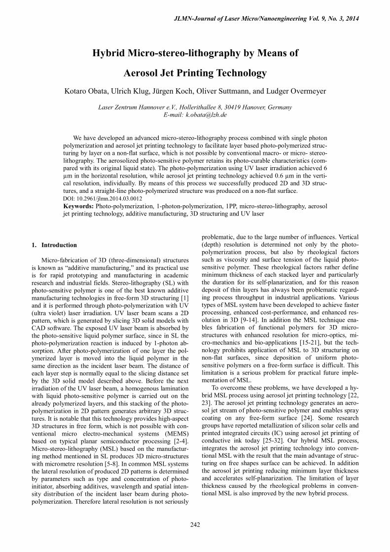
A thin film coating of the photo-sensitive polymer was prepared on a glass slide by the aerosol jet printing system (Optomec Inc.) before laser irradiation. Figure 1 (a) shows a setup of the aerosol jet printing system composed of three parts, (i) generation of the aerosol, (ii) gas flow adjustment and condensation of the aerosol, and (iii) final collimation of the aerosol stream toward sample slide. The procedure begins with atomization of a photo-sensitive polymer into small droplets, and pentaerythritol triacrylate (PETA, Sig-ma Aldrich GmbH) containing 0.2 wt% of photo-initiator (Irgacure369, Ciba) was used for this aromization. The atomizer held liquid PETA and created a dense aerosol of droplets with diameters between 1 and 5 micrometres with high-flow dry N2 gas stream [30]. Droplets larger than 5 micrometres were unable to overcome gravity force and fall back into the PETA reservoir for recycling. The gener-ated aerosol flowed with the N2 gas and was carried through virtual impactor to deposition head. The virtual impactor controlled the flow rate of the N2 gas stream, while minimizing the amount of aerosol loss in the virtual impactor. Inside deposition head, the carried aerosol was focused accurately by a second gas flow or "sheath gas" surrounding the aerosol stream. As sheath gas and aerosol passes through the nozzle head (aperture size 3.0 x 0.5 mm2) in the deposition head, the mixture is compressed and
focuses the aerosol, resulting in accumulation of aerosol stream on the sample. A typical glass slide was used for the sample and observed by an optical microscope, while the gap between nozzle head and glass slide is kept at 3 mm. A mechanical shutter is placed in front of the nozzle head, and figure 1 (b) shows a schematic illustration of the exper-imental setup for hybrid MSL. The deposition head could be moved by a computer controlled linear stage. The com-bination of stage and shutter functions allows for deposi-tion of 3 mm wide uniform PETA layer in line with the PETA aerosol stream on glass slide. After deposition of the PETA layer photo-polymerization structuring using UV laser irradiation was carried out in dry N2 gas ambience. In the experiment, a high-repetition rate UV pulsed picosec-ond (ps) laser system (XCyte, Model CY-355-20, JDS Uni-phase; repetition rate 100 MHz, wavelength 355 nm, pulse width 10 ps) was used. Timing of the laser irradiation and laser power were adjusted by an acoustic optical modulator (AOM) and neutral density (ND) filters. The photo-polymerized structure was fabricated layer by layer by use of an x-y galvanometric mirror scanner (Hurry SCAN 14, SCANLAB AG) and a high-resolution linear z-axis stage (MT105-50 LM, Feinmess Dresden GmbH). Motion of scanner and z-axis stage were controlled by CAD designed data. Laser beam was focused on PETA layer with 103 mm focal-length F-Theta lens. Thereafter, all non-exposed PETA was removed by dipping samples in iso-propanol with laser-exposed PETA structures remaining on glass plate.
Fig. 1 Illustration of experimental setup of (a) the aerosol jet printing and (b) hybrid MSL systems.
JLMN-Journal of Laser Micro/Nanoengineering Vol. 9, No. 3, 2014
244
3. Results and discussion
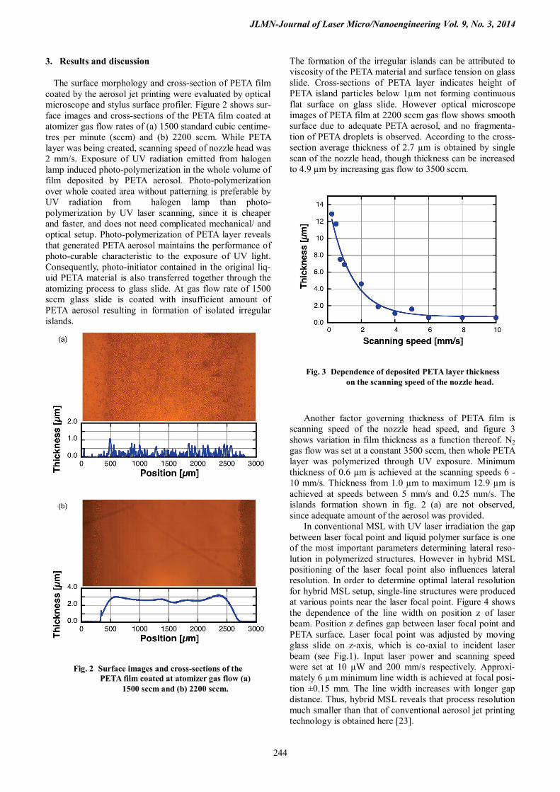
The surface morphology and cross-section of PETA film coated by the aerosol jet printing were evaluated by optical microscope and stylus surface profiler. Figure 2 shows sur-face images and cross-sections of the PETA film coated at atomizer gas flow rates of (a) 1500 standard cubic centime-tres per minute (sccm) and (b) 2200 sccm. While PETA layer was being created, scanning speed of nozzle head was 2 mm/s. Exposure of UV radiation emitted from halogen lamp induced photo-polymerization in the whole volume of film deposited by PETA aerosol. Photo-polymerization over whole coated area without patterning is preferable by UV radiation from halogen lamp than photo-polymerization by UV laser scanning, since it is cheaper and faster, and does not need complicated mechanical/ and optical setup. Photo-polymerization of PETA layer reveals that generated PETA aerosol maintains the performance of photo-curable characteristic to the exposure of UV light. Consequently, photo-initiator contained in the original liq-uid PETA material is also transferred together through the atomizing process to glass slide. At gas flow rate of 1500 sccm glass slide is coated with insufficient amount of PETA aerosol resulting in formation of isolated irregular islands.
The formation of the irregular islands can be attributed to viscosity of the PETA material and surface tension on glass slide. Cross-sections of PETA layer indicates height of PETA island particles below 1µm not forming continuous flat surface on glass slide. However optical microscope images of PETA film at 2200 sccm gas flow shows smooth surface due to adequate PETA aerosol, and no fragmenta-tion of PETA droplets is observed. According to the cross-section average thickness of 2.7 µm is obtained by single scan of the nozzle head, though thickness can be increased to 4.9 µm by increasing gas flow to 3500 sccm.
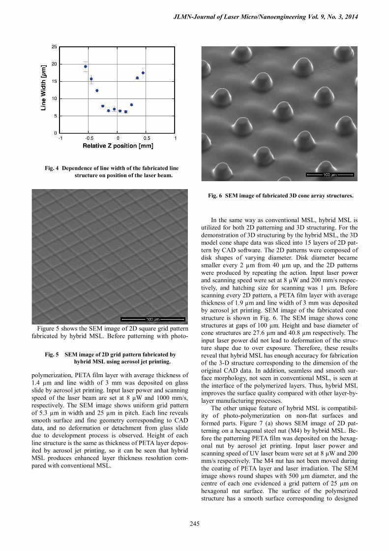
Another factor governing thickness of PETA film is
scanning speed of the nozzle head speed, and figure 3 shows variation in film thickness as a function thereof. N2 gas flow was set at a constant 3500 sccm, then whole PETA layer was polymerized through UV exposure. Minimum thickness of 0.6 µm is achieved at the scanning speeds 6 - 10 mm/s. Thickness from 1.0 µm to maximum 12.9 µm is achieved at speeds between 5 mm/s and 0.25 mm/s. The islands formation shown in fig. 2 (a) are not observed, since adequate amount of the aerosol was provided.
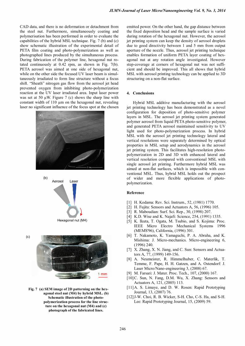
In conventional MSL with UV laser irradiation the gap between laser focal point and liquid polymer surface is one of the most important parameters determining lateral reso-lution in polymerized structures. However in hybrid MSL positioning of the laser focal point also influences lateral resolution. In order to determine optimal lateral resolution for hybrid MSL setup, single-line structures were produced at various points near the laser focal point. Figure 4 shows the dependence of the line width on position z of laser beam. Position z defines gap between laser focal point and PETA surface. Laser focal point was adjusted by moving glass slide on z-axis, which is co-axial to incident laser beam (see Fig.1). Input laser power and scanning speed were set at 10 µW and 200 mm/s respectively. Approxi-mately 6 µm minimum line width is achieved at focal posi-tion ±0.15 mm. The line width increases with longer gap distance. Thus, hybrid MSL reveals that process resolution much smaller than that of conventional aerosol jet printing technology is obtained here [23].
Fig. 2 Surface images and cross-sections of the PETA film coated at atomizer gas flow (a)
1500 sccm and (b) 2200 sccm.
Fig. 3 Dependence of deposited PETA layer thickness on the scanning speed of the nozzle head.
JLMN-Journal of Laser Micro/Nanoengineering Vol. 9, No. 3, 2014
245
Figure 5 shows the SEM image of 2D square grid pattern fabricated by hybrid MSL. Before patterning with photo-
polymerization, PETA film layer with average thickness of 1.4 µm and line width of 3 mm was deposited on glass slide by aerosol jet printing. Input laser power and scanning speed of the laser beam are set at 8 µW and 1000 mm/s, respectively. The SEM image shows uniform grid pattern of 5.3 µm in width and 25 µm in pitch. Each line reveals smooth surface and fine geometry corresponding to CAD data, and no deformation or detachment from glass slide due to development process is observed. Height of each line structure is the same as thickness of PETA layer depos-ited by aerosol jet printing, so it can be seen that hybrid MSL produces enhanced layer thickness resolution com-pared with conventional MSL.
In the same way as conventional MSL, hybrid MSL is utilized for both 2D patterning and 3D structuring. For the demonstration of 3D structuring by the hybrid MSL, the 3D model cone shape data was sliced into 15 layers of 2D pat-tern by CAD software. The 2D patterns were composed of disk shapes of varying diameter. Disk diameter became smaller every 2 µm from 40 µm up, and the 2D patterns were produced by repeating the action. Input laser power and scanning speed were set at 8 µW and 200 mm/s respec-tively, and hatching size for scanning was 1 µm. Before scanning every 2D pattern, a PETA film layer with average thickness of 1.9 µm and line width of 3 mm was deposited by aerosol jet printing. SEM image of the fabricated cone structure is shown in Fig. 6. The SEM image shows cone structures at gaps of 100 µm. Height and base diameter of cone structures are 27.6 µm and 40.8 µm respectively. The input laser power did not lead to deformation of the struc-ture shape due to over exposure. Therefore, these results reveal that hybrid MSL has enough accuracy for fabrication of the 3-D structure corresponding to the dimension of the original CAD data. In addition, seamless and smooth sur-face morphology, not seen in conventional MSL, is seen at the interface of the polymerized layers. Thus, hybrid MSL improves the surface quality compared with other layer-by-layer manufacturing processes.
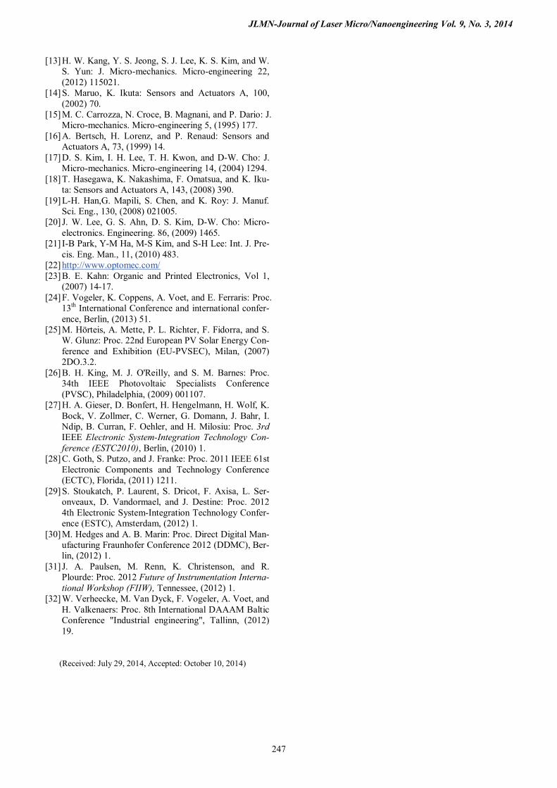
The other unique feature of hybrid MSL is compatibil-ity of photo-polymerization on non-flat surfaces and formed parts. Figure 7 (a) shows SEM image of 2D pat-terning on a hexagonal steel nut (M4) by hybrid MSL. Be-fore the patterning PETA film was deposited on the hexag-onal nut by aerosol jet printing. Input laser power and scanning speed of UV laser beam were set at 8 µW and 200 mm/s respectively. The M4 nut has not been moved during the coating of PETA layer and laser irradiation. The SEM image shows round shapes with 500 µm diameter, and the centre of each one evidenced a grid pattern of 25 µm on hexagonal nut surface. The surface of the polymerized structure has a smooth surface corresponding to designed
Fig. 4 Dependence of line width of the fabricated line structure on position of the laser beam.
Fig. 6 SEM image of fabricated 3D cone array structures.
Fig. 5 SEM image of 2D grid pattern fabricated by hybrid MSL using aerosol jet printing.
JLMN-Journal of Laser Micro/Nanoengineering Vol. 9, No. 3, 2014
246
CAD data, and there is no deformation or detachment from the steel nut. Furthermore, simultaneously coating and polymerisation has been performed in order to evaluate the capabilities of the hybrid MSL technique. Fig. 7 (b) and (c) show schematic illustration of the experimental detail of PETA film coating and photo-polymerization as well as photographed lines produced by the simultaneous process. During fabrication of the polymer line, hexagonal nut ro-tated continuously at 0.42 rpm, as shown in Fig. 7(b). PETA aerosol was aimed at one side of hexagonal nut, while on the other side the focused UV laser beam is simul-taneously irradiated to form line structure without a focus shift. “Sheath” nitrogen gas flow from the aerosol jet head prevented oxygen from inhibiting photo-polymerization reaction at the UV laser irradiated area. Input laser power was set at 50 µW. Figure 7 (c) shows the sharp line with constant width of 110 µm on the hexagonal nut, revealing laser no significant influence of the focus spot at the chosen
emitted power. On the other hand, the gap distance between the fixed deposition head and the sample surface is varied during rotation of the hexagonal nut. However, the aerosol jet printing system can keep the density of aerosol droplets due to good directivity between 1 and 5 mm from output aperture of the nozzle. Thus, aerosol jet printing technique enables formation of uniform PETA layer coating of hex-agonal nut at any rotation angle investigated. However step-coverage at corners of hexagonal nut was not suffi-cient and should be improved. This all shows that hybrid MSL with aerosol printing technology can be applied to 3D structuring on a non-flat surface.
4. Conclusions
Hybrid MSL additive manufacturing with the aerosol jet printing technology has been demonstrated as a novel configuration for deposition of photo-sensitive polymer layers in MSL. The aerosol jet printing system generated polymer aerosol from liquid PETA photo-sensitive polymer, and generated PETA aerosol maintained sensitivity to UV light used for photo-polymerization process. In hybrid MSL with the aerosol jet printing technology lateral and vertical resolutions were separately determined by optical properties in MSL setup and aerodynamics in the aerosol jet printing system. This facilitates high-resolution photo-polymerization in 2D and 3D with enhanced lateral and vertical resolution compared with conventional MSL with single aerosol jet printing. Furthermore hybrid MSL was aimed at non-flat surfaces, which is impossible with con-ventional MSL. Thus, hybrid MSL holds out the prospect of wider and more flexible applications of photo-polymerization.
Reference
[1] H. Kodama: Rev. Sci. Instrum., 52, (1981) 1770. [2] H. Fujita: Sensors and Actuators A, 56, (1996) 105. [3] R. Maboudian: Surf. Sci. Rep., 30, (1998) 207. [4] K.D. Wise and K. Najafi: Science, 254, (1991) 1335. [5] K. Ikuta, T. Ogata, M. Tsubio, and S. Kojima: Proc.
IEEE Micro Electro Mechanical Systems 1996 (MEMS'96), California, (1996) 301.
[6] T. Nakamoto, K. Yamaguchi, P. A. Abraha, and K. Mishima: J. Micro-mechanics. Micro-engineering 6, (1996) 240.
[7] X. Zhang, X. N. Jiang, and C. Sun: Sensors and Actua-tors A, 77, (1999) 149-156.
[8] A. Neumeister, R. Himmelhuber, C. Materlik, T. Temme, F. Pape, H. H. Gatzen, and A. Ostendorf: J. Laser Micro/Nano-engineering 3, (2008) 67.
[9] M. Farsari: J. Mater. Proc. Tech., 107, (2000) 167. [10] C. Sun, N. Fang, D.M. Wu, X. Zhang: Sensors and
Actuators A, 121, (2005) 113. [11] A. S. Limaye, and D. W. Rosen: Rapid Prototyping
Journal, 13, (2007) 76. [12] J-W. Choi, R. B. Wicker, S-H. Cho, C-S. Ha, and S-H.
Lee: Rapid Prototyping Journal, 15, (2009) 59.
Fig. 7 (a) SEM image of 2D patterning on the hex-agonal steel nut (M4) by hybrid MSL. (b)
Schematic illustration of the photo-polymerization process for the line struc-ture on the hexagonal nut (M4) and (c)
photograph of the fabricated lines.
JLMN-Journal of Laser Micro/Nanoengineering Vol. 9, No. 3, 2014
247
[13] H. W. Kang, Y. S. Jeong, S. J. Lee, K. S. Kim, and W. S. Yun: J. Micro-mechanics. Micro-engineering 22, (2012) 115021.
[14] S. Maruo, K. Ikuta: Sensors and Actuators A, 100, (2002) 70.
[15] M. C. Carrozza, N. Croce, B. Magnani, and P. Dario: J. Micro-mechanics. Micro-engineering 5, (1995) 177.
[16] A. Bertsch, H. Lorenz, and P. Renaud: Sensors and Actuators A, 73, (1999) 14.
[17] D. S. Kim, I. H. Lee, T. H. Kwon, and D-W. Cho: J. Micro-mechanics. Micro-engineering 14, (2004) 1294.
[18] T. Hasegawa, K. Nakashima, F. Omatsua, and K. Iku-ta: Sensors and Actuators A, 143, (2008) 390.
[19] L-H. Han,G. Mapili, S. Chen, and K. Roy: J. Manuf. Sci. Eng., 130, (2008) 021005.
[20] J. W. Lee, G. S. Ahn, D. S. Kim, D-W. Cho: Micro-electronics. Engineering. 86, (2009) 1465.
[21] I-B Park, Y-M Ha, M-S Kim, and S-H Lee: Int. J. Pre-cis. Eng. Man., 11, (2010) 483.
[22] http://www.optomec.com/ [23] B. E. Kahn: Organic and Printed Electronics, Vol 1,
(2007) 14-17. [24] F. Vogeler, K. Coppens, A. Voet, and E. Ferraris: Proc.
13th International Conference and international confer-ence, Berlin, (2013) 51.
[25] M. Hörteis, A. Mette, P. L. Richter, F. Fidorra, and S. W. Glunz: Proc. 22nd European PV Solar Energy Con-ference and Exhibition (EU-PVSEC), Milan, (2007) 2DO.3.2.
[26] B. H. King, M. J. O'Reilly, and S. M. Barnes: Proc. 34th IEEE Photovoltaic Specialists Conference (PVSC), Philadelphia, (2009) 001107.
[27] H. A. Gieser, D. Bonfert, H. Hengelmann, H. Wolf, K. Bock, V. Zollmer, C. Werner, G. Domann, J. Bahr, I. Ndip, B. Curran, F. Oehler, and H. Milosiu: Proc. 3rd IEEE Electronic System-Integration Technology Con-ference (ESTC2010), Berlin, (2010) 1.
[28] C. Goth, S. Putzo, and J. Franke: Proc. 2011 IEEE 61st Electronic Components and Technology Conference (ECTC), Florida, (2011) 1211.
[29] S. Stoukatch, P. Laurent, S. Dricot, F. Axisa, L. Ser-onveaux, D. Vandormael, and J. Destine: Proc. 2012 4th Electronic System-Integration Technology Confer-ence (ESTC), Amsterdam, (2012) 1.
[30] M. Hedges and A. B. Marin: Proc. Direct Digital Man-ufacturing Fraunhofer Conference 2012 (DDMC), Ber-lin, (2012) 1.
[31] J. A. Paulsen, M. Renn, K. Christenson, and R. Plourde: Proc. 2012 Future of Instrumentation Interna-tional Workshop (FIIW), Tennessee, (2012) 1.
[32] W. Verheecke, M. Van Dyck, F. Vogeler, A. Voet, and H. Valkenaers: Proc. 8th International DAAAM Baltic Conference "Industrial engineering", Tallinn, (2012) 19.
(Received: July 29, 2014, Accepted: October 10, 2014)
Related Documents