- 1 - Hybrid DVR User’s Manual Model: 4-CH 8-CH 16-CH Before attempting to connect or operate this product, please read these instructions carefully and save this manual for future use. XVR_v1.2.0_20211026

Welcome message from author
This document is posted to help you gain knowledge. Please leave a comment to let me know what you think about it! Share it to your friends and learn new things together.
Transcript
- 1 -
Hybrid DVR
User’s Manual
Model: 4-CH 8-CH
16-CH
Before attempting to connect or operate this product, please read these instructions carefully and save this manual for future use.
XVR_v1.2.0_20211026
- 2 -
CAUTION TO REDUCE THE RISK OF ELECTRIC SHOCK, DO NOT REMOVE COVER. NO USER SERVICEABLE PARTS INSIDE. PLEASE REFER SERVICING TO QUALIFIED SERVICE PERSONNEL.
NOTE: This equipment has been tested and found to comply with the limits for a Class “A” digital device, pursuant to Part 15 of the FCC Rules. These limits are designed to provide reasonable protection against harmful interference when the equipment is operated in a commercial environment. This equipment generates, uses and can radiate radio frequency energy and, if not installed and used in accordance with the instruction manual, may cause harmful interference to radio communications. Operation of this equipment in a residential area is likely to cause harmful interference in which case the users will be required to correct the interference at their own expense. FCC Caution: To assure continued compliance, use only shielded interface cables when connecting to computer or peripheral devices. Any changes or modifications not expressly approved by the party responsible for compliance could void the user’s authority to operate this equipment. This Class A digital apparatus meets all the requirements of the Canadian Interference Causing Equipment Regulations.
WARNING TO PREVENT FIRE OR ELECTRIC SHOCK HAZARD, DO NOT EXPOSE THIS
APPLIANCE TO RAIN OR MOISTURE.
- 3 -
LIMITATION OF LIABILITY THIS PUBLICATION IS PROVIDED “AS IS” WITHOUT WARRANTY OF ANY KIND,
EITHER EXPRESS OR IMPLIED, INCLUDING BUT NOT LIMITED TO, THE IMPLIED WARRANTIES OF MERCHANTIBILITY, FITNESS FOR ANY PARTICULAR PURPOSE, OR NON-INFRINGEMENT OF THE THIRD PARTY’S RIGHT.
THIS PUBLICATION COULD INCLUDE TECHNICAL INACCUACIES OR TYPOGRAPHICAL
ERRORS. CHANGES ARE ADDED TO THE INFORMATION HEREIN, AT ANY TIME, FOR THE IMPROVEMENTS OF THIS PUBLICATION AND/OR THE CORRESPONDING PRODUCT(S).
DISCLAIMER OF WARRANTY IN NO EVENT SHALL THE SUPPLIER BE LIABLBE TO ANY PARTY OR ANY PERSON, EXCEPT FOR REPLACEMENT OR REASONABLE MAINTENANCE OF THE PRODUCT, FOR THE CASES, INCLUDING BUT NOT LIMITED TO THE FOLLOWINGS: ANY DAMAGE OR LOSS, INCLUDING BUT WITHOUT LIMITATION, DIRECT OR
INDIRECT, SPECIAL, CONSEQUENTIAL OR EXEMPLARY, ARISING OUT OF OR RELATING TO THE PRODUCT;
PERSONAL INJURY OR ANY DAMAGE CAUSED BY INAPPROPRIATE USE OR NEGLIGENT OPERATION OF THE USER;
UNAUTHORIZED DISASSEMBLE, REPAIR OR MODIFICATION OF THE PRODUCT BY THE USER;
ANY PROBLEM, CONSEQUENTIAL INCONVENIENCE, OR LOSS OR DAMAGE, ARISING OUT OF THE SYSTEM COMBINED WITH THE DEVICES OF THE THIRD PARTY;
ANY CLAIM OR ACTION FOR DAMAGES, BROUGHT BY ANY PERSON OR ORGANIZATION BEING A PHOTOGENIC SUBJECT, DUE TO VIOLATION OF PRIVACY WITH THE RESULT OF THAT SURVEILLANCE-CAMERA’S PICTURE, INCLUDING SAVED DATA, FOR SOME REASON, BECOMES PUBLIC OR IS USED FOR THE PURPOSE OTHER THAN SURVEILLANCE.

- 4 -
PRECAUTIONS Please refer all work related to the installation of this product to qualified
service personnel or system installers. Do not operate the appliance beyond its specified temperature, humidity or
power source ratings. Use the appliance at temperature within -5oC ~ +60oC and humidity below 85%. The input power source for this appliance is +12 VDC. Performance and lifetime of hard disk drives are easily affected by heat (used at high temperature). It is recommended to use this appliance at temperature within +20oC ~ +30oC.
Handle the hard disk drives with care. It is possible to damage them if they are moved while their motors are still running. Do not move them just after turning the power on or off (for around 30 seconds). Protect the hard disk drives from static electricity. Do not stack them or keep them upright. Do not use an electric screwdriver to fix them.
Clean only with dry cloth. Do not block any ventilation openings. Do not use the appliance near any heat sources such as radiators, heat registers,
stoves or other apparatus that produce heat. Protect the power cord from being stepped on or pinched particularly at plugs,
convenient receptacles and the points where they exit from the apparatus. Do not drop metallic parts through slots. This could permanently damage the
appliance. Turn the power off immediately and contact qualified service personnel for service.
Handle the appliance with care. Do not strike or shake, as this may damage the appliance.
Do not expose the appliance to water or moisture, nor try to operate it in wet areas. Do take immediate action if the appliance becomes wet. Turn the power off and refer servicing to qualified service personnel. Moisture may damage the appliance and also cause electric shock.
Do not use strong or abrasive detergents when cleaning the appliance body. When the dirt is hard to remove, use a mild detergent and wipe gently.
Do not overload outlets and extension cords as this may result in a risk of fire or electric shock.
Please make a note of your settings and save them. This will help when you are required to change the system configuration, or when unexpected failure or trouble occurs.
Distributing, copying, disassembling, reverse compiling, reverse engineering, and also exporting in violation of export laws of the software provided with this product, is expressly prohibited.

5
Table of Contents PRECAUTIONS................................................................................................................................................... - 4 -
TABLE OF CONTENTS............................................................................................................................................. 5
1. PRODUCT OVERVIEW ........................................................................................................................................ 7
2. REMOTE CONTROLLER ...................................................................................................................................... 7
2.1 REMOTE CONTROLLER (WILL BE SUPPORTED IN THE FUTURE.).......................................................................................... 7
3. INSTALLATIONS ................................................................................................................................................. 9
3.1 BASIC CONNECTIONS ............................................................................................................................................... 9 3.2 OPTIONAL CONNECTIONS ....................................................................................................................................... 11
4. MAIN SCREEN AND BASIC OPERATIONS .......................................................................................................... 14
4.1 TEXT INPUT.......................................................................................................................................................... 15 4.2 LOGIN AND LOGOUT .............................................................................................................................................. 15 4.3 BASIC OPERATIONS ............................................................................................................................................... 16 4.4 DIGITAL ZOOM ..................................................................................................................................................... 17
5. MENU DISPLAY ............................................................................................................................................... 18
5.1 STATUS DISPLAY .................................................................................................................................................... 19 5.2 VOLUME CONTROL ................................................................................................................................................ 19 5.3 VIDEO ADJUSTMENT .............................................................................................................................................. 20 5.4 DISPLAY .............................................................................................................................................................. 21 5.5 NETWORK ........................................................................................................................................................... 22
5.5.1 Notification Setup .................................................................................................................................... 24 5.5.2 FTP Setup ................................................................................................................................................. 25 5.5.3 4G/3G Modem Setup ............................................................................................................................... 26 5.5.4 Advanced Network Setup ......................................................................................................................... 27
5.6. PTZ CONTROL ..................................................................................................................................................... 29 5.7 SYSTEM SHUTDOWN (ADMINISTRATOR) .................................................................................................................... 31
6. SETUP (ADMINISTRATOR) ............................................................................................................................... 31
6.1 CAMERA SETUP .................................................................................................................................................... 32 6.1.1 IPCam Encode Setup................................................................................................................................. 35 6.1.2 IPCam Image Setup .................................................................................................................................. 36 6.1.3 Video Loss Setup ...................................................................................................................................... 36 6.1.4 Motion/(eFence)/Privacy Mask Setup ...................................................................................................... 38
6.2 ALARM SETUP ...................................................................................................................................................... 41 6.3 MAIN/SEQ DISPLAY SETUP .................................................................................................................................... 43 6.4 SCHEDULED RECORD SETUP .................................................................................................................................... 44 6.5 HDD SETUP......................................................................................................................................................... 47
6.5.1 HDD Format/Clear.................................................................................................................................... 49 6.5.2 Advanced HDD Setup ............................................................................................................................... 52
6.6 PASSWORD SETUP ................................................................................................................................................. 53 6.7 SYSTEM SETUP ..................................................................................................................................................... 57 6.8 RS-232/485/IR SETUP ........................................................................................................................................ 59 6.9 OSD SETUP ......................................................................................................................................................... 61
7. SEARCH/PLAYBACK/ARCHIVE (ADMINISTRATOR, SUPERVISOR) ...................................................................... 62
7.1 SEARCH BY TIME ................................................................................................................................................... 63 7.2 SEARCH BY EVENT / LOG DISPLAY ............................................................................................................................. 64 7.3 SMART SEARCH .................................................................................................................................................... 66 7.4 SEARCH ARCHIVED FILES......................................................................................................................................... 68 7.5 POS SEARCH ....................................................................................................................................................... 69 7.6 PLAYBACK/ARCHIVE FOR SEARCH BY TIME ................................................................................................................. 71 7.7 PLAYBACK/ARCHIVE FOR SEARCH BY EVENT ............................................................................................................... 74
6
7.8 PLAYBACK/ARCHIVE FOR SMART SEARCH ................................................................................................................... 75 7.9 PLAYBACK FOR ARCHIVED FILES ................................................................................................................................ 75 7.10 PLAYBACK/ARCHIVE FOR POS SEARCH .................................................................................................................... 75
8. REMOTE ACCESS ............................................................................................................................................. 76
8.1 PC REMOTE ACCESS .............................................................................................................................................. 76 8.2 PDA/MOBILE PHONE REMOTE ACCESS (CHROME WAP MODE) ................................................................................ - 90 -
APPENDIX A – TIME ZONE TABLE .................................................................................................................... - 91 -
APPENDIX B – KEYBOARD CONTROL PROTOCOL ............................................................................................. - 93 -
APPENDIX C – MS-WINDOWS HEM UTILITIES ................................................................................................. - 95 -
APPENDIX D – GPS FUNCTION IN REMOTE SOFTWARE WITH GOOGLE EARTH .............................................. - 100 -
APPENDIX E – PROTOCOL CONVERTER FOR MULTIPLE POS ........................................................................... - 104 -

7
1. Product Overview The hybrid digital video/audio recorders are designed for use within a surveillance system with limited space and combine a hard disk recorder, a video multiplexer, and a web server. This series of digital video/audio recorders are all based on industry-leading front-end to back-end surveillance infrastructure to achieve the highest inter-connectivity and inter-operability. With state-of-the-art system architecture, powerful compression/decompression engine, and intelligent recording algorithms, sixfold operation can be easily achieved without sacrificing the increasing demands of functionality, performance, reliability, and availability in the surveillance industry.
2. Remote Controller
2.1 Remote Controller (Will be supported in the future.) The remote controller is an optional accessory to ease the user’s operations. You can do all the operations by the remote controller instead of the buttons on the front panel. The effective distance is about 10 meters without any obstacle.
1. MODE Button Press this button to toggle between live mode and playback mode in main screen display. In some dialogs, this button is used as a miscellaneous function key. At playing, this button is used as “slow backward”.
2. SEQ Button Press this button to switch to or return from SEQ display mode in main screen display. In some dialogs, this button is used as a miscellaneous function key. At playing, this button is used as “slow forward”.
3. CALL Button Press this button to switch to or return from full screen display of the focus camera in main screen display. In some dialogs, this button is used as a miscellaneous function key.
4. SEARCH Button Press this button to display the search menu in main screen display. In some dialogs, this button is used as a miscellaneous function key.
5. REC Button Press this button to force manual recording. To stop manual recording, press it again.
6. Play/Pause Button ( ) Press this button to play the recorded images, or pause the playback.
7. Stop ( ) Button Press this button to stop the playback.
8
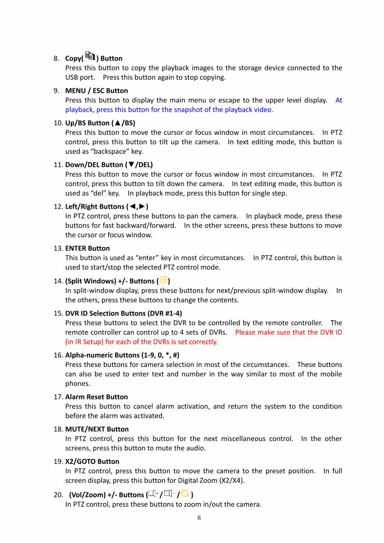
8. Copy( ) Button Press this button to copy the playback images to the storage device connected to the USB port. Press this button again to stop copying.
9. MENU / ESC Button Press this button to display the main menu or escape to the upper level display. At playback, press this button for the snapshot of the playback video.
10. Up/BS Button (▲/BS) Press this button to move the cursor or focus window in most circumstances. In PTZ control, press this button to tilt up the camera. In text editing mode, this button is used as “backspace” key.
11. Down/DEL Button (▼/DEL) Press this button to move the cursor or focus window in most circumstances. In PTZ control, press this button to tilt down the camera. In text editing mode, this button is used as “del” key. In playback mode, press this button for single step.
12. Left/Right Buttons (◄,►) In PTZ control, press these buttons to pan the camera. In playback mode, press these buttons for fast backward/forward. In the other screens, press these buttons to move the cursor or focus window.
13. ENTER Button This button is used as “enter” key in most circumstances. In PTZ control, this button is used to start/stop the selected PTZ control mode.
14. (Split Windows) +/- Buttons ( ) In split-window display, press these buttons for next/previous split-window display. In the others, press these buttons to change the contents.
15. DVR ID Selection Buttons (DVR #1-4) Press these buttons to select the DVR to be controlled by the remote controller. The remote controller can control up to 4 sets of DVRs. Please make sure that the DVR ID (in IR Setup) for each of the DVRs is set correctly.
16. Alpha-numeric Buttons (1-9, 0, *, #) Press these buttons for camera selection in most of the circumstances. These buttons can also be used to enter text and number in the way similar to most of the mobile phones.
17. Alarm Reset Button Press this button to cancel alarm activation, and return the system to the condition before the alarm was activated.
18. MUTE/NEXT Button In PTZ control, press this button for the next miscellaneous control. In the other screens, press this button to mute the audio.
19. X2/GOTO Button In PTZ control, press this button to move the camera to the preset position. In full screen display, press this button for Digital Zoom (X2/X4).
20. (Vol/Zoom) +/- Buttons ( / / ) In PTZ control, press these buttons to zoom in/out the camera.

9
3. Installations The installations described below should be made by qualified service personnel or system installers.
3.1 Basic Connections Please refer to the following diagram for the connections.
Please make sure to set the NTSC/PAL Selector Switch on the main board according to the local TV system for the system to work correctly.
Cameras
Connect the camera video input connectors to the video outputs from system cameras or other composite video sources via coaxial cables. The internal 75Ω termination is always ON.
Main monitor
Connect the main monitor output connector (BNC/VGA/HDMI) to a surveillance TV/VGA monitor. The TV/VGA monitor displays selected live or recorded cameras in any available split window format.
Hard disk drive Make sure to install (at least) one SATA hard disk inside the DVR. The steps are as below: 1. Power off the machine, and then use a
screwdriver to uncover it.
10
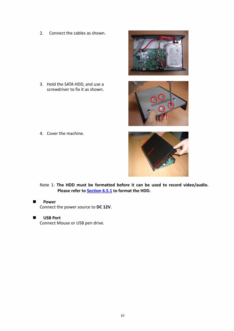
2. Connect the cables as shown. 3. Hold the SATA HDD, and use a
screwdriver to fix it as shown. 4. Cover the machine. Note 1: The HDD must be formatted before it can be used to record video/audio.
Please refer to Section 6.5.1 to format the HDD. Power
Connect the power source to DC 12V. USB Port
Connect Mouse or USB pen drive.

11
3.2 Optional Connections Audio input
Connect the audio input connectors to the audio line-out from system cameras or other audio sources. Please make sure to associate the audio inputs with the cameras in Camera Setup as described in Section 6.1 accordingly.
Audio output Connect the audio output connector to the audio line-in from speakers.
Alarm input Connect the alarm inputs to NC and/or NO type of alarm signals. Please make sure to setup the alarm configurations as described in Section 6.2 accordingly.
Alarm output Connect the alarm output #1 to NC type of alarm signal, or alarm output #2 to NO type of alarm signal.
Ethernet Connect the Ethernet connector to a standard twisted-pair Ethernet cable for IP CAM and remote access via LAN or internet. Please make sure to setup the related configurations as described in Section 5.5 and Section 6.1.
USB 2.0 disk drives, card reader, etc.
If the user wants to use USB2.0 peripheral device to retrieve important recorded images and/or audio, please connect it to the USB2.0 port connector.
I/R remote controller The user may use I/R remote controller to control the digital video/audio recorder.
Call monitor Connect the call monitor output connector to a surveillance TV monitor. This monitor displays the full screen images of the cameras associated with the events (alarm or motion) or the images from the installed cameras sequentially according to the SEQ Display Setup (Section 6.3) for call monitor.

12
PTZ Cameras Connect the RS-232 connector or the RS-485 connector to PTZ camera(s) via the appropriate cable. The system supports a variety of different PTZ cameras, including Pelco D protocol Dome, SamSung SCC-641P, Kalatel Cyber Dome, Bosch AutoDome, etc. But different PTZ cameras can coexist in a system only if they support the same protocol. Please make sure to set the PTZ ID of the camera(s), and setup the camera (Section 6.1), and RS-232 or RS-485 (Section 6.8) accordingly.
RS-485 keyboard or Terminal Connect the RS-485 connector to a RS-485 keyboard controller or VT-100 terminal via the appropriate cables. Please refer to the diagram above for the correct connection. Please make sure to setup the RS-485 configurations as described in Section 6.8 accordingly. Please refer to Appendix B for the Keyboard Control Protocol for the digital video recorder.
eSATA Hard Disk
Connect the eSATA connector to an eSATA hard disk for HDD extension.
GPS modem Connect the RS-232 connector to GPS modem via the appropriate cable. The system supports the GPS modems with NMEA0183 protocol. Please make sure to setup the RS-232 port (Section 6.8) accordingly.

13
POS system Connect the RS-232 connector to POS system via the appropriate cable. The system supports the POS systems which can be connected to the following printers – Epson-TM200, Epson-TMU295, Epson-TMU300, Epson-TMU675, Epson-TMT882, Epson-RPU420, and Epson-MD332S. For 1-to-1 POS, please make sure to setup the RS-232 and RS-485 port correctly (Section 6.8). For Multiple POS, please make sure to setup the ID of protocol converter I-7524 correctly (Appendix E), and then setup the RS-232 and RS-485 port correctly (Section 6.8).
Top figure: 1-to-1; bottom figure: RS-232/Multiple, 1-to-many
14
4. Main Screen and Basic Operations
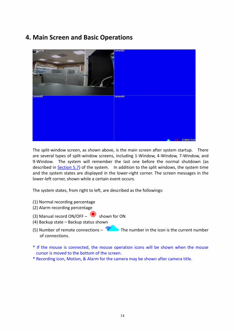
The split-window screen, as shown above, is the main screen after system startup. There are several types of split-window screens, including 1-Window, 4-Window, 7-Window, and 9-Window. The system will remember the last one before the normal shutdown (as described in Section 5.7) of the system. In addition to the split windows, the system time and the system states are displayed in the lower-right corner. The screen messages in the lower-left corner, shown while a certain event occurs. The system states, from right to left, are described as the followings: (1) Normal recording percentage (2) Alarm recording percentage
(3) Manual record ON/OFF – shown for ON (4) Backup state – Backup status shown
(5) Number of remote connections – The number in the icon is the current number of connections.
* If the mouse is connected, the mouse operation icons will be shown when the mouse
cursor is moved to the bottom of the screen. * Recording icon, Motion, & Alarm for the camera may be shown after camera title.

15
4.1 Text Input There are certain circumstances that the system requires the user to enter text, such as system login, camera title setup, and so on. To enter text, please left-click the mouse to edit the highlighted field. The flashing cursor will be shown to indicate the editing point, and the keyboard will be shown as below:
4.2 Login and Logout There are three preset password levels in the system, including Administrator (highest), Supervisor, and Operator (lowest). Besides, the system also provides Customized password level. If the user does not login the system, he/she will be treated as “Guest” and can only view live video display. The system allows up to 18 user accounts. The administrator can set up the login name and password for each user. (Please refer to Section 6.6 for Password Setup.) The Operator can operate live video display, the Supervisor live video display, image playback and archive, and the Administrator everything. To Login/Logout system, right-click the mouse in split-window to call up Menu display then Left-click the mouse to select the Login/Logout In Menu display, the Login/Logout will be shown. In Login/Logout display, follow the Text Input method described in Section 4.1 to enter the Login Name and Password, and select the Login/Logout option to log in/log out to the system. There is one factory-preset login name/password aa/11 at the Administrator level. The user can use it to log in to the system for the first time. Should the user have forgotten all the administrator-level passwords, please contact the local dealer or installer.

16
4.3 Basic Operations The basic user’s operations after he/she has logged into the system are described as below:
REC (Mouse: ) Press this button to force manual recording. To stop manual recording, press it again.
All cameras will be recorded as if the scheduled record is A/V, and will be shown on the lower-right corner of the screen if manual recording is ON.
Alarm Reset (Mouse: ) Press this button to cancel alarm activation, i.e. reset the alarm outputs and silence the buzzer.
Vol+/-, MUTE (Mouse: ) Press these buttons to control the volume.
X2 (Mouse: ) In full screen display, press this button to enter Digital Zoom mode. Please refer to Section 4.4 Digital Zoom for the detailed operations in Digital Zoom mode.
SEQ (Mouse: ) Press this button to switch to or return from SEQ display mode. In SEQ display mode, each page in the sequence will be shown for the preset page dwelling time sequentially.
When the SEQ starts/ends, the SEQ icon / will be displayed in the upper right corner of the screen for about three seconds.
(Mouse: ) Press these buttons to circulate up/down among the available split-window displays.
SEARCH (Mouse: ) (Administrator/Supervisor) In split-window display, press this button to display the search menus. The system will remember the last one the user chose.
Mouse Left click Select the focus window in the split-window display. The border color of the focus camera will change accordingly.

17
4.4 Digital Zoom
The system supports X2/X4 Digital Zoom function.
To use this function, press Zoom button (Mouse: ) in full screen display to enter Digital Zoom mode. There will be a zoom window shown in the video window as shown. The zoom window (a) will always be shown at zoom factor X1, (b) can be shown or hidden at zoom factor X2, and (c) will never be shown at zoom factor X4. The operations in Digital Zoom mode are as below:
▲▼◄► (Mouse: Click the video window) (a) Click outside the yellow zone of the video window to move the yellow zone zoom
window if it’s shown in the video window. (b) Click in the video window to navigate the video window around if the zoom factor
is X2 or X4.
ENTER (Mouse: Click in the video window) Click in the yellow zone of the video window to zoom in the zoom window, from X1 to X2 or from X2 to X4, if the zoom window is shown in the video window.
X2 (Mouse: ) Press this button to (a) Show/hide the zoom window if the current zoom factor is X1/X2. (b) Zoom out the video window back to zoom factor X1 if the current zoom factor is X4.
ESC (Mouse: or Right Click) Press this button to escape from X4 Digital Zoom mode, and return to the normal full-screen display.

18
5. Menu Display Right-click the mouse in the split-window display to call up the Menu as shown below:
There are a variety of displays under Menu display. In the Menu display and all the subsequent displays, the items are disabled in the gray-out icon. Please refer to Section 4.2 for Login/Logout display. The user’s operations are described as the followings:
ENTER (Mouse: Click in the menu item) Press this button to enter the detailed display of the highlighted option. For the details of each option, please refer to the following sections.
X (Mouse: Left Click X or Right Click to leave) Press this button to escape from Menu display, and return to split-window display.

19
5.1 Status Display
Left-click the mouse to select the Status (Mouse: ) In Menu display, the system status will be shown.
The status display includes Alarm Recording Status, Normal Recording Status, Camera Status, Alarm Input Status, Product Serial Number, Product Version Number, and IP Address. Press X (Mouse: Left Click X or Right Click to leave) to escape from the Status display, and return to Menu display.
System Log – the system events are to be shown in the log list. It includes all system-related events, such as power on/off, and will not trigger recording.
5.2 Volume Control Left-click the mouse to select the Volume (Mouse:
) In Menu display, the Volume Control will be shown.
The general operations are as below:
Mouse: Click in the respective item Select the items to set.
X (Mouse: Left Click X or Right Click to leave) Press this button to escape from this screen, and return to Menu display. If the contents have been modified, a Save dialog will be shown to ask the user to save the changes, press YES to exit and save, CANCER to exit without saving.
Following is a brief description for each item and its specific operations:
Mute – to mute the selected audio channel. The default setting is unchecked. Volume – the volume of the selected audio channel.
Note: If want to adjust the audio volume of Coaxial Audio Camera, please change the setting via data-over-coax in camera.

20
5.3 Video Adjustment
Left-click the mouse to select the Video Adjustment (Mouse: ) In Menu display, the Video Adjustment will be shown.
There are 4 items which can be adjusted, including Brightness, Contrast, Hue, and Saturation. The operations are as below: Numeric (Mouse: Left-click the mouse to select the values)
Press these values to adjust the selected items.
Factory Reset This (Mouse: Left-click the mouse to select this) Press this button to reset the settings for this camera to factory default values.
Factory Reset All (Mouse: Left-click the mouse to select this) Press this button to reset the settings for all cameras to factory default values.
Restore (Mouse: Left-click the mouse to select this) Press this button to restore the values.
X (Mouse: Left Click X or Right Click to leave) Press this button to escape from this screen, and return to Menu display. The settings will be saved for future reference.
21
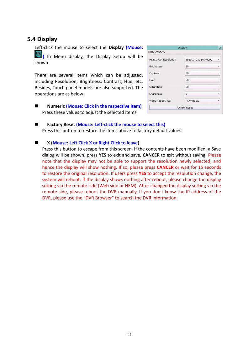
5.4 Display Left-click the mouse to select the Display (Mouse:
) In Menu display, the Display Setup will be shown.
There are several items which can be adjusted, including Resolution, Brightness, Contrast, Hue, etc. Besides, Touch panel models are also supported. The operations are as below: Numeric (Mouse: Click in the respective item)
Press these values to adjust the selected items.
Factory Reset (Mouse: Left-click the mouse to select this) Press this button to restore the items above to factory default values.
X (Mouse: Left Click X or Right Click to leave)
Press this button to escape from this screen. If the contents have been modified, a Save dialog will be shown, press YES to exit and save, CANCER to exit without saving. Please note that the display may not be able to support the resolution newly selected, and hence the display will show nothing. If so, please press CANCER or wait for 15 seconds to restore the original resolution. If users press YES to accept the resolution change, the system will reboot. If the display shows nothing after reboot, please change the display setting via the remote side (Web side or HEM). After changed the display setting via the remote side, please reboot the DVR manually. If you don't know the IP address of the DVR, please use the "DVR Browser" to search the DVR information.

22
5.5 Network
Left-click the mouse to select the Network (Mouse: ) In Menu display, the Network Setup will be shown.
The Network Setup allows the administrator to setup all Ethernet network related parameters. Please check with your network administrator to set these parameters correctly.
The general operations are as below:
Mouse: Click in the respective item Select the items to set.
X (Mouse: Left Click X or Right Click to leave) Press this button to escape from this screen, and return to Setup Menu display. If the Save dialog is shown, press YES to exit and save, CANCER to exit without saving.
Following is a brief description for each item and its specific operations:
Net Type – Static IP, PPPoE, or DHCP. For internet access, please make sure the below IP Address is a public IP address; otherwise, (1) a router with public IP address is required, and the router must be setup for port mapping (forwarding) to the DVR, or (2) CMS server must be used (Sec. 5.5.4).
P2P – if enabled, the QR code of the DVR will be shown on the upper right corner, and users can scan it to access the DVR remotely through the QR code in the future. Please make sure that TCP hole punching is possible for the NAT, Full-cone or Address restricted cone, of the router connected to internet for the DVR or remote software.
IP Address – Ethernet IP address of the “Net Type” above for the system. To get the static IP address, please contact your local ISP (Internet Service Provider). Please follow the Text Input method described in Section 4.1 to modify these items.

23
Net Mask – Net Mask for the Ethernet IP address. Please follow the Text Input method described in Section 4.1 to modify these items.
Gateway – Ethernet Gateway IP address. Please note that the priority of Gateway is (1) Ethernet Gateway and (2) 3G Gateway. Please follow the Text Input method described in Section 4.1 to modify these items.
DNS – DNS (Domain Name Server) IP address for Ethernet. Please follow the Text Input method described in Section 4.1 to modify these items.
PPPoE Username – PPPoE username for the system if PPPoE is used. Please follow the Text Input method described in Section 4.1 to modify this item.
PPPoE Password – PPPoE password for the system if PPPoE is used. Please follow the Text Input method described in Section 4.1 to modify this item.
DDNS Type – Dynamic, Static, Custom DDNS (Dynamic Domain Name Server) type, etc. Please contact your local DDNS Service Provider to get the DDNS URL, username, and password.
URL – the URL (Uniform Resource Locators) for the system. Please follow the Text Input method described in Section 4.1 to modify this item.
DDNS Username – DDNS username for the DVR for Static IP, PPPoE, or DHCP. Please follow the Text Input method described in Section 4.1 to modify this item.
DDNS Password – DDNS password for the DVR for Static IP, PPPoE, or DHCP. Please follow the Text Input method described in Section 4.1 to modify this item.
Note: If DDNS Type is FreeDNS, the URL must be appended with “,hash”. Click "Dynamic DNS" on the FreeDNS website (http://freedns.afraid.org), then click "Direct URL" to get the URL. In the URL, the value after the ? is the "hash" value. The full URL that inputs to DVR is the domain name that you set, hash. The full URL must be less than 70 letters.
Notification – press Notification (Mouse: Left click) to call up Notification Setup. Please refer to Section 5.5.1 for the details.
FTP – press FTP (Mouse: Left click) to call up FTP Setup. Please refer to Section 5.5.2 for the details.
4G/3G – press 4G/3G (Mouse: Left click) to call up 4G/3G Modem Setup. Please refer to Section 5.5.3 for the details.
Advanced – press Advanced (Mouse: Left click) to call up Advanced Network Setup. Please refer to Section 5.5.4 for the details.

24
5.5.1 Notification Setup In Network Setup, press Notification to call up Notification Setup as shown. The Notification Setup allows the administrator to set notification (email & push alarm) related parameters. When an event occurs and Notification/E-mail is enabled for the corresponding action, a
notification will be sent based on the parameters set. The general operations are as below:
Mouse: Click in the respective item Select the items to set.
X (Mouse: Left Click X or Right Click to leave) Press this button to escape from this screen, and return to Network Setup display. If the Save dialog is shown, press YES to exit and save, CANCER to exit without saving.
Following is a brief description for each item and its specific operations:
SMTP Server – SMTP mail server name. Please follow the Text Input method described in Section 4.1 to modify this item.
SMTP Port – the SMTP port for e-mail transmission. The default value is 25. Please follow the Text Input method described in Section 4.1 to modify this item.
Authentication – whether the SMTP mail server requires authentication.
Username – username if the SMTP mail server requires authentication. Please follow the Text Input method described in Section 4.1 to modify this item.
Password – password if the SMTP mail server requires authentication. Please follow the Text Input method described in Section 4.1 to modify this item.
Mail From – the e-mail address of this DVR unit, i.e. the sender of the e-mails originated from the triggered events. Please follow the Text Input method described in Section 4.1 to modify this item.
Mail To #1-5 – the receivers’ e-mail addresses. The system can send the e-mails originated from the triggered events to up to 5 different receivers. Please follow the Text Input method described in Section 4.1 to modify these items.
Attachment – attached picture for the e-mail sent. The value could be (N/A, Original picture, QCIF picture).
Push Alarm – whether Push Alarm is enabled for network notification.

25
5.5.2 FTP Setup In Network Setup, press FTP to call up FTP Setup as shown.
The FTP Setup allows the administrator to set FTP related parameters. When an event
occurs and FTP is enabled for the action, the recorded video/audio for that event will be sent to the FTP server based on the parameters set here. The general operations are as below: Mouse: Click in the respective item
Select the items to set.
X (Mouse: Left Click X or Right Click to leave) Press this button to escape from this screen, and return to Network Setup display. If the Save dialog is shown, press YES to exit and save, CANCER to exit without saving.
Following is a brief description for each item and its specific operations: FTP Server – FTP server web/IP address with or without directory path. Please follow
the Text Input method described in Section 4.1 to modify this item. FTP Port – the FTP port. The default value is 21. Please follow the Text Input method
described in Section 4.1 to modify this item. Username – username for this DVR unit in the FTP server. Please follow the Text Input
method described in Section 4.1 to modify this item. Password – password for this DVR unit in the FTP server. Please follow the Text Input
method described in Section 4.1 to modify this item. Prefix Of Filename – the prefix of the filenames for the files sent to the FTP server. If
it’s empty, the filenames will be “cam..”; if not, the filenames will be “Prefix-cam..”. For example, if the prefix is “DVR01”, then the filenames will be “DVR01-cam..”. Please follow the Text Input method described in Section 4.1 to modify this item.

26
5.5.3 4G/3G Modem Setup In Network Setup, press 4G/3G to call up 4G/3G Modem Setup as shown.
The 4G/3G Modem Setup allows the administrator to set 4G/3G modem related parameters if USB dongle 4G/3G modem is plugged in the USB port. The general operations are as below:
Mouse: Click in the respective item Select the items to set.
X (Mouse: Left Click X or Right Click to leave) Press this button to escape from this screen, and return to Network Setup display. If the Save dialog is shown, press YES to exit and save, CANCER to exit without saving.
Following is a brief description for each item and its specific operations:
Username – username if requested by ISP. Please follow the Text Input method described in Section 4.1 to modify this item.
Password – password if requested by ISP. Please follow the Text Input method described in Section 4.1 to modify this item.
Dial String – the 3G dial command. Please follow the Text Input method described in Section 4.1 to modify this item.
APN – (Optional) APN info. Please follow the Text Input method described in Section 4.1 to modify this item.
PIN – PIN associated with the SIM card used. Please follow the Text Input method described in Section 4.1 to modify this item.
IP Address – 3G IP address for the system. To get the static IP address, please contact your local ISP (Internet Service Provider). This field is for information only.
Net Mask – Net Mask for the 4G/3G IP address. This field is for information only.
Gateway – 4G/3G Gateway IP address. Please note that the priority of Gateway is (1) Ethernet Gateway and (2) 4G/3G Gateway. This field is for information only.
DNS – DNS (Domain Name Server) IP address for the 4G/3G network. This field is for information only.

27
5.5.4 Advanced Network Setup In Network Setup, press Advanced to call up Advanced Network Setup as shown.
The Advanced Network Setup allows the administrator to set advanced network
parameters. If the user is not familiar with network administration, please DO NOT modify the items in this dialog. The general operations are as below: Mouse: Click in the respective item
Select the items to set.
X (Mouse: Left Click X or Right Click to leave) Press this button to escape from this screen, and return to Network Setup display. If the Save dialog is shown, press YES to exit and save, CANCER to exit without saving.
Following is a brief description for each item and its specific operations: Control Port – the control port for remote access. The default value is 67. Please follow
the Text Input method described in Section 4.1 to modify this item. Data Port – the data port for remote access. The default value is 68. Please follow the
Text Input method described in Section 4.1 to modify this item. HTTP Port – the HTTP (web page) port for remote access. The default value is 80.
Please note that value 0 means to disable HTTP.

28
UPNP Port Forwarding – to use UPnP port forwarding for Control/Data/HTTP port for internet access if the router supports UPnP. If UPnP port forwarding is used, the DVR will try to connect with UPnP router to set Control/Data/HTTP port after the user exits from this screen. It may take from a few seconds to a few minutes. If successful, new Control/Data/HTTP port will be shown with (*) in front of it.
WAP Picture Quality – the WAP picture quality if WAP access is supported for the DVR. Video Stream Resolution – network live video stream resolution.
Video Stream Quality – network live video stream quality. Please note that the value
cannot be changed due to the limitation of the main chip. DVR Name – the “DVR Name” used in the “CMS Server” if CMS Server (described below)
is (to be) connected with the DVR. Please follow the Text Input method described in Section 4.1 to modify this item.
CMS Server URL #1-2 – the URL (Uniform Resource Locators) for the CMS Server #1 and
#2. The DVR will connect with up to two CMS servers automatically once it’s running. Please note that with this feature, the DVR needs not to be a web server, while the CMS server needs to be a web server. Please follow the Text Input method described in Section 4.1 to modify these items.
IP Filter #1-4 – the IP filters #1-4 for remote access. Only those PCs with IP addresses
matching one of the IP filters can access the DVR remotely. Please follow the Text Input method described in Section 4.1 to modify these items.
Note: If the Control Port or Data Port is not available or accessible during remote access,
the system will reset the ports to their default values, i.e. 67/68.

29
5.6. PTZ Control The digital video/audio recorder supports a variety of PTZ cameras. The user can easily control the PTZ cameras through the operations described in this Chapter if those PTZ cameras have been connected and setup correctly. Please refer to Section 3.2 Optional Connections for the connections. Please refer to Section 6.1 Camera Setup to set the PTZ ID of each PTZ camera, and Section 6.8 RS-232/422/485 Setup to setup the control port.
If the camera is also a PTZ camera, a PTZ icon ( ) will appear after the title in the video
window. Please left-click the mouse to select the PTZ (Mouse: ) in the Menu display. If the focus camera is a PTZ camera, it can enter PTZ control mode. In PTZ control mode, the user’s operations can be divided into general operations and miscellaneous function-specific operations, and are described as the followings: General operations: X (Mouse: Left Click X or Right Click to leave)
Press this button to exit PTZ control mode. Menu (Mouse: Left-click the button)
Press this button to Open UTC control menu of the camera. (Mouse: Left-click the button)
Press these buttons to tilt the camera up/down. (Mouse: Left-click the button)
Press these buttons to pan the camera left/right. Zoom +/- (Mouse: Left-click the button)
Press these buttons to zoom in/out the camera. Goto (Mouse: Left-click the button)
Press this button to move the camera to the preset position. Press numeric buttons 0-9 to enter the number of the preset position to move the camera to. The range of the preset positions is 00-254.
30
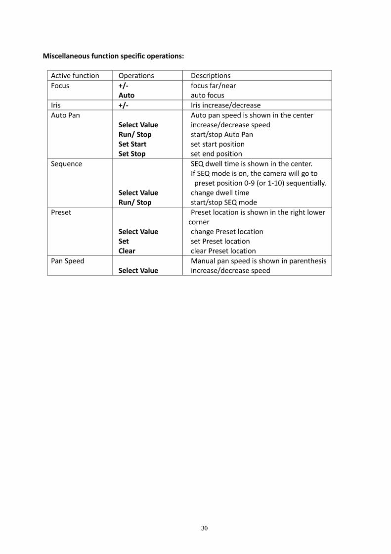
Miscellaneous function specific operations:
Active function Operations Descriptions
Focus +/- Auto
focus far/near auto focus
Iris +/- Iris increase/decrease
Auto Pan Select Value Run/ Stop Set Start Set Stop
Auto pan speed is shown in the center increase/decrease speed start/stop Auto Pan set start position set end position
Sequence Select Value Run/ Stop
SEQ dwell time is shown in the center. If SEQ mode is on, the camera will go to preset position 0-9 (or 1-10) sequentially.
change dwell time start/stop SEQ mode
Preset
Select Value Set Clear
Preset location is shown in the right lower corner change Preset location set Preset location clear Preset location
Pan Speed Select Value
Manual pan speed is shown in parenthesis increase/decrease speed

31
5.7 System Shutdown (Administrator)
Left-click the mouse to select the Shutdown (Mouse: ) In Menu display to shut down the system. A confirmation dialog will be shown on the screen. Press YES to confirm the shutdown. The system will save all the files and all the states, and then display a power-off message in the left lower corner area of the screen. The user may power off the system safely when the power-off message is shown.
6. Setup (Administrator)
Left-click the mouse to select the Setup (Mouse: ) In Menu display, the Setup Menu will be shown. (To enter Setup Menu display of the system, please login as Administrator first.)
The user’s operations are described as the followings: The general operations are as below:
Mouse: Left Click in the respective item Select the items to set.
X (Mouse: Left Click X or Right Click to leave) Press this button to escape from this screen, and return to Menu display. If the contents have been modified, a Save dialog will be shown to ask the user to save the changes, press YES to exit and save, CANCER to exit without saving.
32
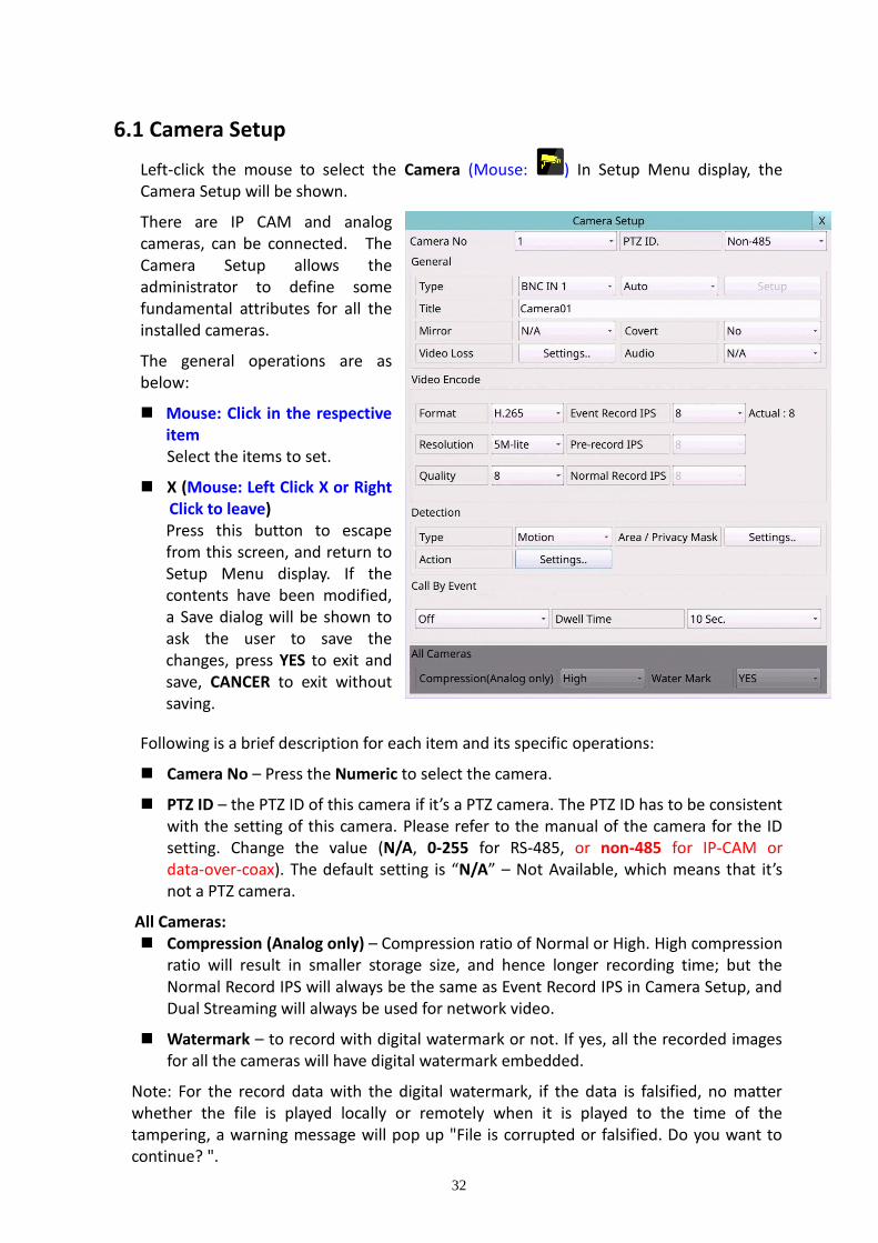
6.1 Camera Setup
Left-click the mouse to select the Camera (Mouse: ) In Setup Menu display, the Camera Setup will be shown.
There are IP CAM and analog cameras, can be connected. The Camera Setup allows the administrator to define some fundamental attributes for all the installed cameras.
The general operations are as below:
Mouse: Click in the respective item Select the items to set.
X (Mouse: Left Click X or Right Click to leave) Press this button to escape from this screen, and return to Setup Menu display. If the contents have been modified, a Save dialog will be shown to ask the user to save the changes, press YES to exit and save, CANCER to exit without saving.
Following is a brief description for each item and its specific operations:
Camera No – Press the Numeric to select the camera.
PTZ ID – the PTZ ID of this camera if it’s a PTZ camera. The PTZ ID has to be consistent with the setting of this camera. Please refer to the manual of the camera for the ID setting. Change the value (N/A, 0-255 for RS-485, or non-485 for IP-CAM or data-over-coax). The default setting is “N/A” – Not Available, which means that it’s not a PTZ camera.
All Cameras:
Compression (Analog only) – Compression ratio of Normal or High. High compression ratio will result in smaller storage size, and hence longer recording time; but the Normal Record IPS will always be the same as Event Record IPS in Camera Setup, and Dual Streaming will always be used for network video.
Watermark – to record with digital watermark or not. If yes, all the recorded images for all the cameras will have digital watermark embedded.
Note: For the record data with the digital watermark, if the data is falsified, no matter whether the file is played locally or remotely when it is played to the time of the tampering, a warning message will pop up "File is corrupted or falsified. Do you want to continue? ".

33
General:
Type – whether this camera is IP CAM, Analog, or N/A. If IP CAM, the IP CAM settings will be settable.
Mode – “Auto” detection or “AHD”, “TVI”, or “CVI”.
Setup – when Type set as IPCAM, it is used to set up the IPCAM related settings for this camera. Press Setup (Mouse: Left click) to call up the IPCAM Setup display for the camera as shown below.
Please select ONVIF for the IP CAM that can support ONVIF Profile S /Profile T, otherwise select RTSP. For ONVIF, user can click on Discover to discover the IP CAM (static IP or DHCP) in the LAN, then double click the left mouse button to select the IP CAM in IPCAM List, the URL and ONVIF Port will be display in the field. For RTSP, please enter Main Stream URI and Dual Stream URI manually. Please also enter the correct Username, Password, and if it’s to be time-synchronized with the NVR for the IP CAM. Please note that camera setup is not supported for RTSP. However, live/network view, record, and playback are supported, but users need to configure the bit rate and the frame rate of main/dual stream manually so that the Max. Incoming bandwidth won’t be exceeded. For plug-and-play, please note that it is supported for DHCP or static IP of IP-CAM, but only two predefined sets of username/password for IP-CAM is supported.
After defined sets of Mode/ URL/ Onvif Port/ Username/ Password/ Time Synchronization, press Register to connect to the IP Camera.
Note: Add IP CAM via left mouse button double click from Discover IP CAM List, it would keep IP CAM's UUID. So that even if the IP URL changed, still can find the IP CAM and automatic use. If key-in the URL and ONVIF Port values directly, it wouldn't keep the UUID. After the IP CAM URL is changed, the user needs to modify the URL value manually.
Title – The title (Max. 16 characters) of this camera. Please follow the Text Input method described in Section 4.1 to modify this item.

34
Mirror – whether to mirror, flip, or rotate 180 degrees for the video.
Covert – covert or not. If the camera is covert, the video of this camera can only be seen if the user has logged in as Administrator.
Video Loss – used to setup the action settings when video loss is detected for this camera. Press Settings (Mouse: Left click) to call up Video Loss Setup display for the camera. Please refer to Section 6.1.3 for the details.
Audio – the AUDIO IN corresponding to this camera. The audio data for the selected AUDIO IN will be recorded with the video data for this camera. Select none (N/A) or AUDIO Inputs (1-4/8) or “Camera” that means audio from IP-CAM / Coaxial Audio Camera. The default setting is “N/A”.
Note: Coaxial Audio function should use Coaxial Audio Camera (TVI Audio over coax Cameras), and select the DVR that supports Coaxial Audio.
Note: The audio input number of some models needs to correspond to the camera number and cannot be paired at will.
Video Encode:
Format – Compression format, H.265 or H.264.
Resolution – the record resolution for the camera.
Record Quality – the record quality for analog camera. The value (1-9, with 1 the lowest (rough) quality, 9 the highest (fine) quality). The record quality for IP camera, please refer to Section 6.1.1 for the details.
Event Record IPS – the IPS (Images Per Second) for analog camera if certain event (Motion, Alarm) occurs for this camera. This camera will be recorded at this rate for Post-record time since the event occurs. The Event Record IPS for IP camera, please refer to Section 6.1.1 for the details.
Pre-record IPS – the pre-record IPS for analog camera if certain event (Video Loss, Motion, Alarm) occurs for this camera. This camera is recorded at this rate for Pre-record time before the event occurs. For this DVR, the value is always the same as Event Record IPS. The Pre-record IPS for IP camera, please refer to Section 6.1.1 for the details.
Normal Record IPS – the normal record IPS for analog camera. This camera will be recorded at this rate if no event occurs. Please note that for High compression ratio in Pre-Camera setup, Normal Record IPS is always the same as Event Record IPS. The Normal Record IPS for IP camera, please refer to Section 6.1.1 for the details.
Actual Event Record IPS – the actual event record IPS set to the cameras because of the limitation of the total system performance.
Detection:
Type –“N/A” or “Motion”, “eFence” to enable motion (or eFence) detection of this camera. (Note: this field has no effect for the Smart Search information.)
Area/Privacy Mask – The settings are for motion (or eFence) detection and privacy mask settings. Please refer to Section 6.1.4 for the details.
35
Action – used to set up the Motion (or eFence) settings for Motion (or eFence) Detection. Press Action (Mouse: Left click) to call up the Detection Action Setup display for the camera. Please refer to Section 6.1.4 for the details.
Call By Event:
Call By Event – whether to switch the monitor to the video of this camera if certain event occurs for this camera. There are 4 options, including Off, Camera Event, Alarm, Both (Camera Event & Alarm).
Dwell Time – the dwell time if Call By Event is set to Camera Event, Alarm, or Both.
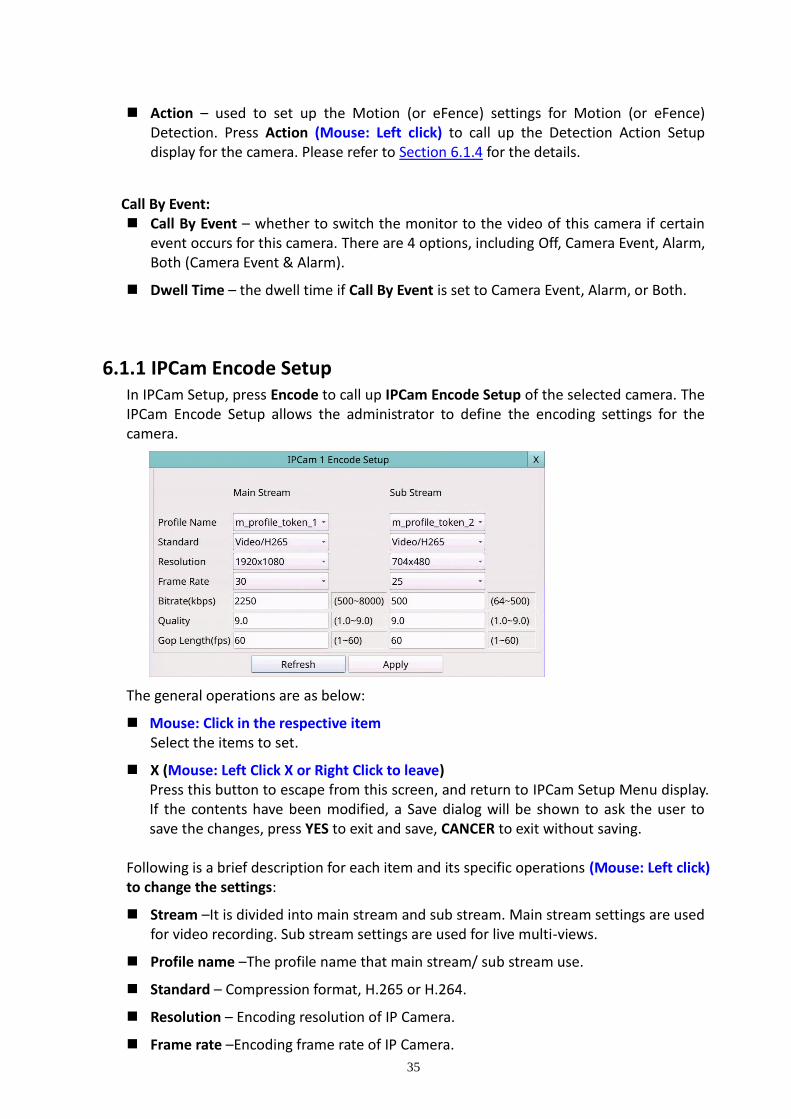
6.1.1 IPCam Encode Setup In IPCam Setup, press Encode to call up IPCam Encode Setup of the selected camera. The IPCam Encode Setup allows the administrator to define the encoding settings for the camera.
The general operations are as below:
Mouse: Click in the respective item Select the items to set.
X (Mouse: Left Click X or Right Click to leave) Press this button to escape from this screen, and return to IPCam Setup Menu display. If the contents have been modified, a Save dialog will be shown to ask the user to save the changes, press YES to exit and save, CANCER to exit without saving.
Following is a brief description for each item and its specific operations (Mouse: Left click) to change the settings:
Stream –It is divided into main stream and sub stream. Main stream settings are used for video recording. Sub stream settings are used for live multi-views.
Profile name –The profile name that main stream/ sub stream use.
Standard – Compression format, H.265 or H.264.
Resolution – Encoding resolution of IP Camera.
Frame rate –Encoding frame rate of IP Camera.

36
Bitrate (kbps) –Encoding bitrate of IP Camera.
Quality –Encoding quality of IP Camera.
Gop length (fps) –Encoding GOV length of IP Camera.
Apply – Apply settings to IP Camera.
Refresh – Reload the encoding settings of IP Camera.
6.1.2 IPCam Image Setup In IPCam Setup, press Image to call up IPCam Image Setup of the selected camera. It will link to Video Adjustment, Please refer to Section 5.3 for the details.
6.1.3 Video Loss Setup In Camera Setup, press Video loss settings.. to call up Video Loss Setup of the selected camera to set up. The Video Loss Setup allows the administrator to define how the system responds to the detected video loss for the camera.
The general operations are as below: Mouse: Click in the respective item
Select the items to set.
X (Mouse: Left Click X or Right Click to leave) Press this button to escape from this screen, and return to Camera Setup display. If the contents have been modified, a Save dialog will be shown to ask the user to save the changes, press YES to exit and save, CANCER to exit without saving.
Following is a brief description for each item and its specific operations:
Camera – Press the Numeric to select the camera.
Duration – response duration to define at most how long (in seconds) the Alarm Out relay and the Buzzer will keep being triggered after video loss is detected for this camera. However, the Alarm Out relay and the Buzzer will be reset immediately once the camera returns to normal. The value (3 seconds - 60 minutes, discrete, ‘-‘ for ‘Forever’).
Camera to go – the camera to go to the preset position in next field after video loss is detected for this camera. “Camera to go” camera must be a PTZ camera.
Goto Preset – to define the preset position to go to for the “Camera to go” Camera in last field if video loss is detected for this camera. For more details about preset locations, please refer to Section 5.6. PTZ Control.

37
Pre-record – to define how long before video loss is detected this camera shall be intensively recorded at Pre-record IPS. Please note that the actual pre-record time may be shorter than the value set if the total size of the pre-record pictures exceeds the pre-record buffer size of the system.
Alarm Out – to define which Alarm Output will be triggered when this event is triggered.
Buzzer – to activate the internal Buzzer or not when video loss of this camera is detected.
Log – to log to event logs or not.
Screen Message – to display the event message on the screen or not.
E-mail – to send the event e-mail to remote station or not. The e-mail will be sent to the predefined receivers at the moment when the event is triggered.
FTP – to send the recorded event video/audio files to FTP server or not.

38
6.1.4 Motion/(eFence)/Privacy Mask Setup In Camera Setup, press Area/Privacy Mask to call up Detection/Privacy Mask Setup as shown.
It used to setup the motion (or eFence) detection settings, including detection area and sensitivity, when motion (or eFence) is detected for this camera. Please note that the motion detection area and sensitivity are also used for the Smart Search information. There won’t be any Smart Search information stored outside the detection area. So, it’s better to enable the whole area if the motion detection for the camera is disabled (and only Smart Search is used). In Motion Detection Setup, the video area is divided into
many small grids, and the area with is the area which will be detected for motion, while transparent grids not detected for motion.
The general operations are as below:
Mouse: Click in the respective item Select the items to set.
X (Mouse: Left Click X or Right Click to leave) Press this button to escape from this screen, and return to Camera Setup display. If the contents have been modified, a Save dialog will be shown to ask the user to save the changes, press YES to exit and save, CANCER to exit without saving.
Following is a brief description for the operations of detection: Type – Press to select the type to set.
Camera – Press the Numeric to select the camera.
Sensitivity – The sensitivity, 1 – 10, for the motion detection of this camera.
Num Of Grids As Detection – The “number of grids treated as motion”
Test – Press this button to test the motion detection of this camera. The detected

39
motion will be shown on the screen. Press this button again to stop testing.
Privacy Mask Settings – used to setup the privacy mask settings. The Privacy Mask Setup is similar to Motion Detection Setup, except that the green area of the camera will be blacked out for live/recorded video.
Following is a brief description for the operations of eFence detection (optional):
Type – Press to select the type to set.
Camera – Press the Numeric to select the camera.
Sensitivity – The sensitivity, 1 – 10, for the motion detection of this camera.
Mouse: Left click and drag – Draw the eFence line. Up to 4 lines can be drawn.
Mouse: Left click – Click on the eFence line to select it.
Delete – Click to delete the selected eFence line.
Test – Click on this button to test. The color of the eFence line will be changed if it’s crossed by an object of reasonable size. Click on it again to stop testing.
Privacy Mask Settings – used to setup the privacy mask settings. The Privacy Mask Setup is similar to Motion Detection Setup, except that the green area of the camera will be blacked out for live/recorded video.

40
In Camera Setup, press Action to call up Detection Action Setup as shown. It allows the administrator to define how the system responds to the detected motion (or eFence) for the camera.
Following is a brief description for each item and its specific operations:
Camera – Press the Numeric to select the camera.
Duration – response duration to define at most how long (in seconds) the Alarm Out relay and the Buzzer will keep being triggered after motion (or eFence) is detected for this camera. However, the Alarm Out relay and the Buzzer will be reset immediately once the camera returns to normal. The value (3 seconds - 60 minutes, discrete, ‘-‘ for ‘Forever’).
Camera to go – the camera to go to the preset position in next field after motion (or eFence) is detected for this camera. “Camera to go” camera must be a PTZ camera.
Goto Preset – to define the preset position to go to for the “Camera to go” Camera in last field if motion (or eFence) is detected for this camera. For more details about preset locations, please refer to Section 5.6. PTZ Control.
Pre-record – to define how long before motion (or eFence) is detected this camera shall be intensively recorded at Pre-record IPS. Please note that the actual pre-record time may be shorter than the value set if the total size of the pre-record pictures exceeds the pre-record buffer size of the system.
Post-record – to define how long after motion (or eFence) is detected this camera shall be intensively recorded at Event Record IPS.
Alarm Out – to define which Alarm Output will be triggered when this event is triggered. Press to select Alarm Output Source.
Buzzer – to activate the internal Buzzer or not when motion (or eFence) of this camera is detected.
Log – to log to event logs or not.
Screen Message – to display the event message on the screen or not.
E-mail – to send the event e-mail to remote station or not. The e-mail will be sent to the predefined receivers when the event is triggered.
FTP – to send the recorded event video/audio files to FTP server or not.
41
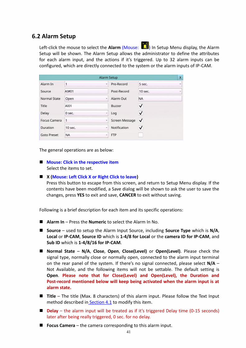
6.2 Alarm Setup
Left-click the mouse to select the Alarm (Mouse: ) In Setup Menu display, the Alarm Setup will be shown. The Alarm Setup allows the administrator to define the attributes for each alarm input, and the actions if it’s triggered. Up to 32 alarm inputs can be configured, which are directly connected to the system or the alarm inputs of IP-CAM.
The general operations are as below: Mouse: Click in the respective item
Select the items to set.
X (Mouse: Left Click X or Right Click to leave) Press this button to escape from this screen, and return to Setup Menu display. If the contents have been modified, a Save dialog will be shown to ask the user to save the changes, press YES to exit and save, CANCER to exit without saving.
Following is a brief description for each item and its specific operations: Alarm In – Press the Numeric to select the Alarm In No.
Source – used to setup the Alarm Input Source, including Source Type which is N/A, Local or IP-CAM, Source ID which is 1-4/8 for Local or the camera ID for IP-CAM, and Sub ID which is 1-4/8/16 for IP-CAM.
Normal State – N/A, Close, Open, Close(Level) or Open(Level). Please check the signal type, normally close or normally open, connected to the alarm input terminal on the rear panel of the system. If there’s no signal connected, please select N/A – Not Available, and the following items will not be settable. The default setting is Open. Please note that for Close(Level) and Open(Level), the Duration and Post-record mentioned below will keep being activated when the alarm input is at alarm state.
Title – The title (Max. 8 characters) of this alarm input. Please follow the Text Input method described in Section 4.1 to modify this item.
Delay – the alarm input will be treated as if it’s triggered Delay time (0-15 seconds) later after being really triggered, 0 sec. for no delay.
Focus Camera – the camera corresponding to this alarm input.

42
Duration – response duration to define at most how long (in seconds) the Alarm Out relay and the Buzzer will keep being triggered after this alarm input is triggered or returns to normal. The value ‘-‘ for ‘Forever’.
Goto Preset – to define the preset position to go to for the Focus Camera if this alarm input is triggered and the Focus Camera is a PTZ camera. For more details about preset locations, please refer to Section 5.6. PTZ Control.
Pre-record – to define how long before this alarm input is triggered the Focus Camera shall be intensively recorded at Pre-record IPS. Please note that the actual pre-record time may be shorter than the value set if the total size of the pre-record pictures exceeds the pre-record buffer size of the system.
Post-record – to define how long after this alarm input is triggered or returns to normal the Focus Camera shall be intensively recorded at Event Record IPS.
Alarm Out – to define which Alarm Output will be triggered when this alarm input is triggered. Alarm Output Source Setup up to 32 alarm outputs can be selected and the definitions are similar to alarm inputs.
Buzzer – to activate the internal Buzzer or not when this alarm input is triggered.
Log – to log to event logs or not.
Screen Message – to display the event message on the screen or not.
Notification – to notify mobile phones and/or send the event e-mail to remote station or not. The mobile phones with alarm notification from the DVR enabled will be notified, and the e-mail will be sent to the predefined receivers when the event is triggered.
FTP – to send the recorded event video/audio files to FTP server or not.

43
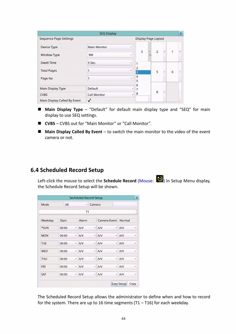
6.3 Main/SEQ Display Setup
Left-click the mouse to select the Main/SEQ Display (Mouse: ) In Setup Menu display, the SEQ Display Setup will be shown.
The Main/SEQ Display Setup allows the administrator to define the display pages in SEQ Display for main monitor and call monitor. Please note that Call Monitor supports 1/4 split window display. The general operations are as below: Mouse: Click in the respective item
Select the items to set.
X (Mouse: Left Click X or Right Click to leave) Press this button to escape from this screen, and return to Setup Menu display. If the contents have been modified, a Save dialog will be shown to ask the user to save the changes, press YES to exit and save, CANCER to exit without saving.
Following is a brief description for each item and its specific operations:
Device Type – select to set Main Monitor or Call Monitor.
Window Type – select to set the split window.
Dwell Time – the dwell time (3 ~ 60 seconds) for each page of this display type.
Total Pages – total pages for this SEQ Display Type. The maximum number varies according to the display type.
Pages No – to change the current page for this SEQ Display Type.
Display Page Layout – used to set the camera in each viewing window for each page of this SEQ Display Type.
In Display Page Layout, the split window display for the current page is shown. Press ▼ buttons to change the camera for the current page.
44
Main Display Type – “Default” for default main display type and “SEQ” for main display to use SEQ settings.
CVBS – CVBS out for “Main Monitor” or “Call Monitor”.
Main Display Called By Event – to switch the main monitor to the video of the event camera or not.
6.4 Scheduled Record Setup
Left-click the mouse to select the Schedule Record (Mouse: ) In Setup Menu display, the Schedule Record Setup will be shown.
The Scheduled Record Setup allows the administrator to define when and how to record for the system. There are up to 16 time segments (T1 – T16) for each weekday.

45
The general operations are as below: Mouse: Click in the respective item
Select the items to set.
X (Mouse: Left Click X or Right Click to leave) Press this button to escape from this screen, and return to Setup Menu display. If the contents have been modified, a Save dialog will be shown to ask the user to save the changes, press YES to exit and save, CANCER to exit without saving.
COPY Press this button to copy the settings of (1) the focus camera to all the following cameras, or (2) the focus weekday to all the following weekdays. (EX. focus weekday is TUE, its settings will be copied to those of weekdays WED-SAT.) To focus the weekday, click the week's text and there will be an asterisk (*) preceding its text.
Easy Setup (Mouse: Left click) Press this button to enter Easy Setup for Schedule Record as described in the following paragraphs.
Following is a brief description for each item and its specific operations: Mode – the schedule below applies to All cameras or Individual camera.
Camera – select the camera if Individual is selected.
Start – the start time of this time segment, increment at 30 minutes. (The end time of this time segment is implicitly set as the start time of next time segment, or the start time of the first time segment of the same weekday if it’s the last one.)
Example: If the user sets the start time of T1/MON as 9:00, T2/MON as 18:00, T3-T16/MON as N/A (Not Available), then T1/MON is 9:00-18:00, T2/MON is 0:00-9:00, and 18:00-24:00.
Alarm – record mode (No, Video, Audio/Video) when certain alarm input is triggered. “OFF” is for alarm detection OFF. Please note that the alarm is the alarm for the focus camera (in Alarm Setup) if Individual is selected.
Motion – record mode (No, Video, or Audio/Video) when motion is detected for certain camera. “OFF” is for motion detection OFF.
Normal – normal record mode, including No, V (Video only), or A/V (Audio/Video).
Note: In a time segment, if both Alarm and Motion are set to “OFF”, the audio/video will be treated as Normal unless there’s Video Loss.

46
Scheduled Record – Easy Setup
The Scheduled Record – Easy Setup allows the administrator to use a simpler and easier way to setup the scheduled record of the system. In Easy Setup, there are Six Selectable Recording Modes: Alarm+Motion+Normal, Alarm+Motion, Alarm, Motion, Normal, and No Record. Video & Audio are all recorded for the selectable Recording Modes except “No Record”. After the Easy Setup, the time segments for each weekday in Scheduled Record will be updated accordingly.
The operations are as below:
Mouse: Click in the respective item Select the items to set.
X (Mouse: Left Click X or Right Click to leave) Press this button to escape from this screen, and return to Scheduled Record Setup display. The time segments for each weekday in Scheduled Record will be updated accordingly. If the contents have been modified, a Save dialog will be shown to ask the user to save the changes, press YES to exit and save, CANCER to exit without saving.
COPY Press this button to copy the settings of the focus camera to all the following cameras. (EX. focus camera is 2, its schedule settings will be copied to those of the cameras 3-8.)
Color (Mouse: Left click) Press these buttons to select the active Recording Mode. The user may press the different color radio button when the focus is on the Recording Mode to activate it. The Recording Modes are : “Light purple color” – Alarm + Motion + Normal, “Dark purple color” – Alarm + Motion, “Light red color” – Alarm, “Blue color” – Motion, “Green color” – Normal, “Yellow color” – No Record, and Gray color for Others (which is not selectable).
(Mouse: Left click and drag) Mouse left click and drag to set the focus interval (one grid for one hour) upwardly/downwardly to the different recording mode.

47
6.5 HDD Setup
Left-click the mouse to select the HDD (Mouse: ) In Setup Menu display, the HDD Setup will be shown.
In surveillance applications, alarm video/audio is much more important than normal video/audio. So, this digital video/audio recorder is designed to allow the user to divide each HDD into an alarm partition and a normal partition. And, alarm video/audio will be recorded in the alarm partition, normal video/audio in the normal partition.
The HDD Setup allows the administrator to format/clear each HDD, set the Alarm Record size and Normal Record size of each HDD, and define the behaviors for Alarm Record and Normal Record if it reaches the end of the last HDD in the system. The general operations are as below: Mouse: Click in the respective item
Select the items to set.
X (Mouse: Left Click X or Right Click to leave) Press this button to escape from this screen, and return to Setup Menu display. If the contents have been modified, a Save dialog will be shown to ask the user to save the changes, press YES to exit and save, CANCER to exit without saving.
HDD Format/Clear (Mouse: Left click) Press this button to format/clear the HDDs as described in Section 6.5.1.
Advanced HDD Setup (Mouse: Left click) Press this button to enter Advanced HDD Setup as described in Section 6.5.2.
Following is a brief description for each item and its specific operations: Size (GB) – the total HDD storage in GB (Giga-Byte) for Alarm Record and Normal
Record respectively. This item is just for information. Please refer to Section 6.5.1 for

48
more detailed information and the setup of each HDD. Please note that if the total alarm record size is zero, the alarm video/audio will be recorded in the normal record partition. If the total normal record size is zero, the normal video/audio will be recorded in the alarm record partition.
Auto Overwrite – automatic overwrite of the recorded video/audio from HDD#1
when the Alarm/Normal Record disk drive capacity reaches the end of the last HDD. If Auto Overwrite is disabled and the Alarm/Normal Record disk drive capacity reaches the end, the system will not overwrite the recorded video/audio, and hence not record Alarm/Normal video/audio, until the user presses the Alarm Reset button.
HDD Full Action – actions when Alarm/Normal Record disk drive capacity reaches the
end of the last HDD. Duration – response duration to define at most how long (in seconds) the Alarm Out
relay and the Buzzer will keep being triggered after the corresponding partition, Alarm Record or Normal Record, is full. The value - means forever.
Alarm Out – to define which Alarm Output will be triggered when this event is
triggered. Alarm Output Source Setup up to 32 alarm outputs can be selected and the definitions are similar to alarm inputs.
Buzzer – to activate the internal Buzzer or not when the corresponding partition,
Alarm Record or Normal Record, is full. Log – to log to event logs or not. E-mail – to send the event e-mail to remote station or not. The e-mail will be sent to
the predefined receivers when the event is triggered.
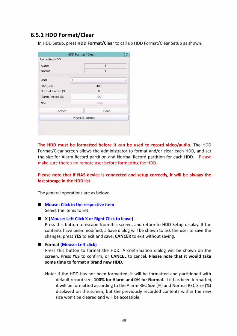
49
6.5.1 HDD Format/Clear In HDD Setup, press HDD Format/Clear to call up HDD Format/Clear Setup as shown.
The HDD must be formatted before it can be used to record video/audio. The HDD Format/Clear screen allows the administrator to format and/or clear each HDD, and set the size for Alarm Record partition and Normal Record partition for each HDD. Please make sure there’s no remote user before formatting the HDD. Please note that if NAS device is connected and setup correctly, it will be always the
last storage in the HDD list. The general operations are as below: Mouse: Click in the respective item
Select the items to set.
X (Mouse: Left Click X or Right Click to leave) Press this button to escape from this screen, and return to HDD Setup display. If the contents have been modified, a Save dialog will be shown to ask the user to save the changes, press YES to exit and save, CANCER to exit without saving.
Format (Mouse: Left click) Press this button to format the HDD. A confirmation dialog will be shown on the screen. Press YES to confirm, or CANCEL to cancel. Please note that it would take some time to format a brand new HDD. Note: If the HDD has not been formatted, it will be formatted and partitioned with
default record size, 100% for Alarm and 0% for Normal. If it has been formatted, it will be formatted according to the Alarm REC Size (%) and Normal REC Size (%) displayed on the screen, but the previously recorded contents within the new size won’t be cleared and will be accessible.
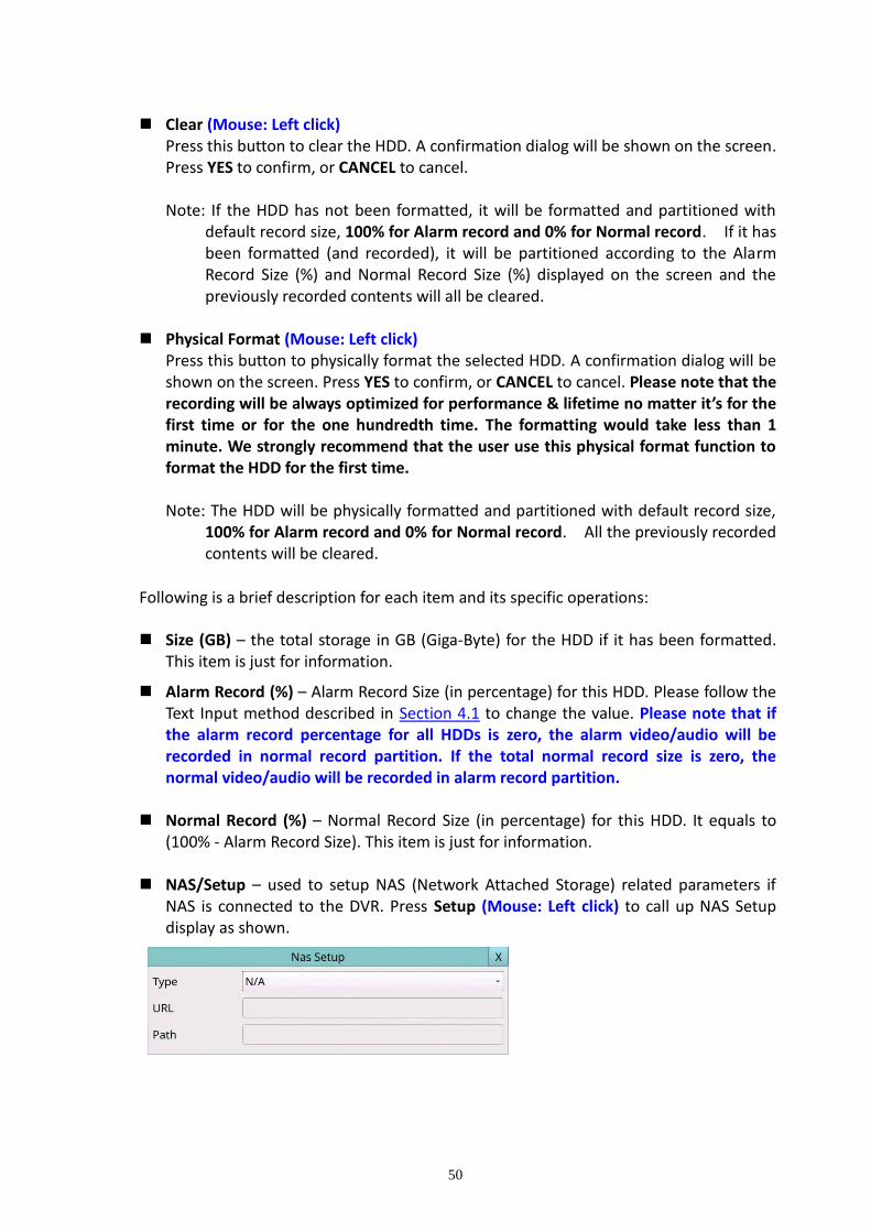
50
Clear (Mouse: Left click) Press this button to clear the HDD. A confirmation dialog will be shown on the screen. Press YES to confirm, or CANCEL to cancel. Note: If the HDD has not been formatted, it will be formatted and partitioned with
default record size, 100% for Alarm record and 0% for Normal record. If it has been formatted (and recorded), it will be partitioned according to the Alarm Record Size (%) and Normal Record Size (%) displayed on the screen and the previously recorded contents will all be cleared.
Physical Format (Mouse: Left click)
Press this button to physically format the selected HDD. A confirmation dialog will be shown on the screen. Press YES to confirm, or CANCEL to cancel. Please note that the recording will be always optimized for performance & lifetime no matter it’s for the first time or for the one hundredth time. The formatting would take less than 1 minute. We strongly recommend that the user use this physical format function to format the HDD for the first time. Note: The HDD will be physically formatted and partitioned with default record size,
100% for Alarm record and 0% for Normal record. All the previously recorded contents will be cleared.
Following is a brief description for each item and its specific operations: Size (GB) – the total storage in GB (Giga-Byte) for the HDD if it has been formatted.
This item is just for information.
Alarm Record (%) – Alarm Record Size (in percentage) for this HDD. Please follow the Text Input method described in Section 4.1 to change the value. Please note that if the alarm record percentage for all HDDs is zero, the alarm video/audio will be recorded in normal record partition. If the total normal record size is zero, the normal video/audio will be recorded in alarm record partition.
Normal Record (%) – Normal Record Size (in percentage) for this HDD. It equals to
(100% - Alarm Record Size). This item is just for information. NAS/Setup – used to setup NAS (Network Attached Storage) related parameters if
NAS is connected to the DVR. Press Setup (Mouse: Left click) to call up NAS Setup display as shown.

51
Following is a brief description for each item and its specific operations:
Mouse: Click in the respective item
Select the items to set.
X (Mouse: Left Click X or Right Click to leave) Press this button to escape from this screen, and return to HDD Format/Clear Setup display. If the contents have been modified, a Save dialog will be shown to ask the user to save the changes, press YES to exit and save, CANCER to exit without saving. Please note that if the NAS settings are changed, the user will be asked to reboot the system for the new settings to take effect. The NAS device will be always the last storage in the HDD list.
Type – “NFS” or “N/A”.
URL – the URL (Uniform Resource Locators) for the NAS device. Please follow the Text Input method described in Section 4.1 to modify this item.
Path – the path in the NAS device to store video/audio. Please follow the Text Input method described in Section 4.1 to modify this item. Please note that lowercase and uppercase are treated differently. Besides, ‘/’ is used for subdirectory.

52
6.5.2 Advanced HDD Setup In HDD Setup, press Advanced HDD Setup to call up Advanced HDD Setup as shown.
The HDD Failure Action in Advanced HDD Setup allows the administrator to define how the system responds to the detected HDD failure, while the Privacy settings allow the administrator to set the DVR to record for Limited Period and the Retention Period of its HDD storage. The HDD Failure Action will be triggered if there’s no available formatted HDD detected.
The general operations are as below:
Mouse: Click in the respective item Select the items to set.
X (Mouse: Left Click X or Right Click to leave) Press this button to escape from this screen, and return to HDD Setup display. If the contents have been modified, a Save dialog will be shown to ask the user to save the changes, press YES to exit and save, CANCER to exit without saving.
Following is a brief description for each item and its specific operations:
Duration – response duration to define at most how long (in seconds) the Alarm Out relay and the Buzzer will keep being triggered after HDD failure is detected. The value (3 seconds - 60 minutes, discrete, ‘-‘ for ‘Forever’).
Alarm Out – to define which Alarm Output will be triggered when this event is triggered. Alarm Output Source Setup up to 32 alarm outputs can be selected, and the definitions are similar to alarm inputs.
Buzzer – to activate the internal Buzzer or not when HDD failure is detected.
Log – to log to event logs or not.
Notification – to notify mobile phones and/or send the event e-mail to remote station or not. The mobile phones with alarm notification from the DVR enabled will be notified, and the e-mail will be sent to the predefined receivers when the event is triggered.
Limited Period – whether the HDD storage is for a limited period or not. The setting “–” means No.
Retention Period (hour) – the retention period of the HDD storage if Limited Period is “ˇ”. Please follow the Text Input method described in Section 4.1 to modify this item. If this item is set as 0, it will be treated as No Limited Period.
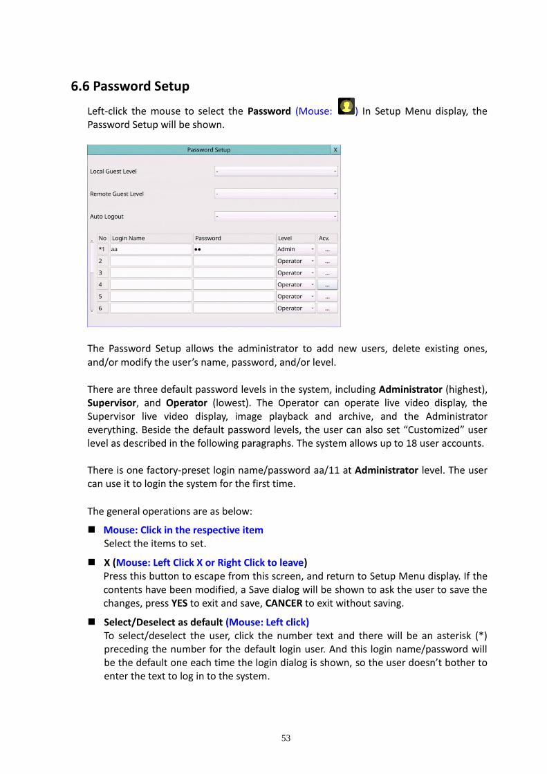
53
6.6 Password Setup
Left-click the mouse to select the Password (Mouse: ) In Setup Menu display, the Password Setup will be shown.
The Password Setup allows the administrator to add new users, delete existing ones, and/or modify the user’s name, password, and/or level. There are three default password levels in the system, including Administrator (highest), Supervisor, and Operator (lowest). The Operator can operate live video display, the Supervisor live video display, image playback and archive, and the Administrator everything. Beside the default password levels, the user can also set “Customized” user level as described in the following paragraphs. The system allows up to 18 user accounts. There is one factory-preset login name/password aa/11 at Administrator level. The user can use it to login the system for the first time.
The general operations are as below:
Mouse: Click in the respective item Select the items to set.
X (Mouse: Left Click X or Right Click to leave) Press this button to escape from this screen, and return to Setup Menu display. If the contents have been modified, a Save dialog will be shown to ask the user to save the changes, press YES to exit and save, CANCER to exit without saving.
Select/Deselect as default (Mouse: Left click) To select/deselect the user, click the number text and there will be an asterisk (*) preceding the number for the default login user. And this login name/password will be the default one each time the login dialog is shown, so the user doesn’t bother to enter the text to log in to the system.

54
Following is a brief description for each item and its specific operations: Local Guest Level – the local access level (Administrator, Supervisor, Operator, -, or
any user) without login the system. Remote Guest Level – the remote access level without login the system. Auto Logout – auto logout, if there’s no user’s operation in 1 minute to 24 hours, or
not (“-“). Login Name – please follow the Text Input method described in Section 4.1 to modify
this item. Password – this item accepts numbers only. Please follow the Text Input method
described in Section 4.1 to modify this item. Level – the password level (Administrator, Supervisor, Operator, or Customized) for
this user. Adv. – press … (Mouse: Left click) to call up Advanced User Setup as shown below.
The Advanced User Setup allows the administrator to setup each user’s detailed access right of the system.
The general operations are as below:
Mouse: Click in the respective item
Select the items to set.

55
X (Mouse: Left Click X or Right Click to leave) Press this button to escape from this screen, and return to Password Setup display. The Password Setup contents will be updated accordingly.
Following is a brief description for each item and its specific operations:
Monitor Channel:
Monitor Channel 1-4/8/16 – the user can only monitor those channels “checked”. Mouse Left click to check/uncheck this item.
Search:
Playback – to enable the user to playback video/audio if “checked”. Mouse Left click to check/uncheck this item.
Backup – to enable the user to backup video/audio if “checked”. Mouse Left click to check/uncheck this item.
Monitor:
X2 – to enable the user to do X2 operation for live/playback video if “checked”. Mouse Left click to check/uncheck this item.
PTZ – to enable the user to do PTZ operation if “checked”. Mouse Left click to check/uncheck this item.
GPS/POS/OSD Display – to enable the user to change GPS/POS/OSD Display if “checked”. Mouse Left click to check/uncheck this item.
Volume – to enable the user to change volume if “checked”. Mouse Left click to check/uncheck this item.
Video Adjustment – to enable the user to do video adjustment operation if “checked”. Mouse Left click to check/uncheck this item.
Display – to enable the user to change display settings if “checked”. Mouse Left click to check/uncheck this item.
Setup:
Configuration Backup/Restore – to enable the user to backup/restore configurations if “checked”. Mouse Left click to check/uncheck this item.
Setup Camera – to enable the user to do Camera Setup if “checked”. Mouse Left click to check/uncheck this item.
Setup Alarm – to enable the user to do Alarm Setup if “checked”. Mouse Left click to check/uncheck this item.
Setup Main/SEQ Display – to enable the user to do Main/SEQ Display Setup if “checked”. Mouse Left click to check/uncheck this item.
Setup Scheduled Record – to enable the user to do Scheduled Record Setup if “checked”. Mouse Left click to check/uncheck this item.
56
Setup HDD – to enable the user to do HDD Setup if “checked”. Mouse Left click to check/uncheck this item.
Setup Password – to enable the user to do Password Setup if “checked”. Mouse Left click to check/uncheck this item.
Setup System – to enable the user to do System Setup if “checked”. Mouse Left click to check/uncheck this item.
Setup RS-232/485 – to enable the user to do RS-232/485 Setup if “checked”. Mouse Left click to check/uncheck this item.
Setup Network – to enable the user to do Network Setup if “checked”. Mouse Left click to check/uncheck this item.
Setup Factory Defaults – to enable the user to restore factory defaults to all setup related configurations if “checked”. Mouse Left click to check/uncheck this item.
Others:
Software Upgrade – to enable the user to upgrade DVR software if “checked”. Mouse Left click to check/uncheck this item.
Shutdown – to enable the user to shutdown the DVR if “checked”. Mouse Left click to check/uncheck this item.
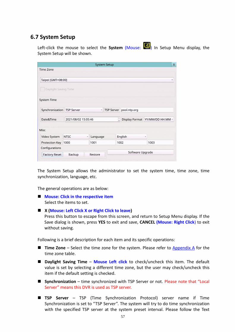
57
6.7 System Setup
Left-click the mouse to select the System (Mouse: ) In Setup Menu display, the System Setup will be shown.
The System Setup allows the administrator to set the system time, time zone, time
synchronization, language, etc. The general operations are as below:
Mouse: Click in the respective item Select the items to set.
X (Mouse: Left Click X or Right Click to leave) Press this button to escape from this screen, and return to Setup Menu display. If the Save dialog is shown, press YES to exit and save, CANCEL (Mouse: Right Click) to exit without saving.
Following is a brief description for each item and its specific operations:
Time Zone – Select the time zone for the system. Please refer to Appendix A for the time zone table.
Daylight Saving Time – Mouse Left click to check/uncheck this item. The default value is set by selecting a different time zone, but the user may check/uncheck this item if the default setting is checked.
Synchronization – time synchronized with TSP Server or not. Please note that “Local Server” means this DVR is used as TSP server.
TSP Server – TSP (Time Synchronization Protocol) server name if Time Synchronization is set to “TSP Server”. The system will try to do time synchronization with the specified TSP server at the system preset interval. Please follow the Text

58
Input method described in Section 4.1 to modify this item.
Date & Time – system date and system time.
Display Format – format used for the system time displayed on the lower-right corner of the main screen.
Video System – NTSC or PAL.
Language – Select the language for the system. The languages supported include: English, Simplified Chinese, Traditional Chinese, etc.
Protection Key – the protection key for the remote access of the system. Please follow the Text Input method described in Section 4.1 to modify these items.
Note: This protection key will be used for authentication when any remote station wants to connect with the system from Ethernet interface, either LAN or internet. So, the same protection key must be entered to install the remote software if it is to be used to access the system.
Factory Reset – reset all the settings to factory default values.
Backup –backup the configurations and QR code image of this unit to the corresponding USB device. The user may enter the directory to back up the configurations to.
Note: The QR code image can be used to connect to device via select this image from HEM device list.
Restore – restore the configuration files in the corresponding backup device to this unit. The user may enter the directory to restore the configurations from.
Software Upgrade – press OK (Mouse: Left click) to start the upgrade process when the highlighted file is a correct upgrade file. A confirmation dialog will be shown on the screen. Press YES to confirm to upgrade the system software.
Note : After the software is upgraded, the system will restart immediately. The split window display will be shown after restart, please wait a moment.
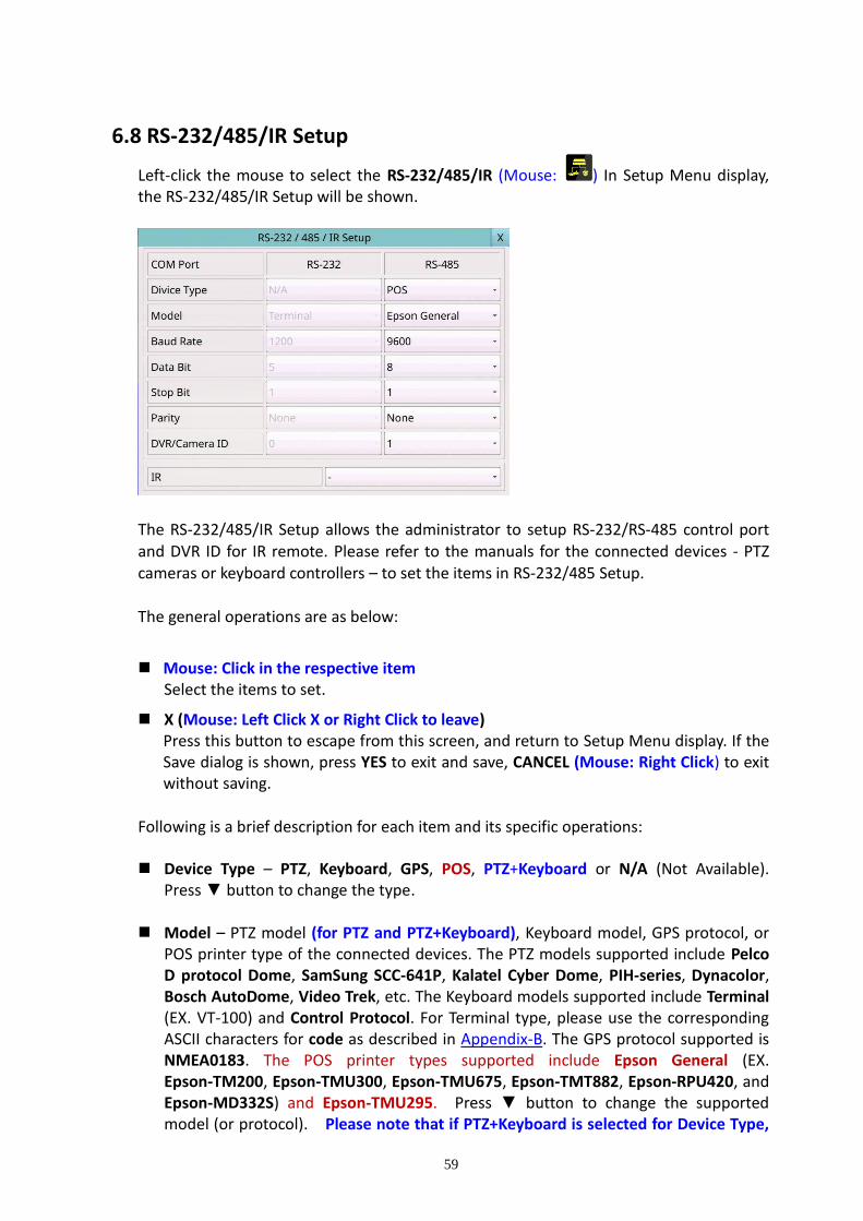
59
6.8 RS-232/485/IR Setup
Left-click the mouse to select the RS-232/485/IR (Mouse: ) In Setup Menu display, the RS-232/485/IR Setup will be shown.
The RS-232/485/IR Setup allows the administrator to setup RS-232/RS-485 control port and DVR ID for IR remote. Please refer to the manuals for the connected devices - PTZ cameras or keyboard controllers – to set the items in RS-232/485 Setup. The general operations are as below:
Mouse: Click in the respective item Select the items to set.
X (Mouse: Left Click X or Right Click to leave) Press this button to escape from this screen, and return to Setup Menu display. If the Save dialog is shown, press YES to exit and save, CANCEL (Mouse: Right Click) to exit without saving.
Following is a brief description for each item and its specific operations: Device Type – PTZ, Keyboard, GPS, POS, PTZ+Keyboard or N/A (Not Available).
Press ▼ button to change the type. Model – PTZ model (for PTZ and PTZ+Keyboard), Keyboard model, GPS protocol, or
POS printer type of the connected devices. The PTZ models supported include Pelco D protocol Dome, SamSung SCC-641P, Kalatel Cyber Dome, PIH-series, Dynacolor, Bosch AutoDome, Video Trek, etc. The Keyboard models supported include Terminal (EX. VT-100) and Control Protocol. For Terminal type, please use the corresponding ASCII characters for code as described in Appendix-B. The GPS protocol supported is NMEA0183. The POS printer types supported include Epson General (EX. Epson-TM200, Epson-TMU300, Epson-TMU675, Epson-TMT882, Epson-RPU420, and Epson-MD332S) and Epson-TMU295. Press ▼ button to change the supported model (or protocol). Please note that if PTZ+Keyboard is selected for Device Type,

60
the Keyboard model is always Control Protocol, and the other settings (Baud Rate, Data Bit, Stop Bit, and Parity) are the same as the PTZ Model selected. Please also note that the installer must be sure that the Keyboard Control Protocol and the PTZ Protocol won’t conflict with each other.
Baud Rate – for Multiple POS, please set the Baud Rate setting as 9600. Press ▼
button to change the value. Data Bit – press ▼ button to change the value. Stop Bit – press▼ button to change the value. Parity – (Odd, Even, or None). Press ▼ button to change the value.
DVR/Camera ID – for PTZ/Keyboard => the device ID for this digital video/audio
recorder, and it must not conflict with the other devices connected in the same control port.; for GPS/POS => the Camera ID to receive the GPS/POS data. For Multiple POS, please set the DVR/Camera ID setting as Multiple. For IR => the DVR ID to receive the IR control signal, “-” to receive any DVR ID signal. Press ▼ button to change the ID.
Note: For Multiple POS, please make sure to setup the ID of protocol converter I-7524
correctly (Appendix E).

61
6.9 OSD Setup
Left-click the mouse to select the OSD (Mouse: ) In Setup Menu display, the OSD Setup will be shown.
The OSD Setup allows the administrator to set up the OSD display on the split window. The general operations are as below:
Mouse: Click in the respective item Select the items to set.
X (Mouse: Left Click X or Right Click to leave) Press this button to escape from this screen, and return to Setup Menu display. If the Save dialog is shown, press YES to exit and save, CANCEL (Mouse: Right Click) to exit without saving.
Following is a brief description for each item and its specific operations:
Title – On/Off. Set display camera title on split window or not.
Time – On/Off. Set display system time on split window or not.
Message – On/Off. Set display system message on split window or not.
Status – On/Off. Set display status on split window or not.
Rec. % – On/Off. Set display HDD record% on split window or not.
GPS – On/Off. Set display GPS data on split window or not.
POS – different Color. Set display POS color on split window or not.

62
7. Search/Playback/Archive (Administrator, Supervisor) There are five ways to search the recorded video/audio for playback: (a) Search by time, (b) Search by event, (c) Smart search, (d) Search archived files, and (e) POS search.
Left-click the mouse to select the Search (Mouse: ) In Menu display, the Search will be shown.
The user’s operations are described as the followings:
Mouse: Click in the respective item Select the items to enter the corresponding Search display.
X (Mouse: Left Click X or Right Click to leave) Press this button to escape from this screen, and return to split-window display.
The Search displays and their operations are described in the following sections, followed by the playback operations of the searched video/audio.
Note: In split-window display, the user can
press PLAY button (Mouse: ) to call up Instant Playback Menu. Select the Stream Type, then select the Time for instant playback.

63
7.1 Search By Time The screen for Search By Time is shown as below:
The Status field will show the ‘Recorded from’ time, it's based on the Video/Audio before searching. Above the status, fields are the 24H time slider and alarm/motion/video loss/normal recording status (from top to bottom). The general operations are as below:
Mouse: Click in the respective item Select the items to enter the corresponding Search display.
X (Mouse: Left Click X or Right Click to leave) Press this button to escape from this screen, and return to split-window display.
Play Button (Mouse: Left click) Press this button to start playing the recorded video/audio with the selected search time and video/audio type. If there’s no camera in playback mode, all the cameras in the current split window will be set to playback mode.
Backup Button (Mouse: Left click) Press this button to backup (copy) the selected type of recorded video/audio starting from the Search Time (described below) in the HDD to the connected backup device without playback. The Backup display (described in Section 7.6) will be shown. Please note that this kind of backup is performed in the background, and the user can still do almost all the operations.
Archive Play Button (Mouse: Left click) Press this button to search/playback archive files from the backup device. The Archive Play screen (described in Section 7.4) will be shown.
Following is a brief description for each item and its specific operations:
Stream – (Main Stream, Sub Stream). Select the stream of the recorded video you want to search for playback.

64
Search Time – (Year, Month, Date, Hour, Minute) for the recorded video/audio. The playback (or backup) will start from the time entered here when the user press the playback buttons (or Copy button) later. Press ▲▼ buttons to modify each item. Users can also select the calendar on the left by mouse click and select the time by mouse dragging the slider icon.
Video/Audio – (Alarm, Motion, Video Loss, Normal). Check the types of the recorded video/audio you want to search for playback. Mouse Left click to check/uncheck each item.
7.2 Search By Event / Log Display The screen for Search By Event - Log display is shown as below:
There are three different types of event logs, including Alarm, Camera Event, Video Loss. And up to 6000 most recent event logs can be stored in the system.
The general operations are as below:
Mouse: Click in the respective item Select the items to enter the corresponding Search display.
X (Mouse: Left Click X or Right Click to leave) Press this button to escape from this screen, and return to split-window display.
Refresh Button (Mouse: Left click) Press this button to refresh the log display. If there are new event logs after the screen is last updated, the log list shown will be updated accordingly.
Log Button (Mouse: Left click) Press this button to export the event log to backup device. The Save To File dialog will be shown as below.
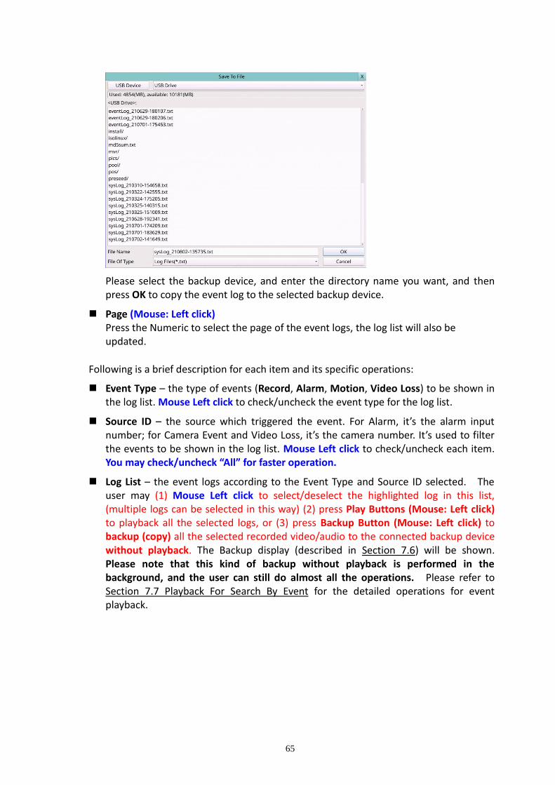
65
Please select the backup device, and enter the directory name you want, and then press OK to copy the event log to the selected backup device.
Page (Mouse: Left click) Press the Numeric to select the page of the event logs, the log list will also be updated.
Following is a brief description for each item and its specific operations:
Event Type – the type of events (Record, Alarm, Motion, Video Loss) to be shown in the log list. Mouse Left click to check/uncheck the event type for the log list.
Source ID – the source which triggered the event. For Alarm, it’s the alarm input number; for Camera Event and Video Loss, it’s the camera number. It’s used to filter the events to be shown in the log list. Mouse Left click to check/uncheck each item. You may check/uncheck “All” for faster operation.
Log List – the event logs according to the Event Type and Source ID selected. The user may (1) Mouse Left click to select/deselect the highlighted log in this list, (multiple logs can be selected in this way) (2) press Play Buttons (Mouse: Left click) to playback all the selected logs, or (3) press Backup Button (Mouse: Left click) to backup (copy) all the selected recorded video/audio to the connected backup device without playback. The Backup display (described in Section 7.6) will be shown. Please note that this kind of backup without playback is performed in the background, and the user can still do almost all the operations. Please refer to Section 7.7 Playback For Search By Event for the detailed operations for event playback.

66
7.3 Smart Search The screen for Smart Search is shown as below:
The Status field will show the ‘Recorded from’ time in the HDDs before searching or the search result after searching. The general operations are as below:
Mouse: Click in the respective item Select the items to enter the corresponding Search display.
X (Mouse: Left Click X or Right Click to leave) Press this button to escape from this screen, and return to split-window display.
Search (Mouse: Left click) Press this button to start searching the recorded video/audio with the selected search time, camera, and motion masks. The search result will be shown on the right half of this dialog. To prevent the system from overloading by Smart Search, up to 500 matched files or 200 GB of HDD storage for each record partition, alarm or normal, from the start time will be searched.
Page (Mouse: Left click) Press the Numeric to select the page of the event logs, the log list will also be updated.
Following is a brief description for each item and its specific operations:
Camera ID – the camera to be searched for matched files. Press the Numeric to change the camera ID.
Start/End Time – (Year, Month, Date, Hour, Minute) for the recorded video/audio. The files will be searched from the start time to the end time entered here when the user press the Search button later for the matched files. Press ▲▼ buttons to modify each item.

67
Matched file List – the matched files (HDD ID & time are shown) according to the
selected search time, camera, and motion masks. The files are shown from the oldest to the newest. The user may (1) Mouse Left click to enter Smart Search Playback display of the selected matched file in this list, (2) press Play Button (Mouse: Left click) to playback it directly, or (3) press Backup Button (Mouse: Left click) to backup (copy) the selected recorded video/audio to the connected backup device without playback. The Backup display (described in Section 7.6) will be shown. Please note that this kind of backup without playback is performed in the background, and the user can still do almost all the operations. Please also note that the playback (or backup) can walk across all the matched files. Please refer to Section 7.8 Playback For Smart Search for the detailed operations for smart search playback.
Motion Area – the motion areas for the camera to be searched for matched files. The
files with motion covering all the motion areas will be selected as matched. In Motion Area Setting, the video area is divided into many small grids, and the area
with is the area which will be checked for matched motion. Please note that based on the search algorithm, there will be more matched files for smaller areas.

68
7.4 Search Archived Files The screen for Search Archived Files is shown as below:
The operations are as below:
Mouse: Click in the respective item Select the items to enter the corresponding Search display.
X (Mouse: Left Click X or Right Click to leave) Press this button to escape from this screen, and return to split-window display.
Following is a brief description for each item and its specific operations:
USB Device – press USB Device (Mouse: Left click) to call up Backup Device dialog (if there’s no Backup device connected).
Disk Storage – to select the disk storage to search the archived files.
Archived File List – the archived files in the selected Disk Storage. Please Mouse Left click to select the file in this list, then press Play Button or Mouse Left click twice to playback it directly. Please refer to Section 7.9 Playback For Archived Files for the detailed operations.
Note : The format of the filename is camNN-YYYYMMDD-hhmmss.h264, where NN stands for camera number, YYYY year, MM month, DD date, hh hour, mm minute, and ss second.

69
7.5 POS Search The screen for POS Search is shown as below:
The Status field will show the ‘Recorded from’ time in the HDDs before searching or the search result after searching. The general operations are as below:
Mouse: Click in the respective item Select the items to enter the corresponding Search display.
X (Mouse: Left Click X or Right Click to leave) Press this button to escape from this screen, and return to split-window display.
Search (Mouse: Left click) Press this button to start searching the recorded video/audio with the selected search time, camera, and key word. The search result will be shown on the right half of this dialog. To prevent the system from overloading by POS Search, up to 500 matched files or 200 GB of HDD storage for each record partition, alarm or normal, from the start time will be searched.
Page (Mouse: Left click) Press the Numeric to select the page of the event logs, the log list will also be updated.
Following is a brief description for each item and its specific operations:
Camera ID – the camera to be searched for matched files. Press the Numeric to change the camera ID.
Key word – the key word for the POS data of the camera to be searched for matched files. The POS data containing the key word will be selected as matched. If key word is empty, all POS data will be selected. Please follow the Text Input method described in Section 4.1 to input this item.

70
Start/End Time – (Year, Month, Date, Hour, Minute) for the POS data for the recorded video/audio. The files will be searched from the start time to the end time entered here when the user press the Search button later for the matched files. Press ▲▼ buttons to modify each item.
Matched file List – the matched files (HDD ID & time are shown) according to the
selected search time, camera, and key word. The files are shown from the oldest to the newest. The user may (1) Mouse Left click to enter POS Search Playback display of the selected matched file in this list, (2) press Play Button (Mouse: Left click) to playback it directly, or (3) press Backup Button (Mouse: Left click) to backup (copy) the selected recorded video/audio to the connected backup device without playback. The Backup display (described in Section 7.6) will be shown. Please note that this kind of backup without playback is performed in the background, and the user can still do almost all the operations. Please refer to Section 7.10 Playback/Archive For POS Search for the detailed operations for POS search playback.

71
7.6 Playback/Archive for Search By Time Please refer to Section 4.3 Basic Operations for how to change the camera(s) in the live view and playback windows. You may use the following buttons to control the playback:
Play/Pause Button (Mouse: ) Press this button to play the recorded video/audio searched at forward speed 1X, or pause the playback. If the playback is paused, press this button again to resume playing. Note that audio can only be played at forward speed 1X.
Stop Button (Mouse: )
Press this button to stop playing the recorded video/audio. If the user press button later, the playback will start from the beginning.
Fast Forward Button (Mouse: ), Slow Forward Button (Mouse: ) => (Mouse:
to toggle) Press this button for fast/slow forward playback. Each time this button is pressed, the forward playback speed will become faster/slower, from 2X, 4X, 8X, up to 64/16X, and then back to 2X.
Fast Backward Button (Mouse: ), Slow Backward Button (Mouse: ) => (Mouse:
to toggle) Press this button for fast/slow backward playback. Each time this button is pressed, the backward playback speed will become faster/slower, from 2X, 4X, 8X, up to 64/16X, and then back to 2X.
Single Step Button (Mouse: ) Press this button to play the recorded images frame by frame.
Copy (Mouse: ) Press this button to copy or stop copying the playback video/audio to the storage device connected to the USB port. The Backup display will be shown as below. Press ... button to set the directory to back up the data, then press Apply button to copy data to drive.
Following is a brief description for the operations in Backup display:
Mouse: Click in the respective item

72
Select the items to enter the corresponding display.
X (Mouse: Left Click X or Right Click to leave) Press this button to escape from this screen, and return to split-window display.
Apply Button (Mouse: Left click) Press this button to start back up (copy) or apply the revised settings. If it’s copying, press this button to return to the previous display. There will be a Copy status on the lower middle indicating that the selected video/audio is being archived to the storage device. For DVD disc, the files won’t be written to the disc until the storage size reaches 1 GB or the user stop copying. Writing to the disc may take more than 1 minute for every 100 MB (depending on the disc type).
Stop Button (Mouse: Right Click) Press this button to stop copy and escape from this screen. It will return to the split-window display.
The description for each item and its specific operations is as below:
Backup Device – the backup device connected to the system. Press USB Device (Mouse: Left click) on the Backup Directory display to call up Backup Device dialog if there’s no backup device connected. Mouse Left click buttons to select the connected device. Connect the backup device before copying.
Connect/Disconnect – If the backup device is disconnected (as shown in Current Status), please plug the device in the USB port and/or insert a DVD for the DVD device, and then Mouse Left click the Connect button to command the system to connect with it. If the device is already connected (EX. R/W - Read/write, as shown in Current Status), please Mouse Left click the Disconnect button to command the
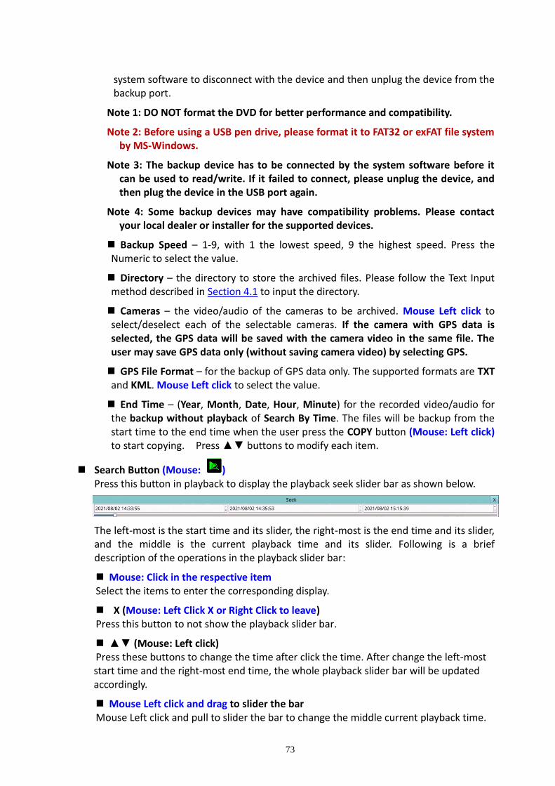
73
system software to disconnect with the device and then unplug the device from the backup port.
Note 1: DO NOT format the DVD for better performance and compatibility.
Note 2: Before using a USB pen drive, please format it to FAT32 or exFAT file system by MS-Windows.
Note 3: The backup device has to be connected by the system software before it can be used to read/write. If it failed to connect, please unplug the device, and then plug the device in the USB port again.
Note 4: Some backup devices may have compatibility problems. Please contact your local dealer or installer for the supported devices.
Backup Speed – 1-9, with 1 the lowest speed, 9 the highest speed. Press the Numeric to select the value.
Directory – the directory to store the archived files. Please follow the Text Input method described in Section 4.1 to input the directory.
Cameras – the video/audio of the cameras to be archived. Mouse Left click to select/deselect each of the selectable cameras. If the camera with GPS data is selected, the GPS data will be saved with the camera video in the same file. The user may save GPS data only (without saving camera video) by selecting GPS.
GPS File Format – for the backup of GPS data only. The supported formats are TXT and KML. Mouse Left click to select the value.
End Time – (Year, Month, Date, Hour, Minute) for the recorded video/audio for the backup without playback of Search By Time. The files will be backup from the start time to the end time when the user press the COPY button (Mouse: Left click) to start copying. Press ▲▼ buttons to modify each item.
Search Button (Mouse: ) Press this button in playback to display the playback seek slider bar as shown below.
The left-most is the start time and its slider, the right-most is the end time and its slider, and the middle is the current playback time and its slider. Following is a brief description of the operations in the playback slider bar:
Mouse: Click in the respective item Select the items to enter the corresponding display.
X (Mouse: Left Click X or Right Click to leave) Press this button to not show the playback slider bar.
▲▼ (Mouse: Left click) Press these buttons to change the time after click the time. After change the left-most start time and the right-most end time, the whole playback slider bar will be updated accordingly.
Mouse Left click and drag to slider the bar Mouse Left click and pull to slider the bar to change the middle current playback time.

74
Except the playback buttons, the user can still do all the other operations in split-window display. Please refer to Section 4.3 Basic Operations for the operations of the other buttons.
Note : The format of the GPS filename is YYYYMMDD-hhmmss.txt (or .kml), where YYYY stands for year, MM month, DD date, hh hour, mm minute, and ss second. GPS file can be displayed in the archived file list, but cannot be played. Please use GPS applications such as Google Earth, PaPaGO, etc. to read/convert its contents.
Note : When backing up, the backup data according to the selected stream type. If the
main stream is selected, the backup data is the main stream. If the sub-stream is selected, the backup data is the sub-stream.
Note : For each camera and each backup, a batch file will be generated as well as the
backup files. A directory “/SelfPlayer” will also be generated if it’s not existing in the backup storage device. The user can use the batch file to self-playback the corresponding backup files in a PC. If the PC has not been installed with the required player components, those components will be installed by running the batch file. For some Windows, please run /SelfPlayer/SelfPlayerInstall.exe manually to install the required player components. If want to copy self-playback files, please copy the batch file and the backup files to the destination directory, and copy the whole directory “/SelfPlayer” to the root directory of the destination device.
Note : For use MS-Windows HEM Utilities (H.265/264 to AVI/MP4 Conversion Utility), the
converted .AVI or .MP4 files can be played by Windows Media Player. The DivX (http://www.divx.com/) or the other H.265/264 decoder should be installed in the PC to play media files.
7.7 Playback/Archive for Search By Event
In Log display, press Play Buttons ( ) (Mouse: Left click) to playback the selected logs. This display is the same as full screen display of the main display, and the playback buttons are effective.
The operations are as below:
Playback Buttons ( , , , , , , , , , ) (Mouse: Left click) These buttons are all the same as in Section 7.6 Playback/Archive For Search By Time.
The Other Buttons All the other buttons are the same as in Section 4.3 Basic Operations.

75
7.8 Playback/Archive for Smart Search Press the Play Button (Mouse: Left click) to playback the selected matched file directly in the Smart Search display. Please note that the playback can walk across all the (up to 500 per record partition) matched files. So, the user doesn’t need to repeat the process of Smart Search & Playback just for a single file. This display is the same as the full-screen display of the main display, and the playback buttons are effective.
The operations are as below:
Playback Buttons ( , , , , , , , , , ) (Mouse: Left click) These buttons are all the same as in Section 7.6 Playback/Archive For Search By Time.
Mouse Left click the playback video display At playing the video, Mouse Left click the playback video display to show or hide the Motion Areas set by the user.
The Other Buttons All the other buttons are the same as in Section 4.3 Basic Operations.
7.9 Playback for Archived Files In Search Archived Files display, Please Mouse Left click to select the file in this list, then press Play Button or Mouse Left click twice to playback it directly. This display is the same as full screen display of the main display, and the playback buttons are effective.
The operations are as below:
Playback Buttons ( , , , , , , , , ) (Mouse: Left click) These buttons are all the same as in Section 7.6 Playback/Archive For Search By Time.
Please note that COPY button ( ) is not effective in this display.
The Other Buttons All the other buttons are the same as in Section 4.3 Basic Operations.
7.10 Playback/Archive for POS Search In POS Search display, Press the Play Button (Mouse: Left click) to playback the selected matched file directly in the POS Search display. This display is the same as full screen display of the main display, and the playback buttons are effective.
The operations are as below:
Playback Buttons ( , , , , , , , , , ) (Mouse: Left click) These buttons are all the same as in Section 7.6 Playback/Archive For Search By Time.
The Other Buttons All the other buttons are the same as in Section 4.3 Basic Operations.
76
8. Remote Access
8.1 PC Remote Access The digital video/audio recorder can be accessed by using a web browser installed on a PC if this unit is connected to a network, either internet or intranet. Before Logging On Before accessing this unit through web browser, please make sure the followings (For most PCs, only step 4 is needed!): 1. This unit is connected to the network correctly, and the configurations are all setup
correctly. Please refer to Section 5.5 Network Setup for the detailed configurations.
2. DirectX® End-User Runtime 9.0 or above has been installed in your PC successfully. If not, please logon to http://www.microsoft.com to get the free download of it.
3. The domain name or IP address of the digital video/audio recorder has been set as trusted web site in your PC, and the (https:) server verification for trusted web site is unchecked. If not, please go to Tools → Options → Security in your I.E. to do the settings. For I.E. 7, please set the Security level for this zone to Low.
4. The ActiveX control in your PC is not disabled. If you are not sure, please go to Tools → Options → Security → Custom in your I.E. to enable ActiveX control.
5. Port 67 (control port) or port 68 (data port) is not blocked out by your router or ISP (Internet Service Provider).
6. If the PC has used I.E. to access earlier software version of DVR, please go to Tools → Options → General in your I.E. to delete “Temporary Internet files” and all offline contents.
7. Please go to Start → Setup → Control, select Display → Settings, and set the Screen Resolution to at least 1024x768 and Color to 32-bit.
Note: If trusted web site is not set, please follow the instructions on the screen to download the manual package, logon the PC as administrator, and install the package in the PC. After the package is installed, users should be able to logon to the DVR successfully.
Logon After the above-mentioned items have been done correctly, restart your web browser and enter the domain name or IP address of the digital video/audio recorder in the Location/Address field of the web browser (EX. http://192.168.1.100 if HTTP port is 80 or http://192.168.1.100:800 if HTTP port is 800). The plug-in software in the system will be downloaded and run automatically in the web browser. Please note that up to 8 users can logon this DVR simultaneously.

77
Edge

78

79

80
Firefox To use Firefox to access the DVR, please do the followings: 1. Launch Firefox. 2. Visit the web site "http://ietab.mozdev.org" to download and install IE Tab Plugin. 1. Select Tools → IE Tab Options. 2. Select Sites Filter.
3. Check the option "Sites list here will always render using embedded IE", and add DVR's
URL into sites list.

81
Chrome
1.) After downloading Google Chrome browser, go to the Chrome web store and search “IE
Tab” for the IE Tab plug-in app. Click on the IE Tab icon for installation page. (please refer
to the above figure for reference
2.) Click on the install button to download and install the IE Tab plug-in. Once you have
finished downloading, the installation page will refresh and the install button area will
show “installed.”

82
3.) After installing the IE Tab plug-in, you will see a small IE icon appear on the top right hand
corner. Click on the icon to display your current active page in an IE-based Tab. (please
refer to the above figure for reference)
4.) Once your page is changed to IE-based display, you may enter your DVR URL or IP address
where indicated to log in remotely. (please refer to the above figure for reference)

- 83 -
Remote Display and Operations After the plug-in software is downloaded and run in the web browser, you will be asked (1) to install redistributable software, and (2) for ActiveX control to interact with your PC. Please select Yes, and the remote login display will be shown. Please note that the PC user must have system administrator password for the PC; otherwise, the process will fail, and an error dialog will be shown. For some PCs, it may be necessary to click in the window with the message in red color, but outside the Login Dialog before the next step. Please enter the correct login name and password (and control port & data port if they have been changed) for the DVR to login the system. Please also enter the directory name if multiple profiles were saved. And the main remote display will be shown as below.
The video images can be displayed in several types of split-window screens, including 1/4/9/16-Window for single DVR and 25/36/49/64 for multiple DVRs. And the focus window is surrounded by a frame border. In addition to the video windows, there are different icons on the lower corner and the right corner of the screen for status display and control. (The “.L” following the camera title stands for Live display, “.P” for Playback, and the camera title with white background has detected motion.)
Note 1: The frame rate is limited by the bandwidth of the network and the pre-record IPS of the camera (Section 6.1).
Note 2: The picture quality depends on the recording resolution and recording quality of the camera (Section 6.1).
When the user leaves I.E., he/she may be asked to save changes to files, please enter the directory name (or use default if only one profile is needed), click on OK or Yes to save the changes. The operations and descriptions for these icons are as below:
In video window, right-click the mouse button to call up Camera/Playback/Print Dialog. (Left) click on Playback or Camera number to change the window to the

- 84 -
corresponding camera and live/playback mode. The user may click on the “Print” button to print the video to the printer, or “Snapshot” the video. The user may also double click for 1-Window display.
Click on these icons for 1/4/9/16/25/36/49/64-Window display. For 4/9 split windows, the user can click on the icon, and select a different display page.
Click on this icon to switch to or return from SEQ display mode.
Click on this icon to toggle between live mode and playback mode for all the video windows.
Click on this icon to freeze/unfreeze the video images for all the video windows.
Click on this icon to enable/mute the audio input from the PC, button down for enable, button up for mute. If enabled, the audio input from the PC will be sent to the DVR. The default setting is ‘mute’.
Click on this icon to enable/mute the audio output from the camera for the focus window (or DVR), button down for enable, button up for mute.
Click on this icon to show/hide the GPS data for (1) the selected DVR, or (2) the DVR for the focus camera, button down to show, button up to hide.
Click on this icon to show/hide the POS data (for 9-split-window or larger video window) for (1) the selected DVR, or (2) the DVR for the focus camera, button down to show, button up to hide.

- 85 -
Click on this icon mirror, flip, or rotate 180 degrees for the video.
Click on this icon to backup video/audio, and the Backup dialog will be shown. Please select the DVR, cameras, event type, destination directory, execution time, and data range, and then click on “Apply” or “OK” to backup, or “Cancel” to cancel. Please note that Execution of “Now” or “Once” is one-time backup, while “Daily” is daily backup.
Click on this icon for snapshot of the focus camera.
Click on this icon for audio broadcasting to all connected DVRs.
Click on this icon to toggle between full screen display and normal IE display.
Click on this icon for full video display (without any icon).
Click on this icon for Google Map display.
Click on this icon for G Sensor Trend Chart display.
Click on these icons to switch the video aspect ratio between 4:3 and 16:9.
Click on this icon to zoom in the video. While enabled, click in the video for 2X, then 4X, and right click to back to 1X.

- 86 -
The device name of the selected DVR is shown. Click on this icon, and the available DVRs will all be shown. The user may type alphanumeric characters to get the matched DVRs. Click on one of them to select a new DVR. The 1/4/9/16 split-window video display, the camera status, and the alarm input/output will all switch to correspond to the newly selected DVR. There’s “Multiple” in the device list, the user can select it to display camera video from different DVRs in 4/9/16 split window display.
Playback panel for playback buttons, including Fast Backward, Fast Forward, Single Step, Play, Pause, Stop, and Copy (from left to right). Please note that the Copy function can be used to archive both live and playback streams. Please check/uncheck the cameras to be archived when the Copy Dialog is shown, and then click on OK or Apply button. If the user click on Apply button and select & highlight one of the cameras, the current copying status for that camera will be shown in the dialog.
PTZ control panel. If the camera in the focus window is a PTZ camera, these buttons in the PTZ control panel can be used for PTZ control. The operations include Tilt Up/Down, Pan Left/Right, Zoom In/Out, Focus Near, Focus Far, Iris – (darker), Iris + (brighter). Camera /
Status indicators for cameras 1-8/4 (GREEN for normal, RED for motion) for the selected DVR. Click on any of these icons to select the corresponding camera of the selected DVR to be displayed in the focus window. Alarm In /
Status indicators for alarm inputs 1-8 (GREEN for normal, RED for alarm) for the selected DVR. Alarm Out /
Alarm outputs 1-2 (GREEN for normal state, RED for triggered state) for the selected DVR. For Administrator, click on any of these icons to control the corresponding alarm output from normal to triggered, or from triggered back to normal.

- 87 -
Click on this icon to call up Search-by-time dialog. Please select the time (Year, Month, Date, Hour, and Minute) and recorded video/audio type (Alarm, Motion, Video Loss, and Normal) to search for playback. Click on Search button to start the search of the recorded video/audio. (If it failed, the result will be shown on the title of the dialog.) Now, you may use the playback buttons to play the recorded video/audio. If there’s not any camera in playback mode, all cameras will be searched and played.
The operations are similar to DVR local operations, except that the user may click on the bottom area of the playback slider to drag it to a different location.
Click on this icon to call up Search-by-event dialog. The event logs will be shown on the screen. Please select the DVR device, event type, and source ID to search for the event logs. Click on Refresh, Up, or Down to update the event logs. Click on the desired event log to highlight and select it. Click on the OK button to search the recorded video/audio for the highlighted event log. Now, you may use the playback buttons to play the recorded video/audio.
Click on this icon to call up search-PC-video dialog. Please select the file(s), and then click on Open. Now, you may use the playback buttons to play the recorded video/audio in the file(s).
Click on this icon to call up POS-Search dialog. Please select the DVR, camera, key word, and start/end time, and click on “Search”, then the matched POS data will be shown. Please select the desired POS data, and click on “Backup” or “Play” to backup or play the recorded video/audio corresponding to the POS data.
Click on this icon to show/hide full PTZ control panel. The user can click on the PTZ Panel (but outside of any object in it) (to call up the Context menu) to move it.
Click on this icon to call up Setup dialog. Unlimited number of DVRs can be added to the device list.
- 88 -
Following is a brief description for each item:
Device Name – any meaningful name for the (DVR) device.
Address – IP address or URL domain name for the (DVR) device. It should be the same as the IP address (for Static IP) or URL (for PPPoE) in Network Setup for the (DVR) device.
Control Port – the control port for the (DVR) device. The default value is 67.
Data Port – the data port for the (DVR) device. The default value is 68.
Video Stream – “Record” – live video same as recording stream, or “Extra” – extra network stream if dual streaming is supported for the (DVR) device. The default value is “Record”.
User Name – the login user name for the (DVR) device. It must be in the list in Password Setup for the (DVR) device. Please note that different levels of users have different available operations.
Password – the corresponding password for the login user name for the (DVR) device.
Auto Connection – whether the user wants to connect automatically to this (DVR) device.
Connected – whether this PC is connected with the (DVR) device now. If a DVR is connected, the user may select it, and click on “Reboot” to reboot it.
The user can download/upload the configurations from/to the connected DVR, or open/save the configurations from/to the designated directory.
Click on this icon to call up remote Software Upgrade dialog. The current software version of the DVR(s) will be shown in the “status” field. Please select the DVR device and upgrade file in the PC, and then click on Start button to start the software upgrade process. The Upgrade status will be updated according to the progress. When the upgrade file is uploading, the user may click on Stop/Close button to stop the upgrade process.After the software in the DVR is upgraded, the DVR will restart immediately and the PC will be disconnected from the DVR. Note: There must be at least one formatted HDD in the DVR for the remote upgrade to succeed.
Click on this icon to call up GPS Configuration dialog. Please select the DVR device. Then select Displayattributes and Outputattributes for Live&Playback respectively.

- 89 -
The display attributes can set whether Google Map displays GPS information, GPS speed, change the color of GPS text, POS display position... etc.If Data Exchange Fileis enabled, the corresponding GPS data will be output to the file specified. Please note that Tag and Icon are to be used by GPS software such as Google Earth for display purpose.If the Route is checked, the output data exchange file will contain the route information. If COM Port is enabled, the corresponding GPS data will be output through the specified COM port of the PC. The output data can be used as input by GPS application software such as Google Earth.
Click on this icon to call up POS Configuration dialog. Please select the DVR device. Then select Video Window or Pop-up Window to show the POS data. All the other attributes are similar to those for the DVR. System Requirements of Remote PC
It is recommended to access the digital video/audio recorder using a PC that meets the following system requirements. If you use a PC that does not meet the following system requirements, it may cause problems such as slow imaging or the browser unable to operate.
PC
IBM PC/AT compatible with Intel® Pentium® 4, 1.7 GHz or above CPU.
OS
MicroSoft®Windows®10/8/7.
Monitor 1920 x 1024 or above.
Memory (DRAM) 4096MB or above.
Web Browser
MicroSoft®Internet Explorer®9.0 or above, 32-bit mode.
DirectX
MicroSoft®DirectX®9.0 or above.

- 90 -
8.2 PDA/Mobile Phone Remote Access (Chrome Wap Mode) The digital video/audio recorder can also be remotely accessed by using a web browser installed on a PDA or mobile phone that (1) supports xHTML and MJPEG file format, and (2) has screen resolution at 240x320 or above. Please enter the domain name or IP address of the digital video/audio recorder in the Location/Address field of the web browser, and the remote login display will be shown. (For most of the mobile devices, the DVR will automatically redirect to the correct web page, EX. http://192.168.1.89/wap.htm for IP address http://192.168.1.89. If not, please enter the full address with /wap.htm. The user may need to enter http://192.168.1.89:800/wap.htm if HTTP port has been changed to 800.) Please enter the correct login name and password for the digital video/audio recorder to login the system, and the screen will be shown as below.
Following is a brief description for each item and its specific operations:
Click on this button to submit the content to the digital video/audio recorder. The new settings will take effect, and the screen will refresh.
Selection of Quad or 1-Window display.
-- for snapshot, 1P-10P for streaming of 1-10FPS (Safari, Firefox), 1S-30S for auto-refresh of 1 second to 30 seconds, 0S for fast auto-refresh that supports HTML4.01.
: Status indicators for alarm inputs 1-8 (unchecked for normal, checked for alarm).
: Alarm outputs (unchecked for normal, checked for triggered). Administrator can check to trigger the alarm output, uncheck for back to normal.

- 91 -
Appendix A – Time Zone Table Time Zone Offset DST Start End
Samoa GMT – 11:00
Hawaii GMT – 10:00
Alaska GMT – 09:00 ˇ Mar, 2nd Sun, 2:00 Nov, 1st Sun, 2:00
Pacific Time (US & Canada) GMT – 08:00 ˇ Mar, 2nd Sun, 2:00 Nov, 1st Sun, 2:00
Arizona, US Mountain GMT – 07:00
Chihuahua, La Paz, Mazatlan GMT – 07:00 ˇ May, 1st Sun, 2:00 Sep, last Sun, 2:00
Mountain Time (US & Canada) GMT – 07:00 ˇ Mar, 2nd Sun, 2:00 Nov, 1st Sun, 2:00
Central America, Saskatchewan GMT – 06:00
Central Time (US & Canada) GMT – 06:00 ˇ Mar, 2nd Sun, 2:00 Nov, 1st Sun, 2:00
Guadalajara, Mexico City, Monterrey
GMT – 06:00 ˇ May, 1st Sun, 2:00 Sep, last Sun, 2:00
Bogota, Lima, Quito, Indiana (East) GMT – 05:00
Eastern Time (US & Canada) GMT – 05:00 ˇ Mar, 2nd Sun, 2:00 Nov, 1st Sun, 2:00
Atlantic Time (Canada) GMT – 04:00 ˇ Mar, 2nd Sun, 2:00 Nov, 1st Sun, 2:00
Caracas, La Paz GMT – 04:00
Santiago GMT – 04:00 ˇ Oct, 2nd Sun, 0:00 Mar, 2nd Sun, 0:00
Newfoundland GMT – 03:30 ˇ Apr, 1st Sun, 2:00 Oct, last Sun, 2:00
Brasilia GMT – 03:00 ˇ Oct, 3rd Sun, 2:00 Feb, 3rd Sun, 2:00
Buenos Aires, Georgetown GMT – 03:00 ˇ Oct, 3rd Sun, 2:00 Feb, 2nd Sun, 2:00
Greenland GMT – 03:00 ˇ Mar, last Sun, 1:00 Oct, last Sun, 1:00
Mid-Atlantic GMT – 02:00 ˇ Mar, last Sun, 2:00 Sep, last Sun, 2:00
Azores GMT – 01:00 ˇ Mar, last Sun, 2:00 Oct, last Sun, 3:00
Cape Verde GMT – 01:00
Casablanca, Monrovia GMT + 00:00
Dublin, London GMT + 00:00 ˇ Mar, last Sun, 1:00 Oct, last Sun, 2:00
Western Europe, Central Europe GMT + 01:00 ˇ Mar, last Sun, 2:00 Oct, last Sun, 3:00
West Central Africa GMT + 01:00
Eastern Europe GMT + 02:00 ˇ Mar, last Sun, 0:00 Oct, last Sun, 1:00
Cairo GMT + 02:00 ˇ Apr, last Fri, 2:00 Sep, last Fri, 2:00
Harare, Pretoria GMT + 02:00
Helsinki, Kyiv, Riga, Sofia, Tallinn GMT + 02:00 ˇ Mar, last Sun, 2:00 Oct, last Sun, 3:00
Jerusalem GMT + 02:00 ˇ Apr 1, 2:00 Oct, 2nd Sun, 2:00
Baghdad GMT + 03:00 ˇ Apr 1, 3:00 Oct 1, 4:00
Kuwait, Riyadh, Nairobi GMT + 03:00
Moscow, St. Petersburg, Volgograd GMT + 03:00 ˇ Mar, last Sun, 2:00 Oct, last Sun, 3:00
Tehran GMT + 03:30 ˇ Mar, 4th Tue, 2:00 Sep, 4th Thu, 2:00
Abu Dhabi, Muscat GMT + 04:00
Baku, Tbilisi, Yerevan GMT + 04:00 ˇ Mar, last Sun, 2:00 Oct, last Sun, 3:00
Time Zone Offset DST Start End
Kabul GMT + 04:30
Ekaterinburg GMT + 05:00 ˇ Mar, last Sun, 2:00 Oct, last Sun, 3:00
Islamabad, Karachi, Tashkent GMT + 05:00

- 92 -
Chennai, Mumbai, New Delhi GMT + 05:30
Kathmandu GMT + 05:45
Almaty, Novosibirsk GMT + 06:00 ˇ Mar, last Sun, 2:00 Oct, last Sun, 3:00
Astana, Dhaka, Sri Lanka GMT + 06:00
Rangoon GMT + 06:30
Bangkok, Hanoi, Jakarta GMT + 07:00
Krasnoyarsk GMT + 07:00 ˇ Mar, last Sun, 2:00 Oct, last Sun, 3:00
Irkutsk, Ulaan Bataar GMT + 08:00 ˇ Mar, last Sun, 2:00 Oct, last Sun, 3:00
Beijing, Chingqing, H. K., Urumqi GMT + 08:00
Kuala Lumpur, Perth, Singapore GMT + 08:00
Taipei GMT + 08:00
Osaka, Seoul, Tokyo GMT + 09:00
Yakutsk GMT + 09:00 ˇ Mar, last Sun, 2:00 Oct, last Sun, 3:00
Adelaide GMT + 09:30 ˇ Oct, last Sun, 2:00 Mar, last Sun, 3:00
Darwin GMT + 09:30
Brisbane, Guam, Port Moresby GMT + 10:00
Canberra, Melbourne, Sydney GMT + 10:00 ˇ Oct, last Sun, 2:00 Mar, last Sun, 3:00
Hobart GMT + 10:00 ˇ Oct, 1st Sun, 2:00 Mar, last Sun, 3:00
Vladivostok GMT + 10:00 ˇ Mar, last Sun, 2:00 Oct, last Sun, 3:00
Magadan, Solomon Is. GMT + 11:00
Auckland, Wellington GMT + 12:00 ˇ Oct, 1st Sun, 2:00 Mar, 3rd Sun, 2:00
Fiji GMT + 12:00
Kamchatka GMT + 12:00 ˇ Mar, last Sun, 2:00 Oct, last Sun, 3:00
Anadyr GMT + 13:00 ˇ Mar, last Sun, 2:00 Oct, last Sun, 3:00
Nuku’alofa GMT + 13:00

- 93 -
Appendix B – Keyboard Control Protocol Data Format 5 Bytes –
Byte 1 : Synchronization Byte (0xFF) Byte 2 : Address, i.e. Device ID (0 – 0xFF) Byte 3 : Code (see below) Byte 4 : Reserved (0x00) Byte 5 : Checksum (sum of Bytes 2 – 4)
Code Value (MSB set for key press, MSB reset for release)
0 – 9 0x30 – 0x39 (ASCII characters ‘0’ – ‘9’)
10 0x21 (ASCII character ‘!’)
11 0x40 (ASCII character ‘@’)
12 0x23 (ASCII character ‘#’)
13 0x24 (ASCII character ‘$’)
14 0x25 (ASCII character ‘%’)
15 0x5e (ASCII character ‘^’)
16 0x26 (ASCII character ‘&’)
4-Window 0x2a (ASCII character ‘*’)
9-Window 0x28 (ASCII character ‘(’)
16-Window 0x29 (ASCII character ‘)’)
*/mark 0x2d (ASCII character ‘–’ – Minus sign)
#/code 0x3d (ASCII character ‘=’ – Equal sign)
Alarm Reset 0x71 (ASCII character ‘q’)
MODE 0x77 (ASCII character ‘w’)
SEQ 0x65 (ASCII character ‘e’)
CALL 0x72 (ASCII character ‘r’)
SEARCH 0x74 (ASCII character ‘t’)
REC 0x79 (ASCII character ‘y’) Byte 4: 0 for toggle, i.e. OFF → ON, ON → OFF, Byte 4: 1 for REC ON, Byte 4: 2 for REC OFF
Fast Backward 0x61 (ASCII character ‘a’)
Fast Forward 0x73 (ASCII character ‘s’)
Single Step 0x64 (ASCII character ‘d’)
Play/Pause 0x66 (ASCII character ‘f’)
Stop 0x67 (ASCII character ‘g’)
Copy 0x68 (ASCII character ‘h’)
MENU 0x75 (ASCII character ‘u’)
ESC/PTZ 0x6f (ASCII character ‘o’)
MUTE/NEXT 0x6e (ASCII character ‘n’)
X2/GOTO 0x2c (ASCII character ‘,’ – Comma)

- 94 -
▲/BS 0x69 (ASCII character ‘i’)
▼/DEL 0x6d (ASCII character ‘m’) ◄ 0x6a (ASCII character ‘j’) ► 0x6c (ASCII character ‘l’ – small L)
ENTER 0x6b (ASCII character ‘k’)
Vol – 0x7a (ASCII character ‘z’)
Vol + 0x78 (ASCII character ‘x’)
– 0x63 (ASCII character ‘c’)
+ 0x76 (ASCII character ‘v’)
MAIN-AUX ON 0x62 (ASCII character ‘b’)
MAIN-AUX OFF 0x70 (ASCII character ‘p’)
CALL-AUX ON 0x5b (ASCII character ‘[’)
CALL-AUX OFF 0x5d (ASCII character ‘]’)
UP-LEFT 0x7b (ASCII character ‘{’)
DOWN-LEFT 0x7c (ASCII character ‘|’)
UP-RIGHT 0x7d (ASCII character ‘}’)
DOWN-RIGHT 0x7e (ASCII character ‘~’)
Alarm out ON 0x3c (ASCII character ‘<’) Byte 4: 1-4 for AO 1-4 respectively
Alarm out OFF 0x3e (ASCII character ‘>’) Byte 4: 1-4 for AO 1-4 respectively

- 95 -
Appendix C – MS-Windows HEM Utilities The remote CMS software (HEM), and the MS-Windows utility programs (HEM Utilities) include HEM, HEM Player, Media Converter, Keyboard Control Simulator, and DVR Browser. Please contact your local dealer or contractor to get the HEM and HEM Utilities applications. Unzip them and double click on HEM/Setup.exe to install HEM, and Utilities/Setup.exe to install the utility programs. Please follow the instructions on the screen to install the software in the default directory “Program Files\Hyper Electronics Mappers” or the directory entered by the user. For HEM, please refer to the manual for HEM. For the other utility programs, please refer to the following paragraphs. HEM Player Before running HEM Player in your PC, please make sure the followings:
1. DirectX® End-User Runtime 9.0 or above has been installed in your PC successfully. If not, please logon to http://www.microsoft.com to get the free download of it.
2. Please go to Start → Setup → Control, select Display → Settings, and set the Screen Resolution to at least 1920x1024 and Color to 32-bit.
To run the HEM Player under MicroSoft® Windows®, please select Start → Programs → Hyper Electronics Mappers → HemPlayer, and the screen will be shown as below.
Since this utility is a free player utility for the archived files, from USB backup or remote backup, some of the functions are disabled. The mouse cursor will change to “Hand” type if it’s on those enabled function icons. The operations and their descriptions are the same as in Chapter 8. Remote Access. To select an archived file for playback, please click on File menu, and then select Open.
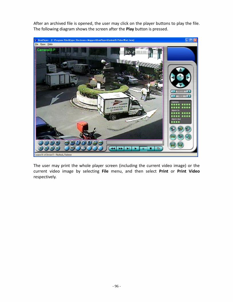
- 96 -
After an archived file is opened, the user may click on the player buttons to play the file. The following diagram shows the screen after the Play button is pressed.
The user may print the whole player screen (including the current video image) or the current video image by selecting File menu, and then select Print or Print Video respectively.

- 97 -
Keyboard Control Simulator To run the Keyboard Control Simulator under MS-Windows, please select Start → Programs → Hyper Electronics Mappers → KCtrlSimulator, and the screen will be shown as below.
Please note that most of the buttons correspond to the keypads on the front panel. If you connect the PC through RS-232 and use an RS-232/RS-485 converter to connect to multiple DVRs, you would be able to control multiple DVRs via the simulation software. Please refer to Section 3.2 Optional Connections to connect/cascade the DVRs to the PC. To select the DVR to control, please click on the button as circled in the above diagram to set the corresponding DVR ID. Please note that the RS-232/422/485 setup (Section 6.8), including the DVR ID, in the DVRs must be configured correctly (Model must be set as Control Protocol). Note: UP-LEFT, UP-RIGHT, DOWN-LEFT, and DOWN-RIGHT are newly added to control
the PTZ cameras diagonally.
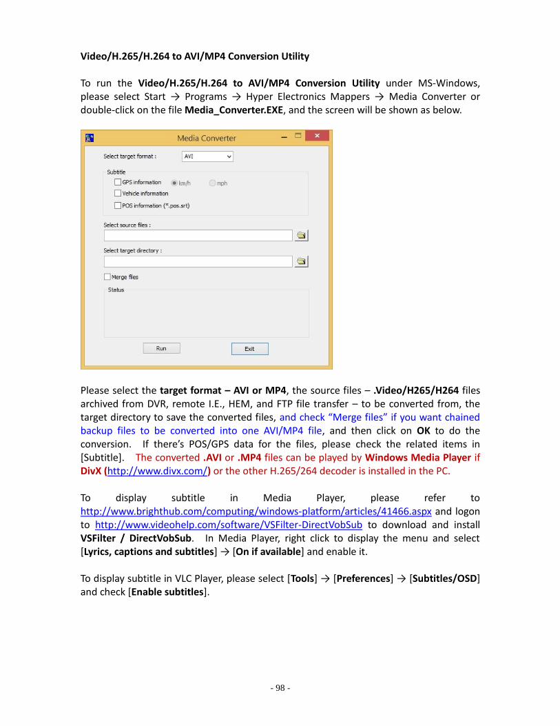
- 98 -
Video/H.265/H.264 to AVI/MP4 Conversion Utility To run the Video/H.265/H.264 to AVI/MP4 Conversion Utility under MS-Windows, please select Start → Programs → Hyper Electronics Mappers → Media Converter or double-click on the file Media_Converter.EXE, and the screen will be shown as below.
Please select the target format – AVI or MP4, the source files – .Video/H265/H264 files archived from DVR, remote I.E., HEM, and FTP file transfer – to be converted from, the target directory to save the converted files, and check “Merge files” if you want chained backup files to be converted into one AVI/MP4 file, and then click on OK to do the conversion. If there’s POS/GPS data for the files, please check the related items in [Subtitle]. The converted .AVI or .MP4 files can be played by Windows Media Player if DivX (http://www.divx.com/) or the other H.265/264 decoder is installed in the PC. To display subtitle in Media Player, please refer to http://www.brighthub.com/computing/windows-platform/articles/41466.aspx and logon to http://www.videohelp.com/software/VSFilter-DirectVobSub to download and install VSFilter / DirectVobSub. In Media Player, right click to display the menu and select [Lyrics, captions and subtitles] → [On if available] and enable it. To display subtitle in VLC Player, please select [Tools] → [Preferences] → [Subtitles/OSD] and check [Enable subtitles].

- 99 -
DVR Browser Utility To run the DVR Browser Utility under MS-Windows, please select Start → Programs → Hyper Electronics Mappers → DVR Browser or double-click on the file DVR_Browser.EXE, and the screen will be shown.
The utility will scan all the DVRs which support UPnP in the LAN. Please select the desired DVR device, and its detailed information will be shown on the right as above. Users can (1) click on the URL to call up IE and logon to the device, (2) select Option → Rescan network, or (3) select Option → Export Device List. The exported device list can be imported to IE software or CMS software in the future.

- 100 -
Appendix D – GPS Function in Remote Software with Google Earth The GPS output for the DVR and its remote software can be used by GPS software such as Google Earth. The user may use the following paragraphs as an example. 1. Open remote software such as IE Browser, and log on to the DVR or open and
playback the archived file with GPS information.
2. Select GPS Configuration ( ). 3. Enable Output with Data Exchange File, and set the related items (File, Tag, & Icon).

- 101 -
4. Open Google Earth.
5. Add Network Link.
6. Select the Data Exchange File in the remote software as Link. Please note that the directory & filename MUST be in English for old version of Google Earth to work correctly.
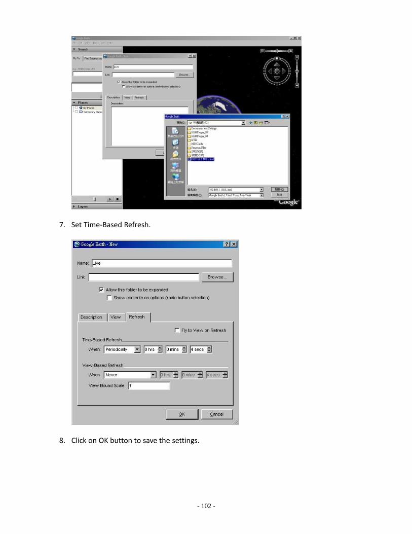
- 102 -
7. Set Time-Based Refresh.
8. Click on OK button to save the settings.

- 103 -
9. Now, the GPS data will be fed from the DVR remote software to Google Earth, and the GPS position will be continuously updated in Google Earth.
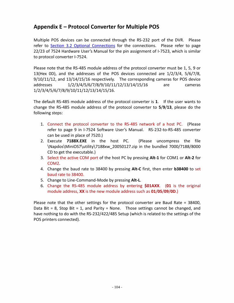
- 104 -
Appendix E – Protocol Converter for Multiple POS Multiple POS devices can be connected through the RS-232 port of the DVR. Please refer to Section 3.2 Optional Connections for the connections. Please refer to page 22/23 of 7524 Hardware User’s Manual for the pin assignment of I-7523, which is similar to protocol converter I-7524. Please note that the RS-485 module address of the protocol converter must be 1, 5, 9 or 13(Hex 0D), and the addresses of the POS devices connected are 1/2/3/4, 5/6/7/8, 9/10/11/12, and 13/14/15/16 respectively. The corresponding cameras for POS device addresses 1/2/3/4/5/6/7/8/9/10/11/12/13/14/15/16 are cameras 1/2/3/4/5/6/7/8/9/10/11/12/13/14/15/16. The default RS-485 module address of the protocol converter is 1. If the user wants to change the RS-485 module address of the protocol converter to 5/9/13, please do the following steps:
1. Connect the protocol converter to the RS-485 network of a host PC. (Please refer to page 9 in I-7524 Software User’s Manual. RS-232-to-RS-485 converter can be used in place of 7520.)
2. Execute 7188X.EXE in the host PC. (Please uncompress the file \Napdos\MiniOS7\utility\7188xw_20050127.zip in the bundled 7000/7188/8000 CD to get the executable.)
3. Select the active COM port of the host PC by pressing Alt-1 for COM1 or Alt-2 for COM2.
4. Change the baud rate to 38400 by pressing Alt-C first, then enter b38400 to set baud rate to 38400.
5. Change to Line-Command-Mode by pressing Alt-L. 6. Change the RS-485 module address by entering $01AXX. (01 is the original
module address, XX is the new module address such as 01/05/09/0D.) Please note that the other settings for the protocol converter are Baud Rate = 38400, Data Bit = 8, Stop Bit = 1, and Parity = None. Those settings cannot be changed, and have nothing to do with the RS-232/422/485 Setup (which is related to the settings of the POS printers connected).
Related Documents