681 HWAHAK KONGHAK Vol. 40, No. 6, December, 2002, pp. 681-686 † * * ( ) (2002 1 10 , 2002 8 7 ) The Effect of Mass Transfer on the Cure Properties of the Urea Resin Moulding Compounds Under the Drying Process Sang Yeul Kim † , Il Gon Choi* and Byoung Chul Kim Division of Metallurgical and Chemical Engineering, Dong-A University, Pusan 604-714, Korea *Dong Kwang Chemical Co., Ltd., Pusan 604-714, Korea (Received 10 January 2002; accepted 7 August 2002) . , . , . , . , , . Abstract - In the industrial field, the theory of drying process is different from the practical application, and it is effective to reduce energy by recirculation of the heat of exhausting gas. But the study of this field may not be performed still. The cure properties of the urea resin moulding compounds was investigated according to drying temperature, drying time, recycle rate of exhausting gas and moulding temperature in the process of drying and moulding. We obtained the following results; water con- tent of material decreases with increasing drying time and drying temperature, and the rate of drying also decreases with increasing recycle rate of exhausting gas. Specially, The cure fluidity of the urea resin moulding compounds decreases, with increas- ing drying temperature, recycle rate of exhausting gas and moulding temperature. And the correlation equations on water content and cure fluidity of the urea resin moulding material were obtained through a regression analysis of experimental data. Key words: Wafer Content, Dryrate, Moulding Temperature, Fluidity, Exhausting Gas 1. , [1-3]. , , , [4-6], . , , , [7-10] . Sato [11, 12] , [13, 14]. , , , 40% [15-17] , † To whom correspondence should be addressed. E-mail: [email protected]

Welcome message from author
This document is posted to help you gain knowledge. Please leave a comment to let me know what you think about it! Share it to your friends and learn new things together.
Transcript

HWAHAK KONGHAK Vol. 40, No. 6, December, 2002, pp. 681-686
�� �� � �� � �� � �� �� �� ���� ��
���†����*���
����� ���� ������ *����(�)
(2002� 1� 10� ��, 2002� 8� 7� ��)
The Effect of Mass Transfer on the Cure Properties of the Urea Resin Moulding Compounds Under the Drying Process
Sang Yeul Kim†, Il Gon Choi* and Byoung Chul Kim
Division of Metallurgical and Chemical Engineering, Dong-A University, Pusan 604-714, Korea*Dong Kwang Chemical Co., Ltd., Pusan 604-714, Korea
(Received 10 January 2002; accepted 7 August 2002)
� �
�� ���� �� �� �� ���� ��� �� �� ����� ���� !" �#$� %&' !(�
)*�� +��,- �. /012� 34 567, 89:� 1;� <=" >?�@� AB. 30� 56 7, 89�
C� +: D8" ��� 89 EF G� ��HI� JK, ���� � ��L M 89HI� 30 �N$O BPQ RS
TQU VWB. 89�C� 7XYZS �� JKQ �� HI� [�Y� *6$�, ��\I� ���� � ��L� [�
$] *6�B. D^ +:_`I� ����� � ��Z, ��HI M 89HI� [�$] *6�B. �� ��HI, ��
JK, ����� � ��Z M 89HI� 30 7XYZQ +:_`I� a� bcd" ?$O ��8e� f� ��"
?g$hB.
Abstract − In the industrial field, the theory of drying process is different from the practical application, and it is effective to
reduce energy by recirculation of the heat of exhausting gas. But the study of this field may not be performed still. The cure
properties of the urea resin moulding compounds was investigated according to drying temperature, drying time, recycle rate of
exhausting gas and moulding temperature in the process of drying and moulding. We obtained the following results; water con-
tent of material decreases with increasing drying time and drying temperature, and the rate of drying also decreases with
increasing recycle rate of exhausting gas. Specially, The cure fluidity of the urea resin moulding compounds decreases, with increas-
ing drying temperature, recycle rate of exhausting gas and moulding temperature. And the correlation equations on water content and
cure fluidity of the urea resin moulding material were obtained through a regression analysis of experimental data.
Key words: Wafer Content, Dryrate, Moulding Temperature, Fluidity, Exhausting Gas
1. � �
����� �� �� � � �� � � ����, �� �
���� � ��� �� �!"� ��# !�� � � $%&
�' (�) �$%���� *+,[1-3].
*-�� ���� '. ��/! !� 0�� 1�2 34 56
�7 89:� ;< =%# &� 4>� =%?@ 4A !B C, 0D
E"�� ��FG HI 89:� ��J6, KLM�5 4NJ6, >
4J6� O � 34�� PQC[4-6], 0D >4J6� RS=% E
"�� ��FG� 1�0�� T� UEV EWQ� X�+,.
E"�� ��FG YZ[\W E"��, $%3, ]^ _`3, '
�3 a �b FG� �� PQC[7-10] *-�� ����U ��/!
!� 0�� 1�2 3456�7� 89:;<5 &�4>� �c
�d+,.
�ef� E"�� ��&�� bg� 'h Sato i[11, 12]� �
� g4jk cl5 �/9 �m� no �p 0�Q� _� + q P
QC, rV E"��� $%0�S $%3� �# s� nt uv+
q P,[13, 14].
�w) '. bg� qxQ� yz�7 E"�� ��FG� 34{
| }~� E"��! !� ���W �]��, ���, ����, �
�`S i� _` H � � � 40% h�� ����� ��� ]^
a _`3� ���� PQC[15-17] '. _`3 E"��� ?�5
�( � M���, >4J6 U 8�V �h� >4�� ��t �†To whom correspondence should be addressed.E-mail: [email protected]
681
682 ����������
� U�g4� !� ����� ��� �8 �BHW ���t��
5� �� � &�' ¡¢ '£�¤ ¥� 3¦W ��FG! e� �
�7 �5 §¨� ©� e� �� ª ]^ « � P &���¬(semi-
molten state)! �S �+,.
E"�� ��FG� 3456 U UEV J6W >456� *c7
��1®� *V 'j�� S¯ °� | ±3kW ²5# ³2 ´
'! PQC rV µ¶56�7 k�� >4H� ·¸¹ºS �}�
A»� � I�' ¼½�¤ ·¸�� ±3 >4! '£���7 U
�&�' p&�� P >4 �p¾� O5 Y®� RS, �¿6
S, JHÀS i� *V ���Á! T� Âä P� Ä� Å�3¦�
�Æ HÇÈu� hÉV �Ê',.
nt7 �ef� ¶Ëyz�7 ÁA ´, HÌ a (H� nt 34
+ ��FG� Í/���5 ���� ¦®�Î Hº� nt p(
� >4 �S ¥�3¦�7 )Ï) $%�p0�� =%! Ð
� Fy� P Å�V �¦� 34 Ñ ³2 �ÃÒ' P� Ó bg
�7 �h��� ��FG� 34J6 U !z �dkW J6W >
4J6� ¶Ëyz�7 'j� S¯ °� | ±®kW ²5� SÒ�
Õ� Ö �� »× � >4RS, dH!\� F �¿9, >4?Ø
a ��RS i� nt E"�� ��FG� �� ¡95 $% �pS
� 4� � � a $%0�� hÙ 1®¸Ú Û5� gl � F
y� P� $ܨ P HÇ� Èu � Å�V 3¦� Ý�/ °,.
2. � �
2-1. ����
E"�� ?� 34� &�H Fig. 1�7 )Ï� q# Þ' ß&,
!�, !§, ^J, àH� ' �'V ��k 1.7 m3� SUS3 &�H�
7 pá%â� pilot kettle� �� °QC, KL M�H �$ 0.15 m
L/D 18W SUS3 M�H(BUSS model HYD-150)�ã Õ HB -�2
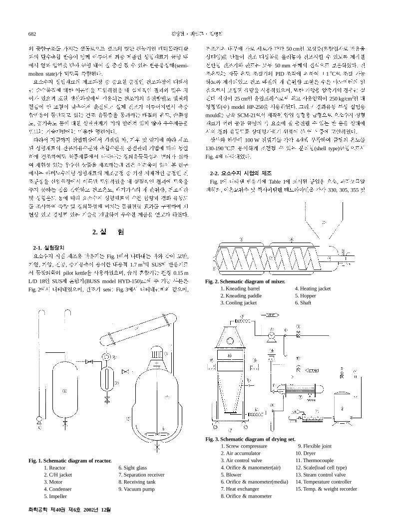
Fig. 2�7 )Ï�äQC, >4H set Fig. 3�7 )Ï� q# ÞQC,
>4H� �-� !� å�! �� 50 cmW �6¾(M�¯/� &��
�¬æ)� �.� >4 *�1� çÃè� >4?é � PS 3XV
ê&� >4H# �� �ë 50 mm ë¢� ®ìQ� _R °,. >
4RS /p RS 4AH� PID 4X� � � í1 oC� 4A !B
S 3X�ä� >4 Y®� F �¿9 4A2 �2 �Ôhî� ï
ðQ�7 _6+ �9� �� °QC, rV !§� § H� $Å ±
ñò ó$' 25 cmW �§�ô\�7 ¥� ��§¨' 250 kg/cm2W ¬
õ6ö(Õ) model HP-250� �� °,. �Î� $%�p 0� ±÷�
mould eÀ SCM-21�7 3X+ §¯ ��� e�Q� E"�� ��
FG! �w � e�� � E"� ª ]^« � P & �� �¬�
7� $% �pS� �*ø! H � � Ó bg U� �× °,.
�-# -� 100 W ̧ �H� �� 4Èù -ú � e�� RS�
130-190oC� �' � 4A« � P �Î�(shell type)e�Q�7
Fig. 4� )Ï�ä,.
2-2. ���� � �
Fig. 1� )Ïû &�H� Table 1� v?+ JË� E", ütmýÂ
ÑDÆ, 'Rß¿� a þ��ÿ� �Zt��� �� 330, 305, 355 a
Fig. 1. Schematic diagram of reactor.1. Reactor 6. Sight glass2. C/H jacket 7. Separation receiver3. Motor 8. Receiving tank4. Condenser 9. Vacuum pump5. Impeller
Fig. 2. Schematic diagram of mixer.1. Kneading barrel 4. Heating jacket2. Kneading paddle 5. Hopper3. Cooling jacket 6. Shaft
Fig. 3. Schematic diagram of drying set. 1. Screw compressure 19. Flexible joint2. Air accumulator 10. Dryer3. Air control valve 11. Thermocouple4. Orifice & manometer(air) 12. Scale(load cell type)5. Blower 13. Steam control valve6. Orifice & manometer(media) 14. Temperature controller7. Heat exchanger 15. Temp. & weight recorder8. Orifice & manometer
���� �40� �6� 2002� 12�
� � � �� �� ����� �� ��� �� �� ! "# 683
15 kg� �� ß& �7 70oC� �R?@ 2?Ø p× &� Ì Í
mýÂÑDÆ� �S! 2.5% ( | 30oC� �� � 34 °,.
2-3. �� �� � �
Table 2� v?+ q# Þ' ¸8Á�7 34+ E"�� ?�, ��
��, $% �Y, a �3� �� 1,000, 200, 0.5 a 1 kg� M�H�
7 M� � 24?Ø¹Ù Ì Fig. 2� v? + M�HW d� RS�
40 oC� �� �7 �® M� � ±ñò� �8 d� �� ó$ 6 mm
� Ô � -ú � d�¡Q�7 KLM�¦' 6-7 mm� (6V K�
43¦' �S °,. ' K� 43¦� �Î�ÿ� �H� ö� �
*� JË� �z�(−17 -−15oC)� _� � >4±÷� �� °,.
2-4. � ��
Fig. 3�7 )Ï� q# Þ' \�£ ��ô��7 JH� bÀ §
� �zV Ì 3���� JH9� 4A �, >4¾� O5V d
H!\� ��H�7 0-50%(�JH# d�� F�¿!\� d�;<)
���7 �� 10%́ � F �¿?@ ��· JH# M�V Ì �ß¿
H� >4 RS� 70-90oC� �� �7 dH!\� �¿�' 0% (
| �2 )Ôhî� >4¾ O5 ÀS� 1 cm/sec� �6 �, �Î�
\� ´§ �Ôhî� dH!\� �¿9� ¼� »"?� ,ð �2
�Ôhî� �¿9 0%( |� �e5 p( � �S 4A � >4
RS! 6��¬! + Ì 30� �� K� 43¦ 10 kg� ±Rf� �
� �6 ¾� �.� Y 10��,� U9 »"� H(Mettler model
KCC 150 SX road cell typeæ sensibility=1 g)?@ >49� IH ��
5 �¸ >4 U9� àV >4»9ºQ� �6 °,.
2-5. �� ��� ��
Fig. 4� )Ïû q# Þ' e� �� "# !* -�� ó$� �
� 3.0 a 4.5 mmW $%� î"� �.� #$� RS� 130-180oC
� %6V Ì PID(í0.5&)� RS� /p 4A �7 >4±÷� 'V
E"�� ��FG� �( � 50 g� ?G� )�V Ì ó$ 20 mm�
§ú � 63% �, 150-170oC�7 ±÷{ e�2 $%FG� *�
�Î{ � P �Î� d� 3X °,. ?G� e�� d� +¯
� 20I Ì� �§�ô\� 50 kg/cm2� §¨Q� �\,� §¯?
@ $%î"�7 ��FG! �p' 6�+ Ì $%�� �:%�� �
\,� !c� §¨' �ØkQ� -�� � � �� ÎhZ \
./Ù� � � §¯V Ì d� 0� P U95 ¥I +¯9�
nt �pS(Masshida Denko co. and Sumidomo Bakerite co.�7 �
�kQ� 1� Pð)� g °,.
(1)
3. �� �
3-1. � �� ���� � !"# $% �& '"
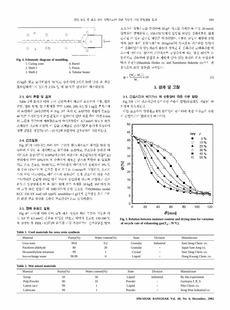
Fig. 5# Þ' >4?Ø' à! � ��� ¡9(��m¡ H2)' -
� � »" °,.
' E"�� ��FG�� àH§' à! � Á� #-�� ��
� àuÀS! 3t�H |4',.
ψW i Wr–( )
W i
----------------------- 10×=
Fig. 4. Schematic diagram of moulding.1. Curing zone 4. Barrel2. Shell-1 5. Piston3. Shell-2 6. Tubular heater
Table 1. Used materials for urea resin synthesis
Material Purity(%) Water content(%) State Division Manufacture
Urea resin 99.8 0.2 Granular Industrial Sam Sung Chem. co.Paraform aldehyde 80 20 Granular " Japan Sam Jung co.Hexamethylene tetramine 99 1 Crystal " Sam Yang Chem. co.Ion exchange water 99.99 0 Liquid " Dong Kwang Chem. co.
Table 2. Wet mixed materials
Material Purity(%) Water content(%) State Division Manufacture
Syrup 50 50 Liquid Industrial By this experiment Pulp Powder 90 10 Powder " Germany J. R. S Latent cat-c 99 1 Liquid " Nito Chem. co. Lubricant 99 1 Powder " Song Won Industrial co.
Fig. 5. Relation between moisture content and drying time for variation of recycle rate of exhausting gas(TD : 70 oC).
HWAHAK KONGHAK Vol. 40, No. 6, December, 2002

684 ����������
>4 ¾� O5 dH!\� F �¿9' 0-30%�7 >4?Ø'
30�f� ��� ¡9' -� � »"��, � 'Ì ��V »"
� )Ï5QC, dH!\� F �¿9' à! � ��¡9� »"ÀS
! ��c�� 0D 100�' �)� ��' ò '� »" � Ä ,.
' dH!\� F �¿� 9' à! � à!{� p&� �
àH� 9' ³� ��� àu9' »"�H |4',.
3-2. � (�) � �� *�# $% �& '"
Fig. 62 K� 43¦� >456 U >4RS# >4?Ø� no E
"�� ��FG� �� ¡9� )Ï�ä,.
Fig. 6�767 >4RS! à! � �� ¡9' »" °,. 0D I
H� >4RS! à! � �� ¡9' -�D »" ) �� ?Ø
� SÎ� h"V à!� )Ï�ä,.
' >4RS! 8��� 6-7 mm� ¯S� 9 E"�� v��
HJ �¬! 4öc�� rV >4?Ø' :2 IH� � E"��
��FG� v�Q� 8�V �å� y�Q� Wc ��� 'p' �
' � �� ¡9' -�D »" ) >4?Ø' ; $Å� <� v
�' �:% � �-� ��' v�Q�� !¶' �=H |4',.
3-3. � +�# ,�- ����� � !"
Fig. 72 >4?Ø� no dH!\� F �¿9� *V >4 ÀS�
)Ï�ä,.
dH!\� F �¿9' à! � >4ÀS! »"V,. ' F �
¿ dH!\ U� �àH9� à!� b�+,.
rV >4?Ø' à!{� IH� >4ÀS! >?C >4?Ø
20-30� 'Ì� ," »" °,.
3-4. �� ���# ,�- � (�
Fig. 82 dH!\� F �¿9� nt >4RS� *V E"���
$% �pS� )Ï�ä,.
Fig. 85 Þ' >4RS# dH!\� F �¿9' à!{� $%
�pS! »" °,.
' >4RS! à!{� ��FG� IH �� »9 ÀS! 3t
6-7 mm� ¯S� !^ FG� v� öS! @¤7 ¯S �-� ���
!¶ ÀS! »" H |4� �R�7 �~ :�� �£��� �
�� �8HW ���H# E"�� �BH#� �� �' �Ã/ $
% �p� A3 � �: _`3�7� HB' @�H |4',. 0D
>4?G� Í��(35oC� ��� B¶ desiccate�� 48?Ø ¹Ù
Ì »"� U9Q� �6)' 7-10%� gØ�7 �£��� ��
¸: ½¯9 U 5-20%! E"��# ²�« � PQC >4 media�
F�¿9 à!� WV mediaU� �àH �§' à! � >4?G U
� ��� »9' C' �R�7� :?Ø' D� E"�� /:�
U��' ^'�E� $%�pS òF »"G,.
Fig. 6. Relation between moisture content and drying temperature forvariation of drying time( γγγγ : 10%).
Fig. 7. Relation between the drying rate and drying time for variationof recycle rate of exhausting gas(TD : 80oC).
Fig. 8. Relation between fluidity and drying temperature for variationof recycle rate of exhausting gas(Tm : 150oC).
���� �40� �6� 2002� 12�
� � � �� �� ����� �� ��� �� �� ! "# 685
H �£��� �� I��'�, �� �:'E� g4� �8
� ���H� !�� P� �Ø J%�¬�7 E"��# ¸9 ��
� � Ä�� X2 9� �� �Q�S ³2 s� E"��! K
F HB� !�H |4',.
rV F �¿9' 10%�7 0%_, ��FG� $% �pS! 8
� )Ï5,. ' F �¿� dH!\� p&� �àH! KF
� Ä 0%�7 >o >4ÀS� nt ��FG �-� ��' 3Î
»"�� �*kQ� :?Ø' D�¤ E"��� �/9' >?�
à! H |4',.
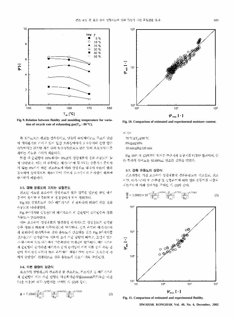
3-5. �� ���# ,�- ./(�
>4+ ?GW E"�� ��FG! �5 §¨� ©Q� e� ��
]^' �'V &L%+ & ���¬! �� $%+,.
Fig. 9 ��RS� nt dH!\� F �¿9� =%� no $%
�pS� )Ï�ä,.
Fig. 9�767 ��RS# dH!\� F �¿9' à!{� $%
�pS! »" °,.
' E"�� ��FG! �$%� ��'E� ��RS! à!{
� $%! >?� '£�� Ñ b�+,. >4 RS# dH!\�
F �¿9' à!{� $% �pS! »" M2 Fig. 8�767
>4RS! à!{� ?G� IH �� »9' >?�, v�� öS
! à! � ¯S �-�7 ��!¶' A3N� b�+,. dH!\�
F �¿9' à! � dH!\ U� àH§' @¤ ?G U� �� »
9' X��C nt7 82 RS�7 :?Ø' D�¤ E"�� /
:� U��' ^'�E� $% �pS� »"! òF �^+,.
3-6. �& '"� 01�
E"�� ��FG� >456 U >4RS, >4?Ø a dH!\�
F �¿9� no �� ¡9� ,UOP�ìº(minitab���Q: R¸
7.1� ��)� nt ��L� g � L (2)# Þ,.
(2)
�H7
70oC TD 90oC
0% γ 50%
10 min θ 120 min
Fig. 102 L (2)�-î Ý�^ ½¶Ù# ±÷Ù� ;ßV ²5'C, �
� ¡9� ��S 92.68%� sJV ²5� Ýä,.
3-7. �� ���� 01�
>456� TS E"�� ��FG� $%�pS� >4RS, >4
?Ø, dH!\� F �¿9 a ��RS� nt $% �pS� ,UO
P�ìº� �c ��L� g � L (3)5 Þ,.
(3)
ϕ 7.1840TD
TDM
-------- 0.7357– γ
γM
------ 0.044762 θ
θM
------ 0.74528–
=
−≤ −≤ −≤ −≤
−≤ −≤
ψθ---- 1.0002 102–×
TD
TDM
-------- 4.0541– Tm
TmM
-------- 0.7531– γ
γM
------ 0.77683–
=
Fig. 9. Relation between fluidity and moulding temperature for varia-tion of recycle rate of exhausting gas(TD : 80oC).
Fig. 10. Comparison of estimated and experimental moisture content.
Fig. 11. Comparison of estimated and experimental fluidity.
HWAHAK KONGHAK Vol. 40, No. 6, December, 2002

686 ����������
.
nce,
�H7
70oC TD 90oC
150oC Tm 170oC
10% γ 50%
Fig. 112 L (3)Q�-î Ý�^ ½¶Ù# ±÷Ù� ;ßV ²5'C,
$% �pS� ��S 90.66%� sJV ²5� Ýä,.
4. � �
>456� Oc7 ¥� 3¦W E"�� ��FG� �5 $%0
�� gl H � � >4RS, dH!\� F �¿9, >4?Ø a �
�RS� no E"�� ��FG� �� ¡95 $% �pS� 4�
� ,ð5 Þ2 ²5� Ýä,.
(1) >4?Ø5 >4RS! à! � �� ¡9' »" C 0D I
H� -�V »"� _') ��� T� =%! Cä,.
(2) >4 ?X Ì 30�f� >4RS# dH!\ F �¿9' à!
¡� nt >4ÀS! @�) � 'Ì� &*� )Ï5,.
(3) dH!\� F�¿9, >4RS a ��RS! à! � �pS
»"V,.
(4) >4RS, >4?Ø, dH!\� F �¿9 a ��RS� nt �
� ¡95 $% �pS� ���ÁL� L (2) a L (3)�7 g °Q
C ±÷Ù# sJV (Ù� )Ï�ä,.
�
Ó bg 2001âTS p�*âß âÇbg;� � � bg�äQ
C '� »�ÆN�,.
���
TD : drying temperature [oC]
Tm : moulding temperature [oC]
Wi : the initial weight in barrel [g]
Wr : the residue weight in barrel [g]
γ : recycle rate of exhausting gas [%]
θ : drying time [min]
ϕ : moisture content [%]
DR : the drying rate [%/min]
ψ : cure fluidity [-]
2345
M : maximum
���
1. Rager, R.: Mod. Plast., 49, 67(1972).
2. Kopf, P. and Wagner, E.: J. Polym. Sci. Chem., 11, 939(1973).
3. Bainbridge, R.: Sail., 8, 142(1995).
4. Gordon, M., Halliwell, A. and Wilson, T.: J. Appl. Polym. Sci., 10,
1153(1966).
5. Aldersley, J. W., Gorden, M., Halliwell, A. and Wilson, T.: Polymer,
9, 345(1966).
6. Shriver, D. S. and Bara, E. J.: U. S. Patent. 3,458,464(1969).
7. Anderson, I. H., Cawely, M. and Steedman, W.: Br. Polym. J., 1, 24
(1967).
8. Shenai, V. A. and Manjeshwar, J. M.: J. Appl. Polym. Sci., 18, 1407
(1974).
9. Blank, W. J.: J. Coatings Technol., 51, 61(1979).
10. Agranoff, J.: Modern Plastics Encyclopedia 1983-1984, McGraw-Hill,
Inc.
11. Sato, K. and Naito, T.: Polym. J., 5, 144(1973).
12. Sato, K. and Abe, Y.: J. Polym. Sci. Polym. Chem. Ed., 13, 263(1975).
13. Koral, J. M. and Petschel, M.: Jr, U. S. Patent. 3,661,819(1972)
14. Calbo, L. J. and Koral, J. N.: U. S. Patent. 3,803,095(1974).
15. Calbox, W. J. and Hensley, W. L.: J. Paint Technol, 46, 46(1974).
16. Rybicky, J. and Kamanis, S. M.: J. Appl. Ploym. Sci., 24, 1523
(1979).
17. Zunker, D. W.: Proceedings of the TAPPI Papermakers Confere
Atlanta, Ga., 1982 and Portland, Ore., Tappi, New York(1983).
−≤ −≤ −≤ −≤
−≤ −≤
���� �40� �6� 2002� 12�
Related Documents