MEC 554 THERMODYNAMIC LAB: HVAC LABORATORY 2015 UNIVERSITI TEKNOLOGI MARA FAKULTI KEJURUTERAAN MEKANIKAL Program : Bachelor Of Engineering ( Hons ) Mechanical Kursus : Thermalfluids lab Kod Kursus : MEC 554 Pensyarah : Cik Siti Mariana binti Hosnie Laboratory Report Title HVAC No Names UiTM No. Signature 1. ‘Usmar Aiman Bin Azhar 2013490144 2. Ahmad Naquiyuddin Bin Rasid 2013802598 3. Ahmad Almizan Bin Che Omar 2013254614 4. Aimi bin Ezani 2013212512 5. Ahmad Haniff ilmuddin Bin Mohd Nawi 2013274648 Sessi Amali : Pengesahan Staf : 1

Welcome message from author
This document is posted to help you gain knowledge. Please leave a comment to let me know what you think about it! Share it to your friends and learn new things together.
Transcript

MEC 554 THERMODYNAMIC LAB: HVAC LABORATORY 2015
UNIVERSITI TEKNOLOGI MARAFAKULTI KEJURUTERAAN MEKANIKAL
Program : Bachelor Of Engineering ( Hons ) Mechanical Kursus : Thermalfluids lab Kod Kursus : MEC 554 Pensyarah : Cik Siti Mariana binti Hosnie
Laboratory Report
Title
HVAC
No Names UiTM No. Signature
1. ‘Usmar Aiman Bin Azhar 2013490144
2. Ahmad Naquiyuddin Bin Rasid 2013802598
3. Ahmad Almizan Bin Che Omar 2013254614
4. Aimi bin Ezani 2013212512
5.Ahmad Haniff ilmuddin Bin Mohd Nawi
2013274648
Sessi Amali : Pengesahan Staf :(Tarikh) (T. Tangan)
Penyerahan Laporan : Pengesahan Staf :(Tarikh) (T. Tangan)
1

MEC 554 THERMODYNAMIC LAB: HVAC LABORATORY 2015
Contents1.0 INTRODUCTION.....................................................................................................................3
1.1 OBJECTIVE..........................................................................................................................3
1.2 THEORETICAL BACKGROUND.......................................................................................3
2.0 PROCEDURE............................................................................................................................6
2.1 APPARATUS........................................................................................................................6
2.1 EXPERIMENTAL PROCEDURE........................................................................................8
3.0 DATA ANALYSIS...................................................................................................................9
3.1 SAMPLE CALCULATION................................................................................................10
3.1.1 No process:...................................................................................................................10
3.1.2 Sensible Heating:..........................................................................................................10
3.1.3 Steam humidification:...................................................................................................11
3.1.4 Cooling and dehumidification:.....................................................................................12
4.0 DISCUSSION..........................................................................................................................13
4.1 Find the schematic of a modern air-conditioning system with advanced air treatment processes and explain the function of the main devices............................................................13
4.2 Explain with the suitable diagrams the operation and arrangements in an automotive air-conditioning unit........................................................................................................................17
5.0 REFERENCES........................................................................................................................19
2
MEC 554 THERMODYNAMIC LAB: HVAC LABORATORY 2015
1.0 INTRODUCTION
Air-conditioning is a process of treating air for the comfort requirements of the occupants in the conditioned space. The properties of air can be modified by undergoing certain thermodynamic processes. The most basic of processes involved in an air-conditioning system are simple heating, sensible Heating (preheater and reheater), steam humidification, simple humidification, simple cooling and dehumidification.
Air-conditioning is useful to maintain the surrounding environment of temperature and ambient to satisfy the the temperature of human comfort, which is between 20°C to 25°C. Conventional air-condition is use to cool and to heat the surrounding environment, but in some country, air-condition may use both heating and cooling, with or without humidifing air. Also the industrial usage of air-condition is to reduce temperature of themal produce machine.
1.1 OBJECTIVE
To observe and understand the changes in air properties as it is treated in a basic air-conditioning unit.
1.2 THEORETICAL BACKGROUND
Basically, the simple theory of operation on how air conditioning works in functional order are through Compressor, Condenser, Expansion Valve System, Orifice Tube System, Evaporator and Accumulator which in other words are compress, heat, cool, condense, dry, expand and cool and finally evaporate. The detailed operations are as explained below.
Starting with the compressor, its primary function is to compress and pressurize gaseous refrigerant. It takes in cool gas into suction port and pressurizes it at a discharge port. The compressor is powered by a drive belt from the engine. The compressor has an electrically operated engagement clutch to either turn the refrigeration operation off or on. Output is high pressure (hot) gas.
Next is the condenser. The condenser is located in front of the radiator and kind of looks like a radiator too. Through the use of cool air flow provided by the engine fan, the condenser cools the hot gas and converts it to liquid. The liquid is still under considerable pressure and is warm, but not as hot or as high pressure as when it exited the compressor. Output is high pressure (warm) liquid.
3
MEC 554 THERMODYNAMIC LAB: HVAC LABORATORY 2015
Expansion Valve System is where the exiting liquid is sent via a small tube (liquid line) to a receiver/drier (applies only to an expansion valve system). The drier is a can with a desiccant bag inside. It looks about the size of a soda can, and is usually located very near to the condenser outlet pipe. There is no pressure or temperature change at the receiver/drier. Output is the same as condenser, but moisture is removed by desiccant.
As the high pressure and warm liquid exits the drier, it passes through an expansion device. It can either be an expansion valve (which modulates refrigerant flow in an expansion valve/drier system), or a fixed expansion orifice tube in a cycling clutch/orifice tube system (which expands at the same rate all the time). The two systems have slight have slight functional differences, mainly in how the low temperature is maintained. Well any way, for illustration, the pressurized liquid passes through the expansion device, the pressure is reduced considerably; hence the temperature drops also. Output is cold liquid. The following paragraph describes the expansion valve.
Cycling Clutch/Orifice Tube System is the exiting liquid is sent via a small liquid line directly to an expansion orifice tube. The orifice tube is fixed, therefore the proportional pressure drop across it will constant. This type of expansion device must work in conjunction with a clutch cycling switch. Because the pressure drop across the orifice tube is constant, the switch is used to maintain the system low pressure side in a certain operating range. The cycling clutch switch, through various pressure changes in the system, turns the compressor off and on during normal operation. A typical operation would have the switch turn the compressor on at about 45 psi and off at 25 degrees. This would maintain the evaporator refrigerant at temperatures around 35-45 degrees F.
The next step is evaporator operation. As the cold liquid exits the expansion device, it is fed to a heat exchanger type device under the dash that blows warm air from the car interior across it. The cold liquid refrigerant is what cools the air you feel coming out of the ducts. As the air is cooled in the heat exchanger, the liquid refrigerant is heated in the other side of the heat exchanger and then it evaporates.
Accumulator is only used in orifice tube system. It contains a desiccant bag also. The accumulator provides a similar function as the drier in the expansion valve system, but is located in the evaporator outlet instead. This positioning allows the accumulator to collect any un-evaporated refrigerant that may still be in the liquid state, hence protecting the compressor from liquid lock damage.
Finally, the evaporated gas then returns via the large tube to the compressor "suction" port to repeat this whole process.
4

MEC 554 THERMODYNAMIC LAB: HVAC LABORATORY 2015
Air conditioning processes can be modeled as steady flow processes:Mass conservation:Dry air : ma,i = mw,e Water : mw,i = mw,e or mai i = ma,ee
Energy conservation:Disregard kinetic and potential energy changes Steady Flow Energy Balance Ei = Eo
Qi + Wi + mihi = Qe + We + mehe
a)Sensble heatingConservation of mass:
ma,1 = mw,2 and (1 = 2) Conservation of energy :
Q = ma (h2 - h1) q = h2 - h1
b)Steam humidification
Dry air mass balance: ma1 = ma2 =ma3 =ma
Water mass balance: ma11 = ma22 , (1 = 2) (heating section) ma22 + mw = ma33 ( humidifying section)
mw = ma(3 - 2)
Energy Balance: Qin + mah1 = ma h2 ( heating section) Qin = ma (h2 - h1)
c)Cooling dehumidificationDry air mass balance: ma1 = ma2 = ma ma22 + mw = ma3
mw = ma(1 - 2)
Energy Balance: mhin = Qout + mhout Qout = m (h2 - h1) - mwhw
5

MEC 554 THERMODYNAMIC LAB: HVAC LABORATORY 2015
2.0 PROCEDURE
2.1 APPARATUS
Computer Linked Air Conditioning Laboratory Unit (P.A. Hilton) -The main equipment used during experiment.
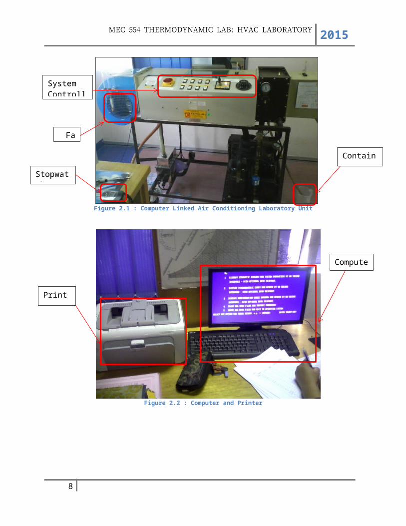
Figure 2.1 : Computer Linked Air Conditioning Laboratory Unit
Figure 2.2 : Computer and Printer
6
System Controller
Fan
Stopwatch
Container
Printer
Computer
MEC 554 THERMODYNAMIC LAB: HVAC LABORATORY 2015
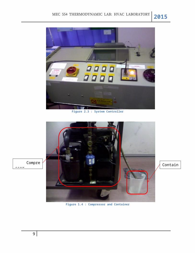
Figure 2.3 : System Controller
Figure 1.4 : Compressor and Container
7
CompressorContainer
MEC 554 THERMODYNAMIC LAB: HVAC LABORATORY 2015
2.1 EXPERIMENTAL PROCEDURE
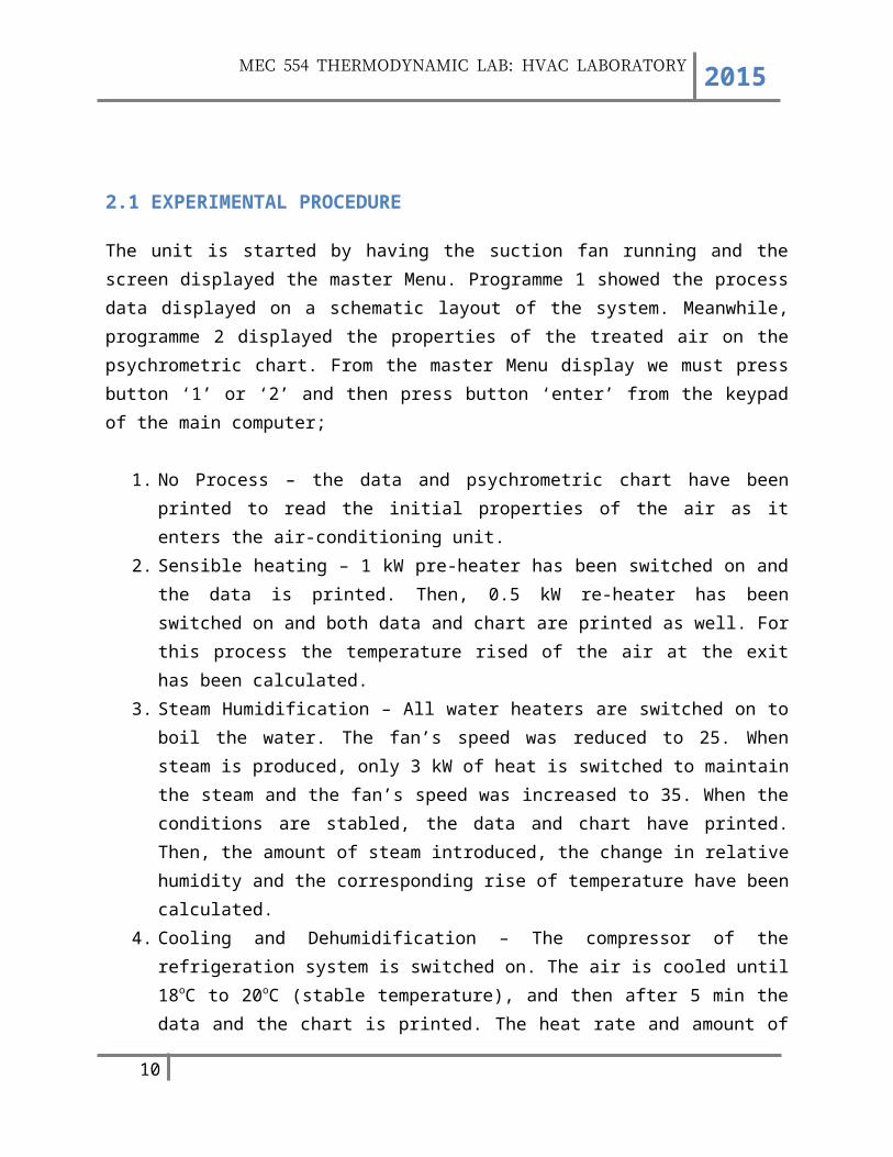
The unit is started by having the suction fan running and the screen displayed the master Menu. Programme 1 showed the process data displayed on a schematic layout of the system. Meanwhile, programme 2 displayed the properties of the treated air on the psychrometric chart. From the master Menu display we must press button ‘1’ or ‘2’ and then press button ‘enter’ from the keypad of the main computer;
1. No Process – the data and psychrometric chart have been printed to read the initial properties of the air as it enters the air-conditioning unit.
2. Sensible heating – 1 kW pre-heater has been switched on and the data is printed. Then, 0.5 kW re-heater has been switched on and both data and chart are printed as well. For this process the temperature rised of the air at the exit has been calculated.
3. Steam Humidification – All water heaters are switched on to boil the water. The fan’s speed was reduced to 25. When steam is produced, only 3 kW of heat is switched to maintain the steam and the fan’s speed was increased to 35. When the conditions are stabled, the data and chart have printed. Then, the amount of steam introduced, the change in relative humidity and the corresponding rise of temperature have been calculated.
4. Cooling and Dehumidification – The compressor of the refrigeration system is switched on. The air is cooled until 18oC to 20oC (stable temperature), and then after 5 min the data and the chart is printed. The heat rate and amount of moisture removed from the air have been calculated. During this experiment, the rate of condensation from the beginning of the cooling process until the end is measured and has been compared with analysis.
8
MEC 554 THERMODYNAMIC LAB: HVAC LABORATORY 2015
3.0 DATA ANALYSISExperiment NO
PROCESSSENSIBLE HEATING
STEAM HUMIDIFICAT
ION
COOLINGAND DEHUMIDIFICATIONReading
T1 (TAd) (oC)
26.0 26.3 26.5
26.928.6 28.9
T2 (TAw) (oC)
22.3 22.7 22.6 23.2 23.7 23.9
T3 (TBd) (oC)
26.3 41.0 45.5 38.6 28.8 28.9
T4 (TBw) (oC)
23.1 29.4 30.7 39.1 24.6 24.5
T5 (TCd) (oC)
25.8 36.4 44.1 38.0 12.1 11.1
T6 (TCw) (oC)
22.0 26.4 28.2 38.0 11.9 11.2
T7 (TDd) (oC)
25.7 34.1 48.8 37.8 12.9 11.9
T8 (TDw) (oC)
22.3 25.7 29.4 38.2 13.0 12.1
T9 (T1) (oC)
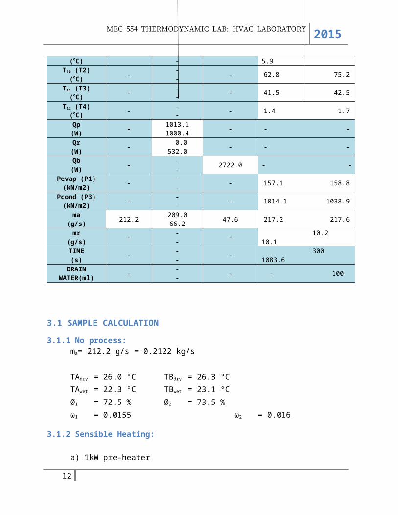
- - - - 4.8 5.9
T10 (T2) (oC)
- - - - 62.8 75.2
T11 (T3) (oC)
- - - - 41.5 42.5
T12 (T4) (oC)
- - - - 1.4 1.7
Qp (W)
- 1013.1 1000.4 - - -
Qr (W)
- 0.0 532.0 - - -
Qb (W)
- - - 2722.0 - -
Pevap (P1) (kN/m2)
- - - - 157.1 158.8
Pcond (P3) (kN/m2)
- - - - 1014.1 1038.9
ma (g/s)
212.2 209.0 66.2 47.6 217.2 217.6
mr (g/s)
- - - - 10.2 10.1
TIME (s)
- - - - 300 1083.6
DRAIN WATER(ml)
- - - - - 100
9
MEC 554 THERMODYNAMIC LAB: HVAC LABORATORY 2015
3.1 SAMPLE CALCULATION
3.1.1 No process:ma= 212.2 g/s = 0.2122 kg/s
TAdry = 26.0 °C TBdry = 26.3 °CTAwet = 22.3 °C TBwet = 23.1 °CØ1 = 72.5 % Ø2 = 73.5 %ω1 = 0.0155 ω2 = 0.016
3.1.2 Sensible Heating:
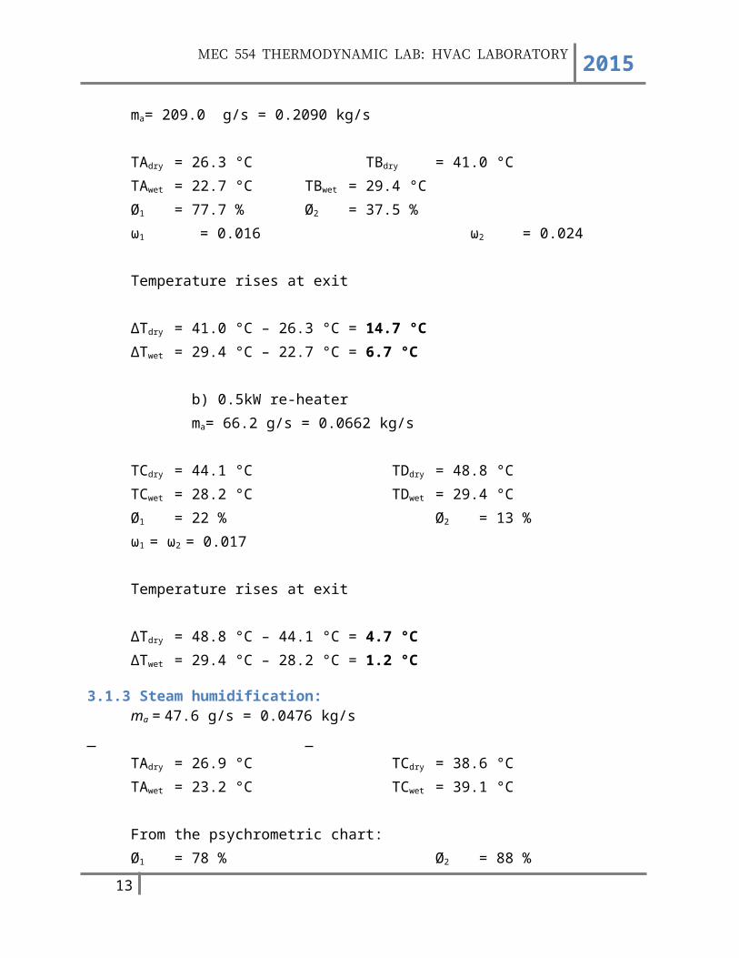
a) 1kW pre-heaterma= 209.0 g/s = 0.2090 kg/s
TAdry = 26.3 °C TBdry = 41.0 °CTAwet = 22.7 °C TBwet = 29.4 °CØ1 = 77.7 % Ø2 = 37.5 %ω1 = 0.016 ω2 = 0.024
Temperature rises at exit
∆Tdry = 41.0 °C – 26.3 °C = 14.7 °C∆Twet = 29.4 °C – 22.7 °C = 6.7 °C
b) 0.5kW re-heater ma= 66.2 g/s = 0.0662 kg/s
TCdry = 44.1 °C TDdry = 48.8 °CTCwet = 28.2 °C TDwet = 29.4 °CØ1 = 22 % Ø2 = 13 %ω1 = ω2 = 0.017
Temperature rises at exit
∆Tdry = 48.8 °C – 44.1 °C = 4.7 °C∆Twet = 29.4 °C – 28.2 °C = 1.2 °C
10

MEC 554 THERMODYNAMIC LAB: HVAC LABORATORY 2015
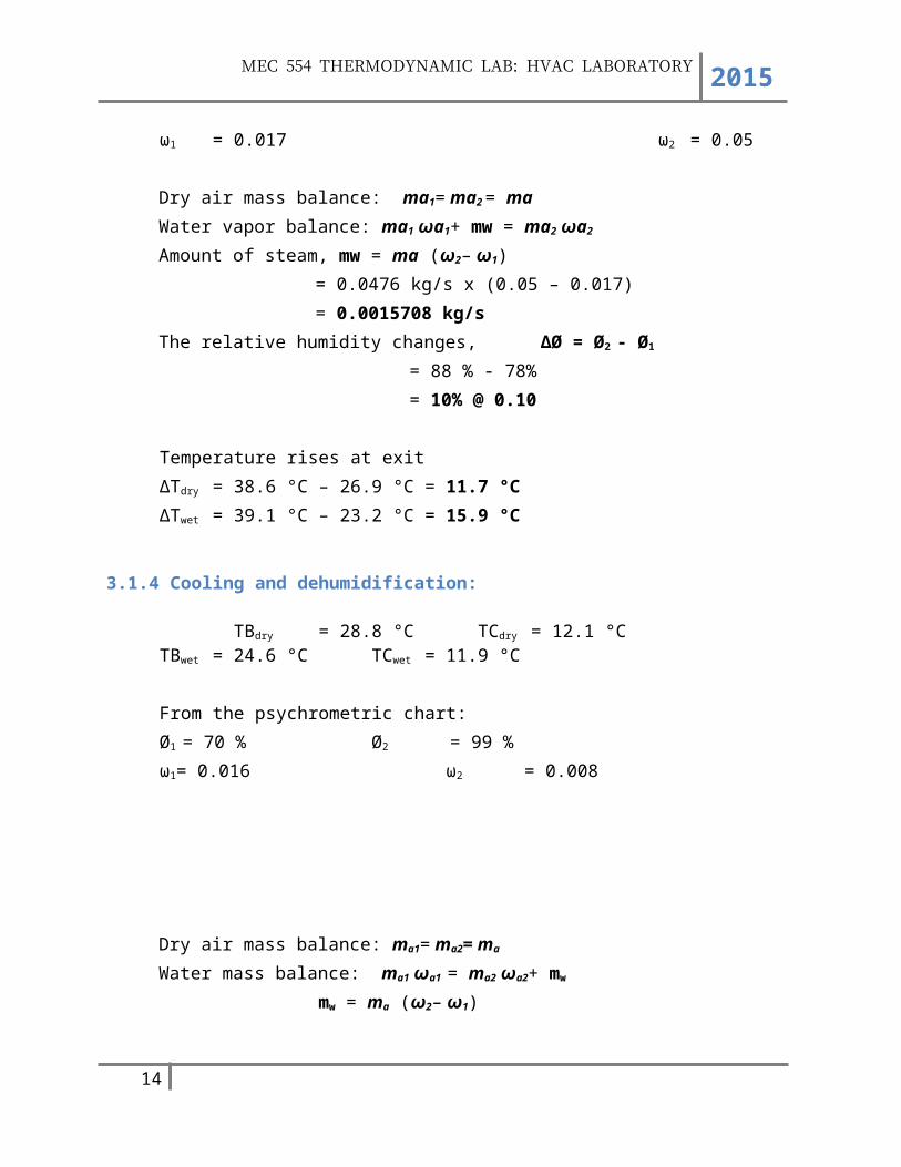
3.1.3 Steam humidification:ma = 47.6 g/s = 0.0476 kg/s
TAdry = 26.9 °C TCdry = 38.6 °CTAwet = 23.2 °C TCwet = 39.1 °C
From the psychrometric chart:Ø1 = 78 % Ø2 = 88 %ω1 = 0.017 ω2 = 0.05
Dry air mass balance: ma1= ma2 = maWater vapor balance: ma1 ωa1+ mw = ma2 ωa2
Amount of steam, mw = ma (ω2– ω1) = 0.0476 kg/s x (0.05 – 0.017) = 0.0015708 kg/s
The relative humidity changes, ∆Ø = Ø2 - Ø1
= 88 % - 78%= 10% @ 0.10
Temperature rises at exit∆Tdry = 38.6 °C – 26.9 °C = 11.7 °C∆Twet = 39.1 °C – 23.2 °C = 15.9 °C
3.1.4 Cooling and dehumidification:
TBdry = 28.8 °C TCdry = 12.1 °CTBwet = 24.6 °C TCwet = 11.9 °C
From the psychrometric chart:Ø1 = 70 % Ø2 = 99 %ω1= 0.016 ω2 = 0.008
Dry air mass balance: ma1= ma2= ma
11
MEC 554 THERMODYNAMIC LAB: HVAC LABORATORY 2015
Water mass balance: ma1 ωa1 = ma2 ωa2+ mw
mw = ma (ω2– ω1)
Energy balance: ∑mihi = Qout + ∑mehe Qout = ma (h1 – h2) – mwhw
State 1: ω1= 0.016, Ø1 = 70 %, T1 =28.8 °C, ma = 217.2 g/s = 0.2172 kg/s
ha1 = CpT1 = 1.005 x 28.8 °C = 28.944 kJ/kg hg1 = 2501.3 + 1.82T = 2501.3 + 1.82 (28.8) = 2553.71 kJ/kg Therefore h1 = ha1 + ω hg1
= 28.944 + (0.0160)2553.71 = 69.80 kJ/kg
State 2: ω2= 0.008, Ø2 = 99 %, T2 = 12.1 °C, ma = 217.2 g/s = 0.2172 kg/sha2= Cp T2 = 1.005 x 12.1 °C = 12.1605 kJ/kgTherefore h2 = ha2 + ωhg2 = 12.1605 + 0.008[2501.3 + 1.82 (12.1)]
= 32.35 kJ/kghw = hf @ T2 (from Table A-4)
=12.1−1015−10
= x−42.02262.982−42.022
hf = 50.83 kJ/kg = hw
Amount of moisture, mw = ma (ω1– ω2)
= 0.2172 (0.016 – 0.008) = 0.00174 kg/s
Heat rate removed, Qout = ma (h1 – h2) – mwhw
= 0.2172 (69.80 – 32.35) – 0.0017 (50.83) = 8.048 kJ/s
12
MEC 554 THERMODYNAMIC LAB: HVAC LABORATORY 2015
4.0 DISCUSSION
4.1 Find the schematic of a modern air-conditioning system with advanced air treatment processes and explain the function of the main devices.
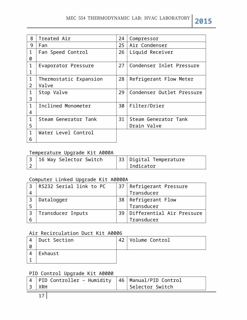
Components and Devices1 Air Inlet 17 Solenoid Valve2 Wet and Dry Temperature Stations 18 Water Inlet3 Steam Injector 19 Sight Glass4 Pre-Heaters 20 Vent5 Evaporator 21 Water Heaters6 Pre-Heaters 22 Overflow to Drain7 Orifice 23 Condensate Measurement8 Treated Air 24 Compressor9 Fan 25 Air Condenser
10 Fan Speed Control 26 Liquid Receiver11 Evaporator Pressure 27 Condenser Inlet Pressure12 Thermostatic Expansion Valve 28 Refrigerant Flow Meter13 Stop Valve 29 Condenser Outlet Pressure14 Inclined Monometer 30 Filter/Drier15 Steam Generator Tank 31 Steam Generator Tank Drain Valve16 Water Level Control
Temperature Upgrade Kit A000A32 16 Way Selector Switch 33 Digital Temperature Indicator
Computer Linked Upgrade Kit A0000A34 RS232 Serial link to PC 37 Refrigerant Pressure Transducer
13
MEC 554 THERMODYNAMIC LAB: HVAC LABORATORY 2015
35 Datalogger 38 Refrigerant Flow Transducer36 Transducer Inputs 39 Differential Air Pressure Transducer
Air Recirculation Duct Kit A000640 Duct Section 42 Volume Control41 Exhaust
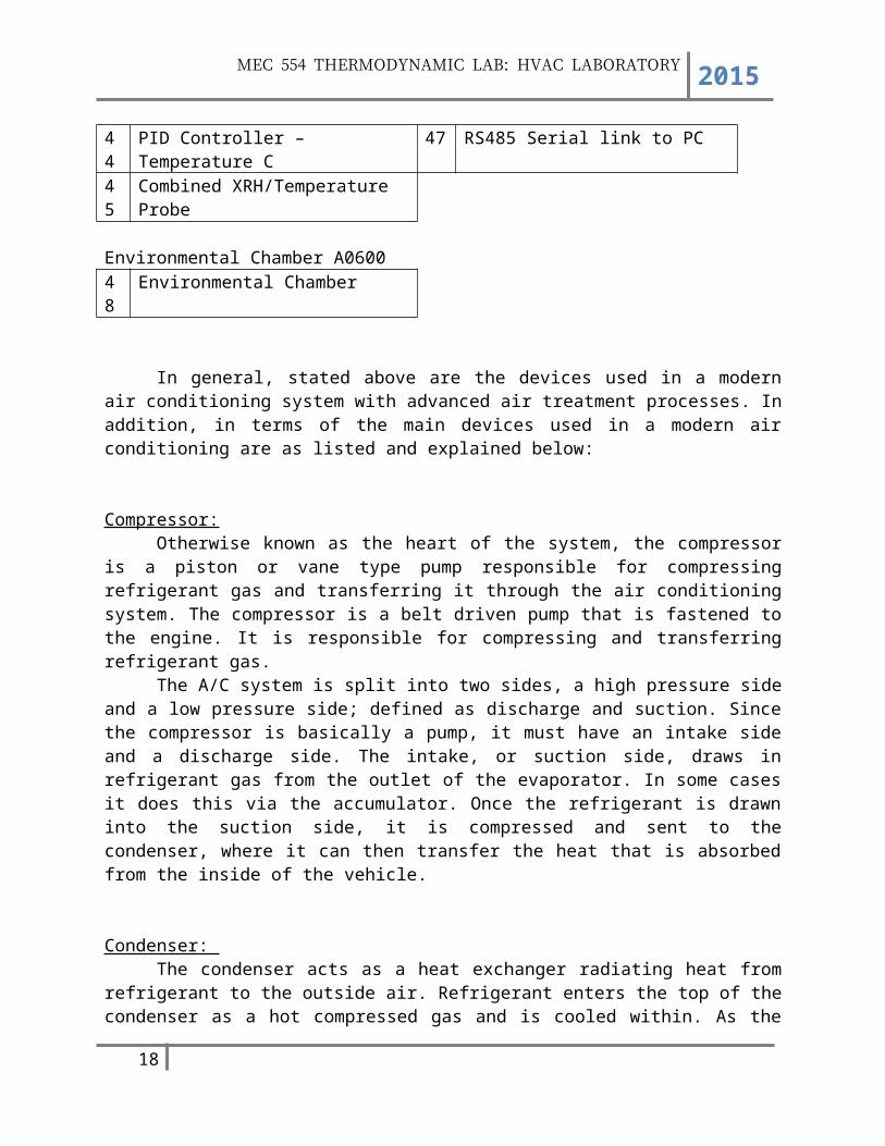
PID Control Upgrade Kit A000043 PID Controller – Humidity XRH 46 Manual/PID Control Selector Switch44 PID Controller – Temperature C 47 RS485 Serial link to PC45 Combined XRH/Temperature Probe
Environmental Chamber A060048 Environmental Chamber
In general, stated above are the devices used in a modern air conditioning system with advanced air treatment processes. In addition, in terms of the main devices used in a modern air conditioning are as listed and explained below:
Compressor:Otherwise known as the heart of the system, the compressor is a piston or vane type
pump responsible for compressing refrigerant gas and transferring it through the air conditioning system. The compressor is a belt driven pump that is fastened to the engine. It is responsible for compressing and transferring refrigerant gas.
The A/C system is split into two sides, a high pressure side and a low pressure side; defined as discharge and suction. Since the compressor is basically a pump, it must have an intake side and a discharge side. The intake, or suction side, draws in refrigerant gas from the outlet of the evaporator. In some cases it does this via the accumulator. Once the refrigerant is drawn into the suction side, it is compressed and sent to the condenser, where it can then transfer the heat that is absorbed from the inside of the vehicle.
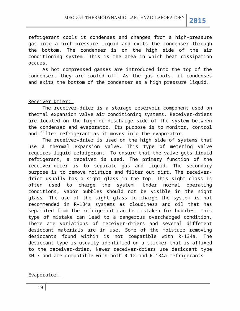
Condenser: The condenser acts as a heat exchanger radiating heat from refrigerant to the outside air.
Refrigerant enters the top of the condenser as a hot compressed gas and is cooled within. As the refrigerant cools it condenses and changes from a high-pressure gas into a high-pressure liquid and exits the condenser through the bottom. The condenser is on the high side of the air conditioning system. This is the area in which heat dissipation occurs.
As hot compressed gasses are introduced into the top of the condenser, they are cooled off. As the gas cools, it condenses and exits the bottom of the condenser as a high pressure liquid.
14

MEC 554 THERMODYNAMIC LAB: HVAC LABORATORY 2015
Receiver Drier: The receiver-drier is a storage reservoir component used on thermal expansion valve air
conditioning systems. Receiver-driers are located on the high or discharge side of the system between the condenser and evaporator. Its purpose is to monitor, control and filter refrigerant as it moves into the evaporator.
The receiver-drier is used on the high side of systems that use a thermal expansion valve. This type of metering valve requires liquid refrigerant. To ensure that the valve gets liquid refrigerant, a receiver is used. The primary function of the receiver-drier is to separate gas and liquid. The secondary purpose is to remove moisture and filter out dirt. The receiver-drier usually has a sight glass in the top. This sight glass is often used to charge the system. Under normal operating conditions, vapor bubbles should not be visible in the sight glass. The use of the sight glass to charge the system is not recommended in R-134a systems as cloudiness and oil that has separated from the refrigerant can be mistaken for bubbles. This type of mistake can lead to a dangerous overcharged condition. There are variations of receiver-driers and several different desiccant materials are in use. Some of the moisture removing desiccants found within is not compatible with R-134a. The desiccant type is usually identified on a sticker that is affixed to the receiver-drier. Newer receiver-driers use desiccant type XH-7 and are compatible with both R-12 and R-134a refrigerants.
Evaporator: An air conditioning evaporator is a refrigeration coil mounted within cooling fins. The
continuous flow of warm air over the coils causes the refrigerant flowing inside to boil and absorb large amounts of heat. The boiling refrigerant leaves the evaporator onto the condenser where it is dissipated into the atmosphere. The evaporator also acts as a dehumidifier and air purifier at the same time.
Accumulator: Accumulators are used on systems that accommodate an orifice tube to meter refrigerants
into the evaporator. It is connected directly to the evaporator outlet and stores excess liquid refrigerant. Introduction of liquid refrigerant into a compressor can do serious damage. Compressors are designed to compress gas not liquid. The chief role of the accumulator is to isolate the compressor from any damaging liquid refrigerant. Accumulators, like receiver-driers, also remove debris and moisture from a system. It is a good idea to replace the accumulator each time the system is opened up for major repair and anytime moisture and/or debris is of concern. Moisture is enemy number one for your A/C system. Moisture in a system mixes with refrigerant and forms a corrosive acid. When in doubt, it may be to your advantage to change the Accumulator or receiver in your system. While this may be a temporary discomfort for your wallet, it is of long term benefit to your air conditioning system.
Fan: Mainly the purpose of using fan concept in an air conditioning unit is to ensure that all
the unwanted heat is rejected from the system into the atmosphere. At the same time, it ensures the cooling rate is maintained at its level.
15

MEC 554 THERMODYNAMIC LAB: HVAC LABORATORY 2015
Humidifiers: Usually reduces the humidity of the air processed by the system. The relatively cold
(below the dew point) evaporator coil condenses water vapor from the processed air, (much like an ice cold drink will condense water on the outside of a glass), sending the water to a drain and removing water vapor from the cooled space and lowering the relative humidity. Since humans perspire to provide natural cooling by the evaporation of perspiration from the skin, drier air (up to a point) improves the comfort provided. The comfort air conditioner is designed to create a 40% to 60% relative humidity in the occupied space. In food retailing establishments’ large open chiller cabinets act as highly effective air dehumidifying units.
Heater: Realized through several physical effects, but they are classified depending on their
applications (driving energy, source and sink of heat, or a heat pump which is basically a refrigeration machine). Refrigerators, air conditioners, and some heating systems are all common applications of heat pumps.
4.2 Explain with the suitable diagrams the operation and arrangements in an automotive air-conditioning unit.
16
MEC 554 THERMODYNAMIC LAB: HVAC LABORATORY 2015
Figure above is the diagram of an automotive air conditioning unit for a Nissan car model ZX-300 (Model - 1988). All the devices and components are same like in the air conditioning use in home application. The difference only the arrangements of the circuit and the add some extra components. As such, the components are as listed; ECM system (which related in the usage in a non-turbo and turbo system), Aspirator fan (used in order to control the air flow in the car in both or either head or foot application), floor duct temperature sensor, vent duct temp sensor, sun load sensor, defroster nozzle temperature sensor, in-vehicle sensor (head and foot
17
MEC 554 THERMODYNAMIC LAB: HVAC LABORATORY 2015
application) and etc. In a way or another, the basic and main components (devices) in an automotive air conditioning are as stated below as well as the operation involves:
Operation One: The compressor is the power unit of the A/C system. It is powered by a drive belt
connected to the engine's crankshaft. When the A/C system is turned on, the compressor pumps out refrigerant vapor under high pressure and high heat to the condenser.
Operation Two: The condenser is a device used to change the high-pressure refrigerant vapor to a liquid.
It is mounted ahead of the engine's radiator, and it looks very similar to a radiator with its parallel tubing and tiny cooling fins. If you look through the grille of a car and see what you think is a radiator, it is most likely the condenser. As the car moves, air flowing through the condenser removes heat from the refrigerant, changing it to a liquid state.
Operation Three: Refrigerant moves to the receiver-drier. This is the storage tank for the liquid refrigerant.
It also removes moisture from the refrigerant. Moisture in the system can freeze and then act similarly to cholesterol in the human blood stream, causing blockage.
Operation Four:As the compressor continues to pressurize the system, liquid refrigerant under high
pressure is circulated from the receiver-drier to the thermostatic expansion valve. The valve removes pressure from the liquid refrigerant so that it can expand and become refrigerant vapor in the evaporator.
Operation Five: The evaporator is very similar to the condenser. It consists of tubes and fins and is
usually mounted inside the passenger compartment. As the cold low-pressure refrigerant is released into the evaporator, it vaporizes and absorbs heat from the air in the passenger compartment. As the heat is absorbed, cool air will be available for the occupants of the vehicle. A blower fan inside the passenger compartment helps to distribute the cooler air.
Operation Six: The heat-laden, low-pressure refrigerant vapor is then drawn into the compressor to start another refrigeration cycle.
5.0 REFERENCES
18
MEC 554 THERMODYNAMIC LAB: HVAC LABORATORY 2015
1. Cengel & Boles.(2013). MEC 551 Thermal Engineering. Thermodynamics : An Engineering Approach, Seventh Edition in SI Units. Chapter 14: Gas-Vapor Mixtures and Air-Conditioning.pg 719-726. McGraw-Hill Education (Asia).
2. Chris Bede.(2013).Automotive Air Conditioning Systems. Article retrieve from www.carparts.com/classroom/ac1.htm on October 4, 2013.
3. Al Nimr & M. Naji.(2002). A Novel Summer Air Conditioning System. Article retrieve from http://www.sciencedirect.com/science/article/pii/S0196890401001352 on October 4, 2013
19
Related Documents