HV-AC LED 1 / 24 Http://www.samsungled.com Rev : 00 SPECIFICATION MODEL : SPHWHTHAD605S0W0U4 HV-AC HIGH POWER LED ISSUE NO : DATE OF ISSUE : 03/14/2011 SAMSUNG LED CO,.LTD. 314. MAETAN3-DONG, YEONGTONG-KU, SUWON-SI,GYUNGKI-DO,KOREA,442-743 SAMSUNG LED DRAWN CHECKED APPROVED CUSTOMER : DRAWN CHECKED APPROVED

Welcome message from author
This document is posted to help you gain knowledge. Please leave a comment to let me know what you think about it! Share it to your friends and learn new things together.
Transcript
HV-AC LED 1 / 24Http://www.samsungled.com
Rev : 00
SPECIF ICAT IONMODEL : SPHWHTHAD605S0W0U4
HV-AC HIGH POWER LED
ISSUE NO :
DATE OF ISSUE : 03/14/2011
SAMSUNG LED CO,.LTD.
314. MAETAN3-DONG, YEONGTONG-KU,
SUWON-SI,GYUNGKI-DO,KOREA,442-743
SAMSUNG LED
DRAWN CHECKED APPROVED
CUSTOMER :
DRAWN CHECKED APPROVED

HV-AC LED 2 / 24Http://www.samsungled.com
Contents
1. Product Outline ------------------------- 3
2. Absolute Maximum Rating ------------------------- 3
3. Characteristics ------------------------- 3
4. Typical Characteristic Graphs --------------- 7
5. Outline Drawing & Dimension ------------------ 10
6. Package Structure --------------------------------- 11
7. Solder Conditions ------------------------------ 11
8. Reliability Test Items & Conditions ---------- 12
9. Circuit Design - Package and PCB --------- 13
10. Taping Dimension ----------------------------------- 14
11. Label Structure ------------------------- 15
12. Lot Number ---------------------------------------- 15
13. Reel Packing Structure --------------------------- 16
14. Aluminum Packing Bag ---------------------- 18
15. Precaution For Use ---------------------------------- 19
16. Hazard Substance Analysis ------------------------- 21
17. Revision history ------------------------------------ 24

HV-AC LED 3 / 24Http://www.samsungled.com
1. Product Outline
1) Features
ㆍ Plastic Molded Lead Frame Type : 12.4(L), 11.4(W), 4.38(T)
ㆍ SMD Type : 1 Heat Pad and 4 Electrical Pad
ㆍ Beam View Angle(θ)* :136˚
ㆍ High Power / Brightness Chip & Long Time Reliability
2) Applications
ㆍ Indoor & Outdoor lighting
ㆍ Direct AC power source plug-in (110Vac, 220Vac)
※ View Angle describes the spatial intensity distribution and is the difference between the angles
corresponding to 50% of the maximum intensity. (Full Width Half Maximum)
2. Absolute Maximum Rating
Parameter Value Unit
Operating Voltage 250 V[RMS]
Power Dissipation 6.5 W
LED Junction Temperature (TJ) 125
Operating Temperature Range (TOPR) -40 ∼ 85
Storage Temperature (TSTG) -40 ∼ 120
ESD Sensitivity ± 3,000V HBM -
3. Characteristics
1) Electro-Optical properties (Ta = 25 )
Parameter Symbol Condition Min. Typ. Max. Unit
Luminous Flux ΦV
IF=22mA(rms)/220Vac
IF=44mA(rms)/110Vac
220 250 - lm
CCT CT - 2700 - K
CRI Ra 80 - - -
Power Dissipation P 3.3 W
Operating Frequency fo 50/60 Hz
※ Tolerance : ±10%

HV-AC LED 4 / 24Http://www.samsungled.com
2) Chromaticity Coordinates (Ta = 25 )

HV-AC LED 5 / 24Http://www.samsungled.com
ㆍ 2700K
TABLE Rank CIE X CIE Y Rank CIE X CIE Y
2700K
(W0)
WH
0.4373 0.3893
WM
0.4465 0.4071
0.4465 0.4071 0.4562 0.4260
0.4523 0.4085 0.4624 0.4274
0.4428 0.3906 0.4523 0.4085
WJ
0.4428 0.3906
WN
0.4523 0.4085
0.4523 0.4085 0.4624 0.4274
0.4582 0.4099 0.4687 0.4289
0.4483 0.3919 0.4582 0.4099
WK
0.4483 0.3919
WP
0.4582 0.4099
0.4582 0.4099 0.4687 0.4289
0.4641 0.4112 0.4750 0.4304
0.4538 0.3931 0.4641 0.4112
WL
0.4538 0.3931
WQ
0.4641 0.4112
0.4641 0.4112 0.4750 0.4304
0.4700 0.4126 0.4813 0.4319
0.4593 0.3944 0.4700 0.4126
WHWJ
WM WN WP WQ
WK WL

HV-AC LED 6 / 24Http://www.samsungled.com
3) Luminous Flux (Ta = 25 ) (Unit, lm)
Parameter Symbol Condition * Rank Min. Typ. Max. CCT
LuminousFlux
ΦV
IF=22mA(rms)*/220Vac
IF=44mA(rms)/110Vac
U4
U1 220 - 240
2700KV1 240 - 260
W1 260 - 280
X1 280 -
※ Tolerance : ±10%
* Sorting is done @ IF=22mA(rms)
4) VF Bin (Ta = 25 )
Symbol Condition Rank Min. Typ. Max. Unit
Vf IF = 22mA(rms) S0
F1 190 - 195
Vac(rms)
F3 195 - 200
F5 200 - 205
※ Tolerance : ±5V
5) Resistor Table
VfParallel Connection Series Connection
Unit100Vac 110Vac 120Vac 220Vac 230Vac 240Vac
ResistorValue
F1 330 560 800 2,200 2,620 3,100
ΩF3 300 510 750 2,100 2,560 3,000
F5 270 460 700 2,000 2,500 2,900
※ LED Power dissipation Tolerance : ±7%

HV-AC LED 7 / 24Http://www.samsungled.com
4. Typical Characteristic Graphs
1) AC voltage operating characteristic
Total Power Consumption = Power_LED + Power_Resistor
Power_LED = Total Power - I2R
< Power consumption vs. Operating current >
0
1
2
3
4
5
6
7
0 10 20 30 40
Operating Current [mA rms]
Consum
ption P
ow
er [W
] .
Power_total
Power_LED
Power_Resistor
< LED Input Power vs. Generated Heat >
0.0
0.5
1.0
1.5
2.0
2.5
3.0
3.5
4.0
0 2 4 6
Input Power [W]
Genera
ted H
eat [W
]
.
※ Total Thermal Power = LED + Resistor
Thermal power of the LED is the vertical axis of the above graph.
Thermal power of the resistor is Current2 X Resistance.
Resistor value and type must be selected depending on the operating condition.
Ballast
Resistor
HV-AC LED 8 / 24Http://www.samsungled.com
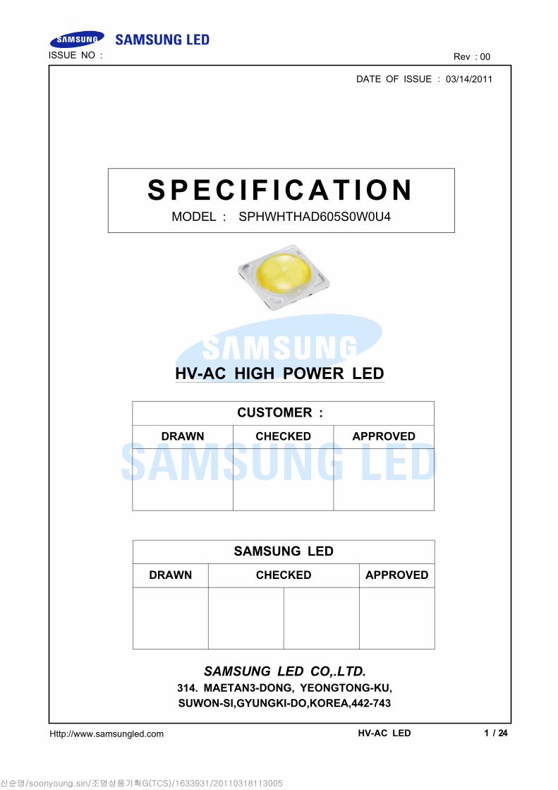
2) IV characteristic (operating in AC voltage, Ta = 25 )
0
10
20
30
40
50
60
70100
120
140
160
180
200
220
240
Voltage [V rms]
Current [m
A rm
s] . Without Resistor
With Resistor' (220Vac)
With Resistor' (230Vac)
0
20
40
60
80
100
120
140
160
180
200
40
50
60
70
80
90
100
110
120
130
140
150
Voltage [V rms]
Current
[m
A r
ms]
.
Without Resistor
With Resistor''' (100Vac)
With Resistor'' (110Vac)
With Resistor' (120Vac)
3) Optical characteristic (operating in AC voltage, Ta = 25 )
0.0
0.2
0.4
0.6
0.8
1.0
1.2
1.4
1.6
0 10 20 30 40
Operating Current [mA rms]
Rela
tive
Lum
inous F
lux
.
0.0
0.2
0.4
0.6
0.8
1.0
1.2
1.4
0 10 20 30 40Operating Current [mA rms]
Rela
tive
Lum
inous E
ffic
acy
.
4) Thermal characteristic (operating in AC voltage, Ta = 25 )
0.0
0.2
0.4
0.6
0.8
1.0
1.2
0 20 40 60 80 100 120
Temp []
Norm
aliz
ed L
um
inous
.
※Temperature is measured on Metal PCB bottom surface with resistance ballast.
Metal PCB Bottom
Temperature

HV-AC LED 9 / 24Http://www.samsungled.com
5) Typical Spatial Distribution
6) Spectrum Distribution
0.0
0.2
0.4
0.6
0.8
1.0
1.2
350 400 450 500 550 600 650 700 750 800
Wavelength (nm)
Rela
tive
Spartia
l P
ow
er
Dis
trib
ution
.

HV-AC LED 10 / 24Http://www.samsungled.com
5. Outline Drawing and Pad Configuration
Pick and Place
1. Do not place pressure on the encapsulating resin
It is recommended to use a pick&place nozzle with inside diameter at 9.2mm
2. The maximum compressing force is 20N on the polymer
Unit :
Tolerance : ±0.1
Pad Function
① Bipolarity
② Bipolarity
③Thermal
(Electrically Isolated)
④ Bipolarity
⑤ Bipolarity

HV-AC LED 11 / 24Http://www.samsungled.com
6. Package Structure
7. Solder Conditions
1) Reflow Conditions (Pb-Free)
Reflow Frequency : 2 time max.
2) For Manual Soldering
Not more than 5 seconds @Max. 300 , under soldering iron.
0
50
100
150
200
250
300
0 50 100 150 200 250 300
Time[sec]
Tem
pera
ture
[
] 0
Preheating : 150~180
Peak Temp. : 260±5 , Max. 10 sec
Max. 60 secTime above 220 : Max. 60 sec
Max. Temp. gradient in cooling : -5 /sec
60~120 sec
NUMBER ITEM MATERIAL
① FRAME Copper Frame(Silver Plated)
② Package Heat-Resistant Polymer
③ LED Chip GaN on Sapphire
④ WIRE Gold Wire
⑤ Encapsulation RESIN Silicone + Phosphor
⑥ Lens Silicone

HV-AC LED 12 / 24Http://www.samsungled.com
8. Reliability Test Items and Conditions
1) Test Items
2) Criteria for Failure
Item Symbol Test ConditionLimit
Min Max
Forward Voltage VF IF = 22 (rms) - U.S.L.*1.2
Luminous Flux ΦV IF = 22 (rms) L.S.L.*0.7 -
※ U.S.L : Upper Standard Level, L.S.L : Lower Standard Level
Test Items Test ConditionsTest
Hours/Cycles
Room Temperaturelife test
25, IF = Max AC 25mA(rms) 1,000 h
High Temperaturehumidity life test
85, 85% RH, IF = Max AC 25mA(rms) 1,000 h
High Temperature lifetest
85, IF = Max AC 25mA(rms) 1,000 h
Low Temperature lifetest
-40, IF = Max AC25mA(rms) 1,000 h
High TemperatureStorage
120 1,000 h
Low TemperatureStorage
-40 1,000 h
Thermal Shock -40 / 120, each 30 min200
cycles
Temperature humidityCycle On/Off test
-40 / 85, each 20 min, 100 min transferPower On/off each 5 min, AC 20
100cycles
Reflow (Pb-Free) Peak 260±5 for 10 sec 3 times
ESD(HBM) R1 : 10 , R2 : 1.5 , C : 100 5 times(± 2 )
Surge Line to Line 2

HV-AC LED 13 / 24Http://www.samsungled.com
9. Circuit Design - Package and PCB
This HV-AC LED can be used for both 110Vac and 220Vac depending on the PCB
circuit design.
Creepage distance between edge and Cu pattern should be greater than 5mm.
Schematic Circuit Connection (Example)
PCB Pattern Circuit (Example)
To improve protection against surge, divide resistor value in 3.5) Resistor Table
(Page 6) by 2 and use half and half on both sides as illustrated in the figures
above.

HV-AC LED 14 / 24Http://www.samsungled.com
10. Taping Dimension
(1) Quantity : 800 Pcs / 13" Reel.
(2) Cumulative Tolerance : Cumulative Tolerance/10 pitches is less than ±0.2
(3) Adhesion Strength of Cover Tape : Adhesion strength to be 0.1-0.7N when
the cover tape is turned off from the carrier tape at 10 angle to be the
carrier tape.
(4) Packaging : P/N, Manufacturing data Code No. and quantity to be indicated
on a damp proof Package
More than 100
Unloaded tape
Mounted with
LED
Leading part more than
(200~400)
More than (100~200)
Unloaded tape
EndStart
Polarity
Symbol A B C W1 W2
Dimension() 330 ± 1 80 ± 1 25 ± 0.5 13 ± 0.3 29.5 ± 1

HV-AC LED 15 / 24Http://www.samsungled.com
11. Label Structure
Rank Code
/S0/ : VF Rank (refer to page 3)
/W0/ : Chromaticity Coordinate Rank, CIE (refer to page 4)
/U4/ : Luminous Flux (refer to page 4)
12. Lot Number
The Lot number is composed of the following characters
/ I / 800PCS
: Production Site (S:SAMSUNG LED, G:Gosin China)
: L (LED)
: Product State (A:Normality, B:Bulk, C:First Production, R:Reproduction, S:Sample)
: Year (S:2008, T:2009, U:2010...)
: Month (1 ~ 9, A, B)
: Day (1 ~ 9, A, B ~ V)
: SAMSUNG LED Product Number (1 ~ 999)
: Reel Number (1 ~ 999)
S0W0U4
SPHWHTHAD605 S0W0U4 XXXX
IIIIIIIIIIIIIIIIIIIIIIIIIIII
/ I / XXXXpcs
IIIIIIIIIIIIIIIIIIIIIIIII

HV-AC LED 16 / 24Http://www.samsungled.com
13. Reel Packing Structure
1) Reel
2) Aluminum Bag
3) Inner Box
HP LED
Material : Paper(SW3B(B))
TYPESIZE()
L W H
13inch 335 45 335
↓
↓Silica gelHumidity Indicator Card
H
L
W
S0W0U4SPHWHTHAD605 S0W0U4 XXXX
IIIIIIIIIIIIIIIIIIIIIIIIIIII
/ I / XXXXpcs
IIIIIIIIIIIIIIIIIIIIIIIII
S0W0U4SPHWHTHAD605 S0W0U4 XXXX
IIIIIIIIIIIIIIIIIIIIIIIIIIII
/ I / XXXXpcs
IIIIIIIIIIIIIIIIIIIIIIIII
S0W0U4
SPHWHTHAD605 S0W0U4 XXXX
IIIIIIIIIIIIIIIIIIIIIIIIIIII
/ I / XXXXpcs
IIIIIIIIIIIIIIIIIIIIIIIII

HV-AC LED 17 / 24Http://www.samsungled.com
4) Carton Box
Material : Paper(SW3B(B))
TYPESIZE()
L W H
13inch 350 350 350
HP LED
↓
L
W
H
S0W0U4SPHWHTHAD605 S0W0U4 XXXX
IIIIIIIIIIIIIIIIIIIIIIIIIIII
/ I / XXXXpcs
IIIIIIIIIIIIIIIIIIIIIIIII

HV-AC LED 18 / 24Http://www.samsungled.com
14. Aluminum Packing Bag
Silica gel & Humidity Indicator Card in Aluminum Packing Bag

HV-AC LED 19 / 24Http://www.samsungled.com
15. Precaution for Use
1) For over-current-proof function, customers are recommended to apply
resistors to prevent sudden change of the current caused by slight shift of
the voltage.
2) This device should not be used in any type of fluid such as water, oil,
organic solvent, etc. When washing is required, IPA is recommended to use.
3) When the LEDs illuminate, operating current should be decided after
considering the ambient maximum temperature.
4) LEDs must be stored in a clean environment. If the LEDs are to be stored
for 3 months or more after being shipped from SAMSUNG LED, they should
be packed by a sealed container with nitrogen gas injected. (Shelf life of
sealed bags : 12 months, temp. 0~40, 20~70%RH)
5) After storage bag is open, device subjected to soldering, solder reflow, or
other high temperature processes must be:
a. Mounted within 168 hours (7days) at an assembly line with a condition
of no more than 30/60%RH,
b. Stored at <10% RH.
6) Repack unused Products with anti-moisture packing, fold to close any
opening and then store in a dry place.
7) Devices require baking before mounting, if humidity card reading is >60% at
23±5.
8) Devices must be baked for 24hours at 65±5, if baking is required.
9) The LEDs are sensitive to the static electricity and surge. It is
recommended to use a wrist band or anti-electrostatic glove when handling
the LEDs.
If voltage exceeding the absolute maximum rating is applied to LEDs, it may
cause damage or even destruction to LED devices.
Damaged LEDs may show some unusual characteristics such as increase in
leak current, lowered turn-on voltage, or abnormal lighting of LEDs at low
current.

HV-AC LED 20 / 24Http://www.samsungled.com
10) When handling LED with tweezers, the LED Should only be held by the
polymer body, not by the encapsulant or LENS.
11) The use of appropriate nozzle for the LED recommended. For the
recommended nozzle size, refer to the figure at the below.
Inner diameter of nozzle ≥ Φ9.2mm
12) Do not stack assembled PCBs together. Since silicone is a soft material,
abrasion between two PCB assembled with silicone encapsulated LED might
cause catastrophic failure of the LEDs due to damage to encapsulant and
wire and LED detachment.

HV-AC LED 21 / 24Http://www.samsungled.com
16. Hazard Substance Analysis

HV-AC LED 22 / 24Http://www.samsungled.com

HV-AC LED 23 / 24Http://www.samsungled.com
HV-AC LED 24 / 24Http://www.samsungled.com
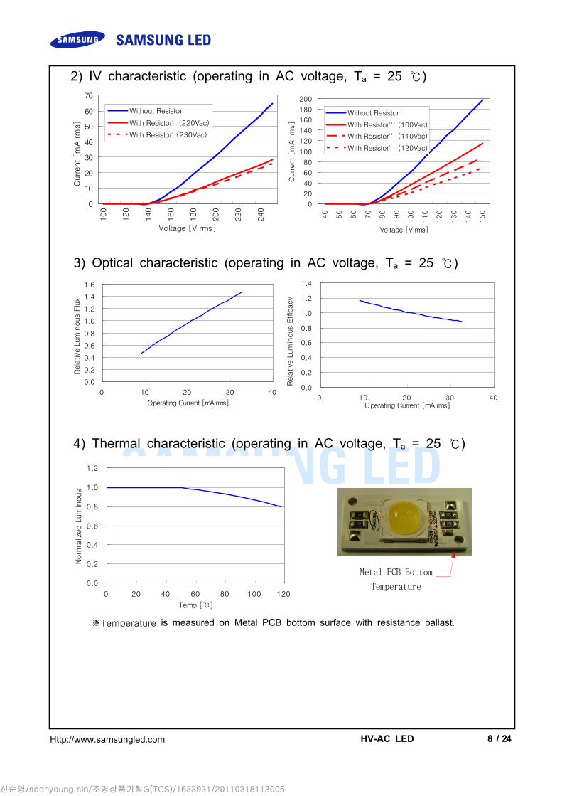
Date Revision HistoryAuthor
Drawn Approved
2011.03.05 Initial Edition Y.J. Lee I.H. Choi
2011.03.14
Revision History(Model : SPHWHTHAD605S0W0U4)
Related Documents