Humphrey ® Field Analyzer Series HFA II - i Field Service Guide CONFIDENTIAL & PROPRIETARY Part No. 52235, Revision C November 2005

Welcome message from author
This document is posted to help you gain knowledge. Please leave a comment to let me know what you think about it! Share it to your friends and learn new things together.
Transcript

Humphrey ®
Field Analyzer
Series HFA II - i
Field Service GuideCONFIDENTIAL & PROPRIETARY
Part No. 52235, Revision CNovember 2005

PROPRIETARY NOTICE
Information contained in this document is copyright Carl Zeiss Meditec Incorporated and may not bereproduced in full or in part by any person without prior written approval of Carl Zeiss Meditec. Itspurpose is to provide the User with adequately detailed information so as to repair, maintain, and orderspare parts for the instrument supplied. Every effort has been made to keep the information containedin this document current and accurate as of the date of publication or revision. However, no guaranteeis given or implied that the document is error-free or that it is accurate with regard to any specification.
TRADEMARK CREDITS
Humphrey Field Analyzer is a registered trademark of Carl Zeiss Meditec Inc.
All trademarks, registered trademarks, and trade names that appear in this manual are the property oftheir respective holders.
Revision C © 2005 by Carl Zeiss Meditec Inc. All rights reserved.
Carl Zeiss Meditec Inc.5160 Hacienda DriveDublin, CA 94568
ii

REVISION CONTROL LIST
Document: Field Analyzer Series HFA II - i Field Service GuidePart No.: 52235 - Revision C
Issued Date: November 2005
Listed at the bottom of each page is the part number of the field service guide, along with the Revisionletter and date for that page (for example, 52235C1105). Subsequent revisions to a page will be notedby a corresponding change to the Revision letter and date.
Pages in this document are at Revision C unless noted otherwise below.
Note - The Revision “B” Humphrey Field Analyzer Series HFA II-i Field Service Guide, P/N 52235has been revised to Revision “C”. The new revision updates all references from “Humphrey Systems”to “Carl Zeiss Meditec Inc. (CZMI)”.
Page Revision Page Revision Page Revision Page Revision
iii

Humphrey Field Analyzer II - i Table of Contents
Confidential and Proprietary
52235C1105 v Field Service Guide
Table of ContentsSection 1 - General Information
1.1 About This Field Service Guide . . . . . . . . . . . . . . . . . . . . . . . . . . . . . . . . 1 - 3
1.1.1 General Information . . . . . . . . . . . . . . . . . . . . . . . . . . . . . . . . . . . 1 - 3
1.1.2 Conventions . . . . . . . . . . . . . . . . . . . . . . . . . . . . . . . . . . . . . . . . . 1 - 4
1.2 About Service Bulletins . . . . . . . . . . . . . . . . . . . . . . . . . . . . . . . . . . . . . . 1 - 4
1.3 HFA II - i Service Strategy . . . . . . . . . . . . . . . . . . . . . . . . . . . . . . . . . . . . 1 - 5
1.3.1 Two-Level Service Strategy . . . . . . . . . . . . . . . . . . . . . . . . . . . . . . 1 - 5
1.3.2 Three Steps to Completing an HFA II - i Service Call . . . . . . . . . . 1 - 5
1.3.3 HFA II - i Field Service Paperwork Requirements . . . . . . . . . . . . . 1 - 6
1.4 Configuration Parameters . . . . . . . . . . . . . . . . . . . . . . . . . . . . . . . . . . . . 1 - 8
1.5 Precautions . . . . . . . . . . . . . . . . . . . . . . . . . . . . . . . . . . . . . . . . . . . . . . . 1 - 8
1.6 Internal Layout . . . . . . . . . . . . . . . . . . . . . . . . . . . . . . . . . . . . . . . . . . . 1 - 10
1.7 Special Topics . . . . . . . . . . . . . . . . . . . . . . . . . . . . . . . . . . . . . . . . . . . . 1 - 10
1.7.1 The Touch Screen . . . . . . . . . . . . . . . . . . . . . . . . . . . . . . . . . . . 1 - 10
1.7.2 Gaze Tracking . . . . . . . . . . . . . . . . . . . . . . . . . . . . . . . . . . . . . . . 1 - 11
1.7.3 Head Tracking / Auto Pupil / Vertex Monitoring . . . . . . . . . . . . . 1 - 14
1.7.4 HFA II - i Light Intensity Fundamentals . . . . . . . . . . . . . . . . . . . . 1 - 15
1.7.5 Comparing HFA II and the HFA II - i . . . . . . . . . . . . . . . . . . . . . 1 - 15
1.8 Peripherals . . . . . . . . . . . . . . . . . . . . . . . . . . . . . . . . . . . . . . . . . . . . . . 1 - 20
1.9 Specifications . . . . . . . . . . . . . . . . . . . . . . . . . . . . . . . . . . . . . . . . . . . . . 1 - 22
Section 2 PM and System Checkout
2.1 System Checkout Checklist . . . . . . . . . . . . . . . . . . . . . . . . . . . . . . . . . . . 2 - 3
2.2 Preventive Maintenance Procedure . . . . . . . . . . . . . . . . . . . . . . . . . . . . . 2 - 8
Section 3 Parts Removal / Replacement
3.1 General Instructions . . . . . . . . . . . . . . . . . . . . . . . . . . . . . . . . . . . . . . . . . . 3 - 4
3.1.1 Removal from Power Table . . . . . . . . . . . . . . . . . . . . . . . . . . . . . 3 - 10
3.2 Front Cover Assembly Removal . . . . . . . . . . . . . . . . . . . . . . . . . . . . . . . . 3 - 11
3.3 Rear Cover Assembly Removal . . . . . . . . . . . . . . . . . . . . . . . . . . . . . . . . 3 - 12
3.4 Operator Panel Assembly Removal . . . . . . . . . . . . . . . . . . . . . . . . . . . . . 3 - 13
3.5 Drive Housing Assembly Removal . . . . . . . . . . . . . . . . . . . . . . . . . . . . . . 3 - 15
Table of Contents Humphrey Field Analyzer II - i
Confidential and Proprietary
Field Service Guide vi 52235C1105
3.6 CPU/Backplane Enclosure Removal . . . . . . . . . . . . . . . . . . . . . . . . . . . . 3 - 17
3.7 CPU and Backplane Removal . . . . . . . . . . . . . . . . . . . . . . . . . . . . . . . . . 3 - 18
3.8 Motor Drive PCB Removal . . . . . . . . . . . . . . . . . . . . . . . . . . . . . . . . . . . 3 - 19
3.9 Separation of the CPU PCB from the Backplane Board . . . . . . . . . . . . . . 3 - 20
3.10 Power Supply Removal . . . . . . . . . . . . . . . . . . . . . . . . . . . . . . . . . . . . . . 3 - 21
3.11 CRT PCB Removal . . . . . . . . . . . . . . . . . . . . . . . . . . . . . . . . . . . . . . . . . 3 - 22
3.12 CRT Removal . . . . . . . . . . . . . . . . . . . . . . . . . . . . . . . . . . . . . . . . . . . . . 3 - 23
3.13 Touch Screen Removal . . . . . . . . . . . . . . . . . . . . . . . . . . . . . . . . . . . . . . 3 - 25
3.14 CCD Camera Removal . . . . . . . . . . . . . . . . . . . . . . . . . . . . . . . . . . . . . . 3 - 26
3.15 Fixation Interconnect PCB Removal . . . . . . . . . . . . . . . . . . . . . . . . . . . . 3 - 26
3.16 Central Fixation LED/Beamsplitter Removal . . . . . . . . . . . . . . . . . . . . . . 3 - 27
3.17 Projection Assembly Removal . . . . . . . . . . . . . . . . . . . . . . . . . . . . . . . . . 3 - 28
3.18 Projection Interconnect PCB Removal . . . . . . . . . . . . . . . . . . . . . . . . . . . 3 - 30
3.19 Film Wedge/Motor Removal . . . . . . . . . . . . . . . . . . . . . . . . . . . . . . . . . . 3 - 30
3.20 Glass Wedge/Motor Removal . . . . . . . . . . . . . . . . . . . . . . . . . . . . . . . . . . 3 - 31
3.21 Color Wheel / Aperture Wheel Removal . . . . . . . . . . . . . . . . . . . . . . . . . 3 - 32
3.22 Carriage Motor Removal . . . . . . . . . . . . . . . . . . . . . . . . . . . . . . . . . . . . . 3 - 33
3.23 Shutter Removal . . . . . . . . . . . . . . . . . . . . . . . . . . . . . . . . . . . . . . . . . . . 3 - 34
3.24 Shutter Motor Removal . . . . . . . . . . . . . . . . . . . . . . . . . . . . . . . . . . . . . . 3 - 35
3.25 Carriage Motor Belt Removal . . . . . . . . . . . . . . . . . . . . . . . . . . . . . . . . . . 3 - 35
3.26 Horizontal (X-axis) Turret Motor Removal . . . . . . . . . . . . . . . . . . . . . . . . 3 - 36
3.27 Horizontal (X-axis) Turret Motor Belt Removal . . . . . . . . . . . . . . . . . . . . 3 - 37
3.28 Vertical (Y-axis) Turret Belt/Motor Removal . . . . . . . . . . . . . . . . . . . . . . . 3 - 39
3.29 Brightness Detector (PCB) Replacement . . . . . . . . . . . . . . . . . . . . . . . . . 3 - 40
3.30 Lower Turret Removal . . . . . . . . . . . . . . . . . . . . . . . . . . . . . . . . . . . . . . . 3 - 41
3.31 Turret Cable Assembly Removal . . . . . . . . . . . . . . . . . . . . . . . . . . . . . . . 3 - 42
3.32 Chinrest/Headrest Switch Assembly Removal . . . . . . . . . . . . . . . . . . . . . 3 - 42
3.33 Chinrest Y-axis Belt/Motor Removal . . . . . . . . . . . . . . . . . . . . . . . . . . . . 3 - 43
3.34 Patient Support Horizontal (X-axis) Belt/Motor Removal . . . . . . . . . . . . . 3 - 44
3.35 Chinrest Vertical Slide and Lead Screw Removal . . . . . . . . . . . . . . . . . . . 3 - 47
3.36 Chinrest Horizontal Slide Removal . . . . . . . . . . . . . . . . . . . . . . . . . . . . . 3 - 48
3.37 Trial Lens Holder Assembly Removal . . . . . . . . . . . . . . . . . . . . . . . . . . . 3 - 49
3.38 Top Fan Removal . . . . . . . . . . . . . . . . . . . . . . . . . . . . . . . . . . . . . . . . . . 3 - 50
3.39 Bowl IR LED Assembly Removal . . . . . . . . . . . . . . . . . . . . . . . . . . . . . . . 3 - 51
Humphrey Field Analyzer II - i Table of Contents
Confidential and Proprietary
52235C1105 vii Field Service Guide
3.40 Blue-Yellow Module / Bowl Plug Removal . . . . . . . . . . . . . . . . . . . . . . . . 3 - 52
3.41 Bowl Removal . . . . . . . . . . . . . . . . . . . . . . . . . . . . . . . . . . . . . . . . . . . . . 3 - 52
3.42 Reflex Gaze LED Removal . . . . . . . . . . . . . . . . . . . . . . . . . . . . . . . . . . . . 3 - 54
3.43 Bowl Lamp Assembly Removal . . . . . . . . . . . . . . . . . . . . . . . . . . . . . . . . 3 - 54
3.44 IR Bowl Plug Removal/Installation . . . . . . . . . . . . . . . . . . . . . . . . . . . . . . 3 - 55
3.45 Quarter-Turn Fastener Replacement . . . . . . . . . . . . . . . . . . . . . . . . . . . . 3 - 56
Section 4 Adjustment / Calibration
4.1 Introduction . . . . . . . . . . . . . . . . . . . . . . . . . . . . . . . . . . . . . . . . . . . . . . . . 4 - 34.2 Related Procedures . . . . . . . . . . . . . . . . . . . . . . . . . . . . . . . . . . . . . . . . . . 4 - 5
4.2.1 HFA II - i Calibration and Service Guidelines . . . . . . . . . . . . . . . . 4 - 54.3 Calibration / Diagnostics Access . . . . . . . . . . . . . . . . . . . . . . . . . . . . . . . . 4 - 64.4 Show Dialog . . . . . . . . . . . . . . . . . . . . . . . . . . . . . . . . . . . . . . . . . . . . . . 4 - 64.5 System Log . . . . . . . . . . . . . . . . . . . . . . . . . . . . . . . . . . . . . . . . . . . . . . . 4 - 64.6 Database . . . . . . . . . . . . . . . . . . . . . . . . . . . . . . . . . . . . . . . . . . . . . . . . . 4 - 64.7 Video Test Pattern . . . . . . . . . . . . . . . . . . . . . . . . . . . . . . . . . . . . . . . . . . 4 - 64.8 Calibration . . . . . . . . . . . . . . . . . . . . . . . . . . . . . . . . . . . . . . . . . . . . . . . . 4 - 7
4.8.1 Verification (obtaining Before and After light intensity calibrationvalues) . . . . . . . . . . . . . . . . . . . . . . . . . . . . . . . . . . . . . . . . . . . . . 4 - 74.8.1.1 Intensity / Spot Ratio . . . . . . . . . . . . . . . . . . . . . . . . . . . 4 - 74.8.1.2 Exerciser . . . . . . . . . . . . . . . . . . . . . . . . . . . . . . . . . . . . 4 - 114.8.1.3 QA Tests . . . . . . . . . . . . . . . . . . . . . . . . . . . . . . . . . . . . 4 - 12
4.8.2 Mechanical . . . . . . . . . . . . . . . . . . . . . . . . . . . . . . . . . . . . . . . . . 4 - 124.8.2.1 Projector . . . . . . . . . . . . . . . . . . . . . . . . . . . . . . . . . . . . 4 - 124.8.2.2 Shutter . . . . . . . . . . . . . . . . . . . . . . . . . . . . . . . . . . . . . 4 - 134.8.2.3 Aperture . . . . . . . . . . . . . . . . . . . . . . . . . . . . . . . . . . . . 4 - 144.8.2.4 Color . . . . . . . . . . . . . . . . . . . . . . . . . . . . . . . . . . . . . . 4 - 154.8.2.5 Right / Left Home . . . . . . . . . . . . . . . . . . . . . . . . . . . . . 4 - 164.8.2.6 Offset . . . . . . . . . . . . . . . . . . . . . . . . . . . . . . . . . . . . . . 4 - 164.8.2.7 Focus . . . . . . . . . . . . . . . . . . . . . . . . . . . . . . . . . . . . . . 4 - 164.8.2.8 Detector . . . . . . . . . . . . . . . . . . . . . . . . . . . . . . . . . . . . 4 - 174.8.2.9 Target . . . . . . . . . . . . . . . . . . . . . . . . . . . . . . . . . . . . . . 4 - 18
4.8.3 Intensity . . . . . . . . . . . . . . . . . . . . . . . . . . . . . . . . . . . . . . . . . . . 4 - 204.8.3.1 Projector . . . . . . . . . . . . . . . . . . . . . . . . . . . . . . . . . . . . 4 - 20 4.8.3.1.1 White . . . . . . . . . . . . . . . . . . . . . . . . . . . . . . . . . . 4 - 20
Table of Contents Humphrey Field Analyzer II - i
Confidential and Proprietary
Field Service Guide viii 52235C1105
4.8.3.1.2 Blue . . . . . . . . . . . . . . . . . . . . . . . . . . . . . . . . . . . 4 - 214.8.3.2 Bowl . . . . . . . . . . . . . . . . . . . . . . . . . . . . . . . . . . . . . . . 4 - 23 4.8.3.2.1 White . . . . . . . . . . . . . . . . . . . . . . . . . . . . . . . . . . 4 - 23 4.8.3.2.2 Yellow . . . . . . . . . . . . . . . . . . . . . . . . . . . . . . . . . 4 - 244.8.3.3 Wedge . . . . . . . . . . . . . . . . . . . . . . . . . . . . . . . . . . . . . 4 - 254.8.3.4 Blue Correction . . . . . . . . . . . . . . . . . . . . . . . . . . . . . . 4 - 26
4.8.4 Print Cal Values . . . . . . . . . . . . . . . . . . . . . . . . . . . . . . . . . . . . . 4 - 304.8.5 Miscellaneous . . . . . . . . . . . . . . . . . . . . . . . . . . . . . . . . . . . . . . . 4 - 304.8.6 Camera . . . . . . . . . . . . . . . . . . . . . . . . . . . . . . . . . . . . . . . . . . . 4 - 30
4.8.6.1 Camera Position / Size . . . . . . . . . . . . . . . . . . . . . . . . . 4 - 304.8.6.2 Gaze Position / Size . . . . . . . . . . . . . . . . . . . . . . . . . . . 4 - 334.8.6.3 Camera Intensity . . . . . . . . . . . . . . . . . . . . . . . . . . . . . 4 - 34
4.9 Adjustments . . . . . . . . . . . . . . . . . . . . . . . . . . . . . . . . . . . . . . . . . . . . . . 4 - 364.9.1 Patient Support Horizontal Leadscrew Adjustment . . . . . . . . . . . 4 - 364.9.2 Belt Tension . . . . . . . . . . . . . . . . . . . . . . . . . . . . . . . . . . . . . . . . 4 - 374.9.3 Edge Detector . . . . . . . . . . . . . . . . . . . . . . . . . . . . . . . . . . . . . . . 4 - 374.9.4 Touch Screen . . . . . . . . . . . . . . . . . . . . . . . . . . . . . . . . . . . . . . . 4 - 374.9.5 CRT Adjustments . . . . . . . . . . . . . . . . . . . . . . . . . . . . . . . . . . . . 4 - 384.9.6 Trial Lens Holder . . . . . . . . . . . . . . . . . . . . . . . . . . . . . . . . . . . . 4 - 424.9.7 Camera Focus . . . . . . . . . . . . . . . . . . . . . . . . . . . . . . . . . . . . . . 4 - 454.9.8 IR LED Alignments . . . . . . . . . . . . . . . . . . . . . . . . . . . . . . . . . . . 4 - 46
Section 5 Troubleshooting
5.1 Introduction . . . . . . . . . . . . . . . . . . . . . . . . . . . . . . . . . . . . . . . . . . . . . . . . . 5-35.2 General Guidelines for Assembly Level Troubleshooting . . . . . . . . . . . . . . . 5-35.3 A Guide to HFA II - i Service Diagnostic Aids . . . . . . . . . . . . . . . . . . . . . . . 5-75.4 Software Module Identifiers . . . . . . . . . . . . . . . . . . . . . . . . . . . . . . . . . . . . . 5-85.5 HFA II - i Motor Exerciser and QA Test Points . . . . . . . . . . . . . . . . . . . . . . . 5-95.6 Printrex Printer Self Tests and Error Handling . . . . . . . . . . . . . . . . . . . . . . 5-11
5.6.1 Printer Self Test . . . . . . . . . . . . . . . . . . . . . . . . . . . . . . . . . . . . . . . 5-115.6.2 Printrex Printer Errors and Error Handling . . . . . . . . . . . . . . . . . . . 5-11
5.7 Power - On Self Tests . . . . . . . . . . . . . . . . . . . . . . . . . . . . . . . . . . . . . . . . 5-135.7.1 Motor Driver Board Startup . . . . . . . . . . . . . . . . . . . . . . . . . . . . . . 5-13
5.8 Startup State Errors . . . . . . . . . . . . . . . . . . . . . . . . . . . . . . . . . . . . . . . . . . 5-155.9 Hexadecimal Error Codes . . . . . . . . . . . . . . . . . . . . . . . . . . . . . . . . . . . . . 5-215.10 Common Error Messages/Solutions . . . . . . . . . . . . . . . . . . . . . . . . . . . . . . 5-23
Humphrey Field Analyzer II - i Table of Contents
Confidential and Proprietary
52235C1105 ix Field Service Guide
Section 6 Diagrams
Figure 6-1. System Interconnect DiagramFigure 6-2. Projection PathFigure 6-3. CPU PCBFigure 6-4. Backplane BoardFigure 6-5. Motor Driver PCB Projection AssemblyFigure 6-6. Fixation Interconnect PCBFigure 6-7. Patient Support AssemblyFigure 6-8. Power Entry and Power Supply
Figure 6-9. Projection AssemblyFigure 6-10. Memory Module DrivesFigure 6-11. Component Locations – CPU PCBsFigure 6-12. Component Locations – Motor Driver PCBs
Section 7 Parts
7.1 Introduction . . . . . . . . . . . . . . . . . . . . . . . . . . . . . . . . . . . . . . . . . . . . . . . . 7 - 37.2 Parts Orders — U.S. Domestic Service Operations . . . . . . . . . . . . . . . . . . . 7 - 37.3 Parts Orders — International Service Operations . . . . . . . . . . . . . . . . . . . . 7 - 37.4 Returning Instruments / Defective Parts . . . . . . . . . . . . . . . . . . . . . . . . . . . 7 - 4
7.4.1 Equipment Return Authorization . . . . . . . . . . . . . . . . . . . . . . . . . . . 7 - 47.4.2 Packing the Instrument for Shipment . . . . . . . . . . . . . . . . . . . . . . . 7 - 47.4.3 Returning Defective Parts . . . . . . . . . . . . . . . . . . . . . . . . . . . . . . . . 7 - 4
7.5 Recommended Spares . . . . . . . . . . . . . . . . . . . . . . . . . . . . . . . . . . . . . . . . 7 - 57.6 Level I Parts Lists . . . . . . . . . . . . . . . . . . . . . . . . . . . . . . . . . . . . . . . . . . . . 7 - 6
7.6.1 Accessories/Supplies/Consumables . . . . . . . . . . . . . . . . . . . . . . . . . 7 - 67.6.2 Software . . . . . . . . . . . . . . . . . . . . . . . . . . . . . . . . . . . . . . . . . . . . . 7 - 87.6.3 Peripherals . . . . . . . . . . . . . . . . . . . . . . . . . . . . . . . . . . . . . . . . . . . 7 - 8
7.7 Illustrated Parts Breakdown . . . . . . . . . . . . . . . . . . . . . . . . . . . . . . . . . . . . 7 - 97.7.1 Shipping Materials and Repack Instructions . . . . . . . . . . . . . . . . . 7 -107.7.2 Miscellaneous–1 . . . . . . . . . . . . . . . . . . . . . . . . . . . . . . . . . . . . . . 7 - 147.7.3 Miscellaneous–2 . . . . . . . . . . . . . . . . . . . . . . . . . . . . . . . . . . . . . . 7 - 167.7.4 Patient Support Assembly . . . . . . . . . . . . . . . . . . . . . . . . . . . . . . . 7 - 207.7.5 Chinrest / Trial Lens Holder Assembly . . . . . . . . . . . . . . . . . . . . . 7 - 227.7.6 Projection Assembly . . . . . . . . . . . . . . . . . . . . . . . . . . . . . . . . . . . 7 - 247.7.7 Projector Assembly . . . . . . . . . . . . . . . . . . . . . . . . . . . . . . . . . . . . 7 - 26
Table of Contents Humphrey Field Analyzer II - i
Confidential and Proprietary
Field Service Guide x 52235C1105
7.7.8 Projection Turret Assembly . . . . . . . . . . . . . . . . . . . . . . . . . . . . . . 7 - 287.7.9 Bowl Assembly . . . . . . . . . . . . . . . . . . . . . . . . . . . . . . . . . . . . . . . 7 - 307.7.9.1 Bowl Assembly . . . . . . . . . . . . . . . . . . . . . . . . . . . . . . . . 7 - 327.7.10 Operator Panel Assembly . . . . . . . . . . . . . . . . . . . . . . . . . . . . . . . 7 - 347.7.11 B/Y Lamp Assembly . . . . . . . . . . . . . . . . . . . . . . . . . . . . . . . . . . . 7 - 367.7.12 Drive Mounting Assemblies . . . . . . . . . . . . . . . . . . . . . . . . . . . . . . 7 - 387.7.13 CPU Backplane Enclosure . . . . . . . . . . . . . . . . . . . . . . . . . . . . . . 7 - 407.7.14 Power Table / Printer Assemblies . . . . . . . . . . . . . . . . . . . . . . . . . 7 - 44
Appendices
Appendix A. Tools, Test Equipment and Service Supplies . . . . . . . . . . . . . . . . . A - 1
A.1 List of Tools, Test Equipment and Service Supplies . . . . . . . . . . . A - 1
A.2 The Special Tools - What They Are / What They Do . . . . . . . . . . . A - 3
A.2.1 Soligor Light Meter Setup . . . . . . . . . . . . . . . . . . . . . . . . A - 3
A.2.2 Soligor Mount Adaptor . . . . . . . . . . . . . . . . . . . . . . . . . . A - 3
A.2.3 Bowl Shroud . . . . . . . . . . . . . . . . . . . . . . . . . . . . . . . . . A - 3
A.2.4 Trial Lens Alignment Adaptor . . . . . . . . . . . . . . . . . . . . . A - 3
A.2.5 Fake Eye . . . . . . . . . . . . . . . . . . . . . . . . . . . . . . . . . . . . A - 5
A.2.6 Tool Stand Assembly . . . . . . . . . . . . . . . . . . . . . . . . . . . A - 5
A.2.7 Mirror Tool . . . . . . . . . . . . . . . . . . . . . . . . . . . . . . . . . . . A - 5
A.2.8 CRT Overlay . . . . . . . . . . . . . . . . . . . . . . . . . . . . . . . . . A - 5
A.2.9 Spot Positioning Cross Fixture . . . . . . . . . . . . . . . . . . . . A - 5
A.2.10 Brightness Detector Alignment Target . . . . . . . . . . . . . . . A - 6
A.2.11 Projection Mount . . . . . . . . . . . . . . . . . . . . . . . . . . . . . . A - 7
A.2.12 Operator Panel Extension/Support . . . . . . . . . . . . . . . . . A - 8
A.2.13 Hard Drive LED Assembly . . . . . . . . . . . . . . . . . . . . . . . A - 9
A.2.14 Service Key . . . . . . . . . . . . . . . . . . . . . . . . . . . . . . . . . . . A - 9
A.2.15 Diagnostic Support Tool . . . . . . . . . . . . . . . . . . . . . . . . . A - 9
A.2.16 Loopback Tool . . . . . . . . . . . . . . . . . . . . . . . . . . . . . . . A - 10
A.2.17 Static Protection Kit . . . . . . . . . . . . . . . . . . . . . . . . . . . A - 10
A.2.18 Communications Terminals . . . . . . . . . . . . . . . . . . . . . A - 10
A.2.19 How To Set Up The P-Factor Diskette . . . . . . . . . . . . . A - 11
Appendix B. The Interface Ports . . . . . . . . . . . . . . . . . . . . . . . . . . . . . . . . . . . . B - 1
B.1 General Information . . . . . . . . . . . . . . . . . . . . . . . . . . . . . . . . . . . B - 1
B.2 RS-232 Interface Hardware and Pin Assignments . . . . . . . . . . . . B - 3
Humphrey Field Analyzer II - i Table of Contents
Confidential and Proprietary
52235C1105 xi Field Service Guide
Appendix C. Data Transfers . . . . . . . . . . . . . . . . . . . . . . . . . . . . . . . . . . . . . . C - 1
C.1 Serial Transfer Modes . . . . . . . . . . . . . . . . . . . . . . . . . . . . . . . . . . C - 1
C.2 Installing the Serial I or the Serial II Transfer Disk . . . . . . . . . . . . . C - 2
C.3 HFA I to HFA II - i Serial Data Transfer . . . . . . . . . . . . . . . . . . . . C - 3
C.4 HFA II To HFA II - i Serial Data Transfer . . . . . . . . . . . . . . . . . . . C - 5
C.5 HFA II - i To HFA II - i Serial Data Transfer . . . . . . . . . . . . . . . . . C - 7
C.6 HFA II - i To Ensemble© Serial Data Transfer . . . . . . . . . . . . . . . C - 9
C.7 HFA II - i To Third Party Programs Serial Data Transfer . . . . . . . C -11
Appendix D. Approved Parallel Laser Jet Printers . . . . . . . . . . . . . . . . . . . . . . D - 1
Appendix E. Instrument/BIOS Configuration . . . . . . . . . . . . . . . . . . . . . . . . . . . E - 1
E.1 Instrument Configuration . . . . . . . . . . . . . . . . . . . . . . . . . . . . . . . E - 1
E.2 BIOS Configuration . . . . . . . . . . . . . . . . . . . . . . . . . . . . . . . . . . . E - 3
Appendix F. Operating System . . . . . . . . . . . . . . . . . . . . . . . . . . . . . . . . . . . . . F - 1
Appendix G. P Initializing the Cal/Config Data
P Setting Serial Number
P Setting the Hardware Options
P Setting the Software Options . . . . . . . . . . . . . . . . . . . . . . . . . . . G - 1
G.1 Initializing the Cal/Config Data . . . . . . . . . . . . . . . . . . . . . . . . . . . G - 3
G.2 Setting Serial Number . . . . . . . . . . . . . . . . . . . . . . . . . . . . . . . . . . G - 3
G.3 Setting the Model/Hardware Options . . . . . . . . . . . . . . . . . . . . . . G - 4
G.4 Setting the Software Options . . . . . . . . . . . . . . . . . . . . . . . . . . . . . G - 6
Appendix H. Calibration Printouts . . . . . . . . . . . . . . . . . . . . . . . . . . . . . . . . . . . H - 1
H.1 Cal / Wedge Printout . . . . . . . . . . . . . . . . . . . . . . . . . . . . . . . . . . H - 1
H.2 Automated Light Intensity Printouts . . . . . . . . . . . . . . . . . . . . . . . H - 8
Appendix I. Service Forms . . . . . . . . . . . . . . . . . . . . . . . . . . . . . . . . . . . . . . . . . I - 1
Appendix J. System Screens and Logs . . . . . . . . . . . . . . . . . . . . . . . . . . . . . . . . I - 1
J.1 Boot Screen . . . . . . . . . . . . . . . . . . . . . . . . . . . . . . . . . . . . . . . . . J - 1
J.2 Unit Configuration Screen . . . . . . . . . . . . . . . . . . . . . . . . . . . . . . J - 1
J.3 System Log . . . . . . . . . . . . . . . . . . . . . . . . . . . . . . . . . . . . . . . . . . J - 4
Appendix K. Data Loss Recovery . . . . . . . . . . . . . . . . . . . . . . . . . . . . . . . . . . . K - 1
K.1 Data Loss Prevention Tips . . . . . . . . . . . . . . . . . . . . . . . . . . . . . . K - 1
K.2 Database Structure . . . . . . . . . . . . . . . . . . . . . . . . . . . . . . . . . . . . K - 2
K.3 The Five “Rs” of Database Recovery . . . . . . . . . . . . . . . . . . . . . . K - 2
K.4 Database Utilities . . . . . . . . . . . . . . . . . . . . . . . . . . . . . . . . . . . . . K - 3
K.4.1 Rebuild Hard Disk Database . . . . . . . . . . . . . . . . . . . . . . K - 3
K.4.2 Rebuild Floppy Database . . . . . . . . . . . . . . . . . . . . . . . . K - 4
Table of Contents Humphrey Field Analyzer II - i
Confidential and Proprietary
Field Service Guide xii 52235C1105
K.4.3 Delete Hard Disk Database . . . . . . . . . . . . . . . . . . . . . . . K - 4
K.4.4 Delete Temporary Database . . . . . . . . . . . . . . . . . . . . . . K - 4
K.4.5 Reconstruct Database . . . . . . . . . . . . . . . . . . . . . . . . . . . K - 4
K.4.6 Secondary Database Utilities . . . . . . . . . . . . . . . . . . . . . K - 4
K.5 Floppy Diskette - Troubleshooting Dialogue . . . . . . . . . . . . . . . . . K - 5
K.6 Hard Disk Drive - Troubleshooting Dialogue . . . . . . . . . . . . . . . . . K - 6
K.7 Magnetic Optical Disks . . . . . . . . . . . . . . . . . . . . . . . . . . . . . . . . . K - 7
Appendix L. Initializing the Hard Disk . . . . . . . . . . . . . . . . . . . . . . . . . . . . . . . . L - 1
Appendix M. Loading Application Software . . . . . . . . . . . . . . . . . . . . . . . . . . . . M - 1
Appendix N. Special Software Options . . . . . . . . . . . . . . . . . . . . . . . . . . . . . . . N - 1
Appendix O. Upgrades . . . . . . . . . . . . . . . . . . . . . . . . . . . . . . . . . . . . . . . . . . . O - 1
Appendix P. Cable Diagrams . . . . . . . . . . . . . . . . . . . . . . . . . . . . . . . . . . . . . . . P - 1
Appendix Q. Cleaning Optics . . . . . . . . . . . . . . . . . . . . . . . . . . . . . . . . . . . . . . Q - 1
Appendix R. Optional Software Installation . . . . . . . . . . . . . . . . . . . . . . . . . . . . R - 1
Confidential and Proprietary
52235C1105 1 - 1 Field Service Guide
Section 1 - General Information
1.1 About This Field Service Guide . . . . . . . . . . . . . . . . . . . . . . . . . . . . . . . 1 - 3
1.1.1 General Information . . . . . . . . . . . . . . . . . . . . . . . . . . . . . . . . . 1 - 3
1.1.2 Conventions . . . . . . . . . . . . . . . . . . . . . . . . . . . . . . . . . . . . . . . 1 - 4
1.2 About Service Bulletins . . . . . . . . . . . . . . . . . . . . . . . . . . . . . . . . . . . . . . 1 - 4
1.3 HFA II - i Service Strategy . . . . . . . . . . . . . . . . . . . . . . . . . . . . . . . . . . . 1 - 5
1.3.1 Two-Level Service Strategy . . . . . . . . . . . . . . . . . . . . . . . . . . . 1 - 5
1.3.2 Three Steps to Completing an HFA II - i Service Call . . . . . . . . 1 - 5
1.3.3 HFA II - i Field Service Paperwork Requirements . . . . . . . . . . . 1 - 6
1.4 Configuration Parameters . . . . . . . . . . . . . . . . . . . . . . . . . . . . . . . . . . . . 1 - 8
1.5 Precautions . . . . . . . . . . . . . . . . . . . . . . . . . . . . . . . . . . . . . . . . . . . . . . . 1 - 8
1.6 Internal Layout . . . . . . . . . . . . . . . . . . . . . . . . . . . . . . . . . . . . . . . . . . . 1 - 10
1.7 Special Topics . . . . . . . . . . . . . . . . . . . . . . . . . . . . . . . . . . . . . . . . . . . 1 - 10
1.7.1 The Touch Screen . . . . . . . . . . . . . . . . . . . . . . . . . . . . . . . . . 1 - 10
1.7.2 Gaze Tracking . . . . . . . . . . . . . . . . . . . . . . . . . . . . . . . . . . . . 1 - 11
1.7.3 Head Tracking / Auto Pupil / Vertex Monitoring . . . . . . . . . . . 1 - 14
1.7.4 HFA II - i Light Intensity Fundamentals . . . . . . . . . . . . . . . . . 1 - 15
1.7.5 Comparing HFA II and the HFA II - i . . . . . . . . . . . . . . . . . . . 1 - 15
1.8 Peripherals . . . . . . . . . . . . . . . . . . . . . . . . . . . . . . . . . . . . . . . . . . . . . . 1 - 20
1.9 Specifications . . . . . . . . . . . . . . . . . . . . . . . . . . . . . . . . . . . . . . . . . . . . 1 - 22

General Information Humphrey Field Analyzer II - i
Confidential and Proprietary
Field Service Guide 1 - 2 52235C1105
Notes:
Humphrey Field Analyzer II - i General Information
Confidential and Proprietary
52235C1105 1 - 3 Field Service Guide
1.1 About This Field Service Guide
1.1.1 General Information
This Service Guide is the field service reference for troubleshooting, repair, adjustment, andcalibration of the Models 720i, 740i and 750i HFA II - i Field Analyzers, manufactured byCarl Zeiss Meditec Inc. The information presented in this Guide assumes that the reader isalready trained and experienced in operation and service of the Humphrey Field AnalyzerSeries 700.
This field service guide is designed to support Level 1 Field Service, which employs modularreplacement of printed circuit boards and other assemblies that are most effectively repairedat a central repair facility. This is the service strategy used in U.S. domestic Field Service,and in Carl Zeiss Meditec Service training classes. See Section 1.3 for additional informationregarding Level 1 and Level 2 Repair Center service.
The procedures in this field service guide assume that the reader is familiar with operation ofthe instrument. Complete operating instructions are contained in the HFA II - iUser's Guide. Information contained in the User's Guide is not repeated in this field serviceguide. The User's Guide can be ordered separately by standard Carl Zeiss Meditec partsorder. Refer to Section 7 for the User's Guide parts information.
The general layout of the field service guide is shown below. For greater detail, please referto the Table of Contents.
Level 1 Field Service Guide Layout
Section 1 General Information
Section 2 Preventive Maintenance & System Checkout
Section 3 Parts Removal/Replacement
Section 4 Adjustment/Calibration
Section 5 Troubleshooting
Section 6 Diagrams
Section 7 Parts
Appendices
General Information Humphrey Field Analyzer II - i
Confidential and Proprietary
Field Service Guide 1 - 4 52235C1105
1.1.2 Conventions
The following conventions apply in this manual:
P The terms left, right, front and back of the instrument are as viewed from thepatient position, unless noted otherwise.
P Dimensions are given in inches unless noted otherwise.
1.2 About Service Bulletins
Field Service Bulletins are a vital element of service support. Bulletins are used to quicklyconvey technical information on a variety of field service topics, including:
P instrument design changesP technical problems and
correctionsP software updatesP new troubleshooting proceduresP problem alerts
P service manual revisionsP upgrade announcements/
proceduresP system checkout – checklistP service disclaimer formsP system work sheets
Service bulletins are used to issue revised pages for service manual/service guide updates.
Your service bulletins should be filed where easily accessible for quick reference.
NOTICEField Service Bulletins are Confidential and Proprietary, for the sole use ofpersonnel employed by Carl Zeiss Meditec, Carl Zeiss Meditec affiliates, andauthorized Carl Zeiss Meditec distributors.Carl Zeiss Meditec has a well-deserved reputation for high quality, reliableinstruments, unsurpassed in the industry.
As a Carl Zeiss Meditec employee, affiliate, or distributor you are required tohandle your service bulletins as appropriate for proprietary and confidentialinformation.
Humphrey Field Analyzer II - i General Information
Confidential and Proprietary
52235C1105 1 - 5 Field Service Guide
1.3 HFA II - i Service Strategy
1.3.1 Two-Level Service Strategy
A two-level service strategy is used for the HFA II - i: Level 1 for on-site service; and Level 2for Repair Center service. Level 1 service employs modular replacement, wherein faultycircuit boards and certain other assemblies are replaced rather than repaired on-site. Thesefaulty assemblies are shipped to a Carl Zeiss Meditec Repair Center for repairs. There arealso certain procedures that require special equipment available only at a Repair Center.
Designated Repair Centers (currently Dublin, CA and Jena, Germany) are the second levelof service for the HFA II - i. The Repair Centers perform major circuit board troubleshootingand repair, plus any other service action that requires special equipment or procedures notavailable in the field.
Several of the circuit boards in the HFA II - i are multilayer boards and use Surface MountTechnology (SMT) components. These boards require special equipment and techniques fortroubleshooting and repair.
All service procedures (including instrument calibration) can be performed in the field, exceptfor those listed below. For Carl Zeiss Meditec U.S. Domestic operations, the followingprocedures must be performed at the Carl Zeiss Meditec Repair Center.
P Circuit board troubleshooting and component replacement
P Repair of floppy, tape, and hard drives.
P Alignment of projection carriage rails and first projection mirror (top turret mirror)
P Repair of power supply assembly
P Repair of camera assembly
1.3.2 Three Steps to Completing an HFA II - i Service Call
The basic approach to an HFA II - i service call is outlined below. This typical processincludes collection of general instrument calibration data and light intensity data both Beforeservice and again After service. The process is described in detail in Section 4.8.1. Forguidelines, refer to HFA II - i Field Service Paperwork Requirements (Section 1.3.3).
1. Obtain the Before Light Intensity instrument data (4.8.1).
This step assumes that the HFA II - i is operable; that is, it will power up to theMain Menu without error. This data gives the service representative a base fromwhich to evaluate the light intensity operation of the instrument, and a point ofcomparison if recalibration is required.
General Information Humphrey Field Analyzer II - i
Confidential and Proprietary
Field Service Guide 1 - 6 52235C1105
If a repair is required to render the instrument operable, and as long as the repairdoes not affect the original light intensity data, the repair can be performed andthen the Before data can be acquired.
The following repairs will affect light intensity data:• Hard Drive replacement or initialization;• cleaning or replacement of the ND wedges, color wheel*, or brightness
detector;• replacement of the Motor Driver PCB.
* Note - Cleaning or replacing the color wheel will not affect the white/whiteBefore light intensity data; it only affects the blue light intensity data.
2. Perform the needed instrument service.
This step includes any parts replacement, adjustments, calibration, cleaning, etc.to repair, update and/or upgrade the instrument.
3. Obtain the After light intensity instrument data (4.8.1) if the Before data was not withinspecifications, or if something was done during service that affects light intensity (see listin step 1).
When instrument service has been fully completed (but before reinstalling theouter covers), a final evaluation of the instrument may be required (see Section2.1, System Checkout). During this step, the Before and After light intensity dataare compared. If necessary, a Calibration Notice is given to the customer.
1.3.3 HFA II - i Field Service Paperwork Requirements
The following guide identifies the paperwork that must be completed and sent to Carl ZeissMeditec Customer Service following each service call or preventive maintenance visit on theHFA II - i by U.S. Domestic service engineers. For all service engineers, this guideidentifies actions essential to properly perform various types of service calls on the HFA II - i.
For all service calls:
G FSR
G Before Foveal ‡
If replacing/initializing Hard Drive; cleaning/replacing brightness detector, ND wedges, orcolor wheel; or replacing Motor Driver PCB:
G If obtainable, include all items from list above under "For all service calls," plus itemslisted below under "Additional if light intensity recalibration is required". If possible,obtain Before paperwork prior to the repair.

Humphrey Field Analyzer II - i General Information
Confidential and Proprietary
52235C1105 1 - 7 Field Service Guide
Additional if upgrade to Blue-Yellow:
G Before and After Light Intensity Verification Printouts
G After Foveal ‡
G Calibration Notice*, if needed.
If performing PM:
G Covered by items listed above under "For all service calls."
G Before Light Intensity Verification Printouts
Additional if light intensity recalibration is required:
G Before and After Light Intensity Verification Printouts
G After Foveal ‡
G Calibration Notice*, if needed.
Notes - * Formerly called "Doctor Card" or "Doctor Letter."
‡ For Model 720i, see Section 4 in the HFA II - i Field Service Guide.

General Information Humphrey Field Analyzer II - i
Confidential and Proprietary
Field Service Guide 1 - 8 52235C1105
1.4 Configuration Parameters
Configuration parameters can be entered and stored in the system by the user. This data isstored on the hard disk. Calibration data also is stored on the hard disk. There is thepossibility that this data may become altered or erased during servicing of the instrument.
To minimize the possibility of altering the calibration values, configuration parameters ordoctor setups during service, the following practices should be observed.
• Whenever possible, when servicing a customer's instrument, backup thecalibration values on the calibration values disk. This option is available via theCalibration Menu.
• Whenever possible, when servicing a customer's instrument, backup the customer-selected configuration. This option is available via the Setup and AdditionalSetup menus.
• When finished servicing the instrument, restore the customer's configurationselections.
• Never intentionally alter the customer's existing doctor setups.
1.5 Precautions
The following precautions should be observed whenever the HFA II - i is being installed orserviced. Point out to the customer any potential hazard and the appropriate corrective action.
WARNING: The CRT and associated circuitry can deliver a lethalshock. Always employ standard high-voltage safety precautionswhen working around the CRT circuitry. DO NOT use metal toolswhen making CRT adjustments.
General Safety Precautions
1. The instrument is equipped with a grounding-pin power plug. The instrument must beplugged into an outlet with a properly grounded receptacle.
2. Ensure that the fuses installed in the instrument and the power table are of the properrating.
3. Use of an extension cord is not recommended. Doing so may compromise the safety ofthe operator and/or patient.
4. Do not overload the AC outlet being used to operate the instrument.
Humphrey Field Analyzer II - i General Information
Confidential and Proprietary
52235C1105 1 - 9 Field Service Guide
5. If the power cord or plug on the instrument is damaged, a shock or fire hazard mayresult. Do not allow continued operation of the instrument until the damaged cord or plughas been replaced.
6. To prevent personal injury and damage to the instrument:
P Use only the power table recommended by Carl Zeiss Meditec.P Do not place the instrument on uneven or sloped surfaces.
7. For stability of the power table, strictly adhere to the following guidelines:
P Ensure that the instrument is secured to the power table with the screws provided.P Do Not place the instrument near the operator end of the table during setup,
service, or operation.P Before servicing the instrument, cycle the table to its lowest position and ensure that
the slider is locked in position.
8. Ensure that the instrument is installed on a stable, vibration-free surface.
9. Be cautious when you first touch the projection assembly. The projection assemblycan become extremely hot any time the projection bulb is lit for prolonged periods,such as during sustained patient testing.
10. The bowl lamp voltage is approximately 550 volts — AVOID TOUCHING!
Instrument Precautions
1. When the instrument is being unpacked, save the shipping materials for possible futureuse. Whenever the instrument is shipped, it must be properly packed to prevent damage. Do Not place objects in the bowl during shipment of the HFA II - i.
2. When spare parts are received, save the shipping materials for returning the defectivepart(s), if appropriate.
3. Handle interconnecting cables carefully. Many of these are constructed of extremelysmall coax cable and are easily damaged.
4. To avoid possible damage to circuit board components, do not plug/unplug cables whilepower is applied to the instrument.
5. Do Not use Windex® to clean the touch screen, as it can scratch plastics. Therecommended cleaner is a 50% solution of isopropyl alcohol and water. Otherwise, usea commercially available anti-static plastic cleaner.
6. Use extreme care whenever working in or near the bowl to avoid causing marks orscratches to the inner bowl surface.
General Information Humphrey Field Analyzer II - i
Confidential and Proprietary
Field Service Guide 1 - 10 52235C1105
7. Do not rub the inner bowl surface while attempting to clean it; rubbing will cause anoticeable polished area in the bowl.
8. Do not touch the glass surface of the projection lamp with your bare fingers. Any oil, dirtor grease on the lamp can shorten its effective life and diminish light output.
9. Do not place items on top of the unit; the internal mechanism of the instrument is veryclose beneath the top cover.
10. Ensure that none of the ventilation openings in the instrument are blocked. Excessiveheat buildup within the instrument can cause instrument failures.
11. DO NOT flex the circuit boards. This instrument uses multilayer circuit boards. Multilayercircuit boards are inherently susceptible to damage by excessive flexing.
12. Proper ElectroStatic Discharge (ESD) precautions must be observed whenever you aredisassembling or handling the instrument's circuitry. Many of the components areextremely vulnerable to static discharge damage. A Field Service Static Protection Kit isavailable for order and must be used for ESD protection during service of this instrument. Refer to Appendix A for details regarding this kit.
13. An abrupt, harsh noise will ensue if the chinrest comes up against its travel limit duringchinrest movement. Moving the chinrest up against its limits for a few seconds causes nomechanical harm.
1.6 Internal Layout
The parts drawings in Section 7 of this Field Service Guide illustrate the internal physicallayout of the instrument. Diagrams in Section 6 illustrate the functional layout of theinstrument.
1.7 Special Topics
1.7.1 The Touch Screen
The HFA II - i uses a transparent, analog, resistive-membrane touch screen. It is constructed oftwo pieces of thin, highly linear, electrically conductive film (Indium Tin Oxide). The twopieces of film are separated by a small air gap. The air gap is maintained by small (.001"),dielectric spacer dots.
Each film sheet has a set of parallel bus bars applied along opposite edges of the film. The twosheets are oriented so that the bus bars on one sheet are perpendicular to those on the othersheet. Slight pressure will cause the conductive surfaces to come into contact. The location ofthe contact point can be detected by a logic circuit measuring the voltage found at thatparticular point.
The analog type of touch screen gives a "voltage divider" analog response that allowspositional determination.
Humphrey Field Analyzer II - i General Information
Confidential and Proprietary
52235C1105 1 - 11 Field Service Guide
1.7.2 Gaze Tracking
The HFA II - i uses two systems for measuring patient fixation: the standard Heijl-Krakau blind-spot monitoring and the IR Gaze Tracking System. Both methods can be used, either togetheror alone, or they can both be turned off, as required. This description covers the IR GazeTracking System.
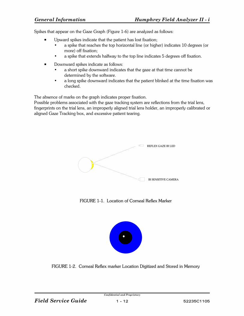
The direction of a patient's gaze is determined in two steps: first, a reflex marker is established onthe corneal surface; and second, the location of the pupil center is determined.
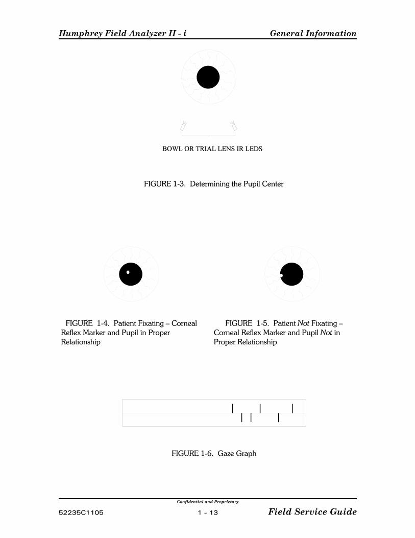
Gaze tracking is initialized in the following manner when a selected test is first started:The patient is asked to fixate on the central illumination LED. Gaze tracking turns on the reflexgaze IR LED located just under the diamond fixation pattern and turns off eye illuminationbriefly . Light from the LED is reflected off the cornea, and back to the IR sensitive camera(Figure 1-1). The majority of the cornea appears black except for the reflected spot. This imageis digitized and stored in memory. The reflected spot is referred to as the reflex marker(Figure 1-2). Because the corneal surface is rounded, the reflex marker will move very little evenif the patient's eye rotates, and thus the marker becomes a (relatively) stationary reference point.
Next, the system locates the pupil center by illuminating the entire eye with the two IR LEDslocated either in the bottom of the bowl, or in the trial lens holder (when in the raised position). The iris appears bright with a dark pupil (Figure 1-3). This image is also digitized and stored inmemory. It is the relationship between the location of the reflex marker on the cornea and thelocation of the pupil center that determines fixation (Figure 1-4).
Note - When gaze tracking is being initialized, it appears as repetitive "strobing" whenviewed by the operator via the video insert on the HFA II - i monitor.
During a test, each time a spot is projected into the bowl, the locations of the reflex marker andthe center of the pupil are compared to the initial images stored in memory. If the patient isfixating correctly, the positional relationship between the reflex marker and the pupil center willbe the same as that of the stored images (Figure 1-4). If the patient is off fixation, the positionalrelationship between the reflex marker and the pupil center will be different, as in Figure 1-5. The greater the misalignment, the higher the mark on the Gaze Graph (Figure 1-6).
(continued)
General Information Humphrey Field Analyzer II - i
Confidential and Proprietary
Field Service Guide 1 - 12 52235C1105
Spikes that appear on the Gaze Graph (Figure 1-6) are analyzed as follows:
P Upward spikes indicate that the patient has lost fixation;• a spike that reaches the top horizontal line (or higher) indicates 10 degrees (or
more) off fixation;• a spike that extends halfway to the top line indicates 5 degrees off fixation.
P Downward spikes indicate as follows:• a short spike downward indicates that the gaze at that time cannot be
determined by the software.• a long spike downward indicates that the patient blinked at the time fixation was
checked.
The absence of marks on the graph indicates proper fixation.Possible problems associated with the gaze tracking system are reflections from the trial lens,fingerprints on the trial lens, an improperly aligned trial lens holder, an improperly calibrated oraligned Gaze Tracking box, and excessive patient tearing.
FIGURE 1-1. Location of Corneal Reflex Marker
FIGURE 1-2. Corneal Reflex marker Location Digitized and Stored in Memory
Humphrey Field Analyzer II - i General Information
Confidential and Proprietary
52235C1105 1 - 13 Field Service Guide
FIGURE 1-3. Determining the Pupil Center
FIGURE 1-4. Patient Fixating – CornealReflex Marker and Pupil in ProperRelationship
FIGURE 1-5. Patient Not Fixating –Corneal Reflex Marker and Pupil Not inProper Relationship
FIGURE 1-6. Gaze Graph

General Information Humphrey Field Analyzer II - i
Confidential and Proprietary
Field Service Guide 1 - 14 52235C1105
1.7.3 Head Tracking / Auto Pupil / Vertex Monitoring
These three features are dependent on the Gaze Tracking system. If Gaze Tracking hassuccessfully initialized, any of these three features can be utilized.
Head TrackingThe Head Tracking feature is designed to lessen the appearance of a trial lens artifactimage when the patient's eye is off center in relation to the center of the trial lens holder. The intent is to reduce the possibility of inducing an arc-like defect or ring scotoma in thepatient's field test results.
Head Tracking is active when the trial lens holder is in the up position and Head Trackinghas been set to ON in the setup menu. The Head Tracking feature will track the center ofthe eye in relation to the trial lens holder. If the patient's eye moves from the center of thetrial lens holder by more than 3 mm for more than one consecutive sample, the headtracking feature will gently move the chinrest and headrest to automatically reposition thepatient's eye in the center of the trial lens holder. The tracking will stop if the eye doesn’tfollow the correction. Tracking begins when the test is started. This feature will operateproperly only if the patient properly rests on the chinrest.
Auto PupilWhen the Auto Pupil feature is set to ON in the setup menu, the gaze monitoring systemwill determine the size of the patient's pupil to the nearest 0.5 mm at the beginning of eachtest (during initialization of gaze tracking), and will automatically enter that information intothe Patient Data information screen, marked Auto (*).
Vertex MonitoringThe Vertex Monitoring feature is designed to lessen the appearance of a trial lens artifactimage when the patient's head moves backwards (away from) the trial lens holder. Theintent is to reduce the possibility of inducing an arc-like defect or ring scotoma in thepatient's field test results. Vertex Monitoring will alert the operator (via a double beep) ifthe patient's eye moves more than 7 mm away from its original position for any onemeasurement. (The sample rate is once every question.)
Vertex distance measurement is obtained during gaze initialization. During gazeinitialization, the two IR LEDs on the trial lens holder appear as two dots of light on thecorneal surface. (Refer to 1.7.2 Gaze Tracking for a complete description.) The distancebetween these two dots will decrease as the head moves away from its original position. Ifthe distance exceeds the software limits, an alert will sound. The test continues, and a pop-up window appears allowing the user to reinitialize, continue without reinitializing, or turnoff vertex monitoring.
Humphrey Field Analyzer II - i General Information
Confidential and Proprietary
52235C1105 1 - 15 Field Service Guide
1.7.4 HFA II - i Light Intensity Fundamentals
The HFA II - i uses one detector mounted at the end of the turret to measure both spot and bowlintensities. The projection lamp voltage is controlled by software to set maximum stimulusbrightness. This means that the lamp can be operated at a lower voltage when the lamp is new;and as it ages, more voltage is applied in order to maintain the same level of brightness. Thisincreases lamp life expectancy and reduces power consumption.
During light intensity calibration, the projection calibration value is stored in memory and set asclose as possible to obtain 929 Ft-L or 10,000 asb of light output. The background lights arefluorescent and the calibration values are set as close as possible to obtain 2.92 Ft-L or 31.5 asb. During calibration, light attenuation is measured at 175 different points on each of the two NDwedges, and the results are stored in memory. The two ND wedges are used in combination toobtain the desired brightness of the projected spot. The duration of the spot is 200 ms and iscontrolled by the software operating the shutter, located between the projection lamp and theND wedges.
During the power-on sequence, the bowl intensity is set to the calibrated value (2.92 Ft-L or31.5 asb). The brightness detector is then pointed at a black patch located on the inside of thefront cover, the shutter is closed, and a measurement is made by the detector. This establishesthe zero asb reference. Next, the shutter is opened, and a spot projected on the bowlapproximately 35E above center is measured by the detector. The projection voltage is adjustedto match the calibration value stored in memory. This measurement sets the maximumbrightness level (10,000 asb, or 0 dB). These two measurement points determine the slope ofthe light from dark to maximum brightness.
If the measured intensity varies from that stored during calibration, the lamp voltage is adjustedand measured again. This continues until the stored intensity and measured intensity match. Ifthe voltage is adjusted above 10 V, the test will fail and a projection lamp error message willappear on the screen. If the test does not fail, ten different points on each ND wedge aremeasured and compared with their stored values. If these values deviate more than ±.5 dBfrom the stored values, the test will fail and a wedge failure error message will be displayed.
1.7.5 Comparing HFA II and HFA II - i
Hardware -
The HFA II - i version differs from the prior production version, the HFA II, in that significantupgrades have been made.
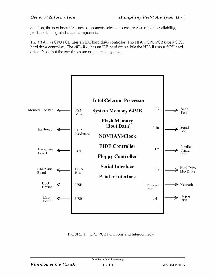
The HFA II - i uses an off-the-shelf CPU PCB featuring an Intel Celeron 433 MHz processor,while the HFA II uses a 20 MHz Motorola 68020-based processor. The new CPU PCBdramatically decreases the test processing time resulting in significant overall test time reduction. The HFA II - i CPU PCB contains 64 megabytes of DIMM memory while the HFA II has 4megabytes of memory on the current CPU. The increase is significant in the ability to supportsoftware features planned for the future; in particular, the implementation of Ensemble. In
General Information Humphrey Field Analyzer II - i
Confidential and Proprietary
Field Service Guide 1 - 16 52235C1105
Intel Celeron Processor
System Memory 64MB
Flash Memory (Boot Data)
NOVRAM/Clock
EIDE Controller
Floppy Controller
Serial Interface
Printer Interface
J 9
J 10
J 7
J 3
EthernetPort
USBDevice USB
PS2Mouse
PS 2Keyboard
PCI
EISABus
BackplaneBoard
BackplaneBoard
Keyboard
Mouse/Glide Pad
Network
Hard DriveMO Drive
ParallelPrinterPort
SerialPort
Serial Port
USBDevice USB J 4 Floppy
Disk
addition, the new board features components selected to ensure ease of parts availability,particularly integrated circuit components.
The HFA II - i CPU PCB uses an IDE hard drive controller. The HFA II CPU PCB uses a SCSIhard drive controller. The HFA II - i has an IDE hard drive while the HFA II uses a SCSI harddrive. Note that the two drives are not interchangeable.
FIGURE 1. CPU PCB Functions and Interconnects
Humphrey Field Analyzer II - i General Information
Confidential and Proprietary
52235C1105 1 - 17 Field Service Guide
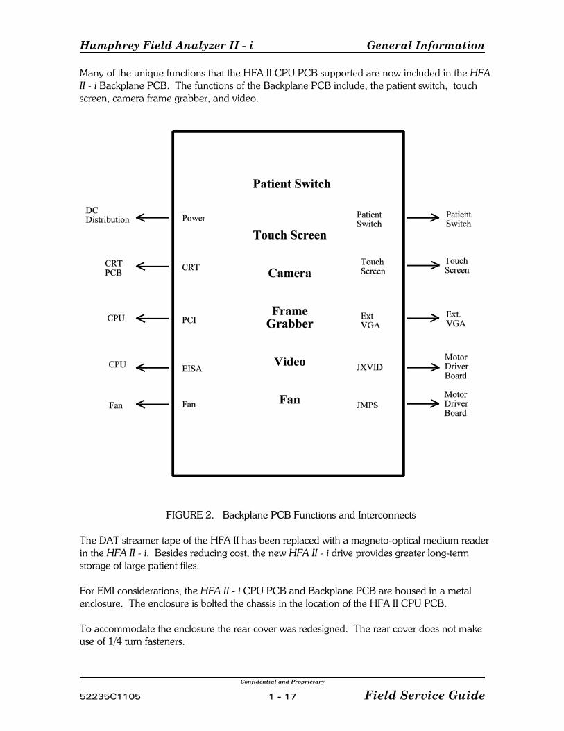
Many of the unique functions that the HFA II CPU PCB supported are now included in the HFAII - i Backplane PCB. The functions of the Backplane PCB include; the patient switch, touchscreen, camera frame grabber, and video.
FIGURE 2. Backplane PCB Functions and Interconnects
The DAT streamer tape of the HFA II has been replaced with a magneto-optical medium readerin the HFA II - i. Besides reducing cost, the new HFA II - i drive provides greater long-termstorage of large patient files.
For EMI considerations, the HFA II - i CPU PCB and Backplane PCB are housed in a metal enclosure. The enclosure is bolted the chassis in the location of the HFA II CPU PCB.
To accommodate the enclosure the rear cover was redesigned. The rear cover does not makeuse of 1/4 turn fasteners.
General Information Humphrey Field Analyzer II - i
Confidential and Proprietary
Field Service Guide 1 - 18 52235C1105
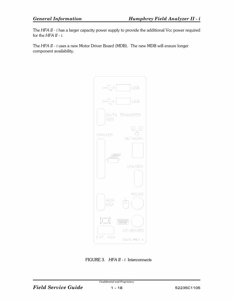
The HFA II - i has a larger capacity power supply to provide the additional Vcc power requiredfor the HFA II - i.
The HFA II - i uses a new Motor Driver Board (MDB). The new MDB will ensure longercomponent availability.
FIGURE 3. HFA II - i Interconnects
Humphrey Field Analyzer II - i General Information
Confidential and Proprietary
52235C1105 1 - 19 Field Service Guide
The external connections to the HFA II - i are considerably different from those of the HFA II. Two USB and a network port have been added to the HFA II - i. These ports are inoperative atthis time. While the HFA II had three serial ports, the HFA II - i has only one functional serialport.
Service Changes -
Calibration of the HFA II - i will differ from the HFA II only in the fact that the calibration datawill be stored differently. In the HFA II the calibration data is stored in the EEPROM, locatedon the CPU PCB. In the HFA II - i, the calibration data is stored in a file on the hard drive. Anadditional copy of the calibration data is stored on a floppy diskette. The calibration diskette isstored behind the rear cover door of the instrument. In cases where the calibration file on thehard drive becomes damaged, the calibration data from the floppy can be loaded back ontothe hard drive via the main calibration menu.
The Diagnostic Service Tool (DST) has been changed significantly for use on the HFA II - i. The DST will no longer perform the CPU PCB tests. These functions will be performed usingthe Quick Tech-Pro Tool, its operation will be described in a future service bulletin.
The Quick Tech-Pro Tool is used with the HFA II - i to test the CPU PCB functions, IDE harddrive, magnetic optical drive, printer, serial ports and parallel port. This utility is a self bootingapplication that will allow the use of three prepared diagnostic programs designed for the HFAII - i, or the choice of selecting any of the individual tests in the Quick Tech 2000 Pro testlibrary.
Unlike the HFA II, the HFA II - i has a BIOS that can be modified as needed with futureupdates. See Appendix E for BIOS Configuration. A significant difference between the HFA II and the HFA II - i is that the HFA II operatingsystem would allow low level formatting of the floppy drives ( formatting a previouslyunformatted diskette). This is not possible with the HFA II - i. The HFA II - i will only allowa preformatted diskette to be reformatted . The HFA II - i will not formatunformatted floppy diskettes.
The HFA II and the HFA II - i use the same floppy drives, but the jumper settings are differentfor the two models. See Bulletin FA2i-003(x) for details on jumper information.
The HFA II - i will no longer support the laptop connection and CPU diagnostics. CPUdiagnostics will be performed with the Quick Tech-Pro Tool.
General Information Humphrey Field Analyzer II - i
Confidential and Proprietary
Field Service Guide 1 - 20 52235C1105
Operational Changes -
Startup screen information, such as the model number, hard option code, soft option code,motor board code and CPU board code, will not be displayed during the bootup process.This information will be displayed on the “i” screen. The model, serial number, operatingsystem revision, language revision, and hardware option code are found on the “i” screen. See the sample ”i” screen printout in Appendix J.
The File Functions screen has some minor changes. The Initialize Disk button has two options.The first option is to format the floppy diskette and the second option is to format the magneticoptical diskette. The Backup Restore Function no longer has a tape option for source ordestination, but has a magnetic optical option.
The Calibration Screen has two new buttons. The first button is the Save button. The Savebutton will save the calibration data that is currently stored on the hard drive to the floppydiskette. The calibration data that was saved prior to the last save will be erased. The secondbutton, the Restore button, will copy the calibration data from the floppy diskette to the harddrive and replaces the previous data on the hard drive.
Software Loading Changes - While the HFA II used three floppies to load the operatingsystem and application software, the HFA II - i requires four diskettes. The DST tool requiredone disk with the HFA II, but requires three diskettes for the HFA II - i.
In all other aspects, field operation of the HFA II - i is essentially identical to the HFA II.
1.8 Peripherals
C MouseC KeyboardC MonitorC Wireless Printer DeviceC Uninterruptible Power Supply (UPS)C HP LaserJet Printer
Peripheral devices may be used with, and purchased for use with, the HFA II - i. Theinformation presented in this section is for guidance only. In no way does the informationpresented here imply that any peripheral device purchased will operate in conjunction with theHFA II - i. The only exception to this statement is if the peripheral device was purchaseddirectly from Carl Zeiss Meditec.
Every effort has been taken to ensure that the HFA II - i software and hardware are compatiblewith the majority of off-the-shelf purchased peripherals described below. However, please beaware that some may not be. It is the customer's responsibility as a consumer to ensure thatthey follow our purchase guidelines and that they resolve any non-operational issues with thevendor from which they purchased the peripheral device.
Humphrey Field Analyzer II - i General Information
Confidential and Proprietary
52235C1105 1 - 21 Field Service Guide
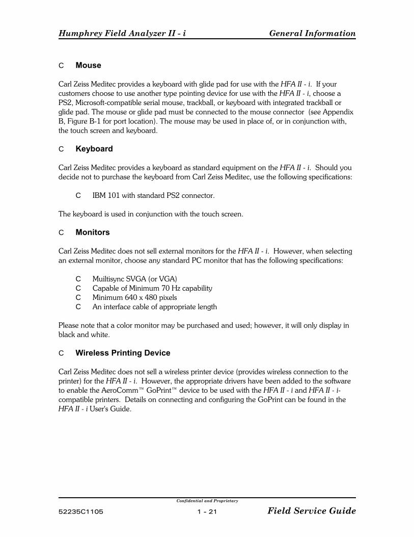
C Mouse
Carl Zeiss Meditec provides a keyboard with glide pad for use with the HFA II - i. If yourcustomers choose to use another type pointing device for use with the HFA II - i, choose aPS2, Microsoft-compatible serial mouse, trackball, or keyboard with integrated trackball orglide pad. The mouse or glide pad must be connected to the mouse connector (see AppendixB, Figure B-1 for port location). The mouse may be used in place of, or in conjunction with,the touch screen and keyboard.
C Keyboard
Carl Zeiss Meditec provides a keyboard as standard equipment on the HFA II - i. Should youdecide not to purchase the keyboard from Carl Zeiss Meditec, use the following specifications:
C IBM 101 with standard PS2 connector.
The keyboard is used in conjunction with the touch screen.
C Monitors
Carl Zeiss Meditec does not sell external monitors for the HFA II - i. However, when selectingan external monitor, choose any standard PC monitor that has the following specifications:
C Muiltisync SVGA (or VGA)C Capable of Minimum 70 Hz capabilityC Minimum 640 x 480 pixelsC An interface cable of appropriate length
Please note that a color monitor may be purchased and used; however, it will only display inblack and white.
C Wireless Printing Device
Carl Zeiss Meditec does not sell a wireless printer device (provides wireless connection to theprinter) for the HFA II - i. However, the appropriate drivers have been added to the softwareto enable the AeroComm™ GoPrint™ device to be used with the HFA II - i and HFA II - i-compatible printers. Details on connecting and configuring the GoPrint can be found in theHFA II - i User's Guide.

General Information Humphrey Field Analyzer II - i
Confidential and Proprietary
Field Service Guide 1 - 22 52235C1105
C Uninterruptible Power Supply (UPS)
Carl Zeiss Meditec does not sell a UPS (provides battery backup during power loss). However,when selecting a UPS for use with the HFA II - i, note the following specifications andrecommendations:
C The UPS must have a minimum 450 VA rating.C It must be dedicated to the HFA II - i. Do not connect the power table or other
devices into the UPS.C Recommended model: APC smart UPS 620.
Power backup during power loss will depend on the type of UPS selected. Consult a localsupplier for details.
C HP LaserJet Printer
Carl Zeiss Meditec does not sell HP LaserJet Printers. Refer to Appendix D, Approved ParallelPrinters for details on using the HP LaserJet.
1.9 Specifications
HFA II - i Field Analyzer
Physical Characteristics
Dimensions . . . . . . . . . . . . . . . . . . 23" H x 22.25" W x 19.25" D(58.4 x 56.5 x 48.9 cm)
Weight . . . . . . . . . . . . . . . . . . . . . 87.6 lbs (36.3 kg)
Recommended Room Size . . . . . . 106" x 64" (269.2 x 162.6 cm)(Ventilation recommended)
Environmental
Operating Temp (ambient) . . . . . . 41 to 95E F
Humidity (ambient) . . . . . . . . . . . . 20 – 85%
Heat Generated . . . . . . . . . . . . . . 1,570 BTU/Hr (460 W)
Electrical
Input Power . . . . . . . . . . . . . . . . . 100 – 120 V @ 4 A, 50-60 Hz230 V @ 2 A, 50 Hz
Humphrey Field Analyzer II - i General Information
Confidential and Proprietary
52235C1105 1 - 23 Field Service Guide
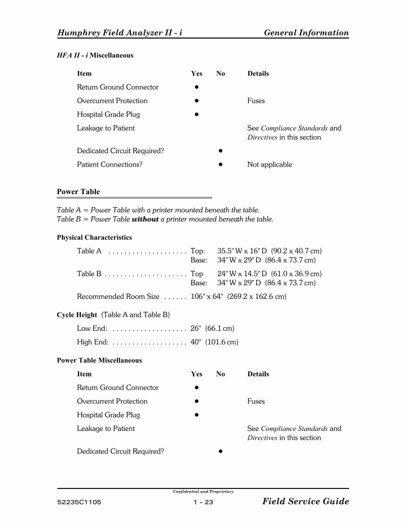
HFA II - i Miscellaneous
Item Yes No Details
Return Ground Connector !
Overcurrent Protection ! Fuses
Hospital Grade Plug !
Leakage to Patient See Compliance Standards andDirectives in this section
Dedicated Circuit Required? !
Patient Connections? ! Not applicable
Power Table
Table A = Power Table with a printer mounted beneath the table.Table B = Power Table without a printer mounted beneath the table.
Physical Characteristics
Table A . . . . . . . . . . . . . . . . . . . . Top: 35.5" W x 16" D (90.2 x 40.7 cm)Base: 34" W x 29" D (86.4 x 73.7 cm)
Table B . . . . . . . . . . . . . . . . . . . . . Top 24" W x 14.5" D (61.0 x 36.9 cm)Base: 34" W x 29" D (86.4 x 73.7 cm)
Recommended Room Size . . . . . . 106" x 64" (269.2 x 162.6 cm)
Cycle Height (Table A and Table B)
Low End: . . . . . . . . . . . . . . . . . . . 26" (66.1 cm)
High End: . . . . . . . . . . . . . . . . . . . 40" (101.6 cm)
Power Table Miscellaneous
Item Yes No Details
Return Ground Connector !
Overcurrent Protection ! Fuses
Hospital Grade Plug !
Leakage to Patient See Compliance Standards andDirectives in this section
Dedicated Circuit Required? !
General Information Humphrey Field Analyzer II - i
Confidential and Proprietary
Field Service Guide 1 - 24 52235C1105
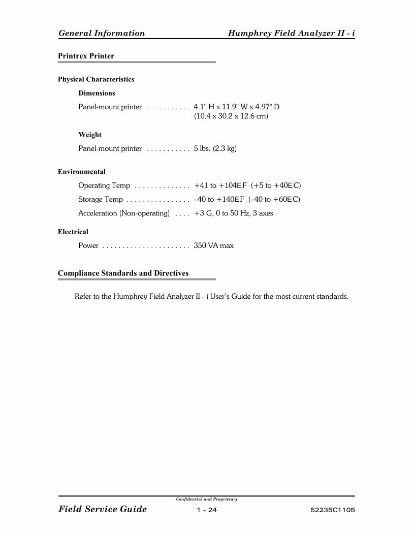
Printrex Printer
Physical Characteristics
Dimensions
Panel-mount printer . . . . . . . . . . . 4.1" H x 11.9" W x 4.97" D(10.4 x 30.2 x 12.6 cm)
Weight
Panel-mount printer . . . . . . . . . . . 5 lbs. (2.3 kg)
Environmental
Operating Temp . . . . . . . . . . . . . . +41 to +104E F (+5 to +40E C)
Storage Temp . . . . . . . . . . . . . . . . –40 to +140E F (–40 to +60E C)
Acceleration (Non-operating) . . . . +3 G, 0 to 50 Hz, 3 axes
Electrical
Power . . . . . . . . . . . . . . . . . . . . . . 350 VA max
Compliance Standards and Directives
Refer to the Humphrey Field Analyzer II - i User’s Guide for the most current standards.

Confidential and Proprietary
52235C1105 2 - 1 Field Service Guide
Section 2 - PM and System Checkout
2.1 System Checkout Checklist . . . . . . . . . . . . . . . . . . . . . . . . . . . . . . . . . 2 - 3
2.2 Preventive Maintenance Procedure . . . . . . . . . . . . . . . . . . . . . . . . . . . . 2 - 8

PM and System Checkout Humphrey Field Analyzer II - i
Confidential and Proprietary
Field Service Guide 2 - 2 52235C1105
Notes:
Humphrey Field Analyzer II - i PM and System Checkout
Confidential and Proprietary
52235C1105 2 - 3 Field Service Guide
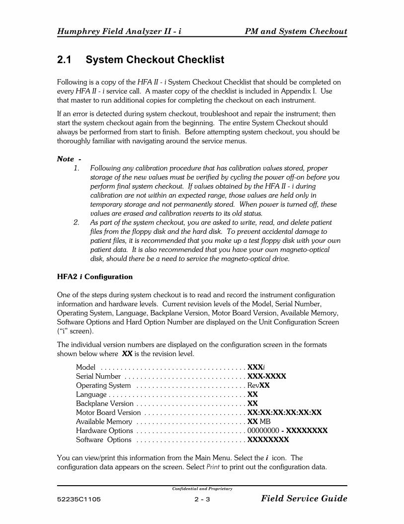
2.1 System Checkout Checklist
Following is a copy of the HFA II - i System Checkout Checklist that should be completed onevery HFA II - i service call. A master copy of the checklist is included in Appendix I. Usethat master to run additional copies for completing the checkout on each instrument.
If an error is detected during system checkout, troubleshoot and repair the instrument; thenstart the system checkout again from the beginning. The entire System Checkout shouldalways be performed from start to finish. Before attempting system checkout, you should bethoroughly familiar with navigating around the service menus.
Note 1. Following any calibration procedure that has calibration values stored, proper
storage of the new values must be verified by cycling the power off-on before youperform final system checkout. If values obtained by the HFA II - i duringcalibration are not within an expected range, those values are held only intemporary storage and not permanently stored. When power is turned off, thesevalues are erased and calibration reverts to its old status.
2. As part of the system checkout, you are asked to write, read, and delete patientfiles from the floppy disk and the hard disk. To prevent accidental damage topatient files, it is recommended that you make up a test floppy disk with your ownpatient data. It is also recommended that you have your own magneto-opticaldisk, should there be a need to service the magneto-optical drive.
HFA2 i Configuration
One of the steps during system checkout is to read and record the instrument configurationinformation and hardware levels. Current revision levels of the Model, Serial Number,Operating System, Language, Backplane Version, Motor Board Version, Available Memory,Software Options and Hard Option Number are displayed on the Unit Configuration Screen(“i” screen).
The individual version numbers are displayed on the configuration screen in the formatsshown below where XX is the revision level.
Model . . . . . . . . . . . . . . . . . . . . . . . . . . . . . . . . . . . . . XXXiSerial Number . . . . . . . . . . . . . . . . . . . . . . . . . . . . . . . XXX-XXXXOperating System . . . . . . . . . . . . . . . . . . . . . . . . . . . . RevXXLanguage . . . . . . . . . . . . . . . . . . . . . . . . . . . . . . . . . . . XXBackplane Version . . . . . . . . . . . . . . . . . . . . . . . . . . . . XXMotor Board Version . . . . . . . . . . . . . . . . . . . . . . . . . . XX:XX:XX:XX:XX:XXAvailable Memory . . . . . . . . . . . . . . . . . . . . . . . . . . . . XX MBHardware Options . . . . . . . . . . . . . . . . . . . . . . . . . . . . 00000000 - XXXXXXXXSoftware Options . . . . . . . . . . . . . . . . . . . . . . . . . . . . XXXXXXXX
You can view/print this information from the Main Menu. Select the i icon. Theconfiguration data appears on the screen. Select Print to print out the configuration data.

PM and System Checkout Humphrey Field Analyzer II - i
Confidential and Proprietary
Field Service Guide 2 - 4 52235C1105
The hardware options number corresponds to the model number of the instrument and isstored in the instrument's configuration file on the Hard Drive. If the hardware optionsnumber is set as a model 750i, all software features are enabled. If set for a 740i, only thosefeatures intended for the 740i are enabled. If set for a 720i, only those features intended forthe 720i are enabled.
The hardware options number should be verified during the system checkout procedure.Refer to Appendix G for specific hardware options numbers.
The hardware options number also appears on the System Log printout and the Cal/Wedgeprintout. You can print this information using the following procedures:
For the System Log!• From the main menu, select System Setup; then select Print System Log. The
hardware options number and instrument serial number are printed on the linetitled Machine ID, at the beginning of the printout.
For the Cal/Wedge printout• From the Calibration main menu, select Print Cal Values to print out the instrument
calibration data. The hardware options number and instrument serial number areprinted on the line titled Machine ID, near the beginning of the printout.

Humphrey Field Analyzer II - i PM and System Checkout
Confidential and Proprietary
52235C1105 2 - 5 Field Service Guide
HFA II - i SYSTEM CHECKOUT CHECKLIST
Your Name: ____________________ HFA II - i S/N: ____________________
Date: ____________________
NOTE: Following any calibration procedure that has calibration values stored in theCal/Config Data, storage of the new values must be verified by cycling the power off-onbefore you perform final system checkout. If values obtained by the HFA II - i duringcalibration are not within an expected range, those values are held only in temporarystorage and not written to the Cal/Config Data. When power is turned off, these valuesare erased and calibration reverts to its old status.
The HFA II - i System Checkout Checklist Guidelines —
# Part I — The items described in Part I must be completed for All service calls.
# Part II — The items described in Part II must be completed when any of the followingservice conditions apply:
-- Performing an instrument PM-- Recalibrating either the White/White or Blue/Yellow light intensities-- Replacing/initializing the Cal/Config Data-- Cleaning/replacing the brightness detector, ND wedges, or the color wheel-- Replacing the motor driver PCB
This checklist assumes that all required service has been performed on the HFA II - i. Place acheckmark next to each item if okay. If an item does not apply to the HFA II - i under service,indicate N/A (not applicable).
Part I -- For All Service Calls (Refer to the above System Checkout Checklist Guidelines.)
1) If a repair has been performed, verify that all required adjustments/checks havebeen performed per Table 3-1.
2) Acquire and print the results of your foveal test. Check that the foveal valueobtained is within ±2 dB of your known foveal value. (4.8.1.1)
3) Print the Cal/Wedge printout. Verify that all values are within specification. (Appendix H)
4) Print the Unit Configuration printout. Verify that all entries are accurate, based oninstrument serial number and model. (Appendix J).
5) Print the System Log printout and then clear the log. Verify that all reported errorconditions have been evaluated/corrected. (Appendix J)
PM and System Checkout Humphrey Field Analyzer II - i
Confidential and Proprietary
Field Service Guide 2 - 6 52235C1105
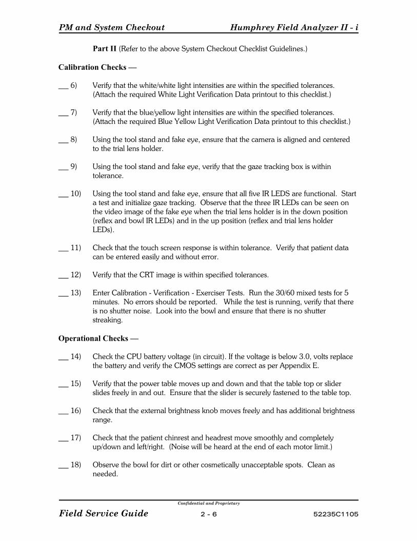
Part II (Refer to the above System Checkout Checklist Guidelines.)
Calibration Checks —
6) Verify that the white/white light intensities are within the specified tolerances. (Attach the required White Light Verification Data printout to this checklist.)
7) Verify that the blue/yellow light intensities are within the specified tolerances. (Attach the required Blue Yellow Light Verification Data printout to this checklist.)
8) Using the tool stand and fake eye, ensure that the camera is aligned and centeredto the trial lens holder.
9) Using the tool stand and fake eye, verify that the gaze tracking box is withintolerance.
10) Using the tool stand and fake eye, ensure that all five IR LEDS are functional. Starta test and initialize gaze tracking. Observe that the three IR LEDs can be seen onthe video image of the fake eye when the trial lens holder is in the down position(reflex and bowl IR LEDs) and in the up position (reflex and trial lens holderLEDs).
11) Check that the touch screen response is within tolerance. Verify that patient datacan be entered easily and without error.
12) Verify that the CRT image is within specified tolerances.
13) Enter Calibration - Verification - Exerciser Tests. Run the 30/60 mixed tests for 5minutes. No errors should be reported. While the test is running, verify that thereis no shutter noise. Look into the bowl and ensure that there is no shutterstreaking.
Operational Checks —
14) Check the CPU battery voltage (in circuit). If the voltage is below 3.0, volts replacethe battery and verify the CMOS settings are correct as per Appendix E.
15) Verify that the power table moves up and down and that the table top or sliderslides freely in and out. Ensure that the slider is securely fastened to the table top.
16) Check that the external brightness knob moves freely and has additional brightnessrange.
17) Check that the patient chinrest and headrest move smoothly and completelyup/down and left/right. (Noise will be heard at the end of each motor limit.)
18) Observe the bowl for dirt or other cosmetically unacceptable spots. Clean asneeded.
Humphrey Field Analyzer II - i PM and System Checkout
Confidential and Proprietary
52235C1105 2 - 7 Field Service Guide
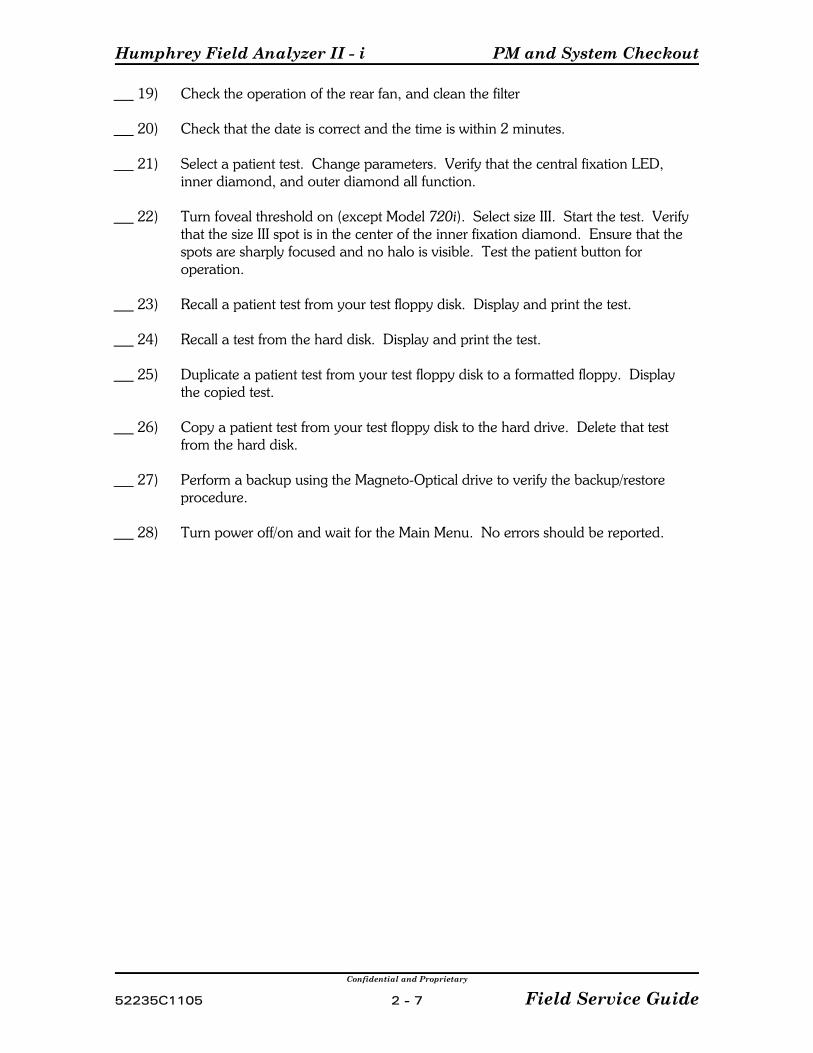
19) Check the operation of the rear fan, and clean the filter
20) Check that the date is correct and the time is within 2 minutes.
21) Select a patient test. Change parameters. Verify that the central fixation LED,inner diamond, and outer diamond all function.
22) Turn foveal threshold on (except Model 720i). Select size III. Start the test. Verifythat the size III spot is in the center of the inner fixation diamond. Ensure that thespots are sharply focused and no halo is visible. Test the patient button foroperation.
23) Recall a patient test from your test floppy disk. Display and print the test.
24) Recall a test from the hard disk. Display and print the test.
25) Duplicate a patient test from your test floppy disk to a formatted floppy. Displaythe copied test.
26) Copy a patient test from your test floppy disk to the hard drive. Delete that testfrom the hard disk.
27) Perform a backup using the Magneto-Optical drive to verify the backup/restoreprocedure.
28) Turn power off/on and wait for the Main Menu. No errors should be reported.

PM and System Checkout Humphrey Field Analyzer II - i
Confidential and Proprietary
Field Service Guide 2 - 8 52235C1105
2.2 Preventive Maintenance Procedure
For U.S. domestic Field Service, an annual preventive maintenance (PM) visit is required forevery HFA II - i instrument under service contract. The PM visit can be combined with a regularservice visit if the timing is suitable. The HFA II - i System Checkout Checklist (Section 2.1)details the checks and measurements required to complete a PM.
In addition to the System Checkout, the following points should be checked during a PM orservice call.
P Check that all external cable and cord connections are secure.P Check that the instrument is being powered from a properly grounded AC outlet.P Observe the ambient conditions in which the instrument is operating:
• Are the cooling vents on the instrument unobstructed?• Are there any ambient conditions present that may cause static generation
(carpeted floors, dry winter weather, etc.)?P Check whether the instrument operator(s) have any questions/comments regarding
performance of the instrument.
PM Procedure
1) Obtain the Before instrument data as prescribed on the Light Intensity worksheetsdetailed in Section 4.8.1.
2) Apply a very thin film of clock oil (P/N 02534) to the projection assembly rails. Therecommended method is to place one drop of oil on your fingertip and lightly wipe italong the length of the top of the rail. Do this once for each rail.
Caution — Apply the oil sparingly. Excessive oil on the rails will migrateto other assemblies and cause problems.
3) After the oil has been applied, proceed to the Motor Exerciser (Section 5) and exercise theF motor (focus/carriage motor). Exercise the focus motor 20 times to distribute the oil onthe rails.
4) Check the rail ends and directly beneath the projection assembly for any excess oil. Carefully wipe up any excess oil.
5) Clean the optics path. Refer to Appendix Q - Cleaning Optics, for general guidelines.Note that cleaning certain elements in the optics path will affect the light intensity readingsof the instrument, and thus necessitate recalibration.
6) Clean the top and bottom air intake filters, and the power supply fan:
Humphrey Field Analyzer II - i PM and System Checkout
Confidential and Proprietary
52235C1105 2 - 9 Field Service Guide
Bottom Filter — It is recommended that this filter be replaced. However, it can becleaned under running water, dried, and then reinstalled, if necessary. Ensure that thefilter is completely dried before reinstalling.Top Filter — Do Not clean this filter — replace it only. Refer to Section 2.3 for specialreplacement procedures required.Power Supply Fan — Gently brush, vacuum, or blow any accumulated dust and debrisoff the power supply fan and surrounding assembly. Use care to avoid getting dust ordebris on the instrument optics or bowl.EMI Box Fan — Gently brush, vacuum, or blow any accumulated dust and debrisoff the EMI Box fan and surrounding assembly. Use care to avoid getting dust ordebris on the instrument optics or bowl.CPU Fan — Open the CPU enclosure and gently brush, vacuum, or blow anyaccumulated dust and debris off the EMI Box fan and surrounding assembly. Use care toavoid getting dust or debris on the instrument optics or bowl.
7) Clean the bowl (see User's Guide).
8) Check all belts, and replace as required.
9) Update the system software to the latest revision that the customer is entitled to free ofcharge.
10) With the covers still off, perform the System Checkout (2.1). Form is found in Appendix I.

PM and System Checkout Humphrey Field Analyzer II - i
Confidential and Proprietary
Field Service Guide 2 - 10 52235C1105
(This page left intentionally blank)
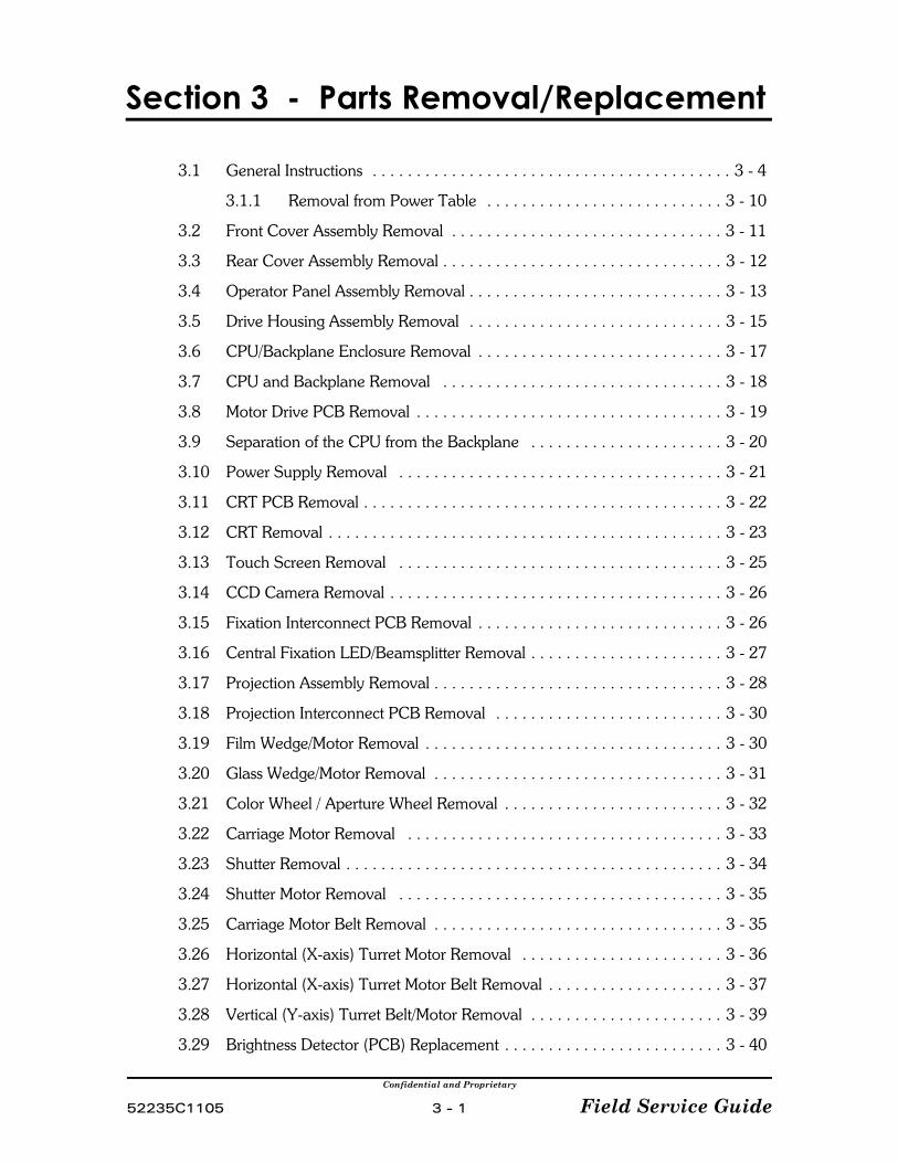
Confidential and Proprietary
52235C1105 3 - 1 Field Service Guide
Section 3 - Parts Removal/Replacement
3.1 General Instructions . . . . . . . . . . . . . . . . . . . . . . . . . . . . . . . . . . . . . . . . . 3 - 4
3.1.1 Removal from Power Table . . . . . . . . . . . . . . . . . . . . . . . . . . . 3 - 10
3.2 Front Cover Assembly Removal . . . . . . . . . . . . . . . . . . . . . . . . . . . . . . . 3 - 11
3.3 Rear Cover Assembly Removal . . . . . . . . . . . . . . . . . . . . . . . . . . . . . . . . 3 - 12
3.4 Operator Panel Assembly Removal . . . . . . . . . . . . . . . . . . . . . . . . . . . . . 3 - 13
3.5 Drive Housing Assembly Removal . . . . . . . . . . . . . . . . . . . . . . . . . . . . . 3 - 15
3.6 CPU/Backplane Enclosure Removal . . . . . . . . . . . . . . . . . . . . . . . . . . . . 3 - 17
3.7 CPU and Backplane Removal . . . . . . . . . . . . . . . . . . . . . . . . . . . . . . . . 3 - 18
3.8 Motor Drive PCB Removal . . . . . . . . . . . . . . . . . . . . . . . . . . . . . . . . . . . 3 - 19
3.9 Separation of the CPU from the Backplane . . . . . . . . . . . . . . . . . . . . . . 3 - 20
3.10 Power Supply Removal . . . . . . . . . . . . . . . . . . . . . . . . . . . . . . . . . . . . . 3 - 21
3.11 CRT PCB Removal . . . . . . . . . . . . . . . . . . . . . . . . . . . . . . . . . . . . . . . . . 3 - 22
3.12 CRT Removal . . . . . . . . . . . . . . . . . . . . . . . . . . . . . . . . . . . . . . . . . . . . . 3 - 23
3.13 Touch Screen Removal . . . . . . . . . . . . . . . . . . . . . . . . . . . . . . . . . . . . . 3 - 25
3.14 CCD Camera Removal . . . . . . . . . . . . . . . . . . . . . . . . . . . . . . . . . . . . . . 3 - 26
3.15 Fixation Interconnect PCB Removal . . . . . . . . . . . . . . . . . . . . . . . . . . . . 3 - 26
3.16 Central Fixation LED/Beamsplitter Removal . . . . . . . . . . . . . . . . . . . . . . 3 - 27
3.17 Projection Assembly Removal . . . . . . . . . . . . . . . . . . . . . . . . . . . . . . . . . 3 - 28
3.18 Projection Interconnect PCB Removal . . . . . . . . . . . . . . . . . . . . . . . . . . 3 - 30
3.19 Film Wedge/Motor Removal . . . . . . . . . . . . . . . . . . . . . . . . . . . . . . . . . . 3 - 30
3.20 Glass Wedge/Motor Removal . . . . . . . . . . . . . . . . . . . . . . . . . . . . . . . . . 3 - 31
3.21 Color Wheel / Aperture Wheel Removal . . . . . . . . . . . . . . . . . . . . . . . . . 3 - 32
3.22 Carriage Motor Removal . . . . . . . . . . . . . . . . . . . . . . . . . . . . . . . . . . . . 3 - 33
3.23 Shutter Removal . . . . . . . . . . . . . . . . . . . . . . . . . . . . . . . . . . . . . . . . . . . 3 - 34
3.24 Shutter Motor Removal . . . . . . . . . . . . . . . . . . . . . . . . . . . . . . . . . . . . . 3 - 35
3.25 Carriage Motor Belt Removal . . . . . . . . . . . . . . . . . . . . . . . . . . . . . . . . . 3 - 35
3.26 Horizontal (X-axis) Turret Motor Removal . . . . . . . . . . . . . . . . . . . . . . . 3 - 36
3.27 Horizontal (X-axis) Turret Motor Belt Removal . . . . . . . . . . . . . . . . . . . . 3 - 37
3.28 Vertical (Y-axis) Turret Belt/Motor Removal . . . . . . . . . . . . . . . . . . . . . . 3 - 39
3.29 Brightness Detector (PCB) Replacement . . . . . . . . . . . . . . . . . . . . . . . . . 3 - 40
Parts Removal/Replacement Humphrey Field Analyzer II - i
Confidential and Proprietary
Field Service Guide 3 - 2 52235C1105
3.30 Lower Turret Removal . . . . . . . . . . . . . . . . . . . . . . . . . . . . . . . . . . . . . . 3 - 41
3.31 Turret Cable Assembly Removal . . . . . . . . . . . . . . . . . . . . . . . . . . . . . . . 3 - 42
3.32 Chinrest/Headrest Switch Assembly Removal . . . . . . . . . . . . . . . . . . . . . 3 - 42
3.33 Chinrest Y-axis Belt/Motor Removal . . . . . . . . . . . . . . . . . . . . . . . . . . . . 3 - 43
3.34 Patient Support Horizontal (X-axis) Belt/Motor Removal . . . . . . . . . . . . 3 - 44
3.35 Chinrest Vertical Slide and Lead Screw Removal . . . . . . . . . . . . . . . . . . 3 - 47
3.36 Chinrest Horizontal Slide Removal . . . . . . . . . . . . . . . . . . . . . . . . . . . . . 3 - 48
3.37 Trial Lens Holder Assembly Removal . . . . . . . . . . . . . . . . . . . . . . . . . . . 3 - 49
3.38 Top Fan Removal . . . . . . . . . . . . . . . . . . . . . . . . . . . . . . . . . . . . . . . . . . 3 - 50
3.39 Bowl IR LED Assembly Removal . . . . . . . . . . . . . . . . . . . . . . . . . . . . . . 3 - 51
3.40 Blue-Yellow Module / Bowl Plug Removal . . . . . . . . . . . . . . . . . . . . . . . 3 - 52
3.41 Bowl Removal . . . . . . . . . . . . . . . . . . . . . . . . . . . . . . . . . . . . . . . . . . . . 3 - 52
3.42 Reflex Gaze LED Removal . . . . . . . . . . . . . . . . . . . . . . . . . . . . . . . . . . . 3 - 54
3.43 Bowl Lamp Assembly Removal . . . . . . . . . . . . . . . . . . . . . . . . . . . . . . . 3 - 54
3.44 IR Bowl Plug Removal/Installation . . . . . . . . . . . . . . . . . . . . . . . . . . . . . 3 - 55
3.45 Quarter-Turn Fastener Replacement . . . . . . . . . . . . . . . . . . . . . . . . . . . . 3 - 56

Humphrey Field Analyzer II - i Parts Removal/Replacement
Confidential and Proprietary
52235C1105 3 - 3 Field Service Guide
Notes:
Parts Removal/Replacement Humphrey Field Analyzer II - i
Confidential and Proprietary
Field Service Guide 3 - 4 52235C1105
3.1 General Instructions
P Table 3-1 is the single source of reference for Removal/Adjustment requirements. Whenever a removal procedure is performed, refer to Table 3-1 to determinewhich follow-up checks/adjustments are required.
P System interconnect diagrams for the entire instrument are contained in Section 6.
P In addition to the drawings in this section, the parts drawings in Section 7 provideuseful reference for parts identification and identifying relative locations duringremoval/replacement procedures.
P References from one procedure to another are shown in the form "(x.x)." EXAMPLE: In the CRT Removal/Replacement procedure, one of the steps is to
"Remove the operator panel (3.4)." If you need further details for removing theoperator panel, you can refer to Section 3.4, and then return to the CRT removalprocedure for the next step.
P Simple removals that are clearly obvious are not described in this service guide.
P Unless noted otherwise, the steps for replacement (reassembly) are simply thereverse order of the steps described for removal and are not listed. Replacement(reassembly) notes are included as needed.
P All screws and nuts mentioned in the instructions are metric unless notedotherwise.
P Because the covers interlock with each other, the required sequence for coverremoval is:
1. Front cover2. Rear cover3. Operator panel
The covers must be reinstalled in exactly the opposite sequence. Successfulreassembly requires careful attention to the interlocking points on the covers.
(continued)

Humphrey Field Analyzer II - i Parts Removal/Replacement
Confidential and Proprietary
52235C1105 3 - 5 Field Service Guide
(3.1 General Instructions - continued)
P Some of the motor pulleys are installed with the collar outward, and some withthe collar inward (next to the motor body). Be sure to make note of the correctposition of the collar before removing the pulley.
P When reinstalling motor pulleys, ensure that there is proper clearance between thepulley and motor body. When reinstalling the belt, ensure that the motor beltteeth are properly meshed with both pulleys.
P The appearance and condition of the bowl's inner surface are critical to thefunctionality of the HFA II - i; work carefully to avoid damaging or dirtying thebowl. Do not touch the inside of the bowl unnecessarily.
P In this service guide, the terms left, right, front and back of the instrument are asviewed from the patient position, unless noted otherwise.
P Whenever you will be working on the projection assembly with it installed in theinstrument, place a sheet of paper or clean cloth under the projection assembly tocatch any small hardware that you may drop.
P Some of the cable connectors in the instrument may not be keyed. To facilitatelater reassembly of the instrument, consider labeling each connector duringdisassembly.
P Proper cable and wire routing is important. Before disassembly, observe thecable routing and locations of the cable ties; then be sure to route the cablesexactly the same during reassembly. Be sure to replace all cable ties removedduring disassembly.
P Be sure to reconnect all ground wires disconnected during disassembly. Failureto do so can cause the instrument to malfunction.
P Certain screws on the projection assembly secure critical alignment of the opticalpath. It is essential that you NOT LOOSEN these screws (see Figure 3-1). Alignment of the projection assembly can only be done at the factory using specialequipment.
P After replacement of parts or an assembly, perform a limited operational check ofthe associated functions before complete reassembly of the instrument. Aftercomplete reassembly, perform the full System Checkout (Section 2).
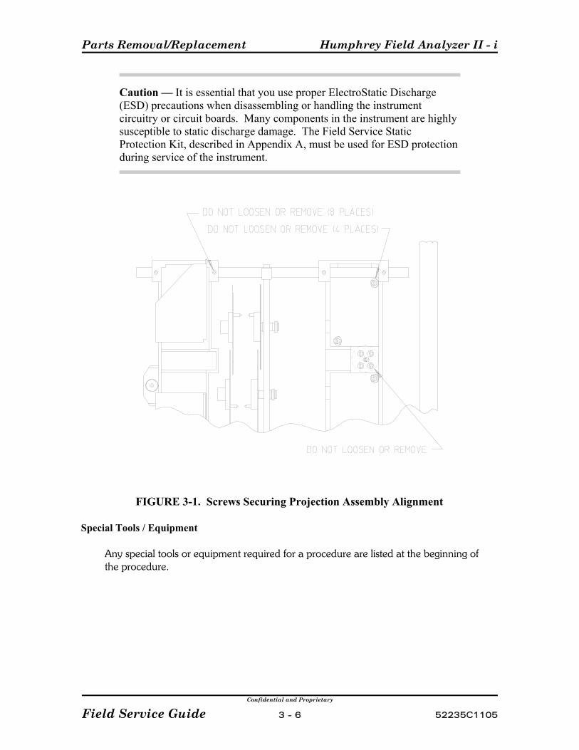
Parts Removal/Replacement Humphrey Field Analyzer II - i
Confidential and Proprietary
Field Service Guide 3 - 6 52235C1105
Caution — It is essential that you use proper ElectroStatic Discharge(ESD) precautions when disassembling or handling the instrumentcircuitry or circuit boards. Many components in the instrument are highlysusceptible to static discharge damage. The Field Service StaticProtection Kit, described in Appendix A, must be used for ESD protectionduring service of the instrument.
FIGURE 3-1. Screws Securing Projection Assembly Alignment
Special Tools / Equipment
Any special tools or equipment required for a procedure are listed at the beginning ofthe procedure.

Humphrey Field Analyzer II - i Parts Removal/Replacement
Confidential and Proprietary
52235C1105 3 - 7 Field Service Guide
(This page left intentionally blank)
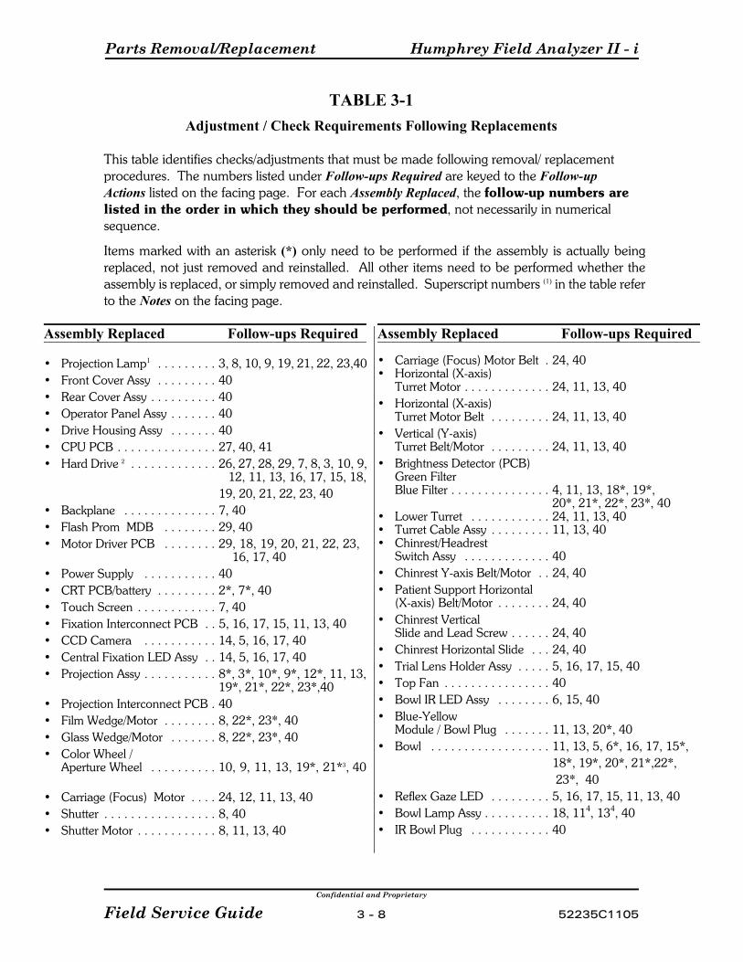
Parts Removal/Replacement Humphrey Field Analyzer II - i
Confidential and Proprietary
Field Service Guide 3 - 8 52235C1105
TABLE 3-1Adjustment / Check Requirements Following Replacements
This table identifies checks/adjustments that must be made following removal/ replacementprocedures. The numbers listed under Follow-ups Required are keyed to the Follow-upActions listed on the facing page. For each Assembly Replaced, the follow-up numbers arelisted in the order in which they should be performed, not necessarily in numericalsequence.
Items marked with an asterisk (*) only need to be performed if the assembly is actually beingreplaced, not just removed and reinstalled. All other items need to be performed whether theassembly is replaced, or simply removed and reinstalled. Superscript numbers (1) in the table referto the Notes on the facing page.
Assembly Replaced Follow-ups Required
• Projection Lamp1 . . . . . . . . . 3, 8, 10, 9, 19, 21, 22, 23,40• Front Cover Assy . . . . . . . . . 40• Rear Cover Assy . . . . . . . . . . 40• Operator Panel Assy . . . . . . . 40• Drive Housing Assy . . . . . . . 40• CPU PCB . . . . . . . . . . . . . . . 27, 40, 41• Hard Drive 2 . . . . . . . . . . . . . 26, 27, 28, 29, 7, 8, 3, 10, 9,
12, 11, 13, 16, 17, 15, 18, 19, 20, 21, 22, 23, 40
• Backplane . . . . . . . . . . . . . . 7, 40 • Flash Prom MDB . . . . . . . . 29, 40 • Motor Driver PCB . . . . . . . . 29, 18, 19, 20, 21, 22, 23,
16, 17, 40 • Power Supply . . . . . . . . . . . 40• CRT PCB/battery . . . . . . . . . 2*, 7*, 40• Touch Screen . . . . . . . . . . . . 7, 40• Fixation Interconnect PCB . . 5, 16, 17, 15, 11, 13, 40• CCD Camera . . . . . . . . . . . 14, 5, 16, 17, 40• Central Fixation LED Assy . . 14, 5, 16, 17, 40• Projection Assy . . . . . . . . . . . 8*, 3*, 10*, 9*, 12*, 11, 13,
19*, 21*, 22*, 23*,40• Projection Interconnect PCB . 40• Film Wedge/Motor . . . . . . . . 8, 22*, 23*, 40• Glass Wedge/Motor . . . . . . . 8, 22*, 23*, 40• Color Wheel /
Aperture Wheel . . . . . . . . . . 10, 9, 11, 13, 19*, 21*3, 40
• Carriage (Focus) Motor . . . . 24, 12, 11, 13, 40• Shutter . . . . . . . . . . . . . . . . . 8, 40• Shutter Motor . . . . . . . . . . . . 8, 11, 13, 40
Assembly Replaced Follow-ups Required
• Carriage (Focus) Motor Belt . 24, 40• Horizontal (X-axis)
Turret Motor . . . . . . . . . . . . . 24, 11, 13, 40• Horizontal (X-axis)
Turret Motor Belt . . . . . . . . . 24, 11, 13, 40• Vertical (Y-axis)
Turret Belt/Motor . . . . . . . . . 24, 11, 13, 40• Brightness Detector (PCB)
Green FilterBlue Filter . . . . . . . . . . . . . . . 4, 11, 13, 18*, 19*,
20*, 21*, 22*, 23*, 40• Lower Turret . . . . . . . . . . . . 24, 11, 13, 40• Turret Cable Assy . . . . . . . . . 11, 13, 40• Chinrest/Headrest
Switch Assy . . . . . . . . . . . . . 40• Chinrest Y-axis Belt/Motor . . 24, 40• Patient Support Horizontal
(X-axis) Belt/Motor . . . . . . . . 24, 40• Chinrest Vertical
Slide and Lead Screw . . . . . . 24, 40• Chinrest Horizontal Slide . . . 24, 40• Trial Lens Holder Assy . . . . . 5, 16, 17, 15, 40• Top Fan . . . . . . . . . . . . . . . . 40• Bowl IR LED Assy . . . . . . . . 6, 15, 40• Blue-Yellow
Module / Bowl Plug . . . . . . . 11, 13, 20*, 40• Bowl . . . . . . . . . . . . . . . . . . 11, 13, 5, 6*, 16, 17, 15*,
18*, 19*, 20*, 21*,22*, 23*, 40
• Reflex Gaze LED . . . . . . . . . 5, 16, 17, 15, 11, 13, 40• Bowl Lamp Assy . . . . . . . . . . 18, 114, 134, 40• IR Bowl Plug . . . . . . . . . . . . 40
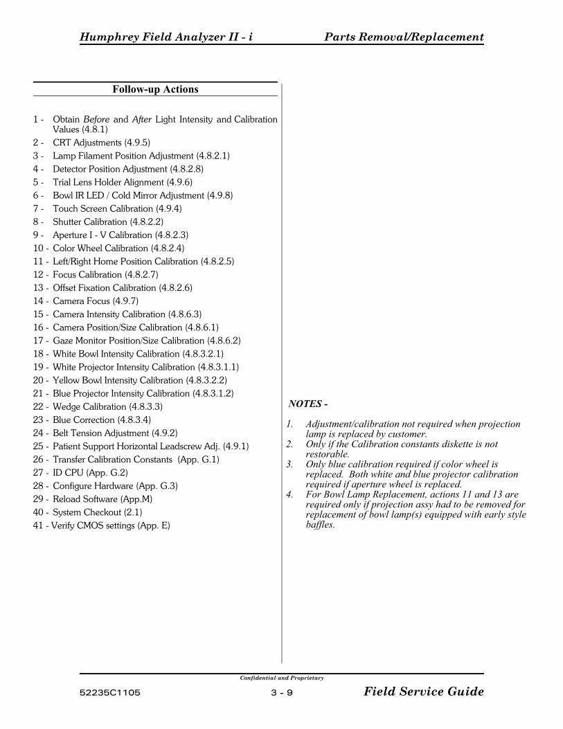
Humphrey Field Analyzer II - i Parts Removal/Replacement
Confidential and Proprietary
52235C1105 3 - 9 Field Service Guide
Follow-up Actions
1 - Obtain Before and After Light Intensity and CalibrationValues (4.8.1)
2 - CRT Adjustments (4.9.5)3 - Lamp Filament Position Adjustment (4.8.2.1)4 - Detector Position Adjustment (4.8.2.8)5 - Trial Lens Holder Alignment (4.9.6)6 - Bowl IR LED / Cold Mirror Adjustment (4.9.8)7 - Touch Screen Calibration (4.9.4)8 - Shutter Calibration (4.8.2.2)9 - Aperture I - V Calibration (4.8.2.3)10 - Color Wheel Calibration (4.8.2.4)11 - Left/Right Home Position Calibration (4.8.2.5)12 - Focus Calibration (4.8.2.7)13 - Offset Fixation Calibration (4.8.2.6)14 - Camera Focus (4.9.7)15 - Camera Intensity Calibration (4.8.6.3)16 - Camera Position/Size Calibration (4.8.6.1)17 - Gaze Monitor Position/Size Calibration (4.8.6.2) 18 - White Bowl Intensity Calibration (4.8.3.2.1)19 - White Projector Intensity Calibration (4.8.3.1.1)20 - Yellow Bowl Intensity Calibration (4.8.3.2.2)21 - Blue Projector Intensity Calibration (4.8.3.1.2)22 - Wedge Calibration (4.8.3.3)23 - Blue Correction (4.8.3.4)24 - Belt Tension Adjustment (4.9.2)25 - Patient Support Horizontal Leadscrew Adj. (4.9.1)26 - Transfer Calibration Constants (App. G.1)27 - ID CPU (App. G.2)28 - Configure Hardware (App. G.3)29 - Reload Software (App.M)40 - System Checkout (2.1)41 - Verify CMOS settings (App. E)
NOTES -
1. Adjustment/calibration not required when projectionlamp is replaced by customer.
2. Only if the Calibration constants diskette is notrestorable.
3. Only blue calibration required if color wheel isreplaced. Both white and blue projector calibrationrequired if aperture wheel is replaced.
4. For Bowl Lamp Replacement, actions 11 and 13 arerequired only if projection assy had to be removed forreplacement of bowl lamp(s) equipped with early stylebaffles.
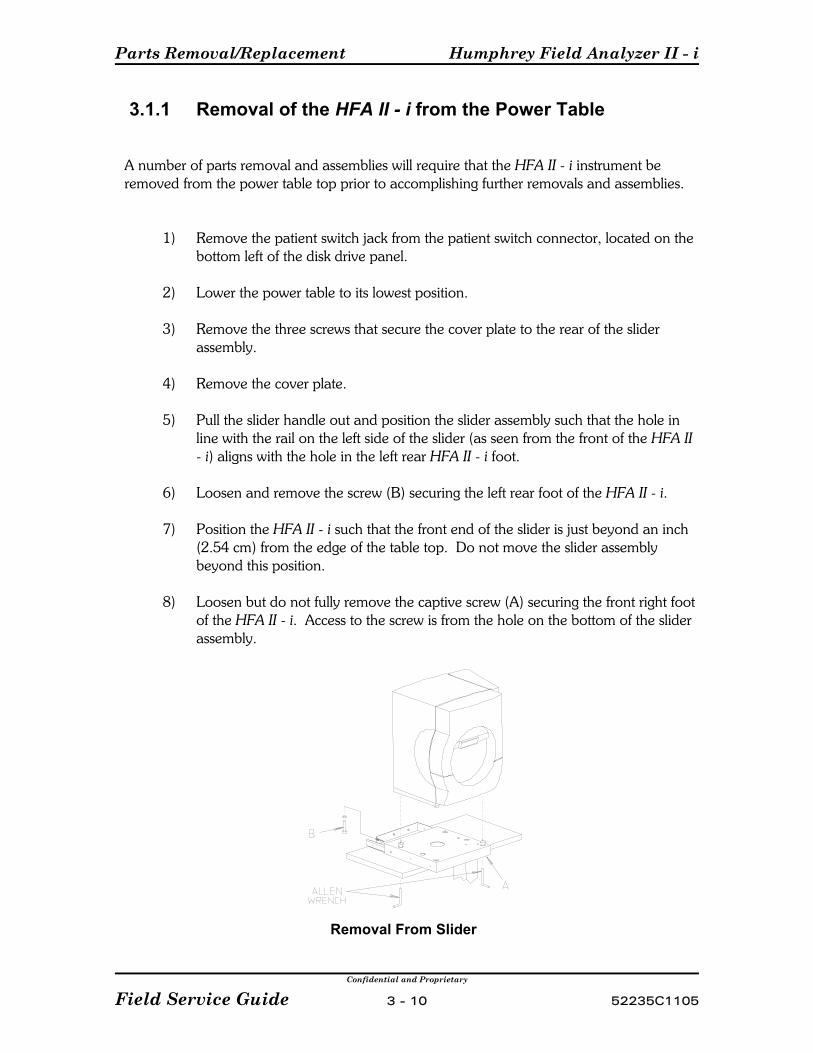
Parts Removal/Replacement Humphrey Field Analyzer II - i
Confidential and Proprietary
Field Service Guide 3 - 10 52235C1105
3.1.1 Removal of the HFA II - i from the Power Table
A number of parts removal and assemblies will require that the HFA II - i instrument beremoved from the power table top prior to accomplishing further removals and assemblies.
1) Remove the patient switch jack from the patient switch connector, located on thebottom left of the disk drive panel.
2) Lower the power table to its lowest position.
3) Remove the three screws that secure the cover plate to the rear of the sliderassembly.
4) Remove the cover plate.
5) Pull the slider handle out and position the slider assembly such that the hole inline with the rail on the left side of the slider (as seen from the front of the HFA II- i) aligns with the hole in the left rear HFA II - i foot.
6) Loosen and remove the screw (B) securing the left rear foot of the HFA II - i.
7) Position the HFA II - i such that the front end of the slider is just beyond an inch(2.54 cm) from the edge of the table top. Do not move the slider assemblybeyond this position.
8) Loosen but do not fully remove the captive screw (A) securing the front right footof the HFA II - i. Access to the screw is from the hole on the bottom of the sliderassembly.
Removal From Slider
Humphrey Field Analyzer II - i Parts Removal/Replacement
Confidential and Proprietary
52235C1105 3 - 11 Field Service Guide
3.2 Front Cover Assembly Removal
NOTE - As described below, the front cover assembly must first be partially removed to allowan internal cable and ground wire to be disconnected (step 3) before the cover can be removedcompletely.
1) Loosen the two captive 1/4-turn fasteners located along the bottom front of the frontcover assembly.
2) Pull the bottom of the front cover assembly out slightly; then gradually lift up on thefront cover assembly while pulling out from the top. This will free the front coverassembly from the rest of the instrument.
3) While holding onto the front cover assembly, disconnect the ribbon cable from thePatient Support Interconnect PCB and disconnect the ground wire from the chassis.
4) Remove the front cover assembly from the instrument.
Replacement Notes:
P Do not over tighten the 1/4-turn fasteners.
P Be sure to reconnect the ground wire to the chassis and the ribbon cable to thePatient Support Interconnect PCB before attaching the front cover assembly. Guidethe cover on carefully to avoid pinching the ground wire or the forehead rest drivebelt between cover and chassis.
Follow-up Checks/Adjustments:
See Table 3-1.

Parts Removal/Replacement Humphrey Field Analyzer II - i
Confidential and Proprietary
Field Service Guide 3 - 12 52235C1105
3.3 Rear Cover Assembly Removal
1) Remove the front cover assembly (3.2).
2) Remove the projection lamp access cover.
3) Remove the fan filter door completely (to avoid interference during rear coverremoval.)
4) Remove the cables and cords from connector on the back panel.
5) Remove the two screws located near the top of the rear cover assembly.
6) Remove the two screws that were exposed by removing the fan filter door.
7) Remove the four screws located along the bottom and side of the rear coverassembly.
Caution — While the cover assembly is being manipulated in the nextstep, be very careful to avoid damaging the neutral density wedges whichare located very close to the top of the cover. The projection lamp cableand the heatsink on the CRT PCB also are very close to the cover.
8) Pull the rear cover assembly part way out, disconnect the fan connector, and thenremove the rear cover assembly.
Replacement Notes:
P Remember to reconnect the fan before reinstalling the rear cover.
P Work carefully to avoid damaging the projection assembly by contact with the coverassembly.
P Be careful of the routing of various cables to prevent them from being damaged bybeing pinched between the rear cover assembly and the frame.
P After the unit is reassembled and power is applied, check that the fan is operating.
P Ensure that the brightness potentiometer moves freely.
Follow-up Checks/Adjustments:
See Table 3-1.
Humphrey Field Analyzer II - i Parts Removal/Replacement
Confidential and Proprietary
52235C1105 3 - 13 Field Service Guide
3.4 Operator Panel Assembly Removal
1) Remove the front cover assembly (3.2).
2) Remove the rear cover assembly (3.3).
3) Remove the patient button assembly from the disk drives panel .
4) Remove the drive housing assembly (3.5).
5) Remove the three screws that secure the CRT bracket clamp.
6) Disconnect:
P the large edge connector on the CRT PCB;P the brightness control potentiometer connector;P the chinrest switch flex-cable connector from the Motor Driver PCBP remove the CPU enclosure lid and then disconnect the touch screen ribbon
cable from connector JTS on the Backplane PCB.
7) Remove the disk/tape drive ribbon cables from their clip(s) on the inside of theoperator panel assembly.
8) Remove the two screws located at the two bottom corners on the backside of theoperator panel assembly (Figure 3-2). These two screws secure the bottom of theoperator panel to the instrument chassis.
9) Loosen the two captive screws, behind the top of the CRT, which are securing theCRT PCB support bracket to the instrument chassis. (Hold onto the operator panelassembly as you loosen the screws, to prevent it from falling.)
10) Remove the operator panel assembly by manipulating it up slightly and to the leftwhile pulling straight out.
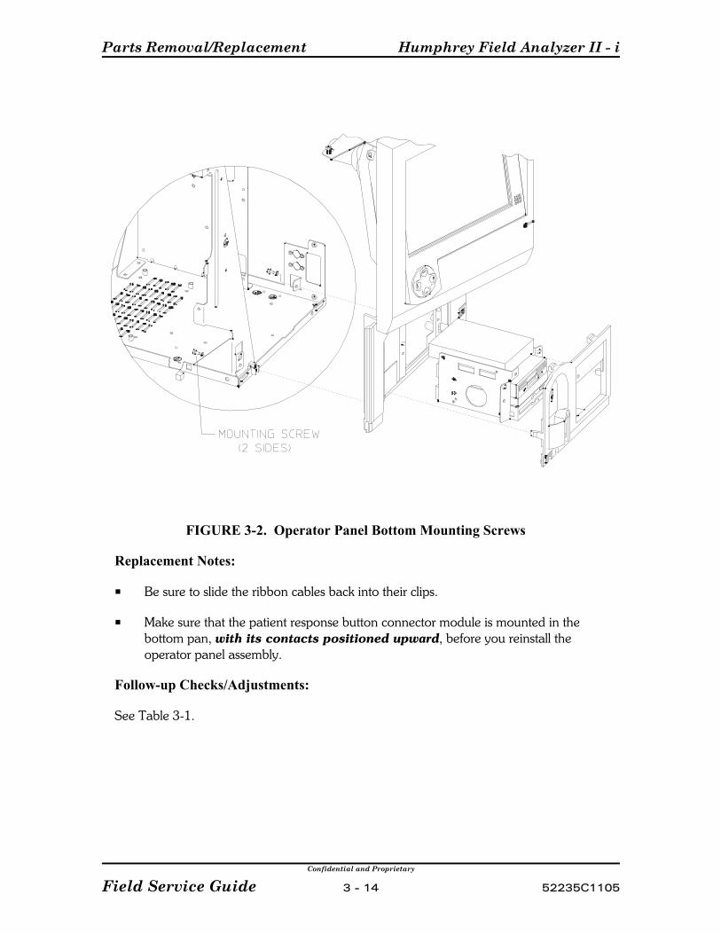
Parts Removal/Replacement Humphrey Field Analyzer II - i
Confidential and Proprietary
Field Service Guide 3 - 14 52235C1105
FIGURE 3-2. Operator Panel Bottom Mounting Screws
Replacement Notes:
P Be sure to slide the ribbon cables back into their clips.
P Make sure that the patient response button connector module is mounted in thebottom pan, with its contacts positioned upward, before you reinstall theoperator panel assembly.
Follow-up Checks/Adjustments:
See Table 3-1.

Humphrey Field Analyzer II - i Parts Removal/Replacement
Confidential and Proprietary
52235C1105 3 - 15 Field Service Guide
3.5 Drive Housing Assembly Removal
1) Remove the patient switch jack from the patient switch connector located on thebottom left of the disk drive panel.
2) Lower the power table to its lowest position.
3) Perform step 3) or step 4) as required.
a) Using both hands, place your fingers along the bottom edge of the drive housingfront panel.
b) Attempt to pull both outward and upward to remove the panel. If the panel canbe removed in this manner, proceed to step 5) below.
4) Remove the front panel from around the drive housing assembly in the followingmanner:
Caution — This step must be performed carefully to avoid possibledamage to the circuit board on the bottom drive.
a) From below the instrument, insert a small diameter tool (such as a hex ball driver— preferably with handle) straight up through the small hole located in thebottom of the instrument, approximately 1.75" back from the front edge of thebezel (Figure 3-3). Insert the tool until it touches the plastic tab securing thebottom edge of the bezel.
Caution — If the tool is inserted with the tip tilted rearward, it maycontact and damage the bottom drive circuit board.
To unlatch the bezel, push the tip of the tool against the latch as you move thehandle of the tool rearward (Figure 3-3).
b) Pull out on the bottom edge of the drive bezel until it separates from the operatorpanel.
5) Remove the three screws (two at the top, one at the bottom) that hold the drivehousing assembly in place.
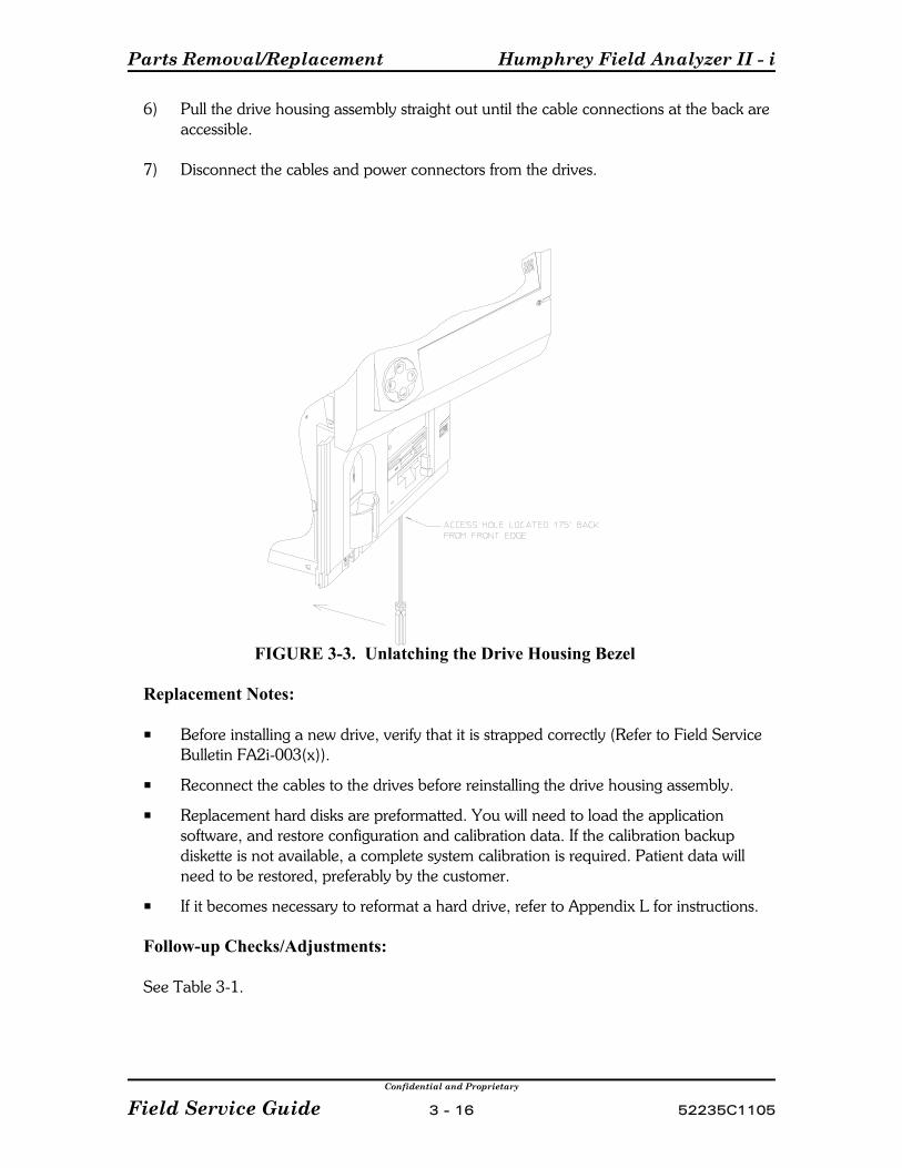
Parts Removal/Replacement Humphrey Field Analyzer II - i
Confidential and Proprietary
Field Service Guide 3 - 16 52235C1105
6) Pull the drive housing assembly straight out until the cable connections at the back areaccessible.
7) Disconnect the cables and power connectors from the drives.
FIGURE 3-3. Unlatching the Drive Housing Bezel
Replacement Notes:
P Before installing a new drive, verify that it is strapped correctly (Refer to Field ServiceBulletin FA2i-003(x)).
P Reconnect the cables to the drives before reinstalling the drive housing assembly.
P Replacement hard disks are preformatted. You will need to load the applicationsoftware, and restore configuration and calibration data. If the calibration backupdiskette is not available, a complete system calibration is required. Patient data willneed to be restored, preferably by the customer.
P If it becomes necessary to reformat a hard drive, refer to Appendix L for instructions.
Follow-up Checks/Adjustments:
See Table 3-1.
Humphrey Field Analyzer II - i Parts Removal/Replacement
Confidential and Proprietary
52235C1105 3 - 17 Field Service Guide
3.6 CPU/Backplane Enclosure Removal
1) Disconnect the printer, COM1, COM2, keyboard, mouse, external VGA, ethernet andUSB connections from the connectors located on the outside of the CPU/BackplaneEnclosure right side.
2) Remove the three M3 screws and washers that secure the top left bracket toCPU/Backplane Enclosure and to the chassis.
3) Remove the four M3 screws and washers from the enclosure lid.
4) Remove touch screen cable connector and patient switch cable connector from theleft side of the Backplane board.
5) Remove the drive lamp LED connector from the bottom of the J12 connector on theCPU board. Note that the two wires connect to the bottom two pins of the connector.
6) Slip the touch screen and patient switch cables from the wire clamp on the left insidewall of the CPU/Backplane Enclosure.
7) Slightly compress and remove the snap bushing from the top left corner of theCPU/Backplane Enclosure.
8) Slide the touch screen and patient switch cables out of the CPU/Backplane Enclosurethrough the slot.
9) Remove the CRT and POWER connectors from the backplane board.
10) Remove the JXVID and JMPS connectors from the backplane board.
11) Remove the two M3 screws and cable clamp that secure the IDE, Floppy and videocables to the top of the CPU/Backplane Enclosure.
12) Remove the inner front screw of the top fan assembly and the Ferrite clamp screw thatsecure the ferrite clamp to the top of the CPU/Backplane Enclosure.
13) Remove the Floppy drive and IDE cable connectors from the top ride side of the CPUboard.
14) Remove the ferrite clamp and attached cables from the CPU/Backplane Enclosure
15) Loosen and release the captive screw on the left side of the bottom CPU/BackplaneEnclosure bracket.
16) Loosen the captive screws on the right side of the bottom bracket.

Parts Removal/Replacement Humphrey Field Analyzer II - i
Confidential and Proprietary
Field Service Guide 3 - 18 52235C1105
17) Loosen the M3 screw that secures the right side bracket to the CPU/BackplaneEnclosure.
18) Loosen and disconnect the 1/4 turn fastener from the retainer at the top of theCPU/Backplane Enclosure.
19) Disconnect the brightness pot cable from the brightness pot assembly.
20) Swing the CPU/Backplane Enclosure out from the chassis just enough to allow accessto the wire saddles on the back of the CPU/Backplane Enclosure.
21) Remove the brightness pot cable from the wire saddle located on the back side of theCPU/Backplane Enclosure.
22) Remove the patient switch cable from the two wire saddles on the back of theCPU/Backplane Enclosure and place the cables free of the CPU/Backplane Enclosure.
23) While supporting the weight of the CPU/Backplane Enclosure, loosen and remove theright side captive screw on the bottom bracket.
Follow-up Checks/Adjustments:
See Table 3-1.
3.7 CPU and Backplane Removal
1) Remove the front cover assembly (3.2).
2) Remove the rear cover assembly (3.3)
3) Remove the CPU/Backplane Enclosure from the Chassis (3.6).
4) Remove the three M3 screws that secure the external CPU PCB clamp to the outsideof the CPU/Backplane Enclosure.
5) Remove the external CPU PCB clamp from the CPU/Backplane Enclosure.
6) Disconnect the two serial port connections from the J9 and J10 connectors on theCPU PCB.
7) Disconnect the parallel port connection from the J7 connector on the CPU PCB.
8) Disconnect the USB cable connector from the J16 connector of the CPU PCB.
9) Remove the two M3 internal CPU PCB clamp screws.

Humphrey Field Analyzer II - i Parts Removal/Replacement
Confidential and Proprietary
52235C1105 3 - 19 Field Service Guide
10) Remove the clamp up through the top corner hole of the CPU/Backplane Enclosure.
11) Remove the five M3 screws that secure the Backplane board to the bottom of theCPU/Backplane Enclosure.
12) Remove the upper fan connector.
13) Remove the CPU PCB and Backplane board as a unit from the CPU/BackplaneEnclosure.
Follow-up Checks/Adjustments:
See Table 3-1.
3.8 Motor Driver PCB Removal
1) Remove the front cover assembly (3.2).
2) Remove the rear cover assembly (3.3).
3) Disconnect the camera cable connector from the P14 connector located in the lowerleft side of the Motor Driver Board (MDB).
4) Disconnect the chinrest motor cable connector from the P5 connector located at theupper left corner of the MDB.
5) Disconnect the Projection Interconnect cables from the P1 and P2 connectors locatedat the top of the MDB.
6) Disconnect the projection lamp cable and the yellow lamp cable connectors from theP3 and P4 connectors located on the top right side of the MDB.
7) Disconnect the Fixation Interface Board cable connector at the P7 connector locatedin the top right corner of the MDB.
8) Disconnect the Chinrest Interface Board cable connector at the P10 connector locatedon the top right side of the MDB.
9) Disconnect the JXVID ribbon cable connector at the P13 connector located in thelower right side of the MDB.
Parts Removal/Replacement Humphrey Field Analyzer II - i
Confidential and Proprietary
Field Service Guide 3 - 20 52235C1105
10) Remove the three screws and right side bracket that secures the CPU/BackplaneEnclosure to the chassis.
11) Disconnect the DC Distribution cable from the bottom of the backside of the MDB.
12) Remove the six screws securing the Motor Driver PCB to the chassis.
13) Slide the MDB to the right and disconnect the JMPS ribbon cable connector at theP15 connector located in the bottom of the middle of the MDB.
14) Remove the Motor Driver PCB.
Replacement Notes:
P Reconnect the cable to the back of the Motor Driver PCB before reinstalling the PCB.
Follow-up Checks/Adjustments:
See Table 3-1.
3.9 Separation of the CPU from the Backplane
NOTE - Improper attempts at separation of the Backplane board and Processor board can result in irrepairable damage to the backplane board or processor board.
1) Place the index finger of your left hand on the E9 mounting hole located along sidethe PCI connector of the Backplane Board.
2) Place the thumb of your left hand on the E10 mounting hole located along side theEISA connector of the Backplane Board.
3) Grasp the CPU PCB board by the edge bracket with your right hand.
4) Pull straight up on the CPU PCB with you right hand while holding the backplaneboard flat with your left hand until the CPU PCB pops out of the PCI and EISAsockets.
Follow-up Checks/Adjustments:
See Table 3-1.

Humphrey Field Analyzer II - i Parts Removal/Replacement
Confidential and Proprietary
52235C1105 3 - 21 Field Service Guide
3.10 Power Supply Removal
NOTE - The power supply used on the HFA II - i is different from that of the HFA II. Do not removethe keys found in the power supply output cables. Do not attempt to use the HFA II power supply.
1) Lower the power table to its lowest position and lock the table top in its centerposition.
2) Remove the front cover assembly (3.2).
3) Remove the rear cover assembly (3.3).
4) Ensure that the power cord is disconnected.
5) Disconnect the two large connectors from the power supply.
6) Remove the two screws securing the power supply assembly.
7) Lift the power supply and carefully maneuver the power supply out of the sideopening in the chassis. (Watch out for the Fixation Interconnect PCB mounted on thebowl.)
8) With a screwdriver, unfasten the two AC supply lines and ground wire attached to thepower supply.
9) Remove the power supply.
Replacement Notes:
P Reconnect the three input wires before reinstalling the power supply assembly.
Follow-up Checks/Adjustments:
See Table 3-1.

Parts Removal/Replacement Humphrey Field Analyzer II - i
Confidential and Proprietary
Field Service Guide 3 - 22 52235C1105
3.11 CRT PCB Removal
1) Remove the operator panel assembly (3.4).
2) Carefully discharge the CRT high voltage to ground and disconnect the high voltagelead from the CRT.
3) Disconnect:
P the yoke connector from the CRT PCB.
P the connector on the end of the CRT neck.
4) Release and remove the CRT PCB from its four plastic standoffs.
Replacement Notes:
P The CRT anode lead must be routed over the top of the CRT neck. If the lead passesunder the neck of the CRT, it lays next to the bowl and the electrostatic field aroundthe lead will attract dust to the inside of the bowl.
Follow-up Checks/Adjustments:
See Table 3-1.

Humphrey Field Analyzer II - i Parts Removal/Replacement
Confidential and Proprietary
52235C1105 3 - 23 Field Service Guide
3.12 CRT Removal
1) Remove the operator panel (3.4).
2) Carefully discharge the CRT high voltage to ground and disconnect the high voltagelead from the CRT.
3) Disconnect:
P the yoke connector from the CRT PCB.
P the connector at the end of the CRT neck.
4) Remove the screw (item 1, Figure 3-4) at each corner of the CRT bracket.
5) Remove the CRT assembly from the operator panel.
6) Remove the four screws (item 2, Figure 3-4) securing the CRT to the bracket. Becareful not to lose the washers, and make note of how many washers are used oneach screw. (The washers adjust the mounted position of the CRT.)
Replacement Notes:
P Anytime the CRT or touch screen is disassembled from the foam gaskets, the CRTand touch screen viewing surfaces should be carefully cleaned before reassembly.
P Ensure that the foam gaskets for the CRT and touch screen are sealing properly, withno gaps between them.
P Tighten the CRT mounting screws enough to compress the foam gaskets slightly for agood seal but DO NOT OVERTIGHTEN. If the gaskets are overcompressed, thetouch screen surface will be pressed against the operator panel bezel and theinstrument will malfunction.Check for adequate clearance by sliding the edge of a business card between thetouch screen surface and the edge of the bezel along the entire perimeter of the bezel. If necessary, loosen the two top CRT mounting screws slightly to obtain adequateclearance.
P Be sure that all of the washers (spacers) are in place on the mounting screws beforesecuring the CRT to the bracket.
P The CRT must be mounted with its anode connector downward, and the CRT anodelead routed over the top of the CRT neck. If the lead passes under the neck of theCRT, it lays next to the bowl and the electrostatic field around the lead will attract dustto the inside of the bowl.
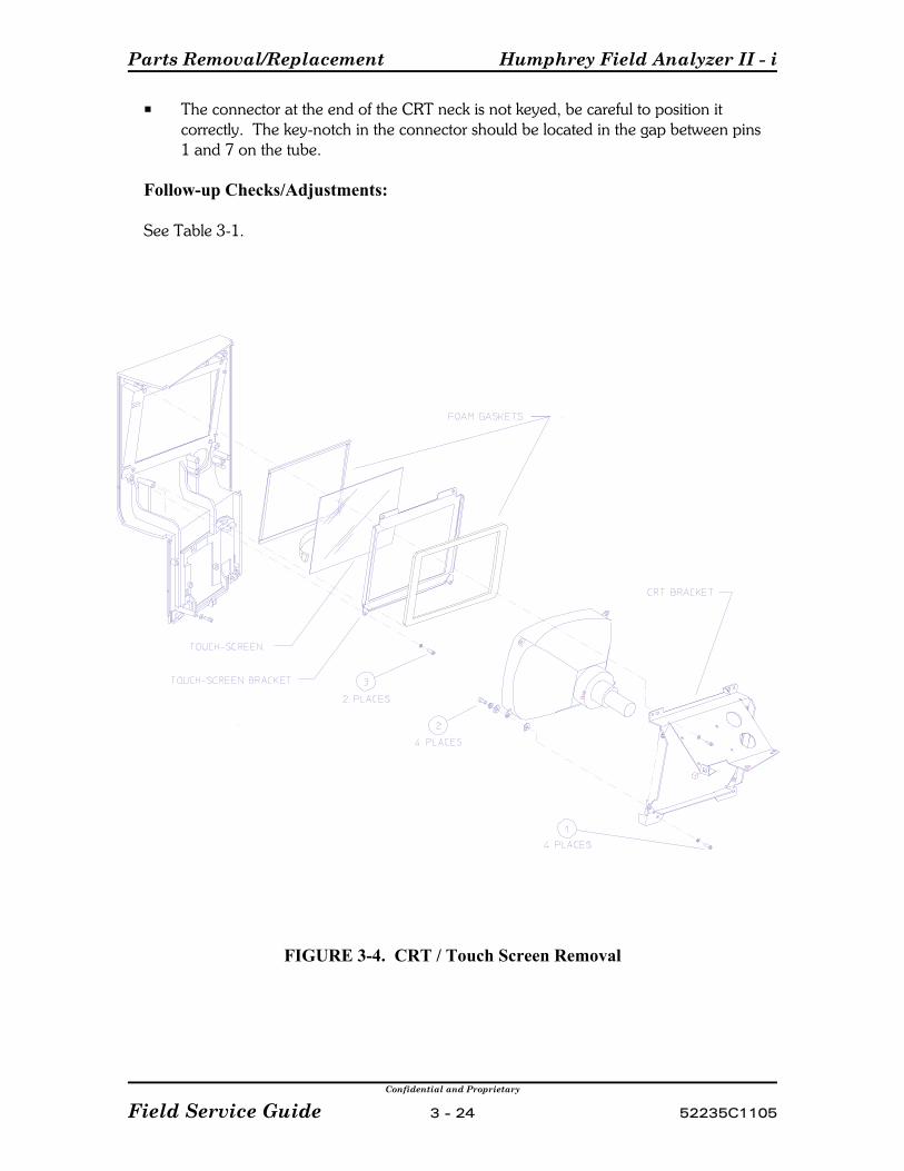
Parts Removal/Replacement Humphrey Field Analyzer II - i
Confidential and Proprietary
Field Service Guide 3 - 24 52235C1105
P The connector at the end of the CRT neck is not keyed, be careful to position itcorrectly. The key-notch in the connector should be located in the gap between pins1 and 7 on the tube.
Follow-up Checks/Adjustments:
See Table 3-1.
FIGURE 3-4. CRT / Touch Screen Removal
Humphrey Field Analyzer II - i Parts Removal/Replacement
Confidential and Proprietary
52235C1105 3 - 25 Field Service Guide
3.13 Touch Screen Removal
1) Remove the operator panel (3.4).
2) Carefully discharge the CRT high voltage to ground.
3) Remove the screw (item 1, Figure 3-4) at each corner of the CRT bracket.
4) Remove the CRT assembly from the operator panel.
5) Remove the two screws (item 3, Figure 3-4) holding the touch screen bracket andremove the bracket.
6) Remove the touch screen.
Replacement Notes:
P Anytime the CRT or touch screen is disassembled from the foam gaskets, the CRTand touch screen viewing surfaces should be carefully cleaned before reassembly.
P Make sure that the touch surface is facing outward when mounting the touchscreen. (The touch surface is a thin film laminated to one side of a glass plate. This is easily observed by looking at the point where the flex cable exits the touchscreen.)
P Ensure that the foam gaskets for the CRT and touch screen are sealing properly,with no gaps.
P The CRT anode lead must be routed over the top of the CRT neck. If the leadpasses under the neck, it lays next to the bowl and the electrostatic field aroundthe lead will attract dust to the inside of the bowl.
Follow-up Checks/Adjustments:
See Table 3-1.
Parts Removal/Replacement Humphrey Field Analyzer II - i
Confidential and Proprietary
Field Service Guide 3 - 26 52235C1105
3.14 CCD Camera Removal1) Remove the front cover assembly (3.2).
2) Remove the rear cover assembly (3.3).
3) Remove the camera cable from the P14 connector of the motor driver board.
4) Loosen the two captive screws securing the camera to the Camera Mount.
5) Make note of the lens setting, for reference during reassembly.
6) Remove the camera from the Camera Mount.
Replacement Notes:
P Before installing the camera, adjust the lens to the setting noted during cameraremoval, but DO NOT secure the lens in position yet with RTV. (If the originalsetting was not noted, or if a new camera is being installed, set the mark on thelens to align with number 2.) When the HFA II - i has been reassembled to thepoint where it can be operated, check/adjust and secure the camera focus asdescribed in 4.9.7, Camera Focus.
Follow-up Checks/Adjustments:
See Table 3-1.
3.15 Fixation Interconnect PCB Removal
1) Remove the front cover assembly (3.2).
2) Remove the rear cover assembly (3.3).
3) Remove the camera assembly (3.14).
4) Remove the bowl lamp connectors from P1 and P2 of the fixation interconnectPCB.
5) Remove the IR LED connectors from P3 and P4 of the fixation interconnect PCB.
6) Remove the ribbon cable from P5 connector of the fixation interconnect PCB.
7) Press the tabs outward on each side of the PCB to release it from the CameraMount.

Humphrey Field Analyzer II - i Parts Removal/Replacement
Confidential and Proprietary
52235C1105 3 - 27 Field Service Guide
8) Remove the Central Fixation LED from the Camera Mount by gently pressingdown on the holding tab with a small allen wrench, while pulling out the LED bythe cable.
9) Loosen the M4 screw at the top of the Camera Mount and remove the two M4screws at the bottom. If the bowl is still in the instrument, the camera will need tobe removed to access the top screw.
10) Maneuver the Reflex LED holder through the opening in the Camera Mount. Ifyou are replacing the Fixation PCB, you must cut the tie-wrap and remove theReflex LED from the Reflex LED holder.
Replacement Notes:
1) When re-inserting the Central Fixation LED, you must line up the notch on theLED with the flat portion of the holder. You will hear a click when the LED movesinto position.
2) The Reflex LED holder will be re-used with the new Fixation PCB. Make sure thatyou tie-wrap the new Reflex LED to the Reflex LED holder.
Follow-up Checks/Adjustments:
See Table 3-1.
3.16 Central Fixation LED/Beamsplitter Removal
1) Remove the CCD camera (3.14).
2) Remove the Central Fixation LED from the Camera Mount by gently pressingdown on the holding tab with a small allen wrench, while pulling out the LED bythe cable.
3) Press a small screw driver against the flat side of the beamsplitter clip and lift theclip upwards.
4) Remove the beamsplitter from the mount. When working with the beamsplitter,make sure that you do not get fingerprints on its surfaces.
Replacement Notes:
P To secure the beamsplitter in place, place the hooks, on the open side of thebeamsplitter clip, in the slots and press down on the flat side of the clip
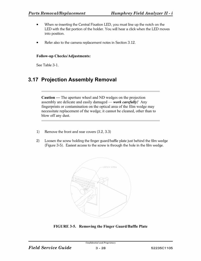
Parts Removal/Replacement Humphrey Field Analyzer II - i
Confidential and Proprietary
Field Service Guide 3 - 28 52235C1105
P When re-inserting the Central Fixation LED, you must line up the notch on theLED with the flat portion of the holder. You will hear a click when the LED movesinto position.
P Refer also to the camera replacement notes in Section 3.12.
Follow-up Checks/Adjustments:
See Table 3-1.
3.17 Projection Assembly Removal
Caution — The aperture wheel and ND wedges on the projectionassembly are delicate and easily damaged — work carefully! Anyfingerprints or contamination on the optical area of the film wedge maynecessitate replacement of the wedge; it cannot be cleaned, other than toblow off any dust.
1) Remove the front and rear covers (3.2, 3.3)
2) Loosen the screw holding the finger guard/baffle plate just behind the film wedge(Figure 3-5). Easiest access to the screw is through the hole in the film wedge.
FIGURE 3-5. Removing the Finger Guard/Baffle Plate

Humphrey Field Analyzer II - i Parts Removal/Replacement
Confidential and Proprietary
52235C1105 3 - 29 Field Service Guide
3) Disconnect the cable from the projection lamp.
4) Disconnect the two ribbon cables from the Projector Interconnect PCB.
5) Loosen the chassis-mounted, quarter-turn fastener that secures the projectionassembly at its end closest to the CPU PCB.
6) Remove the two screws located at the top front of the bowl assembly.
7) Rotate the turret assembly to position the turret Y-motor towards the front.
8) Move the aperture wheel/color wheel carriage all the way forward, towards thefirst projection mirror.
NOTE - Before lifting the projection assembly out of the instrument, ensure that yourprojection mount tool is set up to match the diameter of the carriage rails (3/8") on theprojection assembly..
9) Lift the projection assembly up and out as you maneuver the turret through thehole in the bowl assembly.
10) Install the projection assembly on the projection mount tool.
Replacement Notes:
Check/clean the optics as necessary before reinstalling the projection assembly.
Follow-up Checks/Adjustments:
See Table 3-1.
Parts Removal/Replacement Humphrey Field Analyzer II - i
Confidential and Proprietary
Field Service Guide 3 - 30 52235C1105
3.18 Projection Interconnect PCB Removal
1) Remove the front and rear covers (3.2, 3.3).
2) Disconnect all cables connected to the Projection Interconnect PCB.
3) Remove the finger shaft guard (two screws), which mounts to two standoffs on theProjection Interconnect PCB.
4) Remove the two screws and two standoffs securing the Projection InterconnectPCB, and remove the board.
Replacement Notes:
P When reinstalling the PCB, loosely install the two PCB mounting screws and leaveoff the two standoffs temporarily. Position the PCB for proper clearance betweenthe flag and edge detector on the bottom side of the Projection Interconnect PCBthen tighten the screws and install the standoffs.
Follow-up Checks/Adjustments:
See Table 3-1.
3.19 Film Wedge/Motor Removal
Caution — The aperture wheel and ND wedges on the projectionassembly are delicate and easily damaged — work carefully! Anyfingerprints or contamination on the optical area of the film wedge maynecessitate replacement of the wedge; it cannot be cleaned, other than toblow off any dust.
1) Remove the front and rear covers (3.2, 3.3).
2) Remove the screw securing the bracket that covers the film wedge motor.
3) Remove the two screws securing the film wedge to the film wedge motor shaft,and remove the wedge.
4) Disconnect the "Right" (P4) cable from the Projector Interconnect PCB.
5) Remove the four screws securing the film wedge motor to the projectionassembly.

Humphrey Field Analyzer II - i Parts Removal/Replacement
Confidential and Proprietary
52235C1105 3 - 31 Field Service Guide
NOTE - If washers between the motor and the frame are present they must be reinstalled.
6) Remove the film wedge motor.
Replacement Notes:
P After installing the film wedge on the motor shaft, rotate the wedge and check forproper clearance of the wedge in the film wedge edge detector.
Follow-up Checks/Adjustments:
See Table 3-1.
3.20 Glass Wedge/Motor Removal
1) Remove the front and rear covers (3.2, 3.3).
2) Remove the two screws and standoffs that mount the finger guard bracket to theProjector Interconnect PCB.
3) Disconnect all cables from the Projector Interconnect PCB.
4) Remove the two remaining screws securing the Projector Interconnect PCB andremove the board.
5) Remove the projection lamp assembly.
6) Remove the film wedge.
7) Remove the screw holding the edge detector for the glass wedge. Push the edgedetector down and away from the glass wedge.
8) Loosen the two setscrews holding the glass wedge to the motor shaft, and removethe wedge.
9) Remove the four screws securing the glass wedge motor, and remove the motor.
NOTE - If washers between the motor and the frame are present they must be reinstalled.

Parts Removal/Replacement Humphrey Field Analyzer II - i
Confidential and Proprietary
Field Service Guide 3 - 32 52235C1105
Replacement Notes:
P Route the cable from the glass wedge motor away from the carriage drive pulleyunder the Projector PCB to avoid possible contact with the pulley.
Follow-up Checks/Adjustments:
See Table 3-1.
3.21 Color Wheel / Aperture Wheel Removal
NOTE - The aperture wheel can be removed only after the color wheel is removed.
1) Remove the front and rear covers (3.2, 3.3).
2) Disconnect the two large ribbon cable connectors from the Projection InterconnectPCB.
3) Remove the two socket head screws holding the carriage assembly to the carriagerail block (Figure 3-6). Carefully remove the carriage and place it on a paddedwork surface that will support the color wheel/aperture wheel without damage tothe wheels.
FIGURE 3-6. Color Wheel/Aperture Wheel Removal

Humphrey Field Analyzer II - i Parts Removal/Replacement
Confidential and Proprietary
52235C1105 3 - 33 Field Service Guide
Caution — In the next steps, several wavy washers and flat washers willbe released. Note their relative positions so that you will be able toreinstall them in the same order as removed.
4) Remove the retaining ring (E-clip) securing the shaft of the color wheel to thecarriage. Carefully remove the washers, and remove the color wheel.
Aperture Wheel removal:
5) Remove the retaining ring (E-clip) securing the shaft of the aperture wheel to thecarriage. Carefully remove the washers, and remove the aperture wheel.
Replacement Notes:
Ensure that the washers are reinstalled on the shaft(s) in the same order as removed(Figure 3-6).
Follow-up Checks/Adjustments:
See Table 3-1.
3.22 Carriage Motor Removal
1) Remove the Projection Interconnect PCB (3.18).
2) Loosen the four screws securing the carriage motor to the projection assembly.
3) Remove the projection assembly, using all necessary precautions (3.17).
4) Cut any cable ties securing the carriage motor cable.
5) Remove the four loosened screws holding the motor in place, and remove themotor.
6) Loosen the two setscrews on the carriage motor pulley, and remove the pulleyfrom the shaft.
Parts Removal/Replacement Humphrey Field Analyzer II - i
Confidential and Proprietary
Field Service Guide 3 - 34 52235C1105
Replacement Notes:
P The replacement cable tie(s) for the motor cable must be installed beforereinstalling the projection assembly in the instrument.
P Adjust the belt tension (Section 4).
Follow-up Checks/Adjustments:
See Table 3-1.
3.23 Shutter Removal
Caution — Handle the shutter carefully! It is delicate and easilydeformed or damaged.
1) Switch ON the HFA II - i. Proceed to the shutter calibration menu. Select OPENshutter. Do not make any other selections.
2) Remove the front and rear covers (3.2, 3.3).
3) Loosen the two setscrews holding the ND film wedge to its shaft, and remove thewedge. (Use care to not bend the film wedge and to not get fingerprints or markson the film surface.)
4) Observe the current position of the shutter. The shutter should later be installed atthe same position — this is very important!
5) Loosen the setscrew that secures the shutter to the motor shaft. Gently angle theshutter, and remove it from the shaft.
Replacement Notes:
P Position the shutter for adequate clearance between the glass wedge and theprojection casting. Gently bend the shutter, if necessary.
P Put the shutter in the same position you observed during removal, before securingit to the motor shaft.
Follow-up Checks/Adjustments:
See Table 3-1.

Humphrey Field Analyzer II - i Parts Removal/Replacement
Confidential and Proprietary
52235C1105 3 - 35 Field Service Guide
3.24 Shutter Motor Removal
1) Remove the projection assembly and install it on the projection mount tool (3.17).
2) Disconnect the shutter cable (P6) from the Projector Interconnect PCB (cut thecable ties if necessary).
3) Remove the two screws securing the shutter motor to the projection assembly,and remove the motor.
4) Loosen the setscrew securing the hub and shutter to the motor shaft, and removethem from the shaft.
Replacement Notes:
P Position the shutter for adequate clearance between the glass wedge and theprojection casting. Gently bend the shutter, if necessary.
Follow-up Checks/Adjustments:
See Table 3-1.
3.25 Carriage Motor Belt Removal
1) Loosen the four screws securing the carriage motor to the projection assembly.
2) Remove the two small screws securing the belt plate against the belt.
3) Remove the belt.
Replacement Notes:
Adjust the belt tension (Section 4).
Follow-up Checks/Adjustments:
See Table 3-1.

Parts Removal/Replacement Humphrey Field Analyzer II - i
Confidential and Proprietary
Field Service Guide 3 - 36 52235C1105
3.26 Horizontal (X-axis) Turret Motor Removal
1) Remove the front and rear covers (3.2, 3.3).
2) Disconnect the "X-Axis" 6-pin connector (P10) from the Projection InterconnectPCB.
3) Remove the projection assembly and install it on the projection mount tool (3.17).
4) Remove the four screws securing the X-axis turret motor to the projectionassembly.
5) Remove the belt from the motor pulley; then remove the motor.
6) Loosen the two setscrews on the hub/pulley and remove it from the motor shaft.
Replacement Notes:
Adjust the belt tension (Section 4).
Follow-up Checks/Adjustments:
See Table 3-1.

Humphrey Field Analyzer II - i Parts Removal/Replacement
Confidential and Proprietary
52235C1105 3 - 37 Field Service Guide
3.27 Horizontal (X-axis) Turret Motor Belt Removal
1) Remove the projection assembly and install it on the projection mount tool (3.17).
NOTE - Before lifting the projection assembly out of the instrument, ensure that yourprojection mount tool is set up to match the diameter of the carriage rails (3/8") on theprojection assembly.
2) Carefully slide the X-axis turret motor belt off the large gear at the top of theturret.
FIGURE 3-7. Turret Removal
3) From the top side of the assembly, locate the hole in the casting that providesaccess to the top edge of the turret. Through this hole, one by one, remove thethree screws that hold the turret in place (Figure 3-7).
(As the screws are removed, the X-axis edge detector flag on the turret becomesloose. Check that the loosened flag does not hit the edge detector and blockrotation of the turret for access to the third screw.)
4) Carefully pull the turret out of its top bearing.
NOTE - Be careful to prevent dust or debris from reaching the internal optics of theturret while the turret is open.
5) Remove the turret motor belt.

Parts Removal/Replacement Humphrey Field Analyzer II - i
Confidential and Proprietary
Field Service Guide 3 - 38 52235C1105
Replacement Notes:
P Check/adjust the horizontal (X-axis) edge detector on the turret before reinstallingthe projection assembly into the instrument.
P Adjust the belt as necessary (see Section 4).
P When the three turret screws have been tightened, secure each one with a smalldab of Loctite® No. 222 (see Appendix A for part number).
P When reassembled, manually rotate the turret to check for smooth movementthroughout its normal range.
Follow-up Checks/Adjustments:
Clean the optics. See Table 3-1.
Humphrey Field Analyzer II - i Parts Removal/Replacement
Confidential and Proprietary
52235C1105 3 - 39 Field Service Guide
3.28 Vertical (Y-axis) Turret Belt/Motor Removal
Caution — Be careful not to damage or dirty the bowl.
1) Remove the Y-axis turret belt from the large pulley.
2) Remove the Y-axis turret belt from the small pulley.
Motor Removal:
3) Remove the two screws securing the Y-axis motor cable bracket.
4) Disconnect the motor cable at the connector.
5) Loosen the two setscrews on the motor pulley and remove it from the shaft.
6) Remove the four screws securing the Y-axis motor to the turret assembly.
7) Remove the Y-axis motor.
Replacement Notes:
Adjust the belt tension (Section 4).
Follow-up Checks/Adjustments:
See Table 3-1.
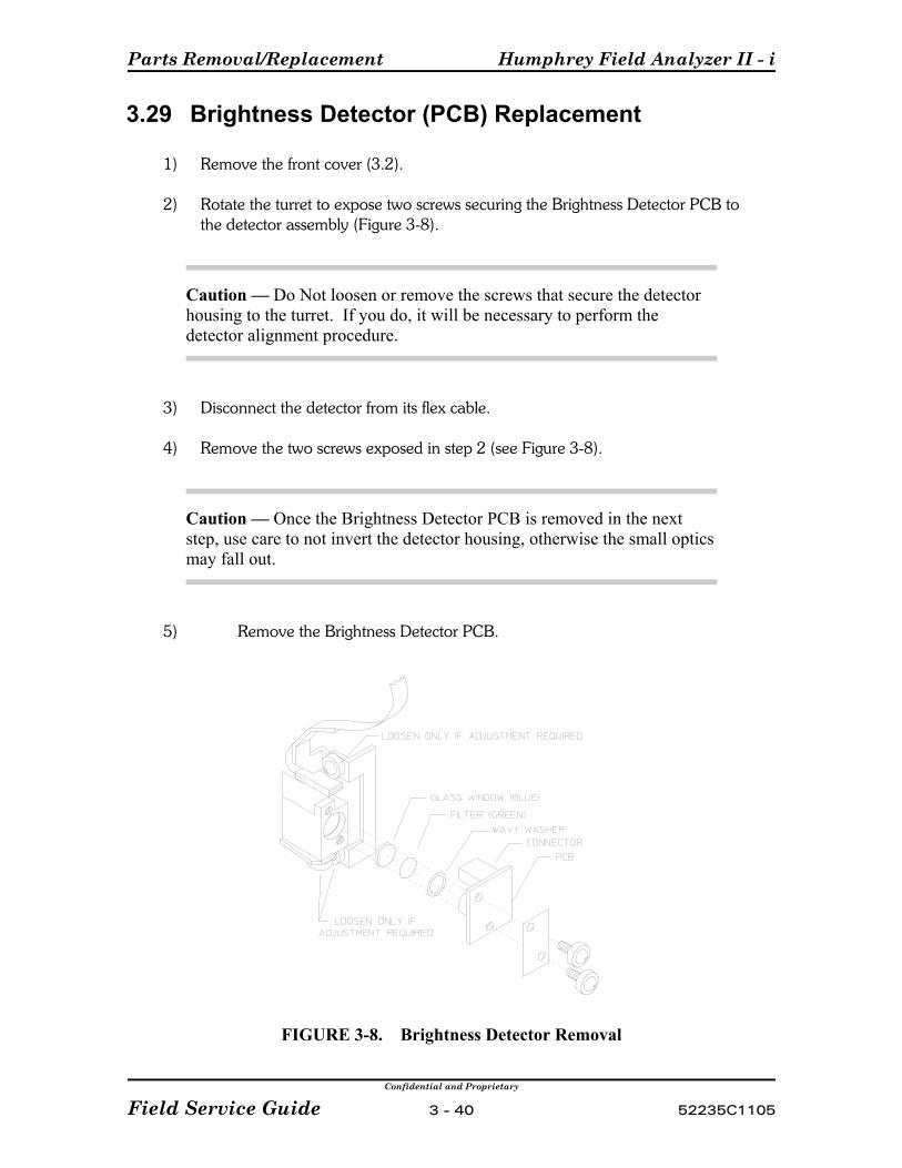
Parts Removal/Replacement Humphrey Field Analyzer II - i
Confidential and Proprietary
Field Service Guide 3 - 40 52235C1105
3.29 Brightness Detector (PCB) Replacement
1) Remove the front cover (3.2).
2) Rotate the turret to expose two screws securing the Brightness Detector PCB tothe detector assembly (Figure 3-8).
Caution — Do Not loosen or remove the screws that secure the detectorhousing to the turret. If you do, it will be necessary to perform thedetector alignment procedure.
3) Disconnect the detector from its flex cable.
4) Remove the two screws exposed in step 2 (see Figure 3-8).
Caution — Once the Brightness Detector PCB is removed in the nextstep, use care to not invert the detector housing, otherwise the small opticsmay fall out.
5) Remove the Brightness Detector PCB.
FIGURE 3-8. Brightness Detector Removal
Humphrey Field Analyzer II - i Parts Removal/Replacement
Confidential and Proprietary
52235C1105 3 - 41 Field Service Guide
Replacement Notes:
P Use care to not get dirt or fingerprints on the detector optics or on the turret lens.
P If any of the small optics have fallen out of the housing, make sure they are cleanbefore reinstalling them, and that they are installed in the correct order (Figure 3-8).
Follow-up Checks/Adjustments:
See Table 3-1.
3.30 Lower Turret Removal1) Remove the front cover (3.2).
2) Remove two screws on the side of the lower turret pulley to detach the lower turretassembly.
Carefully let the lower turret assembly hang by its cable.
Replacement Notes:
P Adjust the belt tension (Section 4).
P Check clearances of Y-motor edge detector.
Follow-up Checks/Adjustments:
See Table 3-1.
Parts Removal/Replacement Humphrey Field Analyzer II - i
Confidential and Proprietary
Field Service Guide 3 - 42 52235C1105
3.31 Turret Cable Assembly Removal
Replacement Notes:
P If a turret cable requires replacement, all three cables must be replaced as anassembly.
Caution — Before removal of the old cable assembly, carefully notecable routing and taping. Failure to properly install the turret cableassembly will cause turret binding and turret noise.
Follow-up Checks/Adjustments:
See Table 3-1.
3.32 Chinrest/Headrest Switch Assembly Removal
1) Remove the operator panel (3.4).
2) Remove the three screws securing the chinrest switch assembly bracket.
3) Remove the chinrest switch assembly .
Replacement Notes:
Follow-up Checks/Adjustments:
See Table 3-1.
Humphrey Field Analyzer II - i Parts Removal/Replacement
Confidential and Proprietary
52235C1105 3 - 43 Field Service Guide
3.33 Chinrest Y-axis Belt/Motor Removal
Belt:
1) Remove the front cover (3.2).
2) Remove the four screws securing the chinrest motor to the bracket.
3) Slip the belt off over the lip of the chinrest motor pulley.
4) Slip the belt off over the lip of the chinrest pulley.
Motor:
1) Remove the front cover (3.2).
2) Make note of the cable ties holding the cable to the chinrest motor, then cut thecable ties. Disconnect the cable at the connector.
3) Remove the four screws securing the chinrest motor to the bracket.
4) Slip the belt off over the lip of the chinrest motor pulley, and remove the motor.
Replacement Notes:
P Adjust the belt tension (Section 4).
P Be sure to secure the connector to the motor body with a cable tie.
P Reattach the ground wire under the motor mounting screw.
Follow-up Checks/Adjustments:
See Table 3-1.

Parts Removal/Replacement Humphrey Field Analyzer II - i
Confidential and Proprietary
Field Service Guide 3 - 44 52235C1105
3.34 Patient Support Horizontal (X-axis) Belt/MotorRemoval
NOTE - The headrest drive belt drives the headrest horizontally in sync with the chinrest. Anytime the headrest belt is off, if either the headrest or chinrest lead screw is rotatedindependently, the headrest and chinrest will become misaligned.
P Remove the front cover (3.2).
P Pull the headrest drive belt (long belt) to move the chinrest horizontal lead screwnut up against its limit nearest to the X-motor. (Since the chinrest and headresthorizontal lead screws are linked by the belt, both lead screws will rotate when thebelt is pulled.)
Belt Removal:
1) Remove the four screws securing the chinrest assembly to the front coverassembly (Figure 3-9).
2) Lift the chinrest assembly away from the front cover assembly and remove the beltfrom the X-motor pulley.
3) Maneuver the belt downward between the headrest pulley and the front coverassembly until the belt is free.
Motor Removal:
1) Remove the four screws securing the chinrest assembly to the front coverassembly (Figure 3-9).
2) Remove the chinrest assembly.
(continued)
FIGURE 3-9. Removing the Chinrest Assembly

Humphrey Field Analyzer II - i Parts Removal/Replacement
Confidential and Proprietary
52235C1105 3 - 45 Field Service Guide
3) Disconnect the "X-MOTOR" cable (P4) from the Patient Support InterconnectPCB. Cut any cable ties holding this cable to the Patient Support InterconnectPCB.
4) Rotate the motor shaft to position the lead screw nut close to the X-motor(Figure 3-10).
5) Loosen the setscrews holding the lead screw to the motor shaft.
6) Grasp the chinrest and move it away from the X-motor until the lead screwdisengages from the motor shaft.
7) Remove the four screws securing the X-motor to the bracket, and remove themotor.
FIGURE 3-10. Disconnecting the X-Motor Lead Screw from the Motor Shaft
Replacement Notes:
P Be sure to reinstall a nylon washer on the motor shaft before attaching the leadscrew. The lead screw should be seated on the motor shaft all the way up to themotor body before tightening the setscrews.
P Before installing the belt:After the lead screw is secured to the motor shaft, rotate the shaft to position thelead screw nut up against its limit nearest to the motor. Then set the headresthorizontal lead screw nut to the same relative position (check for the same amountof thread showing on both lead screws).
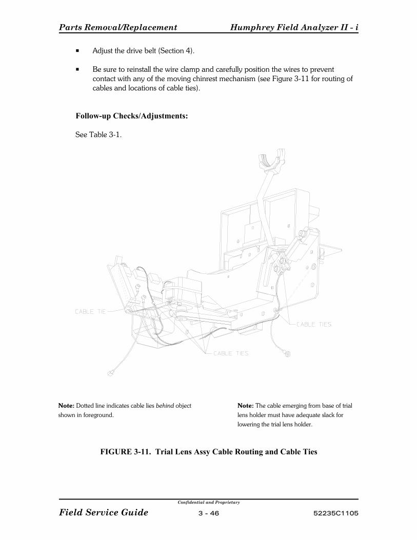
Parts Removal/Replacement Humphrey Field Analyzer II - i
Confidential and Proprietary
Field Service Guide 3 - 46 52235C1105
P Adjust the drive belt (Section 4).
P Be sure to reinstall the wire clamp and carefully position the wires to preventcontact with any of the moving chinrest mechanism (see Figure 3-11 for routing ofcables and locations of cable ties).
Follow-up Checks/Adjustments:
See Table 3-1.
Note: Dotted line indicates cable lies behind object
shown in foreground.
Note: The cable emerging from base of trial
lens holder must have adequate slack for
lowering the trial lens holder.
FIGURE 3-11. Trial Lens Assy Cable Routing and Cable Ties

Humphrey Field Analyzer II - i Parts Removal/Replacement
Confidential and Proprietary
52235C1105 3 - 47 Field Service Guide
3.35 Chinrest Vertical Slide and Lead Screw Removal
1) Remove the front cover (3.2).
2) Remove the four screws securing the chinrest assembly to the front cover(Figure 3-9), and remove the assembly.
3) Remove the plastic chinrest (2 screws).
4) Remove the chinrest cover bracket (2 screws).
5) Turn the pulley on the chinrest X-axis motor to move the chinrest assembly left orright to gain access to the screws holding the vertical lead screw and vertical slide.
Replacement Notes:
P Before installing the headrest drive belt, set the chinrest and headrest horizontallead screw nuts both to the same relative position (check for the same amount ofthread showing on the same side of the lead screws).
P Adjust the drive belt (Section 4).
Follow-up Checks/Adjustments:
See Table 3-1.

Parts Removal/Replacement Humphrey Field Analyzer II - i
Confidential and Proprietary
Field Service Guide 3 - 48 52235C1105
3.36 Chinrest Horizontal Slide Removal
1) Remove the front cover (3.2).
2) Remove the four screws securing the chinrest assembly to the front cover(Figure 3-9).
3) Remove the two screws holding the trial lens trap.
4) Remove the two screws holding the stationary part of the horizontal slide.
5) Remove the two screws holding the moving part of the horizontal slide.
6) Remove the entire slide assembly out from between the stationary bracket and themovable bracket of the chinrest assembly.
Replacement Notes:
P Check the tension of the vertical (Y-axis) and horizontal (X-axis) drive belts(Section 4).
P Straighten the bristles on the trial lens trap brush to position them to the inside ofthe slot in the trap.
P Before installing the headrest drive belt, set the chinrest and headrest horizontallead screw nuts both to the same relative position (check for the same amount ofthread showing on the same side of the lead screws).
Follow-up Checks/Adjustments:
See Table 3-1.
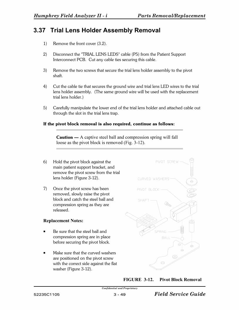
Humphrey Field Analyzer II - i Parts Removal/Replacement
Confidential and Proprietary
52235C1105 3 - 49 Field Service Guide
3.37 Trial Lens Holder Assembly Removal
1) Remove the front cover (3.2).
2) Disconnect the "TRIAL LENS LEDS" cable (P5) from the Patient SupportInterconnect PCB. Cut any cable ties securing this cable.
3) Remove the two screws that secure the trial lens holder assembly to the pivotshaft.
4) Cut the cable tie that secures the ground wire and trial lens LED wires to the triallens holder assembly. (The same ground wire will be used with the replacementtrial lens holder.)
5) Carefully manipulate the lower end of the trial lens holder and attached cable outthrough the slot in the trial lens trap.
If the pivot block removal is also required, continue as follows:
Caution — A captive steel ball and compression spring will fallloose as the pivot block is removed (Fig. 3-12).
6) Hold the pivot block against themain patient support bracket, andremove the pivot screw from the triallens holder (Figure 3-12).
7) Once the pivot screw has beenremoved, slowly raise the pivotblock and catch the steel ball andcompression spring as they arereleased.
Replacement Notes:
P Be sure that the steel ball andcompression spring are in placebefore securing the pivot block.
P Make sure that the curved washersare positioned on the pivot screwwith the correct side against the flatwasher (Figure 3-12).
FIGURE 3-12. Pivot Block Removal
Parts Removal/Replacement Humphrey Field Analyzer II - i
Confidential and Proprietary
Field Service Guide 3 - 50 52235C1105
P Before reinstalling the trial lens holder assembly in the patient support assembly,check for proper operation of the edge detector flag when the trial lens holder israised and lowered. Ensure that the compression spring that holds tension againstthe flag is not over-compressed and preventing proper movement of the flag.
P Before reinstalling the front cover, lift and lower the trial lens holder several timesto check that it operates properly and that the wires to the trial lens holder are notcatching or rubbing against the cover.
P Refer to Section 4.9.6 for Trial Lens Holder alignment.
Follow-up Checks/Adjustments:
See Table 3-1.
3.38 Top Fan Removal
1) Remove front and rear covers (3.2, 3.3)
2) Unplug the fan cable.
3) Remove the two screws attaching the fan bracket to the chassis.
Replacement Notes:
P Make sure that the fan wires are positioned in the narrow slot in the edge ofthe plastic fan housing, and that they are not pinched when the fan mountingscrews are tightened.
Follow-up Checks/Adjustments:
See Table 3-1.
Humphrey Field Analyzer II - i Parts Removal/Replacement
Confidential and Proprietary
52235C1105 3 - 51 Field Service Guide
3.39 Bowl IR LED Assembly Removal
1) Remove the front and rear covers (3.2, 3.3).
2) Remove the tape holding the IR LED assembly wires to the outside of thebowl, and unplug the connector.
3) For the right-hand bowl IR LED, slide the connector and wires out towardsthe front, between the bowl and the baffle and the bottom of the bowl.
Replacement Notes:
P Tighten the left/right IR LED mounting screws only finger tight until afteradjustment has been performed.
Follow-up Checks/Adjustments:
See Table 3-1.
Parts Removal/Replacement Humphrey Field Analyzer II - i
Confidential and Proprietary
Field Service Guide 3 - 52 52235C1105
3.40 Blue-Yellow Module / Bowl Plug Removal
This procedure is for removing the Blue-Yellow module in units equipped with theBlue-Yellow feature, or the Blue-Yellow bowl plug in units not equipped with theBlue-Yellow feature.
1) Remove the front and rear covers (3.2, 3.3).
2) Remove the two screws and washers securing the Blue-Yellow module orunsnap the Blue-Yellow bowl plug from the bowl.
3) Lift out the Blue-Yellow module or bowl plug from the top of thebowl.
Replacement Notes:
Make sure that no light is entering the bowl after reinstalling assembly.
Follow-up Checks/Adjustments:
See Table 3-1.
3.41 Bowl Removal
Caution — Be careful not to damage or dirty the bowl.
1) Remove the front and rear cover assemblies (3.2, 3.3).
2) Remove the projection assembly (3.17).
3) Remove the blue-yellow module (if so equipped) or blue-yellow bowl plug(3.40).
4) Remove the four screws securing the front of the bowl to the chassis.
5) Disconnect:
P The ribbon cable on the Fixation Interconnect PCB.
P Camera cable from the lower-left corner of the Motor Driver PCB. (This is the cable from the camera PCB.)

Humphrey Field Analyzer II - i Parts Removal/Replacement
Confidential and Proprietary
52235C1105 3 - 53 Field Service Guide
P The power Connector on the backside of the Motor Driver PCB.
6) Remove the screw that secures the chassis end of the ground wire that comesfrom the right-hand bowl lamp assembly.
7) Remove two screws securing the left end of the air baffle located below thebowl.
Caution — In the next step, watch closely to prevent the camera fromcatching on cables behind the bowl and the IR LEDs from catching on thelower front baffles.
8) Flex the baffle outward. While holding out on the baffle, lift the bowl until itclears the chassis on the left side, then move the top of the bowl outward andlift it out of the instrument.
9) If a new bowl is going to be installed, note how the wires are routed andtaped on the old bowl before you begin stripping it.
Replacement Notes:
P A replacement bowl comes completely stripped. (See procedure 3.44 forinstallation of the IR bowl plugs on models 720i.)
P On a replacement bowl, secure the wires to the backside of the bowl as theywere on the original bowl.
P Make sure the foam gaskets are properly seated between the bowl and thefan housing of the top fan.
P When reinstalling the bowl, carefully guide the end of the camera past the DCpower harness in the instrument chassis.
Follow-up Checks/Adjustments:
See Table 3-1.

Parts Removal/Replacement Humphrey Field Analyzer II - i
Confidential and Proprietary
Field Service Guide 3 - 54 52235C1105
3.42 Reflex Gaze LED Removal
The Reflex Gaze LED is part of the Fixation Interconnect PCB.(See Fixation Interconnect PCB Removal, Section 3.15)
NOTE - The reflex gaze LED is used in the models 720i for additional eye illumination tohelp differentiate the iris and pupil in the video insert for patients with a dark iris. In the740i and 750i, the reflex gaze LED is used to monitor gaze tracking.
3.43 Bowl Lamp Assembly Removal
1) Remove the front cover assembly (3.2).
2) Remove the rear cover assembly (3.3).
3) Loosen the four bowl mounting screws to relax the bowl.
4) Unplug the right/left bowl lamp connector from the Fixation InterconnectPCB.
5) Remove the tape securing the bowl lamp cable to the bowl.
6) Remove the hex head screw securing the ground cable to the frame.
7) Remove the two hex head screws (inside the bowl) securing the lampassembly to the bowl.
8) For Right Bowl Lamp: Remove the complete lamp assembly by lifting upand maneuvering it out from the front of the instrument, between the bowland frame.For Left Bowl Lamp: Remove the complete lamp assembly by lifting upand maneuvering it out from the back of the instrument, between the bowland frame.
Replacement Notes:
P The bowl lamps must be replaced in pairs only.
P The bowl lamp baffles snap into place.
Follow-up Checks/Adjustments:
See Table 3-1.

Humphrey Field Analyzer II - i Parts Removal/Replacement
Confidential and Proprietary
52235C1105 3 - 55 Field Service Guide
3.44 IR Bowl Plug Removal/Installation
1) Remove the two screws holding the IR Illumination Plug Bracket to the bowl.
2) When installing the IR Bowl Plug, you must rotate the plug until it’s contouredtip is flush with the inner surface of the bowl before tightening the screw thatholds it to the bracket
Replacement Notes:
Follow-up Checks/Adjustments:
See Table 3-1.
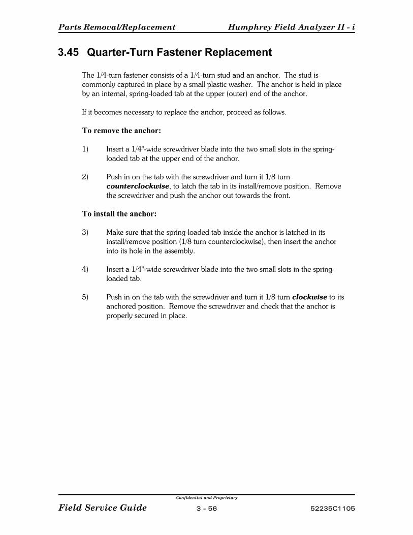
Parts Removal/Replacement Humphrey Field Analyzer II - i
Confidential and Proprietary
Field Service Guide 3 - 56 52235C1105
3.45 Quarter-Turn Fastener Replacement
The 1/4-turn fastener consists of a 1/4-turn stud and an anchor. The stud iscommonly captured in place by a small plastic washer. The anchor is held in placeby an internal, spring-loaded tab at the upper (outer) end of the anchor.
If it becomes necessary to replace the anchor, proceed as follows.
To remove the anchor:
1) Insert a 1/4"-wide screwdriver blade into the two small slots in the spring-loaded tab at the upper end of the anchor.
2) Push in on the tab with the screwdriver and turn it 1/8 turncounterclockwise, to latch the tab in its install/remove position. Removethe screwdriver and push the anchor out towards the front.
To install the anchor:
3) Make sure that the spring-loaded tab inside the anchor is latched in itsinstall/remove position (1/8 turn counterclockwise), then insert the anchorinto its hole in the assembly.
4) Insert a 1/4"-wide screwdriver blade into the two small slots in the spring-loaded tab.
5) Push in on the tab with the screwdriver and turn it 1/8 turn clockwise to itsanchored position. Remove the screwdriver and check that the anchor isproperly secured in place.
Confidential and Proprietary
52235C1105 4 - 1 Field Service Guide
Section 4 - Adjustment / Calibration
4.1 Introduction . . . . . . . . . . . . . . . . . . . . . . . . . . . . . . . . . . . . . . . . . . 4 - 3
4.2 Related Procedures . . . . . . . . . . . . . . . . . . . . . . . . . . . . . . . . . . . . 4 - 5
4.2.1 HFA II - i Calibration and Service Guidelines . . . . . . . . . . 4 - 5
4.3 Calibration / Diagnostics Access . . . . . . . . . . . . . . . . . . . . . . . . . . . 4 - 6
4.4 Show Dialog . . . . . . . . . . . . . . . . . . . . . . . . . . . . . . . . . . . . . . . . . 4 - 6
4.5 System Log . . . . . . . . . . . . . . . . . . . . . . . . . . . . . . . . . . . . . . . . . . 4 - 6
4.6 Database . . . . . . . . . . . . . . . . . . . . . . . . . . . . . . . . . . . . . . . . . . . . 4 - 6
4.7 Video Test Pattern . . . . . . . . . . . . . . . . . . . . . . . . . . . . . . . . . . . . . 4 - 6
4.8 Calibration . . . . . . . . . . . . . . . . . . . . . . . . . . . . . . . . . . . . . . . . . . . 4 - 7
4.8.1 Verification (Obtaining Before and After Light Intensity
Calibration Values) . . . . . . . . . . . . . . . . . . . . . . . . . . . . . . 4 - 7
4.8.1.1 Intensity / Spot Ratio . . . . . . . . . . . . . . . . . . . . . . . . . 4 - 7
4.8.1.2 Exerciser . . . . . . . . . . . . . . . . . . . . . . . . . . . . . . . . . 4 - 11
4.8.1.3 QA Tests . . . . . . . . . . . . . . . . . . . . . . . . . . . . . . . . . 4 - 12
4.8.2 Mechanical . . . . . . . . . . . . . . . . . . . . . . . . . . . . . . . . . . . 4 - 12
4.8.2.1 Projector . . . . . . . . . . . . . . . . . . . . . . . . . . . . . . . . . 4 - 12
4.8.2.2 Shutter . . . . . . . . . . . . . . . . . . . . . . . . . . . . . . . . . . 4 - 13
4.8.2.3 Aperture . . . . . . . . . . . . . . . . . . . . . . . . . . . . . . . . . 4 - 14
4.8.2.4 Color . . . . . . . . . . . . . . . . . . . . . . . . . . . . . . . . . . . . 4 - 15
4.8.2.5 Right / Left Home . . . . . . . . . . . . . . . . . . . . . . . . . . 4 - 16
4.8.2.6 Offset . . . . . . . . . . . . . . . . . . . . . . . . . . . . . . . . . . . . 4 - 16
4.8.2.7 Focus . . . . . . . . . . . . . . . . . . . . . . . . . . . . . . . . . . . . 4 - 16
4.8.2.8 Detector . . . . . . . . . . . . . . . . . . . . . . . . . . . . . . . . . . 4 - 17
4.8.2.9 Target . . . . . . . . . . . . . . . . . . . . . . . . . . . . . . . . . . . 4 - 18
4.8.3 Intensity . . . . . . . . . . . . . . . . . . . . . . . . . . . . . . . . . . . . . 4 - 20
4.8.3.1 Projector . . . . . . . . . . . . . . . . . . . . . . . . . . . . . . . . . 4 - 20
4.8.3.1.1 White . . . . . . . . . . . . . . . . . . . . . . . . . . . . . . . . . . . . 4 - 20
4.8.3.1.2 Blue . . . . . . . . . . . . . . . . . . . . . . . . . . . . . . . . . . . . . 4 - 21
4.8.3.2 Bowl . . . . . . . . . . . . . . . . . . . . . . . . . . . . . . . . . . . . 4 - 23
4.8.3.2.1 White . . . . . . . . . . . . . . . . . . . . . . . . . . . . . . . . . . . . 4 - 23
4.8.3.2.2 Yellow . . . . . . . . . . . . . . . . . . . . . . . . . . . . . . . . . . . 4 - 24
4.8.3.3 Wedge . . . . . . . . . . . . . . . . . . . . . . . . . . . . . . . . . . . 4 - 25
Adjustment / Calibration Humphrey Field Analyzer II - i
Confidential and Proprietary
Field Service Guide 4 - 2 52235C1105
4.8.3.4 Blue Correction . . . . . . . . . . . . . . . . . . . . . . . . . . . . 4 - 26
4.8.4 Print Cal Values . . . . . . . . . . . . . . . . . . . . . . . . . . . . . . . 4 - 30
4.8.5 Miscellaneous . . . . . . . . . . . . . . . . . . . . . . . . . . . . . . . . . 4 - 30
4.8.6 Camera . . . . . . . . . . . . . . . . . . . . . . . . . . . . . . . . . . . . . . 4 - 30
4.8.6.1 Camera Position / Size . . . . . . . . . . . . . . . . . . . . . . . 4 - 30
4.8.6.2 Gaze Position / Size . . . . . . . . . . . . . . . . . . . . . . . . . 4 - 33
4.8.6.3 Camera Intensity . . . . . . . . . . . . . . . . . . . . . . . . . . . 4 - 34
4.9 Adjustments . . . . . . . . . . . . . . . . . . . . . . . . . . . . . . . . . . . . . . . . . 4 - 36
4.9.1 Patient Support Horizontal Leadscrew Adjustment . . . . . 4 - 36
4.9.2 Belt Tension . . . . . . . . . . . . . . . . . . . . . . . . . . . . . . . . . . 4 - 37
4.9.3 Edge Detector . . . . . . . . . . . . . . . . . . . . . . . . . . . . . . . . . 4 - 37
4.9.4 Touch Screen . . . . . . . . . . . . . . . . . . . . . . . . . . . . . . . . . 4 - 37
4.9.5 CRT Adjustments . . . . . . . . . . . . . . . . . . . . . . . . . . . . . . 4 - 38
4.9.6 Trial Lens Holder . . . . . . . . . . . . . . . . . . . . . . . . . . . . . . 4 - 42
4.9.7 Camera Focus . . . . . . . . . . . . . . . . . . . . . . . . . . . . . . . . 4 - 45
4.9.8 IR LED Alignments . . . . . . . . . . . . . . . . . . . . . . . . . . . . . 4 - 46

Humphrey Field Analyzer II - i Adjustment / Calibration
Confidential and Proprietary
52235C1105 4 - 3 Field Service Guide
4.1 Introduction
This section contains the procedures for adjustment and calibration of the HFA II - i. It is important that you use Table 3-1 in Section 3 to determine whenadjustments/calibrations are required following removal/replacement of various partsand assemblies of the HFA II - i.
The information contained here reflects the latest revision level of software as of thetime of this writing. Always check your Field Service Bulletins for possiblesubsequent changes to these procedures.
Calibration and Adjustment Flow ChartThe flowchart shown on the following page provides an overview of all requiredinstrument calibrations and adjustments. Additionally, each block contains thesection number in this manual where detailed procedures can be found for thatspecific calibration or adjustment.
Calibration/Diagnostics Access, Diagnostics Menu, and Calibration Menu selections areall software options. That is, each of these blocks is available via a menu screen. Whereas, the Other blocks are all mechanically related adjustments and are notavailable via software.
NOTE: The Other blocks, labeled Trial Lens Holder, Camera Focus, and Bowl IRLEDS/Mirror, are mechanical adjustments that must be checked/performed prior toperforming the related software calibrations of Position and Intensity.
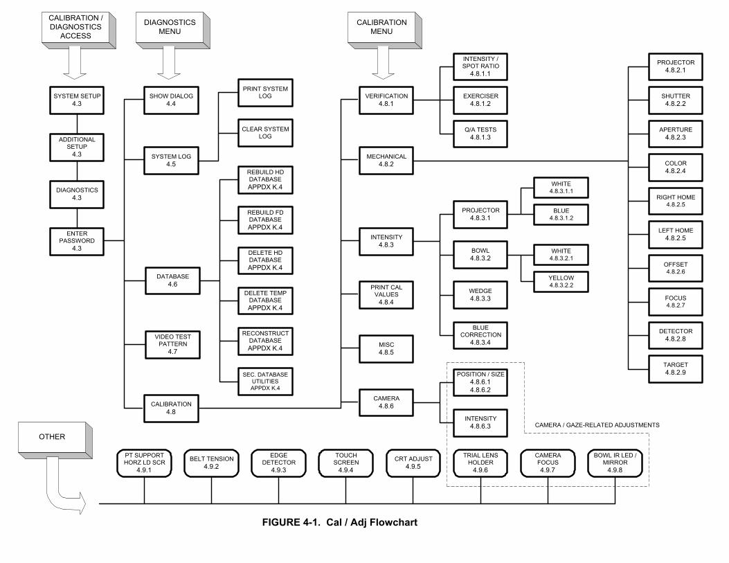
FIGURE 4-1. Cal / Adj Flowchart
CAMERA / GAZE-RELATED ADJUSTMENTS
CALIBRATIONMENU
DIAGNOSTICSMENU
CALIBRATION /DIAGNOSTICS
ACCESS
OTHER
SHOW DIALOG4.4
SYSTEM LOG4.5
DATABASE4.6
CALIBRATION4.8
VERIFICATION4.8.1
CRT ADJUST4.9.5
CAMERAFOCUS4.9.7
POSITION / SIZE4.8.6.14.8.6.2
BOWL IR LED /MIRROR
4.9.8
BLUECORRECTION
4.8.3.4
CLEAR SYSTEMLOG
PRINT SYSTEMLOG
REBUILD HDDATABASEAPPDX K.4
REBUILD FDDATABASEAPPDX K.4
DELETE HDDATABASEAPPDX K.4
DELETE TEMPDATABASEAPPDX K.4
EXERCISER4.8.1.2
INTENSITY /SPOT RATIO
4.8.1.1
Q/A TESTS4.8.1.3
MECHANICAL4.8.2
PROJECTOR4.8.3.1
BOWL4.8.3.2
WEDGE4.8.3.3
TRIAL LENSHOLDER
4.9.6
WHITE4.8.3.1.1
BLUE4.8.3.1.2
WHITE4.8.3.2.1
YELLOW4.8.3.2.2
SYSTEM SETUP4.3
ADDITIONALSETUP
4.3
DIAGNOSTICS4.3
ENTERPASSWORD
4.3
INTENSITY4.8.3
PRINT CALVALUES
4.8.4
MISC4.8.5
CAMERA4.8.6
INTENSITY4.8.6.3
TOUCHSCREEN
4.9.4
EDGEDETECTOR
4.9.3
BELT TENSION4.9.2
PT SUPPORTHORZ LD SCR
4.9.1
PROJECTOR4.8.2.1
SHUTTER4.8.2.2
APERTURE4.8.2.3
COLOR4.8.2.4
RIGHT HOME4.8.2.5
LEFT HOME4.8.2.5
OFFSET4.8.2.6
FOCUS4.8.2.7
TARGET4.8.2.9
DETECTOR4.8.2.8VIDEO TEST
PATTERN4.7
RECONSTRUCTDATABASEAPPDX K.4
SEC. DATABASEUTILITIESAPPDX K.4

Humphrey Field Analyzer II - i Adjustment / Calibration
Confidential and Proprietary
52235C1105 4 - 5 Field Service Guide
NOTE: Push the ToolStand with your finger asshown or use the ForeHead Rest Clip Tool asshown in the Appendix.
4.2 Related Procedures
4.2.1 HFA II - i Calibration and Service Guidelines
NOTES:
1. Various procedures within the Adjustment/Calibration section make reference toHFA II - i White Light Verification Data Printouts. How these printouts andother required service paperwork are utilized on an HFA service call aredescribed in Section 1. Section 1.3.2 (Three Steps to Completing an HFA II - iService Call) and Section 1.3.3 (HFA II - i Field Service PaperworkRequirements) provide a basic approach to servicing the HFA II - i and therequired paperwork needed to complete the call.
2. Following any calibration procedure that has calibration values stored on the harddrive, storage of the new values must be verified by cycling the power off-on before youperform final system checkout. If values obtained during calibration are not within theexpected range, those values are held only in temporary storage and not written to thehard drive. When power is turned off, these values are erased and calibration revertsto its old status.
There are several calibration procedures that require the tool stand to be placed on thechin rest (see Figure 4-2). Once the tool stand has been installed, ensure that the metalstandoffs touch the forehead rest when performing the indicated calibration.
FIGURE 4-2. Proper Tool Stand Positioning
Adjustment / Calibration Humphrey Field Analyzer II - i
Confidential and Proprietary
Field Service Guide 4 - 6 52235C1105
4.3 Calibration / Diagnostics Access
Access to the HFA II - i calibration and diagnostics menus is password protected. Thepassword is proprietary and should be carefully protected.
To initiate access to the calibration and diagnostics functions, perform the following:
C From the instrument's Main Menu, select System Setup.C Select Additional Setup.C Select Diagnostics.C When the ten-key pad appears, type in the password. Then select [Enter].
4.4 Show Dialog
Pressing the Show Dialog button will display a ten-key pad. This selection is left over fromDevelopment. Pressing [Enter] will return to the previous menu.
4.5 System Log
The System Log option enables the Service technician to either print or clear the SystemLog. Refer to Appendix J for a detailed description of the System Log and its uses.
Print System Log — This selection prints out the log.Clear System Log — This selection clears (erases) the log.
4.6 Database
The database selection provides a number of utilities that can be used by the Servicetechnician when problems such as data loss or corruption have occurred to the patientdatabase. The database utilities are accessed via the Calibration and Diagnostics menu,however, they have nothing to do with actual instrument calibration and adjustment. As aconvenience, Appendix K has been developed to describe each utility and their use incorrecting database related problems. Please refer to Appendix K for additional information.
4.7 Video Test PatternThis option allows the Service technician to display a test patten on the CRT. The testpattern may be used when performing CRT alignment and symmetry adjustments. Thereare options to display the pattern for two minutes or one hour. Cycling power is OK.
Humphrey Field Analyzer II - i Adjustment / Calibration
Confidential and Proprietary
52235C1105 4 - 7 Field Service Guide
4.8 Calibration
The Calibration main menu is the principle, or main menu for performing instrumentverification and calibration. The menu consists of the following selections:
Verification — Used to verify the Before and After light intensity calibration.Mechanical — Used to calibrate the projection and turret assemblies.Intensity — Used to calibrate the spot and bowl intensities.Print Cal Values — Used to print out the EEPROM settings and wedge values.Miscellaneous — Used only by Manufacturing.Camera — Used to calibrate the CCD camera and gaze illuminators.Save — Used to save the calibration data to the floppy calibration diskette.Restore — Used to restore the calibration data from the floppy calibration diskette tothe hard drive.
4.8.1 Verification (Obtaining Before and After Light IntensityCalibration Values)
4.8.1.1 Intensity / Spot Ratio
Purpose
The purpose of this procedure is to determine the current state of the instrument lightintensity calibration, both before and after servicing the instrument. The before and afterinformation is compared to determine if the instrument has had any significant light intensitycalibration shift during service.
Special Tools/Equipment Required
P Soligor Light Meter KitP Digital Multimeter, Fluke 8060A or equivalentP Bowl ShroudP Small Flashlight
Prerequisites
P All white intensity related calibrations must be performed with dim room light. Thedimmer the instrument light, the darker the room must be. Because of the very lowblue light levels, blue-yellow calibration requires total darkness. (Use a small flashlightoccasionally to read meters, etc.)
Procedure
NOTES:
1. You will print out all values obtained during this procedure. All values areautomatically recorded on the HFA II - i Light Intensisty Verification Data printouts(Before service or After service, as appropriate).

Adjustment / Calibration Humphrey Field Analyzer II - i
Confidential and Proprietary
Field Service Guide 4 - 8 52235C1105
If the service call requires both Before and After verification of the light intensities, aCalibration Shift Worksheet must be completed to determine the difference or ‘shift’ inlight intensity. Refer to Appendix I, Service Forms.
Preparation:
Depending on the instrument model, perform the preparation steps for models 740i /750 i or for model 720i. (The model 720i does not offer the foveal threshold test; toacquire values surrounding the foveal area a 10-2 SITA test must be run.) These twotests provide a quick reference for determining an instrument’s light intensity quality.
For Models 740i – 750i
1) Select a threshold patient test and turn on foveal threshold. Start the test, obtain yourfoveal threshold value, pause the test, and then select the Print icon. Your foveal valuewill be printed out. Label this printout either Before or After (as required). Save thisprintout, as you will return it with your instrument repair paperwork.
For Model 720i (This test will take approximately three minutes to run.)
NOTE: You can print partial after Primary prints.
2) Select the 10-2 test from the main menu (or go into Show Test Library, selectThreshold, then 10-2).
3) In the Patient Data screen, enter your birth date, then select Proceed.
4) When the 10-2 test comes up, select Change Parameters, set Test Strategy toSita-Fast, and then press Selection Complete.
5) Start the test. With patient response button in hand, position yourself on the chin rest. With both eyes open and fixating on the yellow target, complete the test.
6) The test will take about 2 to 3 minutes to complete. When finished, you will hear twobeeps and the test results will be displayed.
7) Select the PrintIcon and print the results, but do not save them to disk.
8) The four dB numbers nearest fixation (center of field) should be the highest values. Compare these numbers as you would with the Foveal Threshold values you receiveon Models 740i – 750i. Label this printout either Before or After (as required). Savethis printout, as you will return it with your instrument repair paperwork.
Setup: (for all HFA II - i models)
1) Set up the Soligor light meter on the HFA II - i and zero out the meter (Appendix A). (For the Before Service readings, leave all covers on and cover instrument with bowlshroud.)
Humphrey Field Analyzer II - i Adjustment / Calibration
Confidential and Proprietary
52235C1105 4 - 9 Field Service Guide
2) Set the light meter to position 1.
3) From the Main Calibration menu, select VERIFICATION, then INTENSITY/SPOTRATIO.
4) Select either BEFORE or AFTER, as appropriate.
NOTE: The Mfg and QA selections are for manufacturing use only. Selecting either of these two buttons will set tolerance values which are much tighter than those required forfield service evaluation.
5) Set up the instrument as follows to calculate the foot-lamberts for you:
a) Select P1, P2 and P3, and enter the P1, P2 and P3 factors from your SoligorMeter. Select P3B, P3Y and P3F if your light meter has these factors, otherwiseenter the BYP3 factor on your meter for P3B and enter the P3 factor for P3Y andP3F.
b) Select METER and enter your light meter serial number.
NOTE: The Auto Verify and Spot Ratio selections are only used in manufacturing. TheRead P Factors use is described in Appendix A 2.19.
White Spot Intensity Verification:
6) Select WHITE, then #31/0dB. A ten-key pad appears on the screen.
NOTE: Allow the projection lamp to remain lit for at least 3 minutes before proceeding tothe next step.
7) Position the light meter roughly on the projected spot, then maximize the reading bypositioning the chinrest via the chinrest control switch. (First left/right, then up/down,then refine with left/right again. If you subsequently move the light meter accidently,repeat this step in order to remaximize the meter reading.)
8) Enter the voltage reading via the ten-key pad and select [Enter]. The calculated foot-lamberts will be displayed next to #31/0dB. Also displayed is the tolerance for eachreading. If an asterisk (*) appears, this indicates a reading that is out of tolerance.
9) Select #32/4dB and enter the voltage reading via the ten-key pad. Repeat the sameprocedure for selection #33/9dB.
10) Switch to meter position 2 on the light meter and repeat the procedure for selection#34/14dB and then #35/19dB.
11) Switch to meter position 3 on the light meter and repeat the procedure forselections #36/24dB, #37/29dB, and #38/34dB. (#39 is not used at this time.)

Adjustment / Calibration Humphrey Field Analyzer II - i
Confidential and Proprietary
Field Service Guide 4 - 10 52235C1105
White Bowl Intensity Verification:
12) Select #61/BOWL. The bowl lamp warm-up period will begin. (You may cancel fromthe warmup period when the voltage stabilizes at >20%.)
After the warmup period ends or when the voltage reading has stabilized:
13) Enter the voltage reading via the ten-key pad.
14) If the HFA II - i is equipped with the Blue-Yellow option, proceed to the Blue SpotIntensity Verification below.
If the HFA II - i is NOT equipped with Blue-Yellow option, select PRINT to print out theHFA II - i White Light Verification Data printout. Then proceed to Cal/Wedge printoutbelow.
Blue Spot Intensity Verification:
15) Select BLUE/YELLOW, and then #62/0dB.
16) Ensure that the light meter is set to position 3.
17) Position the light meter on the projected spot, then maximize the reading by position-ing the chinrest via the chinrest control switch. (First left/right, then up/down, thenrefine with left/right again. If you subsequently move the light meter accidently, repeatthis step in order to remaximize the meter reading.)
18) Enter the #62/0dB voltage reading via the ten-key pad on the screen and select[Enter]. The calculated foot-lamberts will be displayed. Also displayed is the tolerancefor each reading. If an asterisk (*) appears, this indicates a reading that is out oftolerance.
19) Repeat the procedure for each of the selections #63/3dB thru #65/13dB. (#66 and#67 are not used at this time.)
Yellow Bowl Intensity Verification:
20) Select BLUE/YELLOW and select BOWL.
21) Allow 3 minutes for lamp warm-up and ensure that the light meter is set to position3.
22) Enter the BOWL voltage reading via the ten-key pad on the screen.
23) Select DONE and then PRINT BOTH to print out both the HFA II - i White Light andBlue-Yellow Light Verification Data printouts. Then proceed to Cal/Wedge Printoutbelow.
Humphrey Field Analyzer II - i Adjustment / Calibration
Confidential and Proprietary
52235C1105 4 - 11 Field Service Guide
Cal/Wedge Printout:
1) From the Main Calibration menu, select PRINT CAL VALUES.
2) On a Printrex printer, the printout will always be done on a single sheet. To get theprintout on a single sheet with an HP printer, take the printer off-line and press FormFeed.
3) Proceed to Evaluating Results and evaluate the HFA II - i Light Verification Dataprintouts and Cal/Wedge printout results as indicated below.
Evaluating Results
NOTE: An “Asterick” flags reading out of calibration.
Evaluating White Light Verification Data Printout Results:
P Projector Voltage must be less than 10 volts.
P Spot Positions and Background (Bowl):
• All must fall within the confines of the table.
• The dB Spread can be no more than 1.0 dB.
Evaluating Blue-Yellow Verification Data Printout Results:
P Spot Positions and Background (Bowl):
• All must fall within the confines of the table.
• The dB Spread can be no more than 1.5 dB.
Evaluating Cal/Wedge Printout:
The values on the cal/wedge printout must fall within the ranges indicated in Appendix TableH1.
4.8.1.2 Exerciser
The Exerciser enables the Service technician to move the instrument’s motors individually orin conjunction with one another. For additional details, refer to Section 5, Troubleshooting.
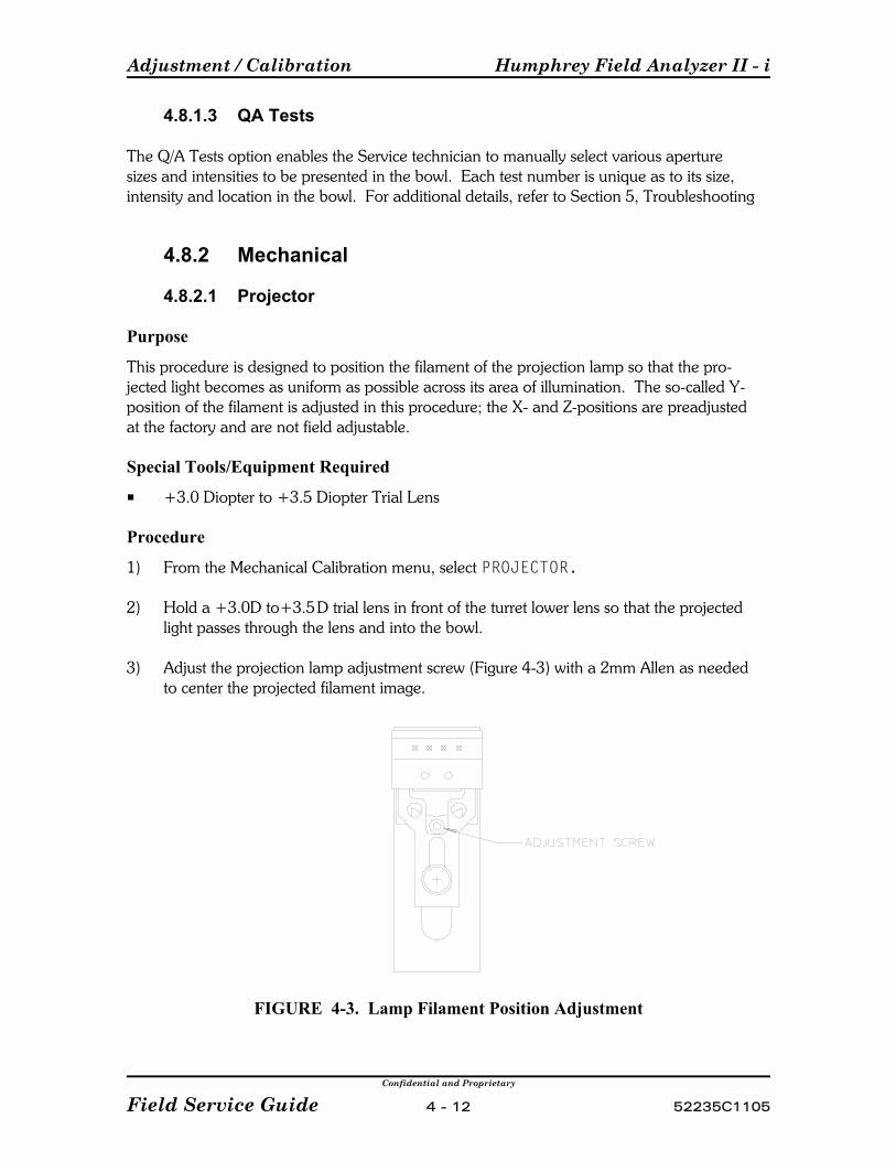
Adjustment / Calibration Humphrey Field Analyzer II - i
Confidential and Proprietary
Field Service Guide 4 - 12 52235C1105
4.8.1.3 QA Tests
The Q/A Tests option enables the Service technician to manually select various aperturesizes and intensities to be presented in the bowl. Each test number is unique as to its size,intensity and location in the bowl. For additional details, refer to Section 5, Troubleshooting
4.8.2 Mechanical
4.8.2.1 Projector
Purpose
This procedure is designed to position the filament of the projection lamp so that the pro-jected light becomes as uniform as possible across its area of illumination. The so-called Y-position of the filament is adjusted in this procedure; the X- and Z-positions are preadjustedat the factory and are not field adjustable.
Special Tools/Equipment Required
P +3.0 Diopter to +3.5 Diopter Trial Lens
Procedure
1) From the Mechanical Calibration menu, select PROJECTOR.
2) Hold a +3.0D to+3.5D trial lens in front of the turret lower lens so that the projectedlight passes through the lens and into the bowl.
3) Adjust the projection lamp adjustment screw (Figure 4-3) with a 2mm Allen as neededto center the projected filament image.
FIGURE 4-3. Lamp Filament Position Adjustment

Humphrey Field Analyzer II - i Adjustment / Calibration
Confidential and Proprietary
52235C1105 4 - 13 Field Service Guide
4.8.2.2 Shutter
Purpose
This procedure ensures that the shutter is positioned correctly in the open and closedpositions, and that it operates silently. (To avoid damage to the shutter, it should becalibrated as early in the calibration process as possible.)
Procedure
1) Make sure that the initial shutter adjustment is correct (the shaft is engaged through theshutter, and the shutter is approximately centered between the hub and the casting).
2) From the Mechanical Calibration menu, select SHUTTER and then ALIGN SHUTTER.
3) Using the UP and DOWN icons, position the shutter so that it is either flush with theboss edge or one step past the boss edge (see Figure 4-4). DO NOT position theshutter below the boss edge.
NOTE: When positioning the shutter, ALWAYS select FLASH after any movementcommand. For example if UP 1 Step is selected, then select FLASH and observe the shutterreaction. DO NOT make multiple movement selections without selecting FLASH after eachselection, as this will create shutter calibration errors.
When the shutter has been correctly positioned, and is then flashed, it should becompletely silent; no tapping or ticking sounds should be heard.
4) When the shutter is positioned correctly, select STORE.
FIGURE 4-4. Shutter Positioning in Calibration
Adjustment / Calibration Humphrey Field Analyzer II - i
Confidential and Proprietary
Field Service Guide 4 - 14 52235C1105
5) Verify that the printer is on-line, then print the CAL values. Verify that the shuttervalue is between 120 and 220.
If the stored shutter value is out of range, loosen the shutter setscrew and reposition theshutter on the motor shaft as follows: (Removal of the film ND wedge may be required. If removed, make certain the setscrews are retightened when reinstalled.)
a) If the Cal value is greater than 220, mount the shutter slightly higher (furtherclockwise) than previously positioned. Retighten the setscrew.
b) If the Cal value is less than 120, mount the shutter slightly lower (further counter-clockwise) than previously positioned. Retighten the setscrew.
c) Repeat steps 3, 4 and 5a or 5b, until the shutter value is within the specifiedrange.
6) Verification: Proceed to the Motor Exerciser menu and exercise the film ND wedge for100 iterations. Then exercise the shutter (with the lamp OFF) for 100 iterations. Theshutter should operate silently.
4.8.2.3 Aperture
Purpose
This procedure is designed to ensure that all five holes in the aperture wheel are properlycentered relative to the light path.
Special Tools/Equipment Required
P PencilP Small Piece of Self-Stick Note Paper
Procedure
1) Dim the room lighting to enable a better view of the stimulus.
2) From the Mechanical Calibration menu, select APERTURE and then LENS BASED.
NOTE: Currently, the GRID BASED selection is used only in manufacturing and requires aspecial tool.
3) On the patient side of the aperture wheel (Figure 4-5), locate the reflected image of theIII stimulus.
4) Using the STEP icons, rotate the aperture wheel until the reflected image and the IIIhole match (the light passes directly through the size three hole), then select STORE.
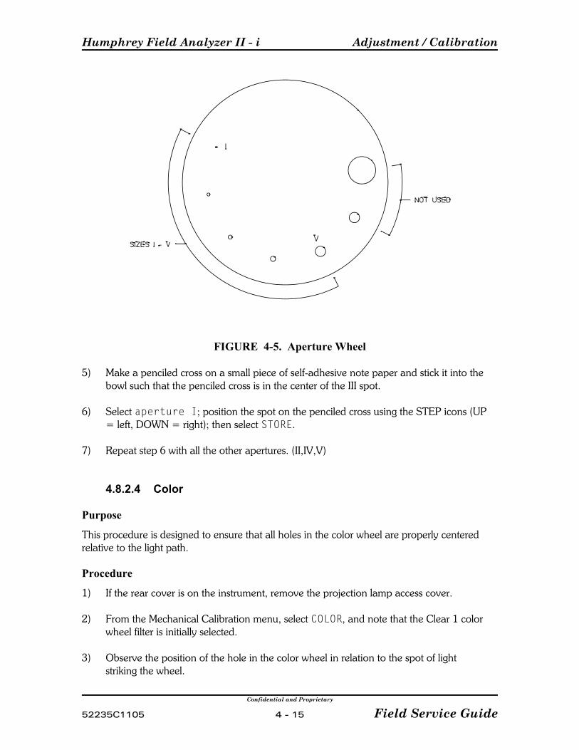
Humphrey Field Analyzer II - i Adjustment / Calibration
Confidential and Proprietary
52235C1105 4 - 15 Field Service Guide
FIGURE 4-5. Aperture Wheel
5) Make a penciled cross on a small piece of self-adhesive note paper and stick it into thebowl such that the penciled cross is in the center of the III spot.
6) Select aperture I; position the spot on the penciled cross using the STEP icons (UP= left, DOWN = right); then select STORE.
7) Repeat step 6 with all the other apertures. (II,IV,V)
4.8.2.4 Color
Purpose
This procedure is designed to ensure that all holes in the color wheel are properly centeredrelative to the light path.
Procedure
1) If the rear cover is on the instrument, remove the projection lamp access cover.
2) From the Mechanical Calibration menu, select COLOR, and note that the Clear 1 colorwheel filter is initially selected.
3) Observe the position of the hole in the color wheel in relation to the spot of lightstriking the wheel.
Adjustment / Calibration Humphrey Field Analyzer II - i
Confidential and Proprietary
Field Service Guide 4 - 16 52235C1105
4) Using the pads on the screen, adjust the color wheel position UP or DOWN until thehole in the color wheel is centered within the spot of light; then press STORE.
5) Repeat steps 3 and 4 for each of the other color wheel filter selections (Clear 2, Blue,Red, Yellow).
4.8.2.5 Right / Left Home
Purpose
This procedure is designed to establish the initial X-Y positioning (home position) of theprojected spot. The HFA II - i perimeter requires two separate home positions: one for theright eye, one for the left eye.
Procedure
1) From the Mechanical Calibration menu, select RIGHT HOME.
2) Center the stimulus spot on the central fixation hole by using the Y (Up or Down) iconsor X (Left or Right) icons; then select STORE. Select DONE.
3) Repeat step 2 in the LEFT HOME mode, then return to the Mechanical Calibrationmenu.
4.8.2.6 Offset
Purpose
This procedure is designed to ensure that the stimulus is in the exact center of the offsetfixation LEDs (diamond.)
1) From the Mechanical Calibration menu, select OFFSET. This causes the offset fixationLEDs to illuminate, and the size III stimulus to be projected in the center.
2) Using the Y (Up or Down) or X (Left or Right) icons, position the spot at the center ofthe fixation target LEDs, then select STORE.
4.8.2.7 Focus
Purpose
This procedure is designed to ensure a sharp focus at the center of the bowl.
Procedure
1) From the Mechanical Calibration menu, select FOCUS.
2) Using the BACK/FORWARD icons, bring the spot into sharp focus, then select STORE.
Humphrey Field Analyzer II - i Adjustment / Calibration
Confidential and Proprietary
52235C1105 4 - 17 Field Service Guide
NOTE: If you first rotate the glass wedge to partially dim the projected spot, you may find iteasier to discern the point of sharpest focus.
3) Use the UPPER CALIBRATION/LOWER CALIBRATION to verify focus in other thancentral positions. (Use this opportunity to check for "halo" around the spot — a suresign of dirty optics.)
4.8.2.8 Detector
Purpose
Normally, detector position check/adjustment is required any time you have removed orreplaced the detector PCB assembly, the detector housing, or the turret lower lens assembly.
Detector position is adjusted to assure that the maximum amount of light will be sensed bythe detector. The alignment of the detector is critical. The HFA II - i uses only one detectorto determine both spot and bowl intensity.
Special Tools/Equipment Required
P Brightness Detector Alignment Target
Procedure
1) Remove the Brightness Detector PCB (3.29).
2) While holding a clean lens tissue below the opening in the detector housing, tip thehousing upward and tap it lightly so that the filter, glass window, and wavy washerdrop out of the detector housing onto the tissue (Figure 4-6).
3) Insert the brightness detector alignment target into the detector housing. Ensure that itis properly seated.
4) From the Mechanical Calibration menu, select DETECTOR.
Work carefully during the next steps to avoid accidently moving the turret. If the turret isaccidently moved, select RESET to reinitialize the detector position.
5) With the room lights on, look into the alignment target and verify that the image of theprojected spot falls within the inner box on the target (ideally, at the cross hairs).
6) If required, slightly loosen the screws that hold the detector housing to the turretassembly, and adjust as necessary.
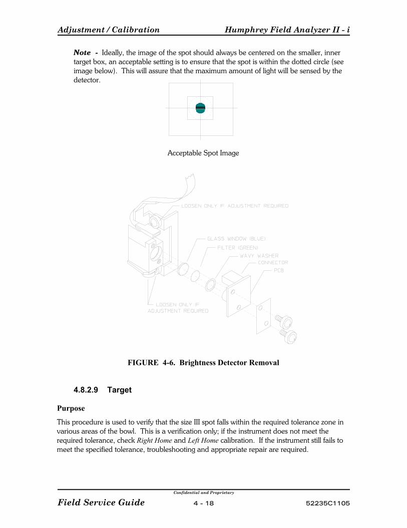
Adjustment / Calibration Humphrey Field Analyzer II - i
Confidential and Proprietary
Field Service Guide 4 - 18 52235C1105
Note Ideally, the image of the spot should always be centered on the smaller, innertarget box, an acceptable setting is to ensure that the spot is within the dotted circle (seeimage below). This will assure that the maximum amount of light will be sensed by thedetector.
Acceptable Spot Image
FIGURE 4-6. Brightness Detector Removal
4.8.2.9 Target
Purpose
This procedure is used to verify that the size III spot falls within the required tolerance zone invarious areas of the bowl. This is a verification only; if the instrument does not meet therequired tolerance, check Right Home and Left Home calibration. If the instrument still fails tomeet the specified tolerance, troubleshooting and appropriate repair are required.

Humphrey Field Analyzer II - i Adjustment / Calibration
Confidential and Proprietary
52235C1105 4 - 19 Field Service Guide
Special Tools/Equipment Required
P Spot Positioning Cross Fixture ("cross tool")P Drafting Tape
Setup
1) Remove the front cover assembly (Section 3.2). Refer to Figure 4-7.
2) Insert the center pin of the cross tool into the central fixation hole in the bowl and holdit in place; then attach the horizontal band of the cross tool as follows:
a) Fit the locating hole at each end of the horizontal band of the tool over the corre-sponding pin or tab on the outer edge of the bowl.
b) While pressing the horizontal band against the bowl, apply a short piece ofdrafting tape halfway out on each horizontal leg of the cross tool to hold it flatagainst the bowl surface.
3) Position and tape the vertical band of the cross tool, using the small hole in the centerbottom edge of the bowl as reference.
Procedure
1) From the Mechanical Calibration menu, select TARGET.
2) Verify that for each of the 6 selections on the Target Verification menu, the size IIIstimulus falls within the corresponding dotted circle on the cross tool.
FIGURE 4-7. Spot Positioning Cross Fixture
Adjustment / Calibration Humphrey Field Analyzer II - i
Confidential and Proprietary
Field Service Guide 4 - 20 52235C1105
4.8.3 Intensity
4.8.3.1 Projector
4.8.3.1.1 White
Purpose
This procedure ensures that the maximum brightness of the projected number V spot in thebowl is close to the optimum 929 Ft-L while the voltage across the projection lamp is lessthan 10 volts.
Special Tools/Equipment Required
P Soligor Light Meter KitP Digital Multimeter, Fluke 8060A or equivalentP Bowl ShroudP Small Flashlight
Prerequisites
Before performing white projector intensity calibration, verify the following:
P Projection lamp filament voltage with lamp on. If voltage is over 10 volts, replacelamp.
P Projector Adjustment (Section 4.8.2.1)P Shutter Calibration (Section 4.8.2.2)P Aperture Calibration (Section 4.8.2.3)P Color Wheel Calibration (Section 4.8.2.4)P Focus Calibration (Section 4.8.2.7)
NOTE: The Wedge Calibration (Section 4.8.3.3) MUST be performed following anychanges to the White Projector Intensity Calibration.
Procedure
1) Set up the Soligor light meter on the HFA II - i and zero out the meter (Appendix A).
2) Set the light meter to position 1.
3) From the Main Calibration menu, select INTENSITY.
4) Set up the instrument as follows to calculate the foot-lamberts:
a) From the Intensity Menu, select P Factors (See Appendix A.2.19) or selectP1, P2and P3 enter the P1, P2 and P3 factors from your Soligor Meter. Select P3B,P3Y and P3F if your light meter has these factors, otherwise enter the BYP3factor on your meter for P3B and enter the P3 factor for P3Y and P3F.
b) Select METER and enter your light meter serial number.
Humphrey Field Analyzer II - i Adjustment / Calibration
Confidential and Proprietary
52235C1105 4 - 21 Field Service Guide
5) Select PROJECTOR, then WHITE. Allow the projector lamp to warm up for 3 minutesbefore proceeding.
6) Position the light meter roughly on the projected spot, then maximize the reading bypositioning the chinrest via the chinrest control switch. (First left/right, then up/down,then refine with left/right again.)
7) Divide 929 by the P1 meter factor on your light meter.
8) Using the pads on the screen, increase or decrease spot intensity until your DMM readsthe closest to the result of the calculation done above. Try to set the spot intensity asclose to 929 Ft-L as you can. (It must be between 888 – 973 Ft-L, otherwise the afterprojector lamp intensity evaluation will not be within tolerance.)
9) Select CALCULATOR, and enter the voltage reading displayed on your DMM via theten-key pad and select [Enter]. The voltage reading and the calculated foot-lambertswill be displayed next to WHITE. Also displayed on the CRT screen is the tolerance forthe bowl intensity calibration. If an asterisk (*) appears, this indicates that the value isout of tolerance.
10) STORE the result. (It may take up to 2 minutes to process and store the new calibrationdata. The instrument will ‘beep’ when the process is complete.)
11) Press DONE.
4.8.3.1.2 Blue
Purpose
This procedure ensures that the maximum brightness of the projected number V blue spot inthe bowl is close to the optimum 3.01 Ft-L.
Special Tools/Equipment Required
P Soligor Light Meter KitP Digital Multimeter, Fluke 8060A or equivalentP Bowl ShroudP Small Flashlight
Prerequisites
Before performing blue projector intensity calibration, verify the following:
P Projection lamp filament voltage with lamp on. If voltage is over 10 volts, replacelamp.
P Projector Adjustment (Section 4.8.2.1)P Shutter Calibration (Section 4.8.2.2)P Aperture Calibration (Section 4.8.2.3)P Color Wheel Calibration (Section 4.8.2.4)

Adjustment / Calibration Humphrey Field Analyzer II - i
Confidential and Proprietary
Field Service Guide 4 - 22 52235C1105
P Focus Calibration (Section 4.8.2.7)P White Projector Intensity Calibration (Section 4.8.3.1.1) (Required only if the Projector
Lamp position was adjusted.)
NOTE: Blue Correction Calibration (Section 4.8.3.4) MUST be performed following anychanges to the Wedge Calibration or the Blue Projector Intensity Calibration.
Procedure
1) Set up the Soligor light meter on the HFA II - i and zero out the meter (Appendix A).
2) Set the light meter to position 3.
3) From the Calibration main menu, select INTENSITY.
4) Set up the instrument as follows to calculate the foot-lamberts:
a) From the Intensity Menu, select P Factors (See Appendix A.2.19) or selectP1, P2and P3 enter the P1, P2 and P3 factors from your Soligor Meter. Select P3B,P3Y and P3F if your light meter has these factors, otherwise enter the BYP3factor on your meter for P3B and enter the P3 factor for P3Y and P3F.
b) Select METER and enter your light meter serial number.
C Or you can use the Read P Factor floppy disk for this step.
5) Select PROJECTOR, then BLUE. Allow the projector lamp to warm up for 3 minutesbefore proceeding.
6) Position the light meter roughly on the projected spot, then maximize the reading bypositioning the chinrest via the chinrest control switch. (First left/right, then up/down,then refine with left/right again.)
7) Divide 3.01 by the P3B meter factor on your light meter (or use BYP3 if your lightmeter does not have a P3B factor).
8) Using the pads on the screen, increase or decrease spot intensity until your DMM readsclosest to the result of the above calculation. Try to set the spot intensity as close to3.01 Ft-L as you can. (It must be between 2.87 – 3.15 Ft-L., otherwise the after blueprojector intensity evaluation will not be within tolerance.)
9) Select CALCULATOR, and enter the voltage reading displayed on your DMM via theten-key pad and select [Enter]. The voltage reading and the calculated foot-lambertswill be displayed next to BLUE. Also displayed is the tolerance for the bowl intensitycalibration. If an asterisk (*) appears, this indicates that the value is out of tolerance.
10) Select STORE, then DONE. (It may take up to 2 minutes to process and store the newcalibration data. The instrument will ‘beep’ when the process is complete.)
Humphrey Field Analyzer II - i Adjustment / Calibration
Confidential and Proprietary
52235C1105 4 - 23 Field Service Guide
4.8.3.2 Bowl
4.8.3.2.1 White
Purpose
This procedure ensures that the brightness of the background illumination is close to theoptimum 2.92 Ft-L.
Special Tools/Equipment Required
P Soligor Light Meter KitP Digital Multimeter, Fluke 8060A or equivalentP Bowl ShroudP Small Flashlight
Procedure
1) Set up the Soligor light meter on the HFA II - i and zero out the meter (Appendix A).
2) Set the light meter to position 3.
3) Position the light meter at a point approximately 2 inches up from the center fixationhole in the bowl.
4) From the Calibration main menu, select INTENSITY.
5) Set up the instrument as follows to calculate the foot-lamberts:
a) From the Intensity Menu, select P Factors (See Appendix A.2.19) or selectP1, P2and P3 enter the P1, P2 and P3 factors from your Soligor Meter. Select P3B,P3Y and P3F if your light meter has these factors, otherwise enter the BYP3factor on your meter for P3B and enter the P3 factor for P3Y and P3F.
b) Select METER and enter your light meter serial number.
C Or you can use the Read P Factor floppy disk for this step.
6) Select BOWL, then WHITE. Allow the bowl lamps to warm up for at least 3 minutesbefore proceeding. Observe the DMM voltage reading for 15 seconds to see if the lightoutput from the bowl lamps has stabilized.
7) Divide 2.92 by the P3F factor on your light meter (or use P3 if your light meter doesnot have a P3F factor).
8) Using the pads on the screen menu, increase or decrease background intensity untilyour DMM reads closest to the result of the calculation done above. Try to set thebackground intensity as close to 2.92 Ft-L as you can. (It must be between 2.72 – 3.13Ft-L, otherwise the after evaluation of the bowl light intensity will not be within toler-ance.)
Adjustment / Calibration Humphrey Field Analyzer II - i
Confidential and Proprietary
Field Service Guide 4 - 24 52235C1105
9) Select CALCULATOR, and enter the voltage reading displayed on your DMM via theten-key pad and select [Enter]. The voltage reading and the calculated foot-lambertswill be displayed next to WHITE. Also displayed on the CRT screen is the tolerance forthe bowl intensity calibration. If an asterisk (*) appears, this indicates that the value isout of tolerance.
10) Select STORE, then DONE.
4.8.3.2.2 Yellow
Purpose
This procedure ensures that the brightness of the yellow background is close to the optimum29.87 Ft-L.
Special Tools/Equipment Required
P Soligor Light Meter KitP Digital Multimeter, Fluke 8060A or equivalentP Bowl ShroudP Small Flashlight
Procedure
1) Set up the Soligor light meter on the HFA II - i and zero out the meter (Appendix A).
2) Set the light meter to position 3.
3) Position the light meter at a point approximately 2 inches up from the center fixationhole in the bowl.
4) From the Calibration main menu, select INTENSITY.
5) Set up the instrument as follows to calculate the foot-lamberts:
a) From the Intensity Menu, select P Factors (See Appendix A.2.19) or selectP1, P2and P3 enter the P1, P2 and P3 factors from your Soligor Meter. Select P3B,P3Y and P3F if your light meter has these factors, otherwise enter the BYP3factor on your meter for P3B and enter the P3 factor for P3Y and P3F.
b) Select METER and enter your light meter serial number.
C Or you can use the Read P Factor floppy disk for this step.
Humphrey Field Analyzer II - i Adjustment / Calibration
Confidential and Proprietary
52235C1105 4 - 25 Field Service Guide
6) Select BOWL, then YELLOW. Allow the yellow lamp to warm up for 3 minutes beforeproceeding. Observe the DMM voltage reading for 15 seconds to see if the light outputfrom the yellow lamp has stabilized.
7) Divide 29.87 by the P3Y factor on your light meter (or use P3 if your light meter doesnot have a P3Y factor).
8) Using the pads on the screen menu, increase or decrease background intensity untilyour DMM reads closest to the result of the calculation done above. Try to set thebackground intensity as close to 29.87 Ft-L as you can. (It must be between 28.53 –31.28 Ft-L., otherwise the after evaluation of the yellow bowl lamp intensity will not bewithin tolerance.)
9) Select CALCULATOR, and enter the voltage reading displayed on your DMM via theten-key pad and select [Enter]. The voltage reading and the calculated foot-lambertswill be displayed next to YELLOW. Also displayed is the tolerance for the bowlintensity calibration. If an asterisk (*) appears, this indicates that the value is out oftolerance.
10) Select STORE, then DONE.
4.8.3.3 Wedge
Purpose
This procedure ensures that both wedges are properly calibrated for attenuation of the whitestimulus light. Wedge calibration must be performed whenever white projector intensitycalibration has been performed.
During the Wedge Calibration procedure, the clear opening on the color wheel is rotatedinto the light path such that a white stimulus is projected into the bowl. Each step positionon the glass wedge and the film wedge is measured by the spot detector, and a resultingwhite stimulus table is stored on the hard drive and calibration floppy diskette.
NOTE: If the Wedge calibration is performed and the instrument is also equipped with theBlue-Yellow option, the Blue Correction calibration MUST be performed after performing theWedge Calibration.
Special Tools/Equipment Required
P Bowl ShroudP Small Flashlight
Procedure
1) Setup: Room lights darkened; bowl shroud on.
2) From the Calibration main menu, select INTENSITY, then WEDGE, then CALIBRATE.
Adjustment / Calibration Humphrey Field Analyzer II - i
Confidential and Proprietary
Field Service Guide 4 - 26 52235C1105
3) After 7 – 10 minutes the unit beeps to indicate the calibration is completed.Select STORE, then DONE.
C If the instrument is equipped with the Blue-Yellow option, proceed to Section 4.8.3.4,Blue Correction.
C If the instrument is NOT equipped the Blue-Yellow option, go to Section 4.8.1 andverify the after intensity values.
4.8.3.4 Blue Correction
Purpose
This procedure ensures that the wedges are properly calibrated for attenuation of the bluestimulus light. Blue Correction calibration must be performed whenever blue projectorintensity calibration has been performed or the Wedge calibration has been performed.
During the Blue Correction calibration procedure, the blue filter on the color wheel isrotated into the light path such that a blue stimulus is reflected into thee detector via themirror instead of being projected into the bowl. Each step position on the glass wedge andthe film wedge is measured by the spot detector, compared to the white light calibrationtable and a resulting blue stimulus correction table is stored on the hard drive and calibrationfloppy diskette.
Special Tools/Equipment Required
P Tool StandP Mirror ToolP Hand-Held MirrorP Bowl Shroud
Prerequisites
Before performing Blue Correction, verify the following:
P Projection lamp filament voltage with lamp on. If voltage is over 10 volts, replacelamp.
P Projector Adjustment (Section 4.8.2.1)P Shutter Calibration (Section 4.8.2.2)P Aperture Calibration (Section 4.8.2.3)P Color Wheel Calibration (Section 4.8.2.4)P Focus Calibration (Section 4.8.2.7)P White Projector Intensity Calibration (Section 4.8.3.1.1) (Required only if the
Projector Lamp position was adjusted.)P Blue Projector Intensity Calibration (Section 4.8.3.1.2)

Humphrey Field Analyzer II - i Adjustment / Calibration
Confidential and Proprietary
52235C1105 4 - 27 Field Service Guide
FIGURE 4-8. Tool Stand with Mirror Tool Attached
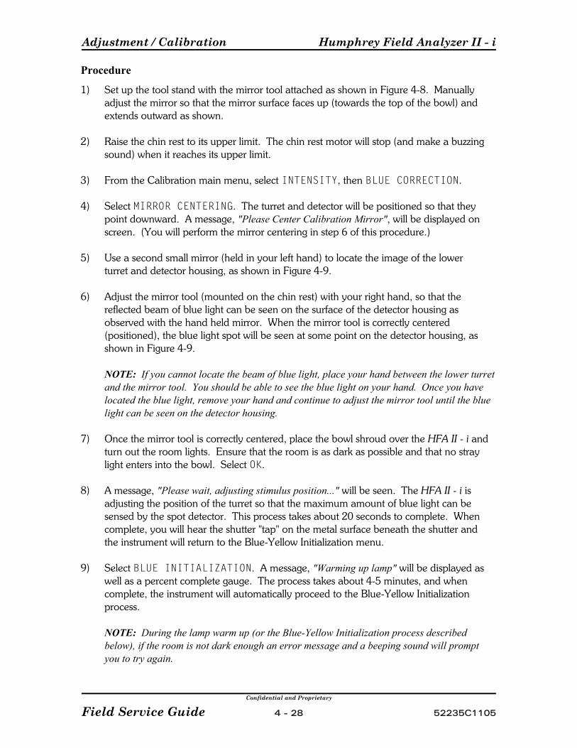
Adjustment / Calibration Humphrey Field Analyzer II - i
Confidential and Proprietary
Field Service Guide 4 - 28 52235C1105
Procedure
1) Set up the tool stand with the mirror tool attached as shown in Figure 4-8. Manuallyadjust the mirror so that the mirror surface faces up (towards the top of the bowl) andextends outward as shown.
2) Raise the chin rest to its upper limit. The chin rest motor will stop (and make a buzzingsound) when it reaches its upper limit.
3) From the Calibration main menu, select INTENSITY, then BLUE CORRECTION.
4) Select MIRROR CENTERING. The turret and detector will be positioned so that theypoint downward. A message, "Please Center Calibration Mirror", will be displayed onscreen. (You will perform the mirror centering in step 6 of this procedure.)
5) Use a second small mirror (held in your left hand) to locate the image of the lowerturret and detector housing, as shown in Figure 4-9.
6) Adjust the mirror tool (mounted on the chin rest) with your right hand, so that thereflected beam of blue light can be seen on the surface of the detector housing asobserved with the hand held mirror. When the mirror tool is correctly centered(positioned), the blue light spot will be seen at some point on the detector housing, asshown in Figure 4-9.
NOTE: If you cannot locate the beam of blue light, place your hand between the lower turretand the mirror tool. You should be able to see the blue light on your hand. Once you havelocated the blue light, remove your hand and continue to adjust the mirror tool until the bluelight can be seen on the detector housing.
7) Once the mirror tool is correctly centered, place the bowl shroud over the HFA II - i andturn out the room lights. Ensure that the room is as dark as possible and that no straylight enters into the bowl. Select OK.
8) A message, "Please wait, adjusting stimulus position..." will be seen. The HFA II - i isadjusting the position of the turret so that the maximum amount of blue light can besensed by the spot detector. This process takes about 20 seconds to complete. Whencomplete, you will hear the shutter "tap" on the metal surface beneath the shutter andthe instrument will return to the Blue-Yellow Initialization menu.
9) Select BLUE INITIALIZATION. A message, "Warming up lamp" will be displayed aswell as a percent complete gauge. The process takes about 4-5 minutes, and whencomplete, the instrument will automatically proceed to the Blue-Yellow Initializationprocess.
NOTE: During the lamp warm up (or the Blue-Yellow Initialization process describedbelow), if the room is not dark enough an error message and a beeping sound will promptyou to try again.
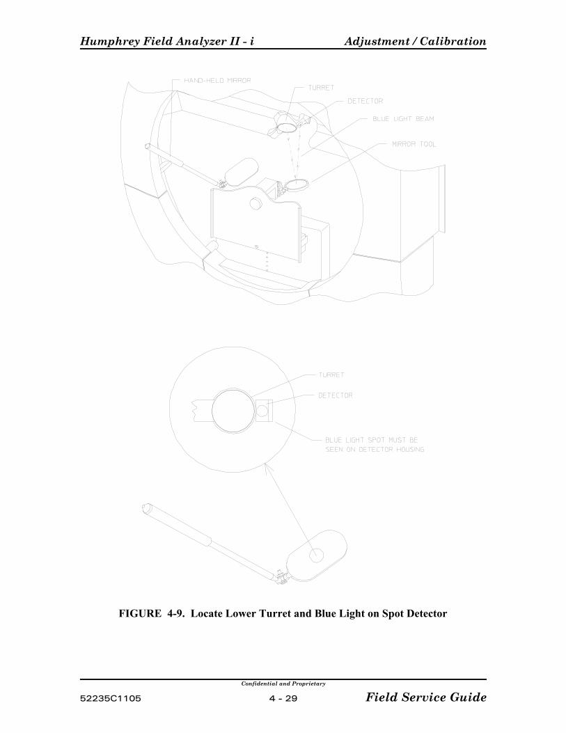
Humphrey Field Analyzer II - i Adjustment / Calibration
Confidential and Proprietary
52235C1105 4 - 29 Field Service Guide
FIGURE 4-9. Locate Lower Turret and Blue Light on Spot Detector
Adjustment / Calibration Humphrey Field Analyzer II - i
Confidential and Proprietary
Field Service Guide 4 - 30 52235C1105
10) During the Blue-Yellow Initialization process a percent complete gauge will be dis-played on screen. The process takes about 4-5 minutes, and when complete, themessage "Blue-Yellow Initialization Successful" will be displayed. When the message isdisplayed, select OK.
11) Select DONE.
4.8.4 Print Cal Values
Selecting Print Cal Values will print out the current settings stored on the hard drive. (NVMdata), and also the film and glass wedge values. Refer to Appendix H for printout examplesand interpretation instructions.
4.8.5 Miscellaneous
Miscellaneous is intended for use only by Manufacturing. Selection will display a ten-keypad. To return to the previous menu, select Cancel.
4.8.6 Camera
4.8.6.1 Camera Position / Size
Purpose
This procedure ensures that the video insert on the CRT is the correct size, and at the correctposition.
Camera Position/Size (for all HFA II - i models)
Special Tools/Equipment Required
P Tool StandP Fake EyeP Strip of Masking Tape
Prerequisites
1) Remove the front and rear covers (Sections 3.2 and 3.3); then reinstall the front cover.
2) Verify the trial lens holder alignment (Section 4.9.6).
3) Remove the height adaptor from the tool stand and attach the fake eye to the toolstand.
4) Mount the tool stand on the chinrest.

Humphrey Field Analyzer II - i Adjustment / Calibration
Confidential and Proprietary
52235C1105 4 - 31 Field Service Guide
NOTE: Push the ToolStand with your finger asshown or use the Fore-Head Rest Clip Tool asshown in the Appendix.
FIGURE 4-10. Proper Tool Stand Positioning
Pre-Setup (for all HFA II - i models)
1) Push the tool stand forward slightly on the chinrest so that the metal tips on the ToolStand Alignment Adaptor make contact with the headrest (Figure 4-10). Then raise thetrial lens holder and pull it forward. This is the position that the tool stand should be inwhen performing the procedure.
2) The right-angle extension on the fake eye assembly will press against the trial lensholder and position it correctly (Figure 4-11). (Set the chinrest height so that the right-angle extension touches the trial lens holder at about the 0 - 0 level on the trial lensholder scale.)
NOTE: Once you have the trial lens holder set, do not move it.
3) From the Calibration main menu, select Camera, then Position, and then CameraMonitor.
4) By using the menus, move the trial lens holder image left or right, until the left outeredge of the trial lens holder image is touching the left edge of the video insert; thenselect X-5 (5 more steps to the left), and STORE.
Adjustment / Calibration Humphrey Field Analyzer II - i
Confidential and Proprietary
Field Service Guide 4 - 32 52235C1105
NOTE: Push the ToolStand with your finger asshown or use the Fore-Head Rest Clip Tool asshown in the Appendix.
FIGURE 4-11. Trial Lens Holder Position
5) Select SIZE, and press the X-5 button until you get the smallest horizontal videopicture and the system beeps twice. Press the X+5 button 11 times and STORE it. Thisstep sets the horizontal width.
6) Press the Y+5 button until you get the smallest vertical video picture and the systembeeps twice. Press the Y-5 button 9 times and STORE it. This step sets the verticalheight.
7) Affix a piece of masking tape across the trial lens holder, with the top edge of the tapealigned on the 0 - 0 level of the scale on the trial lens holder (Figure 4-12). You canplace a pencil mark on the top edge of the tape directly above the 90 degree referencepoint for an aid in setting the camera position as required in the following step. Reposition the trial lens holder against the right-angle extension on the fake eyeassembly.

Humphrey Field Analyzer II - i Adjustment / Calibration
Confidential and Proprietary
52235C1105 4 - 33 Field Service Guide
8) Select (camera) POSITION. Using the menus, move the trial lens holder image up ordown, and left or right until the cross is just slightly below the centerline (top edge ofthe masking tape) of the trial lens holder and centered between the trial lens holdersides. Then select STORE.
FIGURE 4.12 Camera Position/Size Calibration
9) To verify the picture size, you will need to view the camera image in a patient test. Todo this: select DONE three times, press the Main Menu icon, select the CENTRAL24-2 test, select right eye and then select PROCEED.
10) Verify that the picture insert does not extend into the circular test area. The picture sizeshould be about 50 mm x 30 mm (2.0" x 1-3/16").
4.8.6.2 Gaze Position / Size
Purpose
This procedure (models 740i and 750i only) ensures that the gaze-tracking box of the videoinsert is the right size and is symmetrical around the center cross.
Note The 720i will display the gaze tracking box if the calibration menu is entered. It willappear in test modes also, but will not appear after the 720i has been restarted.
Special Tools/Equipment Required
P Tool StandP Fake Eye
Adjustment / Calibration Humphrey Field Analyzer II - i
Confidential and Proprietary
Field Service Guide 4 - 34 52235C1105
Prerequisites
1) Remove the front and rear covers (Section 3.2, 3.3); then reinstall the front cover.
2) Verify trial lens alignment (Section 4.9.6).
3) Verify camera position/size (Section 4.8.6.1).
Procedure
1) Install the fake eye on the tool stand and slide the tool stand onto the instrumentchinrest. Push the tool stand forward slightly on the chinrest so that the metal tips onthe Tool Stand Alignment Adaptor make contact with the headrest (Figure 4-2). This isthe position the tool stand should be in when performing the procedure.
2) From the Calibration main menu, select CAMERA, then POSITION, then GAZEMONITOR.
3) Using the chinrest control switch, center the fake eye on the center cross in the videoinsert.
4) Using the pads on the menu, adjust the size and then the position of the gaze trackingbox until it matches the upper left box scribe marks on the tool. Alternate between sizeand position until the adjustment is correct. Adjust the size of the Gaze Tracking boxuntil it matches the remaining box scribe marks.
5) Select STORE, then DONE.
6) Check for the following values:WIDTH = 23
HEIGHT = 15
RATIO = 0.660
If any of the values displayed are different, repeat the above calibration procedure toaccurately size and position the gaze tracking box. When finished select STORE, thenDONE.
4.8.6.3 Camera Intensity (for all HFA II - i models)
Purpose
This procedure ensures that the patient eye appears clearly illuminated in the camera videoinsert, and the trial lens IR LEDs are emitting proper output.
For models 720i, this procedure sets the reflex gaze LED, providing additional illumination tohelp differentiate the iris from pupil.
For models 740i and 750i, this procedure sets the brightness of the reflex gaze LED toproperly monitor gaze tracking, and sets the brightness and balance of the trial lens LEDs.

Humphrey Field Analyzer II - i Adjustment / Calibration
Confidential and Proprietary
52235C1105 4 - 35 Field Service Guide
Special Tools/Equipment Required
P Tool StandP Fake Eye
Prerequisites
Before performing IR LED intensity, check/adjust the following:
1) Trial Lens Holder Alignment (4.9.6)
2) Camera Focus (4.9.7)
3) Bowl IR LED/Mirror (4.9.8)
4) Perform the Camera Position/Size Calibration as previously described in thisservice bulletin.
Procedure
Models 720i
1) From the Calibration main menu, select CAMERA INTENSITY.
2) Set GAIN WITH LENS HOLDER to 35, and STORE it.
3) Set GAIN WITHOUT LENS HOLDER to 35, STORE it, and select DONE.
Models 740i and 750i
1) Dim the room lights and turn down the brightness on the CRT. (This greatly improvesyour ability to distinguish small differences in illumination in the CRT image.)
2) From the Calibration main menu, select, CAMERA, INTENSITY.
3) Install the fake eye on the tool stand, and slide the tool stand onto the instrumentchinrest. Push the tool stand forward slightly on the chinrest so that the metal tips onthe Tool Stand Alignment Adaptor make contact with the headrest (Figure. 4-10). Thisis the position the tool stand should be in when performing the procedure.
4) Raise and position the trial lens holder against the right angle bracket of the fake eye.The right-angle extension on the fake eye assembly will press against the trial lensholder and position it correctly (Figure 4-11). (Set the chinrest height so that the right-angle extension touches the trial lens holder at about the 0 - 0 level on the trial lensholder scale.) Verify that there is a central reflex indicating that the reflex LED in on.
NOTE: Once you have the trial lens holder set, do not move it.
5) Center the fake eye to the cross in the video insert.
Adjustment / Calibration Humphrey Field Analyzer II - i
Confidential and Proprietary
Field Service Guide 4 - 36 52235C1105
6) Select the REFLEX LED button on the right side of the screen.
7) Set the reflex count located to the right of the REFLEX LED button to 40.
8) Examine the reflex intensity value in the Intensity Reading column on the left side of thescreen. If the reflex intensity is at 31 or higher, use the DOWN STEP buttons to reducethe intensity until the reflex intensity drops to 30. Now increase the gain using the UPSTEP buttons (in small increments until the reflex intensity is again 31. If the reflexintensity is below 31 and the reflex count is at 40, use the UP STEP buttons to increase the reflex intensity until it just reaches 31 if possible. Do not allow the reflex count toexceed 100. A reflex intensity between 24-31 is acceptable. The higher values withinthe range are preferred.
9) Select STORE when the above conditions are set.
NOTE: The <35 count and information are not used in field calibration. They are for engineering use only.
10) Examine the count for the >35 row of the Intensity Reading column for LEFT andRIGHT trial lens LEDs. The intensity readings for both should be between 100–200and should be as close to each other as is possible.
11) If the readings are not in the acceptable range or are not close to each other , selectLEFT LED and/or RIGHT LED and adjust using the UP STEP or DOWN STEP buttons. Repeat the checks until the trial lens LEDs are equally bright and intensity readings arebetween 100–200. The reflex intensity should remain between 24–31. If the reflexintensity has changed, repeat steps 6 and 7 above.
NOTE: When you adjust the brightness of one LED, the readings from the otherLED also will be affected. Therefore, when you adjust one of the LEDs brighter,you may have to adjust the other one dimmer in order to get the readings of bothwithin the desired range of 100–200.
When the desired result is obtained, select STORE.
4.9 Adjustments4.9.1 Patient Support Horizontal Leadscrew Adjustment
Whenever possible, avoid loosening any of the screws that secure alignment of the foreheadrest lead screw and leadscrew nut. The leadscrew and leadscrew nut must remain accuratelyaligned to avoid binding at any point in the range of travel of the nut on the leadscrew. Thepreferred means of adjusting tension of the long belt on the patient support assembly is toadjust the position of the patient support X-motor.
Humphrey Field Analyzer II - i Adjustment / Calibration
Confidential and Proprietary
52235C1105 4 - 37 Field Service Guide
4.9.2 Belt Tension
Belt tension is adjusted by feel.
4.9.3 Edge Detector
Adjust the edge detector and/or flag to center the flag in the edge detector slot.
4.9.4 Touch Screen
Purpose
This procedure is designed to calibrate the touch screen well enough to enable error-free useof the Patient data entry menu. The calibration process entails iterations of verify-calibrate,verify-calibrate — until the touch screen response occurs within 1/8" of the point of contact atthe four corners and center of the screen.
Special Tools/Equipment Required
P Pencil Eraser
Verification
Check/verify touch screen calibration in the following manner.
1) Go to any screen and, using the pencil eraser tip, touch the screen in the four cornersand in the center. Observe how far away the screen response appears from the point ofcontact.
2) P If the screen response is more than 1/8" away from the point of contact:
Proceed to the Calibration Procedure below and recalibrate the touch screen by"following the error". (For example: If the response of the touch screen at the leftside of the CRT was leftward from the point of contact, then at the next touchscreen calibration, you should touch the upper left corner further to the left thanyou did during the last touch screen calibration, i.e., "follow the error" — this iswhy it may take more than one cycle of verify-calibrate to achieve acceptablecalibration.)
P If the screen response is within 1/8" of the touch screen contact point, make afinal check as follows:
From the main menu, select PATIENT icon, then PATIENT NAME, and type inyour name. Verify that the screen displays exactly what you typed (if so, touchscreen calibration is adequate).
Adjustment / Calibration Humphrey Field Analyzer II - i
Confidential and Proprietary
Field Service Guide 4 - 38 52235C1105
Calibration Procedure
NOTE: Use the pencil eraser tip, or similar soft-ended implement, during this procedure.
1) From the additional setup menu, select Touch Screen Calibration. If you areunable to access the additional setup menu, you can power-up the instrument whiledepressing the patient button until the touch screen calibration menu comes up. Thiswill take approximately 2½ minutes.
2) Follow the instructions displayed on the screen.
When you are instructed to press the rectangle in the Top Left Corner, note exactlywhere it is within the rectangle that you touch the screen. This will enable you to"follow the error," (as described above) if another attempt at calibration is necessary.
NOTE: press the rectangle only once; then wait for the screen to display the instruction topress the rectangle in the Bottom Left Corner.
When you touch the rectangle, again note exactly where you touch the screen.
4.9.5 CRT Adjustments
Special Tools / Equipment Required
P Plastic Slot-Tip Alignment ToolP Operator Panel Extension/Support ToolP Extension CablesP CRT Overlay Template (refer to service bulletin HFA2-029)
WARNING: During these adjustments you will be working closelyaround the back of the CRT with power applied. Work carefully toavoid the areas where the CRT high voltage is present.
Procedures
NOTE: Because some of the CRT adjustments interact, they should be performed in theorder presented here.
All of the CRT adjustment control pots are located on the CRT Driver PCB (Figure4-13). The name of each pot is labeled on the PCB.
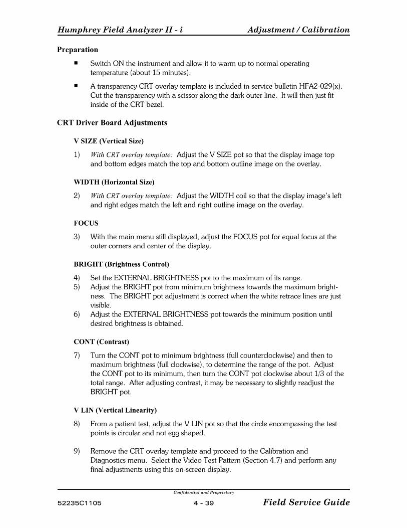
Humphrey Field Analyzer II - i Adjustment / Calibration
Confidential and Proprietary
52235C1105 4 - 39 Field Service Guide
Preparation
P Switch ON the instrument and allow it to warm up to normal operatingtemperature (about 15 minutes).
P A transparency CRT overlay template is included in service bulletin HFA2-029(x). Cut the transparency with a scissor along the dark outer line. It will then just fitinside of the CRT bezel.
CRT Driver Board Adjustments
V SIZE (Vertical Size)
1) With CRT overlay template: Adjust the V SIZE pot so that the display image topand bottom edges match the top and bottom outline image on the overlay.
WIDTH (Horizontal Size)
2) With CRT overlay template: Adjust the WIDTH coil so that the display image’s leftand right edges match the left and right outline image on the overlay.
FOCUS
3) With the main menu still displayed, adjust the FOCUS pot for equal focus at theouter corners and center of the display.
BRIGHT (Brightness Control)
4) Set the EXTERNAL BRIGHTNESS pot to the maximum of its range.5) Adjust the BRIGHT pot from minimum brightness towards the maximum bright-
ness. The BRIGHT pot adjustment is correct when the white retrace lines are justvisible.
6) Adjust the EXTERNAL BRIGHTNESS pot towards the minimum position untildesired brightness is obtained.
CONT (Contrast)
7) Turn the CONT pot to minimum brightness (full counterclockwise) and then tomaximum brightness (full clockwise), to determine the range of the pot. Adjustthe CONT pot to its minimum, then turn the CONT pot clockwise about 1/3 of thetotal range. After adjusting contrast, it may be necessary to slightly readjust theBRIGHT pot.
V LIN (Vertical Linearity)
8) From a patient test, adjust the V LIN pot so that the circle encompassing the testpoints is circular and not egg shaped.
9) Remove the CRT overlay template and proceed to the Calibration andDiagnostics menu. Select the Video Test Pattern (Section 4.7) and perform anyfinal adjustments using this on-screen display.
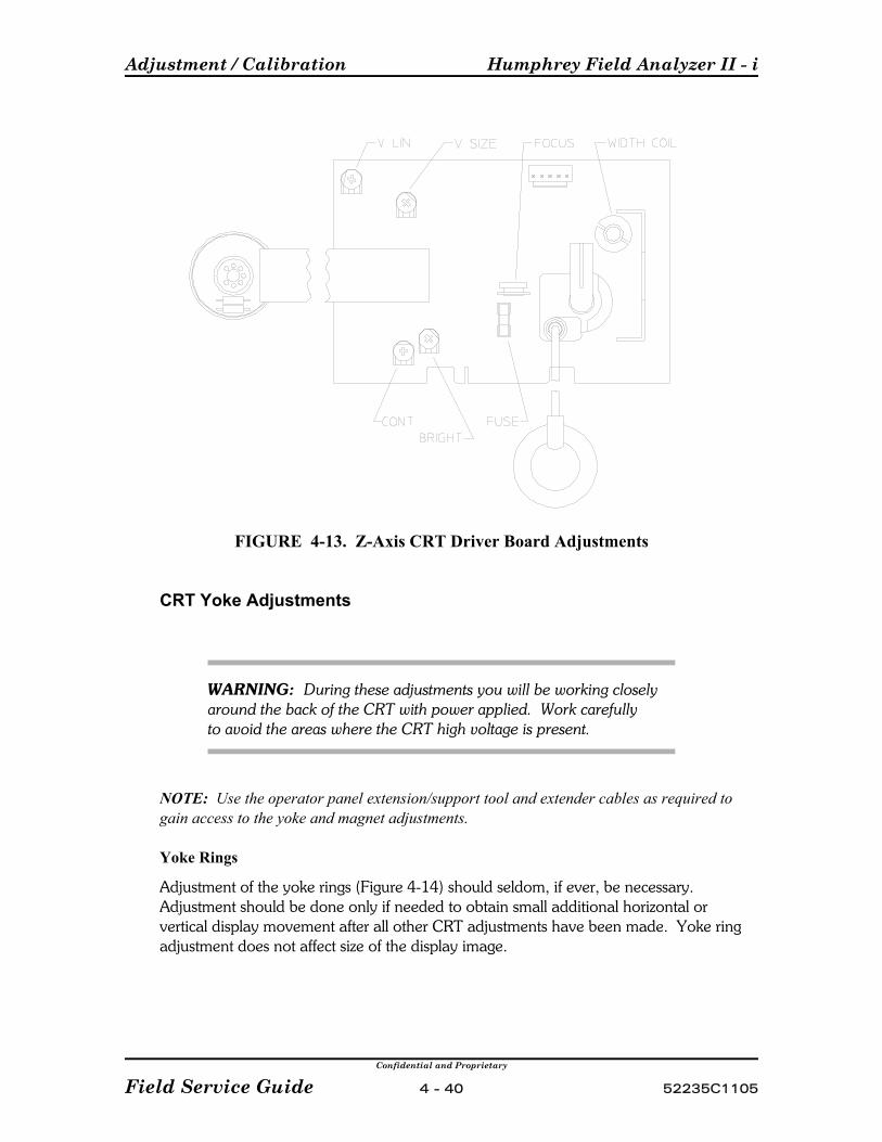
Adjustment / Calibration Humphrey Field Analyzer II - i
Confidential and Proprietary
Field Service Guide 4 - 40 52235C1105
FIGURE 4-13. Z-Axis CRT Driver Board Adjustments
CRT Yoke Adjustments
WARNING: During these adjustments you will be working closely around the back of the CRT with power applied. Work carefully to avoid the areas where the CRT high voltage is present.
NOTE: Use the operator panel extension/support tool and extender cables as required togain access to the yoke and magnet adjustments.
Yoke Rings
Adjustment of the yoke rings (Figure 4-14) should seldom, if ever, be necessary. Adjustment should be done only if needed to obtain small additional horizontal orvertical display movement after all other CRT adjustments have been made. Yoke ringadjustment does not affect size of the display image.

Humphrey Field Analyzer II - i Adjustment / Calibration
Confidential and Proprietary
52235C1105 4 - 41 Field Service Guide
CRT Yoke
CRT yoke adjustment rotates the display image on the CRT screen.
1) Slightly loosen the clamp screw that secures the yoke to the neck of the CRT (Figure 4-14).
2) Gently rotate the yoke to square the display image within the bezel opening. Thedisplay image should not be rotated more than 1/16". Use the rows and columnsof dots on the touch screen as a reference.
3) Tighten the clamp screw just enough to keep the yoke from moving (DON'TOVER-TIGHTEN).
CRT Yoke Magnets
NOTE: Adjustment of the yoke magnets should be avoided if at all possible and should beattempted only after all other possible remedies have been tried!
Each of these magnets (Figure 4-14) has a subtle effect on size and shape of the displayimage. Adjustment of the magnets is a process of trial and error, and becomes adifficult, time-consuming task. If the display is distorted, consider all other possiblecauses before attempting to adjust the yoke magnets.
Caution — USE CAUTION WHEN HANDLING OR WORKINGAROUND THE CRT YOKE TO AVOID MOVINGANY OF THE YOKE MAGNETS.
FIGURE 4-14. Z-Axis CRT Yoke Assembly

Adjustment / Calibration Humphrey Field Analyzer II - i
Confidential and Proprietary
Field Service Guide 4 - 42 52235C1105
4.9.6 Trial Lens Holder
This procedure is used to align the trial lens holder. This must be done prior to aligning thecamera or the gaze tracking system.
Special Tools / Equipment Required
P Tool StandP Trial Lens Holder Height AdaptorP Zero Degree Trial Lens Alignment Adaptor (Black)P C-clamp
Setup
1) Install the trial lens holder height adaptor and the chinrest mount on the bottom of thetool stand.
2) Remove the fake eye and install the trial lens alignment adaptor on the tool stand.
Procedure
1) Remove the front cover assembly (Section 3.2) and, using the C-clamp, clamp itsecurely in the upright position to a convenient work surface.
2) Mount the tool stand on the chinrest. Raise the chinrest (by manipulating the shortbelt inside the front cover) high enough to allow clearance of the height adaptor; thenslide the chinrest mount over the chinrest. Push the mount onto the chinrest as far asit will go.
3) Center the chinrest by moving it left or right (manipulate the long belt). Use the edgesof the chinrest and the molded lines on the front cover as visual reference (Figure 4-15).
4) Lower the chinrest until the height adaptor touches the front cover.
5) Manually lift the chinrest and tool stand slightly, and raise the trial lens holder intoposition below the tip of the trial lens alignment adaptor (Figure 4-16). Now lower thetool stand so that it again rests on the height adaptor.
If properly aligned, the trial lens holder should encircle the tip of the alignmentadaptor, with slight clearance all around (Figure 4-16).
6) Ensure that you have pushed the tool stand forward slightly on the chinrest so that themetal tips on the Tool Stand Alignment Adaptor make contact with the headrest(Figure 4-2). This is the position the tool stand should be in when performing theprocedure.
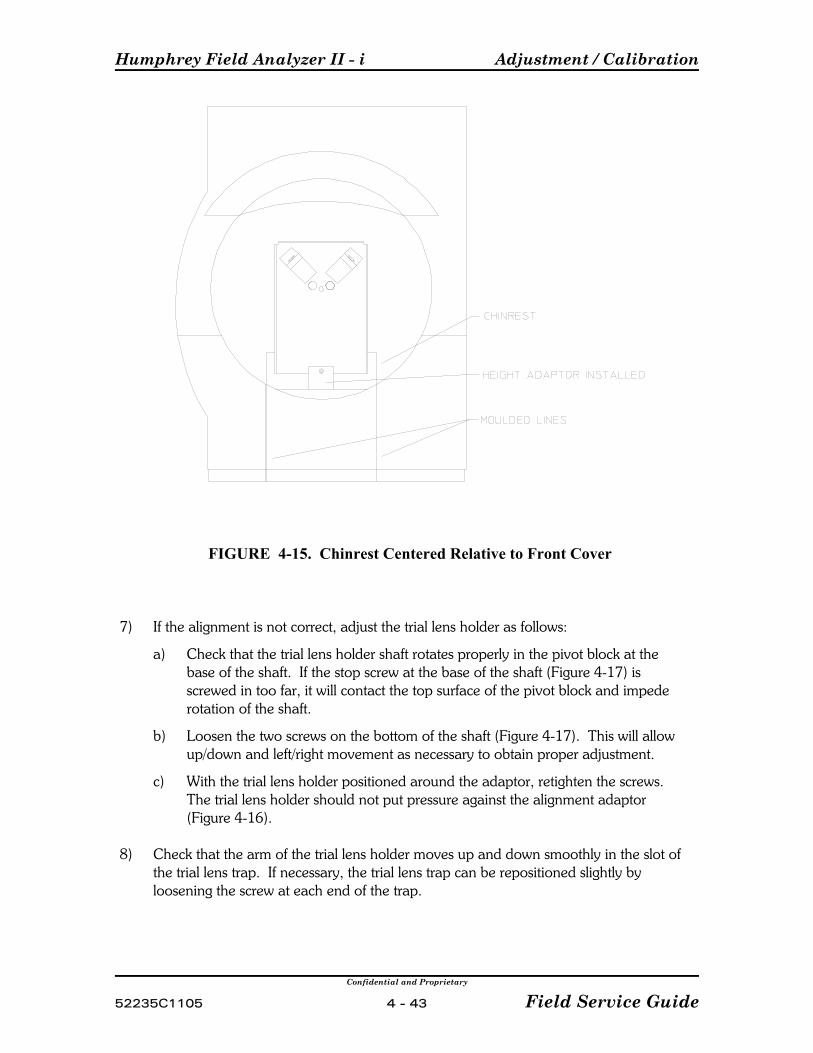
Humphrey Field Analyzer II - i Adjustment / Calibration
Confidential and Proprietary
52235C1105 4 - 43 Field Service Guide
FIGURE 4-15. Chinrest Centered Relative to Front Cover
7) If the alignment is not correct, adjust the trial lens holder as follows:
a) Check that the trial lens holder shaft rotates properly in the pivot block at thebase of the shaft. If the stop screw at the base of the shaft (Figure 4-17) isscrewed in too far, it will contact the top surface of the pivot block and impederotation of the shaft.
b) Loosen the two screws on the bottom of the shaft (Figure 4-17). This will allowup/down and left/right movement as necessary to obtain proper adjustment.
c) With the trial lens holder positioned around the adaptor, retighten the screws. The trial lens holder should not put pressure against the alignment adaptor(Figure 4-16).
8) Check that the arm of the trial lens holder moves up and down smoothly in the slot ofthe trial lens trap. If necessary, the trial lens trap can be repositioned slightly byloosening the screw at each end of the trap.
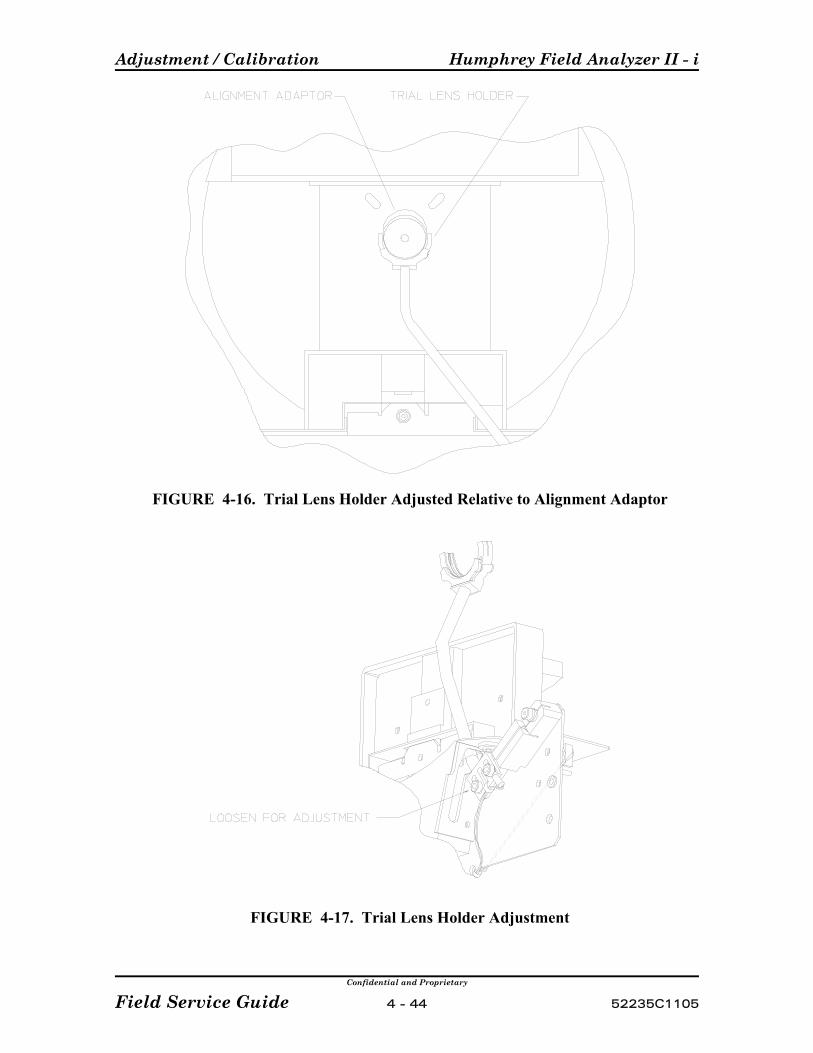
Adjustment / Calibration Humphrey Field Analyzer II - i
Confidential and Proprietary
Field Service Guide 4 - 44 52235C1105
FIGURE 4-16. Trial Lens Holder Adjusted Relative to Alignment Adaptor
FIGURE 4-17. Trial Lens Holder Adjustment
Humphrey Field Analyzer II - i Adjustment / Calibration
Confidential and Proprietary
52235C1105 4 - 45 Field Service Guide
4.9.7 Camera Focus
Purpose
This procedure adjusts the camera lens for optimum focus. It is not normally necessaryto refocus the camera unless you have done replacements that affect the camera lensposition (i.e., bowl replacement, fixation LED replacement, camera replacement).
Special Tools/Equipment Required
P Tool StandP Fake Eye with Camera Focus Target attachedP RTV
Prerequisites
Before starting Camera Focus, the following must be done:
1) Check/adjust the Trial Lens Holder (Section 4.9.6)
2) Check/adjust the Camera Position/Size (Sections 4.8.6.1 and 4.8.6.2).
Procedure
1) Install the tool stand on the instrument, with fake eye attached and height adaptorremoved. Push the tool stand forward slightly on the chinrest so that the metaltips on the Tool Stand Alignment Adaptor make contact with the headrest (Figure4-2). This is the position the tool stand should be in when performing theprocedure.
2) From the Calibration main menu, select CAMERA, then POSITION.
3) Using the chinrest control switch, align the camera focus target in the video insert.
4) Gently rotate the camera lens manually and observe the focus target for bestresolution obtainable. (You may need to use two fingers on opposite sides of thelens in order to rotate the lens without binding.)
5) Apply RTV at the point indicated in Figure 4-18 to secure the lens in position.
NOTE: Squeeze the RTV onto a piece of waste paper and allow it to thicken slightlyand become tacky before you apply it to the lens.
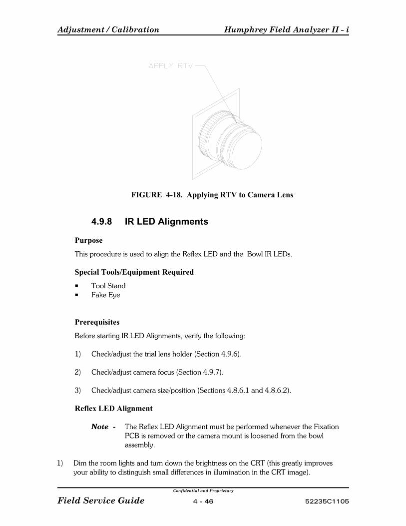
Adjustment / Calibration Humphrey Field Analyzer II - i
Confidential and Proprietary
Field Service Guide 4 - 46 52235C1105
FIGURE 4-18. Applying RTV to Camera Lens
4.9.8 IR LED Alignments
Purpose
This procedure is used to align the Reflex LED and the Bowl IR LEDs.
Special Tools/Equipment Required
P Tool StandP Fake Eye
Prerequisites
Before starting IR LED Alignments, verify the following:
1) Check/adjust the trial lens holder (Section 4.9.6).
2) Check/adjust camera focus (Section 4.9.7).
3) Check/adjust camera size/position (Sections 4.8.6.1 and 4.8.6.2).
Reflex LED Alignment
Note The Reflex LED Alignment must be performed whenever the FixationPCB is removed or the camera mount is loosened from the bowlassembly.
1) Dim the room lights and turn down the brightness on the CRT (this greatly improvesyour ability to distinguish small differences in illumination in the CRT image).
Humphrey Field Analyzer II - i Adjustment / Calibration
Confidential and Proprietary
52235C1105 4 - 47 Field Service Guide
2) From the Calibration Main Menu, select Camera, Position.
3) Install the Tool Stand with Fake Eye in the same manner as for camera intensity Cal.
4) Center the Fake Eye to the cross in the video insert.
5) Slightly loosen the two lower screws on the camera mount, you still want some pressureagainst the Reflex LED holder.
6) Move the Reflex LED using the Reflex LED holder until you center the circular LEDpattern on the Fake Eye.
7) Tighten the screws of the camera mount and recheck to see if the adjustment wassuccessful.
Bowl IR LED Assembly Alignment
Note After replacement or adjustment of the IR LED assembly, camera intensitycalibration must be performed.
1) Dim the room lights and turn down the brightness on the CRT (this greatly improvesyour ability to distinguish small differences in illumination in the CRT image).
2) From the Calibration Main Menu, select Camera, Position.
3) Install the Tool Stand with Fake Eye in the same manner as for camera intensity Cal.
4) Center the Fake Eye to the cross in the video insert.
5) Slightly loosen the screws holding the IR LED clamps.
6) Cover the cold mirror on the opposite side of the bowl with a small sticky note. Becareful that you do not touch the surface of the cold mirror.
7) Using the knurled portion of the IR LED assembly, adjust IR LED until you have thebrightest image on the camera display. You will see four shadow spots in a diamondpattern from the IR LED assembly. You may not see all four spots on the display at onetime. If possible, make sure that none of the spots are in the gaze box.
8) Tighten the IR LED clamps and recheck the camera image.
9) Repeat the procedure for the IR LED assembly on the opposite side of the bowl (asrequired).

Adjustment / Calibration Humphrey Field Analyzer II - i
Confidential and Proprietary
Field Service Guide 4 - 48 52235C1105
(This page left intentionally blank)
Confidential and Proprietary
52235C1105 5 - 1 Field Service Guide
Section 5 - Troubleshooting
5.1 Introduction . . . . . . . . . . . . . . . . . . . . . . . . . . . . . . . . . . . . . . . . . . . . . . . 5-3
5.2 General Guidelines for Assembly Level Troubleshooting . . . . . . . . . . . . . 5-3
5.3 A Guide to HFA II - i Service Diagnostic Aids . . . . . . . . . . . . . . . . . . . . . . 5-7
5.4 Software Module Identifiers . . . . . . . . . . . . . . . . . . . . . . . . . . . . . . . . . . . . 5-8
5.5 HFA II - i Motor Exerciser and QA Test Points . . . . . . . . . . . . . . . . . . . . . . 5-9
5.6 Printrex Printer Self Tests and Error Handling . . . . . . . . . . . . . . . . . . . . . . 5-11
5.6.1 Printer Self Test . . . . . . . . . . . . . . . . . . . . . . . . . . . . . . . . . . . . . 5-11
5.6.2 Printrex Printer Errors and Error Handling . . . . . . . . . . . . . . . . . 5-11
5.7 Power - On Self Tests . . . . . . . . . . . . . . . . . . . . . . . . . . . . . . . . . . . . . . . . 5-13
5.7.1 Motor Driver Board Startup . . . . . . . . . . . . . . . . . . . . . . . . . . . . 5-13
5.8 Startup State Errors . . . . . . . . . . . . . . . . . . . . . . . . . . . . . . . . . . . . . . . . . 5-15
5.9 Hexadecimal Error Codes . . . . . . . . . . . . . . . . . . . . . . . . . . . . . . . . . . . . . 5-21
5.10 Common Error Messages/Solutions . . . . . . . . . . . . . . . . . . . . . . . . . . . . . 5-23

Troubleshooting Humphrey Field Analyzer II - i
Confidential and Proprietary
Field Service Guide 5 - 2 52235C1105
Notes:

Humphrey Field Analyzer II - i Troubleshooting
Confidential and Proprietary
52235C1105 5 - 3 Field Service Guide
5.1 Introduction
The troubleshooting aids in this section provide the Field Service Engineer several aids forproblem diagnostics of the HFA II - i. As Field and Repair Center experience identifiesrecurrent problems and appropriate diagnostic processes, the section will be expanded toinclude additional troubleshooting aids.
5.2 General Guidelines for Assembly LevelTroubleshooting
On-site assembly level troubleshooting poses unique and complex challenges to the FieldService Engineer. In addition to identifying and replacing the faulty assembly, the FieldService Engineer must often travel great distances to the customer location, resolve operatorerrors, and identify power and environmental causes of problems while satisfying thecustomer's perception of quality service.
A structured approach to resolving field problems can greatly increase customer satisfactionand the Field Service Engineer's effectiveness. There are seven major tasks in resolving fieldequipment problems:
Prior to Going On-Site1. Obtain a Service History for the
Instrument
2. Query the Operator of theInstrument
3. Check for Field Service Bulletinsthat Address the Problem
While On-Site4. Have the Operator Demonstrate the
Problem
5. Resolve the Obvious
6. Substitute the Failing Assembly
7. Confirm the Repair
Each of these tasks is explained below.
Prior to Going On-Site:1) Obtain a Service History for the Instrument.
Knowledge of previous problems will assist your troubleshooting efforts. Find out whenthe last Preventive Maintenance (PM) service call was performed (if applicable). If aPM is due, or will be due shortly, be prepared to perform this task in addition to therepair.
2) Query the Operator of the Instrument.
Get a description of the problem and inform the operator that you will need him/her todemonstrate the problem to you when you arrive. A description of the problem shouldinclude the symptoms displayed and also the type of problem. Determining the type ofproblem helps you establish your approach to solving the problem and confirming therepair. All problems can be broadly categorized into one of three types:
Troubleshooting Humphrey Field Analyzer II - i
Confidential and Proprietary
Field Service Guide 5 - 4 52235C1105
# Solid Failure - the problem presents itself continuously.
# Intermittent Duplicable - the problem is intermittent in nature. Usually a specificsequence of events reproduces the intermittent symptom, although occasionallythese problems may be random in nature. By performing the proper sequence ofevents, the problem can usually be reproduced. If a sequence of events readilyreproduces the problem, examination of this sequence of events may help identifythe faulty assembly.
# Intermittent Non-Duplicable - the problem is intermittent, and all reasonableattempts at recreating the symptoms fail. These are the most difficult problems toresolve.
3) Check for Field Service Bulletins that Address the Problem.
If a service bulletin addresses a resolution, be sure to take the necessary equipment toperform the changes.
While On-Site:
4) Have the Operator Demonstrate the Problem.
This is very important. Before doing anything, always have the operator attempt todemonstrate the problem to you. By having the operator demonstrate the problem,you may solve the problem immediately, or avoid some incorrect assumptions. Havingthe operator demonstrate the problem will ALWAYS result in one of the following:
# Reveal Operator Error - You may immediately see that the cause of the problemis operator error. You then have the opportunity to train the customer in theproper use of the instrument, instead of spending time troubleshooting anonexistent instrument problem.
# Demonstrate specific problem sequence - The operator will show you thespecific sequence of events needed to reproduce the problem, reducing yourdiagnostic time.
# Help Form Ideas - The operator may not be able to duplicate the problem. However, the sequence of steps used to demonstrate the problem will give youideas on how to pursue the problem in other ways. In this case you have theopportunity to explain to the customer the difficulty in resolving a nonduplicableproblem.
5) Resolve the Obvious.
Obvious mechanical or physical defects should be resolved when discovered. Often,resolving the obvious will lead you to the real problem.

Humphrey Field Analyzer II - i Troubleshooting
Confidential and Proprietary
52235C1105 5 - 5 Field Service Guide
6) Substitute the Failing Assembly.
Once you have deduced which assembly is at fault, or is suspected to be at fault, itshould be substituted with a known good assembly.
7) Confirm the Repair.
After an assembly is replaced, confirmation should be made by reinstalling the failingassembly to witness the original symptom. You are then assured of the effectiveness ofthe repair, and of the need to utilize your spare assembly. Also, the number of NoProblem Found PCBs returned to the Repair Center is greatly reduced.
Confirming the repair to the customer often helps to bolster confidence in your abilities. To avoid repeat service calls it is especially important to confirm intermittent problems. Time spent confirming a repair is time well spent.
Note If the problem still exists, reinstall the original assembly that you removed,then continue troubleshooting.
Solving Solid Failures:It is usually straightforward deductive logic or electrical checks that will lead you to replacethe faulty assembly. After replacement of the assembly in question resolves the symptom, itis imperative that you CONFIRM THE REPAIR by reinstalling the original assembly andwitnessing the original symptoms again. For many assemblies this is the only means ofpositively verifying that the replacement circuitry has resolved the problem.
Solving Intermittent Duplicable Failures:These failures are resolved in the same manner as solid failures but always require more timeto resolve and confirm. The frequency of the problem helps you determine how long it willtake to verify a repair. A good rule of thumb when troubleshooting intermittent problems is:2 times the frequency of the symptom gives an 80% confidence level of the repair.
EXAMPLE:
Problem: The problem appears only about once an hour. The sequenceof events needed to reproduce the problem leads you tobelieve a circuit board is the likely cause.
Solution: The suspected circuit board is replaced. To provide an 80%confidence level that the circuit board resolved the problem, theinstrument will need to be tested for 2 hours without failing.
Troubleshooting Humphrey Field Analyzer II - i
Confidential and Proprietary
Field Service Guide 5 - 6 52235C1105
Solving Intermittent Non-Duplicable Failures:These failures present the greatest difficulty to the Field Service Engineer. The most effectivemeans for resolving these types of problems requires careful thought and the utilization of allavailable resources that the Field Service Engineer possesses.
It is important that before replacing an assembly, good solid rationale for its replacement bedeveloped and a backup plan devised in case replacement of the assembly does not affectthe symptom. It is best NOT to replace any hardware until solid rationale for replacement isclearly evident.
Once an assembly is replaced by a Field Service Engineer, the customer's expectations areset for a hardware resolution to the problem. This can prove to be a handicap. A goodsequence to follow for resolving intermittent non-duplicable problems is:
1) Analyze the service history in detail. Look for trends or the possibility of aprevious repair inducing the problem.
2) Query the operator(s) at length for any other clues such as:
P Times of failures;P More failures with certain operators.
3) Watch the operator set up and use the instrument.
4) Check all Field Service Bulletins.
5) Contact other Field Service Engineers involved in previous repairs.
6) Look at the operating environment static, power, grounding, temperature or rateof temperature change, humidity, etc.
7) Contact your Technical Support Specialists.
8) Keep a record of everything you've done to solve the problem.
9) Document the customer service report. Record what you feel should happen ifthe problem returns. This will help a different Field Service Engineer in theresolution of the problem.
10) Give the customer a thorough update on the situation.
11) Educate the customer on logging pertinent information that may benefit a FieldService Engineer should the problem return. Often, engaging the customer in thepursuit of a solution emphasizes the difficulty of the situation. In some instances,the customer may welcome the feeling of being involved in resolution of theproblem.

Humphrey Field Analyzer II - i Troubleshooting
Confidential and Proprietary
52235C1105 5 - 7 Field Service Guide
5.3 A Guide to HFA II - i Service Diagnostic Aids
The HFA II - i is equipped with several types of service diagnostic aids. These diagnosticaids are summarized below and detailed elsewhere within this manual.
# Printouts and Identifiers
System Log - The System Log is a function in the software that keeps track of events thathappen within the HFA II - i system. It may also prove invaluable to diagnosing intermittentproblems, or symptoms that seem to worsen over time. Refer to Appendix J for moreinformation on the System log.
Cal / Wedge Printout - The Cal / Wedge printout displays the state of calibration that theHFA II - i is in. More information on the Cal/Wedge printout can be found in Appendix H
Software Module Identifiers - Provides a list of three letter abbreviations that can appearon-screen or in the instrument system log. Use the list to help identify the error source andits possible solution. (Section 5.4)
# Manual and Power-on Tests
Motor Exerciser and QA Test Points - Describes the various exerciser and QA tests thatcan be executed. (Section 5.5)
Printer Self Test - Provides descriptions of the Printrex error conditions, and how toperform a printer self test. (Section 5.6)
Power - On Self Tests - Describes the sequence of events that the motor driver boardinitiates during the instrument power on phase. (Section 5.7)
# Error Messages
Startup State Errors - Provides a list of possible Startup State Errors that may appear on-screen or in the system log. The motor driver board generates these errors during theinstrument power on phase. Use the list to help identify the error source and its possiblesolution. (Section 5.8)
Hexadecimal Error Codes - Provides a table of hexadecimal errors that may appear on-screen or in the system log. Used properly, they can be valuable tools for fault isolation. The HFA II - i can generate thousands of error codes. To better manage this overwhelmingamount of information, you will find only the error code number ranges detailed in Section5.9.
Common Errors - Provides a table of the most common error messages and their solutions.(Section 5.10)
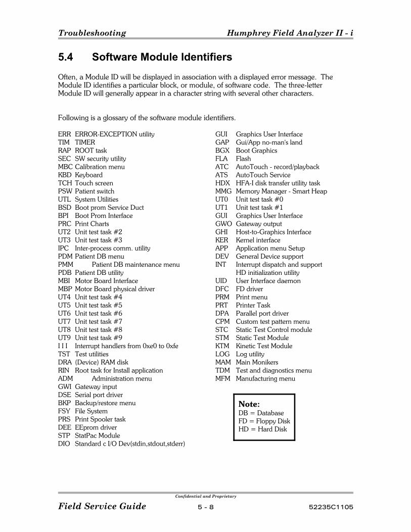
Troubleshooting Humphrey Field Analyzer II - i
Confidential and Proprietary
Field Service Guide 5 - 8 52235C1105
Note:DB = DatabaseFD = Floppy DiskHD = Hard Disk
5.4 Software Module Identifiers
Often, a Module ID will be displayed in association with a displayed error message. TheModule ID identifies a particular block, or module, of software code. The three-letterModule ID will generally appear in a character string with several other characters.
Following is a glossary of the software module identifiers.
ERR ERROR-EXCEPTION utilityTIM TIMER RAP ROOT taskSEC SW security utilityMBC Calibration menuKBD Keyboard TCH Touch screen PSW Patient switch UTL System UtilitiesBSD Boot prom Service DuctBPI Boot Prom InterfacePRC Print ChartsUT2 Unit test task #2UT3 Unit test task #3IPC Inter-process comm. utilityPDM Patient DB menuPMM Patient DB maintenance menuPDB Patient DB utilityMBI Motor Board InterfaceMBP Motor Board physical driverUT4 Unit test task #4UT5 Unit test task #5UT6 Unit test task #6UT7 Unit test task #7UT8 Unit test task #8UT9 Unit test task #9I I I Interrupt handlers from 0xe0 to 0xfeTST Test utilitiesDRA (Device) RAM diskRIN Root task for Install applicationADM Administration menuGWI Gateway inputDSE Serial port driverBKP Backup/restore menuFSY File SystemPRS Print Spooler taskDEE EEprom driverSTP StatPac ModuleDIO Standard c I/O Dev(stdin,stdout,stderr)
GUI Graphics User InterfaceGAP Gui/App no-man's landBGX Boot GraphicsFLA FlashATC AutoTouch - record/playbackATS AutoTouch ServiceHDX HFA-I disk transfer utility taskMMG Memory Manager - Smart HeapUT0 Unit test task #0UT1 Unit test task #1GUI Graphics User InterfaceGWO Gateway outputGHI Host-to-Graphics InterfaceKER Kernel interfaceAPP Application menu SetupDEV General Device supportINT Interrupt dispatch and support
HD initialization utilityUID User Interface daemonDFC FD driverPRM Print menuPRT Printer TaskDPA Parallel port driverCPM Custom test pattern menuSTC Static Test Control moduleSTM Static Test ModuleKTM Kinetic Test ModuleLOG Log utilityMAM Main MonikersTDM Test and diagnostics menu MFM Manufacturing menu

Humphrey Field Analyzer II - i Troubleshooting
Confidential and Proprietary
52235C1105 5 - 9 Field Service Guide
5.5 HFA II - i Motor Exerciser and QA Test PointsThe HFA II - i offers the ability to exercise or move motors individually or in combination. Inaddition, QA test points may be selected in either a manual or automatic sequence.
Motor Exerciser and QA Test Points
1) From the Calibration main menu, select VERIFICATION.
2) Select either EXERCISER or Q/A TESTS. (SPOT SIZE is not performed in thefield. It is used in-house to verify the ratio between the hole sizes in the aperturewheel in relation to the amount of light from the bowl surface.)
3) From the menu presented, select the desired test parameters
Motor Exerciser Menu:
• Test Count - Used to select the number of motor iterations.
• Motor Rate - Used to select the motor speed.
• Projector On - Used to turn the projection lamp ON.
• Projector Off - Used to turn the projection lamp OFF.
• X,Y,F,I,J,S - Used to select individual motors.
X = HorizontalY = VerticalF = Focus or CarriageI = Film WedgeJ = Glass WedgeS = Shutter
• 30 Degree Tests - Used to move all motors within the central 0 - 30 degree range.
• 60 Degree Tests - Used to move all motors within the peripheral 30 - 60 degree range.
• Mixed 30/60 Tests - Used to move all motors within the 0 - 60 degree range.
• Stop Test - Used to stop the exerciser mode currently chosen.
• Done - Used to exit the motor exerciser.
• Iteration Count (looks like "Errors Encountered in Iteration") - Keeps track of the numberof iterations. Updated when the test is complete, error occurs, or Stop Test is selected.
• Errors Current - Keeps track of the current number of errors.
• Errors Total - Keeps track of the total number of errors encountered.
• The last three items above are error status indications. These are displayed in 6 columns, each column representing one of the sequence: X Y F I J S

Troubleshooting Humphrey Field Analyzer II - i
Confidential and Proprietary
Field Service Guide 5 - 10 52235C1105
Q/A Test Points Menu:
• Current Point - Not a selection, but a status window. Provides information as to theparameters of the currently selected test point.
• Auto Sequence - The HFA II - i will automatically advance through all test points. (To interrupt and terminate, press the patient response button and then select Done.
• Manual Sequencing - Each time the patient button is pressed, the test point will advance.
• Open Shutter - Opens the shutter.
• Close Shutter - Closes the shutter.
• Flash Shutter - Opens then closes the shutter.
• Initial Point - Presents a ten-key selection pop-up window. Allows a specific test point tobe entered.
• Next Point - Advances the test point.
• Previous Point - Moves to the previous test point.
• Done - Returns to the Verification Menu.
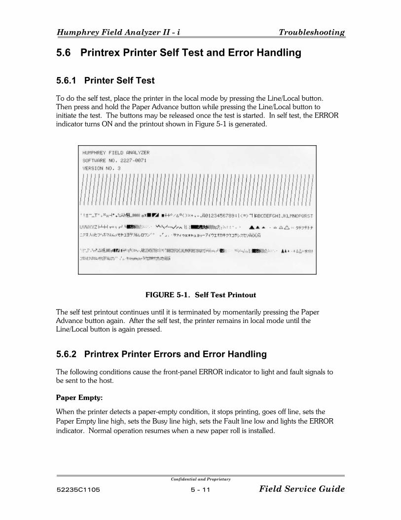
Humphrey Field Analyzer II - i Troubleshooting
Confidential and Proprietary
52235C1105 5 - 11 Field Service Guide
5.6 Printrex Printer Self Test and Error Handling
5.6.1 Printer Self Test
To do the self test, place the printer in the local mode by pressing the Line/Local button. Then press and hold the Paper Advance button while pressing the Line/Local button toinitiate the test. The buttons may be released once the test is started. In self test, the ERRORindicator turns ON and the printout shown in Figure 5-1 is generated.
FIGURE 5-1. Self Test Printout
The self test printout continues until it is terminated by momentarily pressing the PaperAdvance button again. After the self test, the printer remains in local mode until theLine/Local button is again pressed.
5.6.2 Printrex Printer Errors and Error Handling
The following conditions cause the front-panel ERROR indicator to light and fault signals tobe sent to the host.
Paper Empty:
When the printer detects a paper-empty condition, it stops printing, goes off line, sets thePaper Empty line high, sets the Busy line high, sets the Fault line low and lights the ERRORindicator. Normal operation resumes when a new paper roll is installed.
Troubleshooting Humphrey Field Analyzer II - i
Confidential and Proprietary
Field Service Guide 5 - 12 52235C1105
Door Open:
When the door is opened (either latch unlocked), the printer stops printing, goes off line, setsthe Fault Line low, sets the Busy line high, and flashes the ERROR indicator.
Overvoltage Error:
If the +24 Vdc input is too high (+27 volts or greater), the printer stops printing, sets theFault line low, sets the Busy line high, flashes the ERROR indicator, and waits for the voltageto drop to operating levels.
Under Voltage:
If the +24 Vdc input is too low (+21 volts or less) for a period of 625 ms or more, theprinter stops printing, sets the Fault line low, sets the Busy line high, flashes the ERRORindicator, and waits for the voltage to return to +22 volts or higher before resuming normaloperation.
Over Temperature:
If the printhead temperature increases above a preset level, the printer runs slower thanspecified to allow it to cool, and returns to normal speed when the temperature reaches anacceptable level. If the printhead temperature exceeds operating levels, the printer stopsprinting, sets the Fault line low, sets the Busy line high, flashes the ERROR indicator, andwaits for the temperature to drop to operating levels before resuming normal operation.
Brownout:
A brownout condition is defined as the +5 volt supply dropping below +4.5 volts. Theprinter goes into reset and all data in its buffers is lost if a brownout occurs.

Humphrey Field Analyzer II - i Troubleshooting
Confidential and Proprietary
52235C1105 5 - 13 Field Service Guide
5.7 Power-On Self Tests
5.7.1 Motor Driver Board Startup
The startup of the Motor Driver Board involves eighteen distinct operations, each of whichmust succeed before the Motor Driver Board is deemed to be operating successfully andcapable of supporting clinical testing activity.
The Motor Driver Board startup sequence is outlined in the steps below. Recommendedrepair actions are described in Section 5.8.
Step 1 Resets Motor Driver Board
Sends NMI signal to Motor Driver Board, then waits until CTS is true. Bowl intensity is atmaximum value.
Step 2 Gets ROM revision level
Checks the revision level to see whether loader or motor controller code is running, and toascertain that it is at an appropriate level with the desired functional support.
Step 3 Gets ROM status
Reads the status of the Motor Driver Board ROM startup, to ascertain if the self-checksucceeded.
Step 4 Resets motors
Brings all six motors to their respective flag crossings.
Step 5 Sets internal variables for operation.
Sets internal variables using a white stimulus against a white bowl.
Step 6 Initializes calibration constants
Data is read from NVM, and internal variables are populated. This includes offsets for the X,Y, F, and S motors, bowl and projector intensities, aperture wheel calibration values, gazewindow location, eye monitor parameters, eye illumination parameters, and the gazecalibration parameters.
Note all parameters have reasonable default values in case of initial power-up or un-calibrated system.
Step 7 Turns on the projection lamp to allow for lamp warmup.
Troubleshooting Humphrey Field Analyzer II - i
Confidential and Proprietary
Field Service Guide 5 - 14 52235C1105
Step 8 Sets bowl illumination to calibration value
Turns the bowl "on" to the specified calibration value (previously at full intensity).
Step 9 Initializes the DVM
Sets the DVM to internal bipolar mode, then initiates the hardware auto-cal sequence. SetsDVM to bipolar internal mode, then reads for zero value. Iterates until reasonable zero isattained.
Step 10 Zeros the DVM
Sets the DVM to external unipolar, then initiates the hardware auto-cal sequence. Sets DVMto (unipolar) detector mode, then reads for zero value. Iterates until reasonable zero isattained.
Step 11 Turns on the projection lamp as a secondary output check.
Step 12 Positions motors to bowl origin
Sets the X, Y, and F motors to point to the center of the bowl.
Step 13 Sets aperture wheels to clear, w/Goldmann V
Simultaneously moves both wheels to their maximum apertures.
Step 14 Turns projector on
The projector is turned on with the output voltage associated with its calibrated 10,000 asblevel.
Step 15 Sets voltage level
The projector turret is positioned 35 degrees above center. The shutter is opened, with noattenuation, and intensity is read. The intensity is compared with the value established atcalibration time. If there is a notable difference, the output voltage is adjusted until theintensity read is within a specified limit of the calibration value. The voltage drop across theprojection lamp is then measured and used as a reference for future voltage adjustments. The shutter is then closed.
Step 16 Sets flash duration
The shutter is set to flash for a 200-millisecond duration.
Step 17 Verifies wedges
At 10 points on each wheel, the intensity is measured and compared against the value storedin memory. If any value is greater than 1 dB from the measured value, the test fails. If theRMS value for these readings is greater than 0.5 dB, the test fails.
Step 18 Turns off projector
The projector is turned off, but the background bowl lamps are left at their establishedvalues.

Humphrey Field Analyzer II - i Troubleshooting
Confidential and Proprietary
52235C1105 5 - 15 Field Service Guide
5.8 Startup State ErrorsDuring the power-on sequence, the Motor Driver Board goes through 18 discrete operations,as indicated in 5.7.1 Motor Drive Board Startup in the field service guide. If an erroroccurs, the following message(s) will be displayed:
“System startup state ##” where ## indicates the startup state number.
The startup state numbers are as follows:
01 Motor board - reset failed 11 Get ROM ID - mismatch of revision levels 21 Get status - ROM selfcheck failed 31 Resets motors - all motors failed to detect their flags 41 Set motor flag params - motor or edge detector failed 51 Set motor rates - motor did not respond properly 61 Set white - internal variable for operation of white stimulus failed 71 Projector on 1 - lamp warmup cycle failed 81 Bowl on - bowl illumination failed to reach calibrated limit 93 Initialize DVM103 Zero detector112 Projector on 2 - Projector lamp burned out or disconnected121 Position stimulus131 Set both wheels143 Set projector voltage - projector voltage exceeded 10 V, light path may be
blocked153 Set flash duration163 Verify wedges172 Projector off
There will also be a suggested error recovery action to be taken by the operator. They are asfollows:
All codes marked with 1 above will have the following message - "Please cycle power torestart"
All codes marked with 2 above will have the following message - "Please replaceprojection lamp and restart"
All codes marked with 3 above will have the following message - "Please dim room lightsand press Retry"
Please note that an error code can be caused by a number of different things. For example,if there is a problem during the verification of the wedges, code 16, this could be caused byexcessive room illumination, dirt on one of the wedges, dirt on the light detector, a brokenglass wedge or defective electronics. All of the causes are indistinguishable from a softwarestandpoint and the error message "Please dim the room lights and press Retry" is based onthe expected cause of the error.
Note Additional errors may occur at the same time as the startup state errors, and arelogged in the System log. Print out the System Log to check for additional errors.
Troubleshooting Humphrey Field Analyzer II - i
Confidential and Proprietary
Field Service Guide 5 - 16 52235C1105
If the EEPROM should fail, there will be a message displayed as follows:
"HFA II may need service [code XXXXXX: 1>0x%AAAA 2>0x%BBBB]
Where AAAA will be replaced with a status code and BBBB is replaced with the index code.
Status Codes and their meanings are as follows:
190000 Bad Motor Value190002 Bad Camera Value190004 Bad Intensity Value190006 Bad Read190007 Bad Write
Index codes associated with Motor or Light values are:
0 Right Mode1 Left Mode2 Offset3 Focus4 Shutter5 Aperture6 Bowl7 Projector8 Yellow9 Blue10 Color
Index codes associated with Camera values are:
0 Illumination1 Video Window2 Gaze window3 Gaze Parameters4 Max Camera
Error messages will also appear in a small window in the upper right corner on the display.Status numbers, index numbers and an explanation of the error will be shown. Thesewindows may be stacked on top of each other as the error develops. By touching the window,the error message on top will disappear, revealing the message under it (only from the MainMenu). To better see the error and to get a better idea of what may be causing it, print out theSystem Log.
Startup State Errors:
Note After any replacement/repair, refer to Section 3, Table 3-1 for followup actions.
System startup state 0 - Indicates Motor Board Reset failed
Recommended Action:
• Cycle power to restart• Replace motor driver PCB
Humphrey Field Analyzer II - i Troubleshooting
Confidential and Proprietary
52235C1105 5 - 17 Field Service Guide
System startup state 1 - Get ROM ID - there has been a mismatch of revision levels.
Recommended Action:
• Cycle power to restart• Install the most current revision of software• Replace motor driver PCB
System startup state 2 - Get Status - the ROM self-check failed
Recommended Action:
• Cycle power to restart• Install the most current revision of software• Replace motor driver PCB
System startup state 3 - Resets motors - All motors have failed to detect their flags
Recommended Action:
• Cycle power to restart• Check System Log (Appendix J.3) for repetitive motor failures• Visually inspect Motors, Flags, and Edge Detectors for misalignment. The Motor exerciser function can also be used to diagnose motor failures. Adjust as necessary. If failurecannot be traced to a particular Motor, flag, or detector check/replace motor driver PCBor connections.
System startup state 4 - Set motor flag parameters - a motor or edge detector have failed.
Recommended Action:
• Cycle power to restart• Check System Log (Appendix J.3) for repetitive motor failures• Visually inspect Motors, Flags, and Edge Detectors for misalignment. The Motor exerciser function can also be used to diagnose motor failures. Adjust as necessary.• Refer to Common Error Messages (Section 5.10)• If failure cannot be traced to a particular Motor, flag, or detector check/replace motordriver PCB or connections.
System startup state 5 - Set motor rates - A motor did not respond properly.
Recommended Action:
• Cycle power to restart• Check System Log (Appendix J.3) for repetitive motor failures• Visually inspect Motors, Flags, and Edge Detectors for misalignment. The Motor exerciser function can also be used to diagnose motor failures. Adjust as necessary.• If failure cannot be traced to a particular Motor, flag, or detector check/replace motordriver PCB or connections.
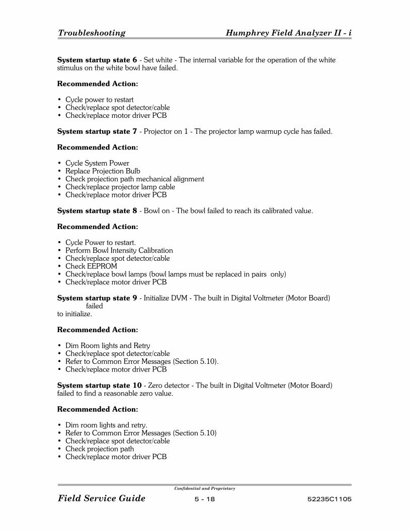
Troubleshooting Humphrey Field Analyzer II - i
Confidential and Proprietary
Field Service Guide 5 - 18 52235C1105
System startup state 6 - Set white - The internal variable for the operation of the whitestimulus on the white bowl have failed.
Recommended Action:
• Cycle power to restart• Check/replace spot detector/cable• Check/replace motor driver PCB
System startup state 7 - Projector on 1 - The projector lamp warmup cycle has failed.
Recommended Action:
• Cycle System Power• Replace Projection Bulb• Check projection path mechanical alignment• Check/replace projector lamp cable• Check/replace motor driver PCB
System startup state 8 - Bowl on - The bowl failed to reach its calibrated value.
Recommended Action:
• Cycle Power to restart.• Perform Bowl Intensity Calibration• Check/replace spot detector/cable• Check EEPROM• Check/replace bowl lamps (bowl lamps must be replaced in pairs only)• Check/replace motor driver PCB
System startup state 9 - Initialize DVM - The built in Digital Voltmeter (Motor Board)failed
to initialize.
Recommended Action:
• Dim Room lights and Retry• Check/replace spot detector/cable• Refer to Common Error Messages (Section 5.10).• Check/replace motor driver PCB
System startup state 10 - Zero detector - The built in Digital Voltmeter (Motor Board)failed to find a reasonable zero value.
Recommended Action:
• Dim room lights and retry.• Refer to Common Error Messages (Section 5.10)• Check/replace spot detector/cable• Check projection path• Check/replace motor driver PCB
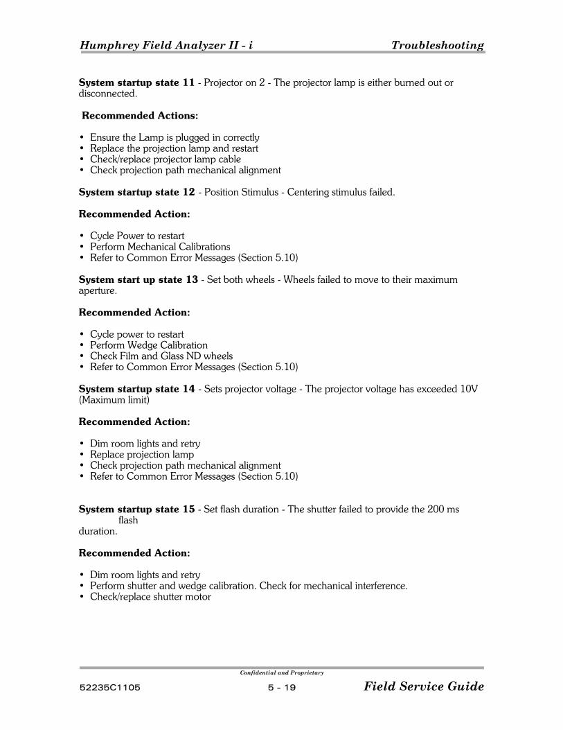
Humphrey Field Analyzer II - i Troubleshooting
Confidential and Proprietary
52235C1105 5 - 19 Field Service Guide
System startup state 11 - Projector on 2 - The projector lamp is either burned out ordisconnected.
Recommended Actions:
• Ensure the Lamp is plugged in correctly• Replace the projection lamp and restart• Check/replace projector lamp cable• Check projection path mechanical alignment
System startup state 12 - Position Stimulus - Centering stimulus failed.
Recommended Action:
• Cycle Power to restart• Perform Mechanical Calibrations• Refer to Common Error Messages (Section 5.10)
System start up state 13 - Set both wheels - Wheels failed to move to their maximumaperture.
Recommended Action:
• Cycle power to restart• Perform Wedge Calibration• Check Film and Glass ND wheels• Refer to Common Error Messages (Section 5.10)
System startup state 14 - Sets projector voltage - The projector voltage has exceeded 10V(Maximum limit)
Recommended Action:
• Dim room lights and retry• Replace projection lamp• Check projection path mechanical alignment • Refer to Common Error Messages (Section 5.10)
System startup state 15 - Set flash duration - The shutter failed to provide the 200 msflash
duration.
Recommended Action:
• Dim room lights and retry• Perform shutter and wedge calibration. Check for mechanical interference.• Check/replace shutter motor

Troubleshooting Humphrey Field Analyzer II - i
Confidential and Proprietary
Field Service Guide 5 - 20 52235C1105
System startup state 16 - Verify Wedges failed
Recommended Action:
• Dim room lights and retry• Perform shutter and wedge calibration• Check for broken, cracked, or very dirty green and/or blue filters in the detector assy. replace as necessary• Check/replace ND Wheel
System startup state 17 - Projector off failed
Recommended Action:
• Replace projection lamp and restart• Check/replace projection lamp cable• Check projection path alignment• Check/replace spot detector/cable
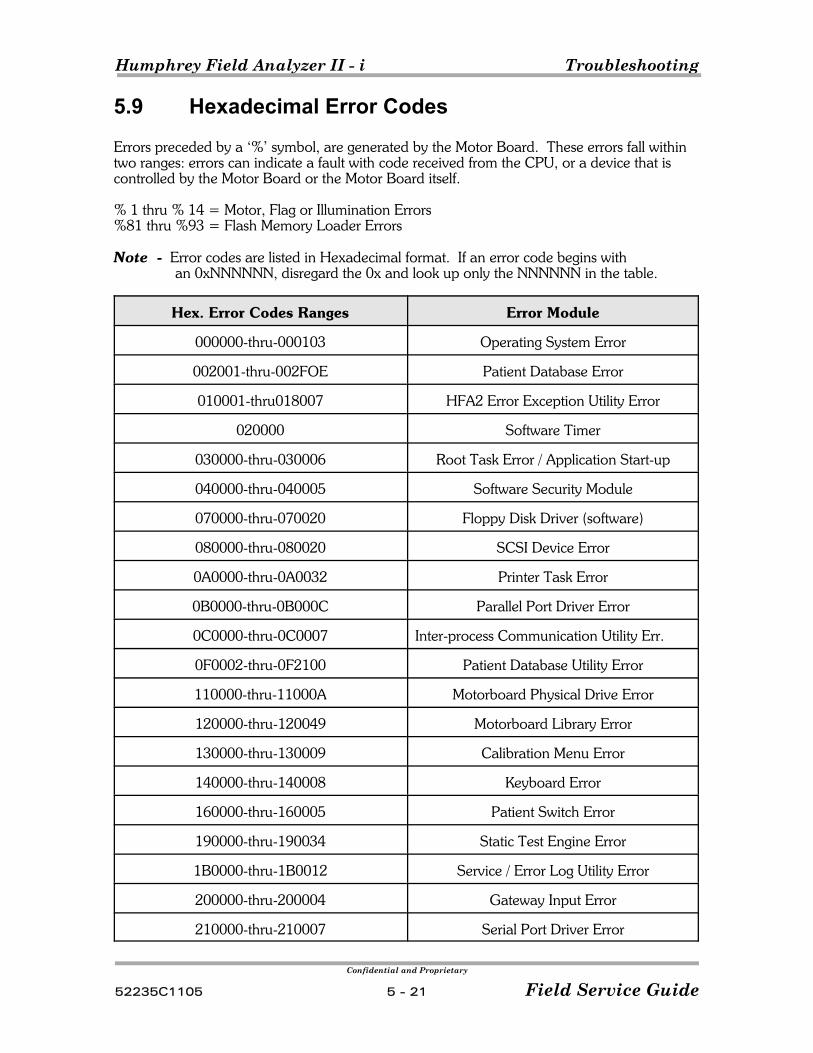
Humphrey Field Analyzer II - i Troubleshooting
Confidential and Proprietary
52235C1105 5 - 21 Field Service Guide
5.9 Hexadecimal Error Codes
Errors preceded by a ‘%’ symbol, are generated by the Motor Board. These errors fall withintwo ranges: errors can indicate a fault with code received from the CPU, or a device that iscontrolled by the Motor Board or the Motor Board itself.
% 1 thru % 14 = Motor, Flag or Illumination Errors%81 thru %93 = Flash Memory Loader Errors
Note Error codes are listed in Hexadecimal format. If an error code begins with an 0xNNNNNN, disregard the 0x and look up only the NNNNNN in the table.
Hex. Error Codes Ranges Error Module
000000-thru-000103 Operating System Error
002001-thru-002FOE Patient Database Error
010001-thru018007 HFA2 Error Exception Utility Error
020000 Software Timer
030000-thru-030006 Root Task Error / Application Start-up
040000-thru-040005 Software Security Module
070000-thru-070020 Floppy Disk Driver (software)
080000-thru-080020 SCSI Device Error
0A0000-thru-0A0032 Printer Task Error
0B0000-thru-0B000C Parallel Port Driver Error
0C0000-thru-0C0007 Inter-process Communication Utility Err.
0F0002-thru-0F2100 Patient Database Utility Error
110000-thru-11000A Motorboard Physical Drive Error
120000-thru-120049 Motorboard Library Error
130000-thru-130009 Calibration Menu Error
140000-thru-140008 Keyboard Error
160000-thru-160005 Patient Switch Error
190000-thru-190034 Static Test Engine Error
1B0000-thru-1B0012 Service / Error Log Utility Error
200000-thru-200004 Gateway Input Error
210000-thru-210007 Serial Port Driver Error
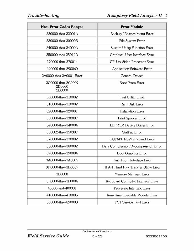
Troubleshooting Humphrey Field Analyzer II - i
Confidential and Proprietary
Field Service Guide 5 - 22 52235C1105
Hex. Error Codes Ranges Error Module
220000-thru-22001A Backup / Restore Menu Error
230000-thru-20000B File System Error
240000-thru-24000A System Utility Function Error
250000-thru-25012D Graphical User Interface Error
270000-thru-270014 CPU to Video Processor Error
290000-thru-290060 Application Software Error
2A0000-thru-2A0001 Error General Device
2C0000-thru-2C00092D00002E0000
Boot Prom Error
300000-thru-310002 Test Utility Error
310000-thru-310002 Ram Disk Error
320000-thru-32000F Installation Error
330000-thru-330007 Print Spooler Error
340000-thru-340004 EEPROM Device Driver Error
350002-thru-350307 StatPac Error
370000-thru-370002 GUI/APP No-Man’s land Error
380000-thru-380002 Data Compression/Decompression Error
390000-thru-390004 Boot Graphics Error
3A0000-thru-3A0005 Flash Prom Interface Error
3D0000-thru-3D0009 HFA-1 Hard Disk Transfer Utility Error
3E0000 Memory Manager Error
3F0000-thru-3F0004 Keyboard Controller Interface Error
40000-and-400001 Processor Interrupt Error
410000-thru-41000b Run-Time Loadable Module Error
880000-thru-890008 DST Service Tool Error
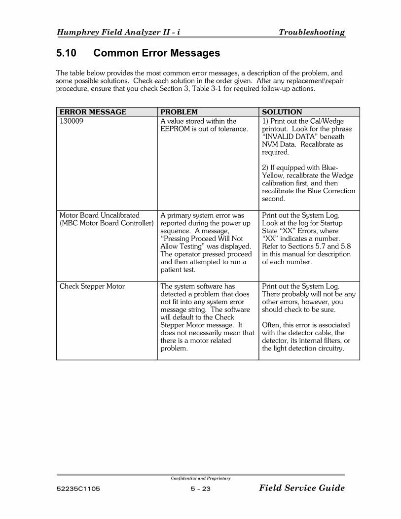
Humphrey Field Analyzer II - i Troubleshooting
Confidential and Proprietary
52235C1105 5 - 23 Field Service Guide
5.10 Common Error Messages
The table below provides the most common error messages, a description of the problem, andsome possible solutions. Check each solution in the order given. After any replacement\repairprocedure, ensure that you check Section 3, Table 3-1 for required follow-up actions.
ERROR MESSAGE PROBLEM SOLUTION130009 A value stored within the
EEPROM is out of tolerance.1) Print out the Cal/Wedgeprintout. Look for the phrase“INVALID DATA” beneathNVM Data. Recalibrate asrequired.
2) If equipped with Blue-Yellow, recalibrate the Wedgecalibration first, and thenrecalibrate the Blue Correctionsecond.
Motor Board Uncalibrated(MBC Motor Board Controller)
A primary system error wasreported during the power upsequence. A message,“Pressing Proceed Will NotAllow Testing” was displayed. The operator pressed proceedand then attempted to run apatient test.
Print out the System Log. Look at the log for StartupState “XX” Errors, where“XX” indicates a number. Refer to Sections 5.7 and 5.8in this manual for descriptionof each number.
Check Stepper Motor The system software hasdetected a problem that doesnot fit into any system errormessage string. The softwarewill default to the CheckStepper Motor message. Itdoes not necessarily mean thatthere is a motor relatedproblem.
Print out the System Log. There probably will not be anyother errors, however, youshould check to be sure.
Often, this error is associatedwith the detector cable, thedetector, its internal filters, orthe light detection circuitry.
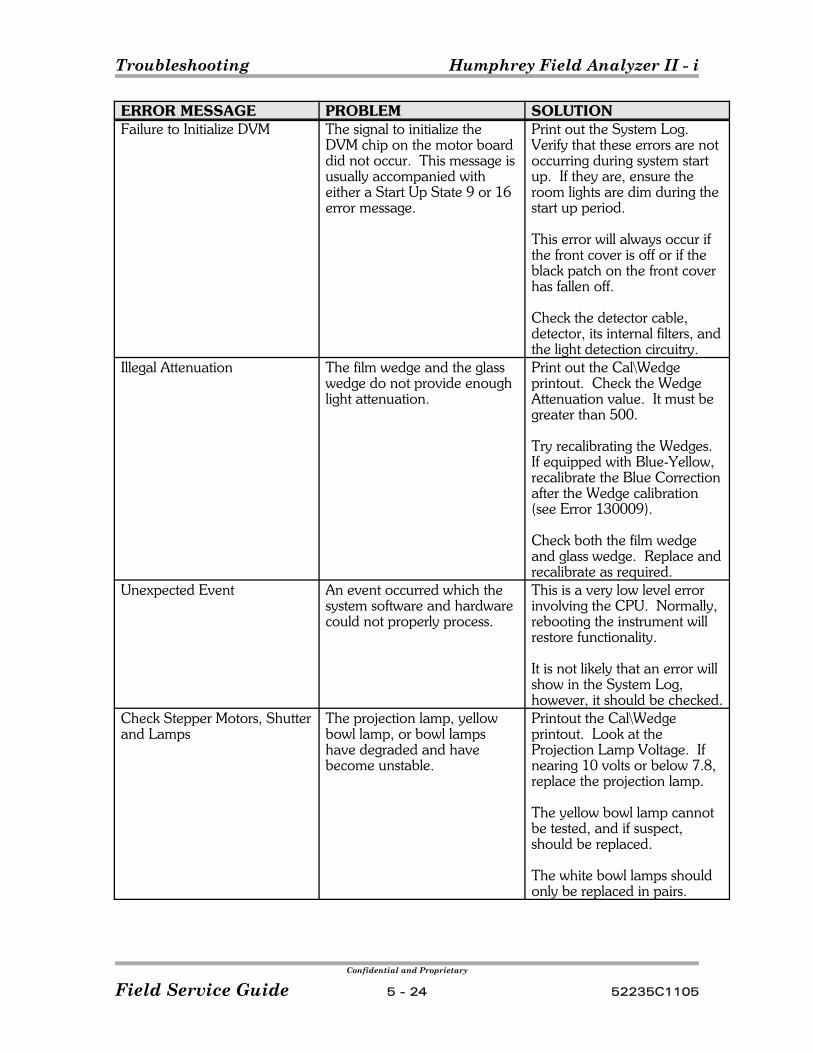
Troubleshooting Humphrey Field Analyzer II - i
Confidential and Proprietary
Field Service Guide 5 - 24 52235C1105
ERROR MESSAGE PROBLEM SOLUTIONFailure to Initialize DVM The signal to initialize the
DVM chip on the motor boarddid not occur. This message isusually accompanied witheither a Start Up State 9 or 16error message.
Print out the System Log. Verify that these errors are notoccurring during system startup. If they are, ensure theroom lights are dim during thestart up period.
This error will always occur ifthe front cover is off or if theblack patch on the front coverhas fallen off.
Check the detector cable,detector, its internal filters, andthe light detection circuitry.
Illegal Attenuation The film wedge and the glasswedge do not provide enoughlight attenuation.
Print out the Cal\Wedgeprintout. Check the WedgeAttenuation value. It must begreater than 500.
Try recalibrating the Wedges. If equipped with Blue-Yellow,recalibrate the Blue Correctionafter the Wedge calibration(see Error 130009).
Check both the film wedgeand glass wedge. Replace andrecalibrate as required.
Unexpected Event An event occurred which thesystem software and hardwarecould not properly process.
This is a very low level errorinvolving the CPU. Normally,rebooting the instrument willrestore functionality.
It is not likely that an error willshow in the System Log,however, it should be checked.
Check Stepper Motors, Shutterand Lamps
The projection lamp, yellowbowl lamp, or bowl lampshave degraded and havebecome unstable.
Printout the Cal\Wedgeprintout. Look at theProjection Lamp Voltage. Ifnearing 10 volts or below 7.8,replace the projection lamp.
The yellow bowl lamp cannotbe tested, and if suspect,should be replaced.
The white bowl lamps shouldonly be replaced in pairs.
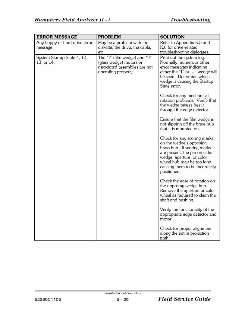
Humphrey Field Analyzer II - i Troubleshooting
Confidential and Proprietary
52235C1105 5 - 25 Field Service Guide
ERROR MESSAGE PROBLEM SOLUTIONAny floppy or hard drive errormessage
May be a problem with thediskette, the drive, the cable,etc.
Refer to Appendix K.5 andK.6 for drive-relatedtroubleshooting dialogues.
System Startup State 4, 12,13, or 14.
The “I” (film wedge) and “J”(glass wedge) motors orassociated assemblies are notoperating properly.
Print out the system log. Normally, numerous othererror messages indicatingeither the “I” or “J” wedge willbe seen. Determine whichwedge is causing the StartupState error.
Check for any mechanicalrotation problems. Verify thatthe wedge passes freelythrough the edge detector.
Ensure that the film wedge isnot slipping off the brass hubthat it is mounted on.
Check for any scoring markson the wedge’s opposingbrass hub. If scoring marksare present, the pin on eitherwedge, aperture, or colorwheel hub may be too long,causing them to be incorrectlypositioned.
Check the ease of rotation onthe opposing wedge hub. Remove the aperture or colorwheel as required to clean theshaft and bushing.
Verify the functionality of theappropriate edge detector andmotor.
Check for proper alignmentalong the entire projectionpath.
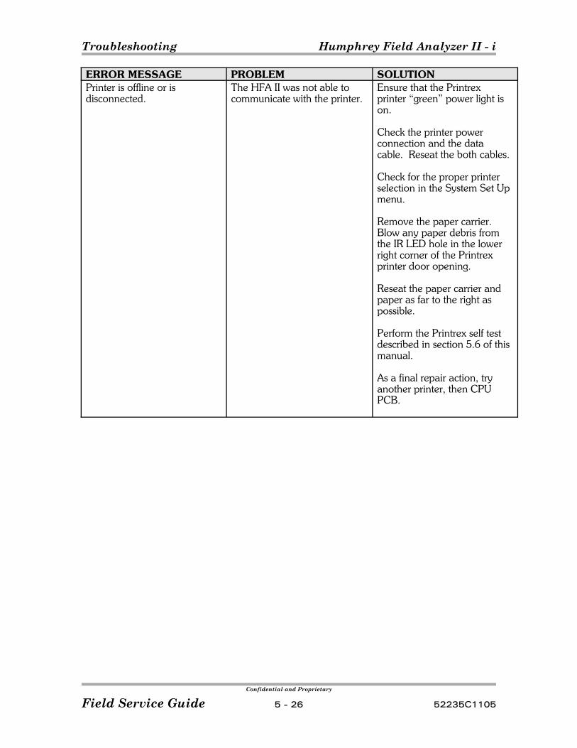
Troubleshooting Humphrey Field Analyzer II - i
Confidential and Proprietary
Field Service Guide 5 - 26 52235C1105
ERROR MESSAGE PROBLEM SOLUTIONPrinter is offline or isdisconnected.
The HFA II was not able tocommunicate with the printer.
Ensure that the Printrexprinter “green” power light ison.
Check the printer powerconnection and the datacable. Reseat the both cables.
Check for the proper printerselection in the System Set Upmenu.
Remove the paper carrier. Blow any paper debris fromthe IR LED hole in the lowerright corner of the Printrexprinter door opening.
Reseat the paper carrier andpaper as far to the right aspossible.
Perform the Printrex self testdescribed in section 5.6 of thismanual.
As a final repair action, tryanother printer, then CPUPCB.
Confidential and Proprietary
52235C1105 6 - 1 Field Service Guide
Section 6 - Diagrams
Note The diagrams in this Section support Level 1 Field Servicerequirements.
Figure 6-1. System Interconnect Diagram
Figure 6-2. Projection Path
Figure 6-3. CPU PCB
Figure 6-4. Backplane Board
Figure 6-5. Motor Driver PCB
Figure 6-6. Fixation Interconnect PCB
Figure 6-7. Patient Support Assembly
Figure 6-8. Power Entry and Power Supply
Figure 6-9. Projection Assembly
Figure 6-10. Memory Module and Drives
Figure 6-11. Component Locations – CPU PCB
Figure 6-12. Component Locations – Backplane PCB
Power Table / Printrex Printer (See Section 7 for wiring diagrams and parts)

Diagrams Humphrey Field Analyzer II - i
Confidential and Proprietary
Field Service Guide 6 - 2 52235C1105
Notes:
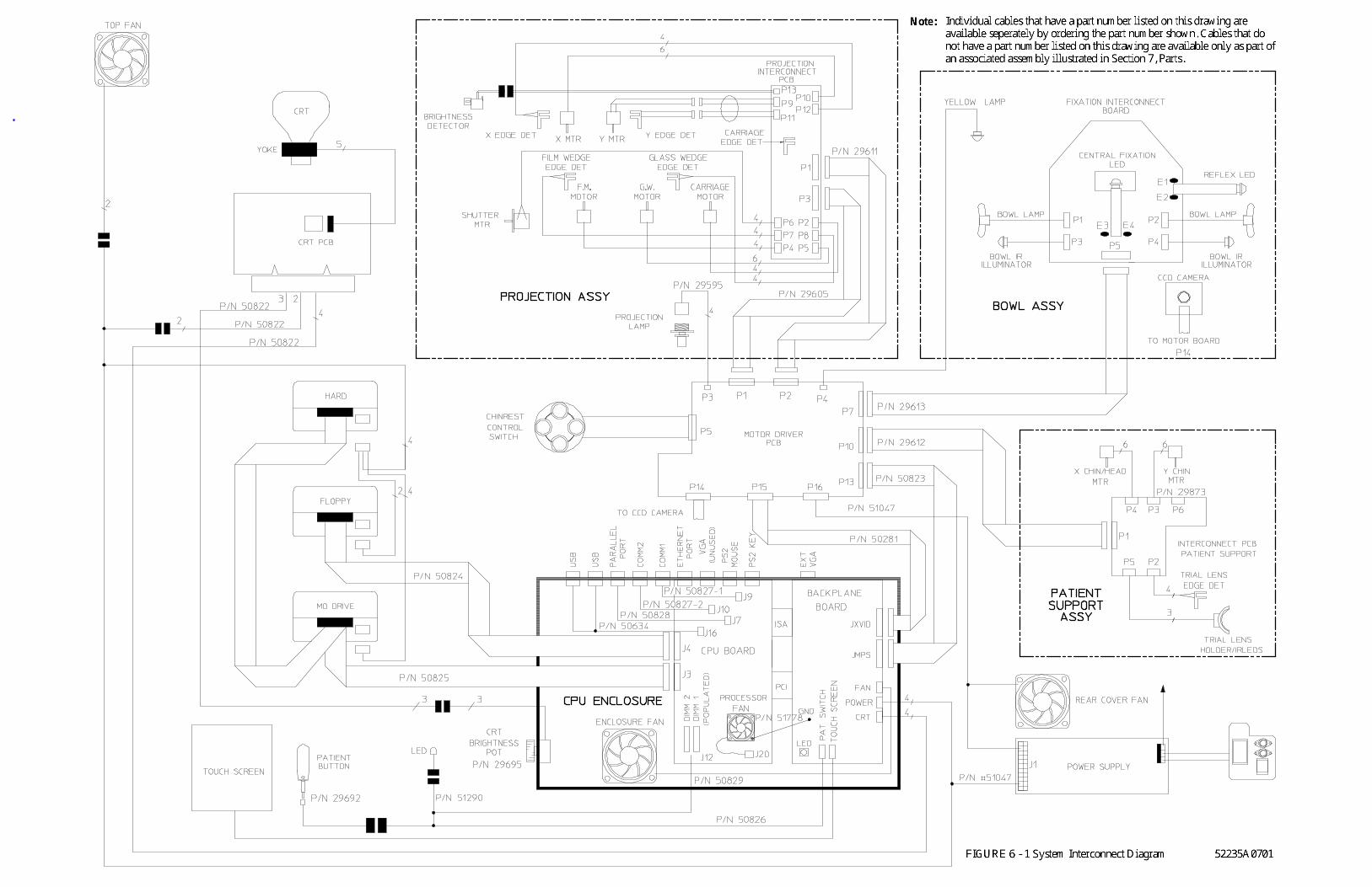

Diagrams Humphrey Field Analyzer II - i
Confidential and Proprietary
Field Service Guide 6 - 4 52235C1105
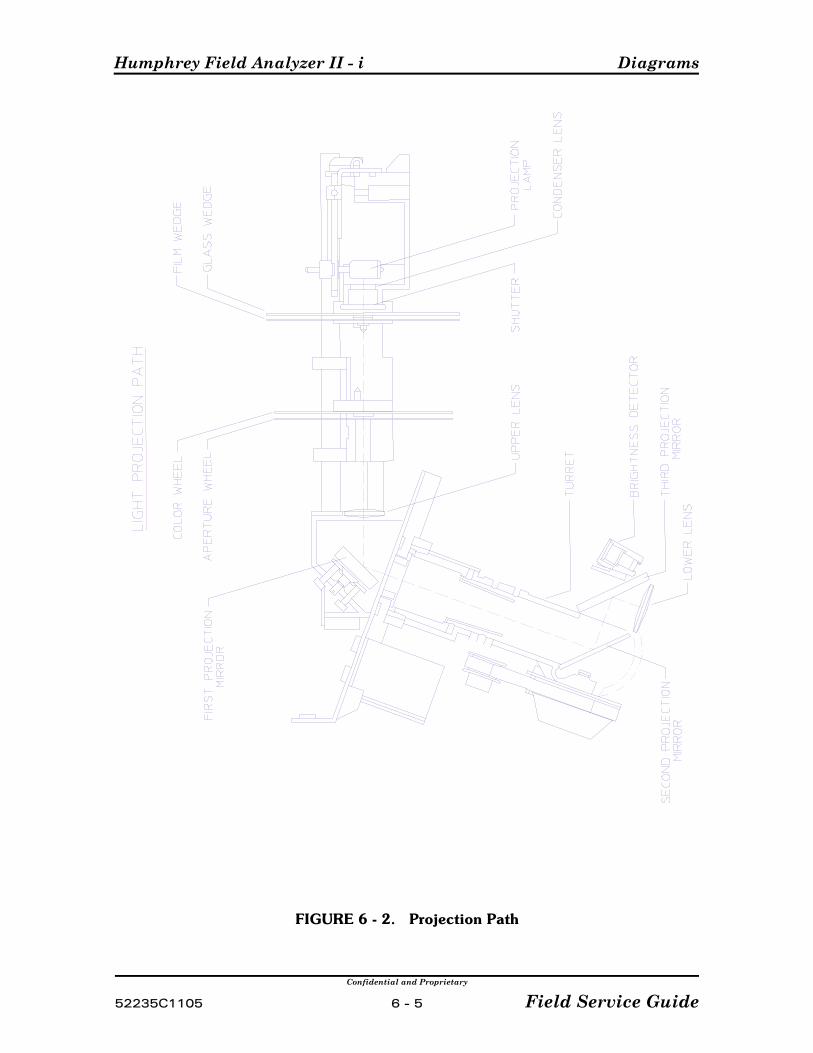
Humphrey Field Analyzer II - i Diagrams
Confidential and Proprietary
52235C1105 6 - 5 Field Service Guide
FIGURE 6 - 2. Projection Path
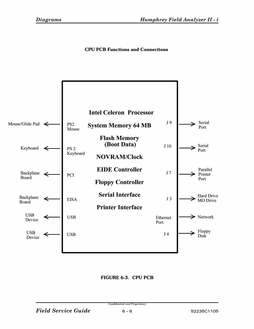
Diagrams Humphrey Field Analyzer II - i
Confidential and Proprietary
Field Service Guide 6 - 6 52235C1105
CPU PCB Functions and Connections
FIGURE 6-3. CPU PCB
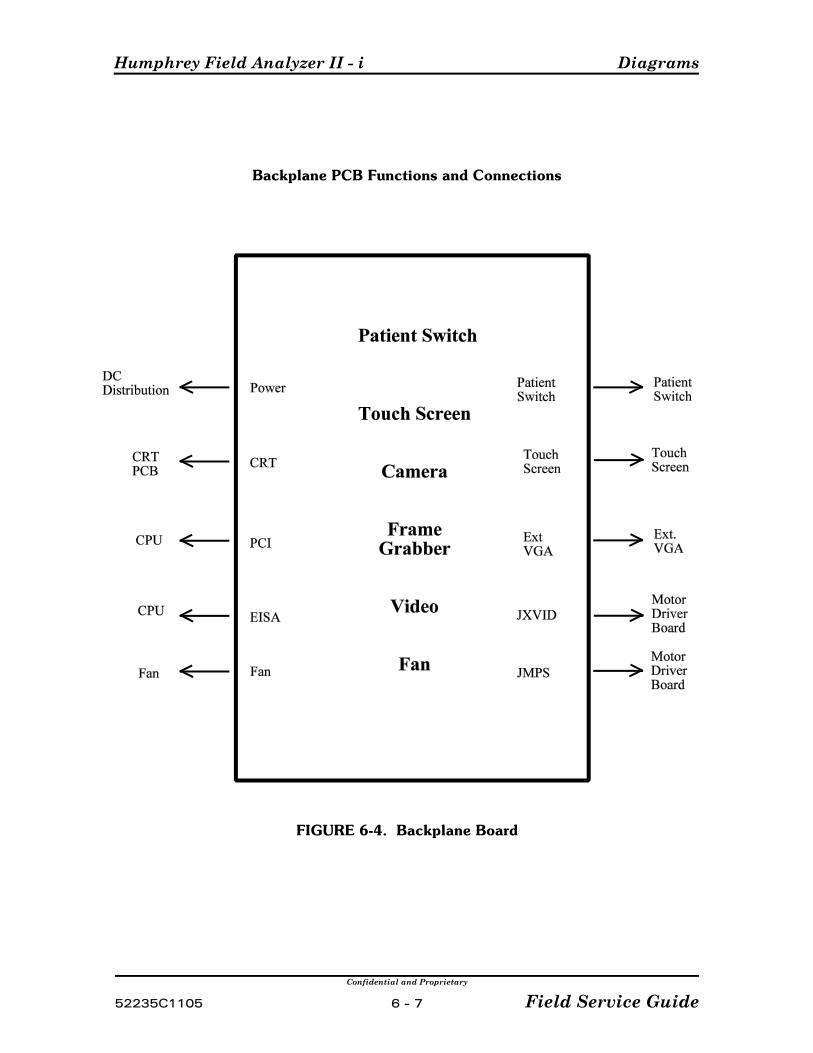
Humphrey Field Analyzer II - i Diagrams
Confidential and Proprietary
52235C1105 6 - 7 Field Service Guide
Backplane PCB Functions and Connections
FIGURE 6-4. Backplane Board
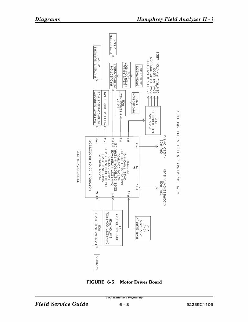
Diagrams Humphrey Field Analyzer II - i
Confidential and Proprietary
Field Service Guide 6 - 8 52235C1105
FIGURE 6-5. Motor Driver Board
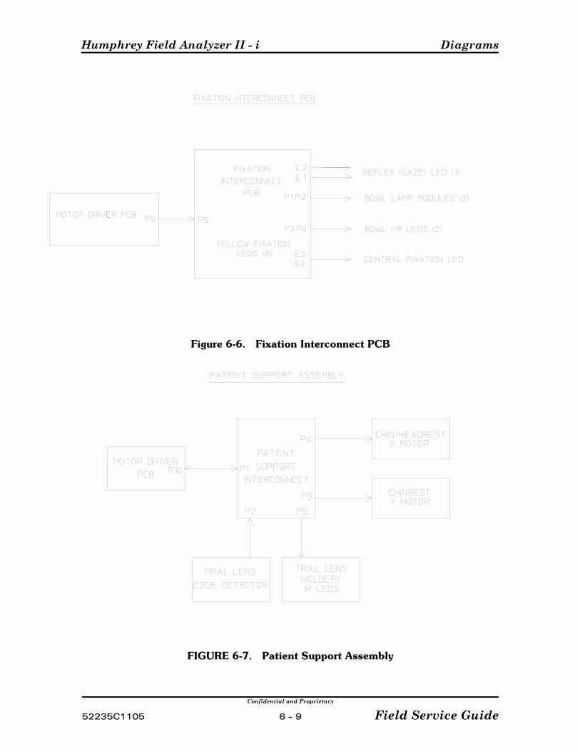
Humphrey Field Analyzer II - i Diagrams
Confidential and Proprietary
52235C1105 6 - 9 Field Service Guide
Figure 6-6. Fixation Interconnect PCB
FIGURE 6-7. Patient Support Assembly
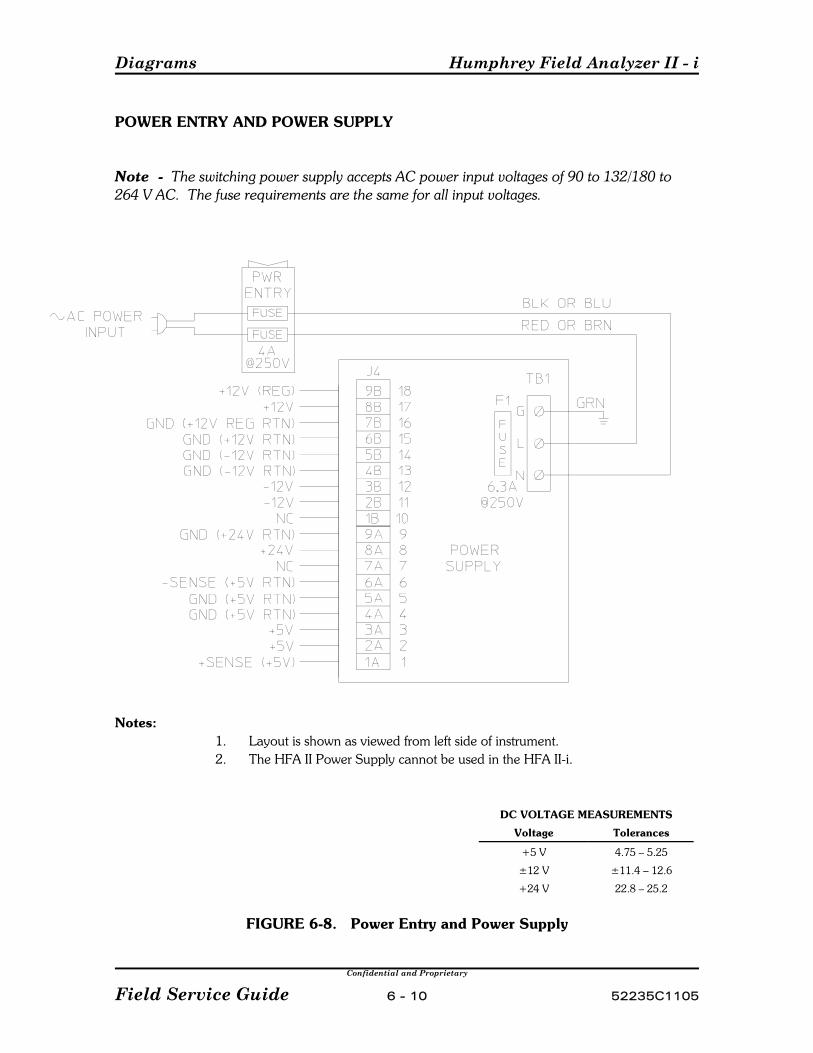
Diagrams Humphrey Field Analyzer II - i
Confidential and Proprietary
Field Service Guide 6 - 10 52235C1105
POWER ENTRY AND POWER SUPPLY
Note The switching power supply accepts AC power input voltages of 90 to 132/180 to264 V AC. The fuse requirements are the same for all input voltages.
Notes:1. Layout is shown as viewed from left side of instrument.2. The HFA II Power Supply cannot be used in the HFA II-i.
DC VOLTAGE MEASUREMENTS
Voltage Tolerances
+5 V 4.75 – 5.25
±12 V ±11.4 – 12.6
+24 V 22.8 – 25.2
FIGURE 6-8. Power Entry and Power Supply
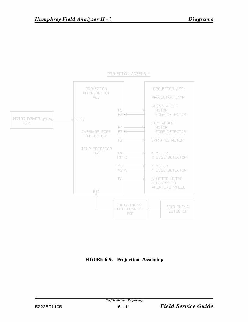
Humphrey Field Analyzer II - i Diagrams
Confidential and Proprietary
52235C1105 6 - 11 Field Service Guide
FIGURE 6-9. Projection Assembly

Diagrams Humphrey Field Analyzer II - i
Confidential and Proprietary
Field Service Guide 6 - 12 52235C1105
FIGURE 6-10. MEMORY MODULE AND DRIVES
NOTICE: For current information regarding the memory module and drives, refer to HFA II - i Field Service Bulletin FA2i-003(x).
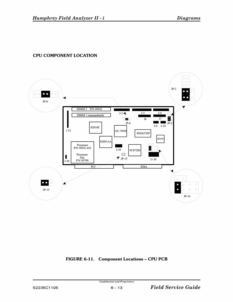
Humphrey Field Analyzer II - i Diagrams
Confidential and Proprietary
52235C1105 6 - 13 Field Service Guide
CPU COMPONENT LOCATION
FIGURE 6-11. Component Locations – CPU PCB
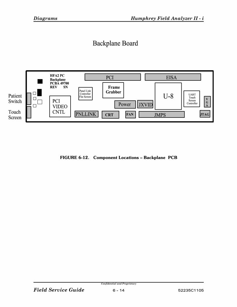
Diagrams Humphrey Field Analyzer II - i
Confidential and Proprietary
Field Service Guide 6 - 14 52235C1105
FIGURE 6-12. Component Locations – Backplane PCB
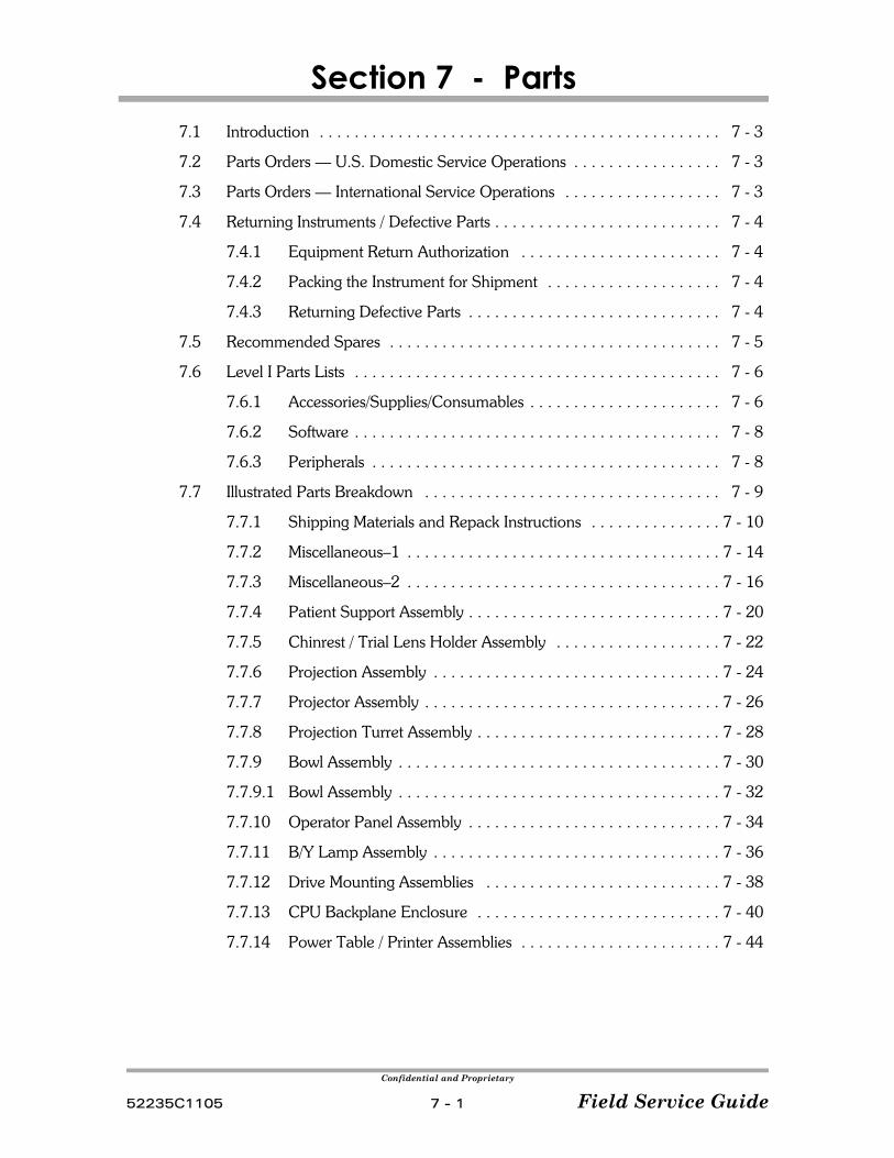
Confidential and Proprietary
52235C1105 7 - 1 Field Service Guide
Section 7 - Parts7.1 Introduction . . . . . . . . . . . . . . . . . . . . . . . . . . . . . . . . . . . . . . . . . . . . . . 7 - 3
7.2 Parts Orders — U.S. Domestic Service Operations . . . . . . . . . . . . . . . . . 7 - 3
7.3 Parts Orders — International Service Operations . . . . . . . . . . . . . . . . . . 7 - 3
7.4 Returning Instruments / Defective Parts . . . . . . . . . . . . . . . . . . . . . . . . . . 7 - 4
7.4.1 Equipment Return Authorization . . . . . . . . . . . . . . . . . . . . . . . 7 - 4
7.4.2 Packing the Instrument for Shipment . . . . . . . . . . . . . . . . . . . . 7 - 4
7.4.3 Returning Defective Parts . . . . . . . . . . . . . . . . . . . . . . . . . . . . . 7 - 4
7.5 Recommended Spares . . . . . . . . . . . . . . . . . . . . . . . . . . . . . . . . . . . . . . 7 - 5
7.6 Level I Parts Lists . . . . . . . . . . . . . . . . . . . . . . . . . . . . . . . . . . . . . . . . . . 7 - 6
7.6.1 Accessories/Supplies/Consumables . . . . . . . . . . . . . . . . . . . . . . 7 - 6
7.6.2 Software . . . . . . . . . . . . . . . . . . . . . . . . . . . . . . . . . . . . . . . . . . 7 - 8
7.6.3 Peripherals . . . . . . . . . . . . . . . . . . . . . . . . . . . . . . . . . . . . . . . . 7 - 8
7.7 Illustrated Parts Breakdown . . . . . . . . . . . . . . . . . . . . . . . . . . . . . . . . . . 7 - 9
7.7.1 Shipping Materials and Repack Instructions . . . . . . . . . . . . . . . 7 - 10
7.7.2 Miscellaneous–1 . . . . . . . . . . . . . . . . . . . . . . . . . . . . . . . . . . . . 7 - 14
7.7.3 Miscellaneous–2 . . . . . . . . . . . . . . . . . . . . . . . . . . . . . . . . . . . . 7 - 16
7.7.4 Patient Support Assembly . . . . . . . . . . . . . . . . . . . . . . . . . . . . . 7 - 20
7.7.5 Chinrest / Trial Lens Holder Assembly . . . . . . . . . . . . . . . . . . . 7 - 22
7.7.6 Projection Assembly . . . . . . . . . . . . . . . . . . . . . . . . . . . . . . . . . 7 - 24
7.7.7 Projector Assembly . . . . . . . . . . . . . . . . . . . . . . . . . . . . . . . . . . 7 - 26
7.7.8 Projection Turret Assembly . . . . . . . . . . . . . . . . . . . . . . . . . . . . 7 - 28
7.7.9 Bowl Assembly . . . . . . . . . . . . . . . . . . . . . . . . . . . . . . . . . . . . . 7 - 30
7.7.9.1 Bowl Assembly . . . . . . . . . . . . . . . . . . . . . . . . . . . . . . . . . . . . . 7 - 32
7.7.10 Operator Panel Assembly . . . . . . . . . . . . . . . . . . . . . . . . . . . . . 7 - 34
7.7.11 B/Y Lamp Assembly . . . . . . . . . . . . . . . . . . . . . . . . . . . . . . . . . 7 - 36
7.7.12 Drive Mounting Assemblies . . . . . . . . . . . . . . . . . . . . . . . . . . . 7 - 38
7.7.13 CPU Backplane Enclosure . . . . . . . . . . . . . . . . . . . . . . . . . . . . 7 - 40
7.7.14 Power Table / Printer Assemblies . . . . . . . . . . . . . . . . . . . . . . . 7 - 44

Parts Humphrey Field Analyzer II - i
Confidential and Proprietary
Field Service Guide 7 - 2 52235C1105
Notes:

Humphrey Field Analyzer II -i Parts
Confidential and Proprietary
52235C1105 7 - 3 Field Service Guide
7.1 Introduction
This section contains Level 1 parts lists and associated information for the HFA II - i. It containsinstructions for ordering parts and returning defective parts, and it identifies the parts that arerecommended as spares for supporting field repairs.
NOTE — International Operations: The procedure for returning defective partsfrom International operations differs somewhat from that for U.S. Domesticoperations. These differences are noted in the instructions. Please follow theinstructions carefully.
7.2 Parts Orders — U.S. Domestic Service Operations
Spare parts may be ordered monthly or weekly by using the standard parts order formavailable from Service Parts Stores. Parts needed overnight can be ordered by phone fromthe Parts Department. The cost of shipping parts for next day delivery is very high and shouldbe used only in emergencies.The Parts Department phone number is (800) 341-6968.
Customers are billed for shipping charges (most items are shipped UPS).
7.3 Parts Orders — International Service Operations
For International Service Operations, please use the ordering procedures that have beenestablished for your area of operations, and which meet the requirements of Carl Zeiss MeditecInternational Parts Department.

Parts Humphrey Field Analyzer II - i
Confidential and Proprietary
Field Service Guide 7 - 4 52235C1105
7.4 Returning Instruments / Defective Parts
When equipment needs to be returned to Carl Zeiss Meditec for repair, it is important that it isproperly packed for shipment, and that authorization for return is obtained before theequipment is shipped.
NOTICE — Costs to repair equipment damage caused by improper packing forshipment to Carl Zeiss Meditec become the responsibility of the sender.Do Not store anything in the bowl when shipping the HFA II - i.
7.4.1 Equipment Return Authorization
Authorization must be obtained from Carl Zeiss Meditec before equipment is returned forrepair. A Return Materials Authorization (RMA) number is required on each return shipmentto Carl Zeiss Meditec. The procedure for obtaining an RMA number varies, depending onyour area of operation. Use the procedure that has been established by Carl Zeiss Meditec foryour area of operations.
7.4.2 Packing the Instrument for Shipment
The shipping materials and repack instructions required for safe shipment of the HFA II - iare described in section 7.7.1 of this manual. A repack instruction sheet was also includedwith the instrument when first shipped from the factory.
7.4.3 Returning Defective Parts
The return of defective subassemblies is a very important part of our operation. Subassemblies are rebuilt and returned to service stock, and are available as needed by ourService Representatives. Our inventory is kept low to keep operating costs down.
When you return parts or assemblies to the Repair Center, attach a paper tag to eachassembly. On the tag, list the following information:
P the serial number of the instrument from which the part was removedP the date of removalP the problem (if you could not find the problem, describe what the customer
reported, and add "CND" - Can Not Duplicate)P the part number of the part/assembly being returnedP your territory number (U.S. Domestic Field Service Engineers)
This information will enable the Repair Center to make repairs as efficiently as possible. (ForU.S. Domestic Field Service Engineers, tags are available from the Parts Department.)
Humphrey Field Analyzer II -i Parts
Confidential and Proprietary
52235C1105 7 - 5 Field Service Guide
NOTE International Operations: Additional procedures are necessary for return ofdefective parts from international service operations. Instructions have been provided to eacharea of operation by the Carl Zeiss Meditec International Parts Department. If you areunfamiliar with the required procedure for your area, or have any questions regarding theprocedure, please contact the Carl Zeiss Meditec International Parts Department.
When you receive spare parts from the Parts Department, save the packaging material forreturning the defective part for repair. Many of the parts are delicate and expensive; extraattention to packaging will pay off in less damage to parts during shipment.
7.5 Recommended Spares
Parts that are recommended as spares for the HFA II - i (small hardware not included) aremarked with an asterisk (*) in the following parts lists. Quantities are not specified. Appropriate spares quantities are based on instrument population in your area, commonalityof spare parts between instrument models, and experienced failure rate of parts.
The parts marked with an asterisk (*) are kept in stock and generally always available forimmediate shipment as replacements. Any parts not in this list is subject to delays in delivery.
A quantity of 1 for each of these commonly-used parts may be used as a starting point fordetermining recommended spare quantities. Items and quantities may be added or deletedbased on local experience and instrument population in your area.
Sparing of small hardware (screws, washers, etc.) is necessary, but is left to the discretion of theindividual service engineer.
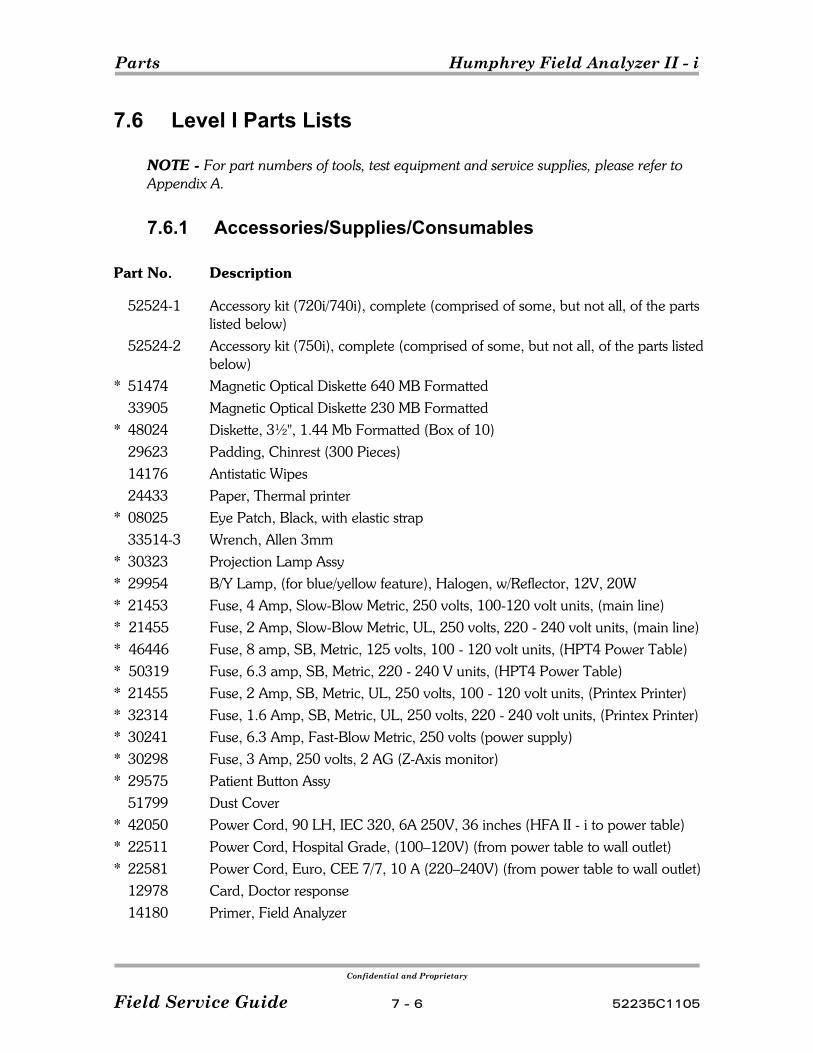
Parts Humphrey Field Analyzer II - i
Confidential and Proprietary
Field Service Guide 7 - 6 52235C1105
7.6 Level I Parts Lists
NOTE - For part numbers of tools, test equipment and service supplies, please refer toAppendix A.
7.6.1 Accessories/Supplies/Consumables
Part No. Description
52524-1 Accessory kit (720i/740i), complete (comprised of some, but not all, of the partslisted below)
52524-2 Accessory kit (750i), complete (comprised of some, but not all, of the parts listedbelow)
* 51474 Magnetic Optical Diskette 640 MB Formatted33905 Magnetic Optical Diskette 230 MB Formatted
* 48024 Diskette, 3½", 1.44 Mb Formatted (Box of 10)29623 Padding, Chinrest (300 Pieces)14176 Antistatic Wipes24433 Paper, Thermal printer
* 08025 Eye Patch, Black, with elastic strap33514-3 Wrench, Allen 3mm
* 30323 Projection Lamp Assy* 29954 B/Y Lamp, (for blue/yellow feature), Halogen, w/Reflector, 12V, 20W* 21453 Fuse, 4 Amp, Slow-Blow Metric, 250 volts, 100-120 volt units, (main line)* 21455 Fuse, 2 Amp, Slow-Blow Metric, UL, 250 volts, 220 - 240 volt units, (main line)* 46446 Fuse, 8 amp, SB, Metric, 125 volts, 100 - 120 volt units, (HPT4 Power Table)* 50319 Fuse, 6.3 amp, SB, Metric, 220 - 240 V units, (HPT4 Power Table)* 21455 Fuse, 2 Amp, SB, Metric, UL, 250 volts, 100 - 120 volt units, (Printex Printer)* 32314 Fuse, 1.6 Amp, SB, Metric, UL, 250 volts, 220 - 240 volt units, (Printex Printer)* 30241 Fuse, 6.3 Amp, Fast-Blow Metric, 250 volts (power supply)* 30298 Fuse, 3 Amp, 250 volts, 2 AG (Z-Axis monitor)* 29575 Patient Button Assy
51799 Dust Cover* 42050 Power Cord, 90 LH, IEC 320, 6A 250V, 36 inches (HFA II - i to power table)* 22511 Power Cord, Hospital Grade, (100–120V) (from power table to wall outlet)* 22581 Power Cord, Euro, CEE 7/7, 10 A (220–240V) (from power table to wall outlet)
12978 Card, Doctor response14180 Primer, Field Analyzer

Humphrey Field Analyzer II -i Parts
Confidential and Proprietary
52235C1105 7 - 7 Field Service Guide
30301-33 Touchup paint (Light Gray)24083 Label, Accessory Kit Quality07696 Plastic Box (holds accessories)51467 Keyboard w/touchpad51112 Keyboard adapter, male DB9 to male mini DIN (PS2)30184 Foam Barrier Strip, 10.5" (Sticks onto table top, flush with CRT side of HFA II - i, to block loose objects on table from rolling under instrument.)
* 51680-1 Owner's Manual, English51680-2 Owner’s Manual, French51680-3 Owner's Manual, German51680-4 Owner’s Manual, Italian51680-7 Owner's Manual, Spanish24500 Warning Sheet, Thermal Paper51947 Packing List, Accessory Kit51940 Reorder Card, HFA II30236 Instruction Sheet, "How to fasten HFA II - i to power table with printer"
* 30132 Instruction Sheet, Repack, HFA II - i30151 Carrier, Paper, Thermal Printer40034 Caster, Non-locking 40035 Caster, Locking
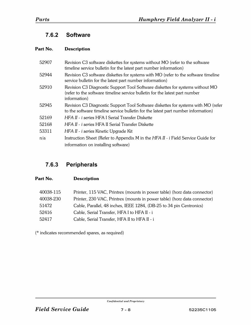
Parts Humphrey Field Analyzer II - i
Confidential and Proprietary
Field Service Guide 7 - 8 52235C1105
7.6.2 Software
Part No. Description
52907 Revision C3 software diskettes for systems without MO (refer to the softwaretimeline service bulletin for the latest part number information)
52944 Revision C3 software diskettes for systems with MO (refer to the software timelineservice bulletin for the latest part number information)
52910 Revision C3 Diagnostic Support Tool Software diskettes for systems without MO(refer to the software timeline service bulletin for the latest part numberinformation)
52945 Revision C3 Diagnostic Support Tool Software diskettes for systems with MO (referto the software timeline service bulletin for the latest part number information)
52169 HFA II - i series HFA I Serial Transfer Diskette52168 HFA II - i series HFA II Serial Transfer Diskette53311 HFA II - i series Kinetic Upgrade Kitn/a Instruction Sheet (Refer to Appendix M in the HFA II - i Field Service Guide for
information on installing software)
7.6.3 Peripherals
Part No. Description
40038-115 Printer, 115 VAC, Printrex (mounts in power table) (horz data connector)40038-230 Printer, 230 VAC, Printrex (mounts in power table) (horz data connector)51472 Cable, Parallel, 48 inches, IEEE 1284, (DB-25 to 34 pin Centronics)52416 Cable, Serial Transfer, HFA I to HFA II - i 52417 Cable, Serial Transfer, HFA II to HFA II - i
(* indicates recommended spares, as required)

Humphrey Field Analyzer II -i Parts
Confidential and Proprietary
52235C1105 7 - 9 Field Service Guide
NOTE - For individual cable part numbers, refer to the System Interconnectdiagram in Section 6 (Figure 6-1). Cables that do not have a part number listedin Figure 6-1 are supplied only as part of an associated assembly shown in thisparts section.
7.7 Illustrated Parts Breakdown
The following drawings provide illustrated parts breakdowns of the HFA II - i instrument. The partsdrawings are keyed by item numbers to the associated parts lists.
All dimensions are listed in inches unless noted otherwise.
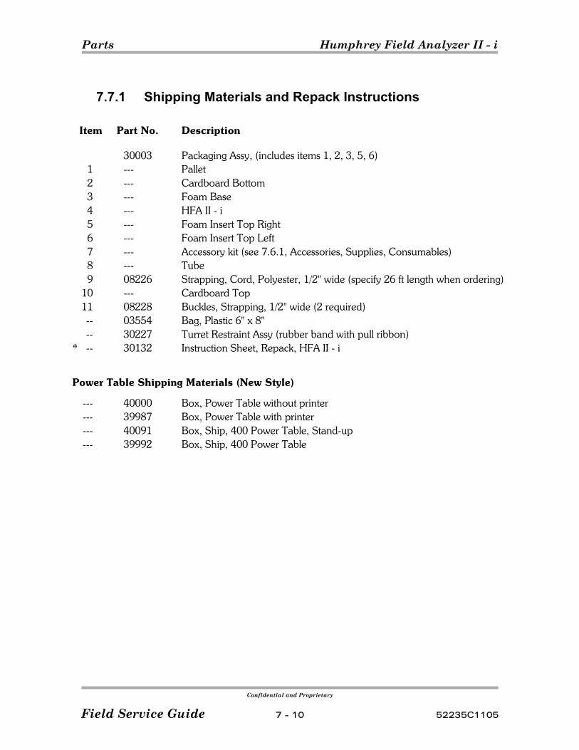
Parts Humphrey Field Analyzer II - i
Confidential and Proprietary
Field Service Guide 7 - 10 52235C1105
7.7.1 Shipping Materials and Repack Instructions
Item Part No. Description
30003 Packaging Assy, (includes items 1, 2, 3, 5, 6)1 --- Pallet2 --- Cardboard Bottom 3 --- Foam Base
4 --- HFA II - i 5 --- Foam Insert Top Right6 --- Foam Insert Top Left7 --- Accessory kit (see 7.6.1, Accessories, Supplies, Consumables)8 --- Tube 9 08226 Strapping, Cord, Polyester, 1/2" wide (specify 26 ft length when ordering)
10 --- Cardboard Top11 08228 Buckles, Strapping, 1/2" wide (2 required)-- 03554 Bag, Plastic 6" x 8"-- 30227 Turret Restraint Assy (rubber band with pull ribbon)
* -- 30132 Instruction Sheet, Repack, HFA II - i
Power Table Shipping Materials (New Style)
--- 40000 Box, Power Table without printer--- 39987 Box, Power Table with printer--- 40091 Box, Ship, 400 Power Table, Stand-up--- 39992 Box, Ship, 400 Power Table
Humphrey Field Analyzer II -i Parts
Confidential and Proprietary
52235C1105 7 - 11 Field Service Guide
HFA II - i Repacking Instructions
Caution — The bowl is easily damaged if abused. DO NOT store anything inside thebowl. If the instrument is received with objects stored inside the bowl, your account will becharged for ensuing repairs.
1) Disconnect the power cords and all peripherals from the HFA II - i.
2) Lock down the drive heads on floppy and Magnetic Optical drive using spare diskettes.
3) Pack the patient button, power cord, and all other accessories in the accessory box, ifappropriate.
4) Put the trial lens holder in the down position.
5) Rotate the HFA II - i turret completely clockwise. To hold the turret in place: C loop one end of the rubber-band turret restraint around the end of the small turretpulley C pass the rubber band behind the turret and loop the other end around the left-handbowl lamp baffle inside the bowl.
6) Remove the perforated cutout from the right side of the base foam insert (item 3).
7) Place the base foam insert inside the cardboard bottom on the pallet (items 1 & 2).
8) Place the HFA II - i (item 4) in the base as indicated on the drawing.
9) Remove the perforated cutout from the right side of the right top foam insert (item 6).
10) Orient the top right and top left foam inserts to conform with the surface of the field analyzercontours.
11) If you are shipping the keyboard (item 12) back with the unit, place the keyboard in the slot onthe rear top of the foam inserts.
12) Place accessory kit (item 7) on top of the left and right foam inserts.
13) Slide cardboard tube (item 8) over the left and right foam inserts until bottom edges touch thebottom of the cardboard bottom.
14) Place cardboard top (item 10) on the cardboard tube.
15) Secure entire shipping container with repackaging straps (item 9) and buckles (item 11). Seethe detail of how to use the buckles.
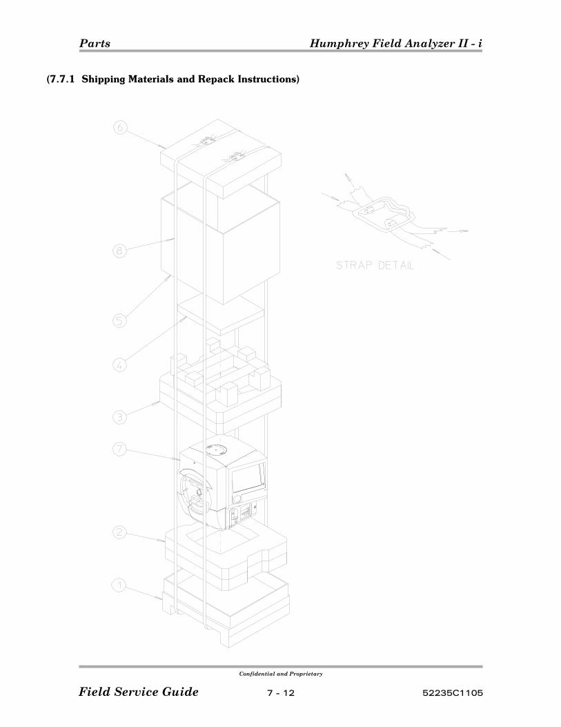
Parts Humphrey Field Analyzer II - i
Confidential and Proprietary
Field Service Guide 7 - 12 52235C1105
(7.7.1 Shipping Materials and Repack Instructions)

Humphrey Field Analyzer II -i Parts
Confidential and Proprietary
52235C1105 7 - 13 Field Service Guide
(This page left intentionally blank)
Parts Humphrey Field Analyzer II - i
Confidential and Proprietary
Field Service Guide 7 - 14 52235C1105
7.7.2 HFA II - i Miscellaneous–1
Item Part No. Description
1 29991 Assy, Door, Lamp Access, w/label29860 Label, Caution, Lamp Door
2 51114 Cover, Rear 3 51115 Cable Access Door4 29380 Door, Fan Filter
* 5 29381 Filter, Bottom Fan, 114mm/138mm/6.35mm6 29793 Assy, Bottom Fan7 29700 Gasket, Fan 8 30447 Guard, Fan
* 9 51072 CPU/Backplane Enclosure (all HFA II - i models)10 51070 Bracket, Right, Side
* 11 48530-3 Motor Driver Board (all HFA II - i models)12 51071 Bracket, Bottom13 28295-12 Screw, M4 x 12, Soc HD, Cap14 14445 Washer, Square Cone, .168/.370/.050, ST/Z15 29735 Assy, Power Entry Module (with cables)16 28293-8 Screw, M3 x 8, Soc HD, Cap17 14446 Washer, Square Cone, .142/.307/.039 18 51485 Bracket, IDE and Floppy Cable19 29861 Screw, M4 x 8, PH HD, Black STL
(* indicates recommended spares)
Sparing of small hardware is left to the discretion of the service engineer.
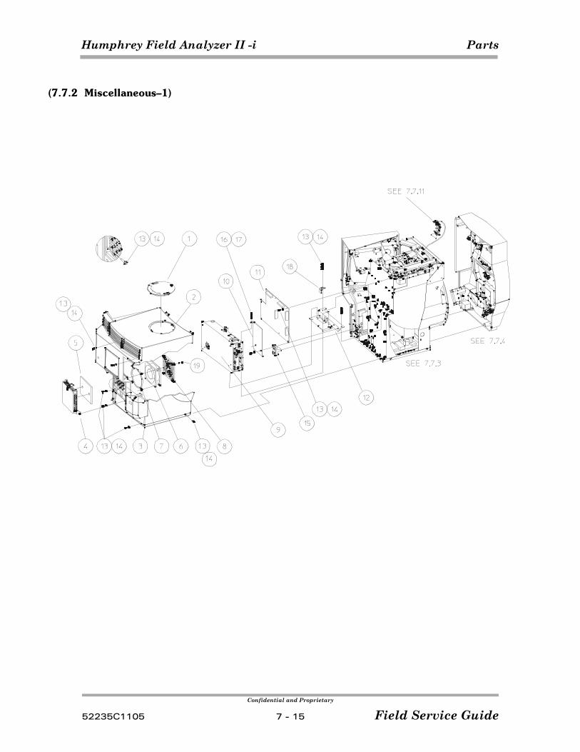
Humphrey Field Analyzer II -i Parts
Confidential and Proprietary
52235C1105 7 - 15 Field Service Guide
(7.7.2 Miscellaneous–1)
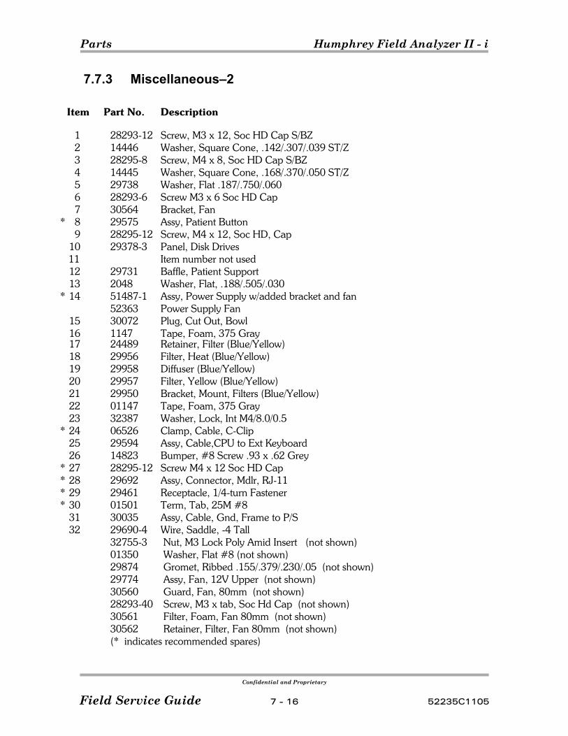
Parts Humphrey Field Analyzer II - i
Confidential and Proprietary
Field Service Guide 7 - 16 52235C1105
7.7.3 Miscellaneous–2
Item Part No. Description
1 28293-12 Screw, M3 x 12, Soc HD Cap S/BZ2 14446 Washer, Square Cone, .142/.307/.039 ST/Z3 28295-8 Screw, M4 x 8, Soc HD Cap S/BZ4 14445 Washer, Square Cone, .168/.370/.050 ST/Z5 29738 Washer, Flat .187/.750/.0606 28293-6 Screw M3 x 6 Soc HD Cap7 30564 Bracket, Fan
* 8 29575 Assy, Patient Button9 28295-12 Screw, M4 x 12, Soc HD, Cap
10 29378-3 Panel, Disk Drives 11 Item number not used
12 29731 Baffle, Patient Support13 2048 Washer, Flat, .188/.505/.030
* 14 51487-1 Assy, Power Supply w/added bracket and fan52363 Power Supply Fan
15 30072 Plug, Cut Out, Bowl16 1147 Tape, Foam, 375 Gray17 24489 Retainer, Filter (Blue/Yellow)18 29956 Filter, Heat (Blue/Yellow)19 29958 Diffuser (Blue/Yellow)20 29957 Filter, Yellow (Blue/Yellow)21 29950 Bracket, Mount, Filters (Blue/Yellow)22 01147 Tape, Foam, 375 Gray23 32387 Washer, Lock, Int M4/8.0/0.5
* 24 06526 Clamp, Cable, C-Clip25 29594 Assy, Cable,CPU to Ext Keyboard26 14823 Bumper, #8 Screw .93 x .62 Grey
* 27 28295-12 Screw M4 x 12 Soc HD Cap* 28 29692 Assy, Connector, Mdlr, RJ-11* 29 29461 Receptacle, 1/4-turn Fastener* 30 01501 Term, Tab, 25M #8
31 30035 Assy, Cable, Gnd, Frame to P/S32 29690-4 Wire, Saddle, -4 Tall
32755-3 Nut, M3 Lock Poly Amid Insert (not shown)01350 Washer, Flat #8 (not shown)29874 Gromet, Ribbed .155/.379/.230/.05 (not shown)29774 Assy, Fan, 12V Upper (not shown)30560 Guard, Fan, 80mm (not shown)28293-40 Screw, M3 x tab, Soc Hd Cap (not shown)30561 Filter, Foam, Fan 80mm (not shown)30562 Retainer, Filter, Fan 80mm (not shown)(* indicates recommended spares)
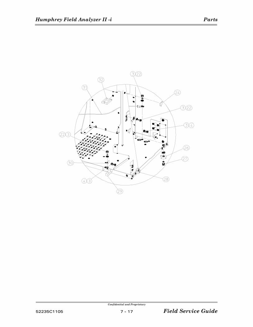
Humphrey Field Analyzer II -i Parts
Confidential and Proprietary
52235C1105 7 - 17 Field Service Guide

Parts Humphrey Field Analyzer II - i
Confidential and Proprietary
Field Service Guide 7 - 18 52235C1105
(This page left intentionally blank)
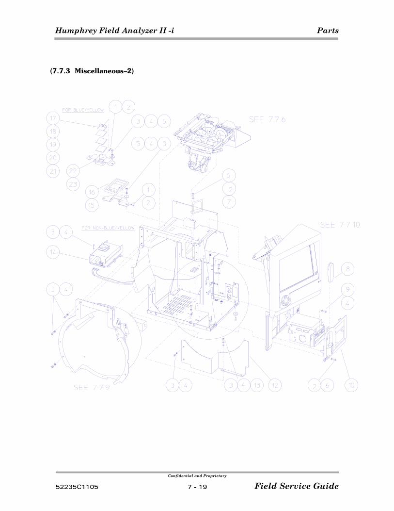
Humphrey Field Analyzer II -i Parts
Confidential and Proprietary
52235C1105 7 - 19 Field Service Guide
(7.7.3 Miscellaneous–2)
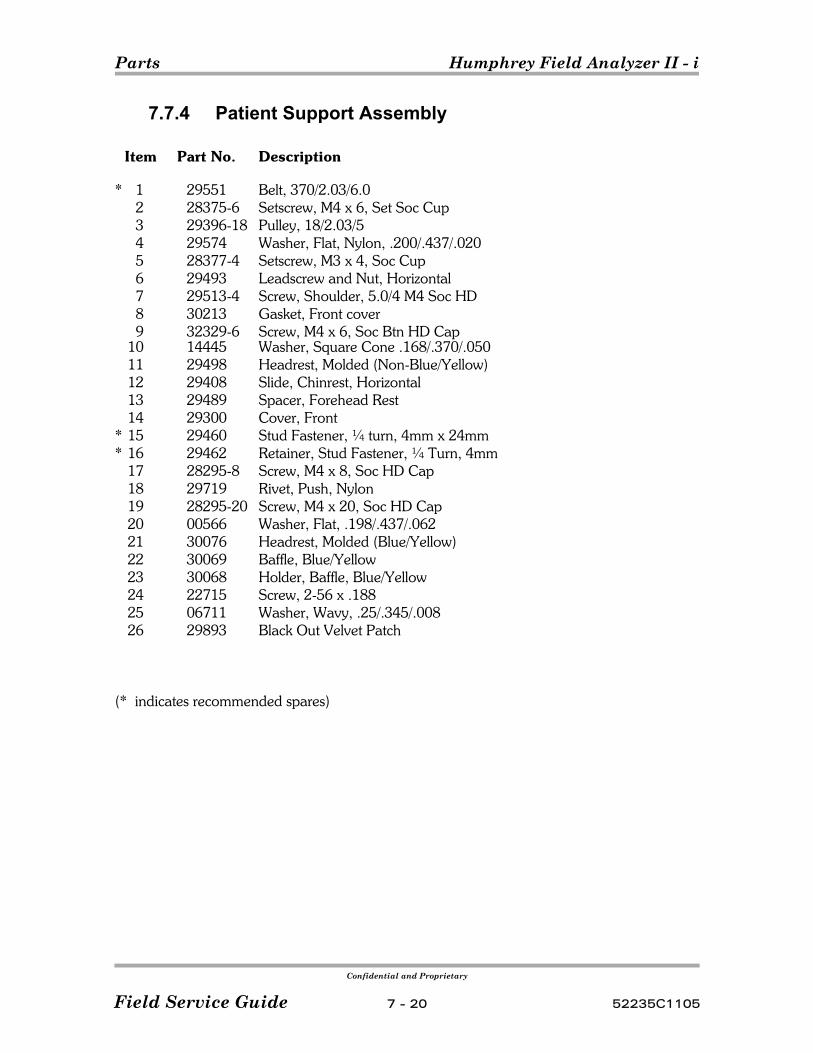
Parts Humphrey Field Analyzer II - i
Confidential and Proprietary
Field Service Guide 7 - 20 52235C1105
7.7.4 Patient Support Assembly
Item Part No. Description
* 1 29551 Belt, 370/2.03/6.02 28375-6 Setscrew, M4 x 6, Set Soc Cup3 29396-18 Pulley, 18/2.03/54 29574 Washer, Flat, Nylon, .200/.437/.0205 28377-4 Setscrew, M3 x 4, Soc Cup6 29493 Leadscrew and Nut, Horizontal7 29513-4 Screw, Shoulder, 5.0/4 M4 Soc HD8 30213 Gasket, Front cover9 32329-6 Screw, M4 x 6, Soc Btn HD Cap
10 14445 Washer, Square Cone .168/.370/.05011 29498 Headrest, Molded (Non-Blue/Yellow)12 29408 Slide, Chinrest, Horizontal13 29489 Spacer, Forehead Rest14 29300 Cover, Front
* 15 29460 Stud Fastener, ¼ turn, 4mm x 24mm* 16 29462 Retainer, Stud Fastener, ¼ Turn, 4mm
17 28295-8 Screw, M4 x 8, Soc HD Cap18 29719 Rivet, Push, Nylon19 28295-20 Screw, M4 x 20, Soc HD Cap20 00566 Washer, Flat, .198/.437/.06221 30076 Headrest, Molded (Blue/Yellow)22 30069 Baffle, Blue/Yellow23 30068 Holder, Baffle, Blue/Yellow24 22715 Screw, 2-56 x .18825 06711 Washer, Wavy, .25/.345/.00826 29893 Black Out Velvet Patch
(* indicates recommended spares)
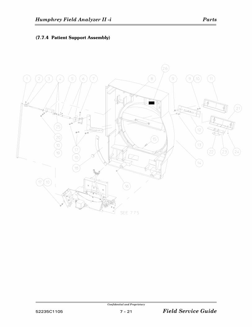
Humphrey Field Analyzer II -i Parts
Confidential and Proprietary
52235C1105 7 - 21 Field Service Guide
(7.7.4 Patient Support Assembly)
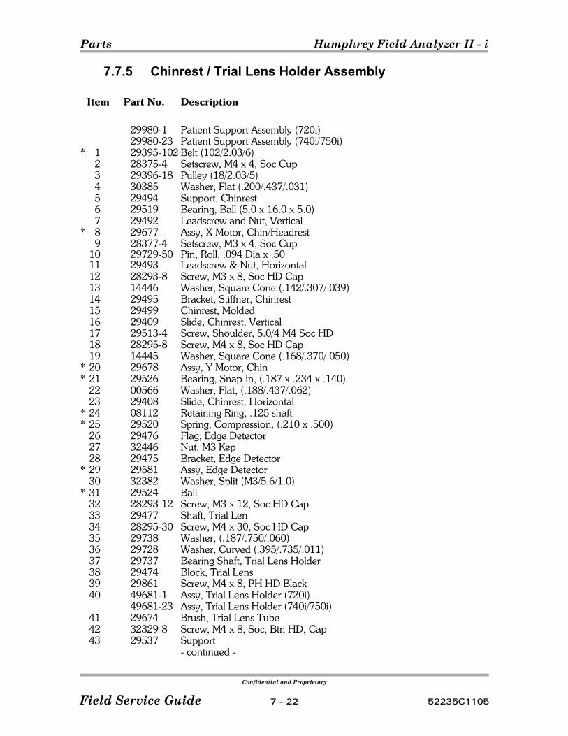
Parts Humphrey Field Analyzer II - i
Confidential and Proprietary
Field Service Guide 7 - 22 52235C1105
7.7.5 Chinrest / Trial Lens Holder Assembly
Item Part No. Description
29980-1 Patient Support Assembly (720i)29980-23 Patient Support Assembly (740i/750i)
* 1 29395-102 Belt (102/2.03/6)2 28375-4 Setscrew, M4 x 4, Soc Cup3 29396-18 Pulley (18/2.03/5)4 30385 Washer, Flat (.200/.437/.031)5 29494 Support, Chinrest6 29519 Bearing, Ball (5.0 x 16.0 x 5.0)7 29492 Leadscrew and Nut, Vertical
* 8 29677 Assy, X Motor, Chin/Headrest9 28377-4 Setscrew, M3 x 4, Soc Cup
10 29729-50 Pin, Roll, .094 Dia x .5011 29493 Leadscrew & Nut, Horizontal12 28293-8 Screw, M3 x 8, Soc HD Cap13 14446 Washer, Square Cone (.142/.307/.039)14 29495 Bracket, Stiffner, Chinrest15 29499 Chinrest, Molded16 29409 Slide, Chinrest, Vertical17 29513-4 Screw, Shoulder, 5.0/4 M4 Soc HD18 28295-8 Screw, M4 x 8, Soc HD Cap19 14445 Washer, Square Cone (.168/.370/.050)
* 20 29678 Assy, Y Motor, Chin* 21 29526 Bearing, Snap-in, (.187 x .234 x .140)
22 00566 Washer, Flat, (.188/.437/.062)23 29408 Slide, Chinrest, Horizontal
* 24 08112 Retaining Ring, .125 shaft* 25 29520 Spring, Compression, (.210 x .500)
26 29476 Flag, Edge Detector27 32446 Nut, M3 Kep28 29475 Bracket, Edge Detector
* 29 29581 Assy, Edge Detector30 32382 Washer, Split (M3/5.6/1.0)
* 31 29524 Ball32 28293-12 Screw, M3 x 12, Soc HD Cap33 29477 Shaft, Trial Len34 28295-30 Screw, M4 x 30, Soc HD Cap35 29738 Washer, (.187/.750/.060)36 29728 Washer, Curved (.395/.735/.011)37 29737 Bearing Shaft, Trial Lens Holder38 29474 Block, Trial Lens39 29861 Screw, M4 x 8, PH HD Black40 49681-1 Assy, Trial Lens Holder (720i)
49681-23 Assy, Trial Lens Holder (740i/750i) 41 29674 Brush, Trial Lens Tube42 32329-8 Screw, M4 x 8, Soc, Btn HD, Cap43 29537 Support
- continued -
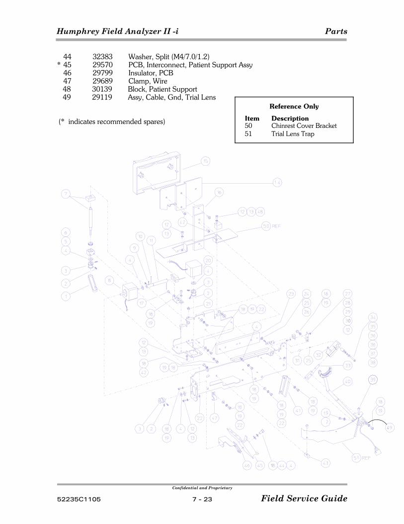
Humphrey Field Analyzer II -i Parts
Confidential and Proprietary
52235C1105 7 - 23 Field Service Guide
Reference Only
Item Description50 Chinrest Cover Bracket51 Trial Lens Trap
44 32383 Washer, Split (M4/7.0/1.2)* 45 29570 PCB, Interconnect, Patient Support Assy
46 29799 Insulator, PCB47 29689 Clamp, Wire48 30139 Block, Patient Support49 29119 Assy, Cable, Gnd, Trial Lens
(* indicates recommended spares)
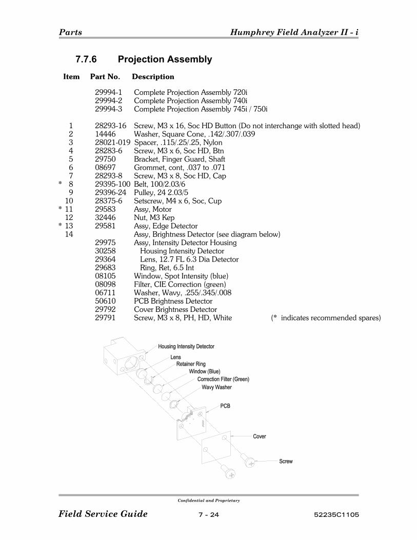
Parts Humphrey Field Analyzer II - i
Confidential and Proprietary
Field Service Guide 7 - 24 52235C1105
7.7.6 Projection Assembly
Item Part No. Description
29994-1 Complete Projection Assembly 720i29994-2 Complete Projection Assembly 740i 29994-3 Complete Projection Assembly 745i / 750i
1 28293-16 Screw, M3 x 16, Soc HD Button (Do not interchange with slotted head)2 14446 Washer, Square Cone, .142/.307/.0393 28021-019 Spacer, .115/.25/.25, Nylon4 28283-6 Screw, M3 x 6, Soc HD, Btn5 29750 Bracket, Finger Guard, Shaft6 08697 Grommet, cont, .037 to .0717 28293-8 Screw, M3 x 8, Soc HD, Cap
* 8 29395-100 Belt, 100/2.03/69 29396-24 Pulley, 24 2.03/5
10 28375-6 Setscrew, M4 x 6, Soc, Cup* 11 29583 Assy, Motor
12 32446 Nut, M3 Kep* 13 29581 Assy, Edge Detector
14 Assy, Brightness Detector (see diagram below)29975 Assy, Intensity Detector Housing30258 Housing Intensity Detector29364 Lens, 12.7 FL 6.3 Dia Detector 29683 Ring, Ret, 6.5 Int08105 Window, Spot Intensity (blue)
08098 Filter, CIE Correction (green)06711 Washer, Wavy, .255/.345/.00850610 PCB Brightness Detector29792 Cover Brightness Detector29791 Screw, M3 x 8, PH, HD, White (* indicates recommended spares)
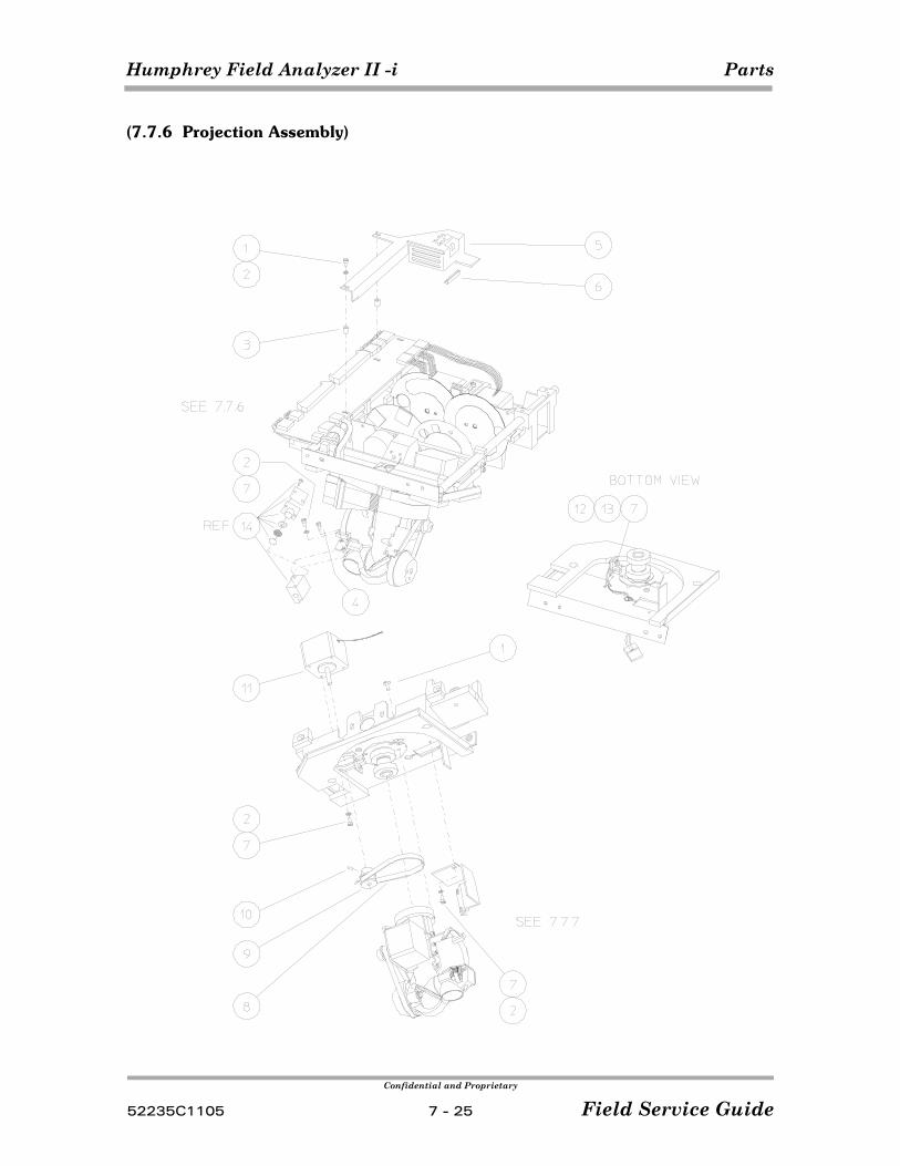
Humphrey Field Analyzer II -i Parts
Confidential and Proprietary
52235C1105 7 - 25 Field Service Guide
(7.7.6 Projection Assembly)
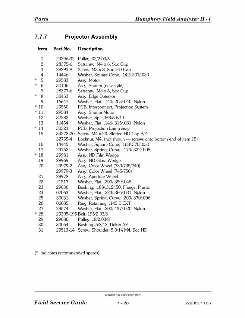
Parts Humphrey Field Analyzer II - i
Confidential and Proprietary
Field Service Guide 7 - 26 52235C1105
7.7.7 Projector Assembly
Item Part No. Description
1 29396-32 Pulley, 32/2.03/52 28375-6 Setscrew, M4 x 6, Soc Cup3 28293-8 Screw, M3 x 8, Soc HD Cap4 14446 Washer, Square Cone, .142/.307/.039
* 5 29583 Assy, Motor* 6 30106 Assy, Shutter (new style)
7 28377-6 Setscrew, M3 x 6, Soc Cup* 8 30453 Assy, Edge Detector
9 16647 Washer, Flat, .140/.205/.040, Nylon* 10 29550 PCB, Interconnect, Projection System* 11 29584 Assy, Shutter Motor
12 32382 Washer, Split, M3/5.6/1.013 16454 Washer, Flat, .146/.315/.031, Nylon
* 14 30323 PCB, Projection Lamp Assy15 34272-20 Screw, M4 x 20, Slotted HD Cap B/Z
32755-4 Locknut, M4, (not shown — screws onto bottom end of item 15)16 14445 Washer, Square Cone, .168/.370/.05017 29752 Washer, Spring, Curvy, .174/.322/.008
* 18 29981 Assy, ND Film Wedge19 29969 Assy, ND Glass Wedge20 29979-2 Assy, Color Wheel (730/735/740)
29979-3 Assy, Color Wheel (745/750)21 29978 Assy, Aperture Wheel22 21517 Washer, Flat, .200/.359/.04823 29636 Bushing, .188/.312/.50, Flange, Plastic24 07063 Washer, Flat, .223/.366/.031, Nylon25 30031 Washer, Spring, Curvy, .200/.370/.00626 06085 Ring, Retaining, .145 E EXT27 29574 Washer, Flat, .200/.437/.020, Nylon
* 28 29395-195 Belt, 195/2.03/629 29686 Pulley, 18/2.03/830 30054 Bushing, 5/8/12, Delrin AF31 29513-14 Screw, Shoulder, 5.0/14 M4, Soc HD
(* indicates recommended spares)
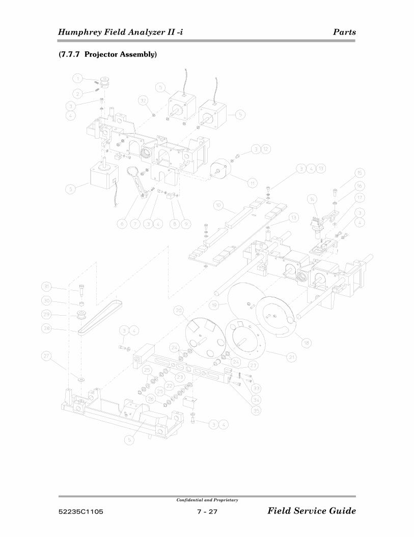
Humphrey Field Analyzer II -i Parts
Confidential and Proprietary
52235C1105 7 - 27 Field Service Guide
(7.7.7 Projector Assembly)
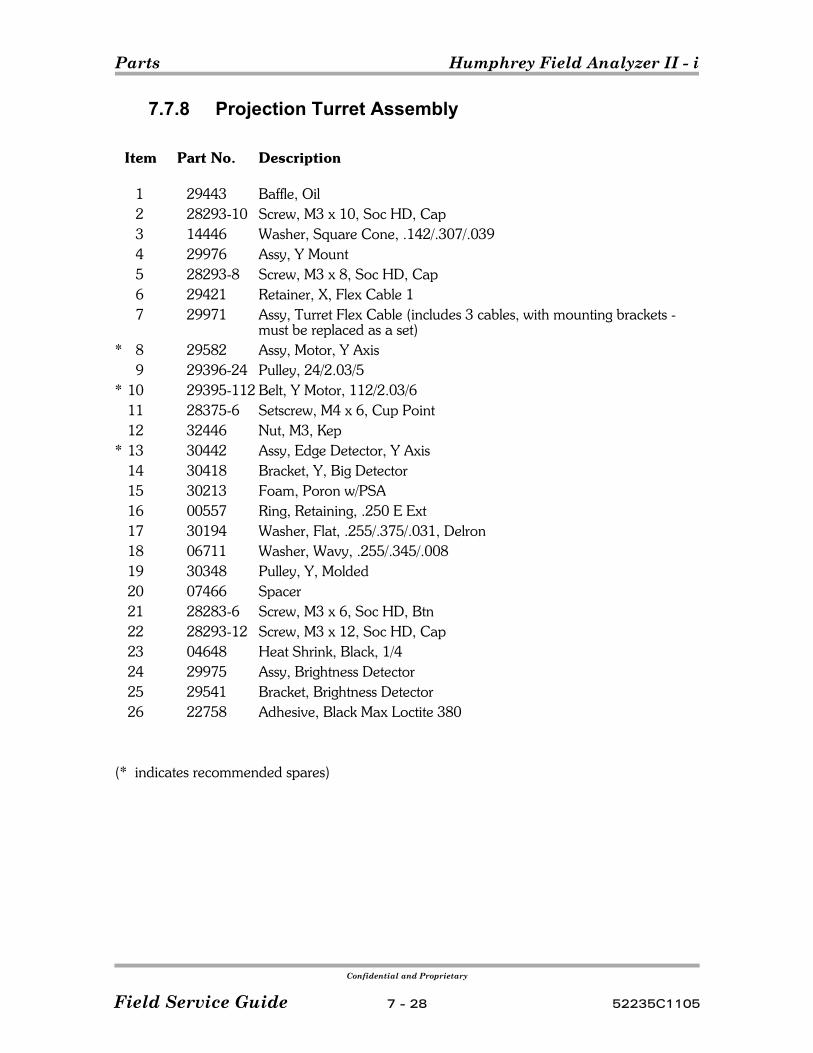
Parts Humphrey Field Analyzer II - i
Confidential and Proprietary
Field Service Guide 7 - 28 52235C1105
7.7.8 Projection Turret Assembly
Item Part No. Description
1 29443 Baffle, Oil2 28293-10 Screw, M3 x 10, Soc HD, Cap3 14446 Washer, Square Cone, .142/.307/.0394 29976 Assy, Y Mount5 28293-8 Screw, M3 x 8, Soc HD, Cap6 29421 Retainer, X, Flex Cable 17 29971 Assy, Turret Flex Cable (includes 3 cables, with mounting brackets -
must be replaced as a set)* 8 29582 Assy, Motor, Y Axis
9 29396-24 Pulley, 24/2.03/5* 10 29395-112 Belt, Y Motor, 112/2.03/6
11 28375-6 Setscrew, M4 x 6, Cup Point12 32446 Nut, M3, Kep
* 13 30442 Assy, Edge Detector, Y Axis14 30418 Bracket, Y, Big Detector15 30213 Foam, Poron w/PSA16 00557 Ring, Retaining, .250 E Ext17 30194 Washer, Flat, .255/.375/.031, Delron18 06711 Washer, Wavy, .255/.345/.00819 30348 Pulley, Y, Molded20 07466 Spacer21 28283-6 Screw, M3 x 6, Soc HD, Btn22 28293-12 Screw, M3 x 12, Soc HD, Cap23 04648 Heat Shrink, Black, 1/424 29975 Assy, Brightness Detector25 29541 Bracket, Brightness Detector26 22758 Adhesive, Black Max Loctite 380
(* indicates recommended spares)
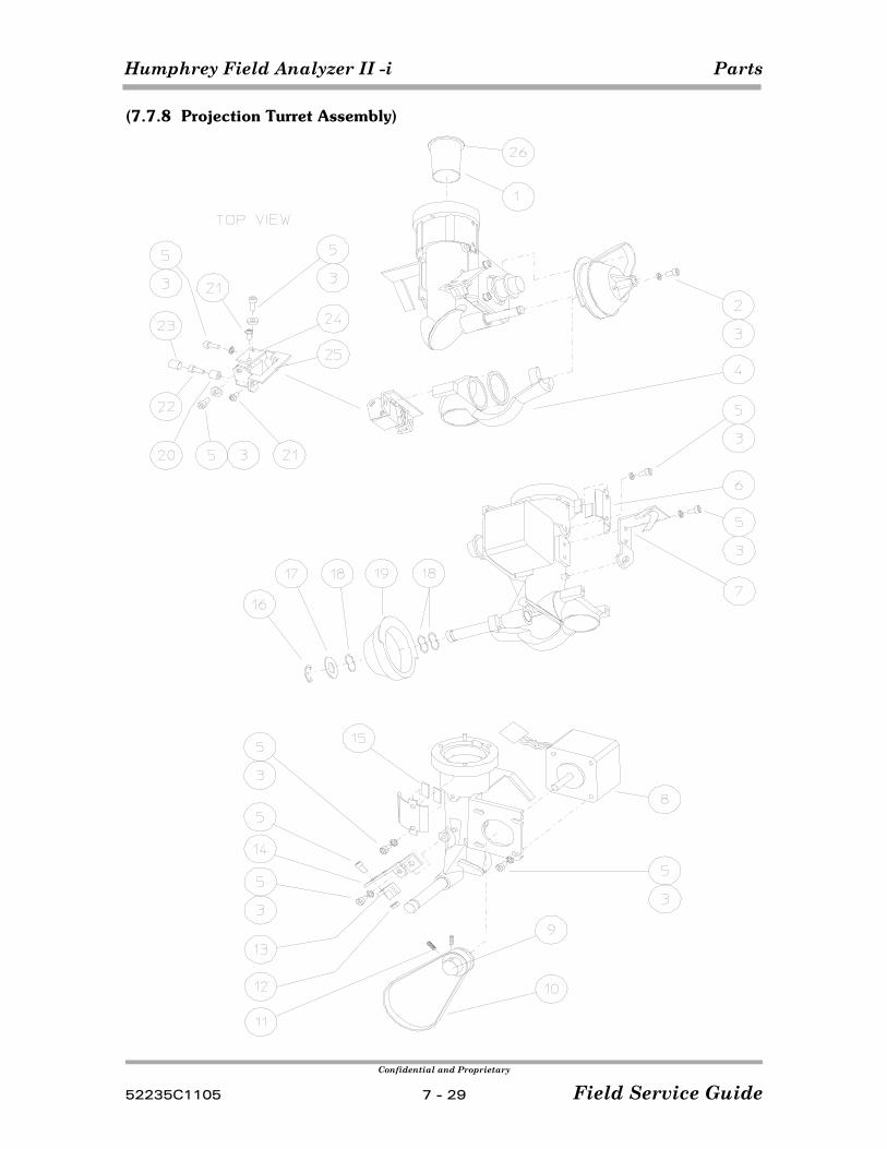
Humphrey Field Analyzer II -i Parts
Confidential and Proprietary
52235C1105 7 - 29 Field Service Guide
(7.7.8 Projection Turret Assembly)
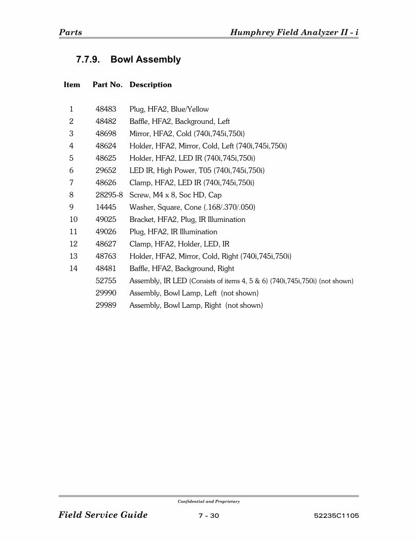
Parts Humphrey Field Analyzer II - i
Confidential and Proprietary
Field Service Guide 7 - 30 52235C1105
7.7.9. Bowl Assembly
Item Part No. Description
1 48483 Plug, HFA2, Blue/Yellow
2 48482 Baffle, HFA2, Background, Left
3 48698 Mirror, HFA2, Cold (740i,745i,750i)
4 48624 Holder, HFA2, Mirror, Cold, Left (740i,745i,750i)
5 48625 Holder, HFA2, LED IR (740i,745i,750i)
6 29652 LED IR, High Power, T05 (740i,745i,750i)
7 48626 Clamp, HFA2, LED IR (740i,745i,750i)
8 28295-8 Screw, M4 x 8, Soc HD, Cap
9 14445 Washer, Square, Cone (.168/.370/.050)
10 49025 Bracket, HFA2, Plug, IR Illumination
11 49026 Plug, HFA2, IR Illumination
12 48627 Clamp, HFA2, Holder, LED, IR
13 48763 Holder, HFA2, Mirror, Cold, Right (740i,745i,750i)
14 48481 Baffle, HFA2, Background, Right
52755 Assembly, IR LED (Consists of items 4, 5 & 6) (740i,745i,750i) (not shown)
29990 Assembly, Bowl Lamp, Left (not shown)
29989 Assembly, Bowl Lamp, Right (not shown)
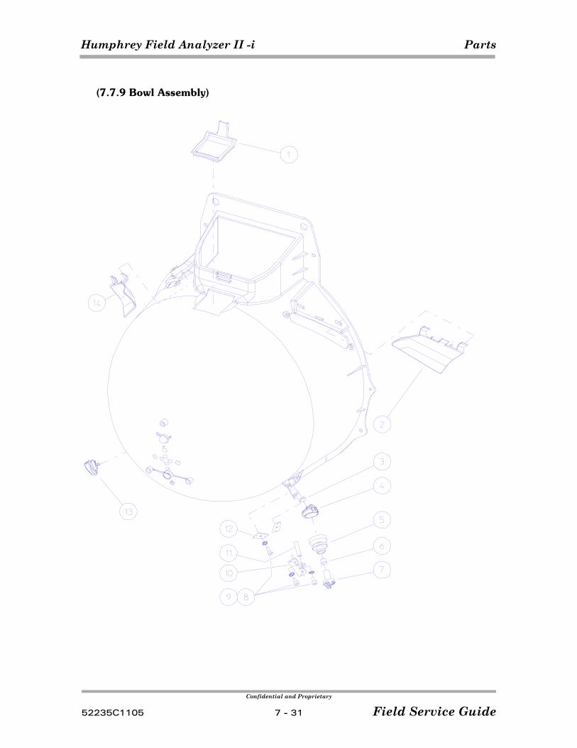
Humphrey Field Analyzer II -i Parts
Confidential and Proprietary
52235C1105 7 - 31 Field Service Guide
(7.7.9 Bowl Assembly)
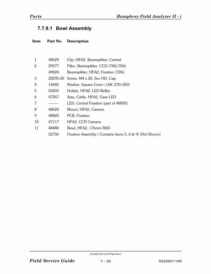
Parts Humphrey Field Analyzer II - i
Confidential and Proprietary
Field Service Guide 7 - 32 52235C1105
7.7.9.1 Bowl Assembly
Item Part No. Description
1 48629 Clip, HFA2, Beamsplitter, Central
2 29577 Filter, Beamsplitter, CCD (740i,750i)
49024 Beamsplitter, HFA2, Fixation (720i)
3 28295-20 Screw, M4 x 20, Soc HD, Cap
4 14445 Washer, Square Cone (.168/.370/.050)
5 50203 Holder, HFA2, LED Reflex
6 47267 Assy, Cable, HFA2, Gaze LED
7 -------- LED, Central Fixation (part of 48820)
8 48628 Mount, HFA2, Camera
9 48820 PCB, Fixation
10 47117 HFA2, CCD Camera
11 48480 Bowl, HFA2, 175mm RAD
52756 Fixation Assembly ( Contains items 5, 6 & 9) (Not Shown)
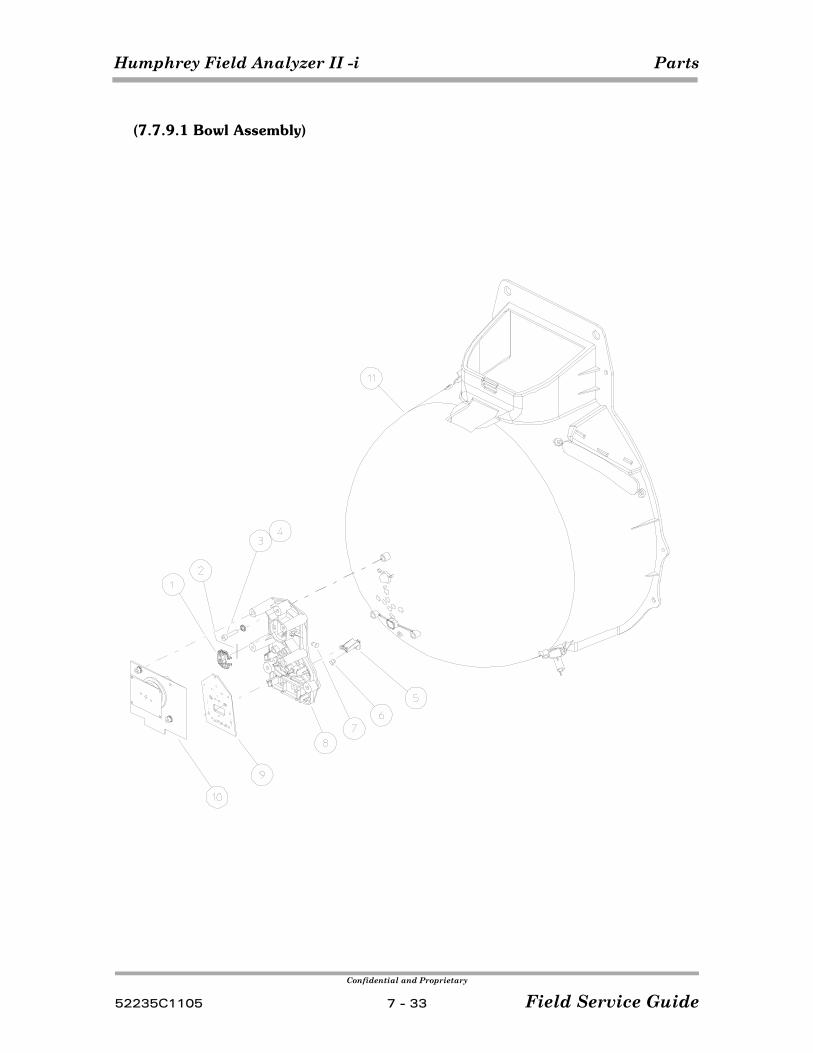
Humphrey Field Analyzer II -i Parts
Confidential and Proprietary
52235C1105 7 - 33 Field Service Guide
(7.7.9.1 Bowl Assembly)
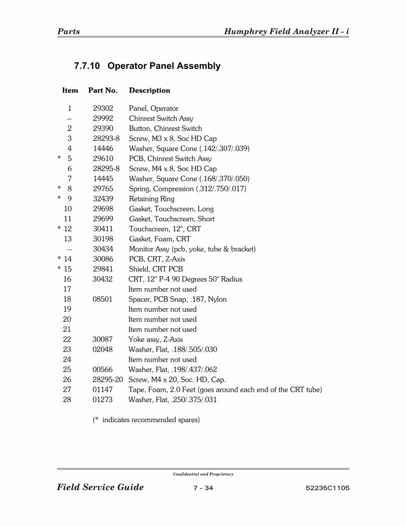
Parts Humphrey Field Analyzer II - i
Confidential and Proprietary
Field Service Guide 7 - 34 52235C1105
7.7.10 Operator Panel Assembly
Item Part No. Description
1 29302 Panel, Operator-- 29992 Chinrest Switch Assy2 29390 Button, Chinrest Switch3 28293-8 Screw, M3 x 8, Soc HD Cap4 14446 Washer, Square Cone (.142/.307/.039)
* 5 29610 PCB, Chinrest Switch Assy6 28295-8 Screw, M4 x 8, Soc HD Cap7 14445 Washer, Square Cone (.168/.370/.050)
* 8 29765 Spring, Compression (.312/.750/.017)* 9 32439 Retaining Ring
10 29698 Gasket, Touchscreen, Long11 29699 Gasket, Touchscreen, Short
* 12 30411 Touchscreen, 12", CRT13 30198 Gasket, Foam, CRT-- 30434 Monitor Assy (pcb, yoke, tube & bracket)
* 14 30086 PCB, CRT, Z-Axis* 15 29841 Shield, CRT PCB
16 30432 CRT, 12" P-4 90 Degrees 50" Radius17 Item number not used18 08501 Spacer, PCB Snap, .187, Nylon19 Item number not used20 Item number not used21 Item number not used22 30087 Yoke assy, Z-Axis23 02048 Washer, Flat, .188/.505/.03024 Item number not used25 00566 Washer, Flat, .198/.437/.06226 28295-20 Screw, M4 x 20, Soc. HD, Cap.27 01147 Tape, Foam, 2.0 Feet (goes around each end of the CRT tube)28 01273 Washer, Flat, .250/.375/.031
(* indicates recommended spares)
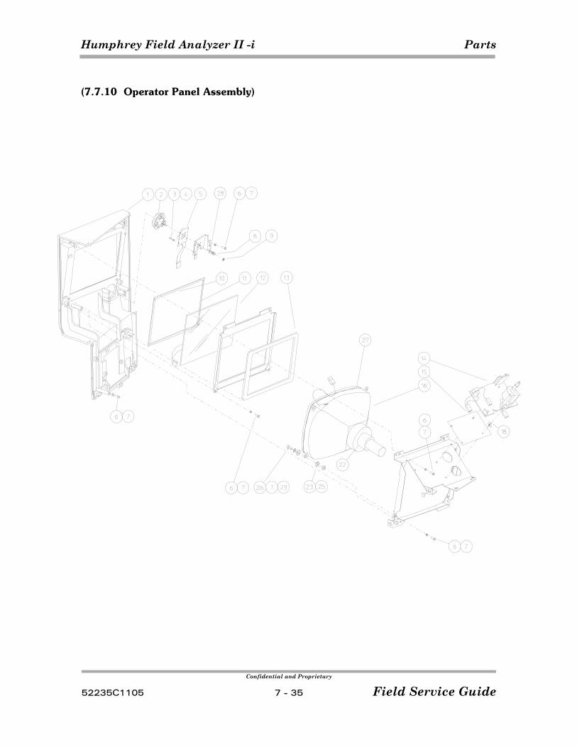
Humphrey Field Analyzer II -i Parts
Confidential and Proprietary
52235C1105 7 - 35 Field Service Guide
(7.7.10 Operator Panel Assembly)
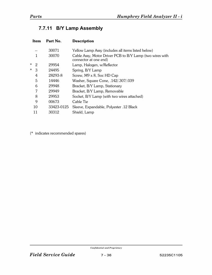
Parts Humphrey Field Analyzer II - i
Confidential and Proprietary
Field Service Guide 7 - 36 52235C1105
7.7.11 B/Y Lamp Assembly
Item Part No. Description
-- 30071 Yellow Lamp Assy (includes all items listed below)1 30070 Cable Assy, Motor Driver PCB to B/Y Lamp (two wires with
connector at one end)* 2 29954 Lamp, Halogen, w/Reflector* 3 24495 Spring, B/Y Lamp
4 28293-8 Screw, M9 x 8, Soc HD Cap5 14446 Washer, Square Cone, .142/.307/.0396 29948 Bracket, B/Y Lamp, Stationary7 29949 Bracket, B/Y Lamp, Removable8 29953 Socket, B/Y Lamp (with two wires attached)9 00673 Cable Tie
10 33423-0125 Sleeve, Expandable, Polyester .12 Black11 30312 Shield, Lamp
(* indicates recommended spares)
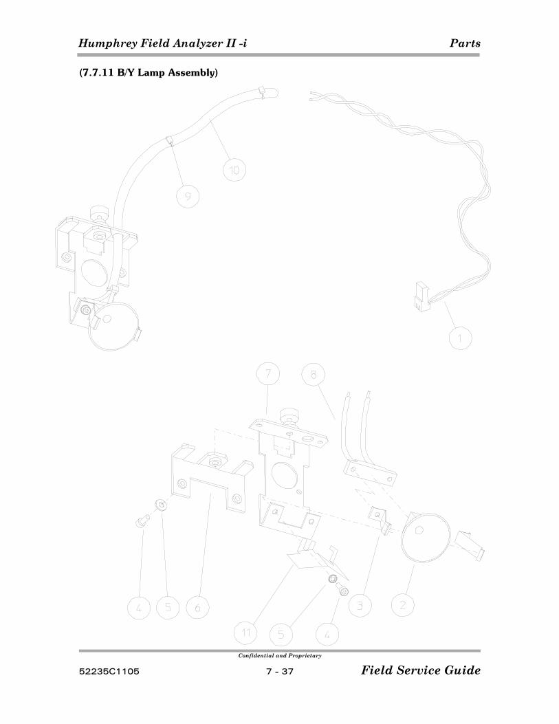
Humphrey Field Analyzer II -i Parts
Confidential and Proprietary
52235C1105 7 - 37 Field Service Guide
(7.7.11 B/Y Lamp Assembly)
Parts Humphrey Field Analyzer II - i
Confidential and Proprietary
Field Service Guide 7 - 38 52235C1105
7.7.12 Drive Mounting Assemblies
Item Part No. Description
1 51290 Assy, LED, HFA II - i Hard Drive, IBM (720i, 740i,750i)680978 Cable Clamp, Assy LED (Not Shown)
* 2 52036 Drive, hard, IDE 20 Gigabyte, (720i, 740i,750i)3 29631 Holder, LED, Hard Drive
* 4 51476 Drive, Magnetic Optical, 3 ½", ATAPI* 5 29244 Drive, Floppy, 3½", High Density
6 06548 Screw, 6-32 x .375, Soc HD Cap7 14446 Washer, Square Cone, .142/.307/.0398 24073 Label, Drive Date Code9 28293-8 Screw, M3 x 8, Soc HD Cap
10 14196 Screw, 6-32 x .250, Soc HD Cap11 51486 Panel Drive, Blanking, HFA II - i (attached using items 7 & 9)12 30317 Floppy Drive Cable Retaining Bracket
Note Refer to service bulletin FA2i-003(x) for additional hard & tape drive information.
(* indicates recommended spares)
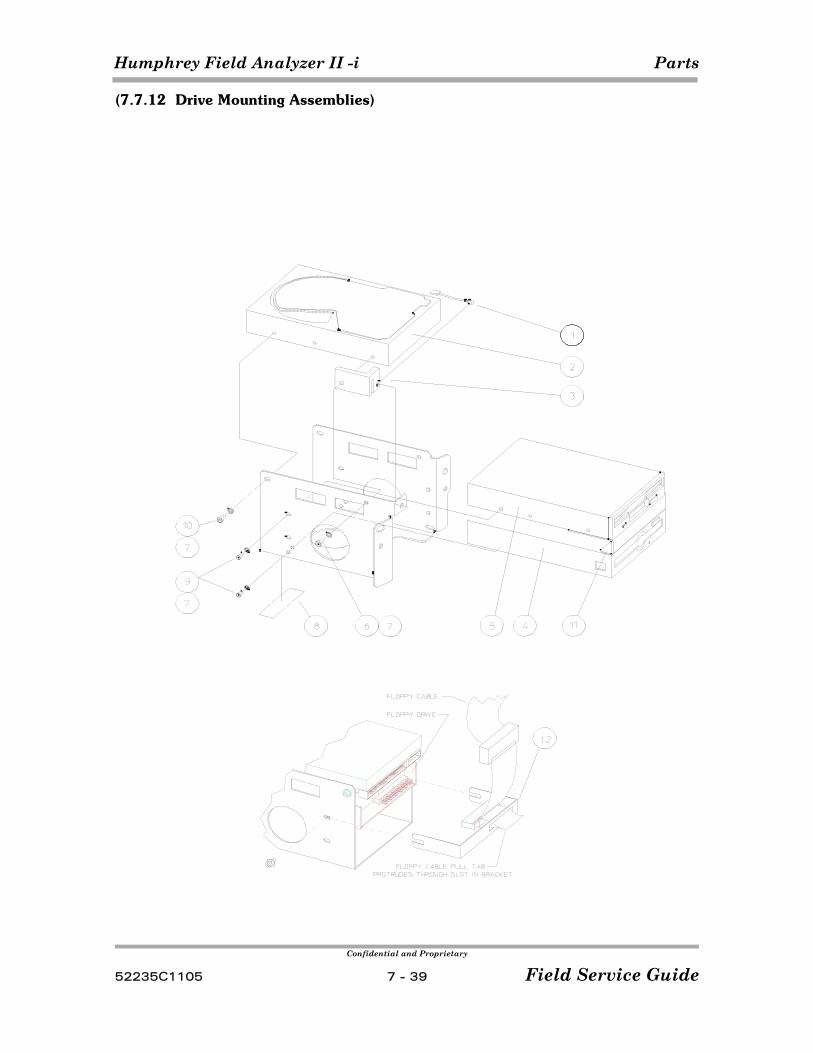
Humphrey Field Analyzer II -i Parts
Confidential and Proprietary
52235C1105 7 - 39 Field Service Guide
(7.7.12 Drive Mounting Assemblies)
Parts Humphrey Field Analyzer II - i
Confidential and Proprietary
Field Service Guide 7 - 40 52235C1105
7.7.13 CPU/Backplane Enclosure
Item Part No. Description
51804 Assy HFA II - i CPU/Backplane Enclosure and Shipping Box51978 Shipping Box for CPU/Backplane Enclosure 51072 CPU and Enclosure
1 51477 CPU PCB, HFA II - i, 433MHz2 49700 Backplane PCB, HFA II - i,3 49443 DIMM, 64MB, PC100, NonECC4 51068 Box, HFA II - i, EMI Shield5 53103 Assembly Lid, HFA II - i, Box EMI6 51067 Clamp, HFA II - i, CPU PCB7 51069 Bracket, External, CPU PCB Clamp8 50827-1 Cable, HFA II - i Serial No. 19 50827-2 Cable, HFA II - i Serial No. 2
10 50828 Cable, HFA II - i Parallel Port11 50829 Fan with Cable, HFA II - i, 5 volt12 50634 Cable USB13 29695 Brightness Pot, Assembly14 53543 Knob, Brightness Pot 15 38706 Snap Bushing 0.625" dia.16 51459 Push Spacer17 38116 Snap Bushing 0.750" dia18 06526 Cable Clamp, C-Clip19 30352 Gasket, EMI foam 1/8" X 1/4" 20 29690-4 Wire Saddle - 421 29690-1 Wire Saddle - 122 51460 Flat Tie Holder23 51778 Braided Ground Cable HFA II - i24 00673 Tie Wrap, Black25 28375-6 Screw, M4 X 6 set Socket Head, Cup26 28293-8 Screw, M3 X 8, Socket Head, Cap27 14446 Washer, Square Cone, .142/.307/.03928 28293-20 Screw, M3 X 20, Socket Head, Cap29 51784 Screw, #6 X 0.625" Self Tap, A-AB Phil30 51484 Shield Brightness Pot Insulator, HFA II - i31 36260 Screw, 4-40 X .25 Jack Socket32 51760 Clamp, IDE/Floppy Cable HFA II - i33 01207-36 Label, SN, HFA II - i CPU 34 29460 Stud Fastener, 1/4 Turn 4 X 24 MM35 29462 Retainer Stud Fastener, 1/4 Turn36 Item number not used37 51285 Caplug SVGA
43824 Ferrite (Not Shown) 51758 Bracket, Ferrite (Not Shown)
48694 SCR M2 X 4 Phil Hd (2 Ea) (Not Shown)
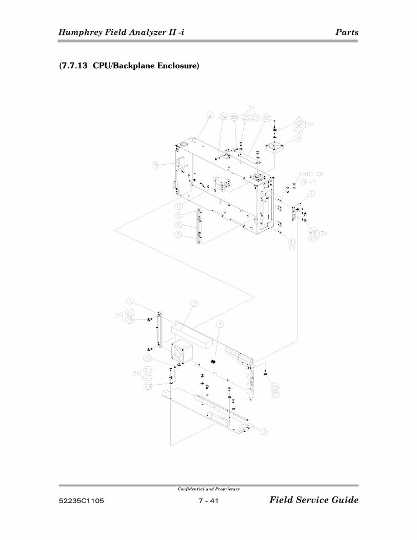
Humphrey Field Analyzer II -i Parts
Confidential and Proprietary
52235C1105 7 - 41 Field Service Guide
(7.7.13 CPU/Backplane Enclosure)
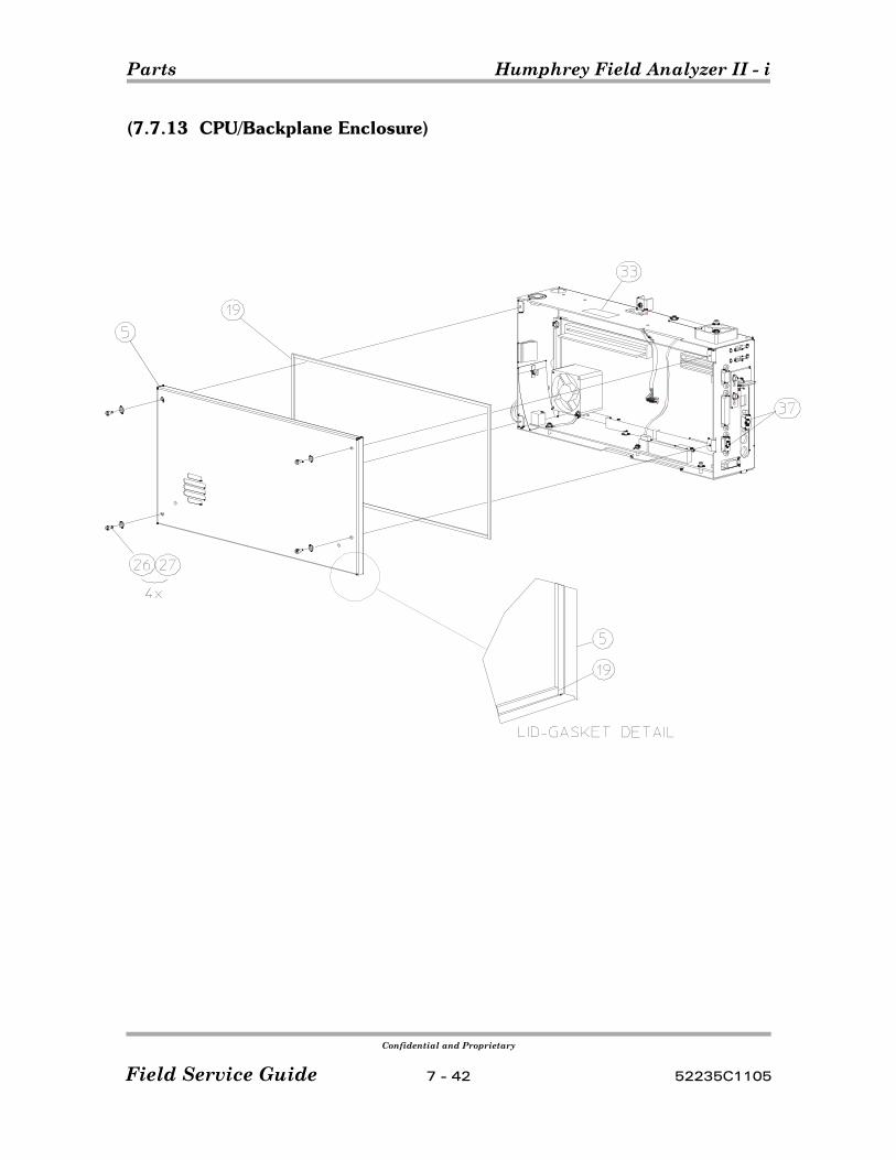
Parts Humphrey Field Analyzer II - i
Confidential and Proprietary
Field Service Guide 7 - 42 52235C1105
(7.7.13 CPU/Backplane Enclosure)
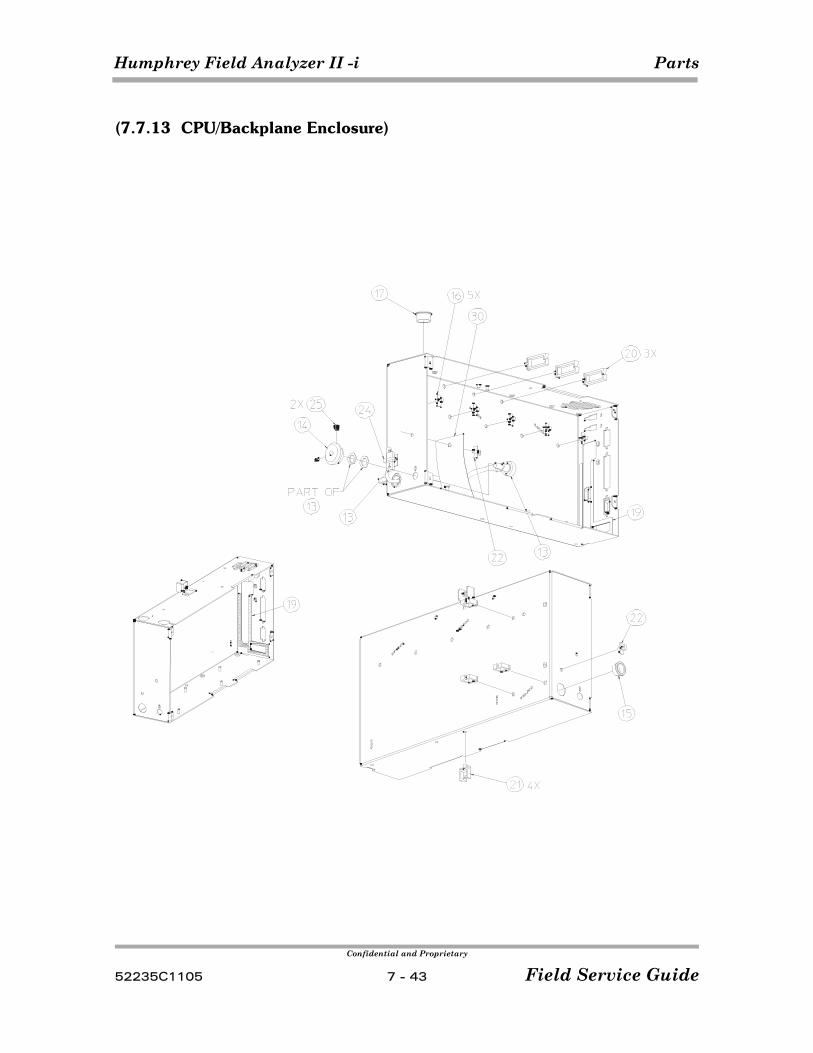
Humphrey Field Analyzer II -i Parts
Confidential and Proprietary
52235C1105 7 - 43 Field Service Guide
(7.7.13 CPU/Backplane Enclosure)

Parts Humphrey Field Analyzer II - i
Confidential and Proprietary
Field Service Guide 7 - 44 52235C1105
7.7.14 Power Table / Printer Assemblies
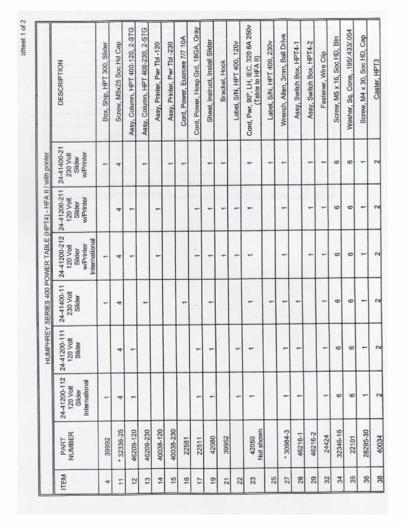

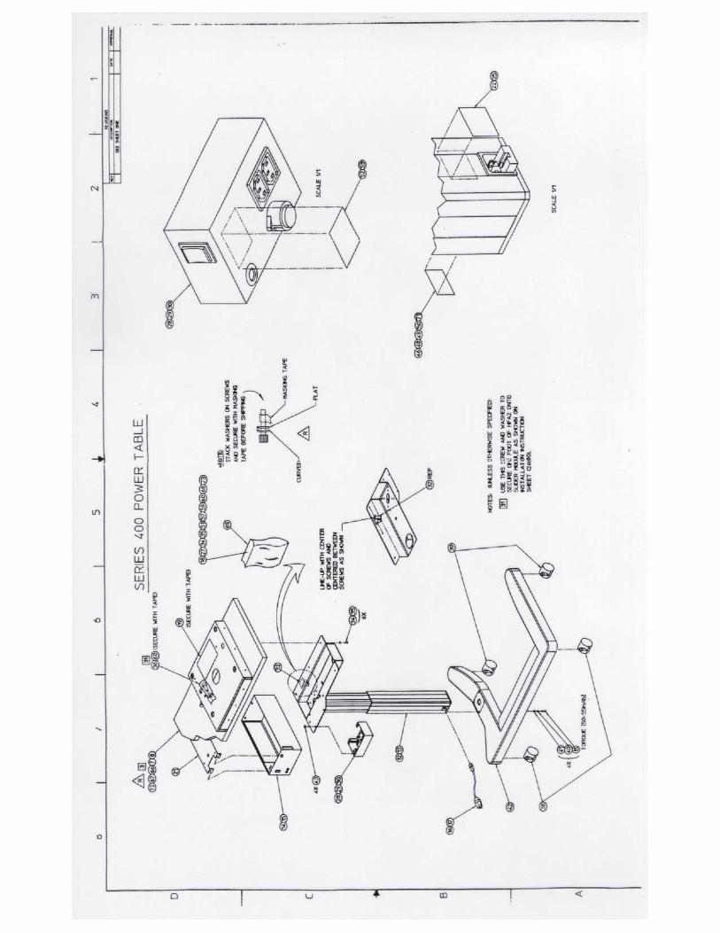
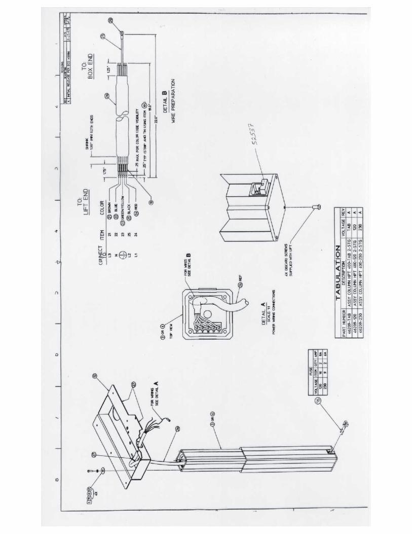
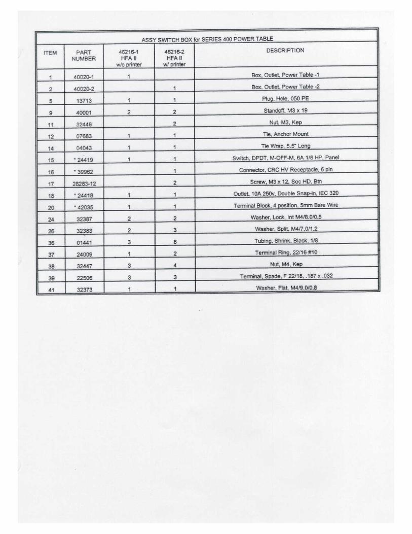
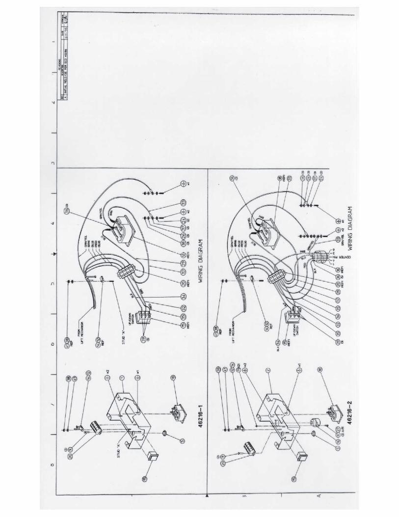
Confidential and Proprietary
52235C1105 App - 1 Field Service Guide
Appendices
Appendix A. Tools, Test Equipment and Service Supplies . . . . . . . . . . . . . . . . . . . . . . . . A - 1
A.1 List of Tools, Test Equipment and Service Supplies . . . . . . . . . . . . . . . . . . . . . . A - 1
A.2 The Special Tools - What They Are / What They Do . . . . . . . . . . . . . . . . . . . . . . A - 3
A.2.1 Soligor Light Meter Setup . . . . . . . . . . . . . . . . . . . . . . . . . . . . . . . . . . A - 3
A.2.2 Soligor Mount Adaptor . . . . . . . . . . . . . . . . . . . . . . . . . . . . . . . . . . . . A - 3
A.2.3 Bowl Shroud . . . . . . . . . . . . . . . . . . . . . . . . . . . . . . . . . . . . . . . . . . . . A - 3
A.2.4 Trial Lens Alignment Adaptor . . . . . . . . . . . . . . . . . . . . . . . . . . . . . . A - 3
A.2.5 Fake Eye . . . . . . . . . . . . . . . . . . . . . . . . . . . . . . . . . . . . . . . . . . . . . . . A - 5
A.2.6 Tool Stand Assembly . . . . . . . . . . . . . . . . . . . . . . . . . . . . . . . . . . . . . A - 5
A.2.7 Mirror Tool . . . . . . . . . . . . . . . . . . . . . . . . . . . . . . . . . . . . . . . . . . . . . A - 5
A.2.8 CRT Overlay . . . . . . . . . . . . . . . . . . . . . . . . . . . . . . . . . . . . . . . . . . . . A - 5
A.2.9 Spot Positioning Cross Fixture . . . . . . . . . . . . . . . . . . . . . . . . . . . . . . A - 5
A.2.10 Brightness Detector Alignment Target . . . . . . . . . . . . . . . . . . . . . . . . A - 6
A.2.11 Projection Mount . . . . . . . . . . . . . . . . . . . . . . . . . . . . . . . . . . . . . . . . . A - 7
A.2.12 Operator Panel Extension/Support . . . . . . . . . . . . . . . . . . . . . . . . . . . A - 8
A.2.13 Hard Drive LED Assembly . . . . . . . . . . . . . . . . . . . . . . . . . . . . . . . . . A - 9
A.2.14 Service Key . . . . . . . . . . . . . . . . . . . . . . . . . . . . . . . . . . . . . . . . . . . . . A - 9
A.2.15 Diagnostic Support Tool . . . . . . . . . . . . . . . . . . . . . . . . . . . . . . . . . . . A - 9
A.2.16 Loopback Tool . . . . . . . . . . . . . . . . . . . . . . . . . . . . . . . . . . . . . . . . . A - 10
A.2.17 Static Protection Kit . . . . . . . . . . . . . . . . . . . . . . . . . . . . . . . . . . . . . A - 10
A.2.18 Communications Terminals . . . . . . . . . . . . . . . . . . . . . . . . . . . . . . . A - 10
A.2.19 How To Set Up The P-Factor Diskette . . . . . . . . . . . . . . . . . . . . . . . A - 11
Appendix B. The Interface Ports . . . . . . . . . . . . . . . . . . . . . . . . . . . . . . . . . . . . . . . . . . . . B - 1
B.1 General Information . . . . . . . . . . . . . . . . . . . . . . . . . . . . . . . . . . . . . . . . . . . . . . . B - 1
B.2 RS-232 Interface Hardware and Pin Assignments . . . . . . . . . . . . . . . . . . . . . . . . B - 3
Appendix C. Data Transfers . . . . . . . . . . . . . . . . . . . . . . . . . . . . . . . . . . . . . . . . . . . . . . . C - 1
C.1 Serial Transfer Modes . . . . . . . . . . . . . . . . . . . . . . . . . . . . . . . . . . . . . . . . . . . . . . . C - 1
C.2 Installing the Serial I or the Serial II Transfer Disk . . . . . . . . . . . . . . . . . . . . . . . . C - 2
C.3 HFA I to HFA II - i Serial Data Transfer . . . . . . . . . . . . . . . . . . . . . . . . . . . . . . . . . C - 3
C.4 HFA II To HFA II - i Serial Data Transfer . . . . . . . . . . . . . . . . . . . . . . . . . . . . . . . C - 5
Appendices Humphrey Field Analyzer II - i
Confidential and Proprietary
Field Service Guide App - 2 52235C1105
C.5 HFA II - i To HFA II - i Serial Data Transfer . . . . . . . . . . . . . . . . . . . . . . . . . . . . . C - 7
C.6 HFA II - i To Ensemble© Serial Data Transfer . . . . . . . . . . . . . . . . . . . . . . . . . . . C - 9
C.7 HFA II - i To Third Party Programs Serial Data Transfer . . . . . . . . . . . . . . . . . . . C -11
Appendix D. Approved Parallel Laser Jet Printers . . . . . . . . . . . . . . . . . . . . . . . . . . . . . . D - 1
Appendix E. Instrument/BIOS Configuration . . . . . . . . . . . . . . . . . . . . . . . . . . . . . . . . . . . E - 1
E.1 Instrument Configuration . . . . . . . . . . . . . . . . . . . . . . . . . . . . . . . . . . . . . . . . . . . . . E - 1
E.2 BIOS Configuration . . . . . . . . . . . . . . . . . . . . . . . . . . . . . . . . . . . . . . . . . . . . . . . . . E - 3
Appendix F. Operating System . . . . . . . . . . . . . . . . . . . . . . . . . . . . . . . . . . . . . . . . . . . . . . F - 1
Appendix G. P Initializing the Cal/Config Data
P Setting Serial Number
P Setting the Hardware Options
P Setting the Software Options . . . . . . . . . . . . . . . . . . . . . . . . . . . . . . . . . . G - 1
G.1 Initializing the Cal/Config Data . . . . . . . . . . . . . . . . . . . . . . . . . . . . . . . . . . . . . . . G - 3
G.2 Setting Serial Number . . . . . . . . . . . . . . . . . . . . . . . . . . . . . . . . . . . . . . . . . . . . . . G - 3
G.3 Setting the Model/Hardware Options . . . . . . . . . . . . . . . . . . . . . . . . . . . . . . . . . . G - 4
G.4 Setting the Software Options . . . . . . . . . . . . . . . . . . . . . . . . . . . . . . . . . . . . . . . . . G - 6
Appendix H. Calibration Printouts . . . . . . . . . . . . . . . . . . . . . . . . . . . . . . . . . . . . . . . . . . . H - 1
H.1 Cal / Wedge Printout . . . . . . . . . . . . . . . . . . . . . . . . . . . . . . . . . . . . . . . . . . . . . . . H - 1
H.2 Automated Light Intensity Printouts . . . . . . . . . . . . . . . . . . . . . . . . . . . . . . . . . . . H - 8
Appendix I. Service Forms . . . . . . . . . . . . . . . . . . . . . . . . . . . . . . . . . . . . . . . . . . . . . . . . . I - 1
Appendix J. System Screens and Logs . . . . . . . . . . . . . . . . . . . . . . . . . . . . . . . . . . . . . . . . I - 1
J.1 Boot Screen . . . . . . . . . . . . . . . . . . . . . . . . . . . . . . . . . . . . . . . . . . . . . . . . . . . . . . . J - 1
J.2 Unit Configuration Screen . . . . . . . . . . . . . . . . . . . . . . . . . . . . . . . . . . . . . . . . . . . . J - 1
J.3 System Log . . . . . . . . . . . . . . . . . . . . . . . . . . . . . . . . . . . . . . . . . . . . . . . . . . . . . . . J - 4
Appendix K. Data Loss Recovery . . . . . . . . . . . . . . . . . . . . . . . . . . . . . . . . . . . . . . . . . . . K - 1
K.1 Data Loss Prevention Tips . . . . . . . . . . . . . . . . . . . . . . . . . . . . . . . . . . . . . . . . . . . K - 1
K.2 Database Structure . . . . . . . . . . . . . . . . . . . . . . . . . . . . . . . . . . . . . . . . . . . . . . . . . K - 2
K.3 The Five “Rs” of Database Recovery . . . . . . . . . . . . . . . . . . . . . . . . . . . . . . . . . . K - 2
K.4 Database Utilities . . . . . . . . . . . . . . . . . . . . . . . . . . . . . . . . . . . . . . . . . . . . . . . . . . K - 3
K.4.1 Rebuild Hard Disk Database . . . . . . . . . . . . . . . . . . . . . . . . . . . . . . . . K - 3
K.4.2 Rebuild Floppy Database . . . . . . . . . . . . . . . . . . . . . . . . . . . . . . . . . . K - 4
Humphrey Field Analyzer II - i Appendices
Confidential and Proprietary
52235C1105 App - 3 Field Service Guide
K.4.3 Delete Hard Disk Database . . . . . . . . . . . . . . . . . . . . . . . . . . . . . . . . . . K - 4
K.4.4 Delete Temporary Database . . . . . . . . . . . . . . . . . . . . . . . . . . . . . . . . . K - 4
K.4.5 Reconstruct Database . . . . . . . . . . . . . . . . . . . . . . . . . . . . . . . . . . . . . . K - 4
K.4.6 Secondary Database Utilities . . . . . . . . . . . . . . . . . . . . . . . . . . . . . . . . K - 4
K.5 Floppy Diskette - Troubleshooting Dialogue . . . . . . . . . . . . . . . . . . . . . . . . . . . . . K - 5
K.6 Hard Disk Drive - Troubleshooting Dialogue . . . . . . . . . . . . . . . . . . . . . . . . . . . . . K - 6
K.7 Magnetic Optical Disks . . . . . . . . . . . . . . . . . . . . . . . . . . . . . . . . . . . . . . . . . . . . . . K - 7
Appendix L. Initializing the Hard Disk . . . . . . . . . . . . . . . . . . . . . . . . . . . . . . . . . . . . . . . . L - 1
Appendix M. Loading Application Software . . . . . . . . . . . . . . . . . . . . . . . . . . . . . . . . . . . M - 1
Appendix N. Special Software Options . . . . . . . . . . . . . . . . . . . . . . . . . . . . . . . . . . . . . . . . N - 1
Appendix O. Upgrades . . . . . . . . . . . . . . . . . . . . . . . . . . . . . . . . . . . . . . . . . . . . . . . . . . . . O - 1
Appendix P. Cable Diagrams . . . . . . . . . . . . . . . . . . . . . . . . . . . . . . . . . . . . . . . . . . . . . . . . P - 1
Appendix Q. Cleaning Optics . . . . . . . . . . . . . . . . . . . . . . . . . . . . . . . . . . . . . . . . . . . . . . . Q - 1
Appendix R. Optional Software Installation . . . . . . . . . . . . . . . . . . . . . . . . . . . . . . . . . . . . R - 1

Appendices Humphrey Field Analyzer II - i
Confidential and Proprietary
Field Service Guide App - 4 52235C1105
Notes:
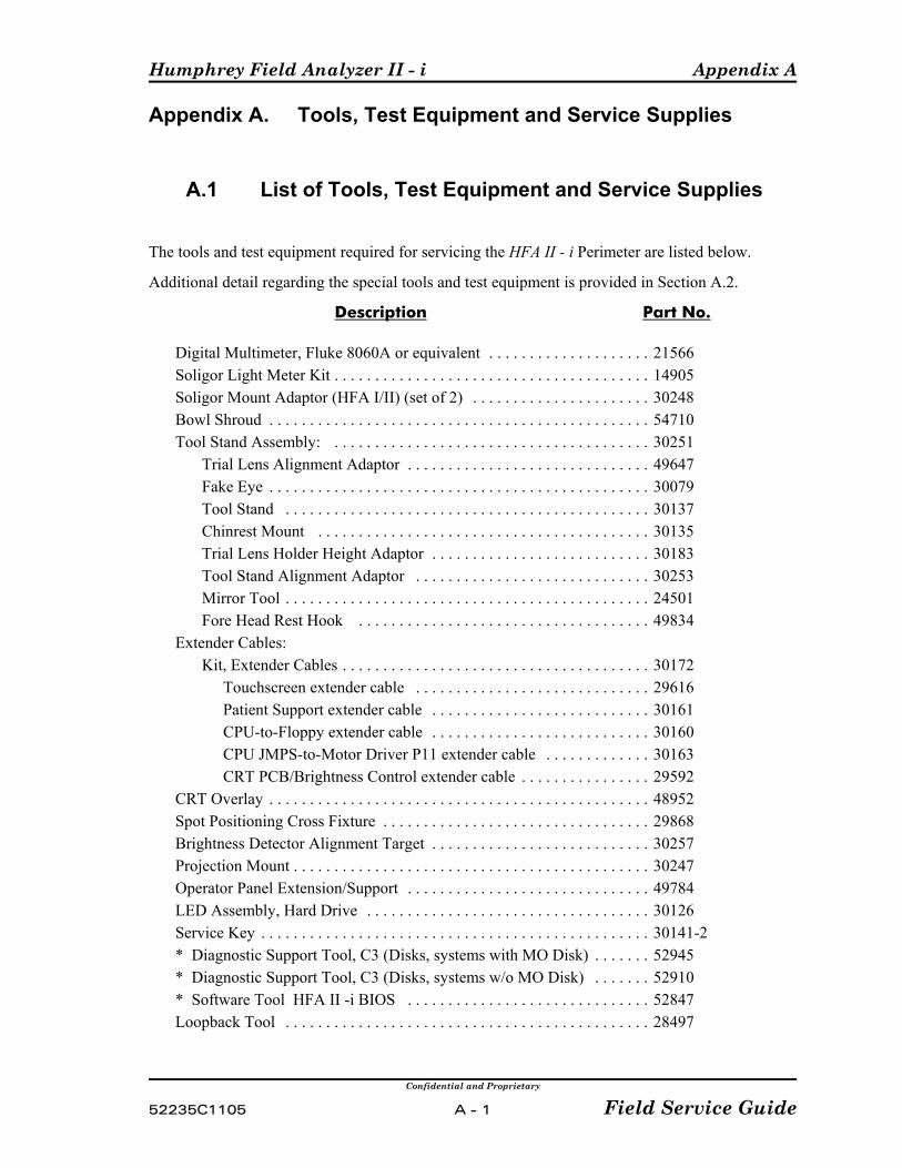
Humphrey Field Analyzer II - i Appendix A
Confidential and Proprietary
52235C1105 A - 1 Field Service Guide
Appendix A. Tools, Test Equipment and Service Supplies
A.1 List of Tools, Test Equipment and Service Supplies
The tools and test equipment required for servicing the HFA II - i Perimeter are listed below.
Additional detail regarding the special tools and test equipment is provided in Section A.2.
Description Part No.
Digital Multimeter, Fluke 8060A or equivalent . . . . . . . . . . . . . . . . . . . . 21566Soligor Light Meter Kit . . . . . . . . . . . . . . . . . . . . . . . . . . . . . . . . . . . . . . . 14905Soligor Mount Adaptor (HFA I/II) (set of 2) . . . . . . . . . . . . . . . . . . . . . . 30248Bowl Shroud . . . . . . . . . . . . . . . . . . . . . . . . . . . . . . . . . . . . . . . . . . . . . . . 54710Tool Stand Assembly: . . . . . . . . . . . . . . . . . . . . . . . . . . . . . . . . . . . . . . . 30251
Trial Lens Alignment Adaptor . . . . . . . . . . . . . . . . . . . . . . . . . . . . . . 49647Fake Eye . . . . . . . . . . . . . . . . . . . . . . . . . . . . . . . . . . . . . . . . . . . . . . . 30079 Tool Stand . . . . . . . . . . . . . . . . . . . . . . . . . . . . . . . . . . . . . . . . . . . . . 30137Chinrest Mount . . . . . . . . . . . . . . . . . . . . . . . . . . . . . . . . . . . . . . . . . 30135Trial Lens Holder Height Adaptor . . . . . . . . . . . . . . . . . . . . . . . . . . . 30183Tool Stand Alignment Adaptor . . . . . . . . . . . . . . . . . . . . . . . . . . . . . 30253Mirror Tool . . . . . . . . . . . . . . . . . . . . . . . . . . . . . . . . . . . . . . . . . . . . . 24501Fore Head Rest Hook . . . . . . . . . . . . . . . . . . . . . . . . . . . . . . . . . . . . 49834
Extender Cables:Kit, Extender Cables . . . . . . . . . . . . . . . . . . . . . . . . . . . . . . . . . . . . . . 30172
Touchscreen extender cable . . . . . . . . . . . . . . . . . . . . . . . . . . . . . 29616Patient Support extender cable . . . . . . . . . . . . . . . . . . . . . . . . . . . 30161CPU-to-Floppy extender cable . . . . . . . . . . . . . . . . . . . . . . . . . . . 30160CPU JMPS-to-Motor Driver P11 extender cable . . . . . . . . . . . . . 30163CRT PCB/Brightness Control extender cable . . . . . . . . . . . . . . . . 29592
CRT Overlay . . . . . . . . . . . . . . . . . . . . . . . . . . . . . . . . . . . . . . . . . . . . . . . 48952Spot Positioning Cross Fixture . . . . . . . . . . . . . . . . . . . . . . . . . . . . . . . . . 29868Brightness Detector Alignment Target . . . . . . . . . . . . . . . . . . . . . . . . . . . 30257Projection Mount . . . . . . . . . . . . . . . . . . . . . . . . . . . . . . . . . . . . . . . . . . . . 30247Operator Panel Extension/Support . . . . . . . . . . . . . . . . . . . . . . . . . . . . . . 49784LED Assembly, Hard Drive . . . . . . . . . . . . . . . . . . . . . . . . . . . . . . . . . . . 30126Service Key . . . . . . . . . . . . . . . . . . . . . . . . . . . . . . . . . . . . . . . . . . . . . . . . 30141-2* Diagnostic Support Tool, C3 (Disks, systems with MO Disk) . . . . . . . 52945* Diagnostic Support Tool, C3 (Disks, systems w/o MO Disk) . . . . . . . 52910* Software Tool HFA II -i BIOS . . . . . . . . . . . . . . . . . . . . . . . . . . . . . . 52847Loopback Tool . . . . . . . . . . . . . . . . . . . . . . . . . . . . . . . . . . . . . . . . . . . . . 28497
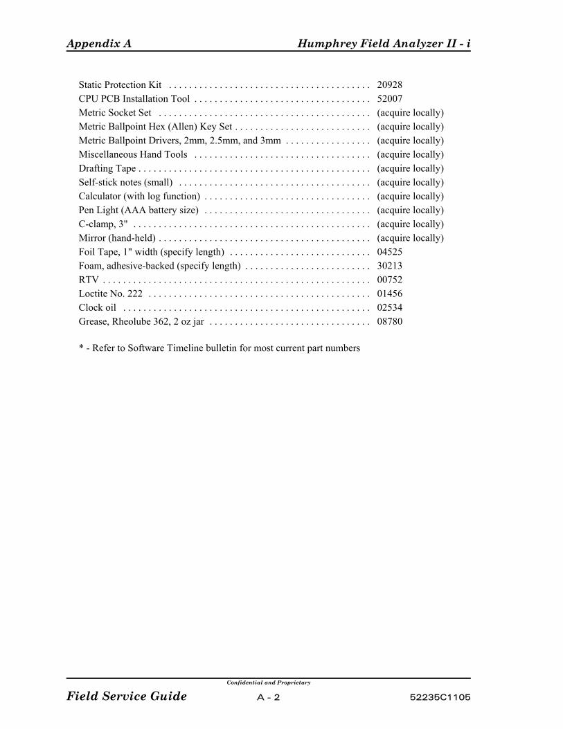
Appendix A Humphrey Field Analyzer II - i
Confidential and Proprietary
Field Service Guide A - 2 52235C1105
Static Protection Kit . . . . . . . . . . . . . . . . . . . . . . . . . . . . . . . . . . . . . . . . 20928CPU PCB Installation Tool . . . . . . . . . . . . . . . . . . . . . . . . . . . . . . . . . . . 52007Metric Socket Set . . . . . . . . . . . . . . . . . . . . . . . . . . . . . . . . . . . . . . . . . . (acquire locally)Metric Ballpoint Hex (Allen) Key Set . . . . . . . . . . . . . . . . . . . . . . . . . . . (acquire locally)Metric Ballpoint Drivers, 2mm, 2.5mm, and 3mm . . . . . . . . . . . . . . . . . (acquire locally)Miscellaneous Hand Tools . . . . . . . . . . . . . . . . . . . . . . . . . . . . . . . . . . . (acquire locally)Drafting Tape . . . . . . . . . . . . . . . . . . . . . . . . . . . . . . . . . . . . . . . . . . . . . . (acquire locally)Self-stick notes (small) . . . . . . . . . . . . . . . . . . . . . . . . . . . . . . . . . . . . . . (acquire locally)Calculator (with log function) . . . . . . . . . . . . . . . . . . . . . . . . . . . . . . . . . (acquire locally)Pen Light (AAA battery size) . . . . . . . . . . . . . . . . . . . . . . . . . . . . . . . . . (acquire locally)C-clamp, 3" . . . . . . . . . . . . . . . . . . . . . . . . . . . . . . . . . . . . . . . . . . . . . . . (acquire locally)Mirror (hand-held) . . . . . . . . . . . . . . . . . . . . . . . . . . . . . . . . . . . . . . . . . . (acquire locally)Foil Tape, 1" width (specify length) . . . . . . . . . . . . . . . . . . . . . . . . . . . . 04525Foam, adhesive-backed (specify length) . . . . . . . . . . . . . . . . . . . . . . . . . 30213RTV . . . . . . . . . . . . . . . . . . . . . . . . . . . . . . . . . . . . . . . . . . . . . . . . . . . . . 00752Loctite No. 222 . . . . . . . . . . . . . . . . . . . . . . . . . . . . . . . . . . . . . . . . . . . . 01456Clock oil . . . . . . . . . . . . . . . . . . . . . . . . . . . . . . . . . . . . . . . . . . . . . . . . . 02534Grease, Rheolube 362, 2 oz jar . . . . . . . . . . . . . . . . . . . . . . . . . . . . . . . . 08780
* - Refer to Software Timeline bulletin for most current part numbers
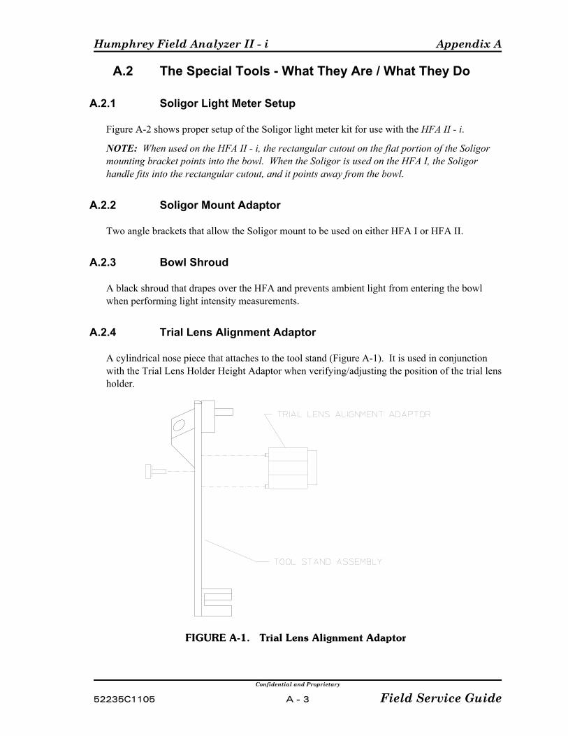
Humphrey Field Analyzer II - i Appendix A
Confidential and Proprietary
52235C1105 A - 3 Field Service Guide
A.2 The Special Tools - What They Are / What They Do
A.2.1 Soligor Light Meter Setup
Figure A-2 shows proper setup of the Soligor light meter kit for use with the HFA II - i.
NOTE: When used on the HFA II - i, the rectangular cutout on the flat portion of the Soligormounting bracket points into the bowl. When the Soligor is used on the HFA I, the Soligorhandle fits into the rectangular cutout, and it points away from the bowl.
A.2.2 Soligor Mount Adaptor
Two angle brackets that allow the Soligor mount to be used on either HFA I or HFA II.
A.2.3 Bowl Shroud
A black shroud that drapes over the HFA and prevents ambient light from entering the bowlwhen performing light intensity measurements.
A.2.4 Trial Lens Alignment Adaptor
A cylindrical nose piece that attaches to the tool stand (Figure A-1). It is used in conjunctionwith the Trial Lens Holder Height Adaptor when verifying/adjusting the position of the trial lensholder.
FIGURE A-1. Trial Lens Alignment Adaptor

Appendix A Humphrey Field Analyzer II - i
Confidential and Proprietary
Field Service Guide A - 4 52235C1105
1) a) Mount the light meter to the chinrest (see Sec. A.2.1).b) Connect the DMM (20V DC scale) and the power supply to the light meter.c) Set the meter to the required position.d) Line up the light meter with the trial lens holder raised, then lower the trial lens holder.e) Aim the light meter to about 10 degrees above the Central Fixation hole.
2) If the light meter was off, let it warm up for 5 minutes.
3) Zero the light meter:a) Turn off the room lights.b) Set the light meter to position 3.c) Check and adjust the light meter (if needed) so that the DMM reads zero when the lens is
completely blocked off. (Use the lens cap provided with the meter.)The tolerance is ±2 mv. (To adjust the light meter, turn the small screw in the handle ofthe meter.)
FIGURE A-2. Soligor Light Meter Setup

Humphrey Field Analyzer II - i Appendix A
Confidential and Proprietary
52235C1105 A - 5 Field Service Guide
A.2.5 Fake Eye
A fixture with an imitation eye, gaze tracking alignment box, focus target, and trial lensholder Z-positioning stop (see Figure A-3). It is used in conjunction with the Tool Stand toperform the following:P verify and set camera window position and size in relation to trial lens holder;P verify and set gaze tracking;P adjust camera focus;P set the Z-position of the trial lens holder.
A.2.6 Tool Stand Assembly
Refer to Figure A-3.
Tool Stand and Chinrest Mount — A stand that attaches to the HFA II - i by means of thechinrest mount. The Tool Stand serves as a mounting base for a variety of calibration andadjustment tools.
Trial Lens Holder Height Adaptor — A block that attaches to the bottom of the Tool Standto set the height of the Tool Stand when performing the Trial Lens Holder adjustment. Theblock is removed for all other adjustments requiring the Tool Stand.
Cold Mirror Alignment Adaptors — These two adaptors attach to the Tool Stand and areused in conjunction with a pen light to set the position of the Cold Mirrors.
Tool Stand Alignment Adaptor — A block with two extended pins that contact theforehead rest to set the correct Z (front-back) alignment of the Tool Stand when mounted onthe chinrest.Forehead Rest Hook — A hook that allows the Tool Stand to be held to the forehead rest.
A.2.7 Mirror Tool
The Mirror Tool is a small mirror that attaches to the center of the Tool Stand. The mirror isused only when setting the correction values for the blue stimulus.
A.2.8 CRT Overlay
A clear plastic template that is placed over the touch screen and is used as an aid toverify/adjust CRT symmetry.
A.2.9 Spot Positioning Cross Fixture
This is a horizontal and vertical target that mounts to the inside surface of the bowl. It is usedto check the positional tolerances of the projected light spot within the bowl.
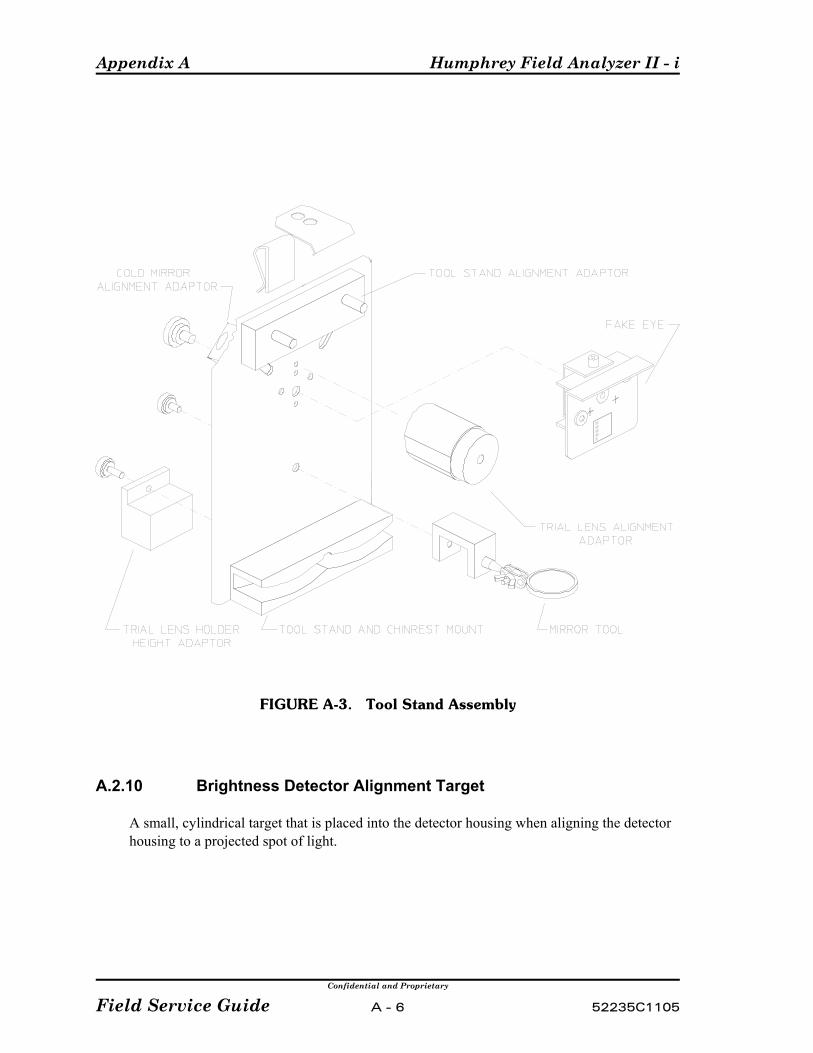
Appendix A Humphrey Field Analyzer II - i
Confidential and Proprietary
Field Service Guide A - 6 52235C1105
FIGURE A-3. Tool Stand Assembly
A.2.10 Brightness Detector Alignment Target
A small, cylindrical target that is placed into the detector housing when aligning the detectorhousing to a projected spot of light.
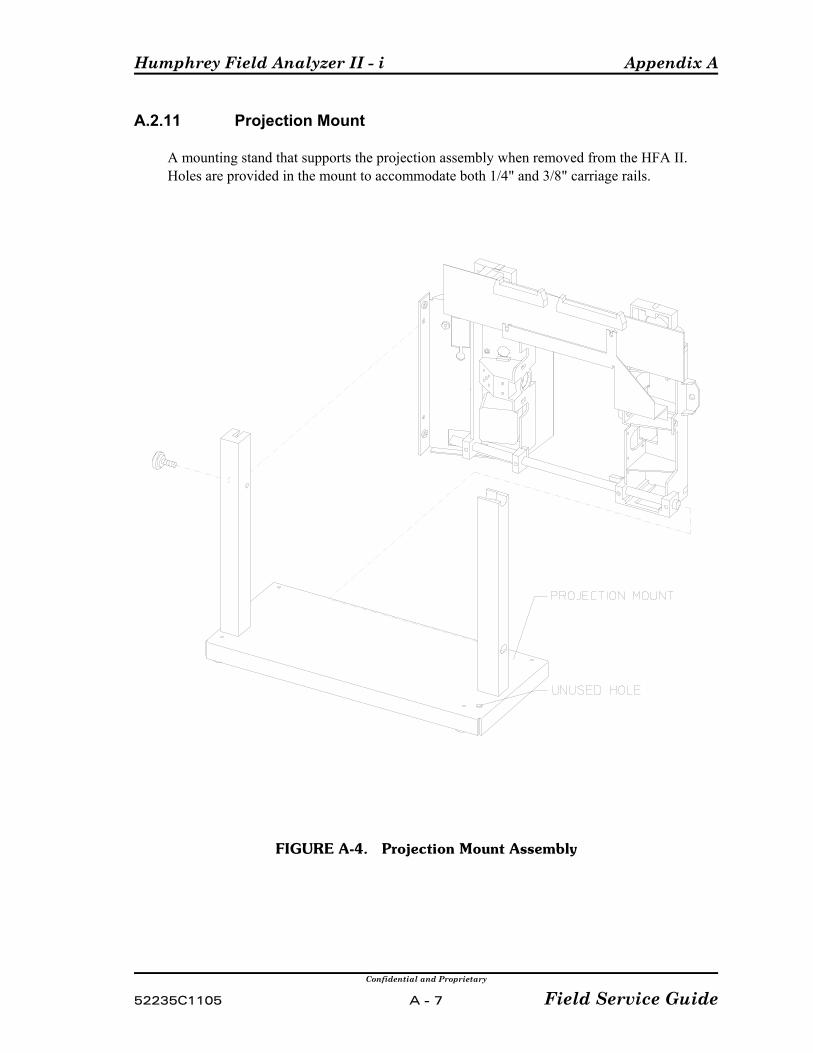
Humphrey Field Analyzer II - i Appendix A
Confidential and Proprietary
52235C1105 A - 7 Field Service Guide
A.2.11 Projection Mount
A mounting stand that supports the projection assembly when removed from the HFA II. Holes are provided in the mount to accommodate both 1/4" and 3/8" carriage rails.
FIGURE A-4. Projection Mount Assembly
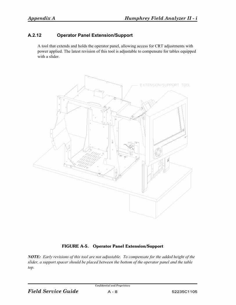
Appendix A Humphrey Field Analyzer II - i
Confidential and Proprietary
Field Service Guide A - 8 52235C1105
A.2.12 Operator Panel Extension/Support
A tool that extends and holds the operator panel, allowing access for CRT adjustments withpower applied. The latest revision of this tool is adjustable to compensate for tables equippedwith a slider.
FIGURE A-5. Operator Panel Extension/Support
NOTE: Early revisions of this tool are not adjustable. To compensate for the added height of theslider, a support spacer should be placed between the bottom of the operator panel and the tabletop.
Humphrey Field Analyzer II - i Appendix A
Confidential and Proprietary
52235C1105 A - 9 Field Service Guide
A.2.13 Hard Drive LED Assembly
An LED with cable and connector used as a hard drive go/no-go indicator.
A.2.14 Service Key
The Service Key is an electronic key, with memory, that can be plugged into the parallel porton the HFA II - i. The Service Key allows the service technician to perform service tasks suchas initializing the EEPROM or setting the identity of the CPU (see Appendix G).
NOTE: The service key is a proprietary element of Humphrey HFA II - i software security. As such, the key should be safeguarded and handled appropriately.
A.2.15 Diagnostic Support Tool
The Diagnostic Support Tool (DST) is a set of three 3½” floppy disk that enables the servicetechnician to perform system configuration, and numerous troubleshooting routines. TheDST is designed as an open framework of menus and test functions, and can only be used inconjunction with the Service Key.
DST Startup Procedure:
1) With the instrument power turned OFF, insert the first DST diskette into thefloppy drive.
2) Switch the instrument power ON. After approximately 3½ minutes, you will seeVxLd.... As time goes by the sequence of dots (periods) will increase. Thisindicates that the DST software is continuing to load.
3) After about one minute you will see the Please Insert diskette #2Press any key message.
4) Remove diskette #1 and install diskette #2 in the drive. Press the space bar or anyother keyboard key.
5) The next message displayed will be a Copying file - /XXX/YYY message,where the XXX and YYY represent different segments of the DST code.
6) After about one minute you will see the Please Insert diskette #3Press any key message.
7) Remove diskette #2 and install diskette #3 in the drive. Press the space bar or anyother keyboard key.
8) The next message displayed will be a Copying file - /XXX/YYY message,where the XXX and YYY represent different segments of the DST code.
9) An on-screen message will instruct you to install the Service Key.10) Install the Service Key into the printer port at the back of the instrument, then
select the on-screen OK button. 11) When the alphanumeric keyboard appears, type in the Calibration password, then
select Enter. The Diagnostic Support Tool Main Menu will appear.

Appendix A Humphrey Field Analyzer II - i
Confidential and Proprietary
Field Service Guide A - 10 52235C1105
A.2.16 Loopback Tool
The Loopback Tool performs external loopback testing of the Data Transfer and Auxilaryserial ports located on the side of the CPU/Backplane enclosure box behind the rear coverdoor. The connector loops the transmit line back to the receive line, and the RTS line back tothe CTS line.
A.2.17 Static Protection Kit
The Static Protection Kit is essential for protection of the HFA II - i Perimeter againstelectrostatic discharge whenever you are disassembling or handling HFA II - i Perimetercircuitry. The kit contains the following items:
# a bench mat with permanently attached alligator clip ground lead;# a banana plug lead with snap connector;# an adjustable wrist cuff.
The static protection kit’s bench mat must be properly grounded, and you must be wearingthe wrist cuff whenever working on the HFA II - i Perimeter with the cover removed.
To use the static protection kit:
1) Connect the bench mat alligator clip to a known good electrical ground point.Any unpainted screw or chassis surface on the HFA II - i Perimeter is an acceptableground point, provided that the HFA II - i Perimeter has its power cord connected andis plugged into a grounded power receptacle.
In situations where work is to be performed on the HFA II - i and it is undesirable tohave the unit plugged into a power receptacle, an alternate grounding point is necessary. Usually, an acceptable ground point can be found at the cover screw for the AC poweroutlet. It is useless to use the bench mat without it being properly grounded.
2) After properly grounding the bench mat, connect the banana plug lead into the benchmat connector.
3) Connect the wrist cuff to the snap clip on the banana plug lead.
4) Adjust the wrist cuff to fit snugly around your wrist. The wrist cuff should always beworn when working on the HFA II - i Perimeter with the cover removed.
A.2.18 Communications Terminals/Laptop
Communication Terminal/Laptop usage with the HFA II - i is not possible.
Humphrey Field Analyzer II - i Appendix A
Confidential and Proprietary
52235C1105 A - 11 Field Service Guide
A.2.19 How To Set Up The P-Factor Diskette
A "Read P Factors" button has been added to the Light Intensity menu. Selecting the "Read PFactors" button from the Light Intensity menu causes the Soligor meter calibration P factor valuesto be read from a disk (located in the HFA II - i floppy drive) and entered into the menu. TheService Engineer must create the Soligor meter calibration P factors disk. The P Factors disk iscreated by copying a file with the name "pfactors.cfg" on a DSHD floppy disk. The file willcontain the Soligor meter P calibration factors for the representative’s meter. A sample file isshown below. Save the file as an ASCII text file. Lines beginning with '#' are comments and areignored by the program. You must use all capital letters and the delimiter between the meter andthe serial number, all of the factors, and all of the factor values must be a TAB. As an example forthe meter, you would need to type METER(TAB)1935, where (TAB) represents pressing the TABkey.
WARNING: You must update your P Factors disk wheneveryour light meter is recalibrated or replaced. Label and Datethe P Factors disk.
################################## pfactors.cfg# Configuration file for MBC module to help enter lightmeter# P Factors and Meter serial numberMETER 1935P1 393.32P2 36.282P3 8.187P3B 6.849P3Y 8.218P3F 7.812

Appendix A Humphrey Field Analyzer II - i
Confidential and Proprietary
Field Service Guide A - 12 52235C1105
(This page left intentionally blank)
Humphrey Field Analyzer II - i Appendix B
Confidential and Proprietary
52235C1105 B - 1 Field Service Guide
Appendix B. The Interface Ports
NOTE: The interface ports on the Humphrey HFA II - i Perimeter ARENOT intended for interfacing the instrument with any other equipment,except as described below.
B.1 General Information
The Humphrey HFA II - i Perimeter provides several interface connectors, most ofwhich are located on the main connector panel (see Figure B-1). The patient switchconnector is located elsewhere on the instrument, as noted below. The following listbriefly explains the intended use of each connector.
NOTE: The notation shown in parentheses indicates the corresponding connector designationthat appears on the CPU /Backplane Enclosure.
• VGA (EXT VGA) - This 15-pin interface port is used to connect an external VGAcolor monitor.
• Network (NETWORK) - This interface port is a ethernet 10BASET 8-pinconnector used to connect Ensemble via a network.
• PRINTER (PRINTER) - This interface port is used to connect an external printer. It is a 25-pin, Centronics-compatible, parallel port.
• SERIAL PORT (DATA TRANSFER) - This port is used to transfer data from HFA Iand HFA II - i. This port is used to send data to StatPac For Windows orEnsemble. This port is not intended for, and does not support, connections to orfrom: communications terminal for service and error message retrieval or medicalrecords programs.
• SERIAL PORT (AUX.) - This port is not used by customer, service, ormanufacturing. It is to be covered with a cap.
Interface hardware and pin assignments for the RS-232 serial ports are identifiedin Section B.2.
• USB PORTS (USB ) - These ports are intended for connection to USB devices ata later date.
• VGA ( UNUSED) - This port is not used by customer, service, manufacturing orsoftware engineering. It will not function and is to be covered with a cap.
• Keyboard (KEYBOARD) - This interface port is used to connect a keyboard with aPS2 connector.
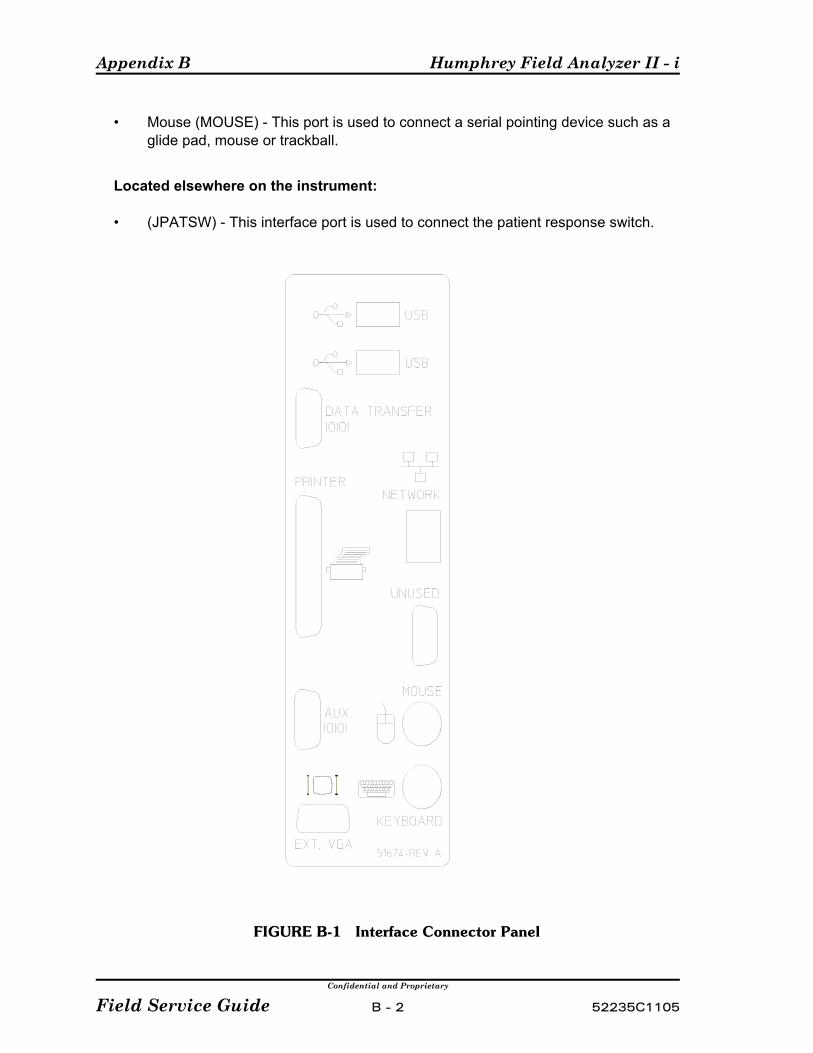
Appendix B Humphrey Field Analyzer II - i
Confidential and Proprietary
Field Service Guide B - 2 52235C1105
• Mouse (MOUSE) - This port is used to connect a serial pointing device such as aglide pad, mouse or trackball.
Located elsewhere on the instrument:
• (JPATSW) - This interface port is used to connect the patient response switch.
FIGURE B-1 Interface Connector Panel
Humphrey Field Analyzer II - i Appendix B
Confidential and Proprietary
52235C1105 B - 3 Field Service Guide
B.2 RS-232 Interface Hardware and Pin Assignments
NOTE: Carl Zeiss Meditec provides this information as a courtesy toour customers, and for the use of authorized Service personnel. CarlZeiss Meditec does not assume any responsibility for interfacing orproviding software to the customer for use of the RS-232 interface withnon-Carl Zeiss Meditec external devices.
The RS-232 interface connectors on the HFA II - i are DB-9F 9-pin sockets. Thisrequires a Cannon DB-9P, or equivalent, mating connector on the interface cable. For reliable data transfer, the interface cable length should be kept as short aspossible. Maximum length allowed is 50 feet.
The pin assignments at the HFA II - i RS-232 output port are detailed below.
Pin 1 - Data Carrier Detect(Input) No Connection.
Pin 2 - Received Data (RX)(Input) Used to receive data from the external system.
Pin 3 - Transmitted Data (TX)
(Output) Used to transmit information asynchronously using ASCII code. The data format, comprising data bits, parity, and stop bit(s), is determined byuser-defined selections. The output goes from -12 volts to +12 volts, in theform of pulses, depending on the data being transmitted.
Pin 4 - Data Terminal Ready (DTR)(Output) Is connected internally with pin 7 (RTS). Both signals are TRUEwhenever the instrument is powered up and ready for operation.
Pin 5 - Signal Ground (GND)Ground reference for the electronic circuits.
Pin 6 - Data Set Ready (DSR)(Input) (no connection)
Pin 7 - Request To Send (RTS)(Output) Is connected internally with pin 4 (DTR). Both signals are TRUEwhenever the instrument is powered up and ready for operation.
Pin 8 - Clear To Send (CTS)(Input) This signal must be TRUE to enable output transmission from theHFA II - i. This signal is usually set to TRUE permanently, or in response to"Request To Send" when the external data system's receive circuit is ready.
Pin 9 - Ring Indicator (RI)(Input) (no connection)
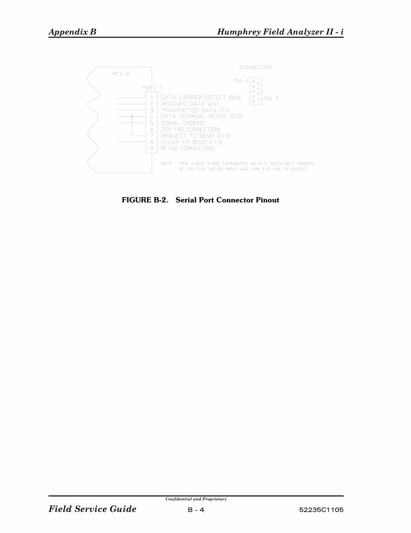
Appendix B Humphrey Field Analyzer II - i
Confidential and Proprietary
Field Service Guide B - 4 52235C1105
FIGURE B-2. Serial Port Connector Pinout
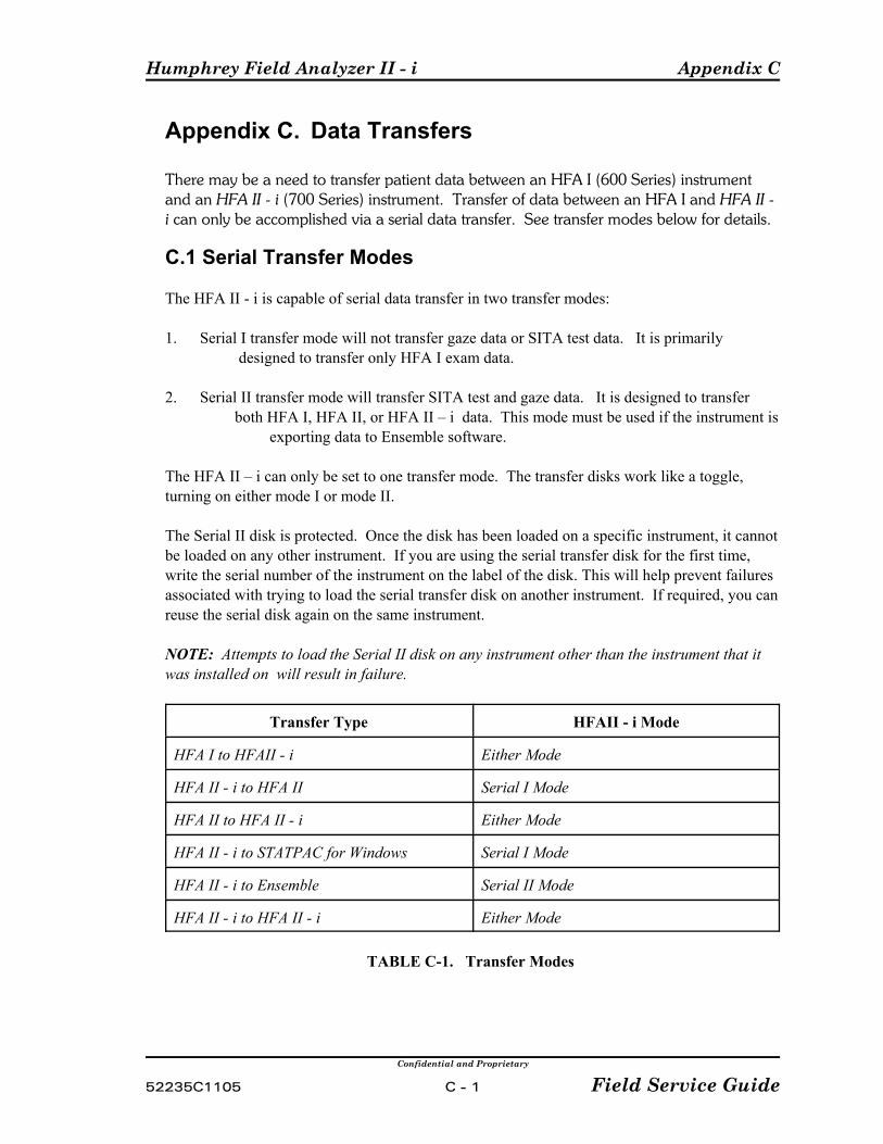
Humphrey Field Analyzer II - i Appendix C
Confidential and Proprietary
52235C1105 C - 1 Field Service Guide
Appendix C. Data Transfers
There may be a need to transfer patient data between an HFA I (600 Series) instrumentand an HFA II - i (700 Series) instrument. Transfer of data between an HFA I and HFA II -i can only be accomplished via a serial data transfer. See transfer modes below for details.
C.1 Serial Transfer Modes
The HFA II - i is capable of serial data transfer in two transfer modes:
1. Serial I transfer mode will not transfer gaze data or SITA test data. It is primarily designed to transfer only HFA I exam data.
2. Serial II transfer mode will transfer SITA test and gaze data. It is designed to transfer both HFA I, HFA II, or HFA II – i data. This mode must be used if the instrument is exporting data to Ensemble software.
The HFA II – i can only be set to one transfer mode. The transfer disks work like a toggle,turning on either mode I or mode II.
The Serial II disk is protected. Once the disk has been loaded on a specific instrument, it cannotbe loaded on any other instrument. If you are using the serial transfer disk for the first time,write the serial number of the instrument on the label of the disk. This will help prevent failuresassociated with trying to load the serial transfer disk on another instrument. If required, you canreuse the serial disk again on the same instrument.
NOTE: Attempts to load the Serial II disk on any instrument other than the instrument that itwas installed on will result in failure.
Transfer Type HFAII - i Mode
HFA I to HFAII - i Either Mode
HFA II - i to HFA II Serial I Mode
HFA II to HFA II - i Either Mode
HFA II - i to STATPAC for Windows Serial I Mode
HFA II - i to Ensemble Serial II Mode
HFA II - i to HFA II - i Either Mode
TABLE C-1. Transfer Modes

Appendix C Humphrey Field Analyzer II - i
Confidential and Proprietary
Field Service Guide C - 2 52235C1105
TESTS THAT CAN BE TRANSFERRED USING EITHER SERIAL I OR II TRANSFERMODE:
1. Macula2. Central 10-2 Threshold3. Central 24-2 Threshold 4. Central 30-2 Threshold5. Peripheral 60-4 Threshold6. Nasal Step Threshold7. Armaly Central Screening8. Armaly Full Field Screening9. Nasal Step Screening10. Central 40 Screening11. Central 76 Screening
12. Central 80 Screening13. Peripheral 68 Screening14. Full Field 81 Screening15. Full Field 120 Screening16. Full Field 246 Screening17. Blindengeldgutachten (German visual
disability test)18. Fuehrerscheingutachten (German driver’s license test)19. Esterman Monocular20. Esterman Binocular21. Kinetic Tests (Serial II mode only)
TESTS THAT WILL NOT BE TRANSFERRED USING EITHER SERIAL I OR IITRANSFER MODE: Fast Threshold tests or Master files.
• Compared, Averaged, or Merged exams.• Tests without birthdates, or with invalid birthdates.• Tests with invalid test dates.• Tests without LEFT or RIGHT denoted in eye field.• Tests that have invalid (x,y) coordinates for test points. C.2 Installing the Serial I or the Serial II Transfer Disk
Installing the Serial I or the Serial II Transfer Disk can be done by the customer or serviceengineer.
1) Starting at the Main Menu, select the Setup icon.
2) Select the Additional Setup menu.
3) Select Install Software.
4) When the “Insert an HFA optional software floppy disk then pres OK to begin installation”dialogue appears, insert the Serial I Transfer disk or the Serial II Transfer disk and pressthe OK button.
5) When the “Installing Revision XXX“ Press OK to Continue” dialogue appears, press OK.
6) After a few seconds the “Optional software installation successful” dialogue appears, Press OK.
NOTE: It is not necessary to restart the instrument for the new software to become active. Thenew features will become active after installation.
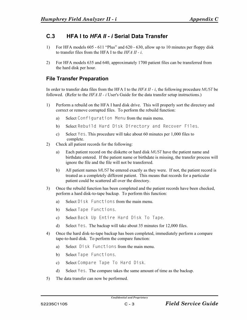
Humphrey Field Analyzer II - i Appendix C
Confidential and Proprietary
52235C1105 C - 3 Field Service Guide
C.3 HFA I to HFA II - i Serial Data Transfer
1) For HFA models 605 - 611 “Plus” and 620 - 630, allow up to 10 minutes per floppy diskto transfer files from the HFA I to the HFA II - i.
2) For HFA models 635 and 640, approximately 1700 patient files can be transferred fromthe hard disk per hour.
File Transfer Preparation
In order to transfer data files from the HFA I to the HFA II - i, the following procedure MUST befollowed. (Refer to the HFA II - i User's Guide for the data transfer setup instructions.)
1) Perform a rebuild on the HFA I hard disk drive. This will properly sort the directory andcorrect or remove corrupted files. To perform the rebuild function:
a) Select Configuration Menu from the main menu.
b) Select Rebuild Hard Disk Directory and Recover Files.
c) Select Yes. This procedure will take about 60 minutes per 1,000 files to complete.
2) Check all patient records for the following:
a) Each patient record on the diskette or hard disk MUST have the patient name andbirthdate entered. If the patient name or birthdate is missing, the transfer process willignore the file and the file will not be transferred.
b) All patient names MUST be entered exactly as they were. If not, the patient record istreated as a completely different patient. This means that records for a particularpatient could be scattered all over the directory.
3) Once the rebuild function has been completed and the patient records have been checked, perform a hard disk-to-tape backup. To perform this function:
a) Select Disk Functions from the main menu.
b) Select Tape Functions.
c) Select Back Up Entire Hard Disk To Tape.
d) Select Yes. The backup will take about 35 minutes for 12,000 files.
4) Once the hard disk-to-tape backup has been completed, immediately perform a comparetape-to-hard disk. To perform the compare function:
a) Select Disk Functions from the main menu.
b) Select Tape Functions.
c) Select Compare Tape To Hard Disk.
d) Select Yes. The compare takes the same amount of time as the backup.
5) The data transfer can now be performed.
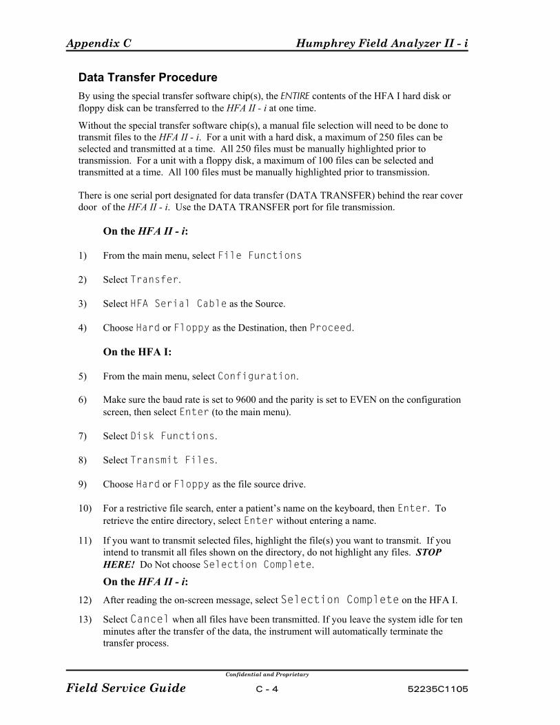
Appendix C Humphrey Field Analyzer II - i
Confidential and Proprietary
Field Service Guide C - 4 52235C1105
Data Transfer Procedure By using the special transfer software chip(s), the ENTIRE contents of the HFA I hard disk orfloppy disk can be transferred to the HFA II - i at one time.
Without the special transfer software chip(s), a manual file selection will need to be done totransmit files to the HFA II - i. For a unit with a hard disk, a maximum of 250 files can beselected and transmitted at a time. All 250 files must be manually highlighted prior totransmission. For a unit with a floppy disk, a maximum of 100 files can be selected andtransmitted at a time. All 100 files must be manually highlighted prior to transmission.
There is one serial port designated for data transfer (DATA TRANSFER) behind the rear coverdoor of the HFA II - i. Use the DATA TRANSFER port for file transmission.
On the HFA II - i:
1) From the main menu, select File Functions
2) Select Transfer.
3) Select HFA Serial Cable as the Source.
4) Choose Hard or Floppy as the Destination, then Proceed.
On the HFA I:
5) From the main menu, select Configuration.
6) Make sure the baud rate is set to 9600 and the parity is set to EVEN on the configurationscreen, then select Enter (to the main menu).
7) Select Disk Functions.
8) Select Transmit Files.
9) Choose Hard or Floppy as the file source drive.
10) For a restrictive file search, enter a patient’s name on the keyboard, then Enter. Toretrieve the entire directory, select Enter without entering a name.
11) If you want to transmit selected files, highlight the file(s) you want to transmit. If you
intend to transmit all files shown on the directory, do not highlight any files. STOPHERE! Do Not choose Selection Complete.
On the HFA II - i: 12) After reading the on-screen message, select Selection Complete on the HFA I. 13) Select Cancel when all files have been transmitted. If you leave the system idle for ten
minutes after the transfer of the data, the instrument will automatically terminate thetransfer process.
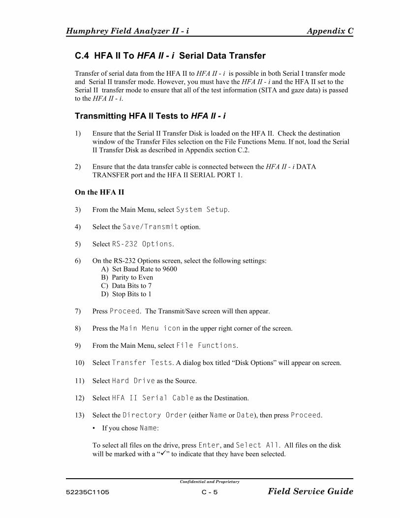
Humphrey Field Analyzer II - i Appendix C
Confidential and Proprietary
52235C1105 C - 5 Field Service Guide
C.4 HFA II To HFA II - i Serial Data Transfer
Transfer of serial data from the HFA II to HFA II - i is possible in both Serial I transfer modeand Serial II transfer mode. However, you must have the HFA II - i and the HFA II set to theSerial II transfer mode to ensure that all of the test information (SITA and gaze data) is passedto the HFA II - i.
Transmitting HFA II Tests to HFA II - i
1) Ensure that the Serial II Transfer Disk is loaded on the HFA II. Check the destinationwindow of the Transfer Files selection on the File Functions Menu. If not, load the SerialII Transfer Disk as described in Appendix section C.2.
2) Ensure that the data transfer cable is connected between the HFA II - i DATATRANSFER port and the HFA II SERIAL PORT 1.
On the HFA II
3) From the Main Menu, select System Setup.
4) Select the Save/Transmit option.
5) Select RS-232 Options.
6) On the RS-232 Options screen, select the following settings: A) Set Baud Rate to 9600 B) Parity to Even C) Data Bits to 7 D) Stop Bits to 1
7) Press Proceed. The Transmit/Save screen will then appear.
8) Press the Main Menu icon in the upper right corner of the screen.
9) From the Main Menu, select File Functions.
10) Select Transfer Tests. A dialog box titled “Disk Options” will appear on screen.
11) Select Hard Drive as the Source.
12) Select HFA II Serial Cable as the Destination.
13) Select the Directory Order (either Name or Date), then press Proceed.
• If you chose Name:
To select all files on the drive, press Enter, and Select All. All files on the diskwill be marked with a “ ” to indicate that they have been selected.
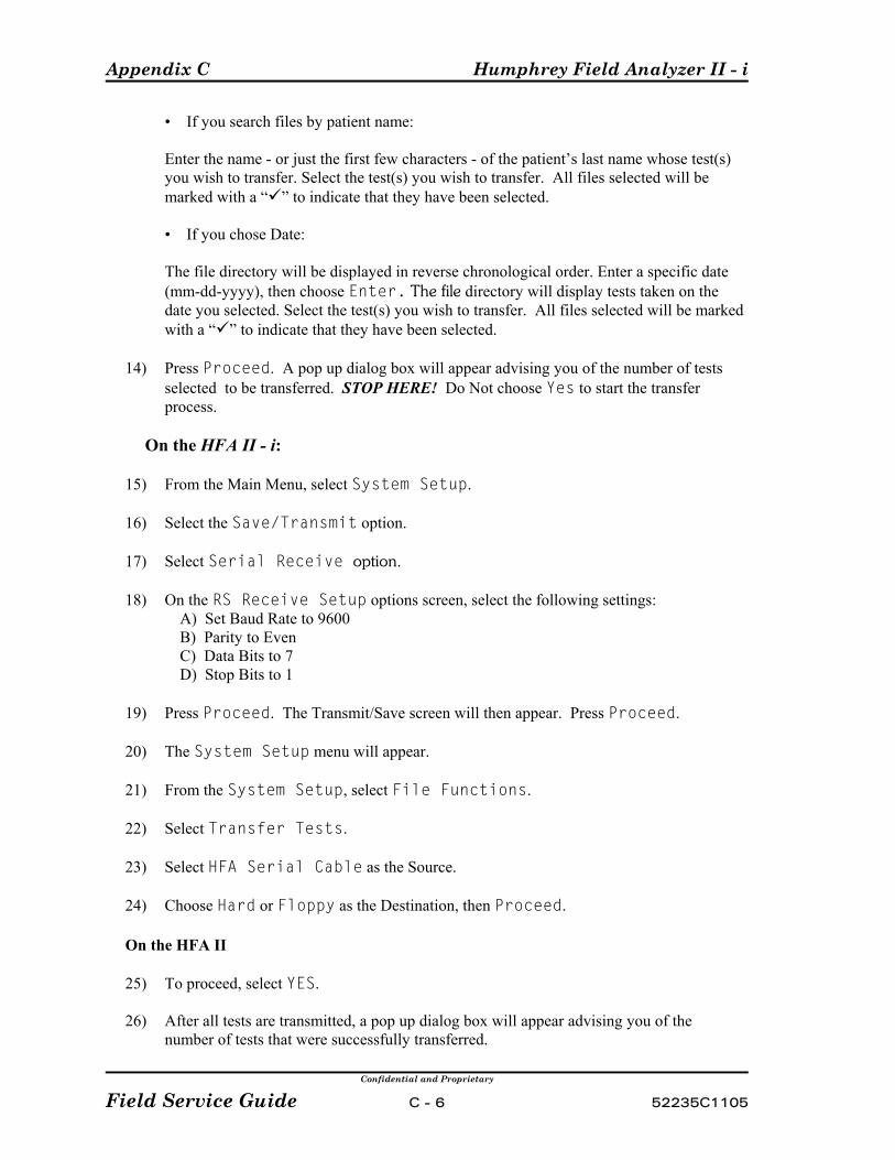
Appendix C Humphrey Field Analyzer II - i
Confidential and Proprietary
Field Service Guide C - 6 52235C1105
• If you search files by patient name:
Enter the name - or just the first few characters - of the patient’s last name whose test(s)you wish to transfer. Select the test(s) you wish to transfer. All files selected will bemarked with a “ ” to indicate that they have been selected.
• If you chose Date:
The file directory will be displayed in reverse chronological order. Enter a specific date (mm-dd-yyyy), then choose Enter. The file directory will display tests taken on thedate you selected. Select the test(s) you wish to transfer. All files selected will be markedwith a “ ” to indicate that they have been selected.
14) Press Proceed. A pop up dialog box will appear advising you of the number of testsselected to be transferred. STOP HERE! Do Not choose Yes to start the transferprocess.
On the HFA II - i:
15) From the Main Menu, select System Setup.
16) Select the Save/Transmit option.
17) Select Serial Receive option.
18) On the RS Receive Setup options screen, select the following settings: A) Set Baud Rate to 9600 B) Parity to Even C) Data Bits to 7 D) Stop Bits to 1
19) Press Proceed. The Transmit/Save screen will then appear. Press Proceed.
20) The System Setup menu will appear.
21) From the System Setup, select File Functions.
22) Select Transfer Tests.
23) Select HFA Serial Cable as the Source.
24) Choose Hard or Floppy as the Destination, then Proceed.
On the HFA II
25) To proceed, select YES.
26) After all tests are transmitted, a pop up dialog box will appear advising you of the number of tests that were successfully transferred.
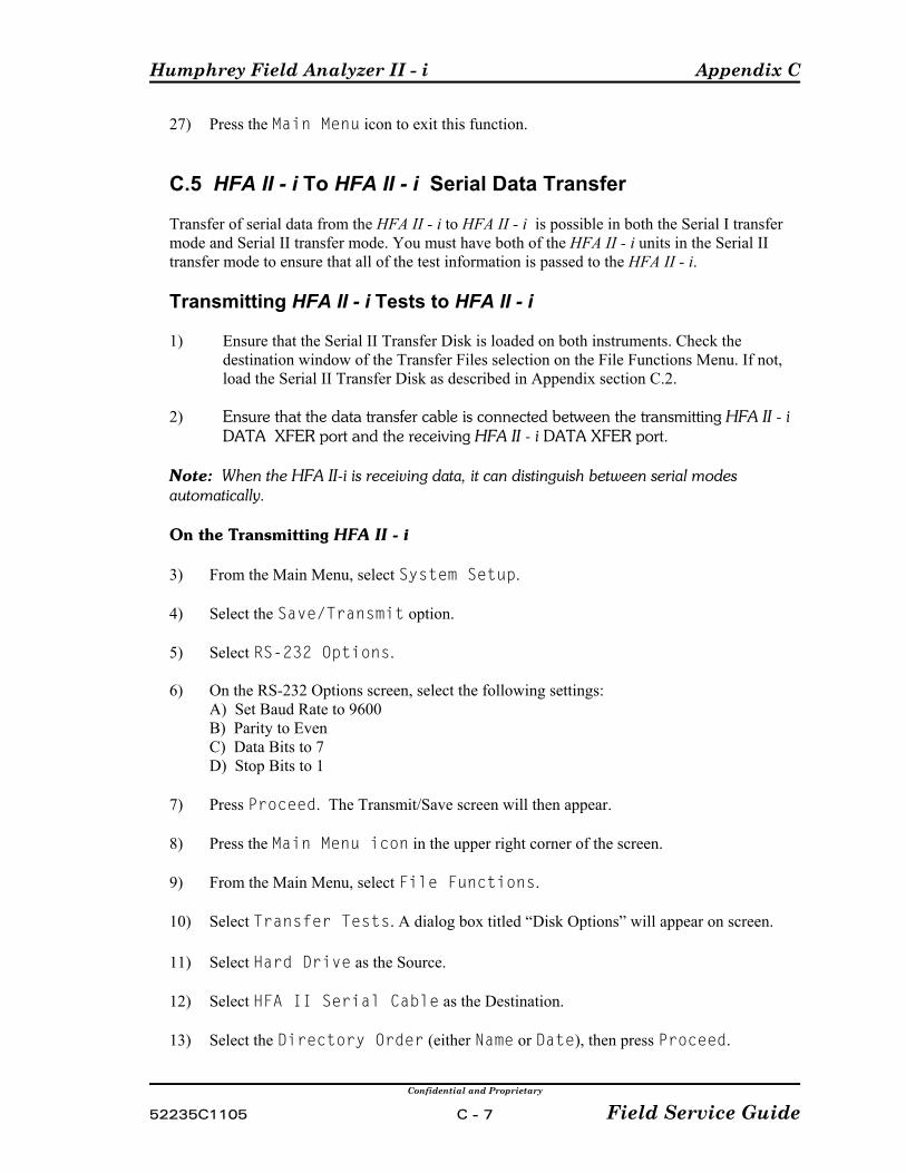
Humphrey Field Analyzer II - i Appendix C
Confidential and Proprietary
52235C1105 C - 7 Field Service Guide
27) Press the Main Menu icon to exit this function.
C.5 HFA II - i To HFA II - i Serial Data Transfer
Transfer of serial data from the HFA II - i to HFA II - i is possible in both the Serial I transfermode and Serial II transfer mode. You must have both of the HFA II - i units in the Serial IItransfer mode to ensure that all of the test information is passed to the HFA II - i.
Transmitting HFA II - i Tests to HFA II - i
1) Ensure that the Serial II Transfer Disk is loaded on both instruments. Check the destination window of the Transfer Files selection on the File Functions Menu. If not, load the Serial II Transfer Disk as described in Appendix section C.2.
2) Ensure that the data transfer cable is connected between the transmitting HFA II - i DATA XFER port and the receiving HFA II - i DATA XFER port.
Note: When the HFA II-i is receiving data, it can distinguish between serial modesautomatically.
On the Transmitting HFA II - i
3) From the Main Menu, select System Setup.
4) Select the Save/Transmit option.
5) Select RS-232 Options.
6) On the RS-232 Options screen, select the following settings:A) Set Baud Rate to 9600B) Parity to EvenC) Data Bits to 7D) Stop Bits to 1
7) Press Proceed. The Transmit/Save screen will then appear.
8) Press the Main Menu icon in the upper right corner of the screen.
9) From the Main Menu, select File Functions.
10) Select Transfer Tests. A dialog box titled “Disk Options” will appear on screen.
11) Select Hard Drive as the Source.
12) Select HFA II Serial Cable as the Destination.
13) Select the Directory Order (either Name or Date), then press Proceed.
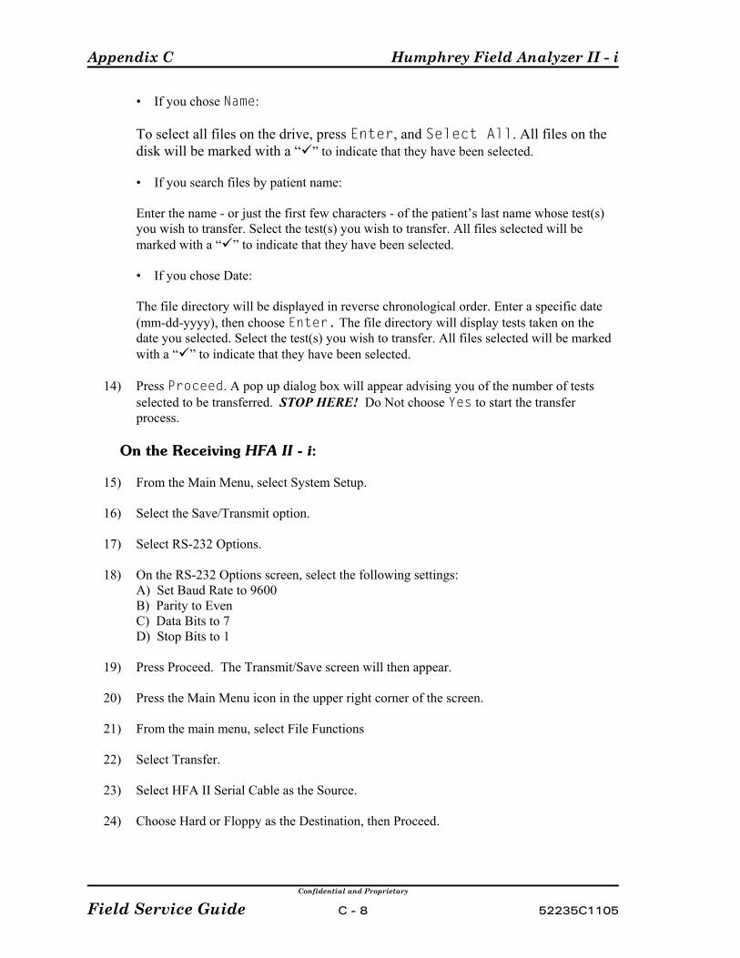
Appendix C Humphrey Field Analyzer II - i
Confidential and Proprietary
Field Service Guide C - 8 52235C1105
• If you chose Name:
To select all files on the drive, press Enter, and Select All. All files on thedisk will be marked with a “ ” to indicate that they have been selected.
• If you search files by patient name:
Enter the name - or just the first few characters - of the patient’s last name whose test(s)you wish to transfer. Select the test(s) you wish to transfer. All files selected will bemarked with a “ ” to indicate that they have been selected.
• If you chose Date:
The file directory will be displayed in reverse chronological order. Enter a specific date (mm-dd-yyyy), then choose Enter. The file directory will display tests taken on thedate you selected. Select the test(s) you wish to transfer. All files selected will be markedwith a “ ” to indicate that they have been selected.
14) Press Proceed. A pop up dialog box will appear advising you of the number of testsselected to be transferred. STOP HERE! Do Not choose Yes to start the transferprocess.
On the Receiving HFA II - i:
15) From the Main Menu, select System Setup.
16) Select the Save/Transmit option.
17) Select RS-232 Options.
18) On the RS-232 Options screen, select the following settings:A) Set Baud Rate to 9600B) Parity to EvenC) Data Bits to 7D) Stop Bits to 1
19) Press Proceed. The Transmit/Save screen will then appear.
20) Press the Main Menu icon in the upper right corner of the screen.
21) From the main menu, select File Functions
22) Select Transfer.
23) Select HFA II Serial Cable as the Source.
24) Choose Hard or Floppy as the Destination, then Proceed.
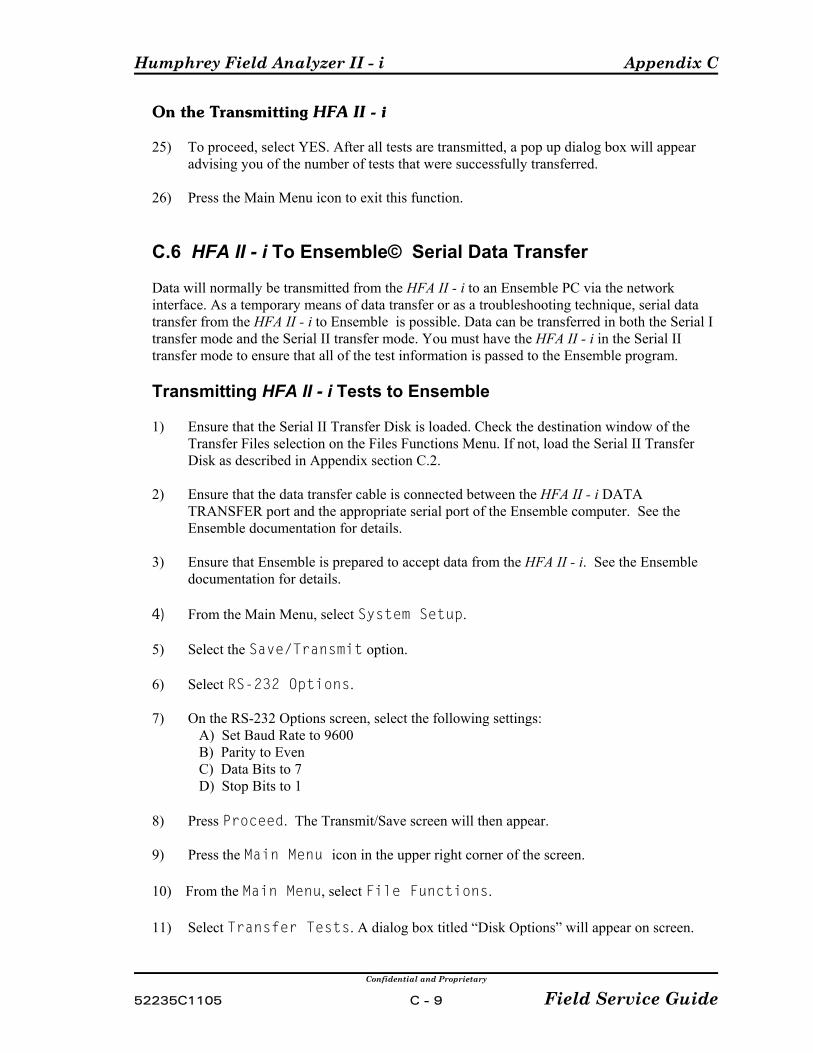
Humphrey Field Analyzer II - i Appendix C
Confidential and Proprietary
52235C1105 C - 9 Field Service Guide
On the Transmitting HFA II - i
25) To proceed, select YES. After all tests are transmitted, a pop up dialog box will appearadvising you of the number of tests that were successfully transferred.
26) Press the Main Menu icon to exit this function.
C.6 HFA II - i To Ensemble© Serial Data Transfer
Data will normally be transmitted from the HFA II - i to an Ensemble PC via the networkinterface. As a temporary means of data transfer or as a troubleshooting technique, serial datatransfer from the HFA II - i to Ensemble is possible. Data can be transferred in both the Serial Itransfer mode and the Serial II transfer mode. You must have the HFA II - i in the Serial IItransfer mode to ensure that all of the test information is passed to the Ensemble program.
Transmitting HFA II - i Tests to Ensemble
1) Ensure that the Serial II Transfer Disk is loaded. Check the destination window of theTransfer Files selection on the Files Functions Menu. If not, load the Serial II TransferDisk as described in Appendix section C.2.
2) Ensure that the data transfer cable is connected between the HFA II - i DATATRANSFER port and the appropriate serial port of the Ensemble computer. See theEnsemble documentation for details.
3) Ensure that Ensemble is prepared to accept data from the HFA II - i. See the Ensembledocumentation for details.
4) From the Main Menu, select System Setup.
5) Select the Save/Transmit option.
6) Select RS-232 Options.
7) On the RS-232 Options screen, select the following settings: A) Set Baud Rate to 9600 B) Parity to Even C) Data Bits to 7 D) Stop Bits to 1
8) Press Proceed. The Transmit/Save screen will then appear.
9) Press the Main Menu icon in the upper right corner of the screen.
10) From the Main Menu, select File Functions.
11) Select Transfer Tests. A dialog box titled “Disk Options” will appear on screen.

Appendix C Humphrey Field Analyzer II - i
Confidential and Proprietary
Field Service Guide C - 10 52235C1105
12) Select Hard Drive as the Source.
13) Select HFA II Serial Cable as the Destination.
14) Select the Directory Order (either Name or Date), then press Proceed.
• If you chose Name:
To select all files on the drive, press Enter, and Select All. All files on thedisk will be marked with a “ ” to indicate that they have been selected.
• If you search files by patient name:
Enter the name - or just the first few characters - of the patient’s last name whose test(s)you wish to transfer. Select the test(s) you wish to transfer. All files selected will bemarked with a “ ” to indicate that they have been selected.
• If you chose Date:
The file directory will be displayed in reverse chronological order. Enter a specific date(mm-dd-yyyy), then choose Enter. The file directory will display tests taken on thedate you selected. Select the test(s) you wish to transfer. All files selected will be markedwith a “ ” to indicate that they have been selected.
15) Press Proceed.
A pop up dialog box will appear advising you of the number of tests selected to be transferred.
16) If you wish to proceed, select YES.
After all tests are transmitted, a pop up dialog box will appear advising you of the numberof tests that were successfully transferred.
17) Press the Main Menu icon to exit this function.

Humphrey Field Analyzer II - i Appendix C
Confidential and Proprietary
52235C1105 C - 11 Field Service Guide
C.7 HFA II - i To Third Party Programs Serial Data Transfer
Transfer of serial data from the HFA II - i to a third party program such as Peridata© is possibleonly in the Serial II transfer mode.
Transmitting HFA II - i Tests to Third Party Programs
Ensure that the Serial II Transfer Disk is loaded by checking the destination window of theTransfer Files selection on the Files Menu. If not, load the Serial II Transfer Disk as describedin Appendix section C.2.
1) From the HFA II - i Main Menu, select System Setup.
2) Select the Save/Transmit option.
3) Select RS-232 Options.
4) On the RS-232 Options screen, select the following settings: A) Set Baud Rate to 9600 B) Parity to Even C) Data Bits to 7 D) Stop Bits to 1
5) Press Proceed. The Transmit/Save screen will then appear.
6) Press the Main Menu icon in the upper right corner of the screen.
7) From the Main Menu, select File Functions.
8) Select Transfer Tests. A dialog box titled “Disk Options” will appear on screen.
9) Select Hard Drive as the Source.
10) Select HFA I Serial Cable as the Destination.
11) Select the Directory Order (either Name or Date), then press Proceed.
• If you chose Name:
To select all files on the drive, press Enter, and Select All. All files on thedisk will be marked with a “ ” to indicate that they have been selected.
• If you search files by patient name:
Enter the name - or just the first few characters - of the patient’s last name whose test(s)you wish to transfer. Select the test(s) you wish to transfer. All files selected will bemarked with a “ ” to indicate that they have been selected.

Appendix C Humphrey Field Analyzer II - i
Confidential and Proprietary
Field Service Guide C - 12 52235C1105
• If you chose Date:
The file directory will be displayed in reverse chronological order. Enter a specific date(mm-dd-yyyy), then choose Enter. The file directory will display tests taken on thedate you selected. Select the test(s) you wish to transfer. All files selected will bemarked with a “ ” to indicate that they have been selected.
12) Press Proceed.
A pop up dialog box will appear advising you of the number of tests selected to be transferred.
13) If you wish to proceed, select YES.
After all tests are transmitted, a pop up dialog box will appear advising you of the numberof tests that were successfully transferred.
14) Press the Main Menu icon to exit this function.
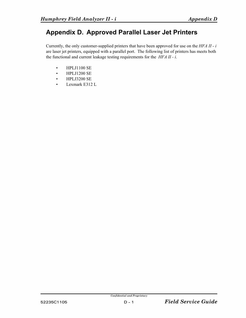
Humphrey Field Analyzer II - i Appendix D
Confidential and Proprietary
52235C1105 D - 1 Field Service Guide
Appendix D. Approved Parallel Laser Jet Printers
Currently, the only customer-supplied printers that have been approved for use on the HFA II - iare laser jet printers, equipped with a parallel port. The following list of printers has meets boththe functional and current leakage testing requirements for the HFA II - i.
• HPLJ1100 SE• HPLJ1200 SE• HPLJ3200 SE• Lexmark E312 L

Appendix D Humphrey Field Analyzer II - i
Confidential and Proprietary
Field Service Guide D - 2 52235C1105
(This page left blank intentionally)
Humphrey Field Analyzer II - i Appendix E
Confidential and Proprietary
52235C1105 E - 1 Field Service Guide
Appendix E. Instrument/BIOS ConfigurationE.1 Instrument ConfigurationThis section provides a listing of configuration settings that are critical to the operation ofthe HFA II - i unit.
Bootup Sequence
In the Advanced CMOS SETUP, the first boot device is IDE-0 (hard drive). Theinstrument will not boot up a system disk from either the Magnetic Optical drive or thefloppy drive (if configured with the default settings). Special instructions have beenprogrammed in the instrument to recognize the installation disks and the DiagnosticSupport Tool disks. If an application diskette or the DST diskette are in the floppy driveduring instrument power up, the system will recognize them and allow the system to bootfrom the floppy disk. If you attempt to load any other diagnostic software utilities that havea system on the disk, you will need to first set the first boot device to floppy. Note: If you set the first boot device in the Advanced CMOS Setup to Floppy fordiagnostic purposes, it is necessary to reset the boot sequence to IDE-0 after using theutility. Failure to do so will create a “Non-system disk or disk error Replace and strike anykey” any time a floppy disk is left in the floppy drive during the bootup sequence.
Changing the BIOS Advanced CMOS Setup First Boot Device
1) Set the HFA II - i system power switch to ON.
2) Press and hold the Delete key.
3) A Enter current Password dialogue will appear.
4) Enter the password.
5) The AMIBIOS HIFLEX SETUP UTILITY screen will appear.
6) Use the down arrow key to select Advanced CMOS Setup.
7) Press Enter.
8) The AMIOBIOS Setup - Advanced CMOS Setup screen is displayed.
9) Use the down arrow to select 1st Boot Device.
10) Use the PgUp (page up) or Pg Dn (page down) keys to select the first boot device. Set thefirst boot device to floppy if you plan on using the diagnostic utilities. Set the first bootdevice to IDE-0 if you plan on resetting the instrument for normal operation.

Appendix E Humphrey Field Analyzer II - i
Confidential and Proprietary
Field Service Guide E - 2 52235C1105
11) Press ESC (escape) to exit the Advanced CMOS Setup screen.
12) Press the F-10 function key to save and exit the AMIBIOS HIFLEX SETUP UTILITY.
13) Press Enter to answer yes to the Save current settings and exit prompt.
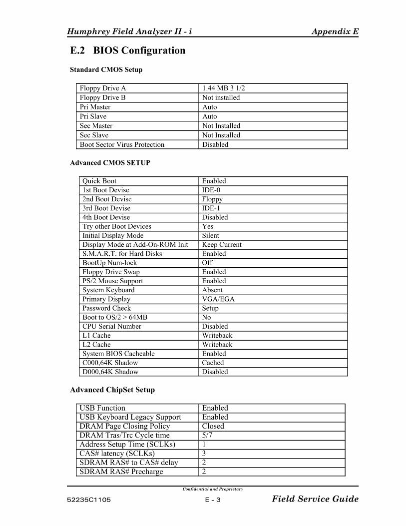
Humphrey Field Analyzer II - i Appendix E
Confidential and Proprietary
52235C1105 E - 3 Field Service Guide
E.2 BIOS Configuration
Standard CMOS Setup
Floppy Drive A 1.44 MB 3 1/2Floppy Drive B Not installedPri Master AutoPri Slave AutoSec Master Not InstalledSec Slave Not InstalledBoot Sector Virus Protection Disabled
Advanced CMOS SETUP
Quick Boot Enabled1st Boot Devise IDE-02nd Boot Devise Floppy3rd Boot Devise IDE-14th Boot Devise DisabledTry other Boot Devices YesInitial Display Mode SilentDisplay Mode at Add-On-ROM Init Keep CurrentS.M.A.R.T. for Hard Disks EnabledBootUp Num-lock OffFloppy Drive Swap EnabledPS/2 Mouse Support EnabledSystem Keyboard AbsentPrimary Display VGA/EGAPassword Check SetupBoot to OS/2 > 64MB NoCPU Serial Number DisabledL1 Cache WritebackL2 Cache WritebackSystem BIOS Cacheable EnabledC000,64K Shadow CachedD000,64K Shadow Disabled
Advanced ChipSet Setup
USB Function EnabledUSB Keyboard Legacy Support EnabledDRAM Page Closing Policy ClosedDRAM Tras/Trc Cycle time 5/7Address Setup Time (SCLKs) 1CAS# latency (SCLKs) 3SDRAM RAS# to CAS# delay 2SDRAM RAS# Precharge 2
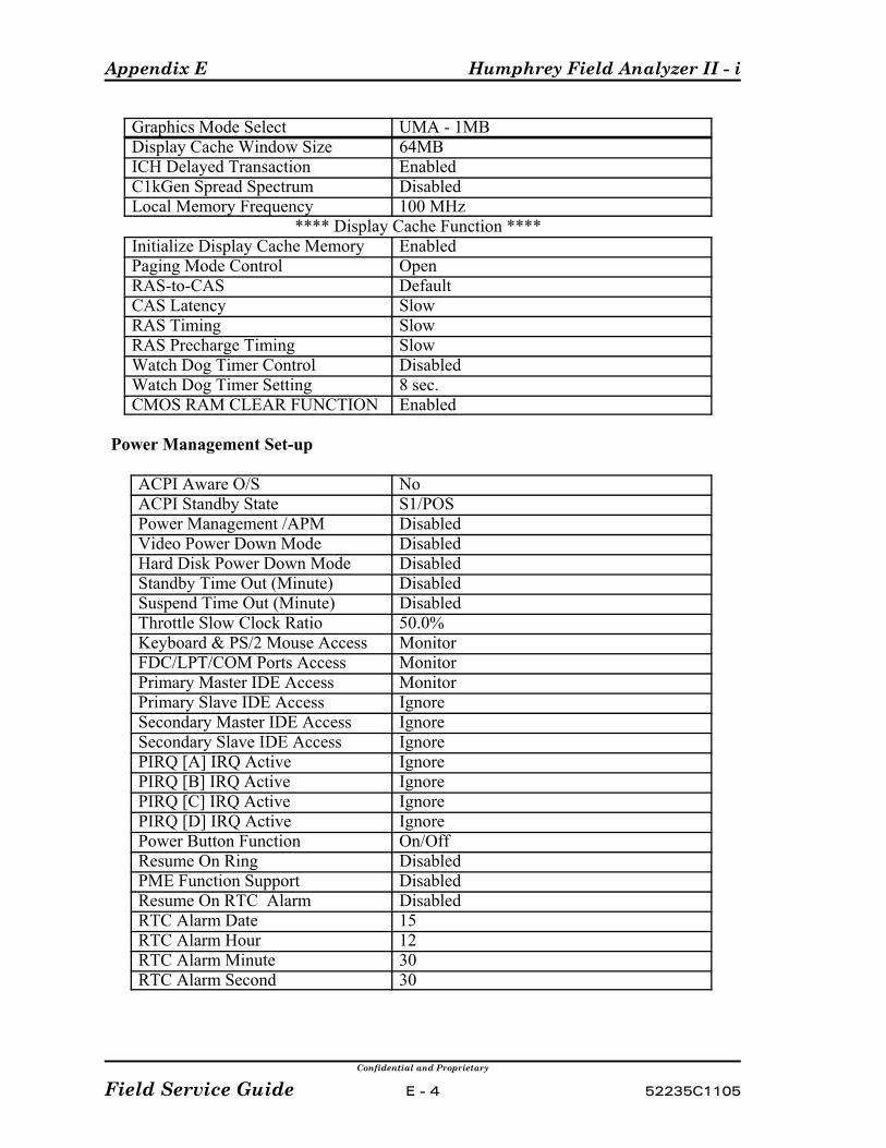
Appendix E Humphrey Field Analyzer II - i
Confidential and Proprietary
Field Service Guide E - 4 52235C1105
Graphics Mode Select UMA - 1MBDisplay Cache Window Size 64MBICH Delayed Transaction EnabledC1kGen Spread Spectrum DisabledLocal Memory Frequency 100 MHz
**** Display Cache Function ****Initialize Display Cache Memory EnabledPaging Mode Control OpenRAS-to-CAS DefaultCAS Latency SlowRAS Timing SlowRAS Precharge Timing SlowWatch Dog Timer Control DisabledWatch Dog Timer Setting 8 sec.CMOS RAM CLEAR FUNCTION Enabled
Power Management Set-up
ACPI Aware O/S NoACPI Standby State S1/POSPower Management /APM DisabledVideo Power Down Mode DisabledHard Disk Power Down Mode DisabledStandby Time Out (Minute) DisabledSuspend Time Out (Minute) DisabledThrottle Slow Clock Ratio 50.0%Keyboard & PS/2 Mouse Access MonitorFDC/LPT/COM Ports Access MonitorPrimary Master IDE Access MonitorPrimary Slave IDE Access IgnoreSecondary Master IDE Access IgnoreSecondary Slave IDE Access IgnorePIRQ [A] IRQ Active IgnorePIRQ [B] IRQ Active IgnorePIRQ [C] IRQ Active IgnorePIRQ [D] IRQ Active IgnorePower Button Function On/OffResume On Ring DisabledPME Function Support DisabledResume On RTC Alarm DisabledRTC Alarm Date 15RTC Alarm Hour 12RTC Alarm Minute 30RTC Alarm Second 30
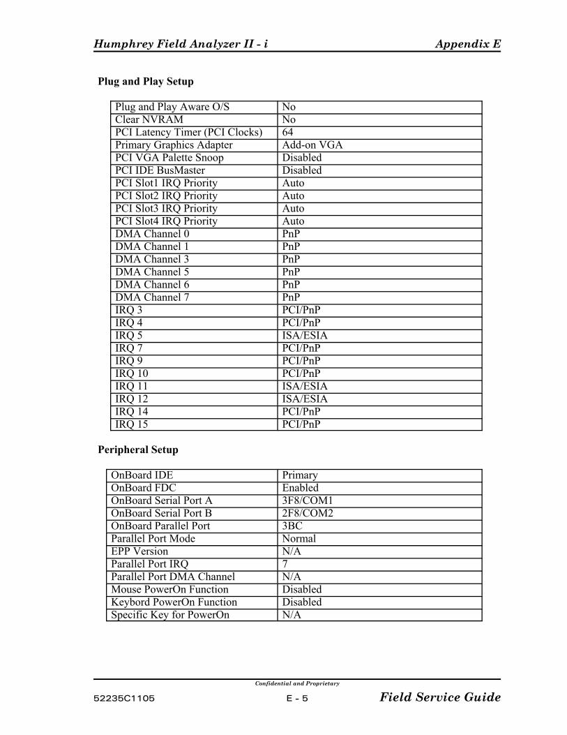
Humphrey Field Analyzer II - i Appendix E
Confidential and Proprietary
52235C1105 E - 5 Field Service Guide
Plug and Play Setup
Plug and Play Aware O/S NoClear NVRAM NoPCI Latency Timer (PCI Clocks) 64Primary Graphics Adapter Add-on VGAPCI VGA Palette Snoop DisabledPCI IDE BusMaster DisabledPCI Slot1 IRQ Priority AutoPCI Slot2 IRQ Priority AutoPCI Slot3 IRQ Priority AutoPCI Slot4 IRQ Priority AutoDMA Channel 0 PnPDMA Channel 1 PnPDMA Channel 3 PnPDMA Channel 5 PnPDMA Channel 6 PnPDMA Channel 7 PnPIRQ 3 PCI/PnPIRQ 4 PCI/PnPIRQ 5 ISA/ESIAIRQ 7 PCI/PnPIRQ 9 PCI/PnPIRQ 10 PCI/PnPIRQ 11 ISA/ESIAIRQ 12 ISA/ESIAIRQ 14 PCI/PnPIRQ 15 PCI/PnP
Peripheral Setup
OnBoard IDE PrimaryOnBoard FDC EnabledOnBoard Serial Port A 3F8/COM1OnBoard Serial Port B 2F8/COM2OnBoard Parallel Port 3BCParallel Port Mode NormalEPP Version N/AParallel Port IRQ 7Parallel Port DMA Channel N/AMouse PowerOn Function DisabledKeybord PowerOn Function DisabledSpecific Key for PowerOn N/A

Appendix E Humphrey Field Analyzer II - i
Confidential and Proprietary
Field Service Guide E - 6 52235C1105
(This page left intentionally blank)

Humphrey Field Analyzer II - i Appendix F
Confidential and Proprietary
52235C1105 F - 1 Field Service Guide
Appendix F. Operating System
The operating system is a real-time system based on the Vx Works kernel. In addition to VxWorks, the file system DOS Fs and Vx Works run-time libraries are utilized.
The operating system is structured to be run as a preemptive, real-time, multitasking environment,using message passing as the principal method of interprocess communication. The systemassumes the existence of both a hard disk as well as a floppy disk system. The floppy disk filesystem is designed to be compatible with that used by IBM PC-DOS compatible machines. The VxWorks operating system supports an IDE hard drive and a Magneto Optical drive through the filesystem.

Appendix F Humphrey Field Analyzer II - i
(This page left intentionally blank)
Confidential and Proprietary
Field Service Guide F - 2 52235C1105

Humphrey Field Analyzer II - i Appendix G
Confidential and Proprietary
52235C1105 G - 1 Field Service Guide
Appendix G. P Initializing the Cal/Config DataP Setting Serial NumberP Setting the Model/Hardware OptionsP Setting the Software Options
The four operations described in Appendix G can be performed by using the DiagnosticSupport Tool (DST).
NOTE: Refer to Figure G-1 for a graphical representation of the descriptions given below.
P Initializing the Cal/Config Data— is required whenever a new Hard Drive isinstalled, or the existing Hard Drive is initialized or becomes corrupted.
Initializing the Cal/Config Data erases the stored systems information in theCALCFG.INI and NVRAM.DAT files that are located on the hard drive. Calibration constants, model and serial number, instrument defaults, hardwareoptions and software options are all erased during the Cal/Config Datainitialization process. All of these parameters must be reentered after Cal/ConfigData initialization.
P Setting Serial Number — is required any time the Hard Drive is replaced, or theCal/Config Data has been initialized or corrupted.
Setting the Serial Number writes and stores the instrument model number andserial number in both the CALCFG.INI and NVRAM.DAT files on the HardDrive.
P Setting the Model/Hardware Options — is required whenever a new hard drive isinstalled or the existing Cal/Config Data has been initialized or corrupted.
Setting the Hardware Options writes and stores the hardware options HEXnumber in the CALCFG.INI file. The hard option HEX number, also called the"hard opt”, is used by the instrument operating system to determine whichfeatures of the instrument are to be enabled (accessible to the user). The hard optnumber can be viewed on the HFA II - i unit information screen.
P Setting the Software Options — is required whenever the model/hardware option
number has been changed or entered into the Cal/Config Data (for the first time).
Each time software is loaded onto the hard disk, a software option number isautomatically written into the Cal/Config Data. The software option numbergenerated is based on the model or hardware option number. If the softwareoption number is missing or does not agree with the hardware option number,instrument features (for a particular model HFA II - i) will not be enabled(accessible to the user). The software option number can be viewed on the HFAII - i information screen.
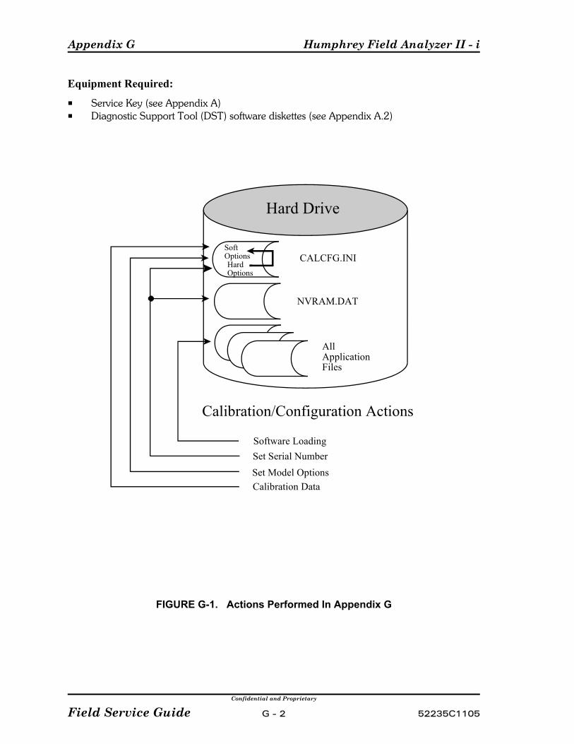
Appendix G Humphrey Field Analyzer II - i
Confidential and Proprietary
Field Service Guide G - 2 52235C1105
Hard Drive
HardOptions
SoftOptions CALCFG.INI
NVRAM.DAT
AllApplication Files
Calibration/Configuration Actions
Software LoadingSet Serial NumberSet Model OptionsCalibration Data
Equipment Required:
P Service Key (see Appendix A)P Diagnostic Support Tool (DST) software diskettes (see Appendix A.2)
FIGURE G-1. Actions Performed In Appendix G
Humphrey Field Analyzer II - i Appendix G
Confidential and Proprietary
52235C1105 G - 3 Field Service Guide
G.1 Initializing the Cal/Config Data
This procedure is required whenever a new hard drive has been installed, before calibrationis performed.
1) Set up the DST for use as described in Appendix A.2, under Diagnostic Support Tool.
2) From the DST Main Menu, select Configuration. The Configuration Menuappears.
3) Select Initialize the Configuration. A warning message appears informingyou that all configuration and calibration data will be destroyed.
4) Select OK. A test log screen appears confirming whether or not you want to continue. Select Initialize to erase all contents of the Cal/Config Data. (Select Quit toreturn to the Configuration Menu.)
5) “Initialization successful” message will appear.
NOTE: If you initialize the CAL/Config Data, you must also perform the procedures forSetting Serial Number, Setting the Model/Hardware Options, and Setting the SoftwareOptions described below. Then recalibrate the instrument (see Table 3-1).
G.2 Setting Serial Number
This procedure is required any time the hard drive is replaced or the Cal/Config Data isinitialized. During this procedure you will be instructed to type in the serial number of theinstrument. The serial number can always be found on the label located on the rear coverassembly.
NOTE: The instrument’s serial number NEVER changes throughout the life of theinstrument. Instrument serial numbers are critical for tracking instrument reliability,performance, and customer satisfaction.
1) Set up the DST for use as described in Appendix A.2, under Diagnostic Support Tool.
2) From the DST Main Menu select Configuration. The Configuration Menu appears.
3) Select Set Serial Number, then select Edit. A ten-key pad appears. Type in thefour-digit model of the instrument. For example, 0750, then select [Enter].
4) A ten-key pad appears. Type in the six-digit serial number of the instrument. Forexample, 001000, then select [Enter].
Appendix G Humphrey Field Analyzer II - i
Confidential and Proprietary
Field Service Guide G - 4 52235C1105
5) Select Save to store the serial number and return to the Configuration Menu. (Selecting Quit will not store the serial number and will return to the ConfigurationMenu.)
6) Switch OFF the instrument and remove the Service Key.
7) Switch ON the instrument and verify that the correct serial number appears on thescreen during the boot-up process.
G.3 Setting the Model/Hardware Options
NOTE: The hardware options codes listed in this section are for C1.1 system software. Changes in future revisions of software may result in changes to the hardware options.
This procedure is designed to set up the basic hardware configuration by setting the modelnumber of the instrument. This is required whenever the CAL/Config Data has just beeninitialized.
For Model 720i
1) Set up the DST for use as described in Appendix A.2, under Diagnostic Support Tool.
2) From the DST Main Menu select Set Model/Hardware Options. TheModel/Hardware Options Menu appears.
3) Select Set Model 720i Defaults, a test log menu appears and displays themodel 720i default settings.
4) Select Continue. The Model 720i hardware Options are set and the Model/HardwareOptions Menu is displayed.
5) Switch OFF the instrument and remove the Service Key.
6) Switch ON the instrument. Select the “i” screen and verify that the correct modelnumber appears on the boot-up screen.
7) Proceed to “Setting the Software Options.”
For Model 740i
1) Set up the DST for use as described in Appendix A.2, under Diagnostic Support Tool.
2) From the DST Main Menu select Set Model/Hardware Options. TheModel/Hardware Options Menu appears.

Humphrey Field Analyzer II - i Appendix G
Confidential and Proprietary
52235C1105 G - 5 Field Service Guide
3) Select Set Model 740i Defaults, a test log menu appears and displays themodel 740i default settings.
4) Select Continue. The Model 740i hardware Options are set and the Model/HardwareOptions Menu is displayed.
5) Switch OFF the instrument and remove the Service Key.
6) Switch ON the instrument. Select the “i” screen and verify that the correct modelnumber appears on the boot-up screen.
7) Proceed to “Setting the Software Options.”
For Model 750i
1) Set up the DST for use as described in Appendix A.2, under Diagnostic Support Tool.
2) From the DST Main Menu select Set Model/Hardware Options. TheModel/Hardware Options Menu appears.
3) Select Set Model 750i Defaults, a test log menu appears and displays themodel 750i default settings.
4) Select Continue. The Model 750i hardware Options are set and the Model/HardwareOptions Menu is displayed.
5) Switch OFF the instrument and remove the Service Key.
6) Switch ON the instrument. Select the “i” screen and verify that the correct modelnumber appears on the boot-up screen.
7) Proceed to “Setting the Software Options.”
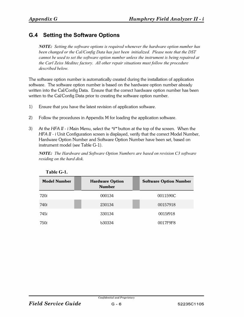
Appendix G Humphrey Field Analyzer II - i
Confidential and Proprietary
Field Service Guide G - 6 52235C1105
G.4 Setting the Software Options
NOTE: Setting the software options is required whenever the hardware option number hasbeen changed or the Cal/Config Data has just been initialized. Please note that the DSTcannot be used to set the software option number unless the instrument is being repaired atthe Carl Zeiss Meditec factory. All other repair situations must follow the proceduredescribed below.
The software option number is automatically created during the installation of applicationsoftware. The software option number is based on the hardware option number alreadywritten into the Cal/Config Data. Ensure that the correct hardware option number has beenwritten to the Cal/Config Data prior to creating the software option number.
1) Ensure that you have the latest revision of application software.
2) Follow the procedures in Appendix M for loading the application software.
3) At the HFA II - i Main Menu, select the “i” button at the top of the screen. When the HFA II - i Unit Configuration screen is displayed, verify that the correct Model Number,Hardware Option Number and Software Option Number have been set, based oninstrument model (see Table G-1).
NOTE: The Hardware and Software Option Numbers are based on revision C3 softwareresiding on the hard disk.
Table G-1.
Model Number Hardware OptionNumber
Software Option Number
720i 000134 0011590C
740i 230134 00157918
745i 330134 0015f918
750i b30334 0017F9F8

Humphrey Field Analyzer II - i Appendix H
Confidential and Proprietary
52235C1105 H - 1 Field Service Guide
Appendix H. Calibration Printouts
Contents:C Cal / Wedge PrintoutC Automated Light Intensity Verification Printouts
C White Light Verification DataC Blue-Yellow Verification Data
H.1 Cal / Wedge Printout
The numbered definitions below (1, 2, 3, etc.) are keyed to the numbered elements of thesample calibration printout shown in Figure H-1.
1 = Date/time of calibration printout, instrument serial number, and hardware optionnumber.
2 = NVM DataThe numbers that appear in the printout represent the current calibration values storedin Cal/Config Data for each item listed, for this particular instrument. A brief definitionof each item is given below, followed by a table that lists the acceptable tolerance rangefor each item.
Proj . . . . . . . represents voltage* (left column) and intensity* (right column) of theprojection lamp when a white stimulus is projected.
Bowl . . . . . . represents voltage* and intensity* for the white bowl lamps.Blue . . . . . . . represents voltage* and intensity* of the projection lamp when a blue
stimulus is projected.Yellow . . . . . represents voltage* and intensity* for the yellow bowl lampRight Mode . microsteps of positioningLeft Mode . . microsteps of positioningOffset Fix . . . microsteps of positioningFocus . . . . . . microsteps of positioningShutter . . . . microsteps of positioningAperture . . . microsteps of positioning for each of the 5 positions of the aperture
wheelColor . . . . . . microsteps of positioning for each of the 5 positions of the color wheel
* Voltage and intensity are expressed here as relative numbers, not actual units of voltage orintensity (such as volts or foot-lamberts). Typically, any high round number (e.g., 30000) thatappears here in the printout is the default value for a parameter that has not been calibrated. It is possible but highly unlikely that a calibrated value would fall precisely at a high roundnumber.
3 = Voltage drop across projector lamp when white stimulus is projected, and when bluestimulus is projected.

Appendix H Humphrey Field Analyzer II - i
Confidential and Proprietary
Field Service Guide H - 2 52235C1105
NOTE: The Blue projector voltage drop will display a value greater than zero only whenthe printout is obtained immediately after performing the light intensitycalibration/verification.
4 = Camera/Gaze Data
Illumination:Reflex LED . . . . . . . . . . intensity of the reflex LEDLeft LED . . . . . . . . . . . . intensity of the left trial lens LEDRight LED . . . . . . . . . . . intensity of the right trial lens LEDGain No Trial Lens . . . . . camera gain with trial lens holder downGain Trial Lens . . . . . . . camera gain with trial lens holder upScale . . . . . . . . . . . . . . . (not currently used)
Video Window:Source X . . . . . . . . . . . . where the video image will be positioned on the CRT
(inside the video insert)Source Y . . . . . . . . . . . . where the video image will be positioned on the CRT
(inside the video insert)Dest X . . . . . . . . . . . . . . where the video insert will be positioned on the CRT
screenDest Y . . . . . . . . . . . . . . where the video insert will be positioned on the CRT
screenWidth . . . . . . . . . . . . . . . represents the width of the video insertHeight . . . . . . . . . . . . . . represents the height of the video insert
Gaze Window:X . . . . . . . . . . . . . . . . . . represents the distance from the left edge of the video
insert to the left edge of the gaze boxY . . . . . . . . . . . . . . . . . . represents the distance from the top edge of the video
insert to the top edge of the gaze boxWidth . . . . . . . . . . . . . . . represents the width of the gaze boxHeight . . . . . . . . . . . . . . represents the height of the gaze box
Gaze Size:Height . . . . . . . . . . . . . . conversion factor for converting pixels to millimetersWidth . . . . . . . . . . . . . . . conversion factor for converting pixels to millimetersAspect Ratio . . . . . . . . . . normalizing factor to produce a true circle from the
data received from the camera
5 = Blue Correction Table.The Blue Correction Table contains twelve correction values for both the Film wedgeand the Glass wedge. The Blue Correction table for the Film wedge should start atzero and typically increase to around the mid to high 20's, and sometimes into the30's The Blue Correction table for the Glass wedge should also start at zero, anddisplay negative numbers going to –20 or –30 (in the middle of the table).
The values given above are to be used as a general guideline. The final evaluationfor Blue Calibration depends on the light intensity worksheet results.
Humphrey Field Analyzer II - i Appendix H
Confidential and Proprietary
52235C1105 H - 3 Field Service Guide
6 = Wedge AttenuationTo help quantify the attenuation of the film and glass wedges, additional data hasbeen added to the calibration printout. This information is intended for manufacturingand engineering use and is not required for field service evaluation. The Working FilmWedge Steps displayed on the calibration printout indicates the total attenuation ofthe film wedge. The Working Glass Wedge Steps indicates the total attenuation of theglass wedge. Both are expressed in centibels (10 centibels equals 1 decibel). TheTotal Working Wedge Attenuation displayed on the calibration printout is the com-bined attenuation of the Working Film Wedge Steps and Working Glass Wedge Steps,also expressed in centibels. The Total Working Wedge Attenuation must be greaterthan 500 centibels. Bins Film and Bins Glass displayed on the calibration printoutare used to evaluate the linearity of the NVM ND Table 0 film wedge and NVM NDTable 1 glass wedge. Ideally, the amount of attenuation between any two adjacentglass or film wedge motor steps should increase between 1, 2, or 3 centibels. However this may not always be the case and is not a requirement for serviceevaluation.
7 = NVM ND Table 0This is the film wedge calibration table stored in Cal/Config Data. The values in thetable were obtained during the latest wedge calibration. During wedge calibration,brightness of the projected spot is sensed for 175 different positions of the wedge.
With a properly calibrated film wedge, the values printed should run fromapproximately 0 – 370 in a linear progression, with no large jumps in value betweenadjacent positions. If a large jump in value is noted, check the wedge for finger-prints, scratches, debris, or flaking emulsion.
8 = NVM ND Table 1This is the glass wedge calibration table stored in Cal/Config Data. The values in thetable are obtained during the wedge calibration process. During wedge calibration,brightness of the projected spot is sensed for 175 different positions of the wedge.
With a properly calibrated glass wedge, the values printed should run from approxi-mately 0 - 270 in a linear progression, with no large jumps in value between adja-cent positions. If a large jump in value is noted, check the wedge for fingerprints,scratches, debris, or flaking emulsion.

Appendix H Humphrey Field Analyzer II - i
Confidential and Proprietary
Field Service Guide H - 4 52235C1105
(This page left intentionally blank)
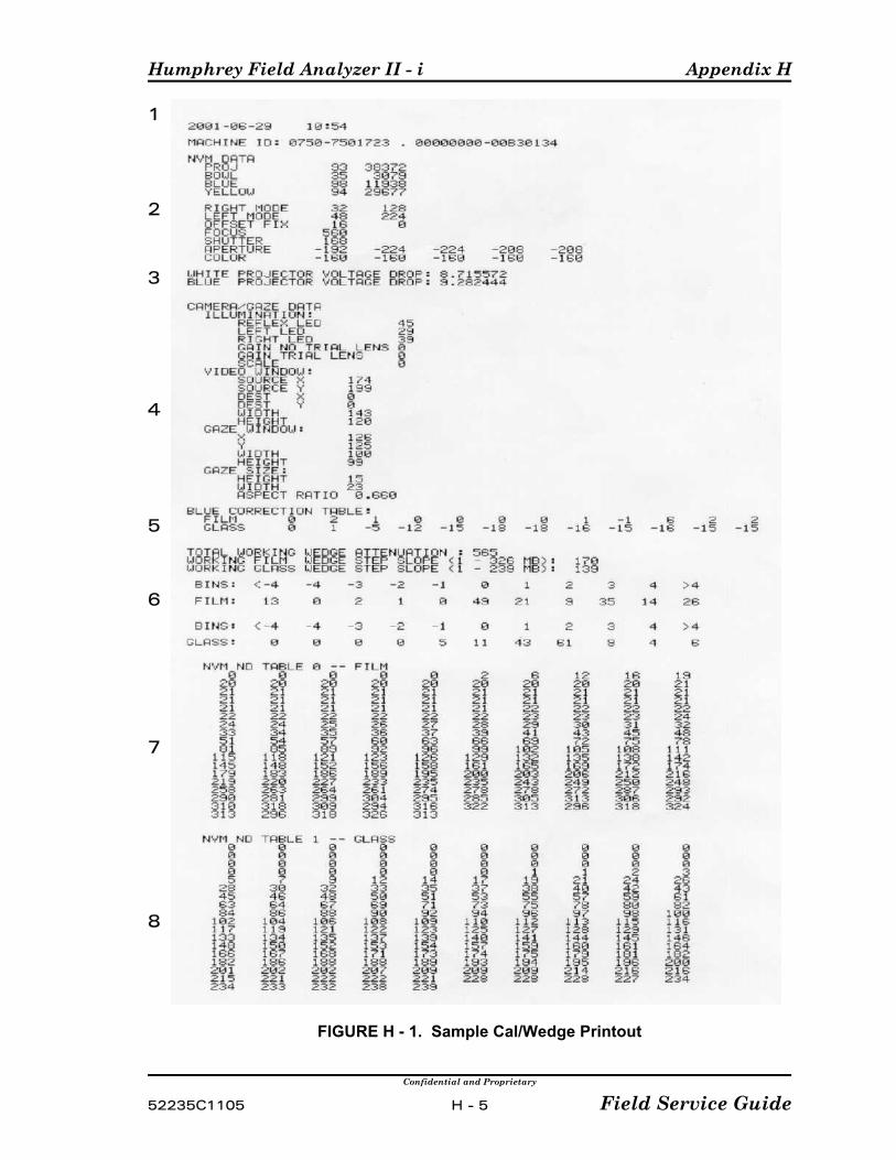
Humphrey Field Analyzer II - i Appendix H
Confidential and Proprietary
52235C1105 H - 5 Field Service Guide
1
2
3
4
5
6
7
8
FIGURE H - 1. Sample Cal/Wedge Printout
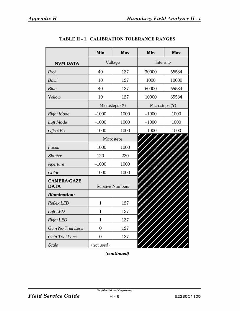
Appendix H Humphrey Field Analyzer II - i
Confidential and Proprietary
Field Service Guide H - 6 52235C1105
TABLE H - 1. CALIBRATION TOLERANCE RANGES
NVM DATA
Min Max Min Max
Voltage Intensity
Proj 40 127 30000 65534
Bowl 10 127 1000 10000
Blue 40 127 60000 65534
Yellow 10 127 10000 65534
Microsteps (X) Microsteps (Y)
Right Mode –1000 1000 –1000 1000
Left Mode –1000 1000 –1000 1000
Offset Fix –1000 1000 –1000 1000
Microsteps
Focus –1000 1000
Shutter 120 220
Aperture –1000 1000
Color –1000 1000
CAMERA/GAZEDATA Relative Numbers
Illumination:
Reflex LED 1 127
Left LED 1 127
Right LED 1 127
Gain No Trial Lens 0 127
Gain Trial Lens 0 127
Scale (not used)
(continued)
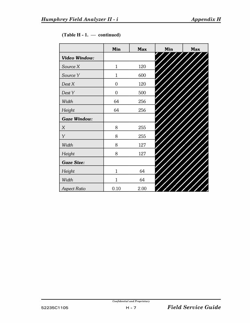
Humphrey Field Analyzer II - i Appendix H
Confidential and Proprietary
52235C1105 H - 7 Field Service Guide
(Table H - 1. — continued)
Min Max Min Max
Video Window:
Source X 1 120
Source Y 1 600
Dest X 0 120
Dest Y 0 500
Width 64 256
Height 64 256
Gaze Window:
X 8 255
Y 8 255
Width 8 127
Height 8 127
Gaze Size:
Height 1 64
Width 1 64
Aspect Ratio 0.10 2.00
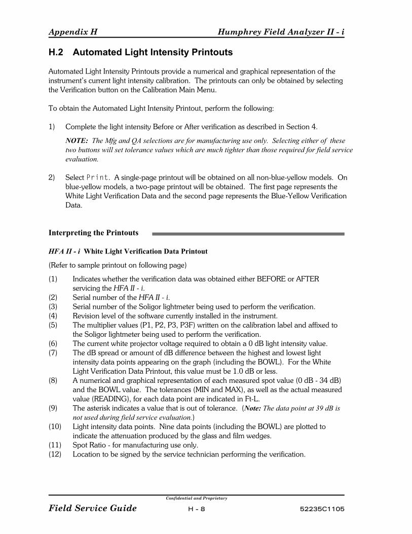
Appendix H Humphrey Field Analyzer II - i
Confidential and Proprietary
Field Service Guide H - 8 52235C1105
H.2 Automated Light Intensity Printouts
Automated Light Intensity Printouts provide a numerical and graphical representation of theinstrument’s current light intensity calibration. The printouts can only be obtained by selectingthe Verification button on the Calibration Main Menu.
To obtain the Automated Light Intensity Printout, perform the following:
1) Complete the light intensity Before or After verification as described in Section 4.
NOTE: The Mfg and QA selections are for manufacturing use only. Selecting either of thesetwo buttons will set tolerance values which are much tighter than those required for field serviceevaluation.
2) Select Print. A single-page printout will be obtained on all non-blue-yellow models. Onblue-yellow models, a two-page printout will be obtained. The first page represents theWhite Light Verification Data and the second page represents the Blue-Yellow VerificationData.
Interpreting the Printouts
HFA II - i White Light Verification Data Printout
(Refer to sample printout on following page)
(1) Indicates whether the verification data was obtained either BEFORE or AFTERservicing the HFA II - i.
(2) Serial number of the HFA II - i.(3) Serial number of the Soligor lightmeter being used to perform the verification.(4) Revision level of the software currently installed in the instrument.(5) The multiplier values (P1, P2, P3, P3F) written on the calibration label and affixed to
the Soligor lightmeter being used to perform the verification.(6) The current white projector voltage required to obtain a 0 dB light intensity value.(7) The dB spread or amount of dB difference between the highest and lowest light
intensity data points appearing on the graph (including the BOWL). For the WhiteLight Verification Data Printout, this value must be 1.0 dB or less.
(8) A numerical and graphical representation of each measured spot value (0 dB - 34 dB)and the BOWL value. The tolerances (MIN and MAX), as well as the actual measuredvalue (READING), for each data point are indicated in Ft-L.
(9) The asterisk indicates a value that is out of tolerance. (Note: The data point at 39 dB isnot used during field service evaluation.)
(10) Light intensity data points. Nine data points (including the BOWL) are plotted toindicate the attenuation produced by the glass and film wedges.
(11) Spot Ratio - for manufacturing use only.(12) Location to be signed by the service technician performing the verification.
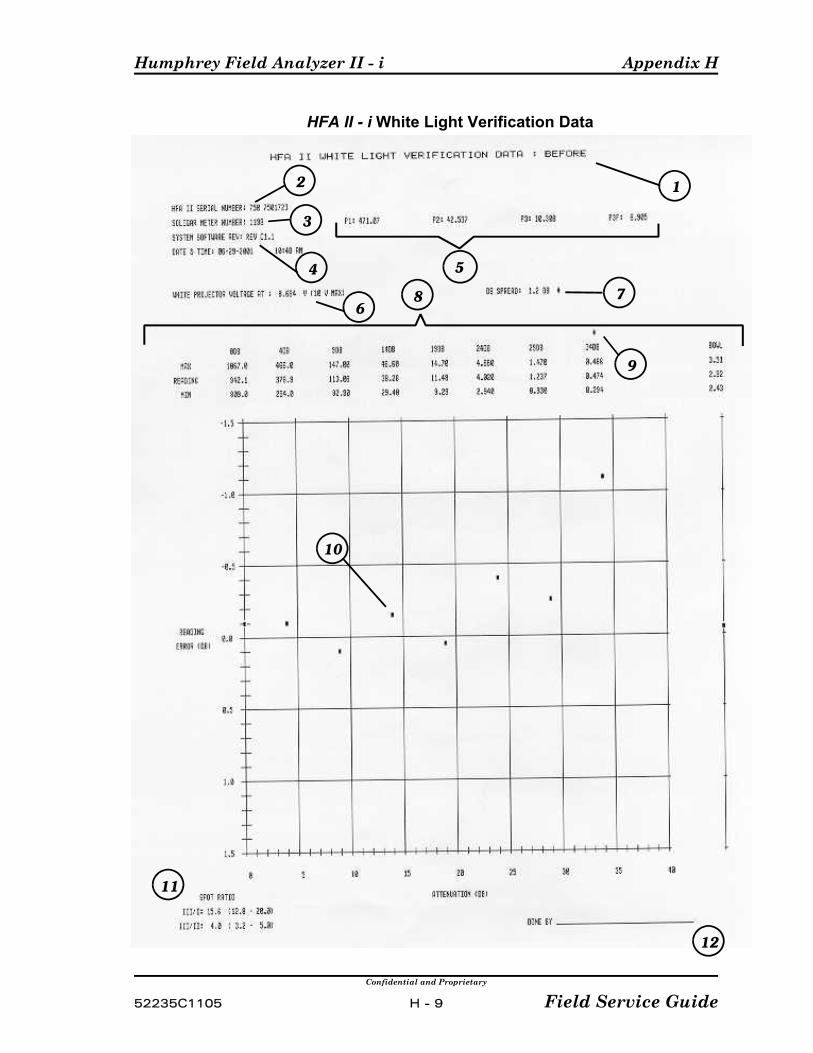
Humphrey Field Analyzer II - i Appendix H
Confidential and Proprietary
52235C1105 H - 9 Field Service Guide
HFA II - i White Light Verification Data
9
10
2 1
4
76
3
5
8
12
11

Appendix H Humphrey Field Analyzer II - i
Confidential and Proprietary
Field Service Guide H - 10 52235C1105
HFA II - i Blue-Yellow Verification Data Printout
(Refer to sample printout on following page)
(13) Indicates whether the verification data was obtained either BEFORE or AFTER servicing theHFA II - i.
(14) Serial number of the HFA II - i.
(15) Serial number of the Soligor lightmeter being used to perform the verification.
(16) Revision level of the system software currently installed in the instrument.
(17) The multiplier values (P3B and P3Y) written on the calibration label and affixed to theSoligor lightmeter being used to perform the verification. (Note: BYP3 and P3 are the oldermultiplier values used to calibrate Blue-Yellow intensities. The newer values are P3B and P3Y.)
(18) The current blue projector voltage required to obtain a 0 dB light intensity value displayed inFt-L.
(19) The dB spread or amount of dB difference between the highest and lowest light intensity datapoints appearing on the graph (including the BOWL). For the Blue Light Verification DataPrintout, this value must be 1.5 dB or less.
(20) A numerical and graphical representation of each measured spot value (0 dB - 23 dB) andthe BOWL value. The tolerances (MIN and MAX) as well as the actual measured value(READING) for each data point are indicated in Ft-L.
(21) The asterisk indicates a value which is out of tolerance. (Note: The data points at 18 dB and 23dB are not used during field service evaluation.)
(22) Light intensity data points. Five data points (including the BOWL) are plotted indicating theattenuation produced by the glass and film wedges.
(23) Location to be signed by the service engineer performing the verification.
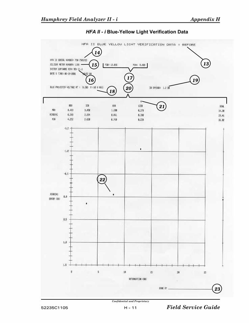
Humphrey Field Analyzer II - i Appendix H
Confidential and Proprietary
52235C1105 H - 11 Field Service Guide
HFA II - i Blue-Yellow Light Verification Data
13
21
22
14
16 19
18
15
17
20
23

Appendix H Humphrey Field Analyzer II - i
Confidential and Proprietary
Field Service Guide H - 12 52235C1105
(This page left intentionally blank)

Humphrey Field Analyzer II - i Appendix I
Confidential and Proprietary
52235C1105 I - 1 Field Service Guide
Appendix I. Service Forms
The forms in this section should be used as masters for making additional copies.
P Calibration Shift Worksheet (previously known as Worksheet 3)
P Calibration Notice ("Doctor Card")
P System Checkout Checklist

Appendix I Humphrey Field Analyzer II - i
Confidential and Proprietary
Field Service Guide I - 2 52235C1105
(This page left intentionally blank)
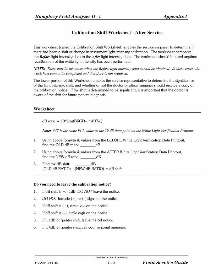
Humphrey Field Analyzer II - i Appendix I
Confidential and Proprietary
52235C1105 I - 3 Field Service Guide
Calibration Shift Worksheet - After Service
This worksheet (called the Calibration Shift Worksheet) enables the service engineer to determine ifthere has been a shift or change in instrument light intensity calibration. The worksheet comparesthe Before light intensity data to the After light intensity data. The worksheet should be used anytimerecalibration of the white light intensity has been performed.
NOTE: There may be instances when the Before light intensity data cannot be obtained. In these cases, theworksheet cannot be completed and therefore is not required.
The lower portion of this Worksheet enables the service representative to determine the significanceof the light intensity shift, and whether or not the doctor or office manager should receive a copy ofthe calibration notice. If the shift is determined to be significant, it is important that the doctor isaware of the shift for future patient diagnosis.
Worksheet
dB ratio = 10*Log(BKGDFtL / #37FtL)
Note: #37 is the same Ft-L value as the 29 dB data point on the White Light Verification Printout.
1. Using above formula & values from the BEFORE White Light Verification Data Printout,find the OLD dB ratio: dB
2. Using above formula & values from the AFTER White Light Verification Data Printout,find the NEW dB ratio: dB
3. Find the dB shift: dB(OLD dB RATIO) – (NEW dB RATIO) = dB shift
Do you need to leave the calibration notice?
1. If dB shift is +/- 1dB, DO NOT leave the notice.
2. DO NOT include (+) or (–) signs on the notice.
3. If dB shift is (+), circle low on the notice.
4. If dB shift is (–), circle high on the notice.
5. If ±1dB or greater shift, leave the cal notice.
6. If ±4dB or greater shift, call your regional manager.

Appendix I Humphrey Field Analyzer II - i
Confidential and Proprietary
Field Service Guide I - 4 52235C1105
(This page left intentionally blank)

Humphrey Field Analyzer II - i Appendix I
Confidential and Proprietary
52235C1105 I - 5 Field Service Guide
Calibration Notice (Sample)
The Calibration Notice is a multipart form. For a supply of this form,please contact the Technical Support Coordinator at Carl Zeiss Meditec.
5160 Hacienda Drive, Dublin, CA 94568 P (925) 557-4100 P (1-800) 858-1508
Date
Dear Doctor:
We checked the calibration of your Field Analyzer, serial number todayand found that it was reading dB too high / low (circle one). The instrument hasnow been recalibrated.
Please keep this calibration shift in mind when comparing future results against previous field. If it wasreading too high, future tests of stable patients will tend to show an artifactual loss in thresholdsensitivity in the amount shown above. If it was reading too low, future tests will tend to show anartifactual improvement.
We recommend yearly preventative maintenance and calibration checks for your Field Analyzer. Inquire about our service contracts which include a yearly preventative maintenance visit.
If you have any questions, please contact Carl Zeiss Meditec at 800-858-1508 and ask to have yourarea’s Regional Service Manager give you a call.
Sincerely,
Carl Zeiss Meditec Field Service Engineer
WHITE-Product Manager Copy CANARY-Service Copy PINK-Customer Copy

Appendix I Humphrey Field Analyzer II - i
Confidential and Proprietary
Field Service Guide I - 6 52235C1105
(This page left intentionally blank)

Humphrey Field Analyzer II - i Appendix I
Confidential and Proprietary
52235C1105 I - 7 Field Service Guide
HFA II SYSTEM CHECKOUT CHECKLIST
Your Name: ______________________ HFA II - i S/N: ____________________
Date: ____________________
NOTE: Following any calibration procedure that has calibration values storedin the Cal/Config Data, storage of the new values must be verified by cycling thepower off-on before you perform final system checkout. If values obtained bythe HFA II - i during calibration are not within an expected range, those valuesare held only in temporary storage and not written to the Cal/Config Data. When power is turned off, these values are erased and calibration reverts to itsold status.
The HFA II - i System Checkout Checklist Guidelines —
# Part I — The items described in Part I must be completed for All service calls.
# Part II — The items described in Part II must be completed when any of thefollowing service conditions apply:
-- Performing an instrument PM-- Recalibrating either the White/White or Blue/Yellow light intensities-- Replacing/initializing the Cal/Config Data-- Cleaning/replacing the brightness detector, ND wedges, or the colorwheel-- Replacing the motor driver PCB
This checklist assumes that all required service has been performed on the HFA II - i. Place a checkmark next to each item if okay. If an item does not apply to the HFA II -i under service, indicate N/A (not applicable).
Part I -- For All Service Calls (Refer to the above System Checkout ChecklistGuidelines.)
1) If a repair has been performed, verify that all required adjustments/checkshave been performed per Table 3-1.
2) Acquire and print the results of your foveal test. Check that the foveal valueobtained is within ±2 dB of your known foveal value. (4.8.1.1)
3) Print the Cal/Wedge printout. Verify that all values are within specification. (Appendix H)
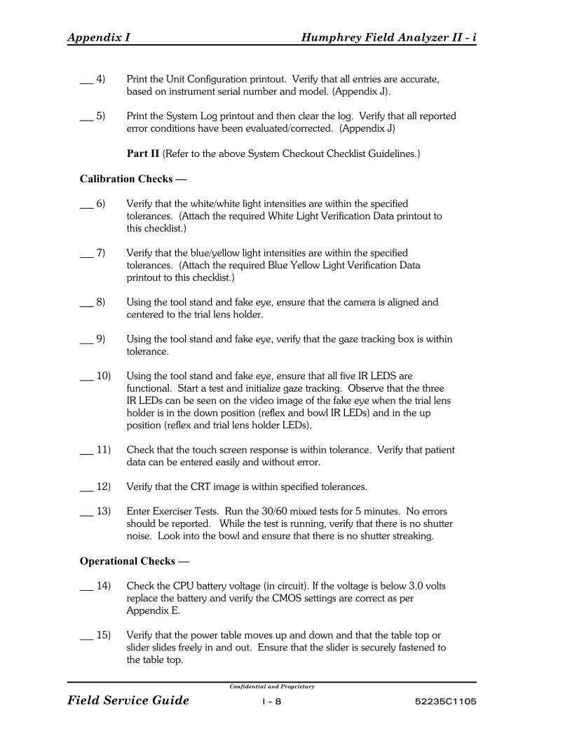
Appendix I Humphrey Field Analyzer II - i
Confidential and Proprietary
Field Service Guide I - 8 52235C1105
4) Print the Unit Configuration printout. Verify that all entries are accurate,based on instrument serial number and model. (Appendix J).
5) Print the System Log printout and then clear the log. Verify that all reported error conditions have been evaluated/corrected. (Appendix J)
Part II (Refer to the above System Checkout Checklist Guidelines.)
Calibration Checks —
6) Verify that the white/white light intensities are within the specifiedtolerances. (Attach the required White Light Verification Data printout tothis checklist.)
7) Verify that the blue/yellow light intensities are within the specifiedtolerances. (Attach the required Blue Yellow Light Verification Dataprintout to this checklist.)
8) Using the tool stand and fake eye, ensure that the camera is aligned andcentered to the trial lens holder.
9) Using the tool stand and fake eye, verify that the gaze tracking box is withintolerance.
10) Using the tool stand and fake eye, ensure that all five IR LEDS arefunctional. Start a test and initialize gaze tracking. Observe that the threeIR LEDs can be seen on the video image of the fake eye when the trial lensholder is in the down position (reflex and bowl IR LEDs) and in the upposition (reflex and trial lens holder LEDs).
11) Check that the touch screen response is within tolerance. Verify that patientdata can be entered easily and without error.
12) Verify that the CRT image is within specified tolerances.
13) Enter Exerciser Tests. Run the 30/60 mixed tests for 5 minutes. No errorsshould be reported. While the test is running, verify that there is no shutternoise. Look into the bowl and ensure that there is no shutter streaking.
Operational Checks —
14) Check the CPU battery voltage (in circuit). If the voltage is below 3.0 voltsreplace the battery and verify the CMOS settings are correct as perAppendix E.
15) Verify that the power table moves up and down and that the table top orslider slides freely in and out. Ensure that the slider is securely fastened tothe table top.
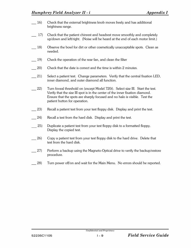
Humphrey Field Analyzer II - i Appendix I
Confidential and Proprietary
52235C1105 I - 9 Field Service Guide
16) Check that the external brightness knob moves freely and has additionalbrightness range.
17) Check that the patient chinrest and headrest move smoothly and completelyup/down and left/right. (Noise will be heard at the end of each motor limit.)
18) Observe the bowl for dirt or other cosmetically unacceptable spots. Clean asneeded.
19) Check the operation of the rear fan, and clean the filter
20) Check that the date is correct and the time is within 2 minutes.
21) Select a patient test. Change parameters. Verify that the central fixation LED,inner diamond, and outer diamond all function.
22) Turn foveal threshold on (except Model 720i). Select size III. Start the test. Verify that the size III spot is in the center of the inner fixation diamond. Ensure that the spots are sharply focused and no halo is visible. Test thepatient button for operation.
23) Recall a patient test from your test floppy disk. Display and print the test.
24) Recall a test from the hard disk. Display and print the test.
___ 25) Duplicate a patient test from your test floppy disk to a formatted floppy. Display the copied test.
26) Copy a patient test from your test floppy disk to the hard drive. Delete thattest from the hard disk.
27) Perform a backup using the Magneto-Optical drive to verify the backup/restoreprocedure.
28) Turn power off/on and wait for the Main Menu. No errors should be reported.

Appendix I Humphrey Field Analyzer II - i
Confidential and Proprietary
Field Service Guide I - 10 52235C1105
(This page left intentionally blank)
Humphrey Field Analyzer II - i Appendix J
Confidential and Proprietary
52235C1105 J - 1 Field Service Guide
Appendix J. System Screens and Logs
Contents:
C Unit Configuration ScreenC System Log
The HFA II - i system software contains several screens and logs which can be used todetermine system configuration, or may be used as troubleshooting aids. The descriptionsgiven below assume that the system is fully operational. In certain instances, some or all ofthe screens or logs may not be obtainable due to instrument malfunction.
NOTE: 1. Example screens and logs will vary based on the HFA II - i model and currently
installed software, or the software being installed. 2. Further discussion of some of the items mentioned in this Appendix can be found
elsewhere in this manual. In particular, software revision level information can alwaysbe found in the service bulletins.
J.1 Boot Screen
Unlike the boot screen on the HFA II, unit configuration related information is not availableon the boot screen of the HFA II - i. The information found on the HFA II boot screen willbe found on the unit configuration screen commonly called the “i” screen of the HFA II - i. Also different from the HFA II is the fact that the HFA II - i does not report system errors witha set of audio beeping patterns. Refer to the Troubleshooting section in this manual foradditional information.
J.2 Unit Configuration Screen
The HFA II - i Unit Configuration Screen provides system configuration data and systemsoftware information. This screen can always be accessed from the main menu of theinstrument, and from some, but not all, other menus. Once accessed, it can also be printed. The screen provides such data as instrument serial number, software revision levels, andwhat hardware or software options have been enabled or disabled on the instrument.
To access the Unit Configuration Screen, perform the following:
C From the instrument’s Main Menu, select the “i” button at the top left.
C After a short delay, a screen similar to the one shown below will be displayed on theCRT.
C If desired, the screen may be printed by selecting Print.
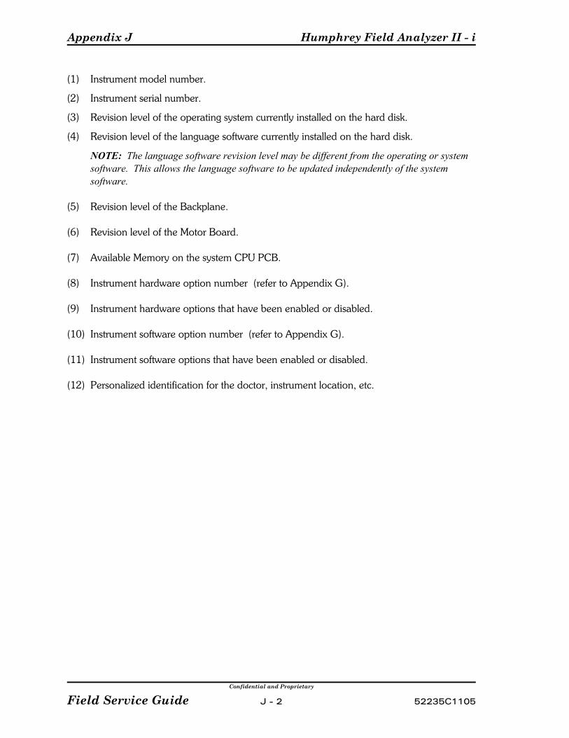
Appendix J Humphrey Field Analyzer II - i
Confidential and Proprietary
Field Service Guide J - 2 52235C1105
(1) Instrument model number.
(2) Instrument serial number.
(3) Revision level of the operating system currently installed on the hard disk.
(4) Revision level of the language software currently installed on the hard disk.
NOTE: The language software revision level may be different from the operating or systemsoftware. This allows the language software to be updated independently of the systemsoftware.
(5) Revision level of the Backplane.
(6) Revision level of the Motor Board.
(7) Available Memory on the system CPU PCB.
(8) Instrument hardware option number (refer to Appendix G).
(9) Instrument hardware options that have been enabled or disabled.
(10) Instrument software option number (refer to Appendix G).
(11) Instrument software options that have been enabled or disabled.
(12) Personalized identification for the doctor, instrument location, etc.
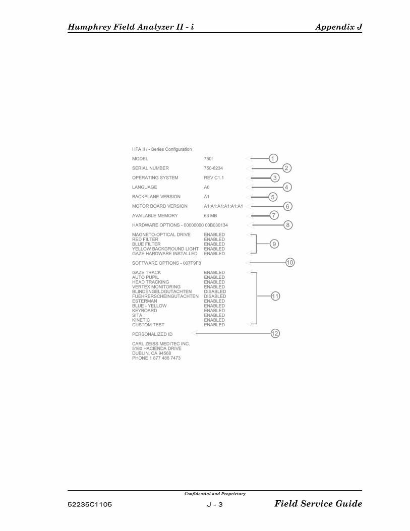
Humphrey Field Analyzer II - i Appendix J
Confidential and Proprietary
52235C1105 J - 3 Field Service Guide

Appendix J Humphrey Field Analyzer II - i
Confidential and Proprietary
Field Service Guide J - 4 52235C1105
J.3 System Log
The principle role of the System Log is to attempt to keep track of all the ‘events’ that occurwithin the instrument. For example, an event can be a system restart (switching theinstrument power to ON), recording an error code, showing the results of an attempt torebuild the hard disk database, or the installation of a new revision of software, just to namea few. The date and time when each event occurred appears prior to each logged event. Note that there will be instances when an event cannot be logged because of an instrumentmalfunction. The log also contains the serial number of the instrument and the hardwareoption number (see Appendix G).
The log, which is stored on the hard disk, is a circular disk file containing up to 1000 entries(about 18, 8½ x 11" pages). The 1001st entry will write over the first entry in the log file. The most recent event will be recorded as the last entry in the log unless there are currently1000 entries.
The instrument operator can print out the log. The service engineer can print out and clear(erase) the log. As part of a service call, after printing out and retaining the log, the currentlog entries may be cleared as described below. Obviously, if there is a malfunction with thehard drive, the log cannot be printed out or cleared.
When possible, the System Log should always be printed out when troubleshooting aninstrument problem. It can often provide valuable ‘clues’ when attempting to solve aninstrument malfunction. If obtainable, the log printout should always be included with anypaperwork returned as part of a field service instrument repair.
To print out the log, perform the following:
1) From the Main Menu, select System Setup.
2) Select Print System Log.
3) After a short delay, the System Log will automatically print to the selected printer. Thelog cannot be displayed on the CRT.
To print out or clear the log, perform the following:
1) From the Main Menu, select System Setup.
2) Select Additional Setup.
3) Select Diagnostics.
4) When the ten key pad appears, enter the calibration password.
5) Select System Log.
6) Select Print System Log and, if necessary, Clear System Log.
Humphrey Field Analyzer II - i Appendix K
Confidential and Proprietary
52235C1105 K - 1 Field Service Guide
Appendix K. Data Loss Recovery
Contents:
C Data Loss Prevention TipsC Database StructureC The Five “R’s” of Database RecoveryC Database UtilitiesC Floppy Diskette - Troubleshooting DialogueC Hard Disk - Troubleshooting DialogueC Magnetic Optical DriveC “Repair Backup” (repairs files on hard disk, enabling backup to be performed.)
K.1 Data Loss Prevention Tips
There may be situations, due either to operator misunderstanding or instrumentmalfunction, when the patient database or backup becomes corrupted or is reported asinaccessible. Prior to completing any data loss related service call, always take the time to discuss thefollowing data loss prevention tips with your customer.
C Ensure that your customer understands the importance of routinely backing up theirpatient data files. At minimum, this should include a copy of each floppy disketteand at least one magnetic optical disk. In fact, it is recommended that two magneticoptical disks are used and rotated every other backup. Consult the User’s Manualfor recommendations on the frequency of backup.
C Stress the importance of proper handling and storage of floppy diskettes andmagnetic optical disks. Make certain that tapes are stored at least five feet away fromany magnetic field. This includes not storing the diskettes on the top surface of theHFA II.
C Verify that only high-quality, double-sided, high-density floppy preformatteddiskettes are used. Only DOS preformatted floppy diskettes will operate in the HFAII. A preformatted diskette can be reformatted on the HFA II.
C Make certain that the customer understands that they should not remove a floppydiskette or magnetic optical disk from the drive during a read or write operation. Point out the floppy drive icon in the upper right of the CRT display. Ensure thatthey observe this icon and only remove the diskette at the appropriate time.
C If frequent data loss occurs, verify the power source that the HFA II is connected tomeets instrument operational requirements. A fluctuating line voltage can causedatabase related problems. Use of an uninterruptible power supply or UPS may helpprevent data loss. Operational and UPS requirements are discussed in Section 1.
Appendix K Humphrey Field Analyzer II - i
Confidential and Proprietary
Field Service Guide K - 2 52235C1105
C Explain the difference between a file that has been copied and one that was backedup using the Backup/Restore function in the disk menu. A copied file is one that wasstored to the floppy drive after completion of a test, one which was copied orduplicated using the Copy or Duplicate Test functions in the File Functions Menu. The copied file can be placed onto the floppy drive and recalled for viewing on theCRT. A file that was backed up using the Backup/Restore function cannot beaccessed and viewed on the CRT. This concept is often a source of confusion.
K.2 Database Structure
Two identical patient databases coexist on the hard disk drive. The Primary or principledatabase, and the Secondary database which is a duplicate of the Primary.
The Primary database is the principle database. That is, when a test is saved to the harddisk drive, it is first saved to the Primary database and then saved to the Secondarydatabase. When a test is recalled from the hard disk drive, it is only recalled from thePrimary database. The Secondary database functions are transparent to the customer.
K.3 The Five “R’s” of Database Recovery
There are five basic steps to consider when attempting to correct a database problem:
Reboot............Recover............Reconstruct............Rebuild............Restore
# Reboot
If the patient database cannot be accessed, Rebooting or turning the power off-on maycorrect the problem. This is often the simplest step to try. The instrument will attempt arecovery if either (but not both) of the databases fails to verify or if recovery was deferred(floppy only) prior to shut down. Rebooting or cycling power will also cause theinstrument to present the operator with the on-screen message to recover or make theinstrument a floppy-only system.
# Recover
The Recover option is very much like performing a restore from magnetic optical disk. This option is selectable only when a problem with the Primary database has beendetected. If a problem occurs within the Primary database, the operator will receive anon-screen message to either attempt to recover the database (Fix Now) or temporarilymake the instrument a floppy-only system. If recovery is selected, the software will attemptto copy the Secondary database over the corrupted Primary database. If successful, thedatabase has been recovered. If unsuccessful, then the hard disk database is disabled andthe instrument can only be operated with a floppy disk database until it is repaired. Thedoctor can also defer recovery until the end of the day or automatically on boot the nextday. This will allow the doctor to continue using the instrument so that he/she can test thepatients in the waiting room.

Humphrey Field Analyzer II - i Appendix K
Confidential and Proprietary
52235C1105 K - 3 Field Service Guide
The floppy-only option will allow the instrument to save only to the floppy disk drive. Thisenables the operator to continue to save patient exams until a service technician can repairthe hard disk drive problem. The floppy-only option would normally be selected if theRecover option has failed, the user has just completed a test and immediately needs tosave it to disk, or does not currently have the time to wait for the Recover option tocomplete.
# Reconstruct (or “Cleanup” on Additional Setup)
The hard disk Reconstruct option is described in Appendix K.4, Database Utilities.
# Rebuild
The hard disk Rebuild option is described in Appendix K. 4, Database Utilities.
# Restore
The restore option is often the last step taken in database recovery. Either the magneticoptical disk or the floppy backup is restored to the hard disk.
K.4 Database Utilities
In the event of a patient database problem, there are a number of software featuresdesigned to protect the integrity of the patient database. These utilities, described below,can be accessed and activated via the calibration portion of the software. Refer to Section4 for access details.
The Database option provides six primary utilities which can be used to either rebuild,reconstruct or delete the patient database. Refer to Section 9 (Database Management) inthe Humphrey Field Analyzer II - i User’s Guide.
K.4.1 Rebuild Hard Disk Database
This utility attempts to rebuild the corrupted index files and reconstruct the checksums thatmay exist on the hard disk. Selection opens a pop-up window warning the user thatrebuilding may take a very long time. The options to continue (OK) or Cancel areprovided. This can be a lengthy process depending on the number of files on the harddisk drive. This option is also available to the user via the System Setup, and AdditionalSystem Setup menu selections. The rebuild function will first attempt a simple recovery ifit detects a database failure. If recovery succeeds, rebuild is done. Otherwise, it startsrebuild. If rebuild fails but the primary database can be opened then a reconstruct isautomatically attempted.
NOTE: When rebuild of the primary database succeeds either the first attempt or aftersubsequent reconstruction the primary database is copied to the secondary database. Thecustomer will see “Ensuring Database Integrity.....” along with a progress bar.

Appendix K Humphrey Field Analyzer II - i
Confidential and Proprietary
Field Service Guide K - 4 52235C1105
K.4.2 Rebuild Floppy Database
This utility attempts to rebuild any corrupt files that may exist on the floppy diskette. Selection opens a pop-up window asking the user if they wish to continue. The options tocontinue (OK) or Cancel are provided. This option is also available to the user via theSystem Setup, and Additional System Setup menu selections.
K.4.3 Delete Hard Disk Database
This utility will delete the entire patient database. All other files on the hard disk will notbe affected. Selection opens a pop-up window informing the user that the entire databasewill be deleted. The options to continue (OK) or Cancel are provided.
K.4.4 Delete Temporary Database
This utility deletes any temporary database copies that reside on the hard disk. Selectionwill begin the deletion process. There is no option to cancel.
K.4.5 Reconstruct Database
The reconstruct utility is very similar to copying the hard disk database to floppy disks,deleting the hard disk database and then copying the floppy disks back to the hard drive. (The copy process differs from the restore process in that the copies only contain thepatient data and not the hard disk File Allocation Table, which is more susceptible tocorruption.) When reconstruct is selected, the Primary database is copied into atemporary location on the hard disk drive rather than the floppy disks. The Primarydatabase at the original location is then deleted, and the Primary database at thetemporary location is renamed (moved) back to the original Primary location. The“Cleanup Hard Disk Database” utility will remove any patients that have no tests. Theseoptions are also available to the user via the System Setup, and Additional System Setupmenu selections.
K.4.6 Secondary Database Utilities
Selecting this option provides nine more database utilities. Each utility is described below.
C Compare Database Sizes
This function does a file by file byte level comparison of both the Primary and Secondarydatabases to verify that they are of the same size. This is a quick test that performs a countof the number of files in each database. Under normal system conditions, the twodatabases should always be equal. If they are not, the recovery option should beperformed.
C Verify Primary Database/Verify Secondary Database

Humphrey Field Analyzer II - i Appendix K
Confidential and Proprietary
52235C1105 K - 5 Field Service Guide
Checks to see that the database can be opened. Each database is verified independently.Copy Primary to Secondary/Copy Secondary to Primary
Once it has been determined that either the Primary or Secondary database has aproblem, this utility allows the service technician to copy the good database over theproblem database.
NOTE: This is what happens during recovery. It is better to first select Rebuild if youknow there is a failure. Rebuild will try to recover if there is a problem. These copycommands are low level equivalents to what happens automatically.
C Primary Read Test/Secondary Read Test
Sometimes a database will open (verify) but will fail a read test. This utility checks eachrecord in the database. Depending on the number of files on the hard disk, this may be avery time consuming test. Each database is read independently.
C Delete Primary Database/Delete Secondary Database
Once it has been determined that either the Primary or the Secondary database has aproblem, this utility allows the service engineer to delete the problem database.
K.5 Floppy Diskette - Troubleshooting Dialogue
If the floppy diskette database is corrupted or inaccessible, the customer will usually reportthe following on-screen error message: “Floppy Disk Database is Not Accessible - Retry,Rebuild, or Cancel” or similar error message.
Check/Perform the Following:
C Is the diskette IBM formatted?C Does the customer have a backup copy?C Is this the only diskette that has a problem or are there others? If all diskettes have
problems, there may be a problem within the floppy subsystem (floppy drive, floppycabling, and/or floppy disk controller on the CPU PCB). Refer to Section 5 fordiagnostic troubleshooting procedures.
C Ensure that the file(s) on the diskette is a copied file and not one that was created aspart of a backup using the Backup/Restore function.
C Check the diskette; is it damaged in any way? Is the diskette label applied properly,or does it cover a portion of the read access door?
C Check the System Log for database-related errors. The floppy database will beindicated as device 3.0. In general, errors like 7000c, 230001, f00de or similar errorsare associated with the floppy drive patient database.
C Attempt a rebuild. From the Main Menu, select System Setup, Additional Setup, andthen Rebuild Floppy Disk Database. This process will attempt to repair the damage. A rebuild can also be executed within Calibration. Refer to Section 4 for details.

Appendix K Humphrey Field Analyzer II - i
Confidential and Proprietary
Field Service Guide K - 6 52235C1105
C If the rebuild fails, try viewing the diskette on a PC. Proceed to the “A” drive andattempt to look at the directory. You cannot view individual patient files, but shouldbe able to see the directory. The directory will consist of files like PATS.DAT,PATS.IDX, PDB.DAT,RXS.DAT, etc. If the diskette is part of a backup that was made using theBackup/Restore function you will only see BACKUP.PDB
C If the directory cannot be seen or looks damaged, try executing scan disk on the PC. It has been reported that this may partially repair a corrupted floppy.
C If all of the above has failed and there is not a duplicate of the diskette, contactTechnical Support for additional assistance. Also, advise your customer to formatand begin using a new diskette.
K.6 Hard Disk Drive - Troubleshooting Dialogue
The following dialogue is intended to assist you in solving database related problems. Thisis only one approach; each situation is unique. Ultimately, it is the service engineer’schoice to determine which utilities should be used and which approach should be taken. The dialogue utilizes the “5 Rs” of database recovery (Appendix K.3).
If the hard disk drive database is corrupted or inaccessible, the customer will usually reportthe following on-screen error message: “Hard Disk Database is Not Accessible - Would YouLike to Recover?” or “A hard drive database failure has occurred. You can only use a floppydisk until the hard disk drive database is repaired.”
Check/Perform the following:
C Does the customer have a backup? This can either be copies, a backup made usingthe Backup/Restore function, or a magnetic optical disk.
C Check the System Log for database-related errors. The hard drive database will beindicated as device 4.2. In general, errors like “hard drive error” or similar errors areassociated with the hard drive patient database and/or the hard drive subsystem(hard disk drive, hard drive cabling, and/or the controller on the CPU PCB). Refer toSection 5 for hardware/diagnostic troubleshooting procedures.
C If a floppy diskette is inserted in the floppy drive, remove it and turn the instrumentpower Off/On (Reboot). Then make a second attempt to view the hard diskdatabase. Sometimes a problem with the floppy diskette may be indicated as aproblem with the hard disk drive or database.
C Was the option to Recover attempted? If not, attempt to recover the database. Therecover option will normally be displayed either after the reboot or if you attempt toaccess the database. Select the “Fix Now” button in the Fix Now/Floppy Onlyalert.
C If the recover option fails, proceed to the Diagnostics/Calibration Menu and select theReconstruct database option. The Reconstruct utility can only be attempted if thedatabase can be opened. If it cannot then use Rebuild to performrebuild/reconstruct.
C If reconstruct fails, attempt a hard disk Rebuild if the database can be opened.C If the rebuild fails, and the customer DOES NOT have a backup of their database
available, replace the hard disk drive with a new drive. Contact the Technical
Humphrey Field Analyzer II - i Appendix K
Confidential and Proprietary
52235C1105 K - 7 Field Service Guide
Support Department and arrange to have the old drive returned. There may be apossibility that the data can be recovered.
C If the customer DOES have a backup available, choose the Restore utility. This willdelete only the database from the hard disk. Once deleted, the Restore utility willcontinue to automatically restore the database, and check to see that all files havebeen restored and can be accessed (viewed and printed). Run at least onesimulation test to ensure that the hard disk drive can also be written to as well.
C If the restore of the database does not correct the problem, attempt to initialize thehard disk drive (refer to Appendix L). Once initialization is complete, restore thedatabase (and other customer set-ups — printer type, personalized ID, etc.) from aconfiguration backup floppy.
C If the initialization fails, it is likely to be a problem with the hard drive subsystem(hard disk drive, hard drive cabling, and/or the controller on the CPU PCB). Refer toSection 5 for hardware/diagnostic troubleshooting procedures.
C Once restore is complete, check to see that all test/patient files have been restoredand can be accessed (viewed and printed). Run at least one simulation test to ensurethat the hard disk drive can be written to.
K.7 Magnetic Optical Disks
If magnetic optical disk cannot be restored, the customer will usually report the followingon-screen error message: “Backup Fails,” “Disk is Write Protected,” ” Insert a Disk with acapacity of at least nnnn,” “Your Database is Too Large to Fit on the Current Disk,”“Format Fails,” “Failure in Verification Phase I,” and “Failure in Verification Phase II.”
Check/Perform the Following:
WARNING: Performing a Restore will write over any filesthat currently reside on the hard disk drive. Ensure that youhave copied (use the Copy function) any files currently on thehard disk on to a floppy diskette prior to performing therestore operation. If the “Replace” option vs the “Merge”option has been selected, option dialogue does not appear if adatabase failure has been detected.
C Does the customer have more than one backup magnetic optical disk? If so, trybacking up to the other magnetic optical disk or to a new magnetic optical disk.
C If the magnetic optical disk is new, try initializing it via the File Functions Menu.C Contact the Technical Support Department and arrange to have the magnetic optical
disk returned. There may be a possibility that the data can be recovered.C Check the System Log for the above mentioned error types. There may be a
problem with the magnetic optical disk subsystem (magnetic optical disk drive,magnetic optical disk cabling, or the controller on the CPU PCB). Refer to Section 5for diagnostic troubleshooting procedures.

Appendix K Humphrey Field Analyzer II - i
Confidential and Proprietary
Field Service Guide K - 8 52235C1105
(This page left intentionally blank)
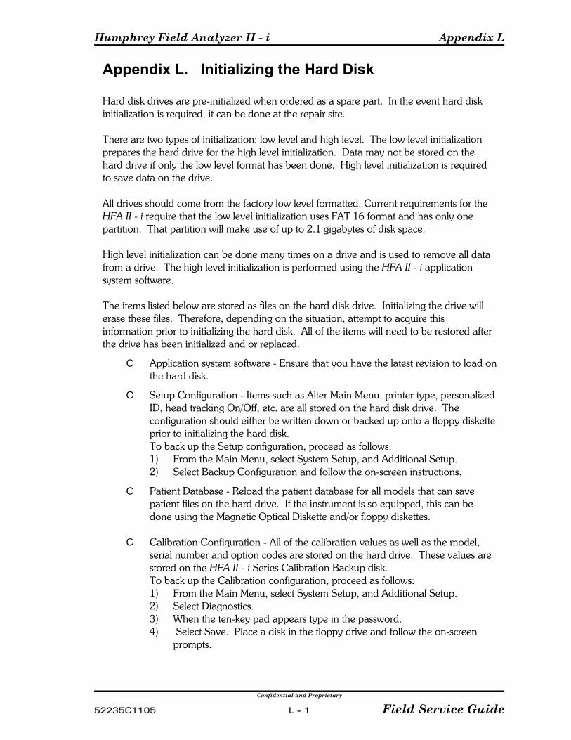
Humphrey Field Analyzer II - i Appendix L
Confidential and Proprietary
52235C1105 L - 1 Field Service Guide
Appendix L. Initializing the Hard Disk
Hard disk drives are pre-initialized when ordered as a spare part. In the event hard diskinitialization is required, it can be done at the repair site.
There are two types of initialization: low level and high level. The low level initializationprepares the hard drive for the high level initialization. Data may not be stored on thehard drive if only the low level format has been done. High level initialization is requiredto save data on the drive.
All drives should come from the factory low level formatted. Current requirements for theHFA II - i require that the low level initialization uses FAT 16 format and has only onepartition. That partition will make use of up to 2.1 gigabytes of disk space.
High level initialization can be done many times on a drive and is used to remove all datafrom a drive. The high level initialization is performed using the HFA II - i applicationsystem software.
The items listed below are stored as files on the hard disk drive. Initializing the drive willerase these files. Therefore, depending on the situation, attempt to acquire thisinformation prior to initializing the hard disk. All of the items will need to be restored afterthe drive has been initialized and or replaced.
C Application system software - Ensure that you have the latest revision to load onthe hard disk.
C Setup Configuration - Items such as Alter Main Menu, printer type, personalizedID, head tracking On/Off, etc. are all stored on the hard disk drive. Theconfiguration should either be written down or backed up onto a floppy disketteprior to initializing the hard disk.To back up the Setup configuration, proceed as follows:1) From the Main Menu, select System Setup, and Additional Setup.2) Select Backup Configuration and follow the on-screen instructions.
C Patient Database - Reload the patient database for all models that can savepatient files on the hard drive. If the instrument is so equipped, this can bedone using the Magnetic Optical Diskette and/or floppy diskettes.
C Calibration Configuration - All of the calibration values as well as the model,serial number and option codes are stored on the hard drive. These values arestored on the HFA II - i Series Calibration Backup disk. To back up the Calibration configuration, proceed as follows:1) From the Main Menu, select System Setup, and Additional Setup.2) Select Diagnostics. 3) When the ten-key pad appears type in the password.4) Select Save. Place a disk in the floppy drive and follow the on-screen
prompts.
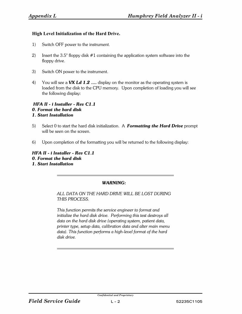
Appendix L Humphrey Field Analyzer II - i
Confidential and Proprietary
Field Service Guide L - 2 52235C1105
High Level Initialization of the Hard Drive.
1) Switch OFF power to the instrument.
2) Insert the 3.5" floppy disk #1 containing the application system software into thefloppy drive.
3) Switch ON power to the instrument.
4) You will see a VX Ld 1.2 .... display on the monitor as the operating system isloaded from the disk to the CPU memory. Upon completion of loading you will seethe following display:
HFA II - i Installer - Rev C1.10. Format the hard disk1. Start Installation
5) Select 0 to start the hard disk initialization. A Formatting the Hard Drive promptwill be seen on the screen.
6) Upon completion of the formatting you will be returned to the following display:
HFA II - i Installer - Rev C1.10. Format the hard disk1. Start Installation
WARNING:
ALL DATA ON THE HARD DRIVE WILL BE LOST DURINGTHIS PROCESS.
This function permits the service engineer to format andinitialize the hard disk drive. Performing this test destroys alldata on the hard disk drive (operating system, patient data,printer type, setup data, calibration data and alter main menudata). This function performs a high-level format of the harddisk drive.
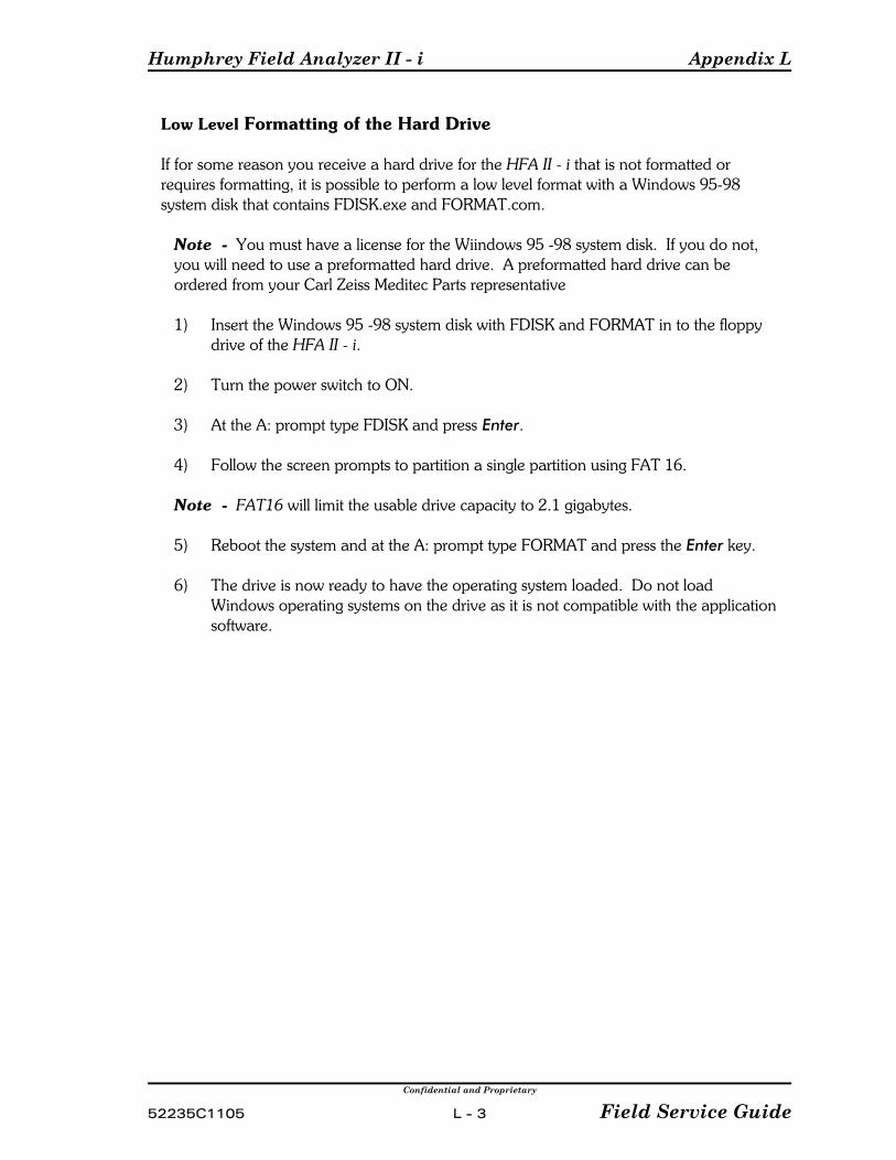
Humphrey Field Analyzer II - i Appendix L
Confidential and Proprietary
52235C1105 L - 3 Field Service Guide
Low Level Formatting of the Hard Drive
If for some reason you receive a hard drive for the HFA II - i that is not formatted orrequires formatting, it is possible to perform a low level format with a Windows 95-98system disk that contains FDISK.exe and FORMAT.com.
Note You must have a license for the Wiindows 95 -98 system disk. If you do not,you will need to use a preformatted hard drive. A preformatted hard drive can beordered from your Carl Zeiss Meditec Parts representative
1) Insert the Windows 95 -98 system disk with FDISK and FORMAT in to the floppydrive of the HFA II - i.
2) Turn the power switch to ON.
3) At the A: prompt type FDISK and press Enter.
4) Follow the screen prompts to partition a single partition using FAT 16.
Note FAT16 will limit the usable drive capacity to 2.1 gigabytes.
5) Reboot the system and at the A: prompt type FORMAT and press the Enter key.
6) The drive is now ready to have the operating system loaded. Do not loadWindows operating systems on the drive as it is not compatible with the applicationsoftware.

Appendix L Humphrey Field Analyzer II - i
Confidential and Proprietary
Field Service Guide L - 4 52235C1105
(This page left intentionally blank)

Humphrey Field Analyzer II - i Appendix M
Confidential and Proprietary
52235C1105 M - 1 Field Service Guide
Appendix M. Loading Application Software
Customer-installable software updates are supplied to the customer on floppy disks. Currently, the software consists of four diskettes. These four diskettes are referred to asthe application system software, or simply the system software.
The system software consists of several other different software revisions, all of which(except the installation software) get loaded into the instrument during the softwareinstallation process. The system software consists of the following:
C Installation softwareC Operating system software — loads onto the hard disk driveC Language software — loads onto the hard disk driveC CPU (boot) software — loads onto the hard disk driveC Motor Driver software — loads into the flash IC on the Motor Driver PCB
To view the revision levels of each software, refer to Appendix J, System Screens andLogs.
In service situations where the hard disk is being replaced, or the service engineersuspects possible corruption of the system software on the hard disk, the system softwarecan be reloaded onto the hard disk using the latest system software floppy disks.
Loading System Software:
1) Switch the instrument power to OFF .
2) Insert the 3.5" HFA II - i Series System Software floppy diskette labeled #1 into thefloppy disk drive. The current software requires four diskettes. Future softwareversions may require more.
3) Switch the instrument power ON and you will soon see a VX Ld 1.2 .... display onthe monitor as the operating system is loaded from the disk to the CPU memory. When complete, you will see the following display:
HFA II - i Installer - Rev C1.10. Format the hard disk1. Start Installation
4) Select 1 to start the hard disk initialization. A Copying Files prompt will be seenon the screen.
5) When the disk files are loaded you will see a Please Insert Disk # 2 and pressany key dialogue displayed.
6) Remove disk # 1 and insert disk # 2. Press any key on the keyboard.

Appendix M Humphrey Field Analyzer II - i
Confidential and Proprietary
Field Service Guide M - 2 52235C1105
7) A Verifying Copy Disk and then Copying Files prompt will again be seenon the screen.
8) When the disk files are loaded you will see a Please Insert Disk # 3 and pressany key message displayed.
9) Remove disk # 2 and insert disk # 3. Press any key on the keyboard.
10) A Verifying Copy Disk and then Copying Files prompt will again be seen onthe screen.
11) When the disk files are loaded you will see a Please Insert Disk # 4 and pressany key message displayed.
12) Remove disk # 3 and insert disk # 4. Press any key on the keyboard.
13) A Verifying Copy Disk and then Copying Files prompt will again be seen onthe screen.
14) When the fourth disk files have been loaded you will see Completed copyingfiles, remove floppy and cycle power to complete installation on thedisplay.
15) Remove disk # 4 and turn the unit power to OFF.
16) Wait fifteen seconds and turn the unit power to ON.
17) Soon a Completing the installation of HFA II - i 51220.rev C1.1 52037.A1Existing installed product HFA II- i XXXXX.revNN XXXXX.NN Installdate MM-DD-YYYY display will be seen. This indicates the application coderevision and the motor driver board code revision respectively of the newlyinstalled software as well as the application code revision and the motor driverboard code revision of the previously loaded software. The XXXXX is the partnumber of the software, NN is the revision number, and MM-DD-YYYY is month,day and year that the previous software was loaded.
18) A progress meter will be displayed and will climb to the 100 % . You will hearthree beeps during the load process indicating that the software is loading correctly.
19) When the load is completed an Installation successful, cycle power to beginusing the installed software dialogue will replace the progress meter.
20) Turn the instrument power to OFF. Wait fifteen seconds and then turn theinstrument power to ON.

Humphrey Field Analyzer II - i Appendix M
Confidential and Proprietary
52235C1105 M - 3 Field Service Guide
21) When the instrument powers up to the main menu, select the ”i” button from thetop of the main menu. Verify that the correct revision of software has been loaded. The software revision level can be viewed opposite the “Operating System” listing.
22) The installation is now completed.
NOTES: If the system software was loaded on a newly initialized drive, you willencounter a number of system errors and messages before the main menu is displayed. One of the messages will indicate that a new patient database will be created.
If the software was loaded on a newly initialized drive you will need to restore thecalibration configuration, unit configuration, patient database and any softwareoptions that were on the unit prior to the initialization. See section 4.8 for instructionson restoring the calibration configuration.

Appendix M Humphrey Field Analyzer II - i
Confidential and Proprietary
Field Service Guide M - 4 52235C1105
(This page left intentionally blank)

Humphrey Field Analyzer II - i Appendix N
Confidential and Proprietary
2235C1105 N - 1 Field Service Guide
Appendix N. Special Software Options
Designed into the software are options that can only be enabled using a particularpassword. One such feature is the Ocular Hypertension Treatment Study or OHTSsoftware. The password for OHTS can be obtained from the Technical SupportDepartment. Once the password has been obtained, perform the following steps toenable OHTS:
1) From the Main Menu, select System Setup.2) Select Additional Setup and then select Diagnostics.3) When the ten key pad appears, type in the specified password and select [Enter].4) Select OHTS Option to ON.5) The instrument is now enabled for the OHTS feature.
Currently, OHTS is the only software feature that may need to be enabled at a customersite. As other specialized options become available, they will be announced in a servicebulletin.

Appendix N Humphrey Field Analyzer II - i
Confidential and Proprietary
Field Service Guide N - 2 52235C1105
(This page left intentionally blank)

Humphrey Field Analyzer II - i Appendix O
Confidential and Proprietary
52235C1105 O - 1 Field Service Guide
Appendix O. Upgrades
At this time the following upgrades are authorized for the HFA II - i:
Magneto Optical Drive Upgrade (P/N 52969) - The Magneto Optical Upgrade wascreated to provide an efficient backup method for the 720i, 740i, and 745i HFA II - imodels. Details as to the required parts, installation, and calibration procedures for thisupgrade are provided in a service bulletin.
Kinetic Software Upgrade (P/N 53311) - The Enhanced Kinetic software program isnow available for customers with HFA II- i models 740i, and 745i. The upgrade willinclude the enhanced kinetic program, custom kinetic and the SSA disability test. Thisupgrade is customer installable.
NOTE: All field upgrades (both domestic and international) MUST be reported to CarlZeiss Meditec. If an upgrade is performed without the knowledge of Carl Zeiss Meditec,a future release of software (when loaded on the upgraded HFA II - i) will disable theunauthorized upgrade.

Appendix O Humphrey Field Analyzer II - i
Confidential and Proprietary
Field Service Guide O - 2 52235C1105
(This page left intentionally blank)
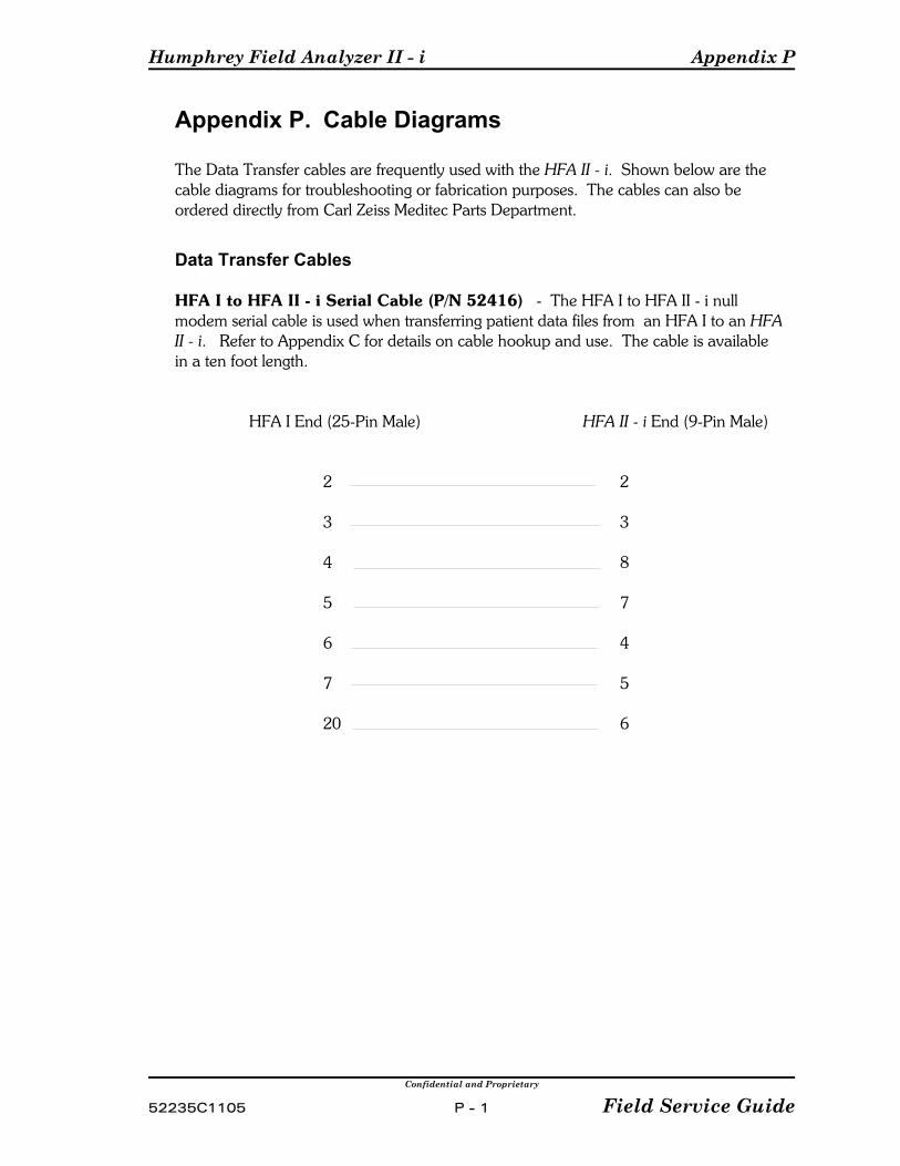
Humphrey Field Analyzer II - i Appendix P
Confidential and Proprietary
52235C1105 P - 1 Field Service Guide
Appendix P. Cable Diagrams
The Data Transfer cables are frequently used with the HFA II - i. Shown below are thecable diagrams for troubleshooting or fabrication purposes. The cables can also beordered directly from Carl Zeiss Meditec Parts Department.
Data Transfer Cables
HFA I to HFA II - i Serial Cable (P/N 52416) - The HFA I to HFA II - i nullmodem serial cable is used when transferring patient data files from an HFA I to an HFAII - i. Refer to Appendix C for details on cable hookup and use. The cable is availablein a ten foot length.
HFA I End (25-Pin Male) HFA II - i End (9-Pin Male)
2 2
3 3
4 8
5 7
6 4
7 5
20 6
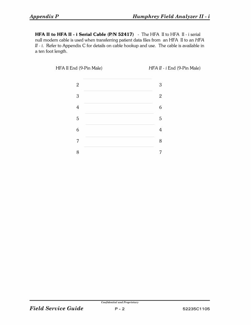
Appendix P Humphrey Field Analyzer II - i
Confidential and Proprietary
Field Service Guide P - 2 52235C1105
HFA II to HFA II - i Serial Cable (P/N 52417) - The HFA II to HFA II - i serialnull modem cable is used when transferring patient data files from an HFA II to an HFA II - i. Refer to Appendix C for details on cable hookup and use. The cable is available ina ten foot length.
HFA II End (9-Pin Male) HFA II - i End (9-Pin Male)
2 3
3 2
4 6
5 5
6 4
7 8
8 7

Humphrey Field Analyzer II - i Appendix Q
Confidential and Proprietary
52235C1105 Q- 1 Field Service Guide
Appendix Q. Cleaning Optics
Cleaning Do's and Don't's
Do – Use real cotton Q-tips (lens tissue can also be used)– Always wet the Q-tip or lens tissue in the cleaning agent before cleaning– Use reagent grade acetone whenever possible (isopropyl alcohol may also be
used).
Don't – Do Not use acetone or alcohol to clean the film wedge. Use onlycompressed air or a camel hair negative brush.
NOTE: Care should be taken when using compressed air as it may occasionallydeposit moisture on the targeted surface.
Assemblies that may be Cleaned
Assemblies that may be cleaned are listed below. Those marked with an asterisk (*) willrequire some recalibration after cleaning. Refer to Table 3-1 in Section 3 for guidelines. Assume that a newly cleaned assembly is the same as one that has just been replaced.
(Refer to the projection path diagram in Section 6 for assembly identification.)
Condenser lens* Glass wedge* Film wedge (see above note on cleaning)* Color wheel Upper lens First projection mirror Second projection mirror Third projection mirror Lower lens* Brightness detector
Blue filter (glass)
WARNING: Damage will occur to the Green Filter if cleanedwith acetone.

Humphrey Field Analyzer II - i Appendix Q
Confidential and Proprietary
Field Service Guide Q - 2 52235C1105
(This page left intentionally blank)

Humphrey Field Analyzer II - i Appendix R
Confidential and Proprietary
52235C1105 R - 1 Field Service Guide
Appendix R. Optional Software InstallationA customer may be provided or purchase an optional software package. A currentexample of an optional software package is the Kinetic software package for 740i instruments. Other optional software packages may be developed in the future. Theoptional software will be provided on a 3 ½" floppy disk and installed via the floppydrive.The floppy disk will load and enable the instrument to run the optional software. Prior toloading the optional software, you should print the current software options in the “i”screen. After loading the software options you should verify that the options are enabledin the “i”screen. Additionally, you should verify that the options appear in the menusand are functional.
Loading the Software Options
1) Set instrument power to ON.
2) At the Main Menu, select System Setup.
3) Select Additional Setup.
4) Select Install Software.
5) You will see a “Insert an HFA Option Floppy Disk, then Press OK to begininstallation”. Press OK.
6) A dialogue with “ Installing nnn, press OK to continue” will appear. Nnn indicatesthe software option that you are loading. In case of the Kinetic option, the nnn will bereplaced with “ HFA II Kinetic Tests 51123.A1?” Select Continue.
7) “Optional Software Installation in Progress...” dialogue will appear. It will soon bereplaced with “Option software installation successful”. Press OK.
8) Verify that the option is enabled by selecting it and using it.

Appendix R Humphrey Field Analyzer II - i
Confidential and Proprietary
Field Service Guide R - 2 52235C1105
(This page left intentionally blank)

iii PROPRIETARY and CONFIDENTIAL iii
SERVICE
BULLETIN Instrument: General No.: GEN-ID02 Subject: Service Bulletin Index Date: 30 Apr 08
Status: Informational Pages: 2
This bulletin replaces Service Bulletin GEN-ID01
This bulletin indexes all General (GEN) service bulletins issued to date. The bulletins are indexed by bulletin number. The index will be updated periodically. Meanwhile, we recommend that you manually write into the index each new GEN bulletin you receive.
Note - Bulletins that have been issued since the last revision of this index are marked by an asterisk (*).

Page 2 GEN-ID02
INDEX BY NUMBER NUMBER SUBJECT
* GEN-ID02 GEN Service Bulletin Index GEN-001B Format for Service Bulletins * GEN-002G Test Equipment Calibration and Certification * GEN-003Y Technical Support Product Responsibilities GEN-004B General Guidelines for Assembly Level Troubleshooting GEN-005A Use of Static Protection Kit * GEN-006C Improved Antistatic Bags * GEN-007C Calibration Certification for Test Equipment (OBSOLETE)
GEN-008A Bloodborne Pathogens * GEN-009J List of Manuals GEN-010D General Disclaimer Form * GEN-011E Release of Service Manuals on CD
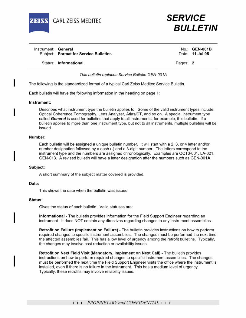
iii PROPRIETARY and CONFIDENTIAL iii
SERVICE BULLETIN Instrument: General No.: GEN-001B Subject: Format for Service Bulletins Date: 11 Jul 05 Status: Informational Pages: 2
This bulletin replaces Service Bulletin GEN-001A The following is the standardized format of a typical Carl Zeiss Meditec Service Bulletin. Each bulletin will have the following information in the heading on page 1: Instrument:
Describes what instrument type the bulletin applies to. Some of the valid instrument types include: Optical Coherence Tomography, Lens Analyzer, Atlas/CT, and so on. A special instrument type called General is used for bulletins that apply to all instruments; for example, this bulletin. If a bulletin applies to more than one instrument type, but not to all instruments, multiple bulletins will be issued.
Number:
Each bulletin will be assigned a unique bulletin number. It will start with a 2, 3, or 4 letter and/or number designation followed by a dash (-) and a 3-digit number. The letters correspond to the instrument type and the numbers are assigned chronologically. Examples are OCT3-001, LA-021, GEN-013. A revised bulletin will have a letter designation after the numbers such as GEN-001A.
Subject:
A short summary of the subject matter covered is provided. Date:
This shows the date when the bulletin was issued. Status:
Gives the status of each bulletin. Valid statuses are:
Informational - The bulletin provides information for the Field Support Engineer regarding an instrument. It does NOT contain any directives regarding changes to any instrument assemblies.
Retrofit on Failure (Implement on Failure) - The bulletin provides instructions on how to perform required changes to specific instrument assemblies. The changes must be performed the next time the affected assemblies fail. This has a low level of urgency among the retrofit bulletins. Typically, the changes may involve cost reduction or availability issues.
Retrofit on Next Field Visit (Mandatory, Implement on Next Call) - The bulletin provides instructions on how to perform required changes to specific instrument assemblies. The changes must be performed the next time the Field Support Engineer visits the office where the instrument is installed, even if there is no failure in the instrument. This has a medium level of urgency. Typically, these retrofits may involve reliability issues.

Page 2 GEN-001B
Retrofit When in the Area (Mandatory, Implement When in the Area) - The bulletin provides instructions on how to perform required changes to specific instrument assemblies. Arrangements must be made by the Field Support Engineer to perform the changes on as many instruments in the area as possible. These retrofits have a high level of urgency. They may involve reliability and clinical issues.
Retrofit as Soon as Possible (Mandatory, Implement Immediately) - The bulletin provides instructions on how to perform required changes to specific instrument assemblies. Arrangements must be made by the Field Support Engineer to perform the changes on all the instruments in the shortest time possible. Typically, the scheduling of these retrofits must be coordinated by the Regional Service Managers because of the very high level of urgency involved.
Retrofit, as Required (Implement, as Required) - This bulletin provides instruction on how to perform changes to specific situations. An example would be upgrading to a specific software revision only if certain hardware is being used. The changes are usually performed the next time the Field Support Engineer visits the office where the instrument is installed, even if there is no failure in the instrument. This usually has a medium level of urgency (unless otherwise specified). Typically, these retrofits may involve reliability issues.
Pages:
The total number of pages in the service bulletin.
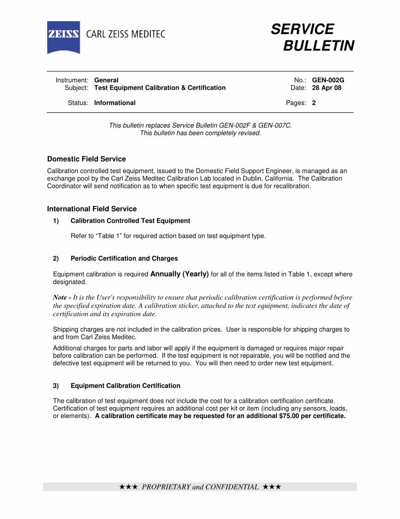
iii PROPRIETARY and CONFIDENTIAL iii
SERVICE
BULLETIN Instrument: General No.: GEN-002G Subject: Test Equipment Calibration & Certification Date: 28 Apr 08 Status: Informational Pages: 2
This bulletin replaces Service Bulletin GEN-002F & GEN-007C. This bulletin has been completely revised.
Domestic Field Service Calibration controlled test equipment, issued to the Domestic Field Support Engineer, is managed as an exchange pool by the Carl Zeiss Meditec Calibration Lab located in Dublin, California. The Calibration Coordinator will send notification as to when specific test equipment is due for recalibration. International Field Service
1) Calibration Controlled Test Equipment Refer to “Table 1” for required action based on test equipment type.
2) Periodic Certification and Charges
Equipment calibration is required Annually (Yearly) for all of the items listed in Table 1, except where designated.
Note - It is the User's responsibility to ensure that periodic calibration certification is performed before
the specified expiration date. A calibration sticker, attached to the test equipment, indicates the date of
certification and its expiration date.
Shipping charges are not included in the calibration prices. User is responsible for shipping charges to and from Carl Zeiss Meditec.
Additional charges for parts and labor will apply if the equipment is damaged or requires major repair before calibration can be performed. If the test equipment is not repairable, you will be notified and the defective test equipment will be returned to you. You will then need to order new test equipment.
3) Equipment Calibration Certification
The calibration of test equipment does not include the cost for a calibration certification certificate. Certification of test equipment requires an additional cost per kit or item (including any sensors, loads, or elements). A calibration certificate may be requested for an additional $75.00 per certificate.
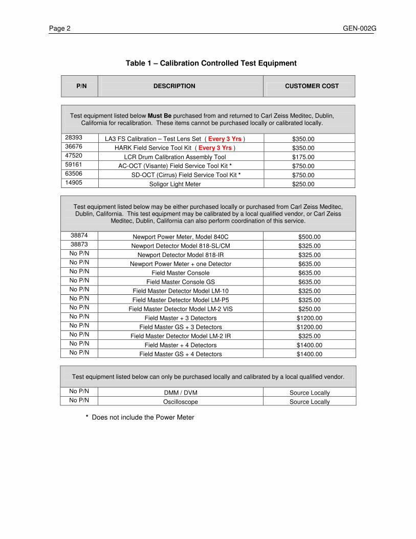
Page 2 GEN-002G
Table 1 – Calibration Controlled Test Equipment
P/N
DESCRIPTION
CUSTOMER COST
Test equipment listed below Must Be purchased from and returned to Carl Zeiss Meditec, Dublin, California for recalibration. These items cannot be purchased locally or calibrated locally.
28393 LA3 FS Calibration – Test Lens Set ( Every 3 Yrs ) $350.00 36676 HARK Field Service Tool Kit ( Every 3 Yrs ) $350.00 47520 LCR Drum Calibration Assembly Tool $175.00 59161 AC-OCT (Visante) Field Service Tool Kit * $750.00 63506 SD-OCT (Cirrus) Field Service Tool Kit * $750.00 14905 Soligor Light Meter $250.00
Test equipment listed below may be either purchased locally or purchased from Carl Zeiss Meditec, Dublin, California. This test equipment may be calibrated by a local qualified vendor, or Carl Zeiss
Meditec, Dublin, California can also perform coordination of this service.
38874 Newport Power Meter, Model 840C $500.00 38873 Newport Detector Model 818-SL/CM $325.00 No P/N Newport Detector Model 818-IR $325.00 No P/N Newport Power Meter + one Detector $635.00 No P/N Field Master Console $635.00 No P/N Field Master Console GS $635.00 No P/N Field Master Detector Model LM-10 $325.00 No P/N Field Master Detector Model LM-P5 $325.00 No P/N Field Master Detector Model LM-2 VIS $250.00 No P/N Field Master + 3 Detectors $1200.00 No P/N Field Master GS + 3 Detectors $1200.00 No P/N Field Master Detector Model LM-2 IR $325.00 No P/N Field Master + 4 Detectors $1400.00 No P/N Field Master GS + 4 Detectors $1400.00
Test equipment listed below can only be purchased locally and calibrated by a local qualified vendor.
No P/N DMM / DVM Source Locally No P/N Oscilloscope Source Locally
* Does not include the Power Meter

ÚÚÚ PROPRIETARY and CONFIDENTIAL ÚÚÚ
SERVICE BULLETIN Instrument: General No.: GEN-003Y Subject: Technical Support Product Responsibilities Date: 10 Apr 08
Status: Informational Pages: 3
This bulletin replaces Service Bulletin GEN-003X The following tables indicate the current Primary (1), Secondary (2), Backup (3), and Instrument Training (4) product responsibilities for the Carl Zeiss Meditec Technical Support Department. Names in RED indicates a Technical Support Manager:
• Ralf Homberg – Senior Manager, Technical Support
• Jurgen Billhofer – Manager, Technical Support: Hardware / Software
• Carl Gagnon – Manager, Technical Support: Training / Documentation Names in BLUE indicates a Technical Support Supervisor:
• Marty Rohman – Supervisor, Technical Support Documentation: For inquiries pertaining to distribution of service documentation (service bulletins,
service manuals, etc.), contact Gina Giuliano @ ex 4287. For other service documentation matters, contact the appropriate Technical Support Engineer for the associated product.
Phone: U.S.: 1-877-486-7473 International: 001-925-557-4100 Fax: 925-557-4652 Training: For inquiries pertaining to Service training, contact:
• Marg Southern @ extension 4497 or • Steven Braman @ extension 4489.
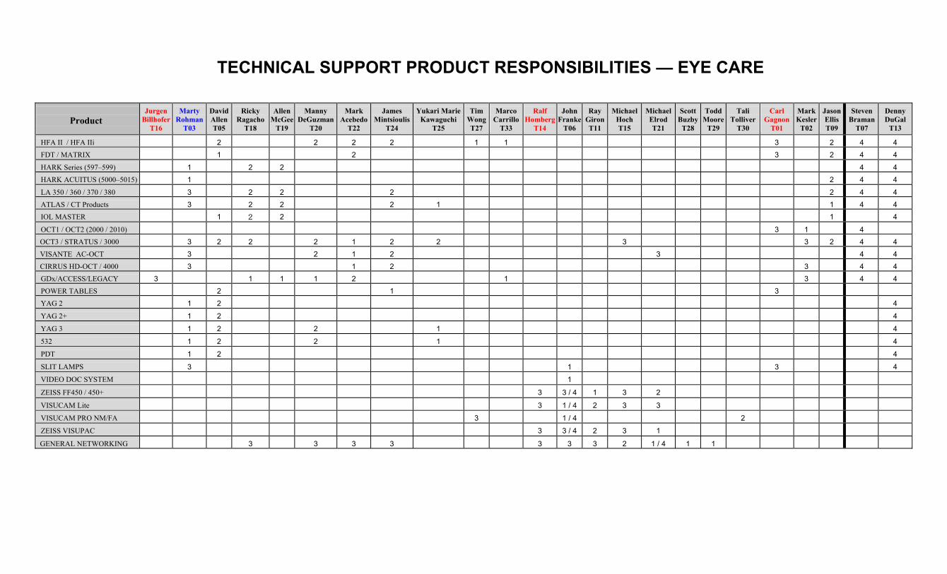
TECHNICAL SUPPORT PRODUCT RESPONSIBILITIES — EYE CARE
Product
Jurgen
Billhofer T16
Marty
Rohman T03
David Allen T05
Ricky
Ragacho T18
Allen
McGeeT19
Manny
DeGuzmanT20
Mark
AcebedoT22
James
Mintsioulis T24
Yukari Marie
Kawaguchi T25
Tim
WongT27
Marco
CarrilloT33
Ralf
HombergT14
John
FrankeT06
Ray
GironT11
Michael
Hoch T15
MichaelElrod T21
Scott
BuzbyT28
Todd
Moore T29
Tali
Tolliver T30
Carl
Gagnon T01
Mark Kesler
T02
Jason Ellis T09
Steven
Braman T07
Denny DuGal
T13
HFA II / HFA IIi
2
2
2
2
1
1
3
2
4
4 FDT / MATRIX
1
2
3
2
4
4
HARK Series (597–599)
1
2
2
4
4
HARK ACUITUS (5000–5015)
1
2
4
4
LA 350 / 360 / 370 / 380
3
2
2
2
2
4
4 ATLAS / CT Products
3
2
2
2
1
1
4
4
IOL MASTER
1
2
2
1
4
OCT1 / OCT2 (2000 / 2010)
3
1
4
OCT3 / STRATUS / 3000
3
2
2
2
1
2
2
3
3
2
4
4
VISANTE AC-OCT
3
2
1
2
3
4
4 CIRRUS HD-OCT / 4000
3
1
2
3
4
4
GDx/ACCESS/LEGACY
3
1
1
1
2
1
3
4
4 POWER TABLES
2
1
3
YAG 2
1
2
4
YAG 2+
1
2
4
YAG 3
1
2
2
1
4
532
1
2
2
1
4
PDT
1
2
4
SLIT LAMPS
3
1
3
4
VIDEO DOC SYSTEM
1
ZEISS FF450 / 450+
3
3 / 4
1
3
2
VISUCAM Lite
3
1 / 4
2
3
3
VISUCAM PRO NM/FA
3
1 / 4
2
ZEISS VISUPAC
3
3 / 4
2
3
1
GENERAL NETWORKING
3
3
3
3
3
3
3
2
1 / 4
1
1
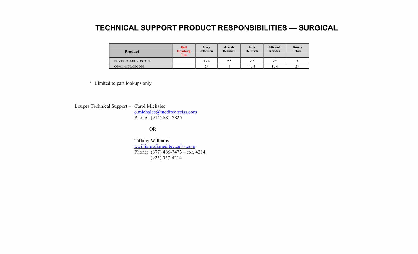
TECHNICAL SUPPORT PRODUCT RESPONSIBILITIES — SURGICAL
Product
Ralf
Homberg T14
Gary
Jefferson
Joseph
Beaulieu
Lutz
Heinrich
Michael Kersten
Jimmy Chau
PENTERO MICROSCOPE
1 / 4
2 *
2 *
2 *
1
OPMI MICROSCOPE
2 *
1
1 / 4
1 / 4
2 *
* Limited to part lookups only
Loupes Technical Support – Carol Michalec [email protected] Phone: (914) 681-7825
OR
Tiffany Williams [email protected] Phone: (877) 486-7473 – ext. 4214 (925) 557-4214

iii PROPRIETARY and CONFIDENTIAL iii
SERVICE BULLETIN Instrument: General No.: GEN-004B Subject: General Guidelines for Assembly Level Troubleshooting
Date: 11 Jul 05
Status: Informational Pages: 4
This bulletin replaces Service Bulletin GEN-004A The following pages contain General Guidelines for Assembly Level Troubleshooting. This procedure is designed to be followed on any service call. It is not specific to any one instrument. Introduction Field experience has proven that a structured approach to problem solving is the key to effective service. This bulletin is intended to provide this structured approach for solving problems on any instrument. The troubleshooting aids in this section will help you to diagnose operating difficulties and system malfunctions. General Guidelines for Assembly Level Troubleshooting On-site assembly level troubleshooting poses unique and complex challenges to the Field Support Engineer. In addition to identifying and replacing the faulty assembly, the Field Support Engineer must often travel great distances to the customer location, resolve operator errors, and identify power and environmental causes of problems while satisfying the customer's perception of quality service. A structured approach to resolving field problems can greatly increase customer satisfaction and the Field Support Engineer's effectiveness. There are seven major tasks in resolving field equipment problems:
Prior to Going On-Site
1. Obtain a Service History for the Instrument
2. Query the Operator of the
Instrument
3. Check for Service Bulletins that Address the Problem
While On-Site 4. Have the Operator Demonstrate the
Problem 5. Resolve the Obvious 6. Substitute the Failing Assembly 7. Confirm the Repair
Each of these tasks is explained on the following pages.
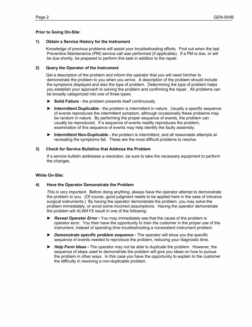
Page 2 GEN-004B
Prior to Going On-Site: 1) Obtain a Service History for the Instrument Knowledge of previous problems will assist your troubleshooting efforts. Find out when the last
Preventive Maintenance (PM) service call was performed (if applicable). If a PM is due, or will be due shortly, be prepared to perform this task in addition to the repair.
2) Query the Operator of the Instrument Get a description of the problem and inform the operator that you will need him/her to
demonstrate the problem to you when you arrive. A description of the problem should include the symptoms displayed and also the type of problem. Determining the type of problem helps you establish your approach to solving the problem and confirming the repair. All problems can be broadly categorized into one of three types:
► Solid Failure - the problem presents itself continuously.
► Intermittent Duplicable - the problem is intermittent in nature. Usually a specific sequence of events reproduces the intermittent symptom, although occasionally these problems may be random in nature. By performing the proper sequence of events, the problem can usually be reproduced. If a sequence of events readily reproduces the problem, examination of this sequence of events may help identify the faulty assembly.
► Intermittent Non-Duplicable - the problem is intermittent, and all reasonable attempts at
recreating the symptoms fail. These are the most difficult problems to resolve. 3) Check for Service Bulletins that Address the Problem
If a service bulletin addresses a resolution, be sure to take the necessary equipment to perform the changes.
While On-Site: 4) Have the Operator Demonstrate the Problem
This is very important. Before doing anything, always have the operator attempt to demonstrate the problem to you. (Of course, good judgment needs to be applied here in the case of intrusive surgical instruments.) By having the operator demonstrate the problem, you may solve the problem immediately, or avoid some incorrect assumptions. Having the operator demonstrate the problem will ALWAYS result in one of the following:
► Reveal Operator Error - You may immediately see that the cause of the problem is
operator error. You then have the opportunity to train the customer in the proper use of the instrument, instead of spending time troubleshooting a nonexistent instrument problem.
► Demonstrate specific problem sequence - The operator will show you the specific
sequence of events needed to reproduce the problem, reducing your diagnostic time.
► Help Form Ideas - The operator may not be able to duplicate the problem. However, the sequence of steps used to demonstrate the problem will give you ideas on how to pursue the problem in other ways. In this case you have the opportunity to explain to the customer the difficulty in resolving a non-duplicable problem.

GEN-004B Page 3
5) Resolve the Obvious
Obvious mechanical or physical defects should be resolved when discovered. Often, resolving the obvious will lead you to the real problem.
6) Substitute the Failing Assembly
Once you have deduced which assembly is at fault, or is suspected to be at fault, it should be substituted with a known good assembly.
7) Confirm the Repair
After an assembly is replaced, confirmation should be made by reinstalling the failing assembly to witness the original symptom. You are then assured of the effectiveness of the repair, and of the need to utilize your spare assembly. Also, the number of "No Problem Found" PCB's returned to the Carl Zeiss Meditec Repair Center is greatly reduced.
Confirming the repair to the customer often helps to bolster confidence in your abilities. To avoid repeat service calls it is especially important to confirm intermittent problems. Time spent confirming a repair is time well spent.
If the problem still exists, reinstall the original assembly that you removed, then continue troubleshooting.
Solving Solid Failures
It is usually straightforward deductive logic or electrical checks that will lead you to replace the faulty assembly. After replacement of the assembly in question resolves the symptom, it is imperative that you CONFIRM THE REPAIR by reinstalling the original assembly and witnessing the original symptoms again. For many assemblies this is the only means of positively verifying that the replacement circuitry has resolved the problem.
Solving Intermittent Duplicable Failures These failures are resolved in the same manner as solid failures but always require more time to resolve and confirm. The frequency of the problem helps you determine how long it will take to verify a repair. A good rule of thumb when troubleshooting intermittent problems is: 2 times the frequency of the symptom gives an 80% confidence level of the repair.
EXAMPLE:
Problem The problem appears only about once an hour. The sequence of events needed to reproduce the problem leads you to believe a circuit board is the likely cause. Solution The suspected circuit board is replaced. To provide an 80% confidence level that the circuit board resolved the problem, the instrument will need to be tested for 2 hours without failing.
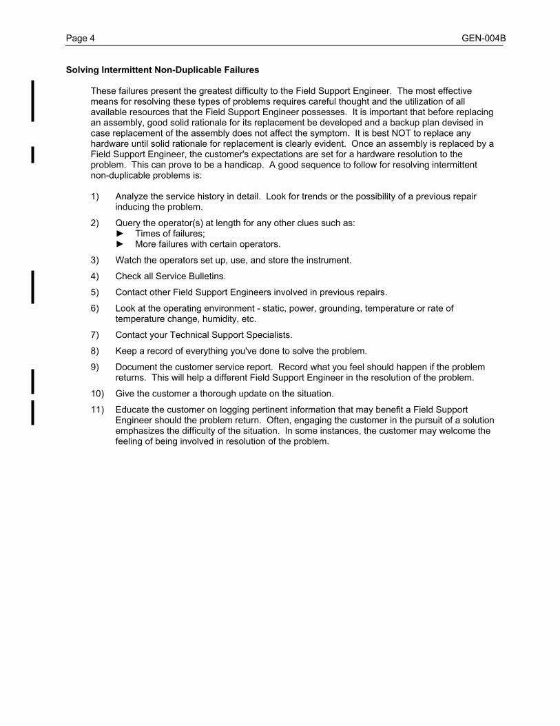
Page 4 GEN-004B Solving Intermittent Non-Duplicable Failures
These failures present the greatest difficulty to the Field Support Engineer. The most effective means for resolving these types of problems requires careful thought and the utilization of all available resources that the Field Support Engineer possesses. It is important that before replacing an assembly, good solid rationale for its replacement be developed and a backup plan devised in case replacement of the assembly does not affect the symptom. It is best NOT to replace any hardware until solid rationale for replacement is clearly evident. Once an assembly is replaced by a Field Support Engineer, the customer's expectations are set for a hardware resolution to the problem. This can prove to be a handicap. A good sequence to follow for resolving intermittent non-duplicable problems is:
1) Analyze the service history in detail. Look for trends or the possibility of a previous repair
inducing the problem.
2) Query the operator(s) at length for any other clues such as: ► Times of failures; ► More failures with certain operators.
3) Watch the operators set up, use, and store the instrument.
4) Check all Service Bulletins.
5) Contact other Field Support Engineers involved in previous repairs.
6) Look at the operating environment - static, power, grounding, temperature or rate of
temperature change, humidity, etc.
7) Contact your Technical Support Specialists.
8) Keep a record of everything you've done to solve the problem.
9) Document the customer service report. Record what you feel should happen if the problem returns. This will help a different Field Support Engineer in the resolution of the problem.
10) Give the customer a thorough update on the situation.
11) Educate the customer on logging pertinent information that may benefit a Field Support
Engineer should the problem return. Often, engaging the customer in the pursuit of a solution emphasizes the difficulty of the situation. In some instances, the customer may welcome the feeling of being involved in resolution of the problem.

iii PROPRIETARY and CONFIDENTIAL iii
SERVICE BULLETIN Instrument: General No.: GEN-005A Subject: Use of Static Protection Kit Date: 17 Aug 98 Status: Mandatory Pages: 1
This bulletin replaces Service Bulletin GEN-005 Static Protection Kit, P/N 20928 The Static Protection Kit is essential for protection of electronic components against electrostatic discharge whenever you are disassembling or handling any PCBs or electronic components. The kit contains the following items:
• a bench mat with permanently attached alligator-clip ground lead; • a banana plug lead with snap connector; • an adjustable wrist cuff.
The static protection kit must be properly grounded, and you must be wearing the wrist cuff whenever working on any instrument with the cover removed. To use the static protection kit: 1) Connect the bench mat alligator clip to a known good electrical ground point. Any unpainted screw,
chassis surface, or metal component on the instrument is generally an acceptable ground point, PROVIDED THAT THE INSTRUMENT HAS ITS POWER CORD CONNECTED AND IS PLUGGED INTO A GROUNDED POWER RECEPTACLE. An acceptable ground point may be confirmed by using an ohmmeter to ensure that a resistance of less than 1 ohm is obtained between the instrument's power cord ground prong and the ground point in question.
In situations where work is to be performed on an instrument and it is undesirable to have the
instrument plugged into a power receptacle, an alternate grounding point is necessary. Usually, an acceptable ground point can be found at the cover screw for the AC power outlet.
Note – It is useless to use the static mat without it being properly grounded.
2) After properly grounding the bench mat, connect the banana plug lead into the bench mat
connector. 3) Connect the wrist cuff to the snap clip on the banana plug lead. 4) Adjust the wrist cuff to fit snugly around your wrist. The wrist cuff should always be worn when
working on an instrument with the cover removed.
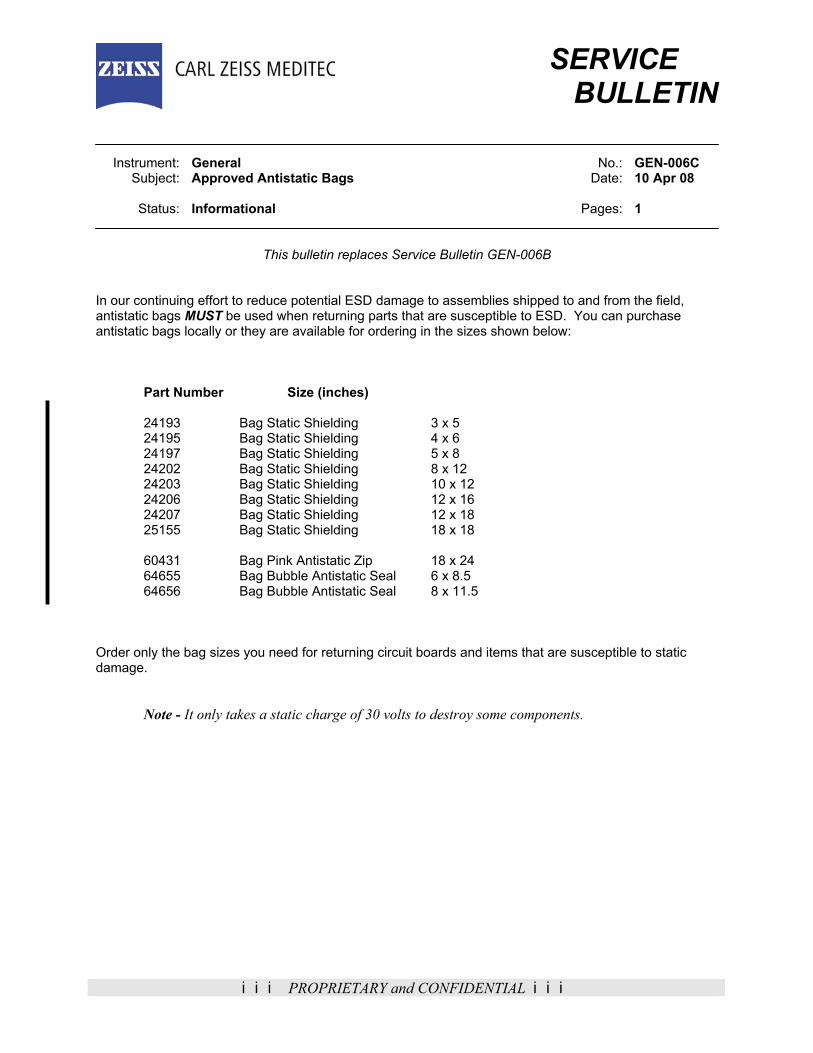
iii PROPRIETARY and CONFIDENTIAL iii
SERVICE BULLETIN Instrument: General No.: GEN-006C Subject: Approved Antistatic Bags Date: 10 Apr 08 Status: Informational Pages: 1
This bulletin replaces Service Bulletin GEN-006B In our continuing effort to reduce potential ESD damage to assemblies shipped to and from the field, antistatic bags MUST be used when returning parts that are susceptible to ESD. You can purchase antistatic bags locally or they are available for ordering in the sizes shown below:
Part Number Size (inches)
24193 Bag Static Shielding 3 x 5 24195 Bag Static Shielding 4 x 6 24197 Bag Static Shielding 5 x 8 24202 Bag Static Shielding 8 x 12 24203 Bag Static Shielding 10 x 12 24206 Bag Static Shielding 12 x 16 24207 Bag Static Shielding 12 x 18 25155 Bag Static Shielding 18 x 18 60431 Bag Pink Antistatic Zip 18 x 24 64655 Bag Bubble Antistatic Seal 6 x 8.5 64656 Bag Bubble Antistatic Seal 8 x 11.5
Order only the bag sizes you need for returning circuit boards and items that are susceptible to static damage. Note - It only takes a static charge of 30 volts to destroy some components.

iii PROPRIETARY and CONFIDENTIAL iii
SERVICE BULLETIN Instrument: General No.: GEN-007C Subject: Calibration Certificate for Test Equipment Date: 11 Jul 05 Status: Informational Pages: 1
Obsolete
11 April 2008
Bulletin GEN-007C is now obsolete, due to the reason indicated below:
No longer valid
No longer necessary
Information incorporated into new service manual release
Information incorporated into bulletin number GEN-002G

iii PROPRIETARY and CONFIDENTIAL iii
SERVICE BULLETIN Instrument: General No.: GEN-008A Subject: Bloodborne Pathogens Date: 17 Aug 98 Status: Informational Pages: 1
This bulletin replaces Service Bulletin GEN-008. Bloodborne Pathogens - Pathogenic microorganisms that are present in human blood can cause disease in humans. These pathogens include, but are not limited to, Hepatitis B virus (HBV) and Human Immunodeficiency Virus (HIV). The Center for Disease Control (CDC) states that the Hepatitis B virus (HBV) can survive for several weeks (or months) in dried blood on environmental surfaces or contaminated needles and instruments. Pathogenic microorganisms require a direct route into the body for them to cause disease in humans. A direct route can be considered a break in the skin, such as a cut, a burn, a rash, or through acne. Certain openings in the body, such as the eyes, can also be considered a direct route. Precautions - Employees should take an approach that assumes all blood and body fluids encountered in the workplace are potentially infected with Human Immunodeficiency Virus (HIV) or Hepatitis B Virus (HBV), or other bloodborne pathogens. Personal Protective Equipment - Disposable LATEX gloves are available to all employees who anticipate having hand contact with blood, other potentially infectious materials, mucous membranes, and non-intact skin; and when handling or touching contaminated or potentially contaminated items, materials, or equipment. The disposable gloves shall not be washed or decontaminated for re-use. Disposable LATEX Glove Quantity 1 P/N 34121 The part number reflects a quantity of one glove, so be sure to order in pairs. If you wish to order one box containing 100 gloves, order a quantity of 100 using the above part number.

iii PROPRIETARY and CONFIDENTIAL iii
SERVICE
BULLETIN
Instrument: General No.: GEN-009J
Subject: List of Manuals Date: 29 Apr 08 Status: Informational Pages: 7
This bulletin replaces Service Bulletin GEN-009I The attached List of Manuals is to be used as a reference to ensure that manuals in your possession are at the latest revision or latest release date. This list will be updated periodically to include new manuals and manual revision changes. Meanwhile, we recommend that you manually indicate in the list each new manual that you receive.
Notes - 1. Manuals issued or amended since the last revision of this list are marked by an asterisk (*).
2. Manuals that are no longer available to order have a line through the part number (02209).
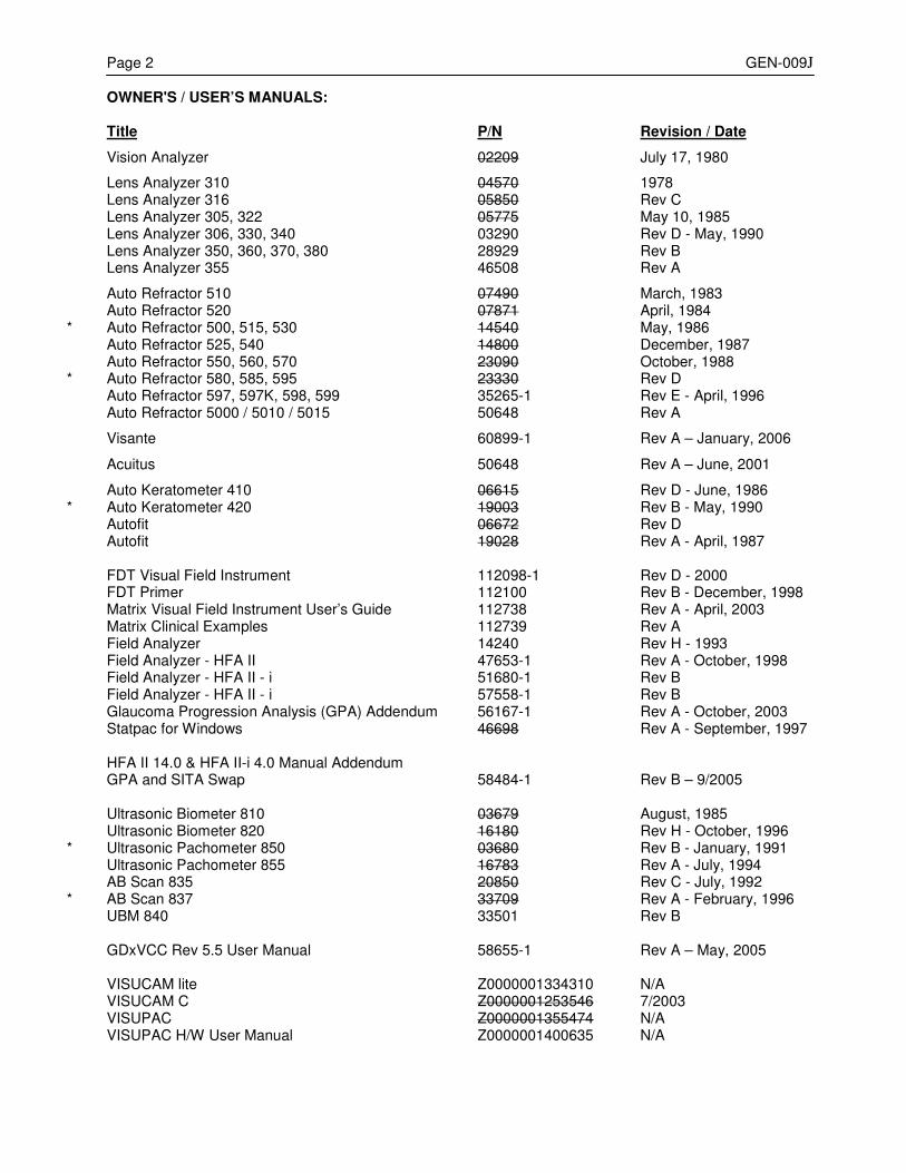
Page 2 GEN-009J OWNER'S / USER’S MANUALS: Title P/N Revision / Date Vision Analyzer 02209 July 17, 1980 Lens Analyzer 310 04570 1978 Lens Analyzer 316 05850 Rev C Lens Analyzer 305, 322 05775 May 10, 1985
Lens Analyzer 306, 330, 340 03290 Rev D - May, 1990 Lens Analyzer 350, 360, 370, 380 28929 Rev B Lens Analyzer 355 46508 Rev A Auto Refractor 510 07490 March, 1983 Auto Refractor 520 07871 April, 1984
* Auto Refractor 500, 515, 530 14540 May, 1986 Auto Refractor 525, 540 14800 December, 1987 Auto Refractor 550, 560, 570 23090 October, 1988
* Auto Refractor 580, 585, 595 23330 Rev D Auto Refractor 597, 597K, 598, 599 35265-1 Rev E - April, 1996 Auto Refractor 5000 / 5010 / 5015 50648 Rev A
Visante 60899-1 Rev A – January, 2006
Acuitus 50648 Rev A – June, 2001 Auto Keratometer 410 06615 Rev D - June, 1986
* Auto Keratometer 420 19003 Rev B - May, 1990 Autofit 06672 Rev D
Autofit 19028 Rev A - April, 1987 FDT Visual Field Instrument 112098-1 Rev D - 2000 FDT Primer 112100 Rev B - December, 1998
Matrix Visual Field Instrument User’s Guide 112738 Rev A - April, 2003 Matrix Clinical Examples 112739 Rev A
Field Analyzer 14240 Rev H - 1993 Field Analyzer - HFA II 47653-1 Rev A - October, 1998
Field Analyzer - HFA II - i 51680-1 Rev B Field Analyzer - HFA II - i 57558-1 Rev B
Glaucoma Progression Analysis (GPA) Addendum 56167-1 Rev A - October, 2003 Statpac for Windows 46698 Rev A - September, 1997
HFA II 14.0 & HFA II-i 4.0 Manual Addendum GPA and SITA Swap 58484-1 Rev B – 9/2005
Ultrasonic Biometer 810 03679 August, 1985
Ultrasonic Biometer 820 16180 Rev H - October, 1996 * Ultrasonic Pachometer 850 03680 Rev B - January, 1991
Ultrasonic Pachometer 855 16783 Rev A - July, 1994 AB Scan 835 20850 Rev C - July, 1992
* AB Scan 837 33709 Rev A - February, 1996 UBM 840 33501 Rev B GDxVCC Rev 5.5 User Manual 58655-1 Rev A – May, 2005
VISUCAM lite Z0000001334310 N/A VISUCAM C Z0000001253546 7/2003 VISUPAC Z0000001355474 N/A VISUPAC H/W User Manual Z0000001400635 N/A
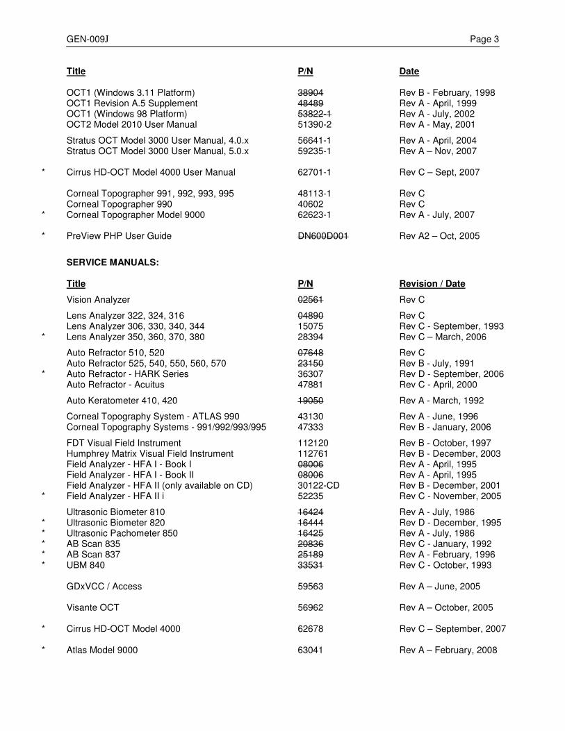
GEN-009J Page 3 Title P/N Date OCT1 (Windows 3.11 Platform) 38904 Rev B - February, 1998 OCT1 Revision A.5 Supplement 48489 Rev A - April, 1999
OCT1 (Windows 98 Platform) 53822-1 Rev A - July, 2002 OCT2 Model 2010 User Manual 51390-2 Rev A - May, 2001
Stratus OCT Model 3000 User Manual, 4.0.x 56641-1 Rev A - April, 2004 Stratus OCT Model 3000 User Manual, 5.0.x 59235-1 Rev A – Nov, 2007
* Cirrus HD-OCT Model 4000 User Manual 62701-1 Rev C – Sept, 2007 Corneal Topographer 991, 992, 993, 995 48113-1 Rev C Corneal Topographer 990 40602 Rev C
* Corneal Topographer Model 9000 62623-1 Rev A - July, 2007
* PreView PHP User Guide DN600D001 Rev A2 – Oct, 2005 SERVICE MANUALS: Title P/N Revision / Date Vision Analyzer 02561 Rev C Lens Analyzer 322, 324, 316 04890 Rev C
Lens Analyzer 306, 330, 340, 344 15075 Rev C - September, 1993 * Lens Analyzer 350, 360, 370, 380 28394 Rev C – March, 2006
Auto Refractor 510, 520 07648 Rev C
Auto Refractor 525, 540, 550, 560, 570 23150 Rev B - July, 1991 * Auto Refractor - HARK Series 36307 Rev D - September, 2006
Auto Refractor - Acuitus 47881 Rev C - April, 2000
Auto Keratometer 410, 420 19050 Rev A - March, 1992 Corneal Topography System - ATLAS 990 43130 Rev A - June, 1996
Corneal Topography Systems - 991/992/993/995 47333 Rev B - January, 2006 FDT Visual Field Instrument 112120 Rev B - October, 1997
Humphrey Matrix Visual Field Instrument 112761 Rev B - December, 2003 Field Analyzer - HFA I - Book I 08006 Rev A - April, 1995 Field Analyzer - HFA I - Book II 08006 Rev A - April, 1995
Field Analyzer - HFA II (only available on CD) 30122-CD Rev B - December, 2001 * Field Analyzer - HFA II i 52235 Rev C - November, 2005
Ultrasonic Biometer 810 16424 Rev A - July, 1986
* Ultrasonic Biometer 820 16444 Rev D - December, 1995 * Ultrasonic Pachometer 850 16425 Rev A - July, 1986 * AB Scan 835 20836 Rev C - January, 1992 * AB Scan 837 25189 Rev A - February, 1996 * UBM 840 33531 Rev C - October, 1993
GDxVCC / Access 59563 Rev A – June, 2005
Visante OCT 56962 Rev A – October, 2005
* Cirrus HD-OCT Model 4000 62678 Rev C – September, 2007
* Atlas Model 9000 63041 Rev A – February, 2008
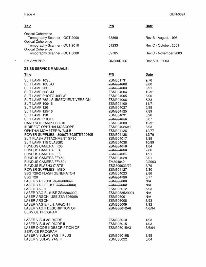
Page 4 GEN-009J Title P/N Date Optical Coherence Tomography Scanner - OCT 2000 38898 Rev B - August, 1998
Optical Coherence Tomography Scanner - OCT 2010 51233 Rev C - October, 2001
Optical Coherence Tomography Scanner - OCT 3000 52785 Rev C - November 2003
* PreView PHP DN600D006 Rev A01 - 2003 ZEISS SERVICE MANUALS: Title P/N Date SLIT LAMP 10SL ZSM301731 9/76
SLIT LAMP 10SL/O ZSM304002 9/80 SLIT LAMP 20SL ZSM304003 6/91 SLIT LAMP 30SL/M ZSM304004 12/91 SLIT LAMP PHOTO 40SL/P ZSM304005 6/90 SLIT LAMP 75SL SUBSEQUENT VERSION ZSM304006 6/83 SLIT LAMP 100/16 ZSM304100 11/71 SLIT LAMP 120 ZSM304027 5/98 SLIT LAMP 125/16 ZSM304125 7/89 SLIT LAMP 130 ZSM304031 6/96 SLIT LAMP PHOTO ZSM304016 3/87 HAND SLIT LAMP HSO-10 ZSM304000 12/91 INDIRECT OPHTHALMOSCOPE ZSM304026A1 8/93 OPHTHALMOMETER W/BULB ZSM304126 12/77 POWER SUPPLIES - 309673/392575/309605 ZSM304128 12/79 SLIT FLASH ATTACHMENT SP30 ZSM304017 1/88 SLIT LAMP 115 CLASSIC ZSM304038 10/99 FUNDUS CAMERA FK30 ZSM304018 1/84 FUNDUS CAMERA FF4 ZSM304020 7/86 FUNDUS CAMERA FF5 ZSM304021 1/91
FUNDUS CAMERA FF450 ZSM304028 3/01 FUNDUS CAMERA FF450+ ZM304042 9/2003
FUNDUS FLASH3-C\RTS ZSG309033/79 3/79 POWER SUPPLIES - MED ZSM304127 6/80 SBG 720-2 FLASH GENERATOR ZSM304023 2/86 SBG 720 ZSM304720 5/77 LASER YAG (USE ZSM306009) ZSM306000 N/A LASER YAG E (USE ZSM306009) ZSM306002 N/A LASER YAG II ZSM306012 5/93 LASER YAG FL (USE ZSM306009) ZSM3068529901 N/A LASER ARGON (USE ZSM306009) ZSM306001 N/A LASER ARGON II ZSM306008 3/93 LASER YAG E/FL & ARGON I ZSM306009 1/92 LASER YAG II DESCRIPTION OF ZSM306012A6 4/6/94 SERVICE PROGRAM LASER VISULAS DIODE ZSM306010 1/93 LASER VISULAS DIODE II ZSM306015 1/93 LASER DIODE II DESCRIPTION OF ZSM306015A3 5/6/94 SERVICE PROGRAM
LASER VISULAS YAG II PLUS ZSM306016E 8/98 LASER VISULAS YAG III ZSM306022 6/04
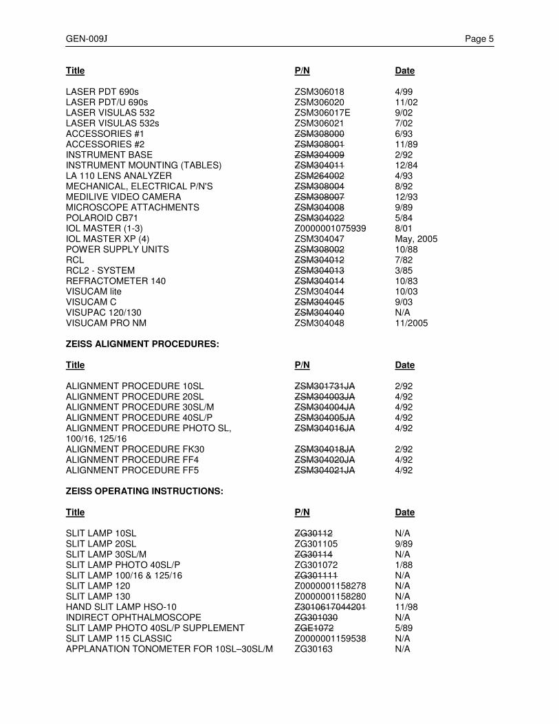
GEN-009J Page 5 Title P/N Date
LASER PDT 690s ZSM306018 4/99 LASER PDT/U 690s ZSM306020 11/02 LASER VISULAS 532 ZSM306017E 9/02 LASER VISULAS 532s ZSM306021 7/02
ACCESSORIES #1 ZSM308000 6/93 ACCESSORIES #2 ZSM308001 11/89 INSTRUMENT BASE ZSM304009 2/92 INSTRUMENT MOUNTING (TABLES) ZSM304011 12/84 LA 110 LENS ANALYZER ZSM264002 4/93 MECHANICAL, ELECTRICAL P/N'S ZSM308004 8/92 MEDILIVE VIDEO CAMERA ZSM308007 12/93 MICROSCOPE ATTACHMENTS ZSM304008 9/89 POLAROID CB71 ZSM304022 5/84
IOL MASTER (1-3) Z0000001075939 8/01 IOL MASTER XP (4) ZSM304047 May, 2005
POWER SUPPLY UNITS ZSM308002 10/88 RCL ZSM304012 7/82 RCL2 - SYSTEM ZSM304013 3/85 REFRACTOMETER 140 ZSM304014 10/83
VISUCAM lite ZSM304044 10/03 VISUCAM C ZSM304045 9/03 VISUPAC 120/130 ZSM304040 N/A VISUCAM PRO NM ZSM304048 11/2005
ZEISS ALIGNMENT PROCEDURES: Title P/N Date ALIGNMENT PROCEDURE 10SL ZSM301731JA 2/92 ALIGNMENT PROCEDURE 20SL ZSM304003JA 4/92 ALIGNMENT PROCEDURE 30SL/M ZSM304004JA 4/92 ALIGNMENT PROCEDURE 40SL/P ZSM304005JA 4/92 ALIGNMENT PROCEDURE PHOTO SL, ZSM304016JA 4/92 100/16, 125/16 ALIGNMENT PROCEDURE FK30 ZSM304018JA 2/92 ALIGNMENT PROCEDURE FF4 ZSM304020JA 4/92 ALIGNMENT PROCEDURE FF5 ZSM304021JA 4/92 ZEISS OPERATING INSTRUCTIONS: Title P/N Date SLIT LAMP 10SL ZG30112 N/A SLIT LAMP 20SL ZG301105 9/89 SLIT LAMP 30SL/M ZG30114 N/A SLIT LAMP PHOTO 40SL/P ZG301072 1/88 SLIT LAMP 100/16 & 125/16 ZG301111 N/A
SLIT LAMP 120 Z0000001158278 N/A SLIT LAMP 130 Z0000001158280 N/A
HAND SLIT LAMP HSO-10 Z3010617044201 11/98 INDIRECT OPHTHALMOSCOPE ZG301030 N/A SLIT LAMP PHOTO 40SL/P SUPPLEMENT ZGE1072 5/89
SLIT LAMP 115 CLASSIC Z0000001159538 N/A APPLANATION TONOMETER FOR 10SL–30SL/M ZG30163 N/A
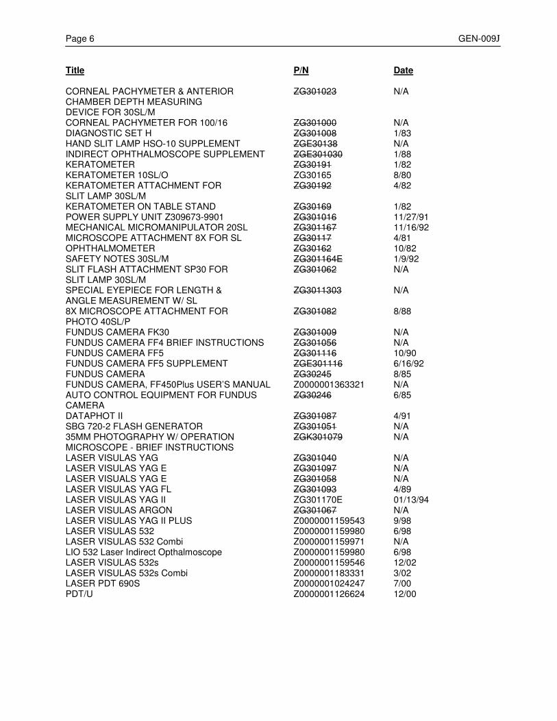
Page 6 GEN-009J Title P/N Date CORNEAL PACHYMETER & ANTERIOR ZG301023 N/A CHAMBER DEPTH MEASURING DEVICE FOR 30SL/M CORNEAL PACHYMETER FOR 100/16 ZG301000 N/A DIAGNOSTIC SET H ZG301008 1/83 HAND SLIT LAMP HSO-10 SUPPLEMENT ZGE30138 N/A INDIRECT OPHTHALMOSCOPE SUPPLEMENT ZGE301030 1/88 KERATOMETER ZG30191 1/82 KERATOMETER 10SL/O ZG30165 8/80 KERATOMETER ATTACHMENT FOR ZG30192 4/82 SLIT LAMP 30SL/M KERATOMETER ON TABLE STAND ZG30169 1/82
POWER SUPPLY UNIT Z309673-9901 ZG301016 11/27/91 MECHANICAL MICROMANIPULATOR 20SL ZG301167 11/16/92 MICROSCOPE ATTACHMENT 8X FOR SL ZG30117 4/81 OPHTHALMOMETER ZG30162 10/82 SAFETY NOTES 30SL/M ZG301164E 1/9/92 SLIT FLASH ATTACHMENT SP30 FOR ZG301062 N/A SLIT LAMP 30SL/M SPECIAL EYEPIECE FOR LENGTH & ZG3011303 N/A ANGLE MEASUREMENT W/ SL 8X MICROSCOPE ATTACHMENT FOR ZG301082 8/88 PHOTO 40SL/P FUNDUS CAMERA FK30 ZG301009 N/A FUNDUS CAMERA FF4 BRIEF INSTRUCTIONS ZG301056 N/A FUNDUS CAMERA FF5 ZG301116 10/90 FUNDUS CAMERA FF5 SUPPLEMENT ZGE301116 6/16/92 FUNDUS CAMERA ZG30245 8/85
FUNDUS CAMERA, FF450Plus USER’S MANUAL Z0000001363321 N/A AUTO CONTROL EQUIPMENT FOR FUNDUS ZG30246 6/85 CAMERA DATAPHOT II ZG301087 4/91 SBG 720-2 FLASH GENERATOR ZG301051 N/A 35MM PHOTOGRAPHY W/ OPERATION ZGK301079 N/A MICROSCOPE - BRIEF INSTRUCTIONS LASER VISULAS YAG ZG301040 N/A LASER VISULAS YAG E ZG301097 N/A LASER VISUALS YAG E ZG301058 N/A LASER VISULAS YAG FL ZG301093 4/89 LASER VISULAS YAG II ZG301170E 01/13/94 LASER VISULAS ARGON ZG301067 N/A LASER VISULAS YAG II PLUS Z0000001159543 9/98 LASER VISULAS 532 Z0000001159980 6/98 LASER VISULAS 532 Combi Z0000001159971 N/A LIO 532 Laser Indirect Opthalmoscope Z0000001159980 6/98
LASER VISULAS 532s Z0000001159546 12/02 LASER VISULAS 532s Combi Z0000001183331 3/02
LASER PDT 690S Z0000001024247 7/00 PDT/U Z0000001126624 12/00
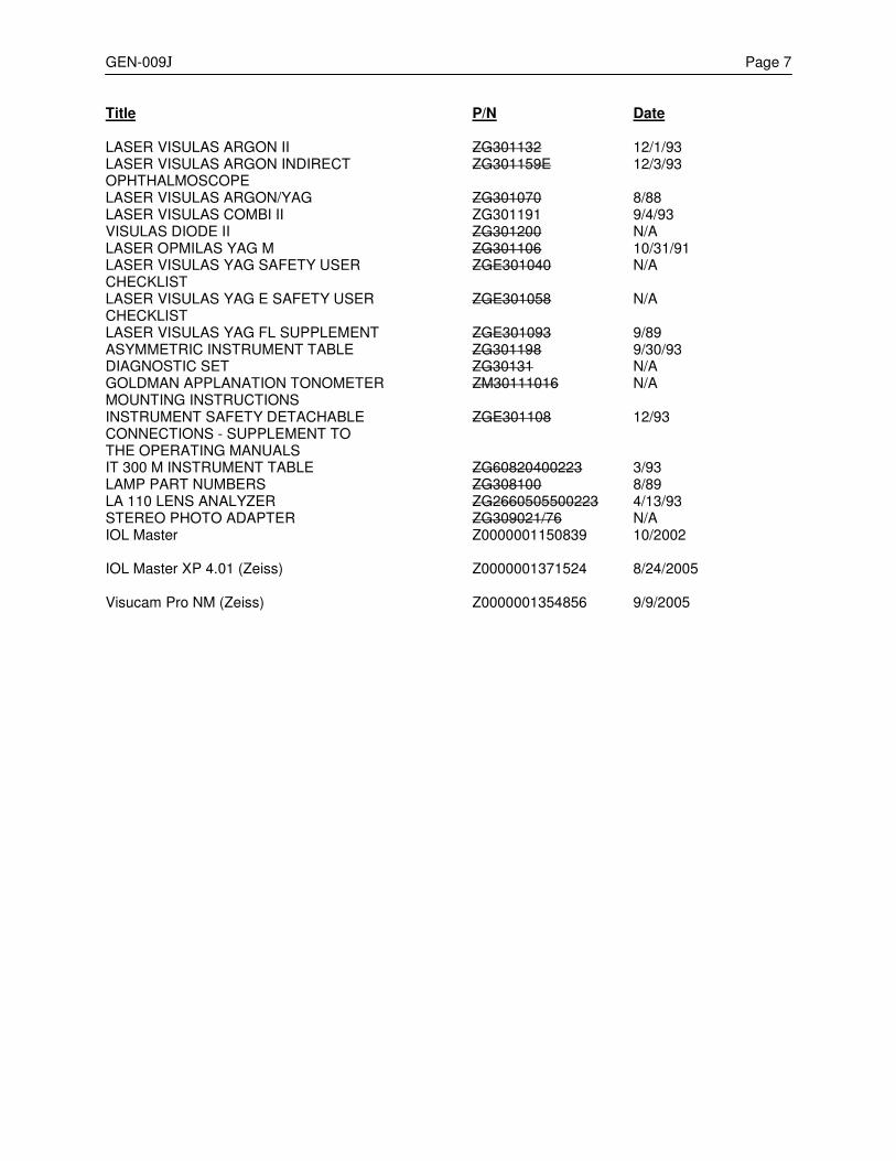
GEN-009J Page 7 Title P/N Date
LASER VISULAS ARGON II ZG301132 12/1/93 LASER VISULAS ARGON INDIRECT ZG301159E 12/3/93 OPHTHALMOSCOPE LASER VISULAS ARGON/YAG ZG301070 8/88 LASER VISULAS COMBI II ZG301191 9/4/93 VISULAS DIODE II ZG301200 N/A LASER OPMILAS YAG M ZG301106 10/31/91 LASER VISULAS YAG SAFETY USER ZGE301040 N/A CHECKLIST LASER VISULAS YAG E SAFETY USER ZGE301058 N/A CHECKLIST LASER VISULAS YAG FL SUPPLEMENT ZGE301093 9/89 ASYMMETRIC INSTRUMENT TABLE ZG301198 9/30/93 DIAGNOSTIC SET ZG30131 N/A GOLDMAN APPLANATION TONOMETER ZM30111016 N/A MOUNTING INSTRUCTIONS INSTRUMENT SAFETY DETACHABLE ZGE301108 12/93 CONNECTIONS - SUPPLEMENT TO THE OPERATING MANUALS IT 300 M INSTRUMENT TABLE ZG60820400223 3/93 LAMP PART NUMBERS ZG308100 8/89 LA 110 LENS ANALYZER ZG2660505500223 4/13/93 STEREO PHOTO ADAPTER ZG309021/76 N/A
IOL Master Z0000001150839 10/2002
IOL Master XP 4.01 (Zeiss) Z0000001371524 8/24/2005
Visucam Pro NM (Zeiss) Z0000001354856 9/9/2005

iii PROPRIETARY and CONFIDENTIAL iii
SERVICE BULLETIN Instrument: General No.: GEN-010D Subject: General Disclaimer Form Date: 13 Apr 07 Status: Informational Pages: 2
This bulletin replaces Service Bulletin GEN-010C The General Disclaimer Form is to be used on instruments that currently require that a disclaimer form be filled out (refer to SOG-006x). This General Disclaimer form will replace existing disclaimer forms that were tailored to the individual instruments. The General Disclaimer form must be signed by the customer prior to any service actions performed. Upon completion of service activity, this form must be sent in (via Prevail) along with the completed System Operation Validation form and the Field Service Report (FSR).

CARL ZEISS MEDITEC SERVICE DISCLAIMER
OWNER: LOCATION: INSTRUMENT MODEL:
DATE: SOFTWARE REV.: INSTRUMENT SERIAL NO.:
At your request, Carl Zeiss Meditec has agreed to service the instrument described above. The possibility exists that during the course of servicing, customer data that has previously been entered onto a hard disk (or onto another media whether internal of external) may be erased or otherwise adversely affected. Carl Zeiss Meditec cannot guarantee that the customer data will not be lost or altered and has no obligation or responsibility to reconstruct the customer data which may have to be restored back onto a hard disk (or onto another media whether internal or external) for any reason. If a hard disk (or another media whether internal or external) that was purchased through Carl Zeiss Meditec, Inc. or came with your instrument has to be replaced or erased / reformatted, it will be restored to its original factory configuration. Customer data will need to be restored back onto the hard disk (or onto another media whether internal or external) by the customer. WARNING:
1. For Hard Disks - It is the customer’s responsibility to archive / backup their database files before service is performed on their equipment.
2. For Networked Instruments / Modalities – As a result of the requested service, Customer acknowledges that there is potential risk of damage to computer hardware, network devices, peripherals, accessories, data storage servers, data storage media, or other hardware not cited. Customer also acknowledges potential risk of damage to, and corruption or loss of computer software, applications, and data.
3. For other media whether internal or external - It is the customer’s responsibility to maintain a copy of their programmed settings in case the programmed settings become corrupted and irretrievable.
Note – Carl Zeiss Meditec, Inc. is obligated to strictly follow the regulations under the Health Insurance Portability and Accountability Act (HIPAA). Please sign below to indicate that you have read this disclaimer, agree to be bound by it, and have authorized the Carl Zeiss Meditec Field Support Engineer to provide the requested service. ACCEPTED AND AGREED TO: Signature Name (printed) Date Title (Officer or authorized representative)
CARL ZEISS MEDITEC FIELD SUPPORT ENGINEER: Signature Name (printed) Date Service Call Number
iii PROPRIETARY and CONFIDENTIAL iii
08 SERVICE
BULLETIN Instrument: General No.: GEN-011E Subject: Release of Service Manuals / Field Service Guides on Disk (CD)
Date: 29 Apr 08
Status: Informational Pages: 1
This bulletin replaces Service Bulletin GEN-011D
The following Carl Zeiss Meditec Service Manuals / Field Service Guides are available on individual CDs: Service Manual Part Number Revision
Auto Refractor – HARK Series 36307-CD Rev D Auto Refractor – Acuitus 47881-CD Rev C Cirrus HD-OCT Model 4000 64492 Rev C ATLAS (HCT2) Model 991-995 47333-CD Rev B ATLAS (CTS2) Model 9000 66728 Rev A Field Analyzer – HFA2 30122-CD Rev B Field Analyzer – HFA2-i 52235-CD Rev C Lens Analyzer Model 350 – 380 28394-CD Rev C Stratus / OCT3 Model 3000 52785-CD Rev C GDxVCC / Access 59563-CD Rev A Visante OCT (AC-OCT) 56962-CD Rev A Each CD will include the entire Service Manual / Field Service Guide, and all GEN and Product Service Bulletins released at the time of the CD duplication. The Service Manual / Field Service Guide CDs are available from Carl Zeiss Meditec through your normal parts order process.
Distribution of New or Revised Service Manuals / Field Service Guides
Distribution of New or Revised Service Manuals / Field Service Guides will be done selectively, as follows:
U.S. Domestic Field Service All Domestic Field Support Engineers can access Service Manuals / Field Service Guides through Lotus Notes.
International Service All International Support personnel can access Service Manuals / Field Service Guides through the Extranet.

iii PROPRIETARY and CONFIDENTIAL iii
SERVICE
BULLETIN Instrument: Humphrey Field Analyzer II - i No.: FA2i-ID05 Subject: Service Bulletin Index Date: 28 Apr 08 Status: Informational Pages: 4
This bulletin replaces Service Bulletin FA2i-ID04
This bulletin indexes all HFA II - i and GEN service bulletins issued to date. The bulletins are indexed both by number and by instrument subassembly. The index will be updated periodically to include new bulletins. Meanwhile, we recommend that you manually list in the index each new bulletin you receive.
Note – Bulletins issued since the last revision of this index are marked by an asterisk (*).

Page 2 FA2i-ID05
INDEX BY NUMBER NUMBER SUBJECT
* GEN-ID02 GEN Service Bulletin Index GEN-001B Format for Service Bulletins * GEN-002G Test Equipment Calibration and Certification * GEN-003Y Technical Support Product Responsibilities GEN-004B General Guidelines for Assembly Level Troubleshooting
GEN-005A Use of Static Protection Kit * GEN-006C Improved Antistatic Bags * GEN-007C Calibration Certification for Test Equipment (OBSOLETE)
GEN-008A Bloodborne Pathogens * GEN-009J List of Manuals * GEN-010D General Disclaimer Form * GEN-011E Release of Service Manuals on CD
FA2i-001 HFA II - i Service Manual, P/N 52235, Rev A Release FA2i-002 Differences between HFA II and HFA II - i
* FA2i-003I Information on the current Floppy Disk, Hard Disk, and Magnetic Optical Drives FA2i-004 HFA II-i Serial Transfer Cables Released
* FA2i-005J Software Timeline / Features / Changes FA2i-006 HFA II-i Service Manual, P/N 52235, Rev B Release
FA2i-007B Magnetic Optical (MO) Drive Upgrade Procedure FA2i-008 Product Changes and New Options FA2i-009 New CCD Camera, Cable & Support PCBA FA2i-010 Model 745i added / Magneto-optical disk drive removed from all models except 750i FA2i-011 CPU Replacement FA2i-012 740i to 745i Blue-Yellow Upgrade
FA2i-013A Printrex Printer with New Universal Power Supply FA2i-014 Correction of Focus Motor Errors FA2i-015 File/Name Notice * FA2i-016F Compatible External Printers FA2i-017E New CPU and BIOS FA2i-018 Power Supply FET Failure FA2i-019 CPU Battery Failure FA2i-020 Change in Carriage Bearing Assembly FA2i-021 Change in Rear Cover and Rear Shield Design FA2i-022 Startup Problems (v 3.4 SW) FA2i-023 Calibration Backup Disk Problems * FA2i-024A Stepper Motor Errors * FA2i-025A Optional Features Licensing Procedure FA2i-026 System Validation Form - Prevail FA2i-027 HFA2i Upgrading 720i to Model 735i * FA2i-028A New Power Supply Released FA2i-029 Update to Field Service Guide * FA2i-030A 12 Volt Regulator Assy * FA2i-031A Calibration Changes with Revision 4.1 or Greater Software * FA2i-032 Networking and Networking Diagnostic Tools * FA2i-033 Recommended Spare Parts List * FA2i-034 Field Service Guide, P/N 52235, Revision C Release * FA2i-035 Test Connections Between Laptop & HFA2i * FA2i-036 New Motor Driver Board P/N 61190
FA2i-ID05 Page 3
* FA2i-037 Never Released * FA2i-038A CPU/Backplane Enclosure P/N 60673 * FA2i-039 New BIOS Utility Disk * FA2i-040 Double Image at Startup * FA2i-041 Touch Screen Calibration Process Problem in Version 4.1 * FA2i-042A New Motor Driver Board * FA2i-043 Version 4.2 Application Software Release * FA2i-044A Power Supply P/N F57974 * FA2i-045A New Power Table & Printer * FA2i-046 New Edge Detectors for Projection Assembly
INDEX BY SUBASSEMBLY BLUE – YELLOW FA2i-012 740i to 745i Blue-Yellow Upgrade CALIBRATION
FA2i-023 Calibration Backup Disk Problems * FA2i-041 Touch Screen Calibration Process Problem in Version 4.1
CAMERA FA2i-009 New CCD Camera, Cable & Support PCBA COVERS
FA2i-021 Change in Rear Cover and Rear Shield Design CPU FA2i-011 CPU Replacement
FA2i-017E New CPU and BIOS FA2i-019 CPU Battery Failure * FA2i-038A CPU/Backplane Enclosure P/N 60673 * FA2i-039 New BIOS Utility Disk
MAGNETIC OPTICAL
FA2i-007B Magnetic Optical (MO) Drive Upgrade Procedure MISCELLANEOUS FA2i-001 HFA II - i Service Manual, P/N 52235, Rev A Release FA2i-002 Differences between HFA II and HFA II - i FA2i-004 HFA II-i Serial Transfer Cables Released FA2i-006 HFA II-i Service Manual, P/N 52235, Rev B Release FA2i-008 Product Changes and New Options FA2i-010 Model 745i added / Magneto-optical disk drive removed from all models except 750i
* FA2i-025A Optional Features Licensing Procedure FA2i-026 System Validation Form - Prevail FA2i-027 HFA2i Upgrading 720i to Model 735i FA2i-029 Update to Field Service Guide * FA2i-034 Field Service Guide, P/N 52235, Revision C Release * FA2i-035 Test Connections Between Laptop & HFA2i * FA2i-040 Double Image at Startup * FA2i-045A New Power Table & Printer

Page 4 FA2i-ID05
MOTOR DRIVER BOARD
* FA2i-036 New Motor Driver Board P/N 61190 * FA2i-042A New Motor Driver Board
NETWORKING
* FA2i-032 Networking and Networking Diagnostic Tools PARTS
* FA2i-033 Recommended Spare Parts List POWER SUPPLY
FA2i-018 Power Supply FET Failure * FA2i-028A New Power Supply Released * FA2i-030A 12 Volt Regulator Assy * FA2i-044A Power Supply P/N F57974
PRINTER
FA2I-013A Printrex Printer with New Universal Power Supply * FA2i-016F Compatible External Printers List
PROJECTION SYSTEM
FA2i-014 Correction of Focus Motor Errors FA2i-020 Change in Carriage Bearing Assembly * FA2i-024A Stepper Motor Errors * FA2i-046 New Edge Detectors for Projection Assembly
SOFTWARE
* FA2i-005J Software Timeline / Features / Changes FA2i-015 File/Name Notice
FA2i-022 Startup Problems (v 3.4 SW) * FA2i-031A Calibration Changes with Revision 4.1 or Greater Software * FA2i-043 Version 4.2 Application Software Release
SYSTEM DRIVES
* FA2i-003I Information on the current Floppy Disk, Hard Disk, and Magnetic Optical Drives
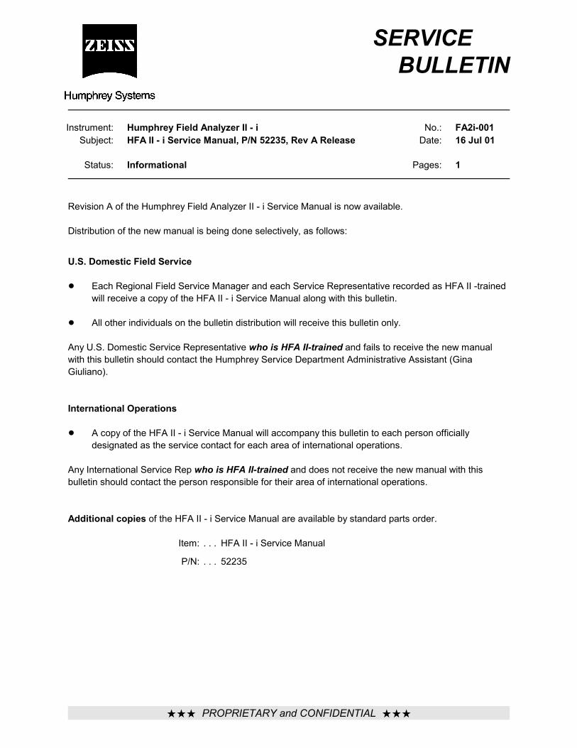
ÚÚÚ PROPRIETARY and CONFIDENTIAL ÚÚÚ
SERVICE BULLETIN
Instrument: Humphrey Field Analyzer II - iSubject: HFA II - i Service Manual, P/N 52235, Rev A Release
No.: FA2i-001Date: 16 Jul 01
Status: Informational Pages: 1
Revision A of the Humphrey Field Analyzer II - i Service Manual is now available.
Distribution of the new manual is being done selectively, as follows:
U.S. Domestic Field Service
! Each Regional Field Service Manager and each Service Representative recorded as HFA II -trainedwill receive a copy of the HFA II - i Service Manual along with this bulletin.
! All other individuals on the bulletin distribution will receive this bulletin only.
Any U.S. Domestic Service Representative who is HFA II-trained and fails to receive the new manualwith this bulletin should contact the Humphrey Service Department Administrative Assistant (GinaGiuliano).
International Operations
! A copy of the HFA II - i Service Manual will accompany this bulletin to each person officiallydesignated as the service contact for each area of international operations.
Any International Service Rep who is HFA II-trained and does not receive the new manual with thisbulletin should contact the person responsible for their area of international operations.
Additional copies of the HFA II - i Service Manual are available by standard parts order.
Item: . . . HFA II - i Service Manual
P/N: . . . 52235
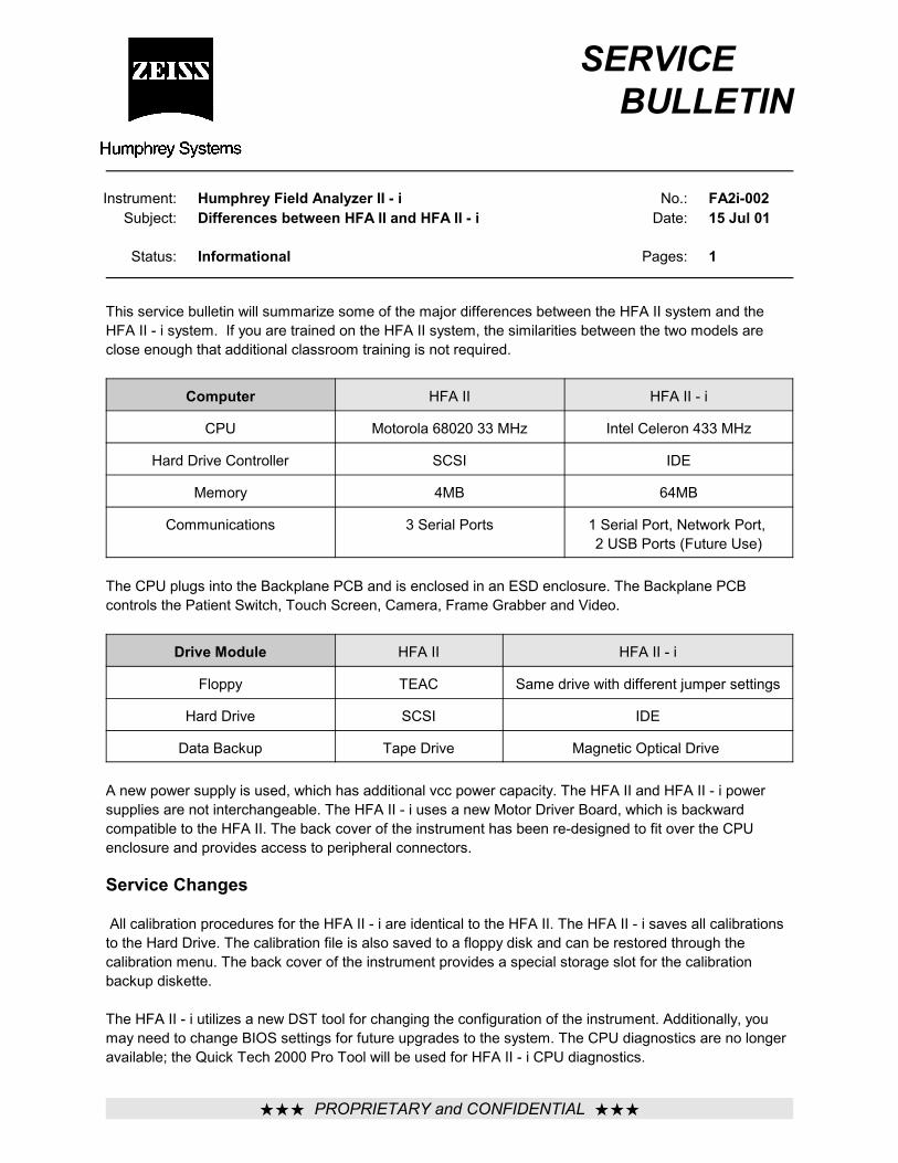
ÚÚÚ PROPRIETARY and CONFIDENTIAL ÚÚÚ
SERVICE BULLETIN
Instrument: Humphrey Field Analyzer II - iSubject: Differences between HFA II and HFA II - i
No.: FA2i-002Date: 15 Jul 01
Status: Informational Pages: 1
This service bulletin will summarize some of the major differences between the HFA II system and theHFA II - i system. If you are trained on the HFA II system, the similarities between the two models areclose enough that additional classroom training is not required.
Computer HFA II HFA II - i
CPU Motorola 68020 33 MHz Intel Celeron 433 MHz
Hard Drive Controller SCSI IDE
Memory 4MB 64MB
Communications 3 Serial Ports 1 Serial Port, Network Port, 2 USB Ports (Future Use)
The CPU plugs into the Backplane PCB and is enclosed in an ESD enclosure. The Backplane PCBcontrols the Patient Switch, Touch Screen, Camera, Frame Grabber and Video.
Drive Module HFA II HFA II - i
Floppy TEAC Same drive with different jumper settings
Hard Drive SCSI IDE
Data Backup Tape Drive Magnetic Optical Drive
A new power supply is used, which has additional vcc power capacity. The HFA II and HFA II - i powersupplies are not interchangeable. The HFA II - i uses a new Motor Driver Board, which is backwardcompatible to the HFA II. The back cover of the instrument has been re-designed to fit over the CPUenclosure and provides access to peripheral connectors.
Service Changes
All calibration procedures for the HFA II - i are identical to the HFA II. The HFA II - i saves all calibrationsto the Hard Drive. The calibration file is also saved to a floppy disk and can be restored through thecalibration menu. The back cover of the instrument provides a special storage slot for the calibrationbackup diskette.
The HFA II - i utilizes a new DST tool for changing the configuration of the instrument. Additionally, youmay need to change BIOS settings for future upgrades to the system. The CPU diagnostics are no longeravailable; the Quick Tech 2000 Pro Tool will be used for HFA II - i CPU diagnostics.
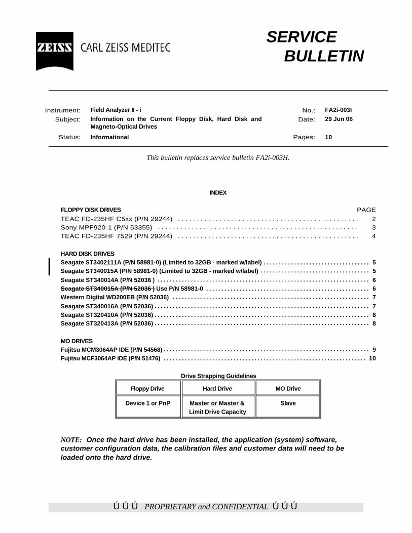
ÚÚÚ PROPRIETARY and CONFIDENTIAL ÚÚÚ
SERVICE BULLETIN
Instrument: Field Analyzer II - i
Subject: Information on the Current Floppy Disk, Hard Disk andMagneto-Optical Drives
No.: FA2i-003I
Date: 29 Jun 06
Status: Informational Pages: 10
This bulletin replaces service bulletin FA2i-003H.
INDEX
FLOPPY DISK DRIVES PAGETEAC FD-235HF C5xx (P/N 29244) . . . . . . . . . . . . . . . . . . . . . . . . . . . . . . . . . . . . . . . . . . . . . . . . 2Sony MPF920-1 (P/N 53355) . . . . . . . . . . . . . . . . . . . . . . . . . . . . . . . . . . . . . . . . . . . . . . . . . . . . . 3TEAC FD-235HF 7529 (P/N 29244) . . . . . . . . . . . . . . . . . . . . . . . . . . . . . . . . . . . . . . . . . . . . . . . . 4
HARD DISK DRIVESSeagate ST3402111A (P/N 58981-0) (Limited to 32GB - marked w/label) . . . . . . . . . . . . . . . . . . . . . . . . . . . . . . . . . . . 5Seagate ST340015A (P/N 58981-0) (Limited to 32GB - marked w/label) . . . . . . . . . . . . . . . . . . . . . . . . . . . . . . . . . . . . 5Seagate ST340014A (P/N 52036 ) . . . . . . . . . . . . . . . . . . . . . . . . . . . . . . . . . . . . . . . . . . . . . . . . . . . . . . . . . . . . . . . . . . . . . . 6Seagate ST340015A (P/N 52036 ) Use P/N 58981-0 . . . . . . . . . . . . . . . . . . . . . . . . . . . . . . . . . . . . . . . . . . . . . . . . . . . . . . 6Western Digital WD200EB (P/N 52036) . . . . . . . . . . . . . . . . . . . . . . . . . . . . . . . . . . . . . . . . . . . . . . . . . . . . . . . . . . . . . . . . . 7Seagate ST340016A (P/N 52036) . . . . . . . . . . . . . . . . . . . . . . . . . . . . . . . . . . . . . . . . . . . . . . . . . . . . . . . . . . . . . . . . . . . . . . . 7Seagate ST320410A (P/N 52036) . . . . . . . . . . . . . . . . . . . . . . . . . . . . . . . . . . . . . . . . . . . . . . . . . . . . . . . . . . . . . . . . . . . . . . . 8Seagate ST320413A (P/N 52036) . . . . . . . . . . . . . . . . . . . . . . . . . . . . . . . . . . . . . . . . . . . . . . . . . . . . . . . . . . . . . . . . . . . . . . . 8
MO DRIVESFujitsu MCM3064AP IDE (P/N 54568) . . . . . . . . . . . . . . . . . . . . . . . . . . . . . . . . . . . . . . . . . . . . . . . . . . . . . . . . . . . . . . . . . . . . 9Fujitsu MCF3064AP IDE (P/N 51476) . . . . . . . . . . . . . . . . . . . . . . . . . . . . . . . . . . . . . . . . . . . . . . . . . . . . . . . . . . . . . . . . . . . 10
Drive Strapping Guidelines
Floppy Drive Hard Drive MO Drive
Device 1 or PnP Master or Master &Limit Drive Capacity
Slave
NOTE: Once the hard drive has been installed, the application (system) software,customer configuration data, the calibration files and customer data will need to beloaded onto the hard drive.
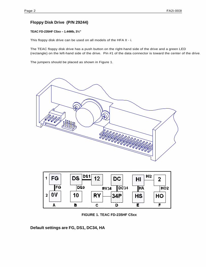
Page 2 FA2i-003I
Floppy Disk Drive (P/N 29244)
TEAC FD-235HF C5xx – 1.44Mb, 3½"
This floppy disk drive can be used on all models of the HFA II - i.
The TEAC floppy disk drive has a push button on the right-hand side of the drive and a green LED(rectangle) on the left-hand side of the drive. Pin #1 of the data connector is toward the center of the drive.
The jumpers should be placed as shown in Figure 1.
FIGURE 1. TEAC FD-235HF C5xx
Default settings are FG, DS1, DC34, HA
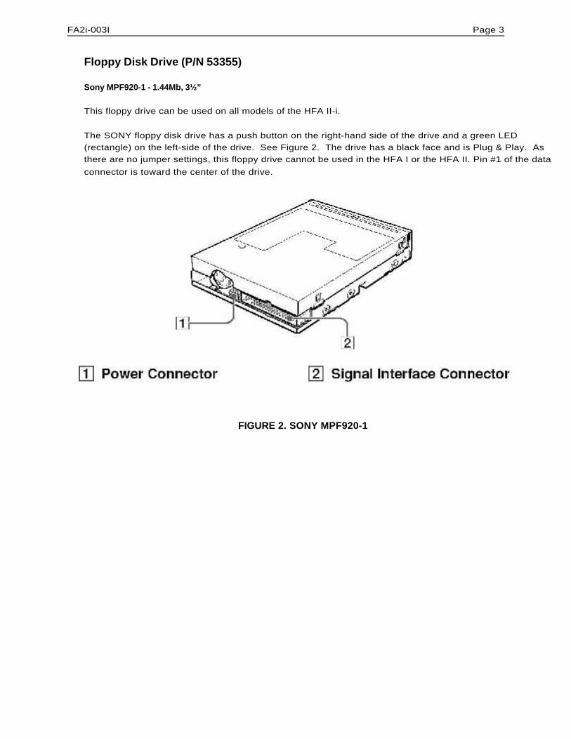
FA2i-003I Page 3
Floppy Disk Drive (P/N 53355)
Sony MPF920-1 - 1.44Mb, 3½”
This floppy drive can be used on all models of the HFA II-i.
The SONY floppy disk drive has a push button on the right-hand side of the drive and a green LED(rectangle) on the left-side of the drive. See Figure 2. The drive has a black face and is Plug & Play. Asthere are no jumper settings, this floppy drive cannot be used in the HFA I or the HFA II. Pin #1 of the dataconnector is toward the center of the drive.
FIGURE 2. SONY MPF920-1
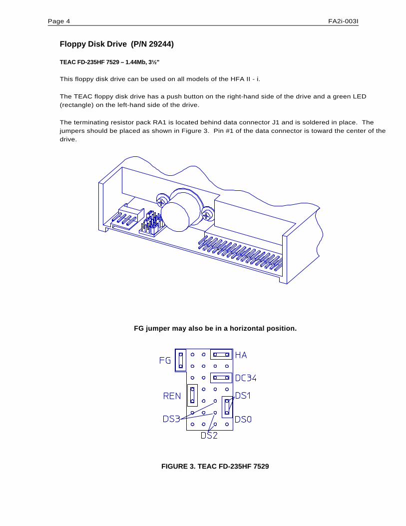
Page 4 FA2i-003I
Floppy Disk Drive (P/N 29244)
TEAC FD-235HF 7529 – 1.44Mb, 3½"
This floppy disk drive can be used on all models of the HFA II - i.
The TEAC floppy disk drive has a push button on the right-hand side of the drive and a green LED(rectangle) on the left-hand side of the drive.
The terminating resistor pack RA1 is located behind data connector J1 and is soldered in place. Thejumpers should be placed as shown in Figure 3. Pin #1 of the data connector is toward the center of thedrive.
FG jumper may also be in a horizontal position.
FIGURE 3. TEAC FD-235HF 7529
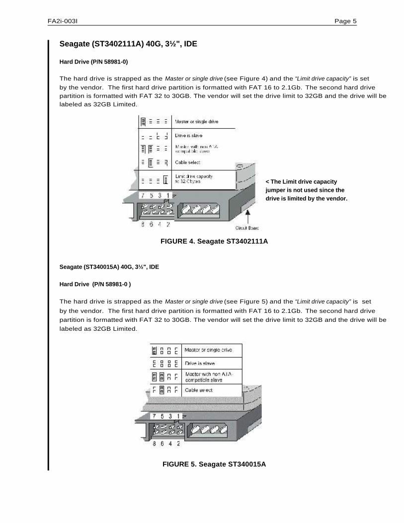
FA2i-003I Page 5
Seagate (ST3402111A) 40G, 3½", IDE
Hard Drive (P/N 58981-0)
The hard drive is strapped as the Master or single drive (see Figure 4) and the “Limit drive capacity” is setby the vendor. The first hard drive partition is formatted with FAT 16 to 2.1Gb. The second hard drivepartition is formatted with FAT 32 to 30GB. The vendor will set the drive limit to 32GB and the drive will belabeled as 32GB Limited.
< The Limit drive capacity jumper is not used since thedrive is limited by the vendor.
FIGURE 4. Seagate ST3402111A
Seagate (ST340015A) 40G, 3½", IDE
Hard Drive (P/N 58981-0 )
The hard drive is strapped as the Master or single drive (see Figure 5) and the “Limit drive capacity” is set
by the vendor. The first hard drive partition is formatted with FAT 16 to 2.1Gb. The second hard drivepartition is formatted with FAT 32 to 30GB. The vendor will set the drive limit to 32GB and the drive will belabeled as 32GB Limited.
FIGURE 5. Seagate ST340015A
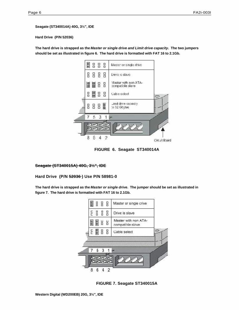
Page 6 FA2i-003I
Seagate (ST340014A) 40G, 3½", IDE
Hard Drive (P/N 52036)
The hard drive is strapped as the Master or single drive and Limit drive capacity. The two jumpersshould be set as illustrated in figure 6. The hard drive is formatted with FAT 16 to 2.1Gb.
FIGURE 6. Seagate ST340014A
Seagate (ST340015A) 40G, 3½", IDE
Hard Drive (P/N 52036 ) Use P/N 58981-0
The hard drive is strapped as the Master or single drive. The jumper should be set as illustrated infigure 7. The hard drive is formatted with FAT 16 to 2.1Gb.
FIGURE 7. Seagate ST340015A
Western Digital (WD200EB) 20G, 3½", IDE
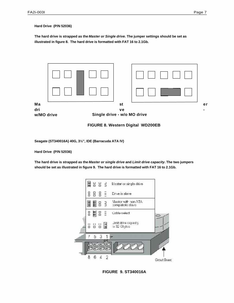
FA2i-003I Page 7
Hard Drive (P/N 52036)
The hard drive is strapped as the Master or Single drive. The jumper settings should be set as
illustrated in figure 8. The hard drive is formatted with FAT 16 to 2.1Gb.
Ma st erdri ve -w/MO drive Single drive - w/o MO drive
FIGURE 8. Western Digital WD200EB
Seagate (ST340016A) 40G, 3½", IDE (Barracuda ATA IV)
Hard Drive (P/N 52036)
The hard drive is strapped as the Master or single drive and Limit drive capacity. The two jumpersshould be set as illustrated in figure 9. The hard drive is formatted with FAT 16 to 2.1Gb.
FIGURE 9. ST340016A
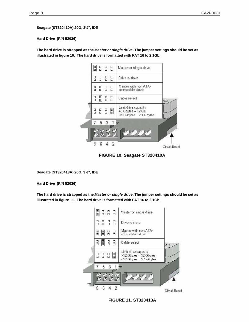
Page 8 FA2i-003I
Seagate (ST320410A) 20G, 3½", IDE
Hard Drive (P/N 52036)
The hard drive is strapped as the Master or single drive. The jumper settings should be set asillustrated in figure 10. The hard drive is formatted with FAT 16 to 2.1Gb.
FIGURE 10. Seagate ST320410A
Seagate (ST320413A) 20G, 3½", IDE
Hard Drive (P/N 52036)
The hard drive is strapped as the Master or single drive. The jumper settings should be set asillustrated in figure 11. The hard drive is formatted with FAT 16 to 2.1Gb.
FIGURE 11. ST320413A
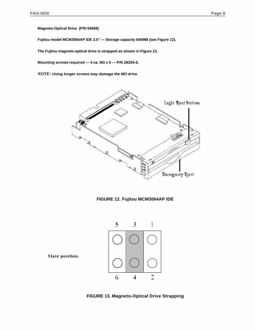
FA2i-003I Page 9
Magneto-Optical Drive (P/N 54568)
Fujitsu model MCM3064AP IDE 3.5" — Storage capacity 640MB (see Figure 12).
The Fujitsu magneto-optical drive is strapped as shown in Figure 13.
Mounting screws required — 4 ea. M3 x 6 — P/N 28293-6.
NOTE: Using longer screws may damage the MO drive.
FIGURE 12. Fujitsu MCM3064AP IDE
Slave position.
FIGURE 13. Magneto-Optical Drive Strapping
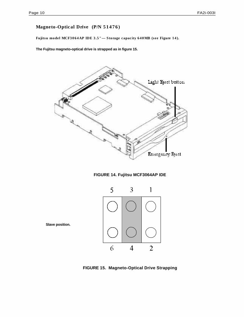
Page 10 FA2i-003I
Magneto-Optical Drive (P/N 51476)
Fujitsu model MCF3064AP IDE 3.5" — Storage capacity 640MB (see Figure 14).
The Fujitsu magneto-optical drive is strapped as in figure 15.
FIGURE 14. Fujitsu MCF3064AP IDE
Slave position.
FIGURE 15. Magneto-Optical Drive Strapping
ÚÚÚ PROPRIETARY and CONFIDENTIAL ÚÚÚ
SERVICE BULLETIN
Instrument: Humphrey Field Analyzer II - iSubject: HFA II - i Serial Transfer Cables Released
No.: FA2i-004Date: 27 Aug 01
Status: Informational Pages: 1
Two new cables have been released for the HFA II - i serial data transfer.
General Information
One cable is required to transfer patient data between an HFA 1 (600 Series) instrument and an HFA II - i(700 Series) instrument. The other cable is required to transfer data between an HFA II and an HFA II - i.
(Refer to HFA II - i User’s guide for the data transfer set up instructions and Appendix C of the HFA II - i Service Manual for detailed Data Transfer procedures.)
P/N 52416 Connectors; DB9 to DB25 HFA I to HFA II - i Serial cable
P/N 52417 Connectors: DB9 to DB9 HFA II to HFA II - i Serial Cable
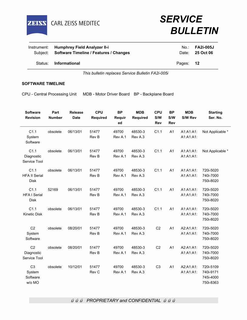
ÚÚÚ PROPRIETARY and CONFIDENTIAL ÚÚÚ
SERVICE BULLETIN
Instrument: Humphrey Field Analyzer II-iSubject: Software Timeline / Features / Changes
No.: FA2i-005JDate: 25 Oct 06
Status: Informational Pages: 12
This bulletin replaces Service Bulletin FA2i-005i
SOFTWARE TIMELINE
CPU - Central Processing Unit MDB - Motor Driver Board BP - Backplane Board
SoftwareRevision
PartNumber
ReleaseDate
CPURequired
BPRequir
ed
MDBRequired
CPUS/WRev
BPS/WRev
MDBS/W Rev
StartingSer. No.
C1.1System
Software
obsolete 06/13/01 51477Rev B
49700Rev A.1
48530-3Rev A.3
C1.1 A1 A1:A1:A1:A1:A1:A1:
Not Applicable *
C1.1Diagnostic
Service Tool
obsolete 06/13/01 51477Rev B
49700Rev A.1
48530-3Rev A.3
C1.1 A1 A1:A1:A1:A1:A1:A1:
Not Applicable *
C1.1HFA II Serial
Disk
obsolete 06/13/01 51477Rev B
49700Rev A.1
48530-3Rev A.3
C1.1 A1 A1:A1:A1:A1:A1:A1:
720i-5020740i-7000750i-8020
C1.1HFA I Serial
Disk
52169 06/13/01 51477Rev B
49700Rev A.1
48530-3Rev A.3
C1.1 A1 A1:A1:A1:A1:A1:A1:
720i-5020740i-7000750i-8020
C1.1Kinetic Disk
obsolete 06/13/01 51477Rev B
49700Rev A.1
48530-3Rev A.3
C1.1 A1 A1:A1:A1:A1:A1:A1:
720i-5020740i-7000750i-8020
C2System
Software
obsolete 08/20/01 51477Rev B
49700Rev A.1
48530-3Rev A.3
C2 A1 A2:A1:A1:A1:A1:A1:
720i-5020740i-7000750i-8020
C2Diagnostic
Service Tool
obsolete 08/20/01 51477Rev B
49700Rev A.1
48530-3Rev A.3
C2 A1 A2:A1:A1:A1:A1:A1:
720i-5020740i-7000750i-8020
C3System
Softwarew/o MO
obsolete 10/12/01 51477Rev C
49700Rev A.1
48530-3Rev A.3
C3 A1 A2:A1:A1:A1:A1:A1:
720i-5109740i-9171 745i-4000750i-8363

Page 2 FA2i-005J
SoftwareRevision
PartNumber
ReleaseDate
CPURequired
BPRequir
ed
MDBRequired
CPUS/WRev
BPS/WRev
MDBS/W Rev
StartingSer. No.
C3System
Softwarewith MO
obsolete 10/12/01 51477Rev C
49700Rev A.1
48530-3Rev A.3
C3 A1 A2:A1:A1:A1:A1:A1:
720i-5109740i-9171 745i-4000750i-8363
C3Diagnostic
Service Toolw/o MO
obsolete 10/12/01 51477Rev C
49700Rev A.1
48530-3Rev A.3
C3 A1 A2:A1:A1:A1:A1:A1:
720i-5109740i-9171 745i-4000750i-8363
C3Diagnostic
Service Toolwith MO
obsolete 10/12/01 51477Rev C
49700Rev A.1
48530-3Rev A.3
C3 A1 A2:A1:A1:A1:A1:A1:
720i-5109740i-9171 745i-4000750i-8363
A1GermanOptionsTests
52862 10/12/01 51477Rev C
49700Rev A.1
48530-3Rev A.3
C3 A1 A2:A1:A1:A1:A1:A1:
720i-5109740i-9171 745i-4000750i-8363
A2HFA II - i
BIOS
52847 10/12/01 51477Rev C
49700Rev A.1
48530-3Rev A.3
C3 A1 A2:A1:A1:A1:A1:A1:
720i-5109740i-9171 745i-4000750i-8363
C3.1System
Software
obsolete 12/5/2001 51477Rev C
49700Rev A.1
48530-3Rev A.3
C3.1 A1 A2:A1:A1:A1:A1:A1:
720i-5316740i-9584745i-4177750i-8517
C3.1Diagnostic
Service Tool
53325Obsolete
12/5/2001 51477Rev C
49700RevA.1
48530-3Rev A.3
C3.1 A1 A2:A1:A1:A1:A1:
A1:
720i-5316740i- 9584745i-4177750i-8517
C1.2KineticDisk
53425 12/5/2001
51477Rev C
49700Rev A.1
48530-3Rev A.3
C3.1 A1 A2:A1:A1:A1:A1:A1:
720i-5316740i-9584745i-4177750i-8517
C1.2HFA II Serial
Disk
53426 12/5/2001 51477Rev C
49700Rev A.1
48530-3Rev A.3
C3.1 A1 A2:A1:A1:A1:A1:A1:
720i-5316740i-9584745i-4177750i-8517
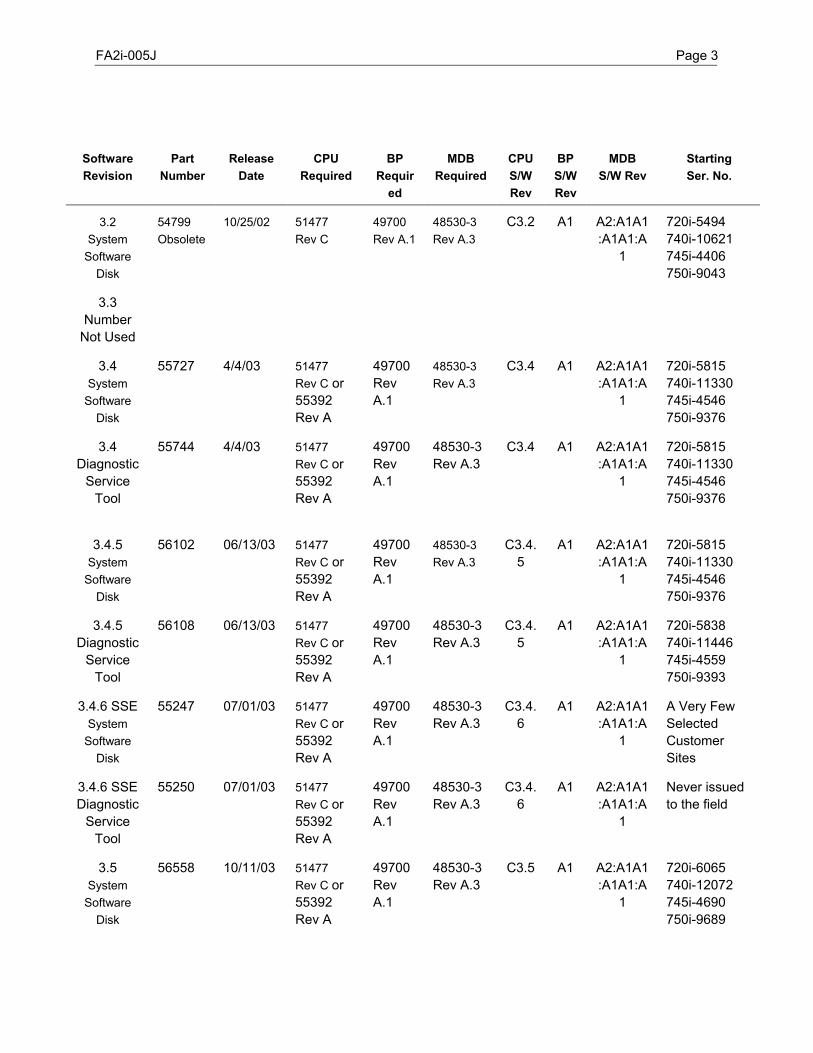
FA2i-005J Page 3
SoftwareRevision
PartNumber
ReleaseDate
CPURequired
BPRequir
ed
MDBRequired
CPUS/WRev
BPS/WRev
MDBS/W Rev
StartingSer. No.
3.2System
SoftwareDisk
54799Obsolete
10/25/02 51477Rev C
49700Rev A.1
48530-3Rev A.3
C3.2 A1 A2:A1A1:A1A1:A
1
720i-5494740i-10621745i-4406750i-9043
3.3Number
Not Used
3.4System
SoftwareDisk
55727 4/4/03 51477Rev C or55392Rev A
49700RevA.1
48530-3Rev A.3
C3.4 A1 A2:A1A1:A1A1:A
1
720i-5815740i-11330745i-4546750i-9376
3.4Diagnostic
ServiceTool
55744 4/4/03 51477Rev C or55392Rev A
49700RevA.1
48530-3Rev A.3
C3.4 A1 A2:A1A1:A1A1:A
1
720i-5815740i-11330745i-4546750i-9376
3.4.5System
SoftwareDisk
56102 06/13/03 51477Rev C or55392Rev A
49700RevA.1
48530-3Rev A.3
C3.4.5
A1 A2:A1A1:A1A1:A
1
720i-5815740i-11330745i-4546750i-9376
3.4.5Diagnostic
ServiceTool
56108 06/13/03 51477Rev C or55392Rev A
49700RevA.1
48530-3Rev A.3
C3.4.5
A1 A2:A1A1:A1A1:A
1
720i-5838740i-11446745i-4559750i-9393
3.4.6 SSESystem
SoftwareDisk
55247 07/01/03 51477Rev C or55392Rev A
49700RevA.1
48530-3Rev A.3
C3.4.6
A1 A2:A1A1:A1A1:A
1
A Very FewSelectedCustomerSites
3.4.6 SSEDiagnostic
ServiceTool
55250 07/01/03 51477Rev C or55392Rev A
49700RevA.1
48530-3Rev A.3
C3.4.6
A1 A2:A1A1:A1A1:A
1
Never issuedto the field
3.5System
SoftwareDisk
56558 10/11/03 51477Rev C or55392Rev A
49700RevA.1
48530-3Rev A.3
C3.5 A1 A2:A1A1:A1A1:A
1
720i-6065740i-12072 745i-4690750i-9689
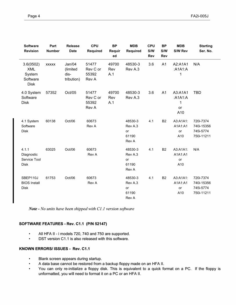
Page 4 FA2i-005J
SoftwareRevision
PartNumber
ReleaseDate
CPURequired
BPRequir
ed
MDBRequired
CPUS/WRev
BPS/WRev
MDBS/W Rev
StartingSer. No.
3.6(0502)XML
SystemSoftware
Disk
xxxxx Jan/04(limiteddis-tribution)
51477Rev C or55392Rev A
49700RevA.1
48530-3Rev A.3
3.6 A1 A2:A1A1:A1A1:A
1
N/A
4.0 SystemSoftwareDisk
57352 Oct/05 51477Rev C or55392Rev A
49700RevA.1
48530-3Rev A.3
3.6 A1 A3:A1A1:A1A1:A
1or
A10
TBD
4.1 SystemSoftwareDisk
60138 Oct/06 60673 Rev A
48530-3Rev A.3or61190Rev A
4.1 B2 A3:A1A1:A1A1:A1
or A10
720i-7374740i-15356 745i-5774750i-11211
4.1.1DiagnosticService ToolDisk
63025 Oct/06 60673 Rev A
48530-3Rev A.3or61190Rev A
4.1 B2 A3:A1A1:A1A1:A1
or A10
N/A
SBEP110JBIOS InstallDisk
61753 Oct/06 60673 Rev A
48530-3Rev A.3or61190Rev A
4.1 B2 A3:A1A1:A1A1:A1
or A10
720i-7374740i-15356 745i-5774750i-11211
FA2i-005J Page 5
When using a magneto optical disk for the first time, you must first initialize it by selecting initialize disk fromthe file functions menu.If you remove a database floppy disk from the floppy drive while attempting to print from the floppy database,a “Floppy Disk Not Present” or “Error Reading From Floppy” message will appear.If attempts are made to install the HFA II - i application software on an unformatted hard drive (a nonHumphrey hard drive), the load will fail. You must first partition the hard drive as a FAT 16 single partitionsystem.
SOFTWARE FEATURES / CHANGES - Rev. C2 (P/N 52486)
The HFA II - i C2 interface is essentially the same as that of HFA II - i C1.1. However, there are changes toaccommodate the new TCP/IP interface. This installer for this version includes a touch screen only userinterface.
• All HFA II - i models 720, 740 and 750 are supported.DST version C2 is also released with this software (P/N 52615).This C2 installer installs the C2 version of the HFA II - i system software including the A2 version of the motorboard software required by the motor board (P/N 48530-3).
KNOWN ERRORS/ ISSUES - Rev. C2
• Same issues apply to C2 as on the C1.1, there have been no corrections made.Intermittent Kinetic printing defect on PRINTREX printers only. The PRINTREX printers some times (about10% of the time) print Kinetic tests with one byte missing. However, if you occasionally print a second timethis problem should be gone.The Application and the DST installer only accept operator response via the touch screen and not via thekeyboard. This is intentional to fit the application and the DST installer on a minimum number of floppy disks.However, both the system application and the DST application support the keyboard, touch screen, andmouse.C2 software performed a date check upon startup. If the date was later than Jan 1989, the instrument wouldgo through the normal boot process. If the date was not valid, the system would not boot any further, hangingthe system.C2 software will not boot if the MO drive is disconnected or inoperative.
SOFTWARE FEATURES - Rev. C3 (P/N 52907- No MO, P/N 52944 - MO)
Two distinct sets of software have been created for the C3 System Software release. One set is used for instrumentswith a Magnetic Optical Drive. The second set is for units without Magnetic Optical Drive.
• Allows loading of system software via floppy diskettes with use of only the touch screen.• Allows loading of optional software without having to restart the system.• Recognizes Models 735i and 745i.• German Optional test strategy disk shall enable the German specialty tests and the Optima strategy.• The Magnetic Optical Drive is now an option for the models 720i, 735i, 740i, and 745i.• DST will allow the adding or removal of the Magneto Optical Drive via a button.• DST will have model/hardware options for the 720i, 735i, 740i, 745i and 750i models.• Invalid dates found at the startup will initiate a prompt that states, ”Please contact Field Service. Instrument
Date and Time are Incorrect. This may be due to low battery voltage, you can temporarily correct the timeand date. The date will automatically be set to Jan 01,1989".
Page 6 FA2i-005J
• C3 software will not boot if the MO drive is disconnected or inoperative.• Uninitialized MO diskettes will cause the system to hang during an attempt to perform a backup from hard
drive.• Attempting to load the C3-MO system software on a 750i instrument that has system software revision C2 will
result in several 750 unique features being disabled. The instrument will have a 745 like model set of features.• There are some issues using the C3 and earlier software with the HP LaserJet 4L printer.
SOFTWARE FEATURES - Rev. C3.1 (P/N 53324)
• Allows instrument to boot if the magnetic optical drive is disconnected or inoperative.• System software will continue to function if a backup is attempted with an uninitialized magnetic optical disk.• Will not disable certain 750I features if loaded over C2 software.• Both Printrex and HP Laserjet printing have been improved. • Includes an internal self-test for date checking. The self-test is set to run in the background unnoticed,
customers may see a pop up window asking them to verify the date shown.
• Floppy databases created on the HFA II can not be restored on the HFA 2i. • Blank screen appears at startup.• You can only re-initialize a floppy on the HFA 2i. If a floppy is unformatted it must be formatted on a PC prior
to use on the HFA2i.• Removing a floppy disk from the floppy drive during a printout will create errors.• You may see shifted text or extra slashes (/) on the extreme left side of a Printex printout.• Models 720 may show either 115908 as a software option code if revision 3.1 is loaded over a C2.X revision.
The normal 11590C software option code can be restored on instruments with the 115908 soft option codeby restoring the calibration configuration diskette on the system. Note that it is not necessary to change thecode from 115908. All 720 units with the 115908 code will function normally.
SOFTWARE FEATURES - DST Rev. C3.1 (P/N 53325)
• The C3.1 DST consists of one set of disks that works for instrument with or without a Magnetic Optical drive.Otherwise the DST is identical to the C3 revision.
• The DST tool installer only accepts input from the touch screen. Keyboard input will be ignored during theinstallation. Keyboard, touch screen and mouse inputs will function after the DST is running.
SOFTWARE FEATURES - Rev. 3.2 (P/N 54799)
• The 3.2 application software changes the NVM printout to include a set of preferred values that will reducethe probability that light intensity errors will occur.
FA2i-005J Page 7
• The 3.2 application software provides an ‘evaluate test date’ function that will scan the HFA 2i database fortest dates older than 8-24-01, or later than the current date. This function is used to detect questionable testdates that may have been entered as a result of a real time clock read failure that could occur in earliersoftware revisions. See Service Bulletin FA2i-015(X) for details.
• The 3.2 application software corrects the condition that results in the incorrect patient name on the printouts. See Service Bulletin FA2i-015(X) for details.
• The 3.2 application software has the same issues as the C3.1 revision other than those fixed as indicatedabove.
SOFTWARE FEATURES - Rev. 3.4 (P/N 55727)
• The 3.4 application software corrects a problem with the keyboard initialization process that results in spuriouscharacters in the data input screen displays.
• Modifications to the Change Parameters screens have been made to make it easier to see the optionsavailable for the parameter selected, based on the test strategy. For example, if SITA STANDARD is the teststrategy selected, the “Stimulus Size” selection displayed will be III. As size III stimulus is the only stimulussize available for a SITA test, none of the other stimulus sizes will be active; they will be “ghosted” or “grayedout”.
• All instruments having the CPU part number 55392 must use the 3.4 revision application software. Revision3.4 application software is compatible with the 51477 CPU that use the 801-0010-03 (original release) BIOS.Details of the SBEP103B BIOS and 55392 CPU are discussed in bulletin HFA2i-017. If a previous versionof the application software is used with the 55392 CPU board, spurious characters will be seen in the datainput screen displays.
• The 3.4. application software has the same issues as the C3.1 revision other than those fixed as indicatedabove.
SOFTWARE FEATURES - DST Rev. 3.4 (P/N 55744)
• The DST for rev 3.4 application software was designed to work with CPU part number 55392. • The DST 3.4 will function with any HFA2i running the 3.1 or higher revision application software loaded on the
instrument with the 51477 CPU. CPU part number 51477 uses the 801-0010-03 (original release) BIOS. • No functional changes were made to the DST other than the correction for the spurious characters.
• The 3.4 DST software must be used with instruments with CPU part number 55392. All CPU’s with partnumber 55392 use the SBEP103B BIOS. Details of the 55392 CPU and the SBEP103B BIOS are discussedin Service BulletinFA2i-017. If a previous version of the DST is used with the 55392 CPU board, spuriouscharacters will be seen in the data input screen displays.
Page 8 FA2i-005J
Rev. 3.4.5
• All instruments having the CPU part number 55392 must use the 3.4 or 3.4.5 Application software. Softwarerevision 3.4 and revision 3.4.5 application software are compatible with the 51477 CPU that uses the originalrelease BIOS. Details of the new BIOS and 55392 CPU are discussed in bulletin HFA2i-017. If a previousversion of the application software is used with the 55392 CPU board, spurious characters will be seen in thedata input screen displays.
• The 3.4.5 application software has the same issues as the C3.1 revision other than those fixed as indicatedabove.
• All instruments having the CPU part number 55392 must use the 3.4 or 3.4.5 DST software. DST softwarerevision 3.4 and revision 3.4.5 DST software are compatible with the 51477 CPU that uses the original releaseBIOS. Details of the new BIOS and 55392 CPU are discussed in bulletin HFA2i-017. If a previous versionof the DST software is used with the 55392 CPU board, spurious characters will be seen in the data inputscreen displays.
• The 3.4.5 DST software has the same issues as the C3.1 revision DST other than those fixed as indicatedabove.
• For HFA2P version 3.4.6 SSE, the Threshold Parameters Setup menu has been greatly remodeled. Themenu no longer displays alerts when the setting of one parameter conflicts with that of another parameter. Instead, priority is given to the strategy, second to blue-yellow. Any parameter in conflict with strategy willbe set to its correct value without warning. If only one value for a given parameter is valid for the selectedstrategy, then this parameter shall be disabled and set to the valid value.
FA2i-005J Page 9
KNOWN ERRORS/ ISSUES - Application Software Rev. 3.4.6
• Blank screens still appear during startup.• A database cannot be restored from a backup floppy made on an HFA II. You can only re-initialize a floppy
disk. This is equivalent to a quick format on a PC. If the floppy is unformatted, you will need to format it ona PC or an HFA2.
• You can leave a floppy in the drive during boot if you change the CMOS settings so that the instrument firstattempts to boot from the hard drive and then attempts to boot from floppy.
• Do not remove a database floppy disk while printing from the floppy database.• The 3.4.6 application software has the same issues as the C3.1 revision.
SOFTWARE FEATURES - DST Rev. 3.4.6 SSE (P/N 55250)
• The DST for rev 3.4.6 application software was designed to work with rev 3.4.6 application software only.It will not be issued to the field. Any request for exceptions should be directed to CZMI Technical Support.
• No new errors known.
• Before the GPA software will function, the GPA licensing process must be completed. Details of the licensingprocess will be available in the FA2i-025 service bulletin.
• The “i” screen has been updated to show if the GPA function is enabled or not.
KNOWN ERRORS/ ISSUES - Application Software Rev. 3.5
• If the date of birth information is entered after the name information in the Patient Information screen and thedate is entered as MM/DD/YYYY, an error display indicating that the DOB is incorrectly input will result. If theDOB is entered before the patient name or the DOB is entered in the MM/DD/YY format, it will be correctlydisplayed.
SOFTWARE FEATURES - Rev. 3.6 - XML Application Software (P/N xxxxx) [4 - disk set]
• Not for commercial release — the HFA2P revision 3.6 software provides the application code needed toexport exam data in XML format and the export of print images in bitmap file format.
• Automatically export the XML files at the end of the exam or at any time on command using the Transfer Testsmenu.
• Automatically export the XML single page print out in bitmap file format at the end of the exam or at any timeon command using the Transfer Tests menu.
Page 10 FA2i-005J
KNOWN ERRORS/ ISSUES - Application Software Rev. 3.6 - XML
• The HFA2P network will not function if an active network connection is not available at boot time.• The FTP password entered using versions prior to version 3.6(0500), will get corrupted because the new
version expects an encrypted password. The FTP password needs to be re-entered with the new version.• Kinetic exams are not transferred.• User can only specify one server IP address for Data Export and TCP/IP transfers in HFA II - Serial format.
This release does not support specifying two servers independently.
RESTRICTIONS / LIMITATIONS
• Current release does not support exporting of XML files for Kinetic exams.• Only single page prints can be exported in bitmap file format.• NOTE: This software cannot be ordered.
SOFTWARE FEATURES - Rev. 4.0 Application Software (P/N 57352)
Networking Features Standard (Optional for all models)• Archive patient data, test results and image files (tif format) to a file server.• Synchronize databases on two or more HFA2i perimeters.• Backup patient data and test results to a file server for safe external storage or off-line backup.• Restore patient data and test results from the network server to the HFA2i.• Export image files of printouts.• Must be licensed.
HFA-NET Pro Features (Optional for all models except 720i)• Import Worklists from certified EMR system.• Export patient data, image files (tif format) and test results to a certified EMR system.• Must be licensed.
Sita SWAP Features (Standard with 750i and 745i models)• Performs a SWAP (Short Wavelength Automated Perimetry) test using the SITA (Swedish Interactive Test
Algorithm).• Must be licensed.
GPA Features (Standard with 750i, 745i and 740i models).• Enhanced performance Glaucoma Progression Analysis. • Must be licensed.
Additional Features• Improved performance of Change Analysis Printout when analyzing 30-2 only printouts.• Reduction of name and exam association errors that may arise when saving tests.• Elimination of Serial Options Disk when performing a data transfer.• Elimination of Transfer Only choice on Save and Transmit Options• Improved readability of floppies created on an HFA II.• Increased name and ID field length from 24 characters to 60 characters.
FA2i-005J Page 11
SERVICE FEATURES - Application Software Rev. 4.0
• Licensing of Network, NetPro, GPA and SITA SWAP.• Configuration of Instrument for Network and NetPro.• Database Upgrade.• Save to floppy the text files of system log, information screen, and calibration values. • New tools for evaluating Networking parameters.
SERVICE CONCERNS - Application Software Rev. 4.0
• Data created on a HFA 2i with a revision 4.0 software will not be able to be saved to a HFA2i withsoftware revision lower than 4.0 or to any HFA II system. See page 2 of the HFA II-i System SoftwareUpgrade document P/N 58122.
• Database upgrade may not be possible on existing hard drive partition due to the partition being nearly full.If the existing 2.0 gigabyte partition is nearly full, a second partition may be created on the hard drive orreplacement of the hard drive with a drive that can be repartitioned to meet the system needs. A separateservice bulletin will cover this topic.
KNOWN ERRORS/ ISSUES - Application Software Rev. 4.0
• None.
SOFTWARE FEATURES - Rev. 4.1 Application Software (P/N 60138)
Changes
• Revision 4.1 software was designed to be compatible with the new EMI Box and the new Motor Driver Board.If either the new EMI box (P/N 60673) or the new MDB are used, the 4.1 software must be loaded. Detailsare presented in HFA2i-036 and HFA2i-038.
• Changes to Touch Screen Calibration – Rev 4.1 will beep when you have held your finger on the calibrationtarget for the required amount of time.
• Startup Test to Determine Calibration of Aperture – At startup of the instrument, an evaluation of correctaperture positioning takes place. Failure of the test will result in a Startup State Error 19 error that saysAperture may be misaligned. Pressing Proceed will not allow testing. Recalibration of the aperture andmeasurement of the spot ratio with a value within specification, will be required before testing can proceed.
• Startup Test to Determine Shutter Misalignment – At startup of the instrument, an evaluation of correct shutterpositioning takes place. Failure of the test will result in a Startup State Error 18 error that says Shutter maybe misaligned. Pressing Proceed will not allow testing. Recalibration will be required before testing canproceed.
New Features
• There are no new features or enhancements in the HFA2i Rev 4.1 software.
Fixes• The failure to save to a floppy disk at the end of the test when the system gives the “floppy full, please insert
a new formatted floppy” message, has been corrected. With the rev 4.1 software the tests will be saved whenthe new formatted floppy is inserted after the prompt.
• Long patient names are now displayed in accordance with the industry standards.• The setting of the default single field printout style for instruments with GPA will default to GPA rather than
classic printout once the GPA feature is licensed.
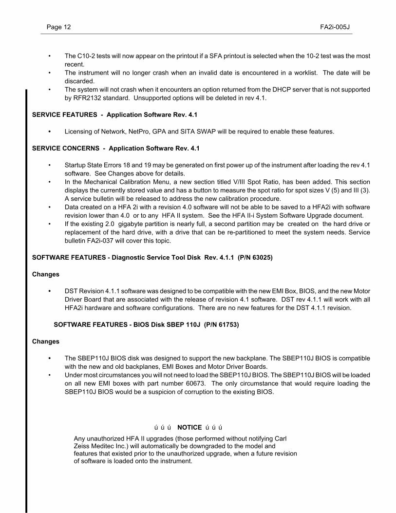
Page 12 FA2i-005J
ÚÚÚ NOTICE ÚÚÚ
Any unauthorized HFA II upgrades (those performed without notifying CarlZeiss Meditec Inc.) will automatically be downgraded to the model andfeatures that existed prior to the unauthorized upgrade, when a future revisionof software is loaded onto the instrument.
• The C10-2 tests will now appear on the printout if a SFA printout is selected when the 10-2 test was the mostrecent.
• The instrument will no longer crash when an invalid date is encountered in a worklist. The date will bediscarded.
• The system will not crash when it encounters an option returned from the DHCP server that is not supportedby RFR2132 standard. Unsupported options will be deleted in rev 4.1.
SERVICE FEATURES - Application Software Rev. 4.1
• Licensing of Network, NetPro, GPA and SITA SWAP will be required to enable these features.
SERVICE CONCERNS - Application Software Rev. 4.1
• Startup State Errors 18 and 19 may be generated on first power up of the instrument after loading the rev 4.1software. See Changes above for details.
• In the Mechanical Calibration Menu, a new section titled V/III Spot Ratio, has been added. This sectiondisplays the currently stored value and has a button to measure the spot ratio for spot sizes V (5) and III (3).A service bulletin will be released to address the new calibration procedure.
• Data created on a HFA 2i with a revision 4.0 software will not be able to be saved to a HFA2i with softwarerevision lower than 4.0 or to any HFA II system. See the HFA II-i System Software Upgrade document.
• If the existing 2.0 gigabyte partition is nearly full, a second partition may be created on the hard drive orreplacement of the hard drive, with a drive that can be re-partitioned to meet the system needs. Servicebulletin FA2i-037 will cover this topic.
SOFTWARE FEATURES - Diagnostic Service Tool Disk Rev. 4.1.1 (P/N 63025)
Changes
• DST Revision 4.1.1 software was designed to be compatible with the new EMI Box, BIOS, and the new MotorDriver Board that are associated with the release of revision 4.1 software. DST rev 4.1.1 will work with allHFA2i hardware and software configurations. There are no new features for the DST 4.1.1 revision.
SOFTWARE FEATURES - BIOS Disk SBEP 110J (P/N 61753)
Changes
• The SBEP110J BIOS disk was designed to support the new backplane. The SBEP110J BIOS is compatiblewith the new and old backplanes, EMI Boxes and Motor Driver Boards.
• Under most circumstances you will not need to load the SBEP110J BIOS. The SBEP110J BIOS will be loadedon all new EMI boxes with part number 60673. The only circumstance that would require loading theSBEP110J BIOS would be a suspicion of corruption to the existing BIOS.

ÚÚÚ PROPRIETARY and CONFIDENTIAL ÚÚÚ
SERVICE BULLETIN
Instrument: Humphrey Field Analyzer II - iSubject: HFA II - i Service Manual, P/N 52235, Rev B Release
No.: FA2i-006Date: 16 Dec 01
Status: Informational Pages: 2
An update package of revised pages for the Humphrey Field Analyzer II - i Service Guide has beenproduced to make a variety of corrections and additions. The update package updates the RevisionA field service guide (P/N 52235) to Revision B. Please remove the specified pages within the fieldservice guide and replace them with these updated pages.
Due to the large number of pages involved in this update, distribution of the update is being doneselectively, as follows:
U.S. Domestic Field Service
O Each Regional Field Service Manager and each Service Support Engineer recorded asHumphrey Field Analyzer II - i trained will receive a copy of the update along with this bulletin.
O All other individuals on the bulletin distribution will receive this bulletin only.
Any U.S. Domestic Service Representative who is Humphrey Field Analyzer II - i trained andfails to receive the update package with this bulletin should contact the Humphrey TechnicalSupport Administrative Assistant.
International Operations
! Each Affiliate and Distributor will reveive a copy of the update along with this bulletin.
! All other individuals on the bulletin distribution will receive this bulletin only.
Any International Service Rep who is Humphrey Field Analyzer II - i trained and does not receivethe update package with this bulletin should contact the person responsible for their area ofinternational operations.
Additional copies of the HFA II - i Service Manual are available by standard parts order.
Item: . . . . HFA II - i Service Manual
P/N: . . . . 52235, Rev B

Page 2 FA2i-006
Revision B Update Package for Humphrey Field Analyzer II - i Field Service Guide, P/N 52235
Highlights:
Rev B changes to the Humphrey Field Analyzer II - i FieldService Guide cover a broad range, including:
O Corrections to the Rev A edition.O Additions / corrections of part numbers.O Additions and changes to parts Removal and
Replacement.O Checkout procedural changes, additions, and deletions.O Changes and additions to tool requirements.
O Changes and additions to the additional informationprovided in the appendix.
Significant changes are noted on revised pages by a verticalbar in the left margin.
Action Required:
Replace selected pages in your Humphrey Field Analyzer II- i Field Service Guide with the corresponding Rev B updatepages enclosed.
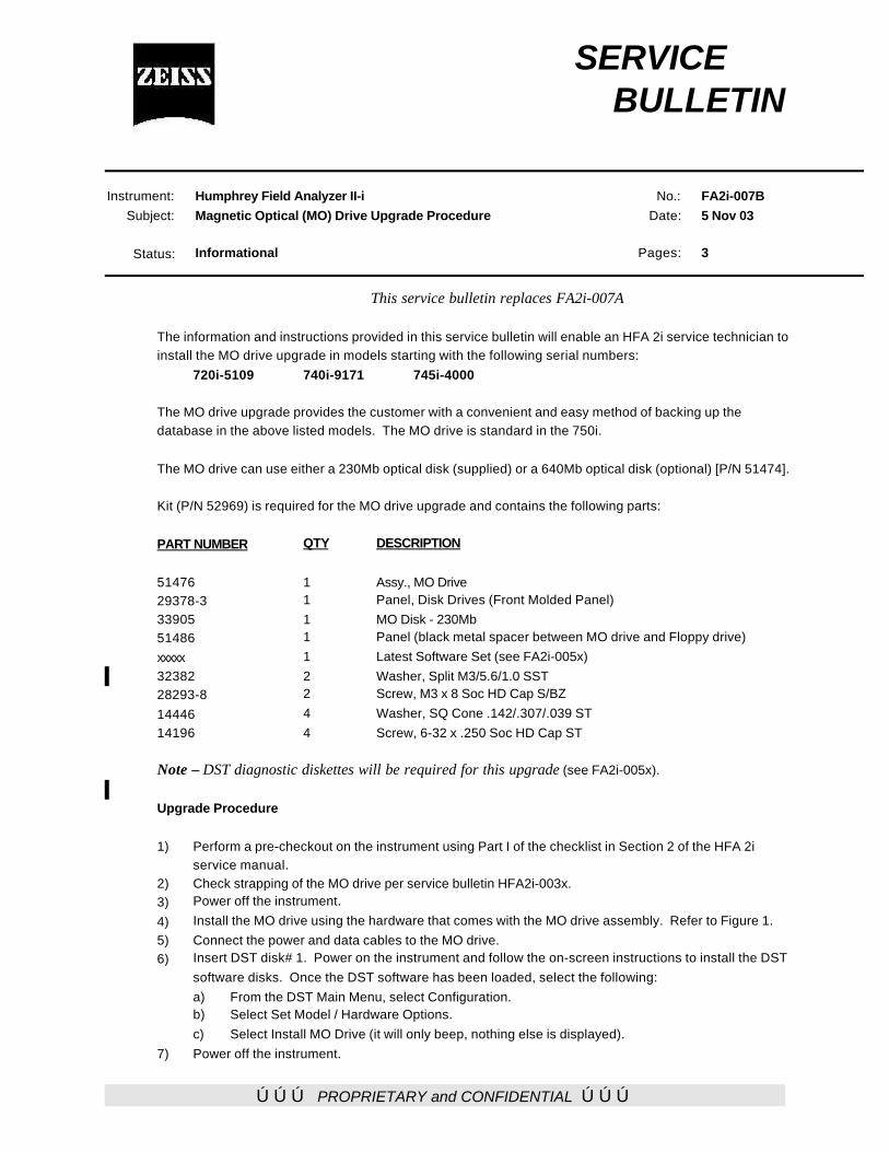
ÚÚÚ PROPRIETARY and CONFIDENTIAL ÚÚÚ
SERVICE BULLETIN
Instrument: Humphrey Field Analyzer II-iSubject: Magnetic Optical (MO) Drive Upgrade Procedure
No.: FA2i-007BDate: 5 Nov 03
Status: Informational Pages: 3
This service bulletin replaces FA2i-007A
The information and instructions provided in this service bulletin will enable an HFA 2i service technician toinstall the MO drive upgrade in models starting with the following serial numbers:
720i-5109 740i-9171 745i-4000
The MO drive upgrade provides the customer with a convenient and easy method of backing up thedatabase in the above listed models. The MO drive is standard in the 750i.
The MO drive can use either a 230Mb optical disk (supplied) or a 640Mb optical disk (optional) [P/N 51474].
Kit (P/N 52969) is required for the MO drive upgrade and contains the following parts:
PART NUMBER QTY DESCRIPTION
51476 1 Assy., MO Drive29378-3 1 Panel, Disk Drives (Front Molded Panel)33905 1 MO Disk - 230Mb51486 1 Panel (black metal spacer between MO drive and Floppy drive)
xxxxx 1 Latest Software Set (see FA2i-005x)32382 2 Washer, Split M3/5.6/1.0 SST28293-8 2 Screw, M3 x 8 Soc HD Cap S/BZ
14446 4 Washer, SQ Cone .142/.307/.039 ST14196 4 Screw, 6-32 x .250 Soc HD Cap ST
Note – DST diagnostic diskettes will be required for this upgrade (see FA2i-005x).
Upgrade Procedure
1) Perform a pre-checkout on the instrument using Part I of the checklist in Section 2 of the HFA 2iservice manual.
2) Check strapping of the MO drive per service bulletin HFA2i-003x.3) Power off the instrument.
4) Install the MO drive using the hardware that comes with the MO drive assembly. Refer to Figure 1.5) Connect the power and data cables to the MO drive.6) Insert DST disk# 1. Power on the instrument and follow the on-screen instructions to install the DST
software disks. Once the DST software has been loaded, select the following:a) From the DST Main Menu, select Configuration.b) Select Set Model / Hardware Options.c) Select Install MO Drive (it will only beep, nothing else is displayed).
7) Power off the instrument.
Page 2 FA2i-007B
8) Insert the System Software disk# 1 of the set. Power on the instrument, and follow the on-screeninstructions to install the System Software.
9) Once the latest system software has been installed, power off/on the instrument.10) Perform a post-checkout on the instrument using the Operational Checks of the checklist in section 2
of the HFA 2i service manual (this will include testing the MO drive for proper operation).11) [IMPORTANT] Save the new changes to the calibration diskette.12) Complete the Upgrade Notification sheet and fax to Technical Support.
Note – Make copies of this sheet for use with future upgrades.
REFER to Figure 1:
Item Part No. Description
1 51290 Assy, LED, Hard Drive, IBM (720i, 740i, 745i, 750i)680978 Cable Clamp, Assy LED (Not Shown)
2 52036 Drive, Hard, IDE 20 Gigabyte, (720i, 740i, 745i, 750i)3 29631 Holder, LED, Hard Drive4 51476 Drive, Magnetic Optical, 3 ½", ATAPI5 29244 Drive, Floppy, 3½", High Density6 06548 Screw, 6-32 x .375, Soc HD Cap7 14446 Washer, Square Cone, .142/.307/.0398 24073 Label, Drive Date Code9 28293-8 Screw, M3 x 8, Soc HD Cap10 14196 Screw, 6-32 x .250, Soc HD Cap11 51486 Panel (black metal spacer between MO drive and Floppy drive) (attached
using items 7 & 9)
FIGURE 1. Installing the MO Drive

facsimileTRANSMITTAL
to:to: HUMPHREY TECHNICAL SUPPORTfax #:fax #: 925-557-4652re:re: HFA 2i Upgrade Notificationdate:date:
pages:pages: 1, including this cover sheet.
Technician’s Name andAffiliate/Distributor Fax No.
Instrument Serial No.
Customer's Name and Address:
Date Upgrade Performed:
Type of UpgradePerformed (circle): • 720i wo/MO -to-720i w/MO Upgrade
• 740i wo/MO -to-740i w/MO Upgrade
• 745i wo/MO -to-745i w/MO Upgrade
Comments:
__________________________________________________________________________________
Note – Use black ink in filling out this form. Please printclearly.

ÚÚÚ PROPRIETARY and CONFIDENTIAL ÚÚÚ
SERVICE BULLETIN
Instrument: Humphrey Field Analyzer 2i No.: FA2i-008 Subject: Product Changes and New Options Date: 18 Apr 02 Status: Informational Pages: 1 The following changes have occurred on the HFA 2i and power table:
• MO Drive � removed on all models except 750i. • Slider � removed from all power tables. • Keyboard � removed from all models except 750i. • Spare yellow lamp (29954) � removed from the accessory kit (effects models 745i and 750i only). • Thermal printer paper (24433) � reduced to 2 rolls for instruments delivered with a Printrex
printer.
The MO drive and Keyboard are now purchased options for all HFA 2i models except for the 750i. The Slider is also a purchased option for all HFA 2i models. The power table can, however, be ordered with a slider attached at time of purchase. Option Part Number MO drive kit 52969 Slider Kit 53533 Keyboard w/touch pad 51467
ÚÚÚ PROPRIETARY and CONFIDENTIAL ÚÚÚ
SERVICE BULLETIN
Instrument: Humphrey Field Analyzer II-iSubject: New CCD Camera, Cable & Support PCBA
No.: FA2i-009Date: 04 Apr 02
Status: Informational Pages: 1
PROBLEMThe CCD camera manufacture has obsoleted this model.
SOLUTIONReplace the current CCD camera with a new CCD camera FRU (see below).
Part Number Description
53850 Kit, FRU, CCD Camera
KIT INCLUDES 52937-2 CCD Camera 53001 Cable 46340-3 Support PCBA
Note – The new CCD Camera, Cable, and Support PCBA are backwards compatible withall models of the HFA II-i.
Starting Serial Numbers
720i-5224 - Pilot720i-5226 - Pilot720i-5236 - Starting740i-9640 - Pilot740i-9646 - Pilot740i-9698 - Starting745i-4183 - Pilot745i-4184 - Pilot745i-4191 - Starting750i-8516 - Pilot750i-8525 - Pilot750i-8547 - Starting

ÚÚÚ PROPRIETARY and CONFIDENTIAL ÚÚÚ
SERVICE BULLETIN
Instrument: Humphrey Field Analyzer II-iSubject: Model 745i added / Magneto-optical disk drive
removed from all models except 750i.
No.: FA2i-010Date: 01 Apr 02
Status: Informational Pages: 1
The model 745i has been introduced as part of the i-series instruments joining the 720i, 740i and750i models.
The 745i has all the features of the 740i with the addition of Blue/Yellow testing capabilities.
Models 720i, 740i and 745i do not ship with a Magneto-optical disk drive or keyboard.
The User’s Guide has been updated to reflect the addition of the 745i and the removal of theMagneto-optical disk drive from all models except the 750i. The addendum to the User’s Guide isHumphrey part number 53538-1.

ÚÚÚ PROPRIETARY and CONFIDENTIAL ÚÚÚ
SERVICE BULLETIN
Instrument: Humphrey Field Analyzer II-iSubject: CPU Replacement
No.: FA2i-011Date: 23 Apr 02
Status: Informational Pages: 1
Humphrey receives the entire CPU/Backplane enclosure (P/N 51804) from our supplier. Thesupplier requires that the entire enclosure be returned for all warranty claims or repairs. Individualparts CANNOT be returned.
Therefore, future orders for individual PCBA’s (CPU and Backplane) can no longer be processed. Orders will only be processed for the entire enclosure.
We apologize for any inconvenience this may cause you.
PART NUMBER DESCRIPTION
51804 CPU/Backplane Enclosure and Shipping Box.
51978 Shipping Box only w/foam insert for CPU/Backplane Enclosure.

ÚÚÚ PROPRIETARY and CONFIDENTIAL ÚÚÚ
SERVICE SERVICE BULLETINBULLETIN
Instrument: Humphrey Field Analyzer II-iSubject: 740i to 745i Blue-Yellow Upgrade
No.: FA2i-012Date: 29 Jul 02
Status: Informational Pages: 15
General Information
The information and instructions provided in this service bulletin will enable a trained HFA II-itechnician to upgrade a model 740i to the Blue-Yellow option.
The upgrade from a model 740i to Blue-Yellow (becomes a model 745i) adds the capability to runBlue-Yellow tests and enables Blue-Yellow Statpac. Before You Start
Listed below are a number of questions and answers that you should review before beginning theupgrade.
What is the minimum HFA II-i Model that can be upgraded to Blue-Yellow?
The following Marketing Department policy has been established: As a prerequisite to performingthe Blue-Yellow upgrade, ensure that the instrument is at minimum a model 740i.
What is the minimum skill level for a technician to perform the upgrade?
This upgrade should only be performed if the technician has complete parts removal andreplacement knowledge and complete instrument calibration knowledge. The procedures in thisservice bulletin offer guidelines for performing the upgrade. It is assumed that the technician hascomplete HFA II-i service knowledge.
How long will the upgrade take to complete?
The estimated time to complete the Blue-Yellow upgrade is 6.0 hours. This time takes intoaccount an instrument pre-checkout, hardware and software changes, an instrument post-checkout, time to correct any unforeseen problems, and time to provide some limited customertraining.
Tools Required to Perform the Upgrade
Listed below are the tools required to perform the upgrade.
Description Part No.
HFA II-i Service Manual and Service Bulletins . . . . . . . . . 52235Soligor Light Meter Kit . . . . . . . . . . . . . . . . . . . 14905Soligor Mount Adaptor (HFA I/II) (set of 2) . . . . . . . . . . . 30248

Page 2 FA2i-012
Bowl Shroud . . . . . . . . . . . . . . . . . . . . . . . 30177Tool Stand Assembly . . . . . . . . . . . . . . . . . . . . 30251
Trial Lens Alignment Adaptor (Zero degree) . . . . . . . 49647Fake Eye . . . . . . . . . . . . . . . . . . . . . . . 30079Tool Stand . . . . . . . . . . . . . . . . . . . . . . 30137Chinrest Mount . . . . . . . . . . . . . . . . . . . . 30135Trial Lens Holder Height Adapter . . . . . . . . . . . . 30183Tool Sand Alignment Adapter . . . . . . . . . . . . . . 30253Mirror Tool . . . . . . . . . . . . . . . . . . . . . . 24501Fore Head Rest Hook . . . . . . . . . . . . . . . . . 49834
Spot Positioning Cross Fixture . . . . . . . . . . . . . . . 29868
Brightness Detector Alignment Target . . . . . . . . . . . . 30257Projection Mount . . . . . . . . . . . . . . . . . . . . . . 30247Operator Panel Extension/Support . . . . . . . . . . . . . . 49784Diagnostic Support Tool (DST) diskette . . . . . . . . . . . . 53325 (C3.1)Grease, Rheolube 362, 2 oz jar . . . . . . . . . . . . . . . 08780Miscellaneous Hand Tools . . . . . . . . . . . . . . . . . (acquire locally)Mirror (hand-held) . . . . . . . . . . . . . . . . . . . . . (acquire locally)Pen Light (AAA battery size) . . . . . . . . . . . . . . . . . (acquire locally)Self-stick notes (small) . . . . . . . . . . . . . . . . . . . (acquire locally)
Upgrade Kit Part Numbers
When you open the upgrade kit box, inventory all of the parts before beginning the upgrade. If anyparts are missing, please contact Humphrey Systems. For parts missing from U.S. Domesticorders, contact Customer Service Parts. For parts missing from international orders, contact theInternational Parts Order Administrator for your country.
NOTE: Each upgrade kit contains the current revision of HFA II-i System Software. This revision of software will beloaded into the instrument as part of the upgrade procedure.
Description Part No. Quantity
740i to 745i (includes Blue-YellowUpgrade Kit (contains all parts listed) 30557-8
HFA II-i System Software (Current Revision) . . . . . . . N/A 1Color Wheel . . . . . . . . . . . . . . . . . . . . . 29979-3 1Washer, Flat, .223/.366/.031, Nylon . . . . . . . . . . 07063 3Washer, Flat, .200/.359/.048, SST . . . . . . . . . . . 21517 3Washer, Curvy, .200/.370/.006, SST . . . . . . . . . . 30031 2Retainer Ring . . . . . . . . . . . . . . . . . . . . 06085 1Lamp, Halogen . . . . . . . . . . . . . . . . . . . 29954 1*Retainer, Filter . . . . . . . . . . . . . . . . . . . 24489 1*Filter, Heat . . . . . . . . . . . . . . . . . . . . . 29956 1*Diffuser . . . . . . . . . . . . . . . . . . . . . . 29958 1*Filter, Yellow . . . . . . . . . . . . . . . . . . . . 29957 1*Bracket, Filter Mounting . . . . . . . . . . . . . . . 29950 1Washer, Square Cone . . . . . . . . . . . . . . . . 14446 3Screw, M3 x 8 . . . . . . . . . . . . . . . . . . . . 28293-8 3Screw, M4 x 8 . . . . . . . . . . . . . . . . . . . . 28295-8 2Washer, Square Cone . . . . . . . . . . . . . . . . 14445 2Washer, .187/.750/.060, SST . . . . . . . . . . . . . 29738 2Tape, Foam . . . . . . . . . . . . . . . . . . . . . 01147 8 inchesLamp Assy, Yellow . . . . . . . . . . . . . . . . . . 30071 1Tie Wrap, 4" . . . . . . . . . . . . . . . . . . . . . 00673 2
FA2i-012 Page 3
Mount, Cable . . . . . . . . . . . . . . . . . . . . 01362 1Rest, Forehead . . . . . . . . . . . . . . . . . . . 30076 1Bracket, Visor . . . . . . . . . . . . . . . . . . . . 30068 1Visor . . . . . . . . . . . . . . . . . . . . . . . . 30069 1Screw, 2-56 . . . . . . . . . . . . . . . . . . . . . 22715 2
* The Yellow bowl lamp filter comes pre-assembled.
Installation Guidelines
The installation guidelines will make frequent reference to a section in the HFA II-i Service Guide. For example, you may see section 2, 3, or Appendix G following an instruction. This indicatesthat you can refer to those sections in the HFA II-i Service Guide for additional help on completingthat particular procedure.
Instrument Pre-CheckoutInstrument Pre-Checkout
Prior to beginning the upgrade, it is essential that you gather all instrument operational data. Without first acquiring this information, you may encounter problems completing the upgradeprocedure.
To acquire all instrument operational data, perform the following:
1) Perform the System Checkout (section 2).
2) Back up the customer’s configuration settings (Alter Main Menu data and Setup Menu data)
to a diskette. (Use the Backup Configuration pad in Additional Setup.)
Hardware InstallationHardware Installation
The following instructions provide procedures for Blue-Yellow hardware installation.
## Color Wheel Installation
To install the color wheel, refer to Figure 1 and follow the guidelines given below.
CAUTION: To avoid dropping any loose parts into the instrument during this procedure, spread asoft cloth beneath the color wheel to catch any parts that may drop. Spring tension created by thecurvy washers on the color wheel shaft can cause the small hardware to fly off when the retainingring is being removed or installed.
NOTE: Ensure that you are installing color wheel P/N 29979-3 (written on the color wheel). This color wheel isincluded in the Blue-Yellow upgrade kit.
1) Remove the front and rear covers (section 3).
2) Remove the existing model 740i color wheel (section 3).
3) Install the new color wheel (refer to Figure 1).
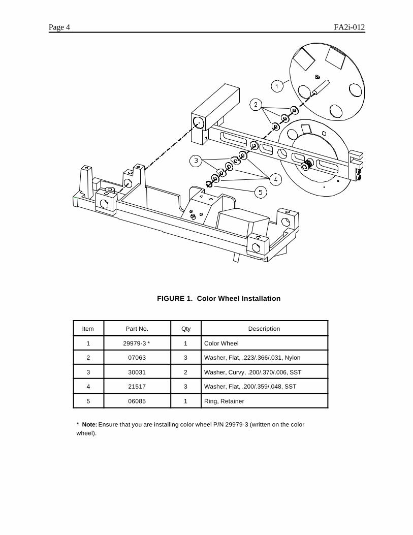
Page 4 FA2i-012
FIGURE 1. Color Wheel Installation
Item Part No. Qty Description
1 29979-3 * 1 Color Wheel
2 07063 3 Washer, Flat, .223/.366/.031, Nylon
3 30031 2 Washer, Curvy, .200/.370/.006, SST
4 21517 3 Washer, Flat, .200/.359/.048, SST
5 06085 1 Ring, Retainer
* Note: Ensure that you are installing color wheel P/N 29979-3 (written on the colorwheel).
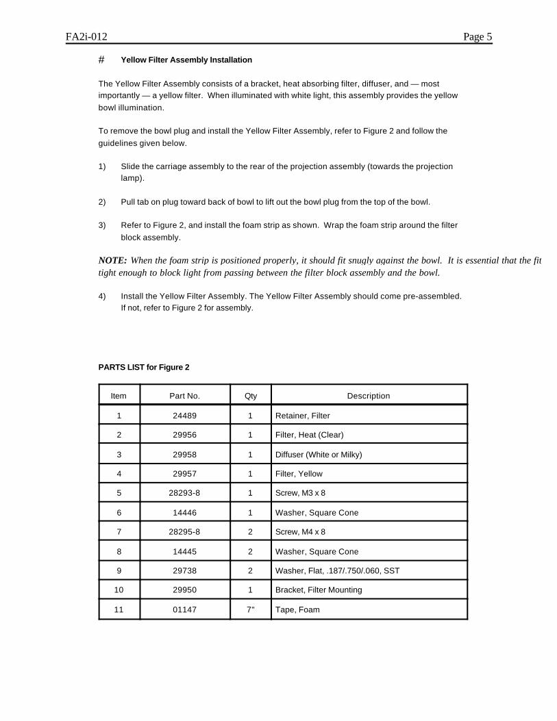
FA2i-012 Page 5
# Yellow Filter Assembly Installation
The Yellow Filter Assembly consists of a bracket, heat absorbing filter, diffuser, and — mostimportantly — a yellow filter. When illuminated with white light, this assembly provides the yellowbowl illumination.
To remove the bowl plug and install the Yellow Filter Assembly, refer to Figure 2 and follow theguidelines given below.
1) Slide the carriage assembly to the rear of the projection assembly (towards the projectionlamp).
2) Pull tab on plug toward back of bowl to lift out the bowl plug from the top of the bowl.
3) Refer to Figure 2, and install the foam strip as shown. Wrap the foam strip around the filterblock assembly.
NOTE: When the foam strip is positioned properly, it should fit snugly against the bowl. It is essential that the fit istight enough to block light from passing between the filter block assembly and the bowl.
4) Install the Yellow Filter Assembly. The Yellow Filter Assembly should come pre-assembled.If not, refer to Figure 2 for assembly.
PARTS LIST for Figure 2
Item Part No. Qty Description
1 24489 1 Retainer, Filter
2 29956 1 Filter, Heat (Clear)
3 29958 1 Diffuser (White or Milky)
4 29957 1 Filter, Yellow
5 28293-8 1 Screw, M3 x 8
6 14446 1 Washer, Square Cone
7 28295-8 2 Screw, M4 x 8
8 14445 2 Washer, Square Cone
9 29738 2 Washer, Flat, .187/.750/.060, SST
10 29950 1 Bracket, Filter Mounting
11 01147 7" Tape, Foam
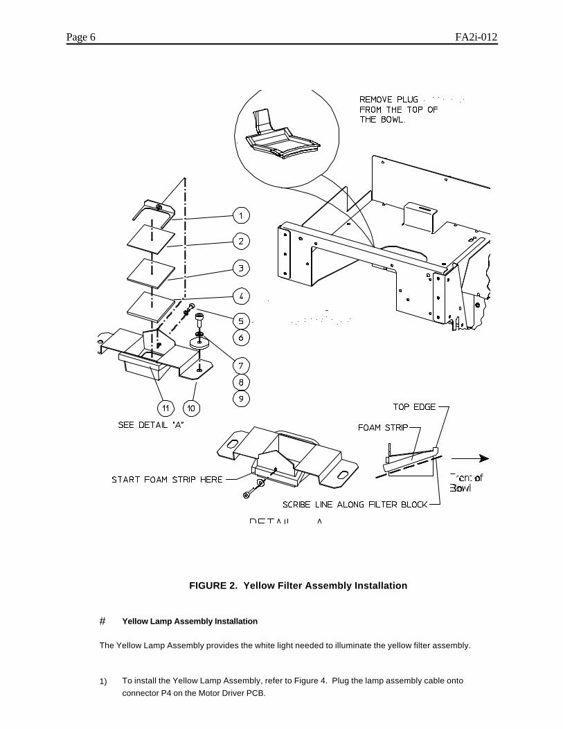
Page 6 FA2i-012
FIGURE 2. Yellow Filter Assembly Installation
# Yellow Lamp Assembly Installation
The Yellow Lamp Assembly provides the white light needed to illuminate the yellow filter assembly.
1) To install the Yellow Lamp Assembly, refer to Figure 4. Plug the lamp assembly cable ontoconnector P4 on the Motor Driver PCB.
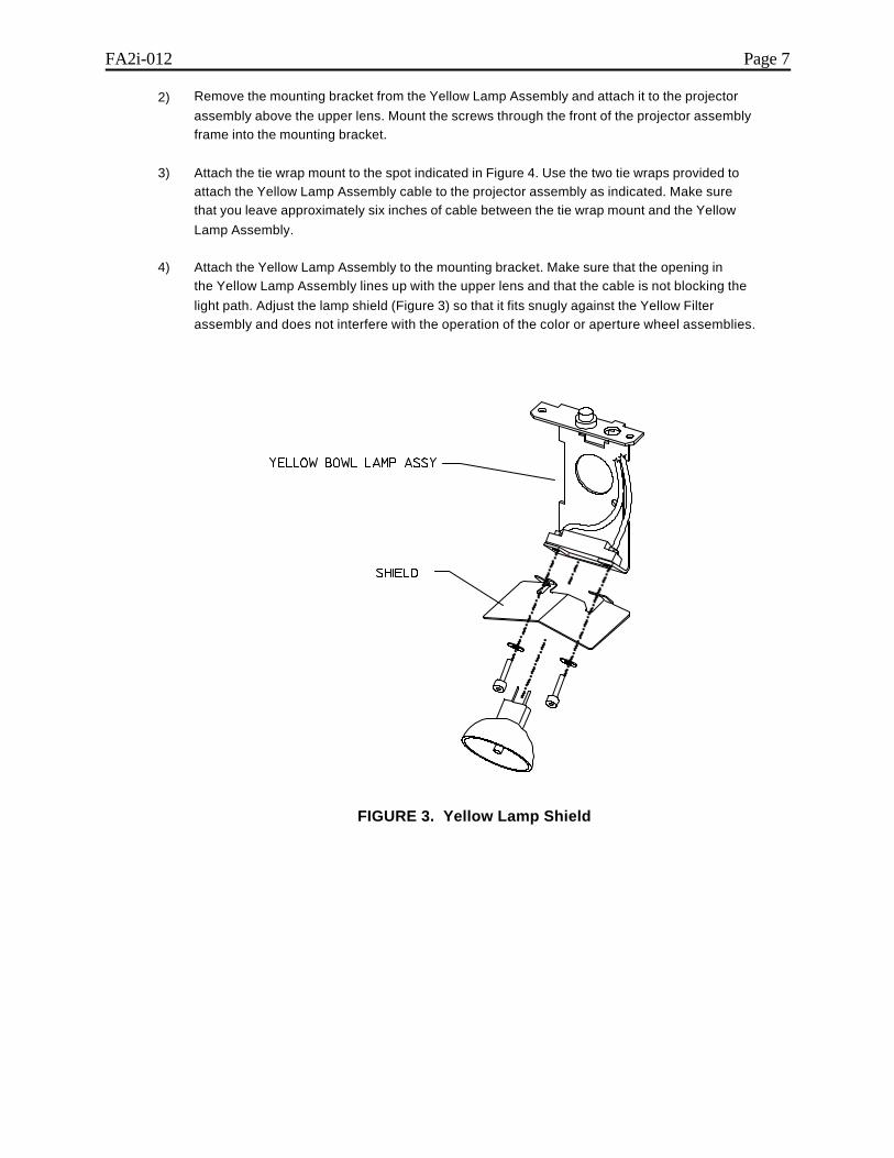
FA2i-012 Page 7
2) Remove the mounting bracket from the Yellow Lamp Assembly and attach it to the projectorassembly above the upper lens. Mount the screws through the front of the projector assemblyframe into the mounting bracket.
3) Attach the tie wrap mount to the spot indicated in Figure 4. Use the two tie wraps provided toattach the Yellow Lamp Assembly cable to the projector assembly as indicated. Make surethat you leave approximately six inches of cable between the tie wrap mount and the YellowLamp Assembly.
4) Attach the Yellow Lamp Assembly to the mounting bracket. Make sure that the opening inthe Yellow Lamp Assembly lines up with the upper lens and that the cable is not blocking thelight path. Adjust the lamp shield (Figure 3) so that it fits snugly against the Yellow Filterassembly and does not interfere with the operation of the color or aperture wheel assemblies.
FIGURE 3. Yellow Lamp Shield
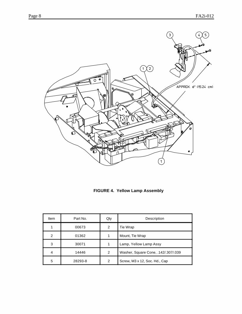
Page 8 FA2i-012
FIGURE 4. Yellow Lamp Assembly
Item Part No. Qty Description
1 00673 2 Tie Wrap
2 01362 1 Mount, Tie Wrap
3 30071 1 Lamp, Yellow Lamp Assy
4 14446 2 Washer, Square Cone, .142/.307/.039
5 28293-8 2 Screw, M3 x 12, Soc. Hd., Cap

FA2i-012 Page 9
# Forehead Rest and Visor Installation
The Installation of a Forehead Rest and Visor (shield) prevents patient visibility of the illuminated yellow filter assembly during Blue-Yellow testing. Without extending the visor during Blue-Yellowtesting, a patient is more likely to be distracted by the bright yellow light at the top of the bowl,thus increasing fixation loss.
NOTE: Prior to removing the forehead rest, set the chinrest and the forehead rest horizontal lead screw nuts both tothe same relative position (check for the same amount of thread showing on the same side of the lead screws).
1) Remove the existing forehead rest from the instrument front cover (see Figure 5). If the
existing forehead rest is in good condition, it can be reused, otherwise, use the new foreheadrest. Install the forehead rest and visor as shown.
2) Don't forget to apply a small amount of grease (Rheolube 362, P/N 08780) to the visor asshown in Figure 5.
3) Once the new forehead rest has been installed, check that the center line on both thechinrest and forehead rest are properly aligned. (Refer to Figure 6.)
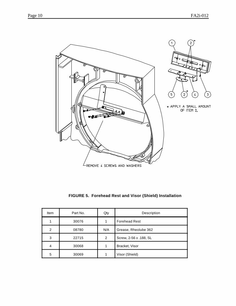
Page 10 FA2i-012
FIGURE 5. Forehead Rest and Visor (Shield) Installation
Item Part No. Qty Description
1 30076 1 Forehead Rest
2 08780 N/A Grease, Rheolube 362
3 22715 2 Screw, 2-56 x .188, SL
4 30068 1 Bracket, Visor
5 30069 1 Visor (Shield)
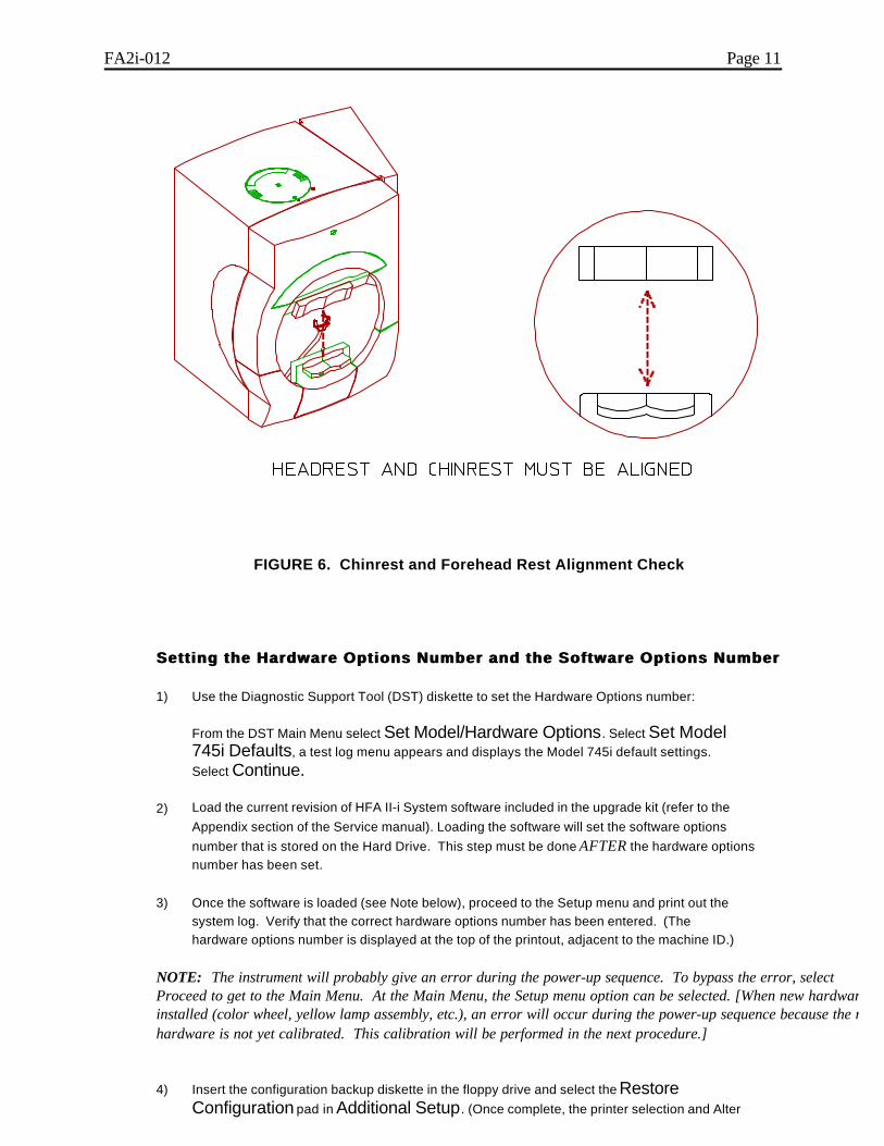
FA2i-012 Page 11
FIGURE 6. Chinrest and Forehead Rest Alignment Check
Setting the Hardware Options Number and the Software Options NumberSetting the Hardware Options Number and the Software Options Number
1) Use the Diagnostic Support Tool (DST) diskette to set the Hardware Options number:
From the DST Main Menu select Set Model/Hardware Options. Select Set Model745i Defaults, a test log menu appears and displays the Model 745i default settings.Select Continue.
2) Load the current revision of HFA II-i System software included in the upgrade kit (refer to theAppendix section of the Service manual). Loading the software will set the software optionsnumber that is stored on the Hard Drive. This step must be done AFTER the hardware optionsnumber has been set.
3) Once the software is loaded (see Note below), proceed to the Setup menu and print out thesystem log. Verify that the correct hardware options number has been entered. (Thehardware options number is displayed at the top of the printout, adjacent to the machine ID.)
NOTE: The instrument will probably give an error during the power-up sequence. To bypass the error, selectProceed to get to the Main Menu. At the Main Menu, the Setup menu option can be selected. [When new hardware isinstalled (color wheel, yellow lamp assembly, etc.), an error will occur during the power-up sequence because the newhardware is not yet calibrated. This calibration will be performed in the next procedure.]
4) Insert the configuration backup diskette in the floppy drive and select the RestoreConfiguration pad in Additional Setup. (Once complete, the printer selection and Alter

Page 12 FA2i-012
Main Menu data will automatically be saved on the hard disk drive.)
Recalibration ProceduresRecalibration Procedures
Perform the following recalibration procedures.
## Color Wheel Calibration and Test
1) Calibrate the color wheel (refer to section 4).
2) Enter QA Tests. Run the 30/60 mixed tests for 5 minutes. No errors should be reported.
Observe the color wheel for proper operation.
# Light Intensity Calibrations
The addition of the new color wheel and the blue-yellow hardware requires recalibration of the lightintensities. Refer to the HFA II-i Service Manual as required to complete the calibrations (section4).
The light intensity calibrations MUST be performed in the order given below. Print both the HFA II-iWhite Light and Blue-Yellow Light Verification Data printouts.
1) White Projector Intensity Calibration
2) Blue Projector Intensity Calibration3) White Bowl Intensity Calibration4) Yellow Bowl Intensity Calibration5) Wedge Calibration6) Blue Correction Calibration7) Intensity/Spot Ratio Verification
NOTE: If the Wedge Calibration is changed after performing the Blue Correction Calibration, an error 130009 willoccur during the power-up sequence. To correct this, perform the Blue Correction Calibration procedure once again. Again save calibration to the floppy calibration diskette.
Operational ChecksOperational Checks
To ensure that the upgraded features are accessible to the operator, perform the followingoperational checks.
For All Upgrades:
1) Proceed to a patient test.2) Select Change Parameters. 3) Select Blue-Yellow ON.4) Start a 30-2 test. Look into the bowl and ensure that a blue stimulus and yellow
background illumination can be observed.5) When the test is complete, save to both floppy and hard drive.6) Proceed to File Functions.7) Select View Test.8) Select Hard Drive.9) Recall the 30-2 Blue-Yellow test previously run.10) Print out the test results.
Instrument Post-CheckoutInstrument Post-Checkout
FA2i-012 Page 13
Prior to completing the upgrade, it is essential that you perform an Instrument Post-Checkout. Thiswill ensure that the instrument is in calibration and all features are operational.
1) To perform the Instrument Post-Checkout, perform the System Checkout (section 2.1).
Suggestions for Customer TrainingSuggestions for Customer Training
1) Ensure that the customer has an understanding of the following instrument operations:
• How to access Change Parameters and select stimulus color changes.• How to access Change Parameters and turn Blue-Yellow to ON.• How to run a Blue-Yellow test.• How to print out Blue-Yellow Statpac results.• How to access the hard disk drive.• How to copy files from the floppy disk drive to the hard disk drive.• How to select patient files from the hard disk drive.
Reporting the Upgrade to Humphrey SystemsReporting the Upgrade to Humphrey Systems
All upgrades performed to the HFA II-i must be reported to Humphrey Systems as described below.
WARNING: Any unauthorized HFA II-i upgrades (those performed withoutnotifying Humphrey Systems) will automatically be downgraded to the modeland features that existed prior to the unauthorized upgrade, when a futurerevision of software is loaded into the instrument.
1) Both U.S. Domestic and International (Affiliates and Distributors) must send a fax toHumphrey Technical Support (925-557-4652) containing the information itemized below (Note! For your convenience, an appropriate fax form is included at the back of this bulletin).
a) Technician's name and Affiliate/Distributor home office fax number.b) The serial number of the HFA II-i that was upgraded.c) The customer's name and address.d) The type of upgrade performed (see HFA II-i Upgrade Types below).
HFA II-i Upgrade Types:
Only the upgrade covered in this service bulletin is listed below.
740i-to-745i (includes Blue-Yellow) Upgrade
2) Once Technical Support receives this information, the Order Administration database will beupdated to indicate the new instrument configuration. If the information is not received,any subsequent software revision upgrade on the instrument will cancel theauthorized but unreported instrument upgrade, and a second service call willthen be required to restore the instrument upgrade.
Finishing UpFinishing Up
## Return Paperwork
The following instructions apply to U.S. Domestic Service Representatives. However, it is

Page 14 FA2i-012
recommended that International Service Engineers return and file the same paperwork at theirAffiliate or Distributor offices.
1) U.S. Domestic service technicians must include the following information with their completedService Report Form:
a) Service Report Form — include type of upgrade performed.b) HFA II-i - Field Light Intensity Data Worksheetc) Calibration Notice - yellow copy (if required)

facsimileTRANSMITTAL
to:to: HUMPHREY TECHNICAL SUPPORTfax #:fax #: 925-557-4652re:re: HFA II-i Upgrade Notificationdate:date:
pages:pages:1, including this cover sheet.
Technician’s Name andAffiliate/Distributor Fax No.
Instrument Serial No.
Customer's Name and Address:
Date Upgrade Performed:
Type of UpgradePerformed (circle): • 740i-to-745i (includes Blue-Yellow) Upgrade
RGA No. (if applicable):
Comments:
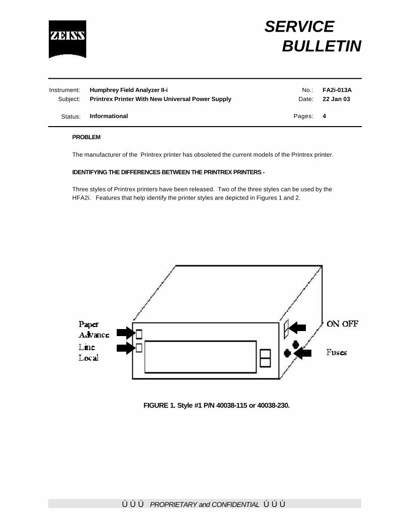
ÚÚÚ PROPRIETARY and CONFIDENTIAL ÚÚÚ
SERVICE BULLETIN
Instrument: Humphrey Field Analyzer II-iSubject: Printrex Printer With New Universal Power Supply
No.: FA2i-013ADate: 22 Jan 03
Status: Informational Pages: 4
PROBLEM
The manufacturer of the Printrex printer has obsoleted the current models of the Printrex printer.
IDENTIFYING THE DIFFERENCES BETWEEN THE PRINTREX PRINTERS -
Three styles of Printrex printers have been released. Two of the three styles can be used by theHFA2i. Features that help identify the printer styles are depicted in Figures 1 and 2.
FIGURE 1. Style #1 P/N 40038-115 or 40038-230.
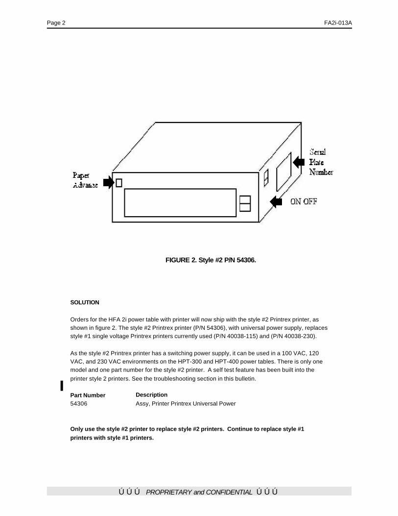
Page 2 FA2i-013A
ÚÚÚ PROPRIETARY and CONFIDENTIAL ÚÚÚ
FIGURE 2. Style #2 P/N 54306.
SOLUTION
Orders for the HFA 2i power table with printer will now ship with the style #2 Printrex printer, asshown in figure 2. The style #2 Printrex printer (P/N 54306), with universal power supply, replacesstyle #1 single voltage Printrex printers currently used (P/N 40038-115) and (P/N 40038-230).
As the style #2 Printrex printer has a switching power supply, it can be used in a 100 VAC, 120VAC, and 230 VAC environments on the HPT-300 and HPT-400 power tables. There is only onemodel and one part number for the style #2 printer. A self test feature has been built into theprinter style 2 printers. See the troubleshooting section in this bulletin.
Part Number Description54306 Assy, Printer Printrex Universal Power
Only use the style #2 printer to replace style #2 printers. Continue to replace style #1printers with style #1 printers.

FA2i-013A Page 3
ÚÚÚ PROPRIETARY and CONFIDENTIAL ÚÚÚ
TROUBLESHOOTING
Normally rebooting the printer and the HFA2i will restore printing operation. If rebooting does notrestore normal printing, run the self test function. The self test function will often restore normalprinting.The self test may be run with or without the data cable connected to the HFA2i. To initiate the selftest feature:
1) Set the printer ON/OFF switch to OFF. 2) Press in and hold the paper advance button. 3) Set the printer ON/OFF switch to ON. 4) Release the paper advance button. 5) The printer will produce a printout that includes:
a) Model informationb) Firmware versionc) Head testd) Platen teste) Character setsf) Buffer informationg) Analog input
Note – Be sure to attempt the self test and retry printing prior to replacing a printer.
Self Test Printout
The following page shows a sample self test printout.
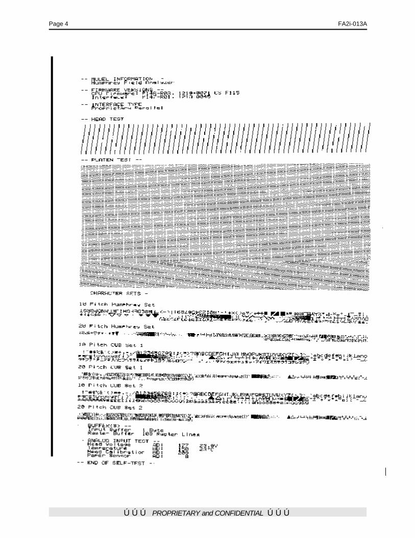
Page 4 FA2i-013A
ÚÚÚ PROPRIETARY and CONFIDENTIAL ÚÚÚ

ÚÚÚ PROPRIETARY and CONFIDENTIAL ÚÚÚ
SERVICE BULLETIN
Instrument: Humphrey Field Analyzer II-i
Subject: Correction of Focus Motor ErrorsNo.: FA2i-014
Date: 10 Oct 02
Status: Informational Pages: 1
INTRODUCTION
Some HFA2i units may produce focus motor positioning errors on an infrequent basis. These errors willnormally appear on the system log and can cause test failure. The following troubleshooting techniques aremost often used to detect focus motor errors; the motor exerciser test, belt tension check, detector check,belt pulley check, and mechanical focus calibration.
PROBLEM
Use of the above mentioned techniques may not identify the problem source.
SOLUTION
Two more possibilities of focus motors have been discovered. The first, is glue on the projection assemblyrails, and the other is excessive friction between the rails and the carriage assembly bushings.
Glue on the rails -
If a slight amount of adhesive sticks to the projection assembly guide rails, during the repair or assemblyprocess, it may not initially cause problems, nor be noticed. Over time, the clock oil used to lubricate therail/carriage assembly reacts with the adhesive and becomes sticky. The sticky oil and adhesivecombination increases the friction between the projection rails and the focus motor carriage assembly. Thiscombination can cause focus motor position errors. In a few cases, it has been found that the adhesive islocated on the bottom side of the rails. More often, it will be on the rail that is closet to the color wheel.Typically it is found on the rail end closest to the patient.
One method to determine if the instrument has glue on the rails is to use a small mirror and place it so youcan examine the rail bottoms. Another method is to loosen or remove the belt and move the carriageassembly by hand, feeling the resistance as the assembly moves on the rails. A change in resistanceduring carriage movement can indicate an adhesive deposit. The adhesive will appear as a brown-rustycolored patch. If you find a deposit on the rails, use acetone to dissolve the deposit and clean the rail. Replace the clock oil used to lubricate the rail after cleaning.
Excessive friction between the carriage and the rails -
Assuming you have examined the rails for adhesive and did not find deposits, the next most likely cause ofthe focus motor errors may be due to excessive friction between the rail and the internal bearings of thecarriage assembly. To test for excessive friction, remove the belt and move the carriage assembly by hand.Ensure that the rails are well lubricated with clock oil. If an abnormal amount of force is required to move thecarriage assembly along the rails, and the amount of force is relatively uniform throughout the range oftravel, the friction between the rails may be due to misalignment, and could be the cause fo the focus motorerrors. Do not attempt to repair the projection assembly rails and carriage. Order and replace the entireprojection assembly.
úúú PROPRIETARY and CONFIDENTIAL úúú
SERVICE BULLETIN Instrument: Humphrey Field Analyzer II-i No.: FA2i-015 Subject: File/Name Notice Date: 15 Jan 03 Status: Informational Pages: 4 General Information Two very infrequently encountered errors have been discovered that affect the Humphrey Field Analyzer HFA 2i models. These two errors have been given the names of the File/Name and the Date/Time errors. Corrective actions have been implemented in the latest HFA2i software release, revision 3.2 to address the errors. This software has been released with new HFA2i units. A software kit (P/N 53787) that includes the 3.2 software application disks (P/N 54799) and a letter will be sent to all current HFA2i customers. The customer letter describes the nature of the errors and the corrective actions. A copy of the body of the text of the letter and enclosures follows this paragraph. If you have questions or if a customer asks you a question that you cannot answer, contact Carl Zeiss Meditec Inc at 877-486-7473. IMPORTANT SOFTWARE UPDATE ENCLOSED RE: Humphrey® Field Analyzer II - i series Dear Carl Zeiss Meditec Customer, As part of our ongoing efforts to ensure data file integrity, Carl Zeiss Meditec Inc. (formerly Carl Zeiss Ophthalmic Systems, Inc., Humphrey Division) has updated its software for your Humphrey Field Analyzer II - i series (“HFA II”, Model 700 i - series). This software revision provides new features that reduce the likelihood of user error that could result in database corruption. The first item concerns “File/Name” association and the second item concerns “Date/Time” association. Both of these items are described in detail on the following pages and have been addressed with the enclosed system software revision 3.2. The enclosed system software revision 3.2 includes updates that will prevent both the “File/Name” issue and the “Date/Time” issue from occurring in the future, provided that system software revision 3.2 is successfully installed on your HFA II - i series instrument. Carl Zeiss Meditec is committed to providing our customers with the highest quality instruments. In keeping with this commitment, enclosed please find HFA II - i series System Software, Revision 3.2. As with all software upgrades, first back up your data and then install the new software. Please be aware that merely installing the new system software revision 3.2 will not correct the files of previously conducted tests. You must follow the steps as indicated in the “Action Required” section on the following pages to correct the files of previously conducted tests.
Page 2 FA2i-015 For further clarification, please contact Customer Service toll free at 877-486-7473. We appreciate your assistance. Sincerely, Jeff Durban Product Manager Enclosures Item 1: “File/Name” Issue If an operator fails to follow the user instructions, and under a highly specific set of unusual circumstances (further described below), then it is possible to have an incorrect patient name associated with a visual field test performed on the Humphrey Field Analyzer II - i series with system software revisions C2, C3, C3_MO or C3.1. For example, Patient A’s name may be matched with Patient B’s test if all of the following circumstances are met: If, during the course of testing a patient on your HFA II- i series: • the instrument encounters an error where the instrument did not restart, • and the patient being tested is not the first patient of the day to be tested, (ie, Patient B) • and you respond to the error message by selecting the “OK” button, • and you then select the “Test Other Eye” button, then the instrument will revert to displaying the name of the last patient who completed a visual field examination on the instrument (ie, Patient A). If, after the above conditions occur, you do not observe the incorrect patient name displayed on the screen: • and you elect to resume the examination, • and the test is completed successfully, • and you elect to save the test result, • and you select “Yes” in response to the message presented on the screen asking you to
confirm that the patient’s name and date of birth are correct [“Do You Wish To Save This Test For”: (ie, “Patient A”)], failing to observe the incorrect patient name displayed,
then the file saved will have the incorrect patient’s name recorded. Additionally, if you chose to print the visual field test results, the incorrect patient name would be printed on the visual field test results. Action Required: Install system software revision 3.2;
check and correct any suspect files.
If you should have any files where you suspect that the patient’s visual field result is not properly associated with the patient’s name, and if, after further investigation you determine that the file must be updated, you may correct the file by completing the following steps:
Main Menu>File Functions>Change Patient Data>One Test>Select the Source (Hard Drive, Floppy Drive)>Select Directory Order (Name, Date or Patient)> Proceed>Enter Name to Find>Enter>Select the patient from the file directory>Proceed>Edit Patient Information>Select Enter after each field is updated>Select Proceed. To exit the Change Patient Data screen, select the Main Menu icon.
Note: You may wish to reprint the visual field test results with the correct patient information recorded. Please be aware that merely installing the new system software revision 3.2 will not
FA2i-015 Page 3 correct the files of previously conducted tests. You must follow the steps as indicated in the “Action Required” section above to correct the files of previously conducted tests. Suggested ways to examine your database for suspect files You may wish to sort your file directory in alphabetical and/or chronological order and then review the directory for any suspect files. For instance, if Patient A has 2 files for one eye for a given test date (i.e., a right eye test plus two left eye tests) or if Patient B only has one file for a given test date, or if you know a given patient was examined on a particular date, but you cannot find a file under his/her name for that date - you may want to investigate further. You may sort your file directory by completing the following steps: Main Menu>File Functions>View Tests>Select the Source (Hard Drive, Floppy Drive)>Select Directory Order (Alphabetical or Chronological)>Proceed. Item 2: “Date/Time” Issue Again, under a highly specific set of unusual circumstances, it is possible to have an invalid test date associated with a patient’s visual field test performed on the Humphrey Field Analyzer II - i series with system software revisions C2, C3 or C3_MO. In the event this occurs, no test date or an incorrect test date would be printed on the patient’s visual field test results and it could calculate an invalid age for the patient tested. This does not affect tests transferred to an HFA II - i series instrument from an HFA II or an HFA I instrument. The STATPAC™ analysis package compares a patient’s visual field to a normative database of visual fields from similarly aged patients. If the instrument did not calculate the patient’s age properly, the STATPAC analysis and printout could be incorrect. Screening tests performed with the Test Mode set to “Age Corrected” could also be affected by the “Date/Time” issue. If the instrument did not calculate the patient’s age properly, the hill of vision assigned to the patient (which is based on the patient’s age) could be incorrect. Action Required: Install system software revision 3.2; perform evaluation of test dates;
correct files as needed. Repeat screening tests performed with the Age Corrected test mode.
In an effort to assist you in determining what files, if any, are affected by the date/time issue, the enclosed system software revision 3.2 contains a quick, easy-to-use utility called “Evaluate Test Dates”. You may use this utility to evaluate your HFA II - i series database contained on a floppy disk and/or a hard drive. Upon performing this evaluation, a printout will be automatically generated that displays a summary of its findings. The printed summary will contain information such as the number of files examined, the number of HFA II - i series files, and the number of files flagged, if any, that are considered to have “Questionable Test Dates”. The files with “Questionable Test Dates” are those that may have been affected by the “Date/Time” issue. If any files are flagged, a printed file directory will display the details of each questionable file (patient’s name, patient’s date-of-birth, eye tested, test type, test time, and test date) so that you may review the file. The printed summary will also contain directions on how to update the date on the file, if needed. The average time to complete the evaluation is less than 7 minutes.
Page 4 FA2i-015 Instructions on how to evaluate test dates Main Menu>System Setup>Additional Setup>Diagnostics>Enter password 1234>Evaluate Test Dates> Select the Source (Hard Drive or Floppy). After reviewing the confirming message, if you still wish to perform the evaluation, select “Yes”. If you do not want to perform the evaluation at this time, select “Cancel”. Note: You may wish to reprint the visual field test results with the correct test date recorded. Please be aware that merely installing the new system software revision 3.2 will not correct the files of previously conducted tests. You must follow the steps as indicated in the “Action Required” section above to correct the files of previously conducted tests. Note: New Feature in Software Revision 3.2 - Internal Self-Test for Date Checking System software revision 3.2 includes an automatic self-test for date validation. Although the new self-test is set up to run unnoticed in the background, you may see a pop-up window that displays the message: “Please verify that today’s date is shown correctly below” along with the date the instrument is set to. If you receive this message and the date displayed is correct, press “Yes”. If the date is incorrect, press “No”; input the appropriate date at the pop up menu, then select “Enter”.
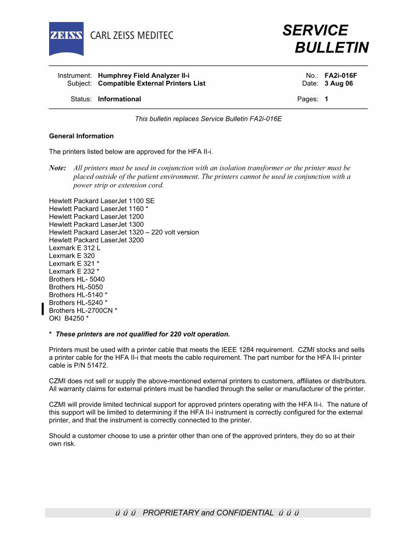
ÚÚÚ PROPRIETARY and CONFIDENTIAL ÚÚÚ
SERVICE BULLETIN
Instrument: Humphrey Field Analyzer II-i No.: FA2i-016F Subject: Compatible External Printers List Date: 3 Aug 06 Status: Informational Pages: 1
This bulletin replaces Service Bulletin FA2i-016E General Information The printers listed below are approved for the HFA II-i. Note: All printers must be used in conjunction with an isolation transformer or the printer must be
placed outside of the patient environment. The printers cannot be used in conjunction with a power strip or extension cord.
Hewlett Packard LaserJet 1100 SE Hewlett Packard LaserJet 1160 * Hewlett Packard LaserJet 1200 Hewlett Packard LaserJet 1300 Hewlett Packard LaserJet 1320 – 220 volt version Hewlett Packard LaserJet 3200 Lexmark E 312 L Lexmark E 320 Lexmark E 321 * Lexmark E 232 * Brothers HL- 5040 Brothers HL-5050 Brothers HL-5140 * Brothers HL-5240 * Brothers HL-2700CN * OKI B4250 * * These printers are not qualified for 220 volt operation. Printers must be used with a printer cable that meets the IEEE 1284 requirement. CZMI stocks and sells a printer cable for the HFA II-i that meets the cable requirement. The part number for the HFA II-i printer cable is P/N 51472. CZMI does not sell or supply the above-mentioned external printers to customers, affiliates or distributors. All warranty claims for external printers must be handled through the seller or manufacturer of the printer. CZMI will provide limited technical support for approved printers operating with the HFA II-i. The nature of this support will be limited to determining if the HFA II-i instrument is correctly configured for the external printer, and that the instrument is correctly connected to the printer. Should a customer choose to use a printer other than one of the approved printers, they do so at their own risk.
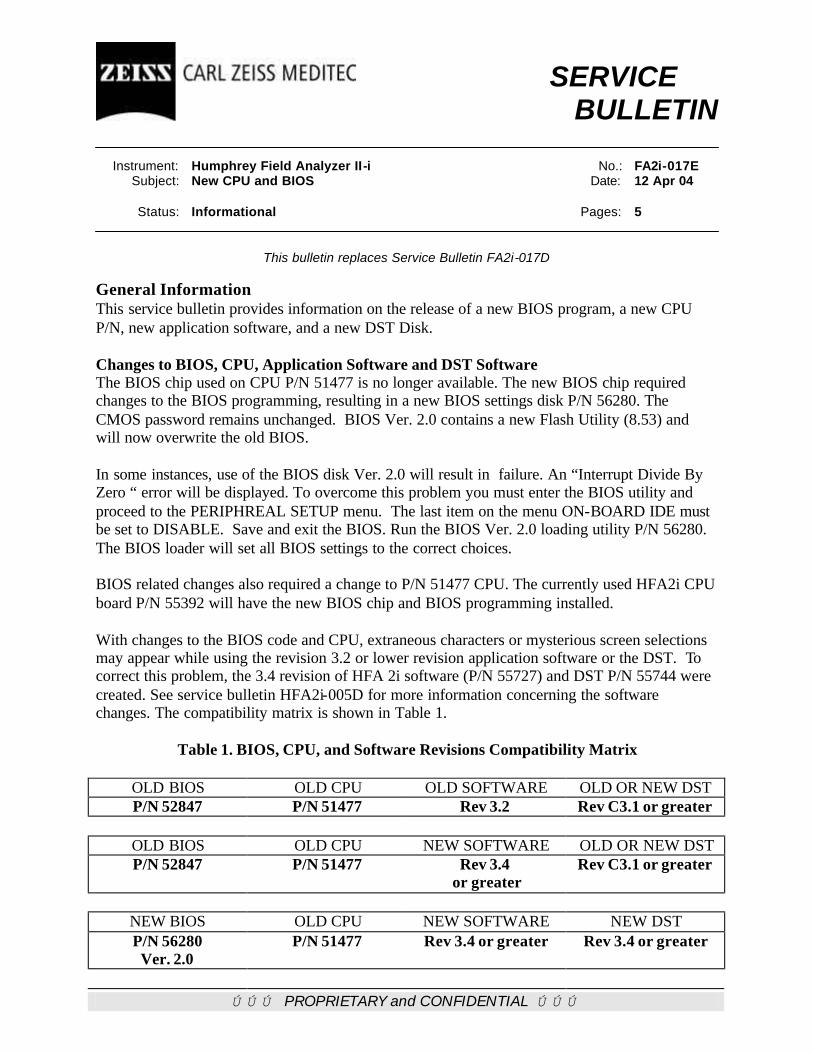
ÚÚÚ PROPRIETARY and CONFIDENTIAL ÚÚÚ
SERVICE BULLETIN Instrument: Humphrey Field Analyzer II-i No.: FA2i-017E Subject: New CPU and BIOS Date: 12 Apr 04 Status: Informational Pages: 5
This bulletin replaces Service Bulletin FA2i-017D
General Information This service bulletin provides information on the release of a new BIOS program, a new CPU P/N, new application software, and a new DST Disk. Changes to BIOS, CPU, Application Software and DST Software The BIOS chip used on CPU P/N 51477 is no longer available. The new BIOS chip required changes to the BIOS programming, resulting in a new BIOS settings disk P/N 56280. The CMOS password remains unchanged. BIOS Ver. 2.0 contains a new Flash Utility (8.53) and will now overwrite the old BIOS. In some instances, use of the BIOS disk Ver. 2.0 will result in failure. An “Interrupt Divide By Zero “ error will be displayed. To overcome this problem you must enter the BIOS utility and proceed to the PERIPHREAL SETUP menu. The last item on the menu ON-BOARD IDE must be set to DISABLE. Save and exit the BIOS. Run the BIOS Ver. 2.0 loading utility P/N 56280. The BIOS loader will set all BIOS settings to the correct choices. BIOS related changes also required a change to P/N 51477 CPU. The currently used HFA2i CPU board P/N 55392 will have the new BIOS chip and BIOS programming installed. With changes to the BIOS code and CPU, extraneous characters or mysterious screen selections may appear while using the revision 3.2 or lower revision application software or the DST. To correct this problem, the 3.4 revision of HFA 2i software (P/N 55727) and DST P/N 55744 were created. See service bulletin HFA2i-005D for more information concerning the software changes. The compatibility matrix is shown in Table 1.
Table 1. BIOS, CPU, and Software Revisions Compatibility Matrix
OLD BIOS OLD CPU OLD SOFTWARE OLD OR NEW DST P/N 52847 P/N 51477 Rev 3.2 Rev C3.1 or greater
OLD BIOS OLD CPU NEW SOFTWARE OLD OR NEW DST P/N 52847 P/N 51477 Rev 3.4
or greater Rev C3.1 or greater
NEW BIOS OLD CPU NEW SOFTWARE NEW DST P/N 56280 Ver. 2.0
P/N 51477 Rev 3.4 or greater Rev 3.4 or greater
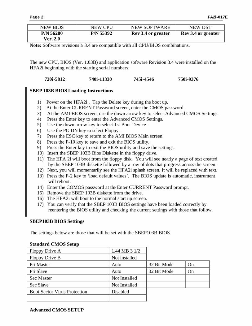
Page 2 FA2i-017E
NEW BIOS NEW CPU NEW SOFTWARE NEW DST P/N 56280 Ver. 2.0
P/N 55392 Rev 3.4 or greater Rev 3.4 or greater
Note: Software revisions ≥ 3.4 are compatible with all CPU/BIOS combinations. The new CPU, BIOS (Ver. 1.03B) and application software Revision 3.4 were installed on the HFA2i beginning with the starting serial numbers: 720i-5812 740i-11330 745i-4546 750i-9376 SBEP 103B BIOS Loading Instructions
1) Power on the HFA2i . Tap the Delete key during the boot up. 2) At the Enter CURRENT Password screen, enter the CMOS password. 3) At the AMI BIOS screen, use the down arrow key to select Advanced CMOS Settings. 4) Press the Enter key to enter the Advanced CMOS Settings. 5) Use the down arrow key to select 1st Boot Device. 6) Use the PG DN key to select Floppy. 7) Press the ESC key to return to the AMI BIOS Main screen. 8) Press the F-10 key to save and exit the BIOS utility. 9) Press the Enter key to exit the BIOS utility and save the settings. 10) Insert the SBEP 103B Bios Diskette in the floppy drive. 11) The HFA 2i will boot from the floppy disk. You will see nearly a page of text created
by the SBEP 103B diskette followed by a row of dots that progress across the screen. 12) Next, you will momentarily see the HFA2i splash screen. It will be replaced with text. 13) Press the F-2 key to ‘load default values’. The BIOS update is automatic, instrument
will reboot. 14) Enter the COMOS password at the Enter CURRENT Password prompt. 15) Remove the SBEP 103B diskette from the drive. 16) The HFA2i will boot to the normal start up screen. 17) You can verify that the SBEP 103B BIOS settings have been loaded correctly by
reentering the BIOS utility and checking the current settings with those that follow.
SBEP103B BIOS Settings The settings below are those that will be set with the SBEP103B BIOS. Standard CMOS Setup Floppy Drive A 1.44 MB 3 1/2 Floppy Drive B Not installed Pri Master Auto 32 Bit Mode On Pri Slave Auto 32 Bit Mode On Sec Master Not Installed Sec Slave Not Installed Boot Sector Virus Protection Disabled Advanced CMOS SETUP

FA2i-017E Page 3
Quick Boot Enabled 1st Boot Devise IDE-0 2nd Boot Devise Floppy 3rd Boot Devise IDE-1 4th Boot Devise Disabled Try other Boot Devices Yes Initial Display Mode Silent Display Mode at Add-On-ROM Init Keep Current S.M.A.R.T. for Hard Disks Enabled BootUp Num-lock Off Floppy Drive Swap Enabled PS/2 Mouse Support Enabled System Keyboard Absent Primary Display VGA/EGA Password Check Setup Boot to OS/2 > 64MB No CPU Serial Number Disabled L1 Cache Writeback L2 Cache Writeback System BIOS Cacheable Enabled C000,64K Shadow Cached D000,64K Shadow Disabled Advanced ChipSet Setup USB Function Enabled USB Keyboard Legacy Support Incl. Mouse DRAM Page Closing Policy Closed DRAM Tras/Trc Cycle time 5/7 Address Setup Time (SCLKs) 1 CAS# latency (SCLKs) 3 SDRAM RAS# to CAS# delay 2 SDRAM RAS# Precharge 2 Graphics Mode Select UMA 1MB Display Cache Window Size 64MB ICH Delayed Transaction Enabled C1kGen Spread Spectrum Disabled Local Memory Frequency 100 MHz
**** Display Cache Function **** Initialize Display Cache Memory Disabled Paging Mode Control Open RAS-to-CAS Default CAS Latency Slow
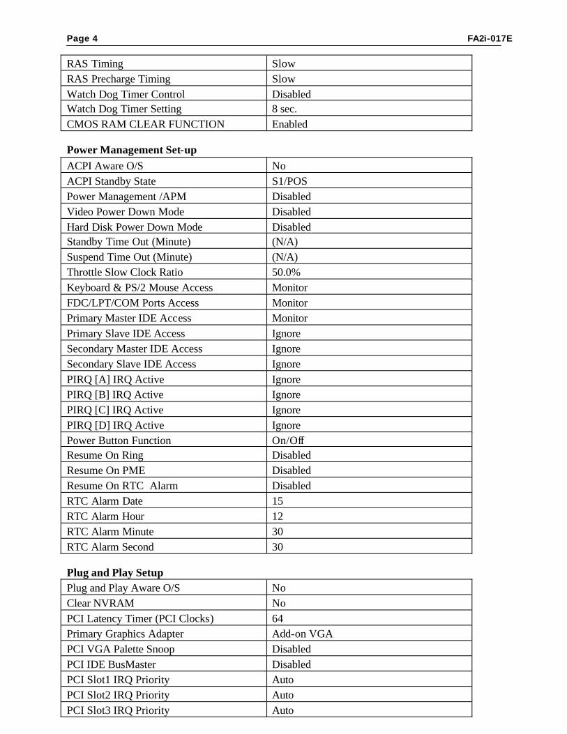
Page 4 FA2i-017E
RAS Timing Slow RAS Precharge Timing Slow Watch Dog Timer Control Disabled Watch Dog Timer Setting 8 sec. CMOS RAM CLEAR FUNCTION Enabled Power Management Set-up ACPI Aware O/S No ACPI Standby State S1/POS Power Management /APM Disabled Video Power Down Mode Disabled Hard Disk Power Down Mode Disabled Standby Time Out (Minute) (N/A) Suspend Time Out (Minute) (N/A) Throttle Slow Clock Ratio 50.0% Keyboard & PS/2 Mouse Access Monitor FDC/LPT/COM Ports Access Monitor Primary Master IDE Access Monitor Primary Slave IDE Access Ignore Secondary Master IDE Access Ignore Secondary Slave IDE Access Ignore PIRQ [A] IRQ Active Ignore PIRQ [B] IRQ Active Ignore PIRQ [C] IRQ Active Ignore PIRQ [D] IRQ Active Ignore Power Button Function On/Off Resume On Ring Disabled Resume On PME Disabled Resume On RTC Alarm Disabled RTC Alarm Date 15 RTC Alarm Hour 12 RTC Alarm Minute 30 RTC Alarm Second 30 Plug and Play Setup Plug and Play Aware O/S No Clear NVRAM No PCI Latency Timer (PCI Clocks) 64 Primary Graphics Adapter Add-on VGA PCI VGA Palette Snoop Disabled PCI IDE BusMaster Disabled PCI Slot1 IRQ Priority Auto PCI Slot2 IRQ Priority Auto PCI Slot3 IRQ Priority Auto
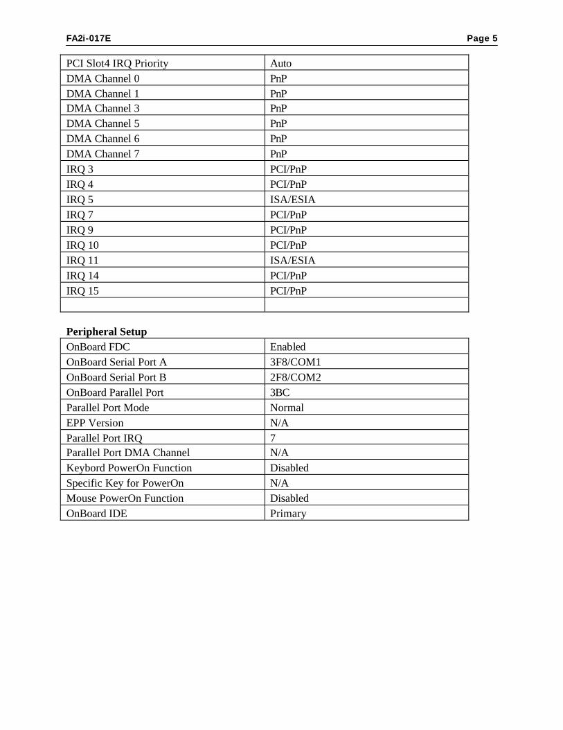
FA2i-017E Page 5
PCI Slot4 IRQ Priority Auto DMA Channel 0 PnP DMA Channel 1 PnP DMA Channel 3 PnP DMA Channel 5 PnP DMA Channel 6 PnP DMA Channel 7 PnP IRQ 3 PCI/PnP IRQ 4 PCI/PnP IRQ 5 ISA/ESIA IRQ 7 PCI/PnP IRQ 9 PCI/PnP IRQ 10 PCI/PnP IRQ 11 ISA/ESIA IRQ 14 PCI/PnP IRQ 15 PCI/PnP Peripheral Setup OnBoard FDC Enabled OnBoard Serial Port A 3F8/COM1 OnBoard Serial Port B 2F8/COM2 OnBoard Parallel Port 3BC Parallel Port Mode Normal EPP Version N/A Parallel Port IRQ 7 Parallel Port DMA Channel N/A Keybord PowerOn Function Disabled Specific Key for PowerOn N/A Mouse PowerOn Function Disabled OnBoard IDE Primary
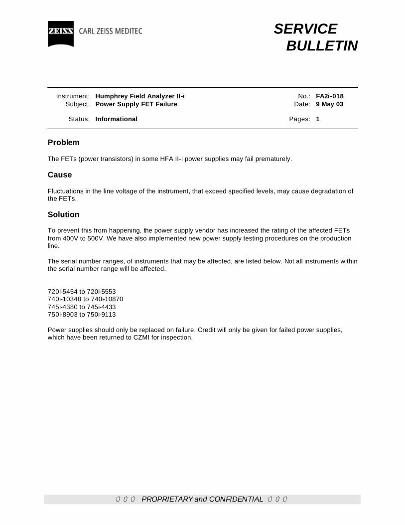
ÚÚÚ PROPRIETARY and CONFIDENTIAL ÚÚÚ
SERVICE BULLETIN Instrument: Humphrey Field Analyzer II-i No.: FA2i-018 Subject: Power Supply FET Failure Date: 9 May 03 Status: Informational Pages: 1 Problem The FETs (power transistors) in some HFA II-i power supplies may fail prematurely. Cause Fluctuations in the line voltage of the instrument, that exceed specified levels, may cause degradation of the FETs. Solution To prevent this from happening, the power supply vendor has increased the rating of the affected FETs from 400V to 500V. We have also implemented new power supply testing procedures on the production line. The serial number ranges, of instruments that may be affected, are listed below. Not all instruments within the serial number range will be affected. 720i-5454 to 720i-5553 740i-10348 to 740i-10870 745i-4380 to 745i-4433 750i-8903 to 750i-9113 Power supplies should only be replaced on failure. Credit will only be given for failed power supplies, which have been returned to CZMI for inspection.
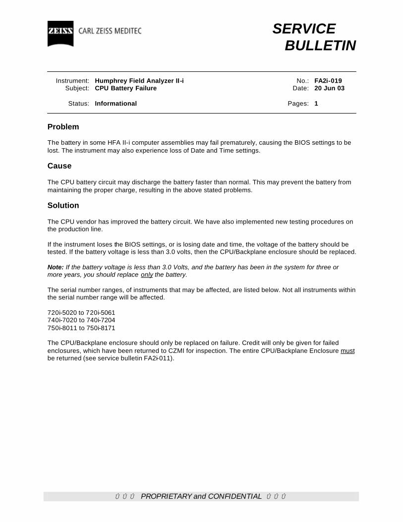
ÚÚÚ PROPRIETARY and CONFIDENTIAL ÚÚÚ
SERVICE BULLETIN Instrument: Humphrey Field Analyzer II-i No.: FA2i-019 Subject: CPU Battery Failure Date: 20 Jun 03 Status: Informational Pages: 1 Problem The battery in some HFA II-i computer assemblies may fail prematurely, causing the BIOS settings to be lost. The instrument may also experience loss of Date and Time settings. Cause The CPU battery circuit may discharge the battery faster than normal. This may prevent the battery from maintaining the proper charge, resulting in the above stated problems. Solution The CPU vendor has improved the battery circuit. We have also implemented new testing procedures on the production line. If the instrument loses the BIOS settings, or is losing date and time, the voltage of the battery should be tested. If the battery voltage is less than 3.0 volts, then the CPU/Backplane enclosure should be replaced. Note: If the battery voltage is less than 3.0 Volts, and the battery has been in the system for three or more years, you should replace only the battery. The serial number ranges, of instruments that may be affected, are listed below. Not all instruments within the serial number range will be affected. 720i-5020 to 720i-5061 740i-7020 to 740i-7204 750i-8011 to 750i-8171 The CPU/Backplane enclosure should only be replaced on failure. Credit will only be given for failed enclosures, which have been returned to CZMI for inspection. The entire CPU/Backplane Enclosure must be returned (see service bulletin FA2i-011).

ÚÚÚ PROPRIETARY and CONFIDENTIAL ÚÚÚ
SERVICE BULLETIN Instrument: Humphrey Field Analyzer II-i No.: FA2i-020 Subject: Change in Carriage Bearing Assemby Date: 7 Jun 03 Status: Informational Pages: 1 Problem HFA2i instruments have displayed “focus motor errors” and “check shutter, motors and lamps error” messages. Cause One possible cause for the “focus motor errors” and “check shutter, motors and lamps error” messages has been found to be a variation in the assembly techniques while gluing the bearings in the carriage assembly. Variations in technique have resulted in misalignment of the bearings or excessive glue, which drips on the bearing shafts. Both causes can result in the carriage not moving or not moving smoothly (See service bulletin FA2i-014 for details). Solution Changes have been made to the manufacturing process that no longer requires the glue within the carriage housing. The new method involves press fitting the bearings into the carriage housing. Instruments that have been manufactured with press fit bearings start with the following serial numbers: 720i-5724 740i-11085 745i-4513 750i-9231
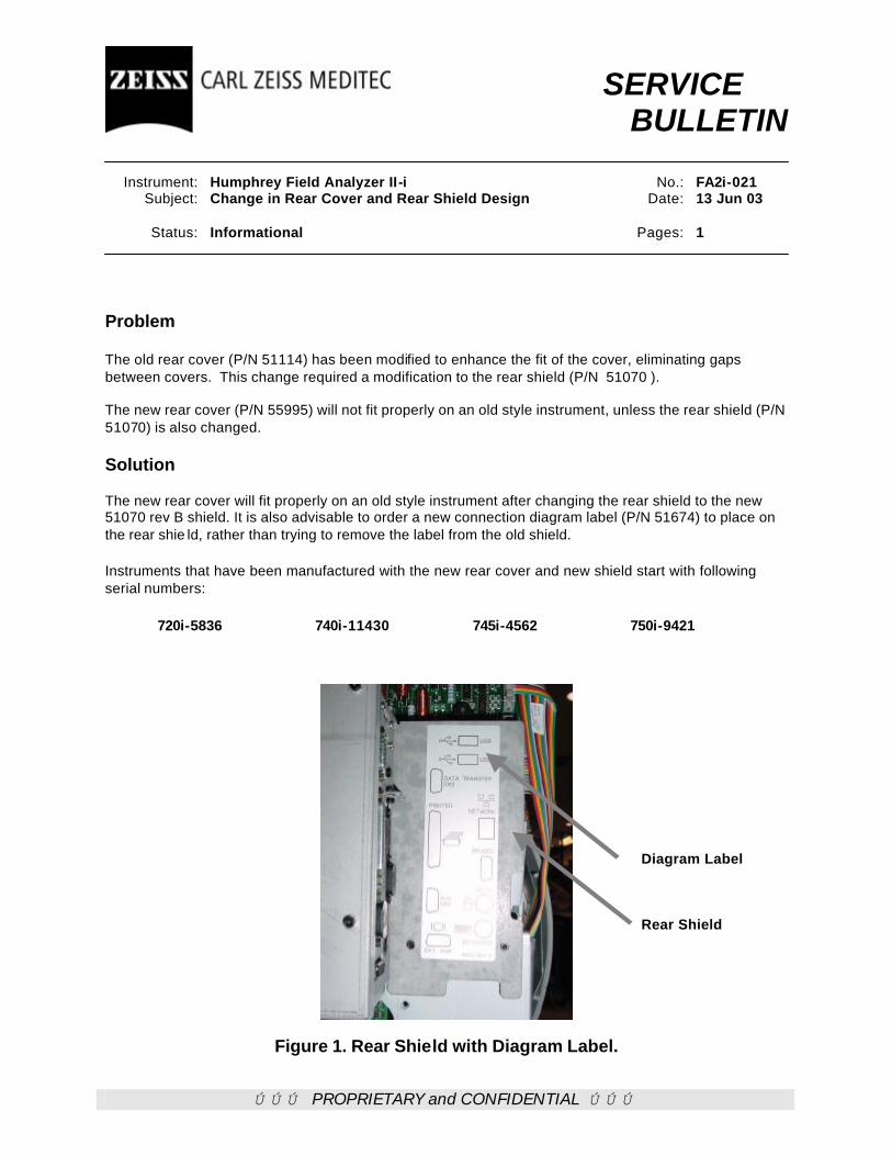
ÚÚÚ PROPRIETARY and CONFIDENTIAL ÚÚÚ
SERVICE BULLETIN Instrument: Humphrey Field Analyzer II-i No.: FA2i-021 Subject: Change in Rear Cover and Rear Shield Design Date: 13 Jun 03 Status: Informational Pages: 1 Problem The old rear cover (P/N 51114) has been modified to enhance the fit of the cover, eliminating gaps between covers. This change required a modification to the rear shield (P/N 51070 ). The new rear cover (P/N 55995) will not fit properly on an old style instrument, unless the rear shield (P/N 51070) is also changed. Solution The new rear cover will fit properly on an old style instrument after changing the rear shield to the new 51070 rev B shield. It is also advisable to order a new connection diagram label (P/N 51674) to place on the rear shie ld, rather than trying to remove the label from the old shield. Instruments that have been manufactured with the new rear cover and new shield start with following serial numbers: 720i-5836 740i-11430 745i-4562 750i-9421
Figure 1. Rear Shield with Diagram Label.
Rear Shield
Diagram Label

ÚÚÚ PROPRIETARY and CONFIDENTIAL ÚÚÚ
SERVICE BULLETIN Instrument: Humphrey Field Analyzer II-i No.: FA2i-022 Subject: Start up Problems Date: 24 Jun 03 Status: Next Visit Pages: 1 Problem HFA2i instruments with the new CPU (P/N 55392), using application revision 3.4 software, may fail to reach the main menu on startup. The display will be blank and the instrument will give no indication that a failure has occurred. Cause Failures in the initialization of the RAM disk are one possible source for the blank display on startup. Solution Changes have been made to the application software in release 3.4.5. Load the application software revision 3.4.5 to install the new RAM disk initialization routine and eliminate the start up problem. If the software upgrade does not correct the start up problem, use the techniques found in the HFA2i service manual to troubleshoot and repair the unit. Instruments that have been manufactured with the new CPU and software revision 3.4, and require the 3.4.5 software, are in the following serial number ranges: 720i-5815 through 720i-5838 740i-11330 through 740i-11446 745i-4546 through 745i-4559 750i-9376 through 750i-9393

ÚÚÚ PROPRIETARY and CONFIDENTIAL ÚÚÚ
SERVICE BULLETIN Instrument: Humphrey Field Analyzer II-i No.: FA2i-023 Subject: Calibration Backup Disk Problems Date: 21 Jul 03 Status: Next Visit Pages: 3 Problem Some HFA2i Calibration Backup Disks may contain corrupted data in the calcfg.ini or nvram.dat.file. If a corrupted calibration disk is used to restore the calibration information, a complete loss of model, serial number, hardware option codes, software option codes, and all calibration data may result. Cause At this time the principle cause of the corruption to the Calibration Backup Disk calcfg.ini file is not known. Solution To prevent loading corrupted calibration files during the calibration restore process, the files on the calibration disk will need to be evaluated. A binary content viewer is used (as described below) to evaluate the calibration backup files. If the calibration backup disk files are corrupted, the files are to be recreated with the HFA2i calibration files save utility. After creating the new files, evaluate them to see that they are normal. During the manufacturing process of the instrument an evaluation of the calibration disk files is performed, similar to the evaluation process described in this bulletin. Manufacturing Implementation dates for the verification of the calibration backup disk are found within this bulletin. Binary Content Viewer A computer utility program called a binary content viewer will allow the service engineer to look at the binary calibration files, and see the corresponding hexidecimal and ASCI code representation. Running the binary viewer program, the engineer can then evaluate the calibration files for corruption. One binary content viewer program is HexDump32, developed by Salty Brine Software, can be down loaded from www.saltybrine.com. Hexdump32.zip is a 1.6 mb Zip file and will not fit on a single 3.5” 1.44 mb floppy disk. Hexdump32 is a freeware program that can be downloaded, used and distributed freely. Downloading Hexdump32.zip
1. Download the hexdump32.zip file to your desktop or a file folder on your hard drive from the
www.saltybrine.com website. 2. Using an unzip utility, extract the setup.exe file. 3. Accept all the default settings during the installation. 4. The Hexdump32 application is now installed on your system and is ready for use.
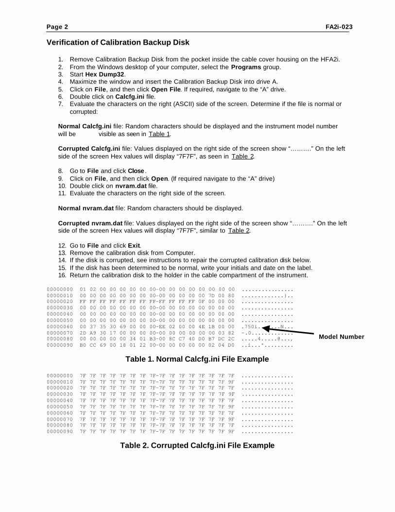
Page 2 FA2i-023 Verification of Calibration Backup Disk
1. Remove Calibration Backup Disk from the pocket inside the cable cover housing on the HFA2i. 2. From the Windows desktop of your computer, select the Programs group. 3. Start Hex Dump32. 4. Maximize the window and insert the Calibration Backup Disk into drive A. 5. Click on File, and then click Open File. If required, navigate to the “A” drive. 6. Double click on Calcfg.ini file. 7. Evaluate the characters on the right (ASCII) side of the screen. Determine if the file is normal or
corrupted: Normal Calcfg.ini file: Random characters should be displayed and the instrument model number will be visible as seen in Table 1. Corrupted Calcfg.ini file: Values displayed on the right side of the screen show “……….” On the left side of the screen Hex values will display “7F7F”, as seen in Table 2.
8. Go to File and click Close . 9. Click on File, and then click Open. (If required navigate to the “A” drive) 10. Double click on nvram.dat file. 11. Evaluate the characters on the right side of the screen. Normal nvram.dat file: Random characters should be displayed. Corrupted nvram.dat file: Values displayed on the right side of the screen show “……….” On the left side of the screen Hex values will display “7F7F”, similar to Table 2. 12. Go to File and click Exit. 13. Remove the calibration disk from Computer. 14. If the disk is corrupted, see instructions to repair the corrupted calibration disk below. 15. If the disk has been determined to be normal, write your initials and date on the label. 16. Return the calibration disk to the holder in the cable compartment of the instrument.
00000000 01 02 00 00 00 00 00 00-00 00 00 00 00 00 00 00 ................ 00000010 00 00 00 00 00 00 00 00-00 00 00 00 00 7D 00 80 .............}.. 00000020 FF FF FF FF FF FF FF FF-FF FF FF FF 0F 00 00 00 ................ 00000030 00 00 00 00 00 00 00 00-00 00 00 00 00 00 00 00 ................ 00000040 00 00 00 00 00 00 00 00-00 00 00 00 00 00 00 00 ................ 00000050 00 00 00 00 00 00 00 00-00 00 00 00 00 00 00 00 ................ 00000060 00 37 35 30 69 00 00 00-EE 02 00 00 4E 1B 00 00 .750i.......N... 00000070 2D A9 30 17 00 00 00 00-00 00 00 00 00 00 03 82 -.0............. 00000080 00 00 00 00 00 34 01 B3-00 8C C7 40 D0 B7 DC 2C .....4.....@..., 00000090 B0 CC 69 00 18 01 22 00-00 00 00 00 00 02 04 D0 ..i...".........
Table 1. Normal Calcfg.ini File Example 00000000 7F 7F 7F 7F 7F 7F 7F 7F-7F 7F 7F 7F 7F 7F 7F 7F ................ 00000010 7F 7F 7F 7F 7F 7F 7F 7F-7F 7F 7F 7F 7F 7F 7F 9F ................ 00000020 7F 7F 7F 7F 7F 7F 7F 7F-7F 7F 7F 7F 7F 7F 7F 7F ................ 00000030 7F 7F 7F 7F 7F 7F 7F 7F-7F 7F 7F 7F 7F 7F 7F 9F ................ 00000040 7F 7F 7F 7F 7F 7F 7F 7F-7F 7F 7F 7F 7F 7F 7F 7F ................ 00000050 7F 7F 7F 7F 7F 7F 7F 7F-7F 7F 7F 7F 7F 7F 7F 9F ................ 00000060 7F 7F 7F 7F 7F 7F 7F 7F-7F 7F 7F 7F 7F 7F 7F 7F ................ 00000070 7F 7F 7F 7F 7F 7F 7F 7F-7F 7F 7F 7F 7F 7F 7F 9F ................ 00000080 7F 7F 7F 7F 7F 7F 7F 7F-7F 7F 7F 7F 7F 7F 7F 7F ................ 00000090 7F 7F 7F 7F 7F 7F 7F 7F-7F 7F 7F 7F 7F 7F 7F 9F ................
Table 2. Corrupted Calcfg.ini File Example
Model Number

FA2i-023 Page 3 Repair of Corrupted Calibration Data disk
1. Boot up instrument 2. Insert Calibration Backup Disk into the instrument floppy drive. 3. From the HFA2i instrument Diagnostic menu select SAVE to save Calibration Data onto the
original Calibration Backup Disk. 4. Take out the disk and follow instructions 2-14 of the Verification of Calibration Backup Disk
procedure above. 5. Initial and date the disk label. 6. Return the Calibration Backup Data disk to the holder in the cable compartment of the instrument. 7. Turn off instrument and reboot. 8. Verify the configuration settings are correct.
Manufacturing Verification of Calibration Backup Disk File Implementation Instruments that have been manufactured with the new Calibration Backup Disk verification process start with the following serial numbers: 720i-5838 740i-11446 745i-4559 750i-9393 Correction of Writing Corrupted Backup Data Disks The next HFA2i software release will have provisions that will reduce or eliminate the possibility of writing corrupted data to the Calibration Backup disk. This bulletin will be revised at that time.

ÚÚÚ PROPRIETARY and CONFIDENTIAL ÚÚÚ
SERVICE BULLETIN Instrument: Humphrey Field Analyzer II-i No.: FA2i-024A Subject: Stepper Motor Errors Date: 27 Jul 07 Status: Informational Pages: 1
This bulletin replaces Service Bulletin FA2i-024
Problem Intermittent stepper motor errors and check stepper motors and lamp errors. Cause Glue contamination on the aperture wheel shaft may be one cause of the stepper motor errors and check stepper motors and lamp errors. The glue on the aperture shaft increases friction between the aperture shaft and the carriage assembly. The additional friction can make it difficult or impossible for the motor to rotate the wheel to the correct position, thus causing an error. Solution Changes have been made to the manufacturing process of the aperture wheel assembly. Gluing the shaft to the hub has been replaced with press fitting the shaft to the hub. Instruments that have been manufactured with the press fit aperture start with the following serial numbers: 720i-5920 740i-11702 745i-4615 750i-9549
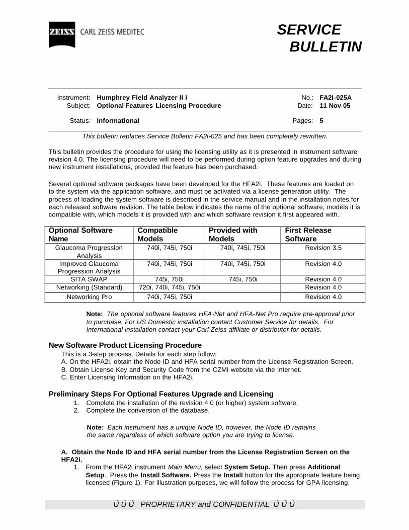
ÚÚÚ PROPRIETARY and CONFIDENTIAL ÚÚÚ
SERVICE BULLETIN Instrument: Humphrey Field Analyzer II i No.: FA2I-025A Subject: Optional Features Licensing Procedure Date: 11 Nov 05 Status: Informational Pages: 5
This bulletin replaces Service Bulletin FA2i-025 and has been completely rewritten.
This bulletin provides the procedure for using the licensing utility as it is presented in instrument software revision 4.0. The licensing procedure will need to be performed during option feature upgrades and during new instrument installations, provided the feature has been purchased. Several optional software packages have been developed for the HFA2i. These features are loaded on to the system via the application software, and must be activated via a license generation utility. The process of loading the system software is described in the service manual and in the installation notes for each released software revision. The table below indicates the name of the optional software, models it is compatible with, which models it is provided with and which software revision it first appeared with. Optional Software Name
Compatible Models
Provided with Models
First Release Software
Glaucoma Progression Analysis
740i, 745i, 750i 740i, 745i, 750i Revision 3.5
Improved Glaucoma Progression Analysis
740i, 745i, 750i 740i, 745i, 750i Revision 4.0
SITA SWAP 745i, 750i 745i, 750i Revision 4.0 Networking (Standard) 720i, 740i, 745i, 750i Revision 4.0
Networking Pro 740i, 745i, 750i Revision 4.0
Note: The optional software features HFA-Net and HFA-Net Pro require pre-approval prior to purchase. For US Domestic installation contact Customer Service for details. For International installation contact your Carl Zeiss affiliate or distributor for details.
New Software Product Licensing Procedure
This is a 3-step process. Details for each step follow: A. On the HFA2i, obtain the Node ID and HFA serial number from the License Registration Screen. B. Obtain License Key and Security Code from the CZMI website via the Internet. C. Enter Licensing Information on the HFA2i.
Preliminary Steps For Optional Features Upgrade and Licensing
1. Complete the installation of the revision 4.0 (or higher) system software. 2. Complete the conversion of the database.
Note: Each instrument has a unique Node ID, however, the Node ID remains the same regardless of which software option you are trying to license.
A. Obtain the Node ID and HFA serial number from the License Registration Screen on the HFA2i.
1. From the HFA2i instrument Main Menu, select System Setup. Then press Additional Setup. Press the Install Software. Press the Install button for the appropriate feature being licensed (Figure 1). For illustration purposes, we will follow the process for GPA licensing.
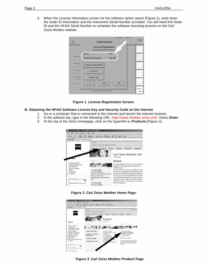
Page 2 FA2i-025A
2. When the License Information screen for the software option opens (Figure 1), write down the Node ID information and the Instrument Serial Number provided. You will need this Node ID and the HFA2i Serial Number to complete the software licensing process on the Carl Zeiss Meditec website.
Figure 1. License Registration Screen.
B. Obtaining the HFA2i Software License Key and Security Code on the Internet 1. Go to a computer that is connected to the Internet and launch the Internet browser. 2. In the address bar, type in the following URL: http://www.meditec.zeiss.com. Select Enter. 3. At the top of the Zeiss homepage, click on the hyperlink to Products (Figure 2).
Figure 2. Carl Zeiss Meditec Home Page.
Figure 3. Carl Zeiss Meditec Product Page.
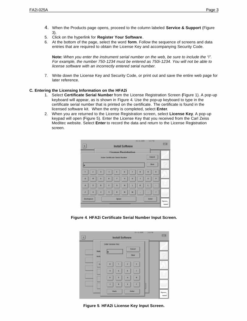
FA2i-025A Page 3
4. When the Products page opens, proceed to the column labeled Service & Support (Figure 3).
5. Click on the hyperlink for Register Your Software . 6. At the bottom of the page, select the word form. Follow the sequence of screens and data
entries that are required to obtain the License Key and accompanying Security Code.
Note: When you enter the instrument serial number on the web, be sure to include the “i”. For example, the number 750-1234 must be entered as 750i-1234. You will not be able to license software with an incorrectly entered serial number.
7. Write down the License Key and Security Code, or print out and save the entire web page for later reference.
C. Entering the Licensing Information on the HFA2i
1. Select Certificate Serial Number from the License Registration Screen (Figure 1). A pop-up keyboard will appear, as is shown in Figure 4. Use the pop-up keyboard to type in the certificate serial number that is printed on the certificate. The certificate is found in the licensed software kit. When the entry is completed, select Enter.
2. When you are returned to the License Registration screen, select License Key. A pop-up keypad will open (Figure 5). Enter the License Key that you received from the Carl Zeiss Meditec website. Select Enter to record the data and return to the License Registration screen.
Figure 4. HFA2i Certificate Serial Number Input Screen.
Figure 5. HFA2i License Key Input Screen.

Page 4 FA2i-025A
3. Select Security Code. A pop-up keypad will open to allow you to enter the Security Code received on the Carl Zeiss Meditec website. Once you have entered the code, select Enter to record the data and return to the License Registration screen.
4. Select Save to record the settings and to return to the Install Software screen. If you have made a mistake entering the data, you will see the following dialogue:
One or more values entered are invalid. Please verify the values you
have entered and try again.
5. If you have successfully entering the data, you will see the following dialogue:
The software has been installed successfully.
6. Select the newly registered product Install button. Select Print to print out a copy of the licensing settings for the customer. Tell the customer to save this information as it will be required should the licensing information on the system need to be restored. Ask the customer to staple or tape the printout inside of the HFA2i Owner’s Guide.
7. Select Done to complete the licensing process, or select the appropriate button to license another software option.
8. After selecting Done, a message will be displayed “Please cycle power to restart.” Turn off the HFA2i and wait approximately 10 seconds before turning it on again.
9. Create a new backup configuration disk. 10. This completes the Licensing process.
Removing the Licensed Feature Situations may arise where the license must be removed from the system. Do not allow customers to casually press the “Remove” button on the License Information screen without serious consideration of the effects.
Note: Once an optional software product is removed, it cannot be licensed again with the same product certificate number. Please contact Order Administration for assistance.
1. From the HFA2i instrument Main Menu, select System Setup. 2. Select Additional Setup. 3. Select Install Software. 4. Select the Install button for the appropriate feature you are going to remove. 5. Select the Remove button. The following dialogue will be displayed:
Warning
If you proceed, the feature, feature name, will no longer be available.
6. At this point, you may choose the Cancel or Proceed button. Proceed will allow you to continue with the removal process. Cancel will halt the license removal process.
7. Select Proceed. 8. A dialogue will be displayed:
Feature name
Your Removal Code is XXXX/XXXX.
9. You will have two choices: Print and Cancel. Print will print the removal code and complete the removal process. Cancel will complete the removal process without printing the code.
10. Provide the removal code to your Carl Zeiss order entry group. The removal code is used to validate that the features have been removed. No customer credit will be given without the removal code.
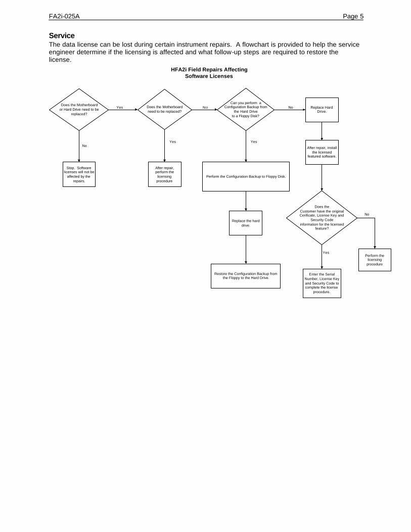
FA2i-025A Page 5 Service The data license can be lost during certain instrument repairs. A flowchart is provided to help the service engineer determine if the licensing is affected and what follow-up steps are required to restore the license.
HFA2i Field Repairs AffectingSoftware Licenses
Stop. Softwarelicenses will not be
affected by therepairs.
Does the Motherboardor Hard Drive need to be
replaced?
Does the Motherboardneed to be replaced?
Can you perform aConfiguration Backup from
the Hard Driveto a Floppy Disk?
Yes
Yes
No
No
After repair,perform thelicensingprocedure
No
Perform the Configuration Backup to Floppy Disk.
Yes
Replace the harddrive.
Restore the Configuration Backup fromthe Floppy to the Hard Drive.
Replace HardDrive.
After repair, installthe licensed
featured software.
Does theCustomer have the originalCerificate, License Key and
Security Codeinformation for the licensed
feature?
Yes
No
Enter the SerialNumber, License Keyand Security Code tocomplete the license
procedure.
Perform thelicensingprocedure
ÚÚÚ PROPRIETARY and CONFIDENTIAL ÚÚÚ
A SERVICE BULLETIN Instrument: Humphrey Field Analyzer II-i No.: FA2i-026 Subject: System Validation Form - Prevail Date: 7 Apr 04 Status: Mandatory - Domestic Only Pages: 4 Domestic Field Service: A new System Validation Form has been released for the HFA II and HFA II-i. The System Validation Form is required for all HFA II and HFA II-i field service calls. The values for the System Validation Form are to be entered into the Prevail system when filling out your Field Service Report. You are still required to perform the tasks specified in the System Checkout Checklist in Section 2 of the Service Manual, but you will no longer need to submit the checklist with your Service Report. Values obtained during the System Checkout will be entered into the System Validation Form on line. The fields required on the System Validation Form are dependent on what type of Service Call, and whether or not the instrument is equipped with B/Y hardware. Service Call Types
• Basic Service Call – Calls that do not require Intensity Verification or Calibration
• Intensity Verification – Calls that require Intensity Verification only
• Intensity Calibration – Calls that require Intensity Calibration and Verification Attached is an example of the new System Validation Form. International: Continue to follow the current Checkout Procedures detailed in the Service Manual.
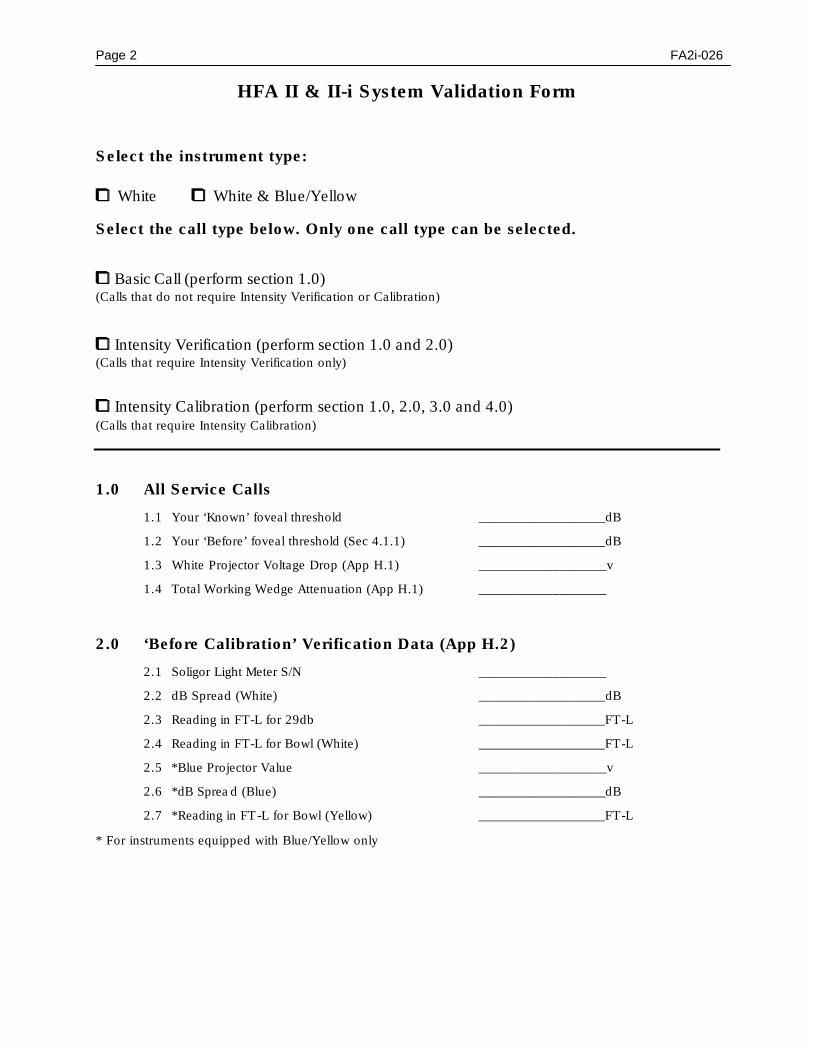
Page 2 FA2i-026
HFA II & II-i System Validation Form
Select the instrument type:
00 White 00 White & Blue/Yellow
Select the call type below. Only one call type can be selected.
00 Basic Call (perform section 1.0) (Calls that do not require Intensity Verification or Calibration)
00 Intensity Verification (perform section 1.0 and 2.0) (Calls that require Intensity Verification only)
00 Intensity Calibration (perform section 1.0, 2.0, 3.0 and 4.0) (Calls that require Intensity Calibration)
1.0 All Service Calls
1.1 Your ‘Known’ foveal threshold ___________________dB
1.2 Your ‘Before’ foveal threshold (Sec 4.1.1) ___________________dB
1.3 White Projector Voltage Drop (App H.1) ___________________v
1.4 Total Working Wedge Attenuation (App H.1) ___________________
2.0 ‘Before Calibration’ Verification Data (App H.2)
2.1 Soligor Light Meter S/N ___________________
2.2 dB Spread (White) ___________________dB
2.3 Reading in FT-L for 29db ___________________FT-L
2.4 Reading in FT-L for Bowl (White) ___________________FT-L
2.5 *Blue Projector Value ___________________v
2.6 *dB Sprea d (Blue) ___________________dB
2.7 *Reading in FT -L for Bowl (Yellow) ___________________FT-L
* For instruments equipped with Blue/Yellow only

FA2i-026 Page 3
3.0 ‘After Calibration’ Verification Data (App H.2)
3.1 Total Working Wedge Attenuation ___________________
3.2 Your ‘After’ foveal threshold ___________________dB
3.3 White Projector Voltage Drop ___________________v
3.4 dB Spread (White) ___________________dB
3.5 Reading in FT-L for 29db ___________________FT-L
3.6 Reading in FT-L for Bowl (White) ___________________FT-L
3.7 *Blue Projector Value ___________________v
3.8 *dB Spread (Blue) ___________________dB
3.9 *Reading in FT -L for Bowl (Yellow) ___________________FT-L
* For instruments equipped with Blue/Yellow only
4.0 Worksheet (App I)
dB ratio = 10*Log(BKGDFtL / #37FtL)
Note: #37 is the same Ft-L value as the 29 dB data point on the White Light Verification Printout. 1. Using above formula & values from the BEFORE White Light Verification Data Printout, find the OLD dB ratio: dB 2. Using above formula & values from the AFTER White Light Verification Data Printout, find the NEW dB ratio: dB 3. Find the dB shift: dB (OLD dB RATIO) – (NEW dB RATIO) = dB shift Do you need to leave the calibration notice? 1. If dB shift is +/- 1dB, DO NOT leave the notice. 2. DO NOT include (+) or (–) signs on the notice. 3. If dB shift is (+), select low on the notice. 4. If dB shift is (–), select high on the notice. 5. If ±1dB or greater shift, leave the cal notice.
6. If ±4dB or greater shift, call your regional manager.
Leave Notice? 0 Yes 0 No

Page 4 FA2i-026
5160 Hacienda Drive, Dublin, CA 94568 � (925) 557-4100 � (1-800) 858-1508
Date ________________________ Dear Doctor: We checked the calibration of your Field Analyzer, serial number ____________, today
and found that it was reading dB too high 0 / low 0 (select). The instrument has now been recalibrated. Please keep this calibration shift in mind when comparing future results against previous field. If it was reading too high, future tests of stable patients will tend to show an artifactual loss in threshold sensitivity in the amount shown above. If it was reading too low, future tests will tend to show an artifactual improvement. We recommend yearly preventative maintenance and calibration checks for your Field Analyzer. Inquire about our service contracts, which include a yearly preventative maintenance visit. If you have any questions, please contact Carl Zeiss Meditec at 1-877-486-7473 and ask to have your area’s Regional Service Manager give you a call. Sincerely, Carl Zeiss Meditec

ÚÚÚ PROPRIETARY and CONFIDENTIAL ÚÚÚ
SERVICE SERVICE BULLETINBULLETIN
Instrument: Humphrey Field Analyzer IIi
Subject: HFA2i Upgrading Model 720i to Model 735iNo.: FA2i-027
Date: 30 May 04
Status: Informational Pages: 6
General Information
The information and instructions provided in this service bulletin will enable a trained HFA2 i technicianto upgrade a model 720i to a model 735i.
The upgrade from a model 720i to a 735i enables color testing (but not Blue-Yellow testing) and willmake the 720i compatible with optional GPA features. GPA software is a license only product with theminimum application software revision of 3.5.
Before You Start
Listed below are a number of questions and answers that you should review before beginning theupgrade.
What is the minimum skill level for a technician to perform the upgrade?
This upgrade should only be performed if the technician has complete parts removal and replacementknowledge and complete instrument calibration knowledge. The procedures in this service bulletin offerguidelines for performing the upgrade. It is assumed that the technician has complete HFA 2i serviceknowledge.
How long will the upgrade take to complete?
The estimated time to complete the upgrade is 2.5 hours. This time takes into account an instrumentpre-checkout, hardware and software changes, an instrument post-checkout, time to correct anyunforeseen problems, and time to provide some limited customer training.
Tools Required to Perform the Upgrade
Listed below are the tools required to perform the upgrade.
Description Part No.
HFA2i Service Manual and Service Bulletins . . . . . . . . . . 52235
Soligor Light Meter Kit . . . . . . . . . . . . . . . . . . . 14905Soligor Mount Adaptor (HFA I/II) (set of 2) . . . . . . . . . . . 30248Bowl Shroud . . . . . . . . . . . . . . . . . . . . . . . 54710Diagnostic Support Tool (DST) diskettes . . . . . . . . . . . see FA2i-005X for current version Service Key . . . . . . . . . . . . . . . . . . . . . . . . 30141-2Miscellaneous Hand Tools . . . . . . . . . . . . . . . . . (acquire locally)
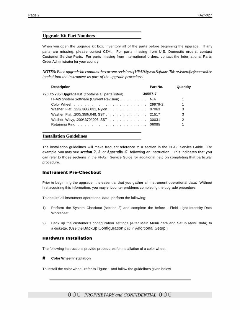
Page 2 FA2i-027
ÚÚÚ PROPRIETARY and CONFIDENTIAL ÚÚÚ
Upgrade Kit Part Numbers
When you open the upgrade kit box, inventory all of the parts before beginning the upgrade. If anyparts are missing, please contact CZMI. For parts missing from U.S. Domestic orders, contactCustomer Service Parts. For parts missing from international orders, contact the International PartsOrder Administrator for your country.
NOTES: Each upgrade kit contains the current revision of HFA2i System Software. This revision of software will beloaded into the instrument as part of the upgrade procedure.
Description Part No. Quantity
720i to 735i Upgrade Kit (contains all parts listed) 30557-7HFA2i System Software (Current Revision) . . . . . . . . N/A 1Color Wheel . . . . . . . . . . . . . . . . . . . . . 29979-2 1Washer, Flat, .223/.366/.031, Nylon . . . . . . . . . . . 07063 3Washer, Flat, .200/.359/.048, SST . . . . . . . . . . . . 21517 3Washer, Wavy, .200/.370/.006, SST . . . . . . . . . . . 30031 2Retaining Ring . . . . . . . . . . . . . . . . . . . . 06085 1
Installation Guidelines
The installation guidelines will make frequent reference to a section in the HFA2i Service Guide. Forexample, you may see section 2, 3, or Appendix G following an instruction. This indicates that youcan refer to those sections in the HFA2i Service Guide for additional help on completing that particularprocedure.
Instrument Pre-CheckoutInstrument Pre-Checkout
Prior to beginning the upgrade, it is essential that you gather all instrument operational data. Withoutfirst acquiring this information, you may encounter problems completing the upgrade procedure.
To acquire all instrument operational data, perform the following:
1) Perform the System Checkout (section 2) and complete the before - Field Light Intensity DataWorksheet.
2) Back up the customer’s configuration settings (Alter Main Menu data and Setup Menu data) toa diskette. (Use the Backup Configuration pad in Additional Setup.)
Hardware InstallationHardware Installation
The following instructions provide procedures for installation of a color wheel.
## Color Wheel Installation
To install the color wheel, refer to Figure 1 and follow the guidelines given below.
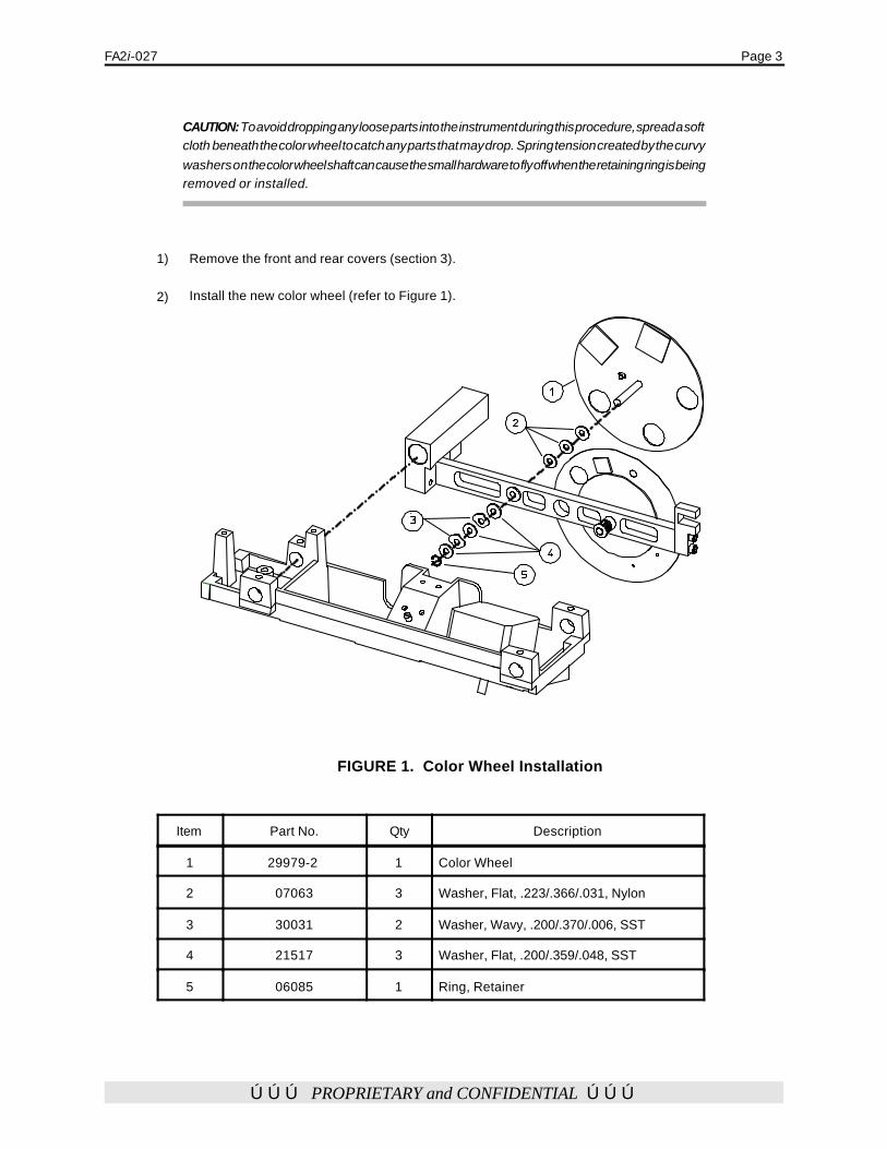
FA2i-027 Page 3
ÚÚÚ PROPRIETARY and CONFIDENTIAL ÚÚÚ
CAUTION: To avoid dropping any loose parts into the instrument during this procedure, spread a softcloth beneath the color wheel to catch any parts that may drop. Spring tension created by the curvywashers on the color wheel shaft can cause the small hardware to fly off when the retaining ring is beingremoved or installed.
1) Remove the front and rear covers (section 3).
2) Install the new color wheel (refer to Figure 1).
FIGURE 1. Color Wheel Installation
Item Part No. Qty Description
1 29979-2 1 Color Wheel
2 07063 3 Washer, Flat, .223/.366/.031, Nylon
3 30031 2 Washer, Wavy, .200/.370/.006, SST
4 21517 3 Washer, Flat, .200/.359/.048, SST
5 06085 1 Ring, Retainer

Page 4 FA2i-027
ÚÚÚ PROPRIETARY and CONFIDENTIAL ÚÚÚ
Setting the Hardware Options Number and Software Options Number
1) Use the Diagnostic Support Tool (DST) diskettes and service key to set the Hardware Optionsnumber: From the DST Main Menu select Set Model/Hardware Options. Select Set Model 735iDefaults, a test log menu appears and displays the Model 735i default settings. Select Continue.Switch OFF the instrument and remove the Service Key.
2) Load the current revision of HFA2i System software included in the upgrade kit (refer to theAppendix section of the Service Manual). Loading the software will set the software optionsnumber. This step must be done AFTER the hardware options number has been set.
3) Once the software is loaded, proceed to the “I” Information screen. Verify that the correct modeland hardware options numbers have been entered.
NOTES: If the instrument gives an error during the power-up sequence, select Proceed to get to the Main Menu. At theMain Menu, the Setup menu option can be selected. The error may occur because the color wheel is not yet calibrated. Thiscalibration will be performed in the next procedure.
Color Wheel Calibration and TestColor Wheel Calibration and Test
As a result of installing a new color wheel earlier in this upgrade procedure, you must perform thefollowing calibration and test:
1) Calibrate the color wheel (refer to section 4).
2) Enter QA Tests. Run the 30/60 mixed tests for 5 minutes. No errors should be reported. Observethe color wheel for proper operation.
Operational ChecksOperational Checks
To ensure that the upgraded features are accessible to the operator, perform the following operationalchecks.
1) Proceed to a patient test.2) Select Change Parameters. 3) Select a red stimulus.4) Start the test. Look into the bowl and ensure that a red stimulus is displayed while
testing.3) Select a blue stimulus.4) Start the test. Look into the bowl and ensure that a blue stimulus is displayed while
testing.
Instrument Post-CheckoutInstrument Post-Checkout
Prior to completing the upgrade, it is essential that you perform an Instrument Post-Checkout. Thiswill ensure that the instrument is in calibration and all features are operational.
1) To perform the Instrument Post-Checkout, perform the System Checkout (section 2).
Suggestions for Customer TrainingSuggestions for Customer Training

FA2i-027 Page 5
ÚÚÚ PROPRIETARY and CONFIDENTIAL ÚÚÚ
1) Ensure that the customer has an understanding of how to access Change Parameters and selectstimulus color changes.
Report ing the Upgrade to CZMIReport ing the Upgrade to CZMI
All upgrades performed to the HFA2i must be reported to CZMI as described below.
WARNING: Any unauthorized HFA2 i upgrades (those performed withoutnotifying CZMI) will automatically be downgraded to the pre-upgrade model andfeatures when a future revision of software is loaded into the instrument.
1) U.S. Domestic service technicians need not provide any additional information other than thefollow up documentation as described in the following section of this bulletin. Prevail systemcoding will alert Customer Service to record the upgrade information found in the Service ReportForm.
2) International (Affiliates and Distributors) service technicians must send a fax to CZMI Customer Service (925-557-4652) containing the information itemized below (Note ! For yourconvenience, an appropriate fax form is included at the back of this bulletin) :
a) Technician's name and Affiliate/Distributor home office fax number.b) The serial number of the HFA2 i that was upgraded.c) The customer's name and address.
3) Once Customer Service receives this information, the Order Administration database will beupdated to indicate the new instrument configuration. If the information is not received, anysubsequent software revision upgrade on the instrument will cancel the authorizedbut unreported model 735i configuration upgrade, and a second service call willthen be required to restore the instrument configuration to model 735i.
Finishing UpFinishing Up
# Follow Up Documentation
1) U.S. Domestic service technicians must perform the actions and complete the following formsvia the Prevail System:a) HFA2i Service Report Form.b) HFA2i - Light Intensity Worksheet (before/after/cal shift).c) Calibration Notice (if required).
2) It is recommended that International Service Engineers return and file the appropriate paperworkat their Affiliate or Distributor offices.a) Service Report Form.b) HFA II - Light Intensity Worksheet (before/after/cal shift).c) Calibration Notice - yellow copy (if required).

facsimileTRANSMITTAL
to:to: CZMI Customer Service
fax #:fax #: 925-557-4298
re:re: HFA2i 720i-to-735i Upgrade Notification
date:date:
pages:pages:1, including this cover sheet.
Technician’s Name .
Affiliate/Distributor Fax No.
Instrument Serial No.
Customer's Name and Address:
Date Upgrade Performed:
Comments:
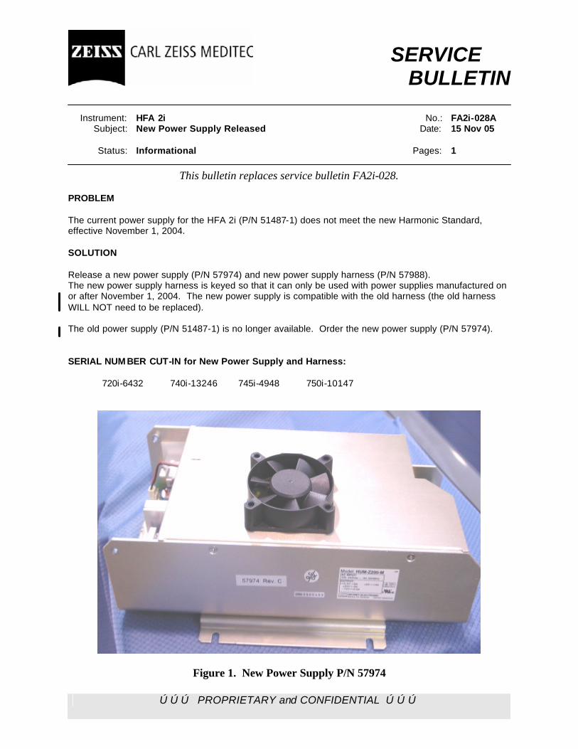
ÚÚÚ PROPRIETARY and CONFIDENTIAL ÚÚÚ
SERVICE BULLETIN Instrument: HFA 2i No.: FA2i-028A Subject: New Power Supply Released Date: 15 Nov 05 Status: Informational Pages: 1
This bulletin replaces service bulletin FA2i-028. PROBLEM The current power supply for the HFA 2i (P/N 51487-1) does not meet the new Harmonic Standard, effective November 1, 2004. SOLUTION Release a new power supply (P/N 57974) and new power supply harness (P/N 57988). The new power supply harness is keyed so that it can only be used with power supplies manufactured on or after November 1, 2004. The new power supply is compatible with the old harness (the old harness WILL NOT need to be replaced). The old power supply (P/N 51487-1) is no longer available. Order the new power supply (P/N 57974). SERIAL NUM BER CUT-IN for New Power Supply and Harness: 720i-6432 740i-13246 745i-4948 750i-10147
Figure 1. New Power Supply P/N 57974

ÚÚÚ PROPRIETARY and CONFIDENTIAL ÚÚÚ
SERVICE BULLETIN Instrument: HFA 2i No.: FA2i-029 Subject: Update to Service Manual Date: 04 Nov 04 Status: Informational Pages: 1 PROBLEM An error was noted in the HFA 2i service manual with respect to the High Level Initialization. SOLUTION Add the following note prior to step 1), High Level Initialization / Appendix L, Page L-2. NOTE: Change BIOS (Advanced CMOS Setup) 1st Boot Device from IDE-0 to Floppy. Change 2nd Boot Device from Floppy to IDE-0. Remember to save the changes when you exit the BIOS setup. Once Initialization has been completed, change the BIOS to its original setup. Remember to save the changes when you exit the BIOS setup. Load the appropriate system software.
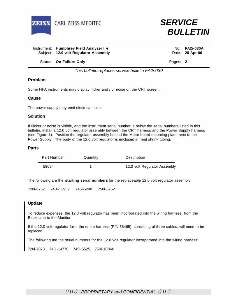
ÚÚÚ PROPRIETARY and CONFIDENTIAL ÚÚÚ
SERVICE BULLETIN Instrument: Humphrey Field Analyzer II-i No.: FA2i-030A Subject: 12.0 volt Regulator Assembly Date: 20 Apr 06 Status: On Failure Only Pages: 2
This bulletin replaces service bulletin FA2i-030 Problem Some HFA instruments may display flicker and / or noise on the CRT screen. Cause The power supply may emit electrical noise. Solution If flicker or noise is visible, and the instrument serial number is below the serial numbers listed in this bulletin, install a 12.0 volt regulator assembly between the CRT harness and the Power Supply harness (see Figure 1). Position the regulator assembly behind the Motor board mounting plate, next to the Power Supply. The body of the 12.0 volt regulator is enclosed in heat shrink tubing. Parts Part Number Quantity Description
59034 1 12.0 volt Regulator Assembly The following are the starting serial numbers for the replaceable 12.0 volt regulator assembly: 720i-6752 740i-13959 745i-5208 750i-6752 Update To reduce expenses, the 12.0 volt regulator has been incorporated into the wiring harness, from the Backplane to the Monitor. If the 12.0 volt regulator fails, the entire harness (P/N 58465), consisting of three cables, will need to be replaced. The following are the serial numbers for the 12.0 volt regulator incorporated into the wiring harness: 720i-7073 740i-14770 745i-5525 750i-10860
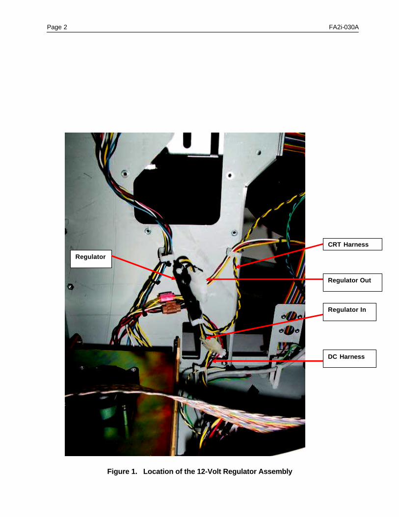
Page 2 FA2i-030A
Figure 1. Location of the 12-Volt Regulator Assembly
CRT Harness
Regulator Out
Regulator In
DC Harness
Regulator
ÚÚÚ PROPRIETARY and CONFIDENTIAL ÚÚÚ
SERVICE BULLETIN
Instrument: Humphrey Field Analyzer II-i No.: FA2i-031A Subject: Calibration Changes with Revision 4.1 or Greater Software
Date: 15 Feb 08
Status: Informational Pages: 2
This bulletin replaces Service Bulletin FA2i-031 Introduction This service bulletin introduces changes to the HFA II-i calibration. Two new startup tests have been added with the release of software revision 4.1. These tests become active once the software has been loaded, and the instrument has been powered On. The first test evaluates the position of the shutter; the second test performs an evaluation of the aperture position. Shutter Misalignment Test At startup of the instrument, an evaluation of correct shutter positioning occurs. The instrument makes a measurement, with the shutter in place, and determines the light intensity that has passed around the shutter paddle. The passed light is compared against a limit. Failure of the test will result in a Startup State Error 18 error, “Shutter may be misaligned.” Pressing Proceed will not allow testing. Failure of the shutter alignment test will require normal shutter calibration. Aperture Spot Ratio Test The spot ratio test measures the spot intensity ratio between spot sizes V and III. The spot ratio is determined and compared with a theoretical value of 16. If the spot ratio is not within the specifications (two dB or 58% of the expected value), a Startup State Error 19 error, “Aperture may be misaligned” results. Pressing Proceed will not allow testing. Failure of the spot ratio test will require the aperture calibration, followed by measuring and saving a spot ratio value that is within specification. The procedure is described in this bulletin. During the first calibration of the instrument, once revision 4.1 software has been loaded, a tighter specification (26% of the expected value) for the spot intensity ratio test is implemented. Failure of the spot ratio test any time after a calibration has been completed will require the aperture calibration, followed by measuring and saving a spot ratio value that is within specification. Measuring and Saving the Aperture Spot Ratio In the aperture calibration menu, additional information to view and measure the aperture spot ratio is provided. The screen contains the following information: V/III Spot Ratio Stored XX.XX (14.1 – 17.9) • XX.XX represents the stored value of the V/III spot ratio. • (14.1 – 17.9) represents the allowable range of the spot ratio.
Measured

Page 2 FA2i-031A
• Calibrate all of the spot sizes, as per Section 4.8.2.3 of the Field Service Guide. However, you must not press the “Store” button after setting each of the positions. They will be held in memory and will be stored when you press the “Store” button when the spot ratio is in specification.
• After calibrating the spot sizes, press the “Measured” button. • A “Please Wait” dialogue will temporarily appear. • A new stored value entry then appears below the “Measured” button in the format, XX.XX. • Check the new stored value. If the new stored value is within specified range (14.1 – 17.9), press
the “Store” button to save the new spot ratio. • Press “Done” button to leave the aperture calibration. Note - Left Home, Right Home and Offset calibrations will be required after aperture calibration. No other changes to the calibration process have been created with the HFA II-i revision 4.1 application software.
ÚÚÚ PROPRIETARY and CONFIDENTIAL ÚÚÚ
SERVICE BULLETIN Instrument: Humphrey Field Analyzer II i No.: FA2I-032 Subject: Networking and Networking Diagnostic Tools Date: 01 Dec 05 Status: Informational Pages: 6
General Information
With the release of the Revision 4.0, Networking (HFA-NET) and Networking Pro (HFA-NET PRO) optional features software packages were created. To help the service engineer troubleshoot the new networking features, a suite of network diagnostic tools have been developed for the Humphrey Field Analyzer II-I ( also known as the HFA2i) . This bulletin describes the use of these tools. Domestic (USA) Service Support Policy
Service will primarily be performed at the customer site or, if the customer elects, via phone support. CZMI will be responsible to support the HFA2i networking functionality up to the point where the network cable plugs into the HFA2i. CZMI will not provide support past this point, but will offer training documentation to the customer on the different diagnostic tools provided with the HFA2i network software. All troubleshooting for the customer’s network is the responsibility of the customer and CZMI will only be responsible to confirm the HFA2i networking software is able to ping the host computer. If the customer has problems connecting the HFA2i networking software to their network, they will be provided two hours of support, free of charge. After that time however, the customer is billable for further support. International Service Support Policy
Service will primarily be performed at the customer site, or if the customer elects, via phone support. CZMI will be responsible to support the HFA2i networking functionality up to the point where the network cable plugs into the HFA2i. CZMI will not provide support past this point, but will offer training documentation to the customer on the different diagnostic tools provided with the HFA2i network software. All troubleshooting for the customer’s network is the responsibility of the customer and CZMI will only be responsible to confirm the HFA2i networking software is able to ping the host computer. International CZMI affiliates or distributors will set their own policies for network support outside of the instrument. Site Survey, Domestic
The Networking and Networking Pro optional features software packages are purchased software options. For domestic customers, it is highly recommended that prior to purchase of either optional features software package, the customer submit a Site Survey to the Order Entry group for approval. The survey is available from the sales representative. The completed Site Survey will be evaluated by the Technical Support Networking Group. Completion of the Site Survey will be a great aid in setting up and configuring the instrument and network.
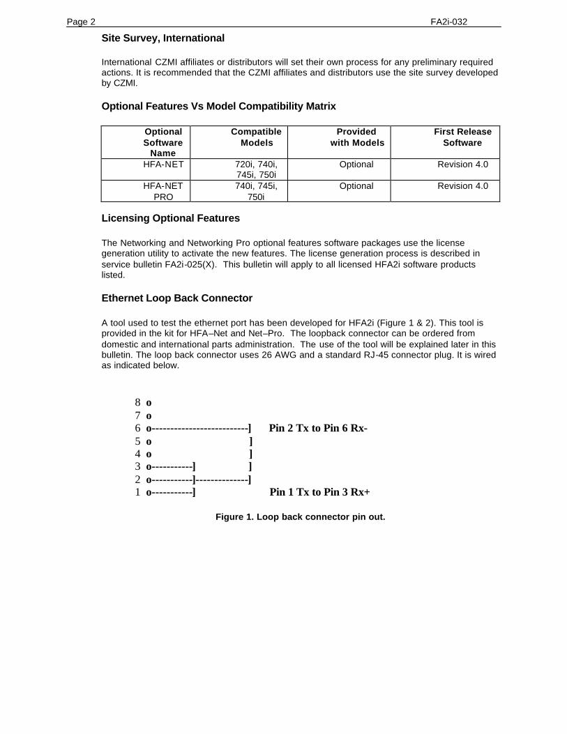
Page 2 FA2i-032 Site Survey, International
International CZMI affiliates or distributors will set their own process for any preliminary required actions. It is recommended that the CZMI affiliates and distributors use the site survey developed by CZMI. Optional Features Vs Model Compatibility Matrix
Optional Software
Name
Compatible Models
Provided with Models
First Release Software
HFA-NET 720i, 740i, 745i, 750i
Optional Revision 4.0
HFA-NET PRO
740i, 745i, 750i
Optional Revision 4.0
Licensing Optional Features
The Networking and Networking Pro optional features software packages use the license generation utility to activate the new features. The license generation process is described in service bulletin FA2i-025(X). This bulletin will apply to all licensed HFA2i software products listed. Ethernet Loop Back Connector
A tool used to test the ethernet port has been developed for HFA2i (Figure 1 & 2). This tool is provided in the kit for HFA–Net and Net–Pro. The loopback connector can be ordered from domestic and international parts administration. The use of the tool will be explained later in this bulletin. The loop back connector uses 26 AWG and a standard RJ-45 connector plug. It is wired as indicated below.
8 o 7 o 6 o--------------------------] Pin 2 Tx to Pin 6 Rx- 5 o ] 4 o ] 3 o-----------] ] 2 o-----------]--------------] 1 o-----------] Pin 1 Tx to Pin 3 Rx+
Figure 1. Loop back connector pin out.

FA2i-032 Page 3
Figure 2. Loop Back Connector P/N 59798. Networking Setup
Chapter 14 in the current HFA2i User’s Guide has instructions on setting up the HFA2i networking features.
Figure 3. Network Diagnostic Screen.
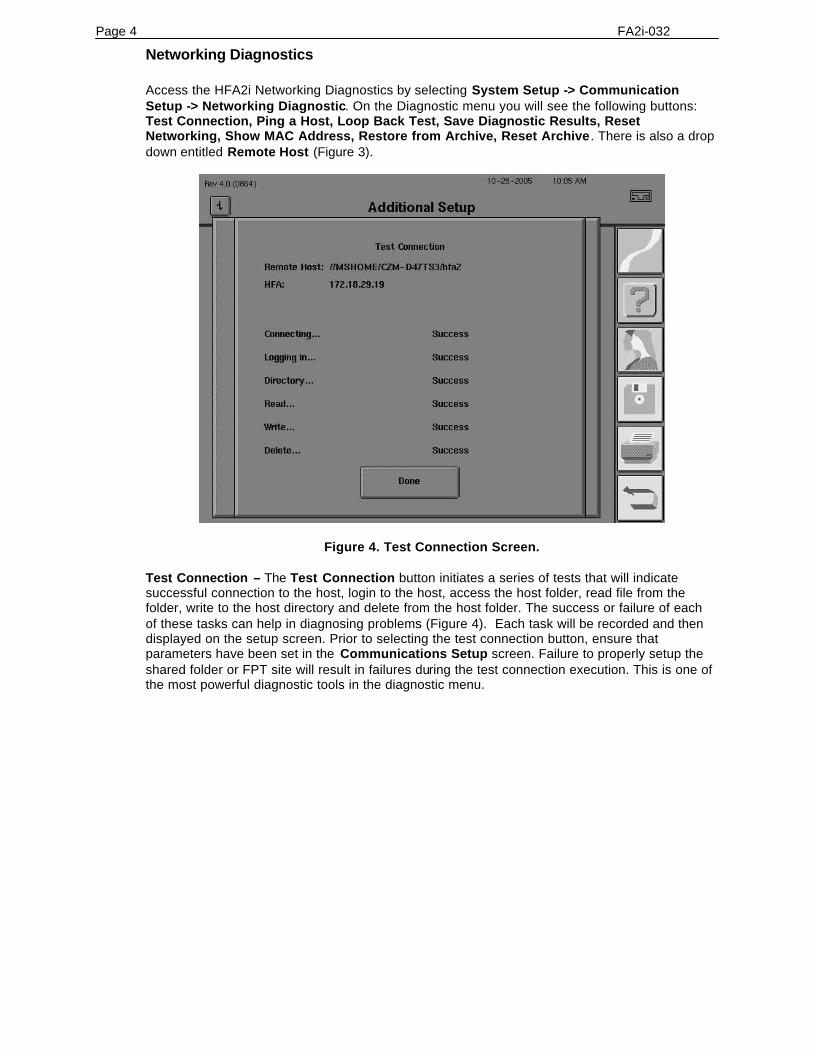
Page 4 FA2i-032 Networking Diagnostics
Access the HFA2i Networking Diagnostics by selecting System Setup -> Communication Setup -> Networking Diagnostic. On the Diagnostic menu you will see the following buttons: Test Connection, Ping a Host, Loop Back Test, Save Diagnostic Results, Reset Networking, Show MAC Address, Restore from Archive, Reset Archive. There is also a drop down entitled Remote Host (Figure 3).
Figure 4. Test Connection Screen. Test Connection – The Test Connection button initiates a series of tests that will indicate successful connection to the host, login to the host, access the host folder, read file from the folder, write to the host directory and delete from the host folder. The success or failure of each of these tasks can help in diagnosing problems (Figure 4). Each task will be recorded and then displayed on the setup screen. Prior to selecting the test connection button, ensure that parameters have been set in the Communications Setup screen. Failure to properly setup the shared folder or FPT site will result in failures during the test connection execution. This is one of the most powerful diagnostic tools in the diagnostic menu.
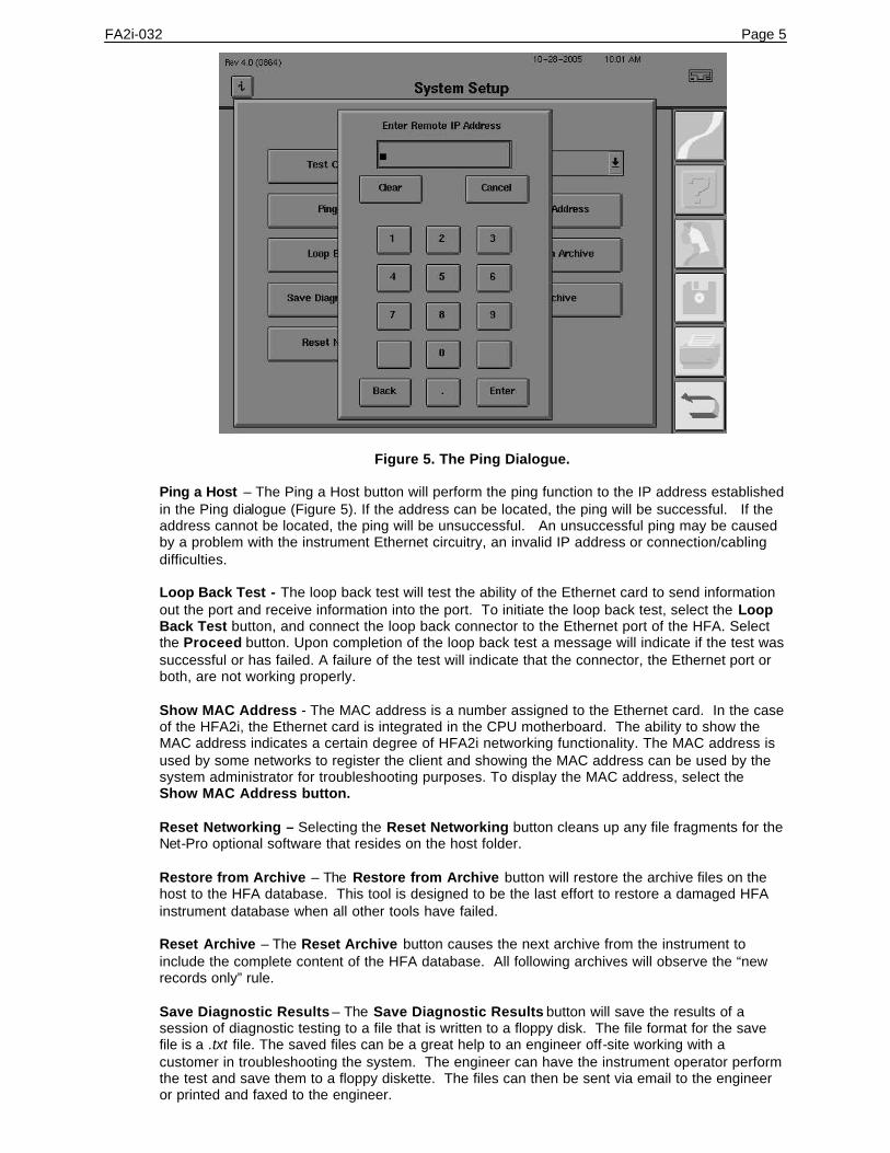
FA2i-032 Page 5
Figure 5. The Ping Dialogue.
Ping a Host – The Ping a Host button will perform the ping function to the IP address established in the Ping dialogue (Figure 5). If the address can be located, the ping will be successful. If the address cannot be located, the ping will be unsuccessful. An unsuccessful ping may be caused by a problem with the instrument Ethernet circuitry, an invalid IP address or connection/cabling difficulties. Loop Back Test - The loop back test will test the ability of the Ethernet card to send information out the port and receive information into the port. To initiate the loop back test, select the Loop Back Test button, and connect the loop back connector to the Ethernet port of the HFA. Select the Proceed button. Upon completion of the loop back test a message will indicate if the test was successful or has failed. A failure of the test will indicate that the connector, the Ethernet port or both, are not working properly. Show MAC Address - The MAC address is a number assigned to the Ethernet card. In the case of the HFA2i, the Ethernet card is integrated in the CPU motherboard. The ability to show the MAC address indicates a certain degree of HFA2i networking functionality. The MAC address is used by some networks to register the client and showing the MAC address can be used by the system administrator for troubleshooting purposes. To display the MAC address, select the Show MAC Address button. Reset Networking – Selecting the Reset Networking button cleans up any file fragments for the Net-Pro optional software that resides on the host folder. Restore from Archive – The Restore from Archive button will restore the archive files on the host to the HFA database. This tool is designed to be the last effort to restore a damaged HFA instrument database when all other tools have failed. Reset Archive – The Reset Archive button causes the next archive from the instrument to include the complete content of the HFA database. All following archives will observe the “new records only” rule. Save Diagnostic Results – The Save Diagnostic Results button will save the results of a session of diagnostic testing to a file that is written to a floppy disk. The file format for the save file is a .txt file. The saved files can be a great help to an engineer off-site working with a customer in troubleshooting the system. The engineer can have the instrument operator perform the test and save them to a floppy diskette. The files can then be sent via email to the engineer or printed and faxed to the engineer.

Page 6 FA2i-032
Additional Networking Troubleshooting Tools/Settings
To locate additional networking troubleshooting tools, select System Setup -> Additional Setup -> Diagnostic. Enter the password 1234 and select Enter. On the User Diagnostic Menu select the Advanced Network Options button. Advanced Network Options displays the Enable startup connection and the Set Network Timeout. Select Enable startup connection for the following features: Archive/Retrieve Host, Data Export Host, EMR/PMS Host and Worklist Host. Archive/Retrieve Host - Selecting Archive/Retrieve Host will activate the system software to attempt to confirm the connection to the folder on the server setup for the Archive/Retrieve Host each time the instrument starts up. The practice/engineer can select to have this feature to their preference. Data Export Host - Selecting Data Export Host will activate the system software to attempt to connect to the folder on the server setup for the Data Export Host each time the instrument starts up. The practice/engineer can select to have this feature to their preference. EMR/PMS Host - Selecting EMR/PMS Host will activate the system software to attempt to connect to the folder on the server setup for the EMR/PMS Host each time the instrument starts up. The practice/engineer can select to have this feature to their preference. Worklist Host - Selecting and Worklist Host will activate the system software to attempt to connect to the folder on the server setup for the and Worklist Host each time the instrument starts up. The practice/engineer can select to have this feature to their preference. The Set Network Timeout button will bring up a dialogue to select the number of seconds that the application attempts to connect to the file server before creating a connection error. The practice/engineer can select to have this feature to their preference. Networking Troubleshooting Error Messages Networking Error messages generated on the HFA2i are presented in a tabular format in appendix F of the HFAII-I User’s Manual. These tables list the specific error messages in one column and possible solutions in the other. The four error tables are: Specific Networking Errors, Unknown Networking Errors, General Networking Errors and Worklist Networking Errors.
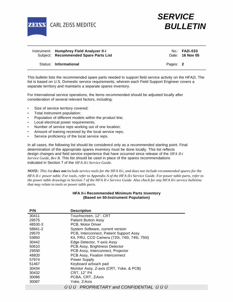
ÚÚÚ PROPRIETARY and CONFIDENTIAL ÚÚÚ
SERVICE BULLETIN Instrument: Humphrey Field Analyzer II-i No.: FA2i-033 Subject: Recommended Spare Parts List Date: 16 Nov 05 Status: Informational Pages: 2 This bulletin lists the recommended spare parts needed to support field service activity on the HFA2i. The list is based on U.S. Domestic service requirements, wherein each Field Support Engineer covers a separate territory and maintains a separate spares inventory. For International service operations, the items recommended should be adjusted locally after consideration of several relevant factors, including: • Size of service territory covered; • Total instrument population; • Population of different models within the product line; • Local electrical power requirements; • Number of service reps working out of one location; • Amount of training received by the local service reps; • Service proficiency of the local service reps. In all cases, the following list should be considered only as a recommended starting point. Final determination of the appropriate spares inventory must be done locally. This list reflects design changes and field service experience that have occurred since release of the HFA II-i Service Guide, Rev B. This list should be used in place of the spares recommendations indicated in Section 7 of the HFA II-i Service Guide. NOTE: This list does not include service tools for the HFA II-i, and does not include recommended spares for the HFA II-i power table. For tools, refer to Appendix A of the HFA II-i Service Guide. For power table parts, refer to the power table drawings in Section 7 of the HFA II-i Service Guide. Also check for any HFA II-i service bulletins that may relate to tools or power table parts.
HFA II-i Recommended Minimum Parts Inventory (Based on 50-Instrument Population)
P/N Description 30411 Touchscreen, 12", CRT 29575 Patient Button Assy 48530-3 PCB, Motor Driver 58841-2 System Software, current version 29570 PCB, Interconnect, Patient Support Assy 53850 Kit, FRU, CCD Camera (720i, 740i, 745i, 750i) 30442 Edge Detector, Y-axis Assy 50610 PCB Assy, Brightness Detector 29550 PCB Assy, Interconnect, Projector 48820 PCB Assy, Fixation Interconnect 57974 Power Supply 51467 Keyboard w/touch pad 30434 Monitor Assy, Z-axis (CRT, Yoke, & PCB) 30432 CRT, 12" P4 30086 PCBA, CRT, Z-Axis 30087 Yoke, Z-Axis
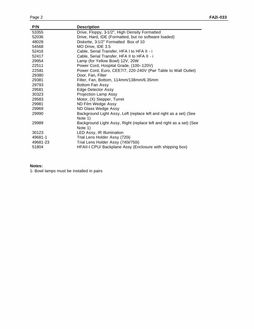
Page 2 FA2i-033 P/N Description 53355 Drive, Floppy, 3-1/2", High Density Formatted 52036 Drive, Hard, IDE (Formatted, but no software loaded) 48028 Diskette, 3-1/2" Formatted Box of 10 54568 MO Drive, IDE 3.5 52416 Cable, Serial Transfer, HFA I to HFA II - i 52417 Cable, Serial Transfer, HFA II to HFA II - i 29954 Lamp (for Yellow Bowl) 12V, 20W 22511 Power Cord, Hospital Grade, (100–120V) 22581 Power Cord, Euro, CEE7/7, 220-240V (Pwr Table to Wall Outlet) 29380 Door, Fan, Filter 29381 Filter, Fan, Bottom, 114mm/138mm/6.35mm 29793 Bottom Fan Assy 29581 Edge Detector Assy 30323 Projection Lamp Assy 29583 Motor, (X) Stepper, Turret 29981 ND Film Wedge Assy 29969 ND Glass Wedge Assy 29990 Background Light Assy, Left (replace left and right as a set) (See
Note 1) 29989 Background Light Assy, Right (replace left and right as a set) (See
Note 1) 30123 LED Assy, IR Illumination 49681-1 Trial Lens Holder Assy (720i) 49681-23 Trial Lens Holder Assy (740i/750i) 51804 HFAII-I CPU/ Backplane Assy (Enclosure with shipping box)
Notes: 1- Bowl lamps must be installed in pairs
iii PROPRIETARY and CONFIDENTIAL iii
SERVICE BULLETIN Instrument: Humphrey Field Analyzer II - i No.: FA2i-034 Subject: Field Service Guide, P/N 52235, Revision C Release Date: 13 Dec 05 Status: Informational Pages: 1 Revision C of the Humphrey Field Analyzer II – i Field Service Guide is now available. Revision C updates all labeling to: Carl Zeiss Meditec. Each Field Service Guide will include the entire Field Service Guide plus all Service Bulletins released at the time of the Field Service Guide duplication.
Distribution of the Humphrey Field Analyzer II – i Field Service Guide Distribution of the Humphrey Field Analyzer II – i Field Service Guide will be done selectively, as follows:
U.S. Domestic Field Service All Domestic Field Support Engineers can access Service Manuals / Field Service Guides through Lotus Notes.
International Service All International Support personnel can access Service Manuals / Field Service Guides through the Extranet. Additional copies of the Humphrey Field Analyzer II – i Field Service Guide are available in hard copy (paper) or on CD through standard parts order. A) Item:....... Humphrey Field Analyzer II – i Field Service Guide, Revision C paper manual P/N:....... 52235 U.S. Domestic List Price: ....... $ 195.00 B) Item:....... Humphrey Field Analyzer II – i Field Service Guide, Revision C
on CD P/N:....... 52235-CD U.S. Domestic List Price: ....... $ 195.00
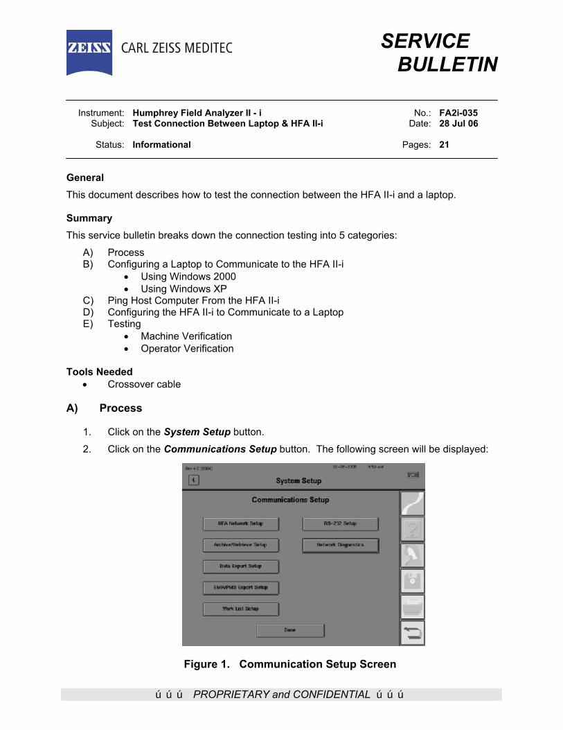
ÚÚÚ PROPRIETARY and CONFIDENTIAL ÚÚÚ
SERVICE BULLETIN Instrument: Humphrey Field Analyzer II - i No.: FA2i-035 Subject: Test Connection Between Laptop & HFA II-i Date: 28 Jul 06 Status: Informational Pages: 21
General This document describes how to test the connection between the HFA II-i and a laptop. Summary This service bulletin breaks down the connection testing into 5 categories:
A) Process B) Configuring a Laptop to Communicate to the HFA II-i
• Using Windows 2000 • Using Windows XP
C) Ping Host Computer From the HFA II-i D) Configuring the HFA II-i to Communicate to a Laptop E) Testing
• Machine Verification • Operator Verification
Tools Needed
• Crossover cable
A) Process
1. Click on the System Setup button. 2. Click on the Communications Setup button. The following screen will be displayed:
Figure 1. Communication Setup Screen
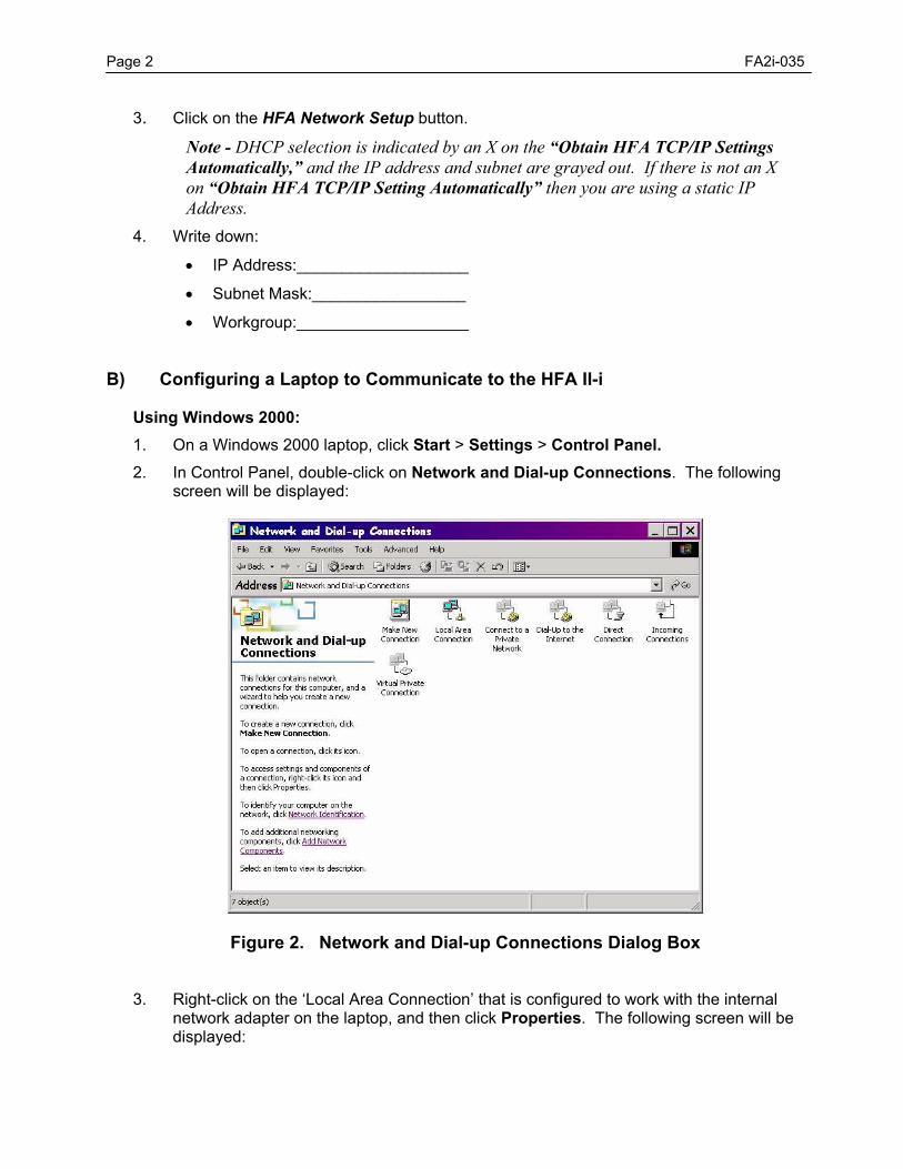
Page 2 FA2i-035
3. Click on the HFA Network Setup button.
Note - DHCP selection is indicated by an X on the “Obtain HFA TCP/IP Settings Automatically,” and the IP address and subnet are grayed out. If there is not an X on “Obtain HFA TCP/IP Setting Automatically” then you are using a static IP Address.
4. Write down: • IP Address:___________________ • Subnet Mask:_________________ • Workgroup:___________________
B) Configuring a Laptop to Communicate to the HFA II-i Using Windows 2000:
1. On a Windows 2000 laptop, click Start > Settings > Control Panel. 2. In Control Panel, double-click on Network and Dial-up Connections. The following
screen will be displayed:
Figure 2. Network and Dial-up Connections Dialog Box
3. Right-click on the ‘Local Area Connection’ that is configured to work with the internal network adapter on the laptop, and then click Properties. The following screen will be displayed:
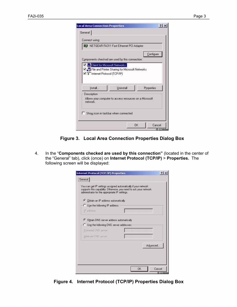
FA2i-035 Page 3
Figure 3. Local Area Connection Properties Dialog Box 4. In the “Components checked are used by this connection” (located in the center of
the “General” tab), click (once) on Internet Protocol (TCP/IP) > Properties. The following screen will be displayed:
Figure 4. Internet Protocol (TCP/IP) Properties Dialog Box
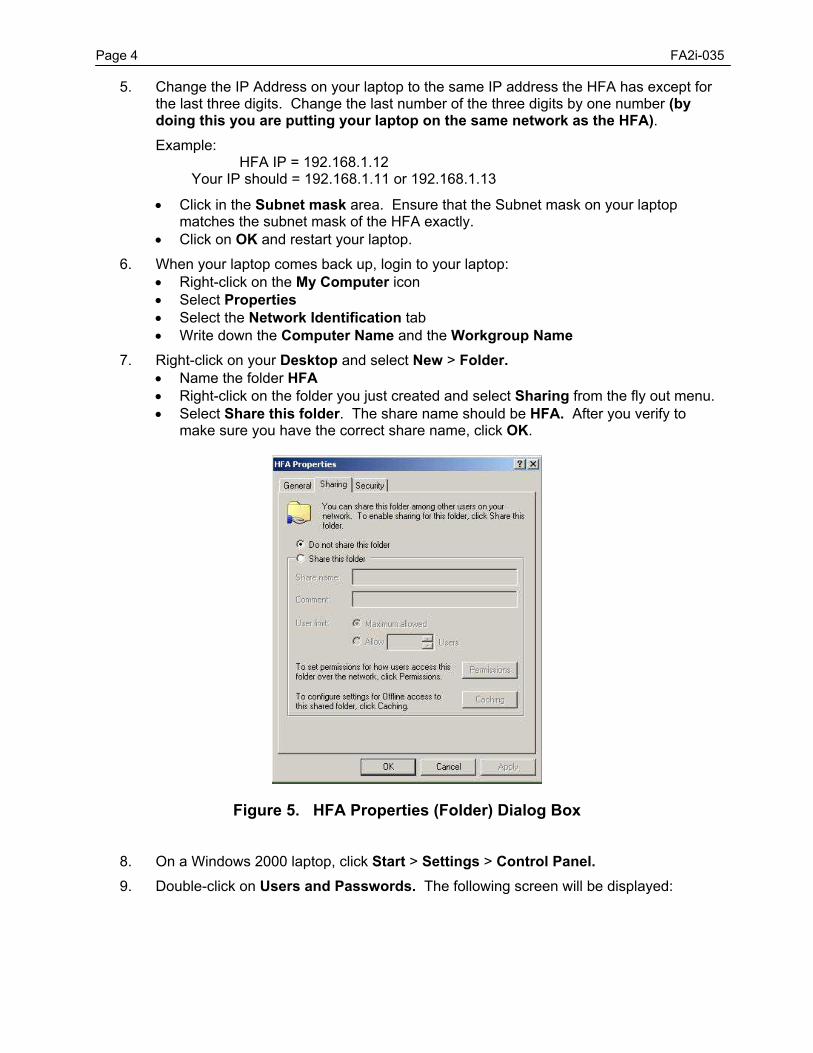
Page 4 FA2i-035
5. Change the IP Address on your laptop to the same IP address the HFA has except for the last three digits. Change the last number of the three digits by one number (by doing this you are putting your laptop on the same network as the HFA). Example: HFA IP = 192.168.1.12 Your IP should = 192.168.1.11 or 192.168.1.13 • Click in the Subnet mask area. Ensure that the Subnet mask on your laptop
matches the subnet mask of the HFA exactly. • Click on OK and restart your laptop.
6. When your laptop comes back up, login to your laptop: • Right-click on the My Computer icon • Select Properties • Select the Network Identification tab • Write down the Computer Name and the Workgroup Name
7. Right-click on your Desktop and select New > Folder. • Name the folder HFA • Right-click on the folder you just created and select Sharing from the fly out menu. • Select Share this folder. The share name should be HFA. After you verify to
make sure you have the correct share name, click OK.
Figure 5. HFA Properties (Folder) Dialog Box
8. On a Windows 2000 laptop, click Start > Settings > Control Panel. 9. Double-click on Users and Passwords. The following screen will be displayed:
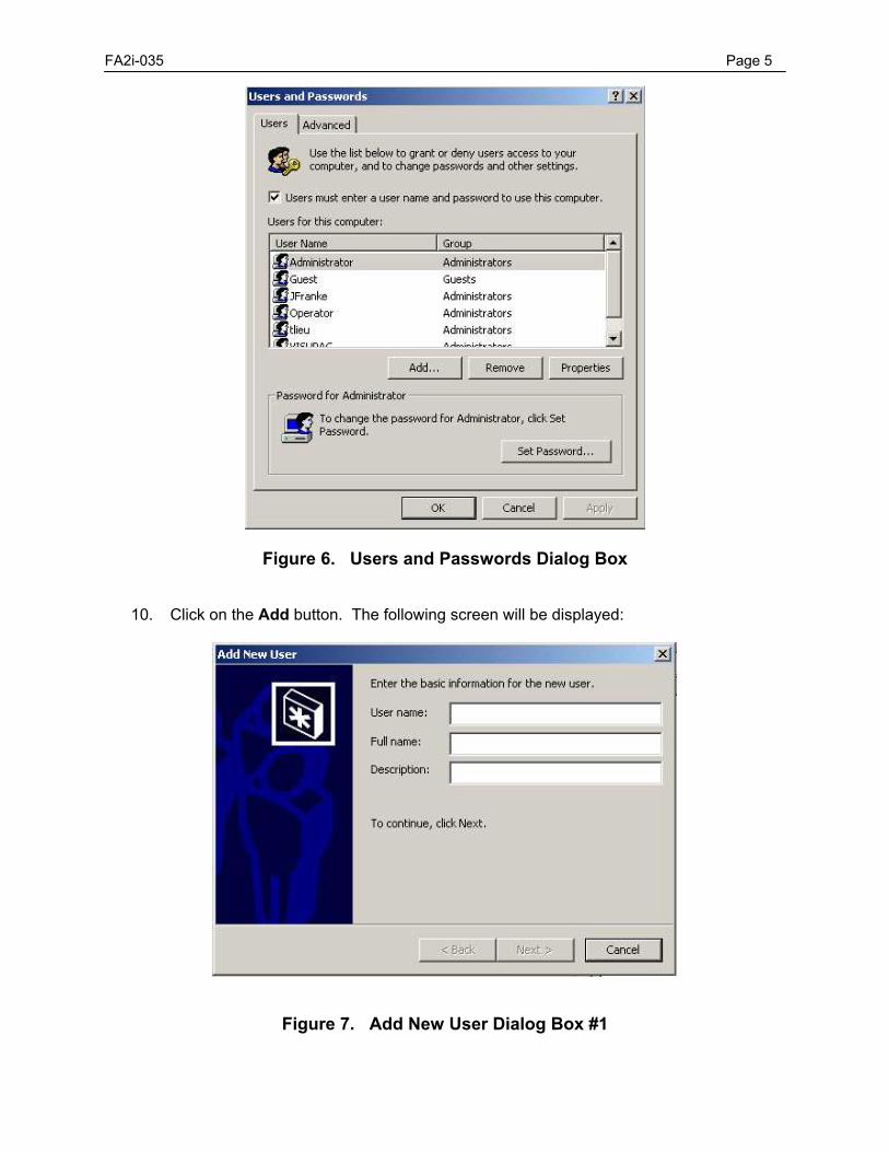
FA2i-035 Page 5
Figure 6. Users and Passwords Dialog Box
10. Click on the Add button. The following screen will be displayed:
Figure 7. Add New User Dialog Box #1
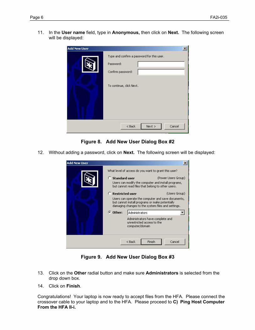
Page 6 FA2i-035
11. In the User name field, type in Anonymous, then click on Next. The following screen will be displayed:
Figure 8. Add New User Dialog Box #2
12. Without adding a password, click on Next. The following screen will be displayed:
Figure 9. Add New User Dialog Box #3
13. Click on the Other radial button and make sure Administrators is selected from the
drop down box. 14. Click on Finish.
Congratulations! Your laptop is now ready to accept files from the HFA. Please connect the crossover cable to your laptop and to the HFA. Please proceed to C) Ping Host Computer From the HFA II-i.
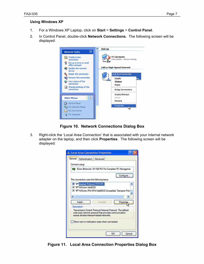
FA2i-035 Page 7 Using Windows XP
1. For a Windows XP Laptop, click on Start > Settings > Control Panel. 2. In Control Panel, double-click Network Connections. The following screen will be
displayed:
Figure 10. Network Connections Dialog Box
3. Right-click the ‘Local Area Connection’ that is associated with your internal network adapter on the laptop, and then click Properties. The following screen will be displayed:
Figure 11. Local Area Connection Properties Dialog Box
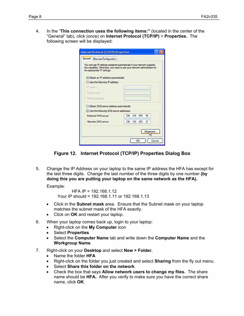
Page 8 FA2i-035
4. In the “This connection uses the following items:” (located in the center of the “General” tab), click (once) on Internet Protocol (TCP/IP) > Properties. The following screen will be displayed:
Figure 12. Internet Protocol (TCP/IP) Properties Dialog Box
5. Change the IP Address on your laptop to the same IP address the HFA has except for the last three digits. Change the last number of the three digits by one number (by doing this you are putting your laptop on the same network as the HFA). Example: HFA IP = 192.168.1.12 Your IP should = 192.168.1.11 or 192.168.1.13 • Click in the Subnet mask area. Ensure that the Subnet mask on your laptop
matches the subnet mask of the HFA exactly. • Click on OK and restart your laptop.
6. When your laptop comes back up, login to your laptop: • Right-click on the My Computer icon • Select Properties • Select the Computer Name tab and write down the Computer Name and the
Workgroup Name. 7. Right-click on your Desktop and select New > Folder.
• Name the folder HFA • Right-click on the folder you just created and select Sharing from the fly out menu. • Select Share this folder on the network. • Check the box that says Allow network users to change my files. The share
name should be HFA. After you verify to make sure you have the correct share name, click OK.

FA2i-035 Page 9
Figure 13. HFA Properties (Folder) Dialog Box
8. For a Windows XP Laptop, click Start > Settings > Control Panel. 9. Double-click on User Accounts. The following screen will be displayed:
Figure 14. User Accounts Dialog Box #1
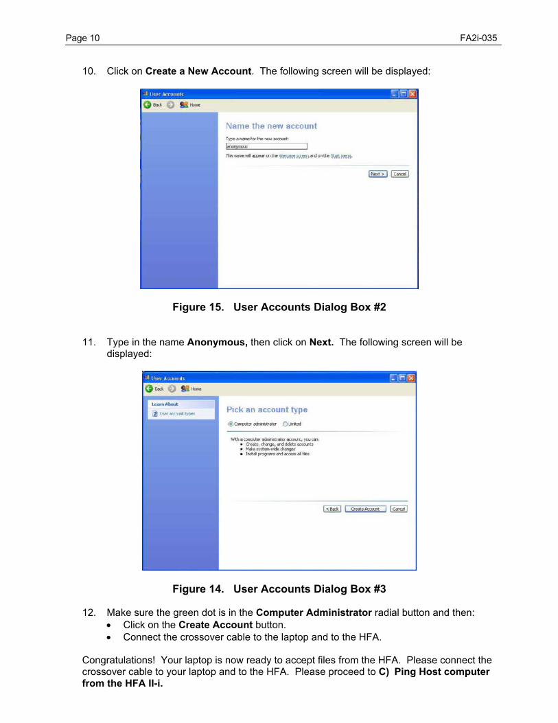
Page 10 FA2i-035
10. Click on Create a New Account. The following screen will be displayed:
Figure 15. User Accounts Dialog Box #2
11. Type in the name Anonymous, then click on Next. The following screen will be displayed:
Figure 14. User Accounts Dialog Box #3
12. Make sure the green dot is in the Computer Administrator radial button and then: • Click on the Create Account button. • Connect the crossover cable to the laptop and to the HFA.
Congratulations! Your laptop is now ready to accept files from the HFA. Please connect the crossover cable to your laptop and to the HFA. Please proceed to C) Ping Host computer from the HFA II-i.
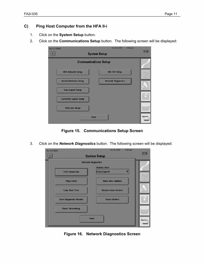
FA2i-035 Page 11 C) Ping Host Computer from the HFA II-i
1. Click on the System Setup button. 2. Click on the Communications Setup button. The following screen will be displayed:
Figure 15. Communications Setup Screen
3. Click on the Network Diagnostics button. The following screen will be displayed:
Figure 16. Network Diagnostics Screen
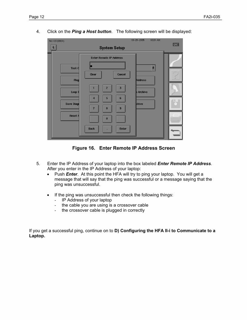
Page 12 FA2i-035
4. Click on the Ping a Host button. The following screen will be displayed:
Figure 16. Enter Remote IP Address Screen
5. Enter the IP Address of your laptop into the box labeled Enter Remote IP Address. After you enter in the IP Address of your laptop: • Push Enter. At this point the HFA will try to ping your laptop. You will get a
message that will say that the ping was successful or a message saying that the ping was unsuccessful.
• If the ping was unsuccessful then check the following things:
- IP Address of your laptop - the cable you are using is a crossover cable - the crossover cable is plugged in correctly
If you get a successful ping, continue on to D) Configuring the HFA II-i to Communicate to a Laptop.
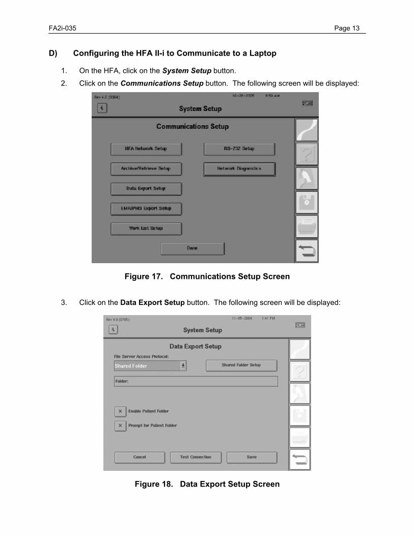
FA2i-035 Page 13 D) Configuring the HFA II-i to Communicate to a Laptop
1. On the HFA, click on the System Setup button. 2. Click on the Communications Setup button. The following screen will be displayed:
Figure 17. Communications Setup Screen
3. Click on the Data Export Setup button. The following screen will be displayed:
Figure 18. Data Export Setup Screen
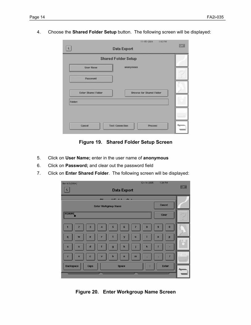
Page 14 FA2i-035
4. Choose the Shared Folder Setup button. The following screen will be displayed:
Figure 19. Shared Folder Setup Screen
5. Click on User Name; enter in the user name of anonymous 6. Click on Password; and clear out the password field 7. Click on Enter Shared Folder. The following screen will be displayed:
Figure 20. Enter Workgroup Name Screen
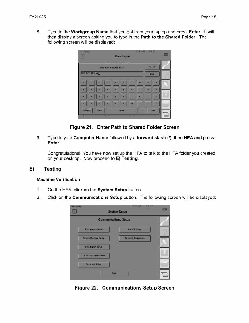
FA2i-035 Page 15
8. Type in the Workgroup Name that you got from your laptop and press Enter. It will then display a screen asking you to type in the Path to the Shared Folder. The following screen will be displayed:
Figure 21. Enter Path to Shared Folder Screen
9. Type in your Computer Name followed by a forward slash (/), then HFA and press Enter.
Congratulations! You have now set up the HFA to talk to the HFA folder you created on your desktop. Now proceed to E) Testing.
E) Testing Machine Verification
1. On the HFA, click on the System Setup button. 2. Click on the Communications Setup button. The following screen will be displayed:
Figure 22. Communications Setup Screen
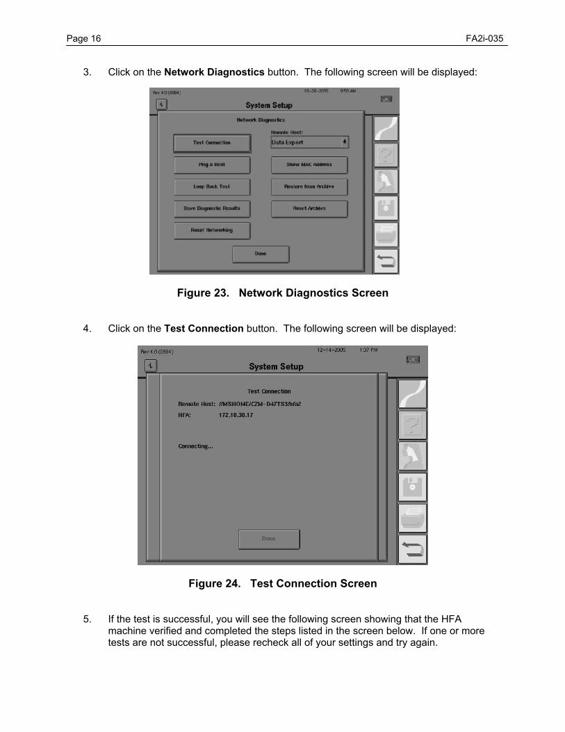
Page 16 FA2i-035
3. Click on the Network Diagnostics button. The following screen will be displayed:
Figure 23. Network Diagnostics Screen
4. Click on the Test Connection button. The following screen will be displayed:
Figure 24. Test Connection Screen
5. If the test is successful, you will see the following screen showing that the HFA machine verified and completed the steps listed in the screen below. If one or more tests are not successful, please recheck all of your settings and try again.
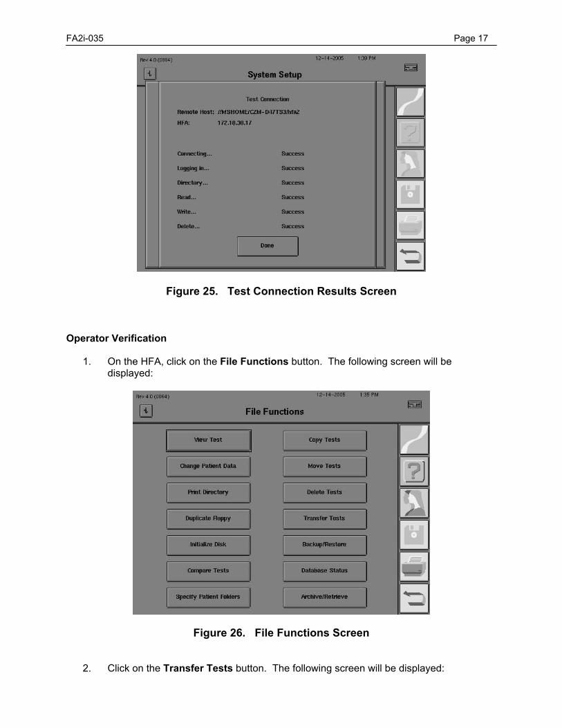
FA2i-035 Page 17
Figure 25. Test Connection Results Screen Operator Verification
1. On the HFA, click on the File Functions button. The following screen will be displayed:
Figure 26. File Functions Screen
2. Click on the Transfer Tests button. The following screen will be displayed:
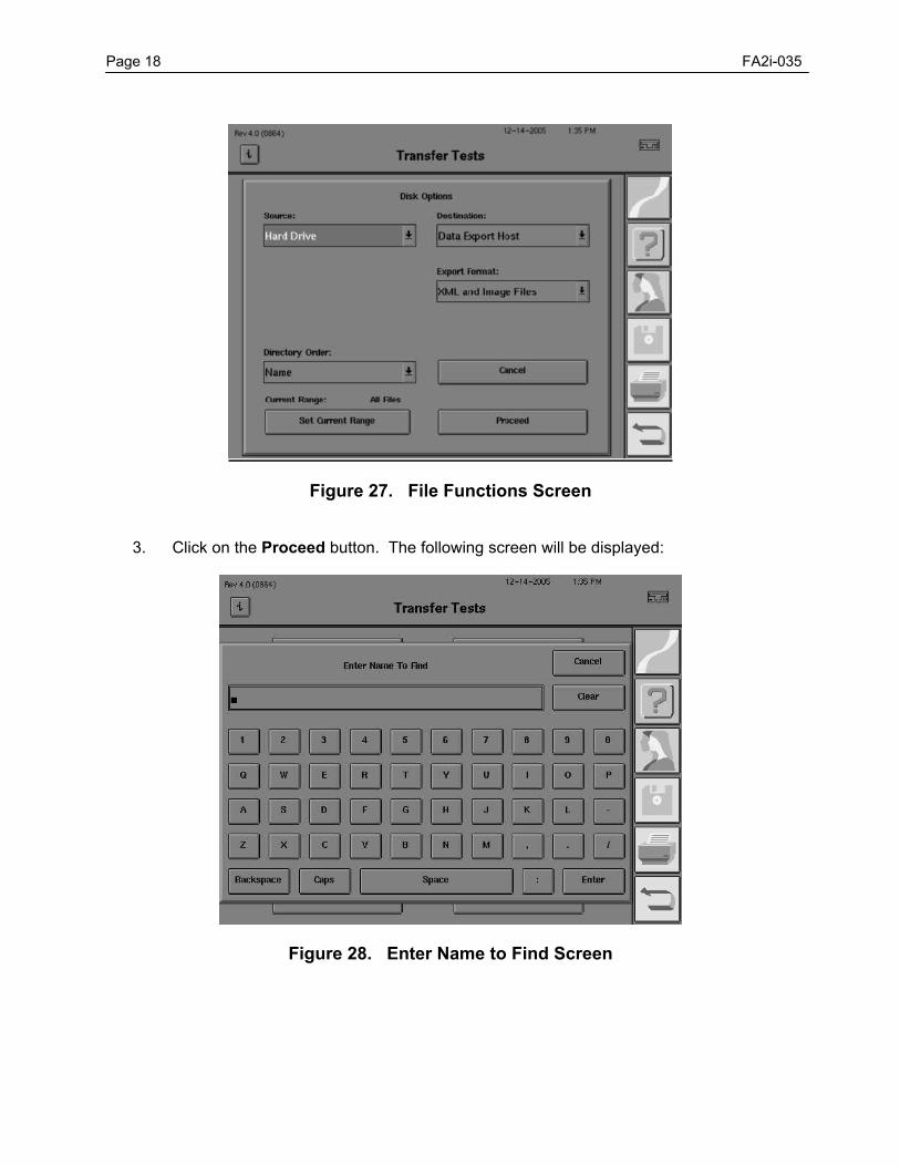
Page 18 FA2i-035
Figure 27. File Functions Screen
3. Click on the Proceed button. The following screen will be displayed:
Figure 28. Enter Name to Find Screen
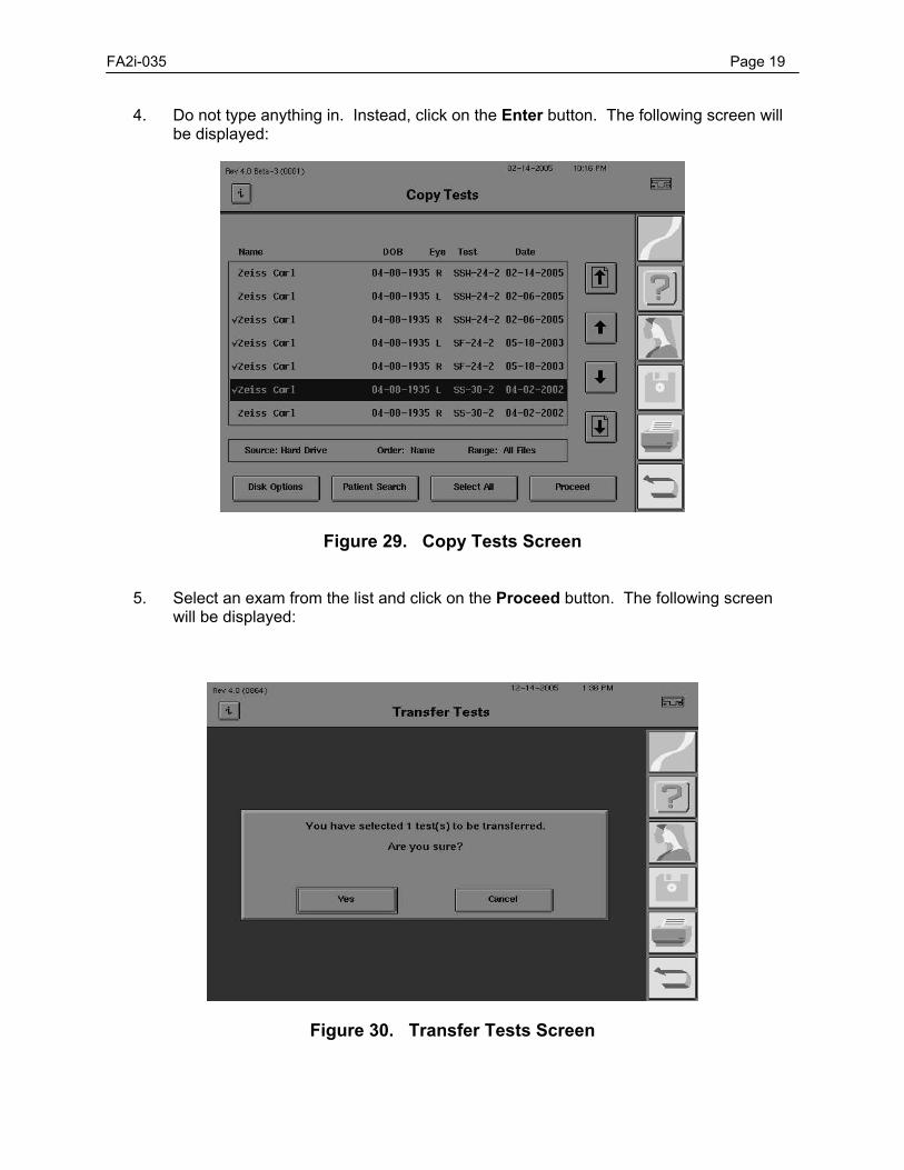
FA2i-035 Page 19
4. Do not type anything in. Instead, click on the Enter button. The following screen will be displayed:
Figure 29. Copy Tests Screen
5. Select an exam from the list and click on the Proceed button. The following screen will be displayed:
Figure 30. Transfer Tests Screen
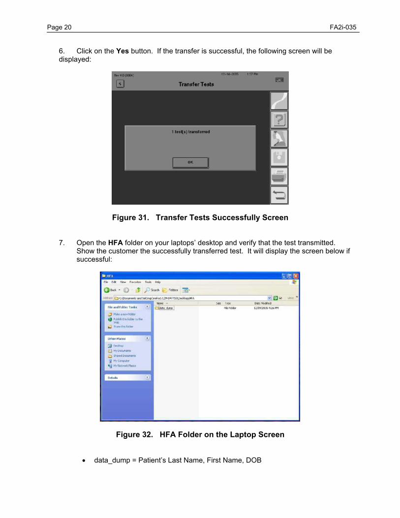
Page 20 FA2i-035
6. Click on the Yes button. If the transfer is successful, the following screen will be displayed:
Figure 31. Transfer Tests Successfully Screen
7. Open the HFA folder on your laptops’ desktop and verify that the test transmitted. Show the customer the successfully transferred test. It will display the screen below if successful:
Figure 32. HFA Folder on the Laptop Screen
• data_dump = Patient’s Last Name, First Name, DOB
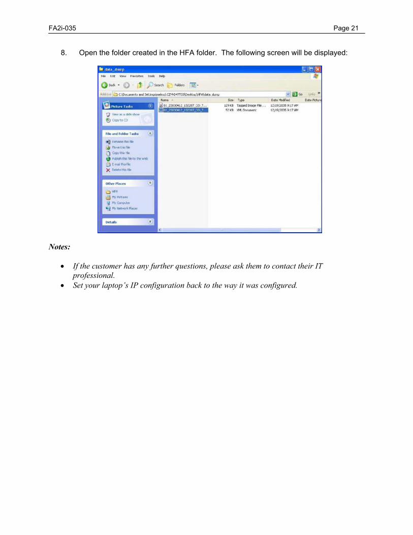
FA2i-035 Page 21
8. Open the folder created in the HFA folder. The following screen will be displayed:
Notes:
• If the customer has any further questions, please ask them to contact their IT professional.
• Set your laptop’s IP configuration back to the way it was configured.

ÚÚÚ PROPRIETARY and CONFIDENTIAL ÚÚÚ
SERVICE BULLETIN Instrument: Humphrey Field Analyzer II-i No.: FA2i-036 Subject: New Motor Driver Board (P/N 61190) Date: 25 Oct 06 Status: Informational Pages: 1
General Information This service bulletin describes the release of a new motor driver board. The new motor driver board (MDB) can only be installed in the HFA II-i. Various integrated circuits used on the existing MDB, are no longer manufactured. The new MDB, P/N 61190, is a replacement for the existing MDB P/N 48530-3. Refer to “Motor Driver Board Compatibility” below.
Motor Driver Board Compatibility
Please observe the following when ordering or replacing P/N 61190:
1) After installing P/N 61190, ensure that system application software revision 4.1 or greater is installed. The new MDB will not operate without revision 4.1 or greater software. Review Service Bulletin FA2i-005i for software compatibility issues.
2) The new MDB (P/N 61190) can directly replace the existing MDB (P/N 48530-3), but only
used in combination with 4.1 or greater application software.
3) The existing MDB (P/N 48530-3) can be used to replace the new MDB (P/N 61190), and will work with any HFA II-i application software revisions that are compatible with the system.
Post Replacement Follow up After installing P/N 61190, ensure that you follow the steps outlined in Table 3.1 of the service manual.
ÚÚÚ PROPRIETARY and CONFIDENTIAL ÚÚÚ
SERVICE BULLETIN Instrument: Humphrey Field Analyzer II-i No.: FA2i-038A Subject: CPU/Back Plane Enclosure (P/N 60673) Date: 24 Jul 07 Status: Informational Pages: 1
This bulletin replaces Service Bulletin FA2i-038 General Information Obsolete components on the HFA II-i back plane required several new releases:
New Part Number Description 60673 CPU and enclosure 60674 CPU/back plane enclosure and shipping container 61753 BIOS SBEP110J software install disk 60138 HFA2i Application Software Revision 4.1 Installation Disks 59494 HFA2i DST Software Revision 4.1 Installation Disks
CPU/Back Plane Changes The new back plane uses new video controller components, touch screen control components and other new components. The new back plane and the original back plane are not to be interchanged. If you determine that a back plane is defective on an old CPU/back plane enclosure P/N 51072, you must replace the complete CPU/back plane enclosure with the new CPU/back plane enclosure (P/N 60673). If a CPU/back plane enclosure is changed, HFA2i software revision 4.1 or newer, Must Be loaded on the instrument, after the hardware installation. See Service Bulletin FA2i-005x for details on software changes. Note - Backplane or CPU failures Must Be replaced with the new complete CPU and enclosure assembly. BIOS Program Changes Due to software setup changes for the video controller set, a new BIOS configuration is required for use with the CPU/back plane enclosure. The new BIOS is compatible with both the new and the old (P/N 51072) CPU/back plane enclosure assemblies. The new BIOS is called the SBEP110J BIOS. All new CPU enclosures have the SBEP110J BIOS pre-installed. If for some reason you find it necessary to reload the BIOS for either CPU/back plane enclosure, it can be loaded via the SBEP110J BIOS software floppy disk. See Service Bulletin FA2i-005x for details on software changes.
Diagnostic Service Tool Software Changes A new Diagnostic Service Tool (DST) was required to function with the hardware/software changes mentioned above. The DST is backwards compatible with all viable hardware and software combinations.
ÚÚÚ PROPRIETARY and CONFIDENTIAL ÚÚÚ
SERVICE BULLETIN
Instrument: Humphrey Field Analyzer II-i No.: FA2i-039 Subject: New BIOS Utility Disk Date: 30 Oct 06 Status: Informational Pages: 1
General Information New components on the HFAII-i back plane required release of a new BIOS Utility Disk. The SBEP110J BIOS disk was designed to support both the old and new back plane. The SBEP110J BIOS is compatible with all EMI CPU/Back Plane & Enclosures and Motor Driver Boards.
New Part Number Description
61753 BIOS SBEP110J Software Installation Disk
Notes: 1) The only circumstance that requires loading the SBEP110J BIOS is suspicion
of corruption to the existing BIOS. 2) The SBEP110J BIOS will be loaded on all new EMI CPU/Back Plane &
Enclosures, part number 60673. To Load the BIOS SBEP110J 1) In the Advanced CMOS Settings of the BIOS setup, set the instrument BIOS boot
order to read first from the floppy disk. 2) Turn the instrument power Off. Turn On the HFA II-i (with the SBEP110J disk in the
drive). 3) The batch file on the disk will load and execute the new SBEP110J BIOS code. Note: If you are overwriting the SBEP103B BIOS, the boot order will automatically be set. If you are overwriting the SBEP110J BIOS, with the SBEP110J BIOS, the boot order will not automatically be reset to the correct order. After loading the BIOS, you will have to manually correct the boot order.
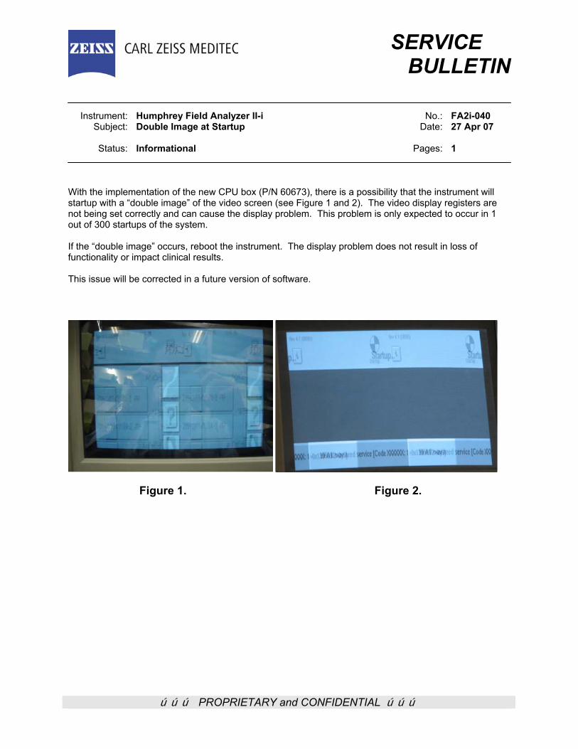
ÚÚÚ PROPRIETARY and CONFIDENTIAL ÚÚÚ
SERVICE BULLETIN Instrument: Humphrey Field Analyzer II-i No.: FA2i-040 Subject: Double Image at Startup Date: 27 Apr 07 Status: Informational Pages: 1 With the implementation of the new CPU box (P/N 60673), there is a possibility that the instrument will startup with a “double image” of the video screen (see Figure 1 and 2). The video display registers are not being set correctly and can cause the display problem. This problem is only expected to occur in 1 out of 300 startups of the system. If the “double image” occurs, reboot the instrument. The display problem does not result in loss of functionality or impact clinical results. This issue will be corrected in a future version of software.
Figure 1. Figure 2.

ÚÚÚ PROPRIETARY and CONFIDENTIAL ÚÚÚ
SERVICE BULLETIN Instrument: Humphrey Field Analyzer II-i No.: FA2i-041 Subject: Touch Screen Calibration Changes in Version 4.1 Date: 17 May 07 Status: Informational Pages: 3 With the release of HFA II-i version 4.1 software, two changes were introduced into the touch screen calibration: 1) Feature: The calibration of the touch screen, as entered from the System Setup menu and Additional
Setup menu, operates as before. However, when the pointing device has been held against the touch screen rectangle, a beep will indicate the new location has been accepted. It will take a few seconds until the beep is heard.
2) Problem: During instrument start up, when holding down the patient button, the on-screen message
“To calibrate touch screen release patient switch now” will appear within a few minutes (Figure 1). For instruments equipped with version 4.1 software, and certain hardware configurations, it will remain on the screen even after you release the patient button.
Note: The problem will be corrected in a future version of HFA II-i software.
There Are Two Problem Work-Around Processes: 1) Use the touch screen calibration process via the System Setup menu. If this is not possible due to
the inability to select the required buttons on the touch screen, the operator can use a compatible keyboard to enter the touch screen process, as described below:
a) From the main menu press F6 to enter the System Setup menu. b) Press the tab key 12 times until the Additional Setup is highlighted. c) Press the Enter key. d) Press the tab key 2 times to highlight the Touch Screen Calibration button. e) Press the Enter key. f) A warning appears indicating that you are about to calibrate the touch screen with a Continue and
a Cancel button. g) Press the Enter key to select the Continue choice. The touch screen calibration process will be
started. h) Follow the on-screen instructions to calibrate the touch screen.
2) Use the hold-down-the-patient-button-at-start-up-touch-screen-calibration process, but Do Not follow
the instructions displayed on-screen. Instead, follow the instructions below:
a) Hold down the patient switch and power ON the instrument. b) A screen image “To calibrate touch screen release patient switch now” will appear within a few
minutes (Figure 1). c) For versions of software other than 4.1, this display will disappear when the patient response
button is released. Instruments equipped with version 4.1 software and certain hardware configurations, it will remain on the screen even after you release the patient button.
d) Note the small white rectangle in the upper left corner of the display (indicated by the arrow in Figure 1).
e) Press the pointing device against the center of the white rectangle, in the upper left corner of the display until you hear a beep.
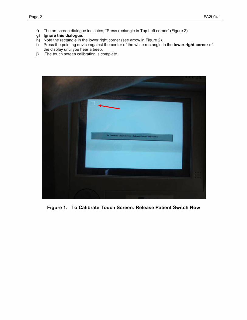
Page 2 FA2i-041
f) The on-screen dialogue indicates, “Press rectangle in Top Left corner” (Figure 2). g) Ignore this dialogue. h) Note the rectangle in the lower right corner (see arrow in Figure 2). i) Press the pointing device against the center of the white rectangle in the lower right corner of
the display until you hear a beep. j) The touch screen calibration is complete.
Figure 1. To Calibrate Touch Screen: Release Patient Switch Now
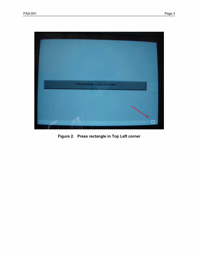
FA2i-041 Page 3
Figure 2. Press rectangle in Top Left corner

ÚÚÚ PROPRIETARY and CONFIDENTIAL ÚÚÚ
SERVICE BULLETIN Instrument: Humphrey Field Analyzer II-i No.: FA2i-042A Subject: New Motor Driver Board (P/N 63710) Date: 30 Jul 07 Status: Informational Pages: 1
This bulletin replaces Service Bulletin FA2i-042 General Information A new HFA II-i Motor Driver board (P/N 63710) has been released. The current Motor Driver board (P/N 61190) has logic level incompatibilities between the 3.3 volt devices and microprocessor, which runs on 5.0 volts. The logic levels rarely affected the operation of the instrument, but in some cases the unit will not boot up to the main menu. The new Motor Driver board (P/N 63710) can be used as a replacement for the previous Motor Driver boards used in the HFA II-i. Motor Driver Board Compatibility Please observe the following when ordering or replacing a Motor Driver board:
Motor Driver board: Replacement For: Software Version Needed:
P/N 63710 P/N 61190 or 48530-3 Requires Version 4.1 or greater
P/N 61190 No longer issued Requires Version 4.1 or greater
P/N 48530-3 P/N 63710, 61190, or 48530-3 Works with all versions of software
Post Replacement Procedures After installing a new Motor Driver board, ensure that you follow the steps outlined in Table 3.1 of the HFA II-i Field Service Guide.
ÚÚÚ PROPRIETARY and CONFIDENTIAL ÚÚÚ
SERVICE BULLETIN Instrument: Humphrey Field Analyzer II-i No.: FA2i-043 Subject: Version 4.2 Application Software Release Date: 6 Feb 08 Status: Informational Pages: 2 General Information Version 4.2 application software offers enhanced networking features and tools, and enhancements to GPA. The features and enhancements are described later in this bulletin. Version 4.2 is not a free upgrade; it is purchasable option software, and as such will be ordered and sold through the appropriate sales channels. Important -
1) Do Not use version 4.2 software as a troubleshooting tool if the HFA is running software less than version 4.2. Use a version of software less than 4.2 (for example, 4.1 or earlier). Failure to do so may cause a system crash.
2) If the HFA is running software version 4.2, Only use 4.2 software as a troubleshooting tool.
Kit Details Version 4.2 software will be offered in two kit configurations, as shown in Table 1 below. Each kit also contains:
• Version 4.2 Application Software (P/N 63331) • Remote Configuration Tool (P/N 63334) • Floppy Disk with sample GPA data (P/N 66563) – not included in Kit B.
Table 1. Version 4.2 Kits
Kit Content Product Number
A Version 4.2 with GPA & NET PRO Certificates 000SW-42-0-GPAPRO
B Version 4.2 with NET Pro Certificate 000SW-42-0-NETPRO
New Networking Features
• Remote Configuration Tool • Improved synchronization and retrieve • Image compression selection • Retrieval of larger files • Faster retrieval of smaller files • Enhanced archive setup

Page 2 FA2i-043
• Export image menu has settings for:
o Image file type (.tif or .pdf) o Image compression o CZM XML version o Advanced DICOM settings
Remote Configuration Tool The EasyConnect™ Remote Configuration Tool (RCT) is a CD software tool that runs on a computer, connected to an existing network. RTC configures network settings for HFA –NET and HFA-NET Pro, using shared folder and shared printer setup. The RTC will not configure File Transfer Protocol (FTP). The Remote Configuration Service will:
• Allow setting up the HFA II-i name from the System Setup > Communication Setup> Network Setup Menu, (limited to 24 characters)
• Remote Configuration can be enabled / disabled from the Network Setup Menu • Open required ports for use of the Remote Configuration Tool • Link Local addressing creates an IP address without a DHCP server • Advanced Network Configuration creates a log file for the remote configuration process.
GPA Enhancements The new summary report includes a number of new features:
• Both baseline exams • Rate of Progression Analysis (ROP) • Follow up exam • Ability to set single page printout style • Visual Field Index • Excludes all exams with a 15 % or greater false positive value from a GPA analysis • Full threshold tests can now be used as follow up exams
GPA Features
• The Exam Selection screen is more user friendly • In most cases, GPA analysis for tests with a mean deviation of <= -20 db will no longer
display the pattern deviation plot • Save to floppy diskette at end of test can now be enabled or disabled using the setup >
save/transmit options menu • Deferred exams can be cleared using the setup > save/transmit options menu
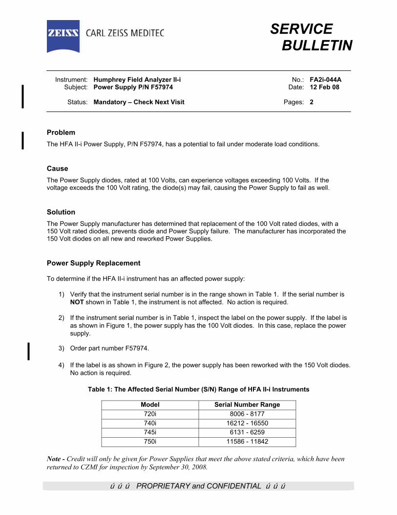
ÚÚÚ PROPRIETARY and CONFIDENTIAL ÚÚÚ
SERVICE BULLETIN
Instrument: Humphrey Field Analyzer II-i No.: FA2i-044A Subject: Power Supply P/N F57974 Date: 12 Feb 08 Status: Mandatory – Check Next Visit Pages: 2
Problem The HFA II-i Power Supply, P/N F57974, has a potential to fail under moderate load conditions. Cause The Power Supply diodes, rated at 100 Volts, can experience voltages exceeding 100 Volts. If the voltage exceeds the 100 Volt rating, the diode(s) may fail, causing the Power Supply to fail as well. Solution The Power Supply manufacturer has determined that replacement of the 100 Volt rated diodes, with a 150 Volt rated diodes, prevents diode and Power Supply failure. The manufacturer has incorporated the 150 Volt diodes on all new and reworked Power Supplies. Power Supply Replacement To determine if the HFA II-i instrument has an affected power supply:
1) Verify that the instrument serial number is in the range shown in Table 1. If the serial number is NOT shown in Table 1, the instrument is not affected. No action is required.
2) If the instrument serial number is in Table 1, inspect the label on the power supply. If the label is
as shown in Figure 1, the power supply has the 100 Volt diodes. In this case, replace the power supply.
3) Order part number F57974.
4) If the label is as shown in Figure 2, the power supply has been reworked with the 150 Volt diodes.
No action is required.
Table 1: The Affected Serial Number (S/N) Range of HFA II-i Instruments
Model Serial Number Range 720i 8006 - 8177 740i 16212 - 16550 745i 6131 - 6259 750i 11586 - 11842
Note - Credit will only be given for Power Supplies that meet the above stated criteria, which have been returned to CZMI for inspection by September 30, 2008.
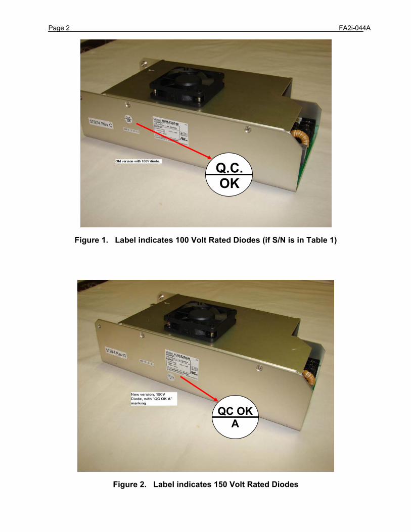
Page 2 FA2i-044A
Figure 1. Label indicates 100 Volt Rated Diodes (if S/N is in Table 1)
Figure 2. Label indicates 150 Volt Rated Diodes
Q.C.OK
QC OKA
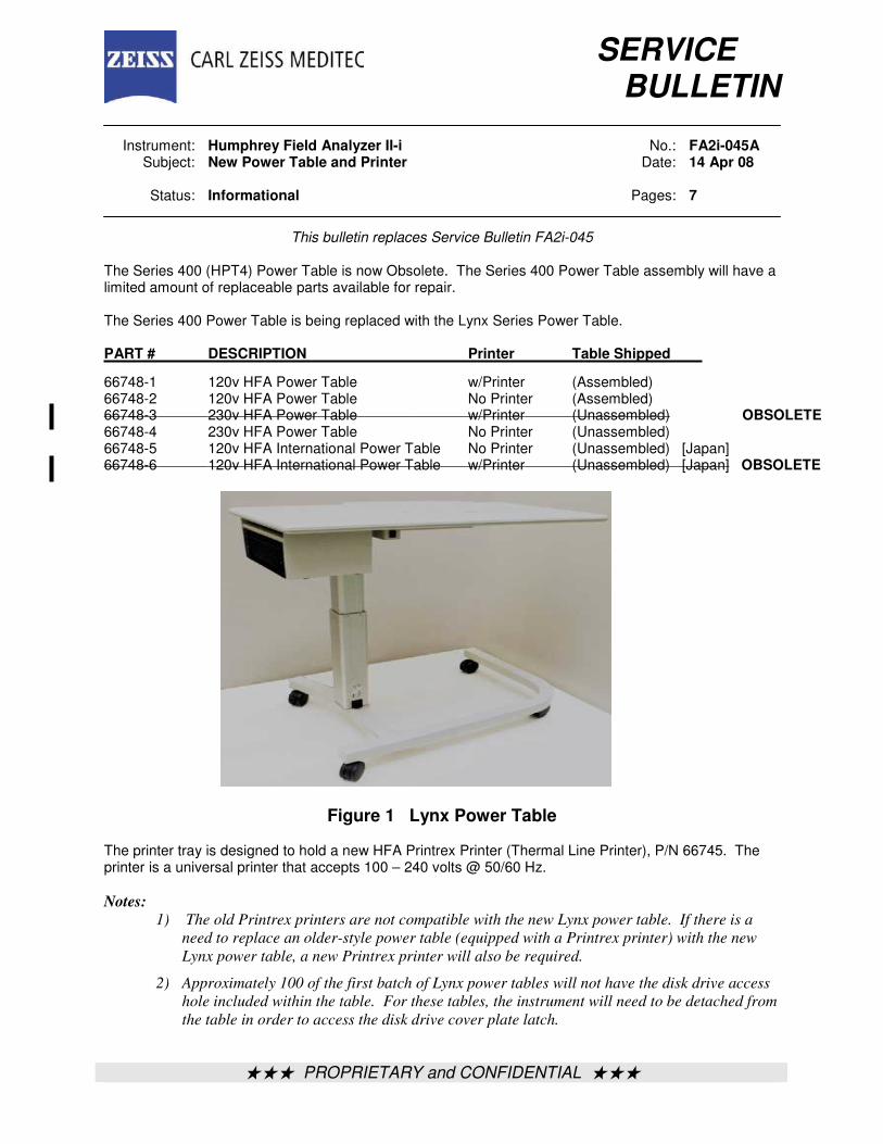
ÚÚÚ PROPRIETARY and CONFIDENTIAL ÚÚÚ
SERVICE
BULLETIN Instrument: Humphrey Field Analyzer II-i No.: FA2i-045A Subject: New Power Table and Printer Date: 14 Apr 08 Status: Informational Pages: 7
This bulletin replaces Service Bulletin FA2i-045 The Series 400 (HPT4) Power Table is now Obsolete. The Series 400 Power Table assembly will have a limited amount of replaceable parts available for repair. The Series 400 Power Table is being replaced with the Lynx Series Power Table. PART # DESCRIPTION Printer Table Shipped 66748-1 120v HFA Power Table w/Printer (Assembled) 66748-2 120v HFA Power Table No Printer (Assembled) 66748-3 230v HFA Power Table w/Printer (Unassembled) OBSOLETE 66748-4 230v HFA Power Table No Printer (Unassembled) 66748-5 120v HFA International Power Table No Printer (Unassembled) [Japan] 66748-6 120v HFA International Power Table w/Printer (Unassembled) [Japan] OBSOLETE
Figure 1 Lynx Power Table The printer tray is designed to hold a new HFA Printrex Printer (Thermal Line Printer), P/N 66745. The printer is a universal printer that accepts 100 – 240 volts @ 50/60 Hz.
Notes:
1) The old Printrex printers are not compatible with the new Lynx power table. If there is a
need to replace an older-style power table (equipped with a Printrex printer) with the new
Lynx power table, a new Printrex printer will also be required. 2) Approximately 100 of the first batch of Lynx power tables will not have the disk drive access
hole included within the table. For these tables, the instrument will need to be detached from
the table in order to access the disk drive cover plate latch.
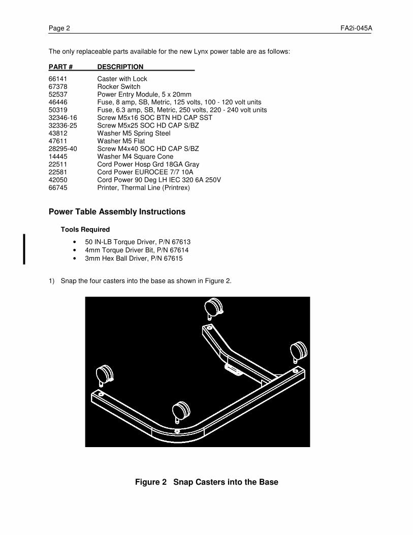
Page 2 FA2i-045A The only replaceable parts available for the new Lynx power table are as follows: PART # DESCRIPTION 66141 Caster with Lock 67378 Rocker Switch 52537 Power Entry Module, 5 x 20mm 46446 Fuse, 8 amp, SB, Metric, 125 volts, 100 - 120 volt units 50319 Fuse, 6.3 amp, SB, Metric, 250 volts, 220 - 240 volt units 32346-16 Screw M5x16 SOC BTN HD CAP SST 32336-25 Screw M5x25 SOC HD CAP S/BZ 43812 Washer M5 Spring Steel 47611 Washer M5 Flat 28295-40 Screw M4x40 SOC HD CAP S/BZ 14445 Washer M4 Square Cone 22511 Cord Power Hosp Grd 18GA Gray 22581 Cord Power EUROCEE 7/7 10A 42050 Cord Power 90 Deg LH IEC 320 6A 250V 66745 Printer, Thermal Line (Printrex)
Power Table Assembly Instructions Tools Required
• 50 IN-LB Torque Driver, P/N 67613
• 4mm Torque Driver Bit, P/N 67614
• 3mm Hex Ball Driver, P/N 67615
1) Snap the four casters into the base as shown in Figure 2.
Figure 2 Snap Casters into the Base
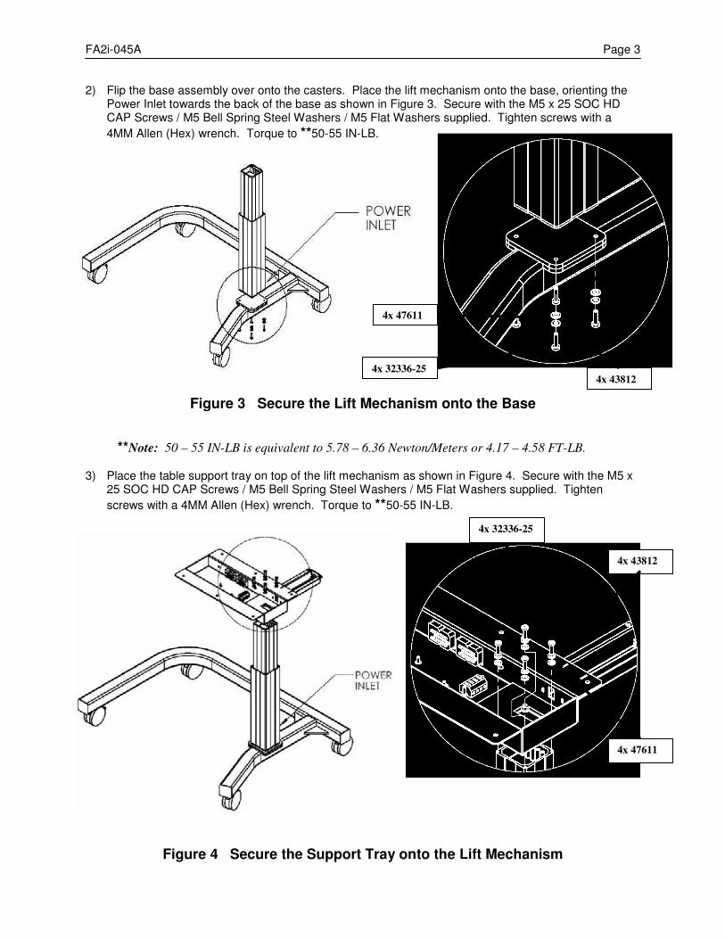
FA2i-045A Page 3 2) Flip the base assembly over onto the casters. Place the lift mechanism onto the base, orienting the
Power Inlet towards the back of the base as shown in Figure 3. Secure with the M5 x 25 SOC HD CAP Screws / M5 Bell Spring Steel Washers / M5 Flat Washers supplied. Tighten screws with a
4MM Allen (Hex) wrench. Torque to **50-55 IN-LB.
Figure 3 Secure the Lift Mechanism onto the Base
**Note: 50 – 55 IN-LB is equivalent to 5.78 – 6.36 Newton/Meters or 4.17 – 4.58 FT-LB. 3) Place the table support tray on top of the lift mechanism as shown in Figure 4. Secure with the M5 x
25 SOC HD CAP Screws / M5 Bell Spring Steel Washers / M5 Flat Washers supplied. Tighten
screws with a 4MM Allen (Hex) wrench. Torque to **50-55 IN-LB.
Figure 4 Secure the Support Tray onto the Lift Mechanism
4x 32336-25
4x 43812
4x 47611
4x 32336-25
4x 43812
4x 47611
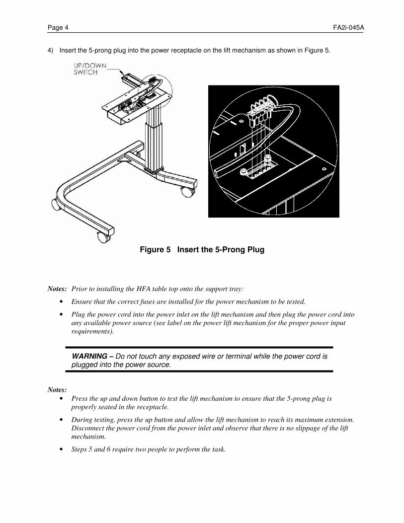
Page 4 FA2i-045A 4) Insert the 5-prong plug into the power receptacle on the lift mechanism as shown in Figure 5.
Figure 5 Insert the 5-Prong Plug
Notes: Prior to installing the HFA table top onto the support tray:
• Ensure that the correct fuses are installed for the power mechanism to be tested.
• Plug the power cord into the power inlet on the lift mechanism and then plug the power cord into
any available power source (see label on the power lift mechanism for the proper power input
requirements).
WARNING – Do not touch any exposed wire or terminal while the power cord is plugged into the power source.
Notes:
• Press the up and down button to test the lift mechanism to ensure that the 5-prong plug is
properly seated in the receptacle.
• During testing, press the up button and allow the lift mechanism to reach its maximum extension.
Disconnect the power cord from the power inlet and observe that there is no slippage of the lift
mechanism.
• Steps 5 and 6 require two people to perform the task.
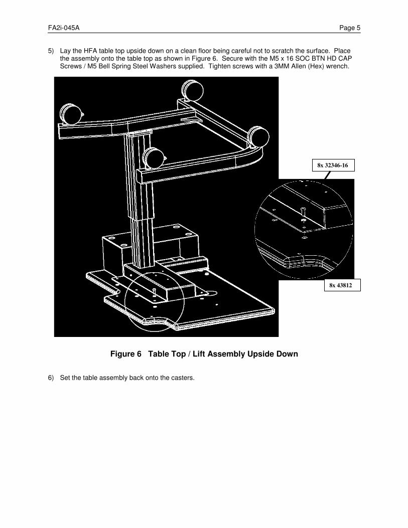
FA2i-045A Page 5 5) Lay the HFA table top upside down on a clean floor being careful not to scratch the surface. Place
the assembly onto the table top as shown in Figure 6. Secure with the M5 x 16 SOC BTN HD CAP Screws / M5 Bell Spring Steel Washers supplied. Tighten screws with a 3MM Allen (Hex) wrench.
Figure 6 Table Top / Lift Assembly Upside Down 6) Set the table assembly back onto the casters.
8x 32346-16
8x 43812
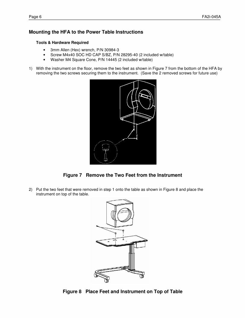
Page 6 FA2i-045A
Mounting the HFA to the Power Table Instructions Tools & Hardware Required
• 3mm Allen (Hex) wrench, P/N 30984-3
• Screw M4x40 SOC HD CAP S/BZ, P/N 28295-40 (2 included w/table)
• Washer M4 Square Cone, P/N 14445 (2 included w/table)
1) With the instrument on the floor, remove the two feet as shown in Figure 7 from the bottom of the HFA by removing the two screws securing them to the instrument. (Save the 2 removed screws for future use)
Figure 7 Remove the Two Feet from the Instrument 2) Put the two feet that were removed in step 1 onto the table as shown in Figure 8 and place the
instrument on top of the table.
Figure 8 Place Feet and Instrument on Top of Table
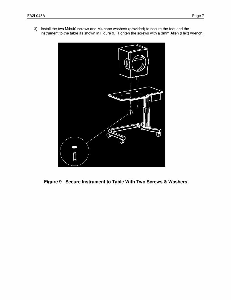
FA2i-045A Page 7
3) Install the two M4x40 screws and M4 cone washers (provided) to secure the feet and the instrument to the table as shown in Figure 9. Tighten the screws with a 3mm Allen (Hex) wrench.
Figure 9 Secure Instrument to Table With Two Screws & Washers
ÚÚÚ PROPRIETARY and CONFIDENTIAL ÚÚÚ
SERVICE
BULLETIN Instrument: Humphrey Field Analyzer II-i No.: FA2i-046 Subject: New Edge Detectors for Projection Assembly Date: 25 Apr 08 Status: Informational Pages: 3 General Information The current edge detector assemblies used with the film and glass wedges and the Y turret motor are obsolete. New edge detector assembly part numbers have been created and released. The new edge detector assemblies are backward compatible on all HFA II-i units. The new HFA II-i detector assemblies are defined in Table 1 below. Edge Detector Usage
Table 1. New Edge Detector Usage
Detector Part Number
Where Used
P/N 67418 Y Turret assembly
P/N 67417 Film (J) and glass (I) wedge assemblies
Both of the new detector assemblies contain a 0.060 inch thick spacing washer to correctly position the detector. See Figure 1 and Figure 2 for washer placement. Replacement Procedures Ensure that you place the spacing washer in the correct position as indicated in Figure 1 and Figure 2 during assembly of the detectors.
Note – Improper spacing washer placement can create motor calibration errors.
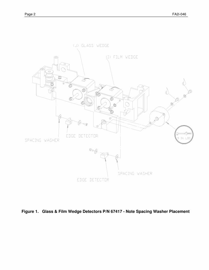
Page 2 FA2i-046
Figure 1. Glass & Film Wedge Detectors P/N 67417 - Note Spacing Washer Placement
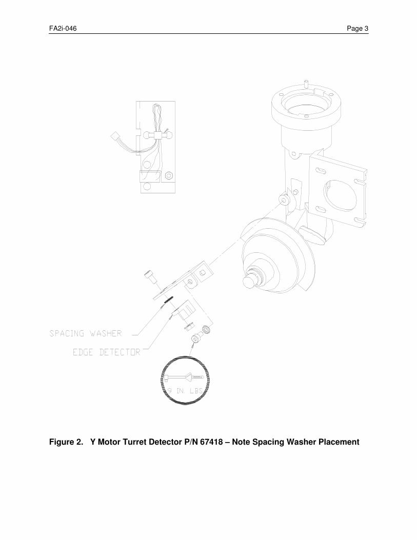
FA2i-046 Page 3
Figure 2. Y Motor Turret Detector P/N 67418 – Note Spacing Washer Placement
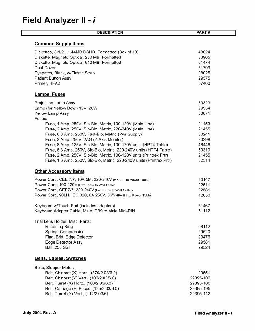
Field Analyzer II - iDESCRIPTION PART #
Common Supply Items
Diskettes, 3-1/2", 1.44MB DSHD, Formatted (Box of 10) 48024Diskette, Magneto Optical, 230 MB, Formatted 33905Diskette, Magneto Optical, 640 MB, Formatted 51474Dust Cover 51799Eyepatch, Black, w/Elastic Strap 08025Patient Button Assy 29575Primer, HFA2 57400
Lamps, Fuses
Projection Lamp Assy 30323Lamp (for Yellow Bowl) 12V, 20W 29954Yellow Lamp Assy 30071Fuses:
Fuse, 4 Amp, 250V, Slo-Blo, Metric, 100-120V (Main Line) 21453Fuse, 2 Amp, 250V, Slo-Blo, Metric, 220-240V (Main Line) 21455Fuse, 6.3 Amp, 250V, Fast-Blo, Metric (Pwr Supply) 30241Fuse, 3 Amp, 250V, 2AG (Z-Axis Monitor) 30298Fuse, 8 Amp, 125V, Slo-Blo, Metric, 100-120V units (HPT4 Table) 46446Fuse, 6.3 Amp, 250V, Slo-Blo, Metric, 220-240V units (HPT4 Table) 50319Fuse, 2 Amp, 250V, Slo-Blo, Metric, 100-120V units (Printrex Prtr) 21455Fuse, 1.6 Amp, 250V, Slo-Blo, Metric, 220-240V units (Printrex Prtr) 32314
Other Accessory Items
Power Cord, CEE 7/7, 10A.5M, 220-240V (HFA II-i to Power Table) 30147 Power Cord, 100-120V (Pwr Table to Wall Outlet 22511 Power Cord, CEE7/7, 220-240V (Pwr Table to Wall Outlet) 22581 Power Cord, 90LH, IEC 320, 6A 250V, 36" (HFA II-i to Power Table) 42050
Keyboard w/Touch Pad (includes adapters) 51467 Keyboard Adapter Cable, Male, DB9 to Male Mini-DIN 51112
Trial Lens Holder, Misc. Parts: Retaining Ring 08112 Spring, Compression 29520 Flag, Brkt, Edge Detector 29476 Edge Detector Assy 29581 Ball .250 SST 29524
Belts, Cables, Switches
Belts, Stepper Motor: Belt, Chinrest (X) Horz., (370/2.03/6.0) 29551 Belt, Chinrest (Y) Vert., (102/2.03/6.0) 29395-102 Belt, Turret (X) Horz., (100/2.03/6.0) 29395-100 Belt, Carriage (F) Focus, (195/2.03/6.0) 29395-195 Belt, Turret (Y) Vert., (112/2.03/6) 29395-112
July 2004 Rev. A Field Analyzer II - i

Field Analyzer II - iDESCRIPTION PART #
Cable, Serial Transfer, HFA I to HFA II - i 52416Cable, Serial Transfer, HFA II to HFA II - i 52417Cable, Printer, Parallel, 4' (HP LaserJet, Lexmark and Brother Printers) 51472Cable Assy, Brightness Pot 29695
Other Miscellaneous
Fan Assy, Bottom 29793 Filter, Fan, Bottom 29381 Filter, Fan, Top 30561Door, Fan, Filter 29380 Door Assy, Lamp Access, w/Caution Label 29991 Brightness Detector Misc. Parts:
Washer, Wavy 06711 Window, Glass, Spot Intensity (Blue) 08105 Filter, Plastic, CIE Correction (Green) 08098
Stepper Motor Assemblies: Motor, (X) Stepper, Chin/Headrest 29677 Motor, (Y) Stepper, Chinrest 29678 Motor, Stepper, Shutter 29584 Motor, (X) Stepper, Turret 29583 Motor, (Y) Stepper, Turret 29582 Motor, (Film or Glass Wedge, Focus) Stepper 29583
Assy, Shutter 30106 Assy, IR, LED 52755Assy, Fixation PCBA 52756Edge Detector Assemblies:
Edge Detector, (Y) Axis 30442Edge Detector, (X) Turret 29581 Edge Detector, Film and Glass Wedges 30453
July 2004 Rev. A Field Analyzer II - i
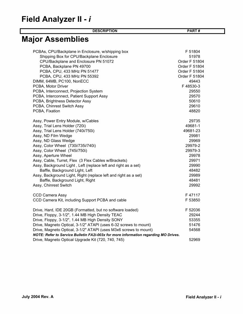
Field Analyzer II - iDESCRIPTION PART #
PCBAs, CPU/Backplane in Enclosure, w/shipping box F 51804 Shipping Box for CPU/Backplane Enclosure 51978 CPU/Backplane and Enclosure PN 51072 Order F 51804PCBA, Backplane PN 49700 Order F 51804PCBA, CPU, 433 MHz PN 51477 Order F 51804PCBA, CPU, 433 MHz PN 55392 Order F 51804
DIMM, 64MB, PC100, NonECC 49443 PCBA, Motor Driver F 48530-3 PCBA, Interconnect, Projection System 29550 PCBA, Interconnect, Patient Support Assy 29570PCBA, Brightness Detector Assy 50610 PCBA, Chinrest Switch Assy 29610 PCBA, Fixation 48820
Assy, Power Entry Module, w/Cables 29735 Assy, Trial Lens Holder (720i) 49681-1 Assy, Trial Lens Holder (740i/750i) 49681-23 Assy, ND Film Wedge 29981 Assy, ND Glass Wedge 29969 Assy, Color Wheel (730i/735i/740i) 29979-2 Assy, Color Wheel (745i/750i) 29979-3 Assy, Aperture Wheel 29978 Assy, Cable, Turret, Flex (3 Flex Cables w/Brackets) 29971 Assy, Background Light , Left (replace left and right as a set) 29990
Baffle, Background Light, Left 48482 Assy, Background Light, Right (replace left and right as a set) 29989
Baffle, Background Light, Right 48481 Assy, Chinrest Switch 29992
CCD Camera Assy F 47117 CCD Camera Kit, including Support PCBA and cable F 53850
Drive, Hard, IDE 20GB (Formatted, but no software loaded) F 52036 Drive, Floppy, 3-1/2", 1.44 MB High Density TEAC 29244 Drive, Floppy, 3-1/2", 1.44 MB High Density SONY 53355 Drive, Magneto Optical, 3-1/2" ATAPI (uses 6-32 screws to mount) 51476 Drive, Magneto Optical, 3-1/2" ATAPI (uses M3x6 screws to mount) 54568
Drive, Magneto Optical Upgrade Kit (720, 740, 745) 52969
Major Assemblies
NOTE: Refer to Service Bulletin FA2i-003x for more information regarding MO Drives.
July 2004 Rev. A Field Analyzer II - i
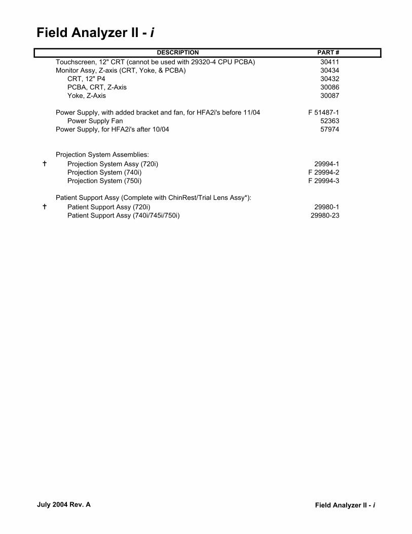
Field Analyzer II - iDESCRIPTION PART #
Touchscreen, 12" CRT (cannot be used with 29320-4 CPU PCBA) 30411 Monitor Assy, Z-axis (CRT, Yoke, & PCBA) 30434
CRT, 12" P4 30432PCBA, CRT, Z-Axis 30086 Yoke, Z-Axis 30087
Power Supply, with added bracket and fan, for HFA2i's before 11/04 F 51487-1
Power Supply Fan 52363 Power Supply, for HFA2i's after 10/04 57974
Projection System Assemblies: Projection System Assy (720i) 29994-1 Projection System (740i) F 29994-2 Projection System (750i) F 29994-3
Patient Support Assy (Complete with ChinRest/Trial Lens Assy*):
Patient Support Assy (720i) 29980-1 Patient Support Assy (740i/745i/750i) 29980-23
July 2004 Rev. A Field Analyzer II - i
Related Documents