OptiX RTN 950 Radio Transmission System V100R003C01 Commissioning and Configuration Guide (U2000) Issue 02 Date 2011-05-20 HUAWEI TECHNOLOGIES CO., LTD.

Huawei OptiX RTN 950 Commissioning and Configuration Guide(V100R003)
Apr 08, 2016
Thunder-Link.com is a Leading Huawei optical transmission product supplier. which was founded by ex-Huawei employee, we have rich experience and well reputation in the field over 3 years.
Welcome message from author
This document is posted to help you gain knowledge. Please leave a comment to let me know what you think about it! Share it to your friends and learn new things together.
Transcript
OptiX RTN 950 Radio Transmission SystemV100R003C01
Commissioning and ConfigurationGuide (U2000)
Issue 02
Date 2011-05-20
HUAWEI TECHNOLOGIES CO., LTD.


Copyright © Huawei Technologies Co., Ltd. 2011. All rights reserved.No part of this document may be reproduced or transmitted in any form or by any means without prior writtenconsent of Huawei Technologies Co., Ltd. Trademarks and Permissions
and other Huawei trademarks are trademarks of Huawei Technologies Co., Ltd.All other trademarks and trade names mentioned in this document are the property of their respective holders. NoticeThe purchased products, services and features are stipulated by the contract made between Huawei and thecustomer. All or part of the products, services and features described in this document may not be within thepurchase scope or the usage scope. Unless otherwise specified in the contract, all statements, information,and recommendations in this document are provided "AS IS" without warranties, guarantees or representationsof any kind, either express or implied.
The information in this document is subject to change without notice. Every effort has been made in thepreparation of this document to ensure accuracy of the contents, but all statements, information, andrecommendations in this document do not constitute the warranty of any kind, express or implied.
Huawei Technologies Co., Ltd.Address: Huawei Industrial Base
Bantian, LonggangShenzhen 518129People's Republic of China
Website: http://www.huawei.com
Email: [email protected]
Issue 02 (2011-05-20) Huawei Proprietary and ConfidentialCopyright © Huawei Technologies Co., Ltd.
i

About This Document
Related VersionsThe following table lists the product versions related to this document.
Product Name Version
OptiX RTN 950 V100R003C01
iManager U2000 V100R005C00
Intended AudienceThis document contains two parts, namely, the commissioning guide and configuration guide.
l The commissioning guide describes how to commission the OptiX RTN 950, includingpreparations before commissioning, site commissioning, and system commissioning.
l The configuration guide describes how to configure various types of services on the OptiXRTN 950, including basic concepts, configuration procedures, configuration examples, andrelated tasks.
The intended audience of this document are:
l Installation and commissioning engineers
l Data configuration engineers
l System maintenance engineers
Symbol ConventionsThe symbols that may be found in this document are defined as follows.
Symbol Description
Indicates a hazard with a high level of risk,which if not avoided, will result in death orserious injury.
OptiX RTN 950 Radio Transmission SystemCommissioning and Configuration Guide (U2000) About This Document
Issue 02 (2011-05-20) Huawei Proprietary and ConfidentialCopyright © Huawei Technologies Co., Ltd.
iii
Symbol Description
Indicates a hazard with a medium or low levelof risk, which if not avoided, could result inminor or moderate injury.
Indicates a potentially hazardous situation,which if not avoided, could result inequipment damage, data loss, performancedegradation, or unexpected results.
Indicates a tip that may help you solve aproblem or save time.
Provides additional information to emphasizeor supplement important points of the maintext.
General ConventionsThe general conventions that may be found in this document are defined as follows.
Convention Description
Times New Roman Normal paragraphs are in Times New Roman.
Boldface Names of files, directories, folders, and users are inboldface. For example, log in as user root.
Italic Book titles are in italics.
Courier New Examples of information displayed on the screen are inCourier New.
Command ConventionsThe command conventions that may be found in this document are defined as follows.
Convention Description
Boldface The keywords of a command line are in boldface.
Italic Command arguments are in italics.
[ ] Items (keywords or arguments) in brackets [ ] are optional.
{ x | y | ... } Optional items are grouped in braces and separated byvertical bars. One item is selected.
About This DocumentOptiX RTN 950 Radio Transmission System
Commissioning and Configuration Guide (U2000)
iv Huawei Proprietary and ConfidentialCopyright © Huawei Technologies Co., Ltd.
Issue 02 (2011-05-20)

Convention Description
[ x | y | ... ] Optional items are grouped in brackets and separated byvertical bars. One item is selected or no item is selected.
{ x | y | ... }* Optional items are grouped in braces and separated byvertical bars. A minimum of one item or a maximum of allitems can be selected.
[ x | y | ... ]* Optional items are grouped in brackets and separated byvertical bars. Several items or no item can be selected.
GUI ConventionsThe GUI conventions that may be found in this document are defined as follows.
Convention Description
Boldface Buttons, menus, parameters, tabs, window, and dialog titlesare in boldface. For example, click OK.
> Multi-level menus are in boldface and separated by the ">"signs. For example, choose File > Create > Folder.
Change HistoryUpdates between document issues are cumulative. Therefore, the latest document issue containsall updates made to previous issues.
Updates in Issue 02 (2011-05-20) Based on Product Version V100R003C01This is the second document issue of the V100R003C01 product version.
Compared with the first issue, the updated contents are follows.
Update Description
7 Configuring Networkwide Service Data Added with the example of configuringnetworkwide service data using the U2000.
8.1 U2000 Quick Start Added with the quick start guide to theU2000.
Updates in Issue 01 (2011-03-10) Based on Product Version V100R003C01This is the first document issue of the V100R003C01 product version.
OptiX RTN 950 Radio Transmission SystemCommissioning and Configuration Guide (U2000) About This Document
Issue 02 (2011-05-20) Huawei Proprietary and ConfidentialCopyright © Huawei Technologies Co., Ltd.
v

Contents
About This Document...................................................................................................................iii
1 Safety Precautions......................................................................................................................1-11.1 General Safety Precautions.............................................................................................................................1-21.2 Warning and Safety Symbols..........................................................................................................................1-31.3 Electrical Safety..............................................................................................................................................1-41.4 Environment of Flammable Gas.....................................................................................................................1-71.5 Storage Batteries.............................................................................................................................................1-71.6 Radiation.........................................................................................................................................................1-9
1.6.1 Safe Usage of Optical Fibers..................................................................................................................1-91.6.2 Electromagnetic Exposure....................................................................................................................1-111.6.3 Forbidden Areas...................................................................................................................................1-121.6.4 Laser.....................................................................................................................................................1-121.6.5 Microwave............................................................................................................................................1-13
1.7 Working at Heights.......................................................................................................................................1-131.7.1 Hoisting Heavy Objects.......................................................................................................................1-131.7.2 Using Ladders......................................................................................................................................1-14
1.8 Mechanical Safety.........................................................................................................................................1-161.9 Other Precautions..........................................................................................................................................1-17
2 Notices for High-Risk Operations..........................................................................................2-12.1 Operation Guide for the Toggle Lever Switch................................................................................................2-22.2 Operation Guide for the IF Jumper.................................................................................................................2-42.3 Operation Guide for the IF Cable....................................................................................................................2-52.4 Operation Guide for the IF Board...................................................................................................................2-6
3 Commissioning Preparations...................................................................................................3-13.1 Preparing Documents and Tools.....................................................................................................................3-23.2 Determining the Commissioning Method.......................................................................................................3-33.3 Checking Commissioning Conditions.............................................................................................................3-3
3.3.1 Site Commissioning...............................................................................................................................3-43.3.2 System Commissioning..........................................................................................................................3-4
4 Commissioning Process............................................................................................................4-14.1 Site Commissioning Process...........................................................................................................................4-24.2 System Commissioning Process......................................................................................................................4-2
OptiX RTN 950 Radio Transmission SystemCommissioning and Configuration Guide (U2000) Contents
Issue 02 (2011-05-20) Huawei Proprietary and ConfidentialCopyright © Huawei Technologies Co., Ltd.
vii
5 Site Commissioning...................................................................................................................5-15.1 Powering On the Equipment...........................................................................................................................5-25.2 Configuring Site Commissioning Data by Using the Web LCT.....................................................................5-4
5.2.1 Connecting the Web LCT to the IDU..................................................................................................5-105.2.2 Creating NEs by Using the Search Method.........................................................................................5-125.2.3 Logging In to an NE.............................................................................................................................5-135.2.4 Changing the NE ID.............................................................................................................................5-145.2.5 Changing the NE Name........................................................................................................................5-155.2.6 Setting NE Communication Parameters...............................................................................................5-165.2.7 Configuring Logical Boards.................................................................................................................5-175.2.8 Synchronizing NE Time.......................................................................................................................5-185.2.9 Creating an IF 1+1 Protection Group...................................................................................................5-185.2.10 Configuring the IF/ODU Information of a Radio Link......................................................................5-195.2.11 Creating an XPIC Workgroup............................................................................................................5-215.2.12 Setting the AM Attributes of the XPIC Workgroup..........................................................................5-235.2.13 Checking Alarms................................................................................................................................5-23
5.3 Testing Connectivity of Cables.....................................................................................................................5-245.3.1 Testing Connectivity of Network Cables.............................................................................................5-255.3.2 Checking Fiber Jumper Connection.....................................................................................................5-26
5.4 Aligning the Antennas...................................................................................................................................5-285.4.1 Main Lobe and Side Lobes...................................................................................................................5-285.4.2 Aligning Single-Polarized Antennas....................................................................................................5-315.4.3 Aligning Dual-Polarized Antennas......................................................................................................5-34
5.5 Checking the Status of Radio Links..............................................................................................................5-365.6 Querying the DCN Status..............................................................................................................................5-37
6 System Commissioning............................................................................................................6-16.1 Configuring Networkwide Service Data.........................................................................................................6-26.2 Testing Ethernet Services................................................................................................................................6-26.3 Testing AM Switching....................................................................................................................................6-56.4 Testing Protection Switching..........................................................................................................................6-7
6.4.1 Testing IF 1+1 Switching.......................................................................................................................6-76.4.2 Testing ERPS Switching......................................................................................................................6-10
6.5 Checking the Clock Status............................................................................................................................6-12
7 Configuring Networkwide Service Data...............................................................................7-17.1 Basic Concepts................................................................................................................................................7-2
7.1.1 DCN.......................................................................................................................................................7-37.1.2 GNE and Non-GNE...............................................................................................................................7-67.1.3 NE ID and NE IP Address......................................................................................................................7-77.1.4 Physical Boards and Logical Boards......................................................................................................7-77.1.5 Adaptive Modulation..............................................................................................................................7-87.1.6 CCDP and XPIC.....................................................................................................................................7-97.1.7 RF Configuration Modes......................................................................................................................7-10
ContentsOptiX RTN 950 Radio Transmission System
Commissioning and Configuration Guide (U2000)
viii Huawei Proprietary and ConfidentialCopyright © Huawei Technologies Co., Ltd.
Issue 02 (2011-05-20)
7.1.8 Ethernet Port Numbers.........................................................................................................................7-117.1.9 IF_ETH Port.........................................................................................................................................7-117.1.10 Auto-Negotiation................................................................................................................................7-127.1.11 Flow Control Function.......................................................................................................................7-137.1.12 MAC Address Table Management.....................................................................................................7-157.1.13 Split Horizon Group...........................................................................................................................7-157.1.14 Protection for Native Ethernet Services.............................................................................................7-167.1.15 Clock Source......................................................................................................................................7-197.1.16 Clock Protection Modes.....................................................................................................................7-197.1.17 Clock Synchronization Policy............................................................................................................7-23
7.2 Configuration Procedure...............................................................................................................................7-267.2.1 Configuration Procedure (Network).....................................................................................................7-277.2.2 Configuration Procedure (Radio Link)................................................................................................7-377.2.3 Configuration Procedure (IEEE 802.1q Bridge-Based E-LAN Services)...........................................7-407.2.4 Configuration Procedure (Clocks).......................................................................................................7-48
7.3 Configuration Example (Networkwide Data Services).................................................................................7-497.3.1 Network Diagram.................................................................................................................................7-507.3.2 Service Planning (Network).................................................................................................................7-537.3.3 Service Planning (Radio Links)...........................................................................................................7-547.3.4 Service Planning (Ethernet Ports)........................................................................................................7-587.3.5 Service Planning (Ethernet Protection)................................................................................................7-617.3.6 Service Planning (Ethernet Services)...................................................................................................7-637.3.7 Service Planning (QoS Information)....................................................................................................7-647.3.8 Service Planning (Clocks)....................................................................................................................7-657.3.9 Configuration Process (Network).........................................................................................................7-667.3.10 Configuration Process (Radio Links).................................................................................................7-707.3.11 Configuration Process (Ethernet Ports)..............................................................................................7-727.3.12 Configuration Process (Ethernet Protection)......................................................................................7-737.3.13 Configuration Process (Ethernet Services)........................................................................................7-747.3.14 Configuration Process (QoS).............................................................................................................7-757.3.15 Configuration Process (Verifying Ethernet Service Configurations).................................................7-787.3.16 Configuration Process (Clocks).........................................................................................................7-81
8 Task Collection...........................................................................................................................8-18.1 U2000 Quick Start...........................................................................................................................................8-2
8.1.1 Logging in to a U2000 Client.................................................................................................................8-28.1.2 Shutting Down a U2000 Client..............................................................................................................8-38.1.3 Using Online Help..................................................................................................................................8-38.1.4 Navigating to Common Views...............................................................................................................8-48.1.4.1 Navigating to the Main Topology.......................................................................................................8-48.1.4.2 Navigating to the NE Explorer............................................................................................................8-58.1.4.3 Navigating to the NE Panel.................................................................................................................8-6
8.2 Network Management.....................................................................................................................................8-7
OptiX RTN 950 Radio Transmission SystemCommissioning and Configuration Guide (U2000) Contents
Issue 02 (2011-05-20) Huawei Proprietary and ConfidentialCopyright © Huawei Technologies Co., Ltd.
ix

8.2.1 Managing NEs........................................................................................................................................8-88.2.1.1 Creating NEs by Using the Search Method........................................................................................8-98.2.1.2 Creating NEs by Using the Manual Method.....................................................................................8-108.2.1.3 Configuring the Logical Board.........................................................................................................8-128.2.1.4 Changing the NE ID..........................................................................................................................8-138.2.1.5 Changing the NE Name.....................................................................................................................8-138.2.1.6 Synchronizing the NE Time..............................................................................................................8-148.2.1.7 Localizing the NE Time....................................................................................................................8-178.2.1.8 Configuring Standard NTP Keys......................................................................................................8-178.2.2 Configuring the NE Data......................................................................................................................8-188.2.2.1 Uploading the NE Data.....................................................................................................................8-198.2.3 Configuring the Performance Monitoring Status of NEs.....................................................................8-198.2.4 Connecting Fibers or Cables................................................................................................................8-208.2.4.1 Creating Optical Fibers by Using the Search Method.......................................................................8-218.2.4.2 Creating Fibers Manually..................................................................................................................8-228.2.4.3 Creating an Extended ECC...............................................................................................................8-228.2.4.4 Creating a Back-to-Back Radio Connection.....................................................................................8-238.2.5 Managing Subnets................................................................................................................................8-248.2.5.1 Creating a Subnet..............................................................................................................................8-248.2.5.2 Copying Topology Objects...............................................................................................................8-268.2.5.3 Moving Topology Objects................................................................................................................8-268.2.6 Managing Communication...................................................................................................................8-278.2.6.1 Setting NE Communication Parameters............................................................................................8-288.2.6.2 Configuring DCCs.............................................................................................................................8-298.2.6.3 Configuring Extended ECC Communication....................................................................................8-308.2.6.4 Creating Static IP Routes..................................................................................................................8-328.2.6.5 Setting OSPF Protocol Parameters....................................................................................................8-338.2.6.6 Enabling the Proxy ARP...................................................................................................................8-348.2.6.7 Configuring the VLAN ID and Bandwidth Used by an Inband DCN..............................................8-348.2.6.8 Configuring the Enable Status of the Inband DCN Function on Ports.............................................8-358.2.6.9 Configuring the Protocol Type of the Inband DCN..........................................................................8-368.2.6.10 Querying ECC Routes.....................................................................................................................8-378.2.6.11 Querying IP Routes.........................................................................................................................8-378.2.6.12 Configuring Access Control............................................................................................................8-388.2.6.13 Setting SNMP Communications Parameters...................................................................................8-398.2.7 Configuring Service Access of NEs ....................................................................................................8-398.2.7.1 Configuring LCT Access to NEs......................................................................................................8-408.2.7.2 Configuring Ethernet Access to NEs................................................................................................8-408.2.7.3 Configuring Serial Port Access to NEs.............................................................................................8-418.2.8 Configuring an NE User.......................................................................................................................8-428.2.8.1 Creating an NE User.........................................................................................................................8-428.2.8.2 Changing the Password of an NE User.............................................................................................8-44
ContentsOptiX RTN 950 Radio Transmission System
Commissioning and Configuration Guide (U2000)
x Huawei Proprietary and ConfidentialCopyright © Huawei Technologies Co., Ltd.
Issue 02 (2011-05-20)
8.2.8.3 Setting Warning Screen Parameters..................................................................................................8-458.2.8.4 Switching NE Users..........................................................................................................................8-458.2.9 Configuring SSL Protocol Communication.........................................................................................8-468.2.9.1 Configuring SSL Protocol Communication Between a U2000 Server and its Clients.....................8-468.2.9.2 Configuring the Connection Mode Between a U2000 Client and Its Gateway NE..........................8-47
8.3 Managing Radio Links..................................................................................................................................8-498.3.1 Creating an IF 1+1 Protection Group...................................................................................................8-508.3.2 Creating an XPIC Workgroup..............................................................................................................8-518.3.3 Configuring the Power to Be Received for the ODUs in an XPIC Workgroup...................................8-528.3.4 Setting the AM Attributes of the XPIC Workgroup............................................................................8-538.3.5 Configuring the IF/ODU Information of a Radio Link........................................................................8-548.3.6 Querying the IF 1+1 Protection Status.................................................................................................8-568.3.7 IF 1+1 Protection Switching................................................................................................................8-57
8.4 Managing Ports.............................................................................................................................................8-588.4.1 Setting Ethernet Port Parameters..........................................................................................................8-588.4.1.1 Setting the Basic Attributes of Ethernet Ports...................................................................................8-588.4.1.2 Configuring the Traffic Control of Ethernet Ports............................................................................8-608.4.1.3 Setting the Layer 2 Attributes of Ethernet Ports...............................................................................8-608.4.1.4 Setting the Advanced Attributes of Ethernet Ports...........................................................................8-628.4.2 Setting IF_ETH Port Parameters..........................................................................................................8-628.4.2.1 Setting the Basic Attributes of IF_ETH Ports...................................................................................8-628.4.2.2 Setting the Layer 2 Attributes of IF_ETH Ports...............................................................................8-638.4.2.3 Setting the Advanced Attributes of IF_ETH Ports............................................................................8-648.4.3 Setting IF Port Parameters....................................................................................................................8-658.4.3.1 Setting IF Attributes..........................................................................................................................8-658.4.3.2 Configuring ATPC Attributes...........................................................................................................8-668.4.3.3 Querying the AM Status....................................................................................................................8-678.4.3.4 Querying ATPC Adjustment Records...............................................................................................8-688.4.4 Setting ODU Port Parameters..............................................................................................................8-688.4.4.1 Setting ODU Transmit Frequency Attributes....................................................................................8-698.4.4.2 Querying ODU Information..............................................................................................................8-698.4.4.3 Setting ODU Power Attributes..........................................................................................................8-708.4.4.4 Setting ODU Advanced Attributes....................................................................................................8-718.4.4.5 Setting the ODU Transmitter State...................................................................................................8-728.4.4.6 Querying the Historical Transmit Power and Receive Power...........................................................8-72
8.5 Configuring Ethernet Services and Features on the Packet Plane.................................................................8-738.5.1 Managing the LAG...............................................................................................................................8-748.5.1.1 Creating a LAG.................................................................................................................................8-748.5.1.2 Setting LAG Parameters....................................................................................................................8-768.5.1.3 Querying the Protocol Information of the LAG................................................................................8-778.5.2 Managing ERPS...................................................................................................................................8-788.5.2.1 Creating Ethernet Ring Protection Instances....................................................................................8-78
OptiX RTN 950 Radio Transmission SystemCommissioning and Configuration Guide (U2000) Contents
Issue 02 (2011-05-20) Huawei Proprietary and ConfidentialCopyright © Huawei Technologies Co., Ltd.
xi

8.5.2.2 Setting the Parameters of Ethernet Ring Protocol.............................................................................8-798.5.2.3 Querying the Status of the Ethernet Ring Protocol...........................................................................8-808.5.3 Configuring Ethernet Services.............................................................................................................8-808.5.3.1 Configuring IEEE 802.1d Bridge-Based E-LAN Services...............................................................8-818.5.3.2 Configuring IEEE 802.1q Bridge-Based E-LAN Services...............................................................8-828.5.3.3 Changing Logical Ports Connected to a VB.....................................................................................8-848.5.3.4 Deleting E-LAN Services..................................................................................................................8-858.5.4 Managing the MAC Address Table.....................................................................................................8-858.5.4.1 Creating a Static MAC Address Entry..............................................................................................8-868.5.4.2 Creating a Blacklist Entry of MAC Addresses.................................................................................8-868.5.4.3 Configuring the Aging Parameters of a MAC Address Table..........................................................8-878.5.4.4 Querying or Deleting a Dynamic MAC Address..............................................................................8-888.5.5 Setting the Mode for Processing an Unknown Frame of the E-LAN Service.....................................8-888.5.6 Managing the QoS................................................................................................................................8-898.5.6.1 Creating a DS Domain......................................................................................................................8-898.5.6.2 Modifying the Mapping Relationships for the DS Domain..............................................................8-918.5.6.3 Changing the Ports Applied to a DS Domain and Their Trusted Packet Types...............................8-938.5.6.4 Creating a Port Policy.......................................................................................................................8-948.5.6.5 Modifying the Port Policy.................................................................................................................8-958.5.6.6 Creating Traffic.................................................................................................................................8-968.5.6.7 Setting the Port That Uses the Port Policy........................................................................................8-978.5.6.8 Configuring Port Shaping..................................................................................................................8-998.5.6.9 Querying the Port Policy.................................................................................................................8-1008.5.6.10 Querying the DS Domain of a Port...............................................................................................8-1018.5.7 Using the IEEE 802.1ag OAM...........................................................................................................8-1018.5.7.1 Creating an MD...............................................................................................................................8-1028.5.7.2 Creating an MA...............................................................................................................................8-1038.5.7.3 Creating MEPs................................................................................................................................8-1048.5.7.4 Creating Remote MEPs in an MA...................................................................................................8-1058.5.7.5 Creating MIPs.................................................................................................................................8-1068.5.7.6 Performing a CC Test......................................................................................................................8-1068.5.7.7 Performing an LB Test....................................................................................................................8-1078.5.7.8 Performing an LT Test....................................................................................................................8-1088.5.8 Using the IEEE 802.3ah OAM ..........................................................................................................8-1108.5.8.1 Enabling the OAM Auto-Discovery Function................................................................................8-1108.5.8.2 Enabling the Link Event Notification ............................................................................................8-1118.5.8.3 Modifying the OAM Error Frame Monitoring Threshold .............................................................8-1128.5.8.4 Performing Remote Loopbacks.......................................................................................................8-1138.5.8.5 Enabling Self-Loop Detection.........................................................................................................8-1148.5.9 Using the RMON...............................................................................................................................8-1148.5.9.1 Browsing the Performance Data in the Statistics Group of an Ethernet Port..................................8-1158.5.9.2 Configuring an Alarm Group for an Ethernet Port.........................................................................8-115
ContentsOptiX RTN 950 Radio Transmission System
Commissioning and Configuration Guide (U2000)
xii Huawei Proprietary and ConfidentialCopyright © Huawei Technologies Co., Ltd.
Issue 02 (2011-05-20)

8.5.9.3 Configuring a Historical Control Group.........................................................................................8-1168.5.9.4 Browsing the Performance Data in the Historical Group of an Ethernet Port................................8-116
8.6 Managing the Clock....................................................................................................................................8-1178.6.1 Configuring the Clock Sources..........................................................................................................8-1188.6.2 Configuring Clock Subnets................................................................................................................8-1198.6.3 User-Defined Clock Quality...............................................................................................................8-1198.6.4 Configuring the SSM Output Status...................................................................................................8-1208.6.5 Configuring the Clock ID Output Status............................................................................................8-1218.6.6 Modifying the Recovery Parameter of the Clock Source...................................................................8-1228.6.7 Querying the Clock Synchronization Status......................................................................................8-122
OptiX RTN 950 Radio Transmission SystemCommissioning and Configuration Guide (U2000) Contents
Issue 02 (2011-05-20) Huawei Proprietary and ConfidentialCopyright © Huawei Technologies Co., Ltd.
xiii

Figures
Figure 1-1 Wearing an ESD wrist strap...............................................................................................................1-7Figure 1-2 Slanting optical interface..................................................................................................................1-11Figure 1-3 Level optical interface......................................................................................................................1-11Figure 1-4 Hoisting heavy objects......................................................................................................................1-14Figure 1-5 Slanting a ladder...............................................................................................................................1-15Figure 1-6 Ladder top being one meter higher than the roof.............................................................................1-16Figure 2-1 Toggle lever switch............................................................................................................................2-2Figure 5-1 Normal state........................................................................................................................................5-3Figure 5-2 Normal state........................................................................................................................................5-4Figure 5-3 Configuration flowchart.....................................................................................................................5-6Figure 5-4 Testing the Ethernet service cable....................................................................................................5-25Figure 5-5 Connection diagram for checking the fiber connection by using an SFP optical module................5-27Figure 5-6 Main lobe and side lobes..................................................................................................................5-28Figure 5-7 Horizontal section and front view of the antenna.............................................................................5-29Figure 5-8 Three tracking paths.........................................................................................................................5-30Figure 5-9 Aligning the antenna with the first side lobe....................................................................................5-31Figure 5-10 Testing the RSSI voltage by using a multimeter............................................................................5-33Figure 5-11 Hop management............................................................................................................................5-38Figure 6-1 Networking diagram for testing Ethernet services.............................................................................6-2Figure 6-2 Configuration for testing IF 1+1 switching........................................................................................6-8Figure 6-3 Configuration for testing ERPS........................................................................................................6-10Figure 7-1 IP over DCC solution.........................................................................................................................7-4Figure 7-2 Inband DCN solution..........................................................................................................................7-4Figure 7-3 HWECC solution................................................................................................................................7-5Figure 7-4 Adaptive modulation..........................................................................................................................7-9Figure 7-5 Single-polarized transmission...........................................................................................................7-10Figure 7-6 CCDP transmission...........................................................................................................................7-10Figure 7-7 Split horizon group...........................................................................................................................7-16Figure 7-8 Implementation of ERPS..................................................................................................................7-17Figure 7-9 LAG..................................................................................................................................................7-18Figure 7-10 Prevention of network loops on the access side.............................................................................7-19Figure 7-11 Clock source protection based on priorities....................................................................................7-20Figure 7-12 SSM protection...............................................................................................................................7-21
OptiX RTN 950 Radio Transmission SystemCommissioning and Configuration Guide (U2000) Figures
Issue 02 (2011-05-20) Huawei Proprietary and ConfidentialCopyright © Huawei Technologies Co., Ltd.
xv
Figure 7-13 Extended SSM protection...............................................................................................................7-23Figure 7-14 Clock synchronization policy for a chain network.........................................................................7-24Figure 7-15 Clock synchronization policy for a tree network............................................................................7-25Figure 7-16 Clock synchronization policy for a ring network...........................................................................7-26Figure 7-17 Clock synchronization policy for a port aggregation network....................................................... 7-26Figure 7-18 Configuration flowchart (network topology)..................................................................................7-28Figure 7-19 Configuration flowchart (IP radio links)........................................................................................7-37Figure 7-20 Configuration flowchart (IEEE 802.1q bridge-based E-LAN services).........................................7-40Figure 7-21 Configuration flowchart (clocks)....................................................................................................7-48Figure 7-22 Network diagram (network topology)............................................................................................7-52Figure 7-23 Network diagram (board configuration).........................................................................................7-53Figure 7-24 Allocated IDs and IP addresses (IP radio ring network)................................................................ 7-54Figure 7-25 Basic information about radio links................................................................................................7-55Figure 7-26 Clock source information (IP radio ring network)......................................................................... 7-66Figure 8-1 Main topology.....................................................................................................................................8-5Figure 8-2 NE explorer.........................................................................................................................................8-6
FiguresOptiX RTN 950 Radio Transmission System
Commissioning and Configuration Guide (U2000)
xvi Huawei Proprietary and ConfidentialCopyright © Huawei Technologies Co., Ltd.
Issue 02 (2011-05-20)
Tables
Table 1-1 Warning and safety symbols of the OptiX RTN 950...........................................................................1-3Table 3-1 Tools and meters..................................................................................................................................3-2Table 4-1 Configuring site commissioning data by using the Web LCT.............................................................4-2Table 4-2 System commissioning process............................................................................................................4-3Table 5-1 Fuse currents........................................................................................................................................5-2Table 5-2 Status of indicators...............................................................................................................................5-3Table 5-3 Procedure for configuring NE data......................................................................................................5-7Table 5-4 Procedure for configuring an IP radio link (XPIC disabled)...............................................................5-7Table 5-5 Procedure for configuring an IP radio link (XPIC enabled)................................................................5-8Table 7-1 Comparison between the IP over DCC solution, the inband DCN solution, and the HWECC solution...............................................................................................................................................................................7-6Table 7-2 Mappings between the physical boards and logical boards.................................................................7-7Table 7-3 Auto-negotiation rules for FE electrical ports (when the local FE electrical port works in auto-negotiationmode)...................................................................................................................................................................7-12Table 7-4 Auto-negotiation rules for GE electrical ports (when the local GE electrical port works in auto-negotiationmode)...................................................................................................................................................................7-13Table 7-5 Procedure for creating NEs................................................................................................................7-29Table 7-6 Procedure for setting NE attributes....................................................................................................7-30Table 7-7 Procedure for configuring logical boards...........................................................................................7-30Table 7-8 Procedure for setting NE communications parameters......................................................................7-31Table 7-9 Procedure for configuring DCCs.......................................................................................................7-31Table 7-10 Procedure for configuring extended ECC........................................................................................7-32Table 7-11 Procedure for querying ECC routes.................................................................................................7-32Table 7-12 Procedure for setting NE communications parameters....................................................................7-32Table 7-13 Procedure for configuring the IP over DCC solution.......................................................................7-33Table 7-14 Procedure for configuring the inband DCN solution.......................................................................7-33Table 7-15 Procedure for configuring extended ECC communication..............................................................7-34Table 7-16 Procedure for querying IP routes.....................................................................................................7-34Table 7-17 Procedure for synchronizing the NE time........................................................................................7-35Table 7-18 Procedure for setting the performance monitoring status................................................................7-36Table 7-19 Procedures for creating fibers/cables and subnets............................................................................7-36Table 7-20 Procedure for configuring an IP radio link (XPIC enabled)............................................................7-38Table 7-21 Procedure for configuring an IP radio link (XPIC disabled)...........................................................7-39Table 7-22 Procedure for configuring Ethernet ports.........................................................................................7-41
OptiX RTN 950 Radio Transmission SystemCommissioning and Configuration Guide (U2000) Tables
Issue 02 (2011-05-20) Huawei Proprietary and ConfidentialCopyright © Huawei Technologies Co., Ltd.
xvii
Table 7-23 Procedure for configuring IF_ETH ports.........................................................................................7-42Table 7-24 Procedures for configuring ERPS protection...................................................................................7-42Table 7-25 Procedures for configuring a LAG...................................................................................................7-44Table 7-26 Procedure for configuring IEEE 802.1q bridge-based E-LAN services..........................................7-45Table 7-27 Procedures for configuring QoS.......................................................................................................7-46Table 7-28 Procedures for verifying Ethernet service configurations................................................................7-47Table 7-29 Procedure for configuring clocks.....................................................................................................7-48Table 7-30 Ethernet service capacity of each BTS/NodeB................................................................................7-51Table 7-31 Basic information about radio links.................................................................................................7-54Table 7-32 Hybrid/AM attribute information.....................................................................................................7-56Table 7-33 Power and ATPC information..........................................................................................................7-56Table 7-34 IF board information........................................................................................................................7-57Table 7-35 Ethernet port information (NE1)......................................................................................................7-58Table 7-36 Ethernet port information (NE2)......................................................................................................7-59Table 7-37 Ethernet port information (NE3)......................................................................................................7-59Table 7-38 Ethernet port information (NE4)......................................................................................................7-60Table 7-39 IF_ETH port information (NE1 to NE4)..........................................................................................7-61Table 7-40 LAG information..............................................................................................................................7-62Table 7-41 Information about ERPS instances...................................................................................................7-62Table 7-42 Information about IEEE 802.1q bridge-based E-LAN services.......................................................7-63Table 7-43 Service type and PHB service class.................................................................................................7-64Table 7-44 Queue scheduling policies................................................................................................................7-65
TablesOptiX RTN 950 Radio Transmission System
Commissioning and Configuration Guide (U2000)
xviii Huawei Proprietary and ConfidentialCopyright © Huawei Technologies Co., Ltd.
Issue 02 (2011-05-20)
1 Safety Precautions
About This Chapter
This topic describes the safety precautions that you must follow when installing, operating, andmaintaining Huawei devices.
1.1 General Safety PrecautionsThis topic describes essential safety precautions that instruct you in the selection of measuringand testing instruments when you install, operate, and maintain Huawei devices.
1.2 Warning and Safety SymbolsBefore using the equipment, note the following warning and safety symbols on the equipment.
1.3 Electrical SafetyThis topic describes safety precautions for high voltage, lightning strikes, high leakage current,power cables, fuses, and ESD.
1.4 Environment of Flammable GasThis topic describes safety precautions for the operating environment of a device.
1.5 Storage BatteriesThis topic describes safety precautions for operations of storage batteries.
1.6 RadiationThis topic describes safety precautions for electromagnetic exposure and lasers.
1.7 Working at HeightsThis topic describes safety precautions for working at heights.
1.8 Mechanical SafetyThis topic describes safety precautions for drilling holes, handling sharp objects, operating fans,and carrying heavy objects.
1.9 Other PrecautionsThis topic describes safety precautions for removing and inserting boards, binding signal cables,and routing cables.
OptiX RTN 950 Radio Transmission SystemCommissioning and Configuration Guide (U2000) 1 Safety Precautions
Issue 02 (2011-05-20) Huawei Proprietary and ConfidentialCopyright © Huawei Technologies Co., Ltd.
1-1
1.1 General Safety PrecautionsThis topic describes essential safety precautions that instruct you in the selection of measuringand testing instruments when you install, operate, and maintain Huawei devices.
All Safety PrecautionsTo ensure the safety of humans and a device, follow the marks on the device and all the safetyprecautions in this document when installing, operating, and maintaining a device.
The "CAUTION", "WARNING", and "DANGER" marks in this document do not cover all thesafety precautions that must be followed. They are supplements to the safety precautions.
Local Laws and RegulationsWhen operating a device, always comply with the local laws and regulations. The safetyprecautions provided in the documents are in addition/supplementary to the local laws andregulations.
Basic Installation RequirementsThe installation and maintenance personnel of Huawei devices must receive strict training andbe familiar with the proper operation methods and safety precautions before any operation.
l Only trained and qualified personnel are permitted to install, operate, and maintain a device.l Only certified professionals are permitted to remove the safety facilities, and to troubleshoot
and maintain the device.l Only the personnel authenticated or authorized by Huawei are permitted to replace or
change the device or parts of the device (including software).l The operating personnel must immediately report the faults or errors that may cause safety
problems to the person in charge.
Grounding RequirementsThe grounding requirements are applicable to the device that needs to be grounded.
l When installing the device, always connect the grounding facilities first. When removingthe device, always disconnect the grounding facilities last.
l Ensure that the grounding conductor is intact.l Do not operate the device in the absence of a suitably installed grounding conductor.l The device must be connected to the PGND permanently. Before operating the device,
check the electrical connections of the device, and ensure that the device is properlygrounded.
Human Safetyl When there is a risk of a lightning strike, do not operate the fixed terminal or touch the
cables.l When there is risk of a lightning strike, unplug the AC power connector. Do not use the
fixed terminal or touch the terminal or antenna connector.
1 Safety PrecautionsOptiX RTN 950 Radio Transmission System
Commissioning and Configuration Guide (U2000)
1-2 Huawei Proprietary and ConfidentialCopyright © Huawei Technologies Co., Ltd.
Issue 02 (2011-05-20)
NOTEThe preceding requirements apply to wireless fixed station terminals.
l To avoid electric shocks, do not connect safety extra-low voltage (SELV) circuits totelephone-network voltage (TNV) circuits.
l Do not look into optical ports without eye protection. Otherwise, human eyes may be hurtby laser beams.
l Before operating the device, wear an ESD protective coat, ESD gloves, and an ESD wriststrap. In addition, you need to get off the conductive objects, such as jewelry and watches,to prevent electric shock and burn.
l In case of fire, escape from the building or site where the device is located and press thefire alarm bell or dial the telephone number for fire alarms. Do not enter the burning buildingagain in any situation.
Device Safetyl Before any operation, install the device firmly on the ground or other rigid objects, such as
on a wall or in a rack.l When the system is working, ensure that the ventilation hole is not blocked.l When installing the front panel, use a tool to tighten the screws firmly, if required.l After installing the device, clean up the packing materials.
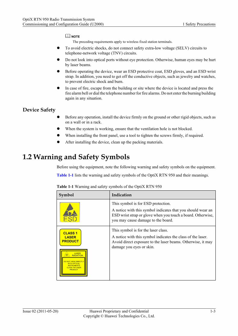
1.2 Warning and Safety SymbolsBefore using the equipment, note the following warning and safety symbols on the equipment.
Table 1-1 lists the warning and safety symbols of the OptiX RTN 950 and their meanings.
Table 1-1 Warning and safety symbols of the OptiX RTN 950
Symbol Indication
This symbol is for ESD protection.A notice with this symbol indicates that you should wear anESD wrist strap or glove when you touch a board. Otherwise,you may cause damage to the board.
CLASS 1LASER
PRODUCT
LASERRADIATION
DO NOT VIEW DIRECTLYWITH OPTICALINSTRUMENTS
CLASS 1M LASERPRODUCT
This symbol is for the laser class.A notice with this symbol indicates the class of the laser.Avoid direct exposure to the laser beams. Otherwise, it maydamage you eyes or skin.
OptiX RTN 950 Radio Transmission SystemCommissioning and Configuration Guide (U2000) 1 Safety Precautions
Issue 02 (2011-05-20) Huawei Proprietary and ConfidentialCopyright © Huawei Technologies Co., Ltd.
1-3

Symbol Indication
A notice with this symbol indicates where the subrack isgrounded.
ATTENTION 警告
CLEAN PERIODICALLY定期清洗
A notice with this symbol indicates that the air filter shouldbe cleaned periodically.
严禁在风扇高速旋转时接触叶片
DON'T TOUCH THEFAN LEAVES BEFORETHEY SLOW DOWN !
This symbol is for fan safety.A notice with this symbol indicates that the fan leaves shouldnot be touched when the fan is rotating.
1.3 Electrical SafetyThis topic describes safety precautions for high voltage, lightning strikes, high leakage current,power cables, fuses, and ESD.
High Voltage
DANGERl A high-voltage power supply provides power for device operations. Direct human contact
with the high voltage power supply or human contact through damp objects can be fatal.l Unspecified or unauthorized high voltage operations could result in fire or electric shock, or
both.
ThunderstormThe requirements apply only to wireless base stations or devices with antennas and feeders.
DANGERDo not perform operations on high voltage, AC power, towers, or backstays in stormy weatherconditions.
1 Safety PrecautionsOptiX RTN 950 Radio Transmission System
Commissioning and Configuration Guide (U2000)
1-4 Huawei Proprietary and ConfidentialCopyright © Huawei Technologies Co., Ltd.
Issue 02 (2011-05-20)
High Leakage Current
WARNINGBefore powering on a device, ground the device. Otherwise, the safety of humans and the devicecannot be ensured.
If a high leakage current mark is labeled near the power connector of the device, you mustconnect the PGND terminal on the shell to the ground before connecting the device to an A/Cinput power supply. This is to prevent the electric shock caused by leakage current of the device.
Power Cables
DANGERDo not install or remove the power cable with a live line. Transient contact between the core ofthe power cable and the conductor may generate electric arc or spark, which may cause fire oreye injury.
l Before installing or removing power cables, you must power off the device.
l Before connecting a power cable, you must ensure that the label on the power cable iscorrect.
Device with Power On
DANGERInstalling or removing a device is prohibited if the device is on.
DANGERDo not install or remove the power cables of the equipment when it is powered on.
Short Circuits
When installing and maintaining devices, place and use the associated tools and instruments inaccordance with regulations to avoid short-circuits caused by metal objects.
OptiX RTN 950 Radio Transmission SystemCommissioning and Configuration Guide (U2000) 1 Safety Precautions
Issue 02 (2011-05-20) Huawei Proprietary and ConfidentialCopyright © Huawei Technologies Co., Ltd.
1-5
CAUTIONTo avoid short-circuits when using a tool (such as a screwdriver), do not place the tool on theventilation plate of the subrack.
CAUTIONPrevent any screws from dropping into the subrack or chassis to avoid short-circuits.
Fuse
WARNINGIf the fuse on a device blows, replace the fuse with a fuse of the same type and specifications toensure safe operation of the device.
Electrostatic Discharge
CAUTIONThe static electricity generated by the human body may damage the electrostatic sensitivecomponents on the board, such as the large-scale integrated circuit (LSI).
l The human body can generate static electromagnetic fields in the following situations:physical movement, clothing friction, friction between shoes and the ground, plastics inthe hand. Such static electromagnetic effects can remain for an appreciable time.
l Before operating a device, circuit boards, or ASICs, wear an ESD wrist strap that is properlygrounded. The ESD wrist strap can prevent the electrostatic-sensitive components frombeing damaged by the static electricity in the human body.
Figure 1-1 shows the method of wearing an ESD wrist strap.
1 Safety PrecautionsOptiX RTN 950 Radio Transmission System
Commissioning and Configuration Guide (U2000)
1-6 Huawei Proprietary and ConfidentialCopyright © Huawei Technologies Co., Ltd.
Issue 02 (2011-05-20)

Figure 1-1 Wearing an ESD wrist strap
1.4 Environment of Flammable GasThis topic describes safety precautions for the operating environment of a device.
DANGERDo not place or operate devices in an environment of flammable or explosive air or gas.
Operating an electronic device in an environment of flammable gas causes a severe hazard.
1.5 Storage BatteriesThis topic describes safety precautions for operations of storage batteries.
DANGERBefore operating a storage battery, you must read the safety precautions carefully and be familiarwith the method of connecting a storage battery.
l Incorrect operations of storage batteries cause hazards. During operation, prevent any short-circuit, and prevent the electrolyte from overflowing or leakage.
l If the electrolyte overflows, it causes potential hazards to the device. The electrolyte maycorrode metal parts and the circuit boards, and ultimately damage the circuit boards.
l A storage battery contains a great deal of energy. Misoperations may cause a short-circuit,which leads to human injuries.
OptiX RTN 950 Radio Transmission SystemCommissioning and Configuration Guide (U2000) 1 Safety Precautions
Issue 02 (2011-05-20) Huawei Proprietary and ConfidentialCopyright © Huawei Technologies Co., Ltd.
1-7
Basic Precautions
To ensure safety, note the following points before installing or maintaining the storage battery:
l Use special insulation tools.l Wear an eye protector and take effective protection measures.l Wear rubber gloves and a protection coat to prevent the hazard caused by the overflowing
electrolyte.l When handling the storage battery, ensure that its electrodes are upward. Leaning or
reversing the storage battery is prohibited.l Before installing or maintaining the storage battery, ensure that the storage battery is
disconnected from the power supply that charges the storage battery.
Short-Circuit
DANGERA battery short-circuit may cause human injuries. Although the voltage of an ordinary batteryis low, the instantaneous high current caused by a short-circuit emits a great deal of energy.
Avoid any short-circuit of batteries caused by metal objects. If possible, disconnect the workingbattery before performing other operations.
Hazardous Gas
CAUTIONDo not use any unsealed lead-acid storage battery. Lay a storage battery horizontally and fix itproperly to prevent the battery from emitting flammable gas, which may cause fire or deviceerosion.
Working lead-acid storage batteries emit flammable gas. Therefore, ventilation and fireproofingmeasures must be taken at the sites where lead-acid storage batteries are placed.
Battery Temperature
CAUTIONIf a battery overheats, the battery may be deformed or damaged, and the electrolyte mayoverflow.
When the temperature of the battery is higher than 60°C, you need to check whether theelectrolyte overflows. If the electrolyte overflows, take appropriate measures immediately.
1 Safety PrecautionsOptiX RTN 950 Radio Transmission System
Commissioning and Configuration Guide (U2000)
1-8 Huawei Proprietary and ConfidentialCopyright © Huawei Technologies Co., Ltd.
Issue 02 (2011-05-20)
Battery Leakage
CAUTIONIn the event of acid overflow or spillage, neutralize the acid and clean it up appropriately.
When handling a leaky battery, protect against the possible damage caused by the acid. Whenyou find the electrolyte leaks, you can use the following substances to counteract and absorb theleaking electrolyte:
l Sodium bicarbonate (NaHCO3)
l Sodium carbonate (Na2CO3)
In the event of acid overflow or spillage, neutralize the acid and clean it up as recommended bythe battery manufacturer and any local regulations for acid disposal.
If a person contacts battery electrolyte, clean the skin that contacts the battery electrolyteimmediately by using water. In case of a severe situation, the person must be sent to a hospitalimmediately.
1.6 RadiationThis topic describes safety precautions for electromagnetic exposure and lasers.
1.6.1 Safe Usage of Optical FibersThe laser beam can cause damage to your eyes. Hence, you must exercise caution when usingoptical fibers.
1.6.2 Electromagnetic ExposureThis topic describes safety precautions for electromagnetic exposure.
1.6.3 Forbidden AreasThe topic describes requirements for a forbidden area.
1.6.4 LaserThis topic describes safety precautions for lasers.
1.6.5 MicrowaveWhen installing and maintaining the equipment of Huawei, follow the safety precautions ofmicrowave to ensure the safety of the human body and the equipment.
1.6.1 Safe Usage of Optical FibersThe laser beam can cause damage to your eyes. Hence, you must exercise caution when usingoptical fibers.
OptiX RTN 950 Radio Transmission SystemCommissioning and Configuration Guide (U2000) 1 Safety Precautions
Issue 02 (2011-05-20) Huawei Proprietary and ConfidentialCopyright © Huawei Technologies Co., Ltd.
1-9
DANGERWhen installing or maintaining an optical interface board or optical fibers, avoid direct eyeexposure to the laser beams launched from the optical interface board or fiber connectors. Thelaser beam can cause damage to your eyes.
Cleaning Fiber Connectors and Optical Interfaces
CAUTIONIf fiber connectors or flanges are contaminated, optical power commissioning is seriouslyaffected. Therefore, the two endfaces and flange of every external fiber must be cleaned beforethe fiber is led into the equipment through the ODF for being inserted into an optical interfaceon the equipment.
The fiber connectors and optical interfaces of the lasers must be cleaned with the followingspecial cleaning tools and materials:
l Special cleaning solvent: It is preferred to use isoamylol. Propyl alcohol, however, can alsobe used. It is prohibited that you use alcohol and formalin.
l Non-woven lens tissue
l Special compressed gas
l Cotton stick (medical cotton or long fiber cotton)
l Special cleaning roll, used with the recommended cleaning solvent
l Special magnifier for fiber connectors
For cleaning steps, see Task Collection "Cleaning Fiber Connectors and Adapters" in the OptiXRTN 950 Radio Transmission System Maintenance and Troubleshooting.
Replacing Optical Fibers
When replacing an optical fiber, cover the fiber connector of the unused optical fiber with aprotective cap.
Connecting Optical Fibersl Use an attenuator if the optical power is excessively high. A high received optical power
damages the optical interface.
l Directly connect an attenuator to a slanting optical interface. Install the attenuator on theIN port instead of the OUT port.
l Do not directly connect an attenuator to the level optical interface. Use the opticaldistribution frame (ODF) to connect an attenuator to a level optical interface.
Figure 1-2 shows a slanting optical interface, and Figure 1-3 shows a level optical interface.
1 Safety PrecautionsOptiX RTN 950 Radio Transmission System
Commissioning and Configuration Guide (U2000)
1-10 Huawei Proprietary and ConfidentialCopyright © Huawei Technologies Co., Ltd.
Issue 02 (2011-05-20)
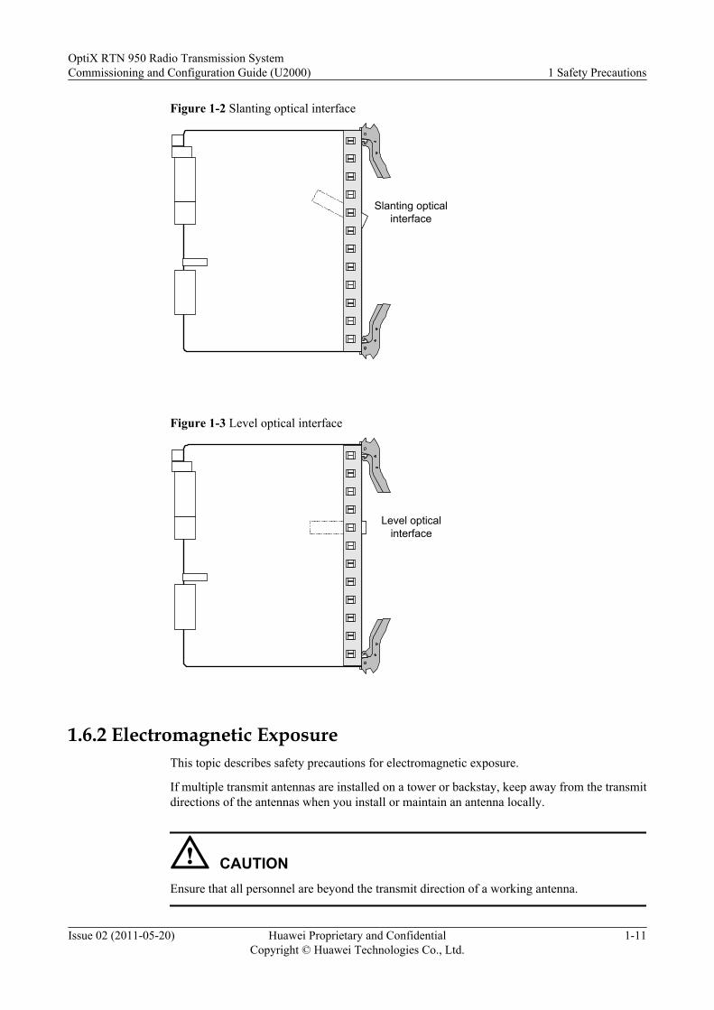
Figure 1-2 Slanting optical interface
Slanting opticalinterface
Figure 1-3 Level optical interface
Level opticalinterface
1.6.2 Electromagnetic ExposureThis topic describes safety precautions for electromagnetic exposure.
If multiple transmit antennas are installed on a tower or backstay, keep away from the transmitdirections of the antennas when you install or maintain an antenna locally.
CAUTIONEnsure that all personnel are beyond the transmit direction of a working antenna.
OptiX RTN 950 Radio Transmission SystemCommissioning and Configuration Guide (U2000) 1 Safety Precautions
Issue 02 (2011-05-20) Huawei Proprietary and ConfidentialCopyright © Huawei Technologies Co., Ltd.
1-11
1.6.3 Forbidden AreasThe topic describes requirements for a forbidden area.
l Before entering an area where the electromagnetic radiation is beyond the specified range,the associated personnel must shut down the electromagnetic radiator or stay at least 10meters away from the electromagnetic radiator, if in the transmit direction.
l A physical barrier and an eye-catching warning flag should be available in each forbiddenarea.
1.6.4 LaserThis topic describes safety precautions for lasers.
WARNINGWhen handling optical fibers, do not stand close to, or look into the optical fiber outlet directlywithout eye protection.
Laser transceivers are used in the optical transmission system and associated test tools. The lasertransmitted through the bare optical fiber produces a small beam of light, and therefore it hasvery high power density and is invisible to human eyes. When a beam of light enters eyes, theeyes may be damaged.
In normal cases, viewing an un-terminated optical fiber or a damaged optical fiber without eyeprotection at a distance greater than 150 mm does not cause eye injury. Eye injury may occur,however, if an optical tool such as a microscope, magnifying glass, or eye loupe is used to viewan un-terminated optical fiber.
Safety Instructions Regarding LasersTo avoid laser radiation, obey the following instructions:
l All operations should be performed by authorized personnel who have completed therequired training courses.
l Wear a pair of eye-protective glasses when you are handling lasers or fibers.l Ensure that the optical source is switched off before disconnecting optical fiber connectors.l Do not look into the end of an exposed fiber or an open connector when you are not sure
whether the optical source is switched off.l Use an optical power meter to measure the optical power and ensure that the optical source
is switched off.l Before opening the front door of an optical transmission device, ensure that you are not
exposed to laser radiation.l Do not use an optical tool such as a microscope, a magnifying glass, or an eye loupe to
view the optical connector or fiber that is transmitting optical signals.
Instructions Regarding Fiber HandlingRead and abide by the following instructions before handling fibers:
1 Safety PrecautionsOptiX RTN 950 Radio Transmission System
Commissioning and Configuration Guide (U2000)
1-12 Huawei Proprietary and ConfidentialCopyright © Huawei Technologies Co., Ltd.
Issue 02 (2011-05-20)

l Only trained personnel are permitted to cut and splice fibers.
l Before cutting or splicing a fiber, ensure that the fiber is disconnected from the opticalsource. After disconnecting the fiber, cap to the fiber connectors.
1.6.5 MicrowaveWhen installing and maintaining the equipment of Huawei, follow the safety precautions ofmicrowave to ensure the safety of the human body and the equipment.
WARNINGStrong radio frequency can harm the human body.
When installing or maintaining an aerial on the tower or mast that is installed with multipleaerials, switch off the transmitter in advance.
1.7 Working at HeightsThis topic describes safety precautions for working at heights.
WARNINGWhen working at heights, be cautious to prevent objects from falling down.
The requirements for working at heights are as follows:
l The personnel who work at heights must be trained.
l Carry and handle the operating machines and tools with caution to prevent them from fallingdown.
l Safety measures, such as wearing a helmet and a safety belt, must be taken.
l Wear cold-proof clothes when working at heights in cold areas.
l Check all lifting appliances thoroughly before starting the work, and ensure that they areintact.
1.7.1 Hoisting Heavy ObjectsThis topic describes the safety precautions for hoisting heavy objects that you must follow wheninstalling, operating, and maintaining Huawei devices.
1.7.2 Using LaddersThis topic describes safety precautions for using ladders.
1.7.1 Hoisting Heavy ObjectsThis topic describes the safety precautions for hoisting heavy objects that you must follow wheninstalling, operating, and maintaining Huawei devices.
OptiX RTN 950 Radio Transmission SystemCommissioning and Configuration Guide (U2000) 1 Safety Precautions
Issue 02 (2011-05-20) Huawei Proprietary and ConfidentialCopyright © Huawei Technologies Co., Ltd.
1-13
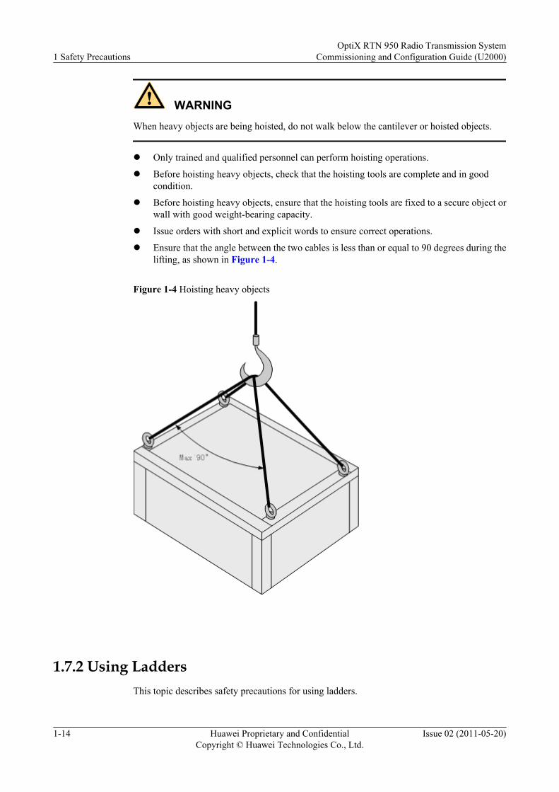
WARNINGWhen heavy objects are being hoisted, do not walk below the cantilever or hoisted objects.
l Only trained and qualified personnel can perform hoisting operations.
l Before hoisting heavy objects, check that the hoisting tools are complete and in goodcondition.
l Before hoisting heavy objects, ensure that the hoisting tools are fixed to a secure object orwall with good weight-bearing capacity.
l Issue orders with short and explicit words to ensure correct operations.
l Ensure that the angle between the two cables is less than or equal to 90 degrees during thelifting, as shown in Figure 1-4.
Figure 1-4 Hoisting heavy objects
1.7.2 Using LaddersThis topic describes safety precautions for using ladders.
1 Safety PrecautionsOptiX RTN 950 Radio Transmission System
Commissioning and Configuration Guide (U2000)
1-14 Huawei Proprietary and ConfidentialCopyright © Huawei Technologies Co., Ltd.
Issue 02 (2011-05-20)
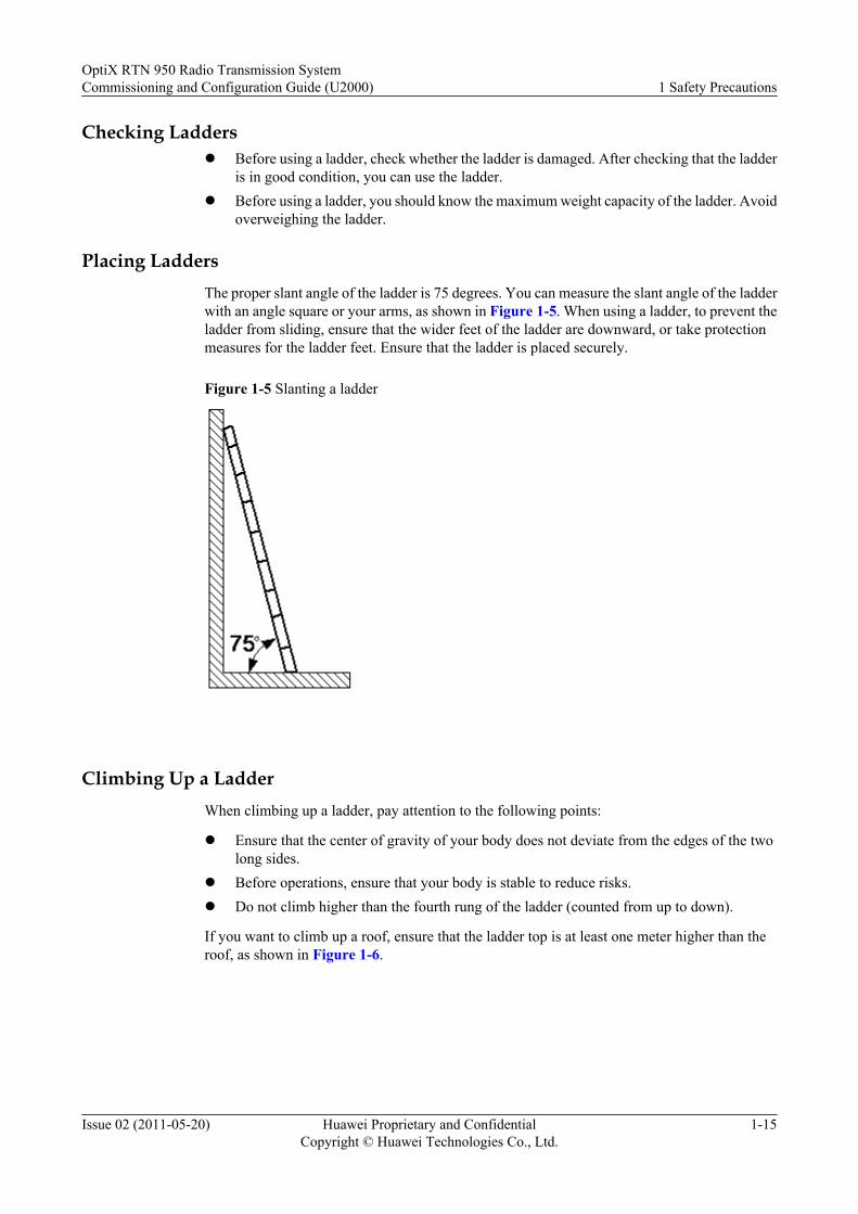
Checking Laddersl Before using a ladder, check whether the ladder is damaged. After checking that the ladder
is in good condition, you can use the ladder.l Before using a ladder, you should know the maximum weight capacity of the ladder. Avoid
overweighing the ladder.
Placing LaddersThe proper slant angle of the ladder is 75 degrees. You can measure the slant angle of the ladderwith an angle square or your arms, as shown in Figure 1-5. When using a ladder, to prevent theladder from sliding, ensure that the wider feet of the ladder are downward, or take protectionmeasures for the ladder feet. Ensure that the ladder is placed securely.
Figure 1-5 Slanting a ladder
Climbing Up a LadderWhen climbing up a ladder, pay attention to the following points:
l Ensure that the center of gravity of your body does not deviate from the edges of the twolong sides.
l Before operations, ensure that your body is stable to reduce risks.l Do not climb higher than the fourth rung of the ladder (counted from up to down).
If you want to climb up a roof, ensure that the ladder top is at least one meter higher than theroof, as shown in Figure 1-6.
OptiX RTN 950 Radio Transmission SystemCommissioning and Configuration Guide (U2000) 1 Safety Precautions
Issue 02 (2011-05-20) Huawei Proprietary and ConfidentialCopyright © Huawei Technologies Co., Ltd.
1-15
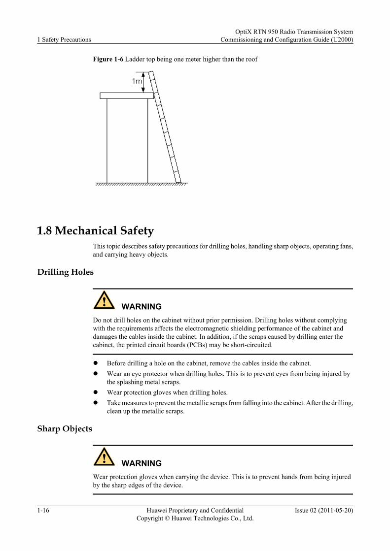
Figure 1-6 Ladder top being one meter higher than the roof
1.8 Mechanical SafetyThis topic describes safety precautions for drilling holes, handling sharp objects, operating fans,and carrying heavy objects.
Drilling Holes
WARNINGDo not drill holes on the cabinet without prior permission. Drilling holes without complyingwith the requirements affects the electromagnetic shielding performance of the cabinet anddamages the cables inside the cabinet. In addition, if the scraps caused by drilling enter thecabinet, the printed circuit boards (PCBs) may be short-circuited.
l Before drilling a hole on the cabinet, remove the cables inside the cabinet.l Wear an eye protector when drilling holes. This is to prevent eyes from being injured by
the splashing metal scraps.l Wear protection gloves when drilling holes.l Take measures to prevent the metallic scraps from falling into the cabinet. After the drilling,
clean up the metallic scraps.
Sharp Objects
WARNINGWear protection gloves when carrying the device. This is to prevent hands from being injuredby the sharp edges of the device.
1 Safety PrecautionsOptiX RTN 950 Radio Transmission System
Commissioning and Configuration Guide (U2000)
1-16 Huawei Proprietary and ConfidentialCopyright © Huawei Technologies Co., Ltd.
Issue 02 (2011-05-20)
Fansl When replacing parts, place the objects such as the parts, screws, and tools properly. This
is to prevent them from falling into the operating fans, which damages the fans or device.
l When replacing the parts near fans, keep your fingers or boards from touching operatingfans before the fans are powered off and stop running. Otherwise, the hands or the boardsare damaged.
Carrying Heavy Objects
Wear protection gloves when carrying heavy objects. This is to prevent hands from being hurt.
WARNINGl The carrier must be prepared for load bearing before carrying heavy objects. This is to prevent
the carrier from being strained or pressed by the heavy objects.
l When you pull a chassis out of the cabinet, pay attention to the unstable or heavy objects onthe cabinet. This is to prevent the heavy objects on the cabinet top from falling down, whichmay hurt you.
l Generally, two persons are needed to carry a chassis. It is prohibited that only one personcarries a heavy chassis. When carrying a chassis, the carriers should stretch their backs andmove stably to avoid being strained.
l When moving or lifting a chassis, hold the handles or bottom of the chassis. Do not holdthe handles of the modules installed in the chassis, such as the power modules, fan modules,and boards.
1.9 Other PrecautionsThis topic describes safety precautions for removing and inserting boards, binding signal cables,and routing cables.
Removing and Inserting a Board
CAUTIONWhen inserting a board, wear an ESD wrist strap or ESD gloves, and handle the board gently toavoid distorting pins on the backplane.
l Slide the board along the guide rails.
l Do not contact one board with another to avoid short-circuits or damage.
l When holding a board in hand, do not touch the board circuits, components, connectors,or connection slots of the board to prevent damage caused by ESD of the human body tothe electrostatic-sensitive components.
OptiX RTN 950 Radio Transmission SystemCommissioning and Configuration Guide (U2000) 1 Safety Precautions
Issue 02 (2011-05-20) Huawei Proprietary and ConfidentialCopyright © Huawei Technologies Co., Ltd.
1-17
Binding Signal Cables
CAUTIONBind the signal cables separately from the high-current or high-voltage cables.
Routing CablesIn the case of extremely low temperature, heavy shock or vibration may damage the plastic skinof the cables. To ensure the construction safety, comply with the following requirements:
l When installing cables, ensure that the environment temperature is above 0°C.l If the cables are stored in a place where the ambient temperature is below 0°C, transfer
them to a place at room temperature and store the cables for more than 24 hours beforeinstallation.
l Handle the cables gently, especially in a low-temperature environment. Do not performany improper operations, for example, pushing the cables down directly from a truck.
High Temperature
WARNINGIf the ambient temperature exceeds 55°C, the temperature of the front panel surface marked the
flag may exceed 70°C. When touching the front panel of the board in such an environment,you must wear the protection gloves.
IF Cables
WARNINGBefore installing or removing an IF cable, you must turn off the power switch of the IF board.
1 Safety PrecautionsOptiX RTN 950 Radio Transmission System
Commissioning and Configuration Guide (U2000)
1-18 Huawei Proprietary and ConfidentialCopyright © Huawei Technologies Co., Ltd.
Issue 02 (2011-05-20)

2 Notices for High-Risk Operations
About This Chapter
This chapter provides notices for the operations that may cause bodily injury or equipmentdamage if they are not performed properly during the commissioning and maintenance ofmicrowave equipment.
2.1 Operation Guide for the Toggle Lever SwitchThe ODU-PWR switch on the IF board is a toggle lever switch which must be turned on and offas per the following instructions to avoid damaging the IF board.
2.2 Operation Guide for the IF JumperBefore removing or installing an IF jumper, turn off the ODU-PWR switch to avoid bodily injuryor damage to the IF board and ODU.
2.3 Operation Guide for the IF CableBefore removing or installing an IF cable, turn off the ODU-PWR switch to avoid bodily injuryor damage to the IF board and ODU.
2.4 Operation Guide for the IF BoardBefore removing or installing an IF board, turn off the ODU-PWR switch to avoid bodily injuryor damage to the IF board and ODU.
OptiX RTN 950 Radio Transmission SystemCommissioning and Configuration Guide (U2000) 2 Notices for High-Risk Operations
Issue 02 (2011-05-20) Huawei Proprietary and ConfidentialCopyright © Huawei Technologies Co., Ltd.
2-1
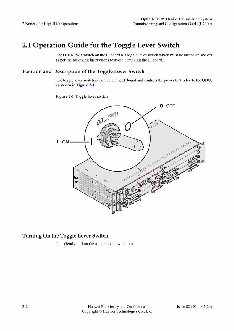
2.1 Operation Guide for the Toggle Lever SwitchThe ODU-PWR switch on the IF board is a toggle lever switch which must be turned on and offas per the following instructions to avoid damaging the IF board.
Position and Description of the Toggle Lever SwitchThe toggle lever switch is located on the IF board and controls the power that is fed to the ODU,as shown in Figure 2-1.
Figure 2-1 Toggle lever switch
I : ON
O: OFF
Turning On the Toggle Lever Switch1. Gently pull on the toggle lever switch out.
2 Notices for High-Risk OperationsOptiX RTN 950 Radio Transmission System
Commissioning and Configuration Guide (U2000)
2-2 Huawei Proprietary and ConfidentialCopyright © Huawei Technologies Co., Ltd.
Issue 02 (2011-05-20)

2. Turn it to the left.
3. Release the toggle lever switch.
Turning Off the Toggle Lever Switch1. Gently pull on the toggle lever switch.
OptiX RTN 950 Radio Transmission SystemCommissioning and Configuration Guide (U2000) 2 Notices for High-Risk Operations
Issue 02 (2011-05-20) Huawei Proprietary and ConfidentialCopyright © Huawei Technologies Co., Ltd.
2-3
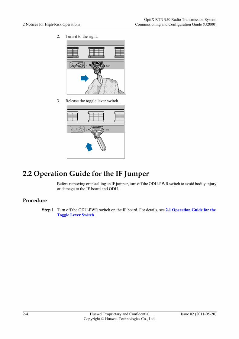
2. Turn it to the right.
3. Release the toggle lever switch.
2.2 Operation Guide for the IF JumperBefore removing or installing an IF jumper, turn off the ODU-PWR switch to avoid bodily injuryor damage to the IF board and ODU.
Procedure
Step 1 Turn off the ODU-PWR switch on the IF board. For details, see 2.1 Operation Guide for theToggle Lever Switch.
2 Notices for High-Risk OperationsOptiX RTN 950 Radio Transmission System
Commissioning and Configuration Guide (U2000)
2-4 Huawei Proprietary and ConfidentialCopyright © Huawei Technologies Co., Ltd.
Issue 02 (2011-05-20)
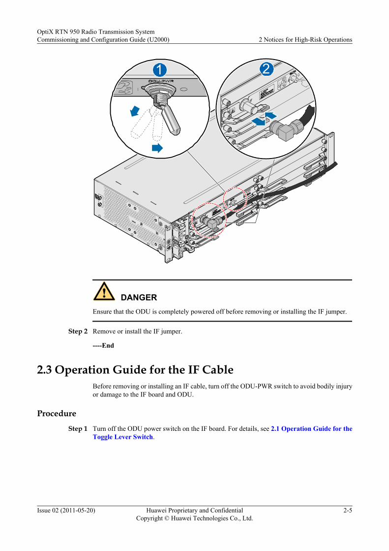
21
DANGEREnsure that the ODU is completely powered off before removing or installing the IF jumper.
Step 2 Remove or install the IF jumper.
----End
2.3 Operation Guide for the IF CableBefore removing or installing an IF cable, turn off the ODU-PWR switch to avoid bodily injuryor damage to the IF board and ODU.
Procedure
Step 1 Turn off the ODU power switch on the IF board. For details, see 2.1 Operation Guide for theToggle Lever Switch.
OptiX RTN 950 Radio Transmission SystemCommissioning and Configuration Guide (U2000) 2 Notices for High-Risk Operations
Issue 02 (2011-05-20) Huawei Proprietary and ConfidentialCopyright © Huawei Technologies Co., Ltd.
2-5

1
2
DANGEREnsure that the ODU is completely powered off before removing or installing the IF cable.
Step 2 Install or remove the IF cable.
----End
2.4 Operation Guide for the IF BoardBefore removing or installing an IF board, turn off the ODU-PWR switch to avoid bodily injuryor damage to the IF board and ODU.
Procedure
Step 1 Turn off the ODU-PWR switch on the IF board. For details, see 2.1 Operation Guide for theToggle Lever Switch.
2 Notices for High-Risk OperationsOptiX RTN 950 Radio Transmission System
Commissioning and Configuration Guide (U2000)
2-6 Huawei Proprietary and ConfidentialCopyright © Huawei Technologies Co., Ltd.
Issue 02 (2011-05-20)
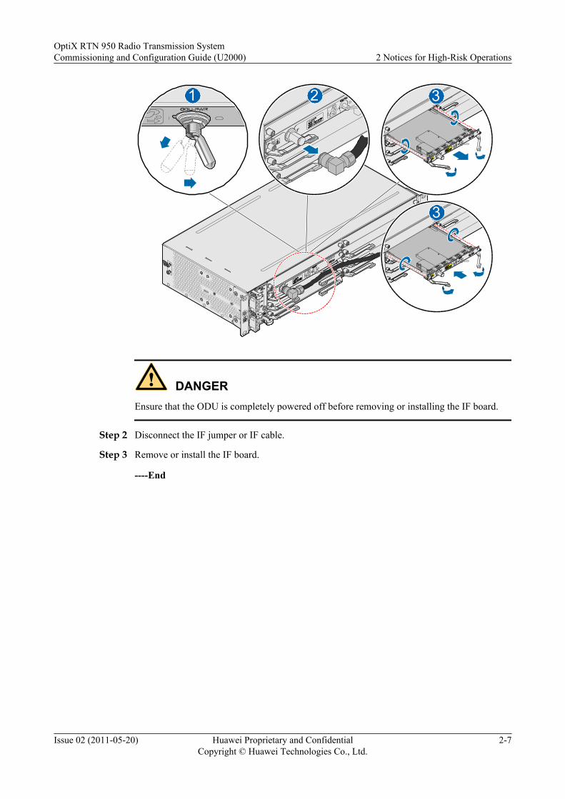
321
3
DANGEREnsure that the ODU is completely powered off before removing or installing the IF board.
Step 2 Disconnect the IF jumper or IF cable.
Step 3 Remove or install the IF board.
----End
OptiX RTN 950 Radio Transmission SystemCommissioning and Configuration Guide (U2000) 2 Notices for High-Risk Operations
Issue 02 (2011-05-20) Huawei Proprietary and ConfidentialCopyright © Huawei Technologies Co., Ltd.
2-7

3 Commissioning Preparations
About This Chapter
This chapter describes the preparations that need to be made prior to commissioning equipment.
3.1 Preparing Documents and ToolsThis section lists the document and tools that should be prepared prior to commissioning theequipment.
3.2 Determining the Commissioning MethodBy using the U2000 for commissioning, engineers can adopt the network commissioningmethod.
3.3 Checking Commissioning ConditionsEnsure that the equipment meets the commissioning requirements for the site or system prior toperforming such tasks. The following sections provide a non-exhaustive checklist for bothscenarios.
OptiX RTN 950 Radio Transmission SystemCommissioning and Configuration Guide (U2000) 3 Commissioning Preparations
Issue 02 (2011-05-20) Huawei Proprietary and ConfidentialCopyright © Huawei Technologies Co., Ltd.
3-1
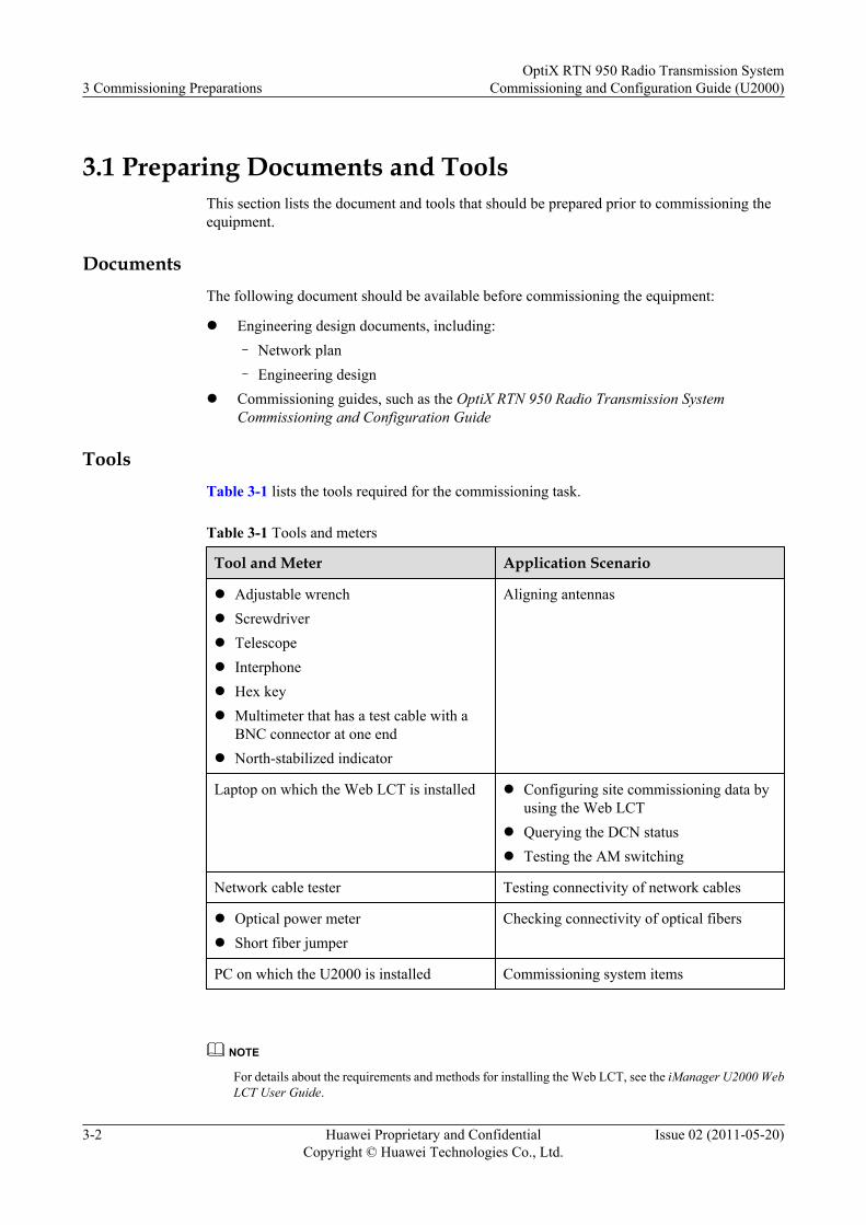
3.1 Preparing Documents and ToolsThis section lists the document and tools that should be prepared prior to commissioning theequipment.
DocumentsThe following document should be available before commissioning the equipment:
l Engineering design documents, including:– Network plan– Engineering design
l Commissioning guides, such as the OptiX RTN 950 Radio Transmission SystemCommissioning and Configuration Guide
ToolsTable 3-1 lists the tools required for the commissioning task.
Table 3-1 Tools and meters
Tool and Meter Application Scenario
l Adjustable wrenchl Screwdriverl Telescopel Interphonel Hex keyl Multimeter that has a test cable with a
BNC connector at one endl North-stabilized indicator
Aligning antennas
Laptop on which the Web LCT is installed l Configuring site commissioning data byusing the Web LCT
l Querying the DCN statusl Testing the AM switching
Network cable tester Testing connectivity of network cables
l Optical power meterl Short fiber jumper
Checking connectivity of optical fibers
PC on which the U2000 is installed Commissioning system items
NOTE
For details about the requirements and methods for installing the Web LCT, see the iManager U2000 WebLCT User Guide.
3 Commissioning PreparationsOptiX RTN 950 Radio Transmission System
Commissioning and Configuration Guide (U2000)
3-2 Huawei Proprietary and ConfidentialCopyright © Huawei Technologies Co., Ltd.
Issue 02 (2011-05-20)
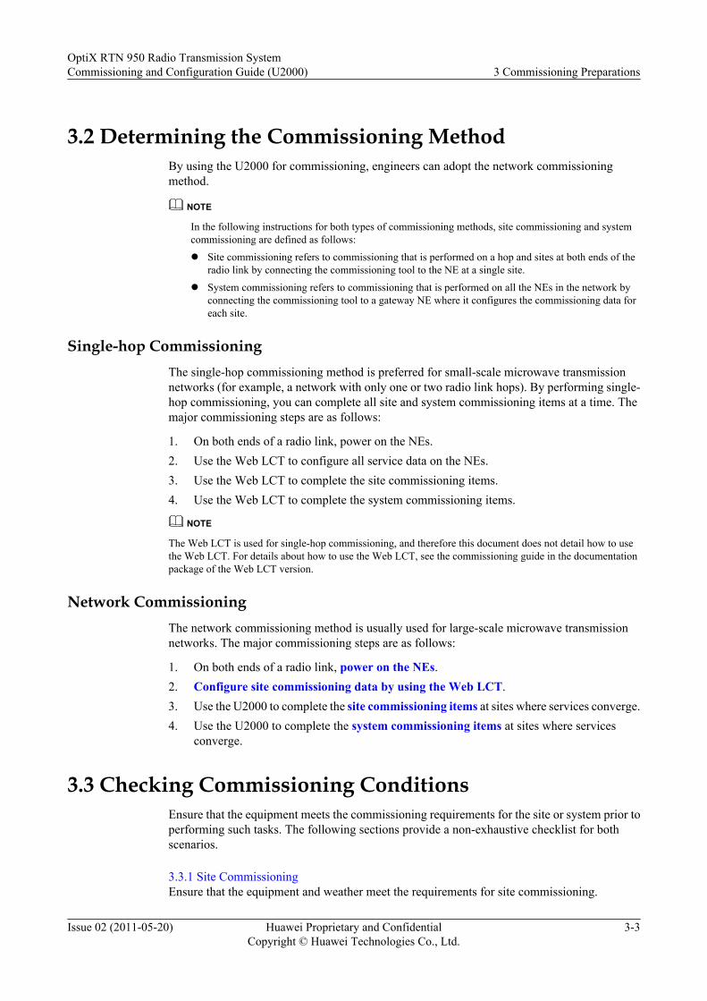
3.2 Determining the Commissioning MethodBy using the U2000 for commissioning, engineers can adopt the network commissioningmethod.
NOTE
In the following instructions for both types of commissioning methods, site commissioning and systemcommissioning are defined as follows:l Site commissioning refers to commissioning that is performed on a hop and sites at both ends of the
radio link by connecting the commissioning tool to the NE at a single site.l System commissioning refers to commissioning that is performed on all the NEs in the network by
connecting the commissioning tool to a gateway NE where it configures the commissioning data foreach site.
Single-hop CommissioningThe single-hop commissioning method is preferred for small-scale microwave transmissionnetworks (for example, a network with only one or two radio link hops). By performing single-hop commissioning, you can complete all site and system commissioning items at a time. Themajor commissioning steps are as follows:
1. On both ends of a radio link, power on the NEs.2. Use the Web LCT to configure all service data on the NEs.3. Use the Web LCT to complete the site commissioning items.4. Use the Web LCT to complete the system commissioning items.
NOTE
The Web LCT is used for single-hop commissioning, and therefore this document does not detail how to usethe Web LCT. For details about how to use the Web LCT, see the commissioning guide in the documentationpackage of the Web LCT version.
Network CommissioningThe network commissioning method is usually used for large-scale microwave transmissionnetworks. The major commissioning steps are as follows:
1. On both ends of a radio link, power on the NEs.2. Configure site commissioning data by using the Web LCT.3. Use the U2000 to complete the site commissioning items at sites where services converge.4. Use the U2000 to complete the system commissioning items at sites where services
converge.
3.3 Checking Commissioning ConditionsEnsure that the equipment meets the commissioning requirements for the site or system prior toperforming such tasks. The following sections provide a non-exhaustive checklist for bothscenarios.
3.3.1 Site CommissioningEnsure that the equipment and weather meet the requirements for site commissioning.
OptiX RTN 950 Radio Transmission SystemCommissioning and Configuration Guide (U2000) 3 Commissioning Preparations
Issue 02 (2011-05-20) Huawei Proprietary and ConfidentialCopyright © Huawei Technologies Co., Ltd.
3-3
3.3.2 System CommissioningEnsure that the equipment and weather meet the requirements for system commissioning.
3.3.1 Site CommissioningEnsure that the equipment and weather meet the requirements for site commissioning.
Details about these requirements are as follows:
l Hardware installation has been completed and has passed the installation check.l Power is available to the equipment.l The service signal cables that are connected to other equipment have been properly routed.l The appropriate risk control measures to arrest falling objects and ensure personnel safety
are in place. Engineers are certified to commission the antennas.l There is no adverse weather (such as wind, rain, snow, or fog) that could hinder or impact
the commissioning.
3.3.2 System CommissioningEnsure that the equipment and weather meet the requirements for system commissioning.
Details about these requirements are as follows:
l Site commissioning at both ends of a radio link has been completed.l There is no adverse weather (such as wind, rain, snow, or fog) that could hinder or impact
the commissioning.
3 Commissioning PreparationsOptiX RTN 950 Radio Transmission System
Commissioning and Configuration Guide (U2000)
3-4 Huawei Proprietary and ConfidentialCopyright © Huawei Technologies Co., Ltd.
Issue 02 (2011-05-20)
4 Commissioning Process
About This Chapter
Based on the objects to be commissioned, the process can be divided into two stages: sitecommissioning and system commissioning.
4.1 Site Commissioning ProcessSite commissioning refers to commissioning that is performed on a hop and sites at both endsof a radio link. Site commissioning ensures that the sites and the radio link between the siteswork properly, and is also performed in preparation of system commissioning.
4.2 System Commissioning ProcessSystem commissioning refers to commissioning for the entire microwave transmission network.System commissioning ensures that various services are transmitted properly and protectionfunctions are implemented over the microwave transmission network.
OptiX RTN 950 Radio Transmission SystemCommissioning and Configuration Guide (U2000) 4 Commissioning Process
Issue 02 (2011-05-20) Huawei Proprietary and ConfidentialCopyright © Huawei Technologies Co., Ltd.
4-1
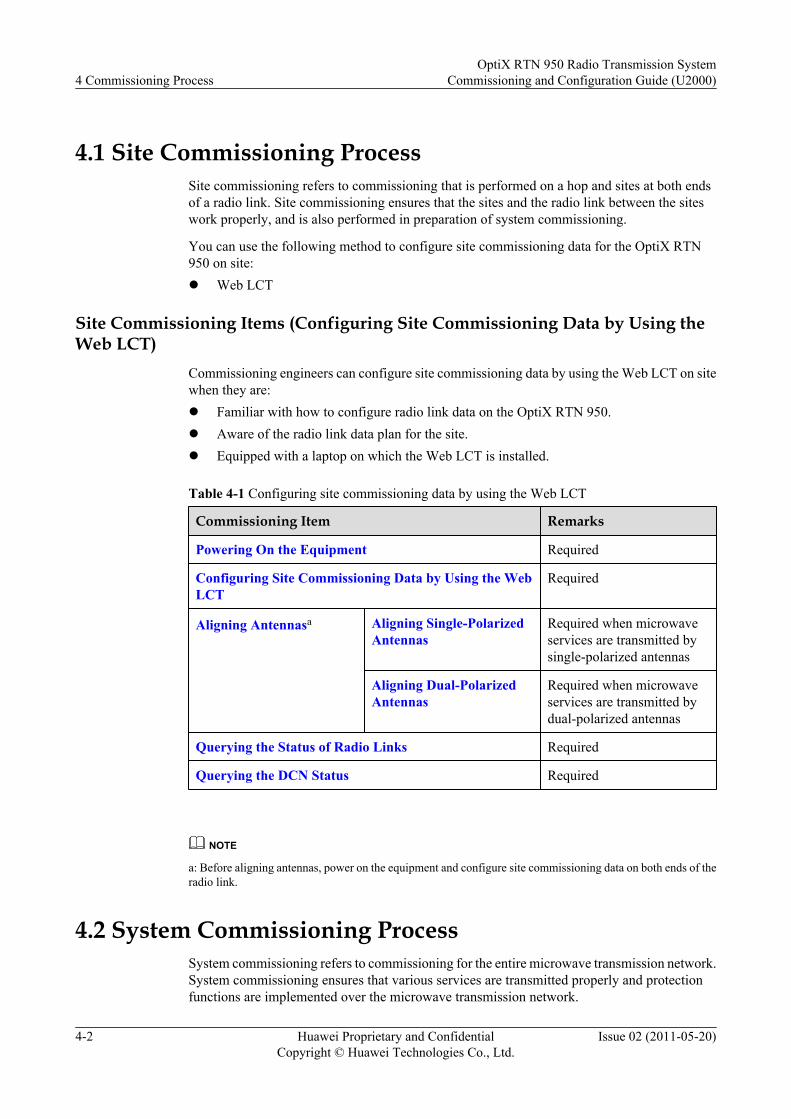
4.1 Site Commissioning ProcessSite commissioning refers to commissioning that is performed on a hop and sites at both endsof a radio link. Site commissioning ensures that the sites and the radio link between the siteswork properly, and is also performed in preparation of system commissioning.
You can use the following method to configure site commissioning data for the OptiX RTN950 on site:l Web LCT
Site Commissioning Items (Configuring Site Commissioning Data by Using theWeb LCT)
Commissioning engineers can configure site commissioning data by using the Web LCT on sitewhen they are:l Familiar with how to configure radio link data on the OptiX RTN 950.l Aware of the radio link data plan for the site.l Equipped with a laptop on which the Web LCT is installed.
Table 4-1 Configuring site commissioning data by using the Web LCT
Commissioning Item Remarks
Powering On the Equipment Required
Configuring Site Commissioning Data by Using the WebLCT
Required
Aligning Antennasa Aligning Single-PolarizedAntennas
Required when microwaveservices are transmitted bysingle-polarized antennas
Aligning Dual-PolarizedAntennas
Required when microwaveservices are transmitted bydual-polarized antennas
Querying the Status of Radio Links Required
Querying the DCN Status Required
NOTE
a: Before aligning antennas, power on the equipment and configure site commissioning data on both ends of theradio link.
4.2 System Commissioning ProcessSystem commissioning refers to commissioning for the entire microwave transmission network.System commissioning ensures that various services are transmitted properly and protectionfunctions are implemented over the microwave transmission network.
4 Commissioning ProcessOptiX RTN 950 Radio Transmission System
Commissioning and Configuration Guide (U2000)
4-2 Huawei Proprietary and ConfidentialCopyright © Huawei Technologies Co., Ltd.
Issue 02 (2011-05-20)
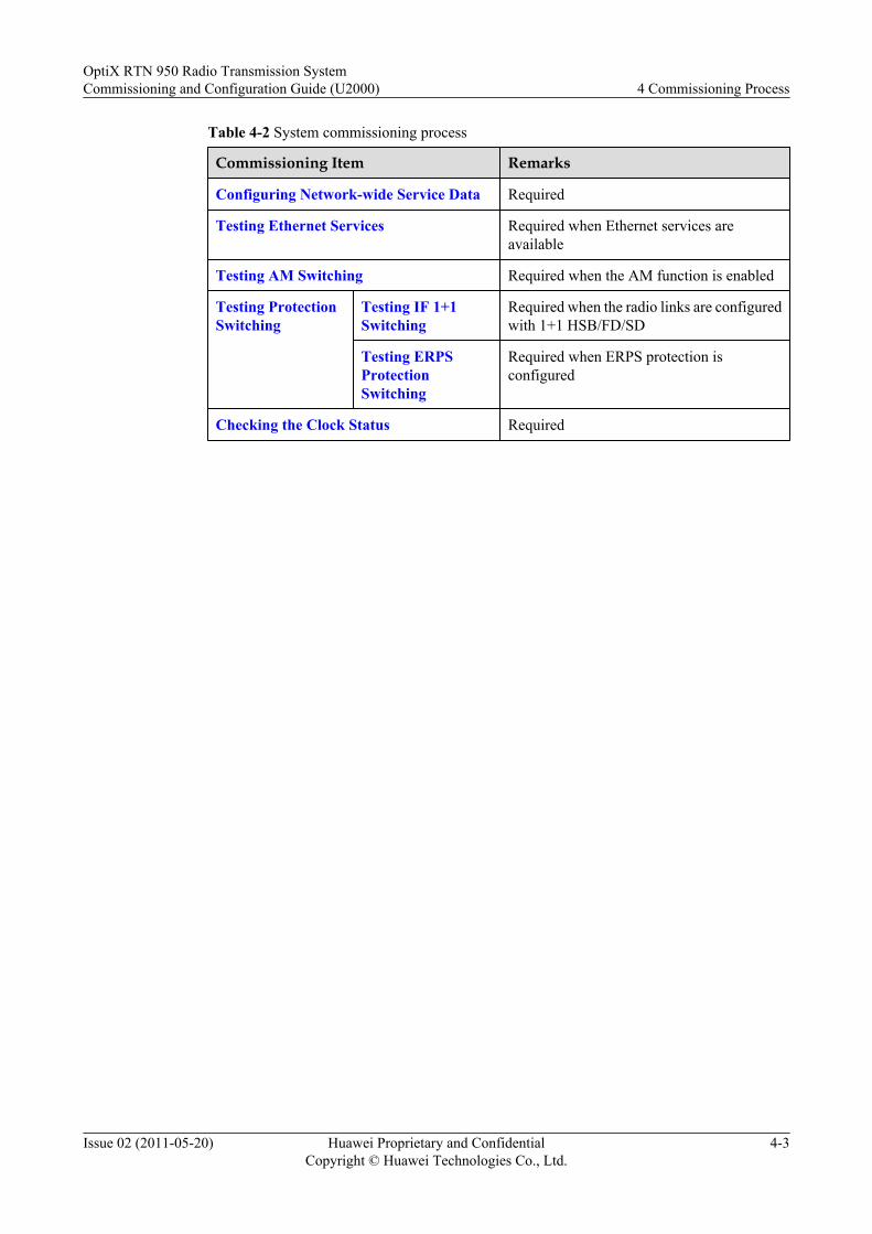
Table 4-2 System commissioning process
Commissioning Item Remarks
Configuring Network-wide Service Data Required
Testing Ethernet Services Required when Ethernet services areavailable
Testing AM Switching Required when the AM function is enabled
Testing ProtectionSwitching
Testing IF 1+1Switching
Required when the radio links are configuredwith 1+1 HSB/FD/SD
Testing ERPSProtectionSwitching
Required when ERPS protection isconfigured
Checking the Clock Status Required
OptiX RTN 950 Radio Transmission SystemCommissioning and Configuration Guide (U2000) 4 Commissioning Process
Issue 02 (2011-05-20) Huawei Proprietary and ConfidentialCopyright © Huawei Technologies Co., Ltd.
4-3

5 Site Commissioning
About This Chapter
Site commissioning includes the specific commissioning processes for all site commissioningitems.
5.1 Powering On the EquipmentBy checking the power-on process of equipment, you can verify whether the hardware systemof the equipment and the power system are functioning properly.
5.2 Configuring Site Commissioning Data by Using the Web LCTThis topic describes how to configure site commissioning data when using the Web LCT toperform site commissioning.
5.3 Testing Connectivity of CablesDuring the installation of the OptiX RTN 900, the cables may be connected to service interfacesincorrectly, or the hardware may malfunction. To ensure that the services run properly, testconnectivity of the cables.
5.4 Aligning the AntennasAligning the antennas is the most important activity in HOP commissioning. The alignment hasa direct effect on the performance of the radio links.
5.5 Checking the Status of Radio LinksAfter aligning the antennas, query the status of radio links and determine whether the radio linksare in the normal state.
5.6 Querying the DCN StatusThe NMS manages NEs through DCN channels. By querying the radio links using the HOPmanagement function, you can determine whether the DCN of the radio links runs properly.
OptiX RTN 950 Radio Transmission SystemCommissioning and Configuration Guide (U2000) 5 Site Commissioning
Issue 02 (2011-05-20) Huawei Proprietary and ConfidentialCopyright © Huawei Technologies Co., Ltd.
5-1
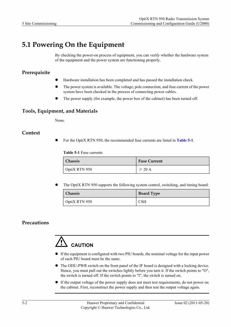
5.1 Powering On the EquipmentBy checking the power-on process of equipment, you can verify whether the hardware systemof the equipment and the power system are functioning properly.
Prerequisitel Hardware installation has been completed and has passed the installation check.
l The power system is available. The voltage, pole connection, and fuse current of the powersystem have been checked in the process of connecting power cables.
l The power supply (for example, the power box of the cabinet) has been turned off.
Tools, Equipment, and Materials
None.
Contextl For the OptiX RTN 950, the recommended fuse currents are listed in Table 5-1.
Table 5-1 Fuse currents
Chassis Fuse Current
OptiX RTN 950 ≥ 20 A
l The OptiX RTN 950 supports the following system control, switching, and timing board:
Chassis Board Type
OptiX RTN 950 CSH
Precautions
CAUTIONl If the equipment is configured with two PIU boards, the nominal voltage for the input power
of each PIU board must be the same.
l The ODU-PWR switch on the front panel of the IF board is designed with a locking device.Hence, you must pull out the switches lightly before you turn it. If the switch points to "O",the switch is turned off. If the switch points to "I", the switch is turned on.
l If the output voltage of the power supply does not meet test requirements, do not power onthe cabinet. First, reconstruct the power supply and then test the output voltage again.
5 Site CommissioningOptiX RTN 950 Radio Transmission System
Commissioning and Configuration Guide (U2000)
5-2 Huawei Proprietary and ConfidentialCopyright © Huawei Technologies Co., Ltd.
Issue 02 (2011-05-20)
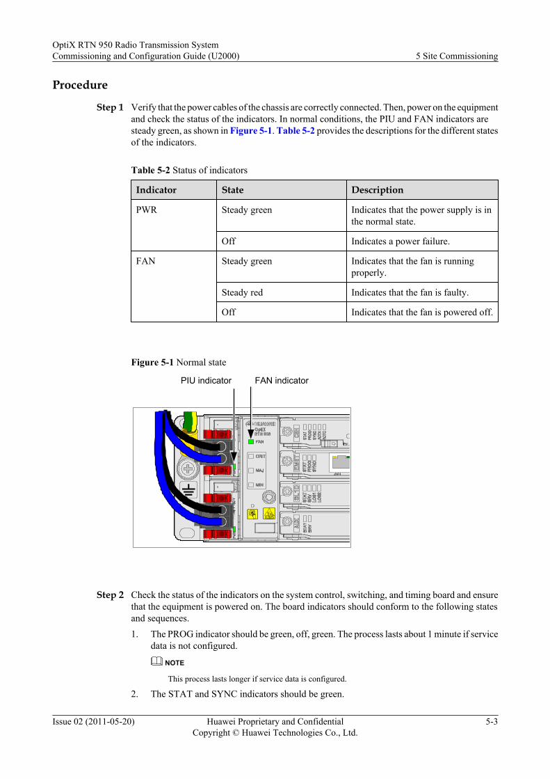
Procedure
Step 1 Verify that the power cables of the chassis are correctly connected. Then, power on the equipmentand check the status of the indicators. In normal conditions, the PIU and FAN indicators aresteady green, as shown in Figure 5-1. Table 5-2 provides the descriptions for the different statesof the indicators.
Table 5-2 Status of indicators
Indicator State Description
PWR Steady green Indicates that the power supply is inthe normal state.
Off Indicates a power failure.
FAN Steady green Indicates that the fan is runningproperly.
Steady red Indicates that the fan is faulty.
Off Indicates that the fan is powered off.
Figure 5-1 Normal state
PIU indicator FAN indicator
Step 2 Check the status of the indicators on the system control, switching, and timing board and ensurethat the equipment is powered on. The board indicators should conform to the following statesand sequences.1. The PROG indicator should be green, off, green. The process lasts about 1 minute if service
data is not configured.
NOTE
This process lasts longer if service data is configured.
2. The STAT and SYNC indicators should be green.
OptiX RTN 950 Radio Transmission SystemCommissioning and Configuration Guide (U2000) 5 Site Commissioning
Issue 02 (2011-05-20) Huawei Proprietary and ConfidentialCopyright © Huawei Technologies Co., Ltd.
5-3
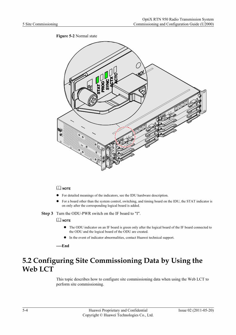
Figure 5-2 Normal state
STAT
PROG
SYNC
ACTX ACTC
NOTE
l For detailed meanings of the indicators, see the IDU hardware description.
l For a board other than the system control, switching, and timing board on the IDU, the STAT indicator ison only after the corresponding logical board is added.
Step 3 Turn the ODU-PWR switch on the IF board to "I".
NOTE
l The ODU indicator on an IF board is green only after the logical board of the IF board connected tothe ODU and the logical board of the ODU are created.
l In the event of indicator abnormalities, contact Huawei technical support.
----End
5.2 Configuring Site Commissioning Data by Using theWeb LCT
This topic describes how to configure site commissioning data when using the Web LCT toperform site commissioning.
5 Site CommissioningOptiX RTN 950 Radio Transmission System
Commissioning and Configuration Guide (U2000)
5-4 Huawei Proprietary and ConfidentialCopyright © Huawei Technologies Co., Ltd.
Issue 02 (2011-05-20)

Configuration ProcessFigure 5-3 describes the process of configuring site commissioning data.
OptiX RTN 950 Radio Transmission SystemCommissioning and Configuration Guide (U2000) 5 Site Commissioning
Issue 02 (2011-05-20) Huawei Proprietary and ConfidentialCopyright © Huawei Technologies Co., Ltd.
5-5
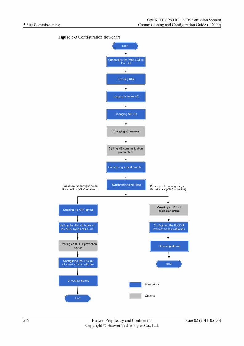
Figure 5-3 Configuration flowchart
Procedure for configuring an IP radio link (XPIC disabled)
End
Mandatory
Optional
Start
Connecting the Web LCT to the IDU
Synchronizing NE time
Creating an IF 1+1 protection group
Procedure for configuring an IP radio link (XPIC enabled)
Creating an XPIC group
Configuring the IF/ODU information of a radio link
Creating an IF 1+1 protection group
Setting the AM attributes of the XPIC hybrid radio link
EndConfiguring the IF/ODU
information of a radio link
Checking alarms
Checking alarms
Creating NEs
Logging in to an NE
Changing NE IDs
Configuring logical boards
Setting NE communication parameters
Changing NE names
5 Site CommissioningOptiX RTN 950 Radio Transmission System
Commissioning and Configuration Guide (U2000)
5-6 Huawei Proprietary and ConfidentialCopyright © Huawei Technologies Co., Ltd.
Issue 02 (2011-05-20)

Procedure for Configuring NE Data
Table 5-3 Procedure for configuring NE data
Step Action Description
1 Connecting the Web LCT tothe IDU
Mandatory.
2 Creating NEs by Using theSearch Method
Mandatory. It is recommended that youcreate an NE in IP Auto Discovery mode.
3 Logging In to an NE Mandatory.Enter correct values in User Name andPassword. The default User Name is lct,and the default Password is password.
4 Changing the NE ID Mandatory. Set parameters as follows:l Set ID according to the guideline
specified in the DCN plan.l If a specific extended NE ID is required,
change Extended ID.
5 Changing the NE Name Optional.
6 Setting NE CommunicationParameters
Mandatory if special requirements areimposed on the IP address of the NE. SetIP and Subnet Mask as required.NOTE
If the IP address of an NE is not changedmanually, the IP address changes to0x81000000 + NE ID.
7 Configuring Logical Boards Mandatory.
8 Synchronizing NE Time Mandatory. This operation synchronizesNE time with the time on the computer thatruns the Web LCT.
Procedure for Configuring an IP radio Link (XPIC Disabled)
Table 5-4 Procedure for configuring an IP radio link (XPIC disabled)
Step Action Description
1 8.3.1Creating anIF 1+1ProtectionGroupa
Mandatory when radio links are configured with 1+1protection.Set the parameters according to the network plan.
OptiX RTN 950 Radio Transmission SystemCommissioning and Configuration Guide (U2000) 5 Site Commissioning
Issue 02 (2011-05-20) Huawei Proprietary and ConfidentialCopyright © Huawei Technologies Co., Ltd.
5-7
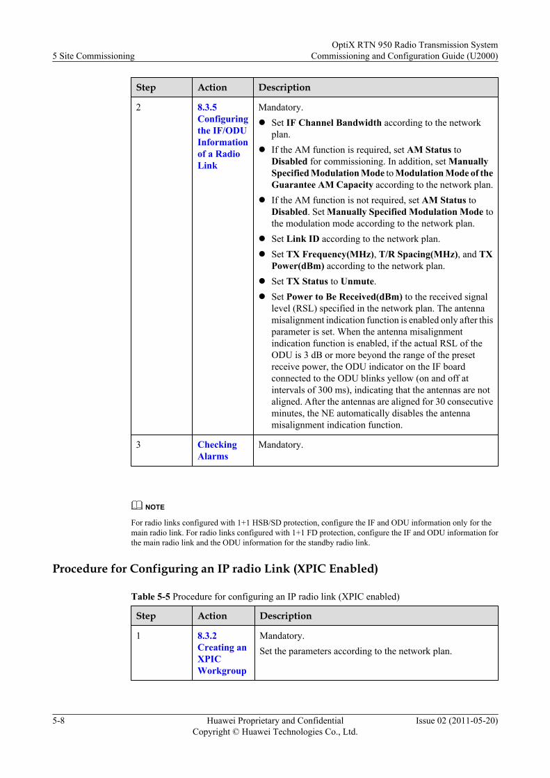
Step Action Description
2 8.3.5Configuringthe IF/ODUInformationof a RadioLink
Mandatory.l Set IF Channel Bandwidth according to the network
plan.l If the AM function is required, set AM Status to
Disabled for commissioning. In addition, set ManuallySpecified Modulation Mode to Modulation Mode of theGuarantee AM Capacity according to the network plan.
l If the AM function is not required, set AM Status toDisabled. Set Manually Specified Modulation Mode tothe modulation mode according to the network plan.
l Set Link ID according to the network plan.l Set TX Frequency(MHz), T/R Spacing(MHz), and TX
Power(dBm) according to the network plan.l Set TX Status to Unmute.l Set Power to Be Received(dBm) to the received signal
level (RSL) specified in the network plan. The antennamisalignment indication function is enabled only after thisparameter is set. When the antenna misalignmentindication function is enabled, if the actual RSL of theODU is 3 dB or more beyond the range of the presetreceive power, the ODU indicator on the IF boardconnected to the ODU blinks yellow (on and off atintervals of 300 ms), indicating that the antennas are notaligned. After the antennas are aligned for 30 consecutiveminutes, the NE automatically disables the antennamisalignment indication function.
3 CheckingAlarms
Mandatory.
NOTE
For radio links configured with 1+1 HSB/SD protection, configure the IF and ODU information only for themain radio link. For radio links configured with 1+1 FD protection, configure the IF and ODU information forthe main radio link and the ODU information for the standby radio link.
Procedure for Configuring an IP radio Link (XPIC Enabled)
Table 5-5 Procedure for configuring an IP radio link (XPIC enabled)
Step Action Description
1 8.3.2Creating anXPICWorkgroup
Mandatory.Set the parameters according to the network plan.
5 Site CommissioningOptiX RTN 950 Radio Transmission System
Commissioning and Configuration Guide (U2000)
5-8 Huawei Proprietary and ConfidentialCopyright © Huawei Technologies Co., Ltd.
Issue 02 (2011-05-20)
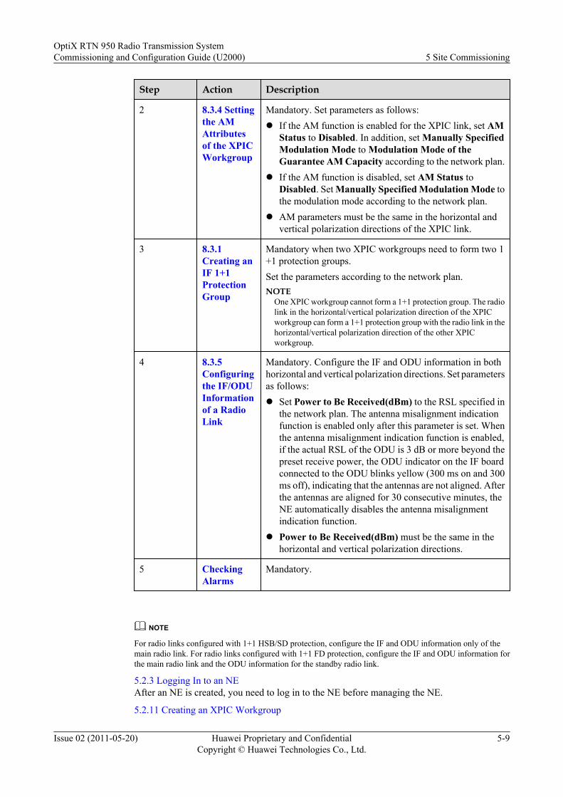
Step Action Description
2 8.3.4 Settingthe AMAttributesof the XPICWorkgroup
Mandatory. Set parameters as follows:l If the AM function is enabled for the XPIC link, set AM
Status to Disabled. In addition, set Manually SpecifiedModulation Mode to Modulation Mode of theGuarantee AM Capacity according to the network plan.
l If the AM function is disabled, set AM Status toDisabled. Set Manually Specified Modulation Mode tothe modulation mode according to the network plan.
l AM parameters must be the same in the horizontal andvertical polarization directions of the XPIC link.
3 8.3.1Creating anIF 1+1ProtectionGroup
Mandatory when two XPIC workgroups need to form two 1+1 protection groups.Set the parameters according to the network plan.NOTE
One XPIC workgroup cannot form a 1+1 protection group. The radiolink in the horizontal/vertical polarization direction of the XPICworkgroup can form a 1+1 protection group with the radio link in thehorizontal/vertical polarization direction of the other XPICworkgroup.
4 8.3.5Configuringthe IF/ODUInformationof a RadioLink
Mandatory. Configure the IF and ODU information in bothhorizontal and vertical polarization directions. Set parametersas follows:l Set Power to Be Received(dBm) to the RSL specified in
the network plan. The antenna misalignment indicationfunction is enabled only after this parameter is set. Whenthe antenna misalignment indication function is enabled,if the actual RSL of the ODU is 3 dB or more beyond thepreset receive power, the ODU indicator on the IF boardconnected to the ODU blinks yellow (300 ms on and 300ms off), indicating that the antennas are not aligned. Afterthe antennas are aligned for 30 consecutive minutes, theNE automatically disables the antenna misalignmentindication function.
l Power to Be Received(dBm) must be the same in thehorizontal and vertical polarization directions.
5 CheckingAlarms
Mandatory.
NOTE
For radio links configured with 1+1 HSB/SD protection, configure the IF and ODU information only of themain radio link. For radio links configured with 1+1 FD protection, configure the IF and ODU information forthe main radio link and the ODU information for the standby radio link.
5.2.3 Logging In to an NEAfter an NE is created, you need to log in to the NE before managing the NE.
5.2.11 Creating an XPIC Workgroup
OptiX RTN 950 Radio Transmission SystemCommissioning and Configuration Guide (U2000) 5 Site Commissioning
Issue 02 (2011-05-20) Huawei Proprietary and ConfidentialCopyright © Huawei Technologies Co., Ltd.
5-9
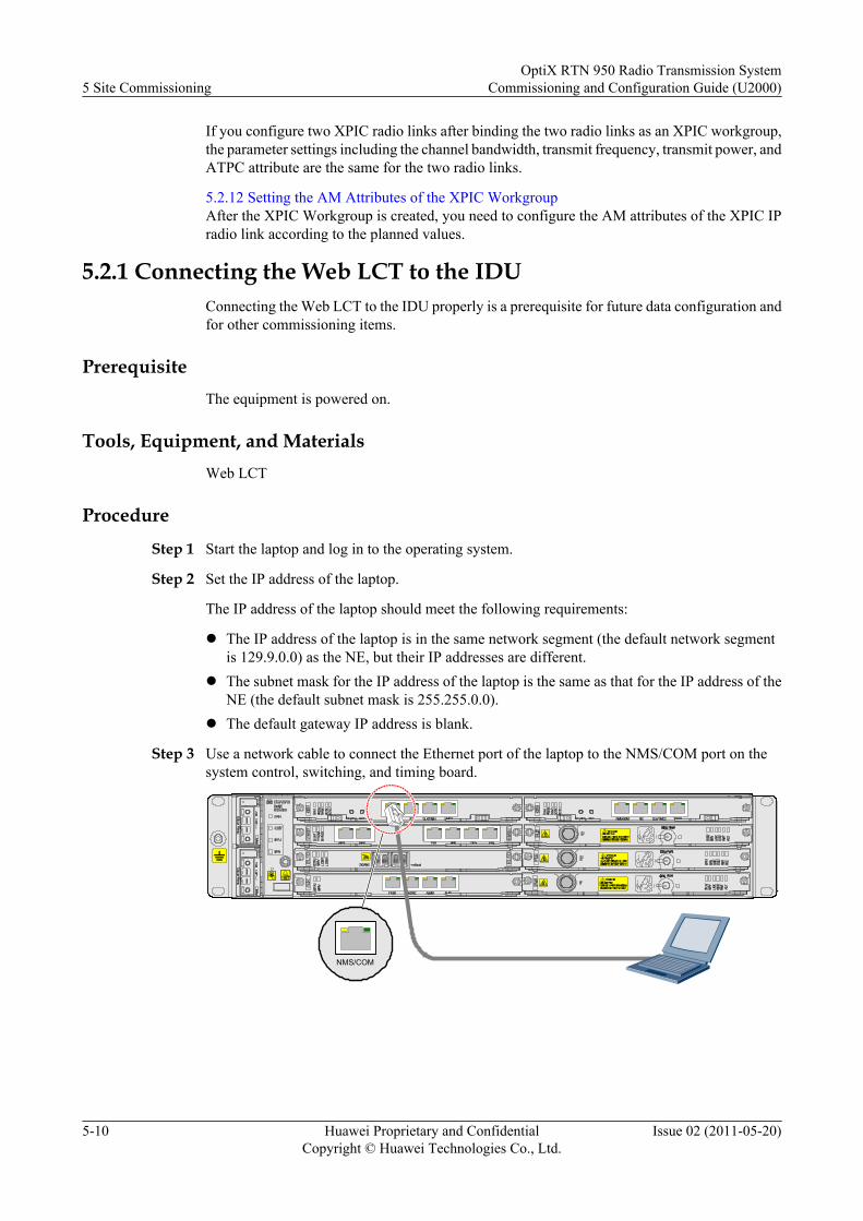
If you configure two XPIC radio links after binding the two radio links as an XPIC workgroup,the parameter settings including the channel bandwidth, transmit frequency, transmit power, andATPC attribute are the same for the two radio links.
5.2.12 Setting the AM Attributes of the XPIC WorkgroupAfter the XPIC Workgroup is created, you need to configure the AM attributes of the XPIC IPradio link according to the planned values.
5.2.1 Connecting the Web LCT to the IDUConnecting the Web LCT to the IDU properly is a prerequisite for future data configuration andfor other commissioning items.
PrerequisiteThe equipment is powered on.
Tools, Equipment, and MaterialsWeb LCT
Procedure
Step 1 Start the laptop and log in to the operating system.
Step 2 Set the IP address of the laptop.
The IP address of the laptop should meet the following requirements:
l The IP address of the laptop is in the same network segment (the default network segmentis 129.9.0.0) as the NE, but their IP addresses are different.
l The subnet mask for the IP address of the laptop is the same as that for the IP address of theNE (the default subnet mask is 255.255.0.0).
l The default gateway IP address is blank.
Step 3 Use a network cable to connect the Ethernet port of the laptop to the NMS/COM port on thesystem control, switching, and timing board.
NMS/COM
5 Site CommissioningOptiX RTN 950 Radio Transmission System
Commissioning and Configuration Guide (U2000)
5-10 Huawei Proprietary and ConfidentialCopyright © Huawei Technologies Co., Ltd.
Issue 02 (2011-05-20)
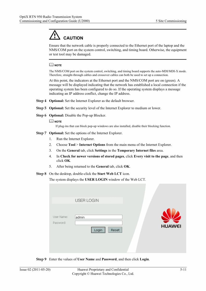
CAUTIONEnsure that the network cable is properly connected to the Ethernet port of the laptop and theNMS/COM port on the system control, switching, and timing board. Otherwise, the equipmentor test tool may be damaged.
NOTE
The NMS/COM port on the system control, switching, and timing board supports the auto-MDI/MDI-X mode.Therefore, straight-through cables and crossover cables can both be used to set up a connection.
At this point, the indicators at the Ethernet port and the NMS/COM port are on (green). Amessage will be displayed indicating that the network has established a local connection if theoperating system has been configured to do so. If the operating system displays a messageindicating an IP address conflict, change the IP address.
Step 4 Optional: Set the Internet Explorer as the default browser.
Step 5 Optional: Set the security level of the Internet Explorer to medium or lower.
Step 6 Optional: Disable the Pop-up Blocker.
NOTEIf plug-ins that can block pop-up windows are also installed, disable their blocking function.
Step 7 Optional: Set the options of the Internet Explorer.1. Run the Internet Explorer.2. Choose Tool > Internet Options from the main menu of the Internet Explorer.3. On the General tab, click Settings in the Temporary Internet files area.4. In Check for newer versions of stored pages, click Every visit to the page, and then
click OK.5. After being returned to the General tab, click OK.
Step 8 On the desktop, double-click the Start Web LCT icon.The system displays the USER LOGIN window of the Web LCT.
Step 9 Enter the values of User Name and Password, and then click Login.
OptiX RTN 950 Radio Transmission SystemCommissioning and Configuration Guide (U2000) 5 Site Commissioning
Issue 02 (2011-05-20) Huawei Proprietary and ConfidentialCopyright © Huawei Technologies Co., Ltd.
5-11
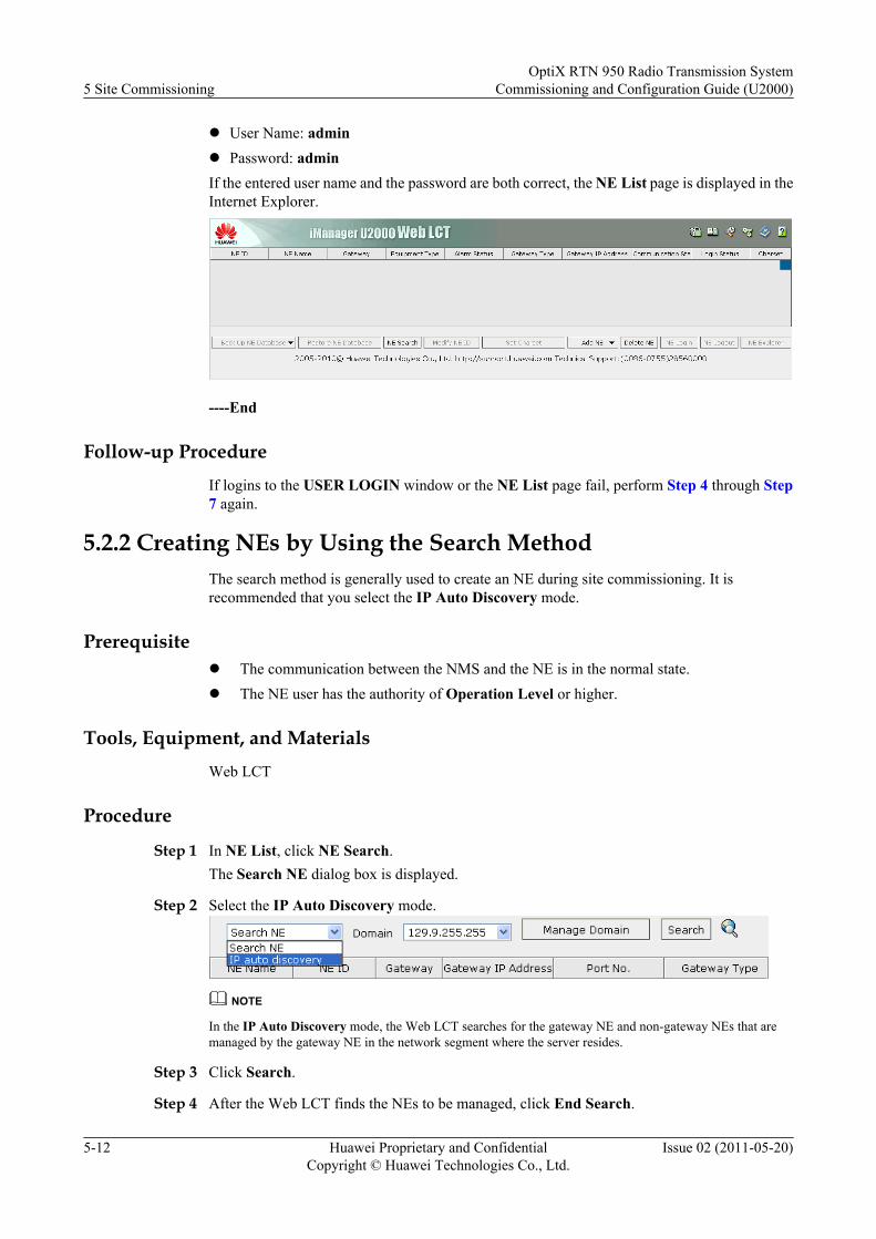
l User Name: adminl Password: adminIf the entered user name and the password are both correct, the NE List page is displayed in theInternet Explorer.
----End
Follow-up ProcedureIf logins to the USER LOGIN window or the NE List page fail, perform Step 4 through Step7 again.
5.2.2 Creating NEs by Using the Search MethodThe search method is generally used to create an NE during site commissioning. It isrecommended that you select the IP Auto Discovery mode.
Prerequisitel The communication between the NMS and the NE is in the normal state.l The NE user has the authority of Operation Level or higher.
Tools, Equipment, and MaterialsWeb LCT
Procedure
Step 1 In NE List, click NE Search.The Search NE dialog box is displayed.
Step 2 Select the IP Auto Discovery mode.
NOTE
In the IP Auto Discovery mode, the Web LCT searches for the gateway NE and non-gateway NEs that aremanaged by the gateway NE in the network segment where the server resides.
Step 3 Click Search.
Step 4 After the Web LCT finds the NEs to be managed, click End Search.
5 Site CommissioningOptiX RTN 950 Radio Transmission System
Commissioning and Configuration Guide (U2000)
5-12 Huawei Proprietary and ConfidentialCopyright © Huawei Technologies Co., Ltd.
Issue 02 (2011-05-20)
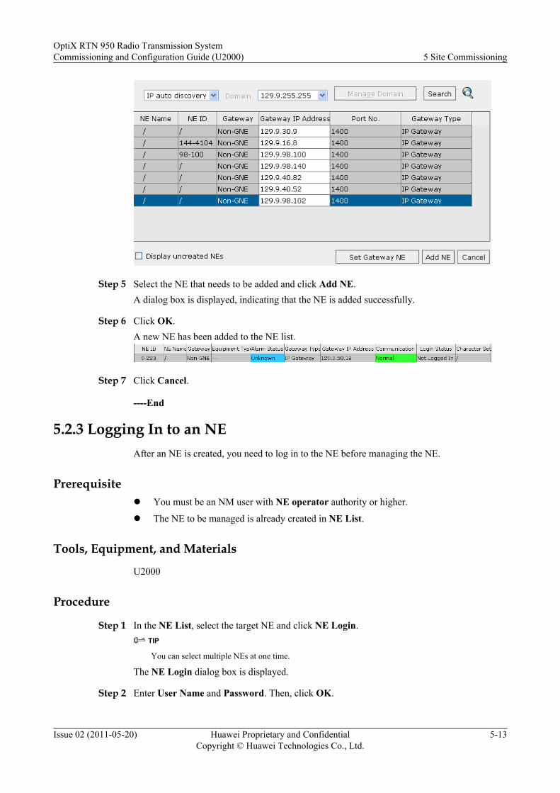
Step 5 Select the NE that needs to be added and click Add NE.A dialog box is displayed, indicating that the NE is added successfully.
Step 6 Click OK.A new NE has been added to the NE list.
Step 7 Click Cancel.
----End
5.2.3 Logging In to an NEAfter an NE is created, you need to log in to the NE before managing the NE.
Prerequisitel You must be an NM user with NE operator authority or higher.
l The NE to be managed is already created in NE List.
Tools, Equipment, and Materials
U2000
Procedure
Step 1 In the NE List, select the target NE and click NE Login.TIP
You can select multiple NEs at one time.
The NE Login dialog box is displayed.
Step 2 Enter User Name and Password. Then, click OK.
OptiX RTN 950 Radio Transmission SystemCommissioning and Configuration Guide (U2000) 5 Site Commissioning
Issue 02 (2011-05-20) Huawei Proprietary and ConfidentialCopyright © Huawei Technologies Co., Ltd.
5-13

NOTE
l The default User Name is lct.
l The default Password for user lct is password.
Login Status of the NE in the NE List changes to Logged In. Alarm Status of the NE is changedfrom Unknown to the current alarm status of the NE.
Step 3 Click NE Explorer.The NE Explorer is displayed.
TIP
To quickly start the NE Explorer, double-click the NE to be managed in the NE list.
TIP
l Check the legend to learn the specific meanings of different colors and symbols in the slot layoutdiagram.
l Click to collapse/expand the legend.
----End
5.2.4 Changing the NE IDModify the NE ID according to the engineering plan and ensure that each NE ID is unique.Modifying the NE ID does not interrupt services.
Prerequisite
The NE user has the authority of Operation Level or higher.
Tools, Equipment, and Materials
Web LCT
5 Site CommissioningOptiX RTN 950 Radio Transmission System
Commissioning and Configuration Guide (U2000)
5-14 Huawei Proprietary and ConfidentialCopyright © Huawei Technologies Co., Ltd.
Issue 02 (2011-05-20)
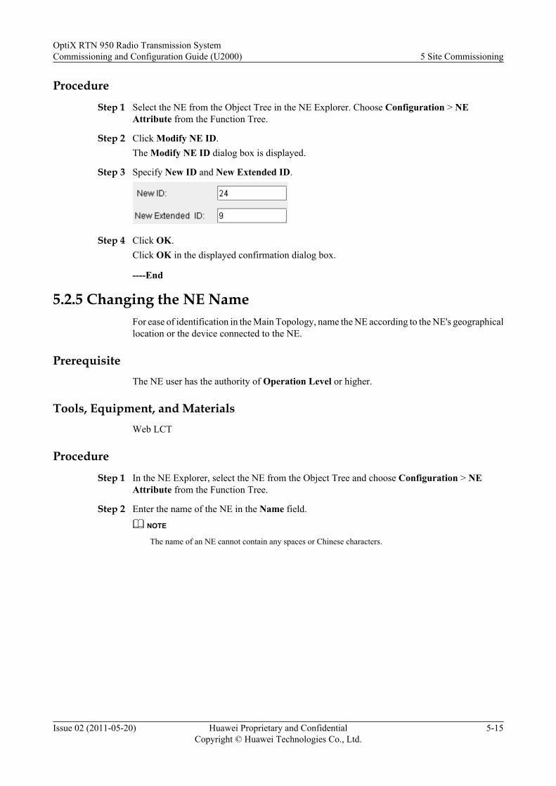
Procedure
Step 1 Select the NE from the Object Tree in the NE Explorer. Choose Configuration > NEAttribute from the Function Tree.
Step 2 Click Modify NE ID.The Modify NE ID dialog box is displayed.
Step 3 Specify New ID and New Extended ID.
Step 4 Click OK.Click OK in the displayed confirmation dialog box.
----End
5.2.5 Changing the NE NameFor ease of identification in the Main Topology, name the NE according to the NE's geographicallocation or the device connected to the NE.
PrerequisiteThe NE user has the authority of Operation Level or higher.
Tools, Equipment, and MaterialsWeb LCT
Procedure
Step 1 In the NE Explorer, select the NE from the Object Tree and choose Configuration > NEAttribute from the Function Tree.
Step 2 Enter the name of the NE in the Name field.
NOTE
The name of an NE cannot contain any spaces or Chinese characters.
OptiX RTN 950 Radio Transmission SystemCommissioning and Configuration Guide (U2000) 5 Site Commissioning
Issue 02 (2011-05-20) Huawei Proprietary and ConfidentialCopyright © Huawei Technologies Co., Ltd.
5-15
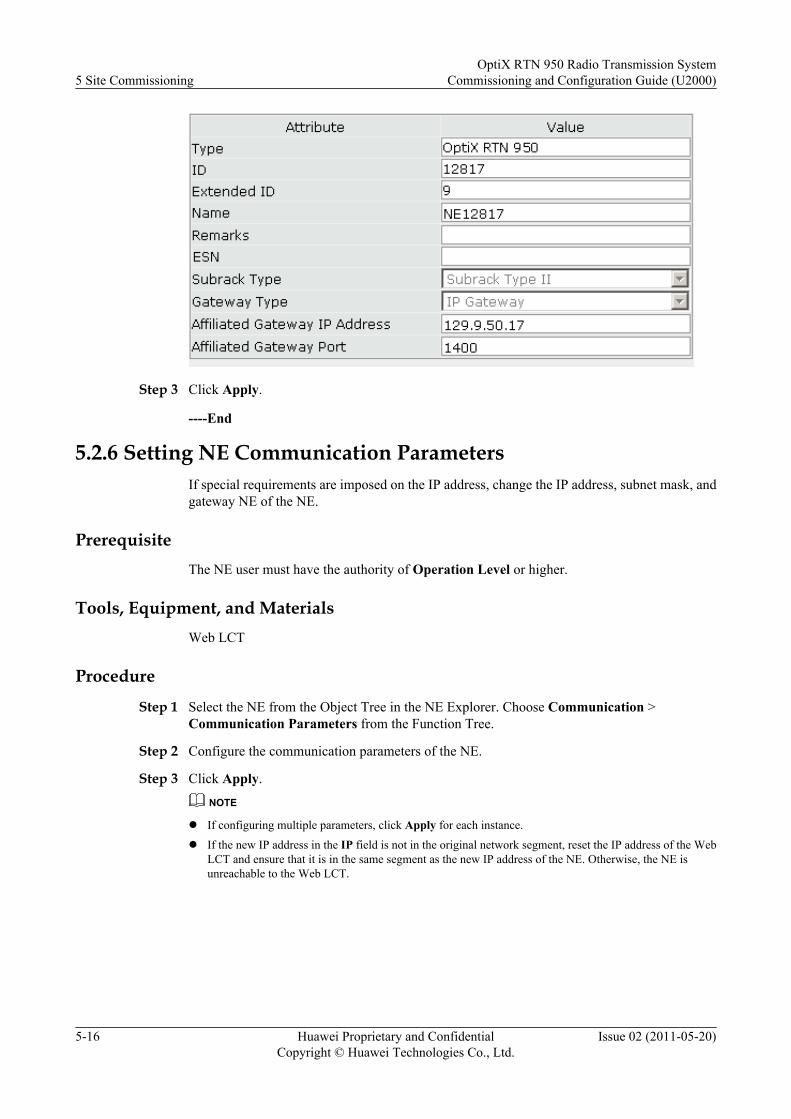
Step 3 Click Apply.
----End
5.2.6 Setting NE Communication ParametersIf special requirements are imposed on the IP address, change the IP address, subnet mask, andgateway NE of the NE.
PrerequisiteThe NE user must have the authority of Operation Level or higher.
Tools, Equipment, and MaterialsWeb LCT
Procedure
Step 1 Select the NE from the Object Tree in the NE Explorer. Choose Communication >Communication Parameters from the Function Tree.
Step 2 Configure the communication parameters of the NE.
Step 3 Click Apply.
NOTE
l If configuring multiple parameters, click Apply for each instance.
l If the new IP address in the IP field is not in the original network segment, reset the IP address of the WebLCT and ensure that it is in the same segment as the new IP address of the NE. Otherwise, the NE isunreachable to the Web LCT.
5 Site CommissioningOptiX RTN 950 Radio Transmission System
Commissioning and Configuration Guide (U2000)
5-16 Huawei Proprietary and ConfidentialCopyright © Huawei Technologies Co., Ltd.
Issue 02 (2011-05-20)
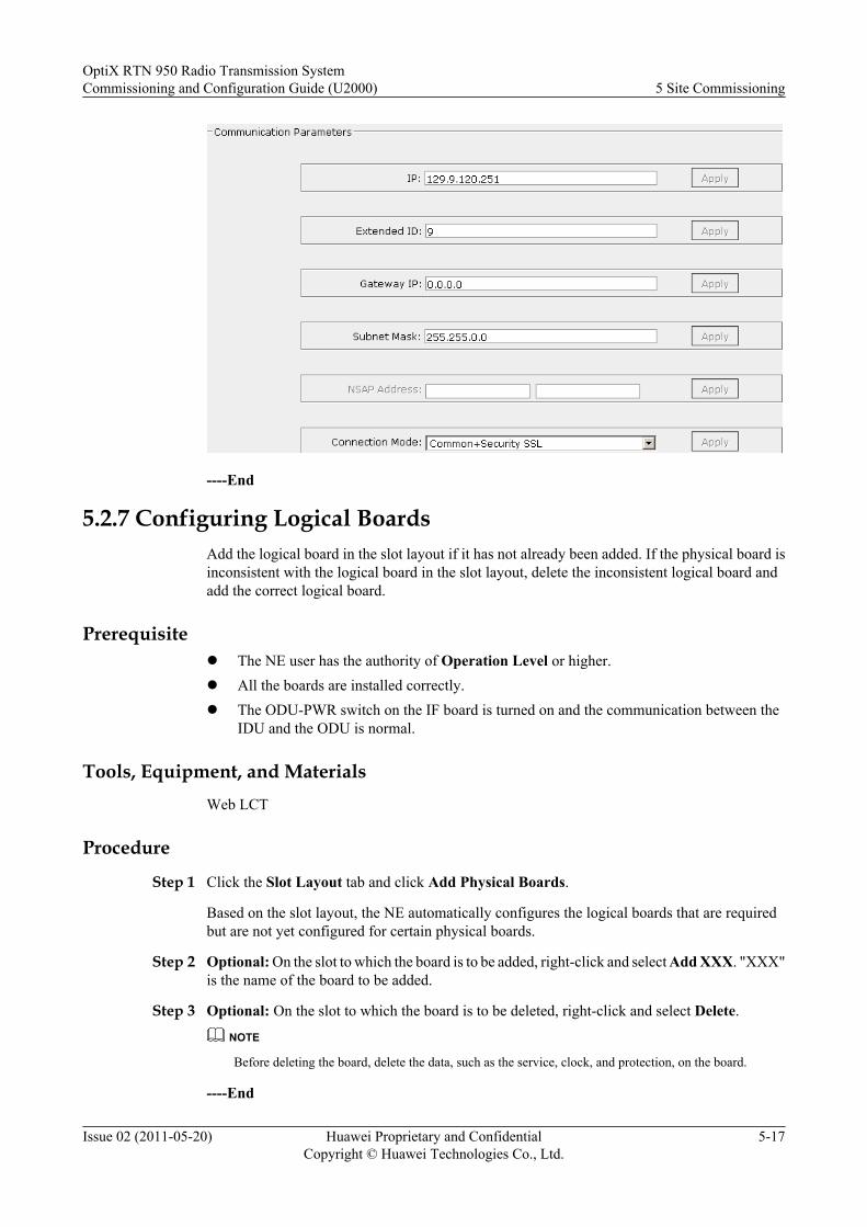
----End
5.2.7 Configuring Logical BoardsAdd the logical board in the slot layout if it has not already been added. If the physical board isinconsistent with the logical board in the slot layout, delete the inconsistent logical board andadd the correct logical board.
Prerequisitel The NE user has the authority of Operation Level or higher.l All the boards are installed correctly.l The ODU-PWR switch on the IF board is turned on and the communication between the
IDU and the ODU is normal.
Tools, Equipment, and MaterialsWeb LCT
Procedure
Step 1 Click the Slot Layout tab and click Add Physical Boards.
Based on the slot layout, the NE automatically configures the logical boards that are requiredbut are not yet configured for certain physical boards.
Step 2 Optional: On the slot to which the board is to be added, right-click and select Add XXX. "XXX"is the name of the board to be added.
Step 3 Optional: On the slot to which the board is to be deleted, right-click and select Delete.
NOTE
Before deleting the board, delete the data, such as the service, clock, and protection, on the board.
----End
OptiX RTN 950 Radio Transmission SystemCommissioning and Configuration Guide (U2000) 5 Site Commissioning
Issue 02 (2011-05-20) Huawei Proprietary and ConfidentialCopyright © Huawei Technologies Co., Ltd.
5-17

5.2.8 Synchronizing NE TimeAdjust the NE time so that the NE time is synchronized with the time on the NMS. In this manner,the NMS can accurately record the time when an alarm, a performance event, or an abnormalevent occurred.
Prerequisitel The basic data of NEs on the entire network has been configured.
l Time settings on the Web LCT are correct.
l You must be an NM user with NE maintainer authority or higher.
Tools, Equipment, and Materials
Web LCT
Procedure
Step 1 Select the NE from the Object Tree in the NE Explorer, and choose Configuration > NE TimeSynchronization from the Function Tree.
Step 2 Right-click the NE whose time needs to be synchronized and choose Synchronize with NMTime from the shortcut menu.
----End
5.2.9 Creating an IF 1+1 Protection GroupIf the radio link adopts 1+1 HSB/FD/SD protection, you need to create the corresponding IF 1+1 protection group.
Prerequisitel The NE user must have the authority of Operation Level or higher.
l The IF boards and the ODUs to which the IF boards are connected must be added on theSlot Layout.
l The IF boards of an IF 1+1 FD/SD protection group must be configured in the paired slots.
Tools, Equipment, and Materials
Web LCT
5 Site CommissioningOptiX RTN 950 Radio Transmission System
Commissioning and Configuration Guide (U2000)
5-18 Huawei Proprietary and ConfidentialCopyright © Huawei Technologies Co., Ltd.
Issue 02 (2011-05-20)
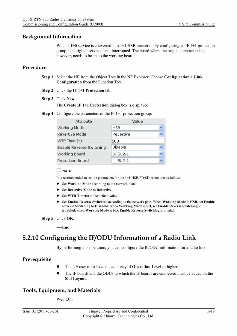
Background InformationWhen a 1+0 service is converted into 1+1 HSB protection by configuring an IF 1+1 protectiongroup, the original service is not interrupted. The board where the original service exists,however, needs to be set to the working board.
Procedure
Step 1 Select the NE from the Object Tree in the NE Explorer. Choose Configuration > LinkConfiguration from the Function Tree.
Step 2 Click the IF 1+1 Protection tab.
Step 3 Click New.The Create IF 1+1 Protection dialog box is displayed.
Step 4 Configure the parameters of the IF 1+1 protection group.
NOTE
It is recommended to set the parameters for the 1+1 HSB/FD/SD protection as follows:
l Set Working Mode according to the network plan.
l Set Revertive Mode to Revertive.
l Set WTR Time(s) to the default value.
l Set Enable Reverse Switching according to the network plan. When Working Mode is HSB, set EnableReverse Switching to Disabled; when Working Mode is SD, set Enable Reverse Switching toEnabled; when Working Mode is FD, Enable Reverse Switching is invalid.
Step 5 Click OK.
----End
5.2.10 Configuring the IF/ODU Information of a Radio LinkBy performing this operation, you can configure the IF/ODU information for a radio link.
Prerequisitel The NE user must have the authority of Operation Level or higher.l The IF boards and the ODUs to which the IF boards are connected must be added on the
Slot Layout.
Tools, Equipment, and MaterialsWeb LCT
OptiX RTN 950 Radio Transmission SystemCommissioning and Configuration Guide (U2000) 5 Site Commissioning
Issue 02 (2011-05-20) Huawei Proprietary and ConfidentialCopyright © Huawei Technologies Co., Ltd.
5-19
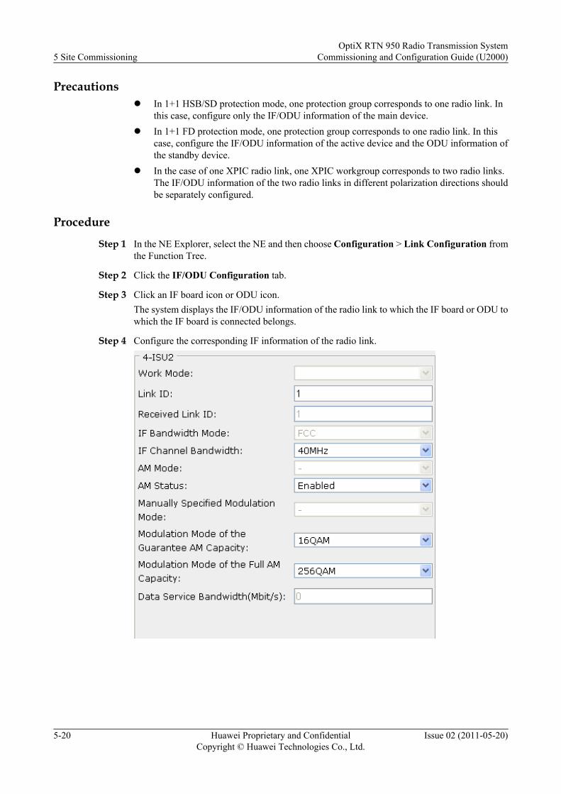
Precautionsl In 1+1 HSB/SD protection mode, one protection group corresponds to one radio link. In
this case, configure only the IF/ODU information of the main device.l In 1+1 FD protection mode, one protection group corresponds to one radio link. In this
case, configure the IF/ODU information of the active device and the ODU information ofthe standby device.
l In the case of one XPIC radio link, one XPIC workgroup corresponds to two radio links.The IF/ODU information of the two radio links in different polarization directions shouldbe separately configured.
Procedure
Step 1 In the NE Explorer, select the NE and then choose Configuration > Link Configuration fromthe Function Tree.
Step 2 Click the IF/ODU Configuration tab.
Step 3 Click an IF board icon or ODU icon.The system displays the IF/ODU information of the radio link to which the IF board or ODU towhich the IF board is connected belongs.
Step 4 Configure the corresponding IF information of the radio link.
5 Site CommissioningOptiX RTN 950 Radio Transmission System
Commissioning and Configuration Guide (U2000)
5-20 Huawei Proprietary and ConfidentialCopyright © Huawei Technologies Co., Ltd.
Issue 02 (2011-05-20)
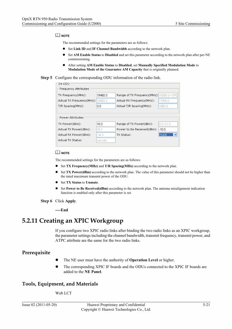
NOTE
The recommended settings for the parameters are as follows:
l Set Link ID and IF Channel Bandwidth according to the network plan.
l Set AM Enable Status to Disabled and set this parameter according to the network plan after per-NEcommissioning.
l After setting AM Enable Status to Disabled, set Manually Specified Modulation Mode toModulation Mode of the Guarantee AM Capacity that is originally planned.
Step 5 Configure the corresponding ODU information of the radio link.
NOTE
The recommended settings for the parameters are as follows:
l Set TX Frequency(MHz) and T/R Spacing(MHz) according to the network plan.
l Set TX Power(dBm) according to the network plan. The value of this parameter should not be higher thanthe rated maximum transmit power of the ODU.
l Set TX Status to Unmute.
l Set Power to Be Received(dBm) according to the network plan. The antenna misalignment indicationfunction is enabled only after this parameter is set.
Step 6 Click Apply.
----End
5.2.11 Creating an XPIC WorkgroupIf you configure two XPIC radio links after binding the two radio links as an XPIC workgroup,the parameter settings including the channel bandwidth, transmit frequency, transmit power, andATPC attribute are the same for the two radio links.
Prerequisitel The NE user must have the authority of Operation Level or higher.
l The corresponding XPIC IF boards and the ODUs connected to the XPIC IF boards areadded to the NE Panel.
Tools, Equipment, and Materials
Web LCT
OptiX RTN 950 Radio Transmission SystemCommissioning and Configuration Guide (U2000) 5 Site Commissioning
Issue 02 (2011-05-20) Huawei Proprietary and ConfidentialCopyright © Huawei Technologies Co., Ltd.
5-21
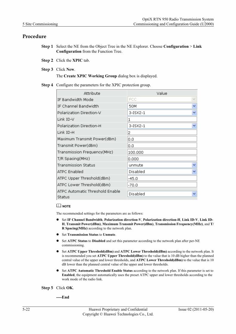
Procedure
Step 1 Select the NE from the Object Tree in the NE Explorer. Choose Configuration > LinkConfiguration from the Function Tree.
Step 2 Click the XPIC tab.
Step 3 Click New.The Create XPIC Working Group dialog box is displayed.
Step 4 Configure the parameters for the XPIC protection group.
NOTE
The recommended settings for the parameters are as follows:
l Set IF Channel Bandwidth, Polarization direction-V, Polarization direction-H, Link ID-V, Link ID-H, Transmit Power(dBm), Maximum Transmit Power(dBm), Transmission Frequency(MHz), and T/R Spacing(MHz) according to the network plan.
l Set Transmission Status to Unmute.
l Set ATPC Status to Disabled and set this parameter according to the network plan after per-NEcommissioning.
l Set ATPC Upper Threshold(dBm) and ATPC Lower Threshold(dBm) according to the network plan. Itis recommended you set ATPC Upper Threshold(dBm) to the value that is 10 dB higher than the plannedcentral value of the upper and lower thresholds, and ATPC Lower Threshold(dBm) to the value that is 10dB lower than the planned central value of the upper and lower thresholds.
l Set ATPC Automatic Threshold Enable Status according to the network plan. If this parameter is set toEnabled, the equipment automatically uses the preset ATPC upper and lower thresholds according to thework mode of the radio link.
Step 5 Click OK.
----End
5 Site CommissioningOptiX RTN 950 Radio Transmission System
Commissioning and Configuration Guide (U2000)
5-22 Huawei Proprietary and ConfidentialCopyright © Huawei Technologies Co., Ltd.
Issue 02 (2011-05-20)
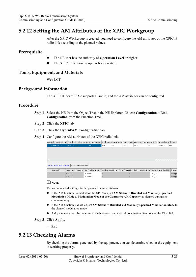
5.2.12 Setting the AM Attributes of the XPIC WorkgroupAfter the XPIC Workgroup is created, you need to configure the AM attributes of the XPIC IPradio link according to the planned values.
Prerequisitel The NE user has the authority of Operation Level or higher.l The XPIC protection group has been created.
Tools, Equipment, and MaterialsWeb LCT
Background InformationThe XPIC IF board ISX2 supports IP radio, and the AM attributes can be configured.
ProcedureStep 1 Select the NE from the Object Tree in the NE Explorer. Choose Configuration > Link
Configuration from the Function Tree.
Step 2 Click the XPIC tab.
Step 3 Click the Hybrid/AM Configuration tab.
Step 4 Configure the AM attributes of the XPIC radio link.
NOTE
The recommended settings for the parameters are as follows:l If the AM function is enabled for the XPIC link, set AM Status to Disabled and Manually Specified
Modulation Mode to Modulation Mode of the Guarantee AM Capacity as planned during sitecommissioning.
l If the AM function is disabled, set AM Status to Disabled and Manually Specified Modulation Mode tothe planned modulation mode.
l AM parameters must be the same in the horizontal and vertical polarization directions of the XPIC link.
Step 5 Click Apply.
----End
5.2.13 Checking AlarmsBy checking the alarms generated by the equipment, you can determine whether the equipmentis working properly.
OptiX RTN 950 Radio Transmission SystemCommissioning and Configuration Guide (U2000) 5 Site Commissioning
Issue 02 (2011-05-20) Huawei Proprietary and ConfidentialCopyright © Huawei Technologies Co., Ltd.
5-23
Prerequisitel The equipment is connected to the Web LCT.
l Data configuration is complete.
Tools, Equipment, and Materials
Web LCT
Procedure
Step 1 In the NE Explorer, select an NE from the Object Tree, and then click on the toolbar.
Step 2 Click the Browse Current Alarms tab.
Step 3 Check the displayed alarm information.
Check whether there are any equipment alarms, the following alarms in particular:
l POWER_ALM
l FAN_FAIL
l HARD_BAD
l BD_STATUS
l SYNC_C_LOS
l CONFIG_NOSUPPORT
l NESF_LOST
l TEMP_ALARM
l IF_CABLE_OPEN
l XPIC_LOS
For details about the preceding alarms and about how to handle them, refer to the OptiX RTN950 Radio Transmission System Maintenance Guide.
----End
5.3 Testing Connectivity of CablesDuring the installation of the OptiX RTN 900, the cables may be connected to service interfacesincorrectly, or the hardware may malfunction. To ensure that the services run properly, testconnectivity of the cables.
5.3.1 Testing Connectivity of Network CablesBy testing connectivity of network cables, you can determine whether the network cables are inthe normal state.
5.3.2 Checking Fiber Jumper ConnectionDuring installation, the fiber jumpers may be incorrectly connected or the attenuation may beexcessively high. As a result, services will fail to run properly. To prevent this situation, checkthe connection after the fiber jumper is routed from the optical interface to the optical distributionframe (ODF).
5 Site CommissioningOptiX RTN 950 Radio Transmission System
Commissioning and Configuration Guide (U2000)
5-24 Huawei Proprietary and ConfidentialCopyright © Huawei Technologies Co., Ltd.
Issue 02 (2011-05-20)
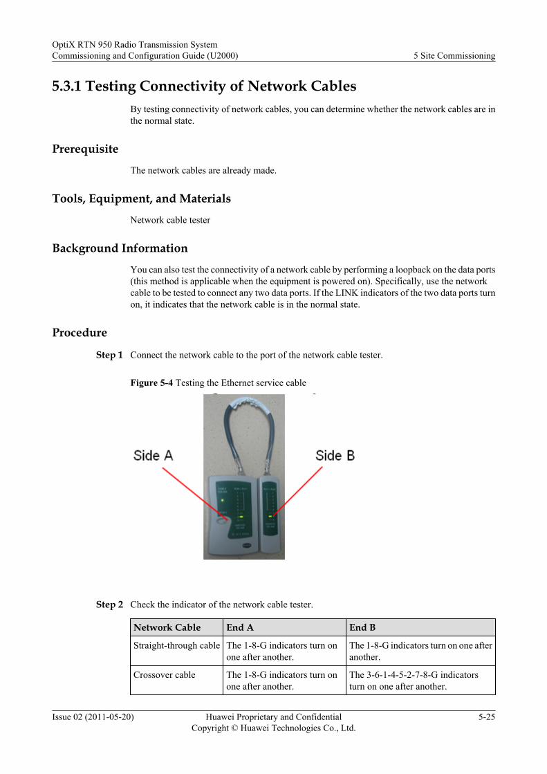
5.3.1 Testing Connectivity of Network CablesBy testing connectivity of network cables, you can determine whether the network cables are inthe normal state.
Prerequisite
The network cables are already made.
Tools, Equipment, and Materials
Network cable tester
Background Information
You can also test the connectivity of a network cable by performing a loopback on the data ports(this method is applicable when the equipment is powered on). Specifically, use the networkcable to be tested to connect any two data ports. If the LINK indicators of the two data ports turnon, it indicates that the network cable is in the normal state.
Procedure
Step 1 Connect the network cable to the port of the network cable tester.
Figure 5-4 Testing the Ethernet service cable
Step 2 Check the indicator of the network cable tester.
Network Cable End A End B
Straight-through cable The 1-8-G indicators turn onone after another.
The 1-8-G indicators turn on one afteranother.
Crossover cable The 1-8-G indicators turn onone after another.
The 3-6-1-4-5-2-7-8-G indicatorsturn on one after another.
OptiX RTN 950 Radio Transmission SystemCommissioning and Configuration Guide (U2000) 5 Site Commissioning
Issue 02 (2011-05-20) Huawei Proprietary and ConfidentialCopyright © Huawei Technologies Co., Ltd.
5-25

Step 3 Connect the network cable that passes the test to the Ethernet port of the device.
----End
5.3.2 Checking Fiber Jumper ConnectionDuring installation, the fiber jumpers may be incorrectly connected or the attenuation may beexcessively high. As a result, services will fail to run properly. To prevent this situation, checkthe connection after the fiber jumper is routed from the optical interface to the optical distributionframe (ODF).
Prerequisitel The fiber jumper is installed and routed from the optical interface to the ODF.l The equipment is powered on.
Tools, Equipment, and Materialsl Optical power meterl Short fiber jumper
Precautions
DANGERWhen you are checking the connection of fiber jumpers, avoid direct eye exposure to the laserbeams.
Connection DiagramWhen you use an SFP optical module to test the fiber jumper connection, connect the fiberjumper to the optical power meter on the ODF side and connect the fiber jumper to the TX portof the SFP optical module on the chassis side. Figure 5-5 shows the connection.
5 Site CommissioningOptiX RTN 950 Radio Transmission System
Commissioning and Configuration Guide (U2000)
5-26 Huawei Proprietary and ConfidentialCopyright © Huawei Technologies Co., Ltd.
Issue 02 (2011-05-20)

Figure 5-5 Connection diagram for checking the fiber connection by using an SFP opticalmodule
TX RX
ExternalCable
Fiber jumper connectedto the TX port
ODF
Procedure
Step 1 On the chassis side, disconnect the fiber jumper from the TX port of the SFP optical module.
Step 2 Connect the optical power meter to the TX port of the SFP optical module with a short fiberjumper.
Step 3 Switch on the optical power meter and set the operating wavelength according to the type ofoptical interface. The measured launched optical power of the SFP optical module is A.
Step 4 Insert the fiber jumper back into the TX port.
Step 5 On the ODF side, disconnect the fiber jumper from the TX port. Connect the fiber jumper to theoptical power meter. The measured optical power is B.
Step 6 Disconnect the fiber jumper from the TX port of the SFP optical module. The optical powermeter reads "LO" and does not receive any optical signals.
Step 7 Compare the values of A and B.l If the difference between A and B is less than 1 dB, it indicates that the fiber jumper is
correctly connected and the attenuation of the fiber jumper is within the normal range.l If the difference between A and B is more than 1 dB, verify that the fiber jumper is in good
condition and is correctly routed. Then, verify that the fiber jumper terminal is clean.
CAUTIONIf the fiber jumper is connected through a flange, the difference between A and B should be lessthan 2 dB. Otherwise, it indicates that the fiber jumper is incorrectly connected or the attenuationof the fiber jumper is not within the normal range. Verify that the fiber jumper is in good conditionand is correctly routed. Then, Verify that the fiber jumper terminal is clean.
OptiX RTN 950 Radio Transmission SystemCommissioning and Configuration Guide (U2000) 5 Site Commissioning
Issue 02 (2011-05-20) Huawei Proprietary and ConfidentialCopyright © Huawei Technologies Co., Ltd.
5-27
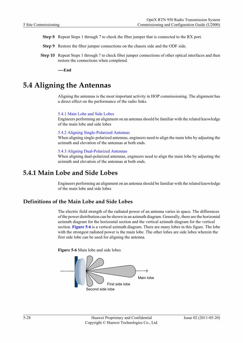
Step 8 Repeat Steps 1 through 7 to check the fiber jumper that is connected to the RX port.
Step 9 Restore the fiber jumper connections on the chassis side and the ODF side.
Step 10 Repeat Steps 1 through 7 to check fiber jumper connections of other optical interfaces and thenrestore the connections when completed.
----End
5.4 Aligning the AntennasAligning the antennas is the most important activity in HOP commissioning. The alignment hasa direct effect on the performance of the radio links.
5.4.1 Main Lobe and Side LobesEngineers performing an alignment on an antenna should be familiar with the related knowledgeof the main lobe and side lobes
5.4.2 Aligning Single-Polarized AntennasWhen aligning single-polarized antennas, engineers need to align the main lobe by adjusting theazimuth and elevation of the antennas at both ends.
5.4.3 Aligning Dual-Polarized AntennasWhen aligning dual-polarized antennas, engineers need to align the main lobe by adjusting theazimuth and elevation of the antennas at both ends.
5.4.1 Main Lobe and Side LobesEngineers performing an alignment on an antenna should be familiar with the related knowledgeof the main lobe and side lobes
Definitions of the Main Lobe and Side Lobes
The electric field strength of the radiated power of an antenna varies in space. The differencesof the power distribution can be shown in an azimuth diagram. Generally, there are the horizontalazimuth diagram for the horizontal section and the vertical azimuth diagram for the verticalsection. Figure 5-6 is a vertical azimuth diagram. There are many lobes in this figure. The lobewith the strongest radiated power is the main lobe. The other lobes are side lobes wherein thefirst side lobe can be used for aligning the antenna.
Figure 5-6 Main lobe and side lobes
Main lobe
First side lobeSecond side lobe
5 Site CommissioningOptiX RTN 950 Radio Transmission System
Commissioning and Configuration Guide (U2000)
5-28 Huawei Proprietary and ConfidentialCopyright © Huawei Technologies Co., Ltd.
Issue 02 (2011-05-20)
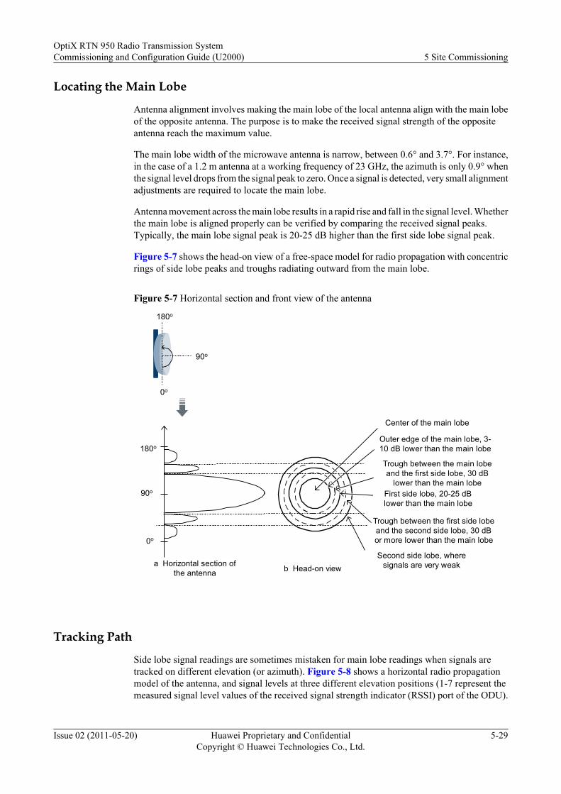
Locating the Main Lobe
Antenna alignment involves making the main lobe of the local antenna align with the main lobeof the opposite antenna. The purpose is to make the received signal strength of the oppositeantenna reach the maximum value.
The main lobe width of the microwave antenna is narrow, between 0.6° and 3.7°. For instance,in the case of a 1.2 m antenna at a working frequency of 23 GHz, the azimuth is only 0.9° whenthe signal level drops from the signal peak to zero. Once a signal is detected, very small alignmentadjustments are required to locate the main lobe.
Antenna movement across the main lobe results in a rapid rise and fall in the signal level. Whetherthe main lobe is aligned properly can be verified by comparing the received signal peaks.Typically, the main lobe signal peak is 20-25 dB higher than the first side lobe signal peak.
Figure 5-7 shows the head-on view of a free-space model for radio propagation with concentricrings of side lobe peaks and troughs radiating outward from the main lobe.
Figure 5-7 Horizontal section and front view of the antenna
0o
a Horizontal section ofthe antenna
90o
180o
0o
90o
180o
Center of the main lobe
Outer edge of the main lobe, 3-10 dB lower than the main lobe
Trough between the main lobeand the first side lobe, 30 dB
lower than the main lobeFirst side lobe, 20-25 dBlower than the main lobe
Trough between the first side lobeand the second side lobe, 30 dBor more lower than the main lobe
Second side lobe, wheresignals are very weakb Head-on view
Tracking Path
Side lobe signal readings are sometimes mistaken for main lobe readings when signals aretracked on different elevation (or azimuth). Figure 5-8 shows a horizontal radio propagationmodel of the antenna, and signal levels at three different elevation positions (1-7 represent themeasured signal level values of the received signal strength indicator (RSSI) port of the ODU).
OptiX RTN 950 Radio Transmission SystemCommissioning and Configuration Guide (U2000) 5 Site Commissioning
Issue 02 (2011-05-20) Huawei Proprietary and ConfidentialCopyright © Huawei Technologies Co., Ltd.
5-29
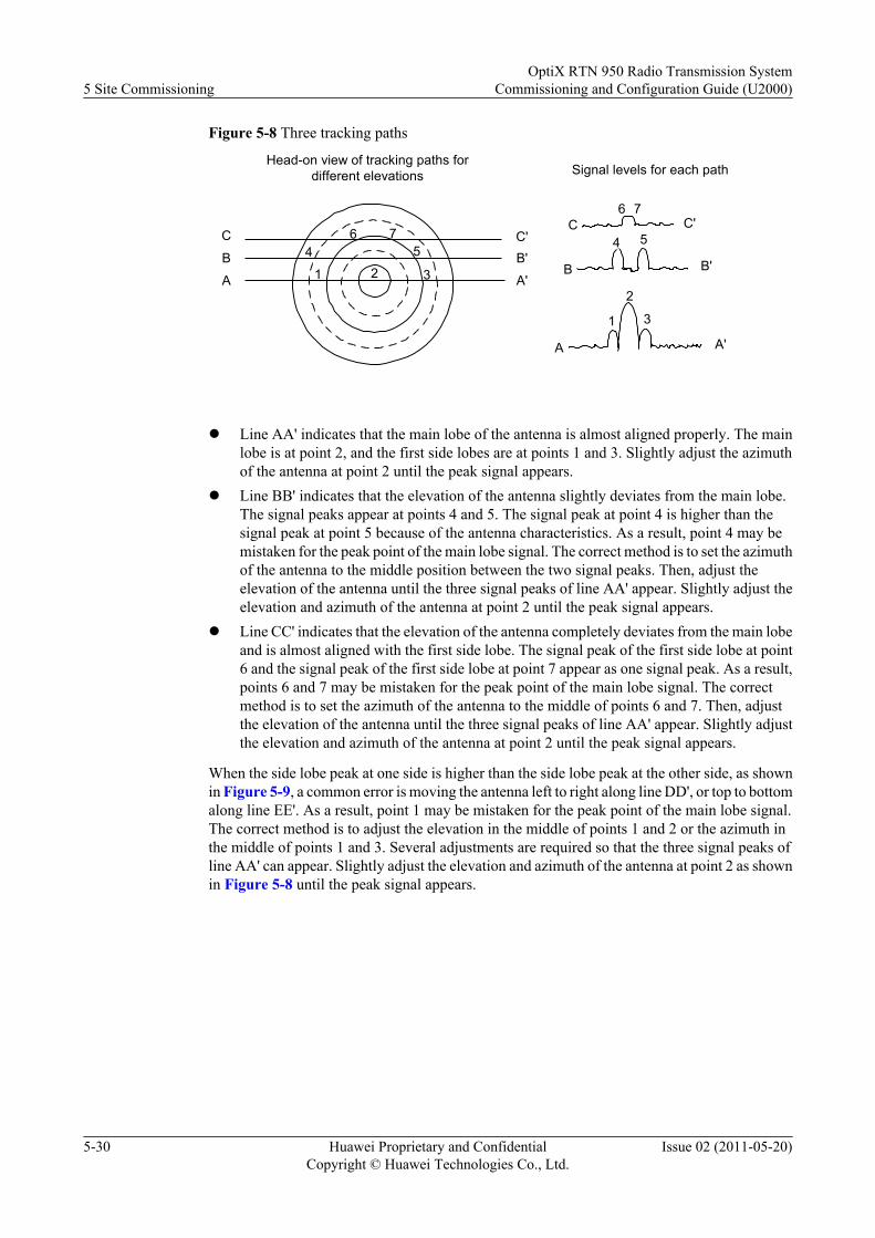
Figure 5-8 Three tracking paths
Signal levels for each path
31
2
B
7
4 5
6
A
B'
A'
C'C
A'A
B B'
C C'
Head-on view of tracking paths fordifferent elevations
24
6 7
1 3
5
l Line AA' indicates that the main lobe of the antenna is almost aligned properly. The mainlobe is at point 2, and the first side lobes are at points 1 and 3. Slightly adjust the azimuthof the antenna at point 2 until the peak signal appears.
l Line BB' indicates that the elevation of the antenna slightly deviates from the main lobe.The signal peaks appear at points 4 and 5. The signal peak at point 4 is higher than thesignal peak at point 5 because of the antenna characteristics. As a result, point 4 may bemistaken for the peak point of the main lobe signal. The correct method is to set the azimuthof the antenna to the middle position between the two signal peaks. Then, adjust theelevation of the antenna until the three signal peaks of line AA' appear. Slightly adjust theelevation and azimuth of the antenna at point 2 until the peak signal appears.
l Line CC' indicates that the elevation of the antenna completely deviates from the main lobeand is almost aligned with the first side lobe. The signal peak of the first side lobe at point6 and the signal peak of the first side lobe at point 7 appear as one signal peak. As a result,points 6 and 7 may be mistaken for the peak point of the main lobe signal. The correctmethod is to set the azimuth of the antenna to the middle of points 6 and 7. Then, adjustthe elevation of the antenna until the three signal peaks of line AA' appear. Slightly adjustthe elevation and azimuth of the antenna at point 2 until the peak signal appears.
When the side lobe peak at one side is higher than the side lobe peak at the other side, as shownin Figure 5-9, a common error is moving the antenna left to right along line DD', or top to bottomalong line EE'. As a result, point 1 may be mistaken for the peak point of the main lobe signal.The correct method is to adjust the elevation in the middle of points 1 and 2 or the azimuth inthe middle of points 1 and 3. Several adjustments are required so that the three signal peaks ofline AA' can appear. Slightly adjust the elevation and azimuth of the antenna at point 2 as shownin Figure 5-8 until the peak signal appears.
5 Site CommissioningOptiX RTN 950 Radio Transmission System
Commissioning and Configuration Guide (U2000)
5-30 Huawei Proprietary and ConfidentialCopyright © Huawei Technologies Co., Ltd.
Issue 02 (2011-05-20)
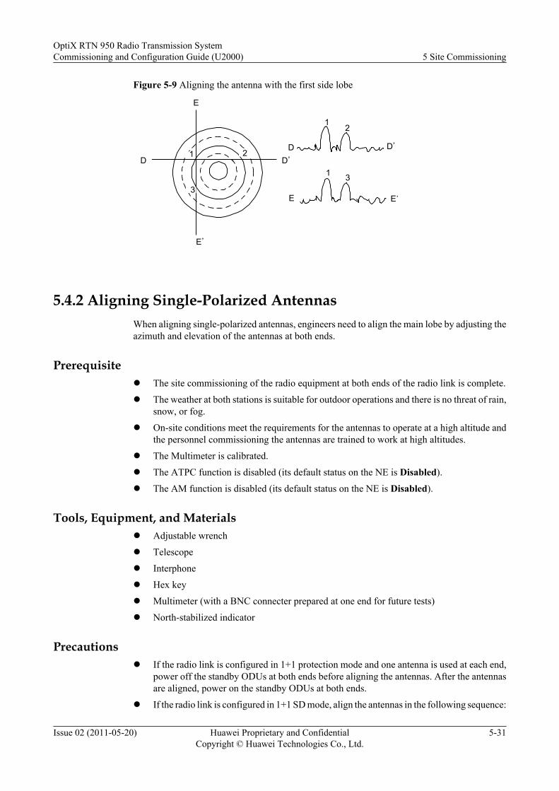
Figure 5-9 Aligning the antenna with the first side lobe
1 3
E E'
D
12
D'
D D'
E
E'
1 2
3
5.4.2 Aligning Single-Polarized AntennasWhen aligning single-polarized antennas, engineers need to align the main lobe by adjusting theazimuth and elevation of the antennas at both ends.
Prerequisitel The site commissioning of the radio equipment at both ends of the radio link is complete.
l The weather at both stations is suitable for outdoor operations and there is no threat of rain,snow, or fog.
l On-site conditions meet the requirements for the antennas to operate at a high altitude andthe personnel commissioning the antennas are trained to work at high altitudes.
l The Multimeter is calibrated.
l The ATPC function is disabled (its default status on the NE is Disabled).
l The AM function is disabled (its default status on the NE is Disabled).
Tools, Equipment, and Materialsl Adjustable wrench
l Telescope
l Interphone
l Hex key
l Multimeter (with a BNC connecter prepared at one end for future tests)
l North-stabilized indicator
Precautionsl If the radio link is configured in 1+1 protection mode and one antenna is used at each end,
power off the standby ODUs at both ends before aligning the antennas. After the antennasare aligned, power on the standby ODUs at both ends.
l If the radio link is configured in 1+1 SD mode, align the antennas in the following sequence:
OptiX RTN 950 Radio Transmission SystemCommissioning and Configuration Guide (U2000) 5 Site Commissioning
Issue 02 (2011-05-20) Huawei Proprietary and ConfidentialCopyright © Huawei Technologies Co., Ltd.
5-31
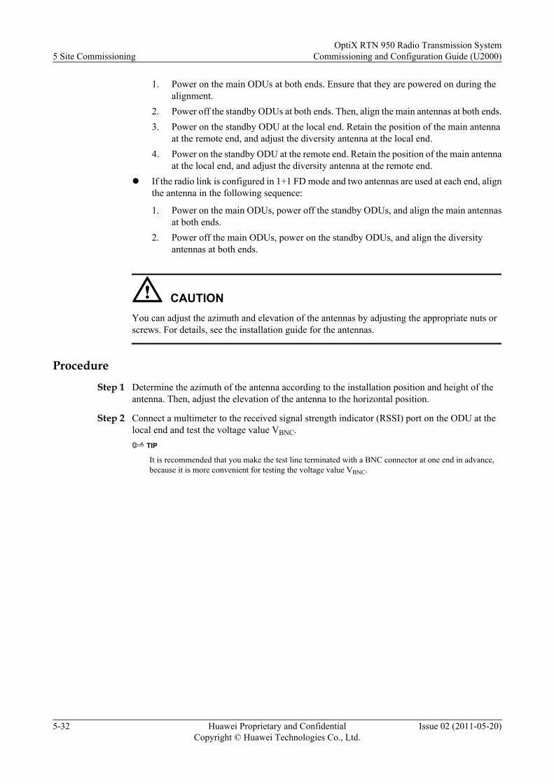
1. Power on the main ODUs at both ends. Ensure that they are powered on during thealignment.
2. Power off the standby ODUs at both ends. Then, align the main antennas at both ends.3. Power on the standby ODU at the local end. Retain the position of the main antenna
at the remote end, and adjust the diversity antenna at the local end.4. Power on the standby ODU at the remote end. Retain the position of the main antenna
at the local end, and adjust the diversity antenna at the remote end.l If the radio link is configured in 1+1 FD mode and two antennas are used at each end, align
the antenna in the following sequence:
1. Power on the main ODUs, power off the standby ODUs, and align the main antennasat both ends.
2. Power off the main ODUs, power on the standby ODUs, and align the diversityantennas at both ends.
CAUTIONYou can adjust the azimuth and elevation of the antennas by adjusting the appropriate nuts orscrews. For details, see the installation guide for the antennas.
Procedure
Step 1 Determine the azimuth of the antenna according to the installation position and height of theantenna. Then, adjust the elevation of the antenna to the horizontal position.
Step 2 Connect a multimeter to the received signal strength indicator (RSSI) port on the ODU at thelocal end and test the voltage value VBNC.
TIP
It is recommended that you make the test line terminated with a BNC connector at one end in advance,because it is more convenient for testing the voltage value VBNC.
5 Site CommissioningOptiX RTN 950 Radio Transmission System
Commissioning and Configuration Guide (U2000)
5-32 Huawei Proprietary and ConfidentialCopyright © Huawei Technologies Co., Ltd.
Issue 02 (2011-05-20)
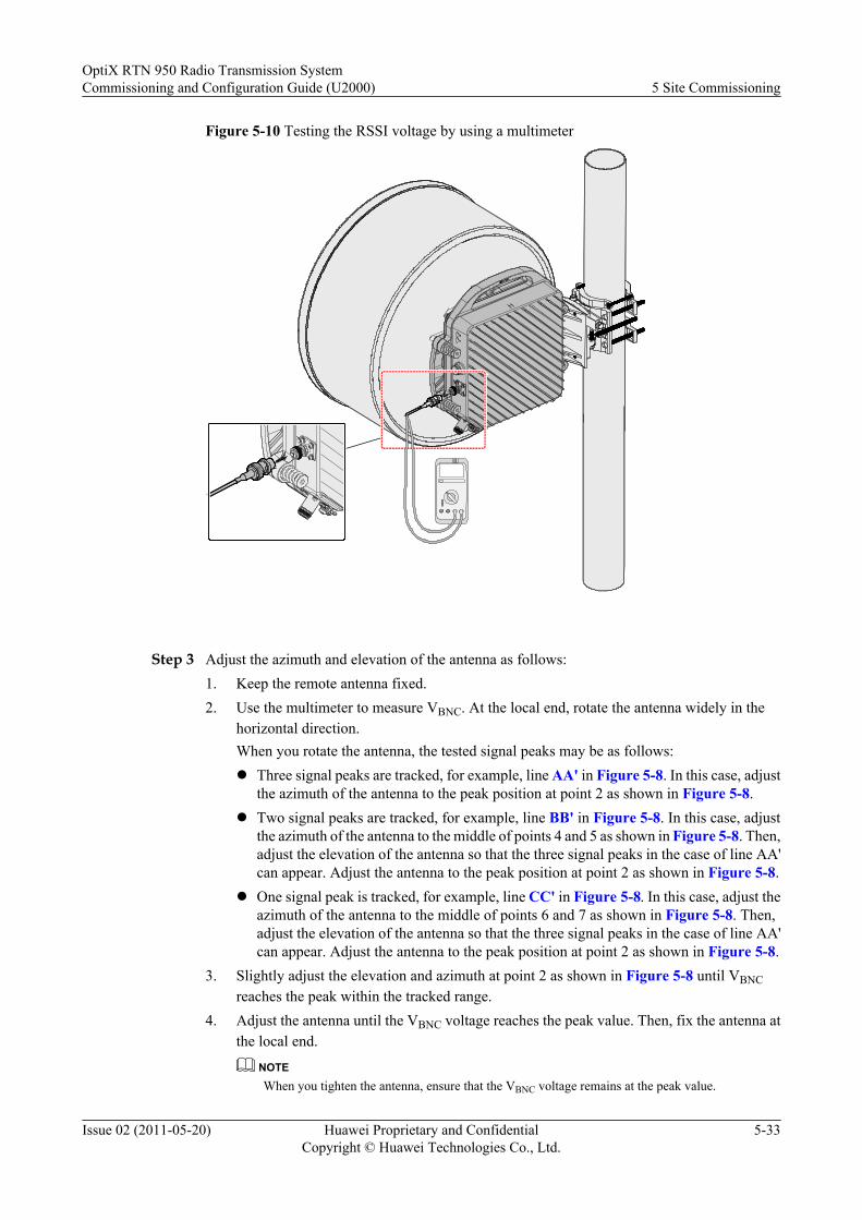
Figure 5-10 Testing the RSSI voltage by using a multimeter
Step 3 Adjust the azimuth and elevation of the antenna as follows:1. Keep the remote antenna fixed.2. Use the multimeter to measure VBNC. At the local end, rotate the antenna widely in the
horizontal direction.When you rotate the antenna, the tested signal peaks may be as follows:l Three signal peaks are tracked, for example, line AA' in Figure 5-8. In this case, adjust
the azimuth of the antenna to the peak position at point 2 as shown in Figure 5-8.l Two signal peaks are tracked, for example, line BB' in Figure 5-8. In this case, adjust
the azimuth of the antenna to the middle of points 4 and 5 as shown in Figure 5-8. Then,adjust the elevation of the antenna so that the three signal peaks in the case of line AA'can appear. Adjust the antenna to the peak position at point 2 as shown in Figure 5-8.
l One signal peak is tracked, for example, line CC' in Figure 5-8. In this case, adjust theazimuth of the antenna to the middle of points 6 and 7 as shown in Figure 5-8. Then,adjust the elevation of the antenna so that the three signal peaks in the case of line AA'can appear. Adjust the antenna to the peak position at point 2 as shown in Figure 5-8.
3. Slightly adjust the elevation and azimuth at point 2 as shown in Figure 5-8 until VBNCreaches the peak within the tracked range.
4. Adjust the antenna until the VBNC voltage reaches the peak value. Then, fix the antenna atthe local end.
NOTEWhen you tighten the antenna, ensure that the VBNC voltage remains at the peak value.
OptiX RTN 950 Radio Transmission SystemCommissioning and Configuration Guide (U2000) 5 Site Commissioning
Issue 02 (2011-05-20) Huawei Proprietary and ConfidentialCopyright © Huawei Technologies Co., Ltd.
5-33

Step 4 Repeat Step 2 to Step 3 to adjust the antenna at the remote end. When VBNC reaches the peakvalue, tighten the antenna at the remote end.
Step 5 Repeat Step 2 to Step 4 two to four times. When VBNC at the local end and VBNC at the remoteend reach the peak value, tighten the antennas at both ends
Step 6 Use the multimeter to test VBNC at both ends. Obtain the current RSL by referring to therelationship curve between VBNC of ODUs and the RSLs at both ends.
NOTE
The curve diagram for VBNC and RSL is delivered along with the ODU.
The actual RSL must be the same as the value planned by the network planning department.
NOTE
l If VBNC does not meet the requirements, see the OptiX RTN 950 Radio Transmission SystemMaintenance Guide for suggestion on how to handle the issue.
Step 7 Observe the ODU indicator on the IF board. The ODU indicator should turn off. If the ODUindicator blinks yellow, align the antennas.
Step 8 Tighten all the screws on the antennas.
NOTE
Use the multimeter to measure the received value of RSSI again to ensure that no fault occurred in the processof tightening the screws.
----End
5.4.3 Aligning Dual-Polarized AntennasWhen aligning dual-polarized antennas, engineers need to align the main lobe by adjusting theazimuth and elevation of the antennas at both ends.
Prerequisitel The site commissioning of the radio equipment at both ends of the radio link is complete.l The weather at both stations is suitable for outdoor operations and there is no threat of rain,
snow, or fogl On-site conditions meet the requirements for the antennas to operate at a high altitude and
the personnel commissioning the antennas are trained to work at high altitudes.l The Multimeter is calibrated.l The ATPC function is disabled (its default status on the NE is Disabled).l The AM function is disabled (its default status on the NE is Disabled).
Tools, Equipment, and Materialsl Adjustable wrenchl Telescopel Interphonel Hex keyl Multimeter (with a BNC connector prepared at one end for future tests)l North-stabilized indicator
5 Site CommissioningOptiX RTN 950 Radio Transmission System
Commissioning and Configuration Guide (U2000)
5-34 Huawei Proprietary and ConfidentialCopyright © Huawei Technologies Co., Ltd.
Issue 02 (2011-05-20)
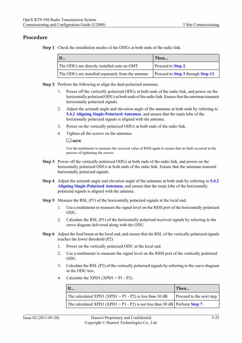
Procedure
Step 1 Check the installation modes of the ODUs at both ends of the radio link.
If... Then...
The ODUs are directly installed onto an OMT Proceed to Step 2.
The ODUs are installed separately from the antenna Proceed to Step 3 through Step 13.
Step 2 Perform the following to align the dual-polarized antennas.
1. Power off the vertically polarized ODUs at both ends of the radio link, and power on thehorizontally polarized ODUs at both ends of the radio link. Ensure that the antennas transmithorizontally polarized signals.
2. Adjust the azimuth angle and elevation angle of the antennas at both ends by referring to5.4.2 Aligning Single-Polarized Antennas, and ensure that the main lobe of thehorizontally polarized signals is aligned with the antenna.
3. Power on the vertically polarized ODUs at both ends of the radio link.
4. Tighten all the screws on the antennas.
NOTE
Use the multimeter to measure the received value of RSSI again to ensure that no fault occurred in theprocess of tightening the screws.
Step 3 Power off the vertically polarized ODUs at both ends of the radio link, and power on thehorizontally polarized ODUs at both ends of the radio link. Ensure that the antennas transmithorizontally polarized signals.
Step 4 Adjust the azimuth angle and elevation angle of the antennas at both ends by referring to 5.4.2Aligning Single-Polarized Antennas, and ensure that the main lobe of the horizontallypolarized signals is aligned with the antenna.
Step 5 Measure the RSL (P1) of the horizontally polarized signals at the local end.
1. Use a multimeter to measure the signal level on the RSSI port of the horizontally polarizedODU.
2. Calculate the RSL (P1) of the horizontally polarized received signals by referring to thecurve diagram delivered along with the ODU.
Step 6 Adjust the feed boom at the local end, and ensure that the RSL of the vertically polarized signalsreaches the lower threshold (P2).
1. Power on the vertically polarized ODU at the local end.
2. Use a multimeter to measure the signal level on the RSSI port of the vertically polarizedODU.
3. Calculate the RSL (P2) of the vertically polarized signals by referring to the curve diagramin the ODU box.
4. Calculate the XPD1 (XPD1 = P1 - P2).
If... Then...
The calculated XPD1 (XPD1 = P1 - P2) is less than 30 dB Proceed to the next step.
The calculated XPD1 (XPD1 = P1 - P2) is not less than 30 dB Perform Step 7.
OptiX RTN 950 Radio Transmission SystemCommissioning and Configuration Guide (U2000) 5 Site Commissioning
Issue 02 (2011-05-20) Huawei Proprietary and ConfidentialCopyright © Huawei Technologies Co., Ltd.
5-35
5. Release the holder of the feed boom to some extent, and turn the feed boom slightly untilthe signal level reaches the lower threshold. The calculated XPD1 (XPD1 = P1 - P2) shouldnot be less than 30 dB.
Step 7 Record the angle (D1) of the current feed boom.
Step 8 Power off the horizontally polarized ODUs at both ends of the radio link, and power on thevertically polarized ODUs at both ends of the radio link. Ensure that the antennas transmitvertically polarized signals.
Step 9 Measure the RSL (P3) of the vertically polarized signals at the local end by referring to Step5.
Step 10 Adjust the feed boom at the local end, and ensure that the RSL of the vertically polarized signalsreaches the lower threshold (P4).1. Power on the vertically polarized ODU at the local end.2. Use a multimeter to measure the signal level on the RSSI port of the vertically polarized
ODU.3. Calculate the RSL (P4) of the vertically polarized signals by referring to the curve diagram
delivered along with the ODU.4. Calculate the XPD2 (XPD2 = P3 - P4).
If... Then...
The calculated XPD2 (XPD2 = P3 - P4) is less than 30 dB Proceed to the next step.
The calculated XPD2 (XPD2 = P3 - P4) is not less than 30 dB Perform Step 11.
5. Release the holder of the feed boom to some extent, and turn the feed boom slightly untilthe signal level reaches the lower threshold. The calculated XPD2 (XPD2 = P3 - P4) shouldnot be less than 30 dB.
Step 11 Record the angle (D2) of the current feed boom.
Step 12 Adjust the feed boom slightly (ranging from D1 to D2), and ensure that XPD1 and XPD2 arenot less than 30 dB.
NOTE
If D1 and D2 are the same, you do not need to adjust the feed boom.
Step 13 Tighten all the screws on the antennas.NOTE
Use the multimeter to measure the received value of RSSI again to ensure that no fault occurred in the processof tightening the screws.
----End
Related InformationIn practice, you can align dual-polarized antennas by measuring only the vertically polarizedsignals.
5.5 Checking the Status of Radio LinksAfter aligning the antennas, query the status of radio links and determine whether the radio linksare in the normal state.
5 Site CommissioningOptiX RTN 950 Radio Transmission System
Commissioning and Configuration Guide (U2000)
5-36 Huawei Proprietary and ConfidentialCopyright © Huawei Technologies Co., Ltd.
Issue 02 (2011-05-20)
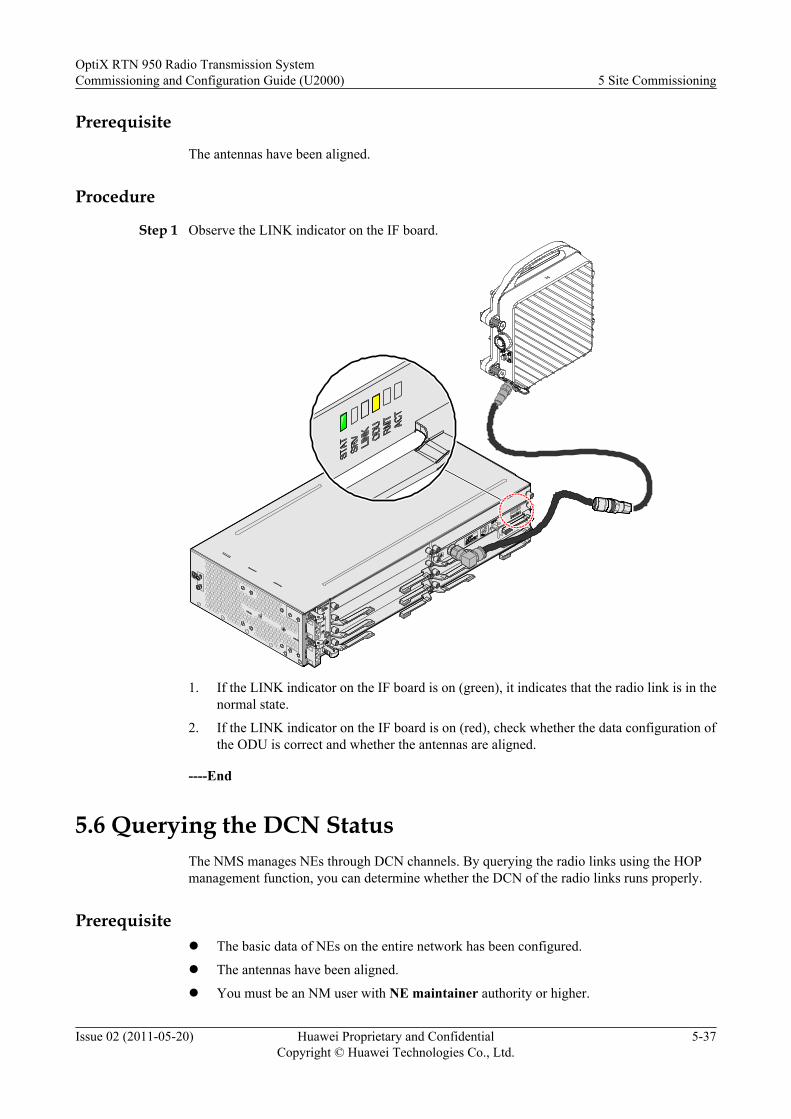
Prerequisite
The antennas have been aligned.
Procedure
Step 1 Observe the LINK indicator on the IF board.
1. If the LINK indicator on the IF board is on (green), it indicates that the radio link is in thenormal state.
2. If the LINK indicator on the IF board is on (red), check whether the data configuration ofthe ODU is correct and whether the antennas are aligned.
----End
5.6 Querying the DCN StatusThe NMS manages NEs through DCN channels. By querying the radio links using the HOPmanagement function, you can determine whether the DCN of the radio links runs properly.
Prerequisitel The basic data of NEs on the entire network has been configured.
l The antennas have been aligned.
l You must be an NM user with NE maintainer authority or higher.
OptiX RTN 950 Radio Transmission SystemCommissioning and Configuration Guide (U2000) 5 Site Commissioning
Issue 02 (2011-05-20) Huawei Proprietary and ConfidentialCopyright © Huawei Technologies Co., Ltd.
5-37
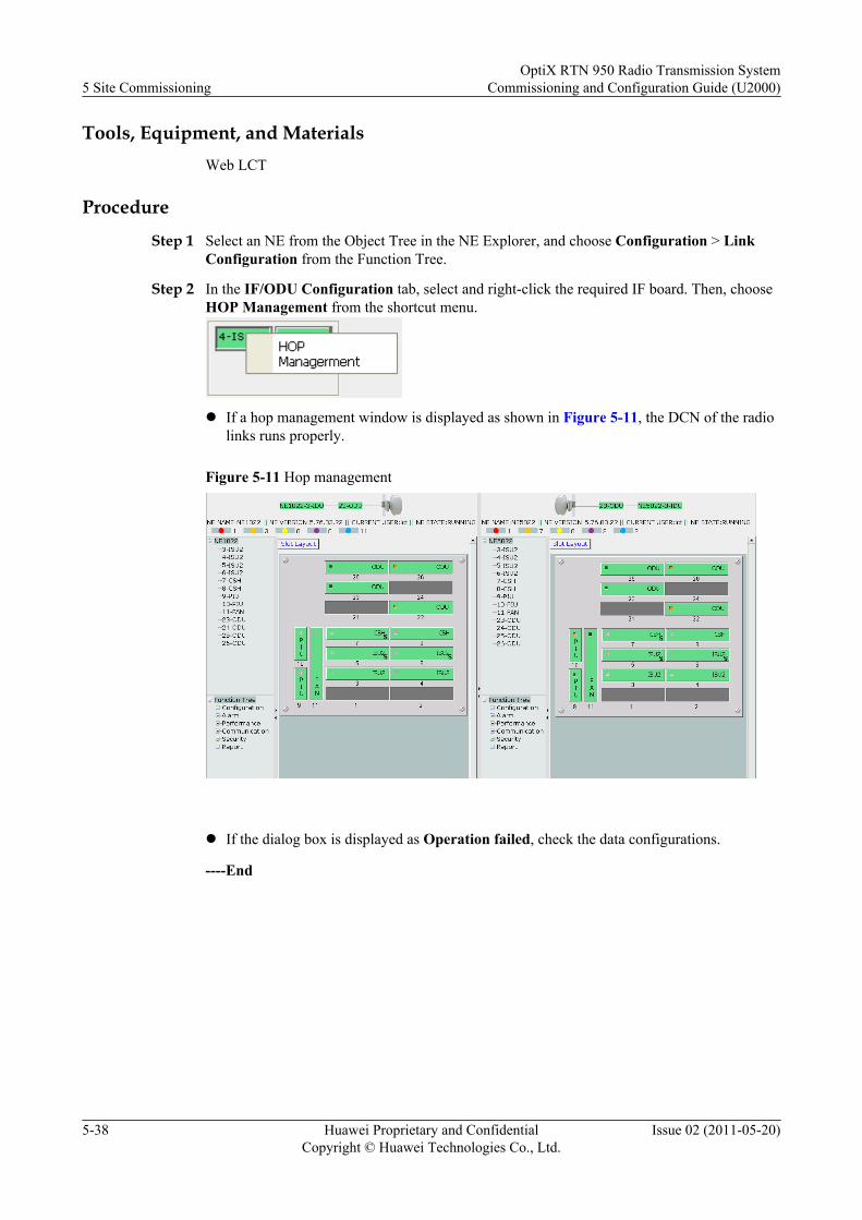
Tools, Equipment, and MaterialsWeb LCT
Procedure
Step 1 Select an NE from the Object Tree in the NE Explorer, and choose Configuration > LinkConfiguration from the Function Tree.
Step 2 In the IF/ODU Configuration tab, select and right-click the required IF board. Then, chooseHOP Management from the shortcut menu.
l If a hop management window is displayed as shown in Figure 5-11, the DCN of the radiolinks runs properly.
Figure 5-11 Hop management
l If the dialog box is displayed as Operation failed, check the data configurations.
----End
5 Site CommissioningOptiX RTN 950 Radio Transmission System
Commissioning and Configuration Guide (U2000)
5-38 Huawei Proprietary and ConfidentialCopyright © Huawei Technologies Co., Ltd.
Issue 02 (2011-05-20)
6 System Commissioning
About This Chapter
System commissioning includes the specific commissioning processes for all systemcommissioning items.
6.1 Configuring Networkwide Service DataAfter site commissioning is performed for each hop of the radio links, the ECC communicationbetween NEs is normal. In this case, an NE can be accessed by using the U2000, and thenetworkwide service data can be configured.
6.2 Testing Ethernet ServicesBy testing Ethernet services, you can check whether the Ethernet services are available overradio links. The Ethernet services can be tested by using the ETH-OAM function. Using thismethod, an Ethernet tester is not required.
6.3 Testing AM SwitchingIf no BER tester is available, you can test AM switching by querying the bit errors over radiolinks.
6.4 Testing Protection SwitchingBy testing protection switching, you can determine whether the protection switching is normalover radio links.
6.5 Checking the Clock StatusCheck the clock status for each NE to ensure that the clocks of all the NEs on a radio networkare synchronized.
OptiX RTN 950 Radio Transmission SystemCommissioning and Configuration Guide (U2000) 6 System Commissioning
Issue 02 (2011-05-20) Huawei Proprietary and ConfidentialCopyright © Huawei Technologies Co., Ltd.
6-1
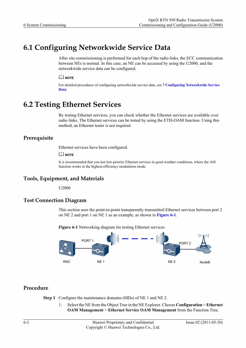
6.1 Configuring Networkwide Service DataAfter site commissioning is performed for each hop of the radio links, the ECC communicationbetween NEs is normal. In this case, an NE can be accessed by using the U2000, and thenetworkwide service data can be configured.
NOTE
For detailed procedures of configuring networkwide service data, see 7 Configuring Networkwide ServiceData.
6.2 Testing Ethernet ServicesBy testing Ethernet services, you can check whether the Ethernet services are available overradio links. The Ethernet services can be tested by using the ETH-OAM function. Using thismethod, an Ethernet tester is not required.
PrerequisiteEthernet services have been configured.
NOTE
It is recommended that you test low-priority Ethernet services in good weather conditions, where the AMfunction works in the highest-efficiency modulation mode.
Tools, Equipment, and MaterialsU2000
Test Connection DiagramThis section uses the point-to-point transparently transmitted Ethernet services between port 2on NE 2 and port 1 on NE 1 as an example, as shown in Figure 6-1.
Figure 6-1 Networking diagram for testing Ethernet services
NE 1 NE 2
PORT 2PORT 1
RNC NodeB
Procedure
Step 1 Configure the maintenance domains (MDs) of NE 1 and NE 2.1. Select the NE from the Object Tree in the NE Explorer. Choose Configuration > Ethernet
OAM Management > Ethernet Service OAM Management from the Function Tree.
6 System CommissioningOptiX RTN 950 Radio Transmission System
Commissioning and Configuration Guide (U2000)
6-2 Huawei Proprietary and ConfidentialCopyright © Huawei Technologies Co., Ltd.
Issue 02 (2011-05-20)
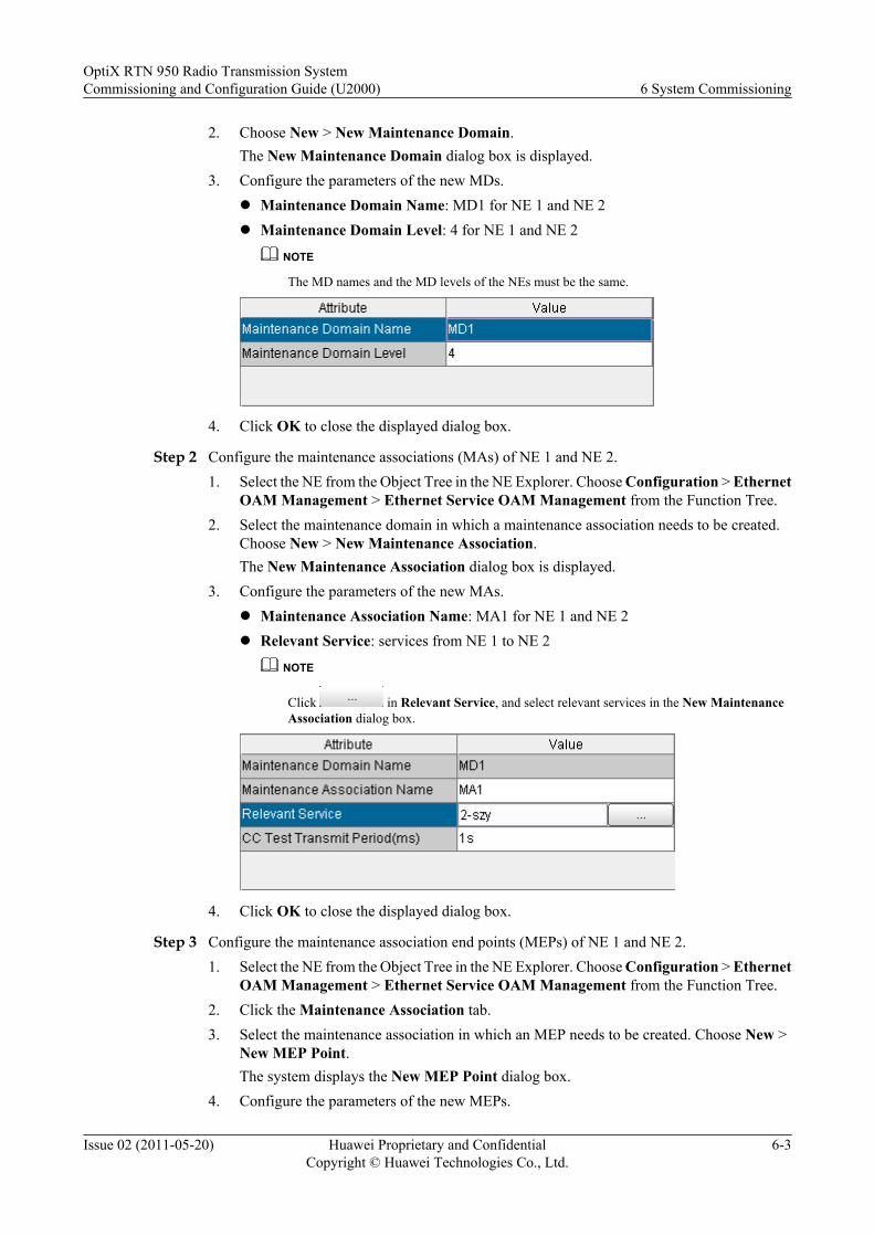
2. Choose New > New Maintenance Domain.The New Maintenance Domain dialog box is displayed.
3. Configure the parameters of the new MDs.l Maintenance Domain Name: MD1 for NE 1 and NE 2l Maintenance Domain Level: 4 for NE 1 and NE 2
NOTE
The MD names and the MD levels of the NEs must be the same.
4. Click OK to close the displayed dialog box.
Step 2 Configure the maintenance associations (MAs) of NE 1 and NE 2.1. Select the NE from the Object Tree in the NE Explorer. Choose Configuration > Ethernet
OAM Management > Ethernet Service OAM Management from the Function Tree.2. Select the maintenance domain in which a maintenance association needs to be created.
Choose New > New Maintenance Association.The New Maintenance Association dialog box is displayed.
3. Configure the parameters of the new MAs.l Maintenance Association Name: MA1 for NE 1 and NE 2l Relevant Service: services from NE 1 to NE 2
NOTE
Click in Relevant Service, and select relevant services in the New MaintenanceAssociation dialog box.
4. Click OK to close the displayed dialog box.
Step 3 Configure the maintenance association end points (MEPs) of NE 1 and NE 2.1. Select the NE from the Object Tree in the NE Explorer. Choose Configuration > Ethernet
OAM Management > Ethernet Service OAM Management from the Function Tree.2. Click the Maintenance Association tab.3. Select the maintenance association in which an MEP needs to be created. Choose New >
New MEP Point.The system displays the New MEP Point dialog box.
4. Configure the parameters of the new MEPs.
OptiX RTN 950 Radio Transmission SystemCommissioning and Configuration Guide (U2000) 6 System Commissioning
Issue 02 (2011-05-20) Huawei Proprietary and ConfidentialCopyright © Huawei Technologies Co., Ltd.
6-3
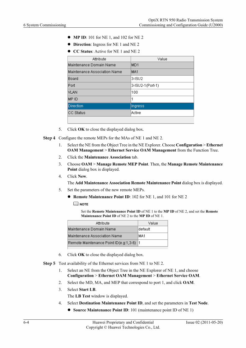
l MP ID: 101 for NE 1, and 102 for NE 2l Direction: Ingress for NE 1 and NE 2l CC Status: Active for NE 1 and NE 2
5. Click OK to close the displayed dialog box.
Step 4 Configure the remote MEPs for the MAs of NE 1 and NE 2.1. Select the NE from the Object Tree in the NE Explorer. Choose Configuration > Ethernet
OAM Management > Ethernet Service OAM Management from the Function Tree.2. Click the Maintenance Association tab.3. Choose OAM > Manage Remote MEP Point. Then, the Manage Remote Maintenance
Point dialog box is displayed.4. Click New.
The Add Maintenance Association Remote Maintenance Point dialog box is displayed.5. Set the parameters of the new remote MEPs.
l Remote Maintenance Point ID: 102 for NE 1, and 101 for NE 2
NOTE
Set the Remote Maintenance Point ID of NE 1 to the MP ID of NE 2, and set the RemoteMaintenance Point ID of NE 2 to the MP ID of NE 1.
6. Click OK to close the displayed dialog box.
Step 5 Test availability of the Ethernet services from NE 1 to NE 2.1. Select an NE from the Object Tree in the NE Explorer of NE 1, and choose
Configuration > Ethernet OAM Management > Ethernet Service OAM.2. Select the MD, MA, and MEP that correspond to port 1, and click OAM.3. Select Start LB.
The LB Test window is displayed.4. Select Destination Maintenance Point ID, and set the parameters in Test Node.
l Source Maintenance Point ID: 101 (maintenance point ID of NE 1)
6 System CommissioningOptiX RTN 950 Radio Transmission System
Commissioning and Configuration Guide (U2000)
6-4 Huawei Proprietary and ConfidentialCopyright © Huawei Technologies Co., Ltd.
Issue 02 (2011-05-20)
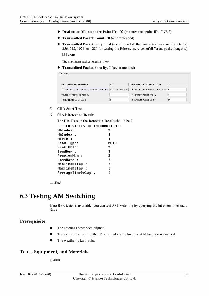
l Destination Maintenance Point ID: 102 (maintenance point ID of NE 2)
l Transmitted Packet Count: 20 (recommended)
l Transmitted Packet Length: 64 (recommended; the parameter can also be set to 128,256, 512, 1024, or 1280 for testing the Ethernet services of different packet lengths.)
NOTE
The maximum packet length is 1400.
l Transmitted Packet Priority: 7 (recommended)
5. Click Start Test.
6. Check Detection Result.The LossRate in the Detection Result should be 0.
----End
6.3 Testing AM SwitchingIf no BER tester is available, you can test AM switching by querying the bit errors over radiolinks.
Prerequisitel The antennas have been aligned.
l The radio links must be the IP radio links for which the AM function is enabled.
l The weather is favorable.
Tools, Equipment, and Materials
U2000
OptiX RTN 950 Radio Transmission SystemCommissioning and Configuration Guide (U2000) 6 System Commissioning
Issue 02 (2011-05-20) Huawei Proprietary and ConfidentialCopyright © Huawei Technologies Co., Ltd.
6-5
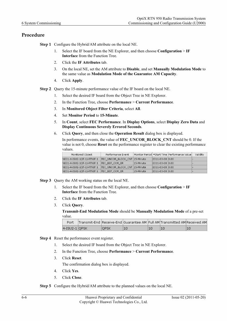
Procedure
Step 1 Configure the Hybrid/AM attribute on the local NE.
1. Select the IF board from the NE Explorer, and then choose Configuration > IFInterface from the Function Tree.
2. Click the IF Attributes tab.
3. On the local NE, set the AM attribute to Disable, and set Manually Modulation Mode tothe same value as Modulation Mode of the Guarantee AM Capacity.
4. Click Apply.
Step 2 Query the 15-minute performance value of the IF board on the local NE.
1. Select the desired IF board from the Object Tree in NE Explorer.
2. In the Function Tree, choose Performance > Current Performance.
3. In Monitored Object Filter Criteria, select All.4. Set Monitor Period to 15-Minute.
5. In Count, select FEC Performance. In Display Options, select Display Zero Data andDisplay Continuous Severely Errored Seconds.
6. Click Query, and then close the Operation Result dialog box is displayed.In performance events, the value of FEC_UNCOR_BLOCK_CNT should be 0. If thevalue is not 0, choose Reset on the performance register to clear the existing performancevalues.
Step 3 Query the AM working status on the local NE.
1. Select the IF board from the NE Explorer, and then choose Configuration > IFInterface from the Function Tree.
2. Click the IF Attributes tab.
3. Click Query.Transmit-End Modulation Mode should be Manually Modulation Mode of a pre-setvalue.
Step 4 Reset the performance event register.
1. Select the desired IF board from the Object Tree in NE Explorer.
2. In the Function Tree, choose Performance > Current Performance.
3. Click Reset.The confirmation dialog box is displayed.
4. Click Yes.
5. Click Close.
Step 5 Configure the Hybrid/AM attribute to the planned values on the local NE.
6 System CommissioningOptiX RTN 950 Radio Transmission System
Commissioning and Configuration Guide (U2000)
6-6 Huawei Proprietary and ConfidentialCopyright © Huawei Technologies Co., Ltd.
Issue 02 (2011-05-20)
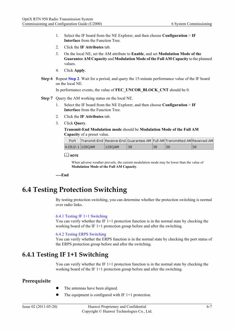
1. Select the IF board from the NE Explorer, and then choose Configuration > IFInterface from the Function Tree.
2. Click the IF Attributes tab.3. On the local NE, set the AM attribute to Enable, and set Modulation Mode of the
Guarantee AM Capacity and Modulation Mode of the Full AM Capacity to the plannedvalues.
4. Click Apply.
Step 6 Repeat Step 2. Wait for a period, and query the 15-minute performance value of the IF boardon the local NE.In performance events, the value of FEC_UNCOR_BLOCK_CNT should be 0.
Step 7 Query the AM working status on the local NE.1. Select the IF board from the NE Explorer, and then choose Configuration > IF
Interface from the Function Tree.2. Click the IF Attributes tab.3. Click Query.
Transmit-End Modulation mode should be Modulation Mode of the Full AMCapacity of a preset value.
NOTE
When adverse weather prevails, the current modulation mode may be lower than the value ofModulation Mode of the Full AM Capacity.
----End
6.4 Testing Protection SwitchingBy testing protection switching, you can determine whether the protection switching is normalover radio links.
6.4.1 Testing IF 1+1 SwitchingYou can verify whether the IF 1+1 protection function is in the normal state by checking theworking board of the IF 1+1 protection group before and after the switching.
6.4.2 Testing ERPS SwitchingYou can verify whether the ERPS function is in the normal state by checking the port status ofthe ERPS protection group before and after the switching.
6.4.1 Testing IF 1+1 SwitchingYou can verify whether the IF 1+1 protection function is in the normal state by checking theworking board of the IF 1+1 protection group before and after the switching.
Prerequisitel The antennas have been aligned.l The equipment is configured with IF 1+1 protection.
OptiX RTN 950 Radio Transmission SystemCommissioning and Configuration Guide (U2000) 6 System Commissioning
Issue 02 (2011-05-20) Huawei Proprietary and ConfidentialCopyright © Huawei Technologies Co., Ltd.
6-7
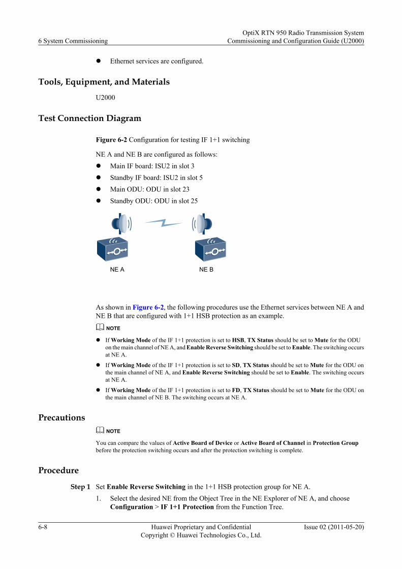
l Ethernet services are configured.
Tools, Equipment, and Materials
U2000
Test Connection Diagram
Figure 6-2 Configuration for testing IF 1+1 switching
NE A and NE B are configured as follows:l Main IF board: ISU2 in slot 3l Standby IF board: ISU2 in slot 5l Main ODU: ODU in slot 23l Standby ODU: ODU in slot 25
NE BNE A
As shown in Figure 6-2, the following procedures use the Ethernet services between NE A andNE B that are configured with 1+1 HSB protection as an example.
NOTE
l If Working Mode of the IF 1+1 protection is set to HSB, TX Status should be set to Mute for the ODUon the main channel of NE A, and Enable Reverse Switching should be set to Enable. The switching occursat NE A.
l If Working Mode of the IF 1+1 protection is set to SD, TX Status should be set to Mute for the ODU onthe main channel of NE A, and Enable Reverse Switching should be set to Enable. The switching occursat NE A.
l If Working Mode of the IF 1+1 protection is set to FD, TX Status should be set to Mute for the ODU onthe main channel of NE B. The switching occurs at NE A.
PrecautionsNOTE
You can compare the values of Active Board of Device or Active Board of Channel in Protection Groupbefore the protection switching occurs and after the protection switching is complete.
Procedure
Step 1 Set Enable Reverse Switching in the 1+1 HSB protection group for NE A.1. Select the desired NE from the Object Tree in the NE Explorer of NE A, and choose
Configuration > IF 1+1 Protection from the Function Tree.
6 System CommissioningOptiX RTN 950 Radio Transmission System
Commissioning and Configuration Guide (U2000)
6-8 Huawei Proprietary and ConfidentialCopyright © Huawei Technologies Co., Ltd.
Issue 02 (2011-05-20)
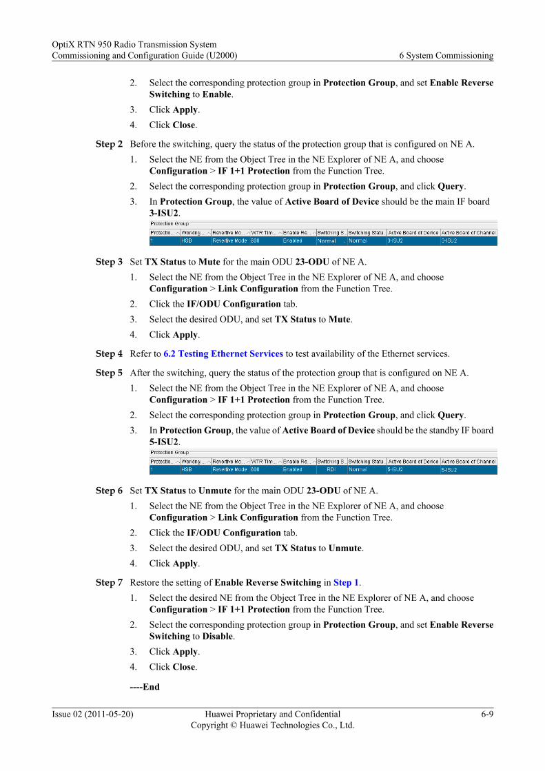
2. Select the corresponding protection group in Protection Group, and set Enable ReverseSwitching to Enable.
3. Click Apply.4. Click Close.
Step 2 Before the switching, query the status of the protection group that is configured on NE A.1. Select the NE from the Object Tree in the NE Explorer of NE A, and choose
Configuration > IF 1+1 Protection from the Function Tree.2. Select the corresponding protection group in Protection Group, and click Query.3. In Protection Group, the value of Active Board of Device should be the main IF board
3-ISU2.
Step 3 Set TX Status to Mute for the main ODU 23-ODU of NE A.1. Select the NE from the Object Tree in the NE Explorer of NE A, and choose
Configuration > Link Configuration from the Function Tree.2. Click the IF/ODU Configuration tab.3. Select the desired ODU, and set TX Status to Mute.4. Click Apply.
Step 4 Refer to 6.2 Testing Ethernet Services to test availability of the Ethernet services.
Step 5 After the switching, query the status of the protection group that is configured on NE A.1. Select the NE from the Object Tree in the NE Explorer of NE A, and choose
Configuration > IF 1+1 Protection from the Function Tree.2. Select the corresponding protection group in Protection Group, and click Query.3. In Protection Group, the value of Active Board of Device should be the standby IF board
5-ISU2.
Step 6 Set TX Status to Unmute for the main ODU 23-ODU of NE A.1. Select the NE from the Object Tree in the NE Explorer of NE A, and choose
Configuration > Link Configuration from the Function Tree.2. Click the IF/ODU Configuration tab.3. Select the desired ODU, and set TX Status to Unmute.4. Click Apply.
Step 7 Restore the setting of Enable Reverse Switching in Step 1.1. Select the desired NE from the Object Tree in the NE Explorer of NE A, and choose
Configuration > IF 1+1 Protection from the Function Tree.2. Select the corresponding protection group in Protection Group, and set Enable Reverse
Switching to Disable.3. Click Apply.4. Click Close.
----End
OptiX RTN 950 Radio Transmission SystemCommissioning and Configuration Guide (U2000) 6 System Commissioning
Issue 02 (2011-05-20) Huawei Proprietary and ConfidentialCopyright © Huawei Technologies Co., Ltd.
6-9
6.4.2 Testing ERPS SwitchingYou can verify whether the ERPS function is in the normal state by checking the port status ofthe ERPS protection group before and after the switching.
Prerequisitel The equipment is configured with ERPS.l The network cable for carrying the working and protection Ethernet services of ERPS is
properly connected.
Tools, Equipment, and MaterialsU2000
Test Connection DiagramAs shown in Figure 6-3, the following procedures use the Ethernet services that are configuredwith ERPS between NE A and NE D as an example. The RPL owner node is NE D.
Figure 6-3 Configuration for testing ERPS
NE A, NE B, NE C, and NE D are configured as follows:l West IF board: ISU2 in slot 3l East IF board: ISU2 in slot 5l West ODU: ODU in slot 23l East ODU: ODU in slot 25
6 System CommissioningOptiX RTN 950 Radio Transmission System
Commissioning and Configuration Guide (U2000)
6-10 Huawei Proprietary and ConfidentialCopyright © Huawei Technologies Co., Ltd.
Issue 02 (2011-05-20)

Working channel
NE BProtection channelWest
East
West
West
East
East
East
West
NE A
NE C
NE D
Procedure
Step 1 Before the switching, query the status of the protection group that is configured on NE D.
1. Select the NE from the Object Tree in the NE Explorer of NE D, and chooseConfiguration > Ethernet Protection > ERPS Management from the Function Tree.
2. Select the ERPS protection group to be queried, and click Query.
3. The value of State Machine Status should be Idle.
Step 2 Refer to 6.2 Testing Ethernet Services to test availability of the Ethernet services.The LossRate in the Detection Result should be 0.
Step 3 Set TX Status to Mute for the west ODU 23-ODU of NE A.
OptiX RTN 950 Radio Transmission SystemCommissioning and Configuration Guide (U2000) 6 System Commissioning
Issue 02 (2011-05-20) Huawei Proprietary and ConfidentialCopyright © Huawei Technologies Co., Ltd.
6-11
1. Select the NE from the Object Tree in the NE Explorer of NE A, and chooseConfiguration > Link Configuration from the Function Tree.
2. Click the IF/ODU Configuration tab.3. Select the desired ODU, and set TX Status to Mute.4. Click Apply.
Step 4 After the switching, query the status of the protection group that is configured on NE D.1. Select the NE from the Object Tree in the NE Explorer of NE D, and choose
Configuration > Ethernet Protection > ERPS Management from the Function Tree.2. Select the ERPS protection group to be queried, and click Query.3. The value of State Machine Status should be Protection.
Step 5 Refer to 6.2 Testing Ethernet Services to test availability of the Ethernet services.The LossRate in the Detection Result should be 0.
Step 6 Set TX Status to Unmute for the west ODU 23-ODU of NE A.1. Select the NE from the Object Tree in the NE Explorer of NE A, and choose
Configuration > Link Configuration from the Function Tree.2. Click the IF/ODU Configuration tab.3. Select the desired ODU, and set TX Status to Unmute.4. Click Apply.
----End
6.5 Checking the Clock StatusCheck the clock status for each NE to ensure that the clocks of all the NEs on a radio networkare synchronized.
Prerequisite
The clock configuration is complete. The link that transmits clocks is in the normal state.
Tools, Equipment, and Materials
U2000
Procedure
Step 1 Select the NE from the Object Tree in the NE Explorer, and choose Configuration > Clock >Physical Clock > Clock Synchronization Status from the Function Tree.
Step 2 Click Query.
NOTE
l If the clock of an NE is selected as the working clock of the radio network, this clock should be in free-run mode and the clocks of the other NEs should be in locked mode.
l If a service clock is selected as the working clock of the radio network, the clocks of all the NEs shouldbe in locked mode.
6 System CommissioningOptiX RTN 950 Radio Transmission System
Commissioning and Configuration Guide (U2000)
6-12 Huawei Proprietary and ConfidentialCopyright © Huawei Technologies Co., Ltd.
Issue 02 (2011-05-20)
Step 3 Repeat Step 1 through Step 2 to check the working modes of the other NEs on the radio network.
----End
OptiX RTN 950 Radio Transmission SystemCommissioning and Configuration Guide (U2000) 6 System Commissioning
Issue 02 (2011-05-20) Huawei Proprietary and ConfidentialCopyright © Huawei Technologies Co., Ltd.
6-13

7 Configuring Networkwide Service Data
About This Chapter
Services can be transmitted in IP radio mode only after networkwide service data is configured.
7.1 Basic ConceptsBefore configuring networkwide service data, be familiar with related basic concepts.
7.2 Configuration ProcedureThis section describes the procedures for configuring networks, radio links, Ethernet services,and clocks.
7.3 Configuration Example (Networkwide Data Services)This section describes how to configure data services on an IP radio ring network according tothe network plan.
OptiX RTN 950 Radio Transmission SystemCommissioning and Configuration Guide (U2000) 7 Configuring Networkwide Service Data
Issue 02 (2011-05-20) Huawei Proprietary and ConfidentialCopyright © Huawei Technologies Co., Ltd.
7-1
7.1 Basic ConceptsBefore configuring networkwide service data, be familiar with related basic concepts.
7.1.1 DCNThe network management system (NMS) communicates with a transmission network element(NE) through the data communication network (DCN) to manage and maintain the NE.
7.1.2 GNE and Non-GNEA gateway NE (GNE) refers to an NE whose application layer communicates directly with theNMS application layer. A non-GNE refers to an NE whose application layer communicates withthe NMS application layer by forwarding data through the GNE application layer.
7.1.3 NE ID and NE IP AddressThe ID and IP address are the unique NE on the DCN.
7.1.4 Physical Boards and Logical BoardsThe NE software and NMS consider a physical board as one or more logical boards whenmanaging the physical board.
7.1.5 Adaptive ModulationThe adaptive modulation (AM) technology adjusts the modulation scheme automatically basedon channel quality.
7.1.6 CCDP and XPICThe co-channel dual-polarization (CCDP) and cross-polarization interference cancellation(XPIC) technologies are developed based on microwave polarization characteristics. The CCDP,wherein two signals are transmitted over two orthogonal polarization waves, doubles thetransmission capacity; the XPIC cancels the cross-polarization interference between the twopolarization waves.
7.1.7 RF Configuration ModesThe OptiX RTN 950 supports four RF configuration modes, namely, 1+0 non-protectionconfiguration, N+0 non-protection configuration, 1+1 protection configuration and cross-polarization interference cancellation (XPIC) configuration.
7.1.8 Ethernet Port NumbersOn the NMS, Ethernet ports are represented by PORTs.
7.1.9 IF_ETH PortIF boards used in IP radio use their IF_ETH ports to receive services from and transmit servicesto the packet plane.
7.1.10 Auto-NegotiationThe auto-negotiation function allows the network equipment to send information about itssupported working mode to the opposite end of the network and to receive correspondinginformation that the opposite end may transfer.
7.1.11 Flow Control FunctionWhen the equipment fails to handle the traffic received at the port due to poor data processing/transferring capability, the line becomes congested. This also causes buffer overflow andtherefore some packets will be discarded. To reduce the number of packets to be discarded, takeappropriate flow control measures.
7.1.12 MAC Address Table Management
7 Configuring Networkwide Service DataOptiX RTN 950 Radio Transmission System
Commissioning and Configuration Guide (U2000)
7-2 Huawei Proprietary and ConfidentialCopyright © Huawei Technologies Co., Ltd.
Issue 02 (2011-05-20)
The entries in a MAC address table show the mappings between MAC addresses and ports. AMAC address table contains dynamic entries, static entries, and blacklist entries.
7.1.13 Split Horizon GroupTo separate services that are converged and to prevent a broadcast storm resulting from a serviceloop, you can configure a split horizon group for the E-LAN services at the specified nodes.After the configuration, the logical ports in one split horizon group cannot forward packets toeach other.
7.1.14 Protection for Native Ethernet ServicesThe OptiX RTN 950 supports three protection modes for Native Ethernet services, namely,Ethernet ring protection switching (ERPS), link aggregation group (LAG), and multiplespanning tree protocol (MSTP).
7.1.15 Clock SourceA clock source is a signal source that carries timing reference information. An NE implementsclock synchronization, by using its phase locked loop (PLL) to lock the timing information ofthe clock source.
7.1.16 Clock Protection ModesThe OptiX RTN 950 supports clock source protection based on priorities, synchronization statusmessage (SSM) protection, and extended SSM protection.
7.1.17 Clock Synchronization PolicyUsers plan an appropriate clock synchronization policy based on the network topology.
7.1.1 DCNThe network management system (NMS) communicates with a transmission network element(NE) through the data communication network (DCN) to manage and maintain the NE.
OverviewOn a DCN, both the NMS and NEs are DCN nodes. The DCN between the NMS and NEs iscalled an external DCN, and the DCN between NEs is called an internal DCN. The OptiX RTN950 supports several DCN solutions, including Huawei embedded control channel (HWECC),IP over DCC, and inband DCN.
IP over DCC SolutionFigure 7-1 shows how network management messages are transmitted in the IP over DCCsolution. Encapsulated in the IP protocol stack, different vendors' network managementmessages are transmitted in one of the following ways: through DCCs carried by microwave,or over the Ethernet between Ethernet network management ports or between NE cascadingports.
OptiX RTN 950 Radio Transmission SystemCommissioning and Configuration Guide (U2000) 7 Configuring Networkwide Service Data
Issue 02 (2011-05-20) Huawei Proprietary and ConfidentialCopyright © Huawei Technologies Co., Ltd.
7-3
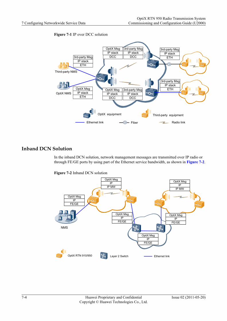
Figure 7-1 IP over DCC solution
OptiX NMS
Ethernet link Fiber Radio link
Third-party NMS
OptiX equipment Third-party equipment
ETHIP stack
3rd-party Msg
ETHIP stack
3rd-party Msg
ETHIP stack
3rd-party Msg
ETHIP stack
OptiX Msg
DCCIP stack
OptiX Msg
DCCIP stack
3rd-party Msg
DCCIP stack
OptiX Msg
DCCIP stack
3rd-party Msg
Inband DCN SolutionIn the inband DCN solution, network management messages are transmitted over IP radio orthrough FE/GE ports by using part of the Ethernet service bandwidth, as shown in Figure 7-2.
Figure 7-2 Inband DCN solution
Ethernet linkLayer 2 SwitchOptiX RTN 910/950
NMS
IPOptiX Msg
FE/GE
IPOptiX Msg
IP MW
IPOptiX Msg
FE/GE
IPOptiX Msg
FE/GE
IPOptiX Msg
FE/GE
IPOptiX Msg
IP MW
7 Configuring Networkwide Service DataOptiX RTN 950 Radio Transmission System
Commissioning and Configuration Guide (U2000)
7-4 Huawei Proprietary and ConfidentialCopyright © Huawei Technologies Co., Ltd.
Issue 02 (2011-05-20)
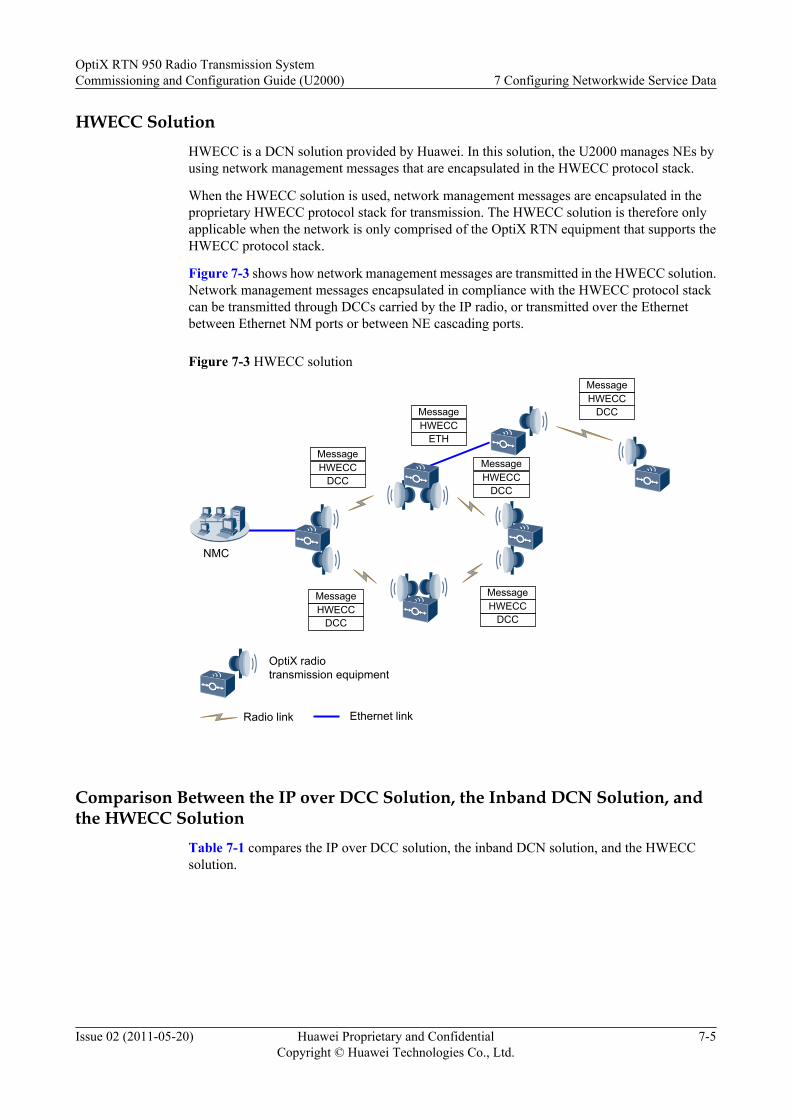
HWECC SolutionHWECC is a DCN solution provided by Huawei. In this solution, the U2000 manages NEs byusing network management messages that are encapsulated in the HWECC protocol stack.
When the HWECC solution is used, network management messages are encapsulated in theproprietary HWECC protocol stack for transmission. The HWECC solution is therefore onlyapplicable when the network is only comprised of the OptiX RTN equipment that supports theHWECC protocol stack.
Figure 7-3 shows how network management messages are transmitted in the HWECC solution.Network management messages encapsulated in compliance with the HWECC protocol stackcan be transmitted through DCCs carried by the IP radio, or transmitted over the Ethernetbetween Ethernet NM ports or between NE cascading ports.
Figure 7-3 HWECC solution
Radio link Ethernet link
OptiX radio transmission equipment
NMC
DCCHWECCMessage
DCCHWECCMessage
DCCHWECCMessage
ETHHWECCMessage
DCCHWECCMessage
DCCHWECCMessage
Comparison Between the IP over DCC Solution, the Inband DCN Solution, andthe HWECC Solution
Table 7-1 compares the IP over DCC solution, the inband DCN solution, and the HWECCsolution.
OptiX RTN 950 Radio Transmission SystemCommissioning and Configuration Guide (U2000) 7 Configuring Networkwide Service Data
Issue 02 (2011-05-20) Huawei Proprietary and ConfidentialCopyright © Huawei Technologies Co., Ltd.
7-5
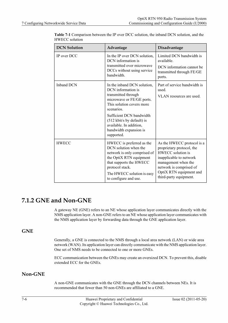
Table 7-1 Comparison between the IP over DCC solution, the inband DCN solution, and theHWECC solution
DCN Solution Advantage Disadvantage
IP over DCC In the IP over DCN solution,DCN information istransmitted over microwaveDCCs without using servicebandwidth.
Limited DCN bandwidth isavailable.DCN information cannot betransmitted through FE/GEports.
Inband DCN In the inband DCN solution,DCN information istransmitted throughmicrowave or FE/GE ports.This solution covers morescenarios.Sufficient DCN bandwidth(512 kbit/s by default) isavailable. In addition,bandwidth expansion issupported.
Part of service bandwidth isused.VLAN resources are used.
HWECC HWECC is preferred as theDCN solution when thenetwork is only comprised ofthe OptiX RTN equipmentthat supports the HWECCprotocol stack.The HWECC solution is easyto configure and use.
As the HWECC protocol is aproprietary protocol, theHWECC solution isinapplicable to networkmanagement when thenetwork is comprised ofOptiX RTN equipment andthird-party equipment.
7.1.2 GNE and Non-GNEA gateway NE (GNE) refers to an NE whose application layer communicates directly with theNMS application layer. A non-GNE refers to an NE whose application layer communicates withthe NMS application layer by forwarding data through the GNE application layer.
GNEGenerally, a GNE is connected to the NMS through a local area network (LAN) or wide areanetwork (WAN). Its application layer can directly communicate with the NMS application layer.One set of NMS needs to be connected to one or more GNEs.
ECC communication between the GNEs may create an oversized DCN. To prevent this, disableextended ECC for the GNEs.
Non-GNEA non-GNE communicates with the GNE through the DCN channels between NEs. It isrecommended that fewer than 50 non-GNEs are affiliated to a GNE.
7 Configuring Networkwide Service DataOptiX RTN 950 Radio Transmission System
Commissioning and Configuration Guide (U2000)
7-6 Huawei Proprietary and ConfidentialCopyright © Huawei Technologies Co., Ltd.
Issue 02 (2011-05-20)

7.1.3 NE ID and NE IP AddressThe ID and IP address are the unique NE on the DCN.
NE IDAt the application layer of each DCN solution, an NE uses its NE ID as the NE address. Therefore,each NE must have a unique NE ID on the DCN and all these NE IDs must be planned in aunified manner.
The NE ID has 24 bits. The most significant eight bits represent the subnet ID (or the extendedID) and the least significant 16 bits represent the basic ID. For example, if an NE ID is 0x090001,the subnet ID is 9 and the basic ID is 1.
NE IP AddressAn NE uses an IP address as its unique identifier during TCP/IP communication.
In the DCN solutions (for example, IP over DCC and inband DCN) where network managementmessages are transmitted over TCP/IP, an NE IP address is used as the NE address at the networklayer. Therefore, each NE IP address on the DCN must be unique and all these NE IP addressesmust be planned in a unified manner.
By default (which indicates that an NE IP address is never manually changed), this NE IP addressis automatically changed to 0x81000000 + ID if the NE ID is changed. For example, if an NEIP address is never manually changed, this NE IP address is automatically changed to 129.9.0.1when the NE ID is changed to 0x090001. Once an NE IP address is manually changed, theinterlocking relationship between the NE ID and NE IP address no longer takes effect.
It is recommended to configure the IP address of a GNE on a different network segment fromthe IP addresses of its non-GNEs.
7.1.4 Physical Boards and Logical BoardsThe NE software and NMS consider a physical board as one or more logical boards whenmanaging the physical board.
Table 7-2 provides the mappings between the physical boards and logical boards.
Table 7-2 Mappings between the physical boards and logical boards
Physical Board Logical Board
CSH CSH in the same slot
AUX AUX in the same slot
ISU2 ISU2 in the same slot
ISX2 ISX2 in the same slot
EM6T EM6T in the same slot
EM6F EM6F in the same slot
PIU PIU in the same slot
OptiX RTN 950 Radio Transmission SystemCommissioning and Configuration Guide (U2000) 7 Configuring Networkwide Service Data
Issue 02 (2011-05-20) Huawei Proprietary and ConfidentialCopyright © Huawei Technologies Co., Ltd.
7-7
Physical Board Logical Board
FAN FAN in the same slot
ODU ODU in the slot whose number is 20 plus theslot number for the IF board that is connectedto the ODU
7.1.5 Adaptive ModulationThe adaptive modulation (AM) technology adjusts the modulation scheme automatically basedon channel quality.
When the AM technology is used, in the case of the same channel spacing, the microwave servicebandwidth varies according to the modulation scheme; the higher the modulation efficiency, thehigher the bandwidth of the transmitted services. With the QoS technology, packet services arescheduled to queues with different priorities. The services in different queues then aretransmitted to a microwave port by using the queue scheduling algorithms. Under all channelconditions, the service capacity varies according to the modulation scheme. Figure 7-4 providesillustrates how the modulation mode is adjusted according to varying weather condition.
l When the channel quality is good (such as on days when weather conditions are favorable),the equipment adopts a high-efficiency modulation scheme to transmit more user services.This improves transmission efficiency and spectrum utilization of the system.
l When the channel quality deteriorates (such as on days with adverse weather), theequipment adopts a low-efficiency modulation scheme to transmit only higher-priorityservices within the available bandwidth and to discard lower-priority services. If lower-priority queues are congested due to insufficient capacity of the air interface, some or allservices in these queues will be discarded. This improves anti-interference capability of aradio link and therefore ensures the link availability for higher-priority services.
7 Configuring Networkwide Service DataOptiX RTN 950 Radio Transmission System
Commissioning and Configuration Guide (U2000)
7-8 Huawei Proprietary and ConfidentialCopyright © Huawei Technologies Co., Ltd.
Issue 02 (2011-05-20)

Figure 7-4 Adaptive modulation
Channelcapability
256QAM
32QAM
QPSK
256QAM
128QAM
32QAM
128QAM
64QAM
64QAM
16QAM
16QAM
Packetservices
The AM technology used by the OptiX RTN 950 has the following characteristics:
l The AM technology uses the QPSK, 16QAM, 32QAM, 64QAM, 128QAM, and 256QAMmodulation schemes.
l The lowest-efficiency modulation scheme (also called reference scheme or modulationscheme of guaranteed capacity) and the highest-efficiency modulation scheme (also callednominal scheme or modulation scheme of full capacity) used by the AM can be configured.
l In AM, when modulation schemes are switched, the transmit frequency, receive frequency,and channel spacing remain unchanged.
l In AM, modulation schemes are switched step-by-step.
l In AM, modulation scheme switching is hitless. When the modulation scheme isdownshifted, high-priority services will not be affected when low-priority services arediscarded. The switching is successful even when 100 dB/s channel fast fading occurs.
7.1.6 CCDP and XPICThe co-channel dual-polarization (CCDP) and cross-polarization interference cancellation(XPIC) technologies are developed based on microwave polarization characteristics. The CCDP,wherein two signals are transmitted over two orthogonal polarization waves, doubles thetransmission capacity; the XPIC cancels the cross-polarization interference between the twopolarization waves.
Microwave transmission can be classified into single-polarized transmission and CCDPtransmission by polarization transmission mode.
OptiX RTN 950 Radio Transmission SystemCommissioning and Configuration Guide (U2000) 7 Configuring Networkwide Service Data
Issue 02 (2011-05-20) Huawei Proprietary and ConfidentialCopyright © Huawei Technologies Co., Ltd.
7-9
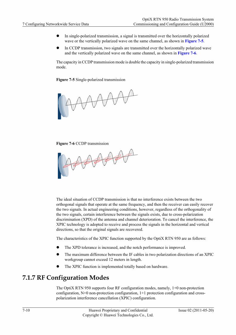
l In single-polarized transmission, a signal is transmitted over the horizontally polarizedwave or the vertically polarized wave on the same channel, as shown in Figure 7-5.
l In CCDP transmission, two signals are transmitted over the horizontally polarized waveand the vertically polarized wave on the same channel, as shown in Figure 7-6.
The capacity in CCDP transmission mode is double the capacity in single-polarized transmissionmode.
Figure 7-5 Single-polarized transmission
Figure 7-6 CCDP transmission
The ideal situation of CCDP transmission is that no interference exists between the twoorthogonal signals that operate at the same frequency, and then the receiver can easily recoverthe two signals. In actual engineering conditions, however, regardless of the orthogonality ofthe two signals, certain interference between the signals exists, due to cross-polarizationdiscrimination (XPD) of the antenna and channel deterioration. To cancel the interference, theXPIC technology is adopted to receive and process the signals in the horizontal and verticaldirections, so that the original signals are recovered.
The characteristics of the XPIC function supported by the OptiX RTN 950 are as follows:
l The XPD tolerance is increased, and the notch performance is improved.
l The maximum difference between the IF cables in two polarization directions of an XPICworkgroup cannot exceed 12 meters in length.
l The XPIC function is implemented totally based on hardware.
7.1.7 RF Configuration ModesThe OptiX RTN 950 supports four RF configuration modes, namely, 1+0 non-protectionconfiguration, N+0 non-protection configuration, 1+1 protection configuration and cross-polarization interference cancellation (XPIC) configuration.
7 Configuring Networkwide Service DataOptiX RTN 950 Radio Transmission System
Commissioning and Configuration Guide (U2000)
7-10 Huawei Proprietary and ConfidentialCopyright © Huawei Technologies Co., Ltd.
Issue 02 (2011-05-20)

1+0 Non-Protection ConfigurationThe 1+0 non-protection configuration indicates that the radio link has one working channel andno protection channel.
N+0 Non-Protection ConfigurationThe N+0 non-protection configuration indicates that the radio link has N working channels andno protection channel.
The OptiX RTN 950 supports N+0 protection (1 < N ≤5).
1+1 Protection ConfigurationThe 1+1 protection configuration indicates that the radio link has one working channel and oneprotection channel.
The 1+1 protection configuration is classified into 1+1 HSB, 1+1 FD, and 1+1 SD.
l In 1+1 HSB protection mode, the equipment provides a 1+1 hot standby configuration forthe IF boards and ODUs at both ends of each hop of radio link, implementing the protection.
l In 1+1 FD protection mode, the system uses two channels with a specific frequency intervalto transmit and receive the same service signal. The opposite end selects one from the tworeceived signals. With the 1+1 FD protection, the impact of the fading on signaltransmission is reduced.The 1+1 FD protection also supports the 1+1 HSB protection.
l In the 1+1 SD protection mode, the system uses two antennas with a space distance toreceive the same RF signal. The equipment selects from the two received signals. With the1+1 SD protection, the impact of the fading on signal transmission is reduced.The 1+1 SD protection also supports the 1+1 HSB protection.
XPIC ConfigurationThe XPIC adopts both the horizontally polarized wave and the vertically polarized wave overone channel to transmit two channels of signals. The radio link capacity in XPIC configurationis double the radio link capacity in 1+0 configuration.
7.1.8 Ethernet Port NumbersOn the NMS, Ethernet ports are represented by PORTs.
l For the EM6F, PORT1 and PORT2 represent GE1 and GE2 respectively; PORT3 to PORT6represent FE1 to FE4 respectively.
l For the EM6T, PORT1 and PORT2 represent GE1 and GE2 respectively; PORT3 to PORT6represent FE1 to FE4 respectively.
7.1.9 IF_ETH PortIF boards used in IP radio use their IF_ETH ports to receive services from and transmit servicesto the packet plane.
On the NMS, an IF_ETH port is displayed as Microwave Interface. An IF_ETH port is aninternal GE port on a general IF board or a general XPIC IF board. Ethernet packets aretransmitted to the local IF board through its IF_ETH ports, and then mapped into microwave
OptiX RTN 950 Radio Transmission SystemCommissioning and Configuration Guide (U2000) 7 Configuring Networkwide Service Data
Issue 02 (2011-05-20) Huawei Proprietary and ConfidentialCopyright © Huawei Technologies Co., Ltd.
7-11
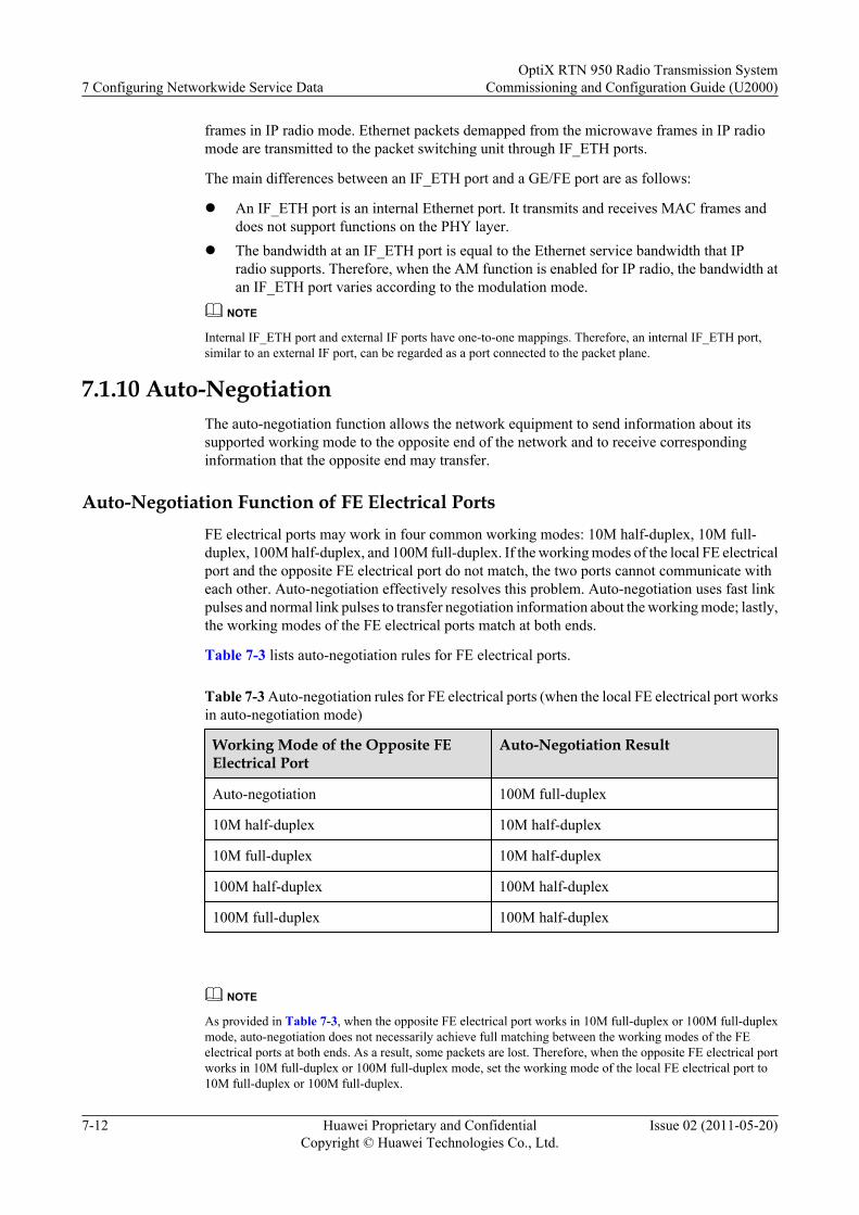
frames in IP radio mode. Ethernet packets demapped from the microwave frames in IP radiomode are transmitted to the packet switching unit through IF_ETH ports.
The main differences between an IF_ETH port and a GE/FE port are as follows:
l An IF_ETH port is an internal Ethernet port. It transmits and receives MAC frames anddoes not support functions on the PHY layer.
l The bandwidth at an IF_ETH port is equal to the Ethernet service bandwidth that IPradio supports. Therefore, when the AM function is enabled for IP radio, the bandwidth atan IF_ETH port varies according to the modulation mode.
NOTE
Internal IF_ETH port and external IF ports have one-to-one mappings. Therefore, an internal IF_ETH port,similar to an external IF port, can be regarded as a port connected to the packet plane.
7.1.10 Auto-NegotiationThe auto-negotiation function allows the network equipment to send information about itssupported working mode to the opposite end of the network and to receive correspondinginformation that the opposite end may transfer.
Auto-Negotiation Function of FE Electrical PortsFE electrical ports may work in four common working modes: 10M half-duplex, 10M full-duplex, 100M half-duplex, and 100M full-duplex. If the working modes of the local FE electricalport and the opposite FE electrical port do not match, the two ports cannot communicate witheach other. Auto-negotiation effectively resolves this problem. Auto-negotiation uses fast linkpulses and normal link pulses to transfer negotiation information about the working mode; lastly,the working modes of the FE electrical ports match at both ends.
Table 7-3 lists auto-negotiation rules for FE electrical ports.
Table 7-3 Auto-negotiation rules for FE electrical ports (when the local FE electrical port worksin auto-negotiation mode)
Working Mode of the Opposite FEElectrical Port
Auto-Negotiation Result
Auto-negotiation 100M full-duplex
10M half-duplex 10M half-duplex
10M full-duplex 10M half-duplex
100M half-duplex 100M half-duplex
100M full-duplex 100M half-duplex
NOTE
As provided in Table 7-3, when the opposite FE electrical port works in 10M full-duplex or 100M full-duplexmode, auto-negotiation does not necessarily achieve full matching between the working modes of the FEelectrical ports at both ends. As a result, some packets are lost. Therefore, when the opposite FE electrical portworks in 10M full-duplex or 100M full-duplex mode, set the working mode of the local FE electrical port to10M full-duplex or 100M full-duplex.
7 Configuring Networkwide Service DataOptiX RTN 950 Radio Transmission System
Commissioning and Configuration Guide (U2000)
7-12 Huawei Proprietary and ConfidentialCopyright © Huawei Technologies Co., Ltd.
Issue 02 (2011-05-20)
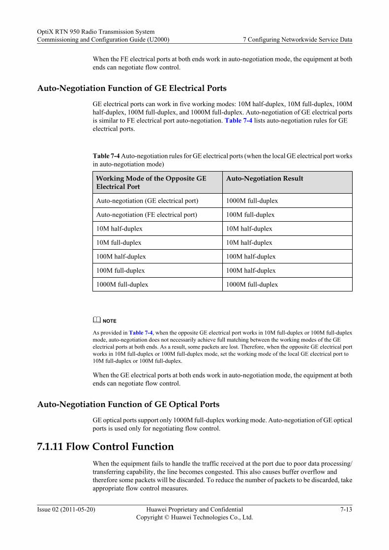
When the FE electrical ports at both ends work in auto-negotiation mode, the equipment at bothends can negotiate flow control.
Auto-Negotiation Function of GE Electrical Ports
GE electrical ports can work in five working modes: 10M half-duplex, 10M full-duplex, 100Mhalf-duplex, 100M full-duplex, and 1000M full-duplex. Auto-negotiation of GE electrical portsis similar to FE electrical port auto-negotiation. Table 7-4 lists auto-negotiation rules for GEelectrical ports.
Table 7-4 Auto-negotiation rules for GE electrical ports (when the local GE electrical port worksin auto-negotiation mode)
Working Mode of the Opposite GEElectrical Port
Auto-Negotiation Result
Auto-negotiation (GE electrical port) 1000M full-duplex
Auto-negotiation (FE electrical port) 100M full-duplex
10M half-duplex 10M half-duplex
10M full-duplex 10M half-duplex
100M half-duplex 100M half-duplex
100M full-duplex 100M half-duplex
1000M full-duplex 1000M full-duplex
NOTE
As provided in Table 7-4, when the opposite GE electrical port works in 10M full-duplex or 100M full-duplexmode, auto-negotiation does not necessarily achieve full matching between the working modes of the GEelectrical ports at both ends. As a result, some packets are lost. Therefore, when the opposite GE electrical portworks in 10M full-duplex or 100M full-duplex mode, set the working mode of the local GE electrical port to10M full-duplex or 100M full-duplex.
When the GE electrical ports at both ends work in auto-negotiation mode, the equipment at bothends can negotiate flow control.
Auto-Negotiation Function of GE Optical Ports
GE optical ports support only 1000M full-duplex working mode. Auto-negotiation of GE opticalports is used only for negotiating flow control.
7.1.11 Flow Control FunctionWhen the equipment fails to handle the traffic received at the port due to poor data processing/transferring capability, the line becomes congested. This also causes buffer overflow andtherefore some packets will be discarded. To reduce the number of packets to be discarded, takeappropriate flow control measures.
OptiX RTN 950 Radio Transmission SystemCommissioning and Configuration Guide (U2000) 7 Configuring Networkwide Service Data
Issue 02 (2011-05-20) Huawei Proprietary and ConfidentialCopyright © Huawei Technologies Co., Ltd.
7-13
Half-duplex Ethernet uses a back-pressure mechanism to control flow. Full-duplex Ethernet usesPAUSE frames to control flow. Currently, half-duplex Ethernet is not widely applied; therefore,flow control implemented on the equipment is used for full-duplex Ethernet.
The flow control function on the equipment is classified into two types: auto-negotiation flowcontrol and non-auto-negotiation flow control.
Auto-Negotiation Flow Control
When an Ethernet port works in auto-negotiation mode, use auto-negotiation flow control. Theauto-negotiation flow control modes include the following:
l Asymmetric PAUSE toward the link partnerThe port can transmit PAUSE frames in case of congestion but cannot process receivedPAUSE frames.
l Symmetric PAUSEThe port can transmit PAUSE frames and process received PAUSE frames.
l Both asymmetric and symmetric PAUSEThe port has the following capabilities:
– Transmits and processes PAUSE frames.
– Transmits PAUSE frames but cannot process received PAUSE frames.
– Processes received PAUSE frames but cannot transmit PAUSE frames.l Disabled
The port does not transmit or process PAUSE frames.
NOTE
On the NMS, the OptiX RTN 950 supports only two auto-negotiation flow control modes: Disabled mode andEnable Symmetric Flow Control (symmetric PAUSE) mode.
Non-Auto-Negotiation Flow Control
When an Ethernet port works in a fixed working mode, use non-auto-negotiation flow control.The non-auto-negotiation flow control modes include the following:
l Send onlyThe port can transmit PAUSE frames in case of congestion but cannot process receivedPAUSE frames.
l Receive onlyThe port can process received PAUSE frames but cannot transmit PAUSE frames in caseof congestion.
l SymmetricThe port can transmit PAUSE frames and can also process received PAUSE frames.
l DisabledThe port does not transmit or process PAUSE frames.
NOTE
On the NMS, the OptiX RTN 950 supports only two non-auto-negotiation flow control modes: Disabled modeand Enable Symmetric Flow Control (symmetric) mode.
7 Configuring Networkwide Service DataOptiX RTN 950 Radio Transmission System
Commissioning and Configuration Guide (U2000)
7-14 Huawei Proprietary and ConfidentialCopyright © Huawei Technologies Co., Ltd.
Issue 02 (2011-05-20)
7.1.12 MAC Address Table ManagementThe entries in a MAC address table show the mappings between MAC addresses and ports. AMAC address table contains dynamic entries, static entries, and blacklist entries.
l Dynamic entryA dynamic entry is obtained by learning of a bridge through the SVL/IVL mode. Thedynamic entry will be aged.
l Static entryA static entry is manually added to the MAC address table by a network administrator usingthe NMS. The static entry will not be aged. Generally, the static entry is configured for aport if a device with a known MAC address is mounted to the port and this device transmitslarge traffic for a long time.
l Blacklist entryA blacklist entry is a MAC disabled entry and is used to discard a data frame that containsa specified MAC address (source MAC address or destination MAC address). A blacklistentry is also called a blackhole entry. The blacklist entry is configured by the networkadministrator. The blacklist entry does not age, and is not lost after the Ethernet processingboard is reset.
NOTEA routing entry is automatically deleted when that routing entry is not updated within a specified period.This occurs when no new packet from this MAC address is received to enable the re-learning of this MACaddress. This mechanism is called aging, and this period is called aging time.
7.1.13 Split Horizon GroupTo separate services that are converged and to prevent a broadcast storm resulting from a serviceloop, you can configure a split horizon group for the E-LAN services at the specified nodes.After the configuration, the logical ports in one split horizon group cannot forward packets toeach other.
Figure 7-7 shows a typical application of the split horizon group. NEs on the network areconfigured with E-LAN services, and the east and west ports and service access ports areconfigured as mounted ports of a bridge. In this case, if a split horizon group is not configuredat NE1, broadcast storm occurs due to a network loop as the east and west ports can forwardpackets to each other. If a split horizon group is created at NE1 and the east and west ports areconfigured as members of the split horizon group, the east and west ports do not forward packetsto each other. Therefore, a service loop is prevented.
OptiX RTN 950 Radio Transmission SystemCommissioning and Configuration Guide (U2000) 7 Configuring Networkwide Service Data
Issue 02 (2011-05-20) Huawei Proprietary and ConfidentialCopyright © Huawei Technologies Co., Ltd.
7-15
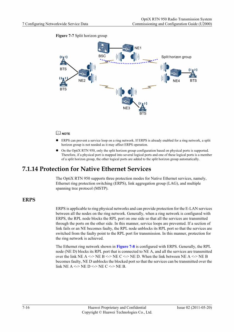
Figure 7-7 Split horizon group
BTS
BTS
NE1
NE3
NE2 NE4
BSC
BTS
BTS
Split horizon group
NOTE
l ERPS can prevent a service loop on a ring network. If ERPS is already enabled for a ring network, a splithorizon group is not needed as it may affect ERPS operation.
l On the OptiX RTN 950, only the split horizon group configuration based on physical ports is supported.Therefore, if a physical port is mapped into several logical ports and one of these logical ports is a memberof a split horizon group, the other logical ports are added to the split horizon group automatically.
7.1.14 Protection for Native Ethernet ServicesThe OptiX RTN 950 supports three protection modes for Native Ethernet services, namely,Ethernet ring protection switching (ERPS), link aggregation group (LAG), and multiplespanning tree protocol (MSTP).
ERPSERPS is applicable to ring physical networks and can provide protection for the E-LAN servicesbetween all the nodes on the ring network. Generally, when a ring network is configured withERPS, the RPL node blocks the RPL port on one side so that all the services are transmittedthrough the ports on the other side. In this manner, service loops are prevented. If a section oflink fails or an NE becomes faulty, the RPL node unblocks its RPL port so that the services areswitched from the faulty point to the RPL port for transmission. In this manner, protection forthe ring network is achieved.
The Ethernet ring network shown in Figure 7-8 is configured with ERPS. Generally, the RPLnode (NE D) blocks its RPL port that is connected to NE A, and all the services are transmittedover the link NE A <-> NE B <-> NE C <-> NE D. When the link between NE A <-> NE Bbecomes faulty, NE D unblocks the blocked port so that the services can be transmitted over thelink NE A <-> NE D <-> NE C <-> NE B.
7 Configuring Networkwide Service DataOptiX RTN 950 Radio Transmission System
Commissioning and Configuration Guide (U2000)
7-16 Huawei Proprietary and ConfidentialCopyright © Huawei Technologies Co., Ltd.
Issue 02 (2011-05-20)
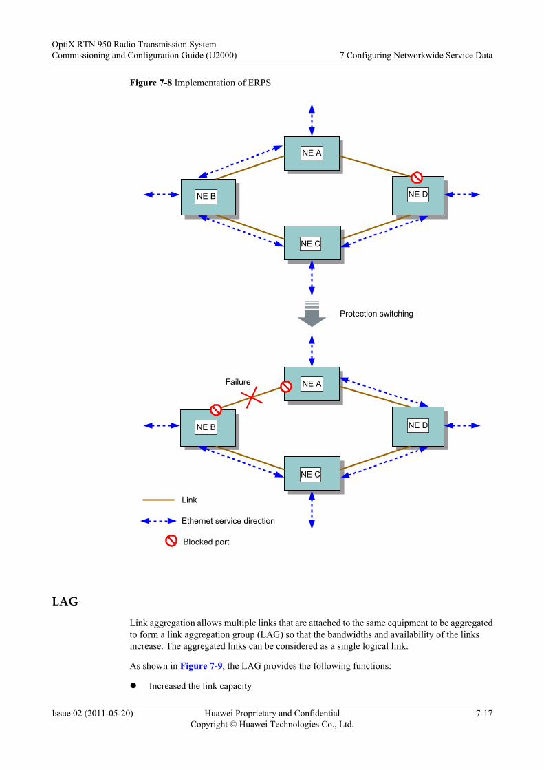
Figure 7-8 Implementation of ERPS
Protection switching
Link
NE B
NE A
NE C
NE D
NE B
NE A
NE C
NE D
Failure
Ethernet service direction
Blocked port
LAG
Link aggregation allows multiple links that are attached to the same equipment to be aggregatedto form a link aggregation group (LAG) so that the bandwidths and availability of the linksincrease. The aggregated links can be considered as a single logical link.
As shown in Figure 7-9, the LAG provides the following functions:
l Increased the link capacity
OptiX RTN 950 Radio Transmission SystemCommissioning and Configuration Guide (U2000) 7 Configuring Networkwide Service Data
Issue 02 (2011-05-20) Huawei Proprietary and ConfidentialCopyright © Huawei Technologies Co., Ltd.
7-17
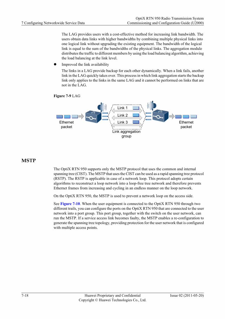
The LAG provides users with a cost-effective method for increasing link bandwidth. Theusers obtain data links with higher bandwidths by combining multiple physical links intoone logical link without upgrading the existing equipment. The bandwidth of the logicallink is equal to the sum of the bandwidths of the physical links. The aggregation moduledistributes the traffic to different members by using the load balancing algorithm, achievingthe load balancing at the link level.
l Improved the link availabilityThe links in a LAG provide backup for each other dynamically. When a link fails, anotherlink in the LAG quickly takes over. This process in which link aggregation starts the backuplink only applies to the links in the same LAG and it cannot be performed on links that arenot in the LAG.
Figure 7-9 LAG
Ethernetpacket
Link 1
Link aggregationgroup
Ethernetpacket
Link 2
Link 3
MSTPThe OptiX RTN 950 supports only the MSTP protocol that uses the common and internalspanning tree (CIST). The MSTP that uses the CIST can be used as a rapid spanning tree protocol(RSTP). The RSTP is applicable in case of a network loop. This protocol adopts certainalgorithms to reconstruct a loop network into a loop-free tree network and therefore preventsEthernet frames from increasing and cycling in an endless manner on the loop network.
On the OptiX RTN 950, the MSTP is used to prevent a network loop on the access side.
See Figure 7-10. When the user equipment is connected to the OptiX RTN 950 through twodifferent trails, you can configure the ports on the OptiX RTN 950 that are connected to the usernetwork into a port group. This port group, together with the switch on the user network, canrun the MSTP. If a service access link becomes faulty, the MSTP enables a re-configuration togenerate the spanning tree topology, providing protection for the user network that is configuredwith multiple access points.
7 Configuring Networkwide Service DataOptiX RTN 950 Radio Transmission System
Commissioning and Configuration Guide (U2000)
7-18 Huawei Proprietary and ConfidentialCopyright © Huawei Technologies Co., Ltd.
Issue 02 (2011-05-20)

Figure 7-10 Prevention of network loops on the access side
CIST
Root Root
Port group
Blocked Port
7.1.15 Clock SourceA clock source is a signal source that carries timing reference information. An NE implementsclock synchronization, by using its phase locked loop (PLL) to lock the timing information ofthe clock source.
The OptiX RTN 950 supports the following clock sources:
l Radio clock source: refers to a clock source that is extracted from the received radio signal.
l Ethernet clock source: refers to a clock source that is extracted from the Ethernet stream.
l Internal clock source: refers to a clock source that is generated through the free-runoscillation of an NE built-in clock. The internal clock source has the lowest priority.
7.1.16 Clock Protection ModesThe OptiX RTN 950 supports clock source protection based on priorities, synchronization statusmessage (SSM) protection, and extended SSM protection.
Clock Source Protection Based on Priorities
Clock source protection is provided based on the priorities specified in the clock source prioritylist. When a clock source with a higher priority fails, a clock source with a lower priority is used.
As shown in Figure 7-11, the radio links between NE1 and NE2 adopt 1+1 HSB protection.NE2 needs to trace the clock on the radio links to keep synchronized with NE1. In this case, theclock sources extracted by the main and standby IF boards can be configured in the clock sourcepriority list. The clock source extracted by the main IF board, however, has a higher priority.Therefore, if the 1+1 HSB protection switching occurs on the radio links, the clock can beswitched at the same time.
OptiX RTN 950 Radio Transmission SystemCommissioning and Configuration Guide (U2000) 7 Configuring Networkwide Service Data
Issue 02 (2011-05-20) Huawei Proprietary and ConfidentialCopyright © Huawei Technologies Co., Ltd.
7-19
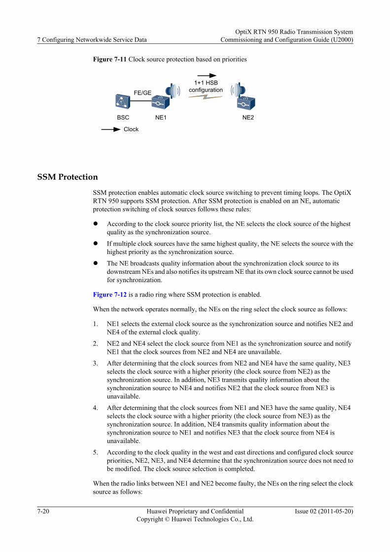
Figure 7-11 Clock source protection based on priorities
NE2NE1BSC
1+1 HSBconfiguration
Clock
FE/GE
SSM Protection
SSM protection enables automatic clock source switching to prevent timing loops. The OptiXRTN 950 supports SSM protection. After SSM protection is enabled on an NE, automaticprotection switching of clock sources follows these rules:
l According to the clock source priority list, the NE selects the clock source of the highestquality as the synchronization source.
l If multiple clock sources have the same highest quality, the NE selects the source with thehighest priority as the synchronization source.
l The NE broadcasts quality information about the synchronization clock source to itsdownstream NEs and also notifies its upstream NE that its own clock source cannot be usedfor synchronization.
Figure 7-12 is a radio ring where SSM protection is enabled.
When the network operates normally, the NEs on the ring select the clock source as follows:
1. NE1 selects the external clock source as the synchronization source and notifies NE2 andNE4 of the external clock quality.
2. NE2 and NE4 select the clock source from NE1 as the synchronization source and notifyNE1 that the clock sources from NE2 and NE4 are unavailable.
3. After determining that the clock sources from NE2 and NE4 have the same quality, NE3selects the clock source with a higher priority (the clock source from NE2) as thesynchronization source. In addition, NE3 transmits quality information about thesynchronization source to NE4 and notifies NE2 that the clock source from NE3 isunavailable.
4. After determining that the clock sources from NE1 and NE3 have the same quality, NE4selects the clock source with a higher priority (the clock source from NE3) as thesynchronization source. In addition, NE4 transmits quality information about thesynchronization source to NE1 and notifies NE3 that the clock source from NE4 isunavailable.
5. According to the clock quality in the west and east directions and configured clock sourcepriorities, NE2, NE3, and NE4 determine that the synchronization source does not need tobe modified. The clock source selection is completed.
When the radio links between NE1 and NE2 become faulty, the NEs on the ring select the clocksource as follows:
7 Configuring Networkwide Service DataOptiX RTN 950 Radio Transmission System
Commissioning and Configuration Guide (U2000)
7-20 Huawei Proprietary and ConfidentialCopyright © Huawei Technologies Co., Ltd.
Issue 02 (2011-05-20)
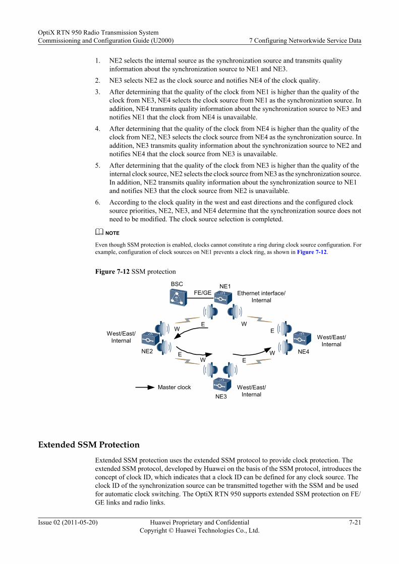
1. NE2 selects the internal source as the synchronization source and transmits qualityinformation about the synchronization source to NE1 and NE3.
2. NE3 selects NE2 as the clock source and notifies NE4 of the clock quality.3. After determining that the quality of the clock from NE1 is higher than the quality of the
clock from NE3, NE4 selects the clock source from NE1 as the synchronization source. Inaddition, NE4 transmits quality information about the synchronization source to NE3 andnotifies NE1 that the clock from NE4 is unavailable.
4. After determining that the quality of the clock from NE4 is higher than the quality of theclock from NE2, NE3 selects the clock source from NE4 as the synchronization source. Inaddition, NE3 transmits quality information about the synchronization source to NE2 andnotifies NE4 that the clock source from NE3 is unavailable.
5. After determining that the quality of the clock from NE3 is higher than the quality of theinternal clock source, NE2 selects the clock source from NE3 as the synchronization source.In addition, NE2 transmits quality information about the synchronization source to NE1and notifies NE3 that the clock source from NE2 is unavailable.
6. According to the clock quality in the west and east directions and the configured clocksource priorities, NE2, NE3, and NE4 determine that the synchronization source does notneed to be modified. The clock source selection is completed.
NOTE
Even though SSM protection is enabled, clocks cannot constitute a ring during clock source configuration. Forexample, configuration of clock sources on NE1 prevents a clock ring, as shown in Figure 7-12.
Figure 7-12 SSM protection
NE1
NE3
NE2 NE4
BSCEthernet interface/
Internal
West/East/Internal
West/East/Internal
West/East/Internal
E
W
E
E
W
WE
W
Master clock
FE/GE
Extended SSM Protection
Extended SSM protection uses the extended SSM protocol to provide clock protection. Theextended SSM protocol, developed by Huawei on the basis of the SSM protocol, introduces theconcept of clock ID, which indicates that a clock ID can be defined for any clock source. Theclock ID of the synchronization source can be transmitted together with the SSM and be usedfor automatic clock switching. The OptiX RTN 950 supports extended SSM protection on FE/GE links and radio links.
OptiX RTN 950 Radio Transmission SystemCommissioning and Configuration Guide (U2000) 7 Configuring Networkwide Service Data
Issue 02 (2011-05-20) Huawei Proprietary and ConfidentialCopyright © Huawei Technologies Co., Ltd.
7-21
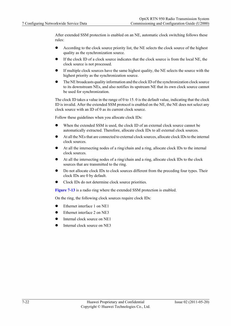
After extended SSM protection is enabled on an NE, automatic clock switching follows theserules:
l According to the clock source priority list, the NE selects the clock source of the highestquality as the synchronization source.
l If the clock ID of a clock source indicates that the clock source is from the local NE, theclock source is not processed.
l If multiple clock sources have the same highest quality, the NE selects the source with thehighest priority as the synchronization source.
l The NE broadcasts quality information and the clock ID of the synchronization clock sourceto its downstream NEs, and also notifies its upstream NE that its own clock source cannotbe used for synchronization.
The clock ID takes a value in the range of 0 to 15. 0 is the default value, indicating that the clockID is invalid. After the extended SSM protocol is enabled on the NE, the NE does not select anyclock source with an ID of 0 as its current clock source.
Follow these guidelines when you allocate clock IDs:
l When the extended SSM is used, the clock ID of an external clock source cannot beautomatically extracted. Therefore, allocate clock IDs to all external clock sources.
l At all the NEs that are connected to external clock sources, allocate clock IDs to the internalclock sources.
l At all the intersecting nodes of a ring/chain and a ring, allocate clock IDs to the internalclock sources.
l At all the intersecting nodes of a ring/chain and a ring, allocate clock IDs to the clocksources that are transmitted to the ring.
l Do not allocate clock IDs to clock sources different from the preceding four types. Theirclock IDs are 0 by default.
l Clock IDs do not determine clock source priorities.
Figure 7-13 is a radio ring where the extended SSM protection is enabled.
On the ring, the following clock sources require clock IDs:
l Ethernet interface 1 on NE1l Ethernet interface 2 on NE3l Internal clock source on NE1l Internal clock source on NE3
7 Configuring Networkwide Service DataOptiX RTN 950 Radio Transmission System
Commissioning and Configuration Guide (U2000)
7-22 Huawei Proprietary and ConfidentialCopyright © Huawei Technologies Co., Ltd.
Issue 02 (2011-05-20)
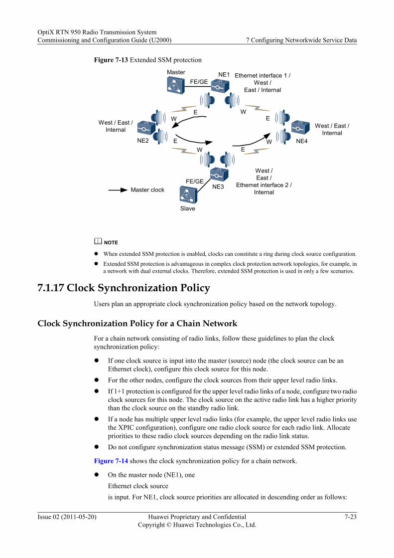
Figure 7-13 Extended SSM protection
NE1
NE3
NE2 NE4
Master
West / East /Internal
West /East /
Ethernet interface 2 /Internal
West / East /Internal
W E
W
E
E
W
Slave
Ethernet interface 1 /West /
East / Internal
WE
Master clock
FE/GE
FE/GE
NOTE
l When extended SSM protection is enabled, clocks can constitute a ring during clock source configuration.
l Extended SSM protection is advantageous in complex clock protection network topologies, for example, ina network with dual external clocks. Therefore, extended SSM protection is used in only a few scenarios.
7.1.17 Clock Synchronization PolicyUsers plan an appropriate clock synchronization policy based on the network topology.
Clock Synchronization Policy for a Chain NetworkFor a chain network consisting of radio links, follow these guidelines to plan the clocksynchronization policy:
l If one clock source is input into the master (source) node (the clock source can be anEthernet clock), configure this clock source for this node.
l For the other nodes, configure the clock sources from their upper level radio links.l If 1+1 protection is configured for the upper level radio links of a node, configure two radio
clock sources for this node. The clock source on the active radio link has a higher prioritythan the clock source on the standby radio link.
l If a node has multiple upper level radio links (for example, the upper level radio links usethe XPIC configuration), configure one radio clock source for each radio link. Allocatepriorities to these radio clock sources depending on the radio link status.
l Do not configure synchronization status message (SSM) or extended SSM protection.
Figure 7-14 shows the clock synchronization policy for a chain network.
l On the master node (NE1), oneEthernet clock sourceis input. For NE1, clock source priorities are allocated in descending order as follows:
OptiX RTN 950 Radio Transmission SystemCommissioning and Configuration Guide (U2000) 7 Configuring Networkwide Service Data
Issue 02 (2011-05-20) Huawei Proprietary and ConfidentialCopyright © Huawei Technologies Co., Ltd.
7-23
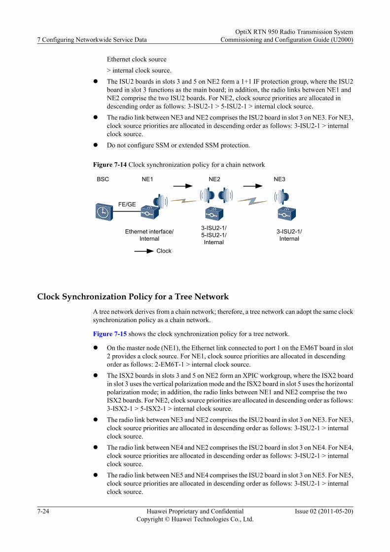
Ethernet clock source> internal clock source.
l The ISU2 boards in slots 3 and 5 on NE2 form a 1+1 IF protection group, where the ISU2board in slot 3 functions as the main board; in addition, the radio links between NE1 andNE2 comprise the two ISU2 boards. For NE2, clock source priorities are allocated indescending order as follows: 3-ISU2-1 > 5-ISU2-1 > internal clock source.
l The radio link between NE3 and NE2 comprises the ISU2 board in slot 3 on NE3. For NE3,clock source priorities are allocated in descending order as follows: 3-ISU2-1 > internalclock source.
l Do not configure SSM or extended SSM protection.
Figure 7-14 Clock synchronization policy for a chain network
3-ISU2-1/5-ISU2-1/Internal
3-ISU2-1/Internal
NE1 NE2
Clock
Ethernet interface/Internal
BSC NE3
FE/GE
Clock Synchronization Policy for a Tree NetworkA tree network derives from a chain network; therefore, a tree network can adopt the same clocksynchronization policy as a chain network.
Figure 7-15 shows the clock synchronization policy for a tree network.
l On the master node (NE1), the Ethernet link connected to port 1 on the EM6T board in slot2 provides a clock source. For NE1, clock source priorities are allocated in descendingorder as follows: 2-EM6T-1 > internal clock source.
l The ISX2 boards in slots 3 and 5 on NE2 form an XPIC workgroup, where the ISX2 boardin slot 3 uses the vertical polarization mode and the ISX2 board in slot 5 uses the horizontalpolarization mode; in addition, the radio links between NE1 and NE2 comprise the twoISX2 boards. For NE2, clock source priorities are allocated in descending order as follows:3-ISX2-1 > 5-ISX2-1 > internal clock source.
l The radio link between NE3 and NE2 comprises the ISU2 board in slot 3 on NE3. For NE3,clock source priorities are allocated in descending order as follows: 3-ISU2-1 > internalclock source.
l The radio link between NE4 and NE2 comprises the ISU2 board in slot 3 on NE4. For NE4,clock source priorities are allocated in descending order as follows: 3-ISU2-1 > internalclock source.
l The radio link between NE5 and NE4 comprises the ISU2 board in slot 3 on NE5. For NE5,clock source priorities are allocated in descending order as follows: 3-ISU2-1 > internalclock source.
7 Configuring Networkwide Service DataOptiX RTN 950 Radio Transmission System
Commissioning and Configuration Guide (U2000)
7-24 Huawei Proprietary and ConfidentialCopyright © Huawei Technologies Co., Ltd.
Issue 02 (2011-05-20)
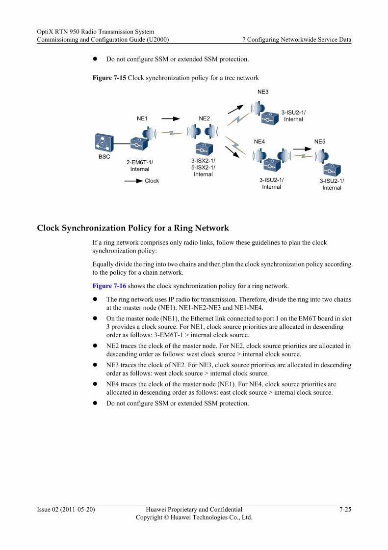
l Do not configure SSM or extended SSM protection.
Figure 7-15 Clock synchronization policy for a tree network
3-ISX2-1/5-ISX2-1/Internal
3-ISU2-1/InternalNE1 NE2
Clock
2-EM6T-1/Internal
NE3
3-ISU2-1/Internal
NE4
3-ISU2-1/Internal
BSC
NE5
Clock Synchronization Policy for a Ring NetworkIf a ring network comprises only radio links, follow these guidelines to plan the clocksynchronization policy:
Equally divide the ring into two chains and then plan the clock synchronization policy accordingto the policy for a chain network.
Figure 7-16 shows the clock synchronization policy for a ring network.
l The ring network uses IP radio for transmission. Therefore, divide the ring into two chainsat the master node (NE1): NE1-NE2-NE3 and NE1-NE4.
l On the master node (NE1), the Ethernet link connected to port 1 on the EM6T board in slot3 provides a clock source. For NE1, clock source priorities are allocated in descendingorder as follows: 3-EM6T-1 > internal clock source.
l NE2 traces the clock of the master node. For NE2, clock source priorities are allocated indescending order as follows: west clock source > internal clock source.
l NE3 traces the clock of NE2. For NE3, clock source priorities are allocated in descendingorder as follows: west clock source > internal clock source.
l NE4 traces the clock of the master node (NE1). For NE4, clock source priorities areallocated in descending order as follows: east clock source > internal clock source.
l Do not configure SSM or extended SSM protection.
OptiX RTN 950 Radio Transmission SystemCommissioning and Configuration Guide (U2000) 7 Configuring Networkwide Service Data
Issue 02 (2011-05-20) Huawei Proprietary and ConfidentialCopyright © Huawei Technologies Co., Ltd.
7-25
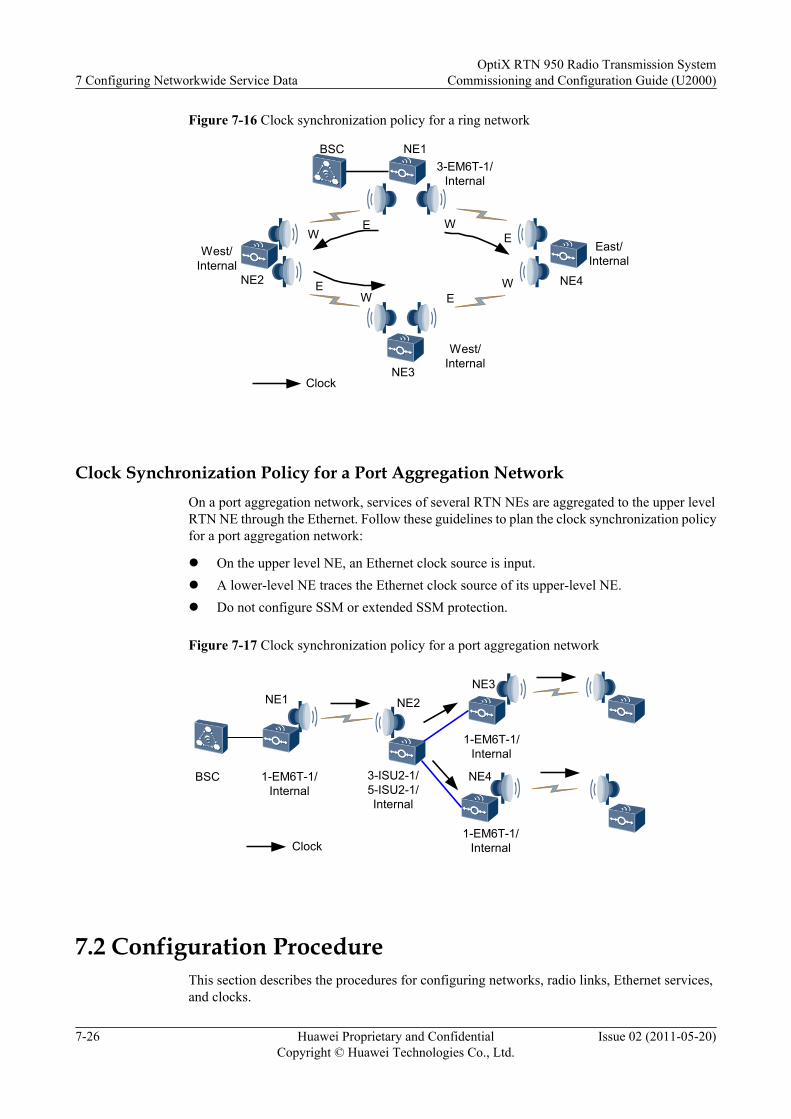
Figure 7-16 Clock synchronization policy for a ring network
NE1
NE3
NE2 NE4
West/Internal
West/Internal
East/Internal
E
W
E
E
W
WE
W
BSC3-EM6T-1/
Internal
Clock
Clock Synchronization Policy for a Port Aggregation NetworkOn a port aggregation network, services of several RTN NEs are aggregated to the upper levelRTN NE through the Ethernet. Follow these guidelines to plan the clock synchronization policyfor a port aggregation network:
l On the upper level NE, an Ethernet clock source is input.l A lower-level NE traces the Ethernet clock source of its upper-level NE.l Do not configure SSM or extended SSM protection.
Figure 7-17 Clock synchronization policy for a port aggregation network
3-ISU2-1/5-ISU2-1/Internal
NE1 NE2
Clock
1-EM6T-1/Internal
NE3
1-EM6T-1/Internal
NE4
1-EM6T-1/Internal
BSC
7.2 Configuration ProcedureThis section describes the procedures for configuring networks, radio links, Ethernet services,and clocks.
7 Configuring Networkwide Service DataOptiX RTN 950 Radio Transmission System
Commissioning and Configuration Guide (U2000)
7-26 Huawei Proprietary and ConfidentialCopyright © Huawei Technologies Co., Ltd.
Issue 02 (2011-05-20)
7.2.1 Configuration Procedure (Network)This section describes the procedures for configuring four topology objects: NEs, boards, fibers/cables, and subnets.
7.2.2 Configuration Procedure (Radio Link)The configuration procedure varies according to the IP radio link configuration mode.
7.2.3 Configuration Procedure (IEEE 802.1q Bridge-Based E-LAN Services)Configuring IEEE 802.1q bridge-based services includes configuring the service information,port information, protection information, and QoS information, and verifying the serviceconfigurations.
7.2.4 Configuration Procedure (Clocks)Configuring clocks includes configuring clock sources, clock protection, and output clocks.
7.2.1 Configuration Procedure (Network)This section describes the procedures for configuring four topology objects: NEs, boards, fibers/cables, and subnets.
Figure 7-18 shows the configuration flowchart of the network topology.
OptiX RTN 950 Radio Transmission SystemCommissioning and Configuration Guide (U2000) 7 Configuring Networkwide Service Data
Issue 02 (2011-05-20) Huawei Proprietary and ConfidentialCopyright © Huawei Technologies Co., Ltd.
7-27
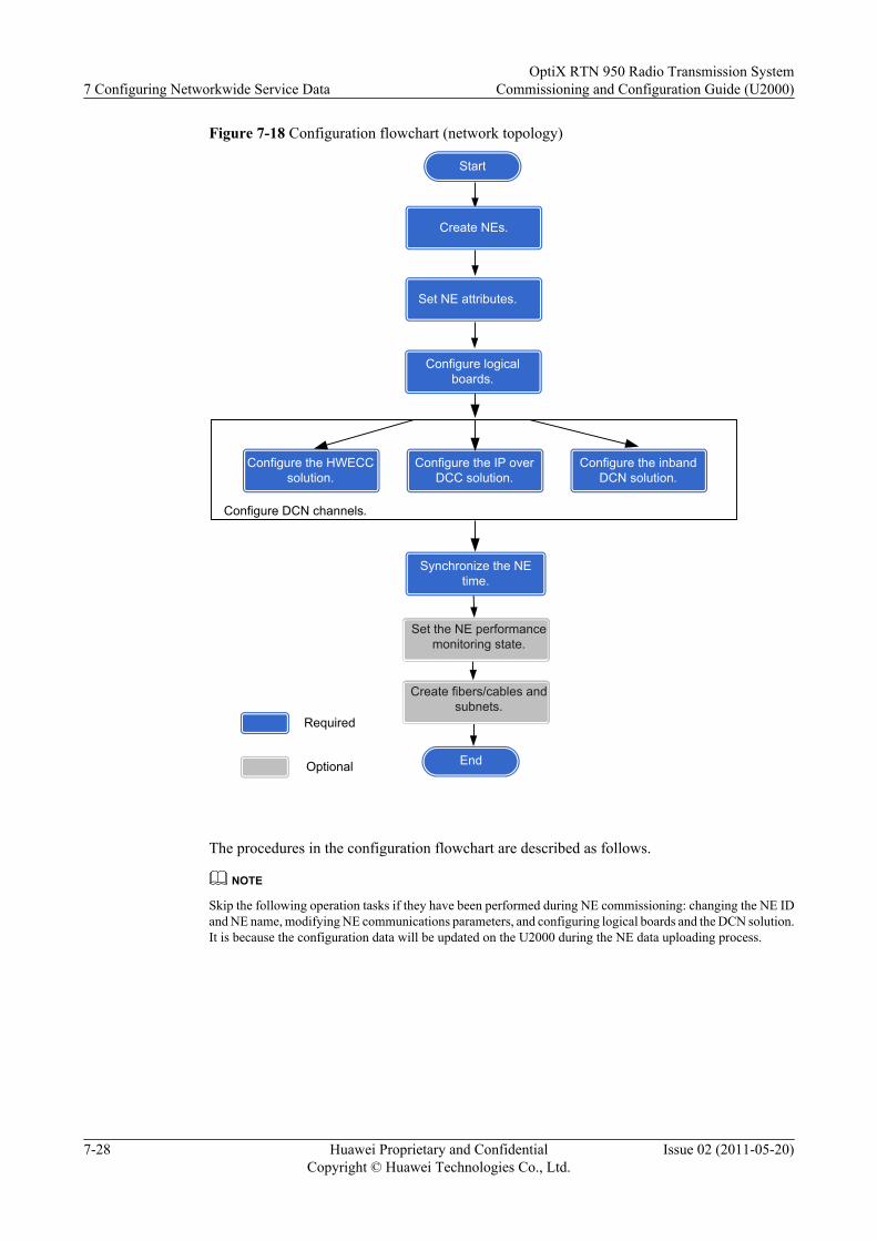
Figure 7-18 Configuration flowchart (network topology)
Required
Optional End
Start
Create NEs.
Synchronize the NE time.
Set the NE performance monitoring state.
Set NE attributes.
Create fibers/cables and subnets.
Configure logical boards.
Configure the HWECC solution.
Configure the IP over DCC solution.
Configure the inband DCN solution.
Configure DCN channels.
The procedures in the configuration flowchart are described as follows.
NOTE
Skip the following operation tasks if they have been performed during NE commissioning: changing the NE IDand NE name, modifying NE communications parameters, and configuring logical boards and the DCN solution.It is because the configuration data will be updated on the U2000 during the NE data uploading process.
7 Configuring Networkwide Service DataOptiX RTN 950 Radio Transmission System
Commissioning and Configuration Guide (U2000)
7-28 Huawei Proprietary and ConfidentialCopyright © Huawei Technologies Co., Ltd.
Issue 02 (2011-05-20)

Creating NEs
Table 7-5 Procedure for creating NEs
Stage Operation Description
1 Creating NEsby using theU2000
8.2.1.2Creating NEsby Using theManualMethod
It is recommended that you performoperations on the U2000 to add one or moreNEs to a large network.To achieve SSL communication between theU2000 and the gateway NE, set ConnectionMode to Security SSL. Otherwise,Connection Mode takes its default value.
8.2.1.1Creating NEsby Using theSearchMethod
It is recommended that you performoperations on the U2000 to add NEs in otherscenarios. Set the parameters as follows:l Search Mode: Set Search Mode to
Search for NE.l Search Domain: When the IP address of
the gateway NE is known, it isrecommended that you set the IP addressrange of the gateway NE as SearchDomain. For initial configuration, it isrecommended that you set the129.9.255.255 network segment asSearch Domain.
l Search for NE: It is recommended thatyou select Create NE after search andUpload after being created. By default,NE User is root and Password ispassword.
l Connection Mode: This parameterspecifies the connection mode betweenthe U2000 and the gateway NE. For SSLconnection, set this parameter to SecuritySSL.
2 8.2.2.1 Uploading the NE Data Optional.Skip this operation task if you select Uploadafter being created during 8.2.1.1 CreatingNEs by Using the Search Method.
OptiX RTN 950 Radio Transmission SystemCommissioning and Configuration Guide (U2000) 7 Configuring Networkwide Service Data
Issue 02 (2011-05-20) Huawei Proprietary and ConfidentialCopyright © Huawei Technologies Co., Ltd.
7-29
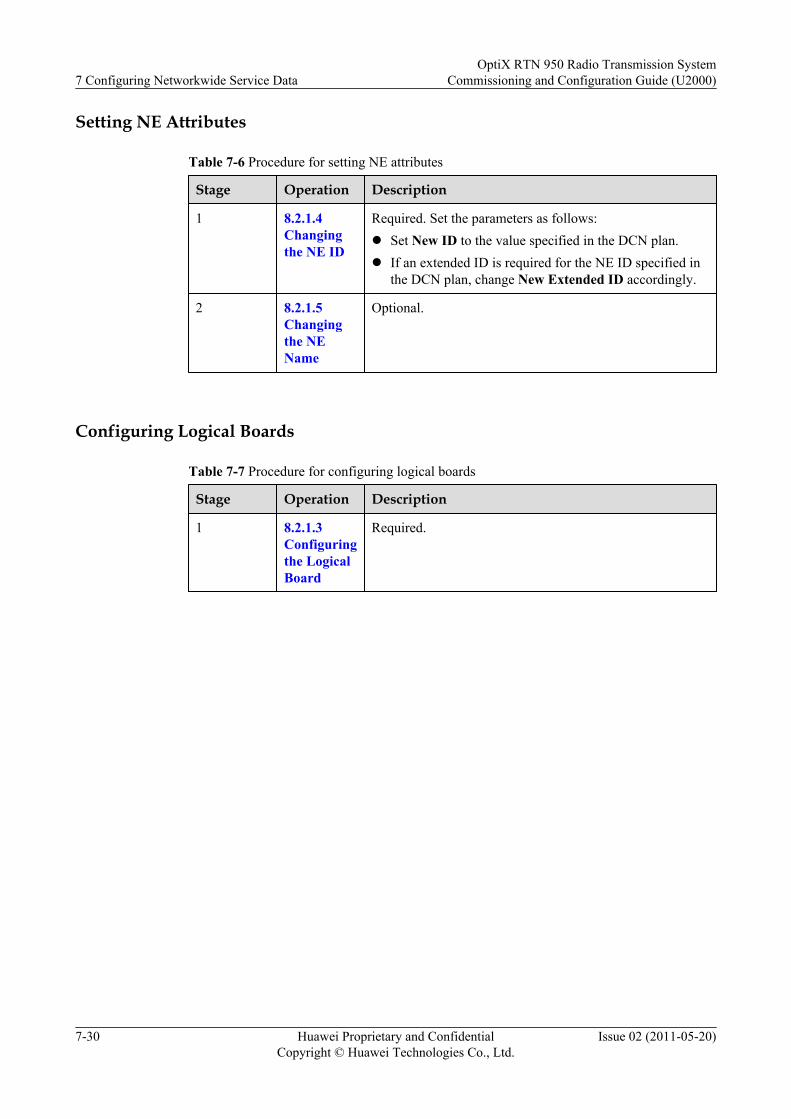
Setting NE Attributes
Table 7-6 Procedure for setting NE attributes
Stage Operation Description
1 8.2.1.4Changingthe NE ID
Required. Set the parameters as follows:l Set New ID to the value specified in the DCN plan.l If an extended ID is required for the NE ID specified in
the DCN plan, change New Extended ID accordingly.
2 8.2.1.5Changingthe NEName
Optional.
Configuring Logical Boards
Table 7-7 Procedure for configuring logical boards
Stage Operation Description
1 8.2.1.3Configuringthe LogicalBoard
Required.
7 Configuring Networkwide Service DataOptiX RTN 950 Radio Transmission System
Commissioning and Configuration Guide (U2000)
7-30 Huawei Proprietary and ConfidentialCopyright © Huawei Technologies Co., Ltd.
Issue 02 (2011-05-20)
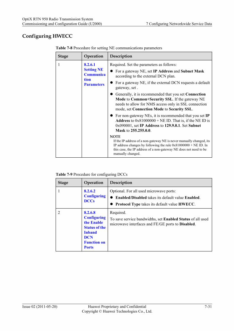
Configuring HWECC
Table 7-8 Procedure for setting NE communications parameters
Stage Operation Description
1 8.2.6.1Setting NECommunicationParameters
Required. Set the parameters as follows:l For a gateway NE, set IP Address and Subnet Mask
according to the external DCN plan.l For a gateway NE, if the external DCN requests a default
gateway, set .l Generally, it is recommended that you set Connection
Mode to Common+Security SSL. If the gateway NEneeds to allow for NMS access only in SSL connectionmode, set Connection Mode to Security SSL.
l For non-gateway NEs, it is recommended that you set IPAddress to 0x81000000 + NE ID. That is, if the NE ID is0x090001, set IP Address to 129.9.0.1. Set SubnetMask to 255.255.0.0.
NOTEIf the IP address of a non-gateway NE is never manually changed, itsIP address changes by following the rule 0x81000000 + NE ID. Inthis case, the IP address of a non-gateway NE does not need to bemanually changed.
Table 7-9 Procedure for configuring DCCs
Stage Operation Description
1 8.2.6.2ConfiguringDCCs
Optional. For all used microwave ports:l Enabled/Disabled takes its default value Enabled.l Protocol Type takes its default value HWECC.
2 8.2.6.8Configuringthe EnableStatus of theInbandDCNFunction onPorts
Required.To save service bandwidths, set Enabled Status of all usedmicrowave interfaces and FE/GE ports to Disabled.
OptiX RTN 950 Radio Transmission SystemCommissioning and Configuration Guide (U2000) 7 Configuring Networkwide Service Data
Issue 02 (2011-05-20) Huawei Proprietary and ConfidentialCopyright © Huawei Technologies Co., Ltd.
7-31

Table 7-10 Procedure for configuring extended ECC
Stage Operation Description
1 8.2.6.3ConfiguringExtendedECCCommunication
Required when an NE uses its Ethernet network managementport or NE cascading port for connection. Set the parametersas follows:l Set ECC Extended Mode to Specified mode.l The other parameters take their default values.NOTE
The operations in 8.2.6.3 Configuring Extended ECCCommunication are performed to disable the automatic extendedECC function on the NE.
Table 7-11 Procedure for querying ECC routes
Stage Operation Description
1 8.2.6.10QueryingECC Routes
Generally, ECC routes between a gateway NE and its non-gateway NEs comply with the network plan andcommunication between NEs is normal.
Configuring the IP over DCC Solution or Inband DCN Solution
Table 7-12 Procedure for setting NE communications parameters
Stage Operation Description
1 8.2.6.1Setting NECommunicationParameters
Required. Set the parameters as follows:l For the gateway NE, set IP Address and Subnet Mask
according to the external DCN plan.l For a gateway NE, if the external DCN requests a default
gateway, set according to the network plan.l For non-gateway NEs, set IP Address according to the
network plan.NOTE
If the IP address of a non-gateway NE is never manually changed, itsIP address changes by following the rule 0x81000000 + NE ID. Inthis case, the IP address of a non-gateway NE does not need to bemanually changed.
7 Configuring Networkwide Service DataOptiX RTN 950 Radio Transmission System
Commissioning and Configuration Guide (U2000)
7-32 Huawei Proprietary and ConfidentialCopyright © Huawei Technologies Co., Ltd.
Issue 02 (2011-05-20)

Table 7-13 Procedure for configuring the IP over DCC solution
Stage Operation Description
1 8.2.6.2ConfiguringDCCs
Required.For all IF ports that are being used, set Enabled/Disabled toEnabled and set Protocol Type to TCP/IP.
2 8.2.6.8Configuringthe EnableStatus of theInbandDCNFunction onPorts
Required.For all IF and FE/GE ports, set Enabled Status of the inbandDCN to Disabled.
3 8.2.6.6Enablingthe ProxyARP
Optional.When the IP address of the gateway NE is on the samenetwork segment as that of the non-gateway NE, you canenable the proxy ARP function on the gateway NE.
4 8.2.6.5SettingOSPFProtocolParameters
Optional. Set the Open Shortest Path First (OSPF) protocolparameters according to the network plan.
5 8.2.6.4CreatingStatic IPRoutes
Optional. Configure the static routes of NEs according to thenetwork plan.
Table 7-14 Procedure for configuring the inband DCN solution
Stage Operation Description
1 8.2.6.2ConfiguringDCCs
Optional.Disable the DCCs over the IF ports if only the inband DCCsolution is used on the network.
2 8.2.6.7Configuringthe VLANID andBandwidthUsed by anInbandDCN
Perform the operations in 8.2.6.7 Configuring the VLAN IDand Bandwidth Used by an Inband DCN when the OptiXRTN NE is connected to packet switching equipment and thepacket switching equipment uses the inband DCN solutionbut does not use the default VLAN ID (4094) or bandwidth(512 kbit/s) planned for the inband DCN.
OptiX RTN 950 Radio Transmission SystemCommissioning and Configuration Guide (U2000) 7 Configuring Networkwide Service Data
Issue 02 (2011-05-20) Huawei Proprietary and ConfidentialCopyright © Huawei Technologies Co., Ltd.
7-33

Stage Operation Description
3 8.2.6.8Configuringthe EnableStatus of theInbandDCNFunction onPorts
Required. Set the parameters as follows.For Ethernet ports and IF ports that an OptiX RTN NE usesfor inband DCN communication with another OptiX RTN NEor packet switching equipment, set Enabled Status toEnabled. For other ports, set Enabled Status to Disabled.
4 8.2.6.12ConfiguringAccessControl
Required when the gateway NE needs to communicate withthe NMS through an Ethernet service port. Set the parametersas follows:l For the Ethernet service port, set Enabled Status to
Enabled. In addition, set IP Address and Subnet Maskto their planned values.
l Set IP Address of the Ethernet service port on a differentnetwork segment from that of the local NE.
Table 7-15 Procedure for configuring extended ECC communication
Stage Operation Description
1 8.2.6.3ConfiguringExtendedECCCommunication
Required when an NE uses its Ethernet network managementport or NE cascading port for connection. Set the parametersas follows:l Set ECC Extended Mode to Specified mode.l The other parameters take their default values.NOTE
The operations in 8.2.6.3 Configuring Extended ECCCommunication are performed to disable the automatic extendedECC function on the NE.
Table 7-16 Procedure for querying IP routes
Stage Operation Description
1 8.2.6.11Querying IPRoutes
In general:l A gateway NE has correct routes to other NEs or network
segments to which the other NEs belong.l A gateway NE has correct routes to the NMS or the
network segment to which the NMS belongs.
7 Configuring Networkwide Service DataOptiX RTN 950 Radio Transmission System
Commissioning and Configuration Guide (U2000)
7-34 Huawei Proprietary and ConfidentialCopyright © Huawei Technologies Co., Ltd.
Issue 02 (2011-05-20)

Synchronizing the NE time
Table 7-17 Procedure for synchronizing the NE time
Stage Operation Description
1 Synchronizing theNE time
8.2.1.6Synchronizing theNE Time
Required.l To synchronize the NEs with the U2000 server,
set the parameters as follows:– Set Synchronous Mode to NM.– Right-click and choose the operations from
the shortcut menu for the NEs to beimmediately synchronized with the U2000server time.
– Set the automatic synchronization parametersas required. It is recommended that theautomatic synchronization parameters taketheir default values.
l To synchronize the NEs with the NTP server, setthe parameters as follows:– Set Synchronous Mode to Standard NTP.– Set Standard NTP Authentication
according to the requirements of the NTPserver.
– It is recommended that you set the upper-levelNTP server that the NEs trace, as follows:– For a gateway NE, set the external NTP
server as the upper-level NTP server. SetStandard NTP Server Identifier to NEIP and set Standard NTP Server to theIP address of the external NTP server.
– For a non-gateway NE, set the gatewayNE as the upper-level NTP server. If thenon-gateway NE needs to communicatewith the gateway NE through the HWECCprotocol, set Standard NTP ServerIdentifier to NE ID and set StandardNTP Server to the NE ID of the gatewayNE. If the non-gateway NE needs tocommunicate with the gateway NEthrough the IP protocol, set StandardNTP Server Identifier to NE IP and setStandard NTP Server Identifier to theIP address of the gateway NE.
– Set Standard NTP Server Key accordingto the requirements of the NTP server.
OptiX RTN 950 Radio Transmission SystemCommissioning and Configuration Guide (U2000) 7 Configuring Networkwide Service Data
Issue 02 (2011-05-20) Huawei Proprietary and ConfidentialCopyright © Huawei Technologies Co., Ltd.
7-35
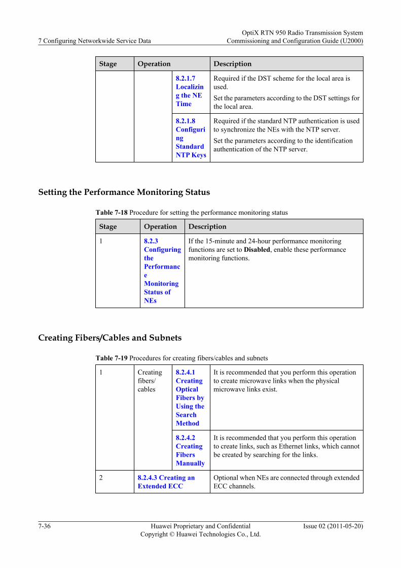
Stage Operation Description
8.2.1.7Localizing the NETime
Required if the DST scheme for the local area isused.Set the parameters according to the DST settings forthe local area.
8.2.1.8ConfiguringStandardNTP Keys
Required if the standard NTP authentication is usedto synchronize the NEs with the NTP server.Set the parameters according to the identificationauthentication of the NTP server.
Setting the Performance Monitoring Status
Table 7-18 Procedure for setting the performance monitoring status
Stage Operation Description
1 8.2.3ConfiguringthePerformanceMonitoringStatus ofNEs
If the 15-minute and 24-hour performance monitoringfunctions are set to Disabled, enable these performancemonitoring functions.
Creating Fibers/Cables and Subnets
Table 7-19 Procedures for creating fibers/cables and subnets
1 Creatingfibers/cables
8.2.4.1CreatingOpticalFibers byUsing theSearchMethod
It is recommended that you perform this operationto create microwave links when the physicalmicrowave links exist.
8.2.4.2CreatingFibersManually
It is recommended that you perform this operationto create links, such as Ethernet links, which cannotbe created by searching for the links.
2 8.2.4.3 Creating anExtended ECC
Optional when NEs are connected through extendedECC channels.
7 Configuring Networkwide Service DataOptiX RTN 950 Radio Transmission System
Commissioning and Configuration Guide (U2000)
7-36 Huawei Proprietary and ConfidentialCopyright © Huawei Technologies Co., Ltd.
Issue 02 (2011-05-20)
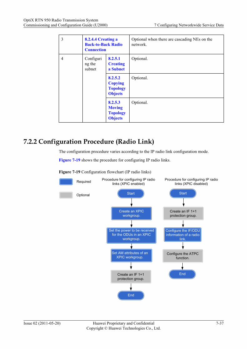
3 8.2.4.4 Creating aBack-to-Back RadioConnection
Optional when there are cascading NEs on thenetwork.
4 Configuring thesubnet
8.2.5.1Creatinga Subnet
Optional.
8.2.5.2CopyingTopologyObjects
Optional.
8.2.5.3MovingTopologyObjects
Optional.
7.2.2 Configuration Procedure (Radio Link)The configuration procedure varies according to the IP radio link configuration mode.
Figure 7-19 shows the procedure for configuring IP radio links.
Figure 7-19 Configuration flowchart (IP radio links)
Create an IF 1+1 protection group.
Start
Procedure for configuring IP radio links (XPIC enabled)
Create an XPIC workgroup.
Start
Create an IF 1+1 protection group.
Procedure for configuring IP radio links (XPIC disabled)
Set AM attributes of an XPIC workgroup.
Required
Optional
End
End
Configure the ATPC function.
Configure the IF/ODU information of a radio
link.
Set the power to be received for the ODUs in an XPIC
workgroup.
OptiX RTN 950 Radio Transmission SystemCommissioning and Configuration Guide (U2000) 7 Configuring Networkwide Service Data
Issue 02 (2011-05-20) Huawei Proprietary and ConfidentialCopyright © Huawei Technologies Co., Ltd.
7-37
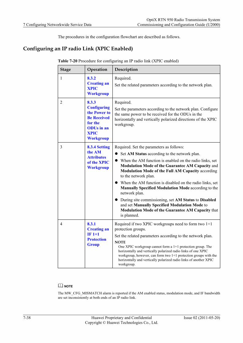
The procedures in the configuration flowchart are described as follows.
Configuring an IP radio Link (XPIC Enabled)
Table 7-20 Procedure for configuring an IP radio link (XPIC enabled)
Stage Operation Description
1 8.3.2Creating anXPICWorkgroup
Required.Set the related parameters according to the network plan.
2 8.3.3Configuringthe Power toBe Receivedfor theODUs in anXPICWorkgroup
Required.Set the parameters according to the network plan. Configurethe same power to be received for the ODUs in thehorizontally and vertically polarized directions of the XPICworkgroup.
3 8.3.4 Settingthe AMAttributesof the XPICWorkgroup
Required. Set the parameters as follows:l Set AM Status according to the network plan.l When the AM function is enabled on the radio links, set
Modulation Mode of the Guarantee AM Capacity andModulation Mode of the Full AM Capacity accordingto the network plan.
l When the AM function is disabled on the radio links, setManually Specified Modulation Mode according to thenetwork plan.
l During site commissioning, set AM Status to Disabledand set Manually Specified Modulation Mode toModulation Mode of the Guarantee AM Capacity thatis planned.
4 8.3.1Creating anIF 1+1ProtectionGroup
Required if two XPIC workgroups need to form two 1+1protection groups.Set the related parameters according to the network plan.NOTE
One XPIC workgroup cannot form a 1+1 protection group. Thehorizontally and vertically polarized radio links of one XPICworkgroup, however, can form two 1+1 protection groups with thehorizontally and vertically polarized radio links of another XPICworkgroup.
NOTE
The MW_CFG_MISMATCH alarm is reported if the AM enabled status, modulation mode, and IF bandwidthare set inconsistently at both ends of an IP radio link.
7 Configuring Networkwide Service DataOptiX RTN 950 Radio Transmission System
Commissioning and Configuration Guide (U2000)
7-38 Huawei Proprietary and ConfidentialCopyright © Huawei Technologies Co., Ltd.
Issue 02 (2011-05-20)
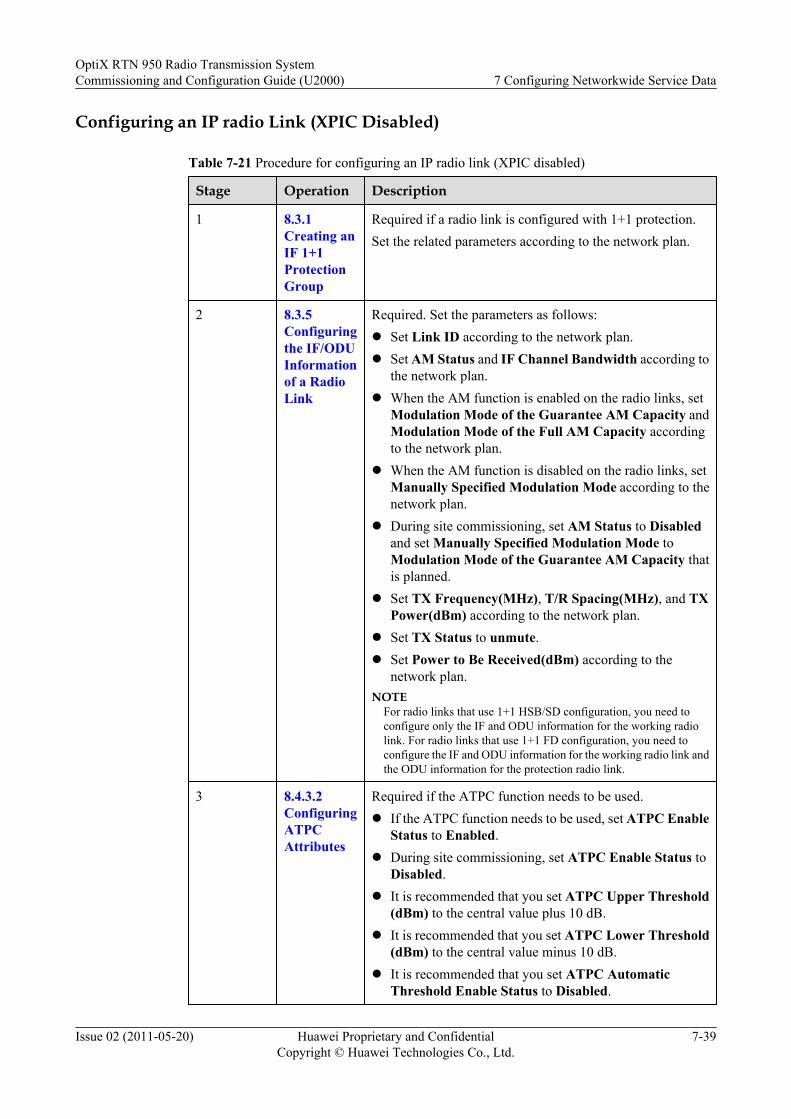
Configuring an IP radio Link (XPIC Disabled)
Table 7-21 Procedure for configuring an IP radio link (XPIC disabled)
Stage Operation Description
1 8.3.1Creating anIF 1+1ProtectionGroup
Required if a radio link is configured with 1+1 protection.Set the related parameters according to the network plan.
2 8.3.5Configuringthe IF/ODUInformationof a RadioLink
Required. Set the parameters as follows:l Set Link ID according to the network plan.l Set AM Status and IF Channel Bandwidth according to
the network plan.l When the AM function is enabled on the radio links, set
Modulation Mode of the Guarantee AM Capacity andModulation Mode of the Full AM Capacity accordingto the network plan.
l When the AM function is disabled on the radio links, setManually Specified Modulation Mode according to thenetwork plan.
l During site commissioning, set AM Status to Disabledand set Manually Specified Modulation Mode toModulation Mode of the Guarantee AM Capacity thatis planned.
l Set TX Frequency(MHz), T/R Spacing(MHz), and TXPower(dBm) according to the network plan.
l Set TX Status to unmute.l Set Power to Be Received(dBm) according to the
network plan.NOTE
For radio links that use 1+1 HSB/SD configuration, you need toconfigure only the IF and ODU information for the working radiolink. For radio links that use 1+1 FD configuration, you need toconfigure the IF and ODU information for the working radio link andthe ODU information for the protection radio link.
3 8.4.3.2ConfiguringATPCAttributes
Required if the ATPC function needs to be used.l If the ATPC function needs to be used, set ATPC Enable
Status to Enabled.l During site commissioning, set ATPC Enable Status to
Disabled.l It is recommended that you set ATPC Upper Threshold
(dBm) to the central value plus 10 dB.l It is recommended that you set ATPC Lower Threshold
(dBm) to the central value minus 10 dB.l It is recommended that you set ATPC Automatic
Threshold Enable Status to Disabled.
OptiX RTN 950 Radio Transmission SystemCommissioning and Configuration Guide (U2000) 7 Configuring Networkwide Service Data
Issue 02 (2011-05-20) Huawei Proprietary and ConfidentialCopyright © Huawei Technologies Co., Ltd.
7-39
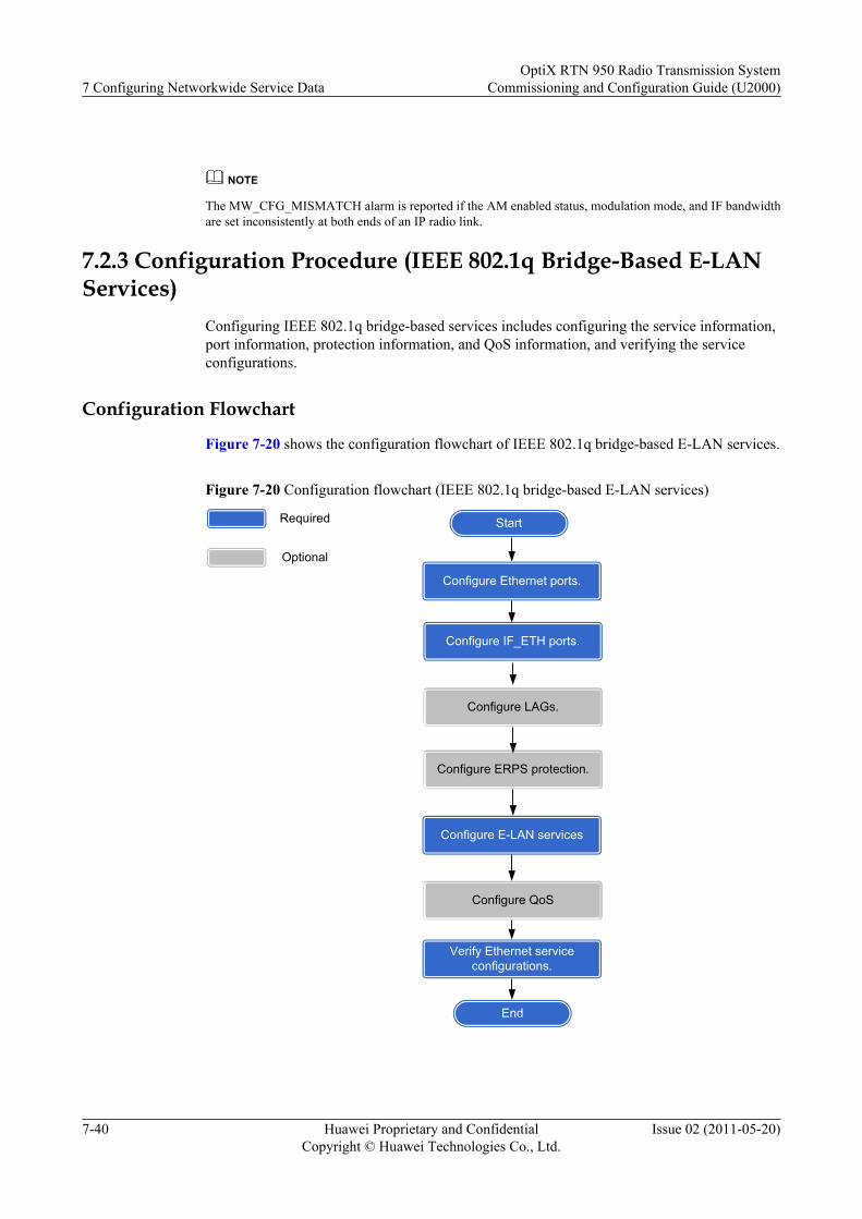
NOTE
The MW_CFG_MISMATCH alarm is reported if the AM enabled status, modulation mode, and IF bandwidthare set inconsistently at both ends of an IP radio link.
7.2.3 Configuration Procedure (IEEE 802.1q Bridge-Based E-LANServices)
Configuring IEEE 802.1q bridge-based services includes configuring the service information,port information, protection information, and QoS information, and verifying the serviceconfigurations.
Configuration Flowchart
Figure 7-20 shows the configuration flowchart of IEEE 802.1q bridge-based E-LAN services.
Figure 7-20 Configuration flowchart (IEEE 802.1q bridge-based E-LAN services)
StartRequired
Optional
End
Configure E-LAN services
Configure Ethernet ports.
Configure ERPS protection.
Verify Ethernet service configurations.
Configure LAGs.
Configure QoS
Configure IF_ETH ports.
7 Configuring Networkwide Service DataOptiX RTN 950 Radio Transmission System
Commissioning and Configuration Guide (U2000)
7-40 Huawei Proprietary and ConfidentialCopyright © Huawei Technologies Co., Ltd.
Issue 02 (2011-05-20)
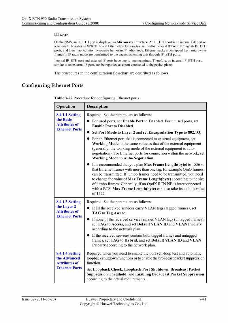
NOTE
On the NMS, an IF_ETH port is displayed as Microwave Interface. An IF_ETH port is an internal GE port ona generic IF board or an XPIC IF board. Ethernet packets are transmitted to the local IF board through its IF_ETHports, and then mapped into microwave frames in IP radio mode. Ethernet packets demapped from microwaveframes in IP radio mode are transmitted to the packet switching unit through IF_ETH ports.
Internal IF_ETH port and external IF ports have one-to-one mappings. Therefore, an internal IF_ETH port,similar to an external IF port, can be regarded as a port connected to the packet plane.
The procedures in the configuration flowchart are described as follows.
Configuring Ethernet Ports
Table 7-22 Procedure for configuring Ethernet ports
Operation Description
8.4.1.1 Settingthe BasicAttributes ofEthernet Ports
Required. Set the parameters as follows:l For used ports, set Enable Port to Enabled. For unused ports, set
Enable Port to Disabled.l Set Port Mode to Layer 2 and set Encapsulation Type to 802.1Q.l For an Ethernet port that is connected to external equipment, set
Working Mode to the same value as that of the external equipment(generally, the working mode of the external equipment is auto-negotiation). For Ethernet ports for connection within the network, setWorking Mode to Auto-Negotiation.
l It is recommended that you plan Max Frame Length(byte) to 1536 sothat Ethernet frames with more than one tag, for example QinQ frames,can be transmitted. If jumbo frames need to be transmitted, you needto change the value of Max Frame Length(byte) according to the sizeof jumbo frames. Generally, if an OptiX RTN NE is interconnectedwith a BTS, Max Frame Length(byte) can also take its default valueof 1522.
8.4.1.3 Settingthe Layer 2Attributes ofEthernet Ports
Required. Set the parameters as follows:l If all the received services carry VLAN tags (tagged frames), set
TAG to Tag Aware.l If none of the received services carries VLAN tags (untagged frames),
set TAG to Access, and set Default VLAN ID and VLAN Priorityaccording to the network plan.
l If the received services contain both tagged frames and untaggedframes, set TAG to Hybrid, and set Default VLAN ID and VLANPriority according to the network plan.
8.4.1.4 Settingthe AdvancedAttributes ofEthernet Ports
Required when you need to enable the port self-loop test and automaticloopback shutdown functions or to enable the broadcast packet suppressionfunction.Set Loopback Check, Loopback Port Shutdown, Broadcast PacketSuppression Threshold, and Enabling Broadcast Packet Suppressionaccording to the actual requirements.
OptiX RTN 950 Radio Transmission SystemCommissioning and Configuration Guide (U2000) 7 Configuring Networkwide Service Data
Issue 02 (2011-05-20) Huawei Proprietary and ConfidentialCopyright © Huawei Technologies Co., Ltd.
7-41
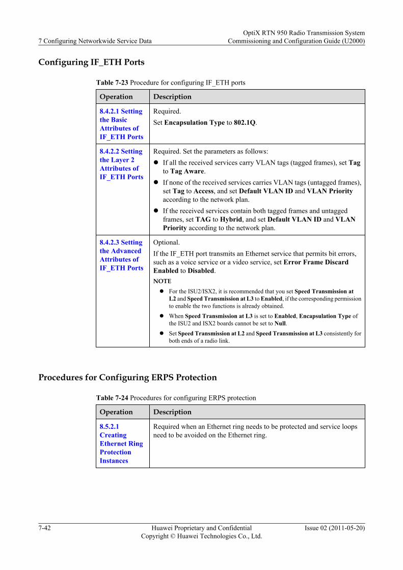
Configuring IF_ETH Ports
Table 7-23 Procedure for configuring IF_ETH ports
Operation Description
8.4.2.1 Settingthe BasicAttributes ofIF_ETH Ports
Required.Set Encapsulation Type to 802.1Q.
8.4.2.2 Settingthe Layer 2Attributes ofIF_ETH Ports
Required. Set the parameters as follows:l If all the received services carry VLAN tags (tagged frames), set Tag
to Tag Aware.l If none of the received services carries VLAN tags (untagged frames),
set Tag to Access, and set Default VLAN ID and VLAN Priorityaccording to the network plan.
l If the received services contain both tagged frames and untaggedframes, set TAG to Hybrid, and set Default VLAN ID and VLANPriority according to the network plan.
8.4.2.3 Settingthe AdvancedAttributes ofIF_ETH Ports
Optional.If the IF_ETH port transmits an Ethernet service that permits bit errors,such as a voice service or a video service, set Error Frame DiscardEnabled to Disabled.NOTEl For the ISU2/ISX2, it is recommended that you set Speed Transmission at
L2 and Speed Transmission at L3 to Enabled, if the corresponding permissionto enable the two functions is already obtained.
l When Speed Transmission at L3 is set to Enabled, Encapsulation Type ofthe ISU2 and ISX2 boards cannot be set to Null.
l Set Speed Transmission at L2 and Speed Transmission at L3 consistently forboth ends of a radio link.
Procedures for Configuring ERPS Protection
Table 7-24 Procedures for configuring ERPS protection
Operation Description
8.5.2.1CreatingEthernet RingProtectionInstances
Required when an Ethernet ring needs to be protected and service loopsneed to be avoided on the Ethernet ring.
7 Configuring Networkwide Service DataOptiX RTN 950 Radio Transmission System
Commissioning and Configuration Guide (U2000)
7-42 Huawei Proprietary and ConfidentialCopyright © Huawei Technologies Co., Ltd.
Issue 02 (2011-05-20)
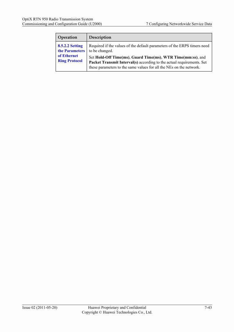
Operation Description
8.5.2.2 Settingthe Parametersof EthernetRing Protocol
Required if the values of the default parameters of the ERPS timers needto be changed.Set Hold-Off Time(ms), Guard Time(ms), WTR Time(mm:ss), andPacket Transmit Interval(s) according to the actual requirements. Setthese parameters to the same values for all the NEs on the network.
OptiX RTN 950 Radio Transmission SystemCommissioning and Configuration Guide (U2000) 7 Configuring Networkwide Service Data
Issue 02 (2011-05-20) Huawei Proprietary and ConfidentialCopyright © Huawei Technologies Co., Ltd.
7-43
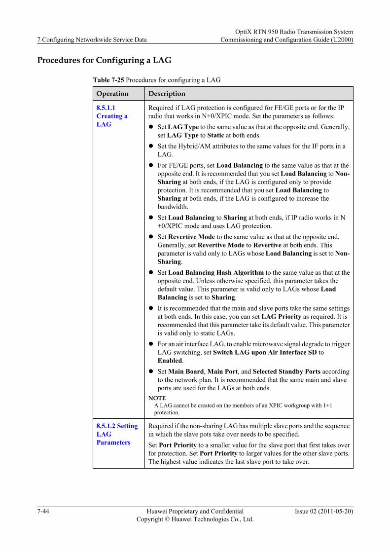
Procedures for Configuring a LAG
Table 7-25 Procedures for configuring a LAG
Operation Description
8.5.1.1Creating aLAG
Required if LAG protection is configured for FE/GE ports or for the IPradio that works in N+0/XPIC mode. Set the parameters as follows:l Set LAG Type to the same value as that at the opposite end. Generally,
set LAG Type to Static at both ends.l Set the Hybrid/AM attributes to the same values for the IF ports in a
LAG.l For FE/GE ports, set Load Balancing to the same value as that at the
opposite end. It is recommended that you set Load Balancing to Non-Sharing at both ends, if the LAG is configured only to provideprotection. It is recommended that you set Load Balancing toSharing at both ends, if the LAG is configured to increase thebandwidth.
l Set Load Balancing to Sharing at both ends, if IP radio works in N+0/XPIC mode and uses LAG protection.
l Set Revertive Mode to the same value as that at the opposite end.Generally, set Revertive Mode to Revertive at both ends. Thisparameter is valid only to LAGs whose Load Balancing is set to Non-Sharing.
l Set Load Balancing Hash Algorithm to the same value as that at theopposite end. Unless otherwise specified, this parameter takes thedefault value. This parameter is valid only to LAGs whose LoadBalancing is set to Sharing.
l It is recommended that the main and slave ports take the same settingsat both ends. In this case, you can set LAG Priority as required. It isrecommended that this parameter take its default value. This parameteris valid only to static LAGs.
l For an air interface LAG, to enable microwave signal degrade to triggerLAG switching, set Switch LAG upon Air Interface SD toEnabled.
l Set Main Board, Main Port, and Selected Standby Ports accordingto the network plan. It is recommended that the same main and slaveports are used for the LAGs at both ends.
NOTEA LAG cannot be created on the members of an XPIC workgroup with 1+1protection.
8.5.1.2 SettingLAGParameters
Required if the non-sharing LAG has multiple slave ports and the sequencein which the slave pots take over needs to be specified.Set Port Priority to a smaller value for the slave port that first takes overfor protection. Set Port Priority to larger values for the other slave ports.The highest value indicates the last slave port to take over.
7 Configuring Networkwide Service DataOptiX RTN 950 Radio Transmission System
Commissioning and Configuration Guide (U2000)
7-44 Huawei Proprietary and ConfidentialCopyright © Huawei Technologies Co., Ltd.
Issue 02 (2011-05-20)

Configuring IEEE 802.1q Bridge-Based E-LAN Services
Table 7-26 Procedure for configuring IEEE 802.1q bridge-based E-LAN services
Operation Description
8.5.3.2 Configuring IEEE802.1q Bridge-Based E-LAN Services
Required. Set the parameters as follows:l Set Tag Type to C-Awared.l Set Self-Learning MAC Address to Enabled.l In the UNI tab page, set related parameters according to
the network plan.l To disable packet forwarding between certain E-LAN
service ports, add the ports to Split Horizon Group.
Managingthe MACaddress table
8.5.4.2Creating aBlacklistEntry ofMACAddresses
Required when you need to disable NEs with specific MACaddresses from using E-LAN services.Set the related parameters according to the network plan.
8.5.4.1Creating aStatic MACAddressEntry
Required if you request specific MAC address entries not toage.Set the related parameters according to the network plan.
8.5.4.3Configuringthe AgingParametersof a MACAddressTable
Required if you need to disable the aging function or changethe aging time (5 minutes by default).Set the related parameters according to the network plan.
8.5.5 Setting the Mode forProcessing an UnknownFrame of the E-LANService
Optional.
OptiX RTN 950 Radio Transmission SystemCommissioning and Configuration Guide (U2000) 7 Configuring Networkwide Service Data
Issue 02 (2011-05-20) Huawei Proprietary and ConfidentialCopyright © Huawei Technologies Co., Ltd.
7-45
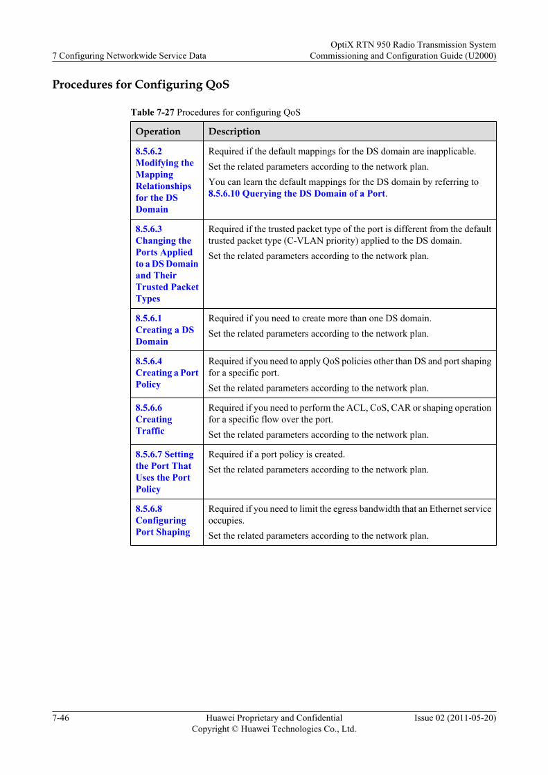
Procedures for Configuring QoS
Table 7-27 Procedures for configuring QoS
Operation Description
8.5.6.2Modifying theMappingRelationshipsfor the DSDomain
Required if the default mappings for the DS domain are inapplicable.Set the related parameters according to the network plan.You can learn the default mappings for the DS domain by referring to8.5.6.10 Querying the DS Domain of a Port.
8.5.6.3Changing thePorts Appliedto a DS Domainand TheirTrusted PacketTypes
Required if the trusted packet type of the port is different from the defaulttrusted packet type (C-VLAN priority) applied to the DS domain.Set the related parameters according to the network plan.
8.5.6.1Creating a DSDomain
Required if you need to create more than one DS domain.Set the related parameters according to the network plan.
8.5.6.4Creating a PortPolicy
Required if you need to apply QoS policies other than DS and port shapingfor a specific port.Set the related parameters according to the network plan.
8.5.6.6CreatingTraffic
Required if you need to perform the ACL, CoS, CAR or shaping operationfor a specific flow over the port.Set the related parameters according to the network plan.
8.5.6.7 Settingthe Port ThatUses the PortPolicy
Required if a port policy is created.Set the related parameters according to the network plan.
8.5.6.8ConfiguringPort Shaping
Required if you need to limit the egress bandwidth that an Ethernet serviceoccupies.Set the related parameters according to the network plan.
7 Configuring Networkwide Service DataOptiX RTN 950 Radio Transmission System
Commissioning and Configuration Guide (U2000)
7-46 Huawei Proprietary and ConfidentialCopyright © Huawei Technologies Co., Ltd.
Issue 02 (2011-05-20)
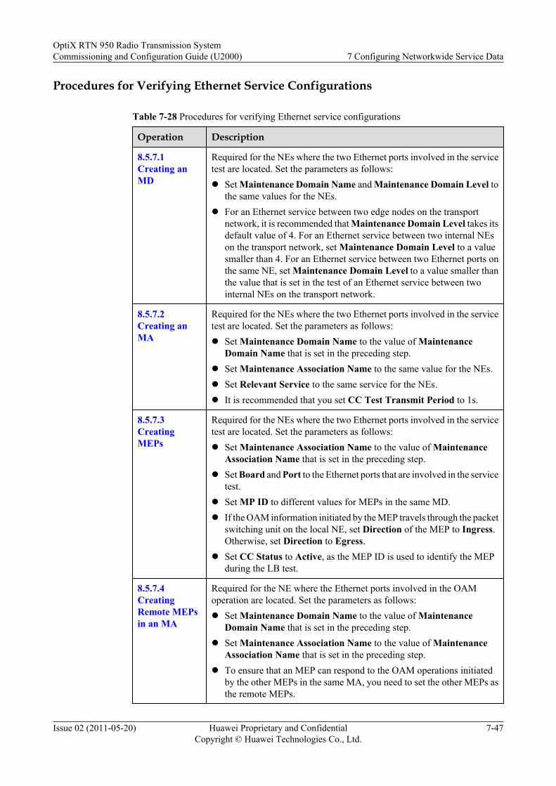
Procedures for Verifying Ethernet Service Configurations
Table 7-28 Procedures for verifying Ethernet service configurations
Operation Description
8.5.7.1Creating anMD
Required for the NEs where the two Ethernet ports involved in the servicetest are located. Set the parameters as follows:l Set Maintenance Domain Name and Maintenance Domain Level to
the same values for the NEs.l For an Ethernet service between two edge nodes on the transport
network, it is recommended that Maintenance Domain Level takes itsdefault value of 4. For an Ethernet service between two internal NEson the transport network, set Maintenance Domain Level to a valuesmaller than 4. For an Ethernet service between two Ethernet ports onthe same NE, set Maintenance Domain Level to a value smaller thanthe value that is set in the test of an Ethernet service between twointernal NEs on the transport network.
8.5.7.2Creating anMA
Required for the NEs where the two Ethernet ports involved in the servicetest are located. Set the parameters as follows:l Set Maintenance Domain Name to the value of Maintenance
Domain Name that is set in the preceding step.l Set Maintenance Association Name to the same value for the NEs.l Set Relevant Service to the same service for the NEs.l It is recommended that you set CC Test Transmit Period to 1s.
8.5.7.3CreatingMEPs
Required for the NEs where the two Ethernet ports involved in the servicetest are located. Set the parameters as follows:l Set Maintenance Association Name to the value of Maintenance
Association Name that is set in the preceding step.l Set Board and Port to the Ethernet ports that are involved in the service
test.l Set MP ID to different values for MEPs in the same MD.l If the OAM information initiated by the MEP travels through the packet
switching unit on the local NE, set Direction of the MEP to Ingress.Otherwise, set Direction to Egress.
l Set CC Status to Active, as the MEP ID is used to identify the MEPduring the LB test.
8.5.7.4CreatingRemote MEPsin an MA
Required for the NE where the Ethernet ports involved in the OAMoperation are located. Set the parameters as follows:l Set Maintenance Domain Name to the value of Maintenance
Domain Name that is set in the preceding step.l Set Maintenance Association Name to the value of Maintenance
Association Name that is set in the preceding step.l To ensure that an MEP can respond to the OAM operations initiated
by the other MEPs in the same MA, you need to set the other MEPs asthe remote MEPs.
OptiX RTN 950 Radio Transmission SystemCommissioning and Configuration Guide (U2000) 7 Configuring Networkwide Service Data
Issue 02 (2011-05-20) Huawei Proprietary and ConfidentialCopyright © Huawei Technologies Co., Ltd.
7-47
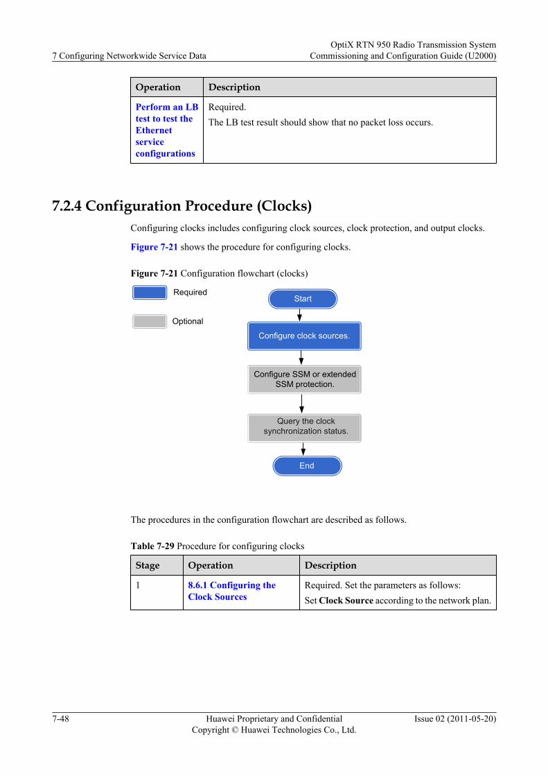
Operation Description
Perform an LBtest to test theEthernetserviceconfigurations
Required.The LB test result should show that no packet loss occurs.
7.2.4 Configuration Procedure (Clocks)Configuring clocks includes configuring clock sources, clock protection, and output clocks.
Figure 7-21 shows the procedure for configuring clocks.
Figure 7-21 Configuration flowchart (clocks)
StartRequired
Optional
End
Configure SSM or extendedSSM protection.
Query the clocksynchronization status.
Configure clock sources.
The procedures in the configuration flowchart are described as follows.
Table 7-29 Procedure for configuring clocks
Stage Operation Description
1 8.6.1 Configuring theClock Sources
Required. Set the parameters as follows:Set Clock Source according to the network plan.
7 Configuring Networkwide Service DataOptiX RTN 950 Radio Transmission System
Commissioning and Configuration Guide (U2000)
7-48 Huawei Proprietary and ConfidentialCopyright © Huawei Technologies Co., Ltd.
Issue 02 (2011-05-20)
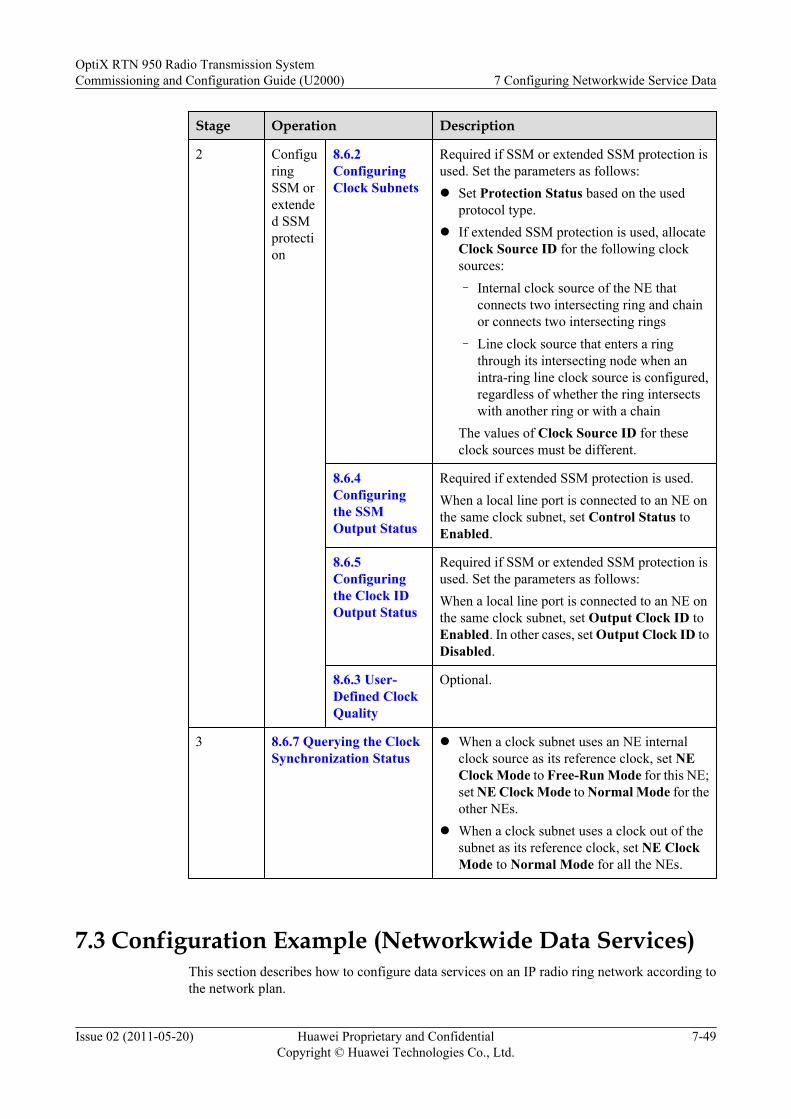
Stage Operation Description
2 ConfiguringSSM orextended SSMprotection
8.6.2ConfiguringClock Subnets
Required if SSM or extended SSM protection isused. Set the parameters as follows:l Set Protection Status based on the used
protocol type.l If extended SSM protection is used, allocate
Clock Source ID for the following clocksources:– Internal clock source of the NE that
connects two intersecting ring and chainor connects two intersecting rings
– Line clock source that enters a ringthrough its intersecting node when anintra-ring line clock source is configured,regardless of whether the ring intersectswith another ring or with a chain
The values of Clock Source ID for theseclock sources must be different.
8.6.4Configuringthe SSMOutput Status
Required if extended SSM protection is used.When a local line port is connected to an NE onthe same clock subnet, set Control Status toEnabled.
8.6.5Configuringthe Clock IDOutput Status
Required if SSM or extended SSM protection isused. Set the parameters as follows:When a local line port is connected to an NE onthe same clock subnet, set Output Clock ID toEnabled. In other cases, set Output Clock ID toDisabled.
8.6.3 User-Defined ClockQuality
Optional.
3 8.6.7 Querying the ClockSynchronization Status
l When a clock subnet uses an NE internalclock source as its reference clock, set NEClock Mode to Free-Run Mode for this NE;set NE Clock Mode to Normal Mode for theother NEs.
l When a clock subnet uses a clock out of thesubnet as its reference clock, set NE ClockMode to Normal Mode for all the NEs.
7.3 Configuration Example (Networkwide Data Services)This section describes how to configure data services on an IP radio ring network according tothe network plan.
OptiX RTN 950 Radio Transmission SystemCommissioning and Configuration Guide (U2000) 7 Configuring Networkwide Service Data
Issue 02 (2011-05-20) Huawei Proprietary and ConfidentialCopyright © Huawei Technologies Co., Ltd.
7-49
7.3.1 Network DiagramThe section describes the networking information about the NEs.
7.3.2 Service Planning (Network)The service planning information contains the information about all the parameters required forconfiguring the NE data.
7.3.3 Service Planning (Radio Links)This section describes the service planning information about all the parameters required forconfiguring radio links.
7.3.4 Service Planning (Ethernet Ports)The service planning information contains the information about all the parameters required forconfiguring Ethernet ports and IF_ETH ports.
7.3.5 Service Planning (Ethernet Protection)The service planning information contains the information about all the parameters required forconfiguring Ethernet protection.
7.3.6 Service Planning (Ethernet Services)The service planning information contains the information about all the parameters required forconfiguring Ethernet services.
7.3.7 Service Planning (QoS Information)The service planning information contains the information about all the parameters required forconfiguring QoS.
7.3.8 Service Planning (Clocks)The service planning information contains all the parameters required for configuring clocks.
7.3.9 Configuration Process (Network)This section describes the procedures for configuring a network.
7.3.10 Configuration Process (Radio Links)This section describes how to configure radio links.
7.3.11 Configuration Process (Ethernet Ports)
7.3.12 Configuration Process (Ethernet Protection)
7.3.13 Configuration Process (Ethernet Services)This section describes how to configure Ethernet services.
7.3.14 Configuration Process (QoS)
7.3.15 Configuration Process (Verifying Ethernet Service Configurations)This section describes how to verify Ethernet service configurations.
7.3.16 Configuration Process (Clocks)This section describes how to configure clocks.
7.3.1 Network DiagramThe section describes the networking information about the NEs.
Figure 7-22 shows the topology of the IP radio network that is used in this configurationexample. The IP radio ring network needs to backhaul services from BTSs/NodeBs to the BSCand has the following service requirements:
7 Configuring Networkwide Service DataOptiX RTN 950 Radio Transmission System
Commissioning and Configuration Guide (U2000)
7-50 Huawei Proprietary and ConfidentialCopyright © Huawei Technologies Co., Ltd.
Issue 02 (2011-05-20)
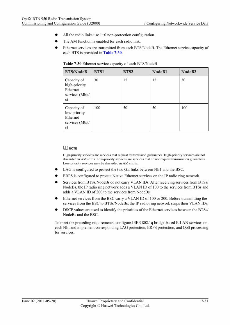
l All the radio links use 1+0 non-protection configuration.l The AM function is enabled for each radio link.l Ethernet services are transmitted from each BTS/NodeB. The Ethernet service capacity of
each BTS is provided in Table 7-30.
Table 7-30 Ethernet service capacity of each BTS/NodeB
BTS/NodeB BTS1 BTS2 NodeB1 NodeB2
Capacity ofhigh-priorityEthernetservices (Mbit/s)
30 15 15 30
Capacity oflow-priorityEthernetservices (Mbit/s)
100 50 50 100
NOTE
High-priority services are services that request transmission guarantees. High-priority services are notdiscarded in AM shifts. Low-priority services are services that do not request transmission guarantees.Low-priority services may be discarded in AM shifts.
l LAG is configured to protect the two GE links between NE1 and the BSC.l ERPS is configured to protect Native Ethernet services on the IP radio ring network.l Services from BTSs/NodeBs do not carry VLAN IDs. After receiving services from BTSs/
NodeBs, the IP radio ring network adds a VLAN ID of 100 to the services from BTSs andadds a VLAN ID of 200 to the services from NodeBs.
l Ethernet services from the BSC carry a VLAN ID of 100 or 200. Before transmitting theservices from the BSC to BTSs/NodeBs, the IP radio ring network strips their VLAN IDs.
l DSCP values are used to identify the priorities of the Ethernet services between the BTSs/NodeBs and the BSC.
To meet the preceding requirements, configure IEEE 802.1q bridge-based E-LAN services oneach NE, and implement corresponding LAG protection, ERPS protection, and QoS processingfor services.
OptiX RTN 950 Radio Transmission SystemCommissioning and Configuration Guide (U2000) 7 Configuring Networkwide Service Data
Issue 02 (2011-05-20) Huawei Proprietary and ConfidentialCopyright © Huawei Technologies Co., Ltd.
7-51
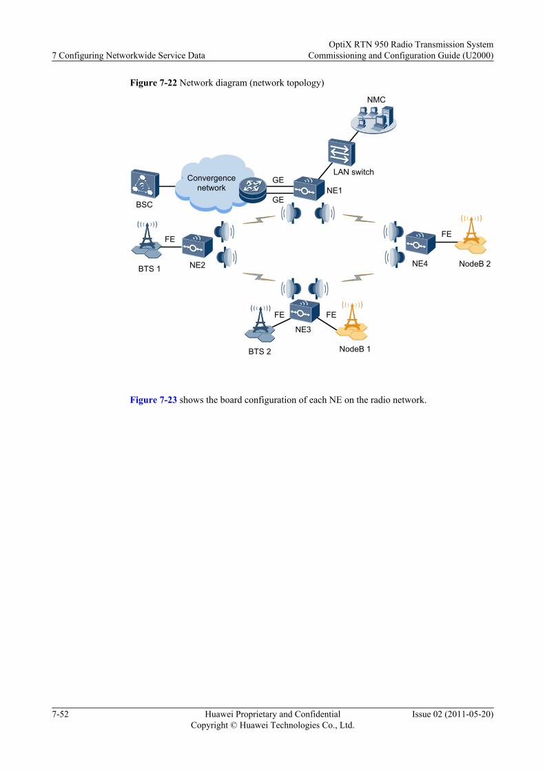
Figure 7-22 Network diagram (network topology)
BTS 1
NE1
NE3
NE2 NE4 NodeB 2
GE
GE
Convergence network
NMC
BTS 2
LAN switch
BSC
NodeB 1
FE
FE FE
FE
Figure 7-23 shows the board configuration of each NE on the radio network.
7 Configuring Networkwide Service DataOptiX RTN 950 Radio Transmission System
Commissioning and Configuration Guide (U2000)
7-52 Huawei Proprietary and ConfidentialCopyright © Huawei Technologies Co., Ltd.
Issue 02 (2011-05-20)
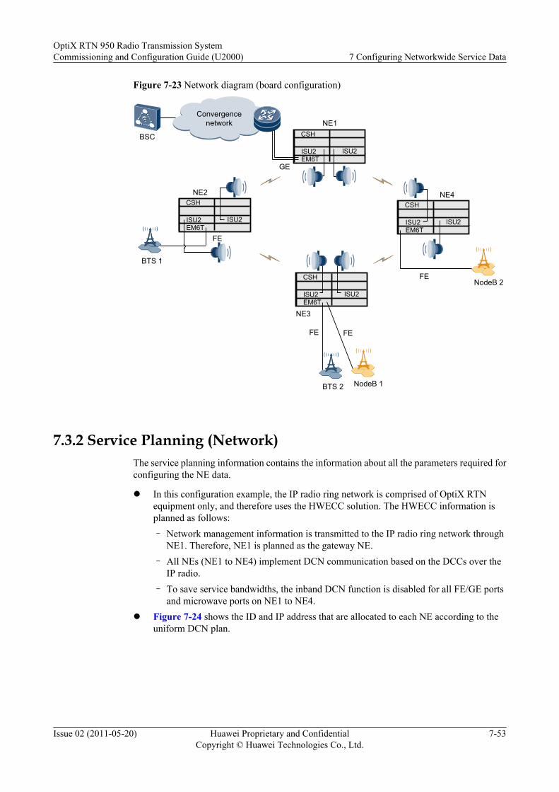
Figure 7-23 Network diagram (board configuration)
NE6
CSH
ISU2ISU2EM6T
NE6
CSH
ISU2ISU2EM6T
NE6
CSH
ISU2ISU2EM6T
NE6
CSH
ISU2ISU2EM6T
Convergence network
NE4
FE
FE
NE3
NE2
BTS 1
BSC
GE
BTS 2
NE1
NodeB 1
NodeB 2
FE
FE
7.3.2 Service Planning (Network)The service planning information contains the information about all the parameters required forconfiguring the NE data.
l In this configuration example, the IP radio ring network is comprised of OptiX RTNequipment only, and therefore uses the HWECC solution. The HWECC information isplanned as follows:– Network management information is transmitted to the IP radio ring network through
NE1. Therefore, NE1 is planned as the gateway NE.– All NEs (NE1 to NE4) implement DCN communication based on the DCCs over the
IP radio.– To save service bandwidths, the inband DCN function is disabled for all FE/GE ports
and microwave ports on NE1 to NE4.l Figure 7-24 shows the ID and IP address that are allocated to each NE according to the
uniform DCN plan.
OptiX RTN 950 Radio Transmission SystemCommissioning and Configuration Guide (U2000) 7 Configuring Networkwide Service Data
Issue 02 (2011-05-20) Huawei Proprietary and ConfidentialCopyright © Huawei Technologies Co., Ltd.
7-53
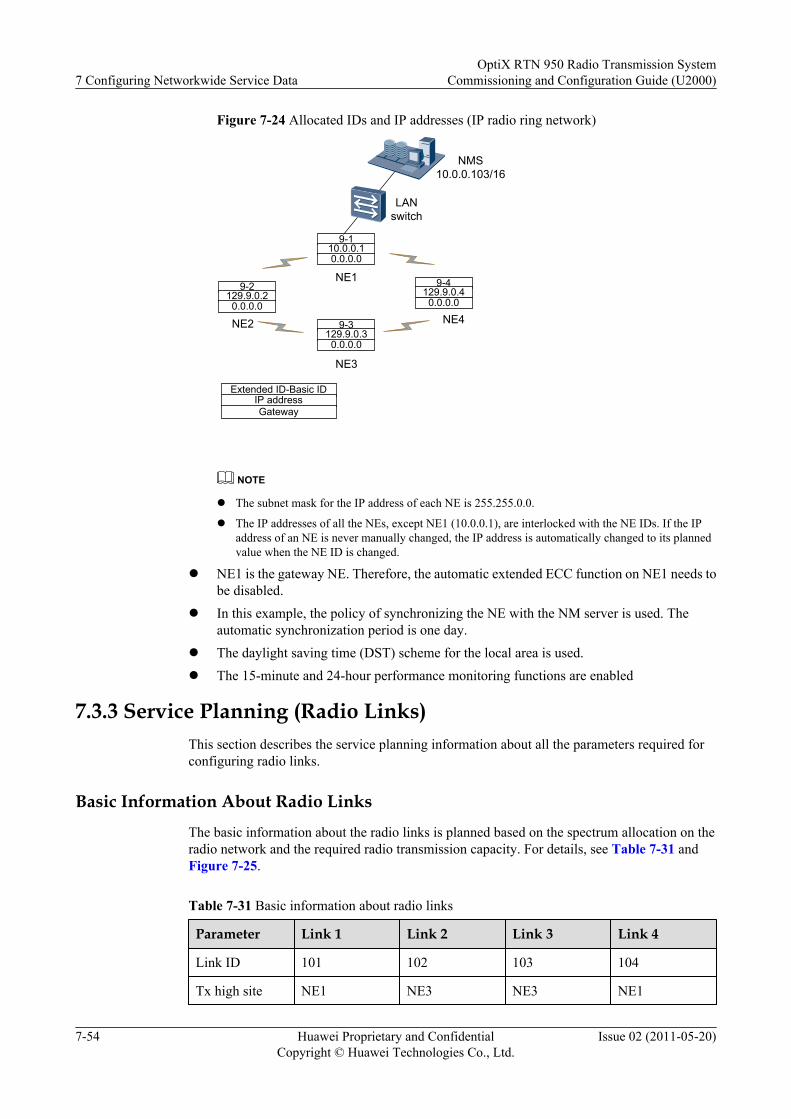
Figure 7-24 Allocated IDs and IP addresses (IP radio ring network)
NE1
NE3
9-2129.9.0.20.0.0.0
9-3129.9.0.30.0.0.0
9-4129.9.0.40.0.0.0
NE2 NE4
Extended ID-Basic IDIP addressGateway
9-110.0.0.10.0.0.0
NMS 10.0.0.103/16
LAN switch
NOTE
l The subnet mask for the IP address of each NE is 255.255.0.0.
l The IP addresses of all the NEs, except NE1 (10.0.0.1), are interlocked with the NE IDs. If the IPaddress of an NE is never manually changed, the IP address is automatically changed to its plannedvalue when the NE ID is changed.
l NE1 is the gateway NE. Therefore, the automatic extended ECC function on NE1 needs tobe disabled.
l In this example, the policy of synchronizing the NE with the NM server is used. Theautomatic synchronization period is one day.
l The daylight saving time (DST) scheme for the local area is used.l The 15-minute and 24-hour performance monitoring functions are enabled
7.3.3 Service Planning (Radio Links)This section describes the service planning information about all the parameters required forconfiguring radio links.
Basic Information About Radio Links
The basic information about the radio links is planned based on the spectrum allocation on theradio network and the required radio transmission capacity. For details, see Table 7-31 andFigure 7-25.
Table 7-31 Basic information about radio links
Parameter Link 1 Link 2 Link 3 Link 4
Link ID 101 102 103 104
Tx high site NE1 NE3 NE3 NE1
7 Configuring Networkwide Service DataOptiX RTN 950 Radio Transmission System
Commissioning and Configuration Guide (U2000)
7-54 Huawei Proprietary and ConfidentialCopyright © Huawei Technologies Co., Ltd.
Issue 02 (2011-05-20)
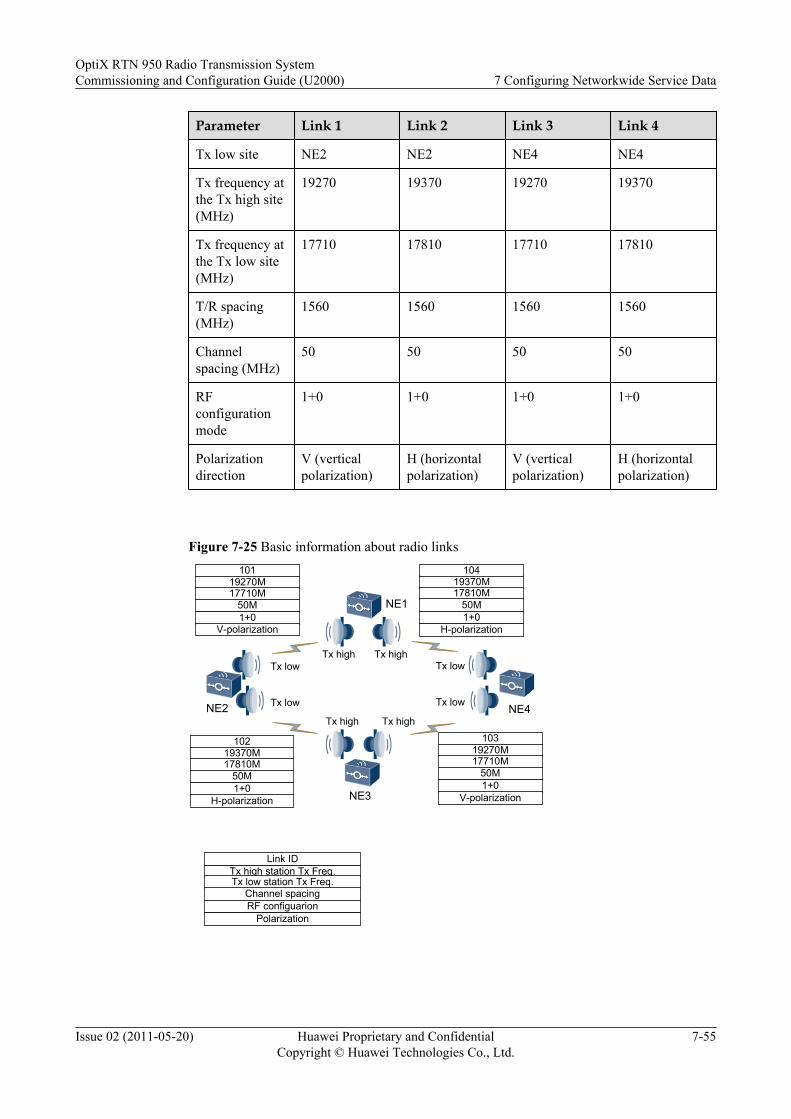
Parameter Link 1 Link 2 Link 3 Link 4
Tx low site NE2 NE2 NE4 NE4
Tx frequency atthe Tx high site(MHz)
19270 19370 19270 19370
Tx frequency atthe Tx low site(MHz)
17710 17810 17710 17810
T/R spacing(MHz)
1560 1560 1560 1560
Channelspacing (MHz)
50 50 50 50
RFconfigurationmode
1+0 1+0 1+0 1+0
Polarizationdirection
V (verticalpolarization)
H (horizontalpolarization)
V (verticalpolarization)
H (horizontalpolarization)
Figure 7-25 Basic information about radio links
NE1
NE3
NE2 NE4
10119270M17710M
50M1+0
V-polarization
19370M17810M
50M1+0
H-polarization
102 10319270M17710M
50M1+0
V-polarization
19370M17810M
50M1+0
H-polarization
104
Tx high Tx high
Tx highTx high
Tx low
Tx low
Tx low
Tx low
Tx high station Tx Freq.Tx low station Tx Freq.
Channel spacingRF configuarion
Polarization
Link ID
OptiX RTN 950 Radio Transmission SystemCommissioning and Configuration Guide (U2000) 7 Configuring Networkwide Service Data
Issue 02 (2011-05-20) Huawei Proprietary and ConfidentialCopyright © Huawei Technologies Co., Ltd.
7-55

NOTE
This example does not provide the planning information (except for the polarization direction) that is notrelated to the IDU configuration.
Hybrid/AM Attribute Information
Based on the capacity of Ethernet services and the availability requirement, you can computethe Hybrid/AM attribute information, as provided in Table 7-32.
Table 7-32 Hybrid/AM attribute information
Parameter Link 1 Link 2 Link 3 Link 4
Capacity ofhigh-priorityEthernetservices (Mbit/s)
90 90 90 90
Capacity of low-priorityEthernetservices (Mbit/s)
300 300 300 300
AM enabling Enabled Enabled Enabled Enabled
Modulationmode of theguaranteed AMcapacity
QPSK QPSK QPSK QPSK
Modulationmode of the fullAM capacity
256QAM 256QAM 256QAM 256QAM
NOTEThe IP radio capacity and the AM function require an appropriate license file.
Power and ATPC Information
By using radio network planning software such as Pathloss, you can analyze and compute variousparameters of the radio links. The power and ATPC information about the radio links is providedin Table 7-33.
Table 7-33 Power and ATPC information
Parameter Link 1 Link 2 Link 3 Link 4
Transmit power(dBm)
16.5 (NE1)16.5 (NE2)
15.5 (NE3)15.5 (NE2)
16 (NE3)16 (NE4)
15 (NE1)15 (NE4)
7 Configuring Networkwide Service DataOptiX RTN 950 Radio Transmission System
Commissioning and Configuration Guide (U2000)
7-56 Huawei Proprietary and ConfidentialCopyright © Huawei Technologies Co., Ltd.
Issue 02 (2011-05-20)

Parameter Link 1 Link 2 Link 3 Link 4
Receive power(dBm)
-42 (NE1)-42 (NE2)
-44 (NE3)-44 (NE2)
-43 (NE3)-43 (NE4)
-45 (NE1)-45 (NE4)
ATPC enabling Disabled Disabled Disabled Disabled
ATPCautomaticthresholdenabling
- - - -
Upper thresholdof ATPCadjustment(dBm)
- - - -
Lower thresholdof ATPCadjustment(dBm)
- - - -
Maximumtransmit power(dBm)
- - - -
NOTE
l The transmit power is computed in modulation mode of the guaranteed AM capacity.
l The receive power is computed in modulation mode of the guaranteed AM capacity.
l In this example, the ATPC function is disabled.
IF Board Information
Table 7-34 provides the information about IF boards, which is obtained based on rules forplanning the radio type, slot priority, and 1+0 non-protection configuration.
Table 7-34 IF board information
Parameter Link 1 Link 2 Link 3 Link 4
Main IF board 4-ISU2 (NE1)3-ISU2 (NE2)
4-ISU2 (NE2)3-ISU2 (NE3)
4-ISU2 (NE3)3-ISU2 (NE4)
4-ISU2 (NE4)3-ISU2 (NE1)
Standby IFboard
- - - -
RFconfigurationmode
1+0 1+0 1+0 1+0
Revertive mode - - - -
OptiX RTN 950 Radio Transmission SystemCommissioning and Configuration Guide (U2000) 7 Configuring Networkwide Service Data
Issue 02 (2011-05-20) Huawei Proprietary and ConfidentialCopyright © Huawei Technologies Co., Ltd.
7-57
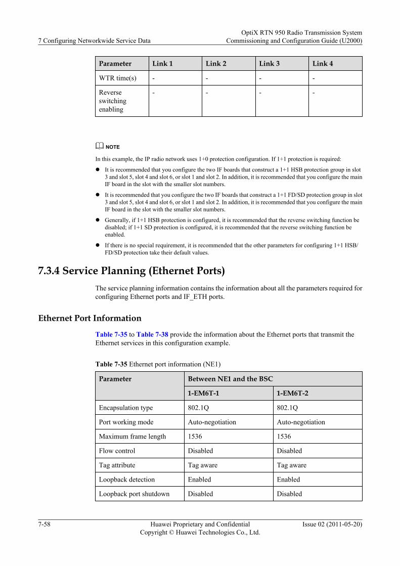
Parameter Link 1 Link 2 Link 3 Link 4
WTR time(s) - - - -
Reverseswitchingenabling
- - - -
NOTE
In this example, the IP radio network uses 1+0 protection configuration. If 1+1 protection is required:
l It is recommended that you configure the two IF boards that construct a 1+1 HSB protection group in slot3 and slot 5, slot 4 and slot 6, or slot 1 and slot 2. In addition, it is recommended that you configure the mainIF board in the slot with the smaller slot numbers.
l It is recommended that you configure the two IF boards that construct a 1+1 FD/SD protection group in slot3 and slot 5, slot 4 and slot 6, or slot 1 and slot 2. In addition, it is recommended that you configure the mainIF board in the slot with the smaller slot numbers.
l Generally, if 1+1 HSB protection is configured, it is recommended that the reverse switching function bedisabled; if 1+1 SD protection is configured, it is recommended that the reverse switching function beenabled.
l If there is no special requirement, it is recommended that the other parameters for configuring 1+1 HSB/FD/SD protection take their default values.
7.3.4 Service Planning (Ethernet Ports)The service planning information contains the information about all the parameters required forconfiguring Ethernet ports and IF_ETH ports.
Ethernet Port Information
Table 7-35 to Table 7-38 provide the information about the Ethernet ports that transmit theEthernet services in this configuration example.
Table 7-35 Ethernet port information (NE1)
Parameter Between NE1 and the BSC
1-EM6T-1 1-EM6T-2
Encapsulation type 802.1Q 802.1Q
Port working mode Auto-negotiation Auto-negotiation
Maximum frame length 1536 1536
Flow control Disabled Disabled
Tag attribute Tag aware Tag aware
Loopback detection Enabled Enabled
Loopback port shutdown Disabled Disabled
7 Configuring Networkwide Service DataOptiX RTN 950 Radio Transmission System
Commissioning and Configuration Guide (U2000)
7-58 Huawei Proprietary and ConfidentialCopyright © Huawei Technologies Co., Ltd.
Issue 02 (2011-05-20)
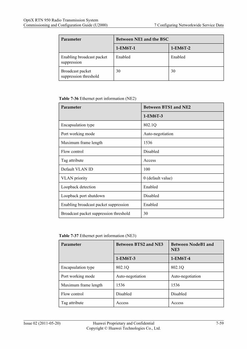
Parameter Between NE1 and the BSC
1-EM6T-1 1-EM6T-2
Enabling broadcast packetsuppression
Enabled Enabled
Broadcast packetsuppression threshold
30 30
Table 7-36 Ethernet port information (NE2)
Parameter Between BTS1 and NE2
1-EM6T-3
Encapsulation type 802.1Q
Port working mode Auto-negotiation
Maximum frame length 1536
Flow control Disabled
Tag attribute Access
Default VLAN ID 100
VLAN priority 0 (default value)
Loopback detection Enabled
Loopback port shutdown Disabled
Enabling broadcast packet suppression Enabled
Broadcast packet suppression threshold 30
Table 7-37 Ethernet port information (NE3)
Parameter Between BTS2 and NE3 Between NodeB1 andNE3
1-EM6T-3 1-EM6T-4
Encapsulation type 802.1Q 802.1Q
Port working mode Auto-negotiation Auto-negotiation
Maximum frame length 1536 1536
Flow control Disabled Disabled
Tag attribute Access Access
OptiX RTN 950 Radio Transmission SystemCommissioning and Configuration Guide (U2000) 7 Configuring Networkwide Service Data
Issue 02 (2011-05-20) Huawei Proprietary and ConfidentialCopyright © Huawei Technologies Co., Ltd.
7-59

Parameter Between BTS2 and NE3 Between NodeB1 andNE3
1-EM6T-3 1-EM6T-4
Default VLAN ID 100 200
VLAN priority 0 (default value) 0 (default value)
Loopback detection Enabled Enabled
Loopback port shutdown Disabled Disabled
Enabling broadcast packetsuppression
Enabled Enabled
Broadcast packetsuppression threshold
30 30
Table 7-38 Ethernet port information (NE4)
Parameter Between NodeB2 and NE4
1-EM6T-3
Encapsulation type 802.1Q
Port working mode Auto-negotiation
Maximum frame length 1536
Flow control Disabled
Tag attribute Access
Default VLAN ID 200
VLAN priority 0 (default value)
Loopback detection Enabled
Loopback port shutdown Disabled
Enabling broadcast packet suppression Enabled
Broadcast packet suppression threshold 30
7 Configuring Networkwide Service DataOptiX RTN 950 Radio Transmission System
Commissioning and Configuration Guide (U2000)
7-60 Huawei Proprietary and ConfidentialCopyright © Huawei Technologies Co., Ltd.
Issue 02 (2011-05-20)
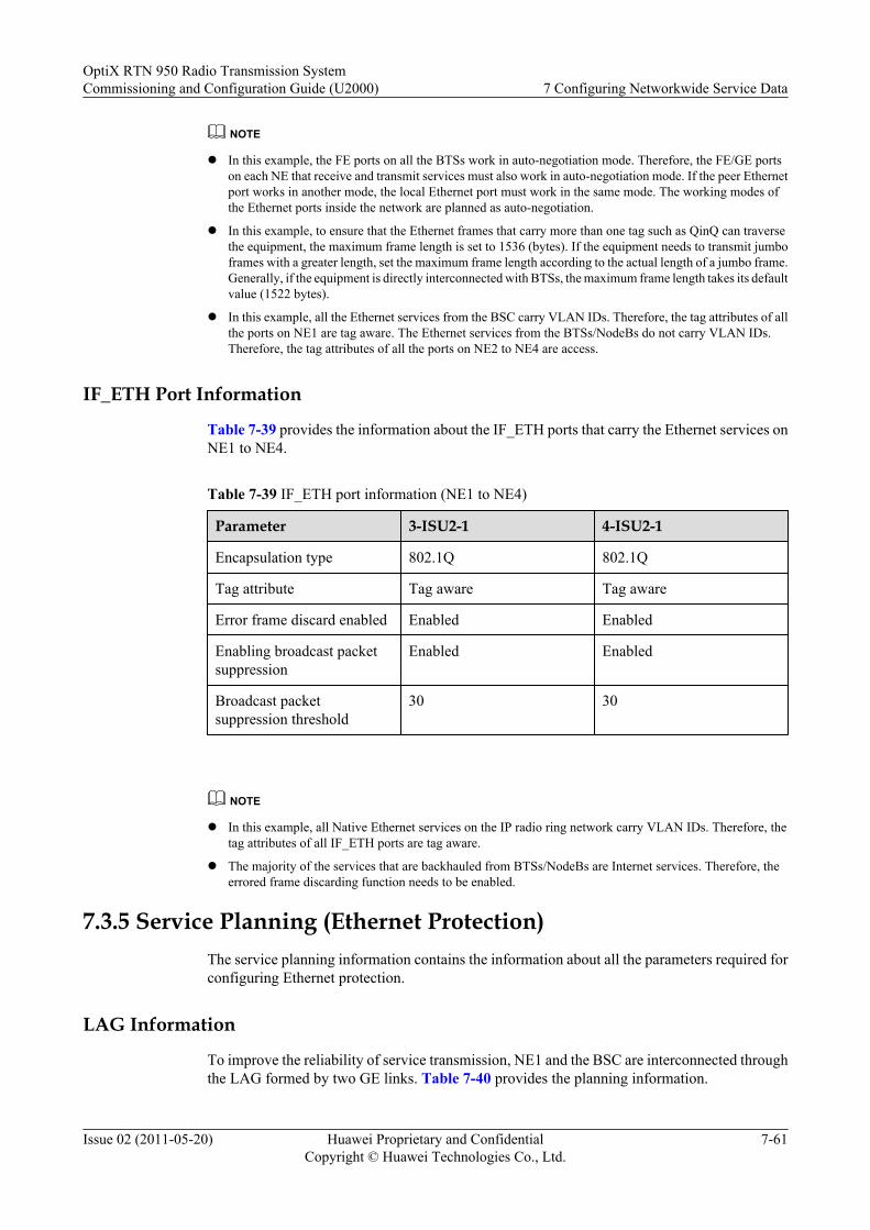
NOTE
l In this example, the FE ports on all the BTSs work in auto-negotiation mode. Therefore, the FE/GE portson each NE that receive and transmit services must also work in auto-negotiation mode. If the peer Ethernetport works in another mode, the local Ethernet port must work in the same mode. The working modes ofthe Ethernet ports inside the network are planned as auto-negotiation.
l In this example, to ensure that the Ethernet frames that carry more than one tag such as QinQ can traversethe equipment, the maximum frame length is set to 1536 (bytes). If the equipment needs to transmit jumboframes with a greater length, set the maximum frame length according to the actual length of a jumbo frame.Generally, if the equipment is directly interconnected with BTSs, the maximum frame length takes its defaultvalue (1522 bytes).
l In this example, all the Ethernet services from the BSC carry VLAN IDs. Therefore, the tag attributes of allthe ports on NE1 are tag aware. The Ethernet services from the BTSs/NodeBs do not carry VLAN IDs.Therefore, the tag attributes of all the ports on NE2 to NE4 are access.
IF_ETH Port Information
Table 7-39 provides the information about the IF_ETH ports that carry the Ethernet services onNE1 to NE4.
Table 7-39 IF_ETH port information (NE1 to NE4)
Parameter 3-ISU2-1 4-ISU2-1
Encapsulation type 802.1Q 802.1Q
Tag attribute Tag aware Tag aware
Error frame discard enabled Enabled Enabled
Enabling broadcast packetsuppression
Enabled Enabled
Broadcast packetsuppression threshold
30 30
NOTE
l In this example, all Native Ethernet services on the IP radio ring network carry VLAN IDs. Therefore, thetag attributes of all IF_ETH ports are tag aware.
l The majority of the services that are backhauled from BTSs/NodeBs are Internet services. Therefore, theerrored frame discarding function needs to be enabled.
7.3.5 Service Planning (Ethernet Protection)The service planning information contains the information about all the parameters required forconfiguring Ethernet protection.
LAG Information
To improve the reliability of service transmission, NE1 and the BSC are interconnected throughthe LAG formed by two GE links. Table 7-40 provides the planning information.
OptiX RTN 950 Radio Transmission SystemCommissioning and Configuration Guide (U2000) 7 Configuring Networkwide Service Data
Issue 02 (2011-05-20) Huawei Proprietary and ConfidentialCopyright © Huawei Technologies Co., Ltd.
7-61
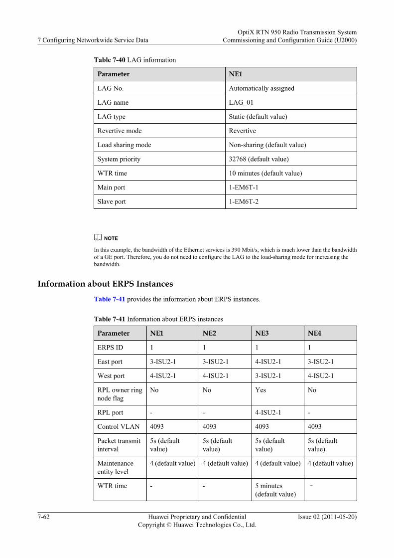
Table 7-40 LAG information
Parameter NE1
LAG No. Automatically assigned
LAG name LAG_01
LAG type Static (default value)
Revertive mode Revertive
Load sharing mode Non-sharing (default value)
System priority 32768 (default value)
WTR time 10 minutes (default value)
Main port 1-EM6T-1
Slave port 1-EM6T-2
NOTE
In this example, the bandwidth of the Ethernet services is 390 Mbit/s, which is much lower than the bandwidthof a GE port. Therefore, you do not need to configure the LAG to the load-sharing mode for increasing thebandwidth.
Information about ERPS Instances
Table 7-41 provides the information about ERPS instances.
Table 7-41 Information about ERPS instances
Parameter NE1 NE2 NE3 NE4
ERPS ID 1 1 1 1
East port 3-ISU2-1 3-ISU2-1 4-ISU2-1 3-ISU2-1
West port 4-ISU2-1 4-ISU2-1 3-ISU2-1 4-ISU2-1
RPL owner ringnode flag
No No Yes No
RPL port - - 4-ISU2-1 -
Control VLAN 4093 4093 4093 4093
Packet transmitinterval
5s (defaultvalue)
5s (defaultvalue)
5s (defaultvalue)
5s (defaultvalue)
Maintenanceentity level
4 (default value) 4 (default value) 4 (default value) 4 (default value)
WTR time - - 5 minutes(default value)
–
7 Configuring Networkwide Service DataOptiX RTN 950 Radio Transmission System
Commissioning and Configuration Guide (U2000)
7-62 Huawei Proprietary and ConfidentialCopyright © Huawei Technologies Co., Ltd.
Issue 02 (2011-05-20)
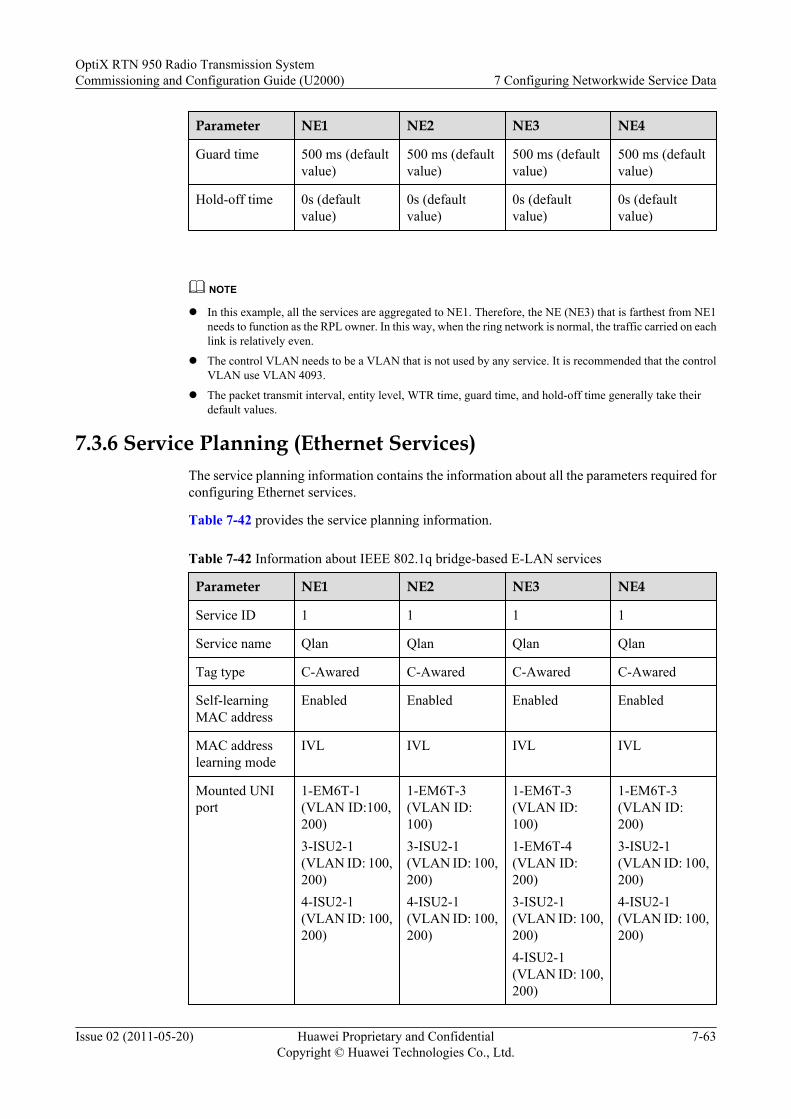
Parameter NE1 NE2 NE3 NE4
Guard time 500 ms (defaultvalue)
500 ms (defaultvalue)
500 ms (defaultvalue)
500 ms (defaultvalue)
Hold-off time 0s (defaultvalue)
0s (defaultvalue)
0s (defaultvalue)
0s (defaultvalue)
NOTE
l In this example, all the services are aggregated to NE1. Therefore, the NE (NE3) that is farthest from NE1needs to function as the RPL owner. In this way, when the ring network is normal, the traffic carried on eachlink is relatively even.
l The control VLAN needs to be a VLAN that is not used by any service. It is recommended that the controlVLAN use VLAN 4093.
l The packet transmit interval, entity level, WTR time, guard time, and hold-off time generally take theirdefault values.
7.3.6 Service Planning (Ethernet Services)The service planning information contains the information about all the parameters required forconfiguring Ethernet services.
Table 7-42 provides the service planning information.
Table 7-42 Information about IEEE 802.1q bridge-based E-LAN services
Parameter NE1 NE2 NE3 NE4
Service ID 1 1 1 1
Service name Qlan Qlan Qlan Qlan
Tag type C-Awared C-Awared C-Awared C-Awared
Self-learningMAC address
Enabled Enabled Enabled Enabled
MAC addresslearning mode
IVL IVL IVL IVL
Mounted UNIport
1-EM6T-1(VLAN ID:100,200)3-ISU2-1(VLAN ID: 100,200)4-ISU2-1(VLAN ID: 100,200)
1-EM6T-3(VLAN ID:100)3-ISU2-1(VLAN ID: 100,200)4-ISU2-1(VLAN ID: 100,200)
1-EM6T-3(VLAN ID:100)1-EM6T-4(VLAN ID:200)3-ISU2-1(VLAN ID: 100,200)4-ISU2-1(VLAN ID: 100,200)
1-EM6T-3(VLAN ID:200)3-ISU2-1(VLAN ID: 100,200)4-ISU2-1(VLAN ID: 100,200)
OptiX RTN 950 Radio Transmission SystemCommissioning and Configuration Guide (U2000) 7 Configuring Networkwide Service Data
Issue 02 (2011-05-20) Huawei Proprietary and ConfidentialCopyright © Huawei Technologies Co., Ltd.
7-63

NOTE
In this example, no split horizon group is configured.
7.3.7 Service Planning (QoS Information)The service planning information contains the information about all the parameters required forconfiguring QoS.
QoS (DiffServ)DiffServ (DS) is the basis for QoS. It is recommended that the VLAN priority or DSCP valueof the BTS services be allocated according to the service type. Then, the transmission networkcreates the corresponding DS domain according to the allocated VLAN priority or DSCP value.Each Ethernet port involved in the service must use the same DS configuration.
In this example, the BTS services are allocated with corresponding DSCP values according tothe service type, and the NEs allocate the PHB service classes according to the DSCP value, asshown in Table 7-43. Each Ethernet port involved in the service uses the same DS configuration.
Table 7-43 Service type and PHB service class
PHB Service Class DSCP Corresponding ServiceType
CS7 56 –
CS6 48 –
EF 40 Real-time voice service andsignaling service (R99conversational and R99streaming services)
AF4 32 –
AF3 24 Real-time OM and HSDPAservices (OM streaming andHSPA streaming services)
AF2 16 Non-real-time R99 service(R99 interactive and R99background services)
AF1 8 –
BE 0 HSDPA data service (HSPAinteractive and backgroundservices)
7 Configuring Networkwide Service DataOptiX RTN 950 Radio Transmission System
Commissioning and Configuration Guide (U2000)
7-64 Huawei Proprietary and ConfidentialCopyright © Huawei Technologies Co., Ltd.
Issue 02 (2011-05-20)
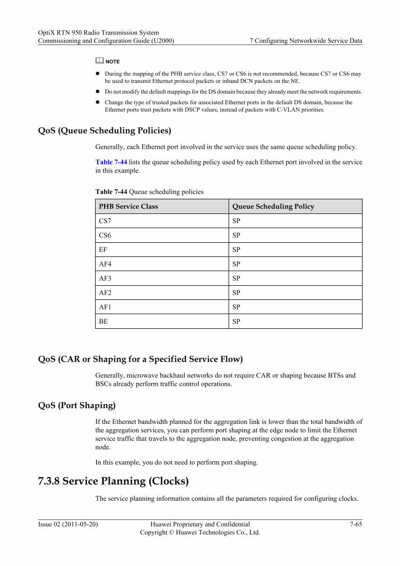
NOTE
l During the mapping of the PHB service class, CS7 or CS6 is not recommended, because CS7 or CS6 maybe used to transmit Ethernet protocol packets or inband DCN packets on the NE.
l Do not modify the default mappings for the DS domain because they already meet the network requirements.
l Change the type of trusted packets for associated Ethernet ports in the default DS domain, because theEthernet ports trust packets with DSCP values, instead of packets with C-VLAN priorities.
QoS (Queue Scheduling Policies)
Generally, each Ethernet port involved in the service uses the same queue scheduling policy.
Table 7-44 lists the queue scheduling policy used by each Ethernet port involved in the servicein this example.
Table 7-44 Queue scheduling policies
PHB Service Class Queue Scheduling Policy
CS7 SP
CS6 SP
EF SP
AF4 SP
AF3 SP
AF2 SP
AF1 SP
BE SP
QoS (CAR or Shaping for a Specified Service Flow)
Generally, microwave backhaul networks do not require CAR or shaping because BTSs andBSCs already perform traffic control operations.
QoS (Port Shaping)
If the Ethernet bandwidth planned for the aggregation link is lower than the total bandwidth ofthe aggregation services, you can perform port shaping at the edge node to limit the Ethernetservice traffic that travels to the aggregation node, preventing congestion at the aggregationnode.
In this example, you do not need to perform port shaping.
7.3.8 Service Planning (Clocks)The service planning information contains all the parameters required for configuring clocks.
OptiX RTN 950 Radio Transmission SystemCommissioning and Configuration Guide (U2000) 7 Configuring Networkwide Service Data
Issue 02 (2011-05-20) Huawei Proprietary and ConfidentialCopyright © Huawei Technologies Co., Ltd.
7-65

Clock Source Information
The IP radio ring network traces the internal clock source of NE1, as shown in Figure 7-26.
Figure 7-26 Clock source information (IP radio ring network)
NE1
NE3
NE2 NE44-ISU2-1/3-ISU2-1/Internal
Internal
3-ISU2-1/4-ISU2-1/
InternalClock
3-ISU2-1/4-ISU2-1/
Internal
SSM
Clock Protection
In this example, the standard SSM protocol is enabled for all NEs on the ring network.
Clock Synchronization Policy (NE1)
In this example, NE1 uses its internal clock source, which is generated by its internal oscillatorin free-run mode, and provides clock synchronization signals to the IP radio ring network.
Clock Synchronization Policy (NE2 to NE4)
In this example, NE2 to NE4 extract reference clock information from the bit streams on radiolinks.
7.3.9 Configuration Process (Network)This section describes the procedures for configuring a network.
Notesl This section uses NE1 as an example to describe how to configure data for an NE on a
network.
l Skip the operation tasks in this section if the following tasks have been performed duringNE commissioning: changing the NE ID and NE name, modifying NE communicationparameters, and configuring logical boards and the DCN solution.
7 Configuring Networkwide Service DataOptiX RTN 950 Radio Transmission System
Commissioning and Configuration Guide (U2000)
7-66 Huawei Proprietary and ConfidentialCopyright © Huawei Technologies Co., Ltd.
Issue 02 (2011-05-20)
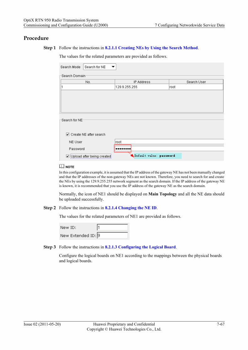
Procedure
Step 1 Follow the instructions in 8.2.1.1 Creating NEs by Using the Search Method.
The values for the related parameters are provided as follows.
NOTEIn this configuration example, it is assumed that the IP address of the gateway NE has not been manually changedand that the IP addresses of the non-gateway NEs are not known. Therefore, you need to search for and createthe NEs by using the 129.9.255.255 network segment as the search domain. If the IP address of the gateway NEis known, it is recommended that you use the IP address of the gateway NE as the search domain.
Normally, the icon of NE1 should be displayed on Main Topology and all the NE data shouldbe uploaded successfully.
Step 2 Follow the instructions in 8.2.1.4 Changing the NE ID.
The values for the related parameters of NE1 are provided as follows.
Step 3 Follow the instructions in 8.2.1.3 Configuring the Logical Board.
Configure the logical boards on NE1 according to the mappings between the physical boardsand logical boards.
OptiX RTN 950 Radio Transmission SystemCommissioning and Configuration Guide (U2000) 7 Configuring Networkwide Service Data
Issue 02 (2011-05-20) Huawei Proprietary and ConfidentialCopyright © Huawei Technologies Co., Ltd.
7-67

Step 4 Follow the instructions in 8.2.6.2 Configuring DCCs.
For NE1, all the parameters take their default values.
Step 5 Follow the instructions in 8.2.6.8 Configuring the Enable Status of the Inband DCN Functionon Ports.
Disable the inband DCN function for all unused FE/GE ports on NE1.
Disable the inband DCN function for all unused IF ports on NE1.
Step 6 Follow the instructions in 8.2.6.1 Setting NE Communication Parameters.
The values for the related parameters of NE1 are provided as follows.
7 Configuring Networkwide Service DataOptiX RTN 950 Radio Transmission System
Commissioning and Configuration Guide (U2000)
7-68 Huawei Proprietary and ConfidentialCopyright © Huawei Technologies Co., Ltd.
Issue 02 (2011-05-20)
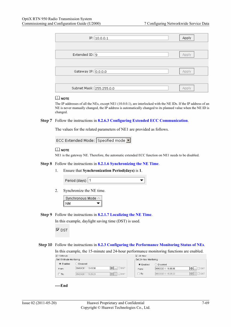
NOTEThe IP addresses of all the NEs, except NE1 (10.0.0.1), are interlocked with the NE IDs. If the IP address of anNE is never manually changed, the IP address is automatically changed to its planned value when the NE ID ischanged.
Step 7 Follow the instructions in 8.2.6.3 Configuring Extended ECC Communication.
The values for the related parameters of NE1 are provided as follows.
NOTENE1 is the gateway NE. Therefore, the automatic extended ECC function on NE1 needs to be disabled.
Step 8 Follow the instructions in 8.2.1.6 Synchronizing the NE Time.
1. Ensure that Synchronization Period(days) is 1.
2. Synchronize the NE time.
Step 9 Follow the instructions in 8.2.1.7 Localizing the NE Time.In this example, daylight saving time (DST) is used.
Step 10 Follow the instructions in 8.2.3 Configuring the Performance Monitoring Status of NEs.In this example, the 15-minute and 24-hour performance monitoring functions are enabled.
----End
OptiX RTN 950 Radio Transmission SystemCommissioning and Configuration Guide (U2000) 7 Configuring Networkwide Service Data
Issue 02 (2011-05-20) Huawei Proprietary and ConfidentialCopyright © Huawei Technologies Co., Ltd.
7-69
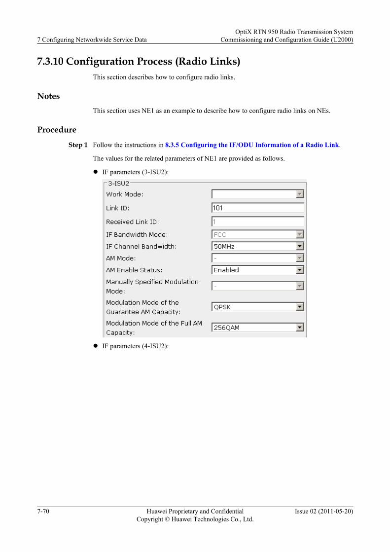
7.3.10 Configuration Process (Radio Links)This section describes how to configure radio links.
NotesThis section uses NE1 as an example to describe how to configure radio links on NEs.
Procedure
Step 1 Follow the instructions in 8.3.5 Configuring the IF/ODU Information of a Radio Link.
The values for the related parameters of NE1 are provided as follows.
l IF parameters (3-ISU2):
l IF parameters (4-ISU2):
7 Configuring Networkwide Service DataOptiX RTN 950 Radio Transmission System
Commissioning and Configuration Guide (U2000)
7-70 Huawei Proprietary and ConfidentialCopyright © Huawei Technologies Co., Ltd.
Issue 02 (2011-05-20)
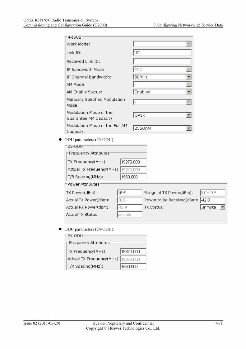
l ODU parameters (23-ODU):
l ODU parameters (24-ODU):
OptiX RTN 950 Radio Transmission SystemCommissioning and Configuration Guide (U2000) 7 Configuring Networkwide Service Data
Issue 02 (2011-05-20) Huawei Proprietary and ConfidentialCopyright © Huawei Technologies Co., Ltd.
7-71
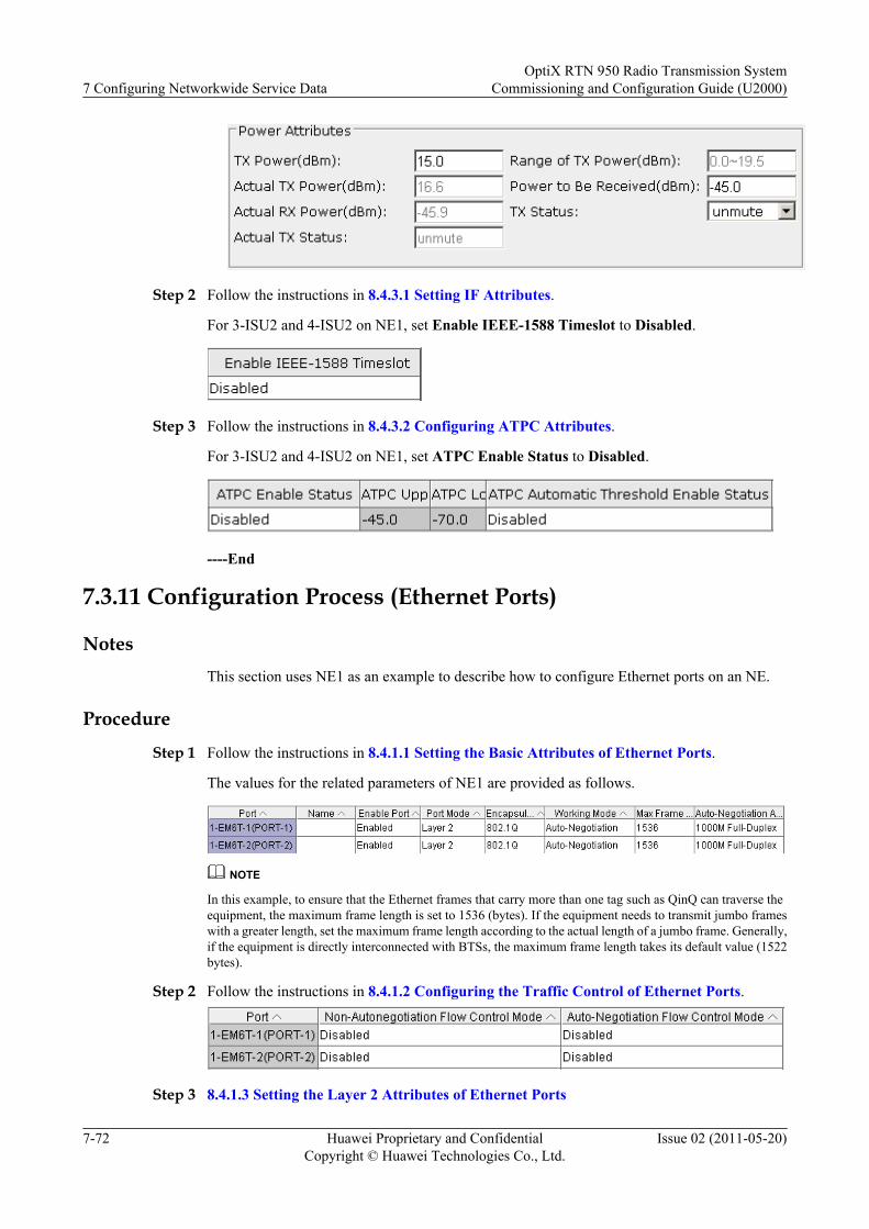
Step 2 Follow the instructions in 8.4.3.1 Setting IF Attributes.
For 3-ISU2 and 4-ISU2 on NE1, set Enable IEEE-1588 Timeslot to Disabled.
Step 3 Follow the instructions in 8.4.3.2 Configuring ATPC Attributes.
For 3-ISU2 and 4-ISU2 on NE1, set ATPC Enable Status to Disabled.
----End
7.3.11 Configuration Process (Ethernet Ports)
NotesThis section uses NE1 as an example to describe how to configure Ethernet ports on an NE.
Procedure
Step 1 Follow the instructions in 8.4.1.1 Setting the Basic Attributes of Ethernet Ports.
The values for the related parameters of NE1 are provided as follows.
NOTE
In this example, to ensure that the Ethernet frames that carry more than one tag such as QinQ can traverse theequipment, the maximum frame length is set to 1536 (bytes). If the equipment needs to transmit jumbo frameswith a greater length, set the maximum frame length according to the actual length of a jumbo frame. Generally,if the equipment is directly interconnected with BTSs, the maximum frame length takes its default value (1522bytes).
Step 2 Follow the instructions in 8.4.1.2 Configuring the Traffic Control of Ethernet Ports.
Step 3 8.4.1.3 Setting the Layer 2 Attributes of Ethernet Ports
7 Configuring Networkwide Service DataOptiX RTN 950 Radio Transmission System
Commissioning and Configuration Guide (U2000)
7-72 Huawei Proprietary and ConfidentialCopyright © Huawei Technologies Co., Ltd.
Issue 02 (2011-05-20)
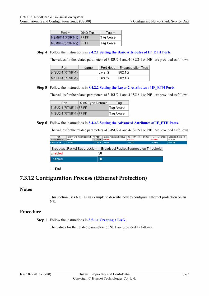
Step 4 Follow the instructions in 8.4.2.1 Setting the Basic Attributes of IF_ETH Ports.
The values for the related parameters of 3-ISU2-1 and 4-ISU2-1 on NE1 are provided as follows.
Step 5 Follow the instructions in 8.4.2.2 Setting the Layer 2 Attributes of IF_ETH Ports.
The values for the related parameters of 3-ISU2-1 and 4-ISU2-1 on NE1 are provided as follows.
Step 6 Follow the instructions in 8.4.2.3 Setting the Advanced Attributes of IF_ETH Ports.
The values for the related parameters of 3-ISU2-1 and 4-ISU2-1 on NE1 are provided as follows.
----End
7.3.12 Configuration Process (Ethernet Protection)
NotesThis section uses NE1 as an example to describe how to configure Ethernet protection on anNE.
Procedure
Step 1 Follow the instructions in 8.5.1.1 Creating a LAG.
The values for the related parameters of NE1 are provided as follows.
OptiX RTN 950 Radio Transmission SystemCommissioning and Configuration Guide (U2000) 7 Configuring Networkwide Service Data
Issue 02 (2011-05-20) Huawei Proprietary and ConfidentialCopyright © Huawei Technologies Co., Ltd.
7-73
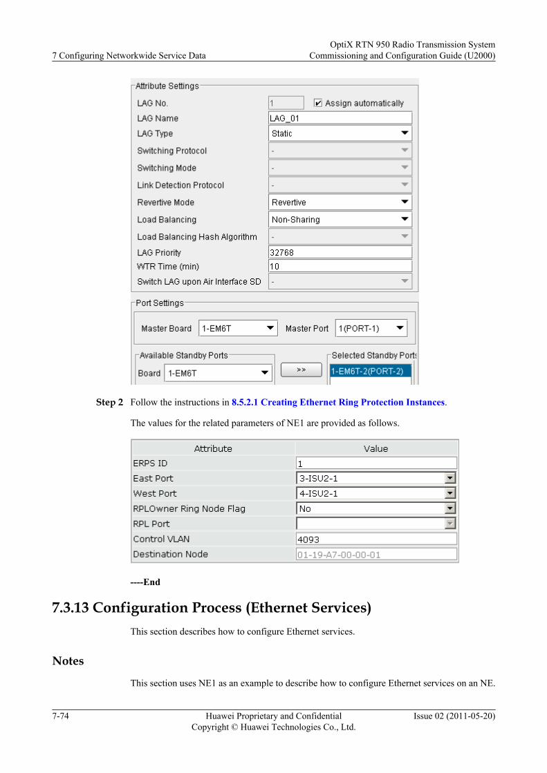
Step 2 Follow the instructions in 8.5.2.1 Creating Ethernet Ring Protection Instances.
The values for the related parameters of NE1 are provided as follows.
----End
7.3.13 Configuration Process (Ethernet Services)This section describes how to configure Ethernet services.
Notes
This section uses NE1 as an example to describe how to configure Ethernet services on an NE.
7 Configuring Networkwide Service DataOptiX RTN 950 Radio Transmission System
Commissioning and Configuration Guide (U2000)
7-74 Huawei Proprietary and ConfidentialCopyright © Huawei Technologies Co., Ltd.
Issue 02 (2011-05-20)
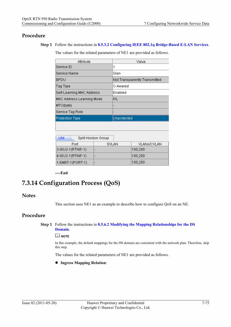
Procedure
Step 1 Follow the instructions in 8.5.3.2 Configuring IEEE 802.1q Bridge-Based E-LAN Services.
The values for the related parameters of NE1 are provided as follows.
----End
7.3.14 Configuration Process (QoS)
NotesThis section uses NE1 as an example to describe how to configure QoS on an NE.
Procedure
Step 1 Follow the instructions in 8.5.6.2 Modifying the Mapping Relationships for the DSDomain.
NOTE
In this example, the default mappings for the DS domain are consistent with the network plan. Therefore, skipthis step.
The values for the related parameters of NE1 are provided as follows.
l Ingress Mapping Relation:
OptiX RTN 950 Radio Transmission SystemCommissioning and Configuration Guide (U2000) 7 Configuring Networkwide Service Data
Issue 02 (2011-05-20) Huawei Proprietary and ConfidentialCopyright © Huawei Technologies Co., Ltd.
7-75
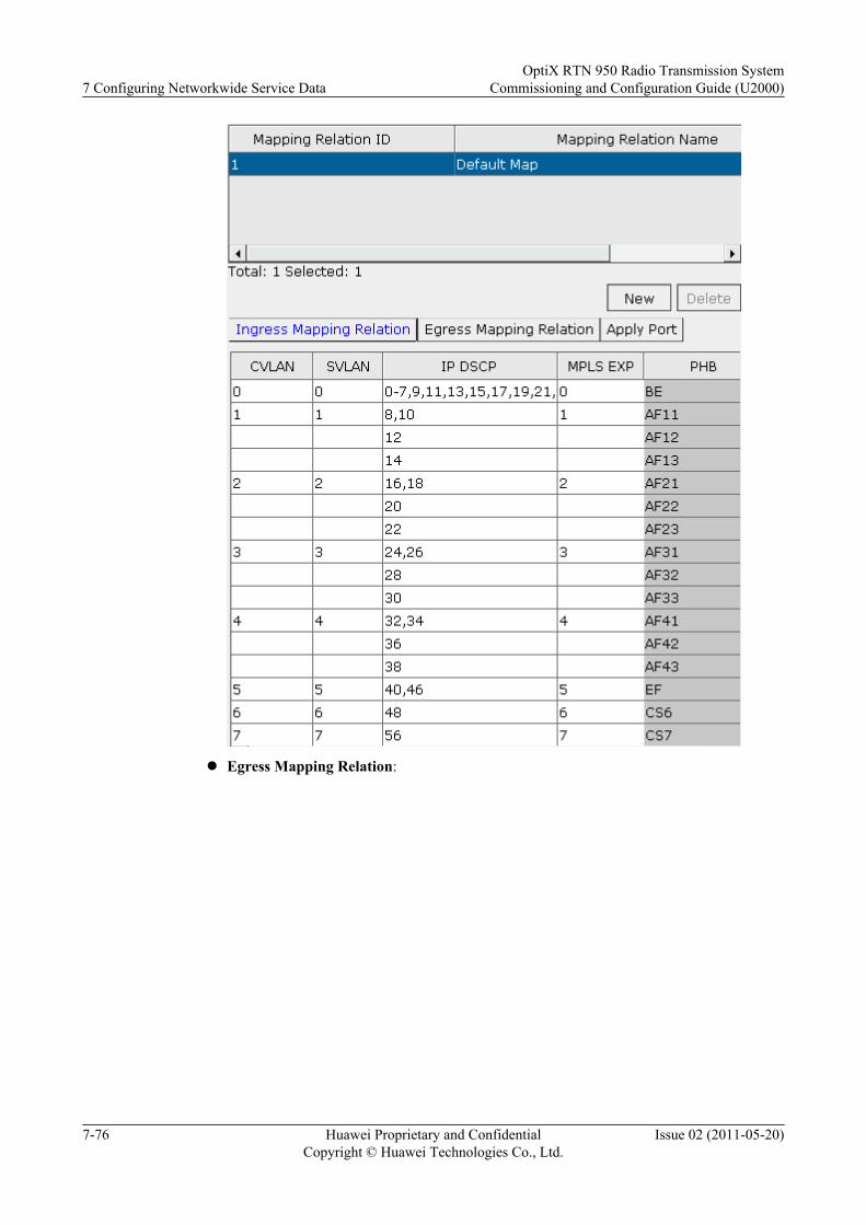
l Egress Mapping Relation:
7 Configuring Networkwide Service DataOptiX RTN 950 Radio Transmission System
Commissioning and Configuration Guide (U2000)
7-76 Huawei Proprietary and ConfidentialCopyright © Huawei Technologies Co., Ltd.
Issue 02 (2011-05-20)
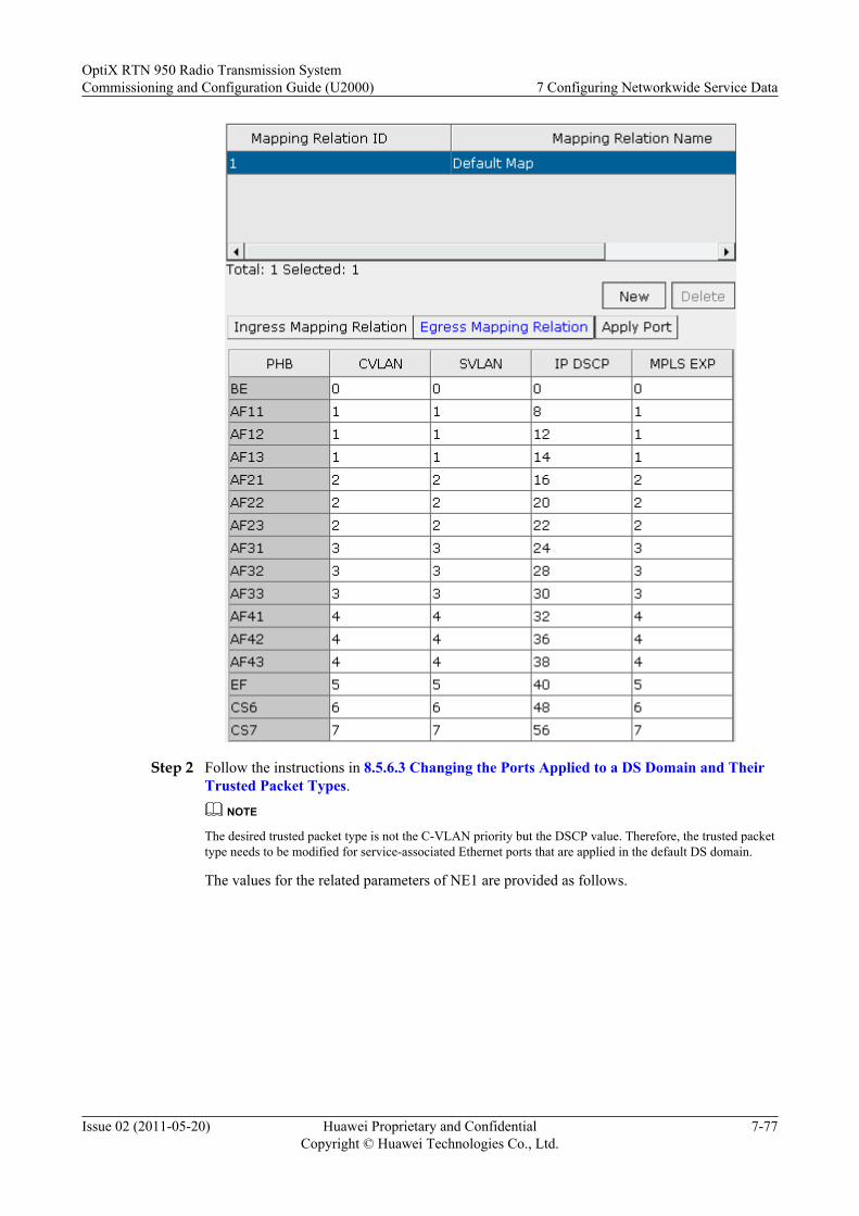
Step 2 Follow the instructions in 8.5.6.3 Changing the Ports Applied to a DS Domain and TheirTrusted Packet Types.
NOTE
The desired trusted packet type is not the C-VLAN priority but the DSCP value. Therefore, the trusted packettype needs to be modified for service-associated Ethernet ports that are applied in the default DS domain.
The values for the related parameters of NE1 are provided as follows.
OptiX RTN 950 Radio Transmission SystemCommissioning and Configuration Guide (U2000) 7 Configuring Networkwide Service Data
Issue 02 (2011-05-20) Huawei Proprietary and ConfidentialCopyright © Huawei Technologies Co., Ltd.
7-77
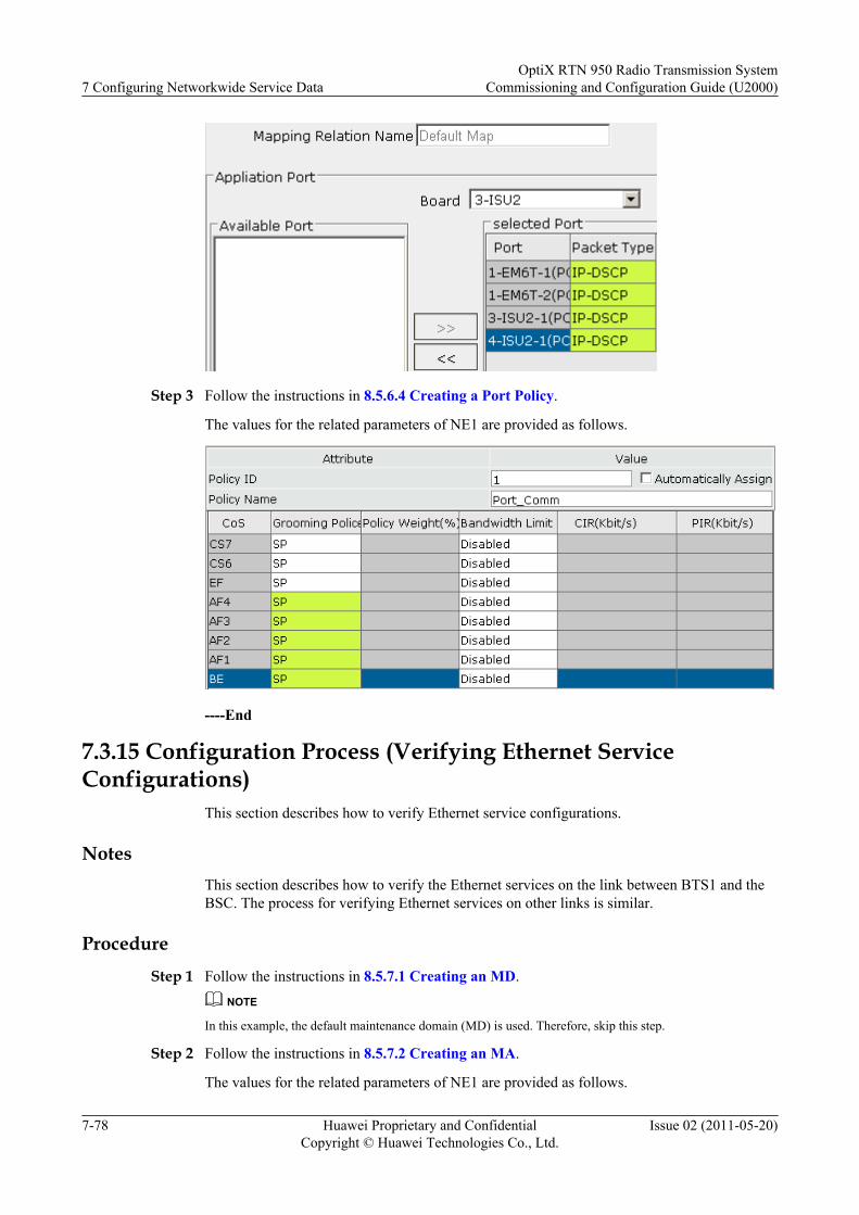
Step 3 Follow the instructions in 8.5.6.4 Creating a Port Policy.
The values for the related parameters of NE1 are provided as follows.
----End
7.3.15 Configuration Process (Verifying Ethernet ServiceConfigurations)
This section describes how to verify Ethernet service configurations.
NotesThis section describes how to verify the Ethernet services on the link between BTS1 and theBSC. The process for verifying Ethernet services on other links is similar.
ProcedureStep 1 Follow the instructions in 8.5.7.1 Creating an MD.
NOTE
In this example, the default maintenance domain (MD) is used. Therefore, skip this step.
Step 2 Follow the instructions in 8.5.7.2 Creating an MA.
The values for the related parameters of NE1 are provided as follows.
7 Configuring Networkwide Service DataOptiX RTN 950 Radio Transmission System
Commissioning and Configuration Guide (U2000)
7-78 Huawei Proprietary and ConfidentialCopyright © Huawei Technologies Co., Ltd.
Issue 02 (2011-05-20)
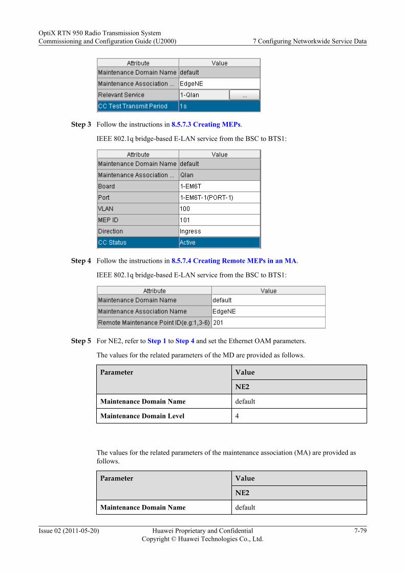
Step 3 Follow the instructions in 8.5.7.3 Creating MEPs.
IEEE 802.1q bridge-based E-LAN service from the BSC to BTS1:
Step 4 Follow the instructions in 8.5.7.4 Creating Remote MEPs in an MA.
IEEE 802.1q bridge-based E-LAN service from the BSC to BTS1:
Step 5 For NE2, refer to Step 1 to Step 4 and set the Ethernet OAM parameters.
The values for the related parameters of the MD are provided as follows.
Parameter Value
NE2
Maintenance Domain Name default
Maintenance Domain Level 4
The values for the related parameters of the maintenance association (MA) are provided asfollows.
Parameter Value
NE2
Maintenance Domain Name default
OptiX RTN 950 Radio Transmission SystemCommissioning and Configuration Guide (U2000) 7 Configuring Networkwide Service Data
Issue 02 (2011-05-20) Huawei Proprietary and ConfidentialCopyright © Huawei Technologies Co., Ltd.
7-79
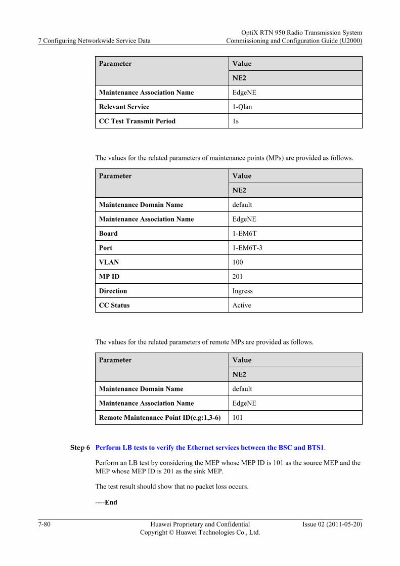
Parameter Value
NE2
Maintenance Association Name EdgeNE
Relevant Service 1-Qlan
CC Test Transmit Period 1s
The values for the related parameters of maintenance points (MPs) are provided as follows.
Parameter Value
NE2
Maintenance Domain Name default
Maintenance Association Name EdgeNE
Board 1-EM6T
Port 1-EM6T-3
VLAN 100
MP ID 201
Direction Ingress
CC Status Active
The values for the related parameters of remote MPs are provided as follows.
Parameter Value
NE2
Maintenance Domain Name default
Maintenance Association Name EdgeNE
Remote Maintenance Point ID(e.g:1,3-6) 101
Step 6 Perform LB tests to verify the Ethernet services between the BSC and BTS1.
Perform an LB test by considering the MEP whose MEP ID is 101 as the source MEP and theMEP whose MEP ID is 201 as the sink MEP.
The test result should show that no packet loss occurs.
----End
7 Configuring Networkwide Service DataOptiX RTN 950 Radio Transmission System
Commissioning and Configuration Guide (U2000)
7-80 Huawei Proprietary and ConfidentialCopyright © Huawei Technologies Co., Ltd.
Issue 02 (2011-05-20)
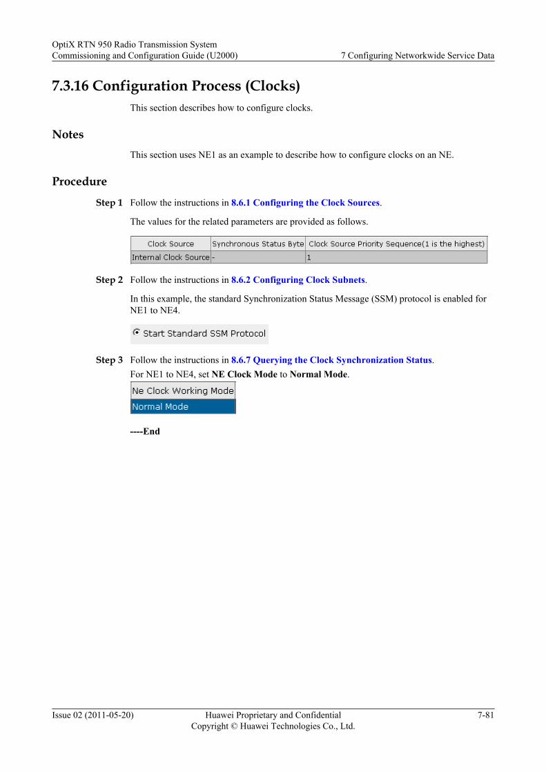
7.3.16 Configuration Process (Clocks)This section describes how to configure clocks.
NotesThis section uses NE1 as an example to describe how to configure clocks on an NE.
Procedure
Step 1 Follow the instructions in 8.6.1 Configuring the Clock Sources.
The values for the related parameters are provided as follows.
Step 2 Follow the instructions in 8.6.2 Configuring Clock Subnets.
In this example, the standard Synchronization Status Message (SSM) protocol is enabled forNE1 to NE4.
Step 3 Follow the instructions in 8.6.7 Querying the Clock Synchronization Status.For NE1 to NE4, set NE Clock Mode to Normal Mode.
----End
OptiX RTN 950 Radio Transmission SystemCommissioning and Configuration Guide (U2000) 7 Configuring Networkwide Service Data
Issue 02 (2011-05-20) Huawei Proprietary and ConfidentialCopyright © Huawei Technologies Co., Ltd.
7-81

8 Task Collection
About This Chapter
This section describes various tasks involved in this document.
8.1 U2000 Quick StartThe U2000 quick start guide helps to learn about basic operations on the U2000 client.
8.2 Network ManagementNetwork management involves topology management, communication management, andsecurity management.
8.3 Managing Radio LinksBefore you configure the radio link between two microwave sites, configure the informationabout the radio link.
8.4 Managing PortsSetting correct port parameter is the basis of configuring ports that transmit services.
8.5 Configuring Ethernet Services and Features on the Packet PlaneConfigurations of Ethernet services and features on the packet plane include Ethernet port,protection, service, protocol, and OAM configurations.
8.6 Managing the ClockTo ensure the clock synchronization between transmission nodes on a transport network, youneed to manage the NE clock.
OptiX RTN 950 Radio Transmission SystemCommissioning and Configuration Guide (U2000) 8 Task Collection
Issue 02 (2011-05-20) Huawei Proprietary and ConfidentialCopyright © Huawei Technologies Co., Ltd.
8-1
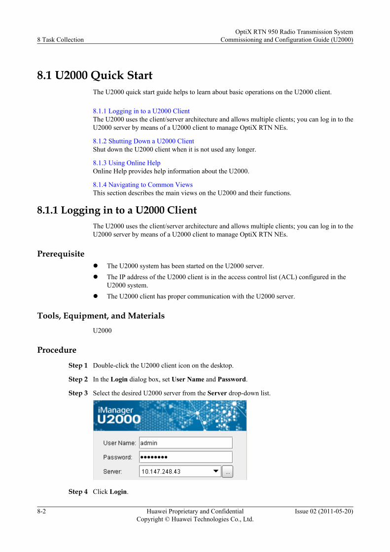
8.1 U2000 Quick StartThe U2000 quick start guide helps to learn about basic operations on the U2000 client.
8.1.1 Logging in to a U2000 ClientThe U2000 uses the client/server architecture and allows multiple clients; you can log in to theU2000 server by means of a U2000 client to manage OptiX RTN NEs.
8.1.2 Shutting Down a U2000 ClientShut down the U2000 client when it is not used any longer.
8.1.3 Using Online HelpOnline Help provides help information about the U2000.
8.1.4 Navigating to Common ViewsThis section describes the main views on the U2000 and their functions.
8.1.1 Logging in to a U2000 ClientThe U2000 uses the client/server architecture and allows multiple clients; you can log in to theU2000 server by means of a U2000 client to manage OptiX RTN NEs.
Prerequisitel The U2000 system has been started on the U2000 server.l The IP address of the U2000 client is in the access control list (ACL) configured in the
U2000 system.l The U2000 client has proper communication with the U2000 server.
Tools, Equipment, and MaterialsU2000
Procedure
Step 1 Double-click the U2000 client icon on the desktop.
Step 2 In the Login dialog box, set User Name and Password.
Step 3 Select the desired U2000 server from the Server drop-down list.
Step 4 Click Login.
8 Task CollectionOptiX RTN 950 Radio Transmission System
Commissioning and Configuration Guide (U2000)
8-2 Huawei Proprietary and ConfidentialCopyright © Huawei Technologies Co., Ltd.
Issue 02 (2011-05-20)
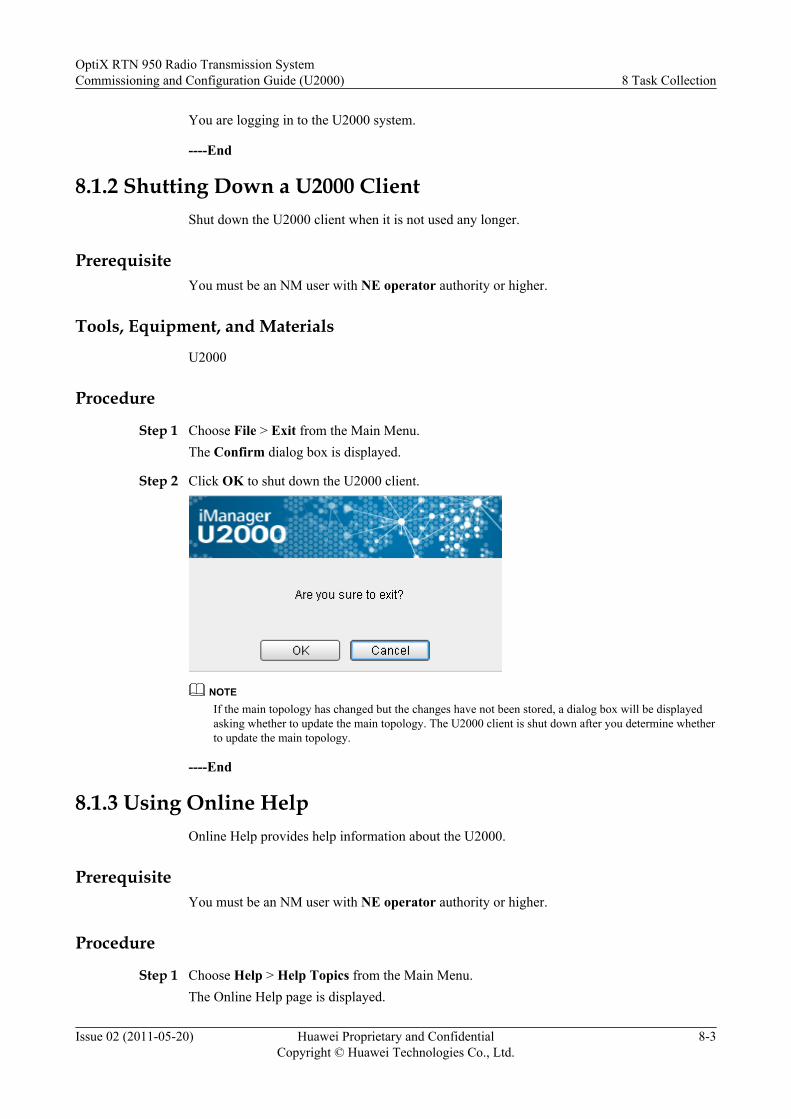
You are logging in to the U2000 system.
----End
8.1.2 Shutting Down a U2000 ClientShut down the U2000 client when it is not used any longer.
PrerequisiteYou must be an NM user with NE operator authority or higher.
Tools, Equipment, and Materials
U2000
Procedure
Step 1 Choose File > Exit from the Main Menu.The Confirm dialog box is displayed.
Step 2 Click OK to shut down the U2000 client.
NOTEIf the main topology has changed but the changes have not been stored, a dialog box will be displayedasking whether to update the main topology. The U2000 client is shut down after you determine whetherto update the main topology.
----End
8.1.3 Using Online HelpOnline Help provides help information about the U2000.
PrerequisiteYou must be an NM user with NE operator authority or higher.
Procedure
Step 1 Choose Help > Help Topics from the Main Menu.The Online Help page is displayed.
OptiX RTN 950 Radio Transmission SystemCommissioning and Configuration Guide (U2000) 8 Task Collection
Issue 02 (2011-05-20) Huawei Proprietary and ConfidentialCopyright © Huawei Technologies Co., Ltd.
8-3
TIP
When using the U2000 client, press the F1 key to quickly display the related Online Help page.
----End
8.1.4 Navigating to Common ViewsThis section describes the main views on the U2000 and their functions.
8.1.4.1 Navigating to the Main TopologyThe U2000 provides the Main Topology view to support network topology management.
8.1.4.2 Navigating to the NE ExplorerThe U2000 provides the NE Explorer view to support users' management on equipment. TheNE Explorer view consists of the Function Tree pane, the Object Tree pane, and theconfiguration interface.
8.1.4.3 Navigating to the NE PanelNE Panel displays the boards configured on the NE. Different colors of the boards representdifferent board states.
8.1.4.1 Navigating to the Main TopologyThe U2000 provides the Main Topology view to support network topology management.
PrerequisiteYou must be an NM user with NE operator authority or higher.
Tools, Equipment, and MaterialsU2000
Procedure
Step 1 Choose View > Main Topology from the Main Menu, or double-click the Main Topology iconin Workbench.The Main Topology view is displayed.
8 Task CollectionOptiX RTN 950 Radio Transmission System
Commissioning and Configuration Guide (U2000)
8-4 Huawei Proprietary and ConfidentialCopyright © Huawei Technologies Co., Ltd.
Issue 02 (2011-05-20)
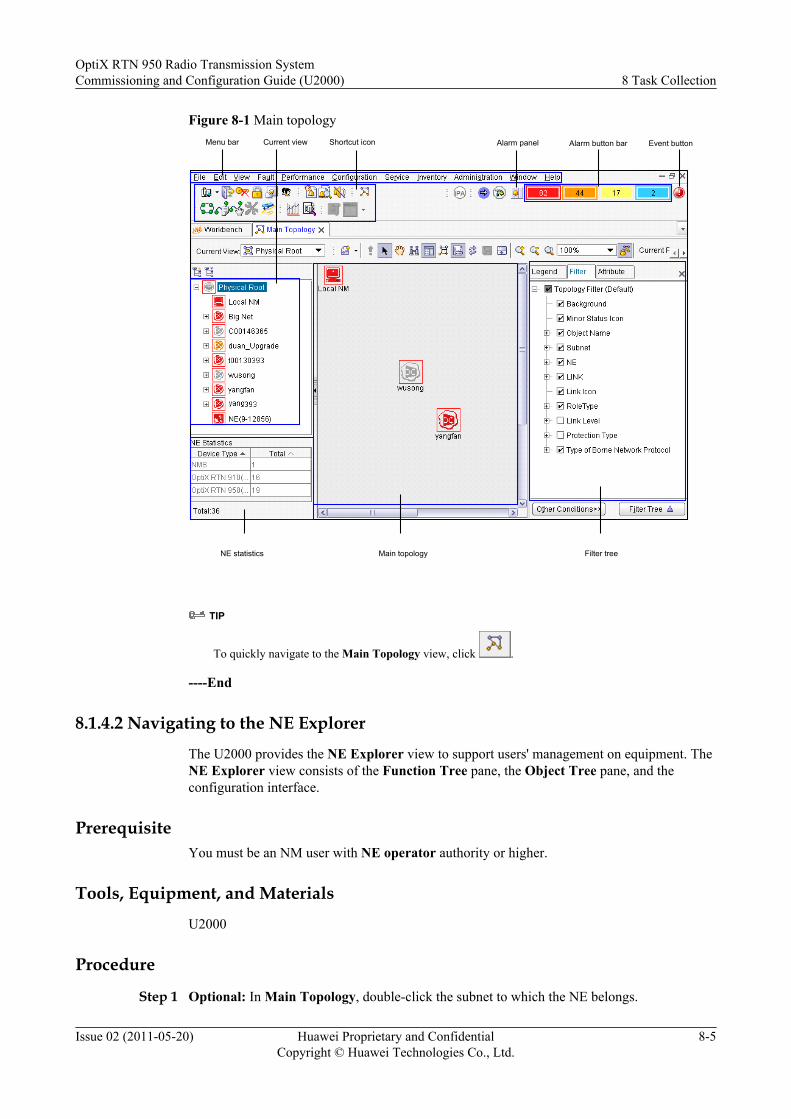
Figure 8-1 Main topologyMenu bar Current view Alarm button barShortcut icon
NE statistics Main topology Filter tree
Event buttonAlarm panel
TIP
To quickly navigate to the Main Topology view, click .
----End
8.1.4.2 Navigating to the NE Explorer
The U2000 provides the NE Explorer view to support users' management on equipment. TheNE Explorer view consists of the Function Tree pane, the Object Tree pane, and theconfiguration interface.
PrerequisiteYou must be an NM user with NE operator authority or higher.
Tools, Equipment, and Materials
U2000
Procedure
Step 1 Optional: In Main Topology, double-click the subnet to which the NE belongs.
OptiX RTN 950 Radio Transmission SystemCommissioning and Configuration Guide (U2000) 8 Task Collection
Issue 02 (2011-05-20) Huawei Proprietary and ConfidentialCopyright © Huawei Technologies Co., Ltd.
8-5
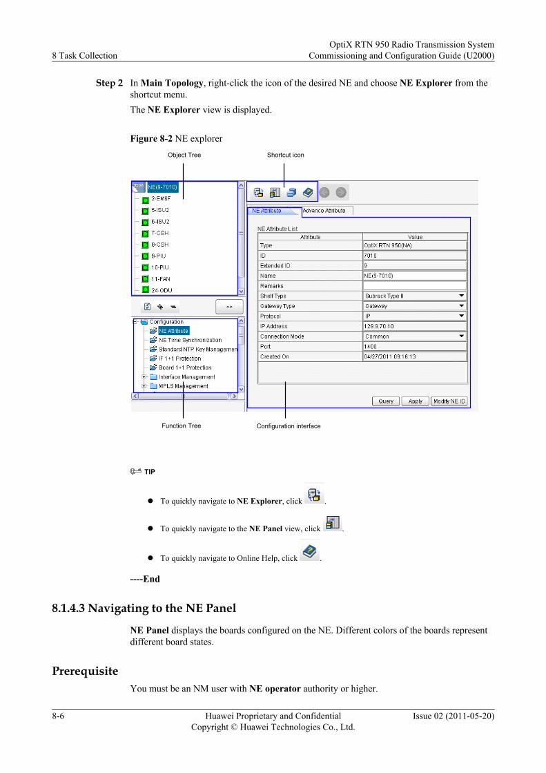
Step 2 In Main Topology, right-click the icon of the desired NE and choose NE Explorer from theshortcut menu.The NE Explorer view is displayed.
Figure 8-2 NE explorerObject Tree
Function Tree
Shortcut icon
Configuration interface
TIP
l To quickly navigate to NE Explorer, click .
l To quickly navigate to the NE Panel view, click .
l To quickly navigate to Online Help, click .
----End
8.1.4.3 Navigating to the NE Panel
NE Panel displays the boards configured on the NE. Different colors of the boards representdifferent board states.
PrerequisiteYou must be an NM user with NE operator authority or higher.
8 Task CollectionOptiX RTN 950 Radio Transmission System
Commissioning and Configuration Guide (U2000)
8-6 Huawei Proprietary and ConfidentialCopyright © Huawei Technologies Co., Ltd.
Issue 02 (2011-05-20)
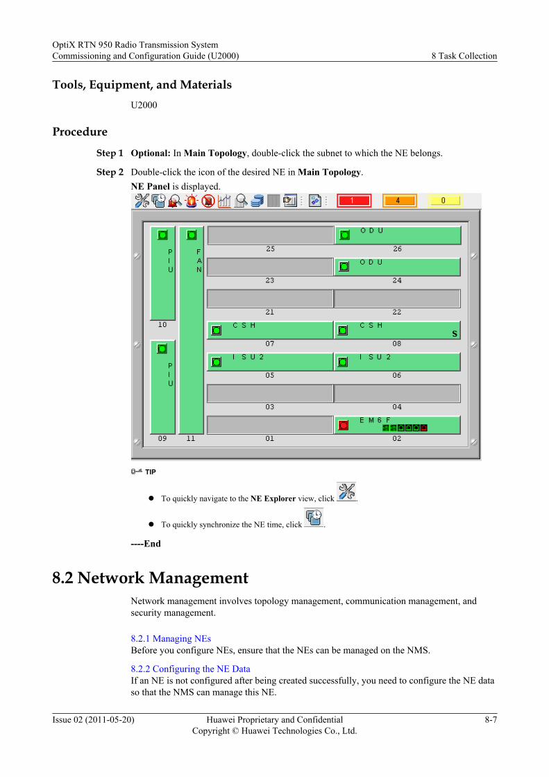
Tools, Equipment, and MaterialsU2000
Procedure
Step 1 Optional: In Main Topology, double-click the subnet to which the NE belongs.
Step 2 Double-click the icon of the desired NE in Main Topology.NE Panel is displayed.
TIP
l To quickly navigate to the NE Explorer view, click .
l To quickly synchronize the NE time, click .
----End
8.2 Network ManagementNetwork management involves topology management, communication management, andsecurity management.
8.2.1 Managing NEsBefore you configure NEs, ensure that the NEs can be managed on the NMS.
8.2.2 Configuring the NE DataIf an NE is not configured after being created successfully, you need to configure the NE dataso that the NMS can manage this NE.
OptiX RTN 950 Radio Transmission SystemCommissioning and Configuration Guide (U2000) 8 Task Collection
Issue 02 (2011-05-20) Huawei Proprietary and ConfidentialCopyright © Huawei Technologies Co., Ltd.
8-7
8.2.3 Configuring the Performance Monitoring Status of NEsBy performing this operation task, you can manually enable or disable performance monitoringfor NEs, or set the performance monitoring period.
8.2.4 Connecting Fibers or CablesTo implement the end-to-end management on the NMS, you need to connect fibers or cables.
8.2.5 Managing SubnetsTo facilitate NE management, you can allocate the NEs that are in the same domain or havesimilar attributes into the same subnet.
8.2.6 Managing CommunicationTo manage the NE by the NMS, ensure that the DCN communication is working properly.
8.2.7 Configuring Service Access of NEsYou can ensure the security of a network by setting service access of the NEs on the network.
8.2.8 Configuring an NE UserNE users refer to the users who log in to and operate NEs. Different types of NE users areassigned different rights to log in and manage NEs.
8.2.9 Configuring SSL Protocol CommunicationThe security socket layer (SSL) protocol provides encrypted and reliable communicationbetween entities. Therefore, SSL protocol communication greatly improves the networkmanagement security.
8.2.1 Managing NEsBefore you configure NEs, ensure that the NEs can be managed on the NMS.
8.2.1.1 Creating NEs by Using the Search MethodThe U2000 can find all NEs that communicate with a specific gateway NE by using the IP addressof the gateway NE, the IP address range of the gateway NE, or the NSAP addresses. In addition,the U2000 can create the NEs that are found in batches. Compared with the method of manuallycreating NEs, this method is faster and more reliable.
8.2.1.2 Creating NEs by Using the Manual MethodYou can only create NEs one by one by using the manual method. The manual method, unlikethe search method, does not allow creating NEs in batches.
8.2.1.3 Configuring the Logical BoardIf the logical board corresponding to the physical board is not added in the slot layout, add thelogical board in the slot layout. If the physical board is inconsistent with the logical board in theslot layout, delete the inconsistent logical board and add the correct logical board.
8.2.1.4 Changing the NE IDChange the NE ID according to the engineering plan to guarantee that each NE ID is unique.This operation task does not interrupt services.
8.2.1.5 Changing the NE NameTo better identify the NE in the Main Topology, name the NE according to the NE geographicallocation or the device connected to the NE.
8.2.1.6 Synchronizing the NE TimeBy setting the NE time to be synchronous with the time on the NMS or standard NTP server,you can record the exact time when alarms and abnormal events occur.
8.2.1.7 Localizing the NE Time
8 Task CollectionOptiX RTN 950 Radio Transmission System
Commissioning and Configuration Guide (U2000)
8-8 Huawei Proprietary and ConfidentialCopyright © Huawei Technologies Co., Ltd.
Issue 02 (2011-05-20)
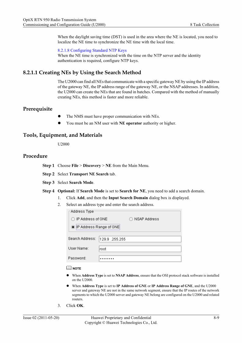
When the daylight saving time (DST) is used in the area where the NE is located, you need tolocalize the NE time to synchronize the NE time with the local time.
8.2.1.8 Configuring Standard NTP KeysWhen the NE time is synchronized with the time on the NTP server and the identityauthentication is required, configure NTP keys.
8.2.1.1 Creating NEs by Using the Search MethodThe U2000 can find all NEs that communicate with a specific gateway NE by using the IP addressof the gateway NE, the IP address range of the gateway NE, or the NSAP addresses. In addition,the U2000 can create the NEs that are found in batches. Compared with the method of manuallycreating NEs, this method is faster and more reliable.
Prerequisitel The NMS must have proper communication with NEs.l You must be an NM user with NE operator authority or higher.
Tools, Equipment, and MaterialsU2000
Procedure
Step 1 Choose File > Discovery > NE from the Main Menu.
Step 2 Select Transport NE Search tab.
Step 3 Select Search Mode.
Step 4 Optional: If Search Mode is set to Search for NE, you need to add a search domain.1. Click Add, and then the Input Search Domain dialog box is displayed.2. Select an address type and enter the search address.
NOTE
l When Address Type is set to NSAP Address, ensure that the OSI protocol stack software is installedon the U2000.
l When Address Type is set to IP Address of GNE or IP Address Range of GNE, and the U2000server and gateway NE are not in the same network segment, ensure that the IP routes of the networksegments to which the U2000 server and gateway NE belong are configured on the U2000 and relatedrouters.
3. Click OK.
OptiX RTN 950 Radio Transmission SystemCommissioning and Configuration Guide (U2000) 8 Task Collection
Issue 02 (2011-05-20) Huawei Proprietary and ConfidentialCopyright © Huawei Technologies Co., Ltd.
8-9

Step 5 Optional: Repeat Step 4 to add several search domains.
Step 6 In the Search for NE dialog box, perform the operations described in the Note part.
NOTE
l If Create NE after search is selected, you need to specify NE User and Password.
l You can select either Create NE after search or Upload after Create or both Create NE after search andUpload after Create. In this manner, after the NE searching is complete, the system automatically createsan NE and uploads the NE.
Step 7 Click Next, and then the Transport NE Search dialog box is displayed.After the search is complete, all the NEs that are found are displayed in the Result list.
Step 8 Create NEs.1. Select an NE that is not created from the Result list.2. Optional: Select the GNE ID of the NE.3. Click Create.
The Create dialog box is displayed.4. Specify User Name and Password.5. Click OK.
The icon of the created NE is displayed in the Main Topology.
Step 9 Optional: Repeat Step 8 to create other NEs that are not created.
----End
8.2.1.2 Creating NEs by Using the Manual MethodYou can only create NEs one by one by using the manual method. The manual method, unlikethe search method, does not allow creating NEs in batches.
Prerequisitel You must be an NM user with NE operator authority or higher.l The NMS must have proper communication with the NE to be created.l If the NE to be created is a non-gateway NE, the gateway NE to which the NE to be created
belongs must be created.
Procedure
Step 1 Choose File > Discovery > NE from the Main Menu.The Create NE dialog box is displayed.
Step 2 Choose RTN Series > OptiX RTN 950 from the Object Tree.
Step 3 Enter the following information: ID, Extended ID, Name, and Remarks.
Step 4 Set Gateway Type for the NE.
If... Then...
The Gateway Type parameter is set toGateway
Proceed to the next step.
8 Task CollectionOptiX RTN 950 Radio Transmission System
Commissioning and Configuration Guide (U2000)
8-10 Huawei Proprietary and ConfidentialCopyright © Huawei Technologies Co., Ltd.
Issue 02 (2011-05-20)
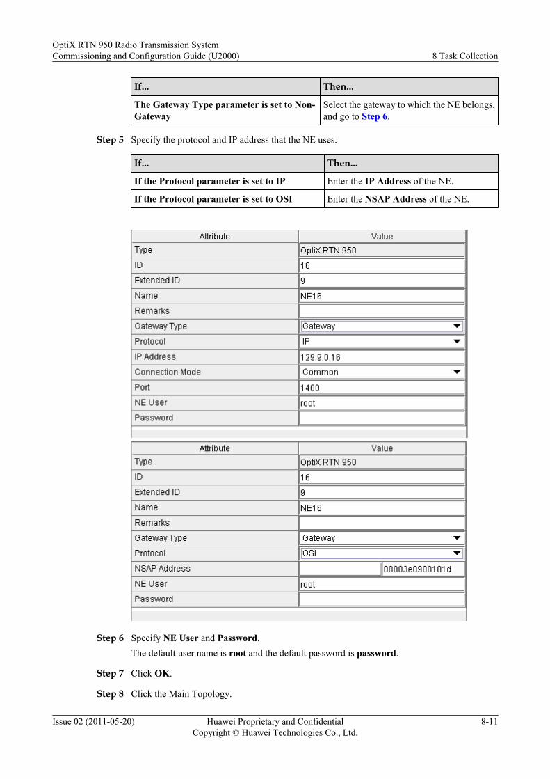
If... Then...
The Gateway Type parameter is set to Non-Gateway
Select the gateway to which the NE belongs,and go to Step 6.
Step 5 Specify the protocol and IP address that the NE uses.
If... Then...
If the Protocol parameter is set to IP Enter the IP Address of the NE.
If the Protocol parameter is set to OSI Enter the NSAP Address of the NE.
Step 6 Specify NE User and Password.The default user name is root and the default password is password.
Step 7 Click OK.
Step 8 Click the Main Topology.
OptiX RTN 950 Radio Transmission SystemCommissioning and Configuration Guide (U2000) 8 Task Collection
Issue 02 (2011-05-20) Huawei Proprietary and ConfidentialCopyright © Huawei Technologies Co., Ltd.
8-11
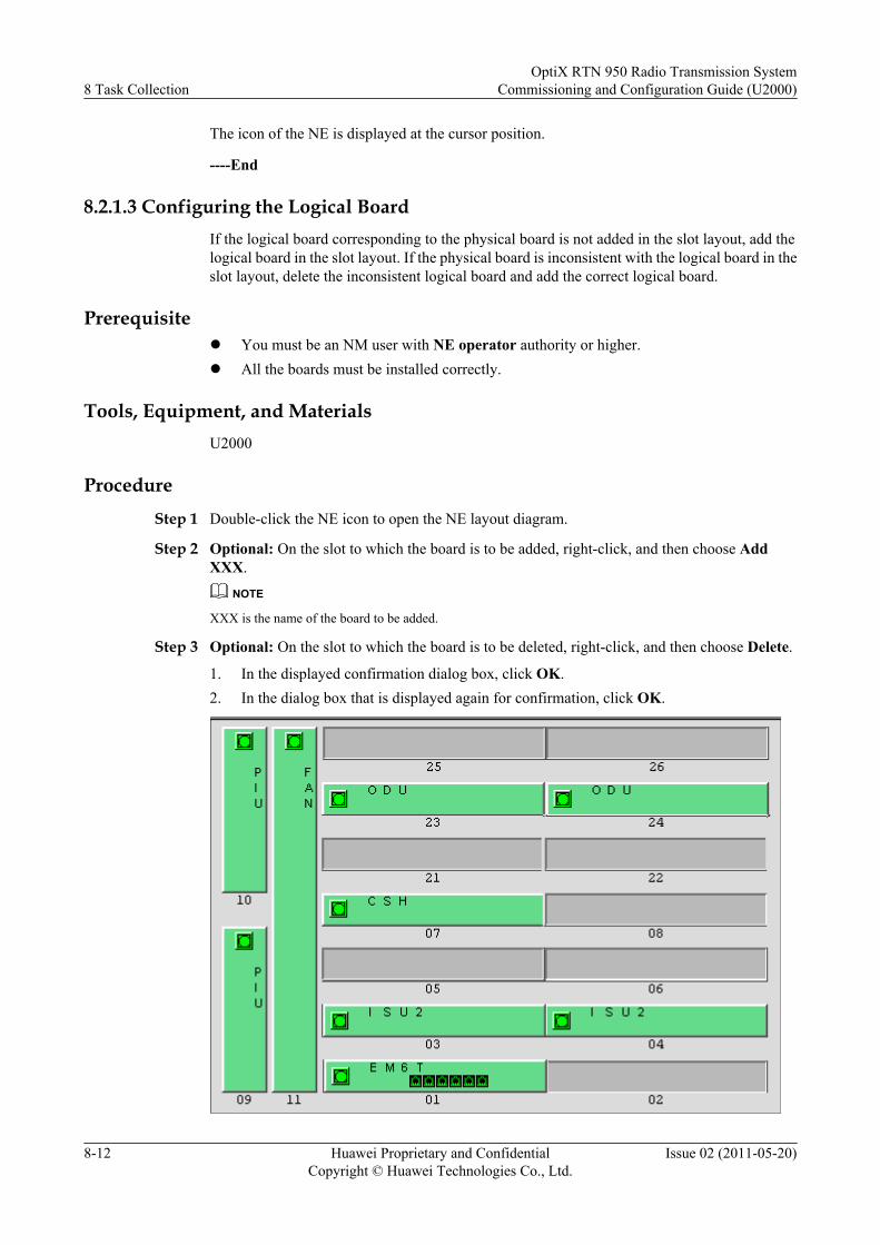
The icon of the NE is displayed at the cursor position.
----End
8.2.1.3 Configuring the Logical BoardIf the logical board corresponding to the physical board is not added in the slot layout, add thelogical board in the slot layout. If the physical board is inconsistent with the logical board in theslot layout, delete the inconsistent logical board and add the correct logical board.
Prerequisitel You must be an NM user with NE operator authority or higher.l All the boards must be installed correctly.
Tools, Equipment, and MaterialsU2000
ProcedureStep 1 Double-click the NE icon to open the NE layout diagram.
Step 2 Optional: On the slot to which the board is to be added, right-click, and then choose AddXXX.
NOTE
XXX is the name of the board to be added.
Step 3 Optional: On the slot to which the board is to be deleted, right-click, and then choose Delete.
1. In the displayed confirmation dialog box, click OK.2. In the dialog box that is displayed again for confirmation, click OK.
8 Task CollectionOptiX RTN 950 Radio Transmission System
Commissioning and Configuration Guide (U2000)
8-12 Huawei Proprietary and ConfidentialCopyright © Huawei Technologies Co., Ltd.
Issue 02 (2011-05-20)
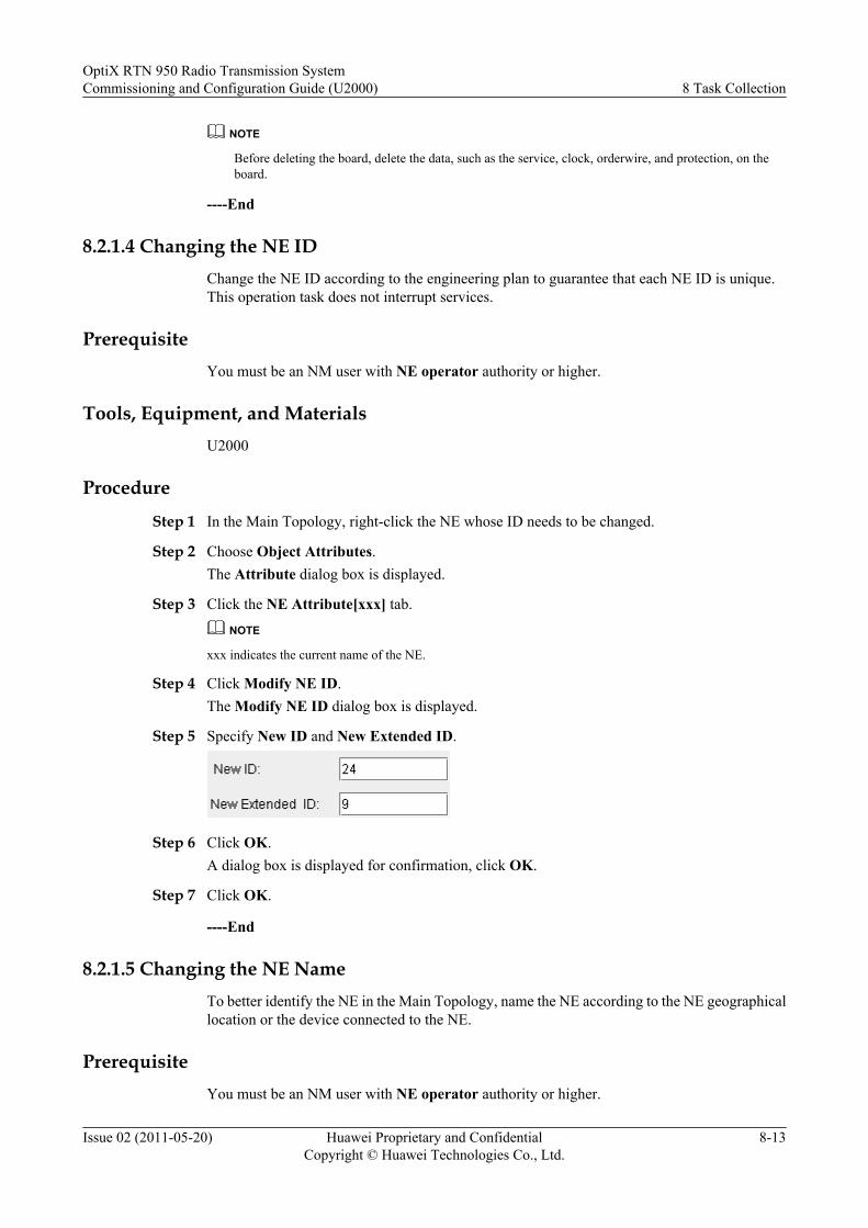
NOTE
Before deleting the board, delete the data, such as the service, clock, orderwire, and protection, on theboard.
----End
8.2.1.4 Changing the NE IDChange the NE ID according to the engineering plan to guarantee that each NE ID is unique.This operation task does not interrupt services.
PrerequisiteYou must be an NM user with NE operator authority or higher.
Tools, Equipment, and MaterialsU2000
Procedure
Step 1 In the Main Topology, right-click the NE whose ID needs to be changed.
Step 2 Choose Object Attributes.The Attribute dialog box is displayed.
Step 3 Click the NE Attribute[xxx] tab.
NOTE
xxx indicates the current name of the NE.
Step 4 Click Modify NE ID.The Modify NE ID dialog box is displayed.
Step 5 Specify New ID and New Extended ID.
Step 6 Click OK.A dialog box is displayed for confirmation, click OK.
Step 7 Click OK.
----End
8.2.1.5 Changing the NE NameTo better identify the NE in the Main Topology, name the NE according to the NE geographicallocation or the device connected to the NE.
PrerequisiteYou must be an NM user with NE operator authority or higher.
OptiX RTN 950 Radio Transmission SystemCommissioning and Configuration Guide (U2000) 8 Task Collection
Issue 02 (2011-05-20) Huawei Proprietary and ConfidentialCopyright © Huawei Technologies Co., Ltd.
8-13
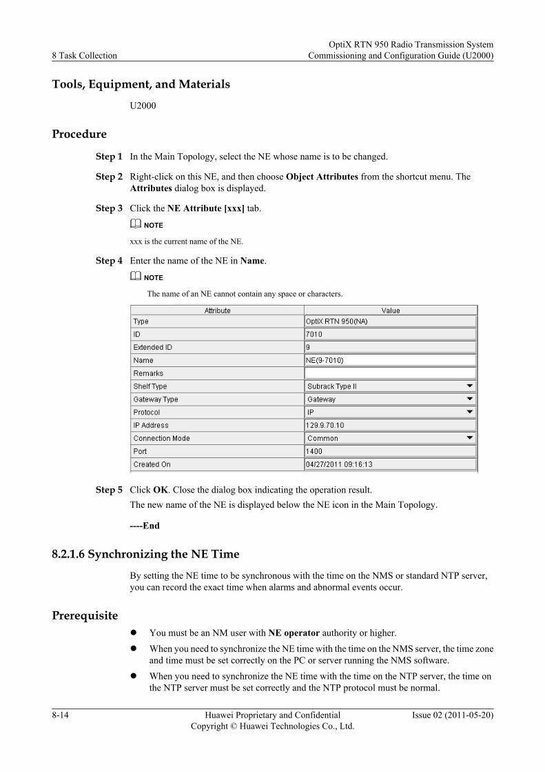
Tools, Equipment, and Materials
U2000
Procedure
Step 1 In the Main Topology, select the NE whose name is to be changed.
Step 2 Right-click on this NE, and then choose Object Attributes from the shortcut menu. TheAttributes dialog box is displayed.
Step 3 Click the NE Attribute [xxx] tab.
NOTE
xxx is the current name of the NE.
Step 4 Enter the name of the NE in Name.
NOTE
The name of an NE cannot contain any space or characters.
Step 5 Click OK. Close the dialog box indicating the operation result.The new name of the NE is displayed below the NE icon in the Main Topology.
----End
8.2.1.6 Synchronizing the NE Time
By setting the NE time to be synchronous with the time on the NMS or standard NTP server,you can record the exact time when alarms and abnormal events occur.
Prerequisitel You must be an NM user with NE operator authority or higher.
l When you need to synchronize the NE time with the time on the NMS server, the time zoneand time must be set correctly on the PC or server running the NMS software.
l When you need to synchronize the NE time with the time on the NTP server, the time onthe NTP server must be set correctly and the NTP protocol must be normal.
8 Task CollectionOptiX RTN 950 Radio Transmission System
Commissioning and Configuration Guide (U2000)
8-14 Huawei Proprietary and ConfidentialCopyright © Huawei Technologies Co., Ltd.
Issue 02 (2011-05-20)
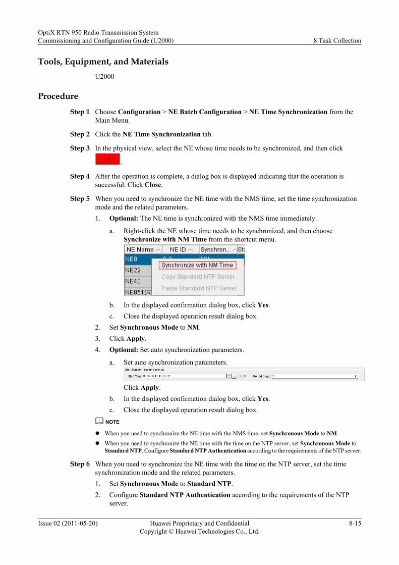
Tools, Equipment, and MaterialsU2000
Procedure
Step 1 Choose Configuration > NE Batch Configuration > NE Time Synchronization from theMain Menu.
Step 2 Click the NE Time Synchronization tab.
Step 3 In the physical view, select the NE whose time needs to be synchronized, and then click
.
Step 4 After the operation is complete, a dialog box is displayed indicating that the operation issuccessful. Click Close.
Step 5 When you need to synchronize the NE time with the NMS time, set the time synchronizationmode and the related parameters.1. Optional: The NE time is synchronized with the NMS time immediately.
a. Right-click the NE whose time needs to be synchronized, and then chooseSynchronize with NM Time from the shortcut menu.
b. In the displayed confirmation dialog box, click Yes.c. Close the displayed operation result dialog box.
2. Set Synchronous Mode to NM.3. Click Apply.4. Optional: Set auto synchronization parameters.
a. Set auto synchronization parameters.
Click Apply.b. In the displayed confirmation dialog box, click Yes.c. Close the displayed operation result dialog box.
NOTE
l When you need to synchronize the NE time with the NMS time, set Synchronous Mode to NM.
l When you need to synchronize the NE time with the time on the NTP server, set Synchronous Mode toStandard NTP. Configure Standard NTP Authentication according to the requirements of the NTP server.
Step 6 When you need to synchronize the NE time with the time on the NTP server, set the timesynchronization mode and the related parameters.1. Set Synchronous Mode to Standard NTP.2. Configure Standard NTP Authentication according to the requirements of the NTP
server.
OptiX RTN 950 Radio Transmission SystemCommissioning and Configuration Guide (U2000) 8 Task Collection
Issue 02 (2011-05-20) Huawei Proprietary and ConfidentialCopyright © Huawei Technologies Co., Ltd.
8-15
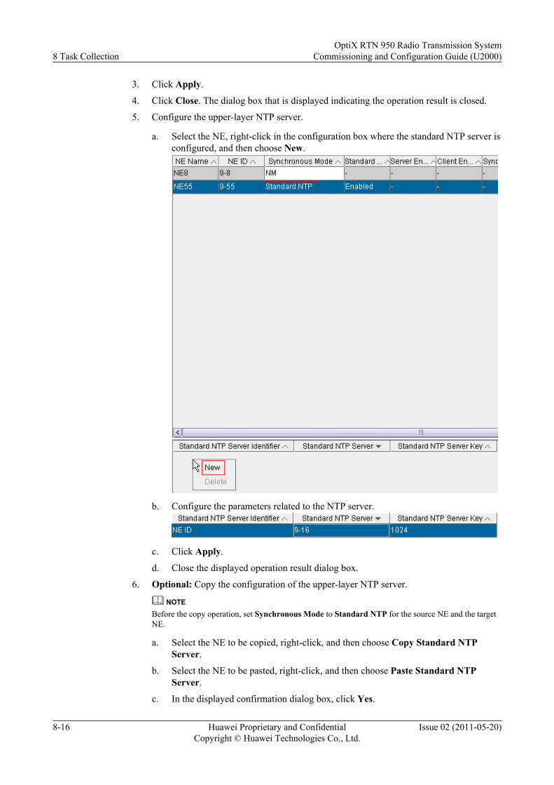
3. Click Apply.
4. Click Close. The dialog box that is displayed indicating the operation result is closed.
5. Configure the upper-layer NTP server.
a. Select the NE, right-click in the configuration box where the standard NTP server isconfigured, and then choose New.
b. Configure the parameters related to the NTP server.
c. Click Apply.
d. Close the displayed operation result dialog box.
6. Optional: Copy the configuration of the upper-layer NTP server.
NOTEBefore the copy operation, set Synchronous Mode to Standard NTP for the source NE and the targetNE.
a. Select the NE to be copied, right-click, and then choose Copy Standard NTPServer.
b. Select the NE to be pasted, right-click, and then choose Paste Standard NTPServer.
c. In the displayed confirmation dialog box, click Yes.
8 Task CollectionOptiX RTN 950 Radio Transmission System
Commissioning and Configuration Guide (U2000)
8-16 Huawei Proprietary and ConfidentialCopyright © Huawei Technologies Co., Ltd.
Issue 02 (2011-05-20)
d. Close the displayed operation result dialog box.
----End
8.2.1.7 Localizing the NE Time
When the daylight saving time (DST) is used in the area where the NE is located, you need tolocalize the NE time to synchronize the NE time with the local time.
Prerequisite
You must be an NM user with NE operator authority or higher.
Tools, Equipment, and Materials
U2000
Procedure
Step 1 Choose Configuration > NE Batch Configuration > NE Time Localization Managementfrom the Main Menu.
Step 2 Select the NE for time localization management from the Object Tree, and then click
.
Step 3 Click the Time Zone drop-down list, and then set the time zone of the NE.
Step 4 Optional: Click DST, and then configure the related parameters.
Step 5 Click Apply. Close the displayed dialog box.
----End
8.2.1.8 Configuring Standard NTP Keys
When the NE time is synchronized with the time on the NTP server and the identityauthentication is required, configure NTP keys.
Prerequisitel You must be an NM user with NE operator authority or higher.
l Synchronous Mode must be set to Standard NTP and Standard NTP Authenticationmust be set to Enabled.
l The NTP protocol must be running properly and the NTP identity authentication must beenabled on the NTP server.
Tools, Equipment, and Materials
U2000
OptiX RTN 950 Radio Transmission SystemCommissioning and Configuration Guide (U2000) 8 Task Collection
Issue 02 (2011-05-20) Huawei Proprietary and ConfidentialCopyright © Huawei Technologies Co., Ltd.
8-17
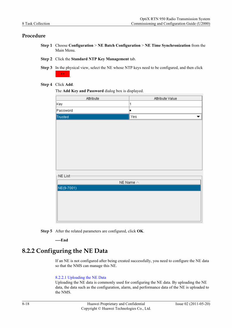
Procedure
Step 1 Choose Configuration > NE Batch Configuration > NE Time Synchronization from theMain Menu.
Step 2 Click the Standard NTP Key Management tab.
Step 3 In the physical view, select the NE whose NTP keys need to be configured, and then click
.
Step 4 Click Add.The Add Key and Password dialog box is displayed.
Step 5 After the related parameters are configured, click OK.
----End
8.2.2 Configuring the NE DataIf an NE is not configured after being created successfully, you need to configure the NE dataso that the NMS can manage this NE.
8.2.2.1 Uploading the NE DataUploading the NE data is commonly used for configuring the NE data. By uploading the NEdata, the data such as the configuration, alarm, and performance data of the NE is uploaded tothe NMS.
8 Task CollectionOptiX RTN 950 Radio Transmission System
Commissioning and Configuration Guide (U2000)
8-18 Huawei Proprietary and ConfidentialCopyright © Huawei Technologies Co., Ltd.
Issue 02 (2011-05-20)
8.2.2.1 Uploading the NE DataUploading the NE data is commonly used for configuring the NE data. By uploading the NEdata, the data such as the configuration, alarm, and performance data of the NE is uploaded tothe NMS.
Prerequisitel An NE must be logged in to successfully.l You must be an NM user with NE operator authority or higher.
Tools, Equipment, and MaterialsU2000
Procedure
Step 1 Select the corresponding operation steps according to the NE status.
If... Then...
An NE is not configured and the NE dataneeds to be uploaded.
In the Main Topology, double-click the NEthat is not configured, and then perform Step2 through Step 4.
An NE is configured with data and NE dataneeds to be uploaded.
Perform Step 5 through Step 8.
Step 2 In the displayed NE Configuration Wizard dialog box, select Upload, and then click Next.A dialog box is displayed for confirmation.
Step 3 Click OK.
Step 4 Click Close.
Step 5 Choose Configuration > NE Configuration Data Management from the Main Menu.
Step 6 Select the NE whose data needs to be uploaded from the Object Tree, and then click .
Step 7 Select the NE, click Upload. In the displayed confirmation dialog box, click OK.The uploading is started. After the uploading is complete, the Operation Result dialog box isdisplayed.
Step 8 Click Close.
----End
8.2.3 Configuring the Performance Monitoring Status of NEsBy performing this operation task, you can manually enable or disable performance monitoringfor NEs, or set the performance monitoring period.
PrerequisiteYou must be an NM user with NE operator authority or higher.
OptiX RTN 950 Radio Transmission SystemCommissioning and Configuration Guide (U2000) 8 Task Collection
Issue 02 (2011-05-20) Huawei Proprietary and ConfidentialCopyright © Huawei Technologies Co., Ltd.
8-19
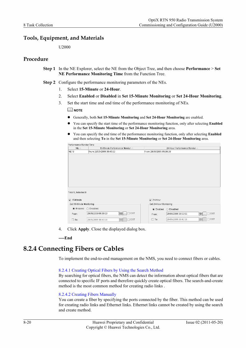
Tools, Equipment, and MaterialsU2000
Procedure
Step 1 In the NE Explorer, select the NE from the Object Tree, and then choose Performance > SetNE Performance Monitoring Time from the Function Tree.
Step 2 Configure the performance monitoring parameters of the NEs.1. Select 15-Minute or 24-Hour.2. Select Enabled or Disabled in Set 15-Minute Monitoring or Set 24-Hour Monitoring.3. Set the start time and end time of the performance monitoring of NEs.
NOTE
l Generally, both Set 15-Minute Monitoring and Set 24-Hour Monitoring are enabled.
l You can specify the start time of the performance monitoring function, only after selecting Enabledin the Set 15-Minute Monitoring or Set 24-Hour Monitoring area.
l You can specify the end time of the performance monitoring function, only after selecting Enabledand then selecting To in the Set 15-Minute Monitoring or Set 24-Hour Monitoring area.
4. Click Apply. Close the displayed dialog box.
----End
8.2.4 Connecting Fibers or CablesTo implement the end-to-end management on the NMS, you need to connect fibers or cables.
8.2.4.1 Creating Optical Fibers by Using the Search MethodBy searching for optical fibers, the NMS can detect the information about optical fibers that areconnected to specific IF ports and therefore quickly create optical fibers. The search-and-createmethod is the most common method for creating radio links .
8.2.4.2 Creating Fibers ManuallyYou can create a fiber by specifying the ports connected by the fiber. This method can be usedfor creating radio links and Ethernet links. Ethernet links cannot be created by using the searchand create method.
8 Task CollectionOptiX RTN 950 Radio Transmission System
Commissioning and Configuration Guide (U2000)
8-20 Huawei Proprietary and ConfidentialCopyright © Huawei Technologies Co., Ltd.
Issue 02 (2011-05-20)
8.2.4.3 Creating an Extended ECCExtended ECC connections indicate that the inter-NE DCN communication is implementedthrough concatenated NM ports.
8.2.4.4 Creating a Back-to-Back Radio ConnectionBack-to-back radio connections indicate the stacking of multiple OptiX RTN NEs on one site.
8.2.4.1 Creating Optical Fibers by Using the Search MethodBy searching for optical fibers, the NMS can detect the information about optical fibers that areconnected to specific IF ports and therefore quickly create optical fibers. The search-and-createmethod is the most common method for creating radio links .
Prerequisitel You must be an NM user with NE operator authority or higher.l The IF boards of various NEs must be created on the NMS.
Tools, Equipment, and MaterialsU2000
Procedure
Step 1 Choose File > Discovery > Fiber from the Main Menu.
Step 2 Select the IF board of the NE on which radio links need to be searched for from the Subject Tree.
Step 3 Click Search.
NOTE
l If Do not search the ports with Fiber/Cable created on NMS is selected, the port whose radio linkis created is not searched on the NMS.
l If you need to check whether the connection of a radio link is the same as the actual connection of theradio link, do not select Do not search the ports with Fiber/Cable created on NMS.
l If Do not search the ports with Fiber/Cable created on NMS is selected and all the selected portsare created with radio links, a dialog box is displayed after the search, indicating that the search domainis null.
Step 4 After the operation is complete, a dialog box is displayed indicating that the operation issuccessful. Click Close.
Step 5 In Physical Fiber/Cable Link List, select one or multiple radio links, and then click CreateFiber/Cable.
NOTE
l When you select one or multiple radio links from Physical Fiber/Cable Link List, the conflictingradio links are automatically displayed in Logical Fiber/Cable Link List. In this manner, you needto delete these conflicting radio links by referring to Step 6, and then create the links.
l When you create radio links, No fiber to create is displayed if the selected radio links are in theAlready created state.
Step 6 When you select one or multiple conflicting radio links from Logical Fiber/Cable Link List,click Delete Fiber/Cable.
----End
OptiX RTN 950 Radio Transmission SystemCommissioning and Configuration Guide (U2000) 8 Task Collection
Issue 02 (2011-05-20) Huawei Proprietary and ConfidentialCopyright © Huawei Technologies Co., Ltd.
8-21
Follow-up ProcedureIf the information about the radio links that are created using the search method is incomplete,you can supplement the information by changing the information about the radio links.
8.2.4.2 Creating Fibers ManuallyYou can create a fiber by specifying the ports connected by the fiber. This method can be usedfor creating radio links and Ethernet links. Ethernet links cannot be created by using the searchand create method.
Prerequisitel You must be an NM user with NE operator authority or higher.l The relevant boards of various NEs must be created on the NMS.l The resources of port IP addresses must be created if the automatic allocation of port IP
addresses is enabled.
Tools, Equipment, and MaterialsU2000
Procedure
Step 1 In the Main Topology, select the icon . Then, the cursor is displayed as "+".
Step 2 Click the source NE of a fiber in the Main Topology.
Step 3 In the Select Fiber/Cable Source dialog box, select the source board and source port.
Step 4 Click OK. In the Main Topology, the cursor is displayed as "+".
Step 5 Click the sink NE of the fiber in the Main Topology.
Step 6 In the Select Fiber/Cable Sink dialog box, select the sink board and sink port.
Step 7 Click OK. Set the attributes of the fiber in the Create Fiber/Cable dialog box.
Step 8 Click OK. Then, the created fiber is displayed between the source NE and the sink NE in theMain Topology.
----End
8.2.4.3 Creating an Extended ECCExtended ECC connections indicate that the inter-NE DCN communication is implementedthrough concatenated NM ports.
PrerequisiteYou must be an NM user with NE operator authority or higher.
Tools, Equipment, and MaterialsU2000
8 Task CollectionOptiX RTN 950 Radio Transmission System
Commissioning and Configuration Guide (U2000)
8-22 Huawei Proprietary and ConfidentialCopyright © Huawei Technologies Co., Ltd.
Issue 02 (2011-05-20)
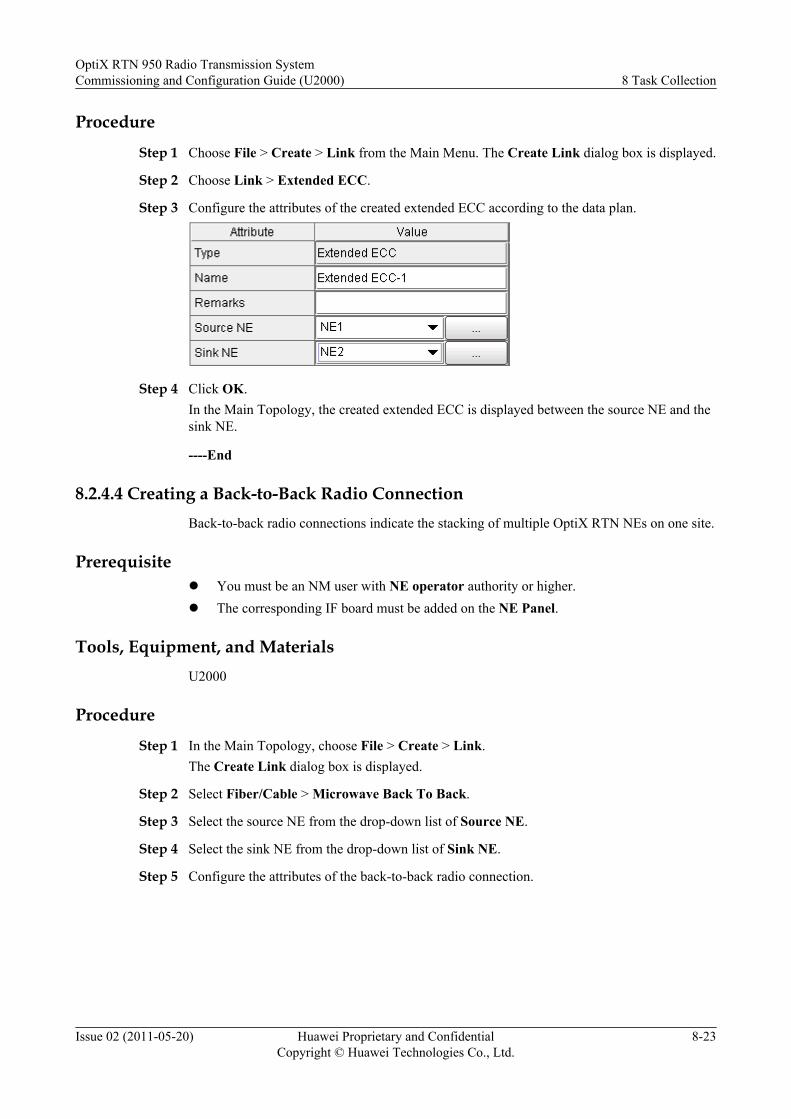
Procedure
Step 1 Choose File > Create > Link from the Main Menu. The Create Link dialog box is displayed.
Step 2 Choose Link > Extended ECC.
Step 3 Configure the attributes of the created extended ECC according to the data plan.
Step 4 Click OK.In the Main Topology, the created extended ECC is displayed between the source NE and thesink NE.
----End
8.2.4.4 Creating a Back-to-Back Radio ConnectionBack-to-back radio connections indicate the stacking of multiple OptiX RTN NEs on one site.
Prerequisitel You must be an NM user with NE operator authority or higher.l The corresponding IF board must be added on the NE Panel.
Tools, Equipment, and MaterialsU2000
Procedure
Step 1 In the Main Topology, choose File > Create > Link.The Create Link dialog box is displayed.
Step 2 Select Fiber/Cable > Microwave Back To Back.
Step 3 Select the source NE from the drop-down list of Source NE.
Step 4 Select the sink NE from the drop-down list of Sink NE.
Step 5 Configure the attributes of the back-to-back radio connection.
OptiX RTN 950 Radio Transmission SystemCommissioning and Configuration Guide (U2000) 8 Task Collection
Issue 02 (2011-05-20) Huawei Proprietary and ConfidentialCopyright © Huawei Technologies Co., Ltd.
8-23
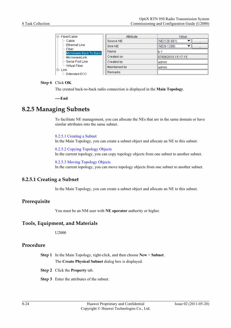
Step 6 Click OK.The created back-to-back radio connection is displayed in the Main Topology.
----End
8.2.5 Managing SubnetsTo facilitate NE management, you can allocate the NEs that are in the same domain or havesimilar attributes into the same subnet.
8.2.5.1 Creating a SubnetIn the Main Topology, you can create a subnet object and allocate an NE to this subnet.
8.2.5.2 Copying Topology ObjectsIn the current topology, you can copy topology objects from one subnet to another subnet.
8.2.5.3 Moving Topology ObjectsIn the current topology, you can move topology objects from one subnet to another subnet.
8.2.5.1 Creating a Subnet
In the Main Topology, you can create a subnet object and allocate an NE to this subnet.
Prerequisite
You must be an NM user with NE operator authority or higher.
Tools, Equipment, and Materials
U2000
Procedure
Step 1 In the Main Topology, right-click, and then choose New > Subnet.The Create Physical Subnet dialog box is displayed.
Step 2 Click the Property tab.
Step 3 Enter the attributes of the subnet.
8 Task CollectionOptiX RTN 950 Radio Transmission System
Commissioning and Configuration Guide (U2000)
8-24 Huawei Proprietary and ConfidentialCopyright © Huawei Technologies Co., Ltd.
Issue 02 (2011-05-20)
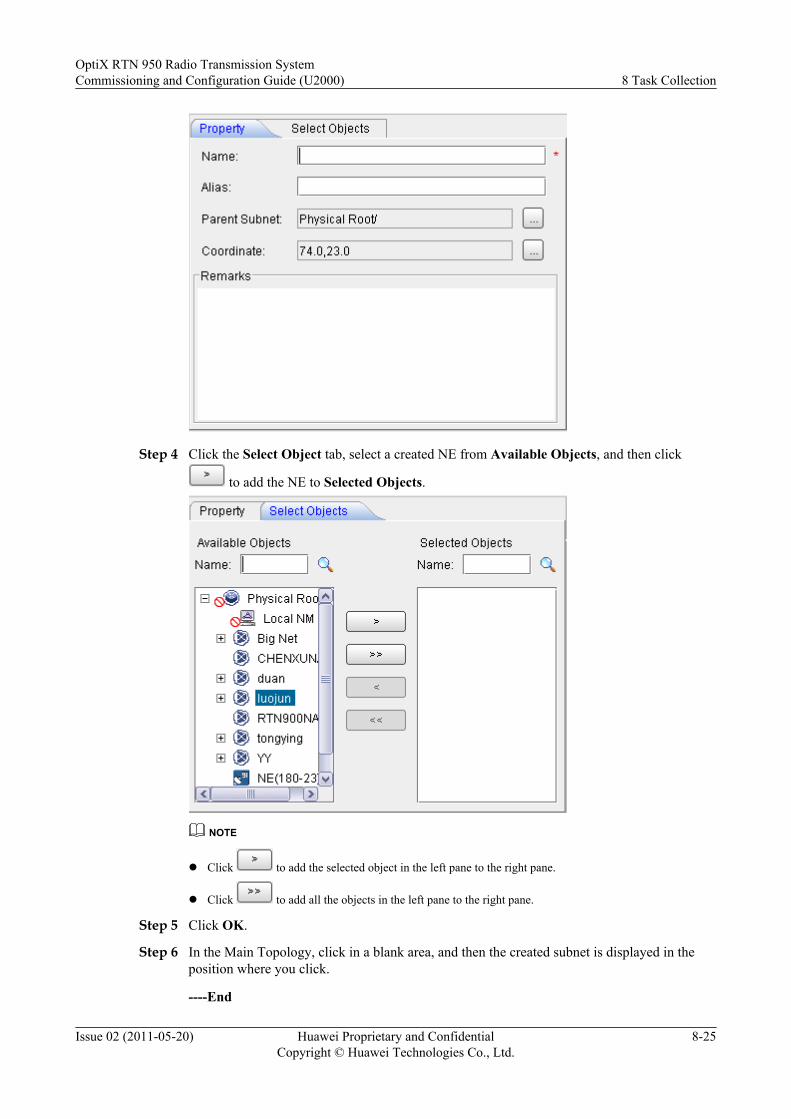
Step 4 Click the Select Object tab, select a created NE from Available Objects, and then click
to add the NE to Selected Objects.
NOTE
l Click to add the selected object in the left pane to the right pane.
l Click to add all the objects in the left pane to the right pane.
Step 5 Click OK.
Step 6 In the Main Topology, click in a blank area, and then the created subnet is displayed in theposition where you click.
----End
OptiX RTN 950 Radio Transmission SystemCommissioning and Configuration Guide (U2000) 8 Task Collection
Issue 02 (2011-05-20) Huawei Proprietary and ConfidentialCopyright © Huawei Technologies Co., Ltd.
8-25

8.2.5.2 Copying Topology ObjectsIn the current topology, you can copy topology objects from one subnet to another subnet.
PrerequisiteYou must be an NM user with NE operator authority or higher.
Tools, Equipment, and MaterialsU2000
Procedure
Step 1 In the Main Topology, right-click the NE or subnet that needs to be copied.
Step 2 Choose Edit > Copy to.The Select Path of Parent Subnet dialog box is displayed.
Step 3 Select the subnet that the NE or subnet needs to be pasted to.
Step 4 Click OK.
----End
8.2.5.3 Moving Topology ObjectsIn the current topology, you can move topology objects from one subnet to another subnet.
PrerequisiteYou must be an NM user with NE operator authority or higher.
Tools, Equipment, and MaterialsU2000
8 Task CollectionOptiX RTN 950 Radio Transmission System
Commissioning and Configuration Guide (U2000)
8-26 Huawei Proprietary and ConfidentialCopyright © Huawei Technologies Co., Ltd.
Issue 02 (2011-05-20)
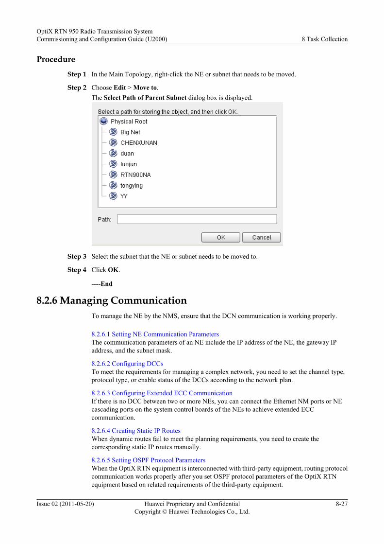
Procedure
Step 1 In the Main Topology, right-click the NE or subnet that needs to be moved.
Step 2 Choose Edit > Move to.The Select Path of Parent Subnet dialog box is displayed.
Step 3 Select the subnet that the NE or subnet needs to be moved to.
Step 4 Click OK.
----End
8.2.6 Managing CommunicationTo manage the NE by the NMS, ensure that the DCN communication is working properly.
8.2.6.1 Setting NE Communication ParametersThe communication parameters of an NE include the IP address of the NE, the gateway IPaddress, and the subnet mask.
8.2.6.2 Configuring DCCsTo meet the requirements for managing a complex network, you need to set the channel type,protocol type, or enable status of the DCCs according to the network plan.
8.2.6.3 Configuring Extended ECC CommunicationIf there is no DCC between two or more NEs, you can connect the Ethernet NM ports or NEcascading ports on the system control boards of the NEs to achieve extended ECCcommunication.
8.2.6.4 Creating Static IP RoutesWhen dynamic routes fail to meet the planning requirements, you need to create thecorresponding static IP routes manually.
8.2.6.5 Setting OSPF Protocol ParametersWhen the OptiX RTN equipment is interconnected with third-party equipment, routing protocolcommunication works properly after you set OSPF protocol parameters of the OptiX RTNequipment based on related requirements of the third-party equipment.
OptiX RTN 950 Radio Transmission SystemCommissioning and Configuration Guide (U2000) 8 Task Collection
Issue 02 (2011-05-20) Huawei Proprietary and ConfidentialCopyright © Huawei Technologies Co., Ltd.
8-27

8.2.6.6 Enabling the Proxy ARPThe proxy ARP enables the NEs in the same network segment but different domains tocommunicate with each other.
8.2.6.7 Configuring the VLAN ID and Bandwidth Used by an Inband DCNThe VLAN ID used by an inband DCN must be different from the VLAN ID used by servicesand the bandwidth by an inband DCN must meet the requirements of the transmission networkfor managing messages.
8.2.6.8 Configuring the Enable Status of the Inband DCN Function on PortsThe network management information can be transmitted over a link by the inband DCN onlywhen the inband DCN function is enabled on the ports at both ends of the link.
8.2.6.9 Configuring the Protocol Type of the Inband DCNThe inband DCN supports two types of protocol: IP and HWECC. The IP is the default protocolsupported by the inband DCN. Generally, it is recommended that you use the default value.
8.2.6.10 Querying ECC RoutesBy querying ECC routes, you can check whether the correct HWECC solution is configured andwhether the communication between NEs works properly.
8.2.6.11 Querying IP RoutesBy querying IP routes, you can check whether the IP over DCC solution and inband DCNsolution are configured correctly and whether the communication between NEs works properly.
8.2.6.12 Configuring Access ControlWhen the equipment is connected to the NMS through an Ethernet service port, you need toconfigure access control.
8.2.6.13 Setting SNMP Communications ParametersThe Simple Network Management Protocol (SNMP) is the most popular network managementprotocol used on the TCP/IP networks. After you set SNMP communications parameters, theSNMP NMS can obtain alarm and performance event data from the OptiX RTN 950.
8.2.6.1 Setting NE Communication Parameters
The communication parameters of an NE include the IP address of the NE, the gateway IPaddress, and the subnet mask.
Prerequisite
You must be an NM user with NE operator authority or higher.
Tools, Equipment, and Materials
U2000
Procedure
Step 1 Select the NE from the Object Tree in the NE Explorer. Choose Communication >Communication Parameters from the Function Tree.
Step 2 Configure the communication parameters of the NE.
Step 3 Click Apply. Close the displayed dialog box.
8 Task CollectionOptiX RTN 950 Radio Transmission System
Commissioning and Configuration Guide (U2000)
8-28 Huawei Proprietary and ConfidentialCopyright © Huawei Technologies Co., Ltd.
Issue 02 (2011-05-20)
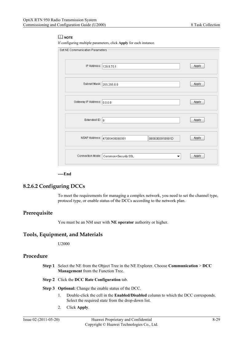
NOTEIf configuring multiple parameters, click Apply for each instance.
----End
8.2.6.2 Configuring DCCsTo meet the requirements for managing a complex network, you need to set the channel type,protocol type, or enable status of the DCCs according to the network plan.
PrerequisiteYou must be an NM user with NE operator authority or higher.
Tools, Equipment, and MaterialsU2000
Procedure
Step 1 Select the NE from the Object Tree in the NE Explorer. Choose Communication > DCCManagement from the Function Tree.
Step 2 Click the DCC Rate Configuration tab.
Step 3 Optional: Change the enable status of the DCC.1. Double-click the cell in the Enabled/Disabled column to which the DCC corresponds.
Select the required state from the drop-down list.2. Click Apply.
OptiX RTN 950 Radio Transmission SystemCommissioning and Configuration Guide (U2000) 8 Task Collection
Issue 02 (2011-05-20) Huawei Proprietary and ConfidentialCopyright © Huawei Technologies Co., Ltd.
8-29

Step 4 Optional: Change the protocol type of the DCC.1. Double-click the cell in the Protocol Type column to which the DCC corresponds. Select
the required protocol type from the drop-down list.2. Click Apply.
NOTE
l If the port is connected to the other ECC subnet, Enabled/Disabled is set to Disabled.l If the port is connected to a third-party network and does not exchange the network management
information with other ports, Enabled/Disabled is set to Disabled.The values recommended for Protocol Type are as follows:l If the IP over DCC solution is adopted, Protocol Type is set to TCP/IP.l If the OSI over DCC solution is adopted, Protocol Type is set to OSI.l Default values are recommended in other scenarios.
Step 5 Optional: Create DCCs.1. Click Create.
The Create dialog box is displayed.2. Set the attributes of the DCC.
NOTE
The values recommended for Protocol Type are as follows:l If the IP over DCC solution is adopted, Protocol Type is set to TCP/IP.l If the OSI over DCC solution is adopted, Protocol Type is set to OSI.l Default values are recommended in other scenarios.
3. Click OK.
----End
8.2.6.3 Configuring Extended ECC CommunicationIf there is no DCC between two or more NEs, you can connect the Ethernet NM ports or NEcascading ports on the system control boards of the NEs to achieve extended ECCcommunication.
PrerequisiteYou must be an NM user with NE operator authority or higher.
Tools, Instruments and MaterialsU2000
8 Task CollectionOptiX RTN 950 Radio Transmission System
Commissioning and Configuration Guide (U2000)
8-30 Huawei Proprietary and ConfidentialCopyright © Huawei Technologies Co., Ltd.
Issue 02 (2011-05-20)
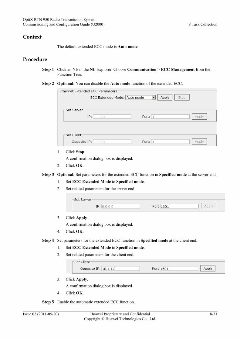
Context
The default extended ECC mode is Auto mode.
Procedure
Step 1 Click an NE in the NE Explorer. Choose Communication > ECC Management from theFunction Tree.
Step 2 Optional: You can disable the Auto mode function of the extended ECC.
1. Click Stop.A confirmation dialog box is displayed.
2. Click OK.
Step 3 Optional: Set parameters for the extended ECC function in Specified mode at the server end.
1. Set ECC Extended Mode to Specified mode.
2. Set related parameters for the server end.
3. Click Apply.A confirmation dialog box is displayed.
4. Click OK.
Step 4 Set parameters for the extended ECC function in Specified mode at the client end.
1. Set ECC Extended Mode to Specified mode.
2. Set related parameters for the client end.
3. Click Apply.A confirmation dialog box is displayed.
4. Click OK.
Step 5 Enable the automatic extended ECC function.
OptiX RTN 950 Radio Transmission SystemCommissioning and Configuration Guide (U2000) 8 Task Collection
Issue 02 (2011-05-20) Huawei Proprietary and ConfidentialCopyright © Huawei Technologies Co., Ltd.
8-31
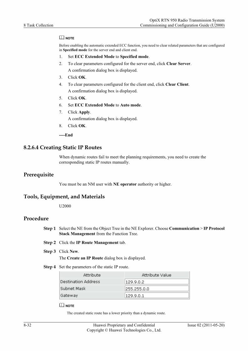
NOTE
Before enabling the automatic extended ECC function, you need to clear related parameters that are configuredin Specified mode for the server end and client end.
1. Set ECC Extended Mode to Specified mode.2. To clear parameters configured for the server end, click Clear Server.
A confirmation dialog box is displayed.3. Click OK.4. To clear parameters configured for the client end, click Clear Client.
A confirmation dialog box is displayed.5. Click OK.6. Set ECC Extended Mode to Auto mode.7. Click Apply.
A confirmation dialog box is displayed.8. Click OK.
----End
8.2.6.4 Creating Static IP RoutesWhen dynamic routes fail to meet the planning requirements, you need to create thecorresponding static IP routes manually.
PrerequisiteYou must be an NM user with NE operator authority or higher.
Tools, Equipment, and MaterialsU2000
Procedure
Step 1 Select the NE from the Object Tree in the NE Explorer. Choose Communication > IP ProtocolStack Management from the Function Tree.
Step 2 Click the IP Route Management tab.
Step 3 Click New.The Create an IP Route dialog box is displayed.
Step 4 Set the parameters of the static IP route.
NOTE
The created static route has a lower priority than a dynamic route.
8 Task CollectionOptiX RTN 950 Radio Transmission System
Commissioning and Configuration Guide (U2000)
8-32 Huawei Proprietary and ConfidentialCopyright © Huawei Technologies Co., Ltd.
Issue 02 (2011-05-20)
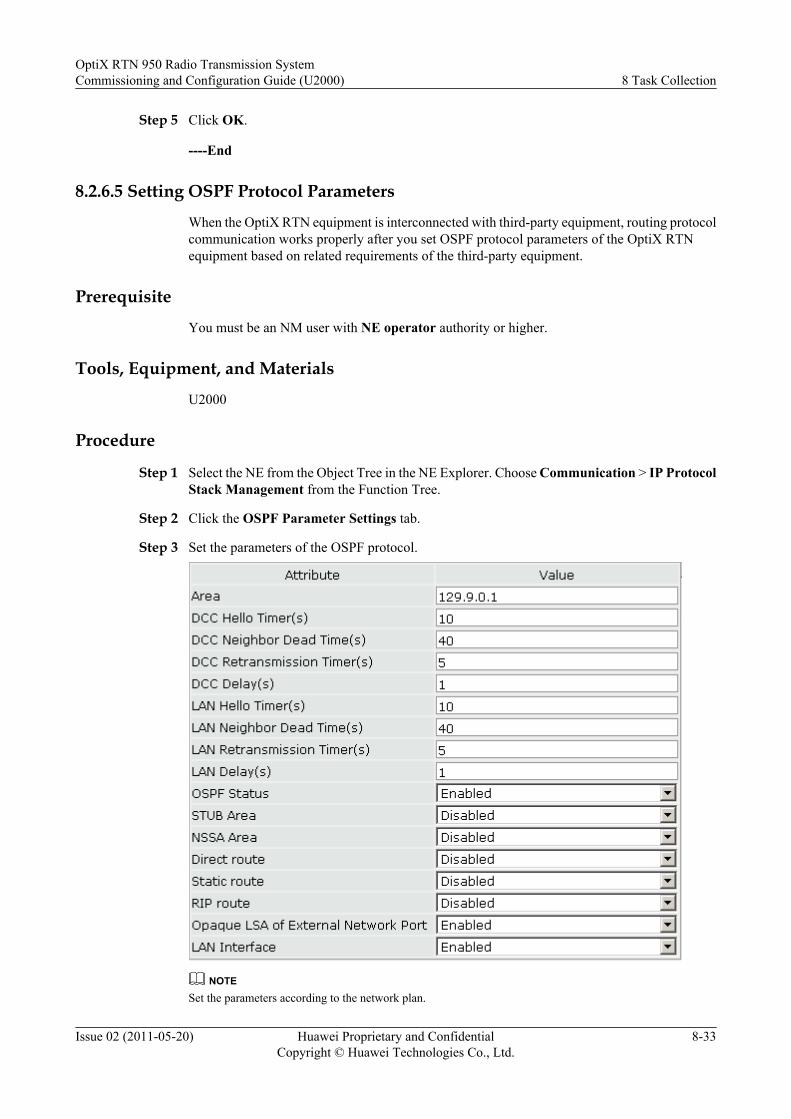
Step 5 Click OK.
----End
8.2.6.5 Setting OSPF Protocol Parameters
When the OptiX RTN equipment is interconnected with third-party equipment, routing protocolcommunication works properly after you set OSPF protocol parameters of the OptiX RTNequipment based on related requirements of the third-party equipment.
Prerequisite
You must be an NM user with NE operator authority or higher.
Tools, Equipment, and Materials
U2000
Procedure
Step 1 Select the NE from the Object Tree in the NE Explorer. Choose Communication > IP ProtocolStack Management from the Function Tree.
Step 2 Click the OSPF Parameter Settings tab.
Step 3 Set the parameters of the OSPF protocol.
NOTESet the parameters according to the network plan.
OptiX RTN 950 Radio Transmission SystemCommissioning and Configuration Guide (U2000) 8 Task Collection
Issue 02 (2011-05-20) Huawei Proprietary and ConfidentialCopyright © Huawei Technologies Co., Ltd.
8-33

Step 4 Click Apply.
Step 5 Optional: Set OSPF parameters for DCC channels.1. Click the Port OSPF Parameter Settings tab.2. Set the OSPF parameters for DCC channels.3. Click Apply.
----End
8.2.6.6 Enabling the Proxy ARPThe proxy ARP enables the NEs in the same network segment but different domains tocommunicate with each other.
PrerequisiteYou must be an NM user with NE operator authority or higher.
Procedure
Step 1 Select the NE from the Object Tree in the NE Explorer. Choose Communication > IP ProtocolStack Management from the Function Tree.
Step 2 Click the Proxy ARP tab.
Step 3 Set the enable status of the proxy ARP.
NOTE
l The proxy ARP enables the NEs in the same network segment but different domains to communicate witheach other.
l To realize communication between such NEs, the source NE sends the ARP broadcast packet to address theroute to the destination NE. The NE with the proxy ARP function enabled checks the routing table aftersensing the ARP broadcast packet. If the routing table contains the destination address that the ARP broadcastpacket looks for, the NE returns an ARP spoofing packet, which enables the NE that sends the ARP broadcastpacket to consider that the MAC address of the NE that returns the ARP spoofing packet is the MAC addressof the destination NE. In this manner, the packet that is to be sent to the destination NE is first sent to theNE with the proxy ARP function enabled and then forwarded to the destination NE.
Step 4 Click Apply.
----End
8.2.6.7 Configuring the VLAN ID and Bandwidth Used by an Inband DCNThe VLAN ID used by an inband DCN must be different from the VLAN ID used by servicesand the bandwidth by an inband DCN must meet the requirements of the transmission networkfor managing messages.
PrerequisiteYou must be an NM user with NE administrator authority or higher.
8 Task CollectionOptiX RTN 950 Radio Transmission System
Commissioning and Configuration Guide (U2000)
8-34 Huawei Proprietary and ConfidentialCopyright © Huawei Technologies Co., Ltd.
Issue 02 (2011-05-20)
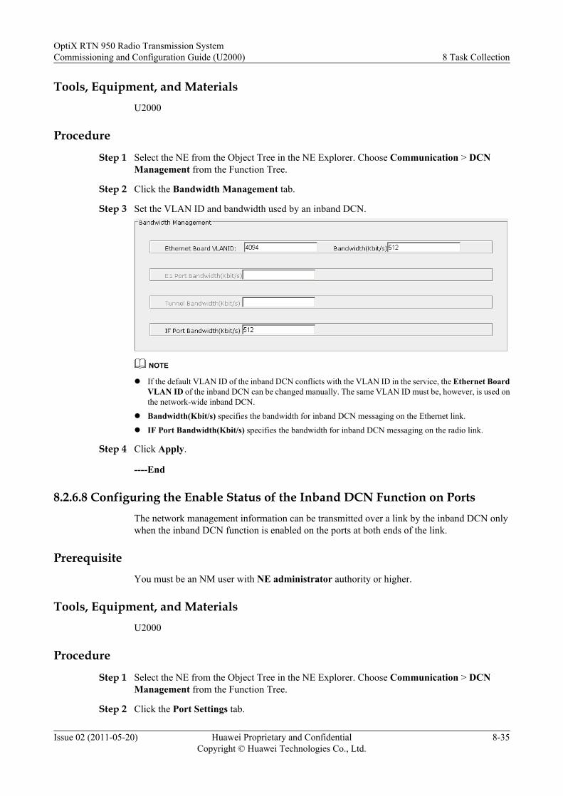
Tools, Equipment, and MaterialsU2000
Procedure
Step 1 Select the NE from the Object Tree in the NE Explorer. Choose Communication > DCNManagement from the Function Tree.
Step 2 Click the Bandwidth Management tab.
Step 3 Set the VLAN ID and bandwidth used by an inband DCN.
NOTE
l If the default VLAN ID of the inband DCN conflicts with the VLAN ID in the service, the Ethernet BoardVLAN ID of the inband DCN can be changed manually. The same VLAN ID must be, however, is used onthe network-wide inband DCN.
l Bandwidth(Kbit/s) specifies the bandwidth for inband DCN messaging on the Ethernet link.
l IF Port Bandwidth(Kbit/s) specifies the bandwidth for inband DCN messaging on the radio link.
Step 4 Click Apply.
----End
8.2.6.8 Configuring the Enable Status of the Inband DCN Function on PortsThe network management information can be transmitted over a link by the inband DCN onlywhen the inband DCN function is enabled on the ports at both ends of the link.
PrerequisiteYou must be an NM user with NE administrator authority or higher.
Tools, Equipment, and MaterialsU2000
Procedure
Step 1 Select the NE from the Object Tree in the NE Explorer. Choose Communication > DCNManagement from the Function Tree.
Step 2 Click the Port Settings tab.
OptiX RTN 950 Radio Transmission SystemCommissioning and Configuration Guide (U2000) 8 Task Collection
Issue 02 (2011-05-20) Huawei Proprietary and ConfidentialCopyright © Huawei Technologies Co., Ltd.
8-35
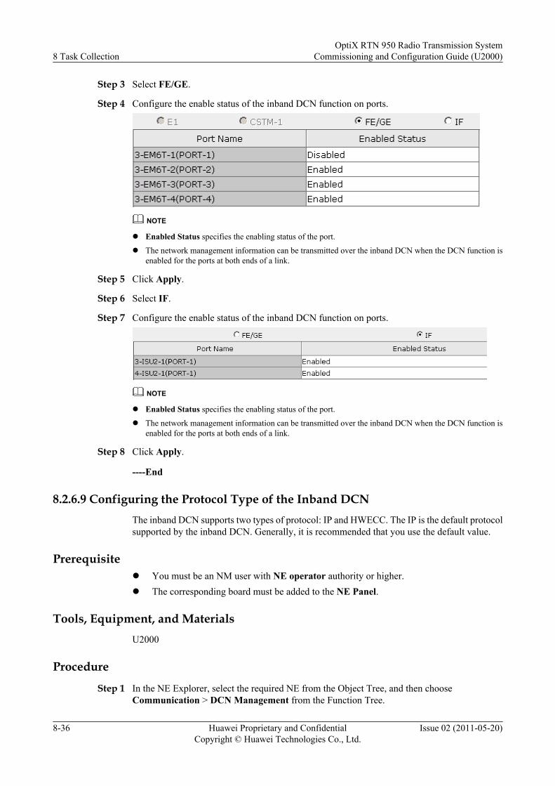
Step 3 Select FE/GE.
Step 4 Configure the enable status of the inband DCN function on ports.
NOTE
l Enabled Status specifies the enabling status of the port.
l The network management information can be transmitted over the inband DCN when the DCN function isenabled for the ports at both ends of a link.
Step 5 Click Apply.
Step 6 Select IF.
Step 7 Configure the enable status of the inband DCN function on ports.
NOTE
l Enabled Status specifies the enabling status of the port.
l The network management information can be transmitted over the inband DCN when the DCN function isenabled for the ports at both ends of a link.
Step 8 Click Apply.
----End
8.2.6.9 Configuring the Protocol Type of the Inband DCNThe inband DCN supports two types of protocol: IP and HWECC. The IP is the default protocolsupported by the inband DCN. Generally, it is recommended that you use the default value.
Prerequisitel You must be an NM user with NE operator authority or higher.l The corresponding board must be added to the NE Panel.
Tools, Equipment, and MaterialsU2000
Procedure
Step 1 In the NE Explorer, select the required NE from the Object Tree, and then chooseCommunication > DCN Management from the Function Tree.
8 Task CollectionOptiX RTN 950 Radio Transmission System
Commissioning and Configuration Guide (U2000)
8-36 Huawei Proprietary and ConfidentialCopyright © Huawei Technologies Co., Ltd.
Issue 02 (2011-05-20)
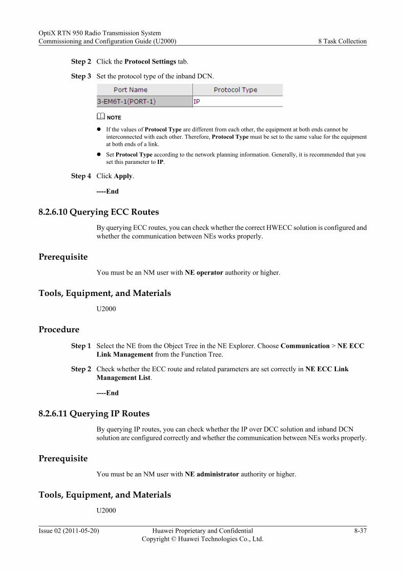
Step 2 Click the Protocol Settings tab.
Step 3 Set the protocol type of the inband DCN.
NOTE
l If the values of Protocol Type are different from each other, the equipment at both ends cannot beinterconnected with each other. Therefore, Protocol Type must be set to the same value for the equipmentat both ends of a link.
l Set Protocol Type according to the network planning information. Generally, it is recommended that youset this parameter to IP.
Step 4 Click Apply.
----End
8.2.6.10 Querying ECC Routes
By querying ECC routes, you can check whether the correct HWECC solution is configured andwhether the communication between NEs works properly.
Prerequisite
You must be an NM user with NE operator authority or higher.
Tools, Equipment, and Materials
U2000
Procedure
Step 1 Select the NE from the Object Tree in the NE Explorer. Choose Communication > NE ECCLink Management from the Function Tree.
Step 2 Check whether the ECC route and related parameters are set correctly in NE ECC LinkManagement List.
----End
8.2.6.11 Querying IP Routes
By querying IP routes, you can check whether the IP over DCC solution and inband DCNsolution are configured correctly and whether the communication between NEs works properly.
Prerequisite
You must be an NM user with NE administrator authority or higher.
Tools, Equipment, and Materials
U2000
OptiX RTN 950 Radio Transmission SystemCommissioning and Configuration Guide (U2000) 8 Task Collection
Issue 02 (2011-05-20) Huawei Proprietary and ConfidentialCopyright © Huawei Technologies Co., Ltd.
8-37
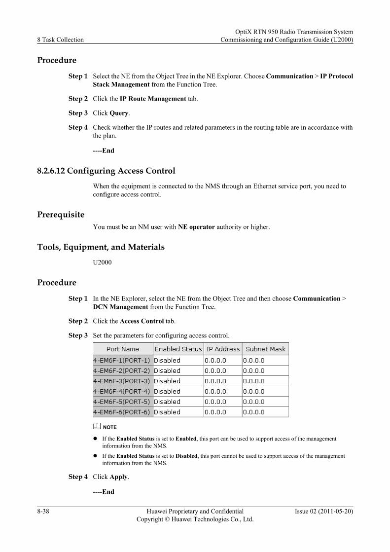
Procedure
Step 1 Select the NE from the Object Tree in the NE Explorer. Choose Communication > IP ProtocolStack Management from the Function Tree.
Step 2 Click the IP Route Management tab.
Step 3 Click Query.
Step 4 Check whether the IP routes and related parameters in the routing table are in accordance withthe plan.
----End
8.2.6.12 Configuring Access Control
When the equipment is connected to the NMS through an Ethernet service port, you need toconfigure access control.
PrerequisiteYou must be an NM user with NE operator authority or higher.
Tools, Equipment, and Materials
U2000
Procedure
Step 1 In the NE Explorer, select the NE from the Object Tree and then choose Communication >DCN Management from the Function Tree.
Step 2 Click the Access Control tab.
Step 3 Set the parameters for configuring access control.
NOTE
l If the Enabled Status is set to Enabled, this port can be used to support access of the managementinformation from the NMS.
l If the Enabled Status is set to Disabled, this port cannot be used to support access of the managementinformation from the NMS.
Step 4 Click Apply.
----End
8 Task CollectionOptiX RTN 950 Radio Transmission System
Commissioning and Configuration Guide (U2000)
8-38 Huawei Proprietary and ConfidentialCopyright © Huawei Technologies Co., Ltd.
Issue 02 (2011-05-20)
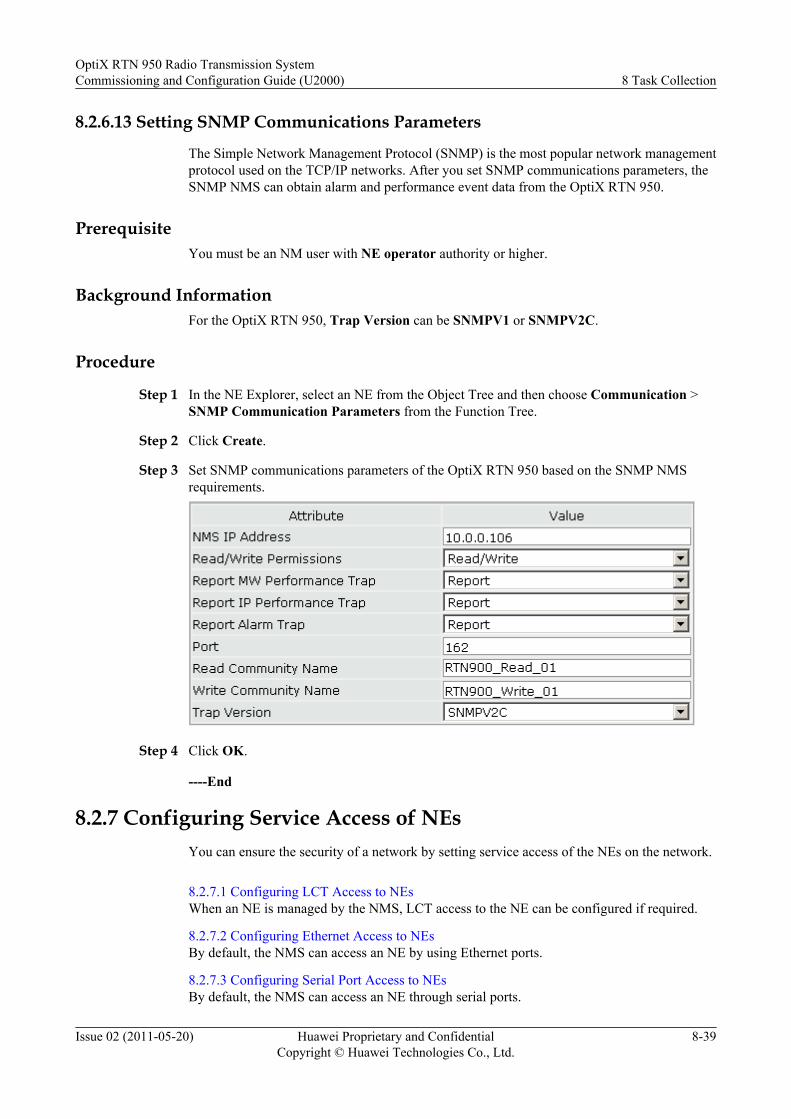
8.2.6.13 Setting SNMP Communications Parameters
The Simple Network Management Protocol (SNMP) is the most popular network managementprotocol used on the TCP/IP networks. After you set SNMP communications parameters, theSNMP NMS can obtain alarm and performance event data from the OptiX RTN 950.
PrerequisiteYou must be an NM user with NE operator authority or higher.
Background InformationFor the OptiX RTN 950, Trap Version can be SNMPV1 or SNMPV2C.
Procedure
Step 1 In the NE Explorer, select an NE from the Object Tree and then choose Communication >SNMP Communication Parameters from the Function Tree.
Step 2 Click Create.
Step 3 Set SNMP communications parameters of the OptiX RTN 950 based on the SNMP NMSrequirements.
Step 4 Click OK.
----End
8.2.7 Configuring Service Access of NEsYou can ensure the security of a network by setting service access of the NEs on the network.
8.2.7.1 Configuring LCT Access to NEsWhen an NE is managed by the NMS, LCT access to the NE can be configured if required.
8.2.7.2 Configuring Ethernet Access to NEsBy default, the NMS can access an NE by using Ethernet ports.
8.2.7.3 Configuring Serial Port Access to NEsBy default, the NMS can access an NE through serial ports.
OptiX RTN 950 Radio Transmission SystemCommissioning and Configuration Guide (U2000) 8 Task Collection
Issue 02 (2011-05-20) Huawei Proprietary and ConfidentialCopyright © Huawei Technologies Co., Ltd.
8-39
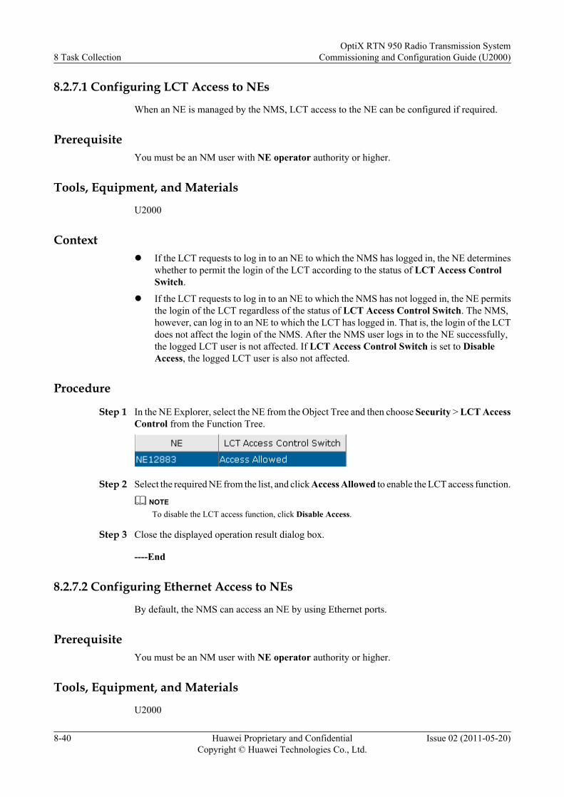
8.2.7.1 Configuring LCT Access to NEs
When an NE is managed by the NMS, LCT access to the NE can be configured if required.
PrerequisiteYou must be an NM user with NE operator authority or higher.
Tools, Equipment, and Materials
U2000
Contextl If the LCT requests to log in to an NE to which the NMS has logged in, the NE determines
whether to permit the login of the LCT according to the status of LCT Access ControlSwitch.
l If the LCT requests to log in to an NE to which the NMS has not logged in, the NE permitsthe login of the LCT regardless of the status of LCT Access Control Switch. The NMS,however, can log in to an NE to which the LCT has logged in. That is, the login of the LCTdoes not affect the login of the NMS. After the NMS user logs in to the NE successfully,the logged LCT user is not affected. If LCT Access Control Switch is set to DisableAccess, the logged LCT user is also not affected.
Procedure
Step 1 In the NE Explorer, select the NE from the Object Tree and then choose Security > LCT AccessControl from the Function Tree.
Step 2 Select the required NE from the list, and click Access Allowed to enable the LCT access function.
NOTETo disable the LCT access function, click Disable Access.
Step 3 Close the displayed operation result dialog box.
----End
8.2.7.2 Configuring Ethernet Access to NEs
By default, the NMS can access an NE by using Ethernet ports.
PrerequisiteYou must be an NM user with NE operator authority or higher.
Tools, Equipment, and Materials
U2000
8 Task CollectionOptiX RTN 950 Radio Transmission System
Commissioning and Configuration Guide (U2000)
8-40 Huawei Proprietary and ConfidentialCopyright © Huawei Technologies Co., Ltd.
Issue 02 (2011-05-20)
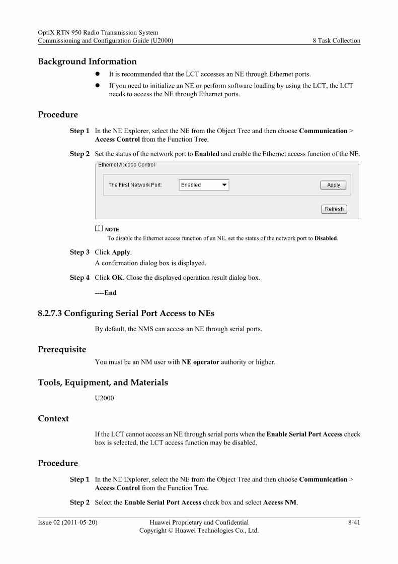
Background Informationl It is recommended that the LCT accesses an NE through Ethernet ports.l If you need to initialize an NE or perform software loading by using the LCT, the LCT
needs to access the NE through Ethernet ports.
Procedure
Step 1 In the NE Explorer, select the NE from the Object Tree and then choose Communication >Access Control from the Function Tree.
Step 2 Set the status of the network port to Enabled and enable the Ethernet access function of the NE.
NOTETo disable the Ethernet access function of an NE, set the status of the network port to Disabled.
Step 3 Click Apply.A confirmation dialog box is displayed.
Step 4 Click OK. Close the displayed operation result dialog box.
----End
8.2.7.3 Configuring Serial Port Access to NEs
By default, the NMS can access an NE through serial ports.
PrerequisiteYou must be an NM user with NE operator authority or higher.
Tools, Equipment, and Materials
U2000
Context
If the LCT cannot access an NE through serial ports when the Enable Serial Port Access checkbox is selected, the LCT access function may be disabled.
Procedure
Step 1 In the NE Explorer, select the NE from the Object Tree and then choose Communication >Access Control from the Function Tree.
Step 2 Select the Enable Serial Port Access check box and select Access NM.
OptiX RTN 950 Radio Transmission SystemCommissioning and Configuration Guide (U2000) 8 Task Collection
Issue 02 (2011-05-20) Huawei Proprietary and ConfidentialCopyright © Huawei Technologies Co., Ltd.
8-41
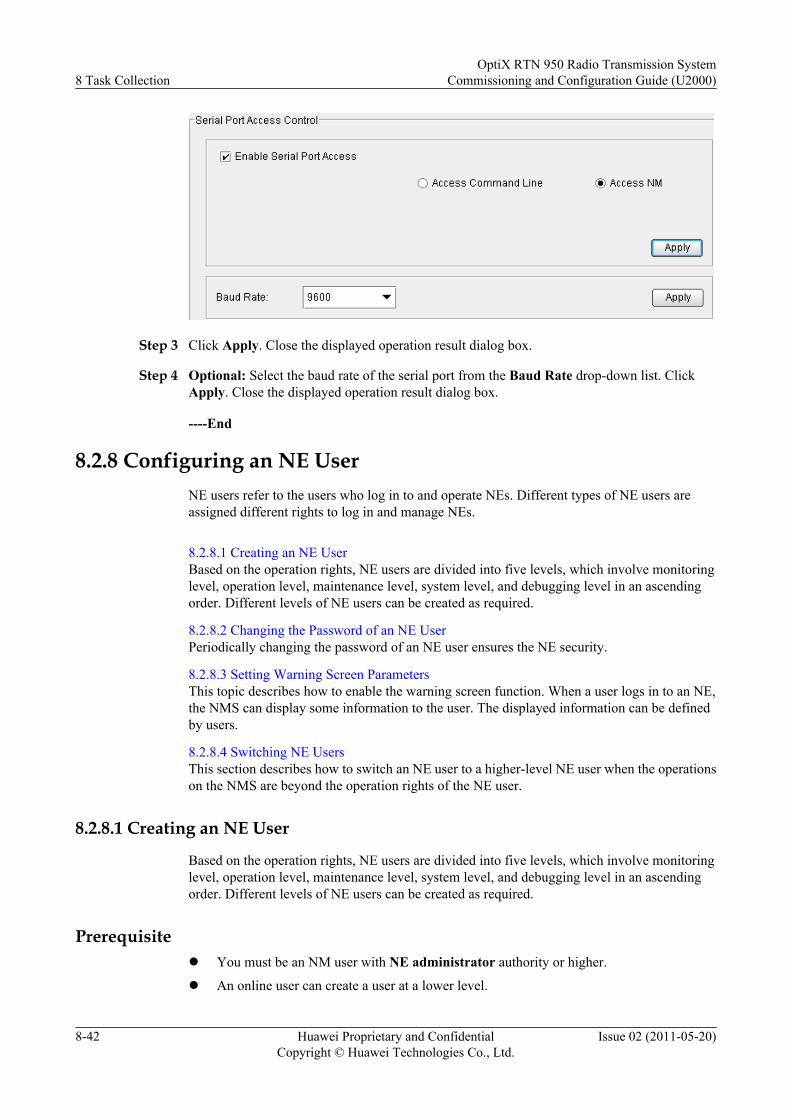
Step 3 Click Apply. Close the displayed operation result dialog box.
Step 4 Optional: Select the baud rate of the serial port from the Baud Rate drop-down list. ClickApply. Close the displayed operation result dialog box.
----End
8.2.8 Configuring an NE UserNE users refer to the users who log in to and operate NEs. Different types of NE users areassigned different rights to log in and manage NEs.
8.2.8.1 Creating an NE UserBased on the operation rights, NE users are divided into five levels, which involve monitoringlevel, operation level, maintenance level, system level, and debugging level in an ascendingorder. Different levels of NE users can be created as required.
8.2.8.2 Changing the Password of an NE UserPeriodically changing the password of an NE user ensures the NE security.
8.2.8.3 Setting Warning Screen ParametersThis topic describes how to enable the warning screen function. When a user logs in to an NE,the NMS can display some information to the user. The displayed information can be definedby users.
8.2.8.4 Switching NE UsersThis section describes how to switch an NE user to a higher-level NE user when the operationson the NMS are beyond the operation rights of the NE user.
8.2.8.1 Creating an NE User
Based on the operation rights, NE users are divided into five levels, which involve monitoringlevel, operation level, maintenance level, system level, and debugging level in an ascendingorder. Different levels of NE users can be created as required.
Prerequisitel You must be an NM user with NE administrator authority or higher.
l An online user can create a user at a lower level.
8 Task CollectionOptiX RTN 950 Radio Transmission System
Commissioning and Configuration Guide (U2000)
8-42 Huawei Proprietary and ConfidentialCopyright © Huawei Technologies Co., Ltd.
Issue 02 (2011-05-20)
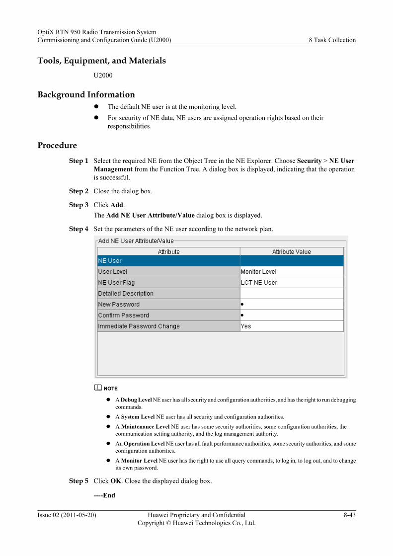
Tools, Equipment, and MaterialsU2000
Background Informationl The default NE user is at the monitoring level.l For security of NE data, NE users are assigned operation rights based on their
responsibilities.
Procedure
Step 1 Select the required NE from the Object Tree in the NE Explorer. Choose Security > NE UserManagement from the Function Tree. A dialog box is displayed, indicating that the operationis successful.
Step 2 Close the dialog box.
Step 3 Click Add.The Add NE User Attribute/Value dialog box is displayed.
Step 4 Set the parameters of the NE user according to the network plan.
NOTE
l A Debug Level NE user has all security and configuration authorities, and has the right to run debuggingcommands.
l A System Level NE user has all security and configuration authorities.
l A Maintenance Level NE user has some security authorities, some configuration authorities, thecommunication setting authority, and the log management authority.
l An Operation Level NE user has all fault performance authorities, some security authorities, and someconfiguration authorities.
l A Monitor Level NE user has the right to use all query commands, to log in, to log out, and to changeits own password.
Step 5 Click OK. Close the displayed dialog box.
----End
OptiX RTN 950 Radio Transmission SystemCommissioning and Configuration Guide (U2000) 8 Task Collection
Issue 02 (2011-05-20) Huawei Proprietary and ConfidentialCopyright © Huawei Technologies Co., Ltd.
8-43
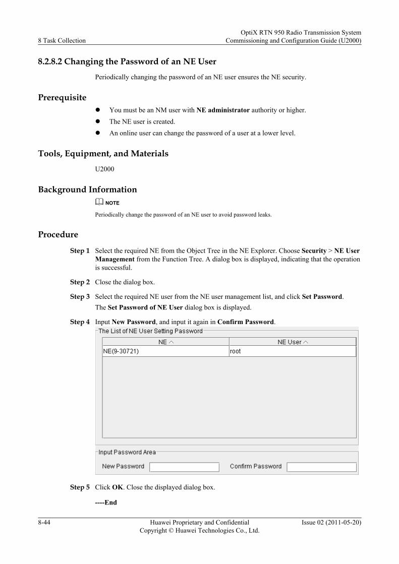
8.2.8.2 Changing the Password of an NE User
Periodically changing the password of an NE user ensures the NE security.
Prerequisitel You must be an NM user with NE administrator authority or higher.l The NE user is created.l An online user can change the password of a user at a lower level.
Tools, Equipment, and Materials
U2000
Background InformationNOTE
Periodically change the password of an NE user to avoid password leaks.
Procedure
Step 1 Select the required NE from the Object Tree in the NE Explorer. Choose Security > NE UserManagement from the Function Tree. A dialog box is displayed, indicating that the operationis successful.
Step 2 Close the dialog box.
Step 3 Select the required NE user from the NE user management list, and click Set Password.The Set Password of NE User dialog box is displayed.
Step 4 Input New Password, and input it again in Confirm Password.
Step 5 Click OK. Close the displayed dialog box.
----End
8 Task CollectionOptiX RTN 950 Radio Transmission System
Commissioning and Configuration Guide (U2000)
8-44 Huawei Proprietary and ConfidentialCopyright © Huawei Technologies Co., Ltd.
Issue 02 (2011-05-20)
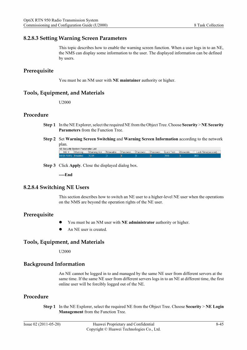
8.2.8.3 Setting Warning Screen Parameters
This topic describes how to enable the warning screen function. When a user logs in to an NE,the NMS can display some information to the user. The displayed information can be definedby users.
Prerequisite
You must be an NM user with NE maintainer authority or higher.
Tools, Equipment, and Materials
U2000
Procedure
Step 1 In the NE Explorer, select the required NE from the Object Tree. Choose Security > NE SecurityParameters from the Function Tree.
Step 2 Set Warning Screen Switching and Warning Screen Information according to the networkplan.
Step 3 Click Apply. Close the displayed dialog box.
----End
8.2.8.4 Switching NE Users
This section describes how to switch an NE user to a higher-level NE user when the operationson the NMS are beyond the operation rights of the NE user.
Prerequisitel You must be an NM user with NE administrator authority or higher.l An NE user is created.
Tools, Equipment, and Materials
U2000
Background Information
An NE cannot be logged in to and managed by the same NE user from different servers at thesame time. If the same NE user from different servers logs in to an NE at different time, the firstonline user will be forcibly logged out of the NE.
Procedure
Step 1 In the NE Explorer, select the required NE from the Object Tree. Choose Security > NE LoginManagement from the Function Tree.
OptiX RTN 950 Radio Transmission SystemCommissioning and Configuration Guide (U2000) 8 Task Collection
Issue 02 (2011-05-20) Huawei Proprietary and ConfidentialCopyright © Huawei Technologies Co., Ltd.
8-45
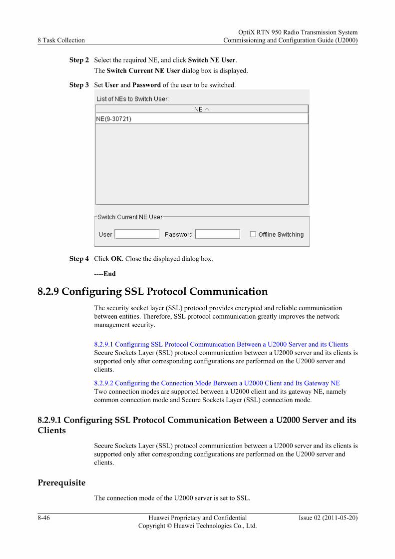
Step 2 Select the required NE, and click Switch NE User.The Switch Current NE User dialog box is displayed.
Step 3 Set User and Password of the user to be switched.
Step 4 Click OK. Close the displayed dialog box.
----End
8.2.9 Configuring SSL Protocol CommunicationThe security socket layer (SSL) protocol provides encrypted and reliable communicationbetween entities. Therefore, SSL protocol communication greatly improves the networkmanagement security.
8.2.9.1 Configuring SSL Protocol Communication Between a U2000 Server and its ClientsSecure Sockets Layer (SSL) protocol communication between a U2000 server and its clients issupported only after corresponding configurations are performed on the U2000 server andclients.
8.2.9.2 Configuring the Connection Mode Between a U2000 Client and Its Gateway NETwo connection modes are supported between a U2000 client and its gateway NE, namelycommon connection mode and Secure Sockets Layer (SSL) connection mode.
8.2.9.1 Configuring SSL Protocol Communication Between a U2000 Server and itsClients
Secure Sockets Layer (SSL) protocol communication between a U2000 server and its clients issupported only after corresponding configurations are performed on the U2000 server andclients.
Prerequisite
The connection mode of the U2000 server is set to SSL.
8 Task CollectionOptiX RTN 950 Radio Transmission System
Commissioning and Configuration Guide (U2000)
8-46 Huawei Proprietary and ConfidentialCopyright © Huawei Technologies Co., Ltd.
Issue 02 (2011-05-20)
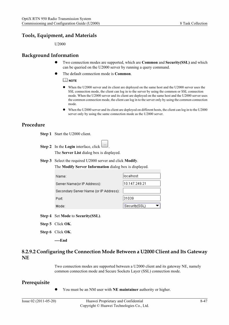
Tools, Equipment, and MaterialsU2000
Background Informationl Two connection modes are supported, which are Common and Security(SSL) and which
can be queried on the U2000 server by running a query command.l The default connection mode is Common.
NOTE
l When the U2000 server and its client are deployed on the same host and the U2000 server uses theSSL connection mode, the client can log in to the server by using the common or SSL connectionmode. When the U2000 server and its client are deployed on the same host and the U2000 server usesthe common connection mode, the client can log in to the server only by using the common connectionmode.
l When the U2000 server and its client are deployed on different hosts, the client can log in to the U2000server only by using the same connection mode as the U2000 server.
Procedure
Step 1 Start the U2000 client.
Step 2 In the Login interface, click .The Server List dialog box is displayed.
Step 3 Select the required U2000 server and click Modify.The Modify Server Information dialog box is displayed.
Step 4 Set Mode to Security(SSL).
Step 5 Click OK.
Step 6 Click OK.
----End
8.2.9.2 Configuring the Connection Mode Between a U2000 Client and Its GatewayNE
Two connection modes are supported between a U2000 client and its gateway NE, namelycommon connection mode and Secure Sockets Layer (SSL) connection mode.
Prerequisitel You must be an NM user with NE maintainer authority or higher.
OptiX RTN 950 Radio Transmission SystemCommissioning and Configuration Guide (U2000) 8 Task Collection
Issue 02 (2011-05-20) Huawei Proprietary and ConfidentialCopyright © Huawei Technologies Co., Ltd.
8-47

l SSL licenses have been deployed on the gateway NE and the U2000 client according tothe SSL loading guide.
Tools, Equipment, and MaterialsU2000
Procedure
Step 1 Configure the connection mode of the U2000 client.1. Choose Administration > DCN Management from Main Menu.
The Filter NE dialog box is displayed.2. Click Cancel and then click the GNE tab.
The Filter GNE dialog box is displayed.
3. Click , choose the required gateway NE, and then click OK.4. Click OK.5. Select the required NE, right-click the NE, and choose Modify GNE from the shortcut
menu.The Modify GNE dialog box is displayed.
6. Change the value of Connection Mode to Security SSL.
7. Click OK.A warning dialog box is displayed.
8. Click OK. Close the displayed dialog box.
Step 2 Configure the connection mode of the gateway NE.1. Select the NE from the Object Tree in the NE Explorer. Choose Communication >
Communication Parameters from the Function Tree.2. Set Connection Mode to Security SSL or Common + Security SSL.
NOTE
If Connection Mode of a gateway NE is Security SSL, tools (such as the Web LCT and DC) that use thecommon connection mode cannot communicate with the gateway NE.
8 Task CollectionOptiX RTN 950 Radio Transmission System
Commissioning and Configuration Guide (U2000)
8-48 Huawei Proprietary and ConfidentialCopyright © Huawei Technologies Co., Ltd.
Issue 02 (2011-05-20)
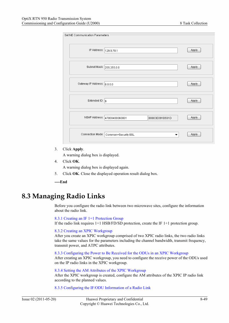
3. Click Apply.A warning dialog box is displayed.
4. Click OK.A warning dialog box is displayed again.
5. Click OK. Close the displayed operation result dialog box.
----End
8.3 Managing Radio LinksBefore you configure the radio link between two microwave sites, configure the informationabout the radio link.
8.3.1 Creating an IF 1+1 Protection GroupIf the radio link requires 1+1 HSB/FD/SD protection, create the IF 1+1 protection group.
8.3.2 Creating an XPIC WorkgroupAfter you create an XPIC workgroup comprised of two XPIC radio links, the two radio linkstake the same values for the parameters including the channel bandwidth, transmit frequency,transmit power, and ATPC attributes.
8.3.3 Configuring the Power to Be Received for the ODUs in an XPIC WorkgroupAfter creating an XPIC workgroup, you need to configure the receive power of the ODUs usedon the IP radio links in the XPIC workgroup.
8.3.4 Setting the AM Attributes of the XPIC WorkgroupAfter the XPIC workgroup is created, configure the AM attributes of the XPIC IP radio linkaccording to the planned values.
8.3.5 Configuring the IF/ODU Information of a Radio Link
OptiX RTN 950 Radio Transmission SystemCommissioning and Configuration Guide (U2000) 8 Task Collection
Issue 02 (2011-05-20) Huawei Proprietary and ConfidentialCopyright © Huawei Technologies Co., Ltd.
8-49
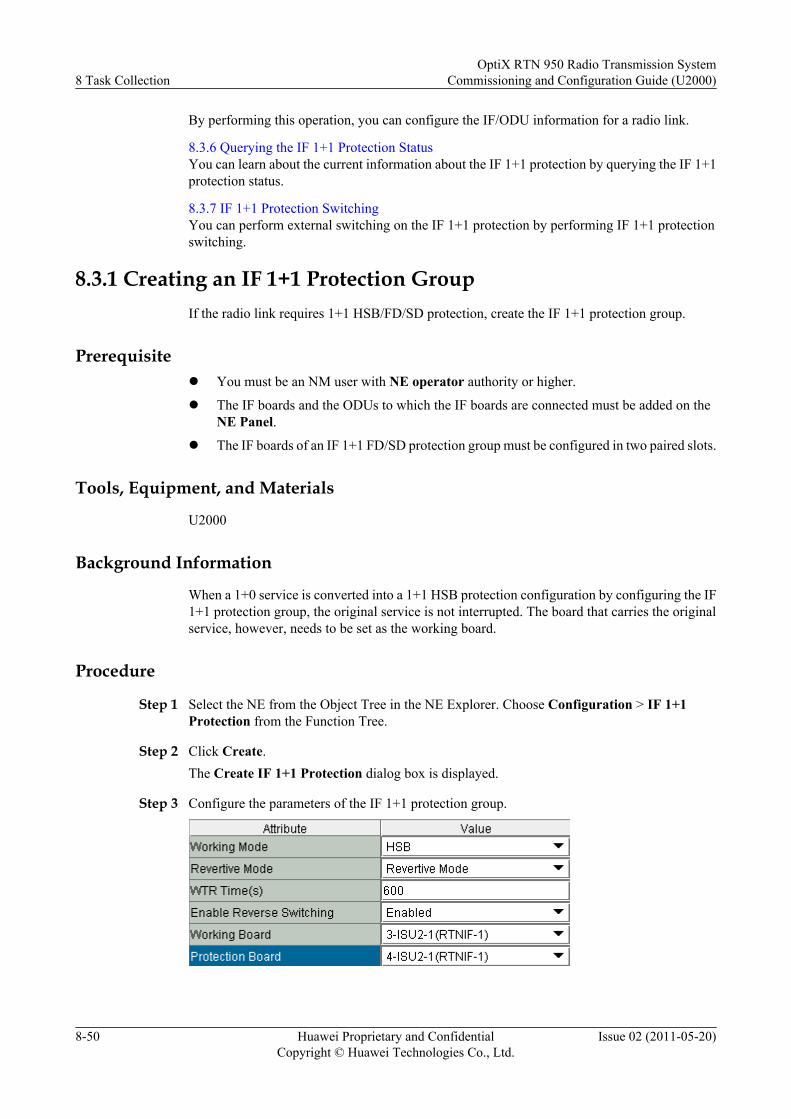
By performing this operation, you can configure the IF/ODU information for a radio link.
8.3.6 Querying the IF 1+1 Protection StatusYou can learn about the current information about the IF 1+1 protection by querying the IF 1+1protection status.
8.3.7 IF 1+1 Protection SwitchingYou can perform external switching on the IF 1+1 protection by performing IF 1+1 protectionswitching.
8.3.1 Creating an IF 1+1 Protection GroupIf the radio link requires 1+1 HSB/FD/SD protection, create the IF 1+1 protection group.
Prerequisitel You must be an NM user with NE operator authority or higher.
l The IF boards and the ODUs to which the IF boards are connected must be added on theNE Panel.
l The IF boards of an IF 1+1 FD/SD protection group must be configured in two paired slots.
Tools, Equipment, and Materials
U2000
Background Information
When a 1+0 service is converted into a 1+1 HSB protection configuration by configuring the IF1+1 protection group, the original service is not interrupted. The board that carries the originalservice, however, needs to be set as the working board.
Procedure
Step 1 Select the NE from the Object Tree in the NE Explorer. Choose Configuration > IF 1+1Protection from the Function Tree.
Step 2 Click Create.The Create IF 1+1 Protection dialog box is displayed.
Step 3 Configure the parameters of the IF 1+1 protection group.
8 Task CollectionOptiX RTN 950 Radio Transmission System
Commissioning and Configuration Guide (U2000)
8-50 Huawei Proprietary and ConfidentialCopyright © Huawei Technologies Co., Ltd.
Issue 02 (2011-05-20)
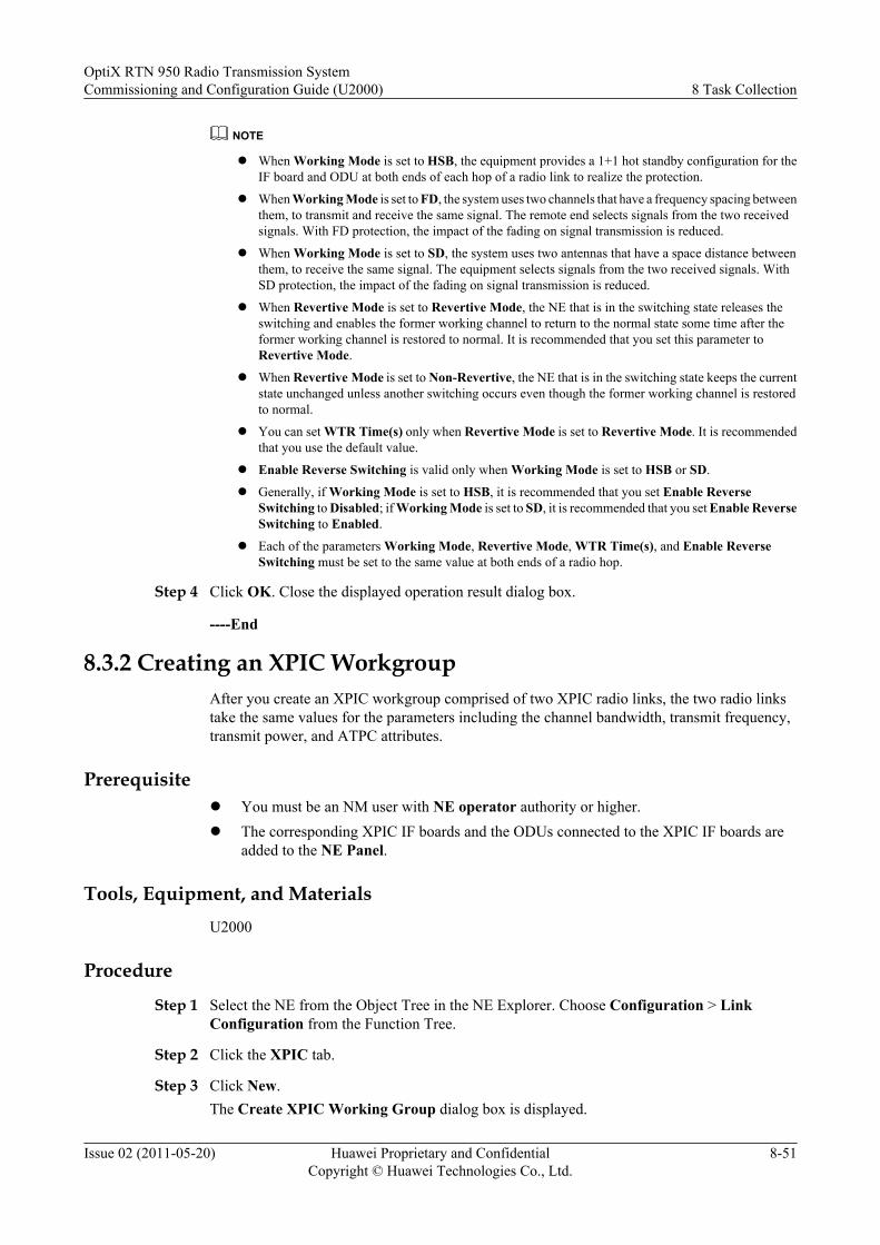
NOTE
l When Working Mode is set to HSB, the equipment provides a 1+1 hot standby configuration for theIF board and ODU at both ends of each hop of a radio link to realize the protection.
l When Working Mode is set to FD, the system uses two channels that have a frequency spacing betweenthem, to transmit and receive the same signal. The remote end selects signals from the two receivedsignals. With FD protection, the impact of the fading on signal transmission is reduced.
l When Working Mode is set to SD, the system uses two antennas that have a space distance betweenthem, to receive the same signal. The equipment selects signals from the two received signals. WithSD protection, the impact of the fading on signal transmission is reduced.
l When Revertive Mode is set to Revertive Mode, the NE that is in the switching state releases theswitching and enables the former working channel to return to the normal state some time after theformer working channel is restored to normal. It is recommended that you set this parameter toRevertive Mode.
l When Revertive Mode is set to Non-Revertive, the NE that is in the switching state keeps the currentstate unchanged unless another switching occurs even though the former working channel is restoredto normal.
l You can set WTR Time(s) only when Revertive Mode is set to Revertive Mode. It is recommendedthat you use the default value.
l Enable Reverse Switching is valid only when Working Mode is set to HSB or SD.
l Generally, if Working Mode is set to HSB, it is recommended that you set Enable ReverseSwitching to Disabled; if Working Mode is set to SD, it is recommended that you set Enable ReverseSwitching to Enabled.
l Each of the parameters Working Mode, Revertive Mode, WTR Time(s), and Enable ReverseSwitching must be set to the same value at both ends of a radio hop.
Step 4 Click OK. Close the displayed operation result dialog box.
----End
8.3.2 Creating an XPIC WorkgroupAfter you create an XPIC workgroup comprised of two XPIC radio links, the two radio linkstake the same values for the parameters including the channel bandwidth, transmit frequency,transmit power, and ATPC attributes.
Prerequisitel You must be an NM user with NE operator authority or higher.l The corresponding XPIC IF boards and the ODUs connected to the XPIC IF boards are
added to the NE Panel.
Tools, Equipment, and MaterialsU2000
Procedure
Step 1 Select the NE from the Object Tree in the NE Explorer. Choose Configuration > LinkConfiguration from the Function Tree.
Step 2 Click the XPIC tab.
Step 3 Click New.The Create XPIC Working Group dialog box is displayed.
OptiX RTN 950 Radio Transmission SystemCommissioning and Configuration Guide (U2000) 8 Task Collection
Issue 02 (2011-05-20) Huawei Proprietary and ConfidentialCopyright © Huawei Technologies Co., Ltd.
8-51
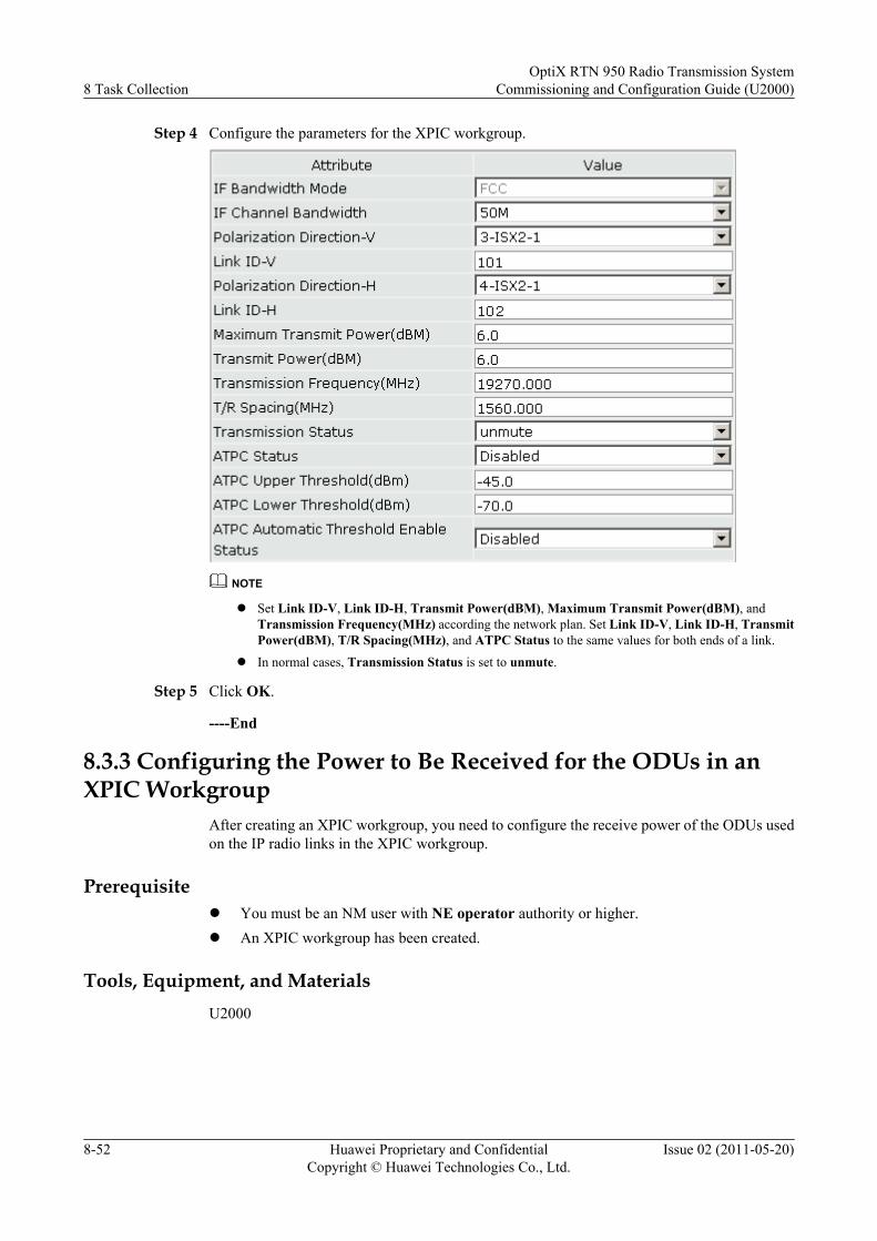
Step 4 Configure the parameters for the XPIC workgroup.
NOTE
l Set Link ID-V, Link ID-H, Transmit Power(dBM), Maximum Transmit Power(dBM), andTransmission Frequency(MHz) according the network plan. Set Link ID-V, Link ID-H, TransmitPower(dBM), T/R Spacing(MHz), and ATPC Status to the same values for both ends of a link.
l In normal cases, Transmission Status is set to unmute.
Step 5 Click OK.
----End
8.3.3 Configuring the Power to Be Received for the ODUs in anXPIC Workgroup
After creating an XPIC workgroup, you need to configure the receive power of the ODUs usedon the IP radio links in the XPIC workgroup.
Prerequisitel You must be an NM user with NE operator authority or higher.l An XPIC workgroup has been created.
Tools, Equipment, and MaterialsU2000
8 Task CollectionOptiX RTN 950 Radio Transmission System
Commissioning and Configuration Guide (U2000)
8-52 Huawei Proprietary and ConfidentialCopyright © Huawei Technologies Co., Ltd.
Issue 02 (2011-05-20)
Procedure
Step 1 Select the NE from the Object Tree in the NE Explorer. Choose Configuration > LinkConfiguration from the Function Tree.
Step 2 Click the XPIC tab.
Step 3 Configure the power to be received for the ODUs in the horizontally and vertically polarizeddirections of the XPIC workgroup.
NOTE
l Configure the same power to be received for the ODUs in the horizontally and vertically polarizeddirections of the XPIC workgroup.
l Power to Be Received(dBm) is used to set the expected receive power of the ODU and is mainly usedin the antenna alignment stage. After this parameter is set, the NE automatically enables the antennamisalignment indicating function.
l When Power to Be Received(dBm) takes the default value (-10.0), the antenna misalignmentindicating function is disabled.
Step 4 Click Apply.
----End
8.3.4 Setting the AM Attributes of the XPIC WorkgroupAfter the XPIC workgroup is created, configure the AM attributes of the XPIC IP radio linkaccording to the planned values.
Prerequisitel You must be an NM user with NE operator authority or higher.l The workgroup must be created.
Tools, Equipment, and Materials
U2000
Background Information
The XPIC IF boards (ISX2 boards) support IP radio, and the AM attributes can be configured.
Procedure
Step 1 Select the NE from the Object Tree in the NE Explorer. Choose Configuration > LinkConfiguration from the Function Tree.
Step 2 Click the XPIC tab.
Step 3 Click the Hybrid/AM Configuration tab.
Step 4 Configure the AM attributes of the XPIC radio link.
OptiX RTN 950 Radio Transmission SystemCommissioning and Configuration Guide (U2000) 8 Task Collection
Issue 02 (2011-05-20) Huawei Proprietary and ConfidentialCopyright © Huawei Technologies Co., Ltd.
8-53
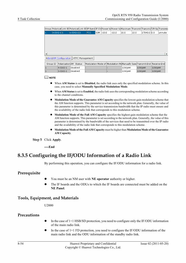
NOTE
l When AM Status is set to Disabled, the radio link uses only the specified modulation scheme. In thiscase, you need to select Manually Specified Modulation Mode.
l When AM Status is set to Enabled, the radio link uses the corresponding modulation scheme accordingto the channel conditions.
l Modulation Mode of the Guarantee AM Capacity specifies the lowest-gain modulation scheme thatthe AM function supports. This parameter is set according to the network plan. Generally, the value ofthis parameter is determined by the service transmission bandwidth that the IP radio must ensure andthe availability of the radio link that corresponds to this modulation scheme.
l Modulation Mode of the Full AM Capacity specifies the highest-gain modulation scheme that theAM function supports. This parameter is set according to the network plan. Generally, the value of thisparameter is determined by the bandwidth of the services that need to be transmitted over the IP radioand the availability of the radio link that corresponds to this modulation scheme.
l Modulation Mode of the Full AM Capacity must be higher than Modulation Mode of the GuaranteeAM Capacity.
Step 5 Click Apply.
----End
8.3.5 Configuring the IF/ODU Information of a Radio LinkBy performing this operation, you can configure the IF/ODU information for a radio link.
Prerequisitel You must be an NM user with NE operator authority or higher.
l The IF boards and the ODUs to which the IF boards are connected must be added on theNE Panel.
Tools, Equipment, and Materials
U2000
Precautionsl In the case of 1+1 HSB/SD protection, you need to configure only the IF/ODU information
of the main radio link.
l In the case of 1+1 FD protection, you need to configure the IF/ODU information of themain radio link and the ODU information of the standby radio link.
8 Task CollectionOptiX RTN 950 Radio Transmission System
Commissioning and Configuration Guide (U2000)
8-54 Huawei Proprietary and ConfidentialCopyright © Huawei Technologies Co., Ltd.
Issue 02 (2011-05-20)
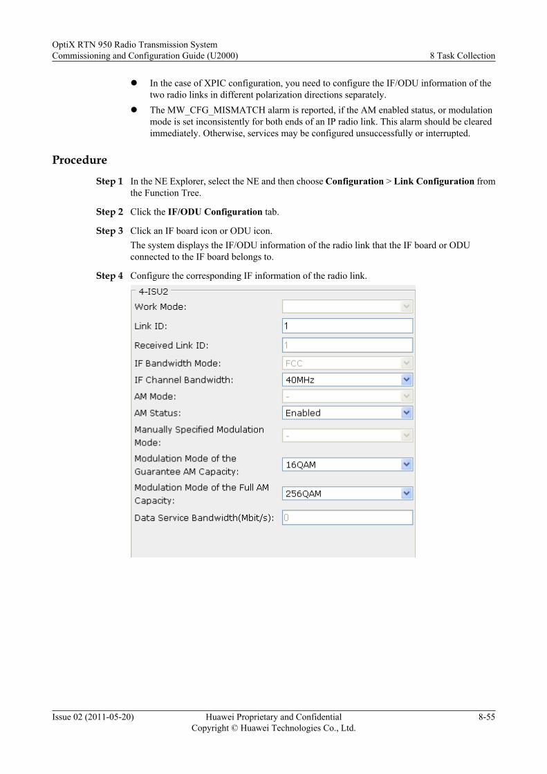
l In the case of XPIC configuration, you need to configure the IF/ODU information of thetwo radio links in different polarization directions separately.
l The MW_CFG_MISMATCH alarm is reported, if the AM enabled status, or modulationmode is set inconsistently for both ends of an IP radio link. This alarm should be clearedimmediately. Otherwise, services may be configured unsuccessfully or interrupted.
Procedure
Step 1 In the NE Explorer, select the NE and then choose Configuration > Link Configuration fromthe Function Tree.
Step 2 Click the IF/ODU Configuration tab.
Step 3 Click an IF board icon or ODU icon.The system displays the IF/ODU information of the radio link that the IF board or ODUconnected to the IF board belongs to.
Step 4 Configure the corresponding IF information of the radio link.
OptiX RTN 950 Radio Transmission SystemCommissioning and Configuration Guide (U2000) 8 Task Collection
Issue 02 (2011-05-20) Huawei Proprietary and ConfidentialCopyright © Huawei Technologies Co., Ltd.
8-55
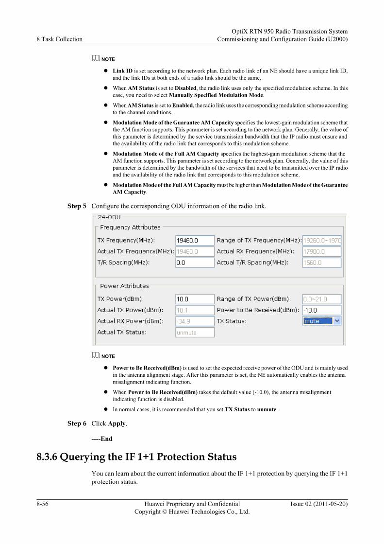
NOTE
l Link ID is set according to the network plan. Each radio link of an NE should have a unique link ID,and the link IDs at both ends of a radio link should be the same.
l When AM Status is set to Disabled, the radio link uses only the specified modulation scheme. In thiscase, you need to select Manually Specified Modulation Mode.
l When AM Status is set to Enabled, the radio link uses the corresponding modulation scheme accordingto the channel conditions.
l Modulation Mode of the Guarantee AM Capacity specifies the lowest-gain modulation scheme thatthe AM function supports. This parameter is set according to the network plan. Generally, the value ofthis parameter is determined by the service transmission bandwidth that the IP radio must ensure andthe availability of the radio link that corresponds to this modulation scheme.
l Modulation Mode of the Full AM Capacity specifies the highest-gain modulation scheme that theAM function supports. This parameter is set according to the network plan. Generally, the value of thisparameter is determined by the bandwidth of the services that need to be transmitted over the IP radioand the availability of the radio link that corresponds to this modulation scheme.
l Modulation Mode of the Full AM Capacity must be higher than Modulation Mode of the GuaranteeAM Capacity.
Step 5 Configure the corresponding ODU information of the radio link.
NOTE
l Power to Be Received(dBm) is used to set the expected receive power of the ODU and is mainly usedin the antenna alignment stage. After this parameter is set, the NE automatically enables the antennamisalignment indicating function.
l When Power to Be Received(dBm) takes the default value (-10.0), the antenna misalignmentindicating function is disabled.
l In normal cases, it is recommended that you set TX Status to unmute.
Step 6 Click Apply.
----End
8.3.6 Querying the IF 1+1 Protection StatusYou can learn about the current information about the IF 1+1 protection by querying the IF 1+1protection status.
8 Task CollectionOptiX RTN 950 Radio Transmission System
Commissioning and Configuration Guide (U2000)
8-56 Huawei Proprietary and ConfidentialCopyright © Huawei Technologies Co., Ltd.
Issue 02 (2011-05-20)
Prerequisitel You must be an NM user with NE administrator authority or higher.l The IF 1+1 protection must be configured.
Tools, Equipment, and MaterialsU2000
ProcedureStep 1 Select the NE from the Object Tree in the NE Explorer. Choose Configuration > IF 1+1
Protection from the Function Tree.
Step 2 Click Query. Close the displayed operation result dialog box. In Protection Group, check theIF 1+1 protection groups.
Step 3 Select the IF 1+1 protection group whose protection status needs to be queried.
Step 4 Click Query Switch Status, and then close the displayed prompt dialog box. In Slot MappingSettings, check the protection status of the IF 1+1 protection group.
----End
8.3.7 IF 1+1 Protection SwitchingYou can perform external switching on the IF 1+1 protection by performing IF 1+1 protectionswitching.
Prerequisitel You must be an NM user with NE operator authority or higher.l The IF 1+1 protection must be configured.
Tools, Equipment, and MaterialsU2000
ProcedureStep 1 Select the NE from the Object Tree in the NE Explorer. Choose Configuration > IF 1+1
Protection from the Function Tree.
Step 2 In Protection Group, select the protection group for protection switching.
Step 3 In Slot Mapping Settings, select a working unit or the protection unit of the protection group,and then right-click the selected unit.
Step 4 Choose the required switching mode from the shortcut menu.The system displays the dialog box that indicates the successful operation.
Step 5 Click Close.
Step 6 Click Query Switching Status and check whether the switching is successful, and then closethe displayed prompt dialog box.
----End
OptiX RTN 950 Radio Transmission SystemCommissioning and Configuration Guide (U2000) 8 Task Collection
Issue 02 (2011-05-20) Huawei Proprietary and ConfidentialCopyright © Huawei Technologies Co., Ltd.
8-57
8.4 Managing PortsSetting correct port parameter is the basis of configuring ports that transmit services.
8.4.1 Setting Ethernet Port ParametersEthernet port parameters include basic attributes, traffic control, Layer-2 attributes, andadvanced attributes.
8.4.2 Setting IF_ETH Port ParametersThis section describes how to set the IF_ETH port parameters. The IF_ETH port is the internalEthernet port on an IF board in IP radio mode and is used to receive and transmit Native ETHservices or packet services.
8.4.3 Setting IF Port ParametersThis section describes how to set IF port parameters, including IF attributes, ATPC attributes,and AM attributes.
8.4.4 Setting ODU Port ParametersThis section describes how to set ODU port parameters, including the transmit frequencyattributes, power attributes, ODU information, and advanced attributes.
8.4.1 Setting Ethernet Port ParametersEthernet port parameters include basic attributes, traffic control, Layer-2 attributes, andadvanced attributes.
8.4.1.1 Setting the Basic Attributes of Ethernet PortsBasic Ethernet port attributes define the physical-layer information, such as the interface mode,encapsulation type, and maximum frame length.
8.4.1.2 Configuring the Traffic Control of Ethernet PortsAfter traffic control is enabled, the Ethernet port sends the pause frame to instruct the peer endto stop sending Ethernet packets for a period if the link is congested, eliminating link congestion.
8.4.1.3 Setting the Layer 2 Attributes of Ethernet PortsEthernet port Layer 2 attributes define link-layer information.
8.4.1.4 Setting the Advanced Attributes of Ethernet PortsYou can configure MAC/PHY layer loopbacks, check the port rates, and configure loopbackdetection and broadcast packet suppression functions by setting related Ethernet advancedattributes.
8.4.1.1 Setting the Basic Attributes of Ethernet Ports
Basic Ethernet port attributes define the physical-layer information, such as the interface mode,encapsulation type, and maximum frame length.
Prerequisitel You must be an NM user with NE operator authority or higher.
l The Ethernet board must be added on the NE Panel.
8 Task CollectionOptiX RTN 950 Radio Transmission System
Commissioning and Configuration Guide (U2000)
8-58 Huawei Proprietary and ConfidentialCopyright © Huawei Technologies Co., Ltd.
Issue 02 (2011-05-20)
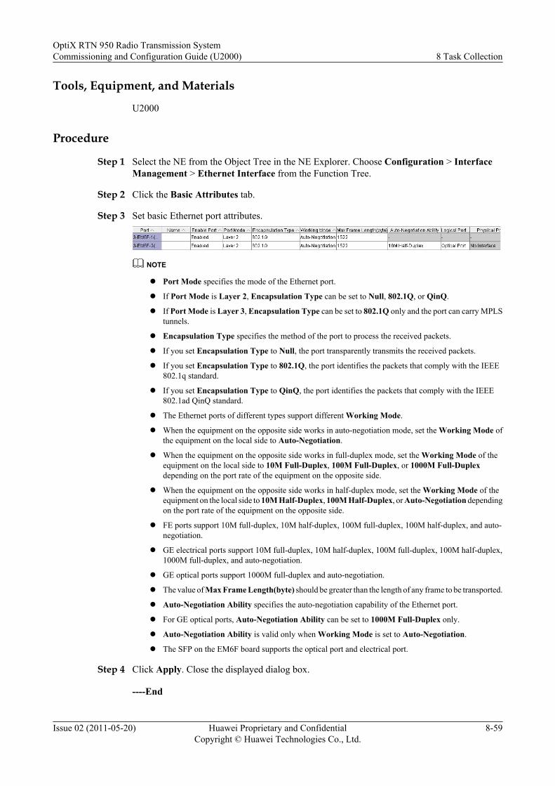
Tools, Equipment, and Materials
U2000
Procedure
Step 1 Select the NE from the Object Tree in the NE Explorer. Choose Configuration > InterfaceManagement > Ethernet Interface from the Function Tree.
Step 2 Click the Basic Attributes tab.
Step 3 Set basic Ethernet port attributes.
NOTE
l Port Mode specifies the mode of the Ethernet port.
l If Port Mode is Layer 2, Encapsulation Type can be set to Null, 802.1Q, or QinQ.
l If Port Mode is Layer 3, Encapsulation Type can be set to 802.1Q only and the port can carry MPLStunnels.
l Encapsulation Type specifies the method of the port to process the received packets.
l If you set Encapsulation Type to Null, the port transparently transmits the received packets.
l If you set Encapsulation Type to 802.1Q, the port identifies the packets that comply with the IEEE802.1q standard.
l If you set Encapsulation Type to QinQ, the port identifies the packets that comply with the IEEE802.1ad QinQ standard.
l The Ethernet ports of different types support different Working Mode.
l When the equipment on the opposite side works in auto-negotiation mode, set the Working Mode ofthe equipment on the local side to Auto-Negotiation.
l When the equipment on the opposite side works in full-duplex mode, set the Working Mode of theequipment on the local side to 10M Full-Duplex, 100M Full-Duplex, or 1000M Full-Duplexdepending on the port rate of the equipment on the opposite side.
l When the equipment on the opposite side works in half-duplex mode, set the Working Mode of theequipment on the local side to 10M Half-Duplex, 100M Half-Duplex, or Auto-Negotiation dependingon the port rate of the equipment on the opposite side.
l FE ports support 10M full-duplex, 10M half-duplex, 100M full-duplex, 100M half-duplex, and auto-negotiation.
l GE electrical ports support 10M full-duplex, 10M half-duplex, 100M full-duplex, 100M half-duplex,1000M full-duplex, and auto-negotiation.
l GE optical ports support 1000M full-duplex and auto-negotiation.
l The value of Max Frame Length(byte) should be greater than the length of any frame to be transported.
l Auto-Negotiation Ability specifies the auto-negotiation capability of the Ethernet port.
l For GE optical ports, Auto-Negotiation Ability can be set to 1000M Full-Duplex only.
l Auto-Negotiation Ability is valid only when Working Mode is set to Auto-Negotiation.
l The SFP on the EM6F board supports the optical port and electrical port.
Step 4 Click Apply. Close the displayed dialog box.
----End
OptiX RTN 950 Radio Transmission SystemCommissioning and Configuration Guide (U2000) 8 Task Collection
Issue 02 (2011-05-20) Huawei Proprietary and ConfidentialCopyright © Huawei Technologies Co., Ltd.
8-59
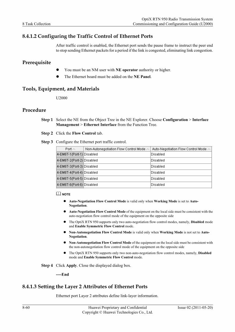
8.4.1.2 Configuring the Traffic Control of Ethernet Ports
After traffic control is enabled, the Ethernet port sends the pause frame to instruct the peer endto stop sending Ethernet packets for a period if the link is congested, eliminating link congestion.
Prerequisitel You must be an NM user with NE operator authority or higher.l The Ethernet board must be added on the NE Panel.
Tools, Equipment, and Materials
U2000
Procedure
Step 1 Select the NE from the Object Tree in the NE Explorer. Choose Configuration > InterfaceManagement > Ethernet Interface from the Function Tree.
Step 2 Click the Flow Control tab.
Step 3 Configure the Ethernet port traffic control.
NOTE
l Auto-Negotiation Flow Control Mode is valid only when Working Mode is set to Auto-Negotiation.
l Auto-Negotiation Flow Control Mode of the equipment on the local side must be consistent with theauto-negotiation flow control mode of the equipment on the opposite side
l The OptiX RTN 950 supports only two auto-negotiation flow control modes, namely, Disabled modeand Enable Symmetric Flow Control mode.
l Non-Autonegotiation Flow Control Mode is valid only when Working Mode is not set to Auto-Negotiation.
l Non-Autonegotiation Flow Control Mode of the equipment on the local side must be consistent withthe non-autonegotiation flow control mode of the equipment on the opposite side
l The OptiX RTN 950 supports only two non-auto-negotiation flow control modes, namely, Disabledmode and Enable Symmetric Flow Control mode.
Step 4 Click Apply. Close the displayed dialog box.
----End
8.4.1.3 Setting the Layer 2 Attributes of Ethernet Ports
Ethernet port Layer 2 attributes define link-layer information.
8 Task CollectionOptiX RTN 950 Radio Transmission System
Commissioning and Configuration Guide (U2000)
8-60 Huawei Proprietary and ConfidentialCopyright © Huawei Technologies Co., Ltd.
Issue 02 (2011-05-20)

Prerequisitel You must be an NM user with NE operator authority or higher.
l The Ethernet board must be added on the NE Panel.
l Port Mode of Ethernet ports are set to Layer 2.
Tools, Equipment, and Materials
U2000
Procedure
Step 1 Select the NE from the Object Tree in the NE Explorer. Choose Configuration > InterfaceManagement > Ethernet Interface from the Function Tree.
Step 2 Click the Layer 2 Attributes tab.
Step 3 Set Ethernet port Layer 2 attributes.
NOTE
l When Encapsulation Type in the General Attributes tab page is set to QinQ, you need to set QinQType Domain. The default value is 88A8.
l When Encapsulation Type in the General Attributes tab page is set to Null or 802.1Q, you cannotset QinQ Type Domain. In this case, QinQ Type Domain is displayed as FFFF and cannot bechanged.
l QinQ Type Domain should be set to the same value for all the ports on the EM6T/EM6F board.
l If all the accessed services are frames with the VLAN tag (tagged frames), set TAG to Tag Aware.
l If all the accessed services are frames without the VLAN tag (untagged frames), set TAG to Access.
l If the accessed services contain tagged frames and untagged frames, set TAG to Hybrid.
l Default VLAN ID is valid only when TAG is set to Access or Hybrid.
l VLAN Priority is valid only when TAG is set to Access or Hybrid.
l When the VLAN priority is required to divide streams or to be used for other purposes, VLANPriority is set according to the planning information. In normal cases, it is recommended that you usethe default value.
Step 4 Click Apply.A warning dialog box is displayed.
Step 5 Click OK. Close the displayed operation result dialog box.
----End
OptiX RTN 950 Radio Transmission SystemCommissioning and Configuration Guide (U2000) 8 Task Collection
Issue 02 (2011-05-20) Huawei Proprietary and ConfidentialCopyright © Huawei Technologies Co., Ltd.
8-61
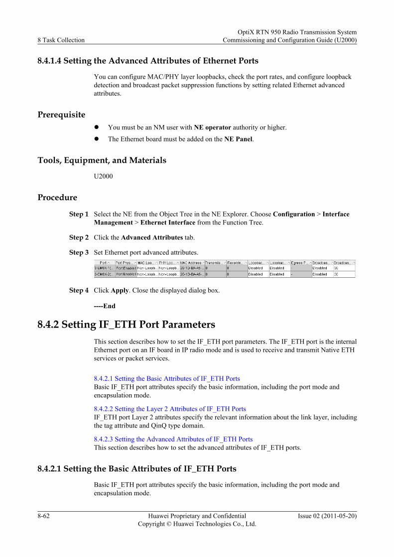
8.4.1.4 Setting the Advanced Attributes of Ethernet Ports
You can configure MAC/PHY layer loopbacks, check the port rates, and configure loopbackdetection and broadcast packet suppression functions by setting related Ethernet advancedattributes.
Prerequisitel You must be an NM user with NE operator authority or higher.
l The Ethernet board must be added on the NE Panel.
Tools, Equipment, and Materials
U2000
Procedure
Step 1 Select the NE from the Object Tree in the NE Explorer. Choose Configuration > InterfaceManagement > Ethernet Interface from the Function Tree.
Step 2 Click the Advanced Attributes tab.
Step 3 Set Ethernet port advanced attributes.
Step 4 Click Apply. Close the displayed dialog box.
----End
8.4.2 Setting IF_ETH Port ParametersThis section describes how to set the IF_ETH port parameters. The IF_ETH port is the internalEthernet port on an IF board in IP radio mode and is used to receive and transmit Native ETHservices or packet services.
8.4.2.1 Setting the Basic Attributes of IF_ETH PortsBasic IF_ETH port attributes specify the basic information, including the port mode andencapsulation mode.
8.4.2.2 Setting the Layer 2 Attributes of IF_ETH PortsIF_ETH port Layer 2 attributes specify the relevant information about the link layer, includingthe tag attribute and QinQ type domain.
8.4.2.3 Setting the Advanced Attributes of IF_ETH PortsThis section describes how to set the advanced attributes of IF_ETH ports.
8.4.2.1 Setting the Basic Attributes of IF_ETH Ports
Basic IF_ETH port attributes specify the basic information, including the port mode andencapsulation mode.
8 Task CollectionOptiX RTN 950 Radio Transmission System
Commissioning and Configuration Guide (U2000)
8-62 Huawei Proprietary and ConfidentialCopyright © Huawei Technologies Co., Ltd.
Issue 02 (2011-05-20)
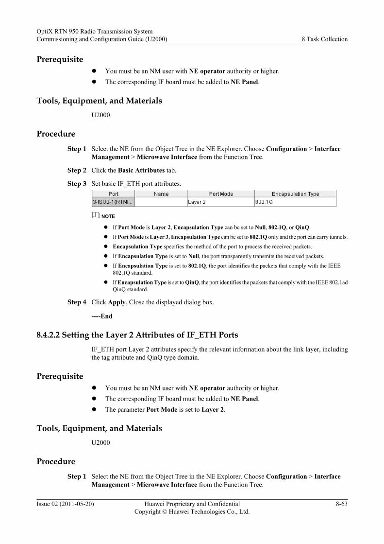
Prerequisitel You must be an NM user with NE operator authority or higher.l The corresponding IF board must be added to NE Panel.
Tools, Equipment, and MaterialsU2000
Procedure
Step 1 Select the NE from the Object Tree in the NE Explorer. Choose Configuration > InterfaceManagement > Microwave Interface from the Function Tree.
Step 2 Click the Basic Attributes tab.
Step 3 Set basic IF_ETH port attributes.
NOTE
l If Port Mode is Layer 2, Encapsulation Type can be set to Null, 802.1Q, or QinQ.
l If Port Mode is Layer 3, Encapsulation Type can be set to 802.1Q only and the port can carry tunnels.
l Encapsulation Type specifies the method of the port to process the received packets.
l If Encapsulation Type is set to Null, the port transparently transmits the received packets.
l If Encapsulation Type is set to 802.1Q, the port identifies the packets that comply with the IEEE802.1Q standard.
l If Encapsulation Type is set to QinQ, the port identifies the packets that comply with the IEEE 802.1adQinQ standard.
Step 4 Click Apply. Close the displayed dialog box.
----End
8.4.2.2 Setting the Layer 2 Attributes of IF_ETH PortsIF_ETH port Layer 2 attributes specify the relevant information about the link layer, includingthe tag attribute and QinQ type domain.
Prerequisitel You must be an NM user with NE operator authority or higher.l The corresponding IF board must be added to NE Panel.l The parameter Port Mode is set to Layer 2.
Tools, Equipment, and MaterialsU2000
Procedure
Step 1 Select the NE from the Object Tree in the NE Explorer. Choose Configuration > InterfaceManagement > Microwave Interface from the Function Tree.
OptiX RTN 950 Radio Transmission SystemCommissioning and Configuration Guide (U2000) 8 Task Collection
Issue 02 (2011-05-20) Huawei Proprietary and ConfidentialCopyright © Huawei Technologies Co., Ltd.
8-63
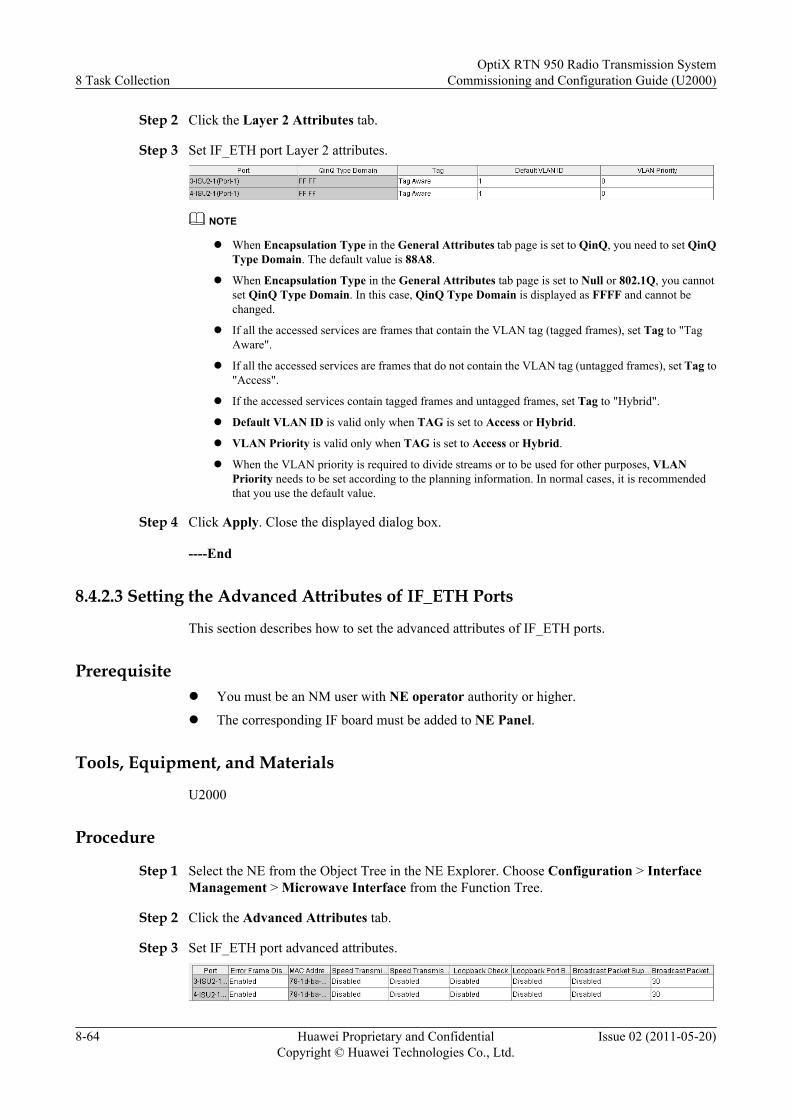
Step 2 Click the Layer 2 Attributes tab.
Step 3 Set IF_ETH port Layer 2 attributes.
NOTE
l When Encapsulation Type in the General Attributes tab page is set to QinQ, you need to set QinQType Domain. The default value is 88A8.
l When Encapsulation Type in the General Attributes tab page is set to Null or 802.1Q, you cannotset QinQ Type Domain. In this case, QinQ Type Domain is displayed as FFFF and cannot bechanged.
l If all the accessed services are frames that contain the VLAN tag (tagged frames), set Tag to "TagAware".
l If all the accessed services are frames that do not contain the VLAN tag (untagged frames), set Tag to"Access".
l If the accessed services contain tagged frames and untagged frames, set Tag to "Hybrid".
l Default VLAN ID is valid only when TAG is set to Access or Hybrid.
l VLAN Priority is valid only when TAG is set to Access or Hybrid.
l When the VLAN priority is required to divide streams or to be used for other purposes, VLANPriority needs to be set according to the planning information. In normal cases, it is recommendedthat you use the default value.
Step 4 Click Apply. Close the displayed dialog box.
----End
8.4.2.3 Setting the Advanced Attributes of IF_ETH Ports
This section describes how to set the advanced attributes of IF_ETH ports.
Prerequisitel You must be an NM user with NE operator authority or higher.
l The corresponding IF board must be added to NE Panel.
Tools, Equipment, and Materials
U2000
Procedure
Step 1 Select the NE from the Object Tree in the NE Explorer. Choose Configuration > InterfaceManagement > Microwave Interface from the Function Tree.
Step 2 Click the Advanced Attributes tab.
Step 3 Set IF_ETH port advanced attributes.
8 Task CollectionOptiX RTN 950 Radio Transmission System
Commissioning and Configuration Guide (U2000)
8-64 Huawei Proprietary and ConfidentialCopyright © Huawei Technologies Co., Ltd.
Issue 02 (2011-05-20)
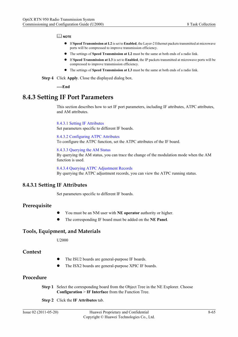
NOTE
l If Speed Transmission at L2 is set to Enabled, the Layer-2 Ethernet packets transmitted at microwaveports will be compressed to improve transmission efficiency.
l The settings of Speed Transmission at L2 must be the same at both ends of a radio link.
l If Speed Transmission at L3 is set to Enabled, the IP packets transmitted at microwave ports will becompressed to improve transmission efficiency.
l The settings of Speed Transmission at L3 must be the same at both ends of a radio link.
Step 4 Click Apply. Close the displayed dialog box.
----End
8.4.3 Setting IF Port ParametersThis section describes how to set IF port parameters, including IF attributes, ATPC attributes,and AM attributes.
8.4.3.1 Setting IF AttributesSet parameters specific to different IF boards.
8.4.3.2 Configuring ATPC AttributesTo configure the ATPC function, set the ATPC attributes of the IF board.
8.4.3.3 Querying the AM StatusBy querying the AM status, you can trace the change of the modulation mode when the AMfunction is used.
8.4.3.4 Querying ATPC Adjustment RecordsBy querying the ATPC adjustment records, you can view the ATPC running status.
8.4.3.1 Setting IF AttributesSet parameters specific to different IF boards.
Prerequisitel You must be an NM user with NE operator authority or higher.l The corresponding IF board must be added on the NE Panel.
Tools, Equipment, and MaterialsU2000
Contextl The ISU2 boards are general-purpose IF boards.l The ISX2 boards are general-purpose XPIC IF boards.
Procedure
Step 1 Select the corresponding board from the Object Tree in the NE Explorer. ChooseConfiguration > IF Interface from the Function Tree.
Step 2 Click the IF Attributes tab.
OptiX RTN 950 Radio Transmission SystemCommissioning and Configuration Guide (U2000) 8 Task Collection
Issue 02 (2011-05-20) Huawei Proprietary and ConfidentialCopyright © Huawei Technologies Co., Ltd.
8-65
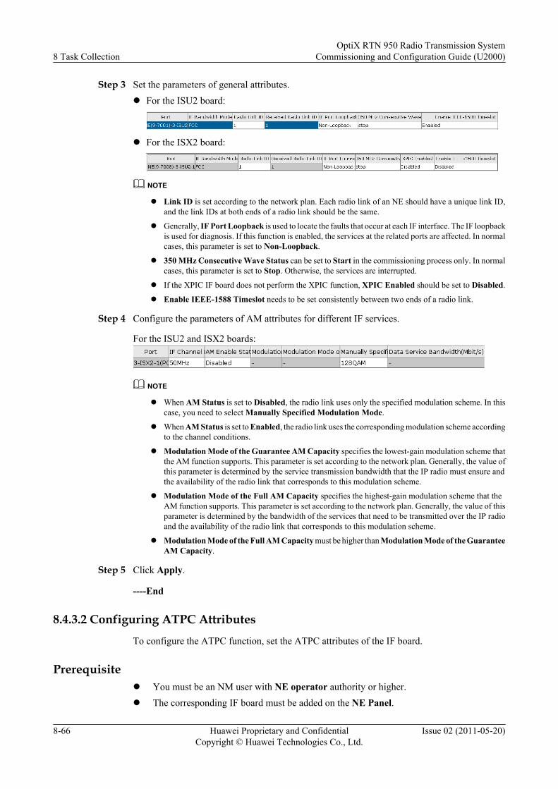
Step 3 Set the parameters of general attributes.l For the ISU2 board:
l For the ISX2 board:
NOTE
l Link ID is set according to the network plan. Each radio link of an NE should have a unique link ID,and the link IDs at both ends of a radio link should be the same.
l Generally, IF Port Loopback is used to locate the faults that occur at each IF interface. The IF loopbackis used for diagnosis. If this function is enabled, the services at the related ports are affected. In normalcases, this parameter is set to Non-Loopback.
l 350 MHz Consecutive Wave Status can be set to Start in the commissioning process only. In normalcases, this parameter is set to Stop. Otherwise, the services are interrupted.
l If the XPIC IF board does not perform the XPIC function, XPIC Enabled should be set to Disabled.
l Enable IEEE-1588 Timeslot needs to be set consistently between two ends of a radio link.
Step 4 Configure the parameters of AM attributes for different IF services.
For the ISU2 and ISX2 boards:
NOTE
l When AM Status is set to Disabled, the radio link uses only the specified modulation scheme. In thiscase, you need to select Manually Specified Modulation Mode.
l When AM Status is set to Enabled, the radio link uses the corresponding modulation scheme accordingto the channel conditions.
l Modulation Mode of the Guarantee AM Capacity specifies the lowest-gain modulation scheme thatthe AM function supports. This parameter is set according to the network plan. Generally, the value ofthis parameter is determined by the service transmission bandwidth that the IP radio must ensure andthe availability of the radio link that corresponds to this modulation scheme.
l Modulation Mode of the Full AM Capacity specifies the highest-gain modulation scheme that theAM function supports. This parameter is set according to the network plan. Generally, the value of thisparameter is determined by the bandwidth of the services that need to be transmitted over the IP radioand the availability of the radio link that corresponds to this modulation scheme.
l Modulation Mode of the Full AM Capacity must be higher than Modulation Mode of the GuaranteeAM Capacity.
Step 5 Click Apply.
----End
8.4.3.2 Configuring ATPC Attributes
To configure the ATPC function, set the ATPC attributes of the IF board.
Prerequisitel You must be an NM user with NE operator authority or higher.l The corresponding IF board must be added on the NE Panel.
8 Task CollectionOptiX RTN 950 Radio Transmission System
Commissioning and Configuration Guide (U2000)
8-66 Huawei Proprietary and ConfidentialCopyright © Huawei Technologies Co., Ltd.
Issue 02 (2011-05-20)
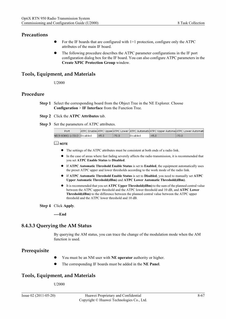
Precautionsl For the IF boards that are configured with 1+1 protection, configure only the ATPC
attributes of the main IF board.l The following procedure describes the ATPC parameter configurations in the IF port
configuration dialog box for the IF board. You can also configure ATPC parameters in theCreate XPIC Protection Group window.
Tools, Equipment, and MaterialsU2000
Procedure
Step 1 Select the corresponding board from the Object Tree in the NE Explorer. ChooseConfiguration > IF Interface from the Function Tree.
Step 2 Click the ATPC Attributes tab.
Step 3 Set the parameters of ATPC attributes.
NOTE
l The settings of the ATPC attributes must be consistent at both ends of a radio link.
l In the case of areas where fast fading severely affects the radio transmission, it is recommended thatyou set ATPC Enable Status to Disabled.
l If ATPC Automatic Threshold Enable Status is set to Enabled, the equipment automatically usesthe preset ATPC upper and lower thresholds according to the work mode of the radio link.
l If ATPC Automatic Threshold Enable Status is set to Disabled, you need to manually set ATPCUpper Automatic Threshold(dBm) and ATPC Lower Automatic Threshold(dBm).
l It is recommended that you set ATPC Upper Threshold(dBm) to the sum of the planned central valuebetween the ATPC upper threshold and the ATPC lower threshold and 10 dB, and ATPC LowerThreshold(dBm) to the difference between the planned central value between the ATPC upperthreshold and the ATPC lower threshold and 10 dB.
Step 4 Click Apply.
----End
8.4.3.3 Querying the AM StatusBy querying the AM status, you can trace the change of the modulation mode when the AMfunction is used.
Prerequisitel You must be an NM user with NE operator authority or higher.l The corresponding IF boards must be added in the NE Panel.
Tools, Equipment, and MaterialsU2000
OptiX RTN 950 Radio Transmission SystemCommissioning and Configuration Guide (U2000) 8 Task Collection
Issue 02 (2011-05-20) Huawei Proprietary and ConfidentialCopyright © Huawei Technologies Co., Ltd.
8-67
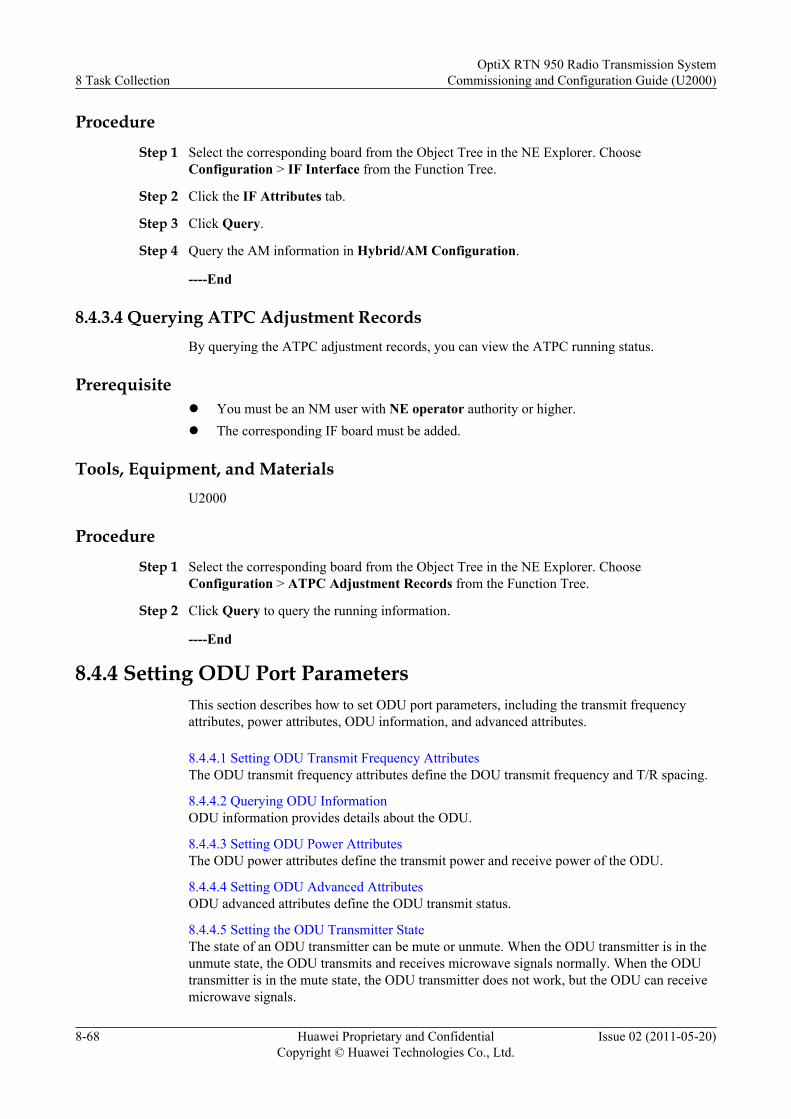
Procedure
Step 1 Select the corresponding board from the Object Tree in the NE Explorer. ChooseConfiguration > IF Interface from the Function Tree.
Step 2 Click the IF Attributes tab.
Step 3 Click Query.
Step 4 Query the AM information in Hybrid/AM Configuration.
----End
8.4.3.4 Querying ATPC Adjustment RecordsBy querying the ATPC adjustment records, you can view the ATPC running status.
Prerequisitel You must be an NM user with NE operator authority or higher.l The corresponding IF board must be added.
Tools, Equipment, and MaterialsU2000
Procedure
Step 1 Select the corresponding board from the Object Tree in the NE Explorer. ChooseConfiguration > ATPC Adjustment Records from the Function Tree.
Step 2 Click Query to query the running information.
----End
8.4.4 Setting ODU Port ParametersThis section describes how to set ODU port parameters, including the transmit frequencyattributes, power attributes, ODU information, and advanced attributes.
8.4.4.1 Setting ODU Transmit Frequency AttributesThe ODU transmit frequency attributes define the DOU transmit frequency and T/R spacing.
8.4.4.2 Querying ODU InformationODU information provides details about the ODU.
8.4.4.3 Setting ODU Power AttributesThe ODU power attributes define the transmit power and receive power of the ODU.
8.4.4.4 Setting ODU Advanced AttributesODU advanced attributes define the ODU transmit status.
8.4.4.5 Setting the ODU Transmitter StateThe state of an ODU transmitter can be mute or unmute. When the ODU transmitter is in theunmute state, the ODU transmits and receives microwave signals normally. When the ODUtransmitter is in the mute state, the ODU transmitter does not work, but the ODU can receivemicrowave signals.
8 Task CollectionOptiX RTN 950 Radio Transmission System
Commissioning and Configuration Guide (U2000)
8-68 Huawei Proprietary and ConfidentialCopyright © Huawei Technologies Co., Ltd.
Issue 02 (2011-05-20)

8.4.4.6 Querying the Historical Transmit Power and Receive PowerIf the radio link requires troubleshooting, query the change trend for the historical transmit powerand receive power for reference.
8.4.4.1 Setting ODU Transmit Frequency Attributes
The ODU transmit frequency attributes define the DOU transmit frequency and T/R spacing.
Prerequisitel You must be an NM user with NE operator authority or higher.l The IF boards and the ODUs to which the IF boards are connected must be added on the
NE Panel.
Tools, Equipment, and Materials
U2000
Procedure
Step 1 Select the ODU from the Object Tree in the NE Explorer. Choose Configuration > ODUInterface from the Function Tree.
Step 2 Click the Radio Frequency Attributes tab.
Step 3 Configure Transmit Frequency(MHz) and T/R Spacing(MHz) of the ODU.
NOTE
l The value of Transmit Frequency(MHz) must not be less than the sum of the minimum transmitfrequency supported by the ODU and a half of the channel spacing, and must not be more than thedifference between the maximum transmit frequency supported by the ODU and a half of the channelspacing.
l The difference between the transmit frequencies at both ends of a radio link should be one T/R spacing.
l If the ODU is a Tx high station, the transmit frequency is one T/R spacing higher than the receivefrequency. If the ODU is a Tx low station, the transmit frequency is one T/R spacing lower than thereceive frequency.
l A valid T/R spacing value is determined by the ODU itself, and T/R Spacing(MHz) should be setaccording to the technical specifications of the ODU.
l The T/R spacing of the ODU should be set to the same value at both ends of a radio link.
Step 4 Click Apply.
----End
8.4.4.2 Querying ODU Information
ODU information provides details about the ODU.
Prerequisitel You must be an NM user with NE operator authority or higher.
OptiX RTN 950 Radio Transmission SystemCommissioning and Configuration Guide (U2000) 8 Task Collection
Issue 02 (2011-05-20) Huawei Proprietary and ConfidentialCopyright © Huawei Technologies Co., Ltd.
8-69
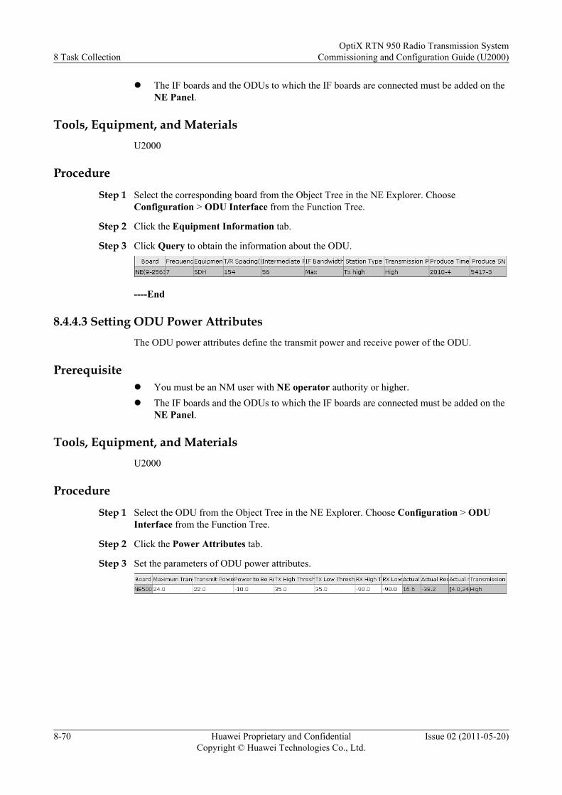
l The IF boards and the ODUs to which the IF boards are connected must be added on theNE Panel.
Tools, Equipment, and MaterialsU2000
Procedure
Step 1 Select the corresponding board from the Object Tree in the NE Explorer. ChooseConfiguration > ODU Interface from the Function Tree.
Step 2 Click the Equipment Information tab.
Step 3 Click Query to obtain the information about the ODU.
----End
8.4.4.3 Setting ODU Power AttributesThe ODU power attributes define the transmit power and receive power of the ODU.
Prerequisitel You must be an NM user with NE operator authority or higher.l The IF boards and the ODUs to which the IF boards are connected must be added on the
NE Panel.
Tools, Equipment, and MaterialsU2000
Procedure
Step 1 Select the ODU from the Object Tree in the NE Explorer. Choose Configuration > ODUInterface from the Function Tree.
Step 2 Click the Power Attributes tab.
Step 3 Set the parameters of ODU power attributes.
8 Task CollectionOptiX RTN 950 Radio Transmission System
Commissioning and Configuration Guide (U2000)
8-70 Huawei Proprietary and ConfidentialCopyright © Huawei Technologies Co., Ltd.
Issue 02 (2011-05-20)
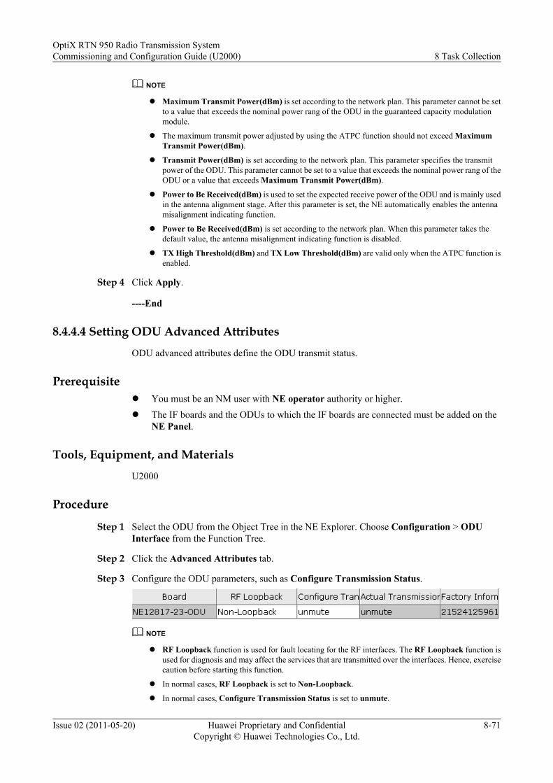
NOTE
l Maximum Transmit Power(dBm) is set according to the network plan. This parameter cannot be setto a value that exceeds the nominal power rang of the ODU in the guaranteed capacity modulationmodule.
l The maximum transmit power adjusted by using the ATPC function should not exceed MaximumTransmit Power(dBm).
l Transmit Power(dBm) is set according to the network plan. This parameter specifies the transmitpower of the ODU. This parameter cannot be set to a value that exceeds the nominal power rang of theODU or a value that exceeds Maximum Transmit Power(dBm).
l Power to Be Received(dBm) is used to set the expected receive power of the ODU and is mainly usedin the antenna alignment stage. After this parameter is set, the NE automatically enables the antennamisalignment indicating function.
l Power to Be Received(dBm) is set according to the network plan. When this parameter takes thedefault value, the antenna misalignment indicating function is disabled.
l TX High Threshold(dBm) and TX Low Threshold(dBm) are valid only when the ATPC function isenabled.
Step 4 Click Apply.
----End
8.4.4.4 Setting ODU Advanced Attributes
ODU advanced attributes define the ODU transmit status.
Prerequisitel You must be an NM user with NE operator authority or higher.l The IF boards and the ODUs to which the IF boards are connected must be added on the
NE Panel.
Tools, Equipment, and Materials
U2000
Procedure
Step 1 Select the ODU from the Object Tree in the NE Explorer. Choose Configuration > ODUInterface from the Function Tree.
Step 2 Click the Advanced Attributes tab.
Step 3 Configure the ODU parameters, such as Configure Transmission Status.
NOTE
l RF Loopback function is used for fault locating for the RF interfaces. The RF Loopback function isused for diagnosis and may affect the services that are transmitted over the interfaces. Hence, exercisecaution before starting this function.
l In normal cases, RF Loopback is set to Non-Loopback.
l In normal cases, Configure Transmission Status is set to unmute.
OptiX RTN 950 Radio Transmission SystemCommissioning and Configuration Guide (U2000) 8 Task Collection
Issue 02 (2011-05-20) Huawei Proprietary and ConfidentialCopyright © Huawei Technologies Co., Ltd.
8-71
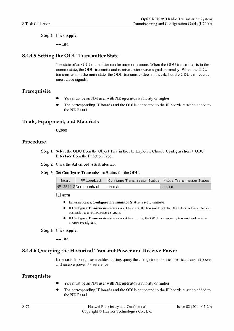
Step 4 Click Apply.
----End
8.4.4.5 Setting the ODU Transmitter StateThe state of an ODU transmitter can be mute or unmute. When the ODU transmitter is in theunmute state, the ODU transmits and receives microwave signals normally. When the ODUtransmitter is in the mute state, the ODU transmitter does not work, but the ODU can receivemicrowave signals.
Prerequisitel You must be an NM user with NE operator authority or higher.l The corresponding IF boards and the ODUs connected to the IF boards must be added to
the NE Panel.
Tools, Equipment, and MaterialsU2000
Procedure
Step 1 Select the ODU from the Object Tree in the NE Explorer. Choose Configuration > ODUInterface from the Function Tree.
Step 2 Click the Advanced Attributes tab.
Step 3 Set Configure Transmission Status for the ODU.
NOTE
l In normal cases, Configure Transmission Status is set to unmute.
l If Configure Transmission Status is set to mute, the transmitter of the ODU does not work but cannormally receive microwave signals.
l If Configure Transmission Status is set to unmute, the ODU can normally transmit and receivemicrowave signals.
Step 4 Click Apply.
----End
8.4.4.6 Querying the Historical Transmit Power and Receive PowerIf the radio link requires troubleshooting, query the change trend for the historical transmit powerand receive power for reference.
Prerequisitel You must be an NM user with NE operator authority or higher.l The corresponding IF boards and the ODUs connected to the IF boards must be added to
the NE Panel.
8 Task CollectionOptiX RTN 950 Radio Transmission System
Commissioning and Configuration Guide (U2000)
8-72 Huawei Proprietary and ConfidentialCopyright © Huawei Technologies Co., Ltd.
Issue 02 (2011-05-20)
Tools, Equipment, and MaterialsU2000
Procedure
Step 1 Select the ODU from the Object Tree in the NE Explorer. Choose Configuration >Performance Graph Analyse from the Function Tree.
Step 2 Specify the start time and end time of a specific time span.NOTE
The time span starts from the last routine maintenance time to the current time.
Step 3 Set Monitoring Period and Power.
Step 4 Click Draw. The historical transmit and receive power curve of the ODU in the specified timespan is displayed.
----End
8.5 Configuring Ethernet Services and Features on thePacket Plane
Configurations of Ethernet services and features on the packet plane include Ethernet port,protection, service, protocol, and OAM configurations.
8.5.1 Managing the LAGLink aggregation allows one or multiple links that are attached to the same equipment to beaggregated together to form a LAG. The aggregated links can be considered as a single logicallink by the MAC address. In this manner, the bandwidth is increased and the availability of thelinks is improved.
8.5.2 Managing ERPSEthernet ring protection switching (ERPS) can be configured on the FE/GE ring or IP radio ringto protect the Ethernet service.
8.5.3 Configuring Ethernet ServicesThis section describes how to configure E-LAN services.
8.5.4 Managing the MAC Address TableThe MAC address table is the core of the E-LAN service. The OptiX RTN 950 provides variousfunctions for managing the MAC address table.
8.5.5 Setting the Mode for Processing an Unknown Frame of the E-LAN ServiceAn unknown frame is a unicast frame whose destination MAC address is not listed in the MACaddress table or a multicast frame whose destination MAC address is not listed in the multicastgroup. By default, the NE broadcasts the unknown frame. By setting the mode for processingan unknown frame of the E-LAN service, you can change the processing mode so that unknownframe can be discarded.
8.5.6 Managing the QoSBy managing the QoS, you can provide the services of different levels for different service types.
8.5.7 Using the IEEE 802.1ag OAMBy using the 802.1ag OAM, you can maintain Ethernet services in an end-to-end manner.
OptiX RTN 950 Radio Transmission SystemCommissioning and Configuration Guide (U2000) 8 Task Collection
Issue 02 (2011-05-20) Huawei Proprietary and ConfidentialCopyright © Huawei Technologies Co., Ltd.
8-73
8.5.8 Using the IEEE 802.3ah OAMBy using the IEEE 802.3ah OAM, you can maintain the point-to-point Ethernet links.
8.5.9 Using the RMONRemote monitoring (RMON) is mainly used to monitor the data traffic on a network segmentor on the entire network. Currently, it is one of the widely used network management standards.
8.5.1 Managing the LAGLink aggregation allows one or multiple links that are attached to the same equipment to beaggregated together to form a LAG. The aggregated links can be considered as a single logicallink by the MAC address. In this manner, the bandwidth is increased and the availability of thelinks is improved.
8.5.1.1 Creating a LAGBetween two NEs, if the bandwidth and availability of the Ethernet links need to be improved,the new LAG must be created.
8.5.1.2 Setting LAG ParametersThe LAG parameters for a LAG include port priorities. In a static LAG, traffic is always carriedby a port with a higher priority.
8.5.1.3 Querying the Protocol Information of the LAGBy performing this operation, you can learn about the running information of the LACP usedfor the LAG.
8.5.1.1 Creating a LAG
Between two NEs, if the bandwidth and availability of the Ethernet links need to be improved,the new LAG must be created.
Prerequisitel You must be an NM user with NE operator authority or higher.
l The board on which the LAG port to be created must be added to the NE Panel.
Tools, Equipment, and Materials
U2000
Procedure
Step 1 Select the NE from the Object Tree in the NE Explorer. Choose Configuration > InterfaceManagement > Link Aggregation Group Management from the Function Tree.
Step 2 Click the Link Aggregation Group Management tab.
Step 3 Click New.The system displays the Create Link Aggregation Group dialog box.
Step 4 Set the LAG attributes in Attribute Settings.
8 Task CollectionOptiX RTN 950 Radio Transmission System
Commissioning and Configuration Guide (U2000)
8-74 Huawei Proprietary and ConfidentialCopyright © Huawei Technologies Co., Ltd.
Issue 02 (2011-05-20)
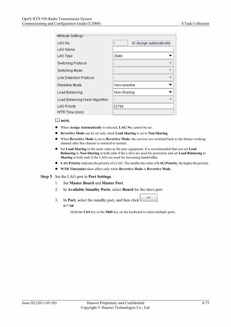
NOTE
l When Assign Automatically is selected, LAG No. cannot be set.
l Revertive Mode can be set only when Load Sharing is set to Non-Sharing.
l When Revertive Mode is set to Revertive Mode, the services are switched back to the former workingchannel after this channel is restored to normal.
l Set Load Sharing to the same value as the peer equipment. It is recommended that you set LoadBalancing to Non-Sharing at both ends if the LAGs are used for protection and set Load Balancing toSharing at both ends if the LAGs are used for increasing bandwidths.
l LAG Priority indicates the priority of a LAG. The smaller the value of LAG Priority, the higher the priority.
l WTR Time(min) takes effect only when Revertive Mode is Revertive Mode.
Step 5 Set the LAG port in Port Settings.1. Set Master Board and Master Port.2. In Available Standby Ports, select Board for the slave port.
3. In Port, select the standby port, and then click .TIP
Hold the Ctrl key or the Shift key on the keyboard to select multiple ports.
OptiX RTN 950 Radio Transmission SystemCommissioning and Configuration Guide (U2000) 8 Task Collection
Issue 02 (2011-05-20) Huawei Proprietary and ConfidentialCopyright © Huawei Technologies Co., Ltd.
8-75
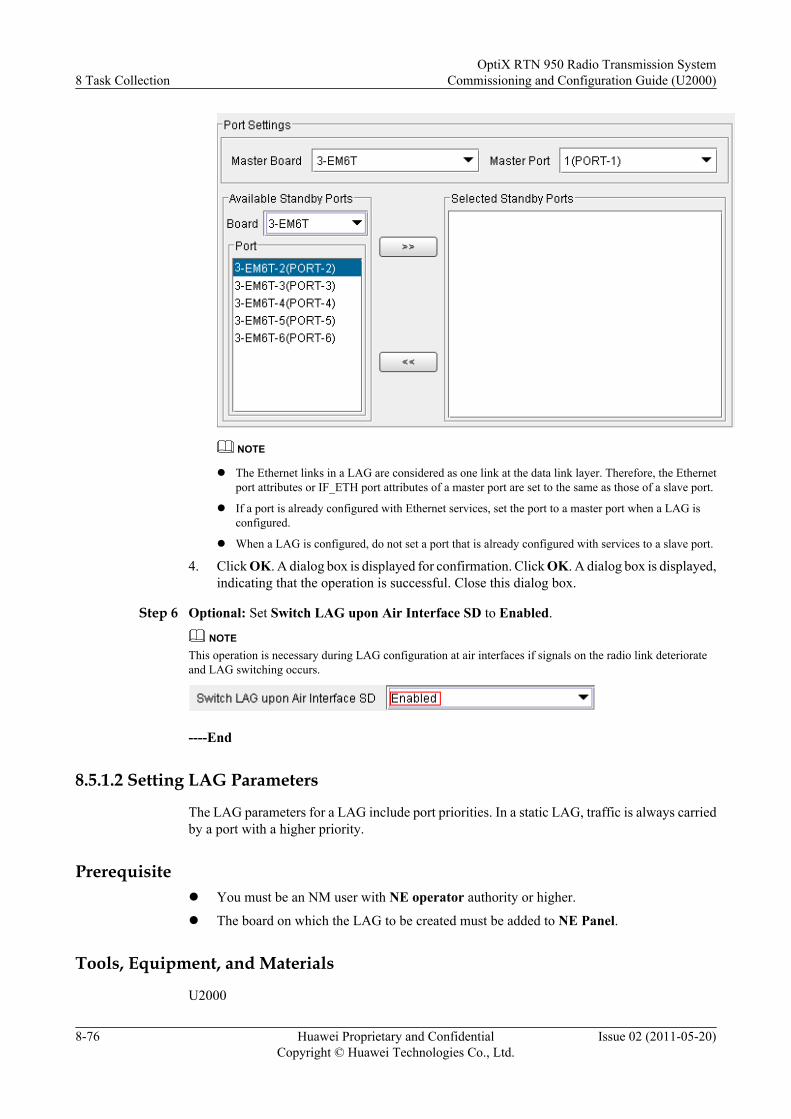
NOTE
l The Ethernet links in a LAG are considered as one link at the data link layer. Therefore, the Ethernetport attributes or IF_ETH port attributes of a master port are set to the same as those of a slave port.
l If a port is already configured with Ethernet services, set the port to a master port when a LAG isconfigured.
l When a LAG is configured, do not set a port that is already configured with services to a slave port.
4. Click OK. A dialog box is displayed for confirmation. Click OK. A dialog box is displayed,indicating that the operation is successful. Close this dialog box.
Step 6 Optional: Set Switch LAG upon Air Interface SD to Enabled.
NOTEThis operation is necessary during LAG configuration at air interfaces if signals on the radio link deteriorateand LAG switching occurs.
----End
8.5.1.2 Setting LAG Parameters
The LAG parameters for a LAG include port priorities. In a static LAG, traffic is always carriedby a port with a higher priority.
Prerequisitel You must be an NM user with NE operator authority or higher.
l The board on which the LAG to be created must be added to NE Panel.
Tools, Equipment, and Materials
U2000
8 Task CollectionOptiX RTN 950 Radio Transmission System
Commissioning and Configuration Guide (U2000)
8-76 Huawei Proprietary and ConfidentialCopyright © Huawei Technologies Co., Ltd.
Issue 02 (2011-05-20)

Procedure
Step 1 Select the NE from the Object Tree in the NE Explorer. Choose Configuration > InterfaceManagement > Link Aggregation Group Management from the Function Tree.
Step 2 Click the Link Aggregation Parameters tab.
Step 3 Set the port priority.
Step 4 Click Apply. Close the displayed dialog box.
----End
8.5.1.3 Querying the Protocol Information of the LAGBy performing this operation, you can learn about the running information of the LACP usedfor the LAG.
Prerequisitel You must be an NM user with NE operator authority or higher.l The LAG must be created.
Tools, Equipment, and MaterialsU2000
Procedure
Step 1 Select the NE from the Object Tree in the NE Explorer. Choose Configuration > InterfaceManagement > Link Aggregation Group Management from the Function Tree.
Step 2 Click the Link Aggregation Group Management tab.
OptiX RTN 950 Radio Transmission SystemCommissioning and Configuration Guide (U2000) 8 Task Collection
Issue 02 (2011-05-20) Huawei Proprietary and ConfidentialCopyright © Huawei Technologies Co., Ltd.
8-77
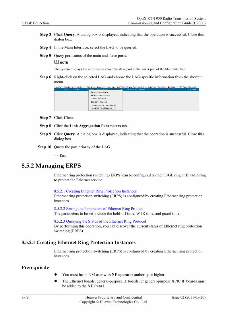
Step 3 Click Query. A dialog box is displayed, indicating that the operation is successful. Close thisdialog box.
Step 4 In the Main Interface, select the LAG to be queried.
Step 5 Query port status of the main and slave ports.
NOTE
The system displays the information about the slave port in the lower part of the Main Interface.
Step 6 Right-click on the selected LAG and choose the LAG-specific information from the shortcutmenu.
Step 7 Click Close.
Step 8 Click the Link Aggregation Parameters tab.
Step 9 Click Query. A dialog box is displayed, indicating that the operation is successful. Close thisdialog box.
Step 10 Query the port priority of the LAG.
----End
8.5.2 Managing ERPSEthernet ring protection switching (ERPS) can be configured on the FE/GE ring or IP radio ringto protect the Ethernet service.
8.5.2.1 Creating Ethernet Ring Protection InstancesEthernet ring protection switching (ERPS) is configured by creating Ethernet ring protectioninstances.
8.5.2.2 Setting the Parameters of Ethernet Ring ProtocolThe parameters to be set include the hold-off time, WTR time, and guard time.
8.5.2.3 Querying the Status of the Ethernet Ring ProtocolBy performing this operation, you can discover the current status of Ethernet ring protectionswitching (ERPS).
8.5.2.1 Creating Ethernet Ring Protection Instances
Ethernet ring protection switching (ERPS) is configured by creating Ethernet ring protectioninstances.
Prerequisitel You must be an NM user with NE operator authority or higher.l The Ethernet boards, general-purpose IF boards, or general-purpose XPIC IF boards must
be added to the NE Panel.
8 Task CollectionOptiX RTN 950 Radio Transmission System
Commissioning and Configuration Guide (U2000)
8-78 Huawei Proprietary and ConfidentialCopyright © Huawei Technologies Co., Ltd.
Issue 02 (2011-05-20)

Tools, Equipment, and Materials
U2000
Procedure
Step 1 Select the NE from the Object Tree in the NE Explorer. Choose Configuration > EthernetProtection > ERPS Management.
Step 2 Click New.The Create Ethernet Ring Protection Protocol Instance dialog box is displayed.
Step 3 Set the parameters for the ERPS protection instance.
NOTE
l Only one node on the ring can be set as the RPL owner for each Ethernet ring.
l An RPL owner needs to balance the traffic on each link of an Ethernet ring. Therefore, it is not recommendedthat you select a convergence node as an RPL owner. Instead, select the NE that is farthest away from theconvergence node as an RPL owner.
l It is recommended that you set the east port on an RPL owner as an RPL Port.
l The ID of a Control VLAN must not be the same as any VLAN ID used by Ethernet services. All ring nodesshould use the same Control VLAN ID.
Step 4 Click OK.
----End
8.5.2.2 Setting the Parameters of Ethernet Ring Protocol
The parameters to be set include the hold-off time, WTR time, and guard time.
Prerequisitel You must be an NM user with NE operator authority or higher.
l The ERPS protection instance must be created.
Tools, Equipment, and Materials
U2000
OptiX RTN 950 Radio Transmission SystemCommissioning and Configuration Guide (U2000) 8 Task Collection
Issue 02 (2011-05-20) Huawei Proprietary and ConfidentialCopyright © Huawei Technologies Co., Ltd.
8-79
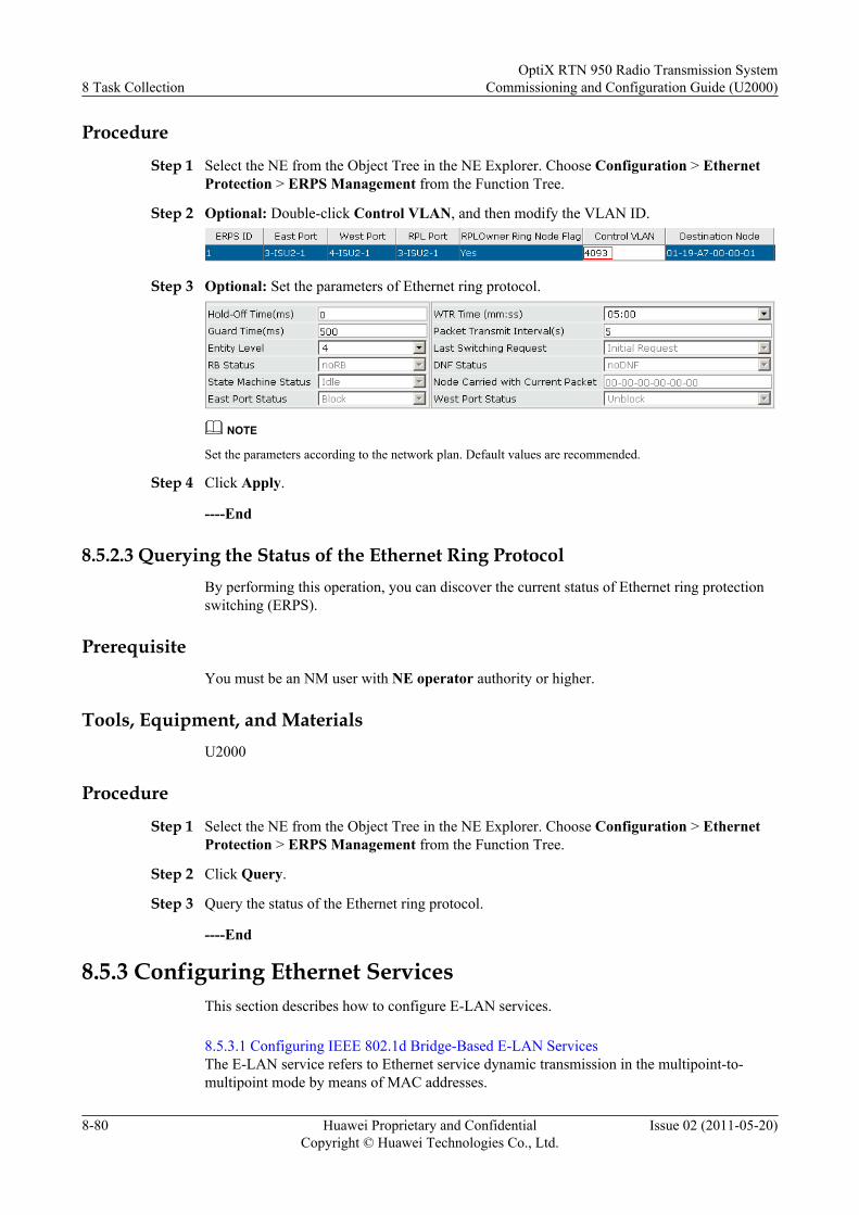
Procedure
Step 1 Select the NE from the Object Tree in the NE Explorer. Choose Configuration > EthernetProtection > ERPS Management from the Function Tree.
Step 2 Optional: Double-click Control VLAN, and then modify the VLAN ID.
Step 3 Optional: Set the parameters of Ethernet ring protocol.
NOTE
Set the parameters according to the network plan. Default values are recommended.
Step 4 Click Apply.
----End
8.5.2.3 Querying the Status of the Ethernet Ring ProtocolBy performing this operation, you can discover the current status of Ethernet ring protectionswitching (ERPS).
PrerequisiteYou must be an NM user with NE operator authority or higher.
Tools, Equipment, and MaterialsU2000
Procedure
Step 1 Select the NE from the Object Tree in the NE Explorer. Choose Configuration > EthernetProtection > ERPS Management from the Function Tree.
Step 2 Click Query.
Step 3 Query the status of the Ethernet ring protocol.
----End
8.5.3 Configuring Ethernet ServicesThis section describes how to configure E-LAN services.
8.5.3.1 Configuring IEEE 802.1d Bridge-Based E-LAN ServicesThe E-LAN service refers to Ethernet service dynamic transmission in the multipoint-to-multipoint mode by means of MAC addresses.
8 Task CollectionOptiX RTN 950 Radio Transmission System
Commissioning and Configuration Guide (U2000)
8-80 Huawei Proprietary and ConfidentialCopyright © Huawei Technologies Co., Ltd.
Issue 02 (2011-05-20)
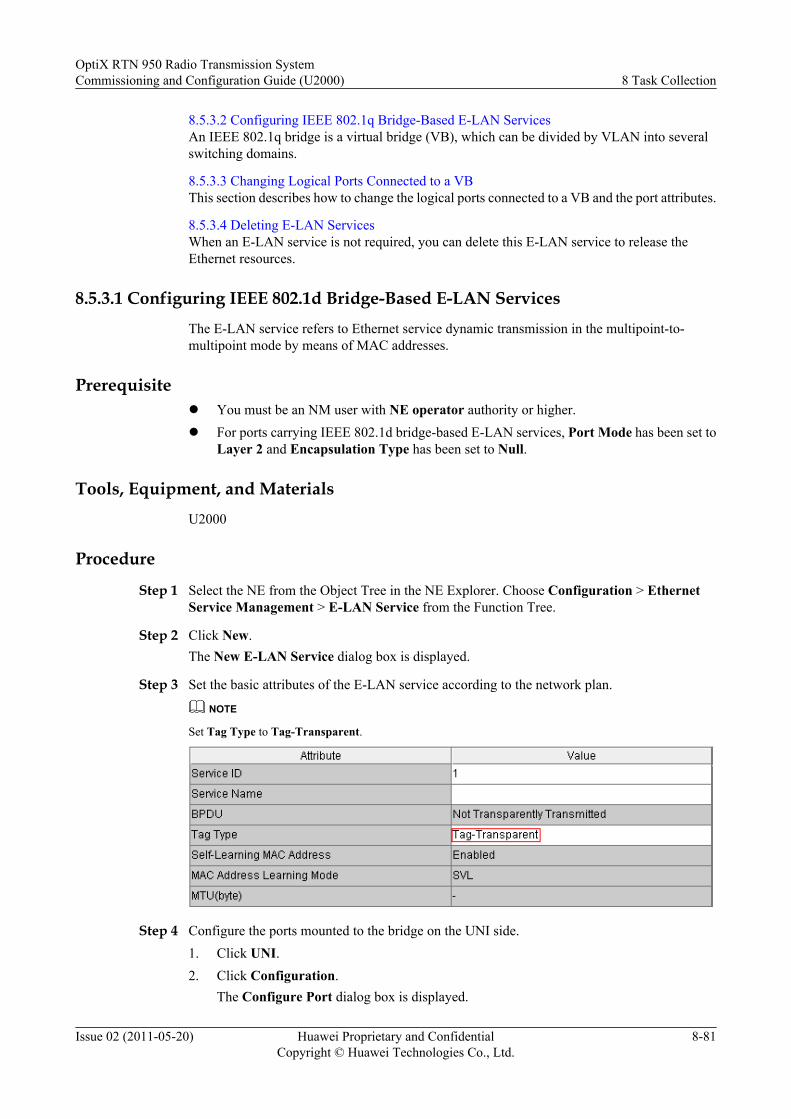
8.5.3.2 Configuring IEEE 802.1q Bridge-Based E-LAN ServicesAn IEEE 802.1q bridge is a virtual bridge (VB), which can be divided by VLAN into severalswitching domains.
8.5.3.3 Changing Logical Ports Connected to a VBThis section describes how to change the logical ports connected to a VB and the port attributes.
8.5.3.4 Deleting E-LAN ServicesWhen an E-LAN service is not required, you can delete this E-LAN service to release theEthernet resources.
8.5.3.1 Configuring IEEE 802.1d Bridge-Based E-LAN ServicesThe E-LAN service refers to Ethernet service dynamic transmission in the multipoint-to-multipoint mode by means of MAC addresses.
Prerequisitel You must be an NM user with NE operator authority or higher.l For ports carrying IEEE 802.1d bridge-based E-LAN services, Port Mode has been set to
Layer 2 and Encapsulation Type has been set to Null.
Tools, Equipment, and MaterialsU2000
Procedure
Step 1 Select the NE from the Object Tree in the NE Explorer. Choose Configuration > EthernetService Management > E-LAN Service from the Function Tree.
Step 2 Click New.The New E-LAN Service dialog box is displayed.
Step 3 Set the basic attributes of the E-LAN service according to the network plan.
NOTE
Set Tag Type to Tag-Transparent.
Step 4 Configure the ports mounted to the bridge on the UNI side.1. Click UNI.2. Click Configuration.
The Configure Port dialog box is displayed.
OptiX RTN 950 Radio Transmission SystemCommissioning and Configuration Guide (U2000) 8 Task Collection
Issue 02 (2011-05-20) Huawei Proprietary and ConfidentialCopyright © Huawei Technologies Co., Ltd.
8-81
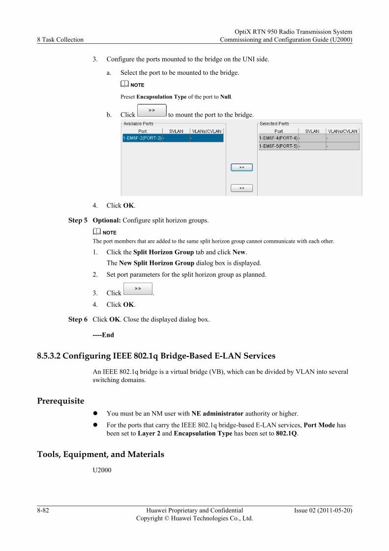
3. Configure the ports mounted to the bridge on the UNI side.
a. Select the port to be mounted to the bridge.
NOTE
Preset Encapsulation Type of the port to Null.
b. Click to mount the port to the bridge.
4. Click OK.
Step 5 Optional: Configure split horizon groups.
NOTEThe port members that are added to the same split horizon group cannot communicate with each other.
1. Click the Split Horizon Group tab and click New.The New Split Horizon Group dialog box is displayed.
2. Set port parameters for the split horizon group as planned.
3. Click .
4. Click OK.
Step 6 Click OK. Close the displayed dialog box.
----End
8.5.3.2 Configuring IEEE 802.1q Bridge-Based E-LAN Services
An IEEE 802.1q bridge is a virtual bridge (VB), which can be divided by VLAN into severalswitching domains.
Prerequisitel You must be an NM user with NE administrator authority or higher.
l For the ports that carry the IEEE 802.1q bridge-based E-LAN services, Port Mode hasbeen set to Layer 2 and Encapsulation Type has been set to 802.1Q.
Tools, Equipment, and Materials
U2000
8 Task CollectionOptiX RTN 950 Radio Transmission System
Commissioning and Configuration Guide (U2000)
8-82 Huawei Proprietary and ConfidentialCopyright © Huawei Technologies Co., Ltd.
Issue 02 (2011-05-20)
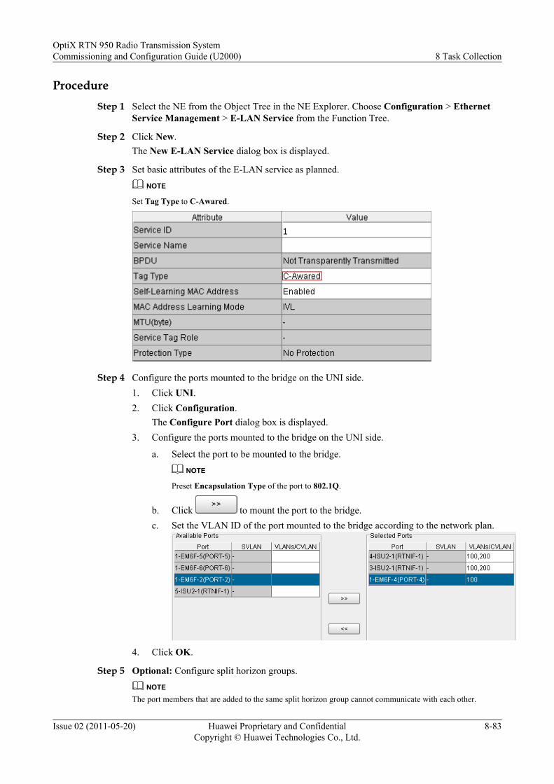
ProcedureStep 1 Select the NE from the Object Tree in the NE Explorer. Choose Configuration > Ethernet
Service Management > E-LAN Service from the Function Tree.
Step 2 Click New.The New E-LAN Service dialog box is displayed.
Step 3 Set basic attributes of the E-LAN service as planned.NOTE
Set Tag Type to C-Awared.
Step 4 Configure the ports mounted to the bridge on the UNI side.1. Click UNI.2. Click Configuration.
The Configure Port dialog box is displayed.3. Configure the ports mounted to the bridge on the UNI side.
a. Select the port to be mounted to the bridge.NOTE
Preset Encapsulation Type of the port to 802.1Q.
b. Click to mount the port to the bridge.c. Set the VLAN ID of the port mounted to the bridge according to the network plan.
4. Click OK.
Step 5 Optional: Configure split horizon groups.NOTE
The port members that are added to the same split horizon group cannot communicate with each other.
OptiX RTN 950 Radio Transmission SystemCommissioning and Configuration Guide (U2000) 8 Task Collection
Issue 02 (2011-05-20) Huawei Proprietary and ConfidentialCopyright © Huawei Technologies Co., Ltd.
8-83
1. Click the Split Horizon Group tab and click New.The New Split Horizon Group dialog box is displayed.
2. Set port parameters for the split horizon group as planned.
3. Click .
4. Click OK.
Step 6 Click OK. Close the displayed dialog box.
----End
8.5.3.3 Changing Logical Ports Connected to a VB
This section describes how to change the logical ports connected to a VB and the port attributes.
Prerequisitel You must be an NM user with NE operator authority or higher.
l The E-LAN services must be created.
Tools, Equipment, and Materials
U2000
Procedure
Step 1 Select the NE from the Object Tree in the NE Explorer. Choose Configuration > EthernetService Management > E-LAN Service from the Function Tree.
Step 2 Add or delete logical ports connected to a VB.
NOTE
l To add or delete ports connected to the VB on the UNI side, click the UNI tab.
l To add or delete ports connected to the VB on the NNI side, click the NNI tab.
1. Click Configuration. In the displayed Configure Port dialog box, select the port to beadded to or deleted from the list of ports connected to the VB.
2. Optional: Click to add ports to the list of ports connected to the VB.
3. Optional: Click to delete ports from the list of ports connected to the VB.TIP
Hold the Ctrl key on the key board to select multiple ports.
4. In Selected Port List, set the attributes of the ports connected to the VB.
5. Click OK.A dialog box is displayed for confirmation.
6. Click Yes. Close the displayed dialog box.
----End
8 Task CollectionOptiX RTN 950 Radio Transmission System
Commissioning and Configuration Guide (U2000)
8-84 Huawei Proprietary and ConfidentialCopyright © Huawei Technologies Co., Ltd.
Issue 02 (2011-05-20)
8.5.3.4 Deleting E-LAN Services
When an E-LAN service is not required, you can delete this E-LAN service to release theEthernet resources.
Prerequisitel You must be an NM user with NE operator authority or higher.
l A configured E-LAN service is not required.
Tools, Equipment, and Materials
U2000
Procedure
Step 1 Select the NE from the Object Tree in the NE Explorer. Choose Configuration > EthernetService Management > E-LAN Service from the Function Tree.
Step 2 Click Query. Close the displayed dialog box.
Step 3 Select the E-LAN service to be deleted and click Delete.A confirmation dialog box is displayed.
Step 4 Click Yes. Close the displayed dialog box.
Step 5 Click Query.The E-LAN service is already deleted.
----End
8.5.4 Managing the MAC Address TableThe MAC address table is the core of the E-LAN service. The OptiX RTN 950 provides variousfunctions for managing the MAC address table.
8.5.4.1 Creating a Static MAC Address EntryThrough the creation of a static MAC address entry, the host with a specified MAC address isnot affected by MAC address aging. In addition, the E-LAN service can be supported by thehost that receives packets only.
8.5.4.2 Creating a Blacklist Entry of MAC AddressesThrough the creation of a blacklist entry of MAC addresses, the host with a specified MACaddress can be prohibited from using the E-LAN service.
8.5.4.3 Configuring the Aging Parameters of a MAC Address TableBy default, the aging function of a MAC address table is enabled and the aging time is fiveminutes. By configuring the aging parameters of a MAC address table, you can modify suchparameters.
8.5.4.4 Querying or Deleting a Dynamic MAC AddressBy querying or deleting a dynamic MAC address, you can query or delete all the MAC addressentries that are learned by the E-LAN service.
OptiX RTN 950 Radio Transmission SystemCommissioning and Configuration Guide (U2000) 8 Task Collection
Issue 02 (2011-05-20) Huawei Proprietary and ConfidentialCopyright © Huawei Technologies Co., Ltd.
8-85
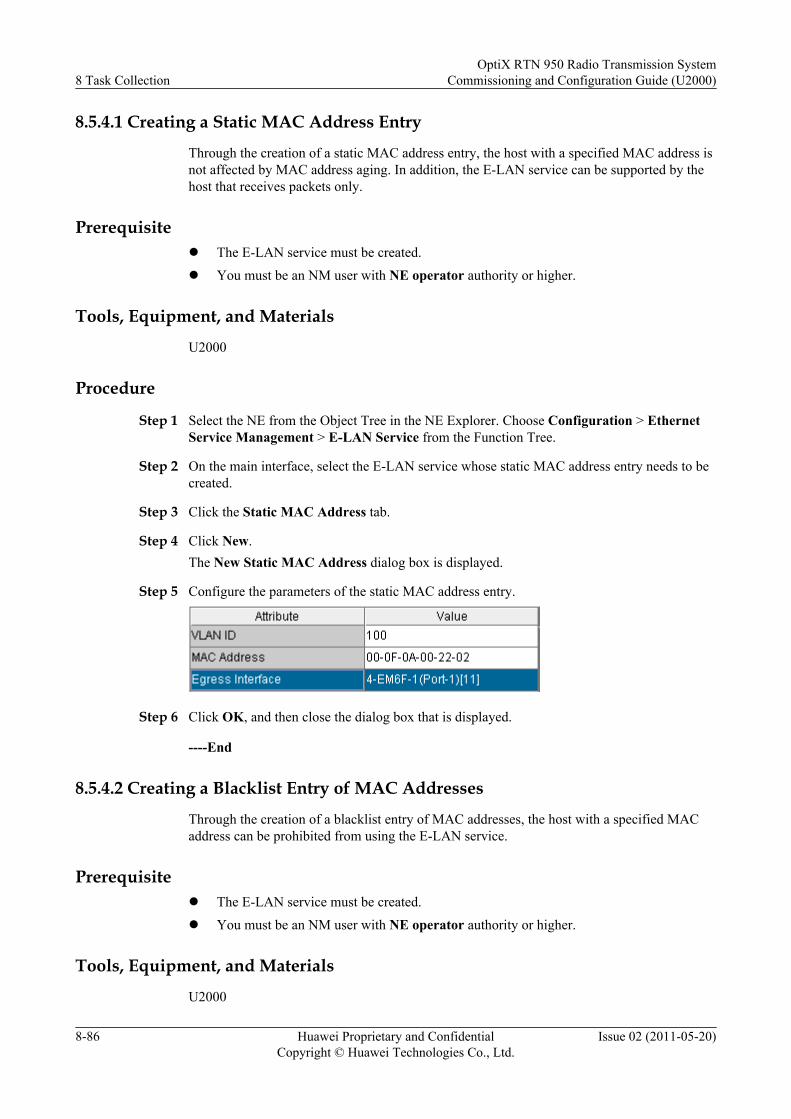
8.5.4.1 Creating a Static MAC Address Entry
Through the creation of a static MAC address entry, the host with a specified MAC address isnot affected by MAC address aging. In addition, the E-LAN service can be supported by thehost that receives packets only.
Prerequisitel The E-LAN service must be created.l You must be an NM user with NE operator authority or higher.
Tools, Equipment, and Materials
U2000
Procedure
Step 1 Select the NE from the Object Tree in the NE Explorer. Choose Configuration > EthernetService Management > E-LAN Service from the Function Tree.
Step 2 On the main interface, select the E-LAN service whose static MAC address entry needs to becreated.
Step 3 Click the Static MAC Address tab.
Step 4 Click New.The New Static MAC Address dialog box is displayed.
Step 5 Configure the parameters of the static MAC address entry.
Step 6 Click OK, and then close the dialog box that is displayed.
----End
8.5.4.2 Creating a Blacklist Entry of MAC Addresses
Through the creation of a blacklist entry of MAC addresses, the host with a specified MACaddress can be prohibited from using the E-LAN service.
Prerequisitel The E-LAN service must be created.l You must be an NM user with NE operator authority or higher.
Tools, Equipment, and Materials
U2000
8 Task CollectionOptiX RTN 950 Radio Transmission System
Commissioning and Configuration Guide (U2000)
8-86 Huawei Proprietary and ConfidentialCopyright © Huawei Technologies Co., Ltd.
Issue 02 (2011-05-20)
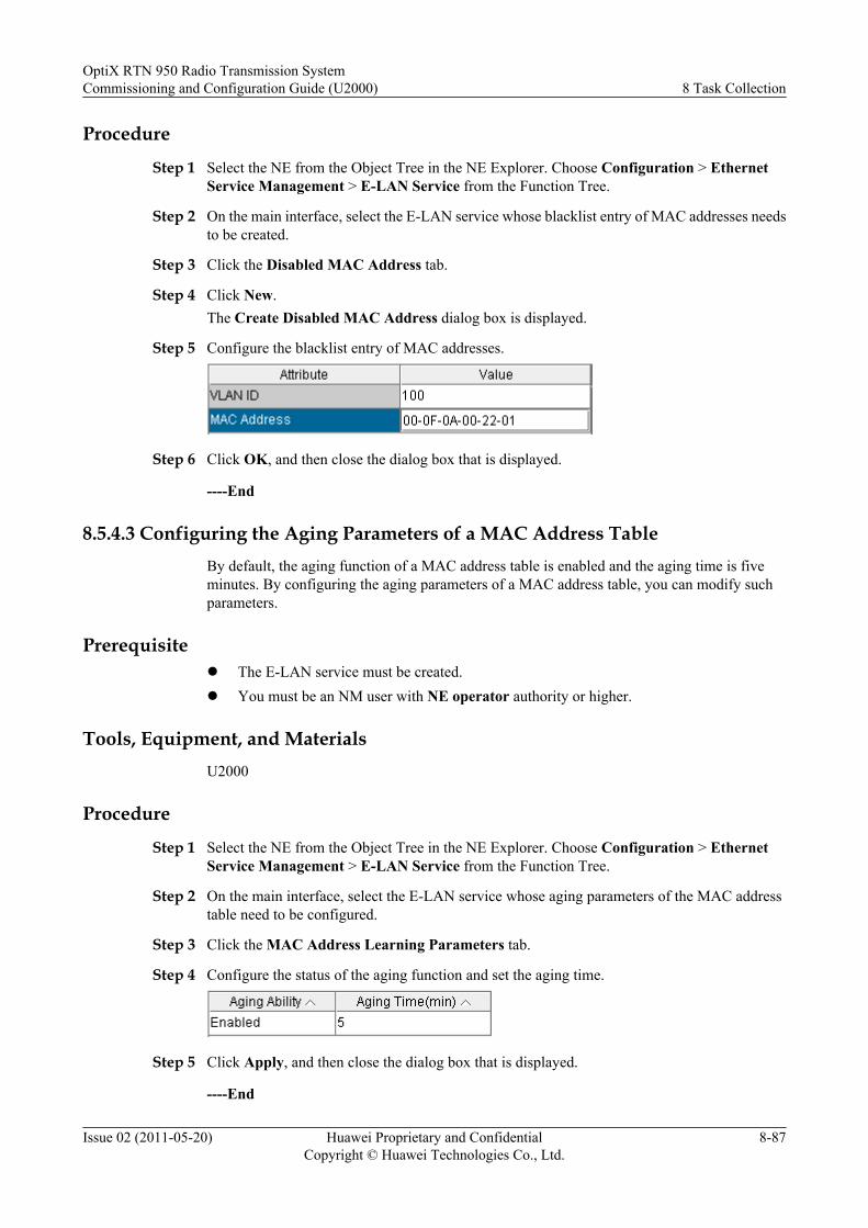
Procedure
Step 1 Select the NE from the Object Tree in the NE Explorer. Choose Configuration > EthernetService Management > E-LAN Service from the Function Tree.
Step 2 On the main interface, select the E-LAN service whose blacklist entry of MAC addresses needsto be created.
Step 3 Click the Disabled MAC Address tab.
Step 4 Click New.The Create Disabled MAC Address dialog box is displayed.
Step 5 Configure the blacklist entry of MAC addresses.
Step 6 Click OK, and then close the dialog box that is displayed.
----End
8.5.4.3 Configuring the Aging Parameters of a MAC Address TableBy default, the aging function of a MAC address table is enabled and the aging time is fiveminutes. By configuring the aging parameters of a MAC address table, you can modify suchparameters.
Prerequisitel The E-LAN service must be created.l You must be an NM user with NE operator authority or higher.
Tools, Equipment, and MaterialsU2000
Procedure
Step 1 Select the NE from the Object Tree in the NE Explorer. Choose Configuration > EthernetService Management > E-LAN Service from the Function Tree.
Step 2 On the main interface, select the E-LAN service whose aging parameters of the MAC addresstable need to be configured.
Step 3 Click the MAC Address Learning Parameters tab.
Step 4 Configure the status of the aging function and set the aging time.
Step 5 Click Apply, and then close the dialog box that is displayed.
----End
OptiX RTN 950 Radio Transmission SystemCommissioning and Configuration Guide (U2000) 8 Task Collection
Issue 02 (2011-05-20) Huawei Proprietary and ConfidentialCopyright © Huawei Technologies Co., Ltd.
8-87
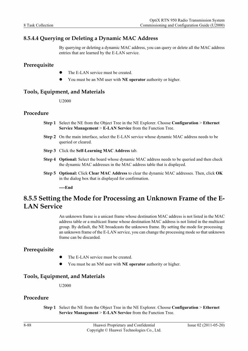
8.5.4.4 Querying or Deleting a Dynamic MAC AddressBy querying or deleting a dynamic MAC address, you can query or delete all the MAC addressentries that are learned by the E-LAN service.
Prerequisitel The E-LAN service must be created.l You must be an NM user with NE operator authority or higher.
Tools, Equipment, and MaterialsU2000
Procedure
Step 1 Select the NE from the Object Tree in the NE Explorer. Choose Configuration > EthernetService Management > E-LAN Service from the Function Tree.
Step 2 On the main interface, select the E-LAN service whose dynamic MAC address needs to bequeried or cleared.
Step 3 Click the Self-Learning MAC Address tab.
Step 4 Optional: Select the board whose dynamic MAC address needs to be queried and then checkthe dynamic MAC addresses in the MAC address table that is displayed.
Step 5 Optional: Click Clear MAC Address to clear the dynamic MAC addresses. Then, click OKin the dialog box that is displayed for confirmation.
----End
8.5.5 Setting the Mode for Processing an Unknown Frame of the E-LAN Service
An unknown frame is a unicast frame whose destination MAC address is not listed in the MACaddress table or a multicast frame whose destination MAC address is not listed in the multicastgroup. By default, the NE broadcasts the unknown frame. By setting the mode for processingan unknown frame of the E-LAN service, you can change the processing mode so that unknownframe can be discarded.
Prerequisitel The E-LAN service must be created.l You must be an NM user with NE operator authority or higher.
Tools, Equipment, and MaterialsU2000
Procedure
Step 1 Select the NE from the Object Tree in the NE Explorer. Choose Configuration > EthernetService Management > E-LAN Service from the Function Tree.
8 Task CollectionOptiX RTN 950 Radio Transmission System
Commissioning and Configuration Guide (U2000)
8-88 Huawei Proprietary and ConfidentialCopyright © Huawei Technologies Co., Ltd.
Issue 02 (2011-05-20)
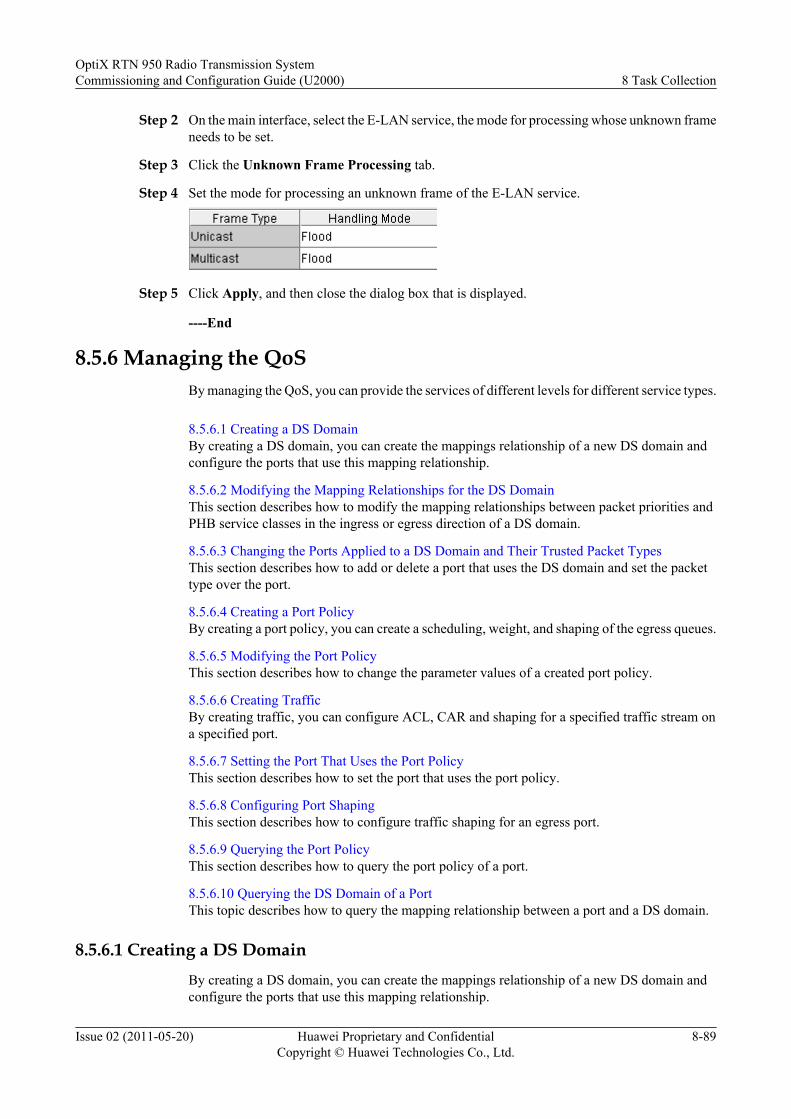
Step 2 On the main interface, select the E-LAN service, the mode for processing whose unknown frameneeds to be set.
Step 3 Click the Unknown Frame Processing tab.
Step 4 Set the mode for processing an unknown frame of the E-LAN service.
Step 5 Click Apply, and then close the dialog box that is displayed.
----End
8.5.6 Managing the QoSBy managing the QoS, you can provide the services of different levels for different service types.
8.5.6.1 Creating a DS DomainBy creating a DS domain, you can create the mappings relationship of a new DS domain andconfigure the ports that use this mapping relationship.
8.5.6.2 Modifying the Mapping Relationships for the DS DomainThis section describes how to modify the mapping relationships between packet priorities andPHB service classes in the ingress or egress direction of a DS domain.
8.5.6.3 Changing the Ports Applied to a DS Domain and Their Trusted Packet TypesThis section describes how to add or delete a port that uses the DS domain and set the packettype over the port.
8.5.6.4 Creating a Port PolicyBy creating a port policy, you can create a scheduling, weight, and shaping of the egress queues.
8.5.6.5 Modifying the Port PolicyThis section describes how to change the parameter values of a created port policy.
8.5.6.6 Creating TrafficBy creating traffic, you can configure ACL, CAR and shaping for a specified traffic stream ona specified port.
8.5.6.7 Setting the Port That Uses the Port PolicyThis section describes how to set the port that uses the port policy.
8.5.6.8 Configuring Port ShapingThis section describes how to configure traffic shaping for an egress port.
8.5.6.9 Querying the Port PolicyThis section describes how to query the port policy of a port.
8.5.6.10 Querying the DS Domain of a PortThis topic describes how to query the mapping relationship between a port and a DS domain.
8.5.6.1 Creating a DS DomainBy creating a DS domain, you can create the mappings relationship of a new DS domain andconfigure the ports that use this mapping relationship.
OptiX RTN 950 Radio Transmission SystemCommissioning and Configuration Guide (U2000) 8 Task Collection
Issue 02 (2011-05-20) Huawei Proprietary and ConfidentialCopyright © Huawei Technologies Co., Ltd.
8-89
Prerequisitel You must be an NM user with NE operator authority or higher.l The board of the Ethernet ports must be added on NE Panel.
Tools, Equipment, and MaterialsU2000
Background InformationThe OptiX RTN 950 has a default DS domain, whose Mapping Relation ID is 1 and MappingRelation Name is default map.
Procedure
Step 1 Select the NE from the Object Tree in the NE Explorer. Choose Configuration > QoSManagement > Diffserv Domain Management > Diffserv Domain Management from theFunction Tree.
Step 2 Click New.The Create DS Domain dialog box is displayed.
Step 3 On the main interface, configure the DS domain attributes.
NOTE
The MPLS EXP value can be modified in the default Diffserv domain (Default Map) only.
Step 4 Click the Inbound Mapping Relation tab.
Step 5 Configure the mapping relationships between the priorities of ingress packets and PHB serviceclasses.
Step 6 Click the Outbound Mapping Relation tab.
Step 7 Configure the mapping relationships between the priorities of egress packets and PHB serviceclasses.
Step 8 Select Board where the application ports exist from Application Port.
Step 9 Select a port from Available Port, and then click .TIP
Hold the Ctrl key on the keyboard to select multiple ports.
8 Task CollectionOptiX RTN 950 Radio Transmission System
Commissioning and Configuration Guide (U2000)
8-90 Huawei Proprietary and ConfidentialCopyright © Huawei Technologies Co., Ltd.
Issue 02 (2011-05-20)
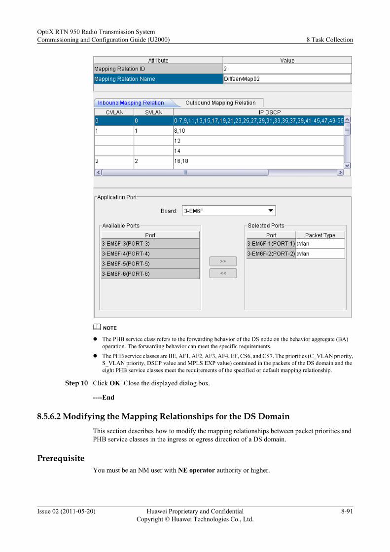
NOTE
l The PHB service class refers to the forwarding behavior of the DS node on the behavior aggregate (BA)operation. The forwarding behavior can meet the specific requirements.
l The PHB service classes are BE, AF1, AF2, AF3, AF4, EF, CS6, and CS7. The priorities (C_VLAN priority,S_VLAN priority, DSCP value and MPLS EXP value) contained in the packets of the DS domain and theeight PHB service classes meet the requirements of the specified or default mapping relationship.
Step 10 Click OK. Close the displayed dialog box.
----End
8.5.6.2 Modifying the Mapping Relationships for the DS DomainThis section describes how to modify the mapping relationships between packet priorities andPHB service classes in the ingress or egress direction of a DS domain.
PrerequisiteYou must be an NM user with NE operator authority or higher.
OptiX RTN 950 Radio Transmission SystemCommissioning and Configuration Guide (U2000) 8 Task Collection
Issue 02 (2011-05-20) Huawei Proprietary and ConfidentialCopyright © Huawei Technologies Co., Ltd.
8-91
Tools, Equipment, and Materials
U2000
Background Information
The OptiX RTN 950 has a default DS domain, whose Mapping Relation ID is 1 and MappingRelation Name is default map.
Procedure
Step 1 Select the NE from the Object Tree in the NE Explorer. Choose Configuration > QoSManagement > Diffserv Domain Management > Diffserv Domain Management from theFunction Tree.
Step 2 Select the created DS domain and change its attributes on the main interface.
NOTE
The MPLS EXP value can be modified in the default Diffserv domain (Default Map) only.
Step 3 Optional: Change the mapping relationship in the ingress direction.
1. Click the Inbound Mapping Relation tab.
2. Double-click the parameters whose values need to be changed and change the mappingrelationship between the packet priorities and PHB classes in the ingress direction.
NOTE
l The PHB service class refers to the forwarding behavior of the DS node on the behavior aggregate(BA) operation. The forwarding behavior can meet the specific requirements.
l The PHB service classes are BE, AF1, AF2, AF3, AF4, EF, CS6, and CS7. The priorities (C_VLANpriority, S_VLAN priority, DSCP value and MPLS EXP value) contained in the packets of the DSdomain and the eight PHB service classes meet the requirements of the specified or default mappingrelationship.
3. Click Apply. Close the displayed dialog box.
Step 4 Optional: Change the mapping relationship in the egress direction.
1. Click the Outbound Mapping Relation tab.
2. Double-click the parameters whose values need to be changed and change the mappingrelationship between the packet priorities and PHB classes in the egress direction.
NOTE
l The PHB service class refers to the forwarding behavior of the DS node on the behavior aggregate(BA) operation. The forwarding behavior can meet the specific requirements.
l The PHB service classes are BE, AF1, AF2, AF3, AF4, EF, CS6, and CS7. The priorities (C_VLANpriority, S_VLAN priority, DSCP value and MPLS EXP value) contained in the packets of the DSdomain and the eight PHB service classes meet the requirements of the specified or default mappingrelationship.
3. Click Apply. Close the displayed dialog box.
Step 5 Click OK.
----End
8 Task CollectionOptiX RTN 950 Radio Transmission System
Commissioning and Configuration Guide (U2000)
8-92 Huawei Proprietary and ConfidentialCopyright © Huawei Technologies Co., Ltd.
Issue 02 (2011-05-20)
8.5.6.3 Changing the Ports Applied to a DS Domain and Their Trusted Packet Types
This section describes how to add or delete a port that uses the DS domain and set the packettype over the port.
PrerequisiteYou must be an NM user with NE operator authority or higher.
Tools, Equipment, and Materials
U2000
Background Information
The OptiX RTN 950 has a default DS domain, whose Mapping Relation ID is 1 and MappingRelation Name is default map.
Procedure
Step 1 Select the NE from the Object Tree in the NE Explorer. Choose Configuration > QoSManagement > Diffserv Domain Management > Diffserv Domain Management from theFunction Tree.
Step 2 Select the DS domain for which you need to add or delete an application port on the maininterface.
Step 3 Click the Application Object tab.
Step 4 Click Modify.
Step 5 Add or delete a port that uses the DS domain.
Option Description
If... Then...
You need to add a port that uses the DSdomain
1. Select the board where the application port islocated from the drop-down list of Board.
2. Select the port to be added from the drop-down list of Available Port.
3. Click .
You need to delete a port that uses the DSdomain
1. Select the board where the application port islocated from the drop-down list of Board.
2. Select the port to be deleted from the port listof Selected Port.
3. Click .
You need to change the packet typeidentified by the port
Select a new packet type from the drop-down listof Packet Type.
OptiX RTN 950 Radio Transmission SystemCommissioning and Configuration Guide (U2000) 8 Task Collection
Issue 02 (2011-05-20) Huawei Proprietary and ConfidentialCopyright © Huawei Technologies Co., Ltd.
8-93

TIP
Hold the Ctrl key on the key board to select multiple ports.
NOTE
l C-VLAN indicates the client-side VLAN priority, and the value 7 indicates the highest priority.
l S-VLAN indicates the server-side VLAN priority, and the value 7 indicates the highest priority.
l The differentiated services code point (DSCP) refers to bits 0-5 of the differentiated services (DS) field inthe packet and indicates the service class and discarding priority of the packet.
l The packets trusted by the OptiX RTN 950 are the C_VLAN, S_VLAN, IP DSCP and MPLS packets thatcontain the C_VLAN priority, S_VLAN priority, DSCP value or MPLS EXP value. By default, the untrustedpackets are mapped to the BE service class for best-effort forwarding.
Step 6 Click OK. Close the displayed dialog box.
----End
8.5.6.4 Creating a Port Policy
By creating a port policy, you can create a scheduling, weight, and shaping of the egress queues.
Prerequisitel You must be an NM user with NE operator authority or higher.
l The board of the Ethernet ports must be added on NE Panel.
Tools, Equipment, and Materials
U2000
Procedure
Step 1 Select the NE from the Object Tree in the NE Explorer. Choose Configuration > QoSManagement > Policy Management > Port Policy from the Function Tree.
Step 2 Create a port policy by adding a port policy on the NMS.
1. Click New. The Create Port Policy dialog box is displayed.
2. Set the ID and name of the port policy.
3. Configure the scheduling, weight, and shaping of the egress queues.
8 Task CollectionOptiX RTN 950 Radio Transmission System
Commissioning and Configuration Guide (U2000)
8-94 Huawei Proprietary and ConfidentialCopyright © Huawei Technologies Co., Ltd.
Issue 02 (2011-05-20)

NOTE
l The strict priority (SP) scheduling algorithm is designed for the key services. One importantcharacteristic of the key services is that higher priorities are required to minimize the response delayin the case of congestion events.
l The weighted round robin (WRR) scheduling algorithm divides each port into multiple output sub-queues. The polling scheduling is performed among the output sub-queues to ensure that each sub-queue has a certain period of service time.
l The OptiX RTN 950 supports the setting of the SP+WRR scheduling algorithm of the CoS queueaccording to the requirement, and provides one or more queues that comply with the SP algorithm.Except for the default value, however, the value of the WRR scheduling algorithm and the value ofthe SP scheduling algorithm cannot be interleaved. That is, except for the default value, GroomingPolice After Reloading can be changed from SP to WRR according to the queue priorities in adescending order (CS7-BE).
l Policy Weight(%) specifies the weight of the policy in the WRR queue. The weight indicates thepercentage of the bandwidth resources obtained by the WRR queue.
l Bandwidth Limit indicates or specifies whether traffic shaping is enabled for an egress queuecorresponding to a PHB service class.
l CIR (kbit/s), PIR (kbit/s), CBS (byte), and PBS (byte) can be set only when Bandwidth Limit isset to Enabled.
4. Click OK. Close the displayed dialog box.
Step 3 Create a port policy by duplicating an existing port policy.1. Select a similar port policy and click Copy.
The Duplicate QoS Policy dialog box is displayed.2. Change the name of the port policy.3. Click OK. Close the displayed dialog box.4. Select the duplicated port policy and change the scheduling, weight, and shaping of the
egress queues.5. Click Apply. Close the displayed dialog box.
----End
8.5.6.5 Modifying the Port Policy
This section describes how to change the parameter values of a created port policy.
Prerequisitel You must be an NM user with NE operator authority or higher.l The port policy must be created.
Tools, Equipment, and Materials
U2000
Procedure
Step 1 Select the NE from the Object Tree in the NE Explorer. Choose Configuration > QoSManagement > Policy Management > Port Policy from the Function Tree.
Step 2 Select the port policy whose parameter values need to be changed.
OptiX RTN 950 Radio Transmission SystemCommissioning and Configuration Guide (U2000) 8 Task Collection
Issue 02 (2011-05-20) Huawei Proprietary and ConfidentialCopyright © Huawei Technologies Co., Ltd.
8-95
Step 3 Double-click the parameters whose values need to be changed and change the queue scheduling,weight, and queue shaping of the port queues.
NOTE
l The strict priority (SP) scheduling algorithm is designed for the key services. One important characteristicof the key services is that higher priorities are required to minimize the response delay in the case ofcongestion events.
l The weighted round robin (WRR) scheduling algorithm divides each port into multiple output sub-queues.The polling scheduling is performed among the output sub-queues to ensure that each sub-queue has a certainperiod of service time.
l The OptiX RTN 950 supports the setting of the SP+WRR scheduling algorithm of the CoS queue accordingto the requirement, and provides one or more queues that comply with the SP algorithm. Except for thedefault value, however, the value of the WRR scheduling algorithm and the value of the SP schedulingalgorithm cannot be interleaved. That is, except for the default value, Grooming Police After Reloadingcan be changed from SP to WRR according to the queue priorities in a descending order (CS7-BE).
l Policy Weight(%) specifies the weight of the policy in the WRR queue. The weight indicates the percentageof the bandwidth resources obtained by the WRR queue.
l Bandwidth Limit indicates or specifies whether traffic shaping is enabled for an egress queue correspondingto a PHB service class.
l CIR (kbit/s), PIR (kbit/s), CBS (byte), and PBS (byte) can be set only when Bandwidth Limit is set toEnabled.
Step 4 Click Apply. Close the displayed dialog box.
----End
8.5.6.6 Creating Traffic
By creating traffic, you can configure ACL, CAR and shaping for a specified traffic stream ona specified port.
Prerequisitel You must be an NM user with NE operator authority or higher.
l The Ethernet board must be added on the NE Panel.
l The port policy must be created.
Tools, Equipment, and Materials
U2000
Procedure
Step 1 Select the NE from the Object Tree in the NE Explorer. Choose Configuration > QoSManagement > Policy Management > Port Policy from the Function Tree.
Step 2 Click the Traffic Classification Configuration tab.
Step 3 Click New.The Create Traffic Classification dialog box is displayed.
Step 4 Set the attributes.
8 Task CollectionOptiX RTN 950 Radio Transmission System
Commissioning and Configuration Guide (U2000)
8-96 Huawei Proprietary and ConfidentialCopyright © Huawei Technologies Co., Ltd.
Issue 02 (2011-05-20)

NOTE
Set the parameters according to the network plan.
Step 5 Click Apply.
----End
8.5.6.7 Setting the Port That Uses the Port PolicyThis section describes how to set the port that uses the port policy.
OptiX RTN 950 Radio Transmission SystemCommissioning and Configuration Guide (U2000) 8 Task Collection
Issue 02 (2011-05-20) Huawei Proprietary and ConfidentialCopyright © Huawei Technologies Co., Ltd.
8-97
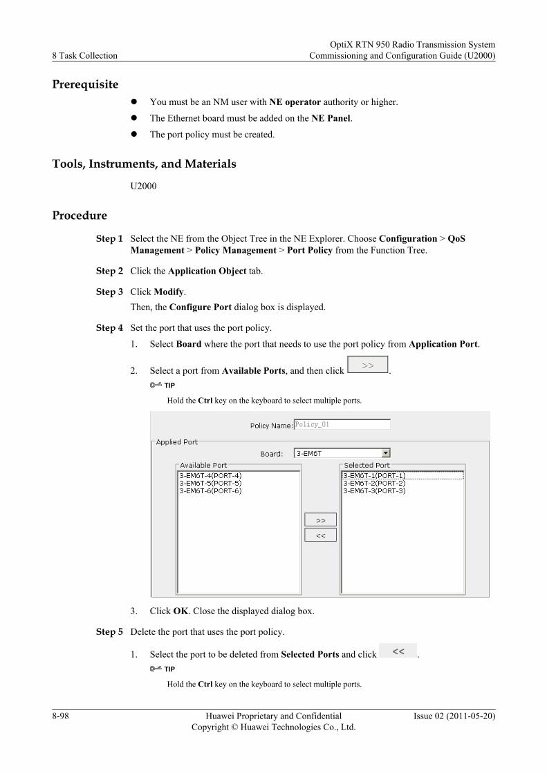
Prerequisitel You must be an NM user with NE operator authority or higher.
l The Ethernet board must be added on the NE Panel.
l The port policy must be created.
Tools, Instruments, and Materials
U2000
Procedure
Step 1 Select the NE from the Object Tree in the NE Explorer. Choose Configuration > QoSManagement > Policy Management > Port Policy from the Function Tree.
Step 2 Click the Application Object tab.
Step 3 Click Modify.Then, the Configure Port dialog box is displayed.
Step 4 Set the port that uses the port policy.
1. Select Board where the port that needs to use the port policy from Application Port.
2. Select a port from Available Ports, and then click .TIP
Hold the Ctrl key on the keyboard to select multiple ports.
3. Click OK. Close the displayed dialog box.
Step 5 Delete the port that uses the port policy.
1. Select the port to be deleted from Selected Ports and click .TIP
Hold the Ctrl key on the keyboard to select multiple ports.
8 Task CollectionOptiX RTN 950 Radio Transmission System
Commissioning and Configuration Guide (U2000)
8-98 Huawei Proprietary and ConfidentialCopyright © Huawei Technologies Co., Ltd.
Issue 02 (2011-05-20)
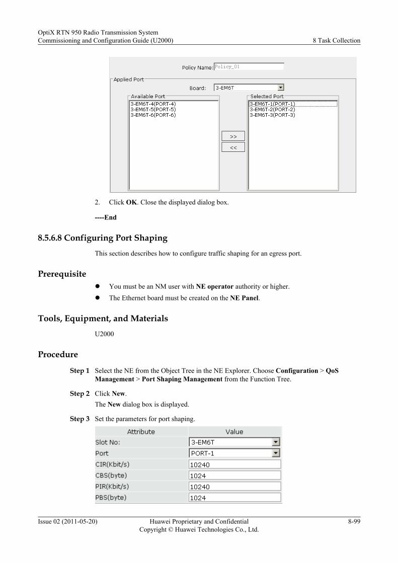
2. Click OK. Close the displayed dialog box.
----End
8.5.6.8 Configuring Port Shaping
This section describes how to configure traffic shaping for an egress port.
Prerequisitel You must be an NM user with NE operator authority or higher.l The Ethernet board must be created on the NE Panel.
Tools, Equipment, and Materials
U2000
Procedure
Step 1 Select the NE from the Object Tree in the NE Explorer. Choose Configuration > QoSManagement > Port Shaping Management from the Function Tree.
Step 2 Click New.The New dialog box is displayed.
Step 3 Set the parameters for port shaping.
OptiX RTN 950 Radio Transmission SystemCommissioning and Configuration Guide (U2000) 8 Task Collection
Issue 02 (2011-05-20) Huawei Proprietary and ConfidentialCopyright © Huawei Technologies Co., Ltd.
8-99
NOTE
Traffic shaping for an egress queue uses the single token bucket two color marker algorithm. The value of theCIR must be equal to the value of the PIR. In actual traffic shaping processing, only the PIR is valid.
If the traffic shaping function is enabled, OptiX RTN 950 processes the packets in the buffer queue through thefollowing methods when no packets are available in the queue.
l When the buffer queue is empty, the packets are processed as follows: If the rate of a packet is equal to orlower than the PIR, it is directly forwarded; if the rate of a packet is higher than the PIR, it enters the bufferqueue and then is forwarded at a rate equal to the PIR.
l When the buffer queue is empty, certain burst packets can be forwarded if the rate of the packets is equal toor lower than the PIR in a certain period. The maximum traffic of the burst packets is determined by thePBS.
l When the buffer queue is not empty, the packets whose rate passes the restriction of the PIR directly enterthe buffer queue and then are forwarded at a rate equal to the PIR.
Step 4 Click OK.
----End
8.5.6.9 Querying the Port PolicyThis section describes how to query the port policy of a port.
PrerequisiteYou must be an NM user with NE operator authority or higher.
Tools, Equipment, and MaterialsU2000
Procedure
Step 1 Select the NE from the Object Tree in the NE Explorer. Choose Configuration > QoSManagement > Policy Management > Port Policy from the Function Tree.
Step 2 Select the created port policy.
Step 3 Click the CoS Configuration tab.
Step 4 Click Query. Close the displayed dialog box.
Step 5 Query the CoS configuration of the port policy.
Step 6 Click the Traffic Classification Configuration tab.
Step 7 Click Query. Close the displayed dialog box.
Step 8 Query the traffic classification of the port policy.
Step 9 Click the Applied Object tab.
Step 10 Click Query. Close the displayed dialog box.
Step 11 Query the ports that use the port policy.
----End
8 Task CollectionOptiX RTN 950 Radio Transmission System
Commissioning and Configuration Guide (U2000)
8-100 Huawei Proprietary and ConfidentialCopyright © Huawei Technologies Co., Ltd.
Issue 02 (2011-05-20)

8.5.6.10 Querying the DS Domain of a PortThis topic describes how to query the mapping relationship between a port and a DS domain.
PrerequisiteYou must be an NM user with NE operator authority or higher.
Tools, Equipment, and MaterialsU2000
Background InformationThe OptiX RTN 950 has a default DS domain, whose Mapping Relation ID is 1 and MappingRelation Name is default map. Before another DS domain is created, all the ports belong to thisdefault DS domain.
Procedure
Step 1 Select the NE from the Object Tree in the NE Explorer. Choose Configuration > QoSManagement > Diffserv Domain Management > Diffserv Domain Management from theFunction Tree.
Step 2 Click the Inbound Mapping Relation tab.
Step 3 Click Query. Close the displayed dialog box.
Step 4 Query the attributes of the DS domain and the mapping relationship between the packet prioritylevel in the ingress direction and the PHB service class.
Step 5 Click the Outbound Mapping Relation tab.
Step 6 Click Query. Close the displayed dialog box.
Step 7 Query the attributes of the DS domain and the mapping relationship between the priority levelof the packets in the egress direction and the PHB service class.
Step 8 Click the Application Object tab.
Step 9 Click Query. Close the displayed dialog box.
Step 10 Query the ports that use the DS domain.
----End
8.5.7 Using the IEEE 802.1ag OAMBy using the 802.1ag OAM, you can maintain Ethernet services in an end-to-end manner.
8.5.7.1 Creating an MDA maintenance domain (MD) defines the Ethernet OAM range and level. MDs of different rangesand levels can provide users with differentiated OAM services.
8.5.7.2 Creating an MAAn MD can be divided into several independent maintenance associations (MAs). By creatingMAs, you can associate specific Ethernet services with MAs. This facilitates Ethernet OAMoperations.
OptiX RTN 950 Radio Transmission SystemCommissioning and Configuration Guide (U2000) 8 Task Collection
Issue 02 (2011-05-20) Huawei Proprietary and ConfidentialCopyright © Huawei Technologies Co., Ltd.
8-101
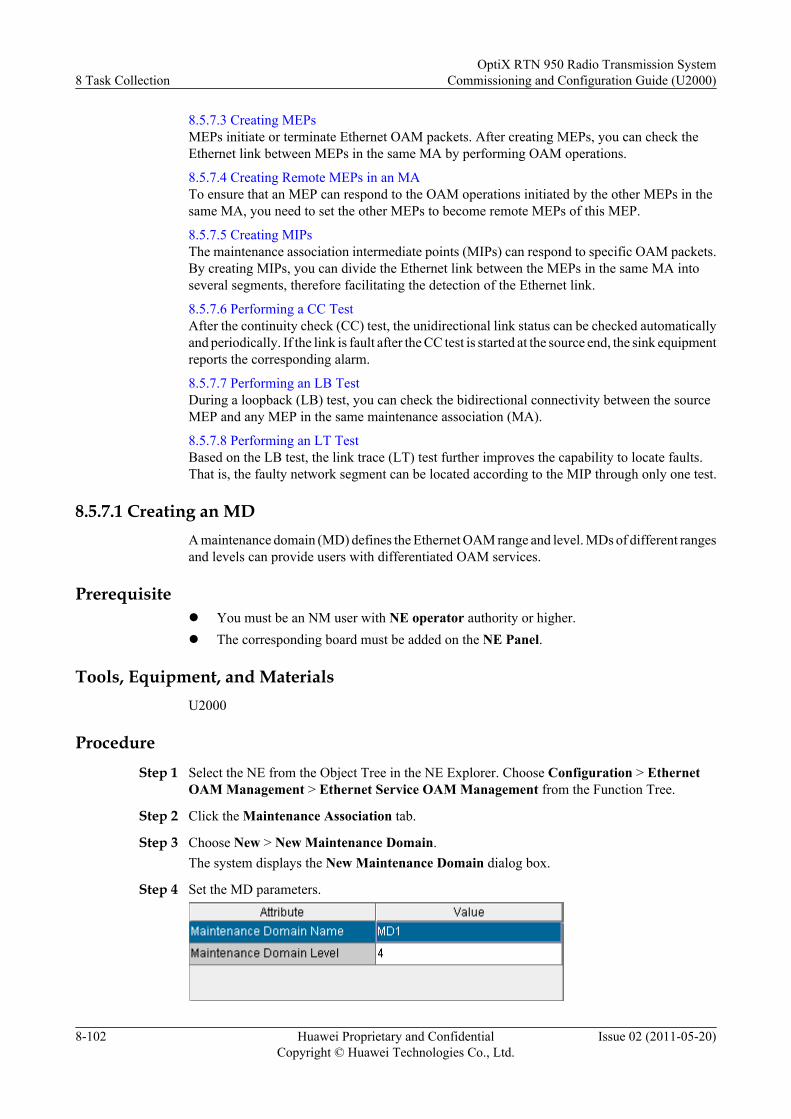
8.5.7.3 Creating MEPsMEPs initiate or terminate Ethernet OAM packets. After creating MEPs, you can check theEthernet link between MEPs in the same MA by performing OAM operations.
8.5.7.4 Creating Remote MEPs in an MATo ensure that an MEP can respond to the OAM operations initiated by the other MEPs in thesame MA, you need to set the other MEPs to become remote MEPs of this MEP.
8.5.7.5 Creating MIPsThe maintenance association intermediate points (MIPs) can respond to specific OAM packets.By creating MIPs, you can divide the Ethernet link between the MEPs in the same MA intoseveral segments, therefore facilitating the detection of the Ethernet link.
8.5.7.6 Performing a CC TestAfter the continuity check (CC) test, the unidirectional link status can be checked automaticallyand periodically. If the link is fault after the CC test is started at the source end, the sink equipmentreports the corresponding alarm.
8.5.7.7 Performing an LB TestDuring a loopback (LB) test, you can check the bidirectional connectivity between the sourceMEP and any MEP in the same maintenance association (MA).
8.5.7.8 Performing an LT TestBased on the LB test, the link trace (LT) test further improves the capability to locate faults.That is, the faulty network segment can be located according to the MIP through only one test.
8.5.7.1 Creating an MDA maintenance domain (MD) defines the Ethernet OAM range and level. MDs of different rangesand levels can provide users with differentiated OAM services.
Prerequisitel You must be an NM user with NE operator authority or higher.l The corresponding board must be added on the NE Panel.
Tools, Equipment, and MaterialsU2000
ProcedureStep 1 Select the NE from the Object Tree in the NE Explorer. Choose Configuration > Ethernet
OAM Management > Ethernet Service OAM Management from the Function Tree.
Step 2 Click the Maintenance Association tab.
Step 3 Choose New > New Maintenance Domain.The system displays the New Maintenance Domain dialog box.
Step 4 Set the MD parameters.
8 Task CollectionOptiX RTN 950 Radio Transmission System
Commissioning and Configuration Guide (U2000)
8-102 Huawei Proprietary and ConfidentialCopyright © Huawei Technologies Co., Ltd.
Issue 02 (2011-05-20)

NOTE
l Maintenance Domain Level specifies the level of the maintenance domain.
l The values 0 to 7 indicates maintenance domain levels in an ascending order.
l MEPs transparently transmit OAM protocol packets if the packets have a higher level than theparameter value.
l MEPs discard OAM protocol packets if the packets have a lower level than the parameter value.
l MEPs respond to or terminate OAM protocol packets based on the packet type if the packets have thesame level as the parameter value.
Step 5 Click OK. Close the displayed dialog box.
----End
8.5.7.2 Creating an MAAn MD can be divided into several independent maintenance associations (MAs). By creatingMAs, you can associate specific Ethernet services with MAs. This facilitates Ethernet OAMoperations.
Prerequisitel You must be an NM user with NE operator authority or higher.l The MD must be created.l The Ethernet service must be created.
Tools, Equipment, and MaterialsU2000
Procedure
Step 1 Select the NE from the Object Tree in the NE Explorer. Choose Configuration > EthernetOAM Management > Ethernet Service OAM Management from the Function Tree.
Step 2 Click the Maintenance Association tab.
Step 3 Select the maintenance domain in which a maintenance association needs to be created. ChooseNew > New Maintenance Association.The system displays the New Maintenance Association dialog box.
Step 4 Set the MA parameters.
NOTE
Click in Relevant Service. Select the corresponding services in the displayed SelectService dialog box.
OptiX RTN 950 Radio Transmission SystemCommissioning and Configuration Guide (U2000) 8 Task Collection
Issue 02 (2011-05-20) Huawei Proprietary and ConfidentialCopyright © Huawei Technologies Co., Ltd.
8-103

Step 5 Click OK. Close the displayed dialog box.
----End
8.5.7.3 Creating MEPs
MEPs initiate or terminate Ethernet OAM packets. After creating MEPs, you can check theEthernet link between MEPs in the same MA by performing OAM operations.
Prerequisitel You must be an NM user with NE operator authority or higher.l The MA must be created.
Tools, Equipment, and Materials
U2000
Procedure
Step 1 Select the NE from the Object Tree in the NE Explorer. Choose Configuration > EthernetOAM Management > Ethernet Service OAM Management from the Function Tree.
Step 2 Click the Maintenance Association tab.
Step 3 Select the maintenance association in which an MEP needs to be created. Choose New > NewMEP Point.The system displays the New MEP Point dialog box.
Step 4 Set the MEP parameters.
8 Task CollectionOptiX RTN 950 Radio Transmission System
Commissioning and Configuration Guide (U2000)
8-104 Huawei Proprietary and ConfidentialCopyright © Huawei Technologies Co., Ltd.
Issue 02 (2011-05-20)

NOTE
l Each MEP needs to be configured with an MP ID, which is unique in the maintenance association.The MP ID is required in the OAM operation.
l Direction specifies the direction of the MEP.
l Ingress indicates the direction in which the packets are transmitted to the port, and Egress indicatesthe direction in which the packets are transmitted from the port.
l In the case of the tests based on the MP IDs, CC Status must be set to Active.
Step 5 Click OK. Close the displayed dialog box.
----End
8.5.7.4 Creating Remote MEPs in an MA
To ensure that an MEP can respond to the OAM operations initiated by the other MEPs in thesame MA, you need to set the other MEPs to become remote MEPs of this MEP.
Prerequisitel You must be an NM user with NE operator authority or higher.
l The MA must be created.
Tools, Equipment, and Materials
U2000
Procedure
Step 1 Select the NE from the Object Tree in the NE Explorer. Choose Configuration > EthernetOAM Management > Ethernet Service OAM Management from the Function Tree.
Step 2 Click the Maintenance Association tab.
Step 3 Choose OAM > Manage Remote MEP Point. The Manage Remote MEP Point dialog boxis displayed.
Step 4 Click New.The Add Maintenance Association Remote Maintenance Point dialog box is displayed.
Step 5 Set the parameters of the new remote MEP.
NOTE
If other MEPs will initiate OAM operations to an MEP in the same MA, set these MEPs as remote MEPs.
Step 6 Click OK. Close the displayed dialog box.
----End
OptiX RTN 950 Radio Transmission SystemCommissioning and Configuration Guide (U2000) 8 Task Collection
Issue 02 (2011-05-20) Huawei Proprietary and ConfidentialCopyright © Huawei Technologies Co., Ltd.
8-105
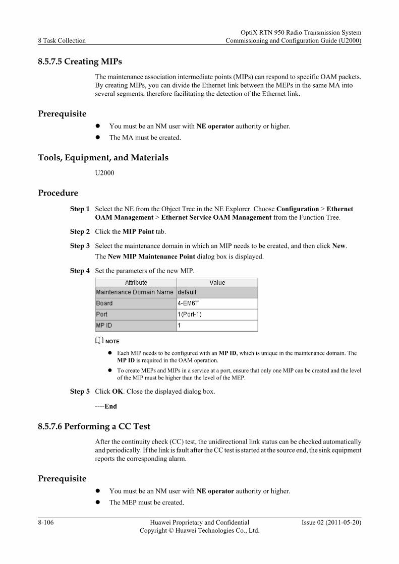
8.5.7.5 Creating MIPsThe maintenance association intermediate points (MIPs) can respond to specific OAM packets.By creating MIPs, you can divide the Ethernet link between the MEPs in the same MA intoseveral segments, therefore facilitating the detection of the Ethernet link.
Prerequisitel You must be an NM user with NE operator authority or higher.l The MA must be created.
Tools, Equipment, and MaterialsU2000
Procedure
Step 1 Select the NE from the Object Tree in the NE Explorer. Choose Configuration > EthernetOAM Management > Ethernet Service OAM Management from the Function Tree.
Step 2 Click the MIP Point tab.
Step 3 Select the maintenance domain in which an MIP needs to be created, and then click New.The New MIP Maintenance Point dialog box is displayed.
Step 4 Set the parameters of the new MIP.
NOTE
l Each MIP needs to be configured with an MP ID, which is unique in the maintenance domain. TheMP ID is required in the OAM operation.
l To create MEPs and MIPs in a service at a port, ensure that only one MIP can be created and the levelof the MIP must be higher than the level of the MEP.
Step 5 Click OK. Close the displayed dialog box.
----End
8.5.7.6 Performing a CC TestAfter the continuity check (CC) test, the unidirectional link status can be checked automaticallyand periodically. If the link is fault after the CC test is started at the source end, the sink equipmentreports the corresponding alarm.
Prerequisitel You must be an NM user with NE operator authority or higher.l The MEP must be created.
8 Task CollectionOptiX RTN 950 Radio Transmission System
Commissioning and Configuration Guide (U2000)
8-106 Huawei Proprietary and ConfidentialCopyright © Huawei Technologies Co., Ltd.
Issue 02 (2011-05-20)
l The remote MEPs must be created.
Tools, Equipment, and MaterialsU2000
Background Informationl Only the MEP can enable the CC test and function as the receiving and responding end in
the test.l During the CC check, the source MEP constructs and transmits continuity check message
(CCM) packets periodically. After receiving the CCM packets from the source MEP, thesink MEP directly enables the CC function for this source MEP. If the sink MEP fails toreceive the CCM packets from the source MEP within the check period (that is, 3.5 timesof the transmit period), it reports the alarm automatically.
l Performing a CC test does not affect the services.
Procedure
Step 1 Select the NE from the Object Tree in the NE Explorer. Choose Configuration > EthernetOAM Management > Ethernet Service OAM Management from the Function Tree.
Step 2 Click the Maintenance Association tab.
Step 3 Select the MEP where you need to perform the CC test and then choose OAM > ActivateCC.A dialog box is displayed, indicating that the operation is successful.
NOTE
l Before the CC test, you can set CC Test Transmit Period according to the actual requirements.
l To disable a CC test, select the MEP where the CC test is performed and then choose OAM >Deactivate.
TIP
l Alternatively, you can enable a CC test by right-clicking an MEP and then choosing Activate CC fromthe shortcut menu.
l Alternatively, you can disable a CC test by right-clicking an MEP and then choosing Deactivate CCfrom the shortcut menu.
Step 4 Click Close.
----End
8.5.7.7 Performing an LB TestDuring a loopback (LB) test, you can check the bidirectional connectivity between the sourceMEP and any MEP in the same maintenance association (MA).
Prerequisitel You must be an NM user with NE operator authority or higher.l The source and sink MEPs in the same maintenance domain must be created.l The remote MEPs must be created.l The CC function must be enabled.
OptiX RTN 950 Radio Transmission SystemCommissioning and Configuration Guide (U2000) 8 Task Collection
Issue 02 (2011-05-20) Huawei Proprietary and ConfidentialCopyright © Huawei Technologies Co., Ltd.
8-107
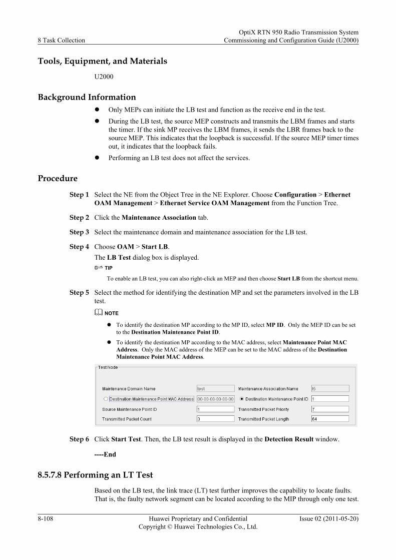
Tools, Equipment, and Materials
U2000
Background Informationl Only MEPs can initiate the LB test and function as the receive end in the test.
l During the LB test, the source MEP constructs and transmits the LBM frames and startsthe timer. If the sink MP receives the LBM frames, it sends the LBR frames back to thesource MEP. This indicates that the loopback is successful. If the source MEP timer timesout, it indicates that the loopback fails.
l Performing an LB test does not affect the services.
Procedure
Step 1 Select the NE from the Object Tree in the NE Explorer. Choose Configuration > EthernetOAM Management > Ethernet Service OAM Management from the Function Tree.
Step 2 Click the Maintenance Association tab.
Step 3 Select the maintenance domain and maintenance association for the LB test.
Step 4 Choose OAM > Start LB.The LB Test dialog box is displayed.
TIP
To enable an LB test, you can also right-click an MEP and then choose Start LB from the shortcut menu.
Step 5 Select the method for identifying the destination MP and set the parameters involved in the LBtest.
NOTE
l To identify the destination MP according to the MP ID, select MP ID. Only the MEP ID can be setto the Destination Maintenance Point ID.
l To identify the destination MP according to the MAC address, select Maintenance Point MACAddress. Only the MAC address of the MEP can be set to the MAC address of the DestinationMaintenance Point MAC Address.
Step 6 Click Start Test. Then, the LB test result is displayed in the Detection Result window.
----End
8.5.7.8 Performing an LT Test
Based on the LB test, the link trace (LT) test further improves the capability to locate faults.That is, the faulty network segment can be located according to the MIP through only one test.
8 Task CollectionOptiX RTN 950 Radio Transmission System
Commissioning and Configuration Guide (U2000)
8-108 Huawei Proprietary and ConfidentialCopyright © Huawei Technologies Co., Ltd.
Issue 02 (2011-05-20)
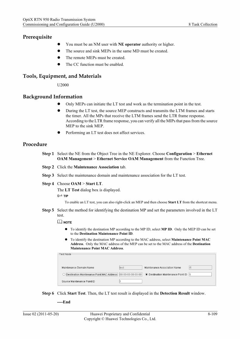
Prerequisitel You must be an NM user with NE operator authority or higher.l The source and sink MEPs in the same MD must be created.l The remote MEPs must be created.l The CC function must be enabled.
Tools, Equipment, and MaterialsU2000
Background Informationl Only MEPs can initiate the LT test and work as the termination point in the test.l During the LT test, the source MEP constructs and transmits the LTM frames and starts
the timer. All the MPs that receive the LTM frames send the LTR frame response.According to the LTR frame response, you can verify all the MIPs that pass from the sourceMEP to the sink MEP.
l Performing an LT test does not affect services.
Procedure
Step 1 Select the NE from the Object Tree in the NE Explorer. Choose Configuration > EthernetOAM Management > Ethernet Service OAM Management from the Function Tree.
Step 2 Click the Maintenance Association tab.
Step 3 Select the maintenance domain and maintenance association for the LT test.
Step 4 Choose OAM > Start LT.The LT Test dialog box is displayed.
TIP
To enable an LT test, you can also right-click an MEP and then choose Start LT from the shortcut menu.
Step 5 Select the method for identifying the destination MP and set the parameters involved in the LTtest.
NOTE
l To identify the destination MP according to the MP ID, select MP ID. Only the MEP ID can be setto the Destination Maintenance Point ID.
l To identify the destination MP according to the MAC address, select Maintenance Point MACAddress. Only the MAC address of the MEP can be set to the MAC address of the DestinationMaintenance Point MAC Address.
Step 6 Click Start Test. Then, the LT test result is displayed in the Detection Result window.
----End
OptiX RTN 950 Radio Transmission SystemCommissioning and Configuration Guide (U2000) 8 Task Collection
Issue 02 (2011-05-20) Huawei Proprietary and ConfidentialCopyright © Huawei Technologies Co., Ltd.
8-109
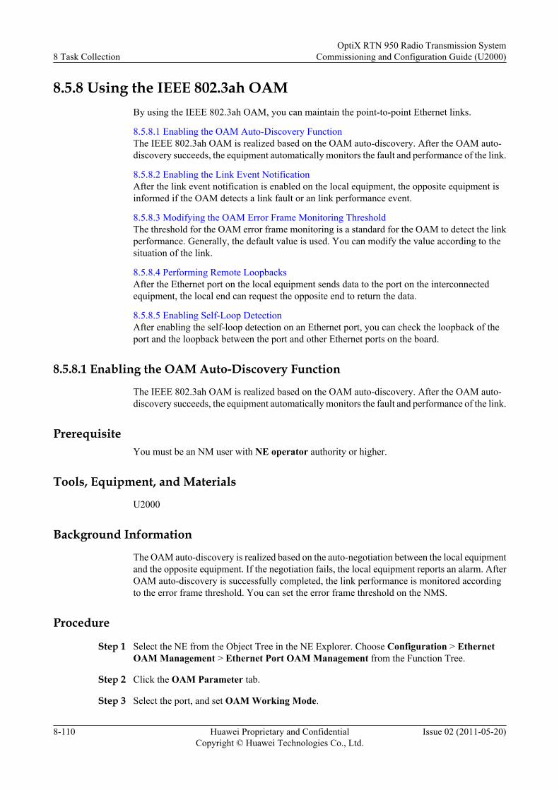
8.5.8 Using the IEEE 802.3ah OAMBy using the IEEE 802.3ah OAM, you can maintain the point-to-point Ethernet links.
8.5.8.1 Enabling the OAM Auto-Discovery FunctionThe IEEE 802.3ah OAM is realized based on the OAM auto-discovery. After the OAM auto-discovery succeeds, the equipment automatically monitors the fault and performance of the link.
8.5.8.2 Enabling the Link Event NotificationAfter the link event notification is enabled on the local equipment, the opposite equipment isinformed if the OAM detects a link fault or an link performance event.
8.5.8.3 Modifying the OAM Error Frame Monitoring ThresholdThe threshold for the OAM error frame monitoring is a standard for the OAM to detect the linkperformance. Generally, the default value is used. You can modify the value according to thesituation of the link.
8.5.8.4 Performing Remote LoopbacksAfter the Ethernet port on the local equipment sends data to the port on the interconnectedequipment, the local end can request the opposite end to return the data.
8.5.8.5 Enabling Self-Loop DetectionAfter enabling the self-loop detection on an Ethernet port, you can check the loopback of theport and the loopback between the port and other Ethernet ports on the board.
8.5.8.1 Enabling the OAM Auto-Discovery Function
The IEEE 802.3ah OAM is realized based on the OAM auto-discovery. After the OAM auto-discovery succeeds, the equipment automatically monitors the fault and performance of the link.
PrerequisiteYou must be an NM user with NE operator authority or higher.
Tools, Equipment, and Materials
U2000
Background Information
The OAM auto-discovery is realized based on the auto-negotiation between the local equipmentand the opposite equipment. If the negotiation fails, the local equipment reports an alarm. AfterOAM auto-discovery is successfully completed, the link performance is monitored accordingto the error frame threshold. You can set the error frame threshold on the NMS.
Procedure
Step 1 Select the NE from the Object Tree in the NE Explorer. Choose Configuration > EthernetOAM Management > Ethernet Port OAM Management from the Function Tree.
Step 2 Click the OAM Parameter tab.
Step 3 Select the port, and set OAM Working Mode.
8 Task CollectionOptiX RTN 950 Radio Transmission System
Commissioning and Configuration Guide (U2000)
8-110 Huawei Proprietary and ConfidentialCopyright © Huawei Technologies Co., Ltd.
Issue 02 (2011-05-20)
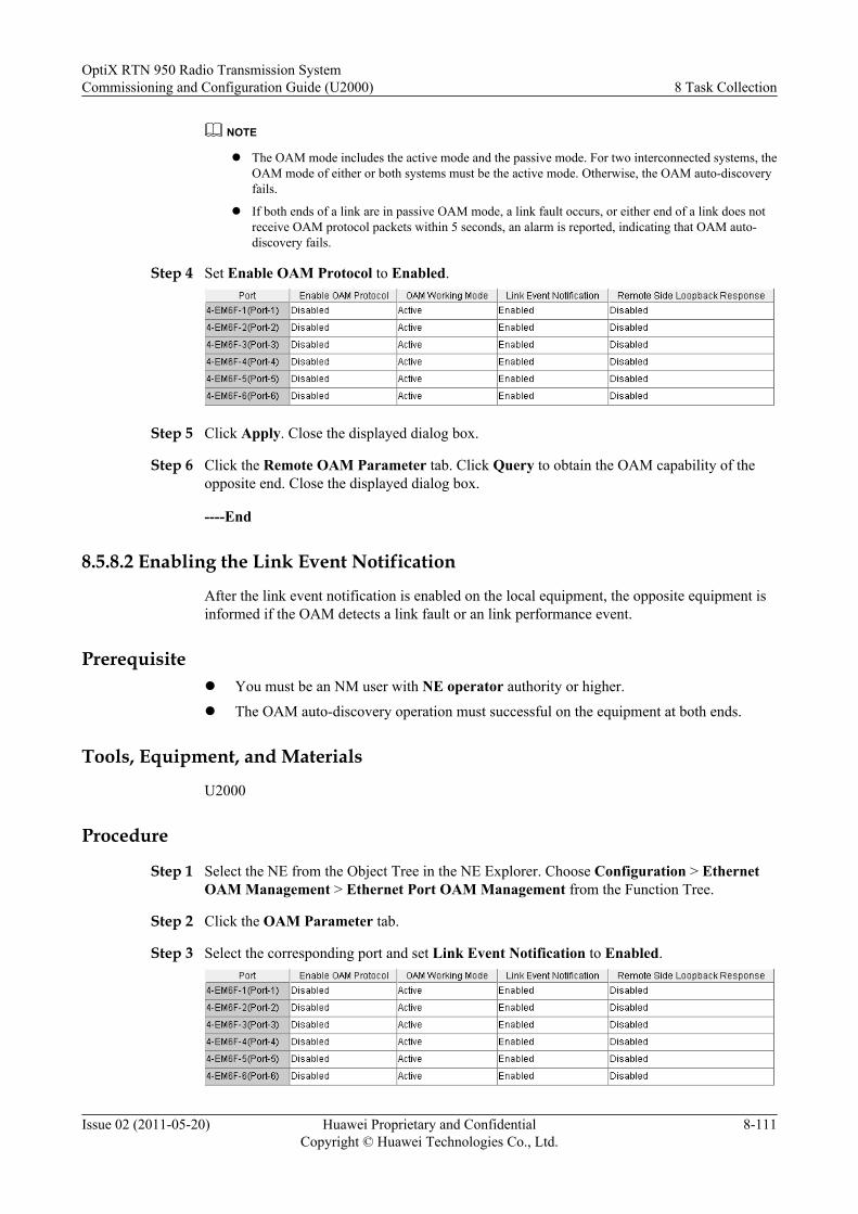
NOTE
l The OAM mode includes the active mode and the passive mode. For two interconnected systems, theOAM mode of either or both systems must be the active mode. Otherwise, the OAM auto-discoveryfails.
l If both ends of a link are in passive OAM mode, a link fault occurs, or either end of a link does notreceive OAM protocol packets within 5 seconds, an alarm is reported, indicating that OAM auto-discovery fails.
Step 4 Set Enable OAM Protocol to Enabled.
Step 5 Click Apply. Close the displayed dialog box.
Step 6 Click the Remote OAM Parameter tab. Click Query to obtain the OAM capability of theopposite end. Close the displayed dialog box.
----End
8.5.8.2 Enabling the Link Event Notification
After the link event notification is enabled on the local equipment, the opposite equipment isinformed if the OAM detects a link fault or an link performance event.
Prerequisitel You must be an NM user with NE operator authority or higher.
l The OAM auto-discovery operation must successful on the equipment at both ends.
Tools, Equipment, and Materials
U2000
Procedure
Step 1 Select the NE from the Object Tree in the NE Explorer. Choose Configuration > EthernetOAM Management > Ethernet Port OAM Management from the Function Tree.
Step 2 Click the OAM Parameter tab.
Step 3 Select the corresponding port and set Link Event Notification to Enabled.
OptiX RTN 950 Radio Transmission SystemCommissioning and Configuration Guide (U2000) 8 Task Collection
Issue 02 (2011-05-20) Huawei Proprietary and ConfidentialCopyright © Huawei Technologies Co., Ltd.
8-111
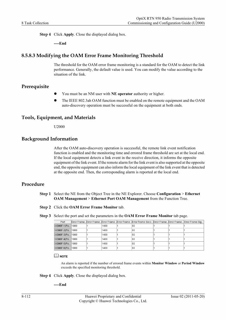
Step 4 Click Apply. Close the displayed dialog box.
----End
8.5.8.3 Modifying the OAM Error Frame Monitoring Threshold
The threshold for the OAM error frame monitoring is a standard for the OAM to detect the linkperformance. Generally, the default value is used. You can modify the value according to thesituation of the link.
Prerequisitel You must be an NM user with NE operator authority or higher.
l The IEEE 802.3ah OAM function must be enabled on the remote equipment and the OAMauto-discovery operation must be successful on the equipment at both ends.
Tools, Equipment, and Materials
U2000
Background Information
After the OAM auto-discovery operation is successful, the remote link event notificationfunction is enabled and the monitoring time and errored frame threshold are set at the local end.If the local equipment detects a link event in the receive direction, it informs the oppositeequipment of the link event. If the remote alarm for the link event is also supported at the oppositeend, the opposite equipment can also inform the local equipment of the link event that is detectedat the opposite end. Then, the corresponding alarm is reported at the local end.
Procedure
Step 1 Select the NE from the Object Tree in the NE Explorer. Choose Configuration > EthernetOAM Management > Ethernet Port OAM Management from the Function Tree.
Step 2 Click the OAM Error Frame Monitor tab.
Step 3 Select the port and set the parameters in the OAM Error Frame Monitor tab page.
NOTE
An alarm is reported if the number of errored frame events within Monitor Window or Period Windowexceeds the specified monitoring threshold.
Step 4 Click Apply. Close the displayed dialog box.
----End
8 Task CollectionOptiX RTN 950 Radio Transmission System
Commissioning and Configuration Guide (U2000)
8-112 Huawei Proprietary and ConfidentialCopyright © Huawei Technologies Co., Ltd.
Issue 02 (2011-05-20)
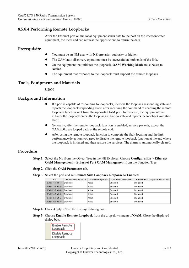
8.5.8.4 Performing Remote LoopbacksAfter the Ethernet port on the local equipment sends data to the port on the interconnectedequipment, the local end can request the opposite end to return the data.
Prerequisitel You must be an NM user with NE operator authority or higher.l The OAM auto-discovery operation must be successful at both ends of the link.l On the equipment that initiates the loopback, OAM Working Mode must be set to
Active.l The equipment that responds to the loopback must support the remote loopback.
Tools, Equipment, and MaterialsU2000
Background Informationl If a port is capable of responding to loopbacks, it enters the loopback responding state and
reports the loopback responding alarm after receiving the command of enabling the remoteloopback function sent from the opposite OAM port. In this case, the equipment thatinitiates the loopback enters the loopback initiation state and reports the loopback initiationalarm.
l Generally, after the remote loopback function is enabled, service packets, except theOAMPDU, are looped back at the remote end.
l After using the remote loopback function to complete the fault locating and the linkperformance detection, you need to disable the remote loopback function at the end wherethe loopback is initiated and then restore the services. The alarm is automatically cleared.
ProcedureStep 1 Select the NE from the Object Tree in the NE Explorer. Choose Configuration > Ethernet
OAM Management > Ethernet Port OAM Management from the Function Tree.
Step 2 Click the OAM Parameter tab.
Step 3 Select the port and set Remote Side Loopback Response to Enabled.
Step 4 Click Apply. Close the displayed dialog box.
Step 5 Choose Enable Remote Loopback from the drop-down menu of OAM. Close the displayeddialog box.
OptiX RTN 950 Radio Transmission SystemCommissioning and Configuration Guide (U2000) 8 Task Collection
Issue 02 (2011-05-20) Huawei Proprietary and ConfidentialCopyright © Huawei Technologies Co., Ltd.
8-113

NOTE
To release remote loopbacks, select Disable Remote Loopback.
----End
8.5.8.5 Enabling Self-Loop DetectionAfter enabling the self-loop detection on an Ethernet port, you can check the loopback of theport and the loopback between the port and other Ethernet ports on the board.
Prerequisitel You must be an NM user with NE operator authority or higher.l The required board is already added on the NE Panel.l All the external physical ports on the Ethernet service processing board must be enabled.
Tools, Equipment, and MaterialsU2000
Procedure
Step 1 Select the NE from the Object Tree in the NE Explorer. Choose Configuration > InterfaceManagement > Ethernet Interface from the Function Tree.
Step 2 Click the Advanced Attributes tab.
Step 3 Set Loopback Check to Enabled.
Step 4 Click Apply. Close the displayed dialog box.
----End
8.5.9 Using the RMONRemote monitoring (RMON) is mainly used to monitor the data traffic on a network segmentor on the entire network. Currently, it is one of the widely used network management standards.
8.5.9.1 Browsing the Performance Data in the Statistics Group of an Ethernet PortAfter you configure an RMON statistics group for an Ethernet port, you can browse the real-time statistical performance data of the port.
8.5.9.2 Configuring an Alarm Group for an Ethernet PortAfter you configure an RMON alarm group for an Ethernet port, you can monitor whether theperformance value of the port crosses the configured thresholds in the long term.
8.5.9.3 Configuring a Historical Control GroupWhen configuring a historical control group for an Ethernet port, you can configure how thehistorical performance data of the port is monitored. The Ethernet board monitors the historicalperformance data of each port at the default sampling interval of 30 minutes. A maximum of 50historical performance entries can be saved.
8.5.9.4 Browsing the Performance Data in the Historical Group of an Ethernet PortAfter you configure an RMON historical group for an Ethernet port, you can browse the historicalperformance data of the port.
8 Task CollectionOptiX RTN 950 Radio Transmission System
Commissioning and Configuration Guide (U2000)
8-114 Huawei Proprietary and ConfidentialCopyright © Huawei Technologies Co., Ltd.
Issue 02 (2011-05-20)
8.5.9.1 Browsing the Performance Data in the Statistics Group of an Ethernet PortAfter you configure an RMON statistics group for an Ethernet port, you can browse the real-time statistical performance data of the port.
Prerequisitel You must be an NM user with NE operator authority or higher.l The corresponding board must be added in the NE Panel.
Tools, Equipment, and MaterialsU2000
Procedure
Step 1 Select the corresponding board from the Object Tree in the NE Explorer. ChoosePerformance > RMON Performance from the Function Tree.
Step 2 Click the Statistics Group tab.
Step 3 Set the required parameters for the statistics group.1. Select the performance items for which statistics need to be collected.2. Set Sampling Interval.
Sampling Interval represents the time unit of the performance statistics.
Step 4 Click Resetting begins.
NOTE
If you click Start, the register of the statistics group is not reset to clear the existing data.
----End
8.5.9.2 Configuring an Alarm Group for an Ethernet PortAfter you configure an RMON alarm group for an Ethernet port, you can monitor whether theperformance value of the port crosses the configured thresholds in the long term.
Prerequisitel You must be an NM user with NE operator authority or higher.l The corresponding boards must be added in the NE Panel.
Tools, Equipment, and MaterialsU2000
Procedure
Step 1 Select the corresponding board from the Object Tree in the NE Explorer. ChoosePerformance > RMON Performance from the Function Tree.
Step 2 Click the RMON Setting tab.
OptiX RTN 950 Radio Transmission SystemCommissioning and Configuration Guide (U2000) 8 Task Collection
Issue 02 (2011-05-20) Huawei Proprietary and ConfidentialCopyright © Huawei Technologies Co., Ltd.
8-115
Step 3 Click the Object tab and set the corresponding parameters.
Step 4 Click the Event tab and set the corresponding parameters.
Step 5 Click Apply. Close the displayed dialog box.
----End
8.5.9.3 Configuring a Historical Control Group
When configuring a historical control group for an Ethernet port, you can configure how thehistorical performance data of the port is monitored. The Ethernet board monitors the historicalperformance data of each port at the default sampling interval of 30 minutes. A maximum of 50historical performance entries can be saved.
Prerequisitel You must be an NM user with NE operator authority or higher.
l The corresponding boards must be added in the NE Panel.
Tools, Equipment, and Materials
U2000
Procedure
Step 1 Select the NE from the Object Tree in the NE Explorer. Choose Performance > RMON HistoryControl Group.
Step 2 Set the parameters of the historical control group.
NOTE
l Sampling Interval(s) represents the time span of the RMON performance item whose statistics arecollected. For Custom Period1, Sampling Interval(s) can range from 300s to 43200s. For CustomPeriod2, Sampling Interval(s) can range from 300s to 86400s. The step for Sampling Interval(s) is30s.
l Number of Items represents the number of RMON performance items whose statistics can be collectedat the same time. The maximum value for this parameter is 50.
Step 3 Click Apply. Close the displayed dialog box.
----End
8.5.9.4 Browsing the Performance Data in the Historical Group of an Ethernet Port
After you configure an RMON historical group for an Ethernet port, you can browse the historicalperformance data of the port.
Prerequisitel You must be an NM user with NE operator authority or higher.
l The corresponding boards must be added in the NE Panel.l The objects and performance events to be monitored must be set.
8 Task CollectionOptiX RTN 950 Radio Transmission System
Commissioning and Configuration Guide (U2000)
8-116 Huawei Proprietary and ConfidentialCopyright © Huawei Technologies Co., Ltd.
Issue 02 (2011-05-20)
Tools, Equipment, and MaterialsU2000
Procedure
Step 1 Select the corresponding board from the Object Tree in the NE Explorer. ChoosePerformance > RMON Performance from the Function Tree.
Step 2 Click the History Group tab.
Step 3 Set the parameters of the historical group.1. Select the target port from Object.2. Click and specify the required time span.3. Select the performance items to browse.4. Under History Table Type, set the time span for the performance items to be browsed.
Step 4 Click Query.
----End
8.6 Managing the ClockTo ensure the clock synchronization between transmission nodes on a transport network, youneed to manage the NE clock.
8.6.1 Configuring the Clock SourcesThis topic describes how to configure the clock source according to the planned clocksynchronization scheme to ensure that all the NEs on the network trace the same clock.
8.6.2 Configuring Clock SubnetsFor simple networks, such as chain networks, configure the clock source protection or onlyconfigure the clock priority to implement the clock source protection. For complex networks,such as ring networks or intersecting and tangent rings that are derived from ring networks,configure clock subnets and enable the standard SSM protocol or extended SSM protocol toimplement the clock source protection.
8.6.3 User-Defined Clock QualityBy default, the NE considers the clock quality extracted from the clock source as the clockquality. If the clock quality is zero (the synchronization quality is unknown), the clock isconsidered as unavailable clock. In the case of any special requirements, the user can define theclock quality for which the source clock quality and clock quality are zero.
8.6.4 Configuring the SSM Output StatusAfter the standard SSM protocol or extended synchronization status message (SSM) protocol isenabled, the NE transmits the SSM to other NEs through the radio link or optical line by default.To prevent two clock subnets from affecting each other, the NE needs to forbid the SSM bytesfrom being transmitted on the link that is connected to other clock subnets.
8.6.5 Configuring the Clock ID Output StatusAfter the extended synchronization status message (SSM) protocol is enabled, the NE transmitsthe clock ID to other NEs through the radio link or optical line by default. To prevent two clocksubnets from affecting each other, the NE needs to forbid the clock ID from being transmittedon the link that is connected to other clock subnets.
OptiX RTN 950 Radio Transmission SystemCommissioning and Configuration Guide (U2000) 8 Task Collection
Issue 02 (2011-05-20) Huawei Proprietary and ConfidentialCopyright © Huawei Technologies Co., Ltd.
8-117

8.6.6 Modifying the Recovery Parameter of the Clock SourceIn the case of the special requirements, you can modify the recovery parameter of the clocksource.
8.6.7 Querying the Clock Synchronization StatusYou can know the current clock synchronization status of an NE by querying the clocksynchronization status.
8.6.1 Configuring the Clock SourcesThis topic describes how to configure the clock source according to the planned clocksynchronization scheme to ensure that all the NEs on the network trace the same clock.
Prerequisite
You must be an NM user with NE operator authority or higher.
Tools, Equipment, and Materials
U2000
Procedure
Step 1 Select the NE from the Object Tree in the NE Explorer. Choose Configuration > Clock >Physical Clock > Clock Source Priority.
Step 2 Click the System Clock Source Priority List tab.
Step 3 Click Create.The Add Clock Source dialog box is displayed.
Step 4 Select the clock sources.TIP
Hold the Ctrl key on the keyboard to select multiple clock sources.
Step 5 Click OK.
Step 6 Optional: Repeat Step 3 to Step 5 to add other clock sources.
Step 7 Optional: Select a clock source and click or to adjust the priority of thisclock source.
8 Task CollectionOptiX RTN 950 Radio Transmission System
Commissioning and Configuration Guide (U2000)
8-118 Huawei Proprietary and ConfidentialCopyright © Huawei Technologies Co., Ltd.
Issue 02 (2011-05-20)
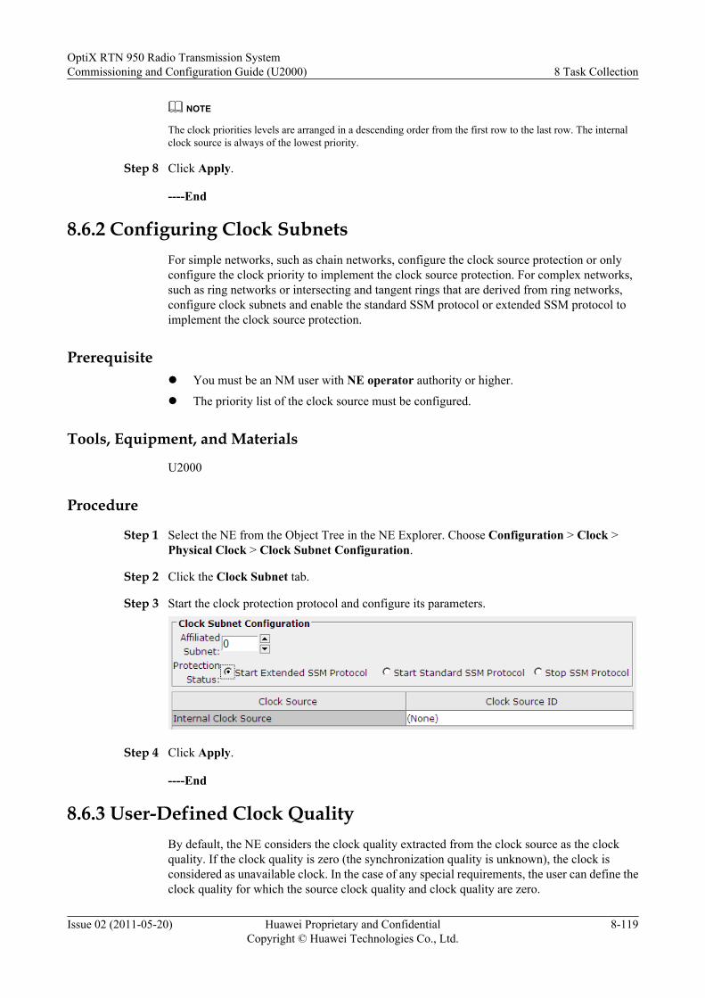
NOTE
The clock priorities levels are arranged in a descending order from the first row to the last row. The internalclock source is always of the lowest priority.
Step 8 Click Apply.
----End
8.6.2 Configuring Clock SubnetsFor simple networks, such as chain networks, configure the clock source protection or onlyconfigure the clock priority to implement the clock source protection. For complex networks,such as ring networks or intersecting and tangent rings that are derived from ring networks,configure clock subnets and enable the standard SSM protocol or extended SSM protocol toimplement the clock source protection.
Prerequisitel You must be an NM user with NE operator authority or higher.
l The priority list of the clock source must be configured.
Tools, Equipment, and Materials
U2000
Procedure
Step 1 Select the NE from the Object Tree in the NE Explorer. Choose Configuration > Clock >Physical Clock > Clock Subnet Configuration.
Step 2 Click the Clock Subnet tab.
Step 3 Start the clock protection protocol and configure its parameters.
Step 4 Click Apply.
----End
8.6.3 User-Defined Clock QualityBy default, the NE considers the clock quality extracted from the clock source as the clockquality. If the clock quality is zero (the synchronization quality is unknown), the clock isconsidered as unavailable clock. In the case of any special requirements, the user can define theclock quality for which the source clock quality and clock quality are zero.
OptiX RTN 950 Radio Transmission SystemCommissioning and Configuration Guide (U2000) 8 Task Collection
Issue 02 (2011-05-20) Huawei Proprietary and ConfidentialCopyright © Huawei Technologies Co., Ltd.
8-119
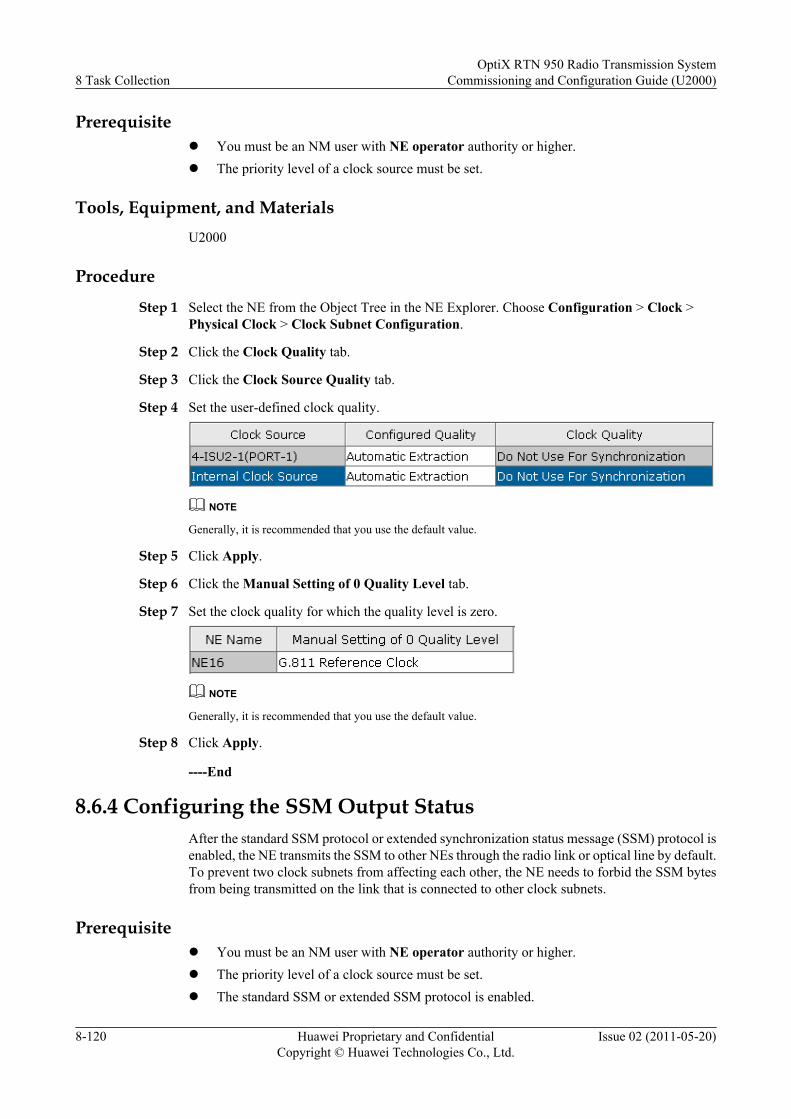
Prerequisitel You must be an NM user with NE operator authority or higher.l The priority level of a clock source must be set.
Tools, Equipment, and MaterialsU2000
Procedure
Step 1 Select the NE from the Object Tree in the NE Explorer. Choose Configuration > Clock >Physical Clock > Clock Subnet Configuration.
Step 2 Click the Clock Quality tab.
Step 3 Click the Clock Source Quality tab.
Step 4 Set the user-defined clock quality.
NOTE
Generally, it is recommended that you use the default value.
Step 5 Click Apply.
Step 6 Click the Manual Setting of 0 Quality Level tab.
Step 7 Set the clock quality for which the quality level is zero.
NOTE
Generally, it is recommended that you use the default value.
Step 8 Click Apply.
----End
8.6.4 Configuring the SSM Output StatusAfter the standard SSM protocol or extended synchronization status message (SSM) protocol isenabled, the NE transmits the SSM to other NEs through the radio link or optical line by default.To prevent two clock subnets from affecting each other, the NE needs to forbid the SSM bytesfrom being transmitted on the link that is connected to other clock subnets.
Prerequisitel You must be an NM user with NE operator authority or higher.l The priority level of a clock source must be set.l The standard SSM or extended SSM protocol is enabled.
8 Task CollectionOptiX RTN 950 Radio Transmission System
Commissioning and Configuration Guide (U2000)
8-120 Huawei Proprietary and ConfidentialCopyright © Huawei Technologies Co., Ltd.
Issue 02 (2011-05-20)
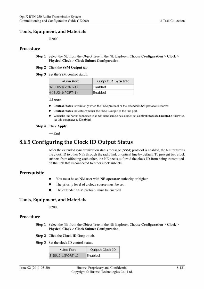
Tools, Equipment, and MaterialsU2000
ProcedureStep 1 Select the NE from the Object Tree in the NE Explorer. Choose Configuration > Clock >
Physical Clock > Clock Subnet Configuration.
Step 2 Click the SSM Output tab.
Step 3 Set the SSM control status.
NOTE
l Control Status is valid only when the SSM protocol or the extended SSM protocol is started.l Control Status indicates whether the SSM is output at the line port.l When the line port is connected to an NE in the same clock subnet, set Control Status to Enabled. Otherwise,
set this parameter to Disabled.
Step 4 Click Apply.
----End
8.6.5 Configuring the Clock ID Output StatusAfter the extended synchronization status message (SSM) protocol is enabled, the NE transmitsthe clock ID to other NEs through the radio link or optical line by default. To prevent two clocksubnets from affecting each other, the NE needs to forbid the clock ID from being transmittedon the link that is connected to other clock subnets.
Prerequisitel You must be an NM user with NE operator authority or higher.l The priority level of a clock source must be set.l The extended SSM protocol must be enabled.
Tools, Equipment, and MaterialsU2000
ProcedureStep 1 Select the NE from the Object Tree in the NE Explorer. Choose Configuration > Clock >
Physical Clock > Clock Subnet Configuration.
Step 2 Click the Clock ID Output tab.
Step 3 Set the clock ID control status.
OptiX RTN 950 Radio Transmission SystemCommissioning and Configuration Guide (U2000) 8 Task Collection
Issue 02 (2011-05-20) Huawei Proprietary and ConfidentialCopyright © Huawei Technologies Co., Ltd.
8-121
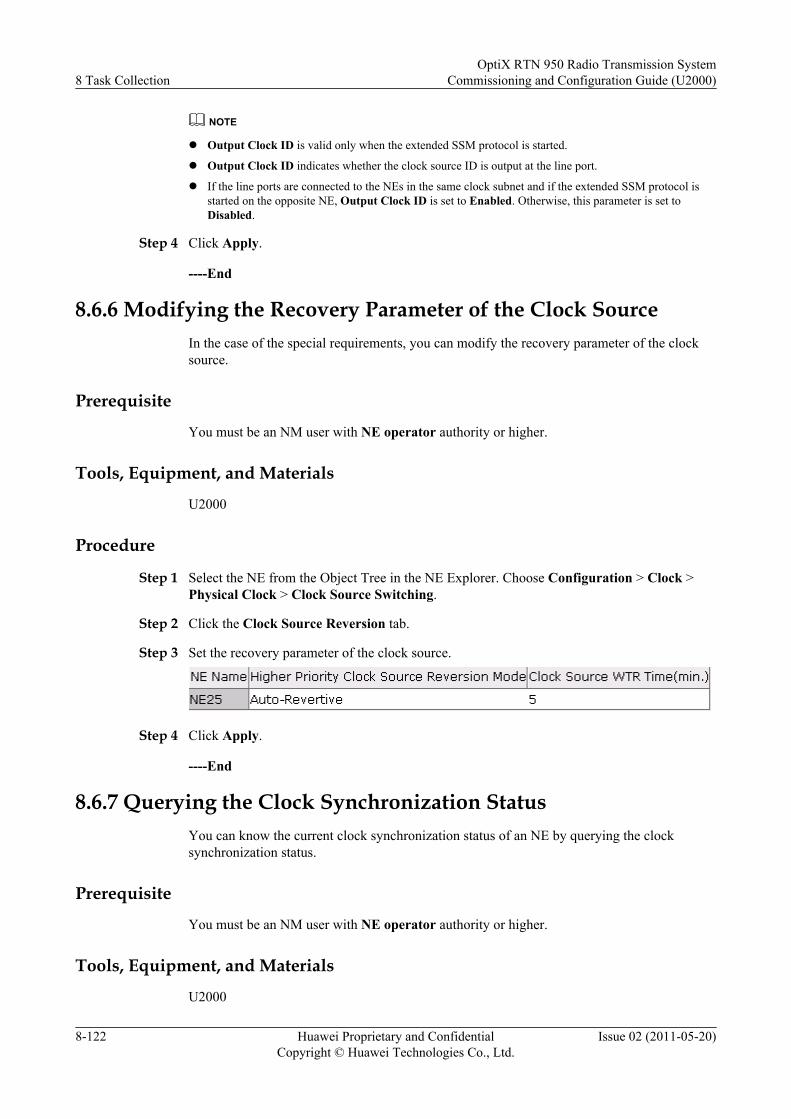
NOTE
l Output Clock ID is valid only when the extended SSM protocol is started.
l Output Clock ID indicates whether the clock source ID is output at the line port.
l If the line ports are connected to the NEs in the same clock subnet and if the extended SSM protocol isstarted on the opposite NE, Output Clock ID is set to Enabled. Otherwise, this parameter is set toDisabled.
Step 4 Click Apply.
----End
8.6.6 Modifying the Recovery Parameter of the Clock SourceIn the case of the special requirements, you can modify the recovery parameter of the clocksource.
Prerequisite
You must be an NM user with NE operator authority or higher.
Tools, Equipment, and Materials
U2000
Procedure
Step 1 Select the NE from the Object Tree in the NE Explorer. Choose Configuration > Clock >Physical Clock > Clock Source Switching.
Step 2 Click the Clock Source Reversion tab.
Step 3 Set the recovery parameter of the clock source.
Step 4 Click Apply.
----End
8.6.7 Querying the Clock Synchronization StatusYou can know the current clock synchronization status of an NE by querying the clocksynchronization status.
Prerequisite
You must be an NM user with NE operator authority or higher.
Tools, Equipment, and Materials
U2000
8 Task CollectionOptiX RTN 950 Radio Transmission System
Commissioning and Configuration Guide (U2000)
8-122 Huawei Proprietary and ConfidentialCopyright © Huawei Technologies Co., Ltd.
Issue 02 (2011-05-20)

Procedure
Step 1 Select the NE from the Object Tree in the NE Explorer. Choose Configuration > Clock >Physical Clock > Clock Synchronization Status.
Step 2 Click Query.
Step 3 Query the clock synchronization status.
----End
OptiX RTN 950 Radio Transmission SystemCommissioning and Configuration Guide (U2000) 8 Task Collection
Issue 02 (2011-05-20) Huawei Proprietary and ConfidentialCopyright © Huawei Technologies Co., Ltd.
8-123
Related Documents