Huawei HERT BBU Software Platform (Version: HERTBBU V200R007C01SPC040B811) Security Target Huawei HERT BBU Software Platform Security Target ST Version: 1.10 Last Update: Nov 01, 2011 Author: Huawei Technologies Co., Ltd. Huawei Technologies Co., Ltd. Classification: Huawei confidential Page 1

Welcome message from author
This document is posted to help you gain knowledge. Please leave a comment to let me know what you think about it! Share it to your friends and learn new things together.
Transcript
Huawei HERT BBU Software Platform (Version: HERTBBU V200R007C01SPC040B811) Security Target
Huawei HERT BBU Software Platform Security Target
ST Version: 1.10 Last Update: Nov 01, 2011 Author: Huawei Technologies Co., Ltd.
Huawei Technologies Co., Ltd. Classification: Huawei confidential Page 1

Huawei HERT BBU Software Platform (Version: HERTBBU V200R007C01SPC040B811) Security Target
Table of Contents
1 INTRODUCTION......................................................................................................................6
1.1 ST reference.....................................................................................................................................6
1.2 TOE reference ..................................................................................................................................6
1.3 TOE overview...................................................................................................................................6 1.3.1 TOE usage ..................................................................................................................................... 6 1.3.2 TOE type ........................................................................................................................................ 8 1.3.3 Non TOE Hardware and Software............................................................................................ 8
1.4 TOE description .............................................................................................................................11 1.4.1 Physical Scope........................................................................................................................... 12 1.4.2 Logical Scope............................................................................................................................. 15
2 CC CONFORMANCE CLAIM................................................................................................ 21
3 SECURITY PROBLEM DEFINITION ................................................................................ 22
3.1 TOE assets .....................................................................................................................................22
3.2 Threats ..........................................................................................................................................22 3.2.1 Threats by Eavesdropper ........................................................................................................ 23 3.2.2 Threats by Interactive Network Attacker ............................................................................. 23 3.2.3 Threats by restricted authorized user .................................................................................. 24
3.3 Organizational Policies ...................................................................................................................24 3.3.1 P1.Audit........................................................................................................................................ 24
3.4 Assumptions..................................................................................................................................24 3.4.1 Physical........................................................................................................................................ 24 3.4.2 Personnel..................................................................................................................................... 24 3.4.3 Connectivity ................................................................................................................................ 24 3.4.4 Support......................................................................................................................................... 25 3.4.5 SecurePKI .................................................................................................................................... 25
4 SECURITY OBJECTIVES ..................................................................................................... 26
4.1 Security Objectives for the TOE ......................................................................................................26
4.2 Security Objectives for the Operational Environment .....................................................................26
4.3 Security Objectives Rationale......................................................................................................... 27 4.3.1 Coverage.......................................................................................................................................27 4.3.2 Sufficiency................................................................................................................................... 28
5 SECURITY REQUIREMENTS ............................................................................................. 30
Huawei Technologies Co., Ltd. Classification: Huawei confidential Page 2
Huawei HERT BBU Software Platform (Version: HERTBBU V200R007C01SPC040B811) Security Target
5.1 TOE Security Functional Requirements ...........................................................................................30 5.1.1 Security Audit (FAU) ................................................................................................................. 30 5.1.2 Cryptographic Support (FCS)................................................................................................. 31 5.1.3 User Data Protection (FDP) ..................................................................................................... 32 5.1.4 Identification and Authentication (FIA) ................................................................................ 35 5.1.5 Security Management (FMT)....................................................................................................37 5.1.6 TOE access (FTA) ...................................................................................................................... 38 5.1.7 Trusted path/channels (FTP) .................................................................................................. 39
5.2 Security Functional Requirements Rationale ..................................................................................39 5.2.1 Coverage...................................................................................................................................... 39 5.2.2 Sufficiency................................................................................................................................... 40 5.2.3 Security Requirements Dependency Rationale ................................................................. 42
5.3 Security Assurance Requirements ..................................................................................................43
5.4 Security Assurance Requirements Rationale...................................................................................44
6 TOE SUMMARY SPECIFICATION ..................................................................................... 45
6.1 TOE Security Functionality .............................................................................................................45 6.1.1 Authentication ............................................................................................................................ 45 6.1.2 Access control ........................................................................................................................... 46 6.1.3 Auditing.........................................................................................................................................47 6.1.4 Communications security ........................................................................................................47 6.1.5 Resource management ............................................................................................................ 48 6.1.6 Security function management.............................................................................................. 49 6.1.7 Digital signature......................................................................................................................... 50
7 ABBREVIATIONS, TERMINOLOGY AND REFERENCES............................................. 51
7.1 Abbreviations ................................................................................................................................51
7.2 Terminology...................................................................................................................................53
7.3 References.....................................................................................................................................53
List of Tables
Table 1 Description for board in BBU system .......................................................................10 Table 2 BBU external interface ................................................................................................11 Table 3 List of the files and documents required for the products ....................................14 Table 4 TOE assets....................................................................................................................22 Table 5 The threat agents of The TOE ....................................................................................23 Table 6 Mapping of the Security Objectives ..........................................................................28 Table 7 Sufficiency analysis for threats .................................................................................29 Table 8 Sufficiency analysis for assumptions.......................................................................29 Table 9 Sufficiency analysis for organizational security policy .........................................29 Table 10 Mapping SFRs to security objectives .......................................................................40 Table 11 SFR sufficiency analysis ............................................................................................42
Huawei Technologies Co., Ltd. Classification: Huawei confidential Page 3
Huawei HERT BBU Software Platform (Version: HERTBBU V200R007C01SPC040B811) Security Target
Table 12 Dependencies between TOE Security Functional Requirements .........................43
List of Figures
Figure 1 Non TOE Hardware and Software environment.........................................................................9 Figure 2 BBU Physical configuration.....................................................................................................10 Figure 3 TOE Physical architecture .......................................................................................................12 Figure 4 TOE Software architecture......................................................................................................15 Figure 5 The TOE logical scope .............................................................................................................19
Huawei Technologies Co., Ltd. Classification: Huawei confidential Page 4
Huawei HERT BBU Software Platform (Version: HERTBBU V200R007C01SPC040B811) Security Target
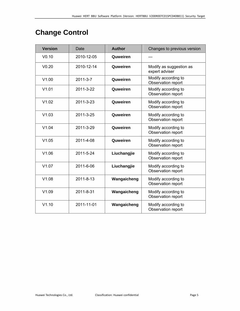
Change Control
Version Date Author Changes to previous version
V0.10 2010-12-05 Quweiren ---
V0.20 2010-12-14 Quweiren Modify as suggestion as expert adviser
V1.00 2011-3-7 Quweiren Modify according to Observation report
V1.01 2011-3-22 Quweiren Modify according to Observation report
V1.02 2011-3-23 Quweiren Modify according to Observation report
V1.03 2011-3-25 Quweiren Modify according to Observation report
V1.04 2011-3-29 Quweiren Modify according to Observation report
V1.05 2011-4-08 Quweiren Modify according to Observation report
V1.06 2011-5-24 Liuchangjie Modify according to Observation report
V1.07 2011-6-06 Liuchangjie Modify according to Observation report
V1.08 2011-8-13 Wangaicheng Modify according to Observation report
V1.09 2011-8-31 Wangaicheng Modify according to Observation report
V1.10 2011-11-01 Wangaicheng Modify according to Observation report
Huawei Technologies Co., Ltd. Classification: Huawei confidential Page 5

Huawei HERT BBU Software Platform (Version: HERTBBU V200R007C01SPC040B811) Security Target
1 Introduction This Security Target is for the CC evaluation of Huawei HERT BBU Software Platform (Huawei Enhanced Radio Technology Base Band Unit), which is the Huawei’s base station (BS) software platform. The TOE Version is HERTBBU V200R007C01SPC040B811.
1.1 ST reference
Title Huawei HERT BBU Software Platform Security Target
Version 1.10 Author Huawei Publication Date 2011-11-01
1.2 TOE reference
TOE Name Huawei HERT BBU Software Platform TOE Version HERTBBU V200R007C01SPC040B811 TOE Developer Huawei TOE Release Date 2011-08-24
In addition to the TOE Name indicated in the table above, the following reference is used, for the sake of simplicity, along the whole product documentation:
HERT BBU
1.3 TOE overview
Huawei’s Enhanced Radio Technology Base Band Unit (HERT BBU), the TOE is software for the management of base station(BS) devices, such as WIMAX/ W-NodeB/ E-NodeB, and may be other products in the future. It is commonly used as a component throughout a number of Huawei wireless products to offer management functionality for these products.
This ST contains a description of the security objectives and the requirements, as well as the necessary functional and assurance measures provided by the TOE. The ST provides the basis for the evaluation of the TOE according to the Common Criteria for Information Technology Security Evaluations (CC).
1.3.1 TOE usage
The TOE is Huawei’s base station software platform (HERT BBU) – in
Huawei Technologies Co., Ltd. Classification: Huawei confidential Page 6
Huawei HERT BBU Software Platform (Version: HERTBBU V200R007C01SPC040B811) Security Target
particular the software that provides the Operation Administration and Maintenance (OM) feature and transport management feature for base station devices to their users.
The OM feature possesses the following functions:
1. Configuration management; 2. Performance management; 3. Inventory management; 4. Log management; 5. Fault management; 6. Software management;
The transport management feature possesses the following functions:
1. ATM transport management; 2. IP transport management; 3. Flow separation;
HERT BBU is used in four Huawei’s particular products (WIMAX, E-NodeB, TD-NodeB ,W-NodeB and maybe other products in the future). The application-specific functionality of these products is out of scope for this evaluation.
The major security features implemented by HERT BBU and subject to evaluation are:
Authentication
Operators using local and remote access to the TOE in order to execute device management functions are identified by individual user names and authenticated by passwords.
Access control
HERT BBU implements role-based access control, limiting access to different management functionality to different roles as defined in administrator-defined access control associations.
Auditing
Audit records are created for security-relevant events related to the use of HERT BBU.
Communications security
HERT BBU offers SSL/TLS channels for FTP (File Transfer Protocol),
Huawei Technologies Co., Ltd. Classification: Huawei confidential Page 7

Huawei HERT BBU Software Platform (Version: HERTBBU V200R007C01SPC040B811) Security Target
MML (man-machine language which is kind of Command Line Interface), and BIN (Huawei’s private binary message protocol) access to the TOE, as well as the IPSec transport channels.
Resource management
VLAN (Virtual Local Area Network) are implemented to separate the traffic from different flow planes, which reduce traffic storms and avoid resource overhead.
Access Control List implemented Packet filtering features to restrict resource access via IP address, ports, etc. The features protect the HERT BBU platform shield against various unauthorized access from unauthorized network elements (NEs).
Security function management
The TOE offers management functionality for its security functionality.
Digital signature
In the production and distribution phases, the digital signature scheme, protect the software package by message digest and signature. The TOE verifies the software digital signature’s validity.
1.3.2 TOE type
The TOE is Huawei’s BS software platform that helps to build BS application software. The TOE implements basic functions of BS: security features, including identification and authentication, system access control, audit management, enforcement of network transmission against data peeking, management functionality to manage the security functions of HERT BBU, and digital signature validation to guarantee the confidentiality and integrity of the software packages that are deployed.
1.3.3 Non TOE Hardware and Software
The TOE is Huawei HERT BBU Software Platform. It is deployed on the boards of base band unit (BBU). These hardware boards provided by Huawei’s hardware platform are TOE environment. The OS (VxWorks) and part of BS software provided by Huawei’s particular products are also TOE environment.
Huawei Technologies Co., Ltd. Classification: Huawei confidential Page 8
Huawei HERT BBU Software Platform (Version: HERTBBU V200R007C01SPC040B811) Security Target
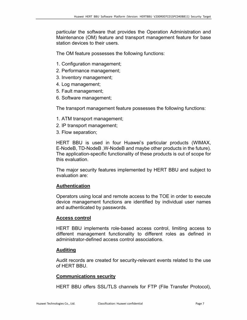
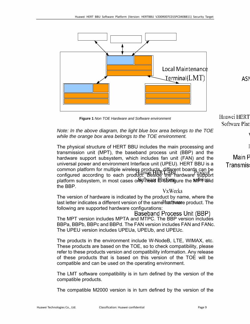
Figure 1 Non TOE Hardware and Software environment
Note: In the above diagram, the light blue box area belongs to the TOE while the orange box area belongs to the TOE environment.
The physical structure of HERT BBU includes the main processing and transmission unit (MPT), the baseband process unit (BBP) and the hardware support subsystem, which includes fan unit (FAN) and the universal power and environment Interface unit (UPEU). HERT BBU is a common platform for multiple wireless products, different boards can be configured according to each product. Beside the hardware support platform subsystem, in most cases only need to configure the MPT and the BBP.
The version of hardware is indicated by the product by name, where the last letter indicates a different version of the same hardware product. The following are supported hardware configurations:
The MPT version includes MPTA and MTPC. The BBP version includes BBPa, BBPb, BBPc and BBPd. The FAN version includes FAN and FANc. The UPEU version includes UPEUa, UPEUb, and UPEUc.
The products in the environment include W-NodeB, LTE, WIMAX, etc. These products are based on the TOE, so to check compatibility, please refer to these products version and compatibility information. Any release of these products that is based on this version of the TOE will be compatible and can be used on the operating environment.
The LMT software compatibility is in turn defined by the version of the compatible products.
The compatible M2000 version is in turn defined by the version of the
Huawei Technologies Co., Ltd. Classification: Huawei confidential Page 9
Huawei HERT BBU Software Platform (Version: HERTBBU V200R007C01SPC040B811) Security Target
compatible products.
HERT BBU Operating System: VxWorks, version 5.5.4
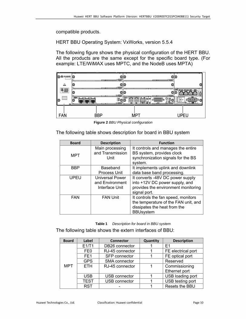
The following figure shows the physical configuration of the HERT BBU. All the products are the same except for the specific board type. (For example: LTE/WiMAX uses MPTC, and the NodeB uses MPTA)
Figure 2 BBU Physical configuration
The following table shows description for board in BBU system
Board Description Function
MPT
Main processing and Transmission
Unit
It controls and manages the entire BS system, provides clock synchronization signals for the BS system.
BBP Baseband Process Unit
It implements uplink and downlink data base band processing.
UPEU Universal Power and Environment
Interface Unit
It converts -48V DC power supply into +12V DC power supply, and provides the environment monitoring signal port.
FAN FAN Unit It controls the fan speed, monitors the temperature of the FAN unit, and dissipates the heat from the BBUsystem
Table 1 Description for board in BBU system
The following table shows the extern interfaces of BBU:
Board Label Connector Quantity Description E1/T1 DB26 connector 1 E1FE0 RJ-45 connector 1 FE electrical portFE1 SFP connector 1 FE optical portGPS SMA connector ReservedETH RJ-45 connector 1 Commissioning
Ethernet portUSB USB connector 1 USB loading portTEST USB connector 1 USB testing port
MPT
RST - 1 Resets the BBU
Huawei Technologies Co., Ltd. Classification: Huawei confidential Page 10
Huawei HERT BBU Software Platform (Version: HERTBBU V200R007C01SPC040B811) Security Target
BBP CPRI SFP female 3 Data transmission port between the BBU and the radio frequency module, supporting input and output of optical and electrical signals
PWR 3V3 1 Port for +24 V DC or -48 V DC input power
EXT-ALM0
RJ-45 1 Port for Boolean signal inputs 0 to 3
EXT-ALM1
RJ-45 1 Port for Boolean signal inputs 4 to 7
MON0 RJ-45 1 Port for RS485 signal input 0
UPEU
MON1 RJ-45 1 Port for RS485 signal input 1
Table 2 BBU external interface
SFP: small form-factor pluggable Rj-45: registered jack-45 FE: fast Ethernet ETH: Ethernet CPRI: common public radio interface GE: gigabit Ethernet E1: A European standard for high-speed data transmission at 2.048 Mbps. T1: A North American standard for high-speed data transmission at 1.544Mbps. SMA: Sub-Miniature-A STM-1: synchronous transport module of order 1 OC-3: optical carrier level 3
1.4 TOE description
The TOE is software for the management of base station (BS) devices, such as WIMAX, W-NodeB, E-NodeB, TD-NodeB, etc. It is commonly used as a component throughout a number of Huawei wireless products to offer management functionality for these products.
The TOE logical security features are Authentication, Role-based Access control, Communications security, Auditing, Security function management and Digital signature. The following sections provide a
Huawei Technologies Co., Ltd. Classification: Huawei confidential Page 11
Huawei HERT BBU Software Platform (Version: HERTBBU V200R007C01SPC040B811) Security Target
more detailed insight of the TOE architecture and scope.
1.4.1 Physical Scope
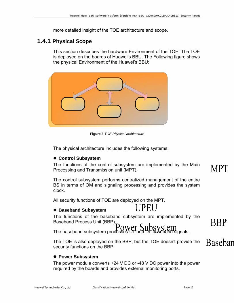
This section describes the hardware Environment of the TOE. The TOE is deployed on the boards of Huawei’s BBU. The Following figure shows the physical Environment of the Huawei’s BBU:
Figure 3 TOE Physical architecture
The physical architecture includes the following systems:
Control Subsystem The functions of the control subsystem are implemented by the Main Processing and Transmission unit (MPT).
The control subsystem performs centralized management of the entire BS in terms of OM and signaling processing and provides the system clock.
All security functions of TOE are deployed on the MPT.
Baseband Subsystem The functions of the baseband subsystem are implemented by the Baseband Process Unit (BBP).
The baseband subsystem processes UL and DL baseband signals.
The TOE is also deployed on the BBP, but the TOE doesn’t provide the security functions on the BBP.
Power Subsystem The power module converts +24 V DC or -48 V DC power into the power required by the boards and provides external monitoring ports.
Huawei Technologies Co., Ltd. Classification: Huawei confidential Page 12

Huawei HERT BBU Software Platform (Version: HERTBBU V200R007C01SPC040B811) Security Target
The TOE is not deployed on this Subsystem.
FAN Subsystem
The power module controls the fan speed, monitors the temperature of the FAN unit, and dissipates the heat in the BBU.
The TOE is not deployed on this Subsystem.
The release packages for HERT BBU is a set of library files, object files, header files, configuration files and documents. The products will link the HERT BBU’s object files with product’s object files to the executable binary files.
The release directory just like the following structure:
[HERT BBU V200R007C01SPC040B811] ├ [InnerDoc] ├ [ReleaseDoc] │ ├ [reference document] │ ├ [differentiation document] │ ├ [version specification] │ └ [relation with products] └ [Software] ├ [RB] └ [BBU] [InnerDoc]
This folder contains the report on the test, the report on the static check, and the report on the virus searching.
[ReleaseDoc]
[reference document]
This directory includes the documents provided with the products. The documents include the MML command references, alarm references, and release notes.
[differentiation document]
The directory includes the document which describes the interface changed information, the new feature list and defects fixed list.
Huawei Technologies Co., Ltd. Classification: Huawei confidential Page 13
Huawei HERT BBU Software Platform (Version: HERTBBU V200R007C01SPC040B811) Security Target
[version specification]
The directory includes the document which includes the usage notes, version compliance and version match relation.
[relation with products]
The directory includes the excel file which descript the match relation between HERT BBU version and the inner component version. The excel file also describe the product’s version which can use the HERT BBU version.
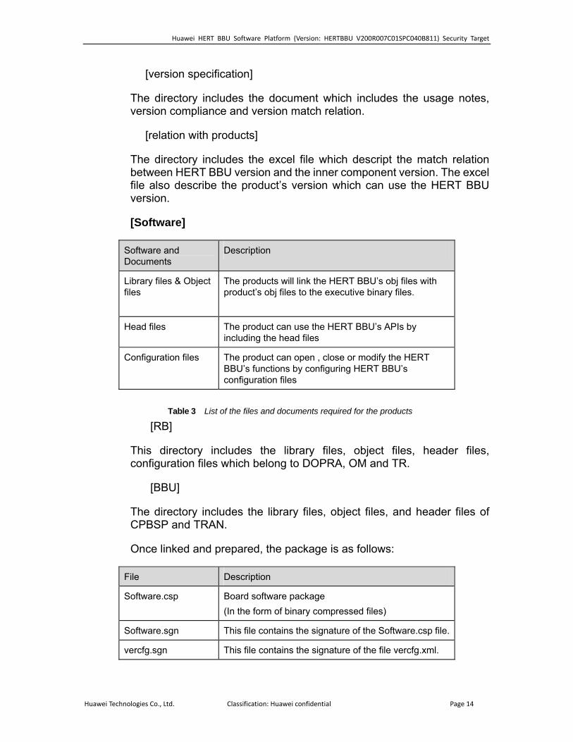
[Software]
Software and Documents
Description
Library files & Object files
The products will link the HERT BBU’s obj files with product’s obj files to the executive binary files.
Head files The product can use the HERT BBU’s APIs by including the head files
Configuration files The product can open , close or modify the HERT BBU’s functions by configuring HERT BBU’s configuration files
Table 3 List of the files and documents required for the products
[RB]
This directory includes the library files, object files, header files, configuration files which belong to DOPRA, OM and TR.
[BBU]
The directory includes the library files, object files, and header files of CPBSP and TRAN.
Once linked and prepared, the package is as follows:
File Description
Software.csp Board software package (In the form of binary compressed files)
Software.sgn This file contains the signature of the Software.csp file.
vercfg.sgn This file contains the signature of the file vercfg.xml.
Huawei Technologies Co., Ltd. Classification: Huawei confidential Page 14
Huawei HERT BBU Software Platform (Version: HERTBBU V200R007C01SPC040B811) Security Target
File Description
vercfg.xml Match relation between HERT BBU version and the inner component version.
1.4.2 Logical Scope
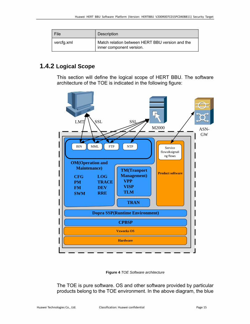
This section will define the logical scope of HERT BBU. The software architecture of the TOE is indicated in the following figure:
Hardware
Vxworks OS
M2000LMT
Product software
SSL SSL
NMI(Management flows)
TM(Tranport Management)
VPPVISPTLM
TRAN
CPBSP
Dopra SSP(Runtime Environment)
ASN-GW
Service flows&signali
ng flows
BIN MML FTP NTP
CFGPMFMSWM
LOGTRACEDEVRRE
OM(Operation and Maintenance)
Figure 4 TOE Software architecture
The TOE is pure software. OS and other software provided by particular products belong to the TOE environment. In the above diagram, the blue
Huawei Technologies Co., Ltd. Classification: Huawei confidential Page 15
Huawei HERT BBU Software Platform (Version: HERTBBU V200R007C01SPC040B811) Security Target
areas are parts of the TOE. HERT BBU includes Operation and Maintenance (OM), Product Service, and HERT platform.
The TOE security functionality, as stated in the section 1.4 TOE Overview is:
• Authentication.
• Access control.
• Auditing.
• Communications security.
• Resource management.
• Security functionality management.
• Digital signature.
As shown in Figure 4 Software Architecture, the TOE is entirely composed by software. The Operating System, and other software provided by particular products belong to the TOE environment. The TOE itself includes OM, Product Service, Transport Management, TRAN, CPBSP and Dopra SSP.
For each of the identified parts of the TOE, a correspondence between them and the TOE security functionality can be achieved. That way, for each part, the appropriate security associated functionality is indicated in the following table:
Element Part Associated security functionality
All the interfaces Resource management
Security Function Interface
Communications through the following protocols:
BIN: Huawei’s private binary message protocol.
MML: Man-Machine Language.
FTP: File transmission Protocol
Communications security
Huawei Technologies Co., Ltd. Classification: Huawei confidential Page 16

Huawei HERT BBU Software Platform (Version: HERTBBU V200R007C01SPC040B811) Security Target
NMI: network management interface: which is the interface for external element
NA
CFG: Configuration Management, responsible for the managed elements configuration.
Security functionality management
PM: Performance management, responsible for the calculation of performance data and the storage of it.
NA
FM: Fault management, which include fault and alarm monitoring.
NA
SWM: Software management, responsible for software upgrade and rollback.
Digital signature
LOG: Responsible for the audit and storage of security log and operational log.
Auditing
DEV: Management of the devices of HERT BBU
NA
TRACE: Responsible for the trace messages which show the state of the BS and MS within the HERT BBU network.
NA
Operation and Maintenance (OM)
RRE: Common service, responsible for basic service for other modules
NA
Transport Management (TM)
VPP: Voice Protocol Platform, which is composed of voice and signal processing component, such as XML Parser, Stream Control Transmission Protocol (SCTP) and Signaling ATM Adaptation Layer (SAAL).
VISP: Versatile IP and Security Platform, which provides TCP / IP protocol stack management interface.
TLM: Transport layer management. The functions include control and supervision of the transport bearer (data forwarding) functions, maintaining the transport resource assignment to product services.
Communication Security
TRAN Huawei's wireless transmission platform, which provide hardware driver
Communication Security
Huawei Technologies Co., Ltd. Classification: Huawei confidential Page 17
Huawei HERT BBU Software Platform (Version: HERTBBU V200R007C01SPC040B811) Security Target
management interface.
DOPRA SSP (Runtime Environment)
Provide Operating System mid-ware layer. It function includes: Operation System Adapter, Memory management, Timer management, etc.
NA
CPBSP Provide a standard API interface for the hardware.
NA
From the Logical point of view, the following figure includes the TOE Logical Scope, where all the connections to the TOE are indicated, and also the way the TOE is deployed in the different boards of the product:
Huawei Technologies Co., Ltd. Classification: Huawei confidential Page 18

Huawei HERT BBU Software Platform (Version: HERTBBU V200R007C01SPC040B811) Security Target
Figure 5 The TOE logical scope
The logical scope of the TOE includes local layer which is deployed in BBP and MPT. System control layer which is deployed in MPT.
System control and security management are performed on MPT board via a secure channel enforcing SSL. The management of the functionality of the TOE can be done through different interfaces:
• BIN/MML through an M2000 server providing management functions to the TOE (in the TOE environment).
Huawei Technologies Co., Ltd. Classification: Huawei confidential Page 19
Huawei HERT BBU Software Platform (Version: HERTBBU V200R007C01SPC040B811) Security Target
• LMT used by users to connect to the TOE for access through HERT BBU via a secure channel enforcing SSL.
Huawei Technologies Co., Ltd. Classification: Huawei confidential Page 20

Huawei HERT BBU Software Platform (Version: HERTBBU V200R007C01SPC040B811) Security Target
2 CC Conformance Claim This ST is CC Part 2 conformant [CC] and CC Part 3 conformant [CC]. The CC version of [CC] is 3.1R3.
This ST is EAL3 conformant as defined in [CC] Part 3, with the assurance level of EAL3 Augmented with ALC_CMC.4, ALC_CMS.4.
The methodology to be used for evaluation is CEM3.1 R3
No conformance to a Protection Profile is claimed.
Huawei Technologies Co., Ltd. Classification: Huawei confidential Page 21

Huawei HERT BBU Software Platform (Version: HERTBBU V200R007C01SPC040B811) Security Target
3 Security problem definition
3.1 TOE assets
The following table includes the assets that have been considered for the TOE:
Asset Description Asset value
A1.Software and patches
The integrity and confidentiality of the system software and the patches when in transit across the management network should be protected from modification and disclosure.
Integrity Confidentiality
A2.Stored configuration data
The integrity and confidentiality of the stored configuration data should be protected. Configuration data includes the security related parameters under the control of the TOE (such as user account information and passwords, audit records, etc).
Integrity Confidentiality
A3. In transit configuration data
The integrity and confidentiality of the configuration data when travelling in the management network.
Integrity Confidentiality
A4. Service Recoverability in terms of the capacity of recovery in case of denial of service. Recoverability
Table 4 TOE assets
3.2 Threats
This section of the security problem definition shows the threats that are to be countered by the TOE, its operational environment, or a combination of the two. The threat agents can be categorized as either:
Agent Description
Eavesdropper An eavesdropper from the management network served by the TOE is able to intercept, and potentially modify or re-use the data that is being sent to the TOE.
Internal attacker An unauthorized agent who is connected to the management network.
Restricted authorized user
An authorized user of the TOE in the management network who has been granted authority to access certain information and perform certain actions.
Huawei Technologies Co., Ltd. Classification: Huawei confidential Page 22

Huawei HERT BBU Software Platform (Version: HERTBBU V200R007C01SPC040B811) Security Target
Table 5 The threat agents of The TOE
In the first and second cases, the users are assumed to be potentially hostile with a clear motivation to get access to the data. In the last case, all authorized users of the TOE are entrusted with performing certain administrative or management activities with regard to the managed device. Consequently, organizational means are expected to be in place to establish a certain amount of trust into these users. However, accidental or casual attempts to perform actions or access data outside of their authorization are expected. The assumed security threats are listed below.
3.2.1 Threats by Eavesdropper
Threat: T1.InTransitConfiguration
Attack An eavesdropper in the management network succeeds in accessing the content of the BS file while transferring, violating its confidentiality or integrity.
Asset A3.In transit configuration data Agent Eavesdropper
Threat: T2. InTransitSoftware
Attack An eavesdropper in the management network succeeds in accessing the content of the BS software/patches while transferring, violating its confidentiality or integrity.
Asset A1.Software and patches; Agent Eavesdropper
3.2.2 Threats by Interactive Network Attacker
Threat: T3.UnwantedNetworkTraffic
Attack
Unwanted network traffic sent to the TOE will cause the TOE’s processing capacity for incoming network traffic to be consumed thus failing to process legitimate traffic. This may further causes the TOE fails to respond to system control and security management operations. The TOE will be able to recover from this kind of situations.
Asset A4. Service Agent Internal Attacker
Threat: T4.UnauthenticatedAccess
Attack An attacker in the management network gains access to the TOE disclosing or modifying the configuration date stored in the TOE in a way that is not detected.
Asset A2.Stored configuration data Agent Internal Attacker
Huawei Technologies Co., Ltd. Classification: Huawei confidential Page 23
Huawei HERT BBU Software Platform (Version: HERTBBU V200R007C01SPC040B811) Security Target
3.2.3 Threats by restricted authorized user
Threat: T5.UnauthorizedAccess
Attack A user of the TOE authorized to perform certain actions and access certain information gains access to commands or information he is not authorized for.
Asset A2.Stored configuration data Agent Restricted authorized user
3.3 Organizational Policies
3.3.1 P1.Audit
The TOE shall provide the following audit functionality:
• Generation of audit information.
• Storage of audit log.
• Review of audit records.
3.4 Assumptions
3.4.1 Physical
A.PhysicalProtection It is assumed that the TOE is protected against unauthorized physical access.
3.4.2 Personnel
A.TrustworthyUsers It is assumed that the organization responsible for the TOE and its operational environment has measures in place to establish trust into and train users of the TOE commensurate with the extent of authorization that these users are given on the TOE. (For example, super users and users that are assigned similar privileges are assumed to be fully trustworthy and capable of operating the TOE in a secure manner abiding by the guidance provided to them).
3.4.3 Connectivity
A.NetworkSegregation It is assumed that the network interfaces that allow access to the TOE’s user interfaces are in a management network that is separate from the
Huawei Technologies Co., Ltd. Classification: Huawei confidential Page 24
Huawei HERT BBU Software Platform (Version: HERTBBU V200R007C01SPC040B811) Security Target
management flows, service flows and signaling flows the application (or, public) networks that the network device hosting the TOE serves.
3.4.4 Support
ms to the TOE: Reliable time stamps for the generation of audit records.
3.4.5 SecurePKI
The certificates used by the TOE and its client are managed by the PKI.
A.Support The operational environment must provide the following supporting mechanis
A.SecurePKI There exists a well managed protected public key infrastructure.
Huawei Technologies Co., Ltd. Classification: Huawei confidential Page 25
Huawei HERT BBU Software Platform (Version: HERTBBU V200R007C01SPC040B811) Security Target
4 Security Objectives
4.1 Security Objectives for the TOE
The following objectives must be met by the TOE:
O.Authentication The TOE must authenticate users and control the session establishment.
O.Authorization The TOE shall implement different authorization levels that can be assigned to administrators in order to restrict the functionality that is available to individual local users.
O. SecureCommunication The TOE shall provide a secure remote communication channel for remote administration of the TOE via SSL.
O. SoftwareIntegrity The TOE must provide functionality to verify the integrity of the received software patches.
O. Resources The TOE must implement VLAN separation and IP based ACLs to avoid resource overhead.
O.Audit The TOE shall provide audit functionality:
• Generation of audit information.
• Storage of audit log.
• Review of audit records.
4.2 Security Objectives for the Operational Environment
OE.PhysicalProtection The TOE (i.e., the complete system including attached interfaces) shall be protected against unauthorized physical access.
OE.NetworkSegregation The TOE environment shall assure that the network interfaces that allow access to the TOE’s user interfaces are in a management network that is
Huawei Technologies Co., Ltd. Classification: Huawei confidential Page 26

Huawei HERT BBU Software Platform (Version: HERTBBU V200R007C01SPC040B811) Security Target
separated from the networks that the TOE serves over the management flows, signaling flows and service flows.
OE.TrustworthyUsers Those responsible for the operation of the TOE and its operational environment must be trustworthy, and trained such that they are capable of securely managing the TOE and following the provided guidance.
OE.Support Those responsible for the operation of the TOE and its operational environment must ensure that the operational environment provides the following supporting mechanisms to the TOE; Reliable time stamps for the generation of audit records.
OE. SecurePKI There exists a well managed protected public key infrastructure. The certificates used by the TOE and its client are managed by the PKI.
4.3 Security Objectives Rationale
4.3.1 Coverage
The following table provides a mapping of security objectives to the environment defined by the threats, policies and assumptions, illustrating that each security objective covers at least one threat and that each threat is countered by at least one objective, assumption or policy.
T1.In
Tran
sitC
onfig
urat
ion
T2.In
Tran
sitS
oftw
are
T3.U
nwan
tedN
etw
orkT
raffi
c
T4.U
naut
hent
icat
edA
cces
s
T5.U
naut
horiz
edA
cces
s
A.P
hysi
calP
rote
ctio
n
A.T
rust
wor
thyU
sers
A.N
etw
orkS
egre
gatio
n
A.S
uppo
rt
A. S
ecur
ePK
I
P1.
Aud
it
O.Authentication X X O.Authorization X O.SecureCommunication X X X O.SoftwareIntegrity X O.Resources X O.Audit X OE.PhysicalProtection X X X
Huawei Technologies Co., Ltd. Classification: Huawei confidential Page 27
Huawei HERT BBU Software Platform (Version: HERTBBU V200R007C01SPC040B811) Security Target
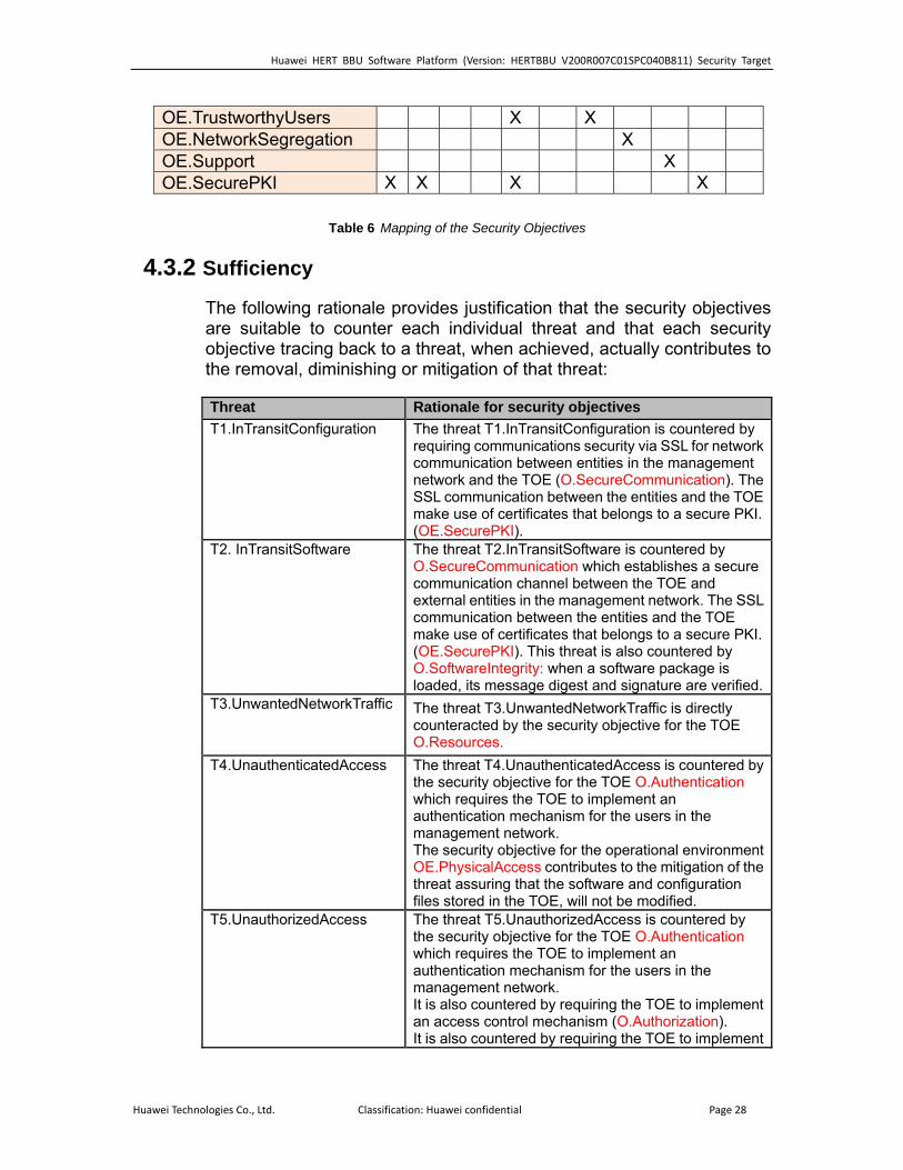
OE.TrustworthyUsers X X OE.NetworkSegregation X OE.Support X OE.SecurePKI X X X X
Table 6 Mapping of the Security Objectives
4.3.2 Sufficiency
The following rationale provides justification that the security objectives are suitable to counter each individual threat and that each security objective tracing back to a threat, when achieved, actually contributes to the removal, diminishing or mitigation of that threat:
Threat Rationale for security objectives T1.InTransitConfiguration The threat T1.InTransitConfiguration is countered by
requiring communications security via SSL for network communication between entities in the management network and the TOE (O.SecureCommunication). The SSL communication between the entities and the TOE make use of certificates that belongs to a secure PKI. (OE.SecurePKI).
T2. InTransitSoftware The threat T2.InTransitSoftware is countered by O.SecureCommunication which establishes a secure communication channel between the TOE and external entities in the management network. The SSL communication between the entities and the TOE make use of certificates that belongs to a secure PKI. (OE.SecurePKI). This threat is also countered by O.SoftwareIntegrity: when a software package is loaded, its message digest and signature are verified.
T3.UnwantedNetworkTraffic The threat T3.UnwantedNetworkTraffic is directly counteracted by the security objective for the TOE O.Resources.
T4.UnauthenticatedAccess The threat T4.UnauthenticatedAccess is countered by the security objective for the TOE O.Authentication which requires the TOE to implement an authentication mechanism for the users in the management network. The security objective for the operational environment OE.PhysicalAccess contributes to the mitigation of the threat assuring that the software and configuration files stored in the TOE, will not be modified.
T5.UnauthorizedAccess The threat T5.UnauthorizedAccess is countered by the security objective for the TOE O.Authentication which requires the TOE to implement an authentication mechanism for the users in the management network. It is also countered by requiring the TOE to implement an access control mechanism (O.Authorization). It is also countered by requiring the TOE to implement
Huawei Technologies Co., Ltd. Classification: Huawei confidential Page 28
Huawei HERT BBU Software Platform (Version: HERTBBU V200R007C01SPC040B811) Security Target
a trusted path between TOE and its users (O.SecureCommunication) so the user credentials
icates that belongs to a secure
the users to be responsible with
iguration files stored in the TOE, will not be modified.
cannot be captured. The SSL communication between the entities and the TOE make use of certifPKI. (OE.SecurePKI). The security objective for the operational environmentOE.TrustworthyUsers contributes to the mitigation of this threat requiringtheir passwords. The security objective for the operational environment OE. PhysicalProtection contributes to the mitigation of the threat assuring that the software and conf
Table 7 Sufficiency analysis for threats
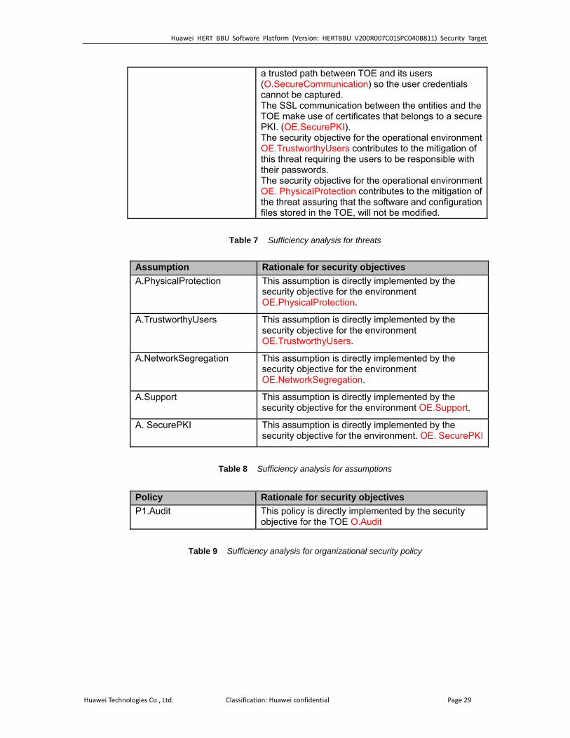
Assumption Rationale for security objectives A.PhysicalProtection d by the
environment This assumption is directly implementesecurity objective for theOE.PhysicalProtection.
A.TrustworthyUsers d by the e environment
This assumption is directly implementesecurity objective for thOE.TrustworthyUsers.
A.NetworkSegregation d by the nvironment
This assumption is directly implementesecurity objective for the eOE.NetworkSegregation.
A.Support rt.
This assumption is directly implemented by the security objective for the environment OE.Suppo
A. SecurePKI security objective for the environment. OE. SecurePKIThis assumption is directly implemented by the
Table 8 Sufficiency analysis for assumptions
Policy Rationale for security objectives P1.Audit ted by the security
objective for the TOE O.Audit This policy is directly implemen
Table 9 Sufficiency analysis for organizational security policy
Huawei Technologies Co., Ltd. Classification: Huawei confidential Page 29
Huawei HERT BBU Software Platform (Version: HERTBBU V200R007C01SPC040B811) Security Target
5 Security Requirements
5.1 TOE Security Functional Requirements
5.1.1 Security Audit (FAU)
I. FAU_GEN.1 Audit data generation
FAU_GEN.1.1 The TSF shall be able to generate an audit record of the following
auditable events: a) Start-up and shutdown of the audit functions; b) All auditable events for the [selection: not specified] level of audit; and c) [assignment: The following auditable events:
i. user activity
1. login, logout (SEC)
2. Operation requests (OPE)
ii. user management
1. add, delete, modify (SEC & OPE)
2. password change (OPE)
3. authorization modification (SEC & OPE)
iii.locking, unlocking (manual or automatic) (SEC & OPE)
iv. command group management
1. add, delete, modify (SEC & OPE) ]
FAU_GEN.1.2 The TSF shall record within each audit record at least the following
information: a) Date and time of the event, type of event, subject identity (if applicable), and the
outcome (success or failure) of the event; and
b) For each audit event type, based on the auditable event definitions of the functional
components included in the PP/ST, [assignment: workstation IP (if applicable),
user (if applicable), and command name (if applicable).]
Application note: There are two kinds of log files, security log file and operation log file.
II. FAU_GEN.2 User identity association
FAU_GEN.2.1 For audit events resulting from actions of identified users, the TSF shall be
able to associate each auditable event with the identity of the user that caused the event.
Huawei Technologies Co., Ltd. Classification: Huawei confidential Page 30
Huawei HERT BBU Software Platform (Version: HERTBBU V200R007C01SPC040B811) Security Target
III. FAU_SAR.1 Audit review
FAU_SAR.1.1 The TSF shall provide [assignment: users with audit review rights] with the
capability to read [assignment: all information] from the audit records.
FAU_SAR.1.2 The TSF shall provide the audit records in a manner suitable for the user to
interpret the information.
IV. FAU_SAR.3 Selectable audit review
FAU_SAR.3.1 The TSF shall provide the ability to apply [assignment: selection] of audit
data based on [assignment: date and time range, user name, terminal type, and/or
result.].
V. FAU_STG.1 Protected audit trail storage
FAU_STG.1.1 The TSF shall protect the stored audit records in the audit trail from
unauthorized deletion
FAU_STG.1.2 The TSF shall be able to [selection: prevent] unauthorized modifications to
the stored audit records in the audit trail.
VI. FAU_STG.3 Action in case of possible audit data loss
FAU_STG.3.1 The TSF shall [assignment: delete the oldest files] if the audit trail exceeds
[assignment: the pre-defined limited size of 1Mbyte].
Application note: For each kind of log file, there are two audit files, when the new file is full,
the old one is deleted.
5.1.2 Cryptographic Support (FCS)
I. FCS_COP.1/Sign Cryptographic operation
FCS_COP.1.1 The TSF shall perform [assignment: digital signature verification] in
accordance with a specified cryptographic algorithm [assignment: RSA with underlying
SHA-256] and cryptographic key sizes [assignment: 1024bits] that meet the following:
[assignment: none]
Huawei Technologies Co., Ltd. Classification: Huawei confidential Page 31
Huawei HERT BBU Software Platform (Version: HERTBBU V200R007C01SPC040B811) Security Target
Application note: This requirement addresses the digital signature verification of the
remote loaded software packages.
II. FCS_COP.1/SSL Cryptographic operation
FCS_COP.1.1 The TSF shall perform [assignment: cipher and decipher of TOE access
channels] in accordance with a specified cryptographic algorithm [assignment: algorithms
supported by SSL/TLS] and cryptographic key sizes [assignment: key sizes supported
by SSL/TLS] that meet the following: [assignment: none].
Application note: This requirement addresses the encryption of the channel with the user
(through the LMT), the M2000 (through the integration port) or with the FTP servers.
III. FCS_CKM.1/SSL Cryptographic key generation
FCS_CKM.1.1 The TSF shall generate cryptographic keys in accordance with a specified
cryptographic key generation algorithm [assignment: cryptographic key generation
methods supported by SSL/TLS] and cryptographic key sizes [assignment: all key sizes
supported by SSL/TLS] that meet the following: [assignment: none]
5.1.3 User Data Protection (FDP)
I. FDP_ACC.1/Local Subset access control
FDP_ACC.1.1 The TSF shall enforce the [assignment: Local access control policy] on
[assignment: local users as subjects, commands as objects, and execution of
commands by local users].
II. FDP_ACF.1/Local Security attribute based access control
FDP_ACF.1.1 The TSF shall enforce the [assignment: Local access control policy] to
objects based on the following:
[assignment: a) local users and their following security attributes:
i. user name ii. user group (role)
b) commands and their following security attributes: i. command name ii. command groups.]
Huawei Technologies Co., Ltd. Classification: Huawei confidential Page 32
Huawei HERT BBU Software Platform (Version: HERTBBU V200R007C01SPC040B811) Security Target
FDP_ACF.1.2 The TSF shall enforce the following rules to determine if an operation among
controlled subjects and controlled objects is allowed: [assignment:
If the user belongs to a user group that is assigned to a command group that
includes the controlled command, then access is granted.
If the user belongs to the custom user group, and he is associated to the command
group that includes the controlled command, then access is granted]
FDP_ACF.1.3 The TSF shall explicitly authorise access of subjects to objects based on the
following additional rules: [assignment: None]
FDP_ACF.1.4 The TSF shall explicitly deny access of subjects to objects based on the
following additional rules: [assignment: None]
III. FDP_ACC.1/Domain Subset access control
FDP_ACC.1.1 The TSF shall enforce the [assignment: Domain access control policy] on
[assignment: domain users as subjects, commands as objects, and execution of
commands by domain users].
IV. FDP_ACF.1/Domain Security attribute based access control
FDP_ACF.1.1 The TSF shall enforce the [assignment: Domain access control policy] to
objects based on the following:
[assignment: a) users and their following security attributes:
i. user name b) commands and their following security attributes:
ii. command name]
FDP_ACF.1.2 The TSF shall enforce the following rules to determine if an operation among
controlled subjects and controlled objects is allowed:
[assignment: if the user is assigned to the requested commands, then access is
granted.]
FDP_ACF.1.3 The TSF shall explicitly authorise access of subjects to objects based on the
following additional rules: [assignment: None]
Huawei Technologies Co., Ltd. Classification: Huawei confidential Page 33
Huawei HERT BBU Software Platform (Version: HERTBBU V200R007C01SPC040B811) Security Target
FDP_ACF.1.4 The TSF shall explicitly deny access of subjects to objects based on the
following additional rules: [assignment: None]
Application note: This requirement implements the domain users’ access control policy.
The users will login to the TOE through the LMT but authentication is performed by an
external entity which will send the operational rights to the TOE so it can exercise the access
control policy.
V. FDP_ACC.1/EMSCOMM Subset access control
FDP_ACC.1.1 The TSF shall enforce the [assignment: EMSCOMM access control policy]
on [assignment: EMSCOMM user as subject, commands as objects, and execution of
commands by the EMSCOMM user].
VI. FDP_ACF.1/EMSCOMM Security attribute based access control
FDP_ACF.1.1 The TSF shall enforce the [assignment: EMSCOMM access control policy]
to objects based on the following:
[assignment: a) EMSCOMM user and its following security attributes:
i. user name b) commands and their following security attributes:
ii. command name]
FDP_ACF.1.2 The TSF shall enforce the following rules to determine if an operation among
controlled subjects and controlled objects is allowed:
[assignment: The EMSCOMM user will always have execution permission of the
targeted command.]
FDP_ACF.1.3 The TSF shall explicitly authorise access of subjects to objects based on the
following additional rules: [assignment: None]
FDP_ACF.1.4 The TSF shall explicitly deny access of subjects to objects based on the
following additional rules: [assignment: None]
Application note: This requirement implements the M2000 access control policy.
Huawei Technologies Co., Ltd. Classification: Huawei confidential Page 34

Huawei HERT BBU Software Platform (Version: HERTBBU V200R007C01SPC040B811) Security Target
5.1.4 Identification and Authentication (FIA)
I. FIA_AFL.1 Authentication failure handling
FIA_AFL.1.1 The TSF shall detect when [selection: an administrator configurable
positive integer within [assignment: 1 and 255]] unsuccessful authentication attempts
occur related to [assignment: authentication of local users since the last successful
authentication of the user and before the counter for these attempts is reset after an
administrator configurable time frame either between 1 and 60 minutes].
FIA_AFL.1.2 When the defined number of unsuccessful authentication attempts has been
[selection: surpassed], the TSF shall [assignment: lockout the account for an
administrator configurable duration either between 1 and 65535 minutes].
Application note: The EMSCOMM user is not considered in this requirement. The
EMSCOMM user is authenticated in the TOE by automatic method and not by user and
password. Domain users are authenticated in the M2000 element of the TOE environment,
so they are not considered in this requirement neither by the TOE authentication
functionality.
II. FIA_ATD.1 User attribute definition
FIA_ATD.1.1 The TSF shall maintain the following list of security attributes belonging to
individual users: [assignment: a) Username b) User Group c) Password d) Number of unsuccessful authentication attempts since last successful
authentication attempt e) Login allowed start time f) Login allowed end time g) Account expiration date h) Lock status]
Application note: The EMSCOMM user is not considered in this requirement. The
EMSCOMM user is authenticated in the TOE by automatic method and not by user and
password. Domain users are authenticated in the M2000 element of the TOE environment,
so they are also not considered in this requirement neither by the TOE authentication
functionality.
Huawei Technologies Co., Ltd. Classification: Huawei confidential Page 35
Huawei HERT BBU Software Platform (Version: HERTBBU V200R007C01SPC040B811) Security Target
III. FIA_SOS.1 Verification of secrets
FIA_SOS.1.1 The TSF shall provide a mechanism to verify that secrets meet: [assignment: a) an administrator configurable minimum length between 6 and 32 characters,
and b) an administrator configurable combination of the following:
i. at least one lower-case alphanumerical character, ii. at least one upper-case alphanumerical character, iii. at least one numerical character, iv. at least one special character.
c) that they are different from an administrator configurable number between 1 to 10 previous used passwords ]
IV. FIA_UAU.1 Timing of authentication
FIA_UAU.1.1 the TSF shall allow [assignment: a) Handshake command; b) Parameter negotiation; c) Link status handshake;
]
on behalf of the user to be performed before the user is authenticated.
FIA_UAU.1.2 The TSF shall require each user to be successfully authenticated before
allowing any other TSF-mediated actions on behalf of that user.
V. FIA_UAU.5 Multiple authentication mechanisms
FIA_UAU.5.1 The TSF shall provide [assignment: a) Authentication for Local Users b) Authentication for Domain Users c) Authentication for EMSCOMM user
]
to support user authentication.
FIA_UAU.5.2 The TSF shall authenticate any user’s claimed identity according to the
[assignment: a) Local Users are authenticated in the TOE by user and password stored in the
TOE. b) Domain users authentication is delegated in the M2000 management element
of the environment by user and password c) EMSCOMM user is authenticated in the TOE by a special arithmetic procedure
common to both parties, the TOE and the M2000. ]
Huawei Technologies Co., Ltd. Classification: Huawei confidential Page 36

Huawei HERT BBU Software Platform (Version: HERTBBU V200R007C01SPC040B811) Security Target
VI. FIA_UID.1 Timing of identification
FIA_UID.1.1 The TSF shall allow [assignment: a) Handshake command; b) Parameter negotiation; c) Link status handshake;
]
on behalf of the user to be performed before the user is identified.
FIA_UID.1.2 the TSF shall require each user to be successfully identified before allowing
any other TSF-mediated actions on behalf of that user.
5.1.5 Security Management (FMT)
I. FMT_MSA.1 Management of security attributes
FMT_MSA.1.1 The TSF shall enforce the [assignment: local access control policy] to
restrict the ability to [selection: query and modify] the security attributes [assignment: a) Command groups b) user groups]
to [assignment: users with the appropriate rights].
II. FMT_MSA.3 Static attribute initialization
FMT_MSA.3.1 The TSF shall enforce the [assignment: local access control policy] to
provide [selection: permissive] default values for security attributes that are used to enforce
the SFP.
FMT_MSA.3.2 The TSF shall allow the [assignment: administrator defined roles with the
appropriate rights] to specify alternative initial values to override the default values when
an object or information is created.
III. FMT_SMF.1 Specification of Management Functions
FMT_SMF.1.1 The TSF shall be capable of performing the following management functions:
[assignment: a) Local User management b) Command group management (creation, deletion, modification, commands
membership) c) Local users authorization management (User group authorization on
Command groups)
Huawei Technologies Co., Ltd. Classification: Huawei confidential Page 37
Huawei HERT BBU Software Platform (Version: HERTBBU V200R007C01SPC040B811) Security Target
d) Configuration of SSL (Certificates and auth mode ) e) Configuration of IPSec f) Configuration of ACL g) Configuration of VLAN h) Enable/Disable software digital signature i) FIA_SOS.1.1 configurable values (Password policy) j) FIA_AFL.1.1 configurable values (Authentication failure handling)]
Application note: The system includes default users whose associated parameters (but
the password) cannot be modified. These users are: admin, guest.
IV. FMT_SMR.1 Security roles
FMT_SMR.1.1 The TSF shall maintain the roles: [assignment: Administrator, User,
Operator, Guest, Custom]
FMT_SMR.1.2 The TSF shall be able to associate users with roles.
Application note: These roles are only applicable to the local users. The domain users are
not maintained in the TOE, no role neither user group is assigned to a domain user. Also,
the EMSCOMM user can not be assigned to any role.
Application note: The custom user group means that the command groups are directly
assigned to the user. The domain users are not maintained by the TOE, no role neither user
group is assigned to a domain user.
5.1.6 TOE access (FTA)
I. FTA_TSE.1/SEP TOE session establishment
FTA_TSE.1.1 The TSF shall be able to deny session establishment based on [assignment: a) Protocol type (IP, ICMP, TCP, UDP or GRE) b) Source IP address and mask c) Source port range d) Destination IP address and mask e) Destination port range f) DSCP value g) VLAN id ]
Application note: This requirement addresses the VLAN separation and IP based ACLs to
Huawei Technologies Co., Ltd. Classification: Huawei confidential Page 38
Huawei HERT BBU Software Platform (Version: HERTBBU V200R007C01SPC040B811) Security Target
avoid resource overhead.
II. FTA_TSE.1/Local TOE session establishment
FTA_TSE.1.1 The TSF shall be able to deny session establishment based on [assignment: a) Login allowed start time b) Login allowed end time c) Account expiration date d) Lock status ]
Application note: The EMSCOMM user is not considered in this requirement. The
EMSCOMM user is authenticated in the TOE by automatic method and not by user and
password. Domain users are authenticated in the M2000 element of the TOE environment,
so they are not considered in this requirement neither by the TOE authentication
functionality.
5.1.7 Trusted path/channels (FTP)
I. FTP_ITC.1 Inter-TSF trusted channel
FTP_ITC.1.1 The TSF shall provide a communication channel between itself and another
trusted IT product that is logically distinct from other communication channels and provides
assured identification of its end points and protection of the channel data from modification
or disclosure.
FTP_ITC.1.2 The TSF shall permit [selection: another trusted IT product] to initiate
communication via the trusted channel.
FTP_ITC.1.3 The TSF shall initiate communication via the trusted channel for [assignment:
accessing the FMT_SMF.1 related functionality].
Application note: This requirement is exercised when accessing the TOE through M2000.
5.2 Security Functional Requirements Rationale
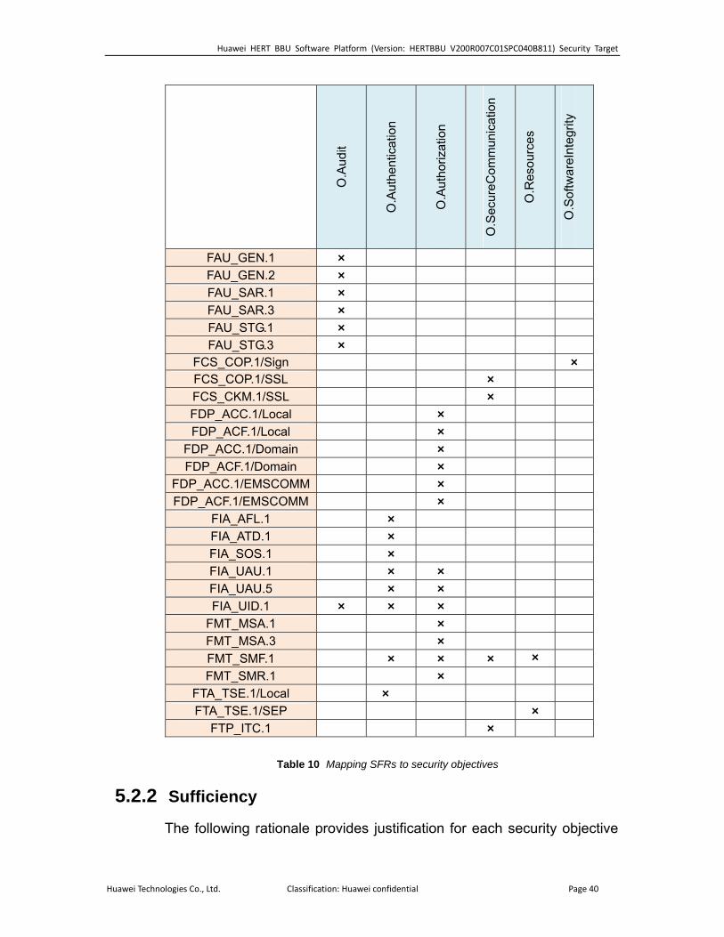
5.2.1 Coverage
The following table provides a mapping of SFR to the security objectives, showing that each security functional requirement addresses at least one security objective.
Huawei Technologies Co., Ltd. Classification: Huawei confidential Page 39
Huawei HERT BBU Software Platform (Version: HERTBBU V200R007C01SPC040B811) Security Target
O.A
udit
O.A
uthe
ntic
atio
n
O.A
utho
rizat
ion
O.S
ecur
eCom
mun
icat
ion
O.R
esou
rces
O.S
oftw
areI
nteg
rity
FAU_GEN.1 × FAU_GEN.2 × FAU_SAR.1 × FAU_SAR.3 × FAU_STG.1 × FAU_STG.3 ×
FCS_COP.1/Sign × FCS_COP.1/SSL × FCS_CKM.1/SSL × FDP_ACC.1/Local × FDP_ACF.1/Local ×
FDP_ACC.1/Domain × FDP_ACF.1/Domain ×
FDP_ACC.1/EMSCOMM × FDP_ACF.1/EMSCOMM ×
FIA_AFL.1 × FIA_ATD.1 × FIA_SOS.1 × FIA_UAU.1 × × FIA_UAU.5 × × FIA_UID.1 × × ×
FMT_MSA.1 × FMT_MSA.3 × FMT_SMF.1 × × × × FMT_SMR.1 ×
FTA_TSE.1/Local × FTA_TSE.1/SEP ×
FTP_ITC.1 ×
Table 10 Mapping SFRs to security objectives
5.2.2 Sufficiency
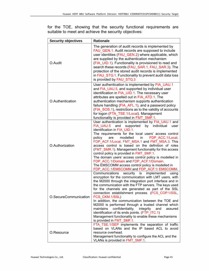
The following rationale provides justification for each security objective
Huawei Technologies Co., Ltd. Classification: Huawei confidential Page 40
Huawei HERT BBU Software Platform (Version: HERTBBU V200R007C01SPC040B811) Security Target
for the TOE, showing that the security functional requirements are suitable to meet and achieve the security objectives:
Security objectives Rationale
O.Audit
which
to prevent audit data loss
The generation of audit records is implemented by FAU_GEN.1. Audit records are supposed to include user identities (FAU_GEN.2) where applicable, are supplied by the authentication mechanism (FIA_UID.1). Functionality is provisioned to read and search these records (FAU_SAR.1, FAU_SAR.3). The protection of the stored audit records is implemented in FAU_STG.1. Functionality is provided by FAU_STG.3
O.Authentication
er
accounts nt
User authentication is implemented by FIA_UAU.1and FIA_UAU.5, and supported by individual useridentification in FIA_UID.1. The necessary usattributes are spelled out in FIA_ATD.1. The authentication mechanism supports authentication failure handling (FIA_AFL.1), and a password policy (FIA_SOS.1), restrictions as to the validity of for logon (FTA_TSE.1/Local). Managemefunctionality is provided in FMT_SMF.1.
O.Authorization
ted by individual user
for this access
elled in
User authentication is implemented by FIA_UAU.1 and FIA_UAU.5 and supporidentification in FIA_UID.1. The requirements for the local users’ access control policy are modelled in FDP_ACC.1/Local, FDP_ACF.1/Local, FMT_MSA.1 and FMT_MSA.3. This access control is based on the definition of roles (FMT_SMR.1). Management functionality control policy is provided in FMT_SMF.1. The domain users’ access control policy is modFDP_ACC.1/Domain and FDP_ACF.1/Domain. The EMSCOMM access control policy is modelled in FDP_ACC.1/EMSCOMM and FDP_ACF.1/ EMSCOMM.
O.SecureCommunicationhment process. (FCS_COP.1/SSL,
assured
enable these mechanisms
Communications security is implemented using encryption for the communication with LMT users, with the M2000 through the integration port interface and in the communication with the FTP servers. The keys used for the channels are generated as part of the SSL connection establisFCS_CKM.1/SSL) In addition, the communication between the TOE and M2000 is performed through a trusted channel which maintains confidentiality, integrity and identification of its ends points. (FTP_ITC.1) Management functionality tois provided in FMT_SMF.1.
O.Resource nd the IP based ACL to avoid
e ACL and the
FTA_TSE.1/SEP implements the separation of traffic based on VLANs aresource overhead. Management functionality to configure thVLANs is provided in FMT_SMF.1.
Huawei Technologies Co., Ltd. Classification: Huawei confidential Page 41
Huawei HERT BBU Software Platform (Version: HERTBBU V200R007C01SPC040B811) Security Target
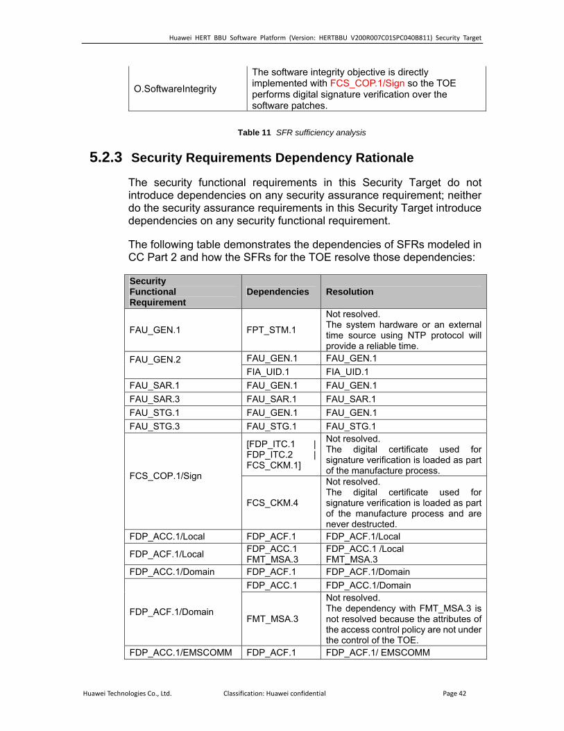
O.SoftwareIntegrity .1/Sign so the TOE performs digital signature verification over the
The software integrity objective is directly implemented with FCS_COP
software patches.
Table 11 SFR sufficiency analysis
5.2.3
irement; neither do the security assurance requirements in this Security Target introduce
The following table demonstrates the dependencies of SFRs modeled in and how the SFRs for the TOE resolve those dependencies:
Security Requirements Dependency Rationale
The security functional requirements in this Security Target do not introduce dependencies on any security assurance requ
dependencies on any security functional requirement.
CC Part 2
Security Functional Dependencies Requirement
Resolution
FAU_GEN.1 FPT_STM.1
Not resolved. The system hardware or an external
g NTP protocol will liable time.
time source usinprovide a re
FAU_GEN.1 FAU_GEN.1 FAU_GEN.2 FIA_UID.1 FIA_UID.1 FAU_SAR.1 FAU_GEN.1 FAU_GEN.1 FAU_SAR.3 FAU_SAR.1 FAU_SAR.1 FAU_STG.1 FAU_GEN.1 FAU_GEN.1 FAU_STG.3 FAU_STG.1 FAU_STG.1
[FDP_ITC.1 | FDP_ITC.2 | FCS_CKM.1]
sed for Not resolved. The digital certificate usignature verification is loaded as part of the manufacture process. FCS_COP.1/Sign
FCS_CKM.4 n is loaded as part process and are
Not resolved. The digital certificate used for signature verificatioof the manufacturenever destructed.
FDP_ACC.1/Local FDP_ACF.1 FDP_ACF.1/Local
FDP_ACF.1/Local FDP_ACC.1 FMT_MSA.3
FDP_ACC.1 /Local FMT_MSA.3
FDP_ACC.1/Domain FDP_ACF.1 FDP_ACF.1/Domain FDP_ACC.1 FDP_ACC.1/Domain
FDP_ACF.1/Domain FMT_MSA.3 e attributes of
e not under
Not resolved. The dependency with FMT_MSA.3 is not resolved because ththe access control policy arthe control of the TOE.
FDP_ACC.1/EMSCOMM FDP_ACF.1 FDP_ACF.1/ EMSCOMM
Huawei Technologies Co., Ltd. Classification: Huawei confidential Page 42

Huawei HERT BBU Software Platform (Version: HERTBBU V200R007C01SPC040B811) Security Target
FDP_ACC.1 FDP_ACC.1/ EMSCOMM
FDP_ACF.1/EMSCOMM FMT_MSA.3 e attributes of
ontrol policy are not under e control of the TOE.
Not resolved. The dependency with FMT_MSA.3 is not resolved because ththe access cth
FIA_AFL.1 FIA_UAU.1 IA_UAU.1 FFIA_ATD.1 None FIA_SOS.1 None FIA_UAU.1 D.1 IA_UID.1 FIA_UI FFIA_UAU.5 None FIA_UID.1 None
[FDP_ACC.1 or FDP_IFC.1] FDP_ACC.1
FMT_SMR.1 FMT_SMR.1 FMT_MSA.1
FMT_SMF.1 FMT_SMF.1 FMT_MSA.1 FMT_MSA.1 FMT_MSA.3 FMT_SMR.1 1 FMT_SMR.
FMT_SMF.1 None FMT_SMR.1 FIA_UID.1 IA_UID.1 FFTA_TSE.1/SEP None FTA_TSE.1/Local None
[FDP_ITC.1 | FDP_ITC.2 | FCS_CKM.1]
FCS_CKM.1/SSL
FCS_COP.1/SSL are not externally
do not need to be
FCS_CKM.4
Not resolved. The generated keysaccessible so they
ved.securely remo[FCS_CKM.2 | FCS_COP.1] FCS_COP.1/SSL
FCS_CKM.1/SSL KM.4 are not externally
ccessible so they do not need to be securely removed.
FCS_C
Not resolved. The generated keysa
FTP_ITC.1 None
Table 12 Dependencies between TOE Security Functional Requirements
5.3 S
onents as specified in [CC] Part 3, augmented with ALC_CMC.4 and ALC_CMS.4. No operations are applied to the a nen
ecurity Assurance Requirements
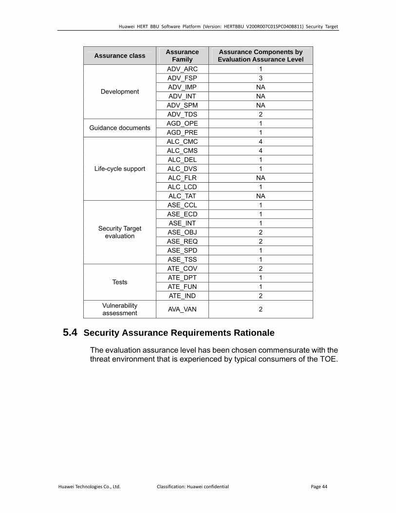
The security assurance requirements for the TOE are the Evaluation Assurance Level 3 comp
ssurance compo ts.
Huawei Technologies Co., Ltd. Classification: Huawei confidential Page 43
Huawei HERT BBU Software Platform (Version: HERTBBU V200R007C01SPC040B811) Security Target
Assurance Family
Assurance Components by Assurance class Evaluation Assurance Level ADV_ARC 1 ADV_FSP 3 ADV_IMP NA ADV_INT NA ADV_SPM
Development
NA ADV_TDS 2 AGD_OPE 1
Guidance documents AGD_PRE 1 ALC_CMC 4 ALC_CMS 4 ALC_DEL 1 ALC_DVS 1 ALC_FLR NA ALC_LCD 1
Life-cycle support
NALC_TAT A ASE_CCL 1 ASE_ECD 1 ASE_INT 1 ASE_OBJ 2 ASE_REQ 2 ASE_SPD 1
Security Target evaluation
ASE_TSS 1 ATE_COV 2 ATE_DPT 1 ATE_FUN 1
Tests
ATE_IND 2 Vulnerability assessment AVA_VAN 2
5.4 S
The evaluation assurance level has been chosen commensurate with the threat environment that is experienced by typical consumers of the TOE.
ecurity Assurance Requirements Rationale
Huawei Technologies Co., Ltd. Classification: Huawei confidential Page 44

Huawei HERT BBU Software Platform (Version: HERTBBU V200R007C01SPC040B811) Security Target
6 TOE Summary Specification
6.1 TOE Security Functionality
6.1.1 Authentication
The TOE offers the enforcement of timer-based account lockouts: administrators can specify after how many consecutive failed authentication attempts an account will be temporarily locked, and whether the counter for failed attempts will be reset automatically after a certain amount of minutes. (FIA_AFL.1)
The TOE authenticates the local users based on individual user IDs and passwords. User IDs are unique within the TOE and stored together with associated passwords and other security attributes in the TOE’s configuration database. Those attributes can be configured by users with the appropriate rights. (FIA_ATD.1, FMT_SMF.1)
The TOE can identify users in the management network by a unique ID and enforces their authentication before granting them access to the TSF management interfaces. Warning of “error username or password” will be prompted when the user fails to provide a correct username or password. Some not security related actions can be performed before identification and authentication. (FIA_UID.1, FIA_UAU.1)
If applicable, i.e., if an administrator has specified values for these parameters for a specific user, the TOE will deny authentication of the user if the user tries to authenticate in a timeframe that lies outside of the “login start time” and “login end time” specified for the user. (FMT_SMF.1, FTA_TSE.1/Local)
The TOE also provide login time control mechanism: Each account can be configured with the login time segment, including the valid date range, time segment, and week restriction. Any login is prohibited beyond the configured time segment. (FMT_SMF.1, FTA_TSE.1/Local)
Several authentication mechanisms are provided for the different available users below. This functionality implements (FIA_UAU.5).
a) Local users
b) Domain users
Huawei Technologies Co., Ltd. Classification: Huawei confidential Page 45
Huawei HERT BBU Software Platform (Version: HERTBBU V200R007C01SPC040B811) Security Target
c) EMSCOMM
6.1.2 Access control
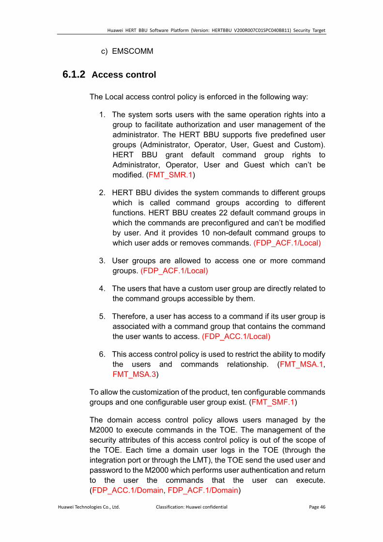
The Local access control policy is enforced in the following way:
1. The system sorts users with the same operation rights into a group to facilitate authorization and user management of the administrator. The HERT BBU supports five predefined user groups (Administrator, Operator, User, Guest and Custom). HERT BBU grant default command group rights to Administrator, Operator, User and Guest which can’t be modified. (FMT_SMR.1)
2. HERT BBU divides the system commands to different groups which is called command groups according to different functions. HERT BBU creates 22 default command groups in which the commands are preconfigured and can’t be modified by user. And it provides 10 non-default command groups to which user adds or removes commands. (FDP_ACF.1/Local)
3. User groups are allowed to access one or more command groups. (FDP_ACF.1/Local)
4. The users that have a custom user group are directly related to the command groups accessible by them.
5. Therefore, a user has access to a command if its user group is associated with a command group that contains the command the user wants to access. (FDP_ACC.1/Local)
6. This access control policy is used to restrict the ability to modify the users and commands relationship. (FMT_MSA.1, FMT_MSA.3)
To allow the customization of the product, ten configurable commands groups and one configurable user group exist. (FMT_SMF.1)
The domain access control policy allows users managed by the M2000 to execute commands in the TOE. The management of the security attributes of this access control policy is out of the scope of the TOE. Each time a domain user logs in the TOE (through the integration port or through the LMT), the TOE send the used user and password to the M2000 which performs user authentication and return to the user the commands that the user can execute. (FDP_ACC.1/Domain, FDP_ACF.1/Domain)
Huawei Technologies Co., Ltd. Classification: Huawei confidential Page 46

Huawei HERT BBU Software Platform (Version: HERTBBU V200R007C01SPC040B811) Security Target
The EMSCOMM user is a built-in user that is used by the M2000 to operate the TOE. This user has permission to execute all the commands of the TOE and cannot be modified neither deleted. This user can only be implicitly accessed through the integration port. (FDP_ACC.1/EMSCOMM, FDP_ACF.1/EMSCOMM)
6.1.3 Auditing
Removing the logs is always forbidden. (FAU_STG.1)
There exist two kinds of audit files, the operation log and the security log.
1. Security log: Records user operations related to the system security, including user behaviour and configuration commands, for example, account locking due to consecutive login failure and updating the security policy
2. Operation log: Records all MML commands run by users.
For each of these kinds there exist two files that are rotated in the following way: if one exceeds 1MB the oldest file is deleted and a new one is created. (FAU_STG.3)
The auditing functionality of the TOE cannot be started or stopped independently from the operational TOE. However, the TOE generates audit records for the start and shutdown of base station, and for several auditable events, storing the audit data in the appropriate file. (FAU_GEN.1)
Where appropriate, the data recorded with each audit record includes the unique user ID associated with a subject during authentication. (FAU_GEN.2)
Users with the appropriate rights can review the audit records available in the database. The TOE offers search functionality based on time intervals, user IDs, interface, and/or result. (FAU_SAR.1, FAU_SAR.3)
6.1.4 Communications security
The TOE provides communications security for network connections to the MPT. This includes connections via the following interfaces:
Huawei Technologies Co., Ltd. Classification: Huawei confidential Page 47
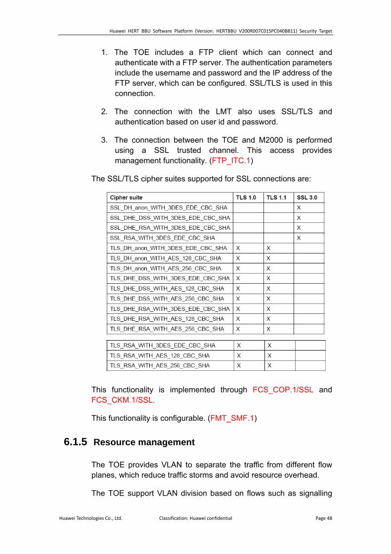
Huawei HERT BBU Software Platform (Version: HERTBBU V200R007C01SPC040B811) Security Target
1. The TOE includes a FTP client which can connect and authenticate with a FTP server. The authentication parameters include the username and password and the IP address of the FTP server, which can be configured. SSL/TLS is used in this connection.
2. The connection with the LMT also uses SSL/TLS and authentication based on user id and password.
3. The connection between the TOE and M2000 is performed using a SSL trusted channel. This access provides management functionality. (FTP_ITC.1)
The SSL/TLS cipher suites supported for SSL connections are:
This functionality is implemented through FCS_COP.1/SSL and FCS_CKM.1/SSL.
This functionality is configurable. (FMT_SMF.1)
6.1.5 Resource management
The TOE provides VLAN to separate the traffic from different flow planes, which reduce traffic storms and avoid resource overhead.
The TOE support VLAN division based on flows such as signalling
Huawei Technologies Co., Ltd. Classification: Huawei confidential Page 48
Huawei HERT BBU Software Platform (Version: HERTBBU V200R007C01SPC040B811) Security Target
flows, media flows, or management flows. In other words, different VLAN tags are marked on the three types of flows passing the BS and they are separate from each other. (FTA_TSE.1/SEP)
The TOE supports IP-based Access Control List (ACL) to filter traffic destined to TOE which might cause system overload and service interruption.
The ACL provides a simple security policy that controls the incoming and outgoing data of unauthorized users. The ACL determines what data is allowed to enter the transmission port and what data is not allowed to enter the transmission port. In this way, the ACL filters the illegitimate data.
The ACL controls the network access, preventing the network attacks. In addition, the ACL filters out illegitimate data flows, improving the network performance.
The ACL consists of multiple rules. Each rule contains the following filtering conditions:
1. Protocol type (IP, ICMP, TCP, UDP, and GRE)
2. Source IP address and mask
3. Source port range
4. Destination IP address and mask
5. Destination port range
6. Differentiated Services Code Point (DSCP) value
7. ACL Action (Deny, Permit)
The ACL rules can be preset in the ASN-GW network interface, and the ACL Action can be designated in advance. In this way, the different types of communication flows can be permitted or denied, and the illegitimate data can be filtered. This method effectively prevents illegitimate intrusions and malicious packet attacks, ensuring the security of network devices. (FMT_SMF.1, FTA_TSE.1/SEP)
6.1.6 Security function management
The TOE offers management functionality for its security functions, where appropriate. This is partially already addressed in more detail in the previous sections of the TSS, but includes:
Huawei Technologies Co., Ltd. Classification: Huawei confidential Page 49
Huawei HERT BBU Software Platform (Version: HERTBBU V200R007C01SPC040B811) Security Target
1. User management, including User Group memberships, passwords, account lockout, validity periods for an account and/or password, etc. Verification of the password policy is performed when creating or modifying users (FIA_SOS.1)
2. Access control management, including the definition of Command Groups, and the association of users and User Groups with Command Groups.
3. Configuration of SSL for the communication between LMT/M2000 and the base station.
4. Configuration of IPSec for the communication between ASN-GW and the base station.
5. Configuration of VLAN for the different plane between the TOE environment and the base station.
6. Configuration of ACL for the communication between the TOE environment and the base station.
7. Authorized administrators are able to configure a system-wide password policy that is then enforced by the TOE. Besides the minimum length of the password, which can be set to be between 6 and 32 characters, administrator has the option to enforce the use of specific characters (numeric, alphanumeric low or capital, and special characters).
All these management options are available. (FMT_SMF.1)
6.1.7 Digital signature
To address security issues, digital signature mechanism to ensure the legitimacy and integrity of the software packages are provided.
The TOE automatically checks the digital signature of the software when the user runs the DLD SOFTWARE command to download the software.
The CSP files will be the files downloaded from the FTP server to update the TOE software and this way exercise the digital signature mechanism implemented in the TOE.
In the following image the CSP structure is depicted:
Huawei Technologies Co., Ltd. Classification: Huawei confidential Page 50
Huawei HERT BBU Software Platform (Version: HERTBBU V200R007C01SPC040B811) Security Target
This way, a directory structure is stored in the CSP file. This structure is expected to contain some important files:
VERDES.SGN contains the signature of the VERDES.XML file. This way, the TOE will verify the hash and CRC value of each of the files using the VERDES.XML file, and will also verify that the file VERDES.XML has not been tampered using the VERDES.SGN stored signature (FCS_COP.1/Sign).
This way, the integrity chain is guaranteed.
7 Abbreviations, Terminology and References
7.1 Abbreviations
Abbreviations Full Spelling ACL Access Control List ASN Access Service Network ASN-GW Access Service Network – Gateway ASPF Application Specific Packet Filter BBU Base Band Unit BBP Base Band Process BS Base Station BIN Huawei’s binary interface BTS Base Transceiver Station BSS Business Support System CC Common Criteria CDMA Code Division Multiple Access CPBSP Common Platform Board Support Package CPE Cunstomer Premises Equipment
Huawei Technologies Co., Ltd. Classification: Huawei confidential Page 51

Huawei HERT BBU Software Platform (Version: HERTBBU V200R007C01SPC040B811) Security Target
DHCP Dynamic Host Configuration Protocol DOPRA-SSP Distributed Open&Object-oriented Programmable
Real-time Architecture- System Service Plane E-NodeB Evolved Universal Terrestrial Radio Access Network
NodeB FTP File Transfer Protocol FTPs FTP-over-SSL GRE Generic Routing Encapsulation GSM Global System for Mobile Communications GUI Graphical User Interface HERT BBU Huawei Enhanced Radio Technology-Base Band Unit ICMP Internet Control Message Protocol IKE Internet Key Exchange IP Internet Protocol IPSec IP Security Protocol LMT Local Maintenance Terminal LTE Long term evolution NBAP NodeB application part NCM Network connection management NE Network Element NMS Network Management System NTP The Network Time Protocol M2000(EMS) Element Management System MAC Medium Access Control MML Man-Machine Language MPT Main Processing&Transmission unit OAM (OM) Operation Administration and Maintenance OSS Operations Support System RNC Radio Network controller ROSA-RB Radio Open Software Architecture-Radio Base-station RRM Radio Resource Management SEC Operator Security management SFR Security Functional Requirement SSL Security Socket Layer ST Security Target SWM Software management TCP Transfer Control Protocol TD-NodeB Time Division-Synchronous Code Division Multiple
Access-NodeB TLS Transport Layer Security TOE Target of Evaluation TSF TOE Security Functions
Huawei Technologies Co., Ltd. Classification: Huawei confidential Page 52

Huawei HERT BBU Software Platform (Version: HERTBBU V200R007C01SPC040B811) Security Target
TR Transfers Management TRAN Transport of Radio Access Network UDP User Datagram Protocol UMTS Universal Mobile Telecommunications System USB Universal Serial BUS VISP Versatile IP and Security Platform VLAN Virtual Local Area Network VPP Voice Protocol Platform WiMAX Worldwide Interoperability for Microwave Access W-NodeB Wideband Code Division Multiple Access-NodeB
7.2 Terminology
This section contains definitions of technical terms that are used with a meaning specific to this document. Terms defined in the [CC] are not reiterated here, unless stated otherwise.
Administrator An administrator is a user of the TOE who may have been assigned specific administrative privileges within the TOE. This ST may use the term administrator occasionally in an informal context, and not in order to refer to a specific role definition – from the TOE’s point of view, an administrator is simply a user who is authorized to perform certain administrative actions on the TOE and the objects managed by the TOE.
Operator See user.
User A user is a human or a product/application using the TOE.
7.3 References
[CC] Common Criteria for Information Technology Security Evaluation. Part 1-3. July 2009. Version 3.1 Revision 3.
[CEM] Common Methodology for Information Technology Security Evaluation. July 2009. Version 3.1 Revision 3.
Huawei Technologies Co., Ltd. Classification: Huawei confidential Page 53
Related Documents