1 © Nokia Siemens Networks RN3167BEN30GLA1 Course Content Radio Resource Management Overview Parameter Configuration Common Channels & Power Control Load Control Admission Control Packet Scheduling Handover Control Resource Manager HSDPA RRM & parameters HSUPA RRM & parameters HSPA+ features & parameters

Welcome message from author
This document is posted to help you gain knowledge. Please leave a comment to let me know what you think about it! Share it to your friends and learn new things together.
Transcript

1 © Nokia Siemens Networks RN3167BEN30GLA1
Course Content
Radio Resource Management OverviewParameter ConfigurationCommon Channels & Power ControlLoad ControlAdmission ControlPacket Scheduling Handover ControlResource ManagerHSDPA RRM & parametersHSUPA RRM & parametersHSPA+ features & parameters
2 © Nokia Siemens Networks RN3167BEN30GLA1
HSPA+ features & parameters:Module Objectives
At the end of the module you will be able to:
• List the mayor data rate boosters of HSDPA & HSUPA and explain their principles
• Explain how different HSPA+ features improve the spectrum efficiency
• Describe the prerequisites and main parameters needed for the described HSPA+ features
3 © Nokia Siemens Networks RN3167BEN30GLA1
HSPA+ RRM: Contents
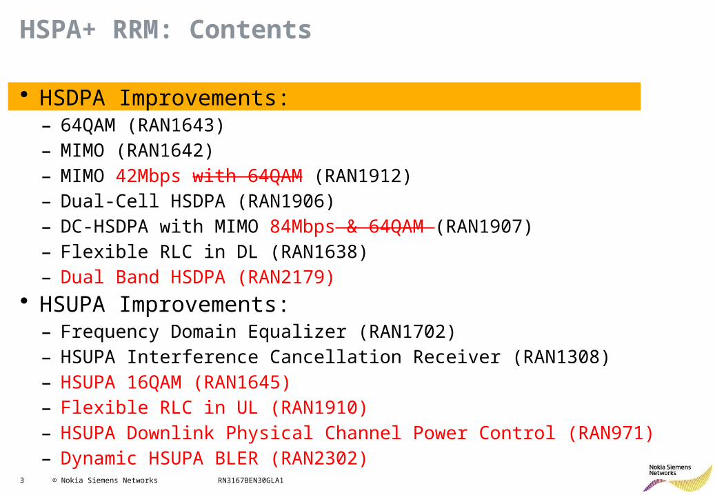
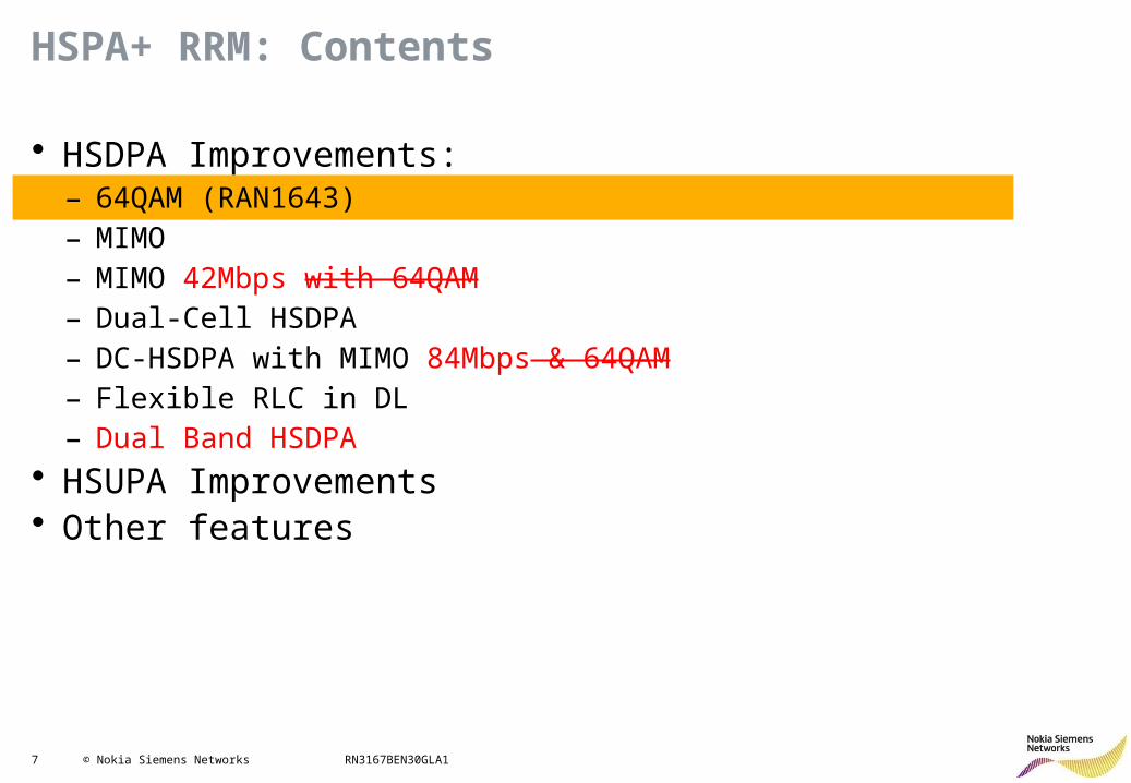
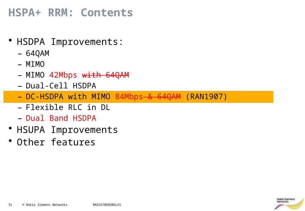
• HSDPA Improvements: – 64QAM (RAN1643)– MIMO (RAN1642)– MIMO 42Mbps with 64QAM (RAN1912)– Dual-Cell HSDPA (RAN1906)– DC-HSDPA with MIMO 84Mbps & 64QAM (RAN1907)– Flexible RLC in DL (RAN1638)– Dual Band HSDPA (RAN2179)
• HSUPA Improvements: – Frequency Domain Equalizer (RAN1702)– HSUPA Interference Cancellation Receiver (RAN1308)– HSUPA 16QAM (RAN1645)– Flexible RLC in UL (RAN1910)– HSUPA Downlink Physical Channel Power Control (RAN971)– Dynamic HSUPA BLER (RAN2302)
4 © Nokia Siemens Networks RN3167BEN30GLA1
HSPA+ RRM: Contents
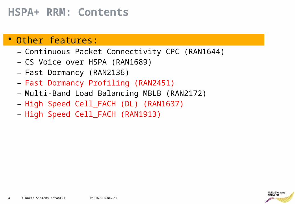
• Other features:– Continuous Packet Connectivity CPC (RAN1644)– CS Voice over HSPA (RAN1689)– Fast Dormancy (RAN2136)– Fast Dormancy Profiling (RAN2451)– Multi-Band Load Balancing MBLB (RAN2172)– High Speed Cell_FACH (DL) (RAN1637)– High Speed Cell_FACH (RAN1913)
5 © Nokia Siemens Networks RN3167BEN30GLA1
Multicarrier HSPA Evolution in Release 9/10 & beyond
1 x 5 MHz
Uplink Downlink
1 x 5 MHz
42 x 5 MHz
Uplink Downlink
48 x 5 MHz
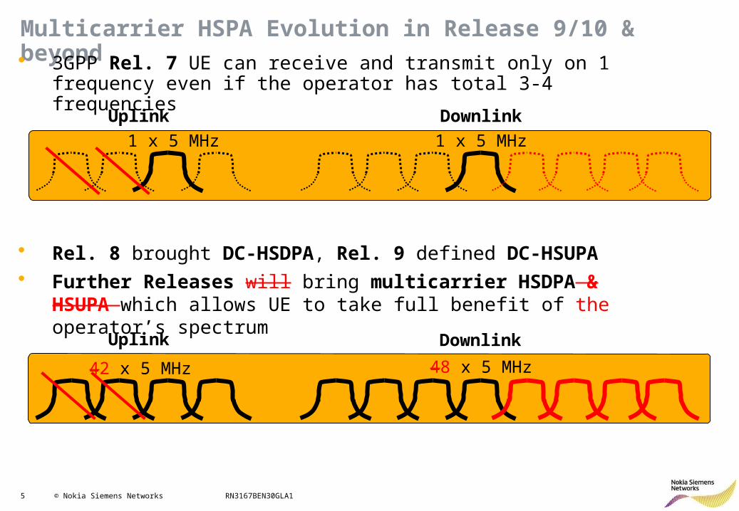
• 3GPP Rel. 7 UE can receive and transmit only on 1 frequency even if the operator has total 3-4 frequencies
• Rel. 8 brought DC-HSDPA, Rel. 9 defined DC-HSUPA• Further Releases will bring multicarrier HSDPA & HSUPA which
allows UE to take full benefit of the operator’s spectrum
6 © Nokia Siemens Networks RN3167BEN30GLA1
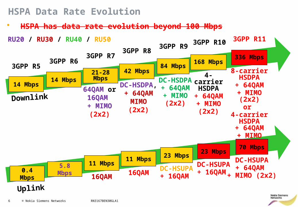
HSPA Data Rate Evolution
14 Mbps
21-28 Mbps
Downlink
3GPP R53GPP R6
3GPP R7
Uplink
42 Mbps84 Mbps
3GPP R83GPP R9
168 Mbps
3GPP R10
14 Mbps
0.4 Mbps
5.8 Mbps
11 Mbps11 Mbps
23 Mbps
DC-HSDPA,+ 64QAM
MIMO(2x2)
DC-HSDPA+ 64QAM+ MIMO
(2x2)
4-carrier HSDPA
+ 64QAM+ MIMO
(2x2)
DC-HSUPA+ 16QAM 16QAM
64QAM or16QAM + MIMO
(2x2)
• HSPA has data rate evolution beyond 100 Mbps
RU20 / RU30 / RU40 / RU50 3GPP R11
336 Mbps
8-carrier HSDPA
+ 64QAM+ MIMO (2x2)
or 4-carrier HSDPA
+ 64QAM+ MIMO (4x4)
23 Mbps
DC-HSUPA+ 16QAM 16QAM
70 Mbps
DC-HSUPA+ 64QAM
+ MIMO (2x2)
7 © Nokia Siemens Networks RN3167BEN30GLA1
HSPA+ RRM: Contents
• HSDPA Improvements: – 64QAM (RAN1643)– MIMO– MIMO 42Mbps with 64QAM– Dual-Cell HSDPA– DC-HSDPA with MIMO 84Mbps & 64QAM– Flexible RLC in DL– Dual Band HSDPA
• HSUPA Improvements• Other features
8 © Nokia Siemens Networks RN3167BEN30GLA1
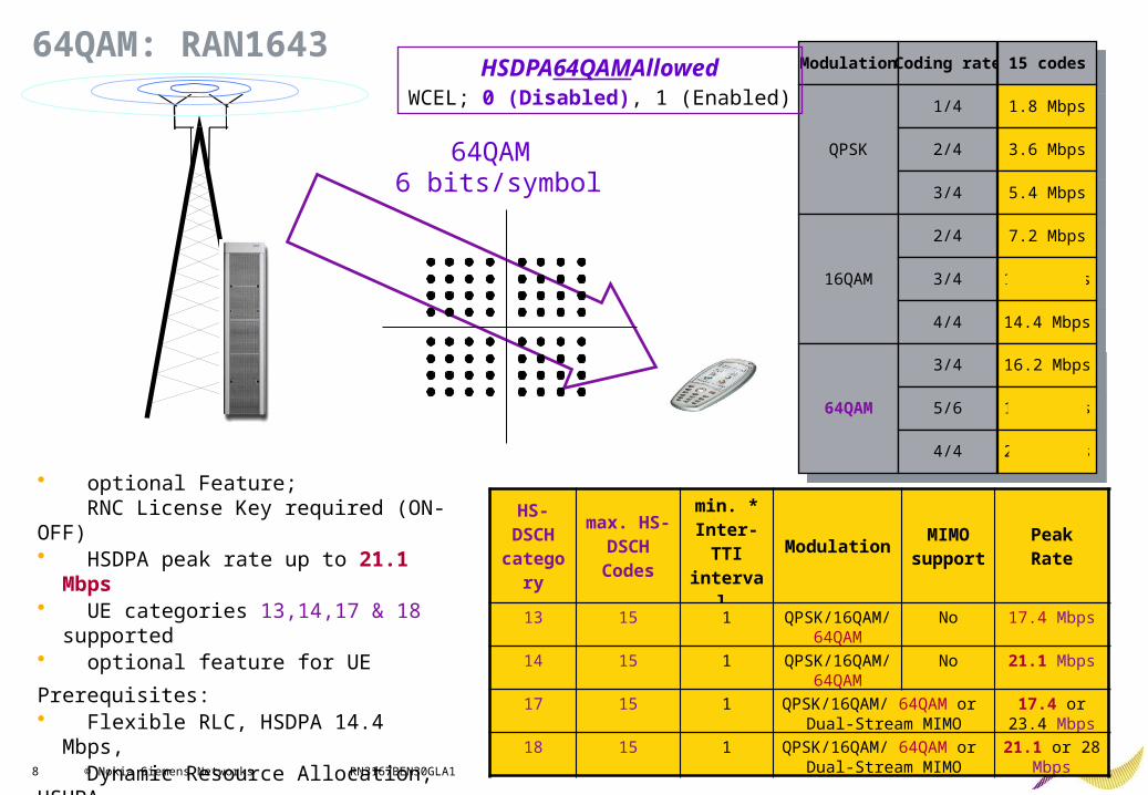
64QAM: RAN1643ModulationModulation
QPSKQPSK
Coding rateCoding rate
1/41/4
2/42/4
3/43/4
15 codes15 codes
1.8 Mbps1.8 Mbps
3.6 Mbps3.6 Mbps
5.4 Mbps5.4 Mbps
16QAM16QAM
2/42/4
3/43/4
4/44/4
7.2 Mbps7.2 Mbps
10.8 Mbps10.8 Mbps
14.4 Mbps14.4 Mbps
64QAM64QAM
3/43/4
5/65/6
4/44/4
16.2 Mbps16.2 Mbps
18.0 Mbps18.0 Mbps
21.6 Mbps21.6 Mbps
64QAM 6 bits/symbol
HSDPA64QAMAllowedWCEL; 0 (Disabled), 1 (Enabled)
HS- DSCH
category
max. HS-DSCH Codes
min. * Inter-TTI interval
ModulationMIMO
supportPeakRate
13 15 1 QPSK/16QAM/ 64QAM
No 17.4 Mbps
14 15 1 QPSK/16QAM/ 64QAM
No 21.1 Mbps
17 15 1 QPSK/16QAM/ 64QAM or Dual-Stream MIMO
17.4 or 23.4 Mbps
18 15 1 QPSK/16QAM/ 64QAM or Dual-Stream MIMO
21.1 or 28 Mbps
• optional Feature; RNC License Key required (ON-OFF)• HSDPA peak rate up to 21.1 Mbps• UE categories 13,14,17 & 18 supported• optional feature for UE
Prerequisites: • Flexible RLC, HSDPA 14.4 Mbps, Dynamic Resource Allocation, HSUPA
9 © Nokia Siemens Networks RN3167BEN30GLA1
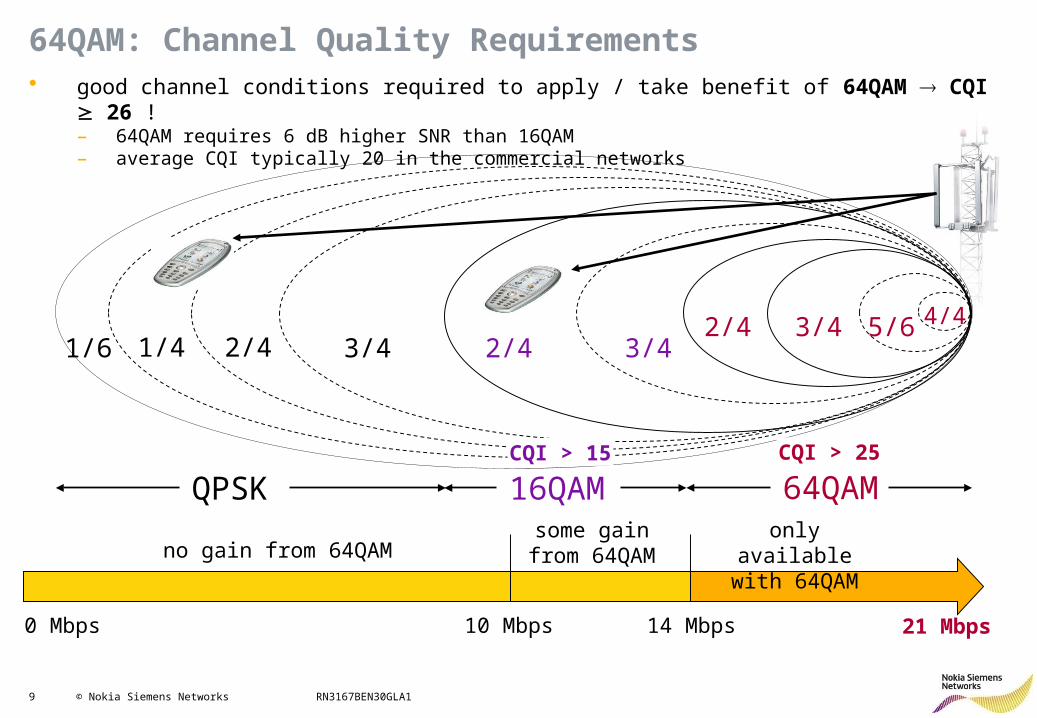
21 Mbps
64QAM: Channel Quality Requirements• good channel conditions required to apply / take benefit of 64QAM CQI 26 !
– 64QAM requires 6 dB higher SNR than 16QAM– average CQI typically 20 in the commercial networks
0 Mbps 10 Mbps 14 Mbps
no gain from 64QAMsome gain from
64QAMonly available with
64QAM
64QAMQPSK 16QAM
1/4 2/42/4
1/6 2/4 3/4 3/43/4 5/6 4/4
CQI > 15 CQI > 25
10 © Nokia Siemens Networks RN3167BEN30GLA1
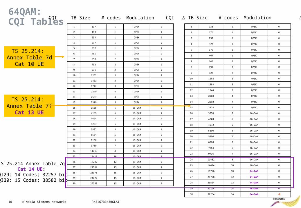
64QAM:CQI Tables
1 136 1 QPSK 0
2 176 1 QPSK 0
3 232 1 QPSK 0
4 320 1 QPSK 0
5 376 1 QPSK 0
6 464 1 QPSK 0
7 648 2 QPSK 0
8 792 2 QPSK 0
9 928 2 QPSK 0
10 1264 3 QPSK 0
11 1488 3 QPSK 0
12 1744 3 QPSK 0
13 2288 4 QPSK 0
14 2592 4 QPSK 0
15 3328 5 QPSK 0
16 3576 5 16-QAM 0
17 4200 5 16-QAM 0
18 4672 5 16-QAM 0
19 5296 5 16-QAM 0
20 5896 5 16-QAM 0
21 6568 5 16-QAM 0
22 7184 5 16-QAM 0
23 9736 7 16-QAM 0
24 11432 8 16-QAM 0
25 14424 10 16-QAM 0
26 15776 10 64-QAM 0
27 21768 12 64-QAM 0
28 26504 13 64-QAM 0
29 32264 14 64-QAM 0
30 32264 14 64-QAM -2
CQI TB Size # codes Modulation
1 137 1 QPSK 0
2 173 1 QPSK 0
3 233 1 QPSK 0
4 317 1 QPSK 0
5 377 1 QPSK 0
6 461 1 QPSK 0
7 650 2 QPSK 0
8 792 2 QPSK 0
9 931 2 QPSK 0
10 1262 3 QPSK 0
11 1483 3 QPSK 0
12 1742 3 QPSK 0
13 2279 4 QPSK 0
14 2583 4 QPSK 0
15 3319 5 QPSK 0
16 3565 5 16-QAM 0
17 4189 5 16-QAM 0
18 4664 5 16-QAM 0
19 5287 5 16-QAM 0
20 5887 5 16-QAM 0
21 6554 5 16-QAM 0
22 7168 5 16-QAM 0
23 9719 7 16-QAM 0
24 11418 8 16-QAM 0
25 14411 10 16-QAM 0
26 17237 12 16-QAM 0
27 21754 15 16-QAM 0
28 23370 15 16-QAM 0
29 24222 15 16-QAM 0
30 25558 15 16-QAM 0
CQI TB Size # codes Modulation
TS 25.214: Annex Table 7d
Cat 10 UE
TS 25.214: Annex Table 7f
Cat 13 UE
TS 25.214 Annex Table 7gCat 14 UE:
CQI29: 14 Codes; 32257 bitCQI30: 15 Codes; 38582 bit
11 © Nokia Siemens Networks RN3167BEN30GLA1
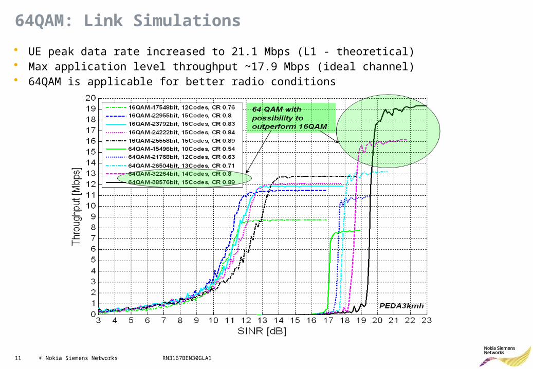
64QAM: Link Simulations
• UE peak data rate increased to 21.1 Mbps (L1 - theoretical)• Max application level throughput ~17.9 Mbps (ideal channel)• 64QAM is applicable for better radio conditions
12 © Nokia Siemens Networks RN3167BEN30GLA1
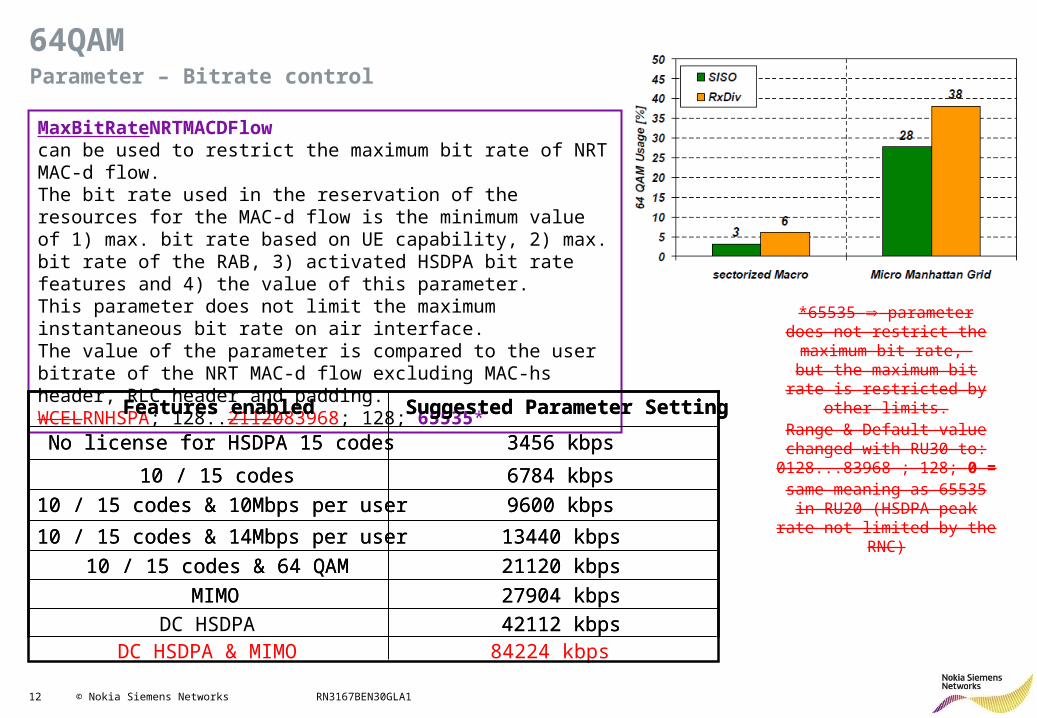
64QAMParameter – Bitrate control
MaxBitRateNRTMACDFlow can be used to restrict the maximum bit rate of NRT MAC-d flow. The bit rate used in the reservation of the resources for the MAC-d flow is the minimum value of 1) max. bit rate based on UE capability, 2) max. bit rate of the RAB, 3) activated HSDPA bit rate features and 4) the value of this parameter. This parameter does not limit the maximum instantaneous bit rate on air interface. The value of the parameter is compared to the user bitrate of the NRT MAC-d flow excluding MAC-hs header, RLC header and padding.WCELRNHSPA; 128..2112083968; 128; 65535*
*65535 parameter does not restrict the maximum bit rate,
but the maximum bit rate is restricted by other limits.Range & Default value changed with RU30 to: 0128...83968 ; 128; 0 =
same meaning as 65535 in RU20 (HSDPA peak rate not
limited by the RNC)
42112 kbpsDC HSDPA
27904 kbpsMIMO
21120 kbps10 / 15 codes & 64 QAM
13440 kbps10 / 15 codes & 14Mbps per user
9600 kbps10 / 15 codes & 10Mbps per user
6784 kbps10 / 15 codes
3456 kbpsNo license for HSDPA 15 codes
Suggested Parameter SettingFeatures enabled
42112 kbps
27904 kbpsMIMO
21120 kbps10 / 15 codes & 64 QAM
13440 kbps10 / 15 codes & 14Mbps per user
9600 kbps10 / 15 codes & 10Mbps per user
6784 kbps10 / 15 codes
3456 kbpsNo license for HSDPA 15 codes
Suggested Parameter SettingFeatures enabled
84224 kbpsDC HSDPA & MIMO
13 © Nokia Siemens Networks RN3167BEN30GLA1
HSPA+ RRM: Contents
• HSDPA Improvements: – 64QAM– MIMO (RAN1642)– MIMO 42Mbps with 64QAM – Dual-Cell HSDPA– DC-HSDPA with MIMO 84Mbps & 64QAM– Flexible RLC in DL– Dual Band HSDPA
• HSUPA Improvements• Other features
14 © Nokia Siemens Networks RN3167BEN30GLA1
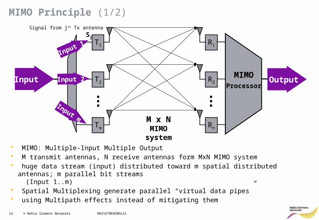
MIMO Principle (1/2)
Tm
T2
T1
Rn
R2
R1
••••••
Input
Input 1
Input 2
Input mM x NMIMO
system
Output
• MIMO: Multiple-Input Multiple Output• M transmit antennas, N receive antennas form MxN MIMO system• huge data stream (input) distributed toward m spatial distributed antennas; m parallel bit streams
(Input 1..m)• Spatial Multiplexing generate parallel “virtual data pipes”• using Multipath effects instead of mitigating them
Signal from jth Tx antenna
Sj
MIMOProcessor
15 © Nokia Siemens Networks RN3167BEN30GLA1
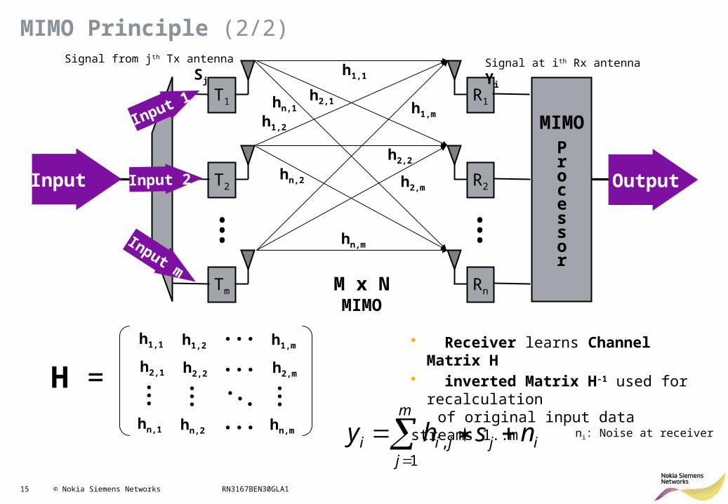
MIMO Principle (2/2)
Tm
T2
T1
Rn
R2
R1
MIMOProcessor
••••••
Input
Input 1
Input 2
Input m
M x NMIMO
Output
h1,1
h2,1hn,1
hn,2
hn,m
h2,2
h2,m
h1,mh1,2
• Receiver learns Channel Matrix H• inverted Matrix H-1 used for
recalculation of original input data streams 1..m
m
jijjii nshy
1,
Signal at ith Rx antenna
Yi
Signal from jth Tx antenna
Sj
ni: Noise at receiver
H =
h1,1
h2,1
hn,1
h1,2
h2,2
hn,2
h1,m
h2,m
hn,m
16 © Nokia Siemens Networks RN3167BEN30GLA1
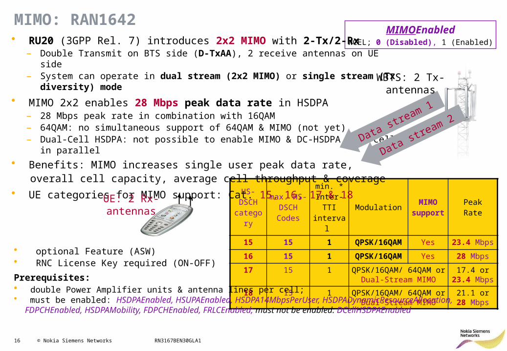
MIMO: RAN1642
HS- DSCH
category
max. HS-DSCH Codes
min. * Inter-TTI interval
ModulationMIMO
supportPeakRate
15 15 1 QPSK/16QAM Yes 23.4 Mbps
16 15 1 QPSK/16QAM Yes 28 Mbps
17 15 1 QPSK/16QAM/ 64QAM or Dual-Stream MIMO
17.4 or 23.4 Mbps
18 15 1 QPSK/16QAM/ 64QAM or Dual-Stream MIMO
21.1 or 28 Mbps
MIMOEnabledWCEL; 0 (Disabled), 1 (Enabled)• RU20 (3GPP Rel. 7) introduces 2x2 MIMO with 2-Tx/2-Rx
– Double Transmit on BTS side (D-TxAA), 2 receive antennas on UE side– System can operate in dual stream (2x2 MIMO) or single stream (Tx diversity) mode
• MIMO 2x2 enables 28 Mbps peak data rate in HSDPA – 28 Mbps peak rate in combination with 16QAM – 64QAM: no simultaneous support of 64QAM & MIMO (not yet)– Dual-Cell HSDPA: not possible to enable MIMO & DC-HSDPA in a cell in parallel
• Benefits: MIMO increases single user peak data rate, overall cell capacity, average cell throughput & coverage • UE categories for MIMO support: Cat. 15, 16, 17 & 18
Data stream 1
UE: 2 Rx-antennas
WBTS: 2 Tx-antennas
Data stream 2
• optional Feature (ASW)• RNC License Key required (ON-OFF)
Prerequisites: • double Power Amplifier units & antenna lines per cell; • must be enabled: HSDPAEnabled, HSUPAEnabled, HSDPA14MbpsPerUser, HSDPADynamicResourceAllocation,
FDPCHEnabled, HSDPAMobility, FDPCHEnabled, FRLCEnabled; must not be enabled: DCellHSDPAEnabled
17 © Nokia Siemens Networks RN3167BEN30GLA1
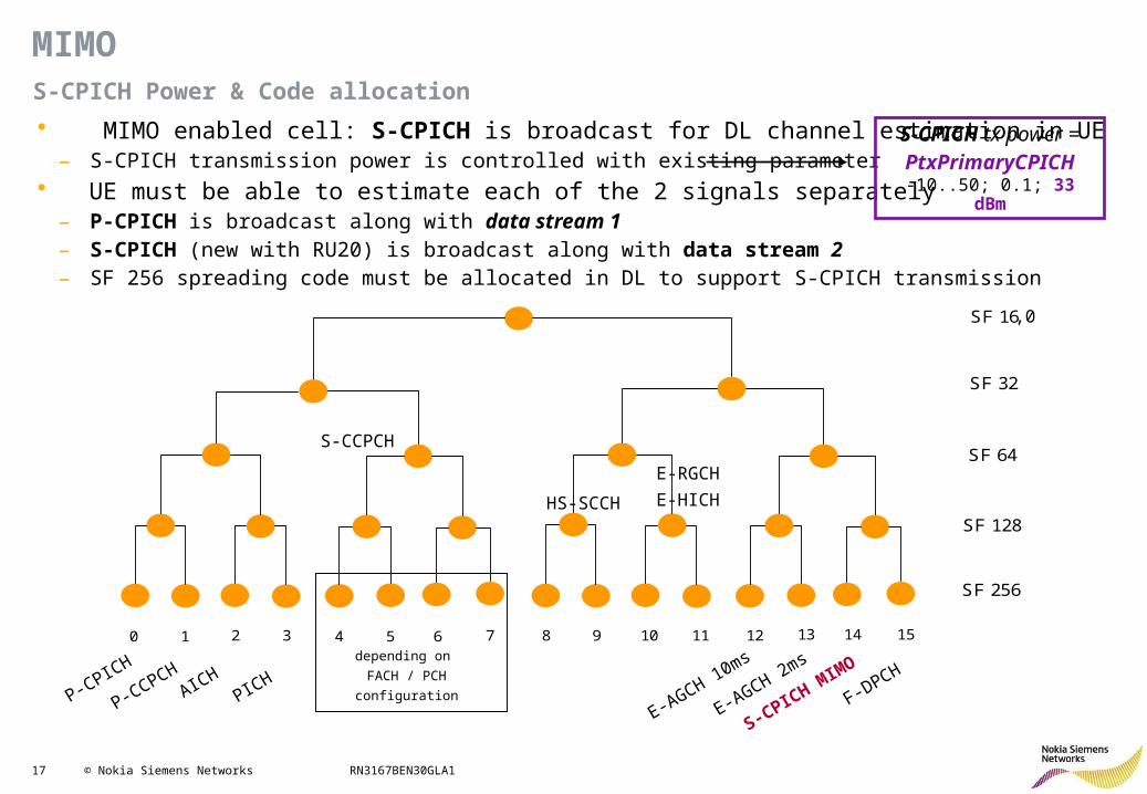
• MIMO enabled cell: S-CPICH is broadcast for DL channel estimation in UE– S-CPICH transmission power is controlled with existing parameter
• UE must be able to estimate each of the 2 signals separately– P-CPICH is broadcast along with data stream 1– S-CPICH (new with RU20) is broadcast along with data stream 2– SF 256 spreading code must be allocated in DL to support S-CPICH transmission
MIMOS-CPICH Power & Code allocation
SF 16
SF 32
SF 64
SF 128
SF 256
0 1 2 3 4 5 6 7 8 9 10 11 12 13 14 15
P-CPICH
P-CCPCHAICH
PICH
S-CCPCH
depending on
FACH / PCH
configuration
HS-SCCH
E-RGCH
E-HICH
E-AGCH 10ms
E-AGCH 2ms
S-CPICH MIM
O
F-DPCH
,0
S-CPICH tx power =PtxPrimaryCPICH-10..50; 0.1; 33 dBm
18 © Nokia Siemens Networks RN3167BEN30GLA1
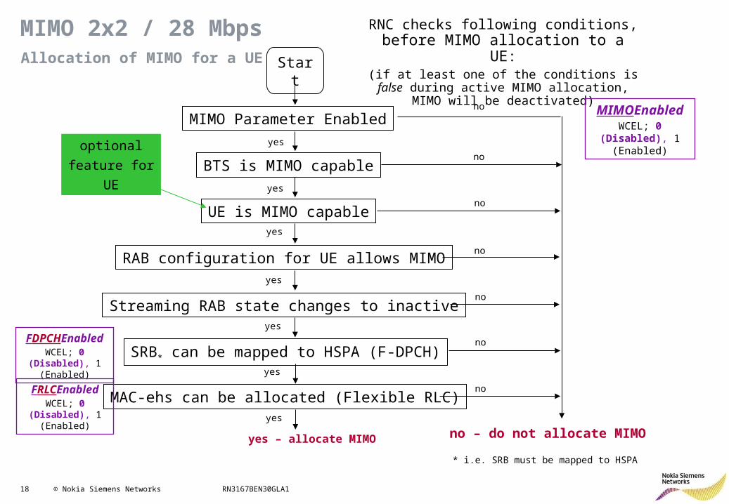
Allocation of MIMO for a UE
MIMO 2x2 / 28 Mbps
MIMO Parameter Enabled
Start
BTS is MIMO capable
RAB configuration for UE allows MIMO
Streaming RAB state changes to inactive
SRB* can be mapped to HSPA (F-DPCH)
MAC-ehs can be allocated (Flexible RLC)
UE is MIMO capable
yes
yes
yes
yes
yes
yes
yes – allocate MIMO
no
no
no
no
no
no
no
no – do not allocate MIMO
optional
feature for
UE
RNC checks following conditions, before MIMO allocation to a UE:
(if at least one of the conditions is false during active MIMO allocation, MIMO will be deactivated)
MIMOEnabledWCEL; 0 (Disabled),
1 (Enabled)
FDPCHEnabledWCEL; 0 (Disabled),
1 (Enabled)
FRLCEnabledWCEL; 0 (Disabled),
1 (Enabled) yes
* i.e. SRB must be mapped to HSPA
19 © Nokia Siemens Networks RN3167BEN30GLA1
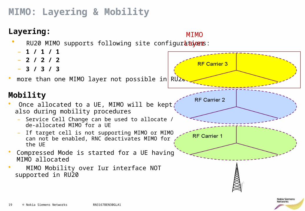
Layering: • RU20 MIMO supports following site configurations:
– 1 / 1 / 1– 2 / 2 / 2– 3 / 3 / 3
• more than one MIMO layer not possible in RU20.
MIMOLayer
MIMO: Layering & Mobility
Mobility• Once allocated to a UE, MIMO will be kept also during
mobility procedures– Service Cell Change can be used to allocate / de-allocated
MIMO for a UE– If target cell is not supporting MIMO or MIMO can not be
enabled, RNC deactivates MIMO for the UE
• Compressed Mode is started for a UE having MIMO allocated
• MIMO Mobility over Iur interface NOT supported in RU20
20 © Nokia Siemens Networks RN3167BEN30GLA1
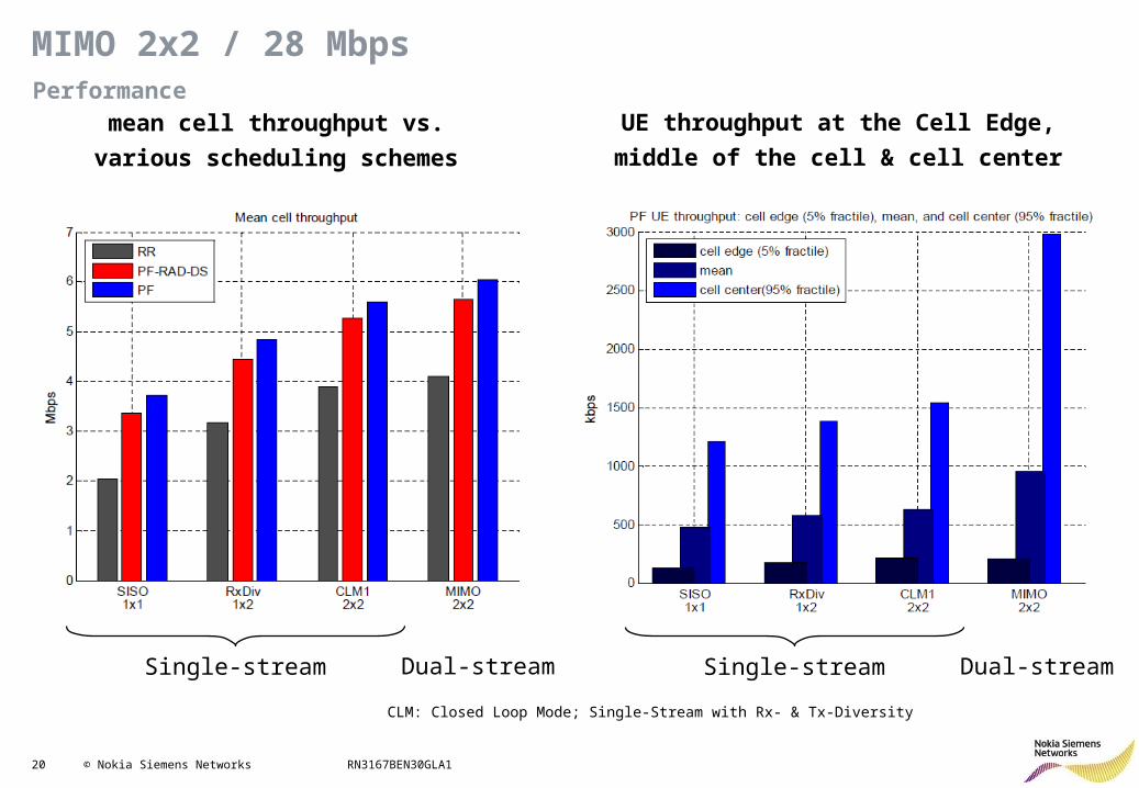
Performance
MIMO 2x2 / 28 Mbps
CLM: Closed Loop Mode; Single-Stream with Rx- & Tx-Diversity
mean cell throughput vs.
various scheduling schemes
UE throughput at the Cell Edge,
middle of the cell & cell center
Single-stream Dual-stream Single-stream Dual-stream
21 © Nokia Siemens Networks RN3167BEN30GLA1
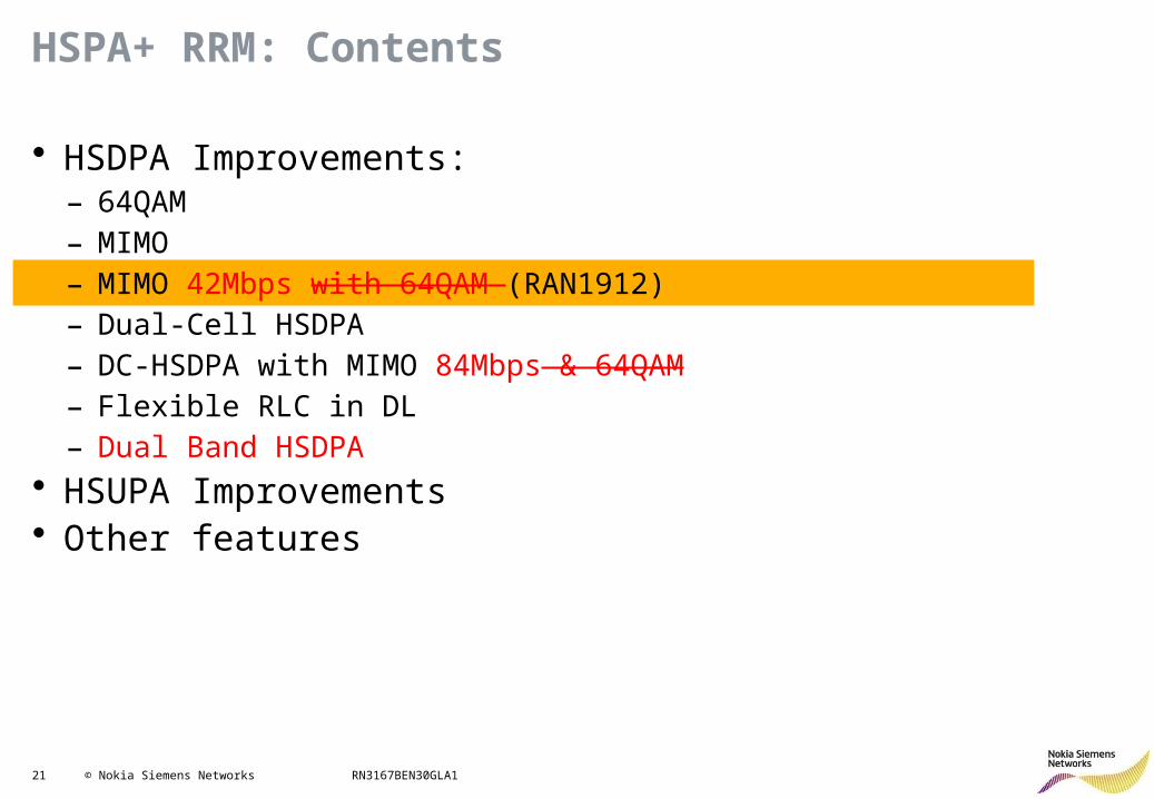
HSPA+ RRM: Contents
• HSDPA Improvements: – 64QAM– MIMO– MIMO 42Mbps with 64QAM (RAN1912)– Dual-Cell HSDPA– DC-HSDPA with MIMO 84Mbps & 64QAM– Flexible RLC in DL– Dual Band HSDPA
• HSUPA Improvements• Other features
22 © Nokia Siemens Networks RN3167BEN30GLA1
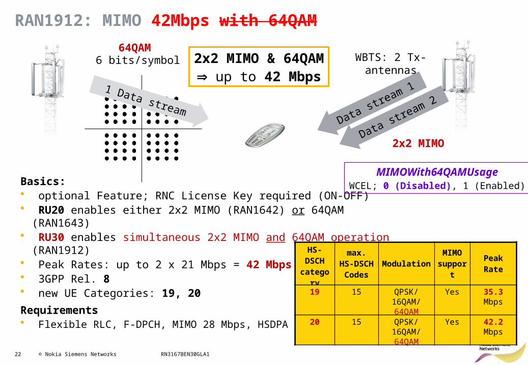
RAN1912: MIMO 42Mbps with 64QAM
64QAM 6 bits/symbol
Data stream 1
WBTS: 2 Tx-antennas
Data stream 21 Data stream
Basics:• optional Feature; RNC License Key required (ON-OFF)• RU20 enables either 2x2 MIMO (RAN1642) or 64QAM (RAN1643)• RU30 enables simultaneous 2x2 MIMO and 64QAM operation (RAN1912)• Peak Rates: up to 2 x 21 Mbps = 42 Mbps• 3GPP Rel. 8• new UE Categories: 19, 20
Requirements• Flexible RLC, F-DPCH, MIMO 28 Mbps, HSDPA 64QAM
2x2 MIMO
MIMOWith64QAMUsageWCEL; 0 (Disabled), 1 (Enabled)
HS- DSCH
category
max. HS-DSCH Codes
ModulationMIMO
support
PeakRate
19 15 QPSK/16QAM/ 64QAM
Yes 35.3 Mbps
20 15 QPSK/16QAM/ 64QAM
Yes 42.2 Mbps
2x2 MIMO & 64QAM up to 42 Mbps
23 © Nokia Siemens Networks RN3167BEN30GLA1
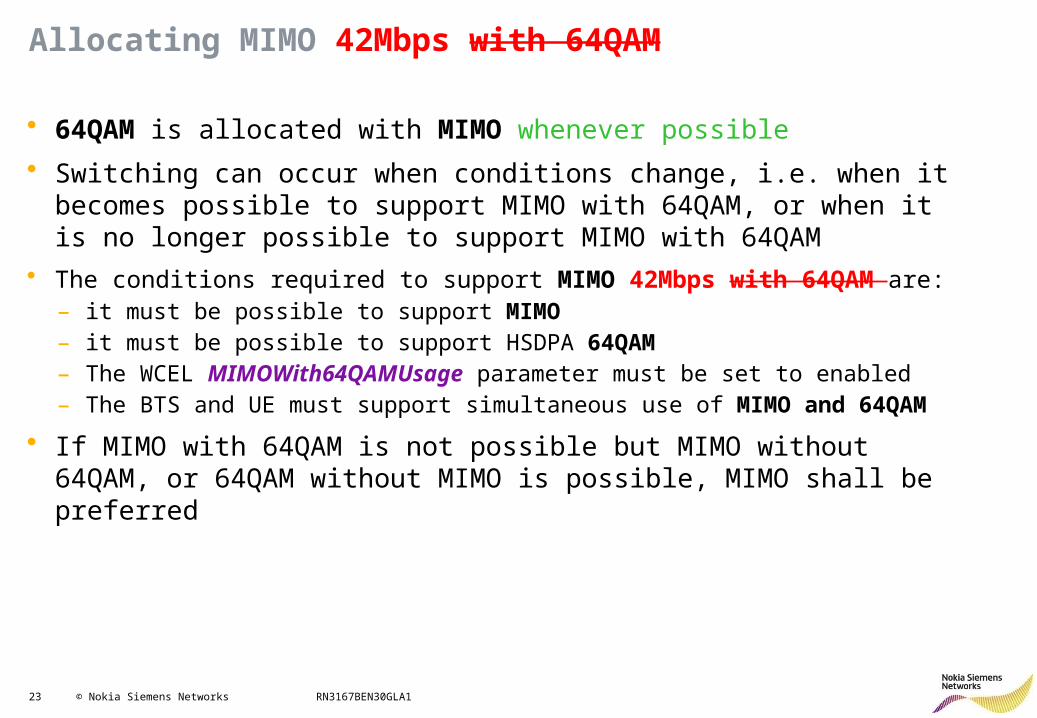
Allocating MIMO 42Mbps with 64QAM
• 64QAM is allocated with MIMO whenever possible
• Switching can occur when conditions change, i.e. when it becomes possible to support MIMO with 64QAM, or when it is no longer possible to support MIMO with 64QAM
• The conditions required to support MIMO 42Mbps with 64QAM are:– it must be possible to support MIMO– it must be possible to support HSDPA 64QAM– The WCEL MIMOWith64QAMUsage parameter must be set to enabled– The BTS and UE must support simultaneous use of MIMO and 64QAM
• If MIMO with 64QAM is not possible but MIMO without 64QAM, or 64QAM without MIMO is possible, MIMO shall be preferred
24 © Nokia Siemens Networks RN3167BEN30GLA1
HSPA+ RRM: Contents
• HSDPA Improvements: – 64QAM– MIMO– MIMO 42Mbps with 64QAM – Dual-Cell HSDPA (RAN1906)– DC-HSDPA with MIMO 84Mbps & 64QAM– Flexible RLC in DL– Dual Band HSDPA
• HSUPA Improvements• Other features
25 © Nokia Siemens Networks RN3167BEN30GLA1
DC-HSDPA Principles (1/2)
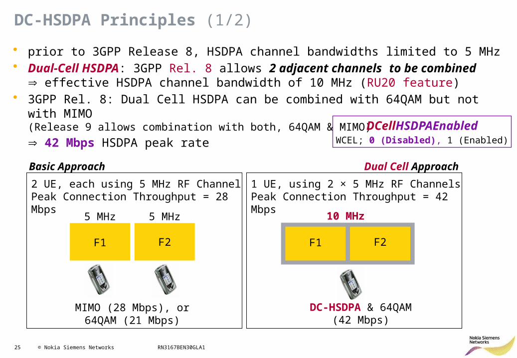
• prior to 3GPP Release 8, HSDPA channel bandwidths limited to 5 MHz• Dual-Cell HSDPA: 3GPP Rel. 8 allows 2 adjacent channels to be combined
effective HSDPA channel bandwidth of 10 MHz (RU20 feature)• 3GPP Rel. 8: Dual Cell HSDPA can be combined with 64QAM but not with MIMO
(Release 9 allows combination with both, 64QAM & MIMO)
42 Mbps HSDPA peak rate
5 MHz 5 MHz
F1 F2
MIMO (28 Mbps), or64QAM (21 Mbps)
10 MHz
DC-HSDPA & 64QAM (42 Mbps)
2 UE, each using 5 MHz RF ChannelPeak Connection Throughput = 28 Mbps
1 UE, using 2 × 5 MHz RF ChannelsPeak Connection Throughput = 42 Mbps
F1 F2
Dual Cell ApproachBasic Approach
DCellHSDPAEnabledWCEL; 0 (Disabled), 1 (Enabled)
26 © Nokia Siemens Networks RN3167BEN30GLA1
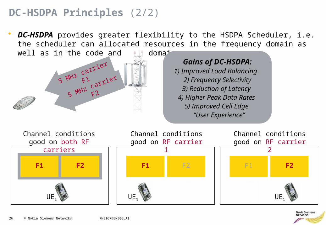
DC-HSDPA Principles (2/2)
• DC-HSDPA provides greater flexibility to the HSDPA Scheduler, i.e. the scheduler can allocated resources in the frequency domain as well as in the code and time domains
F1 F2F1 F2 F1 F2
Channel conditions good on both RF carriers
Channel conditions good on RF carrier 1
Channel conditions good on RF carrier 2
UEx UExUE1UE1 UE1
5 MHz carrier F1
5 MHz carrier F2
Gains of DC-HSDPA:1) Improved Load Balancing
2) Frequency Selectivity3) Reduction of Latency
4) Higher Peak Data Rates 5) Improved Cell Edge “User Experience”
27 © Nokia Siemens Networks RN3167BEN30GLA1
DC-HSDPA: UE Cat & Requirements
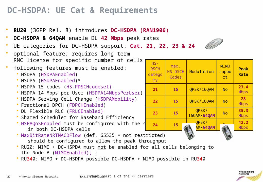
• RU20 (3GPP Rel. 8) introduces DC-HSDPA (RAN1906)• DC-HSDPA & 64QAM enable DL 42 Mbps peak rates• UE categories for DC-HSDPA support: Cat. 21, 22, 23 & 24• optional feature; requires long term
RNC license for specific number of cells• following features must be enabled:
• HSDPA (HSDPAEnabled)• HSUPA (HSUPAEnabled)*• HSDPA 15 codes (HS-PDSCHcodeset) • HSDPA 14 Mbps per User (HSDPA14MbpsPerUser)• HSDPA Serving Cell Change (HSDPAMobility)• Fractional DPCH (FDPCHEnabled)• DL Flexible RLC (FRLCEnabled)• Shared Scheduler for Baseband Efficiency• HSPAQoSEnabled must be configured with the same value in both DC-HSDPA cells• MaxBitRateNRTMACDFlow (def. 65535 = not restricted) should be configured to allow the peak throughput• RU20: MIMO + DC-HSPDA must not be enabled for all cells belonging to the Node B
(MIMOEnabled); ; • RU340: MIMO + DC-HSDPA possible DC-HSDPA + MIMO possible in RU340
HS- DSCH
category
max. HS-DSCH Codes
ModulationMIMO
supportPeakRate
21 15 QPSK/16QAM No 23.4 Mbps
22 15 QPSK/16QAM No 28 Mbps
23 15QPSK/
16QAM/64QAM
No 35.3 Mbps
24 15QPSK/
16QAM/64QAM
No 42.2 Mbps
* at least 1 of the RF carriers
28 © Nokia Siemens Networks RN3167BEN30GLA1
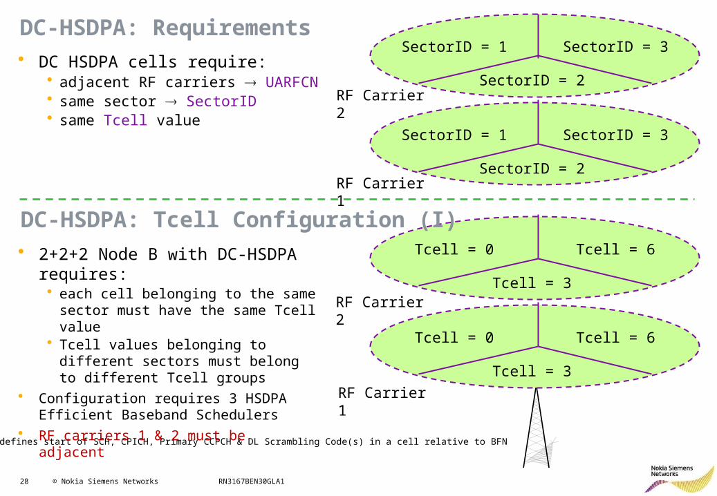
DC-HSDPA: Requirements• DC HSDPA cells require:
• adjacent RF carriers UARFCN• same sector SectorID• same Tcell value
SectorID = 1
RF Carrier 2SectorID = 2
SectorID = 3
SectorID = 1
SectorID = 2
SectorID = 3
RF Carrier 1
Tcell: defines start of SCH, CPICH, Primary CCPCH & DL Scrambling Code(s) in a cell relative to BFN
• 2+2+2 Node B with DC-HSDPA requires:• each cell belonging to the same sector
must have the same Tcell value• Tcell values belonging to different sectors
must belong to different Tcell groups• Configuration requires 3 HSDPA Efficient
Baseband Schedulers• RF carriers 1 & 2 must be adjacent
Tcell = 0
RF Carrier 2Tcell = 3
Tcell = 6
Tcell = 0
Tcell = 3
Tcell = 6
RF Carrier 1
DC-HSDPA: Tcell Configuration (I)
29 © Nokia Siemens Networks RN3167BEN30GLA1
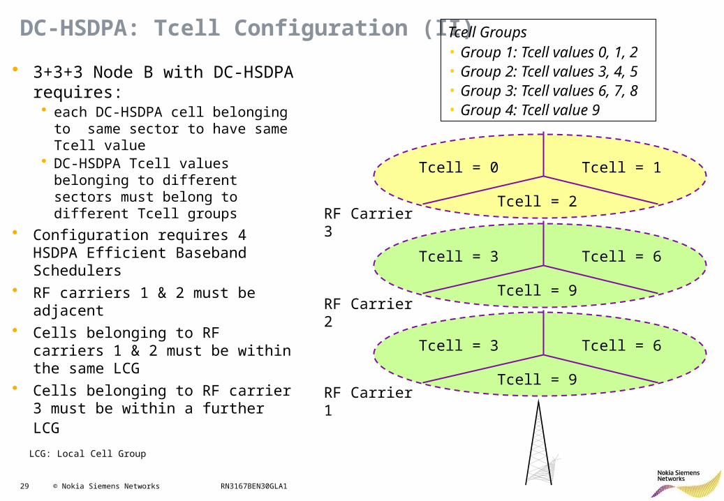
DC-HSDPA: Tcell Configuration (II)
• 3+3+3 Node B with DC-HSDPA requires:• each DC-HSDPA cell belonging to
same sector to have same Tcell value• DC-HSDPA Tcell values belonging to
different sectors must belong to different Tcell groups
• Configuration requires 4 HSDPA Efficient Baseband Schedulers
• RF carriers 1 & 2 must be adjacent• Cells belonging to RF carriers 1 & 2
must be within the same LCG• Cells belonging to RF carrier 3 must be
within a further LCG
Tcell = 3
RF Carrier 2Tcell = 9
Tcell = 6
Tcell = 3
Tcell = 9
Tcell = 6
RF Carrier 1
Tcell = 0
Tcell = 2
Tcell = 1
RF Carrier 3
LCG: Local Cell Group
Tcell Groups• Group 1: Tcell values 0, 1, 2 • Group 2: Tcell values 3, 4, 5• Group 3: Tcell values 6, 7, 8• Group 4: Tcell value 9
30 © Nokia Siemens Networks RN3167BEN30GLA1
DC-HSDPA: HSDPA Scheduler
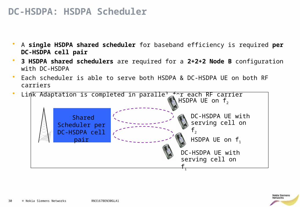
• A single HSDPA shared scheduler for baseband efficiency is required per DC-HSDPA cell pair• 3 HSDPA shared schedulers are required for a 2+2+2 Node B configuration with DC-HSDPA• Each scheduler is able to serve both HSDPA & DC-HSDPA UE on both RF carriers• Link Adaptation is completed in parallel for each RF carrier
Shared Scheduler per DC-HSDPA cell
pair
HSDPA UE on f2
HSDPA UE on f1
DC-HSDPA UE with serving cell on f2
DC-HSDPA UE with serving cell on f1
31 © Nokia Siemens Networks RN3167BEN30GLA1
HSPA+ RRM: Contents
• HSDPA Improvements: – 64QAM– MIMO– MIMO 42Mbps with 64QAM – Dual-Cell HSDPA– DC-HSDPA with MIMO 84Mbps & 64QAM (RAN1907)– Flexible RLC in DL– Dual Band HSDPA
• HSUPA Improvements• Other features
32 © Nokia Siemens Networks RN3167BEN30GLA1
DC-HSDPA with MIMO & 64QAM
64QAM 6 bits/symbol
Data stream 1
WBTS: 2 Tx-antennas
Data stream 21 Data stream
2x2 MIMO
5 MHz carrier F1
5 MHz carrier F2
Dual-Cell (DC-)HSDPA
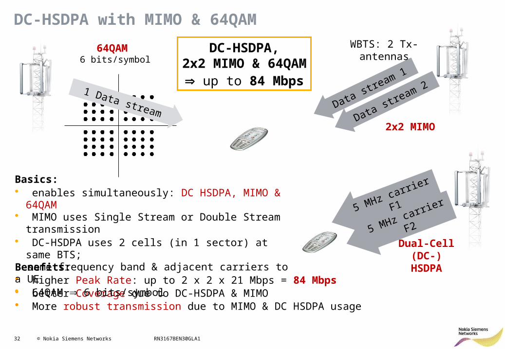
Benefits:• higher Peak Rate: up to 2 x 2 x 21 Mbps = 84 Mbps• better Coverage due to DC-HSDPA & MIMO• More robust transmission due to MIMO & DC HSDPA usage
Basics:• enables simultaneously: DC HSDPA, MIMO & 64QAM• MIMO uses Single Stream or Double Stream
transmission• DC-HSDPA uses 2 cells (in 1 sector) at same BTS; same frequency band & adjacent carriers to a UE• 64QAM 6 bits/symbol
DC-HSDPA,2x2 MIMO & 64QAM
up to 84 Mbps

33 © Nokia Siemens Networks RN3167BEN30GLA1
DC-HSDPA with MIMO & 64QAM
Feature Enabling:• DC-HSDPA with MIMO 84 Mbps: optional feature; but: w/o own license; required licenses:
- RAN1642 MIMO (28 Mbps)- RAN1643 HSDPA 64QAM- RAN1906 DC-HSDPA 42 Mbps
• DC-HSDPA + MIMO can be enabled w/o 64QAM Peak Rate up to 56 Mbps
• to enable Peak Rate = 84 Mbps DCellAndMIMOUsage must be enabled & MIMOWith64QAMUsage = 2
DCellAndMIMOUsageWCEL; 0 (DC-HSDPA & MIMO disabled),
1 (DC-HSDPA & MIMO w/o 64QAM enabled),2 (DC-HSDPA & MIMO with 64QAM enabled)
MIMO + 64QAM RASN1912 / 3GPP Rel. 87
DB-DC-HSDPA + 64QAMRASN2179 / 3GPP Rel. 9
DC-HSDPA + MIMO3GPP Rel. 9
42 Mbps 42 Mbps 56 Mbps
DC-HSDPA + MIMO + 64QAM3GPP Rel. 9
84 Mbps both supported by RAN1907
max. Peak Rate in RU340
MIMOWith64QAMUsageWCEL; 0 (Disabled), 1 (Enabled)
w/o64QAM
34 © Nokia Siemens Networks RN3167BEN30GLA1
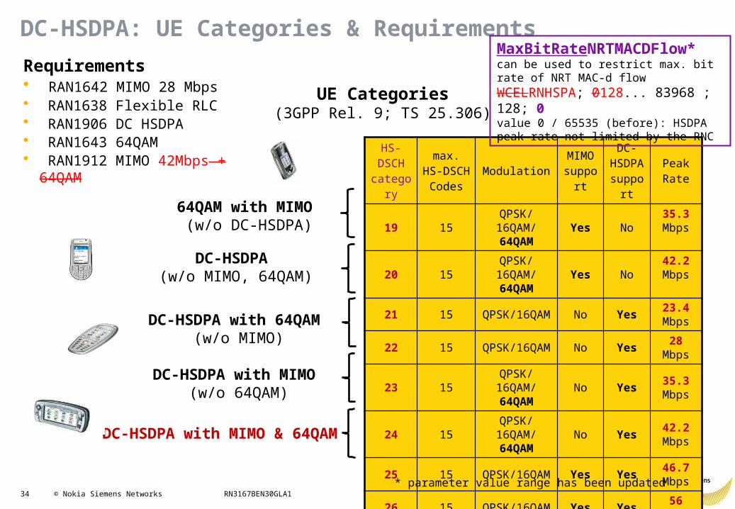
DC-HSDPA: UE Categories & Requirements
HS- DSCH
category
max. HS-DSCH Codes
ModulationMIMO
support
DC-HSDPA support
PeakRate
19 15QPSK/
16QAM/ 64QAM
Yes No35.3 Mbps
20 15QPSK/
16QAM/ 64QAM
Yes No42.2 Mbps
21 15 QPSK/16QAM No Yes 23.4 Mbps
22 15 QPSK/16QAM No Yes 28 Mbps
23 15QPSK/
16QAM/ 64QAM
No Yes 35.3 Mbps
24 15QPSK/
16QAM/ 64QAM
No Yes 42.2 Mbps
25 15 QPSK/16QAM Yes Yes 46.7 Mbps
26 15 QPSK/16QAM Yes Yes 56 Mbps
27 15QPSK/
16QAM/ 64QAM
Yes Yes 70.6 Mbps
28 15QPSK/
16QAM/ 64QAM
Yes Yes 84.4 Mbps
Requirements• RAN1642 MIMO 28 Mbps• RAN1638 Flexible RLC • RAN1906 DC HSDPA• RAN1643 64QAM• RAN1912 MIMO 42Mbps +
64QAM
DC-HSDPA with MIMO & 64QAM
DC-HSDPA with MIMO (w/o 64QAM)
DC-HSDPA with 64QAM (w/o MIMO)
DC-HSDPA (w/o MIMO, 64QAM)
64QAM with MIMO (w/o DC-HSDPA)
UE Categories(3GPP Rel. 9; TS 25.306)
MaxBitRateNRTMACDFlow* can be used to restrict max. bit rate of NRT MAC-d flow WCELRNHSPA; 0128... 83968 ; 128; 0value 0 / 65535 (before): HSDPA peak rate not limited by the RNC
* parameter value range has been updated
35 © Nokia Siemens Networks RN3167BEN30GLA1
DC-HSDPA: Mobility
Carrier f1
Carrier f2
Carrier f1
Carrier f2
HardHandover HHO
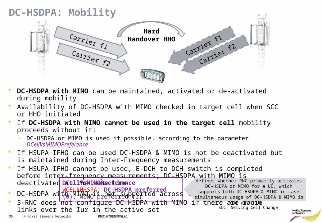
• DC-HSDPA with MIMO can be maintained, activated or de-activated during mobility• Availability of DC-HSDPA with MIMO checked in target cell when SCC or HHO initiated• If DC-HSDPA with MIMO cannot be used in the target cell mobility proceeds without it:
– DC-HSDPA or MIMO is used if possible, according to the parameter DCellVsMIMOPreference • If HSUPA IFHO can be used DC-HSDPA & MIMO is not be deactivated but is maintained
during Inter-Frequency measurements• If HSUPA IFHO cannot be used, E-DCH to DCH switch is completed before inter-frequency
measurements; DC-HSDPA with MIMO is deactivated at the same time
• DC-HSDPA with MIMO is not supported across the Iur• S-RNC does not configure DC-HSDPA with MIMO if there are radio links over the Iur in the
active set
SCC: Serving Cell Change
DCellVsMIMOPreferenceWCELRNHSPA; DC-HSDPA preferred (0), MIMO preferred (1)
defines whether RNC primarily activates DC-HSDPA or MIMO for a UE, which supports both DC-HSDPA & MIMO in case simultaneous usage of DC-HSDPA &
MIMO is not possible.
36 © Nokia Siemens Networks RN3167BEN30GLA1
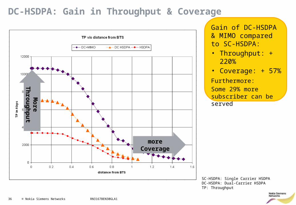
DC-HSDPA: Gain in Throughput & Coverage
Gain of DC-HSDPA & MIMO compared to SC-HSDPA:• Throughput: + 220%• Coverage: + 57%
Furthermore:Some 29% more subscriber can be served
SC-HSDPA: Single Carrier HSDPADC-HSDPA: Dual-Carrier HSDPATP: Throughput
more Coverage
Mo
re Th
rou
gh
pu
t
37 © Nokia Siemens Networks RN3167BEN30GLA1
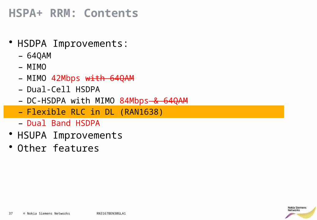
HSPA+ RRM: Contents
• HSDPA Improvements: – 64QAM– MIMO– MIMO 42Mbps with 64QAM – Dual-Cell HSDPA– DC-HSDPA with MIMO 84Mbps & 64QAM– Flexible RLC in DL (RAN1638)– Dual Band HSDPA
• HSUPA Improvements• Other features
38 © Nokia Siemens Networks RN3167BEN30GLA1
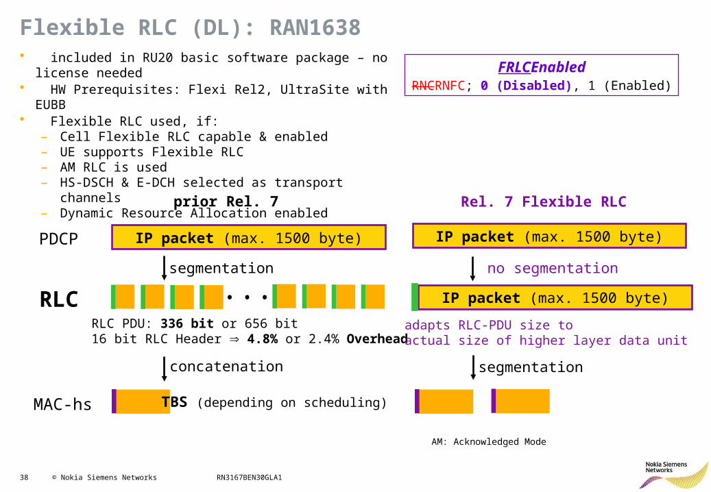
Flexible RLC (DL): RAN1638
FRLCEnabledRNCRNFC; 0 (Disabled), 1 (Enabled)
• included in RU20 basic software package – no license needed
• HW Prerequisites: Flexi Rel2, UltraSite with EUBB• Flexible RLC used, if:
– Cell Flexible RLC capable & enabled – UE supports Flexible RLC– AM RLC is used– HS-DSCH & E-DCH selected as transport channels– Dynamic Resource Allocation enabled
AM: Acknowledged Mode
prior Rel. 7
RLC
PDCP IP packet (max. 1500 byte)
Rel. 7 Flexible RLC
segmentation
RLC PDU: 336 bit or 656 bit16 bit RLC Header 4.8% or 2.4% Overhead
MAC-hs
IP packet (max. 1500 byte)
• • •
concatenation
TBS (depending on scheduling)
IP packet (max. 1500 byte)
adapts RLC-PDU size to actual size of higher layer data unit
no segmentation
segmentation
39 © Nokia Siemens Networks RN3167BEN30GLA1
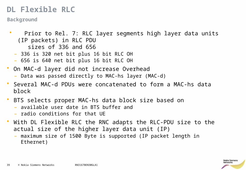
DL Flexible RLC
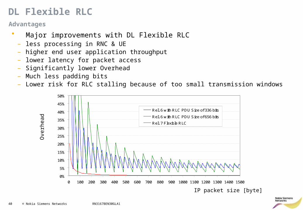
• Prior to Rel. 7: RLC layer segments high layer data units (IP packets) in RLC PDU sizes of 336 and 656
– 336 is 320 net bit plus 16 bit RLC OH– 656 is 640 net bit plus 16 bit RLC OH
• On MAC-d layer did not increase Overhead– Data was passed directly to MAC-hs layer (MAC-d)
• Several MAC-d PDUs were concatenated to form a MAC-hs data block
• BTS selects proper MAC-hs data block size based on– available user date in BTS buffer and– radio conditions for that UE
• With DL Flexible RLC the RNC adapts the RLC-PDU size to the actual size of the higher layer data unit (IP)– maximum size of 1500 Byte is supported (IP packet length in Ethernet)
Background
40 © Nokia Siemens Networks RN3167BEN30GLA1
DL Flexible RLC
• Major improvements with DL Flexible RLC– less processing in RNC & UE– higher end user application throughput– lower latency for packet access– Significantly lower Overhead– Much less padding bits – Lower risk for RLC stalling because of too small transmission windows
Advantages
0%
5%
10%
15%
20%
25%
30%
35%
40%
45%
50%
0 100 200 300 400 500 600 700 800 900 1000 1100 1200 1300 1400 1500
Rel. 6 with RLC PDU Size of 336 bits
Rel. 6 with RLC PDU Size of 656 bits
Rel. 7 Flexible RLC
Ove
rhe
ad
IP packet size [byte]
41 © Nokia Siemens Networks RN3167BEN30GLA1
HSPA+ RRM: Contents
• HSDPA Improvements: – 64QAM– MIMO– MIMO 42Mbps– Dual-Cell HSDPA– DC-HSDPA with MIMO 84Mbps– Flexible RLC in DL– Dual Band HSDPA (RAN2179)
• HSUPA Improvements• Other features
42 © Nokia Siemens Networks RN3167BEN30GLA1
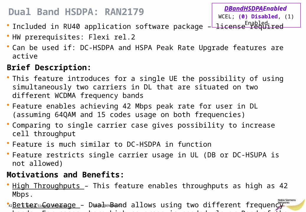
Dual Band HSDPA: RAN2179• Included in RU40 application software package – license required• HW prerequisites: Flexi rel.2• Can be used if: DC-HSDPA and HSPA Peak Rate Upgrade features are active
Brief Description: • This feature introduces for a single UE the possibility of using simultaneously two carriers
in DL that are situated on two different WCDMA frequency bands• Feature enables achieving 42 Mbps peak rate for user in DL (assuming 64QAM and 15
codes usage on both frequencies)• Comparing to single carrier case gives possibility to increase cell throughput• Feature is much similar to DC-HSDPA in function• Feature restricts single carrier usage in UL (DB or DC-HSUPA is not allowed)
Motivations and Benefits:• High Throughputs – This feature enables throughputs as high as 42 Mbps.• Better Coverage – Dual Band allows using two different frequency bands. For cases
where high coverage is needed, lower Band of the two can be used to enhance coverage.• Configurations flexibility – This feature with carriers from 2 different frequency bands
allows more flexibility in spectrum assignments
DBandHSDPAEnabled WCEL; (0) Disabled, (1) Enabled
43 © Nokia Siemens Networks RN3167BEN30GLA1
Dual Band HSDPA: With and Without the Feature
U900*
2 x 5 MHz
U2100
f1 f2
U900*U2100*U2100*
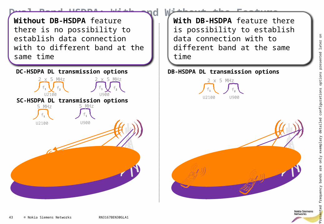
Without DB-HSDPA feature there is no possibility to establish data connection with to different band at the same time
2 x 5 MHz
U900
f1 f2
f1
U2100
5 MHz
f1
U900
5 MHz
DC-HSDPA DL transmission options
SC-HSDPA DL transmission options
2 x 5 MHz
f1 f2
DB-HSDPA DL transmission options
With DB-HSDPA feature there is possibility to establish data connection with to different band at the same time
U2100 U900
*Pre
sent
ed f
requ
ency
ban
ds a
re o
nly
exem
plar
y de
taile
d co
nfig
urat
ions
opt
ions
pre
sent
ed la
ter
on
44 © Nokia Siemens Networks RN3167BEN30GLA1
HSPA+ RRM: Contents
• HSDPA Improvements• HSUPA Improvements:
– Frequency Domain Equalizer (RAN1702)– HSUPA Interference Cancellation Receiver (RAN1308)– HSUPA 16QAM (RAN1645)– Flexible RLC in UL (RAN1910)– HSUPA Downlink Physical Channel Power Control (RAN971)– Dynamic HSUPA BLER (RAN2302)
• Other features
45 © Nokia Siemens Networks RN3167BEN30GLA1
HSPA+ RRM: Contents
• HSDPA Improvements• HSUPA Improvements:
– Frequency Domain Equalizer (RAN1702)– HSUPA Interference Cancellation Receiver– HSUPA 16QAM– Flexible RLC in UL– HSUPA Downlink Physical Channel Power Control– Dynamic HSUPA BLER
• Other features
46 © Nokia Siemens Networks RN3167BEN30GLA1
Frequency Domain Equalizer
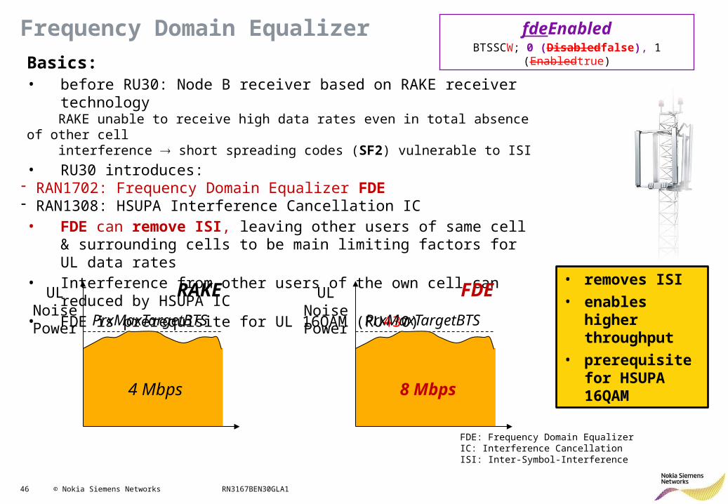
Basics:• before RU30: Node B receiver based on RAKE receiver technology RAKE unable to receive high data rates even in total absence of other cell interference short spreading codes (SF2) vulnerable to ISI
• RU30 introduces:- RAN1702: Frequency Domain Equalizer FDE- RAN1308: HSUPA Interference Cancellation IC• FDE can remove ISI, leaving other users of same cell & surrounding
cells to be main limiting factors for UL data rates• Interference from other users of the own cell can reduced by HSUPA IC• FDE is prerequisite for UL 16QAM (RU430)
PrxMaxTargetBTS
UL Noise Power PrxMaxTargetBTS
4 Mbps 8 Mbps
RAKE FDEUL Noise Power
fdeEnabledBTSSCW; 0 (Disabledfalse), 1 (Enabledtrue)
FDE: Frequency Domain EqualizerIC: Interference CancellationISI: Inter-Symbol-Interference
• removes ISI
• enables higher throughput
• prerequisite for HSUPA 16QAM
47 © Nokia Siemens Networks RN3167BEN30GLA1
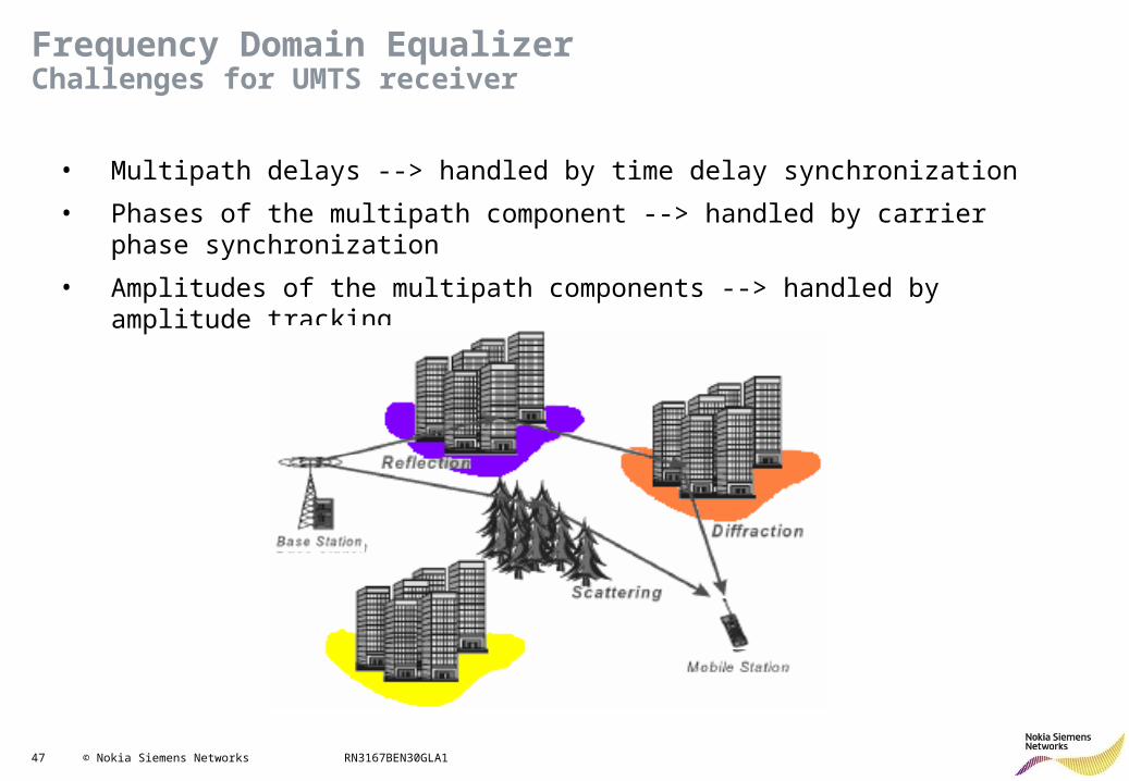
• Multipath delays --> handled by time delay synchronization
• Phases of the multipath component --> handled by carrier phase synchronization
• Amplitudes of the multipath components --> handled by amplitude tracking
Frequency Domain EqualizerChallenges for UMTS receiver
48 © Nokia Siemens Networks RN3167BEN30GLA1
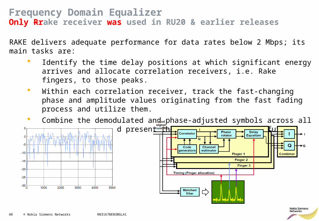
Frequency Domain EqualizerOnly Rrake receiver was used in RU20 & earlier releases
RAKE delivers adequate performance for data rates below 2 Mbps; its main tasks are: Identify the time delay positions at which significant energy arrives and allocate
correlation receivers, i.e. Rake fingers, to those peaks. Within each correlation receiver, track the fast-changing phase and amplitude
values originating from the fast fading process and utilize them. Combine the demodulated and phase-adjusted symbols across all active fingers
and present them to the decoder for further processing.
49 © Nokia Siemens Networks RN3167BEN30GLA1
Frequency Domain EqualizerFDE = linear equalizer + fast convolution
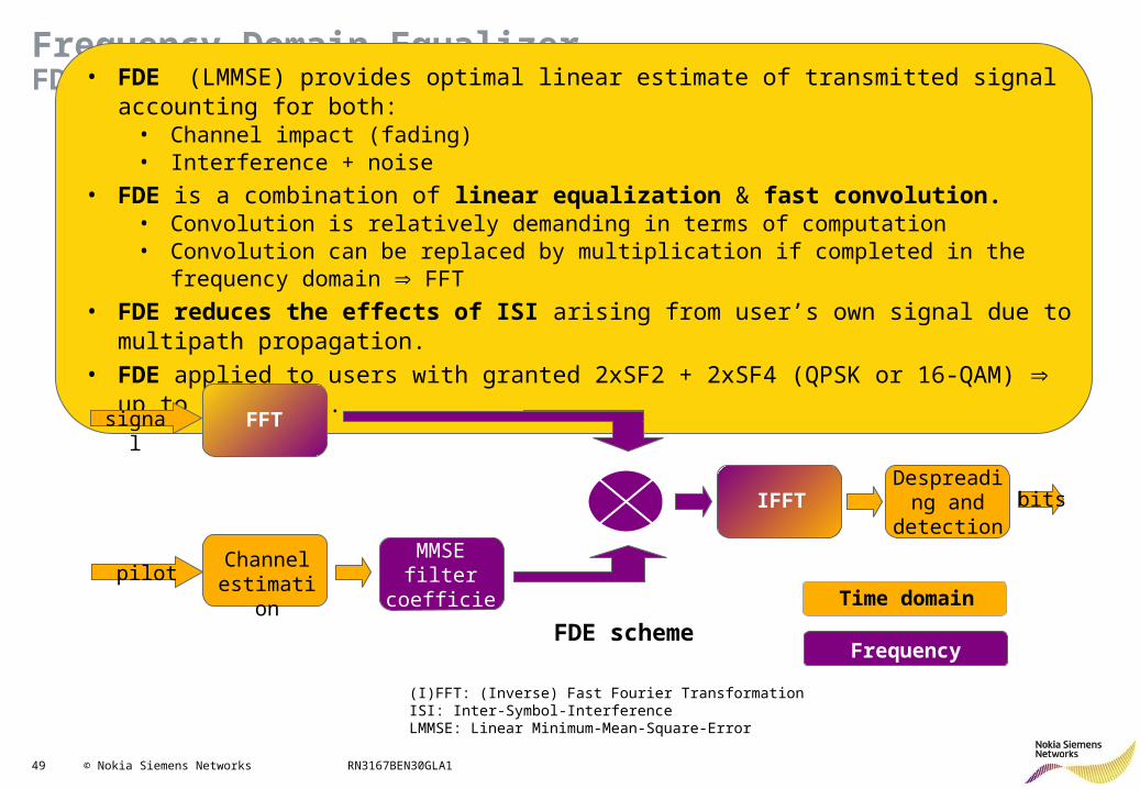
• FDE (LMMSE) provides optimal linear estimate of transmitted signal accounting for both:• Channel impact (fading)• Interference + noise
• FDE is a combination of linear equalization & fast convolution. • Convolution is relatively demanding in terms of computation • Convolution can be replaced by multiplication if completed in the frequency domain FFT
• FDE reduces the effects of ISI arising from user’s own signal due to multipath propagation.• FDE applied to users with granted 2xSF2 + 2xSF4 (QPSK or 16-QAM) up to 11.5 Mbps.
FDE scheme
signal FFT
pilotChannel
estimation
MMSE filter coefficient calculation
IFFTDespreading
and detection
bits
Time domain
Frequency domain
(I)FFT: (Inverse) Fast Fourier TransformationISI: Inter-Symbol-InterferenceLMMSE: Linear Minimum-Mean-Square-Error
50 © Nokia Siemens Networks RN3167BEN30GLA1
Frequency Domain EqualizerE-DPCCH boosted mode
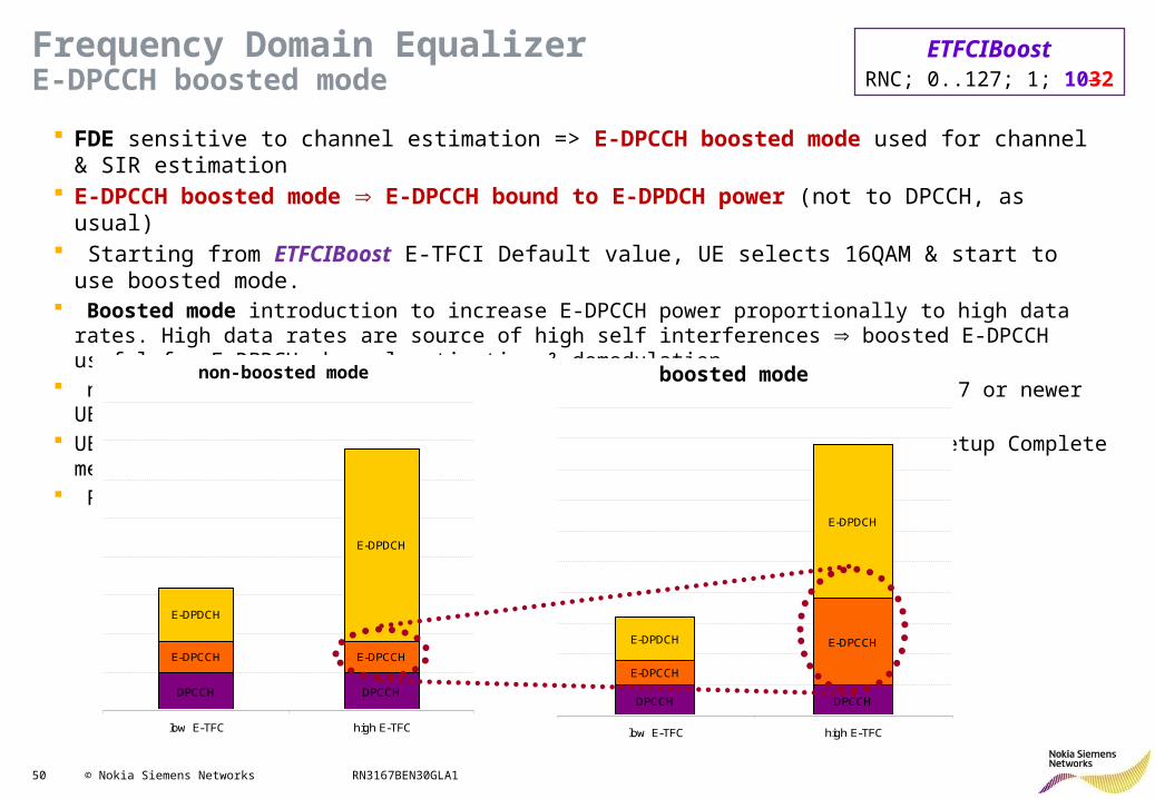
FDE sensitive to channel estimation => E-DPCCH boosted mode used for channel & SIR estimation E-DPCCH boosted mode E-DPCCH bound to E-DPDCH power (not to DPCCH, as usual) Starting from ETFCIBoost E-TFCI Default value, UE selects 16QAM & start to use boosted mode. Boosted mode introduction to increase E-DPCCH power proportionally to high data rates. High data rates are
source of high self interferences boosted E-DPCCH useful for E-DPDCH channel estimation & demodulation. not mandatory for UE to support E-DPCCH power boosting (requires Rel. 7 or newer UE) UE indicates support of E-DPCCH power boosting within RRC Connection Setup Complete message RNC signals E-DPCCH power boosting parameters to UE
non-boosted mode
DPCCH DPCCH
E-DPCCH E-DPCCH
E-DPDCH
E-DPDCH
low E-TFC high E-TFC
boosted mode
DPCCH DPCCH
E-DPCCH
E-DPCCHE-DPDCH
E-DPDCH
low E-TFC high E-TFC
non-boosted mode boosted mode
ETFCIBoostRNC; 0..127; 1; 1032
51 © Nokia Siemens Networks RN3167BEN30GLA1
HSPA+ RRM: Contents
• HSDPA Improvements• HSUPA Improvements:
– Frequency Domain Equalizer– HSUPA Interference Cancellation Receiver (RAN1308)– HSUPA 16QAM– Flexible RLC in UL– HSUPA Downlink Physical Channel Power Control– Dynamic HSUPA BLER
• Other features
52 © Nokia Siemens Networks RN3167BEN30GLA1
HSUPA Interference Cancellation Receiver
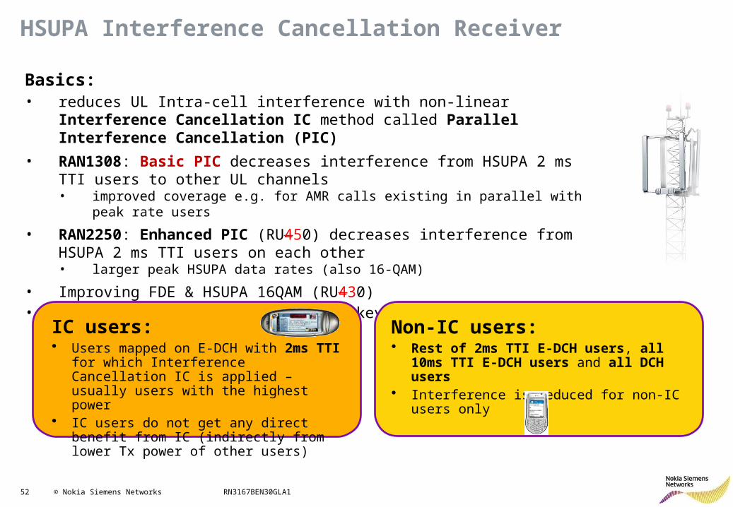
Basics:• reduces UL Intra-cell interference with non-linear Interference Cancellation IC
method called Parallel Interference Cancellation (PIC)
• RAN1308: Basic PIC decreases interference from HSUPA 2 ms TTI users to other UL channels • improved coverage e.g. for AMR calls existing in parallel with peak rate users
• RAN2250: Enhanced PIC (RU450) decreases interference from HSUPA 2 ms TTI users on each other • larger peak HSUPA data rates (also 16-QAM)
• Improving FDE & HSUPA 16QAM (RU430)• Feature activated by BTS license key
IC users:• Users mapped on E-DCH with 2ms TTI for
which Interference Cancellation IC is applied – usually users with the highest power
• IC users do not get any direct benefit from IC (indirectly from lower Tx power of other users)
Non-IC users:• Rest of 2ms TTI E-DCH users, all 10ms TTI
E-DCH users and all DCH users• Interference is reduced for non-IC users only
53 © Nokia Siemens Networks RN3167BEN30GLA1
Basic Parallel Interference Cancellation (PIC) method
Re-modulate2ms HSUPA
De-modulate2ms HSUPA
2ms HSUPAuser data
UL signal fromantenna
De-modulateother
10ms HSUPA,DCH
user data
2ms HSUPA Interference cancelled Non-IC users signal
(Residual signal)
“IC users”
“Non-IC users”
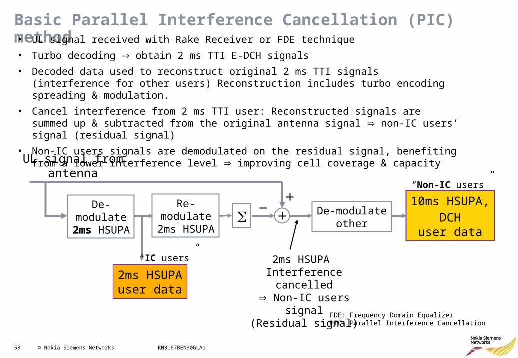
• UL signal received with Rake Receiver or FDE technique
• Turbo decoding obtain 2 ms TTI E-DCH signals
• Decoded data used to reconstruct original 2 ms TTI signals (interference for other users) Reconstruction includes turbo encoding spreading & modulation.
• Cancel interference from 2 ms TTI user: Reconstructed signals are summed up & subtracted from the original antenna signal non-IC users’ signal (residual signal)
• Non-IC users signals are demodulated on the residual signal, benefiting from a lower interference level improving cell coverage & capacity
FDE: Frequency Domain EqualizerPIC: Parallel Interference Cancellation
54 © Nokia Siemens Networks RN3167BEN30GLA1
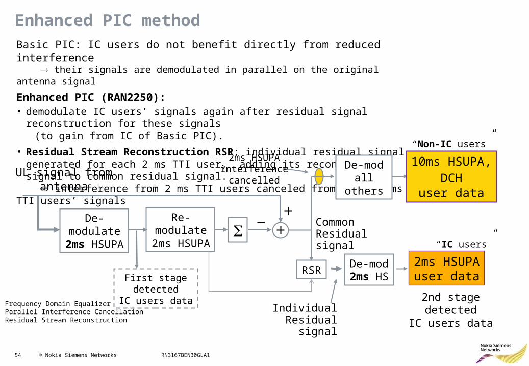
Enhanced PIC methodBasic PIC: IC users do not benefit directly from reduced interference
their signals are demodulated in parallel on the original antenna signal
Enhanced PIC (RAN2250): • demodulate IC users’ signals again after residual signal reconstruction for these
signals (to gain from IC of Basic PIC).
• Residual Stream Reconstruction RSR: individual residual signal generated for each 2 ms TTI user, adding its reconstructed signal to common residual signal.
interference from 2 ms TTI users canceled from other 2 ms TTI users’ signals
FDE: Frequency Domain EqualizerPIC: Parallel Interference CancellationRSR: Residual Stream Reconstruction
UL signal fromantenna
De-modall others
2ms HSUPAinterferencecancelled
RSRDe-mod2ms HS
10ms HSUPA,DCH
user data
“Non-IC users”
2ms HSUPAuser data
“IC users”
CommonResidual signal
First stagedetected
IC users dataIndividual
Residual signal
2nd stage detectedIC users data
Re-modulate2ms HSUPA
De-modulate2ms HSUPA
55 © Nokia Siemens Networks RN3167BEN30GLA1
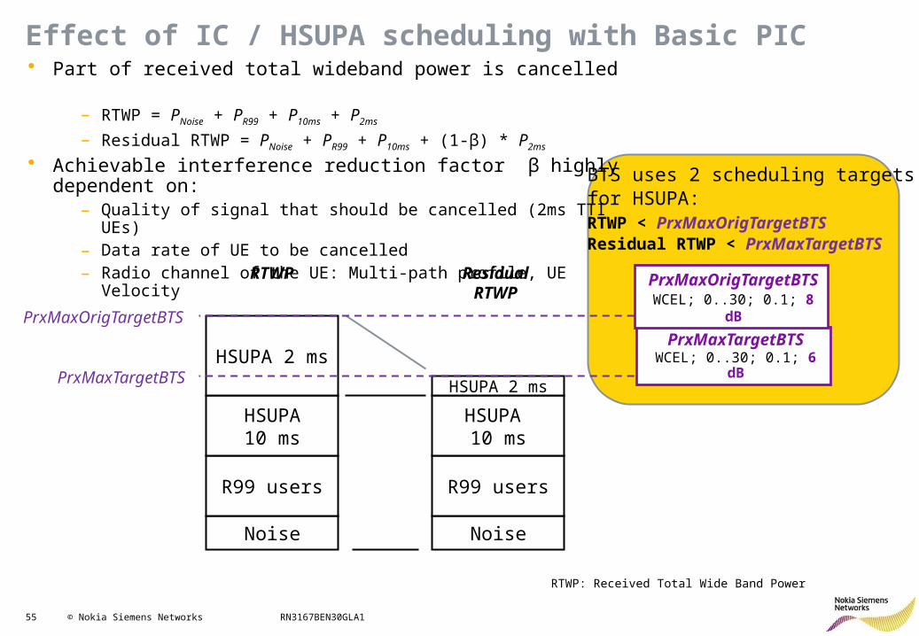
Effect of IC / HSUPA scheduling with Basic PIC• Part of received total wideband power is cancelled
– RTWP = PNoise + PR99 + P10ms + P2ms
– Residual RTWP = PNoise + PR99 + P10ms + (1-β) * P2ms
• Achievable interference reduction factor β highly dependent on:– Quality of signal that should be cancelled (2ms TTI UEs)– Data rate of UE to be cancelled– Radio channel of the UE: Multi-path profile, UE Velocity
Noise
R99 users
HSUPA10 ms
HSUPA 2 ms
Noise
R99 users
HSUPA 10 ms
HSUPA 2 ms
PrxMaxOrigTargetBTS
PrxMaxTargetBTS
RTWP ResidualRTWP
PrxMaxTargetBTSWCEL; 0..30; 0.1; 6 dB
PrxMaxOrigTargetBTSWCEL; 0..30; 0.1; 8 dB
BTS uses 2 scheduling targetsfor HSUPA:RTWP < PrxMaxOrigTargetBTSResidual RTWP < PrxMaxTargetBTS
RTWP: Received Total Wide Band Power
56 © Nokia Siemens Networks RN3167BEN30GLA1
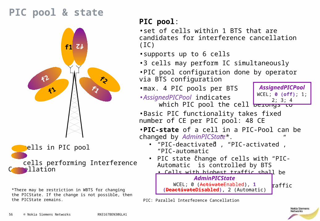
PIC pool & state
PIC: Parallel Interference Cancellation
PIC pool: •set of cells within 1 BTS that are candidates for interference cancellation (IC)•supports up to 6 cells•3 cells may perform IC simultaneously•PIC pool configuration done by operator via BTS configuration•max. 4 PIC pools per BTS•AssignedPICPool indicates which PIC pool the cell belongs to •Basic PIC functionality takes fixed number of CE per PIC pool: 48 CE•PIC-state of a cell in a PIC-Pool can be changed by AdminPICState*.
• “PIC-deactivated”, “PIC-activated”, “PIC-automatic”• PIC state change of cells with “PIC-Automatic” is
controlled by BTS• Cells with highest traffic shall be selected for IC• Cell are deselected for IC if traffic has decreased
f1 f2
cells in PIC pool
cells performing InterferenceCancellation
f1f1
f2 f2
AdminPICStateWCEL; 0 (ActivateEnabled), 1
(DeactivateDisabled), 2 (Automatic)
AssignedPICPoolWCEL; 0 (off); 1; 2; 3; 4
*There may be restriction in WBTS for changing the PICState. If the change is not possible, then the PICState remains.
57 © Nokia Siemens Networks RN3167BEN30GLA1
HSPA+ RRM: Contents
• HSDPA Improvements• HSUPA Improvements:
– Frequency Domain Equalizer– HSUPA Interference Cancellation Receiver– HSUPA 16QAM (RAN1645)– Flexible RLC in UL– HSUPA Downlink Physical Channel Power Control– Dynamic HSUPA BLER
• Other features
58 © Nokia Siemens Networks RN3167BEN30GLA1
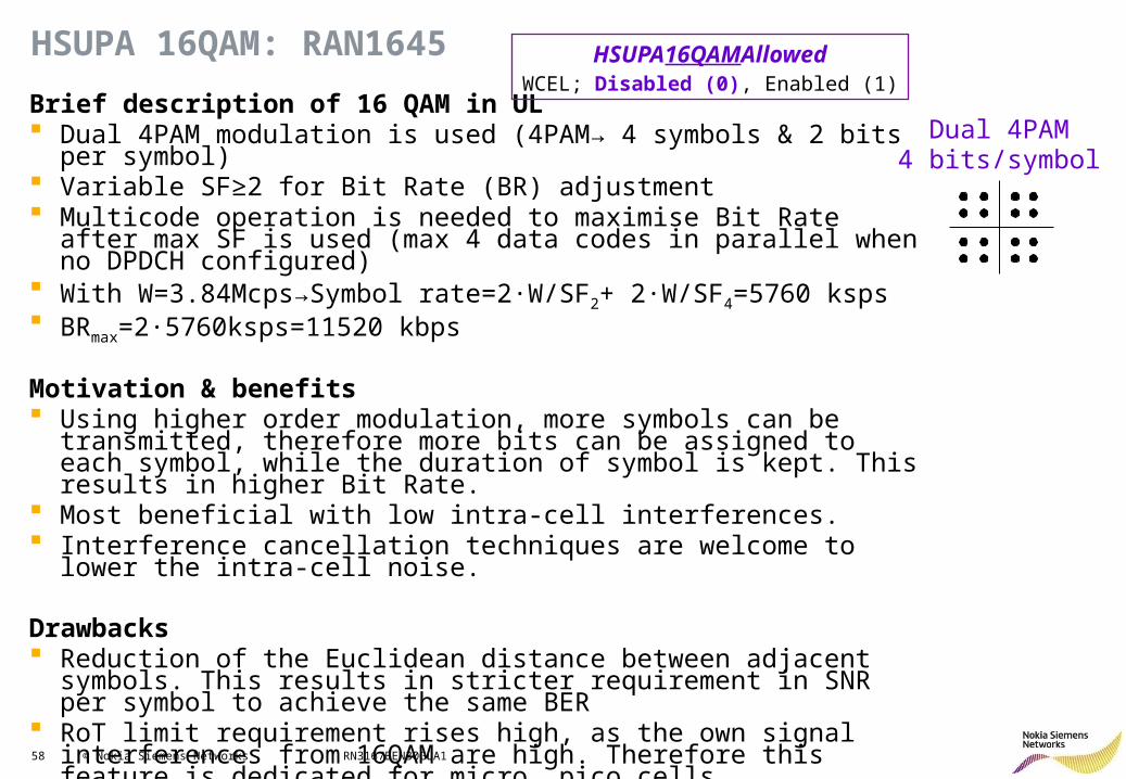
HSUPA 16QAM: RAN1645
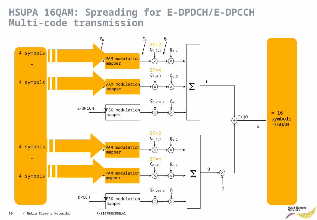
Brief description of 16 QAM in UL Dual 4PAM modulation is used (4PAM→ 4 symbols & 2 bits per symbol) Variable SF≥2 for Bit Rate (BR) adjustment Multicode operation is needed to maximise Bit Rate after max SF is used
(max 4 data codes in parallel when no DPDCH configured) With W=3.84Mcps→Symbol rate=2·W/SF2+ 2·W/SF4=5760 ksps BRmax=2·5760ksps=11520 kbps
Motivation & benefits Using higher order modulation, more symbols can be transmitted, therefore
more bits can be assigned to each symbol, while the duration of symbol is kept. This results in higher Bit Rate.
Most beneficial with low intra-cell interferences. Interference cancellation techniques are welcome to lower the intra-cell
noise.
Drawbacks Reduction of the Euclidean distance between adjacent symbols. This
results in stricter requirement in SNR per symbol to achieve the same BER RoT limit requirement rises high, as the own signal interferences from
16QAM are high. Therefore this feature is dedicated for micro, pico cells.
Dual 4PAM4 bits/symbol
HSUPA16QAMAllowedWCEL; Disabled (0), Enabled (1)
59 © Nokia Siemens Networks RN3167BEN30GLA1
SF=2
SF=2
SF=4
SF=4
Cch,2,1 bed,1
E-DPDCH1 4PAM modulation mapper
Cch,4,1 bed,3
E-DPDCH3 4PAM modulation mapper
Cch,256,0 bc
DPCCH BPSK modulation mapper
Cch,4,1 bed,4
E-DPDCH4 4PAM modulation mapper
Cch,2,1 bed,2
E-DPDCH2 4PAM modulation mapper
Cch,256,1 bec
E-DPCCH BPSK modulation mapper
S
S
I
j
I+jQ
Q
S
Ec Es Eb
4 symbols
+
4 symbols
4 symbols
+
4 symbols
= 16 symbols=16QAM
HSUPA 16QAM: Spreading for E-DPDCH/E-DPCCH Multi-code transmission
60 © Nokia Siemens Networks RN3167BEN30GLA1
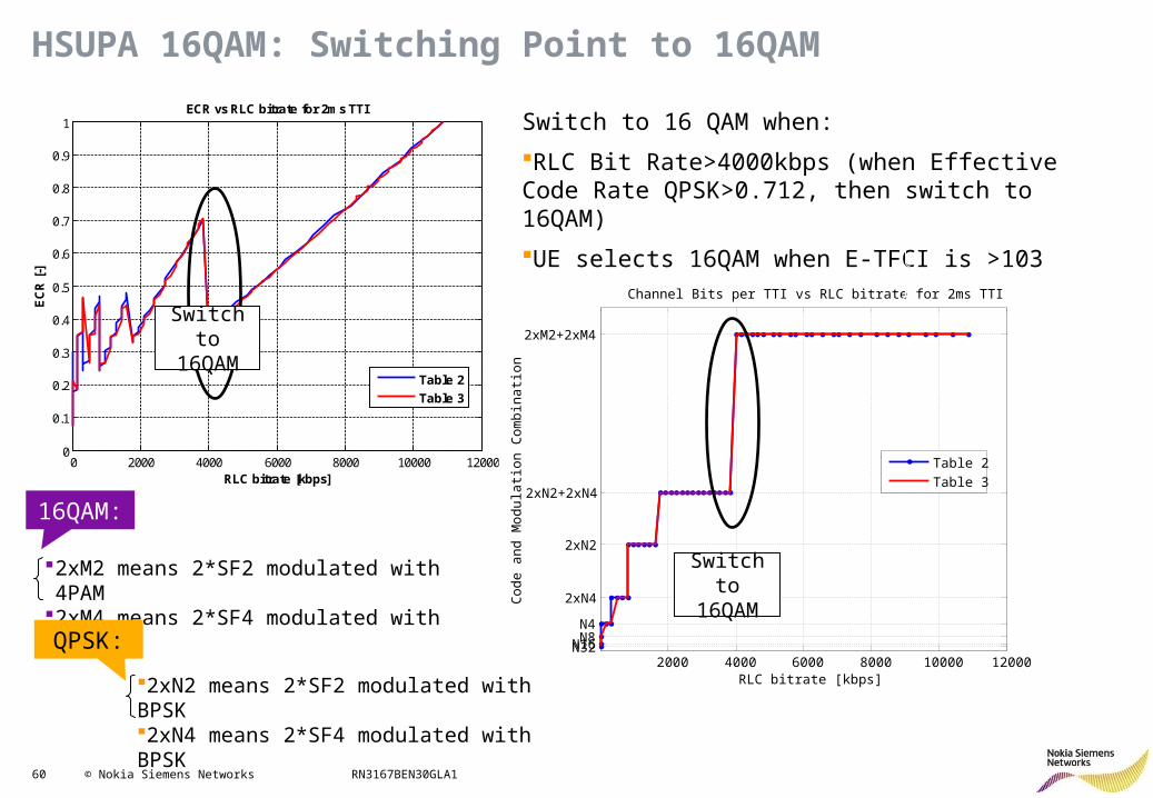
HSUPA 16QAM: Switching Point to 16QAM
Switch to 16QAM
0 2000 4000 6000 8000 10000 120000
0.1
0.2
0.3
0.4
0.5
0.6
0.7
0.8
0.9
1
RLC bitrate [kbps]
EC
R [
-]
ECR vs RLC bitrate for 2ms TTI
Table 2
Table 3
Switch to 16QAM
Switch to 16 QAM when:
RLC Bit Rate>4000kbps (when Effective Code Rate QPSK>0.712, then switch to 16QAM)
UE selects 16QAM when E-TFCI is >103 (Table2) or >69 (Table3)
2000 4000 6000 8000 10000 12000N32N16N8N4
2xN4
2xN2
2xN2+2xN4
2xM2+2xM4
RLC bitrate [kbps]
Cod
e a
nd
Mod
ula
tion
Co
mb
inat
ion
Channel Bits per TTI vs RLC bitrate for 2ms TTI
Table 2
Table 3
Switch to 16QAM
2xM2 means 2*SF2 modulated with 4PAM2xM4 means 2*SF4 modulated with 4PAM
2xN2 means 2*SF2 modulated with BPSK2xN4 means 2*SF4 modulated with BPSK
16QAM:
QPSK:
61 © Nokia Siemens Networks RN3167BEN30GLA1
HSPA+ RRM: Contents
• HSDPA Improvements• HSUPA Improvements:
– Frequency Domain Equalizer– HSUPA Interference Cancellation Receiver– HSUPA 16QAM– Flexible RLC in UL (RAN1910)– HSUPA Downlink Physical Channel Power Control– Dynamic HSUPA BLER
• Other features
62 © Nokia Siemens Networks RN3167BEN30GLA1
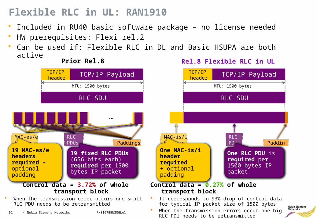
Flexible RLC in UL: RAN1910
…
TCP/IP PayloadTCP/IP header
RLC SDU
MAC-es/e headers Paddings
MTU: 1500 bytes
RLC PDUs
TCP/IP PayloadTCP/IP header
RLC SDU
MTU: 1500 bytes
MAC-is/i headers
RLC PDU Padding
Control data = 3.72% of whole transport block• When the transmission error occurs one small RLC PDU
needs to be retransmitted
19 MAC-es/e headers required + optional padding
19 fixed RLC PDUs (656 bits each) required per 1500 bytes IP packet
One MAC-is/i header required + optional padding
One RLC PDU is required per 1500 bytes IP packet
Control data = 0.27% of whole transport block• It corresponds to 93% drop of control data for typical IP
packet size of 1500 bytes• When the transmission errors occur one big RLC PDU
needs to be retransmitted
• Included in RU40 basic software package – no license needed• HW prerequisites: Flexi rel.2• Can be used if: Flexible RLC in DL and Basic HSUPA are both active
Prior Rel.8 Rel.8 Flexible RLC in UL
63 © Nokia Siemens Networks RN3167BEN30GLA1
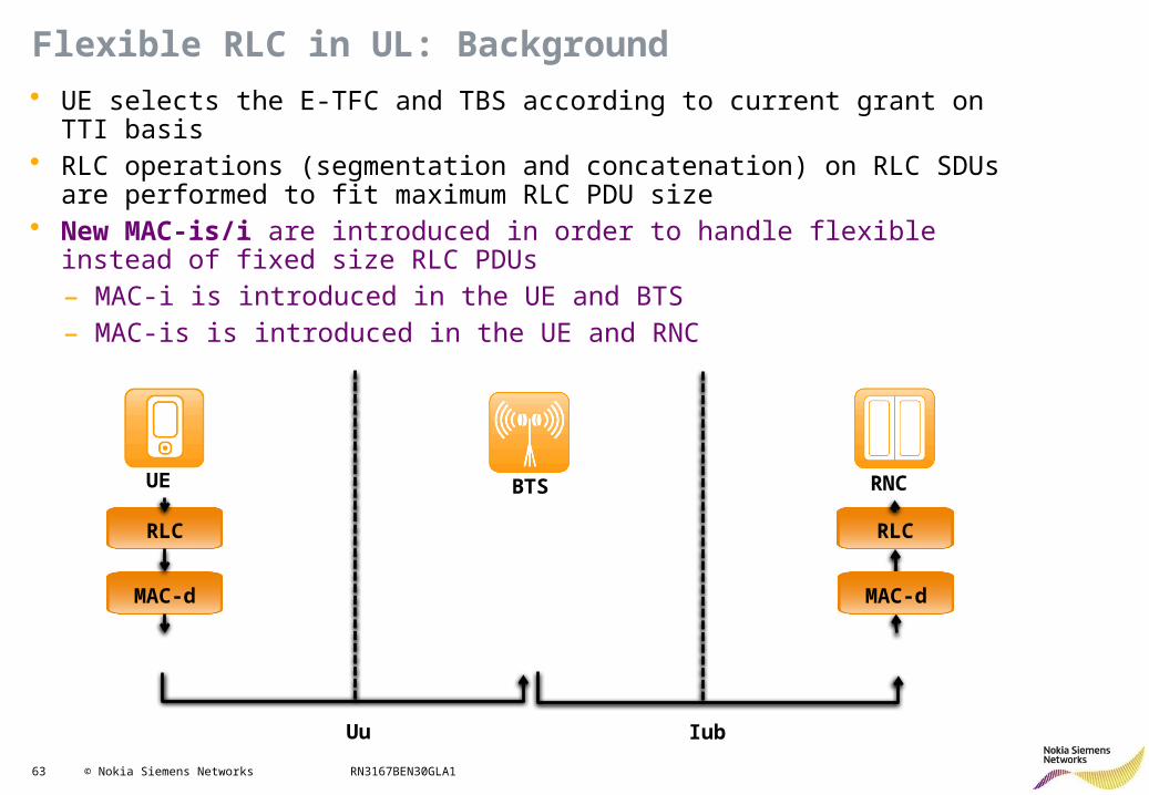
Flexible RLC in UL: Background
RLC
MAC-d
RLC
MAC-d
UE BTS RNC
• UE selects the E-TFC and TBS according to current grant on TTI basis• RLC operations (segmentation and concatenation) on RLC SDUs are performed to
fit maximum RLC PDU size• New MAC-is/i are introduced in order to handle flexible instead of fixed size RLC
PDUs– MAC-i is introduced in the UE and BTS– MAC-is is introduced in the UE and RNC
Uu Iub
64 © Nokia Siemens Networks RN3167BEN30GLA1
Flexible RLC in UL: Advantages
0 100 200 300 400 500 600 700 800 900 1000 1100 1200 1300 1400 15000%
5%
10%
15%
20%
25%Fixed RLC PDU
Flexible RLC PDU
RLC SDU size [bytes]
Re
lati
ve
ov
erh
ea
d a
nd
pa
dd
ing
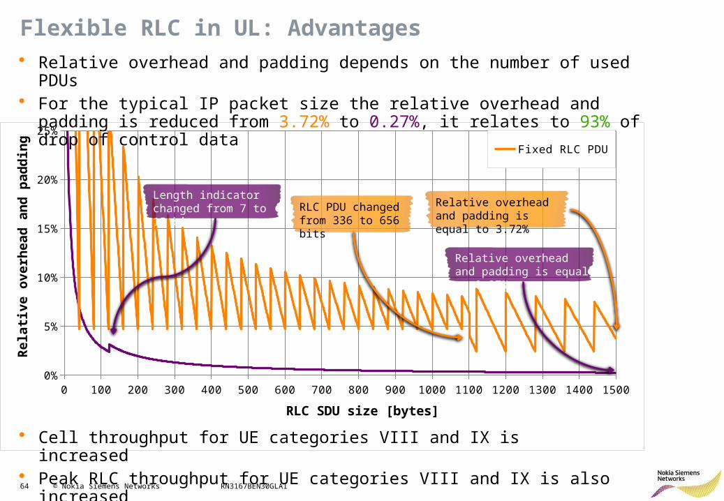
• Relative overhead and padding depends on the number of used PDUs• For the typical IP packet size the relative overhead and padding is reduced from
3.72% to 0.27%, it relates to 93% of drop of control data
RLC PDU changed from 336 to 656 bits
Length indicator changed from 7 to 15 bits
Relative overhead and padding is equal to 0.27%
Relative overhead and padding is equal to 3.72%
• Cell throughput for UE categories VIII and IX is increased• Peak RLC throughput for UE categories VIII and IX is also increased
65 © Nokia Siemens Networks RN3167BEN30GLA1
HSPA+ RRM: Contents
• HSDPA Improvements• HSUPA Improvements:
– Frequency Domain Equalizer– HSUPA Interference Cancellation Receiver– HSUPA 16QAM– Flexible RLC in UL– HSUPA Downlink Physical Channel Power Control (RAN971)– Dynamic HSUPA BLER
• Other features
66 © Nokia Siemens Networks RN3167BEN30GLA1
HSUPA Downlink Physical Channel Power Control: RAN971
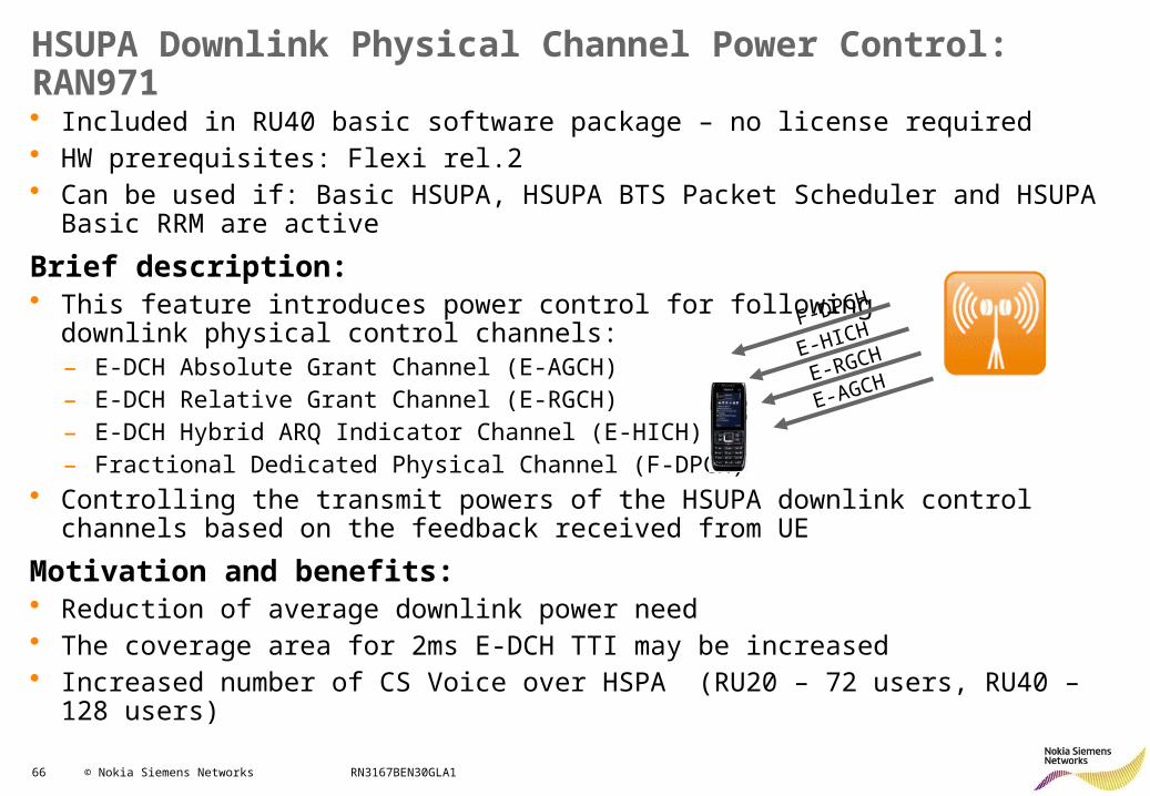
• Included in RU40 basic software package – no license required• HW prerequisites: Flexi rel.2• Can be used if: Basic HSUPA, HSUPA BTS Packet Scheduler and HSUPA Basic RRM
are active
Brief description:• This feature introduces power control for following
downlink physical control channels:– E-DCH Absolute Grant Channel (E-AGCH)– E-DCH Relative Grant Channel (E-RGCH)– E-DCH Hybrid ARQ Indicator Channel (E-HICH) – Fractional Dedicated Physical Channel (F-DPCH)
• Controlling the transmit powers of the HSUPA downlink control channels based on the feedback received from UE
Motivation and benefits:• Reduction of average downlink power need • The coverage area for 2ms E-DCH TTI may be increased• Increased number of CS Voice over HSPA (RU20 – 72 users, RU40 – 128 users)
E-AGCHE-RGCHE-HICHF-DPCH
67 © Nokia Siemens Networks RN3167BEN30GLA1
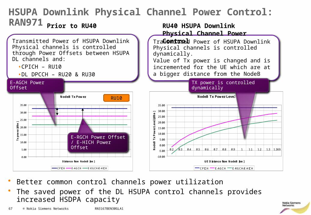
HSUPA Downlink Physical Channel Power Control: RAN971
Transmitted Power of HSUPA Downlink Physical channels is controlled through Power Offsets between HSUPA DL channels and:
•CPICH – RU10•DL DPCCH – RU20 & RU30
NodeB Tx Power
0.00
5.00
10.00
15.00
20.00
25.00
30.00
35.00
Distance from NodeB [km]
Tx
po
wer
[d
Bm
]
CPICH E-AGCH E-EGCH/E-HICH
E-AGCH Power Offset
E-RGCH Power Offset / E-HICH Power Offset
RU10
Transmitted Power of HSUPA Downlink Physical channels is controlled dynamically.Value of Tx power is changed and is incremented for the UE which are at a bigger distance from the NodeB
NodeB Tx Power Level
-10.00
-5.00
0.00
5.00
10.00
15.00
20.00
25.00
30.00
35.00
0.2 0.3 0.4 0.5 0.6 0.7 0.8 0.9 1 1.1 1.2 1.3 1.369
UE Distance from NodeB [km]
No
de
B T
x P
ow
er
Le
ve
l [d
Bm
]
CPICH E-AGCH E-RGCH/E-HICH
TX power is controlled dynamically
Prior to RU40 RU40 HSUPA Downlink Physical Channel Power Control
• Better common control channels power utilization • The saved power of the DL HSUPA control channels provides increased HSDPA capacity
68 © Nokia Siemens Networks RN3167BEN30GLA1
HSPA+ RRM: Contents
• HSDPA Improvements• HSUPA Improvements:
– Frequency Domain Equalizer– HSUPA Interference Cancellation Receiver– HSUPA 16QAM– Flexible RLC in UL– HSUPA Downlink Physical Channel Power Control– Dynamic HSUPA BLER (RAN2302)
• Other features
69 © Nokia Siemens Networks RN3167BEN30GLA1
Dynamic HSUPA BLER: RAN2302
HSUPA
HSUPA
10%BLER
10%BLER
HSUPA
HS
UP
A
1%BLER
10%BLER after 1st NACK
10%BLER
HSU
PA
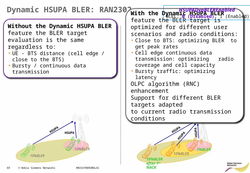
Without the Dynamic HSUPA BLER feature the BLER target evaluation is the same regardless to:• UE - BTS distance (cell edge / close to the
BTS)• Bursty / continuous data transmission
With the Dynamic HSUPA BLER feature the BLER target is optimized for different user scenarios and radio conditions:• Close to BTS: optimizing BLER to get peak
rates • Cell edge continuous data transmission:
optimizing radio coverage and cell capacity• Bursty traffic: optimizing latencyOLPC algorithm (RNC) enhancement Support for different BLER targets adapted to current radio transmission conditions
HSUPADynBLEREnabled WCEL; 0 (Disabled), 1 (Enabled)
70 © Nokia Siemens Networks RN3167BEN30GLA1
HSPA+ RRM: Contents
• HSDPA Improvements• HSUPA Improvements• Other features:
– Continuous Packet Connectivity CPC (RAN1644)– CS Voice over HSPA (RAN1689)– Fast Dormancy (RAN2136)– Fast Dormancy Profiling (RAN2451)– Multi-Band Load Balancing MBLB (RAN2172)– High Speed Cell_FACH (DL) (RAN1637)– High Speed Cell_FACH (RAN1913)
71 © Nokia Siemens Networks RN3167BEN30GLA1
HSPA+ RRM: Contents
• HSDPA Improvements• HSUPA Improvements• Other features:
– Continuous Packet Connectivity CPC (RAN1644)– CS Voice over HSPA– Fast Dormancy– Fast Dormancy Profiling– Multi-Band Load Balancing MBLB– High Speed Cell_FACH (DL)– High Speed Cell_FACH
72 © Nokia Siemens Networks RN3167BEN30GLA1
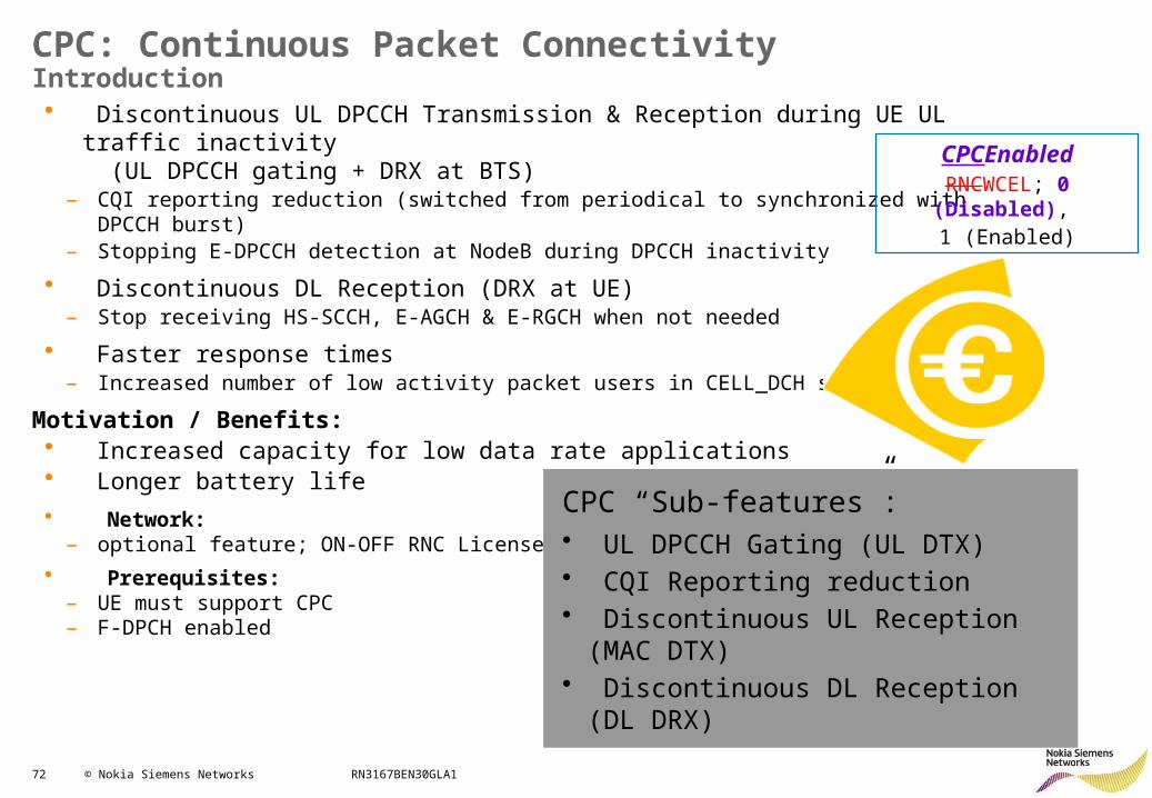
• Discontinuous UL DPCCH Transmission & Reception during UE UL traffic inactivity (UL DPCCH gating + DRX at BTS)
– CQI reporting reduction (switched from periodical to synchronized with DPCCH burst)– Stopping E-DPCCH detection at NodeB during DPCCH inactivity
• Discontinuous DL Reception (DRX at UE)– Stop receiving HS-SCCH, E-AGCH & E-RGCH when not needed
• Faster response times– Increased number of low activity packet users in CELL_DCH state
Motivation / Benefits:• Increased capacity for low data rate applications• Longer battery life
• Network:– optional feature; ON-OFF RNC License
• Prerequisites:– UE must support CPC– F-DPCH enabled
CPC: Continuous Packet ConnectivityIntroduction
CPCEnabledRNCWCEL; 0 (Disabled),
1 (Enabled)
CPC “Sub-features”:• UL DPCCH Gating (UL DTX)• CQI Reporting reduction• Discontinuous UL Reception (MAC
DTX)• Discontinuous DL Reception (DL DRX)
73 © Nokia Siemens Networks RN3167BEN30GLA1
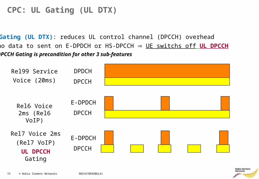
CPC: UL Gating (UL DTX)
UL Gating (UL DTX): reduces UL control channel (DPCCH) overhead • no data to sent on E-DPDCH or HS-DPCCH UE switchs off UL DPCCH• DPCCH Gating is precondition for other 3 sub-features
DPDCH
DPCCH
E-DPDCH
DPCCH
E-DPDCH
DPCCH
Rel99 Service
Voice (20ms)
Rel6 Voice 2ms (Rel6 VoIP)
Rel7 Voice 2ms
(Rel7 VoIP)
UL DPCCH Gating
74 © Nokia Siemens Networks RN3167BEN30GLA1
CPC: UL Gating
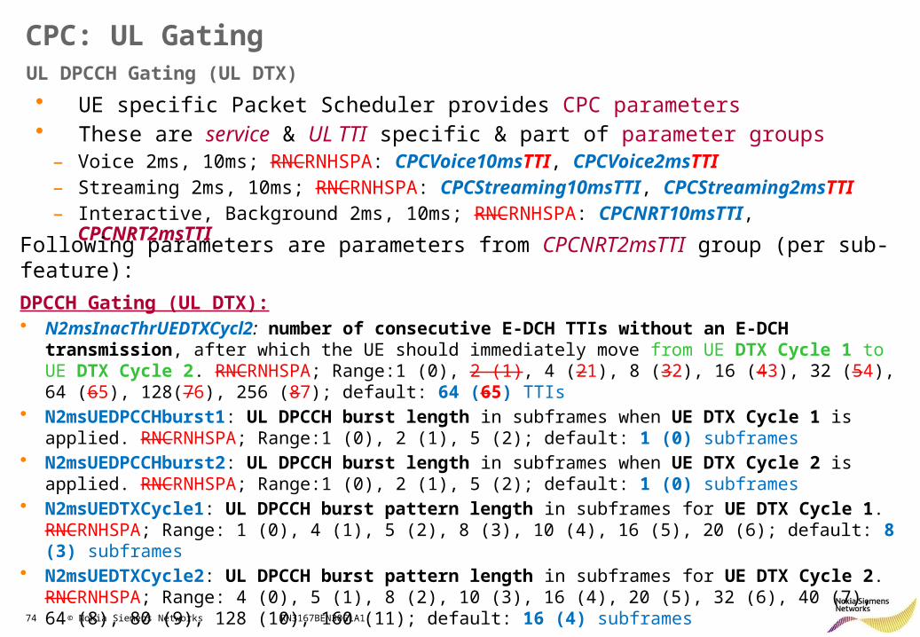
• UE specific Packet Scheduler provides CPC parameters• These are service & UL TTI specific & part of parameter groups
– Voice 2ms, 10ms; RNCRNHSPA: CPCVoice10msTTI, CPCVoice2msTTI– Streaming 2ms, 10ms; RNCRNHSPA: CPCStreaming10msTTI, CPCStreaming2msTTI– Interactive, Background 2ms, 10ms; RNCRNHSPA: CPCNRT10msTTI, CPCNRT2msTTI
UL DPCCH Gating (UL DTX)
Following parameters are parameters from CPCNRT2msTTI group (per sub-feature):
DPCCH Gating (UL DTX):• N2msInacThrUEDTXCycl2: number of consecutive E-DCH TTIs without an E-DCH transmission, after
which the UE should immediately move from UE DTX Cycle 1 to UE DTX Cycle 2. RNCRNHSPA; Range:1 (0), 2 (1), 4 (21), 8 (32), 16 (43), 32 (54), 64 (65), 128(76), 256 (87); default: 64 (65) TTIs
• N2msUEDPCCHburst1: UL DPCCH burst length in subframes when UE DTX Cycle 1 is applied. RNCRNHSPA; Range:1 (0), 2 (1), 5 (2); default: 1 (0) subframes
• N2msUEDPCCHburst2: UL DPCCH burst length in subframes when UE DTX Cycle 2 is applied. RNCRNHSPA; Range:1 (0), 2 (1), 5 (2); default: 1 (0) subframes
• N2msUEDTXCycle1: UL DPCCH burst pattern length in subframes for UE DTX Cycle 1. RNCRNHSPA; Range: 1 (0), 4 (1), 5 (2), 8 (3), 10 (4), 16 (5), 20 (6); default: 8 (3) subframes
• N2msUEDTXCycle2: UL DPCCH burst pattern length in subframes for UE DTX Cycle 2. RNCRNHSPA; Range: 4 (0), 5 (1), 8 (2), 10 (3), 16 (4), 20 (5), 32 (6), 40 (7), 64 (8), 80 (9), 128 (10), 160 (11); default: 16 (4) subframes
75 © Nokia Siemens Networks RN3167BEN30GLA1
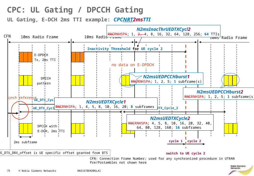
UL Gating, E-DCH 2ms TTI example: CPCNRT2msTTI
CPC: UL Gating / DPCCH Gating
10ms Radio Frame 10ms Radio Frame
2ms subframe
CFN
UE_DTX_Cycle_1
UE_DTX_Cycle_2
Inactivity Threshold for UE cycle 2
10ms Radio Frame
UE_DTX_Cycle_2
switch to UE cycle 2UE_DTX_DRX_offset is UE specific offset granted from BTS
cycle 1 cycle 2
E-DPDCH
Tx, 2ms TTI
DPCCH
pattern
DPCCH with
E-DCH, 2ms TTI
synch reference
CFN: Connection Frame Number; used for any synchronized procedure in UTRAN Pre/Postambles not shown here
no data on E-DPDCH
N2msUEDPCCHburst1RNCRNHSPA; 1, 2, 5; 1 subframe(s)
N2msUEDTXCycle1RNCRNHSPA; 1, 4, 5, 8, 10, 16, 20; 8 subframes
N2msInacThrUEDTXCycl2RNCRNHSPA; 1, 2, 4, 8, 16, 32, 64, 128, 256; 64 TTIs
N2msUEDPCCHburst2RNCRNHSPA; 1, 2, 5; 1 subframe(s)
N2msUEDTXCycle2RNCRNHSPA; 4, 5, 8, 10, 16, 20, 32, 40,
64, 80, 128, 160; 16 subframes
76 © Nokia Siemens Networks RN3167BEN30GLA1
CPC: Reduced CQI Reporting
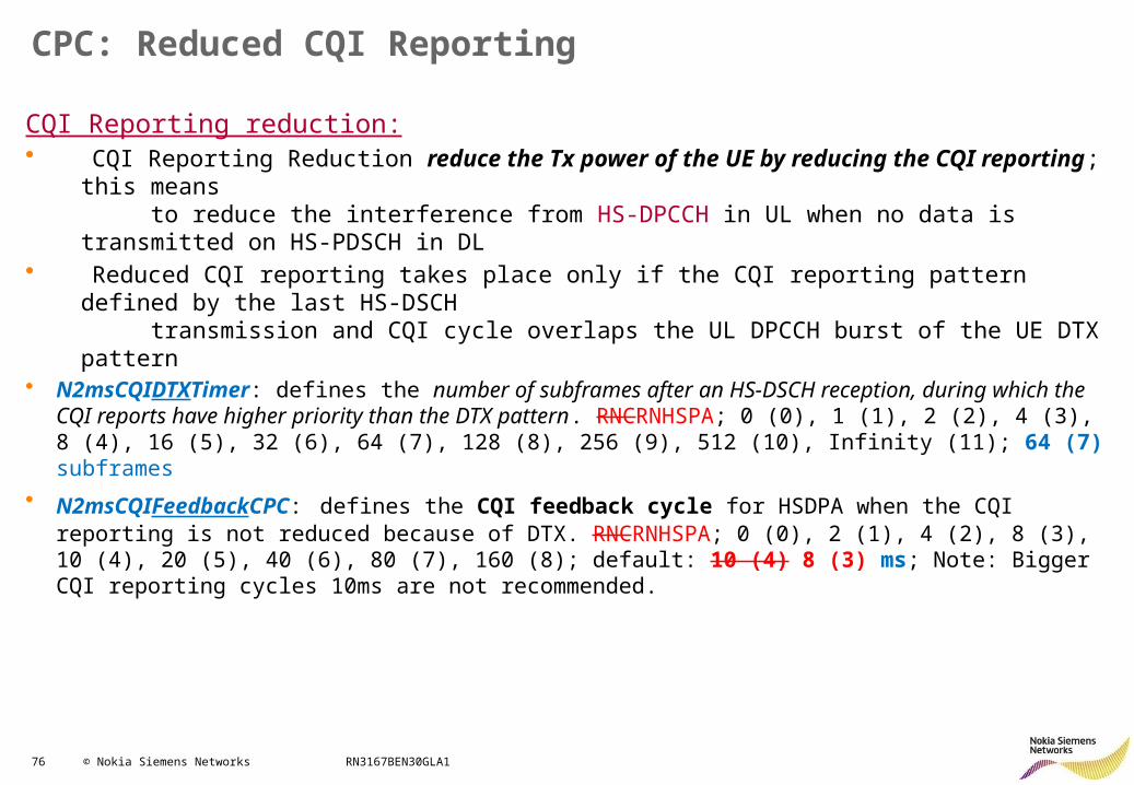
CQI Reporting reduction:• CQI Reporting Reduction reduce the Tx power of the UE by reducing the CQI reporting; this
means to reduce the interference from HS-DPCCH in UL when no data is transmitted on HS-PDSCH in DL
• Reduced CQI reporting takes place only if the CQI reporting pattern defined by the last HS-DSCH transmission and CQI cycle overlaps the UL DPCCH burst of the UE DTX pattern
• N2msCQIDTXTimer: defines the number of subframes after an HS-DSCH reception, during which the CQI reports have higher priority than the DTX pattern. RNCRNHSPA; 0 (0), 1 (1), 2 (2), 4 (3), 8 (4), 16 (5), 32 (6), 64 (7), 128 (8), 256 (9), 512 (10), Infinity (11); 64 (7) subframes
• N2msCQIFeedbackCPC: defines the CQI feedback cycle for HSDPA when the CQI reporting is not reduced because of DTX. RNCRNHSPA; 0 (0), 2 (1), 4 (2), 8 (3), 10 (4), 20 (5), 40 (6), 80 (7), 160 (8); default: 10 (4) 8 (3) ms; Note: Bigger CQI reporting cycles 10ms are not recommended.
77 © Nokia Siemens Networks RN3167BEN30GLA1
CPC: Reduced CQI Reporting
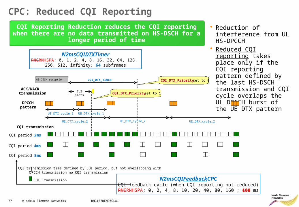
• Reduction of interference from UL HS-DPCCH
• Reduced CQI reporting takes place only if the CQI reporting pattern defined by the last HS-DSCH transmission and CQI cycle overlaps the UL DPCCH burst of the UE DTX pattern
CQI Reporting Reduction reduces the CQI reporting when there are no data transmitted on HS-DSCH for a longer period of time
ACK/NACK transmission
CQI transmission
CQI period 2ms
CQI period 4ms
CQI period 8ms
CQI transmission time defined by CQI period, but not overlapping with DPCCH transmission no CQI transmission
CQI Transmission
DPCCH pattern
UE_DTX_cycle_1 UE_DTX_cycle_1
UE_DTX_cycle_2 UE_DTX_cycle_2
7.5slots
HS-DSCH reception CQI_DTX_TIMER
UE_DTX_cycle_2
CQI_DTX_Priority set to 1
CQI_DTX_Priority set to 0
N2msCQIFeedbackCPCCQI feedback cycle (when CQI reporting not reduced)RNCRNHSPA; 0, 2, 4, 8, 10, 20, 40, 80, 160 ; 108 ms
N2msCQIDTXTimerRNCRNHSPA; 0, 1, 2, 4, 8, 16, 32, 64, 128,
256, 512, infinity; 64 subframes
78 © Nokia Siemens Networks RN3167BEN30GLA1
CPC: Discontinuous UL & DL Reception (MAC DTX & DL DRX)
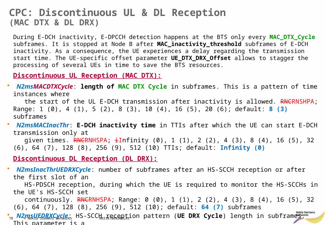
During E-DCH inactivity, E-DPCCH detection happens at the BTS only every MAC_DTX_Cycle subframes. It is stopped at Node B after MAC_inactivity_threshold subframes of E-DCH inactivity. As a consequence, the UE experiences a delay regarding the transmission start time. The UE-specific offset parameter UE_DTX_DRX_Offset allows to stagger the processing of several UEs in time to save the BTS resources.
Discontinuous UL Reception (MAC DTX):
• N2msMACDTXCycle: length of MAC DTX Cycle in subframes. This is a pattern of time instances where the start of the UL E-DCH transmission after inactivity is allowed. RNCRNSHPA; Range: 1 (0), 4 (1), 5 (2), 8 (3), 10 (4), 16 (5), 20 (6); default: 8 (3) subframes
• N2msMACInacThr: E-DCH inactivity time in TTIs after which the UE can start E-DCH transmission only at given times. RNCRNHSPA; iInfinity (0), 1 (1), 2 (2), 4 (3), 8 (4), 16 (5), 32 (6), 64 (7), 128 (8), 256 (9), 512 (10) TTIs; default: Infinity (0)
Discontinuous DL Reception (DL DRX):
• N2msInacThrUEDRXCycle: number of subframes after an HS-SCCH reception or after the first slot of an HS-PDSCH reception, during which the UE is required to monitor the HS-SCCHs in the UE's HS-SCCH set continuously. RNCRNHSPA; Range: 0 (0), 1 (1), 2 (2), 4 (3), 8 (4), 16 (5), 32 (6), 64 (7), 128 (8), 256 (9), 512 (10); default: 64 (7) subframes
• N2msUEDRXCycle: HS-SCCH reception pattern (UE DRX Cycle) length in subframes. This parameter is a multiple or a divisor of the parameter UE DTX Cycle 1. If the value is not allowed, the parameter value minus 1 is used to calculate a new value, and so on. RNCRNHSPA; Range: 0.5 (0), 1 (1), 2 (2), 3 (3), 4 (4); default: 2 (2) subframes
79 © Nokia Siemens Networks RN3167BEN30GLA1
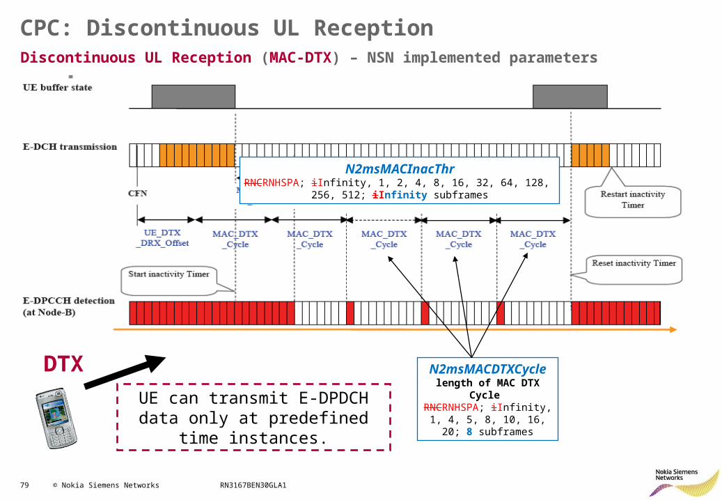
CPC: Discontinuous UL ReceptionDiscontinuous UL Reception (MAC-DTX) – NSN implemented parameters
UE can transmit E-DPDCH data only at predefined time instances.
N2msMACInacThrRNCRNHSPA; iInfinity, 1, 2, 4, 8, 16, 32, 64, 128,
256, 512; iInfinity subframes
N2msMACDTXCyclelength of MAC DTX Cycle RNCRNHSPA; iInfinity, 1, 4, 5, 8, 10, 16, 20; 8 subframes
DTX
80 © Nokia Siemens Networks RN3167BEN30GLA1
CPC: Discontinuous DL ReceptionDiscontinuous DL Reception (DL DRX)
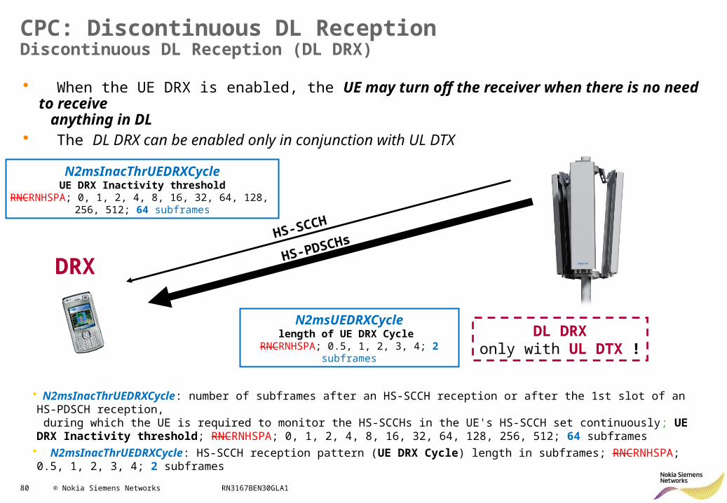
• N2msInacThrUEDRXCycle: number of subframes after an HS-SCCH reception or after the 1st slot of an HS-PDSCH reception, during which the UE is required to monitor the HS-SCCHs in the UE's HS-SCCH set continuously; UE DRX Inactivity threshold; RNCRNHSPA; 0, 1, 2, 4, 8, 16, 32, 64, 128, 256, 512; 64 subframes• N2msInacThrUEDRXCycle: HS-SCCH reception pattern (UE DRX Cycle) length in subframes; RNCRNHSPA; 0.5, 1, 2, 3, 4; 2 subframes
N2msUEDRXCyclelength of UE DRX Cycle
RNCRNHSPA; 0.5, 1, 2, 3, 4; 2 subframes
N2msInacThrUEDRXCycleUE DRX Inactivity threshold
RNCRNHSPA; 0, 1, 2, 4, 8, 16, 32, 64, 128, 256, 512; 64 subframes
HS-SCCH
HS-PDSCHs
DRX
• When the UE DRX is enabled, the UE may turn off the receiver when there is no need to receive anything in DL
• The DL DRX can be enabled only in conjunction with UL DTX
DL DRXonly with UL DTX !
81 © Nokia Siemens Networks RN3167BEN30GLA1
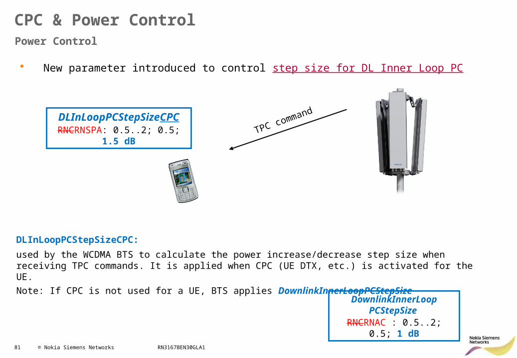
• New parameter introduced to control step size for DL Inner Loop PC
Power Control
CPC & Power Control
TPC command
DownlinkInnerLoop PCStepSize
RNCRNAC : 0.5..2; 0.5; 1 dB
DLInLoopPCStepSizeCPCRNCRNSPA: 0.5..2; 0.5; 1.5 dB
DLInLoopPCStepSizeCPC: used by the WCDMA BTS to calculate the power increase/decrease step size when receiving TPC commands. It is applied when CPC (UE DTX, etc.) is activated for the UE.
Note: If CPC is not used for a UE, BTS applies DownlinkInnerLoopPCStepSize
82 © Nokia Siemens Networks RN3167BEN30GLA1
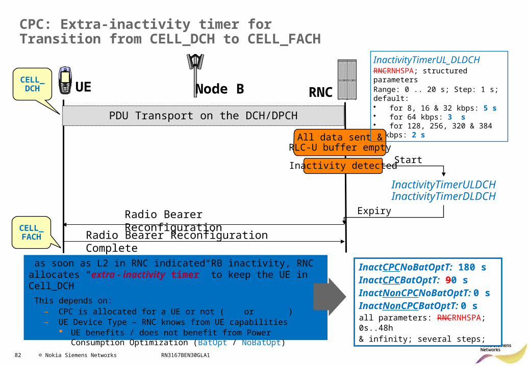
CPC: Extra-inactivity timer for Transition from CELL_DCH to CELL_FACH
RNCUECELL_DCH Node B
PDU Transport on the DCH/DPCH
All data sent &RLC-U buffer empty
Inactivity detectedStart
InactivityTimerULDCHInactivityTimerDLDCH
Radio Bearer Reconfiguration
Radio Bearer Reconfiguration Complete
Expiry
CELL_FACH
InactivityTimerUL_DLDCHRNCRNHSPA; structured parametersRange: 0 .. 20 s; Step: 1 s; default:• for 8, 16 & 32 kbps: 5 s• for 64 kbps: 3 s• for 128, 256, 320 & 384 kbps: 2 s
as soon as L2 in RNC indicated RB inactivity, RNC allocates “extra - inactivity timer” to keep the UE in Cell_DCH
This depends on: – CPC is allocated for a UE or not (CPC or NonCPC)– UE Device Type – RNC knows from UE capabilities
UE benefits / does not benefit from Power Consumption Optimization (BatOpt / NoBatOpt)
InactCPCNoBatOptT: 180 sInactCPCBatOptT: 90 sInactNonCPCNoBatOptT: 0 sInactNonCPCBatOptT: 0 sall parameters: RNCRNHSPA; 0s..48h & infinity; several steps;
83 © Nokia Siemens Networks RN3167BEN30GLA1
HSPA+ RRM: Contents
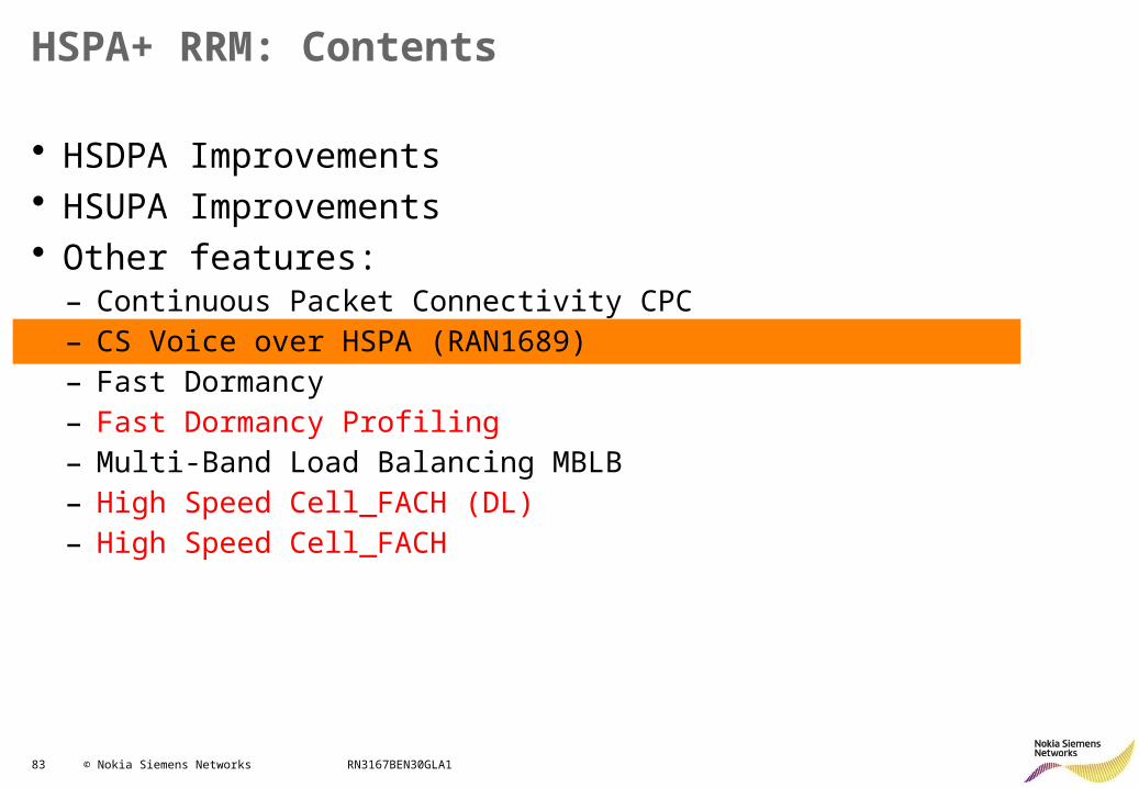
• HSDPA Improvements• HSUPA Improvements• Other features:
– Continuous Packet Connectivity CPC– CS Voice over HSPA (RAN1689)– Fast Dormancy– Fast Dormancy Profiling– Multi-Band Load Balancing MBLB– High Speed Cell_FACH (DL)– High Speed Cell_FACH
84 © Nokia Siemens Networks RN3167BEN30GLA1
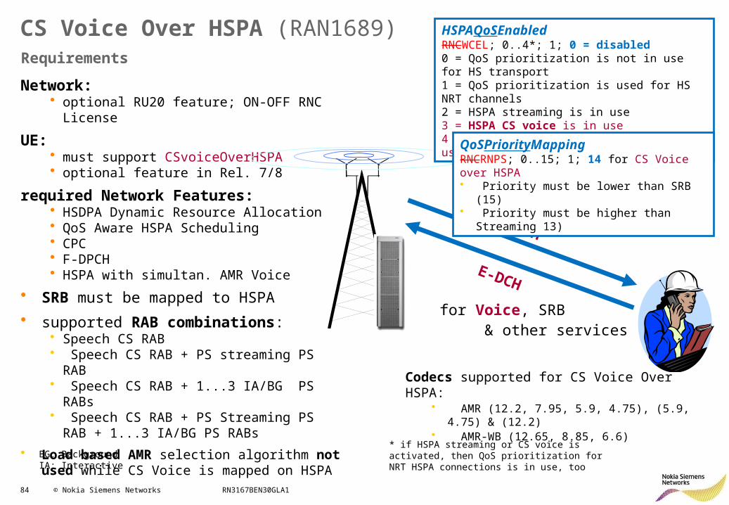
Network:• optional RU20 feature; ON-OFF RNC License
UE:• must support CSvoiceOverHSPA• optional feature in Rel. 7/8
required Network Features:• HSDPA Dynamic Resource Allocation • QoS Aware HSPA Scheduling• CPC• F-DPCH• HSPA with simultan. AMR Voice
• SRB must be mapped to HSPA
• supported RAB combinations: • Speech CS RAB• Speech CS RAB + PS streaming PS RAB• Speech CS RAB + 1...3 IA/BG PS RABs• Speech CS RAB + PS Streaming PS RAB +
1...3 IA/BG PS RABs
• Load based AMR selection algorithm not used while CS Voice is mapped on HSPA
Requirements
CS Voice Over HSPA (RAN1689)
BG: BackgroundIA: Interactive
Codecs supported for CS Voice Over HSPA:• AMR (12.2, 7.95, 5.9, 4.75), (5.9, 4.75) & (12.2)• AMR-WB (12.65, 8.85, 6.6)
HS-DSCH
E-DCH
for Voice, SRB & other services
HSPAQoSEnabledRNCWCEL; 0..4*; 1; 0 = disabled0 = QoS prioritization is not in use for HS transport1 = QoS prioritization is used for HS NRT channels2 = HSPA streaming is in use3 = HSPA CS voice is in use4 = HSPA streaming & CS voice are in use
* if HSPA streaming or CS voice is activated, then QoS prioritization for NRT HSPA connections is in use, too
QoSPriorityMappingRNCRNPS; 0..15; 1; 14 for CS Voice over HSPA• Priority must be lower than SRB (15)• Priority must be higher than Streaming 13)
85 © Nokia Siemens Networks RN3167BEN30GLA1
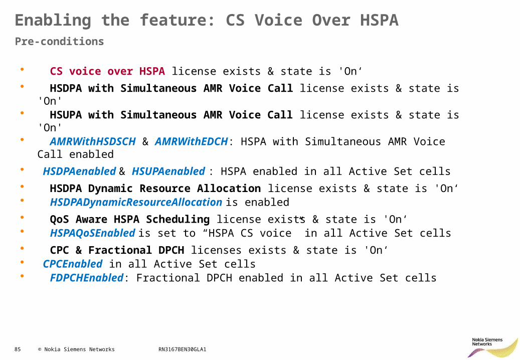
• CS voice over HSPA license exists & state is 'On‘
• HSDPA with Simultaneous AMR Voice Call license exists & state is 'On'• HSUPA with Simultaneous AMR Voice Call license exists & state is 'On'• AMRWithHSDSCH & AMRWithEDCH: HSPA with Simultaneous AMR Voice Call
enabled
• HSDPAenabled & HSUPAenabled : HSPA enabled in all Active Set cells
• HSDPA Dynamic Resource Allocation license exists & state is 'On‘• HSDPADynamicResourceAllocation is enabled
• QoS Aware HSPA Scheduling license exists & state is 'On‘• HSPAQoSEnabled is set to “HSPA CS voice” in all Active Set cells
• CPC & Fractional DPCH licenses exists & state is 'On‘• CPCEnabled in all Active Set cells• FDPCHEnabled: Fractional DPCH enabled in all Active Set cells
Enabling the feature: CS Voice Over HSPAPre-conditions
86 © Nokia Siemens Networks RN3167BEN30GLA1
CS Voice Over HSPAEfficiency
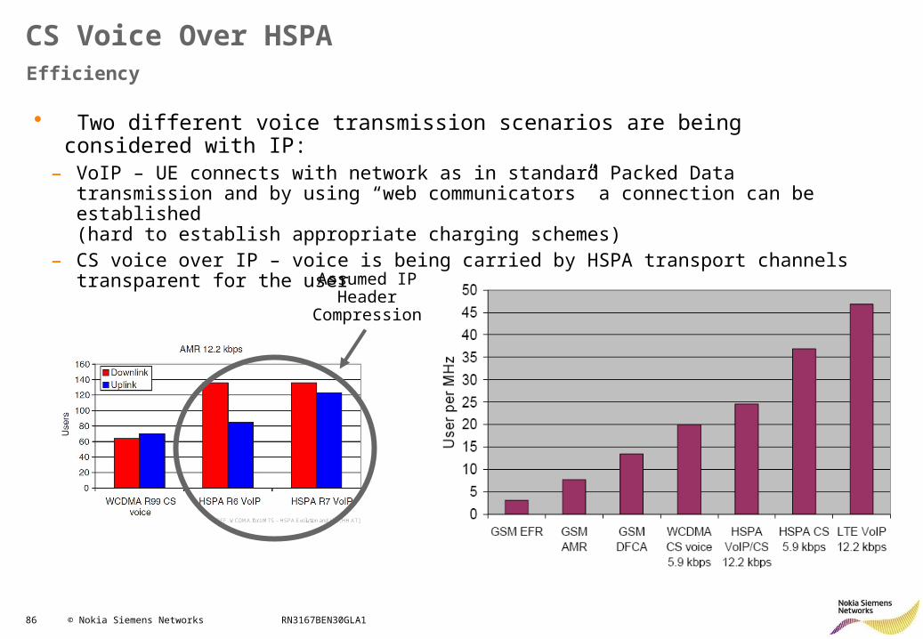
• Two different voice transmission scenarios are being considered with IP:– VoIP – UE connects with network as in standard Packed Data transmission and by using “web
communicators” a connection can be established (hard to establish appropriate charging schemes)
– CS voice over IP – voice is being carried by HSPA transport channels transparent for the user
[REF. WCDMA for UMTS – HSPA Evolution and LTE, HH AT]
Assumed IP Header
Compression
87 © Nokia Siemens Networks RN3167BEN30GLA1
CS Voice Over HSPAConcept / Protocol Stack
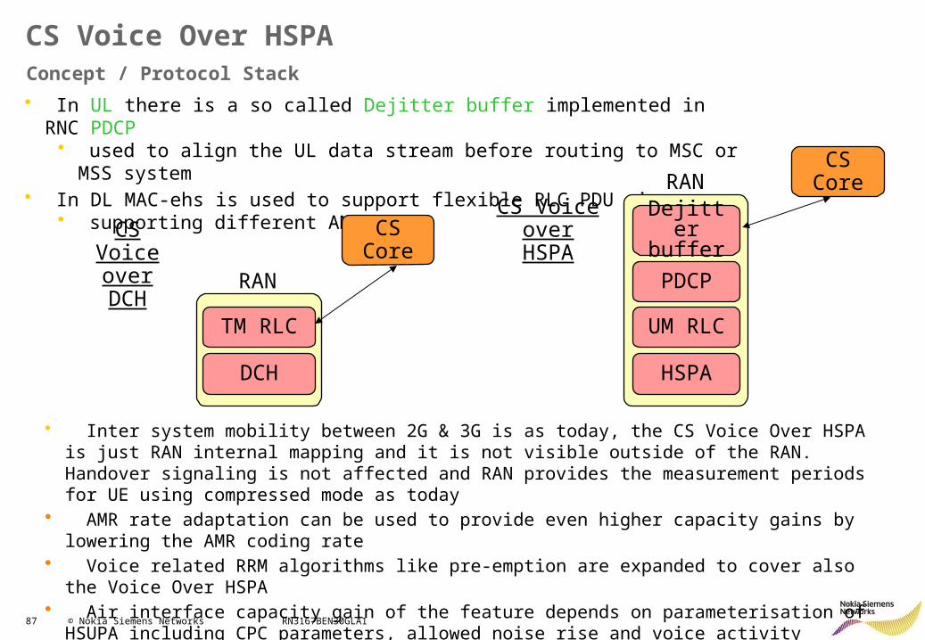
• In UL there is a so called Dejitter buffer implemented in RNC PDCP• used to align the UL data stream before routing to MSC or MSS system
• In DL MAC-ehs is used to support flexible RLC PDU sizes• supporting different AMR rates
DCH
CS Core
TM RLC
RAN
CS Voice over DCH
Dejitter buffer
UM RLC
PDCP
HSPA
CS CoreRAN
CS Voice over HSPA
• Inter system mobility between 2G & 3G is as today, the CS Voice Over HSPA is just RAN internal mapping and it is not visible outside of the RAN. Handover signaling is not affected and RAN provides the measurement periods for UE using compressed mode as today
• AMR rate adaptation can be used to provide even higher capacity gains by lowering the AMR coding rate
• Voice related RRM algorithms like pre-emption are expanded to cover also the Voice Over HSPA• Air interface capacity gain of the feature depends on parameterisation of HSUPA including CPC
parameters, allowed noise rise and voice activity
88 © Nokia Siemens Networks RN3167BEN30GLA1
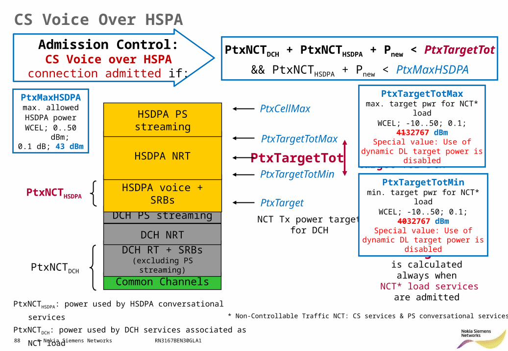
CS Voice Over HSPA
NCT Tx power target for DCH + HSPA
NCT Tx power target for DCH
PtxTargetTot is calculated always
when NCT* load services
are admitted
Common Channels
DCH RT + SRBs(excluding PS streaming)
DCH PS streaming
DCH NRT
HSDPA voice + SRBs
HSDPA NRT
HSDPA PS streaming
PtxNCTDCH
PtxNCTHSDPA
PtxTargetTotMax
PtxTargetTotMin
PtxCellMax
PtxTargetTot
PtxTargetTotMaxmax. target pwr for NCT* load
WCEL; -10..50; 0.1; 4132767 dBmSpecial value: Use of dynamic DL
target power is disabled
PtxTargetTotMinmin. target pwr for NCT* load
WCEL; -10..50; 0.1; 4032767 dBmSpecial value: Use of dynamic DL
target power is disabled
* Non-Controllable Traffic NCT: CS services & PS conversational services
PtxTarget
PtxNCTHSDPA: power used by HSDPA conversational services
PtxNCTDCH: power used by DCH services associated as NCT load
Admission Control:CS Voice over HSPA connection
admitted if:
PtxNCTDCH + PtxNCTHSDPA + Pnew < PtxTargetTot
&& PtxNCTHSDPA + Pnew < PtxMaxHSDPA
PtxMaxHSDPAmax. allowedHSDPA power
WCEL; 0..50 dBm; 0.1 dB; 43 dBm
89 © Nokia Siemens Networks RN3167BEN30GLA1
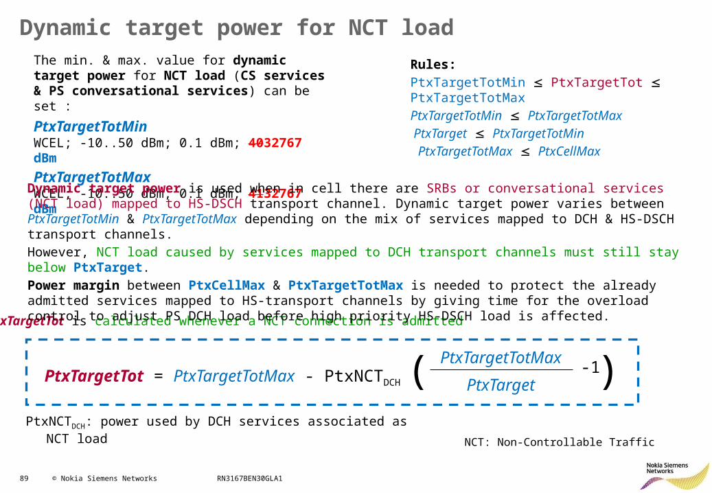
PtxNCTDCH: power used by DCH services associated as NCT load
Dynamic target power for NCT loadThe min. & max. value for dynamic target power for NCT load (CS services & PS conversational services) can be set :
PtxTargetTotMin WCEL; -10..50 dBm; 0.1 dBm; 4032767 dBm
PtxTargetTotMax WCEL; -10..50 dBm; 0.1 dBm; 4132767 dBm
PtxTargetTot = PtxTargetTotMax - PtxNCTDCH
PtxTargetTotMax
PtxTarget-1( )
PtxTargetTot is calculated whenever a NCT connection is admitted
NCT: Non-Controllable Traffic
Dynamic target power is used when in cell there are SRBs or conversational services (NCT load) mapped to HS-DSCH transport channel. Dynamic target power varies between PtxTargetTotMin & PtxTargetTotMax depending on the mix of services mapped to DCH & HS-DSCH transport channels.
However, NCT load caused by services mapped to DCH transport channels must still stay below PtxTarget.
Power margin between PtxCellMax & PtxTargetTotMax is needed to protect the already admitted services mapped to HS-transport channels by giving time for the overload control to adjust PS DCH load before high priority HS-DSCH load is affected.
Rules:
PtxTargetTotMin PtxTargetTot PtxTargetTotMax
PtxTargetTotMin PtxTargetTotMax
PtxTarget PtxTargetTotMin
PtxTargetTotMax PtxCellMax
90 © Nokia Siemens Networks RN3167BEN30GLA1
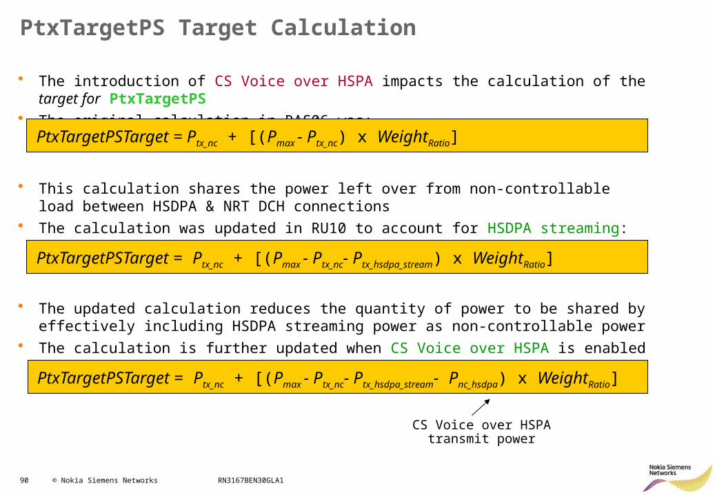
PtxTargetPS Target Calculation
• The introduction of CS Voice over HSPA impacts the calculation of the target for PtxTargetPS• The original calculation in RAS06 was:
PtxTargetPSTarget = Ptx_nc + [(Pmax - Ptx_nc- Ptx_hsdpa_stream) x WeightRatio]
PtxTargetPSTarget = Ptx_nc + [(Pmax - Ptx_nc) x WeightRatio]
PtxTargetPSTarget = Ptx_nc + [(Pmax - Ptx_nc- Ptx_hsdpa_stream- Pnc_hsdpa) x WeightRatio]
• This calculation shares the power left over from non-controllable load between HSDPA & NRT DCH connections
• The calculation was updated in RU10 to account for HSDPA streaming:
• The updated calculation reduces the quantity of power to be shared by effectively including HSDPA streaming power as non-controllable power
• The calculation is further updated when CS Voice over HSPA is enabled
CS Voice over HSPA transmit power
91 © Nokia Siemens Networks RN3167BEN30GLA1
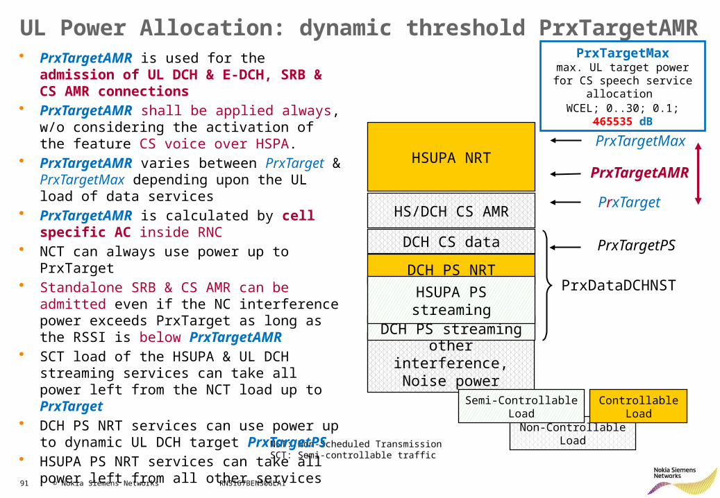
UL Power Allocation: dynamic threshold PrxTargetAMRPrxTargetMax
max. UL target power for CS speech service allocation
WCEL; 0..30; 0.1; 465535 dB
NST: Non-Scheduled TransmissionSCT: Semi-controllable traffic
other interference,Noise power
DCH CS data
DCH PS streaming
DCH PS NRT
HS/DCH CS AMR
HSUPA NRT
HSUPA PS streaming
PrxTargetAMR
PrxTargetPS
PrxTargetMax
PrxTarget
PrxDataDCHNST
Non-Controllable Load
Semi-Controllable Load Controllable Load
• PrxTargetAMR is used for the admission of UL DCH & E-DCH, SRB & CS AMR connections
• PrxTargetAMR shall be applied always, w/o considering the activation of the feature CS voice over HSPA.
• PrxTargetAMR varies between PrxTarget & PrxTargetMax depending upon the UL load of data services
• PrxTargetAMR is calculated by cell specific AC inside RNC
• NCT can always use power up to PrxTarget• Standalone SRB & CS AMR can be admitted
even if the NC interference power exceeds PrxTarget as long as the RSSI is below PrxTargetAMR
• SCT load of the HSUPA & UL DCH streaming services can take all power left from the NCT load up to PrxTarget
• DCH PS NRT services can use power up to dynamic UL DCH target PrxTargetPS
• HSUPA PS NRT services can take all power left from all other services
92 © Nokia Siemens Networks RN3167BEN30GLA1
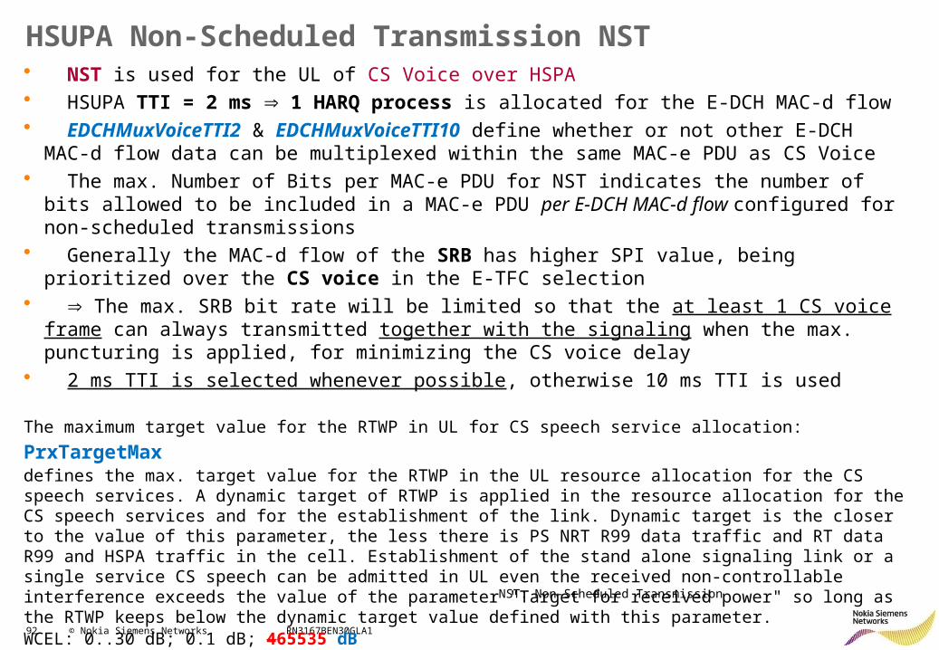
HSUPA Non-Scheduled Transmission NST• NST is used for the UL of CS Voice over HSPA• HSUPA TTI = 2 ms 1 HARQ process is allocated for the E-DCH MAC-d flow• EDCHMuxVoiceTTI2 & EDCHMuxVoiceTTI10 define whether or not other E-DCH MAC-d flow data
can be multiplexed within the same MAC-e PDU as CS Voice• The max. Number of Bits per MAC-e PDU for NST indicates the number of bits allowed to be
included in a MAC-e PDU per E-DCH MAC-d flow configured for non-scheduled transmissions• Generally the MAC-d flow of the SRB has higher SPI value, being prioritized over the CS voice in
the E-TFC selection• The max. SRB bit rate will be limited so that the at least 1 CS voice frame can always transmitted
together with the signaling when the max. puncturing is applied, for minimizing the CS voice delay• 2 ms TTI is selected whenever possible, otherwise 10 ms TTI is used
The maximum target value for the RTWP in UL for CS speech service allocation: PrxTargetMax defines the max. target value for the RTWP in the UL resource allocation for the CS speech services. A dynamic target of RTWP is applied in the resource allocation for the CS speech services and for the establishment of the link. Dynamic target is the closer to the value of this parameter, the less there is PS NRT R99 data traffic and RT data R99 and HSPA traffic in the cell. Establishment of the stand alone signaling link or a single service CS speech can be admitted in UL even the received non-controllable interference exceeds the value of the parameter "Target for received power" so long as the RTWP keeps below the dynamic target value defined with this parameter. WCEL: 0..30 dB; 0.1 dB; 465535 dB
NST: Non-Scheduled Transmission
93 © Nokia Siemens Networks RN3167BEN30GLA1
HSPA+ RRM: Contents
• HSDPA Improvements• HSUPA Improvements• Other features:
– Continuous Packet Connectivity CPC– CS Voice over HSPA– Fast Dormancy (RAN2136)– Fast Dormancy Profiling– Multi-Band Load Balancing MBLB– High Speed Cell_FACH (DL)– High Speed Cell_FACH
94 © Nokia Siemens Networks RN3167BEN30GLA1
Fast Dormancy: Background (1/2)
URA_PCH
CELL_DCH CELL_FACH
CELL_PCH
UTRA RRC Connected Mode
Idle Mode
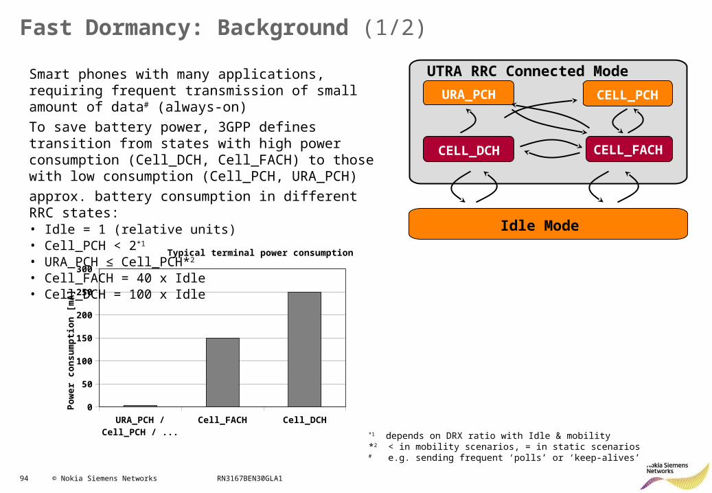
Smart phones with many applications, requiring frequent transmission of small amount of data# (always-on)
To save battery power, 3GPP defines transition from states with high power consumption (Cell_DCH, Cell_FACH) to those with low consumption (Cell_PCH, URA_PCH)
approx. battery consumption in different RRC states: • Idle = 1 (relative units)• Cell_PCH < 2*1
• URA_PCH ≤ Cell_PCH*2
• Cell_FACH = 40 x Idle• Cell_DCH = 100 x Idle
*1 depends on DRX ratio with Idle & mobility*2 < in mobility scenarios, = in static scenarios# e.g. sending frequent ‘polls’ or ‘keep-alives’
URA_PCH / Cell_PCH / Idle
Cell_FACH Cell_DCH0
50
100
150
200
250
300
Typical terminal power consumption
Pow
er c
onsu
mpt
ion
[mA
]
95 © Nokia Siemens Networks RN3167BEN30GLA1
Fast Dormancy: Background (2/2)
URA_PCH
CELL_DCH CELL_FACH
CELL_PCH
UTRA RRC Connected Mode
Idle Mode
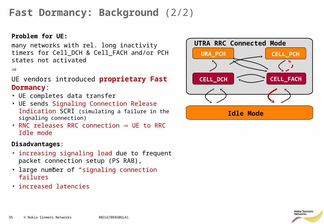
Problem for UE:
many networks with rel. long inactivity timers for Cell_DCH & Cell_FACH and/or PCH states not activated
UE vendors introduced proprietary Fast Dormancy:• UE completes data transfer• UE sends Signaling Connection Release Indication SCRI
(simulating a failure in the signaling connection) • RNC releases RRC connection UE to RRC Idle mode
Disadvantages:
• increasing signaling load due to frequent packet connection setup (PS RAB),
• large number of “signaling connection failures”
• increased latencies
96 © Nokia Siemens Networks RN3167BEN30GLA1
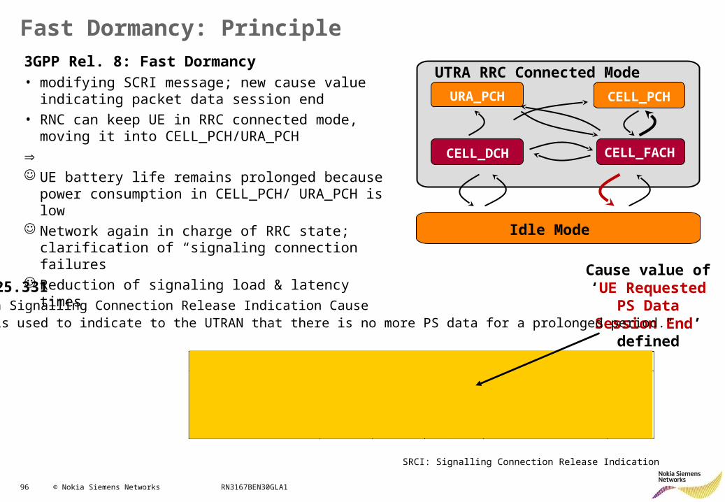
Fast Dormancy: Principle
URA_PCH
CELL_DCH CELL_FACH
CELL_PCH
UTRA RRC Connected Mode
Idle Mode
3GPP Rel. 8: Fast Dormancy• modifying SCRI message; new cause value indicating
packet data session end
• RNC can keep UE in RRC connected mode, moving it into CELL_PCH/URA_PCH
UE battery life remains prolonged because power
consumption in CELL_PCH/ URA_PCH is low Network again in charge of RRC state; clarification of
“signaling connection failures” Reduction of signaling load & latency times
Cause value of ‘UE Requested
PS Data Session End’ defined
3GPP TS 25.33110.3.3.37a Signalling Connection Release Indication Cause„This IE is used to indicate to the UTRAN that there is no more PS data for a prolonged period.“
SRCI: Signalling Connection Release Indication
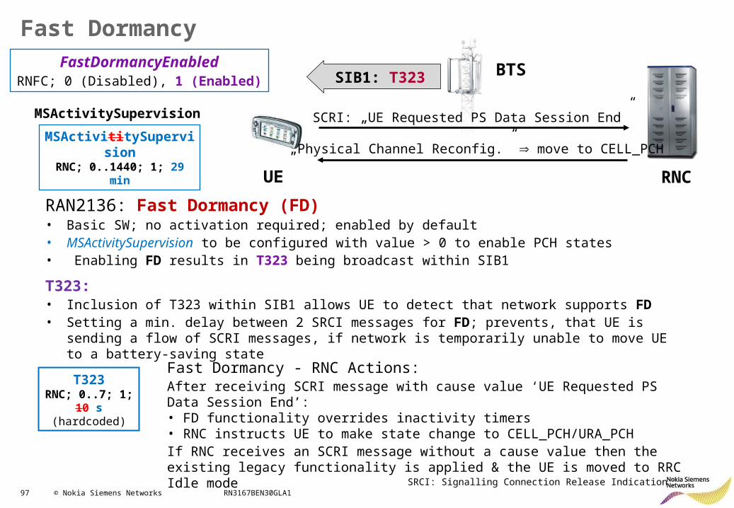
97 © Nokia Siemens Networks RN3167BEN30GLA1
Fast Dormancy
SIB1: T323
SCRI: „UE Requested PS Data Session End”
„Physical Channel Reconfig.” move to CELL_PCH
UE RNC
BTSFastDormancyEnabledRNFC; 0 (Disabled), 1 (Enabled)
RAN2136: Fast Dormancy (FD) • Basic SW; no activation required; enabled by default• MSActivitySupervision to be configured with value > 0 to enable PCH states• Enabling FD results in T323 being broadcast within SIB1
T323:• Inclusion of T323 within SIB1 allows UE to detect that network supports FD• Setting a min. delay between 2 SRCI messages for FD; prevents, that UE is sending a flow of SCRI
messages, if network is temporarily unable to move UE to a battery-saving state
MSActivititySupervisionRNC; 0..1440; 1; 29 min
SRCI: Signalling Connection Release Indication
T323RNC; 0..7; 1; 10 s
(hardcoded)
Fast Dormancy - RNC Actions:After receiving SCRI message with cause value ‘UE Requested PS Data Session End’:• FD functionality overrides inactivity timers• RNC instructs UE to make state change to CELL_PCH/URA_PCHIf RNC receives an SCRI message without a cause value then the existing legacy functionality is applied & the UE is moved to RRC Idle mode
MSActivitySupervision
98 © Nokia Siemens Networks RN3167BEN30GLA1
HSPA+ RRM: Contents
• HSDPA Improvements• HSUPA Improvements• Other features:
– Continuous Packet Connectivity CPC– CS Voice over HSPA– Fast Dormancy– Fast Dormancy Profiling (RAN2451)– Multi-Band Load Balancing MBLB– High Speed Cell_FACH (DL)– High Speed Cell_FACH
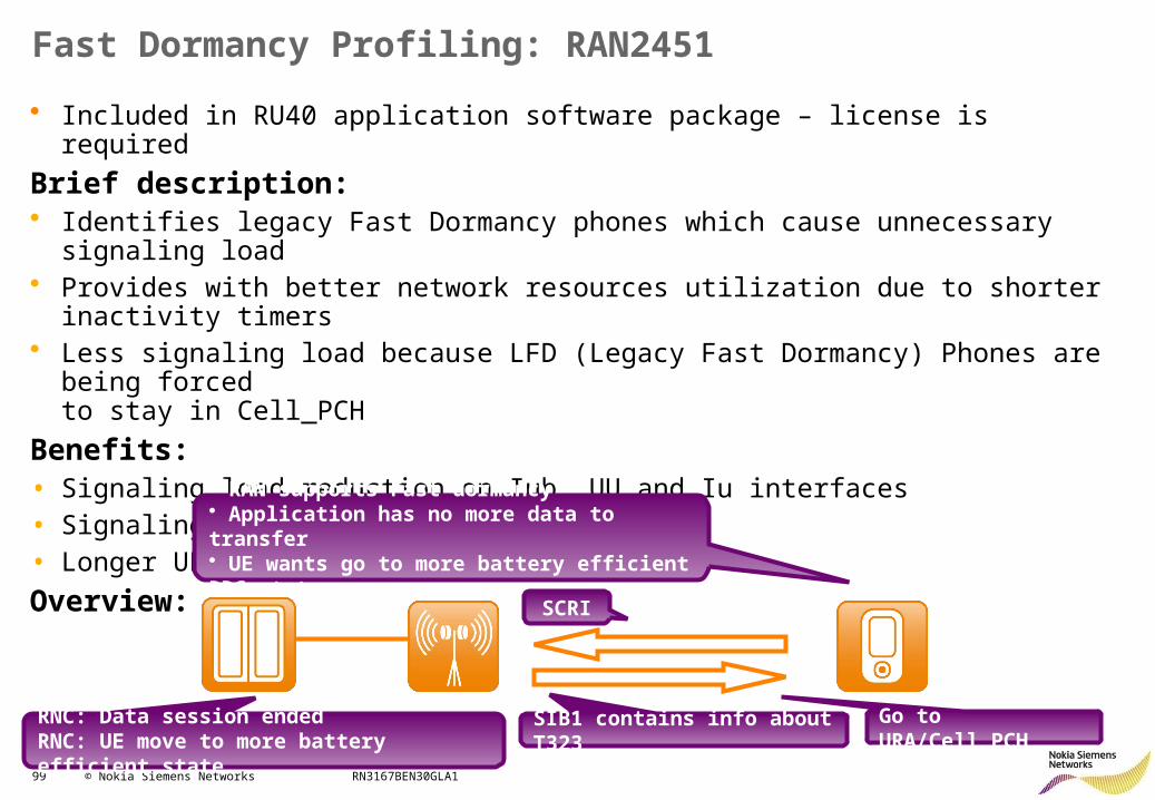
99 © Nokia Siemens Networks RN3167BEN30GLA1
Fast Dormancy Profiling: RAN2451
• Included in RU40 application software package – license is required
Brief description:• Identifies legacy Fast Dormancy phones which cause unnecessary signaling load• Provides with better network resources utilization due to shorter inactivity timers• Less signaling load because LFD (Legacy Fast Dormancy) Phones are being forced
to stay in Cell_PCH
Benefits:• Signaling load reduction on Iub, UU and Iu interfaces • Signaling load reduction in the RNC• Longer UE battery life
Overview:
SIB1 contains info about T323
• RAN supports Fast dormancy• Application has no more data to transfer• UE wants go to more battery efficient RRC state
SCRI
RNC: Data session endedRNC: UE move to more battery efficient state
Go to URA/Cell_PCH
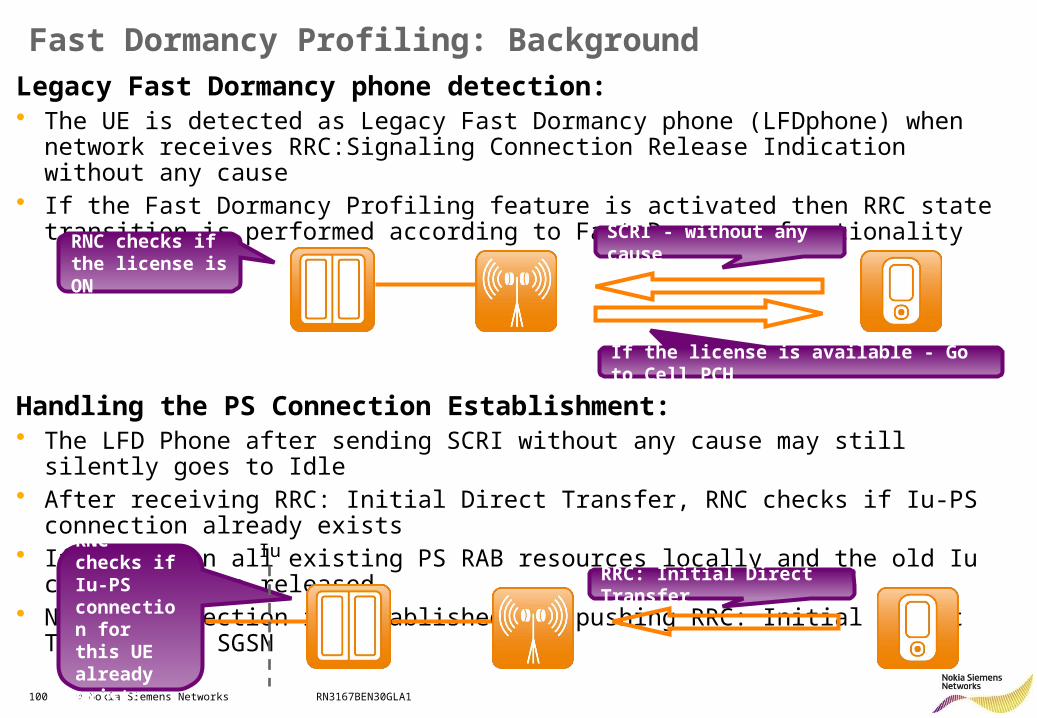
100 © Nokia Siemens Networks RN3167BEN30GLA1
Fast Dormancy Profiling: BackgroundLegacy Fast Dormancy phone detection:• The UE is detected as Legacy Fast Dormancy phone (LFDphone) when network receives
RRC:Signaling Connection Release Indication without any cause• If the Fast Dormancy Profiling feature is activated then RRC state transition is performed
according to Fast Dormancy functionality
Handling the PS Connection Establishment:• The LFD Phone after sending SCRI without any cause may still silently goes to Idle• After receiving RRC: Initial Direct Transfer, RNC checks if Iu-PS connection already exists• If yes, then all existing PS RAB resources locally and the old Iu connection are released• New Iu connection is established for pushing RRC: Initial Direct Transfer to SGSN
SCRI - without any cause RNC checks if the license is ON
If the license is available - Go to Cell_PCH
RRC: Initial Direct TransferRNC checks if Iu-PS connection for this UE already exists
Iu
101 © Nokia Siemens Networks RN3167BEN30GLA1
Fast Dormancy Profiling: Principle
Shorter Inactivity Timers for LFD Phone and Smartphones:• Shorter inactivity timers should be used for moving smartphones and LFD Phones to
Cell_PCH state - saving UE battery• It gives possibility to avoid unnecessary movement to IDLE_mode – less signaling load
Higher Traffic Volume Thresholds for LFD Phone and Smartphones:• Higher traffic volume thresholds should be used for moving smartphones and LFD Phones
to Cell_DCH state• It gives possibility to avoid unnecessary movement to Cell_DCH – only for sending keep-
alive message• Stored IMSI gives possibility to faster usage of higher traffic volume thresholds
102 © Nokia Siemens Networks RN3167BEN30GLA1
HSPA+ RRM: Contents
• HSDPA Improvements• HSUPA Improvements• Other features:
– Continuous Packet Connectivity CPC– CS Voice over HSPA– Fast Dormancy– Fast Dormancy Profiling– Multi-Band Load Balancing MBLB (RAN2172)– High Speed Cell_FACH (DL)– High Speed Cell_FACH
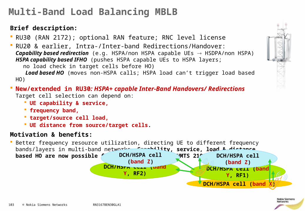
103 © Nokia Siemens Networks RN3167BEN30GLA1
Multi-Band Load Balancing MBLB
Brief description: RU30 (RAN 2172); optional RAN feature; RNC level license RU20 & earlier, Intra-/Inter-band Redirections/Handover:
Capability based redirection (e.g. HSPA/non HSPA capable UEs HSDPA/non HSPA) HSPA capability based IFHO (pushes HSPA capable UEs to HSPA layers;
no load check in target cells before HO) Load based HO (moves non-HSPA calls; HSPA load can’t trigger load based HO)
New/extended in RU30: HSPA+ capable Inter-Band Handovers/ RedirectionsTarget cell selection can depend on:
UE capability & service, frequency band, target/source cell load, UE distance from source/target cells.
Motivation & benefits: Better frequency resource utilization, directing UE to different frequency bands/layers in multi-band
networks. Capability, service, load & distance based HO are now possible for HSPA+ between e.g. UMTS 2100 & 900/850 cells
DCH/HSPA cell (band X)
DCH/HSPA cell (band Y, RF1)DCH/HSPA cell (band Y, RF2)
DCH/HSPA cell (band Z) DCH/HSPA cell (band Z)
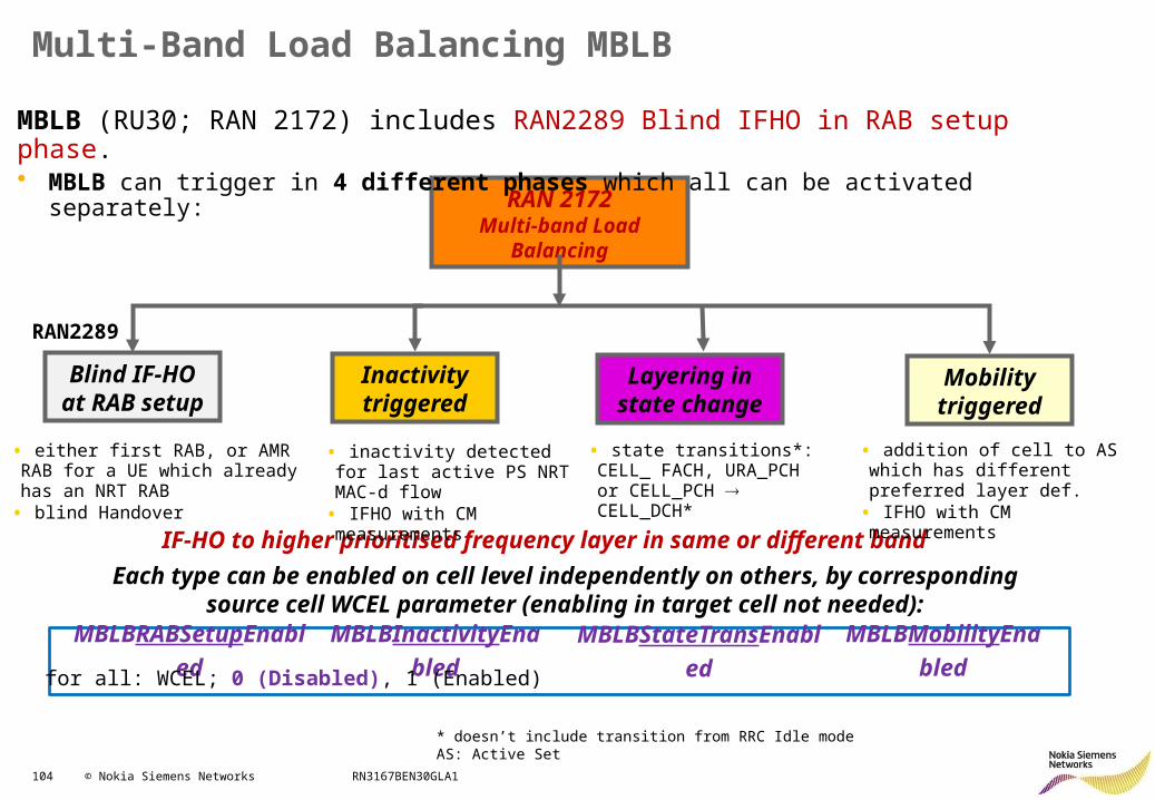
104 © Nokia Siemens Networks RN3167BEN30GLA1
Multi-Band Load Balancing MBLB
a
RAN 2172Multi-band Load Balancing
Blind IF-HO at RAB setup
Inactivity triggered
Layering in state change
Mobility triggered
RAN2289
IF-HO to higher prioritised frequency layer in same or different band
MBLBRABSetupEnabled MBLBInactivityEnabled MBLBStateTransEnabled MBLBMobilityEnabled
Each type can be enabled on cell level independently on others, by corresponding source cell WCEL parameter (enabling in target cell not needed):
for all: WCEL; 0 (Disabled), 1 (Enabled)
MBLB (RU30; RAN 2172) includes RAN2289 Blind IFHO in RAB setup phase.• MBLB can trigger in 4 different phases which all can be activated separately:
• either first RAB, or AMR RAB for a UE which already has an NRT RAB
• blind Handover
• state transitions*: CELL_ FACH, URA_PCH or CELL_PCH CELL_DCH*
* doesn’t include transition from RRC Idle modeAS: Active Set
• inactivity detected for last active PS NRT MAC-d flow
• IFHO with CM measurements
• addition of cell to AS which has different preferred layer def.
• IFHO with CM measurements
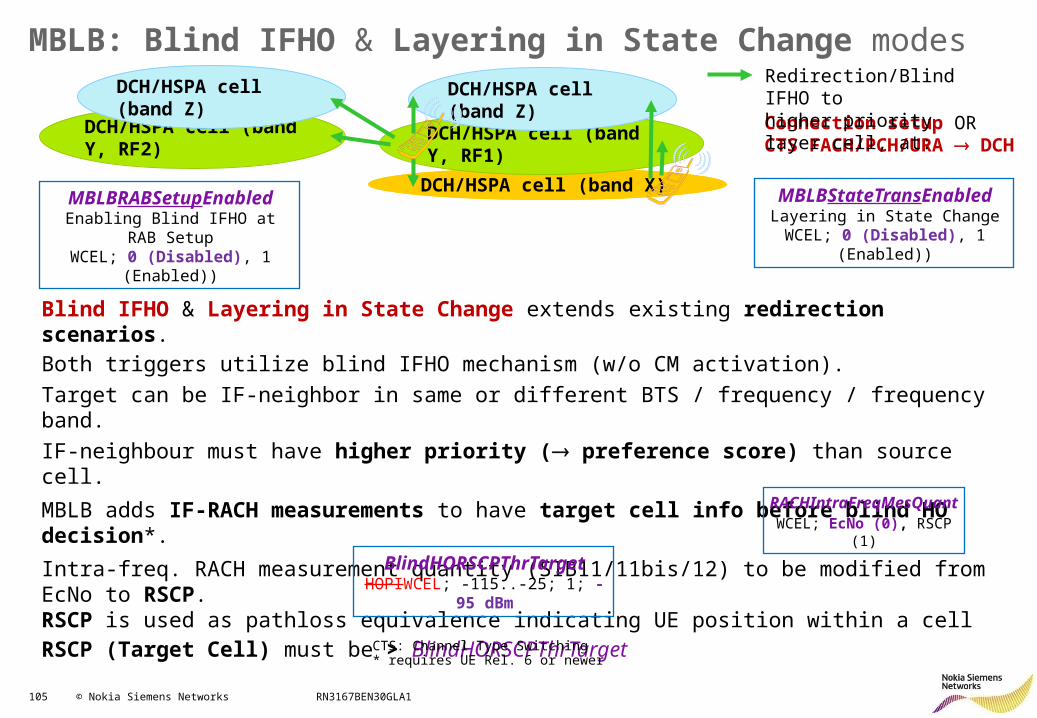
105 © Nokia Siemens Networks RN3167BEN30GLA1
MBLB: Blind IFHO & Layering in State Change modes
DCH/HSPA cell (band X)
DCH/HSPA cell (band Y, RF1)DCH/HSPA cell (band Y, RF2)
DCH/HSPA cell (band Z)Connection setup ORCTS FACH/PCH/URA DCH
Redirection/Blind IFHO tohigher priority layer cell, at:
Blind IFHO & Layering in State Change extends existing redirection scenarios. Both triggers utilize blind IFHO mechanism (w/o CM activation).
Target can be IF-neighbor in same or different BTS / frequency / frequency band.
IF-neighbour must have higher priority ( preference score) than source cell.
MBLB adds IF-RACH measurements to have target cell info before blind HO decision*.
Intra-freq. RACH measurement quantity (SIB11/11bis/12) to be modified from EcNo to RSCP.RSCP is used as pathloss equivalence indicating UE position within a cellRSCP (Target Cell) must be > BlindHORSCPThrTarget
DCH/HSPA cell (band Z)
CTS: Channel Type Switching* requires UE Rel. 6 or newer
MBLBRABSetupEnabledEnabling Blind IFHO at RAB
SetupWCEL; 0 (Disabled), 1 (Enabled))
MBLBStateTransEnabledLayering in State Change
WCEL; 0 (Disabled), 1 (Enabled))
BlindHORSCPThrTargetHOPIWCEL; -115..-25; 1; -95
dBm
RACHIntraFreqMesQuantWCEL; EcNo (0), RSCP (1)
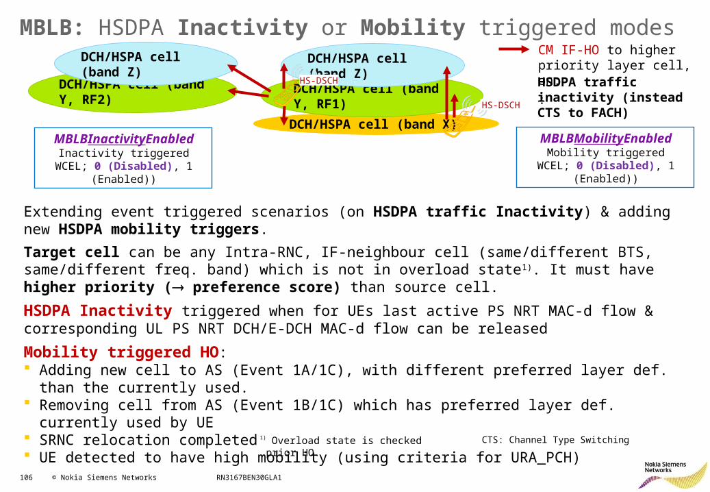
106 © Nokia Siemens Networks RN3167BEN30GLA1
MBLB: HSDPA Inactivity or Mobility triggered modes
DCH/HSPA cell (band X)
DCH/HSPA cell (band Y, RF1)DCH/HSPA cell (band Y, RF2)
DCH/HSPA cell (band Z)HSDPA traffic inactivity (instead CTS to FACH)
CM IF-HO to higher priority layer cell, on:
:
Extending event triggered scenarios (on HSDPA traffic Inactivity) & adding new HSDPA mobility triggers.
Target cell can be any Intra-RNC, IF-neighbour cell (same/different BTS, same/different freq. band) which is not in overload state1). It must have higher priority ( preference score) than source cell.
HSDPA Inactivity triggered when for UEs last active PS NRT MAC-d flow & corresponding UL PS NRT DCH/E-DCH MAC-d flow can be released
Mobility triggered HO: Adding new cell to AS (Event 1A/1C), with different preferred layer def. than the currently used. Removing cell from AS (Event 1B/1C) which has preferred layer def. currently used by UE SRNC relocation completed UE detected to have high mobility (using criteria for URA_PCH)
1) Overload state is checked prior HO.
DCH/HSPA cell (band Z)
CTS: Channel Type Switching
HS-DSCH
HS-DSCH
MBLBInactivityEnabledInactivity triggered
WCEL; 0 (Disabled), 1 (Enabled))
MBLBMobilityEnabledMobility triggered
WCEL; 0 (Disabled), 1 (Enabled))
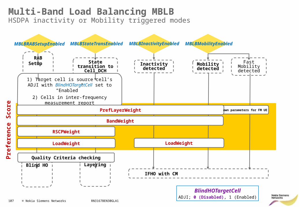
107 © Nokia Siemens Networks RN3167BEN30GLA1
Multi-Band Load Balancing MBLBHSDPA inactivity or Mobility triggered modes
RAB Setup
Inactivity detected
MBLBRABSetupEnabled MBLBStateTransEnabled MBLBInactivityEnabled MBLBMobilityEnabled
Mobility detected
Fast Mobility detected
State transition to Cell_DCH
1) Target cell is source cell’s ADJI with BlindHOTargetCell set to “Enabled”
2) Cells in inter-frequency measurement report
PrefLayerWeight
BandWeight
RSCPWeight
LoadWeight
own parameters for FM UE
LoadWeight
Pre
fere
nce
Sco
re
Blind HO
Layering
IFHO with CM
Quality Criteria checking
BlindHOTargetCellADJI; 0 (Disabled), 1 (Enabled)
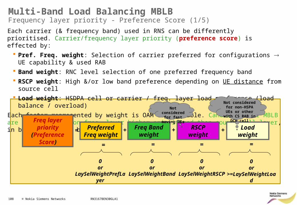
108 © Nokia Siemens Networks RN3167BEN30GLA1
Multi-Band Load Balancing MBLBFrequency layer priority - Preference Score (1/5)
Each carrier (& frequency band) used in RNS can be differently prioritised. Carrier/frequency layer priority (preference score) is effected by:
Pref. Freq. weight: Selection of carrier preferred for configurations UE capability & used RAB
Band weight: RNC level selection of one preferred frequency band
RSCP weight: High &/or low band preference depending on UE distance from source cell
Load weight: HSDPA cell or carrier / freq. layer load preference (load balance / overload)
Each factor represented by weight is OAM configurable. Candidates for MBLB are IF neighbours on freq. layer higher prioritised then source cell layer, in bands supported by UE
Freq layer priority(Preference Score)
= Preferred Freq weight
Freq Band weight
RSCPweight
Loadweight
+ + +
= = = =
0or
LaySelWeightPrefLayer
0or
LaySelWeightBand
0or
LaySelWeightRSCP
0or
>=LaySelWeightLoad
Not considered for fast moving
UEs
Not considered for non-HSPA UEs or
other with CS RAB in DCH cell
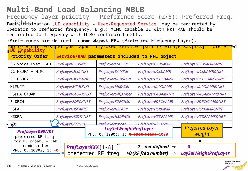
109 © Nokia Siemens Networks RN3167BEN30GLA1
Multi-Band Load Balancing MBLBFrequency layer priority - Preference Score (2/5): Preferred Freq. weight
UE Capability Priority Order Service/RAB parameters included to PFL object
CS Voice Over HSPA PrefLayerCSHSNRT PrefLayerCSHSStr PrefLayerCSHSAMR PrefLayerCSHSAMR&NRT
DC HSDPA + MIMO PrefLayerDCMINRT PrefLayerDCMIStr PrefLayerDCMIAMR PrefLayerDCMIAMR&NRT
DC HSDPA *PrefLayerDCHSDNRT
PrefLayerDCHSDStr
PrefLayerDCHSDAMR
PrefLayerDCHSDAMR&NRT
MIMO** PrefLayerMIMONRT PrefLayerMIMOStr PrefLayerMIMOAMR PrefLayerMIMOAMR&NRT
HSDPA 64QAM PrefLayer64QAMNRT PrefLayer64QAMStr PrefLayer64QAMAMR PrefLayer64QAMAMR&NRT
F-DPCH PrefLayerFDPCHNRT PrefLayerFDPCHStr PrefLayerFDPCHAMR PrefLayerFDPCHAMR&NRT
HSPA PrefLayerHSPANRT PrefLayerHSPAStr PrefLayerHSPAAMR PrefLayerHSPAAMR&NRT
HSDPA PrefLayerHSDPANRT PrefLayerHSDPAStr PrefLayerHSDPAAMR PrefLayerHSDPAAMR&NRT
R99 PrefLayerR99NRT PrefLayerR99Str PrefLayerR99AMR PrefLayerR99AMR&NRT
PrefLayerR99NRTpreferred RF freq. for UE
capab. – RAB combinationPFL; 0..16383; 1; -0
e.g.
Each combination „UE capability – Used/Requested Service” may be redirected by Operator to preferred frequency. E.g.: MIMO capable UE with NRT RAB should be redirected to frequency with MIMO configured cells. •Preferences are defined in new object PFL (Preferred Frequency Layer);•up to 8 carriers per „UE capability-Used Service” pair (PrefLayerXXX[1-8] = preferred RF freq.
Preferred Layerweight
PrefLayerXXX[1-8] = preferred RF freq.
0 = not defined 0
>0 (RF freq number) LaySelWeightPrefLayer
LaySelWeightPrefLayerPFL; 0..10000; 1; 0 (not used) 1000
=
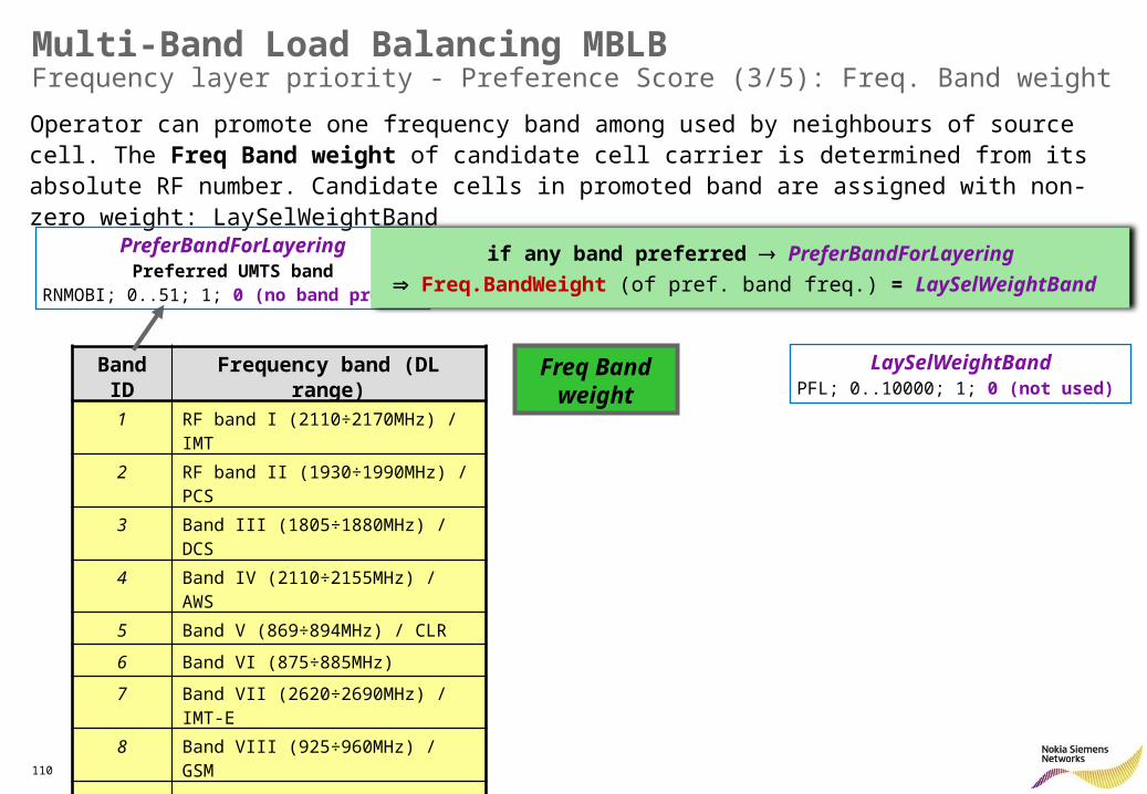
110 © Nokia Siemens Networks RN3167BEN30GLA1
Multi-Band Load Balancing MBLBFrequency layer priority - Preference Score (3/5): Freq. Band weight
Operator can promote one frequency band among used by neighbours of source cell. The Freq Band weight of candidate cell carrier is determined from its absolute RF number. Candidate cells in promoted band are assigned with non-zero weight: LaySelWeightBand
Freq Band weight
Band ID Frequency band (DL range)
1 RF band I (2110÷2170MHz) / IMT
2 RF band II (1930÷1990MHz) / PCS
3 Band III (1805÷1880MHz) / DCS
4 Band IV (2110÷2155MHz) / AWS
5 Band V (869÷894MHz) / CLR
6 Band VI (875÷885MHz)
7 Band VII (2620÷2690MHz) / IMT-E
8 Band VIII (925÷960MHz) / GSM
.. …
11 Band XI (1475.9÷1495.9MHz)
…
LaySelWeightBandPFL; 0..10000; 1; 0 (not used)
PreferBandForLayeringPreferred UMTS band
RNMOBI; 0..51; 1; 0 (no band pref.)
if any band preferred PreferBandForLayering
Freq.BandWeight (of pref. band freq.) = LaySelWeightBand
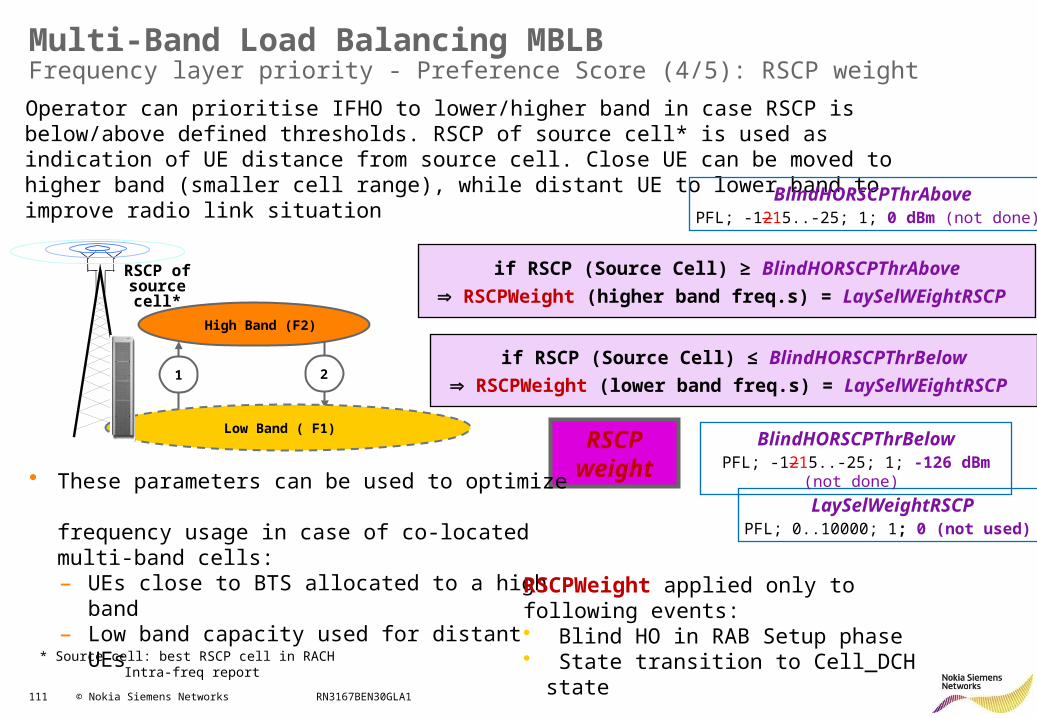
111 © Nokia Siemens Networks RN3167BEN30GLA1
Multi-Band Load Balancing MBLBFrequency layer priority - Preference Score (4/5): RSCP weight
Operator can prioritise IFHO to lower/higher band in case RSCP is below/above defined thresholds. RSCP of source cell* is used as indication of UE distance from source cell. Close UE can be moved to higher band (smaller cell range), while distant UE to lower band to improve radio link situation
RSCPweight
* Source cell: best RSCP cell in RACH Intra-freq report
Low Band ( F1)
High Band (F2)
21
if RSCP (Source Cell) ≥ BlindHORSCPThrAbove
RSCPWeight (higher band freq.s) = LaySelWEightRSCP
if RSCP (Source Cell) ≤ BlindHORSCPThrBelow
RSCPWeight (lower band freq.s) = LaySelWEightRSCP
RSCP of source cell*
BlindHORSCPThrAbovePFL; -1215..-25; 1; 0 dBm (not done)
LaySelWeightRSCPPFL; 0..10000; 1; 0 (not used)
BlindHORSCPThrBelowPFL; -1215..-25; 1; -126 dBm (not done)
• These parameters can be used to optimize frequency usage in case of co-located multi-band cells: – UEs close to BTS allocated to a high band – Low band capacity used for distant UEs RSCPWeight applied only to following events:
• Blind HO in RAB Setup phase• State transition to Cell_DCH state
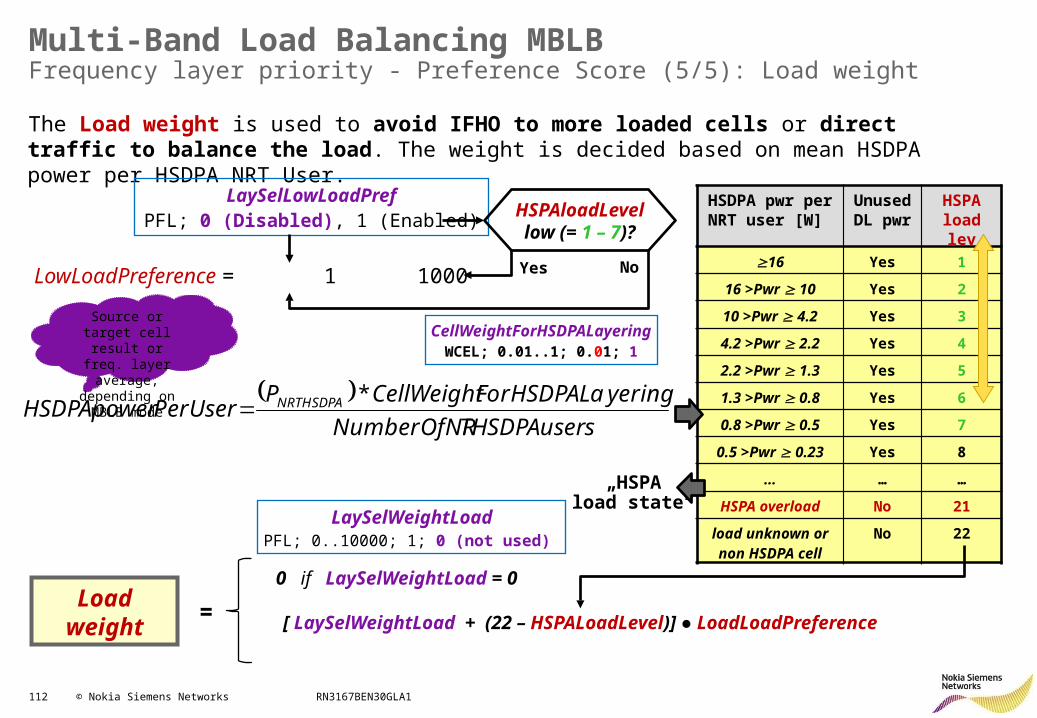
112 © Nokia Siemens Networks RN3167BEN30GLA1
Multi-Band Load Balancing MBLBFrequency layer priority - Preference Score (5/5): Load weight
The Load weight is used to avoid IFHO to more loaded cells or direct traffic to balance the load. The weight is decided based on mean HSDPA power per HSDPA NRT User.
HSDPA pwr per NRT user [W]
Unused DL pwr
HSPA load lev
16 Yes 1
16 >Pwr 10 Yes 2
10 >Pwr 4.2 Yes 3
4.2 >Pwr 2.2 Yes 4
2.2 >Pwr 1.3 Yes 5
1.3 >Pwr 0.8 Yes 6
0.8 >Pwr 0.5 Yes 7
0.5 >Pwr 0.23 Yes 8
… … …
HSPA overload No 21
load unknown or non HSDPA cell
No 22
Loadweight
LaySelLowLoadPrefPFL; 0 (Disabled), 1 (Enabled)
LowLoadPreference = 1 1000
HSPAloadLevellow (= 1 – 7)?
Yes No
LaySelWeightLoadPFL; 0..10000; 1; 0 (not used)
[ LaySelWeightLoad + (22 – HSPALoadLevel)] ● LoadLoadPreference=
0 if LaySelWeightLoad = 0
sTHSDPAuserNumberOfNR
yeringForHSDPALaCellWeightPPerUserHSDPApower NRTHSDPA *
CellWeightForHSDPALayeringWCEL; 0.01..1; 0.01; 1
Source or target cell result or freq. layer
average, depending on MBLB mode
„HSPAload state“
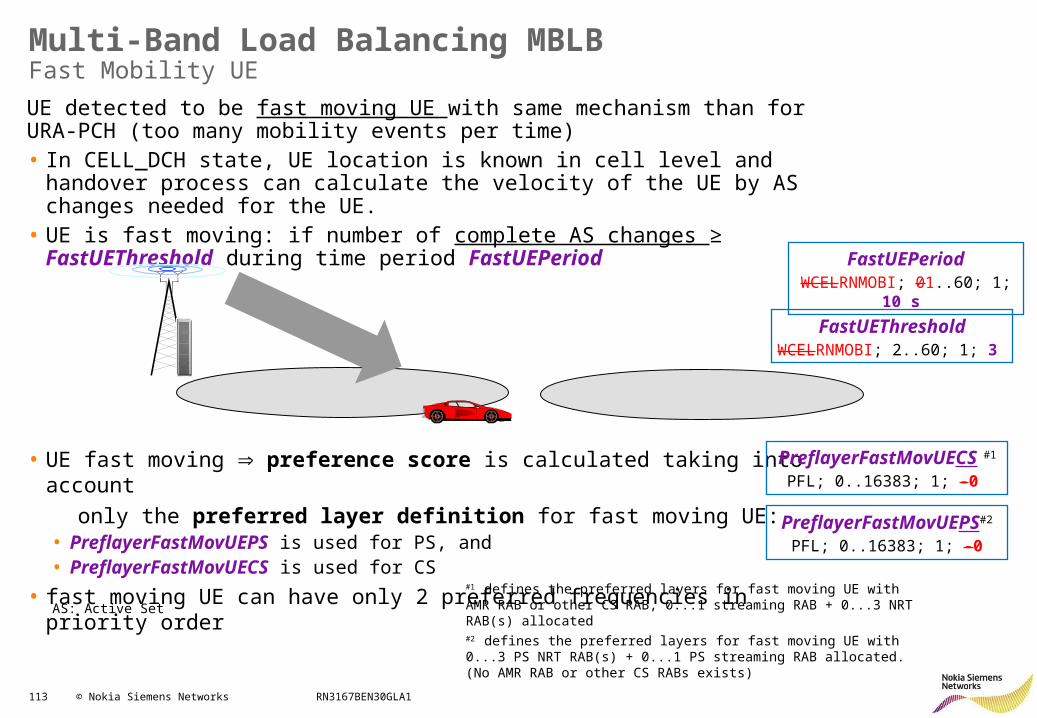
113 © Nokia Siemens Networks RN3167BEN30GLA1
Multi-Band Load Balancing MBLBFast Mobility UE
UE detected to be fast moving UE with same mechanism than for URA-PCH (too many mobility events per time)• In CELL_DCH state, UE location is known in cell level and handover process can
calculate the velocity of the UE by AS changes needed for the UE. • UE is fast moving: if number of complete AS changes ≥ FastUEThreshold during
time period FastUEPeriod
• UE fast moving preference score is calculated taking into account
only the preferred layer definition for fast moving UE:• PreflayerFastMovUEPS is used for PS, and• PreflayerFastMovUECS is used for CS
• fast moving UE can have only 2 preferred frequencies in priority order
FastUEPeriodWCELRNMOBI; 01..60; 1; 10 s
FastUEThresholdWCELRNMOBI; 2..60; 1; 3
AS: Active Set
PreflayerFastMovUEPS#2
PFL; 0..16383; 1; -0
PreflayerFastMovUECS #1
PFL; 0..16383; 1; -0
#1 defines the preferred layers for fast moving UE with AMR RAB or other CS RAB, 0...1 streaming RAB + 0...3 NRT RAB(s) allocated#2 defines the preferred layers for fast moving UE with 0...3 PS NRT RAB(s) + 0...1 PS streaming RAB allocated. (No AMR RAB or other CS RABs exists)
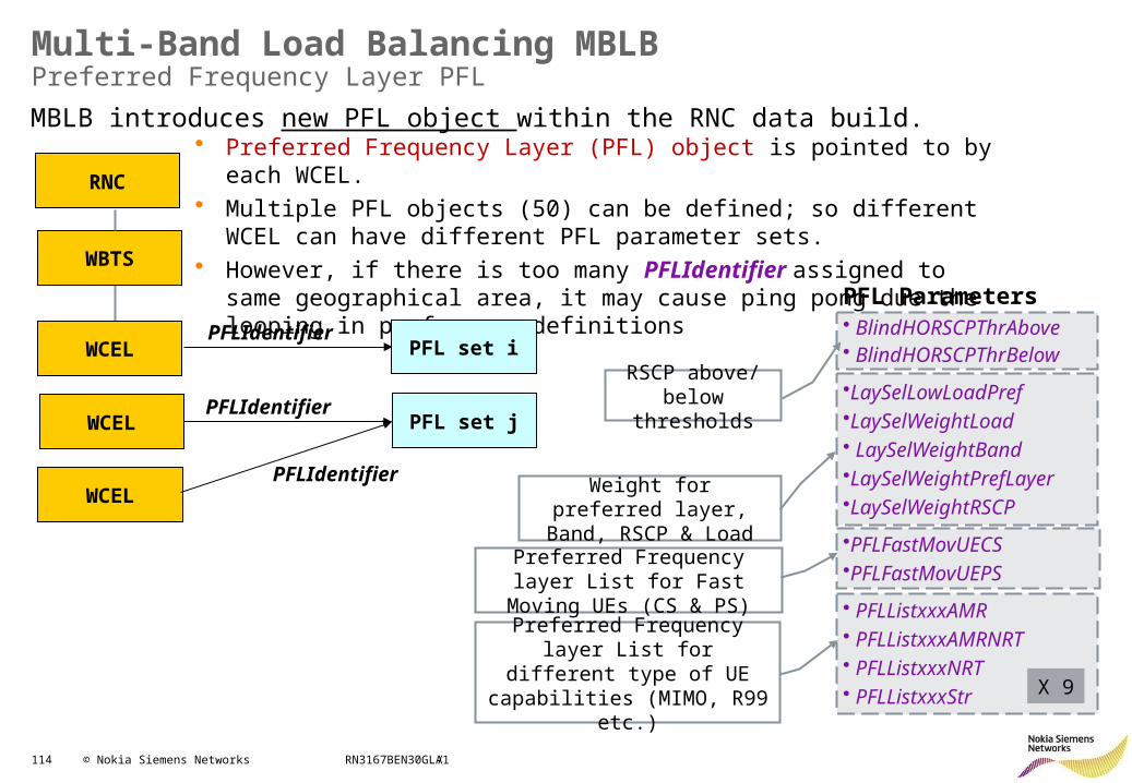
114 © Nokia Siemens Networks RN3167BEN30GLA1
Multi-Band Load Balancing MBLBPreferred Frequency Layer PFL
• Preferred Frequency Layer (PFL) object is pointed to by each WCEL.• Multiple PFL objects (50) can be defined; so different WCEL can have
different PFL parameter sets. • However, if there is too many PFLIdentifier assigned to same geographical
area, it may cause ping pong due the looping in preference definitions
PFLIdentifier
PFLIdentifier
WCELPFLIdentifier
WCEL
WCEL
WBTS
RNC
PFL set i
PFL set j
MBLB introduces new PFL object within the RNC data build.
/
PFL Parameters• BlindHORSCPThrAbove• BlindHORSCPThrBelow
•LaySelLowLoadPref•LaySelWeightLoad• LaySelWeightBand•LaySelWeightPrefLayer•LaySelWeightRSCP
•PFLFastMovUECS•PFLFastMovUEPS
• PFLListxxxAMR• PFLListxxxAMRNRT• PFLListxxxNRT• PFLListxxxStr
RSCP above/below thresholds
Weight for preferred layer, Band, RSCP & Load
Preferred Frequency layer List for Fast Moving UEs (CS & PS)
Preferred Frequency layer List for different type of UE
capabilities (MIMO, R99 etc.) X 9
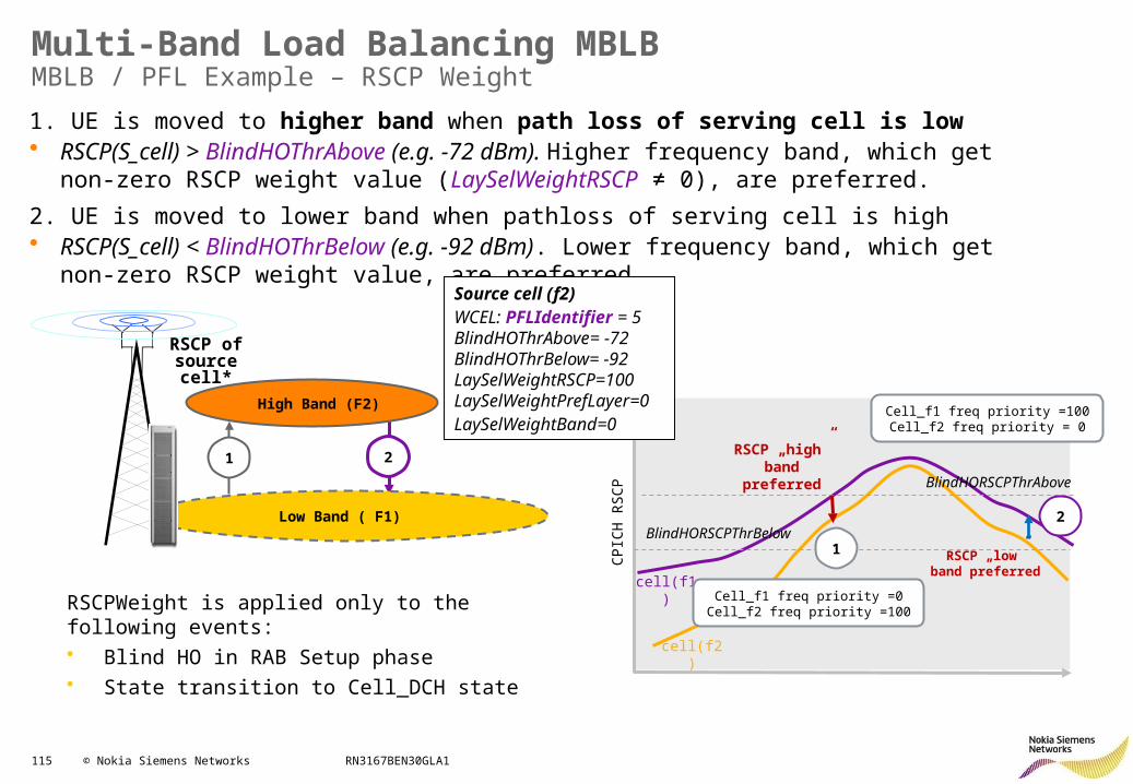
115 © Nokia Siemens Networks RN3167BEN30GLA1
Multi-Band Load Balancing MBLBMBLB / PFL Example – RSCP Weight
RSCPWeight is applied only to the following events:• Blind HO in RAB Setup phase• State transition to Cell_DCH state
1. UE is moved to higher band when path loss of serving cell is low • RSCP(S_cell) > BlindHOThrAbove (e.g. -72 dBm). Higher frequency band, which get non-zero
RSCP weight value (LaySelWeightRSCP ≠ 0), are preferred.
2. UE is moved to lower band when pathloss of serving cell is high • RSCP(S_cell) < BlindHOThrBelow (e.g. -92 dBm). Lower frequency band, which get non-zero
RSCP weight value, are preferred.
Low Band ( F1)
High Band (F2)
21
RSCP of source cell*
RSCP „high” band
preferred BlindHORSCPThrAbove
BlindHORSCPThrBelow
RSCP „low” band preferred
cell(f1)
cell(f2)
1
2
Cell_f1 freq priority =0Cell_f2 freq priority
=100
Cell_f1 freq priority =100
Cell_f2 freq priority = 0
Source cell (f2)WCEL: PFLIdentifier = 5BlindHOThrAbove= -72BlindHOThrBelow= -92LaySelWeightRSCP=100LaySelWeightPrefLayer=0LaySelWeightBand=0
CPIC
H R
SC
P
116 © Nokia Siemens Networks RN3167BEN30GLA1
HSPA+ RRM: Contents
• HSDPA Improvements• HSUPA Improvements• Other features:
– Continuous Packet Connectivity CPC– CS Voice over HSPA– Fast Dormancy– Fast Dormancy Profiling– Multi-Band Load Balancing MBLB– High Speed Cell_FACH (DL) (RAN1637)– High Speed Cell_FACH
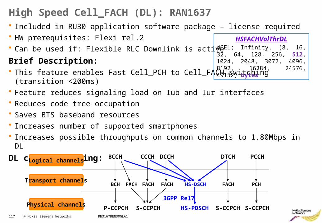
117 © Nokia Siemens Networks RN3167BEN30GLA1
High Speed Cell_FACH (DL): RAN1637• Included in RU30 application software package – license required• HW prerequisites: Flexi rel.2• Can be used if: Flexible RLC Downlink is active
Brief Description: • This feature enables Fast Cell_PCH to Cell_FACH switching (transition <200ms)• Feature reduces signaling load on Iub and Iur interfaces• Reduces code tree occupation• Saves BTS baseband resources• Increases number of supported smartphones• Increases possible throughputs on common channels to 1.80Mbps in DL
DL channel mapping:
HSFACHVolThrDLWCEL; Infinity, (8, 16, 32, 64, 128, 256, 512, 1024, 2048, 3072, 4096, 8192, 16384, 24576, 49152) bytes
PCCH CCCH DCCH DTCH
3GPP Rel7
BCCH
FACH FACH FACHBCH PCHFACH
S-CCPCHP-CCPCH
HS-DSCH
HS-PDSCH S-CCPCH S-CCPCH
Logical channels
Transport channels
Physical channels
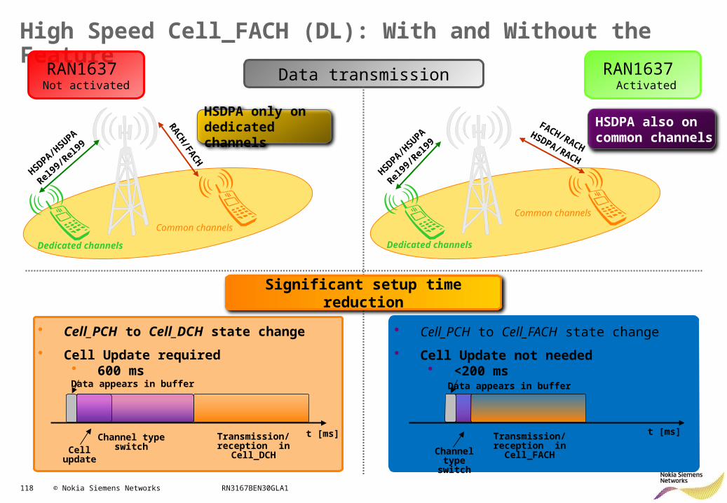
118 © Nokia Siemens Networks RN3167BEN30GLA1
High Speed Cell_FACH (DL): With and Without the Feature
HSDPA/H
SUPA
Rel99
/Rel
99
RACH/FA
CH
Dedicated channels
Common channels
HSDPA
/HSU
PA
Rel99
/Rel
99
Dedicated channels
Common channels
FACH/RACH
HSDPA/RACH
HSDPA only on dedicated channels
HSDPA also on common channels
Data transmission
• Cell_PCH to Cell_FACH state change
• Cell Update not needed• <200 ms
• Cell_PCH to Cell_DCH state change
• Cell Update required• 600 ms
Channel type
switch
Transmission/reception in
Cell_FACH
Data appears in buffer
t [ms]Transmission/reception in
Cell_DCHCell update
Data appears in buffer
t [ms]Channel type switch
Significant setup time reduction
RAN1637 Activated
RAN1637 Not activated
119 © Nokia Siemens Networks RN3167BEN30GLA1
HSPA+ RRM: Contents
• HSDPA Improvements• HSUPA Improvements• Other features:
– Continuous Packet Connectivity CPC– CS Voice over HSPA– Fast Dormancy– Fast Dormancy Profiling– Multi-Band Load Balancing MBLB– High Speed Cell_FACH (DL)– High Speed Cell_FACH (RAN1913)
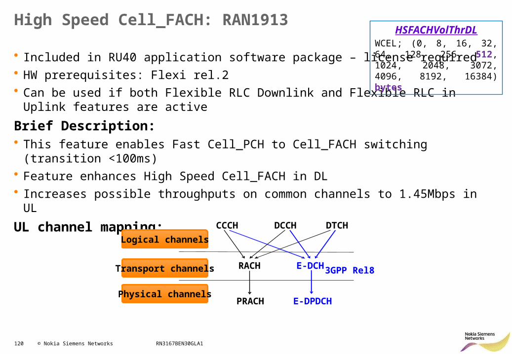
120 © Nokia Siemens Networks RN3167BEN30GLA1
High Speed Cell_FACH: RAN1913
• Included in RU40 application software package – license required• HW prerequisites: Flexi rel.2• Can be used if both Flexible RLC Downlink and Flexible RLC in Uplink features are active
Brief Description: • This feature enables Fast Cell_PCH to Cell_FACH switching (transition <100ms)• Feature enhances High Speed Cell_FACH in DL• Increases possible throughputs on common channels to 1.45Mbps in UL
UL channel mapping:
HSFACHVolThrDLWCEL; (0, 8, 16, 32, 64, 128, 256, 512, 1024, 2048, 3072, 4096, 8192, 16384) bytes
CCCH DCCH DTCH
RACH
PRACH E-DPDCH
3GPP Rel8E-DCH
Logical channels
Transport channels
Physical channels
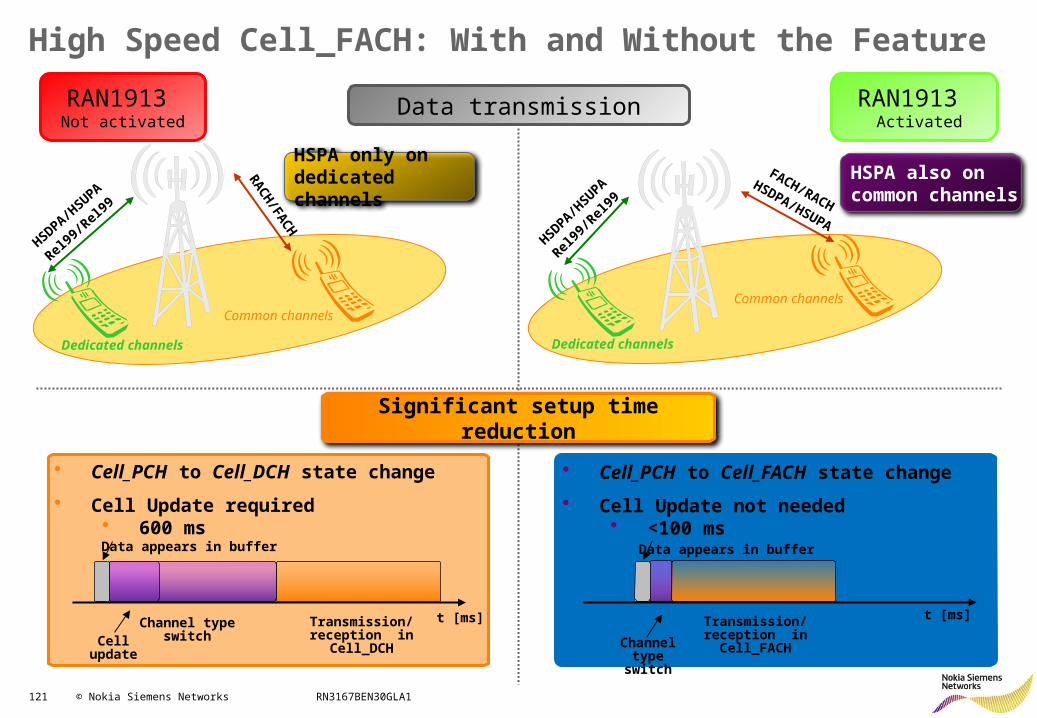
121 © Nokia Siemens Networks RN3167BEN30GLA1
High Speed Cell_FACH: With and Without the Feature
HSDPA/H
SUPA
Rel99
/Rel
99
RACH/FA
CH
Dedicated channels
Common channels
HSDPA
/HSU
PA
Rel99
/Rel
99
Dedicated channels
Common channels
FACH/RACHHSDPA/
HSUPA
HSPA only on dedicated channels
HSPA also on common channels
Data transmission
• Cell_PCH to Cell_FACH state change
• Cell Update not needed• <100 ms
• Cell_PCH to Cell_DCH state change
• Cell Update required• 600 ms
Channel type
switch
Transmission/reception in
Cell_FACH
Data appears in buffer
t [ms]Transmission/reception in
Cell_DCHCell update
Data appears in buffer
t [ms]Channel type switch
Significant setup time reduction
RAN1913 Activated
RAN1913 Not activated
122 © Nokia Siemens Networks RN3167BEN30GLA1
HSPA+ RRM: Contents
• HSDPA Improvements• HSUPA Improvements• Other features• Appendix:
– Dynamic HSDPA BLER (RAN 2171)
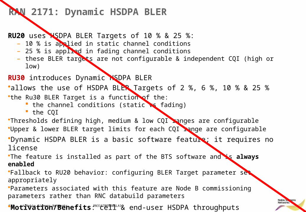
123 © Nokia Siemens Networks RN3167BEN30GLA1
RAN 2171: Dynamic HSDPA BLER
RU20 uses HSDPA BLER Targets of 10 % & 25 %:– 10 % is applied in static channel conditions– 25 % is applied in fading channel conditions– these BLER targets are not configurable & independent CQI (high or low)
RU30 introduces Dynamic HSDPA BLER•allows the use of HSDPA BLER Targets of 2 %, 6 %, 10 % & 25 %•the Ru30 BLER Target is a function of the:
the channel conditions (static vs fading) the CQI
•Thresholds defining high, medium & low CQI ranges are configurable•Upper & lower BLER target limits for each CQI range are configurable
•Dynamic HSDPA BLER is a basic software feature; it requires no license•The feature is installed as part of the BTS software and is always enabled•Fallback to RU20 behavior: configuring BLER Target parameter set appropriately•Parameters associated with this feature are Node B commissioning parameters rather than RNC databuild parameters
•Motivation/Benefits: cell & end-user HSDPA throughputs improved by up to 8 %
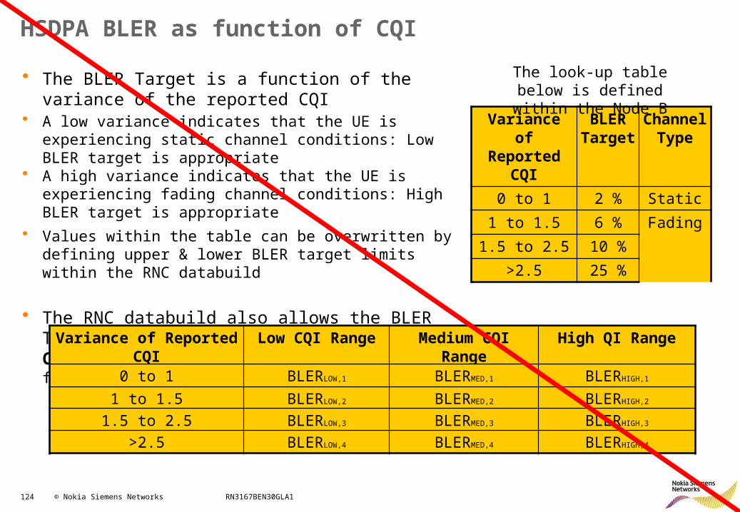
124 © Nokia Siemens Networks RN3167BEN30GLA1
HSDPA BLER as function of CQI
• The BLER Target is a function of the variance of the reported CQI
• A low variance indicates that the UE is experiencing static channel conditions: Low BLER target is appropriate
• A high variance indicates that the UE is experiencing fading channel conditions: High BLER target is appropriate
• Values within the table can be overwritten by defining upper & lower BLER target limits within the RNC databuild
• The RNC databuild also allows the BLER Target to be defined as a function of the CQI, e.g. smaller BLER Targets can be defined for higher CQI values
Variance of Reported CQI
BLER Target
Channel Type
0 to 1 2 % Static
1 to 1.5 6 % Fading
1.5 to 2.5 10 %
>2.5 25 %
The look-up table below is defined within the Node B
Variance of Reported CQI Low CQI Range Medium CQI Range High QI Range
0 to 1 BLERLOW,1 BLERMED,1 BLERHIGH,1
1 to 1.5 BLERLOW,2 BLERMED,2 BLERHIGH,2
1.5 to 2.5 BLERLOW,3 BLERMED,3 BLERHIGH,3
>2.5 BLERLOW,4 BLERMED,4 BLERHIGH,4
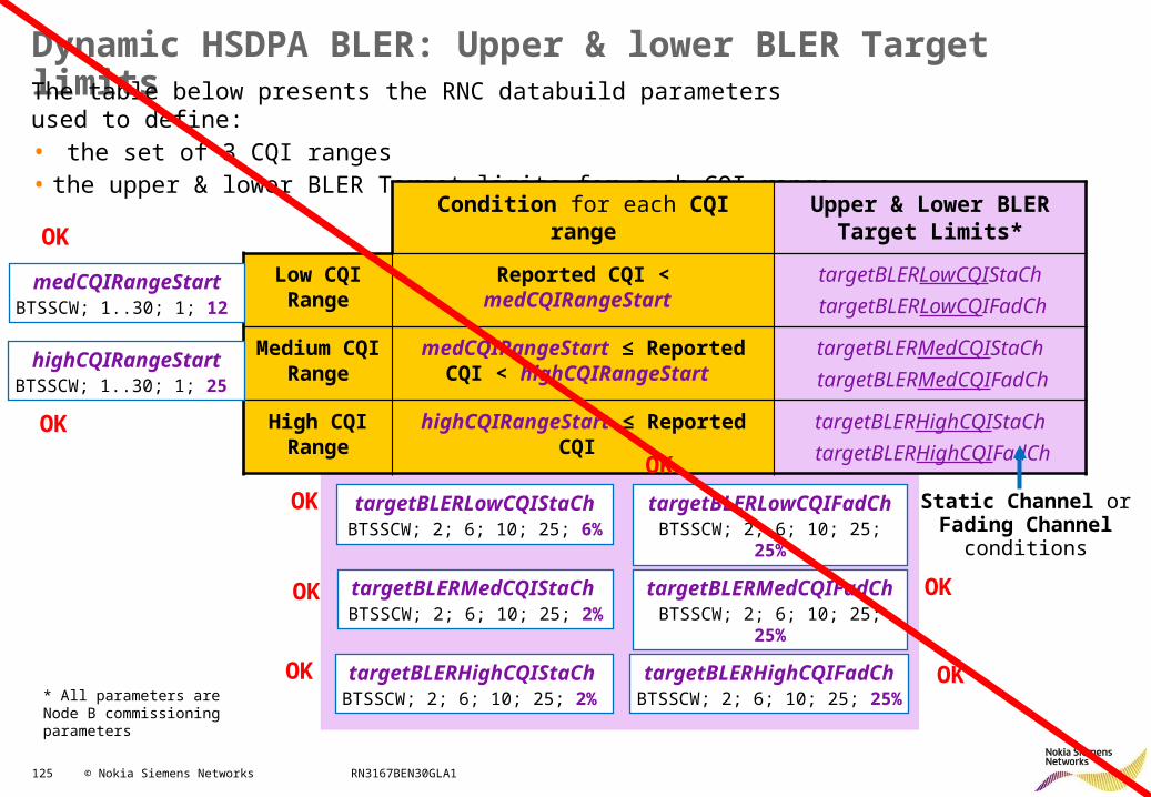
125 © Nokia Siemens Networks RN3167BEN30GLA1
Dynamic HSDPA BLER: Upper & lower BLER Target limitsThe table below presents the RNC databuild parameters used to define:• the set of 3 CQI ranges• the upper & lower BLER Target limits for each CQI range
Condition for each CQI range Upper & Lower BLER Target Limits*
Low CQI Range
Reported CQI < medCQIRangeStart targetBLERLowCQIStaCh targetBLERLowCQIFadCh
Medium CQI Range
medCQIRangeStart ≤ Reported CQI < highCQIRangeStart
targetBLERMedCQIStaCh targetBLERMedCQIFadCh
High CQI Range
highCQIRangeStart ≤ Reported CQI targetBLERHighCQIStaCh targetBLERHighCQIFadCh
Static Channel orFading Channel
conditions
medCQIRangeStartBTSSCW; 1..30; 1; 12
highCQIRangeStartBTSSCW; 1..30; 1; 25
targetBLERLowCQIStaChBTSSCW; 2; 6; 10; 25; 6%
targetBLERLowCQIFadChBTSSCW; 2; 6; 10; 25; 25%
targetBLERMedCQIStaCh BTSSCW; 2; 6; 10; 25; 2%
targetBLERMedCQIFadChBTSSCW; 2; 6; 10; 25; 25%
targetBLERHighCQIStaCh BTSSCW; 2; 6; 10; 25; 2%
targetBLERHighCQIFadChBTSSCW; 2; 6; 10; 25; 25%* All parameters are Node B
commissioning parameters
OK
OK
OK
OK
OK OK
OK OK
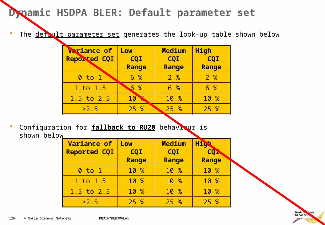
126 © Nokia Siemens Networks RN3167BEN30GLA1
Dynamic HSDPA BLER: Default parameter set
• The default parameter set generates the look-up table shown below
Variance of Reported CQI
Low CQI Range
Medium CQI Range
High CQI Range
0 to 1 6 % 2 % 2 %
1 to 1.5 6 % 6 % 6 %
1.5 to 2.5 10 % 10 % 10 %
>2.5 25 % 25 % 25 %
• Configuration for fallback to RU20 behaviour is shown below
Variance of Reported CQI
Low CQI Range
Medium CQI Range
High CQI Range
0 to 1 10 % 10 % 10 %
1 to 1.5 10 % 10 % 10 %
1.5 to 2.5 10 % 10 % 10 %
>2.5 25 % 25 % 25 %
Related Documents