HSDPA Design Library May 2007

Welcome message from author
This document is posted to help you gain knowledge. Please leave a comment to let me know what you think about it! Share it to your friends and learn new things together.
Transcript
HSDPA Design Library
May 2007
Notice
The information contained in this document is subject to change without notice.
Agilent Technologies makes no warranty of any kind with regard to this material, including, but not limited to, the implied warranties of merchantability and fitness for a particular purpose. Agilent Technologies shall not be liable for errors contained herein or for incidental or consequential damages in connection with the furnishing, performance, or use of this material.
Warranty
A copy of the specific warranty terms that apply to this software product is available upon request from your Agilent Technologies representative.
Restricted Rights Legend
Use, duplication or disclosure by the U. S. Government is subject to restrictions as set forth in subparagraph (c) (1) (ii) of the Rights in Technical Data and Computer Software clause at DFARS 252.227-7013 for DoD agencies, and subparagraphs (c) (1) and (c) (2) of the Commercial Computer Software Restricted Rights clause at FAR 52.227-19 for other agencies.
© Agilent Technologies, Inc. 1983-2007. 395 Page Mill Road, Palo Alto, CA 94304 U.S.A.
Acknowledgments
Mentor Graphics is a trademark of Mentor Graphics Corporation in the U.S. and other countries.
Microsoft®, Windows®, MS Windows®, Windows NT®, and MS-DOS® are U.S. registered trademarks of Microsoft Corporation.
Pentium® is a U.S. registered trademark of Intel Corporation.
PostScript® and Acrobat® are trademarks of Adobe Systems Incorporated.
UNIX® is a registered trademark of the Open Group.
Java™ is a U.S. trademark of Sun Microsystems, Inc.
SystemC® is a registered trademark of Open SystemC Initiative, Inc. in the United States and other countries and is used with permission.
MATLAB® is a U.S. registered trademark of The Math Works, Inc.
ii

Contents1 HSDPA Design Library
Introduction............................................................................................................... 1-13GPP Technical Specifications Supported ............................................................... 1-1HSDPA Systems....................................................................................................... 1-1HSDPA Component Libraries Overview ................................................................... 1-2Design Examples...................................................................................................... 1-4Glossary of Terms..................................................................................................... 1-5References ............................................................................................................... 1-6
2 HSDPA ComponentsHSDPA_Bits ............................................................................................................. 2-2HSDPA_BitScrambling ............................................................................................. 2-5HSDPA_ChDecoder ................................................................................................. 2-7HSDPA_ChEncoder ................................................................................................. 2-9HSDPA_ChEstimate................................................................................................. 2-11HSDPA_CodeBlkDeseg ........................................................................................... 2-13HSDPA_CRCDecoder .............................................................................................. 2-15HSDPA_CRCEncoder .............................................................................................. 2-17HSDPA_Deinterleaver .............................................................................................. 2-19HSDPA_Despread.................................................................................................... 2-21HSDPA_DL_Rake .................................................................................................... 2-23HSDPA_DL_Receiver............................................................................................... 2-25HSDPA_DL_ReceiverRF.......................................................................................... 2-28HSDPA_DL_Source ................................................................................................. 2-32HSDPA_DL_SourceRF............................................................................................. 2-38HSDPA_DownSample .............................................................................................. 2-45HSDPA_EVM............................................................................................................ 2-47HSDPA_Interleaver .................................................................................................. 2-52HSDPA_OCNS_Gain ............................................................................................... 2-54HSDPA_PathSearch................................................................................................. 2-56HSDPA_PDSCH_1_4............................................................................................... 2-58HSDPA_PDSCH_Decoder ....................................................................................... 2-62HSDPA_PDSCH_WithFEC ...................................................................................... 2-65HSDPA_PDSCH_WithoutFEC ................................................................................. 2-69HSDPA_PhCH_Demap ............................................................................................ 2-71HSDPA_PhCH_Mapper............................................................................................ 2-74HSDPA_PowerAdjust ............................................................................................... 2-77HSDPA_RakeCombine............................................................................................. 2-79HSDPA_RateDematch ............................................................................................. 2-81HSDPA_RateMatch .................................................................................................. 2-83
iii
HSDPA_SCCH ......................................................................................................... 2-85HSDPA_SCCH_1_4 ................................................................................................. 2-91HSDPA_SCCH_Decoder.......................................................................................... 2-97HSDPA_SCCH_DeRM ............................................................................................. 2-99HSDPA_SCCH_ParaCalc ........................................................................................ 2-100HSDPA_SCCH_RM.................................................................................................. 2-104HSDPA_SCH............................................................................................................ 2-105HSDPA_Spread ........................................................................................................ 2-107HSDPA_STTD_Decoder .......................................................................................... 2-109HSDPA_STTD_Encoder........................................................................................... 2-111HSDPA_Throughput ................................................................................................. 2-115
3 HSDPA Base Station Transmitter Design ExamplesIntroduction............................................................................................................... 3-1Maximum Power Measurements .............................................................................. 3-2Occupied Bandwidth Measurements........................................................................ 3-4Complementary Cumulative Distribution Function Measurements........................... 3-6Transmitter Spectrum Emissions Measurements ..................................................... 3-8Adjacent Channel Leakage Power Measurements in Frequency Domain ............... 3-11Transmitter EVM Measurements .............................................................................. 3-14Transmitter Peak Code Domain Error Measurements.............................................. 3-16Connection with 89600 VSA Software...................................................................... 3-19
4 HSDPA User Equipment Receiver Design ExamplesIntroduction............................................................................................................... 4-1HS-DSCH Demodulation Performance Measurement ............................................. 4-2HS-SCCH Detection Performance Measurements................................................... 4-15Maximum Input Level Throughput Measurements ................................................... 4-17
Index
iv
Chapter 1: HSDPA Design Library
IntroductionThe HSDPA Wireless Library is designed for High Speed Downlink Packet Access (HSDPA), which is an enhancement to 3GPP downlink and defined in release 5 of 3GPP specification. This design library focuses on the physical layer aspects of HSDPA systems and is intended to be a baseline system for designers to get an idea of what nominal or ideal system performance would be. Evaluations can be made regarding degraded system performance due to system impairments that may include non-ideal component performance.
The transport channels and physical channels defined in previous versions of 3GPP specification s are also supported by HSDPA design library. But they are treated as the accessory channels because HSDPA design library focus on the modeling and test of channels defined in release 5, say HSDPA. The test for the scenario with only 3GPP FDD and without HSDPA can be implemented by 3GPP design library.
3GPP Technical Specifications Supported3GPP committee updates 3GPP technical specifications every 3 months. Each of 3GPP specification is further classified by features: release '99 (Version 3.xx), release 4 (Version 4.xx), release 5 (Version 5.xx) and release 6 (Version 6.xx). Basically, the contents defined in lower version specifications typically duplicate the contents from release '99, release 4 and release 5 that are published simultaneously.
The HSDPA design library is compliant with 3GPP release 6 technical specifications published in 2006-03.
HSDPA design library also reuses some 3GPP design library models in the application level. The technical specifications of those models were published in 2002-03 for release '99 content. The version may be changed if 3GPP design library is updated.
HSDPA SystemsHSDPA offers peak downlink data rates up to 14 Mbps and increases the system capacity for downlink packet data. The increased data rates and improved capacity result in shorter delays for the end-users. This is particularly important for some multimedia applications such as interactive games. The high data rates also benefit streaming and web browsing applications. At the same time, HSDPA is backward-compatible with 3GPP FDD specification.
Introduction 1-1
HSDPA Design Library
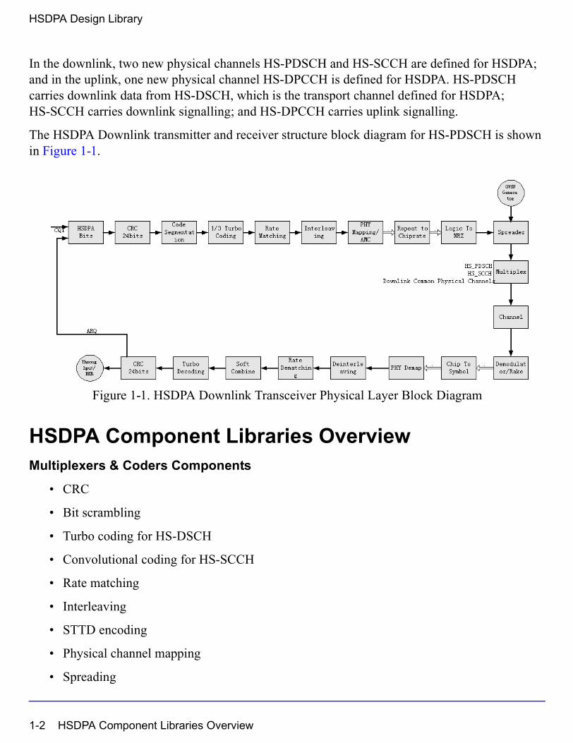
In the downlink, two new physical channels HS-PDSCH and HS-SCCH are defined for HSDPA; and in the uplink, one new physical channel HS-DPCCH is defined for HSDPA. HS-PDSCH carries downlink data from HS-DSCH, which is the transport channel defined for HSDPA; HS-SCCH carries downlink signalling; and HS-DPCCH carries uplink signalling.
The HSDPA Downlink transmitter and receiver structure block diagram for HS-PDSCH is shown in Figure 1-1.
Figure 1-1. HSDPA Downlink Transceiver Physical Layer Block Diagram
HSDPA Component Libraries OverviewMultiplexers & Coders Components
• CRC
• Bit scrambling
• Turbo coding for HS-DSCH
• Convolutional coding for HS-SCCH
• Rate matching
• Interleaving
• STTD encoding
• Physical channel mapping
• Spreading
1-2 HSDPA Component Libraries Overview
Demultiplexers & Decoders Components
• Physical channel demapping
• STTD decoding
• Turbo decoding
• Deinterleaving
• CRC decoding
Measurement Components
• Throughput measurement
• EVM measurement
Receiver Components
• Rake receiver for HSDPA downlink
• Baseband receiver for HSDPA downlink
• RF receiver for HSDPA downlink
Signal Source Components
• Bit signal source with HARQ and AMC functionality
• HS-PDSCH signal source with FEC
• HS-PDSCH signal source without FEC
• HS-SCCH signal source
• HSDPA baseband signal source
• HSDPA RF signal source
HSDPA Component Libraries Overview 1-3

HSDPA Design Library
Design ExamplesThe RF characteristics can be measured using the HSDPA design library. RF measurements for user equipment (UE) are defined in [5]; test methods are described in [8]. For base station (BS), the RF characteristics are defined in [6]; test methods are described in [7].
The HSDPA_BS_Tx_prj project shows base station transmitter performance measurements. Designs for these measurements include:
• BS_Tx_ACLR.dsn
• BS_Tx_CCDF.dsn
• BS_Tx_EVM.dsn
• BS_Tx_MaxPower.dsn
• BS_Tx_OccupiedBW.dsn
• BS_Tx_Pk_Code_Error.dsn
• BS_Tx_Spec_Emission.dsn
• BS_Tx_VSA.dsn
The HSDPA_UE_Rx_prj project shows user equipment receiver performance. Designs for these measurements include:
• UE_Rx_Demodulation_Hset1_PA3_QPSK.dsn
• UE_Rx_Demodulation_Hset2_PB3_16QAM.dsn
• UE_Rx_Demodulation_Hset3_VA30_16QAM.dsn
• UE_Rx_Demodulation_Hset4_PB3_QPSK.dsn
• UE_Rx_Demodulation_Hset5_VA120_QPSK.dsn
• UE_Rx_Demodulation_Hset6_PA3_16QAM.dsn
• UE_Rx_HSSCCH_Detection_TS1_PA3.dsn
• UE_Rx_MaxLevel.dsn
1-4 Design Examples

Glossary of Terms
3GPP third generation partnership project
ACLR adjacent channel leakage power ratio
AWGN additive white Gaussian noise
CCDF complementary cumulative distribution function
DCH dedicated channel
DPDCH dedicated physical data channel
HS-DSCH high speed downlink shared channel
HS-PDSCH high speed physical downlink shared channel
HS-SCCH shared control channel for HS-DSCH
HS-DPCCH dedicated physical control channel (uplink) for HS-DSCH
EVM error vector magnitude
FDD frequency division duplex
FEC forward error correction
HSDPA high speed downlink packet access
HSUPA high speed uplink packet access
PA power amplifier
PER packet error rate
QPSK quadrature phase shift keying
RF radio frequency
RX receive or receiver
TTI transmission timing interval
TX transmit or transmitter
Glossary of Terms 1-5
HSDPA Design Library
References[1] 3GPP Technical Specification TS 25.211, "Physical channels and mapping of transport
channels onto physical channels (FDD)," Version 6.7.0, Dec. 2005.
[2] 3GPP Technical Specification TS 25.212, "Multiplexing and channel coding (FDD)," Version 6.7.0, Dec. 2005.
[3] 3GPP Technical Specification TS 25.213, "Spreading and modulation (FDD)," Version 6.4.0, Sept. 2005.
[4] 3GPP Technical Specification TS 25.214, "Physical layer procedures (FDD)," Version 6.7.1, Dec. 2005.
[5] 3GPP Technical Specification TS 25.101, "UE Radio transmission and Reception (FDD)," Version 6.10.0, Dec. 2005.
[6] 3GPP Technical Specification TS 25.104, "UTRA (BS) FDD: Radio transmission and Reception," Version 6.11.0, Dec. 2005.
[7] 3GPP Technical Specification TS 25.141, "Base station conformance test," Version 6.12.0, Dec. 2005.
[8] 3GPP Technical Specification TS 34.121, "Radio transmission and reception (FDD)," Version 6.3.0, Dec. 2005.
1-6 References
Chapter 2: HSDPA Components
2-1
HSDPA Components
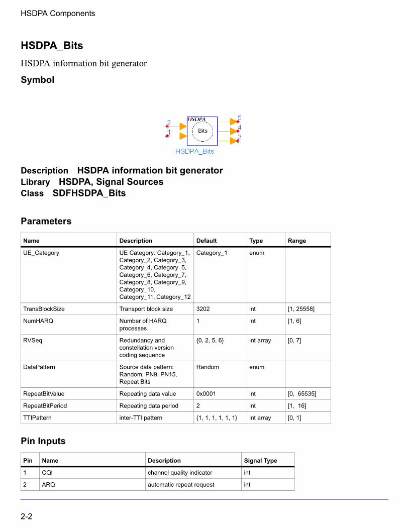
HSDPA_Bits
HSDPA information bit generator
Symbol
Description HSDPA information bit generatorLibrary HSDPA, Signal SourcesClass SDFHSDPA_Bits
Parameters
Pin Inputs
Name Description Default Type Range
UE_Category UE Category: Category_1, Category_2, Category_3, Category_4, Category_5, Category_6, Category_7, Category_8, Category_9, Category_10, Category_11, Category_12
Category_1 enum
TransBlockSize Transport block size 3202 int [1, 25558]
NumHARQ Number of HARQ processes
1 int [1, 6]
RVSeq Redundancy and constellation version coding sequence
{0, 2, 5, 6} int array [0, 7]
DataPattern Source data pattern: Random, PN9, PN15, Repeat Bits
Random enum
RepeatBitValue Repeating data value 0x0001 int [0, 65535]
RepeatBitPeriod Repeating data period 2 int [1, 16]
TTIPattern inter-TTI pattern {1, 1, 1, 1, 1, 1} int array [0, 1]
Pin Name Description Signal Type
1 CQI channel quality indicator int
2 ARQ automatic repeat request int
2-2

Pin Outputs
Notes/Equations
1. This model is used to generate information bits for HS-DSCH block by block, and also supports HARQ and AMC.
Each firing, MaxTransBlockSize tokens are generated at pin Output, one token at pin RV and one token at pin nd, while one token is consumed at pin CQI or ARQ if either is connected. If pin CQI is connected, this model is in AMC (Adaptive Modulation and Coding) mode and if pin ARQ is connected, this model is in HARQ (Hybrid ARQ) mode. Note that pin CQI and ARQ are optional. If they are not connected, no token is consumed. But they cannot be connected simultaneously, which means this model does not support HARQ and AMC simultaneously. If pin CQI is not connected, MaxTransBlockSize is equal to TransBlockSize and all the MaxTransBlockSize data bits are for HS-DSCH. If pin CQI is connected, MaxTransBlockSize is equal to the maximum transport block size the UE_Category supports, and the number of data bits for HS-DSCH is determined by the input CQI value according to Table 7 of 6A.2 in [2]. If the number is less than MaxTransBlockSize, 0s are padded.
2. The input value of CQI is in the range of 1 to 30. In AMC mode, there is no re-transmission, RV is always the first element of the RVSeq, and nd is always 1.
3. The input value of ARQ is in the range of 0 to 1. If the input of ARQ is 0, it means NACK and the correspondent packet are not received correctly. Otherwise, it means ACK and the correspondent packet are received correctly.
If ACK is received, BS will transmit new packet within current HARQ process. If NACK is received, BS will re-transmit the packet. The maximum re-transmission number is determined by the size of RVSeq. if re-transmission number is larger than the size of RVSeq, then this packet will be discarded and a new packet will be transmitted.The delay for ARQ depends on NumHARQ and TTIPattern. User can set the value of NumHARQ and TTIPattern. For example, if the NumHARQ set to 4 and TTIPattern set to {1,0,0,1,0,0}, UE will get the ARQ signal of the first packet when it send the ninth packet.
The output of RV is the redundancy version of current packet. If it is a new packet, RV is the first element of RVSeq; If not, RV can be the second, third,...,last element of RVSeq incrementally.
Pin Name Description Signal Type
3 DataOut data out int
4 RV redundancy version int
5 nd new data indicatior int
2-3

HSDPA Components
4. For the DataPattern parameter:
• if Random is selected, random bits are generated.
• if PN9 is selected, a 511-bit pseudo-random test pattern is generated according to CCITT Recommendation O.153
• if PN15 is selected, a 32767-bit pseudo-random test pattern is generated according to CCITT Recommendation O.151
• if Repeat Bits is selected, the data pattern depends on RepeatBitValue and RepeatBitPeriod. The RepeatBitPeriod length of LSB of RepeatBitValue will be repeated and filled in the data packet.
References
[1] 3GPP Technical Specification TS 25.211, "Physical channels and mapping of transport channels onto physical channels (FDD)," Version 6.7.0, Dec. 2005.
[2] 3GPP Technical Specification TS 25.212, "Multiplexing and channel coding (FDD)," Version 6.7.0, Dec. 2005.
[3] 3GPP Technical Specification TS 25.213, "Spreading and modulation (FDD)," Version 6.4.0, Sept. 2005.
[4] 3GPP Technical Specification TS 25.214, "Physical layer procedures (FDD)," Version 6.7.1, Dec. 2005.
[5] 3GPP Technical Specification TS 25.104, "UTRA (BS) FDD: Radio transmission and Reception," Version 6.11.0, Dec. 2005.
[6] 3GPP Technical Specification TS 25.141, "Base station conformance test," Version 6.12.0, Dec. 2005.
[7] CCITT, Recommendation O.151(10/92).
[8] CCITT, Recommendation O.153(10/92).
2-4

HSDPA_BitScrambling
HSDPA bit scrambling
Symbol
Description Bit scramblerLibrary HSDPA, Multiplexers & CodersClass SDFHSDPA_BitScramblingDerived From HSDPA_DSCH_Base
Parameters
Pin Inputs
Pin Outputs
Name Description Default Type Range
UE_Category : Category_1, Category_2, Category_3, Category_4, Category_5, Category_6, Category_7, Category_8, Category_9, Category_10, Category_11, Category_12
Category_1 enum
TransBlockSize Transport block size 3202 int [1, max transport block size]†
Pin Name Description Signal Type
1 CQI channel quality indicator int
2 DataIn data in int
Pin Name Description Signal Type
3 DataOut data out int
2-5
HSDPA Components
Notes/Equations
1. This model is used to implement bit scrambling on HS-DSCH defined in 4.5.1a in [1].
Each firing, Ndata DataOut tokens are generated while Ndata DataIn tokens consumed. If CQI pin is connected and has input tokens, Ndata=N_TransBlockSize+24. N_TransBlockSize is the maximum transport block size, which the UE of specified category can support according to Table 7 of 6A.2 in [2]. If the CQI pin is unconnected, Ndata=TransBlockSize+24, where TransBlockSize is a parameter of this model.
2. The TransBlockSize parameter determines the transport block size of HS-DSCH. The largest transport block size is 27,952 bits, which corresponds to the highest data rate of 13.976 Mb/s (27,952 bits/2 ms = 13.976 Mb/s). This data rate is obtained by using 16 QAM, an effective code rate of 0.9714, and 15 HS-PDSCHs.
3. The input pin CQI is optional. If connected, the input value of CQI should be in the range of 1 to 30.
References
[1] 3GPP Technical Specification TS 25.212, "Multiplexing and channel coding (FDD)," Version 6.7.0, Dec. 2005.
[2] 3GPP Technical Specification TS 25.214, "Physical layer procedures (FDD)," Version 6.7.1, Dec. 2005.
2-6
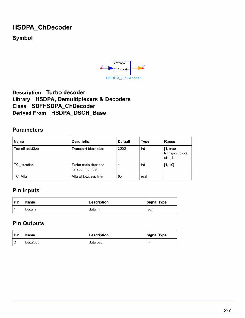
HSDPA_ChDecoder
Symbol
Description Turbo decoderLibrary HSDPA, Demultiplexers & DecodersClass SDFHSDPA_ChDecoderDerived From HSDPA_DSCH_Base
Parameters
Pin Inputs
Pin Outputs
Name Description Default Type Range
TransBlockSize Transport block size 3202 int [1, max transport block size]†
TC_Iteration Turbo code decoder iteration number
4 int [1, 10]
TC_Alfa Alfa of lowpass filter 0.4 real
Pin Name Description Signal Type
1 DataIn data in real
Pin Name Description Signal Type
2 DataOut data out int
2-7
HSDPA Components
Notes/Equations
1. This model is used to implement channel decoding of one code block for HS-DSCH.
Each firing, ( ) DataOut tokens are generated while ( ) DataIn tokens consumed.
2. The TransBlockSize parameter determines the transport block size of HS-DSCH. The largest transport block size is 27,952 bits, which corresponds to the highest data rate of 13.976 Mb/s (27,952 bits/2 ms = 13.976 Mb/s). This data rate is obtained by using 16 QAM, an effective code rate of 0.9714, and 15 HS-PDSCHs. The CodeBlockSize is calculated according to section 4.2.2.2 in [1], with .
3. The schematic of Turbo coder in 3GPP is a parallel concatenated convolutional code (PCCC). A iterative Turbo decoder using modified BAHL et al. algorithm [2][3] is used in this model. The iterative number can be set from 1 through 10 using parameter setting.
References
[1] 3GPP Technical Specification TS 25.212, "Multiplexing and channel coding (FDD)," Version 6.7.0, Dec. 2005.
[2] L.R. Bahl, J. Cocke, F. Jeinek and J. Raviv. "Optimal decoding of linear codes for minimizing symbol error rate." IEEE Trans. Inform. Theory, vol. IT-20. pp.248-287, March 1974.
[3] C. Berrou and A. Glavieus. "Near optimum error correcting coding and decoding: turbo-codes", IEEE Trans. Comm., pp. 1261-1271, Oct. 1996.
CodeBlockSize 3 CodeBlockSize 12+×
Xi TransBlockSize=
2-8
HSDPA_ChEncoder
HSDPA channel encoder
Symbol
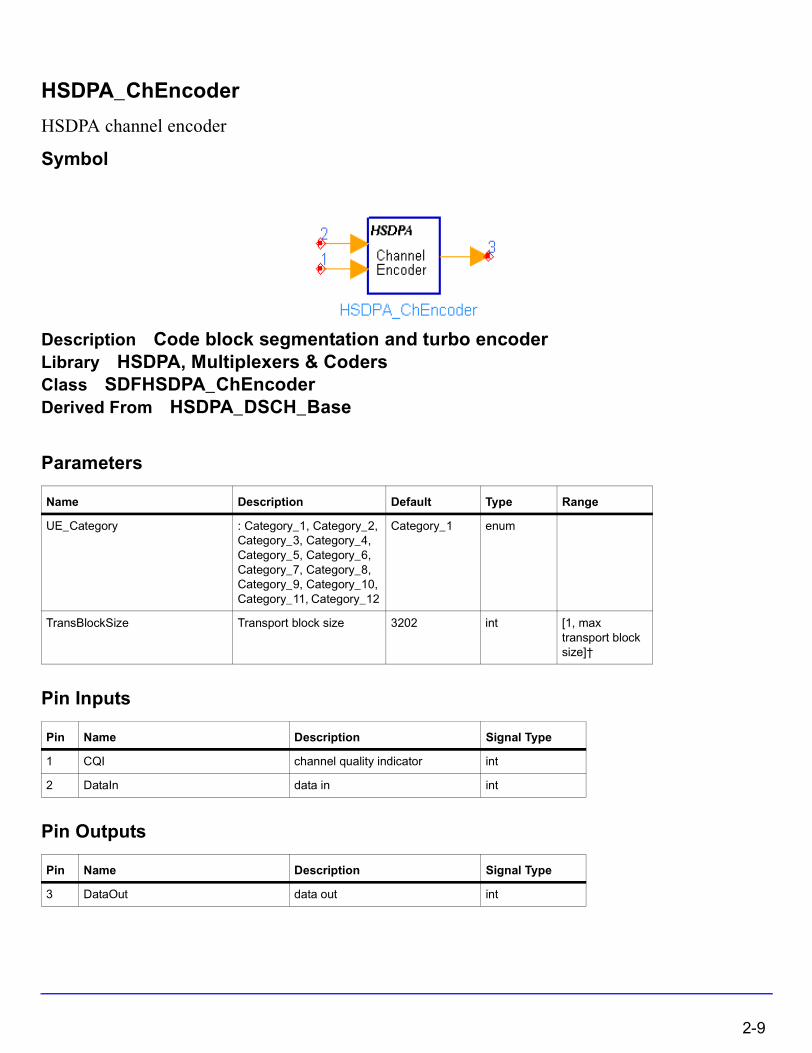
Description Code block segmentation and turbo encoderLibrary HSDPA, Multiplexers & CodersClass SDFHSDPA_ChEncoderDerived From HSDPA_DSCH_Base
Parameters
Pin Inputs
Pin Outputs
Name Description Default Type Range
UE_Category : Category_1, Category_2, Category_3, Category_4, Category_5, Category_6, Category_7, Category_8, Category_9, Category_10, Category_11, Category_12
Category_1 enum
TransBlockSize Transport block size 3202 int [1, max transport block size]†
Pin Name Description Signal Type
1 CQI channel quality indicator int
2 DataIn data in int
Pin Name Description Signal Type
3 DataOut data out int
2-9

HSDPA Components
Notes/Equations
1. This model is used to implement code block segmentation and channel coding for HS-DSCH as defined in 4.5.3 in [1]. There will be a maximum of one transport block. The rate 1/3 turbo coding shall be used.
Each firing, ( ) DataOut tokens are generated while ( ) DataIn tokens consumed. If CQI pin is connected and has input tokens, Ndata=N_TransBlockSize. N_TransBlockSize is the maximum transport block size, which the UE of specific category can support according to Table 7 of 6A.2 in [2]. If CQI pin is unconnected, Ndata=TransBlockSize, where TransBlockSize is a parameter of this model. The BlockNum and BlockSize are calculated according to section 4.2.2.2 in [1], with .
2. The TransBlockSize parameter determines the transport block size of HS-DSCH. The largest transport block size is 27,952 bits, which corresponds to the highest data rate of 13.976 Mb/s (27,952 bits/2 ms = 13.976 Mb/s). This data rate is obtained by using 16 QAM, an effective code rate of 0.9714, and 15 HS-PDSCHs.
3. The input pin CQI is optional. If connected, the input value of CQI should be in the range of 1 to 30.
References
[1] 3GPP Technical Specification TS 25.212, "Multiplexing and channel coding (FDD)," Version 6.7.0, Dec. 2005.
[2] 3GPP Technical Specification TS 25.214, "Physical layer procedures (FDD)," Version 6.7.1, Dec. 2005.
BlockNum BlockSize× Ndata 24+
Xi Ndata=
2-10
HSDPA_ChEstimate
Path Parameter Estimate Aided by Pilot Symbols
Symbol
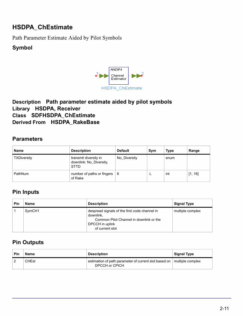
Description Path parameter estimate aided by pilot symbolsLibrary HSDPA, ReceiverClass SDFHSDPA_ChEstimateDerived From HSDPA_RakeBase
Parameters
Pin Inputs
Pin Outputs
Name Description Default Sym Type Range
TXDiversity transmit diversity in downlink: No_Diversity, STTD
No_Diversity enum
PathNum number of paths or fingers of Rake
6 L int [1, 16]
Pin Name Description Signal Type
1 SymCH1 despread signals of the first code channel in downlink, Common Pilot Channel in downlink or the DPCCH in uplink of current slot
multiple complex
Pin Name Description Signal Type
2 CHEst estimation of path parameter of current slot based on DPCCH or CPICH
multiple complex
2-11
HSDPA Components
Notes/Equations
1. This model is used to estimate path characteristics aided by pilot symbols of CPICH in downlink.
Each firing, N tokens are consumed at SymCH per each port, and N tokens are produced at CHEst per each port, where N is the symbol number CPICH in downlink per TTI, and N is the symbol number of CPICH per TTI. The number of ports for SymCH and CHEst depends on the PathNum.
References
[1] 3GPP Technical Specification TS25.211 V6.7.0,“Physical channels and mapping of transport channels onto physical channels (FDD),” Dec. 2005.
[2] S.Tanaka, M.Sawahashi, and F.Adachi, “Pilot Symbol-Assisted Decision-Directed Coherent Adaptive Array Diversity for DS-CDMA Mobile Radio Reverse Link,” Proc. Wireless’97, Canada, July 1997.
[3] Y.Honda, K.Jamal, “Channel Estimation based on Time-Multiplexed Pilot Symbols,” IEICE Technical Report RCS96-70, August 1996.
2-12

HSDPA_CodeBlkDeseg
Code block desegmentation
Symbol
Description Code block desegmentationLibrary HSDPA, Demultiplexers & DecodersClass SDFHSDPA_CodeBlkDesegDerived From HSDPA_DSCH_Base
Parameters
Pin Inputs
Pin Outputs
Name Description Default Type Range
TransBlockSize Transport block size 3202 int [1, max transport block size]†
Pin Name Description Signal Type
1 DataIn data in int
Pin Name Description Signal Type
2 DataOut data out int
2-13
HSDPA Components
Notes/Equations
1. This model is used to implement code block desegmentation.
Each firing, the tokens of all code blocks within one TTI are consumed at pin DataIn, while TransBlockSize + 24 tokens are generated at pin DataOut.
2. This model performs the inverse operation of code block segmentation to combine all transport blocks within one TTI.
References
[1] 3GPP Technical Specification TS 25.212, "Multiplexing and channel coding (FDD)," Version 6.7.0, Dec. 2005.
2-14

HSDPA_CRCDecoder
HSDPA CRC decoder
Symbol
Description CRC decoderLibrary HSDPA, Demultiplexers & DecodersClass SDFHSDPA_CRCDecoderDerived From HSDPA_DSCH_Base
Parameters
Pin Inputs
Pin Outputs
Name Description Default Type Range
TransBlockSize Transport block size 3202 int [1, max transport block size]†
Polynomial generator polynomial 0x1800063 int [3, ∞)
Pin Name Description Signal Type
1 DataIn data in int
Pin Name Description Signal Type
2 CRCOut data out int
3 DataOut data out int
2-15

HSDPA Components
Notes/Equations
1. This model is used to implement CRC check for each transport block in HS-DSCH. The calculation of the CRC parity bits is referenced in [1].
Each firing, TransBlockSize DataOut tokens are generated while (TransBlockSize+24) DataIn tokens and 1 CRCOut token consumed.
2. The TransBlockSize parameter determines the transport block size of HS-DSCH. The largest transport block size is 27,952 bits, which corresponds to the highest data rate of 13.976 Mb/s (27,952 bits/2 ms = 13.976 Mb/s). This data rate is obtained by using 16 QAM, an effective code rate of 0.9714, and 15 HS-PDSCHs.
3. The cyclic generator polynomial for HS-DSCH is: , and the hex representation of polynomial is 0x1800063.
References
[1] 3GPP Technical Specification TS 25.212, "Multiplexing and channel coding (FDD)," Version 6.7.0, Dec. 2005.
gCRC24 D( ) D24
D23
D6
D5
D 1+ + + + +=
2-16
HSDPA_CRCEncoder
HSDPA CRC Encoder
Symbol
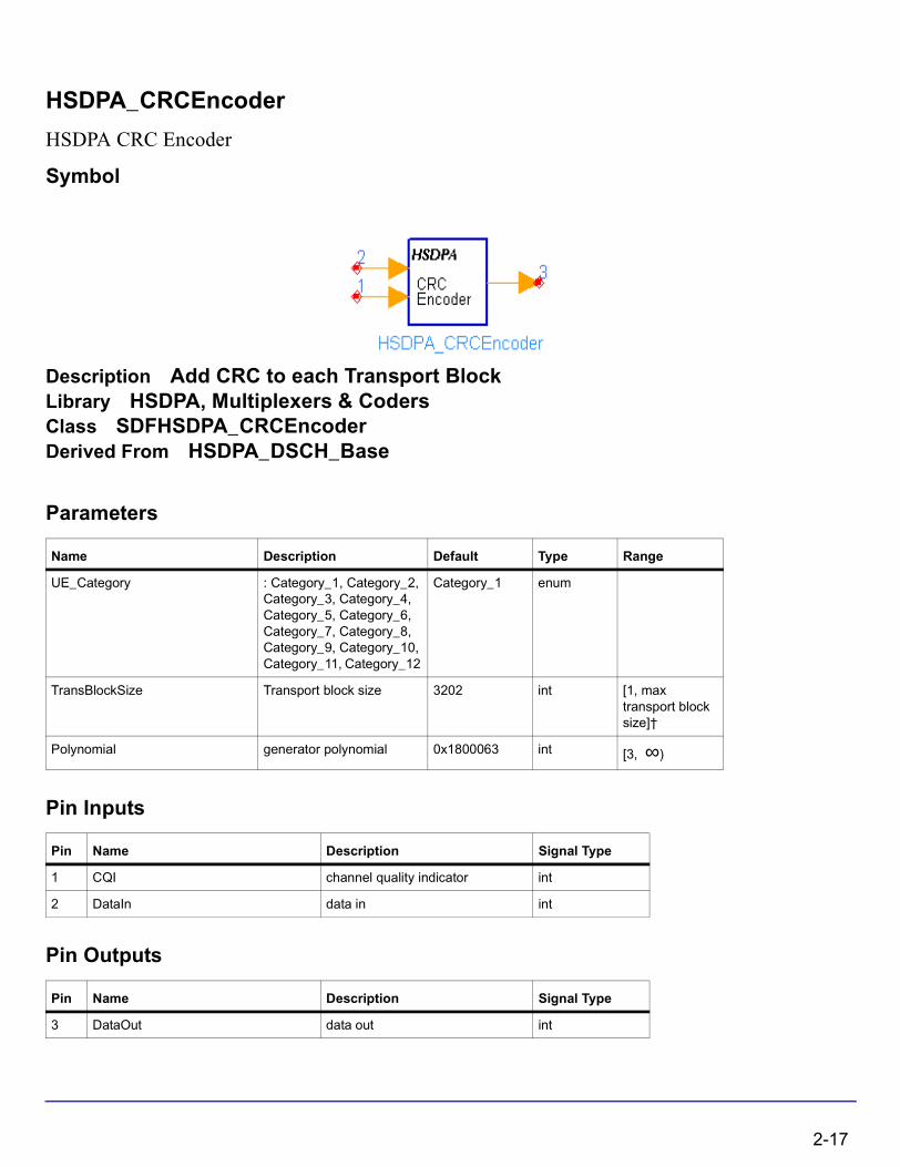
Description Add CRC to each Transport BlockLibrary HSDPA, Multiplexers & CodersClass SDFHSDPA_CRCEncoderDerived From HSDPA_DSCH_Base
Parameters
Pin Inputs
Pin Outputs
Name Description Default Type Range
UE_Category : Category_1, Category_2, Category_3, Category_4, Category_5, Category_6, Category_7, Category_8, Category_9, Category_10, Category_11, Category_12
Category_1 enum
TransBlockSize Transport block size 3202 int [1, max transport block size]†
Polynomial generator polynomial 0x1800063 int [3, ∞)
Pin Name Description Signal Type
1 CQI channel quality indicator int
2 DataIn data in int
Pin Name Description Signal Type
3 DataOut data out int
2-17
HSDPA Components
Notes/Equations
1. This model is used to implement CRC attachment on HS-DSCH as defined in 4.5.1 in [1].
Each firing, (Ndata+24) DataOut tokens are generated while Ndata DataIn tokens consumed. If CQI pin is connected and has input tokens, Ndata=N_TransBlockSize. N_TransBlockSize is the maximum transport block size, which the UE of specific category can support according to Table 7 of 6A.2 in [2]. If CQI pin is unconnected, Ndata=TransBlockSize, where TransBlockSize is a parameter of this model.
2. The input pin CQI is optional. If connected, the input value of CQI should be in the range of 1 to 30.
3. The TransBlockSize parameter determines the transport block size of HS-DSCH. The largest transport block size is 27,952 bits, which corresponds to the highest data rate of 13.976 Mb/s (27,952 bits/2 ms = 13.976 Mb/s). This data rate is obtained by using 16 QAM, an effective code rate of 0.9714, and 15 HS-PDSCHs.
4. The cyclic generator polynomial for HS-DSCH is: , and the hex representation of polynomial is 0x1800063.
References
[1] 3GPP Technical Specification TS 25.212, "Multiplexing and channel coding (FDD)," Version 6.7.0, Dec. 2005.
[2] 3GPP Technical Specification TS 25.214, "Physical layer procedures (FDD)," Version 6.7.1, Dec. 2005.
gCRC24 D( ) D24 D23 D6 D5 D 1+ + + + +=
2-18
HSDPA_Deinterleaver
Interleaver
Symbol
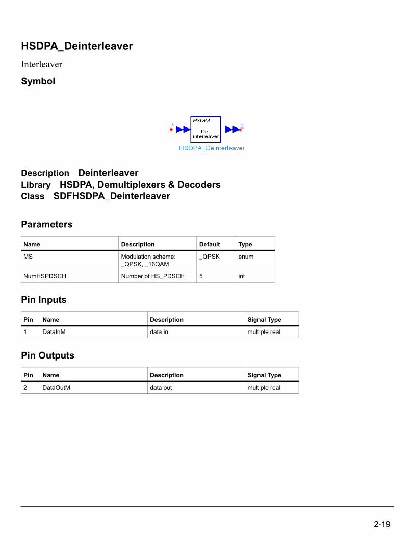
Description DeinterleaverLibrary HSDPA, Demultiplexers & DecodersClass SDFHSDPA_Deinterleaver
Parameters
Pin Inputs
Pin Outputs
Name Description Default Type
MS Modulation scheme: _QPSK, _16QAM
_QPSK enum
NumHSPDSCH Number of HS_PDSCH 5 int
Pin Name Description Signal Type
1 DataInM data in multiple real
Pin Name Description Signal Type
2 DataOutM data out multiple real
2-19

HSDPA Components
Notes/Equations
1. This model is used to implement deinterleaving on HS-DSCH.
Each firing, 1920 tokens are consumed at each sub-port of pin DataInM, while 1920 tokens are generated at each sub-port of pin DataOutM.
2. NumHSPDSCH specifies the number of HS-PDSCHs to be processed and each HS-PDSCH occupies one sub-port of pin DataInM and one sub-port of pin DataOutM. MS specifies the modulation scheme of each HS-PDSCH.
3. Deinterleaving is the inverse operation of interleaving defined in 4.5.6 of [1]. The bits of each HS-PDSCH input to the deinterleaver at each firing are denoted by
, wherein p is the index of HS-PDSCHs. The basic deinterleaver is a
block deinterleaver of fixed size 960, which performs the inverse operation of basic interleaver described in 4.2.11 of [2]. For QPSK, the first 960 bits
are processed by the basic deinterleaver, and the deinterleaved 960 bits are padded 960 0s as the output of corresponding sub-port of pin DataOutM at each firing. For 16QAM, two identical basic deinterleavers are used. are divided two by two
between the deinterleavers: bits go to the first basic deinterleaver and
go to the second basic deinterleaver. Bits are collected two by two from the
deinterleavers: are obtained from the first basic deinterleaver and
are obtained from the second basic deinterleaver.
References
[1] 3GPP Technical Specification TS 25.212, "Multiplexing and channel coding (FDD)," Version 6.7.0, Dec. 2005.
up 1, up 2, up 3, … up 1920,, , , ,
up 1, up 2, up 3, … up 960,, , , ,
up 1, up 2, up 3, … up 1920,, , , ,
up k, up k 1+,,
up k 2+, up k 3+,,
vp k, vp k 1+,, vp k 2+, vp k 3+,,
2-20

HSDPA_Despread
De-Spread Chip Sequence of Code Channels
Symbol
Description De-spread chip sequence of code channelsLibrary HSDPA, ReceiverClass SDFHSDPA_DespreadDerived From HSDPA_RakeBase
Parameters
Pin Inputs
Pin Outputs
Name Description Default Sym Type Range
PathNum number of paths or fingers of Rake
6 L int [1, 16]
ScrambleCode Index of scramble code 0 int
NumHSPDSCH number of HS-PDSCHs 5 M int [1, 16]
HS_PDSCH_CodeOffset Spread code offset 1 int
Pin Name Description Signal Type
1 ChpSeq chip sequences of optimum multi-path multiple complex
Pin Name Description Signal Type
2 HSPDSCHSym de-spread signals of all code channels of current slot multiple complex
3 HSSCCHSym de-spread signals HSSCCH Channel in downlink multiple complex
4 PilotSym de-spread signals of Common in downlink multiple complex
2-21

HSDPA Components
Notes/Equations
1. This model is used to despread the resolved multiple path signals from HSDPA_DownSample.
Each firing, N tokens are consumed at ChipSeq per each port, where N is the number of chips per TTI. The port number of ChipSeq depends on PathNum. M tokens are produced at HSPDSCHSym per each port, where M is the number of symbols per TTI in all HS-PDSCHs. P tokens are produced at HSSCCHSym per each port, where P is the number of symbols per TTI in HS-SCCH. Q tokens are produced at PilotSym per each port, where Q is the number of symbols per TTI in CPICH. The port number of HSPDSCHSym, HSSCCHSym and PilotSym all depends on PathNum.
One TTI delay is inserted to spread code to keep the synchronization with ChipSeq.
References
[1] 3GPP Technical Specification TS25.211 V6.7.0, “Physical channels and mapping of transport channels onto physical channels (FDD),” Dec. 2005.
[2] 3GPP Technical Specification TS25.213 V6.4.0, “Spreading and modulation (FDD),” Sept. 2005.
[3] A. J. Viterbi, “CDMA: Principles of Spread Spectrum Communication,” Wesley Publishing Company, 1995.
2-22
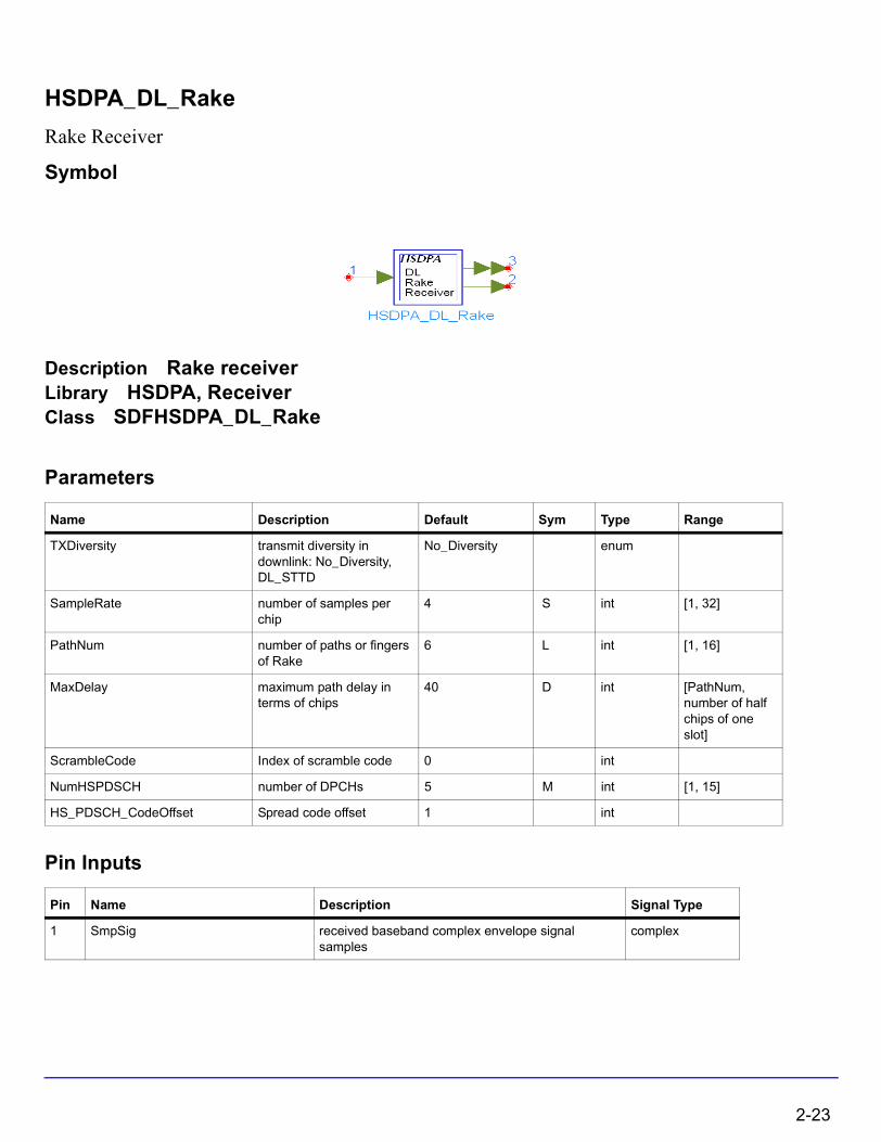
HSDPA_DL_Rake
Rake Receiver
Symbol
Description Rake receiverLibrary HSDPA, ReceiverClass SDFHSDPA_DL_Rake
Parameters
Pin Inputs
Name Description Default Sym Type Range
TXDiversity transmit diversity in downlink: No_Diversity, DL_STTD
No_Diversity enum
SampleRate number of samples per chip
4 S int [1, 32]
PathNum number of paths or fingers of Rake
6 L int [1, 16]
MaxDelay maximum path delay in terms of chips
40 D int [PathNum, number of half chips of one slot]
ScrambleCode Index of scramble code 0 int
NumHSPDSCH number of DPCHs 5 M int [1, 15]
HS_PDSCH_CodeOffset Spread code offset 1 int
Pin Name Description Signal Type
1 SmpSig received baseband complex envelope signal samples
complex
2-23

HSDPA Components
Pin Outputs
Notes/Equations
1. This subnetwork is used to implement coherent Rake receiver with maximal ratio combining (MRC) on multiple code channels.
Each firing, S × T tokens are consumed at SmpSig, where T is the number of chips per TTI, S is the number of SamplesPerChip. N1 tokens are produced at HS-PDSCH, where N1 is the number of HS-PDSCH symbols per TTI. N2 tokens are produced at HS-SCCH, where N2 is the number of HS-SCCH symbols per TTI. The outputs at HS-PDSCH and HS-SCCH are delayed by one TTI because of Rake receiver signal processing.
2. The schematic for this subnetwork is shown in Figure 2-1.
Figure 2-1. HSDPA_DL_RakeReceiver Schematic
References
[1] 3GPP Technical Specification TS25.211 V6.7.0,“Physical channels and mapping of transport channels onto physical channels (FDD),” Dec. 1999.
[2] 3GPP Technical Specification TS25.213 V6.4.0,“Spreading and modulation (FDD),” Sept. 2005.
[3] A. J. Viterbi, “CDMA: Principles of Spread Spectrum Communication,” Wesley Publishing Company, 1995.
Pin Name Description Signal Type
2 HS_SCCH combined signals of the HS_SCCH complex
3 HS_PDSCH combined signals of the HS_PDSCH multiple complex
2-24

HSDPA_DL_Receiver
HSDPA downlink receiver
Symbol
Description HSDPA receiverLibrary HSDPA, ReceiverClass SDFHSDPA_DL_Receiver
Parameters
Name Description Default Type Range
SamplesPerChip number of samples per chip
4 int [1, 32]
PathNum number of paths or fingers of Rake
6 int [1, 16]
MaxDelaySample maximum path delay in terms of chips
40 int [PathNum, number of half chips of one slot]
HS_PDSCH_FRC Fixed reference channel: H-Set_1, H-Set_2, H-Set_3, H-Set_4, H-Set_5, H-Set_6
H-Set_1 enum
UEIdentity UE identity (16 bits) 0xAAAA int [0, 66535]
SignalingSource : SCCH, External External enum
MS Modulation scheme: _QPSK, _16QAM
_QPSK enum
HS_PDSCH_CodeOffset Spread code offset 1 int
TC_Iteration Turbo code decoder iteration number
4 int [1, 10]
TTIPattern inter-TTI pattern {1, 0, 0, 1, 0, 0} int array [0, 1]
2-25

HSDPA Components
Pin Inputs
Pin Outputs
Notes/Equations
1. This subnetwork model is used to demodulate and decode HSDPA related downlink signals, i.e., HS-DSCH and HS-SCCH. The schematic for this subnetwork is shown in Figure 2-2.
Figure 2-2. HSDPA_DL_Receiver Schematic
Pin Name Description Signal Type
1 inCHip received baseband complex envelope signal samples
complex
2 RV redundancy version int
3 nd new data indicator int
Pin Name Description Signal Type
4 SCCHCRC SCCH CRC result int
5 PDSCH PDSCH dtat int
6 PDSCHCRC PDSCH CRC result int
2-26
2. To despread and demodulate a CDMA signal, the channel information and path delay information must be determined. Errors in channel estimation and path search deteriorate the receiver performance.
3. The path searching is performed by correlating the received signals with the spreading code specified in a window whose size is set by MaxDelaySample. The correlations at different offsets are ranked; the top ones are assumed to be the offsets where the paths could occur.
4. All paths are combined assuming that all paths are useful for improving the decoding reliability. In some cases, paths with low SNR are actually harmful to the final SNR improvement. The user must set PathNum for better decoding performance in multipath conditions.
5. There is one slot delay associated with the decoded information.
6. For more information regarding the Rake receiver and different channel decoders, see “HSDPA_DL_Rake” on page 2-23, “HSDPA_PDSCH_Decoder” on page 2-62, and “HSDPA_SCCH_Decoder” on page 2-97 respectively.
References
[1] 3GPP Technical Specification TS 25.211, "Physical channels and mapping of transport channels onto physical channels (FDD)," Version 6.7.0, Dec. 2005.
[2] 3GPP Technical Specification TS 25.212, "Multiplexing and channel coding (FDD)," Version 6.7.0, Dec. 2005.
[3] 3GPP Technical Specification TS 25.213, "Spreading and modulation (FDD)," Version 6.4.0, Sept. 2005.
2-27
HSDPA Components
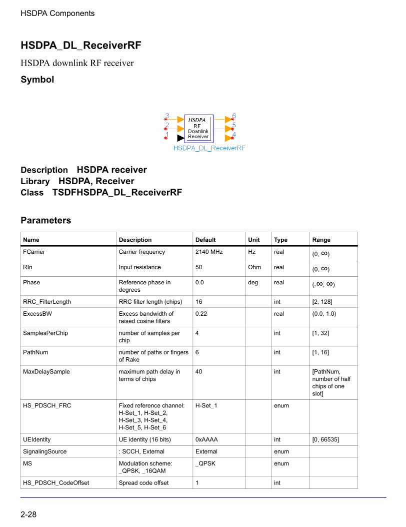
HSDPA_DL_ReceiverRF
HSDPA downlink RF receiver
Symbol
Description HSDPA receiverLibrary HSDPA, ReceiverClass TSDFHSDPA_DL_ReceiverRF
Parameters
Name Description Default Unit Type Range
FCarrier Carrier frequency 2140 MHz Hz real (0, ∞)
RIn Input resistance 50 Ohm real (0, ∞)
Phase Reference phase in degrees
0.0 deg real (-∞, ∞)
RRC_FilterLength RRC filter length (chips) 16 int [2, 128]
ExcessBW Excess bandwidth of raised cosine filters
0.22 real (0.0, 1.0)
SamplesPerChip number of samples per chip
4 int [1, 32]
PathNum number of paths or fingers of Rake
6 int [1, 16]
MaxDelaySample maximum path delay in terms of chips
40 int [PathNum, number of half chips of one slot]
HS_PDSCH_FRC Fixed reference channel: H-Set_1, H-Set_2, H-Set_3, H-Set_4, H-Set_5, H-Set_6
H-Set_1 enum
UEIdentity UE identity (16 bits) 0xAAAA int [0, 66535]
SignalingSource : SCCH, External External enum
MS Modulation scheme: _QPSK, _16QAM
_QPSK enum
HS_PDSCH_CodeOffset Spread code offset 1 int
2-28
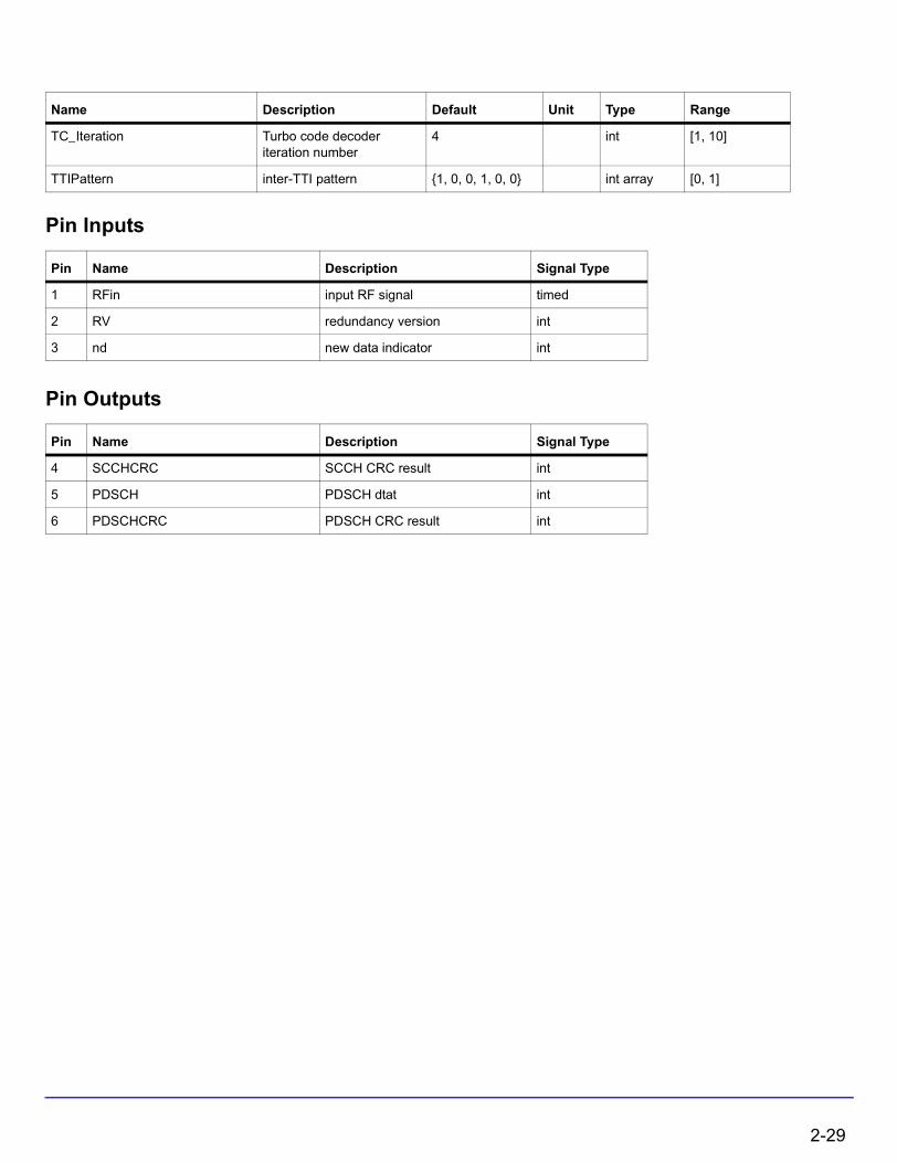
Pin Inputs
Pin Outputs
TC_Iteration Turbo code decoder iteration number
4 int [1, 10]
TTIPattern inter-TTI pattern {1, 0, 0, 1, 0, 0} int array [0, 1]
Pin Name Description Signal Type
1 RFin input RF signal timed
2 RV redundancy version int
3 nd new data indicator int
Pin Name Description Signal Type
4 SCCHCRC SCCH CRC result int
5 PDSCH PDSCH dtat int
6 PDSCHCRC PDSCH CRC result int
Name Description Default Unit Type Range
2-29

HSDPA Components
Notes/Equations
1. This subnetwork model is used to demodulate and decode HSDPA related downlink RF signals, i.e., HS-DSCH and HS-SCCH. The schematic for this subnetwork is shown in Figure 2-3.
Figure 2-3. HSDPA_DL_ReceiverRF Schematic
2. To despread and demodulate a CDMA signal, the channel information and path delay information must be determined. Errors in channel estimation and path search deteriorate the receiver performance.
3. The path searching is performed by correlating the received signals with the spreading code specified in a window whose size is set by MaxDelaySample. The correlations at different offsets are ranked; the top ones are assumed to be the offsets where the paths could occur.
4. All paths are combined assuming that all paths are useful for improving the decoding reliability. In some cases, paths with low SNR are actually harmful to the final SNR improvement. The user must set PathNum for better decoding performance in multipath conditions.
5. There is one slot delay associated with the decoded information.
6. For more information regarding the Rake receiver and different channel decoders, see “HSDPA_DL_Rake” on page 2-23, “HSDPA_PDSCH_Decoder” on page 2-62, and “HSDPA_SCCH_Decoder” on page 2-97 respectively.
2-30

References
[1] 3GPP Technical Specification TS 25.211, "Physical channels and mapping of transport channels onto physical channels (FDD)," Version 6.7.0, Dec. 2005.
[2] 3GPP Technical Specification TS 25.212, "Multiplexing and channel coding (FDD)," Version 6.7.0, Dec. 2005.
[3] 3GPP Technical Specification TS 25.213, "Spreading and modulation (FDD)," Version 6.4.0, Sept. 2005.
2-31
HSDPA Components
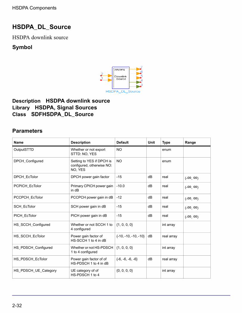
HSDPA_DL_Source
HSDPA downlink source
Symbol
Description HSDPA downlink sourceLibrary HSDPA, Signal SourcesClass SDFHSDPA_DL_Source
Parameters
Name Description Default Unit Type Range
OutputSTTD Whether or not export STTD: NO, YES
NO enum
DPCH_Configured Setting to YES if DPCH is configured, otherwise NO: NO, YES
NO enum
DPCH_EcToIor DPCH power gain factor -15 dB real (-∞, ∞)
PCPICH_EcToIor Primary CPICH power gain in dB
-10.0 dB real (-∞, ∞)
PCCPCH_EcToIor PCCPCH power gain in dB -12 dB real (-∞, ∞)
SCH_EcToIor SCH power gain in dB -15 dB real (-∞, ∞)
PICH_EcToIor PICH power gain in dB -15 dB real (-∞, ∞)
HS_SCCH_Configured Whether or not SCCH 1 to 4 configured
{1, 0, 0, 0} int array
HS_SCCH_EcToIor Power gain factor of HS-SCCH 1 to 4 in dB
{-10, -10, -10, -10} dB real array
HS_PDSCH_Configured Whether or not HS-PDSCH 1 to 4 configured
{1, 0, 0, 0} int array
HS_PDSCH_EcToIor Power gain factor of of HS-PDSCH 1 to 4 in dB
{-6, -6, -6, -6} dB real array
HS_PDSCH_UE_Category UE category of of HS-PDSCH 1 to 4
{0, 0, 0, 0} int array
2-32

Pin Inputs
HS_PDSCH_UEIdentity UE identity of of HS-PDSCH 1 to 4
{0xAAAA, 0x12AA, 0x1AAA, 0x1FAA}
int array [0, 66535]
HS_PDSCH_MS Modulation scheme of HS-PDSCH 1 to 4
{0, 0, 0, 0} int array
HS_PDSCH_CodeOffset Spread code offset of HS-PDSCH 1 to 4
{1, 13, 14, 15} int array
HS_PDSCH_1_FRC Fixed reference channel of HS-PDSCH 1: H-Set_1, H-Set_2, H-Set_3, H-Set_4, H-Set_5, H-Set_6
H-Set_1 enum
HS_PDSCH_1_RVSeq RV coding sequence of of HS-PDSCH 1
{0, 2, 5, 6} int array
HS_PDSCH_1_DataPattern Data pattern of HS-PDSCH 1: Random, PN9, PN15, Repeat Bits
Random enum
HS_PDSCH_1_RepeatBitValue Repeating data value of HS-PDSCH 1
0x0001 int [0, 65535]
HS_PDSCH_1_RepeatBitPeriod Repeating data period of HS-PDSCH 1
2 int [1, 16]
HS_PDSCH_1_TTIPattern Inter-TTI pattern of HS-PDSCH 1
{1, 0, 0, 1, 0, 0} int array [0, 1]
HS_PDSCH_2_TTIPattern Inter-TTI pattern of HS-PDSCH 2
{1, 0, 0, 1, 0, 0} int array [0, 1]
HS_PDSCH_3_TTIPattern Inter-TTI pattern of HS-PDSCH 3
{1, 0, 0, 1, 0, 0} int array [0, 1]
HS_PDSCH_4_TTIPattern Inter-TTI pattern of HS-PDSCH 4
{1, 0, 0, 1, 0, 0} int array [0, 1]
HS_PDSCH_2_NumPhyCH Number of physical channels of HS-PDSCH 2
1 int
HS_PDSCH_3_NumPhyCH Number of physical channels of HS-PDSCH 3
1 int
HS_PDSCH_4_NumPhyCH Number of physical channels of HS-PDSCH 4
1 int
Pin Name Description Signal Type
1 CQI channel quality indicator int
2 ARQ automatic repeat request int
Name Description Default Unit Type Range
2-33
HSDPA Components
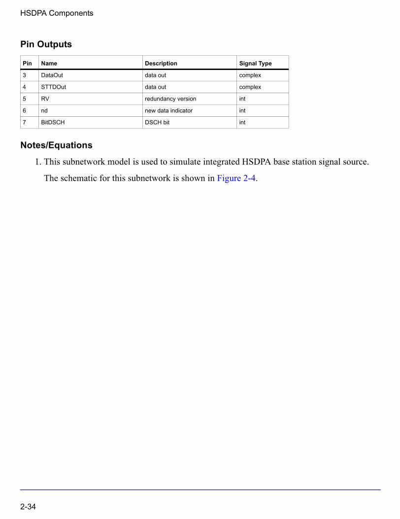
Pin Outputs
Notes/Equations
1. This subnetwork model is used to simulate integrated HSDPA base station signal source.
The schematic for this subnetwork is shown in Figure 2-4.
Pin Name Description Signal Type
3 DataOut data out complex
4 STTDOut data out complex
5 RV redundancy version int
6 nd new data indicator int
7 BitDSCH DSCH bit int
2-34
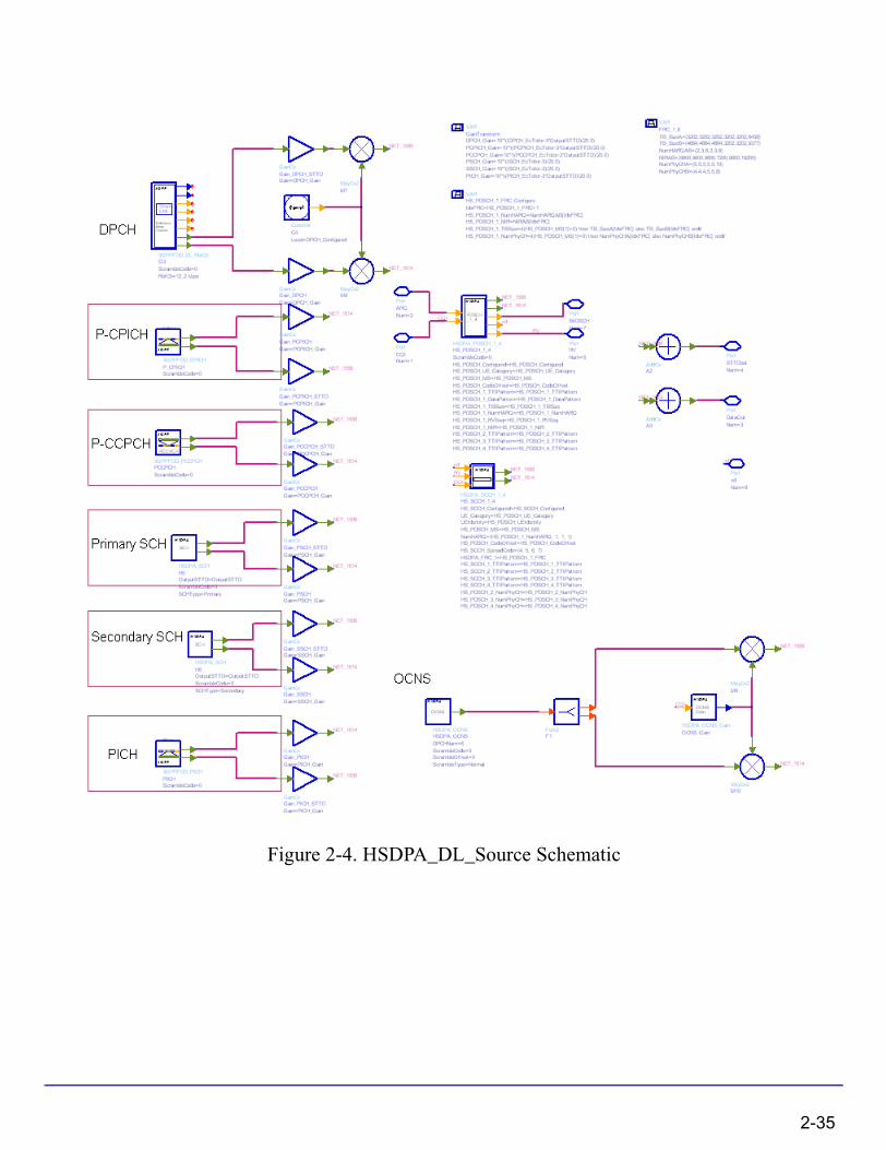
Figure 2-4. HSDPA_DL_Source Schematic
2-35

HSDPA Components
2. The physical channels integrated in this subnetwork model are listed in Table 2-1.
3. The HS-PDSCH is generated by the composite HSDPA_PDSCH_1_4 which can support one full coded and three uncoded HS-PDSCH sources.
4. The HS-SCCH is generated by the full coded HSDPA_SCCH_1_4 which can support four full coded HS-SCCH sources.
5. The DPCH is generated by the fully-coded 3GPPFDD_DL_RefCh signal source.
6. Four data patterns are supported: random, PN9, PN15, and repeated.
7. If data is from a user-defined file, the file name is defined by the respective UserFileName. The user can edit the file with any text editor. The separator between bits can be a space, comma, or any other separator. If the bit sequence is shorter than the output length, data will be output repeatedly.
8. The DPCH data rate can be set through RefCh. DPCH channelization code is set through DPCH_SpreadCode.
9. CPICH includes primary and secondary CPICH. Primary CPICH channelization code is fixed at C256,0. CPICH_SpreadCode is set on secondary CPICH, with a spread factor of 256.
10. The PICH spread factor is 256. PICH channelization code is set through PICH_SpreadCode.
Table 2-1. Downlink Physical Channels
Physical Channel
P_CPICH
S_CPICH
PCCPCH
P_SCH
S_SCH
SCCPCH
PICH
DPCH
HS-PDSCH
HS-SCCH
OCNS
2-36
11. The PCCPCH channelization code is fixed at C256,1. The SCCPCH spread factor and spread channelization code are set through SCCPCH_SpreadFactor and SCCPCH_SpreadCode.
12. Relative gain factor of each channel can be set through the respective GainFactor parameters. They are multiplied to the output of each channel model. A channel can be disabled by setting its gain factor to 0.
13. It is suggested that the square of all the GainFactors add up to 1 to make sure the RMS value of output downlink signal is 1. However, it isn’t so important for baseband signal. A normalized downlink source can be implemented by HSDPA_DL_SourceRF.
14. OCNS can be set through the OCNS_ChannelNum and six OCNS array parameters. The default OCNS channel is 16 and corresponding array parameters are 16 elements long. To change the OCNS channel number, the corresponding array parameters must be changed. For details regarding OCNS settings, refer to HSDPA_OCNS.
References
[1] 3GPP Technical Specification TS 25.211, "Physical channels and mapping of transport channels onto physical channels (FDD)," Version 6.7.0, Dec. 2005.
[2] 3GPP Technical Specification TS 25.212, "Multiplexing and channel coding (FDD)," Version 6.7.0, Dec. 2005.
[3] 3GPP Technical Specification TS 25.213, "Spreading and modulation (FDD)," Version 6.4.0, Sept. 2005.
[4] 3GPP Technical Specification TS 25.214, "Physical layer procedures (FDD)," Version 6.7.1, Dec. 2005.
2-37
HSDPA Components
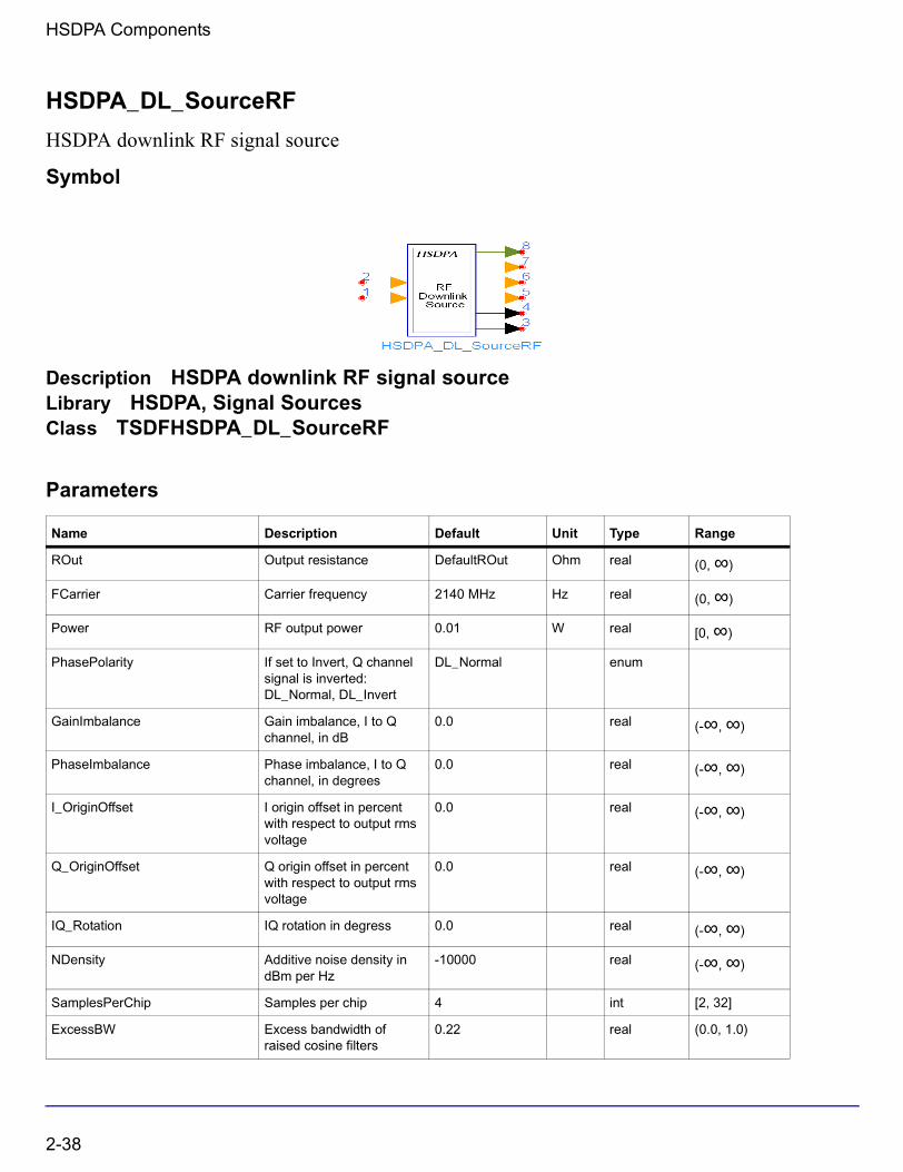
HSDPA_DL_SourceRF
HSDPA downlink RF signal source
Symbol
Description HSDPA downlink RF signal sourceLibrary HSDPA, Signal SourcesClass TSDFHSDPA_DL_SourceRF
Parameters
Name Description Default Unit Type Range
ROut Output resistance DefaultROut Ohm real (0, ∞)
FCarrier Carrier frequency 2140 MHz Hz real (0, ∞)
Power RF output power 0.01 W real [0, ∞)
PhasePolarity If set to Invert, Q channel signal is inverted: DL_Normal, DL_Invert
DL_Normal enum
GainImbalance Gain imbalance, I to Q channel, in dB
0.0 real (-∞, ∞)
PhaseImbalance Phase imbalance, I to Q channel, in degrees
0.0 real (-∞, ∞)
I_OriginOffset I origin offset in percent with respect to output rms voltage
0.0 real (-∞, ∞)
Q_OriginOffset Q origin offset in percent with respect to output rms voltage
0.0 real (-∞, ∞)
IQ_Rotation IQ rotation in degress 0.0 real (-∞, ∞)
NDensity Additive noise density in dBm per Hz
-10000 real (-∞, ∞)
SamplesPerChip Samples per chip 4 int [2, 32]
ExcessBW Excess bandwidth of raised cosine filters
0.22 real (0.0, 1.0)
2-38
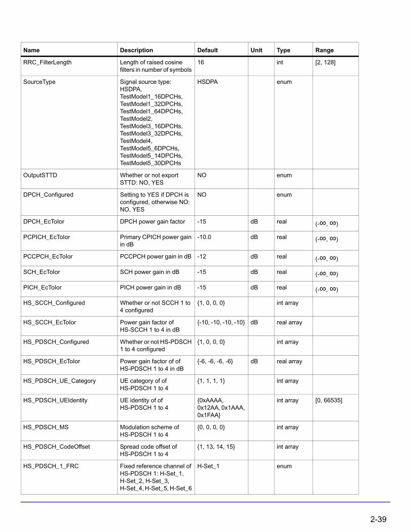
RRC_FilterLength Length of raised cosine filters in number of symbols
16 int [2, 128]
SourceType Signal source type: HSDPA, TestModel1_16DPCHs, TestModel1_32DPCHs, TestModel1_64DPCHs, TestModel2, TestModel3_16DPCHs, TestModel3_32DPCHs, TestModel4, TestModel5_6DPCHs, TestModel5_14DPCHs, TestModel5_30DPCHs
HSDPA enum
OutputSTTD Whether or not export STTD: NO, YES
NO enum
DPCH_Configured Setting to YES if DPCH is configured, otherwise NO: NO, YES
NO enum
DPCH_EcToIor DPCH power gain factor -15 dB real (-∞, ∞)
PCPICH_EcToIor Primary CPICH power gain in dB
-10.0 dB real (-∞, ∞)
PCCPCH_EcToIor PCCPCH power gain in dB -12 dB real (-∞, ∞)
SCH_EcToIor SCH power gain in dB -15 dB real (-∞, ∞)
PICH_EcToIor PICH power gain in dB -15 dB real (-∞, ∞)
HS_SCCH_Configured Whether or not SCCH 1 to 4 configured
{1, 0, 0, 0} int array
HS_SCCH_EcToIor Power gain factor of HS-SCCH 1 to 4 in dB
{-10, -10, -10, -10} dB real array
HS_PDSCH_Configured Whether or not HS-PDSCH 1 to 4 configured
{1, 0, 0, 0} int array
HS_PDSCH_EcToIor Power gain factor of of HS-PDSCH 1 to 4 in dB
{-6, -6, -6, -6} dB real array
HS_PDSCH_UE_Category UE category of of HS-PDSCH 1 to 4
{1, 1, 1, 1} int array
HS_PDSCH_UEIdentity UE identity of of HS-PDSCH 1 to 4
{0xAAAA, 0x12AA, 0x1AAA, 0x1FAA}
int array [0, 66535]
HS_PDSCH_MS Modulation scheme of HS-PDSCH 1 to 4
{0, 0, 0, 0} int array
HS_PDSCH_CodeOffset Spread code offset of HS-PDSCH 1 to 4
{1, 13, 14, 15} int array
HS_PDSCH_1_FRC Fixed reference channel of HS-PDSCH 1: H-Set_1, H-Set_2, H-Set_3, H-Set_4, H-Set_5, H-Set_6
H-Set_1 enum
Name Description Default Unit Type Range
2-39

HSDPA Components
Pin Inputs
Pin Outputs
HS_PDSCH_1_RVSeq RV coding sequence of of HS-PDSCH 1
{0, 2, 5, 6} int array
HS_PDSCH_1_DataPattern Data pattern of HS-PDSCH 1: Random, PN9, PN15, Repeat Bits
Random enum
HS_PDSCH_1_RepeatBitValue Repeating data value of HS-PDSCH 1
0x0001 int [0, 65535]
HS_PDSCH_1_RepeatBitPeriod Repeating data period of HS-PDSCH 1
2 int [1, 16]
HS_PDSCH_1_TTIPattern Inter-TTI pattern of HS-PDSCH 1
{1, 0, 0, 1, 0, 0} int array [0, 1]
HS_PDSCH_2_TTIPattern Inter-TTI pattern of HS-PDSCH 2
{1, 0, 0, 1, 0, 0} int array [0, 1]
HS_PDSCH_3_TTIPattern Inter-TTI pattern of HS-PDSCH 3
{1, 0, 0, 1, 0, 0} int array [0, 1]
HS_PDSCH_4_TTIPattern Inter-TTI pattern of HS-PDSCH 4
{1, 0, 0, 1, 0, 0} int array [0, 1]
HS_PDSCH_2_NumPhyCH Number of physical channels of HS-PDSCH 2
1 int
HS_PDSCH_3_NumPhyCH Number of physical channels of HS-PDSCH 3
1 int
HS_PDSCH_4_NumPhyCH Number of physical channels of HS-PDSCH 4
1 int
TM_OutputMode output mode of test model: Ramp, Stable
Ramp enum
TM4_EnableP_CPICH Test Model 4 enable primary CPICH? NO, YES
YES enum
TM4_PCCPCH_SCH_Gain Test Model 4 PCCPCH_SCH level setting
-6 dB real (-∞, ∞)
TM4_P_CPICH_Gain Test Model 4 P_CPICH level setting
-6 dB real (-∞, ∞)
Pin Name Description Signal Type
1 CQI channel quality indicator int
2 ARQ automatic repeat request int
Pin Name Description Signal Type
3 RFout output RF signal timed
4 STTDOut data out timed
Name Description Default Unit Type Range
2-40

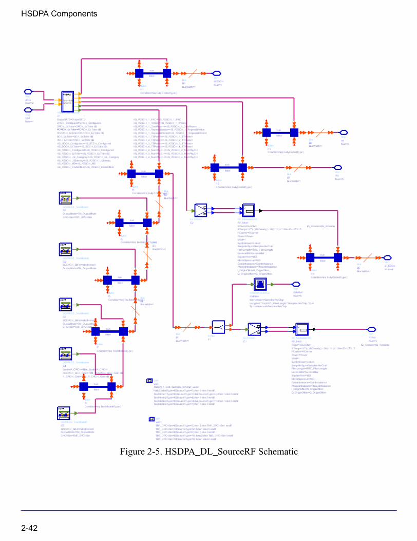
Notes/Equations
1. This subnetwork model is used to simulate integrated HSDPA base station RF signal source.
The schematic for this subnetwork is shown in Figure 2-5.
5 RV redundancy version int
6 nd new data indicator int
7 BitDSCH DSCH bit int
8 EVMRef reference signal for EVM complex
Pin Name Description Signal Type
2-41
HSDPA Components
Figure 2-5. HSDPA_DL_SourceRF Schematic
2-42

2. The physical channels integrated in this subnetwork model are listed in Table 2-2.
3. The HS-PDSCH is generated by the composite HSDPA_PDSCH_1_4 which can support one full coded and three uncoded HS-PDSCH source.
4. The HS-SCCH is generated by the full coded HSDPA_SCCH_1_4 which can support four full coded HS-SCCH source.
5. The DPCH is generated by the fully-coded 3GPPFDD_DL_RefCh signal source.
6. Four data patterns are supported: random, PN9, PN15, and repeated.
7. If data is from a user-defined file, the file name is defined by the respective UserFileName. The user can edit the file with any text editor. The separator between bits can be a space, comma, or any other separator. If the bit sequence is shorter than the output length, data will be output repeatedly.
8. The DPCH data rate can be set through RefCh. DPCH channelization code is set through DPCH_SpreadCode.
9. CPICH includes primary and secondary CPICH. Primary CPICH channelization code is fixed at C256,0. CPICH_SpreadCode is set on secondary CPICH, with a spread factor of 256.
10. The PICH spread factor is 256. PICH channelization code is set through PICH_SpreadCode.
Table 2-2. Downlink Physical Channels
Physical Channel
P_CPICH
S_CPICH
PCCPCH
P_SCH
S_SCH
SCCPCH
PICH
DPCH
HS-PDSCH
HS-SCCH
OCNS
2-43

HSDPA Components
11. The PCCPCH channelization code is fixed at C256,1. The SCCPCH spread factor and spread channelization code are set through SCCPCH_SpreadFactor and SCCPCH_SpreadCode.
12. The transmitter power is set by the parameter Power.
Relative power levels of each channel can then be set through the respective GainFactor parameters, in dB units.OCNS_GainFactor is calculated from other GainFactors. (Refer to Table C.6 in [5]).
The GainFactors are converted into voltage values and multiplied to the output of each channel model. A channel can be disabled by setting its gain factor to a large minus value such as -300 dB.
13. OCNS can be set through the OCNS_ChannelNum and six OCNS array parameters. The default OCNS channel is 16 and corresponding array parameters are 16 elements long. To change the OCNS channel number, the corresponding array parameters must be changed. The output of OCNS must be normalized. For details regarding OCNS settings, see HSDPA_OCNS.
References
[1] 3GPP Technical Specification TS 25.211, "Physical channels and mapping of transport channels onto physical channels (FDD)," Version 6.7.0, Dec. 2005.
[2] 3GPP Technical Specification TS 25.212, "Multiplexing and channel coding (FDD)," Version 6.7.0, Dec. 2005.
[3] 3GPP Technical Specification TS 25.213, "Spreading and modulation (FDD)," Version 6.4.0, Sept. 2005.
[4] 3GPP Technical Specification TS 25.214, "Physical layer procedures (FDD)," Version 6.7.1, Dec. 2005.
[5] 3GPP Technical Specification TS 25.101, "UE Radio transmission and Reception (FDD)," Version 6.10.0, Dec. 2005.
2-44
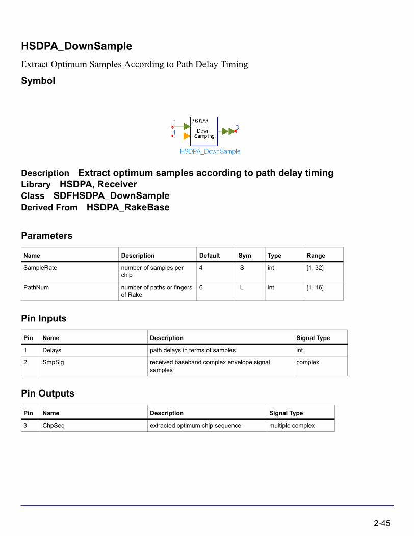
HSDPA_DownSample
Extract Optimum Samples According to Path Delay Timing
Symbol
Description Extract optimum samples according to path delay timingLibrary HSDPA, ReceiverClass SDFHSDPA_DownSampleDerived From HSDPA_RakeBase
Parameters
Pin Inputs
Pin Outputs
Name Description Default Sym Type Range
SampleRate number of samples per chip
4 S int [1, 32]
PathNum number of paths or fingers of Rake
6 L int [1, 16]
Pin Name Description Signal Type
1 Delays path delays in terms of samples int
2 SmpSig received baseband complex envelope signal samples
complex
Pin Name Description Signal Type
3 ChpSeq extracted optimum chip sequence multiple complex
2-45

HSDPA Components
Notes/Equations
1. This model is used to extract optimum samples using the path delay timing given by HSDPA_PathSearch.
Each firing, S × N tokens are consumed at SmpSig, L tokens are consumed at Delays, N tokens are produced at ChipSeq per each port, where N is the number of chips per TTI, S is the SampleRate, and L is the number of path. The port number of ChipSeq depends on PathNum.
References
[1] 3GPP Technical Specification TS25.211 V6.7.0,“Physical channels and mapping of transport channels onto physical channels (FDD),” Dec. 2005.
[2] A. J. Viterbi, “CDMA: Principles of Spread Spectrum Communication,” Wesley Publishing Company, 1995.
2-46
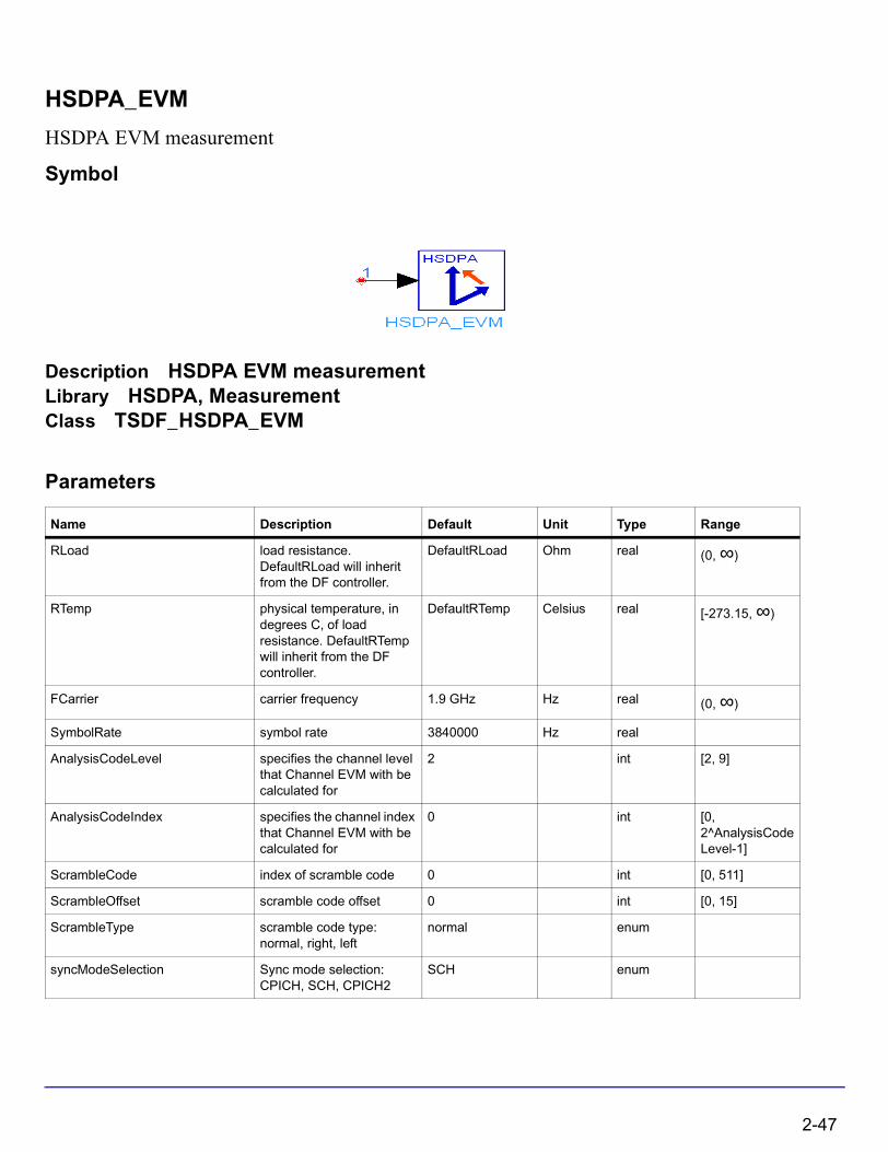
HSDPA_EVM
HSDPA EVM measurement
Symbol
Description HSDPA EVM measurementLibrary HSDPA, MeasurementClass TSDF_HSDPA_EVM
Parameters
Name Description Default Unit Type Range
RLoad load resistance. DefaultRLoad will inherit from the DF controller.
DefaultRLoad Ohm real (0, ∞)
RTemp physical temperature, in degrees C, of load resistance. DefaultRTemp will inherit from the DF controller.
DefaultRTemp Celsius real [-273.15, ∞)
FCarrier carrier frequency 1.9 GHz Hz real (0, ∞)
SymbolRate symbol rate 3840000 Hz real
AnalysisCodeLevel specifies the channel level that Channel EVM with be calculated for
2 int [2, 9]
AnalysisCodeIndex specifies the channel index that Channel EVM with be calculated for
0 int [0, 2^AnalysisCodeLevel-1]
ScrambleCode index of scramble code 0 int [0, 511]
ScrambleOffset scramble code offset 0 int [0, 15]
ScrambleType scramble code type: normal, right, left
normal enum
syncModeSelection Sync mode selection: CPICH, SCH, CPICH2
SCH enum
2-47
HSDPA Components
TestModel test model selection: NONE, MODEL_1_DPCH_16, MODEL_1_DPCH_32, MODEL_1_DPCH_64, MODEL_2, MODEL_3_DPCH_16, MODEL_3_DPCH_32, MODEL_4, MODEL_1_DPCH_16_SCCPCH, MODEL_1_DPCH_32_SCCPCH, MODEL_1_DPCH_64_SCCPCH, MODEL_2_SCCPCH, MODEL_3_DPCH_16_SCCPCH, MODEL_3_DPCH_32_SCCPCH, MODEL_4_PCPICH, MODEL_5_HSPDSCH_2_DPCH_6, MODEL_5_HSPDSCH_4_DPCH_14, MODEL_5_HSPDSCH_8_DPCH_30
NONE enum
MirrorSpectrum Mirror spectrum about carrier? NO, YES
NO enum
EVMIncludeIQOffset selection of calculating EVM pre-compensating for IQ origin offset: NO, YES
NO enum
SuppressSCH suppress SCH for channel measurements: NO, YES
NO enum
EVMIncludingSCH boolean if true will include the SCH bits when calculating composite EVM: NO, YES
NO enum
Start start time for data recording. DefaultTimeStart will inherit from the DF Controller.
DefaultTimeStart sec real [0, ∞)
ResultLength result length in number of slots
15 int [15, ∞)
MeasurementOffset specifies the offset in number of slots from the start of the data record to analysis of channel EVM
0 int [0, ∞)
MeasurementInterval specifies how many slots that channel EVM will be calculated over
1 int [1, ∞)
alpha specify the alpha for 3GPP root raised cosine filtering.
0.22 real [0, 1]
Name Description Default Unit Type Range
2-48
Pin Inputs
Notes/Equations
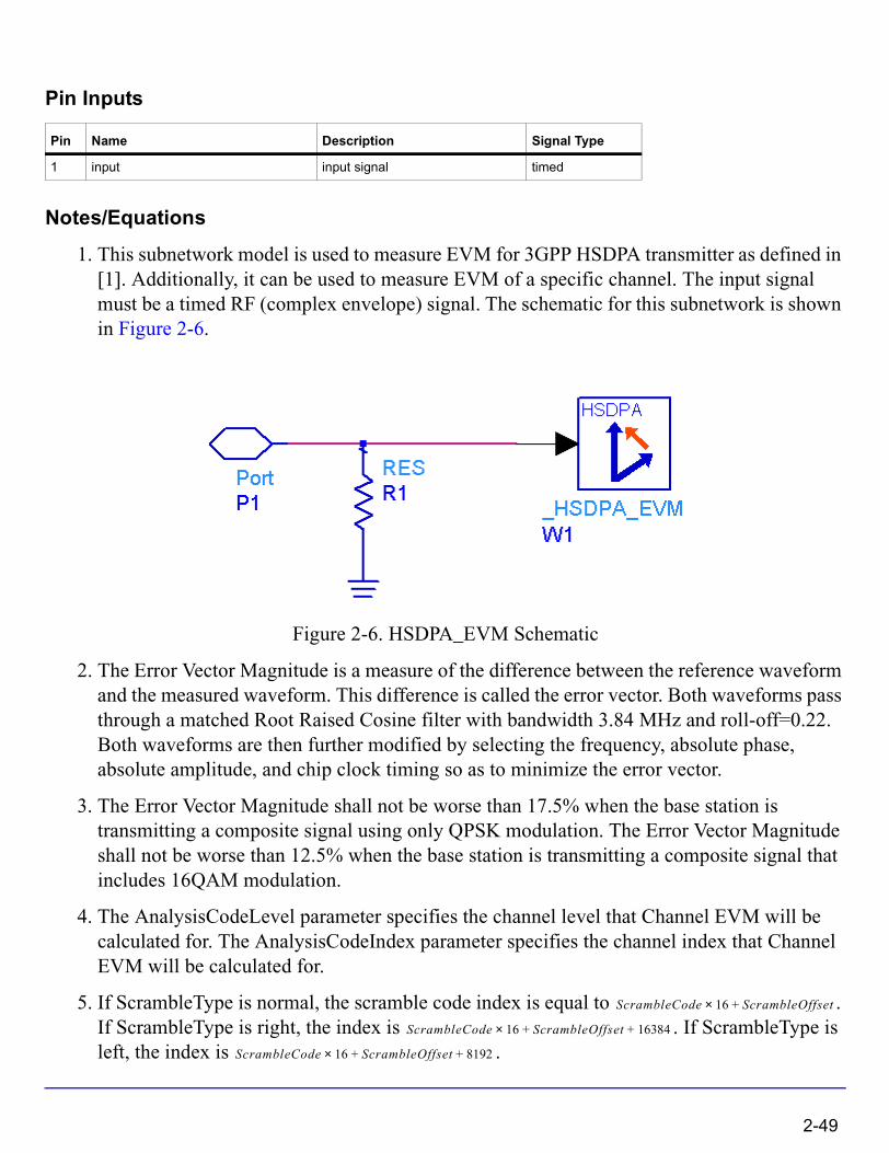
1. This subnetwork model is used to measure EVM for 3GPP HSDPA transmitter as defined in [1]. Additionally, it can be used to measure EVM of a specific channel. The input signal must be a timed RF (complex envelope) signal. The schematic for this subnetwork is shown in Figure 2-6.
Figure 2-6. HSDPA_EVM Schematic
2. The Error Vector Magnitude is a measure of the difference between the reference waveform and the measured waveform. This difference is called the error vector. Both waveforms pass through a matched Root Raised Cosine filter with bandwidth 3.84 MHz and roll-off=0.22. Both waveforms are then further modified by selecting the frequency, absolute phase, absolute amplitude, and chip clock timing so as to minimize the error vector.
3. The Error Vector Magnitude shall not be worse than 17.5% when the base station is transmitting a composite signal using only QPSK modulation. The Error Vector Magnitude shall not be worse than 12.5% when the base station is transmitting a composite signal that includes 16QAM modulation.
4. The AnalysisCodeLevel parameter specifies the channel level that Channel EVM will be calculated for. The AnalysisCodeIndex parameter specifies the channel index that Channel EVM will be calculated for.
5. If ScrambleType is normal, the scramble code index is equal to . If ScrambleType is right, the index is . If ScrambleType is left, the index is .
Pin Name Description Signal Type
1 input input signal timed
ScrambleCode 16× ScrambleOffset+
ScrambleCode 16× ScrambleOffset 16384+ +
ScrambleCode 16× ScrambleOffset 8192+ +
2-49
HSDPA Components
6. The syncModeSelection parameter specifies synchronization mode: CPICH, SCH or CPICH2.
7. The TestModel parameter is used to select the base station test models as defined in [2]. If TestModel is selected to be none, the transmitter outputs the user defined HSDPA downlink signal.
8. Starting at the time instant specified by the Start parameter, a signal segment of ResultLength slots is acquired. This signal segment is searched in order for a complete frame to be detected.
9. If the acquired signal segment does not contain 15 slots, the algorithm may fail to detect any frame and the analysis that follows will most likely produce incorrect results. Therefore, ResultLength must be longer than 15. If there is an unknown idle part at the beginning of the burst, then a TimedSink component can be used to plot the signal in the data display. By observing the magnitude of the signal's envelope versus time one can determine the duration of the burst and the idle interval. Making the Start parameter equals to the idle interval will facilitate the testing.
10. The MirrorSpectrum parameter can be used to mirror the spectrum (invert the Q envelope) at the output of the modulator. Depending on the configuration of the mixers in the upconverter, which typically follows a modulator, the signal at the upconverter's input may need to be mirrored. If such a configuration is used, then this parameter should be set to YES.
11. The EVMIncludeIQOffset parameter specifies whether to pre-compensate for IQ origin offset or not when calculating EVM.
12. The SuppressSCH parameter specifies whether to suppress SCH for channel EVM measurements or not.
13. The EVMIncludingSCH parameter specifies whether to suppress SCH for composite EVM measurements or not.
14. The MeasurementOffset parameter specifies the offset in number of slots from the start of the data record to analysis of channel EVM. The MeasurementInterval parameter specifies how many slots that channel EVM will be calculated over.
15. The alpha parameter specifies the alpha for 3GPP root raised cosine filtering and should be 0.22 in this testing.
2-50
References
[1] 3GPP Technical Specification TS 25.104, "Base Station (BS) radio transmission and reception (FDD)," Version 6.11.0, Dec. 2005.
[2] 3GPP Technical Specification TS 25.141, "Base station (BS) conformance testing (FDD)," V6.12.0, Dec. 2005.
2-51
HSDPA Components
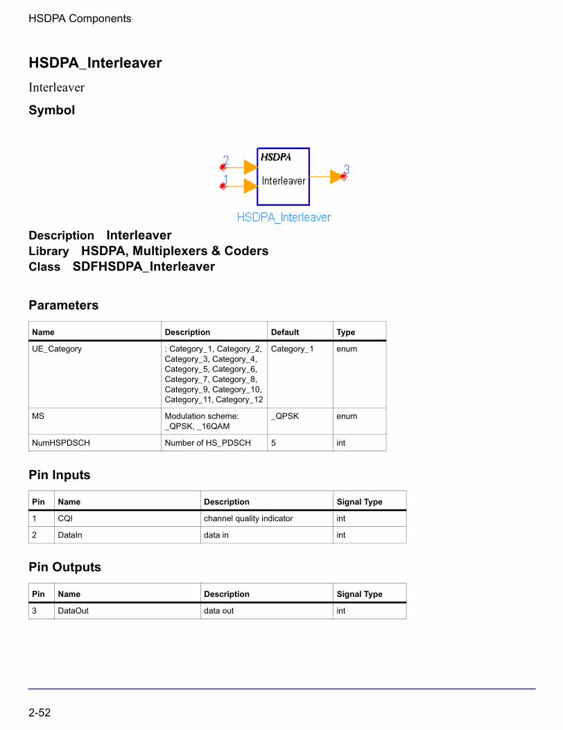
HSDPA_Interleaver
Interleaver
Symbol
Description InterleaverLibrary HSDPA, Multiplexers & CodersClass SDFHSDPA_Interleaver
Parameters
Pin Inputs
Pin Outputs
Name Description Default Type
UE_Category : Category_1, Category_2, Category_3, Category_4, Category_5, Category_6, Category_7, Category_8, Category_9, Category_10, Category_11, Category_12
Category_1 enum
MS Modulation scheme: _QPSK, _16QAM
_QPSK enum
NumHSPDSCH Number of HS_PDSCH 5 int
Pin Name Description Signal Type
1 CQI channel quality indicator int
2 DataIn data in int
Pin Name Description Signal Type
3 DataOut data out int
2-52
Notes/Equations
1. This model is used to implement interleaving on HS-DSCH defined in 4.5.6 of [1].
Each firing, tokens are consumed at pin DataIn, and 1 token is consumed at pin CQI if it is connected, while tokens are generated at pin DataOut.
is the possible maximum data bits and MaxNumHSPDSCH is the possible maximum HS-PDSCHs within one TTI. If pin CQI is connected, MaxNumHSPDSCH equals to maximum HS-PDSCHs UE_Category supports. Otherwise, MaxNumHSPDSCH equals to NumHSPDSCH.
2. If pin CQI is connected, modulation scheme and number of HS-PDSCHs practically used (EffectiveNumHSPDSCH) are determined by input CQI value and UE_Category according to Table 7 of 6A.2 in [2]. Otherwise, modulation schemes are determined by MS, and EffectiveNumHSPDSCH is equal to NumHSPDSCH.
3. Although tokens are consumed at each firing, only the first EffectiveNumHSPDSCH HS-PDSCHs are occupied and 0s are padded for the other HS-PDSCHs. Each HS-PDSCH contains 1920 bits. If the modulation scheme is QPSK, only the first 960 bits are useful data bits, and the other 960 bits are 0s. If the modulation scheme is 16QAM, all 1920 bits are useful data bits.
4. The bits input to the interleaver are denoted by , wherein p is the
index of HS-PDSCHs. The basic interleaver is a block interleaver of fixed size 960, which is described in 4.2.11 of [1]. For QPSK, the useful data bits are
interleaved by the basic interleaver, and the interleaved 960 bits are padded 960 0s as the output. For 16QAM, two identical basic interleavers are used. are
divided two by two between the interleavers: bits go to the first basic interleaver
and go to the second basic interleaver. Bits are collected two by two from the
interleavers: are obtained from the first basic interleaver and are
obtained from the second basic interleaver.
References
[1] 3GPP Technical Specification TS 25.212, "Multiplexing and channel coding (FDD)," Version 6.7.0, Dec. 2005.
[2] 3GPP Technical Specification TS 25.214, "Physical layer procedures (FDD)," Version 6.7.1, Dec. 2005.
1920 MaxNumHSPDSCH×1920 MaxNumHSPDSCH×
1920 MaxNumHSPDSCH×
1920 MaxNumHSPDSCH×
up 1, up 2, up 3, … up 1920,, , , ,
up 1, up 2, up 3, … up 960,, , , ,
up 1, up 2, up 3, … up 1920,, , , ,
up k, up k 1+,,
up k 2+, up k 3+,,
vp k, vp k 1+,, vp k 2+, vp k 3+,,
2-53
HSDPA Components
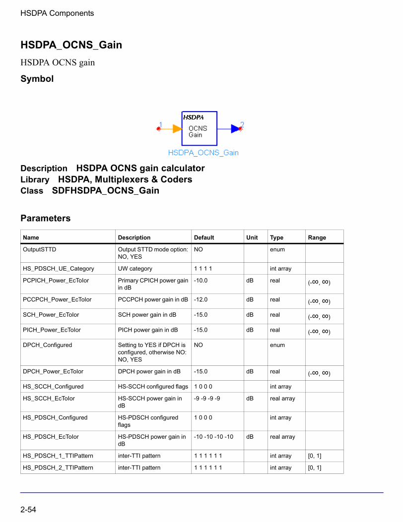
HSDPA_OCNS_Gain
HSDPA OCNS gain
Symbol
Description HSDPA OCNS gain calculatorLibrary HSDPA, Multiplexers & CodersClass SDFHSDPA_OCNS_Gain
Parameters
Name Description Default Unit Type Range
OutputSTTD Output STTD mode option: NO, YES
NO enum
HS_PDSCH_UE_Category UW category 1 1 1 1 int array
PCPICH_Power_EcToIor Primary CPICH power gain in dB
-10.0 dB real (-∞, ∞)
PCCPCH_Power_EcToIor PCCPCH power gain in dB -12.0 dB real (-∞, ∞)
SCH_Power_EcToIor SCH power gain in dB -15.0 dB real (-∞, ∞)
PICH_Power_EcToIor PICH power gain in dB -15.0 dB real (-∞, ∞)
DPCH_Configured Setting to YES if DPCH is configured, otherwise NO: NO, YES
NO enum
DPCH_Power_EcToIor DPCH power gain in dB -15.0 dB real (-∞, ∞)
HS_SCCH_Configured HS-SCCH configured flags 1 0 0 0 int array
HS_SCCH_EcToIor HS-SCCH power gain in dB
-9 -9 -9 -9 dB real array
HS_PDSCH_Configured HS-PDSCH configured flags
1 0 0 0 int array
HS_PDSCH_EcToIor HS-PDSCH power gain in dB
-10 -10 -10 -10 dB real array
HS_PDSCH_1_TTIPattern inter-TTI pattern 1 1 1 1 1 1 int array [0, 1]
HS_PDSCH_2_TTIPattern inter-TTI pattern 1 1 1 1 1 1 int array [0, 1]
2-54

Pin Inputs
Pin Outputs
Notes/Equations
1. This model is used to calculate OCNS gain so that total transmit power spectral density of Node B(Ior) adds to one. OCNS interference consists of six dedicated data channels as specified in table C.13 of [3].
Each firing, 7680 GainOut tokens are generated for one TTI.
2. The input pin CQI is optional. If connected, the input value of CQI should be in the range of 1 to 30. The CQI value is used to determined the reference power adjustment according to section 6A.2 of [2].
References
[1] 3GPP Technical Specification TS 25.212, "Multiplexing and channel coding (FDD)," Version 6.7.0, Dec. 2005.
[2] 3GPP Technical Specification TS 25.214, "Physical layer procedures (FDD)," Version 6.7.1, Dec. 2005.
[3] 3GPP Technical Specification TS 25.101, "User Equipment (UE) radio transmission and reception (FDD)," Version 6.10.0, Dec. 2005.
HS_PDSCH_3_TTIPattern inter-TTI pattern 1 1 1 1 1 1 int array [0, 1]
HS_PDSCH_4_TTIPattern inter-TTI pattern 1 1 1 1 1 1 int array [0, 1]
Pin Name Description Signal Type
1 CQI channel quality indicator int
Pin Name Description Signal Type
2 GainOut Gain for OCNS group real
Name Description Default Unit Type Range
2-55

HSDPA Components
HSDPA_PathSearch
Multiple Path Timing Search
Symbol
Description Multiple path maximum power timing searchLibrary HSDPA, ReceiverClass SDFHSDPA_PathSearchDerived From HSDPA_RakeBase
Parameters
Pin Inputs
Pin Outputs
Name Description Default Sym Type Range
TXDiversity transmit diversity in downlink: No_Diversity, STTD
No_Diversity enum
SampleRate number of samples per chip
4 S int [1, 32]
PathNum number of paths or fingers of Rake
6 L int [1, 16]
MaxDelay maximum path delay in terms of chips
40 D int [PathNum, number of half chips of one slot]
ScrambleCode Index of scramble code 0 int
Pin Name Description Signal Type
1 SmpSig received baseband complex envelope signal samples
complex
Pin Name Description Signal Type
2 Delays searched timing of path delay in terms of samples int
2-56
Notes/Equations
1. This model is used to search and determine the timing of multiple paths. Each path timing corresponds to one propagation path of radio.
Each firing, S × T tokens are consumed at SmpSig, where T is the number of chips per TTI and S is the number of SamplesPerChip. L tokens are produced at Delays, L is the number of PathNum. The output at Delays is delayed by one TTI because signals of multiple path may be overlapped on adjacent slots.
References
[1] 3GPP Technical Specification TS25.211 V6.7.0,“Physical channels and mapping of transport channels onto physical channels (FDD),” Dec. 2005.
[2] A. J. Viterbi, “CDMA: Principles of Spread Spectrum Communication,” Wesley Publishing Company, 1995.
[3] S.Fukumoto, M.Sawahashi, F.Adachi, “Matched Filter-Based RAKE Combiner for Wideband DS-CDMA Mobile Radio,” IEICE Trans. Commun., Vol., E81-B, No.7, July 1998.
2-57
HSDPA Components
HSDPA_PDSCH_1_4
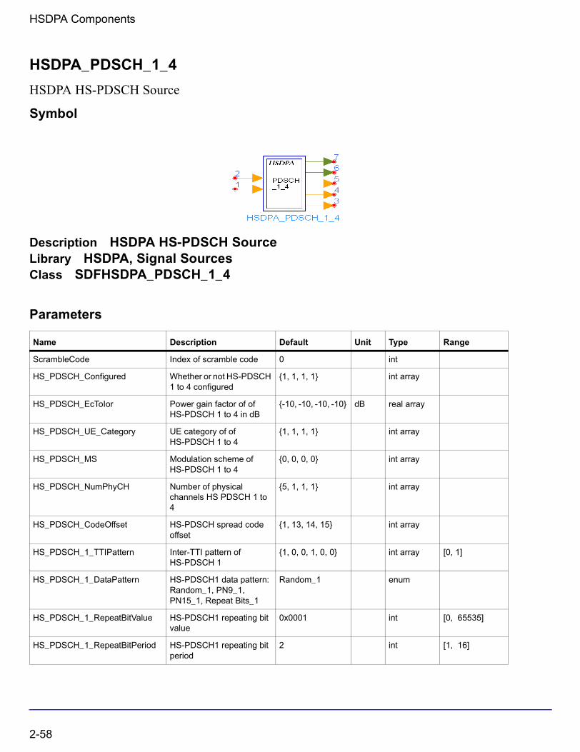
HSDPA HS-PDSCH Source
Symbol
Description HSDPA HS-PDSCH SourceLibrary HSDPA, Signal SourcesClass SDFHSDPA_PDSCH_1_4
Parameters
Name Description Default Unit Type Range
ScrambleCode Index of scramble code 0 int
HS_PDSCH_Configured Whether or not HS-PDSCH 1 to 4 configured
{1, 1, 1, 1} int array
HS_PDSCH_EcToIor Power gain factor of of HS-PDSCH 1 to 4 in dB
{-10, -10, -10, -10} dB real array
HS_PDSCH_UE_Category UE category of of HS-PDSCH 1 to 4
{1, 1, 1, 1} int array
HS_PDSCH_MS Modulation scheme of HS-PDSCH 1 to 4
{0, 0, 0, 0} int array
HS_PDSCH_NumPhyCH Number of physical channels HS PDSCH 1 to 4
{5, 1, 1, 1} int array
HS_PDSCH_CodeOffset HS-PDSCH spread code offset
{1, 13, 14, 15} int array
HS_PDSCH_1_TTIPattern Inter-TTI pattern of HS-PDSCH 1
{1, 0, 0, 1, 0, 0} int array [0, 1]
HS_PDSCH_1_DataPattern HS-PDSCH1 data pattern: Random_1, PN9_1, PN15_1, Repeat Bits_1
Random_1 enum
HS_PDSCH_1_RepeatBitValue HS-PDSCH1 repeating bit value
0x0001 int [0, 65535]
HS_PDSCH_1_RepeatBitPeriod HS-PDSCH1 repeating bit period
2 int [1, 16]
2-58

Pin Inputs
Pin Outputs
HS_PDSCH_1_TBSize HS-PDSCH1 transport block size
3202 int [1, max transport block size]†
HS_PDSCH_1_NumHARQ Number of HARQ processes of HS-PDSCH1
1 int [1, 6]
HS_PDSCH_1_RVSeq HS-PDSCH1 redundancy version coding sequence
{0, 2, 5, 6} int array [0, 7]
HS_PDSCH_1_NIR HS-PDSCH1 Inremental Redundancy Register Buffer Size
9600 int
HS_PDSCH_2_TTIPattern Inter-TTI pattern of HS-PDSCH 2
{1, 0, 0, 1, 0, 0} int array [0, 1]
HS_PDSCH_2_DataPattern HS-PDSCH2 data pattern: PN9_2, PN15_2, FIX4_2, _4_1_4_0_2, _8_1_8_0_2, _16_1_16_0_2, _32_1_32_0_2, _64_1_64_0_2
PN9_2 enum
HS_PDSCH_3_TTIPattern Inter-TTI pattern of HS-PDSCH 3
{1, 0, 0, 1, 0, 0} int array [0, 1]
HS_PDSCH_3_DataPattern HS-PDSCH3 data pattern: PN9_3, PN15_3, FIX4_3, _4_1_4_0_3, _8_1_8_0_3, _16_1_16_0_3, _32_1_32_0_3, _64_1_64_0_3
PN9_3 enum
HS_PDSCH_4_TTIPattern Inter-TTI pattern of HS-PDSCH 4
{1, 0, 0, 1, 0, 0} int array [0, 1]
HS_PDSCH_4_DataPattern HS-PDSCH4 data pattern: PN9_4, PN15_4, FIX4_4, _4_1_4_0_4, _8_1_8_0_4, _16_1_16_0_4, _32_1_32_0_4, _64_1_64_0_4
PN9_4 enum
Pin Name Description Signal Type
1 CQI channel quality indicator int
2 ARQ automatic repeat request int
Pin Name Description Signal Type
3 RV redundancy version int
4 nd new data indicator int
Name Description Default Unit Type Range
2-59
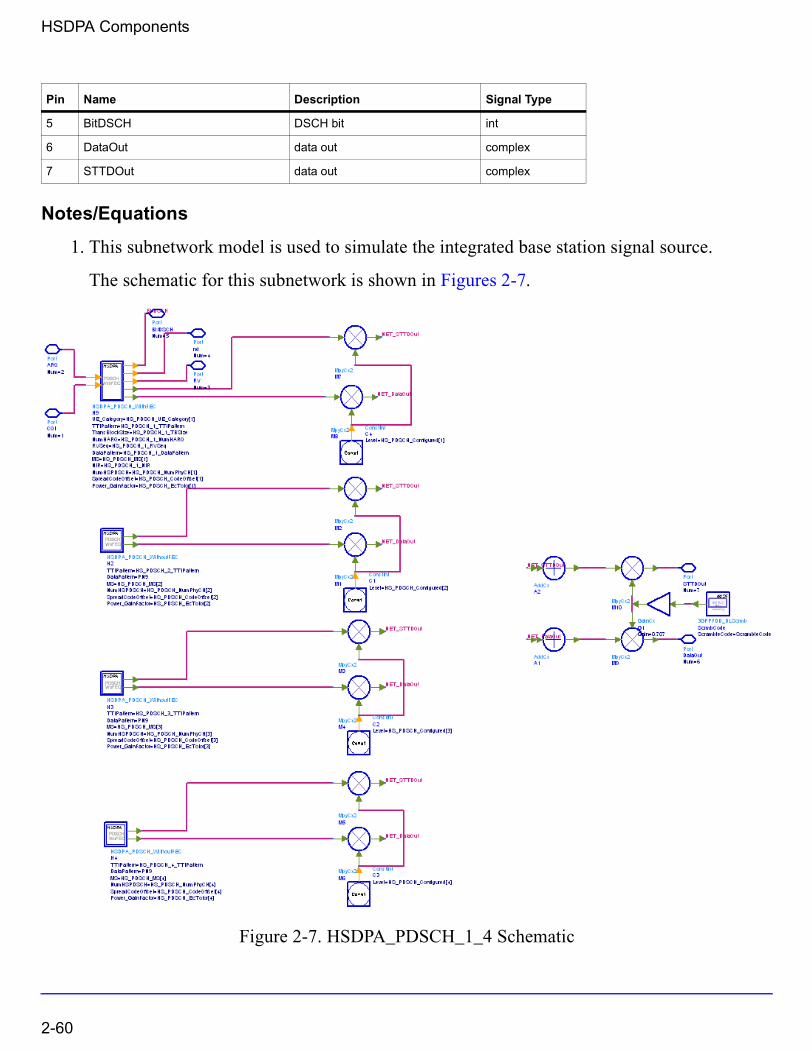
HSDPA Components
Notes/Equations
1. This subnetwork model is used to simulate the integrated base station signal source.
The schematic for this subnetwork is shown in Figures 2-7.
Figure 2-7. HSDPA_PDSCH_1_4 Schematic
5 BitDSCH DSCH bit int
6 DataOut data out complex
7 STTDOut data out complex
Pin Name Description Signal Type
2-60
2. The HSDPA_PDSCH_1_4 is generated by one fully-coded HSDPA_PDSCH_WithFEC signal source and three HSDPA_PDSCH_WithoutFEC signal sources.
References
[1] 3GPP Technical Specification TS 25.211, "Physical channels and mapping of transport channels onto physical channels (FDD)," Version 6.7.0, Dec. 2005.
[2] 3GPP Technical Specification TS 25.212, "Multiplexing and channel coding (FDD)," Version 6.7.0, Dec. 2005.
[3] 3GPP Technical Specification TS 25.213, "Spreading and modulation (FDD)," Version 6.4.0, Sept. 2005.
[4] 3GPP Technical Specification TS 25.214, "Physical layer procedures (FDD)," Version 6.7.1, Dec. 2005.
2-61
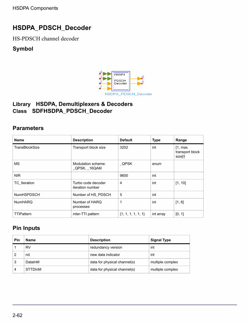
HSDPA Components
HSDPA_PDSCH_Decoder
HS-PDSCH channel decoder
Symbol
Library HSDPA, Demultiplexers & DecodersClass SDFHSDPA_PDSCH_Decoder
Parameters
Pin Inputs
Name Description Default Type Range
TransBlockSize Transport block size 3202 int [1, max transport block size]†
MS Modulation scheme: _QPSK, _16QAM
_QPSK enum
NIR 9600 int
TC_Iteration Turbo code decoder iteration number
4 int [1, 10]
NumHSPDSCH Number of HS_PDSCH 5 int
NumHARQ Number of HARQ processes
1 int [1, 6]
TTIPattern inter-TTI pattern {1, 1, 1, 1, 1, 1} int array [0, 1]
Pin Name Description Signal Type
1 RV redundancy version int
2 nd new data indicator int
3 DataInM data for physical channel(s) multiple complex
4 STTDInM data for physical channel(s) multiple complex
2-62
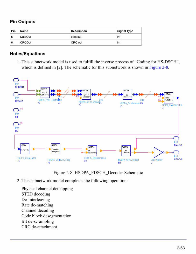
Pin Outputs
Notes/Equations
1. This subnetwork model is used to fulfill the inverse process of “Coding for HS-DSCH”, which is defined in [2]. The schematic for this subnetwork is shown in Figure 2-8.
Figure 2-8. HSDPA_PDSCH_Decoder Schematic
2. This subnetwork model completes the following operations:
Physical channel demappingSTTD decodingDe-InterleavingRate de-matchingChannel decodingCode block desegmentationBit de-scramblingCRC de-attachment
Pin Name Description Signal Type
5 DataOut data out int
6 CRCOut CRC out int
2-63
HSDPA Components
3. For each received HS-DSCH transport block, error-detection is performed by checking the CRC. If there is no error, the pin CRCOut outputs 1 (otherwise outputs 0).
References
[1] 3GPP Technical Specification TS 25.211, "Physical channels and mapping of transport channels onto physical channels (FDD)," Version 6.7.0, Dec. 2005.
[2] 3GPP Technical Specification TS 25.212, "Multiplexing and channel coding (FDD)," Version 6.7.0, Dec. 2005.
[3] 3GPP Technical Specification TS 25.213, "Spreading and modulation (FDD)," Version 6.4.0, Sept. 2005.
2-64

HSDPA_PDSCH_WithFEC
HSDPA downlink PDSCH With FEC
Symbol
Description HSDPA PDSCH with codingLibrary HSDPA, Signal SourcesClass SDFHSDPA_PDSCH_WithFEC
Parameters
Name Description Default Type Range
UE_Category : Category_1, Category_2, Category_3, Category_4, Category_5, Category_6, Category_7, Category_8, Category_9, Category_10, Category_11, Category_12
Category_1 enum
TTIPattern inter-TTI pattern {1, 0, 1, 0, 1, 0} int array [0, 1]
TransBlockSize Transport block size 3202 int [1, max transport block size]†
NumHARQ Number of HARQ processes
1 int [1, 6]
RVSeq Redundancy and constellation version coding sequence
{0, 2, 5, 6} int array [0, 7]
DataPattern Source data pattern: Random, PN9, PN15, Repeat Bits
Random enum
RepeatBitValue Repeating data value 0x0001 int [0, 65535]
RepeatBitPeriod Repeating data period 2 int [1, 16]
MS Modulation scheme: _QPSK, _16QAM
_QPSK enum
NIR 9600 int
NumHSPDSCH number of physical channels
5 int
2-65

HSDPA Components
Pin Inputs
Pin Outputs
Notes/Equations
1. This subnetwork model is used to simulate a full coded HS-PDSCH signal source.
SpreadCodeOffset Spread code offset 1 int
Power_GainFactor Power gain factor -10.0 real
Pin Name Description Signal Type
1 CQI channel quality indicator int
2 ARQ automatic repeat request int
Pin Name Description Signal Type
3 DataOut data out complex
4 STTDOut data out complex
5 RV redundancy version int
6 nd new data indicator int
7 BitDSCH DSCH bit int
Name Description Default Type Range
2-66
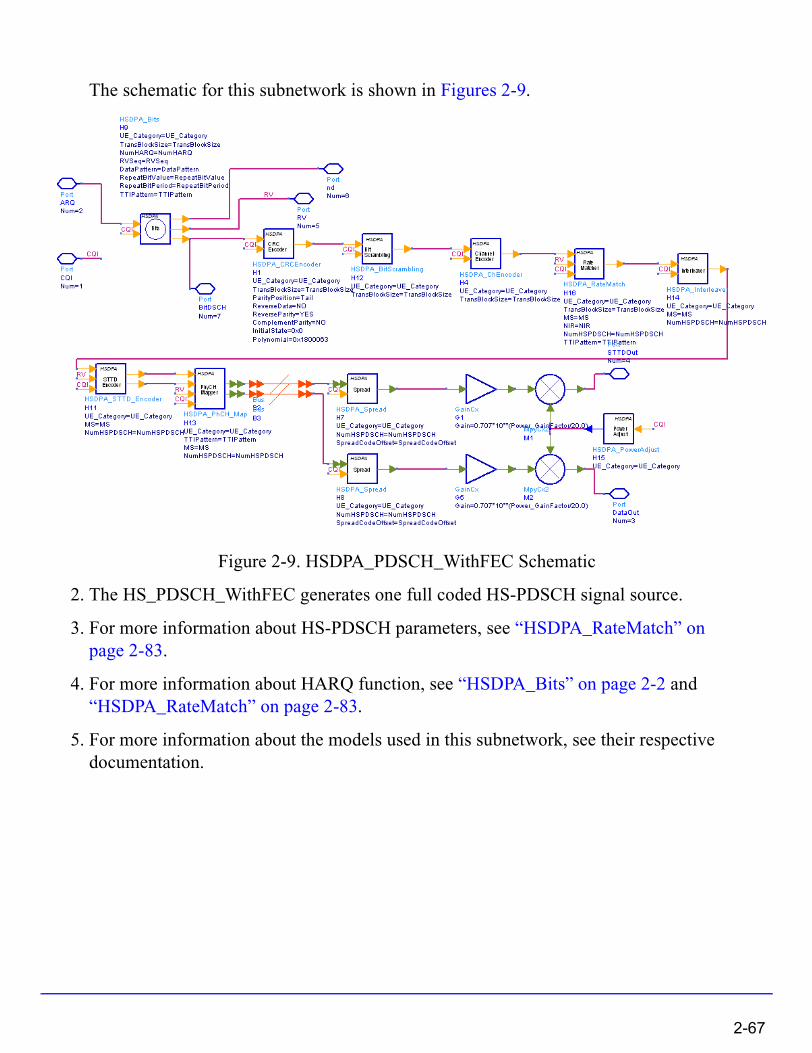
The schematic for this subnetwork is shown in Figures 2-9.
Figure 2-9. HSDPA_PDSCH_WithFEC Schematic
2. The HS_PDSCH_WithFEC generates one full coded HS-PDSCH signal source.
3. For more information about HS-PDSCH parameters, see “HSDPA_RateMatch” on page 2-83.
4. For more information about HARQ function, see “HSDPA_Bits” on page 2-2 and “HSDPA_RateMatch” on page 2-83.
5. For more information about the models used in this subnetwork, see their respective documentation.
2-67
HSDPA Components
References
[1] 3GPP Technical Specification TS 25.211, "Physical channels and mapping of transport channels onto physical channels (FDD)," Version 6.7.0, Dec. 2005.
[2] 3GPP Technical Specification TS 25.212, "Multiplexing and channel coding (FDD)," Version 6.7.0, Dec. 2005.
[3] 3GPP Technical Specification TS 25.213, "Spreading and modulation (FDD)," Version 6.4.0, Dec. 2005.
[4] 3GPP Technical Specification TS 25.214, "Physical layer procedures (FDD)," Version 6.7.1, Dec. 2005.
2-68

HSDPA_PDSCH_WithoutFEC
HSDPA HS-PDSCH Without FEC
Symbol
Description HSDPA PDSCH without codingLibrary HSDPA, Signal SourcesClass SDFHSDPA_PDSCH_WithoutFEC
Parameters
Pin Outputs
Name Description Default Type Range
TTIPattern inter-TTI pattern {1, 0, 1, 0, 1, 0} int array [0, 1]
DataPattern : PN9, PN15, FIX4, _4_1_4_0, _8_1_8_0, _16_1_16_0, _32_1_32_0, _64_1_64_0
PN9 enum
MS Modulation scheme: _QPSK, _16QAM
_QPSK enum
NumHSPDSCH number of physical channels
1 int
SpreadCodeOffset 13 int
Power_GainFactor Power gain factor -10.0 real
Pin Name Description Signal Type
1 DataOut data out complex
2 STTDOut data out complex
2-69
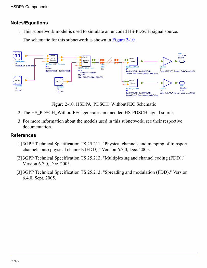
HSDPA Components
Notes/Equations
1. This subnetwork model is used to simulate an uncoded HS-PDSCH signal source.
The schematic for this subnetwork is shown in Figure 2-10.
Figure 2-10. HSDPA_PDSCH_WithoutFEC Schematic
2. The HS_PDSCH_WithoutFEC generates an uncoded HS-PDSCH signal source.
3. For more information about the models used in this subnetwork, see their respective documentation.
References
[1] 3GPP Technical Specification TS 25.211, "Physical channels and mapping of transport channels onto physical channels (FDD)," Version 6.7.0, Dec. 2005.
[2] 3GPP Technical Specification TS 25.212, "Multiplexing and channel coding (FDD)," Version 6.7.0, Dec. 2005.
[3] 3GPP Technical Specification TS 25.213, "Spreading and modulation (FDD)," Version 6.4.0, Sept. 2005.
2-70

HSDPA_PhCH_Demap
Physical channel demapper
Symbol
Description Soft demapperLibrary HSDPA, Demultiplexers & DecodersClass SDFHSDPA_PhCH_Demap
Parameters
Pin Inputs
Pin Outputs
Name Description Default Type
MS Modulation scheme: _QPSK, _16QAM
_QPSK enum
NumHSPDSCH Number of HS_PDSCH 5 int
Pin Name Description Signal Type
1 DataInM data for physical channel(s) multiple complex
2 STTDInM data for physical channel(s) multiple complex
Pin Name Description Signal Type
3 DataOutM soft-decision data for physical channel(s) multiple real
4 STTDOutM soft-decision STTD data for physical channel(s) multiple real
2-71
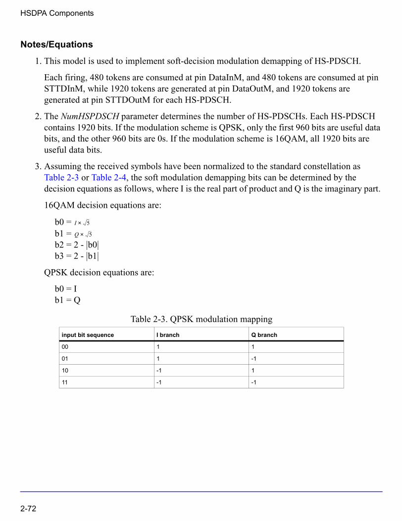
HSDPA Components
Notes/Equations
1. This model is used to implement soft-decision modulation demapping of HS-PDSCH.
Each firing, 480 tokens are consumed at pin DataInM, and 480 tokens are consumed at pin STTDInM, while 1920 tokens are generated at pin DataOutM, and 1920 tokens are generated at pin STTDOutM for each HS-PDSCH.
2. The NumHSPDSCH parameter determines the number of HS-PDSCHs. Each HS-PDSCH contains 1920 bits. If the modulation scheme is QPSK, only the first 960 bits are useful data bits, and the other 960 bits are 0s. If the modulation scheme is 16QAM, all 1920 bits are useful data bits.
3. Assuming the received symbols have been normalized to the standard constellation as Table 2-3 or Table 2-4, the soft modulation demapping bits can be determined by the decision equations as follows, where I is the real part of product and Q is the imaginary part.
16QAM decision equations are:
b0 = b1 = b2 = 2 - |b0|b3 = 2 - |b1|
QPSK decision equations are:
b0 = Ib1 = Q
Table 2-3. QPSK modulation mapping
input bit sequence I branch Q branch
00 1 1
01 1 -1
10 -1 1
11 -1 -1
I 5×
Q 5×
2-72
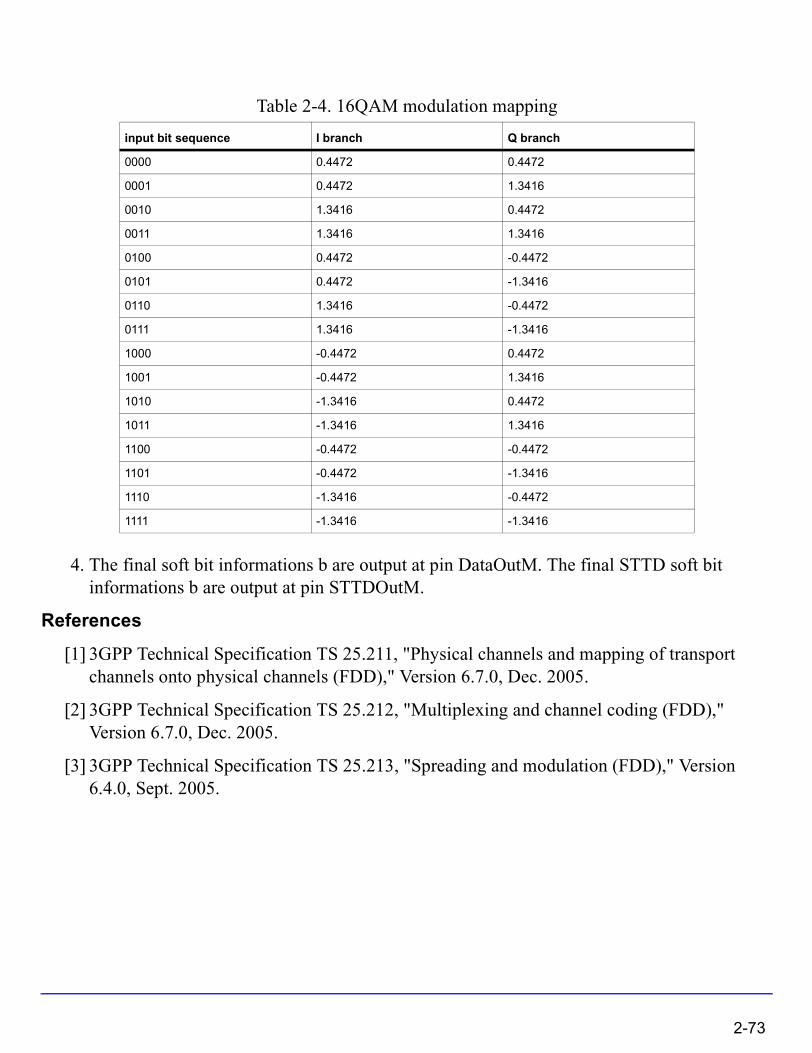
4. The final soft bit informations b are output at pin DataOutM. The final STTD soft bit informations b are output at pin STTDOutM.
References
[1] 3GPP Technical Specification TS 25.211, "Physical channels and mapping of transport channels onto physical channels (FDD)," Version 6.7.0, Dec. 2005.
[2] 3GPP Technical Specification TS 25.212, "Multiplexing and channel coding (FDD)," Version 6.7.0, Dec. 2005.
[3] 3GPP Technical Specification TS 25.213, "Spreading and modulation (FDD)," Version 6.4.0, Sept. 2005.
Table 2-4. 16QAM modulation mapping
input bit sequence I branch Q branch
0000 0.4472 0.4472
0001 0.4472 1.3416
0010 1.3416 0.4472
0011 1.3416 1.3416
0100 0.4472 -0.4472
0101 0.4472 -1.3416
0110 1.3416 -0.4472
0111 1.3416 -1.3416
1000 -0.4472 0.4472
1001 -0.4472 1.3416
1010 -1.3416 0.4472
1011 -1.3416 1.3416
1100 -0.4472 -0.4472
1101 -0.4472 -1.3416
1110 -1.3416 -0.4472
1111 -1.3416 -1.3416
2-73
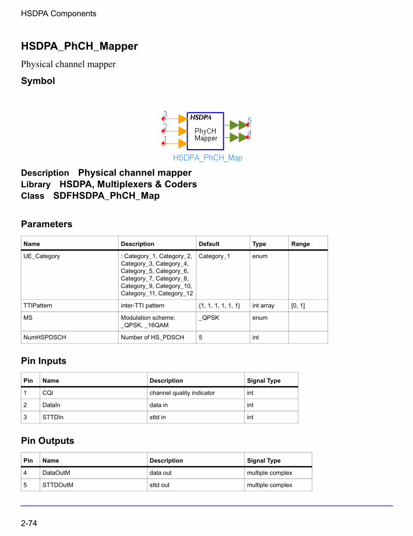
HSDPA Components
HSDPA_PhCH_Mapper
Physical channel mapper
Symbol
Description Physical channel mapperLibrary HSDPA, Multiplexers & CodersClass SDFHSDPA_PhCH_Map
Parameters
Pin Inputs
Pin Outputs
Name Description Default Type Range
UE_Category : Category_1, Category_2, Category_3, Category_4, Category_5, Category_6, Category_7, Category_8, Category_9, Category_10, Category_11, Category_12
Category_1 enum
TTIPattern inter-TTI pattern {1, 1, 1, 1, 1, 1} int array [0, 1]
MS Modulation scheme: _QPSK, _16QAM
_QPSK enum
NumHSPDSCH Number of HS_PDSCH 5 int
Pin Name Description Signal Type
1 CQI channel quality indicator int
2 DataIn data in int
3 STTDIn sttd in int
Pin Name Description Signal Type
4 DataOutM data out multiple complex
5 STTDOutM sttd out multiple complex
2-74
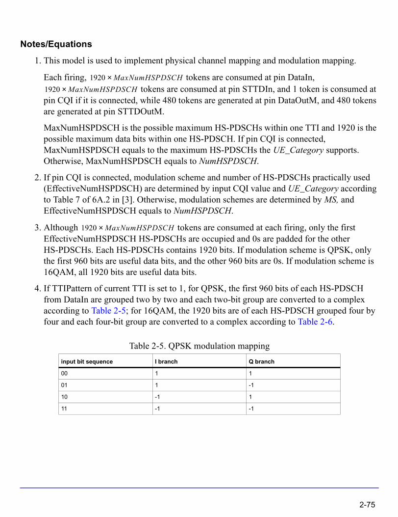
Notes/Equations
1. This model is used to implement physical channel mapping and modulation mapping.
Each firing, tokens are consumed at pin DataIn, tokens are consumed at pin STTDIn, and 1 token is consumed at
pin CQI if it is connected, while 480 tokens are generated at pin DataOutM, and 480 tokens are generated at pin STTDOutM.
MaxNumHSPDSCH is the possible maximum HS-PDSCHs within one TTI and 1920 is the possible maximum data bits within one HS-PDSCH. If pin CQI is connected, MaxNumHSPDSCH equals to the maximum HS-PDSCHs the UE_Category supports. Otherwise, MaxNumHSPDSCH equals to NumHSPDSCH.
2. If pin CQI is connected, modulation scheme and number of HS-PDSCHs practically used (EffectiveNumHSPDSCH) are determined by input CQI value and UE_Category according to Table 7 of 6A.2 in [3]. Otherwise, modulation schemes are determined by MS, and EffectiveNumHSPDSCH equals to NumHSPDSCH.
3. Although tokens are consumed at each firing, only the first EffectiveNumHSPDSCH HS-PDSCHs are occupied and 0s are padded for the other HS-PDSCHs. Each HS-PDSCHs contains 1920 bits. If modulation scheme is QPSK, only the first 960 bits are useful data bits, and the other 960 bits are 0s. If modulation scheme is 16QAM, all 1920 bits are useful data bits.
4. If TTIPattern of current TTI is set to 1, for QPSK, the first 960 bits of each HS-PDSCH from DataIn are grouped two by two and each two-bit group are converted to a complex according to Table 2-5; for 16QAM, the 1920 bits are of each HS-PDSCH grouped four by four and each four-bit group are converted to a complex according to Table 2-6.
Table 2-5. QPSK modulation mapping
input bit sequence I branch Q branch
00 1 1
01 1 -1
10 -1 1
11 -1 -1
1920 MaxNumHSPDSCH×1920 MaxNumHSPDSCH×
1920 MaxNumHSPDSCH×
2-75
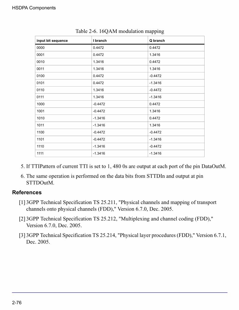
HSDPA Components
5. If TTIPattern of current TTI is set to 1, 480 0s are output at each port of the pin DataOutM.
6. The same operation is performed on the data bits from STTDIn and output at pin STTDOutM.
References
[1] 3GPP Technical Specification TS 25.211, "Physical channels and mapping of transport channels onto physical channels (FDD)," Version 6.7.0, Dec. 2005.
[2] 3GPP Technical Specification TS 25.212, "Multiplexing and channel coding (FDD)," Version 6.7.0, Dec. 2005.
[3] 3GPP Technical Specification TS 25.214, "Physical layer procedures (FDD)," Version 6.7.1, Dec. 2005.
Table 2-6. 16QAM modulation mapping
input bit sequence I branch Q branch
0000 0.4472 0.4472
0001 0.4472 1.3416
0010 1.3416 0.4472
0011 1.3416 1.3416
0100 0.4472 -0.4472
0101 0.4472 -1.3416
0110 1.3416 -0.4472
0111 1.3416 -1.3416
1000 -0.4472 0.4472
1001 -0.4472 1.3416
1010 -1.3416 0.4472
1011 -1.3416 1.3416
1100 -0.4472 -0.4472
1101 -0.4472 -1.3416
1110 -1.3416 -0.4472
1111 -1.3416 -1.3416
2-76
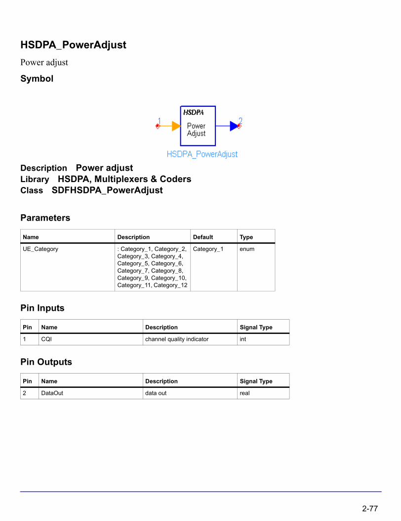
HSDPA_PowerAdjust
Power adjust
Symbol
Description Power adjustLibrary HSDPA, Multiplexers & CodersClass SDFHSDPA_PowerAdjust
Parameters
Pin Inputs
Pin Outputs
Name Description Default Type
UE_Category : Category_1, Category_2, Category_3, Category_4, Category_5, Category_6, Category_7, Category_8, Category_9, Category_10, Category_11, Category_12
Category_1 enum
Pin Name Description Signal Type
1 CQI channel quality indicator int
Pin Name Description Signal Type
2 DataOut data out real
2-77

HSDPA Components
Notes/Equations
1. This model is used to implement power adjustment.
Each firing, 1 token is consumed at pin CQI if it is connected, while 7680 tokens are generated at pin DataOut.
2. If pin CQI is connected, power gain is determined by input CQI value and UE_Category according to Table 7 of 6A.2 in [1]. Otherwise, 1.0 is output.
References
[1] 3GPP Technical Specification TS 25.214, "Physical layer procedure (FDD)" Version 6.7.1, Dec. 2005.
2-78
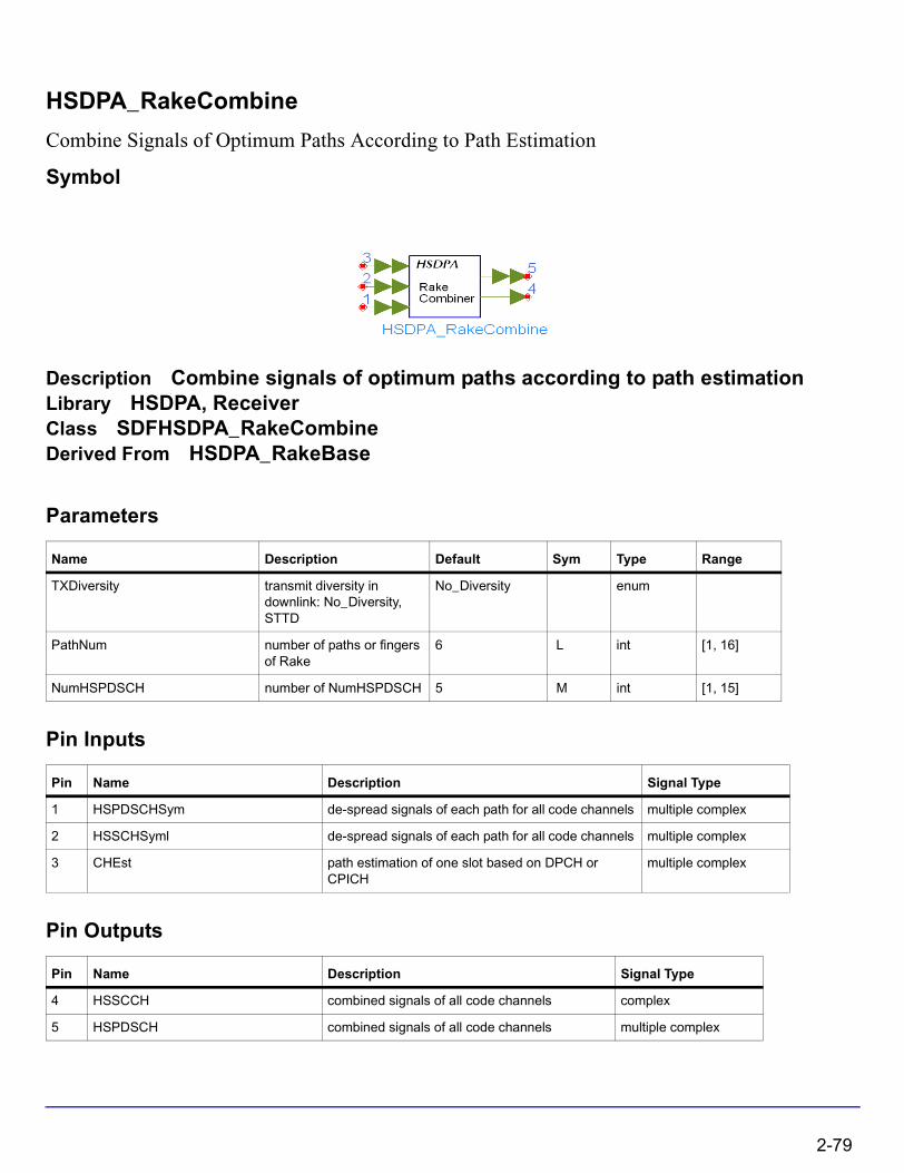
HSDPA_RakeCombine
Combine Signals of Optimum Paths According to Path Estimation
Symbol
Description Combine signals of optimum paths according to path estimationLibrary HSDPA, ReceiverClass SDFHSDPA_RakeCombineDerived From HSDPA_RakeBase
Parameters
Pin Inputs
Pin Outputs
Name Description Default Sym Type Range
TXDiversity transmit diversity in downlink: No_Diversity, STTD
No_Diversity enum
PathNum number of paths or fingers of Rake
6 L int [1, 16]
NumHSPDSCH number of NumHSPDSCH 5 M int [1, 15]
Pin Name Description Signal Type
1 HSPDSCHSym de-spread signals of each path for all code channels multiple complex
2 HSSCHSyml de-spread signals of each path for all code channels multiple complex
3 CHEst path estimation of one slot based on DPCH or CPICH
multiple complex
Pin Name Description Signal Type
4 HSSCCH combined signals of all code channels complex
5 HSPDSCH combined signals of all code channels multiple complex
2-79
HSDPA Components
Notes/Equations
1. This model is used to fulfill maximal ratio combining.
Each firing, N tokens are consumed at CHEst per each port, M tokens are consumed at HSPDSCHSym per each port and P tokens are consumed at HSSCCHSym, where N is the number of symbols per TTI in downlink CPICH, M is the number of symbols per TTI in all HS-PDSCHs, P is the number of symbols per TTI in HS-SCCH. Q tokens are produced at HSPDSCH per each port, where Q is the number of symbols per TTI in one HS-PDSCH. P tokens are produced at HSSCCH, where P is the number of symbols per TTI in HS-SCCH. The number of ports at ChEst, HSPDSCHSym and HSSCCHSym depend on PathNum. The number of ports at HSPDSCH depends on the NumHSPDSCH.
References
[1] 3GPP Technical Specification TS25.211 V6.7.0, “Physical channels and mapping of transport channels onto physical channels (FDD),” Dec. 2005.
[2] S.Tanaka, M.Sawahashi, and F.Adachi, “Pilot Symbol-Assisted Decision-Directed Coherent Adaptive Array Diversity for DS-CDMA Mobile Radio Reverse Link,” Proc. Wireless’97, Canada, July 1997.
[3] A. J. Viterbi, “CDMA: Principles of Spread Spectrum Communication,” Wesley Publishing Company, 1995.
2-80
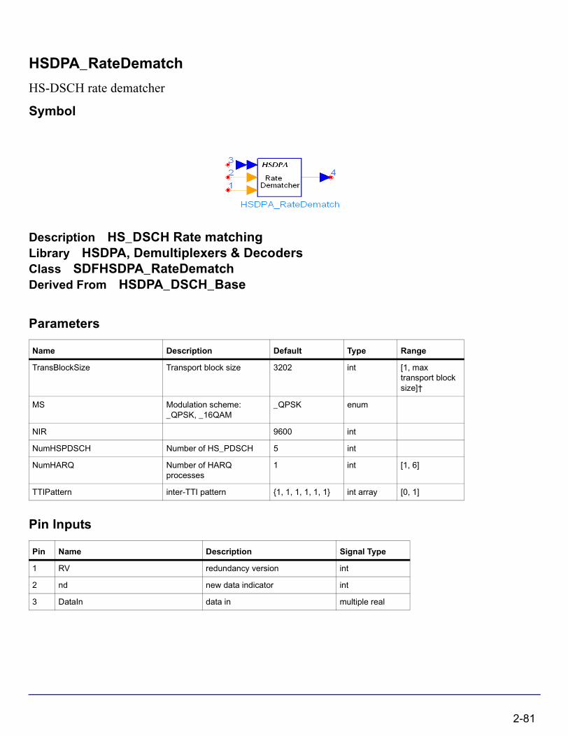
HSDPA_RateDematch
HS-DSCH rate dematcher
Symbol
Description HS_DSCH Rate matchingLibrary HSDPA, Demultiplexers & DecodersClass SDFHSDPA_RateDematchDerived From HSDPA_DSCH_Base
Parameters
Pin Inputs
Name Description Default Type Range
TransBlockSize Transport block size 3202 int [1, max transport block size]†
MS Modulation scheme: _QPSK, _16QAM
_QPSK enum
NIR 9600 int
NumHSPDSCH Number of HS_PDSCH 5 int
NumHARQ Number of HARQ processes
1 int [1, 6]
TTIPattern inter-TTI pattern {1, 1, 1, 1, 1, 1} int array [0, 1]
Pin Name Description Signal Type
1 RV redundancy version int
2 nd new data indicator int
3 DataIn data in multiple real
2-81

HSDPA Components
Pin Outputs
Notes/Equations
1. This model is used to implement rate dematch for HSDPA downlink.
Each firing, ((TransBlockSize + number of padding bits) * 3 + code block number * 12) Output tokens are generated while Ndata Input tokens are consumed. Determination of Ndata is described in 4.8.4.1 in [2].
2. This model implement the inverse operation of HSDPA_RateMatch. For more information, please refer to manual of HSDPA_RateMatch.
3. The received signal for each HARQ process are buffered in this model. If the input nd is 1 and TTIPattern is 1, current input data will be stored into the buffer of current HARQ process directly. If the input of nd is 0 and TTIPattern is 1, it means the received signal is a redundancy version and there is a previous version stored in the buffer of current HARQ process. Versions of received signal are combined and then stored into buffer of current HARQ process. The data in the buffer for current HARQ process are then fed into channel decoder(s).
4. Since the soft combination described above depends on HARQ process and rate dematch is implemented TTI by TTI, the beginning of the first HARQ process must be known to the model. Generally, receiver may introduce some delays into data stream.
References
[1] 3GPP Technical Specification TS 25.211, "Physical channels and mapping of transport channels onto physical channels (FDD)," Version 6.7.0, Dec. 2005.
[2] 3GPP Technical Specification TS 25.212, "Multiplexing and channel coding (FDD)," Version 6.7.0, Dec. 2005.
[3] 3GPP Technical Specification TS 25.213, "Spreading and modulation (FDD)," Version 6.4.0, Dec. 2005.
Pin Name Description Signal Type
4 DataOut data in real
2-82
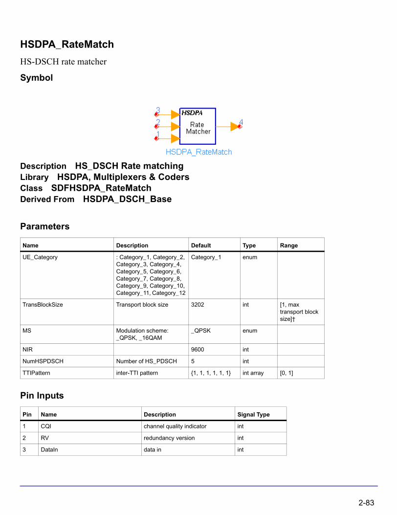
HSDPA_RateMatch
HS-DSCH rate matcher
Symbol
Description HS_DSCH Rate matchingLibrary HSDPA, Multiplexers & CodersClass SDFHSDPA_RateMatchDerived From HSDPA_DSCH_Base
Parameters
Pin Inputs
Name Description Default Type Range
UE_Category : Category_1, Category_2, Category_3, Category_4, Category_5, Category_6, Category_7, Category_8, Category_9, Category_10, Category_11, Category_12
Category_1 enum
TransBlockSize Transport block size 3202 int [1, max transport block size]†
MS Modulation scheme: _QPSK, _16QAM
_QPSK enum
NIR 9600 int
NumHSPDSCH Number of HS_PDSCH 5 int
TTIPattern inter-TTI pattern {1, 1, 1, 1, 1, 1} int array [0, 1]
Pin Name Description Signal Type
1 CQI channel quality indicator int
2 RV redundancy version int
3 DataIn data in int
2-83

HSDPA Components
Pin Outputs
Notes/Equations
1. This model is used to implement rate match defined in 4.5.4 in for HSDPA downlink.
Each firing, Ndata Output tokens are generated while ((TransBlockSize + number of padding bits) * 3 + code block number * 12) Input tokens consumed. Determination of Ndata and number of HS-PDSCH is described in 4.5.4.1 in [2].
2. The process of bit separation, rate match with specific RV value and bit collection can be found in 4.5.4 in [2].
References
[1] 3GPP Technical Specification TS 25.211, "Physical channels and mapping of transport channels onto physical channels (FDD)," Version 6.7.0, Dec. 2005.
[2] 3GPP Technical Specification TS 25.212, "Multiplexing and channel coding (FDD)," Version 6.7.0, Dec. 2005.
[3] 3GPP Technical Specification TS 25.213, "Spreading and modulation (FDD)," Version 6.4.0, Dec. 2005.
[4] 3GPP Technical Specification TS 25.214, "Physical layer procedures (FDD)," Version 6.7.1, Dec. 2005.
Pin Name Description Signal Type
4 DataOut data out int
2-84
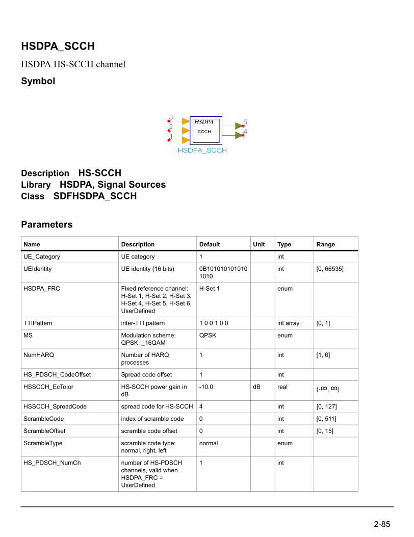
HSDPA_SCCH
HSDPA HS-SCCH channel
Symbol
Description HS-SCCHLibrary HSDPA, Signal SourcesClass SDFHSDPA_SCCH
Parameters
Name Description Default Unit Type Range
UE_Category UE category 1 int
UEIdentity UE identity (16 bits) 0B1010101010101010
int [0, 66535]
HSDPA_FRC Fixed reference channel: H-Set 1, H-Set 2, H-Set 3, H-Set 4, H-Set 5, H-Set 6, UserDefined
H-Set 1 enum
TTIPattern inter-TTI pattern 1 0 0 1 0 0 int array [0, 1]
MS Modulation scheme: QPSK, _16QAM
QPSK enum
NumHARQ Number of HARQ processes
1 int [1, 6]
HS_PDSCH_CodeOffset Spread code offset 1 int
HSSCCH_EcToIor HS-SCCH power gain in dB
-10.0 dB real (-∞, ∞)
HSSCCH_SpreadCode spread code for HS-SCCH 4 int [0, 127]
ScrambleCode index of scramble code 0 int [0, 511]
ScrambleOffset scramble code offset 0 int [0, 15]
ScrambleType scramble code type: normal, right, left
normal enum
HS_PDSCH_NumCh number of HS-PDSCH channels, valid when HSDPA_FRC = UserDefined
1 int
2-85

HSDPA Components
Pin Inputs
Pin Outputs
Notes/Equations
1. This subnetwork model is used to generate the baseband signal of HS-SCCH as defined in [1]. The HS-SCCH carries signaling information related to the HS-DSCH transport channel transmission. The HS-SCCH bit rate is fixed at 60 Kb/s, but its code number can be configured. The schematic for this subnetwork is shown in Figure 2-11.
Pin Name Description Signal Type
1 CQI channel quality indicator int
2 Xrv redundancy and constellation version (3 bits) int
3 Xnd new data indicator (1 bit) int
Pin Name Description Signal Type
4 Output output complex
5 STTD space time transmit diversity output complex
2-86

Figure 2-11. HSDPA_SCCH Schematic
2. The input pin CQI is optional. If connected, the input value of CQI should be in the range of 1 to 30. The pin Xrv inputs redundancy and constellation version indicator. The pin Xnd inputs new data indicator.
3. The parameter HSDPA_FRC determines the fixed reference channel set for HSDPA tests. The fixed reference channel is defined in section A.7 [3].
4. The parameter HS_PDSCH_NumCh is used to generate the HS-DSCH channel coding information in HS-SCCH. It is valid only when the corresponding HSDPA_FRC = UserDefined.
2-87

HSDPA Components
5. The physical channel structure of the HS-SCCH is illustrated in Figure 2-12. The first slot carries critical information for HS-PDSCH reception, such as the channelization code set (7 bits) and the modulation scheme (1 bit). The second and third slots carry the HS-DSCH channel coding information, such as the transport block size (6 bits), HARQ information (3 bits), the redundancy and constellation version (3 bits), and the new data indicator (1 bit).
Figure 2-12. Structure of the HS-SCCH (Ref: 3GPP TS 25.211 5.3.3.12)
6. The overall coding chain for HS-SCCH is illustrated in Figure 2-13. If the pin CQI is connected, then Xccs, Xtbs and Xms are calculated according to Table 7 of 6A.2 in [2]. If the pin CQI is unconnected, then Xccs, Xtbs and Xms are calculated according to the section A.7 of [3]. At the end of coding chain, the signal of each slot is spreaded and scrambled as defined in [2], then output at pin output (non STTD). Pin STTD outputs the signal with STTD encoding.
2-88
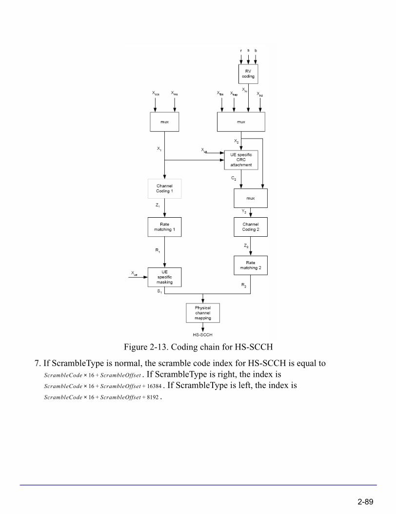
Figure 2-13. Coding chain for HS-SCCH
7. If ScrambleType is normal, the scramble code index for HS-SCCH is equal to . If ScrambleType is right, the index is
. If ScrambleType is left, the index is .
ScrambleCode 16× ScrambleOffset+
ScrambleCode 16× ScrambleOffset 16384+ +
ScrambleCode 16× ScrambleOffset 8192+ +
2-89
HSDPA Components
References
[1] 3GPP Technical Specification TS 25.212, "Multiplexing and channel coding (FDD)," Version 6.7.0, Dec. 2005.
[2] 3GPP Technical Specification TS 25.214, "Physical layer procedures (FDD)," Version 6.7.1, Dec. 2005.
[3] 3GPP Technical Specification TS 25.101, "User Equipment (UE) radio transmission and reception (FDD)," Version 6.10.0, Dec. 2005.
2-90
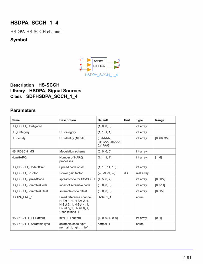
HSDPA_SCCH_1_4
HSDPA HS-SCCH channels
Symbol
Description HS-SCCHLibrary HSDPA, Signal SourcesClass SDFHSDPA_SCCH_1_4
Parameters
Name Description Default Unit Type Range
HS_SCCH_Configured {1, 0, 0, 0} int array
UE_Category UE category {1, 1, 1, 1} int array
UEIdentity UE identity (16 bits) {0xAAAA, 0x12AA, 0x1AAA, 0x1FAA}
int array [0, 66535]
HS_PDSCH_MS Modulation scheme {0, 0, 0, 0} int array
NumHARQ Number of HARQ processes
{1, 1, 1, 1} int array [1, 6]
HS_PDSCH_CodeOffset Spread code offset {1, 13, 14, 15} int array
HS_SCCH_EcToIor Power gain factor {-9, -9, -9, -9} dB real array
HS_SCCH_SpreadCode spread code for HS-SCCH {4, 5, 6, 7} int array [0, 127]
HS_SCCH_ScrambleCode index of scramble code {0, 0, 0, 0} int array [0, 511]
HS_SCCH_ScrambleOffset scramble code offset {0, 0, 0, 0} int array [0, 15]
HSDPA_FRC_1 Fixed reference channel: H-Set 1_1, H-Set 2_1, H-Set 3_1, H-Set 4_1, H-Set 5_1, H-Set 6_1, UserDefined_1
H-Set 1_1 enum
HS_SCCH_1_TTIPattern inter-TTI pattern {1, 0, 0, 1, 0, 0} int array [0, 1]
HS_SCCH_1_ScrambleType scramble code type: normal_1, right_1, left_1
normal_1 enum
2-91
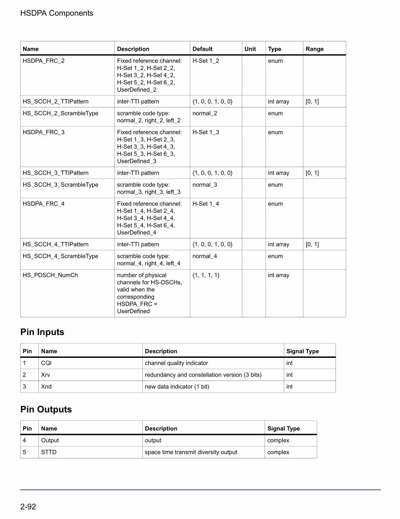
HSDPA Components
Pin Inputs
Pin Outputs
HSDPA_FRC_2 Fixed reference channel: H-Set 1_2, H-Set 2_2, H-Set 3_2, H-Set 4_2, H-Set 5_2, H-Set 6_2, UserDefined_2
H-Set 1_2 enum
HS_SCCH_2_TTIPattern inter-TTI pattern {1, 0, 0, 1, 0, 0} int array [0, 1]
HS_SCCH_2_ScrambleType scramble code type: normal_2, right_2, left_2
normal_2 enum
HSDPA_FRC_3 Fixed reference channel: H-Set 1_3, H-Set 2_3, H-Set 3_3, H-Set 4_3, H-Set 5_3, H-Set 6_3, UserDefined_3
H-Set 1_3 enum
HS_SCCH_3_TTIPattern inter-TTI pattern {1, 0, 0, 1, 0, 0} int array [0, 1]
HS_SCCH_3_ScrambleType scramble code type: normal_3, right_3, left_3
normal_3 enum
HSDPA_FRC_4 Fixed reference channel: H-Set 1_4, H-Set 2_4, H-Set 3_4, H-Set 4_4, H-Set 5_4, H-Set 6_4, UserDefined_4
H-Set 1_4 enum
HS_SCCH_4_TTIPattern inter-TTI pattern {1, 0, 0, 1, 0, 0} int array [0, 1]
HS_SCCH_4_ScrambleType scramble code type: normal_4, right_4, left_4
normal_4 enum
HS_PDSCH_NumCh number of physical channels for HS-DSCHs, valid when the corresponding HSDPA_FRC = UserDefined
{1, 1, 1, 1} int array
Pin Name Description Signal Type
1 CQI channel quality indicator int
2 Xrv redundancy and constellation version (3 bits) int
3 Xnd new data indicator (1 bit) int
Pin Name Description Signal Type
4 Output output complex
5 STTD space time transmit diversity output complex
Name Description Default Unit Type Range
2-92
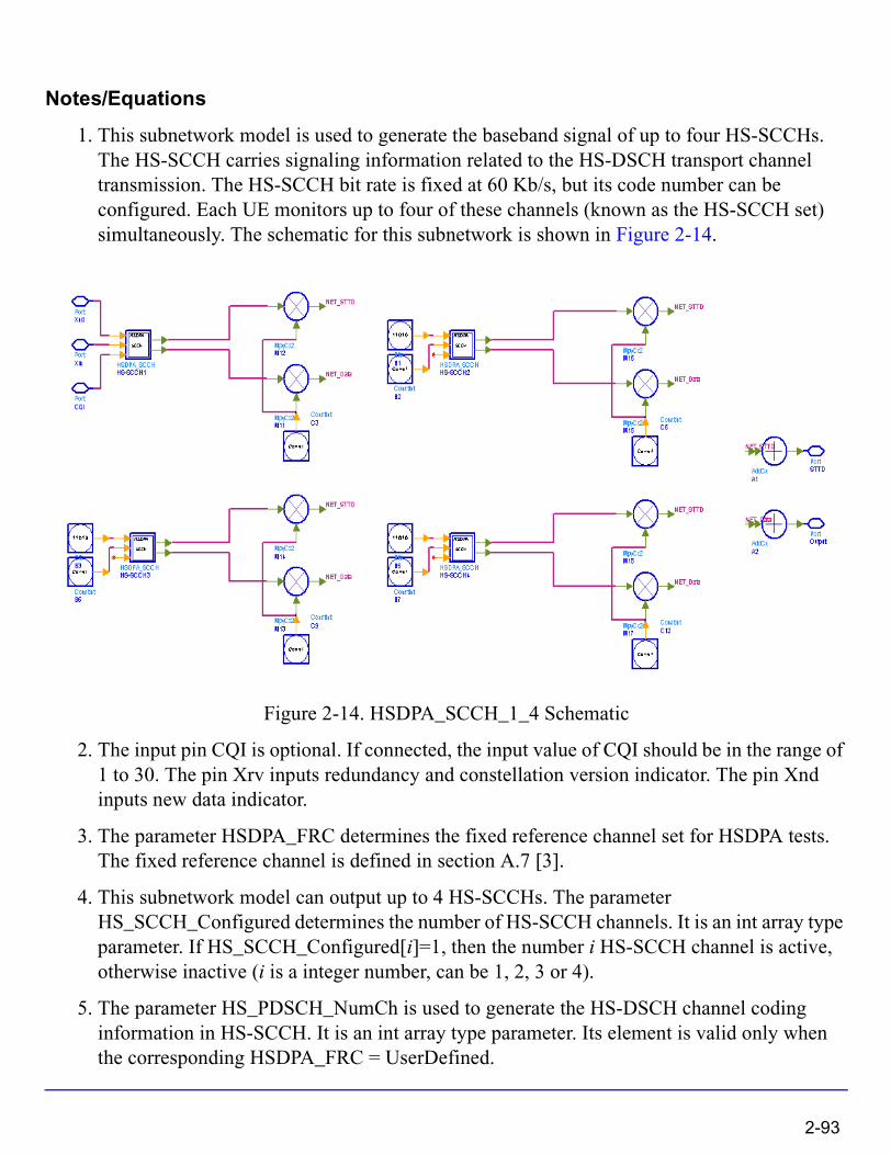
Notes/Equations
1. This subnetwork model is used to generate the baseband signal of up to four HS-SCCHs. The HS-SCCH carries signaling information related to the HS-DSCH transport channel transmission. The HS-SCCH bit rate is fixed at 60 Kb/s, but its code number can be configured. Each UE monitors up to four of these channels (known as the HS-SCCH set) simultaneously. The schematic for this subnetwork is shown in Figure 2-14.
Figure 2-14. HSDPA_SCCH_1_4 Schematic
2. The input pin CQI is optional. If connected, the input value of CQI should be in the range of 1 to 30. The pin Xrv inputs redundancy and constellation version indicator. The pin Xnd inputs new data indicator.
3. The parameter HSDPA_FRC determines the fixed reference channel set for HSDPA tests. The fixed reference channel is defined in section A.7 [3].
4. This subnetwork model can output up to 4 HS-SCCHs. The parameter HS_SCCH_Configured determines the number of HS-SCCH channels. It is an int array type parameter. If HS_SCCH_Configured[i]=1, then the number i HS-SCCH channel is active, otherwise inactive (i is a integer number, can be 1, 2, 3 or 4).
5. The parameter HS_PDSCH_NumCh is used to generate the HS-DSCH channel coding information in HS-SCCH. It is an int array type parameter. Its element is valid only when the corresponding HSDPA_FRC = UserDefined.
2-93
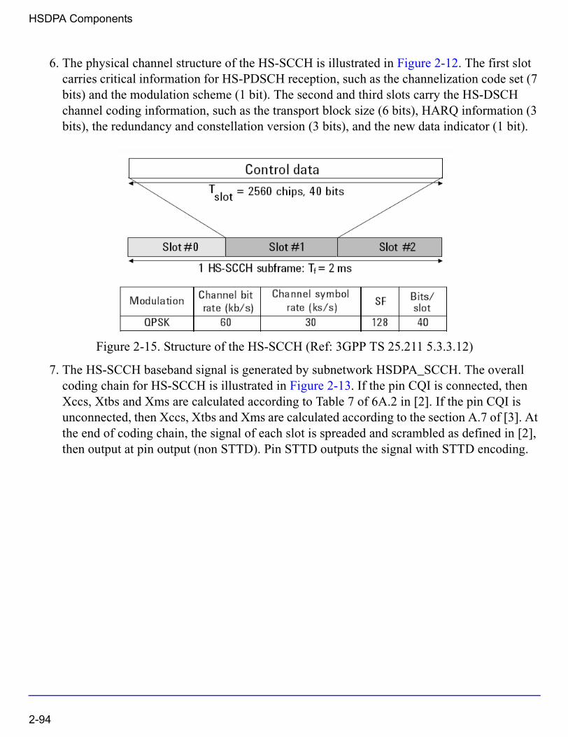
HSDPA Components
6. The physical channel structure of the HS-SCCH is illustrated in Figure 2-12. The first slot carries critical information for HS-PDSCH reception, such as the channelization code set (7 bits) and the modulation scheme (1 bit). The second and third slots carry the HS-DSCH channel coding information, such as the transport block size (6 bits), HARQ information (3 bits), the redundancy and constellation version (3 bits), and the new data indicator (1 bit).
Figure 2-15. Structure of the HS-SCCH (Ref: 3GPP TS 25.211 5.3.3.12)
7. The HS-SCCH baseband signal is generated by subnetwork HSDPA_SCCH. The overall coding chain for HS-SCCH is illustrated in Figure 2-13. If the pin CQI is connected, then Xccs, Xtbs and Xms are calculated according to Table 7 of 6A.2 in [2]. If the pin CQI is unconnected, then Xccs, Xtbs and Xms are calculated according to the section A.7 of [3]. At the end of coding chain, the signal of each slot is spreaded and scrambled as defined in [2], then output at pin output (non STTD). Pin STTD outputs the signal with STTD encoding.
2-94
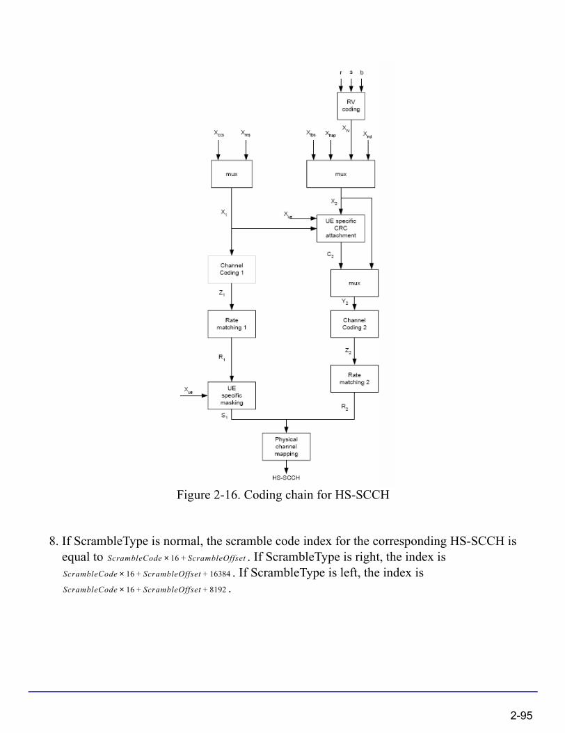
Figure 2-16. Coding chain for HS-SCCH
8. If ScrambleType is normal, the scramble code index for the corresponding HS-SCCH is equal to . If ScrambleType is right, the index is
. If ScrambleType is left, the index is .
ScrambleCode 16× ScrambleOffset+
ScrambleCode 16× ScrambleOffset 16384+ +
ScrambleCode 16× ScrambleOffset 8192+ +
2-95

HSDPA Components
References
[1] 3GPP Technical Specification TS 25.212, "Multiplexing and channel coding (FDD)," Version 6.7.0, Dec. 2005.
[2] 3GPP Technical Specification TS 25.214, "Physical layer procedures (FDD)," Version 6.7.1, Dec. 2005.
[3] 3GPP Technical Specification TS 25.101, "User Equipment (UE) radio transmission and reception (FDD)," Version 6.10.0, Dec. 2005.
2-96

HSDPA_SCCH_Decoder
HSDPA HS-SCCH decoder
Symbol
Description HS-SCCH decoderLibrary HSDPA, Demultiplexers & DecodersClass SDFHSDPA_SCCH_Decoder
Parameters
Pin Inputs
Pin Outputs
Name Description Default Type Range
UEIdentity UE identity (16 bits) 0xAAAA int [0, 66535]
Pin Name Description Signal Type
1 DataIn SCCH input complex
Pin Name Description Signal Type
2 Xccs channelization code set int
3 Xms modulation scheme int
4 Xtbs transport-block size information int
5 Xhap HARQ process information (3 bits) int
6 Xrv redundancy and constellation version (3 bits) int
7 Xnd new data indicator (1 bit) int
8 SCCHCRC SCCH CRC result int
2-97
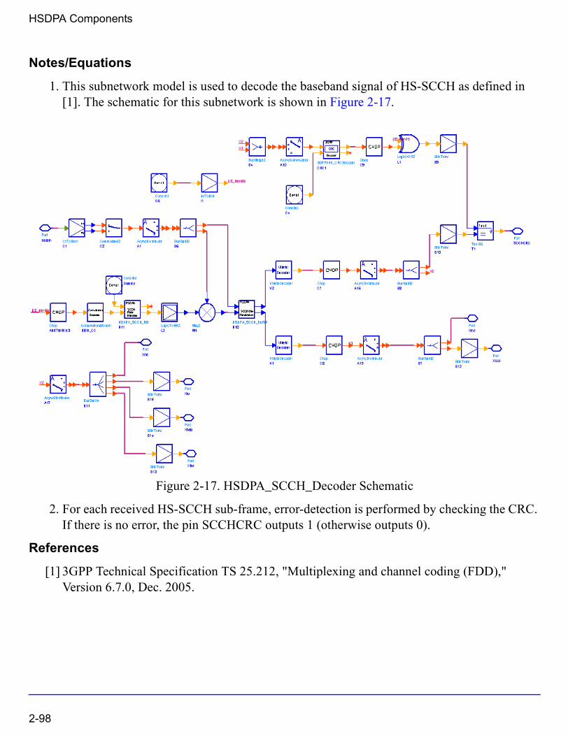
HSDPA Components
Notes/Equations
1. This subnetwork model is used to decode the baseband signal of HS-SCCH as defined in [1]. The schematic for this subnetwork is shown in Figure 2-17.
Figure 2-17. HSDPA_SCCH_Decoder Schematic
2. For each received HS-SCCH sub-frame, error-detection is performed by checking the CRC. If there is no error, the pin SCCHCRC outputs 1 (otherwise outputs 0).
References
[1] 3GPP Technical Specification TS 25.212, "Multiplexing and channel coding (FDD)," Version 6.7.0, Dec. 2005.
2-98
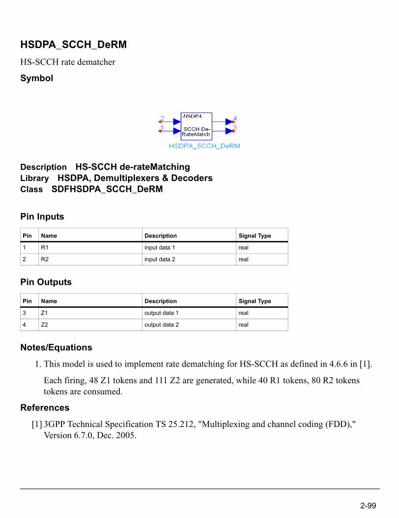
HSDPA_SCCH_DeRM
HS-SCCH rate dematcher
Symbol
Description HS-SCCH de-rateMatchingLibrary HSDPA, Demultiplexers & DecodersClass SDFHSDPA_SCCH_DeRM
Pin Inputs
Pin Outputs
Notes/Equations
1. This model is used to implement rate dematching for HS-SCCH as defined in 4.6.6 in [1].
Each firing, 48 Z1 tokens and 111 Z2 are generated, while 40 R1 tokens, 80 R2 tokens tokens are consumed.
References
[1] 3GPP Technical Specification TS 25.212, "Multiplexing and channel coding (FDD)," Version 6.7.0, Dec. 2005.
Pin Name Description Signal Type
1 R1 input data 1 real
2 R2 input data 2 real
Pin Name Description Signal Type
3 Z1 output data 1 real
4 Z2 output data 2 real
2-99

HSDPA Components
HSDPA_SCCH_ParaCalc
HSDPA HS-SCCH parameter calculator
Symbol
Description HS-SCCH CQI MappingLibrary HSDPA, Multiplexers & CodersClass SDFHSDPA_SCCH_ParaCalc
Parameters
Pin Inputs
Name Description Default Type Range
UE_Category UE category: Category_1, Category_2, Category_3, Category_4, Category_5, Category_6, Category_7, Category_8, Category_9, Category_10, Category_11, Category_12
Category_1 enum
HSDPA_FRC Fixed reference channel: H-Set 1, H-Set 2, H-Set 3, H-Set 4, H-Set 5, H-Set 6, UserDefined
H-Set 1 enum
MS Modulation scheme: QPSK, _16QAM
QPSK enum
NumHARQ Number of HARQ processes, only valid when port CQI is connected
1 int [1, 6]
HS_PDSCH_CodeOffset Spread code offset 1 int [1, 15]
HS_PDSCH_NumCh Number of HS-PDSCH channels, valid when HSDPA_FRC = UserDefined
1 int [1, 15]
Pin Name Description Signal Type
1 CQI channel quality indicator int
2-100
Pin Outputs
Notes/Equations
1. This model is used to calculate the Xccs, Xtbs, Xms and Xhap parameters of HS-SCCH as defined in [1].
2. The input pin CQI is optional. If connected, the input value of CQI should be in the range of 1 to 30.
3. Xccs, Xtbs, Xms and Xhap are used to generate HS-SCCH message. The overall coding chain for HS-SCCH is illustrated in Figure 2-13. If the pin CQI is connected, then Xccs, Xtbs and Xms are calculated according to Table 7 of 6A.2 in [2], and Xhap is determined by the parameter NumHARQ. If the pin CQI is unconnected, then Xccs, Xtbs and Xhap are calculated according to the section A.7 of [3], and Xms is determined by the parameter MS.
Pin Name Description Signal Type
2 Xhap HARQ process information (3 bits) int
3 Xms Modulation scheme information (1 bit) int
4 Xtbs transport-block size information (6 bits) int
5 Xccs channelization-code-set information (7 bits) int
2-101

HSDPA Components
Figure 2-18. Coding chain for HS-SCCH
4. Xccs is a channelization-code-set information (7 bits). It is coded according to section 4.6.2.3 [1].
5. Xtbs is a transport-block size information (6 bits). It is coded according to section 4.6.2.6 [1].
6. Xms is a modulation scheme information (1 bit). If modulation scheme is QPSK, then Xms=0; and if modulation scheme is 16QAM, then Xms=1.
7. Xhap is a hybrid-ARQ process information (3 bits). It is coded according to section 4.6.2.5 [1].
2-102
References
[1] 3GPP Technical Specification TS 25.212, "Multiplexing and channel coding (FDD)," Version 6.7.0, Dec. 2005.
[2] 3GPP Technical Specification TS 25.214, "Physical layer procedures (FDD)," Version 6.7.1, Dec. 2005.
[3] 3GPP Technical Specification TS 25.101, "User Equipment (UE) radio transmission and reception (FDD)," Version 6.10.0, Dec. 2005.
2-103
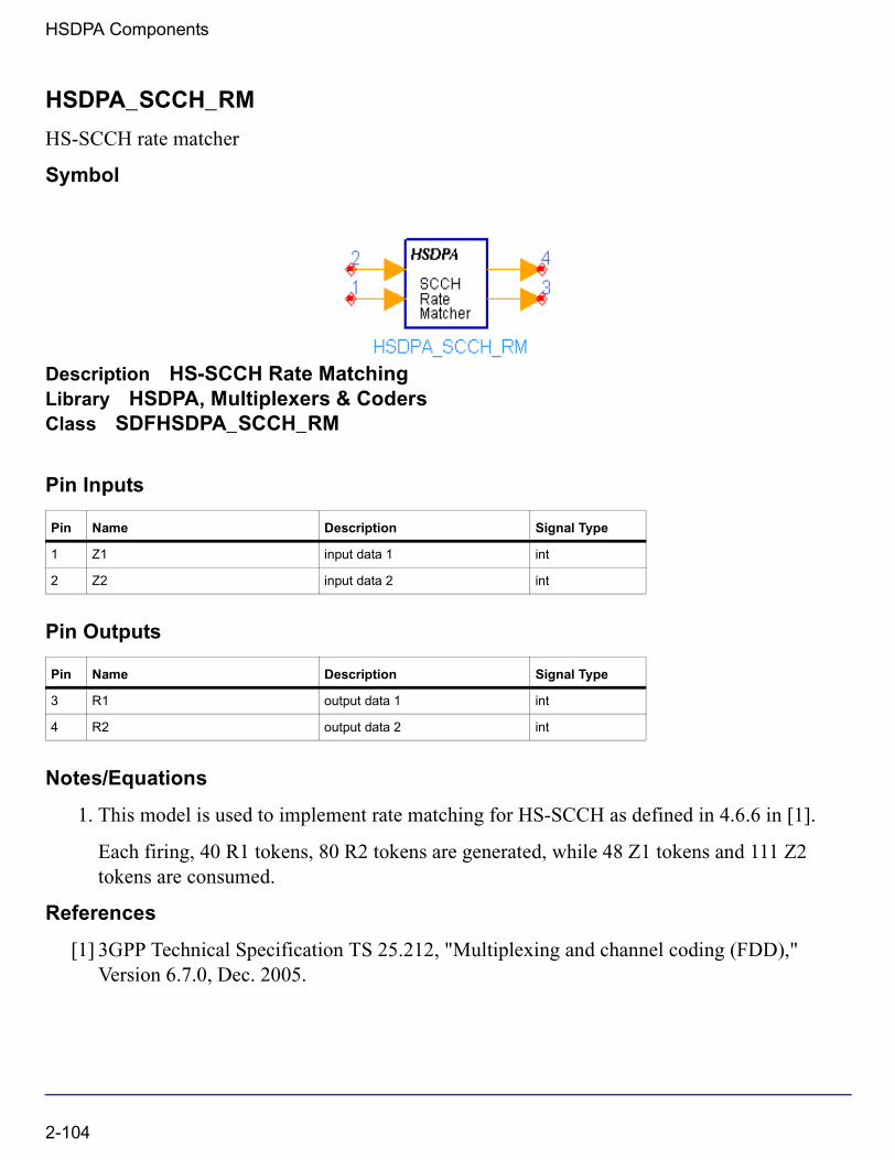
HSDPA Components
HSDPA_SCCH_RM
HS-SCCH rate matcher
Symbol
Description HS-SCCH Rate MatchingLibrary HSDPA, Multiplexers & CodersClass SDFHSDPA_SCCH_RM
Pin Inputs
Pin Outputs
Notes/Equations
1. This model is used to implement rate matching for HS-SCCH as defined in 4.6.6 in [1].
Each firing, 40 R1 tokens, 80 R2 tokens are generated, while 48 Z1 tokens and 111 Z2 tokens are consumed.
References
[1] 3GPP Technical Specification TS 25.212, "Multiplexing and channel coding (FDD)," Version 6.7.0, Dec. 2005.
Pin Name Description Signal Type
1 Z1 input data 1 int
2 Z2 input data 2 int
Pin Name Description Signal Type
3 R1 output data 1 int
4 R2 output data 2 int
2-104
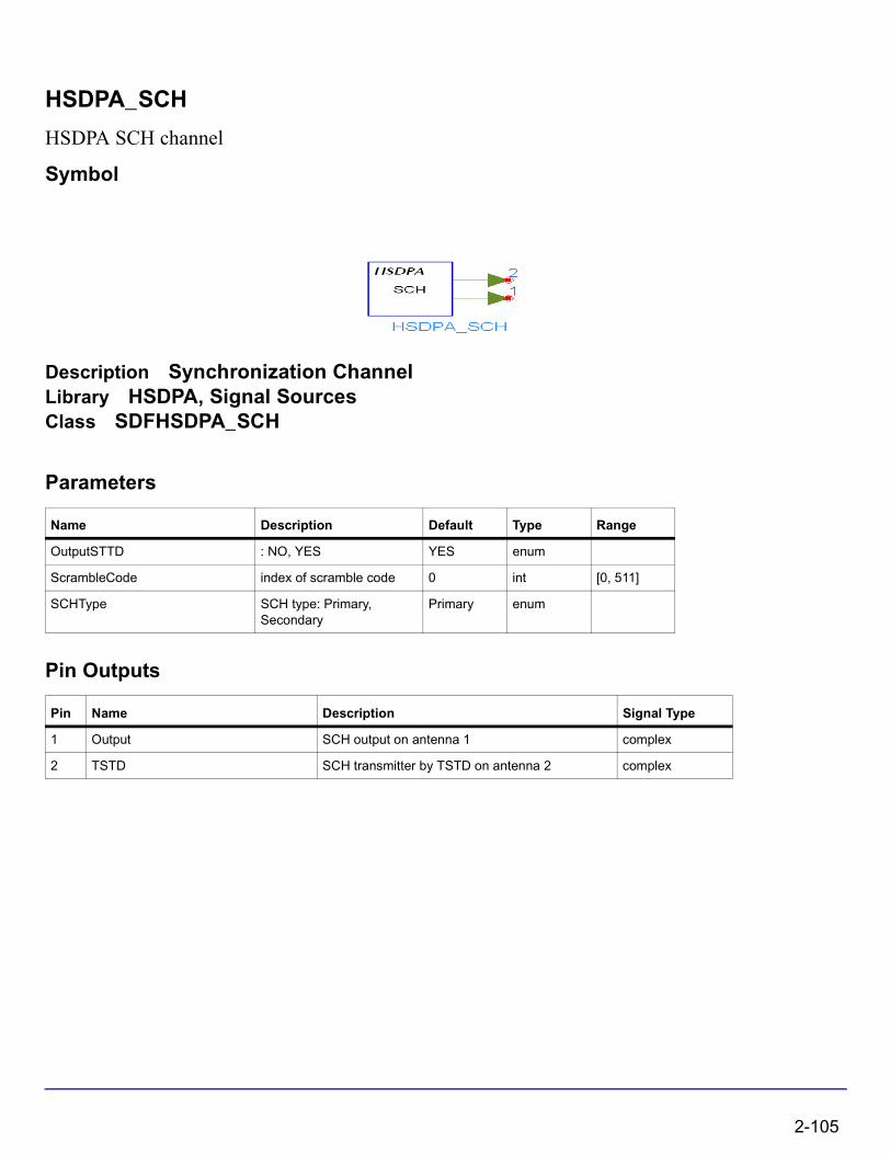
HSDPA_SCH
HSDPA SCH channel
Symbol
Description Synchronization ChannelLibrary HSDPA, Signal SourcesClass SDFHSDPA_SCH
Parameters
Pin Outputs
Name Description Default Type Range
OutputSTTD : NO, YES YES enum
ScrambleCode index of scramble code 0 int [0, 511]
SCHType SCH type: Primary, Secondary
Primary enum
Pin Name Description Signal Type
1 Output SCH output on antenna 1 complex
2 TSTD SCH transmitter by TSTD on antenna 2 complex
2-105
HSDPA Components
Notes/Equations
1. This model can be used to generate P-SCH or S-SCH.
2. SCHType = Secondary specifies the cell's downlink scrambling code group.
When SCHType = Primary, ScrambleCode is not used.
References
[1] 3GPP Technical Specification TS 25.211, "Physical channels and mapping of transport channels onto physical channels (FDD)," Version 6.7.0, Dec. 2005.
[2] 3GPP Technical Specification TS 25.213, "Spreading and modulation (FDD)," Version 6.4.0, Sept. 2005.
2-106
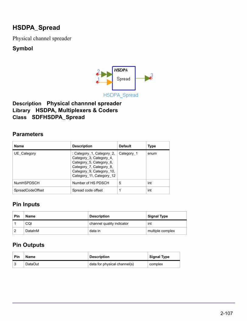
HSDPA_Spread
Physical channel spreader
Symbol
Description Physical channnel spreaderLibrary HSDPA, Multiplexers & CodersClass SDFHSDPA_Spread
Parameters
Pin Inputs
Pin Outputs
Name Description Default Type
UE_Category : Category_1, Category_2, Category_3, Category_4, Category_5, Category_6, Category_7, Category_8, Category_9, Category_10, Category_11, Category_12
Category_1 enum
NumHSPDSCH Number of HS PDSCH 5 int
SpreadCodeOffset Spread code offset 1 int
Pin Name Description Signal Type
1 CQI channel quality indicator int
2 DataInM data in multiple complex
Pin Name Description Signal Type
3 DataOut data for physical channel(s) complex
2-107
HSDPA Components
Notes/Equations
1. This model is used to implement spreading on HS-PDSCH.
Each firing, 480 tokens are consumed for each HS-PDSCH, which corresponds to one sub-port of pin DataInM, and 1 token is consumed at pin CQI if it is connected, while
tokens are generated at pin DataOut.
2. If pin CQI is connected, number of HS-PDSCHs occupied (EffectiveNumHSPDSCH) is determined by input CQI value and UE_Category according to Table 7 of 6A.2 in [4]. Otherwise, EffectiveNumHSPDSCH equals to NumHSPDSCH.
3. OVSF codes with length 16 and index from SpreadCodeOffset to SpreadCodeOffset+EffectiveNumHSPDSCH-1 are assigned to the EffectiveNumHSPDSCH HS-PDSCHs respectively. Spreading is performed on each token within one HS-PDSCH with the OVSF code assigned to the HS-PDSCH. So tokens are generated for each HS-PDSCH.
4. The spread tokens for each HS-PDSCH are summed together and output at pin DataOut.
References
[1] 3GPP Technical Specification TS 25.211, "Physical channels and mapping of transport channels onto physical channels (FDD)," Version 6.7.0, Dec. 2005.
[2] 3GPP Technical Specification TS 25.212, "Multiplexing and channel coding (FDD)," Version 6.7.0, Dec. 2005.
[3] 3GPP Technical Specification TS 25.213, "Spreading and modulation (FDD)," Version 6.4.0, Dec. 2005.
[4] 3GPP Technical Specification TS 25.214, "Physical layer procedures (FDD)," Version 6.7.1, Dec. 2005.
480 16×
480 16×
2-108
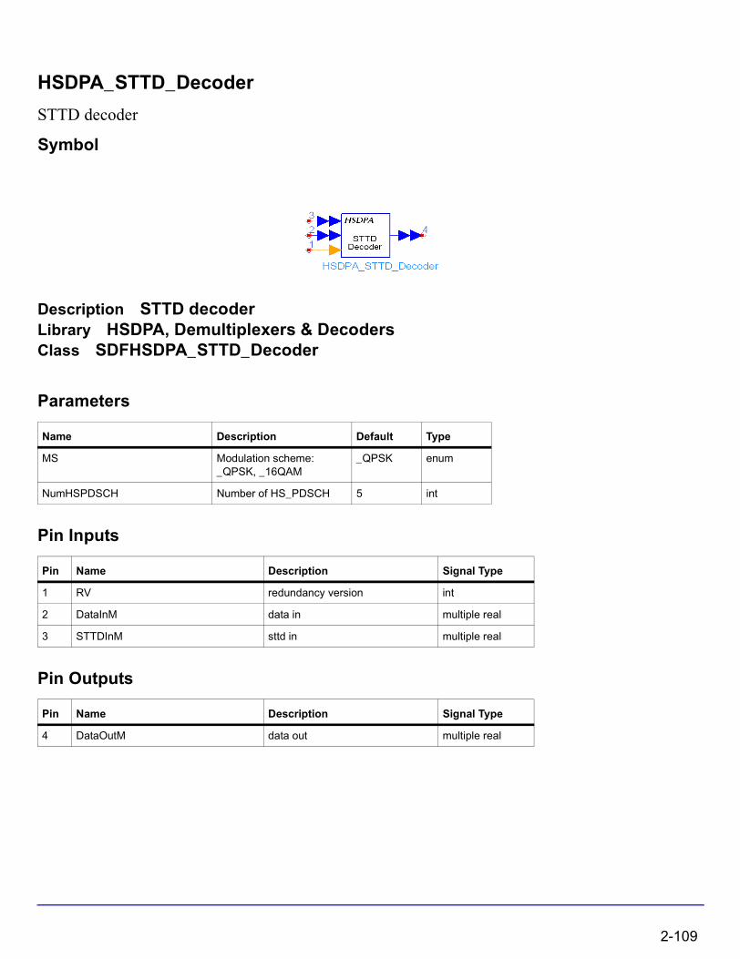
HSDPA_STTD_Decoder
STTD decoder
Symbol
Description STTD decoderLibrary HSDPA, Demultiplexers & DecodersClass SDFHSDPA_STTD_Decoder
Parameters
Pin Inputs
Pin Outputs
Name Description Default Type
MS Modulation scheme: _QPSK, _16QAM
_QPSK enum
NumHSPDSCH Number of HS_PDSCH 5 int
Pin Name Description Signal Type
1 RV redundancy version int
2 DataInM data in multiple real
3 STTDInM sttd in multiple real
Pin Name Description Signal Type
4 DataOutM data out multiple real
2-109
HSDPA Components
Notes/Equations
1. This model is used to perform the inverse operation of constellation re-arrangement for 16QAM and will be updated to perform STTD decoding in the future.
Each firing, 1920 tokens are consumed at each sub-port of pin DataInM, 1920 tokens at each sub-port of pin STTDInM, and 1 token is consumed at pin RV, while 1920 tokens are generated at each sub-port of pin DataOutM.
2. NumHSPDSCH specifies the number of HS-PDSCHs to be processed and each HS-PDSCH occupies one sub-port of pin DataInM and one sub-port of pin DataOutM. MS specifies the modulation scheme of each HS-PDSCH.
3. For QPSK, the 1920 bits consumed at each sub-port of DataInM will pass through this model transparently and output at each sub-port of DataOutM. For 16QAM, the 1920 bits are grouped four by four. The operation which is inverse to that shown in Table 2-7.
4. The tokens consumed at pin STTDIn are not processed inside the model now. In the future, STTD decoding and combining with the tokens from DataInM will be performed.
References
[1] 3GPP Technical Specification TS 25.211, "Physical channels and mapping of transport channels onto physical channels (FDD)," Version 6.7.0, Dec. 2005.
[2] 3GPP Technical Specification TS 25.212, "Multiplexing and channel coding (FDD)," Version 6.7.0, Dec. 2005.
Table 2-7. Constellation re-arrangement for 16QAM
constellation version parameter b Output bit sequence Operation
0 None
1 Swapping MSBs with LSBs
2 Inversion of the logical values of LSBs
3 Swapping MSBs with LSBs and inversion of the logical values of LSBs
vp k, vp k 1+, vp k 2+, vp k 3+,, , ,
vp k 2+, vp k 3+, vp k, vp k 1+,, , ,
vp k, vp k 1+, vp k 2+, vp k 3+,, , ,
vp k 2+, vp k 3+, vp k, vp k 1+,, , ,
2-110
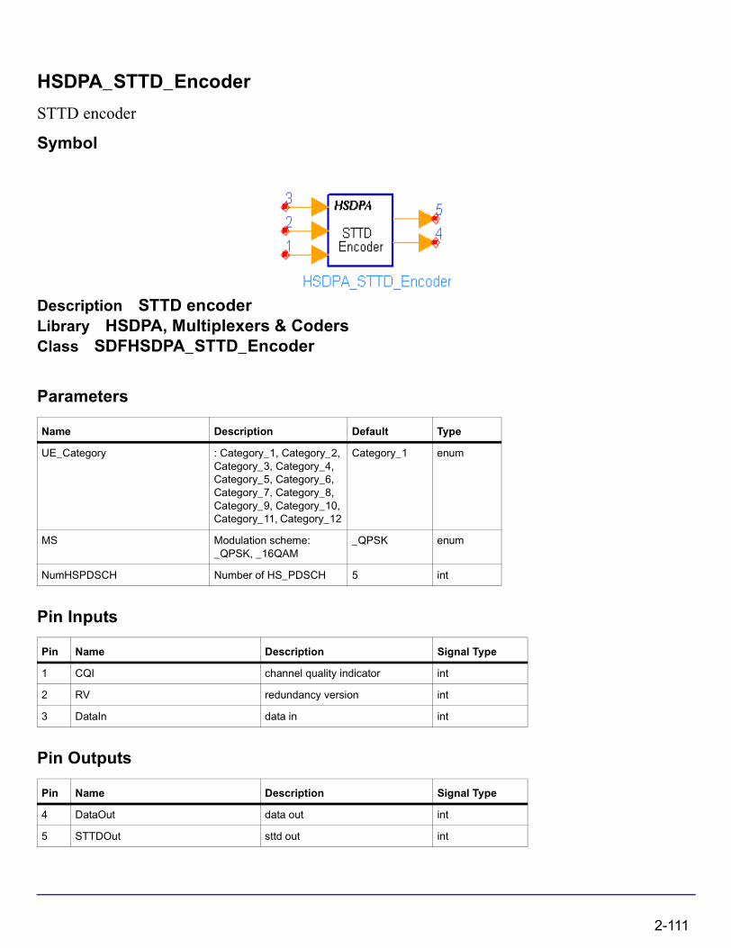
HSDPA_STTD_Encoder
STTD encoder
Symbol
Description STTD encoderLibrary HSDPA, Multiplexers & CodersClass SDFHSDPA_STTD_Encoder
Parameters
Pin Inputs
Pin Outputs
Name Description Default Type
UE_Category : Category_1, Category_2, Category_3, Category_4, Category_5, Category_6, Category_7, Category_8, Category_9, Category_10, Category_11, Category_12
Category_1 enum
MS Modulation scheme: _QPSK, _16QAM
_QPSK enum
NumHSPDSCH Number of HS_PDSCH 5 int
Pin Name Description Signal Type
1 CQI channel quality indicator int
2 RV redundancy version int
3 DataIn data in int
Pin Name Description Signal Type
4 DataOut data out int
5 STTDOut sttd out int
2-111

HSDPA Components
Notes/Equations
1. This model is used to implement constellation re-arrangement for 16QAM and STTD encoding.
Each firing, tokens are consumed at pin DataIn, 1 token is consumed at pin CQI if it is connected, and 1 token is consumed at pin RV, while
tokens are generated at pin DataOut, and tokens are generated at pin STTDOut.
is the possible maximum data bits and MaxNumHSPDSCH is the possible maximum HS-PDSCHs within one TTI. If pin CQI is connected, MaxNumHSPDSCH equals to maximum HS-PDSCHs UE_Category supports. Otherwise, MaxNumHSPDSCH equals to NumHSPDSCH.
2. If pin CQI is connected, modulation scheme and number of HS-PDSCHs practically used (EffectiveNumHSPDSCH) are determined by input CQI value and UE_Category according to Table 7 of 6A.2 in [3]. Otherwise, modulation scheme are determined by MS, and EffectiveNumHSPDSCH equals to NumHSPDSCH.
3. Although tokens are consumed at each firing, only the first EffectiveNumHSPDSCH HS-PDSCHs are occupied and 0s are padded for the other HS-PDSCHs. Each HS-PDSCHs contains 1920 bits. If modulation scheme is QPSK, only the first 960 bits are useful data bits, and the other 960 bits are 0s. If modulation scheme is 16QAM, all 1920 bits are useful data bits.
4. For QPSK, only STTD encoding is performed on the data bits from pin DataIn as shown in Figure 2-19.
Figure 2-19. Generic block diagram of STTD encoder for QPSK
5. For 16QAM, constellation re-arrangement is first performed on the data bits from pin DataIn according to Table 2-8. Then, STTD encoding is performed on the constellation re-arranged bits as shown in
1920 MaxNumHSPDSCH×
1920 MaxNumHSPDSCH×1920 MaxNumHSPDSCH×
1920 MaxNumHSPDSCH×
1920 MaxNumHSPDSCH×
b0 b 1 b 2 b 3
b0 b1 b2 b3
b2 b3 b0 b1
Antenna 1
Antenna 2Symbol
STTD encoded symbols for antenna 1 and antenna
2-112
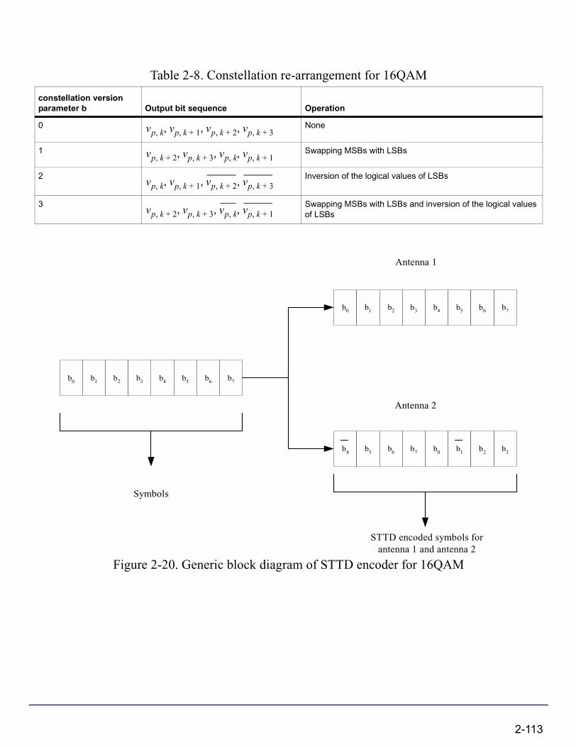
Figure 2-20. Generic block diagram of STTD encoder for 16QAM
Table 2-8. Constellation re-arrangement for 16QAM
constellation version parameter b Output bit sequence Operation
0 None
1 Swapping MSBs with LSBs
2 Inversion of the logical values of LSBs
3 Swapping MSBs with LSBs and inversion of the logical values of LSBs
vp k, vp k 1+, vp k 2+, vp k 3+,, , ,
vp k 2+, vp k 3+, vp k, vp k 1+,, , ,
vp k, vp k 1+, vp k 2+, vp k 3+,, , ,
vp k 2+, vp k 3+, vp k, vp k 1+,, , ,
b0 b1 b2 b4b3 b5 b7b6
b0 b1 b2 b4b3 b5 b7b6
b4 b5 b6 b0b7 b1 b3b2
Antenna 1
Antenna 2
Symbols
STTD encoded symbols forantenna 1 and antenna 2
2-113
HSDPA Components
References
[1] 3GPP Technical Specification TS 25.211, "Physical channels and mapping of transport channels onto physical channels (FDD)," Version 6.7.0, Dec. 2005.
[2] 3GPP Technical Specification TS 25.212, "Multiplexing and channel coding (FDD)," Version 6.7.0, Dec. 2005.
[3] 3GPP Technical Specification TS 25.214, "Physical layer procedures (FDD)," Version 6.7.1, Dec. 2005.
2-114
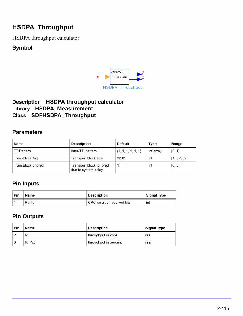
HSDPA_Throughput
HSDPA throughput calculator
Symbol
Description HSDPA throughput calculatorLibrary HSDPA, MeasurementClass SDFHSDPA_Throughput
Parameters
Pin Inputs
Pin Outputs
Name Description Default Type Range
TTIPattern inter-TTI pattern {1, 1, 1, 1, 1, 1} int array [0, 1]
TransBlockSize Transport block size 3202 int [1, 27952]
TransBlockIgnored Transport block Ignored due to system delay
1 int [0, 5]
Pin Name Description Signal Type
1 Parity CRC result of received bits int
Pin Name Description Signal Type
2 R throughput in kbps real
3 R_Pct throughput in percent real
2-115
HSDPA Components
Notes/Equations
1. This model is used to estimate throughput of HSDPA downlink.
2. The TransBlockSize parameter determines the transport block size of HS-DSCH. The largest transport block size is 27,952 bits, which corresponds to the highest data rate of 13.976 Mb/s (27,952 bits/2 ms = 13.976 Mb/s). This data rate is obtained by using 16 QAM, an effective code rate of 0.9714, and 15 HS-PDSCHs.
3. R_Pct is the number of valid TTIs with Parity=1 divided by the total number of Parity in valid TTIs. R is the throughput in kbps: R=R_Pct*TransBlockSize/2.
References
[1] 3GPP Technical Specification TS 25.212, "Multiplexing and channel coding (FDD)," Version 6.7.0, Dec. 2005.
2-116

Chapter 3: HSDPA Base Station Transmitter Design Examples
IntroductionThe HSDPA_BS_Tx_prj project shows base station transmitter measurement characteristics including maximum output power, occupied bandwidth, complementary cumulative distribution function (CCDF), spectrum emission, adjacent channel leakage power ratio (ACLR), EVM and peak code domain error and code domain power measurement. The downlink frequency band is set at 2110 to 2170 MHz and the signal sources are the test models defined in 25.141.
Designs for these measurements include:
• Maximum power measurements: BS_Tx_MaxPower.dsn
• Occupied bandwidth measurements: BS_Tx_OccupiedBW.dsn
• Complementary cumulative distribution function measurements: BS_Tx_CCDF.dsn
• Transmitter spectrum emissions measurements: BS_Tx_Spec_Emission.dsn
• Adjacent channel leakage power measurements in frequency domain: BS_Tx_ACLR.dsn
• Transmitter EVM measurements: BS_Tx_EVM.dsn
• Transmitter peak code domain error measurements: BS_Tx_Pk_Code_Error.dsn
• Connect with VSA 89600 software and show the results of VSA 89600 software: BS_Tx_VSA.dsn
Variables used in these designs are listed in Table 3-1.
Table 3-1. VAR Parameters
Parameter Name Description Default Value
SamplePerChip Samples per chip 8
ChipsPerSlot Chips per slot 2560
NumSlotMeasured Number of slots to be measured Depends on measurements
StartSlot The first slot to be measured 0
TimeStart Start point for timed measurement (1+StartSlot)*667e-6
TimeStep Time step 1/(3840000*SamplesPerChip)
TimeStop Stop point for timed measurement (1+StartSlot+NumSlotMeasured)*667e-6
FilterLength Filter length in terms of samples 16
Introduction 3-1

HSDPA Base Station Transmitter Design Examples
Maximum Power MeasurementsBS_Tx_MaxPower.dsn design
Features
• maximum power measurement
• HSDPA signal or test model 1 can be used as the signal sourceHSDPA signal or test model 1 can be used as the signal source
• synchronized slot measurement
Description
BS_Tx_MaxPower.dsn measures the maximum power of downlink signal. Normally, the base station maximum output power must remain within +2dB and -2dB of the manufacturer’s rated power.
The schematic for this design is shown in Figure 3-1.
Figure 3-1. BS_Tx_MaxPower.dsn Schematic
HSDPA_DL_SourceRF can output 3GPP TestModel1 signal. This signal consists of 16/32/64 DPCH channels, one PICH channel, one primary CPICH channel and one PCCPCH+SCH channel. The PICH channel and DPCH channels are transmitted after different time offsets. When OutputMode = Ramp, the output power will reach its preset value after all channels are transmitted. Meaningful maximum power is reached after 15 slots.
RF_Freq RF frequency 2140 (MHz)
SignalPower Signal power Depends on measurement
Table 3-1. VAR Parameters
Parameter Name Description Default Value
3-2 Maximum Power Measurements
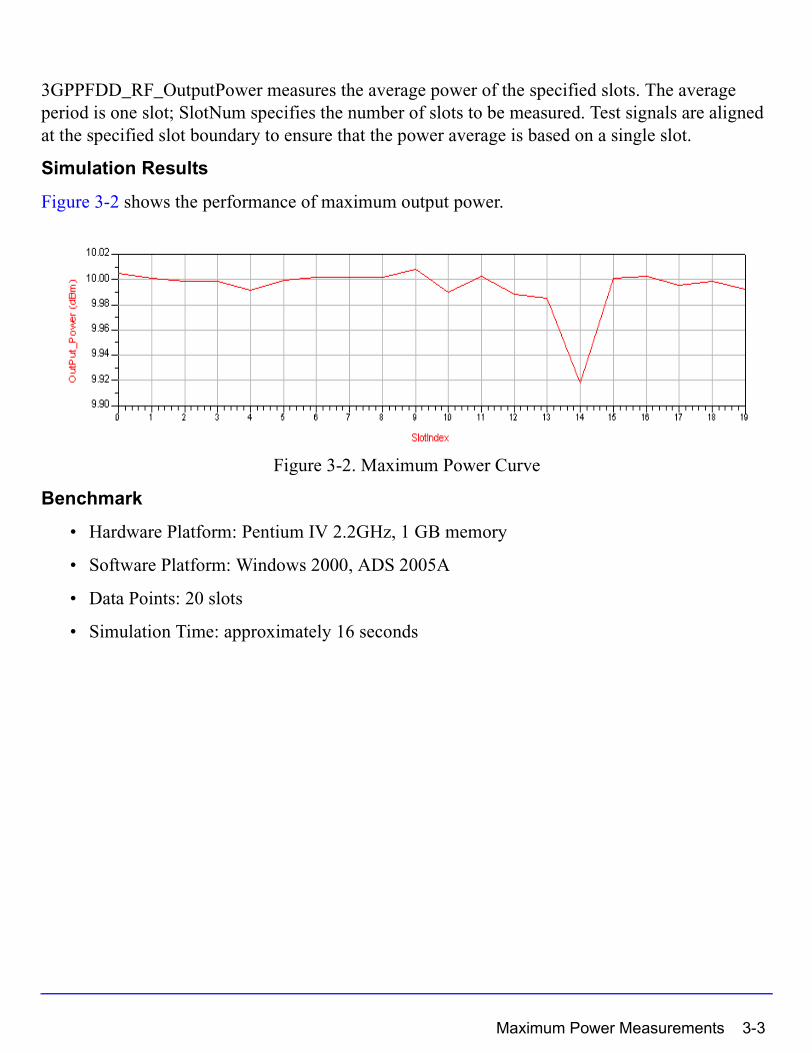
3GPPFDD_RF_OutputPower measures the average power of the specified slots. The average period is one slot; SlotNum specifies the number of slots to be measured. Test signals are aligned at the specified slot boundary to ensure that the power average is based on a single slot.
Simulation Results
Figure 3-2 shows the performance of maximum output power.
Figure 3-2. Maximum Power Curve
Benchmark
• Hardware Platform: Pentium IV 2.2GHz, 1 GB memory
• Software Platform: Windows 2000, ADS 2005A
• Data Points: 20 slots
• Simulation Time: approximately 16 seconds
Maximum Power Measurements 3-3
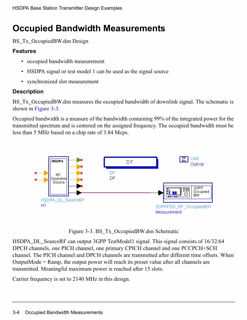
HSDPA Base Station Transmitter Design Examples
Occupied Bandwidth MeasurementsBS_Tx_OccupiedBW.dsn Design
Features
• occupied bandwidth measurement
• HSDPA signal or test model 1 can be used as the signal source
• synchronized slot measurement
Description
BS_Tx_OccupiedBW.dsn measures the occupied bandwidth of downlink signal. The schematic is shown in Figure 3-3.
Occupied bandwidth is a measure of the bandwidth containing 99% of the integrated power for the transmitted spectrum and is centered on the assigned frequency. The occupied bandwidth must be less than 5 MHz based on a chip rate of 3.84 Mcps.
Figure 3-3. BS_Tx_OccupiedBW.dsn Schematic
HSDPA_DL_SourceRF can output 3GPP TestModel1 signal. This signal consists of 16/32/64 DPCH channels, one PICH channel, one primary CPICH channel and one PCCPCH+SCH channel. The PICH channel and DPCH channels are transmitted after different time offsets. When OutputMode = Ramp, the output power will reach its preset value after all channels are transmitted. Meaningful maximum power is reached after 15 slots.
Carrier frequency is set to 2140 MHz in this design.
3-4 Occupied Bandwidth Measurements
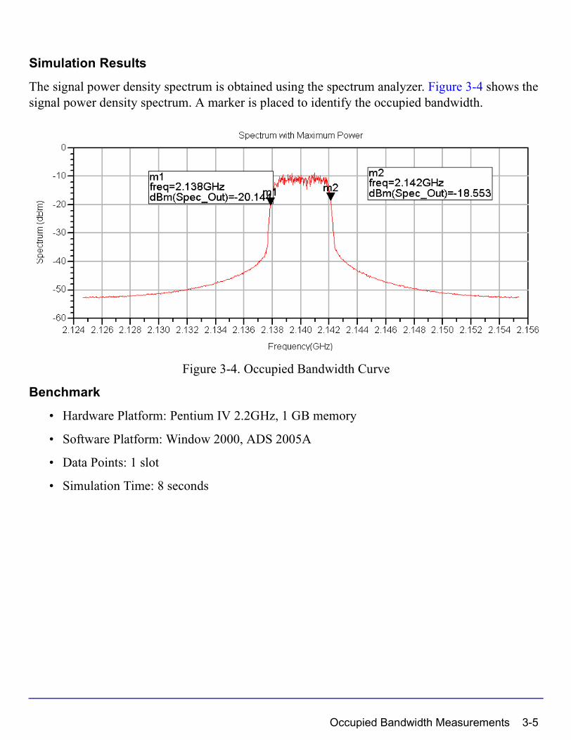
Simulation Results
The signal power density spectrum is obtained using the spectrum analyzer. Figure 3-4 shows the signal power density spectrum. A marker is placed to identify the occupied bandwidth.
Figure 3-4. Occupied Bandwidth Curve
Benchmark
• Hardware Platform: Pentium IV 2.2GHz, 1 GB memory
• Software Platform: Window 2000, ADS 2005A
• Data Points: 1 slot
• Simulation Time: 8 seconds
Occupied Bandwidth Measurements 3-5
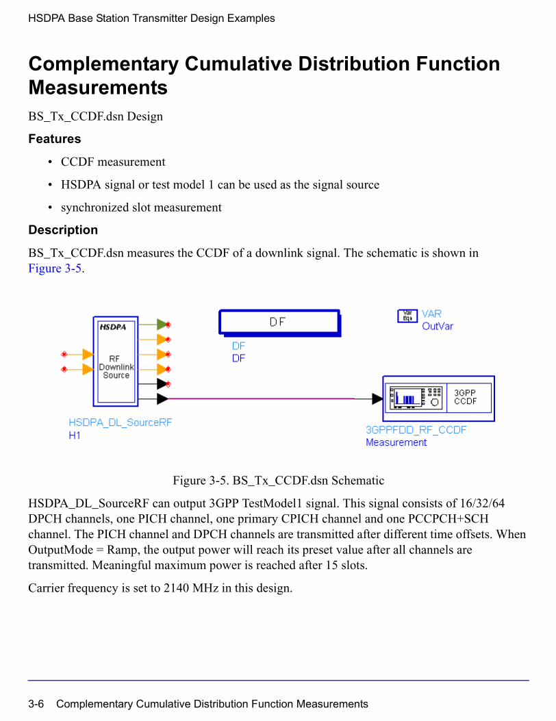
HSDPA Base Station Transmitter Design Examples
Complementary Cumulative Distribution Function MeasurementsBS_Tx_CCDF.dsn Design
Features
• CCDF measurement
• HSDPA signal or test model 1 can be used as the signal source
• synchronized slot measurement
Description
BS_Tx_CCDF.dsn measures the CCDF of a downlink signal. The schematic is shown in Figure 3-5.
Figure 3-5. BS_Tx_CCDF.dsn Schematic
HSDPA_DL_SourceRF can output 3GPP TestModel1 signal. This signal consists of 16/32/64 DPCH channels, one PICH channel, one primary CPICH channel and one PCCPCH+SCH channel. The PICH channel and DPCH channels are transmitted after different time offsets. When OutputMode = Ramp, the output power will reach its preset value after all channels are transmitted. Meaningful maximum power is reached after 15 slots.
Carrier frequency is set to 2140 MHz in this design.
3-6 Complementary Cumulative Distribution Function Measurements
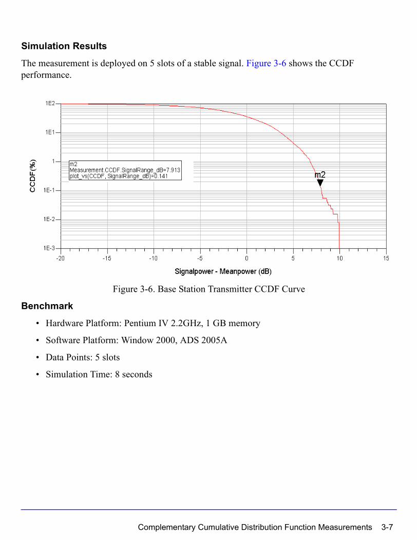
Simulation Results
The measurement is deployed on 5 slots of a stable signal. Figure 3-6 shows the CCDF performance.
Figure 3-6. Base Station Transmitter CCDF Curve
Benchmark
• Hardware Platform: Pentium IV 2.2GHz, 1 GB memory
• Software Platform: Window 2000, ADS 2005A
• Data Points: 5 slots
• Simulation Time: 8 seconds
Complementary Cumulative Distribution Function Measurements 3-7

HSDPA Base Station Transmitter Design Examples
Transmitter Spectrum Emissions MeasurementsBS_Tx_Spec_Emission.dsn Design
Feature
• HSDPA signal or test model 1 can be used as the signal source
• Out-of-band power is measured by sweeping the center frequency of the band-pass filter
Description
BS_Tx_Spec_Emission.dsn measures the base station transmitter spectrum emission. Out-of-band emissions are unwanted emissions immediately outside the channel bandwidth resulting from the modulation process and non-linearity in the transmitter. Figure 3-7 shows the schematic for this design.
Figure 3-7. BS_Tx_Spec_Emission.dsn Schematic
Notes
Emissions must not exceed the maximum level specified by the mask in the frequency range with offset from ∆fmin -12.5 MHz to ∆fmax 12.5 MHz from the carrier frequency. Mask values are specified in Table 3-2. A sweeper is used to simulate all frequency offsets.
3-8 Transmitter Spectrum Emissions Measurements
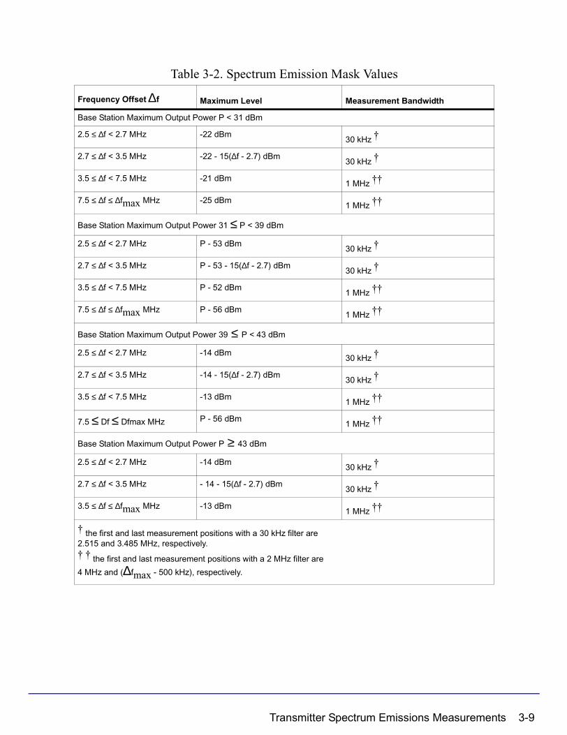
Table 3-2. Spectrum Emission Mask Values
Frequency Offset ∆f Maximum Level Measurement Bandwidth
Base Station Maximum Output Power P < 31 dBm
2.5 ≤ ∆f < 2.7 MHz -22 dBm30 kHz †
2.7 ≤ ∆f < 3.5 MHz -22 - 15(∆f - 2.7) dBm30 kHz †
3.5 ≤ ∆f < 7.5 MHz -21 dBm1 MHz ††
7.5 ≤ ∆f ≤ ∆fmax MHz -25 dBm1 MHz ††
Base Station Maximum Output Power 31 ≤ P < 39 dBm
2.5 ≤ ∆f < 2.7 MHz P - 53 dBm30 kHz †
2.7 ≤ ∆f < 3.5 MHz P - 53 - 15(∆f - 2.7) dBm30 kHz †
3.5 ≤ ∆f < 7.5 MHz P - 52 dBm1 MHz ††
7.5 ≤ ∆f ≤ ∆fmax MHz P - 56 dBm1 MHz ††
Base Station Maximum Output Power 39 ≤ P < 43 dBm
2.5 ≤ ∆f < 2.7 MHz -14 dBm30 kHz †
2.7 ≤ ∆f < 3.5 MHz -14 - 15(∆f - 2.7) dBm30 kHz †
3.5 ≤ ∆f < 7.5 MHz -13 dBm1 MHz ††
7.5 ≤ Df ≤ Dfmax MHz P - 56 dBm1 MHz ††
Base Station Maximum Output Power P ≥ 43 dBm
2.5 ≤ ∆f < 2.7 MHz -14 dBm30 kHz †
2.7 ≤ ∆f < 3.5 MHz - 14 - 15(∆f - 2.7) dBm30 kHz †
3.5 ≤ ∆f ≤ ∆fmax MHz -13 dBm1 MHz ††
† the first and last measurement positions with a 30 kHz filter are 2.515 and 3.485 MHz, respectively.† † the first and last measurement positions with a 2 MHz filter are
4 MHz and (∆fmax - 500 kHz), respectively.
Transmitter Spectrum Emissions Measurements 3-9

HSDPA Base Station Transmitter Design Examples
Simulation Results
The spectrum emission is stored in the sink after 15 slots. Figure 3-8 shows the spectrum emission for the base station output powers listed in Table 3-2.
Figure 3-8. Spectrum Emission Curves
Benchmark
• Hardware Platform: Pentium IV 2.2GHz, 1 GB memory
• Software Platform: Windows 2000, ADS 2005A
• Data Points: 1slot sweeping frequency offset from -12.5 MHz to 12.5 MHz
• Simulation Time: approximately 2 hours
3-10 Transmitter Spectrum Emissions Measurements
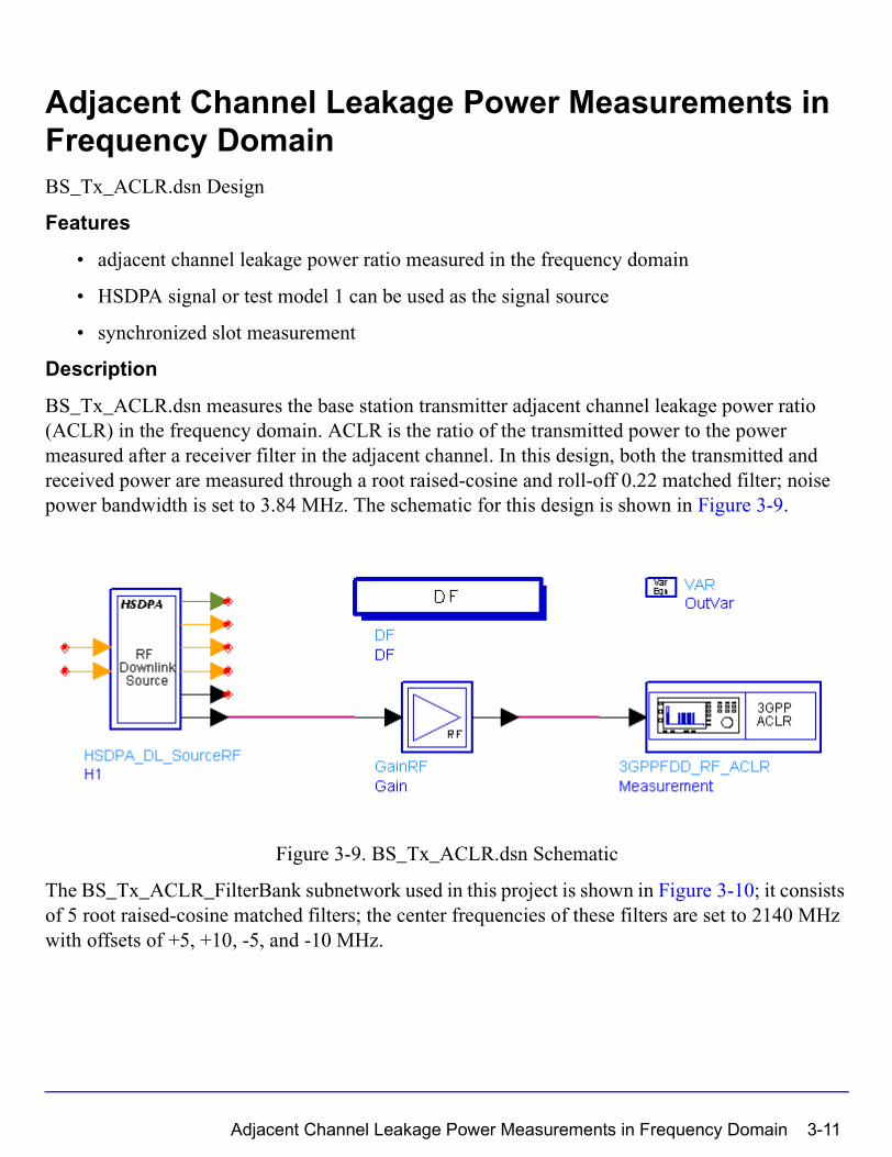
Adjacent Channel Leakage Power Measurements in Frequency DomainBS_Tx_ACLR.dsn Design
Features
• adjacent channel leakage power ratio measured in the frequency domain
• HSDPA signal or test model 1 can be used as the signal source
• synchronized slot measurement
Description
BS_Tx_ACLR.dsn measures the base station transmitter adjacent channel leakage power ratio (ACLR) in the frequency domain. ACLR is the ratio of the transmitted power to the power measured after a receiver filter in the adjacent channel. In this design, both the transmitted and received power are measured through a root raised-cosine and roll-off 0.22 matched filter; noise power bandwidth is set to 3.84 MHz. The schematic for this design is shown in Figure 3-9.
Figure 3-9. BS_Tx_ACLR.dsn Schematic
The BS_Tx_ACLR_FilterBank subnetwork used in this project is shown in Figure 3-10; it consists of 5 root raised-cosine matched filters; the center frequencies of these filters are set to 2140 MHz with offsets of +5, +10, -5, and -10 MHz.
Adjacent Channel Leakage Power Measurements in Frequency Domain 3-11
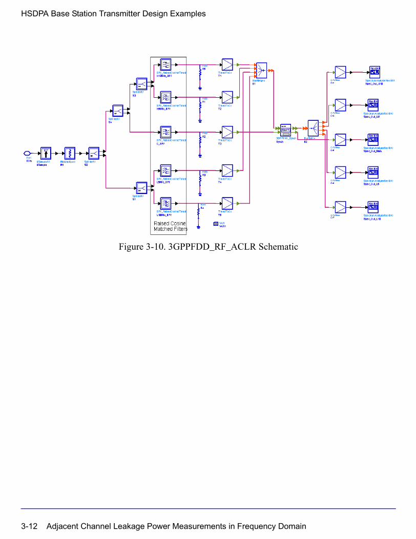
HSDPA Base Station Transmitter Design Examples
Figure 3-10. 3GPPFDD_RF_ACLR Schematic
3-12 Adjacent Channel Leakage Power Measurements in Frequency Domain

Simulation Results
The Spectrum analyzer is used to measure the transmitted power and adjacent channel power in the frequency domain. When the base station adjacent channel offset is +5 or -5 MHz, the ACLR limit is 45 dB; when the base station adjacent channel offset is +10 or -10 MHz, the ACLR limit is 50 dB. The measurement is deployed after the first frame (15 slots) and the signal becomes stable. Figure 3-11 shows the ACLR performance of the base station transmitter.
Figure 3-11. Base Station Transmitter Spectrum and ACLR Performance
Benchmark
• Hardware Platform: Pentium IV 2.2GHz, 1 GB memory
• Software Platform: Window 2000, ADS 2005A
• Data Points: 1 slot
• Simulation Time: approximately 26 seconds
Adjacent Channel Leakage Power Measurements in Frequency Domain 3-13
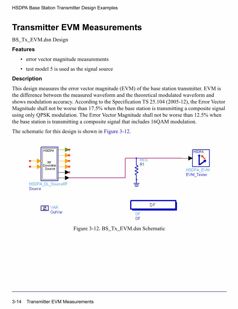
HSDPA Base Station Transmitter Design Examples
Transmitter EVM MeasurementsBS_Tx_EVM.dsn Design
Features
• error vector magnitude measurements
• test model 5 is used as the signal source
Description
This design measures the error vector magnitude (EVM) of the base station transmitter. EVM is the difference between the measured waveform and the theoretical modulated waveform and shows modulation accuracy. According to the Specification TS 25.104 (2005-12), the Error Vector Magnitude shall not be worse than 17.5% when the base station is transmitting a composite signal using only QPSK modulation. The Error Vector Magnitude shall not be worse than 12.5% when the base station is transmitting a composite signal that includes 16QAM modulation.
The schematic for this design is shown in Figure 3-12.
Figure 3-12. BS_Tx_EVM.dsn Schematic
3-14 Transmitter EVM Measurements
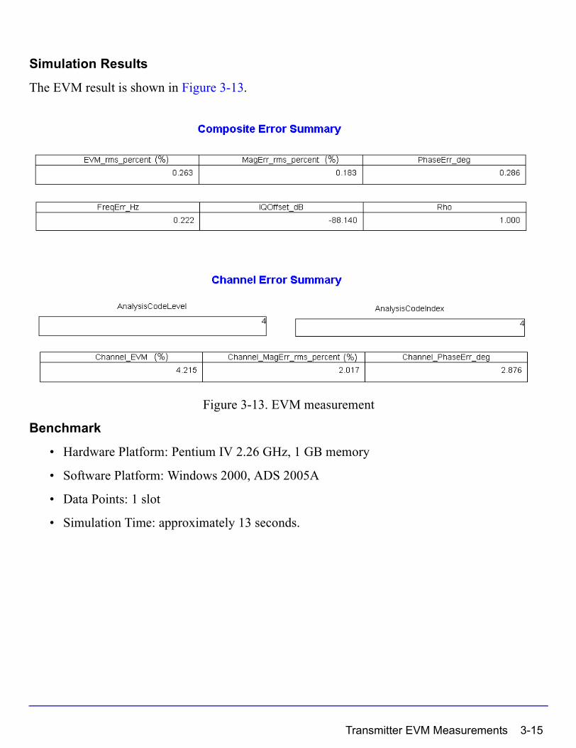
Simulation Results
The EVM result is shown in Figure 3-13.
Figure 3-13. EVM measurement
Benchmark
• Hardware Platform: Pentium IV 2.26 GHz, 1 GB memory
• Software Platform: Windows 2000, ADS 2005A
• Data Points: 1 slot
• Simulation Time: approximately 13 seconds.
Transmitter EVM Measurements 3-15
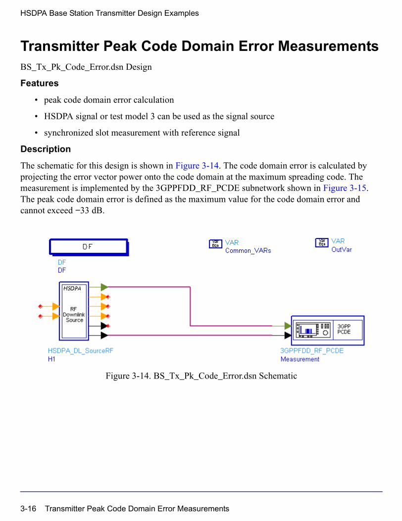
HSDPA Base Station Transmitter Design Examples
Transmitter Peak Code Domain Error MeasurementsBS_Tx_Pk_Code_Error.dsn Design
Features
• peak code domain error calculation
• HSDPA signal or test model 3 can be used as the signal source
• synchronized slot measurement with reference signal
Description
The schematic for this design is shown in Figure 3-14. The code domain error is calculated by projecting the error vector power onto the code domain at the maximum spreading code. The measurement is implemented by the 3GPPFDD_RF_PCDE subnetwork shown in Figure 3-15. The peak code domain error is defined as the maximum value for the code domain error and cannot exceed −33 dB.
Figure 3-14. BS_Tx_Pk_Code_Error.dsn Schematic
3-16 Transmitter Peak Code Domain Error Measurements
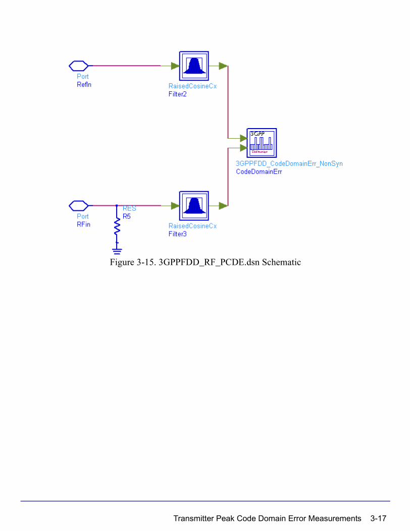
Figure 3-15. 3GPPFDD_RF_PCDE.dsn Schematic
Transmitter Peak Code Domain Error Measurements 3-17
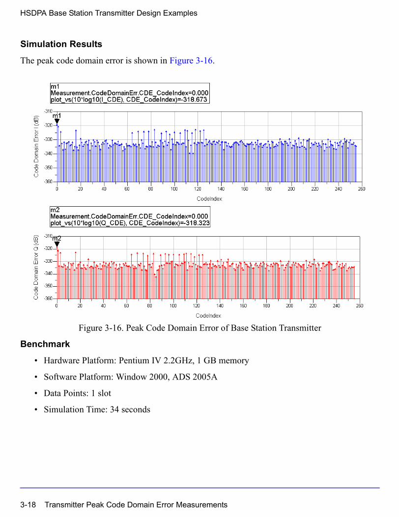
HSDPA Base Station Transmitter Design Examples
Simulation Results
The peak code domain error is shown in Figure 3-16.
Figure 3-16. Peak Code Domain Error of Base Station Transmitter
Benchmark
• Hardware Platform: Pentium IV 2.2GHz, 1 GB memory
• Software Platform: Window 2000, ADS 2005A
• Data Points: 1 slot
• Simulation Time: 34 seconds
3-18 Transmitter Peak Code Domain Error Measurements
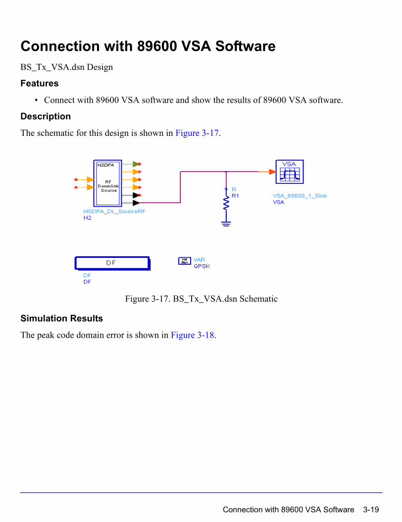
Connection with 89600 VSA SoftwareBS_Tx_VSA.dsn Design
Features
• Connect with 89600 VSA software and show the results of 89600 VSA software.
Description
The schematic for this design is shown in Figure 3-17.
Figure 3-17. BS_Tx_VSA.dsn Schematic
Simulation Results
The peak code domain error is shown in Figure 3-18.
Connection with 89600 VSA Software 3-19

HSDPA Base Station Transmitter Design Examples
Figure 3-18. 89600 VSA software results
Benchmark
• Hardware Platform: Pentium IV 2.26GHz, 1 GB memory
• Software Platform: Window 2000, ADS 2005A, 89600 VSA
References
[1] 3GPP Technical Specification TS 34.121 V6.3.0 “Terminal conformance Specification: Radio transmission and reception (FDD),” December 2005.
[2] 3GPP Technical Specification TS 25.104 V6.11.0, “Base Station (BS) radio transmission and reception (FDD),” December 2005.
[3] 3GPP Technical Specification TS 25.141 V6.12.0, “Base station (BS) conformance testing (FDD),” December 2005.
3-20 Connection with 89600 VSA Software

Chapter 4: HSDPA User Equipment Receiver Design Examples
IntroductionThe HSDPA_UE_Rx_prj project shows user equipment receiver measurement performances, including HS-DSCH demodulation performance, HS-SCCH signaling detection performance.
Designs for these measurements are described in the following sections; including:
• Demodulation performance:
UE_Rx_Demodulation_Hset1_PA3_QPSK.dsn
UE_Rx_Demodulation_Hset2_PB3_16QAM.dsn
UE_Rx_Demodulation_Hset3_VA30_16QAM.dsn
UE_Rx_Demodulation_Hset4_PB3_QPSK.dsn
UE_Rx_Demodulation_Hset5_VA120_QPSK.dsn
UE_Rx_Demodulation_Hset6_PA3_16QAM.dsn
UE_Rx_MaxLevel.dsn
• Signaling detection performance - false alarm:
UE_Rx_HSSCCH_Detection_TS1_PA3.dsn
Designs under this project consist of:
• Downlink RF band signal source
HSDPA_DL_SourceRF is used to provide an RF HSDPA downlink signal source.
• Fading channel
HSPA_Channel is used to provide various multi-path fading propagation conditions.
• AWGN noise
AddNDensity is used to provide AWGN in order to calibrate the system Ec/N0 at certain levels, which are required by various performance measurements.
• User Equipment RF receiver
HSDPA_DL_ReceiverRF is used to provide a receiver of RF HSDPA downlink signals.
Introduction 4-1
HSDPA User Equipment Receiver Design Examples
References
[1] 3GPP Technical Specification TS 25.101, "UE Radio transmission and Reception (FDD)," Version 6.10.0, Dec. 2005.
HS-DSCH Demodulation Performance MeasurementUE_Rx_Demodulation_Hset1_PA3_QPSK.dsn
UE_Rx_Demodulation_Hset2_PB3_16QAM.dsn
UE_Rx_Demodulation_Hset3_VA30_16QAM.dsn
UE_Rx_Demodulation_Hset4_PB3_QPSK.dsn
UE_Rx_Demodulation_Hset5_VA120_QPSK.dsn
UE_Rx_Demodulation_Hset6_PA3_16QAM.dsn
Features
• Base station receiver demodulation performance measurements
• ARQ (feedback) controlled source
• Integrated RF models
• Throughput (R)
• Multiple Ec/N0 measurement points
• Multi-path fading propagation conditions
Description
UE_Rx_Demodulation_Hset1_PA3_QPSK.dsn measures user equipment receiver HS-DSCH demodulation performance under H-Set1 FRC (Fixed Reference Channel) and PA3 channel with QPSK modulation. UE_Rx_Demodulation_Hset2_PB3_16QAM.dsn measures user equipment receiver HS-DSCH demodulation performance under H-Set2 FRC and PB3 channel with 16QAM modulation. UE_Rx_Demodulation_Hset3_VA30_16QAM.dsn measures user equipment receiver HS-DSCH demodulation performance under H-Set3 FRC and VA30 channel with 16QAM modulation. UE_Rx_Demodulation_Hset4_PB3_QPSK.dsn measures user equipment receiver HS-DSCH demodulation performance under H-Set4 FRC and VA30 channel with QPSK modulation. UE_Rx_Demodulation_Hset5_VA120_QPSK.dsn measures user equipment receiver HS-DSCH demodulation performance under H-Set5 FRC and VA120 channel with 16QAM modulation. UE_Rx_Demodulation_Hset6_PA3_16QAM.dsn measures user equipment receiver
4-2 HS-DSCH Demodulation Performance Measurement
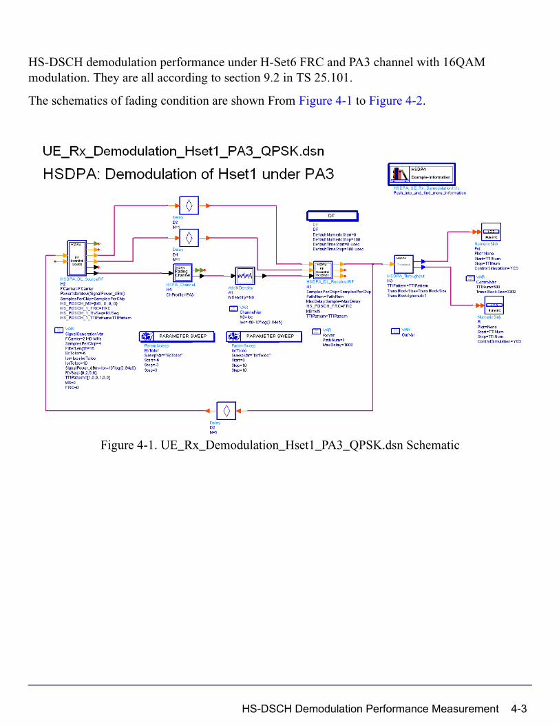
HS-DSCH demodulation performance under H-Set6 FRC and PA3 channel with 16QAM modulation. They are all according to section 9.2 in TS 25.101.
The schematics of fading condition are shown From Figure 4-1 to Figure 4-2.
Figure 4-1. UE_Rx_Demodulation_Hset1_PA3_QPSK.dsn Schematic
HS-DSCH Demodulation Performance Measurement 4-3

HSDPA User Equipment Receiver Design Examples
Figure 4-2. UE_Rx_Demodulation_Hset2_PB3_16QAM.dsn Schematic
4-4 HS-DSCH Demodulation Performance Measurement

Figure 4-3. UE_Rx_Demodulation_Hset3_VA30_16QAM.dsn Schematic
HS-DSCH Demodulation Performance Measurement 4-5
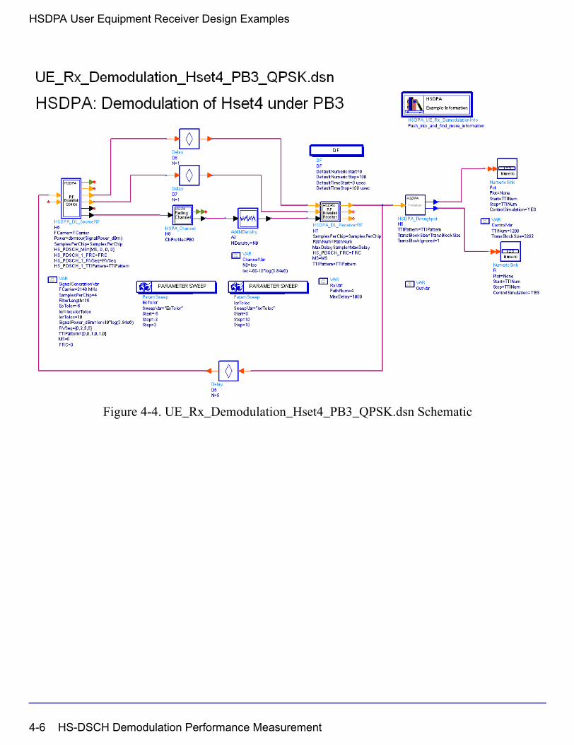
HSDPA User Equipment Receiver Design Examples
Figure 4-4. UE_Rx_Demodulation_Hset4_PB3_QPSK.dsn Schematic
4-6 HS-DSCH Demodulation Performance Measurement
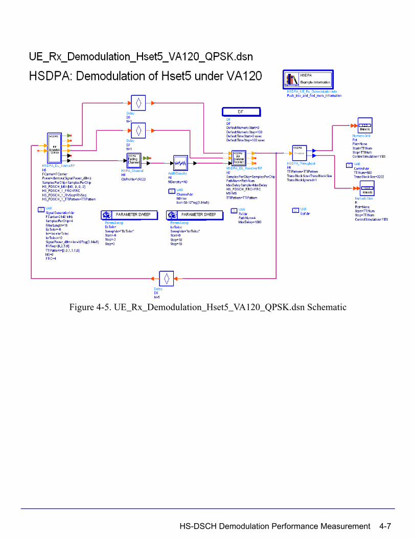
Figure 4-5. UE_Rx_Demodulation_Hset5_VA120_QPSK.dsn Schematic
HS-DSCH Demodulation Performance Measurement 4-7
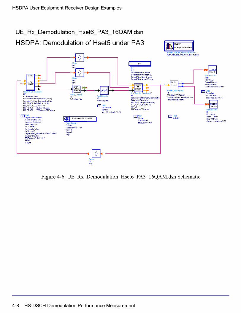
HSDPA User Equipment Receiver Design Examples
Figure 4-6. UE_Rx_Demodulation_Hset6_PA3_16QAM.dsn Schematic
4-8 HS-DSCH Demodulation Performance Measurement

Simulation Results
Simulation results are shown in Figure 4-7 to Figure 4-12.
Figure 4-7. Throughput Results (R) for User Equipment Demodulation Performance Measurement (Fading) Hset1 under PA3 channel with QPSK modulation
HS-DSCH Demodulation Performance Measurement 4-9
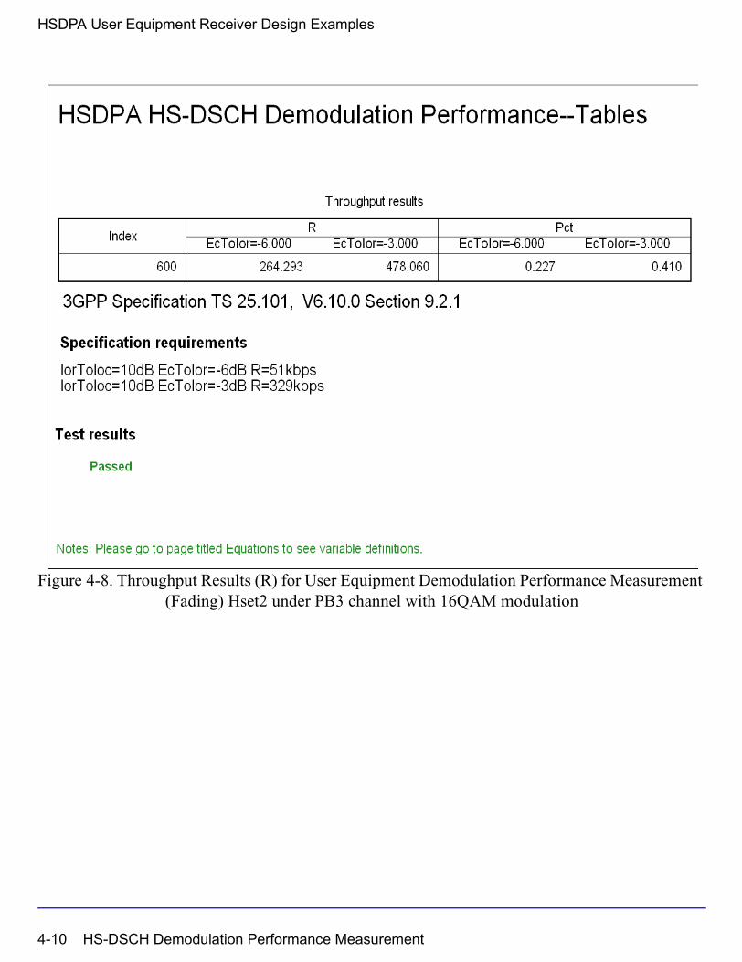
HSDPA User Equipment Receiver Design Examples
Figure 4-8. Throughput Results (R) for User Equipment Demodulation Performance Measurement (Fading) Hset2 under PB3 channel with 16QAM modulation
4-10 HS-DSCH Demodulation Performance Measurement

Figure 4-9. Throughput Results (R) for User Equipment Demodulation Performance Measurement (Fading) Hset3 under VA30 channel with 16QAM modulation
HS-DSCH Demodulation Performance Measurement 4-11
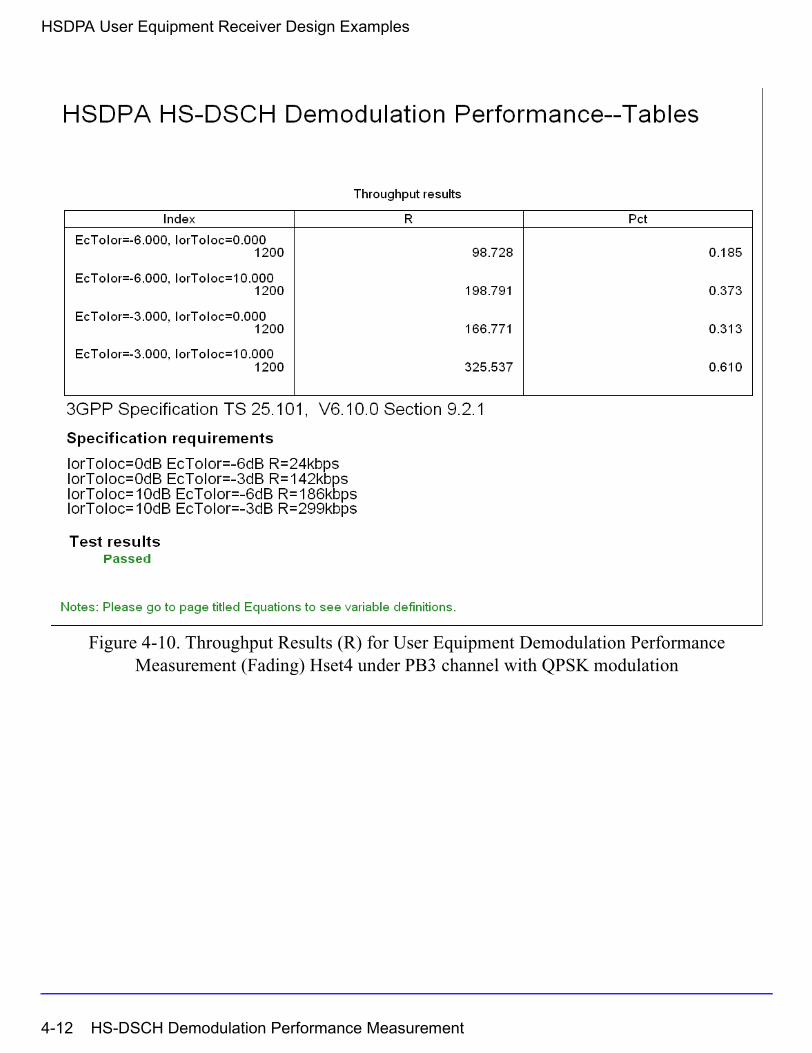
HSDPA User Equipment Receiver Design Examples
Figure 4-10. Throughput Results (R) for User Equipment Demodulation Performance Measurement (Fading) Hset4 under PB3 channel with QPSK modulation
4-12 HS-DSCH Demodulation Performance Measurement

Figure 4-11. Throughput Results (R) for User Equipment Demodulation Performance Measurement (Fading) Hset5 under VA120 channel with QPSK modulation
HS-DSCH Demodulation Performance Measurement 4-13
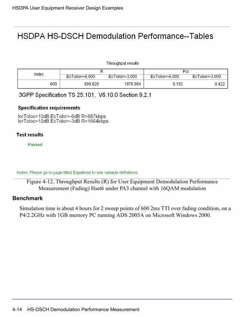
HSDPA User Equipment Receiver Design Examples
Figure 4-12. Throughput Results (R) for User Equipment Demodulation Performance Measurement (Fading) Hset6 under PA3 channel with 16QAM modulation
Benchmark
Simulation time is about 4 hours for 2 sweep points of 600 2ms TTI over fading condition, on a P4/2.2GHz with 1GB memory PC running ADS 2005A on Microsoft Windows 2000.
4-14 HS-DSCH Demodulation Performance Measurement
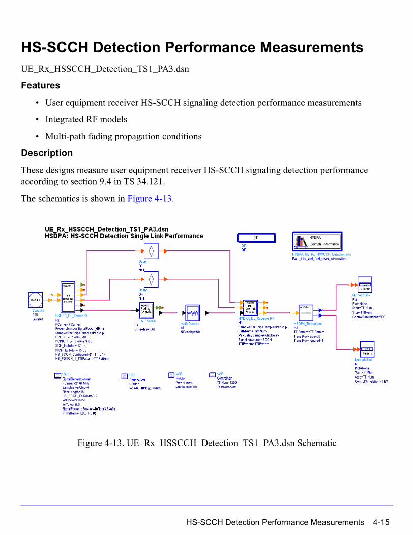
HS-SCCH Detection Performance MeasurementsUE_Rx_HSSCCH_Detection_TS1_PA3.dsn
Features
• User equipment receiver HS-SCCH signaling detection performance measurements
• Integrated RF models
• Multi-path fading propagation conditions
Description
These designs measure user equipment receiver HS-SCCH signaling detection performance according to section 9.4 in TS 34.121.
The schematics is shown in Figure 4-13.
Figure 4-13. UE_Rx_HSSCCH_Detection_TS1_PA3.dsn Schematic
HS-SCCH Detection Performance Measurements 4-15
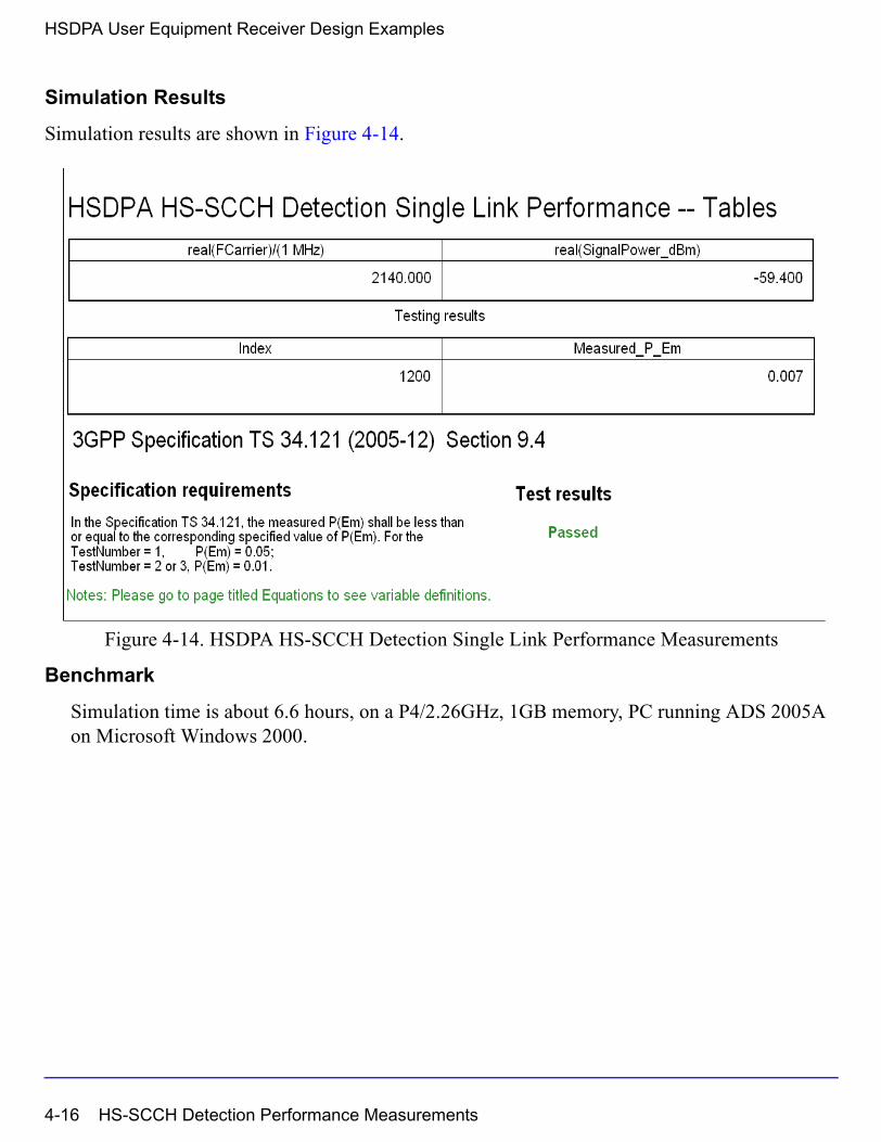
HSDPA User Equipment Receiver Design Examples
Simulation Results
Simulation results are shown in Figure 4-14.
Figure 4-14. HSDPA HS-SCCH Detection Single Link Performance Measurements
Benchmark
Simulation time is about 6.6 hours, on a P4/2.26GHz, 1GB memory, PC running ADS 2005A on Microsoft Windows 2000.
4-16 HS-SCCH Detection Performance Measurements
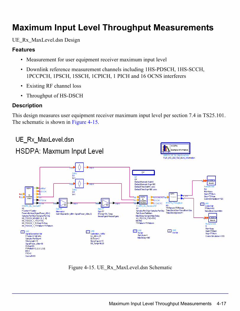
Maximum Input Level Throughput MeasurementsUE_Rx_MaxLevel.dsn Design
Features
• Measurement for user equipment receiver maximum input level
• Downlink reference measurement channels including 1HS-PDSCH, 1HS-SCCH, 1PCCPCH, 1PSCH, 1SSCH, 1CPICH, 1 PICH and 16 OCNS interferers
• Existing RF channel loss
• Throughput of HS-DSCH
Description
This design measures user equipment receiver maximum input level per section 7.4 in TS25.101. The schematic is shown in Figure 4-15.
Figure 4-15. UE_Rx_MaxLevel.dsn Schematic
Maximum Input Level Throughput Measurements 4-17
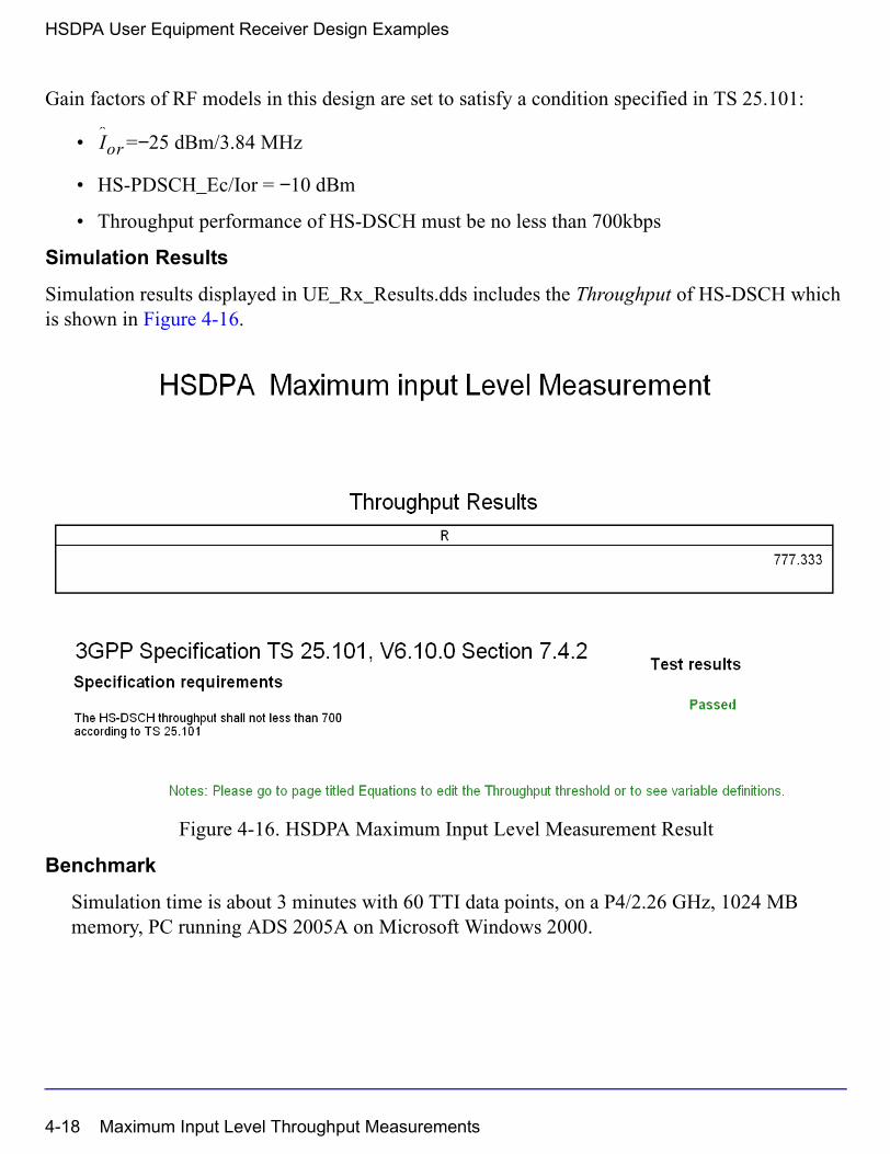
HSDPA User Equipment Receiver Design Examples
Gain factors of RF models in this design are set to satisfy a condition specified in TS 25.101:
• =−25 dBm/3.84 MHz
• HS-PDSCH_Ec/Ior = −10 dBm
• Throughput performance of HS-DSCH must be no less than 700kbps
Simulation Results
Simulation results displayed in UE_Rx_Results.dds includes the Throughput of HS-DSCH which is shown in Figure 4-16.
Figure 4-16. HSDPA Maximum Input Level Measurement Result
Benchmark
Simulation time is about 3 minutes with 60 TTI data points, on a P4/2.26 GHz, 1024 MB memory, PC running ADS 2005A on Microsoft Windows 2000.
Ior
4-18 Maximum Input Level Throughput Measurements
Index
Aadjacent channel leakage powermeasurement, 3-11
Ccomplementary cumulative distribution
function measurement, 3-6connection with 89600 VSA software, 3-19
HHSDPA_Bits, 2-2HSDPA_BitScrambling, 2-5HSDPA_ChBlkDeseg, 2-13HSDPA_ChDecoder, 2-7HSDPA_ChEncoder, 2-9HSDPA_ChEstimate, 2-11HSDPA_CRCDecoder, 2-15HSDPA_CRCEncoder, 2-17HSDPA_Deinterleaver, 2-19HSDPA_Despread, 2-21HSDPA_DL_Rake, 2-23HSDPA_DL_Receiver, 2-25HSDPA_DL_ReceiverRF, 2-28HSDPA_DL_Source, 2-32HSDPA_DL_SourceRF, 2-38HSDPA_DownSample, 2-45HSDPA_EVM, 2-47HSDPA_Interleaver, 2-52HSDPA_OCNS_Gain, 2-54HSDPA_PathSearch, 2-56HSDPA_PDSCH_1_4, 2-58HSDPA_PDSCH_Decoder, 2-62HSDPA_PDSCH_WithFEC, 2-65HSDPA_PDSCH_WithoutFEC, 2-69HSDPA_PhCH_Demap, 2-71HSDPA_PhCH_Mapper, 2-74HSDPA_PowerAdjust, 2-77HSDPA_RakeCombine, 2-79HSDPA_RateDematch, 2-81HSDPA_RateMatch, 2-83HSDPA_SCCH, 2-85HSDPA_SCCH_1_4, 2-91HSDPA_SCCH_Decoder, 2-97HSDPA_SCCH_DeRM, 2-99HSDPA_SCCH_ParaCalc, 2-100
HSDPA_SCCH_RM, 2-104HSDPA_SCH, 2-105HSDPA_Spread, 2-107HSDPA_STTD_Decoder, 2-109HSDPA_STTD_Encoder, 2-111HSDPA_Throughput, 2-115HS-DSCH demodulation performance
measurement, 4-2HS-SCCH detection performance
measurement, 4-15
Mmaximum input level performance
measurement, 4-17maximum power measurements, 3-2
Ooccupied bandwidth measurement, 3-4
Pperformance measurement
HS-DSCH demodulation, 4-2HS-SCCH detection, 4-15maximum input level, 4-17
Ttransmitter EVM measurement, 3-14transmitter peak code domain error
measurement, 3-16transmitter spectrum emissions
measurement, 3-8
Index-1

Index-2
Related Documents