HS 252 - STANDARD ASSEMBLY TORQUES Page 1 of 38 Revision Level - 69 - PUBLISHED Security Level - PUBLIC Standard No. HS 252 © 2021 Husky Injection Molding Systems Ltd. NO INTELLECTUAL PROPERTY RIGHTS ARE GRANTED INCLUDING ANY LICENSE, IMPLIED OR OTHERWISE. ALL RIGHTS RESERVED. Printed copies are uncontrolled. HS 252 - STANDARD ASSEMBLY TORQUES TABLE OF CONTENTS 1 SCOPE .....................................................................................................................................8 2 PURPOSE ................................................................................................................................8 3 DOCUMENT CONTROL .......................................................................................................8 4 REFERENCES ........................................................................................................................8 5 WARNINGS ............................................................................................................................9 6 APPLICATIONS .....................................................................................................................9 6.1 APPLICATION NOTES ...................................................................................................... 12 7 TORQUE TOLERANCES ....................................................................................................13 8 ADHESIVES .........................................................................................................................13 9 HGT-80 STANDARD (SCREWS AND THREADED RODS - 80% PRELOAD)..............13 10 HGT-50 STANDARD (SCREWS AND THREADED RODS - 50% PRELOAD)..............15 11 HGT-35 STANDARD (SCREWS - 35% PRELOAD) .........................................................16 12 HGT-SS STANDARD (SET SCREWS) ...............................................................................17 13 HGT-LHCS STANDARD (LOW HEAD CAP SCREWS) ..................................................18 14 HGT-FT STANDARD (FITTINGS) .....................................................................................19 14.1 IMPORTANT NOTES......................................................................................................... 19 15 HGT-EL STANDARD (ELECTRICAL APPLICATIONS) .................................................24 16 DRAWING SPECIFICATIONS ...........................................................................................25 17 SUPPLIER RECOMMENDED TORQUE SPECIFICATIONS ...........................................27 17.1 HYDRAULIC MANIFOLDS – TORQUE VALUES FOR SCREWS ............................................ 27 17.2 HYDRAULIC MANIFOLDS – TORQUE VALUES FOR ORIFICES .......................................... 27 17.3 HOSE/PIPE CLAMPS – TORQUE VALUES FOR SCREWS .................................................... 28 17.4 HYDRAULIC MOTORS – TORQUE FOR MOUNTING BOLTS ............................................... 29 17.5 BOSCH REXROTH DBDS PRESSURE RELIEF VALVES ..................................................... 29 17.6 BLADDER ACCUMULATOR NECK ADAPTOR SPECIFICATIONS ......................................... 30 17.7 HYDAC OIL LEVEL SIGHT GAUGE .................................................................................. 30 17.8 HYDAC PRESSURE TRANSDUCERS .................................................................................. 30 17.9 DANFOSS PRESSURE TRANSDUCER................................................................................. 30 17.10 NUMATICS AIR VALVE ASSEMBLY TORQUE SPECIFICATIONS ........................................ 31

Welcome message from author
This document is posted to help you gain knowledge. Please leave a comment to let me know what you think about it! Share it to your friends and learn new things together.
Transcript
HS 252 - STANDARD ASSEMBLY TORQUES Page 1 of 38 Revision Level - 69 - PUBLISHED Security Level - PUBLIC Standard No. HS 252
© 2021 Husky Injection Molding Systems Ltd.
NO INTELLECTUAL PROPERTY RIGHTS ARE GRANTED INCLUDING ANY LICENSE, IMPLIED OR OTHERWISE. ALL RIGHTS RESERVED.
Printed copies are uncontrolled.
HS 252 - STANDARD ASSEMBLY TORQUES
TABLE OF CONTENTS 1 SCOPE .....................................................................................................................................8 2 PURPOSE ................................................................................................................................8 3 DOCUMENT CONTROL .......................................................................................................8 4 REFERENCES ........................................................................................................................8 5 WARNINGS ............................................................................................................................9 6 APPLICATIONS .....................................................................................................................9
6.1 APPLICATION NOTES ...................................................................................................... 12
7 TORQUE TOLERANCES ....................................................................................................13 8 ADHESIVES .........................................................................................................................13 9 HGT-80 STANDARD (SCREWS AND THREADED RODS - 80% PRELOAD)..............13 10 HGT-50 STANDARD (SCREWS AND THREADED RODS - 50% PRELOAD)..............15 11 HGT-35 STANDARD (SCREWS - 35% PRELOAD) .........................................................16 12 HGT-SS STANDARD (SET SCREWS) ...............................................................................17 13 HGT-LHCS STANDARD (LOW HEAD CAP SCREWS) ..................................................18 14 HGT-FT STANDARD (FITTINGS) .....................................................................................19
14.1 IMPORTANT NOTES ......................................................................................................... 19
15 HGT-EL STANDARD (ELECTRICAL APPLICATIONS) .................................................24 16 DRAWING SPECIFICATIONS ...........................................................................................25 17 SUPPLIER RECOMMENDED TORQUE SPECIFICATIONS ...........................................27
17.1 HYDRAULIC MANIFOLDS – TORQUE VALUES FOR SCREWS ............................................ 27
17.2 HYDRAULIC MANIFOLDS – TORQUE VALUES FOR ORIFICES .......................................... 27
17.3 HOSE/PIPE CLAMPS – TORQUE VALUES FOR SCREWS .................................................... 28
17.4 HYDRAULIC MOTORS – TORQUE FOR MOUNTING BOLTS ............................................... 29
17.5 BOSCH REXROTH DBDS PRESSURE RELIEF VALVES ..................................................... 29
17.6 BLADDER ACCUMULATOR NECK ADAPTOR SPECIFICATIONS ......................................... 30
17.7 HYDAC OIL LEVEL SIGHT GAUGE .................................................................................. 30
17.8 HYDAC PRESSURE TRANSDUCERS .................................................................................. 30
17.9 DANFOSS PRESSURE TRANSDUCER................................................................................. 30
17.10 NUMATICS AIR VALVE ASSEMBLY TORQUE SPECIFICATIONS ........................................ 31
HS 252 - STANDARD ASSEMBLY TORQUES Page 2 of 38 Revision Level - 69 - PUBLISHED Security Level - PUBLIC Standard No. HS 252
© 2021 Husky Injection Molding Systems Ltd.
NO INTELLECTUAL PROPERTY RIGHTS ARE GRANTED INCLUDING ANY LICENSE, IMPLIED OR OTHERWISE. ALL RIGHTS RESERVED.
Printed copies are uncontrolled.
17.10.1 Torque Specifications for Numatics 2012 & 2035 Air Valve Assemblies ........... 31
17.10.2 Torque Specifications for Numatics ISO 1, 2 & 3 Air Valve Assemblies ........... 32
17.11 HYDAC MALE PRESSURE TEST POINT ............................................................................ 33
18 INTERNATIONAL STANDARDS TORQUE SPECIFICATIONS ....................................34 18.1 ISO 6162:1994 - SPLIT FLANGE ASSEMBLIES ................................................................ 34
18.2 CAUTION ........................................................................................................................ 34
18.3 NOTES ............................................................................................................................ 34
19 PET MOLD AND HOT RUNNER SPECIAL TORQUE SPECIFICATIONS ....................34 19.1 CAM FOLLOWER TORQUE SPECIFICATIONS ................................................................... 35
19.2 EOAT TUBE RETAINER PIN TORQUE SPECIFICATION ..................................................... 35
19.3 COOLPIK VACUUM/BLOW PIN TORQUE SPECIFICATIONS ............................................... 35
19.4 COOLPIK MOVING PUCK INSTALLATION TORQUE SPECIFICATION ................................. 36
19.5 COOLPIK PLATE MOUNTING TORQUE SPECIFICATION.................................................... 36
19.6 MOLD/HOT RUNNER LIFT BARS MOUNTING SCREWS TORQUE APPLICATIONS .............. 37
19.7 GIB/WEAR PLATE MOUNTING SCREWS TORQUE SPECIFICATION ................................... 37
19.8 NECK RING PLUGS TORQUE SPECIFICATION.................................................................... 37
19.9 STACK INSERTS TORQUE SPECIFICATION ....................................................................... 37
19.10 TORQUE SPECIFICATION FOR WATER MANIFOLDS TO SLIDES ........................................ 38
19.11 TORQUE SPECIFICATION FOR SLIDE TO CONNECTING BARS ........................................... 38
19.12 TORQUE SPECIFICATION FOR EOAT ASSY. TO ROBOT ................................................... 38
TABLE OF FIGURES Figure 1 – Husky General Torque (HGT) - Standard Applications (# 1 to 8) .............................. 10
Figure 2 – Using Hex Tool Adapter to Access Mold Mounting Screws ...................................... 12
Figure 3 – Individual Torque Specifications ................................................................................ 25
Figure 4 – Husky General Torque Chart....................................................................................... 26
Figure 5 – Numatics 2012 & 2035 Air Valve Assemblies ........................................................... 31
Figure 6 – Numatics ISO 1, 2 & 3 Air Valve Assemblies ............................................................ 32
Figure 7 – EOAT Tube Retainer Pin Torque Specification .......................................................... 35
Figure 8 – Moving Puck Assembly Installation Torque Specification ......................................... 36
Figure 9 – COOLPIK Assembly on machine Plenum .................................................................. 36
HS 252 - STANDARD ASSEMBLY TORQUES Page 3 of 38 Revision Level - 69 - PUBLISHED Security Level - PUBLIC Standard No. HS 252
© 2021 Husky Injection Molding Systems Ltd.
NO INTELLECTUAL PROPERTY RIGHTS ARE GRANTED INCLUDING ANY LICENSE, IMPLIED OR OTHERWISE. ALL RIGHTS RESERVED.
Printed copies are uncontrolled.
TABLE OF TABLES Table 1 – Husky General Torque (HGT) - Standard Applications ............................................... 10
Table 2 – Adhesive Selection for Soft Joint Applications ............................................................ 13
Table 3 – HGT-80 Metric Fasteners ............................................................................................. 13
Table 4 – HGT-80 Imperial Fasteners .......................................................................................... 14
Table 5 – HGT-50 Metric Fasteners ............................................................................................. 15
Table 6 – HGT-50 Imperial Fasteners .......................................................................................... 15
Table 7 – HGT-35 Metric Fasteners ............................................................................................. 16
Table 8 – HGT-35 Imperial Fasteners .......................................................................................... 16
Table 9 – HGT-SS Metric Set Screws .......................................................................................... 17
Table 10 – HGT-SS Imperial Screws ........................................................................................... 17
Table 11 – HGT-LHCS Metric Low Head Cap Screws ............................................................... 18
Table 12 – HGT-FT ORFS Tube Ends ......................................................................................... 20
Table 13 – HGT-FT ORFS Hose Ends (Manuli Hose Fittings) ................................................... 20
Table 14 – HGT-FT SAE and BSPP Ends.................................................................................... 21
Table 15 – HGT-FT JIC Ends ....................................................................................................... 21
Table 16 – HGT-FT NPT and BSPT Plugs and Fittings .............................................................. 22
Table 17 – HGT-FT Flareless Tube Ends ..................................................................................... 22
Table 18 – HGT-FT SAE Plugs .................................................................................................... 22
Table 19 – HGT-FT Bulkhead Locknuts ...................................................................................... 22
Table 20 – HGT-FT BSPP Plugs .................................................................................................. 23
Table 21 – HGT-FT Metric Plugs ................................................................................................. 23
Table 22 – HGT-EL Metric and Imperial Screws, Mounting Hardware (Electrical Applications)............................................................................................................................................... 24
Table 23 – HGT-EL Heater Bands (Electrical Applications) ....................................................... 24
Table 24 – HGT-EL Solid State Relays (Electrical Applications) ............................................... 25
Table 25 – HGT-EL Premolded Cables (Electrical Applications) ............................................... 25
Table 26 – HGT-EL Electrical Cabinet Door Ground Stud (Electrical Applications) ................. 25
HS 252 - STANDARD ASSEMBLY TORQUES Page 4 of 38 Revision Level - 69 - PUBLISHED Security Level - PUBLIC Standard No. HS 252
© 2021 Husky Injection Molding Systems Ltd.
NO INTELLECTUAL PROPERTY RIGHTS ARE GRANTED INCLUDING ANY LICENSE, IMPLIED OR OTHERWISE. ALL RIGHTS RESERVED.
Printed copies are uncontrolled.
Table 27 – Torque for Hydraulic Valves Mounting Bolts ............................................................ 27
Table 28 – Torque for Orifices on Hydraulic Manifolds .............................................................. 27
Table 29 – Torque for Stauff or Hydac Hose/Pipe Clamps Mounting Bolts ................................ 28
Table 30 – Torque for Stopflex Hose Bands Mounting Bolts ...................................................... 28
Table 31 – Heavy-Duty Hose Clamp (T-Bolt Style) .................................................................... 29
Table 32 – Torques for Hydraulic Motors Mounting Bolts .......................................................... 29
Table 33 – Bosh Rexroth DBDS Pressure Relief Valves ............................................................. 29
Table 34 – Bladder Accumulator Neck Adaptor Specifications ................................................... 30
Table 35 – Numatics 2012 & 2035 Air Valve Assemblies ........................................................... 31
Table 36 - Numatics ISO 1, 2 & 3 Air Valve Assemblies ............................................................ 32
Table 37 - Code 61 Split Flange Assemblies ................................................................................ 34
Table 38 - Code 62 Split Flange Assemblies ................................................................................ 34
Table 39 – CAM Follower Torque Specifications ........................................................................ 35
Table 40 – COOLPIK Vacuum/Blow Pin Torque Specifications ................................................ 35
Table 41 – Mold/Hot Runner Lift Bars Mounting Screws Torque Specifications ....................... 37
Table 42 – Neck Ring Plugs Torque Specifications ..................................................................... 37
REVISION LOG
Document Last Saved 8/20/2021 4:03:00 PM By User Duckett, Ian (Milton)
Approved By (see reviewers below)
***NOTE: this document has a duplicate copy that is published to www.husky.co.
All future revisions must be posted to www.husky.co ***
Rev. Remarks Edited Reviewed
69 Removed Adhesive info and moved to HS 897 – Adhesive Standard. Left Torque/Loctite info for clamp fasteners.
Ian Duckett (2021-08-20) Ian Duckett (2021-08-20)
68 Section 17.08 Torque values added for new Hydac PT HPN 9247632
Mrinal Patra (2020-11-20) Samsir Tanary (2020-11-20)
67 Lubrication notes added to section 14 - Torque values for fittings (HGT-FT)
Fred Mazzia (2020-06-17) Konrad Pach (2020-06-17)
66 Section 14 Torque values for fittings (HGT-FT) reviewed and updated: Section 14.1 relocated and revised to clarify assembly lubrication practices. Tables 12, 13, 14, 15, 18 and 19 updated as per the latest industry standards from Parker and Manuli. Section 17.11 added: Torque value for male pressure test point specified as per latest Hydac catalog.
Fred Mazzia (2020-05-26) Greg Schultz, Konrad Pach (2020-05-26)
HS 252 - STANDARD ASSEMBLY TORQUES Page 5 of 38 Revision Level - 69 - PUBLISHED Security Level - PUBLIC Standard No. HS 252
© 2021 Husky Injection Molding Systems Ltd.
NO INTELLECTUAL PROPERTY RIGHTS ARE GRANTED INCLUDING ANY LICENSE, IMPLIED OR OTHERWISE. ALL RIGHTS RESERVED.
Printed copies are uncontrolled.
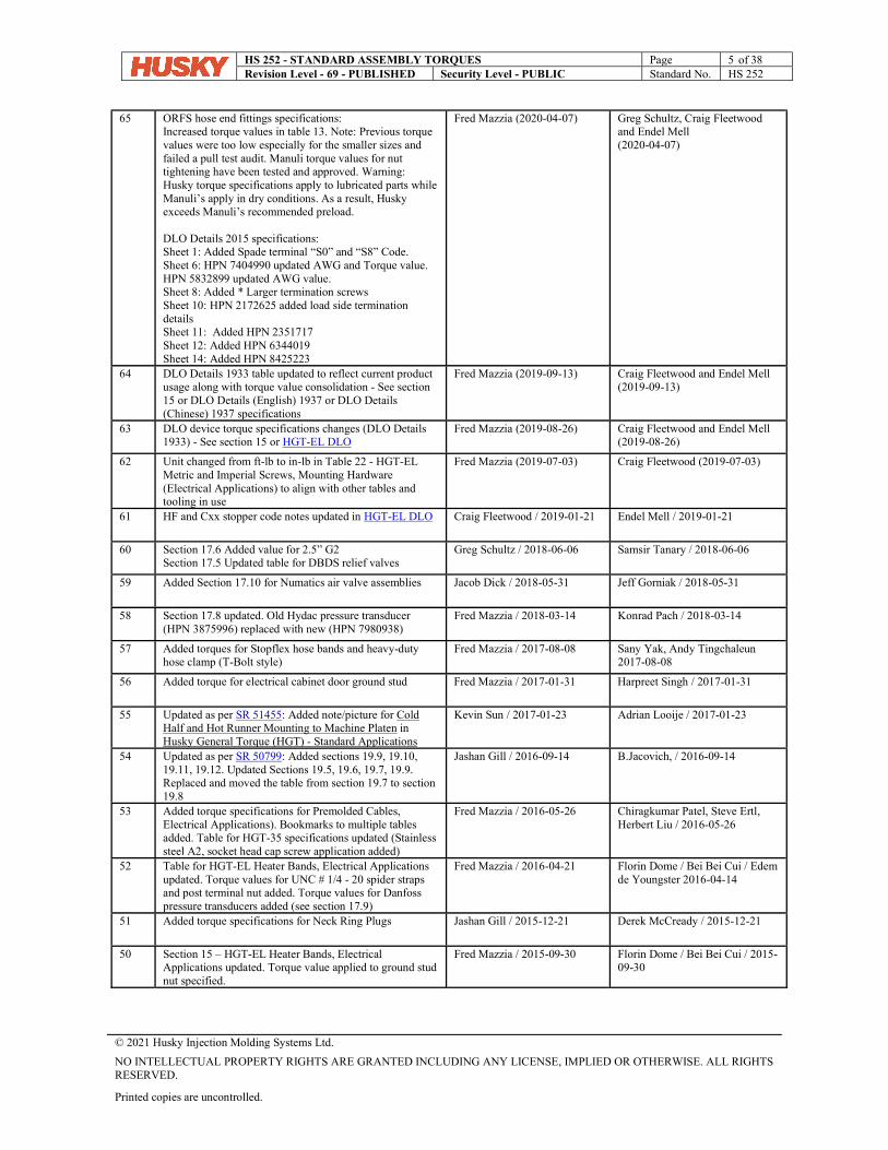
65 ORFS hose end fittings specifications: Increased torque values in table 13. Note: Previous torque values were too low especially for the smaller sizes and failed a pull test audit. Manuli torque values for nut tightening have been tested and approved. Warning: Husky torque specifications apply to lubricated parts while Manuli’s apply in dry conditions. As a result, Husky exceeds Manuli’s recommended preload. DLO Details 2015 specifications: Sheet 1: Added Spade terminal “S0” and “S8” Code. Sheet 6: HPN 7404990 updated AWG and Torque value. HPN 5832899 updated AWG value. Sheet 8: Added * Larger termination screws Sheet 10: HPN 2172625 added load side termination details Sheet 11: Added HPN 2351717 Sheet 12: Added HPN 6344019 Sheet 14: Added HPN 8425223
Fred Mazzia (2020-04-07) Greg Schultz, Craig Fleetwood and Endel Mell (2020-04-07)
64 DLO Details 1933 table updated to reflect current product usage along with torque value consolidation - See section 15 or DLO Details (English) 1937 or DLO Details (Chinese) 1937 specifications
Fred Mazzia (2019-09-13) Craig Fleetwood and Endel Mell (2019-09-13)
63 DLO device torque specifications changes (DLO Details 1933) - See section 15 or HGT-EL DLO
Fred Mazzia (2019-08-26) Craig Fleetwood and Endel Mell (2019-08-26)
62 Unit changed from ft-lb to in-lb in Table 22 - HGT-EL Metric and Imperial Screws, Mounting Hardware (Electrical Applications) to align with other tables and tooling in use
Fred Mazzia (2019-07-03) Craig Fleetwood (2019-07-03)
61 HF and Cxx stopper code notes updated in HGT-EL DLO Craig Fleetwood / 2019-01-21 Endel Mell / 2019-01-21
60 Section 17.6 Added value for 2.5” G2 Section 17.5 Updated table for DBDS relief valves
Greg Schultz / 2018-06-06 Samsir Tanary / 2018-06-06
59 Added Section 17.10 for Numatics air valve assemblies Jacob Dick / 2018-05-31 Jeff Gorniak / 2018-05-31
58 Section 17.8 updated. Old Hydac pressure transducer (HPN 3875996) replaced with new (HPN 7980938)
Fred Mazzia / 2018-03-14 Konrad Pach / 2018-03-14
57 Added torques for Stopflex hose bands and heavy-duty hose clamp (T-Bolt style)
Fred Mazzia / 2017-08-08 Sany Yak, Andy Tingchaleun 2017-08-08
56 Added torque for electrical cabinet door ground stud Fred Mazzia / 2017-01-31 Harpreet Singh / 2017-01-31
55 Updated as per SR 51455: Added note/picture for Cold Half and Hot Runner Mounting to Machine Platen in Husky General Torque (HGT) - Standard Applications
Kevin Sun / 2017-01-23 Adrian Looije / 2017-01-23
54 Updated as per SR 50799: Added sections 19.9, 19.10, 19.11, 19.12. Updated Sections 19.5, 19.6, 19.7, 19.9. Replaced and moved the table from section 19.7 to section 19.8
Jashan Gill / 2016-09-14 B.Jacovich, / 2016-09-14
53 Added torque specifications for Premolded Cables, Electrical Applications). Bookmarks to multiple tables added. Table for HGT-35 specifications updated (Stainless steel A2, socket head cap screw application added)
Fred Mazzia / 2016-05-26 Chiragkumar Patel, Steve Ertl, Herbert Liu / 2016-05-26
52 Table for HGT-EL Heater Bands, Electrical Applications updated. Torque values for UNC # 1/4 - 20 spider straps and post terminal nut added. Torque values for Danfoss pressure transducers added (see section 17.9)
Fred Mazzia / 2016-04-21 Florin Dome / Bei Bei Cui / Edem de Youngster 2016-04-14
51 Added torque specifications for Neck Ring Plugs Jashan Gill / 2015-12-21 Derek McCready / 2015-12-21
50 Section 15 – HGT-EL Heater Bands, Electrical Applications updated. Torque value applied to ground stud nut specified.
Fred Mazzia / 2015-09-30 Florin Dome / Bei Bei Cui / 2015-09-30
HS 252 - STANDARD ASSEMBLY TORQUES Page 6 of 38 Revision Level - 69 - PUBLISHED Security Level - PUBLIC Standard No. HS 252
© 2021 Husky Injection Molding Systems Ltd.
NO INTELLECTUAL PROPERTY RIGHTS ARE GRANTED INCLUDING ANY LICENSE, IMPLIED OR OTHERWISE. ALL RIGHTS RESERVED.
Printed copies are uncontrolled.
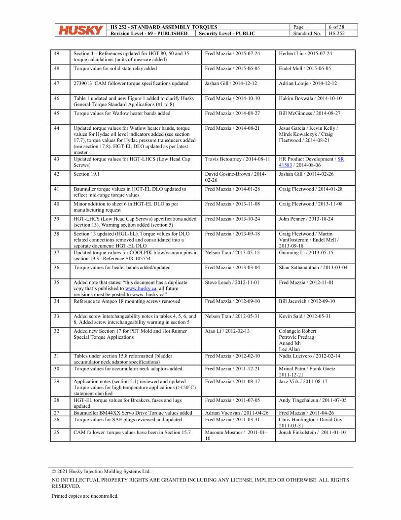
49 Section 4 – References updated for HGT 80, 50 and 35 torque calculations (units of measure added)
Fred Mazzia / 2015-07-24 Herbert Liu / 2015-07-24
48 Torque value for solid state relay added Fred Mazzia / 2015-06-05 Endel Mell / 2015-06-05
47 2739013 CAM follower torque specifications updated Jashan Gill / 2014-12-12 Adrian Looije / 2014-12-12
46 Table 1 updated and new Figure 1 added to clarify Husky General Torque Standard Applications (#1 to 8)
Fred Mazzia / 2014-10-10 Hakim Boxwala / 2014-10-10
45 Torque values for Watlow heater bands added Fred Mazzia / 2014-08-27 Bill McGinness / 2014-08-27
44 Updated torque values for Watlow heater bands, torque values for Hydac oil level indicators added (see section 17.7), torque values for Hydac pressure transducers added (see section 17.8). HGT-EL DLO updated as per latest master
Fred Mazzia / 2014-08-21 Jesus Garcia / Kevin Kelly / Mirek Kowalczyk / Craig Fleetwood / 2014-08-21
43 Updated torque values for HGT-LHCS (Low Head Cap Screws)
Travis Betourney / 2014-08-11 HR Product Development / SR 41583 / 2014-08-06
42 Section 19.1 David Gosine-Brown / 2014-02-26
Jashan Gill / 20114-02-26
41 Baumuller torque values in HGT-EL DLO updated to reflect mid-range torque values
Fred Mazzia / 2014-01-28 Craig Fleetwood / 2014-01-28
40 Minor addition to sheet 6 in HGT-EL DLO as per manufacturing request
Fred Mazzia / 2013-11-08 Craig Fleetwood / 2013-11-08
39 HGT-LHCS (Low Head Cap Screws) specifications added (section 13). Warning section added (section 5)
Fred Mazzia / 2013-10-24 John Penner / 2013-10-24
38 Section 13 updated (HGL-EL). Torque values for DLO related connections removed and consolidated into a separate document: HGT-EL DLO
Fred Mazzia / 2013-09-18 Craig Fleetwood / Martin VanOosterom / Endel Mell / 2013-09-18
37 Updated torque values for COOLPIK blow/vacuum pins in section 19.3 . Reference SIR 105554
Nelson Tran / 2013-05-15 Guoming Li / 2013-05-15
36 Torque values for heater bands added/updated Fred Mazzia / 2013-03-04 Shan Sathananthan / 2013-03-04
35 Added note that states: “this document has a duplicate copy that’s published to www.husky.ca, all future revisions must be posted to www. husky.ca”
Steve Leach / 2012-11-01 Fred Mazzia / 2012-11-01
34 Reference to Ampco 18 mounting screws removed Fred Mazzia / 2012-09-10 Bill Jacovich / 2012-09-10
33 Added screw interchangeability notes in tables 4, 5, 6, and 8. Added screw interchangeability warning in section 5
Nelson Tran / 2012-05-31 Kevin Said / 2012-05-31
32 Added new Section 17 for PET Mold and Hot Runner Special Torque Applications
Xiao Li / 2012-02-13 Colangelo Robert Petrovic Predrag Anand Ish Lee Allan
31 Tables under section 15.8 reformatted (bladder accumulator neck adaptor specifications)
Fred Mazzia / 2012-02-10 Nadia Lucivero / 2012-02-14
30 Torque values for accumulator neck adaptors added Fred Mazzia / 2011-12-21 Mrinal Patra / Frank Goetz 2011-12-21
29 Application notes (section 5.1) reviewed and updated: Torque values for high temperature applications (>150°C) statement clarified
Fred Mazzia / 2011-08-17 Jazz Virk / 2011-08-17
28 HGT-EL torque values for Breakers, fuses and lugs updated
Fred Mazzia / 2011-07-05 Andy Tingchaleun / 2011-07-05
27 Baumueller BM44XX Servo Drive Torque values added Adrian Vucovan / 2011-04-26 Fred Mazzia / 2011-04-26 26 Torque values for SAE plugs reviewed and updated Fred Mazzia / 2011-03-31 Chris Huntington / David Gay
2011-03-31 25 CAM follower torque values have been in Section 15.7 Masoum Mosmer / 2011-01-
10 Jonah Finkelstein / 2011-01-10
HS 252 - STANDARD ASSEMBLY TORQUES Page 7 of 38 Revision Level - 69 - PUBLISHED Security Level - PUBLIC Standard No. HS 252
© 2021 Husky Injection Molding Systems Ltd.
NO INTELLECTUAL PROPERTY RIGHTS ARE GRANTED INCLUDING ANY LICENSE, IMPLIED OR OTHERWISE. ALL RIGHTS RESERVED.
Printed copies are uncontrolled.
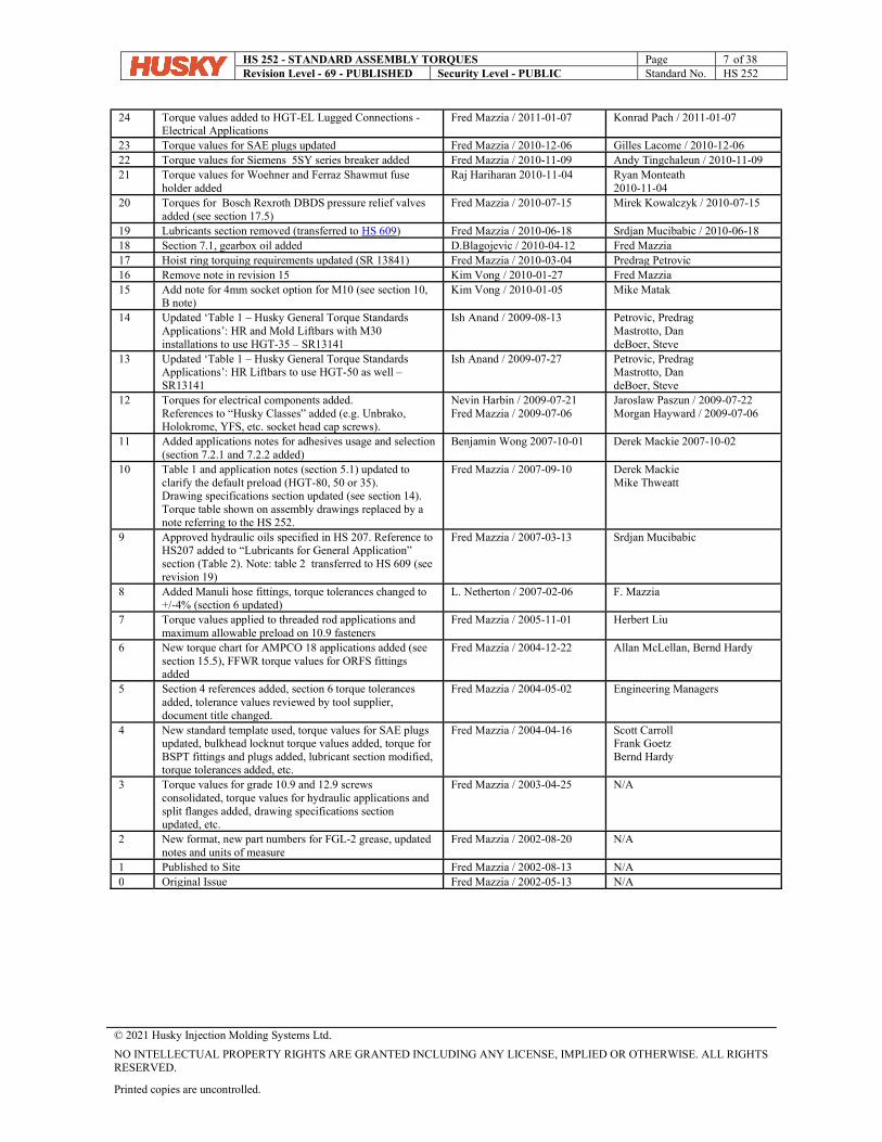
24 Torque values added to HGT-EL Lugged Connections - Electrical Applications
Fred Mazzia / 2011-01-07 Konrad Pach / 2011-01-07
23 Torque values for SAE plugs updated Fred Mazzia / 2010-12-06 Gilles Lacome / 2010-12-06 22 Torque values for Siemens 5SY series breaker added Fred Mazzia / 2010-11-09 Andy Tingchaleun / 2010-11-09 21 Torque values for Woehner and Ferraz Shawmut fuse
holder added Raj Hariharan 2010-11-04 Ryan Monteath
2010-11-04 20 Torques for Bosch Rexroth DBDS pressure relief valves
added (see section 17.5) Fred Mazzia / 2010-07-15 Mirek Kowalczyk / 2010-07-15
19 Lubricants section removed (transferred to HS 609) Fred Mazzia / 2010-06-18 Srdjan Mucibabic / 2010-06-18 18 Section 7.1, gearbox oil added D.Blagojevic / 2010-04-12 Fred Mazzia 17 Hoist ring torquing requirements updated (SR 13841) Fred Mazzia / 2010-03-04 Predrag Petrovic 16 Remove note in revision 15 Kim Vong / 2010-01-27 Fred Mazzia 15 Add note for 4mm socket option for M10 (see section 10,
B note) Kim Vong / 2010-01-05 Mike Matak
14 Updated ‘Table 1 – Husky General Torque Standards Applications’: HR and Mold Liftbars with M30 installations to use HGT-35 – SR13141
Ish Anand / 2009-08-13 Petrovic, Predrag Mastrotto, Dan deBoer, Steve
13 Updated ‘Table 1 – Husky General Torque Standards Applications’: HR Liftbars to use HGT-50 as well – SR13141
Ish Anand / 2009-07-27 Petrovic, Predrag Mastrotto, Dan deBoer, Steve
12 Torques for electrical components added. References to “Husky Classes” added (e.g. Unbrako, Holokrome, YFS, etc. socket head cap screws).
Nevin Harbin / 2009-07-21 Fred Mazzia / 2009-07-06
Jaroslaw Paszun / 2009-07-22 Morgan Hayward / 2009-07-06
11 Added applications notes for adhesives usage and selection (section 7.2.1 and 7.2.2 added)
Benjamin Wong 2007-10-01 Derek Mackie 2007-10-02
10 Table 1 and application notes (section 5.1) updated to clarify the default preload (HGT-80, 50 or 35). Drawing specifications section updated (see section 14). Torque table shown on assembly drawings replaced by a note referring to the HS 252.
Fred Mazzia / 2007-09-10 Derek Mackie Mike Thweatt
9 Approved hydraulic oils specified in HS 207. Reference to HS207 added to “Lubricants for General Application” section (Table 2). Note: table 2 transferred to HS 609 (see revision 19)
Fred Mazzia / 2007-03-13 Srdjan Mucibabic
8 Added Manuli hose fittings, torque tolerances changed to +/-4% (section 6 updated)
L. Netherton / 2007-02-06 F. Mazzia
7 Torque values applied to threaded rod applications and maximum allowable preload on 10.9 fasteners
Fred Mazzia / 2005-11-01 Herbert Liu
6 New torque chart for AMPCO 18 applications added (see section 15.5), FFWR torque values for ORFS fittings added
Fred Mazzia / 2004-12-22 Allan McLellan, Bernd Hardy
5 Section 4 references added, section 6 torque tolerances added, tolerance values reviewed by tool supplier, document title changed.
Fred Mazzia / 2004-05-02 Engineering Managers
4 New standard template used, torque values for SAE plugs updated, bulkhead locknut torque values added, torque for BSPT fittings and plugs added, lubricant section modified, torque tolerances added, etc.
Fred Mazzia / 2004-04-16 Scott Carroll Frank Goetz Bernd Hardy
3 Torque values for grade 10.9 and 12.9 screws consolidated, torque values for hydraulic applications and split flanges added, drawing specifications section updated, etc.
Fred Mazzia / 2003-04-25 N/A
2 New format, new part numbers for FGL-2 grease, updated notes and units of measure
Fred Mazzia / 2002-08-20 N/A
1 Published to Site Fred Mazzia / 2002-08-13 N/A 0 Original Issue Fred Mazzia / 2002-05-13 N/A
HS 252 - STANDARD ASSEMBLY TORQUES Page 8 of 38 Revision Level - 69 - PUBLISHED Security Level - PUBLIC Standard No. HS 252
© 2021 Husky Injection Molding Systems Ltd.
NO INTELLECTUAL PROPERTY RIGHTS ARE GRANTED INCLUDING ANY LICENSE, IMPLIED OR OTHERWISE. ALL RIGHTS RESERVED.
Printed copies are uncontrolled.
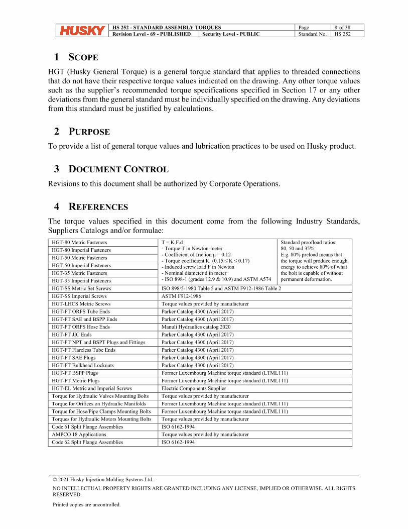
1 SCOPE HGT (Husky General Torque) is a general torque standard that applies to threaded connections that do not have their respective torque values indicated on the drawing. Any other torque values such as the supplier’s recommended torque specifications specified in Section 17 or any other deviations from the general standard must be individually specified on the drawing. Any deviations from this standard must be justified by calculations.
2 PURPOSE To provide a list of general torque values and lubrication practices to be used on Husky product.
3 DOCUMENT CONTROL Revisions to this document shall be authorized by Corporate Operations.
4 REFERENCES The torque values specified in this document come from the following Industry Standards, Suppliers Catalogs and/or formulae:
HGT-80 Metric Fasteners T = K.F.d - Torque T in Newton-meter - Coefficient of friction μ = 0.12 - Torque coefficient K (0.15 ≤ K ≤ 0.17) - Induced screw load F in Newton - Nominal diameter d in meter - ISO 898-1 (grades 12.9 & 10.9) and ASTM A574
Standard proofload ratios: 80, 50 and 35%. E.g. 80% preload means that the torque will produce enough energy to achieve 80% of what the bolt is capable of without permanent deformation.
HGT-80 Imperial Fasteners
HGT-50 Metric Fasteners
HGT-50 Imperial Fasteners
HGT-35 Metric Fasteners
HGT-35 Imperial Fasteners
HGT-SS Metric Set Screws ISO 898/5-1980 Table 5 and ASTM F912-1986 Table 2
HGT-SS Imperial Screws ASTM F912-1986
HGT-LHCS Metric Screws Torque values provided by manufacturer
HGT-FT ORFS Tube Ends Parker Catalog 4300 (April 2017)
HGT-FT SAE and BSPP Ends Parker Catalog 4300 (April 2017)
HGT-FT ORFS Hose Ends Manuli Hydraulics catalog 2020
HGT-FT JIC Ends Parker Catalog 4300 (April 2017)
HGT-FT NPT and BSPT Plugs and Fittings Parker Catalog 4300 (April 2017)
HGT-FT Flareless Tube Ends Parker Catalog 4300 (April 2017)
HGT-FT SAE Plugs Parker Catalog 4300 (April 2017)
HGT-FT Bulkhead Locknuts Parker Catalog 4300 (April 2017)
HGT-FT BSPP Plugs Former Luxembourg Machine torque standard (LTML111)
HGT-FT Metric Plugs Former Luxembourg Machine torque standard (LTML111)
HGT-EL Metric and Imperial Screws Electric Components Supplier
Torque for Hydraulic Valves Mounting Bolts Torque values provided by manufacturer
Torque for Orifices on Hydraulic Manifolds Former Luxembourg Machine torque standard (LTML111)
Torque for Hose/Pipe Clamps Mounting Bolts Former Luxembourg Machine torque standard (LTML111)
Torques for Hydraulic Motors Mounting Bolts Torque values provided by manufacturer
Code 61 Split Flange Assemblies ISO 6162-1994
AMPCO 18 Applications Torque values provided by manufacturer
Code 62 Split Flange Assemblies ISO 6162-1994

HS 252 - STANDARD ASSEMBLY TORQUES Page 9 of 38 Revision Level - 69 - PUBLISHED Security Level - PUBLIC Standard No. HS 252
© 2021 Husky Injection Molding Systems Ltd.
NO INTELLECTUAL PROPERTY RIGHTS ARE GRANTED INCLUDING ANY LICENSE, IMPLIED OR OTHERWISE. ALL RIGHTS RESERVED.
Printed copies are uncontrolled.
5 WARNINGS Always use the correct parts and the proper torques. Incorrect fastener connections can dangerously weaken assemblies. Ensure that all safety information, instructions and warnings such as shown in the two examples below are read and understood before any operation or any maintenance procedures are performed.
CAUTION! Mechanical hazard – risk of equipment damage. Use of improper torque can result in equipment damage. Consult the assembly drawings for the torque specifications before referring to the torque charts in this section.
WARNING! Molten plastic spray hazard - risk of serious injury and equipment damage. If incorrectly sized screws are used, equipment damage may occur that could result in uncontained molten plastic spray. If replacing the screws, only use the screw sizes specified in the machine bill of material.
6 APPLICATIONS HGT consists of seven torque standards HGT-80, HGT-50, HGT-35, HGT-SS, HGT-LHCS, HGT-FT and HGT-EL as shown in Table 1. For mechanical applications, screws are torqued to the HGT-
HS 252 - STANDARD ASSEMBLY TORQUES Page 10 of 38 Revision Level - 69 - PUBLISHED Security Level - PUBLIC Standard No. HS 252
© 2021 Husky Injection Molding Systems Ltd.
NO INTELLECTUAL PROPERTY RIGHTS ARE GRANTED INCLUDING ANY LICENSE, IMPLIED OR OTHERWISE. ALL RIGHTS RESERVED.
Printed copies are uncontrolled.
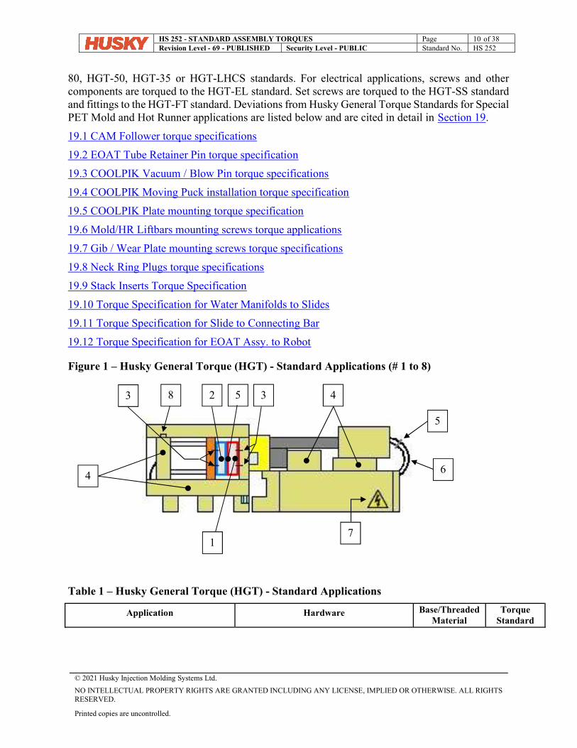
80, HGT-50, HGT-35 or HGT-LHCS standards. For electrical applications, screws and other components are torqued to the HGT-EL standard. Set screws are torqued to the HGT-SS standard and fittings to the HGT-FT standard. Deviations from Husky General Torque Standards for Special PET Mold and Hot Runner applications are listed below and are cited in detail in Section 19.
19.1 CAM Follower torque specifications
19.2 EOAT Tube Retainer Pin torque specification
19.3 COOLPIK Vacuum / Blow Pin torque specifications
19.4 COOLPIK Moving Puck installation torque specification
19.5 COOLPIK Plate mounting torque specification
19.6 Mold/HR Liftbars mounting screws torque applications
19.7 Gib / Wear Plate mounting screws torque specifications
19.8 Neck Ring Plugs torque specifications
19.9 Stack Inserts Torque Specification
19.10 Torque Specification for Water Manifolds to Slides
19.11 Torque Specification for Slide to Connecting Bar
19.12 Torque Specification for EOAT Assy. to Robot
Figure 1 – Husky General Torque (HGT) - Standard Applications (# 1 to 8)
Table 1 – Husky General Torque (HGT) - Standard Applications
Application Hardware Base/Threaded Material
Torque Standard
2
1
3 3 4
7
4
8
6
5
5
HS 252 - STANDARD ASSEMBLY TORQUES Page 11 of 38 Revision Level - 69 - PUBLISHED Security Level - PUBLIC Standard No. HS 252
© 2021 Husky Injection Molding Systems Ltd.
NO INTELLECTUAL PROPERTY RIGHTS ARE GRANTED INCLUDING ANY LICENSE, IMPLIED OR OTHERWISE. ALL RIGHTS RESERVED.
Printed copies are uncontrolled.
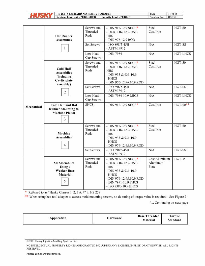
Mechanical
Hot Runner Assemblies
Screws and Threaded Rods
- DIN 912-12.9 SHCS* - DURLOK-12.9-UNB HHS - DIN 976-12.9 ROD - ASTM A574 SHCS
Steel Cast Iron
HGT-80
Set Screws - ISO 898/5-45H - ASTM F912
N/A HGT-SS
Low Head Cap Screws
- DIN 7984 N/A HGT-LHCS
Cold Half Assemblies (including
Cavity plate assembly)
Screws and Threaded Rods
- DIN 912-12.9 SHCS* - DURLOK-12.9-UNB HHS - DIN 933 & 931-10.9 HHCS - DIN 976-12.9&10.9 ROD - ASTM A574 SHCS
Steel Cast Iron
HGT-50
Set Screws - ISO 898/5-45H - ASTM F912
N/A HGT-SS
Low Head Cap Screws
- DIN 7984-10.9 LHCS N/A HGT-LHCS
Cold Half and Hot Runner Mounting to
Machine Platen
SHCS - DIN 912-12.9 SHCS* Cast Iron HGT-50**
Machine Assemblies
Screws and Threaded Rods
- DIN 912-12.9 SHCS* - DURLOK-12.9-UNB HHS - DIN 933 & 931-10.9 HHCS - DIN 976-12.9&10.9 ROD - ASTM A574 SHCS
Steel Cast Iron
HGT-50
Set Screws - ISO 898/5-45H - ASTM F912
N/A HGT-SS
All Assemblies Using a
Weaker Base Material
Screws and Threaded Rods
- DIN 912-12.9 SHCS* - DURLOK-12.9-UNB HHS - DIN 933 & 931-10.9 HHCS - DIN 976-12.9&10.9 ROD - DIN 7991-10.9 FHCS - ISO 7380-10.9 BHCS - ASTM A574 SHCS
Cast Aluminum Aluminum Plate
HGT-35
* Referred to as “Husky Classes 1, 2, 3 & 4” in HS 258 ** When using hex tool adapter to access mold mounting screws, no de-rating of torque value is required - See Figure 2
/… Continuing on next page
Application Hardware Base/Threaded
Material Torque
Standard
1
2
3
5
4
HS 252 - STANDARD ASSEMBLY TORQUES Page 12 of 38 Revision Level - 69 - PUBLISHED Security Level - PUBLIC Standard No. HS 252
© 2021 Husky Injection Molding Systems Ltd.
NO INTELLECTUAL PROPERTY RIGHTS ARE GRANTED INCLUDING ANY LICENSE, IMPLIED OR OTHERWISE. ALL RIGHTS RESERVED.
Printed copies are uncontrolled.
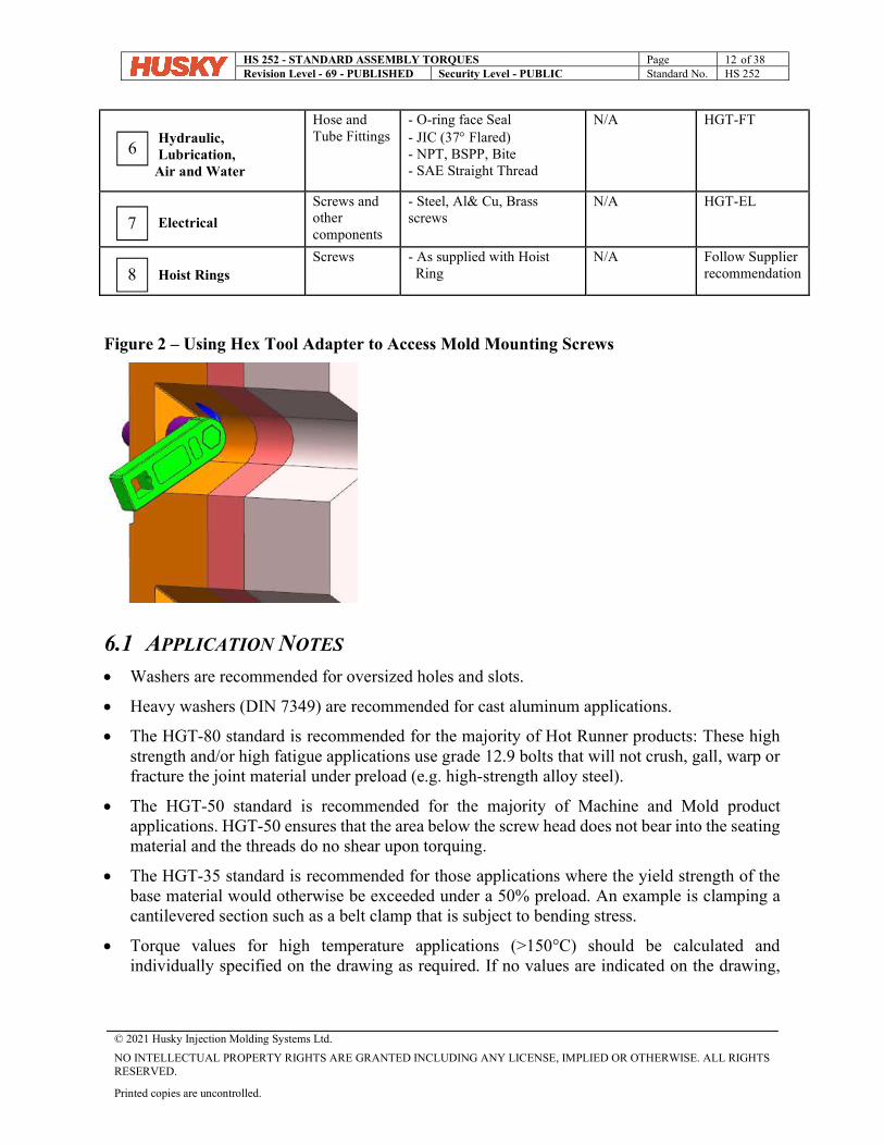
Hydraulic, Lubrication, Air and Water
Hose and Tube Fittings
- O-ring face Seal - JIC (37 Flared) - NPT, BSPP, Bite - SAE Straight Thread
N/A HGT-FT
Electrical
Screws and other components
- Steel, Al& Cu, Brass screws
N/A HGT-EL
Hoist Rings Screws - As supplied with Hoist
Ring N/A Follow Supplier
recommendation
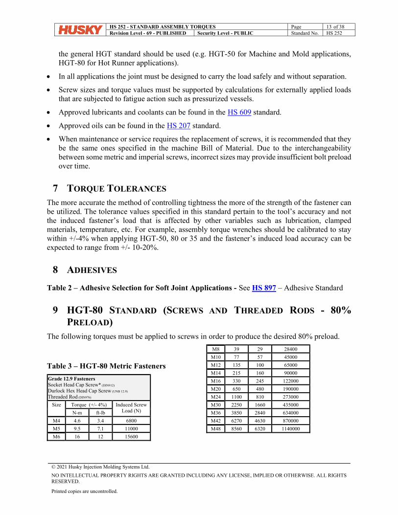
Figure 2 – Using Hex Tool Adapter to Access Mold Mounting Screws
6.1 APPLICATION NOTES Washers are recommended for oversized holes and slots.
Heavy washers (DIN 7349) are recommended for cast aluminum applications.
The HGT-80 standard is recommended for the majority of Hot Runner products: These high strength and/or high fatigue applications use grade 12.9 bolts that will not crush, gall, warp or fracture the joint material under preload (e.g. high-strength alloy steel).
The HGT-50 standard is recommended for the majority of Machine and Mold product applications. HGT-50 ensures that the area below the screw head does not bear into the seating material and the threads do no shear upon torquing.
The HGT-35 standard is recommended for those applications where the yield strength of the base material would otherwise be exceeded under a 50% preload. An example is clamping a cantilevered section such as a belt clamp that is subject to bending stress.
Torque values for high temperature applications (>150°C) should be calculated and individually specified on the drawing as required. If no values are indicated on the drawing,
6
7
8
HS 252 - STANDARD ASSEMBLY TORQUES Page 13 of 38 Revision Level - 69 - PUBLISHED Security Level - PUBLIC Standard No. HS 252
© 2021 Husky Injection Molding Systems Ltd.
NO INTELLECTUAL PROPERTY RIGHTS ARE GRANTED INCLUDING ANY LICENSE, IMPLIED OR OTHERWISE. ALL RIGHTS RESERVED.
Printed copies are uncontrolled.
the general HGT standard should be used (e.g. HGT-50 for Machine and Mold applications, HGT-80 for Hot Runner applications).
In all applications the joint must be designed to carry the load safely and without separation.
Screw sizes and torque values must be supported by calculations for externally applied loads that are subjected to fatigue action such as pressurized vessels.
Approved lubricants and coolants can be found in the HS 609 standard.
Approved oils can be found in the HS 207 standard.
When maintenance or service requires the replacement of screws, it is recommended that they be the same ones specified in the machine Bill of Material. Due to the interchangeability between some metric and imperial screws, incorrect sizes may provide insufficient bolt preload over time.
7 TORQUE TOLERANCES The more accurate the method of controlling tightness the more of the strength of the fastener can be utilized. The tolerance values specified in this standard pertain to the tool’s accuracy and not the induced fastener’s load that is affected by other variables such as lubrication, clamped materials, temperature, etc. For example, assembly torque wrenches should be calibrated to stay within +/-4% when applying HGT-50, 80 or 35 and the fastener’s induced load accuracy can be expected to range from +/- 10-20%.
8 ADHESIVES
Table 2 – Adhesive Selection for Soft Joint Applications - See HS 897 – Adhesive Standard
9 HGT-80 STANDARD (SCREWS AND THREADED RODS - 80%
PRELOAD) The following torques must be applied to screws in order to produce the desired 80% preload.
Table 3 – HGT-80 Metric Fasteners
Grade 12.9 Fasteners Socket Head Cap Screw* (DIN912)
Durlock Hex Head Cap Screw (UNB 12.9)
Threaded Rod (DIN976)
Size
Torque (+/- 4%) Induced Screw Load (N) N-m ft-lb
M4 4.6 3.4 6800
M5 9.5 7.1 11000
M6 16 12 15600
M8 39 29 28400
M10 77 57 45000
M12 135 100 65000
M14 215 160 90000
M16 330 245 122000
M20 650 480 190000
M24 1100 810 273000
M30 2250 1660 435000
M36 3850 2840 634000
M42 6270 4630 870000
M48 8560 6320 1140000
HS 252 - STANDARD ASSEMBLY TORQUES Page 14 of 38 Revision Level - 69 - PUBLISHED Security Level - PUBLIC Standard No. HS 252
© 2021 Husky Injection Molding Systems Ltd.
NO INTELLECTUAL PROPERTY RIGHTS ARE GRANTED INCLUDING ANY LICENSE, IMPLIED OR OTHERWISE. ALL RIGHTS RESERVED.
Printed copies are uncontrolled.
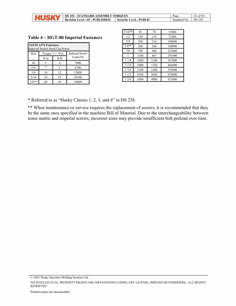
Table 4 – HGT-80 Imperial Fasteners
ASTM A574 Fasteners Imperial Socket Head Cap Screw
Size
Torque (+/- 4%) Induced Screw Load (N) N-m ft-lb
#8 5 4 7000
#10 7 5 8700
1/4 16 12 15800
5/16 35 25 26100
3/8** 60 45 38000
7/16** 95 70 53000
1/2 150 110 71000
5/8 290 210 108000
3/4** 500 360 160000
7/8 790 580 222000
1 1180 865 291000
1 1/8 1680 1240 367000
1 1/4 2400 1750 466000
1 3/8 3100 2300 555000
1 1/2 4100 3040 676000
1 3/4 6500 4800 911000
* Referred to as “Husky Classes 1, 2, 3, and 4” in HS 258.
** When maintenance or service requires the replacement of screws, it is recommended that they be the same ones specified in the machine Bill of Material. Due to the interchangeability between some metric and imperial screws, incorrect sizes may provide insufficient bolt preload over time.
HS 252 - STANDARD ASSEMBLY TORQUES Page 15 of 38 Revision Level - 69 - PUBLISHED Security Level - PUBLIC Standard No. HS 252
© 2021 Husky Injection Molding Systems Ltd.
NO INTELLECTUAL PROPERTY RIGHTS ARE GRANTED INCLUDING ANY LICENSE, IMPLIED OR OTHERWISE. ALL RIGHTS RESERVED.
Printed copies are uncontrolled.
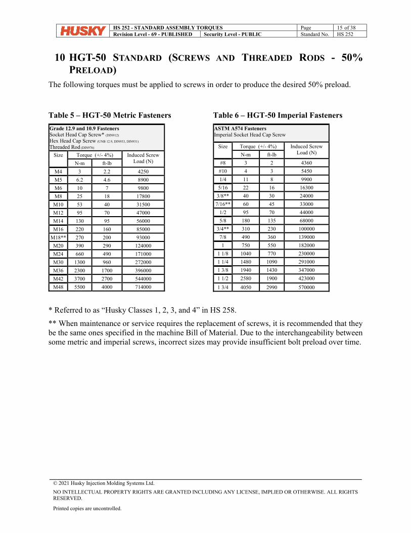
10 HGT-50 STANDARD (SCREWS AND THREADED RODS - 50%
PRELOAD) The following torques must be applied to screws in order to produce the desired 50% preload.
Table 5 – HGT-50 Metric Fasteners
Grade 12.9 and 10.9 Fasteners Socket Head Cap Screw* (DIN912)
Hex Head Cap Screw (UNB 12.9, DIN933, DIN931)
Threaded Rod (DIN976)
Size
Torque (+/- 4%) Induced Screw Load (N) N-m ft-lb
M4 3 2.2 4250
M5 6.2 4.6 8900
M6 10 7 9800
M8 25 18 17800
M10 53 40 31500
M12 95 70 47000
M14 130 95 56000
M16 220 160 85000
M18** 270 200 93000
M20 390 290 124000
M24 660 490 171000
M30 1300 960 272000
M36 2300 1700 396000
M42 3700 2700 544000
M48 5500 4000 714000
Table 6 – HGT-50 Imperial Fasteners
ASTM A574 Fasteners Imperial Socket Head Cap Screw
Size
Torque (+/- 4%) Induced Screw Load (N) N-m ft-lb
#8 3 2 4360
#10 4 3 5450
1/4 11 8 9900
5/16 22 16 16300
3/8** 40 30 24000
7/16** 60 45 33000
1/2 95 70 44000
5/8 180 135 68000
3/4** 310 230 100000
7/8 490 360 139000
1 750 550 182000
1 1/8 1040 770 230000
1 1/4 1480 1090 291000
1 3/8 1940 1430 347000
1 1/2 2580 1900 423000
1 3/4 4050 2990 570000
* Referred to as “Husky Classes 1, 2, 3, and 4” in HS 258.
** When maintenance or service requires the replacement of screws, it is recommended that they be the same ones specified in the machine Bill of Material. Due to the interchangeability between some metric and imperial screws, incorrect sizes may provide insufficient bolt preload over time.
HS 252 - STANDARD ASSEMBLY TORQUES Page 16 of 38 Revision Level - 69 - PUBLISHED Security Level - PUBLIC Standard No. HS 252
© 2021 Husky Injection Molding Systems Ltd.
NO INTELLECTUAL PROPERTY RIGHTS ARE GRANTED INCLUDING ANY LICENSE, IMPLIED OR OTHERWISE. ALL RIGHTS RESERVED.
Printed copies are uncontrolled.
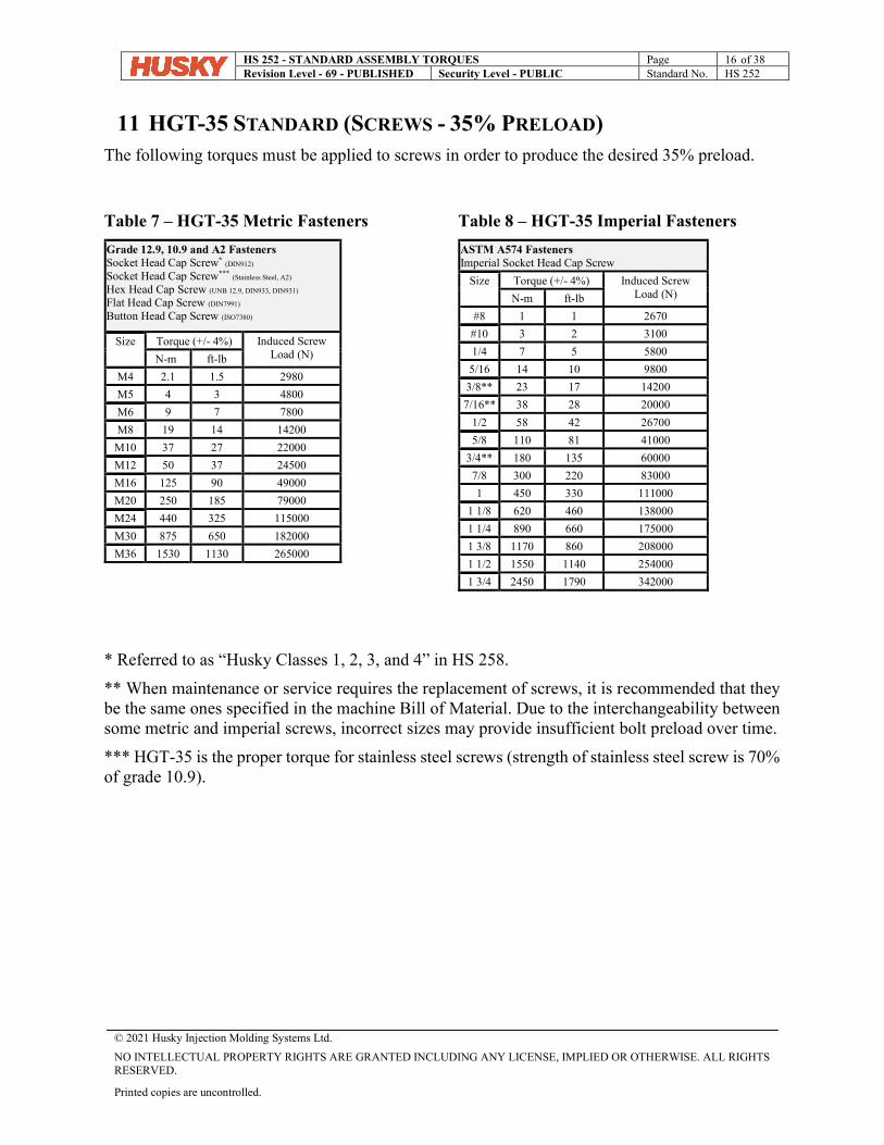
11 HGT-35 STANDARD (SCREWS - 35% PRELOAD) The following torques must be applied to screws in order to produce the desired 35% preload.
Table 7 – HGT-35 Metric Fasteners
Grade 12.9, 10.9 and A2 Fasteners Socket Head Cap Screw* (DIN912)
Socket Head Cap Screw*** (Stainless Steel, A2)
Hex Head Cap Screw (UNB 12.9, DIN933, DIN931)
Flat Head Cap Screw (DIN7991)
Button Head Cap Screw (ISO7380)
Size
Torque (+/- 4%) Induced Screw Load (N) N-m ft-lb
M4 2.1 1.5 2980
M5 4 3 4800
M6 9 7 7800
M8 19 14 14200
M10 37 27 22000
M12 50 37 24500
M16 125 90 49000
M20 250 185 79000
M24 440 325 115000
M30 875 650 182000
M36 1530 1130 265000
Table 8 – HGT-35 Imperial Fasteners
ASTM A574 Fasteners Imperial Socket Head Cap Screw
Size
Torque (+/- 4%) Induced Screw Load (N) N-m ft-lb
#8 1 1 2670
#10 3 2 3100
1/4 7 5 5800
5/16 14 10 9800
3/8** 23 17 14200
7/16** 38 28 20000
1/2 58 42 26700
5/8 110 81 41000
3/4** 180 135 60000
7/8 300 220 83000
1 450 330 111000
1 1/8 620 460 138000
1 1/4 890 660 175000
1 3/8 1170 860 208000
1 1/2 1550 1140 254000
1 3/4 2450 1790 342000
* Referred to as “Husky Classes 1, 2, 3, and 4” in HS 258.
** When maintenance or service requires the replacement of screws, it is recommended that they be the same ones specified in the machine Bill of Material. Due to the interchangeability between some metric and imperial screws, incorrect sizes may provide insufficient bolt preload over time.
*** HGT-35 is the proper torque for stainless steel screws (strength of stainless steel screw is 70% of grade 10.9).
HS 252 - STANDARD ASSEMBLY TORQUES Page 17 of 38 Revision Level - 69 - PUBLISHED Security Level - PUBLIC Standard No. HS 252
© 2021 Husky Injection Molding Systems Ltd.
NO INTELLECTUAL PROPERTY RIGHTS ARE GRANTED INCLUDING ANY LICENSE, IMPLIED OR OTHERWISE. ALL RIGHTS RESERVED.
Printed copies are uncontrolled.
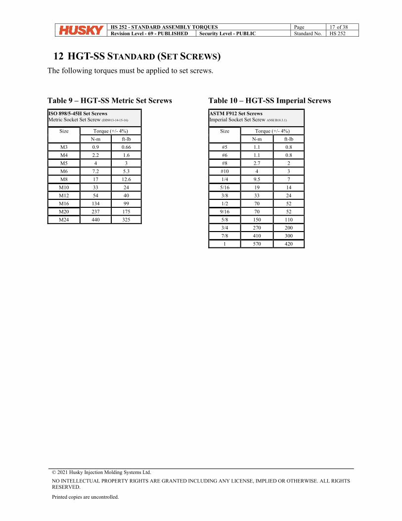
12 HGT-SS STANDARD (SET SCREWS) The following torques must be applied to set screws.
Table 9 – HGT-SS Metric Set Screws
ISO 898/5-45H Set Screws Metric Socket Set Screw (DIN913-14-15-16)
Size
Torque (+/- 4%)
N-m ft-lb
M3 0.9 0.66
M4 2.2 1.6
M5 4 3
M6 7.2 5.3
M8 17 12.6
M10 33 24
M12 54 40
M16 134 99
M20 237 175
M24 440 325
Table 10 – HGT-SS Imperial Screws
ASTM F912 Set Screws Imperial Socket Set Screw ANSI B18.3.1)
Size
Torque (+/- 4%)
N-m ft-lb
#5 1.1 0.8
#6 1.1 0.8
#8 2.7 2
#10 4 3
1/4 9.5 7
5/16 19 14
3/8 33 24
1/2 70 52
9/16 70 52
5/8 150 110
3/4 270 200
7/8 410 300
1 570 420
HS 252 - STANDARD ASSEMBLY TORQUES Page 18 of 38 Revision Level - 69 - PUBLISHED Security Level - PUBLIC Standard No. HS 252
© 2021 Husky Injection Molding Systems Ltd.
NO INTELLECTUAL PROPERTY RIGHTS ARE GRANTED INCLUDING ANY LICENSE, IMPLIED OR OTHERWISE. ALL RIGHTS RESERVED.
Printed copies are uncontrolled.
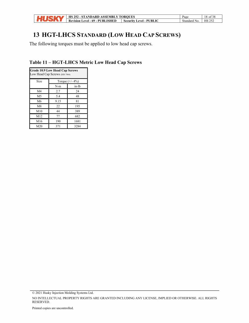
13 HGT-LHCS STANDARD (LOW HEAD CAP SCREWS) The following torques must be applied to low head cap screws.
Table 11 – HGT-LHCS Metric Low Head Cap Screws
Grade 10.9 Low Head Cap Screws Low Head Cap Screws (DIN 7984)
Size
Torque (+/- 4%)
N-m in-lb
M4 2.7 24
M5 5.4 48
M6 9.15 81
M8 22 195
M10 44 389
M12 77 682
M16 190 1681
M20 371 3284
HS 252 - STANDARD ASSEMBLY TORQUES Page 19 of 38 Revision Level - 69 - PUBLISHED Security Level - PUBLIC Standard No. HS 252
© 2021 Husky Injection Molding Systems Ltd.
NO INTELLECTUAL PROPERTY RIGHTS ARE GRANTED INCLUDING ANY LICENSE, IMPLIED OR OTHERWISE. ALL RIGHTS RESERVED.
Printed copies are uncontrolled.
14 HGT-FT STANDARD (FITTINGS) The following tables provide the recommended torque values required for the safe and effective operation of the fittings using a torque wrench or other methods such as “Turn From Finger Tight”, “Flats From Finger Tight” or “Flats from Wrench Resistance”. For TFFT or FFFT, the joint should be hand tightened snugly and then tightened with a wrench by the number of flats or turns indicated by the table. For “FFWR”, the joint should be tightened snugly with a wrench and then tightened again with the same wrench by the number of flats indicated by the table. The torque method of assembly is the preferred method of assembly. It reduces the risk of human error during assembly that is more prevalent in the “FFWR” method. To ensure the most accurate assembly of the fitting, it is strongly recommended that the torque method be utilized.
14.1 IMPORTANT NOTES
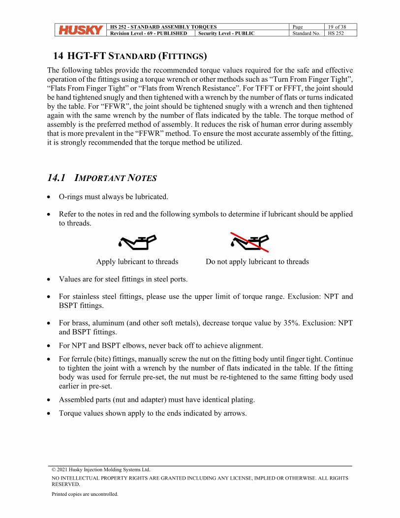
O-rings must always be lubricated.
Refer to the notes in red and the following symbols to determine if lubricant should be applied to threads.
Apply lubricant to threads Do not apply lubricant to threads
Values are for steel fittings in steel ports.
For stainless steel fittings, please use the upper limit of torque range. Exclusion: NPT and BSPT fittings.
For brass, aluminum (and other soft metals), decrease torque value by 35%. Exclusion: NPT and BSPT fittings.
For NPT and BSPT elbows, never back off to achieve alignment.
For ferrule (bite) fittings, manually screw the nut on the fitting body until finger tight. Continue to tighten the joint with a wrench by the number of flats indicated in the table. If the fitting body was used for ferrule pre-set, the nut must be re-tightened to the same fitting body used earlier in pre-set.
Assembled parts (nut and adapter) must have identical plating.
Torque values shown apply to the ends indicated by arrows.
HS 252 - STANDARD ASSEMBLY TORQUES Page 20 of 38 Revision Level - 69 - PUBLISHED Security Level - PUBLIC Standard No. HS 252
© 2021 Husky Injection Molding Systems Ltd.
NO INTELLECTUAL PROPERTY RIGHTS ARE GRANTED INCLUDING ANY LICENSE, IMPLIED OR OTHERWISE. ALL RIGHTS RESERVED.
Printed copies are uncontrolled.
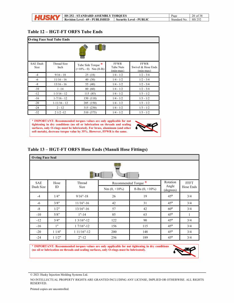
Table 12 – HGT-FT ORFS Tube Ends
O-ring Face Seal Tube Ends
SAE Dash
Size Thread Size
Inch Tube Side Torque *
(+10% - 0) Nm (ft-lb)
FFWR Tube Nuts (min-max)
FFWR Swivel & Hose Ends
(min-max) -4 9/16 - 18 25 (18) 1/4 - 1/2 1/2 - 3/4
-6 11/16 - 16 40 (30) 1/4 - 1/2 1/2 - 3/4
-8 13/16 - 16 55 (40) 1/4 - 1/2 1/2 - 3/4
-10 1 -14 80 (60) 1/4 - 1/2 1/2 - 3/4
-12 1-3/16 - 12 115 (85) 1/4 - 1/2 1/3 - 1/2
-16 1-7/16 - 12 150 (110) 1/4 - 1/2 1/3 - 1/2
-20 1-11/16 - 12 205 (150) 1/4 - 1/2 1/3 - 1/2
-24 2 - 12 315 (230) 1/4 - 1/2 1/3 - 1/2
-32 2 1/2 -12 510 (375) 1/4 - 1/2 1/3 - 1/2
* IMPORTANT: Recommended torques values are only applicable for nut tightening in dry conditions (no oil or lubrication on threads and sealing surfaces, only O-rings must be lubricated). For brass, aluminum (and other soft metals), decrease torque value by 35%. However, FFWR is the same.
Table 13 – HGT-FT ORFS Hose Ends (Manuli Hose Fittings)
O-ring Face Seal
SAE
Dash Size Hose
ID Thread
Size Recommended Torque * Rotation
Angle (degrees)
FFFT Hose Ends
Nm (0, +10%) ft-lbs (0, +10%)
-4 1/4" 9/16"-18 26 19 45º 3/4
-6 3/8" 11/16"-16 42 31 45º 3/4
-8 1/2" 13/16"-16 57 42 60º 3/4
-10 5/8” 1"-14 85 63 45º 1
-12 3/4" 1 3/16"-12 122 90 45º 3/4
-16 1" 1 7/16"-12 156 115 45º 3/4
-20 1 1/4" 1 11/16"-12 200 148 45º 3/4
-24 1 1/2" 2"-12 256 189 45º 3/4
* IMPORTANT: Recommended torques values are only applicable for nut tightening in dry conditions (no oil or lubrication on threads and sealing surfaces, only O-rings must be lubricated).
HS 252 - STANDARD ASSEMBLY TORQUES Page 21 of 38 Revision Level - 69 - PUBLISHED Security Level - PUBLIC Standard No. HS 252
© 2021 Husky Injection Molding Systems Ltd.
NO INTELLECTUAL PROPERTY RIGHTS ARE GRANTED INCLUDING ANY LICENSE, IMPLIED OR OTHERWISE. ALL RIGHTS RESERVED.
Printed copies are uncontrolled.
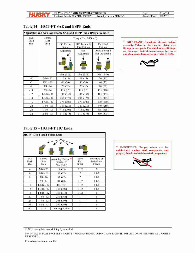
Table 14 – HGT-FT SAE and BSPP Ends
Adjustable and Non-Adjustable SAE and BSPP Ends (Plugs excluded)
SAE Dash Size
Thread Size Inch
Torque * (+10% - 0)
JIC, Ferrule Fittings
JIC, Ferrule & Pipe Fittings
Face Seal Fittings
Adjustable
Non- Adjustable
Adjustable and Non-Adjustable
Nm (ft-lb) Nm (ft-lb) Nm (ft-lb)
-4 7/16 - 20 20 (15) 29 (15) 20 (15)
-6 9/16 - 18 40 (30) 40 (30) 46 (35)
-8 3/4 - 16 70 (52) 70 (52) 80 (60)
-10 7/8 - 14 115 (85) 115 (85) 135 (100)
-12 1-1/16 - 12 185 (135) 185 (135) 185 (135)
-14 1-3/16 - 12 235 (175) 235 (175) 235 (175)
-16 1-5/16 - 12 270 (200) 270 (200) 270 (200)
-20 1-5/8 - 12 340 (250) 340 (250) 340 (250)
-24 1-7/8 - 12 415 (305) 415 (305) 415 (305)
-32 2-1/2 - 12 510 (375) 510 (375) 510 (375)
Table 15 – HGT-FT JIC Ends
JIC (37 Deg Flared Tube) Ends
SAE Dash Size
Thread Size Inch
Assembly Torque * (+10% - 0) Nm (ft-lb)
Tube End
FFWR
Hose End or Swivel Nut
FFWR
4 7/16 - 20 18 (13) 2 1/2 2
6 9/16 - 18 30 (22) 2 1 1/2
8 3/4 - 16 57 (42) 2 1 1/2
10 7/8 - 14 81 (60) 1 1/2 1 1/2
12 1-1/16 - 12 115 (84) 1 1/2 1 1/4
14 1-3/16 - 12 135 (100) 1 1/2 1 1/4
16 1-5/16 - 12 160 (118) 1 1/2 1
20 1-5/8 - 12 230 (168) 1 1
24 1-7/8 - 12 265 (195) 1 1
32 2-1/2 - 12 360 (265) 1 1
40 3-12 Not Applicable 1 1
* IMPORTANT: Torque values are for unlubricated carbon steel components and properly lubricated stainless-steel components.
* IMPORTANT: Lubricate threads before assembly. Values in chart are for plated steel fittings in steel ports. For stainless steel fittings, use the upper limit of torque range. For brass and aluminum, decrease torque value by 35%.
HS 252 - STANDARD ASSEMBLY TORQUES Page 22 of 38 Revision Level - 69 - PUBLISHED Security Level - PUBLIC Standard No. HS 252
© 2021 Husky Injection Molding Systems Ltd.
NO INTELLECTUAL PROPERTY RIGHTS ARE GRANTED INCLUDING ANY LICENSE, IMPLIED OR OTHERWISE. ALL RIGHTS RESERVED.
Printed copies are uncontrolled.
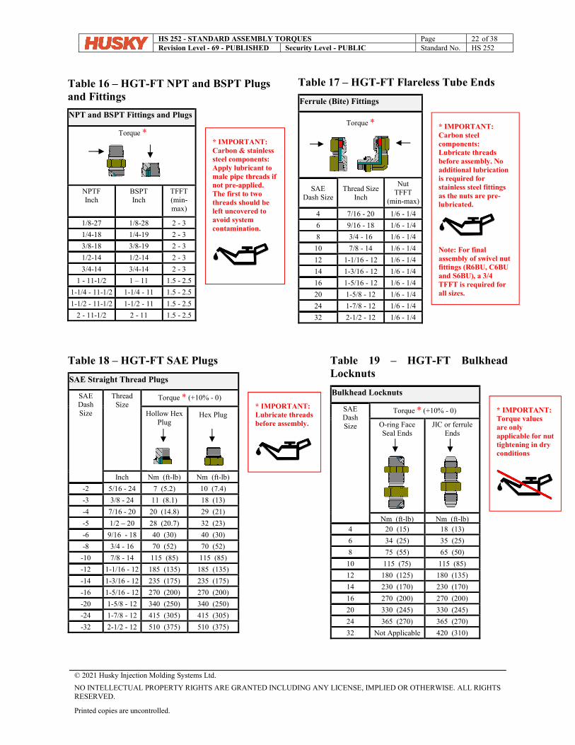
Table 16 – HGT-FT NPT and BSPT Plugs and Fittings
NPT and BSPT Fittings and Plugs
Torque *
NPTF Inch
BSPT Inch
TFFT (min-max)
1/8-27 1/8-28 2 - 3
1/4-18 1/4-19 2 - 3
3/8-18 3/8-19 2 - 3
1/2-14 1/2-14 2 - 3
3/4-14 3/4-14 2 - 3
1 - 11-1/2 1 – 11 1.5 - 2.5
1-1/4 - 11-1/2 1-1/4 - 11 1.5 - 2.5
1-1/2 - 11-1/2 1-1/2 - 11 1.5 - 2.5
2 - 11-1/2 2 - 11 1.5 - 2.5
Table 17 – HGT-FT Flareless Tube Ends
Ferrule (Bite) Fittings
Torque *
SAE Dash Size
Thread Size Inch
Nut TFFT
(min-max)
4 7/16 - 20 1/6 - 1/4
6 9/16 - 18 1/6 - 1/4
8 3/4 - 16 1/6 - 1/4
10 7/8 - 14 1/6 - 1/4
12 1-1/16 - 12 1/6 - 1/4
14 1-3/16 - 12 1/6 - 1/4
16 1-5/16 - 12 1/6 - 1/4
20 1-5/8 - 12 1/6 - 1/4
24 1-7/8 - 12 1/6 - 1/4
32 2-1/2 - 12 1/6 - 1/4
Table 18 – HGT-FT SAE Plugs
SAE Straight Thread Plugs
SAE Dash Size
Thread Size
Torque * (+10% - 0)
Hollow Hex Plug
Hex Plug
Inch Nm (ft-lb) Nm (ft-lb)
-2 5/16 - 24 7 (5.2) 10 (7.4)
-3 3/8 - 24 11 (8.1) 18 (13)
-4 7/16 - 20 20 (14.8) 29 (21)
-5 1/2 – 20 28 (20.7) 32 (23)
-6 9/16 - 18 40 (30) 40 (30)
-8 3/4 - 16 70 (52) 70 (52)
-10 7/8 - 14 115 (85) 115 (85)
-12 1-1/16 - 12 185 (135) 185 (135)
-14 1-3/16 - 12 235 (175) 235 (175)
-16 1-5/16 - 12 270 (200) 270 (200)
-20 1-5/8 - 12 340 (250) 340 (250)
-24 1-7/8 - 12 415 (305) 415 (305)
-32 2-1/2 - 12 510 (375) 510 (375)
Table 19 – HGT-FT Bulkhead Locknuts
Bulkhead Locknuts
SAE Dash Size
Torque * (+10% - 0)
O-ring Face Seal Ends
JIC or ferrule Ends
Nm (ft-lb) Nm (ft-lb) 4 20 (15) 18 (13)
6 34 (25) 35 (25)
8 75 (55) 65 (50)
10 115 (75) 115 (85)
12 180 (125) 180 (135)
14 230 (170) 230 (170)
16 270 (200) 270 (200)
20 330 (245) 330 (245)
24 365 (270) 365 (270)
32 Not Applicable 420 (310)
* IMPORTANT: Torque values are only applicable for nut tightening in dry conditions
* IMPORTANT: Carbon steel components: Lubricate threads before assembly. No additional lubrication is required for stainless steel fittings as the nuts are pre-lubricated.
Note: For final assembly of swivel nut fittings (R6BU, C6BU and S6BU), a 3/4 TFFT is required for all sizes.
* IMPORTANT: Carbon & stainless steel components: Apply lubricant to male pipe threads if not pre-applied. The first to two threads should be left uncovered to avoid system contamination.
* IMPORTANT: Lubricate threads before assembly.
HS 252 - STANDARD ASSEMBLY TORQUES Page 23 of 38 Revision Level - 69 - PUBLISHED Security Level - PUBLIC Standard No. HS 252
© 2021 Husky Injection Molding Systems Ltd.
NO INTELLECTUAL PROPERTY RIGHTS ARE GRANTED INCLUDING ANY LICENSE, IMPLIED OR OTHERWISE. ALL RIGHTS RESERVED.
Printed copies are uncontrolled.
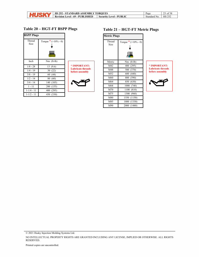
Table 20 – HGT-FT BSPP Plugs
BSPP Plugs
Thread Size
Torque * (+10% - 0)
Inch Nm (ft-lb)
1/8 - 28 13 (9.6)
1/4 - 19 30 (22)
3/8 - 19 60 (44)
1/2 - 14 80 (60)
3/4 - 14 140 (105)
1 - 11 200 (155)
1-1/4 - 11 400 (295)
1-1/2 - 11 450 (330)
Table 21 – HGT-FT Metric Plugs
Metric Plugs
Thread Size
Torque * (+10% - 0)
Metric Nm (ft-lb)
M42 400 (295)
M48 500 (370)
M52 600 (440)
M60 800 (590)
M64 850 (630)
M68 1000 (740)
M70 1100 (810)
M75 1300 (960)
M80 1550 (1150)
M85 1800 (1330)
M90 2000 (1480)
* IMPORTANT: Lubricate threads before assembly
* IMPORTANT: Lubricate threads before assembly
HS 252 - STANDARD ASSEMBLY TORQUES Page 24 of 38 Revision Level - 69 - PUBLISHED Security Level - PUBLIC Standard No. HS 252
© 2021 Husky Injection Molding Systems Ltd.
NO INTELLECTUAL PROPERTY RIGHTS ARE GRANTED INCLUDING ANY LICENSE, IMPLIED OR OTHERWISE. ALL RIGHTS RESERVED.
Printed copies are uncontrolled.
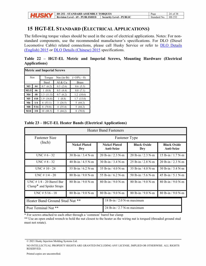
15 HGT-EL STANDARD (ELECTRICAL APPLICATIONS) The following torque values should be used in the case of electrical applications. Notes: For non-standard components, use the recommended manufacturer’s specifications. For DLO (Diesel Locomotive Cable) related connections, please call Husky Service or refer to DLO Details (English) 2015 or DLO Details (Chinese) 2015 specifications.
Table 22 – HGT-EL Metric and Imperial Screws, Mounting Hardware (Electrical Applications)
Metric and Imperial Screws
Size
Torque Nm (in-lb) (+10% - 0)
Steel Al & Cu Brass M3 #4 0.7 (6.2) 0.3 (2.6) 0.6 (5.3)
M3.5 #6 1 (8.8) 0.5 (4.4) 0.8 (7.1)
M4 #8 1.3 (11.5) 0.7 (6.2) 1.2 (10.6)
M5 #10 1.9 (16.8) 1 (8.8) 1.7 (15.0)
M6 1/4 6 (53.1) 3 (26.5) 5 (44.2)
M8 5/16 8 (70.8) 4 (35.4) 5 (44.2)
M10 3/8 10 (88.5) 5 (44.2) 8 (70.8)
Table 23 – HGT-EL Heater Bands (Electrical Applications)
Heater Band Fasteners
Fastener Size (Inch)
Fastener Type
Nickel Plated Dry
Nickel Plated Anti-Seize
Black Oxide Dry
Black Oxide Anti-Seize
UNC # 6 - 32 30 lb-in / 3.4 N-m 20 lb-in / 2.3 N-m 20 lb-in / 2.3 N-m 15 lb-in / 1.7 N-m
UNC # 8 - 32 40 lb-in / 4.5 N-m 30 lb-in / 3.4 N-m 25 lb-in / 2.8 N-m 20 lb-in / 2.3 N-m
UNC # 10 - 24 55 lb-in / 6.2 N-m 35 lb-in / 4.0 N-m 35 lb-in / 4.0 N-m 30 lb-in / 3.4 N-m
UNC # 1/4 - 20 80 lb-in / 9.0 N-m 55 lb-in / 6.2 N-m 50 lb-in / 5.6 N-m 45 lb-in / 5.1 N-m
UNC # 1/4 - 20 Barrel Bar Clamp* and Spider Straps
80 lb-in / 9.0 N-m 80 lb-in / 9.0 N-m 80 lb-in / 9.0 N-m 80 lb-in / 9.0 N-m
UNC # 5/16 - 18 80 lb-in / 9.0 N-m 80 lb-in / 9.0 N-m 80 lb-in / 9.0 N-m 80 lb-in / 9.0 N-m
Heater Band Ground Stud Nut ** 18 lb-in / 2.0 N-m maximum
Post Terminal Nut ** 24 lb-in / 2.7 N-m maximum
* For screws attached to each other through a ‘common’ barrel bar clamp ** Use an open ended wrench to hold the nut closest to the heater as the wiring nut is torqued (threaded ground stud must not rotate).
HS 252 - STANDARD ASSEMBLY TORQUES Page 25 of 38 Revision Level - 69 - PUBLISHED Security Level - PUBLIC Standard No. HS 252
© 2021 Husky Injection Molding Systems Ltd.
NO INTELLECTUAL PROPERTY RIGHTS ARE GRANTED INCLUDING ANY LICENSE, IMPLIED OR OTHERWISE. ALL RIGHTS RESERVED.
Printed copies are uncontrolled.
Table 24 – HGT-EL Solid State Relays (Electrical Applications)
Solid state relays (e.g. HPN 231452, Crydom model# H12D4840DE 40A Dual SSR)
15 to 20 lb-in / 1.7 to 2.2 N-m
Table 25 – HGT-EL Premolded Cables (Electrical Applications)
Premolded Cable Size Torque
M8 3.5 lb-in / 0.4 N-m
M12 5.5 lb-in / 0.6 N-m
Table 26 – HGT-EL Electrical Cabinet Door Ground Stud (Electrical Applications)
M6 35 lb-in / 4.0 N-m
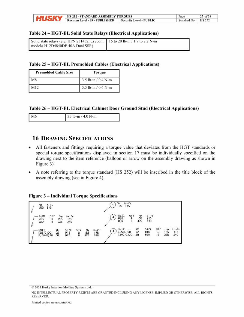
16 DRAWING SPECIFICATIONS All fasteners and fittings requiring a torque value that deviates from the HGT standards or
special torque specifications displayed in section 17 must be individually specified on the drawing next to the item reference (balloon or arrow on the assembly drawing as shown in Figure 3).
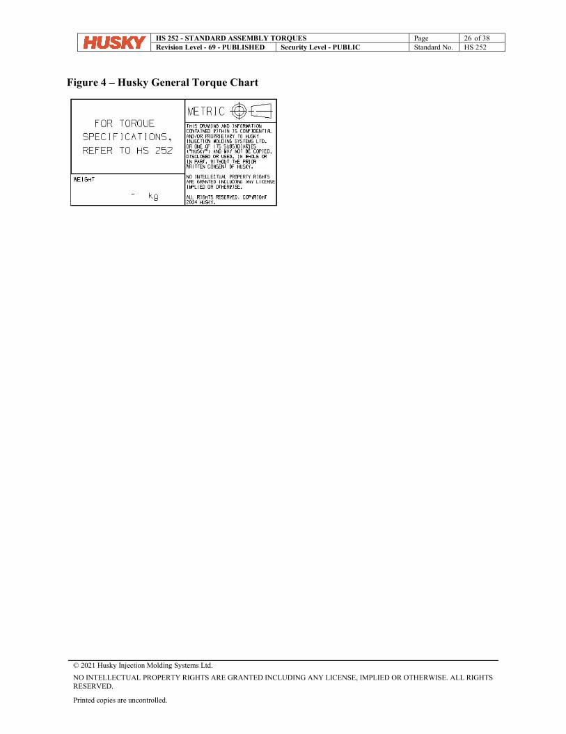
A note referring to the torque standard (HS 252) will be inscribed in the title block of the assembly drawing (see in Figure 4).
Figure 3 – Individual Torque Specifications
HS 252 - STANDARD ASSEMBLY TORQUES Page 26 of 38 Revision Level - 69 - PUBLISHED Security Level - PUBLIC Standard No. HS 252
© 2021 Husky Injection Molding Systems Ltd.
NO INTELLECTUAL PROPERTY RIGHTS ARE GRANTED INCLUDING ANY LICENSE, IMPLIED OR OTHERWISE. ALL RIGHTS RESERVED.
Printed copies are uncontrolled.
Figure 4 – Husky General Torque Chart
HS 252 - STANDARD ASSEMBLY TORQUES Page 27 of 38 Revision Level - 69 - PUBLISHED Security Level - PUBLIC Standard No. HS 252
© 2021 Husky Injection Molding Systems Ltd.
NO INTELLECTUAL PROPERTY RIGHTS ARE GRANTED INCLUDING ANY LICENSE, IMPLIED OR OTHERWISE. ALL RIGHTS RESERVED.
Printed copies are uncontrolled.
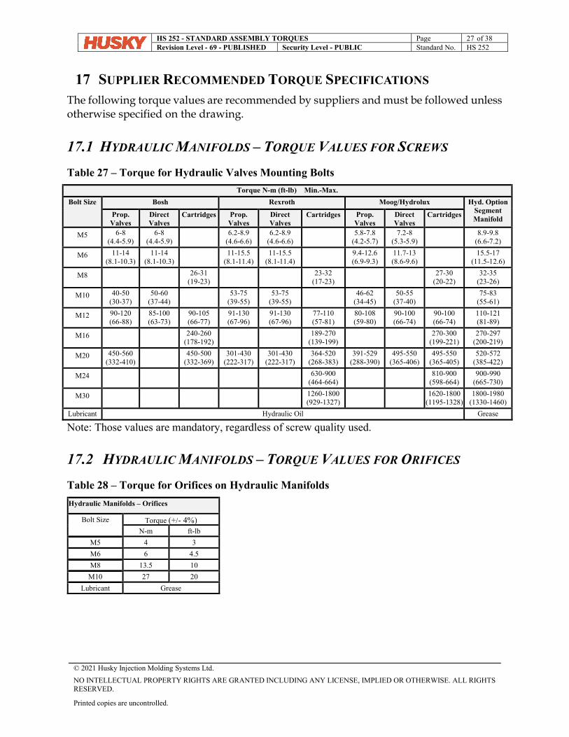
17 SUPPLIER RECOMMENDED TORQUE SPECIFICATIONS The following torque values are recommended by suppliers and must be followed unless otherwise specified on the drawing.
17.1 HYDRAULIC MANIFOLDS – TORQUE VALUES FOR SCREWS
Table 27 – Torque for Hydraulic Valves Mounting Bolts
Torque N-m (ft-lb) Min.-Max.
Bolt Size Bosh Rexroth Moog/Hydrolux Hyd. Option Segment Manifold
Prop. Valves
Direct Valves
Cartridges Prop. Valves
Direct Valves
Cartridges Prop. Valves
Direct Valves
Cartridges
M5 6-8 (4.4-5.9)
6-8 (4.4-5.9)
6.2-8.9 (4.6-6.6)
6.2-8.9 (4.6-6.6)
5.8-7.8 (4.2-5.7)
7.2-8 (5.3-5.9)
8.9-9.8 (6.6-7.2)
M6 11-14 (8.1-10.3)
11-14 (8.1-10.3)
11-15.5 (8.1-11.4)
11-15.5 (8.1-11.4)
9.4-12.6 (6.9-9.3)
11.7-13 (8.6-9.6)
15.5-17 (11.5-12.6)
M8 26-31 (19-23)
23-32 (17-23)
27-30 (20-22)
32-35 (23-26)
M10 40-50 (30-37)
50-60 (37-44)
53-75 (39-55)
53-75 (39-55)
46-62 (34-45)
50-55 (37-40)
75-83 (55-61)
M12 90-120 (66-88)
85-100 (63-73)
90-105 (66-77)
91-130 (67-96)
91-130 (67-96)
77-110 (57-81)
80-108 (59-80)
90-100 (66-74)
90-100 (66-74)
110-121 (81-89)
M16 240-260 (178-192)
189-270 (139-199)
270-300 (199-221)
270-297 (200-219)
M20 450-560 (332-410)
450-500 (332-369)
301-430 (222-317)
301-430 (222-317)
364-520 (268-383)
391-529 (288-390)
495-550 (365-406)
495-550 (365-405)
520-572 (385-422)
M24 630-900 (464-664)
810-900 (598-664)
900-990 (665-730)
M30 1260-1800 (929-1327)
1620-1800 (1195-1328)
1800-1980 (1330-1460)
Lubricant Hydraulic Oil Grease
Note: Those values are mandatory, regardless of screw quality used.
17.2 HYDRAULIC MANIFOLDS – TORQUE VALUES FOR ORIFICES
Table 28 – Torque for Orifices on Hydraulic Manifolds
Hydraulic Manifolds – Orifices
Bolt Size
Torque (+/- 4%) N-m ft-lb
M5 4 3
M6 6 4.5
M8 13.5 10
M10 27 20
Lubricant Grease
HS 252 - STANDARD ASSEMBLY TORQUES Page 28 of 38 Revision Level - 69 - PUBLISHED Security Level - PUBLIC Standard No. HS 252
© 2021 Husky Injection Molding Systems Ltd.
NO INTELLECTUAL PROPERTY RIGHTS ARE GRANTED INCLUDING ANY LICENSE, IMPLIED OR OTHERWISE. ALL RIGHTS RESERVED.
Printed copies are uncontrolled.
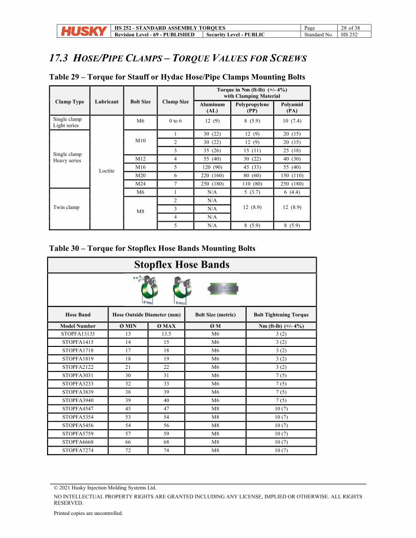
17.3 HOSE/PIPE CLAMPS – TORQUE VALUES FOR SCREWS
Table 29 – Torque for Stauff or Hydac Hose/Pipe Clamps Mounting Bolts
Clamp Type
Lubricant
Bolt Size
Clamp Size
Torque in Nm (ft-lb) (+/- 4%) with Clamping Material
Aluminum (AL)
Polypropylene (PP)
Polyamid (PA)
Single clamp Light series
Loctite
M6 0 to 6 12 (9) 8 (5.9) 10 (7.4)
Single clamp Heavy series
M10 1 30 (22) 12 (9) 20 (15)
2 30 (22) 12 (9) 20 (15)
3 35 (26) 15 (11) 25 (18)
M12 4 55 (40) 30 (22) 40 (30)
M16 5 120 (90) 45 (33) 55 (40)
M20 6 220 (160) 80 (60) 150 (110)
M24 7 250 (180) 110 (80) 250 (180)
Twin clamp
M6 1 N/A 5 (3.7) 6 (4.4)
M8
2 N/A 12 (8.9) 12 (8.9) 3 N/A
4 N/A
5 N/A 8 (5.9) 8 (5.9)
Table 30 – Torque for Stopflex Hose Bands Mounting Bolts
Stopflex Hose Bands
Hose Band Hose Outside Diameter (mm) Bolt Size (metric) Bolt Tightening Torque
Model Number Ø MIN Ø MAX Ø M Nm (ft-lb) (+/- 4%)
STOPFA13135 13 13.5 M6 3 (2)
STOPFA1415 14 15 M6 3 (2)
STOPFA1718 17 18 M6 3 (2)
STOPFA1819 18 19 M6 3 (2)
STOPFA2122 21 22 M6 3 (2)
STOPFA3031 30 31 M6 7 (5)
STOPFA3233 32 33 M6 7 (5)
STOPFA3839 38 39 M6 7 (5)
STOPFA3940 39 40 M6 7 (5)
STOPFA4547 45 47 M8 10 (7)
STOPFA5354 53 54 M8 10 (7)
STOPFA5456 54 56 M8 10 (7)
STOPFA5759 57 59 M8 10 (7)
STOPFA6668 66 68 M8 10 (7)
STOPFA7274 72 74 M8 10 (7)
HS 252 - STANDARD ASSEMBLY TORQUES Page 29 of 38 Revision Level - 69 - PUBLISHED Security Level - PUBLIC Standard No. HS 252
© 2021 Husky Injection Molding Systems Ltd.
NO INTELLECTUAL PROPERTY RIGHTS ARE GRANTED INCLUDING ANY LICENSE, IMPLIED OR OTHERWISE. ALL RIGHTS RESERVED.
Printed copies are uncontrolled.
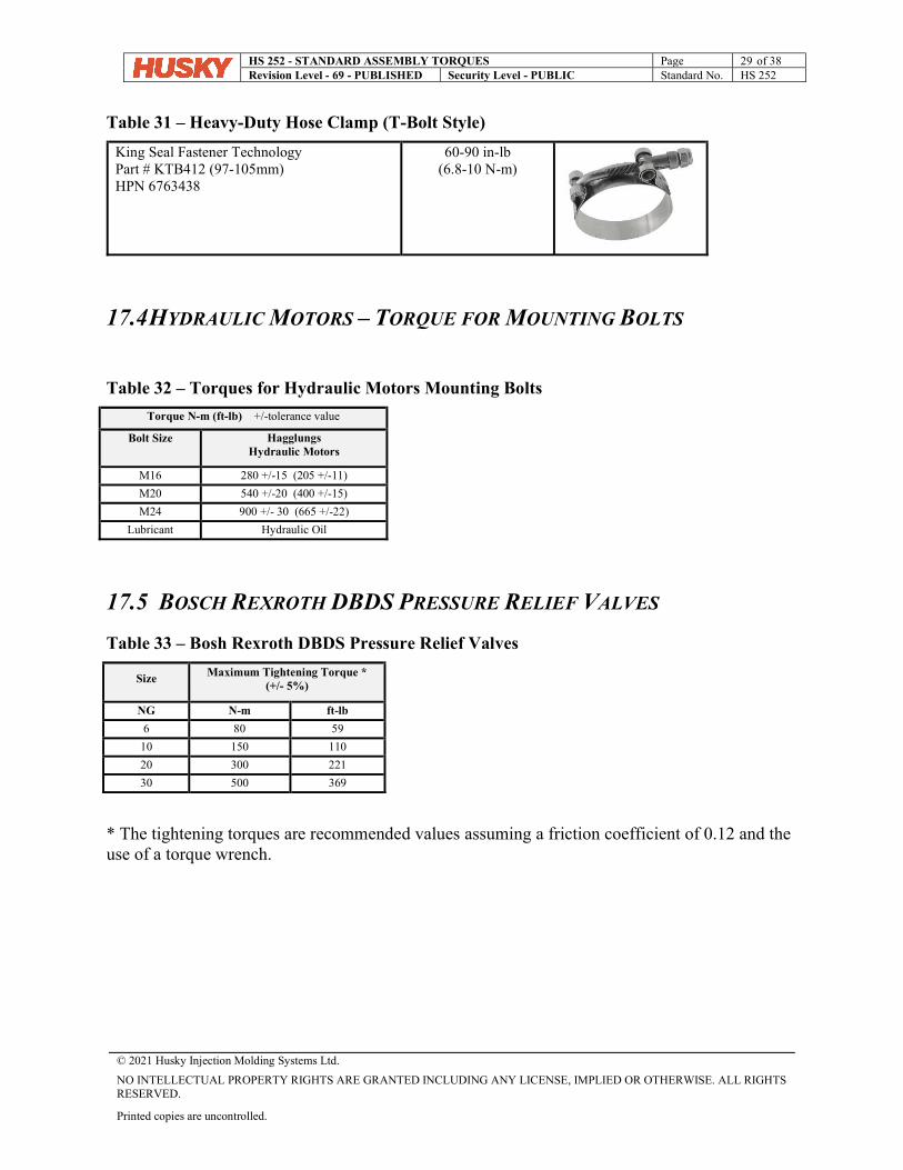
Table 31 – Heavy-Duty Hose Clamp (T-Bolt Style)
King Seal Fastener Technology Part # KTB412 (97-105mm) HPN 6763438
60-90 in-lb (6.8-10 N-m)
17.4 HYDRAULIC MOTORS – TORQUE FOR MOUNTING BOLTS
Table 32 – Torques for Hydraulic Motors Mounting Bolts
Torque N-m (ft-lb) +/-tolerance value
Bolt Size Hagglungs Hydraulic Motors
M16 280 +/-15 (205 +/-11)
M20 540 +/-20 (400 +/-15)
M24 900 +/- 30 (665 +/-22)
Lubricant Hydraulic Oil
17.5 BOSCH REXROTH DBDS PRESSURE RELIEF VALVES
Table 33 – Bosh Rexroth DBDS Pressure Relief Valves
Size Maximum Tightening Torque * (+/- 5%)
NG N-m ft-lb
6 80 59
10 150 110
20 300 221
30 500 369
* The tightening torques are recommended values assuming a friction coefficient of 0.12 and the use of a torque wrench.
HS 252 - STANDARD ASSEMBLY TORQUES Page 30 of 38 Revision Level - 69 - PUBLISHED Security Level - PUBLIC Standard No. HS 252
© 2021 Husky Injection Molding Systems Ltd.
NO INTELLECTUAL PROPERTY RIGHTS ARE GRANTED INCLUDING ANY LICENSE, IMPLIED OR OTHERWISE. ALL RIGHTS RESERVED.
Printed copies are uncontrolled.
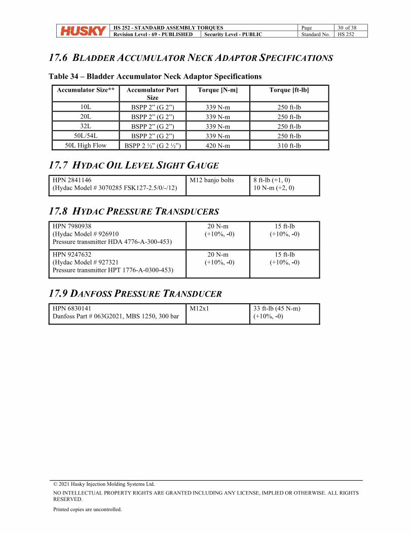
17.6 BLADDER ACCUMULATOR NECK ADAPTOR SPECIFICATIONS
Table 34 – Bladder Accumulator Neck Adaptor Specifications
Accumulator Size** Accumulator Port Size
Torque [N-m] Torque [ft-lb]
10L BSPP 2” (G 2”) 339 N-m 250 ft-lb 20L BSPP 2” (G 2”) 339 N-m 250 ft-lb 32L BSPP 2” (G 2”) 339 N-m 250 ft-lb
50L/54L BSPP 2” (G 2”) 339 N-m 250 ft-lb 50L High Flow BSPP 2 ½” (G 2 ½”) 420 N-m 310 ft-lb
17.7 HYDAC OIL LEVEL SIGHT GAUGE HPN 2841146 (Hydac Model # 3070285 FSK127-2.5/0/-/12)
M12 banjo bolts 8 ft-lb (+1, 0) 10 N-m (+2, 0)
17.8 HYDAC PRESSURE TRANSDUCERS HPN 7980938 (Hydac Model # 926910 Pressure transmitter HDA 4776-A-300-453)
20 N-m (+10%, -0)
15 ft-lb (+10%, -0)
HPN 9247632 (Hydac Model # 927321 Pressure transmitter HPT 1776-A-0300-453)
20 N-m (+10%, -0)
15 ft-lb (+10%, -0)
17.9 DANFOSS PRESSURE TRANSDUCER HPN 6830141 Danfoss Part # 063G2021, MBS 1250, 300 bar
M12x1 33 ft-lb (45 N-m) (+10%, -0)
HS 252 - STANDARD ASSEMBLY TORQUES Page 31 of 38 Revision Level - 69 - PUBLISHED Security Level - PUBLIC Standard No. HS 252
© 2021 Husky Injection Molding Systems Ltd.
NO INTELLECTUAL PROPERTY RIGHTS ARE GRANTED INCLUDING ANY LICENSE, IMPLIED OR OTHERWISE. ALL RIGHTS RESERVED.
Printed copies are uncontrolled.
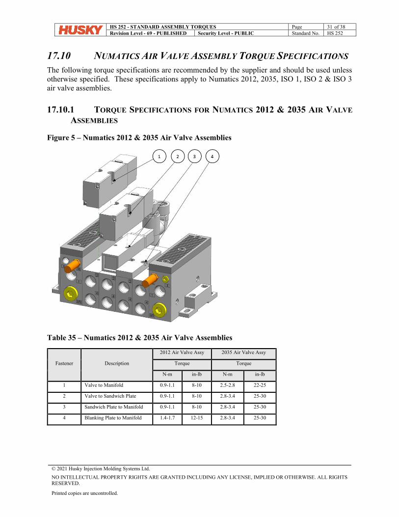
17.10 NUMATICS AIR VALVE ASSEMBLY TORQUE SPECIFICATIONS The following torque specifications are recommended by the supplier and should be used unless otherwise specified. These specifications apply to Numatics 2012, 2035, ISO 1, ISO 2 & ISO 3 air valve assemblies.
17.10.1 TORQUE SPECIFICATIONS FOR NUMATICS 2012 & 2035 AIR VALVE
ASSEMBLIES
Figure 5 – Numatics 2012 & 2035 Air Valve Assemblies
Table 35 – Numatics 2012 & 2035 Air Valve Assemblies
Fastener Description
2012 Air Valve Assy 2035 Air Valve Assy
Torque Torque
N-m in-lb N-m in-lb
1 Valve to Manifold 0.9-1.1 8-10 2.5-2.8 22-25
2 Valve to Sandwich Plate 0.9-1.1 8-10 2.8-3.4 25-30
3 Sandwich Plate to Manifold 0.9-1.1 8-10 2.8-3.4 25-30
4 Blanking Plate to Manifold 1.4-1.7 12-15 2.8-3.4 25-30
HS 252 - STANDARD ASSEMBLY TORQUES Page 32 of 38 Revision Level - 69 - PUBLISHED Security Level - PUBLIC Standard No. HS 252
© 2021 Husky Injection Molding Systems Ltd.
NO INTELLECTUAL PROPERTY RIGHTS ARE GRANTED INCLUDING ANY LICENSE, IMPLIED OR OTHERWISE. ALL RIGHTS RESERVED.
Printed copies are uncontrolled.
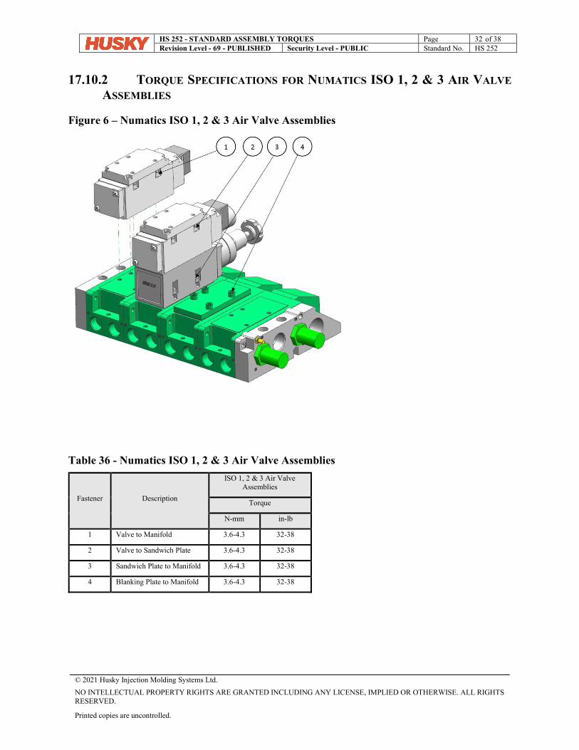
17.10.2 TORQUE SPECIFICATIONS FOR NUMATICS ISO 1, 2 & 3 AIR VALVE
ASSEMBLIES
Figure 6 – Numatics ISO 1, 2 & 3 Air Valve Assemblies
Table 36 - Numatics ISO 1, 2 & 3 Air Valve Assemblies
Fastener Description
ISO 1, 2 & 3 Air Valve Assemblies
Torque
N-mm in-lb
1 Valve to Manifold 3.6-4.3 32-38
2 Valve to Sandwich Plate 3.6-4.3 32-38
3 Sandwich Plate to Manifold 3.6-4.3 32-38
4 Blanking Plate to Manifold 3.6-4.3 32-38
HS 252 - STANDARD ASSEMBLY TORQUES Page 33 of 38 Revision Level - 69 - PUBLISHED Security Level - PUBLIC Standard No. HS 252
© 2021 Husky Injection Molding Systems Ltd.
NO INTELLECTUAL PROPERTY RIGHTS ARE GRANTED INCLUDING ANY LICENSE, IMPLIED OR OTHERWISE. ALL RIGHTS RESERVED.
Printed copies are uncontrolled.
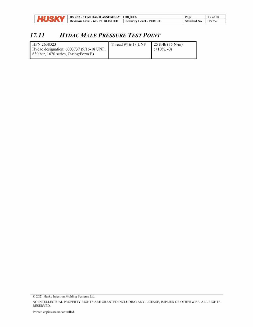
17.11 HYDAC MALE PRESSURE TEST POINT HPN 2638323 Hydac designation: 6003737 (9/16-18 UNF, 630 bar, 1620 series, O-ring/Form E)
Thread 9/16-18 UNF 25 ft-lb (35 N-m) (+10%, -0)
HS 252 - STANDARD ASSEMBLY TORQUES Page 34 of 38 Revision Level - 69 - PUBLISHED Security Level - PUBLIC Standard No. HS 252
© 2021 Husky Injection Molding Systems Ltd.
NO INTELLECTUAL PROPERTY RIGHTS ARE GRANTED INCLUDING ANY LICENSE, IMPLIED OR OTHERWISE. ALL RIGHTS RESERVED.
Printed copies are uncontrolled.
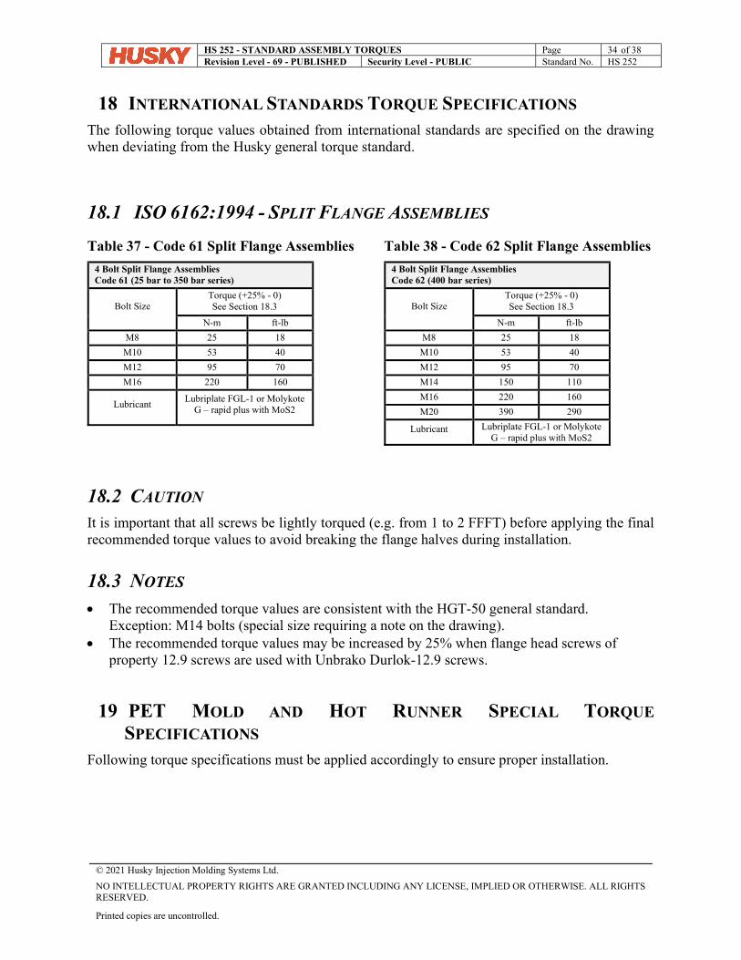
18 INTERNATIONAL STANDARDS TORQUE SPECIFICATIONS The following torque values obtained from international standards are specified on the drawing when deviating from the Husky general torque standard.
18.1 ISO 6162:1994 - SPLIT FLANGE ASSEMBLIES
Table 37 - Code 61 Split Flange Assemblies
4 Bolt Split Flange Assemblies Code 61 (25 bar to 350 bar series)
Bolt Size Torque (+25% - 0) See Section 18.3
N-m ft-lb M8 25 18
M10 53 40
M12 95 70
M16 220 160
Lubricant Lubriplate FGL-1 or Molykote
G – rapid plus with MoS2
Table 38 - Code 62 Split Flange Assemblies
4 Bolt Split Flange Assemblies Code 62 (400 bar series)
Bolt Size Torque (+25% - 0) See Section 18.3
N-m ft-lb M8 25 18
M10 53 40
M12 95 70
M14 150 110
M16 220 160
M20 390 290
Lubricant Lubriplate FGL-1 or Molykote G – rapid plus with MoS2
18.2 CAUTION It is important that all screws be lightly torqued (e.g. from 1 to 2 FFFT) before applying the final recommended torque values to avoid breaking the flange halves during installation.
18.3 NOTES The recommended torque values are consistent with the HGT-50 general standard.
Exception: M14 bolts (special size requiring a note on the drawing). The recommended torque values may be increased by 25% when flange head screws of
property 12.9 screws are used with Unbrako Durlok-12.9 screws.
19 PET MOLD AND HOT RUNNER SPECIAL TORQUE
SPECIFICATIONS Following torque specifications must be applied accordingly to ensure proper installation.
HS 252 - STANDARD ASSEMBLY TORQUES Page 35 of 38 Revision Level - 69 - PUBLISHED Security Level - PUBLIC Standard No. HS 252
© 2021 Husky Injection Molding Systems Ltd.
NO INTELLECTUAL PROPERTY RIGHTS ARE GRANTED INCLUDING ANY LICENSE, IMPLIED OR OTHERWISE. ALL RIGHTS RESERVED.
Printed copies are uncontrolled.
19.1 CAM FOLLOWER TORQUE SPECIFICATIONS
Table 39 – CAM Follower Torque Specifications
CAM follower HPN Component Torque [N-m] Torque [ft-lb]
1425388 Nut 22 N-m 16 ft-lb
1502548 Nut 87 N-m 64 ft-lb
2739013 Cam Follower 87 N-m 64 ft-lb
Set Screw 8.5-9 N-m 6.3-6.6 ft-lb
5792862 Cam Follower 87 N-m 64 ft-lb
Set Screw 8.5-9 N-m 6.3-6.6 ft-lb
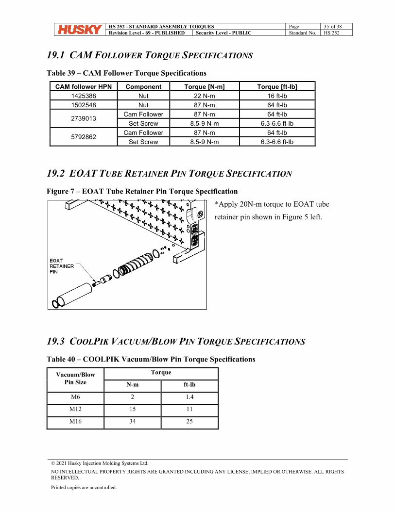
19.2 EOAT TUBE RETAINER PIN TORQUE SPECIFICATION
Figure 7 – EOAT Tube Retainer Pin Torque Specification
*Apply 20N-m torque to EOAT tube
retainer pin shown in Figure 5 left.
19.3 COOLPIK VACUUM/BLOW PIN TORQUE SPECIFICATIONS
Table 40 – COOLPIK Vacuum/Blow Pin Torque Specifications
Vacuum/Blow Pin Size
Torque
N-m ft-lb
M6 2 1.4
M12 15 11
M16 34 25
HS 252 - STANDARD ASSEMBLY TORQUES Page 36 of 38 Revision Level - 69 - PUBLISHED Security Level - PUBLIC Standard No. HS 252
© 2021 Husky Injection Molding Systems Ltd.
NO INTELLECTUAL PROPERTY RIGHTS ARE GRANTED INCLUDING ANY LICENSE, IMPLIED OR OTHERWISE. ALL RIGHTS RESERVED.
Printed copies are uncontrolled.
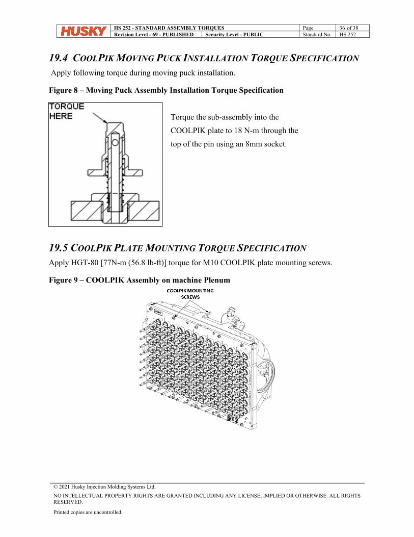
19.4 COOLPIK MOVING PUCK INSTALLATION TORQUE SPECIFICATION Apply following torque during moving puck installation.
Figure 8 – Moving Puck Assembly Installation Torque Specification
Torque the sub-assembly into the
COOLPIK plate to 18 N-m through the
top of the pin using an 8mm socket.
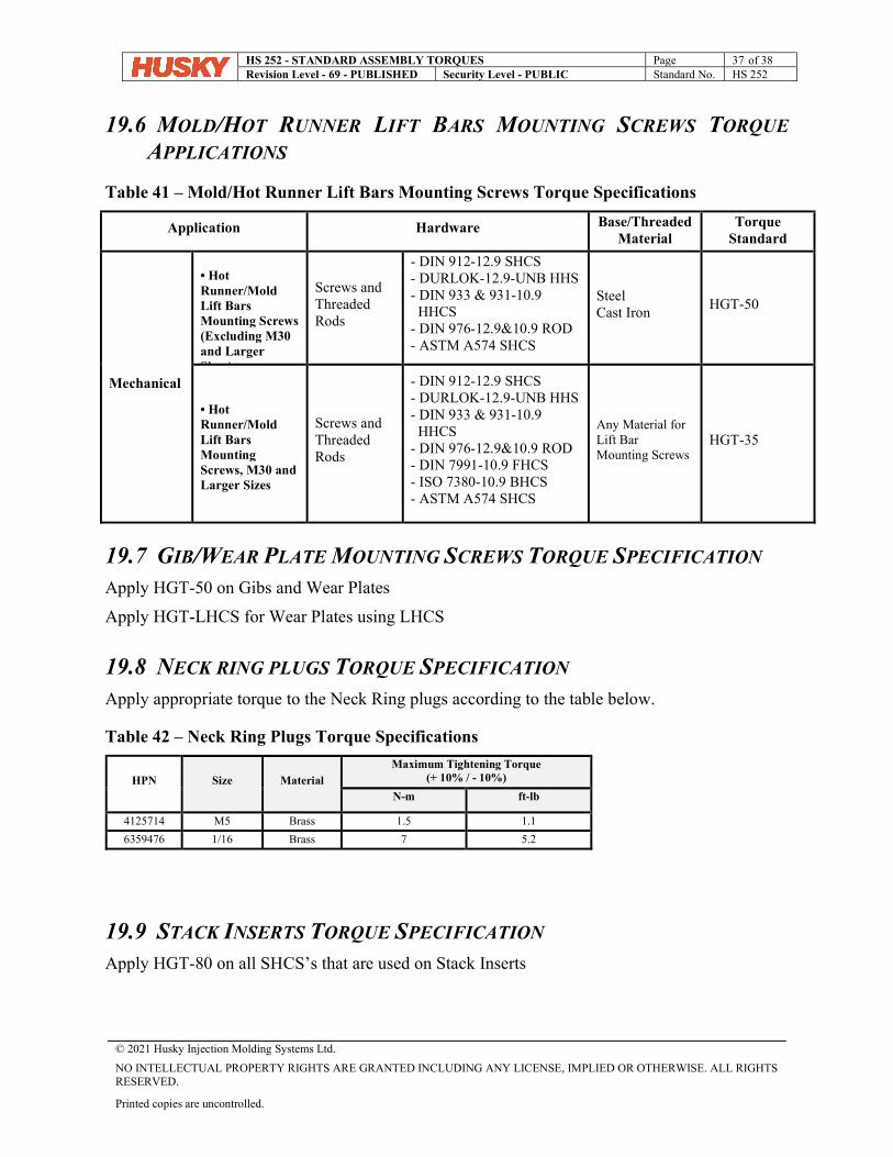
19.5 COOLPIK PLATE MOUNTING TORQUE SPECIFICATION Apply HGT-80 [77N-m (56.8 lb-ft)] torque for M10 COOLPIK plate mounting screws.
Figure 9 – COOLPIK Assembly on machine Plenum
HS 252 - STANDARD ASSEMBLY TORQUES Page 37 of 38 Revision Level - 69 - PUBLISHED Security Level - PUBLIC Standard No. HS 252
© 2021 Husky Injection Molding Systems Ltd.
NO INTELLECTUAL PROPERTY RIGHTS ARE GRANTED INCLUDING ANY LICENSE, IMPLIED OR OTHERWISE. ALL RIGHTS RESERVED.
Printed copies are uncontrolled.
19.6 MOLD/HOT RUNNER LIFT BARS MOUNTING SCREWS TORQUE
APPLICATIONS
Table 41 – Mold/Hot Runner Lift Bars Mounting Screws Torque Specifications
Application Hardware Base/Threaded Material
Torque Standard
Mechanical
• Hot Runner/Mold Lift Bars Mounting Screws (Excluding M30 and Larger Sizes)
Screws and Threaded Rods
- DIN 912-12.9 SHCS - DURLOK-12.9-UNB HHS - DIN 933 & 931-10.9 HHCS - DIN 976-12.9&10.9 ROD - ASTM A574 SHCS
Steel Cast Iron
HGT-50
• Hot Runner/Mold Lift Bars Mounting Screws, M30 and Larger Sizes
Screws and Threaded Rods
- DIN 912-12.9 SHCS - DURLOK-12.9-UNB HHS - DIN 933 & 931-10.9 HHCS - DIN 976-12.9&10.9 ROD - DIN 7991-10.9 FHCS - ISO 7380-10.9 BHCS - ASTM A574 SHCS
Any Material for Lift Bar Mounting Screws
HGT-35
19.7 GIB/WEAR PLATE MOUNTING SCREWS TORQUE SPECIFICATION Apply HGT-50 on Gibs and Wear Plates
Apply HGT-LHCS for Wear Plates using LHCS
19.8 NECK RING PLUGS TORQUE SPECIFICATION Apply appropriate torque to the Neck Ring plugs according to the table below.
Table 42 – Neck Ring Plugs Torque Specifications
19.9 STACK INSERTS TORQUE SPECIFICATION Apply HGT-80 on all SHCS’s that are used on Stack Inserts
HPN Size Material
Maximum Tightening Torque (+ 10% / - 10%)
N-m ft-lb
4125714 M5 Brass 1.5 1.1
6359476 1/16 Brass 7 5.2
HS 252 - STANDARD ASSEMBLY TORQUES Page 38 of 38 Revision Level - 69 - PUBLISHED Security Level - PUBLIC Standard No. HS 252
© 2021 Husky Injection Molding Systems Ltd.
NO INTELLECTUAL PROPERTY RIGHTS ARE GRANTED INCLUDING ANY LICENSE, IMPLIED OR OTHERWISE. ALL RIGHTS RESERVED.
Printed copies are uncontrolled.
19.10 TORQUE SPECIFICATION FOR WATER MANIFOLDS TO
SLIDES Apply HGT-80 on all SHCS’s that are used to mount Slide Water Manifolds to Slides
19.11 TORQUE SPECIFICATION FOR SLIDE TO CONNECTING BARS Apply HGT-80 on all SHCS’s that are used to mount Slides to Connecting Bars
19.12 TORQUE SPECIFICATION FOR EOAT ASSY. TO ROBOT Apply HGT-80 on all SHCS’s that are used to mount EOAT Assembly to Robot Carriage
HS 897 – ADHESIVE STANDARD Page 1 of 5 Revision Level - 1 - PUBLISHED Security Level - PUBLIC Standard No. HS 897
© 2021 Husky Injection Molding Systems Ltd.
NO INTELLECTUAL PROPERTY RIGHTS ARE GRANTED INCLUDING ANY LICENSE, IMPLIED OR OTHERWISE. ALL RIGHTS RESERVED.
Printed copies are uncontrolled.
HS 897 - ADHESIVE STANDARD
TABLE OF CONTENTS 1 PURPOSE ............................................................................................................... 2
2 DOCUMENT CONTROL .......................................................................................... 2
3 REFERENCES......................................................................................................... 2
4 ADHESIVES............................................................................................................. 2
4.1 USAGE ................................................................................................................ 2
4.2 SELECTION .......................................................................................................... 3
5 ADDITIONAL LINKS ................................................................................................ 5
TABLE OF TABLES Table 1 - Adhesive Selection for Specific Applications .......................................................... 3
Table 2 - Adhesive Selection for General Applications .......................................................... 3
Table 3 - Adhesive List ................................................................................................................ 4
REVISION LOG
Document Last Saved 8/24/2021 8:41:00
AM By User
Duckett, Ian (Milton)
Release Date 2021-08-19 Approved By (see reviewers below)
Rev Remarks Edited Reviewed
0 Original Issue Ian Duckett / 2021-08-19 HRC Standards / Fred
Mazzia 1 Added Loctite 668 per SR 60966 Ian Duckett / 2021-08-23 HRC Standards / Z.Sever
HS 897 – ADHESIVE STANDARD Page 2 of 5 Revision Level - 1 - PUBLISHED Security Level - PUBLIC Standard No. HS 897
© 2021 Husky Injection Molding Systems Ltd.
NO INTELLECTUAL PROPERTY RIGHTS ARE GRANTED INCLUDING ANY LICENSE, IMPLIED OR OTHERWISE. ALL RIGHTS RESERVED.
Printed copies are uncontrolled.
1 PURPOSE This standard contains a list of approved adhesives, thread lockers & retaining compounds for use in Husky systems. Specific product selection is the responsibility of the equipment operator/owner and may depend on climate, application, performance and regional/regulatory requirements.
2 DOCUMENT CONTROL Revisions to this document shall be authorized by Corporate Operations.
3 REFERENCES HS 252 – Standard Assembly Torques
HS 609 – Lubricants and Coolants
4 ADHESIVES
4.1 USAGE Clean threads of machine oils and lubricant to maximize bonding of adhesive.
For thru holes, apply the adhesive onto the bolt at the thread engagement area.
For blind holes, apply the adhesive to the fastener and the internal threads down to the bottom of the hole. If the adhesive is only applied to the fastener, air pressure will force the liquid thread locker to escape as you torque down.
For disassembly: Remove with standard hand tools or in rare instances where hand tools do not work because of excessive engagement length, apply localized heat to nut or bolt to approximately 250°C. Disassemble while hot.
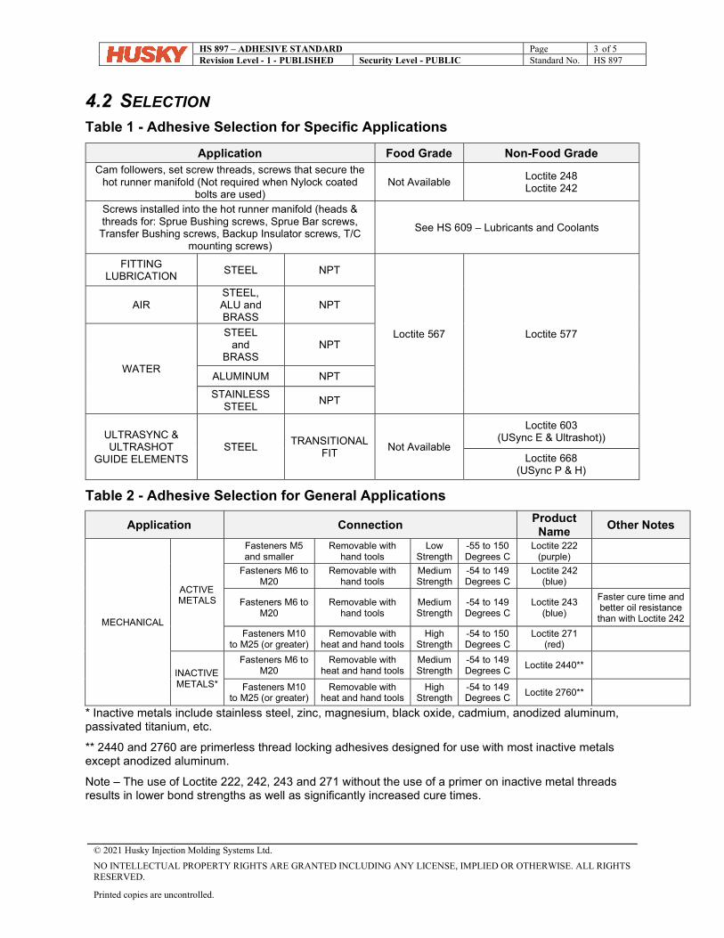
HS 897 – ADHESIVE STANDARD Page 3 of 5 Revision Level - 1 - PUBLISHED Security Level - PUBLIC Standard No. HS 897
© 2021 Husky Injection Molding Systems Ltd.
NO INTELLECTUAL PROPERTY RIGHTS ARE GRANTED INCLUDING ANY LICENSE, IMPLIED OR OTHERWISE. ALL RIGHTS RESERVED.
Printed copies are uncontrolled.
4.2 SELECTION Table 1 - Adhesive Selection for Specific Applications
Table 2 - Adhesive Selection for General Applications
Application Connection Product Name
Other Notes
MECHANICAL
ACTIVE METALS
Fasteners M5 and smaller
Removable with hand tools
Low Strength
-55 to 150 Degrees C
Loctite 222 (purple)
Fasteners M6 to M20
Removable with hand tools
Medium Strength
-54 to 149 Degrees C
Loctite 242 (blue)
Fasteners M6 to M20
Removable with hand tools
Medium Strength
-54 to 149 Degrees C
Loctite 243 (blue)
Faster cure time and better oil resistance than with Loctite 242
Fasteners M10 to M25 (or greater)
Removable with heat and hand tools
High Strength
-54 to 150 Degrees C
Loctite 271 (red)
INACTIVE METALS*
Fasteners M6 to M20
Removable with heat and hand tools
Medium Strength
-54 to 149 Degrees C
Loctite 2440**
Fasteners M10 to M25 (or greater)
Removable with heat and hand tools
High Strength
-54 to 149 Degrees C
Loctite 2760**
* Inactive metals include stainless steel, zinc, magnesium, black oxide, cadmium, anodized aluminum, passivated titanium, etc.
** 2440 and 2760 are primerless thread locking adhesives designed for use with most inactive metals except anodized aluminum.
Note – The use of Loctite 222, 242, 243 and 271 without the use of a primer on inactive metal threads results in lower bond strengths as well as significantly increased cure times.
Application Food Grade Non-Food Grade Cam followers, set screw threads, screws that secure the
hot runner manifold (Not required when Nylock coated bolts are used)
Not Available Loctite 248 Loctite 242
Screws installed into the hot runner manifold (heads & threads for: Sprue Bushing screws, Sprue Bar screws, Transfer Bushing screws, Backup Insulator screws, T/C
mounting screws)
See HS 609 – Lubricants and Coolants
FITTING LUBRICATION
STEEL NPT
Loctite 567 Loctite 577
AIR STEEL, ALU and BRASS
NPT
WATER
STEEL and
BRASS NPT
ALUMINUM NPT
STAINLESS STEEL
NPT
ULTRASYNC & ULTRASHOT
GUIDE ELEMENTS STEEL
TRANSITIONAL FIT
Not Available
Loctite 603 (USync E & Ultrashot))
Loctite 668 (USync P & H)
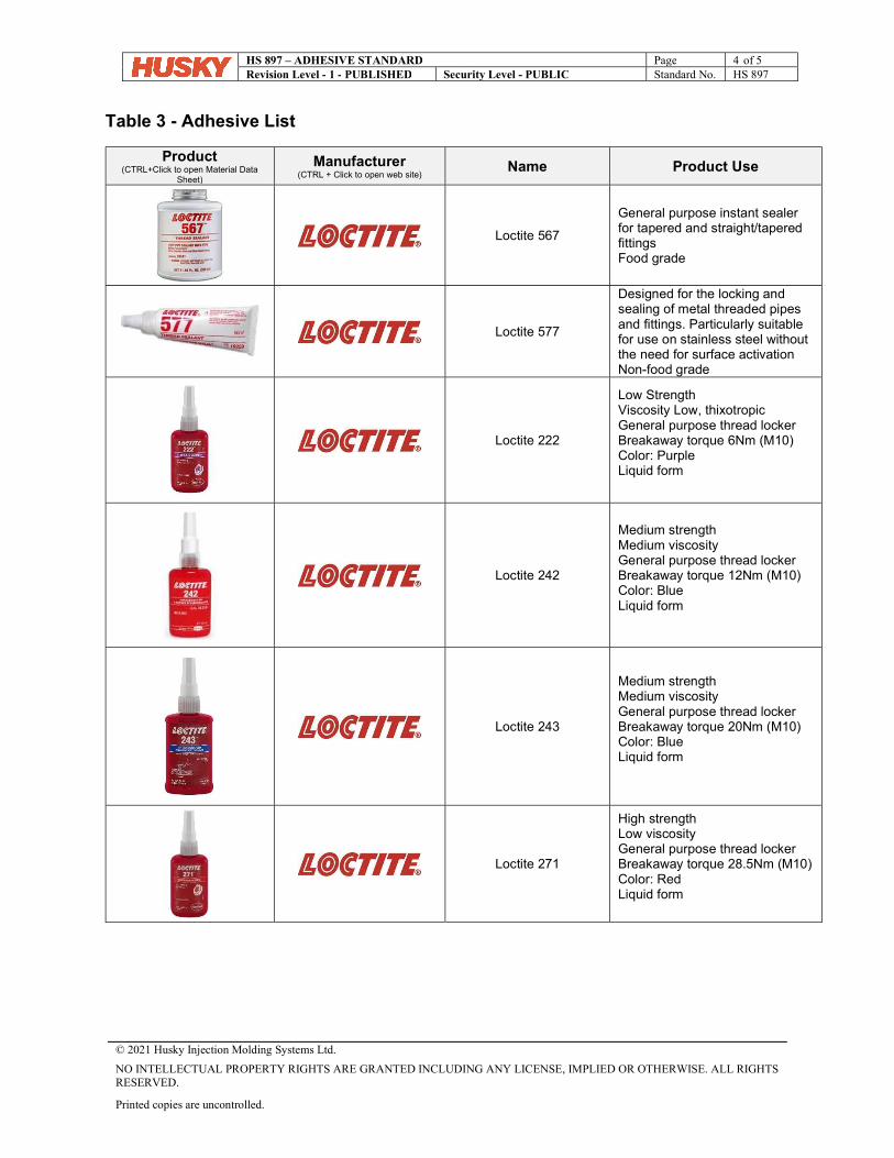
HS 897 – ADHESIVE STANDARD Page 4 of 5 Revision Level - 1 - PUBLISHED Security Level - PUBLIC Standard No. HS 897
© 2021 Husky Injection Molding Systems Ltd.
NO INTELLECTUAL PROPERTY RIGHTS ARE GRANTED INCLUDING ANY LICENSE, IMPLIED OR OTHERWISE. ALL RIGHTS RESERVED.
Printed copies are uncontrolled.
Table 3 - Adhesive List
Product (CTRL+Click to open Material Data
Sheet) Manufacturer
(CTRL + Click to open web site) Name Product Use
Loctite 567
General purpose instant sealer for tapered and straight/tapered fittings Food grade
Loctite 577
Designed for the locking and sealing of metal threaded pipes and fittings. Particularly suitable for use on stainless steel without the need for surface activation Non-food grade
Loctite 222
Low Strength Viscosity Low, thixotropic General purpose thread locker Breakaway torque 6Nm (M10) Color: Purple Liquid form
Loctite 242
Medium strength Medium viscosity General purpose thread locker Breakaway torque 12Nm (M10) Color: Blue Liquid form
Loctite 243
Medium strength Medium viscosity General purpose thread locker Breakaway torque 20Nm (M10) Color: Blue Liquid form
Loctite 271
High strength Low viscosity General purpose thread locker Breakaway torque 28.5Nm (M10) Color: Red Liquid form
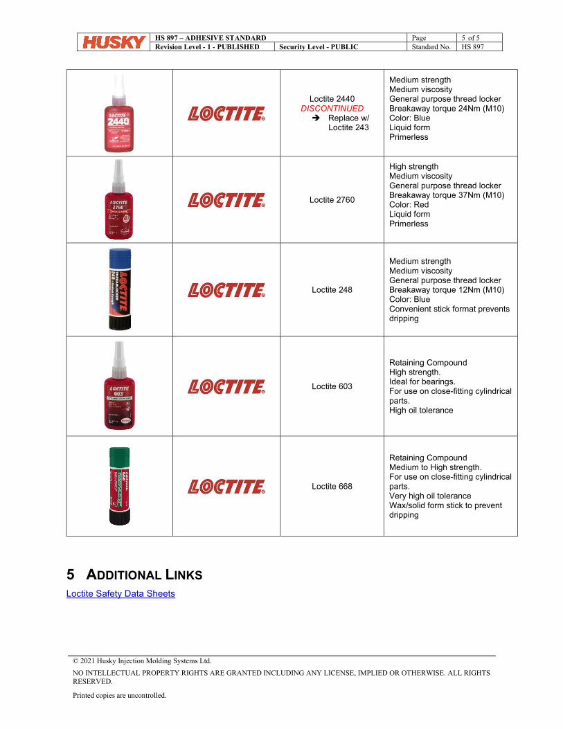
HS 897 – ADHESIVE STANDARD Page 5 of 5 Revision Level - 1 - PUBLISHED Security Level - PUBLIC Standard No. HS 897
© 2021 Husky Injection Molding Systems Ltd.
NO INTELLECTUAL PROPERTY RIGHTS ARE GRANTED INCLUDING ANY LICENSE, IMPLIED OR OTHERWISE. ALL RIGHTS RESERVED.
Printed copies are uncontrolled.
5 ADDITIONAL LINKS Loctite Safety Data Sheets
Loctite 2440 DISCONTINUED Replace w/
Loctite 243
Medium strength Medium viscosity General purpose thread locker Breakaway torque 24Nm (M10) Color: Blue Liquid form Primerless
Loctite 2760
High strength Medium viscosity General purpose thread locker Breakaway torque 37Nm (M10) Color: Red Liquid form Primerless
Loctite 248
Medium strength Medium viscosity General purpose thread locker Breakaway torque 12Nm (M10) Color: Blue Convenient stick format prevents dripping
Loctite 603
Retaining Compound High strength. Ideal for bearings. For use on close-fitting cylindrical parts. High oil tolerance
Loctite 668
Retaining Compound Medium to High strength. For use on close-fitting cylindrical parts. Very high oil tolerance Wax/solid form stick to prevent dripping
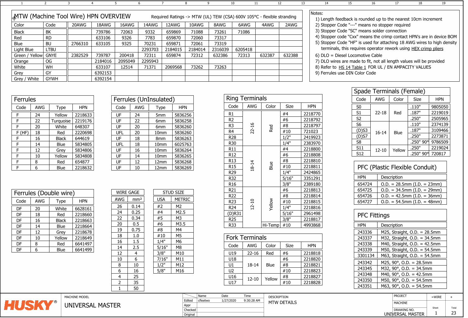
1 2 3 4 5 6 7 8 9 10 11 12 13 14 15 16
DRAWING NO.
MACHINE
17 18
UNIVERSAL MASTER
=
Sheet
WIRE
1
19
Total
23
+PROJECTMACHINE MODEL DESCRIPTION
MTW DETAILSAppr
Original
cfleetwoEdited
Checked
1/27/2020Name Date
UNIVERSAL MASTERTime9:30:28 AM
MTW (Machine Tool Wire) HPN OVERVIEW20AWG
2766310
2382529
2AWG
632388632387
4AWG
72313
710866AWG
732637326220695687137112514633107229594320950492184016
63238672312659874723112004187397872316039218401421840152293703733197206165987170231932563310573317720606598707783932663310673261710886598699332720637397868AWG 10AWG 12AWG 14AWG 16AWG 18AWG Color
Black
Blue
White
Green / YellowLight Blue
Orange
Red
Required Ratings -> MTW (UL) TEW (CSA) 600V 105°C - flexible stranding 1) Length feedback is rounded up to the nearest 10cm incrementCodeBK
BU
WH
GNYELTBU
OG
RD
FerrulesTypeAWGCode HPN
F YellowFFF (HF)FFFFFF 2218632
65487758348085834806583480564461922206986483072219176221863324
2220181614121086
TurquoiseWhiteRedBlackBlueGrey
YellowRedBlue
DFDFDFDFDFDF 2218649
2218678221866422186632218660662816120
1816141210
WhiteRedBlackBlueGrey
Yellow
UFUFUF
UFLUFUFUFUF 5836269
5836268583626558362646025763
58362605836258583625624
2220
1816141210
U1U2U16 #8U17 #10 2218828
221882722188232218821
U19 221881822-16 RedU18 2218820
18-14 Blue
#6#6#8#10
Yellow12-10
.250"
.250" 90°
S6(D)S3
S11S12
.110"
.187"Blue16-14
12-10 Yellow
23741393109466
2219024720817
S1S2
.187"
.250"Red22-18 2219019
2505965
.250" 2273871(D)S7
2) Stopper Code "---" means no stopper required
HS 14 Table 1
6) DLO = Diesel Locomotive Cable7) DLO wires are made to fit, not all length values will be provided8) Refer to FOR UL / EN AMPACITY VALUES
UF 583626318
6mm6mm
UFL 583626020 10mm
10mm8mm
5mm
10mm10mm12mm12mm
R1
22-1
6
#4R2
Red
#6R3 #8R4R28R30R11R12
#10
R13R15R29R32
2424865221881122188102218808221880023839702419923721023221879722187922218770
1/2"1/4"
18-1
4
Blue
#4#6#8#101/4"
33512915/16"
2218817
2218816221881522188142218813R21
12-1
0
Yello
w
#6#8#101/4"
R22R23R24(D)R31R25
29614983/8"5/16"
R33 4993868Hi-Temp #10
6205418
R16 23891803/8"
3) Stopper Code "SC" means solder connection
Ring TerminalsSizeAWGCode HPNColor
Fork TerminalsAWGCode HPNColor Size
Spade Terminals (Female)SizeAWGCode HPNColor
Notes:
mm²AWGWIRE GAGE
0.7519
0.340.520
22
M6M8M10
M12
M5
1/2"
3/8"5/16"1/4"#10
USASTUD SIZE
M165/8"
METRIC
M3.5M4
M2.5
#8#6
#4M2#2
M3#5
M117/16"
DFDF
86
RedBlue
HPN
PFC (Plastic Flexible Conduit)Description
654725654726654727
654724 O.D. = 28.5mm (I.D. = 23mm)O.D. = 34.5mm (I.D. = 29mm)O.D. = 42.5mm (I.D. = 36mm)O.D. = 54.5mm (I.D. = 48mm)
HPN
PFC FittingsDescriptionM25, Straight, O.D. = 28.5mmM32, Straight, O.D. = 34.5mm243337
243336
243338 M40, Straight, O.D. = 42.5mm243339 M50, Straight, O.D. = 54.5mm3301134 M63, Straight, O.D. = 54.5mm
M40, 90°, O.D. = 42.5mmM50, 90°, O.D. = 54.5mm
M25, 90°, O.D. = 28.5mmM32, 90°, O.D. = 34.5mm
M63, 90°, O.D. = 54.5mm
243342243345243348243350243351
6392153Grey GY6392154Grey / White GYWH
Ferrules (UnInsulated)TypeAWGCode HPN
0.2524
Ferrules (Double wire)TypeAWGCode HPN
66414976641499
9) Ferrules use DIN Color Code
16253550
10
12468
5) Stopper Code "HF" is used for attaching 18 AWG wires to high densityterminals, this requires operator rework using
1.0181.516
42.5
1214
610
0.1426
HEX crimp pliers
4) Stopper code "Cxx" means the crimp contact HPN's are in device BOM
.250" 90° 9786509S8
S0 .110" 9805050
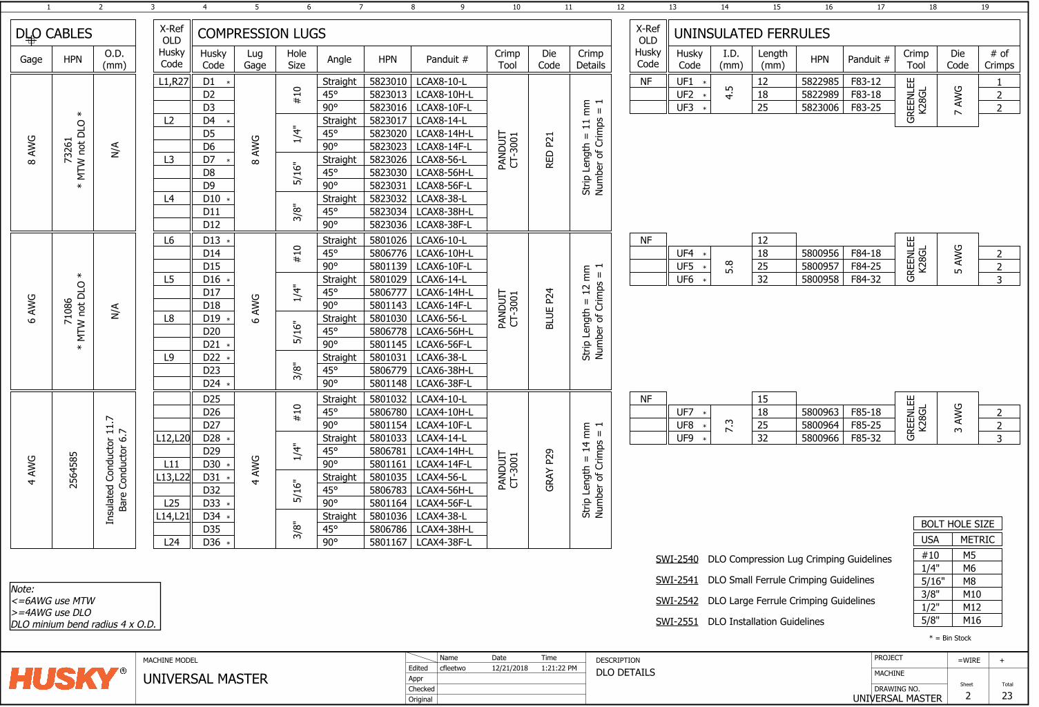
1 2 3 4 5 6 7 8 9 10 11 12 13 14 15 16
DRAWING NO.
MACHINE
17 18
UNIVERSAL MASTER
=
Sheet
WIRE
2
19
Total
23
+PROJECTMACHINE MODEL DESCRIPTION
DLO DETAILSAppr
Original
cfleetwoEdited
Checked
12/21/2018Name Date
UNIVERSAL MASTERTime1:21:22 PM
D136
AWG
Straight LCAX6-10-L
BLUE
P24
D14 #10 45°
D15 90°D16D17D18D19D20
Straight45°90°Straight45°
1/4"
5/16
"
D21 90°D22D23
Straight45°
D24 90°3/8"
UF4
5.8
182532
2564
585
Straight45°90°Straight45°90°Straight45°90°Straight45°90°
7.3
182532
UF6
UF9
UF7
PAND
UIT
CT-3
001
4 AW
G
PAND
UIT
CT-3
001
GRAY
P29
4 AW
G6
AWG
GREE
NLEE
K28G
L
5 AW
G
GREE
NLEE
K28G
L
3 AW
G
223
223
5800956 F84-185800957 F84-255800958 F84-32
580096358009645800966
580116758067865801036580116458067835801035580116158067815801033580115458067805801032580114858067795801031580114558067785801030580114358067775801029580113958067765801026
LCAX6-10H-LLCAX6-10F-LLCAX6-14-LLCAX6-14H-LLCAX6-14F-LLCAX6-56-LLCAX6-56H-LLCAX6-56F-LLCAX6-38-LLCAX6-38H-LLCAX6-38F-L
LCAX4-14-LLCAX4-14H-LLCAX4-14F-LLCAX4-56-LLCAX4-56H-LLCAX4-56F-LLCAX4-38-LLCAX4-38H-LLCAX4-38F-L
LCAX4-10-LLCAX4-10H-LLCAX4-10F-L#
101/
4"5/
16"
3/8"
D25D26D27D28D29D30D31D32D33D34D35D36
F85-18F85-25F85-32
L6
L5
L8
L9
L12,L20
L13,L22
L25L14,L21
L24
M6M8M10M12
M5
1/2"3/8"5/16"1/4"#10USABOLT HOLE SIZE
M165/8"
*
*
*
*
*
*
*
*
*
*
* = Bin Stock
D1
8 AW
G
Straight LCAX8-10-L
RED
P21
D2 #10 45°
D3 90°D4D5D6D7D8
Straight45°90°Straight45°
1/4"
5/16
"
D9 90°D10D11
Straight45°
D12 90°3/8"
UF1
4.5 18
Strip
Len
gth
= 1
1 m
m
PAND
UIT
CT-3
001
8 AW
G
5822989 F83-18
582303658230345823032582303158230305823026582302358230205823017582301658230135823010
LCAX8-10H-LLCAX8-10F-LLCAX8-14-LLCAX8-14H-LLCAX8-14F-LLCAX8-56-LLCAX8-56H-LLCAX8-56F-LLCAX8-38-LLCAX8-38H-LLCAX8-38F-L
L1,R27
L2
L3
L4 *
*
*
*
GREE
NLEE
K28G
L
7 AW
G 21
L11
N/A
Num
ber o
f Crim
ps =
1St
rip L
engt
h =
12
mm
Nu
mbe
r of C
rimps
= 1
Strip
Len
gth
= 1
4 m
mNu
mbe
r of C
rimps
= 1
METRIC
COMPRESSION LUGS UNINSULATED FERRULESHoleSize Angle Lug
Gage HPN Panduit # I.D.(mm) HPN Panduit #O.D.
(mm)Gage HPN
DLO CABLESCrimpTool
X-RefOLD
HuskyCode
# ofCrimps
DieCode
CrimpTool
HuskyCode
Length(mm)
CrimpDetails
DieCode
*
*
5823006 F83-25UF2
25
UF5
UF8
Note: <=6AWG use MTW>=4AWG use DLODLO minium bend radius 4 x O.D.
12 5822985 F83-12
UF3 2
*
*
*
*
*
*
*
X-RefOLD
HuskyCodeNF
12NF
NF 15
*
*
7108
6
N/A
7326
1*
MTW
not
DLO
**
MTW
not
DLO
*
DLO Compression Lug Crimping Guidelines
DLO Small Ferrule Crimping Guidelines
DLO Large Ferrule Crimping Guidelines
DLO Installation Guidelines
SWI-2540
SWI-2541
SWI-2542
SWI-2551
Insu
late
d Co
nduc
tor 1
1.7
Bare
Con
duct
or 6
.7
HuskyCode
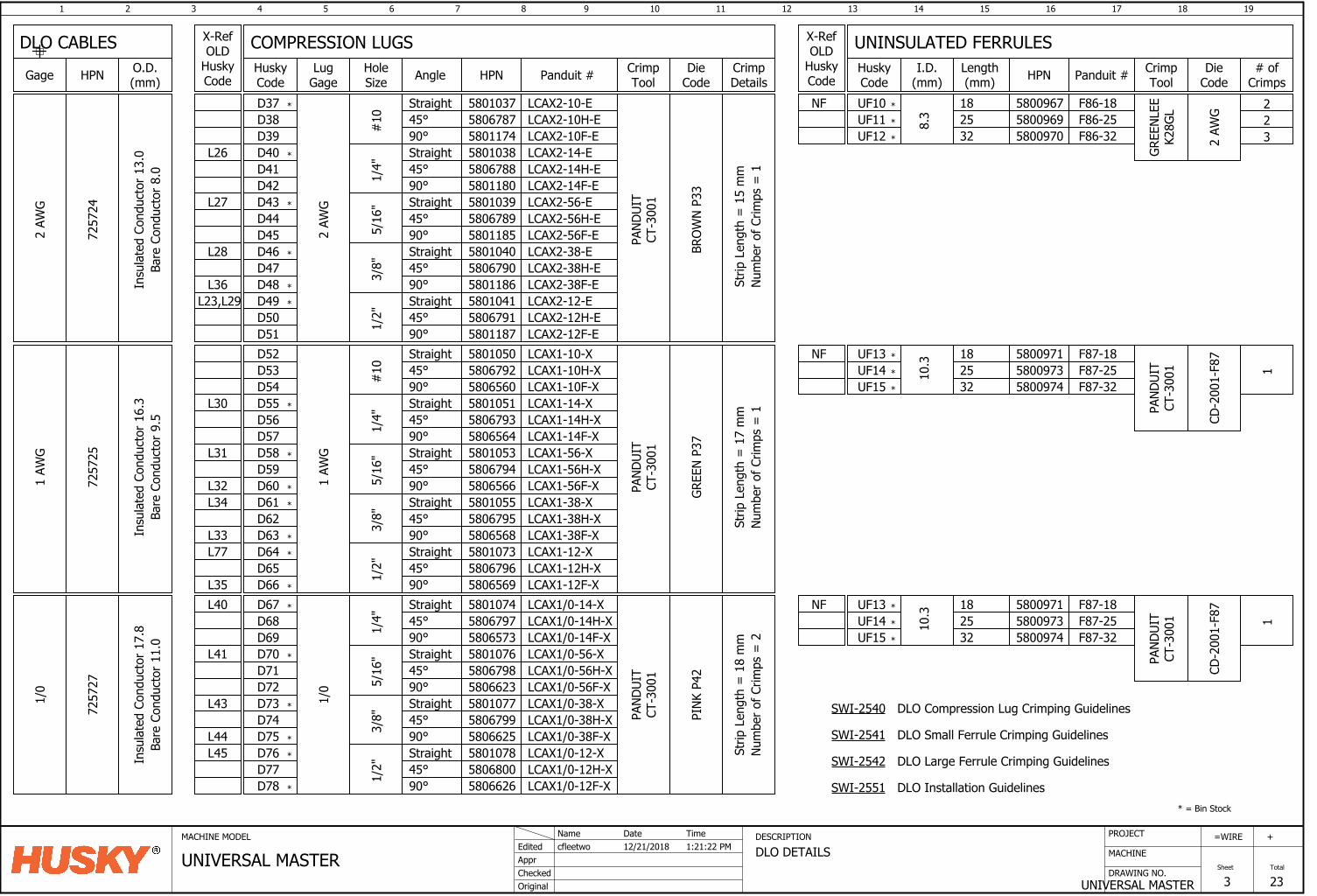
1 2 3 4 5 6 7 8 9 10 11 12 13 14 15 16
DRAWING NO.
MACHINE
17 18
UNIVERSAL MASTER
=
Sheet
WIRE
3
19
Total
23
+PROJECTMACHINE MODEL DESCRIPTION
DLO DETAILSAppr
Original
cfleetwoEdited
Checked
12/21/2018Name Date
UNIVERSAL MASTERTime1:21:22 PM
7257
25
D64
1 AW
G
Straight 5801051
GREE
N P3
7
D65
45° 580679390° 5806564
58010535806794
D66
5806566
D67
5801055
D68
5806795
Straight45°90°Straight45°
D69
580656890°
D70D71
Straight45°
D72
90°
580107358067965806569
7257
27
Straight45°90°
D76D77D78
Straight45°90°Straight45°
1/4"
5/16
"
90°Straight45°90°
3/8"
UF10
PAND
UIT
CT-3
001
1/0
PAND
UIT
CT-3
001
PINK
P42
1/0
1 AW
G
1/2"
1/4"
5/16
"3/
8"1/
2"
10.3 18
255800971
UF15 32
158009735800974
LCAX1-14-XLCAX1-14H-XLCAX1-14F-XLCAX1-56-XLCAX1-56H-XLCAX1-56F-XLCAX1-38-XLCAX1-38H-XLCAX1-38F-XLCAX1-12-XLCAX1-12H-XLCAX1-12F-XLCAX1/0-14-XLCAX1/0-14H-XLCAX1/0-14F-XLCAX1/0-56-XLCAX1/0-56H-XLCAX1/0-56F-XLCAX1/0-38-XLCAX1/0-38H-XLCAX1/0-38F-XLCAX1/0-12-XLCAX1/0-12H-XLCAX1/0-12F-X
D73D74D75
Straight 580105045° 580679290° 5806560#
10
LCAX1-10-XLCAX1-10H-XLCAX1-10F-X
580662658068005801078580662558067995801077580662358067985801076580657358067975801074
D52D53D54D55D56D57D58D59D60D61D62D63
F87-18F87-25F87-32
L30
L31
L34
L40
L41
L43
L44L45
L77L33
L35
*
*
*
*
*
*
*
*
*
*
*
*
D37D38D39D40D41D42D43D44D45D46D47D48D49
Straight
D50
45°
D51
90°Straight45°90°Straight45°
1/4"
5/16
"
90°Straight45°90°
3/8"
2 AW
G
PAND
UIT
CT-3
001
BROW
N P3
3
1/2"
7257
24
2 AW
G
580118758067915801041580118658067905801040580118558067895801039580118058067885801038 LCAX2-14-E
LCAX2-14H-ELCAX2-14F-ELCAX2-56-ELCAX2-56H-ELCAX2-56F-ELCAX2-38-ELCAX2-38H-ELCAX2-38F-ELCAX2-12-ELCAX2-12H-ELCAX2-12F-E
Straight 580103745° 580678790° 5801174#
10
LCAX2-10-ELCAX2-10H-ELCAX2-10F-E
L26
L27
L28
L36L23,L29 *
*
*
*
*
8.3
1825
5800967
UF13
UF12 32
GREE
NLEE
K28G
L
2 AW
G 225800969
5800970
F86-18F86-25F86-32
*
* = Bin Stock
L32
*
Strip
Len
gth
= 1
5 m
mNu
mbe
r of C
rimps
= 1
Strip
Len
gth
= 1
7 m
mNu
mbe
r of C
rimps
= 1
Strip
Len
gth
= 1
8 m
mNu
mbe
r of C
rimps
= 2
UF113
UF14
*
*
*
*
NF
NF
*
*
10.3 18
255800971
UF15 32
CD-2
001-
F87
58009735800974
F87-18F87-25F87-32
UF13 *UF14 *
*
NF
PAND
UIT
CT-3
001 1
PAND
UIT
CT-3
001
CD-2
001-
F87
DLO Compression Lug Crimping Guidelines
DLO Small Ferrule Crimping Guidelines
DLO Large Ferrule Crimping Guidelines
DLO Installation Guidelines
SWI-2540
SWI-2541
SWI-2542
SWI-2551
Insu
late
d Co
nduc
tor 1
3.0
Bare
Con
duct
or 8
.0In
sula
ted
Cond
ucto
r 16.
3Ba
re C
ondu
ctor
9.5
Insu
late
d Co
nduc
tor 1
7.8
Bare
Con
duct
or 1
1.0
COMPRESSION LUGS UNINSULATED FERRULESHoleSize Angle Lug
Gage HPN Panduit # I.D.(mm) HPN Panduit #O.D.
(mm)Gage HPN
DLO CABLESCrimpTool
X-RefOLD
HuskyCode
# ofCrimps
DieCode
CrimpTool
HuskyCode
Length(mm)
CrimpDetails
DieCode
X-RefOLD
HuskyCode
HuskyCode
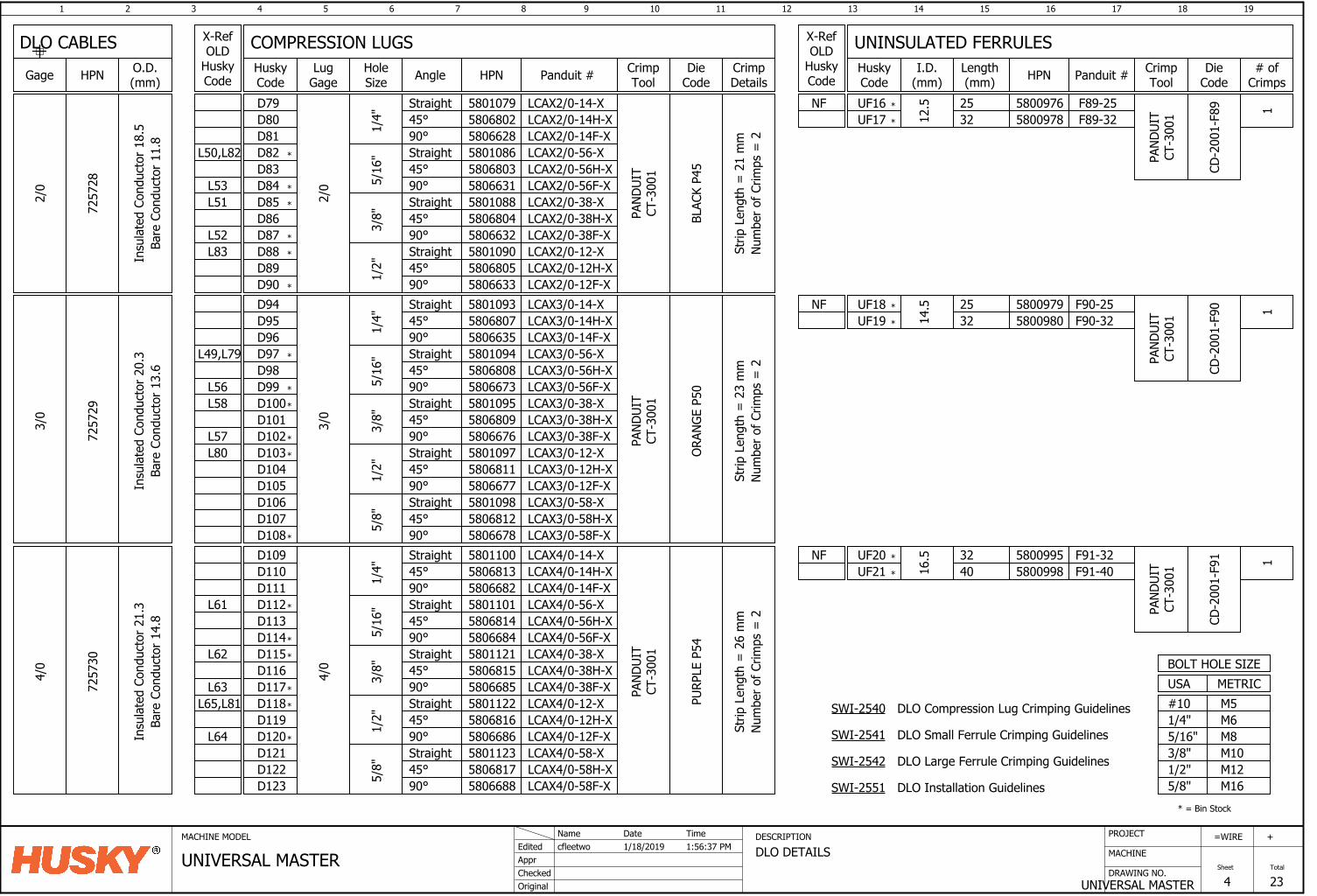
1 2 3 4 5 6 7 8 9 10 11 12 13 14 15 16
DRAWING NO.
MACHINE
17 18
UNIVERSAL MASTER
=
Sheet
WIRE
4
19
Total
23
+PROJECTMACHINE MODEL DESCRIPTION
DLO DETAILSAppr
Original
cfleetwoEdited
Checked
1/18/2019Name Date
UNIVERSAL MASTERTime1:56:37 PM
7257
30
D106D107D108
4/0
16.5 32
40
58010945806808580667358010955806809
Straight45°90°Straight45°
5/16
"
580667690°Straight45°90°
580109758068115806677
3/8"
1/2"
3/0
PAND
UIT
CT-3
001
ORAN
GE P
50
7257
29
3/0
25
14.5D94
D95D96D97D98D99D100D101D102D103D104D105
Straight45°90°1/
4"
LCAX3/0-14-XLCAX3/0-14H-XLCAX3/0-14F-X5806635
58068075801093
Straight45°90°
5801098580681258066785/
8"
58011015806814580668458011215806815
Straight45°90°Straight45°
5/16
"
580668590°Straight45°90°
580112258068165806686
3/8"
1/2"
4/0
D109D110D111D112D113D114D115D116D117D118D119D120
Straight45°90°1/
4"
580668258068135801100
Straight45°90°
5801123580681758066885/
8"
D121D122D123
PAND
UIT
CT-3
001
PURP
LE P
54
LCAX3/0-56-XLCAX3/0-56H-XLCAX3/0-56F-XLCAX3/0-38-XLCAX3/0-38H-XLCAX3/0-38F-XLCAX3/0-12-XLCAX3/0-12H-XLCAX3/0-12F-XLCAX3/0-58-XLCAX3/0-58H-XLCAX3/0-58F-XLCAX4/0-14-XLCAX4/0-14H-XLCAX4/0-14F-XLCAX4/0-56-XLCAX4/0-56H-XLCAX4/0-56F-XLCAX4/0-38-XLCAX4/0-38H-XLCAX4/0-38F-XLCAX4/0-12-XLCAX4/0-12H-XLCAX4/0-12F-XLCAX4/0-58-XLCAX4/0-58H-XLCAX4/0-58F-X
5800979 F90-25
58009955800998
F91-32F91-40
UF20
UF19
UF16
UF21
L49,L79
L58
L80
L56
L57
L62
L65,L81
L64
L61
L63
*
*
*
*
*
*
*
*
*
*
*
*
*
*
*
*
*
L52
L53
L83
L51
L50,L82 580108658068035806631580108858068045806632580109058068055806633
580107958068025806628
LCAX2/0-12F-XLCAX2/0-12H-XLCAX2/0-12-XLCAX2/0-38F-XLCAX2/0-38H-XLCAX2/0-38-XLCAX2/0-56F-XLCAX2/0-56H-XLCAX2/0-56-XLCAX2/0-14F-XLCAX2/0-14H-XLCAX2/0-14-X
1/4"
90°45°Straight
1/2"
2/0
3/8"
90°45°Straight90°
5/16
"
45°Straight90°45°Straight
D90D89D88D87D86D85D84D83D82D81D80D79
PAND
UIT
CT-3
001
BLAC
K P4
5
7257
28
2/0
12.5 25
32F89-25F89-32UF17
UF18
58009765800978
*
M6M8M10M12
M5
1/2"3/8"5/16"1/4"#10
METRICUSA
M165/8"
BOLT HOLE SIZE
* = Bin Stock
Strip
Len
gth
= 2
1 m
mNu
mbe
r of C
rimps
= 2
Strip
Len
gth
= 2
3 m
mNu
mbe
r of C
rimps
= 2
Strip
Len
gth
= 2
6 m
mNu
mbe
r of C
rimps
= 2
*
32 5800980 F90-32
*
*
*
NF
NF
NF
*
*
CD-2
001-
F89
PAND
UIT
CT-3
001 1
CD-2
001-
F90
PAND
UIT
CT-3
001
CD-2
001-
F91
PAND
UIT
CT-3
001
11
DLO Compression Lug Crimping Guidelines
DLO Small Ferrule Crimping Guidelines
DLO Large Ferrule Crimping Guidelines
DLO Installation Guidelines
SWI-2540
SWI-2541
SWI-2542
SWI-2551
Insu
late
d Co
nduc
tor 1
8.5
Bare
Con
duct
or 1
1.8
Insu
late
d Co
nduc
tor 2
0.3
Bare
Con
duct
or 1
3.6
Insu
late
d Co
nduc
tor 2
1.3
Bare
Con
duct
or 1
4.8
COMPRESSION LUGS UNINSULATED FERRULESHoleSize Angle Lug
Gage HPN Panduit # I.D.(mm) HPN Panduit #O.D.
(mm)Gage HPN
DLO CABLESCrimpTool
X-RefOLD
HuskyCode
# ofCrimps
DieCode
CrimpTool
HuskyCode
Length(mm)
CrimpDetails
DieCode
X-RefOLD
HuskyCode
HuskyCode
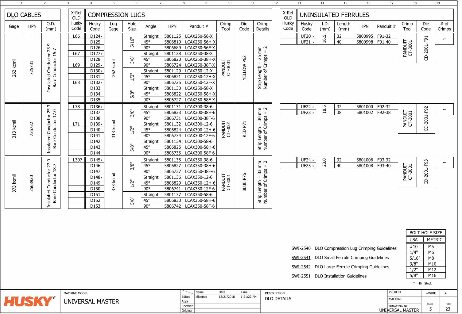
1 2 3 4 5 6 7 8 9 10 11 12 13 14 15 16
DRAWING NO.
MACHINE
17 18
UNIVERSAL MASTER
=
Sheet
WIRE
5
19
Total
23
+PROJECTMACHINE MODEL DESCRIPTION
DLO DETAILSAppr
Original
cfleetwoEdited
Checked
12/21/2018Name Date
UNIVERSAL MASTERTime1:21:22 PM
7257
32
313
kcm
il
323818
.558011315806823
Straight45°
580673190°Straight45°90°
580113258068245806734
3/8"
1/2"
Straight45°90°
5801134580682558067355/8"
LCAX300-38-6LCAX300-38H-6LCAX300-38F-6LCAX300-12-6LCAX300-12H-6LCAX300-12F-6LCAX300-58-6LCAX300-58H-6LCAX300-58F-6
PAND
UIT
CT-3
001
313
kcm
il
RED
P71
D136D137D138D139D140D141D142D143D144
58011355806827
Straight45°
580673790°Straight45°90°
580113658068295806741
3/8"
1/2"
Straight45°90°
5801137580683058067425/
8"
PAND
UIT
CT-3
001
373
kcm
il
D145D146D147D148D149D150D151D152D153
LCAX350-38-6LCAX350-38H-6LCAX350-38F-6LCAX350-12-6LCAX350-12H-6LCAX350-12F-6LCAX350-58-6LCAX350-58H-6LCAX350-58F-6
BLUE
P76
373
kcm
il
2568
920
324020
.0
58010005801002 F92-38
F92-32
58010065801008 F93-40
F93-32UF24
UF23
UF20
UF25
L71
L78
L307
M6M8M10M12
M5
1/2"3/8"5/16"1/4"#10
METRICUSA
M165/8"
BOLT HOLE SIZE
*
*
*
* = Bin Stock
LCAX250-58F-XLCAX250-58H-XLCAX250-58-XLCAX250-12F-XLCAX250-12H-XLCAX250-12-XLCAX250-38F-XLCAX250-38H-XLCAX250-38-XLCAX250-56F-XLCAX250-56H-XLCAX250-56-X
YELL
OW P
62
PAND
UIT
CT-3
001
D135D134D133
5/8"
580672758068225801130
90°45°Straight
D132D131D130D129D128D127D126D125D124
262
kcm
il
1/2"
3/8"
580672558068215801129
90°45°Straight90° 5806724
5/16
"
45°Straight90°45°Straight
58068205801128580668958068195801125
4032
16.5
262
kcm
il
7257
3158009955800998 F91-40
F91-32
L68
L66
L67
L69
*
UF22
UF21
*
*
*
*
*
*
Strip
Len
gth
= 2
6 m
mNu
mbe
r of C
rimps
= 2
Strip
Len
gth
= 3
0 m
mNu
mbe
r of C
rimps
= 2
Strip
Len
gth
= 3
3 m
mNu
mbe
r of C
rimps
= 2
*
*
*
*
*
CD-2
001-
F91
PAND
UIT
CT-3
001
CD-2
001-
F92
PAND
UIT
CT-3
001
PAND
UIT
CT-3
001
CD-2
001-
F93
11
1
DLO Compression Lug Crimping Guidelines
DLO Small Ferrule Crimping Guidelines
DLO Large Ferrule Crimping Guidelines
DLO Installation Guidelines
SWI-2540
SWI-2541
SWI-2542
SWI-2551
Insu
late
d Co
nduc
tor 2
3.9
Bare
Con
duct
or 1
5.7
Insu
late
d Co
nduc
tor 2
5.3
Bare
Con
duct
or 1
7.0
Insu
late
d Co
nduc
tor 2
7.0
Bare
Con
duct
or 1
8.7
COMPRESSION LUGS UNINSULATED FERRULESHoleSize Angle Lug
Gage HPN Panduit # I.D.(mm) HPN Panduit #O.D.
(mm)Gage HPN
DLO CABLESCrimpTool
X-RefOLD
HuskyCode
# ofCrimps
DieCode
CrimpTool
HuskyCode
Length(mm)
CrimpDetails
DieCode
X-RefOLD
HuskyCode
HuskyCode
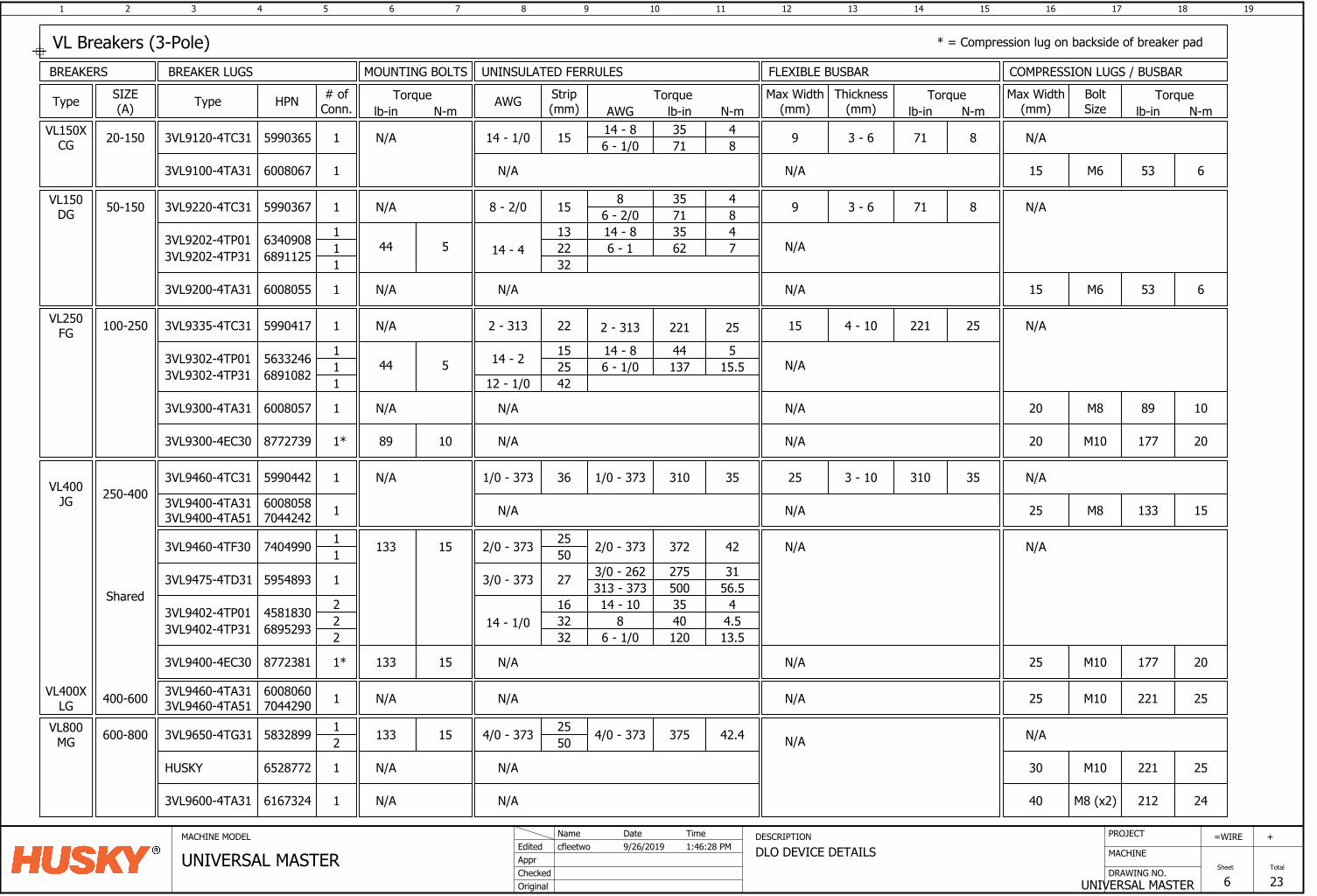
1 2 3 4 5 6 7 8 9 10 11 12 13 14 15 16
DRAWING NO.
MACHINE
17 18
UNIVERSAL MASTER
=
Sheet
WIRE
6
19
Total
23
+PROJECTMACHINE MODEL DESCRIPTION
DLO DEVICE DETAILSAppr
Original
cfleetwoEdited
Checked
9/26/2019Name Date
UNIVERSAL MASTERTime1:46:28 PM
SIZE(A)Type
VL150DG 50-150
Type HPN # ofConn.
Strip(mm)
3VL9220-4TC31 5990367
VL250FG 100-250 3VL9335-4TC31 5990417
VL400JG
3VL9460-4TC31 5990442250-400
VL400XLG 400-600
36 310 351 1/0 - 373
1 222 - 313
1 158 - 2/0 8 35 46 - 2/0 71 8
2 - 313 221 25
VL150XCG 20-150 3VL9120-4TC31 5990365 1 1514 - 1/0
1/0 - 373
68952933VL9402-4TP31 14 - 1/022
1632
2 32
14 - 10 35 48 40 4.5
13.51206 - 1/0
AWG Torquelb-in N-mAWG
14 - 8 35 46 - 1/0 71 8
Torque
N/A
lb-in N-m
MOUNTING BOLTS
N/A
N/A
N/A
BREAKER LUGS
56332463VL9302-4TP01 14 - 211
1525
1 4244 5
14 - 8 44 515.51376 - 1/0
12 - 1/0
VL800MG 600-800 3VL9650-4TG31 5832899 4/0 - 373 375 42.4133 152
1 4/0 - 373 2550
BREAKERS
3VL9302-4TP31 6891082
63409083VL9202-4TP0114 - 4
11
1322
1 3244 5
14 - 8 35 47626 - 13VL9202-4TP31 6891125
45818303VL9402-4TP01
3VL9475-4TD31 5954893 1 273/0 - 373 3/0 - 262 275 31313 - 373 500 56.5
Torquelb-in N-m
BoltSize
N/A
COMPRESSION LUGS / BUSBAR
3VL9100-4TA31 6008067 1
UNINSULATED FERRULES
53 6M6N/A
N/A
53 6M63VL9200-4TA31 6008055 1 N/A N/A
89 10M81 N/A N/A3VL9300-4TA31 6008057
N/A
133 15M81 N/A3VL9400-4TA313VL9400-4TA51
60080587044242
N/A
221 25M101 N/A N/A3VL9460-4TA313VL9460-4TA51
60080607044290
N/A372 422/0 - 37311 2/0 - 373 25
50133 153VL9460-4TF30 7404990
Shared
N/A
HUSKY 6528772 221 25M101 N/A N/A
Thickness(mm)
3 - 69
Max Width(mm)
FLEXIBLE BUSBAR
N/A
Torquelb-in N-m
71 8
3 - 69
N/A
71 8
N/A
4 - 1015
N/A
221 25
N/A
3 - 1025 310 35
N/A
N/A
N/A
Max Width(mm)
15
15
20
25
25
30
N/A
VL Breakers (3-Pole)
177 20M101* N/A3VL9300-4EC30 8772739 N/A 2089 10
177 20M101* N/A3VL9400-4EC30 8772381 N/A 25133 15
* = Compression lug on backside of breaker pad
3VL9600-4TA31 6167324 212 24M8 (x2)1 N/A N/A 40
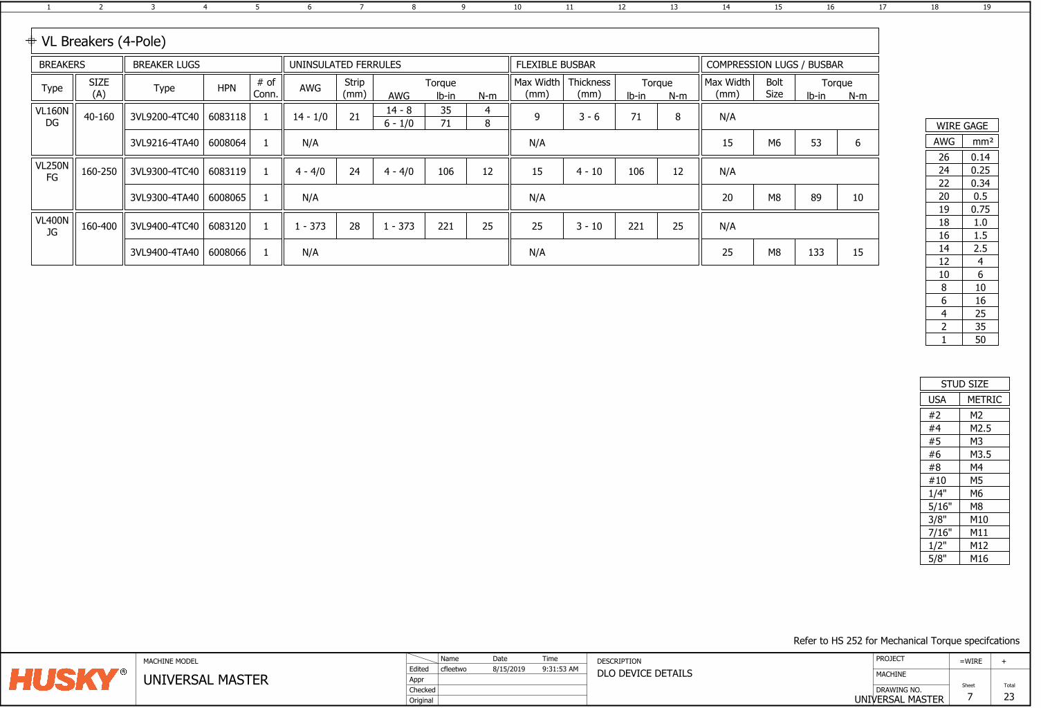
1 2 3 4 5 6 7 8 9 10 11 12 13 14 15 16
DRAWING NO.
MACHINE
17 18
UNIVERSAL MASTER
=
Sheet
WIRE
7
19
Total
23
+PROJECTMACHINE MODEL DESCRIPTION
DLO DEVICE DETAILSAppr
Original
cfleetwoEdited
Checked
8/15/2019Name Date
UNIVERSAL MASTERTime9:31:53 AM
SIZE(A)Type Type HPN # of
Conn.Strip(mm)AWG Torque
lb-in N-mAWG
BREAKER LUGSBREAKERS
VL160NDG 40-160 3VL9200-4TC40 6083118 1 2114 - 1/0 14 - 8 35 4
6 - 1/0 71 8
VL250NFG 160-250 3VL9300-4TC40 6083119 1 244 - 4/0 4 - 4/0 106 12
VL400NJG 160-400 3VL9400-4TC40 6083120 1 281 - 373 1 - 373 25221
Torquelb-in N-m
BoltSize
COMPRESSION LUGS / BUSBARUNINSULATED FERRULES
N/A
Thickness(mm)
Max Width(mm)
FLEXIBLE BUSBAR
Torquelb-in N-m
3 - 69 71 8
4 - 1015 106 12
3 - 1025 221 25
Max Width(mm)
N/A
N/A
VL Breakers (4-Pole)
53 6M63VL9216-4TA40 6008064 1 N/A N/A 15
89 10M81 N/A3VL9300-4TA40 6008065 N/A 20
133 15M81 N/A3VL9400-4TA40 6008066 N/A 25
Refer to HS 252 for Mechanical Torque specifcations
M6M8M10
M12
M5
1/2"
3/8"5/16"1/4"#10
USASTUD SIZE
M165/8"
METRIC
M3.5M4
M2.5
#8#6
#4M2#2
M3#5
M117/16"
mm²AWGWIRE GAGE
0.7519
0.340.520
220.2524
16253550
10
12468
1.0181.516
42.5
1214
610
0.1426
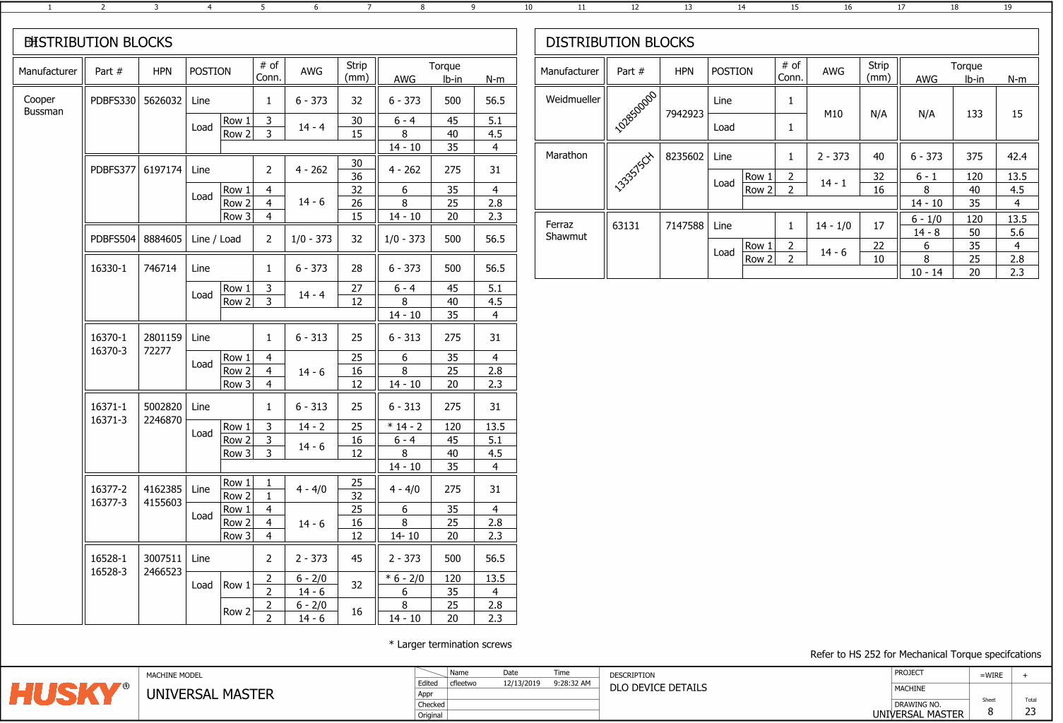
1 2 3 4 5 6 7 8 9 10 11 12 13 14 15 16
DRAWING NO.
MACHINE
17 18
UNIVERSAL MASTER
=
Sheet
WIRE
8
19
Total
23
+PROJECTMACHINE MODEL DESCRIPTION
DLO DEVICE DETAILSAppr
Original
cfleetwoEdited
Checked
12/13/2019Name Date
UNIVERSAL MASTERTime9:28:32 AM
DISTRIBUTION BLOCKS
Part # HPN # ofConn.
Strip(mm)Manufacturer POSTION
16330-1 746714 1 28
6 - 4 45 5.18 40 4.5Load
Line
Row 1Row 2
2712
6 - 373 500 56.5
14 - 10 35 4
CooperBussman
16370-1 2801159 1 25
35 425 2.8Load
Line
Row 1Row 2
251614 - 6
6 - 313 275 31
20 2.38
14 - 10
6 - 31316370-3 72277
Row 3 12
16371-1 5002820 1 25
4.5
Load
Line
Row 1Row 2
275 31
48
14 - 10
6 - 31316371-3 2246870
Row 3 121625
6 - 4 45 5.14035
3 14 - 2
14 - 6
Load
Line
Row 1Row 2
4 - 4/0 275 314 - 4/0
Row 3 121625
14 - 6444
416238516377-216377-3 4155603
Row 1Row 2 32
2511
814- 10
6 35 425 2.820 2.3
Load
Line
Row 1
2 - 373 500 56.52 - 373
22
16528-116528-3 2466523
814 - 10
6 35 425 2.820 2.3
3007511 2 45
14 - 66 - 2/0 32
Row 2 22
6 - 2/0 16
* 6 - 2/0 120 13.5
PDBFS330 1 32
Load
Line
Row 1Row 2
6 - 373 500 56.56 - 373
15303 14 - 4
5626032
3 814 - 10
6 - 44.54
45 5.14035
33
* 14 - 2 120 13.5
444
33
14 - 6
Torquelb-in N-mAWG
AWG
14 - 4
6 - 373
6 - 313
6
DISTRIBUTION BLOCKS
Part # HPN # ofConn.
Strip(mm)Manufacturer POSTION AWG Torque
lb-in N-mAWG
PDBFS377 2
Load
Line
Row 1Row 2
4 - 262 275 314 - 262
26324
14 - 6
6197174
4 814 - 10
62.82.3
35 42520
3630
Row 3 4 15
Refer to HS 252 for Mechanical Torque specifcations
Weidmueller
1028
5000
00
7942923Line
Load
1
1M10 N/A 133 15N/A
PDBFS504 2Line / Load 1/0 - 3738884605 32 500 56.51/0 - 373
1333
575C
H 1 40
Load
Line
Row 1Row 2
2 - 373 375 42.46 - 373
16322 14 - 1
8235602
2 814 - 10
6 - 14.54
120 13.54035
Marathon
FerrazShawmut
63131 7147588 1 17
Load
Line
Row 1Row 2
2210
14 - 1/0
14 - 6
14 - 86 - 1/0
35 425 2.8
50 5.6
20 2.3
120 13.5
68
10 - 14
22
* Larger termination screws
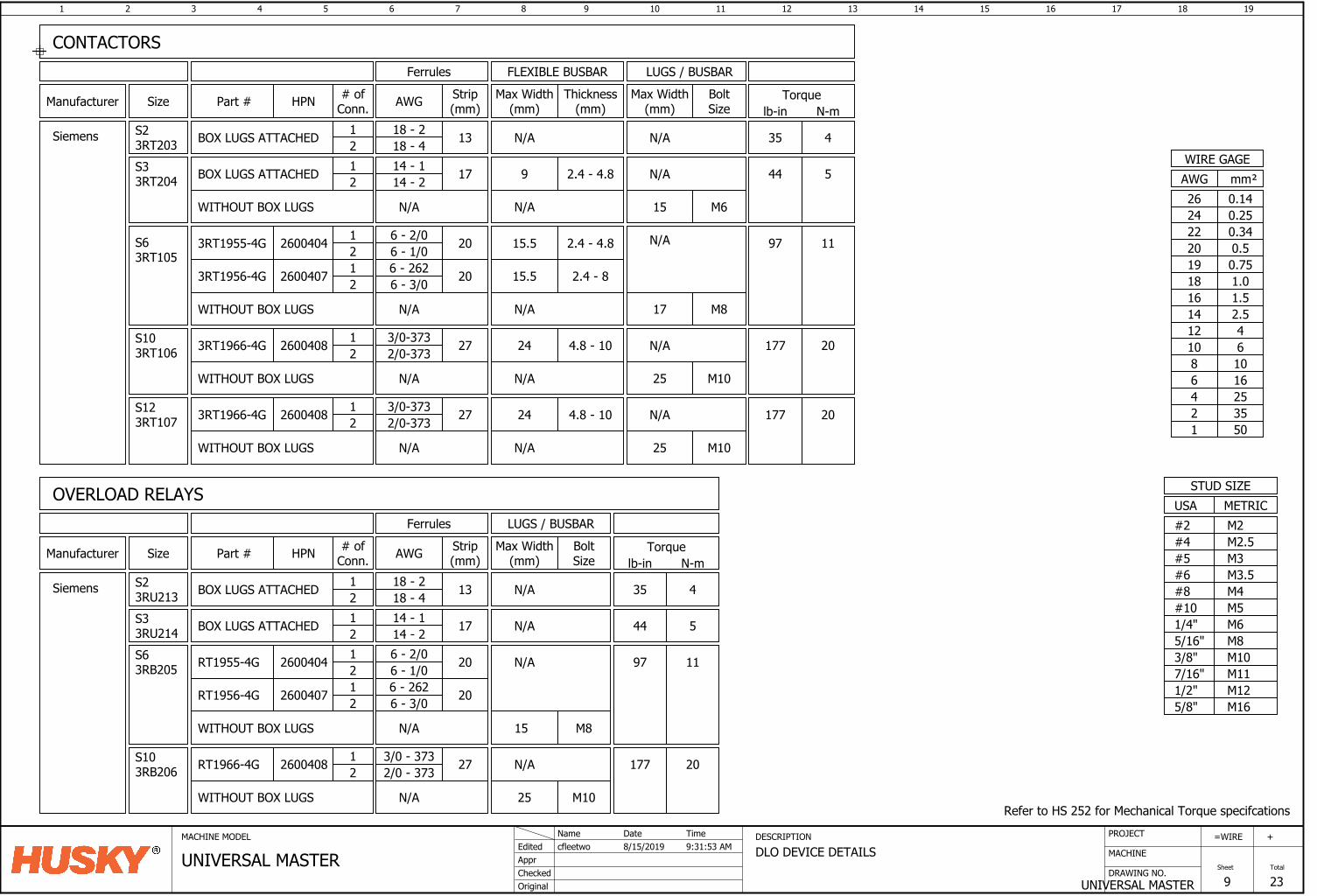
1 2 3 4 5 6 7 8 9 10 11 12 13 14 15 16
DRAWING NO.
MACHINE
17 18
UNIVERSAL MASTER
=
Sheet
WIRE
9
19
Total
23
+PROJECTMACHINE MODEL DESCRIPTION
DLO DEVICE DETAILSAppr
Original
cfleetwoEdited
Checked
8/15/2019Name Date
UNIVERSAL MASTERTime9:31:53 AM
Part # HPN # ofConn.
Strip(mm)Manufacturer
Siemens
3RT1955-4G 2600404 1 206 - 2/02 6 - 1/0
Size
S63RT105
3RT1956-4G 2600407 201 6 - 2622 6 - 3/0
3RT1966-4G 2600408 1 273/0-3732 2/0-373
S103RT106
BoltSize
M817
Ferrules LUGS / BUSBAR
M1025
3RT1966-4G 2600408 12 2/0-373
S123RT107 273/0-373
1 172S33RT204 BOX LUGS ATTACHED
12
S23RT203 N/A
Part # HPN # ofConn.
Strip(mm)Manufacturer
Siemens
Size BoltSize
S33RU214S63RB205
S103RB206
RT1955-4G 2600404 1 206 - 2/02 6 - 1/0
RT1956-4G 2600407 201 6 - 2622 6 - 3/0
RT1966-4G 2600408 1 273/0 - 3732 2/0 - 373
M815
BOX LUGS ATTACHED
1 172 N/ABOX LUGS ATTACHED
1318 - 218 - 4
CONTACTORS
OVERLOAD RELAYS
AWG Max Width(mm)
Max Width(mm)AWG
44 5
97 11
Torquelb-in N-m
Refer to HS 252 for Mechanical Torque specifcations
M6M8M10
M12
M5
1/2"
3/8"5/16"1/4"#10
USASTUD SIZE
M165/8"
METRIC
M3.5M4
M2.5
#8#6
#4M2#2
M3#5
M117/16"
mm²AWGWIRE GAGE
0.7519
0.340.520
220.2524
16253550
10
12468
1.0181.516
42.5
1214
610
0.1426
Thickness(mm)
Max Width(mm)
FLEXIBLE BUSBAR
Torquelb-in N-m
4.8 - 1024 177 20
4.8 - 1024 177 20
N/A
2.4 - 4.815.5 97 11
2.4 - 815.5
WITHOUT BOX LUGS N/A
N/A
N/A
WITHOUT BOX LUGS N/A N/A
N/A
M1025WITHOUT BOX LUGS N/A N/A
N/A
WITHOUT BOX LUGS N/A
N/A
M1025
177 20
WITHOUT BOX LUGS N/A
N/A
WITHOUT BOX LUGS N/A N/A M615
N/A2.4 - 4.89 44 514 - 114 - 2
35 4
Ferrules LUGS / BUSBAR
14 - 114 - 2
S23RU213
1 132 N/ABOX LUGS ATTACHED 35 418 - 218 - 4
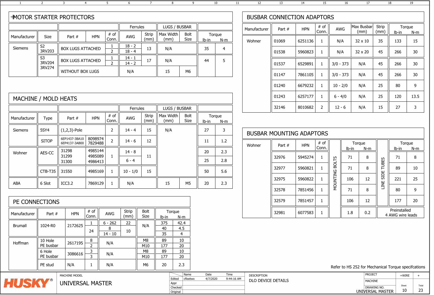
1 2 3 4 5 6 7 8 9 10 11 12 13 14 15 16
DRAWING NO.
MACHINE
17 18
UNIVERSAL MASTER
=
Sheet
WIRE
10
19
Total
23
+PROJECTMACHINE MODEL DESCRIPTION
DLO DEVICE DETAILSAppr
Original
cfleetwoEdited
Checked
4/7/2020Name Date
UNIVERSAL MASTERTime9:44:16 AM
2 15 27 3
1 11
MACHINE / MOLD HEATS
# ofConn.
Strip(mm)
Torquelb-in N-m
HPN
14 - 4
Part #Manufacturer
Siemens
Type
5SY4
AES-CCWohner
AWG
(1,2,3)-Pole
1 15 50 5.64985169 10 - 1/0CTB-T35 31550
Refer to HS 252 for Mechanical Torque specifcations
25
20
2.8
2.3
6 - 4
14 - 8
MOTOR STARTER PROTECTORS
Part # HPN # ofConn.
Strip(mm)Manufacturer
Siemens
Size BoltSizeAWG Max Width
(mm)Torque
lb-in N-m
Ferrules LUGS / BUSBAR
S23RV203 13BOX LUGS ATTACHED
S33RV2043RV274
17BOX LUGS ATTACHED
35 4
44 5
N/A1212
WITHOUT BOX LUGS N/A M615
N/A
1 22 375 42.4
PE CONNECTIONS# of
Conn.Strip(mm)
Torquelb-in N-m
HPN
6 - 262
Part #Manufacturer
Brumall
AWG
21726251024-R0
N/AHoffman 261719510 HolePE busbar
BoltSize
N/A
M10M88
2
N/A30866166 HolePE busbar M10
M833
17789
2010
89 1020177
1 20 2.3N/APE stud M6N/A
18 - 218 - 414 - 114 - 2
1 35 133 15
BUSBAR CONNECTION ADAPTORS# of
Conn.HPN
6251136 N/A
Part #Manufacturer
Wohner 01069
652989101537
667923201240
01243 6257177
596082301538
786110501147 1
1 45 266 303/0 - 373
1 45
1 25 80 910 - 2/0
1 25 120 13.56 - 4/0
Strip(mm)AWG Torque
lb-in N-m
32 x 10
Max Busbar(mm)
N/A
N/A 32 x 20 266 30
453/0 - 373 N/A 266 30
N/A
N/A
594527432976
32975 5960822
1 71 8
1 89 1032977 5960821
1 221 25
LINE
SID
E TU
BES
Torquelb-in N-m
MOU
NTIN
G BO
LTS
Torquelb-in N-m
71 8
71 8
106 12
Part # HPN # ofConn.
1 20 2.3ABA 6 Slot 7869129ICC3.2
Ferrules LUGS / BUSBAR
M515
N/A
BoltSize
Max Width(mm)
2 1214 - 6SITOP 80989746EP1437-3BA10 11 1.2
N/A
31300 498641331299 498508931298 4985144
32579 7851457
1 80 932578 7851456
1 177 20
71 8
106 12
BUSBAR MOUNTING ADAPTORS
32146 8010682 2 15 27 312 - 6 N/A
Wohner
32981 6077583 1 1.8 0.2 Preinstalled 4 AWG wire leads
6EP4137-3AB00 7829488
24 8 10 40 4.535 414 - 10
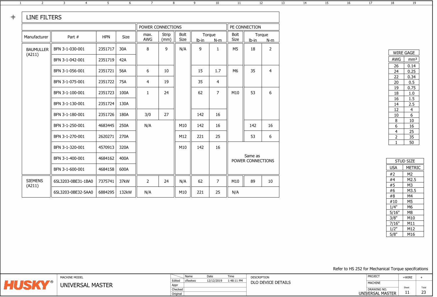
1 2 3 4 5 6 7 8 9 10 11 12 13 14 15 16
DRAWING NO.
MACHINE
17 18
UNIVERSAL MASTER
=
Sheet
WIRE
11
19
Total
23
+PROJECTMACHINE MODEL DESCRIPTION
DLO DEVICE DETAILSAppr
Original
cfleetwoEdited
Checked
12/12/2019Name Date
UNIVERSAL MASTERTime1:48:11 PM
Strip(mm)Manufacturer
BAUMULLER(A211)
Part #
POWER CONNECTIONS
BFN 3-1-180-001 273/02351726
HPN
BFN 3-1-250-001 N/A4683445
BFN 3-1-130-001 2351724
BFN 3-1-100-001 2351723
BFN 3-1-075-001 2351722
BFN 3-1-056-001 2351721
BFN 3-1-270-001 2620271
BFN 3-1-320-001 4570913
BFN 3-1-400-001 4684162
BFN 3-1-600-001 4684158
BFN 3-1-042-001 2351719
LINE FILTERS
241
19
10
4
98
Size
42A
56A
75A
100A
130A
180A
250A
270A
320A
400A
600A
PE CONNECTIONmax.AWG
6
Torquelb-in N-m
9 1
15 1.7
35 4
62 7
142 16
142 16
221 25
16142
Torquelb-in N-m
18
35
53
2
4
6
16
53 6
142
6SL3203-0BE31-1BA0 7375741 37kW 62 7SIEMENS(A211)
Refer to HS 252 for Mechanical Torque specifcations
M6M8M10
M12
M5
1/2"
3/8"5/16"1/4"#10
USASTUD SIZE
M165/8"
METRIC
M3.5M4
M2.5
#8#6
#4M2#2
M3#5
M117/16"
mm²AWGWIRE GAGE
0.7519
0.340.520
220.2524
16253550
10
12468
1.0181.516
42.5
1214
610
0.1426
6SL3203-0BE32-5AA0 6884295 132kW 221 25N/A
242 89 10
BoltSize
N/A
M10
M10
N/A
M12
M10
BoltSize
N/A
M10
M10
M6
M5
Same as POWER CONNECTIONS
BFN 3-1-030-001 2351717 30A
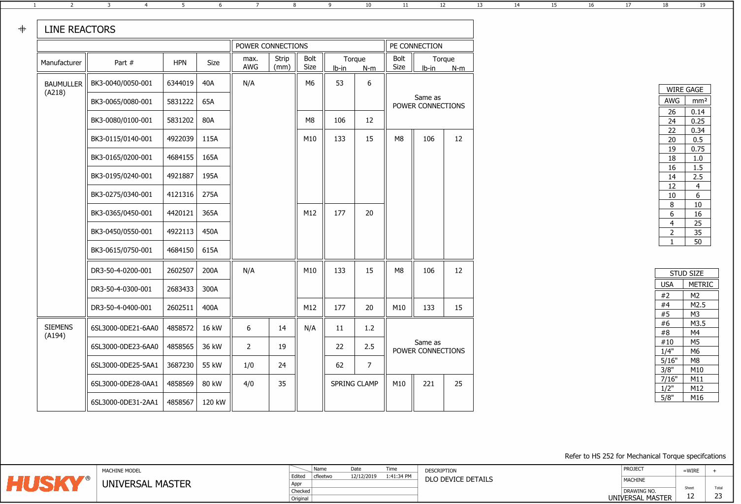
1 2 3 4 5 6 7 8 9 10 11 12 13 14 15 16
DRAWING NO.
MACHINE
17 18
UNIVERSAL MASTER
=
Sheet
WIRE
12
19
Total
23
+PROJECTMACHINE MODEL DESCRIPTION
DLO DEVICE DETAILSAppr
Original
cfleetwoEdited
Checked
12/12/2019Name Date
UNIVERSAL MASTERTime1:41:34 PM
Strip(mm)Manufacturer
BAUMULLER(A218)
BoltSize
POWER CONNECTIONS
HPN
BK3-0195/0240-001 4921887
BK3-0275/0340-001 4121316
M10DR3-50-4-0200-001 2602507 N/A
6SL3000-0DE28-0AA1 4858569
SIEMENS(A194)
354/0
BK3-0065/0080-001 5831222
BK3-0080/0100-001 5831202
BK3-0115/0140-001 4922039
BK3-0165/0200-001 4684155
BK3-0365/0450-001 4420121
BK3-0450/0550-001 4922113
BK3-0615/0750-001 4684150
2683433DR3-50-4-0300-001
2602511DR3-50-4-0400-001
6SL3000-0DE23-6AA0 4858565
6SL3000-0DE25-5AA1 3687230
6SL3000-0DE31-2AA1 4858567
M10
M12
M12
M6N/A
LINE REACTORS
192
241/0
Size
80 kW
55 kW
36 kW
200A
300A
400A
120 kW
BoltSize
PE CONNECTION
Same as POWER CONNECTIONS
M10
N/A
M8
M8
Part # max.AWG
6SL3000-0DE21-6AA0 4858572 14616 kW
65A
80A
115A
165A
450A
365A
275A
195A
615A
M10
Torquelb-in N-m
53
133
177
6
15
20
133 15
177 20
11 1.2
22 2.5
62 7
SPRING CLAMP
Torquelb-in N-m
106 12
106 12
133 15
221 25
M8 12106
Refer to HS 252 for Mechanical Torque specifcations
M6M8M10
M12
M5
1/2"
3/8"5/16"1/4"#10
USASTUD SIZE
M165/8"
METRIC
M3.5M4
M2.5
#8#6
#4M2#2
M3#5
M117/16"
mm²AWGWIRE GAGE
0.7519
0.340.520
220.2524
16253550
10
12468
1.0181.516
42.5
1214
610
0.1426
Same as POWER CONNECTIONS
BK3-0040/0050-001 6344019 40A
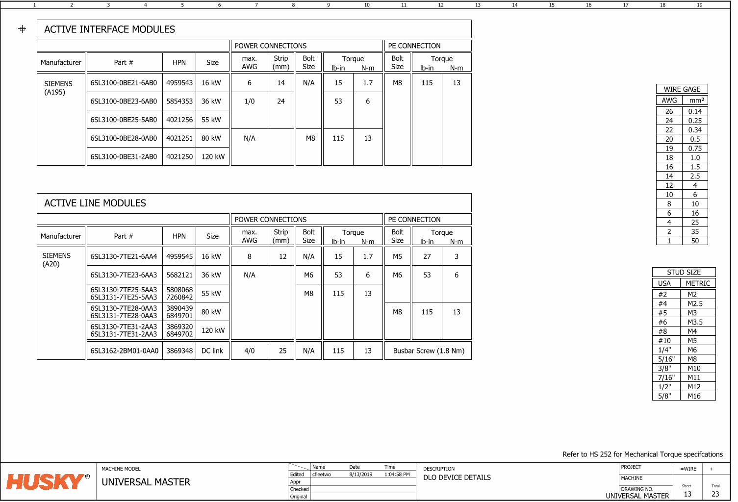
1 2 3 4 5 6 7 8 9 10 11 12 13 14 15 16
DRAWING NO.
MACHINE
17 18
UNIVERSAL MASTER
=
Sheet
WIRE
13
19
Total
23
+PROJECTMACHINE MODEL DESCRIPTION
DLO DEVICE DETAILSAppr
Original
cfleetwoEdited
Checked
8/13/2019Name Date
UNIVERSAL MASTERTime1:04:58 PM
SIEMENS(A195)
5854353
4021251
6SL3100-0BE23-6AB0
6SL3100-0BE28-0AB0
40212506SL3100-0BE31-2AB0
6SL3100-0BE25-5AB0 4021256
241/0
M8N/A
36 kW
80 kW
120 kW
55 kW
49595436SL3100-0BE21-6AB0 16 kW 146
ACTIVE INTERFACE MODULES
Strip(mm)Manufacturer Part #
POWER CONNECTIONS
HPN Size
PE CONNECTIONmax.AWG
Torquelb-in N-m
15 1.7
53 6
115 13
115 13
Torquelb-in N-m
SIEMENS(A20)
5682121
3890439
6SL3130-7TE23-6AA3
6SL3130-7TE28-0AA3
38693206SL3130-7TE31-2AA3
58080686SL3130-7TE25-5AA3
ACTIVE LINE MODULES
80 kW
55 kW
36 kW
120 kW
M6
M8
M8
38693486SL3162-2BM01-0AA0 254/0DC link N/A Busbar Screw (1.8 Nm)
49595456SL3130-7TE21-6AA4 16 kW
M6N/A
Manufacturer HPN Strip(mm)
BoltSize
POWER CONNECTIONS
Size
PE CONNECTION
Part # max.AWG
N/A128 M5
BoltSize
Torquelb-in N-m
15
115
1.7
13
653
115 13
Torquelb-in N-m
27 3
653
131156SL3131-7TE28-0AA3 6849701
6SL3131-7TE31-2AA3 6849702
BoltSize
N/A
BoltSize
M8
Refer to HS 252 for Mechanical Torque specifcations
M6M8M10
M12
M5
1/2"
3/8"5/16"1/4"#10
USASTUD SIZE
M165/8"
METRIC
M3.5M4
M2.5
#8#6
#4M2#2
M3#5
M117/16"
mm²AWGWIRE GAGE
0.7519
0.340.520
220.2524
16253550
10
12468
1.0181.516
42.5
1214
610
0.1426
6SL3131-7TE25-5AA3 7260842
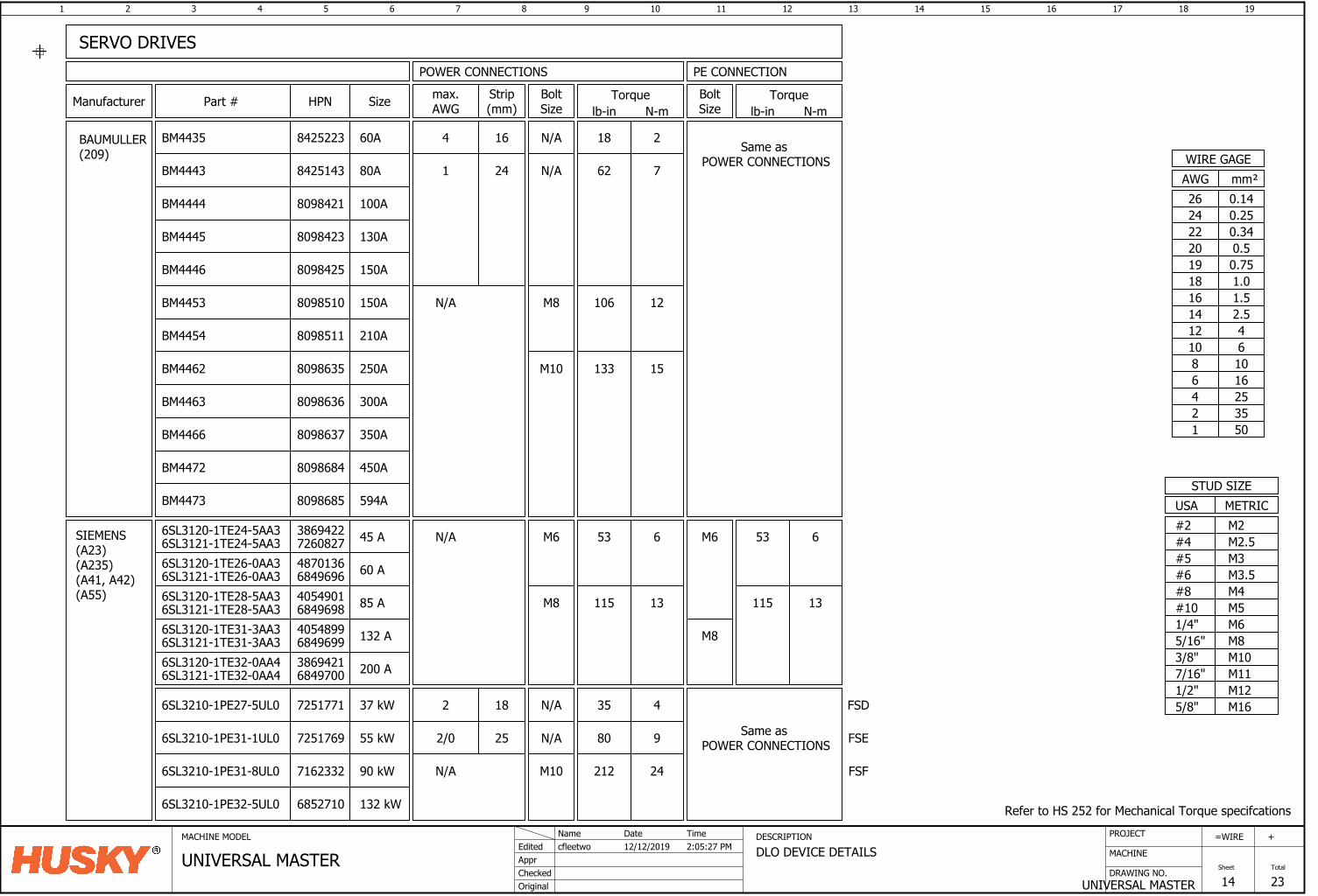
1 2 3 4 5 6 7 8 9 10 11 12 13 14 15 16
DRAWING NO.
MACHINE
17 18
UNIVERSAL MASTER
=
Sheet
WIRE
14
19
Total
23
+PROJECTMACHINE MODEL DESCRIPTION
DLO DEVICE DETAILSAppr
Original
cfleetwoEdited
Checked
12/12/2019Name Date
UNIVERSAL MASTERTime2:05:27 PM
Manufacturer
BAUMULLER(209)
HPN
BM4444
BM4445
BM4446
BM4453 N/A
BM4454
BM4462
BM4463
BM4466
BM4472
Strip(mm)
BoltSize
POWER CONNECTIONS
M10
1 24
M8
SERVO DRIVES
Size
N/A
Part # max.AWG
BoltSize
PE CONNECTION
100A
130A
150A
150A
210A
250A
300A
350A
450A
Torquelb-in N-m
62
106
7
12
Torquelb-in N-m
15133
Same as POWER CONNECTIONS
Refer to HS 252 for Mechanical Torque specifcations
M6M8M10
M12
M5
1/2"
3/8"5/16"1/4"#10
USASTUD SIZE
M165/8"
METRIC
M3.5M4
M2.5
#8#6
#4M2#2
M3#5
M117/16"
8098421
8098423
8098425
8098510
8098511
8098635
8098636
8098637
8098684
mm²AWGWIRE GAGE
0.7519
0.340.520
220.2524
16253550
10
12468
1.0181.516
42.5
1214
610
0.1426
BM4443 80A8425143
BM4473 594A8098685
SIEMENS(A23)(A235)(A41, A42)(A55)
6SL3121-1TE24-5AA3 7260827 45 A
6SL3120-1TE26-0AA3 60 A4870136
6SL3120-1TE28-5AA3 4054901 85 A
6SL3120-1TE31-3AA3 4054899 132 A
6SL3120-1TE32-0AA4 3869421 200 A
M6N/A
M8
M8
M6
115 13
53 6
115 13
53 6
N/A 35 4
6SL3121-1TE26-0AA3 6849696
6SL3121-1TE28-5AA3 6849698
6SL3121-1TE31-3AA3 6849699
6SL3121-1TE32-0AA4 6849700
6SL3210-1PE27-5UL0 7251771 37 kW
6SL3120-1TE24-5AA3 3869422
M10
Same as POWER CONNECTIONS
212 24N/A6SL3210-1PE31-8UL0 7162332 90 kW
6SL3210-1PE31-1UL0 7251769 55 kW N/A 80 9
2 18
2/0 25
FSD
FSE
FSF
6SL3210-1PE32-5UL0 6852710 132 kW
BM4435 60A8425223 N/A 18 24 16
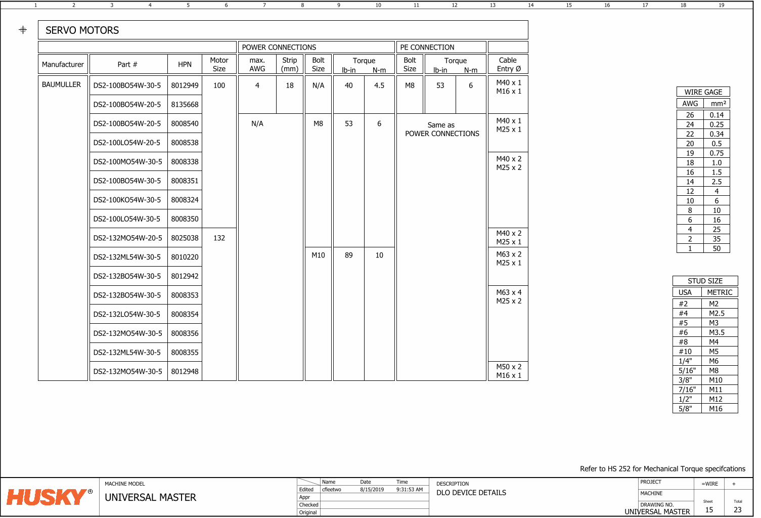
1 2 3 4 5 6 7 8 9 10 11 12 13 14 15 16
DRAWING NO.
MACHINE
17 18
UNIVERSAL MASTER
=
Sheet
WIRE
15
19
Total
23
+PROJECTMACHINE MODEL DESCRIPTION
DLO DEVICE DETAILSAppr
Original
cfleetwoEdited
Checked
8/15/2019Name Date
UNIVERSAL MASTERTime9:31:53 AM
Refer to HS 252 for Mechanical Torque specifcations
M6M8M10
M12
M5
1/2"
3/8"5/16"1/4"#10
USASTUD SIZE
M165/8"
METRIC
M3.5M4
M2.5
#8#6
#4M2#2
M3#5
M117/16"
mm²AWGWIRE GAGE
0.7519
0.340.520
220.2524
16253550
10
12468
1.0181.516
42.5
1214
610
0.1426
Manufacturer
BAUMULLER
SERVO MOTORS
HPN
8135668
8008538
8008540
8008350
8008324
8012949
8008353
8012942
8025038
DS2-100BO54W-30-5
DS2-100BO54W-20-5
DS2-100BO54W-20-5
DS2-100LO54W-20-5
DS2-100BO54W-30-5
DS2-100KO54W-30-5
DS2-100LO54W-30-5
DS2-132MO54W-20-5
DS2-132BO54W-30-5
DS2-132BO54W-30-5
8008351
DS2-100MO54W-30-5 8008338
DS2-132MO54W-30-5
DS2-132ML54W-30-5
DS2-132LO54W-30-5
M40 x 2M25 x 1
8010220
8008354
8008356
MotorSize
Cable Entry Ø
BoltSize
M8
N/A
Strip(mm)
max.AWG
184
PE CONNECTION
M8
BoltSize
POWER CONNECTIONS
M10
M40 x 1M16 x 1
Torquelb-in N-m
89 10
40
53 6
4.5
Torquelb-in N-m
53 6
Same as POWER CONNECTIONS
100
132
Part #
DS2-132ML54W-30-5 8008355
DS2-132MO54W-30-5 8012948
N/A M40 x 1M25 x 1
M40 x 2M25 x 2
M63 x 4M25 x 2
M50 x 2M16 x 1
M63 x 2M25 x 1
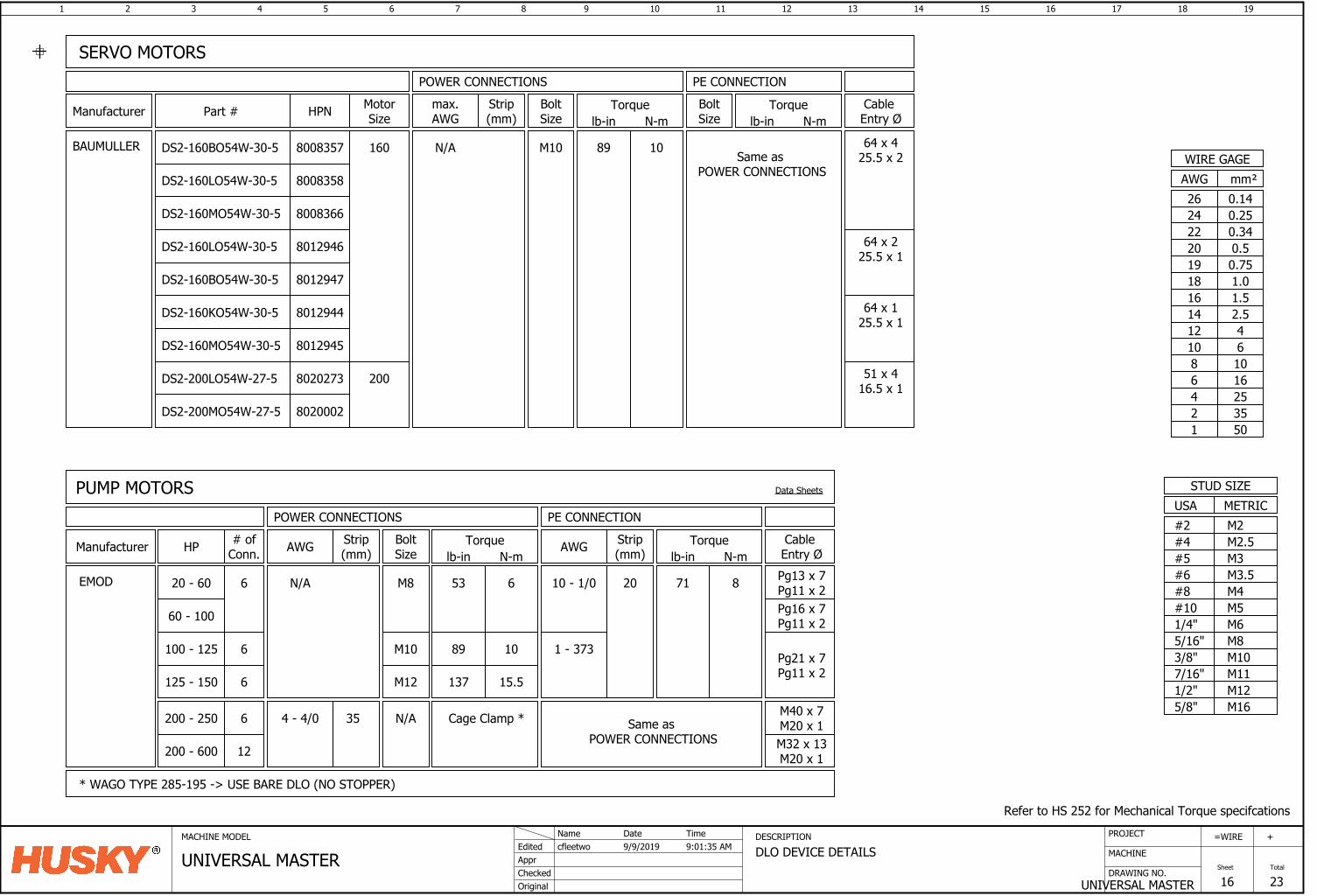
1 2 3 4 5 6 7 8 9 10 11 12 13 14 15 16
DRAWING NO.
MACHINE
17 18
UNIVERSAL MASTER
=
Sheet
WIRE
16
19
Total
23
+PROJECTMACHINE MODEL DESCRIPTION
DLO DEVICE DETAILSAppr
Original
cfleetwoEdited
Checked
9/9/2019Name Date
UNIVERSAL MASTERTime9:01:35 AM
Refer to HS 252 for Mechanical Torque specifcations
M6M8M10
M12
M5
1/2"
3/8"5/16"1/4"#10
USASTUD SIZE
M165/8"
METRIC
M3.5M4
M2.5
#8#6
#4M2#2
M3#5
M117/16"
mm²AWGWIRE GAGE
0.7519
0.340.520
220.2524
16253550
10
12468
1.0181.516
42.5
1214
610
0.1426
Manufacturer
BAUMULLER
SERVO MOTORS
HPN
8008358
8012946
8008366
8020273
8012945
8008357
8020002
DS2-160BO54W-30-5
DS2-160LO54W-30-5
DS2-160MO54W-30-5
DS2-160LO54W-30-5
DS2-160KO54W-30-5
DS2-160MO54W-30-5
DS2-200LO54W-27-5
DS2-200MO54W-27-5
8012944
DS2-160BO54W-30-5 8012947
64 x 225.5 x 1
MotorSize
Cable Entry Ø
BoltSize
N/A
Strip(mm)
max.AWG
PE CONNECTIONBoltSize
POWER CONNECTIONS
M10
Torquelb-in N-m
89 10
Torquelb-in N-m
Same as POWER CONNECTIONS
160
200
Part #
64 x 425.5 x 2
51 x 416.5 x 1
64 x 125.5 x 1
Manufacturer
EMOD
PUMP MOTORS
# ofConn.
6
HP
20 - 60
100 - 125 6
6125 - 150
12200 - 600
Cage Clamp *
* WAGO TYPE 285-195 -> USE BARE DLO (NO STOPPER)
53 6
1089
15.5137
BoltSize
M8
M10
M12
Torquelb-in N-m
Data Sheets
N/A
N/A
Strip(mm)AWG
4 - 4/0 35
Pg13 x 7Pg11 x 2
Cable Entry Ø
Pg21 x 7Pg11 x 2
71 8
Torquelb-in N-m
PE CONNECTIONPOWER CONNECTIONS
10 - 1/0 20
Strip(mm)AWG
Same as POWER CONNECTIONS M32 x 13
M20 x 1
Pg16 x 7Pg11 x 2
6200 - 250 M40 x 7M20 x 1
60 - 100
1 - 373
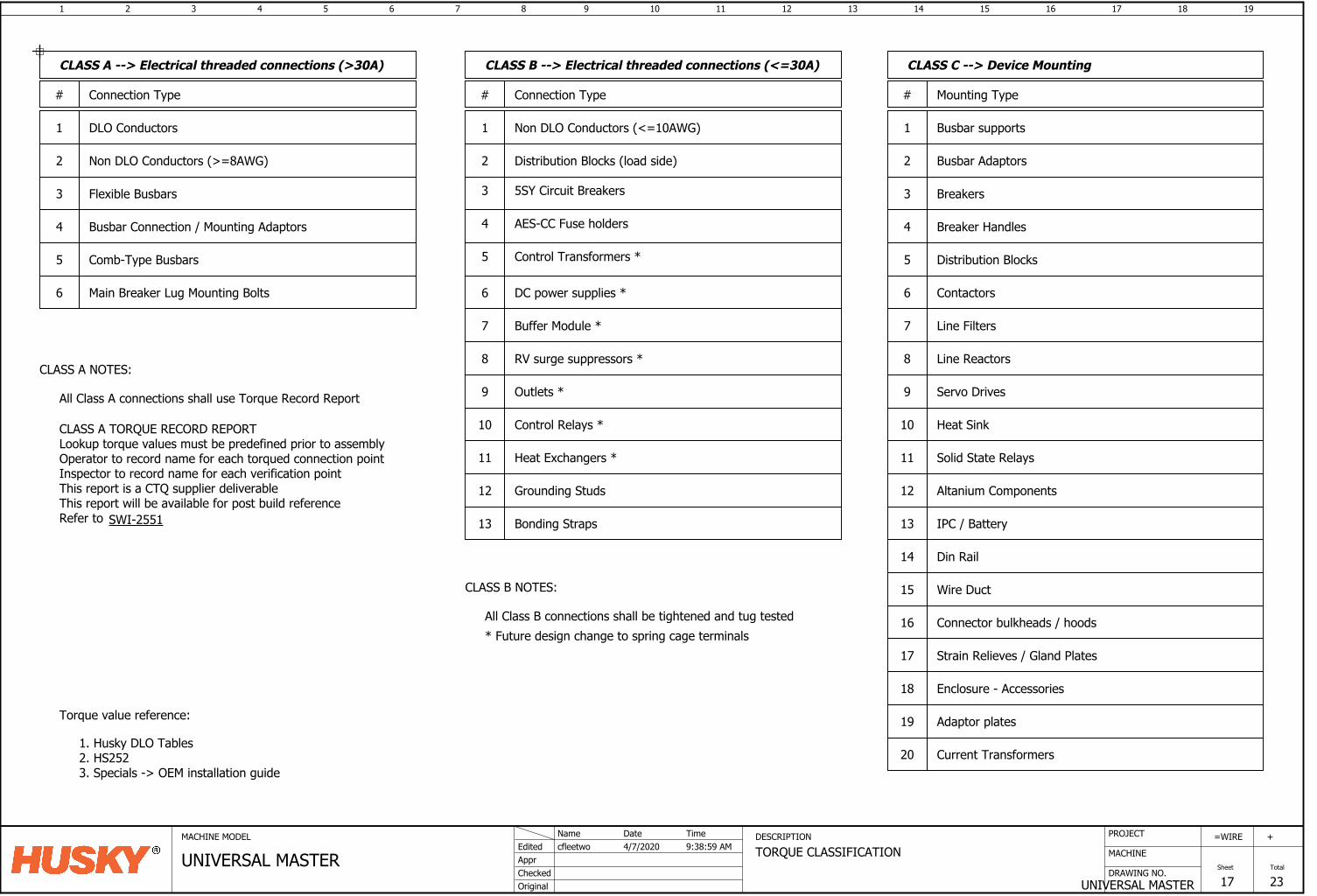
1 2 3 4 5 6 7 8 9 10 11 12 13 14 15 16
DRAWING NO.
MACHINE
17 18
UNIVERSAL MASTER
=
Sheet
WIRE
17
19
Total
23
+PROJECTMACHINE MODEL DESCRIPTION
TORQUE CLASSIFICATIONAppr
Original
cfleetwoEdited
Checked
4/7/2020Name Date
UNIVERSAL MASTERTime9:38:59 AM
# Connection Type
All Class A connections shall use Torque Record Report
DLO Conductors
Non DLO Conductors (>=8AWG)
1
2
Flexible Busbars3
Comb-Type Busbars
4 Busbar Connection / Mounting Adaptors
5
Main Breaker Lug Mounting Bolts6
CLASS A NOTES:
Distribution Blocks (load side)
5SY Circuit Breakers
AES-CC Fuse holders
RV surge suppressors *
2
11
12
13
3
# Connection Type
4
9
CLASS B --> Electrical threaded connections (<=30A)CLASS A --> Electrical threaded connections (>30A)
Busbar Adaptors
Breakers
Breaker Handles
Contactors
Line Filters
Line Reactors
Servo Drives
Solid State Relays
Din Rail
Wire Duct
Connector bulkheads / hoods
1
2
3
4
6
Busbar supports
7
# Mounting Type
8
9
11
13
14
15
CLASS C --> Device Mounting
Strain Relieves / Gland Plates
16
IPC / Battery
17
Heat Sink10
Distribution Blocks5
Altanium Components12Grounding Studs
Enclosure - Accessories18
Adaptor plates19
Control Relays *
DC power supplies *
7
Control Transformers *
6
Outlets *
10
Current Transformers20
Buffer Module *
8
5
Heat Exchangers *
1 Non DLO Conductors (<=10AWG)
Bonding Straps
All Class B connections shall be tightened and tug tested
CLASS A TORQUE RECORD REPORTLookup torque values must be predefined prior to assemblyOperator to record name for each torqued connection pointInspector to record name for each verification pointThis report is a CTQ supplier deliverableThis report will be available for post build referenceRefer to
CLASS B NOTES:
* Future design change to spring cage terminals
Torque value reference:
1. Husky DLO Tables2. HS2523. Specials -> OEM installation guide
SWI-2551
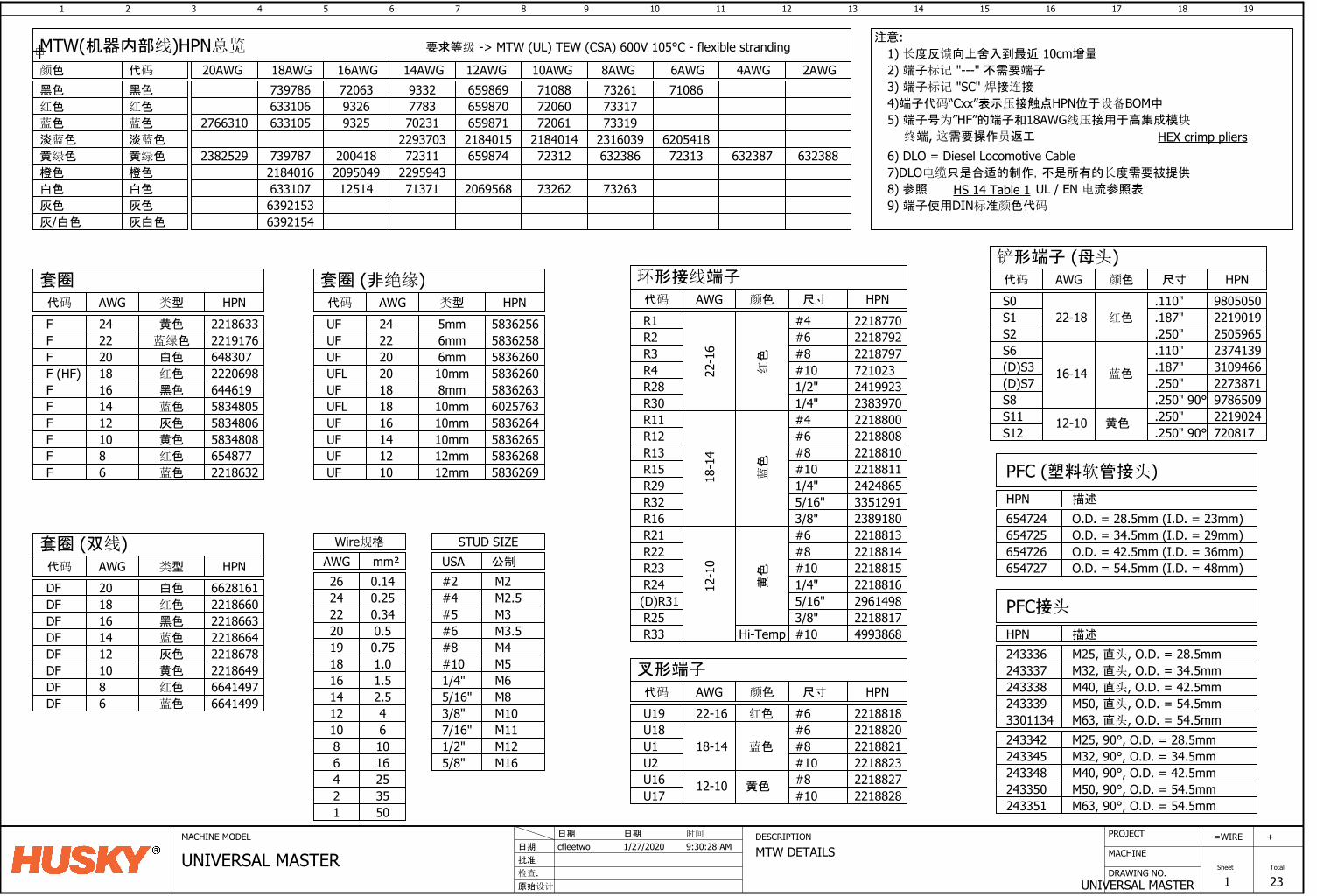
1 2 3 4 5 6 7 8 9 10 11 12 13 14 15 16
DRAWING NO.
MACHINE
17 18
UNIVERSAL MASTER
=
Sheet
WIRE
1
19
Total
23
+PROJECTMACHINE MODEL DESCRIPTION
MTW DETAILS批准
原始设计
cfleetwo日期
检查.
1/27/2020日期 日期
UNIVERSAL MASTER时间
9:30:28 AM
MTW(机器内部线)HPN总览
20AWG
2766310
2382529
2AWG
632388632387
4AWG
72313
710866AWG
732637326220695687137112514633107229594320950492184016
63238672312659874723112004187397872316039218401421840152293703733197206165987170231932563310573317720606598707783932663310673261710886598699332720637397868AWG 10AWG 12AWG 14AWG 16AWG 18AWG 颜色
黑色
蓝色
白色
黄绿色
淡蓝色
橙色
红色
要求等级 -> MTW (UL) TEW (CSA) 600V 105°C - flexible stranding 1) 长度反馈向上舍入到最近 10cm增量
代码
黑色
蓝色
白色
黄绿色
淡蓝色
橙色
红色
套圈类型AWG代码 HPN
F 黄色
FFF (HF)FFFFFF 2218632
65487758348085834806583480564461922206986483072219176221863324
2220181614121086
蓝绿色
白色
红色
黑色
蓝色
灰色
黄色
红色
蓝色
DFDFDFDFDFDF 2218649
2218678221866422186632218660662816120
1816141210
白色
红色
黑色
蓝色
灰色
黄色
UFUFUF
UFLUFUFUFUF 5836269
5836268583626558362646025763
58362605836258583625624
2220
1816141210
U1U2U16 #8U17 #10 2218828
221882722188232218821
U19 221881822-16 红色
U18 221882018-14 蓝色
#6#6#8#10
黄色12-10
.250"
.250" 90°
S6(D)S3
S11S12
.110"
.187"蓝色16-14
12-10 黄色
23741393109466
2219024720817
S1S2
.187"
.250"红色22-18 2219019
2505965
.250" 2273871(D)S7
2) 端子标记 "---" 不需要端子
HS 14 Table 1
6) DLO = Diesel Locomotive Cable7)DLO电缆只是合适的制作,不是所有的长度需要被提供
8) 参照 UL / EN 电流参照表
UF 583626318
6mm6mm
UFL 583626020 10mm
10mm8mm
5mm
10mm10mm12mm12mm
R1
22-1
6
#4R2
红色
#6R3 #8R4R28R30R11R12
#10
R13R15R29R32
2424865221881122188102218808221880023839702419923721023221879722187922218770
1/2"1/4"
18-1
4
蓝色
#4#6#8#101/4"
33512915/16"
2218817
2218816221881522188142218813R21
12-1
0
黄色
#6#8#101/4"
R22R23R24(D)R31R25
29614983/8"5/16"
R33 4993868Hi-Temp #10
6205418
R16 23891803/8"
3) 端子标记 "SC" 焊接连接
环形接线端子尺寸AWG代码 HPN颜色
叉形端子AWG代码 HPN颜色 尺寸
铲形端子 (母头)尺寸AWG代码 HPN颜色
注意:
mm²AWGWire规格
0.7519
0.340.520
22
M6M8M10
M12
M5
1/2"
3/8"5/16"1/4"#10
USASTUD SIZE
M165/8"
公制
M3.5M4
M2.5
#8#6
#4M2#2
M3#5
M117/16"
DFDF
86
红色
蓝色
HPN
PFC (塑料软管接头)描述
654725654726654727
654724 O.D. = 28.5mm (I.D. = 23mm)O.D. = 34.5mm (I.D. = 29mm)O.D. = 42.5mm (I.D. = 36mm)O.D. = 54.5mm (I.D. = 48mm)
HPN
PFC接头
描述
M25, 直头, O.D. = 28.5mmM32, 直头, O.D. = 34.5mm243337
243336
243338 M40, 直头, O.D. = 42.5mm243339 M50, 直头, O.D. = 54.5mm3301134 M63, 直头, O.D. = 54.5mm
M40, 90°, O.D. = 42.5mmM50, 90°, O.D. = 54.5mm
M25, 90°, O.D. = 28.5mmM32, 90°, O.D. = 34.5mm
M63, 90°, O.D. = 54.5mm
243342243345243348243350243351
6392153灰色 灰色
6392154灰/白色 灰白色
套圈 (非绝缘)类型AWG代码 HPN
0.2524
套圈 (双线)类型AWG代码 HPN
66414976641499
9) 端子使用DIN标准颜色代码
16253550
10
12468
5) 端子号为”HF”的端子和18AWG线压接用于高集成模块
终端, 这需要操作员返工
1.0181.516
42.5
1214
610
0.1426
HEX crimp pliers
4)端子代码“Cxx”表示压接触点HPN位于设备BOM中
.250" 90° 9786509S8
S0 .110" 9805050
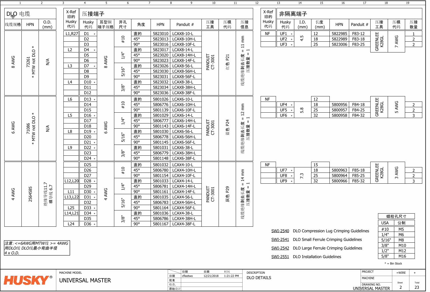
1 2 3 4 5 6 7 8 9 10 11 12 13 14 15 16
DRAWING NO.
MACHINE
17 18
UNIVERSAL MASTER
=
Sheet
WIRE
2
19
Total
23
+PROJECTMACHINE MODEL DESCRIPTION
DLO DETAILS批准
原始设计
cfleetwo日期
检查.
12/21/2018日期 日期
UNIVERSAL MASTER时间
1:21:22 PM
D136
AWG
直的 LCAX6-10-L
蓝色
P24
D14 #10 45°
D15 90°D16D17D18D19D20
直的
45°90°直的
45°
1/4"
5/16
"
D21 90°D22D23
直的
45°D24 90°3/
8"
UF4
5.8
182532
2564
585
直的
45°90°直的
45°90°直的
45°90°直的
45°90°
7.3
182532
UF6
UF9
UF7
PAND
UIT
CT-3
001
4 AW
G
PAND
UIT
CT-3
001
灰色
P29
4 AW
G6
AWG
GREE
NLEE
K28G
L
5 AW
G
GREE
NLEE
K28G
L
3 AW
G
223
223
5800956 F84-185800957 F84-255800958 F84-32
580096358009645800966
580116758067865801036580116458067835801035580116158067815801033580115458067805801032580114858067795801031580114558067785801030580114358067775801029580113958067765801026
LCAX6-10H-LLCAX6-10F-LLCAX6-14-LLCAX6-14H-LLCAX6-14F-LLCAX6-56-LLCAX6-56H-LLCAX6-56F-LLCAX6-38-LLCAX6-38H-LLCAX6-38F-L
LCAX4-14-LLCAX4-14H-LLCAX4-14F-LLCAX4-56-LLCAX4-56H-LLCAX4-56F-LLCAX4-38-LLCAX4-38H-LLCAX4-38F-L
LCAX4-10-LLCAX4-10H-LLCAX4-10F-L#
101/
4"5/
16"
3/8"
D25D26D27D28D29D30D31D32D33D34D35D36
F85-18F85-25F85-32
L6
L5
L8
L9
L12,L20
L13,L22
L25L14,L21
L24
M6M8M10M12
M5
1/2"3/8"5/16"1/4"#10USA
螺栓孔尺寸
M165/8"
*
*
*
*
*
*
*
*
*
*
* = Bin Stock
D1
8 AW
G
直的 LCAX8-10-L
红色
P21
D2 #10 45°
D3 90°D4D5D6D7D8
直的
45°90°直的
45°
1/4"
5/16
"
D9 90°D10D11
直的
45°D12 90°3/
8"
UF1
4.5 18
线缆绝缘
剥去长度
= 1
1 m
m
PAND
UIT
CT-3
001
8 AW
G
5822989 F83-18
582303658230345823032582303158230305823026582302358230205823017582301658230135823010
LCAX8-10H-LLCAX8-10F-LLCAX8-14-LLCAX8-14H-LLCAX8-14F-LLCAX8-56-LLCAX8-56H-LLCAX8-56F-LLCAX8-38-LLCAX8-38H-LLCAX8-38F-L
L1,R27
L2
L3
L4 *
*
*
*
GREE
NLEE
K28G
L
7 AW
G 21
L11
N/A
压接数量
= 1
线缆绝缘
剥去长度
= 1
2 m
m压接数量
= 1
线缆绝缘
剥去长度
= 1
4 m
m压接数量
= 1
公制
压接端子 非隔离端子
开孔尺寸
角度耳型铜
端子规格HPN Panduit # I.D.
(mm) HPN Panduit #O.D.(mm)线缆规格 HPN
DLO 电缆
压接工具
X-Ref旧的
Husky代码
压接数量
压模代码
压接工具
Husky代码
长度 (mm)
压接信息
压模代码
*
*
5823006 F83-25UF2
25
UF5
UF8
注意:<=6AWG用MTW线 >= 4AWG用DLO线 DLO线最小弯曲半径4 x O.D.
12 5822985 F83-12
UF3 2
*
*
*
*
*
*
*
X-Ref旧的
Husky代码
NF
12NF
NF 15
*
*
7108
6
N/A
7326
1*
MTW
not
DLO
**
MTW
not
DLO
*
DLO Compression Lug Crimping Guidelines
DLO Small Ferrule Crimping Guidelines
DLO Large Ferrule Crimping Guidelines
DLO Installation Guidelines
SWI-2540
SWI-2541
SWI-2542
SWI-2551
绝缘导线
11.7
裸导线
6.7
Husky代码
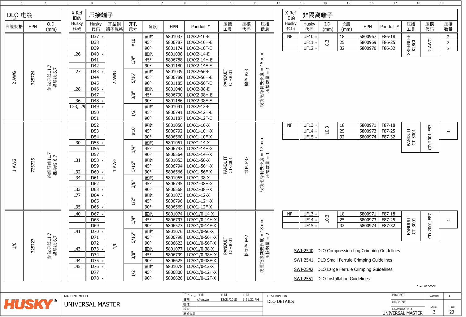
1 2 3 4 5 6 7 8 9 10 11 12 13 14 15 16
DRAWING NO.
MACHINE
17 18
UNIVERSAL MASTER
=
Sheet
WIRE
3
19
Total
23
+PROJECTMACHINE MODEL DESCRIPTION
DLO DETAILS批准
原始设计
cfleetwo日期
检查.
12/21/2018日期 日期
UNIVERSAL MASTER时间
1:21:22 PM
7257
25
D64
1 AW
G
直的 5801051
绿色
P37
D65
45° 580679390° 5806564
58010535806794
D66
5806566
D67
5801055
D68
5806795
直的
45°90°直的
45°
D69
580656890°
D70D71
直的
45°
D72
90°
580107358067965806569
7257
27
直的
45°90°
D76D77D78
直的
45°90°直的
45°
1/4"
5/16
"
90°直的
45°90°
3/8"
UF10
PAND
UIT
CT-3
001
1/0
PAND
UIT
CT-3
001
粉红色
P42
1/0
1 AW
G
1/2"
1/4"
5/16
"3/
8"1/
2"
10.3 18
255800971
UF15 32
158009735800974
LCAX1-14-XLCAX1-14H-XLCAX1-14F-XLCAX1-56-XLCAX1-56H-XLCAX1-56F-XLCAX1-38-XLCAX1-38H-XLCAX1-38F-XLCAX1-12-XLCAX1-12H-XLCAX1-12F-XLCAX1/0-14-XLCAX1/0-14H-XLCAX1/0-14F-XLCAX1/0-56-XLCAX1/0-56H-XLCAX1/0-56F-XLCAX1/0-38-XLCAX1/0-38H-XLCAX1/0-38F-XLCAX1/0-12-XLCAX1/0-12H-XLCAX1/0-12F-X
D73D74D75
直的 580105045° 580679290° 5806560#
10
LCAX1-10-XLCAX1-10H-XLCAX1-10F-X
580662658068005801078580662558067995801077580662358067985801076580657358067975801074
D52D53D54D55D56D57D58D59D60D61D62D63
F87-18F87-25F87-32
L30
L31
L34
L40
L41
L43
L44L45
L77L33
L35
*
*
*
*
*
*
*
*
*
*
*
*
D37D38D39D40D41D42D43D44D45D46D47D48D49
直的
D50
45°
D51
90°直的
45°90°直的
45°
1/4"
5/16
"
90°直的
45°90°
3/8"
2 AW
G
PAND
UIT
CT-3
001
棕色
P33
1/2"
7257
24
2 AW
G
580118758067915801041580118658067905801040580118558067895801039580118058067885801038 LCAX2-14-E
LCAX2-14H-ELCAX2-14F-ELCAX2-56-ELCAX2-56H-ELCAX2-56F-ELCAX2-38-ELCAX2-38H-ELCAX2-38F-ELCAX2-12-ELCAX2-12H-ELCAX2-12F-E
直的 580103745° 580678790° 5801174#
10
LCAX2-10-ELCAX2-10H-ELCAX2-10F-E
L26
L27
L28
L36L23,L29 *
*
*
*
*
8.3
1825
5800967
UF13
UF12 32
GREE
NLEE
K28G
L
2 AW
G 225800969
5800970
F86-18F86-25F86-32
*
* = Bin Stock
L32
*
线缆绝缘
剥去长度
= 1
5 m
m压接数量
= 1
线缆绝缘
剥去长度
= 1
7 m
m压接数量
= 1
线缆绝缘
剥去长度
= 1
8 m
m压接数量
= 2
UF113
UF14
*
*
*
*
NF
NF
*
*
10.3 18
255800971
UF15 32
CD-2
001-
F87
58009735800974
F87-18F87-25F87-32
UF13 *UF14 *
*
NF
PAND
UIT
CT-3
001 1
PAND
UIT
CT-3
001
CD-2
001-
F87
DLO Compression Lug Crimping Guidelines
DLO Small Ferrule Crimping Guidelines
DLO Large Ferrule Crimping Guidelines
DLO Installation Guidelines
SWI-2540
SWI-2541
SWI-2542
SWI-2551
绝缘导线
11.7
裸导线
6.7
绝缘导线
11.7
裸导线
6.7
绝缘导线
11.7
裸导线
6.7
压接端子 非隔离端子
开孔尺寸
角度耳型铜
端子规格HPN Panduit # I.D.
(mm) HPN Panduit #O.D.(mm)线缆规格 HPN
DLO 电缆
压接工具
X-Ref旧的
Husky代码
压接数量
压模代码
压接工具
Husky代码
长度 (mm)
压接信息
压模代码
X-Ref旧的
Husky代码
Husky代码
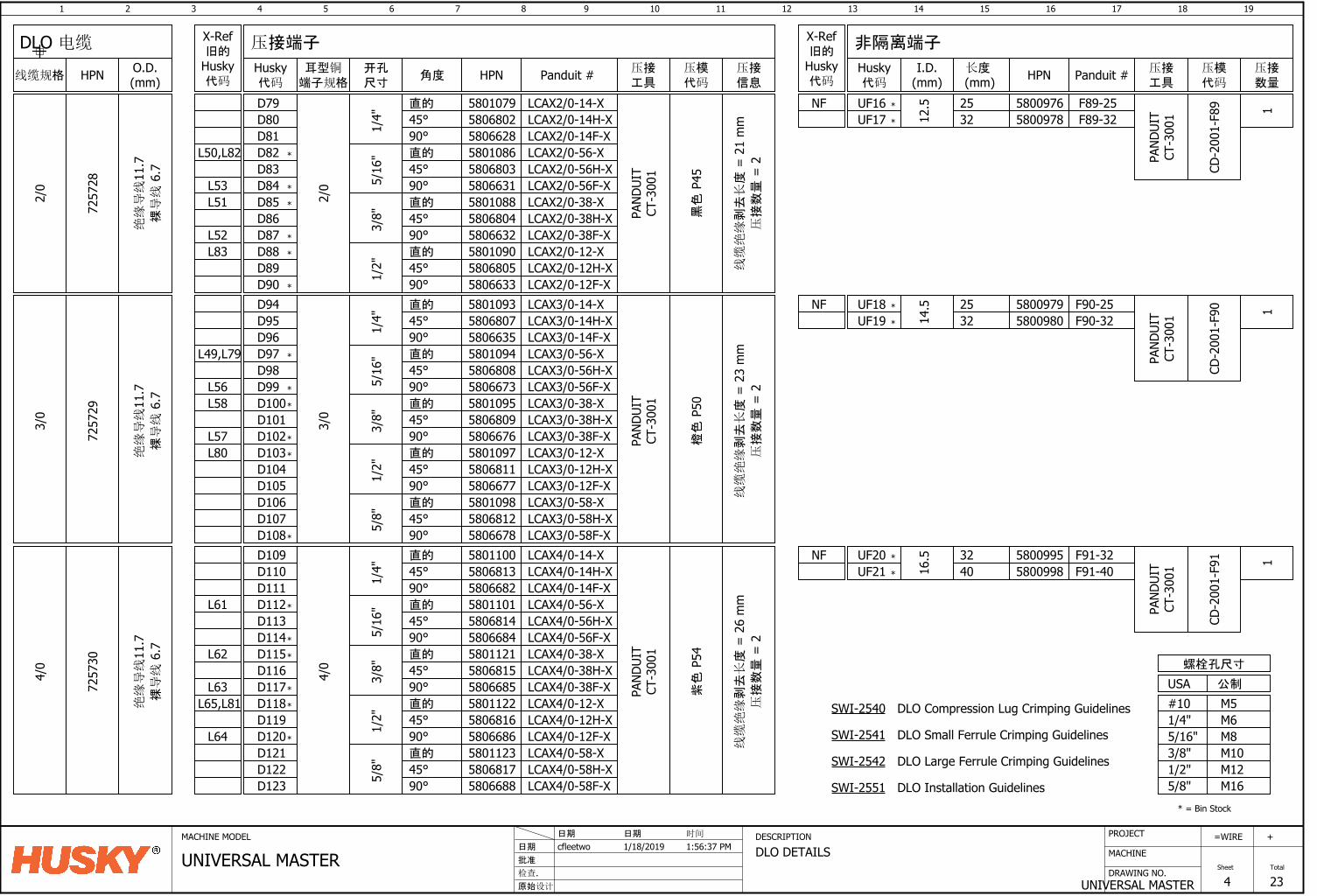
1 2 3 4 5 6 7 8 9 10 11 12 13 14 15 16
DRAWING NO.
MACHINE
17 18
UNIVERSAL MASTER
=
Sheet
WIRE
4
19
Total
23
+PROJECTMACHINE MODEL DESCRIPTION
DLO DETAILS批准
原始设计
cfleetwo日期
检查.
1/18/2019日期 日期
UNIVERSAL MASTER时间
1:56:37 PM
7257
30
D106D107D108
4/0
16.5 32
40
58010945806808580667358010955806809
直的
45°90°直的
45°
5/16
"
580667690°直的
45°90°
580109758068115806677
3/8"
1/2"
3/0
PAND
UIT
CT-3
001
橙色
P50
7257
29
3/0
25
14.5D94
D95D96D97D98D99D100D101D102D103D104D105
直的
45°90°1/
4"
LCAX3/0-14-XLCAX3/0-14H-XLCAX3/0-14F-X5806635
58068075801093
直的
45°90°
5801098580681258066785/
8"
58011015806814580668458011215806815
直的
45°90°直的
45°
5/16
"
580668590°直的
45°90°
580112258068165806686
3/8"
1/2"
4/0
D109D110D111D112D113D114D115D116D117D118D119D120
直的
45°90°1/
4"
580668258068135801100
直的
45°90°
5801123580681758066885/
8"
D121D122D123
PAND
UIT
CT-3
001
紫色
P54
LCAX3/0-56-XLCAX3/0-56H-XLCAX3/0-56F-XLCAX3/0-38-XLCAX3/0-38H-XLCAX3/0-38F-XLCAX3/0-12-XLCAX3/0-12H-XLCAX3/0-12F-XLCAX3/0-58-XLCAX3/0-58H-XLCAX3/0-58F-XLCAX4/0-14-XLCAX4/0-14H-XLCAX4/0-14F-XLCAX4/0-56-XLCAX4/0-56H-XLCAX4/0-56F-XLCAX4/0-38-XLCAX4/0-38H-XLCAX4/0-38F-XLCAX4/0-12-XLCAX4/0-12H-XLCAX4/0-12F-XLCAX4/0-58-XLCAX4/0-58H-XLCAX4/0-58F-X
5800979 F90-25
58009955800998
F91-32F91-40
UF20
UF19
UF16
UF21
L49,L79
L58
L80
L56
L57
L62
L65,L81
L64
L61
L63
*
*
*
*
*
*
*
*
*
*
*
*
*
*
*
*
*
L52
L53
L83
L51
L50,L82 580108658068035806631580108858068045806632580109058068055806633
580107958068025806628
LCAX2/0-12F-XLCAX2/0-12H-XLCAX2/0-12-XLCAX2/0-38F-XLCAX2/0-38H-XLCAX2/0-38-XLCAX2/0-56F-XLCAX2/0-56H-XLCAX2/0-56-XLCAX2/0-14F-XLCAX2/0-14H-XLCAX2/0-14-X
1/4"
90°45°直的
1/2"
2/0
3/8"
90°45°直的
90°
5/16
"
45°直的
90°45°直的
D90D89D88D87D86D85D84D83D82D81D80D79
PAND
UIT
CT-3
001
黑色
P45
7257
28
2/0
12.5 25
32F89-25F89-32UF17
UF18
58009765800978
*
M6M8M10M12
M5
1/2"3/8"5/16"1/4"#10
公制USA
M165/8"
螺栓孔尺寸
* = Bin Stock
线缆绝缘
剥去长度
= 2
1 m
m压接数量
= 2
线缆绝缘
剥去长度
= 2
3 m
m压接数量
= 2
线缆绝缘剥去长度
= 2
6 m
m压接数量
= 2*
32 5800980 F90-32
*
*
*
NF
NF
NF
*
*
CD-2
001-
F89
PAND
UIT
CT-3
001 1
CD-2
001-
F90
PAND
UIT
CT-3
001
CD-2
001-
F91
PAND
UIT
CT-3
001
11
DLO Compression Lug Crimping Guidelines
DLO Small Ferrule Crimping Guidelines
DLO Large Ferrule Crimping Guidelines
DLO Installation Guidelines
SWI-2540
SWI-2541
SWI-2542
SWI-2551
绝缘导线
11.7
裸导线
6.7
绝缘导线
11.7
裸导线
6.7
绝缘导线
11.7
裸导线
6.7
压接端子 非隔离端子
开孔尺寸
角度耳型铜
端子规格HPN Panduit # I.D.
(mm) HPN Panduit #O.D.(mm)线缆规格 HPN
DLO 电缆
压接工具
X-Ref旧的
Husky代码
压接数量
压模代码
压接工具
Husky代码
长度 (mm)
压接信息
压模代码
X-Ref旧的
Husky代码
Husky代码
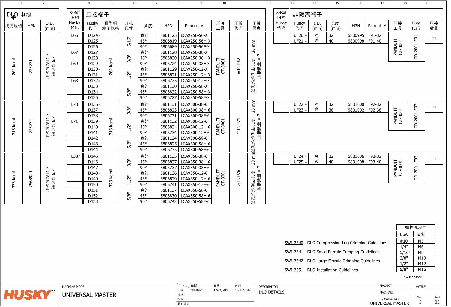
1 2 3 4 5 6 7 8 9 10 11 12 13 14 15 16
DRAWING NO.
MACHINE
17 18
UNIVERSAL MASTER
=
Sheet
WIRE
5
19
Total
23
+PROJECTMACHINE MODEL DESCRIPTION
DLO DETAILS批准
原始设计
cfleetwo日期
检查.
12/21/2018日期 日期
UNIVERSAL MASTER时间
1:21:22 PM
7257
32
313
kcm
il
323818
.558011315806823
直的
45°580673190°
直的
45°90°
580113258068245806734
3/8"
1/2"
直的
45°90°
5801134580682558067355/8"
LCAX300-38-6LCAX300-38H-6LCAX300-38F-6LCAX300-12-6LCAX300-12H-6LCAX300-12F-6LCAX300-58-6LCAX300-58H-6LCAX300-58F-6
PAND
UIT
CT-3
001
313
kcm
il
红色
P71
D136D137D138D139D140D141D142D143D144
58011355806827
直的
45°580673790°
直的
45°90°
580113658068295806741
3/8"
1/2"
直的
45°90°
5801137580683058067425/
8"
PAND
UIT
CT-3
001
373
kcm
il
D145D146D147D148D149D150D151D152D153
LCAX350-38-6LCAX350-38H-6LCAX350-38F-6LCAX350-12-6LCAX350-12H-6LCAX350-12F-6LCAX350-58-6LCAX350-58H-6LCAX350-58F-6
蓝色
P76
373
kcm
il
2568
920
324020
.0
58010005801002 F92-38
F92-32
58010065801008 F93-40
F93-32UF24
UF23
UF20
UF25
L71
L78
L307
M6M8M10M12
M5
1/2"3/8"5/16"1/4"#10
公制USA
M165/8"
螺栓孔尺寸
*
*
*
* = Bin Stock
LCAX250-58F-XLCAX250-58H-XLCAX250-58-XLCAX250-12F-XLCAX250-12H-XLCAX250-12-XLCAX250-38F-XLCAX250-38H-XLCAX250-38-XLCAX250-56F-XLCAX250-56H-XLCAX250-56-X
黄色
P62
PAND
UIT
CT-3
001
D135D134D133
5/8"
580672758068225801130
90°45°直的
D132D131D130D129D128D127D126D125D124
262
kcm
il
1/2"
3/8"
580672558068215801129
90°45°直的
90° 5806724
5/16
"
45°直的
90°45°直的
58068205801128580668958068195801125
4032
16.5
262
kcm
il
7257
3158009955800998 F91-40
F91-32
L68
L66
L67
L69
*
UF22
UF21
*
*
*
*
*
*
线缆绝缘
剥去长度
= 2
6 m
m压接数量
= 2
线缆绝缘剥去长度
= 3
0 m
m压接数量
= 2
线缆绝缘
剥去长度
= 3
3 m
m压接数量
= 2
*
*
*
*
*
CD-2
001-
F91
PAND
UIT
CT-3
001
CD-2
001-
F92
PAND
UIT
CT-3
001
PAND
UIT
CT-3
001
CD-2
001-
F93
11
1
DLO Compression Lug Crimping Guidelines
DLO Small Ferrule Crimping Guidelines
DLO Large Ferrule Crimping Guidelines
DLO Installation Guidelines
SWI-2540
SWI-2541
SWI-2542
SWI-2551
绝缘导线
11.7
裸导线
6.7
绝缘导线
11.7
裸导线
6.7
绝缘导线
11.7
裸导线
6.7
压接端子 非隔离端子
开孔尺寸
角度耳型铜
端子规格HPN Panduit # I.D.
(mm) HPN Panduit #O.D.(mm)线缆规格 HPN
DLO 电缆
压接工具
X-Ref旧的
Husky代码
压接数量
压模代码
压接工具
Husky代码
长度 (mm)
压接信息
压模代码
X-Ref旧的
Husky代码
Husky代码
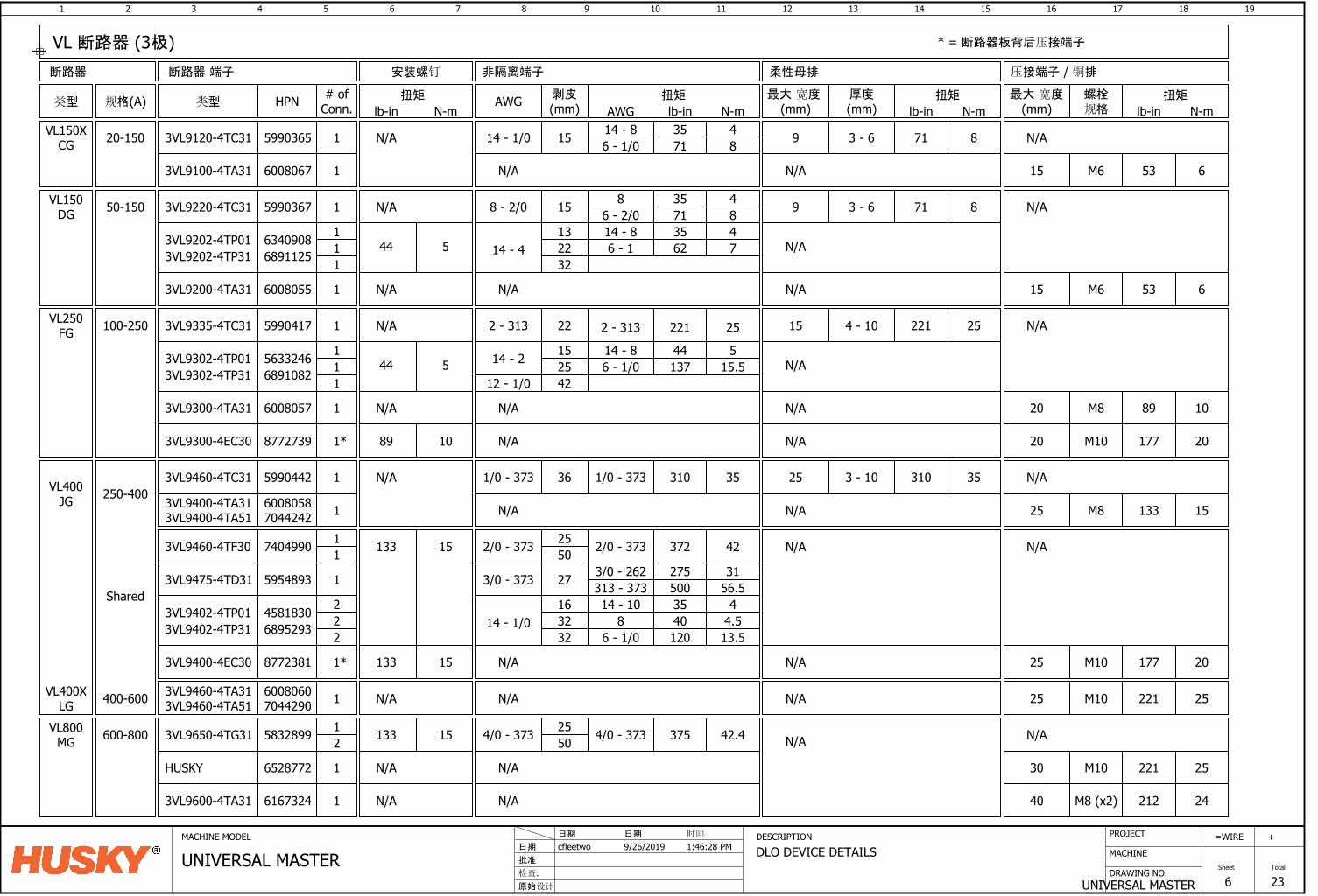
1 2 3 4 5 6 7 8 9 10 11 12 13 14 15 16
DRAWING NO.
MACHINE
17 18
UNIVERSAL MASTER
=
Sheet
WIRE
6
19
Total
23
+PROJECTMACHINE MODEL DESCRIPTION
DLO DEVICE DETAILS批准
原始设计
cfleetwo日期
检查.
9/26/2019日期 日期
UNIVERSAL MASTER时间
1:46:28 PM
规格(A)类型
VL150DG 50-150
类型 HPN # ofConn.
剥皮(mm)
3VL9220-4TC31 5990367
VL250FG 100-250 3VL9335-4TC31 5990417
VL400JG
3VL9460-4TC31 5990442250-400
VL400XLG 400-600
36 310 351 1/0 - 373
1 222 - 313
1 158 - 2/0 8 35 46 - 2/0 71 8
2 - 313 221 25
VL150XCG 20-150 3VL9120-4TC31 5990365 1 1514 - 1/0
1/0 - 373
68952933VL9402-4TP31 14 - 1/022
1632
2 32
14 - 10 35 48 40 4.5
13.51206 - 1/0
AWG 扭矩
lb-in N-mAWG14 - 8 35 46 - 1/0 71 8
扭矩
N/A
lb-in N-m
安装螺钉
N/A
N/A
N/A
断路器 端子
56332463VL9302-4TP01 14 - 211
1525
1 4244 5
14 - 8 44 515.51376 - 1/0
12 - 1/0
VL800MG 600-800 3VL9650-4TG31 5832899 4/0 - 373 375 42.4133 152
1 4/0 - 373 2550
断路器
3VL9302-4TP31 6891082
63409083VL9202-4TP0114 - 4
11
1322
1 3244 5
14 - 8 35 47626 - 13VL9202-4TP31 6891125
45818303VL9402-4TP01
3VL9475-4TD31 5954893 1 273/0 - 373 3/0 - 262 275 31313 - 373 500 56.5
扭矩
lb-in N-m螺栓规格
N/A
压接端子 / 铜排
3VL9100-4TA31 6008067 1
非隔离端子
53 6M6N/A
N/A
53 6M63VL9200-4TA31 6008055 1 N/A N/A
89 10M81 N/A N/A3VL9300-4TA31 6008057
N/A
133 15M81 N/A3VL9400-4TA313VL9400-4TA51
60080587044242
N/A
221 25M101 N/A N/A3VL9460-4TA313VL9460-4TA51
60080607044290
N/A372 422/0 - 37311 2/0 - 373 25
50133 153VL9460-4TF30 7404990
Shared
N/A
HUSKY 6528772 221 25M101 N/A N/A
厚度(mm)
3 - 69
最大 宽度 (mm)
柔性母排
N/A
扭矩
lb-in N-m
71 8
3 - 69
N/A
71 8
N/A
4 - 1015
N/A
221 25
N/A
3 - 1025 310 35
N/A
N/A
N/A
最大 宽度(mm)
15
15
20
25
25
30
N/A
VL 断路器 (3极)
177 20M101* N/A3VL9300-4EC30 8772739 N/A 2089 10
177 20M101* N/A3VL9400-4EC30 8772381 N/A 25133 15
* = 断路器板背后压接端子
3VL9600-4TA31 6167324 212 24M8 (x2)1 N/A N/A 40
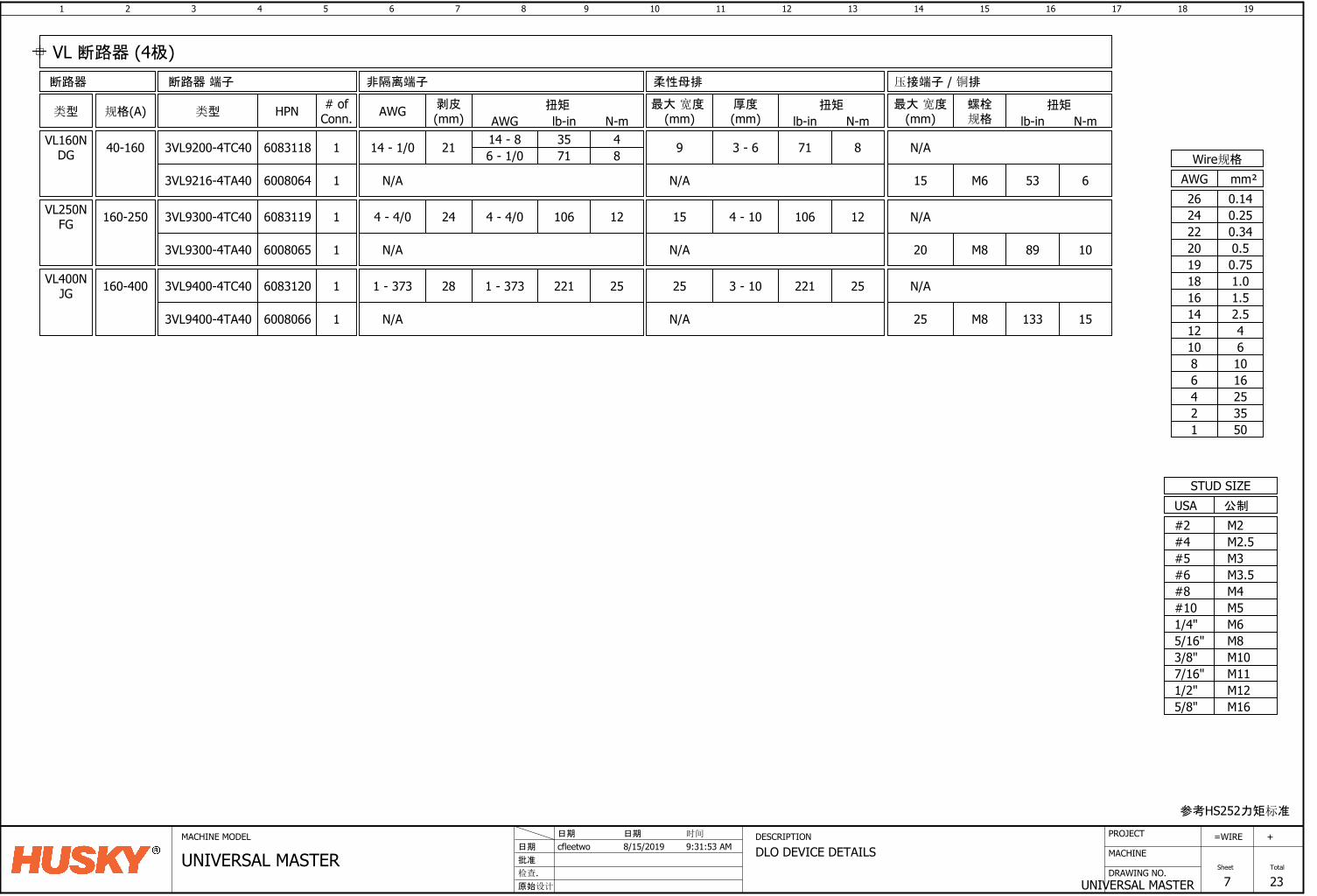
1 2 3 4 5 6 7 8 9 10 11 12 13 14 15 16
DRAWING NO.
MACHINE
17 18
UNIVERSAL MASTER
=
Sheet
WIRE
7
19
Total
23
+PROJECTMACHINE MODEL DESCRIPTION
DLO DEVICE DETAILS批准
原始设计
cfleetwo日期
检查.
8/15/2019日期 日期
UNIVERSAL MASTER时间
9:31:53 AM
规格(A)类型 类型 HPN # ofConn.
剥皮(mm)AWG 扭矩
lb-in N-mAWG
断路器 端子断路器
VL160NDG 40-160 3VL9200-4TC40 6083118 1 2114 - 1/0 14 - 8 35 4
6 - 1/0 71 8
VL250NFG 160-250 3VL9300-4TC40 6083119 1 244 - 4/0 4 - 4/0 106 12
VL400NJG 160-400 3VL9400-4TC40 6083120 1 281 - 373 1 - 373 25221
扭矩
lb-in N-m螺栓规格
压接端子 / 铜排非隔离端子
N/A
厚度(mm)
最大 宽度 (mm)
柔性母排
扭矩
lb-in N-m
3 - 69 71 8
4 - 1015 106 12
3 - 1025 221 25
最大 宽度(mm)
N/A
N/A
VL 断路器 (4极)
53 6M63VL9216-4TA40 6008064 1 N/A N/A 15
89 10M81 N/A3VL9300-4TA40 6008065 N/A 20
133 15M81 N/A3VL9400-4TA40 6008066 N/A 25
参考HS252力矩标准
M6M8M10
M12
M5
1/2"
3/8"5/16"1/4"#10
USASTUD SIZE
M165/8"
公制
M3.5M4
M2.5
#8#6
#4M2#2
M3#5
M117/16"
mm²AWGWire规格
0.7519
0.340.520
220.2524
16253550
10
12468
1.0181.516
42.5
1214
610
0.1426
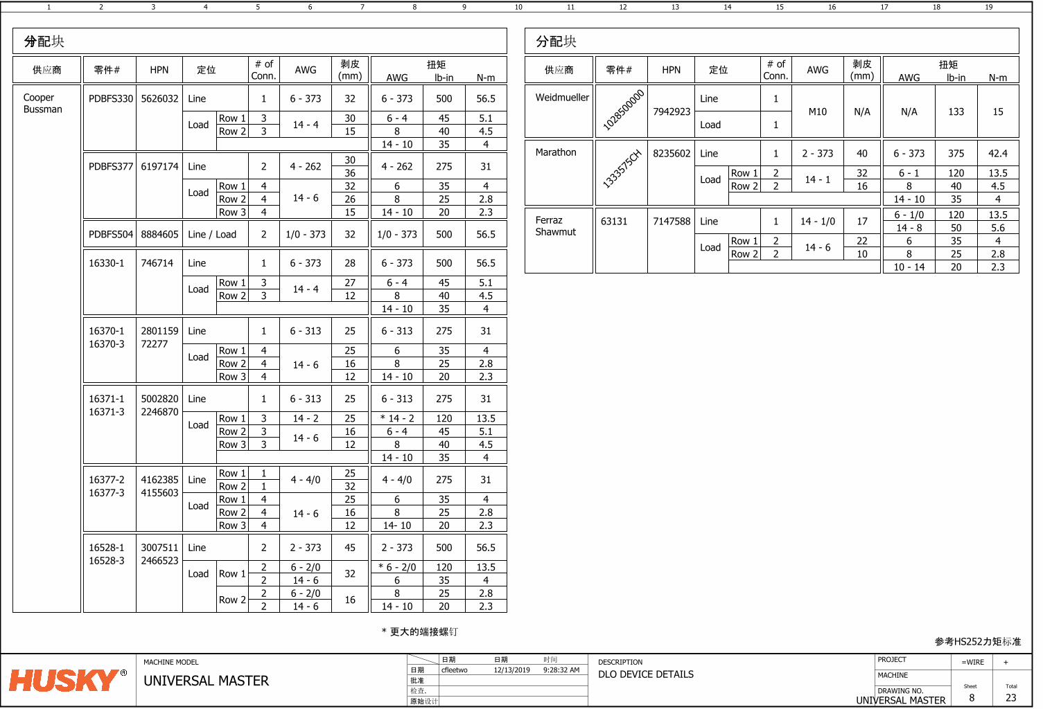
1 2 3 4 5 6 7 8 9 10 11 12 13 14 15 16
DRAWING NO.
MACHINE
17 18
UNIVERSAL MASTER
=
Sheet
WIRE
8
19
Total
23
+PROJECTMACHINE MODEL DESCRIPTION
DLO DEVICE DETAILS批准
原始设计
cfleetwo日期
检查.
12/13/2019日期 日期
UNIVERSAL MASTER时间
9:28:32 AM
分配块
零件# HPN # ofConn.
剥皮(mm)供应商 定位
16330-1 746714 1 28
6 - 4 45 5.18 40 4.5Load
Line
Row 1Row 2
2712
6 - 373 500 56.5
14 - 10 35 4
CooperBussman
16370-1 2801159 1 25
35 425 2.8Load
Line
Row 1Row 2
251614 - 6
6 - 313 275 31
20 2.38
14 - 10
6 - 31316370-3 72277
Row 3 12
16371-1 5002820 1 25
4.5
Load
Line
Row 1Row 2
275 31
48
14 - 10
6 - 31316371-3 2246870
Row 3 121625
6 - 4 45 5.14035
3 14 - 2
14 - 6
Load
Line
Row 1Row 2
4 - 4/0 275 314 - 4/0
Row 3 121625
14 - 6444
416238516377-216377-3 4155603
Row 1Row 2 32
2511
814- 10
6 35 425 2.820 2.3
Load
Line
Row 1
2 - 373 500 56.52 - 373
22
16528-116528-3 2466523
814 - 10
6 35 425 2.820 2.3
3007511 2 45
14 - 66 - 2/0 32
Row 2 22
6 - 2/0 16
* 6 - 2/0 120 13.5
PDBFS330 1 32
Load
Line
Row 1Row 2
6 - 373 500 56.56 - 373
15303 14 - 4
5626032
3 814 - 10
6 - 44.54
45 5.14035
33
* 14 - 2 120 13.5
444
33
14 - 6
扭矩
lb-in N-mAWGAWG
14 - 4
6 - 373
6 - 313
6
分配块
零件# HPN # ofConn.
剥皮(mm)供应商 定位 AWG 扭矩
lb-in N-mAWG
PDBFS377 2
Load
Line
Row 1Row 2
4 - 262 275 314 - 262
26324
14 - 6
6197174
4 814 - 10
62.82.3
35 42520
3630
Row 3 4 15
参考HS252力矩标准
Weidmueller
1028
5000
00
7942923Line
Load
1
1M10 N/A 133 15N/A
PDBFS504 2Line / Load 1/0 - 3738884605 32 500 56.51/0 - 373
1333
575C
H 1 40
Load
Line
Row 1Row 2
2 - 373 375 42.46 - 373
16322 14 - 1
8235602
2 814 - 10
6 - 14.54
120 13.54035
Marathon
FerrazShawmut
63131 7147588 1 17
Load
Line
Row 1Row 2
2210
14 - 1/0
14 - 6
14 - 86 - 1/0
35 425 2.8
50 5.6
20 2.3
120 13.5
68
10 - 14
22
* 更大的端接螺钉
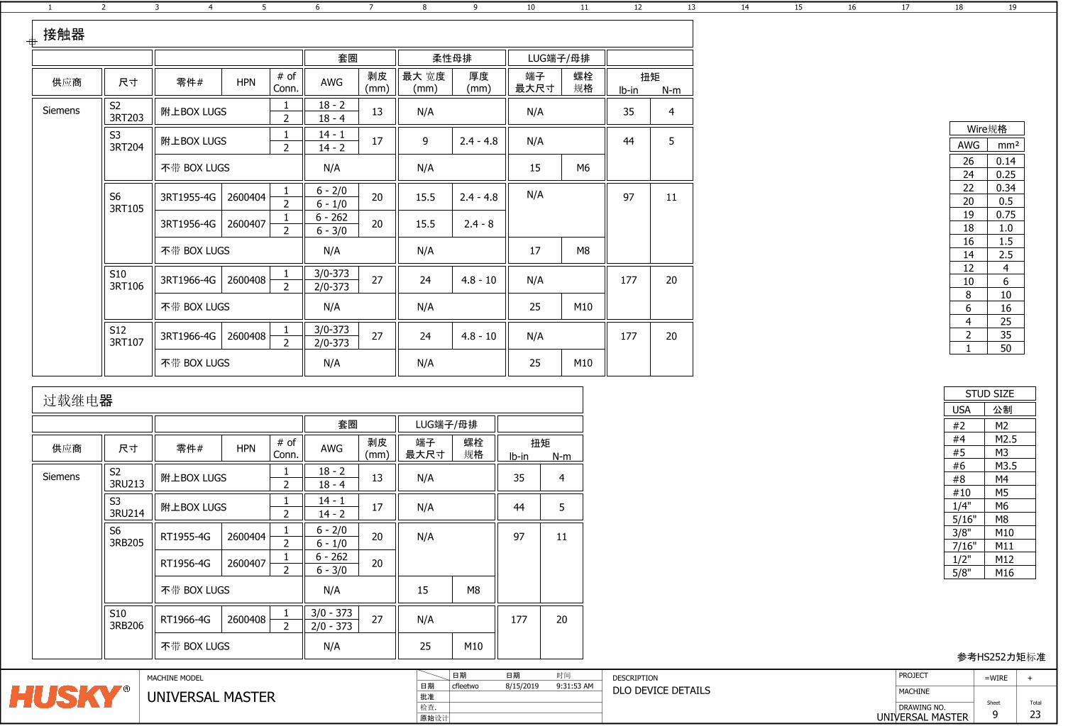
1 2 3 4 5 6 7 8 9 10 11 12 13 14 15 16
DRAWING NO.
MACHINE
17 18
UNIVERSAL MASTER
=
Sheet
WIRE
9
19
Total
23
+PROJECTMACHINE MODEL DESCRIPTION
DLO DEVICE DETAILS批准
原始设计
cfleetwo日期
检查.
8/15/2019日期 日期
UNIVERSAL MASTER时间
9:31:53 AM
零件# HPN # ofConn.
剥皮(mm)供应商
Siemens
3RT1955-4G 2600404 1 206 - 2/02 6 - 1/0
尺寸
S63RT105
3RT1956-4G 2600407 201 6 - 2622 6 - 3/0
3RT1966-4G 2600408 1 273/0-3732 2/0-373
S103RT106
螺栓规格
M817
套圈 LUG端子/母排
M1025
3RT1966-4G 2600408 12 2/0-373
S123RT107 273/0-373
1 172S33RT204 附上BOX LUGS
12
S23RT203 N/A
零件# HPN # ofConn.
剥皮(mm)供应商
Siemens
尺寸螺栓规格
S33RU214S63RB205
S103RB206
RT1955-4G 2600404 1 206 - 2/02 6 - 1/0
RT1956-4G 2600407 201 6 - 2622 6 - 3/0
RT1966-4G 2600408 1 273/0 - 3732 2/0 - 373
M815
附上BOX LUGS
1 172 N/A附上BOX LUGS
1318 - 218 - 4
接触器
过载继电器
AWG 端子最大尺寸
端子最大尺寸
AWG
44 5
97 11
扭矩
lb-in N-m
参考HS252力矩标准
M6M8M10
M12
M5
1/2"
3/8"5/16"1/4"#10
USASTUD SIZE
M165/8"
公制
M3.5M4
M2.5
#8#6
#4M2#2
M3#5
M117/16"
mm²AWGWire规格
0.7519
0.340.520
220.2524
16253550
10
12468
1.0181.516
42.5
1214
610
0.1426
厚度(mm)
最大 宽度 (mm)
柔性母排
扭矩
lb-in N-m
4.8 - 1024 177 20
4.8 - 1024 177 20
N/A
2.4 - 4.815.5 97 11
2.4 - 815.5
不带 BOX LUGS N/A
N/A
N/A
不带 BOX LUGS N/A N/A
N/A
M1025不带 BOX LUGS N/A N/A
N/A
不带 BOX LUGS N/A
N/A
M1025
177 20
不带 BOX LUGS N/A
N/A
不带 BOX LUGS N/A N/A M615
N/A2.4 - 4.89 44 514 - 114 - 2
35 4
套圈 LUG端子/母排
14 - 114 - 2
S23RU213
1 132 N/A附上BOX LUGS 35 418 - 218 - 4
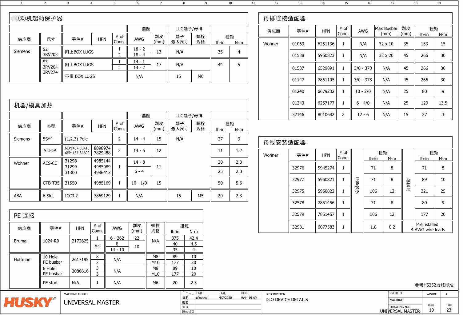
1 2 3 4 5 6 7 8 9 10 11 12 13 14 15 16
DRAWING NO.
MACHINE
17 18
UNIVERSAL MASTER
=
Sheet
WIRE
10
19
Total
23
+PROJECTMACHINE MODEL DESCRIPTION
DLO DEVICE DETAILS批准
原始设计
cfleetwo日期
检查.
4/7/2020日期 日期
UNIVERSAL MASTER时间
9:44:16 AM
2 15 27 3
1 11
机器/模具加热
# ofConn.
剥皮(mm)
扭矩
lb-in N-mHPN
14 - 4
零件#供应商
Siemens
类型
5SY4
AES-CCWohner
AWG
(1,2,3)-Pole
1 15 50 5.64985169 10 - 1/0CTB-T35 31550
参考HS252力矩标准
25
20
2.8
2.3
6 - 4
14 - 8
电动机起动保护器
零件# HPN # ofConn.
剥皮(mm)供应商
Siemens
尺寸螺栓规格
AWG 端子最大尺寸
扭矩
lb-in N-m
套圈 LUG端子/母排
S23RV203 13附上BOX LUGS
S33RV2043RV274
17附上BOX LUGS
35 4
44 5
N/A1212
不带 BOX LUGS N/A M615
N/A
1 22 375 42.4
PE 连接
# ofConn.
剥皮(mm)
扭矩
lb-in N-mHPN
6 - 262
零件#供应商
Brumall
AWG
21726251024-R0
N/AHoffman 261719510 HolePE busbar
螺栓规格
N/A
M10M88
2
N/A30866166 HolePE busbar M10
M833
17789
2010
89 1020177
1 20 2.3N/APE stud M6N/A
18 - 218 - 414 - 114 - 2
1 35 133 15
母排连接适配器
# ofConn.HPN
6251136 N/A
零件#供应商
Wohner 01069
652989101537
667923201240
01243 6257177
596082301538
786110501147 1
1 45 266 303/0 - 373
1 45
1 25 80 910 - 2/0
1 25 120 13.56 - 4/0
剥皮(mm)AWG 扭矩
lb-in N-m
32 x 10
Max Busbar(mm)
N/A
N/A 32 x 20 266 30
453/0 - 373 N/A 266 30
N/A
N/A
594527432976
32975 5960822
1 71 8
1 89 1032977 5960821
1 221 25线侧管
扭矩
lb-in N-m
安装螺
钉
扭矩
lb-in N-m
71 8
71 8
106 12
零件# HPN # ofConn.
1 20 2.3ABA 6 Slot 7869129ICC3.2
套圈 LUG端子/母排
M515
N/A
螺栓规格
端子最大尺寸
2 1214 - 6SITOP 80989746EP1437-3BA10 11 1.2
N/A
31300 498641331299 498508931298 4985144
32579 7851457
1 80 932578 7851456
1 177 20
71 8
106 12
母线安装适配器
32146 8010682 2 15 27 312 - 6 N/A
Wohner
32981 6077583 1 1.8 0.2 Preinstalled 4 AWG wire leads
6EP4137-3AB00 7829488
24 8 10 40 4.535 414 - 10
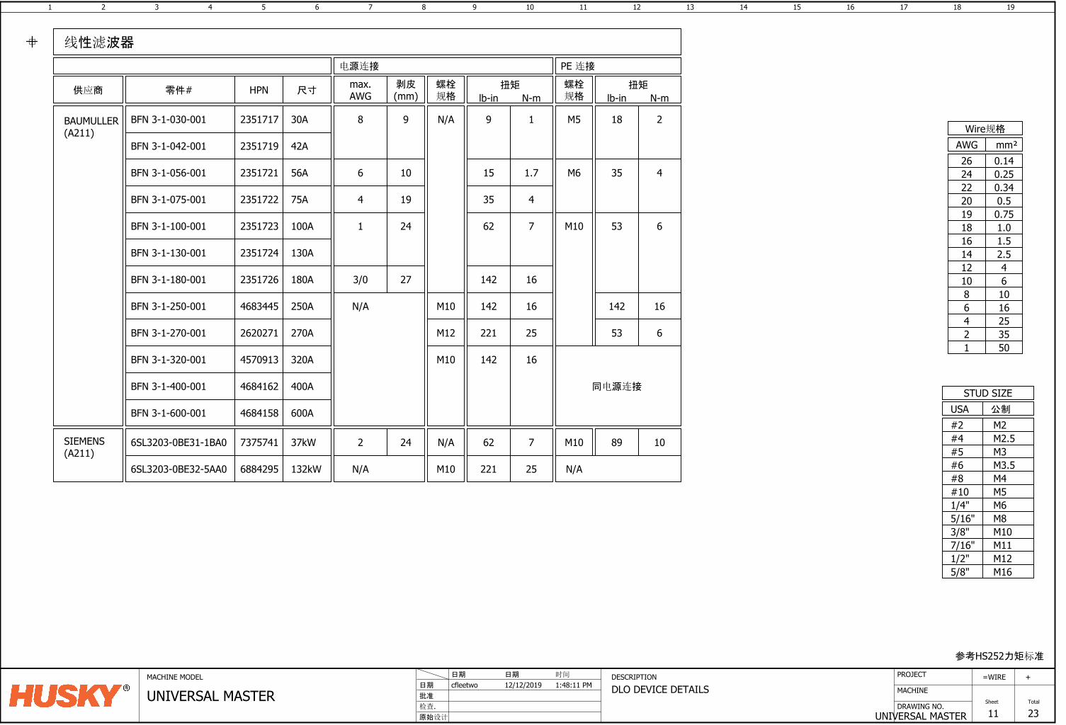
1 2 3 4 5 6 7 8 9 10 11 12 13 14 15 16
DRAWING NO.
MACHINE
17 18
UNIVERSAL MASTER
=
Sheet
WIRE
11
19
Total
23
+PROJECTMACHINE MODEL DESCRIPTION
DLO DEVICE DETAILS批准
原始设计
cfleetwo日期
检查.
12/12/2019日期 日期
UNIVERSAL MASTER时间
1:48:11 PM
剥皮(mm)供应商
BAUMULLER(A211)
零件#
电源连接
BFN 3-1-180-001 273/02351726
HPN
BFN 3-1-250-001 N/A4683445
BFN 3-1-130-001 2351724
BFN 3-1-100-001 2351723
BFN 3-1-075-001 2351722
BFN 3-1-056-001 2351721
BFN 3-1-270-001 2620271
BFN 3-1-320-001 4570913
BFN 3-1-400-001 4684162
BFN 3-1-600-001 4684158
BFN 3-1-042-001 2351719
线性滤波器
241
19
10
4
98
尺寸
42A
56A
75A
100A
130A
180A
250A
270A
320A
400A
600A
PE 连接
max.AWG
6
扭矩
lb-in N-m
9 1
15 1.7
35 4
62 7
142 16
142 16
221 25
16142
扭矩
lb-in N-m
18
35
53
2
4
6
16
53 6
142
6SL3203-0BE31-1BA0 7375741 37kW 62 7SIEMENS(A211)
参考HS252力矩标准
M6M8M10
M12
M5
1/2"
3/8"5/16"1/4"#10
USASTUD SIZE
M165/8"
公制
M3.5M4
M2.5
#8#6
#4M2#2
M3#5
M117/16"
mm²AWGWire规格
0.7519
0.340.520
220.2524
16253550
10
12468
1.0181.516
42.5
1214
610
0.1426
6SL3203-0BE32-5AA0 6884295 132kW 221 25N/A
242 89 10
螺栓规格
N/A
M10
M10
N/A
M12
M10
螺栓规格
N/A
M10
M10
M6
M5
同电源连接
BFN 3-1-030-001 2351717 30A
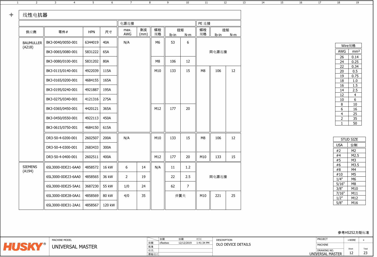
1 2 3 4 5 6 7 8 9 10 11 12 13 14 15 16
DRAWING NO.
MACHINE
17 18
UNIVERSAL MASTER
=
Sheet
WIRE
12
19
Total
23
+PROJECTMACHINE MODEL DESCRIPTION
DLO DEVICE DETAILS批准
原始设计
cfleetwo日期
检查.
12/12/2019日期 日期
UNIVERSAL MASTER时间
1:41:34 PM
剥皮(mm)供应商
BAUMULLER(A218)
螺栓规格
电源连接
HPN
BK3-0195/0240-001 4921887
BK3-0275/0340-001 4121316
M10DR3-50-4-0200-001 2602507 N/A
6SL3000-0DE28-0AA1 4858569
SIEMENS(A194)
354/0
BK3-0065/0080-001 5831222
BK3-0080/0100-001 5831202
BK3-0115/0140-001 4922039
BK3-0165/0200-001 4684155
BK3-0365/0450-001 4420121
BK3-0450/0550-001 4922113
BK3-0615/0750-001 4684150
2683433DR3-50-4-0300-001
2602511DR3-50-4-0400-001
6SL3000-0DE23-6AA0 4858565
6SL3000-0DE25-5AA1 3687230
6SL3000-0DE31-2AA1 4858567
M10
M12
M12
M6N/A
线性电抗器
192
241/0
尺寸
80 kW
55 kW
36 kW
200A
300A
400A
120 kW
螺栓规格
PE 连接
同电源连接
M10
N/A
M8
M8
零件# max.AWG
6SL3000-0DE21-6AA0 4858572 14616 kW
65A
80A
115A
165A
450A
365A
275A
195A
615A
M10
扭矩
lb-in N-m
53
133
177
6
15
20
133 15
177 20
11 1.2
22 2.5
62 7
弹簧夹
扭矩
lb-in N-m
106 12
106 12
133 15
221 25
M8 12106
参考HS252力矩标准
M6M8M10
M12
M5
1/2"
3/8"5/16"1/4"#10
USASTUD SIZE
M165/8"
公制
M3.5M4
M2.5
#8#6
#4M2#2
M3#5
M117/16"
mm²AWGWire规格
0.7519
0.340.520
220.2524
16253550
10
12468
1.0181.516
42.5
1214
610
0.1426同电源连接
BK3-0040/0050-001 6344019 40A
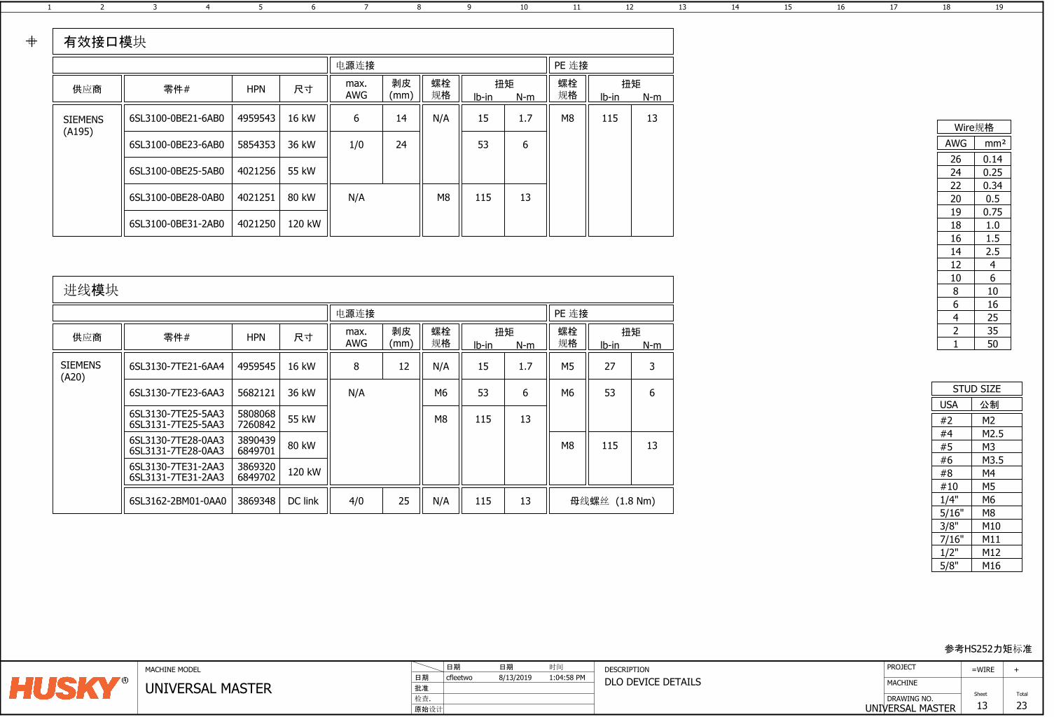
1 2 3 4 5 6 7 8 9 10 11 12 13 14 15 16
DRAWING NO.
MACHINE
17 18
UNIVERSAL MASTER
=
Sheet
WIRE
13
19
Total
23
+PROJECTMACHINE MODEL DESCRIPTION
DLO DEVICE DETAILS批准
原始设计
cfleetwo日期
检查.
8/13/2019日期 日期
UNIVERSAL MASTER时间
1:04:58 PM
SIEMENS(A195)
5854353
4021251
6SL3100-0BE23-6AB0
6SL3100-0BE28-0AB0
40212506SL3100-0BE31-2AB0
6SL3100-0BE25-5AB0 4021256
241/0
M8N/A
36 kW
80 kW
120 kW
55 kW
49595436SL3100-0BE21-6AB0 16 kW 146
有效接口模块
剥皮(mm)供应商 零件#
电源连接
HPN 尺寸
PE 连接
max.AWG
扭矩
lb-in N-m
15 1.7
53 6
115 13
115 13
扭矩
lb-in N-m
SIEMENS(A20)
5682121
3890439
6SL3130-7TE23-6AA3
6SL3130-7TE28-0AA3
38693206SL3130-7TE31-2AA3
58080686SL3130-7TE25-5AA3
进线模块
80 kW
55 kW
36 kW
120 kW
M6
M8
M8
38693486SL3162-2BM01-0AA0 254/0DC link N/A 母线螺丝 (1.8 Nm)
49595456SL3130-7TE21-6AA4 16 kW
M6N/A
供应商 HPN 剥皮(mm)
螺栓规格
电源连接
尺寸
PE 连接
零件# max.AWG
N/A128 M5
螺栓规格
扭矩
lb-in N-m
15
115
1.7
13
653
115 13
扭矩
lb-in N-m
27 3
653
131156SL3131-7TE28-0AA3 6849701
6SL3131-7TE31-2AA3 6849702
螺栓规格
N/A
螺栓规格
M8
参考HS252力矩标准
M6M8M10
M12
M5
1/2"
3/8"5/16"1/4"#10
USASTUD SIZE
M165/8"
公制
M3.5M4
M2.5
#8#6
#4M2#2
M3#5
M117/16"
mm²AWGWire规格
0.7519
0.340.520
220.2524
16253550
10
12468
1.0181.516
42.5
1214
610
0.1426
6SL3131-7TE25-5AA3 7260842
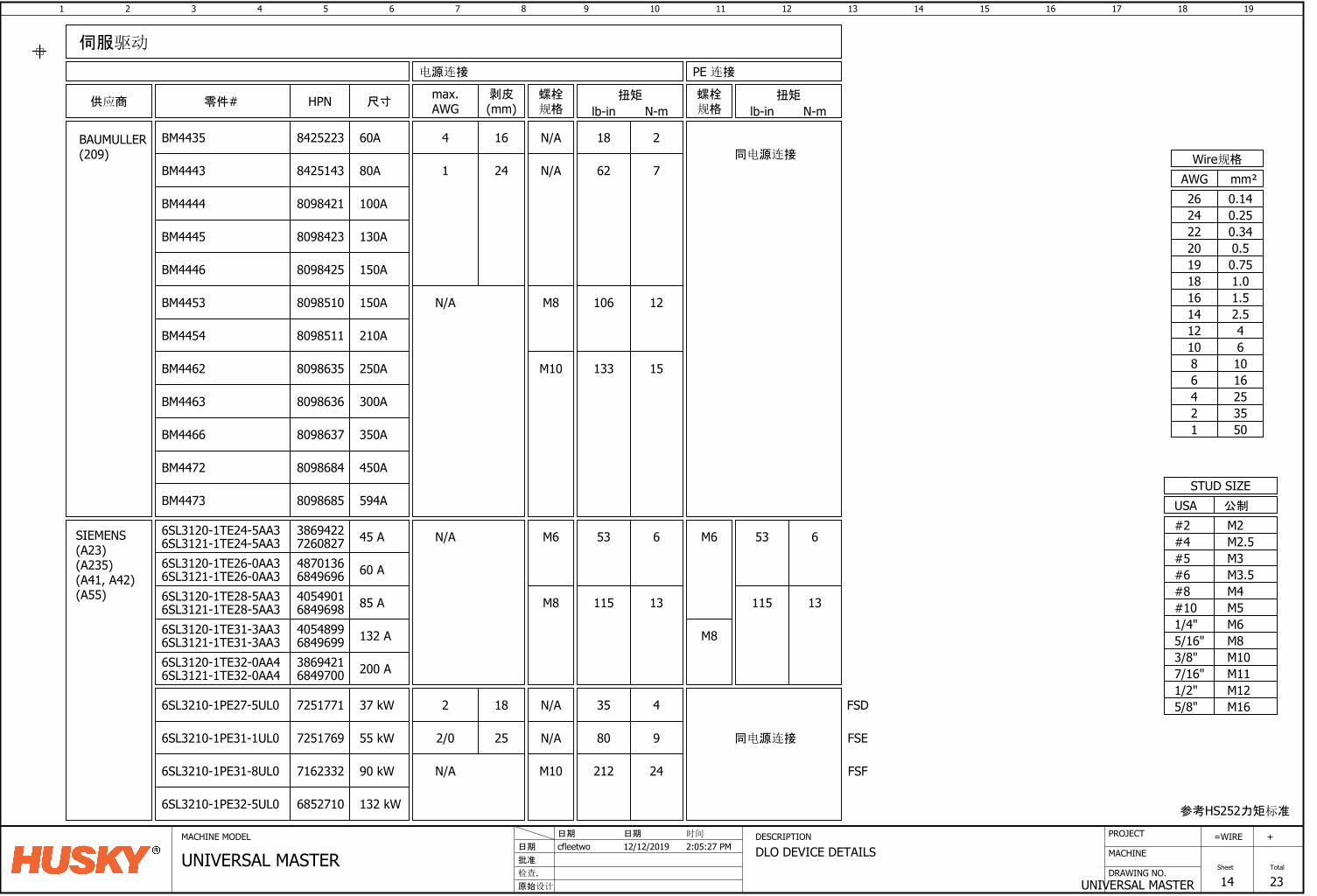
1 2 3 4 5 6 7 8 9 10 11 12 13 14 15 16
DRAWING NO.
MACHINE
17 18
UNIVERSAL MASTER
=
Sheet
WIRE
14
19
Total
23
+PROJECTMACHINE MODEL DESCRIPTION
DLO DEVICE DETAILS批准
原始设计
cfleetwo日期
检查.
12/12/2019日期 日期
UNIVERSAL MASTER时间
2:05:27 PM
供应商
BAUMULLER(209)
HPN
BM4444
BM4445
BM4446
BM4453 N/A
BM4454
BM4462
BM4463
BM4466
BM4472
剥皮(mm)
螺栓规格
电源连接
M10
1 24
M8
伺服驱动
尺寸
N/A
零件# max.AWG
螺栓规格
PE 连接
100A
130A
150A
150A
210A
250A
300A
350A
450A
扭矩
lb-in N-m
62
106
7
12
扭矩
lb-in N-m
15133
同电源连接
参考HS252力矩标准
M6M8M10
M12
M5
1/2"
3/8"5/16"1/4"#10
USASTUD SIZE
M165/8"
公制
M3.5M4
M2.5
#8#6
#4M2#2
M3#5
M117/16"
8098421
8098423
8098425
8098510
8098511
8098635
8098636
8098637
8098684
mm²AWGWire规格
0.7519
0.340.520
220.2524
16253550
10
12468
1.0181.516
42.5
1214
610
0.1426
BM4443 80A8425143
BM4473 594A8098685
SIEMENS(A23)(A235)(A41, A42)(A55)
6SL3121-1TE24-5AA3 7260827 45 A
6SL3120-1TE26-0AA3 60 A4870136
6SL3120-1TE28-5AA3 4054901 85 A
6SL3120-1TE31-3AA3 4054899 132 A
6SL3120-1TE32-0AA4 3869421 200 A
M6N/A
M8
M8
M6
115 13
53 6
115 13
53 6
N/A 35 4
6SL3121-1TE26-0AA3 6849696
6SL3121-1TE28-5AA3 6849698
6SL3121-1TE31-3AA3 6849699
6SL3121-1TE32-0AA4 6849700
6SL3210-1PE27-5UL0 7251771 37 kW
6SL3120-1TE24-5AA3 3869422
M10
同电源连接
212 24N/A6SL3210-1PE31-8UL0 7162332 90 kW
6SL3210-1PE31-1UL0 7251769 55 kW N/A 80 9
2 18
2/0 25
FSD
FSE
FSF
6SL3210-1PE32-5UL0 6852710 132 kW
BM4435 60A8425223 N/A 18 24 16
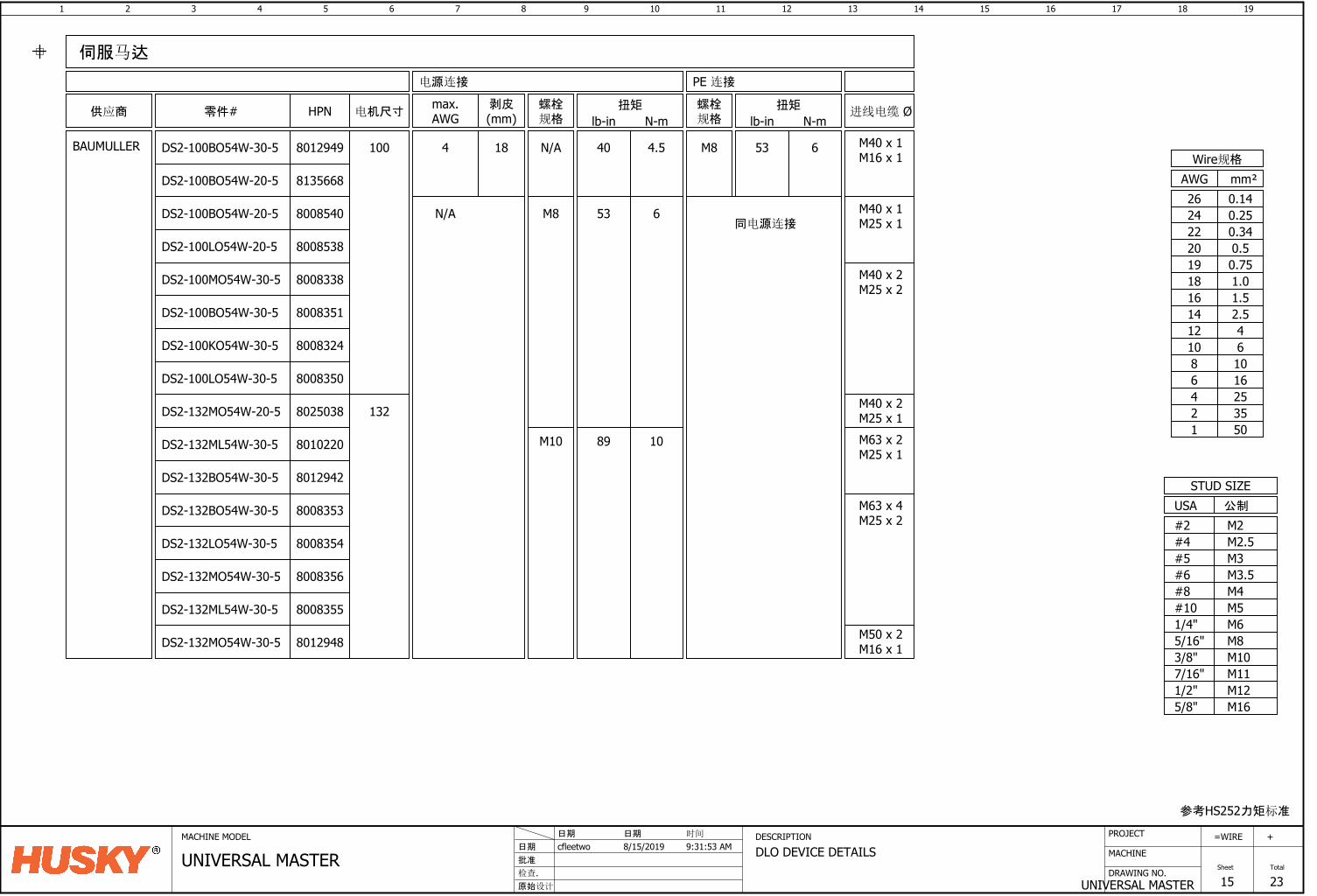
1 2 3 4 5 6 7 8 9 10 11 12 13 14 15 16
DRAWING NO.
MACHINE
17 18
UNIVERSAL MASTER
=
Sheet
WIRE
15
19
Total
23
+PROJECTMACHINE MODEL DESCRIPTION
DLO DEVICE DETAILS批准
原始设计
cfleetwo日期
检查.
8/15/2019日期 日期
UNIVERSAL MASTER时间
9:31:53 AM
参考HS252力矩标准
M6M8M10
M12
M5
1/2"
3/8"5/16"1/4"#10
USASTUD SIZE
M165/8"
公制
M3.5M4
M2.5
#8#6
#4M2#2
M3#5
M117/16"
mm²AWGWire规格
0.7519
0.340.520
220.2524
16253550
10
12468
1.0181.516
42.5
1214
610
0.1426
供应商
BAUMULLER
伺服马达
HPN
8135668
8008538
8008540
8008350
8008324
8012949
8008353
8012942
8025038
DS2-100BO54W-30-5
DS2-100BO54W-20-5
DS2-100BO54W-20-5
DS2-100LO54W-20-5
DS2-100BO54W-30-5
DS2-100KO54W-30-5
DS2-100LO54W-30-5
DS2-132MO54W-20-5
DS2-132BO54W-30-5
DS2-132BO54W-30-5
8008351
DS2-100MO54W-30-5 8008338
DS2-132MO54W-30-5
DS2-132ML54W-30-5
DS2-132LO54W-30-5
M40 x 2M25 x 1
8010220
8008354
8008356
电机尺寸 进线电缆 Ø螺栓规格
M8
N/A
剥皮(mm)
max.AWG
184
PE 连接
M8
螺栓规格
电源连接
M10
M40 x 1M16 x 1
扭矩
lb-in N-m
89 10
40
53 6
4.5
扭矩
lb-in N-m
53 6
同电源连接
100
132
零件#
DS2-132ML54W-30-5 8008355
DS2-132MO54W-30-5 8012948
N/A M40 x 1M25 x 1
M40 x 2M25 x 2
M63 x 4M25 x 2
M50 x 2M16 x 1
M63 x 2M25 x 1
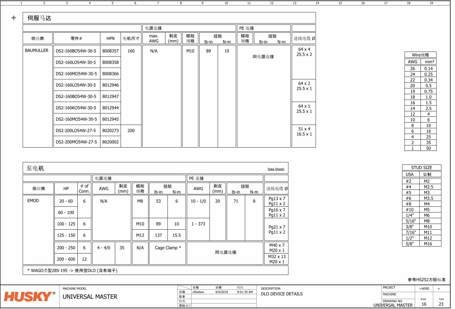
1 2 3 4 5 6 7 8 9 10 11 12 13 14 15 16
DRAWING NO.
MACHINE
17 18
UNIVERSAL MASTER
=
Sheet
WIRE
16
19
Total
23
+PROJECTMACHINE MODEL DESCRIPTION
DLO DEVICE DETAILS批准
原始设计
cfleetwo日期
检查.
9/9/2019日期 日期
UNIVERSAL MASTER时间
9:01:35 AM
参考HS252力矩标准
M6M8M10
M12
M5
1/2"
3/8"5/16"1/4"#10
USASTUD SIZE
M165/8"
公制
M3.5M4
M2.5
#8#6
#4M2#2
M3#5
M117/16"
mm²AWGWire规格
0.7519
0.340.520
220.2524
16253550
10
12468
1.0181.516
42.5
1214
610
0.1426
供应商
BAUMULLER
伺服马达
HPN
8008358
8012946
8008366
8020273
8012945
8008357
8020002
DS2-160BO54W-30-5
DS2-160LO54W-30-5
DS2-160MO54W-30-5
DS2-160LO54W-30-5
DS2-160KO54W-30-5
DS2-160MO54W-30-5
DS2-200LO54W-27-5
DS2-200MO54W-27-5
8012944
DS2-160BO54W-30-5 8012947
64 x 225.5 x 1
电机尺寸 进线电缆 Ø螺栓规格
N/A
剥皮(mm)
max.AWG
PE 连接
螺栓规格
电源连接
M10
扭矩
lb-in N-m
89 10
扭矩
lb-in N-m
同电源连接
160
200
零件#
64 x 425.5 x 2
51 x 416.5 x 1
64 x 125.5 x 1
供应商
EMOD
泵电机
# ofConn.
6
HP
20 - 60
100 - 125 6
6125 - 150
12200 - 600
Cage Clamp *
* WAGO类型285-195 -> 使用空DLO (没有端子)
53 6
1089
15.5137
螺栓规格
M8
M10
M12
扭矩
lb-in N-m
Data Sheets
N/A
N/A
剥皮(mm)AWG
4 - 4/0 35
Pg13 x 7Pg11 x 2
进线电缆 Ø
Pg21 x 7Pg11 x 2
71 8
扭矩
lb-in N-m
PE 连接电源连接
10 - 1/0 20
剥皮(mm)AWG
同电源连接M32 x 13M20 x 1
Pg16 x 7Pg11 x 2
6200 - 250 M40 x 7M20 x 1
60 - 100
1 - 373

1 2 3 4 5 6 7 8 9 10 11 12 13 14 15 16
DRAWING NO.
MACHINE
17 18
UNIVERSAL MASTER
=
Sheet
WIRE
17
19
Total
23
+PROJECTMACHINE MODEL DESCRIPTION
TORQUE CLASSIFICATION批准
原始设计
cfleetwo日期
检查.
4/7/2020日期 日期
UNIVERSAL MASTER时间
9:38:59 AM
# Connection Type
All Class A connections shall use Torque Record Report
DLO Conductors
Non DLO Conductors (>=8AWG)
1
2
Flexible Busbars3
Comb-Type Busbars
4 Busbar Connection / Mounting Adaptors
5
Main Breaker Lug Mounting Bolts6
CLASS A NOTES:
Distribution Blocks (load side)
5SY Circuit Breakers
AES-CC Fuse holders
RV surge suppressors *
2
11
12
13
3
# Connection Type
4
9
CLASS B --> Electrical threaded connections (<=30A)CLASS A --> Electrical threaded connections (>30A)
Busbar Adaptors
Breakers
Breaker Handles
Contactors
Line Filters
Line Reactors
Servo Drives
Solid State Relays
Din Rail
Wire Duct
Connector bulkheads / hoods
1
2
3
4
6
Busbar supports
7
# Mounting Type
8
9
11
13
14
15
CLASS C --> Device Mounting
Strain Relieves / Gland Plates
16
IPC / Battery
17
Heat Sink10
Distribution Blocks5
Altanium Components12Grounding Studs
Enclosure - Accessories18
Adaptor plates19
Control Relays *
DC power supplies *
7
Control Transformers *
6
Outlets *
10
Current Transformers20
Buffer Module *
8
5
Heat Exchangers *
1 Non DLO Conductors (<=10AWG)
Bonding Straps
All Class B connections shall be tightened and tug tested
CLASS A TORQUE RECORD REPORTLookup torque values must be predefined prior to assemblyOperator to record name for each torqued connection pointInspector to record name for each verification pointThis report is a CTQ supplier deliverableThis report will be available for post build referenceRefer to
CLASS B NOTES:
* Future design change to spring cage terminals
Torque value reference:
1. Husky DLO Tables2. HS2523. Specials -> OEM installation guide
SWI-2551
Related Documents