HRC-100-RS-RF INSTRUCTION MANUAL Wireless Rain/Freeze Sensor HRC-100-RS-RF

Welcome message from author
This document is posted to help you gain knowledge. Please leave a comment to let me know what you think about it! Share it to your friends and learn new things together.
Transcript
HRC-100-RS-RF
I n s t r u c t I o n M A n u A LWireless rain/Freeze sensor
HRC-100-RS-RF
08HYD005598 04008-24 rA.indd 1 11/16/07 3:39:35 PM

table of contents
Section 1: IntroductIon ................................................... 03
Section 2: InstALLAtIon InstructIons ...................... 06
Section 3: operAtIon checks . . . . . . . . . . . . . . . . . . . . . . . . . . . . . . . 10
Section 4: AdjustMents And operAtIon .................. 12
Section 5: MAIntenAnce And troubLeshootIng ......17
thank you for selecting a hydro-rain® Wireless rain/Freeze sensor (hrc-100-rs-rF). this hydro-rain® sensor provides conservation, convenience, and flexibility to your fully automatic watering system. After a set amount of rain has fallen, the sensor will send a wireless signal to the receiver and prevent the timer from watering. When the freeze sensor option switch is activated the sensor interrupt s watering when the temperature drops on or below 37°F ± 2° (3°c ± 1°).
please read this manual completely before you install and use the sensor.
A Few of the Notable Design Features Include:
RF CommunicationrF (radio Frequency) technology eliminates unsightly wires and simplifies mounting.
Battery Powerthe rain/freeze sensor is powered by two replaceable 3V lithium batteries.
Feature Control SwitchLocated on the bottom of the transmitter, the 3-position control switch allows you to select rain sensor, rain/Freeze sensor and sensor off.
Section 1: IntroductIon
n 02 n n 03 n
08HYD005598 04008-24 rA.indd 2 11/16/07 3:39:35 PM

table of contents
Section 1: IntroductIon ................................................... 03
Section 2: InstALLAtIon InstructIons ...................... 06
Section 3: operAtIon checks . . . . . . . . . . . . . . . . . . . . . . . . . . . . . . . 10
Section 4: AdjustMents And operAtIon .................. 12
Section 5: MAIntenAnce And troubLeshootIng ......17
thank you for selecting a hydro-rain® Wireless rain/Freeze sensor (hrc-100-rs-rF). this hydro-rain® sensor provides conservation, convenience, and flexibility to your fully automatic watering system. After a set amount of rain has fallen, the sensor will send a wireless signal to the receiver and prevent the timer from watering. When the freeze sensor option switch is activated the sensor interrupt s watering when the temperature drops on or below 37°F ± 2° (3°c ± 1°).
please read this manual completely before you install and use the sensor.
A Few of the Notable Design Features Include:
RF CommunicationrF (radio Frequency) technology eliminates unsightly wires and simplifies mounting.
Battery Powerthe rain/freeze sensor is powered by two replaceable 3V lithium batteries.
Feature Control SwitchLocated on the bottom of the transmitter, the 3-position control switch allows you to select rain sensor, rain/Freeze sensor and sensor off.
Section 1: IntroductIon
n 02 n n 03 n
08HYD005598 04008-24 rA.indd 3 11/16/07 3:39:35 PM
n 04 n n 05 n
1. Manual Test Stempushing downward on stem tests transmitter communication with the receiver.
2. Rain Fall Adjustment Caprange adjusts from ¹⁄8" to 1" (3mm to 25mm). this setting will prevent watering when rainfall reaches the specified setting.
3. Vent RingAn adjustable ring is designed to control the rain delay duration.
4. Communication Antennatransmits a wireless signal (up to 200') to the rain/freeze receiver.
5. Mounting BracketsAttach to gutter or flat surface.
Figure 1: rain/Freeze transmitter
1
2
3
4
5
Section 1: IntroductIonSection 1: IntroductIon
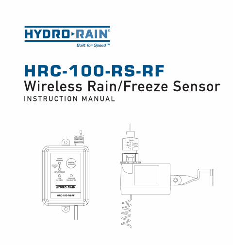
6. Communication Antennareceives wireless signal from the rain/freeze sensor.
7. Manual Override ButtonFunctions in two ways: 1. stops timer from watering 2. Allows watering when rain/freeze sensor is active see Manual override (section 4) for additional detail
LED Panel LightsLocated on the receiver, the Led lights communicate the current status of the sensor. (see Figure 2)
8. Sensor Override LEDIndicates when manual override is on (see manual override above).
9. Active Sensor LEDIndicates when the rain/freeze sensor is overriding the sprinkler timer.
10. Low Battery LEDIndicates when battery needs to be replaced.
08HYD005598 04008-24 rA.indd 4 11/16/07 3:39:35 PM

n 04 n n 05 n
1. Manual Test Stempushing downward on stem tests transmitter communication with the receiver.
2. Rain Fall Adjustment Caprange adjusts from ¹⁄8" to 1" (3mm to 25mm). this setting will prevent watering when rainfall reaches the specified setting.
3. Vent RingAn adjustable ring is designed to control the rain delay duration.
4. Communication Antennatransmits a wireless signal (up to 200') to the rain/freeze receiver.
5. Mounting BracketsAttach to gutter or flat surface.
Figure 1: rain/Freeze transmitter
1
2
3
4
5
Section 1: IntroductIonSection 1: IntroductIon
6. Communication Antennareceives wireless signal from the rain/freeze sensor.
7. Manual Override ButtonFunctions in two ways: 1. stops timer from watering 2. Allows watering when rain/freeze sensor is active see Manual override (section 4) for additional detail
LED Panel LightsLocated on the receiver, the Led lights communicate the current status of the sensor. (see Figure 2)
8. Sensor Override LEDIndicates when manual override is on (see manual override above).
9. Active Sensor LEDIndicates when the rain/freeze sensor is overriding the sprinkler timer.
10. Low Battery LEDIndicates when battery needs to be replaced.
HRC-100-RS-RF
Figure 2: receiver
6
7
8
9
10
08HYD005598 04008-24 rA.indd 5 11/16/07 3:39:36 PM

n 06 n n 07 n
Mounting the Receiver
1. select a location within 6” adjacent to your sprinkler timer (receiver may be located indoor or outdoor).2. Mount rain/freeze receiver (antenna side up) using screws provided.3. extend and straighten the antenna upward.
Wiring the Receiver to Timer
Important: this sensor is designed for 24-Volt irrigation timers only. do not connect the receiver to 120/240 VAc. All wiring must conform to applicable local codes. disconnect power to the sprinkler timer (unplug timer, turn off the appropriate circuit breaker or remove fuse) before attempting to connect the rain sensor receiver.
the two most common wiring situations are detailed below. the green “normal open” wire is not used in most installations. For nonstandard wiring situations, please contact our customer support hotline at 1-888-hYdrorAIn.
24-Volt Solenoid Valves Only (No Booster Pump)
1. remove wire terminal cover from timer.
2. check your timer for pre-installed sensor terminals. If the timer does not have sensor terminals, proceed to step 3. If it does, take the wire from rain/freeze receiver and connect the white (common) wire to one sensor terminal and the yellow (normal closed) wire to the other. (see Figure 3) skip to step 5.
Section 2: InstALLAtIon InstructIons
3. disconnect the common valve wire from the timer, and attach it (using a wire nut) to the yellow (normal closed) wire from the rain/freeze receiver. (see Figure 4)
4. connect the white (common) wire from the rain/freeze receiver to the common terminal of the timer.
5. connect the (2) red “24V” wires to the 24V terminals of the timer.
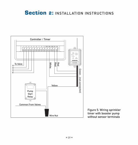
24-Volt Solenoid Valves with Booster Pump
note: the pump circuit output must be 24 volts in this situation— if different, do not proceed.
1. remove wire terminal cover from timer.
2. check your timer for pre-installed sensor terminals. If the timer does not have sensor terminals, proceed to step 3. If it does, take the wire from the rain/freeze receiver and connect the white (common) wire to one sensor terminal and the yellow (normal closed) wire to the other. (see Figure 3) skip to step 5.
3. disconnect the common valve wire(s) from the timer and the common wire lead of the relay that starts the pump from the common terminal of the timer. Attach them to the yellow (normal closed) wire from the receiver, using a wire nut. (see Figure 5).
4. connect the white (common) wire from the rain/freeze receiver to the common terminal on the timer.
5. connect the (2) red “24V” wires to the 24V terminals of the timer.
Section 2: InstALLAtIon InstructIons
08HYD005598 04008-24 rA.indd 6 11/16/07 3:39:36 PM

n 06 n n 07 n
Mounting the Receiver
1. select a location within 6” adjacent to your sprinkler timer (receiver may be located indoor or outdoor).2. Mount rain/freeze receiver (antenna side up) using screws provided.3. extend and straighten the antenna upward.
Wiring the Receiver to Timer
Important: this sensor is designed for 24-Volt irrigation timers only. do not connect the receiver to 120/240 VAc. All wiring must conform to applicable local codes. disconnect power to the sprinkler timer (unplug timer, turn off the appropriate circuit breaker or remove fuse) before attempting to connect the rain sensor receiver.
the two most common wiring situations are detailed below. the green “normal open” wire is not used in most installations. For nonstandard wiring situations, please contact our customer support hotline at 1-888-hYdrorAIn.
24-Volt Solenoid Valves Only (No Booster Pump)
1. remove wire terminal cover from timer.
2. check your timer for pre-installed sensor terminals. If the timer does not have sensor terminals, proceed to step 3. If it does, take the wire from rain/freeze receiver and connect the white (common) wire to one sensor terminal and the yellow (normal closed) wire to the other. (see Figure 3) skip to step 5.
Section 2: InstALLAtIon InstructIons
3. disconnect the common valve wire from the timer, and attach it (using a wire nut) to the yellow (normal closed) wire from the rain/freeze receiver. (see Figure 4)
4. connect the white (common) wire from the rain/freeze receiver to the common terminal of the timer.
5. connect the (2) red “24V” wires to the 24V terminals of the timer.
24-Volt Solenoid Valves with Booster Pump
note: the pump circuit output must be 24 volts in this situation— if different, do not proceed.
1. remove wire terminal cover from timer.
2. check your timer for pre-installed sensor terminals. If the timer does not have sensor terminals, proceed to step 3. If it does, take the wire from the rain/freeze receiver and connect the white (common) wire to one sensor terminal and the yellow (normal closed) wire to the other. (see Figure 3) skip to step 5.
3. disconnect the common valve wire(s) from the timer and the common wire lead of the relay that starts the pump from the common terminal of the timer. Attach them to the yellow (normal closed) wire from the receiver, using a wire nut. (see Figure 5).
4. connect the white (common) wire from the rain/freeze receiver to the common terminal on the timer.
5. connect the (2) red “24V” wires to the 24V terminals of the timer.
Section 2: InstALLAtIon InstructIons
08HYD005598 04008-24 rA.indd 7 11/16/07 3:39:36 PM

n 08 n n 09 n
24V 24VCOM1 COM21 2 3 4 5 6 7 8 9 PUMP
Controller / Timer
To Valve
Red
Red
Green (not connected)
White
Common From Valves
Wire Nut
Yellow
HRC-100-RS-RF
Figure 4: Wiring sprinkler timer without sensor terminals with booster pump
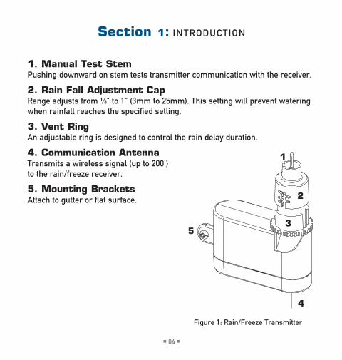
Figure 3: Wiring sprinkler timer with sensor terminals without booster pump
Section 2: InstALLAtIon InstructIons
24V 24VCOM1 COM21 2 3 4 5 6 7 8 9 PUMP
Controller / Timer
To Valve
Common From Valves
White
Yellow
Red
Red
Green (not connected)
SENSOR
HRC-100-RS-RF
Section 2: InstALLAtIon InstructIons
24V 24VCOM1 COM21 2 3 4 5 6 7 8 9 PUMP
Controller / Timer
To Valve
Red
Red
Green (not connected)
White
Common From Valves
Wire Nut
Yellow
Pump Start Relay
HRC-100-RS-RF
08HYD005598 04008-24 rA.indd 8 11/16/07 3:39:37 PM
n 08 n n 09 n
Figure 4: Wiring sprinkler timer without sensor terminals with booster pump
Figure 3: Wiring sprinkler timer with sensor terminals without booster pump
Section 2: InstALLAtIon InstructIonsSection 2: InstALLAtIon InstructIons
24V 24VCOM1 COM21 2 3 4 5 6 7 8 9 PUMP
Controller / Timer
To Valve
Red
Red
Green (not connected)
White
Common From Valves
Wire Nut
Yellow
Pump Start Relay
HRC-100-RS-RF
Figure 5: Wiring sprinkler timer with booster pump without sensor terminals
08HYD005598 04008-24 rA.indd 9 11/16/07 3:39:37 PM
n 10 n n 11 n
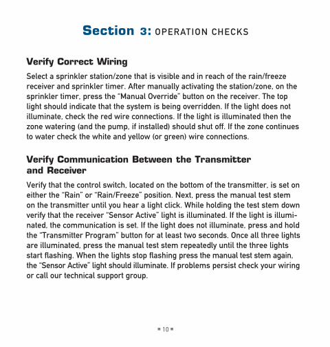
Verify Correct Wiring
select a sprinkler station/zone that is visible and in reach of the rain/freeze receiver and sprinkler timer. After manually activating the station/zone, on the sprinkler timer, press the “Manual override” button on the receiver. the top light should indicate that the system is being overridden. If the light does not illuminate, check the red wire connections. If the light is illuminated then the zone watering (and the pump, if installed) should shut off. If the zone continues to water check the white and yellow (or green) wire connections.
Verify Communication Between the Transmitter and Receiver
Verify that the control switch, located on the bottom of the transmitter, is set on either the “rain” or “rain/Freeze” position. next, press the manual test stem on the transmitter until you hear a light click. While holding the test stem down verify that the receiver “sensor Active” light is illuminated. If the light is illumi-nated, the communication is set. If the light does not illuminate, press and hold the “transmitter program” button for at least two seconds. once all three lights are illuminated, press the manual test stem repeatedly until the three lights start flashing. When the lights stop flashing press the manual test stem again, the “sensor Active” light should illuminate. If problems persist check your wiring or call our technical support group.
Section 3: operAtIon checks
Mounting the Transmitter
Mount the rain/freeze sensor to a gutter with the provided thumb screw, or to a flat surface, with provided screws, where it will be exposed to direct, unobstructed rainfall (but away from sprinkler spray). the test stem must be upright. note: the distance that the transmitter and receiver will operate at is approximately 200 feet line of sight. this distance may be affected by obstacles such as walls, automobiles, metal siding, etc.
Hints for Mounting:
1. Mount the transmitter in the highest possible position where rain can fall directly upon the rain sensor.
2. the transmitter mounting location will affect the reset rate, the amount of time it takes the rain sensor to dry out sufficiently for the sprinkler system to reactivate. For example, mounting the rain sensor on a very sunny, south-eastern end of a house may cause the rain sensor to dry out sooner than desired. similarly, mounting on the northern end of a building with constant shade may keep the rain sensor from drying out at all. some experimentation with the “vent ring” (described in the “Adjustments and operation” section 4) will usually yield satisfactory results.
Section 3: operAtIon checks
08HYD005598 04008-24 rA.indd 10 11/16/07 3:39:38 PM

n 10 n n 11 n
Verify Correct Wiring
select a sprinkler station/zone that is visible and in reach of the rain/freeze receiver and sprinkler timer. After manually activating the station/zone, on the sprinkler timer, press the “Manual override” button on the receiver. the top light should indicate that the system is being overridden. If the light does not illuminate, check the red wire connections. If the light is illuminated then the zone watering (and the pump, if installed) should shut off. If the zone continues to water check the white and yellow (or green) wire connections.
Verify Communication Between the Transmitter and Receiver
Verify that the control switch, located on the bottom of the transmitter, is set on either the “rain” or “rain/Freeze” position. next, press the manual test stem on the transmitter until you hear a light click. While holding the test stem down verify that the receiver “sensor Active” light is illuminated. If the light is illumi-nated, the communication is set. If the light does not illuminate, press and hold the “transmitter program” button for at least two seconds. once all three lights are illuminated, press the manual test stem repeatedly until the three lights start flashing. When the lights stop flashing press the manual test stem again, the “sensor Active” light should illuminate. If problems persist check your wiring or call our technical support group.
Section 3: operAtIon checks
Mounting the Transmitter
Mount the rain/freeze sensor to a gutter with the provided thumb screw, or to a flat surface, with provided screws, where it will be exposed to direct, unobstructed rainfall (but away from sprinkler spray). the test stem must be upright. note: the distance that the transmitter and receiver will operate at is approximately 200 feet line of sight. this distance may be affected by obstacles such as walls, automobiles, metal siding, etc.
Hints for Mounting:
1. Mount the transmitter in the highest possible position where rain can fall directly upon the rain sensor.
2. the transmitter mounting location will affect the reset rate, the amount of time it takes the rain sensor to dry out sufficiently for the sprinkler system to reactivate. For example, mounting the rain sensor on a very sunny, south-eastern end of a house may cause the rain sensor to dry out sooner than desired. similarly, mounting on the northern end of a building with constant shade may keep the rain sensor from drying out at all. some experimentation with the “vent ring” (described in the “Adjustments and operation” section 4) will usually yield satisfactory results.
Section 3: operAtIon checks
08HYD005598 04008-24 rA.indd 11 11/16/07 3:39:38 PM

n 12 n n 13 n
Rain Sensor
the rain sensor keeps the irrigation system from starting or continuing after rainfall quantities of ¹⁄8", ¼", ½", ¾", or 1". We recommend that the sensor be set at the ½" setting. to adjust to the desired quantity of rainfall, rotate the cap on the switch housing so that the pins are located in the proper slots. do not forcibly twist the cap as this might break the pins. the time that it takes the rain sensor to reset for normal sprinkler operation after the rain has stopped is determined by weather conditions (wind, sunlight, humidity, etc.). these condi-tions will determine how fast the hygroscopic discs dry out, and since the landscape is also experiencing the same conditions, their respective drying rates will roughly parallel each other. there is an adjustment capability on the rain sensor that will slow down the rest rate. by turning the “vent ring” to
Section 4: AdjustMents And operAtIon
Figure 6: Attaching sensor/transmitter to gutter or flat surface
completely or partially cover the ventilation holes, the hygroscopic discs will dry more slowly. this adjustment can compensate for an “overly sunny” installation location or peculiar soil conditions. experimenting with the vent rings will best determine the ideal vent setting. (see Figure 7)
Freeze Sensor
the temperature at which the freeze sensor is activated is 37°F ±2° (3°c ±1°) and is not adjustable. the freeze sensor feature can be bypassed by moving the switch (located on the bottom of the rain/freeze sensor) to the “rain” position.
Manual Override
the Manual override button can be used in 2 functions: 1. running the sprinkler timer when rain/freeze sensor is active (deactivating the sensor) 2. to stop timer from watering (deactivating sensor and timer)
Section 4: AdjustMents And operAtIon
08HYD005598 04008-24 rA.indd 12 11/16/07 3:39:39 PM

n 12 n n 13 n
Rain Sensor
the rain sensor keeps the irrigation system from starting or continuing after rainfall quantities of ¹⁄8", ¼", ½", ¾", or 1". We recommend that the sensor be set at the ½" setting. to adjust to the desired quantity of rainfall, rotate the cap on the switch housing so that the pins are located in the proper slots. do not forcibly twist the cap as this might break the pins. the time that it takes the rain sensor to reset for normal sprinkler operation after the rain has stopped is determined by weather conditions (wind, sunlight, humidity, etc.). these condi-tions will determine how fast the hygroscopic discs dry out, and since the landscape is also experiencing the same conditions, their respective drying rates will roughly parallel each other. there is an adjustment capability on the rain sensor that will slow down the rest rate. by turning the “vent ring” to
Section 4: AdjustMents And operAtIon
completely or partially cover the ventilation holes, the hygroscopic discs will dry more slowly. this adjustment can compensate for an “overly sunny” installation location or peculiar soil conditions. experimenting with the vent rings will best determine the ideal vent setting. (see Figure 7)
Freeze Sensor
the temperature at which the freeze sensor is activated is 37°F ±2° (3°c ±1°) and is not adjustable. the freeze sensor feature can be bypassed by moving the switch (located on the bottom of the rain/freeze sensor) to the “rain” position.
Manual Override
the Manual override button can be used in 2 functions: 1. running the sprinkler timer when rain/freeze sensor is active (deactivating the sensor) 2. to stop timer from watering (deactivating sensor and timer)
Section 4: AdjustMents And operAtIon
Figure 7: rain and vent ring adjustments
08HYD005598 04008-24 rA.indd 13 11/16/07 3:39:39 PM

n 14 n n 15 n
Section 4: AdjustMents And operAtIon
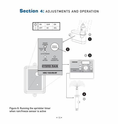
Running the Sprinkler Timer when Rain/Freeze Sensor is Active (see Figure 8)
1. Make sure “Active sensor” is the only Led illuminated (on the rain/freeze receiver).
2. push the “Manual override” button–“sensor override” Led will illuminate and “Active sensor” Led will turn off.
3. to restore rain/freeze sensor function push “Manual override” again– “sensor override” Led will turn off.
Stop Sprinkler Timer from Watering (see Figure 9)
1. Make sure “Active sensor” and/or “sensor override” is/are not illuminated (on the rain/freeze receiver).Important: If “Active sensor” is illuminated, do not push “Manual override” (this will engage the function above). If you need to shut your irrigation system down, turn your timer to the off position.
2. push the “Manual override” button–both “sensor override” and “Active sensor” will illuminate (on the rain/freeze receiver).
3. to restore sprinkler timer function, push “Manual override” again– “sensor override” will turn off.
Section 4: AdjustMents And operAtIon
1
3
4
2
on
oFF
sur
de
en
deL
HRC 100
1
2ndprogrAM
InterVALoddeVen
234
MAnuAL
cLeAr
neXt enter
resetrAIn deLAY
stAtIons
stArttIMes
1 2 3 4dAte
d M Y
M t W t F s s
ActIVe/bYpAss
sensor
progrAM b
progrAM
A
budg
et
off date
time/ tim
es start
stat
ion
days of
start times
station Week
dura
tion
duration
run
Watering
Interval
HRC-100-RS-RF
Figure 8: running the sprinkler timer when rain/freeze sensor is active
08HYD005598 04008-24 rA.indd 14 11/16/07 3:39:40 PM
n 14 n n 15 n
Section 4: AdjustMents And operAtIon
Running the Sprinkler Timer when Rain/Freeze Sensor is Active (see Figure 8)
1. Make sure “Active sensor” is the only Led illuminated (on the rain/freeze receiver).
2. push the “Manual override” button–“sensor override” Led will illuminate and “Active sensor” Led will turn off.
3. to restore rain/freeze sensor function push “Manual override” again– “sensor override” Led will turn off.
Stop Sprinkler Timer from Watering (see Figure 9)
1. Make sure “Active sensor” and/or “sensor override” is/are not illuminated (on the rain/freeze receiver).Important: If “Active sensor” is illuminated, do not push “Manual override” (this will engage the function above). If you need to shut your irrigation system down, turn your timer to the off position.
2. push the “Manual override” button–both “sensor override” and “Active sensor” will illuminate (on the rain/freeze receiver).
3. to restore sprinkler timer function, push “Manual override” again– “sensor override” will turn off.
Section 4: AdjustMents And operAtIon
1
3
4
2
on
oFF
sur
de
en
deL
HRC 100
1
2ndprogrAM
InterVALoddeVen
234
MAnuAL
cLeAr
neXt enter
resetrAIn deLAY
stAtIons
stArttIMes
1 2 3 4dAte
d M Y
M t W t F s s
ActIVe/bYpAss
sensor
progrAM b
progrAM
A
budg
et
off date
time/ tim
es start
stat
ion
days of
start times
station Week
dura
tion
duration
run
Watering
Interval
HRC-100-RS-RF
Figure 8: running the sprinkler timer when rain/freeze sensor is active
08HYD005598 04008-24 rA.indd 15 11/16/07 3:39:40 PM

n 16 n n 17 n
ON
OFF
SUR
DE
EN
DEL
1
3
4
2
HRC 100
1
2ndPROGRAM
INTERVALODDEVEN
234
MANUAL
CLEAR
NEXT ENTER
RESETRAIN DELAY
STATIONS
STARTTIMES
1 2 3 4DATE
D M Y
M T W T F S S
ACTIVE/BYPASS
SENSOR
PROGRAM B
PROGRAM
A
Budg
et
Off Date
Time/ Tim
es Start
Stat
ion
Days of
Start Times
Station Week
Dura
tion
Duration
Run
Watering
Interval
HRC-100-RS-RF
Section 4: AdjustMents And operAtIon
Figure 9: to stop timer from watering
Maintenance
the two lithium 3V batteries (cr2032) will need to be changed as needed. there is a low battery indicator light on the receiver that tells you when you need to change the battery. to change the batteries, remove the black rubber cover from underneath the sensor/transmitter. the battery mount should drop down, attached with a wire. replace both batteries, making sure the + side of the batteries point to the + indicated on the mount. Insert the battery mount and replace cover, making sure it’s seated properly.
neither the rain nor freeze sensor needs to be removed or covered during the winter. All parts are easily replaceable if they become damaged or lost. the spindle assembly is designed to stay with the cap. do not pull them apart.
Follow These Simple Checks Before Replacing Your Rain/Freeze Sensor:
System Will Not Come On At All:
A. check to see that the rain sensor discs are dry and the switch “clicks” on and off freely by pressing the top of the spindle.
b. check the feature control switch to make sure it is switched to the “rain” setting or the “rain/freeze” setting.
Section 5: MAIntenAnce And troubLeshootIng
08HYD005598 04008-24 rA.indd 16 11/16/07 3:39:41 PM

n 16 n n 17 n
ON
OFF
SUR
DE
EN
DEL
1
3
4
2
HRC 100
1
2ndPROGRAM
INTERVALODDEVEN
234
MANUAL
CLEAR
NEXT ENTER
RESETRAIN DELAY
STATIONS
STARTTIMES
1 2 3 4DATE
D M Y
M T W T F S S
ACTIVE/BYPASS
SENSOR
PROGRAM B
PROGRAM
A
Budg
et
Off Date
Time/ Tim
es Start
Stat
ion
Days of
Start Times
Station Week
Dura
tion
Duration
Run
Watering
Interval
HRC-100-RS-RF
Section 4: AdjustMents And operAtIon
Maintenance
the two lithium 3V batteries (cr2032) will need to be changed as needed. there is a low battery indicator light on the receiver that tells you when you need to change the battery. to change the batteries, remove the black rubber cover from underneath the sensor/transmitter. the battery mount should drop down, attached with a wire. replace both batteries, making sure the + side of the batteries point to the + indicated on the mount. Insert the battery mount and replace cover, making sure it’s seated properly.
neither the rain nor freeze sensor needs to be removed or covered during the winter. All parts are easily replaceable if they become damaged or lost. the spindle assembly is designed to stay with the cap. do not pull them apart.
Follow These Simple Checks Before Replacing Your Rain/Freeze Sensor:
System Will Not Come On At All:
A. check to see that the rain sensor discs are dry and the switch “clicks” on and off freely by pressing the top of the spindle.
b. check the feature control switch to make sure it is switched to the “rain” setting or the “rain/freeze” setting.
Section 5: MAIntenAnce And troubLeshootIng
08HYD005598 04008-24 rA.indd 17 11/16/07 3:39:42 PM

n 18 n n 19 n
c. toggle the manual override switch on the receiver to change status.
d. If you have a timer with built-in sensor terminals there is usually a bypass switch located near the terminals, check that the switch is set to “on.”
e. check that the temperature is at least 39°F (4°c) or higher.
System Will Not Shut Off Even After Heavy Rainfall:
A. check wiring for correct installation (see “operation checks: Verify correct Wiring”).
b. check sensitivity setting on rain sensor, and move the cap to a more sensitive setting. the rain sensor is an accurate rain gauge and can be verified by setting up a “tube” type rain gauge in the same vicinity and making periodic readings.
c. check for obstructions to rainfall such as overhangs, trees, or walls.
d. check the batteries.
e. If your controller has a rain bypass switch make sure it is in the correct position to allow the sensor to communicate with the controller.
F. toggle the manual override switch on the receiver to change status.
help: before returning this timer to the distributor, contact hydro-rain® technical service at: 1-888-hYdrorAIn.
Section 5: MAIntenAnce And troubLeshootIng
Specifications: › rain/Freeze Wireless range: up to 200 feet or 61 meters (Line of site) › rain settings: ¹⁄8"-1" (3-25mm) › Freeze set point: 37°F ±2° (3°c ±1°) › Average battery Life: 2 Years › battery type: two cr2032 3-volt cells › Led status Lights: Low battery, Active sensor and sensor override › relay contacts output: normal open and normal close 3A@24VAc › operating temperatures: 12˚F (-10˚c) to 140˚F (60˚c) › transmitter switch: rain only, rain/Freeze and sensor off › twist ring for Adjusting dry-out duration › Mounting brackets: gutter Mount and Flat surface Mount › Warranty: 3 Years Limited
Warranty and Statement
hydro-rain® warrants to its customers that its products will be free from defects in materials and workmanship for a period of three years from the date of purchase. We will replace, free of charge, the defective part or parts found to be defective under normal use and service for a period of up to three years after purchase (proof of purchase required). We reserve the right to inspect the defective part prior to replacement. hydro-rain® will not be responsible for consequential or incidental cost or damage caused by the product failure. hydro-rain® liability under this warranty is limited solely to the replacement or repair of defective parts.to exercise your warranty, return the unit to your dealer with a copy of the sales receipt.
Section 5: MAIntenAnce And troubLeshootIng
08HYD005598 04008-24 rA.indd 18 11/16/07 3:39:42 PM

n 18 n n 19 n
c. toggle the manual override switch on the receiver to change status.
d. If you have a timer with built-in sensor terminals there is usually a bypass switch located near the terminals, check that the switch is set to “on.”
e. check that the temperature is at least 39°F (4°c) or higher.
System Will Not Shut Off Even After Heavy Rainfall:
A. check wiring for correct installation (see “operation checks: Verify correct Wiring”).
b. check sensitivity setting on rain sensor, and move the cap to a more sensitive setting. the rain sensor is an accurate rain gauge and can be verified by setting up a “tube” type rain gauge in the same vicinity and making periodic readings.
c. check for obstructions to rainfall such as overhangs, trees, or walls.
d. check the batteries.
e. If your controller has a rain bypass switch make sure it is in the correct position to allow the sensor to communicate with the controller.
F. toggle the manual override switch on the receiver to change status.
help: before returning this timer to the distributor, contact hydro-rain® technical service at: 1-888-hYdrorAIn.
Section 5: MAIntenAnce And troubLeshootIng
Specifications: › rain/Freeze Wireless range: up to 200 feet or 61 meters (Line of site) › rain settings: ¹⁄8"-1" (3-25mm) › Freeze set point: 37°F ±2° (3°c ±1°) › Average battery Life: 2 Years › battery type: two cr2032 3-volt cells › Led status Lights: Low battery, Active sensor and sensor override › relay contacts output: normal open and normal close 3A@24VAc › operating temperatures: 12˚F (-10˚c) to 140˚F (60˚c) › transmitter switch: rain only, rain/Freeze and sensor off › twist ring for Adjusting dry-out duration › Mounting brackets: gutter Mount and Flat surface Mount › Warranty: 3 Years Limited
Warranty and Statement
hydro-rain® warrants to its customers that its products will be free from defects in materials and workmanship for a period of three years from the date of purchase. We will replace, free of charge, the defective part or parts found to be defective under normal use and service for a period of up to three years after purchase (proof of purchase required). We reserve the right to inspect the defective part prior to replacement. hydro-rain® will not be responsible for consequential or incidental cost or damage caused by the product failure. hydro-rain® liability under this warranty is limited solely to the replacement or repair of defective parts.to exercise your warranty, return the unit to your dealer with a copy of the sales receipt.
Section 5: MAIntenAnce And troubLeshootIng
08HYD005598 04008-24 rA.indd 19 11/16/07 3:39:42 PM

Model 04008-24 rAwww.hydrorain.com
9 1 5 o v e r l a n d s t r e e t n o r t h s a l t L a k e , u t 8 4 0 5 4
1 .888.hYdrorAIn
p 801 295 9820 f 801 951 5815
www.fluid-studio.net
1065 South 500 West Bountiful, Utah 84010
proof no: 2
date: 11.16.07
des: SM spck: SM
job no: 08HYD005598
client: Orbit
sku: 04008
upc: ? ????? ????? ?
file name: 08HYD005598
04008-24 rA.indd
software: InDesign CS2
colors
additional instructions:· Font sizes cannot be smaller than 7 pt. · ·
color non printing
PMS 2955
PMS ????
color non printing
PMS ????
Registration
K
Printers are responsible for meeting print production requirements. Any changes must be approved by the client and Fluid Studio. printed piece must meet designated specifications on this form.
dimensions:
flat: w: 5" h: 5.25"
finished: w 5" d: " h 5.25"
© 2007 Fluid Studio. This work is the property of Fluid Studio, and cannot be used, reproduced or distributed in any way without their express permission.
08HYD005598 04008-24 rA.indd 20 11/16/07 3:39:43 PM
Related Documents