■ HPV22M SERIES – HIGH PRESSURE HIGH SPEED DOUBLE PUMPS These double pumps consist of two HPV2 series single pumps combined in tandem within a single housing and driven by a common shaft. Fluid delivered from the two-separate ports can be either supplied to separate or common circuits. These HPV pumps are designed for high-pressure functions. Suitable for mobile applications like Drill rigs, Railways & Construction Equipments. HPV22M Series Double Vane Pumps Graphic Symbol 215 ■ Specifications Model Number Series Geometric Displacement cm 3 /rev. Max. Oper. Pressure Kgf/cm 2 Output Flow and Input Power Shaft Speed Range r/min. Mass (Approx.) Kg. 1 st Section 2 nd Section Max. Min. Flange Mounting Foot Mounting HPV22M 03 10.8 10.8 140 Ref. Page Nos. 220, 221, 222 & 223 2800 400 26.0 29.3 05 17.2 17.2 280 06 21.3 21.3 08 26.4 26.4 10 34.1 34.1 12 37.1 37.1 14 46.0 46.0 15 50.5 50.5 17 58.3 58.3 20 63.8 63.8 22 70.3 70.3 25 79.3 79.3 2500 28 88.8 88.8 210 31 100.0 100.0 VANE PUMPS HPV22M Series Double Vane Pumps EIC-B-1018-0 B

Welcome message from author
This document is posted to help you gain knowledge. Please leave a comment to let me know what you think about it! Share it to your friends and learn new things together.
Transcript

■ HPV22M SERIES – HIGH PRESSURE HIGH SPEED DOUBLE PUMPSThese double pumps consist of two HPV2 series single pumps combined in tandem within a single housing and
driven by a common shaft. Fluid delivered from the two-separate ports can be either supplied to separate or common
circuits. These HPV pumps are designed for high-pressure functions. Suitable for mobile applications like Drill rigs,
Railways & Construction Equipments.
HPV22M Series Double Vane Pumps
Graphic Symbol
215
■ Specifications
Model Number
Series
Geometric Displacement cm3/rev.
Max. Oper. Pressure Kgf/cm2
Output Flow and
Input Power
Shaft Speed Range r/min.
Mass (Approx.) Kg.
1st Section 2nd Section Max. Min. Flange
Mounting Foot
Mounting
HPV22M
03 10.8 10.8 140
Ref. Page Nos. 220, 221, 222
& 223
2800
400 26.0 29.3
05 17.2 17.2
280
06 21.3 21.3
08 26.4 26.4
10 34.1 34.1
12 37.1 37.1
14 46.0 46.0
15 50.5 50.5
17 58.3 58.3
20 63.8 63.8
22 70.3 70.3
25 79.3 79.3
2500 28 88.8 88.8 210
31 100.0 100.0
VANE PUMPS
HPV22M Series
Double Vane Pumps
EIC
-B-1
018-0
B
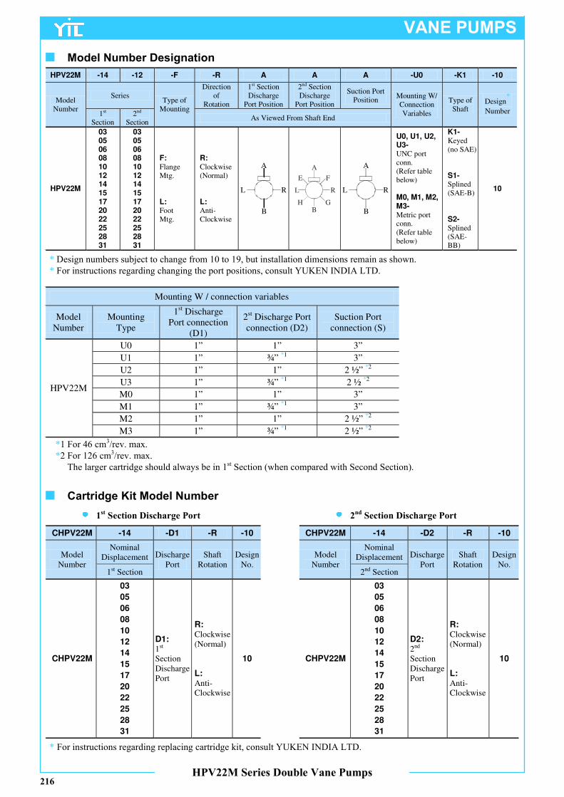
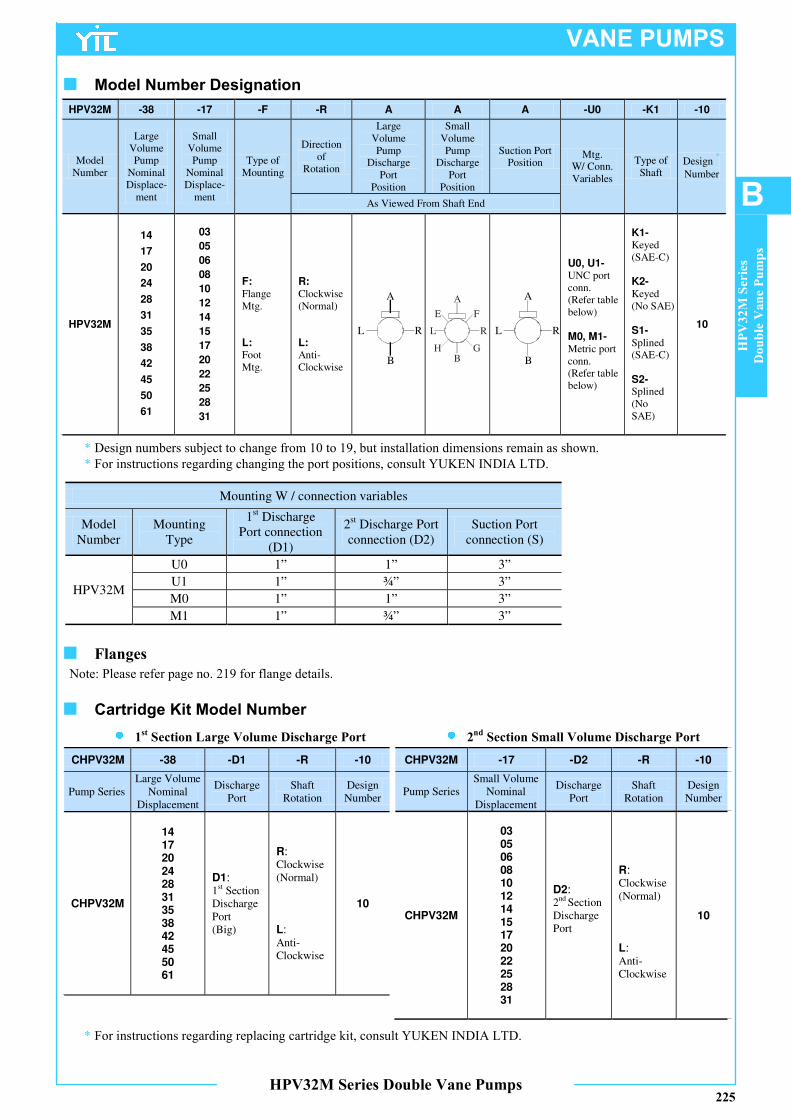
■ Model Number Designation
A
B
L R
A
B
L R
A
E F
L R
H GB
Mounting W / connection variables
Model Number
Mounting Type
1st Discharge Port connection
(D1)
2st Discharge Port connection (D2)
Suction Port connection (S)
HPV22M
U0 1” 1” 3”
U1 1” ¾” *1 3”
U2 1” 1” 2 ½” *2
U3 1” ¾” *1 2 ½ *2
M0 1” 1” 3”
M1 1” ¾” *1 3”
M2 1” 1” 2 ½” *2
M3 1” ¾” *1 2 ½” *2
*1 For 46 cm3/rev. max.
*2 For 126 cm3/rev. max.
The larger cartridge should always be in 1st Section (when compared with Second Section).
216
CHPV22M -14 -D1 -R -10
Model Number
Nominal Displacement Discharge
Port Shaft
Rotation Design
No. 1st Section
CHPV22M
03
05
06
08
10
12
14
15
17
20
22
25
28
31
D1:
1st
Section Discharge Port
R:
Clockwise (Normal) L:
Anti- Clockwise
10
CHPV22M -14 -D2 -R -10
Model Number
Nominal Displacement Discharge
Port Shaft
Rotation Design
No. 2nd Section
CHPV22M
03
05
06
08
10
12
14
15
17
20
22
25
28
31
D2:
2nd Section Discharge Port
R:
Clockwise (Normal) L:
Anti- Clockwise
10
■ Cartridge Kit Model Number
1st Section Discharge Port 2nd Section Discharge Port
VANE PUMPS
HPV22M Series Double Vane Pumps
* Design numbers subject to change from 10 to 19, but installation dimensions remain as shown.
* For instructions regarding changing the port positions, consult YUKEN INDIA LTD.
* For instructions regarding replacing cartridge kit, consult YUKEN INDIA LTD.
HPV22M -14 -12 -F -R A A A -U0 -K1 -10
Model Number
Series Type of
Mounting
Direction of
Rotation
1st Section Discharge
Port Position
2nd Section Discharge
Port Position
Suction Port Position
Mounting W/ Connection Variables
Type of Shaft
Design*
Number 1st Section
2nd Section
As Viewed From Shaft End
HPV22M
03
05
06 08
10
12 14
15
17 20
22
25 28
31
03
05
06 08
10
12 14
15
17 20
22
25 28
31
F:
Flange Mtg. L: Foot Mtg.
R:
Clockwise (Normal) L: Anti-Clockwise
U0, U1, U2, U3-
UNC port conn. (Refer table below) M0, M1, M2,
M3-
Metric port conn. (Refer table below)
K1-
Keyed (no SAE) S1- Splined (SAE-B)
S2-
Splined (SAE-BB)
10
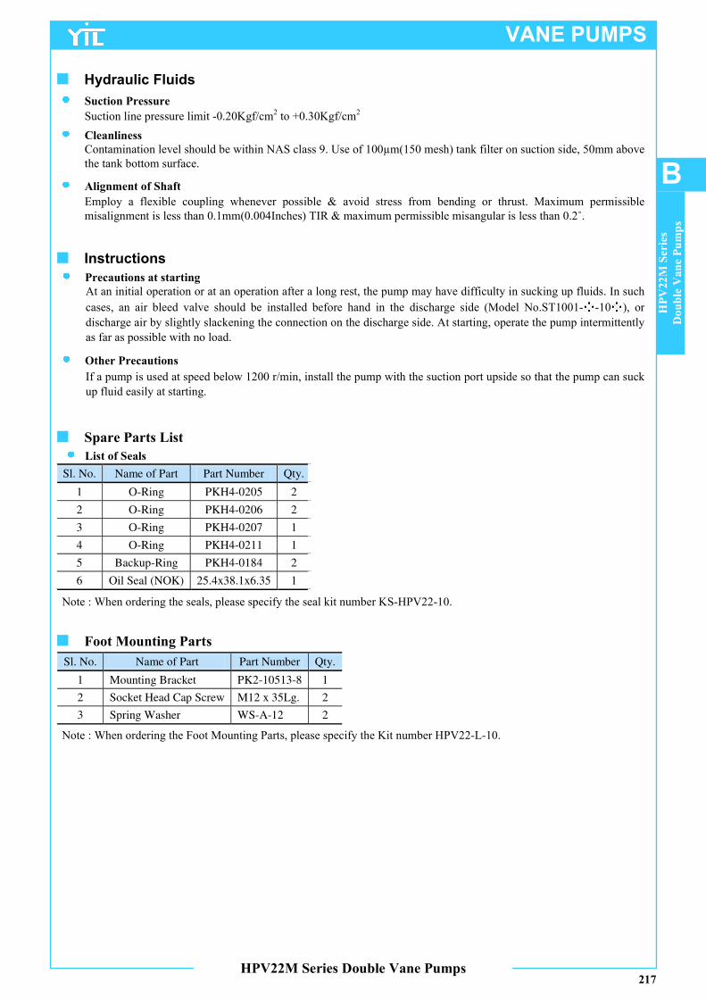
Sl. No. Name of Part Part Number Qty.
1 O-Ring PKH4-0205 2
2 O-Ring PKH4-0206 2
3 O-Ring PKH4-0207 1
4 O-Ring PKH4-0211 1
5 Backup-Ring PKH4-0184 2
6 Oil Seal (NOK) 25.4x38.1x6.35 1
Note : When ordering the seals, please specify the seal kit number KS-HPV22-10.
217
■ Spare Parts List
List of Seals
Sl. No. Name of Part Part Number Qty.
1 Mounting Bracket PK2-10513-8 1
2 Socket Head Cap Screw M12 x 35Lg. 2
3 Spring Washer WS-A-12 2
Note : When ordering the Foot Mounting Parts, please specify the Kit number HPV22-L-10.
■ Foot Mounting Parts
VANE PUMPS
■ Hydraulic Fluids
Suction line pressure limit -0.20Kgf/cm2
to +0.30Kgf/cm2
Suction Pressure
Contamination level should be within NAS class 9. Use of 100µm(150 mesh) tank filter on suction side, 50mm above
the tank bottom surface.
Cleanliness
Alignment of Shaft
Employ a flexible coupling whenever possible & avoid stress from bending or thrust. Maximum permissible
misalignment is less than 0.1mm(0.004Inches) TIR & maximum permissible misangular is less than 0.2˚.
■ Instructions
Precautions at starting
At an initial operation or at an operation after a long rest, the pump may have difficulty in sucking up fluids. In such
cases, an air bleed valve should be installed before hand in the discharge side (Model No.ST1001-※-10※), or
discharge air by slightly slackening the connection on the discharge side. At starting, operate the pump intermittently
as far as possible with no load.
Other Precautions
If a pump is used at speed below 1200 r/min, install the pump with the suction port upside so that the pump can suck
up fluid easily at starting.
HPV22M Series Double Vane Pumps
HPV22M Series
Double Vane Pumps
B

B
AA
B 26.2
52
.4
24.5
38" - 16 UNC x 19 Deep
(M10 Thd. x 19 Deep)4 Places
2nd SectionDischarge Port"C" Dia.
Suction Port"C" Dia.
1st SectionDelivery Port
25.4 Dia.
12.7
9.445.5
"E" Thd.4 Places
S1 (Splined Shaft SAE B)ANSI B92.1-199616
32 DP -13 Teeth30° pressure angleFlat root side fit.
38" - 16 UNC x 19 Deep
(M10 Thd. x 19 Deep)4 Places
40.7
9.4
24.5
S2 (Splined Shaft SAE BB)ANSI B92.1-199616
32 DP -15 Teeth30° pressure angleFlat root side fit.
73
.28
4.1
D
265.688.2 101.6 38.1
9.431.8
58.2
22.2
25
22.2
00
24
.54 M
ax. 1
01.6
010
1.5
5
76
.211
8 S
q.
73
146
175
122 Dia.
4.7624.712
Shaft - K1
Dia
.
Dia
.
Shaft - S2
Keyed (No SAE)
D1D2 S
Key Width
14.3 Dia. x Thru.21 Dia. Spotface2 Places (From Rear)
Shaft - S1
Port Port Connection Port Size A B C D E Thd.
S U0,U1,M0,M1 3″ 106.4 61.9 76.2 -
5/8 – 11 UNCx28.4 Deep (M16x28.4 Deep)
U2,U3,M2,M3 2-1/2″ 88.9 50.8 63.5 - 1/2 – 13 UNCx24.0 Deep
(M12x24.0 Deep)
D2 U0,U2,M0,M2 1″ 52.4 26.2 25.4 74.7 3/8 – 16 UNCx19.0 Deep
(M10x19.0 Deep) U1,U3,M1,M3 3/4″ 47.6 22.2 19.0 76.2
■ HPV22M- - - - - - -10
Flange Mounting
Foot Mounting
DIMENSIONS IN
MILLIMETRES
218
20
101.6
Dia
.
97 D
ia.
1560
115
14 Dia. x Thru.28 Dia. Spotface
x 1 Deep4 Places
189
102
95
190
230
M12 Thd. x Thru.4 Places
174 Dia.
146 Dia. PCD
VANE PUMPS
HPV22M Series Double Vane Pumps
VANE PUMPS
219
VANE PUMPS
HPV22M Series Double Vane Pumps
HPV22M Series
Double Vane Pumps
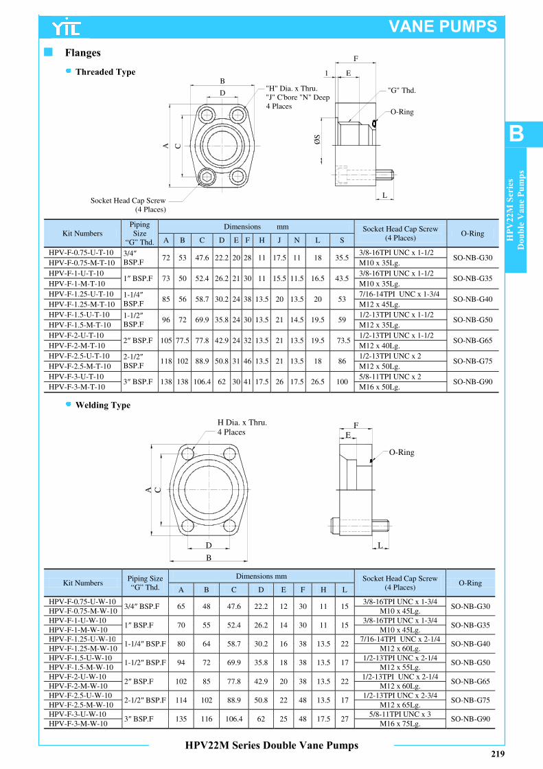
BA C
D
B
EFH Dia. x Thru.
4 Places
O-Ring
L
Kit Numbers Piping Size “G” Thd.
Dimensions mm Socket Head Cap Screw (4 Places)
O-Ring A B C D E F H L
HPV-F-0.75-U-W-10 3/4″ BSP.F 65 48 47.6 22.2 12 30 11 15
3/8-16TPI UNC x 1-3/4 SO-NB-G30
HPV-F-0.75-M-W-10 M10 x 45Lg.
HPV-F-1-U-W-10 1″ BSP.F 70 55 52.4 26.2 14 30 11 15
3/8-16TPI UNC x 1-3/4 SO-NB-G35
HPV-F-1-M-W-10 M10 x 45Lg. HPV-F-1.25-U-W-10
1-1/4″ BSP.F 80 64 58.7 30.2 16 38 13.5 22 7/16-14TPI UNC x 2-1/4
SO-NB-G40 HPV-F-1.25-M-W-10 M12 x 60Lg.
HPV-F-1.5-U-W-10 1-1/2″ BSP.F 94 72 69.9 35.8 18 38 13.5 17
1/2-13TPI UNC x 2-1/4 SO-NB-G50
HPV-F-1.5-M-W-10 M12 x 55Lg.
HPV-F-2-U-W-10 2″ BSP.F 102 85 77.8 42.9 20 38 13.5 22
1/2-13TPI UNC x 2-1/4 SO-NB-G65
HPV-F-2-M-W-10 M12 x 60Lg.
HPV-F-2.5-U-W-10 2-1/2″ BSP.F 114 102 88.9 50.8 22 48 13.5 17
1/2-13TPI UNC x 2-3/4 SO-NB-G75
HPV-F-2.5-M-W-10 M12 x 65Lg.
HPV-F-3-U-W-10 3″ BSP.F 135 116 106.4 62 25 48 17.5 27
5/8-11TPI UNC x 3 SO-NB-G90
HPV-F-3-M-W-10 M16 x 75Lg.
■ Flanges
Threaded Type
Welding Type
CA
D
B
Socket Head Cap Screw(4 Places)
"H" Dia. x Thru."J" C'bore "N" Deep4 Places
L
F
E1
O-Ring
"G" Thd.
ØS
Kit Numbers Piping Size
“G” Thd.
Dimensions mm Socket Head Cap Screw (4 Places)
O-Ring A B C D E F H J N L S
HPV-F-0.75-U-T-10 3/4″ BSP.F
72 53 47.6 22.2 20 28 11 17.5 11 18 35.5 3/8-16TPI UNC x 1-1/2
SO-NB-G30 HPV-F-0.75-M-T-10 M10 x 35Lg.
HPV-F-1-U-T-10 1″ BSP.F 73 50 52.4 26.2 21 30 11 15.5 11.5 16.5 43.5
3/8-16TPI UNC x 1-1/2 SO-NB-G35
HPV-F-1-M-T-10 M10 x 35Lg.
HPV-F-1.25-U-T-10 1-1/4″ BSP.F
85 56 58.7 30.2 24 38 13.5 20 13.5 20 53 7/16-14TPI UNC x 1-3/4
SO-NB-G40 HPV-F-1.25-M-T-10 M12 x 45Lg.
HPV-F-1.5-U-T-10 1-1/2″ BSP.F
96 72 69.9 35.8 24 30 13.5 21 14.5 19.5 59 1/2-13TPI UNC x 1-1/2
SO-NB-G50 HPV-F-1.5-M-T-10 M12 x 35Lg.
HPV-F-2-U-T-10 2″ BSP.F 105 77.5 77.8 42.9 24 32 13.5 21 13.5 19.5 73.5
1/2-13TPI UNC x 1-1/2 SO-NB-G65
HPV-F-2-M-T-10 M12 x 40Lg.
HPV-F-2.5-U-T-10 2-1/2″ BSP.F
118 102 88.9 50.8 31 46 13.5 21 13.5 18 86 1/2-13TPI UNC x 2
SO-NB-G75 HPV-F-2.5-M-T-10 M12 x 50Lg.
HPV-F-3-U-T-10 3″ BSP.F 138 138 106.4 62 30 41 17.5 26 17.5 26.5 100
5/8-11TPI UNC x 2 SO-NB-G90
HPV-F-3-M-T-10 M16 x 50Lg.
HPV22M-06
HPV22M-05
HPV22M-08
HPV22M-03
220
VANE PUMPS
HPV22M Series Double Vane Pumps
Typical Pump Characteristics Oil Viscosity 20 cSt [ISO VG 32, Temp 500C]
10
20
30
40
50
Del
iver
y
10
0
5
Inpu
t P
ow
er
L/min.
kW
0 10
20
30
40
50
Del
iver
y
L/min.60
2500 r/min.
0 1057035 140 175 Kgf/cm²210 240 280 315
Pressure
0 1057035 140 175 Kgf/cm²210 240 280 315
Pressure
10
0
5
15
Inp
ut
Pow
er
kW20
2000 r/min.
1500 r/min.
1000 r/min.
2500 r/min.2000 r/min.1500 r/min.
1000 r/min.
2500 r/min.
1500 r/min.1000 r/min.
2000 r/min.
2500 r/min.
1500 r/min.
1000 r/min.
2000 r/min.
0 1057035 140 175 Kgf/cm²210 240 280 315
10
20
30
40
50
Del
iver
y
L/min.
60
70
20
30
40
50
Del
iver
y
L/min.
60
70
80
2500 r/min. 2500 r/min.
Pressure
0 1057035 140 175 Kgf/cm²210 240 280 315
Pressure
0
Inpu
t P
ow
er
kW
20
30
10
0
Input
Pow
er
kW
20
30
10
40
2000 r/min.
1500 r/min.
1000 r/min.
2000 r/min.
1500 r/min.
1000 r/min.
2500 r/min.
2000 r/min.
1500 r/min.1000 r/min.
2500 r/min.
2000 r/min.
1500 r/min.
1000 r/min.
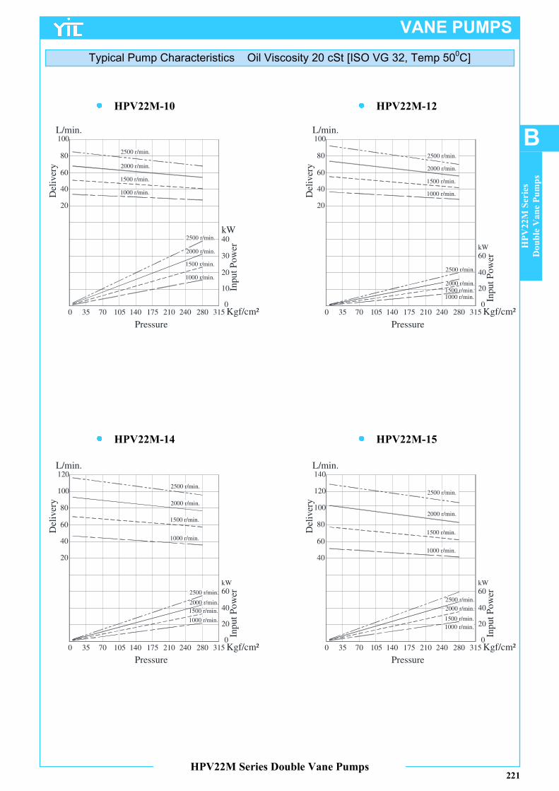
HPV22M-14
HPV22M-12
HPV22M-15
HPV22M-10
221
VANE PUMPS
HPV22M Series Double Vane Pumps
Typical Pump Characteristics Oil Viscosity 20 cSt [ISO VG 32, Temp 500C]
HPV22M Series
Double Vane Pumps
B
20
40
60
80
100
Del
iver
y
L/min.
10
0
20
Inpu
t P
ow
er
30
kW
20
0
40
Input
Pow
er60kW
20
40
60
80
100
Del
iver
y
L/min.
20
40
60
80
100
Del
iver
y
L/min.120
40
60
80
100
Del
iver
y
L/min.
120
140
0 1057035 140 175 Kgf/cm²210 240 280 315
Pressure
0 1057035 140 175 Kgf/cm²210 240 280 315
Pressure
0 1057035 140 175 Kgf/cm²210 240 280 315
Pressure
0 1057035 140 175 Kgf/cm²210 240 280 315
Pressure
40
20
0
40
Inp
ut
Po
wer60
kW
20
0
40
Inp
ut
Po
wer60
kW
2500 r/min.
2000 r/min.
1500 r/min.
1000 r/min.
2500 r/min.
2000 r/min.
1500 r/min.
1000 r/min.
2500 r/min.
2000 r/min.
1500 r/min.
1000 r/min.
2500 r/min.
2000 r/min.
1500 r/min.
1000 r/min.
2500 r/min.
2000 r/min.
1500 r/min.
1000 r/min.
2500 r/min.
2000 r/min.1500 r/min.1000 r/min.
2500 r/min.
2000 r/min.
1500 r/min.
1000 r/min.
2500 r/min.
2000 r/min.
1500 r/min.
1000 r/min.

HPV22M-22
HPV22M-20
HPV22M-25
HPV22M-17
222
VANE PUMPS
HPV22M Series Double Vane Pumps
Typical Pump Characteristics Oil Viscosity 20 cSt [ISO VG 32, Temp 500C]
20
0
40
Inpu
t P
ow
erkW
40
60
80
100
Del
iver
y
L/min.
120
140
160
40
60
80
100Del
iver
y
L/min.
120
140
160
180
40
80
120
Del
iver
y
L/min.
160
200
40
80
120
Del
iver
y
L/min.
160
200
2500 r/min. 2500 r/min.
0 1057035 140 175 Kgf/cm²210 240 280 315
Pressure
0 1057035 140 175 Kgf/cm²210 240 280 315
Pressure
0 1057035 140 175 Kgf/cm²210 240 280 315
Pressure
0 1057035 140 175 Kgf/cm²210 240 280 315
Pressure
60
80
20
0
40
Inpu
t P
ow
er
kW
60
80
20
0
40
Inp
ut
Po
wer60
80
kW100
20
0
40
Inp
ut
Po
wer60
80
kW100
2000 r/min.
1500 r/min.
1000 r/min.
2000 r/min.
1500 r/min.
1000 r/min.
2500 r/min.
2000 r/min.
1500 r/min.
1000 r/min.
2500 r/min.
2000 r/min.
1500 r/min.
1000 r/min.
2500 r/min.
2000 r/min.
1500 r/min.
1000 r/min.
2500 r/min.
2000 r/min.
1500 r/min.
1000 r/min.
2500 r/min.
2000 r/min.
1500 r/min.
1000 r/min.
2500 r/min.
2000 r/min.
1500 r/min.
1000 r/min.
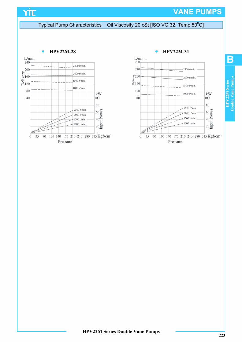
HPV22M-31HPV22M-28
223
VANE PUMPS
HPV22M Series Double Vane Pumps
Typical Pump Characteristics Oil Viscosity 20 cSt [ISO VG 32, Temp 500C]
HPV22M Series
Double Vane Pumps
B
40
80
120Del
iver
y
L/min.
160
200
240
80
120
Del
iver
y
L/min.
160
200
240
280
0 1057035 140 175 Kgf/cm²210 240 280 315
Pressure
0 1057035 140 175 Kgf/cm²210 240 280 315
Pressure
20
0
40
Inp
ut
Po
wer60
80
kW100
20
0
40
Inp
ut
Po
wer60
80
kW100
2500 r/min.
2000 r/min.
1500 r/min.
1000 r/min.
2500 r/min.
2000 r/min.
1500 r/min.
1000 r/min.
2500 r/min.
2000 r/min.
1500 r/min.
1000 r/min.
2500 r/min.
2000 r/min.
1500 r/min.
1000 r/min.

■ HPV32M SERIES – HIGH PRESSURE HIGH SPEED DOUBLE PUMPSThese double pumps consist of one HPV3 and one HPV2 series single pump combined in tandem within a single
housing and driven by a common shaft. Fluid delivered from the two-separate ports can be either supplied to separate
or common circuits. These HPV pumps are designed for High-pressure function. Suitable for mobile applications
like Drill rigs, Railways & Construction Equipments.
Graphic Symbol
■ Specifications
Model Number
Geometric Displacement cm
3/rev.
Max. Oper.
Pressure Kgf/cm
2
Output Flow and
Input Power
Shaft Speed Range r/min.
Mass (Approx.) Kg.
Series 1st Section Series 2
nd Section Max. Min.
Flange Mounting
Foot Mounting
HPV32M
14 47.6 03 10.8
275*1
Ref. Page Nos. 220, 221, 222, 223, 228,
229 & 230
2500*2
800 41.1 51.1
05 17.2
17 58.2 06 21.3
20 66.0 08 26.4
24 79.5 10 34.1
28 89.7 12 37.1
31 98.3 14 46.0
35 110.0 15 50.5
38 120.3 17 58.3
42 136.0 20 63.8
45 145.7 22 70.3
50 158.0 25 79.3
61 190.5 28 88.8
31 100.0
*1 Different max. operating pressure for Small and Large Volume Pumps
As follows
Small Volume Pumps Series 28, 31 is 210 Kgf/cm2.
Large Volume Pumps Series 50 is 210 Kgf/cm2.
Large Volume Pumps Series 61 is 120 Kgf/cm2 max. intermittent, 80 Kgf/cm
2 continuous.
All other Larger Volume Pumps are limited to max. pressure of 240 Kgf/cm2.
*2 Tandem pumps with Large Volume Pumps of series 42, 45, 50, 61 is 2200 r/min. max.
224
VANE PUMPS
HPV32M Series Double Vane Pumps
■ Model Number Designation
HPV32M -38 -17 -F -R A A A -U0 -K1 -10
Model Number
Large Volume Pump
Nominal Displace-
ment
Small Volume Pump
Nominal Displace-
ment
Type of Mounting
Direction of
Rotation
Large Volume Pump
Discharge Port
Position
Small Volume Pump
Discharge Port
Position
Suction Port Position
Mtg. W/ Conn. Variables
Type of Shaft
Design *
Number
As Viewed From Shaft End
HPV32M
14
17
20
24
28
31
35
38
42
45
50
61
03
05
06
08
10
12
14
15
17
20
22
25
28
31
F:
Flange Mtg. L: Foot Mtg.
R:
Clockwise (Normal) L: Anti-Clockwise
U0, U1- UNC port conn. (Refer table below) M0, M1-
Metric port conn. (Refer table below)
K1- Keyed (SAE-C) K2-
Keyed (No SAE) S1-
Splined (SAE-C) S2- Splined (No SAE)
10
A
B
L R
A
B
L R
A
E F
L R
H GB
CHPV32M -38 -D1 -R -10
Pump Series Large Volume
Nominal Displacement
Discharge Port
Shaft Rotation
Design Number
CHPV32M
14
17 20
24 28
31 35
38 42 45
50 61
D1:
1st Section Discharge Port (Big)
R: Clockwise (Normal) L:
Anti-Clockwise
10
CHPV32M -17 -D2 -R -10
Pump Series Small Volume
Nominal Displacement
Discharge Port
Shaft Rotation
Design Number
CHPV32M
03
05 06
08 10
12 14
15 17 20
22 25
28 31
D2:
2nd Section Discharge Port
R:
Clockwise (Normal) L:
Anti-Clockwise
10
■ Cartridge Kit Model Number
1stSection Large Volume Discharge Port 2
ndSection Small Volume Discharge Port
225
VANE PUMPS
HPV32M Series Double Vane Pumps
B
HPV32M Series
Double Vane Pumps
* Design numbers subject to change from 10 to 19, but installation dimensions remain as shown.
* For instructions regarding changing the port positions, consult YUKEN INDIA LTD.
* For instructions regarding replacing cartridge kit, consult YUKEN INDIA LTD.
Note: Please refer page no. 219 for flange details.
■ Flanges
Mounting W / connection variables
Model Number
Mounting Type
1st Discharge Port connection
(D1)
2st Discharge Port connection (D2)
Suction Port connection (S)
HPV32M
U0 1” 1” 3”
U1 1” ¾” 3”
M0 1” 1” 3”
M1 1” ¾” 3”
Sl. No. Name of Part Part Number Qty.
1 O-Ring PKH4-0205 1
2 O-Ring PKH4-0206 1
3 O-Ring PKH4-0208 1
4 O-Ring PKH4-0209 1
5 O-Ring PKH4-0210 1
6 O-Ring PKH4-0211 1
7 Backup-Ring PKH4-0184 1
8 Backup-Ring PKH4-0185 1
9 Oil Seal (NOK) 34.9x57.15x8.3 1
Note : When ordering the seals, please specify the seal kit number KS-HPV32-10.
■ Spare Parts List
List of Seals
Note : When ordering the Foot Mounting Parts, please specify the Kit number HPV32-L-10.
■ Foot Mounting Parts
Sl. No. Name of Part Part Number Qty.
1 Mounting Bracket PK2-10182-3 1
2 Socket Head Cap Screw M16 x 45 Lg. 2
3 Spring Washer WS-A-16 2
226
VANE PUMPS
■ Hydraulic Fluids
Suction line pressure limit -0.20Kgf/cm2
to +0.30Kgf/cm2
Suction Pressure
Contamination level should be within NAS class 9. Use of 100µm(150 mesh) tank filter on suction side, 50mm above
the tank bottom surface.
Cleanliness
Alignment of Shaft
Employ a flexible coupling whenever possible & avoid stress from bending or thrust. Maximum permissible
misalignment is less than 0.1mm(0.004Inches) TIR & maximum permissible misangular is less than 0.2˚.
■ Instructions
Precautions at starting
At an initial operation or at an operation after a long rest, the pump may have difficulty in sucking up fluids. In such
cases, an air bleed valve should be installed before hand in the discharge side (Model No.ST1001-※-10※), or
discharge air by slightly slackening the connection on the discharge side. At starting, operate the pump intermittently
as far as possible with no load.
Other Precautions
If a pump is used at speed below 1200 r/min, install the pump with the suction port upside so that the pump can suck
up fluid easily at starting.
HPV32M Series Double Vane Pumps
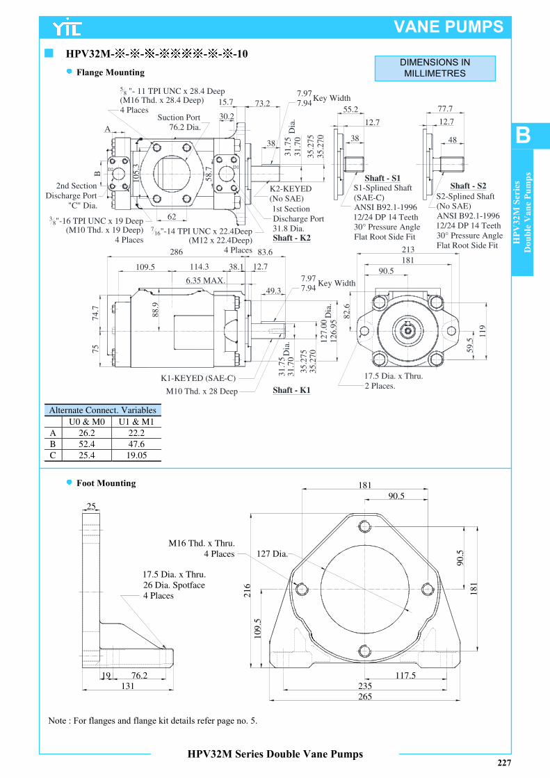
Alternate Connect. Variables
U0 & M0 U1 & M1
A 26.2 22.2
B 52.4 47.6
C 25.4 19.05
■ HPV32M- - - - - - -10
Flange Mounting
Foot Mounting
DIMENSIONS IN
MILLIMETRES
114.3109.5
74.7
75
82.6
B
A
62
10
5.3
30.2
58
.7
15.7 73.2
38
35
.27
53
5.2
70
12
7.0
012
6.9
5
38.1
6.35 MAX.
83.6
12.7
49.3
88
.9
286
90.5
181
213
59
.5
119
12.7
55.2
38
77.7
48
12.7
D1D2
38"-16 TPI UNC x 19 Deep
(M10 Thd. x 19 Deep)4 Places
716"-14 TPI UNC x 22.4Deep
(M12 x 22.4Deep)4 Places
58 "- 11 TPI UNC x 28.4 Deep
(M16 Thd. x 28.4 Deep)4 Places
1st SectionDischarge Port31.8 Dia.
Suction Port76.2 Dia.
2nd SectionDischarge Port
"C" Dia.
35
.275
35
.27
0
7.977.94
K2-KEYED(No SAE)
17.5 Dia. x Thru.2 Places.
7.977.94
K1-KEYED (SAE-C)
M10 Thd. x 28 Deep
S1-Splined Shaft(SAE-C)ANSI B92.1-199612/24 DP 14 Teeth30° Pressure AngleFlat Root Side Fit
S2-Splined Shaft(No SAE)ANSI B92.1-199612/24 DP 14 Teeth30° Pressure AngleFlat Root Side Fit
Key Width
Key Width
Shaft - K2
Shaft - S1Shaft - S2
Shaft - K1
31
.75
31
.70
Dia
.
Dia
.
31.7
531
.70
Dia
.
227
VANE PUMPS
90.5181
109
.52
16
117.5235265
90
.5
18
1
17.5 Dia. x Thru.26 Dia. Spotface4 Places
M16 Thd. x Thru.4 Places
76.219131
25
127 Dia.
HPV32M Series Double Vane Pumps
B
HPV32M Series
Double Vane Pumps
Note : For flanges and flange kit details refer page no. 5.
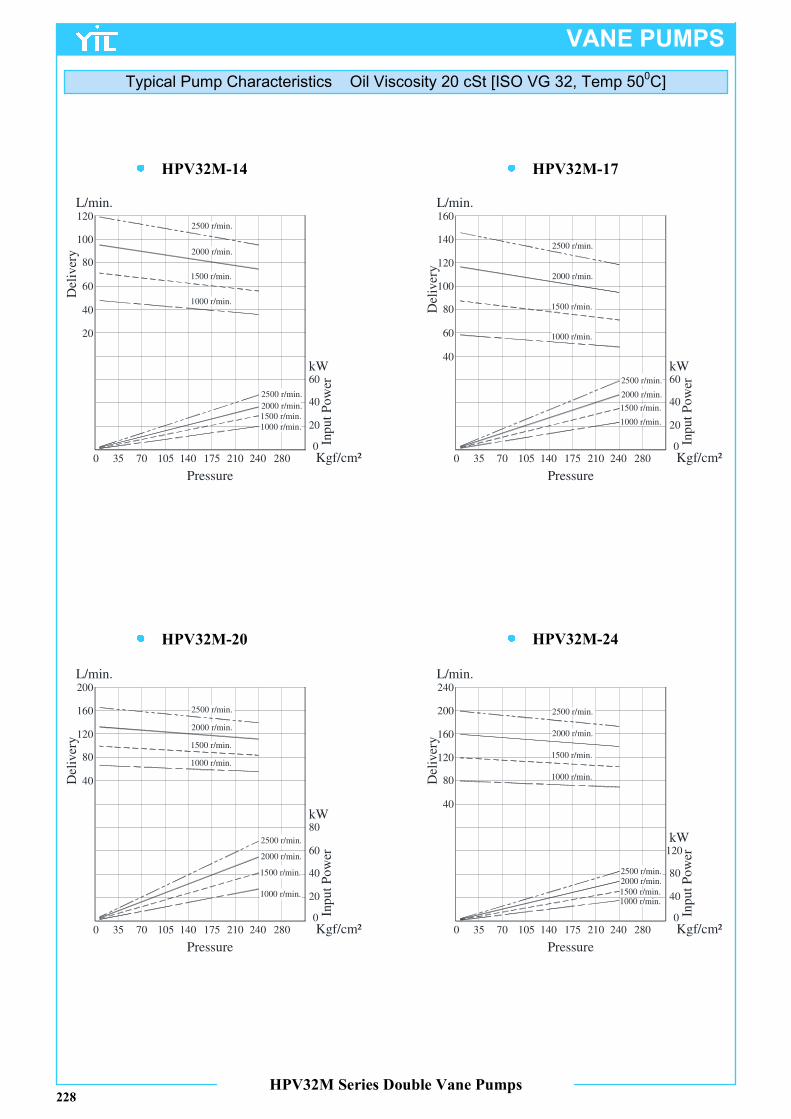
HPV32M-20
HPV32M-17
HPV32M-24
HPV32M-14
VANE PUMPS
HPV32M Series Double Vane Pumps
Typical Pump Characteristics Oil Viscosity 20 cSt [ISO VG 32, Temp 500C]
228
40
60
80
100
Del
iver
y
40
0
60
Inp
ut
Po
wer
L/min.
kW
0 1057035 140 175 Kgf/cm²210 240 280
Pressure
0 1057035 140 175 Kgf/cm²210 240 280
Pressure
0 1057035 140 175 Kgf/cm²210 240 280
Pressure
0 1057035 140 175 Kgf/cm²210 240 280
Pressure
20
20
120
40
0
60
Inp
ut
Po
wer
kW
20
40
60
80
100
Del
iver
y
L/min.
120
140
160
40
0
60
Inp
ut
Po
wer
kW
20
80
40
80
120
Del
iver
y
L/min.
160
200
80
0
120
Inp
ut
Po
wer
kW
40
40
80
120
Del
iver
y
L/min.
160
200
240
2500 r/min.
2000 r/min.
1500 r/min.
1000 r/min.
2500 r/min.
2000 r/min.
1500 r/min.
1000 r/min.
2500 r/min.
2000 r/min.
1500 r/min.
1000 r/min.
2500 r/min.
2000 r/min.
1500 r/min.
1000 r/min.
2500 r/min.
2000 r/min.1500 r/min.
1000 r/min.
2500 r/min.
2000 r/min.
1500 r/min.
1000 r/min.
2500 r/min.
2000 r/min.
1500 r/min.
1000 r/min.
2500 r/min.2000 r/min.
1500 r/min.1000 r/min.
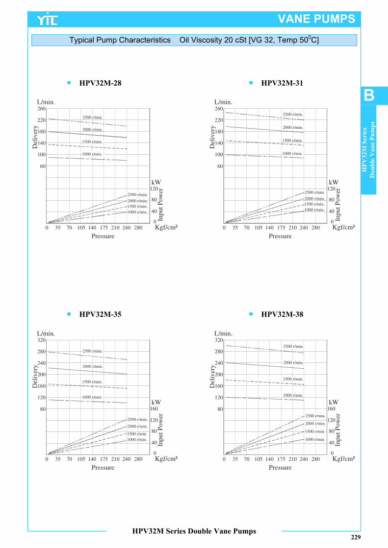
HPV32M-35
HPV32M-31
HPV32M-38
HPV32M-28
VANE PUMPS
HPV32M Series Double Vane Pumps
Typical Pump Characteristics Oil Viscosity 20 cSt [VG 32, Temp 500C]
B
HPV32M Series
Double Vane Pumps
229
220
Del
iver
y
L/min.
0 1057035 140 175 Kgf/cm²210 240 280
Pressure
0 1057035 140 175 Kgf/cm²210 240 280
Pressure
0 1057035 140 175 Kgf/cm²210 240 280
Pressure
0 1057035 140 175 Kgf/cm²210 240 280
Pressure
60
260
80
0
120
Inp
ut
Po
wer
kW
40
180
140
100
80
0
120
Inp
ut
Po
wer
kW
40
220
Del
iver
y
L/min.
60
260
180
140
100
80
0
120
Inp
ut
Po
wer
kW
40
160
240
Del
iver
y
L/min.
80
280
200
160
120
320
240
Del
iver
y
L/min.
80
280
200
160
120
320
80
0
120
Inp
ut
Po
wer
kW
40
160
2500 r/min.
2000 r/min.
1500 r/min.
1000 r/min.
2500 r/min.
2000 r/min.
1500 r/min.
1000 r/min.
2500 r/min.
2000 r/min.
1500 r/min.
1000 r/min.
2500 r/min.
2000 r/min.
1500 r/min.
1000 r/min.
2500 r/min.
2000 r/min.
1500 r/min.
1000 r/min.
2500 r/min.
2000 r/min.
1500 r/min.
1000 r/min.
2500 r/min.
2000 r/min.
1500 r/min.
1000 r/min.
2500 r/min.
2000 r/min.
1500 r/min.
1000 r/min.
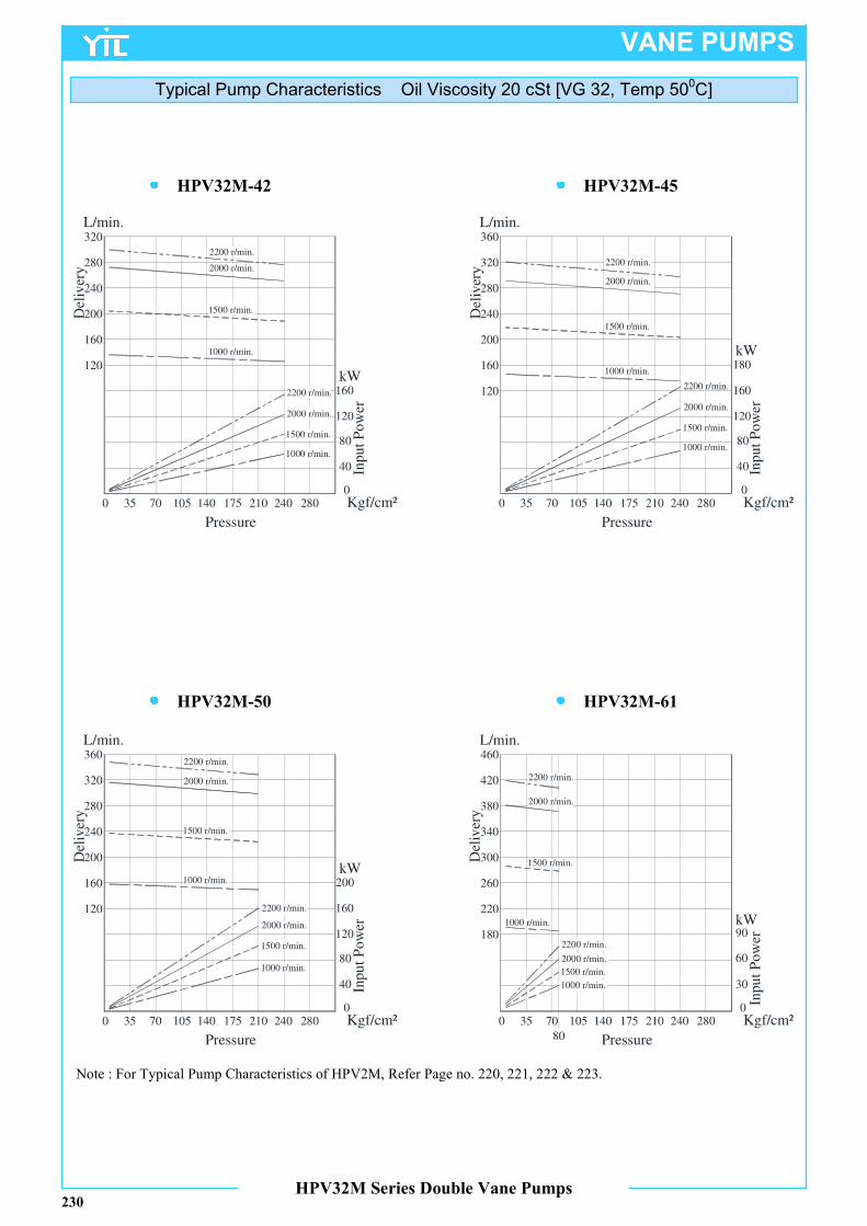
HPV32M-50
HPV32M-45
HPV32M-61
HPV32M-42
Note : For Typical Pump Characteristics of HPV2M, Refer Page no. 220, 221, 222 & 223.
VANE PUMPS
HPV32M Series Double Vane Pumps
Typical Pump Characteristics Oil Viscosity 20 cSt [VG 32, Temp 500C]
230
0 1057035 140 175 Kgf/cm²210 240 280
Pressure
0 1057035 140 175 Kgf/cm²210 240 280
Pressure
0 1057035 140 175 Kgf/cm²210 240 280
Pressure
0 1057035 140 175 Kgf/cm²210 240 280
Pressure
80
0
120
Inp
ut
Po
wer
kW
40
160
300Del
iver
y
L/min.
340
260
220
180
380
0
Inp
ut
Po
wer
kW
30
80
0
120
Inp
ut
Po
wer
kW
40
160
240
Del
iver
y
L/min.
280
200
160
120
320
80
0
120
Inp
ut
Po
wer
kW
40
160
180
240Del
iver
y
L/min.
280
200
160
120
320
360
240
Del
iver
y
L/min.
280
200
160
120
320
360
200
80
60
90
420
460
2200 r/min.
2000 r/min.
1500 r/min.
1000 r/min.
2000 r/min.
1500 r/min.
1000 r/min.
2200 r/min.
2000 r/min.
1500 r/min.
1000 r/min.
2000 r/min.
1500 r/min.
1000 r/min.
2200 r/min.
2200 r/min.
2200 r/min.
2000 r/min.
1500 r/min.
1000 r/min.
2200 r/min.
2000 r/min.
1500 r/min.
1000 r/min.
2200 r/min.
2000 r/min.
1500 r/min.
1000 r/min.
2200 r/min.
2000 r/min.
1500 r/min.
1000 r/min.
VANE PUMPS
HPV32M Series Double Vane Pumps
B
HPV32M Series
Double Vane Pumps
231
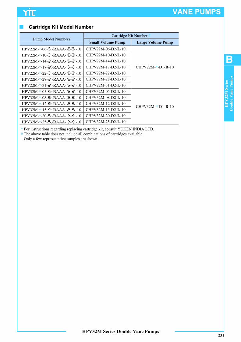
Pump Model Numbers Cartridge Kit Number #
Small Volume Pump Large Volume Pump
HPV22M-*-06-※-RAAA-※-※-10 CHPV22M-06-D2-L-10
CHPV22M-*-D1-R-10
HPV22M-*-10-※-RAAA-※-※-10 CHPV22M-10-D2-L-10
HPV22M-*-14-※-RAAA-※-※-10 CHPV22M-14-D2-L-10
HPV22M-*-17-※-RAAA-※-※-10 CHPV22M-17-D2-L-10
HPV22M-*-22-※-RAAA-※-※-10 CHPV22M-22-D2-L-10
HPV22M-*-28-※-RAAA-※-※-10 CHPV22M-28-D2-L-10
HPV22M-*-31-※-RAAA-※-※-10 CHPV22M-31-D2-L-10
HPV32M-*-05-※-RAAA-※-※-10 CHPV32M-05-D2-L-10
CHPV32M-*-D1-R-10
HPV32M-*-08-※-RAAA-※-※-10 CHPV32M-08-D2-L-10
HPV32M-*-12-※-RAAA-※-※-10 CHPV32M-12-D2-L-10
HPV32M-*-15-※-RAAA-※-※-10 CHPV32M-15-D2-L-10
HPV32M-*-20-※-RAAA-※-※-10 CHPV32M-20-D2-L-10
HPV32M-*-25-※-RAAA-※-※-10 CHPV32M-25-D2-L-10
* For instructions regarding replacing cartridge kit, consult YUKEN INDIA LTD.
# The above table does not include all combinations of cartridges available.
Only a few representative samples are shown.
■ Cartridge Kit Model Number
Related Documents


