Voltage regulation in transformers is the difference between the “No-Load voltage” and the “Full-Load voltage”. This is expressed in terms of percentage. The secondary voltage (nominal) listed in these pages are at Full-Load, meaning the point at which the transformer is operating at maximum permissible secondary current. No-Load voltage can increase 6 to 10% max. Warning: Secondary voltages of transformers may damage some loads. For example, a transformer connected as 480/120 Volt but applied 495 Volt primary can produce at No-Load a voltage of 134 Volts which will damage the inputs of a PLC D0-06AA, whose maximum input voltage is 132 Volt. Notice that the current of D0-06AA input is 10mA, making it very close to No-Load. HPS Fortress™ Commercial Encapsulated Transformers Regulation Percentage No-Load - Full Load = Full Load (100%) E E E Voltage Regulation R Totally enclosed to seal out moisture and airborne contaminants Conduit knockouts and an easily accessible wiring compartment Installation is made quick and easy with keyhole mounting slots Easily accessible nameplate All units are encapsulated with an electrical grade silica sand and resin compound NEMA 3R enclosure meets or exceeds listing criteria including NEMA and ANSI standards for indoor and outdoor applications Features Transformers www.automationdirect.com/power-transformers tTXF-15 For latest prices, please check AutomationDirect.com

Welcome message from author
This document is posted to help you gain knowledge. Please leave a comment to let me know what you think about it! Share it to your friends and learn new things together.
Transcript

Voltage regulation in transformers is the difference between the “No-Load voltage” and the “Full-Load voltage”. This is expressed in terms of percentage.
The secondary voltage (nominal) listed in these pages are at Full-Load, meaning the point at which the transformer is operating at maximum permissible secondary current. No-Load voltage can increase 6 to 10% max.
Warning: Secondary voltages of transformers may damage some loads. For example, a transformer connected as 480/120 Volt but applied 495 Volt primary can produce at No-Load a voltage of 134 Volts which will damage the inputs of a PLC D0-06AA, whose maximum input voltage is 132 Volt. Notice that the current of D0-06AA input is 10mA, making it very close to No-Load.
HPS Fortress™ Commercial Encapsulated Transformers
RegulationPercentage
No-Load - Full Load=Full Load
(100%)E E
E
Voltage Regulation
R
Totally enclosed to seal out moisture and airborne contaminants
Conduit knockouts and an easily accessible wiring compartment
Installation is made quick and easy with keyhole mounting slots
Easily accessible nameplate
All units are encapsulated with an electrical grade silica sand and resin compound
NEMA 3R enclosure meets or exceeds listing criteria including NEMA and ANSI standards for indoor and outdoor applications
Features
Transformersw w w . a u t o m a t i o n d i r e c t . c o m / p o w e r - t r a n s f o r m e r s tTXF-15
For latest prices, please check AutomationDirect.com
Features• Ratings: Single phase from 0.50kVA to
25kVA; 60 Hz• Electrostatic Shield: Standard on all sin-
gle phase units 0.75kVA and larger• Quality Design: All units are encapsu-
lated with electrical grade silica sand and resin compounds which completely enclose the core and coil to seal out mois-ture, airborne contaminants and elimi-nates corrosion and deterioration.
• Insulation: Offering UL class 130°C (266°F) insulation, 95°C (203°F) tempera-ture rise up to 1kVA on single phase; 180°C (356°F) insulation, 135°C (275°F) temperature rise on all units over 1kVA on single phase. Quiet operation with sound levels below NEMA standards.
• Enclosures: NEMA 3R enclosures meet or exceed listing criteria including NEMA, ANSI, and OSHA standards for indoor and outdoor service.
• To provide NEMA 3R protection (protec-tion from falling rain), the transformer must be mounted vertically with the mounting tabs facing up.
• Rear and side entry conduit knockouts into an easily accessible and roomy wir-ing compartment.
• Color is ANSI 61 gray, UL50• Taps are convenient to select output
voltage.• Wiring compartment: Provides tinned
copper lead wire terminations up to 5kVA, terminal pad termination on 7.5KVA and larger and standard ground lug assembly for easy cable installation.
• Output voltage adjustable by taps.• Temperature Range: -20°C (-4°F) to
average ambient temperature 30°C (86°F), not to exceed 40°C (104°F)
• Installation made quick and easy: All encapsulated transformers are designed for wall mounting and include keyhole mounting slots.
• 10 year warranty (limited to mfg. defects)
Agency Approvals• UL Listed File No. E50394 (Type Q)• CSA File No. LR3902 (Type Q)• CE (up to 10 kVA)• RoHS
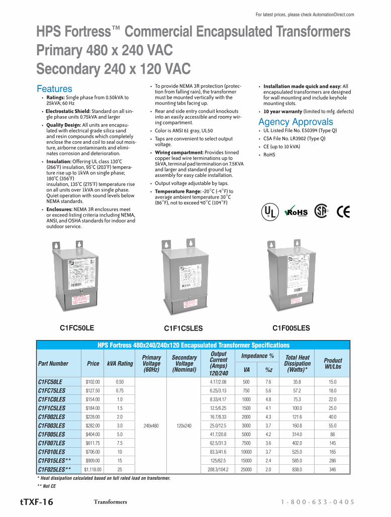
HPS Fortress 480x240/240x120 Encapsulated Transformer Specifications
Part Number Price kVA RatingPrimary Voltage (60Hz)
Secondary Voltage
(Nominal)
Output Current (Amps)120/240
Impedance % Total Heat Dissipation
(Watts)*Product Wt/Lbs VA %z
C1FC50LE $102.00 0.50
240x480 120x240
4.17/2.08 500 7.6 35.8 15.0
C1FC75LES $127.50 0.75 6.25/3.13 750 5.6 57.2 18.0
C1F1C0LES $154.00 1.0 8.33/4.17 1000 4.8 75.3 22.0
C1F1C5LES $184.00 1.5 12.5/6.25 1500 4.1 100.0 25.0
C1F002LES $228.00 2.0 16.7/8.33 2000 4.3 121.6 40.0
C1F003LES $282.00 3.0 25.0/12.5 3000 3.7 160.8 55.0
C1F005LES $404.00 5.0 41.7/20.8 5000 4.2 314.0 88
C1F007LES $611.75 7.5 62.5/31.3 7500 3.6 402.0 145
C1F010LES $706.00 10 83.3/41.6 10000 3.7 525.0 165
C1F015LES** $909.00 15 125/62.5 15000 2.4 585.0 286
C1F025LES** $1,118.00 25 208.3/104.2 25000 2.0 838.0 346
* Heat dissipation calculated based on full rated load on transformer.
** Not CE
C1FC50LE C1F1C5LES C1F005LES
R
HPS Fortress™ Commercial Encapsulated Transformers Primary 480 x 240 VAC Secondary 240 x 120 VAC
Transformers 1 - 8 0 0 - 6 3 3 - 0 4 0 5tTXF-16
For latest prices, please check AutomationDirect.com
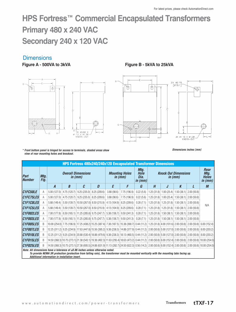
HPS Fortress 480x240/240x120 Encapsulated Transformer Dimensions
Part Number
Mtg. Fig.
Overall Dimensions in (mm)
Mounting Holes in (mm)
Mtg. Hole Dia.
in (mm)
Knock Out Dimensions in (mm)
Rear Mtg. Holes
in (mm)
A B C D E F G H J K L MC1FC50LE A 5.00 (127.0) 4.75 (120.7) 9.25 (235.0) 8.25 (209.6) 3.88 (98.6) 7.75 (196.9) 0.22 (5.6) 1.25 (31.8) 1.00 (25.4) 1.50 (38.1) 2.00 (50.8)
N/A
C1FC75LES A 5.00 (127.0) 4.75 (120.7) 9.25 (235.0) 8.25 (209.6) 3.88 (98.6) 7.75 (196.9) 0.22 (5.6) 1.25 (31.8) 1.00 (25.4) 1.50 (38.1) 2.00 (50.8)
C1F1C0LES A 5.88 (149.4) 5.50 (139.7) 10.50 (267.0) 8.50 (215.9) 4.13 (104.9) 8.25 (209.6) 0.28 (7.1) 1.25 (31.8) 1.25 (31.8) 1.50 (38.1) 2.00 (50.8)
C1F1C5LES A 5.88 (149.4) 5.50 (139.7) 10.50 (267.0) 8.50 (215.9) 4.13 (104.9) 8.25 (209.6) 0.28 (7.1) 1.25 (31.8) 1.25 (31.8) 1.50 (38.1) 2.00 (50.8)
C1F002LES A 7.00 (177.8) 6.50 (165.1) 11.25 (285.8) 9.75 (247.7) 5.38 (136.7) 9.50 (241.3) 0.28 (7.1) 1.25 (31.8) 1.50 (38.1) 1.50 (38.1) 2.00 (50.8)
C1F003LES A 7.00 (177.8) 6.50 (165.1) 11.25 (285.8) 9.75 (247.7) 5.38 (136.7) 9.50 (241.3) 0.28 (7.1) 1.25 (31.8) 1.50 (38.1) 1.50 (38.1) 2.00 (50.8)
C1F005LES B 10.00 (254.0) 7.75 (196.9) 17.25 (438.2) 15.25 (387.4) 7.38 (187.5) 15.38 (390.7) 0.44 (11.2) 1.25 (31.8) 4.00 (101.6) 2.00 (50.8) 2.00 (50.8) 6.00 (152.4)
C1F007LES B 12.25 (311.2) 9.25 (234.9) 17.63 (447.8) 15.56 (395.2) 9.38 (238.3) 14.88 (377.9) 0.44 (11.2) 2.00 (50.8) 5.00 (127.0) 2.00 (50.8) 2.00 (50.8) 8.00 (203.2)
C1F010LES B 12.25 (311.2) 9.25 (234.9) 20.88 (530.4) 18.88 (479.6) 9.38 (238.3) 18.13 (460.5) 0.44 (11.2) 2.00 (50.8) 5.00 (127.0) 2.00 (50.8) 2.00 (50.8) 8.00 (203.2)
C1F015LES B 14.50 (368.3) 10.75 (273.1) 21.38 (543.1) 19.38 (492.3) 11.63 (295.4) 18.63 (473.2) 0.44 (11.2) 2.00 (50.8) 6.00 (152.4) 2.00 (50.8) 2.00 (50.8) 10.00 (254.0)
C1F025LES B 14.50 (368.3) 10.75 (273.1) 27.38 (695.5) 24.88 (631.9) 11.13 (282.7) 24.50 (622.3) 0.56 (14.2) 2.00 (50.8) 6.00 (152.4) 2.00 (50.8) 2.00 (50.8) 10.00 (254.0)Note: All dimensions have a tolerance of ±0.06 inches unless otherwise noted.
To provide NEMA 3R protection (protection from falling rain), the transformer must be mounted vertically with the mounting tabs facing up. Additional information in installation insert.
Dimensions
* Front bottom panel is hinged for access to terminals, shaded areas show view of rear mounting holes and knockout.
HPS Fortress™ Commercial Encapsulated Transformers Primary 480 x 240 VAC Secondary 240 x 120 VAC
Dimensions inches [mm]
Figure A - 500VA to 3kVA Figure B - 5kVA to 25kVA
Transformersw w w . a u t o m a t i o n d i r e c t . c o m / p o w e r - t r a n s f o r m e r s tTXF-17
For latest prices, please check AutomationDirect.com
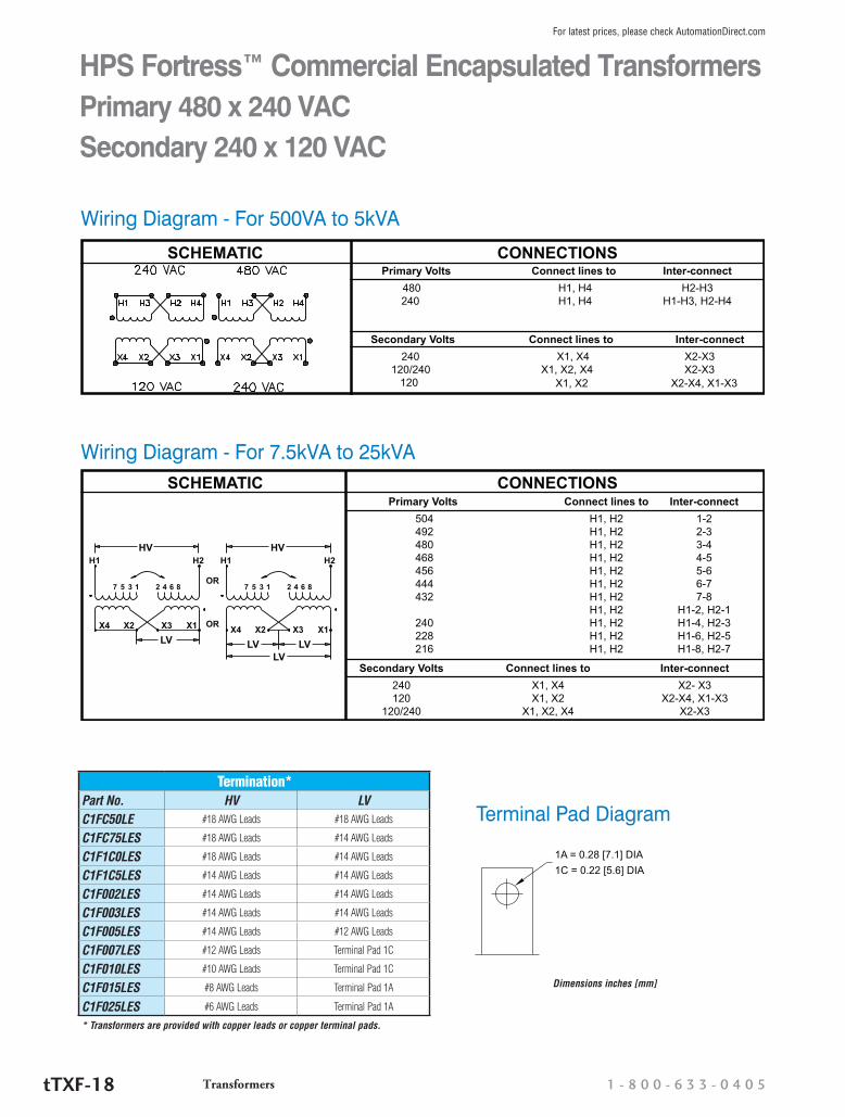
HV HVH1 H2 H1 H2
OR
OR
7 8642135 7 8642135
X4 X1X3X2X4 X1X3X2LV LV LV
LV
Primary Volts Connect lines to Inter-connect
504 H1, H2 1-2 492 H1, H2 2-3 480 H1, H2 3-4 468 H1, H2 4-5 456 H1, H2 5-6 444 H1, H2 6-7 432 H1, H2 7-8
H1, H2 H1-2, H2-1 240 H1, H2 H1-4, H2-3 228 H1, H2 H1-6, H2-5 216 H1, H2 H1-8, H2-7
SCHEMATIC CONNECTIONS
Secondary Volts Connect lines to Inter-connect
240 X1, X4 X2- X3 120 X1, X2 X2-X4, X1-X3 120/240 X1, X2, X4 X2-X3
Wiring Diagram - For 7.5kVA to 25kVA
* Transformers are provided with copper leads or copper terminal pads.
HPS Fortress™ Commercial Encapsulated Transformers Primary 480 x 240 VAC Secondary 240 x 120 VAC
Primary Volts Connect lines to Inter-connect
480 H1, H4 H2-H3 240 H1, H4 H1-H3, H2-H4
SCHEMATIC CONNECTIONS
Secondary Volts Connect lines to Inter-connect
240 X1, X4 X2-X3 120/240 X1, X2, X4 X2-X3 120 X1, X2 X2-X4, X1-X3
Wiring Diagram - For 500VA to 5kVA
Termination*Part No. HV LVC1FC50LE #18 AWG Leads #18 AWG Leads
C1FC75LES #18 AWG Leads #14 AWG Leads
C1F1C0LES #18 AWG Leads #14 AWG Leads
C1F1C5LES #14 AWG Leads #14 AWG Leads
C1F002LES #14 AWG Leads #14 AWG Leads
C1F003LES #14 AWG Leads #14 AWG Leads
C1F005LES #14 AWG Leads #12 AWG Leads
C1F007LES #12 AWG Leads Terminal Pad 1C
C1F010LES #10 AWG Leads Terminal Pad 1C
C1F015LES #8 AWG Leads Terminal Pad 1A
C1F025LES #6 AWG Leads Terminal Pad 1A
1A = 0.28 [7.1] DIA1C = 0.22 [5.6] DIA
Terminal Pad Diagram
Dimensions inches [mm]
Transformers 1 - 8 0 0 - 6 3 3 - 0 4 0 5tTXF-18
For latest prices, please check AutomationDirect.com
Control Transformer SelectionControl transformer selectionTo select the proper transformer, you must first determine three characteristics of the load circuit. They are: total steady-state (sealed) VA, total inrush VA, and inrush load power factor.
Total steady-state “sealed” VA is the total amount of VA that the transformer must supply to the load circuit for an extended length of time. Calculate by adding the total steady-state VA of all devices in your control circuit. (The operating VA data for the devices should be available from the manufacturers.)
The inrush VA is the amount of VA that the transformer must supply for all components in the control circuit that are ener-gized together. Consideration for the start-up sequence may be required. (Inrush VA data should be obtained from the device manufacturers.)
The inrush load power factor is difficult to determine without detailed vector analysis of all the control components. In the absence of such information, we recommend that a 40% power factor be utilized.
Six easy stepsOnce the three load circuit variables have been determined, follow these steps to select the proper transformer.
1. Determine your primary (supply) and secondary (output) voltage requirements, as well as the required frequency (i.e. 60 Hz).
2. Calculate the total sealed VA of your circuit by adding the total sealed VA of all devices in the control circuit.
3. Calculate the inrush VA by adding the inrush VA of all components being energized together. Remember to add the sealed VA of all components that do not have inrush VA (lamps, timers, etc.), as they do present a load to the transformer during maximum inrush. If the inrush for your components is unknown, assume a 40% inrush power factor.
4. Calculate the total inrush VA using one of two methods: Method B will result in slightly larger transformer selected.
5. If the nominal supply voltage does not fluctuate more than 5%, then reference the 90% secondary voltage column in the Regulation Data Table for the correct VA rating. If the supply voltage varies up to 10%, the 95% secondary voltage column should be used to size the transformer. The 85% secondary voltage column gives minimum values for proper electromagnetic device operation and should only be used as a reference.
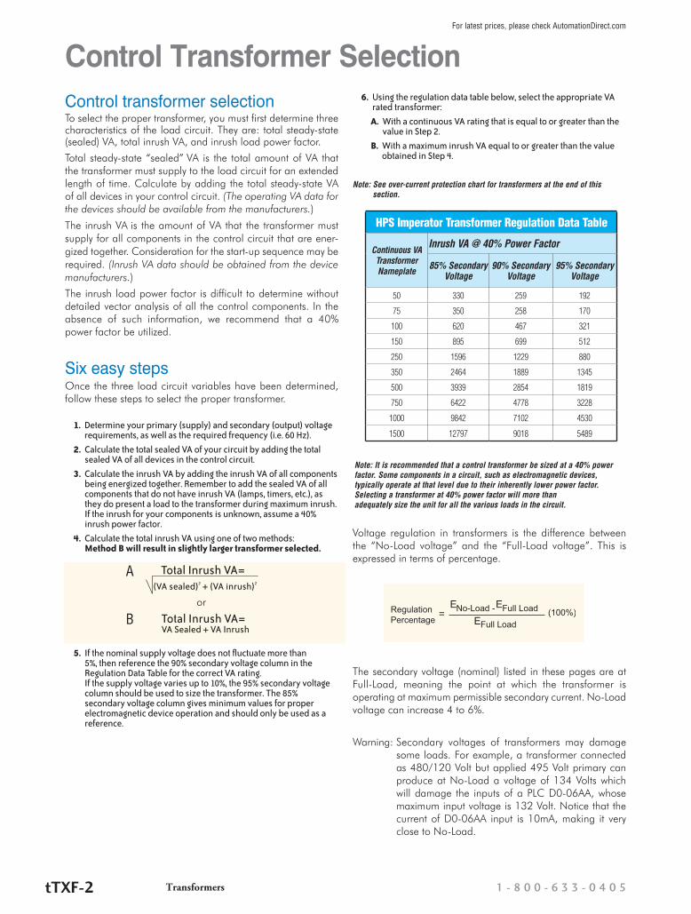
6. Using the regulation data table below, select the appropriate VA rated transformer:
A. With a continuous VA rating that is equal to or greater than the value in Step 2.
B. With a maximum inrush VA equal to or greater than the value obtained in Step 4.
Note: See over-current protection chart for transformers at the end of this section.
Voltage regulation in transformers is the difference between the “No-Load voltage” and the “Full-Load voltage”. This is expressed in terms of percentage.
The secondary voltage (nominal) listed in these pages are at Full-Load, meaning the point at which the transformer is operating at maximum permissible secondary current. No-Load voltage can increase 4 to 6%.
Warning: Secondary voltages of transformers may damage some loads. For example, a transformer connected as 480/120 Volt but applied 495 Volt primary can produce at No-Load a voltage of 134 Volts which will damage the inputs of a PLC D0-06AA, whose maximum input voltage is 132 Volt. Notice that the current of D0-06AA input is 10mA, making it very close to No-Load.
or
A
B
HPS Imperator Transformer Regulation Data Table
Continuous VA Transformer Nameplate
Inrush VA @ 40% Power Factor
85% Secondary Voltage
90% Secondary Voltage
95% Secondary Voltage
50 330 259 192
75 350 258 170
100 620 467 321
150 895 699 512
250 1596 1229 880
350 2464 1889 1345
500 3939 2854 1819
750 6422 4778 3228
1000 9842 7102 4530
1500 12797 9018 5489
Note: It is recommended that a control transformer be sized at a 40% power factor. Some components in a circuit, such as electromagnetic devices, typically operate at that level due to their inherently lower power factor. Selecting a transformer at 40% power factor will more than adequately size the unit for all the various loads in the circuit.
RegulationPercentage
No-Load - Full Load=Full Load
(100%)E E
E
Transformers 1 - 8 0 0 - 6 3 3 - 0 4 0 5tTXF-2
For latest prices, please check AutomationDirect.com
Related Documents