HPE Synergy 480 Gen10 Compute Module User Guide Part Number: 876831-006 Published: June 2019 Edition: 6 Abstract This document is for the person who installs, administers, and troubleshoots the HPE Synergy system. Hewlett Packard Enterprise assumes you are qualified in the servicing of computer equipment and trained in recognizing hazards in products with hazardous energy levels.

Welcome message from author
This document is posted to help you gain knowledge. Please leave a comment to let me know what you think about it! Share it to your friends and learn new things together.
Transcript
HPE Synergy 480 Gen10 Compute ModuleUser Guide
Part Number: 876831-006Published: June 2019Edition: 6
AbstractThis document is for the person who installs, administers, and troubleshoots the HPE Synergysystem. Hewlett Packard Enterprise assumes you are qualified in the servicing of computerequipment and trained in recognizing hazards in products with hazardous energy levels.

© Copyright 2017, 2019 Hewlett Packard Enterprise Development LP
NoticesThe information contained herein is subject to change without notice. The only warranties for Hewlett PackardEnterprise products and services are set forth in the express warranty statements accompanying suchproducts and services. Nothing herein should be construed as constituting an additional warranty. HewlettPackard Enterprise shall not be liable for technical or editorial errors or omissions contained herein.
Confidential computer software. Valid license from Hewlett Packard Enterprise required for possession, use,or copying. Consistent with FAR 12.211 and 12.212, Commercial Computer Software, Computer SoftwareDocumentation, and Technical Data for Commercial Items are licensed to the U.S. Government undervendor's standard commercial license.
Links to third-party websites take you outside the Hewlett Packard Enterprise website. Hewlett PackardEnterprise has no control over and is not responsible for information outside the Hewlett Packard Enterprisewebsite.
AcknowledgmentsIntel®, Itanium®, Pentium®, Xeon®, Intel Inside®, and the Intel Inside logo are trademarks of Intel Corporation inthe U.S. and other countries.
Microsoft® and Windows® are either registered trademarks or trademarks of Microsoft Corporation in theUnited States and/or other countries.
Adobe® and Acrobat® are trademarks of Adobe Systems Incorporated.
Java® and Oracle® are registered trademarks of Oracle and/or its affiliates.
UNIX® is a registered trademark of The Open Group.
Contents
Component identification........................................................................... 6Front panel components......................................................................................................................6
Serial label pull tab information.................................................................................................6Front panel LEDs and buttons.............................................................................................................7Drive numbering.................................................................................................................................. 8Hot-plug drive LED definitions.............................................................................................................9SFF flash adapter components and LED definitions......................................................................... 10NVMe SSD LED definitions............................................................................................................... 11System board components................................................................................................................12
System maintenance switch................................................................................................... 13Processor, heatsink, and socket components........................................................................ 14Mezzanine connector definitions............................................................................................ 14DIMM slot locations................................................................................................................ 15DIMM label identification.........................................................................................................15NVDIMM identification............................................................................................................ 17NVDIMM LED identification.................................................................................................... 18HPE Persistent Memory module label identification...............................................................20Enterprise Midline USB...........................................................................................................20LEDs.......................................................................................................................................21
Component and LED identification for HPE Synergy hardware........................................................ 21
Operations..................................................................................................22Powering up the compute module ....................................................................................................22Powering down the compute module ............................................................................................... 22Removing the drive blank..................................................................................................................22Removing the compute module.........................................................................................................23Removing the compute module end cap...........................................................................................24Removing the access panel.............................................................................................................. 24Removing the DIMM baffle................................................................................................................ 25Removing the front panel/drive cage assembly.................................................................................26Installing the compute module end cap.............................................................................................27Installing the access panel................................................................................................................ 27Installing the DIMM baffles................................................................................................................ 28Installing the front panel/drive cage assembly...................................................................................28
Setup...........................................................................................................30Installation overview.......................................................................................................................... 30Installing the compute module...........................................................................................................30Completing the configuration.............................................................................................................31
Hardware options installation.................................................................. 32Introduction........................................................................................................................................32Installing SAS, SATA, or solid state drives........................................................................................ 32Installing the SFF flash adapter option..............................................................................................33Installing the M.2 SSD flash drive and adapter board....................................................................... 34Installing the controller option............................................................................................................35
3
Installing mezzanine card options..................................................................................................... 36Installing the P416ie-m Controller mezzanine option........................................................................ 37HPE Smart Storage Battery...............................................................................................................39HPE Smart Storage Hybrid Capacitor............................................................................................... 39
Minimum firmware versions....................................................................................................39Installing the energy pack option............................................................................................ 39
Memory options.................................................................................................................................42DIMM and NVDIMM population information........................................................................... 42DIMM-processor compatibility................................................................................................ 42HPE SmartMemory speed information................................................................................... 42Installing a DIMM....................................................................................................................42HPE 16GB NVDIMM option....................................................................................................43HPE Persistent Memory option...............................................................................................47
Installing the processor heatsink option............................................................................................ 51HPE Trusted Platform Module 2.0 Gen10 option.............................................................................. 54
Overview.................................................................................................................................54HPE Trusted Platform Module 2.0 Guidelines........................................................................ 54Installing and enabling the HPE TPM 2.0 Gen10 Kit..............................................................55
Cabling........................................................................................................60Cabling resources..............................................................................................................................60Energy pack option cabling............................................................................................................... 60P416ie-m Smart Array Controller cabling..........................................................................................60
Removing and replacing the system battery.......................................... 62
Electrostatic discharge............................................................................. 64Preventing electrostatic discharge.....................................................................................................64Grounding methods to prevent electrostatic discharge..................................................................... 64
Specifications............................................................................................ 65Compute module environmental specifications.................................................................................65Compute module physical specifications...........................................................................................65
Documentation and troubleshooting resources for HPE Synergy....... 66HPE Synergy documentation............................................................................................................ 66
HPE Synergy Configuration and Compatibility Guide.............................................................66HPE Synergy Frame Link Module User Guide....................................................................... 66HPE OneView User Guide and Help for HPE Synergy.......................................................... 66HPE OneView Global Dashboard User Guide and Help........................................................ 66HPE Synergy Image Streamer User Guide............................................................................ 66HPE Synergy Image Streamer GitHub................................................................................... 67HPE Synergy Software Overview Guide................................................................................ 67HPE OneView for Synergy Firmware and Driver Update Guide.............................................67HPE OneView Support Matrix for HPE Synergy.....................................................................67HPE Synergy Image Streamer Support Matrix.......................................................................67HPE Synergy Firmware Comparison Tool ............................................................................. 67HPE Synergy Upgrade Paths................................................................................................. 67HPE Synergy Glossary...........................................................................................................68
HPE Synergy troubleshooting resources...........................................................................................68Troubleshooting within HPE OneView....................................................................................68
4
HPE Synergy Troubleshooting Guide.....................................................................................68Error Message Guide for HPE ProLiant Gen10 servers and HPE Synergy........................... 68HPE OneView Help and HPE OneView API Reference......................................................... 68HPE Synergy QuickSpecs......................................................................................................68
HPE Synergy document overview (documentation map)...................... 69
Websites..................................................................................................... 71
Support and other resources................................................................... 72Accessing Hewlett Packard Enterprise Support................................................................................72Accessing updates............................................................................................................................ 72Customer self repair.......................................................................................................................... 73Remote support.................................................................................................................................73Warranty information......................................................................................................................... 73Regulatory information...................................................................................................................... 73Documentation feedback...................................................................................................................74
5
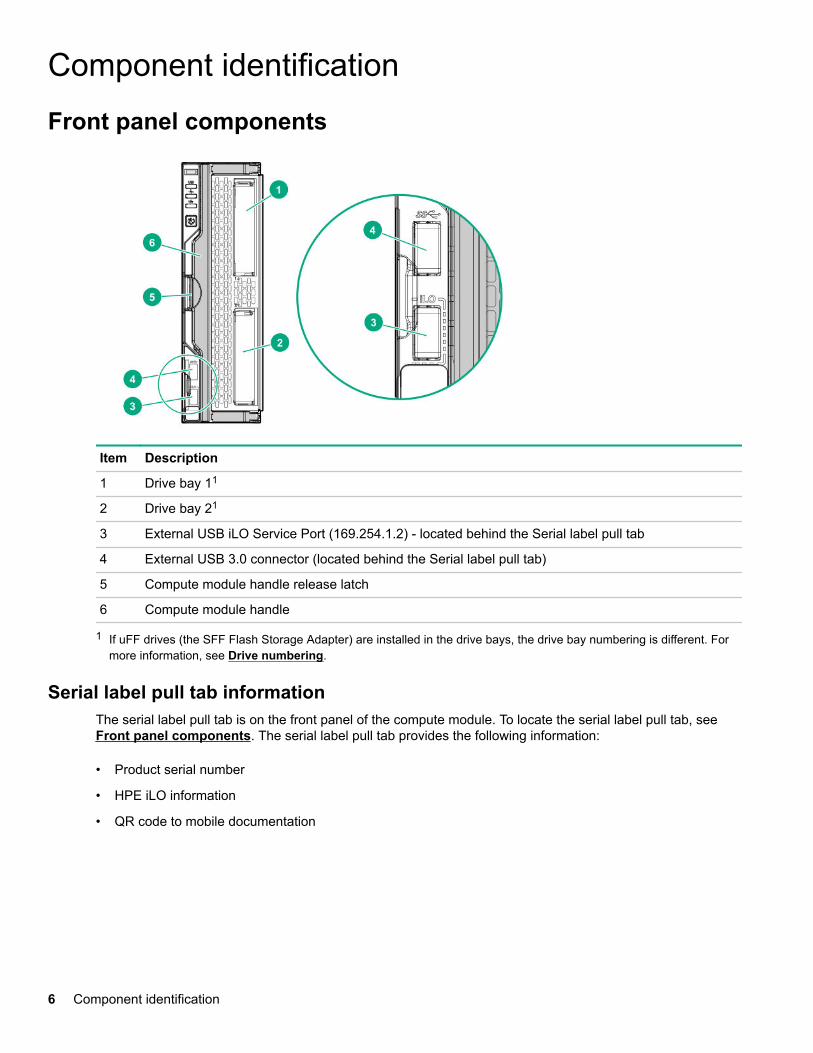
Component identificationFront panel components
Item Description
1 Drive bay 11
2 Drive bay 21
3 External USB iLO Service Port (169.254.1.2) - located behind the Serial label pull tab
4 External USB 3.0 connector (located behind the Serial label pull tab)
5 Compute module handle release latch
6 Compute module handle
1 If uFF drives (the SFF Flash Storage Adapter) are installed in the drive bays, the drive bay numbering is different. Formore information, see Drive numbering.
Serial label pull tab informationThe serial label pull tab is on the front panel of the compute module. To locate the serial label pull tab, see Front panel components. The serial label pull tab provides the following information:
• Product serial number
• HPE iLO information
• QR code to mobile documentation
6 Component identification
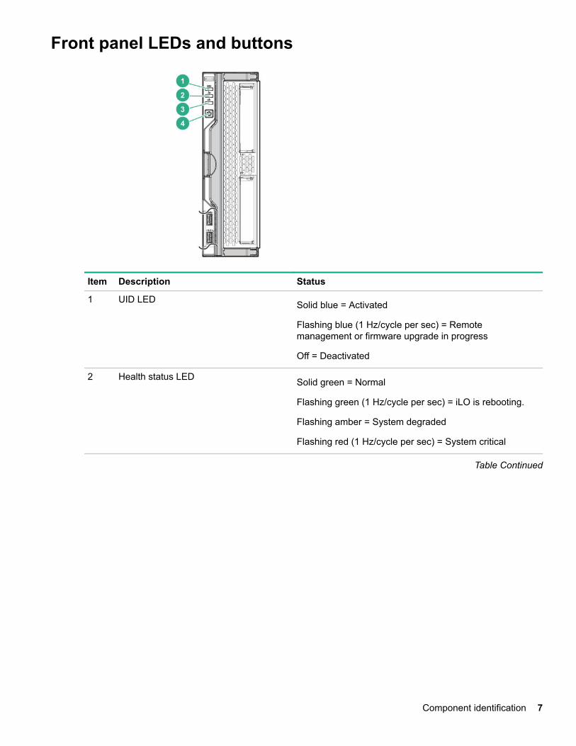
Front panel LEDs and buttons
Item Description Status
1 UID LED Solid blue = Activated
Flashing blue (1 Hz/cycle per sec) = Remotemanagement or firmware upgrade in progress
Off = Deactivated
2 Health status LED Solid green = Normal
Flashing green (1 Hz/cycle per sec) = iLO is rebooting.
Flashing amber = System degraded
Flashing red (1 Hz/cycle per sec) = System critical
Table Continued
Component identification 7
Item Description Status
3 Mezzanine NIC status LED Solid green= Link on any Mezzanine NIC
Flashing green= Activity on any Mezzanine NIC
Off = No link or activity on any Mezzanine NIC
4 Power On/Standby button and systempower LED Solid green = System on
Flashing green (1 Hz/cycle per sec) = Performing poweron sequence
Solid amber = System in standby
Off = No power present
NOTE: If all other LEDs are off, no compute modulepower is present (facility power is not present, powercord is not attached, power supplies are not installed,power supply failure has occurred, or the power buttoncable is disconnected). If the health LED is flashing greenwhile the system power LED is off, the Power On/Standby button service is initializing or an iLO reboot isin progress.
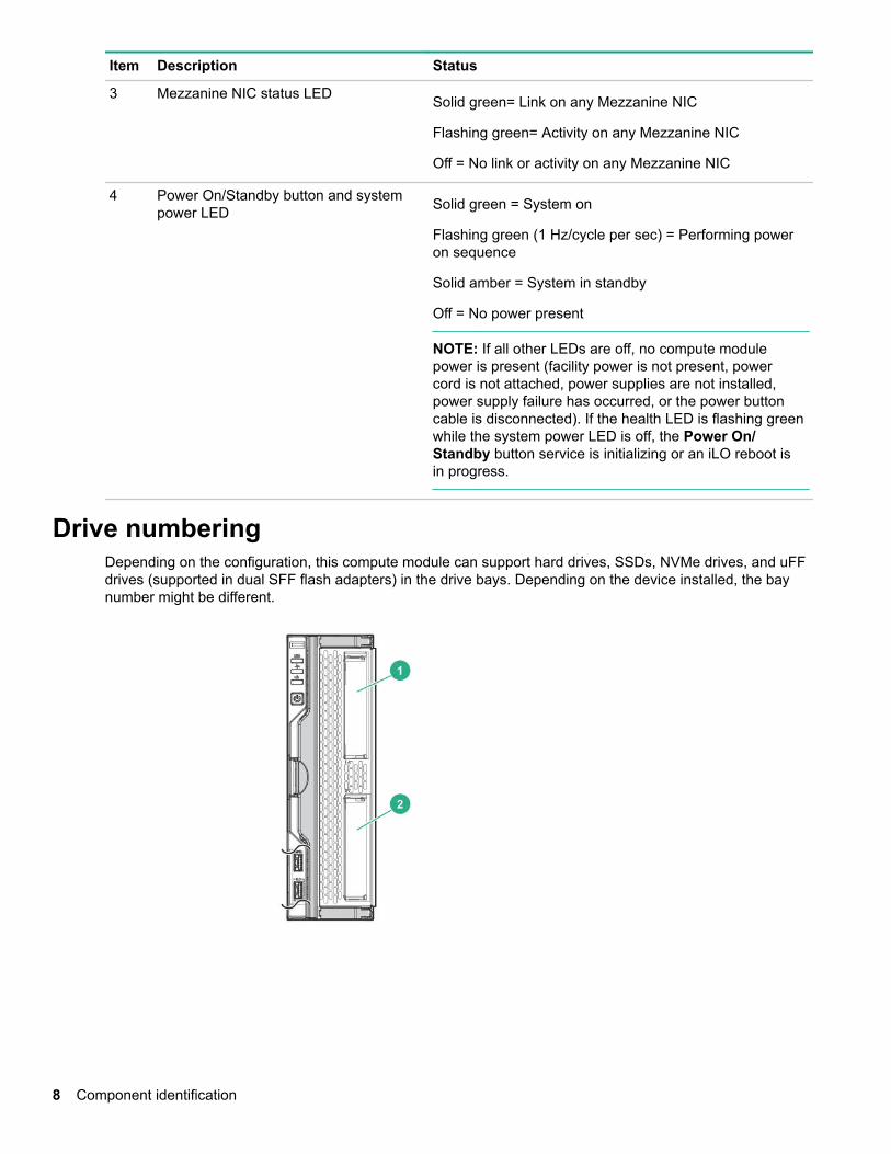
Drive numberingDepending on the configuration, this compute module can support hard drives, SSDs, NVMe drives, and uFFdrives (supported in dual SFF flash adapters) in the drive bays. Depending on the device installed, the baynumber might be different.
8 Component identification
Item Hard drive/SSD baynumbering
uFF drive baynumbering
NVMe drive baynumbering
1 1 1 and 101 1
2 2 2 and 102 2
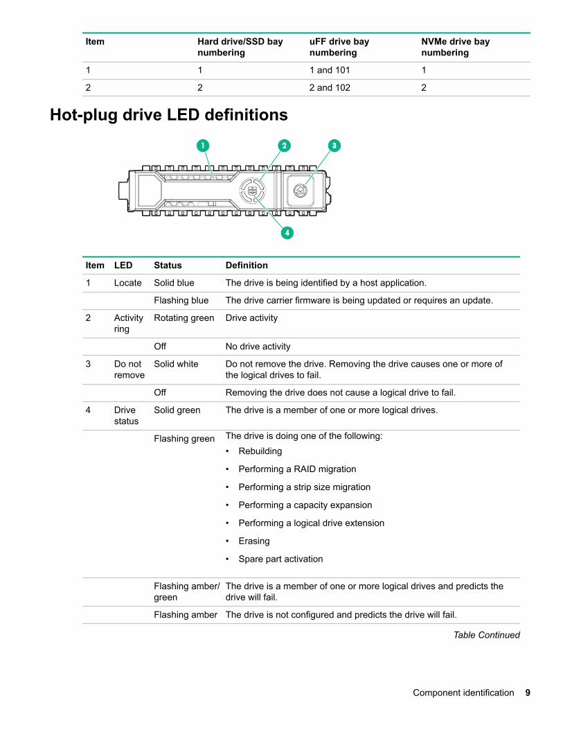
Hot-plug drive LED definitions
Item LED Status Definition
1 Locate Solid blue The drive is being identified by a host application.
Flashing blue The drive carrier firmware is being updated or requires an update.
2 Activityring
Rotating green Drive activity
Off No drive activity
3 Do notremove
Solid white Do not remove the drive. Removing the drive causes one or more ofthe logical drives to fail.
Off Removing the drive does not cause a logical drive to fail.
4 Drivestatus
Solid green The drive is a member of one or more logical drives.
Flashing green The drive is doing one of the following:• Rebuilding
• Performing a RAID migration
• Performing a strip size migration
• Performing a capacity expansion
• Performing a logical drive extension
• Erasing
• Spare part activation
Flashing amber/green
The drive is a member of one or more logical drives and predicts thedrive will fail.
Flashing amber The drive is not configured and predicts the drive will fail.
Table Continued
Component identification 9
Item LED Status Definition
Solid amber The drive has failed.
Off The drive is not configured by a RAID controller or a spare drive.
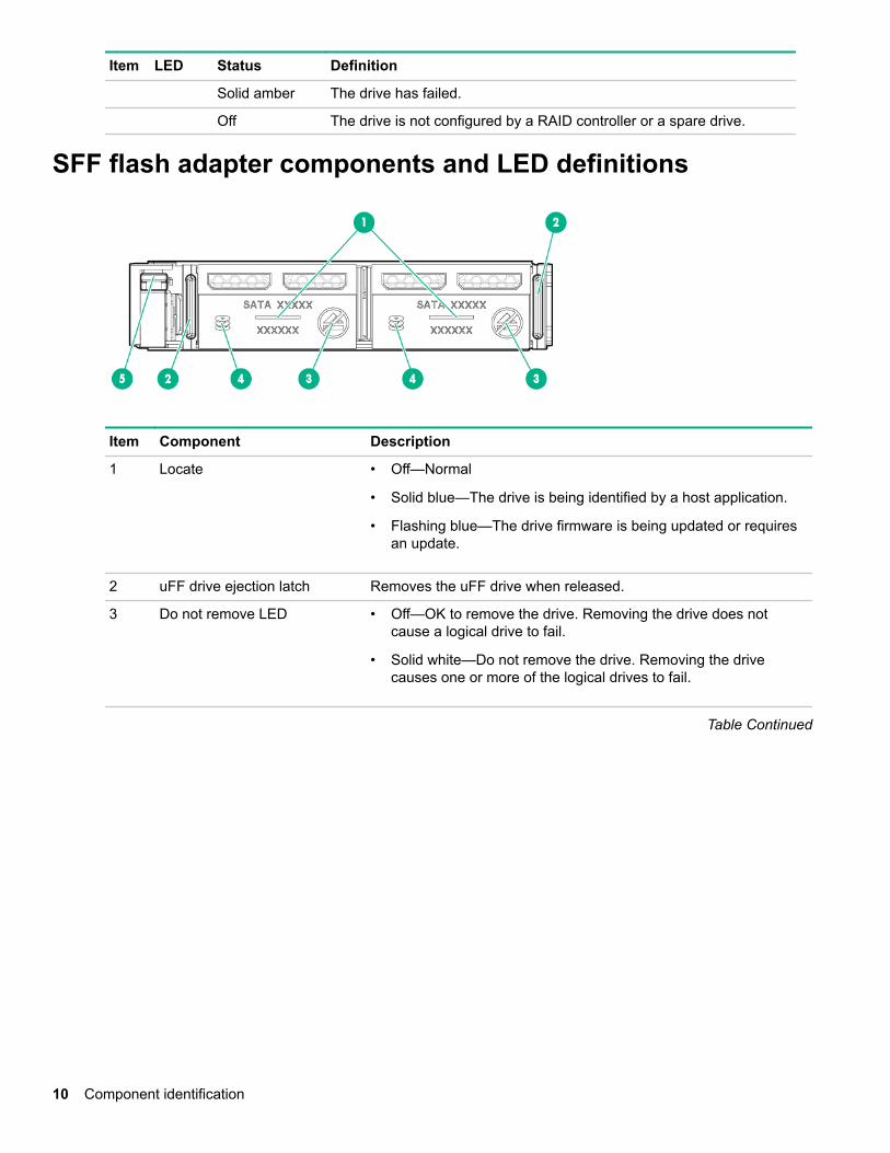
SFF flash adapter components and LED definitions
Item Component Description
1 Locate • Off—Normal
• Solid blue—The drive is being identified by a host application.
• Flashing blue—The drive firmware is being updated or requiresan update.
2 uFF drive ejection latch Removes the uFF drive when released.
3 Do not remove LED • Off—OK to remove the drive. Removing the drive does notcause a logical drive to fail.
• Solid white—Do not remove the drive. Removing the drivecauses one or more of the logical drives to fail.
Table Continued
10 Component identification
Item Component Description
4 Drive status LED • Off—The drive is not configured by a RAID controller or a sparedrive.
• Solid green—The drive is a member of one or more logicaldrives.
• Flashing green (4 Hz)—The drive is operating normally and hasactivity.
• Flashing green (1 Hz)—The drive is rebuilding, erasing, orperforming a RAID migration, stripe size migration, capacityexpansion, logical drive extension, or spare activation.
• Flashing amber/green (1 Hz)—The drive is a member of one ormore logical drives that predicts the drive will fail.
• Solid amber—The drive has failed.
• Flashing amber (1 Hz)—The drive is not configured and predictsthe drive will fail.
5 Adapter ejection release latchand handle
Removes the SFF flash adapter when released.
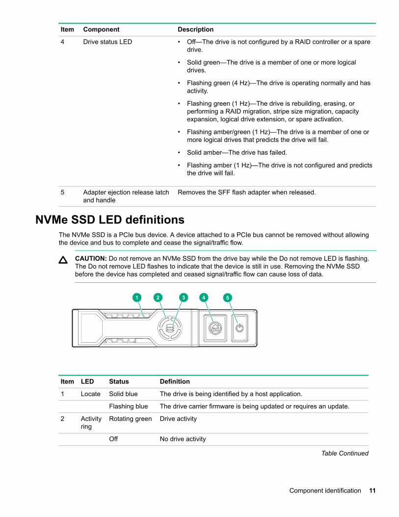
NVMe SSD LED definitionsThe NVMe SSD is a PCIe bus device. A device attached to a PCIe bus cannot be removed without allowingthe device and bus to complete and cease the signal/traffic flow.
CAUTION: Do not remove an NVMe SSD from the drive bay while the Do not remove LED is flashing.The Do not remove LED flashes to indicate that the device is still in use. Removing the NVMe SSDbefore the device has completed and ceased signal/traffic flow can cause loss of data.
Item LED Status Definition
1 Locate Solid blue The drive is being identified by a host application.
Flashing blue The drive carrier firmware is being updated or requires an update.
2 Activityring
Rotating green Drive activity
Off No drive activity
Table Continued
Component identification 11
Item LED Status Definition
3 Drivestatus
Solid green The drive is a member of one or more logical drives.
Flashing green The drive is doing one of the following:• Rebuilding
• Performing a RAID migration
• Performing a stripe size migration
• Performing a capacity expansion
• Performing a logical drive extension
• Erasing
Flashing amber/green
The drive is a member of one or more logical drives and predicts thedrive will fail.
Flashing amber The drive is not configured and predicts the drive will fail.
Solid amber The drive has failed.
Off The drive is not configured by a RAID controller.
4 Do notremove
Solid white Do not remove the drive. The drive must be ejected from the PCIe busprior to removal.
Flashing white The drive ejection request is pending.
Off The drive has been ejected.
5 Power Solid green Do not remove the drive. The drive must be ejected from the PCIe busprior to removal.
Flashing green The drive ejection request is pending.
Off The drive has been ejected.
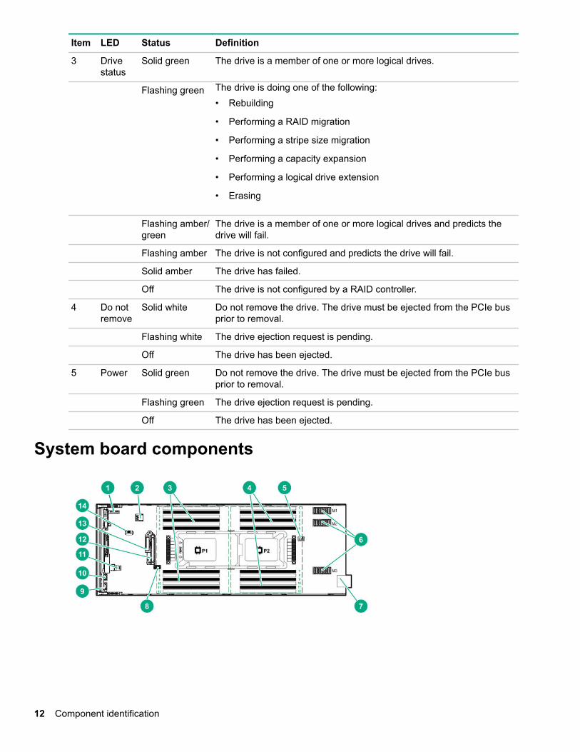
System board components
12 Component identification
Item Description
1 System battery
2 Internal USB 3.0 connector
3 Processor 1 DIMM slots (12)
4 Processor 2 DIMM slots (12)
5 Energy pack option connector
6 Mezzanine connectors (M1, M2, and M3)
7 Management/power connector
8 System maintenance switch
9 External USB iLO Service Port (169.254.1.2) - located behind the Serial label pull tab
10 External USB 3.0 connector (located behind the Serial label pull tab)
11 MicroSD connector
12 Drive backplane connector
13 SATA interconnect / M.2 adapter connector
14 TPM 2.0
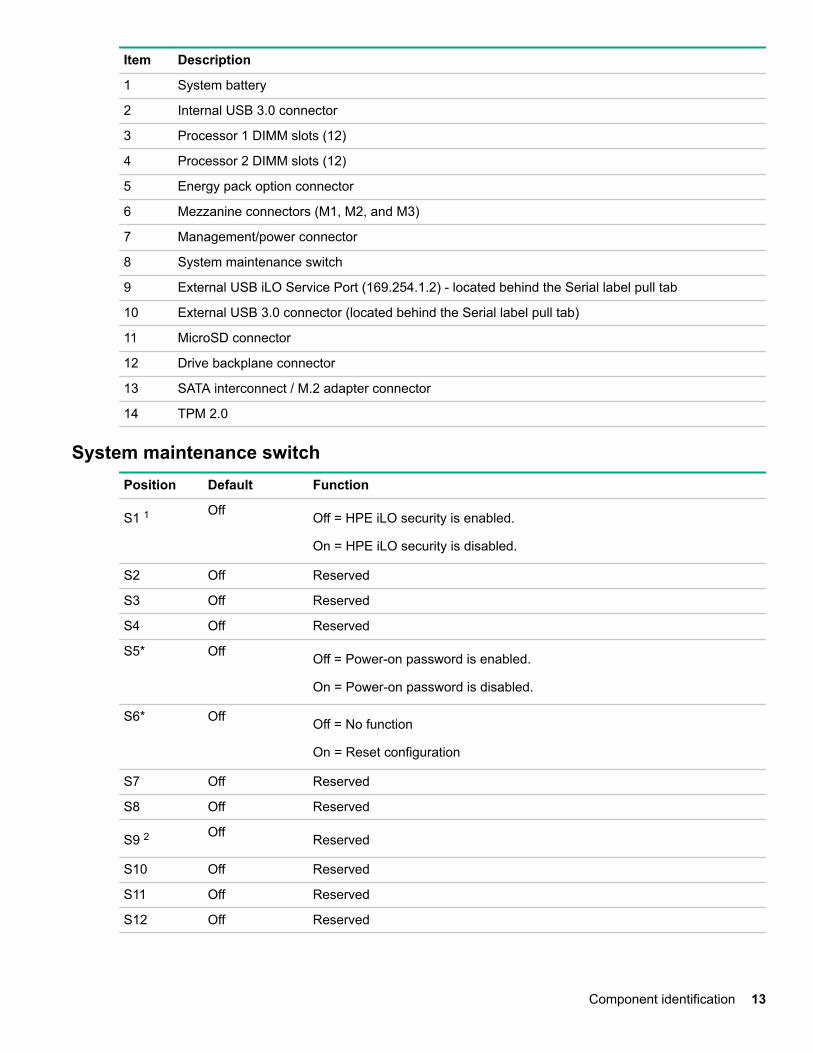
System maintenance switchPosition Default Function
S1 1 Off Off = HPE iLO security is enabled.
On = HPE iLO security is disabled.
S2 Off Reserved
S3 Off Reserved
S4 Off Reserved
S5* Off Off = Power-on password is enabled.
On = Power-on password is disabled.
S6* Off Off = No function
On = Reset configuration
S7 Off Reserved
S8 Off Reserved
S9 2 Off Reserved
S10 Off Reserved
S11 Off Reserved
S12 Off Reserved
Component identification 13
1 To access redundant ROM, set S1, S5 and S6 to On.2 Set swtich S9 to On for GPU expansion options
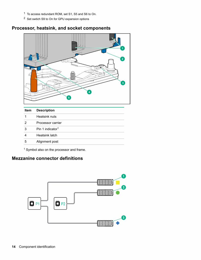
Processor, heatsink, and socket components
Item Description
1 Heatsink nuts
2 Processor carrier
3 Pin 1 indicator1
4 Heatsink latch
5 Alignment post
1 Symbol also on the processor and frame.
Mezzanine connector definitions
14 Component identification
Item Connector identification Supported card types Fabric Supported ICM bays
1 Mezzanine connector 1 (M1)* Type C and Type D 1 ICM 1 and 4
2 Mezzanine connector 2 (M2)** Type C and Type D 2 ICM 2 and 5
3 Mezzanine connector 3 (M3) Type C only 3 ICM 3 and 6
NOTE: Hewlett Packard Enterprise recommends that you install P416ie-m on mezzanine 1.
* When an NVIDIA Tesla M6 GPU FIO Adapter for HPE Synergy 480 Gen10 compute module is installed inmezzanine connector 1, mezzanine connector 2 is not available for additional mezzanine cards.
** When installing a mezzanine option on mezzanine connector 2, processor 2 must be installed.
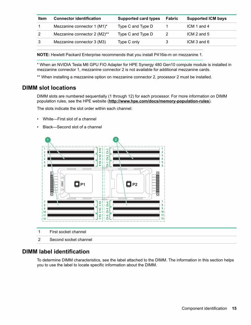
DIMM slot locationsDIMM slots are numbered sequentially (1 through 12) for each processor. For more information on DIMMpopulation rules, see the HPE website (http://www.hpe.com/docs/memory-population-rules).
The slots indicate the slot order within each channel:
• White—First slot of a channel
• Black—Second slot of a channel
1 First socket channel
2 Second socket channel
DIMM label identificationTo determine DIMM characteristics, see the label attached to the DIMM. The information in this section helpsyou to use the label to locate specific information about the DIMM.
Component identification 15
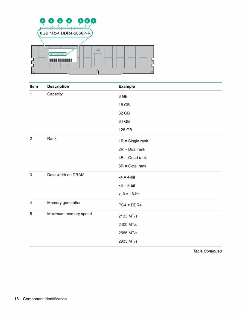
Item Description Example
1 Capacity 8 GB
16 GB
32 GB
64 GB
128 GB
2 Rank 1R = Single rank
2R = Dual rank
4R = Quad rank
8R = Octal rank
3 Data width on DRAM x4 = 4-bit
x8 = 8-bit
x16 = 16-bit
4 Memory generation PC4 = DDR4
5 Maximum memory speed 2133 MT/s
2400 MT/s
2666 MT/s
2933 MT/s
Table Continued
16 Component identification

Item Description Example
6 CAS latency P = CAS 15-15-15
T = CAS 17-17-17
U = CAS 20-18-18
V = CAS 19-19-19 (for RDIMM, LRDIMM)
V = CAS 22-19-19 (for 3DS TSV LRDIMM)
Y = CAS 21-21-21 (for RDIMM, LRDIMM)
Y = CAS 24-21-21 (for 3DS TSV LRDIMM)
7 DIMM type R = RDIMM (registered)
L = LRDIMM (load reduced)
E = Unbuffered ECC (UDIMM)
For more information about product features, specifications, options, configurations, and compatibility, see theHPE DDR4 SmartMemory QuickSpecs on the Hewlett Packard Enterprise website (http://www.hpe.com/support/DDR4SmartMemoryQS).
NVDIMM identificationNVDIMM boards are blue instead of green. This change to the color makes it easier to distinguish NVDIMMsfrom DIMMs.
To determine NVDIMM characteristics, see the full product description as shown in the following example:
Item Description Definition
1 Capacity 16 GiB
2 Rank 1R (Single rank)
3 Data width per DRAM chip x4 (4 bit)
4 Memory type NN4=DDR4 NVDIMM-N
5 Maximum memory speed 2667 MT/s
6 Speed grade V (latency 19-19-19)
Table Continued
Component identification 17
Item Description Definition
7 DIMM type RDIMM (registered)
8 Other —
For more information about NVDIMMs, see the product QuickSpecs on the Hewlett Packard Enterprisewebsite (http://www.hpe.com/info/qs).
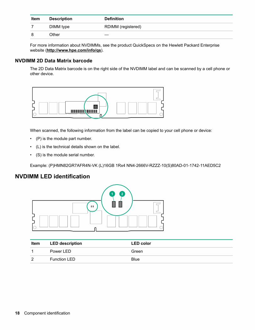
NVDIMM 2D Data Matrix barcodeThe 2D Data Matrix barcode is on the right side of the NVDIMM label and can be scanned by a cell phone orother device.
When scanned, the following information from the label can be copied to your cell phone or device:
• (P) is the module part number.
• (L) is the technical details shown on the label.
• (S) is the module serial number.
Example: (P)HMN82GR7AFR4N-VK (L)16GB 1Rx4 NN4-2666V-RZZZ-10(S)80AD-01-1742-11AED5C2
NVDIMM LED identification
Item LED description LED color
1 Power LED Green
2 Function LED Blue
18 Component identification
NVDIMM-N LED combinations
State Definition NVDIMM-N Power LED(green)
NVDIMM-N Function LED(blue)
0 AC power is on (12V rail) but the NVMcontroller is not working or not ready.
On Off
1 AC power is on (12V rail) and the NVMcontroller is ready.
On On
2 AC power is off or the battery is off (12V railoff).
Off Off
3 AC power is on (12V rail) or the battery ison (12V rail) and the NVDIMM-N is active(backup and restore).
On Flashing
NVDIMM Function LED patternsFor the purpose of this table, the NVDIMM-N LED operates as follows:
• Solid indicates that the LED remains in the on state.
• Flashing indicates that the LED is on for 2 seconds and off for 1 second.
• Fast-flashing indicates that the LED is on for 300 ms and off for 300 ms.
State Definition NVDIMM-N Function LED
0 The restore operation is in progress. Flashing
1 The restore operation is successful. Solid or On
2 Erase is in progress. Flashing
3 The erase operation is successful. Solid or On
4 The NVDIMM-N is armed, and the NVDIMM-N is innormal operation.
Solid or On
5 The save operation is in progress. Flashing
6 The NVDIMM-N finished saving and battery is still turnedon (12 V still powered).
Solid or On
7 The NVDIMM-N has an internal error or a firmwareupdate is in progress. For more information about anNVDIMM-N internal error, see the IML.
Fast-flashing
Component identification 19
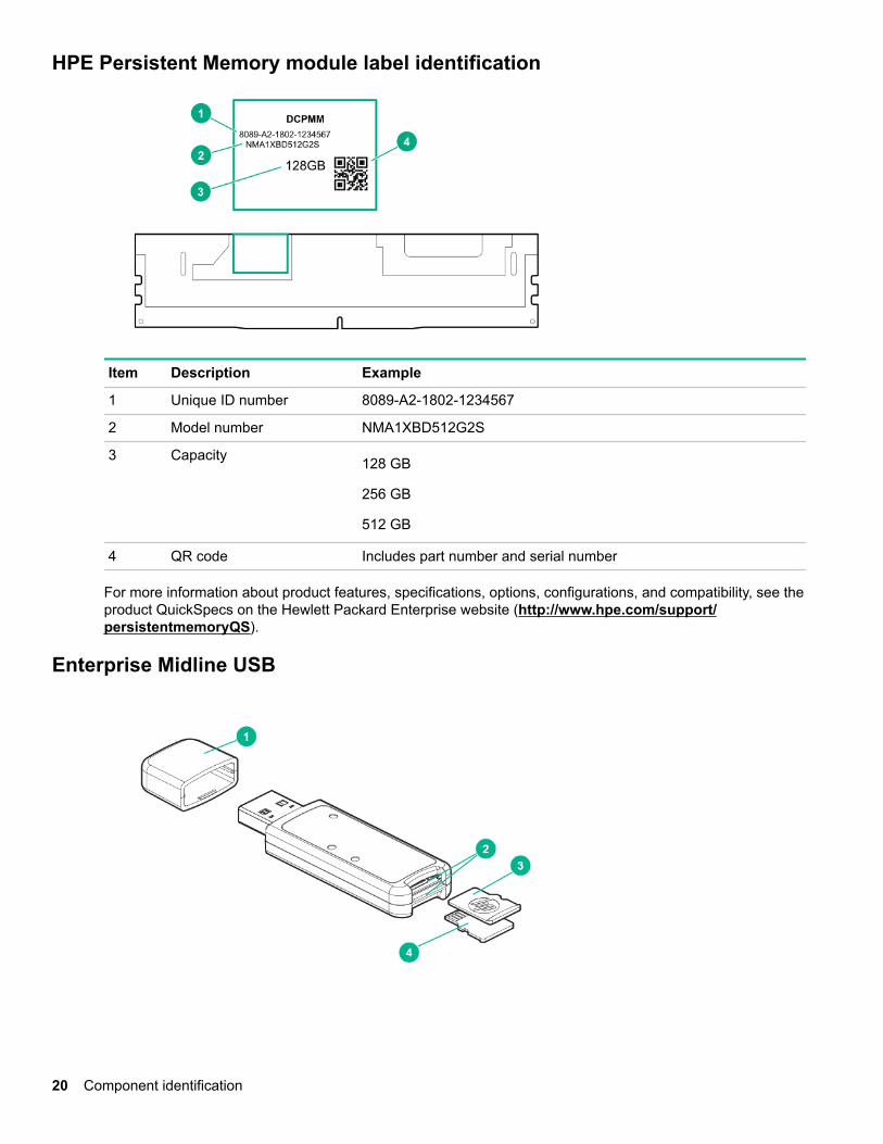
HPE Persistent Memory module label identification
Item Description Example
1 Unique ID number 8089-A2-1802-1234567
2 Model number NMA1XBD512G2S
3 Capacity 128 GB
256 GB
512 GB
4 QR code Includes part number and serial number
For more information about product features, specifications, options, configurations, and compatibility, see theproduct QuickSpecs on the Hewlett Packard Enterprise website (http://www.hpe.com/support/persistentmemoryQS).
Enterprise Midline USB
20 Component identification
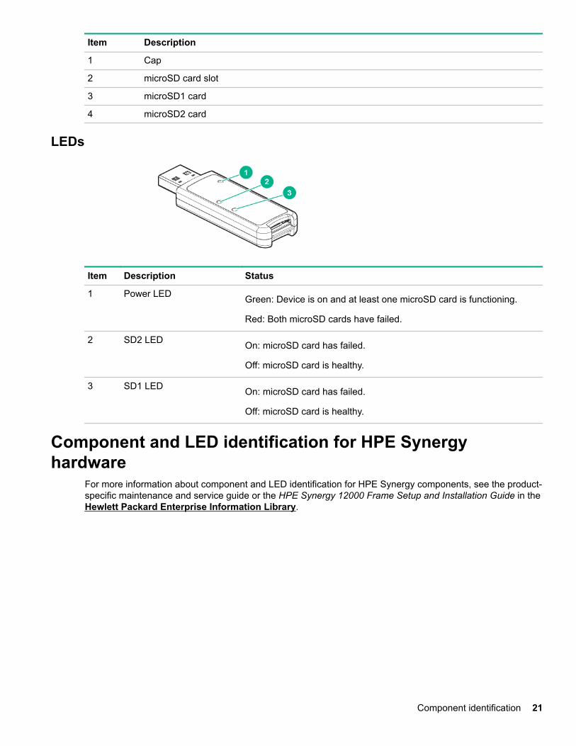
Item Description
1 Cap
2 microSD card slot
3 microSD1 card
4 microSD2 card
LEDs
Item Description Status
1 Power LED Green: Device is on and at least one microSD card is functioning.
Red: Both microSD cards have failed.
2 SD2 LED On: microSD card has failed.
Off: microSD card is healthy.
3 SD1 LED On: microSD card has failed.
Off: microSD card is healthy.
Component and LED identification for HPE Synergyhardware
For more information about component and LED identification for HPE Synergy components, see the product-specific maintenance and service guide or the HPE Synergy 12000 Frame Setup and Installation Guide in the Hewlett Packard Enterprise Information Library.
Component identification 21
OperationsPowering up the compute module
To power up the compute module, press the Power On/Standby button after the power button LED has turnedamber.
Powering down the compute moduleBefore powering down the compute module for any upgrade or maintenance procedures, perform a backup ofthe system and all data. Then, shut down, as appropriate, applications and operating systems. A successfulshutdown is indicated by the system power LED displaying amber.
IMPORTANT: Always attempt a graceful shutdown before forcing a nongraceful shutdown. Applicationdata can be lost when performing a nongraceful shutdown of applications and the OS.
Before proceeding, verify the following:
• The compute module is in standby mode by observing that the system power LED is amber.
• The UID LED is not flashing blue.
NOTE: ◦ When the compute module is in standby mode, auxiliary power is still being provided to the system.
◦ If the UID LED is flashing blue, a remote session is in progress.
To power down the compute module, use one of the following methods:
• To perform a graceful shutdown of applications and the OS when powering down the compute module tostandby mode, do one of the following:◦ Press and release the Power On/Standby button.
◦ Select the Momentary press power off selection in HPE OneView.
◦ Select the Momentary press virtual power button selection in HPE iLO.
• If a graceful shutdown fails to power down the compute module to standby mode when an application orOS stops responding, force a nongraceful shutdown of applications and the OS. Do one of the following:◦ Press and hold the Power On/Standby button for more than four seconds.
◦ Select the Press and hold power off selection in HPE OneView.
◦ Select the Press and hold virtual power button selection in HPE iLO.
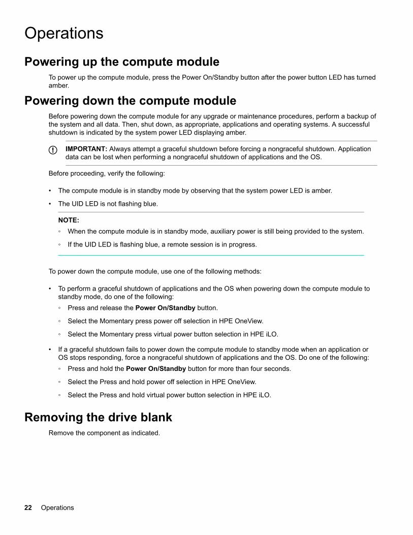
Removing the drive blankRemove the component as indicated.
22 Operations
CAUTION: To prevent improper cooling and thermal damage, do not operate the compute moduleunless all bays are populated with either a component or a blank.
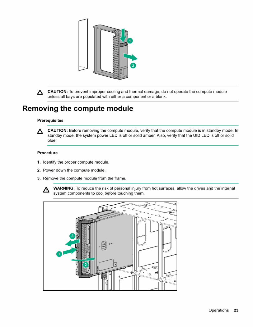
Removing the compute modulePrerequisites
CAUTION: Before removing the compute module, verify that the compute module is in standby mode. Instandby mode, the system power LED is off or solid amber. Also, verify that the UID LED is off or solidblue.
Procedure
1. Identify the proper compute module.
2. Power down the compute module.
3. Remove the compute module from the frame.
WARNING: To reduce the risk of personal injury from hot surfaces, allow the drives and the internalsystem components to cool before touching them.
Operations 23
4. Place the compute module on a flat, level work surface.
CAUTION: To prevent damage to electrical components, properly ground the compute modulebefore beginning any installation procedure. Improper grounding can cause ESD.
5. Install the compute module end cap.
To replace the component, reverse the removal procedure.
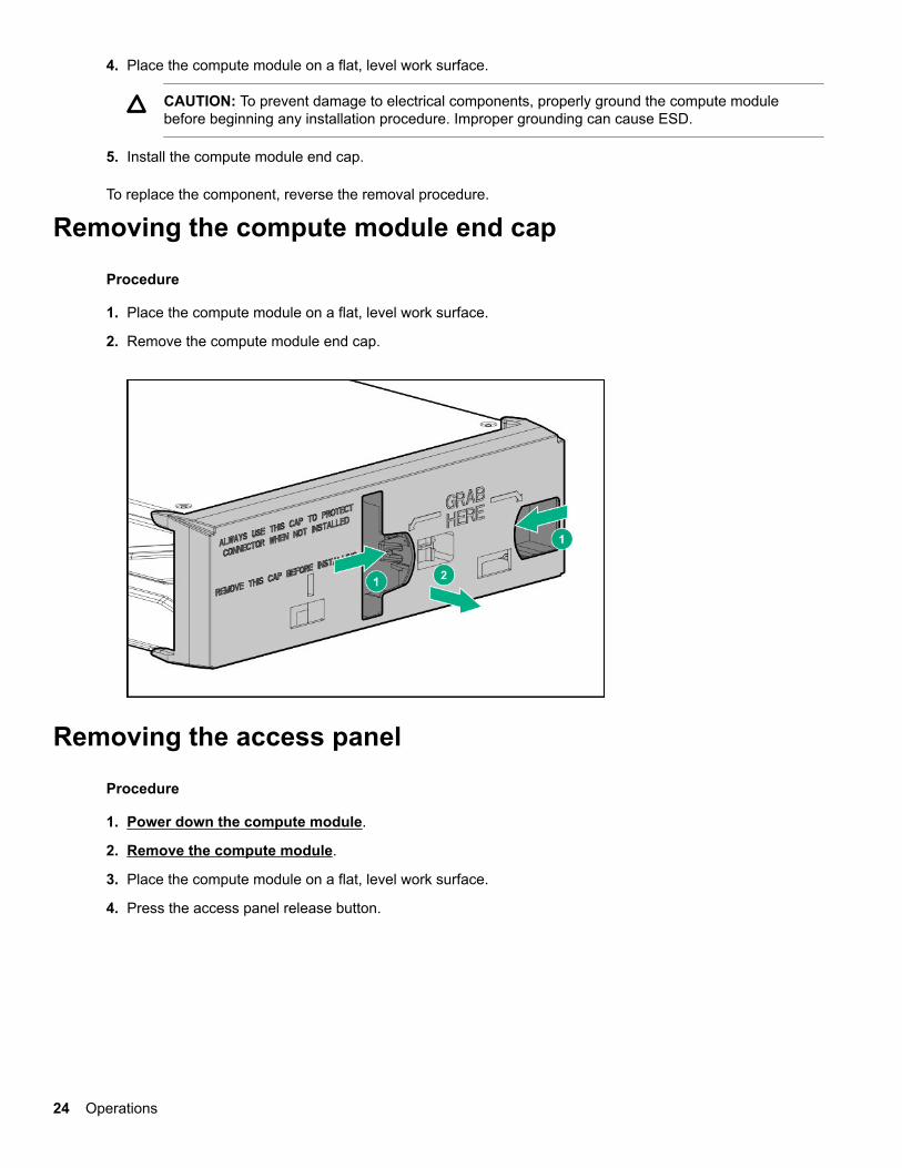
Removing the compute module end cap
Procedure
1. Place the compute module on a flat, level work surface.
2. Remove the compute module end cap.
Removing the access panel
Procedure
1. Power down the compute module.
2. Remove the compute module.
3. Place the compute module on a flat, level work surface.
4. Press the access panel release button.
24 Operations
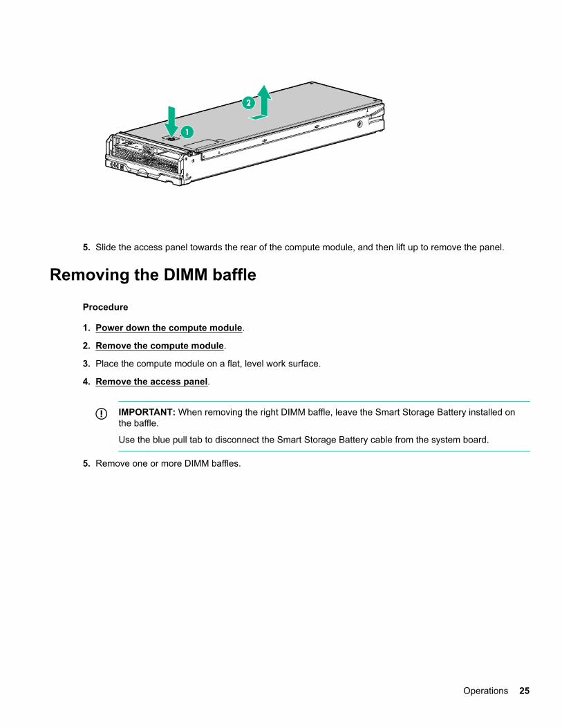
5. Slide the access panel towards the rear of the compute module, and then lift up to remove the panel.
Removing the DIMM baffle
Procedure
1. Power down the compute module.
2. Remove the compute module.
3. Place the compute module on a flat, level work surface.
4. Remove the access panel.
IMPORTANT: When removing the right DIMM baffle, leave the Smart Storage Battery installed onthe baffle.
Use the blue pull tab to disconnect the Smart Storage Battery cable from the system board.
5. Remove one or more DIMM baffles.
Operations 25

Removing the front panel/drive cage assembly
Procedure
1. Power down the compute module.
2. Remove the compute module.
3. Place the compute module on a flat, level work surface.
4. Remove the access panel.
5. Remove all drives.
6. Remove the front panel/drive cage assembly.
26 Operations
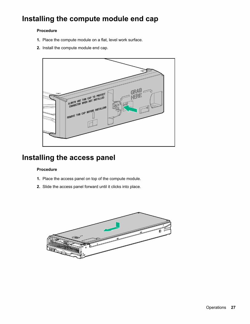
Installing the compute module end capProcedure
1. Place the compute module on a flat, level work surface.
2. Install the compute module end cap.
Installing the access panelProcedure
1. Place the access panel on top of the compute module.
2. Slide the access panel forward until it clicks into place.
Operations 27
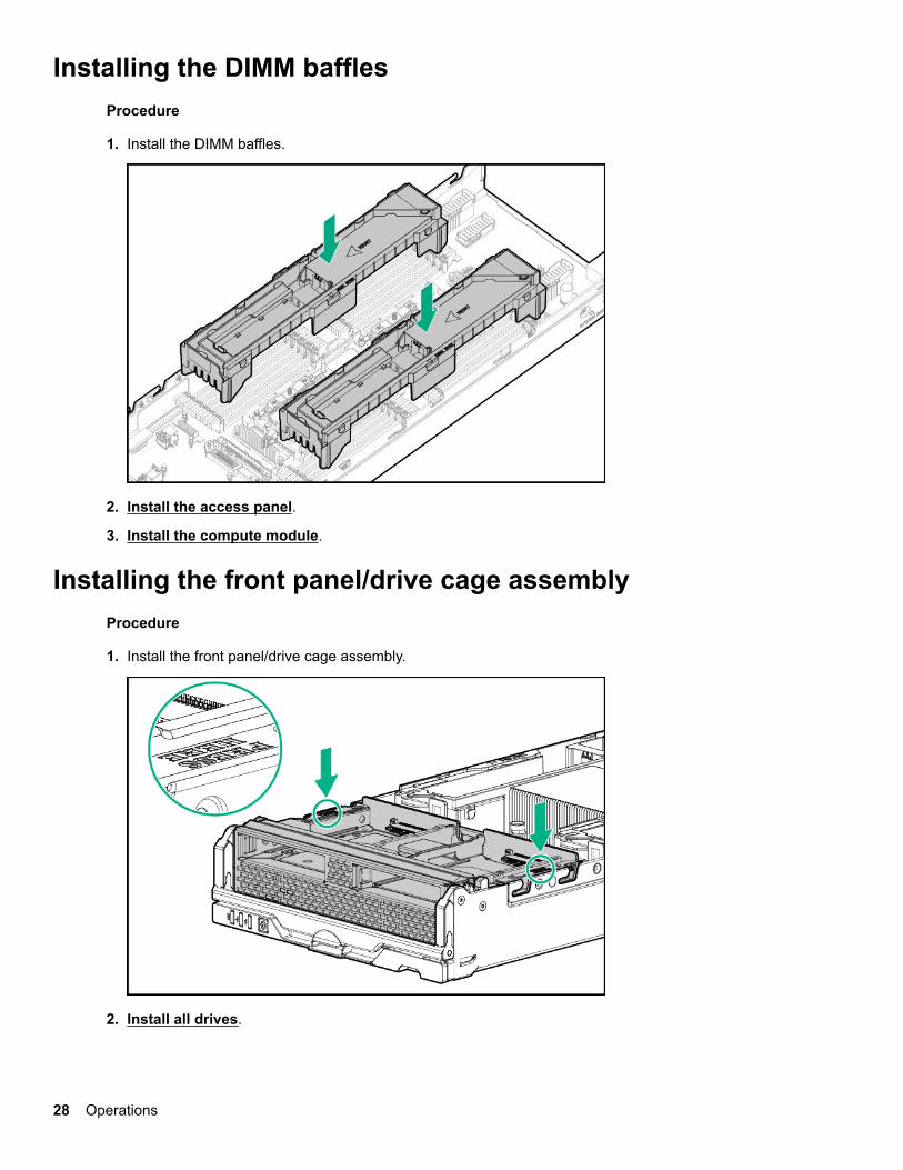
Installing the DIMM bafflesProcedure
1. Install the DIMM baffles.
2. Install the access panel.
3. Install the compute module.
Installing the front panel/drive cage assemblyProcedure
1. Install the front panel/drive cage assembly.
2. Install all drives.
28 Operations

3. Install the access panel.
4. Install the compute module.
Operations 29
SetupInstallation overview
Use this section and the following procedure to install the HPE Synergy 480 Gen10 Compute Module in aframe for the first time.
Procedure
1. Install supported options for the compute module.
2. Install the compute module.
3. Complete the compute module configuration.
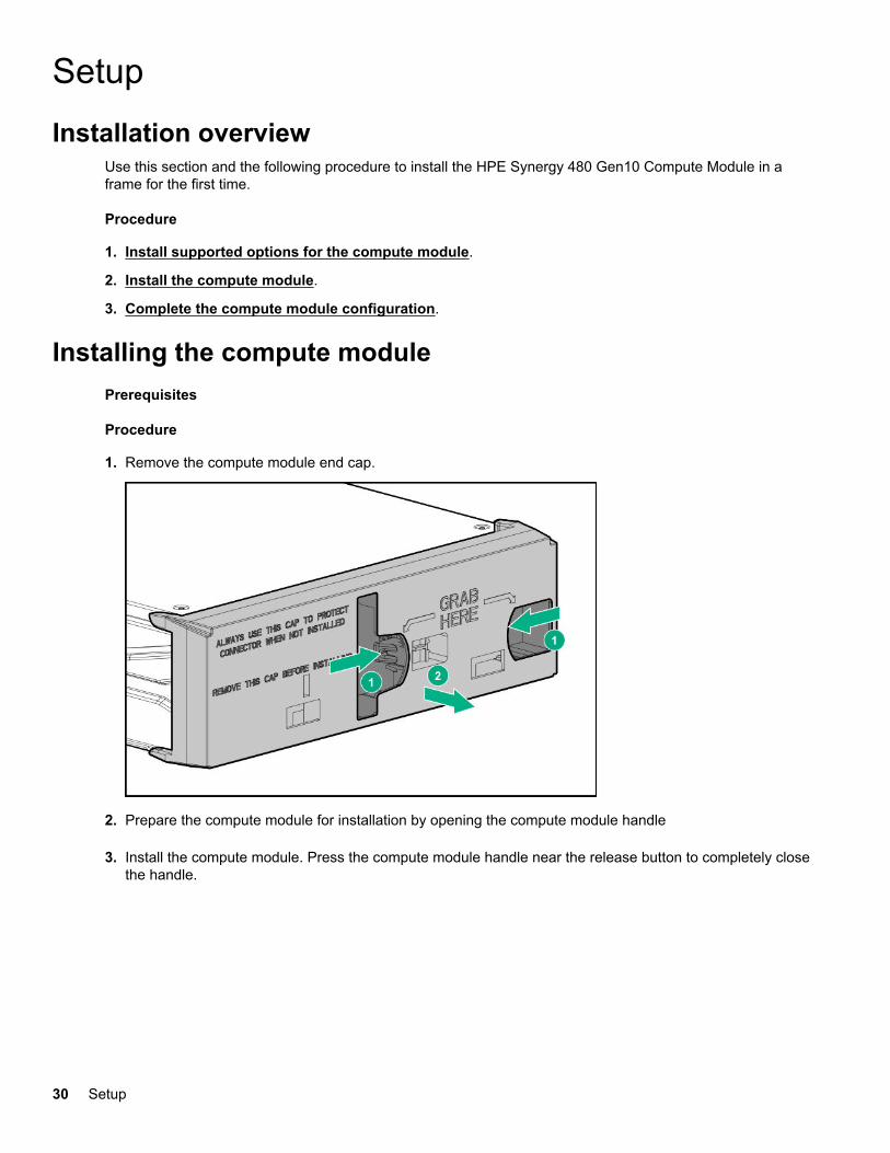
Installing the compute modulePrerequisites
Procedure
1. Remove the compute module end cap.
2. Prepare the compute module for installation by opening the compute module handle
3. Install the compute module. Press the compute module handle near the release button to completely closethe handle.
30 Setup
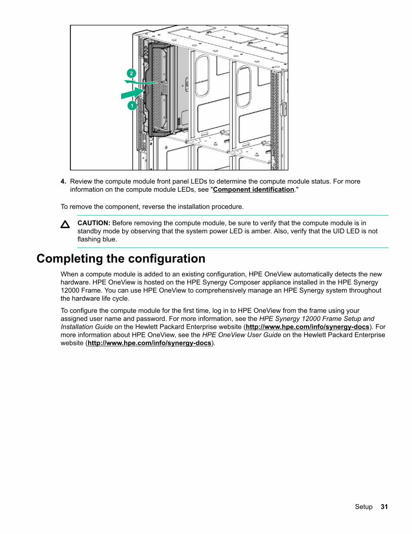
4. Review the compute module front panel LEDs to determine the compute module status. For moreinformation on the compute module LEDs, see "Component identification."
To remove the component, reverse the installation procedure.
CAUTION: Before removing the compute module, be sure to verify that the compute module is instandby mode by observing that the system power LED is amber. Also, verify that the UID LED is notflashing blue.
Completing the configurationWhen a compute module is added to an existing configuration, HPE OneView automatically detects the newhardware. HPE OneView is hosted on the HPE Synergy Composer appliance installed in the HPE Synergy12000 Frame. You can use HPE OneView to comprehensively manage an HPE Synergy system throughoutthe hardware life cycle.
To configure the compute module for the first time, log in to HPE OneView from the frame using yourassigned user name and password. For more information, see the HPE Synergy 12000 Frame Setup andInstallation Guide on the Hewlett Packard Enterprise website (http://www.hpe.com/info/synergy-docs). Formore information about HPE OneView, see the HPE OneView User Guide on the Hewlett Packard Enterprisewebsite (http://www.hpe.com/info/synergy-docs).
Setup 31
Hardware options installationThis chapter provides detailed instructions on how to install hardware options.
For more information on supported options, see the product QuickSpecs on the HPE Synergy 480 Gen10compute module website at:
http://www.hpe.com/info/synergy-docs
To view the warranty for your server and supported options, see Warranty information on page 73.
IntroductionIf more than one option is being installed, read the installation instructions for all the hardware options andidentify similar steps to streamline the installation process.
WARNING: To reduce the risk of personal injury from hot surfaces, allow the drives and the internalsystem components to cool before touching them.
CAUTION: To prevent damage to electrical components, properly ground the compute module beforebeginning any installation procedure. Improper grounding can cause electrostatic discharge.
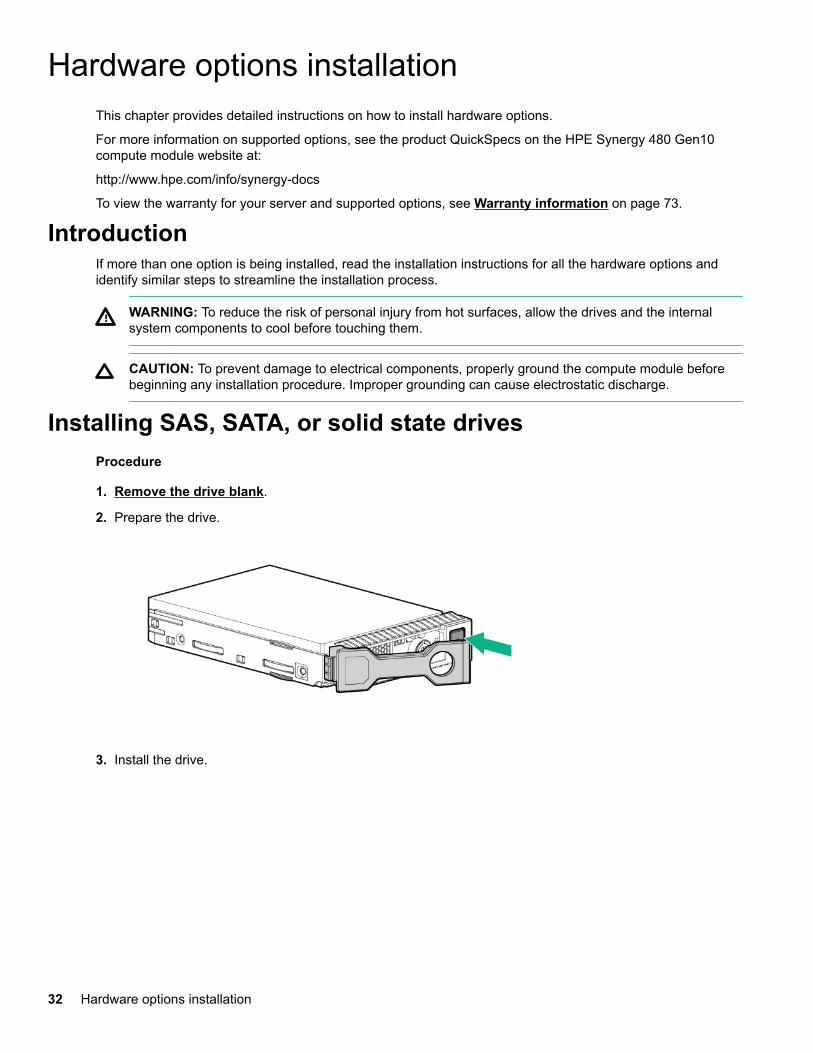
Installing SAS, SATA, or solid state drivesProcedure
1. Remove the drive blank.
2. Prepare the drive.
3. Install the drive.
32 Hardware options installation
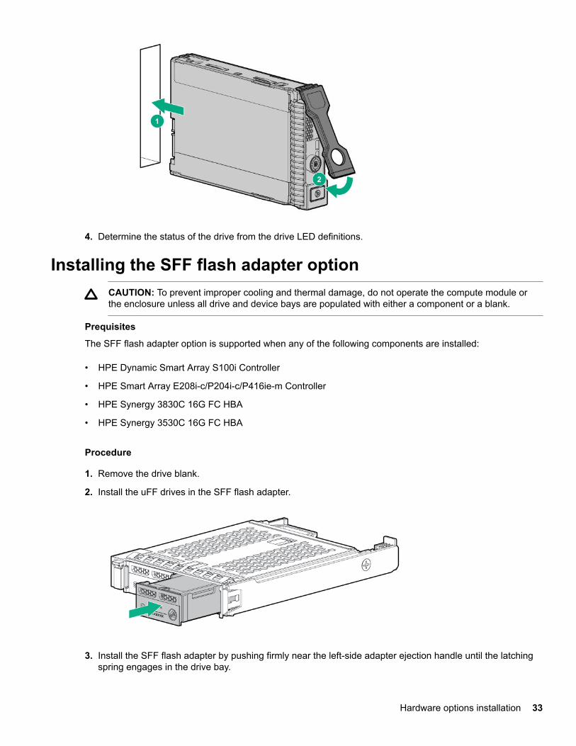
4. Determine the status of the drive from the drive LED definitions.
Installing the SFF flash adapter optionCAUTION: To prevent improper cooling and thermal damage, do not operate the compute module orthe enclosure unless all drive and device bays are populated with either a component or a blank.
Prequisites
The SFF flash adapter option is supported when any of the following components are installed:
• HPE Dynamic Smart Array S100i Controller
• HPE Smart Array E208i-c/P204i-c/P416ie-m Controller
• HPE Synergy 3830C 16G FC HBA
• HPE Synergy 3530C 16G FC HBA
Procedure
1. Remove the drive blank.
2. Install the uFF drives in the SFF flash adapter.
3. Install the SFF flash adapter by pushing firmly near the left-side adapter ejection handle until the latchingspring engages in the drive bay.
Hardware options installation 33
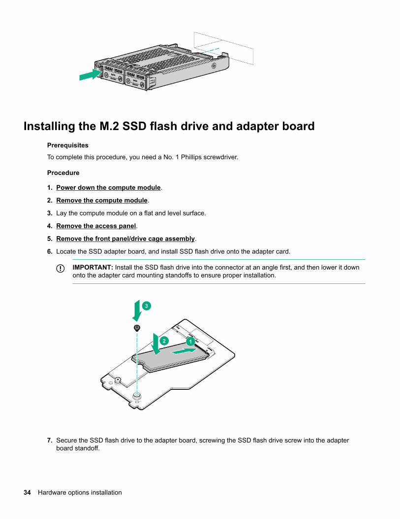
Installing the M.2 SSD flash drive and adapter boardPrerequisites
To complete this procedure, you need a No. 1 Phillips screwdriver.
Procedure
1. Power down the compute module.
2. Remove the compute module.
3. Lay the compute module on a flat and level surface.
4. Remove the access panel.
5. Remove the front panel/drive cage assembly.
6. Locate the SSD adapter board, and install SSD flash drive onto the adapter card.
IMPORTANT: Install the SSD flash drive into the connector at an angle first, and then lower it downonto the adapter card mounting standoffs to ensure proper installation.
7. Secure the SSD flash drive to the adapter board, screwing the SSD flash drive screw into the adapterboard standoff.
34 Hardware options installation
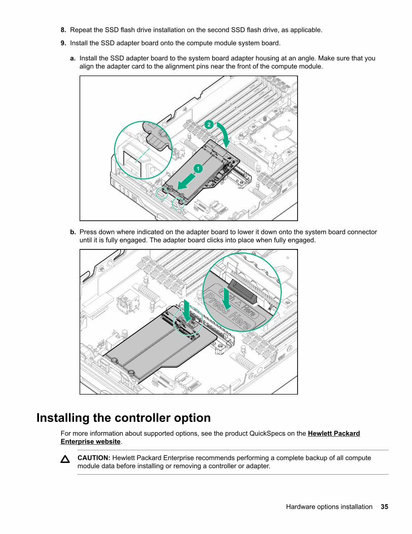
8. Repeat the SSD flash drive installation on the second SSD flash drive, as applicable.
9. Install the SSD adapter board onto the compute module system board.
a. Install the SSD adapter board to the system board adapter housing at an angle. Make sure that youalign the adapter card to the alignment pins near the front of the compute module.
b. Press down where indicated on the adapter board to lower it down onto the system board connectoruntil it is fully engaged. The adapter board clicks into place when fully engaged.
Installing the controller optionFor more information about supported options, see the product QuickSpecs on the Hewlett PackardEnterprise website.
CAUTION: Hewlett Packard Enterprise recommends performing a complete backup of all computemodule data before installing or removing a controller or adapter.
Hardware options installation 35
CAUTION: In systems that use external data storage, be sure that the compute module is the first unitto be powered down and the last to be powered back up. Taking this precaution ensures that the systemdoes not erroneously mark the drives as failed when the compute module is powered up.
Procedure
1. Power down the compute module.
2. Remove the compute module.
3. Remove the access panel.
4. Remove the front panel/drive cage assembly.
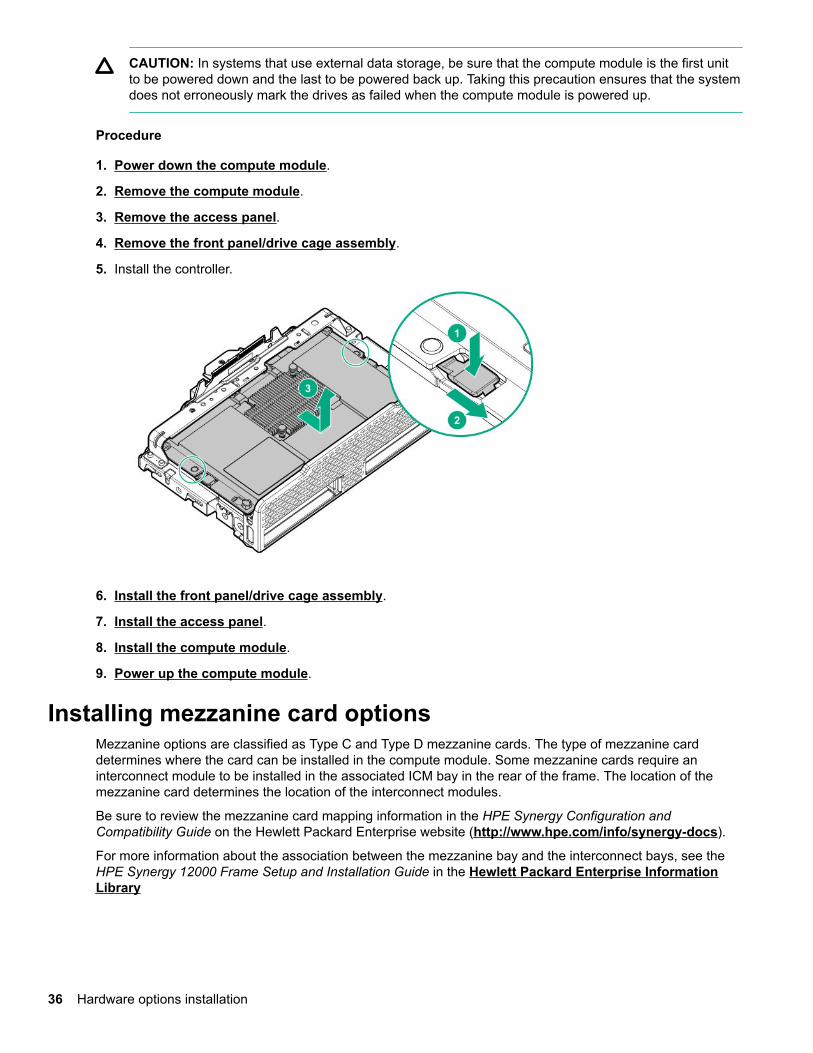
5. Install the controller.
6. Install the front panel/drive cage assembly.
7. Install the access panel.
8. Install the compute module.
9. Power up the compute module.
Installing mezzanine card optionsMezzanine options are classified as Type C and Type D mezzanine cards. The type of mezzanine carddetermines where the card can be installed in the compute module. Some mezzanine cards require aninterconnect module to be installed in the associated ICM bay in the rear of the frame. The location of themezzanine card determines the location of the interconnect modules.
Be sure to review the mezzanine card mapping information in the HPE Synergy Configuration andCompatibility Guide on the Hewlett Packard Enterprise website (http://www.hpe.com/info/synergy-docs).
For more information about the association between the mezzanine bay and the interconnect bays, see theHPE Synergy 12000 Frame Setup and Installation Guide in the Hewlett Packard Enterprise InformationLibrary
36 Hardware options installation
Procedure
1. Power down the compute module.
2. Remove the compute module.
3. Place the compute module on a flat, level work surface.
4. Remove the access panel.
5. Locate the appropriate mezzanine connector.
To locate the connector, see System board components.
6. If installed, remove the mezzanine connector cover.
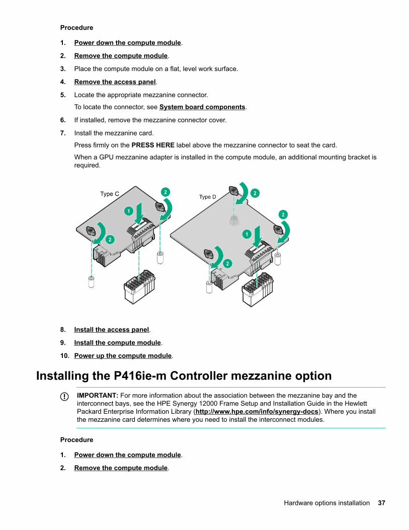
7. Install the mezzanine card.
Press firmly on the PRESS HERE label above the mezzanine connector to seat the card.
When a GPU mezzanine adapter is installed in the compute module, an additional mounting bracket isrequired.
8. Install the access panel.
9. Install the compute module.
10. Power up the compute module.
Installing the P416ie-m Controller mezzanine optionIMPORTANT: For more information about the association between the mezzanine bay and theinterconnect bays, see the HPE Synergy 12000 Frame Setup and Installation Guide in the HewlettPackard Enterprise Information Library (http://www.hpe.com/info/synergy-docs). Where you installthe mezzanine card determines where you need to install the interconnect modules.
Procedure
1. Power down the compute module.
2. Remove the compute module.
Hardware options installation 37
3. Place the compute module on a flat, level work surface.
4. Remove the access panel.
5. Locate the appropriate mezzanine connector. To locate the connector, see "System boardcomponents."
6. Remove the front panel/drive cage assembly.
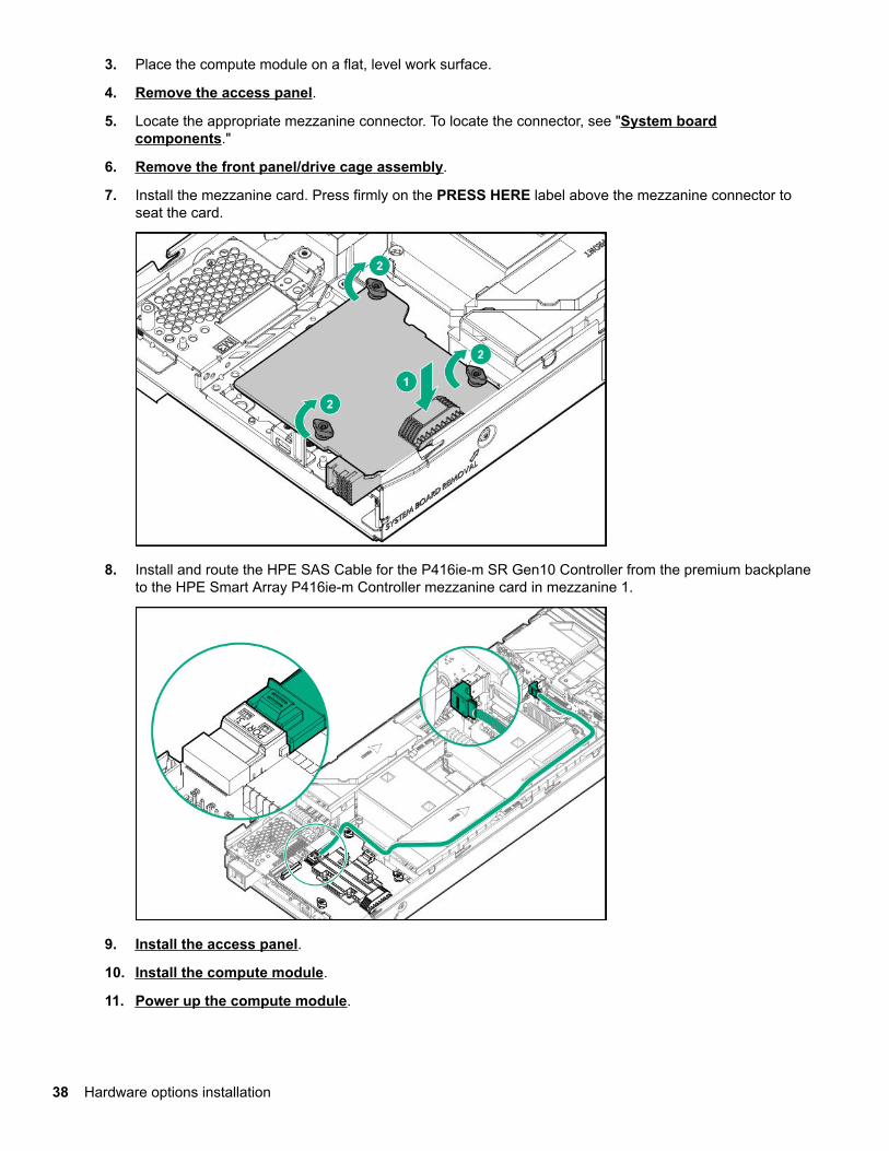
7. Install the mezzanine card. Press firmly on the PRESS HERE label above the mezzanine connector toseat the card.
8. Install and route the HPE SAS Cable for the P416ie-m SR Gen10 Controller from the premium backplaneto the HPE Smart Array P416ie-m Controller mezzanine card in mezzanine 1.
9. Install the access panel.
10. Install the compute module.
11. Power up the compute module.
38 Hardware options installation
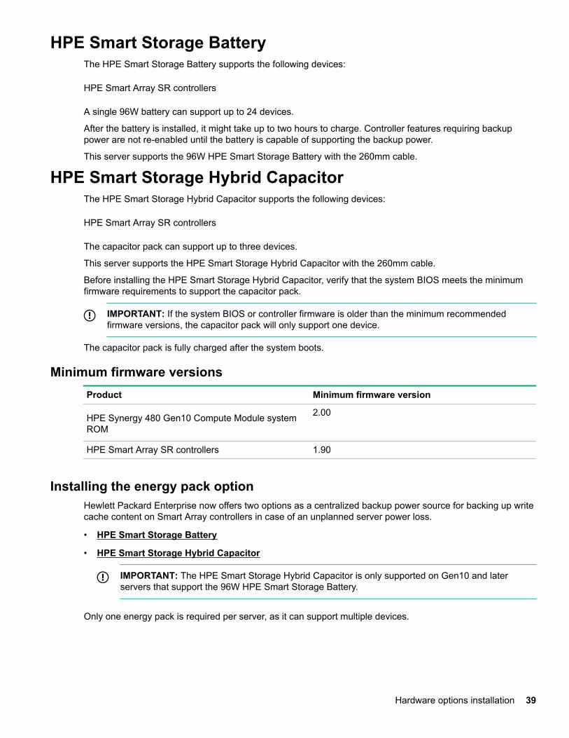
HPE Smart Storage BatteryThe HPE Smart Storage Battery supports the following devices:
HPE Smart Array SR controllers
A single 96W battery can support up to 24 devices.
After the battery is installed, it might take up to two hours to charge. Controller features requiring backuppower are not re-enabled until the battery is capable of supporting the backup power.
This server supports the 96W HPE Smart Storage Battery with the 260mm cable.
HPE Smart Storage Hybrid CapacitorThe HPE Smart Storage Hybrid Capacitor supports the following devices:
HPE Smart Array SR controllers
The capacitor pack can support up to three devices.
This server supports the HPE Smart Storage Hybrid Capacitor with the 260mm cable.
Before installing the HPE Smart Storage Hybrid Capacitor, verify that the system BIOS meets the minimumfirmware requirements to support the capacitor pack.
IMPORTANT: If the system BIOS or controller firmware is older than the minimum recommendedfirmware versions, the capacitor pack will only support one device.
The capacitor pack is fully charged after the system boots.
Minimum firmware versionsProduct Minimum firmware version
HPE Synergy 480 Gen10 Compute Module systemROM
2.00
HPE Smart Array SR controllers 1.90
Installing the energy pack optionHewlett Packard Enterprise now offers two options as a centralized backup power source for backing up writecache content on Smart Array controllers in case of an unplanned server power loss.
• HPE Smart Storage Battery
• HPE Smart Storage Hybrid Capacitor
IMPORTANT: The HPE Smart Storage Hybrid Capacitor is only supported on Gen10 and laterservers that support the 96W HPE Smart Storage Battery.
Only one energy pack is required per server, as it can support multiple devices.
Hardware options installation 39
Procedure
1. Power down the compute module.
2. Remove the compute module.
3. Place the compute module on a flat, level work surface.
4. Remove the access panel.
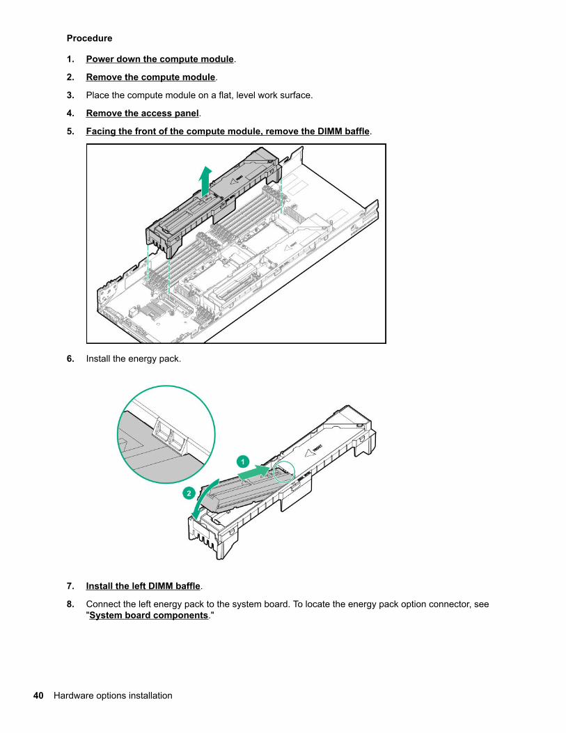
5. Facing the front of the compute module, remove the DIMM baffle.
6. Install the energy pack.
7. Install the left DIMM baffle.
8. Connect the left energy pack to the system board. To locate the energy pack option connector, see"System board components."
40 Hardware options installation
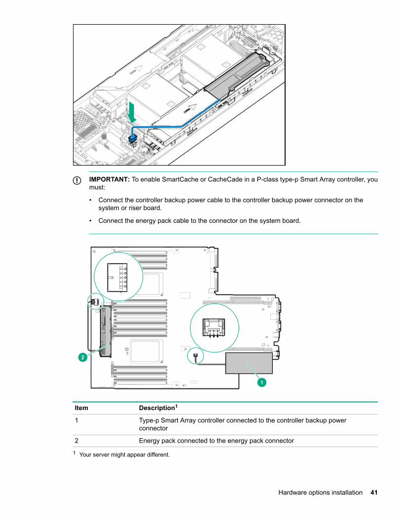
IMPORTANT: To enable SmartCache or CacheCade in a P-class type-p Smart Array controller, youmust:
• Connect the controller backup power cable to the controller backup power connector on thesystem or riser board.
• Connect the energy pack cable to the connector on the system board.
Item Description1
1 Type-p Smart Array controller connected to the controller backup powerconnector
2 Energy pack connected to the energy pack connector
1 Your server might appear different.
Hardware options installation 41
9. Install the access panel.
10. Install the compute module.
11. Power up the compute module.
Memory optionsIMPORTANT: This compute module does not support mixing LRDIMMs and RDIMMs. Attempting to mixany combination of these DIMMs can cause the server to halt during BIOS initialization. All memoryinstalled in the compute module must be of the same type.
DIMM and NVDIMM population informationFor specific DIMM and NVDIMM population information, see the DIMM population guidelines on the HewlettPackard Enterprise website (http://www.hpe.com/docs/memory-population-rules).
DIMM-processor compatibilityThe installed processor determines the type of DIMM that is supported in the compute module:
• First-generation Intel Xeon Scalable processors support DDR4-2666 DIMMs.
• Second-generation Intel Xeon Scalable processors support DDR4-2933 DIMMs.
Mixing DIMM types is not supported. Install only the supported DDR4-2666 or DDR4-2933 DIMMs in thecompute module.
HPE SmartMemory speed informationFor more information about memory speed information, see the Hewlett Packard Enterprise website (https://www.hpe.com/docs/memory-speed-table).
Installing a DIMMThe server supports up to 24 DIMMs.
Prerequisites
Before installing this option, be sure you have the following:
The components included with the hardware option kit
For more information on specific options, see the compute module QuickSpecs on the Hewlett PackardEnterprise website.
Procedure
1. Power down the compute module.
2. Remove the compute module.
3. Place the compute module on a flat, level work surface.
4. Remove the access panel.
5. Open the DIMM slot latches.
6. Install the DIMM.
42 Hardware options installation
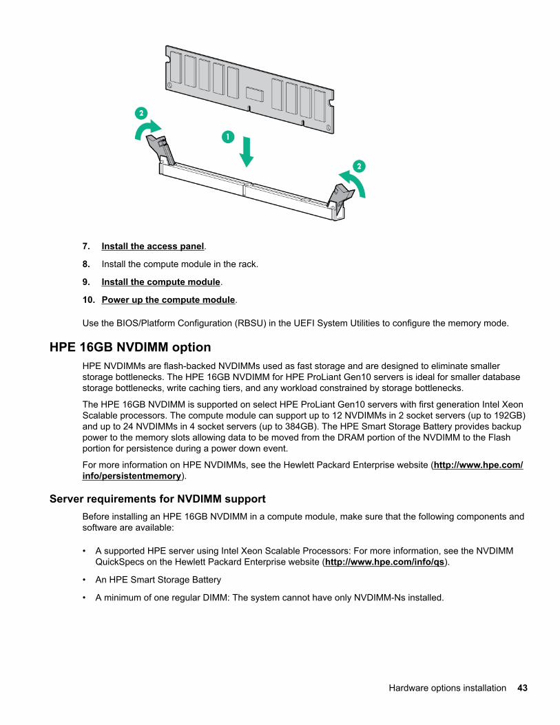
7. Install the access panel.
8. Install the compute module in the rack.
9. Install the compute module.
10. Power up the compute module.
Use the BIOS/Platform Configuration (RBSU) in the UEFI System Utilities to configure the memory mode.
HPE 16GB NVDIMM optionHPE NVDIMMs are flash-backed NVDIMMs used as fast storage and are designed to eliminate smallerstorage bottlenecks. The HPE 16GB NVDIMM for HPE ProLiant Gen10 servers is ideal for smaller databasestorage bottlenecks, write caching tiers, and any workload constrained by storage bottlenecks.
The HPE 16GB NVDIMM is supported on select HPE ProLiant Gen10 servers with first generation Intel XeonScalable processors. The compute module can support up to 12 NVDIMMs in 2 socket servers (up to 192GB)and up to 24 NVDIMMs in 4 socket servers (up to 384GB). The HPE Smart Storage Battery provides backuppower to the memory slots allowing data to be moved from the DRAM portion of the NVDIMM to the Flashportion for persistence during a power down event.
For more information on HPE NVDIMMs, see the Hewlett Packard Enterprise website (http://www.hpe.com/info/persistentmemory).
Server requirements for NVDIMM supportBefore installing an HPE 16GB NVDIMM in a compute module, make sure that the following components andsoftware are available:
• A supported HPE server using Intel Xeon Scalable Processors: For more information, see the NVDIMMQuickSpecs on the Hewlett Packard Enterprise website (http://www.hpe.com/info/qs).
• An HPE Smart Storage Battery
• A minimum of one regular DIMM: The system cannot have only NVDIMM-Ns installed.
Hardware options installation 43
• A supported operating system with persistent memory/NVDIMM drivers. For the latest softwareinformation, see the Hewlett Packard Enterprise website (http://persistentmemory.hpe.com).
• For minimum firmware versions, see the HPE 16GB NVDIMM User Guide on the Hewlett PackardEnterprise website (http://www.hpe.com/info/nvdimm-docs).
To determine NVDIMM support for your compute module, see the compute module QuickSpecs on theHewlett Packard Enterprise website (http://www.hpe.com/info/qs).
Installing an NVDIMM
CAUTION: To avoid damage to the hard drives, memory, and other system components, the air baffle,drive blanks, and access panel must be installed when the server is powered up.
CAUTION: To avoid damage to the hard drives, memory, and other system components, be sure toinstall the correct DIMM baffles for your server model.
CAUTION: DIMMs are keyed for proper alignment. Align notches in the DIMM with the correspondingnotches in the DIMM slot before inserting the DIMM. Do not force the DIMM into the slot. When installedproperly, not all DIMMs will face in the same direction.
CAUTION: Electrostatic discharge can damage electronic components. Be sure you are properlygrounded before beginning this procedure.
CAUTION: Failure to properly handle DIMMs can damage the DIMM components and the system boardconnector. For more information, see the DIMM handling guidelines in the troubleshooting guide for yourproduct on the Hewlett Packard Enterprise website:
• HPE ProLiant Gen10 (http://www.hpe.com/info/gen10-troubleshooting)
• HPE Synergy (http://www.hpe.com/info/synergy-troubleshooting)
CAUTION: Unlike traditional storage devices, NVDIMMs are fully integrated in with the ProLiantcompute module. Data loss can occur when system components, such as the processor or HPE SmartStorage Battery, fails. HPE Smart Storage battery is a critical component required to perform the backupfunctionality of NVDIMMs. It is important to act when HPE Smart Storage Battery related failures occur.Always follow best practices for ensuring data protection.
Prerequisites
Before installing an NVDIMM, be sure the compute module meets the Server requirements for NVDIMMsupport on page 43.
Procedure
1. Power down the compute module.
2. Remove the compute module.
3. Place the compute module on a flat, level work surface.
4. Remove the access panel.
5. Locate any NVDIMMs already installed in the compute module.
44 Hardware options installation
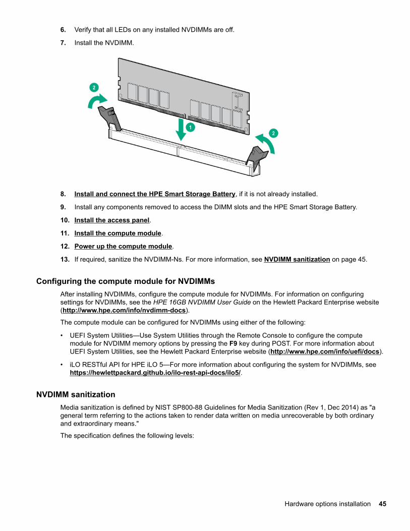
6. Verify that all LEDs on any installed NVDIMMs are off.
7. Install the NVDIMM.
8. Install and connect the HPE Smart Storage Battery, if it is not already installed.
9. Install any components removed to access the DIMM slots and the HPE Smart Storage Battery.
10. Install the access panel.
11. Install the compute module.
12. Power up the compute module.
13. If required, sanitize the NVDIMM-Ns. For more information, see NVDIMM sanitization on page 45.
Configuring the compute module for NVDIMMsAfter installing NVDIMMs, configure the compute module for NVDIMMs. For information on configuringsettings for NVDIMMs, see the HPE 16GB NVDIMM User Guide on the Hewlett Packard Enterprise website(http://www.hpe.com/info/nvdimm-docs).
The compute module can be configured for NVDIMMs using either of the following:
• UEFI System Utilities—Use System Utilities through the Remote Console to configure the computemodule for NVDIMM memory options by pressing the F9 key during POST. For more information aboutUEFI System Utilities, see the Hewlett Packard Enterprise website (http://www.hpe.com/info/uefi/docs).
• iLO RESTful API for HPE iLO 5—For more information about configuring the system for NVDIMMs, see https://hewlettpackard.github.io/ilo-rest-api-docs/ilo5/.
NVDIMM sanitizationMedia sanitization is defined by NIST SP800-88 Guidelines for Media Sanitization (Rev 1, Dec 2014) as "ageneral term referring to the actions taken to render data written on media unrecoverable by both ordinaryand extraordinary means."
The specification defines the following levels:
Hardware options installation 45
• Clear: Overwrite user-addressable storage space using standard write commands; might not sanitize datain areas not currently user-addressable (such as bad blocks and overprovisioned areas)
• Purge: Overwrite or erase all storage space that might have been used to store data using dedicateddevice sanitize commands, such that data retrieval is "infeasible using state-of-the-art laboratorytechniques"
• Destroy: Ensure that data retrieval is "infeasible using state-of-the-art laboratory techniques" and renderthe media unable to store data (such as disintegrate, pulverize, melt, incinerate, or shred)
The NVDIMM-N Sanitize options are intended to meet the Purge level.
For more information on sanitization for NVDIMMs, see the following sections in the HPE 16GB NVDIMMUser Guide on the Hewlett Packard Enterprise website (http://www.hpe.com/info/nvdimm-docs):
• NVDIMM sanitization policies
• NVDIMM sanitization guidelines
• Setting the NVDIMM-N Sanitize/Erase on the Next Reboot Policy
NIST SP800-88 Guidelines for Media Sanitization (Rev 1, Dec 2014) is available for download from the NISTwebsite (http://nvlpubs.nist.gov/nistpubs/SpecialPublications/NIST.SP.800-88r1.pdf).
NVDIMM relocation guidelines
Requirements for relocating NVDIMMs or a set of NVDIMMs when the data must be preserved
• The destination compute module hardware must match the original compute module hardwareconfiguration.
• All System Utilities settings in the destination compute module must match the original System Utilitiessettings in the original compute module.
• If NVDIMM-Ns are used with NVDIMM Interleaving ON mode in the original compute module, do thefollowing:◦ Install the NVDIMMs in the same DIMM slots in the destination compute module.
◦ Install the entire NVDIMM set (all the NVDIMM-Ns on the processor) on the destination computemodule.
This guideline would apply when replacing a system board due to system failure.
If any of the requirements cannot be met during NVDIMM relocation, do the following:◦ Manually back up the NVDIMM-N data before relocating NVDIMM-Ns to another compute module.
◦ Relocate the NVDIMM-Ns to another compute module.
◦ Sanitize all NVDIMM-Ns on the new compute module before using them.
Requirements for relocating NVDIMMs or a set of NVDIMMs when the data does not have to bepreserved
If data on the NVDIMM-N or set of NVDIMM-Ns does not have to be preserved, then
46 Hardware options installation
• Move the NVDIMM-Ns to the new location and sanitize all NVDIMM-Ns after installing them to the newlocation. For more information, see NVDIMM sanitization on page 45.
• Observe all DIMM and NVDIMM population guidelines. For more information, see DIMM and NVDIMMpopulation information on page 42.
• Observe the process for removing an NVDIMM.
• Observe the process for installing an NVDIMM.
• Review and configure the system settings for NVDIMMs. For more information, see Configuring thecompute module for NVDIMMs on page 45.
HPE Persistent Memory optionHPE Persistent Memory, which offers the flexibility to deploy as dense memory or fast storage and featuresIntel Optane DC Persistent Memory, enables per-socket memory capacity of up to 3.0 TB. HPE PersistentMemory, together with traditional volatile DRAM DIMMs, provide fast, high-capacity, cost-effective memoryand storage to transform big data workloads and analytics by enabling data to be stored, moved, andprocessed quickly.
HPE Persistent Memory modules use the standard DIMM form factor and are installed alongside DIMMs in acompute module memory slot. HPE Persistent Memory modules are designed for use only with second-generation Intel Xeon Scalable processors, and are available in the following capacities:
• 128 GB
• 256 GB
• 512 GB
HPE Persistent Memory module-processor compatibilityHPE Persistent Memory modules are supported only in compute modules with second-generation Intel XeonScalable processors installed.
HPE Persistent Memory population informationFor specific population and configuration information, see the memory population guidelines on the HewlettPackard Enterprise website (http://www.hpe.com/docs/memory-population-rules).
System requirements for HPE Persistent Memory module support
IMPORTANT: Hewlett Packard Enterprise recommends that you implement best practicesconfigurations for high availability (HA) such as clustered configurations.
Before installing HPE Persistent Memory modules, make sure that the following components and software areavailable:
• A supported HPE ProLiant Gen10 server or Synergy compute module using second-generation Intel XeonScalable processors. For more information, see the product QuickSpecs on the Hewlett PackardEnterprise website (http://www.hpe.com/support/persistentmemoryQS).
• HPE DDR4 Standard Memory RDIMMs or LRDIMMs (the number will vary based on your chosenconfiguration).
• Supported firmware and drives:
Hardware options installation 47
◦ System ROM version 2.10 or later
◦ Server Platform Services (SPS) Firmware version 04.01.02.296
◦ HPE iLO 5 Firmware version 1.43
◦ HPE Innovation Engine Firmware version 2.1.x or later
Download the required firmware and drivers from the Hewlett Packard Enterprise website (http://www.hpe.com/info/persistentmemory).
• A supported operating system:◦ Windows Server 2012 R2 with persistent memory drivers from Hewlett Packard Enterprise
◦ Windows Server 2016 with persistent memory drivers from Hewlett Packard Enterprise
◦ Windows Server 2019
◦ Red Hat Enterprise Linux 7.6
◦ SUSE Linux Enterprise Server 15 SP1
◦ VMware vSphere 6.7 U1
• Hardware and licensing requirements for optional encryption of the HPE Persistent Memory modules:◦ HPE TPM 2.0 (local key encryption)
◦ HPE iLO Advanced Pack license (remote key encryption)
◦ Key management server (remote key encryption)
For more information, see the HPE Persistent Memory User Guide on the Hewlett Packard Enterprise website(http://www.hpe.com/info/persistentmemory-docs).
Installing HPE Persistent Memory modules
IMPORTANT: Hewlett Packard Enterprise recommends that you implement best practicesconfigurations for high availability (HA) such as clustered configurations.
Prerequisites
Before you perform this procedure, make sure that you have the following items available:
• The components included with the hardware option kit
• A T-10 Torx screwdriver might be needed to unlock the access panel.
Procedure
1. Observe the following alerts:
CAUTION: DIMMs are keyed for proper alignment. Align notches in the DIMM with thecorresponding notches in the DIMM slot before inserting the DIMM. Do not force the DIMM into theslot. When installed properly, not all DIMMs will face in the same direction.
CAUTION: Electrostatic discharge can damage electronic components. Be sure you are properlygrounded before beginning this procedure.
48 Hardware options installation
CAUTION: Failure to properly handle DIMMs can damage the DIMM components and the systemboard connector. For more information, see the DIMM handling guidelines in the troubleshootingguide for your product on the Hewlett Packard Enterprise website:
• HPE ProLiant Gen10 (http://www.hpe.com/info/gen10-troubleshooting)
• HPE Synergy (http://www.hpe.com/info/synergy-troubleshooting)
2. Power down the compute module.
a. Shut down the OS as directed by the OS documentation.
b. To place the compute module in standby mode, press the Power On/Standby button. When thecompute module enters standby power mode, the system power LED changes to amber.
c. Disconnect the power cords (rack and tower servers).
3. Remove the compute module from the frame
4. Place the compute module on a flat, level work surface.
5. Remove the access panel.
6. Remove all components necessary to access the DIMM slots.
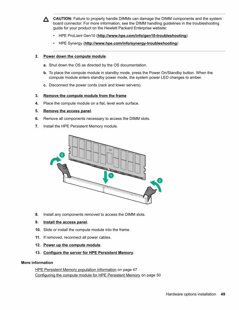
7. Install the HPE Persistent Memory module.
8. Install any components removed to access the DIMM slots.
9. Install the access panel.
10. Slide or install the compute module into the frame.
11. If removed, reconnect all power cables.
12. Power up the compute module.
13. Configure the server for HPE Persistent Memory.
More information
HPE Persistent Memory population information on page 47Configuring the compute module for HPE Persistent Memory on page 50
Hardware options installation 49
Configuring the compute module for HPE Persistent MemoryAfter installing HPE Persistent Memory modules, configure the compute module for HPE Persistent Memory.
IMPORTANT: Always follow recommendations from your software application provider for high-availability best practices to ensure maximum uptime and data protection.
A number of configuration tools are available, including:
• UEFI System Utilities—Access System Utilities through the Remote Console to configure the computemodule by pressing the F9 key during POST.
• iLO RESTful API—Use the iLO RESTful API through tools such as the RESTful Interface Tool (ilorest) orother third-party tools.
• HPE Persistent Memory Management Utility—The HPE Persistent Memory Management Utility is adesktop application used to configure the compute module for HPE Persistent Memory, as well asevaluate and monitor the compute module memory configuration layout.
For more information, see the HPE Persistent Memory User Guide on the Hewlett Packard Enterprise website(http://www.hpe.com/info/persistentmemory-docs).
HPE Persistent Memory module relocation guidelinesObserve the relocation guidelines when doing the following:
• When relocating HPE Persistent Memory modules to another DIMM slot on the compute module.
• When relocating HPE Persistent Memory modules to another compute module.
• When reinstalling HPE Persistent Memory modules after replacing the compute module system board.
IMPORTANT: When data must be preserved, Hewlett Packard Enterprise strongly recommends thatyou perform a manual backup of all user data on the HPE Persistent Memory modules beforeperforming relocation procedures.
Requirements for relocating HPE Persistent Memory modules or a set of HPE Persistent Memorymodules when the data must be preserved
• The destination compute module hardware must match the original compute module hardwareconfiguration.
• All System Utilities settings in the destination compute module must match the original System Utilitiessettings in the original compute module.
• If HPE Persistent Memory modules are used with Persistent Memory Interleaving set to Enabled in theoriginal compute module, do the following:◦ Install the HPE Persistent Memory modules in the same DIMM slots in the destination compute
module.
◦ Install the entire interleaved set (all the DIMMs and HPE Persistent Memory modules on the processor)on the destination compute module.
If any of the requirements cannot be met during relocation, do the following:
50 Hardware options installation
◦ Manually back up the persistent memory data before relocating HPE Persistent Memory modules toanother compute module.
◦ Relocate the HPE Persistent Memory modules to another compute module.
◦ Sanitize all HPE Persistent Memory modules on the new compute module before using them.
Requirements for relocating encrypted HPE Persistent Memory modules or a set of HPE PersistentMemory modules when the data must be preserved
• If HPE Persistent Memory modules are encrypted with local key management, either manually retrieve theHPE Persistent Memory module passwords from the compute module (user-generated passwords only) orexport a password file to a USB key.
Hewlett Packard Enterprise recommends exporting the password file to a USB key.
• Follow the requirements for relocating HPE Persistent Memory modules or a set of HPE PersistentMemory modules when the data must be preserved.
• Do one of the following:
◦ If HPE Persistent Memory modules are encrypted with local key management, either manually enterthe HPE Persistent Memory module passwords in the System Utilities or import the password file fromthe USB key.
◦ If HPE Persistent Memory modules are encrypted with remote key management, enroll the HPE iLO inthe key management server to provide access to the data on the HPE Persistent Memory modules.
For more information, see the HPE Persistent Memory User Guide on the Hewlett Packard Enterprisewebsite (http://www.hpe.com/info/persistentmemory-docs).
Requirements for relocating HPE Persistent Memory modules or a set of HPE Persistent Memorymodules when the data does not have to be preserved
• Move the HPE Persistent Memory modules to the new location and sanitize all HPE Persistent Memorymodules after installing them to the new location.
• Observe the DIMM and HPE Persistent Memory module population guidelines.
• Observe the process for removing an HPE Persistent Memory module.
• Observe the process for installing an HPE Persistent Memory module.
• Review and configure the system settings for HPE Persistent Memory.
For more information, see the HPE Persistent Memory User Guide on the Hewlett Packard Enterprise website(http://www.hpe.com/info/persistentmemory-docs).
Migrating an HPE Persistent Memory module
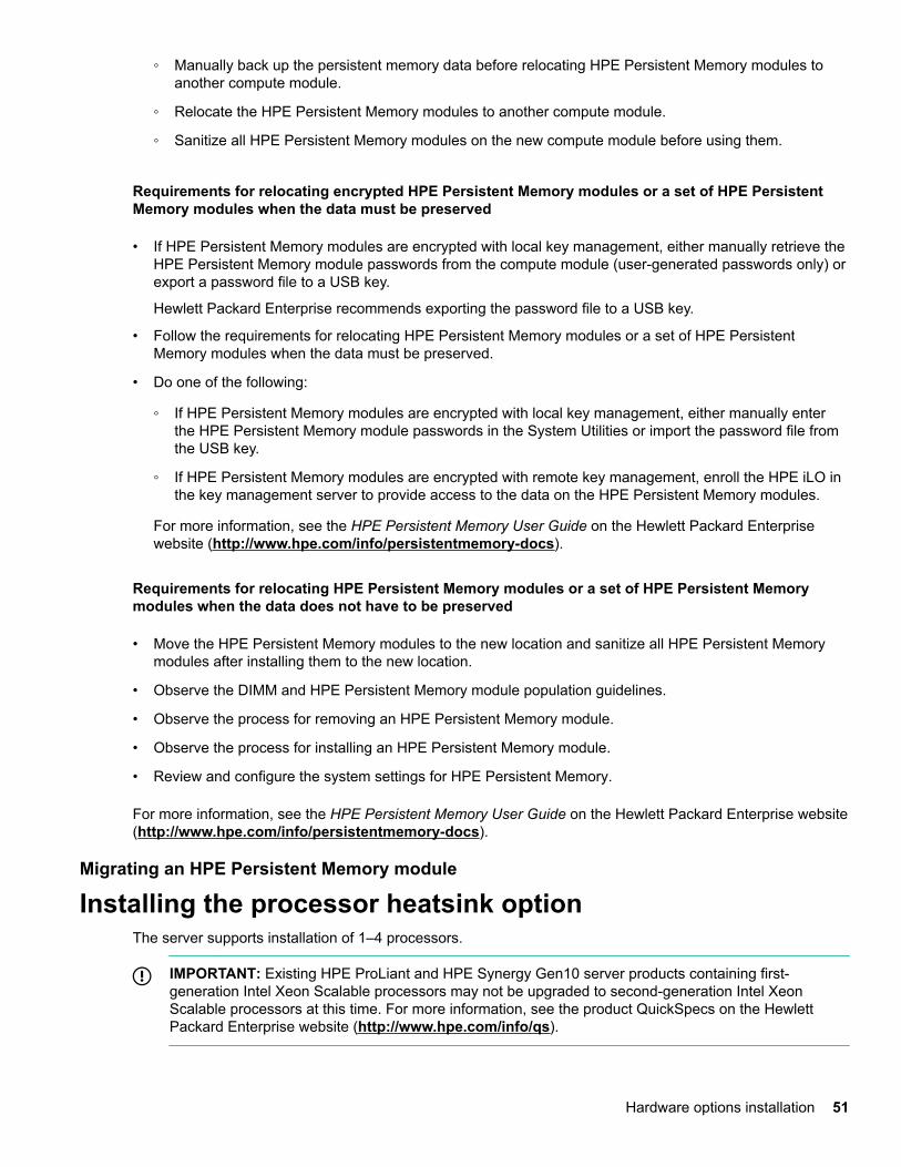
Installing the processor heatsink optionThe server supports installation of 1–4 processors.
IMPORTANT: Existing HPE ProLiant and HPE Synergy Gen10 server products containing first-generation Intel Xeon Scalable processors may not be upgraded to second-generation Intel XeonScalable processors at this time. For more information, see the product QuickSpecs on the HewlettPackard Enterprise website (http://www.hpe.com/info/qs).
Hardware options installation 51
Prerequisites
To complete this procedure, you need a T-30 Torx screwdriver.
Procedure
1. Observe the following cautions and warnings:
WARNING: To reduce the risk of personal injury from hot surfaces, allow the drives and the internalsystem components to cool before touching them.
CAUTION: To prevent possible compute module malfunction and damage to the equipment,multiprocessor configurations must contain processors with the same part number.
CAUTION: The heatsink thermal interface media is not reusable and must be replaced if theheatsink is removed from the processor after it has been installed.
CAUTION: To prevent possible compute module overheating, always populate processor socket 2with a processor and a heatsink or a processor socket cover and a heatsink blank.
CAUTION: To prevent damage to electrical components, properly ground the compute modulebefore beginning any installation procedure. Improper grounding can cause ESD.
IMPORTANT: Processor socket 1 must be populated at all times or the compute module does notfunction.
2. Update the system ROM.
Locate and download the latest ROM version from the Hewlett Packard Enterprise website (http://www.hpe.com/support). Follow the instructions on the website to update the system ROM.
3. Power down the compute module.
4. Remove the compute module.
5. Remove the access panel.
6. Remove all DIMM baffles.
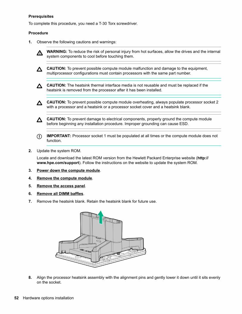
7. Remove the heatsink blank. Retain the heatsink blank for future use.
8. Align the processor heatsink assembly with the alignment pins and gently lower it down until it sits evenlyon the socket.
52 Hardware options installation
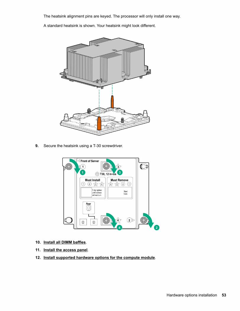
The heatsink alignment pins are keyed. The processor will only install one way.
A standard heatsink is shown. Your heatsink might look different.
9. Secure the heatsink using a T-30 screwdriver.
10. Install all DIMM baffles.
11. Install the access panel.
12. Install supported hardware options for the compute module.
Hardware options installation 53
HPE Trusted Platform Module 2.0 Gen10 optionOverview
Use these instructions to install and enable an HPE TPM 2.0 Gen10 Kit in a supported compute module. Thisoption is not supported on Gen9 and earlier compute modules.
This procedure includes three sections:
1. Installing the Trusted Platform Module board.
2. Enabling the Trusted Platform Module.
3. Retaining the recovery key/password.
HPE TPM 2.0 installation is supported with specific operating system support such as Microsoft® WindowsServer® 2012 R2 and later. For more information about operating system support, see the productQuickSpecs on the Hewlett Packard Enterprise website (http://www.hpe.com/info/qs). For more informationabout Microsoft® Windows® BitLocker Drive Encryption feature, see the Microsoft website (http://www.microsoft.com).
CAUTION: If the TPM is removed from the original compute module and powered up on a differentcompute module, data stored in the TPM including keys will be erased.
IMPORTANT: In UEFI Boot Mode, the HPE TPM 2.0 Gen10 Kit can be configured to operate as TPM2.0 (default) or TPM 1.2 on a supported compute module. In Legacy Boot Mode, the configuration canbe changed between TPM 1.2 and TPM 2.0, but only TPM 1.2 operation is supported.
HPE Trusted Platform Module 2.0 Guidelines
CAUTION: Always observe the guidelines in this document. Failure to follow these guidelines can causehardware damage or halt data access.
Hewlett Packard Enterprise SPECIAL REMINDER: Before enabling TPM functionality on this system, youmust ensure that your intended use of TPM complies with relevant local laws, regulations and policies, andapprovals or licenses must be obtained if applicable.
For any compliance issues arising from your operation/usage of TPM which violates the above mentionedrequirement, you shall bear all the liabilities wholly and solely. Hewlett Packard Enterprise will not beresponsible for any related liabilities.
When installing or replacing a TPM, observe the following guidelines:
• Do not remove an installed TPM. Once installed, the TPM becomes a permanent part of the system board.
• When installing or replacing hardware, Hewlett Packard Enterprise service providers cannot enable theTPM or the encryption technology. For security reasons, only the customer can enable these features.
• When returning a system board for service replacement, do not remove the TPM from the system board.When requested, Hewlett Packard Enterprise Service provides a TPM with the spare system board.
• Any attempt to remove the cover of an installed TPM from the system board can damage the TPM cover,the TPM, and the system board.
54 Hardware options installation
• If the TPM is removed from the original server and powered up on a different server, data stored in theTPM including keys will be erased.
• When using BitLocker, always retain the recovery key/password. The recovery key/password is required tocomplete Recovery Mode after BitLocker detects a possible compromise of system integrity.
• Hewlett Packard Enterprise is not liable for blocked data access caused by improper TPM use. Foroperating instructions, see the TPM documentation or the encryption technology feature documentationprovided by the operating system.
Installing and enabling the HPE TPM 2.0 Gen10 Kit
Installing the Trusted Platform Module board
Preparing the compute module for installation
Procedure
1. Observe the following warnings:
WARNING: The front panel Power On/Standby button does not shut off system power. Portions ofthe power supply and some internal circuitry remain active until AC power is removed.
To reduce the risk of personal injury, electric shock, or damage to the equipment, remove power fromthe compute module:
For rack and tower servers, remove the power cord.
For server blades and compute modules, remove the server blade or compute module from theenclosure.
WARNING: To reduce the risk of personal injury from hot surfaces, allow the drives and the internalsystem components to cool before touching them.
2. Update the system ROM.
Locate and download the latest ROM version from the Hewlett Packard Enterprise Support Centerwebsite. Follow the instructions on the website to update the system ROM.
3. Update the system ROM.
Locate and download the latest ROM version from the Hewlett Packard Enterprise Support Center website(http://www.hpe.com/support/hpesc). To update the system ROM, follow the instructions on the website.
4. Power down the compute module.
a. Shut down the OS as directed by the OS documentation.
b. To place the compute module in standby mode, press the Power On/Standby button. When thecompute module enters standby power mode, the system power LED changes to amber.
c. Disconnect the power cords (rack and tower servers).
5. Do one of the following:
Hardware options installation 55
• Remove the compute module from the rack, if necessary.
• Remove the compute module or compute module blade from the frame.
6. Place the compute module on a flat, level work surface.
7. Remove the access panel.
8. Remove any options or cables that may prevent access to the TPM connector.
9. Proceed to Installing the TPM board and cover on page 56.
Installing the TPM board and cover
Procedure
1. Observe the following alerts:
CAUTION: If the TPM is removed from the original compute module and powered up on a differentcompute module, data stored in the TPM including keys will be erased.
CAUTION: The TPM is keyed to install only in the orientation shown. Any attempt to install the TPMin a different orientation might result in damage to the TPM or system board.
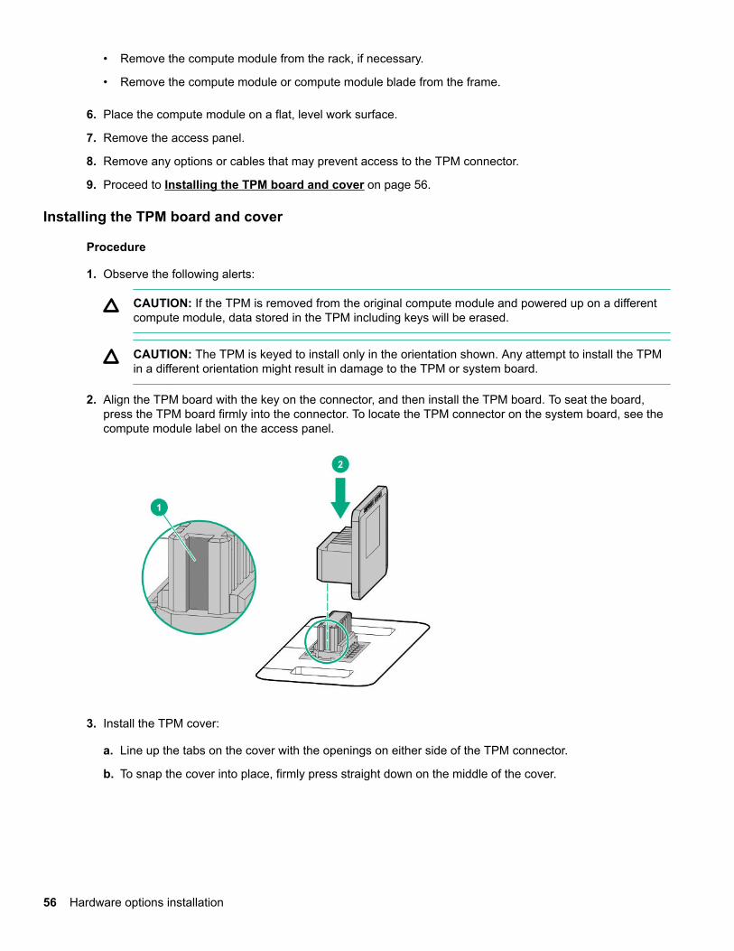
2. Align the TPM board with the key on the connector, and then install the TPM board. To seat the board,press the TPM board firmly into the connector. To locate the TPM connector on the system board, see thecompute module label on the access panel.
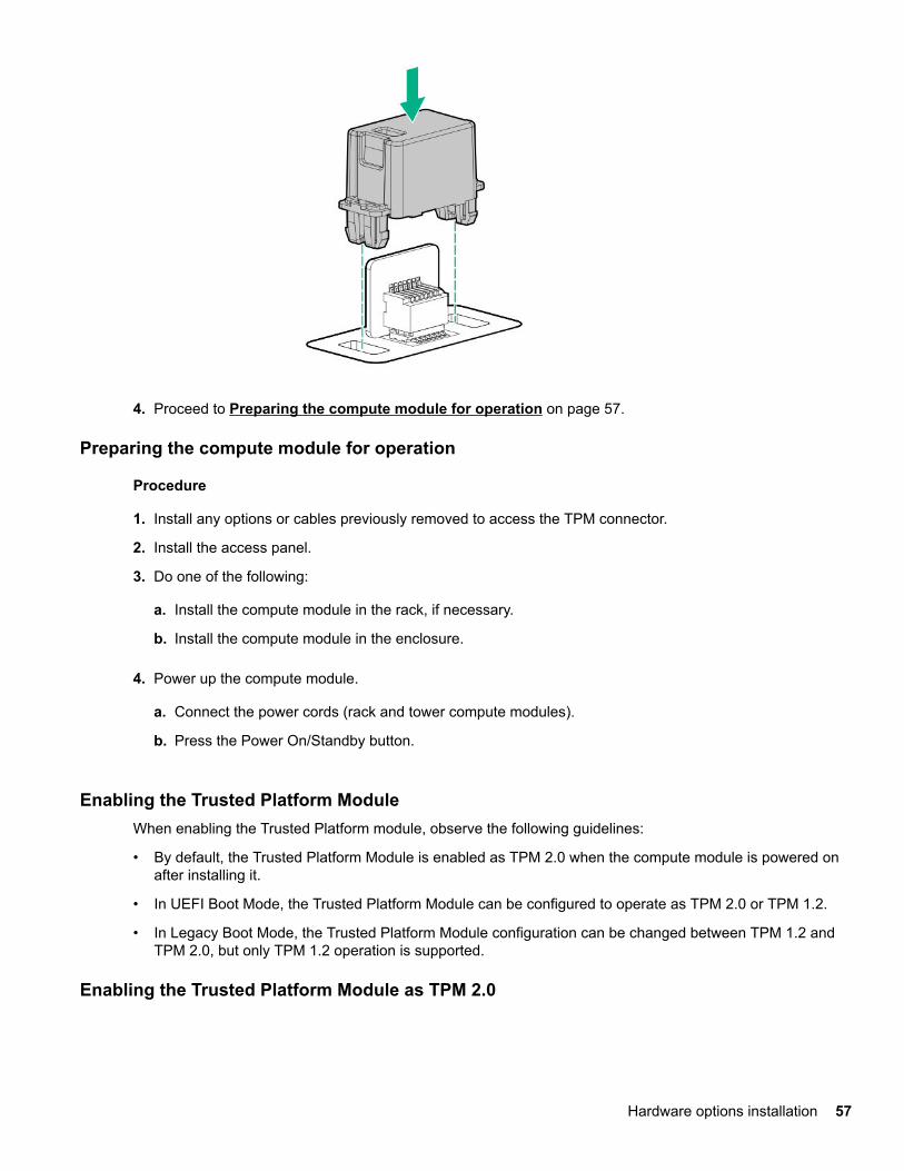
3. Install the TPM cover:
a. Line up the tabs on the cover with the openings on either side of the TPM connector.
b. To snap the cover into place, firmly press straight down on the middle of the cover.
56 Hardware options installation
4. Proceed to Preparing the compute module for operation on page 57.
Preparing the compute module for operation
Procedure
1. Install any options or cables previously removed to access the TPM connector.
2. Install the access panel.
3. Do one of the following:
a. Install the compute module in the rack, if necessary.
b. Install the compute module in the enclosure.
4. Power up the compute module.
a. Connect the power cords (rack and tower compute modules).
b. Press the Power On/Standby button.
Enabling the Trusted Platform ModuleWhen enabling the Trusted Platform module, observe the following guidelines:
• By default, the Trusted Platform Module is enabled as TPM 2.0 when the compute module is powered onafter installing it.
• In UEFI Boot Mode, the Trusted Platform Module can be configured to operate as TPM 2.0 or TPM 1.2.
• In Legacy Boot Mode, the Trusted Platform Module configuration can be changed between TPM 1.2 andTPM 2.0, but only TPM 1.2 operation is supported.
Enabling the Trusted Platform Module as TPM 2.0
Hardware options installation 57
Procedure
1. During the compute module startup sequence, press the F9 key to access System Utilities.
2. From the System Utilities screen, select System Configuration > BIOS/Platform Configuration (RBSU)> Server Security > Trusted Platform Module options.
3. Verify the following:
• "Current TPM Type" is set to TPM 2.0.
• "Current TPM State" is set to Present and Enabled.
• "TPM Visibility" is set to Visible.
4. If changes were made in the previous step, press the F10 key to save your selection.
5. If F10 was pressed in the previous step, do one of the following:
• If in graphical mode, click Yes.
• If in text mode, press the Y key.
6. Press the ESC key to exit System Utilities.
7. If changes were made and saved, the compute module prompts for reboot request. Press the Enter key toconfirm reboot.
If the following actions were performed, the compute module reboots a second time without user input.During this reboot, the TPM setting becomes effective.
• Changing from TPM 1.2 and TPM 2.0
• Changing TPM bus from FIFO to CRB
• Enabling or disabling TPM
• Clearing the TPM
8. Enable TPM functionality in the OS, such as Microsoft Windows BitLocker or measured boot.
For more information, see the Microsoft website.
Enabling the Trusted Platform Module as TPM 1.2
Procedure
1. During the compute module startup sequence, press the F9 key to access System Utilities.
2. From the System Utilities screen select System Configuration > BIOS/Platform Configuration (RBSU)> Server Security > Trusted Platform Module options.
3. Change the "TPM Mode Switch Operation" to TPM 1.2.
4. Verify "TPM Visibility" is Visible.
5. Press the F10 key to save your selection.
6. When prompted to save the change in System Utilities, do one of the following:
58 Hardware options installation
• If in graphical mode, click Yes.
• If in text mode, press the Y key.
7. Press the ESC key to exit System Utilities.
The compute module reboots a second time without user input. During this reboot, the TPM settingbecomes effective.
8. Enable TPM functionality in the OS, such as Microsoft Windows BitLocker or measured boot.
For more information, see the Microsoft website.
Retaining the recovery key/passwordThe recovery key/password is generated during BitLocker setup, and can be saved and printed afterBitLocker is enabled. When using BitLocker, always retain the recovery key/password. The recovery key/password is required to enter Recovery Mode after BitLocker detects a possible compromise of systemintegrity.
To help ensure maximum security, observe the following guidelines when retaining the recovery key/password:
• Always store the recovery key/password in multiple locations.
• Always store copies of the recovery key/password away from the compute module.
• Do not save the recovery key/password on the encrypted hard drive.
Hardware options installation 59
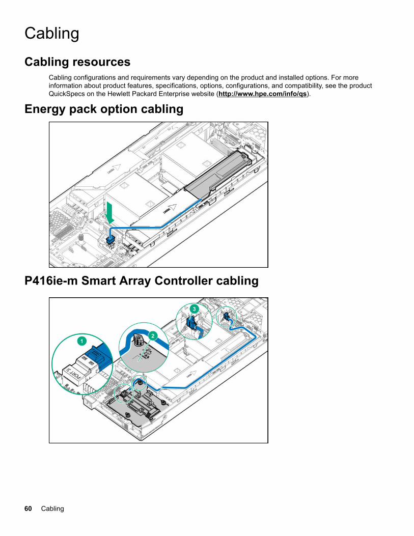
CablingCabling resources
Cabling configurations and requirements vary depending on the product and installed options. For moreinformation about product features, specifications, options, configurations, and compatibility, see the productQuickSpecs on the Hewlett Packard Enterprise website (http://www.hpe.com/info/qs).
Energy pack option cabling
P416ie-m Smart Array Controller cabling
60 Cabling
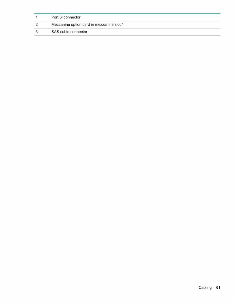
1 Port 3i connector
2 Mezzanine option card in mezzanine slot 1
3 SAS cable connector
Cabling 61
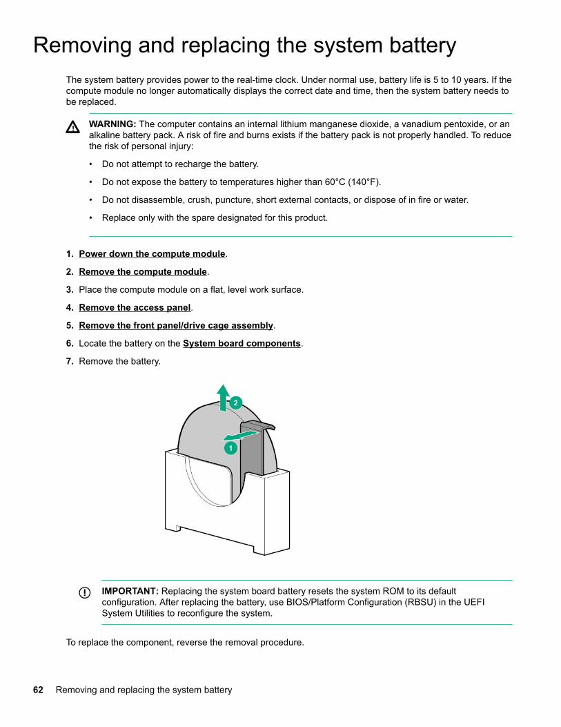
Removing and replacing the system batteryThe system battery provides power to the real-time clock. Under normal use, battery life is 5 to 10 years. If thecompute module no longer automatically displays the correct date and time, then the system battery needs tobe replaced.
WARNING: The computer contains an internal lithium manganese dioxide, a vanadium pentoxide, or analkaline battery pack. A risk of fire and burns exists if the battery pack is not properly handled. To reducethe risk of personal injury:
• Do not attempt to recharge the battery.
• Do not expose the battery to temperatures higher than 60°C (140°F).
• Do not disassemble, crush, puncture, short external contacts, or dispose of in fire or water.
• Replace only with the spare designated for this product.
1. Power down the compute module.
2. Remove the compute module.
3. Place the compute module on a flat, level work surface.
4. Remove the access panel.
5. Remove the front panel/drive cage assembly.
6. Locate the battery on the System board components.
7. Remove the battery.
IMPORTANT: Replacing the system board battery resets the system ROM to its defaultconfiguration. After replacing the battery, use BIOS/Platform Configuration (RBSU) in the UEFISystem Utilities to reconfigure the system.
To replace the component, reverse the removal procedure.
62 Removing and replacing the system battery

For more information about battery replacement or proper disposal, contact an authorized reseller or anauthorized service provider.
Removing and replacing the system battery 63
Electrostatic dischargePreventing electrostatic discharge
To prevent damaging the system, be aware of the precautions you must follow when setting up the system orhandling parts. A discharge of static electricity from a finger or other conductor may damage system boards orother static-sensitive devices. This type of damage may reduce the life expectancy of the device.
Procedure
• Avoid hand contact by transporting and storing products in static-safe containers.
• Keep electrostatic-sensitive parts in their containers until they arrive at static-free workstations.
• Place parts on a grounded surface before removing them from their containers.
• Avoid touching pins, leads, or circuitry.
• Always be properly grounded when touching a static-sensitive component or assembly.
Grounding methods to prevent electrostatic dischargeSeveral methods are used for grounding. Use one or more of the following methods when handling orinstalling electrostatic-sensitive parts:
• Use a wrist strap connected by a ground cord to a grounded workstation or computer chassis. Wrist strapsare flexible straps with a minimum of 1 megohm ±10 percent resistance in the ground cords. To provideproper ground, wear the strap snug against the skin.
• Use heel straps, toe straps, or boot straps at standing workstations. Wear the straps on both feet whenstanding on conductive floors or dissipating floor mats.
• Use conductive field service tools.
• Use a portable field service kit with a folding static-dissipating work mat.
If you do not have any of the suggested equipment for proper grounding, have an authorized reseller installthe part.
For more information on static electricity or assistance with product installation, contact the Hewlett PackardEnterprise Support Center.
64 Electrostatic discharge
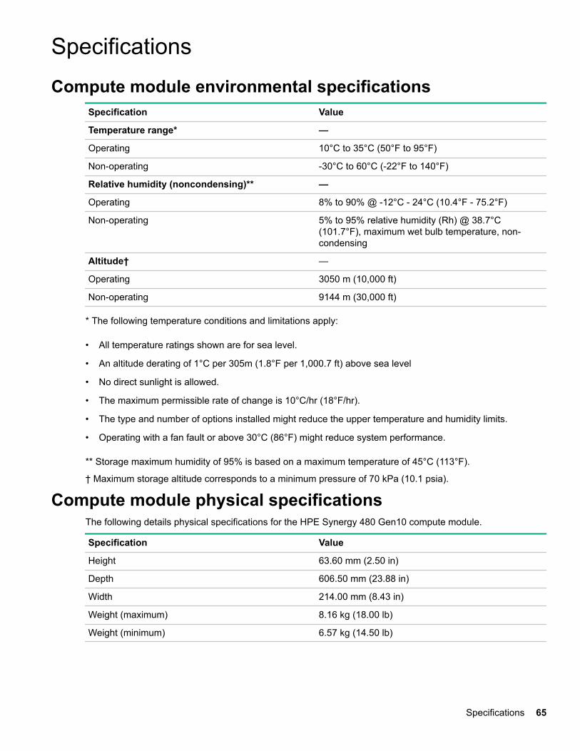
SpecificationsCompute module environmental specifications
Specification Value
Temperature range* —
Operating 10°C to 35°C (50°F to 95°F)
Non-operating -30°C to 60°C (-22°F to 140°F)
Relative humidity (noncondensing)** —
Operating 8% to 90% @ -12°C - 24°C (10.4°F - 75.2°F)
Non-operating 5% to 95% relative humidity (Rh) @ 38.7°C(101.7°F), maximum wet bulb temperature, non-condensing
Altitude† —
Operating 3050 m (10,000 ft)
Non-operating 9144 m (30,000 ft)
* The following temperature conditions and limitations apply:
• All temperature ratings shown are for sea level.
• An altitude derating of 1°C per 305m (1.8°F per 1,000.7 ft) above sea level
• No direct sunlight is allowed.
• The maximum permissible rate of change is 10°C/hr (18°F/hr).
• The type and number of options installed might reduce the upper temperature and humidity limits.
• Operating with a fan fault or above 30°C (86°F) might reduce system performance.
** Storage maximum humidity of 95% is based on a maximum temperature of 45°C (113°F).
† Maximum storage altitude corresponds to a minimum pressure of 70 kPa (10.1 psia).
Compute module physical specificationsThe following details physical specifications for the HPE Synergy 480 Gen10 compute module.
Specification Value
Height 63.60 mm (2.50 in)
Depth 606.50 mm (23.88 in)
Width 214.00 mm (8.43 in)
Weight (maximum) 8.16 kg (18.00 lb)
Weight (minimum) 6.57 kg (14.50 lb)
Specifications 65
Documentation and troubleshooting resourcesfor HPE SynergyHPE Synergy documentation
The Hewlett Packard Enterprise Information Library (www.hpe.com/info/synergy-docs) is a task-basedrepository. It includes installation instructions, user guides, maintenance and service guides, best practices,and links to additional resources. Use this website to obtain the latest documentation, including:
• Learning about HPE Synergy technology
• Installing and cabling HPE Synergy
• Updating the HPE Synergy components
• Using and managing HPE Synergy
• Troubleshooting HPE Synergy
HPE Synergy Configuration and Compatibility GuideThe HPE Synergy Configuration and Compatibility Guide is in the Hewlett Packard Enterprise InformationLibrary (www.hpe.com/info/synergy-docs). It provides an overview of HPE Synergy management and fabricarchitecture, detailed hardware component identification and configuration, and cabling examples.
HPE Synergy Frame Link Module User GuideThe HPE Synergy Frame Link Module User Guide is in the Hewlett Packard Enterprise Information Library(www.hpe.com/info/synergy-docs). It outlines frame link module management, configuration, and security.
HPE OneView User Guide and Help for HPE SynergyThe HPE OneView User Guide and Help for HPE Synergy is in the Hewlett Packard Enterprise InformationLibrary (www.hpe.com/info/synergy-docs). It describes resource features, planning tasks, configurationquick start tasks, navigational tools for the graphical user interface, and more support and referenceinformation for HPE OneView.
HPE OneView Global Dashboard User Guide and HelpThe HPE OneView Global Dashboard provides a unified view of health, alerting, and key resources managedby HPE OneView across multiple platforms and data center sites. The HPE OneView Global Dashboard UserGuide is in the Hewlett Packard Enterprise Information Library (www.hpe.com/info/synergy-docs). Itprovides instructions for installing, configuring, navigating, and troubleshooting the HPE OneView GlobalDashboard.
HPE Synergy Image Streamer User GuideThe HPE Synergy Image Streamer User Guide is in the Hewlett Packard Enterprise Information Library(www.hpe.com/info/synergy-docs). It describes the OS deployment process using Image Streamer,features of Image Streamer, and purpose and life cycle of Image Streamer artifacts. It also includesauthentication, authorization, and troubleshooting information for Image Streamer.
66 Documentation and troubleshooting resources for HPE Synergy
HPE Synergy Image Streamer GitHubThe HPE Synergy Image Streamer GitHub repository (github.com/HewlettPackard) contains sampleartifacts and documentation on how to use the sample artifacts. It also contains technical white papersexplaining deployment steps that can be performed using Image Streamer.
HPE Synergy Software Overview GuideThe HPE Synergy Software Overview Guide is in the Hewlett Packard Enterprise Information Library(www.hpe.com/info/synergy-docs). It provides detailed references and overviews of the various softwareand configuration utilities to support HPE Synergy. The guide is task-based and covers the documentationand resources for all supported software and configuration utilities available for:
• HPE Synergy setup and configuration
• OS deployment
• Firmware updates
• Troubleshooting
• Remote support
HPE OneView for Synergy Firmware and Driver Update GuideThe HPE OneView for Synergy Firmware and Driver Update Guide is in the Hewlett Packard EnterpriseInformation Library (www.hpe.com/info/synergy-docs). It provides information on how to update thefirmware and recommended best practices to update firmware and drivers through HPE Synergy Composer,which is powered by HPE OneView.
HPE OneView Support Matrix for HPE SynergyThe HPE OneView Support Matrix for HPE Synergy is in the Hewlett Packard Enterprise Information Library(www.hpe.com/info/synergy-docs). It maintains the latest software and firmware requirements, supportedhardware, and configuration maximums for HPE OneView.
HPE Synergy Image Streamer Support MatrixThe HPE Synergy Image Streamer Support Matrix is in the Hewlett Packard Enterprise Information Library(www.hpe.com/info/synergy-docs). It maintains the latest software and firmware requirements, supportedhardware, and configuration maximums for HPE Synergy Image Streamer.
HPE Synergy Firmware Comparison ToolThe HPE Synergy Firmware Comparison Tool is on the Hewlett Packard Enterprise website (http://www.hpe.com/info/synergy-fw-comparison-tool). HPE Synergy Software Releases are made up of amanagement combination and an HPE Synergy Custom SPP. This tool provides a list of ManagementCombinations and lets you compare HPE Synergy SPPs supported by the selected managementcombination.
HPE Synergy Upgrade PathsThe HPE Synergy Upgrade Paths is a table on the Hewlett Packard Enterprise website (http://www.hpe.com/info/synergy-fw-upgrade-table). The table provides information on HPE Synergy Composerand HPE Synergy Image Streamer upgrade paths and management combinations.
Documentation and troubleshooting resources for HPE Synergy 67
HPE Synergy GlossaryThe HPE Synergy Glossary, in the Hewlett Packard Enterprise Information Library (www.hpe.com/info/synergy-docs), defines common terminology associated with HPE Synergy.
HPE Synergy troubleshooting resourcesHPE Synergy troubleshooting resources are available within HPE OneView and in the Hewlett PackardEnterprise Information Library (www.hpe.com/info/synergy-docs).
Troubleshooting within HPE OneViewHPE OneView graphical user interface includes alert notifications and options for troubleshooting within HPEOneView. The UI provides multiple views of HPE Synergy components, including colored icons to indicateresource status and potential problem resolution in messages.
You can also use the Enclosure view and Map view to quickly see the status of all discovered HPE Synergyhardware.
HPE Synergy Troubleshooting GuideThe HPE Synergy Troubleshooting Guide is in the Hewlett Packard Enterprise Information Library(www.hpe.com/info/synergy-docs). It provides information for resolving common problems and courses ofaction for fault isolation and identification, issue resolution, and maintenance for both HPE Synergy hardwareand software components.
Error Message Guide for HPE ProLiant Gen10 servers and HPE SynergyThe Error Message Guide for HPE ProLiant Gen10 servers and HPE Synergy is in the Hewlett PackardEnterprise Information Library (www.hpe.com/info/synergy-docs). It provides information for resolvingcommon problems associated with specific error messages received for both HPE Synergy hardware andsoftware components.
HPE OneView Help and HPE OneView API ReferenceThe HPE OneView Help and the HPE OneView API Reference are readily accessible, embedded online helpavailable within the HPE OneView user interface. These help files include “Learn more” links to commonissues, as well as procedures and examples to troubleshoot issues within HPE Synergy.
The help files are also available in the Hewlett Packard Enterprise Information Library (www.hpe.com/info/synergy-docs).
HPE Synergy QuickSpecsHPE Synergy has system specifications as well as individual product and component specifications. Forcomplete specification information, see the HPE Synergy and individual HPE Synergy product QuickSpecs onthe Hewlett Packard Enterprise website (www.hpe.com/info/qs).
68 Documentation and troubleshooting resources for HPE Synergy

HPE Synergy document overview(documentation map)
www.hpe.com/info/synergy-docs
HPE Synergy document overview (documentation map) 69
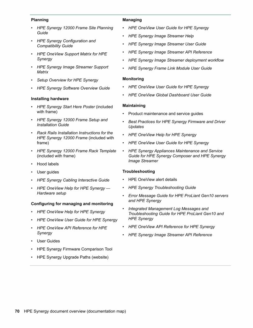
Planning
• HPE Synergy 12000 Frame Site PlanningGuide
• HPE Synergy Configuration andCompatibility Guide
• HPE OneView Support Matrix for HPESynergy
• HPE Synergy Image Streamer SupportMatrix
• Setup Overview for HPE Synergy
• HPE Synergy Software Overview Guide
Installing hardware
• HPE Synergy Start Here Poster (includedwith frame)
• HPE Synergy 12000 Frame Setup andInstallation Guide
• Rack Rails Installation Instructions for theHPE Synergy 12000 Frame (included withframe)
• HPE Synergy 12000 Frame Rack Template(included with frame)
• Hood labels
• User guides
• HPE Synergy Cabling Interactive Guide
• HPE OneView Help for HPE Synergy —Hardware setup
Configuring for managing and monitoring
• HPE OneView Help for HPE Synergy
• HPE OneView User Guide for HPE Synergy
• HPE OneView API Reference for HPESynergy
• User Guides
• HPE Synergy Firmware Comparison Tool
• HPE Synergy Upgrade Paths (website)
Managing
• HPE OneView User Guide for HPE Synergy
• HPE Synergy Image Streamer Help
• HPE Synergy Image Streamer User Guide
• HPE Synergy Image Streamer API Reference
• HPE Synergy Image Streamer deployment workflow
• HPE Synergy Frame Link Module User Guide
Monitoring
• HPE OneView User Guide for HPE Synergy
• HPE OneView Global Dashboard User Guide
Maintaining
• Product maintenance and service guides
• Best Practices for HPE Synergy Firmware and DriverUpdates
• HPE OneView Help for HPE Synergy
• HPE OneView User Guide for HPE Synergy
• HPE Synergy Appliances Maintenance and ServiceGuide for HPE Synergy Composer and HPE SynergyImage Streamer
Troubleshooting
• HPE OneView alert details
• HPE Synergy Troubleshooting Guide
• Error Message Guide for HPE ProLiant Gen10 serversand HPE Synergy
• Integrated Management Log Messages andTroubleshooting Guide for HPE ProLiant Gen10 andHPE Synergy
• HPE OneView API Reference for HPE Synergy
• HPE Synergy Image Streamer API Reference
70 HPE Synergy document overview (documentation map)
WebsitesGeneral websitesHewlett Packard Enterprise Information Library
www.hpe.com/info/EILSingle Point of Connectivity Knowledge (SPOCK) Storage compatibility matrix
www.hpe.com/storage/spockStorage white papers and analyst reports
www.hpe.com/storage/whitepapers
For additional websites, see Support and other resources.
Websites 71
Support and other resourcesAccessing Hewlett Packard Enterprise Support
• For live assistance, go to the Contact Hewlett Packard Enterprise Worldwide website:
http://www.hpe.com/info/assistance
• To access documentation and support services, go to the Hewlett Packard Enterprise Support Centerwebsite:
http://www.hpe.com/support/hpesc
Information to collect
• Technical support registration number (if applicable)
• Product name, model or version, and serial number
• Operating system name and version
• Firmware version
• Error messages
• Product-specific reports and logs
• Add-on products or components
• Third-party products or components
Accessing updates• Some software products provide a mechanism for accessing software updates through the product
interface. Review your product documentation to identify the recommended software update method.
• To download product updates:
Hewlett Packard Enterprise Support Centerwww.hpe.com/support/hpesc
Hewlett Packard Enterprise Support Center: Software downloadswww.hpe.com/support/downloads
Software Depotwww.hpe.com/support/softwaredepot
• To subscribe to eNewsletters and alerts:
www.hpe.com/support/e-updates
• To view and update your entitlements, and to link your contracts and warranties with your profile, go to theHewlett Packard Enterprise Support Center More Information on Access to Support Materials page:
www.hpe.com/support/AccessToSupportMaterials
IMPORTANT: Access to some updates might require product entitlement when accessed through theHewlett Packard Enterprise Support Center. You must have an HPE Passport set up with relevantentitlements.
72 Support and other resources
Customer self repairHewlett Packard Enterprise customer self repair (CSR) programs allow you to repair your product. If a CSRpart needs to be replaced, it will be shipped directly to you so that you can install it at your convenience.Some parts do not qualify for CSR. Your Hewlett Packard Enterprise authorized service provider willdetermine whether a repair can be accomplished by CSR.
For more information about CSR, contact your local service provider or go to the CSR website:
http://www.hpe.com/support/selfrepair
Remote supportRemote support is available with supported devices as part of your warranty or contractual supportagreement. It provides intelligent event diagnosis, and automatic, secure submission of hardware eventnotifications to Hewlett Packard Enterprise, which will initiate a fast and accurate resolution based on yourproduct's service level. Hewlett Packard Enterprise strongly recommends that you register your device forremote support.
If your product includes additional remote support details, use search to locate that information.
Remote support and Proactive Care informationHPE Get Connected
www.hpe.com/services/getconnectedHPE Proactive Care services
www.hpe.com/services/proactivecareHPE Proactive Care service: Supported products list
www.hpe.com/services/proactivecaresupportedproductsHPE Proactive Care advanced service: Supported products list
www.hpe.com/services/proactivecareadvancedsupportedproducts
Proactive Care customer informationProactive Care central
www.hpe.com/services/proactivecarecentralProactive Care service activation
www.hpe.com/services/proactivecarecentralgetstarted
Warranty informationTo view the warranty information for your product, see the links provided below:
HPE ProLiant and IA-32 Servers and Optionswww.hpe.com/support/ProLiantServers-Warranties
HPE Enterprise and Cloudline Serverswww.hpe.com/support/EnterpriseServers-Warranties
HPE Storage Productswww.hpe.com/support/Storage-Warranties
HPE Networking Productswww.hpe.com/support/Networking-Warranties
Regulatory informationTo view the regulatory information for your product, view the Safety and Compliance Information for Server,Storage, Power, Networking, and Rack Products, available at the Hewlett Packard Enterprise Support Center:
Support and other resources 73
www.hpe.com/support/Safety-Compliance-EnterpriseProducts
Additional regulatory information
Hewlett Packard Enterprise is committed to providing our customers with information about the chemicalsubstances in our products as needed to comply with legal requirements such as REACH (Regulation EC No1907/2006 of the European Parliament and the Council). A chemical information report for this product can befound at:
www.hpe.com/info/reach
For Hewlett Packard Enterprise product environmental and safety information and compliance data, includingRoHS and REACH, see:
www.hpe.com/info/ecodata
For Hewlett Packard Enterprise environmental information, including company programs, product recycling,and energy efficiency, see:
www.hpe.com/info/environment
Documentation feedbackHewlett Packard Enterprise is committed to providing documentation that meets your needs. To help usimprove the documentation, send any errors, suggestions, or comments to Documentation Feedback([email protected]). When submitting your feedback, include the document title, part number, edition,and publication date located on the front cover of the document. For online help content, include the productname, product version, help edition, and publication date located on the legal notices page.
74 Support and other resources
Related Documents