HPE ArubaOS-Switch Management and Configuration Guide K/KA/KB.16.01 Abstract This switch software guide is intended for network administrators and support personnel, and applies to the switch models listed on this page unless otherwise noted. This guide does not provide information about upgrading or replacing switch hardware. The information in this guide is subject to change without notice. Applicable Products Aruba 3810M Switch Series (JL071A, JL072A, JL073A, JL074A, JL075A, JL076A) Aruba 5400Rzl2 Switch Series (J8698A, J8700A, J9823A-J9824A, J9825A, J9826A, J9868A, J9447A, J9448A) Aruba 5406R Switch Series (JL002A, JL003A, JL095A,J9850A) Aruba 5406Rzl Switch Series (J9821A, J9822A) ) Aruba 5412R Switch Series (J9851A, JL001A) HPE 3500 Switch Series (J9470A-J9473A) HPE 3500yl Switch Series (J8692A, J8693A, J9310A, J9311A) HPE 3800 Switch Series (J9573A—J9576A, J9584A—J9588A) HPE 5406 Switch Series (J9533A, J9539A, J9642A, J9866A) HPE 5406zl Switch Series (J8697A, J8699A, J9447A) HPE 5412 Switch Series (J9532A, J9540A) HPE 5412zl Switch Series (J869A, J8700A, J9448A, J9643A) Part Number: 5200-0137b Published: June 2016 Edition: 3

Welcome message from author
This document is posted to help you gain knowledge. Please leave a comment to let me know what you think about it! Share it to your friends and learn new things together.
Transcript
HPE ArubaOS-Switch Managementand Configuration GuideK/KA/KB.16.01
AbstractThis switch software guide is intended for network administrators and support personnel, and applies to the switch models listedon this page unless otherwise noted. This guide does not provide information about upgrading or replacing switch hardware.The information in this guide is subject to change without notice.
Applicable Products
Aruba 3810M Switch Series (JL071A, JL072A, JL073A, JL074A, JL075A, JL076A)Aruba 5400Rzl2 Switch Series (J8698A, J8700A, J9823A-J9824A, J9825A, J9826A, J9868A, J9447A, J9448A)Aruba 5406R Switch Series (JL002A, JL003A, JL095A,J9850A)Aruba 5406Rzl Switch Series (J9821A, J9822A) )Aruba 5412R Switch Series (J9851A, JL001A)HPE 3500 Switch Series (J9470A-J9473A)HPE 3500yl Switch Series (J8692A, J8693A, J9310A, J9311A)HPE 3800 Switch Series (J9573A—J9576A, J9584A—J9588A)HPE 5406 Switch Series (J9533A, J9539A, J9642A, J9866A)HPE 5406zl Switch Series (J8697A, J8699A, J9447A)HPE 5412 Switch Series (J9532A, J9540A)HPE 5412zl Switch Series (J869A, J8700A, J9448A, J9643A)
Part Number: 5200-0137bPublished: June 2016Edition: 3

© Copyright 2016 Hewlett Packard Enterprise Development LP
Confidential computer software. Valid license from Hewlett Packard Enterprise required for possession, use or copying. Consistent with FAR12.211 and 12.212, Commercial Computer Software, Computer Software Documentation, and Technical Data for Commercial Items are licensedto the U.S. Government under vendor's standard commercial license. The information contained herein is subject to change without notice. Theonly warranties for Hewlett Packard Enterprise products and services are set forth in the express warranty statements accompanying suchproducts and services. Nothing herein should be construed as constituting an additional warranty. Hewlett Packard Enterprise shall not be liablefor technical or editorial errors or omissions contained herein. UNIX is a registered trademark of The Open Group.
Acknowledgments
Microsoft, Windows, Windows XP, and Windows NT are U.S. registered trademarks of Microsoft Corporation.
Java is a registered trademark of Oracle and/or its affiliates.
Warranty
For the software end user license agreement and the hardware limited warranty information for Hewlett Packard Enterprise Networking products,visit www.hpe.com/networking/support.

Contents1 Time protocols...................................................................................................24
General steps for running a time protocol on the switch....................................................................24About SNTP time synchronization.................................................................................................24About TimeP time synchronization................................................................................................25
Selecting a time synchronization protocol..........................................................................................25timesync command........................................................................................................................25
Network Time Protocol (NTP).............................................................................................................25NTP related commands.................................................................................................................26
timesync...................................................................................................................................26timesync ntp.............................................................................................................................26ntp............................................................................................................................................26no ntp.......................................................................................................................................27ntp enable.................................................................................................................................27ntp authentication.....................................................................................................................27ntp max-associations...............................................................................................................28ntp server.................................................................................................................................29ntp ipv6-multicast.....................................................................................................................30debug ntp.................................................................................................................................31ntp trap.....................................................................................................................................31show ntp statistics....................................................................................................................32show ntp status........................................................................................................................32show ntp authentication...........................................................................................................33show ntp associations..............................................................................................................33
Enabling and disabling time synchronization protocols......................................................................34Enabling SNTP..............................................................................................................................34
Broadcast/Unicast switch.........................................................................................................34Enabling SNTP in Broadcast Mode..........................................................................................34Enabling SNTP in unicast mode..............................................................................................35
Enabling TimeP.............................................................................................................................36Enabling TimeP in DHCP mode...............................................................................................37Enabling TimeP operation in manual mode.............................................................................38Viewing, enabling, and modifying the TimeP protocol (Menu).................................................39
Disabling time synchronization protocols .....................................................................................40Disabling time synchronization without changing the TimeP or SNTP configuration...............40Disabling SNTP Mode..............................................................................................................41Disabling the TimeP mode.......................................................................................................42
Viewing and configuring time synchronization protocol parameters...................................................43Viewing and configuring SNTP parameters...................................................................................43
Viewing all SNTP server addresses configured on the switch ................................................43Enabling SNTP client authentication........................................................................................44Configuring other SNTP parameters........................................................................................45Poll interval...............................................................................................................................45Server priority...........................................................................................................................46Version.....................................................................................................................................46Server address.........................................................................................................................46
Viewing and configuring SNTP parameters (Menu)......................................................................47Viewing and configuring TimeP parameters..................................................................................49
Disabling TimeP.......................................................................................................................49Timesync .................................................................................................................................49Enabling TimeP in DHCP or manual mode..............................................................................49Poll interval...............................................................................................................................49Server address.........................................................................................................................49
Contents 3

Disabling time synchronization...........................................................................................................50Other time protocol commands...........................................................................................................50
Show management command.......................................................................................................50Show SNTP command..................................................................................................................51Show TimeP command.................................................................................................................52
Viewing and configuring SNTP...........................................................................................................54Enabling or disabling the SNTP mode ...............................................................................................55Configuring the SNTP mode...............................................................................................................56
Enabling SNTP in broadcast mode...............................................................................................56Enabling or disabling in Broadcast mode...........................................................................................57SNTP in unicast mode........................................................................................................................58
SNTP unicast time polling with multiple SNTP servers.................................................................59Changing the SNTP poll interval.........................................................................................................60Changing the SNTP server priority.....................................................................................................60Disabling time synchronization without changing the SNTP configuration.........................................60Viewing all SNTP server addresses configured on the switch...........................................................61Adding SNTP server addresses.........................................................................................................61Deleting SNTP server addresses.......................................................................................................61Configuring the key-identifier, authentication mode, and key-value...................................................62
Configuring a key-id as trusted......................................................................................................63Associating a key with an SNTP server........................................................................................63Enabling and disabling SNTP client authentication.......................................................................64Viewing SNTP authentication configuration information...............................................................64Viewing statistical information for each SNTP server....................................................................65
Configuring a key-id as trusted...........................................................................................................66Associating a key with an SNTP server..............................................................................................67Configuring unicast and for authentication.........................................................................................67Viewing SNTP authentication configuration information.....................................................................68Viewing all SNTP authentication keys that have been configured on the switch...............................68Viewing statistical information for each SNTP server.........................................................................69Storing security information in the running-config file.........................................................................69Viewing and configuring SNTP (Menu)...............................................................................................69Viewing the current TimeP configuration............................................................................................71Enabling TimeP mode.........................................................................................................................72Disabling TimeP mode........................................................................................................................73Enabling TimeP in manual mode........................................................................................................73
Disabling TimeP in manual mode..................................................................................................74Enabling TimeP in DHCP Mode....................................................................................................74Enabling TimeP in Manual Mode...................................................................................................74Disabling TimeP in manual mode..................................................................................................75
Changing from one TimeP server to another .....................................................................................75Changing the TimeP poll interval........................................................................................................75Disabling time synchronization...........................................................................................................75Disabling the TimeP mode..................................................................................................................76Viewing, enabling, and modifying the TimeP protocol(Menu).............................................................77About SNTP time synchronization......................................................................................................78About SNTP: Selecting and configuring.............................................................................................78
About SNTP unicast time polling with multiple SNTP servers.......................................................79About trusted keys..............................................................................................................................80About saving configuration files and the include-credentials command.............................................80SNTP messages in the event log.......................................................................................................81Viewing current resource usage.........................................................................................................81Viewing information on resource usage..............................................................................................83
When insufficient resources are available.....................................................................................84Policy enforcement engine............................................................................................................85
4 Contents

Usage notes for show resources output........................................................................................852 Port status and configuration.............................................................................87
Viewing port status and configuration.................................................................................................87Internal port names........................................................................................................................87Services.........................................................................................................................................88
Show services..........................................................................................................................88No parameters..........................................................................................................................89Show services locator..............................................................................................................89Show services device...............................................................................................................90Requesting a reboot.................................................................................................................91Services in Operator/Manager/Configure context....................................................................91Show services set locator module............................................................................................93Reloading services module......................................................................................................94Connection to the application via a serial port.........................................................................94Shutdown the services module................................................................................................94
Viewing the port VLAN tagged status.................................................................................................94Dynamically updating the show interfaces command.........................................................................95Customizing the show interfaces command.......................................................................................96
Smart Rate....................................................................................................................................97Viewing port utilization statistics.........................................................................................................97
Operating notes for viewing port utilization statistics.....................................................................98Viewing transceiver status..................................................................................................................98
Transceiver Operating notes.........................................................................................................98Enabling or disabling ports and configuring port mode......................................................................99Enabling or disabling the USB port...................................................................................................100
Software versions K.13.XX operation..........................................................................................101Software Version K.14.XX Operation..........................................................................................101
Enabling or disabling flow control.....................................................................................................101Configuring auto-MDIX.....................................................................................................................102Viewing port configuration (Menu)....................................................................................................104Configuring ports (Menu)..................................................................................................................105Configuring friendly port names........................................................................................................105
Configuring a single port name...................................................................................................105Configuring the same name for multiple ports.............................................................................106Viewing friendly port names with other port data........................................................................106
Listing all ports or selected ports with their friendly port names.......................................................107Including friendly port names in per-port statistics listings..........................................................107Searching the configuration for ports with friendly port names...................................................108
Configuring the type of a module......................................................................................................109Clearing the module configuration....................................................................................................109Configuring uni-directional link detection..........................................................................................109
Enabling UDLD............................................................................................................................110Changing the keepalive interval..................................................................................................110Changing the keepalive retries....................................................................................................110Configuring UDLD for tagged ports.............................................................................................111Viewing UDLD information..........................................................................................................111Viewing summary information on all UDLD-enabled ports..........................................................111Viewing detailed UDLD information for specific ports.................................................................112Clearing UDLD statistics..............................................................................................................112
About viewing port status and configuring port parameters.............................................................113Connecting transceivers to fixed-configuration devices..............................................................113Error messages associated with the show interfaces command.................................................114
Using pattern matching with the show interfaces custom command.....................................115About configuring auto-MDIX............................................................................................................115
Contents 5

Manual override...........................................................................................................................115About using friendly port names.......................................................................................................116
Configuring and operating rules for friendly port names.............................................................116Configuring transceivers and modules that have not been inserted.................................................116
Transceivers................................................................................................................................116Modules.......................................................................................................................................117Clearing the module configuration...............................................................................................117
Restrictions.............................................................................................................................117Uni-directional link detection (UDLD)................................................................................................117
Configuring UDLD.......................................................................................................................118Uplink failure detection.....................................................................................................................119
Configuration Guidelines for UFD...............................................................................................120UFD enable/disable.....................................................................................................................120UFD track data configuration.......................................................................................................121UFD enable/disable.....................................................................................................................121UFD track data configuration.......................................................................................................121UFD minimum uplink threshold configuration..............................................................................122show uplink-failure-detection.......................................................................................................122UFD operating notes...................................................................................................................123Error log.......................................................................................................................................123Invalid port error messages.........................................................................................................123
3 Power over ethernet (PoE/PoE+) operation....................................................124PoE Overview...................................................................................................................................124
PoE..............................................................................................................................................124Disabling or re-enabling PoE port operation.....................................................................................124Enabling support for pre-standard devices.......................................................................................124Configuring the PoE port priority.......................................................................................................124Controlling PoE allocation.................................................................................................................125Manually configuring PoE power levels............................................................................................126Configuring PoE redundancy (chassis switches only)......................................................................127Changing the threshold for generating a power notice.....................................................................127Enabling or disabling ports for allocating power using LLDP...........................................................127Enabling PoE detection via LLDP TLV advertisement......................................................................128Negotiating power using the DLL......................................................................................................128Initiating advertisement of PoE+ TLVs..............................................................................................130Viewing PoE when using LLDP information.....................................................................................131Viewing the global PoE power status of the switch..........................................................................133Viewing PoE status on all ports........................................................................................................134Viewing the PoE status on specific ports..........................................................................................136Planning and implementing a PoE configuration..............................................................................138
Power requirements....................................................................................................................138Assigning PoE ports to VLANs....................................................................................................139Applying security features to PoE configurations........................................................................139Assigning priority policies to PoE traffic.......................................................................................139
PoE operation...................................................................................................................................139PoE configuration options............................................................................................................140PD support...................................................................................................................................140PoE power priority.......................................................................................................................141
Assigning PoE priority with two or more modules..................................................................141About configuring PoE......................................................................................................................142Configuring thresholds for generating a power notice......................................................................143PoE/PoE+ allocation using LLDP.....................................................................................................144
LLDP with PoE............................................................................................................................144LLDP with PoE+..........................................................................................................................144
6 Contents

PoE+ with LLDP Overview.....................................................................................................144PoE allocation........................................................................................................................144
Operation Note............................................................................................................................1454 Port trunking....................................................................................................146
Viewing and configuring port trunk groups.......................................................................................146Viewing static trunk type and group for all ports or for selected ports.........................................146Viewing static LACP and dynamic LACP trunk data...................................................................147Configuring a static trunk or static LACP trunk group.................................................................148Removing ports from a static trunk group...................................................................................148Port Shutdown with Broadcast Storm..........................................................................................148
Configuration Commands......................................................................................................149Viewing broadcast-storm configuration..................................................................................149Definitions...............................................................................................................................150Event logs...............................................................................................................................150
Enabling dynamic LACP trunk groups.........................................................................................151Removing ports from a dynamic LACP trunk group....................................................................151Setting the LACP key..................................................................................................................152
Viewing and configuring a static trunk group (Menu)........................................................................152Enabling L4-based trunk load balancing..........................................................................................154Viewing trunk load balancing............................................................................................................155
Operating notes...........................................................................................................................156Distributed trunking...........................................................................................................................156
Configuring ISC ports..................................................................................................................156Configuring distributed trunking ports..........................................................................................156Configuring peer-keepalive links.................................................................................................157Viewing distributed trunking information......................................................................................158Viewing peer-keepalive configuration..........................................................................................159Viewing switch interconnect........................................................................................................159
Port trunking overview......................................................................................................................159Port trunk connections and configuration....................................................................................160
Port trunk operations........................................................................................................................160Fault tolerance ............................................................................................................................161
Trunk configuration methods............................................................................................................161Dynamic LACP trunk...................................................................................................................161Dynamic LACP Standby Links....................................................................................................161Viewing LACP Local Information.................................................................................................162Viewing LACP Peer Information..................................................................................................162Viewing LACP Counters..............................................................................................................162Using keys to control dynamic LACP trunk configuration............................................................162Static trunk...................................................................................................................................163
Operating port trunks.............................................................................................................164Show port-security log............................................................................................................166
Configuring a static or dynamic trunk group overview.................................................................166Enabling a dynamic LACP trunk group.......................................................................................166Dynamic LACP standby links......................................................................................................167Viewing LACP local information..................................................................................................168Viewing LACP peer information...................................................................................................168Viewing LACP counters...............................................................................................................168
Trunk group operation using LACP..................................................................................................169Default port operation..................................................................................................................171LACP operating notes and restrictions........................................................................................172
802.1X (Port-based access control) configured on a port......................................................172Port security...........................................................................................................................172Changing trunking methods...................................................................................................172
Contents 7

Static LACP trunks.................................................................................................................172Dynamic LACP trunks............................................................................................................172VLANs and dynamic LACP....................................................................................................173Blocked ports with older devices............................................................................................173Spanning Tree and IGMP.......................................................................................................174Half-duplex, different port speeds, or both not allowed in LACP trunks.................................174Dynamic/static LACP interoperation......................................................................................174
Trunk group operation using the "trunk" option................................................................................174Viewing trunk data on the switch......................................................................................................174Outbound traffic distribution across trunked links.............................................................................175Trunk load balancing using Layer 4 ports.........................................................................................176Distributed trunking overview............................................................................................................176
Distributed trunking interconnect protocol...................................................................................178Configuring distributed trunking...................................................................................................178
Configuring peer-keepalive links.......................................................................................................179Maximum DT trunks and links supported....................................................................................180Forwarding traffic with distributed trunking and spanning tree....................................................181
Forwarding unicast traffic.......................................................................................................181Forwarding broadcast, multicast, and unknown traffic ..........................................................182
IP routing and distributed trunking...............................................................................................183Distributed trunking restrictions...................................................................................................185
DT operating notes when updating software versions......................................................................1865 Port traffic controls...........................................................................................188
Rate-limiting......................................................................................................................................188Configuring rate-limiting on all traffic...........................................................................................188Viewing the current rate-limit configuration.................................................................................189Configuring ICMP rate-limiting.....................................................................................................190Viewing the current ICMP rate-limit configuration.......................................................................191Resetting the ICMP trap function of the port...............................................................................192
Determining the switch port number used in ICMP port reset commands.............................192Configuring an egress/outbound broadcast limit on the switch...................................................193
Configuring inbound rate-limiting for broadcast and multicast traffic.....................................194Configuring egress per-queue rate-limiting.................................................................................195
Overview................................................................................................................................195Configuration commands.......................................................................................................196
Configuring Guaranteed Minimum Bandwidth (GMB) for outbound traffic.......................................198Viewing the current GMB configuration.......................................................................................202Validation rules............................................................................................................................205Event log......................................................................................................................................206
Configuring jumbo frame operation..................................................................................................206Overview......................................................................................................................................206Viewing the current jumbo configuration.....................................................................................207Enabling or disabling jumbo traffic on a VLAN............................................................................208Configuring a maximum frame size.............................................................................................208Configuring IP MTU.....................................................................................................................208Viewing the maximum frame size................................................................................................209
Operating notes for maximum frame size..............................................................................209All traffic rate-limiting........................................................................................................................209
Operating notes for rate-limiting..................................................................................................210ICMP rate-limiting.............................................................................................................................212
Configuring ICMP rate-limiting.....................................................................................................213Using both ICMP rate-limiting and all-traffic rate-limiting on the same interface.........................214Operating notes for ICMP rate-limiting........................................................................................214
Testing ICMP rate-limiting......................................................................................................216
8 Contents

ICMP rate-limiting trap...........................................................................................................216Guaranteed minimum bandwidth (GMB)..........................................................................................216
GMB operations...........................................................................................................................217Impacts of QoS queue configuration on GMB operation........................................................217Impact of QoS queue configuration on GMB commands.......................................................218
Jumbo frames...................................................................................................................................218Operating rules for jumbo frames................................................................................................218
Jumbo traffic-handling............................................................................................................219Jumbo frame maximum size........................................................................................................220Jumbo IP MTU.............................................................................................................................221Troubleshooting Jumbo frames...................................................................................................221
A VLAN is configured to allow jumbo frames, but one or more ports drops all inbound jumboframes....................................................................................................................................221A non-jumbo port is generating "Excessive undersize/giant frames" messages in the EventLog.........................................................................................................................................221
6 Fault-Finder port-level link-flap........................................................................222Overview...........................................................................................................................................222Fault-finder link-flap .........................................................................................................................222Show fault-finder link-flap.................................................................................................................224Event Log..........................................................................................................................................225Restrictions.......................................................................................................................................225
7 Configuring for Network Management Applications........................................226Configuring the switch to filter untagged traffic.................................................................................226Viewing configuration file change information..................................................................................226Minimal interval for successive data change notifications................................................................227Viewing the current port speed and duplex configuration on a switch port......................................228Viewing the configuration..................................................................................................................229RMON advanced management........................................................................................................230Configuring UDLD verify before forwarding......................................................................................232
UDLD time delay.........................................................................................................................232Restrictions.............................................................................................................................233
UDLD configuration commands..................................................................................................233Show commands.........................................................................................................................234RMON generated when user changes UDLD mode...................................................................234
Configuring MAC..............................................................................................................................234Configuring the MAC address count option.................................................................................234Configuring the MAC address table change option.....................................................................235Configuring the mac-notify option at the interface context level..................................................235Per-port MAC change options for mac-notify..............................................................................236Viewing the mac-count-notify option............................................................................................236Viewing mac-notify traps configuration........................................................................................237
Configuring sFlow.............................................................................................................................238Configuring sFlow........................................................................................................................238sFlow Configuring multiple instances..........................................................................................239Viewing sFlow Configuration and Status.....................................................................................240Viewing management stations for SNMPv3................................................................................241
Configuring SNMP............................................................................................................................241Network security notifications......................................................................................................241
SNMP traps on running configuration changes......................................................................242Source IP address for SNMP notifications.............................................................................242Listening mode.......................................................................................................................243
Group access levels....................................................................................................................243SNMPv3 communities............................................................................................................244
SNMPv2c informs........................................................................................................................244
Contents 9
SNMP notifications......................................................................................................................244Supported Notifications..........................................................................................................245Configuring SNMP notifications.............................................................................................245SNMPv1 and SNMPv2c Traps...............................................................................................245
SNMPv3 users.............................................................................................................................247About adding users................................................................................................................248
Using SNMP tools to manage the switch....................................................................................248SNMP management features.................................................................................................248SNMPv1 and v2c access to the switch..................................................................................249SNMPv3 access to the switch................................................................................................249
Enabling SNMPv3.......................................................................................................................250Configuring users in SNMPv3.....................................................................................................251Enabling and disabling switch for access from SNMPv3 agents.................................................251Enabling or disabling restrictions to access from only SNMPv3 agents......................................251Enabling or disabling restrictions from all non-SNMPv3 agents to read-only access.................252Viewing the operating status of SNMPv3....................................................................................252Viewing status of message reception of non-SNMPv3 messages..............................................252Viewing status of write messages of non-SNMPv3 messages...................................................252Viewing and configuring non-version-3 SNMP communities (Menu)..........................................252Configuring an SNMP trap receiver.............................................................................................253Enabling SNMPv2c informs.........................................................................................................254Configuring SNMPv3 notifications...............................................................................................255Mapping SNMPv3 communities..................................................................................................257Enabling SNMP traps on running configuration changes............................................................258Enabling SNMP traps on Startup Configuration changes...........................................................258Configuring the source IP address for SNMP notifications.........................................................259Verify the configuration for SNMP replies and traps....................................................................261Viewing SNMP notification configuration.....................................................................................261Assigning users to groups...........................................................................................................261Listing community names and values.........................................................................................262Configuring community names and values.................................................................................263Enabling or disabling notification/traps for network security failures and other security events...264Viewing the current configuration for network security notifications............................................265Enabling Link-Change Traps.......................................................................................................266Configuring listening mode..........................................................................................................266
Configuring CDP...............................................................................................................................267Configuring CDP mode................................................................................................................267Configuring CDPv2 for voice transmission..................................................................................267Enabling or disabling CDP operation on individual ports............................................................269Enabling and Disabling CDP Operation......................................................................................269Filtering CDP information............................................................................................................269Viewing the current CDP configuration of the switch..................................................................270Viewing the current CDP neighbors table of the switch..............................................................270
Configuring LLDP.............................................................................................................................271LLDP and CDP data management..............................................................................................271
LLDP and CDP neighbor data................................................................................................271CDP operations......................................................................................................................272
LLDP............................................................................................................................................273LLDP operations....................................................................................................................273Packet boundaries in a network topology..............................................................................274LLDP operation configuration options....................................................................................274Transmit and receive mode....................................................................................................274Options for reading LLDP information collected by the switch...............................................276LLDP and LLDP-MED standards compatibility......................................................................276Port trunking...........................................................................................................................276
10 Contents
IP address advertisements.....................................................................................................276Spanning-tree blocking..........................................................................................................277802.1X blocking......................................................................................................................277LLDP operation on the switch................................................................................................277Time-to-Live for transmitted advertisements..........................................................................277Delay interval between advertisements.................................................................................277Re-initialize delay interval......................................................................................................277SNMP notification support......................................................................................................277Changing the minimum interval..............................................................................................278Basic LLDP per-port advertisement content..........................................................................278Port VLAN ID TLV support on LLDP......................................................................................279
LLDP-MED..................................................................................................................................279LLDP-MED classes................................................................................................................280LLDP-MED operational support.............................................................................................281
Configuring per-port transmit and receive modes.......................................................................281Configuring a remote management address for outbound LLDP advertisements......................281Configuring support for port speed and duplex advertisements..................................................282Configuring location data for LLDP-MED devices.......................................................................283Enabling LLDP data change notification for SNMP trap receivers..............................................284Enabling or disabling LLDP operation on the switch...................................................................285LLDP-MED fast start control........................................................................................................285Changing the packet transmission interval..................................................................................285Changing the time-to-live for transmitted advertisements...........................................................286Changing the delay interval ........................................................................................................286Changing the reinitialization delay interval..................................................................................287Filtering PVID mismatch log messages.......................................................................................287Viewing port configuration details................................................................................................288Viewing switch information available for outbound advertisements............................................288Viewing LLDP statistics...............................................................................................................289Viewing the global LLDP, port admin, and SNMP notification status..........................................291Tracking LLDP-MED connects and disconnects—topology change notification.........................292Advertising device capability, network policy, PoE status and location data...............................292
Network policy advertisements..............................................................................................293Policy elements......................................................................................................................293PoE advertisements...............................................................................................................294Location data for LLDP-MED devices....................................................................................294Viewing the current port speed and duplex configuration......................................................296Viewing LLDP statistics..........................................................................................................296LLDP over OOBM..................................................................................................................296LLDP operating notes............................................................................................................301
Viewing advertisements currently in the neighbors MIB..............................................................302Viewing PoE advertisements.......................................................................................................303
Configuring TVL................................................................................................................................303Configuring the VLAN ID TLV......................................................................................................303Viewing the TLVs advertised.......................................................................................................304Enabling or Disabling TLVs controlled by medTLvEnable...........................................................305
Generic header ID in configuration file.............................................................................................306DHCP auto deployment...............................................................................................................306Add-Ignore-Tag option.................................................................................................................306Configuration commands for the add-ignore-tag option..............................................................307Show logging commands for the add-ignore-tag option..............................................................308Exclusions...................................................................................................................................308
8 DHCPv4 server................................................................................................309Overview...........................................................................................................................................309
Contents 11

IP pools.............................................................................................................................................309DHCP options...................................................................................................................................309BootP support...................................................................................................................................309Authoritative server and support for DHCP inform packets..............................................................309Authoritative pools............................................................................................................................309Authoritative dummy pools...............................................................................................................310Change in server behavior................................................................................................................310DHCPv4 configuration commands....................................................................................................311
Enable/disable the DHCPv4 server.............................................................................................311Configuring the DHCP address pool name.................................................................................311Authoritative.................................................................................................................................312Specify a boot file for the DHCP client .......................................................................................312Configure a default router for a DHCP client...............................................................................312Configure the DNS IP servers ....................................................................................................312Configure a domain name...........................................................................................................313Configure lease time....................................................................................................................313Configure the NetBIOS WINS servers........................................................................................313Configure the NetBIOS node type...............................................................................................313Configure subnet and mask .......................................................................................................313Configure DHCP server options..................................................................................................314Configure the range of IP address..............................................................................................314Configure the static binding information......................................................................................314Configure the TFTP server domain name...................................................................................314Configure the TFTP server address............................................................................................315Change the number of ping packets...........................................................................................315Change the amount of time.........................................................................................................315Configure DHCP Server to save automatic bindings..................................................................315Configure a DHCP server to send SNMP notifications...............................................................315Enable conflict logging on a DHCP server..................................................................................316Enable the DHCP server on a VLAN...........................................................................................316Clear commands.........................................................................................................................316Reset all DHCP server and BOOTP counters.............................................................................316Delete an automatic address binding..........................................................................................316
Show commands..............................................................................................................................316Display the DHCPv4 server address bindings............................................................................316Display address conflicts.............................................................................................................317Display DHCPv4 server database agent.....................................................................................317Display DHCPv4 server statistics................................................................................................317Display the DHCPv4 server IP pool information..........................................................................317Display DHCPv4 server global configuration information............................................................317
Event log...........................................................................................................................................318Event Log Messages...................................................................................................................318
9 DHCPv6 server................................................................................................320Add hardware address to DHCPv6...................................................................................................320Enable/Disable DHCPv6 Snooping..................................................................................................320Enable or disable DHCPv6 snooping on a VLAN.............................................................................320Configure trusted interfaces..............................................................................................................320Configure authorized DHCPv6 servers.............................................................................................321Configuring lease entry file for DHCPv6 snooping...........................................................................321
Validation rules............................................................................................................................321Configuring upper limit of binding addresses per binding anchor.....................................................322
Validation Rules...........................................................................................................................322Configuring DHCPv6 relay option 79................................................................................................323Configuring DHCPv6 snooping on a VLAN range ...........................................................................323
12 Contents

Validation Rules...........................................................................................................................323Configuring a port as trusted............................................................................................................324
Validation rules............................................................................................................................324Configuring authorized DHCPv6 server for snooping.......................................................................324
Validation rules............................................................................................................................324Configuring traps for DHCPv6-snooping..........................................................................................324Configure IPv6 lockdown globally and per port................................................................................325
Validation rules............................................................................................................................325Configure static DHCPv6 binding entry............................................................................................326
Validation rules............................................................................................................................326Configuring traps for IPv6 source-lockdown.....................................................................................327Clearing DHCPv6 snooping statistics...............................................................................................327
Validation rules............................................................................................................................327Enable debug for DHCPv6-snooping................................................................................................327Debug security for dynamic IPv6 lockdown......................................................................................328Show DHCPv6-snooping configuration............................................................................................328
Validation rules............................................................................................................................328Show DHCPv6 snooping bindings....................................................................................................328
Validation rules............................................................................................................................328Show DHCPv6 snooping statistics...................................................................................................328Show IPv6 source-lockdown bindings or status...............................................................................328Show IPv6 source-lockdown status per port....................................................................................329Show snmp-server traps...................................................................................................................329Show distributed-trunking consistency-parameters feature..............................................................330Show distributed-trunking consistency-parameters..........................................................................331Show DHCPv6 relay.........................................................................................................................332Exclusions.........................................................................................................................................332Event log...........................................................................................................................................332Event Messages...............................................................................................................................334
10 Captive Portal for ClearPass.........................................................................336Requirements...................................................................................................................................336Best Practices...................................................................................................................................337Limitations.........................................................................................................................................337Features............................................................................................................................................337
High Availability...........................................................................................................................337Load balancing and redundancy.................................................................................................337
Captive Portal when disabled...........................................................................................................338Disabling Captive Portal..............................................................................................................338
Configuring Captive Portal on CPPM...............................................................................................338Import the HP RADIUS dictionary...............................................................................................338Create enforcement profiles........................................................................................................338Create a ClearPass guest self-registration..................................................................................340Configure the login delay ............................................................................................................340
Configuring the switch......................................................................................................................340Configure the URL key................................................................................................................341
Configuring a certificate for Captive Portal usage............................................................................341Display Captive Portal configuration.................................................................................................342Show certificate information..............................................................................................................342Troubleshooting................................................................................................................................342
Event Timestamp not working.....................................................................................................342Cannot enable Captive Portal.....................................................................................................342Unable to enable feature.............................................................................................................343Authenticated user redirected to login page ...............................................................................343Unable to configure a URL hash key...........................................................................................343
Contents 13

authentication command.............................................................................................................344show command...........................................................................................................................344Debug command.........................................................................................................................344
11 ZTP with AirWave Network Management......................................................346Requirements...................................................................................................................................346Best Practices...................................................................................................................................346Limitations.........................................................................................................................................346Switch configuration..........................................................................................................................347Configure AirWave details in DHCP (preferred method)..................................................................347Configure AirWave details in DHCP (alternate method)...................................................................352Zero Touch Provisioning...................................................................................................................359
Auto-configuration using ZTP......................................................................................................359Disabling ZTP..............................................................................................................................360Image Upgrade............................................................................................................................360
Configure a switch using the CLI......................................................................................................360Stacking and chassis switches.........................................................................................................361Troubleshooting................................................................................................................................361
View AMP server messages........................................................................................................361Validation Rules...........................................................................................................................361
View configuration details.................................................................................................................362amp-server........................................................................................................................................362debug ztp..........................................................................................................................................363
12 Auto configuration upon Aruba AP detection................................................364Auto device detection and configuration...........................................................................................364
Requirements..............................................................................................................................364Limitations...................................................................................................................................364Feature Interactions.....................................................................................................................365
Profile Manager and 802.1X..................................................................................................365Profile Manager and LMA/WMA/MAC-AUTH.........................................................................365Profile manager and Private VLANs......................................................................................365
Creating a profile and associate a device type............................................................................365device-profile name.....................................................................................................................366device-profile type.......................................................................................................................367
Rogue AP Isolation...........................................................................................................................368Limitations...................................................................................................................................369Feature Interactions.....................................................................................................................369
MAC lockout and lockdown ...................................................................................................369LMA/WMA/802.1X/Port-Security............................................................................................370L3 MAC..................................................................................................................................370
Using the Rogue AP Isolation feature.........................................................................................370rogue-ap-isolation........................................................................................................................371rogue-ap-isolation action.............................................................................................................371rogue-ap-isolation whitelist..........................................................................................................372clear rogue-ap-isolation...............................................................................................................372
Troubleshooting................................................................................................................................373Dynamic configuration not displayed when using “show running-config”....................................373Switch does not detect the rogue AP TLVs.................................................................................373The show run command displays non-numerical value for untagged-vlan.................................374Show commands.........................................................................................................................374Validation Rules...........................................................................................................................374
13 Link Aggregation Control Protocol-Multi-Active Detection.............................376LACP configuration...........................................................................................................................376Viewing LACP-MAD configuration....................................................................................................376
14 Contents

Clear all LACP statistics...................................................................................................................376LACP-MAD Operations.....................................................................................................................376
14 File transfers..................................................................................................378File transfer methods........................................................................................................................378TFTP.................................................................................................................................................378
TFTP software downloads...........................................................................................................378TFTP software downloads...........................................................................................................378Enabling TFTP.............................................................................................................................379Downloading software automatically from a TFTP server...........................................................380Downloading to primary flash using TFTP..................................................................................381Disabling TFTP and auto-TFTP for enhanced security...............................................................382
Enabling SSH V2 (required for SFTP)...................................................................................384Authentication.........................................................................................................................384Using USB to transfer files to and from the switch.................................................................387
SCP and SFTP.................................................................................................................................387Enabling SCP and SFTP.............................................................................................................387Using SCP and SFTP..................................................................................................................387
Xmodem...........................................................................................................................................389Downloading software via a Xmodem.........................................................................................389
Downloading to Flash using Xmodem and terminal emulator................................................389Downloading to primary flash using Xmodem (Menu)...........................................................390
USB..................................................................................................................................................390Enabling or disabling the USB port.............................................................................................390Downloading switch software using USB....................................................................................391Viewing the status of the USB port..............................................................................................392
Using USB autorun................................................................................................................392Configuring autorun on the switch..........................................................................................393Viewing autorun configuration information.............................................................................393
Using USB autorun......................................................................................................................393Security considerations..........................................................................................................394Troubleshooting autorun operations.......................................................................................394Autorun secure mode.............................................................................................................395
Behavior of autorun when USB port is disabled..........................................................................396Software versions K.13.XX operation....................................................................................396Software version K.14.XX operation......................................................................................396
Switch to Switch................................................................................................................................396Switch-to-switch download..........................................................................................................396
Downloading the OS from another switch..............................................................................396Downloading from primary only..............................................................................................396Downloading from source flash..............................................................................................397Switch-to-switch download to primary flash (Menu)...............................................................397
Copying.............................................................................................................................................398Copying software images............................................................................................................398
Copying a software image to a remote host in TRTP............................................................398Copying using Xmodem.........................................................................................................398Copying using USB................................................................................................................399
Copying diagnostic data to a remote host, USB device, PC, or UNIX workstation.....................399Copying command output to a destination device.................................................................399Copying Event Log output to a destination device.................................................................400Copying crash data content to a destination device...............................................................400Copying crash data with redundant management..................................................................401Copying crash log data content to a destination device.........................................................401Copying crash logs with redundant management..................................................................402
Copying coredumps from the standby management module .....................................................402
Contents 15

Flight data recorder................................................................................................................403Copying diagnostic data to a remote host, USB device, PC or UNIX workstation......................404
Transferring.......................................................................................................................................404Transferring switch configurations...............................................................................................404
Copying a configuration file to a remote host in TFTP...........................................................404Copying a configuration file from a remote host in TFTP.......................................................404Copying customized command file........................................................................................405copy TFTP config detail.........................................................................................................406Copying a configuration file using Xmodem...........................................................................406Copying a configuration file from a serially connected PC or UNIX workstation....................407Copying a configuration file to a USB device.........................................................................407Copying a configuration file from a USB device.....................................................................408
Transferring ACL command files.................................................................................................408Uploading an ACL command file from a TFTP server...........................................................408Uploading an ACL command file using Xmodem...................................................................409USB: Uploading an ACL command file from a USB device...................................................409
Transferring switch configurations...............................................................................................410Transferring ACL command files.................................................................................................410
Downloading.....................................................................................................................................411Downloading switch software......................................................................................................411Switch software download rules..................................................................................................411
Troubleshooting TFTP download failures...............................................................................411Single copy command......................................................................................................................412
Single copy command.................................................................................................................412Multiple management switches...................................................................................................415Stacking switches........................................................................................................................415Standalone switches....................................................................................................................416Crash file options.........................................................................................................................416
15 Monitoring and Analyzing Switch Operation..................................................417Switch and network operations.........................................................................................................417Status and counters data..................................................................................................................417
Accessing status and counters (Menu).......................................................................................417Viewing system information.........................................................................................................418
Locating a switch....................................................................................................................419Chassislocate at Boot............................................................................................................419
Collecting processor data with the task monitor..........................................................................420Accessing system information (Menu)........................................................................................421Accessing switch management address information..................................................................421Accessing switch management address information (Menu)......................................................421Viewing additional component information..................................................................................422Viewing port status (Menu)..........................................................................................................423
Enabling and Disabling Compatibility Mode for v2 zl and zl modules..............................................423Viewing port status...........................................................................................................................424Viewing port status (Menu)...............................................................................................................424Accessing port and trunk group statistics.........................................................................................424
Viewing the port counter summary report....................................................................................424Viewing a detailed traffic summary for specific ports...................................................................424Resetting the port counters.........................................................................................................425
Accessing port and trunk statistics (Menu).......................................................................................425Viewing the switch's MAC address tables........................................................................................426
Accessing MAC address views and searches.............................................................................426Accessing MAC address views and searches (Menu)................................................................427
Viewing and searching per-VLAN MAC-addresses...............................................................427Finding the port connection for a specific device on a VLAN.................................................428
16 Contents

Viewing and searching port-level MAC addresses.................................................................428Determining whether a specific device is connected to the selected port..............................429
Accessing MSTP Data......................................................................................................................429Show IP IGMP status........................................................................................................................430Viewing VLAN information................................................................................................................431WebAgent status information............................................................................................................433Configuring local mirroring................................................................................................................433
Configuring a local mirroring session..........................................................................................434Configuring traffic-direction criteria to select traffic......................................................................434Configuring ACL criteria to select inbound traffic — deprecated.................................................435Configuring a mirroring policy to select inbound traffic................................................................435Configuring MAC-based criteria to select traffic..........................................................................435
Configuring a remote mirroring destination on the remote switch....................................................435Configuring a remote mirroring destination on the local switch........................................................436Configuring a local mirroring destination on the local switch............................................................436Configuring monitored traffic.............................................................................................................436Configuring local mirroring (Menu)...................................................................................................437Configuring the mirroring destination on a remote switch................................................................439Configuring the mirroring source on the local switch........................................................................439Configuring traffic-direction criteria to select traffic...........................................................................439Configuring ACL criteria to select inbound traffic..............................................................................439Configuring a mirroring policy to select inbound traffic.....................................................................439Configuring the MAC-based criteria to select traffic.........................................................................440Configuring a destination switch in a remote mirroring session.......................................................440Configuring a source switch in a local mirroring session..................................................................441Configuring a source switch in a remote mirroring session..............................................................441Selecting all traffic on a port interface for mirroring according to traffic direction.............................443Selecting all traffic on a VLAN interface for mirroring according to traffic direction..........................444Configuring a MAC address to filter mirrored traffic on an interface.................................................444Configuring classifier-based mirroring..............................................................................................445
Applying a mirroring policy on a port or VLAN interface..............................................................447Viewing a classifier-based mirroring configuration...........................................................................447Viewing all mirroring sessions configured on the switch...................................................................448Viewing the remote endpoints configured on the switch...................................................................449Viewing the mirroring configuration for a specific session................................................................450Viewing a remote mirroring session..................................................................................................451Viewing a MAC-based mirroring session..........................................................................................451Viewing a local mirroring session.....................................................................................................451Viewing information on a classifier-based mirroring session............................................................452Viewing information about a classifier-based mirroring configuration..............................................453Viewing information about a classifier-based mirroring configuration..............................................453Viewing information about statistics on one or more mirroring policies............................................454Viewing resource usage for mirroring policies..................................................................................454Viewing the mirroring configurations in the running configuration file..............................................455Compatibility mode...........................................................................................................................456Port and trunk group statistics and flow control status.....................................................................457Traffic mirroring overview..................................................................................................................457
Mirroring overview.......................................................................................................................458Mirroring destinations..................................................................................................................458Mirroring sources and sessions...................................................................................................458Mirroring sessions.......................................................................................................................459
Mirroring session limits...........................................................................................................459Selecting mirrored traffic........................................................................................................459
Mirrored traffic destinations.........................................................................................................460Local destinations..................................................................................................................460
Contents 17

Remote destinations..............................................................................................................460Monitored traffic sources.............................................................................................................461Criteria for selecting mirrored traffic............................................................................................461Mirroring configuration.................................................................................................................461Remote mirroring endpoint and intermediate devices.................................................................462Migration to release K.12.xx........................................................................................................463
Booting from software versions earlier than K.12.xx..............................................................463Maximum supported frame size.............................................................................................463Frame truncation....................................................................................................................463
Migration to release K.14.01 or greater.......................................................................................463Using the Menu to configure local mirroring.....................................................................................464
Menu and WebAgent limits..........................................................................................................464Remote mirroring overview...............................................................................................................464
Quick reference to remote mirroring setup..................................................................................465High-level overview of the mirror configuration process...................................................................466
Determine the mirroring session and destination........................................................................466For a local mirroring session..................................................................................................466For a remote mirroring session..............................................................................................466
Configure a mirroring destination on a remote switch.................................................................466Configure a destination switch in a remote mirroring session................................................466
Configure a mirroring session on the source switch....................................................................466Configure a source switch in a remote mirroring session......................................................467
Configure the monitored traffic in a mirror session......................................................................467Traffic selection options..........................................................................................................467Mirroring-source restrictions...................................................................................................468
About selecting all inbound/outbound traffic to mirror.......................................................................468Untagged mirrored packets.........................................................................................................468
About using SNMP to configure no-tag-added.......................................................................468Operating notes......................................................................................................................469
About selecting inbound traffic using an ACL (deprecated)........................................................469About selecting inbound/outbound traffic using a MAC address.................................................470About selecting inbound traffic using advanced classifier-based mirroring.................................471
Classifier-based mirroring configuration...........................................................................................472Classifier-based mirroring restrictions.........................................................................................474About applying multiple mirroring sessions to an interface.........................................................475Mirroring configuration examples................................................................................................476
Maximum supported frame size........................................................................................................480Enabling jumbo frames to increase the mirroring path MTU.......................................................480
Effect of downstream VLAN tagging on untagged, mirrored traffic...................................................481Operating notes for traffic mirroring.............................................................................................481
Troubleshooting traffic mirroring.......................................................................................................48316 Virtual Technician..........................................................................................484
Cisco Discovery Protocol (CDP).......................................................................................................484Show cdp traffic...........................................................................................................................484Clear cdp counters......................................................................................................................484
Enable/Disable debug tracing for MOCANA code............................................................................485Debug security ............................................................................................................................485
User diagnostic crash via Front Panel Security (FPS) button..........................................................485Front panel security password-clear...........................................................................................485Front-panel-security diagnostic-reset..........................................................................................486[no] front-panel-security diagnostic-reset....................................................................................486Front-panel-security diagnostic-reset clear-button......................................................................487[No] front-panel-security diagnostic-reset clear-button................................................................487Show front-panel-security............................................................................................................488
18 Contents
Diagnostic table...........................................................................................................................488Validation rules............................................................................................................................489FPS Error Log..............................................................................................................................489
User initiated diagnostic crash via the serial console.......................................................................490Front-panel-security diagnostic-reset serial-console...................................................................490[No] front-panel-security diagnostic-reset serial-console............................................................490Serial console error messages....................................................................................................491
17 Scalability: IP Address, VLAN, and Routing Maximum Values.....................49218 Job Scheduler................................................................................................494
Job Scheduler...................................................................................................................................494Commands.......................................................................................................................................494
Job at | delay | enable | disable...............................................................................494Show job......................................................................................................................................495Show job <Name>.......................................................................................................................495
19 Virtual Switching Framework (VSF)...............................................................497Overview...........................................................................................................................................497Benefits of VSF.................................................................................................................................497Member roles....................................................................................................................................498
Commander.................................................................................................................................498Standby.......................................................................................................................................498
Commander election.........................................................................................................................498Management module for the Aruba 5400R switch...........................................................................498VSF member ID................................................................................................................................498VSF link............................................................................................................................................499
vsf member <MEMBER-ID> link <LINK-ID>...............................................................................499Validation rules.......................................................................................................................499
Physical VSF ports...........................................................................................................................500VSF domain ID.................................................................................................................................500VSF split...........................................................................................................................................501VSF merge........................................................................................................................................501Member priority.................................................................................................................................502Interface naming conventions...........................................................................................................502Running-configuration synchronization ...........................................................................................503VSF deployment methods................................................................................................................503
Discovered configuration mode procedure..................................................................................503Provisioned configuration mode procedure.................................................................................503
Configuration commands..................................................................................................................503vsf enable....................................................................................................................................503
...............................................................................................................................................504Validation rules.......................................................................................................................504
vsf domain...................................................................................................................................504Validation rules.......................................................................................................................504
vsf member..................................................................................................................................505vsf member shutdown.................................................................................................................505
Validation rules.......................................................................................................................505vsf member reboot.......................................................................................................................505
Validation rules.......................................................................................................................506vsf member remove.....................................................................................................................506
Validation rules.......................................................................................................................506vsf member priority......................................................................................................................507vsf member type .........................................................................................................................507
Validation rules.......................................................................................................................508snmp-server enable traps vsf......................................................................................................509
Contents 19

Validation rules.......................................................................................................................509Show commands..............................................................................................................................509
show vsf.......................................................................................................................................509Validation rules.......................................................................................................................510
show vsf link................................................................................................................................510show vsf member........................................................................................................................511
OOBM-MAD commands...................................................................................................................512vsf oobm-mad..............................................................................................................................512
Validation rules.......................................................................................................................512oobm vsf member........................................................................................................................513oobm vsf member interface speed-duplex..................................................................................513show OOBM................................................................................................................................514show OOBM vsf member............................................................................................................514show OOBM IP............................................................................................................................515show OOBM discovery................................................................................................................517show running-config OOBM........................................................................................................517
show vsf trunk-designated-forwarder.....................................................................................517Validation rules.......................................................................................................................518
LLDP-MAD........................................................................................................................................518VSF split explanation...................................................................................................................519MAD readiness check..................................................................................................................519vsf lldp-mad ipv4..........................................................................................................................519
Validation rules.......................................................................................................................520show vsf lldp-mad [parameters | status]......................................................................................520VSF re-join after a split................................................................................................................521MAD assist device requirements.................................................................................................521Limitations of MAD......................................................................................................................522
Changes to existing commands........................................................................................................522copy core-dump...........................................................................................................................522core-dump vsf..............................................................................................................................523copy fdr-log..................................................................................................................................523copy crash-log.............................................................................................................................523copy crash-data...........................................................................................................................524copy crash-files............................................................................................................................524core-dump...................................................................................................................................525erase fdr-log vsf...........................................................................................................................525redundancy switchover................................................................................................................525Power-over-ethernet slot and VSF-member configuration..........................................................526show boot-history........................................................................................................................526show system information.............................................................................................................526show system information vsf member ........................................................................................527show system temperature...........................................................................................................529show system fans........................................................................................................................530show CPU....................................................................................................................................531show CPU process slot...............................................................................................................532show power-over-ethernet...........................................................................................................533show modules..............................................................................................................................534show system chassislocate.........................................................................................................537show system power-supply.........................................................................................................538
VSF restrictions................................................................................................................................538Updates for a VSF virtual chassis.....................................................................................................539
A Chassis Redundancy (HPE 5400R Switches)................................................540Viewing management module redundancy status............................................................................540Enabling or disabling redundant management.................................................................................540
20 Contents

Transitioning from no redundancy to nonstop switching...................................................................544Setting the Rapid Switchover Stale Timer...................................................................................544
Directing the standby module to become active...............................................................................544Setting the rapid switchover stale timer............................................................................................545Directing the standby module to become active...............................................................................545Setting the active management module for next boot......................................................................546Hotswapping out the active management module............................................................................548Resetting the management module..................................................................................................549Viewing management information....................................................................................................549
Viewing information about the management and fabric modules................................................550Viewing information about the redundancy role of each management module...........................550Viewing which software version is in each flash image...............................................................551Viewing system software image information for both management modules.............................551Viewing the status of the switch and its management modules..................................................552
Standby management module commands.......................................................................................552Viewing redundancy status on the standby module....................................................................552Viewing the flash information on the standby module.................................................................553Viewing the version information on the standby module.............................................................553
Setting the default flash for boot.......................................................................................................553Booting the active management module from the current default flash......................................554
Displaying module events.................................................................................................................555Viewing log events.......................................................................................................................555Copying crash file information to another file..............................................................................556Viewing saved crash information.................................................................................................557
Enabling and disabling fabric modules.............................................................................................557Overview of chassis redundancy......................................................................................................558
Nonstop switching with redundant management modules..........................................................558How the management modules interact......................................................................................558
About using redundant management................................................................................................558Transition from no redundancy to nonstop switching..................................................................558About setting the rapid switchover stale timer.............................................................................558About directing the standby module to become active................................................................559
Nonstop switching with VRRP..........................................................................................................559Example nonstop routing configuration............................................................................................560Nonstop forwarding with RIP............................................................................................................561Nonstop forwarding with OSPFv2 and OSPFv3...............................................................................561
Enabling nonstop forwarding for OSPFv2...................................................................................561Configuring restart parameters for OSPFv2................................................................................562Viewing OSPFv2 nonstop forwarding information.......................................................................562Enabling nonstop forwarding for OSPFv3...................................................................................563
Configuring restart parameters for OSPFv3...........................................................................563Viewing OSPFv3 nonstop forwarding information..................................................................563
Hotswapping management modules................................................................................................564Management module switchover.................................................................................................564
Events that cause a switchover..............................................................................................564What happens when switchover occurs.................................................................................564When switchover will not occur..............................................................................................565When a management module crashes while the other management module is rebooting....565Hotswapping out the active management module.................................................................565When the standby module is not available.............................................................................565Hotswapping in a management module.................................................................................565
Software version mismatch between active and hotswapped module........................................565Other software version mismatch conditions...............................................................................566
About downloading a new software version.....................................................................................566File synchronization after downloading.......................................................................................566
Contents 21

Potential software version mismatches after downloading..........................................................567Downloading a software version serially if the management module is corrupted......................569
About turning off redundant management........................................................................................569Disable management module redundancy with two modules present........................................569Disable management module redundancy with only one module present..................................570
Active management module commands..........................................................................................570Viewing modules.........................................................................................................................570
CLI commands affected by redundant management........................................................................570boot command.............................................................................................................................571Boot and reload commands with OSPFv2 or OSPFv3 enabled..................................................572
Modules operating in nonstop mode......................................................................................572Additional commands affected by redundant management...................................................573
Using the WebAgent for redundant management............................................................................574Determining active module...............................................................................................................575
Diagram of the decision process.................................................................................................576Syncing commands..........................................................................................................................576Management module redundancy features......................................................................................577
Nonstop switching features.........................................................................................................577Unsupported zl modules...................................................................................................................577
Hot swapping of management modules......................................................................................577Rapid routing switchover and stale timer....................................................................................578
Task Usage Reporting......................................................................................................................578Help text......................................................................................................................................578
process-tracking help.............................................................................................................578show cpu help........................................................................................................................578show cpu process help...........................................................................................................578
Command tab..............................................................................................................................579process-tracking.....................................................................................................................579show cpu process..................................................................................................................579
Command ouput..........................................................................................................................580show cpu process..................................................................................................................580show cpu process slot <SLOT-LIST>....................................................................................580
B Smart Rate Technology...................................................................................581Show Smart Rate port......................................................................................................................581
Rate-Limiting — GMB features when Fast-Connect SmartRate ports are configured................583Error messages...........................................................................................................................583
Speed-duplex....................................................................................................................................583Limitations on 5Gbps ports..........................................................................................................584Error messages...........................................................................................................................584
C Time Domain Reflectometry...........................................................................585Virtual cable testing..........................................................................................................................585Test cable-diagnostics......................................................................................................................585show cable-diagnostics.....................................................................................................................588clear cable-diagnostics.....................................................................................................................589Limitations.........................................................................................................................................589
D HPE Networking 6th Generation Switch ASIC................................................590Introduction.......................................................................................................................................590Commands.......................................................................................................................................590
Configuration setup.....................................................................................................................590Show commands.........................................................................................................................590
Show system..........................................................................................................................590Show system information.......................................................................................................591Show running configuration....................................................................................................591
22 Contents
Event logging..........................................................................................................................592Version 2 — version 3 blade compatibility on the 5400R switch......................................................592
Allow V2 command......................................................................................................................592Validation rules.......................................................................................................................592
Show commands.........................................................................................................................593Event Log...............................................................................................................................593
E MAC Address Management............................................................................594Overview...........................................................................................................................................594Determining MAC addresses............................................................................................................594Viewing the MAC addresses of connected devices..........................................................................594Viewing the switch's MAC address assignments for VLANs configured on the switch....................594
Viewing the port and VLAN MAC addresses...............................................................................595F Network Out-of-Band Management (OOBM) .................................................597
OOBM Configuration........................................................................................................................597Entering the OOBM configuration context from the general configuration context.....................597Enabling and disabling OOBM....................................................................................................597Enabling and disabling the OOBM port.......................................................................................597Setting the OOBM port speed.....................................................................................................598Configuring an OOBM IPv4 address...........................................................................................598Configuring an OOBM IPv4 default gateway...............................................................................599
OOBM show commands...................................................................................................................599Showing the global OOBM and OOBM port configuration..........................................................599Showing OOBM IP configuration.................................................................................................600Showing OOBM ARP information...............................................................................................600
Application server commands...........................................................................................................600Application client commands............................................................................................................601Concepts...........................................................................................................................................603
Example.......................................................................................................................................604OOBM and switch applications...................................................................................................605
Index...................................................................................................................606
Contents 23

1 Time protocolsNOTE: For successful time protocol setup and specific configuration details, you may need tocontact your system administrator regarding your local configuration.
General steps for running a time protocol on the switchUsing time synchronization ensures a uniform time among interoperating devices. This helpsyou to manage and troubleshoot switch operation by attaching meaningful time data to eventand error messages.The switch offers TimeP and SNTP (Simple Network Time Protocol) and a timesync commandfor changing the time protocol selection (or turning off time protocol operation.)
NOTE: Although you can create and save configurations for both time protocols without conflicts,the switch allows only one active time protocol at any time.In the factory-default configuration, the time synchronization option is set to TimeP, with theTimeP mode itself set to Disabled.
1. Select a time synchronization protocol: SNTP or TimeP (the default.)2. Enable the protocol; the choices are:
• SNTP: Broadcast or Unicast
• TimeP: DHCP or Manual3. Configure the remaining parameters for the time protocol you selected.
NOTE: The switch retains the parameter settings for both time protocols even if you changefrom one protocol to the other. Thus, if you select a time protocol, the switch uses theparameters you last configured for the selected protocol.
4. View the configuration.
IMPORTANT: Simply selecting a time synchronization protocol does not enable that protocolon the switch unless you also enable the protocol itself (step 2, above.) For example, in thefactory-default configuration, TimeP is the selected time synchronization method. However,because TimeP is disabled in the factory-default configuration, no time synchronization protocolis running.
About SNTP time synchronizationSNTP provides two operating modes:
• Broadcast modeThe switch acquires time updates by accepting the time value from the first SNTP timebroadcast detected. (In this case, the SNTP server must be configured to broadcast timeupdates to the network broadcast address; see the documentation provided with your SNTPserver application.) Once the switch detects a particular server, it ignores time broadcastsfrom other SNTP servers unless the configurable Poll Interval expires three consecutivetimes without an update received from the first-detected server. If the Poll Interval(configurable up to 720 seconds) expires three times without the switch detecting a timeupdate from the original server, the switch accepts a broadcast time update from the nextserver it detects.
24 Time protocols
NOTE: To use Broadcast mode, the switch and the SNTP server must be in the samesubnet.
• Unicast modeThe switch periodically requests a time update, for the purposes of time synchronization,from the configured SNTP server. (You can configure one server using the menu interface,or up to three servers using the CLI sntp server command.) This option provides increasedsecurity over the Broadcast mode by specifying which time server to use instead of usingthe first one detected through a broadcast. The default value between each polling requestis 720 seconds, but can be configured. At least one manually configured server IP addressis required.
About TimeP time synchronizationYou can either manually assign the switch to use a TimeP server or use DHCP to assign theTimeP server. In either case, the switch can get its time synchronization updates from only one,designated TimeP server. This option enhances security by specifying which time server to use.
Selecting a time synchronization protocoltimesync command
The timesync command configures the network time protocol for sntp or timep modes.
Syntaxtimesync timep|sntp
• Term: SNTPDescription: Sets the time protocol to SNTP.Output: (HP_Switch_name#) timesync sntp
• Term: TimePDescription: Sets the time protocol to TIME.Output: (HP_Switch_name#) timesync timep
Network Time Protocol (NTP)The Network Time Protocol (NTP) synchronizes the time of day among a set of distributed timeservers and clients in order to correlate events when receiving system logs and other time-specificevents from multiple network devices. NTP uses the User Datagram Protocol (UDP) as itstransport protocol.All NTP communications use Coordinated Universal Time (UTC). An NTP server usually receivesits time from an authoritative time source, such as a radio clock or an atomic clock attached toa time server, and then distributes this time across the network. NTP is extremely efficient; nomore than one packet per minute is necessary to synchronize two machines to within a millisecondof each other.NTP uses a stratum to describe the distance between a network device and an authoritative timesource:• A stratum 1 time server is directly attached to an authoritative time source (such as a radio
or atomic clock or a GPS time source).• A stratum 2 NTP server receives its time through NTP from a stratum 1 time server.
Selecting a time synchronization protocol 25

Before synchronizing, NTP compares the time reported by several network devices and doesnot synchronize with one that is significantly different, even if it is a stratum 1.The security features of NTP can be used to avoid the accidental or malicious setting of incorrecttime. One such mechanism is available: an encrypted authentication mechanism.Though similar, the NTP algorithm is more complex and accurate than the Simple Network TimeProtocol (SNTP).
IMPORTANT: Enabling this feature results in synchronizing the system clock; therefore, it mayaffect all sub-systems that rely on system time.
NTP related commandsThe following commands allow the user to configure NTP or show NTP configurations.
timesyncThis command is used to configure the protocol used for network time synchronization.
Syntax[no] timesync { timep | sntp | timep-or-sntp | ntp }
Optionsno
Deletes all timesync configurations on the device.timep
Updates the system clock using TIMEP.sntp
Updates the system clock using SNTP.timep-or-sntp
Updates the system clock using TIMEP or SNTP (default).ntp
Updates the system clock using NTP
ExampleSwitch(config)# timesyncsntp Update the system clock using SNTP.timep Update the system clock using TIMEP.timep-or-sntp Update the system clock using TIMEP or SNTP.ntp Update the system clock using NTP.
timesync ntpThis command is used to update the system clock using NTP.
Syntaxtimesync ntp
ntpThis command selects the operating mode of the NTP client.
Syntaxntp [broadcast|unicast]
26 Time protocols

Optionsbroadcast
Sets ntp server to operate in broadcast mode.unicast
Sets ntp server to operate in unicast mode.
UsageThe default mode is broadcast.
no ntpThis command disables NTP and removes all NTP configurations on the device.
Syntaxno ntp
Exampleswitch(config)# no ntpThis will delete all NTP configurations on this device. Continue [y/n]?
ntp enableThis command is used to enable or disable NTP on the switch.
Syntaxntp enable
Exampleswitch(config)# ntpenable Enable/disable NTP.
Restrictions
Error/Warning/PromptValidation
Timesync is not configured to NTP.If timeSync is in SNTP or Timep when NTP is enabled.
Disable NTP before changing timesync toSNTP or TIMEP
When timesync is NTP and ntp is enabled and we try tochange timesync to SNTP.
ntp authenticationThis command is used for authentication of NTP server by the NTP client.
Syntaxntp authentication key-id <KEY-ID> [authentication-mode <MODE> key-value<KEY-STRING>] [trusted]
Parameters/Optionskey-id <id>
Sets the key-id for the authentication key.
Subcommandsauthentication-mode
Sets the NTP authentication mode
Network Time Protocol (NTP) 27

key-value <KEY-STRING>
Sets the key-value for the authentication key.[trusted]
Sets the authentication key as trusted.
ExampleSwitch(config)# ntpAuthentication Configure NTP authentication.
Switch(config)# ntp authenticationkey-id Set the key-id for this authentication key.
Switch(config)# ntp authentication key-id<1-4294967295> Set the authentication key-id.
Switch(config)# ntp authentication key-id 1authentication-mode Set the NTP authentication mode.trusted Set this authentication key as trusted.
Switch(config)# ntp authentication key-id 1authentication-mode|trusted md5Authenticate using MD5.
Switch(config)# ntp authentication key-id 1authentication-mode|trusted md5key-value Set the NTP authentication key.
Switch(config)# ntp authentication key-id 1authentication-mode|trusted md5 key-valueKEY Enter a string to be set as the NTP authentication key.
ntp max-associationsThis command is used to configure the maximum number of servers associated with this NTPclient.
Syntaxntp max-associations <number>
Optionsmax-associations <number>
Sets the maximum number of NTP associations.
RestrictionsThe range for a maximum number of NTP associations is 1–8.
ExampleSwitch(config)# ntpmax-associations Maximum number of NTP associations.
Switch(config)# ntp max-associations<1-8> Enter the number.
28 Time protocols

Restrictions
Error/Warning/PromptValidation
The maximum number of NTP servers allowedis <number>.
When the number of configured NTP servers is more thanthe max-associations value.
Max-associations value cannot be less thanthe number of NTP servers configured.
When the max-associations value is less than the (n)number of configured NTP servers.
ntp serverThis command is used to configure the NTP servers.
Syntax[no] ntp serverntp server <IP-ADDR|IPv6-ADDR> [key <key-id>] [oobm] [max-poll<max-poll-val>][min-poll <min-poll-val>][burst | iburst] [version <1-4>]
Parameters/Options[no]
Removes the unicast NTP configurations on the device.
SubcommandsIP-ADDR
Sets the IPv4 address of the NTP server.IPV6-ADDR
Sets the IPv6 address of the NTP server.oobm
Specifies that the NTP Unicast server is accessible over an OOBM interface.key <key-id>
Specifies the authentication key.max-poll <max-poll-val>
Configures the maximum time intervals in power of 2 seconds. Range is 4–17 (e.g., 5 wouldtranslate to 2 raised to 5 or 32).min-poll <min-poll-val>
Configures the minimum time intervals in seconds. Range is 4–17.burst
Enables burst mode.iburst
Enables initial burst mode.version
Sets version 1–4.
UsageA maximum of 8 NTP servers can be configured.
ExampleSwitch(config)# ntpserver Allow the software clock to be synchronized by an NTP
Network Time Protocol (NTP) 29

time server.broadcast Operate in broadcast mode.unicast Operate in unicast mode.
Switch(config)# ntp serverIP-ADDR IPv4 address of the NTP server.IPV6-ADDR IPv6 address of the NTP server.
Switch(config)# ntp server <IP-ADDR>Key Specify the authentication key.
Switch(config)# ntp server <IP-ADDR> key key-idMax-poll Configure the maximum time intervals in seconds.
Switch(config)# ntp server <IP-ADDR> key key-id max-poll<4-17> Enter an integer number.
Switch(config)# ntp server <IP-ADDR> key key-idMin-poll Configure the minimum time intervals in seconds.
Switch(config)# ntp server <IP-ADDR> key key-id min-poll<4-17> Enter an integer number.
Switch(config)# ntp server <IP-ADDR> key key-id prefer max-poll<max-poll-val> min-poll <min-poll-val>iburst Enable initial burst (iburst) mode.burst Enable burst mode.
Switch(config)# ntp server IP-ADDR key key-id prefer maxpoll <number>minpoll <number> iburst
Restrictions
Error/Warning/PromptValidation
Authentication key-id has not beenconfigured.
If authentication key-id not configured
Key-id is not trusted.If Key-id is not marked as trusted
NTP max poll value should be more than minpoll value.
When min poll value is more than max poll value
ntp ipv6-multicastThis command is used to configure NTP multicast on a VLAN interface.
Syntaxntp ipv6-multicast
ExampleSwitch(vlan-2)# ntpipv6-multicast Configure the interface to listen to the NTP multicast packets.
30 Time protocols

Restrictions
Error/Warning/PromptValidation
IPv6 address not configured on the VLAN.If ipv6 is not enabled on vlan interface
debug ntpThis command is used to display debug messages for NTP.
Syntaxdebug ntp
Subcommandsevent
Displays event log messages related to NTP.packets
Displays NTP packet messages.
ExampleSwitch(config)# debug ntpevent Display event log messages related to NTP.packet Display NTP packet messages.
ntp trapThis command is used to configure NTP traps.
Syntax[no] ntp trap <TRAP-NAME>
Parameters/Options[no]
Disables NTP traps.<TRAP-NAME>
Specifies the NTP trap name.
Specifiers (trap names)ntp-mode-changentp-stratum-changentp-peer-changentp-new-associationntp-remove-associationntp-config-changentp-leapsec-announcedntp-alive-heartbeat
UsageThe traps defined below are generated as the result of finding an unusualcondition while parsing an NTP packet or a processing a timer event.Note that if more than one type of unusual condition is encounteredwhile parsing the packet or processing an event, only the first onewill generate a trap. Possible trap names are:
Network Time Protocol (NTP) 31

- 'ntpEntNotifModeChange' The notification to be sent when the NTPentity changes mode, including starting and stopping (if possible).
- 'ntpEntNotifStratumChange' The notification to be sent when stratumlevel of NTP changes.
- 'ntpEntNotifSyspeerChanged' The notification to be sent when a (new)syspeer has been selected.
- 'ntpEntNotifAddAssociation' The notification to be sent when a newassociation is mobilized.
- 'ntpEntNotifRemoveAssociation' The notification to be sent when anassociation is demobilized.
- 'ntpEntNotifConfigChanged' The notification to be sent when the NTPconfiguration has changed.
- 'ntpEntNotifLeapSecondAnnounced' The notification to be sent when aleap second has been announced.
- 'ntpEntNotifHeartbeat' The notification to be sent periodically (asdefined by ntpEntHeartbeatInterval) to indicate that the NTP entity isstill alive.
show ntp statisticsThis command is used to show NTP statistics.
Syntaxshow ntp statistics
ExampleSwitch(config)# show ntp statistics
NTP Global statistics information
NTP In Packets : 100NTP Out Packets : 110NTP Bad Version Packets : 4NTP Protocol Error Packets : 0
show ntp statusThis command is used to show the status of the NTP.
Syntaxshow ntp status
ExampleSwitch(config)# show ntp status
NTP Status informationNTP Status : Disabled NTP Mode : BroadcastSynchronization Status : Synchronized Peer Dispersion : 8.01 secStratum Number : 2 Leap Direction : 1Reference Assoc Id : 1 Clock Offset : 0.0000 secReference : 192.0.2.1 Root Delay : 0.00 secPrecision : 2**7 Root Dispersion : 15.91 secNTP Uptime : 01d 09h 15m Time Resolution : 1Drift : 0.000000000 sec/sec
32 Time protocols

System Time : Tue Aug 25 04:59:11 2015Reference Time : Mon Jan 1 00:00:00 1990
show ntp authenticationThis command is used to show the authentication status of the NTP.
Syntaxshow ntp authentication
ExampleSwitch(config)# show ntp authentication
NTP Authentication Information
Key-ID Auth Mode Trusted-------- ---------- -------67 md5 yes7 md5 no
show ntp associationsThis command is used to show the NTP associations configured for your system.
Syntaxshow ntp associations
ExampleSwitch(config)# show ntp associations
NTP Associations Entries
Address St T When Poll Reach Delay Offset Dispersion-------------- --- -- ---- ----- ------ ------- ------- ----------121.0.23.1 16 u - 1024 0 0.000 0.000 0.000231.45.21.4 16 u - 1024 0 0.000 0.000 0.00055.21.56.2 16 u - 1024 0 0.000 0.000 0.00023.56.13.1 3 u 209 1024 377 54.936 -6.159 12.68891.34.255.216 4 u 132 1024 377 1.391 0.978 3.860
show ntp associations detailThis command is used to show the detailed status of NTP associations configured for your system.
Syntaxshow ntp associations detail <IP ADDR>
Parameters/OptionsIP-ADDR
Specify the IPv4 address of the NTP server.
ExampleSwitch(config)# show ntp association detail <IP ADDR>
NTP association information
IP address : 172.31.32.2 Peer Mode : ServerStatus : Configured, Insane, Invalid Peer Poll Intvl : 64Stratum : 5 Root Delay : 137.77 secRef Assoc ID : 0 Root Dispersion : 142.75Association Name : NTP Association 0 Reach : 376
Network Time Protocol (NTP) 33

Reference ID : 16.93.49.4 Delay : 4.23 secOur Mode : Client Offset : -8.587 secOur Poll Intvl : 1024 Precision : 2**19Dispersion : 1.62 secAssociation In Packets : 60Association Out Packets : 60Association Error Packets : 0Origin Time : Fri Jul 3 11:39:40 2015Receive Time : Fri Jul 3 11:39:44 2015Transmit Time : Fri Jul 3 11:39:44 2015
-----------------------------------------------------------------------------Filter Delay = 4.23 4.14 2.41 5.95 2.37 2.33 4.26 4.33Filter Offset = -8.59 -8.82 -9.91 -8.42 -10.51 -10.77 -10.13 -10.11
Enabling and disabling time synchronization protocolsEnabling SNTP
This section describes steps and syntax for enabling the Simple Network Time Protocol (SNTP).
IMPORTANT: Enabling SNTP means configuring the broadcast|unicast switch.SNTP mode is disabled by default. Unless it is enabled, SNTP does not operate even if specifiedby the CLI timesync command or by the menu interface Time Sync Method parameter. Inorder to run SNTP as the switch's time synchronization protocol, you must also select SNTP asthe time synchronization method by using the CLI timesync command, or the menu interfaceTime Sync Method parameter.
NOTE: At least one key-id must be configured as trusted, and it must be associated withone of the SNTP servers . To edit or remove the associated key-id information or SNTP serverinformation, SNTP authentication must be disabled.
Broadcast/Unicast switch
Syntaxsntp broadcast|unicast
This command configures SNTP and specifies whether the switch operates in broadcast orunicast mode. If no mode is specified, then the mode defaults to broadcast.
• Broadcast mode output: (HP_Switch_name#) sntp broadcast
or
• Unicast mode output:(HP_Switch_name#) sntp unicast
IMPORTANT: To enable SNTP client authentication, you must configure either unicast orbroadcast mode.
To set the SNTP mode or change from one mode to the other, enter the appropriate command.
Enabling SNTP in Broadcast ModeBecause the switch provides an SNTP polling interval (default: 720 seconds), you need onlythese two commands for minimal SNTP broadcast configuration:
Syntaxtimesync sntp
Selects SNTP as the time synchronization method.
34 Time protocols

Syntaxsntp broadcast
Configures broadcast as the SNTP mode.
Example 1 Enable broadcast
Suppose the time synchronization is in the factory default configuration (TimeP is the currentlyselected time synchronization method.) Complete the following:1. View the current time synchronization: show sntp displays the SNTP configuration and
also shows that TimeP is the currently active time synchronization mode.2. Select SNTP as the time synchronization mode.3. Enable SNTP for Broadcast mode.4. View the SNTP configuration again to verify the configuration.The commands and output appear as shown in Figure 1 (page 35).
Figure 1 Enabling SNTP operation in Broadcast Mode
Enabling SNTP in unicast modeWhen running SNTP unicast time polling as the time synchronization method, the switch requestsa time update from the server you configured, with either the server address parameter in themenu interface, or the primary server in a list of up to three SNTP servers configured using theCLI. If the switch does not receive a response from the primary server after three consecutivepolling intervals, the switch tries the next server (if any) in the list. If the switch tries all serversin the list without success, it sends an error message to the Event Log and reschedules to trythe address list again after the configured Poll Interval time has expired.As with broadcast mode, configuring SNTP for unicast mode enables SNTP. For unicast operation,however, you must also specify the IP address of at least one SNTP server. The switch allowsup to three unicast servers. You can use the Menu interface or the CLI to configure one serveror to replace an existing unicast server with another. To add a second or third server, you mustuse the CLI.
Syntaxsntp unicast
Configures the SNTP mode for unicast operation.
Syntaxsntp server <ip-addr>
Required only for unicast mode.
Enabling and disabling time synchronization protocols 35
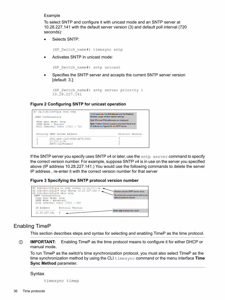
ExampleTo select SNTP and configure it with unicast mode and an SNTP server at10.28.227.141 with the default server version (3) and default poll interval (720seconds):
• Selects SNTP:
(HP_Switch_name#) timesync sntp
• Activates SNTP in unicast mode:
(HP_Switch_name#) sntp unicast
• Specifies the SNTP server and accepts the current SNTP server version[default: 3.]:
(HP_Switch_name#) sntp server priority 110.28.227.141
Figure 2 Configuring SNTP for unicast operation
If the SNTP server you specify uses SNTP v4 or later, use the sntp server command to specifythe correct version number. For example, suppose SNTP v4 is in use on the server you specifiedabove (IP address 10.28.227.141.) You would use the following commands to delete the serverIP address , re-enter it with the correct version number for that server
Figure 3 Specifying the SNTP protocol version number
Enabling TimePThis section describes steps and syntax for selecting and enabling TimeP as the time protocol.
IMPORTANT: Enabling TimeP as the time protocol means to configure it for either DHCP ormanual mode.To run TimeP as the switch's time synchronization protocol, you must also select TimeP as thetime synchronization method by using the CLI timesync command or the menu interface TimeSync Method parameter.
Syntaxtimesync timep
36 Time protocols

Selects TimeP as the time synchronization method.
Syntaxip timep dhcp|manual
Enables the selected TimeP mode.
Syntax[no]ip timep
Disables the TimeP mode.
Syntax[no]timesyncDisables the time protocol.
Enabling TimeP in DHCP modeBecause the switch provides a TimeP polling interval (default:720 minutes), you need only thesetwo commands for a minimal TimeP DHCP configuration:1. Enable the TimeP protocol as shown above.2. Select DHCP as the TimeP mode.
Syntaxip timep dhcp
Enabling and disabling time synchronization protocols 37
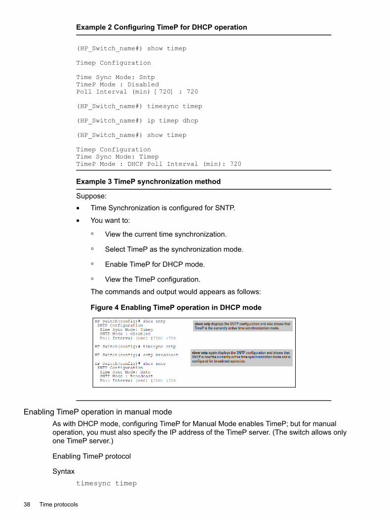
Example 2 Configuring TimeP for DHCP operation
(HP_Switch_name#) show timep
Timep Configuration
Time Sync Mode: SntpTimeP Mode : DisabledPoll Interval (min) [720] : 720
(HP_Switch_name#) timesync timep
(HP_Switch_name#) ip timep dhcp
(HP_Switch_name#) show timep
Timep ConfigurationTime Sync Mode: TimepTimeP Mode : DHCP Poll Interval (min): 720
Example 3 TimeP synchronization method
Suppose:• Time Synchronization is configured for SNTP.
• You want to:
◦ View the current time synchronization.
◦ Select TimeP as the synchronization mode.
◦ Enable TimeP for DHCP mode.
◦ View the TimeP configuration.
The commands and output would appears as follows:
Figure 4 Enabling TimeP operation in DHCP mode
Enabling TimeP operation in manual modeAs with DHCP mode, configuring TimeP for Manual Mode enables TimeP; but for manualoperation, you must also specify the IP address of the TimeP server. (The switch allows onlyone TimeP server.)
Enabling TimeP protocol
Syntaxtimesync timep
38 Time protocols

Select TimeP
Syntaxip timep manual <ip-addr>
This activates TimeP in manual mode with a specified TimeP server. (By default,SNTP traffic goes through the data ports.)
Example 4 Configuring TimeP for manual operation
To select TimeP and configure it for manual operation using a TimeP serveraddress of 10.28.227.141 and the default poll interval (720 minutes, assumingthe TimeP poll interval is already set to the default).
(HP_Switch_name#) timesync time
Selects TimeP and activates TimeP in manual mode:
(HP_Switch_name#) timesync timep(HP_Switch_name#) ip timep manual 10.28.227.141
(HP_Switch_name#) show timepTimep Configuration
Time Sync Mode: TimepTimeP Mode : Manual Server Address : 10.28.227.141Poll Interval (min) : 720
Viewing, enabling, and modifying the TimeP protocol (Menu)1. From the Main Menu, select:
2. Switch Configuration1. System Information
Figure 5 System Information screen (default values)
2. Press [E] (for Edit.)The cursor moves to the System Name field.
3. Use â to move the cursor to the Time Sync Method field.4. If TIMEP is not already selected, use the Space bar to select TIMEP, then press â once to
display and move to the TIMEP Mode field.
Enabling and disabling time synchronization protocols 39
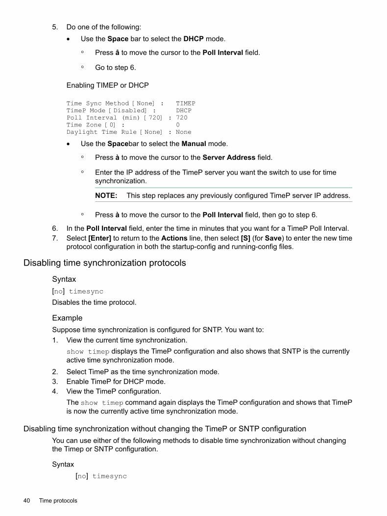
5. Do one of the following:• Use the Space bar to select the DHCP mode.
◦ Press â to move the cursor to the Poll Interval field.
◦ Go to step 6.
Enabling TIMEP or DHCP
Time Sync Method [None] : TIMEPTimeP Mode [Disabled] : DHCPPoll Interval (min) [720] : 720Time Zone [0] : 0Daylight Time Rule [None] : None
• Use the Spacebar to select the Manual mode.
◦ Press à to move the cursor to the Server Address field.
◦ Enter the IP address of the TimeP server you want the switch to use for timesynchronization.
NOTE: This step replaces any previously configured TimeP server IP address.
◦ Press à to move the cursor to the Poll Interval field, then go to step 6.
6. In the Poll Interval field, enter the time in minutes that you want for a TimeP Poll Interval.7. Select [Enter] to return to the Actions line, then select [S] (for Save) to enter the new time
protocol configuration in both the startup-config and running-config files.
Disabling time synchronization protocols
Syntax[no] timesync
Disables the time protocol.
ExampleSuppose time synchronization is configured for SNTP. You want to:1. View the current time synchronization.
show timep displays the TimeP configuration and also shows that SNTP is the currentlyactive time synchronization mode.
2. Select TimeP as the time synchronization mode.3. Enable TimeP for DHCP mode.4. View the TimeP configuration.
The show timep command again displays the TimeP configuration and shows that TimePis now the currently active time synchronization mode.
Disabling time synchronization without changing the TimeP or SNTP configurationYou can use either of the following methods to disable time synchronization without changingthe Timep or SNTP configuration.
Syntax[no] timesync
40 Time protocols

This disables time synchronization by changing the Time Sync Modeconfiguration to Disabled. This halts time synchronization without changing yourTimeP configuration. The recommended method for disabling time synchronizationis to use the timesync command.System Information screen of the Menu interface:a. Set the Time Synch Method parameter to None.b. Press [Enter], then [S] (for Save.)
ExampleSuppose TimeP is running as the switch's time synchronization protocol, withDHCP as the TimeP mode, and the factory-default polling interval. You would halttime synchronization with this command:
HP Switch (config#) no timesync
If you then viewed the TimeP configuration, you would see the following:
Example 5 TimeP with time synchronization disabled
(HP_Switch_name#) show timep
Timep ConfigurationTime Sync Mode: DisabledTimeP Mode : DHCP Poll Interval (min): 720
In another example, suppose SNTP is running as the switch's time synchronizationprotocol, with broadcast as the SNTP mode and the factory-default pollinginterval. You would halt time synchronization with this command:
(HP_Switch_name#) no timesync
If you then viewed the SNTP configuration, you would see the following:
HP_Switch_name#) show sntpSNTP ConfigurationTime Sync Mode: DisabledSNTP Mode : BroadcastPoll Interval (sec) [720] : 720
Disabling SNTP ModeIf you want to prevent the SNTP from being used even if it is selected by timesync (or the Menuinterface's Time Sync Method parameter), configure the SNTP mode as disabled.
Syntax[no] sntp
Disables SNTP by changing the SNTP mode configuration to Disabled.
Enabling and disabling time synchronization protocols 41

Example 6 Disabling time synchronization by disabling the SNTP mode
If the switch is running SNTP in unicast mode with an SNTP server at 10.28.227.141 and a serverversion of 3 (the default), no sntp changes the SNTP configuration as shown below and disablestime synchronization on the switch.
HP-5406zl(config)# no sntpHP-5406zl(config)# show sntp
SNTP ConfigurationSNTP Authentication : DisabledTime Sync Mode: SNTPSNTP Mode : disabledPoll Interval (sec) [720] : 719Source IP Selection: Outgoing Interface
Priority SNTP Server Address Version Key-id-------- --------------------------------------- ------- ----------1 2001:db8::215:60ff:fe79:8980 7 02 10.255.5.24 3 0
Deleting an SNTP server
Syntax[no] sntp server priority <priority> <ip-address>
Deletes the specified SNTP server.
NOTE: Deleting an SNTP server when only one server is configured disables SNTP unicastoperation.
Disabling SNTP by deleting a server
Syntax[no] sntp server priority <PRIORITY> <IP-ADDR | IPV6-ADDR> version key-id<KEY-ID>
Disabling SNTP by deleting the specified SNTP server. Uses the no version of the command todisable SNTP.
Disabling the TimeP mode
Disabling time synchronization in DHCP mode by disabling the TimeP mode parameterThe [no] ip timep command changes the TimeP configuration for both DHCP and manualmodes, as shown below, and disables time synchronization. Even though the TimeSync modeis set to TimeP, time synchronization is disabled because the no ip timep command hasdisabled the TimeP mode parameter.
Syntax[no] ip timep
42 Time protocols

Example 7 Disabling TimeP in DHCP mode
(HP_Switch_name#) no ip timep
(HP_Switch_name#) show timep
Timep ConfigurationTime Sync Mode: TimepTimeP Mode : Disabled
Example 8 Disabling TimeP in manual mode
Timep Configuration
Time Sync Mode: SntpTimeP Mode : DisabledPoll Interval (min) [720] : 720
(HP_Switch_name#) timesync timep
(HP_Switch_name#) ip timep manual
(HP_Switch_name#) show timep
Timep ConfigurationTime Sync Mode: TimepTimeP Mode : DHCP Poll Interval (min): 720
NOTE: To change from one TimeP server to another, you must use the no ip timepcommand to disable TimeP mode, then reconfigure TimeP in manual mode with the new serverIP address.
Viewing and configuring time synchronization protocol parametersViewing and configuring SNTP parameters
Viewing all SNTP server addresses configured on the switchThere are two methods to view all SNTP server addresses:• CLI
• GUITo view the SNTP server addresses using the CLI:
Command syntaxshow management
Displays all configured SNTP servers on the switch.
To view the SNTP server addresses using the GUI:The System Information screen in the menu interface displays only one SNTP server address,even if the switch is configured for two or three servers.
Viewing and configuring time synchronization protocol parameters 43

Example 9 How to list all SNTP servers configured on the switch
(HP_Switch_name#) show management
Status and Counters - Management Address InformationTime Server Address : fe80::215:60ff:fe7a:adc0%vlan10
Priority SNTP Server Address Protocol Version-------- ---------------------------------------------- ----------------1 2001:db8::215:60ff:fe79:8980 72 10.255.5.24 33 fe80::123%vlan10 3
Default Gateway : 10.0.9.80
VLAN Name MAC Address | IP Address------------ ------------------- + -------------------DEFAULT_VLAN 001279-88a100 | DisabledVLAN10 001279-88a100 | 10.0.10.17
Enabling SNTP client authenticationThe command sntp authentication enables SNTP client authentication on the switch. IfSNTP authentication is not enabled, SNTP packets are not authenticated.Enabling SNTP authentication allows network devices such as HPE switches to validate theSNTP messages received from an NTP or SNTP server before updating the network time. NTPor SNTP servers and clients must be configured with the same set of authentication keys so thatthe servers can authenticate the messages they send and clients (switches) can validate thereceived messages before updating the time.This feature provides support for SNTP client authentication on switches, which addressessecurity considerations when deploying SNTP in a network.
Requirements to enable SNTP client authenticationYou must configure all of the the following items to enable SNTP client authentication on theswitch.
SNTP client Authentication Support Requirements
• Timesync mode must be SNTP. Use the timesync sntp command. SNTP is disabled bydefault.
• SNTP must be in unicast or broadcast mode.
• The MD5 authentication mode must be selected.
• An SNTP authentication key-identifier (key-id) must be configured on the switch and avalue (key-value) must be provided for the authentication key. A maximum of 8 sets ofkey-id and key-value can be configured on the switch.
• Among the keys that have been configured, one key or a set of keys must be configured astrusted. Only trusted keys will be used for SNTP authentication.
• If the SNTP server requires authentication, one of the trusted keys has to be associated withthe SNTP server.
• SNTP client authentication must be enabled on the switch. If client authentication is disabled,packets are processed without authentication. All of the above steps are necessary to enableauthentication on the client.
44 Time protocols

SNTP server authentication supportThe following must be performed on the SNTP server:
• The same authentication key-identifier, trusted key, authentication mode and key-value thatwere configured on the SNTP client must also be configured on the SNTP server.
• SNTP server authentication must be enabled on the server. If any of the parameters on theserver are changed, the parameters have to be changed on all the SNTP clients in thenetwork as well. The authentication check will fail on the clients otherwise, and the SNTPpackets will be dropped.
NOTE: SNTP server is not supported on HPE products.
IMPORTANT: If any of the parameters on the server are changed, the parameters have to bechanged on all the SNTP clients in the network as well. The authentication check fails on theclients otherwise, and the SNTP packets are dropped.
Configuring other SNTP parameters
IMPORTANT: To run SNTP as the switch's time synchronization protocol, you must also selectSNTP as the time synchronization method by using the CLI timesync command, or the Menuinterface Time Sync Method parameter.
SNTP disabled
Syntaxsntp disabled
The default mode. SNTP does not operate, even if specified by the Menu interface Time SyncMethod parameter or the CLI timesync command.
SNTP for broadcast or unicast modeEnabling SNTP means configuring the time protocol for broadcast or unicast mode.
Poll interval
Syntaxsntp poll-interval <30-720>
Configures the poll interval, which is the amount of time between updates of the system clockvia SNTP.Specifies the amount of time between updates of the system clock via SNTP. The default is 720seconds and the range is 30 to 720 seconds.
IMPORTANT: This parameter is separate from the poll interval parameter used forTimeP operation.
NOTE: Enabling the SNTP mode also enables the SNTP poll interval.
Viewing and configuring time synchronization protocol parameters 45

Example 10 Changing an SNTP poll interval to 300 seconds
(HP_Switch_name#) sntp 300
SNTP unicast time polling with multiple SNTP servers
NOTE: When you use the Menu interface to configure an SNTP server IP address, the newaddress writes over the current primary address, if one is configured.
When running SNTP unicast time polling as the time synchronization method, the switch requestsa time update from the server you configured with either the Server Address parameter inthe menu interface, or the primary server in a list of up to three SNTP servers configured usingthe CLI. If the switch does not receive a response from the primary server after three consecutivepolling intervals, the switch tries the next server (if any) in the list. If the switch tries all serversin the list without success, it sends an error message to the Event Log and reschedules to trythe address list again after the configured Poll Interval time has expired.If there are already three SNTP server addresses configured on the switch, and you want to usethe CLI to replace one of the existing addresses with a new one, you must delete the unwantedaddress before you configure the new one.
Server priorityYou can choose the order in which configured servers are polled for getting the time by settingthe server priority.
Syntaxsntp server priority <1-3><ip-address>
Specifies the order in which the configured SNTP servers are polled for the current time. Valueis between 1 and 3.
NOTE: You can enter both IPv4 and IPv6 addresses.
ExampleTo set one server to priority 1 and another to priority 2:
(HP_Switch_name#) sntp server priority 1 10.28.22.141(HP_Switch_name#) sntp server priority 2 2001:db8::215:60ff:fe79:8980
VersionSpecifies the SNTP software version to use and is assigned on a per-server basis. The versionsetting is backwards-compatible. For example, using version 3 means that the switch acceptsversions 1 through 3. Default: 3; range: 1 to 7.
Syntaxsntp server <ip-address><version>
The protocol version of the SNTP server. Allowable values are 1 through 7; default is 3.
Server address
NOTE: Required only for unicast mode.
Specifies the IP address of the SNTP server that the switch accesses for time synchronizationupdates. You can configure up to three servers; one using the menu or CLI, and two more usingthe CLI.
46 Time protocols

Syntaxsntp server <ip-address>
An IPv4 or IPv6 address of an SNTP server.for information on usage in changing server priorities.
Adding and deleting SNTP server addresses
Adding addressesYou can configure one SNTP server address using either the Menu interface or the CLI. Toconfigure a second and third address, you must use the CLI. To configure these remaining twoaddresses, you would do the following:
Example
Example 11 Creating additional SNTP server addresses with the CLI
HP-5406zl(config)# no sntp server priority 1 2001:db8::215:60ff:fe79:8980HP-5406zl(config)# no sntp server priority 2 10.255.5.24
NOTE: If there are already three SNTP server addresses configured on the switch, and youwant to use the CLI to replace one of the existing addresses with a new one, you must deletethe unwanted address before you configure the new one.
Deleting addresses
Syntax[no]sntp server <PRIORITY><ip-addr>
Deletes a server address. If there are multiple addresses and you delete one of them, the switchre-orders the address priority.
Example 12 Converting a secondary address to primary
To delete the primary address and automatically convert the secondary address to primary:
(HP_Switch_name#) no sntp server 10.28.227.141
Viewing and configuring SNTP parameters (Menu)1. From the Main Menu, select:
2. Switch Configuration…1. System Information
Figure 6 System Information screen (default values)
Viewing and configuring time synchronization protocol parameters 47
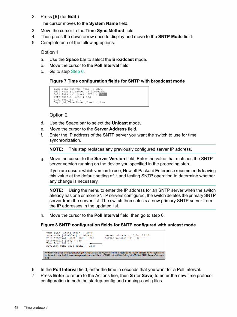
2. Press [E] (for Edit.)The cursor moves to the System Name field.
3. Move the cursor to the Time Sync Method field.4. Then press the down arrow once to display and move to the SNTP Mode field.5. Complete one of the following options.
Option 1a. Use the Space bar to select the Broadcast mode.b. Move the cursor to the Poll Interval field.c. Go to step Step 6.
Figure 7 Time configuration fields for SNTP with broadcast mode
Option 2d. Use the Space bar to select the Unicast mode.e. Move the cursor to the Server Address field.f. Enter the IP address of the SNTP server you want the switch to use for time
synchronization.
NOTE: This step replaces any previously configured server IP address.
g. Move the cursor to the Server Version field. Enter the value that matches the SNTPserver version running on the device you specified in the preceding step .If you are unsure which version to use, Hewlett Packard Enterprise recommends leavingthis value at the default setting of 3 and testing SNTP operation to determine whetherany change is necessary.
NOTE: Using the menu to enter the IP address for an SNTP server when the switchalready has one or more SNTP servers configured, the switch deletes the primary SNTPserver from the server list. The switch then selects a new primary SNTP server fromthe IP addresses in the updated list.
h. Move the cursor to the Poll Interval field, then go to step 6.
Figure 8 SNTP configuration fields for SNTP configured with unicast mode
6. In the Poll Interval field, enter the time in seconds that you want for a Poll Interval.7. Press Enter to return to the Actions line, then S (for Save) to enter the new time protocol
configuration in both the startup-config and running-config files.
48 Time protocols

Viewing and configuring TimeP parameters
IMPORTANT: To run TimeP as the switch's time synchronization protocol, you must also selectTimeP as the time synchronization method by using the CLI timesync command, or the Menuinterface Time Sync Method parameter.
TimeP parameters and their operations are listed below.
Disabling TimePThe default mode. Timep does not operate, even if specified by the Menu interface Time SyncMethod parameter or the CLI timesync command.
Syntaxtimep disabled
TimesyncThe timesync command configures the network time protocol for sntp or timep modes.
Enabling TimeP in DHCP or manual modeEnabling TimeP means configuring the protocol for DHCP or manual mode.
Poll interval
NOTE: This parameter is separate from the poll interval parameter used for SNTPoperation.
Specifies how long the switch waits between time polling intervals. The default is 720 minutesand the range is 1 to 9999 minutes.
Syntaxip timep [ dhcp | manual ] interval [<1-9999> ]
Changing the TimeP poll interval
Example 13 Changing the poll interval to 60 minutes
To change the poll interval to 60 minutes:
(HP_Switch_name#) ip timep interval 60
Server address
Syntaxip-address
This command can be used only when the TimePMode is set toManual. Specifiesthe IP address of the TimeP server that the switch accesses for timesynchronization updates. You can configure one server.
Changing from one TimeP server to another1. Use the no ip timep command to disable TimeP mode.2. Reconfigure TimeP in manual mode with the new server IP address.
Viewing and configuring time synchronization protocol parameters 49

Disabling time synchronizationEither of these methods can be used to disable time synchronization without changing the Timepor SNTP configuration.
SyntaxTo disable time synchronization using the CLI:no timesync
System Information screen of the Menu interface :a. Set the Time Synch Method parameter to None.b. Press [Enter], then [S] (for Save.)
Other time protocol commandsFeatures that apply to both SNTP and TimeP protocols.
Show management command
Syntaxshow management
This command shows the switch addresses available for management, and thetime server if the switch uses one. It can help you to easily examine and comparethe IP addressing on the switch. It lists the IP addresses for all time serversconfigured on the switch, plus the IP addresses and default gateway for all VLANsconfigured on the switch.
50 Time protocols

Example 14 Display showing IP addressing for all configured time serversand VLANs
HP-Switch(config)# show managementStatus and Counters - Management Address Information
Time Server Address : 10.10.28.100
Priority SNTP Server Address Protocol Version-------- ------------------- ----------------1 10.10.28.101 32 10.255.5.24 3
Default Gateway : 10.0.9.80
VLAN Name MAC Address | IP Address------------ -------------- + --------------DEFAULT_VLAN 001871-c42f00 | 10.30.248.184VLAN10 001871-c42f00 | 10.0.10.17
Internet (IPv6) Service
Interface Name : DEFAULT_VLANIPv6 Status : Disabled
Interface Name : VLAN10IPv6 Status : Disabled
Show SNTP command
NOTE: In the factory-default configuration (where TimeP is the selected time synchronizationmethod), show sntp still lists the SNTP configuration, even though it is not currently in use.
Syntaxshow sntp
Description: Shows configured time protocol and servers. Lists both the timesynchronization method (TimeP, SNTP, or None) and the SNTP configuration,even if SNTP is not the selected time protocol.
OptionsAuthentication Displays all the configured SNTP authentication
information.Statistics Displays SNTP protocol statistics.Configure the switch with SNTP as the time synchronization method, and thenenable SNTP in broadcast mode with the default poll interval, show sntp.
Other time protocol commands 51
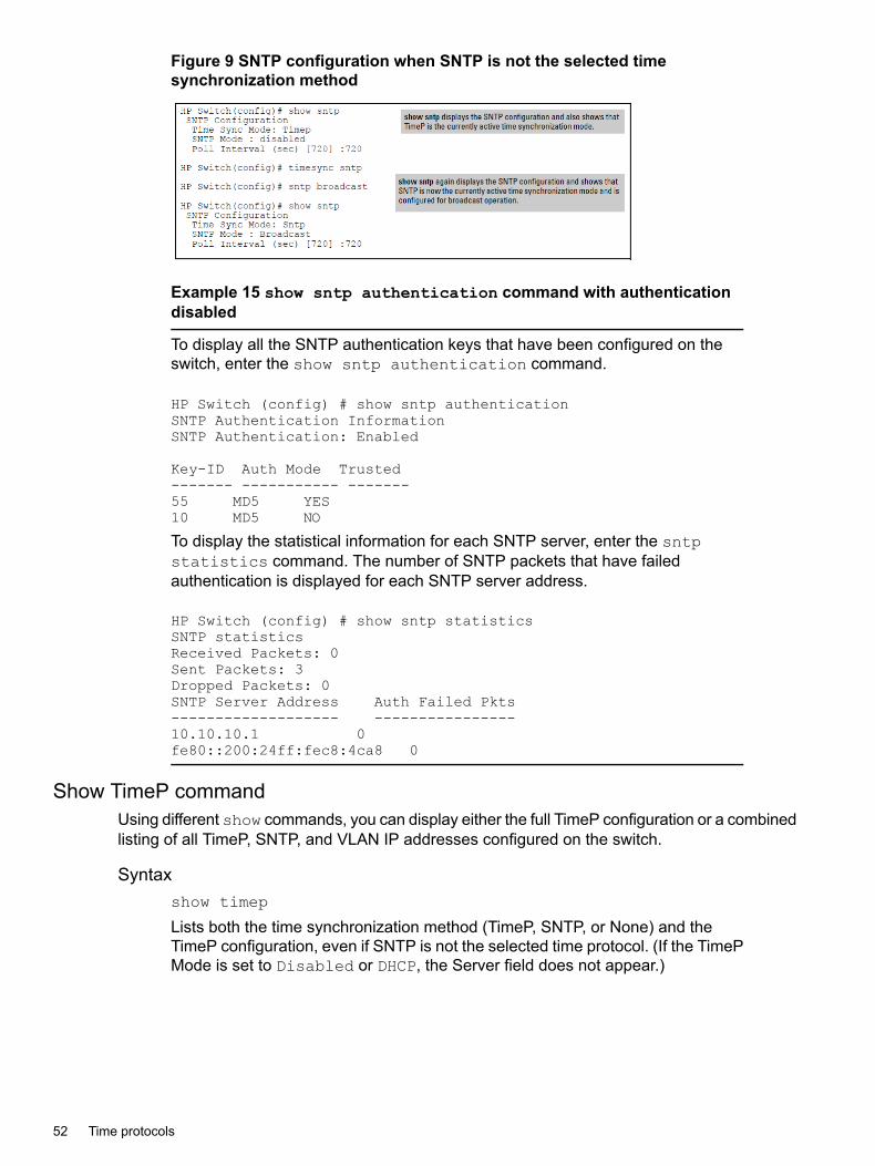
Figure 9 SNTP configuration when SNTP is not the selected timesynchronization method
Example 15 show sntp authentication command with authenticationdisabled
To display all the SNTP authentication keys that have been configured on theswitch, enter the show sntp authentication command.
HP Switch (config) # show sntp authenticationSNTP Authentication InformationSNTP Authentication: Enabled
Key-ID Auth Mode Trusted------- ----------- -------55 MD5 YES10 MD5 NO
To display the statistical information for each SNTP server, enter the sntpstatistics command. The number of SNTP packets that have failedauthentication is displayed for each SNTP server address.
HP Switch (config) # show sntp statisticsSNTP statisticsReceived Packets: 0Sent Packets: 3Dropped Packets: 0SNTP Server Address Auth Failed Pkts------------------- ----------------10.10.10.1 0fe80::200:24ff:fec8:4ca8 0
Show TimeP commandUsing different show commands, you can display either the full TimeP configuration or a combinedlisting of all TimeP, SNTP, and VLAN IP addresses configured on the switch.
Syntaxshow timep
Lists both the time synchronization method (TimeP, SNTP, or None) and theTimeP configuration, even if SNTP is not the selected time protocol. (If the TimePMode is set to Disabled or DHCP, the Server field does not appear.)
52 Time protocols
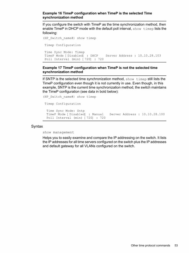
Example 16 TimeP configuration when TimeP is the selected Timesynchronization method
If you configure the switch with TimeP as the time synchronization method, thenenable TimeP in DHCP mode with the default poll interval, show timep lists thefollowing:(HP_Switch_name#) show timep
Timep Configuration
Time Sync Mode: TimepTimeP Mode [Disabled] : DHCP Server Address : 10.10.28.103Poll Interval (min) [720] : 720
Example 17 TimeP configuration when TimeP is not the selected timesynchronization method
If SNTP is the selected time synchronization method, show timep still lists theTimeP configuration even though it is not currently in use. Even though, in thisexample, SNTP is the current time synchronization method, the switch maintainsthe TimeP configuration (see data in bold below):(HP_Switch_name#) show timep
Timep Configuration
Time Sync Mode: SntpTimeP Mode [Disabled] : Manual Server Address : 10.10.28.100Poll Interval (min) [720] : 720
Syntaxshow management
Helps you to easily examine and compare the IP addressing on the switch. It liststhe IP addresses for all time servers configured on the switch plus the IP addressesand default gateway for all VLANs configured on the switch.
Other time protocol commands 53

Example 18 Display showing IP addressing for all configured time serversand VLANs
(HP_Switch_name#) show management
Status and Counters - Management Address Information
Time Server Address : 10.10.28.100
Priority SNTP Server Address ProtocolVersion-------- ----------------------------------------------
----------------1 10.10..28.101 32 10.255.5.24 33 fe80::123%vlan10 3
Default Gateway : 10.0.9.80
VLAN Name MAC Address | IP Address------------ ------------------- + -------------------DEFAULT_VLAN 001279-88a100 | 10.30.248.184VLAN10 001279-88a100 | 10.0.10.17
Viewing and configuring SNTPSyntax
show sntp
Lists both the time synchronization method (TimeP, SNTP, or None) and the SNTPconfiguration (even if SNTP is not the selected time protocol) and the statistics.
ExampleIf you configure the switch with SNTP as the time synchronization method, thenenable SNTP in broadcast mode with the default poll interval, show sntp liststhe following:
Figure 10 SNTP configuration when SNTP is the selected timesynchronization method
In the factory-default configuration (where TimeP is the selected timesynchronization method), show sntp still lists the SNTP configuration, eventhough it is not currently in use.
54 Time protocols

Figure 11 SNTP configuration
Syntaxshow management
This command can help you to easily examine and compare the IP addressingon the switch. It lists the IP addresses for all time servers configured on the switch,plus the IP addresses and default gateway for all VLANs configured on the switch.
Figure 12 Display showing IP addressing for all configured time servers andVLANs
Enabling or disabling the SNTP modeIf you want to prevent SNTP from being used even if it is selected by timesync (or the Menuinterface's Time Sync Method parameter), configure the SNTP mode as disabled.
Syntaxno sntp
Disables SNTP by changing the SNTP mode configuration to Disabled.
ExampleIf the switch is running SNTP in unicast mode with an SNTP server at 10.28.227.141 and a serverversion of 3 (the default), no sntp changes the SNTP configuration as shown below and disablestime synchronization on the switch.
Enabling or disabling the SNTP mode 55

Figure 13 Disabling time synchronization by disabling the SNTP mode
Configuring the SNTP modeEnabling the SNTP mode means to configure it for either broadcast or unicast mode. Rememberthat to run SNTP as the switch's time synchronization protocol, you must also select SNTP asthe time synchronization method by using the CLI timesync command (or the menu interfaceTime Sync Method parameter.)
Syntaxtimesync sntp
Selects SNTP as the time protocol.sntp <broadcast|unicast>Enables the SNTP mode.
Syntaxsntp server <ip-addr>
Required only for unicast mode.
Syntaxsntp server priority <1-3>
Specifies the order in which the configured servers are polled for getting the time.Value is between 1 and 3.
Syntaxsntp <30-720>
Configures the amount of time between updates of the system clock via SNTP.Default: 720 seconds
Enabling SNTP in broadcast modeBecause the switch provides an SNTP polling interval (default:720 seconds), you need only thesetwo commands for minimal SNTP broadcast configuration:
Syntaxtimesync sntp
Selects SNTP as the time synchronization method.
Syntaxsntp broadcast
Configures broadcast as the SNTP mode.
56 Time protocols

Example 19 Enable SNTP for broadcast mode
Suppose that time synchronization is in the factory-default configuration (TimeP is the currentlyselected time synchronization method.) Complete the following:1. View the current time synchronization.2. Select SNTP as the time synchronization mode.3. Enable SNTP for Broadcast mode.4. View the SNTP confguration again to verify the configuration.The commands and output would appear as follows:
Enabling or disabling in Broadcast modeThe switch provides an SNTP polling interval (default:720 seconds.) You need the two followingcommands for minimal SNTP broadcast configuration.
Syntaxtimesync sntp
Selects SNTP as the time synchronization method.
Syntaxsntp broadcast
Configures broadcast as the SNTP mode.
ExampleSuppose time synchronization is in the factory-default configuration (TimeP is the currentlyselected time synchronization method.)You want to:1. View the current time synchronization: show sntp displays the SNTP configuration and
also shows that TimeP is the currently active time synchronization mode.2. Select SNTP as the time synchronization mode.3. Enable SNTP for .4. View the SNTP configuration again to verify the configuration.The commands and output appear as follows:
Enabling or disabling in Broadcast mode 57

Figure 14 show sntp configuration output
SNTP in unicast modeLike , configuring SNTP for unicast mode enables SNTP. However, for unicast operation, youmust also specify the IP address of at least one SNTP server. The switch allows up to threeunicast servers. You can use the Menu interface or the CLI to configure one server or to replacean existing unicast server with another. To add a second or third server, you must use the CLI.
Syntaxtimesync sntp
Selects SNTP as the time synchronization method.
Syntaxsntp unicast
Configures the SNTP mode for unicast operation.
Syntax[no] sntp server priority [ 1-3 ] ip-address [ oobm ] [ version ]Use the no version of the command to disable SNTP.priority Specifies the order in which the configured SNTP servers are polled for the
time.ip-address An IPv4 or IPv6 address of an SNTP server.oobm For switches that have a separate out-of-band management port, specifies that
SNTP traffic goes through that port. (By default, SNTP traffic goes through thedata ports.)
version The protocol version of the SNTP server. Allowable values are 1 through 7;default is 3.
Syntaxno sntp server <ip-addr>
Deletes the specified SNTP server.
NOTE: Deleting an SNTP server when only one is configured disables SNTP unicast operation.
ExampleTo select SNTP and configure it with unicast mode and an SNTP server at 10.28.227.141 withthe default server version (3) and default poll interval (720 seconds):
HP Switch(config)# timesync sntp
Selects SNTP.
58 Time protocols
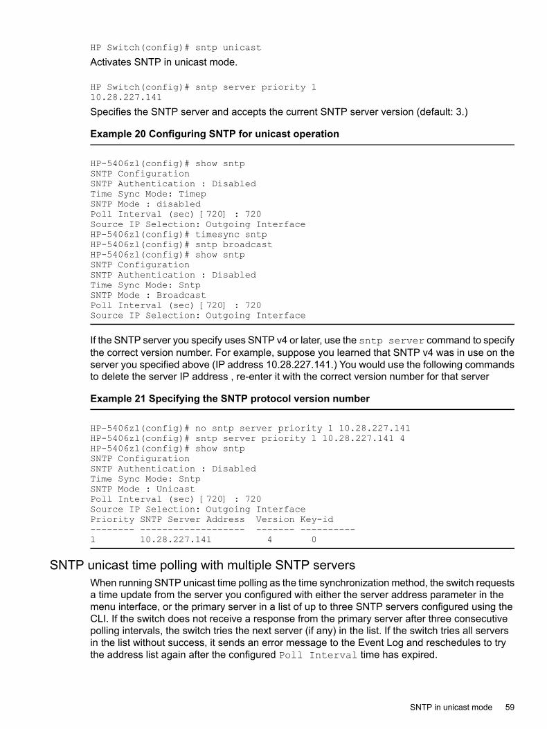
HP Switch(config)# sntp unicast
Activates SNTP in unicast mode.
HP Switch(config)# sntp server priority 110.28.227.141
Specifies the SNTP server and accepts the current SNTP server version (default: 3.)
Example 20 Configuring SNTP for unicast operation
HP-5406zl(config)# show sntpSNTP ConfigurationSNTP Authentication : DisabledTime Sync Mode: TimepSNTP Mode : disabledPoll Interval (sec) [720] : 720Source IP Selection: Outgoing InterfaceHP-5406zl(config)# timesync sntpHP-5406zl(config)# sntp broadcastHP-5406zl(config)# show sntpSNTP ConfigurationSNTP Authentication : DisabledTime Sync Mode: SntpSNTP Mode : BroadcastPoll Interval (sec) [720] : 720Source IP Selection: Outgoing Interface
If the SNTP server you specify uses SNTP v4 or later, use the sntp server command to specifythe correct version number. For example, suppose you learned that SNTP v4 was in use on theserver you specified above (IP address 10.28.227.141.) You would use the following commandsto delete the server IP address , re-enter it with the correct version number for that server
Example 21 Specifying the SNTP protocol version number
HP-5406zl(config)# no sntp server priority 1 10.28.227.141HP-5406zl(config)# sntp server priority 1 10.28.227.141 4HP-5406zl(config)# show sntpSNTP ConfigurationSNTP Authentication : DisabledTime Sync Mode: SntpSNTP Mode : UnicastPoll Interval (sec) [720] : 720Source IP Selection: Outgoing InterfacePriority SNTP Server Address Version Key-id-------- ------------------- ------- ----------1 10.28.227.141 4 0
SNTP unicast time polling with multiple SNTP serversWhen running SNTP unicast time polling as the time synchronization method, the switch requestsa time update from the server you configured with either the server address parameter in themenu interface, or the primary server in a list of up to three SNTP servers configured using theCLI. If the switch does not receive a response from the primary server after three consecutivepolling intervals, the switch tries the next server (if any) in the list. If the switch tries all serversin the list without success, it sends an error message to the Event Log and reschedules to trythe address list again after the configured Poll Interval time has expired.
SNTP in unicast mode 59
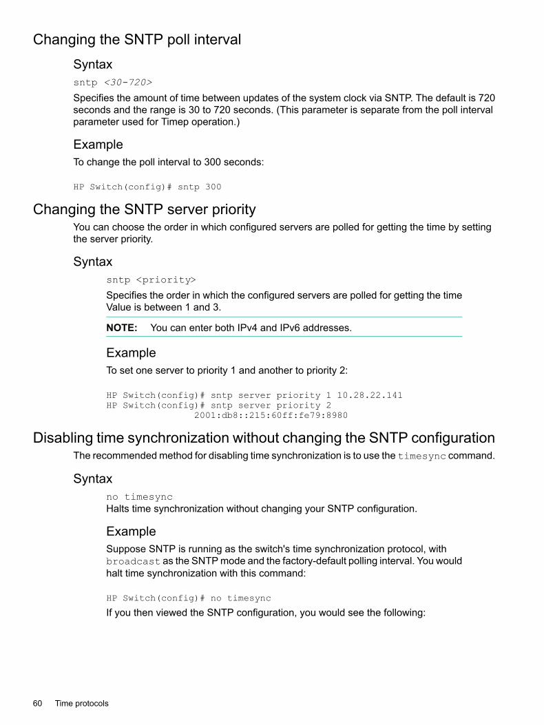
Changing the SNTP poll intervalSyntaxsntp <30-720>
Specifies the amount of time between updates of the system clock via SNTP. The default is 720seconds and the range is 30 to 720 seconds. (This parameter is separate from the poll intervalparameter used for Timep operation.)
ExampleTo change the poll interval to 300 seconds:
HP Switch(config)# sntp 300
Changing the SNTP server priorityYou can choose the order in which configured servers are polled for getting the time by settingthe server priority.
Syntaxsntp <priority>
Specifies the order in which the configured servers are polled for getting the timeValue is between 1 and 3.
NOTE: You can enter both IPv4 and IPv6 addresses.
ExampleTo set one server to priority 1 and another to priority 2:
HP Switch(config)# sntp server priority 1 10.28.22.141HP Switch(config)# sntp server priority 2
2001:db8::215:60ff:fe79:8980
Disabling time synchronization without changing the SNTP configurationThe recommended method for disabling time synchronization is to use the timesync command.
Syntaxno timesyncHalts time synchronization without changing your SNTP configuration.
ExampleSuppose SNTP is running as the switch's time synchronization protocol, withbroadcast as the SNTP mode and the factory-default polling interval. You wouldhalt time synchronization with this command:
HP Switch(config)# no timesync
If you then viewed the SNTP configuration, you would see the following:
60 Time protocols
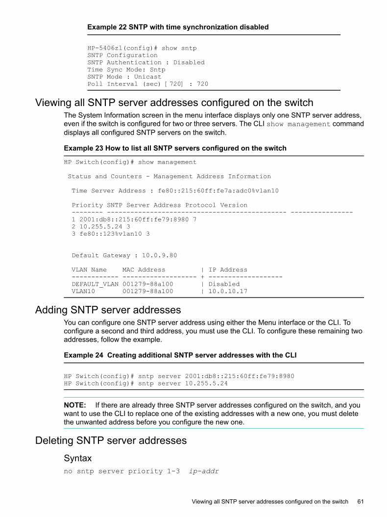
Example 22 SNTP with time synchronization disabled
HP-5406zl(config)# show sntpSNTP ConfigurationSNTP Authentication : DisabledTime Sync Mode: SntpSNTP Mode : UnicastPoll Interval (sec) [720] : 720
Viewing all SNTP server addresses configured on the switchThe System Information screen in the menu interface displays only one SNTP server address,even if the switch is configured for two or three servers. The CLI show management commanddisplays all configured SNTP servers on the switch.
Example 23 How to list all SNTP servers configured on the switch
HP Switch(config)# show management
Status and Counters - Management Address Information
Time Server Address : fe80::215:60ff:fe7a:adc0%vlan10
Priority SNTP Server Address Protocol Version-------- ---------------------------------------------- ----------------1 2001:db8::215:60ff:fe79:8980 72 10.255.5.24 33 fe80::123%vlan10 3
Default Gateway : 10.0.9.80
VLAN Name MAC Address | IP Address------------ ------------------- + -------------------DEFAULT_VLAN 001279-88a100 | DisabledVLAN10 001279-88a100 | 10.0.10.17
Adding SNTP server addressesYou can configure one SNTP server address using either the Menu interface or the CLI. Toconfigure a second and third address, you must use the CLI. To configure these remaining twoaddresses, follow the example.
Example 24 Creating additional SNTP server addresses with the CLI
HP Switch(config)# sntp server 2001:db8::215:60ff:fe79:8980HP Switch(config)# sntp server 10.255.5.24
NOTE: If there are already three SNTP server addresses configured on the switch, and youwant to use the CLI to replace one of the existing addresses with a new one, you must deletethe unwanted address before you configure the new one.
Deleting SNTP server addressesSyntaxno sntp server priority 1-3 ip-addr
Viewing all SNTP server addresses configured on the switch 61

Deletes a server address. If there are multiple addresses and you delete one of them, the switchre-orders the address priority.
ExampleTo delete the primary address and automatically convert the secondary address to primary:
HP Switch(config)# no sntp server 10.28.227.141
Configuring the key-identifier, authentication mode, and key-valueConfigures the key-id, authentication-mode, and key-value, which are required forauthentication. It is executed in the global configuration context.At least one key-id must be configured as trusted, and it must be associated with one of theSNTP servers. To edit or remove the associated key-id information or SNTP server information,SNTP authentication must be disabled.
Syntaxsntp authentication key-id <key-id> authentication-mode md5key-value <key-string> trusted [encrypted-key <key-string>]Configures a key-id, authentication-mode (MD5 only), and key-value, which arerequired for authentication.key-id
A numeric key identifier in the range of 1-4,294,967,295 (232) that identifies theunique key value. It is sent in the SNTP packet.key-value <key-string>
The secret key that is used to generate the message digest. Up to 32 charactersare allowed for key-string.
Syntaxno sntp authentication key-id <key-id>
The no version of the command deletes the authentication key.Default: No default keys are configured on the switch.
Syntaxno sntp authentication key-id key-id
Configures a key-id, authentication-mode (MD5 only), and key-value, which arerequired for authentication.The no version of the command deletes the authentication key.Default: No default keys are configured on the switch.A numeric key identifier in the range of 1-4,294,967,295 (232) that identifies theunique key value. It is sent in the SNTP packet.The secret key that is used to generate the message digest. Up to 32 charactersare allowed for key-string.
62 Time protocols

NOTE: For the 5400zl, and 3800 switches, when the switch is in enhancedsecure mode, commands that take a secret key as a parameter have the echo ofthe secret typing replaced with asterisks. The input for <key-string> is promptedfor interactively.encrypted-key <key-string>
Set the SNTP authentication key value using a base64–encoded aes-256encrypted string.
Example 25 Setting parameters for SNTP authentication(HP_Switch_name#) sntp authentication key-id 55 authentication-mode md5 key-value secretkey1
Configuring a key-id as trusted• Trusted keys are used in SNTP authentication.
• If the packet contains key-id value information that is not configured on the SNTP clientswitch, or if the received packet contains no authentication information, it is discarded. TheSNTP client switch expects packets to be authenticated if SNTP authentication is enabled.
• When authentication succeeds, the time in the packet is used to update the time on theswitch.
• In unicast mode: The trusted key is associated with a specific NTP/SNTP server, andconfigured on the switch so that the SNTP client communicates with the server to get thedate and time. The key is used for authenticating the SNTP packet.
• In : The SNTP client switch checks the size of the received packet to determine if it isauthenticated. If the broadcast packet is authenticated, the key-id value is checked to seeif the same key-id value is configured on the SNTP client switch. If the switch is configuredwith the same key-id value, and the key-id value is configured as "trusted," the authenticationsucceeds. Only trusted key-id value information is used for SNTP authentication.
Syntaxsntp authentication key-id <key-id> trusted
Syntaxno sntp authentication key-id <key-id> trusted
Trusted keys are used during the authentication process. You can configure the switch with upto eight sets of key-id/key-value pairs. One specific set must selected for authentication; this isdone by configuring the set as trusted.The key-id itself must already be configured on the switch. To enable authentication, at leastone key-id must be configured as trusted.The no version of the command indicates the key is unreliable (not trusted).Default: No key is trusted by default.
Associating a key with an SNTP server
Syntax[no] sntp server priority 1-3 [<ip-address> | <ipv6-address>]<version-num> [ key-id <1-4,294,967,295> ]Configures a to be associated with a specific server. The key itself must alreadybe configured on the switch.
Configuring the key-identifier, authentication mode, and key-value 63

The no version of the command disassociates the key from the server. This doesnot remove the authentication key.Default: No key is associated with any server by default.
• priority
Specifies the order in which the configured servers are polled for getting thetime.
• version-num
Specifies the SNTP software version to use and is assigned on a per-serverbasis. The version setting is backwards-compatible. For example, usingversion 3 means that the switch accepts versions 1 through 3. Default: 3;range: 1 - 7.
• key-id
Optional command. The key identifier sent in the SNTP packet. This key-idis associated with the SNTP server specified in the command.
Example 26 Associating a key-id with a specific server
(HP_Switch_name#) sntp server priority 1 10.10.19.5 2 key-id 55
Enabling and disabling SNTP client authenticationThe sntp authentication command enables SNTP client authentication on the switch. IfSNTP authentication is not enabled, SNTP packets are not authenticated.
Syntax[no] sntp authentication
Enables the SNTP client authentication.The no version of the command disables authentication.Default: SNTP client authentication is disabled .
Viewing SNTP authentication configuration informationThe show sntp command displays SNTP configuration information, including any SNTPauthentication keys that have been configured on the switch.
64 Time protocols

Example 27 SNTP configuration information
(HP_Switch_name#) show sntp
SNTP Configuration
SNTP Authentication : EnabledTime Sync Mode: SntpSNTP Mode : UnicastPoll Interval (sec) [720] : 720
Priority SNTP Server Address Protocol Version KeyId-------- --------------------------------------- ---------------- -----1 10.10.10.2 3 552 fe80::200:24ff:fec8:4ca8 3 55
Example 28 show sntp authentication command output
To display all the SNTP authentication keys that have been configured on the switch, enter theshow sntp authentication command.HP Switch (config) # show sntp authenticationSNTP Authentication InformationSNTP Authentication: EnabledKey-ID Auth Mode Trusted------- ----------- -------55 MD5 YES10 MD5 NO
To display the statistical information for each SNTP server, enter the sntp statisticscommand. The number of SNTP packets that have failed authentication is displayed for eachSNTP server address.HP Switch (config) # show sntp statisticsSNTP statisticsReceived Packets: 0Sent Packets: 3Dropped Packets: 0
SNTP Server Address Auth Failed Pkts------------------- ----------------10.10.10.1 0fe80::200:24ff:fec8:4ca8 0
Viewing statistical information for each SNTP serverTo display the statistical information for each SNTP server, enter the show sntp statisticscommand.
Syntaxshow sntp statistics
Shows the number of SNTP packets that have failed authentication for each SNTPserver address.
Configuring the key-identifier, authentication mode, and key-value 65

Example 29 SNTP authentication statistical information
(HP_Switch_name#) show sntp statisticsSNTP Statistics
Received Packets : 0Sent Packets : 3Dropped Packets : 0
SNTP Server Address Auth Failed Pkts--------------------------------------- ----------------10.10.10.1 0fe80::200:24ff:fec8:4ca8 0
Example 30 show sntp statistics command
Displays all SNTP authentication keys configured on the switch.
HP Switch (config) # show sntp authenticationSNTP Authentication InformationSNTP Authentication: Enabled
Key-ID Auth Mode Trusted------- ----------- -------55 MD5 YES10 MD5 NO
Shows the statistical information for each SNTP server. The number of SNTP packets that havefailed authentication is displayed for each SNTP server address.
HP Switch (config) # show sntp statisticsSNTP statisticsReceived Packets: 0Sent Packets: 3Dropped Packets: 0SNTP Server Address Auth Failed Pkts------------------- ----------------10.10.10.1 0fe80::200:24ff:fec8:4ca8 0
Configuring a key-id as trusted
Syntaxsntp authentication key-id key-id trusted
Syntaxno sntp authentication key-id key-id trusted
Trusted keys are used during the authentication process. You can configure the switch with upto eight sets of key-id/key-value pairs. One specific set must selected for authentication; this isdone by configuring the set as trusted. The key-id itself must already be configured on theswitch. To enable authentication, at least one key-id must be configured as trusted.The no version of the command indicates the key is unreliable (not trusted.)Default: No key is trusted by default.
66 Time protocols

Associating a key with an SNTP serverSyntax
[no] sntp server priority 1-3 ip-address | ipv6-addressversion-num [ key-id 1-4,294,967,295 ]Configures a key-id to be associated with a specific server. The key itself mustalready be configured on the switch.The no version of the command disassociates the key from the server. This doesnot remove the authentication key.Default: No key is associated with any server by default.priority Specifies the order in which the configured servers are polled
for getting the time.version-num Specifies the SNTP software version to use and is assigned
on a per-server basis. The version setting isbackwards-compatible. For example, using version 3 meansthat the switch accepts versions 1 through 3. Default: 3; range:1 - 7.
key-id Optional command. The key identifier sent in the SNTP packet.This key-id is associated with the SNTP server specified inthe command.
Example 31 Associating a key-id with a specific server
HP Switch(config)# sntp server priority 1 10.10.19.5 2 key-id 55
Configuring unicast and for authenticationIMPORTANT: To enable authentication, you must configure either unicast or broadcast mode.After authentication is enabled, changing the mode from unicast to broadcast or vice versa isnot allowed; you must disable authentication and then change the mode.
To set the SNTP mode or change from one mode to the other, enter the appropriate command.
Syntaxsntp unicastsntp broadcast
Enables SNTP for either broadcast or unicast mode.Unicast Directs the switch to poll a specific server periodically for SNTP time
synchronization.The default value between each polling request is 720 seconds, but can beconfigured.At least one manually configured server IP address is required.
NOTE: At least one key-id must be configured as trusted, and it must beassociated with one of the SNTP servers. To edit or remove the associatedkey-id information or SNTP server information, SNTP authentication must bedisabled.
Broadcast Directs the switch to acquire its time synchronization from data broadcast by anySNTP server to the network broadcast address. The switch uses the first serverdetected and ignores any others. However, if the Poll Interval (configurable up
Associating a key with an SNTP server 67

to 720 seconds) expires three times without the switch detecting a time updatefrom the original server, the switch accepts a broadcast time update from thenext server it detects.
Viewing SNTP authentication configuration informationThe show sntp command displays SNTP configuration information, including any SNTPauthentication keys that have been configured on the switch.
Example 32 SNTP configuration information
HP Switch(config)# show sntp
SNTP Configuration
SNTP Authentication : EnabledTime Sync Mode: SntpSNTP Mode : UnicastPoll Interval (sec) [720] : 720
Priority SNTP Server Address Protocol Version KeyId-------- --------------------------------------- ---------------- -----1 10.10.10.2 3 552 fe80::200:24ff:fec8:4ca8 3 55
Example 33 show sntp authentication
To display all the SNTP authentication keys that have been configured on the switch, enter theshow sntp authentication command.HP Switch (config) # show sntp authenticationSNTP Authentication InformationSNTP Authentication: EnabledKey-ID Auth Mode Trusted------- ----------- -------55 MD5 YES10 MD5 NO
Example 34 SNTP Statistics command output
To display the statistical information for each SNTP server, enter the sntp statisticscommand. The number of SNTP packets that have failed autherntication is displayed for eachSNTP server address.HP Switch (config) # show sntp statisticsSNTP statisticsReceived Packets: 0Sent Packets: 3Dropped Packets: 0
SNTP Server Address Auth Failed Pkts------------------- ----------------10.10.10.1 0fe80::200:24ff:fec8:4ca8 0
Viewing all SNTP authentication keys that have been configured on theswitch
Enter the show sntp authentication command.
68 Time protocols

Example 35 Show SNTP authentication command output
HP Switch(config)# show sntp authentication
SNTP Authentication Information
SNTP Authentication : Enabled
Key-ID Auth Mode Trusted------- ---------- --------55 MD5 Yes10 MD5 No
Viewing statistical information for each SNTP serverTo display the statistical information for each SNTP server, enter the show sntp statisticscommand.The number of SNTP packets that have failed authentication is displayed for each SNTP serveraddress.
ExampleHP Switch(config)# show sntp statisticsSNTP Statistics
Received Packets : 0Sent Packets : 3Dropped Packets : 0
SNTP Server Address Auth Failed Pkts--------------------------------------- ----------------10.10.10.1 0fe80::200:24ff:fec8:4ca8 0
Storing security information in the running-config fileEnter the include-credentials command.
Viewing and configuring SNTP (Menu)1. From the Main Menu, select:2. 2. Switch Configuration…
1. System Information
Figure 15 System Information screen (default values)
Viewing statistical information for each SNTP server 69
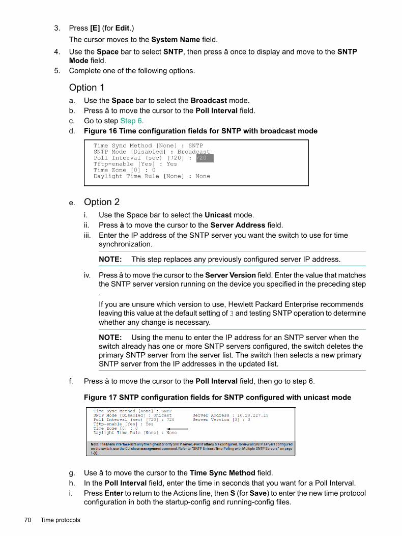
3. Press [E] (for Edit.)The cursor moves to the System Name field.
4. Use the Space bar to select SNTP, then press â once to display and move to the SNTPMode field.
5. Complete one of the following options.
Option 1a. Use the Space bar to select the Broadcast mode.b. Press â to move the cursor to the Poll Interval field.c. Go to step Step 6.d. Figure 16 Time configuration fields for SNTP with broadcast mode
e. Option 2i. Use the Space bar to select the Unicast mode.ii. Press à to move the cursor to the Server Address field.iii. Enter the IP address of the SNTP server you want the switch to use for time
synchronization.
NOTE: This step replaces any previously configured server IP address.
iv. Press â to move the cursor to the Server Version field. Enter the value that matchesthe SNTP server version running on the device you specified in the preceding step.If you are unsure which version to use, Hewlett Packard Enterprise recommendsleaving this value at the default setting of 3 and testing SNTP operation to determinewhether any change is necessary.
NOTE: Using the menu to enter the IP address for an SNTP server when theswitch already has one or more SNTP servers configured, the switch deletes theprimary SNTP server from the server list. The switch then selects a new primarySNTP server from the IP addresses in the updated list.
f. Press à to move the cursor to the Poll Interval field, then go to step 6.
Figure 17 SNTP configuration fields for SNTP configured with unicast mode
g. Use â to move the cursor to the Time Sync Method field.h. In the Poll Interval field, enter the time in seconds that you want for a Poll Interval.i. Press Enter to return to the Actions line, then S (for Save) to enter the new time protocol
configuration in both the startup-config and running-config files.
70 Time protocols

Viewing the current TimeP configurationUsing different show commands, you can display either the full TimeP configuration or a combinedlisting of all TimeP, SNTP, and VLAN IP addresses configured on the switch.
Syntaxshow timep
Lists both the time synchronization method (TimeP, SNTP, or None) and theTimeP configuration, even if SNTP is not the selected time protocol. (If the TimePMode is set to Disabled or DHCP, the Server field does not appear.)
Example 36 TimeP configuration when TimeP is the selected Timesynchronization method
If you configure the switch with TimeP as the time synchronization method, thenenable TimeP in DHCP mode with the default poll interval, show timep lists thefollowing:HP Switch(config)# show timep
Timep Configuration
Time Sync Mode: TimepTimeP Mode [Disabled] : DHCP Server Address : 10.10.28.103Poll Interval (min) [720] : 720
Example 37 TimeP configuration when TimeP is not the selected timesynchronization method
If SNTP is the selected time synchronization method, show timep still lists theTimeP configuration even though it is not currently in use. Even though, in thisexample, SNTP is the current time synchronization method, the switch maintainsthe TimeP configuration.HP Switch(config)# show timep
Timep Configuration
Time Sync Mode: SntpTimeP Mode [Disabled] : Manual Server Address : 10.10.28.100Poll Interval (min) [720] : 720
Syntaxshow management
Helps you to easily examine and compare the IP addressing on the switch. It liststhe IP addresses for all time servers configured on the switch plus the IP addressesand default gateway for all VLANs configured on the switch.
Viewing the current TimeP configuration 71

Example 38 Showing IP addressing for all configured time servers andVLANs
HP Switch(config)# show management
Status and Counters - Management Address Information
Time Server Address : 10.10.28.100
Priority SNTP Server Address ProtocolVersion-------- ----------------------------------------------
----------------1 10.10..28.101 32 10.255.5.24 33 fe80::123%vlan10 3
Default Gateway : 10.0.9.80
VLAN Name MAC Address | IP Address------------ ------------------- + -------------------DEFAULT_VLAN 001279-88a100 | 10.30.248.184VLAN10 001279-88a100 | 10.0.10.17
Enabling TimeP modeEnabling the TimeP mode configures it for either broadcast or unicast. Run TimeP as the switch'stime synchronization protocol and select TimeP as the time synchronization method by usingthe CLI timesync command (or the menu interface Time Sync Method parameter.
Syntaxtimesync timep
Selects TimeP as the time synchronization method.
Syntaxip timep <dhcp|manual>
Enables the selected TimeP mode.
72 Time protocols

Example 39 Enabling TimeP for DHCP
Suppose time synchronization is configured for SNTP. Following this example to enable TimePfor DHCP.1. View the current time synchronization.2. show timep displays the TimeP configuration and also shows that SNTP is the currently
active time synchronization mode.3. Select TimeP as the time synchronization mode.4. Enable TimeP for DHCP mode.5. View the TimeP configuration.6. show timep again displays the TimeP configuration and shows that TimeP is now the
currently active time synchronization mode.
HP Switch(config)# show timep
Timep Configuration
Time Sync Mode: SntpTimeP Mode : DisabledPoll Interval (min) [720] : 720
HP Switch(config)# timesync timep
HP Switch(config)# ip timep dhcp
HP Switch(config)# show timep
Timep ConfigurationTime Sync Mode: TimepTimeP Mode : DHCP Poll Interval (min): 720
Disabling TimeP modeSyntax
[no]ip timep
Disables the TimeP mode.
Syntax[no]timesyncDisables the time protocol.
Enabling TimeP in manual modeLike DHCP mode, configuring TimeP for manual mode enables TimeP. However, for manualoperation, you must also specify the IP address of the TimeP server. (The switch allows onlyone TimeP server.)
Syntaxtimesync timep
Selects TimeP.
Syntaxip timep manual ip-addr
Activates TimeP in manual mode with a specified TimeP server.
Disabling TimeP mode 73

For switches that have a separate out-of-band management port, oobm specifiesthat SNTP traffic goes through that port. (By default, SNTP traffic goes throughthe data ports.)
Disabling TimeP in manual mode
Syntaxno ip timep
Disables TimeP.
Enabling TimeP in DHCP ModeBecause the switch provides a TimeP polling interval (default:720 minutes), you need only thesetwo commands for a minimal TimeP DHCP configuration:
Syntaxtimesync timep
Selects TimeP as the time synchronization method.
Syntaxip timep dhcp
Configures DHCP as the TimeP mode.
Example 40 TimeP synchronization method
Follow this example to enable TimeP for DHCP mode if Time Synchronization is configured forSNTP.1. View the current time synchronization.2. Select TimeP as the synchronization mode.3. Enable TimeP for DHCP mode.4. View the TimeP configuration.
HP-5406zl(config)# show timepTimep ConfigurationTime Sync Mode: TimepTimeP Mode [Disabled] : Disabled
Enabling TimeP in Manual Mode
Syntaxtimesync timep
Selects TimeP.
Syntaxip timep manual <ip-addr>
Activates TimeP in manual mode with a specified TimeP server. By default, SNTPtraffic goes through the data ports.
74 Time protocols

Example 41 Enabling TimeP in manual mode
To select TimeP and configure it for manual operation using a TimeP server address of10.28.227.141 and the default poll interval (720 minutes, assuming the TimeP poll interval isalready set to the default):
HP Switch(config)# timesync time
Selects TimeP.
HP Switch(config)# ip timep manual 10.28.227.141
Activates TimeP in Manual mode.
HP Switch(config)# timesync timepHP Switch(config)# ip timep manual 10.28.227.141
HP Switch(config)# show timepTimep Configuration
Time Sync Mode: TimepTimeP Mode : Manual Server Address : 10.28.227.141Poll Interval (min) : 720
Disabling TimeP in manual mode
Syntax[no]ip timep
Disables TimeP.
NOTE: To change from one TimeP server to another, you must use the no ip timepcommand to disable TimeP mode, the reconfigure TimeP in manual mode with the new serverIP address.
Changing from one TimeP server to anotherTo change from one TimeP server to a different server, use the no ip timep command todisable TimeP mode then reconfigure TimeP in manual mode with the new server IP address.
Changing the TimeP poll intervalSyntax
ip timep dhcp | manual interval [ 1-9999 ]Specifies how long the switch waits between time polling intervals. The default is720 minutes and the range is 1 to 9999 minutes. (This parameter is separate fromthe poll interval parameter used for SNTP operation.)
Disabling time synchronizationSyntax
no timesync
Disables time synchronization by changing the Time Sync Mode configurationto Disabled. This halts time synchronization without changing your TimePconfiguration.The recommended method for disabling time synchronization is touse the timesync command.
Changing from one TimeP server to another 75

Example 42 TimeP with time synchronization disabled
Suppose TimeP is running as the switch's time synchronization protocol, withDHCP as the TimeP mode, and the factory-default polling interval. You would halttime synchronization with this command:
HP Switch (config)# no timesync
If you then viewed the TimeP configuration, you would see the following:HP Switch(config)# show timep
Timep ConfigurationTime Sync Mode: DisabledTimeP Mode : DHCP Poll Interval (min): 720
Disabling the TimeP modeSyntax
no ip timep
Disables TimeP by changing the TimeP mode configuration to Disabled andprevents the switch from using it as the time synchronization protocol, even if itis the selected Time Sync Method option.
76 Time protocols
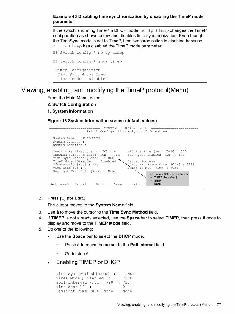
Example 43 Disabling time synchronization by disabling the TimeP modeparameter
If the switch is running TimeP in DHCP mode, no ip timep changes the TimePconfiguration as shown below and disables time synchronization. Even thoughthe TimeSync mode is set to TimeP, time synchronization is disabled becauseno ip timep has disabled the TimeP mode parameter.HP Switch(config)# no ip timep
HP Switch(config)# show timep
Timep ConfigurationTime Sync Mode: TimepTimeP Mode : Disabled
Viewing, enabling, and modifying the TimeP protocol(Menu)1. From the Main Menu, select:
2. Switch Configuration1. System Information
Figure 18 System Information screen (default values)
2. Press [E] (for Edit.)The cursor moves to the System Name field.
3. Use â to move the cursor to the Time Sync Method field.4. If TIMEP is not already selected, use the Space bar to select TIMEP, then press â once to
display and move to the TIMEP Mode field.5. Do one of the following:
• Use the Space bar to select the DHCP mode.
Press â to move the cursor to the Poll Interval field.◦◦ Go to step 6.
• Enabling TIMEP or DHCP
Time Sync Method [None] : TIMEPTimeP Mode [Disabled] : DHCPPoll Interval (min) [720] : 720Time Zone [0] : 0Daylight Time Rule [None] : None
Viewing, enabling, and modifying the TimeP protocol(Menu) 77

Use the Spacebar to select the Manual mode.
• Press à to move the cursor to the Server Address field.
• Enter the IP address of the TimeP server you want the switch to use for timesynchronization.
NOTE: This step replaces any previously configured TimeP server IP address.
• Press à to move the cursor to the Poll Interval field, then go to step 6.6. In the Poll Interval field, enter the time in minutes that you want for a TimeP Poll Interval.7. Select [Enter] to return to the Actions line, then select [S] (for Save) to enter the new time
protocol configuration in both the startup-config and running-config files.
About SNTP time synchronizationSNTP provides two operating modes:
• Broadcast modeThe switch acquires time updates by accepting the time value from the first SNTP timebroadcast detected. (In this case, the SNTP server must be configured to broadcast timeupdates to the network broadcast address; see the documentation provided with your SNTPserver application.) Once the switch detects a particular server, it ignores time broadcastsfrom other SNTP servers unless the configurable Poll Interval expires three consecutivetimes without an update received from the first-detected server.
NOTE: To use Broadcast mode, the switch and the SNTP server must be in the samesubnet.
• Unicast modeThe switch requests a time update from the configured SNTP server. (You can configureone server using the menu interface, or up to three servers using the CLI sntp servercommand.) This option provides increased security over the Broadcast mode by specifyingwhich time server to use instead of using the first one detected through a broadcast.
About SNTP: Selecting and configuringTable 1 (page 78) shows the SNTP parameters and their operations.
Table 1 SNTP parameters
OperationSNTP parameter
Used to select either SNTP, TIMEP, or None as the time synchronizationmethod.
Time Sync Method
SNTP Mode
The Default. SNTP does not operate, even if specified by the Menu interfaceTime Sync Method parameter or the CLI timesync command.
Disabled
Directs the switch to poll a specific server for SNTP time synchronization.Requires at least one server address.
Unicast
Directs the switch to acquire its time synchronization from data broadcastby any SNTP server to the network broadcast address. The switch uses
Broadcast
the first server detected and ignores any others. However, if the Poll Intervalexpires three times without the switch detecting a time update from theoriginal server, the switch accepts a broadcast time update from the nextserver it detects.
78 Time protocols
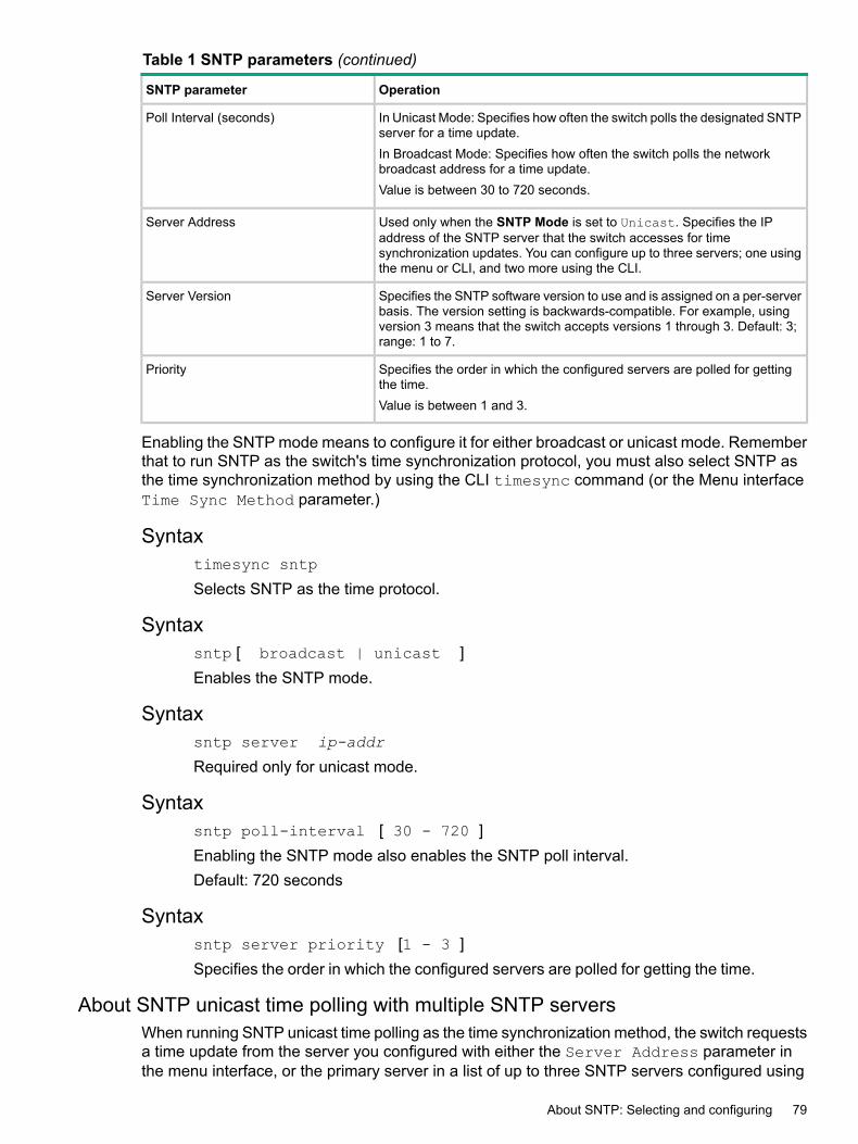
Table 1 SNTP parameters (continued)
OperationSNTP parameter
In Unicast Mode: Specifies how often the switch polls the designated SNTPserver for a time update.
Poll Interval (seconds)
In Broadcast Mode: Specifies how often the switch polls the networkbroadcast address for a time update.Value is between 30 to 720 seconds.
Used only when the SNTP Mode is set to Unicast. Specifies the IPaddress of the SNTP server that the switch accesses for time
Server Address
synchronization updates. You can configure up to three servers; one usingthe menu or CLI, and two more using the CLI.
Specifies the SNTP software version to use and is assigned on a per-serverbasis. The version setting is backwards-compatible. For example, using
Server Version
version 3 means that the switch accepts versions 1 through 3. Default: 3;range: 1 to 7.
Specifies the order in which the configured servers are polled for gettingthe time.
Priority
Value is between 1 and 3.
Enabling the SNTP mode means to configure it for either broadcast or unicast mode. Rememberthat to run SNTP as the switch's time synchronization protocol, you must also select SNTP asthe time synchronization method by using the CLI timesync command (or the Menu interfaceTime Sync Method parameter.)
Syntaxtimesync sntp
Selects SNTP as the time protocol.
Syntaxsntp [ broadcast | unicast ]Enables the SNTP mode.
Syntaxsntp server ip-addr
Required only for unicast mode.
Syntaxsntp poll-interval [ 30 - 720 ]Enabling the SNTP mode also enables the SNTP poll interval.Default: 720 seconds
Syntaxsntp server priority [1 - 3 ]Specifies the order in which the configured servers are polled for getting the time.
About SNTP unicast time polling with multiple SNTP serversWhen running SNTP unicast time polling as the time synchronization method, the switch requestsa time update from the server you configured with either the Server Address parameter inthe menu interface, or the primary server in a list of up to three SNTP servers configured using
About SNTP: Selecting and configuring 79
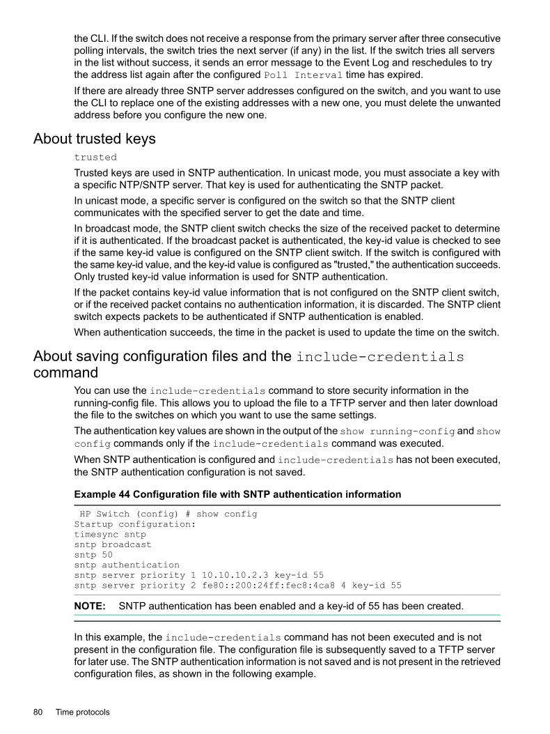
the CLI. If the switch does not receive a response from the primary server after three consecutivepolling intervals, the switch tries the next server (if any) in the list. If the switch tries all serversin the list without success, it sends an error message to the Event Log and reschedules to trythe address list again after the configured Poll Interval time has expired.If there are already three SNTP server addresses configured on the switch, and you want to usethe CLI to replace one of the existing addresses with a new one, you must delete the unwantedaddress before you configure the new one.
About trusted keystrusted
Trusted keys are used in SNTP authentication. In unicast mode, you must associate a key witha specific NTP/SNTP server. That key is used for authenticating the SNTP packet.In unicast mode, a specific server is configured on the switch so that the SNTP clientcommunicates with the specified server to get the date and time.In broadcast mode, the SNTP client switch checks the size of the received packet to determineif it is authenticated. If the broadcast packet is authenticated, the key-id value is checked to seeif the same key-id value is configured on the SNTP client switch. If the switch is configured withthe same key-id value, and the key-id value is configured as "trusted," the authentication succeeds.Only trusted key-id value information is used for SNTP authentication.If the packet contains key-id value information that is not configured on the SNTP client switch,or if the received packet contains no authentication information, it is discarded. The SNTP clientswitch expects packets to be authenticated if SNTP authentication is enabled.When authentication succeeds, the time in the packet is used to update the time on the switch.
About saving configuration files and the include-credentialscommand
You can use the include-credentials command to store security information in therunning-config file. This allows you to upload the file to a TFTP server and then later downloadthe file to the switches on which you want to use the same settings.The authentication key values are shown in the output of the show running-config and showconfig commands only if the include-credentials command was executed.When SNTP authentication is configured and include-credentials has not been executed,the SNTP authentication configuration is not saved.
Example 44 Configuration file with SNTP authentication information
HP Switch (config) # show configStartup configuration:timesync sntpsntp broadcastsntp 50sntp authenticationsntp server priority 1 10.10.10.2.3 key-id 55sntp server priority 2 fe80::200:24ff:fec8:4ca8 4 key-id 55
NOTE: SNTP authentication has been enabled and a key-id of 55 has been created.
In this example, the include-credentials command has not been executed and is notpresent in the configuration file. The configuration file is subsequently saved to a TFTP serverfor later use. The SNTP authentication information is not saved and is not present in the retrievedconfiguration files, as shown in the following example.
80 Time protocols
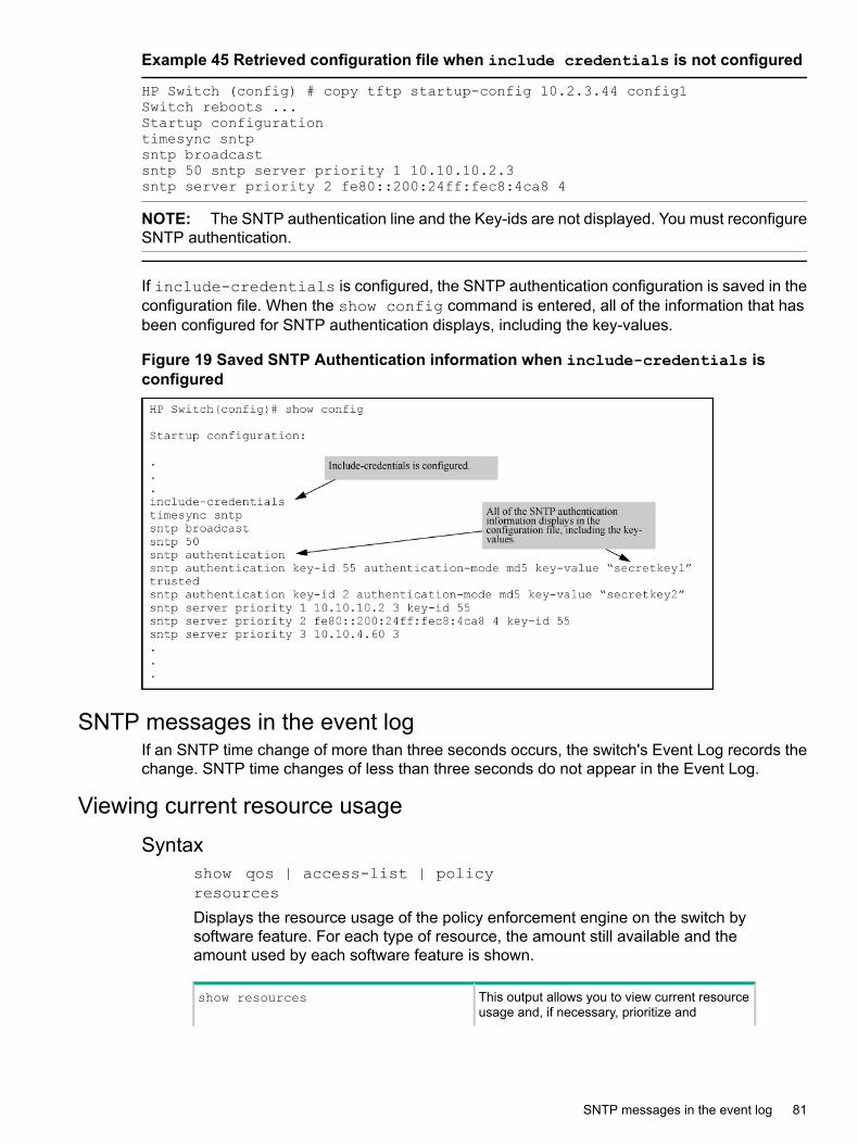
Example 45 Retrieved configuration file when include credentials is not configured
HP Switch (config) # copy tftp startup-config 10.2.3.44 config1Switch reboots ...Startup configurationtimesync sntpsntp broadcastsntp 50 sntp server priority 1 10.10.10.2.3sntp server priority 2 fe80::200:24ff:fec8:4ca8 4
NOTE: The SNTP authentication line and the Key-ids are not displayed. You must reconfigureSNTP authentication.
If include-credentials is configured, the SNTP authentication configuration is saved in theconfiguration file. When the show config command is entered, all of the information that hasbeen configured for SNTP authentication displays, including the key-values.
Figure 19 Saved SNTP Authentication information when include-credentials isconfigured
SNTP messages in the event logIf an SNTP time change of more than three seconds occurs, the switch's Event Log records thechange. SNTP time changes of less than three seconds do not appear in the Event Log.
Viewing current resource usageSyntax
show qos | access-list | policyresources
Displays the resource usage of the policy enforcement engine on the switch bysoftware feature. For each type of resource, the amount still available and theamount used by each software feature is shown.
This output allows you to view current resourceusage and, if necessary, prioritize and
show resources
SNTP messages in the event log 81

reconfigure software features to free resourcesreserved for less important features.
Display the same command output and providedifferent ways to access task-specificinformation.
NOTE: See OpenFlow administrators guide.
qos
access-list
openflow
policy
82 Time protocols

Example 46 Unavailable resources
The resource usage on a 3500yl switch configured for ACLs, QoS, RADIUS-basedauthentication, and other features:
• The "Rules Used" columns show that ACLs, VT, mirroring, and other features(for example, Management VLAN) have been configured globally or per-VLAN,because identical resource consumption is displayed for each port range inthe switch. If ACLs were configured per-port, the number of rules used ineach port range would be different.
• The switch is also configured for VT and is either blocking or throttling routedtraffic with a high rate-of-connection requests.
• Varying ICMP rate-limiting configurations on ports 1 to 24, on ports 25 to 48,and on slot A, have resulted in different meter usage and different rule usagelisted under QoS. Global QoS settings would otherwise result in identicalresource consumption on each port range in the switch.
• There is authenticated client usage of IDM resources on ports 25 to 48.
Figure 20 Viewing current QoS resource usage on a series 3500yl switch
Viewing information on resource usageThe switch allows you to view information about the current usage and availability of resourcesin the Policy Enforcement engine, including the following software features:
Viewing information on resource usage 83

• Access control lists (ACL)
• Quality-of-service (QoS), including device and application port priority, ICMP rate-limiting,and QoS policies
• Dynamic assignment of per-port or per-user ACLs and QoS through RADIUS authenticationdesignated as “IDM”, with or without the optional identity-driven management (IDM) application
• Virus throttling (VT) using connection-rate filtering
• Mirroring policies, including switch configuration as an endpoint for remote intelligent mirroring
• Other features, including:
Management VLAN◦◦ DHCP snooping
◦ Dynamic ARP protection
◦ Jumbo IP-MTU
When insufficient resources are availableThe switch has ample resources for configuring features and supporting:
• RADIUS-authenticated clients (with or without the optional IDMapplication)
• VT and blocking on individual clients.
NOTE: Virus throttling does not operate on IPv6 traffic.
If the resources supporting these features become fully subscribed:
• The current feature configuration, RADIUS-authenticated client sessions, and VT instancescontinue to operate normally.
• The switch generates anevent log notice to say that current resources are fully subscribed.
• Currently engaged resources must be released before any of the following actions aresupported:• Modifying currently configured ACLs, IDM, VT, and other software features, such as
Management VLAN, DHCP snooping, and dynamic ARP protection.You can modify currently configured classifier-base QoS and mirroring policies if a policyhas not been applied to an interface. However, sufficient resources must be availablewhen you apply a configured policy to an interface.
• Acceptance of new RADIUS-based client authentication requests (displayed as a newresource entry for IDM.)Failure to authenticate a client that presents valid credentials may indicate that insufficientresources are available for the features configured for the client in the RADIUS server.To troubleshoot, check the event log.
• Throttling or blocking of newly detected clients with high rate-of-connection requests(as defined by the current VT configuration.)The switch continues to generate Event Log notifications (and SNMP trap notification,if configured) for new instances of high-connection-rate behavior detected by the VTfeature.
84 Time protocols

Policy enforcement engineThe policy enforcement engine is the hardware element in the switch that manages QoS, mirroring,and ACL policies, as well as other software features, using the rules that you configure. Resourceusage in the policy enforcement engine is based on how these features are configured on theswitch:
• Resource usage by dynamic port ACLs and VT is determined as follows:Dynamic port ACLs configured by a RADIUS server (with or without the optional IDMapplication) for an authenticated client determine the current resource consumption for
•
this feature on a specified slot. When a client session ends, the resources in use forthat client become available for other uses.
• A VT configuration (connection-rate filtering) on the switch does not affect switchresources unless traffic behavior has triggered either a throttling or blocking action onthe traffic from one or more clients. When the throttling action ceases or a blocked clientis unblocked, the resources used for that action are released.
• When the following features are configured globally or per-VLAN, resource usage is appliedacross all port groups or all slots with installed modules:• ACLs
• QoS configurations that use the following commands:QoS device priority (IP address) through the CLI using the qos device-prioritycommand
•
• QoS application port through the CLI using qos tcp-port or qos udp-port
• VLAN QoS policies through the CLI using service-policy
• Management VLAN configuration
• DHCP snooping
• Dynamic ARP protection
• Remote mirroring endpoint configuration
• Mirror policies per VLAN through the CLI using monitor service
• Jumbo IP-MTU
• When the following features are configured per-port, resource usage is applied only to theslot or port group on which the feature is configured:• ACLs or QoS applied per-port or per-user through RADIUS authentication
• ACLs applied per-port through the CLI using the ip access-group or ipv6traffic-filter commands
• QoS policies applied per port through the CLI using the service-policycommand
• Mirror policies applied per-port through the CLI using the monitor all service andservice-policycommands
• ICMP rate-limiting through the CLI using the rate-limit icmpcommand
• VT applied to any port (when a high-connection-rate client is being throttled or blocked)
Usage notes for show resources output• A 1:1 mapping of internal rules to configured policies in the switch does not necessarily exist.
As a result, displaying current resource usage is the most reliable method for keeping track
Viewing information on resource usage 85

of available resources. Also, because some internal resources are used by multiple features,deleting a feature configuration may not increase the amount of available resources.
• Resource usage includes resources actually in use or reserved for future use by the listedfeatures.
• "Internal dedicated-purpose resources" include the following features:Per-port ingress and egress rate limiting through the CLI using rate-limit in/out•
• Per-port ingress and egress broadcast rate limiting through the CLI using rate-limitbcast/mcast
• Per-port or per-VLAN priority or DSCP through the CLI using qos priority or qosdscp
• Per protocol priority through the CLI using qos protocol
• For chassis products (for example, the 5400zl or 8212zl switches), 'slots' are listed insteadof 'ports,' with resources shown for all installed modules on the chassis.
• The "Available" columns display the resources available for additional feature use.
• The "IDM" column shows the resources used for RADIUS-based authentication with orwithout the IDM option.
• "Meters" are used when applying either ICMP rate-limiting or a QoS policy with a rate-limitclass action.
86 Time protocols

2 Port status and configurationViewing port status and configuration
Use the following commands to display port status and configuration data.
Syntaxshow interfaces [ brief | config | <PORT-LIST> ]brief Lists the current operating status for all ports on the switch.config Lists a subset of configuration data for all ports on the switch;
that is, for each port, the display shows whether the port isenabled, the operating mode, and whether it is configured forflow control.
<PORT-LIST> Shows a summary of network traffic handled by the specifiedports.
Example 47 Show interfaces brief command listing
(HP_Switch_name#) show interfaces briefStatus and Counters - Port Status
| Intrusion MDI Flow BcastPort Type | Alert Enabled Status Mode Mode Ctrl Limit----- --------- + --------- ------- ------ ---------- ----- ----- ------B1 100/1000T | No Yes Down Auto-10-100 Auto off 0B2 100/1000T | No Yes Down 1000FDx Auto off 0B3 100/1000T | No Yes Down 1000FDx Auto off 0B4 100/1000T | No Yes Down 1000FDx Auto off 0B5 100/1000T | No Yes Down 1000FDx Auto off 0B6 100/1000T | No Yes Down 1000FDx Auto off 0
Example 48 Show interfaces config command listing
(HP_Switch_name#) show interfaces config
Port Settings
Port Type | Enabled Mode Flow Ctrl MDI----- --------- + ------- ------------ --------- ----B1 100/1000T | Yes Auto-10-100 Disable AutoB2 100/1000T | Yes Auto Disable AutoB3 100/1000T | Yes Auto Disable AutoB4 100/1000T | Yes Auto Disable AutoB5 100/1000T | Yes Auto Disable AutoB6 100/1000T | Yes Auto Disable Auto
Internal port namesBoth external and internal ports are supported on the same module. Internal ports have an “i”suffix to indicate that they are internal ports.• “10GbE-INT” – Internal 10G data-plane ports (1i-2i, 4i-5i)
• “1GbE-INT” – Internal 1G control-plane port (3i)Port 3i always shows as link-down.
Viewing port status and configuration 87
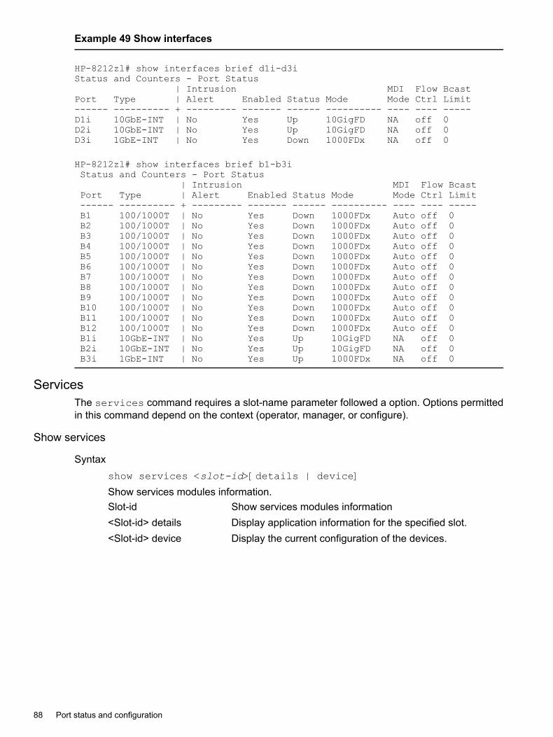
Example 49 Show interfaces
HP-8212zl# show interfaces brief d1i-d3iStatus and Counters - Port Status
| Intrusion MDI Flow BcastPort Type | Alert Enabled Status Mode Mode Ctrl Limit------ ---------- + --------- ------- ------ ---------- ---- ---- -----D1i 10GbE-INT | No Yes Up 10GigFD NA off 0D2i 10GbE-INT | No Yes Up 10GigFD NA off 0D3i 1GbE-INT | No Yes Down 1000FDx NA off 0
HP-8212zl# show interfaces brief b1-b3iStatus and Counters - Port Status
| Intrusion MDI Flow BcastPort Type | Alert Enabled Status Mode Mode Ctrl Limit------ ---------- + --------- ------- ------ ---------- ---- ---- -----B1 100/1000T | No Yes Down 1000FDx Auto off 0B2 100/1000T | No Yes Down 1000FDx Auto off 0B3 100/1000T | No Yes Down 1000FDx Auto off 0B4 100/1000T | No Yes Down 1000FDx Auto off 0B5 100/1000T | No Yes Down 1000FDx Auto off 0B6 100/1000T | No Yes Down 1000FDx Auto off 0B7 100/1000T | No Yes Down 1000FDx Auto off 0B8 100/1000T | No Yes Down 1000FDx Auto off 0B9 100/1000T | No Yes Down 1000FDx Auto off 0B10 100/1000T | No Yes Down 1000FDx Auto off 0B11 100/1000T | No Yes Down 1000FDx Auto off 0B12 100/1000T | No Yes Down 1000FDx Auto off 0B1i 10GbE-INT | No Yes Up 10GigFD NA off 0B2i 10GbE-INT | No Yes Up 10GigFD NA off 0B3i 1GbE-INT | No Yes Up 1000FDx NA off 0
ServicesThe services command requires a slot-name parameter followed a option. Options permittedin this command depend on the context (operator, manager, or configure).
Show services
Syntaxshow services <slot-id>[details | device]
Show services modules information.Slot-id Show services modules information<Slot-id> details Display application information for the specified slot.<Slot-id> device Display the current configuration of the devices.
88 Port status and configuration

Example 50 Show services
HP-8212zl# show services
Installed ServicesSlot Index Description Name------ -------------------------------- ------------------H,L 1. Services zl Module services-moduleL 2. HP ProCurve MSM765 zl Int-Ctlr msm765-applicatiH 3. Threat Management Services zl Module tms-module
No parametersThis no parameters command lists only installed modules which have applications runningthat provide a pass-through CLI feature.
Syntaxshow services
Show services of only installed modules.
Example
HP-8212zl# show services
Installed Services
Slot Index Description NameH,L 1. Services zl Moduleservices-moduleL 2. HP ProCurve MSM765 zl Int-Ctlrmsm765-applicatiH 3.Threat Management Services zl Module tms-module
Show services locatorShow services information.
Syntaxshow services [<SLOT-ID>|details|device]Slot-id Display summary table for the specified slot.details Display application information for the specified slot.device Display the current configuration of the devices.
Example
HP-8212zl# show services fStatus and Counters - Services Module F StatusHP Services zl Module J9840AVersions :Current status : runningFor more information, use the show commands in services context
Example
HP-8212zl# show services f detailsStatus and Counters - Services Module F StatusHP Services zl Module J9840AVersions :
Viewing port status and configuration 89
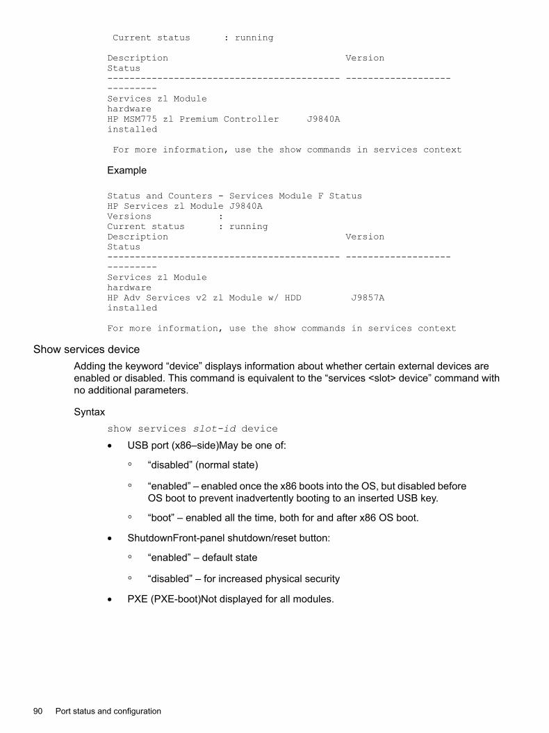
Current status : running
Description VersionStatus------------------------------------------ ----------------------------Services zl ModulehardwareHP MSM775 zl Premium Controller J9840Ainstalled
For more information, use the show commands in services context
Example
Status and Counters - Services Module F StatusHP Services zl Module J9840AVersions :Current status : runningDescription VersionStatus------------------------------------------ ----------------------------Services zl ModulehardwareHP Adv Services v2 zl Module w/ HDD J9857Ainstalled
For more information, use the show commands in services context
Show services deviceAdding the keyword “device” displays information about whether certain external devices areenabled or disabled. This command is equivalent to the “services <slot> device” command withno additional parameters.
Syntaxshow services slot-id device
• USB port (x86–side)May be one of:
“disabled” (normal state)◦◦ “enabled” – enabled once the x86 boots into the OS, but disabled before
OS boot to prevent inadvertently booting to an inserted USB key.
◦ “boot” – enabled all the time, both for and after x86 OS boot.
• ShutdownFront-panel shutdown/reset button:
“enabled” – default state◦◦ “disabled” – for increased physical security
• PXE (PXE-boot)Not displayed for all modules.
90 Port status and configuration

Example 51 Show services device
HP-8212zl# show services d deviceServices Module Device ConfigurationDevice | State----------------|--------------------USB | disabledShutdown | enabledPXE | enabled
Requesting a rebootThis command requests a reboot (graceful shutdown and restart) of the x86.
Syntaxservices <slot>boot[product|PXE|service|USB]product Boot to the Product OS.PXE Boot to the PXE or Product OS (if supported).service Boot to the Service OS.USB Boot to the USB or Product OS (if supported).
NOTE: If no parameters are given, the switch attempts to boot to the same OS(product, service, or USB) that was enabled before the command was given. Ifthe services <slot> boot product|usb command is given on anon-permitted module, one of the following error messages is returned:
HP-8212zl# services b boot productCommand not supported for the Services module in slot B.
HP-8212zl# services b boot pxeCommand not supported for the Services module in slot B.
HP-8212zl# services b boot usbCommand not supported for the Services module in slot B.
Services in Operator/Manager/Configure contextThis top-level command requires a slot-name parameter followed a subcommand. Permittedsubcommands depend on one of the three context: operator, manager, or configure.
Services in operator contextDisplays applications installed and running for the services module in the Operator context.
Syntaxservices <slot-id>[<index> | locator | name <name>]Slot-id Device slot identifier for the services module.Integer Index of the services CLI to access.Locator Control services module locator LED.Name Name of the services CLI to access.<Slot-id> <index> Configure parameters for the installed
application.<Slot-id> locator Controls services module locator LED.
Viewing port status and configuration 91

<Slot-id> name <name> Configure parameters for the installedapplication.
Services in Manager ContextDisplay applications installed and running for the services module or change the module's state(reload or shutdown).
Syntaxservices <slot-id>[<index>| boot | locator | name <name>|reload |serial | shutdown]slot-id Device slot identifier for the services module.
<slot-id> <index> Configure parameters for theinstalled application.
<slot-id> boot Reboot the services module.<slot-id> locator Controls services module locator
LED.<slot-id> name <name> Configure parameters for the
installed application.<slot-id> reload Reset the services module.<slot-id> serial Connect to services module via
serial port.<slot-id> shutdown Shutdown (halt) the services
module.
Boot Reboot the services module.Integer Index of the services CLI to access.Locator Control services module locator LED.Name Name of the services CLI to access.Reload Reset the services module.Serial Connect to application via serial port.Shutdown Shutdown (halt) the services module.
Services in configure contextConfigure parameters for the services module or change the module's state (reload or shutdown).
Syntaxservices [<slot-id> <index> boot | locator | name <name>|reload |serial | shutdown]
Syntax[no]services <slot-id>device[shutdown | usbslot-id Device slot identifier for the services module.
<slot-id> <index> Configure parameters for theinstalled application.
<slot-id> boot Reboot the services module.<slot-id> locator Controls services module locator
LED.<slot-id> name <name> Configure parameters for the
installed application.
92 Port status and configuration

<slot-id> reload Reset the services module.<slot-id> serial Connect to services module via
serial port.<slot-id> shutdown Shutdown (halt) the services
module.
Boot Reboot the services module.Integer Index of the services CLI to access.Locator Control services module locator LED.Name Name of the services CLI to access.Reload Reset the services module.Serial Connect to application via serial port.Shutdown Shutdown (halt) the services module.
Enable or disable devices.Enable or disable devices. This command must be run from the configure context.
Syntax[no]services <slot> device [PXE|shutdown|USB|CF]PXE Enable or disable booting from PXE (if supported).shutdown Enable or disable the shutdown or reset button.USB Enable or Disable the USB after boot.CF Enable or disable the Compact Flash or SD1 card.
Accessing CLI-passthroughAccessing the CLI-passthrough feature on modules that support the feature. Feature can bereported by the show servicescommand given with no additional parameters.
Syntaxservices <slot>[<index>|<name>ASCII-STR Enter an ASCII string.
Example 52 Show services
HP-8212zl# show services
Installed Services
Slot Index Description NameH,L 1. Services zl Moduleservices-moduleL 2. HP ProCurve MSM765 zl Int-Ctlrmsm765-applicatiH 3. Threat Management Services zl Module tms-module
Show services set locator moduleThis command sets the Module Locator LED to either solid-on, off or slow-blink for a specifiedduration of time or to turn it off before the previously-specified time has passed. Options arepermitted in this command for the Operator.
Viewing port status and configuration 93
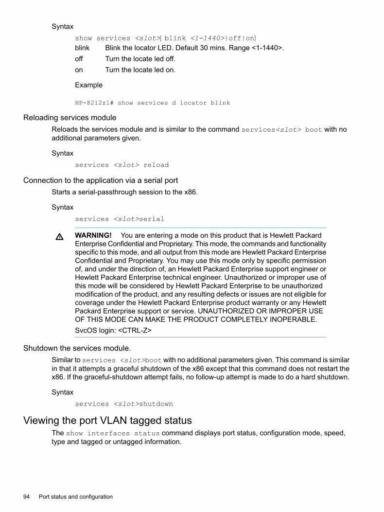
Syntaxshow services <slot>[blink <1-1440>|off|on]blink Blink the locator LED. Default 30 mins. Range <1-1440>.off Turn the locate led off.on Turn the locate led on.
Example
HP-8212zl# show services d locator blink
Reloading services moduleReloads the services module and is similar to the command services<slot> boot with noadditional parameters given.
Syntaxservices <slot> reload
Connection to the application via a serial portStarts a serial-passthrough session to the x86.
Syntaxservices <slot>serial
WARNING! You are entering a mode on this product that is Hewlett PackardEnterprise Confidential and Proprietary. This mode, the commands and functionalityspecific to this mode, and all output from this mode are Hewlett Packard EnterpriseConfidential and Proprietary. You may use this mode only by specific permissionof, and under the direction of, an Hewlett Packard Enterprise support engineer orHewlett Packard Enterprise technical engineer. Unauthorized or improper use ofthis mode will be considered by Hewlett Packard Enterprise to be unauthorizedmodification of the product, and any resulting defects or issues are not eligible forcoverage under the Hewlett Packard Enterprise product warranty or any HewlettPackard Enterprise support or service. UNAUTHORIZED OR IMPROPER USEOF THIS MODE CAN MAKE THE PRODUCT COMPLETELY INOPERABLE.SvcOS login: <CTRL-Z>
Shutdown the services module.Similar to services <slot>bootwith no additional parameters given. This command is similarin that it attempts a graceful shutdown of the x86 except that this command does not restart thex86. If the graceful-shutdown attempt fails, no follow-up attempt is made to do a hard shutdown.
Syntaxservices <slot>shutdown
Viewing the port VLAN tagged statusThe show interfaces status command displays port status, configuration mode, speed,type and tagged or untagged information.
94 Port status and configuration

Tagged values can be:
• VLAN ID: When the VLAN number is displayed, the port is a member of a single taggedVLAN.
• multi: When “multi” is displayed, the port is a member of multiple tagged VLANs.
• no: When “no” is displayed, the port is not a member of any tagged VLAN.Untagged values can be:
• VLAN-ID: When the VLAN number is displayed, the port is a member of a single untaggedVLAN.
• multi: When “multi” is displayed, the port is added to multiple untagged VLANs.
• no: When “no” is displayed, the port is not a member of any tagged VLAN.If the port is part of a trunk, then the trunk_VLAN membership is displayed in the Tagged andUntagged columns.
Example
HP-Switch(config#) show interfaces statusPort Name Status Config-mode Speed Type Tagged Untagged-------- -------- ------ ----------- ------- --------- ------ ---------A1 Up Auto 1000FDx 100/1000T 2 1A2 Down 10HDx 10HDx 100/1000T multi 2A3 Down 100HDx 100HDx 100/1000T multi 3A4 Down 10FDx 10FDx 100/1000T 5 4A5-Trk1 Down 100FDx 100FDx 100/1000T No NoA6 Down Auto 1000FDx 100/1000T No 6A7 Down Auto-10 10HDx 100/1000T No 7
Dynamically updating the show interfaces commandSyntaxshow interfaces display
Uses the display option to initiate the dynamic update of the show interfaces command,with the output being the same as the show interfaces command.
NOTE: Select Back to exit the display.
Example
HP Switch# show interfaces display
When using the display option in the CLI, the information stays on the screen and is updatedevery 3 seconds, as occurs with the display using the menu feature. The update is terminatedwith CTRL-C.You can use the arrow keys to scroll through the screen when the output does not fit in onescreen.
Dynamically updating the show interfaces command 95

Figure 21 show interfaces display command with dynamically updating output
Customizing the show interfaces commandYou can create show commands displaying the information that you want to see in any orderyou want by using the option.
Syntaxshow interfaces custom <PORT-LIST> <column-list>
Select the information that you want to display. Supported columns are shown in Table 2(page 96).
Table 2 Supported columns, what they display, and examples
ExamplesDisplaysParameter column
A2Port identifierport
100/1000TPort typetype
up or downPort statusstatus
1000FDXConnection speed and duplexspeed
auto, auto-100, 100FDXConfigured modemode
auto, MDIXMDI modemdi
on or offFlow controlflow
Friendly port namename
4The vlan id this port belongs to, or"tagged" if it belongs to more thanone vlan
vlanidtagged
yes or noport is or is not enabledenabledintrusion
noIntrusion alert statusintrusion
0Broadcast limitbcast
96 Port status and configuration

Example 53 Example of the custom show interfaces command
(HP_Switch_name#) show int custom 1-4 port name:4 type vlan intrusion speed enabled mdi
Status and Counters - Custom Port Status
IntrusionPort Name Type VLAN Alert Speed Enabled MDI-mode---- ---------- ---------- ----- --------- ------- ------- --------1 Acco 100/1000T 1 No 1000FDx Yes Auto2 Huma 100/1000T 1 No 1000FDx Yes Auto3 Deve 100/1000T 1 No 1000FDx Yes Auto4 Lab1 100/1000T 1 No 1000FDx Yes Auto
You can specify the column width by entering a colon after the column name, then indicating thenumber of characters to display. In Example 53 (page 97), the Name column displays only thefirst four characters of the name. All remaining characters are truncated.
NOTE: Each field has a fixed minimum width to be displayed. If you specify a field width smallerthan the minimum width, the information is displayed at the minimum width. For example, if theminimum width for the Name field is 4 characters and you specify Name:2, the Name field displays4 characters.
You can enter parameters in any order. There is a limit of 80 characters per line; if you exceedthis limit an error displays.
Smart Rate
Syntaxshow interface <PORT-LIST> smartrate
The option smartrate has been added to the show interface <PORT-LIST>command. This option is used to display port diagnostics on a Smart Rate portonly. If the command is run on a non‐Smart Rate port, a message similar to PortA1: This command is only applicable to Smart Rate ports willdisplay.
Viewing port utilization statisticsUse the show interface port-utilization command to view a real-time rate display forall ports on the switch. Figure 22 (page 97) shows a sample output from this command.
Figure 22 Example of a show interface port-utilization command listing
Viewing port utilization statistics 97

Operating notes for viewing port utilization statistics• For each port on the switch, the command provides a real-time display of the rate at which
data is received (Rx) and transmitted (Tx) in terms of kilobits per second (KBits/s), numberof packets per second (Pkts/s), and utilization (Util) expressed as a percentage of the totalbandwidth available.
• The show interfaces <PORT-LIST> command can be used to display the current linkstatus and the port rate average over a 5 minute period. Port rates are shown in bits persecond (bps) for ports up to 1 Gigabit; for 10 Gigabit ports, port rates are shown in kilobitsper second (Kbps.)
Viewing transceiver statusThe show interfaces transceivers command allows you to:
• Remotely identify transceiver type and revision number without having to physically removean installed transceiver from its slot.
• Display real-timestatus information about all installed transceivers, including non-operationaltransceivers.
Figure 23 (page 98) shows sample output from the show tech transceivers command.
NOTE: Part # column in Figure 23 (page 98) enables you to determine the manufacturer fora specified transceiver and revision number.
Figure 23 Example of show tech transceivers command
Transceiver Operating notes• The following information is displayed for each installed transceiver:
Port number on which transceiver is installed.◦◦ Type of transceiver.
98 Port status and configuration

◦ Product number — Includes revision letter, such as A, B, or C. If no revision letter followsa product number, this means that no revision is available for the transceiver.
◦ Part number — Allows you to determine the manufacturer for a specified transceiverand revision number.
• For a non- switches installed transceiver (see line 23 Figure 23 (page 98)), no transceivertype, product number, or part information is displayed. In the Serial Number field,non-operational is displayed instead of a serial number.
• The following error messages may be displayed for a non-operational transceiver:Unsupported Transceiver. (SelfTest Err#060)Check: http://www.hpe.com/rnd/device_help/2_inform for more info.
•
• This switch only supports revision B and above transceivers.Check: http://www.hpe.com/rnd/device_help/2_inform for more info.
• Self test failure.
• Transceiver type not supported in this port.
• Transceiver type not supported in this software version.
• Not an HP Switch Transceiver.Go to: http://www.hpe.com/rnd/device_help/2_inform for more info.
Enabling or disabling ports and configuring port modeYou can configure one or more of the following port parameters.
Syntaxinterface <PORT-LIST> [ disable | enable ]Disables or enables the port for network traffic. Does not use the no form of the command.(Default: enable.)speed-duplex [ auto-10 | 10-full | 10-half | 100-full | 100-half |auto | auto-100 | 1000-full ]Note that in the above syntax, you can substitute int for interface (for example, int<PORT-LIST>.)Specifies the port's data transfer speed and mode. Does not use the no form of the command.Default: auto.The 10/100 auto-negotiation feature allows a port to establish a link with a port at the other endat either 10 Mbps or 100 Mbps, using the highest mutual speed and duplex mode available. Onlythese speeds are allowed with this setting.
ExamplesTo configure port C5 for auto-10-100, enter this command:
(HP_Switch_name#) int c5 speed-duplex auto-10-100
To configure ports C1 through C3 and port C6 for 100Mbps full-duplex, enter these commands:
(HP_Switch_name#) int c1-c3,c6 speed-duplex 100-full
Similarly, to configure a single port with the above command settings, you could either enter thesame command with only the one port identified or go to the context level for that port and thenenter the command. For example, to enter the context level for port C6 and then configure thatport for 100FDx:
Enabling or disabling ports and configuring port mode 99
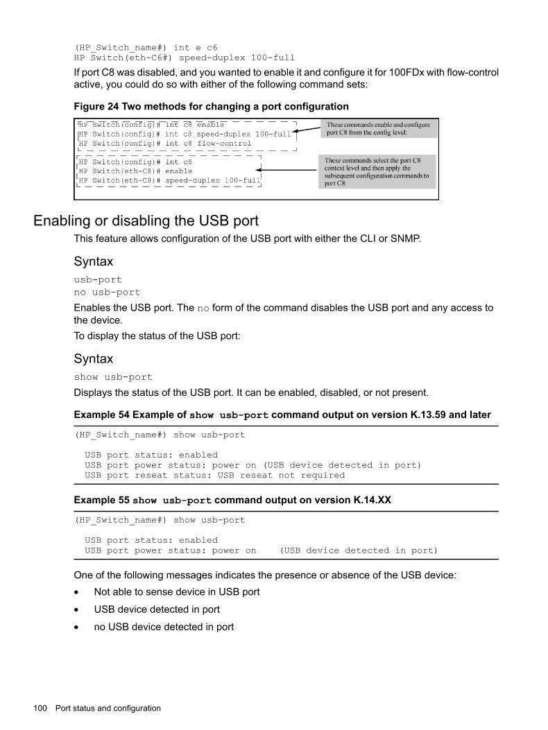
(HP_Switch_name#) int e c6HP Switch(eth-C6#) speed-duplex 100-full
If port C8 was disabled, and you wanted to enable it and configure it for 100FDx with flow-controlactive, you could do so with either of the following command sets:
Figure 24 Two methods for changing a port configuration
Enabling or disabling the USB portThis feature allows configuration of the USB port with either the CLI or SNMP.
Syntaxusb-portno usb-port
Enables the USB port. The no form of the command disables the USB port and any access tothe device.To display the status of the USB port:
Syntaxshow usb-port
Displays the status of the USB port. It can be enabled, disabled, or not present.
Example 54 Example of show usb-port command output on version K.13.59 and later
(HP_Switch_name#) show usb-port
USB port status: enabledUSB port power status: power on (USB device detected in port)USB port reseat status: USB reseat not required
Example 55 show usb-port command output on version K.14.XX
(HP_Switch_name#) show usb-port
USB port status: enabledUSB port power status: power on (USB device detected in port)
One of the following messages indicates the presence or absence of the USB device:• Not able to sense device in USB port
• USB device detected in port
• no USB device detected in port
100 Port status and configuration
The reseat status messages can be one of the following (K.13.XX only):• undetermined USB reseat requirement
• USB reseat not required
• USB device reseat required for USB autorunThe autorun feature works only when a USB device is inserted and the USB port is enabled.
Software versions K.13.XX operationWhen using software version K.13.58, if the USB port is disabled (no usb-port command), theUSB autorun function does not work in the USB port until the USB port is enabled, the config fileis saved, and the switch is rebooted. The 5 volt power to the USB port remains on even after theUSB port has been disabled. For software versions after K.13.58, the 5 volt power applied to theUSB port is synchronized with the enabling of the USB port, that is, when the USB port is enabled,the 5 volts are supplied; when the USB port is disabled, the 5 volts are not supplied. For previoussoftware versions the power was supplied continuously. The autorun function does not requirea switch reboot, but the USB device must be inserted at least once after the port is enabled sothat the switch recognizes that the device is present. If the USB device is inserted and then theUSB port is enabled, the switch does not recognize that a USB device is present.
Software Version K.14.XX Operation.For software versions K.14.XX, the USB port can be disabled and enabled without affecting theautorun feature. When the USB port is enabled, the autorun feature activates if a USB device isalready inserted in the USB port. Power is synchronized with the enabling and disabling of USBports as described above for K.13.59 and later software.
Enabling or disabling flow controlNOTE: You must enable flow control on both ports in a given link. Otherwise, flow control doesnot operate on the link and appears as Off in the show interfaces brief port listing, evenif flow control is configured as enabled on the port in the switch. (See Example 47 (page 87).)Also, the port (speed-duplex) mode must be set to Auto (the default.)
To disable flow control on some ports, while leaving it enabled on other ports, just disable it onthe individual ports you want to exclude. (You can find more information on flow control in Table 3(page 113).)
Syntax[no] interface <PORT-LIST> flow-control
Enables or disables flow control packets on the port. The no form of the command disables flowcontrol on the individual ports.Default: Disabled.
ExamplesSuppose that:1. You want to enable flow control on ports A1-A6.2. Later, you decide to disable flow control on ports A5 and A6.3. As a final step, you want to disable flow control on all ports.Assuming that flow control is currently disabled on the switch, you would use these commands:
Enabling or disabling flow control 101

Example 56 Configuring flow control for a series of ports
(HP_Switch_name#) int a1-a6 flow-control(HP_Switch_name#) show interfaces brief
Status and Counters - Port Status
| Intrusion MDI Flow BcastPort Type | Alert Enabled Status Mode Mode Ctrl Limit------ --------- + --------- ------- ------ ---------- ---- ---- -----A1 10GbE-T | No Yes Up 1000FDx NA on 0A2 10GbE-T | No Yes Up 10GigFD NA on 0A3 10GbE-T | No Yes Up 10GigFD NA on 0A4 10GbE-T | No Yes Up 10GigFD NA on 0A5 10GbE-T | No Yes Up 10GigFD NA on 0A6 10GbE-T | No Yes Up 10GigFD NA on 0A7 10GbE-T | No Yes Down 10GigFD NA off 0A8 10GbE-T | No Yes Up 10GigFD NA off 0
Example 57 Example continued from Example 56 (page 102)
(HP_Switch_name#) no int a5-a6 flow-control(HP_Switch_name#) show interfaces brief
Status and Counters - Port Status
| Intrusion MDI Flow BcastPort Type | Alert Enabled Status Mode Mode Ctrl Limit------ --------- + --------- ------- ------ ---------- ---- ---- -----A1 10GbE-T | No Yes Up 1000FDx NA on 0A2 10GbE-T | No Yes Down 10GigFD NA on 0A3 10GbE-T | No Yes Down 10GigFD NA on 0A4 10GbE-T | No Yes Down 10GigFD NA on 0A5 10GbE-T | No Yes Down 10GigFD NA off 0A6 10GbE-T | No Yes Down 10GigFD NA off 0A7 10GbE-T | No Yes Down 10GigFD NA off 0A8 10GbE-T | No Yes Down 10GigFD NA off 0
Example 58 Example continued from Example 57 (page 102)
(HP_Switch_name#) no int a1-a4 flow-control(HP_Switch_name#) show interfaces brief
Status and Counters - Port Status
| Intrusion MDI Flow BcastPort Type | Alert Enabled Status Mode Mode Ctrl Limit------ --------- + --------- ------- ------ ---------- ---- ---- -----A1 10GbE-T | No Yes Down 1000FDx NA off 0A2 10GbE-T | No Yes Down 10GigFD NA off 0A3 10GbE-T | No Yes Down 10GigFD NA off 0A4 10GbE-T | No Yes Down 10GigFD NA off 0A5 10GbE-T | No Yes Down 10GigFD NA off 0A6 10GbE-T | No Yes Down 10GigFD NA off 0A7 10GbE-T | No Yes Down 10GigFD NA off 0A8 10GbE-T | No Yes Down 10GigFD NA off 0
Configuring auto-MDIXThe auto-MDIX features apply only to copper port switches using twisted-pair copper Ethernetcables.
102 Port status and configuration

Syntaxinterface <PORT-LIST> mdix-mode [ auto-mdix | mdi | mdix ]
The automatic, default setting. This configures the portfor automatic detection of the cable (either straight-throughor crossover.)
auto-mdix
The manual mode setting that configures the port forconnecting to either a PC or other MDI device with a
mdi
crossover cable, or to a switch, hub, or other MDI-X devicewith a straight-through cable.
The manual mode setting that configures the port forconnecting to either a switch, hub, or other MDI-X device
mdix
with a crossover cable, or to a PC or other MDI devicewith a straight-through cable.
Syntaxshow interfaces config
Lists the current per-port Auto/MDI/MDI-X configuration.
Syntaxshow interfaces brief
• Where a port is linked to another device, this command lists the MDI mode the port is currentlyusing.
• In the case of ports configured for Auto ( auto-mdix), the MDI mode appears as eitherMDI or MDIX, depending upon which option the port has negotiated with the device on theother end of the link.
• In the case of ports configured for MDI or MDIX, the mode listed in this display matches theconfigured setting.
• If the link to another device was up, but has gone down, this command shows the lastoperating MDI mode the port was using.
• If a port on a given switch has not detected a link to another device since the last reboot,this command lists the MDI mode to which the port is currently configured.
Exampleshow interfaces config displays the following data when port A1 is configured forauto-mdix, port A2 is configured for mdi, and port A3 is configured for mdix:
Configuring auto-MDIX 103

Example 59 Example of displaying the current MDI configuration
(HP_Switch_name#) show interfaces config
Port Settings
Port Type | Enabled Mode Flow Ctrl MDI------ --------- + ------- ------------ --------- ----A1 10GbE-T | Yes Auto Disable AutoA2 10GbE-T | Yes Auto Disable MDIA3 10GbE-T | Yes Auto Disable MDIXA4 10GbE-T | Yes Auto Disable AutoA5 10GbE-T | Yes Auto Disable AutoA6 10GbE-T | Yes Auto Disable AutoA7 10GbE-T | Yes Auto Disable AutoA8 10GbE-T | Yes Auto Disable Auto
Example 60 Example of displaying the current MDI operating mode
(HP_Switch_name#) show interfaces brief
Status and Counters - Port Status
| Intrusion MDI Flow BcastPort Type | Alert Enabled Status Mode Mode Ctrl Limit------ --------- + --------- ------- ------ ---------- ---- ---- -----A1 10GbE-T | No Yes Up 1000FDx MDIX off 0A2 10GbE-T | No Yes Down 10GigFD MDI off 0A3 10GbE-T | No Yes Down 10GigFD MDIX off 0A4 10GbE-T | No Yes Down 10GigFD Auto off 0A5 10GbE-T | No Yes Down 10GigFD Auto off 0A6 10GbE-T | No Yes Down 10GigFD Auto off 0A7 10GbE-T | No Yes Down 10GigFD Auto off 0A8 10GbE-T | No Yes Down 10GigFD Auto off 0
Viewing port configuration (Menu)The menu interface displays the configuration for ports and (if configured) any trunk groups.From the Main Menu, select:1. Status and Counters4. Port Status
Figure 25 Switch port status screen
104 Port status and configuration
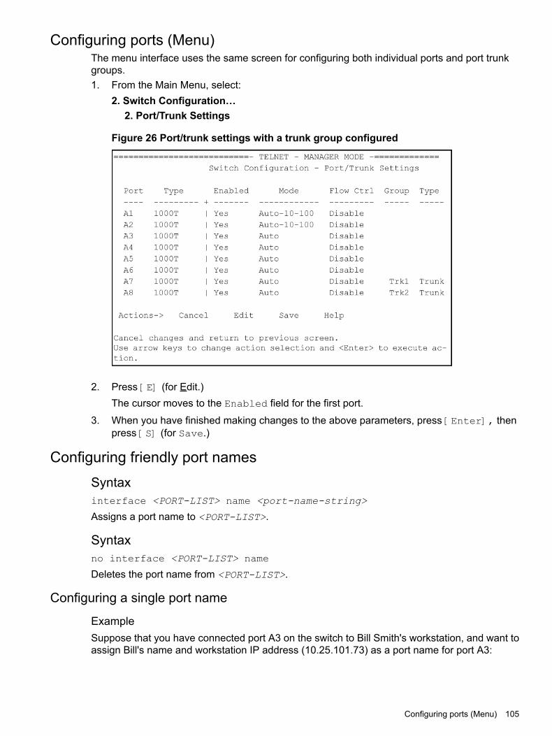
Configuring ports (Menu)The menu interface uses the same screen for configuring both individual ports and port trunkgroups.1. From the Main Menu, select:
2. Switch Configuration…2. Port/Trunk Settings
Figure 26 Port/trunk settings with a trunk group configured
2. Press [E] (for Edit.)The cursor moves to the Enabled field for the first port.
3. When you have finished making changes to the above parameters, press [Enter], thenpress [S] (for Save.)
Configuring friendly port namesSyntaxinterface <PORT-LIST> name <port-name-string>
Assigns a port name to <PORT-LIST>.
Syntaxno interface <PORT-LIST> name
Deletes the port name from <PORT-LIST>.
Configuring a single port name
ExampleSuppose that you have connected port A3 on the switch to Bill Smith's workstation, and want toassign Bill's name and workstation IP address (10.25.101.73) as a port name for port A3:
Configuring ports (Menu) 105

Example 61 Example of configuring a friendly port name
(HP_Switch_name#) int A3 name [email protected](HP_Switch_name#) write mem(HP_Switch_name#) show name A3
Port NamesPort : A3Type : 10/100TXName : [email protected]
Configuring the same name for multiple ports
ExampleSuppose that you want to use ports A5 through A8 as a trunked link to a server used by a draftinggroup. In this case you might configure ports A5 through A8 with the name "Draft-Server:Trunk."
Example 62 Example of configuring one friendly port name on multiple ports
(HP_Switch_name#) int a5-a8 name Draft-Server:Trunk(HP_Switch_name#) write mem(HP_Switch_name#) show name a5-a8
Port Names
Port : A5Type : 10GbE-TName : Draft-Server:Trunk
Port : A6Type : 10GbE-TName : Draft-Server:Trunk
Port : A7Type : 10GbE-TName : Draft-Server:Trunk
Port : A8Type : 10GbE-TName : Draft-Server:Trunk
Viewing friendly port names with other port data
Syntaxshow name
Displays a listing of port numbers with their corresponding friendly port names and also quicklyshows you which ports do not have friendly name assignments. (show name data comes fromthe running-config file.)
Syntaxshow interface <port-number>
Displays the friendly port name, if any, along with the traffic statistics for that port. (The friendlyport name data comes from the running-config file.)
Syntaxshow config
Includes friendly port names in the per-port data of the resulting configuration listing. (showconfig data comes from the startup-config file.)
106 Port status and configuration

Listing all ports or selected ports with their friendly port namesSyntaxshow name [ <PORT-LIST> ]Lists the friendly port name with its corresponding port number and port type. The show namecommand without a port list shows this data for all ports on the switch.
Example
Example 63 Example of friendly port name data for all ports on the switch
(HP_Switch_name#) show namePort Names
Port Type Name------ --------- -----------------------------------------------------------A1 10GbE-TA2 10GbE-TA3 10GbE-T [email protected] 10GbE-TA5 10GbE-T Draft-Server:TrunkA6 10GbE-T Draft-Server:TrunkA7 10GbE-T Draft-Server:TrunkA8 10GbE-T Draft-Server:Trunk
Example 64 Example of friendly port name data for specific ports on the switch
(HP_Switch_name#) show name A3-A5
Port Names
Port : A3Type : 10GbE-TName : [email protected] : A4Type : 10GbE-TName :Port : A5Type : 10GbE-TName : Draft-Server:Trunk
Including friendly port names in per-port statistics listings
Syntaxshow interface port-number
Includes the friendly port name with the port's traffic statistics listing. A friendly port nameconfigured to a port is automatically included when you display the port's statistics output.
ExampleIf you configure port A1 with the name "O'Connor_10.25.101.43," the show interface outputfor this port appears similar to the following:
Listing all ports or selected ports with their friendly port names 107

Example 65 Example of a friendly port name in a per-port statistics listing
(HP_Switch_name#) show interface a1
Status and Counters - Port Counters for port A1
Name : O’[email protected] Address : 001871-b995ffLink Status : UpTotals (Since boot or last clear) :Bytes Rx : 2,763,197 Bytes Tx : 22,972Unicast Rx : 2044 Unicast Tx : 128Bcast/Mcast Rx : 23,456 Bcast/Mcast Tx : 26Errors (Since boot or last clear) :FCS Rx : 0 Drops Tx : 0Alignment Rx : 0 Collisions Tx : 0Runts Rx : 0 Late Colln Tx : 0Giants Rx : 0 Excessive Colln : 0Total Rx Errors : 0 Deferred Tx : 0Others (Since boot or last clear) :Discard Rx : 0 Out Queue Len : 0Unknown Protos : 0Rates (5 minute weighted average) :Total Rx (bps) : 3,028,168 Total Tx (bps) : 1,918,384Unicast Rx (Pkts/sec) : 5 Unicast Tx (Pkts/sec) : 0B/Mcast Rx (Pkts/sec) : 71 B/Mcast Tx (Pkts/sec) : 0Utilization Rx : 00.30 % Utilization Tx : 00.19 %
For a given port, if a friendly port name does not exist in the running-config file, the Name line inthe above command output appears as:
Name : not assigned
Searching the configuration for ports with friendly port namesThis option tells you which friendly port names have been saved to the startup-config file. (showconfig does not include ports that have only default settings in the startup-config file.)
Syntaxshow config
Includes friendly port names in a listing of all interfaces (ports) configured with non-default settings.Excludes ports that have neither a friendly port name nor any other non-default configurationsettings.
ExampleIf you configure port A1 with a friendly port name:
108 Port status and configuration

Figure 27 Listing of the startup-config file with a friendly port name configured
Configuring the type of a moduleSyntaxmodule module-num type module-type
Allows you to configure the type of the module.
Clearing the module configurationSyntax[no] module slot
Allows removal of the module configuration in the configuration file after the module has beenremoved. Enter an integer between 1 and 12 for slot.
Example
(HP_Switch_name#) no module 3
Configuring uni-directional link detectionSyntax[ no ]interface <PORT-LIST> link-keepalive
Enables UDLD on a port or range of ports.To disable this feature, enter the no form of the command.Default: UDLD disabled
Syntaxlink-keepalive interval interval
Determines the time interval to send UDLD control packets. The interval parameter specifieshow often the ports send a UDLD packet. You can specify from 10 to 100, in 100-ms increments,where 10 is 1 second, 11 is 1.1 seconds, and so on.Default: 50 (5 seconds)
Configuring the type of a module 109

Syntaxlink-keepalive retries num
Determines the maximum number of retries to send UDLD control packets. The num parameterspecifies the maximum number of times the port will try the health check. You can specify a valuefrom 3 to 10.Default: 5
Syntax[ no ]interface <PORT-LIST> link-keepalive vlan vid
Assigns a VLAN ID to a UDLD-enabled port for sending tagged UDLD control packets.Underdefault settings, untagged UDLD packets can still be transmitted and received on tagged onlyports; however, a warning message is logged.The no form of the command disables UDLD on the specified ports.Default: UDLD packets are untagged; tagged-only ports transmit and receive untagged UDLDcontrol packets
Enabling UDLDUDLD is enabled on a per-port basis.
ExampleTo enable UDLD on port a1, enter:
(HP_Switch_name#) interface al link-keepalive
To enable the feature on a trunk group, enter the appropriate port range. For example:
(HP_Switch_name#)interface al-a4 link-keepalive
NOTE: When at least one port is UDLD-enabled, the switch will forward out UDLD packetsthat arrive on non-UDLD-configured ports out of all other non-UDLDconfigured ports in the samevlan. That is, UDLD control packets will “pass through” a port that is not configured for UDLD.However, UDLD packets will be dropped on any blocked ports that are not configured for UDLD.
Changing the keepalive intervalBy default, ports enabled for UDLD send a link health-check packet once every 5 seconds. Youcan change the interval to a value from 10 to 100 deciseconds, where 10 is 1 second, 11 is 1.1seconds, and so on.
ExampleTo change the packet interval to seven seconds, enter the following command at the globalconfiguration level:
(HP_Switch_name#) link-keepalive interval 70
Changing the keepalive retriesBy default, a port waits 5 seconds to receive a health-check reply packet from the port at theother end of the link. If the port does not receive a reply, the port tries four more times by sendingup to four more health-check packets. If the port still does not receive a reply after the maximumnumber of retries, the port goes down.You can change the maximum number of keepalive attempts to a value from 3 to 10.
110 Port status and configuration
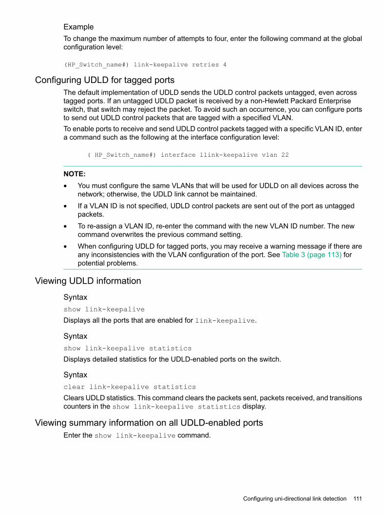
ExampleTo change the maximum number of attempts to four, enter the following command at the globalconfiguration level:
(HP_Switch_name#) link-keepalive retries 4
Configuring UDLD for tagged portsThe default implementation of UDLD sends the UDLD control packets untagged, even acrosstagged ports. If an untagged UDLD packet is received by a non-Hewlett Packard Enterpriseswitch, that switch may reject the packet. To avoid such an occurrence, you can configure portsto send out UDLD control packets that are tagged with a specified VLAN.To enable ports to receive and send UDLD control packets tagged with a specific VLAN ID, entera command such as the following at the interface configuration level:
( HP_Switch_name#) interface llink-keepalive vlan 22
NOTE:• You must configure the same VLANs that will be used for UDLD on all devices across the
network; otherwise, the UDLD link cannot be maintained.• If a VLAN ID is not specified, UDLD control packets are sent out of the port as untagged
packets.• To re-assign a VLAN ID, re-enter the command with the new VLAN ID number. The new
command overwrites the previous command setting.• When configuring UDLD for tagged ports, you may receive a warning message if there are
any inconsistencies with the VLAN configuration of the port. See Table 3 (page 113) forpotential problems.
Viewing UDLD information
Syntaxshow link-keepalive
Displays all the ports that are enabled for link-keepalive.
Syntaxshow link-keepalive statistics
Displays detailed statistics for the UDLD-enabled ports on the switch.
Syntaxclear link-keepalive statistics
Clears UDLD statistics. This command clears the packets sent, packets received, and transitionscounters in the show link-keepalive statistics display.
Viewing summary information on all UDLD-enabled portsEnter the show link-keepalive command.
Configuring uni-directional link detection 111

Example
Figure 28 show link-keepalive command
Viewing detailed UDLD information for specific portsEnter the show link-keepalive statistics command.
Example
Figure 29 show link-keepalive statistics command
Clearing UDLD statistics
Syntaxclear link-keepalive statistics
112 Port status and configuration
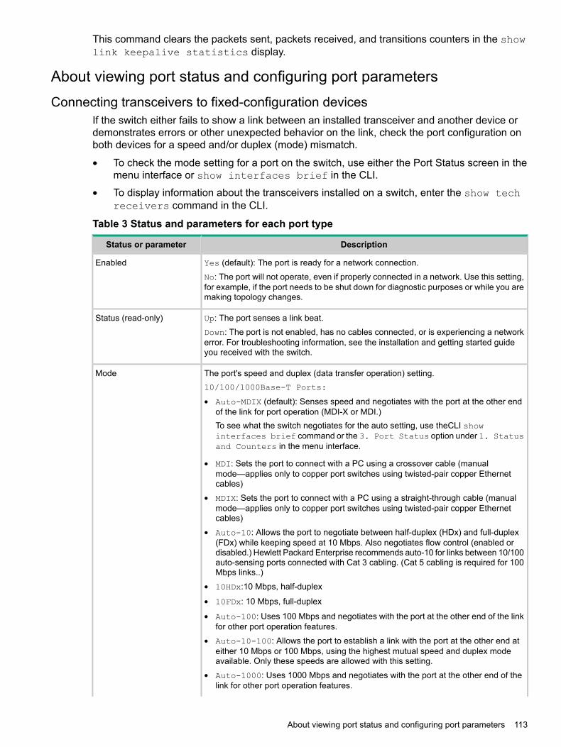
This command clears the packets sent, packets received, and transitions counters in the showlink keepalive statistics display.
About viewing port status and configuring port parametersConnecting transceivers to fixed-configuration devices
If the switch either fails to show a link between an installed transceiver and another device ordemonstrates errors or other unexpected behavior on the link, check the port configuration onboth devices for a speed and/or duplex (mode) mismatch.
• To check the mode setting for a port on the switch, use either the Port Status screen in themenu interface or show interfaces brief in the CLI.
• To display information about the transceivers installed on a switch, enter the show techreceivers command in the CLI.
Table 3 Status and parameters for each port type
DescriptionStatus or parameter
Yes (default): The port is ready for a network connection.EnabledNo: The port will not operate, even if properly connected in a network. Use this setting,for example, if the port needs to be shut down for diagnostic purposes or while you aremaking topology changes.
Up: The port senses a link beat.Status (read-only)Down: The port is not enabled, has no cables connected, or is experiencing a networkerror. For troubleshooting information, see the installation and getting started guideyou received with the switch.
The port's speed and duplex (data transfer operation) setting.Mode10/100/1000Base-T Ports:
• Auto-MDIX (default): Senses speed and negotiates with the port at the other endof the link for port operation (MDI-X or MDI.)To see what the switch negotiates for the auto setting, use theCLI showinterfaces brief command or the 3. Port Status option under 1. Statusand Counters in the menu interface.
• MDI: Sets the port to connect with a PC using a crossover cable (manualmode—applies only to copper port switches using twisted-pair copper Ethernetcables)
• MDIX: Sets the port to connect with a PC using a straight-through cable (manualmode—applies only to copper port switches using twisted-pair copper Ethernetcables)
• Auto-10: Allows the port to negotiate between half-duplex (HDx) and full-duplex(FDx) while keeping speed at 10 Mbps. Also negotiates flow control (enabled ordisabled.) Hewlett Packard Enterprise recommends auto-10 for links between 10/100auto-sensing ports connected with Cat 3 cabling. (Cat 5 cabling is required for 100Mbps links..)
• 10HDx:10 Mbps, half-duplex
• 10FDx: 10 Mbps, full-duplex
• Auto-100: Uses 100 Mbps and negotiates with the port at the other end of the linkfor other port operation features.
• Auto-10-100: Allows the port to establish a link with the port at the other end ateither 10 Mbps or 100 Mbps, using the highest mutual speed and duplex modeavailable. Only these speeds are allowed with this setting.
• Auto-1000: Uses 1000 Mbps and negotiates with the port at the other end of thelink for other port operation features.
About viewing port status and configuring port parameters 113

Table 3 Status and parameters for each port type (continued)
DescriptionStatus or parameter
• 100Hdx: Uses 100 Mbps, half-duplex.
• 100Fdx: Uses 100 Mbps, full-duplex
Gigabit Fiber-Optic Ports (Gigabit-SX, Gigabit-LX, and Gigabit-LH):• 1000FDx: 1000 Mbps (1 Gbps), full-duplex only
• Auto (default): The port operates at 1000FDx and auto-negotiates flow control withthe device connected to the port.
Gigabit Copper Ports:• 1000FDx: 1000 Mbps (1 Gbps), full-duplex only
• Auto (default): The port operates at 1000FDx and auto-negotiates flow control withthe device connected to the port.
10-Gigabit CX4 Copper Ports:• Auto: The port operates at 10 gigabits FDx and negotiates flow control. Lower speed
settings or half-duplex are not allowed.10-Gigabit SC Fiber-Optic Ports (10-GbE SR, 10-GbE LR, 10-GbE ER):• Auto: The port operates at 10 gigabits FDx and negotiates flow control. Lower speed
settings or half-duplex are not allowed.
NOTE: Conditioning patch cord cables are not supported on 10-GbE.
The switch supports Auto-MDIX on 10Mb, 100Mb, and 1 Gb T/TX (copper) ports. (Fiberports and 10-gigabit ports do not use this feature.)
Auto-MDIX
• Automdix: Configures the port for automatic detection of the cable type(straight-through or crossover.)
• MDI: Configures the port to connect to a switch, hub, or other MDI-X device with astraight-through cable.
• MDIX: Configures the port to connect to a PC or other MDI device with astraight-through cable.
Flow control • Disabled (default): The port does not generate flow control packets, and dropsany flow control packets it receives.
• Enabled: The port uses 802.3x link layer flow control, generates flow-control packets,and processes received flow-control packets.
With the port mode set to Auto (the default) and flow control enabled, the switchnegotiates flow control on the indicated port. If the port mode is not set to Auto, or ifflow control is disabled on the port, flow control is not used. Note that flow control mustbe enabled on both ends of a link.
Specifies the percentage of the theoretical maximum network bandwidth that can beused for broadcast traffic. Any broadcast traffic exceeding that limit will be dropped.Zero (0) means the feature is disabled.
Broadcast limit
The broadcast-limit command operates at the port context level to set the broadcastlimit for a port on the switch.
NOTE: This feature is not appropriate for networks that require high levels of IPX orRIP broadcast traffic.
Error messages associated with the show interfaces command
Error messageError
Total length of selected data exceeds one lineRequesting too many fields (total characters exceeds 80)
Invalid input: inputField name is misspelled
114 Port status and configuration

Error messageError
Module not present for port or invalid port: inputMistake in specifying the port list
Incomplete input: customThe port list is not specified
Using pattern matching with the show interfaces custom commandIf you have included a pattern matching command to search for a field in the output of the showint custom command, and the show int custom command produces an error, the errormessage may not be visible and the output is empty. For example, if you enter a command thatproduces an error (such as vlan is misspelled) with the pattern matching include option, theoutput may be empty:
[ (HP_Switch_name#) show int custom 1-3 name vlun | includevlan1 ]
It is advisable to try the show int custom command first to ensure there is output, and thenenter the command again with the pattern matching option.Note that in the above command, you can substitute int for interface; that is: show intcustom.
About configuring auto-MDIXCopper ports on the switch can automatically detect the type of cable configuration (MDI orMDI-X) on a connected device and adjust to operate appropriately.This means you can use a "straight-through" twisted-pair cable or a "crossover" twisted-pair cablefor any of the connections—the port makes the necessary adjustments to accommodate eitherone for correct operation. The following port types on your switch support the IEEE 802.3abstandard, which includes the "Auto MDI/MDI-X" feature:• 10/100-TX xl module ports
• 100/1000-T xl module ports
• 10/100/1000-T xl module portsUsing the above ports:• If you connect a copper port using a straight-through cable on a switch to a port on another
switch or hub that uses MDI-X ports, the switch port automatically operates as an MDI port.• If you connect a copper port using a straight-through cable on a switch to a port on an end
node—such as a server or PC—that uses MDI ports, the switch port automatically operatesas an MDI-X port.
Switch auto-MDIX supports operation in forced speed and duplex modes.For more information on this subject, see the IEEE 802.3ab standard reference. For moreinformation on MDI-X, see the installation and getting started guide.
Manual overrideIf you require control over the MDI/MDI-X feature, you can set the switch to either of thesenon-default modes:• Manual MDI
• Manual MDI-XTable 4 (page 116) shows the cabling requirements for the MDI/MDI-X settings.
About configuring auto-MDIX 115

Table 4 Cable types for auto and manual MDI/MDI-X settings
MDI/MDI-X device typeSetting
Switch, hub, or other MDI-X devicePC or other MDI device type
Straight-through cableCrossover cableManual MDI
Crossover cableStraight-through cableManual MDI-X
Either crossover or straight-through cableAuto-MDI-X (the default)
The AutoMDIX features apply only to copper port switches using twisted-pair copper Ethernetcables.
About using friendly port namesOptional: This feature enables you to assign alphanumeric port names of your choosing toaugment automatically assigned numeric port names. This means you can configure meaningfulport names to make it easier to identify the source of information listed by some show commands.(Note that this feature augments port numbering, but does not replace it.)
Configuring and operating rules for friendly port names• At either the global or context configuration level, you can assign a unique name to a port.
You can also assign the same name to multiple ports.• The friendly port names you configure appear in the output of the show name <PORT-LIST>,
show config, and show interface port-number commands. They do not appearin the output of other show commands or in Menu interface screens. (See “Viewing friendlyport names with other port data” (page 106).)
• Friendly port names are not a substitute for port numbers in CLI commands or Menu displays.
• Trunking ports together does not affect friendly naming for the individual ports. (If you wantthe same name for all ports in a trunk, you must individually assign the name to each port.)
• A friendly port name can have up to 64 contiguous alphanumeric characters.
• Blank spaces within friendly port names are not allowed, and if used, cause an invalid inputerror. (The switch interprets a blank space as a name terminator.)
• In a port listing, not assigned indicates that the port does not have a name assignmentother than its fixed port number.
• To retain friendly port names across reboots, you must save the current running-configurationto the startup-config file after entering the friendly port names. (In the CLI, use the writememory command.)
Configuring transceivers and modules that have not been insertedTransceivers
Previously, a port had to be valid and verified for the switch to allow it to be configured.Transceivers are removable ports and considered invalid when not present in the switch, so theycannot be configured unless they are already in the switch. For switches, the verification forallowable port configurations performed by the CLI is removed and configuration of transceiversis allowed even if they are not yet inserted in the switch.
116 Port status and configuration

ModulesYou can create or edit configuration files (as text files) that can be uploaded to the switch withoutthe modules having been installed yet. Additionally, you can pre-configure the modules with theCLI module command.The same module command used in an uploaded configuration file is used to define a modulethat is being pre-configured. The validation performed when issued through the CLI is stillperformed just as if the command was executed on the switch, in other words, as if the modulewere actually present in the switch.
NOTE: You cannot use this method to change the configuration of a module that has alreadybeen configured. The slot must be empty and the configuration file must not have a configurationassociated with it.
Clearing the module configurationBecause of the hot-swap capabilities of the modules, when a module is removed from the chassis,the module configuration remains in the configuration file. [no] module slot allows you toremove the module configuration information from the configuration file.
NOTE: This does not change how hot-swap works.
RestrictionsThe following restrictions apply:• The slot being cleared must be empty
• There was no module present in the slot since the last boot
• If there was a module present after the switch was booted, the switch will have to be rebootedbefore any module (new or same) can be used in the slot.
• This does not clear the configuration of a module still in use by the switch.
Uni-directional link detection (UDLD)Uni-directional link detection (UDLD) monitors a link between two switches and blocks the portson both ends of the link if the link fails at any point between the two devices. This feature isparticularly useful for detecting failures in fiber links and trunks. Figure 30 (page 118) shows anexample.
Uni-directional link detection (UDLD) 117

Figure 30 UDLD
In this example, each switch load balances traffic across two ports in a trunk group. Without theUDLD feature, a link failure on a link that is not directly attached to one of the switches remainsundetected. As a result, each switch continue to send traffic on the ports connected to the failedlink. When UDLD is enabled on the trunk ports on each switch, the switches detect the failedlink, block the ports connected to the failed link, and use the remaining ports in the trunk groupto forward the traffic.Similarly, UDLD is effective for monitoring fiber optic links that use two uni-direction fibers totransmit and receive packets. Without UDLD, if a fiber breaks in one direction, a fiber port mayassume the link is still good (because the other direction is operating normally) and continue tosend traffic on the connected ports. UDLD-enabled ports; however, will prevent traffic from beingsent across a bad link by blocking the ports in the event that either the individual transmitter orreceiver for that connection fails.Ports enabled for UDLD exchange health-check packets once every five seconds (thelink-keepalive interval.) If a port does not receive a health-check packet from the port at the otherend of the link within the keepalive interval, the port waits for four more intervals. If the port stilldoes not receive a health-check packet after waiting for five intervals, the port concludes thatthe link has failed and blocks the UDLD-enabled port.When a port is blocked by UDLD, the event is recorded in the switch log or via an SNMP trap (ifconfigured); and other port blocking protocols, like spanning tree or meshing, will not use thebad link to load balance packets. The port will remain blocked until the link is unplugged, disabled,or fixed. The port can also be unblocked by disabling UDLD on the port.
Configuring UDLDWhen configuring UDLD, keep the following considerations in mind:• UDLD is configured on a per-port basis and must be enabled at both ends of the link. See
the note below for a list of switches that support UDLD.• To configure UDLD on a trunk group, you must configure the feature on each port of the
group individually. Configuring UDLD on a trunk group's primary port enables the featureon that port only.
• Dynamic trunking is not supported. If you want to configure a trunk group that contains portson which UDLD is enabled, you must remove the UDLD configuration from the ports. Afteryou create the trunk group, you can re-add the UDLD configuration.
118 Port status and configuration
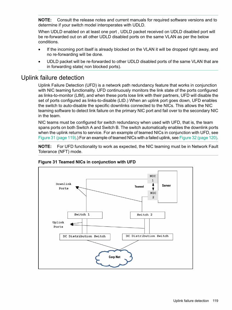
NOTE: Consult the release notes and current manuals for required software versions and todetermine if your switch model interoperates with UDLD.When UDLD enabled on at least one port , UDLD packet received on UDLD disabled port willbe re-forwarded out on all other UDLD disabled ports on the same VLAN as per the belowconditions.
• If the incoming port itself is already blocked on the VLAN it will be dropped right away, andno re-forwarding will be done.
• UDLD packet will be re-forwarded to other UDLD disabled ports of the same VLAN that arein forwarding state( non blocked ports).
Uplink failure detectionUplink Failure Detection (UFD) is a network path redundancy feature that works in conjunctionwith NIC teaming functionality. UFD continuously monitors the link state of the ports configuredas links-to-monitor (LtM), and when these ports lose link with their partners, UFD will disable theset of ports configured as links-to-disable (LtD.) When an uplink port goes down, UFD enablesthe switch to auto-disable the specific downlinks connected to the NICs. This allows the NICteaming software to detect link failure on the primary NIC port and fail over to the secondary NICin the team.NIC teams must be configured for switch redundancy when used with UFD, that is, the teamspans ports on both Switch A and Switch B. The switch automatically enables the downlink portswhen the uplink returns to service. For an example of teamed NICs in conjunction with UFD, seeFigure 31 (page 119).) For an example of teamed NICs with a failed uplink, see Figure 32 (page 120).
NOTE: For UFD functionality to work as expected, the NIC teaming must be in Network FaultTolerance (NFT) mode.
Figure 31 Teamed NICs in conjunction with UFD
Uplink failure detection 119

Figure 32 Teamed NICs with a failed uplink
Configuration Guidelines for UFDBelow is a list of configuration guidelines to be followed for UFD. These are applicable only toblade switches where there is a clear distinction between downlink and uplink ports.1. UFD is required only when uplink-path redundancy is not available on the blade switches.2. An LtM can be either one or more uplink ports or one or more multi-link trunk group of uplink
ports.3. Ports that are already members of a trunk group are not allowed to be assigned to an LtM
or LtD.4. A trunk group configured as an LtM can contain multiple uplink ports, but no downlink ports
or ISL (Inter-Switch-Link) ports.5. A port cannot be added to a trunk group if it already belongs to an LtM or LtD.6. An LtD can contain one or more ports, and/or one or more trunks7. A trunk group configured as an LtD can contain multiple downlink ports, but no uplink ports
or ISL (Inter-Switch-Link) ports.A common API will be provided for higher layers, like CLI and SNMP, which will determine if aport-list can be an LtM or LtD. The API will handle the platform specific details and ensure auniform code flow for blade and other switch families.
NOTE: ProCurve and TOR switches do not have a clear distinction between uplink and downlinkports so some of the points listed above may not be applicable.
UFD enable/disable
Syntaxuplink-failure-detection
Used to globally enable UFD. The [no] option globally disables UFD.
120 Port status and configuration

UFD track data configuration
syntaxuplink-failure-detection-track track-id links-to-monitorport-list links-to-disable port-list
Used to configure ports given as LtM and ports given as LtD for track-id. Thiscommand will also accept trunk interfaces.
Options[no]ufd track-id track-id
From within track-id context:[no]links-to-monitor port-list[no]links-to-disable port-list
Example 66 uplink-failure-detection-trackProCurve 6120XG Blade Switch(config)#uplink-failure-detection-track 10 links-to-monitor 18,19,20links-to-disable 1,2,3
The above command is used to configure ports 18,19,20 as LtM and ports 1,2,3as LtD for track-id 10.ProCurve 6120XG Blade Switch(config)# nouplink-failure-detection-track 10
This command will remove any track data associated with track-id 10.ProCurve 6120XG Blade Switch(config)# nouplink-failure-detection-track 10 links-to-monitor 18links-to-disable 1
This command will remove port 18 as LtM and port 1 as LtD from track-id 10. Thiscommand can be issued from track-id context as well.
UFD enable/disable
Syntaxuplink-failure-detection
Used to globally enable UFD. The [no] option globally disables UFD.
UFD track data configuration
syntaxuplink-failure-detection-track track-id links-to-monitorport-list links-to-disable port-list
The above command is used to configure ports given as LtM and ports given asLtD for track-id. This command will accept trunk interfaces as well.
Options[no]ufd track-id track-id
From within track-id context:[no]links-to-monitor port-list[no]links-to-disable port-list
Uplink failure detection 121
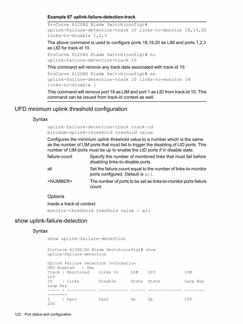
Example 67 uplink-failure-detection-trackProCurve 6120XG Blade Switch(config)#uplink-failure-detection-track 10 links-to-monitor 18,19,20links-to-disable 1,2,3
The above command is used to configure ports 18,19,20 as LtM and ports 1,2,3as LtD for track-id 10.ProCurve 6120XG Blade Switch(config)# nouplink-failure-detection-track 10
This command will remove any track data associated with track-id 10.ProCurve 6120XG Blade Switch(config)# nouplink-failure-detection-track 10 links-to-monitor 18links-to-disable 1
This command will remove port 18 as LtM and port 1 as LtD from track-id 10. Thiscommand can be issued from track-id context as well.
UFD minimum uplink threshold configuration
Syntaxuplink-failure-detection-track track-idminimum-uplink-threshold treshold value
Configures the minimum uplink threshold value to a number which is the sameas the number of LtM ports that must fail to trigger the disabling of LtD ports. Thisnumber of LtM ports must be up to enable the LtD ports if in disable state.failure-count Specify the number of monitored links that must fail before
disabling links-to-disable ports.all Set the failure-count equal to the number of links-to-monitor
ports configured. Default is all.<NUMBER> The number of ports to be set as links-to-monitor ports failure
count.
OptionsInside a track-id context:monitor-threshold treshold value | all
show uplink-failure-detection
Syntaxshow uplink-failure-detection
ProCurve 6120G/XG Blade Switch(config)# showuplink-failure-detection
Uplink Failure Detection InformationUFD Enabled : YesTrack | Monitored Links to LtM LtD LtMLtDID | Links Disable State State Lacp KeyLacp Key----- + ------------ ------------ ------ -------------- ----------------1 | Dyn1 Dyn2 Up Up 100200
122 Port status and configuration
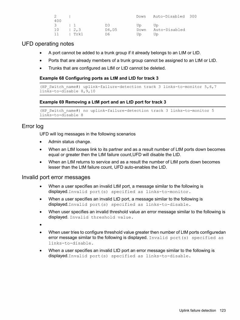
2 | Down Auto-Disabled 3004003 | 1 D3 Up Up10 | 2,3 D4,D5 Down Auto-Disabled11 | Trk1 D6 Up Up
UFD operating notes• A port cannot be added to a trunk group if it already belongs to an LtM or LtD.
• Ports that are already members of a trunk group cannot be assigned to an LtM or LtD.
• Trunks that are configured as LtM or LtD cannot be deleted.
Example 68 Configuring ports as LtM and LtD for track 3
(HP_Switch_name#) uplink-failure-detection track 3 links-to-monitor 5,6,7links-to-disable 8,9,10
Example 69 Removing a LtM port and an LtD port for track 3
(HP_Switch_name#) no uplink-failure-detection track 3 links-to-monitor 5links-to-disable 8
Error logUFD will log messages in the following scenarios
• Admin status change.
• When an LtM looses link to its partner and as a result number of LtM ports down becomesequal or greater then the LtM failure count,UFD will disable the LtD.
• When an LtM returns to service and as a result the number of LtM ports down becomeslesser than the LtM failure count, UFD auto-enables the LtD.
Invalid port error messages• When a user specifies an invalid LtM port, a message similar to the following is
displayed.Invalid port(s) specified as links-to-monitor.
• When a user specifies an invalid LtD port, a message similar to the following isdisplayed.Invalid port(s) specified as links-to-disable.
• When user specifies an invalid threshold value an error message similar to the following isdisplayed. Invalid threshold value.
•
• When user tries to configure threshold value greater then number of LtM ports configuredanerror message similar to the following is displayed. Invalid port(s) specified aslinks-to-disable.
• When a user specifies an invalid LtD port an error message similar to the following isdisplayed.Invalid port(s) specified as links-to-disable.
Uplink failure detection 123
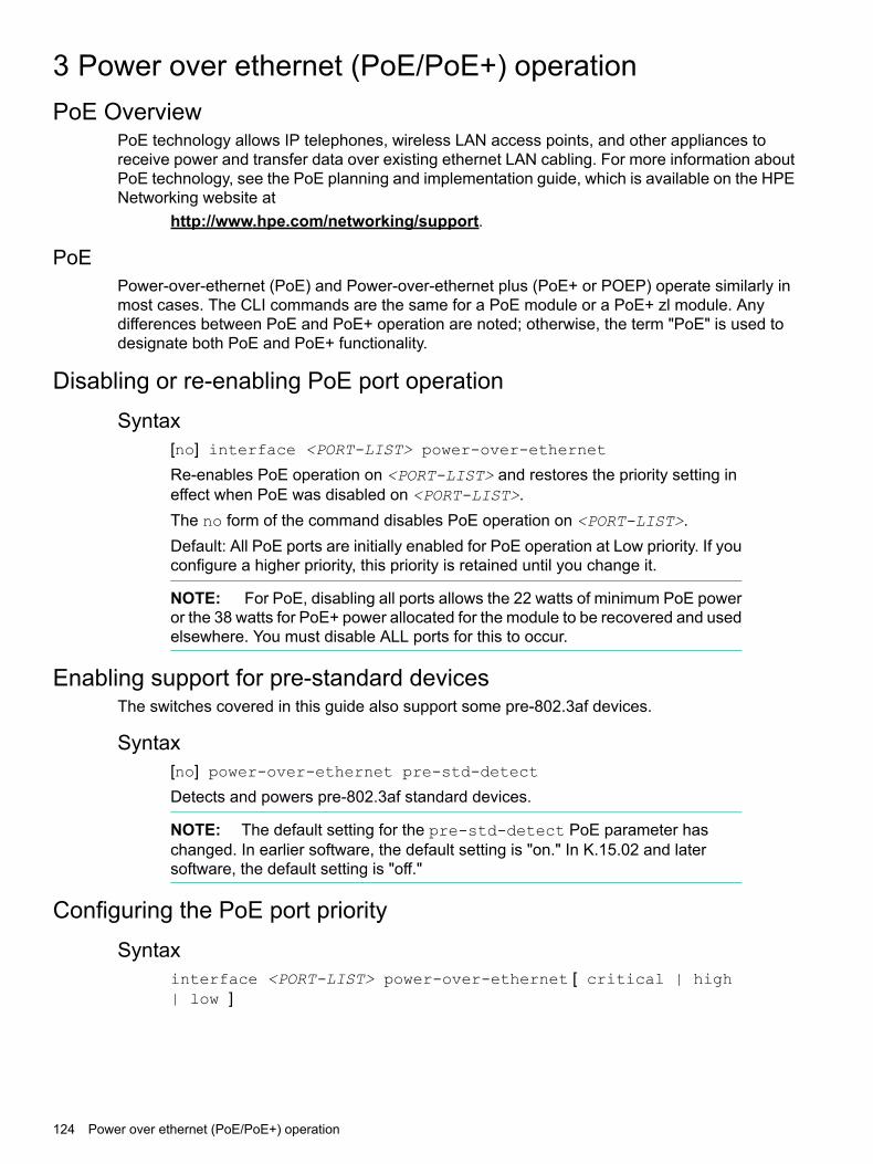
3 Power over ethernet (PoE/PoE+) operationPoE Overview
PoE technology allows IP telephones, wireless LAN access points, and other appliances toreceive power and transfer data over existing ethernet LAN cabling. For more information aboutPoE technology, see the PoE planning and implementation guide, which is available on the HPENetworking website at
http://www.hpe.com/networking/support.
PoEPower-over-ethernet (PoE) and Power-over-ethernet plus (PoE+ or POEP) operate similarly inmost cases. The CLI commands are the same for a PoE module or a PoE+ zl module. Anydifferences between PoE and PoE+ operation are noted; otherwise, the term "PoE" is used todesignate both PoE and PoE+ functionality.
Disabling or re-enabling PoE port operationSyntax
[no] interface <PORT-LIST> power-over-ethernet
Re-enables PoE operation on <PORT-LIST> and restores the priority setting ineffect when PoE was disabled on <PORT-LIST>.The no form of the command disables PoE operation on <PORT-LIST>.Default: All PoE ports are initially enabled for PoE operation at Low priority. If youconfigure a higher priority, this priority is retained until you change it.
NOTE: For PoE, disabling all ports allows the 22 watts of minimum PoE poweror the 38 watts for PoE+ power allocated for the module to be recovered and usedelsewhere. You must disable ALL ports for this to occur.
Enabling support for pre-standard devicesThe switches covered in this guide also support some pre-802.3af devices.
Syntax[no] power-over-ethernet pre-std-detect
Detects and powers pre-802.3af standard devices.
NOTE: The default setting for the pre-std-detect PoE parameter haschanged. In earlier software, the default setting is "on." In K.15.02 and latersoftware, the default setting is "off."
Configuring the PoE port prioritySyntax
interface <PORT-LIST> power-over-ethernet [ critical | high| low ]
124 Power over ethernet (PoE/PoE+) operation

Reconfigures the PoE priority level on <PORT-LIST>. For a given level, ports
Specifies the highest-priority PoE support for <PORT-LIST>. The active PoEports at this level are provisioned before the PoE ports at any other level areprovisioned.
Critical
Specifies the second priority PoE support for <PORT-LIST>. The active PoEports at this level are provisioned before the Low priority PoE ports areprovisioned.
High
(Default) Specifies the third priority PoE support for <PORT-LIST>. The activePoE ports at this level are provisioned only if there is power available afterprovisioning any active PoE ports at the higher priority levels.
Low
Controlling PoE allocationSyntax
[no]int<PORT-LIST> poe-allocate-by [ usage | class | value ]Allows you to manually allocate the amount of PoE power for a port by either itsclass or a defined value.The default option for PoE allocation is usage, which is what a PD attached to theport is allocated. You can override this value by specifying the amount of powerallocated to a port by using the class or value options.usage (Default) The automatic allocation by a PD.class Uses the power ramp-up signature of the PD to identify which power
class the device will be in. Classes and their ranges are shown in Table 5(page 125).
value A user-defined level of PoE power allocated for that port.
NOTE: The allowable PD requirements are lower than those specified for PSEsto allow for power losses along the Cat-5 cable.
Table 5 Power classes and their values
ValuePower class
Depends on cable type and PoE architecture. Maximum power level output of 15.4 watts at the PSE.0This is the default class; if there is not enough information about the load for a specific classification,the PSE classifies the load as class 0 (zero.)
Requires at least 4 watts at the PSE.1
Requires at least 7 watts at the PSE.2
15.4 watts3
For PoE+4Maximum power level output of 30 watts at the PSE.
Controlling PoE allocation 125

Example 70 PoE port allocation by class
To allocate by class for ports 6 to 8:(HP_Switch_name#) int 6-8 PoE-allocate-by class
Manually configuring PoE power levelsYou can specify a power level (in watts) allocated for a port by using the value option. This isthe maximum amount of power that will be delivered.1. To configure a port by value, first set the PoE allocation by entering the poe-allocate-by
value command:HP Switch(config) # int A6 poe-allocate-by value
or in interface context:HP Switch(eth-A6) # poe-allocate-by value
2. Then select a value:HP Switch(config) # int A6 poe-value 15
or in interface context:HP Switch(eth-A6) # poe-value 15
3. To view the settings, enter the show power-over-ethernet command, shown below.
Figure 33 Displaying PoE allocation by value and the maximum power delivered
If you set the PoE maximum value to less than what the PD requires, a fault occurs, as shownin Figure Figure 34 (page 126).
Figure 34 Showing PoE power value set too low for the PD
126 Power over ethernet (PoE/PoE+) operation

Configuring PoE redundancy (chassis switches only)PoE redundancy occurs automatically when enabled. The switch keeps track of power use anddoes not supply PoE power to additional PoE devices trying to connect if that results in the switchnot having enough power in reserve for redundancy.
Syntax[no] power-over-ethernet redundancy [ n+1 | full ]Allows you to set the amount of power held in reserve for redundancy.
Means that all available power can be allocated to PDs.no
Default: No PoE redundancy enforced.
One of the power supplies is held in reserve for redundancy. If a single power supplyfails, no powered devices are shut down.
n+1
If power supplies with different ratings are used, the highest-rated power supply isheld in reserve to ensure full redundancy.
Half of the available power supply is held in reserve for redundancy. If power supplieswith different ratings are used, the highest-rated power supply is held in reserve toensure full redundancy.
full
For more information about PoE redundancy and power supplies, see the PoE planning andimplementation guide, available on the Hewlett Packard Enterprise website at
http://www.hpe.com/networking/support.
Changing the threshold for generating a power noticeSyntax
power-over-ethernet slot <SLOT-ID-RANGE> <threshold 1 - 99>
Specifies the PoE usage level (as a percentage of the PoE power available on amodule) at which the switch generates a power usage notice. This notice appearsas an SNMP trap and a corresponding Event Log message and occurs when aPoE module's power consumption crosses the configured threshold value. Thatis, the switch generates a notice whenever the power consumption on a moduleeither exceeds or drops below the specified percentage of the total PoE poweravailable on the module.This command configures the notification threshold for PoE power usage on eithera global or per-module (slot) basis.Without the slot PoE <SLOT-ID-RANGE> option, the switch applies one powerthreshold setting on all PoE modules installed in the switch.
Enabling or disabling ports for allocating power using LLDPSyntax
int <PORT-LIST> poe-lldp-detect enabled|disabled
Enables or disables ports for allocating PoE power based on the link-partner'scapabilities via LLDP.Default: Enabled
Configuring PoE redundancy (chassis switches only) 127

Example 71 Enable LLDP detection
HP Switch(config) # int A7 poe-lldp-detect enabled
Example 72 Interface context
HP Switch(eth-A7) # poe-lldp-detect enabled
Enabling PoE detection via LLDP TLV advertisementSyntaxlldp config <port-number>
For inserting the desired port or ports.
Negotiating power using the DLLWhen a PD requests power on a PoE port, LLDP interacts with PoE to see if there is enoughpower to fulfill the request. Power is set at the level requested. If the PD goes into power-savingmode, the power supplied is reduced; if the need for power increases, the amount suppliedincreases. PoE and LLDP interact to meet the current power demands.
Syntaxint <PORT-LIST>poe-lldp-detect [ enabled | disabled ]Allows the data link layer to be used for power negotiation between a PD on aPoE port and LLDP.Default: Disabled
Example 73 Enable LLDP
HP Switch(config) # int 7 PoE-lldp-detect enabled
Example 74 Interface context
HP Switch(eth-7) # PoE-lldp-detect enabled
NOTE: Detecting PoE information via LLDP affects only power delivery; it doesnot affect normal Ethernet connectivity.
128 Power over ethernet (PoE/PoE+) operation

Example 75 Port with LLDP configuration information obtained from thedevice
HP-5406zl(config)# show power-over-ethernet briefStatus and Counters - Port Power StatusSystem Power Status : No redundancyPoE Power Status : No redundancy
Available: 273 W Used: 0 W Remaining: 273 W
Module A PowerAvailable: 273 W Used: 0 W Remaining: 273 W
PoE | Power Power Alloc Alloc Actual Configured DetectionPower
Port | Enable Priority By Power Power Type StatusClass
------ ------ --------- ----- ----- ------ ----------- --------------Pre-stdDetect------A1 | Yes low usage 17 W 0.0 W Searching0
offA2 | Yes low usage 17 W 0.0 W Searching0
offA3 | Yes critical usage 17 W 0.0 W Searching0
offA4 | Yes critical usage 17 W 0.0 W Searching0
offA5 | Yes critical usage 17 W 0.0 W Searching0
offA6 | Yes high usage 17 W 0.0 W Searching0
offA7 | Yes high usage 17 W 0.0 W Searching0
offA8 | Yes high usage 17 W 0.0 W Searching0
offA9 | Yes low usage 17 W 0.0 W Searching0
offA10 | Yes low usage 17 W 0.0 W Searching0
offA11 | Yes low usage 17 W 0.0 W Searching0
offA12 | Yes low usage 17 W 0.0 W Searching0
offA13 | Yes low usage 17 W 0.0 W Searching0
offA14 | Yes low usage 17 W 0.0 W Searching0
off
Negotiating power using the DLL 129

A15 | Yes low usage 17 W 0.0 W Searching0
offA16 | Yes low usage 17 W 0.0 W Searching0
Figure 35 Port with LLDP configuration
Initiating advertisement of PoE+ TLVsSyntax
lldp config <PORT-LIST> dot3TlvEnable poe_config
Enables advertisement of data link layer power using PoE+ TLVs.The TLV isprocessed only after the physical layer and the data link layer are enabled. TheTLV informs the PSE about the actual power required by the device.Default: Enabled
NOTE: If LLDP is disabled at runtime, and a PD is using PoE+ power that hasbeen negotiated through LLDP, there is a temporary power drop; the port beginsusing PoE+ power through the PLC. This event is recorded in the Event Log.
Example 76 Event log messages
W 08/04/10 13:35:50 02768 ports: Port A1 PoE power dropped.
Exceeded physical classification for a PoE Type1 device (LLDP process
disabled)
When LLDP is enabled again, it causes a temporary power drop. This event isalso recorded in the Event Log.W 08/04/10 13:36:31 02771 ports: Port A1 PoE power dropped.
Exceeded physical classification due to change in classification type (LLDP process
enabled)
130 Power over ethernet (PoE/PoE+) operation

Viewing PoE when using LLDP informationSyntax
show lldp config <PORT-LIST>
Displays the LLDP port configuration information, including the TLVs advertised.
Viewing PoE when using LLDP information 131

Example 77 LLDP port configuration information with PoE
Figure Figure 37 (page 132) shows an example of the local device power information using theshow lldp info local-device <PORT-LIST> command.
Figure 36 LLDP port configuration information with PoE
Figure 37 Local power information
Figure Figure 38 (page 132) shows an example of the remote device power information using theshow lldp info remote-device <PORT-LIST> command.
Figure 38 Remote power information
132 Power over ethernet (PoE/PoE+) operation

Viewing the global PoE power status of the switchSyntax
show power-over-ethernet [brief| [ethernet] ]showpower-over-ethernetbrief|[ethernet]PORT-LIST|slot<SLOT-ID-RANGE>
Displays the switch's global PoE power status, including:
• Total Available PowerLists the maximum PoE wattage available to provision active PoE ports onthe switch. This is the amount of usable power for PDs.
• Total Failover PowerLists the amount of PoE power available in the event of a single power supplyfailure. This is the amount of power the switch can maintain without droppingany PDs.
• Total Redundancy PowerIndicates the amount of PoE power held in reserve for redundancy in caseof a power supply failure.
• Total Remaining PowerThe amount of PoE power still available.
Displays PoE information for each port.brief
Displays PoE information for the ports in PORT-LIST.<PORT-LIST>
Displays PoE information for the selected slots.SLOT-ID-RANGE
Enter the all option to display the PoE information for allslots.
Viewing the global PoE power status of the switch 133

Example 78 Show power-over-etherne
The command show power-over-ethernet displays data similar to that shown in FigureFigure 39 (page 134).
Figure 39 show power-over-ethernet command output
Viewing PoE status on all portsSyntax
show power-over-ethernet brief
Displays the port power status.
• PoE PortLists all PoE-capable ports on the switch.
• Power EnableShows Yes for ports enabled to support PoE (the default) and No for portson which PoE is disabled.
• Power PriorityLists the power priority (Low, High, and Critical) configured on ports enabledfor PoE.
• Alloc byDisplays how PoE is allocated (usage, class, value)
• Alloc PowerThe maximum amount of PoE power allocated for that port (expressed inwatts.)Default: 17 watts for PoE; 33 watts for PoE+.
• Actual PowerThe power actually being used on that port.
134 Power over ethernet (PoE/PoE+) operation
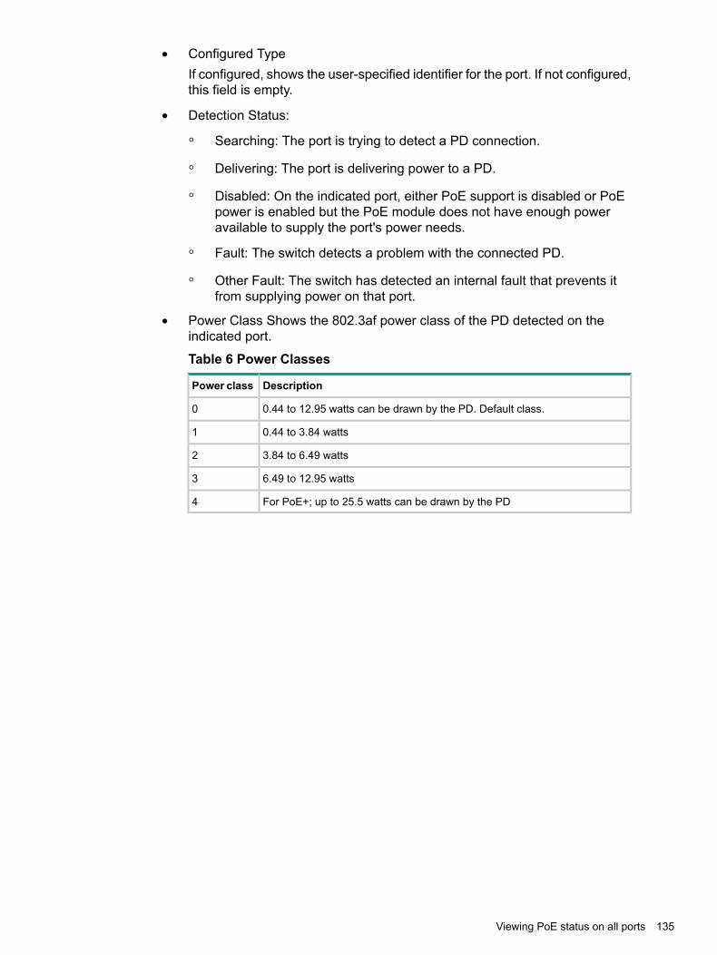
• Configured TypeIf configured, shows the user-specified identifier for the port. If not configured,this field is empty.
• Detection Status:
Searching: The port is trying to detect a PD connection.◦◦ Delivering: The port is delivering power to a PD.
◦ Disabled: On the indicated port, either PoE support is disabled or PoEpower is enabled but the PoE module does not have enough poweravailable to supply the port's power needs.
◦ Fault: The switch detects a problem with the connected PD.
◦ Other Fault: The switch has detected an internal fault that prevents itfrom supplying power on that port.
• Power Class Shows the 802.3af power class of the PD detected on theindicated port.
Table 6 Power Classes
DescriptionPower class
0.44 to 12.95 watts can be drawn by the PD. Default class.0
0.44 to 3.84 watts1
3.84 to 6.49 watts2
6.49 to 12.95 watts3
For PoE+; up to 25.5 watts can be drawn by the PD4
Viewing PoE status on all ports 135

Example 79 Show power-over-ethernet brief
show power-over-ethernet brief displays this output:
Figure 40 show power-over-ethernet brief command output
You can also show the PoE information by slot:
Figure 41 Showing the PoE information by slot
Viewing the PoE status on specific portsSyntax
show power-over-ethernet <PORT-LIST>
Displays the following PoE status and statistics (since the last reboot) for eachport in <PORT-LIST>:
Shows Yes for ports enabled to support PoE (the default) and No for portson which PoE is disabled. For ports on which power is disabled, this is theonly field displayed by show power-over-ethernet <PORT-LIST>.
Power Enable
Lists the power priority (Low, High, and Critical) configured on ports enabledfor PoE.
Priority
How PoE is allocated (usage, class, value.)Allocate by
Detection Status Searching The port is available to support a PD.Delivering The port is delivering power to a PD.Disabled PoE power is enabled on the port but the PoE module
does not have enough power available to supply theport's power needs.
Fault The switch detects a problem with the connected PD.
136 Power over ethernet (PoE/PoE+) operation

Other Fault The switch has detected an internal fault that preventsit from supplying power on that port.
Shows the number of times a connected PD has attempted to draw morethan 15.4 watts for PoE or 24.5 watts for PoE+. Each occurrence generatesan Event Log message.
Over Current Cnt
Shows the number of times PDs requesting power on the port have beendenied because of insufficient power available. Each occurrence generatesan Event Log message.
Power Denied Cnt
The total voltage, in volts, being delivered to PDs.Voltage
The total power, in watts, being delivered to PDs.Power
Port is enabled or disabled for allocating PoE power, based on thelink-partner's capabilities via LLDP.
LLDP Detect
If configured, shows the user-specified identifier for the port. If notconfigured, the field is empty.
Configured Type
The maximum amount of PoE power allocated for that port (expressed inwatts.) Default: 17 watts for PoE; 33 watts for PoE+
Value
Shows the power class of the PD detected on the indicated port. Classesinclude:
Power Class
0 0.44 to 12.95 watts1 0.44 to 3.84 watts2 3.84 to 6.49 watts3 6.49 to 12.95 watts4 For PoE+; up to 25.5 watts can be drawn by the PD
Shows the number of times a detected PD has no longer requested powerfrom the port. Each occurrence generates an Event Log message. ("MPS"refers to the "maintenance power signature.")
MPS Absent Cnt
Shows the number of times the switch provided insufficient current to aconnected PD.
Short Cnt
The total current, in mA, being delivered to PDs.Current
Viewing the PoE status on specific ports 137

Example 80 PoE status of ports
If you want to view the PoE status of ports A6 and A7, you would use showpower-over-ethernet A6-A7 to display the data:
Figure 42 show power-over-ethernet PORT-LIST output
Planning and implementing a PoE configurationThis section provides an overview of some considerations for planning a PoE application. Foradditional information on this topic, refer to the PoE planning and implementation guide whichis available on the Networking web site at http://www.hpe.com/networking/support.Some of the elements you may want to consider for a PoE installation include:• Port assignments to VLANs
• Use of security features
• Power requirementsThis section can help you to plan your PoE installation. If you use multiple VLANs in your network,or if you have concerns about network security, you should read the first two topics. If your PoEinstallation comes close to (or is likely to exceed) the system’s ability to supply power to alldevices that may request it, then you should also read the third topic. (If it is unlikely that yourinstallation will even approach a full utilization of the PoE power available, then you may find itunnecessary to spend much time on calculating PoE power scenarios.)
Power requirementsTo get the best PoE performance, you should provide enough PoE power to exceed the maximumamount of power that is needed by all the PDs that are being used.By connecting an external power supply you can optionally provision more PoE wattage per portand or supply the switch with redundant 12V power to operate should an internal power supplyfail.By installing a second power supply in the 5406zl or a third power supply in a 5412zl chassis,depending on how many PoE ports are being supplied with power, the switch can have redundant
138 Power over ethernet (PoE/PoE+) operation
power if one power supply fails. A Power Supply Shelf (external power supply) can also beconnected to the 5400zl switches to provide extra or redundant PoE power.For example, if the 5406zl has two 24-port PoE modules (J8702A) installed, and all ports areusing 15.4 watts, then the total wattage used is 739.2 watts (48 x 15.4.) To supply the necessaryPoE wattage a J8713A power supply is installed in one of the power supply slots.To gain redundant power, a second J8713A must be installed in the second power supply slot.If the first power supply fails, then the second power supply can supply all necessary power.See the PoE planning and implementation guide for detailed information about the PoE/PoE+power requirements.
Assigning PoE ports to VLANsIf your network includes VLANs, you may want to assign various PoE-configured ports to specificVLANs. For example, if you are using PoE telephones in your network, you may want to assignports used for telephone access to a VLAN reserved for telephone traffic.
Applying security features to PoE configurationsYou can utilize security features built into the switch to control device or user access to thenetwork through PoE ports in the same way as non-PoE ports.Using Port Security, you can configure each switch port with a unique list of MAC addresses fordevices that are authorized to access the network through that port. For more information, seethe Access security guide for your switch.
Assigning priority policies to PoE trafficYou can use the configurable QoS (Quality of Service) features in the switch to create prioritizationpolicies for traffic moving through PoE ports. The available classifiers and their order of precedenceare show in Table 7 (page 139).
Table 7 Classifiers for prioritizing outbound packets
QoS classifierPriority
UDP/TCP application type (port)1
Device priority (destination or source IP address)2
IP type of service (ToS) field (IP packets only)3
VLAN priority4
Incoming source-port on the switch5
Incoming 802.1 priority (present in tagged VLAN environments)6
For more on this topic, see the advanced traffic management guide.
PoE operationUsing the commands described in this chapter, you can:• Enable or disable PoE operation on individual ports.
• Monitor PoE status and performance per module.
• Configure a non-default power threshold for SNMP and Event Log reporting of PoEconsumption on either all PoE ports on the switch or on all PoE ports in one or more PoEmodules.
• Specify the port priority you want to use for provisioning PoE power in the event that thePoE resources become oversubscribed.
PoE operation 139

Power-sourcing equipment (PSE) detects the power needed by a powered device (PD) beforesupplying that power, a detection phase referred to as "searching." If the PSE cannot supply therequired amount of power, it does not supply any power. For PoE using a Type 1 device, a PSEwill not supply any power to a PD unless the PSE has at least 17 watts available. For example,if a PSE has a maximum available power of 382 watts and is already supplying 378 watts, andis then connected to a PD requiring 10 watts, the PSE will not supply power to the PD.For PoE+ using Type 2 devices, the PSE must have at least 33 watts available. A slot in a zlchassis can provide a maximum of 370 watts of PoE/PoE+ power to a module.
PoE configuration optionsIn the default configuration, PoE support is enabled on the ports in a PoE module installed onthe switch. The default priority for all ports is low and the default power notification threshold is80%. Using the CLI, you can:
• Disable or re-enable PoE operation on individual PoE ports
• Enable support for pre-standard devices
• Change the PoE priority level on individual PoE ports
• Change the threshold for generating a power level notice
• Manually allocate the amount of PoE power for a port by usage, value, or class
• Allocate PoE power based on the link-partner’s capabilities via LLDP
NOTE: The ports support standard networking links and PoE links. You can connect either anon-PoE device or a PD to a port enabled for PoE without reconfiguring the port.
PD supportTo best utilize the allocated PoE power, spread your connected PoE devices as evenly as possibleacross modules. Depending on the amount of power delivered to a PoE module, there may ormay not always be enough power available to connect and support PoE operation on all portsin the module. When a new PD connects to a PoE module and the module does not have enoughpower left for that port, if the new PD connects to a port "X" that has a:Higher PoE priority than another port "Y" that is already supporting another PD, the power
is removed from port "Y" and delivered to port "X." In this case the PD on port "Y"loses power and the PD on port "X" receives power.
Lower priority than all other PoE ports currently providing power to PDs, power is not suppliedto port "X" until one or more PDs using higher priority ports are removed.
In the default configuration (usage), when a PD connects to a PoE port and begins operating,the port retains only enough PoE power to support the PD's operation. Unused power becomesavailable for supporting other PD connections. However, if you configure the poe-allocate-byoption to either value or class, all of the power configured is allocated to the port.For PoE (not PoE+), while 17 watts must be available for a PoE module on the switch to beginsupplying power to a port with a PD connected, 17 watts per port is not continually required ifthe connected PD requires less power. For example, with 20 watts of PoE power remainingavailable on a module, you can connect one new PD without losing power to any connected PDson that module. If that PD draws only 3 watts, 17 watts remain available, and you can connectat least one more PD to that module without interrupting power to any other PoE devicesconnected to the same module. If the next PD you connect draws 5 watts, only 12 watts remainunused. With only 12 unused watts available, if you then connect yet another PD to a higher-priorityPoE port, the lowest-priority port on the module loses PoE power and remains unpowered untilthe module once again has 17 or more watts available.
140 Power over ethernet (PoE/PoE+) operation

For PoE+, there must be 33 watts available for the module to begin supplying power to a portwith a PD connected. A slot in a zl chassis can provide a maximum of 370 watts of PoE/PoE+power to a module.Disconnecting a PD from a PoE port makes that power available to any other PoE ports withPDs waiting for power. If the PD demand for power becomes greater than the PoE power available,power is transferred from the lower-priority ports to the higher-priority ports. (Ports not currentlyproviding power to PDs are not affected.)
PoE power priorityIf a PSE can provide power for all connected PD demand, it does not use its power priority settingsto allocate power. However, if the PD power demand oversubscribes the available power, thepower allocation is prioritized to the ports that present a PD power demand. This causes the lossof power from one or more lower-priority ports to meet the power demand on other, higher-priorityports. This operation occurs regardless of the order in which PDs connect to the module'sPoE-enabled ports.Power allocation is prioritized according to the following methods:Priority class Assigns a power priority of low (the default), high, or criticalto
each enabled PoE port.Port-number priority A lower-numbered port has priority over a higher-numbered port
within the same configured priority class, for example, port A1has priority over port A5 if both are configured with high priority.
Assigning PoE priority with two or more modulesPorts across two or more modules can be assigned a class priority of low (the default), high, orcritical. For example, A5, B7, and C10 could all be assigned a priority class of Critical. Whenpower is allocated to the ports on a priority basis, theCritical priority power requests are allocatedto module A first, then Module B, then C, and so on. Next, the High priority power requests areallocated, starting with module A, then B, then C, and the remaining modules in order. Anyremaining power is allocated in the same manner for the Low priority ports, beginning with moduleA though the remaining modules. If there is not enough PoE power for all the PDs connected toPoE modules in the switch, power is allocated according to priority class across modules.
ExampleAll ports on module C are prioritized as Critical.
(HP_Switch_name#) interface c1-c24 power-over-ethernetcritical
All ports on module A are prioritized as Low.
(HP_Switch_name#) interface a1-a24 power-over-ethernetlow
There are 48 PDs attached to all ports of modules A and C (24 ports each module); however,there is enough PoE power for only 32 ports (8.5 watts × 32 ports=273 watts.) The result is thatall the Critical priority ports on module C receive power, but only 8 ports on module A receivepower.On module A, the port A1 has the highest priority of the ports in that module if all ports are in thesame priority class, which is the case for this example. Since a minimum 17 + 5 watts of poweris allocated per PoE module for PoE, port A1 will always receive PoE power. If another port onmodule A had a higher priority class than port A1, that port would be allocated the power beforeport A1.For PoE+ modules there must be a minimum of 33 + 5 watts of power allocated per PoE+ module.
PoE operation 141

About configuring PoEIn the default configuration,PoE support is enabled on the ports in a PoE module installed on theswitch. The default priority for all ports is low and the default power notification threshold is 80%.Using the CLI, you can:
• Disable or re-enable PoE operation on individual PoE ports.
• Enable support for pre-standard devices.
• Change PoE priority level on individual PoE ports.
• Change the threshold for generating a power level notice.
• Manually allocate the amount of PoE power for a port by usage, value, or class.
• Allocate PoE power based on the link-partner's capabilities via LLDP.For a given level, ports are prioritized by port number in ascending order. For example, if portsA1 to A24 have a priority level of critical, port A1 has priority over ports A2 to A24.If there is not enough power available to provision all active PoE ports at a given priority level,the lowest-numbered port at that level is provisioned first. For chassis switches, thelowest-numbered port at that level starting with module A, then B, C, and so on is provisioned.PoE priorities are invoked only when all active PoE ports cannot be provisioned (supplied withPoE power.)In chassis switches, you can use one command to set the same priority level on PoE ports inmultiple modules. For example, to configure the priority to High for ports c5 to c10, C23 to C24,D1 to D10, and D12, you could use this command:
(HP_Switch_name#) interface c5-c10,c23-c24,d1-d10,d12 power-over-ethernet high
ExampleSuppose that you configure the PoE priority for a module in slot C as shown in Table 8 (page 142).
Table 8 PoE priority operation on a PoE module
Configuration command and resulting operation with PDs connected to portsC3 through C24
Priority settingPort
In this example, the following CLI command sets ports C3 to C17 to Critical:CriticalC3 - C17
(HP_Switch_name#) interface c3-c17 power-over-ethernetcritical
The critical priority class always receives power. If there is not enough power toprovision PDs on all ports configured for this class, no power goes to ports configuredfor high and low priority. If there is enough power to provision PDs on only some ofthe critical-priority ports, power is allocated to these ports in ascending order,beginning with the lowest-numbered port in the class, which, in this case, is port 3.
In this example, the following CLI command sets ports C19 to C22 to high:highC18 - C21(HP_Switch_name#) interface c19-c22 power-over-ethernet high
The high priority class receives power only if all PDs on ports with a critical prioritysetting are receiving power. If there is not enough power to provision PDs on all portswith a high priority, no power goes to ports with a low priority. If there is enoughpower to provision PDs on only some of the high-priority ports, power is allocated tothese ports in ascending order, beginning, in this example, with port 18, until allavailable power is in use.
In this example, the CLI command sets ports C23 to C24 to low1:lowC22 - C24(HP_Switch_name#) interface c23-c24 power-over-ethernet low
142 Power over ethernet (PoE/PoE+) operation

Table 8 PoE priority operation on a PoE module (continued)
Configuration command and resulting operation with PDs connected to portsC3 through C24
Priority settingPort
This priority class receives power only if all PDs on ports with high and criticalpriority settings are receiving power. If there is enough power to provision PDs ononly some low- priority ports, power is allocated to the ports in ascending order,beginning with the lowest-numbered port in the class (port 22, in this case), until allavailable power is in use.
In this example, the CLI command disables PoE power on ports C1 to C2:N/AC1 - C2(HP_Switch_name#) no interface c1-c2 power-over-ethernet
There is no priority setting for the ports in this example.
1 In the default PoE configuration, the ports are already set to low priority. In this case, the command is not necessary.
Configuring thresholds for generating a power noticeYou can configure one of the following thresholds:A global power threshold thatapplies to all modules on the switch.
This setting acts as a trigger for sending a notice when thePoE power consumption on any PoE module installed inthe switch crosses the configured global threshold level.(Crossing the threshold level in either direction—PoE powerusage either increasing or decreasing—triggers the notice.)The default setting is 80%.
A per-slot power threshold thatapplies to an individual PoE moduleinstalled in the designated slot.
This setting acts as a trigger for sending a notice when themodule in the specified slot exceeds or goes below aspecific level of PoE power consumption.
ExampleSuppose slots A, B, and C each have a PoE module installed. In this case, executing the followingcommand sets the global notification threshold to 70% of available PoE power.
(HP_Switch_name#) power-over-ethernet threshold70
With this setting, if module B is allocated 100 watts of PoE power and is using 68 watts, and thenanother PD is connected to the module in slot B that uses 8 watts, the 70% threshold of 70 wattsis exceeded. The switch sends an SNMP trap and generates this Event Log message:Slot B POE usage has exceeded threshold of 70%.
If the switch is configured for debug logging, it also sends the Event Log message to the configureddebug destinations.On any PoE module, if an increasing PoE power load (1) exceeds the configured powerthreshold—which triggers the log message and SNMP trap—and then (2) later decreases anddrops below the threshold again, the switch generates another SNMP trap, plus a message tothe Event Log and any configured Debug destinations.
ExampleTo continue the preceding example, if the PoE power usage on the PoE module in slot B dropsbelow 70%, another SNMP trap is generated and you will see this message in the Event Log:Slot B POE usage is below threshold of 70%.
By using the [slot SLOT-ID-RANGE] option, you can specify different notification thresholdsfor different PoE modules installed in the switch. For example, you could set the power thresholdfor a PoE module in slot "A" to 75% and the threshold for the module in slot "B" to 68% byexecuting the following two commands:
Configuring thresholds for generating a power notice 143

(HP_Switch_name#) power-over-ethernet slot athreshold 75
(HP_Switch_name#) power-over-ethernet slot bthreshold 68
The last threshold command affecting a given slot supersedes the previous threshold commandaffecting the same slot. Thus, executing the following two commands in the order shown setsthe threshold for the PoE module in slot "D" to 75%, but leaves the thresholds for any PoEmodules in the other slots at 90%:
(HP_Switch_name#) power-over-ethernetthreshold 90
(HP_Switch_name#) power-over-ethernet slot dthreshold 75
(If you reverse the order of the above two commands, all PoE modules in the switch will have athreshold of 90%.)Without the [slot SLOT-ID-RANGE] option, the switch applies one power threshold settingon all PoE modules installed in the switch.
PoE/PoE+ allocation using LLDPLLDP with PoE
When using PoE, enabling poe-lldp-detect allows automatic power configuration if the linkpartner supports PoE. When LLDP is enabled, the information about the power usage of the PDis available, and the switch can then comply with or ignore this information. You can configurePoE on each port according to the PD (IP phone, wireless device, and so on) specified in theLLDP field. The default configuration is for PoE information to be ignored if detected throughLLDP.
NOTE: Detecting PoE information via LLDP affects only power delivery; it does not affectnormal Ethernet connectivity.
LLDP with PoE+
PoE+ with LLDP OverviewThe DLC for PoE provides more exact control over the power requirement between a PSE andPD. The DLC works in conjunction with the PLC and is mandatory for any Type-2 PD that requiresmore than 12.95 watts of input power.
NOTE: DLC is defined as part of the IEEE 802.3at standard.
You can implement the power negotiation between a PSE and a PD at the physical layer or atthe data link layer. After the link is powered at the physical layer, the PSE can use LLDP to querythe PD repeatedly to discover the power needs of the PD. Communication over the data linklayer allows finer control of power allotment, which makes it possible for the PSE to supplydynamically the power levels needed by the PD. Using LLDP is optional for the PSE but mandatoryfor a Type 2 PD that requires more than 12.95 watts of power.If the power needed by the PD is not available, that port is shut off.
PoE allocationThere are two ways LLDP can negotiate power with a PD:
• Using LLDP MED TLVsDisabled by default. Can be enabled using theint <PORT-LIST> PoE-lldp-detect [ enabled | disabled ]
144 Power over ethernet (PoE/PoE+) operation

command, as shown below.LLDP MED TLVs sent by the PD are used to negotiate power only if the LLDP PoE+ TLVis disabled or inactive; if the LLDP PoE+ TLV is sent as well (not likely), the LLDP MED TLVis ignored.
• Using LLDP PoE+ TLVsEnabled by default. The LLDP PoE+ TLV is always advertised unless it has been disabled(enable it by using the lldp config <PORT-LIST> dot3TlvEnable poeplus_configcommand.)It always takes precedence over the LLDP MED TLV.
Enabling PoE-lldp-detect allows the data link layer to be used for power negotiation.Whena PD requests power on a PoE port, LLDP interacts with PoE to see if there is enough power tofulfill the request. Power is set at the level requested. If the PD goes into power-saving mode,the power supplied is reduced; if the need for power increases, the amount supplied is increased.PoE and LLDP interact to meet the current power demands.
Operation NoteThe advertisement of power with TLVs for LLDP PoE+ is enabled by default. If LLDP is disabledat runtime and a PD is using PoE+ power that has been negotiated through LLDP, there will bea temporary power drop. The port will begin using PoE+ power through the PLC. This event isrecorded in the event log. An example message would look like the following:W 08/04/10 13:35:50 02768 ports: Port A1 PoE power dropped. Exceeded physical classification for a PoE Type1device (LLDP process disabled)
When LLDP is enabled again, it causes a temporary power drop. This event is also recorded inthe event log. An example message looks like the following:W 08/04/10 13:36:31 02771 ports: Port A1 PoE power dropped. Exceeded physical classification due to change inclassification type (LLDP process enabled)
PoE/PoE+ allocation using LLDP 145

4 Port trunkingViewing and configuring port trunk groups
You can list the trunk type and group for all ports on the switch or for selected ports. You canalso list LACP-only status information for LACP-configured ports.
CAUTION: To avoid broadcast storms or loops in your network while configuring a trunk, firstdisable or disconnect all ports you want to add to or remove from the trunk. After you finishconfiguring the trunk, enable or re-connect the ports.
Viewing static trunk type and group for all ports or for selected ports
Syntaxshow trunks<PORT-LIST>
Omitting the <PORT-LIST> parameter results in a static trunk data listing for allLAN ports in the switch.
146 Port trunking

Example 81 Static trunk group
In a switch where ports A4 and A5 belong to Trunk 1 and ports A7 and A8 belong to Trunk 2,you have the options shown in figures Figure 43 (page 147) and Example 82 (page 147) fordisplaying port data for ports belonging to static trunks.Using a port list specifies, for switch ports in a static trunk group, only the ports you want to view.In this case, the command specifies ports A5 through A7. However, because port A6 is not in astatic trunk group, it does not appear in the resulting listing:
Figure 43 Listing specific ports belonging to static trunks
The show trunks <PORT-LIST> command in the above example includes a port list, andthus shows trunk group information only for specific ports that have membership in a static trunk.In Example 82 (page 147), the command does not include a port list, so the switch lists all portshaving static trunk membership.
Example 82 Example of a show trunk listing without specifying ports
HP Switch> show trunks
Load Balancing
Port | Name Type | Group Type---- + ----------------------- --------- + ----- -----4 | Print-Server-Trunk 10/100TX | Trk1 Trunk5 | Print-Server-Trunk 10/100TX | Trk1 Trunk7 | 10/100TX | Trk2 Trunk8 | 10/100TX | Trk2 Trunk
Viewing static LACP and dynamic LACP trunk data
Syntaxshow lacp
Lists data for only the LACP-configured ports.
Viewing and configuring port trunk groups 147

Example 83 Example of a show LACP listing
Ports A1 and A2 have been previously configured for a static LACP trunk. (For more on theActive parameter, see Table 12 (page 171).)HP Switch> show lacp
LACP Trunk Port LACP LACP Admin OperPort Enabled Group Status Partner Status Key Key---- ------- ------- ------- ------- ------- ------ ------Al Active Trkl Up Yes Success 0 250A2 Active Trkl Up Yes Success 0 250A3 Active A3 Down No Success 0 300A4 Passive A4 Down No Success 0 0A5 Passive A5 Down No Success 0 0A6 Passive A6 Down No Success 0 0
For a description of each of the above-listed data types, see Table 12 (page 171).
Configuring a static trunk or static LACP trunk group
IMPORTANT: Configure port trunking before you connect the trunked links between switches.Otherwise, a broadcast storm could occur. If you need to connect the ports before configuringthem for trunking, you can temporarily disable the ports until the trunk is configured.
Syntaxtrunk <PORT-LIST><trk1 | trk2 | ..... trkN>trunk | lacp |dt-lacp | dt-trunk
Configures the specified static trunk type.
Example 84 Static trunk group
This example uses ports C4 to C6 to create a non-protocol static trunk group with the groupname Trk2.
(HP_Switch_name#) trunk c4-c6 trk2 trunk
Removing ports from a static trunk group
CAUTION: Removing a port from a trunk can create a loop and cause a broadcast storm.When you remove a port from a trunk where spanning tree is not in use, Switch recommendsthat you first disable the port or disconnect the link on that port.
Syntaxno trunk <PORT-LIST>
Removes the specified ports from an existing trunk group.
ExampleTo remove ports C4 and C5 from an existing trunk group:
(HP_Switch_name#) no trunk c4-c5
Port Shutdown with Broadcast StormA LAN broadcast storm arises when an excessively high rate of broadcast packets flood the LAN.Occurrence of LAN broadcast storm disrupts traffic and degrades network performance. Toprevent LAN traffic from being disrupted, the use of fault-finder commands trigger a port
148 Port trunking

disablement when a broadcast storm is detected. Commands can be used only to supportbroadcast traffic and not multicast and unicast types of traffic.The waiting period range for re-enabling ports is 0 to 604800 seconds. The default waiting periodto re-enable a port is zero which prevents the port from automatic re-enabling.
NOTE: Avoid port flapping when choosing the waiting period by considering the time to re-enablecarefully.
Configuration CommandsUse the following commands to configure the broadcast-storm on a port.
Syntax[no]fault-finder broadcast-storm [ethernet]<PORT-LIST> action[warn | warn-and-disable <seconds>][percent <Percent> |pps<rate>]
To remove the current configuration of broadcast-storm on a port, use:
Syntax[no]fault-finder broadcast-storm [ethernet] <PORT-LIST>
Configuration example 1
SyntaxHP Switch(config)# fault-finder broadcast-storm [ethernet]<A1> action [warn-and-disable <65535>]< percent 10>
Configuration example 2
SyntaxHP Switch(config)# fault-finder broadcast-storm [ethernet]<A2> action [warn-and-disable]<pps 100>
Configuration example 3
SyntaxHP Switch(config)# fault-finder broadcast-storm[ethernet]<A22> action [warn]<pps100>
Viewing broadcast-storm configurationUse the following command to display the broadcast-storm-control configuration.
Syntaxshow fault-finder broadcast-storm [<ethernet> PORT-LIST]
Show example 1
Disable timer leftDisable timerActionRising
thresholdPort statusBcast stormPort
65535warnanddisable10%DownYesA1
Viewing and configuring port trunk groups 149

Show example 2HP Switch (config)# show fault-finder broadcast-storm
Disable timerleft
Disabletimer
ActionRisingthreshold
Port statusBcast stormPort
910warnanddisable200 ppsDownYesA1
Show example 3HP Switch (config)# show fault-finder broadcast-storm A1
Disable timerleft
Disable timerActionRisingthreshold
Port statusBcast stormPort
noneUpNoA1
Show example 4HP Switch (config)# show fault-finder broadcast-storm
Disable timerleft
Disable timerActionRisingthreshold
Port statusBcast stormPort
warn75%UpYesA1
Definitionsbroadcast-storm Configure broadcast storm control.pps Rising threshold level in number of broadcast packets per second.Percent Rising threshold level as a percentage of bandwidth of the port. The
percentage is calculated on 64 byte packet size.warn Log the event only.warn-and-disable Log the event and disable the port.seconds Re-enable the port after waiting for the specified number of seconds.
Default is not to re-enable.
Event logsDepending on the configuration of broadcast storm control several of the following messagescan be logged:
• FFI: port <ID>-Administrator action required to re-enable.
• FFI: port <ID>-Excessive Broadcasts. Broadcast-storm control threshold <configured value>percent exceeded.
• FFI: port <ID>-Excessive Broadcasts. Broadcast-storm control threshold <configuredvalue>pps exceeded.
• FFI: port <ID>-Port disabled by Fault-finder.
• ports:Fault-Finder(<FF ID>) has disabled port A1 for 100 Seconds.The following messages can be logged after the port is enabled:
• ports: port <ID> timer (<FF ID>) has expired.
• ports: port <ID> is now on-line.
150 Port trunking

Example 85 Event log
l 01/01/90 00:35:20 00025 ip: DEFAULT_VLAN: ip address 10.100.38.231/24 configured on vlan 1l 01/01/90 00:35:20 00083 dhcp: updating IP address and subnet maskl 01/01/90 00:35:05 00076 ports: port A1 is now on-linel 01/01/90 00:35:02 00900 ports: port A1 timer (71) has expiredW 01/01/90 00:34:13 00026 ip: DEFAULT_VLAN: ip address 10.100.38.231/24 removed from vlan 1l 01/01/90 00:34:12 00077 ports: port A1 is now off-linel 01/01/90 00:34:12 00898 ports:Fault-Finder(71) has disabled port A1 for 5secondsM 01/01/90 00:34:12 02673 FFI: port A1-Port disabled by Fault-finder.W 01/01/90 00:34:12 02676 FFI: port A1-Excessive Broadcasts. Broadcast-storm control threshold 4 percent exceeded.---- Reverse event Log listing: Events Since Boot ----I 01/01/90 00:08:44 00025 ip: DEFAULT_VLAN: ip address 10.100.38.231/24 configured on vlan 1I 01/01/90 00:08:44 00083 dhcp: updating IP address and subnet maskI 01/01/90 00:08:11 00076 ports: port A1 is now on-lineI 01/01/90 00:08:08 00900 ports: port A1 timer (71) has expiredW 01/01/90 00:06:29 00026 ip: DEFAULT_VLAN: ip address 10.100.38.231/24 removed from vlan 1I 01/01/90 00:06:28 00077 ports: port A1 is now off-lineI 01/01/90 00:06:28 00898 ports:Fault-Finder(71) has disabled port A1 for 100 secondsM 01/01/90 00:06:28 02673 FFI: port A1-Port disabled by Fault-finder.W 01/01/90 00:06:28 02675 FFI: port A1-Excessive Broadcasts. Broadcast-storm control threshold 10 pps exceeded.
Enabling dynamic LACP trunk groupsAn individual trunk can have up to eight links, with additional standby links if you are using LACP.You can configure trunk group types as follows:
Syntaxinterface <PORT-LIST> lacp active
Configures <PORT-LIST> as LACP active. If the ports at the other end of the links on<PORT-LIST> are configured as LACP passive, this command enables a dynamic LACP trunkgroup on <PORT-LIST>.
ExampleThis example uses ports C4 and C5 to enable a dynamic LACP trunk group.
(HP_Switch_name#) interface c4-c5 lacp active
Removing ports from a dynamic LACP trunk groupTo remove a port from dynamic LACP trunk operation, you must turn off LACP on the port. (Ona port in an operating, dynamic LACP trunk, you cannot change between LACP Active andLACP passive without first removing LACP operation from the port.)
CAUTION: Unless spanning tree is running on your network, removing a port from a trunk canresult in a loop. To help prevent a broadcast storm when you remove a port from a trunk wherespanning tree is not in use, Hewlett Packard Enterprise recommends that you first disable theport or disconnect the link on that port.
Syntaxno interface <PORT-LIST> lacp
Removes <PORT-LIST> from any dynamic LACP trunk and returns the ports in <PORT-LIST>to passive LACP.
ExamplePort C6 belongs to an operating, dynamic LACP trunk. To remove port C6 from the dynamictrunk and return it to passive LACP, do the following:
(HP_Switch_name#) no interface c6 lacp(HP_Switch_name#) interface c6 lacp passive
Viewing and configuring port trunk groups 151

In the above example, if the port on the other end of the link is configured for active LACP orstatic LACP, the trunked link will be re-established almost immediately.
Setting the LACP keyDuring dynamic link aggregation using LACP, ports with the same key are aggregated as a singletrunk.
Syntax[no]lacp [[active] | [passive] | [key 0-65535]]
Example 86 Enabling LACP and configuring an LACP key
(HP_Switch_name#) int A2-A3 lacp active(HP_Switch_name#) int A2-A3 lacp key 500
(HP_Switch_name#) show lacp
LACP Trunk Port LACP LACP Admin OperPort Enabled Group Status Partner Status Key Key---- ------- ------- ------- ------- ------- ------ ------A2 Active A2 Down No Success 500 500A3 Active A3 Down No Success 500 500
Example 87 Interface configured with a different LACP key
(HP_Switch_name#) int A5 lacp active(HP_Switch_name#) int A5 lacp key 250
HP Switch> show lacp
LACP Trunk Port LACP LACP Admin OperPort Enabled Group Status Partner Status Key Key---- ------- ------- ------- ------- ------- ------ ------Al Active Dyn1 Up Yes Success 100 100A2 Active Dyn1 Up Yes Success 100 100A3 Active Dyn1 Up Yes Success 100 100A4 Active Dyn1 Up Yes Success 100 100A5 Active A5 Up No Success 250 250
Viewing and configuring a static trunk group (Menu)IMPORTANT: Configure port trunking before you connect the trunked links to another switch,routing switch, or server. Otherwise, a broadcast storm could occur. (If you need to connect theports before configuring them for trunking, you can temporarily disable the ports until the trunkis configured. See "Enabling or Disabling Ports and Configuring Port_Mode".)
This procedure uses the Port/Trunk Settings screen to configure a static port trunk group on theswitch.1. Follow the procedures in the preceding IMPORTANT note.2. From the Main Menu, select:
2. Switch Configuration …2. Port/Trunk Settings
3. Press [E] (for Edit) and then use the arrow keys to access the port trunk parameters.
152 Port trunking
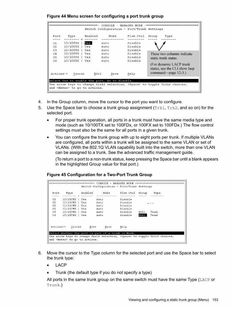
Figure 44 Menu screen for configuring a port trunk group
4. In the Group column, move the cursor to the port you want to configure.5. Use the Space bar to choose a trunk group assignment (Trk1, Trk2, and so on) for the
selected port.• For proper trunk operation, all ports in a trunk must have the same media type and
mode (such as 10/100TX set to 100FDx, or 100FX set to 100FDx.) The flow controlsettings must also be the same for all ports in a given trunk.
• You can configure the trunk group with up to eight ports per trunk. If multiple VLANsare configured, all ports within a trunk will be assigned to the same VLAN or set ofVLANs. (With the 802.1Q VLAN capability built into the switch, more than one VLANcan be assigned to a trunk. See the advanced traffic management guide.(To return a port to a non-trunk status, keep pressing the Space bar until a blank appearsin the highlighted Group value for that port.)
Figure 45 Configuration for a Two-Port Trunk Group
6. Move the cursor to the Type column for the selected port and use the Space bar to selectthe trunk type:• LACP
• Trunk (the default type if you do not specify a type)All ports in the same trunk group on the same switch must have the same Type (LACP orTrunk.)
Viewing and configuring a static trunk group (Menu) 153

7. When you are finished assigning ports to the trunk group, press [Enter], then [S] (for Save)and return to the Main Menu. (It is not necessary to reboot the switch.)During the Save process, traffic on the ports configured for trunking is delayed for severalseconds. If the Spanning Tree Protocol is enabled, the delay may be up to 30 seconds.
8. Connect the trunked ports on the switch to the corresponding ports on the opposite device.If you previously disabled any of the trunked ports on the switch, enable them now. (See"Viewing Port Status and Configuring Port Parameters")
Check the Event Log to verify that the trunked ports are operating properly.
Enabling L4-based trunk load balancingEnter the following command with the L4-based option to enable load balancing on Layer 4information when it is present.
Syntaxtrunk-load-balance [ L3-based | L4-based ]When the L4-based option is configured, enables load balancing based on Layer 4 informationif it is present. If it is not present, Layer 3 information is used if present; if Layer 3 information isnot present, Layer 2 information is used. The configuration is executed in global configurationcontext and applies to the entire switch.
Load balance on Layer 3 information if present, or Layer 2 information.L3-based
Load balance on Layer 4 port information if present, or Layer 3 if present, or Layer2.
L4-based
Default: L3-based load balancing
Examples
Figure 46 Enabling L4-based trunk load balancing
Figure 47 0utput when L4-based trunk load balancing is enabled
154 Port trunking

Figure 48 Running config file when L4-based trunk load balancing is enabled
Viewing trunk load balancingThe show trunks load-balance interface command displays the port on which theinformation will be forwarded out for the specified traffic flow with the specified source anddestination address.
Syntaxshow trunks load-balance interface <trunk-id> mac <src-addr> <dest-addr>[ip <src-addr> <dest-addr> [[<src-tcp-port>] | [<src-upd-port>][[<dest-tcp-port>] | [<dest-udp-port>]]]]inbound-port <port-num>
Displays the port on which the information will be forwarded out for the specified traffic flow withthe specified source and destination address.trunk-id The trunk id (trk1, trk2, etc.)mac src-addr dest-addr The source MAC address and the destination MAC address.ip src-addr dest-addr The source IPv4 /IPv6 address and the destination IPv4/IPv6
address.[src-tcp-port|src-udp-port] The source TCP port
or the source UDPport.
[dest-tcp-port|dest-udp-port] The destination TCPport or the destinationUDP port.
inbound-port port-num the port number of which the traffic is received.
Viewing trunk load balancing 155

Example 88 Example showing information about the forwarding port
HP Switch# show trunks load-balance interface trk1 mac 424521-498421 534516-795463 inbound-port a5Traffic in this flow will be forwarded out port 23 based on the confiugred L2load balancing.
Operating notesThe port cannot be determined if:
• All the ports in the trunk are down.
• The MAC address is all zeros.
• The source MAC address is broadcast or multicast.
Distributed trunkingConfiguring ISC ports
You must configure the ISC ports before you can configure the trunks for distributed trunking.
Syntaxswitch-interconnect <PORT-LIST>|<trk1|trk2|...trkN>
no switch-interconnect
Configures an InterSwitch-Connection (ISC) port. The <PORT-LIST>|<trk1|trk2|...trkN>variable is the interconnect interface that connects two distributed trunking switches. It can be aphysical port, manual LACP trunk, or manual non-protocol trunk. You can override an ISCconfiguration by configuring the command with a different value.The no form of the command removes the ISC interface configuration.
NOTE: A port that is already part of a trunk cannot be configured as an ISC interface.
Configuring distributed trunking portsDistributed trunking ports must be configured manually.
Syntaxtrunk <PORT-LIST> <trk1|trk2|...trkN> trunk <PORT-LIST>|lacp | dt-lacp| dt-trunk
Configures distributed trunking on a switch. Use either the dt-lacp or dt-trunk option.The trunk groups and trunk types must be identical in both switches. For example, if Switch Localis configured with trk1 and uses the dt-lacp option, Switch Remote also must be configuredwith trk1 and use the dt-lacp option to form a distributed trunk. Similarly, if Switch Local isconfigured with trk2 and uses the dt-trunk option, Switch Remote must be configured withtrk2 and use the dt-trunk option to form the distributed trunk.The no form of the command removes the distributed trunking configuration on the switch.
NOTE: DT requires that the platforms at both ends of the DT-link be the same and runningthe same software version.
ExampleFigure 49 (page 157) shows an ISC port being configured for the local switch and the remoteswitch.
156 Port trunking
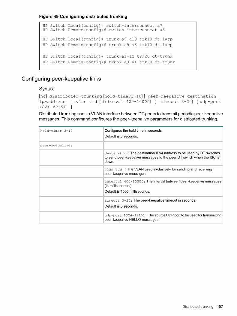
Figure 49 Configuring distributed trunking
Configuring peer-keepalive links
Syntax[no] distributed-trunking [hold-timer3-10] [ peer-keepalive destinationip-address | vlan vid [interval 400-10000] [ timeout 3-20] [udp-port1024-49151] ]Distributed trunking uses a VLAN interface between DT peers to transmit periodic peer-keepalivemessages. This command configures the peer-keepalive parameters for distributed trunking.
Configures the hold time in seconds.hold-timer 3-10
Default is 3 seconds.
peer-keepalive:
destination: The destination IPv4 address to be used by DT switchesto send peer-keepalive messages to the peer DT switch when the ISC isdown.
vlan vid : The VLAN used exclusively for sending and receivingpeer-keepalive messages.
interval 400-10000: The interval between peer-keepalive messages(in milliseconds.)Default is 1000 milliseconds.
timeout 3-20: The peer-keepalive timeout in seconds.Default is 5 seconds.
udp-port 1024-49151: The source UDP port to be used for transmittingpeer-keepalive HELLO messages.
Distributed trunking 157

Viewing distributed trunking information
Syntaxshow lacp [distributed]Displays information about distributed trunks and LACP status.
ExampleHP Switch Local (config#): show lacp distributed
Distributed LACPLocal Port Status:
LACP Trunk Port LACP LACP Admin OperPort Enabled Group Status Partner Status Key Key----- --------- ------- --------- --------- ------ ------- ---A9 Active Trk10 Up Yes Sucess 350 350A10 Active Trk10 Up Yes Sucess 350 350
Remote Port StatusLACP Trunk Port LACP LACP Oper
Port Enabled Group Status Partner Status Key----- --------- ------- --------- --------- ------ -----A5 Active Trk10 Up Yes Sucess 200A6 Active Trk10 Up Yes Sucess 200
Syntaxshow distributed-trunk consistency-parameters global
This command displays configured features on VLANs that have dt‐lacp or dt‐trunkports as member port. This command also displays VLAN memberships andloop‐protect status of a given DT trunk. You can use this command to determineif there is any mismatch in the configuration parameters on VLANs configured forDT ports or on DT interfaces.
Exampleshow distributed-trunk consistency-parameters global
Local Peer----- -----
Image Version K.15.XX K.15.XXIP Routing Enabled EnabledPeer-keepalive interval (ms) 1000 1000
IGMP enabled VLANs on Local : 1-10, 100-110, 501 ,600610 ,800IGMP enabled VLANs on Peer : 1-10, 100-110, 501 ,600
DHCP-snooping enabled VLANs on Local : 1,2DHCP-snooping enabled VLANs on Peer : 1
Loop-protect enabled VLANs on Local : 1,4Loop-protect enabled VLANs on Peer : 1,5
MLD enabled VLANs on Local : 1-10MLD enabled VLANs on Peer : 1-10
ExampleShow distributed-trunkconsistency-parameters trunk <trk1...trkN>Allowed VLANs on Local : 1-10, 100-110, 501 ,600610 ,800Allowed VLANs on Peer : 1-10, 100-110, 501 ,600
158 Port trunking
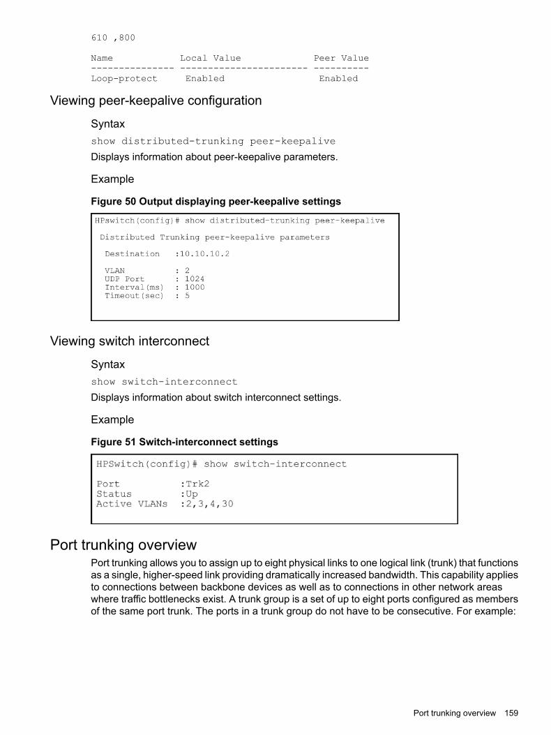
610 ,800
Name Local Value Peer Value--------------- ----------------------- ----------Loop-protect Enabled Enabled
Viewing peer-keepalive configuration
Syntaxshow distributed-trunking peer-keepalive
Displays information about peer-keepalive parameters.
Example
Figure 50 Output displaying peer-keepalive settings
Viewing switch interconnect
Syntaxshow switch-interconnect
Displays information about switch interconnect settings.
Example
Figure 51 Switch-interconnect settings
Port trunking overviewPort trunking allows you to assign up to eight physical links to one logical link (trunk) that functionsas a single, higher-speed link providing dramatically increased bandwidth. This capability appliesto connections between backbone devices as well as to connections in other network areaswhere traffic bottlenecks exist. A trunk group is a set of up to eight ports configured as membersof the same port trunk. The ports in a trunk group do not have to be consecutive. For example:
Port trunking overview 159

Figure 52 Conceptual example of port trunking
With full-duplex operation in a eight-port trunk group, trunking enables the following bandwidthcapabilities:
Port trunk connections and configurationAll port trunk links must be point-to-point connections between a switch and another switch,router, server, or workstation configured for port trunking. No intervening, non-trunking devicesare allowed. It is important to note that ports on both ends of a port trunk group must have thesame mode (speed and duplex) and flow control settings.
CAUTION: To avoid broadcast storms or loops in your network while configuring a trunk, firstdisable or disconnect all ports you want to add to or remove from the trunk. After you finishconfiguring the trunk, enable or re-connect the ports.
NOTE:Link connections The switch does not support port trunking through an
intermediate, non-trunking device such as a hub, or usingmore than onemedia type in a port trunk group. Similarly,for proper trunk operation, all links in the same trunk groupmust have the same speed, duplex, and flow control.
Port security restriction Port security does not operate on a trunk group. If youconfigure port security on one or more ports that are lateradded to a trunk group, the switch resets the port securityparameters for those ports to the factory-defaultconfiguration.
Port trunk operationsThe switches covered in this guide offer these options for port trunking:
• LACP: IEEE 802.3ad—
• Trunk: Non-Protocol—Up to 144 trunk groups are supported on the switches. The actual maximum depends on thenumber of ports available on the switch and the number of links in each trunk. (Using the linkaggregation control protocol—LACP—option, you can include standby trunked ports in addition
160 Port trunking
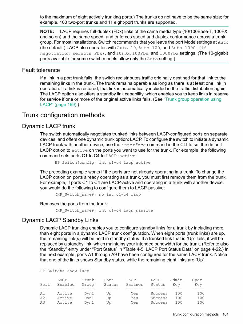
to the maximum of eight actively trunking ports.) The trunks do not have to be the same size; forexample, 100 two-port trunks and 11 eight-port trunks are supported.
NOTE: LACP requires full-duplex (FDx) links of the same media type (10/100Base-T, 100FX,and so on) and the same speed, and enforces speed and duplex conformance across a trunkgroup. For most installations, Switch recommends that you leave the port Mode settings at Auto(the default.) LACP also operates with Auto-10, Auto-100, and Auto-1000 (ifnegotiation selects FDx), and 10FDx, 100FDx, and 1000FDx settings. (The 10-gigabitports available for some switch models allow only the Auto setting.)
Fault toleranceIf a link in a port trunk fails, the switch redistributes traffic originally destined for that link to theremaining links in the trunk. The trunk remains operable as long as there is at least one link inoperation. If a link is restored, that link is automatically included in the traffic distribution again.The LACP option also offers a standby link capability, which enables you to keep links in reservefor service if one or more of the original active links fails. (See “Trunk group operation usingLACP” (page 169).)
Trunk configuration methodsDynamic LACP trunk
The switch automatically negotiates trunked links between LACP-configured ports on separatedevices, and offers one dynamic trunk option: LACP. To configure the switch to initiate a dynamicLACP trunk with another device, use the interface command in the CLI to set the defaultLACP option to active on the ports you want to use for the trunk. For example, the followingcommand sets ports C1 to C4 to LACP active:
HP Switch(config) int c1-c4 lacp active
The preceding example works if the ports are not already operating in a trunk. To change theLACP option on ports already operating as a trunk, you must first remove them from the trunk.For example, if ports C1 to C4 are LACP-active and operating in a trunk with another device,you would do the following to configure them to LACP-passive:
(HP_Switch_name#) no int c1-c4 lacp
Removes the ports from the trunk:(HP_Switch_name#) int c1-c4 lacp passive
Dynamic LACP Standby LinksDynamic LACP trunking enables you to configure standby links for a trunk by including morethan eight ports in a dynamic LACP trunk configuration. When eight ports (trunk links) are up,the remaining link(s) will be held in standby status. If a trunked link that is “Up” fails, it will bereplaced by a standby link, which maintains your intended bandwidth for the trunk. (Refer to alsothe “Standby” entry under “Port Status” in "Table 4-5. LACP Port Status Data" on page 4-22.) Inthe next example, ports A1 through A9 have been configured for the same LACP trunk. Noticethat one of the links shows Standby status, while the remaining eight links are “Up”.
HP Switch> show lacp
LACP Trunk Port LACP LACP Admin OperPort Enabled Group Status Partner Status Key Key---- ------- ----- ------ ------- ------ ---- -----Al Active Dyn1 Up Yes Success 100 100A2 Active Dyn1 Up Yes Success 100 100A3 Active Dyn1 Up Yes Success 100 100
Trunk configuration methods 161

A4 Active Dyn1 Up Yes Success 100 100A5 Active Dyn1 Up Yes Success 100 100A6 Active Dyn1 Up Yes Success 100 100A7 Active Dyn1 Up Yes Success 100 100A8 Active Dyn1 Up Yes Success 100 100A9 Active Dyn1 Standby Yes Success 100 100
Viewing LACP Local Information
HP Switch# show lacp localLACP Local Information.System ID: 001871-b98500
LACP Tx Rx TimerPort Trunk Mode Aggregated Timer Expired----- ------- ------- ----------- ------ ---------A2 A2 Active Yes Fast NoA3 A3 Active Yes Fast No
Viewing LACP Peer InformationUse the show lacp peer command to display information about LACP peers. The System IDrepresents the MAC address of a partner switch. It will be zero if a partner is not found.
(HP_Switch_name#) show lacp peerLACP Peer Information.System ID: 001871-b98500Local Local Port Oper LACP TxPort Trunk System ID Port Priority Key Mode Timer------ ------ -------------- ----- --------- ------- -------- -----A2 A2 123456-654321 2 0 100 Passive FastA3 A3 234567-456789 3 0 100 Passive Fast
Viewing LACP CountersUse the show lacp counters command to display statistical information about LACP ports.Note on the Marker Protocol. Data traffic can be dynamically redistributed in port channels. Thismay occur when a link is added or removed, or there is a change in load-balancing. Traffic thatis redistributed in the middle of a traffic flow could potentially cause mis-ordered data packets.LACP uses the marker protocol to prevent data packets from being duplicated or reordered dueto redistribution. Marker PDUs are sent on each port-channel link. The remote system respondsto the marker PDU by sending a marker responder when it has received all the frames receivedon this link prior to the marker PDU. When the marker responders are received by the localsystem on all member links of the port channel, the local system can redistribute the packets inthe traffic flow correctly.For the switches covered in this guide, the marker BPDUs are not initiated, only forwarded whenreceived, resulting in the Marker fields in the output usually displaying zeros.(HP_Switch_name#) show lacp countersLACP Port Counters.
LACP LACP Marker Marker Marker MarkerPort Trunk PDUs Tx PDUs Rx Req. Tx Req. Rx Resp. Tx Resp. Rx Error---- ------ ------- ------- ------- ------- -------- -------- -----A2 A2 1234 1234 0 0 0 0 0A3 A3 1234 1234 0 0 0 0 0
Using keys to control dynamic LACP trunk configurationThe lacp key option provides the ability to control dynamic trunk configuration. Ports with thesame key will be aggregated as a single trunk.There are two types of keys associated with each port, the Admin key and the Operational key.The Operational key is the key currently in use. The Admin key is used internally to modify the
162 Port trunking

value of the Operational key. The Admin and Operational key are usually the same, but usingstatic LACP can alter the Operational key during runtime, in which case the keys would differ.The lacp key command configures both the Admin and Operational keys when using dynamicLACP trunks. It only configures the Admin key if the trunk is a static LACP trunk. It is executedin the interface context.
Static trunkThe switch uses the links you configure with the Port/Trunk Settings screen in the menu interfaceor the trunk command in the CLI to create a static port trunk. The switch offers two types ofstatic trunks: LACP and Trunk.
Table 9 Trunk types used in static and dynamic trunk groups
TrunkLACPTrunking method
NoYesDynamic
YesYesStatic
Table 10 describes the trunking options for LACP and Trunk protocols.
Table 10 Trunk configuration protocols
Trunking OptionsProtocol
Provides dynamic and static LACP trunking options.LACP (802.3ad)
• Dynamic LACP — Use the switch-negotiated dynamicLACP trunk when:
• The port on the other end of the trunk link isconfigured for Active or Passive LACP.
• You want fault-tolerance for high-availabilityapplications. If you use an eight-link trunk, you canalso configure one or more additional links tooperate as standby links that will activate only ifanother active link goes down.
• Static LACP — Use the manually configured staticLACP trunk when:
• The port on the other end of the trunk link isconfigured for a static LACP trunk.
• You want to configure non-default spanning tree orIGMP parameters on an LACP trunk group.
• You want an LACP trunk group to operate in aVLAN other than the default VLAN and GVRP isdisabled.
• You want to use a monitor port on the switch tomonitor an LACP trunk.
Provides manually configured, static-only trunking to:Trunk(non-protocol) • Most Switch and routing switches not running the
802.3ad LACP protocol.
• Windows NT and HP-UX workstations and servers
Use the Trunk option when:
• The device to which you want to create a trunk link isusing a non-802.3ad trunking protocol.
• You are unsure which type of trunk to use, or thedevice to which you want to create a trunk link is usingan unknown trunking protocol.
• You want to use a monitor port on the switch to monitortraffic on a trunk.
Trunk configuration methods 163

Table 10 Trunk configuration protocols (continued)
Trunking OptionsProtocol
Operating port trunksMedia: For proper trunk operation, all ports on both ends of a trunk group
must have the same media type and mode (speed and duplex.)(For the switches, Switch recommends leaving the port Mode settingat Auto or, in networks using Cat 3 cabling, Auto-10.)
Port Configuration The default port configuration is Auto, which enables a port to sensespeed and negotiate duplex with an auto-enabled port on anotherdevice. Switch recommends that you use the Auto setting for allports you plan to use for trunking. Otherwise, you must manuallyensure that the mode setting for each port in a trunk is compatiblewith the other ports in the trunk.
Example 89 Recommended port mode setting for LACP
(HP_Switch_name#) show interfaces config
Port Settings
Port Type | Enabled Mode Flow Ctrl MDI----- --------- + ------- ------------ --------- ----1 10/100TX | Yes Auto Enable Auto2 10/100TX | Yes Auto Enable MDI
All of the following operate on a per-port basis, regardless of trunk membership:
• Enable/Disable
• Flow control (Flow Ctrl)LACP is a full-duplex protocol.Trunk configuration: All ports in the same trunk group must be the same trunk type
(LACP or trunk.) All LACP ports in the same trunk group mustbe either all static LACP or all dynamic LACP.A trunk appears as a single port labeledDyn1(for an LACPdynamic trunk) or Trk1 (for a static trunk of type LACP, Trunk)on various menu and CLI screens.For spanning-tree or VLAN operation, configuration for all portsin a trunk is done at the trunk level. (You cannot separatelyconfigure individual ports within a trunk for spanning-tree orVLAN operation.)
Traffic distribution: All of the switch trunk protocols use the SA/DA (sourceaddress/destination address) method of distributing trafficacross the trunked links.
Spanning Tree: 802.1D (STP) and 802.1w (RSTP) Spanning Tree operate asa global setting on the switch (with one instance of SpanningTree per switch.) 802.1s (MSTP) Spanning Tree operates ona per-instance basis (with multiple instances allowed perswitch.) For each Spanning Tree instance, you can adjustSpanning Tree parameters on a per-port basis.A static trunk of any type appears in the Spanning Treeconfiguration display, and you can configure Spanning Tree
164 Port trunking

parameters for a static trunk in the same way that you wouldconfigure Spanning Tree parameters on a non-trunked port.(Note that the switch lists the trunk by name—such asTrk1—and does not list the individual ports in the trunk.) Forexample, if ports C1 and C2 are configured as a static trunknamed Trk1, they are listed in the Spanning Tree display asTrk1 and do not appear as individual ports in the Spanning Treedisplays.When Spanning Tree forwards on a trunk, all ports in the trunkwill be forwarding. Conversely, when Spanning Tree blocks atrunk, all ports in the trunk are blocked.
NOTE: A dynamic LACP trunk operates only with the defaultSpanning Tree settings. Also, this type of trunk appears in theCLI show spanning-tree display, but not in the SpanningTree Operation display of the Menu interface.
If you remove a port from a static trunk, the port retains thesame Spanning Tree settings that were configured for the trunk.
Figure 53 Example of a port trunk in a Spanning Tree listing
IP multicast protocol (IGMP): A static trunk of any type appears in the IGMP configurationdisplay, and you can configure IGMP for a static trunk inthe same way that you would configure IGMP on anon-trunked port. (Note that the switch lists the trunk byname—such as Trk1—and does not list the individual portsin the trunk.) Also, creating a new trunk automaticallyplaces the trunk in IGMP Auto status if IGMP is enabledfor the default VLAN.A dynamic LACP trunk operates only with the default IGMPsettings and does not appear in the IGMP configurationdisplay or show ip igmp listing.
VLANs: Creating a new trunk automatically places the trunk in theDEFAULT_VLAN, regardless of whether the ports in thetrunk were in another VLAN. Similarly, removing a portfrom a trunk group automatically places the port in thedefault VLAN. You can configure a static trunk in the sameway that you configure a port for membership in any VLAN.
NOTE: For a dynamic LACP trunk to operate in a VLANother than the default VLAN (DEFAULT_VLAN), GVRPmust be enabled.
Port security Trunk groups (and their individual ports) cannot beconfigured for port security, and the switch excludestrunked ports from the show port-security listing. Ifyou configure non-default port security settings for a port,
Trunk configuration methods 165

then subsequently try to place the port in a trunk, you seethe following message and the command is not executed:<PORT-LIST> Command cannot operate over a logicalport.
Monitor portNOTE: A trunk cannot be a monitor port. A monitor portcan monitor a static trunk but cannot monitor a dynamicLACP trunk.
Show port-security log
Syntaxshow port-security intrusion-log
Example 90 show port-security intrusion-log
HP-3800-24G-PoEP-2SFPP(config)# sh port-security intrusion-log
Status and Counters - Intrusion Log
Port MAC Address Date / Time------ ------------- --------------------------23 000087-c78b49 11/19/14 11:09:3023 000087-c78041 11/19/14 11:12:2923 000087-c781c1 11/19/14 11:14:08
Configuring a static or dynamic trunk group overview
IMPORTANT: Configure port trunking before you connect the trunked links between switches.Otherwise, a broadcast storm could occur. (If you need to connect the ports before configuringthem for trunking, you can temporarily disable the ports until the trunk is configured.)
The table on Table 9 describes the maximum number of trunk groups you can configure on theswitch. An individual trunk can have up to eight links, with additional standby links if you are usingLACP. You can configure trunk group types as follows:
Trunk Group MembershipTrunk Type
DynX (dynamic)TrkX (static)
YesYesLACP
NoYesTrunk
Enabling a dynamic LACP trunk groupIn the default port configuration, all ports on the switch are set to disabled. To enable the switchto automatically form a trunk group that is dynamic on both ends of the link, the ports on one endof a set of links must be LACP Active. The ports on the other end can be either LACP Active orLACP Passive. The active command enables the switch to automatically establish a (dynamic)LACP trunk group when the device on the other end of the link is configured for LACP Passive.
166 Port trunking
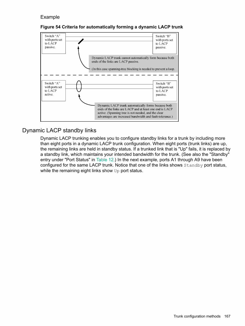
Example
Figure 54 Criteria for automatically forming a dynamic LACP trunk
Dynamic LACP standby linksDynamic LACP trunking enables you to configure standby links for a trunk by including morethan eight ports in a dynamic LACP trunk configuration. When eight ports (trunk links) are up,the remaining links are held in standby status. If a trunked link that is "Up" fails, it is replaced bya standby link, which maintains your intended bandwidth for the trunk. (See also the "Standby"entry under "Port Status" in Table 12.) In the next example, ports A1 through A9 have beenconfigured for the same LACP trunk. Notice that one of the links shows Standby port status,while the remaining eight links show Up port status.
Trunk configuration methods 167
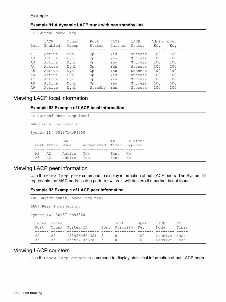
Example
Example 91 A dynamic LACP trunk with one standby link
HP Switch> show lacp
LACP Trunk Port LACP LACP Admin OperPort Enabled Group Status Partner Status Key Key---- ------- ------- ------- ------- ------- ------ ------Al Active Dyn1 Up Yes Success 100 100A2 Active Dyn1 Up Yes Success 100 100A3 Active Dyn1 Up Yes Success 100 100A4 Active Dyn1 Up Yes Success 100 100A5 Active Dyn1 Up Yes Success 100 100A6 Active Dyn1 Up Yes Success 100 100A7 Active Dyn1 Up Yes Success 100 100A8 Active Dyn1 Up Yes Success 100 100A9 Active Dyn1 Standby Yes Success 100 100
Viewing LACP local information
Example 92 Example of LACP local information
HP Switch# show lacp local
LACP Local Information.
System ID: 001871-b98500
LACP Tx Rx TimerPort Trunk Mode Aggregated Timer Expired---- ------ -------- ----------- ------ --------A2 A2 Active Yes Fast NoA3 A3 Active Yes Fast No
Viewing LACP peer informationUse the show lacp peer command to display information about LACP peers. The System IDrepresents the MAC address of a partner switch. It will be zero if a partner is not found.
Example 93 Example of LACP peer information
(HP_Switch_name#) show lacp peer
LACP Peer Information.
System ID: 001871-b98500
Local Local Port Oper LACP TxPort Trunk System ID Port Priority Key Mode Timer------ ------ -------------- ----- --------- ------- -------- -----A2 A2 123456-654321 2 0 100 Passive FastA3 A3 234567-456789 3 0 100 Passive Fast
Viewing LACP countersUse the show lacp counters command to display statistical information about LACP ports.
168 Port trunking

NOTE: Data traffic can be dynamically redistributed in port channels. This may occur whena link is added or removed, or there is a change in load-balancing. Traffic that is redistributed inthe middle of a traffic flow could potentially cause mis-ordered data packets.LACP uses the marker protocol to prevent data packets from being duplicated or reordered dueto redistribution. Marker PDUs are sent on each port-channel link. The remote system respondsto the marker PDU by sending a marker responder when it has received all the frames receivedon this link prior to the marker PDU. When the marker responders are received by the localsystem on all member links of the port channel, the local system can redistribute the packets inthe traffic flow correctly.
For the switches covered in this guide, the marker BPDUs are not initiated, only forwarded whenreceived, resulting in the Marker fields in the output usually displaying zeros.
Example 94 Example of LACP counters output
(HP_Switch_name#) show lacp counters
LACP Port Counters.
LACP LACP Marker Marker Marker MarkerPort Trunk PDUs Tx PDUs Rx Req. Tx Req. Rx Resp. Tx Resp. Rx Error---- ------ --------- --------- -------- -------- -------- -------- --------A2 A2 1234 1234 0 0 0 0 0A3 A3 1234 1234 0 0 0 0 0
Trunk group operation using LACPThe switch can automatically configure a dynamic LACP trunk group, or you can manuallyconfigure a static LACP trunk group.
NOTE: LACP requires full-duplex (FDx) links of the same media type (10/100Base-T, 100FX,and so on) and the same speed and enforces speed and duplex conformance across a trunkgroup. For most installations, Switch recommends that you leave the port mode settings at Auto(the default.) LACP also operates with Auto-10, Auto-100, and Auto-1000 (if negotiationselects FDx), and 10FDx, 100FDx, and 1000FDx settings.
LACP trunk status commands include:
Dynamic LACP trunkStatic LACP trunkTrunk display method
Included in listing.Included in listing.CLI show lacp command
Not included.Included in listing.CLI show trunk command
Not includedIncluded in listing.Port/Trunk Settings screen in menuinterface
Thus, to display a listing of dynamic LACP trunk ports, you must use the show lacp command.In most cases, trunks configured for LACP on the switches operate as described in Table 11(page 169).
Table 11 LACP trunk types
OperationLACP port trunkconfiguration
This option automatically establishes an 802.3ad-compliant trunk group, with LACPfor the port Type parameter and DynX for the port Group name, where X is an
Dynamic LACP
automatically assigned value from 1 to 144, depending on how many dynamic and
Trunk group operation using LACP 169
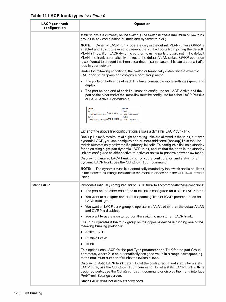
Table 11 LACP trunk types (continued)
OperationLACP port trunkconfiguration
static trunks are currently on the switch. (The switch allows a maximum of 144 trunkgroups in any combination of static and dynamic trunks.)
NOTE: Dynamic LACP trunks operate only in the default VLAN (unless GVRP isenabled and Forbid is used to prevent the trunked ports from joining the defaultVLAN.) Thus, if an LACP dynamic port forms using ports that are not in the defaultVLAN, the trunk automatically moves to the default VLAN unless GVRP operationis configured to prevent this from occurring. In some cases, this can create a trafficloop in your network.Under the following conditions, the switch automatically establishes a dynamicLACP port trunk group and assigns a port Group name:
• The ports on both ends of each link have compatible mode settings (speed andduplex.)
• The port on one end of each link must be configured for LACP Active and theport on the other end of the same link must be configured for either LACP Passiveor LACP Active. For example:
Either of the above link configurations allows a dynamic LACP trunk link.Backup Links: A maximum of eight operating links are allowed in the trunk, but, withdynamic LACP, you can configure one or more additional (backup) links that theswitch automatically activates if a primary link fails. To configure a link as a standbyfor an existing eight-port dynamic LACP trunk, ensure that the ports in the standbylink are configured as either active-to-active or active-to-passive between switches.Displaying dynamic LACP trunk data: To list the configuration and status for adynamic LACP trunk, use the CLI show lacp command.
NOTE: The dynamic trunk is automatically created by the switch and is not listedin the static trunk listings available in the menu interface or in the CLI show trunklisting.
Provides a manually configured, static LACP trunk to accommodate these conditions:Static LACP
• The port on the other end of the trunk link is configured for a static LACP trunk.
• You want to configure non-default Spanning Tree or IGMP parameters on anLACP trunk group.
• You want an LACP trunk group to operate in a VLAN other than the default VLANand GVRP is disabled.
• You want to use a monitor port on the switch to monitor an LACP trunk.
The trunk operates if the trunk group on the opposite device is running one of thefollowing trunking protocols:
• Active LACP
• Passive LACP
• Trunk
This option uses LACP for the port Type parameter and TrkX for the port Groupparameter, where X is an automatically assigned value in a range correspondingto the maximum number of trunks the switch allows.Displaying static LACP trunk data : To list the configuration and status for a staticLACP trunk, use the CLI show lacp command. To list a static LACP trunk with itsassigned ports, use the CLI show trunk command or display the menu interfacePort/Trunk Settings screen.Static LACP does not allow standby ports.
170 Port trunking

Default port operationIn the default configuration, LACP is disabled for all ports. If LACP is not configured as Activeon at least one end of a link, the port does not try to detect a trunk configuration and operatesas a standard, untrunked port. Table 12 (page 171) lists the elements of per-port LACP operation.To display this data for a switch, execute the following command in the CLI:
HP Switch show lacp
Table 12 LACP port status data
MeaningStatus name
Shows the physical port number for each port configured for LACP operation (C1, C2, C3 ….)Unlisted port numbers indicate that the missing ports that are assigned to a static trunk group arenot configured for any trunking.
Port Numb
Active: The port automatically sends LACP protocol packets.LACP EnabledPassive: The port does not automatically send LACP protocol packets and responds only if itreceives LACP protocol packets from the opposite device.A link having either two active LACP ports or one active port and one passive port can performdynamic LACP trunking. A link having two passive LACP ports does not perform LACP trunkingbecause both ports are waiting for an LACP protocol packet from the opposite device.
NOTE: In the default switch configuration, LACP is disabled for all ports.
TrkX: This port has been manually configured into a static LACP trunk.Trunk GroupTrunk group same as port number: The port is configured for LACP, but is not a member of a porttrunk.
Up: The port has an active LACP link and is not blocked or in standby mode.Port StatusDown: The port is enabled, but an LACP link is not established. This can indicate, for example, aport that is not connected to the network or a speed mismatch between a pair of linked ports.Disabled: The port cannot carry traffic.Blocked: LACP, Spanning Tree has blocked the port. (The port is not in LACP standby mode.) Thismay be caused by a (brief) trunk negotiation or a configuration error, such as differing port speedson the same link or trying to connect the switch to more trunks than it can support. (See the tableon Table 10.)
NOTE: Some older devices are limited to four ports in a trunk. When eight LACP-enabled portsare connected to one of these older devices, four ports connect, but the other four ports are blocked.Standby: The port is configured for dynamic LACP trunking to another device, but the maximumnumber of ports for the dynamic trunk to that device has already been reached on either the switchor the other device. This port will remain in reserve, or "standby" unless LACP detects that another,active link in the trunk has become disabled, blocked, or down. In this case, LACP automaticallyassigns a standby port, if available, to replace the failed port.
Yes: LACP is enabled on both ends of the link.LACP PartnerNo: LACP is enabled on the switch, but either LACP is not enabled or the link has not been detectedon the opposite device.
Success: LACP is enabled on the port, detects and synchronizes with a device on the other endof the link, and can move traffic across the link.
LACP Status
Failure: LACP is enabled on a port and detects a device on the other end of the link, but is not ableto synchronize with this device, and therefore is not able to send LACP packets across the link.This can be caused, for example, by an intervening device on the link (such as a hub), a badhardware connection, or if the LACP operation on the opposite device does not comply with theIEEE 802.3ad standard.
Trunk group operation using LACP 171

LACP operating notes and restrictions
802.1X (Port-based access control) configured on a portTo maintain security, LACP is not allowed on ports configured for 802.1X authenticator operation.If you configure port security on a port on which LACP (active or passive) is configured, the switchremoves the LACP configuration, displays a notice that LACP is disabled on the port, and enables802.1X on that port.
(HP_Switch_name#) aaa port-access authenticator b1LACP has been disabled on 802.1x port(s.)(HP_Switch_name#)
The switch does not allow you to configure LACP on a port on which port access (802.1X) isenabled. For example:
(HP_Switch_name#) int b1 lacp passiveError configuring port port-number : LACP and 802.1x cannotbe run together.(HP_Switch_name#)
To restore LACP to the port, you must first remove the 802.1X configuration of the port and thenre-enable LACP active or passive on the port.
Port securityTo maintain security, LACP is not allowed on ports configured for port security. If you configureport security on a port on which LACP (active or passive) is configured, the switch removes theLACP configuration, displays a notice that LACP is disabled on the port, and enables port securityon that port. For example:
(HP_Switch_name#) port-security a17 learn-mode static address-limit 2 LACP has been disabled on secured port(s.)(HP_Switch_name#)
The switch does not allow you to configure LACP on a port on which port security is enabled.For example:
(HP_Switch_name#) int a17 lacp passiveError configuring port A17: LACP and port security cannot berun together.(HP_Switch_name#)
To restore LACP to the port, you must remove port security and re-enable LACP active or passive.
Changing trunking methodsTo convert a trunk from static to dynamic, you must first eliminate the static trunk.
Static LACP trunksWhen a port is configured for LACP (active or passive), but does not belong to an existing trunkgroup, you can add that port to a static trunk. Doing so disables dynamic LACP on that port,which means you must manually configure both ends of the trunk.
NOTE: Static LACP allows ports with different speed to be part of the same trunk.
Dynamic LACP trunksYou can configure a port for LACP-active or LACP-passive, but on a dynamic LACP trunk youcannot configure the other options that you can on static trunks. If you want to manually configurea trunk, use the trunk command. (See "Using the CLI To Configure a Static or Dynamic TrunkGroup")
172 Port trunking

VLANs and dynamic LACPA dynamic LACP trunk operates only in the default VLAN (unless you have enabled GVRP onthe switch and use Forbid to prevent the ports from joining the default VLAN.)If you want to use LACP for a trunk on a non-default VLAN and GVRP is disabled, configure thetrunk as a static trunk.
Blocked ports with older devices.Some older devices are limited to four ports in a trunk. When eight LACP-enabled ports areconnected to one of these older devices, four ports connect, but the other four ports are blocked.The LACP status of the blocked ports is shown as "Failure."If one of the other ports becomes disabled, a blocked port replaces it (Port Status becomes "Up".)When the other port becomes active again, the replacement port goes back to blocked (PortStatus is "Blocked".) It can take a few seconds for the switch to discover the current status ofthe ports.
Figure 55 Blocked ports with LACP
If there are ports that you do not want on the default VLAN, ensure that they cannot becomedynamic LACP trunk members. Otherwise a traffic loop can unexpectedly occur. For example:
Figure 56 A dynamic LACP trunk forming in a VLAN can cause a traffic loop
Easy control methods include either disabling LACP on the selected ports or configuring themto operate in static LACP trunks.
Trunk group operation using LACP 173

Spanning Tree and IGMPIf Spanning Tree, IGMP, or both are enabled in the switch, a dynamic LACP trunk operates onlywith the default settings for these features and does not appear in the port listings for thesefeatures.
Half-duplex, different port speeds, or both not allowed in LACP trunksTheports on both sides of an LACP trunk must be configured for the same speed and for full-duplex(FDx.) The 802.3ad LACP standard specifies a full-duplex (FDx) requirement for LACP trunking.(10-gigabit ports operate only at FDx.)A port configured as LACP passive and not assigned to a port trunk can be configured tohalf-duplex (HDx.) However, in any of the following cases, a port cannot be reconfigured to anHDx setting:• If the port is a 10-gigabit port.
• If a port is set to LACP Active, you cannot configure it to HDx.
• If a port is already a member of a static or dynamic LACP trunk, you cannot configure it toHDx.
• If a port is already set to HDx, the switch does not allow you to configure it for a static ordynamic LACP trunk.
Dynamic/static LACP interoperationA port configured for dynamic LACP can properly interoperate with a port configured for static(TrkX) LACP, but any ports configured as standby LACP links are ignored.
Trunk group operation using the "trunk" optionThis method creates a trunk group that operates independently of specific trunking protocols anddoes not use a protocol exchange with the device on the other end of the trunk. With this choice,the switch simply uses the SA/DA method of distributing outbound traffic across the trunked portswithout regard for how that traffic is handled by the device at the other end of the trunked links.Similarly, the switch handles incoming traffic from the trunked links as if it were from a trunkedsource.When a trunk group is configured with the trunk option, the switch automatically sets the trunkto a priority of "4" for Spanning Tree operation (even if Spanning Tree is currently disabled.) Thisappears in the running-config file as spanning-tree Trkn priority 4. Executing writememory after configuring the trunk places the same entry in the startup-config file.Use the trunk option to establish a trunk group between a switch and another device, wherethe other device's trunking operation fails to operate properly with LACP trunking configured onthe switches.
Viewing trunk data on the switchStatic trunk group Appears in the menu interface and the output from the CLI
show trunk and show interfaces commands.Dynamic LACP trunk group Appears in the output from the CLI show lacp command.
Static non-protocolStatic LACP trunkgroup
Dynamic LACP trunkgroup
Interface option
YesYesNoMenu interface
YesYesNoCLI show trunk
YesYesNoCLI show interfaces
174 Port trunking

Static non-protocolStatic LACP trunkgroup
Dynamic LACP trunkgroup
Interface option
NoYesYesCLI show lacp
YesYesNoCLI show spanning-tree
YesYesNoCLI show igmp
YesYesNoCLI show config
Outbound traffic distribution across trunked linksThe two trunk group options (LACP and trunk) use SA/DA pairs for distributing outbound trafficover trunked links. That is, the switch sends traffic from the same source address to the samedestination address through the same trunked link, and may also send traffic from the samesource address to a different destination address through the same link or a different link,depending on the mapping of path assignments among the links in the trunk. Likewise, the switchdistributes traffic for the same destination address but from different source addresses throughlinks depending on the path assignment.The load-balancing is done on a per-communication basis. Otherwise, traffic is transmitted acrossthe same path as shown in Figure 57 (page 175). That is, if Client A attached to Switch 1 sendsfive packets of data to Server A attached to Switch 2, the same link is used to send all five packets.The SA/DA address pair for the traffic is the same. The packets are not evenly distributed acrossany other existing links between the two switches; they all take the same path.
Figure 57 Example of single path traffic through a trunk
The actual distribution of the traffic through a trunk depends on a calculation using bits from theSA/DA. When an IP address is available, the calculation includes the last five bits of the IP sourceaddress and IP destination address; otherwise, the MAC addresses are used. The result of thatprocess undergoes a mapping that determines which link the traffic goes through. If you haveonly two ports in a trunk, it is possible that all the traffic will be sent through one port even if theSA/DA pairs are different. The more ports you have in the trunk, the more likely it is that the trafficwill be distributed among the links.When a new port is added to the trunk, the switch begins sending traffic, either new traffic orexisting traffic, through the new link. As links are added or deleted, the switch redistributes trafficacross the trunk group. For example, in Figure 58 (page 176) showing a three-port trunk, trafficcould be assigned as shown in Table 13 (page 176).
Outbound traffic distribution across trunked links 175

Figure 58 Example of port-trunked network
Table 13 Example of link assignments in a trunk group (SA/DA distribution)
LinkDestinationSource
1Node WNode A
2Node XNode B
3Node YNode C
1Node ZNode D
2Node YNode A
3Node WNode B
Because the amount of traffic coming from or going to various nodes in a network can vary widely,it is possible for one link in a trunk group to be fully utilized while other links in the same trunkhave unused bandwidth capacity, even if the assignments were evenly distributed across thelinks in a trunk.
Trunk load balancing using Layer 4 portsTrunk load balancing using Layer 4 ports allows the use of TCP/UDP source and destinationport number for trunk load balancing. This is in addition to the current use of source and destinationIP address and MAC addresses. Configuration of Layer 4 load balancing would apply to all trunkson the switch. Only non-fragmented packets will have their TCP/UDP port number used by loadbalancing. This ensures that all frames associated with a fragmented IP packet are sent throughthe same trunk on the same physical link.The priority for using Layer 4 packets when this feature is enabled is as follows:1. If the packet protocol is an IP packet and has Layer 4 port information, use Layer 4.2. If the packet protocol is an IP packet and does not have Layer 4 information, use Layer 3
information.3. If the packet is not an IP packet, use Layer 2 information.
Distributed trunking overviewThe IEEE standard 802.3ad requires that all links in a trunk group originate from the same switch.Distributed trunking uses a proprietary protocol that allows two or more port trunk links distributedacross two switches to create a trunk group. The grouped links appear to the downstream deviceas if they are from a single device. This allows third party devices such as switches, servers, orany other networking device that supports trunking to interoperate with the distributed trunkingswitches (DTSs) seamlessly. Distributed trunking provides device-level redundancy in additionto link failure protection.DTSs are connected by a special interface called the InterSwitch-Connect (ISC) port. This interfaceexchanges information so that the DTSs appear as a single switch to a downstream device, asmentioned above. Each distributed trunk (DT) switch in a DT pair must be configured with aseparate ISC link and peer-keepalive link. The peer-keepalive link is used to transmit keepalive
176 Port trunking
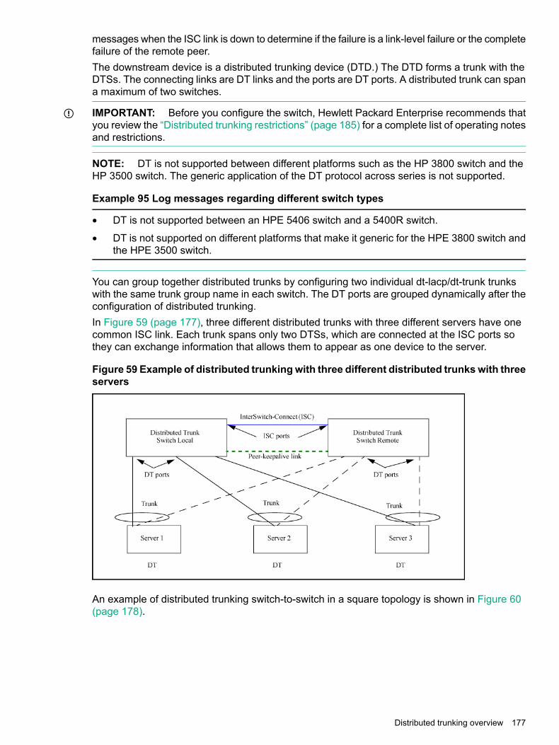
messages when the ISC link is down to determine if the failure is a link-level failure or the completefailure of the remote peer.The downstream device is a distributed trunking device (DTD.) The DTD forms a trunk with theDTSs. The connecting links are DT links and the ports are DT ports. A distributed trunk can spana maximum of two switches.
IMPORTANT: Before you configure the switch, Hewlett Packard Enterprise recommends thatyou review the “Distributed trunking restrictions” (page 185) for a complete list of operating notesand restrictions.
NOTE: DT is not supported between different platforms such as the HP 3800 switch and theHP 3500 switch. The generic application of the DT protocol across series is not supported.
Example 95 Log messages regarding different switch types
• DT is not supported between an HPE 5406 switch and a 5400R switch.
• DT is not supported on different platforms that make it generic for the HPE 3800 switch andthe HPE 3500 switch.
You can group together distributed trunks by configuring two individual dt-lacp/dt-trunk trunkswith the same trunk group name in each switch. The DT ports are grouped dynamically after theconfiguration of distributed trunking.In Figure 59 (page 177), three different distributed trunks with three different servers have onecommon ISC link. Each trunk spans only two DTSs, which are connected at the ISC ports sothey can exchange information that allows them to appear as one device to the server.
Figure 59 Example of distributed trunkingwith three different distributed trunkswith threeservers
An example of distributed trunking switch-to-switch in a square topology is shown in Figure 60(page 178).
Distributed trunking overview 177

Figure 60 Distributed trunking switch-to-switch square topology
Distributed trunking interconnect protocolDistributed trunking uses the distributed trunking interconnect protocol (DTIP) to transferDT-specific configuration information for the comparison process and to synchronize MAC andDHCP snooping binding data between the two DT peer switches.
NOTE: For DHCP snooping to function correctly in a DT topology, the system time must bethe same on both switches, and the ISC must be trusted for DHCP snooping.
Configuring distributed trunkingThe following parameters must be configured identically on the peer devices or undesirablebehavior in traffic flow may occur:• The ISC link must have a VLAN interface configured for the same VLAN on both DT switches.
• VLAN membership for all DT trunk ports should be the same on both DT switches in a DTpair.
• IGMP-snooping or DHCP-snooping configuration on a DT VLAN should be the same onboth DT switches. For example, for a DT, if IGMP-snooping or DHCP-snooping is enabledon a VLAN that has a DT port as a member port of the VLAN, the same must be configuredon the peer DT on the same VLAN.
• Loop-protection configuration on a DT VLAN should be the same for both DT switches.
178 Port trunking

Configuring peer-keepalive linksDistributed trunking uses UDP-based peer-keepalive messages to determine if an ISC link failureis at the link level or the peer has completely failed. The following operating rules must be followedto use peer-keepalive links:
• An IP address must be configured for a peer-keepalive VLAN interface and the same IPaddress must be configured as a peer-keepalive destination on the peer DT switch.
• There must be logical Layer 3 connectivity between the two IP addresses configured for thepeer-keepalive VLAN interface.
• Only peer-keepalive messages are sent over the peer-keepalive VLAN (Layer 3 link.) Thesemessages indicate that the DT switch from which the message originates is up and running.No data or synchronization traffic is sent over the peer-keepalive VLAN.
• STP cannot run on peer-keepalive links.
• The peer-keepalive VLAN can have only one member port. If you attempt to assign a secondmember port to this VLAN, or if you attempt to configure a VLAN that has more than onemember port as a peer-keepalive VLAN, this message displays:A keepalive VLAN can only have one member port.
• A port cannot be a member of a regular VLAN and a peer-keepalive VLAN. An error messagedisplays:A port cannot simultaneously be a member of a keepalive and anon-keepalive VLAN.
• The DEFAULT VLAN cannot be a peer-keepalive VLAN. An error message displays:The default VLAN cannot be configured as a keepalive VLAN.
NOTE: If you are upgrading your software from a version prior to K.15.05.xxxxx with aconfiguration that violates any of the above operating rules, the following message displays:DT: Keepalive mis-configuration detected. Reconfigure the keepaliveVLAN.
You must then manually correct the configuration.
DT switches have an operational role that depends on the system MAC address. The bridge withthe lowest system MAC address acts as the DT primary device; the other device is the DTsecondary device. These roles are used to determine which device forwards traffic when the ISClink is down.
Configuring peer-keepalive links 179

Figure 61 ISC link failure with peer-keepalive
Peer-keepalive messages are sent by both the DT switches as soon as the switches detect thatthe ISC link is down. Peer-keepalive message transmission (sending and receiving) is suspendeduntil the peer-keepalive hold timer expires. When the hold timer expires, the DT switches beginsending peer-keepalive messages periodically while receiving peer-keepalive messages fromthe peer switch. If the DT switch fails to receive any peer-keepalive messages for the timeoutperiod, it continues to forward traffic, assuming that the DT peer switch has completely failed.Conversely, if the failure is because the ISC link went down and the secondary DT switch receiveseven one peer-keepalive message from the primary peer, the secondary switch disables all itsDT ports. The primary switch always forwards the traffic on its DT ports even if it receivespeer-keepalive messages from the secondary DT switch.In both situations, if the ISC link or the DT switch becomes operational, both the DT peers syncthe MAC addresses learned during the failover and continue to forward traffic normally. Thepeer-keepalive timers and operation is halted.
Maximum DT trunks and links supportedTable 14 (page 180) shows the maximum number of DT trunks and DT links that are supported.
Table 14 Maximum supported DT trunks and links
Max numberDescription
144Maximum number of groups (DT trunks) in a DT switch (that is, maximum number ofservers supported)
2Maximum number of switches that can be aggregated
4Maximum number of physical links that can be aggregated in a single switch from a server(that is, maximum number of ports that can be in a trunk connected to a single switch)
From the server perspective, this means that there could be a maximum total of 60 serversconnected to two DT switches. Each server can have up to four physical links aggregated in asingle switch, meaning that a single server could have a maximum of eight links (that is, four oneach DT switch) in a DT trunk.
180 Port trunking

Forwarding traffic with distributed trunking and spanning treeRefer to Figure 62 (page 181) for the following discussion about forwarding traffic when spanningtree is enabled. In this example, it is assumed that traffic is sent from a host off switch B to aserver, and from the server back to the host. STP can block any one of the upstream links; inthis example, STP has blocked all the links except the I1 link connected to DT1.
NOTE: STP is automatically disabled on the DT ports.
Figure 62 Distributed trunking with STP forwarding unicast, broadcast, and multicasttraffic
Forwarding unicast trafficRefer to Figure 63 (page 182) for the following discussion about forwarding traffic withswitch-to-switch distributed trunking. Traffic from Host X or Y that is destined for Host F is alwaysforwarded by Switch A over one of its standard 802.1AX trunk links to either Switch B or SwitchC. When either Switch B or Switch C receives incoming traffic from Switch A, the traffic is directlyforwarded to Switch F without traversing the ISC link.Traffic from Host Y to Host D may go over the ISC if Switch A sends it to Switch C instead ofsending it to Switch B.
Configuring peer-keepalive links 181

Figure 63 Unicast traffic flow across DT switches
Forwarding broadcast, multicast, and unknown trafficIn the example shown in Figure 64 (page 183), multicast/broadcast/unknown traffic from Host Xor Y is always forwarded by Switch A over one of its standard 802.3ad trunk links to either SwitchB or C. Switch B or C forwards the traffic on all the links including the ISC port, but not on theport that the traffic was received on. The peer DT switch (B or C) that receivesbroadcast/multicast/unknown traffic over the ISC port does not forward the packets to any of theDT trunks; the packet is sent only over the non-DT ports. The one exception is if the DT trunkon the peer aggregation device is down, then traffic received over the ISC is forwarded to thecorresponding DT trunk.
182 Port trunking

Figure 64 Broadcast/multicast/unknown traffic flow access DT switches
IP routing and distributed trunkingIn switch-to-switch distributed trunking, the peer DT switches behave like independent Layer 3devices with their own IP addresses in each active VLAN. If a DT switch receives a packetdestined for the peer DT switch, it switches the packet through the ISC link. Interfaces on a VLANusing DT typically use a single default gateway pointing to only one of the DT switches in a DTpair.The example in Figure 65 (page 184) shows Layer 3 (IP unicast) forwarding in a DT topology.The packet is sent as follows:1. Switch A selects the link (using the trunk hash) to the DT pair. The packet is sent to the
selected link DT_SW_1.2. When DT_SW_1 receives the packet, it determines, based on the MAC address, that the
packet must be sent over the ISC link to DT_SW_2.3. When the packet arrives, DT_SW_2 performs a lookup and determines that the packet needs
to be sent to Switch B.
Configuring peer-keepalive links 183

Figure 65 Layer 3 forwarding (IP unicast) in DT topology
Another example in Figure 66 shows Layer 3 (IP unicast) forwarding in a DT topology. The packetis sent as follows:1. Host 2 sends a packet to Switch C.2. Switch C performs a lookup in the routing table and determines that the default gateway IP
address is 10.0.0.1.3. Layer 2 lookup determines that the outgoing interface is the DT port.4. Hashing determines that the trunk member chosen is DT_SW_2 and the packet is sent there.5. DT_SW_2 determines that the packet needs to be sent over the ISC link to DT_SW_1 based
on the MAC address.6. DT_SW_1 performs a lookup and determines that the packet goes to Switch A.The packet is only forwarded if the outgoing interface is not a DT port, or if the outgoing DT portdoes not have an active interface on the peer switch.
184 Port trunking

Figure 66 Layer 3 forwarding (IP unicast) in DT topology
Distributed trunking restrictionsThere are several restrictions with distributed trunking:Beginning with software version K.15.07, the switch will not allow both Distributed Trunking andMAC-based mirroring to function simultaneously. The switch will respond as follows:• If the user attempts to configure both, an error message will appear.
• When a switch is updated from older software to K.15.07, if the older config file has bothDistributed Trunking and MAC-based mirroring, the switch will automatically remove theMAC-based mirroring lines from the config file, and will give an explanatory error message.
• If a switch is running K.15.07 and an existing config file that has both Distributed Trunkingand MAC-based mirroring is loaded onto the switch, the switch will automatically removethe MAC-based mirroring lines from the config file, and will give an explanatory error message.
• All DT linked switches must be running the same software version.
• The port trunk links should be configured manually (using manual LACP or manual trunks.)Dynamic linking across switches is not supported.
• A distributed trunk can span a maximum of two switches.
• DT is not supported between different platforms such as the HP 3800 switch and the HP3500 switch. The generic application of the DT protocol across series is not supported.
• A maximum total of 144 servers can be connected to two DT switches. Each server canhave up to four physical links aggregated in a single switch, meaning that there can be amaximum of eight ports (four aggregated links for each DT switch) included in a DT trunk.
• Only one ISC link is supported per switch, with a maximum of 60 DT trunks supported onthe switch. The ISC link can be configured as a manual LACP trunk, non-protocol trunk, oras an individual link. Dynamic LACP trunks are not supported as ISCs.
• An ISC port becomes a member of all VLANs that are configured on the switch. When anew VLAN is configured, the ISC ports become members of that VLAN.
• Port trunk links can be done only on a maximum of two switches that are connected to aspecific server.
Configuring peer-keepalive links 185
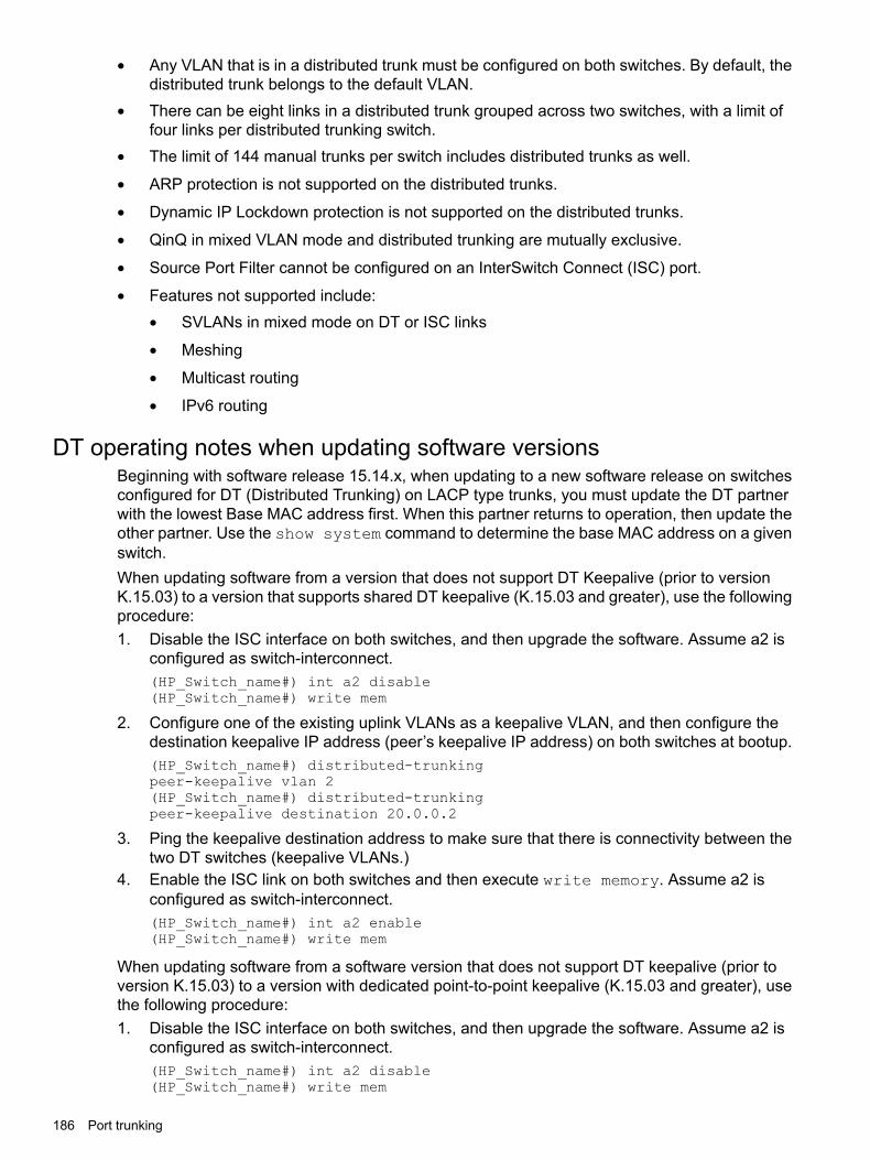
• Any VLAN that is in a distributed trunk must be configured on both switches. By default, thedistributed trunk belongs to the default VLAN.
• There can be eight links in a distributed trunk grouped across two switches, with a limit offour links per distributed trunking switch.
• The limit of 144 manual trunks per switch includes distributed trunks as well.
• ARP protection is not supported on the distributed trunks.
• Dynamic IP Lockdown protection is not supported on the distributed trunks.
• QinQ in mixed VLAN mode and distributed trunking are mutually exclusive.
• Source Port Filter cannot be configured on an InterSwitch Connect (ISC) port.
• Features not supported include:SVLANs in mixed mode on DT or ISC links•
• Meshing
• Multicast routing
• IPv6 routing
DT operating notes when updating software versionsBeginning with software release 15.14.x, when updating to a new software release on switchesconfigured for DT (Distributed Trunking) on LACP type trunks, you must update the DT partnerwith the lowest Base MAC address first. When this partner returns to operation, then update theother partner. Use the show system command to determine the base MAC address on a givenswitch.When updating software from a version that does not support DT Keepalive (prior to versionK.15.03) to a version that supports shared DT keepalive (K.15.03 and greater), use the followingprocedure:1. Disable the ISC interface on both switches, and then upgrade the software. Assume a2 is
configured as switch-interconnect.(HP_Switch_name#) int a2 disable(HP_Switch_name#) write mem
2. Configure one of the existing uplink VLANs as a keepalive VLAN, and then configure thedestination keepalive IP address (peer’s keepalive IP address) on both switches at bootup.(HP_Switch_name#) distributed-trunkingpeer-keepalive vlan 2(HP_Switch_name#) distributed-trunkingpeer-keepalive destination 20.0.0.2
3. Ping the keepalive destination address to make sure that there is connectivity between thetwo DT switches (keepalive VLANs.)
4. Enable the ISC link on both switches and then execute write memory. Assume a2 isconfigured as switch-interconnect.(HP_Switch_name#) int a2 enable(HP_Switch_name#) write mem
When updating software from a software version that does not support DT keepalive (prior toversion K.15.03) to a version with dedicated point-to-point keepalive (K.15.03 and greater), usethe following procedure:1. Disable the ISC interface on both switches, and then upgrade the software. Assume a2 is
configured as switch-interconnect.(HP_Switch_name#) int a2 disable(HP_Switch_name#) write mem
186 Port trunking

2. At switch bootup, create a dedicated VLAN for keepalive, and assign only the keepalive linkport as a member port of the VLAN. Configure the keepalive destination IP address.(HP_Switch_name#) distributed-trunkingpeer-keepalive vlan 2(HP_Switch_name#) distributed-trunkingpeer-keepalive destination 20.0.0.2
3. Ping the keepalive destination address to make sure that there is connectivity between thetwo DT switches (keepalive VLANs.)
4. Enable the ISC link on both switches, and then execute write memory. Assume a2 isconfigured as switch-interconnect.(HP_Switch_name#) int a2 enable(HP_Switch_name#) write mem
When updating software from a software version that does support shared DT keepalive (K.15.03,K.15.04) to a version that supports dedicated point-to-point keepalive (K.15.05), use the followingprocedure:1. Disable the ISC interface and undo the keepalive configuration on both switches. Ignore the
warning message that is displayed by the keepalive command while undoing the configuration.Upgrade the software. Assume a2 is configured as switch-interconnect.(HP_Switch_name#) int a2 disable(HP_Switch_name#) no distributed-trunkingpeer-keepalive vlan(HP_Switch_name#) write mem
2. At switch bootup, create a dedicated VLAN for keepalive and assign only the keepalive linkport as a member port of the VLAN. Configure the keepalive destination IP address.(HP_Switch_name#) vlan 10 (dedicated point-to-point VLAN interface)HP Switch(vlan-10)#HP Switch(vlan-10)# untagged b2 (keepalive link port)HP Switch(vlan-10)# ip address 10.0.0.1/24HP Switch(vlan-10)# exit(HP_Switch_name#) distributed-trunkingpeer-keepalive vlan 10(HP_Switch_name#) distributed-trunkingpeer-keepalive destination 10.0.0.2
3. Ping the keepalive destination address to make sure that there is connectivity between thetwo DT switches (keepalive VLANs.)
4. Enable the ISC link on both switches, and then execute write memory. Assume a2 isconfigured as switch-interconnect.(HP_Switch_name#) int a2 enable(HP_Switch_name#) write mem
DT operating notes when updating software versions 187

5 Port traffic controlsRate-limiting
Beginning with software release 12.xx, the switches covered by this guide support configuringinbound and outbound rate-limiting for all traffic on a port and specifying bandwidth usage interms of either percent or kilobits per second (kbps.)You can enable rate limiting for various types of traffic. When a limit is enabled on a port, excesstraffic above the configured rate is discarded. The default is no limit.• All-traffic rate limiting is primarily used for end-node connections (i.e. at the network edge).
It is not recommended for use on links to servers, routers, switches, or the network core.Rate limiting traffic on such links may interfere with important network functions.
• Broadcast rate limiting is used to protect the network from disruption by excessive broadcasttraffic.
• ICMP rate limiting is primarily used for throttling denial of service attacks.
• Multicast rate limiting is used to protect the network from disruption by excessive multicasttraffic. This is an Interface context command. It can be called directly from the interfacecontext or following the interface <PORT-LIST> command.
• Queues rate limiting sets an outbound rate limit for each traffic queue on a selected interface.
CAUTION: Rate-limiting is intended for use on edge ports in a network. It is not recommendedfor use on links to other switches, routers, or servers within a network, or for use in the networkcore. Doing so can interfere with applications the network requires to function properly.ICMP traffic is necessary for network routing functions. For this reason, blocking all ICMP trafficis not recommended.
NOTE: Applying rate-limiting to desirable traffic is not recommended.
For more information on all-traffic rate-limiting, see “All traffic rate-limiting” (page 209).
Configuring rate-limiting on all traffic
Syntax[no] int <PORT-LIST> rate-limit all [ in | out ] percent <0-100> | kbps<0-100000000>
Configures a traffic rate limit (on non-trunked ports) on the link. The no form of the commanddisables rate-limiting on the specified ports.The rate-limit all command controls the rate of traffic sent or received on a port by settinga limit on the bandwidth available. It includes options for:• Rate-limiting on either inbound or outbound traffic.
• Specifying the traffic rate as either a percentage of bandwidth, or in terms of kilobits persecond.
(Default: Disabled.)
Specifies a traffic rate limit on inbound traffic passingthrough that port, or on outbound traffic.
in or out
Specifies the rate limit as a percentage of total availablebandwidth, or in kilobits per second.
percent or kbps
188 Port traffic controls

NOTE: The granularity of actual limits may vary across different switch models.
Viewing the current rate-limit configurationThe show rate-limit all command displays the per-port rate-limit configuration in therunning-config file.
Syntaxshow rate-limit all <PORT-LIST>
Without <PORT-LIST>, this command lists the rate-limit configuration for all ports on the switch.With <PORT-LIST>, this command lists the rate-limit configuration for the specified ports. Thiscommand operates the same way in any CLI context.
ExampleThe following figure shows a rate-limiting configuration for the first six ports in the module in slot"A". In this instance:• Ports A1–A4 are configured with an outbound rate limit of 200 Kbps.
• Port A5 is configured with an inbound rate limit of 20%.
• Port A6 is not configured for rate-limiting.
Figure 67 Listing the rate-limit configuration
NOTE: To view RADIUS-assigned rate-limit information, use one of the following commandoptions:
show port-accessweb-based clients <PORT-LIST> detailedmac-based clients <PORT-LIST> detailedauthenticator clients <PORT-LIST> detailed
The show running command displays the currently applied setting for any interfaces in theswitch configured for all traffic rate-limiting and ICMP rate-limiting.The show config command displays this information for the configuration currently stored inthe startup-config file. (Note that configuration changes performed with the CLI, but notfollowed by a write mem command, do not appear in the startup-config file.)
Rate-limiting 189

Figure 68 Rate-limit settings listed in the show config output
Configuring ICMP rate-limitingICMP rate-limiting provides a method for limiting the amount of bandwidth that may be used forinbound ICMP traffic on a switch port. This feature allows users to restrict ICMP traffic topercentage levels that permit necessary ICMP functions, but throttle additional traffic that maybe caused by worms or viruses (reducing their spread and effect.) In addition, ICMP rate-limitingpreserves inbound port bandwidth for non-ICMP traffic.
CAUTION: This feature should not be used to remove all ICMP traffic from a network. ICMPis necessary for routing, diagnostic, and error responses in an IP network. ICMP rate-limiting isprimarily used for throttling worm or virus-like behavior and should normally be configured toallow one to five percent of available inbound bandwidth (at 10 Mbps or 100 Mbps speeds) or100 to 10,000 kbps (1Gbps or 10 Gbps speeds) to be used for ICMP traffic.
For more information on ICMP rate-limiting operation, see “ICMP rate-limiting” (page 212).The rate-limit icmp command controls inbound usage of a port by setting a limit on thebandwidth available for inbound ICMP traffic.
Syntaxint <PORT-LIST> rate-limit icmp <ip-type> <kbps <0-10000000>|percent <0-100>| trap-clear>
190 Port traffic controls

Where <ip-type> is one of the following:
• ip-all: Set a rate limit for all ICMP traffic.
• ipv4: Set a rate limit for IPv4 ICMP traffic.
• ipv6: Set a rate limit for IPv6 ICMP traffic.
• kbps: Set the rate limit in kilobits per second.
• percent: Set the rate limit as a percentage of the port link speed.
• trap-clear: Clear an existing ICMP rate limiting trap condition.
Configures inbound ICMP traffic rate-limiting. You can configure a rate limit from either the globalconfiguration level (as shown above) or from the interface context level. The no form of thecommand disables ICMP rate-limiting on the specified interfaces.(Default: Disabled.)
Values in this range allow ICMP traffic as a percentageof the bandwidth available on the interface.
percent 1-100
Specifies the rate at which to forward traffic in kilobits persecond.
kbps 0-100000000
Causes an interface to drop all incoming ICMP traffic andis not recommended. See the Caution on page 190.
0
ExampleEither of the following commands configures an inbound rate limit of 1% on ports A3 to A5, whichare used as network edge ports:
HP Switch(config) # int a3-a5 rate-limit icmp percent 1HP Switch(eth-A3-A5) # rate-limit icmp percent 1
Viewing the current ICMP rate-limit configurationThe show rate-limit icmp command displays the per-interface ICMP rate-limit configurationin the running-config file.
Syntaxshow rate-limit icmp <PORT-LIST>
Without [PORT-LIST], this command lists the ICMP rate-limit configuration for all ports on theswitch.With [PORT-LIST], this command lists the rate-limit configuration for the specified interfaces.This command operates the same way in any CLI context
ExampleIf you want to view the rate-limiting configuration on the first six ports in the module in slot "B":
Rate-limiting 191
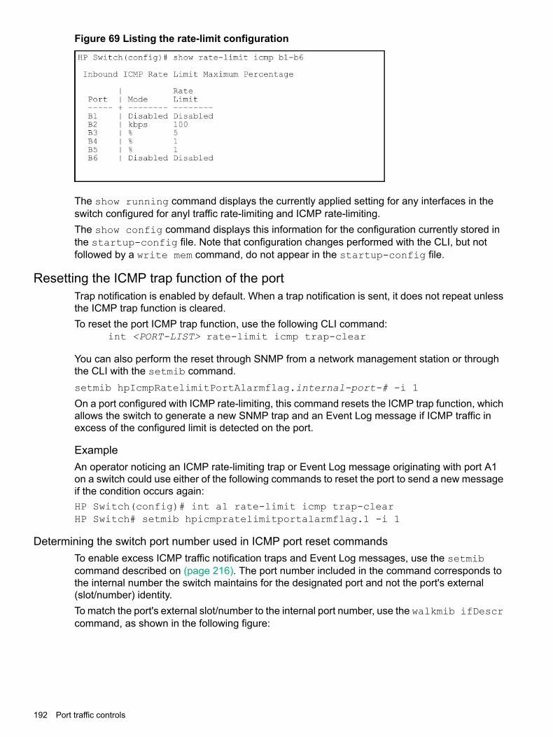
Figure 69 Listing the rate-limit configuration
The show running command displays the currently applied setting for any interfaces in theswitch configured for anyl traffic rate-limiting and ICMP rate-limiting.The show config command displays this information for the configuration currently stored inthe startup-config file. Note that configuration changes performed with the CLI, but notfollowed by a write mem command, do not appear in the startup-config file.
Resetting the ICMP trap function of the portTrap notification is enabled by default. When a trap notification is sent, it does not repeat unlessthe ICMP trap function is cleared.To reset the port ICMP trap function, use the following CLI command:
int <PORT-LIST> rate-limit icmp trap-clear
You can also perform the reset through SNMP from a network management station or throughthe CLI with the setmib command.setmib hpIcmpRatelimitPortAlarmflag.internal-port-# -i 1
On a port configured with ICMP rate-limiting, this command resets the ICMP trap function, whichallows the switch to generate a new SNMP trap and an Event Log message if ICMP traffic inexcess of the configured limit is detected on the port.
ExampleAn operator noticing an ICMP rate-limiting trap or Event Log message originating with port A1on a switch could use either of the following commands to reset the port to send a new messageif the condition occurs again:HP Switch(config)# int a1 rate-limit icmp trap-clearHP Switch# setmib hpicmpratelimitportalarmflag.1 -i 1
Determining the switch port number used in ICMP port reset commandsTo enable excess ICMP traffic notification traps and Event Log messages, use the setmibcommand described on (page 216). The port number included in the command corresponds tothe internal number the switch maintains for the designated port and not the port's external(slot/number) identity.To match the port's external slot/number to the internal port number, use the walkmib ifDescrcommand, as shown in the following figure:
192 Port traffic controls

Figure 70 Matching internal port numbers to external slot/port numbers
Configuring an egress/outbound broadcast limit on the switchEgress broadcast limiting on switches is configured on a per-port basis. You must be at the portcontext level for this command to work, for example:
HP Switch(config) # int B1HP Switch(int B1) # broadcast-limit 1
Syntaxbroadcast-limit [0-99]Enables or disables broadcast limiting for outbound broadcasts on a selected port on the switch.The value selected is the percentage of traffic allowed, for example, broadcast-limit 5allows 5% of the maximum amount of traffic for that port. A value of zero disables broadcastlimiting for that port.
NOTE: You must switch to port context level before issuing the broadcast-limit command.This feature is not appropriate for networks requiring high levels of IPX or RIP broadcast traffic.
Syntaxshow config
Displays the startup-config file. The broadcast limit setting appears here if enabled andsaved to the startup-config file.
Syntaxshow running-config
Displays the running-config file. The broadcast limit setting appears here if enabled. If thesetting is not also saved to the startup-config file, rebooting the switch returns broadcastlimit to the setting currently in the startup-config file.
Rate-limiting 193

ExampleThe following command enables broadcast limiting of 1% of the outbound traffic rate on theselected port on the switch:
HP Switch(int B1) # broadcast-limit 1
For a 1-Gbps port, this results in an outbound broadcast traffic rate of 10 Mbps.
Configuring inbound rate-limiting for broadcast and multicast trafficYou can configure rate-limiting (throttling) of inbound broadcast and multicast traffic on the switch,which helps prevent the switch from being disrupted by traffic storms if they occur on therate-limited port. The rate-limiting is implemented as either a percentage of the total availablebandwidth on the port or as kilobits per-second.The rate-limit command can be executed from the global or interface context, for example:
(HP_Switch_name#) interface 3 rate-limit bcast in percent 10
or
(HP_Switch_name#) interface 3HP Switch(eth-3#) rate-limit bcast in percent 10
Syntaxrate-limit [ bcast | mcast ] in [ percent 0-100 | kbps 0-100000000 ][no]rate-limit [ bcast | [mcast ]] inEnables rate-limiting and sets limits for the specified inbound broadcast or multicast traffic. Onlythe amount of traffic specified by the percent is forwarded.Default: Disabled
ExampleIf you want to set a limit of 50% on inbound broadcast traffic for port 3, you can first enter interfacecontext for port 3 and then execute the rate-limit command, as shown in Figure 71. Only50% of the inbound broadcast traffic will be forwarded.
Figure 71 Inbound broadcast rate-limiting of 50% on port 3
If you rate-limit multicast traffic on the same port, the multicast limit is also in effect for that port,as shown in Figure 72. Only 20% of the multicast traffic will be forwarded.
194 Port traffic controls

Figure 72 Inbound multicast rate-limiting of 20% on port 3
To disable rate-limiting for a port enter the no form of the command, as shown in Figure 73.
Figure 73 Disabling inbound multicast rate-limiting for port 3
Operating notes
• This rate-limiting option does not limit unicast traffic.
• This option does not include any form of outbound rate-limiting.
Configuring egress per-queue rate-limiting
NOTE: Software release 15.18 supports Egress Per-Queue Rate-Limiting, includingconfiguration on static trunks, on the HPE 5400R, 3800, and 2920 switches. (Egress Per-QueueRate-Limiting is not supported on dynamic LACP trunks, distributed trunks, or Mesh ports.)
OverviewEgress rate-limiting permits administrators to configure the maximum percentage of traffic allowedto egress an interface for each priority queue.
• Egress per-queue rate-limiting allows configurations on both physical ports and static trunks.
• The number of queue percentages will vary based on the number of queues configured onthe device (i.e. 2-queues, 4-queues, 8-queues).
• Configuration is allowed on a static trunk (manual HPE trunks and static LACP trunks), butthe actual traffic enforcement occurs per-port on the individual ports belonging to the trunk.
Restrictions
• While limits on all egress traffic (egress rate-limit all) and limits on specific egressqueues (egress rate-limit queues) can be configured at the same time on a givenport (i.e., can be concurrent features), this may result in lower actual limits than expected.
Rate-limiting 195
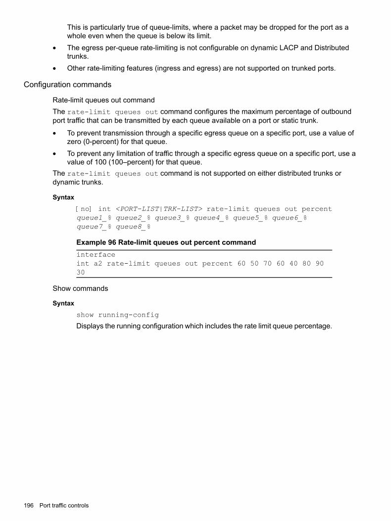
This is particularly true of queue-limits, where a packet may be dropped for the port as awhole even when the queue is below its limit.
• The egress per-queue rate-limiting is not configurable on dynamic LACP and Distributedtrunks.
• Other rate-limiting features (ingress and egress) are not supported on trunked ports.
Configuration commands
Rate-limit queues out commandThe rate-limit queues out command configures the maximum percentage of outboundport traffic that can be transmitted by each queue available on a port or static trunk.
• To prevent transmission through a specific egress queue on a specific port, use a value ofzero (0-percent) for that queue.
• To prevent any limitation of traffic through a specific egress queue on a specific port, use avalue of 100 (100–percent) for that queue.
The rate-limit queues out command is not supported on either distributed trunks ordynamic trunks.
Syntax[no] int <PORT-LIST|TRK-LIST> rate-limit queues out percentqueue1_% queue2_% queue3_% queue4_% queue5_% queue6_%queue7_% queue8_%
Example 96 Rate-limit queues out percent commandinterfaceint a2 rate-limit queues out percent 60 50 70 60 40 80 9030
Show commands
Syntaxshow running-config
Displays the running configuration which includes the rate limit queue percentage.
196 Port traffic controls

Example 97 Show running-config output
HP-5406zl(config)# show running-config
Running configuration:; J8697A Configuration Editor; Created on release #KA.15.18.0001; Ver #09:14.6b.fb.ff.fd.ff.ff:3f.ef:5fhostname "HP-Switch"module 1 type j9986amodule 6 type j9987atrunk A5-A6 trk1 trunk
ip access-list standard "std"10 permit 0.0.0.0 255.255.255.255 logexit
interface A2rate-limit all out percent 90rate-limit queues out percent 60 50 70 60 40 80 90 30exit
interface Trk1ip access-group "std" inrate-limit queues out percent 60 50 70 60 40 80 90 30exit
snmp-server community "public" unrestrictedvlan 1name "DEFAULT_VLAN"untagged A1-A4,A7-A22,F1-F24,Trk1ip address dhcp-bootpexit
spanning-tree Trk1 priority 4
Example 98 show running config router
show running-config router
show rate-limit queues
Syntaxshow rate-limit queues <PORT-LIST|TRK-LIST>
Using the show rate-limit command with the queues option added in softwarerelease 15.18 enables you to specify both individual ports and port trunk namesto display the output. If nothing is specified, all physical ports and any static,non-DT trunks are displayed with their current settings previously configured withthe rate-limit queues command. The optional PORT-LIST parameter limitsthe display output to the listed ports (and static, non-DT trunks, if any).
Rate-limiting 197

Example 99 Command output when no port list specified
HP-Switch# show rate-limit queues
Outbound Queue-Based Rate-Limit %
Port Q1 Q2 Q3 Q4 Q5 Q6 Q7 Q8------ --- --- --- --- --- --- --- ---A1 5 10 10 5 10 10 20 20A2 5 10 10 5 10 10 20 20A3 5 10 10 5 10 10 20 20A4 5 10 10 5 10 10 20 20A7 5 10 10 5 10 10 20 20
A22 5 10 10 5 10 10 20 20F1 5 10 10 5 10 10 20 20
F24 5 10 10 5 10 10 20 20Trk1 5 10 10 5 10 10 10 20Trk6 5 10 10 5 10 10 10 20
Example 100 Output with trunk queue set to 100 percent
HP-Switch# show rate-limit queues
Outbound Queue-Based Rate-Limit %
Port Q1 Q2 Q3 Q4 Q5 Q6 Q7 Q8------ --- ------ --- ------ --- --- --- ------A5 5 10 10 5 10 10 20 20A8 5 10 10 5 10 10 20 20A18 5 10 10 5 10 10 20 20Trk1 5 10 10 5 10 10 20 100
Example 101 Output when port list specified
HP-Switch# show rate-limit queues A1-A4
Outbound Queue-Based Rate-Limit %
Port Q1 Q2 Q3 Q4 Q5 Q6 Q7 Q8------ --- --- --- --- --- --- --- ---A1 5 10 10 5 10 10 20 20A2 5 10 10 5 10 10 20 20A3 5 10 10 5 10 10 20 20A4 5 10 10 5 10 10 20 20
Example 102 Output when trunk name specified
HP-Switch# show rate-limit queues Trk6
Outbound Queue-Based Rate-Limit %
Port Q1 Q2 Q3 Q4 Q5 Q6 Q7 Q8------ --- --- --- --- --- --- --- ---Trk6 5 10 10 5 10 10 20 20
Configuring Guaranteed Minimum Bandwidth (GMB) for outbound traffic
198 Port traffic controls

NOTE: Earlier software releases supported GMB configuration on a per-port basis. Beginningwith software release 15.18, the 5400R and 3800 switches also support GMB configuration onstatic trunks. (GMB configuration is not supported on dynamic LACP or distributed (DT) trunks.)
For any port, group of ports, or static trunk you can use the default minimum bandwidth settingsfor each outbound priority queue or a customized bandwidth profile. It is also possible to disablethe feature entirely.
NOTE: For application to static trunk interfaces, GMB enforcement is applied individually toeach port belonging to the trunk, and not to the trunk as a whole.
By default, GMB is configured with a recommended profile for outgoing traffic that preventshigher-priority queues from starving lower-priority traffic. In the eight-queue configuration, thedefault values per priority queue are:• Queue 1 (low priority): 2%
• Queue 2 (low priority): 3%
• Queue 3 (normal priority): 30%
• Queue 4 (normal priority): 10%
• Queue 5 (medium priority): 10%
• Queue 6 (medium priority): 10%
• Queue 7 (high priority): 15%
• Queue 8 (high priority): 20%The value for each of the queues indicates the minimum percentage of port throughput that isguaranteed for that queue. If a given queue does not require its guaranteed minimum in a givenservice window, any extra bandwidth is allocated to the other queues, beginning with thehighest-priority queue.The actual number of queues can be two, four, or eight, depending on either the system defaultor the value set by the latest instance of the qos queue-config <n-queues> command.Per-queue values must be specified starting with queue 1 being the lowest priority and queue 8being the highest priority. If desired, the highest-priority queue may be put into “strict” mode byspecifying strict rather than a percentage value. In strict mode, the highest-priority queue getsall the bandwidth it needs, and any remaining bandwidth is shared among the non-strict queuesbased on their need and their configured bandwidth profiles. If no guaranteed minimum bandwidthis configured (i.e., the settings for all queues are 0), the traffic is serviced strictly by priority. Inpractice, this may cause complete starvation of some or all lower-priority queues during anyperiods where the output port traffic is over-subscribed.This is an Interface context command. It can be called directly from the interface context, orfollowing the interface <PORT-LIST> command. For most applications, Hewlett PackardEnterprise recommends having the same GMB profile on all the ports on a switch so that theoutbound traffic profile is consistent for all outbound traffic. However, there may be instanceswhere it may be advantageous to configure special profiles on connections to servers or to thenetwork infrastructure (such as links to routers, other switches, or to the network core).For more details on GMB operation, see “Guaranteed minimum bandwidth (GMB)” (page 216).
Syntax[no] int <PORT-LIST|TRK-LIST> bandwidth-min output
Configures the default minimum bandwidth allocation for the outbound priority queue for eachport in the PORT-LIST.
Configuring Guaranteed Minimum Bandwidth (GMB) for outbound traffic 199
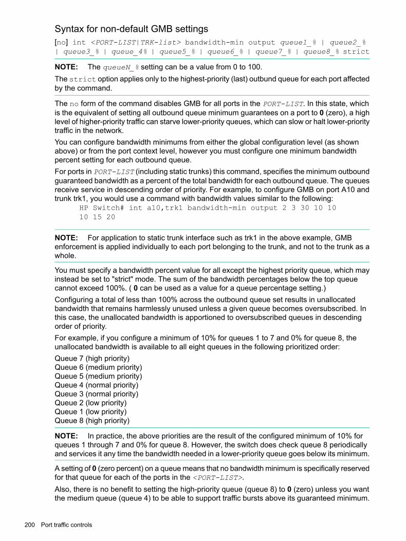
Syntax for non-default GMB settings[no] int <PORT-LIST|TRK-list> bandwidth-min output queue1_% | queue2_%| queue3_% | queue_4% | queue5_% | queue6_% | queue7_% | queue8_% strict
NOTE: The queueN_% setting can be a value from 0 to 100.The strict option applies only to the highest-priority (last) outbund queue for each port affectedby the command.
The no form of the command disables GMB for all ports in the PORT-LIST. In this state, whichis the equivalent of setting all outbound queue minimum guarantees on a port to 0 (zero), a highlevel of higher-priority traffic can starve lower-priority queues, which can slow or halt lower-prioritytraffic in the network.You can configure bandwidth minimums from either the global configuration level (as shownabove) or from the port context level, however you must configure one minimum bandwidthpercent setting for each outbound queue.For ports in PORT-LIST (including static trunks) this command, specifies the minimum outboundguaranteed bandwidth as a percent of the total bandwidth for each outbound queue. The queuesreceive service in descending order of priority. For example, to configure GMB on port A10 andtrunk trk1, you would use a command with bandwidth values similar to the following:
HP Switch# int a10,trk1 bandwidth-min output 2 3 30 10 1010 15 20
NOTE: For application to static trunk interface such as trk1 in the above example, GMBenforcement is applied individually to each port belonging to the trunk, and not to the trunk as awhole.
You must specify a bandwidth percent value for all except the highest priority queue, which mayinstead be set to "strict" mode. The sum of the bandwidth percentages below the top queuecannot exceed 100%. ( 0 can be used as a value for a queue percentage setting.)Configuring a total of less than 100% across the outbound queue set results in unallocatedbandwidth that remains harmlessly unused unless a given queue becomes oversubscribed. Inthis case, the unallocated bandwidth is apportioned to oversubscribed queues in descendingorder of priority.For example, if you configure a minimum of 10% for queues 1 to 7 and 0% for queue 8, theunallocated bandwidth is available to all eight queues in the following prioritized order:Queue 7 (high priority)Queue 6 (medium priority)Queue 5 (medium priority)Queue 4 (normal priority)Queue 3 (normal priority)Queue 2 (low priority)Queue 1 (low priority)Queue 8 (high priority)
NOTE: In practice, the above priorities are the result of the configured minimum of 10% forqueues 1 through 7 and 0% for queue 8. However, the switch does check queue 8 periodicallyand services it any time the bandwidth needed in a lower-priority queue goes below its minimum.
A setting of 0 (zero percent) on a queue means that no bandwidth minimum is specifically reservedfor that queue for each of the ports in the <PORT-LIST>.Also, there is no benefit to setting the high-priority queue (queue 8) to 0 (zero) unless you wantthe medium queue (queue 4) to be able to support traffic bursts above its guaranteed minimum.
200 Port traffic controls

Using Strict modeStrict mode provides the ability to configure the highest priority queue as strict. Per-queue valuesmust be specified in priority order, with queue 1 having the lowest priority and queue 8 (or 4, or2) having the highest priority. (The highest queue is determined by how many outbound queuesare configured on the switch. Two, four, and eight queues are permitted. (See the qosqueue-config command.) The strict queue is provided all the bandwidth it needs. Any remainingbandwidth is shared among the non-strict queues based on need and configured bandwidthprofiles. (The profiles are applied to the leftover bandwidth in this case.) The total sum ofpercentages for non-strict queues must not exceed 100.
NOTE: Configuring 0% for a queue can result in that queue being starved if any higher queuebecomes over-subscribed and is then given all unused bandwidth.The switch applies the bandwidth calculation to the link speed the port is currently using. Forexample, if a 10/100 Mbs port negotiates to 10 Mbps on the link, it bases its GMB calculationson 10 Mbps, not 100 Mbps.Use show bandwidth output<PORT-LIST|TRK-LIST> to display the current GMBconfiguration. (The show config and show running commands do not include GMBconfiguration data.)
ExampleFor example, suppose you want to configure the following outbound minimum bandwidthavailability for ports A1 through A5:
Effect on outbound bandwidth allocationMinimumbandwidth %
Priority ofoutbound port
queue
Queue 8 has the first priority use of all outbound bandwidth not specifically allocatedto queues 1 to 7.
20%8
If, for example, bandwidth allocated to queue 5 is not being used and queues 7and 8 become oversubscribed, queue 8 has first-priority use of the unusedbandwidth allocated to queue 5.
Queue 7 has a GMB of 15% available for outbound traffic. If queue 7 becomesoversubscribed and queue 8 is not already using all of the unallocated bandwidth,queue 7 can use the unallocated bandwidth.
15%7
Also, any unused bandwidth allocated to queues 6 to queue 1 is available to queue7 if queue 8 has not already claimed it.
Queue 6 has a GMB of 10% and, if oversubscribed, is subordinate to queues 8and 7 in priority for any unused outbound bandwidth available on the port.
10%6
Queue 5 has a GMB of 10% and, if oversubscribed, is subordinate to queues 8,7, and 6 for any unused outbound bandwidth available on the port.
10%5
Queue 4 has a GMB of 10% and, if oversubscribed, is subordinate to queues, 8,7, 6, and 5 for any unused outbound bandwidth available on the port.
10%4
Queue 3 has a GMB of 30% and, if oversubscribed, is subordinate to queues, 8,7, 6, 5, and 4 for any unused outbound bandwidth available on the port.
30%3
Queue 2 has a GMB of 3% and, if oversubscribed, is subordinate to queues, 8, 7,6, 5, 4, and 3 for any unused outbound bandwidth available on the port.
3%2
Queue 1 has a GMB of 2% and, if oversubscribed, is subordinate to all the otherqueues for any unused outbound bandwidth available on the port.
2%1
Either of the following commands configures ports A1 through A5 with bandwidth settings:
Configuring Guaranteed Minimum Bandwidth (GMB) for outbound traffic 201

HP Switch(config) # int a1-a5 bandwidth-min output 2 3 30 10 10 10 15 strictHP Switch(eth-A1-A5) # bandwidth-min output 2 3 30 10 10 10 15 strict
Viewing the current GMB configurationThis command displays the per-port GMB configuration in the running-config file.
Syntaxshow bandwidth output <PORT-LIST|TRK-LIST>
Without PORT-LIST, this command lists the GMB configuration for all ports on the switch.With PORT-LIST, this command lists the GMB configuration for the specified ports.This command operates the same way in any CLI context. If the command lists Disabled fora port, there are no bandwidth minimums configured for any queue on the port.
ExampleTo display the GMB configuration resulting from either of the above commands:
Figure 74 Listing the GMB configuration(HP_Switch_name#) show bandwidth output a1-a5
Outbound Guaranteed Minimum Bandwidth %
Port Q1 Q2 Q3 Q4 Q5 Q6 Q7 Q8------ --- ------ --- ------ --- --- --- ------A1 2 3 30 10 10 10 15 strictA2 2 3 30 10 10 10 15 strictA3 2 3 30 10 10 10 15 strictA4 2 3 30 10 10 10 15 strictA5 2 3 30 10 10 10 15 strict
The following figure shows how the preceding listing of the GMB configuration would appear inthe startup-config file.
202 Port traffic controls

Figure 75 GMB settings listed in the show config output(HP Switch#) show config statusRunning configuration is same as the startup configuration(HP Switch#) show config
Startup configuration:; J9821A configuration Editor; Created on release #KB.15.18.0001
hostnme “HP Switch”module 1 type J9986Asnmp-server community “public” Unrestrictedvlan 1
name “DEFAULT_VLAN”untagged A1-A24ip address dhcp-bootpexit
interface A1bandwidth-min output 2 3 30 10 10 10 15 strictexit
interface A2bandwidth-min output 2 3 30 10 10 10 15 strictexit
interface A3bandwidth-min output 2 3 30 10 10 10 15 strictexit
interface A4bandwidth-min output 2 3 30 10 10 10 15 strictexit
interface A5bandwidth-min output 2 3 30 10 10 10 15 strictexit
Configuring Guaranteed Minimum Bandwidth (GMB) for outbound traffic 203

Example 103 Output when trunk name specified
HP-5406zl# show bandwidth output Trk1Outbound Guaranteed Minimum Bandwidth %
Port Q1 Q2 Q3 Q4 Q5 Q6 Q7 Q8------ --- ------ --- ------ --- --- --- ------Trk1 10 15 10 15 10 15 10 15
204 Port traffic controls

Example 104 Output when no port list specified
HP-5406zl# show bandwidth outputOutbound Guaranteed Minimum Bandwidth %
Port Q1 Q2 Q3 Q4 Q5 Q6 Q7 Q8------ --- ------ --- ------ --- --- --- ------A1 2 3 30 10 10 10 15 20A2 10 15 10 15 10 15 10 15A3 2 3 30 10 10 10 15 20A4 2 3 30 10 10 10 15 20A5 2 3 30 10 10 10 15 20A6 2 3 30 10 10 10 15 20A7 2 3 30 10 10 10 15 20A8 2 3 30 10 10 10 15 20A9 2 3 30 10 10 10 15 20A10 2 3 30 10 10 10 15 20A11 2 3 30 10 10 10 15 20A12 2 3 30 10 10 10 15 20A13 2 3 30 10 10 10 15 20A14 2 3 30 10 10 10 15 20A15 2 3 30 10 10 10 15 20A16 2 3 30 10 10 10 15 20A17 2 3 30 10 10 10 15 20A18 2 3 30 10 10 10 15 20A19 2 3 30 10 10 10 15 20A20 2 3 30 10 10 10 15 20A21 2 3 30 10 10 10 15 20A22 2 3 30 10 10 10 15 20A23 2 3 30 10 10 10 15 20A24 2 3 30 10 10 10 15 20F1 2 3 30 10 10 10 15 20F2 2 3 30 10 10 10 15 20F3 2 3 30 10 10 10 15 20F4 2 3 30 10 10 10 15 20F5 2 3 30 10 10 10 15 20F6 2 3 30 10 10 10 15 20F7 2 3 30 10 10 10 15 20F8 2 3 30 10 10 10 15 20F9 2 3 30 10 10 10 15 20F10 2 3 30 10 10 10 15 20F11 2 3 30 10 10 10 15 20F12 2 3 30 10 10 10 15 20F13 2 3 30 10 10 10 15 20F14 2 3 30 10 10 10 15 20F15 2 3 30 10 10 10 15 20F16 2 3 30 10 10 10 15 20F17 2 3 30 10 10 10 15 20F18 2 3 30 10 10 10 15 20F19 2 3 30 10 10 10 15 20F20 2 3 30 10 10 10 15 20F21 2 3 30 10 10 10 15 20F22 2 3 30 10 10 10 15 20F23 2 3 30 10 10 10 15 20F24 2 3 30 10 10 10 15 20Trk1 10 15 10 15 10 15 10 15Trk2 15 10 15 10 15 10 15 10
Validation rules
Error/Warning/PromptValidation
Configuring Guaranteed Minimum Bandwidth (GMB) for outbound traffic 205

Error/Warning/PromptValidation
Rate-limit queues out percent command
Invalid port numberValid port number?
Invalid trunk interfaceValid trunk interface?
Unsupported trunk typeTrunk type supported?
Invalid maximum value.Maximum bandwidth value is greater thanthe minimum bandwidth configured for aqueue?
Bandwidth-min output command
Invalid trunk interfaceValid trunk interface?
Unsupported trunk typeTrunk type supported?
Invalid minimum value.Minimum bandwidth value is lesser than themaximum bandwidth configured for a queue?
Show rate-limit queues command
Invalid port numberValid port number?
Invalid trunk interfaceValid trunk interface?
Unsupported trunk typeTrunk type supported?
Show bandwidth output command
Invalid trunk interfaceValid trunk interface?
Unsupported trunk typeTrunk type supported?
Event log
MessageEvent
The port number <port num> entered is invalid.Invalid port number
The trunk <trunk name> entered is invalid.Invalid trunk interface
This command is not supported on distributed ordynamic trunks.
Unsupported trunk type
The maximum bandwidth value <max value > enteredshould be greater than the minimum bandwidth value<min value> configured.
Invalid maximum value
Configuring jumbo frame operationOverview
1. Determine the VLAN membership of the ports or trunks through which you want the switchto accept inbound jumbo traffic. For operation with GVRP enabled, refer to the GVRP topicunder “Operating Rules”, above.
2. Ensure that the ports through which you want the switch to receive jumbo frames areoperating at least at gigabit speed. (Check the Mode field in the output for the showinterfaces brief <PORT-LIST> command.)
3. Use the jumbo command to enable jumbo frames on one or more VLANs statically configuredin the switch. (All ports belonging to a jumbo-enabled VLAN can receive jumbo frames.
4. Execute write memory to save your configuration changes to the startupconfig file.
206 Port traffic controls

Viewing the current jumbo configuration
Syntaxshow vlans
Lists the static VLANs configured on the switch and includes a Jumbo column to indicate whichVLANs are configured to support inbound jumbo traffic. All ports belonging to a jumbo-enabledVLAN can receive jumbo traffic.
Figure 76 Listing of static VLANs to show jumbo status per VLAN
Syntaxshow vlans ports<PORT-LIST>
Lists the static VLANs to which the specified ports belong, including the Jumbo column to indicatewhich VLANs are configured to support jumbo traffic.Entering only one port in PORT-LIST results in a list of all VLANs to which that port belongs.Entering multiple ports in PORT-LIST results in a superset list that includes the VLANmemberships of all ports in the list, even though the individual ports in the list may belong todifferent subsets of the complete VLAN listing.
ExampleIf port 1 belongs to VLAN 1, port 2 belongs to VLAN 10, and port 3 belongs to VLAN 15, executingthis command with a PORT-LIST of 1 - 3 results in a listing of all three VLANs, even thoughnone of the ports belong to all three VLANS. (See Figure 77.)
Figure 77 Listing the VLAN memberships for a range of ports
Syntaxshow vlans vid
Shows port membership and jumbo configuration for the specified vid . (See Figure 78.)
Configuring jumbo frame operation 207

Figure 78 Listing the port membership and jumbo status for a VLAN
Enabling or disabling jumbo traffic on a VLAN
Syntaxvlan vid jumbono vlan vid jumbo
Configures the specified VLAN to allow jumbo frames on all ports on the switch that belong tothat VLAN. If the VLAN is not already configured on the switch, vlan vid jumbo also createsthe VLAN.A port belonging to one jumbo VLAN can receive jumbo frames through any other VLAN staticallyconfigured on the switch, regardless of whether the other VLAN is enabled for jumbo frames.The [no] form of the command disables inbound jumbo traffic on all ports in the specified VLANthat do not also belong to another VLAN that is enabled for jumbo traffic. In a VLAN context, thecommand forms are jumbo and no jumbo.(Default: Jumbos disabled on the specified VLAN.)
Configuring a maximum frame sizeYou can globally set a maximum frame size for jumbo frames that will support values from 1518bytes to 9216 bytes for untagged frames.
Syntaxjumbo max-frame-size size
Sets the maximum frame size for jumbo frames. The range is from 1518 bytes to 9216 bytes.(Default: 9216 bytes)
NOTE: The jumbo max-frame-size is set on a GLOBAL level.
Configuring IP MTU
NOTE: The following feature is available on the switches covered in this guide. jumbos supportis required for this feature. On switches that do not support this command, the IP MTU value isderived from the maximum frame size and is not configurable.
You can set the IP MTU globally by entering this command. The value of max-frame-sizemust be greater than or equal to 18 bytes more than the value selected for ip-mtu. For example,if ip-mtu is set to 8964, the max-frame-size is configured as 8982.
Syntaxjumbo ip-mtu size
208 Port traffic controls
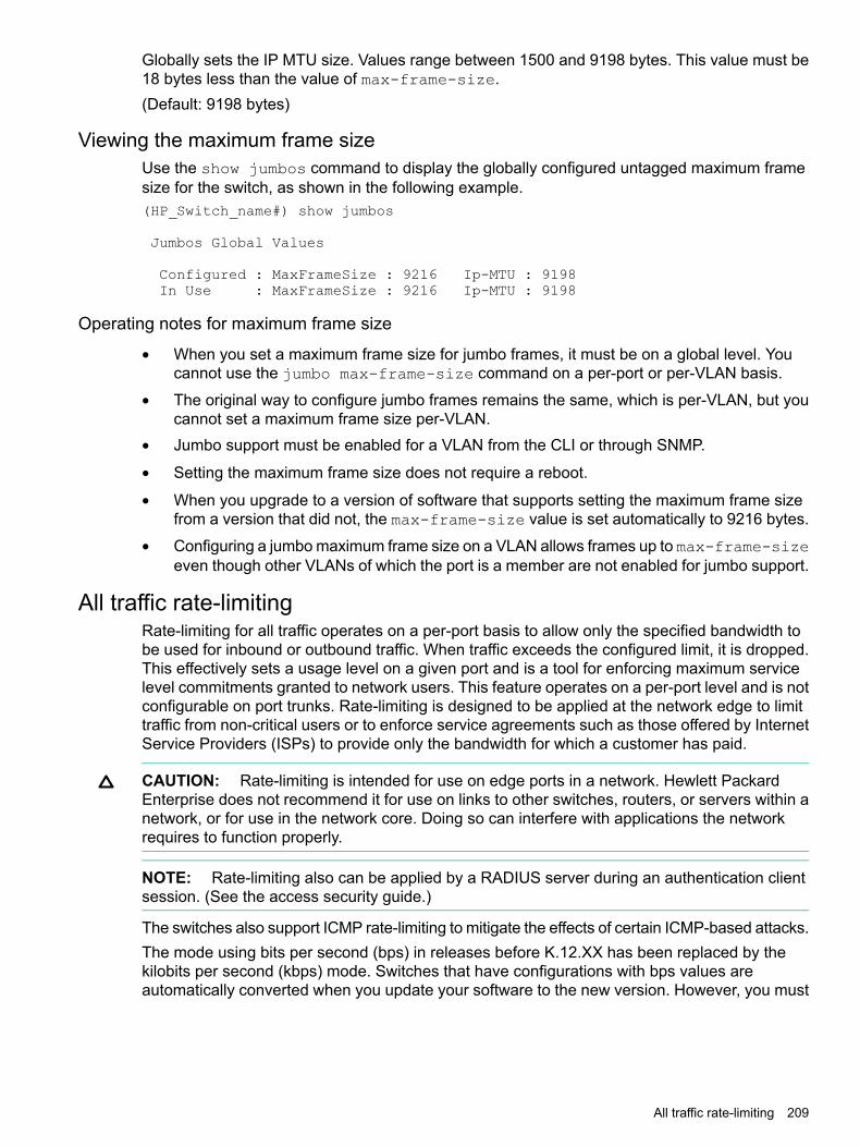
Globally sets the IP MTU size. Values range between 1500 and 9198 bytes. This value must be18 bytes less than the value of max-frame-size.(Default: 9198 bytes)
Viewing the maximum frame sizeUse the show jumbos command to display the globally configured untagged maximum framesize for the switch, as shown in the following example.(HP_Switch_name#) show jumbos
Jumbos Global Values
Configured : MaxFrameSize : 9216 Ip-MTU : 9198In Use : MaxFrameSize : 9216 Ip-MTU : 9198
Operating notes for maximum frame size
• When you set a maximum frame size for jumbo frames, it must be on a global level. Youcannot use the jumbo max-frame-size command on a per-port or per-VLAN basis.
• The original way to configure jumbo frames remains the same, which is per-VLAN, but youcannot set a maximum frame size per-VLAN.
• Jumbo support must be enabled for a VLAN from the CLI or through SNMP.
• Setting the maximum frame size does not require a reboot.
• When you upgrade to a version of software that supports setting the maximum frame sizefrom a version that did not, the max-frame-size value is set automatically to 9216 bytes.
• Configuring a jumbo maximum frame size on a VLAN allows frames up to max-frame-sizeeven though other VLANs of which the port is a member are not enabled for jumbo support.
All traffic rate-limitingRate-limiting for all traffic operates on a per-port basis to allow only the specified bandwidth tobe used for inbound or outbound traffic. When traffic exceeds the configured limit, it is dropped.This effectively sets a usage level on a given port and is a tool for enforcing maximum servicelevel commitments granted to network users. This feature operates on a per-port level and is notconfigurable on port trunks. Rate-limiting is designed to be applied at the network edge to limittraffic from non-critical users or to enforce service agreements such as those offered by InternetService Providers (ISPs) to provide only the bandwidth for which a customer has paid.
CAUTION: Rate-limiting is intended for use on edge ports in a network. Hewlett PackardEnterprise does not recommend it for use on links to other switches, routers, or servers within anetwork, or for use in the network core. Doing so can interfere with applications the networkrequires to function properly.
NOTE: Rate-limiting also can be applied by a RADIUS server during an authentication clientsession. (See the access security guide.)
The switches also support ICMP rate-limiting to mitigate the effects of certain ICMP-based attacks.The mode using bits per second (bps) in releases before K.12.XX has been replaced by thekilobits per second (kbps) mode. Switches that have configurations with bps values areautomatically converted when you update your software to the new version. However, you must
All traffic rate-limiting 209

manually update to kbps values an older config file that uses bps values or it will not loadsuccessfully onto a switch running later versions of the software (K.12.XX or greater.)
• The rate-limit icmp command specifies a rate limit on inbound ICMP traffic only (See“ICMP Rate-Limiting” on page 13-9)
• Rate-limiting does not apply to trunked ports (including meshed ports.)
• Kbps rate-limiting is done in segments of 1% of the lowest corresponding media speed.For example, if the media speed is 100 Kbps, the value would be 1 Mbps.
• A 1 to 100 Kbps rate-limit is implemented as a limit of 100 Kbps
• A limit of 101 to 199 Kbps is also implemented as a limit of 200 Kbps.
• A limit of 201 to 299 Kbps is implemented as a limit of 300 Kbps, and so on.
• Percentage limits are based on link speed.For example, if a 100 Mbps port negotiates a link at 100 Mbps and the inbound rate-limit isconfigured at 50%, the traffic flow through that port is limited to no more than 50 Mbps.Similarly, if the same port negotiates a 10 Mbps link, it allows no more than 5 Mbps of inboundtraffic.
• Configuring a rate limit of 0 (zero) on a port blocks all traffic on that port. However, if this isthe desired behavior on the port, Switch recommends that you use the <PORT-LIST>disable command instead of configuring a rate limit of 0.
• You can configure a rate limit from either the global configuration level or from the portcontext level.
ExampleEither of the following commands configures an inbound rate limit of 60% on ports A3 to A5:
HP Switch (config #) int a3-a5 rate-limit all in percent 60HP Switch (eth-A3-A5)# rate-limit all in percent 60
Operating notes for rate-limiting• In general, desirable traffic should not be rate-limited.
• When going from a switch with faster links to a switch with slower links, it is better to forcethe speed of the port connection to be slower rather than to rate-limit the traffic.
• Rate-limiting operates on a per-port basis, regardless of traffic priority. Rate-limiting isavailable on all types of ports and at all port speeds configurable for these switches.
• Except for the egress per-queue option with static trunks on 5400R and 3800 ProVisionswitches, rate-limiting is not supported on trunked ports (including mesh ports.) Wheretrunked ports are not supported, configuring a port for rate-limiting and then adding it to atrunk suspends rate-limiting on the port while it is in the trunk. Attempting to configurerate-limiting on a port that already belongs to a trunk generates the following message:<PORT-LIST>: Operation is not allowed for a trunked port.
• Rate-limiting for inbound and outbound traffic are separate features. The rate limits for eachdirection of traffic flow on the same port are configured separately—even the specified limitscan be different.
• Rate-limiting and hardware: The granularity of actual limits may vary across different switchmodels.
• Rate-limiting is visible as an outbound forwarding rate. Because inbound rate-limiting isperformed on packets during packet-processing, it is not shown via the inbound drop counters.
210 Port traffic controls

Instead, this limit is verifiable as the ratio of outbound traffic from an inbound rate-limitedport versus the inbound rate. For outbound rate-limiting, the rate is visible as the percentageof available outbound bandwidth (assuming that the amount of requested traffic to beforwarded is larger than the rate-limit.)
• Operation with other features: Configuring rate-limiting on a port where other features affectport queue behavior (such as flow control) can result in the port not achieving its configuredrate-limiting maximum. For example, in a situation whereflow control is configured on arate-limited port, there can be enough "back pressure" to hold high-priority inbound trafficfrom the upstream device or application to a rate that is lower than the configured rate limit.In this case, the inbound traffic flow does not reach the configured rate and lower prioritytraffic is not forwarded into the switch fabric from the rate-limited port. (This behavior istermed "head-of-line blocking" and is a well-known problem with flow-control.)In another type of situation, an outbound port can become oversubscribed by traffic receivedfrom multiple rate-limited ports. In this case, the actual rate for traffic on the rate-limited portsmay be lower than configured because the total traffic load requested to the outbound portexceeds the port's bandwidth, and thus some requested traffic may be held off on inbound.
• Traffic filters on rate-limited ports. Configuring a traffic filter on a port does not prevent theswitch from including filtered traffic in the bandwidth-use measurement for rate-limiting whenit is configured on the same port. For example, ACLs, source-port filters, protocol filters, andmulticast filters are all included in bandwidth usage calculations.
• Monitoring (mirroring) rate-limited interfaces.If monitoring is configured, packets dropped byrate-limiting on a monitored interface are still forwarded to the designated monitor port.(Monitoring shows what traffic is inbound on an interface, and is not affected by "drop" or"forward" decisions.)
• Optimum rate-limiting operation. Optimum rate-limiting occurs with 64-byte packet sizes.Traffic with larger packet sizes can result in performance somewhat below the configuredbandwidth. This is to ensure the strictest possible rate-limiting of all sizes of packets.
All traffic rate-limiting 211

NOTE: Rate-limiting is applied to the available bandwidth on a port and not to any specificapplications running through the port. If the total bandwidth requested by all applications is lessthan the configured maximum rate, then no rate-limit can be applied. This situation occurs witha number of popular throughput-testing applications, as well as most regular network applications.Consider the following example that uses the minimum packet size:
The total available bandwidth on a 100 Mbps port "X" (allowing for Inter-packetGap-IPG), with no rate-limiting restrictions, is:(((100,000,000 bits) / 8 ) / 84) × 64 = 9,523,809 bytes persecond
where:
• The divisor (84) includes the 12-byte IPG, 8-byte preamble, and 64-bytes ofdata required to transfer a 64-byte packet on a 100 Mbps link.
• Calculated "bytes-per-second" includes packet headers and data. This valueis the maximum "bytes-per-second" that 100 Mbps can support forminimum-sized packets.
Suppose port "X" is configured with a rate limit of 50% (4,761,904 bytes.) If athroughput-testing application is the only application using the port and transmits1 Mbyte of data through the port, it uses only 10.5% of the port's availablebandwidth, and the rate-limit of 50% has no effect. This is because the maximumrate permitted (50%) exceeds the test application's bandwidth usage(126,642-164,062 bytes, depending upon packet size, which is only 1.3% to 1.7%of the available total.) Before rate-limiting can occur, the test application'sbandwidth usage must exceed 50% of the port's total available bandwidth. Thatis, to test the rate-limit setting, the following must be true:bandwidth usage (0.50 × 9,523,809)
ICMP rate-limitingAs of software version K.15.02.0004, ICMP rate-limiting and classifier-based-rate-limiting operateon the entire packet length instead of just the IP payload part of the packet. As a result, theeffective metering rate is now the same as the configured rate. The rate-limiting applies to thesemodules:
Minimum supportedsoftware version
Product numberHPE device
K.15.02.0004J9534AHPE Switch 24-port 10/100/1000 PoE+ v2 zl Module
K.15.02.0004J9535AHPE Switch 20-port 10/100/1000 PoE+ / 4-port SFP v2 zl Module
K.15.02.0004J9536AHPE Switch 20-port 10/100/1000 PoE+ / 2-port 10-GbE SFP+ v2zl Module
K.15.02.0004J9537AHPE Switch 24-port SFP v2 zl Module
K.15.02.0004J9538AHPE Switch 8-port 10-GbE SFP+ v2 zl Module
K.15.02.0004J9547AHPE 24-port 10/100 PoE+ v2 zl Module
K.15.02.0004J9548AHPE 20-port Gig-T / 2-port 10-GbE SFP+ v2 zl Module
K.15.02.0004J9549AHPE 20-port Gig-T / 4-port SFP v2 zl Module
K.15.02.0004J9550AHPE 24-port Gig-T v2 zl Module
K.15.02.0004J9637AHPE 12-port Gig-T / 12-port SFP v2 zl Module
212 Port traffic controls

ICMP rate-limiting provides a method for limiting the amount of bandwidth that may be used forinbound ICMP traffic on a switch port. This feature allows users to restrict ICMP traffic topercentage levels that permit necessary ICMP functions, but throttle additional traffic that maybe caused by worms or viruses (reducing their spread and effect.) In addition, ICMP rate-limitingpreserves inbound port bandwidth for non-ICMP traffic.
CAUTION: This feature should not be used to remove all ICMP traffic from a network. ICMPis necessary for routing, diagnostic, and error responses in an IP network. ICMP rate-limiting isprimarily used for throttling worm or virus-like behavior and should normally be configured toallow one to five percent of available inbound bandwidth (at 10 Mbps or 100 Mbps speeds) or100 to 10,000 kbps (1Gbps or 10 Gbps speeds) to be used for ICMP traffic.
In IP networks, ICMP messages are generated in response to either inquiries or requests fromrouting and diagnostic functions. These messages are directed to the applications originatingthe inquiries. In unusual situations, if the messages are generated rapidly with the intent ofoverloading network circuits, they can threaten network availability. This problem is visible indenial-of-service (DoS) attacks or other malicious behaviors where a worm or virus overloadsthe network with ICMP messages to an extent where no other traffic can get through. (ICMPmessages themselves can also be misused as virus carriers.) Such malicious misuses of ICMPcan include a high number of ping packets that mimic a valid source IP address and an invaliddestination IP address (spoofed pings), and a high number of response messages (such asDestination Unreachable error messages) generated by the network.
NOTE: ICMP rate-limiting does not throttle non-ICMP traffic. In cases where you want to throttleboth ICMP traffic and all other inbound traffic on a given interface, you can separately configureboth ICMP rate-limiting and all-traffic rate-limiting.Beginning with software release K.12.xx or later, the all-traffic rate-limiting command (rate-limitall) and the ICMP rate-limiting command (rate-limit icmp) operate differently:
• All-traffic rate-limiting applies to both inbound and outbound traffic and can be specifiedeither in terms of a percentage of total bandwidth or in terms of bits per second;
• ICMP rate-limiting applies only to inbound traffic and can be specified as only a percentageof total bandwidth.
ICMP rate-limiting is not supported on meshed ports. (Rate-limiting can reduce the efficiency ofpaths through a mesh domain.)
Configuring ICMP rate-limitingApply ICMP rate-limiting on all connected interfaces on the switch to effectively throttle excessiveICMP messaging from any source. Figure 79 (page 214) shows an example of how to configurethis for a small to mid-sized campus though similar rate-limit thresholds are applicable to othernetwork environments. On edge interfaces, where ICMP traffic should be minimal, a thresholdof 1% of available bandwidth should be sufficient for most applications. On core interfaces, suchas switch-to-switch and switch-to-router, a maximum threshold of 5% should be sufficient fornormal ICMP traffic. ("Normal" ICMP traffic levels should be the maximums that occur when thenetwork is rebooting.)
ICMP rate-limiting 213

Figure 79 ICMP rate-limiting
NOTE: When using kbps-mode ICMP rate-limiting, the rate-limiting operates on only the IPpayload part of the ICMP packet (as required by metering RFC 2698.) This means that effectivemetering is at a rate greater than the configured rate, with the disparity increasing as the packetsize decreases (the packet to payload ratio is higher.)Also, in kbps mode, metering accuracy is limited at low values, for example, less than 45 Kbps.This is to allow metering to function well at higher media speeds such as 10 Gbps.
Using both ICMP rate-limiting and all-traffic rate-limiting on the same interfaceICMP and all-traffic rate-limiting can be configured on the same interface. All-traffic rate-limitingapplies to all inbound or outbound traffic (including ICMP traffic), while ICMP rate-limiting appliesonly to inbound ICMP traffic.
NOTE: If the all-traffic load on an interface meets or exceeds the currently configured all-trafficinbound rate-limit while the ICMP traffic rate-limit on the same interface has not been reached,all excess traffic is dropped, including any inbound ICMP traffic above the all-traffic limit (regardlessof whether the ICMP rate-limit has been reached.)
ExampleSuppose:
• The all-traffic inbound rate-limit on port "X" is configured at 55% of the port's bandwidth.
• The ICMP traffic rate-limit on port "X" is configured at 2% of the port's bandwidth.If at a given moment:
• Inbound ICMP traffic on port "X" is using 1% of the port's bandwidth, and
• Inbound traffic of all types on port "X" demands 61% of the ports's bandwidth,all inbound traffic above 55% of the port's bandwidth, including any additional ICMP traffic, isdropped as long as all inbound traffic combined on the port demands 55% or more of the port'sbandwidth.
Operating notes for ICMP rate-limitingICMP rate-limiting operates on an interface (per-port) basis to allow, on average, the highestexpected amount of legitimate, inbound ICMP traffic.
214 Port traffic controls

NOTE: On a given port, ICMP rate-limiting and classifier-based QoS are mutually exclusive.However, you can include ICMP rate-limiting as part of a larger classifier-QoS policy on a givenport.
Interface support ICMP rate-limiting is available on all types of ports (otherthan trunk ports or mesh ports), and at all port speedsconfigurable for the switch.
Rate-limiting is not permitted onmesh ports
Either type of rate-limiting (all-traffic or ICMP) can reducethe efficiency of paths through a mesh domain.
Except for the egress per-queuefeature on 5400R and 3800
All-traffic, bcast, ICMP, and mcast rate-limiting are notsupported on ports configured in a trunk group.
switches, rate-limiting is notsupported on port trunksICMP percentage-based rate-limitsare calculated as a percentage ofthe negotiated link speed
For example, if a 100 Mbps port negotiates a link to anotherswitch at 100 Mbps and is ICMP rate-limit configured at5%, the inbound ICMP traffic flow through that port is limitedto 5 Mbps. Similarly, if the same port negotiates a 10 Mbpslink, it allows 0.5 Mbps of inbound traffic. If an interfaceexperiences an inbound flow of ICMP traffic in excess ofits configured limit, the switch generates a log messageand an SNMP trap (if an SNMP trap receiver is configured.)
ICMP rate-limiting is port-based ICMP rate-limiting reflects the available percentage of aninterface's entire inbound bandwidth. The rate of inboundflow for traffic of a given priority and the rate of flow froman ICMP rate-limited interface to a particular queue of anoutbound interface are not measures of the actual ICMPrate limit enforced on an interface.
Below-maximum rates ICMP rate-limiting operates on a per-interface basis,regardless of traffic priority. Configuring ICMP rate-limitingon an interface where other features affect inbound portqueue behavior (such as flow control) can result in theinterface not achieving its configured ICMP rate-limitingmaximum. For example, in some situations with flow controlconfigured on an ICMP rate-limited interface, there can beenough "back pressure" to hold high-priority inbound trafficfrom the upstream device or application to a rate that doesnot allow bandwidth for lower-priority ICMP traffic. In thiscase, the inbound traffic flow may not permit the forwardingof ICMP traffic into the switch fabric from the rate-limitedinterface. (This behavior is termed "head-of-line blocking"and is a well-known problem with flow-control.) In caseswhere both types of rate-limiting (rate-limit all andrate-limit icmp) are configured on the same interface,this situation is more likely to occur.In another type of situation, an outbound interface canbecome oversubscribed by traffic received from multipleICMP rate-limited interfaces. In this case, the actual ratefor traffic on the rate-limited interfaces may be lower thanconfigured because the total traffic load requested to theoutbound interface exceeds the interface's bandwidth, andthus some requested traffic may be held off on inbound.
ICMP rate-limiting 215

Monitoring (mirroring) ICMPrate-limited interfaces
If monitoring is configured, packets dropped by ICMPrate-limiting on a monitored interface are still forwarded tothe designated monitor port. (Monitoring shows what trafficis inbound on an interface, and is not affected by "drop" or"forward" decisions.)
Optimum rate-limiting operation Optimum rate-limiting occurs with 64-byte packet sizes.Traffic with larger packet sizes can result in performancesomewhat below the configured inbound bandwidth. Thisis to ensure the strictest possible rate-limiting of all sizesof packets.
Outbound traffic flow Configuring ICMP rate-limiting on an interface does notcontrol the rate of outbound traffic flow on the interface.
Testing ICMP rate-limitingICMP rate-limiting is applied to the available bandwidth on an interface. If the total bandwidthrequested by all ICMP traffic is less than the available, configured maximum rate, no ICMPrate-limit can be applied. That is, an interface must be receiving more inbound ICMP traffic thanthe configured bandwidth limit allows. If the interface is configured with both rate-limit alland rate-limit icmp, the ICMP limit can be met or exceeded only if the rate limit for all typesof inbound traffic has not already been met or exceeded. Also, to test the ICMP limit you needto generate ICMP traffic that exceeds the configured ICMP rate limit. Using the recommendedsettings—1% for edge interfaces and 5% maximum for core interfaces—it is easy to generatesufficient traffic. However, if you are testing with higher maximums, you need to ensure that theICMP traffic volume exceeds the configured maximum.When testing ICMP rate-limiting where inbound ICMP traffic on a given interface has destinationson multiple outbound interfaces, the test results must be based on the received outbound ICMPtraffic.ICMP rate-limiting is not reflected in counters monitoring inbound traffic because inbound packetsare counted before the ICMP rate-limiting drop action occurs.
ICMP rate-limiting trapIf the switch detects a volume of inbound ICMP traffic on a port that exceeds the ICMP rate-limitconfigured for that port, it generates one SNMP trap and one informational Event Log messageto notify the system operator of the condition. (The trap and Event Log message are sent withintwo minutes of when the event occurred on the port.) For example:
I 06/30/05 11:15:42 RateLim: ICMP traffic exceeded configured limit onport A1
These trap and Event Log messages provide an advisory that inbound ICMP traffic on a giveninterface has exceeded the configured maximum. The additional ICMP traffic is dropped, but theexcess condition may indicate an infected host (or other traffic threat or network problem) on thatinterface. The system operator should investigate the attached devices or network conditionsfurther; the switch does not send more traps or Event Log messages for excess ICMP traffic onthe affected port until the system operator resets the port's ICMP trap function.The switch does not send more traps or Event Log messages for excess ICMP traffic on theaffected port until the system operator resets the port’s ICMP trap function. The reset can bedone through SNMP from a network management station or through the CLI with the trap-clearcommand option or the setmib command.
Guaranteed minimum bandwidth (GMB)GMB provides a method for ensuring that each of a given port's outbound traffic priority queueshas a specified minimum consideration for sending traffic out on the link to another device. This
216 Port traffic controls

can prevent a condition where applications generating lower-priority traffic in the network arefrequently or continually "starved" by high volumes of higher-priority traffic. You can configureGMB per-port.
GMB operationsThe switch services per-port outbound traffic in a descending order of priority; that is, from thehighest priority to the lowest priority. By default, each port offers eight prioritized, outbound trafficqueues. Tagged VLAN traffic is prioritized according to the 802.1p priority the traffic carries.Untagged VLAN traffic is assigned a priority of 0 (normal.)
Table 15 Per-port outbound priority queues
Outbound priority queue for a given port802.1p Priority settings in tagged VLANpackets1
11 (low)
22 (low)
30 (normal)
43 (normal)
54 (medium)
65 (medium)
76 (high)
87 (high)1 The switch processes outbound traffic from an untagged port at the "0" (normal) priority level.
You can use GMB to reserve a specific percentage of each port's available outbound bandwidthfor each of the eight priority queues. This means that regardless of the amount of high-priorityoutbound traffic on a port, you can ensure that there will always be bandwidth reserved forlower-priority traffic.Since the switch services outbound traffic according to priority (highest to lowest), thehighest-priority outbound traffic on a given port automatically receives the first priority in servicing.Thus, in most applications, it is necessary only to specify the minimum bandwidth you want toallocate to the lower priority queues. In this case, the high-priority traffic automatically receivesall unassigned bandwidth without starving the lower-priority queues.Conversely, configuring a bandwidth minimum on only the high-priority outbound queue of a port(and not providing a bandwidth minimum for the lower-priority queues) is not recommended,because it may "starve" the lower-priority queues.
NOTE: For a given port, when the demand on one or more outbound queues exceeds theminimum bandwidth configured for those queues, the switch apportions unallocated bandwidthto these queues on a priority basis. As a result, specifying a minimum bandwidth for a high-priorityqueue but not specifying a minimum for lower-priority queues can starve the lower-priority queuesduring periods of high demand on the high priority queue. For example, if a port configured toallocate a minimum bandwidth of 80% for outbound high-priority traffic experiences a demandabove this minimum, this burst starves lower-priority queues that do not have a minimumconfigured. Normally, this will not altogether halt lower priority traffic on the network, but will likelycause delays in the delivery of the lower-priority traffic.The sum of the GMB settings for all outbound queues on a given port cannot exceed 100%.
Impacts of QoS queue configuration on GMB operationThe section on “Configuring Guaranteed Minimum Bandwidth (GMB) for outbound traffic” (page 198)assumes the ports on the switch offer eight prioritized, outbound traffic queues. This may not
Guaranteed minimum bandwidth (GMB) 217

always be the case, however, because the switch supports aQoS queue configuration featurethat allows you to reduce the number of outbound queues from eight (the default) to four queues,or two.Changing the number of queues affects the GMB commands (interface bandwidth-minand show bandwidth output) such that they operate only on the number of queues currentlyconfigured. If the queues are reconfigured, the guaranteed minimum bandwidth per queue isautomatically re-allocated according to the following percentages:
Table 16 Default GMB percentage allocations per QoS queue configuration
2 queues4 queues8 queues (default)802.1p priority
90%
10%2%1 (lowest)
3%2
70%30%0 (normal)
10%3
10%
10%10%4
10%5
10%15%6
20%7 (highest)
For more information on queue configuration and the associated default minimum bandwidthsettings, (see the advanced traffic management guide.)
Impact of QoS queue configuration on GMB commands.Changing the number of queues causes the GMB commands (interface bandwidth-minand show bandwidth output) to operate only on the number of queues currently configured.In addition, when the qos queue-config command is executed, any previously configuredbandwidth-min output settings are removed from the startup configuration.
Jumbo framesThe maximum transmission unitize (MTU) IP frame the switch can receive for Layer 2 framesinbound on a port. The switch drops any inbound frames larger than the MTU allowed on theport. Ports operating at a minimum of 10 Mbps on the 3500 switches and 1 Gbps on the otherswitches covered in this guide can accept forward frames of up to 9220 bytes (including fourbytes for a VLAN tag) when configured for jumbo traffic. You can enable inbound jumbo frameson a per-VLAN basis. That is, on a VLAN configured for jumbo traffic, all ports belonging to thatVLAN and operating at a minimum of 10 Mbps on the 3500 switches and 1 Gbps on the otherswitches covered in this guide allow inbound jumbo frames of up to 9220 bytes.
Minimum speed for jumbo trafficSwitch model
10 Mbps3500
1 GbpsAll others in this guide
Operating rules for jumbo framesRequired port speed This feature allows inbound and outbound jumbo frames on
ports operating at a minimum of 10 Mbps on the 3500 switchesand 1 Gbps on the other switches.
Switch meshing If you enable jumbo traffic on a VLAN, all meshed ports on theswitch are enabled to support jumbo traffic. (On a given meshed
218 Port traffic controls

switch, every meshed port operating at 1 Gbps or higherbecomes a member of every VLAN configured on the switch.)
GVRP operation A VLAN enabled for jumbo traffic cannot be used to create adynamic VLAN. A port belonging to a statically configured,jumbo-enabled VLAN cannot join a dynamic VLAN.
Port adds and moves If you add a port to a VLAN that is already configured for jumbotraffic, the switch enables that port to receive jumbo traffic. Ifyou remove a port from a jumbo-enabled VLAN, the switchdisables jumbo traffic capability on the port only if the port isnot currently a member of another jumbo-enabled VLAN. Thissame operation applies to port trunks.
Jumbo traffic sources A port belonging to a jumbo-enabled VLAN can receive inboundjumbo frames through any VLAN to which it belongs, includingnon-jumbo VLANs. For example, if VLAN 10 (without jumbosenabled) and VLAN 20 (with jumbos enabled) are bothconfigured on a switch, and port 1 belongs to both VLANs, port1 can receive jumbo traffic from devices on either VLAN.
Jumbo traffic-handling
• Switch does not recommend configuring avoice VLAN to accept jumbo frames. Voice VLANframes are typically small, and allowing a voice VLAN to accept jumbo frame traffic candegrade the voice transmission performance.
• You can configure the default, primary, and/or (if configured) the management VLAN toaccept jumbo frames on all ports belonging to the VLAN.
• When the switch applies the default MTU (1522-bytes including 4 bytes for the VLAN tag)to a VLAN, all ports in the VLAN can receive incoming frames of up to 1522 bytes. Whenthe switch applies the jumbo MTU (9220 bytes including 4 bytes for the VLAN tag) to a VLAN,all ports in that VLAN can receive incoming frames of up to 9220 bytes. A port receivingframes exceeding the applicable MTU drops such frames, causing the switch to generatean Event Log message and increment the "Giant Rx" counter (displayed by showinterfaces <PORT-LIST>.)
• The switch allows flow control and jumbo frame capability to co-exist on a port.
• The default MTU is 1522 bytes (including 4 bytes for the VLAN tag.) The jumbo MTU is 9220bytes (including 4 bytes for the VLAN tag.)
• When a port is not a member of any jumbo-enabled VLAN, it drops all jumbo traffic. If theport is receiving "excessive"inbound jumbo traffic, the port generates an Event Log messageto notify you of this condition. This same condition also increments the switch's "Giant Rx"counter.
• If you do not want all ports in a given VLAN to accept jumbo frames, you can considercreating one or more jumbo VLANs with a membership comprising only the ports you wantto receive jumbo traffic. Because a port belonging to one jumbo-enabled VLAN can receivejumbo frames through any VLAN to which it belongs, this method enables you to includeboth jumbo-enabled and non-jumbo ports within the same VLAN.For example, suppose you want to allow inbound jumbo frames only on ports 6, 7, 12, and13. However, these ports are spread across VLAN 100 and VLAN 200 and also share theseVLANs with other ports you want excluded from jumbo traffic. A solution is to create a third
Jumbo frames 219

VLAN with the sole purpose of enabling jumbo traffic on the desired ports, while leaving theother ports on the switch disabled for jumbo traffic. That is:
VLAN 300VLAN 200VLAN 100
6, 7, 12, and 1311-156-10Ports
YesNoNoJumbo-enabled
If there are security concerns with grouping the ports as shown for VLAN 300, you can eitheruse source-port filtering to block unwanted traffic paths or create separate jumbo VLANs,one for ports 6 and 7, and another for ports 12 and 13.
• Any port operating at 1 Gbps or higher can transmit outbound jumbo frames through anyVLAN, regardless of the jumbo configuration. The VLAN is not required to be jumbo-enabled,and the port is not required to belong to any other, jumbo-enabled VLANs. This can occurin situations where a non-jumbo VLAN includes some ports that do not belong to another,jumbo-enabled VLAN and some ports that do belong to another, jumbo-enabled VLAN. Inthis case, ports capable of receiving jumbo frames can forward them to the ports in the VLANthat do not have jumbo capability, as shown in Figure 80.
Figure 80 Forwarding jumbo frames through non-jumbo ports
Jumbo frames can also be forwarded out non-jumbo ports when the jumbo frames receivedinbound on a jumbo-enabled VLAN are routed to another, non-jumbo VLAN for outboundtransmission on ports that have no memberships in other, jumbo-capable VLANs. Whereeither of the above scenarios is a possibility, the downstream device must be configured toaccept the jumbo traffic. Otherwise, this traffic will be dropped by the downstream device.
• If a switch belongs to a meshed domain, but does not have any VLANs configured to supportjumbo traffic, the meshed ports on that switch drop any jumbo frames they receive fromother devices. In this regard, if a mesh domain includes any HPE1600M/2400M/2424M/4000M/8000M switches, along with the switches covered in this guideconfigured to support jumbo traffic, only the switches covered in this guide receive jumboframes. The other switch models in the mesh will drop such frames. For more informationon switch meshing, see the advanced traffic management guide.
Jumbo frame maximum sizeThe maximum frame size for jumbos is supported with the following proprietary MIB object:
hpSwitchMaxFrameSize OBJECT-TYPE
This is the value of the global max-frame-size supported by the switch. The default value isset to 9216 bytes.
220 Port traffic controls
Jumbo IP MTUThe IP MTU for jumbos is supported with the following proprietary MIB object:
hpSwitchIpMTU OBJECT-TYPE
This is the value of the global jumbos IP MTU (or L3 MTU) supported by the switch. The defaultvalue is set to 9198 bytes (a value that is 18 bytes less than the largest possible maximum framesize of 9216 bytes.) This object can be used only in switches that support max-frame-sizeand ip-mtu configuration.
Troubleshooting Jumbo frames
A VLAN is configured to allow jumbo frames, but one or more ports drops all inbound jumboframes
The port may not be operating at a minimum of 10 Mbps on the 3500 switches or 1 Gbps on theother switches covered in this guide. Regardless of a port's configuration, if it is actually operatingat a speed lower than 10 Mbps for 3500 switches or 1 Gbps for the other switches, it dropsinbound jumbo frames. For example, if a port is configured for Auto mode (speed-duplexauto), but has negotiated a 7 Mbps speed with the device at the other end of the link, the portcannot receive inbound jumbo frames. To determine the actual operating speed of one or moreports, view the Mode field in the output for the following command:
show interfaces brief <PORT-LIST>
A non-jumbo port is generating "Excessive undersize/giant frames" messages in the Event LogThe switches can transmit outbound jumbo traffic on any port, regardless of whether the portbelongs to a jumbo VLAN. In this case, another port in the same VLAN on the switch may bejumbo-enabled through membership in a different, jumbo-enabled VLAN, and may be forwardingjumbo frames received on the jumbo VLAN to non-jumbo ports.
Jumbo frames 221

6 Fault-Finder port-level link-flapOverview
Detection of link-flap and taking action on the port is done via fault-finder command at 3 differentsensitivity levels (low, medium and high). The configuration in fault-finder for link-flap is a globalconfiguration affecting all ports on the switch/stack. To provide further granularity to link-flapdetection and action which provides different link-flap detection and action configuration for eachport rather than the same configuration for all ports on the switch/stack. The per-port configurationwill supersede the global configuration for fault-finder link-flap.A configurable option to re-enable ports disabled by link-flap after a waiting period is also beenadded. The waiting period time is expressed in unit of seconds in the range 0 to 604800. Maximumallowed waiting period is one week. Zero is the default value, meaning that the port will not bere-enabled automatically.
NOTE: A very important point is the wording of “link-flap” itself – i.e. the word “link”. Thiscondition should be at the link/port-level granular, allowing alerts and actions only on those certainlinks/ports where the functionality is needed.
Fault-finder link-flapSyntaxIn the config context:[no] fault-finder link-flap [ethernet] PORT-LIST action warn |warn-and-disable SECONDS sensitivity low | medium | high
DescriptionConfigures the link-flap on a port. The default value is warn.
Optionslink-flap Configure link-flap control.warn Log the event only.warn-and-disable Log the event and disable the port.seconds Re-enable the port after waiting for the specified number of seconds.
The default value is 0, which indicates that the port will not beautomatically enabled.
sensitivity Indicate the sensitivity of the link-flap control threshold within a10-second interval.• Low indicates 10 link-flaps.
• Medium indicates 6 link-flaps.
• High indicates 3 link-flaps.
Parametersaction Configure the action taken when a fault is detected.ethernet PORT-LIST Enable link-flap control on a list of ports.warn Warn about faults found.warn-and-disable Warn and disable faulty component.
222 Fault-Finder port-level link-flap

seconds Configure the number of seconds for which the port remainsdisabled. A value of 0 means that the port will remain disabled untilmanually re-enabled.
sensitivity Configure the fault sensitivity level.low Low sensitivity.medium Medium sensitivityhigh High sensitivity.
Subcommand Syntax[no] fault-finder link-flap ethernet PORT-LIST
DescriptionTo remove the current configuration of link-flap on a port
UsageEnable a linkFault-Finder check and set parameters for it. These commands may be repeatedto enable additional checks. The default sensitivity is medium and the default action is warn.[no] fault-finder all | fault sensitivity low | medium | high actionwarn | warn-and-disable[no] fault-finder broadcast-storm sensitivity low | medium | high actionwarn | warn-and-disable SECONDS[no] fault-finder link-flap sensitivity low | medium | high action warn| warn-and-disable[no] fault-finder link-flap PORT-LIST action warn | warn-and-disableSECONDS sensitivity low | medium | high
Fault-finder link-flap 223
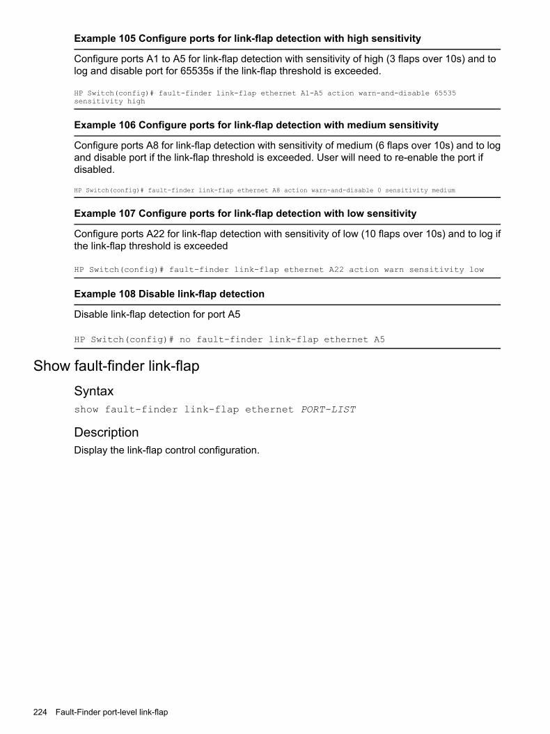
Example 105 Configure ports for link-flap detection with high sensitivity
Configure ports A1 to A5 for link-flap detection with sensitivity of high (3 flaps over 10s) and tolog and disable port for 65535s if the link-flap threshold is exceeded.
HP Switch(config)# fault-finder link-flap ethernet A1-A5 action warn-and-disable 65535sensitivity high
Example 106 Configure ports for link-flap detection with medium sensitivity
Configure ports A8 for link-flap detection with sensitivity of medium (6 flaps over 10s) and to logand disable port if the link-flap threshold is exceeded. User will need to re-enable the port ifdisabled.
HP Switch(config)# fault-finder link-flap ethernet A8 action warn-and-disable 0 sensitivity medium
Example 107 Configure ports for link-flap detection with low sensitivity
Configure ports A22 for link-flap detection with sensitivity of low (10 flaps over 10s) and to log ifthe link-flap threshold is exceeded
HP Switch(config)# fault-finder link-flap ethernet A22 action warn sensitivity low
Example 108 Disable link-flap detection
Disable link-flap detection for port A5
HP Switch(config)# no fault-finder link-flap ethernet A5
Show fault-finder link-flapSyntaxshow fault-finder link-flap ethernet PORT-LIST
DescriptionDisplay the link-flap control configuration.
224 Fault-Finder port-level link-flap

Example 109 Show fault-finder link-flap
HP Switch# show fault-finder link-flap A1
Link | Port Disable Disable TimePort Flap | Status Sensitivity Action Timer Left------ ----- + ------ ----------- ------------------ ---------- ------------A1 Yes Down Low warn-and-disable 65535 45303
HP Switch# show fault-finder link-flapLink | Port Disable Disable Time
Port Flap | Status Sensitivity Action Timer Left------ ----- + ------ ----------- ------------------- ---------- ------------A1 Yes Down Low warn-and-disable 65535 45303A5 No Up None None - -A22 Yes Down Low warn-and-disable - -A23 Yes Down High warn-and-disable 100 -
NOTE: This example displays only the list of ports configured via the above per-port configcommands, does not include the global configuration ports.
Event Log
CauseMessage
Link-flap is detected by fault-finder per the sensitivity configured.FFI: port <ID>- Excessive link state transitions.
Link-flap is detected and the action is to disable the port with nodisable timer.
FFI: port <ID>- Excessive link state transitions.FFI: port <ID>-Port disabled by Fault-finder.FFI: port <ID>-Administrator action is required tore-enable.ports: Fault-finder (71) has disabled port <ID>.ports: port <ID> is now offline.vlan: VLAN<VLAN-ID> virtual LAN is disabled.
Link-flap is detected and the action is to disable the port withdisable timer.
FFI: port <ID>- Excessive link state transitions.FFI: port <ID>-Port disabled by Fault-finder.ports: Fault-finder(71) has disabled port <ID> for<SECONDS> seconds.ports: port <ID> is now off-line.vlan: VLAN<VLAN-ID> virtual LAN is disabled.
The port is enabled when the disable timer expires.
port <ID> timer (71) has expired.ports: port <ID> is now on-line.vlan: VLAN<VLAN-ID> virtual LAN is enabled.
Restrictions• Per port configuration for options – link-flap only. Global settings for other options.
• No support for menu interface.
• No support for Web UI.
• No changes to PCM.
• No changes to IDM.
• No support for trunks.
Event Log 225

7 Configuring for Network Management ApplicationsConfiguring the switch to filter untagged traffic
Enter this command to configure the switch not to learn CDP, LLDP, or EAPOL traffic for a setof interfaces.
Syntax[no]ignore-untagged-mac <PORT-LIST>
Prevents MAC addresses from being learned on the specified ports when theVLAN is untagged and the destination MAC address is one of the following:• 01000C-CCCCCC (CDP)
• 0180c2- 00000e (LLDP)
• 0180c2-000003 (EAPOL)
ExampleConfiguring the switch to ignore packet MAC address learns for an untaggedVLAN.HP Switch(config) ignore-untagged-mac 1-2
Viewing configuration file change informationSyntaxshow running-config [ changes-history [ 1-32 ] ] [ detail ]Displays the history up to 32 events for changes made to the running-configuration file, as shownin Figure 81 (page 226) and Figure 82 (page 226). The changes are displayed in descending order,the most recent change at the top of the list. You can specify from 1 to 32 entries for display.The detail option displays a more detailed amount of information for the configuration changes.Figure 83 (page 227) and Figure 84 (page 227) display detailed information for configurationchanges history.
Examples
Figure 81 Output for running configuration changes history for all ports
Figure 82 Example of output for running configuration changes history
226 Configuring for Network Management Applications

Figure 83 Detailed output for running configuration changes history
Figure 84 Example of output for running config changes history with detail
Figure 85 (page 227) displays the current status (enabled/disabled) of the SNMP trap type forrunning-configuration changes.
Figure 85 SNMP trap configuration status information
Minimal interval for successive data change notificationsTo change the minimum interval for successive data change notifications for the same neighbor,use the following command.
Syntaxsetmib lldpnotificationinterval.0 -i 1 - 3600
Globally changes the interval between successive traps generated by the switch. If multiple trapsare generated in the specified interval, only the first trap is sent. The remaining traps aresuppressed. (A network management application can periodically check the switch MIB to detectany missed change notification traps. See IEEE P802.1AB or later for more information.)(Default: 5 seconds)
Minimal interval for successive data change notifications 227

ExampleThe following command limits change notification traps from a particular switch to one per minute.
(HP_Switch_name#) setmib lldpnotificationinterval.0 -i 60 lldpNotificationInterval.0=60
Viewing the current port speed and duplex configuration on a switch portSyntax
show interfaces brief ...|config|custom ...|display|port-utilization|transceiver ...| status ...|tunnel...|ethernet PORT-LIST
Show port configuration and status information.brief Show port operational parameters.config Show port configuration information.custom Show port parameters in a customized table.display Show summary of network traffic handled by the
ports.internal-use Show reserved or eligible internal ports.[ethernet] PORT-LIST Show summary of network traffic handled by the
ports.port-utilization Show port bandwidth utilization.status Show interfaces tagged or untagged VLAN
information.transceiver Show the transceiver information.tunnel Show tunnel configuration and status information.
228 Configuring for Network Management Applications

Example 110 Show interfaces
HP-5406Rzl2# show interfacesStatus and Counters - Port Counters
Flow BcastPort Total Bytes Total Frames Errors Rx Drops TxCtrl Limit------ -------------- -------------- ------------ ---------------- -----A1 419,179 1555 0 0 off0
A2 4217 24 0 0 off0
A3 0 0 0 0 off0
A4 0 0 0 0 off0
A5 0 0 0 0 off0
A6 0 0 0 0 off0
A7 0 0 0 0 off0
A8 0 0 0 0 off0
A9 0 0 0 0 off0
A10 0 0 0 0 off0
A11 0 0 0 0 off0
A12 0 0 0 0 off0
A13 0 0 0 0 off0
A14 0 0 0 0 off0
A15 0 0 0 0 off0
A16 0 0 0 0 off0
A17 0 0 0 0 off0
A18 0 0 0 0 off0
A19 0 0 0 0 off0
A20 0 0 0 0 off0
A21 3846 21 0 0 off0
A22 3855 19 0 0 off0
MACsec Port Counters:Port Errors Rx Drops Tx------ ------------ ------------A2 0 0
Viewing the configuration
Viewing the configuration 229
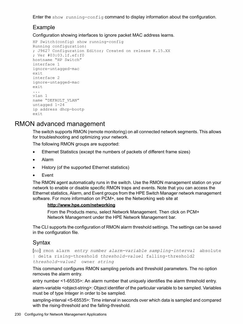
Enter the show running-config command to display information about the configuration.
ExampleConfiguration showing interfaces to ignore packet MAC address learns.HP Switch(config) show running-configRunning configuration:; J9627 Configuration Editor; Created on release K.15.XX; Ver #03:03.1f.ef:f0hostname “HP Switch”interface 1ignore-untagged-macexitinterface 2ignore-untagged-macexit...vlan 1name “DEFAULT_VLAN”untagged 1-24ip address dhcp-bootpexit
RMON advanced managementThe switch supports RMON (remote monitoring) on all connected network segments. This allowsfor troubleshooting and optimizing your network.The following RMON groups are supported:
• Ethernet Statistics (except the numbers of packets of different frame sizes)
• Alarm
• History (of the supported Ethernet statistics)
• EventThe RMON agent automatically runs in the switch. Use the RMON management station on yournetwork to enable or disable specific RMON traps and events. Note that you can access theEthernet statistics, Alarm, and Event groups from the HPE Switch Manager network managementsoftware. For more information on PCM+, see the Networking web site at
http://www.hpe.com/networkingFrom the Products menu, select Network Management. Then click on PCM+Network Management under the HPE Network Management bar.
The CLI supports the configuration of RMON alarm threshold settings. The settings can be savedin the configuration file.
Syntax[no] rmon alarm entry number alarm-variable sampling-interval absolute| delta rising-threshold threshold-value1 falling-threshold2threshold-value2 owner string
This command configures RMON sampling periods and threshold parameters. The no optionremoves the alarm entry.entry number <1-65535>: An alarm number that uniquely identifies the alarm threshold entry.alarm-variable <object-string>: Object identifier of the particular variable to be sampled. Variablesmust be of type Integer in order to be sampled.sampling-interval <5-65535>: Time interval in seconds over which data is sampled and comparedwith the rising-threshold and the falling-threshold.
230 Configuring for Network Management Applications

absolute: The value of the selected variable is compared directly with the thresholdsat the end of the sampling interval.
NOTE: If the absolute option is used for alarm variables of counter-type, anRMON trap is generated only once, when the threshold limit is reached. TheRMON trap is never generated again.
It is recommended that you use the delta option instead when using a counter-typealarm variable.delta: The value of the selected variable at the last sample is subtracted from thecurrent value, and the difference is compared with the thresholds.
rising-threshold <threshold-value1>:An integer value for the upper threshold for the sampledstatistic. A single event is generated when the current sampled value of the specified statisticbecomes greater than or equal to this threshold, and if the value at the last sampling intervalswas less than this threshold.
NOTE: The value of the rising-threshold must be greater than the value of the falling-threshold.
falling-threshold <threshold-value2>: An integer value for the lower threshold for the sampledstatistic. A single event is generated when the current sampled value of the specified statisticbecomes less than or equal to this threshold, and if the value at the last sampling interval wasgreater than this threshold.owner <string>: The name of the owner of this alarm.
Examples
Figure 86 Configuring the RMON Alarm Parameters in the CLI
Figure 87 Removing an RMON Alarm
Figure 88 Show Command Output for a Specific Alarm
RMON advanced management 231

Figure 89 Display Command Output for a Specific Alarm
Figure 90 Output of the running-config File Displaying the Configured RMON AlarmParameters
Configuring UDLD verify before forwardingWhen an UDLD enabled port transitions to link-up, the port will begin with a UDLD blocking state.UDLD will probe via protocol packet exchange to determine the bidirectional state of the link.Until UDLD has completed the probe, all data traffic will be blocked. If the link is found to bebidirectional, UDLD will unblock the port for data traffic to pass. Once UDLD unblocks the port,other protocols will see the port as up and data traffic can be safely forwarded.The default mode of a switch is “forward first then verify’’. Enabling UDLD link-up will default to“forward first then verify”. To change the mode to “verify then forward”, you need to configureusing the commands found in section 6.72.
NOTE: Link-UP data traffic will resumed after probing the link partner completes. All otherprotocols running will see the port as down.
UDLD time delayUDLD protocol informs the link partner simultaneously as it detects a state change fromunidirectional to bidirectional traffic. Additional packet exchanges will be carried out by UDLD inaddition to the existing UDLD exchanges whenever state changes from unidirectional tobidirectional.
232 Configuring for Network Management Applications

Table 17 Peer state transition timings
Interval 3Interval 2Interval 1 + deltaInterval 1Interval Time
15 sec10 sec5+(<5) sec*5 sec
Regular UDLD TXRegular UDLD TXInform PeerState =unblockedPeer State =unblocked
State =blockedPeerState = blocked
With triggeredupdates
Regular UDLD TXInform PeerState =unblockedPeer State =unblocked
State = unblockedPeer State =blocked
State =blockedPeerState = blocked
Withouttriggeredupdates
*delta is the time when the unblock event occurs on local side
Restrictions
• There is no support available when configuring this mode from the web and menu interface.
• There are no new packet types are introduced with UDLD.
• There are no new UDLD timers being introduced.
UDLD configuration commands
Syntaxlink-keepalive mode [verify-then-forward |forward-then-verify]
This command configures the link-keepalive mode.Link-keepalive provides two modes of operation; verify-then-forward andforward-then-verify.When using the verify-then-forward mode, the port is in a blocking stateuntil the link configured for UDLD establishes bidirectional communication. Whenusing the forward-then-verifymode, the port forwards the data then verifiesthe status of the link-in state.When a unidirectional state is detected, the port is moved to a blocked state.When a bidirectional state is detected, the data is forwarded without interruption.
Syntaxlink-keepalive mode verify-then-forward
Keeps the port in a logically blocked state until the link configured for UDLD hasbeen successfully established in bi-directional communication.
Syntaxlink-keepalive mode forward-then-verify
Forwards the data then verifies the status of the link. If a unidirectional state isdetected, the port is then moved to a blocked state.
Syntaxlink-keepalive interval <deciseconds>
Configure the interval for link-keepalive. The link-keepalive interval isthe time between sending two UDLD packets. The time interval is entered indeciseconds (1/10 sec). The default keepalive interval is 50 deciseconds.
Configuring UDLD verify before forwarding 233
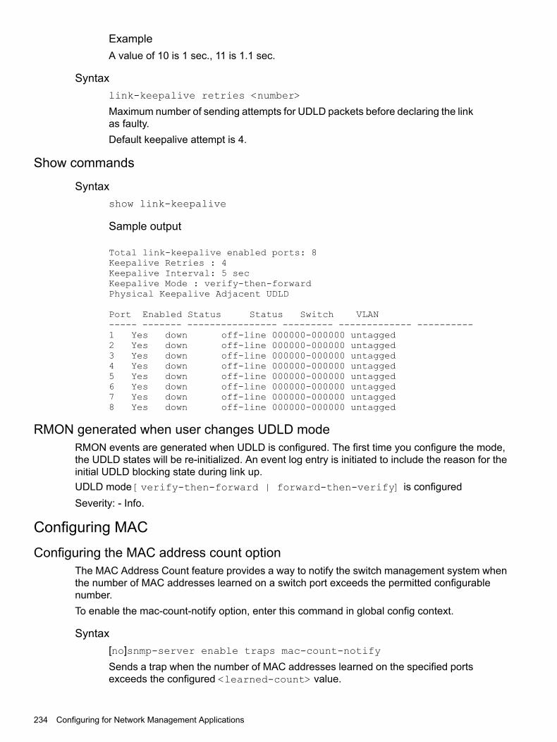
ExampleA value of 10 is 1 sec., 11 is 1.1 sec.
Syntaxlink-keepalive retries <number>
Maximum number of sending attempts for UDLD packets before declaring the linkas faulty.Default keepalive attempt is 4.
Show commands
Syntaxshow link-keepalive
Sample output
Total link-keepalive enabled ports: 8Keepalive Retries : 4Keepalive Interval: 5 secKeepalive Mode : verify-then-forwardPhysical Keepalive Adjacent UDLD
Port Enabled Status Status Switch VLAN----- ------- ---------------- --------- ------------- ----------1 Yes down off-line 000000-000000 untagged2 Yes down off-line 000000-000000 untagged3 Yes down off-line 000000-000000 untagged4 Yes down off-line 000000-000000 untagged5 Yes down off-line 000000-000000 untagged6 Yes down off-line 000000-000000 untagged7 Yes down off-line 000000-000000 untagged8 Yes down off-line 000000-000000 untagged
RMON generated when user changes UDLD modeRMON events are generated when UDLD is configured. The first time you configure the mode,the UDLD states will be re-initialized. An event log entry is initiated to include the reason for theinitial UDLD blocking state during link up.UDLD mode [verify-then-forward | forward-then-verify] is configuredSeverity: - Info.
Configuring MACConfiguring the MAC address count option
The MAC Address Count feature provides a way to notify the switch management system whenthe number of MAC addresses learned on a switch port exceeds the permitted configurablenumber.To enable the mac-count-notify option, enter this command in global config context.
Syntax[no]snmp-server enable traps mac-count-notify
Sends a trap when the number of MAC addresses learned on the specified portsexceeds the configured <learned-count> value.
234 Configuring for Network Management Applications
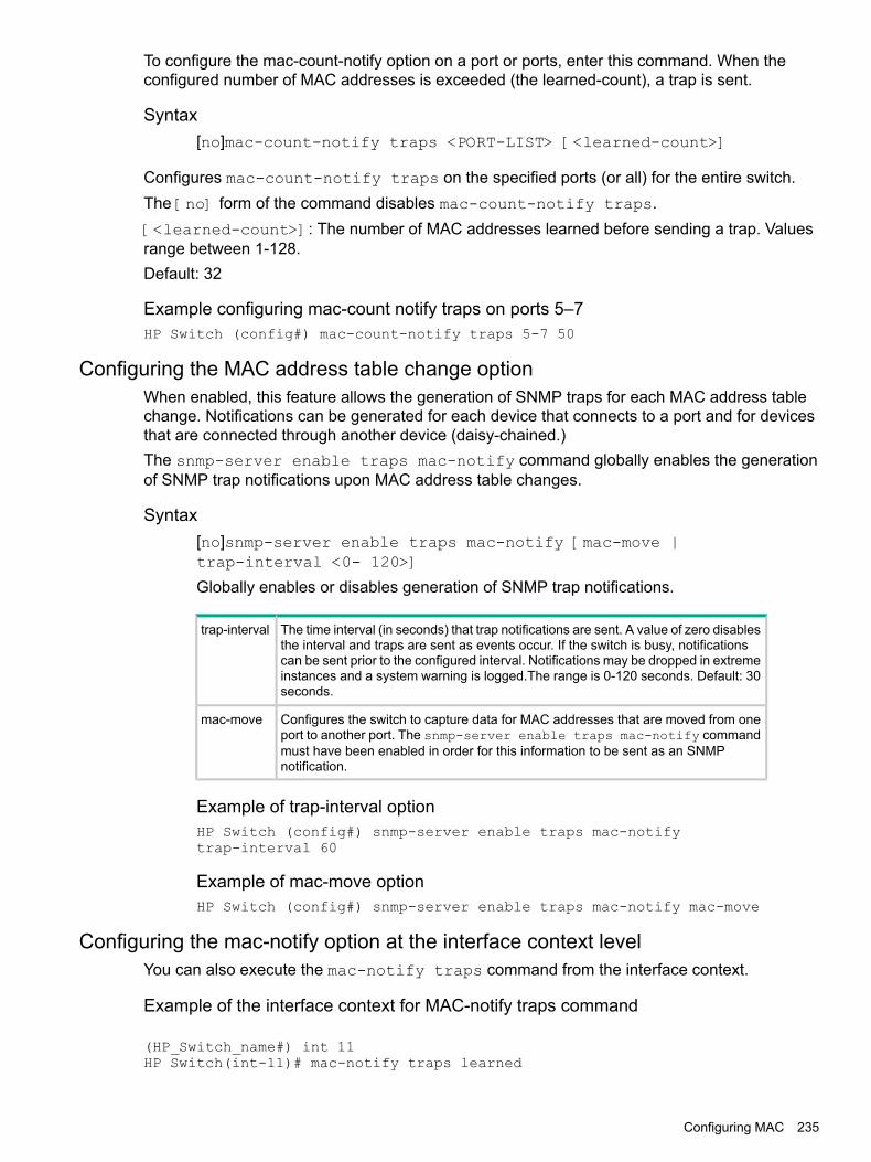
To configure the mac-count-notify option on a port or ports, enter this command. When theconfigured number of MAC addresses is exceeded (the learned-count), a trap is sent.
Syntax[no]mac-count-notify traps <PORT-LIST> [<learned-count>]
Configures mac-count-notify traps on the specified ports (or all) for the entire switch.The [no] form of the command disables mac-count-notify traps.[<learned-count>]: The number of MAC addresses learned before sending a trap. Valuesrange between 1-128.Default: 32
Example configuring mac-count notify traps on ports 5–7HP Switch (config#) mac-count-notify traps 5-7 50
Configuring the MAC address table change optionWhen enabled, this feature allows the generation of SNMP traps for each MAC address tablechange. Notifications can be generated for each device that connects to a port and for devicesthat are connected through another device (daisy-chained.)The snmp-server enable traps mac-notify command globally enables the generationof SNMP trap notifications upon MAC address table changes.
Syntax[no]snmp-server enable traps mac-notify [mac-move |trap-interval <0- 120>]
Globally enables or disables generation of SNMP trap notifications.
The time interval (in seconds) that trap notifications are sent. A value of zero disablesthe interval and traps are sent as events occur. If the switch is busy, notifications
trap-interval
can be sent prior to the configured interval. Notifications may be dropped in extremeinstances and a system warning is logged.The range is 0-120 seconds. Default: 30seconds.
Configures the switch to capture data for MAC addresses that are moved from oneport to another port. The snmp-server enable traps mac-notify command
mac-move
must have been enabled in order for this information to be sent as an SNMPnotification.
Example of trap-interval optionHP Switch (config#) snmp-server enable traps mac-notifytrap-interval 60
Example of mac-move optionHP Switch (config#) snmp-server enable traps mac-notify mac-move
Configuring the mac-notify option at the interface context levelYou can also execute the mac-notify traps command from the interface context.
Example of the interface context for MAC-notify traps command
(HP_Switch_name#) int 11HP Switch(int-11)# mac-notify traps learned
Configuring MAC 235

Per-port MAC change options for mac-notifyUse the following command to configure SNMP traps for learned or removed MAC addresseson a per-port basis.
NOTE: The switch will capture learned or removed events on the selected ports, but will notsend an SNMP trap unless mac-notify has been enabled with the snmp-server enabletraps mac-notify command.
Syntax[no]mac-notify traps <PORT-LIST>[learned | removed]
When this command is executed without the learned or removed option, it enables or disablesthe capture of both learned and removed MAC address table changes for the selected ports in<PORT-LIST>.
Configures MAC address table changes capture on the specified ports. Use all to capturechanges for all ports on the switch.
<PORT-LIST>
Enables the capture of learned MAC address table changes on the selected ports.learned
Enables the capture of removed MAC address table changes table on the selected ports.removed
Example of configuring traps on a per-port basis for learned MAC addresses(HP_Switch_name#) mac-notify traps 5-6 learned(HP_Switch_name#) show mac-notify traps 5-6Mac Notify Trap InformationMac-notify Enabled : YesMac-move Enabled : YesTrap-interval : 60Port MAC Addresses trap learned/removed------ ----------------------------------5 Learned6 Learned
Example of configuring traps on a port-bases for removed MAC addresses(HP_Switch_name#) mac-notify traps 3-4 removedHP_Switch(config#) show mac-notify trapsMac Notify Trap InformationMac-notify Enabled : YesMac-move Enabled : YesTrap-interval : 60Port MAC Addresses trap learned/removed------ ----------------------------------1 None2 None3 Removed4 Removed
Viewing the mac-count-notify optionUse the show mac-count-notify traps [<PORT-LIST>] command to display information about theconfigured value for sending a trap, the current count, and if a trap has been sent.
Example of information displayed for show mac-count-notify traps commandHP Siwtch (config #) show mac-count-notify traps
Mac-count-notify Enabled: Yes
Port Count for Count Trap Sent
236 Configuring for Network Management Applications
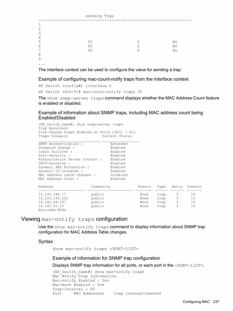
sending Trap-----------------------------------------------------------------12345 50 0 No6 50 2 No7 50 0 No89...
The interface context can be used to configure the value for sending a trap.
Example of configuring mac-count-notify traps from the interface contextHP Switch (config#) interface 5
HP Switch (eth-5)# mac-count-notify traps 35
The show snmp-server traps command displays whether the MAC Address Count featureis enabled or disabled.
Example of information about SNMP traps, including MAC address count beingEnabled/Disabled(HP_Switch_name#) show snmp-server trapsTrap ReceiversLink-Change Traps Enabled on Ports [All] : AllTraps Category Current Status_____________________________ __________________SNMP Authentication : ExtendedPassword change : EnabledLogin failures : EnabledPort-Security : EnabledAuthorization Server Contact : EnabledDHCP-Snooping : EnabledDynamic ARP Protection : EnabledDynamic IP Lockdown : EnabledMAC address table changes : DisabledMAC Address Count : Enabled
Address Community Events Type Retry Timeout---------------------- ---------------------- -------- ------ ------- -------15.146.194.77 public None trap 3 1515.255.134.252 public None trap 3 1516.181.49.167 public None trap 3 1516.181.51.14 public None trap 3 15Excluded MIBs
Viewing mac-notify traps configurationUse the show mac-notify traps command to display information about SNMP trapconfiguration for MAC Address Table changes.
Syntaxshow mac-notify traps <PORT-LIST>
Example of information for SNMP trap configurationDisplays SNMP trap information for all ports, or each port in the <PORT-LIST>.(HP_Switch_name#) show mac-notify trapsMac Notify Trap InformationMac-notify Enabled : YesMac-move Enabled : YesTrap-interval : 60Port MAC Addresses trap learned/removed
Configuring MAC 237

------ ----------------------------------1 None2 None3 Removed4 Removed5 Learned6 Learned
The configured mac-notify commands are displayed in the show running-configurationoutput.
Example of running config file with mac-notify parameters configured(HP_Switch_name#) show running-configRunning configuration:; J9087A Configuration Editor; Created on release #R.11.XXhostname "Switch"snmp-server community "public" Unrestrictedsnmp-server host 15.255.133.236 "public"snmp-server host 15.255.133.222 "public"snmp-server host 15.255.133.70 "public"snmp-server host 15.255.134.235 "public"vlan 1name "DEFAULT_VLAN"untagged 1-28ip address dhcp-bootpexit
snmp-server enable traps mac-notify mac-movesnmp-server enable traps mac-notify trap-interval 60snmp-server enable traps mac-notifymac-notify traps 5-6 learnedmac-notify traps 3-4 removed
Configuring sFlowConfiguring sFlow
The following sFlow commands allow you to configure sFlow instances via the CLI.
Syntax[no] sflow receiver-instance destination ip-address [ udp-port-num ]Enables an sFlow receiver/destination. The receiver-instance number must be a 1, 2, or 3.By default, the udp destination port number is 6343.To disable an sFlow receiver/destination, enter no sflow receiver-instance.
Syntaxsflow receiver-instance sampling <PORT-LIST> sampling rate
Once an sFlow receiver/destination has been enabled, this command enables flow sampling forthat instance. The receiver-instance number is 1, 2, or 3, and the sampling rate is the allowablenon-zero skipcount for the specified port or ports.To disable flow-sampling for the specified <PORT-LIST> repeat the above command with asampling rate of 0.
Syntaxsflow <receiver-instance> polling <PORT-LIST> polling interval
238 Configuring for Network Management Applications

Once an sFlow receiver/destination has been enabled, this command enables counter pollingfor that instance. The receiver-instance number is 1, 2, or 3, and the polling interval may be setto an allowable non-zero value to enable polling on the specified port or ports.To disable counter-polling for the specified <PORT-LIST>, repeat the above command with apolling interval of 0.
NOTE: Under the multiple instance implementation, sFlow can be configured via the CLI orvia SNMP. However, CLI-owned sFlow configurations cannot be modified via SNMP, whereasSNMP-owned instances can be disabled via the CLI using the no sflow<receiver-instance> command.
Syntax[no] sflow receiver-instance destination <ipv4 | ipv6>udp-port-numoobm
This command provides a configurable option for sending sFlow packets to a destination throughthe OOBM port on the switch. The sFlow collector collects sample packets through the OOBMport, allowing the monitoring of network traffic. Both IPv4 and IPv6 addresses are supported.The command enables an sFlow receiver/destination. The receiver-instance number must be a1, 2, or 3. By default, the udp destination port number is 6343.To disable an sFlow receiver/destination, enter no sflow <receiver-instance>oobm: Use the OOBM port to reach the specified sFlow receiver.
Example 111 sFlow Destination is OOBM port
HP_Switch (Config#) sflow 1 destination 192.168.2.3 6000 oobm
Figure 91 Output showing OOBM Support Enabled
Figure 92 Output of the running-config File showing the sFlow Destination is the OOBMPort
sFlow Configuring multiple instancesIn earlier software releases, sFlow was configured on the switch via SNMP using a single sFlowinstance. Beginning with software release K.11.34, sFlow can also be configured via the CLI for
Configuring sFlow 239

up to three distinct sFlow instances: once enabled, an sFlow receiver/destination can beindependently configured for full flow-sampling and counter-polling. CLI-configured sFlow instancesmay be saved to the startup configuration to persist across a switch reboot.
Viewing sFlow Configuration and StatusThe following sFlow commands allow you to display sFlow configuration and status via the CLI.Figure 94 (page 240) is an example of sflow agent information.
Syntaxshow sflow agent
Displays sFlow agent information. The agent address is normally the IP address of the first VLANconfigured.The show sflow agent command displays read-only switch agent information. The versioninformation shows the sFlow version, MIB support, and software versions; the agent address istypically the IP address of the first VLAN configured on the switch.
Figure 93 Example of viewing sflow agent information
Syntaxshow sflow receiver instance destination
Displays information about the management station to which the sFlow sampling-polling data issent.The show sflow instance destination command includes information about themanagement-station's destination address, receiver port, and owner, as shown in Figure 94(page 240).
Figure 94 Example of viewing sFlow destination information
Note the following details:• Destination Address remains blank unless it has been configured.
• Datagrams Sent shows the number of datagrams sent by the switch agent to the managementstation since the switch agent was last enabled.
• Timeout displays the number of seconds remaining before the switch agent will automaticallydisable sFlow (this is set by the management station and decrements with time.)
• Max Datagram Size shows the currently set value (typically a default value, but this can alsobe set by the management station.)
Syntaxshow sflow <receiver instance> sampling-polling <PORT-LIST/range>
Displays status information about sFlow sampling and polling.
240 Configuring for Network Management Applications

Theshow sflow instance sampling-polling<PORT-LIST> command displays informationabout sFlow sampling and polling on the switch, as shown in Figure 95 (page 241). You canspecify a list or range of ports for which to view sampling information.
Figure 95 Example of viewing sFlow sampling and polling information
NOTE: The sampling and polling instances (noted in parentheses) coupled to a specific receiverinstance are assigned dynamically, and so the instance numbers may not always match. Thekey thing to note is whether sampling or polling is enabled on a port, and the sampling rates orpolling intervals for the receiver instance configured on each port.
Viewing management stations for SNMPv3
Syntaxshow snmpv3 user
Example
Example 112 Displays information about the management stations configured on VLAN1 to access the switch
HP Switch# configure terminal(HP_Switch_name#) vlan 1HP Switch(vlan-1)# show snmpv3 user
Status and Counters - SNMPv3 Global Configuration Information
User Name Auth. Protocol Privacy Protocol----------- -------------- -----------------initial MD5 CFB AES-128NetworkAdmin MD5 CBC-DES
Configuring SNMPNetwork security notifications
By default, a switch is enabled to send the SNMP notifications listed in “Supported Notifications”(page 245) when a network security event (for example, authentication failure) occurs. However,before security notifications can be sent, you must first configure one or more trap receivers orSNMPv3 management stations as described in:
• “Configuring an SNMP trap receiver” (page 253)
• “Configuring SNMPv3 notifications” (page 255)You can manage the default configuration of the switch to disable and re-enable notifications tobe sent for the following types of security events:
• ARP protection events
• Inability to establish a connection with the RADIUS or TACACS+ authentication server
• DHCP snooping events
Configuring SNMP 241
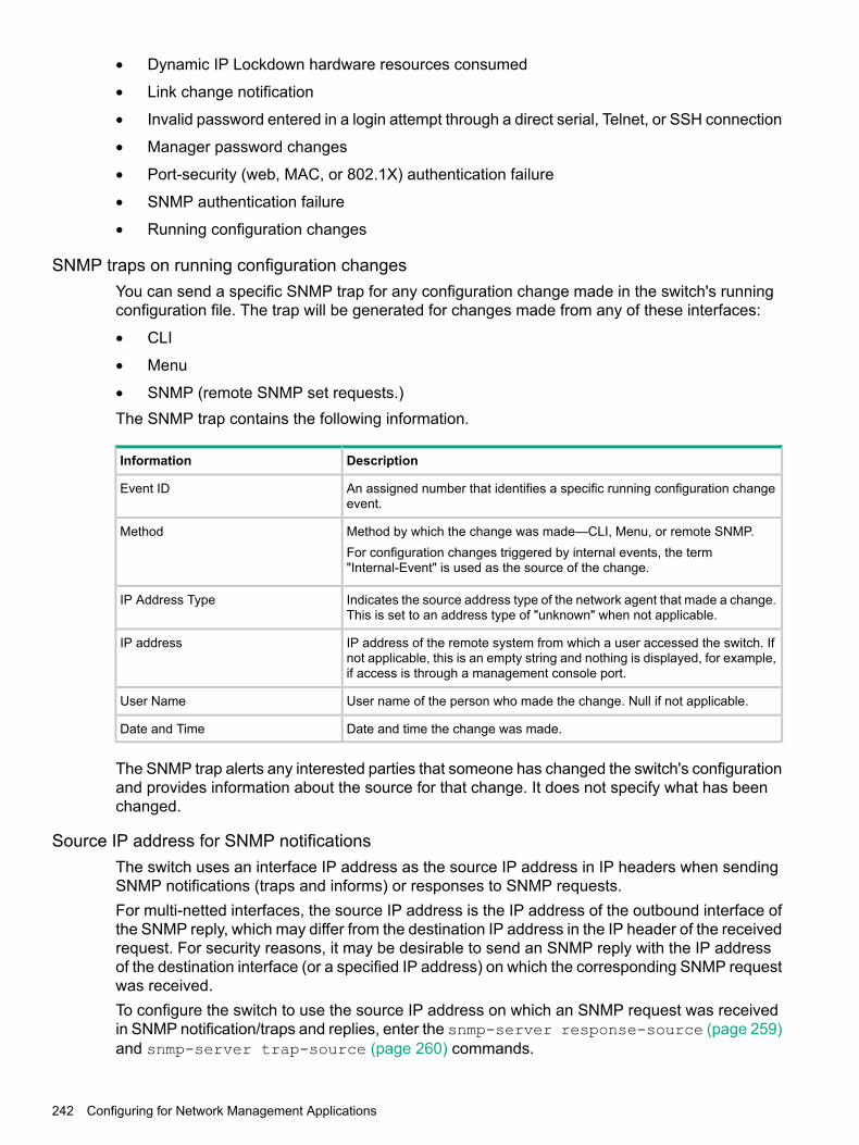
• Dynamic IP Lockdown hardware resources consumed
• Link change notification
• Invalid password entered in a login attempt through a direct serial, Telnet, or SSH connection
• Manager password changes
• Port-security (web, MAC, or 802.1X) authentication failure
• SNMP authentication failure
• Running configuration changes
SNMP traps on running configuration changesYou can send a specific SNMP trap for any configuration change made in the switch's runningconfiguration file. The trap will be generated for changes made from any of these interfaces:
• CLI
• Menu
• SNMP (remote SNMP set requests.)The SNMP trap contains the following information.
DescriptionInformation
An assigned number that identifies a specific running configuration changeevent.
Event ID
Method by which the change was made—CLI, Menu, or remote SNMP.MethodFor configuration changes triggered by internal events, the term"Internal-Event" is used as the source of the change.
Indicates the source address type of the network agent that made a change.This is set to an address type of "unknown" when not applicable.
IP Address Type
IP address of the remote system from which a user accessed the switch. Ifnot applicable, this is an empty string and nothing is displayed, for example,if access is through a management console port.
IP address
User name of the person who made the change. Null if not applicable.User Name
Date and time the change was made.Date and Time
The SNMP trap alerts any interested parties that someone has changed the switch's configurationand provides information about the source for that change. It does not specify what has beenchanged.
Source IP address for SNMP notificationsThe switch uses an interface IP address as the source IP address in IP headers when sendingSNMP notifications (traps and informs) or responses to SNMP requests.For multi-netted interfaces, the source IP address is the IP address of the outbound interface ofthe SNMP reply, which may differ from the destination IP address in the IP header of the receivedrequest. For security reasons, it may be desirable to send an SNMP reply with the IP addressof the destination interface (or a specified IP address) on which the corresponding SNMP requestwas received.To configure the switch to use the source IP address on which an SNMP request was receivedin SNMP notification/traps and replies, enter the snmp-server response-source (page 259)and snmp-server trap-source (page 260) commands.
242 Configuring for Network Management Applications

Listening modeFor switches that have a separate out-of-band management port, you can specify whether aconfigured SNMP server listens for SNMP queries over the OOBM interface, the data interface,or both. By default, the switch listens over both interfaces.This option is not available for switches that do not have a separate OOBM port.The listening mode is set with parameters to the snmp-server command.
Group access levelsThe switch supports eight predefined group access levels, shown in Table 6-3 (page 243). Thereare four levels for use by version 3 users and four are used for access by version 2c or version1 management applications.
Table 18 Predefined group access levels
Group write viewGroup read viewGroup access typeGroup name
ManagerWriteViewManagerReadViewVer3 Must haveAuthentication andPrivacy
managerpriv
ManagerWriteViewManagerReadViewVer3 Must haveAuthentication
managerauth
DiscoveryViewOperatorReadViewVer3 Must haveAuthentication
operatorauth
DiscoveryViewOperatorReadViewVer3 No Authenticationoperatornoauth
ManagerWriteViewManagerReadViewVer2c or Ver1commanagerrw
DiscoveryViewManagerReadViewVer2c or Ver1commanagerr
OperatorReadViewOperatorReadViewVer2c or Ver1comoperatorrw
DiscoveryViewOperatorReadViewVer2c or Ver1comoperatorr
Each view allows you to view or modify a different set of MIBs:
• Manager Read View – access to all managed objects
• Manager Write View – access to all managed objects except the following:vacmContextTable•
• vacmAccessTable
• vacmViewTreeFamilyTable
• OperatorReadView – no access to the following:icfSecurityMIB•
• hpSwitchIpTftpMode
• vacmContextTable
• vacmAccessTable
• vacmViewTreeFamilyTable
• usmUserTable
• snmpCommunityTable
• Discovery View – Access limited to samplingProbe MIB.
Configuring SNMP 243

NOTE: All access groups and views are predefined on the switch. There is no method to modifyor add groups or views to those that are predefined on the switch.
SNMPv3 communitiesSNMP commuities are supported by the switch to allow management applications that use version2c or version 1 to access the switch. The communities are mapped to Group Access Levels thatare used for version 2c or version 1 support. This mapping happens automatically based on thecommunities access privileges, but special mappings can be added with the snmpv3 communitycommand.
SNMP community featuresUse SNMP communities to restrict access to the switch by SNMP management stations byadding, editing, or deleting SNMP communities. You can configure up to five SNMP communities,each with either an operator-level or a manager-level view and either restricted or unrestrictedwrite access.Using SNMP requires that the switch have an IP address and subnet mask compatible with yournetwork.
CAUTION: For PCM/PCM+ version 1.5 or earlier (or any TopTools version), deleting the"public" community disables some network management functions (such as traffic monitoring,SNMP trap generation, and threshold setting.) If network management security is a concern, andif you are using the above software versions, Hewlett Packard Enterprise recommends that youchange the write access for the "public" community to "Restricted."
SNMPv2c informsOn a switch enabled for SNMPv2c, you can use the snmp-server host inform command(“Enabling SNMPv2c informs” (page 254)) to send inform requests when certain events occur.When an SNMP Manager receives an inform request, it can send an SNMP response back tothe sending agent on the switch to let the agent know that the inform request reached itsdestination.If the sending agent on the switch does not receive an SNMP response back from the SNMPManager within the timeout period, the inform request may be resent, based on the retry countvalue.When you enable SNMPv2c inform requests to be sent, you must specify the IP address andcommunity name of the management station that will receive the inform notification.
SNMP notificationsThe switches:
• Fixed or “Well-Known” Traps: A switch automatically sends fixed traps (such as “coldStart”,“warmStart”, “linkDown”, and “linkUp”) to trap receivers using the public community name,which is the default. These traps can also be sent with configured non-public communities.
• SNMPv2c informs
• SNMP v3 notification process, including trapsThis section describes how to configure a switch to send network security and link-changenotifications to configured trap receivers.
244 Configuring for Network Management Applications

Supported NotificationsBy default, the following notifications are enabled on a switch:
• Manager password changes
• SNMP authentication failure
• Link-change traps: when the link on a port changes from up to down (linkDown) or down toup (linkUp)
• Port-security (web, MAC, or 802.1X) authentication failure
• Invalid password entered in a login attempt through a direct serial, Telnet, or SSH connection
• Inability to establish a connection with the RADIUS or TACACS+ authentication server
• DHCP snooping events
• ARP protection events
Configuring SNMP notifications1. Determine the versions of SNMP notifications that you want to use in your network.
If you want to use SNMPv1 and SNMPv2c traps, you must also configure a trapreceiver.If you want to use SNMPv3 notifications (including traps), you must also configurean SNMPv3 management station.
2. To reconfigure any of the SNMP notifications that are enabled by default to be sent to amanagement station (trap receiver.)
3. (Optional) See the following sections to configure optional SNMP notification features andverify the current configuration:• “Configuring the source IP address for SNMP notifications” (page 259)
• “Viewing SNMP notification configuration” (page 261)
SNMPv1 and SNMPv2c TrapsThe switches support the following functionality from earlier SNMP versions (SNMPv1 andSNMPv2c):• Trap receivers: A trap receiver is a management station to which the switch sends SNMP
traps and (optionally) event log messages sent from the switch. From the CLI you canconfigure up to ten SNMP trap receivers to receive SNMP traps from the switch.
• Fixed or "Well-Known" Traps: A switch automatically sends fixed traps (such as "coldStart","warmStart", "linkDown", and "linkUp") to trap receivers using the public community name.These traps cannot be redirected to other communities. If you change or delete the defaultpublic community name, these traps are not sent.
• Thresholds: A switch automatically sends all messages created when a system thresholdis reached to the network management station that configured the threshold, regardless ofthe trap receiver configuration.
SNMP trap receiversUse the snmp-server host command to configure a trap receiver that can receive SNMPv1and SNMPv2c traps, and (optionally) Event Log messages. When you configure a trap receiver,you specify its community membership, management station IP address, and (optionally) thetype of Event Log messages to be sent.
Configuring SNMP 245

If you specify a community name that does not exist—that is, has not yet been configured on theswitch—the switch still accepts the trap receiver assignment. However, no traps are sent to thattrap receiver until the community to which it belongs has been configured on the switch.
NOTE: To replace one community name with another for the same IP address, you must firstenter theno snmp-server host community-name ipv4-address | ipv6-addresscommand to delete the unwanted community name. Otherwise, if you add a new communityname with an IP address that is already used with a different community name, two validcommunity name entries are created for the same management station.If you do not specify the event level ([ none | all | not-info | critical | debug]), the switch does not send Event Log messages as traps. However, "well-known" traps andthreshold traps (if configured) are still sent.
SNMP trap when MAC address table changesAn SNMP trap is generated when a laptop/PC is removed from the back of an IP phone and thelaptop/PC MAC address ages out of the MAC table for the Switch 2920 and 5400 series switch.The mac-notify trap feature globally enables the generation of SNMP trap notifications on MACaddress table changes (learns/moves/removes/ages.)The following command enables trap for aged MAC addresses:
Syntaxno] mac-notify traps <PORT-LIST>aged
ExampleFor port 1 the command is:
Syntaxmac-notify traps 1 aged
Show commandUse the following show command to display the different mac-notify traps configured on aninterface:
Syntaxshow mac-notify traps
Displays the following information:
Mac Notify Trap InformationMac-notify Enabled : NoMac-move Enabled : NoTrap-interval : 30Port MAC Addresses trap learned/removed/aged------ ---------------------------------------1 Learned, Removed & Aged2 Removed & Aged3 Learned & Aged4 Learned & Removed5 Aged6 Learned7 Removed
ExampleFor port 1 the command would be as follows
246 Configuring for Network Management Applications

show mac-notify traps 1
Displays the following information:
1 Aged
SNMP trap when power supply is inserted or removedSNMP traps generate while inserting or removing a powered up Power Supply Unit (PSU) withoutpulling out the power cable and also when removing a powered down PSU from the Switch 5406Series. RMON log events are used to generate SNMP traps for PSU insertion and removal inboth powered up and powered down states.
Log Event
Chassis: Power Supply 1 insertedChassis: Power Supply 1 removed while poweredChassis: Power Supply 2 removed while not powered
ExamplePower Supply inserted while powered off:
W 09/13/13 09:10:18 03834 chassis: AM1: Power Supply 1 insertedW 09/13/13 09:10:19 00071 chassis: AM1: Power Supply failure: Supply: 1, Failures: 4
ExamplePower Supply inserted while powered on:
W 09/13/13 09:06:20 03834 chassis: AM1: Power Supply 1 insertedW 09/13/13 09:06:21 00071 chassis: AM1: Power Supply OK: Supply: 1, Failures: 2
ExamplePower Supply removed while powered off:
W 09/13/13 09:08:57 03835 chassis: AM1: Power Supply 1 removed while not poweredW 09/13/13 09:08:57 00071 chassis: AM1: Power Supply failure: Supply: 1, Failures: 3
ExamplePower Supply inserted while powered on:
W 09/13/13 09:03:36 03835 chassis: AM1: Power Supply 1 removed while poweredW 09/13/13 09:03:36 00071 chassis: AM1: Power Supply failure: Supply: 1, Failures: 2
Configuring SNMP notification supportYou can enable SNMP trap notification of LLDP data changes detected on advertisementsreceived from neighbor devices, and control the interval between successive notifications of datachanges on the same neighbor.
SNMPv3 users
NOTE: To create new users, most SNMPv3 management software requires an initial userrecord to clone. The initial user record can be downgraded and provided with fewer features, butnot upgraded by adding new features. For this reason, Hewlett Packard Enterprise recommendsthat when you enable SNMPv3, you also create a second user with SHA authentication and DESprivacy.
To use SNMPv3 on the switch, you must configure the users that will be assigned to differentgroups:
Configuring SNMP 247

1. Configure users in the User Table with the snmpv3 user command.To view the list of configured users, enter the show snmpv3 user command.
2. Assign users to Security Groups based on their security model with the snmpv3 groupcommand.
CAUTION: If you add an SNMPv3 user without authentication, privacy, or both, to a group thatrequires either feature, the user will not be able to access the switch. Ensure that you add a userwith the appropriate security level to an existing security group.
About adding usersTo configure an SNMPv3 user, you must first add the user name to the list of known users withthe snmpv3 user command, as shown in Figure 96 (page 248).
Figure 96 Adding SNMPv3 users and displaying SNMPv3 configuration
Using SNMP tools to manage the switchSNMP is a management protocol that allows an SNMP client application to retrieve deviceconfiguration and status information and to configure the device (get and set.) You can managethe switch via SNMP from a network management station running an application such as PCM+.For more information on PCM+, see the Hewlett Packard Enterprise website at:
http://www.hpe.com/networkingFrom the Products menu, select Network Management. The click on PCM+Network Management under the HP Network Management bar.
To implement SNMP management, the switch must have an IP address configured either manuallyor dynamically (using DHCP or Bootp.) If multiple VLANs are configured, each VLAN interfaceshould have its own IP address.
NOTE: If you use the switch's Authorized IP Managers and Management VLAN features,ensure that the SNMP management station, the choice of switch port used for SNMP access tothe switch, or both, are compatible with the access controls enforced by these features. Otherwise,SNMP access to the switch will be blocked.
SNMP management featuresSNMP management features on the switch include:
• SNMP version 1, version 2c, or version 3 over IP
• Security via configuration of SNMP communities (“SNMPv3 communities” (page 244))
248 Configuring for Network Management Applications
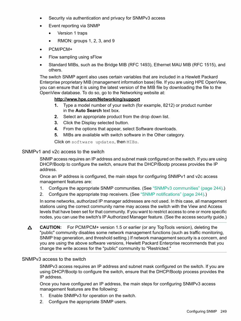
• Security via authentication and privacy for SNMPv3 access
• Event reporting via SNMPVersion 1 traps•
• RMON: groups 1, 2, 3, and 9
• PCM/PCM+
• Flow sampling using sFlow
• Standard MIBs, such as the Bridge MIB (RFC 1493), Ethernet MAU MIB (RFC 1515), andothers.
The switch SNMP agent also uses certain variables that are included in a Hewlett PackardEnterprise proprietary MIB (management information base) file. If you are using HPE OpenView,you can ensure that it is using the latest version of the MIB file by downloading the file to theOpenView database. To do so, go to the Networking website at:
http://www.hpe.com/Networking/support1. Type a model number of your switch (for example, 8212) or product number
in the Auto Search text box.2. Select an appropriate product from the drop down list.3. Click the Display selected button.4. From the options that appear, select Software downloads.5. MIBs are available with switch software in the Other category.Click on software updates, then MIBs.
SNMPv1 and v2c access to the switchSNMP access requires an IP address and subnet mask configured on the switch. If you are usingDHCP/Bootp to configure the switch, ensure that the DHCP/Bootp process provides the IPaddress.Once an IP address is configured, the main steps for configuring SNMPv1 and v2c accessmanagement features are:1. Configure the appropriate SNMP communities. (See “SNMPv3 communities” (page 244).)2. Configure the appropriate trap receivers. (See “SNMP notifications” (page 244).)In some networks, authorized IP manager addresses are not used. In this case, all managementstations using the correct community name may access the switch with the View and Accesslevels that have been set for that community. If you want to restrict access to one or more specificnodes, you can use the switch's IP Authorized Manager feature. (See the access security guide.)
CAUTION: For PCM/PCM+ version 1.5 or earlier (or any TopTools version), deleting the"public" community disables some network management functions (such as traffic monitoring,SNMP trap generation, and threshold setting.) If network management security is a concern, andyou are using the above software versions, Hewlett Packard Enterprise recommends that youchange the write access for the "public" community to "Restricted."
SNMPv3 access to the switchSNMPv3 access requires an IP address and subnet mask configured on the switch. If you areusing DHCP/Bootp to configure the switch, ensure that the DHCP/Bootp process provides theIP address.Once you have configured an IP address, the main steps for configuring SNMPv3 accessmanagement features are the following:1. Enable SNMPv3 for operation on the switch.2. Configure the appropriate SNMP users.
Configuring SNMP 249

3. Configure the appropriate SNMP communities.4. Configure the appropriate trap receivers.In some networks, authorized IP manager addresses are not used. In this case, all managementstations using the correct User and community name may access the switch with the View andAccess levels that have been set for that community. If you want to restrict access to one or morespecific nodes, you can use the IP Authorized Manager feature for the switch. (See the accesssecurity guide.)SNMP version 3 (SNMPv3) adds some new commands to the CLI for configuring SNMPv3functions. To enable SNMMPv3 operation on the switch, use the snmpv3 enable command.An initial user entry will be generated with MD5 authentication and DES privacy.You may (optionally) restrict access to only SNMPv3 agents by using the snmpv3 onlycommand. To restrict write-access to only SNMPv3 agents, use the snmpv3restricted-access command.
CAUTION: Restricting access to only version 3 messages will make the community named“public” inaccessible to network management applications (such as autodiscovery, trafficmonitoring, SNMP trap generation, and threshold setting) from operating in the switch.
Enabling SNMPv3The snmpv3 enable command allows the switch to:
• Receive SNMPv3 messages.
• Configure initial users.
• Restrict non-version 3 messages to "read only" (optional.)
CAUTION: Restricting access to only version 3 messages makes the community named"public" inaccessible to network management applications (such as autodiscovery, trafficmonitoring, SNMP trap generation, and threshold setting) from operating in the switch.
250 Configuring for Network Management Applications

Example
Example 113 SNMP version 3 enable command
Configuring users in SNMPv3
Syntax[no] snmpv3 user <user_name>[auth md5|sha]auth_pass[ priv des | aes <priv_pass>
Adds or deletes a user entry for SNMPv3. Authorization and privacy are optional, but to useprivacy, you must use authorization. When you delete a user, only the user_name is required.With authorization, you can set either MD5 or SHA authentication. The authentication passwordauth_pass must be 6 to 32 characters and is mandatory when you configure authentication.(Default: None)With privacy, the switch supports DES (56-bit) and AES (128-bit) encryption. The privacy passwordpriv_pass must be 6 to 32 characters and is mandatory when you configure privacy.(Default: DES)
NOTE: Only AES 128-bit and DES 56-bit encryption are supported as privacy protocols. Othernon-standard encryption algorithms, such as AES-172, AES-256, and 3-DES are not supported.
NOTE: For the 5400zl, and 3800 switches, when the switch is in enhanced secure mode,commands that take a password as a parameter have the echo of the password typing replacedwith asterisks. The input for the password is prompted for interactively. Additionally, the DESoption is not available. For more information, see the access security guide.
Enabling and disabling switch for access from SNMPv3 agentsThis includes the creation of the initial user record.
Syntax[no] snmpv3 enable
Enabling or disabling restrictions to access from only SNMPv3 agentsWhen enabled, the switch rejects all non-SNMPv3 messages.
Configuring SNMP 251
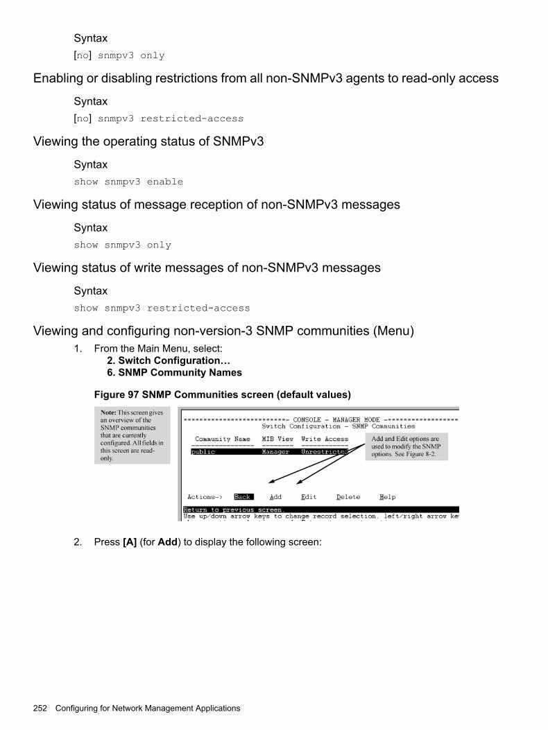
Syntax[no] snmpv3 only
Enabling or disabling restrictions from all non-SNMPv3 agents to read-only access
Syntax[no] snmpv3 restricted-access
Viewing the operating status of SNMPv3
Syntaxshow snmpv3 enable
Viewing status of message reception of non-SNMPv3 messages
Syntaxshow snmpv3 only
Viewing status of write messages of non-SNMPv3 messages
Syntaxshow snmpv3 restricted-access
Viewing and configuring non-version-3 SNMP communities (Menu)1. From the Main Menu, select:
2. Switch Configuration…6. SNMP Community Names
Figure 97 SNMP Communities screen (default values)
2. Press [A] (for Add) to display the following screen:
252 Configuring for Network Management Applications
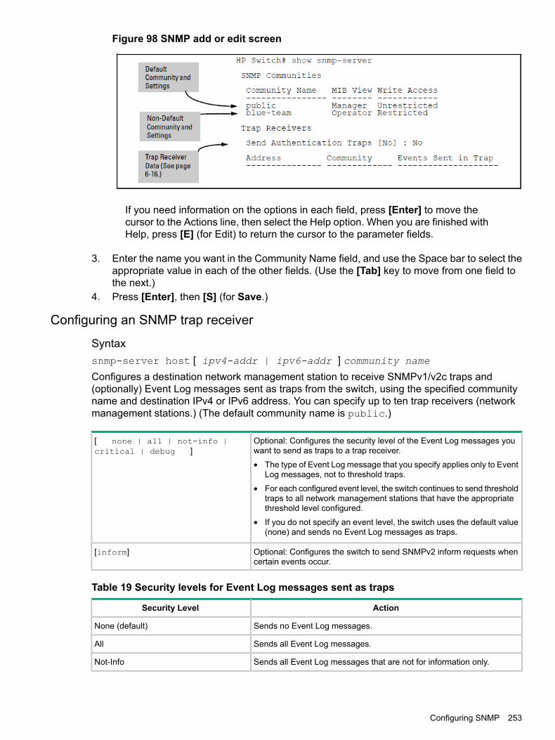
Figure 98 SNMP add or edit screen
If you need information on the options in each field, press [Enter] to move thecursor to the Actions line, then select the Help option. When you are finished withHelp, press [E] (for Edit) to return the cursor to the parameter fields.
3. Enter the name you want in the Community Name field, and use the Space bar to select theappropriate value in each of the other fields. (Use the [Tab] key to move from one field tothe next.)
4. Press [Enter], then [S] (for Save.)
Configuring an SNMP trap receiver
Syntaxsnmp-server host [ ipv4-addr | ipv6-addr ] community name
Configures a destination network management station to receive SNMPv1/v2c traps and(optionally) Event Log messages sent as traps from the switch, using the specified communityname and destination IPv4 or IPv6 address. You can specify up to ten trap receivers (networkmanagement stations.) (The default community name is public.)
Optional: Configures the security level of the Event Log messages youwant to send as traps to a trap receiver.
[ none | all | not-info |critical | debug ]
• The type of Event Log message that you specify applies only to EventLog messages, not to threshold traps.
• For each configured event level, the switch continues to send thresholdtraps to all network management stations that have the appropriatethreshold level configured.
• If you do not specify an event level, the switch uses the default value(none) and sends no Event Log messages as traps.
Optional: Configures the switch to send SNMPv2 inform requests whencertain events occur.
[inform]
Table 19 Security levels for Event Log messages sent as traps
ActionSecurity Level
Sends no Event Log messages.None (default)
Sends all Event Log messages.All
Sends all Event Log messages that are not for information only.Not-Info
Configuring SNMP 253

Table 19 Security levels for Event Log messages sent as traps (continued)
ActionSecurity Level
Sends only Event Log messages for critical error conditions.Critical
Sends only Event Log messages needed to troubleshoot network- andswitch-level problems.
Debug
ExampleTo configure a trap receiver in a community named "red-team" with an IP address of 10.28.227.130to receive only "critical" event log messages, you can enter the following command:
(HP_Switch_name#) snmp-server host 10.28.227.130 red-team critical
Enabling SNMPv2c informs
Syntax[no] snmp-server host [ ipv4-addr | ipv6-addr ]community name inform [ retries count ] [ timeout interval ]Enables (or disables) the inform option for SNMPv2c on the switch and allows you to configureoptions for sending SNMP inform requests.
Maximum number of times to resend an inform request if no SNMPresponse is received.
retries
(Default: 3)
Number of seconds to wait for an acknowledgement before resendingthe inform request.
timeout
(Default: 15 seconds)
NOTE: The retries and timeout values are not used to send trap requests.
To verify the configuration of SNMPv2c informs, enter the show snmp-server command, asshown in Example 114 (page 255) (note indication of inform Notify Type in bold below):
254 Configuring for Network Management Applications

Example 114 Display of SNMPv2c inform configuration
(HP_Switch_name#) show snmp-server
SNMP Communities
Community Name MIB View Write Access---------------- -------- ------------ public Manager Unrestricted
Trap Receivers
Link-Change Traps Enabled on Ports [All] : All...Address Community Events Sent Notify Type Retry Timeout--------------------- --------------- ----------- ----------- ----- --------15.28.333.456 guest All inform 3 15
Excluded MIBs
Snmp Response Pdu Source-IP Information
Selection Policy : Default rfc1517
Trap Pdu Source-IP InformationSelection Policy : Configured IPIp Address : 10.10.10.10
Configuring SNMPv3 notificationsThe SNMPv3 notification process allows messages that are passed via SNMP between theswitch and a network management station to be authenticated and encrypted.1. Enable SNMPv3 operation on the switch by entering the snmpv3 enable command.
When SNMPv3 is enabled, the switch supports:
• Reception of SNMPv3 notification messages (traps and informs)
• Configuration of initial users
• (Optional) Restriction of non-SNMPv3 messages to "read only"2. Configure SNMPv3 users by entering the snmpv3 user command. Each SNMPv3 user
configuration is entered in the User Table.3. Assign SNMPv3 users to security groups according to their level of access privilege by
entering the snmpv3 group command.4. Define the name of an SNMPv3 notification configuration by entering the snmpv3 notify
command.
Syntax[no] snmpv3 notify notify_name tagvalue tag_name
Associates the name of an SNMPv3 notification configuration with a tag name used (internally)in SNMPv3 commands. To delete a notification-to-tag mapping, enter no snmpv3 notifynotify_name.
Specifies the name of an SNMPv3 notification configuration.notify notify_name
Specifies the name of a tag value used in other SNMPv3 commands,such as snmpv3 targetaddress params taglist tag_namein Step 5.
tagvalue tag_name
5. Configure the target address of the SNMPv3 management station to which SNMPv3 informsand traps are sent by entering the snmpv3 targetaddress command.
Configuring SNMP 255

Syntax[no] snmpv3 targetaddress [ ipv4-addr | ipv6-addr ]name
Configures the IPv4 or IPv6 address, name, and configuration filename of the SNMPv3management station to which notification messages are sent.
Name of the SNMPv3 station's parameters file.params parms_name
The parameters filename configured with params params_namemust match the params params_name value entered with thesnmpv3 params command in Step 6.
Specifies the SNMPv3 notifications (identified by one or moretag_name values) to be sent to the IP address of the SNMPv3management station.
taglist tag_name [ tag_name ]…
You can enter more than one tag_name value. Each tag_namevalue must be already associated with the name of an SNMPv3notification configuration entered with the snmpv3 notifycommand in Step 4.Use a blank space to separate tag_name values.You can enter up to 103 characters in tag_name entries followingthe taglist keyword.
(Optional) Configures the type of messages sent to a managementstation.
[ filter [ none | debug | all |not-info | critical ] ]
(Default: none.)
(Optional) Specifies the UDP port to use.[ udp-port port ](Default: 162.)
(Optional) Specifies a range of UDP ports. (Default: 0.)[ port-mask mask ]
(Optional) Specifies a range of IP addresses as destinations fornotification messages.
[ addr-mask mask ]
(Default: 0.)
(Optional) Number of times a notification is retransmitted if noresponse is received. Range: 1-255.
[ retries value ]
(Default: 3.)
(Optional) Time (in millisecond increments) allowed to receive aresponse from the target before notification packets areretransmitted. Range: 0-2147483647.
[ timeout value ]
[Default: 1500 (15 seconds.)]
(Optional) Maximum number of bytes supported in a notificationmessage to the specified target. (Default: 1472)
[ max-msg-sizesize ]
6. Create a configuration record for the target address with the snmpv3 params command.
Syntax[no] snmpv3 params params_name user user_name
Applies the configuration parameters and IP address of an SNMPv3 management station (fromthe params params_name value configured with the snmpv3 targetaddress command inStep 5) to a specified SNMPv3 user (from the user user_name value configured with thesnmpv3 user command in Step 2.)
256 Configuring for Network Management Applications

If you enter the snmpv3 params user command, you must also configure a security model (sec-model) and message processing algorithm ( msg-processing.)
Configures the security model used for SNMPv3 notificationmessages sent to the management station configured withthe snmpv3 targetaddress command in Step 5.
[ sec-model [ ver1 | ver2c | ver3 ] ]
If you configure the security model as ver3, you must alsoconfigure the message processing value as ver3.
Configures the algorithm used to process messages sent tothe SNMPv3 target address.
[ msg-processing ver1 | ver2c | ver3[ noaut | auth | priv ] ]
If you configure the message processing value as ver3 andthe security model as ver3, you must also configure asecurity services level ( noauth, auth, or priv.)
ExampleAn example of how to configure SNMPv3 notification is shown here:
Figure 99 SNMPv3 notification configuration
Mapping SNMPv3 communitiesSNMP communities are supported by the switch to allow management applications that useversion 2c or version 1 to access the switch.
Syntax[no] snmpv3 community
Maps or removes a mapping of a community name to a group access level. To remove a mappingyou need to specify only the index_name parameter.
An index number or title for the mapping. The values of 1 to 5are reserved and can not be mapped.
index index_name
The community name that is being mapped to a group accesslevel.
name community_name
The group level to which the community is being mapped.sec-name security_name
This is used to specify which target address may have accessby way of this index reference.
tag tag_value
ExampleFigure 100 (page 258) shows the assigning of the Operator community on MgrStation1 to theCommunityOperatorReadWrite group. Any other Operator has an access level ofCommunityOperatorReadOnly.
Configuring SNMP 257

Figure 100 Assigning a community to a group access level
Enabling SNMP traps on running configuration changes
Syntax[no] snmp-server enable trapsfig-change [ transmission-interval0-4294967295 ]
running-conEnables SNMP traps being sent when changes to the running configuration file are made.(Default: Disabled)transmission-interval 0-2147483647 controls the egress rate for generating SNMPtraps for the running configuration file. The value configured specifies the time interval in secondsthat is allowed between the transmission of two consecutive traps.None of the running configuration change events that occur within the specified interval generateSNMP traps, although they are logged in the Configuration Changes History Table.A value of 0 (zero) means there is no limit; traps can be sent for every running configurationchange event.(Default: Zero)
Enabling SNMP traps on Startup Configuration changesYou can send a specific SNMP trap for any configuration change made in the switch’s startupconfiguration file when the change is written to flash. Changes to the configuration file can occurwhen executing a CLI write command, executing an SNMP set command directly using SNMP,or when using the WebAgent
NOTE: A log message is always generated when a startup configuration change occurs. Anexample log entry is:I 07/06/10 18:21:39 02617 mgr: Startup configuration changed by SNMP.New seq. number 8
The corresponding trap message is sent if the snmp-server enable traps startupconfig- changecommand is configured.
Syntax[no]snmp-server enable traps startup-config-change
Enables notification of a change to the startup configuration. The change eventis logged. Default: Disabled
258 Configuring for Network Management Applications

An example of configuring the command from the CLI is shown in Figure 6-16. The number thatdisplays when show config is executed is global for the switch and represents the startupconfiguration sequence number.
Figure 101 Enabling notification of changes to the Startup Configuration file
Figure 6-17 displays an example o f the fields in the trap when a change is made via SNMP(station ip=0xAC161251 (172.22.18.81), no username is set, and the new sequence number is16.)
Figure 102 Fields when the SNMP trap is set
Configuring the source IP address for SNMP notifications
Syntax[no] snmp-server response-source [ dst-ip-of-request [ ipv4-addr |ipv6-addr ] | loopback0-7 ]Specifies the source IP address of the SNMP response PDU. The default SNMP response PDUuses the IP address of the active interface from which the SNMP response was sent as thesource IP address.The no form of the command resets the switch to the default behavior (compliant with rfc-1517.)
Configuring SNMP 259
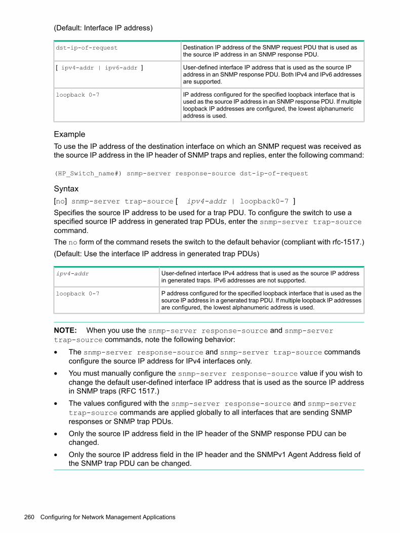
(Default: Interface IP address)
Destination IP address of the SNMP request PDU that is used asthe source IP address in an SNMP response PDU.
dst-ip-of-request
User-defined interface IP address that is used as the source IPaddress in an SNMP response PDU. Both IPv4 and IPv6 addressesare supported.
[ ipv4-addr | ipv6-addr ]
IP address configured for the specified loopback interface that isused as the source IP address in an SNMP response PDU. If multiple
loopback 0-7
loopback IP addresses are configured, the lowest alphanumericaddress is used.
ExampleTo use the IP address of the destination interface on which an SNMP request was received asthe source IP address in the IP header of SNMP traps and replies, enter the following command:
(HP_Switch_name#) snmp-server response-source dst-ip-of-request
Syntax[no] snmp-server trap-source [ ipv4-addr | loopback0-7 ]Specifies the source IP address to be used for a trap PDU. To configure the switch to use aspecified source IP address in generated trap PDUs, enter the snmp-server trap-sourcecommand.The no form of the command resets the switch to the default behavior (compliant with rfc-1517.)(Default: Use the interface IP address in generated trap PDUs)
User-defined interface IPv4 address that is used as the source IP addressin generated traps. IPv6 addresses are not supported.
ipv4-addr
P address configured for the specified loopback interface that is used as thesource IP address in a generated trap PDU. If multiple loopback IP addressesare configured, the lowest alphanumeric address is used.
loopback 0-7
NOTE: When you use the snmp-server response-source and snmp-servertrap-source commands, note the following behavior:
• The snmp-server response-source and snmp-server trap-source commandsconfigure the source IP address for IPv4 interfaces only.
• You must manually configure the snmp-server response-source value if you wish tochange the default user-defined interface IP address that is used as the source IP addressin SNMP traps (RFC 1517.)
• The values configured with the snmp-server response-source and snmp-servertrap-source commands are applied globally to all interfaces that are sending SNMPresponses or SNMP trap PDUs.
• Only the source IP address field in the IP header of the SNMP response PDU can bechanged.
• Only the source IP address field in the IP header and the SNMPv1 Agent Address field ofthe SNMP trap PDU can be changed.
260 Configuring for Network Management Applications

Verify the configuration for SNMP replies and trapsTo verify the configuration of the interface IP address used as the source IP address in IP headersfor SNMP replies and traps sent from the switch, enter the show snmp-server command todisplay the SNMP policy configuration, as shown in Figure 103 (page 261).
Figure 103 Display of source IP address configuration
Viewing SNMP notification configuration
Syntaxshow snmp-server
Displays the currently configured notification settings for versions SNMPv1 andSNMPv2c traps, including SNMP communities, trap receivers, link-change traps,and network security notifications.
ExampleIn the following example, the show snmp-server command output shows that the switch hasbeen configured to send SNMP traps and notifications to management stations that belong tothe "public," "red-team," and "blue-team" communities.
Figure 104 Display of SNMP notification configuration
Assigning users to groupsNext you must set the group access level for the user by assigning the user to a group. This isdone with the snmpv3 group command, as shown in Figure 105 (page 262).
Configuring SNMP 261
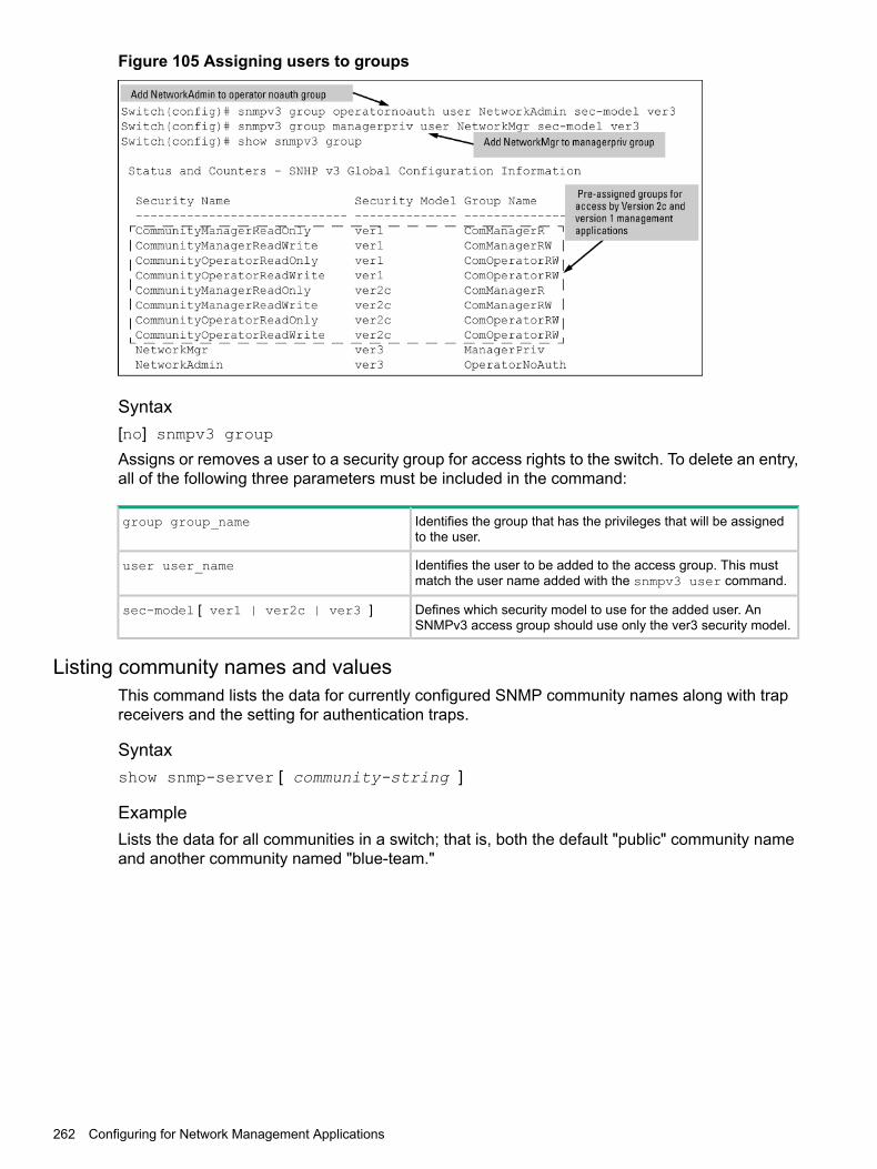
Figure 105 Assigning users to groups
Syntax[no] snmpv3 group
Assigns or removes a user to a security group for access rights to the switch. To delete an entry,all of the following three parameters must be included in the command:
Identifies the group that has the privileges that will be assignedto the user.
group group_name
Identifies the user to be added to the access group. This mustmatch the user name added with the snmpv3 user command.
user user_name
Defines which security model to use for the added user. AnSNMPv3 access group should use only the ver3 security model.
sec-model [ ver1 | ver2c | ver3 ]
Listing community names and valuesThis command lists the data for currently configured SNMP community names along with trapreceivers and the setting for authentication traps.
Syntaxshow snmp-server [ community-string ]
ExampleLists the data for all communities in a switch; that is, both the default "public" community nameand another community named "blue-team."
262 Configuring for Network Management Applications

Figure 106 SNMP community listing with two communities
To list the data for only one community, such as the "public" community, use the above commandwith the community name included. For example:
HP Switch# show snmp-server public
Configuring community names and valuesThe snmp-server command enables you to add SNMP communities with either default orspecific access attributes, and to delete specific communities.
Syntax[no] snmp-server community community-name
Configures a new community name.
• If you do not also specify operator or manager, the switch automatically assigns thecommunity to the operator MIB view.
• If you do not specify restricted or unrestricted, the switch automatically assigns thecommunity to restricted (read-only) access.
The no form uses only the community-name variable and deletes the named communityfrom the switch.
Optionally assigns an access level.[ operator | manager ]
• At the operator level, the community can access all MIB objectsexcept the CONFIG MIB.
• At the manager level, the community can access all MIB objects.
Optionally assigns MIB access type.[ restricted | unrestricted ]
• Assigning the restricted type allows the community to read MIBvariables, but not to set them.
• Assigning the unrestricted type allows the community to read andset MIB variables.
Configuring SNMP 263

ExampleTo add the following communities:
Type of AccessAccess LevelCommunity
unrestricted (read/write)manager (Access to all MIB objects.)red-team
restricted (read-only)operator (Access to all MIB objects except theCONFIG MIB.)
blue-team
(HP_Switch_name#) snmp-server community red-teammanager unrestricted
(HP_Switch_name#) snmp-server community blue-teamoperator restricted
To eliminate a previously configured community named "gold-team":
HP Switch(config) # no snmp-server community gold-team
Enabling or disabling notification/traps for network security failures and other securityevents
Syntax[no]snmp-server enable traps [ snmp-auth | password-change-mgr |login-failure-mgr | port-security | auth-server-fail | dhcp-snooping |arp-protect | running-config-change | [macsec failure]]Enables or disables sending one of the security notification types listed below to configured trapreceivers. (Unless otherwise stated, all of the following notifications are enabled in the defaultconfiguration.)The notification sends a trap:
If ARP packets are received with an invalid source or destinationMAC address, an invalid IP address, or an invalid IP-to-MACbinding.
arp-protect
If the connection with a RADIUS or TACACS+ authenticationserver fails.
auth-server-fail
If DHCP packets are received from an untrusted source or if DHCPpackets contain an invalid IP-to-MAC binding.
dhcp-snooping
If the switch is out of hardware resources needed to program adynamic IP lockdown rule
dyn-ip-lockdown
When the link state on a port changes from up to down, or thereverse.
link-change <PORT-LIST>
For a failed login with a manager password.login-failure-mgr
When a manager password is reset.password-change-mgr
Globally enables the generation of SNMP trap notifications uponMAC address table changes.
mac-notify
For a failed authentication attempt through a web, MAC, or 801.Xauthentication session.
port-security
When changes to the running configuration file are made.running-config-change
For a failed authentication attempt via SNMP.snmp-authentication [ extended |standard ] (Default: extended.)
264 Configuring for Network Management Applications
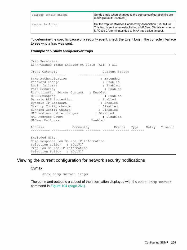
Sends a trap when changes to the startup configuration file aremade.(Default: Disabled.)
Startup-config-change
Set the trap for MACsec Connectivity Association (CA) failure.This trap is sent when establishing a MACsec CA fails or when aMACsec CA terminates due to MKA keep-alive timeout.
macsec failures
To determine the specific cause of a security event, check the Event Log in the console interfaceto see why a trap was sent.
Example 115 Show snmp-server traps
Trap ReceiversLink-Change Traps Enabled on Ports [All] : All
Traps Category Current Status------------------ ----------------SNMP Authentication : ExtendedPassword change : EnabledLogin failures : EnabledPort-Security : EnabledAuthorization Server Contact : EnabledDHCP-Snooping : EnabledDynamic ARP Protection : EnabledDynamic IP Lockdown : EnabledStartup Config change : DisabledRunning Config Change : DisabledMAC address table changes : DisabledMAC Address Count : DisabledMACsec Failures : Enabled
Address Community Events Type Retry Timeout---------- ----------------- -------- ------ ------- -------
Excluded MIBsSnmp Response Pdu Source-IP InformationSelection Policy : rfc1517Trap Pdu Source-IP InformationSelection Policy : rfc1517
Viewing the current configuration for network security notifications
Syntaxshow snmp-server traps
The command output is a subset of the information displayed with the show snmp-servercommand in Figure 104 (page 261).
Configuring SNMP 265

Figure 107 Display of configured network security notifications
Enabling Link-Change TrapsBy default, a switch is enabled to send a trap when the link state on a port changes from up todown (linkDown) or down to up (linkUp.) To reconfigure the switch to send link-change traps toconfigured trap receivers, enter the snmp-server enable traps link-change command.
Syntax[no] snmp-server enable traps link-change<PORT-LIST> [ all ]Enables or disables the switch to send a link-change trap to configured trap receivers when thelink state on a port goes from up to down or down to up.Enter all to enable or disable link-change traps on all ports on the switch.
Configuring listening modeFor more information, See “Configuring listening mode” (page 266).
Syntaxsnmp-server [ listen [ oobm | data | both ] ]Enables or disables inbound SNMP access on a switch.Use the no version of the command to disable inbound SNMP access.The listen parameter is available only on switches that have a separate out-of-bandmanagement port. Values for this parameter are:
Inbound SNMP access is enabled only on the out-of-band managementport.
oobm
Inbound SNMP access is enabled only on the data ports.data
Inbound SNMP access is enabled on both the out-of-band managementport and on the data ports.
both
This is the default value.
266 Configuring for Network Management Applications

The listen parameter is not available on switches that do not have a separate out-of-bandmanagement port.
Configuring CDPConfiguring CDP mode
To set the CDP mode to pass-through or receive only, enter this command.
Syntax[no]cdp moden[pass-through|rxonly]
Sets the selected mode of CDP processing.
Configuring CDPv2 for voice transmissionLegacy Cisco VOIP phones only support manual configuration or using CDPv2 for voice VLANauto-configuration. LLDP-MED is not supported. CDPv2 exchanges information such as softwareversion, device capabilities, and voice VLAN information between directly connected devicessuch as a VOIP phone and a switch.When the Cisco VOIP phone boots up (or sometimes periodically), it queries the switch andadvertises information about itself using CDPv2. The switch receives the VOIP VLAN Query TLV(type 0x0f) from the phone and then immediately sends the voice VLAN ID in a reply packet tothe phone using the VLAN Reply TLV (type 0x0e.) The phone then begins tagging all packetswith the advertised voice VLAN ID.
NOTE: A voice VLAN must be configured before the voice VLAN can be advertised. Forexample, to configure VLAN 10 as a voice VLAN tagged for ports 1 through 10, enter thesecommands:(HP_Switch_name#) vlan 10
HP Switch(vlan-10)# tagged 1-10
HP Switch(vlan-10)# voice
HP Switch(vlan-10)# exit
The switch CDP packet includes these TLVs:• CDP Version: 2
• CDP TTL: 180 seconds
• Checksum
• Capabilities (type 0x04): 0x0008 (is a switch)
• Native VLAN: The PVID of the port
• VOIP VLAN Reply (type 0xe): voice VLAN ID (same as advertised by LLDPMED)
• Trust Bitmap (type 0x12): 0x00
• Untrusted port COS (type 0x13): 0x00CDP should be enabled and running on the interfaces to which the phones are connected. Usethe cdp enable and cdp run commands.The pre-standard-voice option for the cdp mode command allows the configuration of CDPmode so that it responds to received CDP queries from a VoIP phone.
Syntax[no]cdp mode pre-standard-voice [admin-status <PORT-LIST>[tx_rx | rxonly]]
Configuring CDP 267
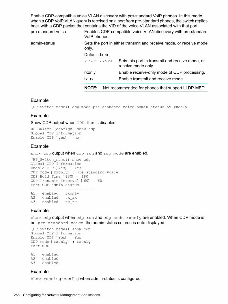
Enable CDP-compatible voice VLAN discovery with pre-standard VoIP phones. In this mode,when a CDP VoIP VLAN query is received on a port from pre-standard phones, the switch repliesback with a CDP packet that contains the VID of the voice VLAN associated with that port.pre-standard-voice Enables CDP-compatible voice VLAN discovery with pre-standard
VoIP phones.admin-status Sets the port in either transmit and receive mode, or receive mode
only.Default: tx-rx.<PORT-LIST> Sets this port in transmit and receive mode, or
receive mode only.rxonly Enable receive-only mode of CDP processing.tx_rx Enable transmit and receive mode.
NOTE: Not recommended for phones that support LLDP-MED.
Example(HP_Switch_name#) cdp mode pre-standard-voice admin-status A5 rxonly
ExampleShow CDP output when CDP Run is disabled.HP Switch (config#) show cdpGlobal CDP informationEnable CDP [yes] : no
Exampleshow cdp output when cdp run and sdp mode are enabled.(HP_Switch_name#) show cdpGlobal CDP InformationEnable CDP [Yes] : YesCDP mode [rxonly] : pre-standard-voiceCDP Hold Time [180] : 180CDP Transmit Interval [60] : 60Port CDP admin-status---- --------- ------------A1 enabled rxonlyA2 enabled tx_rxA3 enabled tx_rx
Exampleshow cdp output when cdp run and cdp mode rxonly are enabled. When CDP mode isnot pre-standard voice, the admin-status column is note displayed.(HP_Switch_name#) show cdpGlobal CDP InformationEnable CDP [Yes} : YesCDP mode [rxonly] : rxonlyPort CDP---- --------A1 enabledA2 enabledA3 enabled
Exampleshow running-config when admin-status is configured.
268 Configuring for Network Management Applications

(HP_Switch_name#) show running-configRunning configuration:; J9477A Configuration Editor; Created on release #K.16.09.0000x; Ver #03:01:1f:ef:f2hostname “HPSwitch”module 1 type J9307Acdp mode pre-standard-voice admin-status A5 RxOnly
Enabling or disabling CDP operation on individual portsIn the factory-default configuration, the switch has all ports enabled to receive CDP packets.Disabling CDP on a port causes it to drop inbound CDP packets without recording their data inthe CDP Neighbors table.
Syntax[no] cdp enable [ [ e ] <PORT-LIST> ]
ExampleTo disable CDP on port A1:
(HP_Switch_name#) no cdp enable a1
Enabling and Disabling CDP OperationEnabling CDP operation (the default) on the switch causes the switch to add entries to its CDPNeighbors table for any CDP packets it receives from other neighboring CDP devices.Disabling CDP operation clears the switch's CDP Neighbors table and causes the switch to dropinbound CDP packets from other devices without entering the data in the CDP Neighbors table.
Syntax[no] cdp run
Enables or disables CDP read-only operation on the switch.(Default: Enabled)
ExampleTo disable CDP read-only on the switch:
(HP_Switch_name#) no cdp run
When CDP is disabled:• show cdp neighbors displays an empty CDP Neighbors table
• show cdp displaysGlobal CDP informationEnable CDP [Yes]: No
Filtering CDP informationIn some environments it is desirable to be able to configure a switch to handle CDP packets byfiltering out the MAC address learns from untagged VLAN traffic from IP phones. This meansthat normal protocol processing occurs for the packets, but the addresses associated with thesepackets is not learned or reported by the software address management components. Thisenhancement also filters out the MAC address learns from LLDP and 802.1x EAPOL packetson untagged VLANs.The feature is configured per-port.
Configuring CDP 269

Viewing the current CDP configuration of the switchCDP is shown as enabled/disabled both globally on the switch and on a per-port basis.
Syntaxshow cdp
Lists the global and per-port CDP configuration of the switch.
Example
Example 116 Show CDP with the default CDP configuration
This example shows the default CDP configuration.(HP_Switch_name#) show cdp
Global CDP information
Enable CDP [Yes] : Yes (Receive Only)
Port CDP---- --------1 enabled2 enabled3 enabled. .. .. .
Viewing the current CDP neighbors table of the switchDevices are listed by the port on which they were detected.
Syntaxshow cdp neighbors
Lists the neighboring CDP devices the switch detects, with a subset of the information collectedfrom the device's CDP packet.
Lists the CDP device connected to the specified port. (Allows onlyone port at a time.)
[ [ e ] port-numb [ detail ] ]
Using detail provides a longer list of details on the CDP devicethe switch detects on the specified port.
Provides a list of the details for all of the CDP devices the switchdetects.
[ detail [ [ e ]port-num ] ]
Using port-num produces a list of details for the selected port.
270 Configuring for Network Management Applications

Example
Example 117 CDP neighbors table listing
This example displays the CDP devices that the switch has detected by receiving their CDPpackets.
(HP_Switch_name#) show cdp neighbors
CDP neighbors information
Port Device ID | Platform Capability---- ----------------------------- + ---------------------------- -----------1 Accounting (0030c1-7fcc40) | J4812A HP Switch. . . S2 Resear¢1-1 (0060b0-889e43) | J4121A HP Switch. . . S4 Support (0060b0_761a45) | J4121A HP Switch. . . S7 Marketing (0030c5_33dc59) | J4313A HP Switch. . . S12 Mgmt NIC(099a05-09df9b | NIC Model X666 H12 Mgmt NIC(099a05-09df11 | NIC Model X666 H
Configuring LLDPLLDP and CDP data management
This section describes points to note regarding LLDP and CDP (Cisco Discovery Protocol) datareceived by the switch from other devices. LLDP operation includes both transmitting LLDPpackets to neighbor devices and reading LLDP packets received from neighbor devices. CDPoperation is limited to reading incoming CDP packets from neighbor devices. ( switches do notgenerate CDP packets.)Incoming CDP and LLDP packets tagged for VLAN 1 are processed even if VLAN 1 does notcontain any ports. VLAN 1 must be present, but it is typically present as the default VLAN for theswitch.
NOTE: The switch may pick up CDP and LLDP multicast packets from VLAN 1 even whenCDP- and /or LLDP-enabled ports are not members of VLAN 1.
LLDP and CDP neighbor dataWith both LLDP and (read-only) CDP enabled on a switch port, the port can read both LLDP andCDP advertisements, and stores the data from both types of advertisements in its neighbordatabase. (The switch stores only CDP data that has a corresponding field in the LLDP neighbordatabase.) The neighbor database itself can be read by either LLDP or CDP methods or by usingthe show lldp commands. Take note of the following rules and conditions:
• If the switch receives both LLDP and CDP advertisements on the same port from the sameneighbor, the switch stores this information as two separate entries if the advertisementshave different chassis ID and port ID information.
• If the chassis and port ID information are the same, the switch stores this information as asingle entry. That is, LLDP data overwrites the corresponding CDP data in the neighbordatabase if the chassis and port ID information in the LLDP and CDP advertisements receivedfrom the same device is the same.
• Data read from a CDP packet does not support some LLDP fields, such as "System Descr,""SystemCapSupported," and "ChassisType." For such fields, LLDP assigns relevant defaultvalues. Also:• The LLDP "System Descr" field maps to CDP's "Version" and "Platform" fields.
• The switch assigns "ChassisType" and "PortType" fields as "local" for both the LLDPand the CDP advertisements it receives.
Configuring LLDP 271

• Both LLDP and CDP support the "System Capability" TLV. However, LLDP differentiatesbetween what a device is capable of supporting and what it is actually supporting, andseparates the two types of information into subelements of the System Capability TLV.CDP has only a single field for this data. Thus, when CDP System Capability data ismapped to LLDP, the same value appears in both LLDP System Capability fields.
• System Name and Port Descr are not communicated by CDP, and thus are not includedin the switch's Neighbors database.
NOTE: Because switches do not generate CDP packets, they are not represented in the CDPdata collected by any neighbor devices running CDP.A switch with CDP disabled forwards the CDP packets it receives from other devices, but doesnot store the CDP information from these packets in its own MIB.
LLDP data transmission/collection and CDP data collection are both enabled in the switch'sdefault configuration. In this state, an SNMP network management application designed todiscover devices running either CDP or LLDP can retrieve neighbor information from the switchregardless of whether LLDP or CDP is used to collect the device-specific information.
Inbound packet forwardingInbound datamanagement
Packet generationProtocol state
No forwarding of inbound CDPpackets.
Store inbound CDPdata.
N/ACDP Enabled1
Floods inbound CDP packetsfrom connected devices tooutbound ports.
No storage of CDPdata from neighbordevices.
N/ACDP Disabled
No forwarding of inboundLLDP packets.
Store inbound LLDPdata.
Generates andtransmits LLDP
LLDP Enabled1
packets out allports on the switch.
No forwarding of inboundLLDP packets.
No storage of LLDPdata from neighbordevices.
No packetgeneration.
LLDP Disabled
1 Both CDP data collection and LLDP transmit/receive are enabled in the default configuration. If a switch receives CDPpackets and LLDP packets from the same neighbor device on the same port, it stores and displays the two types ofinformation separately if the chassis and port ID information in the two types of advertisements is different. In this case,if you want to use only one type of data from a neighbor sending both types, disable the unwanted protocol on eitherthe neighbor device or on the switch. However, if the chassis and port ID information in the two types of advertisementsis the same, the LLDP information overwrites the CDP data for the same neighbor device on the same port.
CDP operationsBy default the switches have CDP enabled on each port. This is a read-only capability, meaningthat the switch can receive and store information about adjacent CDP devices but does notgenerate CDP packets.When a CDP-enabled switch receives a CDP packet from another CDP device, it enters thatdevice's data in the CDP Neighbors table, along with the port number where the data wasreceived—and does not forward the packet. The switch also periodically purges the table of anyentries that have expired. (The hold time for any data entry in the switch's CDP Neighbors tableis configured in the device transmitting the CDP packet and cannot be controlled in the switchreceiving the packet.) A switch reviews the list of CDP neighbor entries every three seconds andpurges any expired entries.
272 Configuring for Network Management Applications
NOTE: For details on how to use an SNMP utility to retrieve information from the switch's CDPNeighbors table maintained in the switch's MIB, see the documentation provided with the particularSNMP utility.
LLDPTo standardize device discovery on all switches, LLDP will be implemented while offering limitedread-only support for CDP, as documented in this manual. For the latest information on yourswitch model, consult the Release Notes (available on the Networking website.) If LLDP has notyet been implemented (or if you are running an older version of software), consult a previousversion of the Management and Configuration Guide for device discovery details.LLDP (Link Layer DiscoveryProtocol)
Provides a standards-based method for enabling theswitches covered in this guide to advertise themselves toadjacent devices and to learn about adjacent LLDPdevices.
LLDP-MED (LLDP Media EndpointDiscovery)
Provides an extension to LLDP and is designed to supportVoIP deployments.
NOTE: LLDP-MED is an extension for LLDP, and the switch requires that LLDP be enabledas a prerequisite to LLDP-MED operation.
An SNMP utility can progressively discover LLDP devices in a network by:1. Reading a given device's Neighbors table (in the Management Information Base, or MIB) to
learn about other, neighboring LLDP devices.2. Using the information learned in step 1 to find and read the neighbor devices' Neighbors
tables to learn about additional devices, and so on.Also, by using show commands to access the switch's neighbor database for information collectedby an individual switch, system administrators can learn about other devices connected to theswitch, including device type (capability) and some configuration information. In VoIP deploymentsusing LLDP-MED on the switches, additional support unique to VoIP applications is also available.See “LLDP-MED” (page 279).
LLDP operationsAn LLDP packet contains data about the transmitting switch and port. The switch advertises itselfto adjacent (neighbor) devices by transmitting LLDP data packets out all ports on which outboundLLDP is enabled and by reading LLDP advertisements from neighbor devices on ports that areinbound LLDP-enabled. (LLDP is a one-way protocol and does not include any acknowledgementmechanism.) An LLDP-enabled port receiving LLDP packets inbound from neighbor devicesstores the packet data in a Neighbor database (MIB.)
LLDP-MEDThis capability is an extension to LLDP and is available on the switches. See “LLDP-MED”(page 279).
Configuring LLDP 273

Packet boundaries in a network topology
• Where multiple LLDP devices are directly connected, an outbound LLDP packet travels onlyto the next LLDP device. An LLDP-capable device does not forward LLDP packets to anyother devices, regardless of whether they are LLDP-enabled.
• An intervening hub or repeater forwards the LLDP packets it receives in the same manneras any other multicast packets it receives. Thus, two LLDP switches joined by a hub orrepeater handle LLDP traffic in the same way that they would if directly connected.
• Any intervening 802.1D device or Layer-3 device that is either LLDP-unaware or has disabledLLDP operation drops the packet.
LLDP operation configuration optionsIn the default configuration, LLDP is enabled and in both transmit and receive mode on all activeports. The LLDP configuration includes global settings, which apply to all active ports on theswitch, and per-port settings, which affect only the operation of the specified ports.The commands in the LLDP sections affect both LLDP and LLDP-MED operation.
Enable or disable LLDP on the switchIn the default configuration, LLDP is globally enabled on the switch. To prevent transmission orreceipt of LLDP traffic, you can disable LLDP operation.
Enabling or disabling LLDP-MEDIn the default configuration for the switches, LLDP-MED is enabled by default which requires thatLLDP is also enabled.
Changing the frequency of LLDP packet transmissions to neighbor devicesOn a global basis, you can increase or decrease the frequency of outbound LLDP advertisements.
Changing the Time-To-Live for LLDP packets sent to neighborsOn a global basis, you can increase or decrease the time that the information in an LLDP packetoutbound from the switch will be maintained in a neighbor LLDP device.
Transmit and receive modeWith LLDP enabled, the switch periodically transmits an LLDP advertisement (packet) out eachactive port enabled for outbound LLDP transmissions and receives LLDP advertisements oneach active port enabled to receive LLDP traffic (Section (page 281).) Per-port configurationoptions include four modes:
• Transmit and receive ( tx_rx): This is the default setting on all ports. It enables a given portto both transmit and receive LLDP packets and to store the data from received (inbound)LLDP packets in the switch's MIB.
• Transmit only ( txonly): This setting enables a port to transmit LLDP packets that can beread by LLDP neighbors. However, the port drops inbound LLDP packets from LLDPneighbors without reading them. This prevents the switch from learning about LLDP neighborson that port.
• Receive only ( rxonly): This setting enables a port to receive and read LLDP packets fromLLDP neighbors and to store the packet data in the switch's MIB. However, the port doesnot transmit outbound LLDP packets. This prevents LLDP neighbors from learning aboutthe switch through that port.
• Disable ( disable): This setting disables LLDP packet transmissions and reception on aport. In this state, the switch does not use the port for either learning about LLDP neighborsor informing LLDP neighbors of its presence.
274 Configuring for Network Management Applications

SNMP notificationYou can enable the switch to send a notification to any configured SNMP trap receiver(s) whenthe switch detects a remote LLDP data change on an LLDP-enabled port (SNMP notificationsupport (page 277).)
Per-port (outbound) data optionsThe following table lists the information the switch can include in the per-port, outbound LLDPpackets it generates. In the default configuration, all outbound LLDP packets include thisinformation in the TLVs transmitted to neighbor devices. However, you can configure LLDPadvertisements on a per-port basis to omit some of this information (Section (page 281).)
Table 20 Data available for basic LLDP advertisements
DescriptionDefaultConfiguration optionsData type
The length of time an LLDPneighbor retains the
120 Seconds1.Time-to-Live
advertised data beforediscarding it.
Indicates the type ofidentifier used for ChassisID.
Always EnabledN/AChassis Type2, 6
Uses base MAC address ofthe switch.
Always EnabledN/AChassis ID6
Uses "Local," meaningassigned locally by LLDP.
Always EnabledN/APort Type3, 6
Uses port number of thephysical port. This is an
Always EnabledN/APort Id6
internal number reflectingthe reserved slot/portposition in the chassis.
Remote Management Address
Shows the network addresstype.
Always EnabledN/AType4, 6
Uses a default address selection method unless anoptional address is configured.
Default or ConfiguredAddress4
Uses the switch's assignedname.
EnabledEnable/DisableSystem Name6
Includes switch model nameand running softwareversion, and ROM version.
EnabledEnable/DisableSystem Description6
Uses the physical portidentifier.
EnabledEnable/DisablePort Description6
Identifies the switch'sprimary capabilities (bridge,router.)
EnabledEnable/DisableSystem capabilitiessupported5, 6
Identifies the primary switchfunctions that are enabled,such as routing.
EnabledEnable/DisableSystem capabilitiesenabled5 6
1 The packet time-to-live value is included in LLDP data packets. (See “Changing the time-to-live for transmittedadvertisements” (page 286).)
2 Subelement of the Chassis ID TLV.6 Populated with data captured internally by the switch. For more on these data types, refer to the IEEE P802.1AB
Standard.
Configuring LLDP 275

3 Subelement of the Port ID TLV.4 Subelement of the Remote-Management-Address TLV.5 Subelement of the System Capability TLV.
Remote management addressThe switch always includes an IP address in its LLDP advertisements. This can be either anaddress selected by a default process or an address configured for inclusion in advertisements.
Debug loggingYou can enable LLDP debug logging to a configured debug destination (Syslog server, a terminaldevice, or both) by executing the debug lldp command. Note that the switch's Event Log doesnot record usual LLDP update messages.
Options for reading LLDP information collected by the switchYou can extract LLDP information from the switch to identify adjacent LLDP devices. Optionsinclude:
• Using the switch's show lldp info command options to display data collected on adjacentLLDP devices—as well as the local data the switch is transmitting to adjacent LLDP devices(“Viewing the global LLDP, port admin, and SNMP notification status” (page 291).)
• Using an SNMP application that is designed to query the Neighbors MIB for LLDP data touse in device discovery and topology mapping.
• Using the walkmib command to display a listing of the LLDP MIB objects
LLDP and LLDP-MED standards compatibilityThe operation covered by this section is compatible with these standards:
• IEEE P802.1AB
• RFC 2922 (PTOPO, or Physical Topology MIB)
• RFC 2737 (Entity MIB)
• RFC 2863 (Interfaces MIB)
• ANSI/TIA-1057/D6 (LLDP-MED; refer to “LLDP-MED” (page 279).)
Port trunkingLLDP manages trunked ports individually. That is, trunked ports are configured individually forLLDP operation, in the same manner as non-trunked ports. Also, LLDP sends separateadvertisements on each port in a trunk, and not on a per-trunk basis. Similarly, LLDP data receivedthrough trunked ports is stored individually, per-port.
IP address advertisementsIn the default operation, if a port belongs to only one static VLAN, the port advertises thelowest-order IP address configured on that VLAN. If a port belongs to multiple VLANs, the portadvertises the lowest-order IP address configured on the VLAN with the lowest VID. If thequalifying VLAN does not have an IP address, the port advertises 127.0.0.1 as its IP address.For example, if the port is a member of the default VLAN (VID=1), and there is an IP addressconfigured for the default VLAN, the port advertises this IP address. In the default operation, theIP address that LLDP uses can be an address acquired by DHCP or Bootp.You can override the default operation by configuring the port to advertise any IP address thatis manually configured on the switch, even if the port does not belong to the VLAN configuredwith the selected IP address (Section (page 281).) (Note that LLDP cannot be configured throughthe CLI to advertise an addresses acquired through DHCP or Bootp. However, as mentioned
276 Configuring for Network Management Applications

above, in the default LLDP configuration, if the lowest-order IP address on the VLAN with thelowest VID for a given port is a DHCP or Bootp address, the switch includes this address in itsLLDP advertisements unless another address is configured for advertisements on that port.)Also, although LLDP allows configuring multiple remote management addresses on a port, onlythe lowest-order address configured on the port will be included in outbound advertisements.Attempting to use the CLI to configure LLDP with an IP address that is either not configured ona VLAN or has been acquired by DHCP or Bootp results in the following error message.
xxx.xxx.xxx.xxx: This IP address is not configured or is a DHCP address.
Spanning-tree blockingSpanning tree does not prevent LLDP packet transmission or receipt on STP-blocked links.
802.1X blockingPorts blocked by 802.1X operation do not allow transmission or receipt of LLDP packets.
LLDP operation on the switchEnabling LLDP operation (the default) causes the switch to:
• Use active, LLDP-enabled ports to transmit LLDP packets describing itself to neighbordevices.
• Add entries to its neighbors table based on data read from incoming LLDP advertisements.
Time-to-Live for transmitted advertisementsThe Time-to-Live value (in seconds) for all LLDP advertisements transmitted from a switch iscontrolled by the switch that generates the advertisement and determines how long an LLDPneighbor retains the advertised data before discarding it. The Time-to-Live value is the result ofmultiplying the refresh-interval by the holdtime-multiplier.
Delay interval between advertisementsThe switch uses a delay-interval setting to delay transmitting successive advertisements resultingfrom these LLDP MIB changes. If a switch is subject to frequent changes to its LLDP MIB,lengthening this interval can reduce the frequency of successive advertisements. You can changethe delay-interval by using either an SNMP network management application or the CLI setmibcommand.
Re-initialize delay intervalIn the default configuration, a port receiving a disable command followed immediately by atxonly, rxonly, or tx_rx command delays re-initializing for two seconds, during which LLDPoperation remains disabled. If an active port is subjected to frequent toggling between the LLDPdisabled and enabled states, LLDP advertisements are more frequently transmitted to the neighbordevice. Also, the neighbor table in the adjacent device changes more frequently as it deletes,then replaces LLDP data for the affected port which, in turn, generates SNMP traps (if trapreceivers and SNMP notification are configured.) All of this can unnecessarily increase networktraffic. Extending the re-initialization-delay interval delays the ability of the port to re-initialize andgenerate LLDP traffic following an LLDP disable/enable cycle.
SNMP notification supportYou can enable SNMP trap notification of LLDP data changes detected on advertisementsreceived from neighbor devices and control the interval between successive notifications of datachanges on the same neighbor.
Configuring LLDP 277

Changing the minimum intervalIf LLDP trap notification is enabled on a port, a rapid succession of changes in LLDP informationreceived in advertisements from one or more neighbors can generate a high number of traps.To reduce this effect, you can globally change the interval between successive notifications ofneighbor data change.
Basic LLDP per-port advertisement contentIn the default LLDP configuration, outbound advertisements from each port on the switch includeboth mandatory and optional data.
Mandatory DataAn active LLDP port on the switch always includes the mandatory data in its outboundadvertisements. LLDP collects the mandatory data, and, except for the Remote ManagementAddress, you cannot use LLDP commands to configure the actual data.
• Chassis Type (TLV subelement)
• Chassis ID (TLV)
• Port Type (TLV subelement)
• Port ID (TLV)
• Remote Management Address (TLV; actual IP address is a subelement that can be a defaultaddress or a configured address)
Optional DataYou can configure an individual port or group of ports to exclude one or more of the followingdata types from outbound LLDP advertisements.
• Port description (TLV)
• System name (TLV)
• System description (TLV)
• System capabilities (TLV)System capabilities Supported (TLV subelement)•
• System capabilities Enabled (TLV subelement)
• Port speed and duplex (TLV subelement)Optional data types, when enabled, are populated with data internal to the switch; that is, youcannot use LLDP commands to configure their actual content.
Support for port speed and duplex advertisementsThis feature is optional for LLDP operation, but is required for LLDP-MED operation.Port speed and duplex advertisements are supported on the switches to inform an LLDP endpointand the switch port of each other's port speed and duplex configuration and capabilities.Configuration mismatches between a switch port and an LLDP endpoint can result in excessivecollisions and voice quality degradation. LLDP enables discovery of such mismatches bysupporting SNMP access to the switch MIB for comparing the current switch port and endpointsettings. (Changing a current device configuration to eliminate a mismatch requires interventionby the system operator.)An SNMP network management application can be used to compare the port speed and duplexdata configured in the switch and advertised by the LLDP endpoint. You can also use the CLI todisplay this information.
278 Configuring for Network Management Applications
Port VLAN ID TLV support on LLDPThe port-vlan-id option enables advertisement of the port VLAN ID TLV as part of the regularlyadvertised TLVs. This allows discovery of a mismatch in the configured native VLAN ID betweenLLDP peers. The information is visible using show commands and is logged to the Syslog server.
SNMP supportThe LLDP-EXT-DOT1-MIB has the corresponding MIB variables for the Port VLAN ID TLV. TheTLV advertisement can be enabled or disabled using the MIB objectlldpXdot1ConfigPortVlanTxEnable in the lldpXdot1ConfigPortVlanTable.The port VLAN ID TLV local information can be obtained from the MIB objectlldpXdot1LocPortVlanId in the local information table lldpXdot1LocTable.The port VLAN ID TLV information about all the connected peer devices can be obtained fromthe MIB object lldpXdot1RemPortVlanId in the remote information tablelldpXdot1RemTable.
LLDP-MEDLLDP-MED (ANSI/TIA-1057/D6) extends the LLDP (IEEE 802.1AB) industry standard to supportadvanced features on the network edge for Voice Over IP (VoIP) endpoint devices with specializedcapabilities and LLDP-MED standards-based functionality. LLDP-MED in the switches uses thestandard LLDP commands described earlier in this section, with some extensions, and alsointroduces new commands unique to LLDP-MED operation. The show commands describedelsewhere in this section are applicable to both LLDP and LLDP-MED operation. LLDP-MEDbenefits include:
• Plug-and-play provisioning for MED-capable, VoIP endpoint devices
• Simplified, vendor-independent management enabling different IP telephony systems tointeroperate on one network
• Automatic deployment of convergence network policies (voice VLANs, Layer 2/CoS priority,and Layer 3/QoS priority)
• Configurable endpoint location data to support the Emergency Call Service (ECS) (such asEnhanced 911 service, 999, 112)
• Detailed VoIP endpoint data inventory readable via SNMP from the switch
• Power over Ethernet (PoE) status and troubleshooting support via SNMP
• support for IP telephony network troubleshooting of call quality issues via SNMPThis section describes how to configure and use LLDP-MED features in the switches to supportVoIP network edge devices (media endpoint devices) such as:
• IP phones
• Voice/media gateways
• Media servers
• IP communications controllers
• Other VoIP devices or serversLLDP-MED interoperates with directly connected IP telephony (endpoint) clients having thesefeatures and services:
• Auto-negotiate speed and duplex configuration with the switch
• Use the following network policy elements configured on the client port
• Voice VLAN ID
Configuring LLDP 279

• 802.1p (Layer 2) QoS
• Diffserv codepoint (DSCP) (Layer 3) QoS
• Discover and advertise device location data learned from the switch
• Support ECS (such as E911, 999, and 112)
• Advertise device information for the device data inventory collected by the switch, including:
• Asset ID•• Serial numberHardware revision
• •Firmware revision Manufacturer name
•• Model nameSoftware revision
• Provide information on network connectivity capabilities (for example, a multi-port VoIPphone with Layer 2 switch capability)
• Support the fast-start capability
NOTE: LLDP-MED is intended for use with VoIP endpoints and is not designed to supportlinks between network infrastructure devices, such as switch-to-switch or switch-to-router links.
Figure 108 Example of LLDP-MED network elements
LLDP-MED classesLLDP-MED endpoint devices are, by definition, located at the network edge and communicateusing the LLDP-MED framework. Any LLDP-MED endpoint device belongs to one of the followingthree classes:
• Class 1 (generic endpoint devices): These devices offer the basic LLDP discovery services,network policy advertisement (VLAN ID, Layer 2/802.1p priority, and Layer 3/DSCP priority),and PoE management. This class includes such devices as IP call controllers andcommunication-related servers.
• Class 2 (media endpoint devices): These devices offer all Class 1 features plusmedia-streaming capability, and include such devices as voice/media gateways, conferencebridges, and media servers.
• Class 3 (communication devices): These devices are typically IP phones or end-user devicesthat otherwise support IP media and offer all Class 1 and Class 2 features, plus locationidentification and emergency 911 capability, Layer 2 switch support, and device informationmanagement.
280 Configuring for Network Management Applications

LLDP-MED operational supportThe switches offer two configurable TLVs supporting MED-specific capabilities:
• medTlvEnable (for per-port enabling or disabling of LLDP-MED operation)
• medPortLocation (for configuring per-port location or emergency call data)
NOTE: LLDP-MED operation also requires the port speed and duplex TLV (dot3TlvEnable;page 14-41), which is enabled in the default configuration.Topology change notifications provide one method for monitoring system activity. However,because SNMP normally employs UDP, which does not guarantee datagram delivery, topologychange notification should not be relied upon as the sole method for monitoring critical endpointdevice connectivity.
Configuring per-port transmit and receive modes
Syntaxlldp admin-status <PORT-LIST> txonly | rxonly | tx_rx | disable
With LLDP enabled on the switch in the default configuration, each port is configured to transmitand receive LLDP packets. These options enable you to control which ports participate in LLDPtraffic and whether the participating ports allow LLDP traffic in only one direction or in bothdirections.
Configures the specified ports to transmit LLDP packets, but blockinbound LLDP packets from neighbor devices.
txonly
Configures the specified ports to receive LLDP packets from neighbors,but block outbound packets to neighbors.
rxonly
Configures the specified ports to both transmit and receive LLDPpackets. (This is the default setting.)
tx_rx
Disables LLDP packet transmit and receive on the specified ports.disable
Configuring a remote management address for outbound LLDP advertisementsThis is an optional command you can use to include a specific IP address in the outbound LLDPadvertisements for specific ports.
Syntax[no] lldp config <PORT-LIST> ipAddrEnable ip-address
Replaces the default IP address for the port with an IP address you specify. This can be any IPaddress configured in a static VLAN on the switch, even if the port does not belong to the VLANconfigured with the selected IP address.The no form of the command deletes the specified IP address.If there are no IP addresses configured as management addresses, the IP address selectionmethod returns to the default operation.Default: The port advertises the IP address of the lowest-numbered VLAN (VID) to which itbelongs. If there is no IP address configured on the VLANs to which the port belongs, and if theport is not configured to advertise an IP address from any other (static) VLAN on the switch, theport advertises an address of 127.0.0.1.)
NOTE: This command does not accept either IP addresses acquired through DHCP or Bootp,or IP addresses that are not configured in a static VLAN on the switch.
Configuring LLDP 281

ExampleIf port 3 belongs to a subnetted VLAN that includes an IP address of 10.10.10.100 and you wantport 3 to use this secondary address in LLDP advertisements, you need to execute the followingcommand:
(HP_Switch_name#) lldp config 3 ipAddrEnable 10.10.10.100
Syntax[no] lldp config <PORT-LIST> basicTlvEnable TLV-Type
For outbound LLDP advertisements, this TLV includes an alphanumericstring describing the port.
port_descr
(Default: Enabled)
For outbound LLDP advertisements, this TLV includes an alphanumericstring showing the assigned name of the system.
system_name
(Default: Enabled)
For outbound LLDP advertisements, this TLV includes an alphanumericstring describing the full name and version identification for the
system_descr
hardware type, software version, and networking application of thesystem.(Default: Enabled)
For outbound advertisements, this TLV includes a bitmask of supportedsystem capabilities (device functions.) Also includes information onwhether the capabilities are enabled.
system_cap
(Default: Enabled)
ExampleIf you want to exclude the system name TLV from the outbound LLDP advertisements for allports on a switch, use this command:
(HP_Switch_name#) no lldp config 1-24 basicTlvEnable system_name
If you later decide to reinstate the system name TLV on ports 1-5, use this command:
(HP_Switch_name#) lldp config 1-5 basicTlvEnable system_name
Configuring support for port speed and duplex advertisements
Syntax[no] lldp config <PORT-LIST> dot3TlvEnable macphy_config
For outbound advertisements, this TLV includes the (local) switch port's current speed and duplexsettings, the range of speed and duplex settings the port supports, and the method required forreconfiguring the speed and duplex settings on the device (autonegotiation during link initialization,or manual configuration.)Using SNMP to compare local and remote information can help in locating configurationmismatches.(Default: Enabled)
NOTE: For LLDP operation, this TLV is optional. For LLDP-MED operation, this TLV ismandatory.
282 Configuring for Network Management Applications

Configuring location data for LLDP-MED devices
Syntax[no] lldp config <PORT-LIST> medPortLocation Address-Type
Configures location of emergency call data the switch advertises per port in the location_idTLV. This TLV is for use by LLDP-MED endpoints employing location-based applications.
NOTE: The switch allows one medPortLocation entry per port (without regard to type.)Configuring a new medPortLocation entry of any type on a port replaces any previously configuredentry on that port.
civic-addr COUNTRY-STR WHAT CA-TYPE CA-VALUE … [ CA-TYPECA-VALUE ]… [ CA-TYPE CA-VALUE ]Enables configuration of a physical address on a switch port and allows up to 75 characters ofaddress information.
A two-character country code, as defined by ISO 3166. Some examplesinclude FR (France), DE (Germany), and IN (India.) This field is required
COUNTRY-STR
in a civic-addr command. (For a complete list of country codes, visithttp://www.iso.org.)
A single-digit number specifying the type of device to which the locationdata applies:
0: Location of DHCP server
WHAT
1: Location of switch2: Location of LLDP-MED endpoint (recommendedapplication)
This field is required in a civic-addr command.
Configuring LLDP 283

A series of data pairs, each composed of a location data "type" specifierand the corresponding location data for that type. That is, the first value
Type/Value Pairs[CA-TYPE|CA-VALUE]
in a pair is expected to be the civic address "type" number (CA-TYPE),and the second value in a pair is expected to be the corresponding civicaddress data (CA-VALUE.)For example, if the CA-TYPE for "city name" is "3," the type/value pair todefine the city of Paris is "3 Paris."Multiple type/value pairs can be entered in any order, although HewlettPackard Enterprise recommends that multiple pairs be entered inascending order of the CA-TYPE.When an emergency call is placed from a properly configured class 3endpoint device to an appropriate PSAP, the country code, device type,and type/value pairs configured on the switch port are included in thetransmission. The "type" specifiers are used by the PSAP to identify andorganize the location data components in an understandable format forresponse personnel to interpret.A civic-addr command requires a minimum of one type/value pair, buttypically includes multiple type/value pairs as needed to configure acomplete set of data describing a given location.CA-TYPE: This is the first entry in a type/value pair and is a numberdefining the type of data contained in the second entry in the type/valuepair (CA-VALUE.) Some examples of CA-TYPE specifiers include:
• 3=city
• 6=street (name)
• 25=building name
(Range: 0 - 255)CA-VALUE: This is the second entry in a type/value pair and is analphanumeric string containing the location information corresponding tothe immediately preceding CA-TYPE entry.Strings are delimited by either blank spaces, single quotes (' … '), or doublequotes ("… ".)Each string should represent a specific data type in a set of uniquetype/value pairs comprising the description of a location, and each stringmust be preceded by a CA-TYPE number identifying the type of data inthe string.
NOTE: A switch port allows one instance of any given CA-TYPE. Forexample, if a type/value pair of 6 Atlantic (to specify "Atlantic" as a streetname) is configured on port A5 and later another type/value pair of 6 Pacificis configured on the same port, Pacific replaces Atlantic in the civic addresslocation configured for port A5.
This feature is intended for use in ECS applications to support class 3LLDP-MED VoIP telephones connected to a switch in an MLTSinfrastructure.
elin-addr emergency-number
An ELIN is a valid NANP format telephone number assigned to MLTSoperators in North America by the appropriate authority. The ELIN is usedto route emergency (E911) calls to a PSAP.(Range: 1-15 numeric characters)
Enabling LLDP data change notification for SNMP trap receivers
Syntax[no] lldp enable-notification <PORT-LIST>
Enables or disables each port in <PORT-LIST> for sending notification to configured SNMPtrap receivers if an LLDP data change is detected in an advertisement received on the port froman LLDP neighbor.
284 Configuring for Network Management Applications

(Default: Disabled)
ExampleThis command enables SNMP notification on ports 1 - 5:
(HP_Switch_name#) lldp enable-notification 1-5
Enabling or disabling LLDP operation on the switch
Syntax[no] lldp run
Enables or disables LLDP operation on the switch.The no form of the command, regardless of individual LLDP port configurations, prevents theswitch from transmitting outbound LLDP advertisements and causes the switch to drop all LLDPadvertisements received from other devices.The switch preserves the current LLDP configuration when LLDP is disabled. After LLDP isdisabled, the information in the LLDP neighbors database remains until it times-out.(Default: Enabled)
ExampleTo disable LLDP on the switch:
(HP_Switch_name#) no lldp run
LLDP-MED fast start control
Syntaxlldp fast-start-count 1 - 10
An LLDP-MED device connecting to a switch port may use the data contained in the MED TLVsfrom the switch to configure itself. However, the lldp refresh-interval setting (default: 30seconds) for transmitting advertisements can cause an unacceptable delay in MED deviceconfiguration.To support rapid LLDP-MED device configuration, the lldp fast-start-count commandtemporarily overrides the refresh-interval setting for the fast-start-count advertisementinterval. This results in the port initially advertising LLDP-MED at a faster rate for a limited time.Thus, when the switch detects a new LLDP-MED device on a port, it transmits one LLDP-MEDadvertisement per second out the port for the duration of the fast-start-count interval. Inmost cases, the default setting should provide an adequate fast-start-count interval.(Default: 5 seconds)
NOTE: This global command applies only to ports on which a new LLDP-MED device isdetected. It does not override the refresh-interval setting on ports where non-MED devicesare detected.
Changing the packet transmission intervalThis interval controls how often active ports retransmit advertisements to their neighbors.
Syntaxlldp refresh-interval <5 - 32768>
Configuring LLDP 285

Changes the interval between consecutive transmissions of LLDP advertisements on any givenport.(Default: 30 seconds)
NOTE: The refresh-interval must be greater than or equal to (4 x delay-interval.)(The default delay-interval is 2.) For example, with the default delay-interval, the lowestrefresh-intervalyou can use is 8 seconds (4 x 2=8.) Thus, if you want a refresh-intervalof 5 seconds, you must first change the delay interval to 1 (that is, 4 x 1 5.) If you want to changethe delay-interval, use the setmib command.
Changing the time-to-live for transmitted advertisements
Syntaxlldp holdtime-multiplier 2 - 10
Changes the multiplier an LLDP switch uses to calculate the Time-to-Live for the LLDPadvertisements it generates and transmits to LLDP neighbors. When the Time-to-Live for a givenadvertisement expires, the advertised data is deleted from the neighbor switch's MIB.(Default: 4; Range 2–10)
ExampleIf the refresh-interval on the switch is 15 seconds and the holdtime-multiplier is at thedefault, the Time-to-Live for advertisements transmitted from the switch is 60 seconds (4 x 15.)To reduce the Time-to-Live, you could lower the holdtime-interval to 2, which would resultin a Time-to-Live of 30 seconds.
(HP_Switch_name#) lldp holdtime-multiplier 2
Changing the delay intervalTo change the delay interval between advertisements generated by value or status changes tothe LLDP MIB, use the following command.
Syntaxsetmib lldpTxDelay.0 -i 1 - 8192
Uses setmib to change the minimum time (delay-interval) any LLDP port will delay advertisingsuccessive LLDP advertisements because of a change in LLDP MIB content.(Default: 2; Range 1–8192)
NOTE: The LLDP refresh-interval (transmit interval) must be greater than or equal to (4 xdelay-interval.) The switch does not allow increasing the delay interval to a value that conflictswith this relationship. That is, the switch displays Inconsistent value if (4 x delay-interval)exceeds the current transmit interval, and the command fails. Depending on the currentrefresh-interval setting, it may be necessary to increase the refresh-interval before using thiscommand to increase the delay-interval.
NOTE: For the 5400zl, and 3800 switches, when the switch is in enhanced secure mode, thefollowing prompt appears before the sensitive information for the setmib command is displayed:The setmib command should not be used in enhanced secure mode.
For more information, see the access security guide.
286 Configuring for Network Management Applications

ExampleTo change the delay-interval from 2 seconds to 8 seconds when the refresh-interval is at thedefault 30 seconds, you must first set the refresh-interval to a minimum of 32 seconds (32 = 4 x8.) (See Figure 109 (page 287).)
Figure 109 Changing the transmit-delay interval
Changing the reinitialization delay interval
Syntaxsetmib lldpReinitDelay.0 -i <1-10>
Uses setmib to change the minimum time (reinitialization delay interval) an LLDP port will waitbefore reinitializing after receiving an LLDP disable command followed closely by a txonly ortx_rx command. The delay interval commences with execution of the lldp admin-status<PORT-LIST> disable command.(Default: 2 seconds; Range 1–10 seconds)
ExampleThe following command changes the reinitialization delay interval to five seconds:
(HP_Switch_name#) setmib lldpreinitdelay.0 -i 5
Filtering PVID mismatch log messagesThis enhancement filters out PVID mismatch log messages on a per-port basis. PVID mismatchesare logged when there is a difference in the PVID advertised by a neighboring switch and thePVID of the switch port which receives the LLDP advertisement. Logging is an LLDP feature thatallows detection of possible vlan leakage between adjacent switches. However, if these eventsare logged too frequently, they can overwhelm the log buffer and push relevant logging data outof log memory, making it difficult to troubleshoot another issue.Logging is disabled and enabled with the support of CLI commands.This enhancement also includes displaying the Mac-Address in the PVID mismatch log messagewhen the port ID is Mac-Address instead of displaying garbage characters in the peer deviceport ID field.Use the following command to disable the logging of the PVID mismatch log messages:
Syntaxlogging filter [<filter-name><sub filter id>] <regularexpression> denyRegular-expression The regular expression should match the message which is to be
filtered.
Configuring LLDP 287
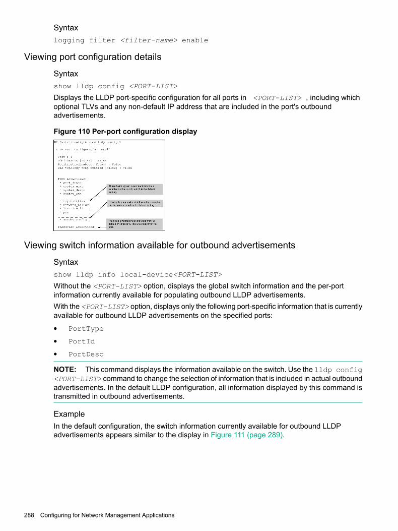
Syntaxlogging filter <filter-name> enable
Viewing port configuration details
Syntaxshow lldp config <PORT-LIST>
Displays the LLDP port-specific configuration for all ports in <PORT-LIST> , including whichoptional TLVs and any non-default IP address that are included in the port's outboundadvertisements.
Figure 110 Per-port configuration display
Viewing switch information available for outbound advertisements
Syntaxshow lldp info local-device<PORT-LIST>
Without the <PORT-LIST> option, displays the global switch information and the per-portinformation currently available for populating outbound LLDP advertisements.With the <PORT-LIST> option, displays only the following port-specific information that is currentlyavailable for outbound LLDP advertisements on the specified ports:
• PortType
• PortId
• PortDesc
NOTE: This command displays the information available on the switch. Use the lldp config<PORT-LIST> command to change the selection of information that is included in actual outboundadvertisements. In the default LLDP configuration, all information displayed by this command istransmitted in outbound advertisements.
ExampleIn the default configuration, the switch information currently available for outbound LLDPadvertisements appears similar to the display in Figure 111 (page 289).
288 Configuring for Network Management Applications

Figure 111 Displaying the global and per-port information available for outboundadvertisements
Example 118 Default per-port information content for ports 1 and 2
(HP_Switch_name#) show lldp info local 1-2
LLDP Local Port Information Detail
Port : 1PortType : localPortId : 1PortDesc : 1
----------------------------------------Port : 2PortType : localPortId : 2PortDesc : 2
Viewing LLDP statistics
Syntaxshow lldp stats<PORT-LIST>
The global LLDP statistics command displays an overview of neighbor detection activity on theswitch, plus data on the number of frames sent, received, and discarded per-port.The per-port LLDP statistics command enhances the list of per-port statistics provided by theglobal statistics command with some additional per-port LLDP statistics.Global LLDP Counters:
The elapsed time since a neighbor was last added or deleted.Neighbor Entries List Last Updated
The total of new LLDP neighbors detected since the last switchreboot. Disconnecting, and then reconnecting a neighborincrements this counter.
New Neighbor Entries Count
Configuring LLDP 289

The number of neighbor deletions from the MIB for AgeOut Countand forced drops for all ports.
Neighbor Entries Deleted Count
For example, if the admin status for port on a neighbor devicechanges from tx_rx or txonly to disabled or rxonly, theneighbor device sends a "shutdown" packet out the port andceases transmitting LLDP frames out that port.The device receiving the shutdown packet deletes all informationabout the neighbor received on the applicable inbound port andincrements the counter.
The number of valid LLDP neighbors the switch detected, butcould not add.
Neighbor Entries Dropped Count
This can occur, for example, when a new neighbor is detectedwhen the switch is already supporting the maximum number ofneighbors. See “Neighbor maximum” (page 301).
The number of LLDP neighbors dropped on all ports because ofTime-to-Live expiring.
Neighbor Entries AgeOut Count
Per-Port LLDP Counters:
The total number of valid, inbound LLDP advertisementsreceived from any neighbors on <PORT-LIST>.
NumFramesRecvd
Where multiple neighbors are connected to a port througha hub, this value is the total number of LLDPadvertisements received from all sources.
The total number of LLDP advertisements sent from<PORT-LIST>.
NumFramesSent
The total number of inbound LLDP advertisementsdiscarded by <PORT-LIST>.
NumFramesDiscarded
This can occur, for example, when a new neighbor isdetected on the port, but the switch is already supportingthe maximum number of neighbors. See “Neighbormaximum” (page 301). This can also be an indication ofadvertisement formatting problems in the neighbor device.
The total number of invalid LLDP advertisements receivedon the port.
Frames Invalid
An invalid advertisement can be caused by headerformatting problems in the neighbor device.
The total number of LLDP TLVs received on a port witha type value in the reserved range.
TLVs Unrecognized
This can be caused by a basic management TLV from alater LLDP version than the one currently running on theswitch.
The total number of LLDP TLVs discarded for any reason.In this case, the advertisement carrying the TLV may beaccepted, but the individual TLV is not usable.
TLVs Discarded
The number of LLDP neighbors dropped on the portbecause of Time-to-Live expiring.
Neighbor Ageouts
290 Configuring for Network Management Applications

Examples
Example 119 A global LLDP statistics display
(HP_Switch_name#) show lldp stats
LLDP Device Statistics
Neighbor Entries List Last Updated : 2 hoursNew Neighbor Entries Count : 20Neighbor Entries Deleted Count : 20Neighbor Entries Dropped Count : 0Neighbor Entries AgeOut Count : 20
LLDP Port Statistics
Port | NumFramesRecvd NumFramesSent NumFramesDiscarded------ + -------------- ------------- ------------------A1 | 97317 97843 0A2 | 21 12 0A3 | 0 0 0A4 | 446 252 0A5 | 0 0 0A6 | 0 0 0A7 | 0 0 0A8 | 0 0 0
Example 120 A per-port LLDP statistics display
(HP_Switch_name#) show lldp stats 1
LLDP Port Statistics Detail
PortName : 1Frames Discarded : 0Frames Invalid : 0Frames Received : 7309Frames Sent : 7231TLVs Unrecognized : 0TLVs Discarded : 0Neighbor Ageouts : 0
Viewing the global LLDP, port admin, and SNMP notification statusIn the default configuration, LLDP is enabled and in both transmit and receive mode on all activeports. The LLDP configuration includes global settings that apply to all active ports on the switch,and per-port settings that affect only the operation of the specified ports.The commands in this section affect both LLDP and LLDP-MED operation.
Syntaxshow lldp config
Displays the LLDP global configuration, LLDP port status, and SNMP notification status.
Example of viewing the general LLDP configurationshow lldp config produces the following display when the switch is in the default LLDPconfiguration:(HP_Switch_name#) show lldp config
LLDP Global Configuration
Configuring LLDP 291
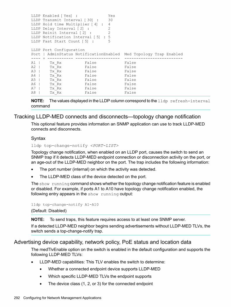
LLDP Enabled [Yes] : YesLLDP Transmit Interval [30] : 30LLDP Hold time Multiplier [4] : 4LLDP Delay Interval [2] : 2LLDP Reinit Interval [2] : 2LLDP Notification Interval [5] : 5LLDP Fast Start Count [5] : 5
LLDP Port ConfigurationPort | AdminStatus NotificationEnabled Med Topology Trap Enabled---- + ----------- ------------------- -------------------------A1 | Tx_Rx False FalseA2 | Tx_Rx False FalseA3 | Tx_Rx False FalseA4 | Tx_Rx False FalseA5 | Tx_Rx False FalseA6 | Tx_Rx False FalseA7 | Tx_Rx False FalseA8 | Tx_Rx False False
NOTE: The values displayed in the LLDP column correspond to the lldp refresh-intervalcommand
Tracking LLDP-MED connects and disconnects—topology change notificationThis optional feature provides information an SNMP application can use to track LLDP-MEDconnects and disconnects.
Syntaxlldp top-change-notify <PORT-LIST>
Topology change notification, when enabled on an LLDP port, causes the switch to send anSNMP trap if it detects LLDP-MED endpoint connection or disconnection activity on the port, oran age-out of the LLDP-MED neighbor on the port. The trap includes the following information:• The port number (internal) on which the activity was detected.
• The LLDP-MED class of the device detected on the port.The show running command shows whether the topology change notification feature is enabledor disabled. For example, if ports A1 to A10 have topology change notification enabled, thefollowing entry appears in the show running output:
lldp top-change-notify A1-A10
(Default: Disabled)
NOTE: To send traps, this feature requires access to at least one SNMP server.If a detected LLDP-MED neighbor begins sending advertisements without LLDP-MED TLVs, theswitch sends a top-change-notify trap.
Advertising device capability, network policy, PoE status and location dataThe medTlvEnable option on the switch is enabled in the default configuration and supports thefollowing LLDP-MED TLVs:
• LLDP-MED capabilities: This TLV enables the switch to determine:Whether a connected endpoint device supports LLDP-MED•
• Which specific LLDP-MED TLVs the endpoint supports
• The device class (1, 2, or 3) for the connected endpoint
292 Configuring for Network Management Applications

This TLV also enables an LLDP-MED endpoint to discover what LLDP-MED TLVs the switchport currently supports.
• Network policy operating on the port to which the endpoint is connected (VLAN, Layer 2QoS, Layer 3 QoS.)
• PoE (MED Power-over-Ethernet.)
• Physical location data.
NOTE: LLDP-MED operation requires the macphy_config TLV subelement (enabled by default)that is optional for IEEE 802.1AB LLDP operation. For more information, see the dot3TlvEnablemacphy_config command.
Network policy advertisementsNetwork policy advertisements are intended for real-time voice and video applications, and includethese TLV subelements:
• Layer 2 (802.1p) QoS
• Layer 3 DSCP (diffserv code point) QoS
• Voice VLAN ID (VID)
VLAN operating rulesThese rules affect advertisements of VLANs in network policy TLVs:
• The VLAN ID TLV subelement applies only to a VLAN configured for voice operation ( vlanvid voice.)
• If there are multiple voice VLANs configured on a port, LLDP-MED advertises the voiceVLAN having the lowest VID.
• The voice VLAN port membership configured on the switch can be tagged or untagged.However, if the LLDP-MED endpoint expects a tagged membership when the switch port isconfigured for untagged, or the reverse, a configuration mismatch results. (Typically, theendpoint expects the switch port to have a tagged voice VLAN membership.)
• If a given port does not belong to a voice VLAN, the switch does not advertise the VLAN IDTLV through this port.
Policy elementsThese policy elements may be statically configured on the switch or dynamically imposed duringan authenticated session on the switch using a RADIUS server and 802.1X or MAC authentication.(Web authentication does not apply to VoIP telephones and other telecommunications devicesthat are not capable of accessing the switch through a Web browser.) The QoS and voice VLANpolicy elements can be statically configured with the following CLI commands:
vlan vid voice
vlan vid tagged | untagged<PORT-LIST>
int <PORT-LIST> qos priority 0 - 7
vlan vid qos dscp codepoint
Configuring LLDP 293

NOTE: A codepoint must have an 802.1p priority before you can configure it for use in prioritizingpackets by VLAN-ID. If a codepoint you want to use shows No Override in the Prioritycolumn of the DSCP policy table (display with show qos-dscp map, then use qos-dscp mapcodepoint priority 0 - 7 to configure a priority before proceeding.For more information on this topic, see the advanced traffic management guide.
PoE advertisementsThese advertisements inform an LLDP-MED endpoint of the power (PoE) configuration on switchports. Similar advertisements from an LLDP-MED endpoint inform the switch of the endpoint'spower needs and provide information that can be used to identify power priority mismatches.PoE TLVs include the following power data:Power type Indicates whether the device is a power-sourcing entity (PSE) or a PD.
Ports on the J8702A PoE zl module are PSE devices. A MED-capableVoIP telephone is a PD.
Power source Indicates the source of power in use by the device. Power sources forPDs include PSE, local (internal), and PSE/local. The switches advertiseunknown.
Power priority Indicates the power priority configured on the switch (PSE) port or thepower priority configured on the MED-capable endpoint.
Power value Indicates the total power in watts that a switch port (PSE) can deliver ata particular time, or the total power in watts that the MED endpoint (PD)requires to operate.
Location data for LLDP-MED devicesYou can configure a switch port to advertise location data for the switch itself, the physical wall-jacklocation of the endpoint (recommended), or the location of a DHCP server supporting the switch,endpoint, or both. You also have the option of configuring these different address types:Civic address Physical address data such as city, street number, and
building information.ELIN (Emergency LocationIdentification Number)
An emergency number typically assigned to MLTS(Multiline Telephone System) Operators in North America.
Coordinate-based location Attitude, longitude, and altitude information (Requiresconfiguration via an SNMP application.)
Configuring coordinate-based locationsLatitude, longitude, and altitude data can be configured per switch port using an SNMPmanagement application. For more information, see the documentation provided with theapplication. A further source of information on this topic is the RFC 3825: Dynamic HostConfiguration Protocol Option for Coordinate-based Location Configuration Information.
NOTE: Endpoint use of data from a medPortLocation TLV sent by the switch isdevice-dependent. See the documentation provided with the endpoint device.
The code assignments in the following table are examples from a work-in-progress (the internetdraft titled "Dynamic Host Configuration Protocol (DHCPv4 and DHCPv6) Option for CivicAddresses Configuration Information draft-ietf-geopriv-dhcp-civil-06" dated May 30, 2005.) Forthe actual codes to use, contact the PSAP or other authority responsible for specifying the civicaddressing data standard for your network.
294 Configuring for Network Management Applications

Table 21 Some location codes used in CA-TYPE fields
CodeLocation elementCodeLocation element
19street number1national subdivision
22additional location data2regional subdivision
26unit or apartment3city or township
27floor4city subdivision
28room number6street
18street suffix
ExampleSuppose a system operator wants to configure the following information as the civic address fora telephone connected to her company's network through port A2 of a switch at the followinglocation:
CA-VALUECA-typeDescription
CA1national subdivision
Widgitville3city
Main6street
143319street number
Suite 4-N26unit
427floor
N4-328room number
Example 121 (page 296) shows the commands for configuring and displaying the above data.
Configuring LLDP 295

Example 121 Example of a civic address configuration
(HP_Switch_name#) lldp config 2 medportlocation civic-addr US 2 1 CA 3Widgitville 6 Main 19 1433 26 Suite_4—N 27 4 28 N4—3
(HP_Switch_name#) show lldp config 2LLDP Port Configuration DetailPort : A2AdminStatus [Tx_Rx] : Tx_RxNotificationEnabled [False] : FalseMed Topology Trap Enabled [False] : FalseCountry Name : USWhat : 2Ca-Type : 1Ca-Length : 2Ca-Value : CACa-Type : 3Ca-Length : 11Ca-Value : WidgitvilleCa-Type : 6Ca-Length : 4Ca-Value : MainCa-Type : 19Ca-Length : 4Ca-Value : 1433Ca-Type : 26Ca-Length : 9Ca-Value : Suite_4-NCa-Type : 27Ca-Length : 1Ca-Value : 4Ca-Type : 28Ca-Length : 4Ca-Value : N4-3
Viewing the current port speed and duplex configurationYou can compare port speed and duplex information for a switch port and a connected LLDP-MEDendpoint for configuration mismatches by using an SNMP application. You can also use theswitch CLI to display this information, if necessary. The show interfaces brief<PORT-LIST> and show lldp info remote-device<PORT-LIST> commands providemethods for displaying speed and duplex information for switch ports. For information on displayingthe currently configured port speed and duplex on an LLDP-MED endpoint.
Viewing LLDP statisticsLLDP statistics are available on both a global and a per-port levels. Rebooting the switch resetsthe LLDP statistics counters to zero. Disabling the transmit and/or receive capability on a port"freezes" the related port counters at their current values.
LLDP over OOBMBeginning with switch software release 16.01, LLDP over OOBM is supported on the followingswitch models covered in this guide:• 3800 (KA software)
• 3810 (KB software)
• 5400R (KB software)The following commands enable the user to configure LLDP for OOBM ports.
296 Configuring for Network Management Applications

LLDP over OOBM commands
lldp admin-status oobmThis command sets the OOBM port operational mode.
Syntaxlldp admin-status oobm [ txonly | rxonly | tx_rx | disable ]
Parameters/Optionstxonly
Sets in transmit only mode.rxonly
Sets in receive mode.tx_rx
Sets in transmit and receive mode.disable
Disables lldp on OOBM port.
lldp enable-notification oobmThis command enables or disables notification on the OOBM port.
Syntax[no]lldp enable-notification oobm
Specifiersoobm
Enables notification on the OOBM port.
Parameters/Optionsno
Disables notification.
Example output/response/...switch(config)#lldp enable-notification ?oobm Enable or disable notification on the OOBM port.[ethernet] PORT-LIST Enable notification on the specified ports.
show lldp configThis command shows LLDP configuration information.
Syntaxshow lldp config [[ethernet] PORT-LIST | oobm]
Parameters/Options[ethernet] PORT-LIST
Shows port-list configuration information.oobm
Shows oobm LLDP configuration information.
Configuring LLDP 297

Exampleswitch(config)#show lldp config
LLDP Global Configuration
LLDP Enabled [Yes] : YesLLDP Transmit Interval [30] : 30LLDP Hold time Multiplier [4] : 4LLDP Delay Interval [2] : 2LLDP Reinit Interval [2] : 2LLDP Notification Interval [5] : 5LLDP Fast Start Count [5] : 5
LLDP Port Configuration
Port | AdminStatus NotificationEnabled Med Topology Trap Enabled------ + ----------- ------------------- -------------------------1 | Tx_Rx False False2 | Tx_Rx False False3 | Tx_Rx False False4 | Tx_Rx False False5 | Tx_Rx False False6 | Tx_Rx False False7 | Tx_Rx False False8 | Tx_Rx False False9 | Tx_Rx False FalseOOBM | Tx_Rx False False
show lldp config oobmThis command shows oobm LLDP configuration information.
Syntaxshow lldp config oobm
Exampleswitch(config)#show lldp config oobm
LLDP Port Configuration Detail
Port : OOBMAdminStatus [Tx_Rx] : Tx_RxNotificationEnabled [False] : FalseMed Topology Trap Enabled [False] : False
TLVS Advertised:* port_descr* system_name* system_descr* system_cap
IpAddress Advertised:* 10.0.0.1
show lldp infoThis command shows LLDP information about a local or remote device.
Syntaxshow lldp info <local-device | remote-device> [[ethernet] PORT-LIST |oobm]
298 Configuring for Network Management Applications

Parameters/Optionslocal-device
Shows LLDP information about a local device.remote-device
Shows LLDP information about a remote device.
Sub-parametersThe following are next level parameters of a local-or remote-device.[ethernet] PORT-LIST
Shows port-list configuration information.oobm
Shows oobm LLDP configuration information.
show lldp info local-deviceThis command shows LLDP information about a local device.
Syntaxshow lldp info local-device
Exampleswitch(config)# show lldp info local-device
LLDP Local Device Information
Chassis Type : mac-addressChassis Id : 08 2e 5f 69 8c 00System Name : HPE SwitchSystem Description : HPE Switch, revision XX.15.15.000...System Capabilities Supported: bridge, routerSystem Capabilities Enabled: bridge
Management Address :Type: ipv4Address: 20.0.0.1
OOBM Management Address:Type: ipv4Address: 100.0.0.1
LLDP Port Information
Port PortType PortId PortDesc-------- -------- -------- --------1 local 1 12 local 2 23 local 3 34 local 4 45 local 5 5OOBM local 4000 OOBM
show lldp info local-device oobmThis command shows LLDP information about a local device for the specified oobm ports.
Syntaxshow lldp info local-device oobm
Configuring LLDP 299

Exampleswitch(config)# show lldp info local-device oobmLLDP Local Port Information Detail
Port : OOBMPortType : localPortId : 4000PortDesc : OOBMPvid : n/a
show lldp info remote-device oobmThis command shows LLDP information about a remote device for the specified oobm ports.
Syntaxshow lldp info remote-device oobm
Exampleswitch(config)# show lldp info remote-device oobm
LLDP Remote Device Information Detail
Local Port : OOBMChassisType : mac-addressChassisId : b4 b5 2f a8 84 00PortType : localPortId : 21SysName : HPE SwitchSystem Descr : HPE Switch, revision XX.15.15.000...PortDescr : 21Pvid :
System Capabilities Supported : bridge, routerSystem Capabilities Enabled : bridge
Remote Management AddressType : all802Address : b4 b5 2f a8 84 00
Exampleswitch(config)# show lldp info remote-device 21
LLDP Remote Device Information Detail
Local Port : 21ChassisType : mac-addressChassisId : b4 b5 2f a8 84 00PortType : localPortId : OOBMSysName : HPE SwitchSystem Descr : HPE Switch, revision XX.15.15.000...PortDescr : OOBMPvid :
System Capabilities Supported : bridge, routerSystem Capabilities Enabled : bridge
Remote Management AddressType : all802Address : b4 b5 2f a8 84 00
300 Configuring for Network Management Applications

show lldp statsThis command shows LLDP statistics.
Syntaxshow lldp stats [[ethernet] PORT-LIST | oobm]
Parameters/Optionsoobm
Shows statistics for the specified ports.
Exampleswitch(config)# show lldp stats
LLDP Device Statistics
Neighbor Entries List Last Updated : 45 minsNew Neighbor Entries Count : 2Neighbor Entries Deleted Count : 0Neighbor Entries Dropped Count : 0Neighbor Entries AgeOut Count : 0
LLDP Port Statistics
Port | NumFramesRecvd NumFramesSent NumFramesDiscarded------ + -------------- ------------- ------------------1 | 91 96 02 | 91 96 0OOBM | 1 6 0
LLDP operating notes
Neighbor maximumThe neighbors table in the switch supports as many neighbors as there are ports on the switch.The switch can support multiple neighbors connected through a hub on a given port, but if theswitch neighbor maximum is reached, advertisements from additional neighbors on the same orother ports will not be stored in the neighbors table unless some existing neighbors time-out orare removed.
LLDP packet forwardingAn 802.1D-compliant switch does not forward LLDP packets, regardless of whether LLDP isglobally enabled or disabled on the switch.
One IP address advertisement per portLLDP advertises only one IP address per port, even if multiple IP addresses are configured bylldp config <PORT-LIST> ipAddrEnable on a given port.
802.1Q VLAN informationLLDP packets do not include 802.1Q header information and are always handled as untaggedpackets.
Effect of 802.1X operationIf 802.1X port security is enabled on a port, and a connected device is not authorized, LLDPpackets are not transmitted or received on that port. Any neighbor data stored in the neighborMIB for that port prior to the unauthorized device connection remains in the MIB until it ages out.If an unauthorized device later becomes authorized, LLDP transmit and receive operation resumes.
Configuring LLDP 301

Disconnecting a neighbor LLDP deviceAfter disconnecting a neighbor LLDP device from the switch, the neighbor can continue to appearin the switch's neighbor database for an extended period if the neighbor'sholdtime-multiplier is high; especially if the refresh-interval is large. See “Changingthe time-to-live for transmitted advertisements” (page 286).
Mandatory TLVsAll mandatory TLVs required for LLDP operation are also mandatory for LLDP-MED operation.
Enabling topology change notificationEnabling topology change notification on a switch port and then connecting or disconnecting anLLDP-MED endpoint on that port causes the switch to send an SNMP trap to notify the designatedmanagement stations. The port number included in the trap corresponds to the internal numberthe switch maintains for the designated port, and not the port's external (slot/number) identity.To match the port's external slot/number to the internal port number appearing in an SNMP trap,use the walkmib ifDescr command, as shown in Figure 112 (page 302).
Figure 112 Matching internal port numbers to external slot/port numbers
Viewing advertisements currently in the neighbors MIB
Syntaxshow lldp info remote-device<PORT-LIST>
Without the <PORT-LIST> option, provides a global list of the individual devices it has detectedby reading LLDP advertisements. Discovered devices are listed by the inbound port on whichthey were discovered.Multiple devices listed for a single port indicates that such devices are connected to the switchthrough a hub.Discovering the same device on multiple ports indicates that the remote device may be connectedto the switch in one of the following ways:
• Through different VLANS using separate links. (This applies to switches that use the sameMAC address for all configured VLANs.)
• Through different links in the same trunk.
• Through different links using the same VLAN. (In this case, spanning-tree should be invokedto prevent a network topology loop. Note that LLDP packets travel on links that spanning-treeblocks for other traffic types.)
With the <PORT-LIST> option, provides a listing of the LLDP data that the switch has detectedin advertisements received on the specified ports.For descriptions of the various types of information displayed by these commands, see Table6-4 (page 275).
302 Configuring for Network Management Applications

Examples
Example 122 A global listing of discovered devices
(HP_Switch_name#) show lldp info remote
LLDP Remote Devices Information
LocalPort | ChassisId PortId PortDescr SysName--------- + ------------------------- ------ --------- -------------1 | 00 11 85 35 3b 80 6 6 HP Switch 3500yl2 | 00 11 85 cf 66 60 8 8 HP Switch 3500yl
Figure 113 An LLLDP-MED listing of an advertisement received from an LLDP-MED (VoIPtelephone) source
Viewing PoE advertisementsTo display the current power data for an LLDP-MED device connected to a port, use the followingcommand:show lldp info remote-device <PORT-LIST>
To display the current PoE configuration on the switch, use the following commands:show power <PORT-LIST>
Configuring TVLConfiguring the VLAN ID TLV
This TLV advertisement is enabled by default. To enable or disable the TLV, use this command.
Configuring TVL 303

Syntax[no] lldp config <PORT-LIST> dot1TlvEnable port-vlan-id
Enables the VLAN ID TLV advertisement.The no form of the command disables the TLV advertisement.Default: Enabled.
Example
Example 123 Enabling the VLAN ID TLV
(HP_Switch_name#) lldp config a1 dot1TlvEnable port-vlan-id
Viewing the TLVs advertisedThe show commands display the configuration of the TLVs. The command show lldp configlists the TLVs advertised for each port, as shown in Figure 115 (page 304) through Figure 116(page 305).
Figure 114 Displaying the TLVs for a port
Figure 115 Example of local device LLDP information
304 Configuring for Network Management Applications

Figure 116 Example of remote device LLDP information
Enabling or Disabling TLVs controlled by medTLvEnableIn the default LLDP-MED configuration, the TLVs controlled by medTlvEnable are enabled.
Syntax[no] lldp config <PORT-LIST> medTlvEnable medTlv
Enables or disables advertisement of the following TLVs on the specified ports:
• Device capability TLV
• Configured network policy TLV
• Configured location data TLV
• Current PoE status TLV(Default: All of the above TLVs are enabled.)Helps to locate configuration mismatches by allowing use of an SNMP application to comparethe LLDP-MED configuration on a port with the LLDP-MED TLVs advertised by a neighborconnected to that port.
This TLV enables the switch to determine:capabilities
• Which LLDP-MED TLVs a connected endpoint can discover
• The device class (1, 2, or 3) for the connected endpoint
This TLV also enables an LLDP-MED endpoint to discover what LLDP-MEDTLVs the switch port currently supports.(Default: enabled)
NOTE: This TLV cannot be disabled unless the network_policy, poe,and location_id TLVs are already disabled.
This TLV enables the switch port to advertise its configured network policies(voice VLAN, Layer 2 QoS, Layer 3 QoS), and allows LLDP-MED endpoint
network-policy
devices to autoconfigure the voice network policy advertised by the switch.This also enables the use of SNMP applications to troubleshoot staticallyconfigured endpoint network policy mismatches.(Default: Enabled)
Configuring TVL 305

NOTE: Network policy is advertised only for ports that are configured asmembers of the voice VLAN. If the port belongs to more than one voice VLAN,the voice VLAN with the lowest-numbered VID is selected as the VLAN forvoice traffic. Also, this TLV cannot be enabled unless the capability TLVis already enabled.
This TLV enables the switch port to advertise its configured location data (ifany.)
location_id
(Default: Enabled)
NOTE: When disabled, this TLV cannot be enabled unless the capabilityTLV is already enabled.
This TLV enables the switch port to advertise its current PoE state and toread the PoE requirements advertised by the LLDP-MED endpoint deviceconnected to the port.
poe
(Default: Enabled)
NOTE: When disabled, this TLV cannot be enabled unless the capabilityTLV is already enabled.
Generic header ID in configuration fileDHCP auto deployment
Auto deployment relies on DHCP options and the current DHCP auto-configuration function.Auto deployment is platform independent, avoiding the J-number validation of the downloadedconfiguration file when downloaded using DHCP option 66/67. The downloaded configurationfile has an IGNORE tag immediately after the J-number in its header.An option to add an add-ignore-tag to an existing copy command will insert an ignore taginto the configuration header. This insertion happens while transferring the configurations,(startup configuration filesand running configuration files) from the switchto a configuration file setup on a remote server. The process uses TFTP/SFTP or can beaccomplished with a serially connected workstation using XMODEM.
Add-Ignore-Tag optionThe add-ignore-tag option is used in conjunction with the copy command to transfer thestartup configuration or running configuration files from the switch to a remoteserver with IGNORE tag inserted into it.The IGNORE tag is inserted into the first line of the configuration file directly after the J-number.
306 Configuring for Network Management Applications

Example 124 Configuration file
; J9782A IGNORE Configuration Editor; Created on release #YB.15.14.0000x; Ver #04:63.ff.37.27:88hostname "HP-2530-24"snmp-server community "public" unrestrictedvlan 1name "DEFAULT_VLAN"no untagged 2,20-25untagged 1,3-19,26-28ip address dhcp-bootp
NOTE: The J-number validation is ignored only when configuration file that contains the IGNOREtag is downloaded to a switch via DHCP option 66/67. When a configuration file containingthe IGNORE tag is downloaded to a switch using CLI, SNMP or WebUI, the downloadedconfiguration file is only accepted if the J-number in it matches the J-number on the switch.
There is no change to the current switch configuration when executing the copy command withthe add-ignore-tag option. The IGNORE tag is only added to the configuration file beingexported to the external server. The configuration file stored on an external server is thendownloaded to the switch using DHCP option 66 during bootup. If the IGNORE tag is availablein the downloaded configuration file then the switch will avoid the J-number validation of theconfiguration file. The downloaded configuration file will then go through a line by linevalidation. Once the configuration file passes this validation, it gets updated in the flash.Once the configuration file has been updated, the switch will reboot automatically.
NOTE: The J-number in the downloaded configuration file is replaced with that of theswitch. The IGNORE tag is removed from the downloaded configuration file before updatingit to flash. The show running-configuration command will not display the IGNORE tag butdisplays the switch’s J-number as part of the output.
Example 125 Copy with add-ignore-tag
HPN Switch(config)# copy startup-config tftp <ip-addr> <filename> add-ignore-tagHPN Switch(config)# copy running-config tftp <ip-addr> <filename> add-ignore-tagHPN Switch(config)# copy startup-config sftp <ip-addr> <filename> add-ignore-tagHPN Switch(config)# copy running-config sftp <ip-addr> <filename> add-ignore-tagHPN Switch(config)# copy startup-config xmodem add-ignore-tagHPN Switch(config)# copy running-config xmodem add-ignore-tag
Configuration commands for the add-ignore-tag optionConfiguration files can be transferred to the switch from a server using the following copycommands:
• copy tftp
• copy xmodem
• copy sftp
Generic header ID in configuration file 307

Example 126 Copy commands
copy tftp < startup-config | running-config > < ip-address > < remote-file >[ pc | unix ]copy xmodem startup-config < pc | unix >copy sftp < startup-config | running-config > < ip-address > < remote-file >
Configuration files that are downloaded using the copy commands as described in theexample will be accepted by the switch if they pass J-number validations and line by linevalidations after download. The downloaded configuration file will be discarded by the switch ifthe validations fail. If the validations fail, the switch will work with it’s previous configuration.
Show logging commands for the add-ignore-tag optionThe show logging command is used to locate errors during a configuration validation process.The event log catalogs entries with the ID#00158 and updates for each invalid entry found in theconfiguration file.
Example 127 Show logging
-- Reverse event Log listing: Events Since Boot ----W 01/07/14 00:29:31 00158 update: line 13. Module command missing for port or invalid port: 36I 01/07/14 00:29:30 00131 tftp: Transfer completedI 01/07/14 00:29:29 00090 dhcp: Trying to download Config File (using TFTP) received in DHCP from 192.168.1.1
NOTE: Downloading manually edited configuration file is not encouraged.
ExclusionsThe IGNORE tag is not an available option when using external SCP, SFTP or TFTP clients suchas PuTTY™, Open SSH™, WinSCP™ and SSH Secure Shell™ to transfer configurationfiles out of the switch.
308 Configuring for Network Management Applications

8 DHCPv4 serverOverview
The Dynamic Host Configuration Protocol (DHCP) is a network protocol that enables a serverto automate assignment of IP addresses to hosts. A DHCP server can be configured to provideother network information like IP addresses of TFTP servers, DNS server, boot file name andvendor specific options. Commonly there are two types of address assignments, dynamic andmanual. The lease of dynamic addresses is renewed periodically; manual leases are permanentlyassigned to hosts. With this feature, you can configure multiple pools of IP addresses for IPaddress assignment and tracking.
IP poolsA DHCP server is configured with IP pools. The server is then instructed to use IP addressesfalling into the specified range of IP while offering leases. Multiple IP pools are configured to nothave duplicate or overlapping IP subnets. You can also configure a DHCP server with multipleIP ranges within an IP subnet; this confines the allocatable IP addresses within the configuredIP pool.An IP pool will be claimed valid only if it is either:• Dynamic pool – Has a network address, subnet mask and IP range(s)
• Static pool – Should have a static IP-to-MAC binding.The DHCP server will discard the invalid and incomplete pools and will only operate on the validIP pools. The DHCP server will require at least one valid pool to start.
DHCP optionsOn a DHCP server, an IP pool is configured with various options. These options signify additionalinformation about the network. Options are supported with explicit commands such as boot-file.Option codes that correspond to explicit commands can not be configured with a generic optioncommand; the generic option command requires an option code and TLV.
NOTE: RFC 2132 defines various network information that a client may request when tryingto get the lease.
BootP supportThe DHCP server also functions as BootP server. A manual binding configured in a static IP Poolmay either service a BootP client request or a DHCP client request.
Authoritative server and support for DHCP inform packetsThe server message DHCPinformmay be received when the server is already configured forstatic IPv4 addresses so that the server can to get configuration parameters dynamically.
NOTE: From RFC 2131 states that if a client has obtained a network address through someother means (e.g., manual configuration), it may use a DHCPinform request message to obtainother local configuration parameters. Servers receiving a DHCPinform message construct aDHCPACK message with any local configuration parameters appropriate for the client without:allocating a new address, checking for an existing binding, filling in yiaddr or including leasetime parameters.
Authoritative poolsTo process the DHCPINFORM packets received from a client within the given IP pool, a DHCPserver has to be configured as authoritative for that IP pool. The server is the sole authority
Overview 309
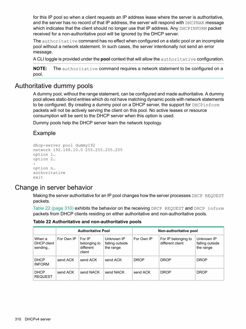
for this IP pool so when a client requests an IP address lease where the server is authoritative,and the server has no record of that IP address, the server will respond with DHCPNAK messagewhich indicates that the client should no longer use that IP address. Any DHCPINFORM packetreceived for a non-authoritative pool will be ignored by the DHCP server.The authoritative command has no effect when configured on a static pool or an incompletepool without a network statement. In such cases, the server intentionally not send an errormessage.A CLI toggle is provided under the pool context that will allow the authoritative configuration.
NOTE: The authoritative command requires a network statement to be configured on apool.
Authoritative dummy poolsA dummy pool, without the range statement, can be configured and made authoritative. A dummypool allows static-bind entries which do not have matching dynamic pools with network statementsto be configured. By creating a dummy pool on a DHCP server, the support for DHCPinformpackets will not be actively serving the client on this pool. No active leases or resourceconsumption will be sent to the DHCP server when this option is used.Dummy pools help the DHCP server learn the network topology.
Example
dhcp-server pool dummy192network 192.168.10.0 255.255.255.255option 1…option 2…:option n…authoritativeexit
Change in server behaviorMaking the server authoritative for an IP pool changes how the server processes DHCP REQUESTpackets.Table 22 (page 310) exhibits the behavior on the receiving DHCP REQUEST and DHCP informpackets from DHCP clients residing on either authoritative and non-authoritative pools.
Table 22 Authoritative and non-authoritative pools
Non-authoritative poolAuthoritative Pool
Unknown IPfalling outsidethe range
For IP belonging todifferent client
For Own IPUnknown IPfalling outsidethe range
For IPbelonging todifferentclient
For Own IPWhen aDHCP clientsending..
DROPDROPDROPsend ACKsend ACKsend ACKDHCPINFORM
DROPDROPsend ACKsend NACKsend NACKsend ACKDHCPREQUEST
310 DHCPv4 server

DHCPv4 configuration commandsEnable/disable the DHCPv4 server
Syntax[no]dhcp-server [enable | disable]
To enable/disable the DHCPv4 server in a switch.
• Enable the DHCPv4 server on the device. The no form of this command will remove allDHCPv4 server configurations.
• Disable the DHCPv4 server on the device. The no form of this command will remove allDHCPv4 server configurations.
The default is disabled.
Configuring the DHCP address pool nameUse the following command in the global configuration mode to configure the DHCP addresspool name and enter the DHCP pool context.Maximum of 128 pools are supported.
Syntax[no]dhcp-server pool < pool-name>
Configure the DHCPv4 server IP address pool with either a static IP or a networkIP range.pool DHCPv4 server IP address pool.ASCII-STR Enter an ASCII string.authoritative Configure the DHCP server authoritative for a pool.bootfile-name Specify the boot file name which is used as a boot
image.default-router List of IP addresses of the default routers.dns-server List of IP addresses of the DNS servers.domain-name Configure the DNS (Domain Name System) domain
name for translation of hostnames to IP addresses.lease Lease period of an IP address.netbios-name-server List of IP addresses of the NetBIOS (WINS) name
servers.netbios-node-type NetBIOS node type for a Microsoft DHCPv4 client.network Subnet IP and mask of the DHCPv4 server address
pool.option Raw DHCPv4 server options.range Range of IP addresses for the DHCPv4 server
address pool.static-bind Static binding information for the DHCPv4 server
address pool.tftp-server Configure a TFTP server for the DHCPv4 server
address pool.
DHCPv4 configuration commands 311

Validations
Error/Warning/PromptValidation
Maximum number of pools (128) has alreadybeen reached
Configuring pool when maximum Numberof pools already configured.
String %s too long. Allowed length is 32characters.
Configuring Pool with a name that exceedsthe maximum length requirement.
The specified address pool does not exist.Trying to delete non existing pool
Invalid name. Only alphanumeric charactersand hyphen are allowed.
Only alphanumeric characters, numerals andunderscore is allowed in the pool name.Violating this would throw the following errormessage.
DHCP server should be disabled beforechanging the configuration.
Trying to delete existing pool or adding newpool when DHCP server enabled.
Authoritative
Syntax[no]authoritativeauthoritative Configure the DHCP server authoritative for a pool.The DHCP server is the sole authority for the network configured under this pool.When the DHCP server is configured as authoritative, the server will respond withDHCP ACK or NACK as appropriate for all the received DHCP REQUEST andDHCP INFORM packets belonging to the subnet.Non-authoritative DHCP INFORM packets received from the clients on anon-authoritative pool will be ignored.
Specify a boot file for the DHCP client
Syntax[no]bootfile-name<filename>Specify the boot file name to be used as the boot image.
Configure a default router for a DHCP client
Syntax[no]default-router <IP-ADDR-STR> [IP-ADDR2 IP-ADDR8]
Configure the DHCP pool context to the default router for a DHCP client. List allof the IP addresses of the default routers.Two IP addresses must be separated by a comma.Maximum of eight default routers can be configured.
Configure the DNS IP servers
Syntax[no]dns-server <IP-ADDR> [IP-ADDR2 IP-ADDR8]
Configure the DHCP pool context to the DNS IP servers that are available to a DHCP client. Listof IP addresses of the DNS servers.Two IP addresses must be separated by comma.
312 DHCPv4 server

Maximum of eight DNS servers can be configured.
Configure a domain name
Syntax[no]domain-name <name>
Configure the DNS domain name for translation of hostnames to IP addresses.
Configure lease time
Syntax[no]lease [DD:HH:MM | infinite]DD:HH:MM Enter lease period.Lease Lease period of an IP address.
Configure the lease time for an IP address in the DHCP pool. Lease time is infinite for staticpools.The default lease period is one day.
Configure the NetBIOS WINS servers
Syntax[no]netbios-name-server <IP-ADDR-STR> [IP-ADDR2 IP-ADDR8]
Configure the DHCP pool for the NetBIOS WINS servers that are available to a Microsoft DHCPclient. List all IP addresses of the NetBIOS(WINS) name servers. The Windows Internet NamingService (WINS) is a name resolution service that Microsoft DHCP clients use to correlate hostnames to IP addresses within a general grouping of networks.Two IP addresses must be separated by a comma.Maximum of 8 NetBIOS (WINS) name servers can be configured.
Configure the NetBIOS node type
Syntax[no]netbios-node-type [ broadcast | hybrid | mixed |peer-to-peer ]broadcast Broadcast node.hybrid Hybrid node.mixed Mixed node.peer-to-peer Peer to peer node.Configure the DHCP pool mode to the NetBIOS node type for a Microsoft DHCP.The NetBIOS node type for Microsoft DHCP clients can be one of four settings:broadcast, peer-to-peer, mixed, or hybrid.
Configure subnet and mask
Syntax[no]network <ip-addr/mask-lenght>ip-addr/mask-lenght Interface IP address/mask.
Configure the DHCPv4 server pool subnet and mask for the DHCP server address pool.
DHCPv4 configuration commands 313

Range is configured to enable pool.
Configure DHCP server options
Syntax[no]option <CODE> {ascii <ascii-string>|hex <hex-string>|ip<IP-ADDR-STR>[IP-ADDR2 … IP-ADDR8]}ascii Specify ASCII string as option code value.hex Specify hexadecimal string as option code value.ip Specify one or more IP addresses as option code value.ip-addr-str Specify IP address.ascii-str Enter an ASCII string.hex-str Specify Hexadecimal string.Configure the raw DHCP server options.
Configure the range of IP address
Syntax[no]range <IP-ADDR>[<IP-ADDR>]range Range of IP addresses for the DHCPv4 server address pool.ip-addr Low IP address.
High IP address.
Configure the DHCP pool to the range of IP address for the DHCP address pool.
Configure the static binding information
Syntax[no]static-bind ip<IP-ADDR/MASK-LENGTH> mac <MAC-ADDR>ip Specify client IP address.static-bind Static binding information for the DHCPv4 server
address pool.ip-addr / mask-length Interface IP address or mask.mac Specify client MAC address.mac-addr Enter a MAC address.
Configure static binding information for the DHCPv4 server address pool. Manual bindings areIP addresses that have been manually mapped to the MAC addresses of hosts that are foundin the DHCP database. Manual bindings are just special address pools. There is no limit on thenumber of manual bindings but you can only configure one manual binding per host pool.
Configure the TFTP server domain name
Syntax[no]tftp-server [server-name <server-name> | server-ip <ip-address >]tftp-server Configure a TFTP server for the DHCPv4 server address pool.server-name TFTP server name for the DHCPv4 server address pool.
Configure the TFTP server domain name for the DHCP address pool.
314 DHCPv4 server

Configure the TFTP server address
Syntax[no]tftp-server server-ip< ip-address>server-ip TFTP server IP addresses for the DHCPv4 server address pool.ip-addr Specify TFTP server IP address.Configure the TFTP server address for the DHCP address pool.
Change the number of ping packets
Syntax[no]dhcp-server ping [packets <0-10>|timeout <0-10>]ping Specify DHCPv4 ping parameters.packets Specify number of ping packets.<0-10> Number of ping packets (0 disables ping).Specify, in the global configuration context, the number of ping packets the DHCPserver will send to the pool address before assigning the address. The default istwo packets.
Change the amount of time
Syntax[no]dhcp-server ping timeout <1-10>timeout Ping timeout.<1-10> Ping timeout in seconds.Amount of time the DHCPv4 server must wait before timing out a ping packet.The default is one second.
Configure DHCP Server to save automatic bindings
Syntax[no]dhcp-server database [file ASCII-STR][delay<15-86400>][timeout <0-86400>]delay Seconds to delay writing to the lease database file.file URL Format: "tftp://<ip-address>/<filename>".database Specifies DHCPv4 database agent and the interval between
database updates and database transfers.timeout Seconds to wait for the transfer before failing.ascii-str Database URL.<15-86400> Delay in seconds.<0-86400> Timeout in seconds.Specifies DHCPv4 database agent and the interval between database updatesand database transfers.
Configure a DHCP server to send SNMP notifications
Syntax[no]snmp-server enable traps dhcp-server
DHCPv4 configuration commands 315

dhcp-server Traps for DHCP-Server.Configure a DHCP server to send SNMP notifications to the SNMP entity. Thiscommand enables or disables event traps sent by the switch.
Enable conflict logging on a DHCP server
Syntax[no]dhcp-server conflict-loggingconflict-logging Enable DHCPv4 server address conflict logging.Enable conflict logging on a DHCP server. Default is disabled.
Enable the DHCP server on a VLAN
Syntax[no]dhcp-serverdhcp-server Enable DHCPv4 server on a VLAN.Enable DHCPv4 server on a VLAN. DHCPv4 client or DHCPv4 relay cannotco-exist with DHCPv4 server on a VLAN.
Clear commands
Syntaxclear dhcp-server conflicts [ip-addr]dhcp-server Clears theDHCPv4 server information.ip-addr Specify the IP address whose conflict is to be cleared.Reset DHCPv4 server conflicts database. If IP address is specified, reset onlythat conflict.
Reset all DHCP server and BOOTP counters
Syntaxclear dhcp-server statisticsstatistics Reset DHCPv4 server and BOOTP counters.Reset all DHCP server and BOOTP counters
Delete an automatic address binding
Syntaxclear dhcp-server statisticsbinding Reset DHCPv4 server automatic address bindings.ip-addr Specify IP address of the binding is to be cleared.Delete an automatic address binding from the DHCP server database.
Show commandsDisplay the DHCPv4 server address bindings
Syntaxshow dhcp-server binding
316 DHCPv4 server

dhcp-server Show DHCPv4 server global configuration information for thedevice.
binding Show DHCPv4 server IP binding information for the device.Display the DHCPv4 server address bindings on the device.
Display address conflicts
Syntaxshow dhcp-server bindingconflicts Show DHCPv4 server conflicts information for the device.Display address conflicts found by a DHCPv4 server when addresses are offeredby a client.
Display DHCPv4 server database agent
Syntaxshow dhcp-server databaseDatabase Show DHCPv4 server database information for the device.Display DHCPv4 server database agent information.
Display DHCPv4 server statistics
Syntaxshow dhcp-server statisticsstatistics Show DHCPv4 server statistics information for the device.Display DHCPv4 server statistics.
Display the DHCPv4 server IP pool information
Syntaxshow dhcp-server pool <pool-name>Pool Show DHCPv4 server pool information for the device.Display the DHCPv4 server IP pool information.
Display DHCPv4 server global configuration information
Syntaxshow dhcp-serverdhcp-server Show DHCPv4 server global configuration information for the
device.Display DHCPv4 server global configuration information.
Show commands 317

Event logEvent Log Messages
Table 23 Event Log Messages
Debug messagesEvents
DHCP server is enabled globally.DHCP server is enabled globally.
DHCP server is enabled globally.Warning -One ormore incomplete pool configurations are foundduring the server startup.
DHCP server is enabled globally. Warnings -One or more incomplete pool configurationsare found during the server startup.
A dynamic pool is considered invalid, if networkIP or subnet mask is not configured. A staticpool is considered incomplete, if network IP,subnet mask or MAC address is not configured.
DHCP server failed to start: %s "with a manualbinding.
DHCP server failed to start. The reason forfailure is printed as the argument.
DHCP server is disabled globally.DHCP server is disabled globally.
The DHCP server configurations are deletedThe DHCP server configurations are deleted.
%s: Decline offer from %x (server) of %x becausethe address is illegal.
Decline from client when server assigns anillegal Ipv6 address.
DHCP server is enabled on VLAN %dDHCP server is enabled on a specific VLAN.
DHCP server is disabled on VLAN %dDHCP server is disabled on a specific VLAN.
Ping-check configured with retry count = %d,timeout = %d
Ping check is enabled and configured withspecified retry count and timeout values
Ping-check is disabledPing check is disabled
Conflict-logging is enabledConflict-logging is enabled
Conflict-logging is disabled.Conflict-logging is disabled.
IP address %s is removed from the conflict-loggingdatabase.
A specific IP address is removed from theconflict logging database.
"All IP addresses are removed from theconflict-logging database
All IP addresses are removed from theconflict-logging database.
Dynamic binding for IP address %s is freedDynamic binding for a specific IP address isfreed.
All the dynamic IP bindings are freedAll the dynamic IP bindings are freed.
Remote binding database is configured at %sRemote binding database is configured for aspecific URL.
Remote binding database is disabledRemote biding database is disabled.
Binding database read from %s at %sBinding database is read from the specifiedURL at the specified time
318 DHCPv4 server

Table 23 Event Log Messages (continued)
Debug messagesEvents
Failed to read the remote binding database at %sFailed to read the remote binding from thespecified URL.
Binding database written to %s at %sBinding database is written to the specifiedURL at the specified time.
Failed to write the binding database to %s. Error:%s
Failed to write the binding database to thespecified URL. The reason for failure is printedas argument.
Invalid binding database at %sInvalid bindings are found in the database atthe specified URL.
VLAN %d does not have a matching IP poolThe specified VLAN does not have a matchingIP pool configured.This occurs when theDHCP-server is enabled on the specifiedVLAN, but no IP pool is configured with anetwork IP matching the VLAN network IP.
Binding database is replicated to standbymanagement module
Binding database is replicated to standbymanagement module.
DHCP server is listening for DHCP packetsDHCP server is listening for DHCP packetsThismessage is displayed when DHCP server isenabled globally and DHCP server is enabledon at-least one VLAN.
DHCP server is disabled on all the VLANs. Serveris no longer listening for DHCP packets
DHCP server is disabled on all the VLANs.Server is no longer listening for DHCP packets.
IP address %s is not offered, as it is already inuse
The specified IP is not offered to the DHCPclient, as it is already in use.
No IP addresses to offer from pool %sNo IP addresses available on the specifiedpool.
High threshold reached for pool %s. Activebindings: %d, Free bindings: %d
High threshold reached for the specified pool.Count of Active bindings and Free bindings areprinted as arguments.
Low threshold reached for pool %s. Active bindings:%d, Free bindings: %d
Low threshold reached for the specified pool.Count of Active bindings and Free bindings areprinted as arguments.
No active Vlan with an IP address available to readbinding database
No active VLAN with an IP address is availableto read binding database from the configuredURL.
Event log 319

9 DHCPv6 serverAdd hardware address to DHCPv6
The incremental deployment of IPv6 to existing IPv4 networks results in dual-stacking networkenvironments. Some devices will act as both DHCPv4 and DHCPv6 clients. For these dual-stacksituation, here is a need to associate DHCPv4 and DHCPv6 messages with the same clientinterface. A DHCPv4 server uses the client link-layer address as the customer identifier and akey for lookup in the client database. The DHCPv6 Relay-Forward message carries the clientlink-layer address to the DHCPv6 server allowing the association of both DHCPv4 and DHCPv6messages with the same client interface.As defined in RFC-6939, DHCPv6 relay agents receiving solicit and request messages thatoriginate from DHCPv6 clients include the link-layer source address of the received DHCPv6message. This is accomplished in the Client Link-Layer Address option within DHCPv6Relay-Forward messages. The Client Link-Layer Address enables the server to recognize andservice specific clients. DHCPv6 relay agent behavior (as set by the configuration) decideswhether the Client Link-Layer Address option is included for each client.DHCPv6 relays agents include Option–79 for all message types when enabled. The messagetypes are: solicit, request, confirm, decline, renew, rebind, release and information-request.DHCPv6 provides additional information for event debugging and logging related to the client atthe server.
NOTE: All cascading relay-agents simply encapsulate the message received and relay-forwardto the server. The service function does not receive any message-types directly from the clienteven when the feature is enabled.
Enable/Disable DHCPv6 SnoopingSyntax
[no]dhcpv6-snoopingEnable or disable the global administrative status of DHCPv6 snooping. Nosnooping will be performed on any VLAN if the global administrative status isdisabled.
Enable or disable DHCPv6 snooping on a VLANSyntax
[no]dhcpv6-snooping vlan VLAN-ID-RANGE
Enable or disable snooping on a VLAN. DHCP snooping must also be globallyenabled with the dhcpv6-snooping command for snooping to performed onany VLAN.
Configure trusted interfacesSyntax
[no]dhcpv6-snooping trust ethernet PORT-LIST
Configure trusted interfaces. Only server packets received on trusted interfaceswill be forwarded. When no is specified the interfaces are marked as untrusted.The default port state is untrusted.
320 DHCPv6 server

Configure authorized DHCPv6 serversSyntax
[no]dhcpv6-snoopingauthorized-server IPv6-address
Configure authorized DHCPv6 servers. For DHCPv6 snooping to allow a serverto client packet to be forwarded, it must be received on a trusted port from anauthorized server. If no authorized servers are configured, all server addressesare valid.
Configuring lease entry file for DHCPv6 snoopingSyntax
[no]dhcpv6-snooping database file ASCII-STR|delay 15-86400 |timeout 0-86400
Configure a lease entry file and its options for storing DHCPv6 snooping bindingdatabase.ASCII-STR Copies the DHCPv6 snooping lease file to a TFTP server.
The parameter ASCII-STR is a URL and is in the formattftp://<IP-ADDR>/<FILENAME>. The TFTP addresscan be up to 255 characters. IP-ADDR can be an IPv4address or an IPv6 address. The IPv6 address must beenclosed in square brackets [].
timeout seconds Configures the number of seconds to wait for theDSNOOPv6 lease file transfer to complete. An errormessage is displayed if the file transfer is not completedwithin the timeout value. A value of zero indicates thatthe attempt to transfer the DHCPv6 lease file retriesindefinitely. The default timeout value is 300 seconds.
database Configure the parameters to copy the DHCPv6 Snoopinglease file to a TFTP server.
delay Configure the number of seconds to wait before copyingthe DSNOOPv6 lease file to a TFTP server.
file Copy the DHCPv6 Snooping lease file to a TFTP server.timeout Configure the number of seconds to wait for the
DSNOOPv6 lease file transfer to complete.
Validation rules
Error/Warning/PromptValidation
database: Bad URL format.Verify whether file name entered is in URLformat
Invalid input: <value>Verify whether the timeout value is withinthe limit
Invalid input: <value>Verify whether the delay value is within thelimit.
Bad URL format.If the URL format is not proper
URL Transport mode is not supported.If the entered URL does not have a validtransfer mode.
Configure authorized DHCPv6 servers 321

Configuring upper limit of binding addresses per binding anchorSyntax
[no]dhcpv6-snooping max-bindings PORT-LIST 1-8192
Configure the maximum number of binding addresses allowed per binding anchor.A binding anchor is a unique attribute that can be associated with clients address.
• If the max-bindings value is configured before enabling dhcpv6-snoopingthe limit is immediately applied and the bindings are not allowed to exceedthe max-bindings value.
• The max-bindings value is set after enabling dhcpv6-snooping.
• The current bindings are greater than the max-binding value, the configurationwill be applied as and when clients release there IPv6 addresses.
• Current bindings are lesser than that of the value entered, the configurationwill be immediately applied.
max-binding Configuring maximum number of binding addresses allowedper port.
PORT-LIST Specify the ports on which max-bindings need to be applied.<1-8192> Value of maximum bindings.
Validation Rules
Error/Warning/PromptValidation
Invalid input: <value>Verify max-bindings value entered is in therange
Existing bindings %d are more than themax-bindings being configured, and the
If DHCPv6-Snooping is already configuredbefore entering the command and current
maximum limit will be applied once thebindings are greater than the value beingset. number of existing bindings fall below this
limit
Cannot configure maximum binding forDHCPv6 snooping feature on a trustedport
If the value is being configured for a trustedport
Port %s is not a part of aDHCPv6-snooping VLAN.
If the value is being configured for a portwhich is not a part of a dhcpv6-snooped vlan
Cannot configure DHCPv6 Snooping ona port when Dynamic Trunking is enabledon that port.
If the max-binding value is being set for aDynamic trunk.
Cannot configure the maximum bindingvalue because the number of static
If the number of static bindings is greaterthan the max-binding value being set.
bindings on the port exceeds themaximum binding value.
Cannot add a port to a trunk group whenDHCPv6 Snooping Maxbinding isconfigured on that port.
If a port on which max-binding is enabled isbeing put into a trunk.
Cannot remove the port %s from the trunkgroup because DHCPv6 Snooping
If a trunk has max-bindings configured on it.And the trunk is being removed.
max-binding is configured on the trunk
322 DHCPv6 server

Error/Warning/PromptValidation
and removing the port will delete thetrunk.
Cannot configure Distributed Trunking ona port when DHCPv6 Snoopingmax-binding is configured on that port.
If DT trunk is being configured on amax-binding enabled port.
NOTE: DT trunks can use jumbo VLAN as usual, but user needs to ensure that jumbo isconfigured on both the DT pairs, otherwise packet drops/fragmentations can be seen.
Configuring DHCPv6 relay option 79Syntax
[no]dhcpv6-relay option 79
Enabling option 79 will force the DHCPv6 Relay agent to forward the clientLink-layer address.The default behavior is disabled.
Configuring DHCPv6 snooping on a VLAN rangeValidation Rules
Error/Warning/PromptValidation
DHCPv6-snooping is not supported onSVLANs and SVLAN ports in QinQmixed VLAN mode
if the VLAN is a SVLAN and the bridge modeis mixed mode
DHCPv6 snooping cannot be enabledon %s VLANs. The switch will support
If number of snooped VLAN count is greaterthan max_vlans_with_dipv6ld and also themax binding limit has reached. only 8 DHCPv6 snooping enabled
VLANs when Dynamic IPv6 Lockdownfeature is enabled.
Cannot configure DHCPv6 Snoopingon a VLAN containing Smart Link ports.
If the VLAN which is being configured forDHCPv6 Snooping has a Smart Link enabledport.
Cannot configure a VLAN as aprotected VLAN when DHCPv6Snooping is enabled on it .
If a VLAN is being configured as a SmartLink protected VLAN and DHCPv6 Snoopingis enabled on it.
Canot configure the Smart Link featureon a port when DHCPv6 Snooping isenabled on that port.
If Smart Link is being configured on a portwhich is a part of DHCPv6 Snooping VLAN..
Configuring DHCPv6 relay option 79 323

Configuring a port as trustedValidation rules
Error/Warning/PromptValidation
Module not present for port or invalid port:<PORT-LIST>
Verify whether the port exist in thedevice.
Port %s cannot be configured as trusted portas it is part of a SVLAN in QinQ mixed VLANmode.
If the port is a part of a SVLAN andthe bridge mode is mixed mode.
Port %s is not a part of a DHCPv6-snoopingVLAN.
If the port is not a part of adsnoopv6 enabled VLAN
Disable max-binding feature configured on theport before configuring it as a trusted port.
If trusted attribute is beingconfigured on a port on whichmax-binding has been alreadyconfigured.
Cannot configure a port as a DHCPv6 Snoopingtrusted port when Dynamic Trunking is enabledon that port.
If a Dynamic trunk is configured asa trusted port.
Cannot configure a Smart Link port as aDHCPv6 Snooping trusted port.
If a Smart Link port is beingconfigured as a trusted port
Cannot configure a DHCPv6 Snooping trustedport as a Smart Link port
If a trusted port is being configuredas a Smart Link port
Configuring authorized DHCPv6 server for snoopingValidation rules
Error/Warning/PromptValidation
Invalid Ipv6 address:< ipv6-address>Verify whether entered ipv6 address isvalid
Invalid IP address. Only IPv6 unicast orlink-local addresses are supported.
If an invalid server address is configured
Cannot configure the authorized server asonly 20 authorized servers can beconfigured.
If the limit on configuring the authorizedservers had reached.
Configuring traps for DHCPv6-snoopingSyntax
[no] snmp-server enable traps dhcpv6-snoopingout-of-resources|errant-reply
Configure the traps for DHCPv6 snooping.out-of-resources This trap is sent when the number of bindings exceed
the maximum limit of 8192 bindings.errant-reply This trap is sent when a DHCPv6 reply packet is
received on an untrusted port or from an un-authorizedserver.
324 DHCPv6 server

Configure IPv6 lockdown globally and per portSyntax
[no] ipv6 source-lockdown ethernet PORT-LIST
Used to configure DIPv6LD lockdown globally and on specific ports which can beconfigured on per-port basis using the PORT-LIST option.[ethernet] PORT-LIST Specify the ports being configured for Ipv6
source-lockdown.source-lockdown Enable IPv6 source lockdown for a specific port.
Validation rules
Error/Warning/PromptValidation
DHCPv6 snooping is disabled.Verify whether dhcpv6-snooping is enabledglobally
Ports <PORT-LIST> are not in a DHCPv6Snooping VLAN.
Verify whether port configured is in theVLAN which is dhcpv6-snooping enabled.
Port %s is a trusted port.If lockdown is being configured on a trustedport
Cannot enable DIPLDv6 as requiredresources are unavailable.
If the HW resources are not available forchanging dipv6ld global or a portcharacteristic
DIPLDv6 cannot be enabled when GVRPis enabled
If global GVRP is enabled
DHCPv6 snooping cannot be enabled on%s VLANs. The switch support only 8
If no of snooped VLAN count is greaterthan max_vlans_with_dipv6ld
DhCPv6 snooping enabled VLANs whenDynamic Ipv6 lockdown is enabled.
Cannot enable Dynamic Ipv6 Lockdown onports %s as manual binding limits areexceeded.
If Binding limits are exceeded
Cannot configure Dynamic Ipv6 Lockdownon interface %s, it is a Dynamic trunk.
If lockdown is being enabled on aninterface which is part of a dynamic trunk(LACP)
Cannot configure Dynamic Ipv6 Lockdownon a logical mesh port.
If lock down is being configured on a meshport
Cannot add a port to a trunk group whenDynamic IPv6 Lockdown is enabled on thatport.
If trunk is being formed using a port whichhas DIPLDv6 enabled on it.
Cannot remove the port %s from the trunkgroup because Dynamic IPv6 Lockdown is
If DIPLDv6 is configured on a trunk and thetrunk is being removed.
configured on the trunk and removing theport will delete the trunk.
Cannot enable Dynamic IPv6 Lockdownfeature on a Smart Link port.
If DIPLDv6 is being is configured on aSmart Link port
Cannot configure the Smart Link feature ona port when the Dynamic IPv6 Lockdownfeature is enabled on that port.
If Smart Link is being enabled on aDIPLDv6 enabled port
Configure IPv6 lockdown globally and per port 325
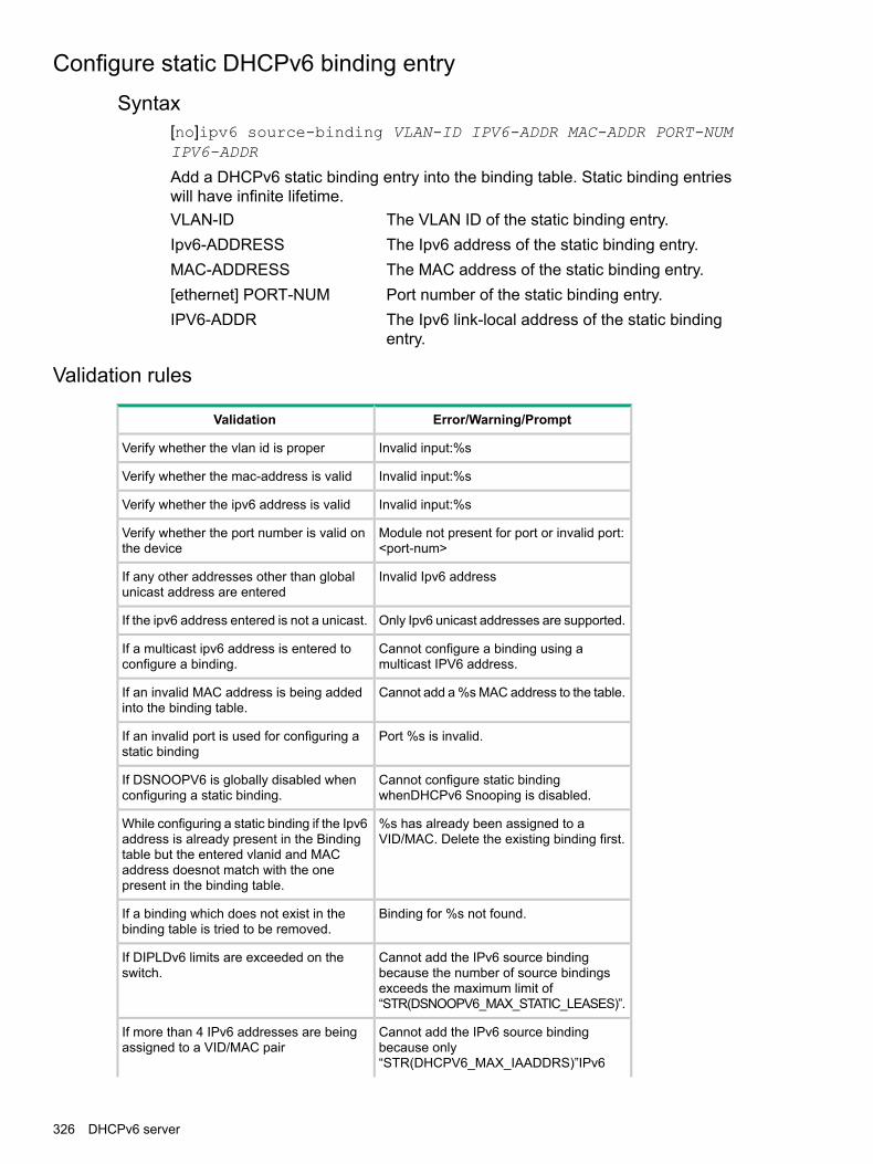
Configure static DHCPv6 binding entrySyntax
[no]ipv6 source-binding VLAN-ID IPV6-ADDR MAC-ADDR PORT-NUMIPV6-ADDR
Add a DHCPv6 static binding entry into the binding table. Static binding entrieswill have infinite lifetime.VLAN-ID The VLAN ID of the static binding entry.Ipv6-ADDRESS The Ipv6 address of the static binding entry.MAC-ADDRESS The MAC address of the static binding entry.[ethernet] PORT-NUM Port number of the static binding entry.IPV6-ADDR The Ipv6 link-local address of the static binding
entry.
Validation rules
Error/Warning/PromptValidation
Invalid input:%sVerify whether the vlan id is proper
Invalid input:%sVerify whether the mac-address is valid
Invalid input:%sVerify whether the ipv6 address is valid
Module not present for port or invalid port:<port-num>
Verify whether the port number is valid onthe device
Invalid Ipv6 addressIf any other addresses other than globalunicast address are entered
Only Ipv6 unicast addresses are supported.If the ipv6 address entered is not a unicast.
Cannot configure a binding using amulticast IPV6 address.
If a multicast ipv6 address is entered toconfigure a binding.
Cannot add a %s MAC address to the table.If an invalid MAC address is being addedinto the binding table.
Port %s is invalid.If an invalid port is used for configuring astatic binding
Cannot configure static bindingwhenDHCPv6 Snooping is disabled.
If DSNOOPV6 is globally disabled whenconfiguring a static binding.
%s has already been assigned to aVID/MAC. Delete the existing binding first.
While configuring a static binding if the Ipv6address is already present in the Bindingtable but the entered vlanid and MACaddress doesnot match with the onepresent in the binding table.
Binding for %s not found.If a binding which does not exist in thebinding table is tried to be removed.
Cannot add the IPv6 source bindingbecause the number of source bindings
If DIPLDv6 limits are exceeded on theswitch.
exceeds the maximum limit of“STR(DSNOOPV6_MAX_STATIC_LEASES)”.
Cannot add the IPv6 source bindingbecause only
If more than 4 IPv6 addresses are beingassigned to a VID/MAC pair
“STR(DHCPV6_MAX_IAADDRS)”IPv6
326 DHCPv6 server

Error/Warning/PromptValidation
addresses can be bound to a VID-MACpair.
%s is already bound to a link-local address.To bind another link-local address, deletethe existing binding .
If a VID-MAC pair is bound to a link-localaddress and the same VID-MAC pair isbeing assigned another link-local address.
The IPv6 source binding already exists foranother port.
If a binding exists for a particular client inthe BST and the same binding is beingconfigured for another port.
Cannot add the IPv6 source bindingbecause the number of source bindings
If the switch total limit for bindings isexceeded.
exceeds the maximum limit ofSTR(DSNOOPV6_MAX_STATIC_LEASES).
Cannot add a port to a trunk group whenIPv6 source binding is configured on thatport.
If a trunk is being configured for a portwhich has static binding configured on it.
Cannot configure IPv6 source binding on aSmart Link port.
If static binding is being configured on aSmart Link enabled port
Cannot configure Smart Link feature on aport when IPv6 source binding is configuredon that port.
If Smart Link is being configured on a portwith static binding.
Configuring traps for IPv6 source-lockdownSyntax
[no]snmp-server enable traps dyn-ipv6-lockdownout-of-resources | violations
The Dynamic IPv6 Lockdown trap is sent when resources are unavailable forconfiguring. This trap is sent when a source lockdown violation takes place.out-of-resources Dynamic IPv6 Lockdown out of resources.violations Dynamic IPv6 lockdown violations.
Clearing DHCPv6 snooping statisticsSyntax
clear dhcpv6-snooping stats
Clears dhcpv6 snooping statistics.
Validation rules
Error/Warning/PromptValidation
DHCPv6 snooping is disabled.If dhcp-snooping not enabledglobally
Enable debug for DHCPv6-snoopingSyntaxdebug security dhcpv6-snooping config|event|packet
Enable debug for DHCPv6 snooping.
Configuring traps for IPv6 source-lockdown 327

config Debug DHCPv6 snooping configuration.event Debug a DHCPv6 snooping event.packet Debug DHCPv6 snooping by packet.
Debug security for dynamic IPv6 lockdownSyntax
debug security dynamic-ipv6-lockdown
Enable debug for DIPLDv6
Show DHCPv6-snooping configurationSyntax
show dhcpv6-snooping
Show dhcpv6 snooping configuration.
Validation rules
Error/Warning/PromptValidation
DHCPv6 snooping is disabledIf dhcpv6-snooping not enabled
Show DHCPv6 snooping bindingsSyntax
show dhcpv6-snooping bindings
Show dhcpv6 snooping binding entries. This would show both dynamic and staticbinding entries.
Validation rules
Error/Warning/PromptValidation
DHCPv6 snooping is disabledIf dhcpv6-snooping not enabled
Show DHCPv6 snooping statisticsSyntax
show dhcpv6-snooping stats
Show dhcpv6-snooping statistics.
Show IPv6 source-lockdown bindings or statusSyntax
show ipv6 source-lockdown bindings | status
Shows IPv6 source bindings that are configured using the command IPv6source-bindings.bindings Show source bindings for Dynamic IPv6 Lockdown ports.status Show source bindings for Dynamic IPv6 Lockdown status.
328 DHCPv6 server

Example 128 Show source bindings Dynamic IPv6 Lockdown status
Dynamic IPv6 Lockdown Bindings
Port IPv6 Address Vlan MACNot
Addressin HW
---- ---------------------------------------- ----- --------------------A1 3000:abbb:1234:3456:1234: 1234:1234:1234 1 123456-789101Yes
F23 300:ab::2 4092 abcdef-123455No
Show IPv6 source-lockdown status per portSyntax
show ipv6 source-lockdown status
Used to show IPV6 source-lockdown status per port.source-lockdown Show dynamic IPv6 Lockdown.
Example 129 Show dynamic IPv6 Lockdown configuration
Dynamic IPv6 Lockdown informationGlobal State: EnabledPort Operational State------ --------------------------1 Active2 ActiveIPv6 Source Lockdown is disabled on Ports 3-24.
Show snmp-server trapsSyntax
show snmp-server COMMUNITY-STR
Shows traps controlled. Shows all information on SNMP communities, trapreceivers and SNMP response or trap source-ip policy configured on the switch.If COMMUNITY-STR is specified, only information for that community is displayed.traps Show all configured traps.
Show IPv6 source-lockdown status per port 329

Example 130 Show snmp-server traps
HP-E3500yl-24G(config)# sh snmp-server traps
Trap ReceiversLink-Change Traps Enabled on Ports [All] : All
Traps Category CurrentStatus_____________________________ __________________SNMP Authentication : ExtendedPassword change : EnabledLogin failures :EnabledPort-Security :EnabledAuthorization Server Contact : EnabledDHCP-Snooping :EnabledDHCPv6-Snooping Out of Resource : EnabledDHCPv6-Snooping Errant Replies : EnabledDynamic ARP Protection : EnabledDynamic IP Lockdown : EnabledDynamic IPv6 Lockdown Out of Resource : EnabledDynamic IPv6 Lockdown Violations : EnabledStartup Config change : DisabledRunning Config Change : DisabledMAC address table changes : DisabledMAC Address Count : Disabled
Address Community Events Type Retry Timeout
Excluded MIBsHP-E3500yl-24G(config)#Alignment change – right shifted
Show distributed-trunking consistency-parameters featureSyntax
Show distributed-trunking consistency-parameters globalfeaturedhcp-snooping Display DHCP snooping peer consistency details.IGMP Display IGMP peer consistency details.loop-protect Display Loop protect peer consistency details.MLD Display MLD peer consistency details.pim-dm Display PIM-DM peer consistency details.pim-sm Display PIM-SM peer consistency details.
330 DHCPv6 server

Example 131 Display PIM-SM peer consistency details.
show distributed-trunking consistency-parameters global featurepim-sm
PIM-SM Enabled VLANs on Local : 20,30PIM-SM Enabled VLANs on Peer : 20,30
Show distributed-trunking consistency-parametersSyntax
show distributed-trunking consistency-parameters global
Display global peer consistency details.global Display global peer consistency details.
Example 132 Show distributed-trunking consistency-parameters global
HP-5406Rzl2# show distributed-trunking consistency-parametersglobalLocal Peer----- ----Peer config unavailable.Image Version KB.15.18.0000x
IP Routing Disabled DisabledPeer-keepalive interval 1000 0PIM-DM Support Disabled DisabledPIM-SM Support Disabled DisabledIGMP enabled VLANs on Local :IGMP enabled VLANs on Peer :PIM-DM Enabled VLANs on Local : <List of Vlans>PIM-DM Enabled VLANs on Peer : <List of Vlans>PIM-SM enabled VLANs on Local : <List of Vlans>PIM-SM enabled VLANs on Peer : <List of Vlans>DHCP-snooping Enabled on Local :DHCP-Snooping Enabled on Peer : YesDHCP-Snooping Enabled VLANs on Local : 1DHCP-Snooping Enabled VLANs on Peer : 1DHCP-Snooping Max-Binding Configured on Local : Yes
Ports Max-Bindings------- ------------Trk2 6
DHCP-Snooping Max-Binding Configured on Peer : No
NOTE: If the platforms do not match an error message similar to inconsistant critiriawill be returned.
Syntaxshow distributed-trunking consistency-parameters globalpim-sm
Display PIM-SM peer consistency details.
Show distributed-trunking consistency-parameters 331

Example 133 Feature pim-sm
show distributed-trunking consistency-parameters global featurepim-sm
PIM-SM Enabled VLANs on Local : 20,30PIM-SM Enabled VLANs on Peer : 20,30
Show DHCPv6 relaySyntax
show dhcpv6-relay
Show the DHCPv6 relay configuration.
Sample output
show dhcpv6-relay
DHCPV6 Relay Agent : EnabledOption 79 : Disabled
Exclusionsdhcpv6-relay can not be configured from the WebUI or Menu.
Event log
MessageEvent
%s: %s message received on the untrusted port%s from %s.
RMON_DSNOOPV6_UNTRUSTED_PORT_SERVER_RELAY
%s: Ceasing the log messages for the serverpackets received on an untrusted port for %s.
RMON_DSNOOPV6_UNTRUSTED_PORT_SERVER_SUSP
%s: Client packet destined to the untrusted port%s is dropped.
RMON_DSNOOPV6_UNTRUSTED_PORT_CLIENT_DEST
%s: Ceasing the log messages for the clientpackets destined to an untrusted port for %s.
RMON_DSNOOPV6_UNTRUSTED_PORT_CLIENT_DEST_SUSP
%s: Unauthorized server %s detected on port %sRMON_DSNOOPV6_UNAUTHORIZED_SERVER
%s: Ceasing unauthorized server logs for %sRMON_DSNOOPV6_UNAUTHORIZED_SERVER_SUSP
%s: Illegal IPv6 release from%02X%02X%02X-%02X%02X%02X on port %s;Address leased to other client or not leased. %s.
RMON_DSNOOPV6_BAD_RELEASE
%s: Ceasing the log messages for the illegal IPv6release messages received from the clients for%s
RMON_DSNOOPV6_BAD_RELEASE_SUSP
%s: Unable to add the DHCPv6 lease becausethe lease table is full.
RMON_DSNOOPV6_TABLE_FULL
%s: Ceasing the log messages for the failed leasetable updates for %s.
RMON_DSNOOPV6_TABLE_FULL_SUSP
%s: Droppped IPv6 request from%02X%02X%02X-%02X%02X%02X. Themax-binding limit has reached on the port %s. %s
RMON_DSNOOPV6_MAX_BINDING_CROSSED
332 DHCPv6 server

MessageEvent
%s: Ceasing max-binding limit crossed packetinformation logs for %s.
RMON_DSNOOPV6_MAX_BINDING_CROSSED_SUSP
%s: The DHCPv6-Snooping max-bindingconfigured on port %s is removed.
RMON_DSNOOPV6_EVENT_MAXBINDING_REMOVED
%s: Ceasing the log messages for the removalof DHCPv6-Snooping max-binding from the portsfor %s
RMON_DSNOOPV6_EVENT_MAXBINDING_REMOVED_SUSP
%s: The number of bindings on the port %sequals the maximum binding configured on thatport.
RMON_DSNOOPV6_EVENT_BINDINGS_EQUALS_MAXBIND
%s: Ceasing the log messages for bindings onport that equals max-binding value for %s.
RMON_DSNOOPV6_EVENT_BINDINGS_EQUALS_MAXBIND_SUSP
%s: The number of bindings on the port %sexceeds the maximum binding configured on thatport.
RMON_DSNOOPV6_EVENT_MAXBIND_BELOW_BINDINGS
%s: Ceasing the log messages for bindings onport that exceeds max-binding for %s.
RMON_DSNOOPV6_EVENT_MAXBIND_BELOW_BINDINGS_SUSP
%s: Reading %s/%s %sRMON_DSNOOPV6_READ_LEASES_ERROR
%s: Ceasing remote server lease file read statuslogs for %s
RMON_DSNOOPV6_READ_LEASES_SUSP
%s: Writing %s/%s %sRMON_DSNOOPV6_WRITE_LEASES_ERROR
%s: Ceasing remote server lease file write statuslogs for %s
RMON_DSNOOPV6_WRITE_LEASES_SUSP
%s: The dynamic binding for %s on port %s wasreplaced with a manual binding.
RMON_DSNOOPV6_TABLE_FULL_REM_LEASE
%s: Ceasing removed lease logs for %s.RMON_DSNOOPV6_TABLE_FULL_REM_LEASE_SUSP
%s: Illegal IPv6 request from%02X%02X%02X-%02X%02X%02X on port %s;%s.
RMON_DSNOOPV6_BAD_IP_REQ
%s: s: Ceasing the log messages for illegal IPv6requests for %s
RMON_DSNOOPV6_BAD_IP_REQ_SUSP
%s: Offered lease from %s conflicts other leasesin BST. %s.
RMON_DSNOOPV6_BAD_IP_OFFER
%s: Ceasing the log messages for duplicate IPv6offers for %s.
RMON_DSNOOPV6_BAD_IP_OFFER_SUSP
%s: Dropped the IPv6 offer from %s because theoffered address is illegal. %s.
RMON_DSNOOPV6_ILLEGAL_LEASE
%s: Ceasing the log messages for illegal IPv6offers for %s
RMON_DSNOOPV6_ILLEGAL_LEASE_SUSP
%s: Invalid DHCPv6 packet %s. %s.RMON_DSNOOPV6_INVALID_PACKET
%s: Ceasing the log messages for invalidDHCPv6 packets for %s
RMON_DSNOOPV6_INVALID_PACKET_SUSP
Port %s removed from dhcpv6-snooping enabledvlan %d
RMON_DSNOOPV6_DIPLDV6_PORT_REMOVED_VLAN
Dhcpv6-snooping disabled globally, dynamic Ipv6lockdown also disabled.
RMON_DIPLDV6_DSNOOPV6_DISABLED_GLOBAL
Event log 333

MessageEvent
Dhcpv6-snooping disabled on vlan %d, dynamicIpv6 lockdown also disabled.
RMON_DIPLDV6_DSNOOPv6_DISABLED_VLAN
The port %s is configured as an untrusted port.RMON_DSNOOPV6_PORT_TRUSTED_TO_VALIDATING
Unable to add port %s to trunk, insufficient HWresources.
RMON_DSNOOPV6_PORT_ADD_TO_TRUNK_ERROR
Unable to apply dynamic Ipv6 lockdown to port%s, insufficient HW resources.
RMON_DIPLDV6_PORT_ADD_HW_RESOURCE_ERROR
Unable to add binding for %x,%02x%02x%02x-%02x%02x%02x on port %s.
RMON_DIPLDV6_ADD_BINDING_OUT_OF_RESOURCES
Unable to ipv6 lock-down VLAN %d on port %s,not enough HW resources.
RMON_DIPLDV6_VLAN_DENY_OUT_OF_RESOURCES
Access denied %s -> %s port %s, %d packetsreceived since last log
RMON_DIPLDV6_VIOLATION
DHCPV6 REQUEST dropped for%02x%02x%02x-%02x%02x%02x port %s,
RMON_DIPLDV6_DHCPV6_REQUEST_DROPPED
unable to add the binding; a port or switch limitwas reached.
Access was denied on VLAN %d, %d packetsreceived since last log.
RMON_DIPLDV6_VIOLATION_ON_VLAN
%s: The IPv6 address %s provided by theDHCPv6 server to the client %s is alreadyassigned to another client %s.
RMON_DSNOOPV6_CONFLICT_IN_BST
%s: Ceasing status logs for Conflicts in BST for%s
RMON_DSNOOPV6_CONFLICT_IN_BST_SUSP
Event Messages
Debug messagesEvents
Unable to add binding for %x,%02x%02x%02x-%02x%02x%02x on port%s. BST is full.
When the BST becomes full, to indicatethat lease bindings are being dropped.
Dropping packet as validation failed, reason%s
When DHCPv6 packet validation fails(packets are received on which they arenot expected to).
The dynamic binding for %s on port %s wasreplaced with a manual binding.
When a Dynamic binding is replaced witha static binding on a particular port.
Unable to release.%02x%02x%02x-%02x%02x%02x is boundnot bound to port %u.
While an attempt to release an Ipv6address from port which is leased toanother port.
%s: Decline offer from %x (server)of %xbecause the address is already assignedto another client.
Decline from client to server when clientfinds the address issued by server isalready in use in the link where the clientis connected.
%s: Decline offer from %x (server) of %xbecause the address is illegal.
Decline from client when server assigns anillegal Ipv6 address.
TFTP of BST from the dsnoopv6 device issuccessful / failed.
When TFTP transfer of binding state tableis a success or failure.
334 DHCPv6 server

Debug messagesEvents
Port %u is removed from a dhcpv6-snoopedVLAN
When a DIPLDv6 enabled port is removedfrom a DsnoopV6 enabled vlan.
Dhcpv6-snooping disabled globally,dynamic Ipv6 lockdown also disabled.
When DsnoopV6 is disabled globally whichmakes DIPLDv6 no longer configured?
Dhcpv6-snooping disabled on VLAN %s,dynamic Ipv6 lockdown also disabled.
When DsnoopV6 is disabled on a particularVLAN which makes DIPLDv6 also disabled
Port %u is validating.When a port moved from SAVI-Trust tovalidating port.
Unable to add port %u to trunk, dynamicipv6 lockdown is enabled on it.
While adding a port to a trunk for whichDIPLDv6 is already enabled.
Unable to configure dynamic Ipv6 lockdownon port %u which is a part of a trunk.
While enabling DIPLDv6 on a port which isadded to a trunk.
Unable to configure dynamic Ipv6 lockdownon port %u, ACL is configured on port.
While enabling DIPLDv6 on a port for whichACL is configured.
Access was denied on VLAN %d, deny ruleexists on the VLAN
When it is unable to add a lock on aparticular VLAN for a particular port due tovlan deny rule.
Access was denied on VLAN %d, %dpackets received since last log.
When DIPLDv6 violations are detected ona VLAN
Max-binding limit reached on Port %s.When max-binding limit is reached on aPort
Event Messages 335

10 Captive Portal for ClearPassBeginning with switch software release 16.01, Captive Portal for ClearPass is supported on thefollowing switch models covered in this guide:• 3800 (KA software)
• 3810 (KB software)
• 5400R (KB software)
• 5400 v2 modules (K software)The Captive Portal feature allows the support of the ClearPass Policy Manager (CPPM) into theArubaOS-Switch product line. The switch provides configuration to allow you to enable or disablethe Captive Portal feature. By default, Captive Portal is disabled to avoid impacting existinginstallations as this feature is mutually exclusive with the following web-based authenticationmechanisms: Web Authentication, EWA, MAFR, and BYOD Redirect.Captive Portal is user-based, rather than port or VLAN-based, therefore the configuration is ona switch global basis. ArubaOS-Switch supports the following authentication types on the switchwith RADIUS for Captive Portal:• Media Access Control (MAC)
• 802.1XOnce you enable Captive Portal, the redirect functionality is triggered only if a redirect URLattribute is provided as part of the RADIUS Access-Accept response from an authenticationrequest of type 802.1X or MAC. The redirect enables the client to self-register or directly loginwith valid credentials via the CPPM. Upon subsequent re-authentication, it provides access tothe network per the CPPM configured policies that are communicated via the RADIUS attributes.The redirect feature offers:• Client self-registration
• Client direct login with valid credentials via CPPM Captive Portal
• On-boarding
• Ability to quarantine devices to remedy their status
More informationHPE Switch Software Advanced Traffic Management GuideArubaOS User GuideAruba Networks ClearPass Policy Manager User Guide
Requirements• HTTPS support requires a certificate to be configured on the switch with a usage type of
all or captive-portal.
• If you are running HPE 5400 Series v2 modules, you must turn off the compatibility modewith the following command:switch(config)# no allow-v1-modules
This will ensure that the switch will only power up with the v2 modules.
336 Captive Portal for ClearPass

Best Practices• Use the Port Bounce VSA via a CoA message, instead of the Disconnect message, to cause
the second RADIUS authentication to occur during the Captive Portal exchange. This is themore reliable method for forcing a re-DHCP for the client.
• Configure Captive Portal such that the first ACCESS_ACCEPT returns a rate limit VSA toreduce the risk of DoS attacks. This configuration enables rate limiting for the HTTP/HTTPSACL for traffic sent to CPPM.
• Do not use the keyword cpy in any other NAS-Filter-Rules. The keyword cpy in theenforcement profile attributes is specific to CPPM use. It is only supported with the denyattribute. If you configure the cpy keyword to permit, no ACL will be applied.
Limitations• Captive Portal will not work with RADIUS configured on a loopback port or on the Out-of-Band
Management (OOBM) port.• Captive Portal is supported in CPPM versions 6.5.5 and later. However, by manually modifying
the RADIUS dictionary files, any CPPM version 6.5.* can be used.• Captive Portal does not support v1 modules, and will not work unless compatibility mode is
turned off.• Captive Portal does not support IPv6.
• Simultaneous Captive Portal client connections: maximum of 512
• Captive Portal does not support web proxy. The permit CPPM ACLs and the steal ACLsonly use port 80 and 443. Non-standard ports for HTTP and HTTPS are not supported.
• Captive Portal is mutually exclusive with the following web-based authentication mechanisms:Web Authentication, EWA, MAFR, and BYOD.
• URL-string limitation of 253 characters.
FeaturesHigh Availability
Captive Portal includes support for High Availability (HA). The Captive Portal configurations (suchas enablement, authenticated clients, and redirect URLs) are replicated to standby or othermembers.If the feature is enabled and a failover occurs, clients in the process of onboarding are stillredirected to Captive Portal, and authenticated clients continue to have the same access to thenetwork.Clients that are in the process of authenticating via MAC or 802.1X authentication will not bereplicated to the standby. Replication of client data is only done when MAC or 802.1Xauthentication has resulted in a successful authentication.
Load balancing and redundancyThe following options are available to create load balancing and provide redundancy for CPPM:• Virtual IP use for a CPPM server member
• CPPM servers configured in the switch RADIUS server group
• External load balancer
Best Practices 337

Captive Portal when disabledBy default, Captive Portal is disabled. If the Captive Portal feature is disabled and the switchreceives a redirect URL attribute from the RADIUS server as part of the Access-Accept, it willview the redirect as an error. The authentication success will be overridden, the session will beflushed, and the switch will send the Accounting Start and Accounting Stop messages to indicatethe client is no longer authenticated.The Captive Portal feature may be disabled while there are in flight authentication requests.These are authentication sessions that have not finished the final authentication with the switch.The switch flushes all sessions with a redirect URL associated with them when Captive Portalis disabled.Fully authenticated sessions are not impacted when Captive Portal is disabled. If CPPM deemsthese sessions to be invalid, a RADIUS Disconnect can be sent to flush all these sessions.
Disabling Captive PortalTo disable Captive Portal, enter one of the following:switch(config)# aaa authentication captive-portal disable
switch(config)# no aaa authentication captive-portal enable
Configuring Captive Portal on CPPM1. “Import the HP RADIUS dictionary” (page 338)2. “Create enforcement profiles” (page 338)3. “Create a ClearPass guest self-registration” (page 340)4. “Configure the login delay ” (page 340)
Import the HP RADIUS dictionaryFor CPPM versions 6.5.*, you must update the HP RADIUS dictionary. To import the dictionaryin CPPM, follow these steps:1. Go to Administration -> Dictionaries -> RADIUS and click Import.2. Select the XML HP RADIUS Dictionary from your Hard Drive.3. Click Import.
Create enforcement profiles
NOTE: Create the HPE Bounce Host-Port profile and the Guest Login profile only if they donot already exist.
For the HPE Bounce Host-Port profile, configure Captive Portal so that the RADIUS CoA messagethat includes the Port Bounce VSA is sent to force the second RADIUS re-authentication afterthe user registers their device and makes it known.1. In CPPM, go to Configuration -> Enforcement -> Profiles2. Click Add.3. Enter the Profile Name: HPE Bounce Host-Port4. Enter the Description: Custom-defined profile to bounce host port (HPE).5. Select the type RADIUS_CoA.6. Select the action CoA.
338 Captive Portal for ClearPass

7. Add all of the attributes required for a CoA message, and specify the port bounce duration(valid values are between 0 and 60). This is the amount of time in seconds the port will beheld in the down state. The recommended setting is 12 seconds.
8. Repeat Step 2 to Step 6 to configure the Guest Login profile that will be sent as part of thefirst RADIUS Access-Accept and enforce the redirect to the Captive Portal on CPPM. Forthis profile, select RADIUS as the type and Accept as the action.
9. Add all of the NAS-Filter-Rule attributes specified below, replacing the IP address in the firsttwo NAS-Filter-Rule attributes with your CPPM address. Add the HPE-Captive-Portal-URLattribute to specify the redirect URL, replacing the IP address with your CPPM address. Thiswill cause the client to be redirected to the Captive Portal on CPPM. You can add otherattributes, such as a VLAN to isolate onboarding clients, or a rate limit to help prevent DoSattacks.
NOTE: The HPE-Captive-Portal-URL value must be a URL normalized string. Thescheme and host must be in lower case, for example http://www.example.com/
Configuring Captive Portal on CPPM 339

Create a ClearPass guest self-registration1. From the Customize Guest Registration window, selectServer-initiated as the Login Method.2. Optionally, under Security Hash, select the level of checking to apply to the redirect URL.
Configure the login delayEnter the Login Delay value. The value must be greater than the HPE-Port-Bounce-Hostattribute. In this example, we set the login delay value to 20 seconds.
Configuring the switchOnce you have configured Captive Portal, you can configure the switch. To configure the switch,you must first configure the switch as a RADIUS client, then configure the ports that will be usedfor Captive Portal, as follows:1. Configure the switch as a RADIUS client. In this example, the CPPM IP address is
10.73.4.136 and secret is the secret key shared with the RADIUS server:a. switch(config)# radius-server host 10.73.4.136 key "secret"
b. switch(config)# radius-server host 10.73.4.136 dyn-authorization
c. switch(config)# radius-server host 10.73.4.136 time-window 0
NOTE: Make sure to set your time-window to 0. See “Event Timestamp not working”(page 342).
340 Captive Portal for ClearPass
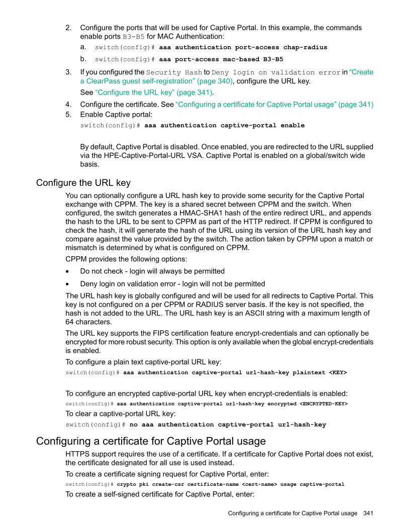
2. Configure the ports that will be used for Captive Portal. In this example, the commandsenable ports B3-B5 for MAC Authentication:a. switch(config)# aaa authentication port-access chap-radius
b. switch(config)# aaa port-access mac-based B3-B5
3. If you configured the Security Hash to Deny login on validation error in “Createa ClearPass guest self-registration” (page 340), configure the URL key.See “Configure the URL key” (page 341).
4. Configure the certificate. See “Configuring a certificate for Captive Portal usage” (page 341)5. Enable Captive portal:
switch(config)# aaa authentication captive-portal enable
By default, Captive Portal is disabled. Once enabled, you are redirected to the URL suppliedvia the HPE-Captive-Portal-URL VSA. Captive Portal is enabled on a global/switch widebasis.
Configure the URL keyYou can optionally configure a URL hash key to provide some security for the Captive Portalexchange with CPPM. The key is a shared secret between CPPM and the switch. Whenconfigured, the switch generates a HMAC-SHA1 hash of the entire redirect URL, and appendsthe hash to the URL to be sent to CPPM as part of the HTTP redirect. If CPPM is configured tocheck the hash, it will generate the hash of the URL using its version of the URL hash key andcompare against the value provided by the switch. The action taken by CPPM upon a match ormismatch is determined by what is configured on CPPM.CPPM provides the following options:• Do not check - login will always be permitted
• Deny login on validation error - login will not be permittedThe URL hash key is globally configured and will be used for all redirects to Captive Portal. Thiskey is not configured on a per CPPM or RADIUS server basis. If the key is not specified, thehash is not added to the URL. The URL hash key is an ASCII string with a maximum length of64 characters.The URL key supports the FIPS certification feature encrypt-credentials and can optionally beencrypted for more robust security. This option is only available when the global encrypt-credentialsis enabled.To configure a plain text captive-portal URL key:switch(config)# aaa authentication captive-portal url-hash-key plaintext <KEY>
To configure an encrypted captive-portal URL key when encrypt-credentials is enabled:switch(config)# aaa authentication captive-portal url-hash-key encrypted <ENCRYPTED-KEY>
To clear a captive-portal URL key:switch(config)# no aaa authentication captive-portal url-hash-key
Configuring a certificate for Captive Portal usageHTTPS support requires the use of a certificate. If a certificate for Captive Portal does not exist,the certificate designated for all use is used instead.To create a certificate signing request for Captive Portal, enter:switch(config)# crypto pki create-csr certificate-name <cert-name> usage captive-portal
To create a self-signed certificate for Captive Portal, enter:
Configuring a certificate for Captive Portal usage 341

switch(config)# crypto pki enroll-self-signed certificate-name
Display Captive Portal configurationTo display the Captive Portal configuration settings, enter the show captive-portal command:switch(config)# show captive-portal
Captive Portal ConfigurationRedirection Enabled : YesURL Hash Key Configured : No
Show certificate informationTo view the certificate information, enter:switch(config)# show crypto pki local-certificate
Name Usage Expiration Parent / Profile-------------------- --------------- -------------- --------------------cp Captive Portal 2016/08/14 default
TroubleshootingEvent Timestamp not working
SymptomThe client gets a credentials request on the web browser even though the valid credentials werealready provided, or the client is not redirected to the Captive Portal.
Cause
• ClearPass 6.5.x does not support the sending of Event Timestamp in automated workflows(manual via Access Tracker works).
• The switch will reject CoA requests when the time on CPPM is ahead of the switch time byeven a second.
ActionSet the time-window security feature in PVOS to 0:radius-server host<CLEARPASS-IP> time-window 0
Cannot enable Captive Portal
SymptomWhen running the aaa authentication captive-portal enable command, getting thefollowing error message:Captive portal cannot be enabled when BYOD redirect, MAC authentication failureredirect, or web-based authentication are enabled.
CauseThe failure is due to a mutual exclusion restriction.
Action1. Check which one of the following are enabled: BYOD redirect, MAC authentication failure
redirect, or web-based authentication.2. Disabled the enabled authentication method found in step 1.3. Run the aaa authentication captive-portal enable command.
342 Captive Portal for ClearPass

Unable to enable feature
SymptomOne of the following messages is displayed:
• BYOD redirect cannot be enabled when captive portal is enabled.
• MAC authentication failure redirect cannot be enabled when captiveportal is enabled.
• Web-based authentication cannot be enabled when captive portalis enabled.
• V1 compatibility mode cannot be enabled when captive portalis enabled.
CauseYou cannot enable these features when Captive Portal is already enabled. They are mutuallyexclusive.
ActionYou can either disable Captive Portal or avoid enabling these features.
Authenticated user redirected to login page
SymptomUser is redirected back to the login page to submit credentials even after getting fully authenticated.
Solution 1
CauseThe status is not changed to Known.
ActionAfter the client submits the credentials, the CPPM service must change the Endpoint Status toKnown.
Solution 2
CauseThe cache value is set.
ActionClear the CPPM Cache Timeout of the Endpoint Repository.
Unable to configure a URL hash key
SymptomThe following message is displayed:Key exceeds the maximum length of 64 characters.
CauseThe URL hash key is not valid.
Troubleshooting 343
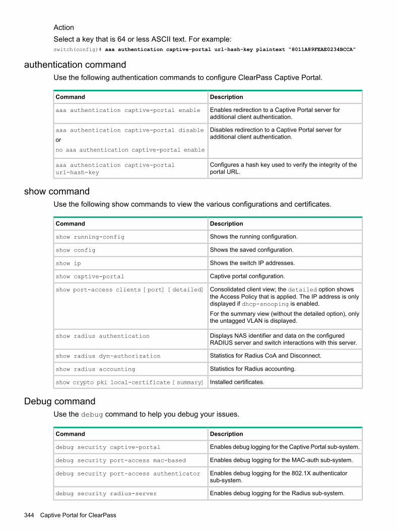
ActionSelect a key that is 64 or less ASCII text. For example:switch(config)# aaa authentication captive-portal url-hash-key plaintext “8011A89FEAE0234BCCA”
authentication commandUse the following authentication commands to configure ClearPass Captive Portal.
DescriptionCommand
Enables redirection to a Captive Portal server foradditional client authentication.
aaa authentication captive-portal enable
Disables redirection to a Captive Portal server foradditional client authentication.
aaa authentication captive-portal disable
orno aaa authentication captive-portal enable
Configures a hash key used to verify the integrity of theportal URL.
aaa authentication captive-portalurl-hash-key
show commandUse the following show commands to view the various configurations and certificates.
DescriptionCommand
Shows the running configuration.show running-config
Shows the saved configuration.show config
Shows the switch IP addresses.show ip
Captive portal configuration.show captive-portal
Consolidated client view; the detailed option showsthe Access Policy that is applied. The IP address is onlydisplayed if dhcp-snooping is enabled.
show port-access clients [port] [detailed]
For the summary view (without the detailed option), onlythe untagged VLAN is displayed.
Displays NAS identifier and data on the configuredRADIUS server and switch interactions with this server.
show radius authentication
Statistics for Radius CoA and Disconnect.show radius dyn-authorization
Statistics for Radius accounting.show radius accounting
Installed certificates.show crypto pki local-certificate [summary]
Debug commandUse the debug command to help you debug your issues.
DescriptionCommand
Enables debug logging for the Captive Portal sub-system.debug security captive-portal
Enables debug logging for the MAC-auth sub-system.debug security port-access mac-based
Enables debug logging for the 802.1X authenticatorsub-system.
debug security port-access authenticator
Enables debug logging for the Radius sub-system.debug security radius-server
344 Captive Portal for ClearPass

DescriptionCommand
Prints debug messages to terminal.debug destination session
Sends debug messages to the syslog server.debug destination logging
Prints debug messages to a buffer in memory.debug destination buffer
Troubleshooting 345

11 ZTP with AirWave Network ManagementBeginning with switch software release 16.01, ZTP with AirWave Network Management issupported on the following switch models covered in this guide:• 3800 (KA software)
• 3810 (KB software)
• 5400R (KB software)AirWave is a Network Management Solution (NMS) tool. Once connected to AirWave using theWebUI and CLI interfaces, you can:
• Configure your switches using Zero Touch Provisioning (ZTP)
• Configure your switches using the CLI
• Troubleshoot your switches
• Monitor your switches
• Upgrade your firmware for your switchesOnce you have configured your switch, you can monitor, manage, and upgrade your hardwareusing the AirWave Management Platform.
More information“Switch configuration” (page 347)“Stacking and chassis switches” (page 361)“Troubleshooting” (page 361)Aruba Networks and AirWave Switch Configuration Guide
Requirements• DHCP server
• AirWave NMS
• HPE Aruba switches
Best Practices• Implement ZTP in a secure and private environment. Any public access may compromise
the security of the switch, as follows:
◦ Since ZTP is enabled only on the factory default configuration of the switch, DHCPsnooping is not enabled. You must manage the Rogue DHCP server.
◦ The DHCP offer is in plain data without encryption. Therefore, the offer can be listenedby any device on the network and they can in turn obtain the AirWave information.
◦ The TLS certificate of the server is not validated by the switch during the HTTPs check-into AirWave. The AirWave server is in the private environment of the switch.
Limitations• ZTP is not supported through OOBM.
• The DNS/hostname in option 66 is not supported, only the IPv4 address.
• The switch does not validate peer certificate of the AirWave server as part of the TLShandshake.
346 ZTP with AirWave Network Management

• The HTTPS check-in to AirWave does not support HTTPS proxy.
• For non-ZTP cases, the AirWave check-in starts by validating the following condition:Primary or Management VLAN must be configured with the IP address and one of theinterface must be UP. By default, VLAN 1 is the primary VLAN.
Switch configurationTo configure your switch, follow these steps:1. “Configure AirWave details in DHCP (preferred method)” (page 347).
NOTE: If you are using existing HPE switches and using the DHCP server for theconfiguration or firmware management, you can configure the AirWave details in DHCPusing this method: “Configure AirWave details in DHCP (alternate method)” (page 352)
2. If you are configuring the switch using a CLI, see “Configure a switch using the CLI” (page360)If you are using ZTP, the configuration is automatic and does not require any user interaction,see “Zero Touch Provisioning” (page 359)
The switch contacts the AirWave server that is configured on the switch and initiates the check-inprocess.Once you have configured the DHCP server, the AirWave details received from the DHCP optionsare stored in the switch configuration. This assures that the configuration is retained acrossreboots.Once AirWave completes the switch check-in, it lists the first switch as New Devices. The firstswitch is used to create a new configuration template for the specific group and device type. Withthis new template, the required configuration is generated for the group. Subsequent switch ofthe specific type and joining the same group as the first device are added directly to the groupand the configuration is pushed using the configuration template via a SSH connection.
Configure AirWave details in DHCP (preferred method)To configure a DHCP server for AirWave, from a Windows Server 2008, do the following steps:
Switch configuration 347

1. From the Start menu, select Server Manager.
2. Select Roles -> DHCP -> Server -> w2k8 -> IPv4.
3. Right click on IPv4 and select Set Predefined Options...
348 ZTP with AirWave Network Management

4. The Predefined Options and Values screen is displayed. Click Add....
5. Enter the desired Name (any), Data type (select String), Code (enter 60), and Description(any).
Configure AirWave details in DHCP (preferred method) 349
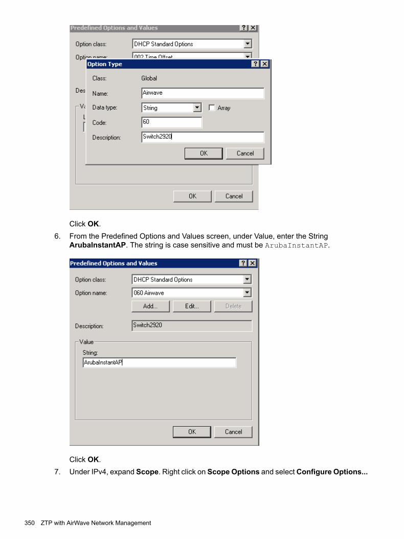
Click OK.6. From the Predefined Options and Values screen, under Value, enter the String
ArubaInstantAP. The string is case sensitive and must be ArubaInstantAP.
Click OK.7. Under IPv4, expand Scope. Right click on Scope Options and select Configure Options...
350 ZTP with AirWave Network Management

8. Under the General tab, select 043 Vendor Specific Info. The Data entry data appears.Under ASCII, enter hpeSwitch:hp2920,90.1.1.10,admin. The ASCII value has the followingformat:<Group>:<Topfolder>,<AMP IP>,<shared secret>
If you need to add sub-folders, use the following format:<Group>:<Topfolder>:<folder1>,<AMP IP>,<shared secret>
9. Under the General tab, select 060 Airwave. Click OK.
Configure AirWave details in DHCP (preferred method) 351

NOTE: No changes are required to the 060 option.
10. You can verify the AirWave details as follows:switch# show amp-serverswitch# show run
Configure AirWave details in DHCP (alternate method)To configure a DHCP server for ZTP and AirWave, from a Windows Server 2008, do the followingsteps:
NOTE: You must repeat these steps for every type of switch that needs to be configured forZTP, selecting a different Vendor Class for each type of switch.
352 ZTP with AirWave Network Management
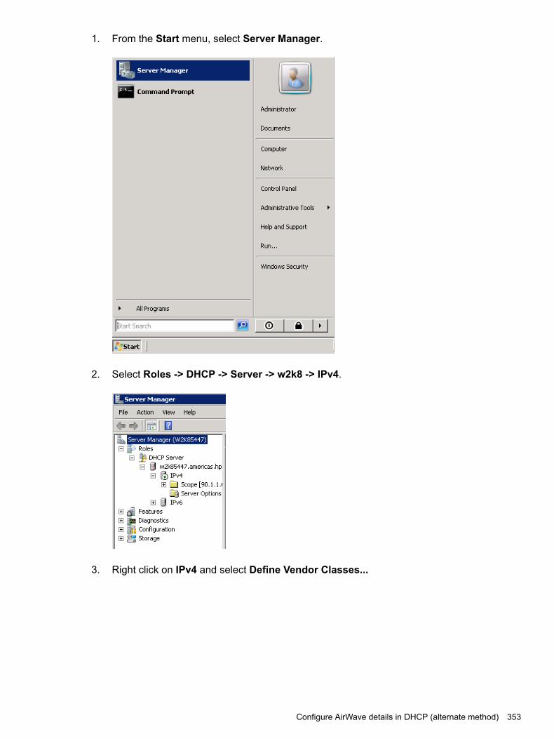
1. From the Start menu, select Server Manager.
2. Select Roles -> DHCP -> Server -> w2k8 -> IPv4.
3. Right click on IPv4 and select Define Vendor Classes...
Configure AirWave details in DHCP (alternate method) 353

4. The DHCP Vendor Classes window is displayed. Click Add....
5. To get the vendor-specific value of a switch, go to the switch console and enter:switch# show dhcp client vendor-specific
In our example, the command returns the following value:Vendor Class Id = HP J9729A 2920-24G-PoE+ Switch dslforum.org
Processing of Vendor Specific Configuration is enabled6. From the New Class window, enter the desired Display name (any) and the Description
(any). For theASCII field, enter the exact value that you got by executing the show command
354 ZTP with AirWave Network Management

performed in the previous step. In this example, HP J9729A 2920-24G-PoE+ Switchdslforum.org.
Click OK.7. Right click on IPv4 and select Set Predefined Options....
Configure AirWave details in DHCP (alternate method) 355

8. From the Predefined Options and Values window, select Option class. The Option Classdisplayed is the one that you configured under DHCP Vendor Class. In this example, theOption Class is switch.
Click Add....
356 ZTP with AirWave Network Management

9. From the Option Type window, enter the desired Class (any), the Data type (select string),the Code (enter 146), and the Description (any).
Click OK.10. Under the Predefined Options and Values window, enter the Value String. In this example,
we enter hpeSwitch:hp2920,90.1.1.10,admin. The String has the following format:<Group>:<Topfolder>,<AMP IP>,<shared secret>
If you need to add sub-folders, use the following format:<Group>:<Topfolder>:<folder1>,<AMP IP>,<shared secret>
Configure AirWave details in DHCP (alternate method) 357

Click OK.11. Under IPv4, expand Scope. Right click on Scope Options and selectConfigure Options...
12. From the Scope Options window:a. Select the Advanced tab.b. Under Vendor class, select the desired switch. In this example, switch.c. Select the 146 hpswitch option.d. Click OK.
358 ZTP with AirWave Network Management

13. You can verify the AirWave details as follows:switch# show amp-serverswitch# show run
Zero Touch ProvisioningThe Zero Touch Provisioning (ZTP) solution enables the auto-configuration of your switches onthe first boot without requiring any administrator’s intervention at the switch. The switches useDHCP server option configurations to support ZTP.
NOTE: If the switch does not contain the minimal configuration set, ZTP will get disabled. See“Image Upgrade” (page 360).
More information“Auto-configuration using ZTP” (page 359)“Disabling ZTP” (page 360)“Image Upgrade” (page 360)
Auto-configuration using ZTPZTP auto-configures your switches as follows:
Zero Touch Provisioning 359

1. The switch boots up with the factory default configuration.2. The switch sends out a DHCP discovery from the primary VLAN interface.
• The preferred configuration method uses DHCP option 43 value as a string to parseAirwave configuration. Switch would expect a DHCP option 60 with valueArubaInstantAP along with DHCP option 43 to parse Airwave details
• The alternate configuration method supports both encapsulated values from option 43and direct value from option 43. Encapsulated vendor-specific sub options, withsub-option code 146 is for Airwave details.
3. After the AirWave details are verified and configured, the switch initiates the check-in intothe AirWave server using the HTTPS communication.
NOTE: The AirWave configuration must be in the following format:<Group>:<Topfolder>:<folder1>,<AMP IP >,<shared secret>
4. After a successful registration, AirWave can monitor, configure, and troubleshoot the switches.Refer to Aruba Networks and AirWave Switch Configuration Guide.
5. Check-in failure retry is done every 60 seconds for 10 retries.6. If the DHCP options are not configured for AirWave, the switch is left in its default state for
manual configuration.
Disabling ZTPZero touch provisioning is disabled if you make any of the following changes to the switch’sconfiguration:
• Enter the switch configuration mode using the configure terminal command.
• Enter into Menu and exit without doing any configuration.
• Make any successful configuration that changes the running-configuration of the switchusing a CLI, SNMP, REST APIs, menu interface, or the web GUI.
• If you upgrade with non-minimal configuration set from any 15.xx version to version 16.01,see “Image Upgrade” (page 360).
Image UpgradeIf you upgrade from any 15.xx version to version 16.01, the following minimal set of configurationis validated to enable or disable the ZTP process:• If the switch has any other VLAN apart from the default VLAN, ZTP gets disabled.
• In default VLAN, if the IPv4 address is not set as DHCP (default option is DHCP), ZTP getsdisabled.
• In default VLAN, if IPv6 is enabled or configured, ZTP gets disabled.If you have any other configuration during the upgrade, ZTP will be in the enabled state only.
Configure a switch using the CLIUse the amp-server command to configure the AirWave IP address, group, folder, and sharedsecret. You must have the manager role to execute this command.For example:switch(config)# amp-server ip 172.16.185.23 group 2530 folder 2530 secret secret
The show amp-server command shows the configuration details:switch# show amp-serverAirwave Configuration detailsAMP Server IP : 172.16.185.23
360 ZTP with AirWave Network Management
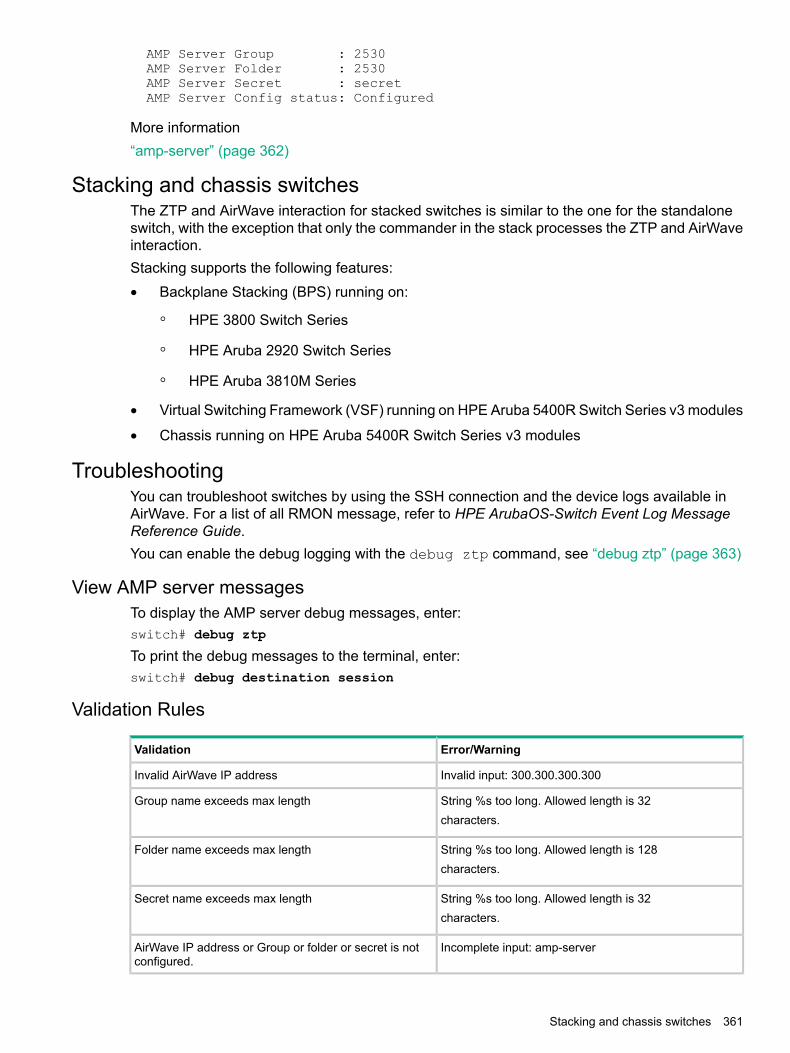
AMP Server Group : 2530AMP Server Folder : 2530AMP Server Secret : secretAMP Server Config status: Configured
More information“amp-server” (page 362)
Stacking and chassis switchesThe ZTP and AirWave interaction for stacked switches is similar to the one for the standaloneswitch, with the exception that only the commander in the stack processes the ZTP and AirWaveinteraction.Stacking supports the following features:• Backplane Stacking (BPS) running on:
HPE 3800 Switch Series◦◦ HPE Aruba 2920 Switch Series
◦ HPE Aruba 3810M Series
• Virtual Switching Framework (VSF) running on HPE Aruba 5400R Switch Series v3 modules
• Chassis running on HPE Aruba 5400R Switch Series v3 modules
TroubleshootingYou can troubleshoot switches by using the SSH connection and the device logs available inAirWave. For a list of all RMON message, refer to HPE ArubaOS-Switch Event Log MessageReference Guide.You can enable the debug logging with the debug ztp command, see “debug ztp” (page 363)
View AMP server messagesTo display the AMP server debug messages, enter:switch# debug ztp
To print the debug messages to the terminal, enter:switch# debug destination session
Validation Rules
Error/WarningValidation
Invalid input: 300.300.300.300Invalid AirWave IP address
String %s too long. Allowed length is 32Group name exceeds max lengthcharacters.
String %s too long. Allowed length is 128Folder name exceeds max lengthcharacters.
String %s too long. Allowed length is 32Secret name exceeds max lengthcharacters.
Incomplete input: amp-serverAirWave IP address or Group or folder or secret is notconfigured.
Stacking and chassis switches 361
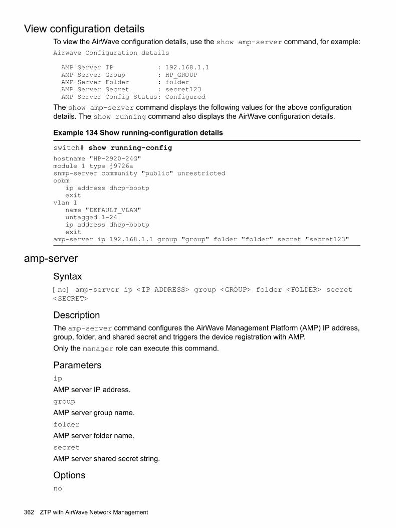
View configuration detailsTo view the AirWave configuration details, use the show amp-server command, for example:Airwave Configuration details
AMP Server IP : 192.168.1.1AMP Server Group : HP_GROUPAMP Server Folder : folderAMP Server Secret : secret123AMP Server Config Status: Configured
The show amp-server command displays the following values for the above configurationdetails. The show running command also displays the AirWave configuration details.
Example 134 Show running-configuration details
switch# show running-confighostname "HP-2920-24G"module 1 type j9726asnmp-server community "public" unrestrictedoobm
ip address dhcp-bootpexit
vlan 1name "DEFAULT_VLAN"untagged 1-24ip address dhcp-bootpexit
amp-server ip 192.168.1.1 group "group" folder "folder" secret "secret123"
amp-serverSyntax[no] amp-server ip <IP ADDRESS> group <GROUP> folder <FOLDER> secret<SECRET>
DescriptionThe amp-server command configures the AirWave Management Platform (AMP) IP address,group, folder, and shared secret and triggers the device registration with AMP.Only the manager role can execute this command.
Parametersip
AMP server IP address.group
AMP server group name.folder
AMP server folder name.secret
AMP server shared secret string.
Optionsno
362 ZTP with AirWave Network Management
The no amp-server command removes the configuration for the AMP server.
PermissionsOnly the manager role can execute this command.
debug ztpSyntax[no] debug ztp
DescriptionEnables or disables ZTP debug logging.
Parametersztp
Zero Touch Provisioning.
Optionsno
The no debug ztp command disables the ZTP debug logging.
debug ztp 363

12 Auto configuration upon Aruba AP detectionBeginning with switch software release 16.01, Auto configuration upon Aruba AP detection issupported on the following switch models covered in this guide:• 3800 (KA software)
• 3810 (KB software)
• 5400R (KB software)
• 5400 (K software)
Auto device detection and configurationThe auto device detection and configuration detects a directly connected Aruba AP dynamicallyand applies predefined configurations to ports on which the Aruba AP is detected.You can create port configuration profiles, associate them to a device type, and enable or disablea device type. The only device type supported is aruba-ap and it is used to identify all the ArubaAPs.When a configured device type is connected on a port, the system automatically applies thecorresponding port profile. Connected devices are identified using LLDP. When the LLDPinformation on the port ages out, the device profile is removed.By default, the device profile feature is disabled. When you enable the device profile support fora device type, if no other device profile is mapped to the device type, the default device profiledefault-ap-profile is associated with the device type. You can modify the AP default deviceprofile configuration but you cannot delete it. The default-ap-profile command supportsonly the AP device type.
More information“Creating a profile and associate a device type” (page 365)“device-profile name” (page 366)“device-profile type” (page 367)
Requirements• Only APs directly connected to the switch will be detected.
Limitations• Only one device type is supported, aruba-ap, and it is used to identify all the Aruba APs.
• You can modify the configuration parameters of the default profile, default-ap-profile,but you cannot delete it or change its name.
• For HPE 5400 Series v1 & v2 modules devices, the maximum value for poe-max-poweris 30 W. For all other devices, the maximum value for poe-max-power is 33 W.
• If the port was part of any protocol VLANs prior to the device profile application, those VLANswill not be removed while applying the device profile.
• Egress rate limiting is not supported for devices running on:
HPE Aruba 2530 Switch Series◦◦ HPE Switch 2530G Series
◦ HPE Switch 2620 Series
364 Auto configuration upon Aruba AP detection

• The egress-bandwidth is only supported for devices running on:
HPE Aruba 2920 Switch Series◦◦ HPE Aruba 5400R Switch Series v2 & v3 modules
◦ HPE 3800 Switch Series
• The egress-bandwidth option is not supported and not displayed in the CLI running on:
HPE Switch 2530G Series◦◦ HPE Aruba 2530 Switch Series
◦ HPE Switch 2620 Series
• 40G is not supported in egress rate-limit.
Feature Interactions
Profile Manager and 802.1XProfile Manager interoperates with RADIUS when it is working in the client mode. When a portis blocked due to 802.1X authentication failure, the LLDP packets cannot come in on that port.Therefore, the Aruba AP cannot be detected and the device profile cannot be applied. When theport gets authenticated, the LLDP packets comes in, the AP is detected, and the device profileis applied.You must ensure that the RADIUS server will not supply additional configuration such as VLANor CoS during the 802.1X authentication as they will conflict with the configuration applied by theProfile Manager. If the RADIUS server supplies any such configurations to a port, the deviceprofile will not be applied on such ports.
Profile Manager and LMA/WMA/MAC-AUTHIf either LMA, WMA, or MAC-AUTH is enabled on an interface, all the MAC addresses reachingthe port must be authenticated. If LMA, WMA, or MAC-AUTH is configured on an interface, theuser can have more granular control and does not need the device profile configuration. Therefore,the device profile will not be applied on such interface.
Profile manager and Private VLANsWhen the device profile is applied, a check is performed to verify if the VLAN addition violatesany PVLAN requirements. The following PVLAN related checks are done before applying theVLANs configured in the device profile to an interface:• A port can be a member of only one VLAN from a given PVLAN instance.
• A promiscuous port cannot be a member of a secondary VLAN.
Creating a profile and associate a device type1. Create a new profile:
switch# device-profile <profile-name>
2. Enable the aruba-ap device type:switch# device-profile type aruba-ap enable
3. Associate the new profile to the aruba-ap device type:switch# device-profile type aruba-ap associate <profile-name>
For example, to add the profile abc and associate it with the aruba-ap type, enter:.
Auto device detection and configuration 365
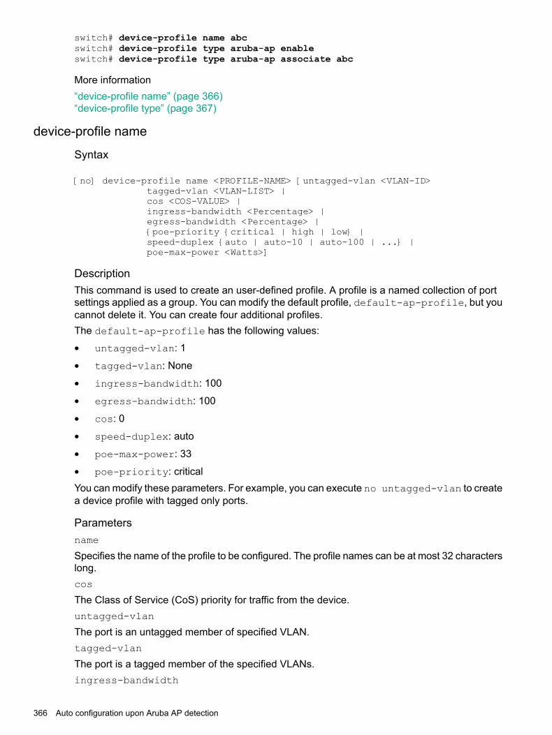
switch# device-profile name abcswitch# device-profile type aruba-ap enableswitch# device-profile type aruba-ap associate abc
More information“device-profile name” (page 366)“device-profile type” (page 367)
device-profile name
Syntax
[no] device-profile name <PROFILE-NAME> [untagged-vlan <VLAN-ID>tagged-vlan <VLAN-LIST> |cos <COS-VALUE> |ingress-bandwidth <Percentage> |egress-bandwidth <Percentage> |{poe-priority {critical | high | low} |speed-duplex {auto | auto-10 | auto-100 | ...} |poe-max-power <Watts>]
DescriptionThis command is used to create an user-defined profile. A profile is a named collection of portsettings applied as a group. You can modify the default profile, default-ap-profile, but youcannot delete it. You can create four additional profiles.The default-ap-profile has the following values:
• untagged-vlan: 1
• tagged-vlan: None
• ingress-bandwidth: 100
• egress-bandwidth: 100
• cos: 0
• speed-duplex: auto
• poe-max-power: 33
• poe-priority: criticalYou can modify these parameters. For example, you can execute no untagged-vlan to createa device profile with tagged only ports.
Parametersname
Specifies the name of the profile to be configured. The profile names can be at most 32 characterslong.cos
The Class of Service (CoS) priority for traffic from the device.untagged-vlan
The port is an untagged member of specified VLAN.tagged-vlan
The port is a tagged member of the specified VLANs.ingress-bandwidth
366 Auto configuration upon Aruba AP detection

The ingress maximum bandwidth for the device port.egress-bandwidth
The egress maximum bandwidth for the device port.poe-priority
The PoE priority for the device port.speed-duplex
The speed and duplex for the device port.poe-max-power
The maximum PoE power for the device port.
Optionsno
Removes the user-defined profiles.
Restrictions
• You can modify the configuration parameters of the default profile, default-ap-profile,but you cannot delete it or change its name.
• For HPE Aruba 5400R Switch Series devices, the maximum value for poe-max-power is30 W. For all other devices, the maximum value for poe-max-power is 33 W.
• Egress rate limiting is not supported for devices running on:
HPE Aruba 2530 Switch Series◦◦ HPE Switch 2530G Series
◦ HPE Switch 2620 Series
• The egress-bandwidth is only supported for HP Switch 2920 Series, HP Switch 5400RSeries v2 & v3 modules, and HP Switch 3800 Series.
• The egress-bandwidth option is not supported and not displayed in the CLI for deviceson: HPE Switch 2530G Series, HPE Aruba 2530 Switch Series, and HPE Switch 2620 Series.
• The profile configuration is only applicable to access points.
More information“device-profile type” (page 367)
device-profile type
Syntaxdevice-profile type <DEVICE> [associate <PROFILE-NAME> | enable | disable ]
DescriptionThis command specifies an approved device type in order to configure and attach a profile to it.The profile’s configuration is applied to any port where a device of this type is connected.
Parameterstype
An approved device type in order to configure and attach a profile to it. The only device typesupported is aruba-ap and it is used to identify all the Aruba APs.
Auto device detection and configuration 367

APs.associate
Associates a profile with a device type.enable
Enables automatic profile association.disable
Disables automatic profile association.
Optionsno
Removes the device type association and disables the feature for the device type. By default,this feature is disabled.
RestrictionsOnly one device type is supported, aruba-ap, and it is used to identify all the Aruba accesspoints.
More information“device-profile name” (page 366)
Rogue AP IsolationThe Rogue AP Isolation feature detects and blocks any unauthorized APs in the network. Youcan either log or block the rogue device. If the action requested is to log the rogue device, theMAC address of the rogue device is logged in the system logs (RMON). If the action is to blockthe rogue device, the traffic to and from the MAC address of the rogue device is blocked. TheMAC is also logged in the system log.When an Aruba AP detects a rogue AP on the network, it sends out the MAC address of the APas well as the MAC of the clients connected to the AP to the switch using the ArubaOS-Switchproprietary LLDP TLV protocol. The switch then adds a rule in its hardware table to block all thetraffic originating from the rogue AP’s MAC address.The rogue-ap-isolation command configures the rogue AP isolation for the switch andgives the option to enable or disable the rogue AP isolation feature. The rogue-ap-isolationaction command gives you the ability to block the traffic to or from the rogue device or log theMAC of the rogue device. When the action is set to block, the rogue MAC is logged as well. Bydefault, the action is set to block.The rogue-ap-isolation whitelist command lets you add devices detected as possiblerogue APs to the whitelist. A maximum of 128 MAC addresses are supported for the whitelist.The clear rogue-aps command clears the detected rogue AP device MAC address.
NOTE: Rogue AP Containment feature in ArubaOS-Switch only works with Instant AP.
More information“rogue-ap-isolation” (page 371)“rogue-ap-isolation action” (page 371)“rogue-ap-isolation whitelist” (page 372)“clear rogue-ap-isolation” (page 372)
368 Auto configuration upon Aruba AP detection

Limitations• You can add a maximum of 128 MAC addresses to the whitelist.
• When a MAC is already authorized by any of the port security features such as LMA, WMA,or 802.1X, the MAC is logged but you cannot block it using the rogue-ap-isolationfeature. A RMON event is logged to notify the user.
• When a MAC is already configured as an IP received MAC of a VLAN interface, the MACis logged but you cannot block it by using the rogue-ap-isolation feature. A RMONevent is logged to notify the user.
• When a MAC is already locked out via lockout-mac or locked down using the static-macconfiguration, the MAC is logged but you cannot block it using the rogue-ap-isolationfeature. A RMON event is logged to notify the user.
• The number of rogue MACs supported on a switch is a function of the value of max-vlansat boot time. Since the resources are shared with the lockout-mac feature, the scale isdependent on how many lockout addresses have been configured on the switch using thelockout-mac feature.The following table lists the scale when there are no lockout addresses configured on theswitch:
Supported MACsMax VLAN
2000 < VLAN <= 8
1008 < VLAN <= 16
6416 < VLAN <= 256
16256 < VLAN <= 1024
81024 < VLAN <= 2048
42048 < VLAN <= 4094
The switch will throw a RMON log and the rogue MAC will be ignored when the limit isreached.
NOTE: If the max-vlans value is changed to a different value, the scale of rogue MACssupported will not change until the next reboot.
Feature Interactions
MAC lockout and lockdownThe Rogue AP isolation feature uses the MAC lockout feature to block MACs in hardware.Therefore, any MAC blocked with the Rogue AP isolation feature cannot be added with thelockout-mac or [static-mac] command if the action type is set to block.For example:switch# lockout-mac 247703-7a8950Cannot add the entry for the MAC address 247703-7a8950 because it is alreadyblocked by rogue-ap-isolation.
switch# static-mac 247703-7a8950 vlan 1 interface 1Cannot add the entry for the MAC address 247703-7a8950 because it is alreadyblocked by rogue-ap-isolation.
Similarly, any MAC that was added with the lockout-mac or static-mac command and thatis being detected as rogue will be logged, but not blocked in hardware as it already is set to block.
Rogue AP Isolation 369

If the MAC is removed from lockout-mac or static-mac but is still in the rogue device list,it will be blocked back in hardware if the action type is block.
LMA/WMA/802.1X/Port-SecurityAny configuration using LMA, WMA, 802.1X, or Port-Security will not be blocked if the RogueAP isolation feature is enabled. All these features act only when a packet with the said MAC isreceived on a port.If rogue-ap-isolation blocks a MAC before it is configured to be authorized, packets fromsuch MACs will be dropped until one of the following happens:
• Rogue action is changed to LOG.
• Rogue-AP isolation feature is disabled.
• The MAC is not detected as rogue anymore.
• LLDP is disabled on the port (or globally).Once a MAC has been authorized by one of these features, it will not be blocked by Rogue APisolation. A RMON will be logged to indicate the failure to block.The Rogue AP module will retry to block any such MACs periodically. In the event of the MACno longer being authorized, Rogue AP isolation will block the MAC again. No RMON is loggedto indicate this event.
L3 MACThe Rogue AP isolation feature will not block a MAC configured as an IP receive MAC addresson a VLAN interface. This event will be logged in RMON if such MACs are detected as rogue.Conversely, any MAC already blocked by Rogue AP isolation will not be allowed to be configuredas an IP receive MAC address of a VLAN interface.For example:switch# vlan 1 ip-recv-mac-address 247703-3effbbCannot add an entry for the MAC address 247703-3effbb because it is alreadyblocked by rogue-ap-isolation.
Using the Rogue AP Isolation feature1. Check the feature state:
switch# show rogue-ap-isolation
Rogue AP Isolation
Rogue AP Status : DisabledRogue AP Action : Block
Rogue MAC Address Neighbour MAC Address----------------- ---------------------
2. Enable the feature:switch# rogue-ap-isolation enableswitch# show rogue-ap-isolation
Rogue AP Isolation
Rogue AP Status : EnabledRogue AP Action : Block
Rogue MAC Address Neighbour MAC Address----------------- ---------------------
3. Change the action type from block to log:
370 Auto configuration upon Aruba AP detection

switch# rogue-ap-isolation action logswitch# show rogue-ap-isolation
Rogue AP Isolation
Rogue AP Status : EnabledRogue AP Action : Log
Rogue MAC Address Neighbour MAC Address----------------- ---------------------
4. List the current whitelist entries:switch# show rogue-ap-isolation whitelist
Rogue AP Whitelist Configuration
Rogue AP MAC------------------
5. Add a new whitelist entry:switch# rogue-ap-isolation whitelist 005056-00326aswitch# show rogue-ap-isolation whitelist
Rogue AP Whitelist Configuration
Rogue AP MAC------------------00:50:56:00:32:6a
rogue-ap-isolation
syntaxrogue-ap-isolation {enable | disable}
DescriptionConfigures the rogue AP isolation for the switch.
Parametersenable
Enables the rogue AP isolation.disable
Disables the rogue AP isolation.
More information“rogue-ap-isolation action” (page 371)“rogue-ap-isolation whitelist” (page 372)“clear rogue-ap-isolation” (page 372)
rogue-ap-isolation action
syntaxrogue-ap-isolation action {log | block}
DescriptionConfigures the action to take for the rogue AP packets. This function is disabled by default.
Rogue AP Isolation 371
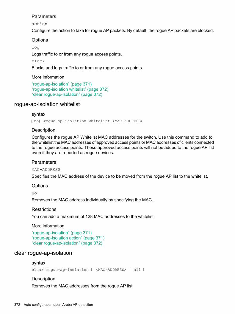
Parametersaction
Configure the action to take for rogue AP packets. By default, the rogue AP packets are blocked.
Optionslog
Logs traffic to or from any rogue access points.block
Blocks and logs traffic to or from any rogue access points.
More information“rogue-ap-isolation” (page 371)“rogue-ap-isolation whitelist” (page 372)“clear rogue-ap-isolation” (page 372)
rogue-ap-isolation whitelist
syntax[no] rogue-ap-isolation whitelist <MAC-ADDRESS>
DescriptionConfigures the rogue AP Whitelist MAC addresses for the switch. Use this command to add tothe whitelist the MAC addresses of approved access points or MAC addresses of clients connectedto the rogue access points. These approved access points will not be added to the rogue AP listeven if they are reported as rogue devices.
ParametersMAC-ADDRESS
Specifies the MAC address of the device to be moved from the rogue AP list to the whitelist.
Optionsno
Removes the MAC address individually by specifying the MAC.
RestrictionsYou can add a maximum of 128 MAC addresses to the whitelist.
More information“rogue-ap-isolation” (page 371)“rogue-ap-isolation action” (page 371)“clear rogue-ap-isolation” (page 372)
clear rogue-ap-isolation
syntaxclear rogue-ap-isolation { <MAC-ADDRESS> | all }
DescriptionRemoves the MAC addresses from the rogue AP list.
372 Auto configuration upon Aruba AP detection
ParametersMAC-ADDRESS
Specifies the MAC address of the device to be moved from the rogue AP list.all
Clears all MAC addresses from the rogue AP list.
RestrictionsThe MAC addresses cleared using this option will be added back to the rogue list under thefollowing cases:1. The LLDP administrator status of the port on which the AP that reported the MAC is disabled
and enabled back.2. The data that is in the rogue AP TLV sent from the AP that informed the rogue MAC has
changed.3. To permanently ignore a MAC from being detected as rogue, add it to the whitelist.
More information“rogue-ap-isolation” (page 371)“rogue-ap-isolation action” (page 371)“rogue-ap-isolation whitelist” (page 372)
TroubleshootingDynamic configuration not displayed when using “show running-config”
SymptomThe show running-config command does not display the dynamic configuration appliedthrough the device profile.
CauseThe show running-config command shows only the permanent user configuration andparameters configured through device profile.
ActionUse the specific show device-profile command to display the parameters dynamicallyconfigured through the device profile.
Switch does not detect the rogue AP TLVs
SymptomThe switch does not detect the rogue AP TLVs that could be sent from the neighboring device.
CauseThe LLDP administrator status of a port is moved from txOnly to tx_rx or rx_only within 120seconds of the previous state change to txOnly.
Action1. Wait for 120 seconds before moving from the state txOnly to the state tx_rx or rx_only.2. Move the administrator status to disable and then back to tx_rx or rx_only.
Troubleshooting 373

The show run command displays non-numerical value for untagged-vlan
SymptomThe show run command displays one of the following values for untagged-vlan:
• no untagged-vlan
• untagged-vlan : None
CauseTheno device-profile or theno rogue-ap-isolation whitelist command is executedto configure untagged-vlan to 0.
ActionNo actions is required.
Show commandsUse the following show commands to view the various configurations and status.
DescriptionCommand
Shows the device profile configuration and status.show device-profile
Shows the device profile configuration details for a singleprofile or all profiles.
show device-profile config
Shows currently applied device profiles.show device-profile status
Shows the following information:show rogue-ap-isolation
• The status of the feature: enabled or disabled.
• The current action type for the rogue MACs detected.
• The list of MAC addresses detected as rogue and theMAC address of the AP that reported them.
Shows the rogue AP whitelist configuration.show rogue-ap-isolation whitelist
Shows the running configuration.show run
Validation Rules
Error/Warning/PromptValidation
Maximum tagged VLANs that can be associated with adevice-profile is 256.
device-profile profile-namedefault-ap-profile
String too long. Allowed length is 32 characters.device-profile profile-name creation.
Device profile <> already exists.device-profile profile-name creation.
The maximum number of device profiles allowed is 5.device-profile profile-name creation.
Device profile <> does not exist.device-profile profile-name deletion.
Cannot delete profile <> when associated with a devicetype.
device-profile profile-name deletion.
Default profile cannot be deleted.device-profile profile-name deletion.
Default profile name cannot be changed.device-profile profile-name modification viaSNMP.
374 Auto configuration upon Aruba AP detection

Error/Warning/PromptValidation
Device profile index cannot be greater than 5.device-profileprofile-name creation/modificationvia SNMP.
Invalid VLAN.untagged-vlan
Cannot configure the VLAN <> as an untagged VLANbecause this is already used as a tagged VLAN.
untagged-vlan
The maximum number of tagged VLANs in a profile isless than 512 or the maximum VLANs, MAX_VLANs,configurable in the system.
tagged-vlan 1-1000
Cannot configure the VLAN <> as a tagged VLAN becausethis is already used as an untagged VLAN.
tagged-vlan
SNMP should return WRONG_VALUE_ERROR.ingress-bandwidth
SNMP should return WRONG_VALUE_ERROR.egress-bandwidth
SNMP should return WRONG_VALUE_ERROR.cos
SNMP should return WRONG_VALUE_ERROR.speed-duplex
SNMP should return WRONG_VALUE_ERROR.poe-max-power
SNMP should return WRONG_VALUE_ERROR.poe-priority
String <> too long. Allowed length is 32 characters.device-profile type aruba-ap profile-name
Device profile <> does not exist.device-profile type aruba-ap profile-name
Device type is not supported.device-profile type aruba-switch-router
Whitelist MAC address already exists in the list.rogue-ap-whitelist
Whitelist MAC address does not exist in the list.rogue-ap-whitelist
The maximum number of whitelist MACs allowed is 128.rogue-ap-whitelist
Cannot add the whitelist entry because the specified MACaddress is already configured as a lock-out MAC.
rogue-ap-whitelist <MAC>
Cannot add the lock-out entry because the specified MACaddress is already configured as a whitelist MAC.
lock-out <MAC>
Cannot add an entry for the MAC address<MAC-ADDRESS> because it is already blocked byrogue-ap-isolation.
lockout-mac <MAC-ADDRESS>
ORstatic-mac <MAC-ADDRESS> vlan <vlan-id>interface <interface>
ORvlan <vlan-id> ip-recv-mac-address<MAC-ADDRESS
Troubleshooting 375

13 Link Aggregation Control Protocol-Multi-Active DetectionLACP configuration
The following command defines whether LACP is enabled on a port, and whether it is in activeor passive mode when enabled. When LACP is enabled and active, the port sends LACP packetsand listens to them. When LACP is enabled and passive, the port sends LACP packets only if itis spoken to. When LACP is disabled, the port ignores LACP packets. If the command is issuedwithout a mode parameter, 'active' is assumed. During dynamic link aggregation using LACP,ports with the same key are aggregated as a single trunk. MAD passthrough applies only totrunks and not to physical ports.
Syntax[no]interface <PORT-LIST> lacp [mad-passthrough[enable|disable]|active|passive|key <key>]
Viewing LACP-MAD configurationSyntaxshow lacp [counters [<PORT-LIST>] | local [<PORT-LIST>] |peer[<PORT-LIST>] | distributed | mad-passthrough [counters [<PORT-LIST>]]]
Show LACP-MAD passthrough configuration on LACP trunks.
Syntaxshow lacp mad-passthrough counters [<PORT-LIST>]
Show LACP-MAD passthough counters on ports
Clear all LACP statisticsSyntaxclear lacp statistics
Clear all LACP statistics including MAD passthrough counters. Resets LACP packets sent andreceived on all ports.
LACP-MAD OperationsLink Aggregation Control Protocol-Multi-Active Detection (LACP-MAD) is a detection mechanismdeployed by switches to recover from a breakup of the Intelligent Resilient Framework (VSF)stack due to link or other failure.LACP-MAD is implemented by sending extended LACP data units (LACPDUs) with a type lengthvalue (TLV) that conveys the active ID of an VSF virtual device. The active ID is identical to themember ID of the master and is thus unique to the VSF virtual device. When LACP MAD detectionis enabled, the members exchange their active IDs by sending extended LACPDUs.
• When the VSF virtual device operates normally, the active IDs in the extended LACPDUssent by all members are the same, indicating that there is no multi-active collision.
• When there is a breakup in the VSF virtual chassis, the active IDs in the extended LACPDUssent by the members in different VSF virtual devices are different, indicating that there aremulti-active collisions.
LACP-MAD passthrough helps VSF-capable devices detect multi-access and take correctiveaction. These devices do not initiate transmission of LACP-MAD frames or participate in anyMAD decision making process. These devices simply forward LACP-MAD TLVs received on one
376 Link Aggregation Control Protocol-Multi-Active Detection

interface to the other interfaces on the trunk. LACP-MAD passthrough can be enabled for 24LACP trunks. By default, LACP-MAD passthrough is disabled.
LACP-MAD Operations 377
14 File transfersFile transfer methods
The switches support several methods for transferring files to and from a physically connecteddevice or via the network, including TFTP, Xmodem, and USB. This appendix explains how todownload new switch software, upload or download switch configuration files and softwareimages, and upload command files for configuring ACLs.
TFTPTFTP software downloads
This procedure assumes that:
• A software version for the switch has been stored on a TFTP server accessible to the switch.(The software file is typically available from the Switch Networking website at http://www.hpe.com/networking/support.)
• The switch is properly connected to your network and has already been configured with acompatible IP address and subnet mask.
• The TFTP server is accessible to the switch via IP.Before you use the procedure, do the following:
• Obtain the IP address of the TFTP server in which the software file has been stored.
• If VLANs are configured on the switch, determine the name of the VLAN in which the TFTPserver is operating.
• Determine the name of the software file stored in the TFTP server for the switch (for example,E0820.swi.)
NOTE: If your TFTP server is a UNIX workstation, ensure that the case (upper or lower) thatyou specify for the filename is the same case as the characters in the software filenames on theserver.
TFTP software downloads
Syntaxcopy tftp flash ip-address remote-file [ primary | secondary ] [oobm]Automatically downloads a switch software file to primary or secondary flash. If you do not specifythe flash destination, the TFTP download defaults to primary flash.
ExampleTo download a switch software file named k0800.swi from a TFTP server with the IP address of10.28.227.103 to primary flash:
378 File transfers

1. Execute copy as shown below:
Figure 117 Download command for an OS (switch software)
When the switch finishes downloading the software file from the server, it displays thisprogress message:Validating and Writing System Software to FLASH ...
2. When the download finishes, you must reboot the switch to implement the newly downloadedsoftware image. To do so, use one of the following commands:
Syntaxboot system flash [ primary | secondary ]Boots from the selected flash.
Syntaxreload
Boots from the flash image and startup-config file. A switch covered in this guide (with multipleconfiguration files), also uses the current startup-config file.
3. To confirm that the software downloaded correctly, execute show system and check theFirmware revision line.
For information on primary and secondary flash memory and the boot commands, see the basicoperation guide.
NOTE: If you use auto-tftp to download a new image in a redundant management system,the active management module downloads the new image to both the active and standby modules.Rebooting after the auto-tftp process completes reboots the entire system.
Enabling TFTPTFTP is enabled by default on the switch. If TFTP operation has been disabled, you can re-enableit by specifying TFTP client or server functionality with the following command.
Syntaxtftp [ client | server ]
Syntax[ no ] tftp [ client | server [ listen oobm | data | both ]]Disables/re-enables TFTP for client or server functionality so that the switch can:
• Use TFTP client functionality to access TFTP servers in the network to receivedownloaded files.
• Use TFTP server functionality to upload files to other devices on the network.
TFTP 379

For switches that have a separate out-of-band management port, the listen parameter in aserver configuration allows you to specify whether transfers take place through the out-of-bandmanagement (oobm) interface, the data interface, or both.
NOTE: To disable all TFTP client or server operation on the switch except for the auto-TFTPfeature, enter the no tftp [client|server] command.When IP SSH file transfer is used to enable SCP and SFTP functionality on the switch, thisdisables TFTP client and server functionality. Once ip ssh file transfer is enabled, TFTP andauto-TFTP cannot be re-enabled from the CLI.When TFTP is disabled, instances of TFTP in the CLI copy command and the Menu interface"Download OS" screen become unavailable.The no tftp <client | server> command does not disable auto-TFTP operation. Todisable an auto-TFTP command configured on the switch, use the no auto-tftp commanddescribed on page “Downloading software automatically from a TFTP server” (page 380) to removethe command entry from the switch's configuration.For information on how to configure TFTP file transfers on an IPv6 network, see the IPv6configuration guide.
Operation notesTFTP at the switch is allows for extensive use of scripts on various customer environments. Suchenvirons, like FW, configurations, backups, and restores all use the TFTP network service.
• SSH/SFTP is needed to secure access to network components.
• Users are allowed to re-enable TFTP and make both TFTP and SFTP work in parallel.
• SFTP support for database of DSNOOPv4, v6 and DHCP Server are also available. Toprovide a secure way to transfer the database, the SFTP option has been added where therespective database can also be transferred to a SFTP Server.
Example 135 Running-configuration of the device
HP Switch (config)# show running-config
Running configuration:; J8693A Configuration Editor; Created on release #K.15.15.0000x; Ver #04:7f.ff.3f.ef:54hostname "HP-3500yl-48G"no tftp clientno tftp server
Example 136 Enable TFTP client/server
HP Switch (config)# tftp client
The command ip ssh filetransfer will still disable the TFTP Client and TFTP Serverhowever the user is able to re-enable them. The command will display the following message.
ip ssh filetransfertftp and auto-tftp have been disabled.
Downloading software automatically from a TFTP serverThe auto-tftp command lets you configure the switch to download software automaticallyfrom a TFTP server.
380 File transfers

At switch startup, the auto-TFTP feature automatically downloads a specified software image tothe switch from a specified TFTP server and then reboots the switch. To implement the process,you must first reboot the switch using one of the following methods:
• Enter the boot system flash primary command in the CLI.
• With the default flash boot image set to primary flash (the default), enter the boot or thereload command, or use the reset button on the switch. (To reset the boot image to primaryflash, use boot set-default flash primary.)
Syntaxauto-tftp ip-addr filename
By default, auto-TFTP is disabled. This command configures the switch to automatically downloadthe specified software file from the TFTP server at the specified IP address. The file is downloadedinto primary flash memory at switch startup; the switch then automatically reboots from primaryflash.
NOTE: To enable auto-TFTP to copy a software image to primary flash memory, the versionnumber of the downloaded software file (for example, K_14_01.swi) must be different from theversion number currently in the primary flash image.The current TFTP client status (enabled or disabled) does not affect auto-TFTP operation. (See“Enabling TFTP” (page 379).)Completion of the auto-TFTP process may require several minutes while the switch executesthe TFTP transfer to primary flash and then reboots again.
The no form of the command disables auto-TFTP operation by deleting the auto-tftp entryfrom the startup configuration.The no auto-tftp command does not affect the current TFTP-enabled configuration on theswitch. However, entering the ip ssh filetransfer command automatically disables bothauto-tftp and tftp operation.
Downloading to primary flash using TFTPNote that the menu interface accesses only the primary flash.1. In the console Main Menu, selectDownloadOS to display the screen in Figure 118 (page 381).
(The term "OS" or "operating system" refers to the switch software):
Figure 118 Download OS (software) screen (default values)
TFTP 381

2. Press [E] (for Edit.)3. Ensure that the Method field is set to TFTP (the default.)4. In the TFTP Server field, enter the IP address of the TFTP server in which the software file
has been stored.5. In the Remote File Name field, enter the name of the software file (if you are using a UNIX
system, remember that the filename is case-sensitive.)6. Press [Enter], then [X] (for eXecute) to begin the software download.
The screen shown in Figure 119 (page 382) appears:
Figure 119 Download OS (software) screen during a download
A "progress" bar indicates the progress of the download. When the entire software file hasbeen received, all activity on the switch halts and you will see Validating and writing systemsoftware to FLASH...
7. After the primary flash memory is updated with the new software, you must reboot the switchto implement the newly downloaded software. Return to the Main Menu and press [6] (forReboot Switch.)You will see this prompt:Continue reboot of system? : No
Press the space bar once to change No to Yes, then press [Enter] to begin the reboot.
NOTE: When you use the menu interface to download a switch software, the new imageis always stored in primary flash. Also, using the Reboot Switch command in the MainMenu always reboots the switch from primary flash. Rebooting the switch from the CLIprovides more options. See the basic operation guide.
8. After you reboot the switch, confirm that the software downloaded correctly:a. From the Main Menu, select
2. Switch Configuration...2. Port/Trunk Settings
b. Check the Firmware revision line.
Disabling TFTP and auto-TFTP for enhanced securityUsing the ip ssh filetransfer command to enable SFTP automatically disables TFTP andauto-TFTP (if either or both are enabled), as shown in Figure 120 (page 383).
382 File transfers
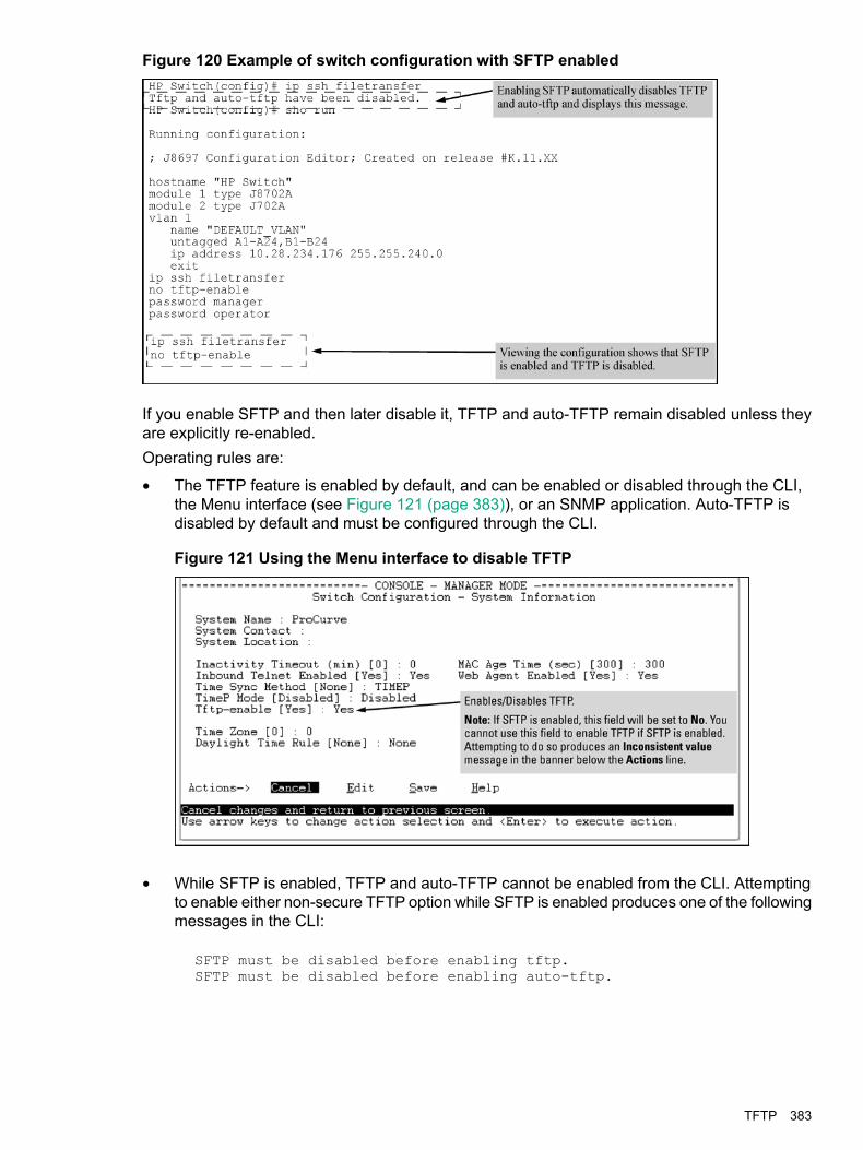
Figure 120 Example of switch configuration with SFTP enabled
If you enable SFTP and then later disable it, TFTP and auto-TFTP remain disabled unless theyare explicitly re-enabled.Operating rules are:
• The TFTP feature is enabled by default, and can be enabled or disabled through the CLI,the Menu interface (see Figure 121 (page 383)), or an SNMP application. Auto-TFTP isdisabled by default and must be configured through the CLI.
Figure 121 Using the Menu interface to disable TFTP
• While SFTP is enabled, TFTP and auto-TFTP cannot be enabled from the CLI. Attemptingto enable either non-secure TFTP option while SFTP is enabled produces one of the followingmessages in the CLI:
SFTP must be disabled before enabling tftp.SFTP must be disabled before enabling auto-tftp.
TFTP 383

Similarly, while SFTP is enabled, TFTP cannot be enabled using an SNMP managementapplication. Attempting to do so generates an "inconsistent value" message. (An SNMPmanagement application cannot be used to enable or disable auto-TFTP.)
• To enable SFTP by using an SNMP management application, you must first disable TFTPand, if configured, auto-TFTP on the switch. You can use either an SNMP application or theCLI to disable TFTP, but you must use the CLI to disable auto-TFTP. The following CLIcommands disable TFTP and auto-TFTP on the switch.
Enabling SSH V2 (required for SFTP)HP Switch(config)# ip ssh version 2
NOTE: As a matter of policy, administrators should not enable the SSH V1-only or the SSHV1-or-V2 advertisement modes. SSHv1 is supported on only some legacy switches (such as theHPE Switch Series 2500 switches.)
Viewing SSHHP Switch(config)# show ip ssh
Once you have confirmed that you have enabled an SSH session (with the show ip sshcommand), enter ip ssh filetransfer so that SCP and/or SFTP can run. You can thenopen your third-party software client application to begin using the SCP or SFTP commands tosafely transfer files or issue commands to the switch.
NOTE: Any attempts to use SCP or SFTP without using ip ssh filetransfer cause theSCP or SFTP session to fail. Depending on the client software in use, you will receive an errormessage on the originating console, for example:
IP file transfer not enabled on the switch
Disabling secure file transfer
HP Switch(config)# no ip ssh filetransfer
AuthenticationSwitch memory allows up to ten public keys. This means the authentication and encryption keysyou use for your third-party client SCP/SFTP software can differ from the keys you use for theSSH session, even though both SCP and SFTP use a secure SSH tunnel.
NOTE: SSH authentication is mutually exclusive with RADIUS servers.
Some clients, such as PSCP (PuTTY SCP), automatically compare switch host keys for you.Other clients require you to manually copy and paste keys to the $HOME/.ssh/known_hostsfile. Whatever SCP/SFTP software tool you use, after installing the client software you must verifythat the switch host keys are available to the client.Because the third-party software utilities you may use for SCP/SFTP vary, you should refer tothe documentation provided with the utility you select before performing this process.
SCP/SFTP operating notes
• When an SFTP client connects, the switch provides a file system displaying all of its availablefiles and folders. No file or directory creation is permitted by the user. Files may be onlyuploaded or downloaded, according to the permissions mask. All of the necessary files the
384 File transfers
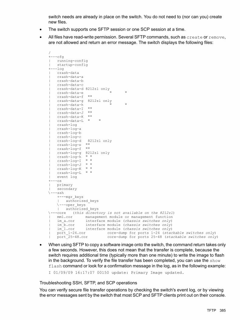
switch needs are already in place on the switch. You do not need to (nor can you) createnew files.
• The switch supports one SFTP session or one SCP session at a time.
• All files have read-write permission. Several SFTP commands, such as create or remove,are not allowed and return an error message. The switch displays the following files:
/+---cfg| running-config| startup-config+---log| crash-data| crash-data-a| crash-data-b| crash-data-c| crash-data-d 8212zl only| crash-data-e " "| crash-data-f ""| crash-data-g 8212zl only| crash-data-h " "| crash-data-I ""| crash-data-J ""| crash-data-K ""| crash-data-L " "| crash-log| crash-log-a| crash-log-b| crash-log-c| crash-log-d 8212zl only| crash-log-e ""| crash-log-f ""| crash-log-g 8212zl only| crash-log-h " "| crash-log-I " "| crash-log-J " "| crash-log-K " "| crash-log-L " "| event log+---os| primary| secondary\---ssh
+---mgr_keys| authorized_keys\---oper_keys| authorized_keys
\---core (this directory is not available on the 8212zl)| mm1.cor management module or management function| im_a.cor interface module (chassis switches only)| im_b.cor interface module (chassis switches only)| im_1.cor interface module (chassis switches only)| port_1-24.cor core-dump for ports 1-24 (stackable switches only)| port_25-48.cor core-dump for ports 25-48 (stackable switches only)
• When using SFTP to copy a software image onto the switch, the command return takes onlya few seconds. However, this does not mean that the transfer is complete, because theswitch requires additional time (typically more than one minute) to write the image to flashin the background. To verify the file transfer has been completed, you can use the showflash command or look for a confirmation message in the log, as in the following example:I 01/09/09 16:17:07 00150 update: Primary Image updated.
Troubleshooting SSH, SFTP, and SCP operationsYou can verify secure file transfer operations by checking the switch's event log, or by viewingthe error messages sent by the switch that most SCP and SFTP clients print out on their console.
TFTP 385
NOTE: Messages that are sent by the switch to the client depend on the client software in useto display them on the user console.
Broken SSH connectionIf an ssh connection is broken at the wrong moment (for instance, the link goes away or spanningtree brings down the link), a fatal exception occurs on the switch. If this happens, the switchgracefully exits the session and produces an Event Log message indicating the cause of failure.The following three examples show the error messages that may appear in the log, dependingon the type of session that is running (SSH, SCP, or SFTP):
ssh: read error Bad file number, session aborted I 01/01/9000:06:11 00636 ssh: sftp session from ::ffff:10.0.12.35 W01/01/90 00:06:26 00641 ssh:
sftp read error Bad file number, session aborted I 01/01/9000:09:54 00637 ssh: scp session from ::ffff:10.0.12.35 W 01/01/90
ssh: scp read error Bad file number, session aborted
NOTE: The Bad file number is from the system error value and may differ depending onthe cause of the failure. In the third example, the device file to read was closed as the deviceread was about to occur.
Attempt to start a session during a flash writeIf you attempt to start an SCP (or SFTP) session while a flash write is in progress, the switchdoes not allow the SCP or SFTP session to start. Depending on the client software in use, thefollowing error message may appear on the client console:
Received disconnect from 10.0.12.31: 2: Flash access inprogress
lost connection
Failure to exit from a previous sessionThis next example shows the error message that may appear on the client console if a new SCP(or SFTP) session is started from a client before the previous client session has been closed(the switch requires approximately ten seconds to timeout the previous session):
Received disconnect from 10.0.12.31: 2: Wait for previoussession to complete
lost connection
Attempt to start a second sessionThe switch supports only one SFTP session or one SCP session at a time. If a second sessionis initiated (for example, an SFTP session is running and then an SCP session is attempted),the following error message may appear on the client console:
Received disconnect from 10.0.12.31: 2: Other SCP/SFTPsession running
lost connection
386 File transfers
Using USB to transfer files to and from the switchThe switch's USB port (labeled as Auxiliary Port) allows the use of a USB flash drive for copyingconfiguration files to and from the switch. Beginning with software release K_12_XX or later,copy commands that used either tftp or xmodem now include an additional option for usb asa source or destination for file transfers.Operating rules and restrictions on USB usage are:
• Unformatted USB flash drives must first be formatted on a PC (Windows FAT format.) Fordevices with multiple partitions, only the first partition is supported. Devices with securepartitions are not supported.
• If they already exist on the device, subdirectories are supported. When specifying afilename , you must enter either the individual file name (if at the root) or the full pathname (for example, /subdir/filename.)
• To view the contents of a USB flash drive, use the dir command. This lists all files anddirectories at the root. To view the contents of a directory, you must specify the subdirectoryname (that is, dir subdirectory.)
• The USB port supports connection to a single USB device. USB hubs to add more ports arenot supported.
NOTE: Some USB flash drives may not be supported on your switch. Consult the latestReleaseNotes for information on supported devices.
SCP and SFTPEnabling SCP and SFTP
1. Open an SSH session as you normally would to establish a secure encrypted tunnel betweenyour computer and the switch. Please note that this is a one-time procedure for new switchesor connections. If you have already done it once you should not need to do it a second time.For more detailed directions on how to open an SSH session, see the access security guide.
2. To enable secure file transfer on the switch (once you have an SSH session establishedbetween the switch and your computer), open a terminal window and enter the followingcommand:HP Switch(config)# ip ssh filetransfer
Using SCP and SFTPFor some situations you may want to use a secure method to issue commands or copy files tothe switch. By opening a secure, encrypted SSH session and enabling ip ssh file transfer, youcan then use a third-party software application to take advantage of SCP and SFTP. SCP andSFTP provide a secure alternative to TFTP for transferring information that may be sensitive (likeswitch configuration files) to and from the switch. Essentially, you are creating a secure SSHtunnel as a way to transfer files with SFTP and SCP channels.Once you have configured your switch to enable secure file transfers with SCP and SFTP, filescan be copied to or from the switch in a secure (encrypted) environment and TFTP is no longernecessary.To use these commands, you must install on the administrator workstation a third-party applicationsoftware client that supports the SFTP and/or SCP functions. Some examples of software thatsupports SFTP and SCP are PuTTY, Open SSH, WinSCP, and SSH Secure Shell. Most of theseare freeware and may be downloaded without cost or licensing from the internet. There aredifferences in the way these clients work, so be sure you also download the documentation.
SCP and SFTP 387
As described earlier in this chapter you can use a TFTP client on the administrator workstationto update software images. This is a plain-text mechanism that connects to a standalone TFTPserver or another switch acting as a TFTP server to obtain the software image files. Using SCPand SFTP allows you to maintain your switches with greater security. You can also roll out newsoftware images with automated scripts that make it easier to upgrade multiple switchessimultaneously and securely.SFTP is unrelated to FTP, although there are some functional similarities. Once you set up anSFTP session through an SSH tunnel, some of the commands are the same as FTP commands.Certain commands are not allowed by the SFTP server on the switch, such as those that createfiles or folders. If you try to issue commands such as create or remove using SFTP, the switchserver returns an error message.You can use SFTP just as you would TFTP to transfer files to and from the switch, but with SFTP,your file transfers are encrypted and require authentication, so they are more secure than theywould be using TFTP. SFTP works only with SSH version 2 (SSH v2.)
NOTE: SFTP over SSH version 1 (SSH v1) is not supported. A request from either the clientor the switch (or both) using SSH v1 generates an error message. The actual text of the errormessage differs, depending on the client software in use. Some examples are:
Protocol major versions differ: 2 vs. 1Connection closed
Protocol major versions differ: 1 vs. 2Connection closed
Received disconnect from ip-addr : /usr/local/libexec/sftp-server: command not supportedConnection closed
SCP is an implementation of the BSD rcp (Berkeley UNIX remote copy) command tunneledthrough an SSH connection.SCP is used to copy files to and from the switch when security is required. SCP works with bothSSH v1 and SSH v2. Be aware that the most third-party software application clients that supportSCP use SSHv1.The general process for using SCP and SFTP involves three steps:1. Open an SSH tunnel between your computer and the switch if you have not already done
so.(This step assumes that you have already set up SSH on the switch.)
2. Execute ip ssh filetransfer to enable secure file transfer.3. Use a third-party client application for SCP and SFTP commands.
388 File transfers

XmodemDownloading software via a Xmodem
This procedure assumes that:
• The switch is connected via the Console RS-232 port to a PC operating as a terminal. (Forinformation on connecting a PC as a terminal and running the switch console interface, seethe installation and getting started guide you received with the switch.)
• The switch software is stored on a disk drive in the PC.
• The terminal emulator you are using includes the Xmodem binary transfer feature. (Forexample, in the HyperTerminal application included with Windows NT, you would use theSend File option in the Transfer drop-down menu.)
Downloading to Flash using Xmodem and terminal emulator
Syntaxcopy xmodem flash [ primary | secondary ]Downloads a software file to primary or secondary flash. If you do not specify the flash destination,the Xmodem download defaults to primary flash.
ExampleTo download a switch software file named E0822.swi from a PC (running a terminal emulatorprogram such as HyperTerminal) to primary flash:1. Execute the following command in the CLI:
2. Execute the terminal emulator commands to begin the Xmodem transfer. For example, usingHyperTerminal:a. Click on Transfer, then Send File.b. Type the file path and name in the Filename field.c. In the Protocol field, select Xmodem.d. Click on the [Send] button.
The download can take several minutes, depending on the baud rate used in the transfer.
3. When the download finishes, you must reboot the switch to implement the newly downloadedsoftware. To do so, use one of the following commands:
Syntaxboot system flash [ primary | secondary ]Reboots from the selected flash
Syntaxreload
Reboots from the flash image currently in use4. To confirm that the software downloaded correctly:
HP Switch show system
Check the Firmware revision line. It should show the software version that you downloadedin the preceding steps.
Xmodem 389

Downloading to primary flash using Xmodem (Menu)
NOTE: The menu interface accesses only the primary flash.
1. From the console Main Menu, select7. Download OS
2. Press [E] (for Edit.)3. Use the Space bar to select XMODEM in the Method field.4. Press [Enter], then [X] (for eXecute) to begin the software download.
The following message appears:Press enter and then initiate Xmodem transfer from the attached computer.....
5. Press [Enter] and then execute the terminal emulator commands to begin Xmodem binarytransfer.For example, using HyperTerminal:a. Click on Transfer, then Send File.b. Enter the file path and name in the Filename field.c. In the Protocol field, select Xmodem.d. Click on the [Send] button.The download then commences. It can take several minutes, depending on the baud rateset in the switch and in your terminal emulator.
6. After the primary flash memory has been updated with the new software, you must rebootthe switch to implement the newly downloaded software. Return to the Main Menu and press[6] (for Reboot Switch.) You then see the following prompt:
Continue reboot of system? : No
Press the space bar once to change No to Yes, then press [Enter] to begin the reboot.7. To confirm that the software downloaded correctly:
a. From the Main Menu, select1. Status and Counters1. General System Information
b. Check the Firmware revision line.
USBEnabling or disabling the USB port
This feature allows configuration of the USB port with either the CLI or SNMP.
Syntaxusb-portno usb-port
Enables the USB port. The no form of the command disables the USB port andany access to the device.
390 File transfers

Downloading switch software using USBThis procedure assumes that:
• A software version for the switch has been stored on a USB flash drive. (The latest softwarefile is typically available from the Switch Networking website at http://www.hpe.com/networking/support.)
• The USB device has been plugged into the switch's USB port.Before you use the procedure:
• Determine the name of the software file stored on the USB flash drive (for example,k0800.swi.)
• Decide whether the image will be installed in the primary or secondary flash.
Syntaxcopy usb flash filename [ primary | secondary ]This command automatically downloads a switch software file to primary or secondary flash. Ifyou do not specify the flash destination, the USB download defaults to primary flash.
ExampleTo copy a switch software file named k0800.swi from a USB device to primary flash:1. Execute copy as shown below:
Figure 122 The command to copy switch software from USB
When the switch finishes copying the software file from the USB device, it displays thisprogress message:
Validating and Writing System Software to the Filesystem....
2. When the copy finishes, you must reboot the switch to implement the newly loaded software.To do so, use one of the following commands
Syntaxboot system flash [ primary | secondary ]Boots from the selected flash.
Syntaxreload
Boots from the flash image and startup-config file. A switch covered in this guide(with multiple configuration files), also uses the current startup-config file.
3. To confirm that the software downloaded correctly, execute show system and check theFirmware revision line.
USB 391
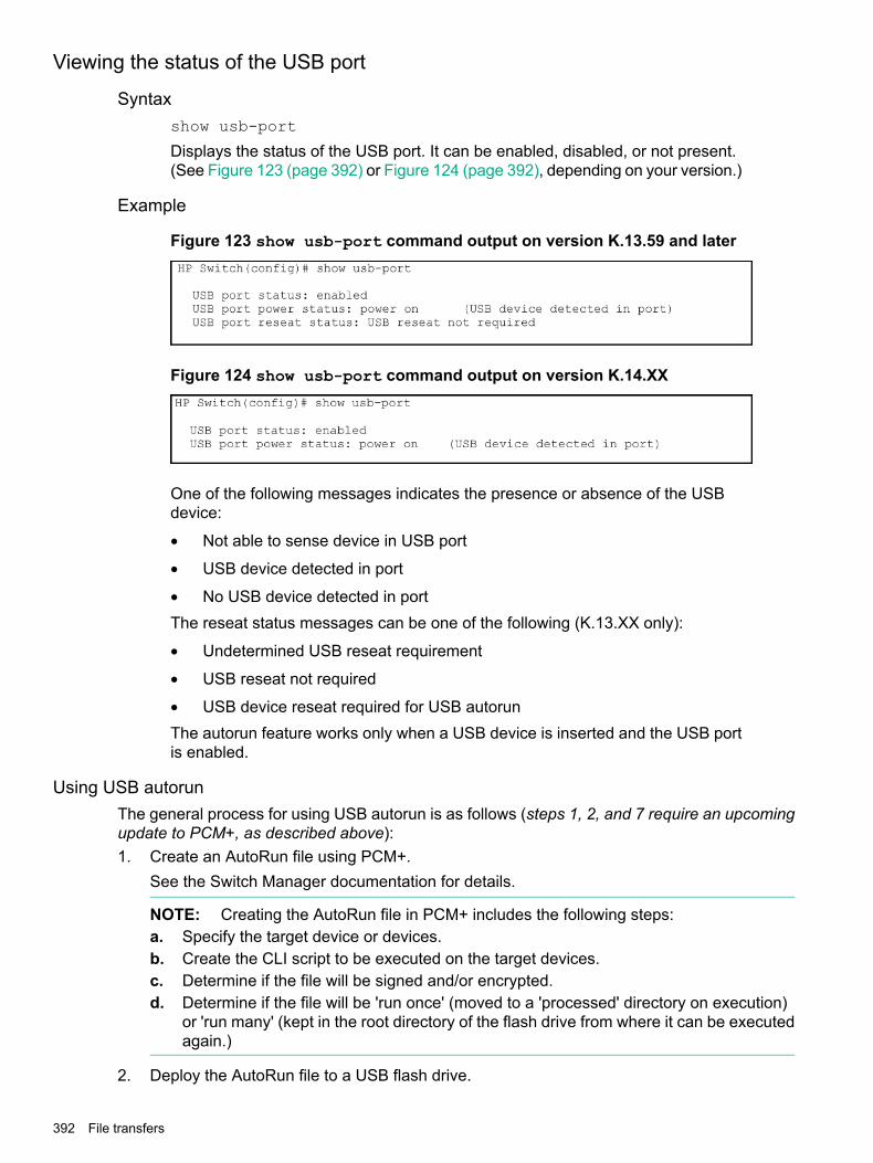
Viewing the status of the USB port
Syntaxshow usb-port
Displays the status of the USB port. It can be enabled, disabled, or not present.(See Figure 123 (page 392) or Figure 124 (page 392), depending on your version.)
Example
Figure 123 show usb-port command output on version K.13.59 and later
Figure 124 show usb-port command output on version K.14.XX
One of the following messages indicates the presence or absence of the USBdevice:
• Not able to sense device in USB port
• USB device detected in port
• No USB device detected in portThe reseat status messages can be one of the following (K.13.XX only):
• Undetermined USB reseat requirement
• USB reseat not required
• USB device reseat required for USB autorunThe autorun feature works only when a USB device is inserted and the USB portis enabled.
Using USB autorunThe general process for using USB autorun is as follows (steps 1, 2, and 7 require an upcomingupdate to PCM+, as described above):1. Create an AutoRun file using PCM+.
See the Switch Manager documentation for details.
NOTE: Creating the AutoRun file in PCM+ includes the following steps:a. Specify the target device or devices.b. Create the CLI script to be executed on the target devices.c. Determine if the file will be signed and/or encrypted.d. Determine if the file will be 'run once' (moved to a 'processed' directory on execution)
or 'run many' (kept in the root directory of the flash drive from where it can be executedagain.)
2. Deploy the AutoRun file to a USB flash drive.
392 File transfers

3. (If required) Enable the autorun feature on the switch (autorun is enabled by default unlessan operator or manager password has been set—See “Autorun and configuring passwords”(page 395).)
4. (If the AutoRun file has been signed or encrypted) Enable secure-mode on the switch:a. Configure an encryption key and a valid trusted certificateb. Enable secure-mode via the CLI.
See “Downloading switch software” (page 411).
5. Insert the USB flash drive into the switch's USB auxiliary port.The switch processes the AutoRun file automatically and writes a result (.txt) file and report(.xml) file back to the USB flash drive, reporting on the command operations that wereexecuted.
6. Remove the USB device from the USB port.The switch executes any post-commands, such as rebooting the switch to apply anyconfiguration updates.
7. (Optional) Transfer the 'result file' and 'report file' to a PCM+-enabled computer for reportchecking.See “Troubleshooting autorun operations” (page 394).
Configuring autorun on the switch
Syntax[ no ] autorun [ encryption-key key-string | secure-mode ]When executed from the configuration mode, enables or disables USB autorunon the switch.Use the encryption-key keyword to configure or remove an encryption-key (abase-64 encoded string.) The encryption key is a prerequisite for enabling autorunin secure-mode. Encryption is regarded only when the AutoRun file is also signedby an authentic source.Use the secure-mode keyword to enable or disable secure mode for autorun.(Default: Enabled—or disabled if a password has been set)
Viewing autorun configuration informationThe show autorun command displays autorun configuration status information, as shown inthe following example.
HP Switch(config)# show autorun
Autorun configuration status
Enabled : YesSecure-mode : DisabledEncryption-key :
Using USB autorunUSB autorun helps ease the configuration of Switch switches by providing a way to auto-executeCLI commands from a USB flash drive. Using this solution, you can create a command file (alsoknown as an AutoRun file), write it to a USB storage device, and then execute the file simply byinserting the USB device into the switch's 'Auxiliary Port.' The AutoRun file is executedautomatically when autorun is enabled on the switch and can be designed for various purposes,
USB 393

such as to configure the switch, to update software, or to retrieve diagnostic logs fortroubleshooting purposes.The overall USB autorun solution requires the following components:
• An Switch switch that can securely use USB autorun to load authorized configurations andwrite reporting information. This requires software versions K.13.01, T.13.01 or greater.
• The network management applicationHPESwitch Manager Plus (PCM+.) PCM+ is requiredto create a valid AutoRun file and to view the results after the file has been executed on theswitch.
• A non-proprietary USB flash drive.
Security considerationsBy default, the switch is unsecured when shipped (that is, USB autorun is enabled by default.)However, as soon as an operator or manager password is configured, autorun is disabled andmust be re-enabled at the configuration level of the CLI before it can be used. The requirementto use PCM+ to create a valid AutoRun file helps prevent a nonauthorized command file frombeing created and processed by the switch.In terms of physical security, access to the switch's console port and USB port are equivalent.Keeping the switch in a locked wiring closet or other secure space helps to prevent unauthorizedphysical access. As additional precautions, you have the following configuration options via theCLI.
• Disable autorun by setting an operator or manager password.
• Disable or re-enable the USB autorun function via the CLI.
• Enable autorun in secure mode to verify signatures in autorun command files and to decryptencrypted command files.
Troubleshooting autorun operationsYou can verify autorun operations by checking the following items:
USB auxiliary port LEDsThe following table shows LED indications on the Auxiliary Port that allow you to identify thedifferent USB operation states.
MeaningStateColor
Switch is processing USB AutoRun file.Slow blinkingGreen
Switch has finished processing USB AutoRun file. This LED state indicates the AutoRunfile was successfully executed and the report files were generated. You can review the
SolidGreen
report files on a USB-enabled computer for more details. Upon removal of the USB device,the LED turns OFF.
Indicates one or more of the following:OffN/A
• No USB device has been inserted.
• A USB device that cannot be recognized as a USB storage device has been inserted.
• No AutoRun file can be found on the inserted USB device..
If the USB device has just been removed from the port, the switch executes any postcommands.
Processing Error. The AutoRun file stops processing when an error is encountered (forexample, no more disk space is available on the USB device to write the result and report
Fast blinkingAmber
files.) For more information on the error, remove the USB device and inspect its contentson a USB-enabled computer.
394 File transfers

AutoRun status files.The following files are generated during autorun operations and written to the USB flash drive:
• Report files (.xml file)—show which CLI commands have been run. The file name includesa serial number and datetime stamp to indicate when and on which device the AutoRun filewas executed.
• Result files (.txt file)—contain the CLI output for each command that was run on the switch,allowing you to verify whether a command was executed successfully or not.
NOTE: PCM+ provides a mechanism to read these status files and capture the results of thecommands executed. It also allows you to verify the report files for their authenticity and rejectfiles that have not been signed.The status files do not include any records of post commands that may have been executed afterthe USB flash drive was removed from the switch.
Autorun secure modeYou can use autorun secure mode to verify the authenticity of autorun command files.Secure-mode is configured using the autorun secure-mode command and can be enabledunder both of the following conditions:
• An encryption-key has already been configured using the autorun encryption keycommand.
• A trusted certificate for verifying autorun command files has been copied to the switch usingthecopy [ tftp | usb ] autorun-cert-filecommand.
There is an additional security option to install a valid key-pair for signing the result files that aregenerated during autorun operations. You can generate the key-pair on the switch using thecrypto key generate autorun [rsa] command.
NOTE: You can also install the key-pair from a tftp server or via the USB port using thecopy [ tftp | usb ] autorun-key-file ipaddr filenamecommand. The filename must contain the private key and the matching public key in a X509certificate structure. Both the private key and the X509 certificate must be in PEM format.
Operating notes and restrictions
• Autorun is enabled by default, until passwords are set on the device.
• Secure-mode and encryption-key are disabled by default.
• To enable secure mode, both an encryption key and trusted certificate must be set.
• If secure-mode is enabled, the following conditions apply:The encryption-key cannot be removed or unconfigured.•
• The key-pair cannot be removed.
• If secure mode is disabled, the key-pair can be removed using the crypto key zeorizeautorun command.
• When installing the autorun certificate file and/or the other key files, the files must be in PEMformat.
Autorun and configuring passwordsWhen an operator or manager password is configured on a switch, autorun is disabledautomatically, and a message is displayed on the screen, as shown in the following example:
USB 395
HP Switch# password managerNew password for manager: *****Please retype new password for manager: *****Autorun is disabled as operator/manager is configured.
After passwords are set, you can re-enable autorun as needed using the autorun command.
Behavior of autorun when USB port is disabled
Software versions K.13.XX operationWhen using software version K.13.58, if the USB port is disabled (no usb-port command),the USB autorun function does not work in the USB port until the USB port is enabled, the configfile is saved, and the switch is rebooted. The 5-volt power to the USB port remains on, even afterthe USB port has been disabled.For software versions after K.13.58, the 5-volt power applied to the USB port is synchronizedwith the enabling of the USB port, that is, when the USB port is enabled, the 5 volts are supplied;when the USB port is disabled, the 5 volts are not supplied. For previous software versions, thepower was supplied continuously. The autorun function does not require a switch reboot, but theUSB device must be inserted at least once after the port is enabled so the switch recognizes thatthe device is present. If the USB device is inserted, and then the USB port is enabled, the switchdoes not recognize that a USB device is present.
Software version K.14.XX operationFor software versions K.14.XX, the USB port can be disabled and enabled without affecting theautorun feature. When the USB port is enabled, the autorun feature activates if a USB device isalready inserted in the USB port.Power is synchronized with the enabling and disabling of USB ports as described above forK.13.59 and later software.
Switch to SwitchSwitch-to-switch download
You can use TFTP to transfer a software image between two switches of the same series. TheCLI enables all combinations of flash location options. The menu interface enables you to transferprimary-to-primary or secondary-to-primary.
Downloading the OS from another switchWhere two switches in your network belong to the same series, you can download a softwareimage between them by initiating a copy tftp command from the destination switch. Theoptions for this CLI feature include:
• Copy from primary flash in the source to either primary or secondary in the destination.
• Copy from either primary or secondary flash in the source to either primary or secondaryflash in the destination.
Downloading from primary only
Syntaxcopy tftp flash ip-addr flash [ primary | secondary ] [oobm]When executed in the destination switch, downloads the software flash in the source switch'sprimary flash to either the primary or secondary flash in the destination switch.
396 File transfers
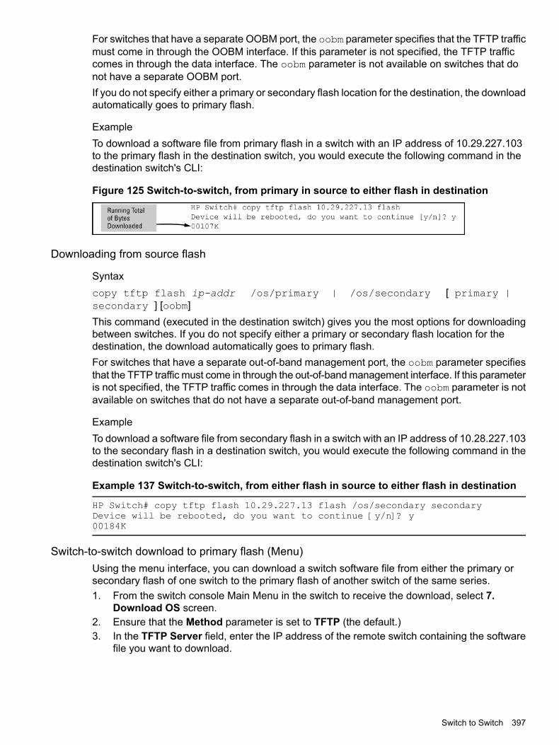
For switches that have a separate OOBM port, the oobm parameter specifies that the TFTP trafficmust come in through the OOBM interface. If this parameter is not specified, the TFTP trafficcomes in through the data interface. The oobm parameter is not available on switches that donot have a separate OOBM port.If you do not specify either a primary or secondary flash location for the destination, the downloadautomatically goes to primary flash.
ExampleTo download a software file from primary flash in a switch with an IP address of 10.29.227.103to the primary flash in the destination switch, you would execute the following command in thedestination switch's CLI:
Figure 125 Switch-to-switch, from primary in source to either flash in destination
Downloading from source flash
Syntaxcopy tftp flash ip-addr /os/primary | /os/secondary [ primary |secondary ] [oobm]This command (executed in the destination switch) gives you the most options for downloadingbetween switches. If you do not specify either a primary or secondary flash location for thedestination, the download automatically goes to primary flash.For switches that have a separate out-of-band management port, the oobm parameter specifiesthat the TFTP traffic must come in through the out-of-band management interface. If this parameteris not specified, the TFTP traffic comes in through the data interface. The oobm parameter is notavailable on switches that do not have a separate out-of-band management port.
ExampleTo download a software file from secondary flash in a switch with an IP address of 10.28.227.103to the secondary flash in a destination switch, you would execute the following command in thedestination switch's CLI:
Example 137 Switch-to-switch, from either flash in source to either flash in destination
HP Switch# copy tftp flash 10.29.227.13 flash /os/secondary secondaryDevice will be rebooted, do you want to continue [y/n]? y00184K
Switch-to-switch download to primary flash (Menu)Using the menu interface, you can download a switch software file from either the primary orsecondary flash of one switch to the primary flash of another switch of the same series.1. From the switch console Main Menu in the switch to receive the download, select 7.
Download OS screen.2. Ensure that the Method parameter is set to TFTP (the default.)3. In the TFTP Server field, enter the IP address of the remote switch containing the software
file you want to download.
Switch to Switch 397

4. For the Remote File Name, enter one of the following:• To download the software in the primary flash of the source switch, enter flash in
lowercase characters.• To download the software in the secondary flash of the source switch, enter
/os/secondary.5. Press [Enter], and then [X] (for eXecute) to begin the software download.
A "progress" bar indicates the progress of the download. When the entire switch softwaredownload has been received, all activity on the switch halts and the following messagesappear:
Validating and writing system software to FLASH...
6. After the primary flash memory has been updated with the new software, you must rebootthe switch to implement the newly downloaded software. Return to the Main Menu and press[6] (for Reboot Switch.) You then see this prompt:
Continue reboot of system? : No
Press the space bar once to change No to Yes, then press [Enter] to begin the reboot.
7. To confirm that the software downloaded correctly:a. From the Main Menu, select
Status and CountersGeneral System Information
b. Check the Firmware revision line.
CopyingCopying software images
Copying a software image to a remote host in TRTP
Syntaxcopy flash tftp ip-addr filename [oobm]Copies the primary flash image to a TFTP server.For switches that have a separate OOBM port, the oobm parameter specifies that the transfer isthrough the OOBM interface. If this parameter is not specified, the transfer is through the datainterface.The oobm parameter is not available on switches that do not have a separate OOBM port.
ExampleTo copy the primary flash to a TFTP server having an IP address of 10.28.227.105:
HP Switch# copy flash tftp 10.28.227.105 k0800.swi
where k0800.swi is the filename given to the flash image being copied.
Copying using XmodemTo use this method, the switch must be connected via the serial port to a PC or UNIX workstation.
Syntaxcopy flash xmodem [[ pc] | unix ]Uses Xmodem to copy a designated configuration file from the switch to a PC or UNIX workstation.
398 File transfers

ExampleTo copy the primary flash image to a serially connected PC:1. Execute the following command:
HP Switch# copy xmodem flashPress 'Enter' and start XMODEM on your host...
2. After you see the above prompt, press [Enter].3. Execute the terminal emulator commands to begin the file transfer.
Copying using USBTo use this method, a USB flash memory device must be connected to the switch's USB port.
Syntaxcopy flash usb filename
Uses the USB port to copy the primary flash image from the switch to a USB flash memory device.
ExampleTo copy the primary image to a USB flash drive:1. Insert a USB device into the switch's USB port.2. Execute the following command:
HP Switch# copy flash usb k0800.swi
where k0800.swi is the name given to the primary flash image that is copied from theswitch to the USB device.
Copying diagnostic data to a remote host, USB device, PC, or UNIX workstation
Copying command output to a destination device
Syntaxcopy command-output <cli-command> tftp ip-addressfilepath-filename [oobm]copy command-output <cli-command> usb <filename>copy command-output <cli-command> xmodem
These commands direct the displayed output of a CLI command to a remote host,attached USB device, or to a serially connected PC or UNIX workstation.For switches that have a separate OOBM port, the oobm parameter specifies thatthe transfer is through the OOBM interface. If this parameter is not specified, thetransfer is through the data interface. The oobm parameter is not available onswitches that do not have a separate OOBM port.
ExampleTo use Xmodem to copy the output of show config to a serially connected PC:
Figure 126 Sending command output to a file on an attached PC
NOTE: The command you specify must be enclosed in double quotation marks.
Copying 399

Copying Event Log output to a destination device
Syntaxcopy event-log smm [ tftp | usb | xmodem ]
Syntaxcopy event-log tftp ip-address filepath_filename [oobm]
Syntaxcopy event-log usb filename
Syntaxcopy event-log xmodem filename
These commands copy the Event Log content to a remote host, attached USBdevice, or to a serially connected PC or UNIX workstation.When used with the smm option, the entire Event Log, both active managementmodule events and standby management module events, is copied to the selectedhost, USB device, or serially connected PC or UNIX workstation.For switches that have a separate OOBM port, the oobm parameter specifies thatthe transfer is through the OOBM interface. If this parameter is not specified, thetransfer is through the data interface. The oobm parameter is not available onswitches that do not have a separate OOBM port.
ExampleTo copy the event log to a PC connected to the switch:
Figure 127 Sending event log content to a file on an attached PC
Copying crash data content to a destination deviceThis command uses TFTP, USB, or Xmodem to copy the Crash Data content to a destinationdevice. You can copy individual slot information or the management module’s switch information.If you do not specify either, the command defaults to the management function’s data.
Syntaxcopy crash-data [ slot-id | master ]tftp ip-address filename [oobm]
Syntaxcopy crash-data [ slot-id | mm ]usb filename
Syntaxcopy crash-data [ slot-id | mm ]xmodem
400 File transfers

These commands copy the crash data content to a remote host, attached USBdevice, or to a serially connected PC or UNIX workstation.
a - h—Retrieves the crash log or crash data from the processor on themodule in the specified slot
slot-id
Retrieves crash log or crash data from the switch's chassis processor.When "mm" is specified, crash files from both management modulesare copied.
mm
For switches that have a separate OOBM port, specifies that the transferis through the OOBM interface. (Default is transfer through the datainterface.)
oobm
You can copy individual slot information or the management module (mm) switchinformation. If you do not specify either, the command defaults to the mm data.
ExampleTo copy the switch's crash data to a file in a PC:
Figure 128 Copying switch crash data content to a PC
Copying crash data with redundant managementWhen you use redundant management, the copy crash-data command operates somewhatdifferently:
Syntaxcopy crash-data [ slot-id | mm ] tftp ip-address filename[oobm]Copies the crash data of both the active and standby management modules to auser-specified file. If no parameter is specified, files from all modules (managementand interface) are concatenated.
Retrieves the crash data from the module in the specified slot.slot-id
Retrieves the crash data from both management modules andconcatenates them.
mm
For switches that have a separate OOBM port, specifies that the transferis through the OOBM interface. (Default is transfer through the datainterface.)
oobm
Copying crash log data content to a destination device
Syntaxcopy crash-log [ slot-id | mm ] tftp ip-address filepath andfilename [oobm]
Copying 401

Syntaxcopy crash-log [ slot-id | mm ] usb filename
Syntaxcopy crash-log [ slot-id | mm ] xmodemThese commands copy the Crash Log content to a remote host, attached USBdevice, or to a serially connected PC or UNIX workstation. You can copy individualslot information or the management module (mm) switch information.
a - h—Retrieves the crash log from the processor on the module in thespecified slot
slot-id
Retrieves the crash log from the switch's chassis processor. When mmis specified, crash files from both management modules are copied.
mm
For switches that have a separate OOBM port, specifies that the transferis through the OOBM interface. (Default is transfer through the datainterface.)
oobm
If you do not specify either, the command defaults to the mm data.
ExampleTo copy the crash log for slot C to a file in a PC connected to the switch:
Figure 129 Sending a crash log for slot C to a file on an attached PC
Copying crash logs with redundant managementWhen you use redundant management, the copy crash-log command operates somewhatdifferently.
Syntaxcopy crash-log [ slot-id | mm ] tftp ip-address filepath andfilename [oobm]Copies the crash logs of both the active and standby management modules to auser-specified file. If no parameter is specified, files from all modules (managementand interface) are concatenated.
Retrieves the crash log from the module in the specified slot.slot-id
Retrieves the crash logs from both management modules andconcatenates them.
mm
For switches that have a separate OOBM port, specifies that the transferis through the OOBM interface. (Default is transfer through the datainterface.)
oobm
Copying coredumps from the standby management moduleIt is important that the coredump files on the standby management module are accessible fordiagnostic purposes.
402 File transfers

Syntaxcopy core-dump [ mm usb filename | standby flash | usbfilename ]Copies the management module coredump or the standby management modulecoredump to the active management module flash or to a USB flash drive, (seeFigure 130 (page 403).)
Copies the core file of the standby management module to the flash ofthe active management module. The destination file is fixed as
flash
dumpM1.cor or dumpM2.cor, depending on which module is thestandby management module.
Copies the management module's core file or the standby managementmodule's core file to a USB flash drive. The optional filename defaults
usb filename
to dumpM1.cor or dumpM2.cor, depending on which module is thestandby management module
While the file is being copied, the number of bytes transferred and the percentageof the total is displayed. Management module core files can be quite large. UseCntl-C to cleanly cancel the transfer.
Example
Figure 130 Copying the standby coredump to flash
If there is no coredump on the standby management module, the following errormessage displays:Standby MM coredump does not exist.
If there is not enough destination space before or during the transfer to flash orUSB, the following error message displays:Insufficient FLASH space to complete the file copy.
Flight data recorderThe Flight Data Recorder (FDR) log collects information that is "interesting" when the switch isnot performing correctly, but has not crashed. Runtime logs are written to FDR memory whilethe switch is running, and crashtime logs are collected and stored in the FDR buffer during aswitch crash.
Syntaxcopy fdr-log [[slot slot-list] | [mm-active [[current] | [previous]]]| [mm-standby] | [all]]tftp [[hostname] | [ip-addr]]filename
Copies fdr-log files to a user-specified file.all Copies all the log files from both management modules and all slots.mn-active Copies the active management module's log.mn-standby Copies the standby management module's log.slot Retrieves the crash log from the module in the identified slots.
Copying 403

Copying diagnostic data to a remote host, USB device, PC or UNIX workstationYou can use the CLI to copy the following types of switch data to a text file in a destination device:Command output Sends the output of a switch CLI command as a file on the
destination device.Event log Copies the switch's Event Log into a file on the destination
device.Crash data Software-specific data useful for determining the reason
for a system crash.Crash log Processor-specific operating data useful for determining
the reason for a system crash.Flight data recorder (FDR) logs Information that is “interesting” at the time of the crash, as
well as when the switch is not performing correctly but hasnot crashed.
The destination device and copy method options are as follows (CLI keyword is in bold):
• Remote Host via TFTP.
• Physically connected USB flash drive via the switch's USB port.
• Serially connected PC or UNIX workstation via Xmodem.
TransferringTransferring switch configurations
Copying a configuration file to a remote host in TFTP
Syntaxcopy startup-config | running-config tftp ip-addr remote-file [ pc| unix ] [oobm]copy config filename tftp ip-addr remote-file [ pc | unix ] [oobm]This command can copy a designated config file in the switch to a TFTP server.For more information, see the basic operation guide.For switches that have a separate OOBM port, the oobm parameter specifies that the transfer isthrough the OOBM interface. If this parameter is not specified, the transfer is through the datainterface.The oobm parameter is not available on switches that do not have a separate OOBM port.
ExampleTo upload the current startup configuration to a file named sw8200 in the configs directory ondrive "d" in a TFTP server having an IP address of 10.28.227.105:
ProCurve# copy startup-config tftp 10.28.227.105d:\configs\sw8200
Copying a configuration file from a remote host in TFTP
Syntaxcopy tftp startup-config | running-config ip-addr remote-file [ pc| unix ] [oobm]copy tftp config filename ip-addr remote-file [ pc | unix ] [oobm]
404 File transfers

This command can copy a configuration from a remote host to a designated config file in theswitch.For switches that have a separate OOBM port, the oobm parameter specifies that the transfer isthrough the OOBM interface. If this parameter is not specified, the transfer is through the datainterface.The oobm parameter is not available on switches that do not have a separate OOBM port.
ExampleTo download a configuration file named sw8200 in the configs directory on drive "d" in aremote host having an IP address of 10.28.227.105:
HP Switch# copy tftp startup-config 10.28.227.105d:\configs\sw8200
Copying customized command fileUsing the copy tftp command with the show-tech option provides the ability to copy acustomized command file to the switch. When the show tech custom command is executed,the commands in the custom file are executed instead of the hard-coded list of commands. If nocustom file is found, the current hard-coded list is executed. This list contains commands todisplay data, such as the image stamp, running configuration, boot history, port settings, and soon.
Syntaxcopy tftp show-tech ipv4 or ipv6 address filename [oobm]Copies a customized command file to the switch.For switches that have a separate OOBM port, the oobm parameter specifies that the transfer isthrough the out-of-band management interface. If this parameter is not specified, the transfer isthrough the data interface. The oobm parameter is not available on switches that do not have aseparate OOBM port.
Example
Example 138Using thecopy tftp show-tech command to upload a customized commandfile
HP Switch(config)# copy tftp show-tech 10.10.10.3 commandfile1
Syntaxshow tech custom
Executes the commands found in a custom file instead of the hard-coded list.
NOTE: Exit the global config mode (if needed) before executing show tech commands.
Transferring 405

Example
Example 139 The show tech custom command
You can include show tech commands in the custom file, with the exception of show techcustom. For example, you can include the command show tech all.If no custom file is found, a message displays stating "No SHOW-TECH file found." (No customfile was uploaded with the copy tftp show-tech command.)HP Switch# show tech customNo SHOW-TECH file found.
copy TFTP config detail
Syntaxcopy TFTP config SOURCE CONFIG FILE NAME destination ip addressDESTINATION CONFIG FILE detail
DescriptionDisplays the progress, in lines and percent, of the configuration file copy to or from the switch.A large configuration file can take several minutes to transfer, this feature allows the customerto watch the progress.detail Display copy progress.oobm Use the OOBM interface to reach TFTP server.pc Change CR/LF to PC style.unix Change CR/LF to unix style
Example
HP-Switch-5406Rzl2# copy tftp config myConfig 10.100.0.12 myConfig.cfg oobm detailProcessing line 4968 of 20740 (23%)
Copying a configuration file using XmodemTo use this method, the switch must be connected via the serial port to a PC or UNIX workstation.You will need to:
• Determine a filename to use.
• Know the directory path you will use to store the configuration file.
Syntaxcopy [ startup-config | running-config ] xmodem [ pc | unix ]copy config filename xmodem pc | unix
Uses Xmodem to copy a designated configuration file from the switch to a PC or UNIX workstation.
ExampleTo copy a configuration file to a PC serially connected to the switch:1. Determine the file name and directory location on the PC.2. Execute the following command:
HP Switch# copy startup-config xmodem pcPress 'Enter' and start XMODEM on your host...
3. After you see the above prompt, press [Enter].4. Execute the terminal emulator commands to begin the file transfer.
406 File transfers

Copying a configuration file from a serially connected PC or UNIX workstationTo use this method, the switch must be connected via the serial port to a PC or UNIX workstationon which is stored the configuration file you want to copy. To complete the copying, you need toknow the name of the file to copy and the drive and directory location of the file.
Syntaxcopy xmodem startup-config [ pc | unix ]copy xmodem config filename [ pc | unix ]Copies a configuration file from a serially connected PC or UNIX workstation to a designatedconfiguration file on the switch.
ExampleTo copy a configuration file from a PC serially connected to the switch:1. Execute the following command:
HP Switch# copy xmodem startup-config pcDevice will be rebooted, do you want to continue [y/n]? yPress 'Enter' and start XMODEM on your host...
2. After you see the above prompt, press [Enter].3. Execute the terminal emulator commands to begin the file transfer.4. When the download finishes, you must reboot the switch to implement the newly downloaded
software. To do so, use one of the following commands:
Syntaxboot system flash [ primary | secondary ]boot system flash [config filename ]Switches boot from the designated configuration file.
Syntaxreload
Reboots from the flash image currently in use.
Copying a configuration file to a USB deviceTo use this method, a USB flash memory device must be connected to the switch's USB port.
Syntaxcopy startup-config usb filenamecopy running-config usb filename
ExampleTo copy the startup configuration file to a USB flash drive:1. Insert a USB device into the switch's USB port.2. Execute the following command:
HP Switch# copy startup-config usb HP Switch-config
where HP Switch-config is the name given to the configuration file that is copied fromthe switch to the USB device.
Transferring 407
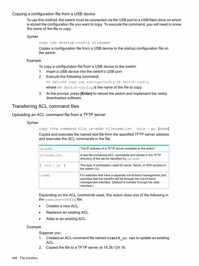
Copying a configuration file from a USB deviceTo use this method, the switch must be connected via the USB port to a USB flash drive on whichis stored the configuration file you want to copy. To execute the command, you will need to knowthe name of the file to copy.
Syntaxcopy usb startup-config filename
Copies a configuration file from a USB device to the startup configuration file onthe switch.
ExampleTo copy a configuration file from a USB device to the switch:1. Insert a USB device into the switch's USB port.2. Execute the following command:
HP Switch# copy usb startup-config HP Switch-config
where HP Switch-config is the name of the file to copy.
3. At the prompt, press [Enter] to reboot the switch and implement the newlydownloaded software.
Transferring ACL command files
Uploading an ACL command file from a TFTP server
Syntaxcopy tftp command-file ip-addr filename.txt unix | pc [oobm]Copies and executes the named text file from the specified TFTP server addressand executes the ACL commands in the file.
The IP address of a TFTP server available to the switchip-addr
A text file containing ACL commands and stored in the TFTPdirectory of the server identified by ip-addr
filename.txt
The type of workstation used for serial, Telnet, or SSH access tothe switch CLI
[ unix | pc ]
For switches that have a separate out-of-band management port,specifies that the transfer will be through the out-of-band
[oobm]
management interface. (Default is transfer through the datainterface.)
Depending on the ACL commands used, this action does one of the following inthe running-config file:
• Creates a new ACL.
• Replaces an existing ACL.
• Adds to an existing ACL.
ExampleSuppose you:1. Created an ACL command file named vlan10_in.txt to update an existing
ACL.2. Copied the file to a TFTP server at 18.38.124.16.
408 File transfers
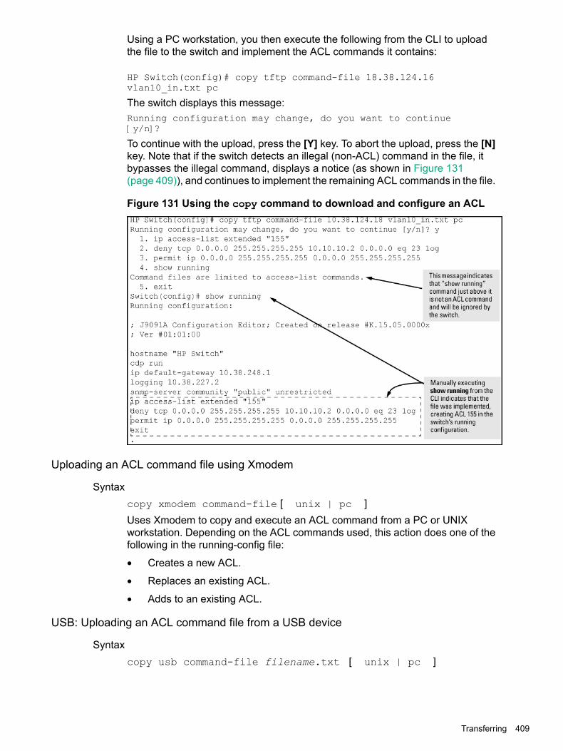
Using a PC workstation, you then execute the following from the CLI to uploadthe file to the switch and implement the ACL commands it contains:
HP Switch(config)# copy tftp command-file 18.38.124.16vlan10_in.txt pc
The switch displays this message:Running configuration may change, do you want to continue[y/n]?
To continue with the upload, press the [Y] key. To abort the upload, press the [N]key. Note that if the switch detects an illegal (non-ACL) command in the file, itbypasses the illegal command, displays a notice (as shown in Figure 131(page 409)), and continues to implement the remaining ACL commands in the file.
Figure 131 Using the copy command to download and configure an ACL
Uploading an ACL command file using Xmodem
Syntaxcopy xmodem command-file [ unix | pc ]Uses Xmodem to copy and execute an ACL command from a PC or UNIXworkstation. Depending on the ACL commands used, this action does one of thefollowing in the running-config file:
• Creates a new ACL.
• Replaces an existing ACL.
• Adds to an existing ACL.
USB: Uploading an ACL command file from a USB device
Syntaxcopy usb command-file filename.txt [ unix | pc ]
Transferring 409

Copies and executes the named text file from a USB flash drive and executes theACL commands in the file.
A text file containing ACL commands and stored in the USB flashdrive
filename.txt
The type of workstation used to create the text file.unix | pc
Depending on the ACL commands used, this action does one of the following inthe running-config file:
• Creates a new ACL.
• Replaces an existing ACL.
• Adds to an existing ACL.
ExampleSuppose you:1. Created an ACL command file named vlan10_in.txt to update an existing
ACL.2. Copied the file to a USB flash drive.Using a PC workstation, you then execute the following from the CLI to uploadthe file to the switch and implement the ACL commands it contains:
HP Switch(config)# copy usb command-file vlan10_in.txt pc
The switch displays this message:
Running configuration may change, do you want to continue[y/n]?
To continue with the upload, press the [Y] key. To abort the upload, press the [N]key. Note that if the switch detects an illegal (non-ACL) command in the file, itbypasses the illegal command, displays a notice (as in the tftp example shown inFigure 131 (page 409)), and continues to implement the remaining ACL commandsin the file.
Transferring switch configurationsUsing CLI commands you can copy switch configurations to and from a switch, or copy a softwareimage to configure or replace an ACL in the switch configuration.
NOTE: For greater security, you can perform all TFTP operations using SFTP.You can also use the include-credentials command to save passwords, secret keys, andother security credentials in the running config file.
Transferring ACL command filesThis section describes how to upload and execute a command file to the switch for configuringor replacing an ACL in the switch configuration. Such files should contain only access controlentry (ACE) commands.
410 File transfers

DownloadingDownloading switch software
Switch periodically provides switch software updates through the Switch Networking website.For more information, see the support and warranty booklet shipped with the switch, or visithttp://www.hpe.Com/Networking/Support.
NOTE: This manual uses the terms switch software and software image to refer to thedownloadable software files the switch uses to operate its networking features. Other termssometimes include Operating System, or OS.
Switch software download rules• Switch software that you download via the menu interface always goes to primary flash.
• After a software download, you must reboot the switch to implement the new software. Untila reboot occurs, the switch continues to run on the software it was using before the download.
NOTE: Downloading new switch software does not change the current switch configuration.The switch configuration is contained in separate files that can also be transferred. See“Transferring switch configurations” (page 404).In most cases, if a power failure or other cause interrupts a flash image download, the switchreboots with the image previously stored in primary flash. In the unlikely event that the primaryimage is corrupted (which may occur if a download is interrupted by a power failure), the switchgoes into boot ROM mode. In this case, use the boot ROM console to download a new imageto primary flash.
Troubleshooting TFTP download failuresWhen using the menu interface, if a TFTP download fails, the Download OS (Operating System,or software) screen indicates the failure.
Figure 132 Example of message for download failure
Some of the causes of download failures include:
• Incorrect or unreachable address specified for the TFTP Server parameter. This may includenetwork problems.
• Incorrect VLAN.
• Incorrect name specified for the Remote File Name parameter, or the specified file cannotbe found on the TFTP server. This can also occur if the TFTP server is a UNIX machine andthe case (upper or lower) for the filename on the server does not match the case for the
Downloading 411

filename entered for the Remote File Name parameter in the Download OS (OperatingSystem, or software) screen.
• One or more of the switch's IP configuration parameters are incorrect.
• For a UNIX TFTP server, the file permissions for the software file do not allow the file to becopied.
• Another console session (through either a direct connection to a terminal device or throughTelnet) was already running when you started the session in which the download wasattempted.
To find more information on the cause of a download failure:
• Examine the messages in the switch's Event Log by executing the show log tftpcommand from the CLI.
NOTE: If an error occurs in which normal switch operation cannot be restored, the switchautomatically reboots itself, and an appropriate message is displayed after the reboot.
Single copy commandWhen a switch crashes, five files relating to the crash; core-dump, crash-data, crash-log, fdr-log,and event-log are created and should be copied for review. All five files (core-dump, crash-data,crash-log, fdr-log, and event-log) should be copied to a destination specified under a directoryby file name.TFTP A destination directory and files can be created for all crash files (core-dump, crash-data,
crash-log, fdr-log, and event-log) on an TFTP server (with write permissions).SFTP Files are auto created on the SFTP server as a secured transfer. The destination
directories however can be manually created on the server.
NOTE: Specified directories can be used for the TFTP/SFTP transfers in the copy command.If the directory is specified, all files will be copied under one directory, otherwise all files will becopied to the TFTP/SFTP server home directory. It is mandatory to specify the directory name.
Single copy command
Syntaxcopy source destination options
Copy data files to and from the switch.Source Specify the source of data using any of the following destinations.
Operation noteDestination
n/aFlash
For transfer of crash-files via SFTP, the destination directorymust exist on the SFTP server with write permissions.
SFTP
File creation is not mandatory as files are automatically createdwith the chassis serial number suffix to the filename whenusing SFTP.
412 File transfers

Operation noteDestination
The listed crash-files captured for 3500 switch for both MMand slot using SFTP are as follows:
• MM crash-files:M-SG238TF00K.corM-SG238TF00K.cdataM-SG238TF00K.clogM-SG238TF00K.evtM-SG238TF00K.fdr
• Slot crash-files:I-SG238TF00K.corI-SG238TF00K.cdataI-SG238TF00K.clogI-SG238TF00K.evtI-SG238TF00K.fdr
For transfer of crash-files via TFTP, the destination directoryalong with the file names (core-dump, crash-data, crash-log,
TFTP
fdr-log, and event-log) must exist on the TFTP server withwrite permissions.
For transfer of crash-files via USB, the destination directoryalong with the file names (core-dump, crash-data, crash-log,
USB
fdr-log, and event-log) must exist on the device with writepermissions.
n/aXmodem
Data Files Specify the data file to be copied from the source.
Operation noteData file
Specify a command to copy output.When using command-output, place thedesired CLI command in double-quotes. Forexample: "show system".
command-outputcommand
Copy named configuration file.The file-name option is the sourceconfiguration file being copied.
config file-name
Copy core-dump file from flash.core-dump
Copy the switch crash-data file.crash-data
Copy the switch crash-log file.crash-loga|b|c|d|e|f|g|h|master
Copy core-dump, crash-data, crash-log, fdr-log,and event-log files to an SFTP/TFTP server,USB, or xmodem terminal.
crash-files
When using the crash-files option, thedestination directory alone must be specified asthe destination path. Specifying the file namesis not mandatory.
Copy custom default-config file.default-config
Copy event-log file.event-log
Copy FDR-og file from the switch to anSFTP/TFTP server, USB or xmodem terminal.
fdr-log
Single copy command 413

Operation noteData file
Copy the switch system image file.flash
Copy data from a SFTP server.SFTP server
Copy in-flash configuration file.startup-config
Copy the known hosts file.ssh-client-known-hosts
Copy the switch's SSH server public key.ssh-server-pub-key
Copy running configuration file.running-config
Copy data from a TFTP server.TFTP
Copy data from a USB flash drive.USB
Use xmodem on the terminal as the data source.xmodem
Destination Specify the copy target.
Destination
SFTP
TFTP
USB
xmodem
Data Files Specify the data file name at the target.
Data file
autorun-cert-file
autorun-key-file
command file
config
default-config
flash
pub-key-file
show-tech
startup-config
ssh-client-key
ssh-client-known-hosts
414 File transfers

Options, RequirementOperation noteOption
n/aAdd the keys for operatoraccess.
append
Required for TFTP, SFTP and USBtransfers.
Directory name toupload.
directory
Required for TFTP, SFTP and USBtransfers.
File-name toupload/download.
filename
Required for TFTP, SFTP transfers.Hostname of the TFTP,SFTP server.
hostname
Required for TFTP, SFTP transfers.TFTP, SFTP server IPv4address.
IPv4address
Required for TFTP, SFTP transfers.TFTP, SFTP server IPv6address.
IPv6address
n/aReplace the keys formanager access; follow
manager
with the append optionto add the keys.
n/aReplace the keys foroperator access
operator
(default); follow with theappend option to add thekeys.
n/apc
n/aunix
Multiple management switches
Syntaxcopy crash-filesslot-id Copy interface management crash files.mm-active Copy active management module crash files.mm-standby Copy standby management module crash files.
Destination
XmodemUSBTFTPSFTP
XXXXSlot-ID
XXXXMM-active
XXXXMM-standby
Stacking switches
Syntaxcopy crash-filesmember Copy stack member crash files.
Single copy command 415

Options for member
DestinationOption
xmodemUSBTFTPSFTP
XXXXmanagement
XXXXinterfaces
Standalone switches
Syntaxcopy crash-files
Options
DestinationOption
xmodemUSBTFTPSFTP
XXXXmanagement
XXXXinterfaces
Crash file options
Syntaxcopy crash-files crash-file-options host-name-str | ip-addr| ipv6-addrsftp dirname-str | oobm
Optionshost-name-str Specify hostname of the SFTP server.ip-addr Specify SFTP server IPv4 address.ipv6–addr Specify SFTP server IPv6 address.user Specify the username on the remote system.username@ip-str Specify the username along with remote system.
Information (hostname, IPv4 or IPv6 address).dirname-str Specify the destination directory name.oobm Use the OOBM interface to reach SFTP server.
Destination optionsslot-id Copy interface core-dump file.mm-active Copy active management module crash files.mm-standby Copy standby management module crash files.member Copy member crash files.interfaces Copy interfaces crash files.management Copy management crash files.
416 File transfers

15 Monitoring and Analyzing Switch OperationSwitch and network operations
The switches have several built-in tools for monitoring, analyzing, and troubleshooting switchand network operation:
• StatusIncludes options for displaying general switch information, management address data, portstatus, port and trunk group statistics, MAC addresses detected on each port or VLAN, andSTP, IGMP, and VLAN data.
• CountersDisplay details of traffic volume on individual ports (“Accessing port and trunk statistics(Menu)” (page 425).)
• Event LogLists switch operating events. See the HPE ProVision switch software troubleshooting guidefor troubleshooting information.
• Configurable trap receiversUses SNMP to enable management stations on your network to receive SNMP traps fromthe switch.
• Port monitoring (mirroring)Copy all traffic from the specified ports to a designated monitoring port .
NOTE: Link test and ping test—analysis tools in troubleshooting situations—are described inthe ProVision Switch Software Troubleshooting Guide.
Status and counters dataThis section describes the status and counters screens available through the switch consoleinterface and/or the WebAgent.
NOTE: You can access all console screens from the WebAgent via Telnet to the console.Telnet access to the switch is available in the Device View window under the Configurationtab.
Accessing status and counters (Menu)Beginning at the Main Menu, display the Status and Counters menu by selecting:
1. Status and Counters
Switch and network operations 417

Figure 133 The Status and Counters menu
Each of the above menu items accesses the read-only screens described on the following pages.See the online help for a description of the entries displayed in these screens.
Viewing system information
Syntaxshow system [ chassislocate | information | power-supply |temperature | fans ]Displays global system information and operational parameters for the switch.
Displays the chassisLocator LED status. Possible values are ON,Off, or Blink.
chassislocate
When the status is On or Blink, the number of minutes that theLocator LED will continue to be on or to blink is displayed. (Seefigure Figure 134 (page 418).)
Displays global system information and operational parameters forthe switch. (See Figure 136 (page 419).)
information
Shows chassis power supply and settings.power-supply
Shows system temperature and settings.temperature
Shows system fan status. (See Figure 135 (page 419).)fans
Example
Figure 134 Command results for show system chassislocate command
418 Monitoring and Analyzing Switch Operation
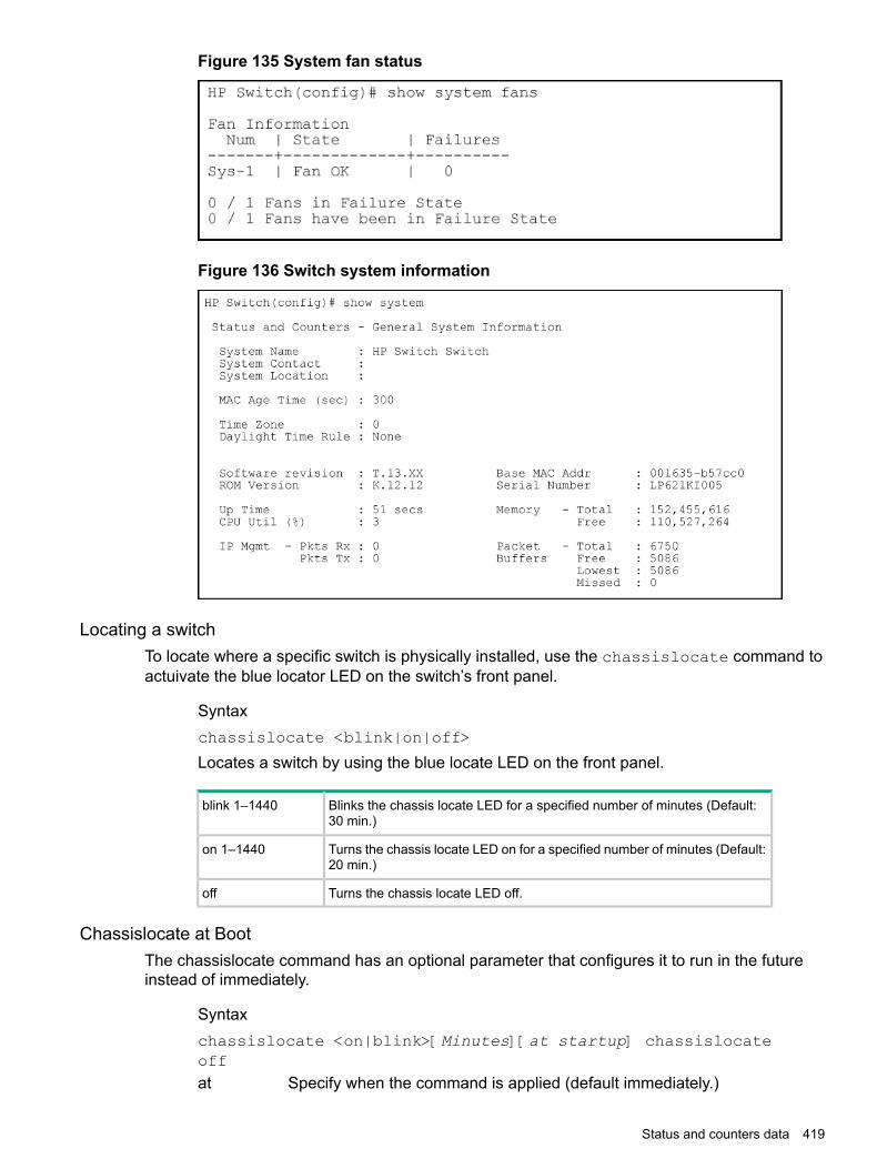
Figure 135 System fan status
Figure 136 Switch system information
Locating a switchTo locate where a specific switch is physically installed, use the chassislocate command toactuivate the blue locator LED on the switch’s front panel.
Syntaxchassislocate <blink|on|off>
Locates a switch by using the blue locate LED on the front panel.
Blinks the chassis locate LED for a specified number of minutes (Default:30 min.)
blink 1–1440
Turns the chassis locate LED on for a specified number of minutes (Default:20 min.)
on 1–1440
Turns the chassis locate LED off.off
Chassislocate at BootThe chassislocate command has an optional parameter that configures it to run in the futureinstead of immediately.
Syntaxchassislocate <on|blink>[Minutes][at startup] chassislocateoffat Specify when the command is applied (default immediately.)
Status and counters data 419

now Turn on the chassis locate LED immediately.startup Turn on the chassis locate LED at switch startup.
Examplechassislocate blink 10 at startup
Show locate
Syntaxshow system chassislocate
Display
Locator LED StatusCurrent Time
Member State Remaining Configuration------ ------- --------- -------------1 blink 00:27:05 blink 30 at startup2 on 01:05:273 off
Collecting processor data with the task monitorThe task monitor feature allows you to enable or disable the collection of processor utilizationdata. The task-monitor cpu command is equivalent to the existing debug mode commandtaskusage -d. (The taskUsageShow command is also available.)When the task-monitor command is enabled, the show cpu command summarizes theprocessor usage by protocol and system functions.
Syntax[ no ] task-monitor cpu
Allows the collection of processor utilization data.Only manager logins can execute this command.The settings are not persistent, that is, there are no changes to the configuration.(Default: Disabled)The task monitor feature allows you to enable or disable the collection of processorutilization data. The task-monitor cpu command is equivalent to the existingdebug mode command taskusage -d. (The taskUsageShow command isavailable as well.)When the task-monitor command is enabled, the show cpu commandsummarizes the processor usage by protocol and system functions.
420 Monitoring and Analyzing Switch Operation

Example
Figure 137 The task-monitor cpu command and show cpu output
Accessing system information (Menu)From the console Main Menu, select:
1. Status and Counters1. General System Information
Figure 138 Example of general switch information
This screen dynamically indicates how individual switch resources are being used. See the onlinehelp for details.
Accessing switch management address information
Syntaxshow management
Accessing switch management address information (Menu)From the Main Menu, select:
1. Status and Counters ...2. Switch Management Address Information
Status and counters data 421

Figure 139 Example of management address information with VLANs configured
This screen displays addresses that are important for management of the switch. If multipleVLANs are not configured, this screen displays a single IP address for the entire switch. See theonline help for details.
NOTE: As shown in Figure 139 (page 422), all VLANs on the switches use the same MACaddress. (This includes both the statically configured VLANs and any dynamic VLANs existingon the switch as a result of GVRP operation.)Also, the switches use a multiple forwarding database. When using multiple VLANs and connectinga switch to a device that uses a single forwarding database, such as a Switch 4000M, there arecabling and tagged port VLAN requirements.
Viewing additional component informationThe CLI show modules command displays additional component information for the following:
• SSM—identification, including serial number
• Mini-GBICS—a list of installed mini-GBICs displaying the type, "J" number, and serial number(when available)
Syntaxshow modules [details]Displays information about the installed modules (Figure 140 (page 423)), including:
• The slot in which the module is installed
• The module description
• The serial numberAdditionally, this command displays the part number (J number) and serial numberof the chassis. (See Figure 141 (page 423).)
422 Monitoring and Analyzing Switch Operation

Examples
Figure 140 The show modules command output
Figure 141 The show modules details command for the 8212zl, showingSSM and mini-GBIC information
NOTE: On HPE Switch 3500yl series switches, the mini-GBIC information does not display,because the ports are fixed and not part of any module.
Viewing port status (Menu)From the Main Menu, select:
1. Status and Counters ...3. Module Information
Enabling and Disabling Compatibility Mode for v2 zl and zl modulesNOTE: In the following context, v2 zl modules are the second version of the current zl modules.Both v2 zl and zl modules are supported in the 5400zl series chassis switches.Compatibility Mode allows the inter-operation of v2 zl modules with zl modules in a chassis switch.When in Compatibility Mode, the switch accepts either v2 zl or zl modules. The default isCompatibility Mode enabled. If Compatibility Mode is disabled by executing the noallow-v1-modules command, the switch will only power up v2 zl modules.
Syntax[ no ] allow-v1-modules
Enables Compatibility Mode for interoperation of v2 zl and zl modules in the samechassis. (See Figure 142 (page 424).)The no form of the command disables Compatibility Mode. Only the v2 zl modulesare powered up. (See Figure 143 (page 424).)(Default: Enabled.)
Enabling and Disabling Compatibility Mode for v2 zl and zl modules 423

Examples
Figure 142 Enabling compatibility mode
Figure 143 Disabling compatibility mode
Viewing port statusSyntax
show interfaces brief
Viewing port status (Menu)From the Main Menu, select:
1. Status and Counters ...4. Port Status
Figure 144 Example of port status on the menu interface
Accessing port and trunk group statisticsViewing the port counter summary report
Syntaxshow interfaces
Provides an overview of port activity for all ports on the switch.
Viewing a detailed traffic summary for specific ports
Syntaxshow interfaces <PORT-LIST>
424 Monitoring and Analyzing Switch Operation

Provides traffic details for the ports you specify.
Resetting the port countersIt is useful to be able to clear all counters and statistics without rebooting the switch whentroubleshooting network issues. The clear statistics global command clears all countersand statistics for all interfaces except SNMP. You can also clear the counters and statistics foran individual port using the clear statistics <PORT-LIST> command.
Syntaxclear statistics [ <PORT-LIST> | global ]When executed with the <PORT-LIST> option, clears the counters and statisticsfor an individual port.When executed with the global option, clears all counters and statistics for allinterfaces except SNMP.
The show interfaces <PORT-LIST> command displays the totals accumulated since thelast boot or the last clear statistics command was executed. The menu page also displaysthese totals.SNMP displays the counter and statistics totals accumulated since the last reboot; it is not affectedby the clear statistics global command or the clear statistics <PORT-LIST>command. An SNMP trap is sent whenever the statistics are cleared.
Accessing port and trunk statistics (Menu)From the Main Menu, select:
1. Status and Counters ...4. Port Counters
Figure 145 Example of port counters on the menu interface
To view details about the traffic on a particular port, use the ↓ key to highlight that port number,then select Show Details. For example, selecting port A2 displays a screen similar to Figure 146(page 426), below.
Accessing port and trunk statistics (Menu) 425
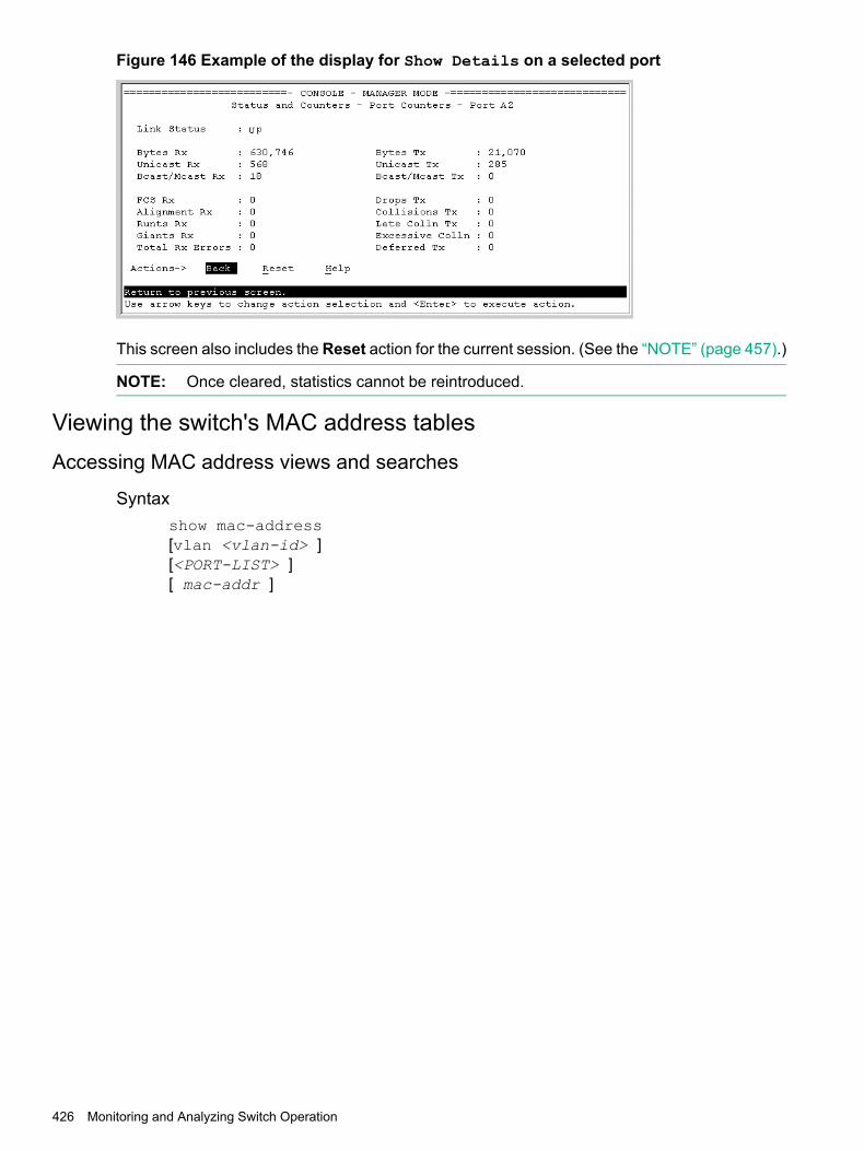
Figure 146 Example of the display for Show Details on a selected port
This screen also includes the Reset action for the current session. (See the “NOTE” (page 457).)
NOTE: Once cleared, statistics cannot be reintroduced.
Viewing the switch's MAC address tablesAccessing MAC address views and searches
Syntaxshow mac-address[vlan <vlan-id> ][<PORT-LIST> ][ mac-addr ]
426 Monitoring and Analyzing Switch Operation

Example 140 Listing all learned MAC addresses on the switch, with the port number onwhich each MAC address was learned
HP Switch# show mac-address
Example 141 Listing all learned MAC addresses on one or more ports, with theircorresponding port numbers
For example, to list the learned MAC address on ports A1 through A4 and port A6:
HP Switch# show mac-address a1-a4,a6
Example 142 Listing all learned MAC addresses on a VLAN, with their port numbers
This command lists the MAC addresses associated with the ports for a given VLAN. For example:
HP Switch# show mac-address vlan 100
NOTE: The switches operate with a multiple forwarding database architecture.
Example 143 Finding the port on which the switch learned a specific MAC address
For example, to find the port on which the switch learns a MAC address of 080009-21ae84:
Accessing MAC address views and searches (Menu)
Viewing and searching per-VLAN MAC-addressesThis feature lets you determine which switch port on a selected VLAN is being used tocommunicate with a specific device on the network.From the Main Menu, select:
1. Status and Counters ...5. VLAN Address Table
1. The switch then prompts you to select a VLAN.
Viewing the switch's MAC address tables 427
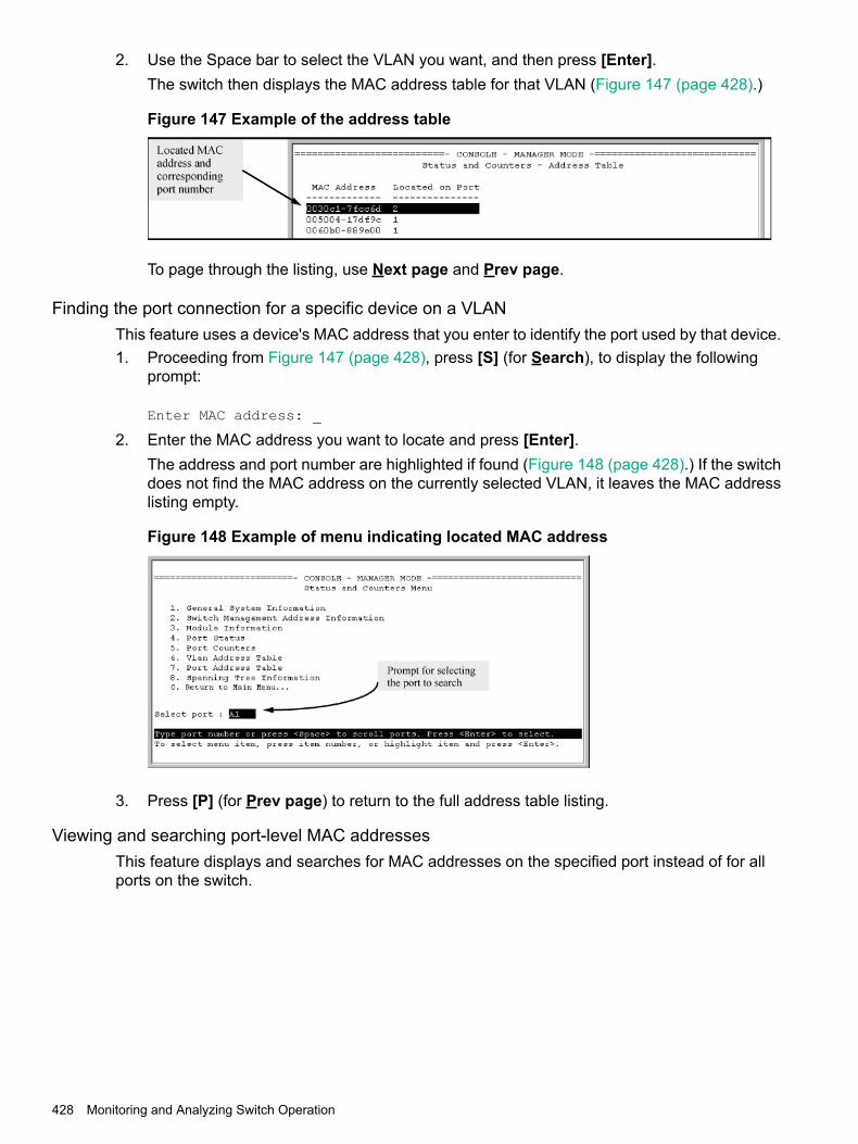
2. Use the Space bar to select the VLAN you want, and then press [Enter].The switch then displays the MAC address table for that VLAN (Figure 147 (page 428).)
Figure 147 Example of the address table
To page through the listing, use Next page and Prev page.
Finding the port connection for a specific device on a VLANThis feature uses a device's MAC address that you enter to identify the port used by that device.1. Proceeding from Figure 147 (page 428), press [S] (for Search), to display the following
prompt:
Enter MAC address: _
2. Enter the MAC address you want to locate and press [Enter].The address and port number are highlighted if found (Figure 148 (page 428).) If the switchdoes not find the MAC address on the currently selected VLAN, it leaves the MAC addresslisting empty.
Figure 148 Example of menu indicating located MAC address
3. Press [P] (for Prev page) to return to the full address table listing.
Viewing and searching port-level MAC addressesThis feature displays and searches for MAC addresses on the specified port instead of for allports on the switch.
428 Monitoring and Analyzing Switch Operation

1. From the Main Menu, select:1. Status and Counters ...7. Port Address Table
Figure 149 Listing MAC addresses for a specific port
2. Use the Space bar to select the port you want to list or search for MAC addresses, thenpress [Enter] to list the MAC addresses detected on that port.
Determining whether a specific device is connected to the selected portProceeding from step 2 (page 429), above:1. Press [S] (for Search), to display the following prompt:
Enter MAC address: _
2. Enter the MAC address you want to locate and press [Enter].The address is highlighted if found. If the switch does not find the address, it leaves the MACaddress listing empty.
3. Press [P] (for Prev page) to return to the previous per-port listing.
Accessing MSTP DataSyntax
show spanning-tree
Displays the switch's global and regional spanning-tree status, plus the per-portspanning-tree operation at the regional level.Values for the following parameters appear only for ports connected to activedevices: Designated Bridge, Hello Time, PtP, and Edge.
Accessing MSTP Data 429

Example
Figure 150 Output from show spanning-tree command
Show IP IGMP status
OutputShow command
Global command listing IGMP status for all VLANs configured in the switch:show ip igmp
• VLAN ID (VID) and name
• Querier address
• Active group addresses per VLAN
• Number of report and query packets per group
• Querier access port per VLAN
Displays the IGMP configuration information, including VLAN ID, VLAN name,status, forwarding, and Querier information.
show ip igmp config
Per-VLAN command listing above, IGMP status for specified VLAN (VID)show ip igmp vlan-id
430 Monitoring and Analyzing Switch Operation

OutputShow command
Lists the ports currently participating in the specified group, with port type,Access type, Age Timer data and Leave Timer data.
show ip igmp group ip-addr
Displays VLAN-ID, group address, uptime, expiration time, multicast filtertype, and the last reporter for IGMP groups.
show ip igmp groups
Displays IGMP operational information, such as VLAN IDs and names, andfiltered and flooding statistics.
show ip igmp statistics
Examples
Example 144 Output from show ip igmp config command
Example 145 IGMP statistical information
HP Switch(vlan-2)# show ip igmp statistics
IGMP Service Statistics
Total VLANs with IGMP enabled : 1Current count of multicast groups joined : 1
IGMP Joined Groups Statistics
VLAN ID VLAN Name Filtered Flood------- -------------------------------- ------------ ------------
2 VLAN2 2 1
Viewing VLAN information
OutputShow command
Lists:show vlan
• Maximum number of VLANs to support
• Existing VLANs
• Status (static or dynamic)
• Primary VLAN
For the specified VLAN, lists:show vlan vlan-id
• Name, VID, and status (static/dynamic)
• Per-port mode (tagged, untagged, forbid, no/auto)
Viewing VLAN information 431

OutputShow command
• "Unknown VLAN" setting (Learn, Block, Disable)
• Port status (up/down)
ExampleSuppose that your switch has the following VLANs:
VIDVLANPorts
1DEFAULT_VLANA1-A12
33VLAN-33A1, A2
44VLAN-44A3, A4
The next three figures show how you could list data on the above VLANs.
Figure 151 Listing the VLAN ID (vid) and status for specific ports
Figure 152 Example of VLAN listing for the entire switch
432 Monitoring and Analyzing Switch Operation

Figure 153 Port listing for an individual VLAN
WebAgent status informationThe WebAgent Status screen provides an overview of the status of the switch. Scroll down toview more details. For information about this screen, click on ? in the upper right corner of theWebAgent screen.
Figure 154 Example of a WebAgent status screen
Configuring local mirroringTo configure a local mirroring session in which the mirroring source and destination are on thesame switch, follow these general steps:
WebAgent status information 433
1. Determine the session and local destination port:• Session number (1-4) and (optional) alphanumeric name
• Exit port (any port on the switch except a monitored interface used to mirror traffic)
CAUTION: An exit port should be connected only to a network analyzer, IDS, or othernetwork edge device that has no connection to other network resources. Connecting amirroring exit port to a network can result in serious network performance problems, and isstrongly discouraged by Hewlett Packard Enterprise.
2. Enter the mirror session-# [name session-name ] port port-# command toconfigure the session.
3. Determine the traffic to be selected for mirroring by any of the following methods and theappropriate configuration level (VLAN, port, mesh, trunk, switch):a. Direction: inbound, outbound, or bothb. Classifier-based mirroring policy: inbound only for IPv4 or IPv6 trafficc. MAC source and/or destination address: inbound, outbound, or both
4. Enter the monitor command to assign one or more source interfaces to the session.After you complete step 4, the switch begins mirroring traffic to the configured exit port.The following commands configure mirroring for a local session in which the mirroring sourceand destination are on the same switch.
• The mirror command identifies the destination in a mirroring session.
• The interface and vlan commands identify the mirroring source, including sourceinterface, traffic direction, and traffic-selection criteria for a specified session.
NOTE: When no allow-v2-modules is specified in the configuration of a switch with V3 moduleson KB firmware, Egress VLAN ACLs do not filter mirrored traffic. You must use a port ACL tofilter mirrored traffic.
Configuring a local mirroring session
Syntax[ no ] mirror 1 - 4 port exit-port-# [name name-str ]The no mirror session-# port command removes the mirroring sessionand any mirroring source previously assigned to that session by the followingcommands.
Configuring traffic-direction criteria to select traffic
Syntax[ no ] [ interface port/trunk/mesh | vlan vid-# ]monitor allin | out | both mirror session [ session ]... [no-tag-added]
434 Monitoring and Analyzing Switch Operation

Configuring ACL criteria to select inbound traffic — deprecated
Deprecated command:
Syntax[ no ] [ interface port/trunk/mesh | vlan vid-# ]monitor ipaccess-group acl-name in mirror session [ session ...]
Configuring a mirroring policy to select inbound traffic
Syntaxclass ipv4 | ipv6 classname [ no ] [seq-number] [ match |ignore ip-protocol source-address destination-address ][precedence precedence-value] [tos tos-value] [ip-dscpcodepoint] [vlan vlan-id]
Syntaxpolicy mirror policy-name [no] [seq-number] [ class ipv4 | ipv6classname action mirror session ] [ action mirror session]... [ no ]default-class action mirror session [ no ] [ interfaceport/trunk | vlan vid-# ]service-policy mirror-policy-name in
In the policy mirror command, the mirror session parameter accepts a number (1 to4) or name, if the specified mirroring session has already been configured with the namename-str option in the mirror command.The [no] interface | vlan service-policy in command removes the mirroring policyfrom a port, VLAN, trunk, or mesh interface for a specified session, but leaves the sessionavailable for other assignments.
Configuring MAC-based criteria to select traffic
Syntax[ no ] monitor mac mac-addr [ src | dst | both ] mirrorsession
Enter the monitor mac mirror command at the global configuration level.Use the no form of the complete Command syntax (for example, no monitormac 112233-445566 src mirror 3) to remove a MAC address as mirroringcriteria from an active session on the switch without removing the session itself.
Configuring a remote mirroring destination on the remote switchSyntax
mirror endpoint ip src-ip src-udp-port dst-ip exit-port[truncation]
Configuring a remote mirroring destination on the remote switch 435

Configuring a remote mirroring destination on the local switchSyntax
mirror session remote ip src-ip src-udp-port dst-ip
Configuring a local mirroring destination on the local switchSyntax
mirror session port exit-port
Configuring monitored trafficDeprecation of ACL-based traffic selection:In release K.14.01 and greater, the use of ACLs to select inbound traffic in a mirroring sessioninterface | vlan monitor ip access-group in mirror command has beendeprecated and is replaced with classifier-based mirroring policies.
Syntaxinterface port/trunk/mesh
Syntaxmonitor all [ in | out | both ] mirror session [no-tag-added]
Syntaxmonitor ip access-group acl-name in mirror session
Syntaxservice-policy mirror-policy-name in
Syntaxvlan vid-#
Syntaxmonitor all [ in | out | both ] mirror session
Syntaxmonitor ip access-group acl-name in mirror session
Syntaxservice-policy mirror-policy-name in
Syntaxmonitor mac mac-addr src | dest | both mirror
Syntaxshow monitor [ endpoint | session-number | name session-name]
436 Monitoring and Analyzing Switch Operation

Configuring local mirroring (Menu)If mirroring has already been enabled on the switch, the Menu screens appear different from theone shown in this section.Procedure 11. From the Main Menu, select:
1. Switch Configuration ...3. Network Monitoring Port
Figure 155 The default network mirroring configuration screen
2. In the Actions menu, press [E] (for Edit.)3. If mirroring is currently disabled for session 1 (the default), enable it by pressing the Space
bar (or [Y]) to select Yes.4. Press the down arrow key to display a screen similar to Figure 156 (page 437), and move
the cursor to the Monitoring Port parameter.
Figure 156 How to select a local exit port
5. Use the Space bar to select the port to use for sending mirrored traffic to a locally connectedtraffic analyzer or IDS.(The selected interface must be a single port. It cannot be a trunk or mesh.) In this example,port 5 is selected as the local exit port.
6. Highlight the Monitor field and use the Space bar to select the interfaces to mirror:Ports: Use for mirroring ports, static trunks, or the mesh.VLAN: Use for mirroring a VLAN.
Configuring local mirroring (Menu) 437
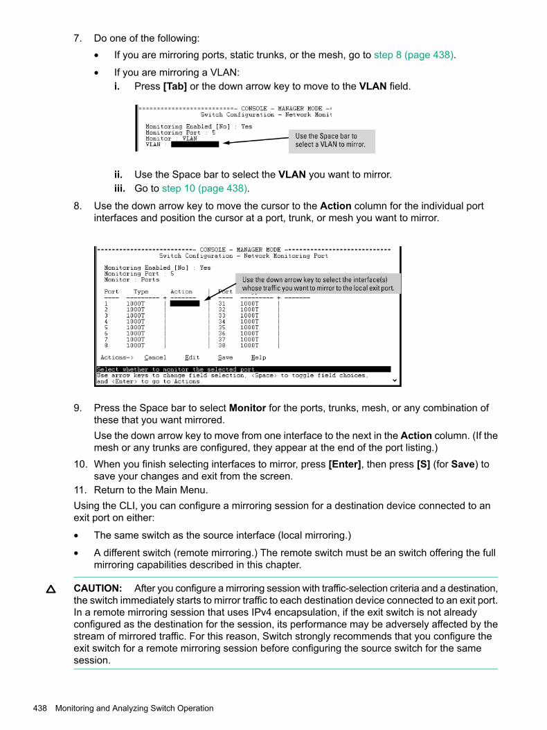
7. Do one of the following:• If you are mirroring ports, static trunks, or the mesh, go to step 8 (page 438).
• If you are mirroring a VLAN:i. Press [Tab] or the down arrow key to move to the VLAN field.
ii. Use the Space bar to select the VLAN you want to mirror.iii. Go to step 10 (page 438).
8. Use the down arrow key to move the cursor to the Action column for the individual portinterfaces and position the cursor at a port, trunk, or mesh you want to mirror.
9. Press the Space bar to select Monitor for the ports, trunks, mesh, or any combination ofthese that you want mirrored.Use the down arrow key to move from one interface to the next in the Action column. (If themesh or any trunks are configured, they appear at the end of the port listing.)
10. When you finish selecting interfaces to mirror, press [Enter], then press [S] (for Save) tosave your changes and exit from the screen.
11. Return to the Main Menu.Using the CLI, you can configure a mirroring session for a destination device connected to anexit port on either:
• The same switch as the source interface (local mirroring.)
• A different switch (remote mirroring.) The remote switch must be an switch offering the fullmirroring capabilities described in this chapter.
CAUTION: After you configure a mirroring session with traffic-selection criteria and a destination,the switch immediately starts to mirror traffic to each destination device connected to an exit port.In a remote mirroring session that uses IPv4 encapsulation, if the exit switch is not alreadyconfigured as the destination for the session, its performance may be adversely affected by thestream of mirrored traffic. For this reason, Switch strongly recommends that you configure theexit switch for a remote mirroring session before configuring the source switch for the samesession.
438 Monitoring and Analyzing Switch Operation
Configuring the mirroring destination on a remote switchSyntax
mirror endpoint ip src-ip-addr src-udp-port dst-ip-addr portexit-port
Enter this command on a remote switch to configure the exit port to use in a remotemirroring session. You will configure the mirroring source on the local switch inthe next step.The mirror endpoint ip command configures:
• The unique UDP port number to be used for the mirroring session on thesource switch. The recommended port range is from 7933 to 65535.
• The IP address of the source switch to use in the session.
• The IP address and exit-port number on the remote (endpoint) switch.In a remote mirroring endpoint, the IP address of exit port and the remotedestination switch can belong to different VLANs.
Configuring the mirroring source on the local switchSyntax
mirror 1 - 4 [name name-str ] remote ip src-ip src-udp-portdst-ip [truncation]The no mirror 1 - 4 command form removes both the mirroring session andany mirroring sources previously assigned to the session by the followingcommands.
Configuring traffic-direction criteria to select trafficSyntax
[ no ] [ interface port/trunk/mesh | vlan vid-# ]monitor allin | out | both mirror 1 - 4 | name-str [ 1 - 4 |name-str ...]
Configuring ACL criteria to select inbound trafficDeprecated command:
Syntax[ no ] [ interface port/trunk/mesh | vlan vid-# ]monitor ipaccess-group acl-name inmirror [ 1 - 4 | name-str ] [ 1 - 4 | name-str ...]
Configuring a mirroring policy to select inbound trafficSyntax
class ipv4 | ipv6 classname [ no ] [seq-number] [ match |ignore ip-protocol source-address destination-address ][precedence precedence-value] [tos tos-value] [ip-dscpcodepoint] [vlan vlan-id]
Configuring the mirroring destination on a remote switch 439

Syntaxpolicy mirror policy-name [no] [seq-number] [ class ipv4 | ipv6classname action mirror session ] [ action mirror session]... [ no ]default-class action mirror session [ no ] [ interfaceport/trunk | vlan vid-# ]service-policy mirror-policy-name in
In the policy mirror command, the mirror session parameter acceptsa number (1 to 4) or name, if the specified mirroring session has already beenconfigured with the name name-str option in the mirror command.Theno [ interface | vlan ] service-policy incommand removes the mirroring policy from a port, VLAN, trunk, or mesh interfacefor a specified session, but leaves the session available for other assignments.
Configuring the MAC-based criteria to select trafficSyntax
[ no ] monitor mac mac-addr [ src | dst | both ] mirrorsession
NOTE: If you have already configured session 1 with a destination, you can enter the vlanvid monitor or interface port monitor command without traffic-selection criteria andsession identifier to:• Overwrite the existing session 1 configuration.
• Automatically configure mirroring in session 1 for inbound and outbound traffic on specifiedVLAN or port interfaces with the preconfigured destination.
NOTE: MAC based mirroring not working when creating a mirroring with destination number3 or 4 on the HPE 5406R switch. The workaround for this issue is to clear the mac-learns for themac being mirrored then re-apply the mirror.
Configuring a destination switch in a remote mirroring session
CAUTION: When configuring a remote mirroring session, always configure the destinationswitch first. Configuring the source switch first can result in a large volume of mirrored,IPv4-encapsulated traffic arriving at the destination without an exit path, which can slow switchperformance.
Syntaxmirror endpoint ip src-ip src-udp-port dst-ip exit-port-#no mirror endpoint ip src-ip src-udp-port dst-ip
Used on a destination switch to configure the remote endpoint of a mirroringsession. The command uniquely associates the mirrored traffic from the desiredsession on a monitored source with a remote exit port on the destination switch.You must use the same set of source and destination parameters used when youconfigure the same session on both the source and destination switches.For a given mirroring session, the same src-ip , src-udp-port anddst-ip values must be entered with the mirror endpoint ip command
440 Monitoring and Analyzing Switch Operation

on the destination switch, and later with the mirror remote ip command onthe source switch.
CAUTION: Do not remove the configuration of a remote mirroring endpointsupport for a given session if there are source switches currently configured tomirror traffic to the endpoint.
Must exactly match the src-ip address you configure on the sourceswitch for the remote session.
src-ip
Must exactly match the src-udp-port value you configure on thesource switch for the remote session. The recommended port range is7933 to 65535.
src-udp-port
This setting associates the monitored source with the desired remoteendpoint in the remote session by using the same, unique UDP portnumber to identify the session on the source and remote switches.
Must exactly match the dst-ip setting you configure on the sourceswitch for the remote session.
dst-ip
Exit port for mirrored traffic in the remote session, to which a trafficanalyzer or IDS is connected.
exit-port-#
The no form of the command deletes the mirroring endpoint for the configuredsession on the remote destination switch.
Configuring a source switch in a local mirroring sessionEnter the mirror port command on the source switch to configure an exit port on the sameswitch. To create the mirroring session, use the information gathered in “High-level overview ofthe mirror configuration process” (page 466).
Syntaxmirror 1 - 4 port exit-port-# [name name-str ]no mirror 1- 4
Assigns the exit port to use for the specified mirroring session and must beexecuted from the global configuration level.
Identifies the mirroring session created by this command.(Multiple sessions on the switch can use the same exitport.)
1 - 4
Optional alphanumeric name string used to identify thesession ( up to 15 characters)
name name-str
Exit port for mirrored traffic in the remote session. This isthe port to which a traffic analyzer or IDS is connected.
portexit-port-#
The no form of the command removes the mirroring session and any mirroringsource previously assigned to that session.
Configuring a source switch in a remote mirroring sessionSyntax
[ no ] mirror 1 - 4 [name name-str ] remote ip src-ipsrc-udp-port dst-ip [truncation]
Configuring a source switch in a local mirroring session 441

Used on the source switch to uniquely associate the mirrored traffic in the specifiedsession with a remote destination switch. You must configure the same sourceand destination parameters when you configure the same session on both thesource and destination switches. (If multiple remote sessions use the same sourceand destination IP addresses, each session must use a unique UDP port value.)When you execute this command, the following message is displayed:
Caution: Please configure destination switch first.Do you want to continue [y/n]?
• If you have not yet configured the session on the remote destination switch,follow the configuration procedure in “Configure a mirroring destination on aremote switch” (page 466) before using this command.
• If you have already configured the session on the remote destination switch,enter y (for "yes") to complete this command.
Identifies the mirroring session created by this command.1 - 4
Optional alphanumeric name string used as an additionalsession identifier (up to 15 characters.)
name name-str
The IP address of the VLAN or subnet on which the traffic tobe mirrored enters or leaves the switch.
src-ip
Associates the remote session with a UDP port number. Whenmultiple sessions have the same source IP address src-ip
src-udp-port
and destination IP address dst-ip , the UDP port numbermust be unique in each session. The UDP port number usedfor a given session should be in the range of 7933 to 65535.
CAUTION: UDP port numbers below 7933 are reservedfor various IP applications. Using them for mirroring can resultin the interruption of other IP functions and in non-mirroredtraffic being received on the destination switch and sent to adevice connected to the remote exit port.The configured UDP port number is included in the framesmirrored from the source switch to the remote destinationswitch (mirror endpoint), and enables the remote switchto match the frames to the exit port configured for thecombined UDP port number, source IP address, anddestination IP address..
For the remote session specified in the command, this is theIP address of the VLAN or subnet on which the remote exit
dst-ip
port exists. (The exit port to which a traffic analyzer or IDS isconnected is configured on the remote switch in section.) .)
Enables truncation of oversize frames, causing the part ofthe frame in excess of the MTU size to be truncated. Unless
[truncation]
truncation is enabled, oversize frames are dropped. The framesize is truncated to a multiple of 18 bytes—for example, if theMTU is 1000 bytes, the frame is truncated to 990 bytes (55* 18 bytes.)
The no form of the command removes the mirroring session and any mirroringsource previously assigned to the session. To preserve the session while deletinga monitored source assigned to it.
442 Monitoring and Analyzing Switch Operation

Selecting all traffic on a port interface for mirroring according to trafficdirection
Syntax[ no ] interface port/trunk/mesh monitor all [ in | out | both] [ mirror 1 - 4 | name-str ] [ 1 - 4 | name-str 1 - 4| name-str 1 - 4 | name-str ] [no-tag-added]Assigns a mirroring source to a previously configured mirroring session on asource switch by specifying the port, trunk, and/or mesh sources to use, thedirection of traffic to mirror, and the session.
Identifies the source ports, static trunks, and/or mesh on which tomirror traffic.
interfaceport/trunk/mesh
Use a hyphen for a range of consecutive ports or trunks (a5-a8,Trk2-Trk4.)Use a comma to separate non-contiguous interfaces (b11, b14,Trk4, Trk7.)
For the interface specified by port/trunk/mesh , selects trafficto mirror based on whether the traffic is entering or leaving theswitch on the interface:
monitor all [ in | out| both ]
• in: Mirrors entering traffic.
• out: Mirrors exiting traffic.
• both:Mirrors traffic entering and exiting.
If you enter the monitor all command without selection criteriaor a session identifier, the command applies by default to session1
Assigns the traffic specified by the interface and direction to asession by number or—if configured—by name. The session musthave been previously configured.
mirror [ 1 - 4 |name-str ]
Depending on how many sessions are already configured on theswitch, you can use the same command to assign the specifiedsource to up to four sessions, for example, interface a1monitor all in mirror 1 2 4.
• 1 - 4 : Configures the selected port traffic to be mirrored inthe specified session number.
• [ name name-str ]Optional: configures the selected porttraffic to be mirrored in the specified session name. The stringcan be used interchangeably with the session number whenusing this command to assign a mirroring source to a session.
Prevents a VLAN tag from being added to the mirrored copy of anoutbound packet sent to a local or remote mirroring destination.
[no-tag-added]
The no form of the command removes a mirroring source assigned to the session,but does not remove the session itself. This enables you to repurpose a sessionby removing an unwanted mirroring source and adding another in its place.
Selecting all traffic on a port interface for mirroring according to traffic direction 443

Selecting all traffic on a VLAN interface for mirroring according to trafficdirection
Syntaxvlan vid-# monitor all [ in | out | both ] [ mirror 1 - 4 |name-str ] [ 1 - 4 | name-str 1 - 4 | name-str 1 -4 | name-str ]This command assigns a monitored VLAN source to a previously configuredmirroring session on a source switch by specifying the VLAN ID, the direction oftraffic to mirror, and the session.
Identifies the VLAN on which to mirror traffic.vlan vid-#
Uses the direction of traffic on the specified vid-# to select traffic tomirror.If you enter the monitor all command without selection
monitor all [ in |out | both ]
criteria or a session identifier, the command applies by default tosession 1.
Assigns the VLAN traffic defined by the VLAN ID and traffic directionto a session number or name.
mirror [ 1 - 4 |name-str ]
Depending on how many sessions are already configured on the switch,you can use the same command to assign the specified VLAN sourceto up to four sessions, for example, interface a1 monitor allin mirror 1 2 4.
• 1 - 4 : Configures the selected VLAN traffic to be mirrored in thespecified session number.
• [name name-str ]:Optional; configures the selected port trafficto be mirrored in the specified session name. The string can beused interchangeably with the session number when using thiscommand to assign a mirroring source to a session. To configurean alphanumeric name for a mirroring session, see the commanddescription under “Configuring a source switch in a remote mirroringsession” (page 441).
Assigning a VLAN to a mirroring session precludes assigning any other mirroringsources to the same session. If a VLAN is already assigned to a given mirroringsession, using this command to assign another VLAN to the same mirroringsession results in the second assignment replacing the first. Also, if there areother (port, trunk, or mesh) mirroring sources already assigned to a session, theswitch displays a message similar to:
Mirror source port exists on session N. Can not add mirrorsource VLAN.
The no form of the command removes a mirroring source assigned to the session,but does not remove the session itself. This allows you to repurpose a sessionby removing an unwanted mirroring source and adding another in its place.
Configuring a MAC address to filter mirrored traffic on an interfaceEnter the monitor mac mirror command at the global configuration level.
Syntax[ no ] monitor mac mac-addr [ src | dest | both ] mirror 1- 4 | name-str [ 1 - 4 | name-str ] [ 1 - 4 | name-str ][ 1 - 4 | name-str ]
444 Monitoring and Analyzing Switch Operation

Use this command to configure a source and/or destination MAC address ascriteria for selecting traffic in one or more mirroring sessions on the switch. TheMAC address you enter is configured to mirror inbound (src), outbound (dest),or both inbound and outbound (both) traffic on any port or learned VLAN on theswitch.
monitor mac mac-addr
Configures the MAC address as selection criteria for mirroring traffic on any port or learned VLANon the switch.
Specifies how the MAC address is used to filter and mirror packets ininbound and/or outbound traffic on the interfaces on which the mirroringsession is applied:
src | dest | both
• src:Mirrors all packets in inbound traffic that contain the specifiedMAC address as source address.
• dest: Mirrors all packets in outbound traffic that contain thespecified MAC address as destination address.
NOTE: The MAC address of the switch is not supported as eitherthe source or destination MAC address used to select mirrored traffic.
• both: Mirrors all packets in both inbound and outbound traffic thatcontain the specified MAC address as either source or destinationaddress.
Assigns the inbound and/or outbound traffic filtered by the specifiedMAC address to a previously configured mirroring session. The sessionis identified by a number or (if configured) a name.
mirror [ 1 - 4 |name-str ]
Depending on how many sessions are configured on the switch, youcan use the same command to configure a MAC address as mirroringcriteria in up to four sessions. To identify a session, you can entereither its name or number; for example: mirror 1 2 3 traffsrc4
1 - 4 : Specifies a mirroring session by number, for which theconfigured MAC address is used to select and mirror inbound and/oroutbound traffic.
Packets that are sent or received on an interface configured with a mirroringsession and that contain the MAC address as source and/or destination addressare mirrored to a previously configured destination device.To remove a MAC address as selection criteria in a mirroring session, you mustenter the complete Command syntax, for example, no monitor mac998877-665544 dest mirror 4.The no form of the command removes the MAC address as a mirroring criteriafrom an active session, but does not remove the session itself. This enables youto repurpose a session by removing an unwanted mirroring criteria and addinganother in its place.
Configuring classifier-based mirroringFor more information and a list of general steps for the process beginning with this command,see the information about restrictions on classifier-based mirroring.
Context: Global configuration
Syntax[ no ] class [ ipv4 | ipv6 classname ]
Configuring classifier-based mirroring 445
Defines the name of a traffic class and specifies whether a policy is to be appliedto IPv4 or IPv6 packets, where classname is a text string (64 charactersmaximum.)After you enter the class command, you enter the class configuration context tospecify match criteria. A traffic class contains a series of match and ignorecommands, which specify the criteria used to classify packets.To configure a default traffic class, use the default-class command asdescribed below. A default class manages the packets that do not match thematch/ignore criteria in any other classes in a policy.
Context: Class configuration
Syntax[ no ] [seq-number] [ match | ignore ip-protocolsource-address destination-address ] [ip-dscp codepoint][precedence precedence-value] [tos tos-value] [vlan vlan-id]For detailed information about how to enter match and ignore commands toconfigure a traffic class, the Advanced Traffic Management Guide.
Context: Global configuration
Syntax[ no ] policy mirror policy-name
Defines the name of a mirroring policy and enters the policy configuration context.A traffic policy consists of one or more classes and one or more mirroring actionsconfigured for each class of traffic. The configured actions are executed on packetsthat match a match statement in a class. No policy action is performed on packetsthat match an ignore statement.
Context: Policy configuration
Syntax[ no ] [seq-number] class [ ipv4 | ipv6 classname ]action mirror session
Defines the mirroring action to be applied on a pre-configured IPv4 or IPv6 trafficclass when a packet matches the match criteria in the traffic class. You can entermultiple class action mirror statements in a policy.
The (optional) seq-number parameter sequentially orders the mirroringactions that you enter in a policy configuration. Actions are executedon matching packets in numerical order.
[seq-number]
Default: Mirroring action statements are numbered in increments of10, starting at 10.
Defines the preconfigured traffic class on which the mirroring actionsin the policy are executed and specifies whether the mirroring policy
class [ ipv4 | ipv6classname ]
is applied to IPv4 or IPv6 traffic in the class. The classname is a textstring (64 characters maximum.)
Configures mirroring for the destination and session specified by thesession parameter.
action mirrorsession
446 Monitoring and Analyzing Switch Operation
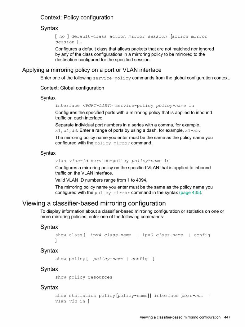
Context: Policy configuration
Syntax[ no ] default-class action mirror session [action mirrorsession ]...Configures a default class that allows packets that are not matched nor ignoredby any of the class configurations in a mirroring policy to be mirrored to thedestination configured for the specified session.
Applying a mirroring policy on a port or VLAN interfaceEnter one of the following service-policy commands from the global configuration context.
Context: Global configuration
Syntaxinterface <PORT-LIST> service-policy policy-name in
Configures the specified ports with a mirroring policy that is applied to inboundtraffic on each interface.Separate individual port numbers in a series with a comma, for example,a1,b4,d3. Enter a range of ports by using a dash, for example, a1-a5.The mirroring policy name you enter must be the same as the policy name youconfigured with the policy mirror command.
Syntaxvlan vlan-id service-policy policy-name in
Configures a mirroring policy on the specified VLAN that is applied to inboundtraffic on the VLAN interface.Valid VLAN ID numbers range from 1 to 4094.The mirroring policy name you enter must be the same as the policy name youconfigured with the policy mirror command in the syntax (page 435).
Viewing a classifier-based mirroring configurationTo display information about a classifier-based mirroring configuration or statistics on one ormore mirroring policies, enter one of the following commands:
Syntaxshow class [ ipv4 class-name | ipv6 class-name | config]
Syntaxshow policy [ policy-name | config ]
Syntaxshow policy resources
Syntaxshow statistics policy [policy-name] [ interface port-num |vlan vid in ]
Viewing a classifier-based mirroring configuration 447

Viewing all mirroring sessions configured on the switchSyntax
show monitor
If a monitored source for a remote session is configured on the switch, the followinginformation is displayed. Otherwise, the output displays: Mirroring is currentlydisabled.
Lists the four configurable sessions on the switch.Sessions
Displays the current status of each sessionStatus:
• active: The session is configured.
• inactive: Only the destination has been configured; the mirroring source is notconfigured.
• not defined: Mirroring is not configured for this session.
Indicates whether the mirroring session is local (port), remote (IPv4), or MAC-based(mac) for local or remote sessions.
Type
Indicates how many monitored source interfaces are configured for each mirroringsession.
Sources
Indicates whether the source is using a classifier-based mirroring policy to selectinbound IPv4 or IPv6 traffic for mirroring.
Policy
If a remote mirroring endpoint is configured on the switch, the following informationis displayed. Otherwise, the output displays: There are no Remote Mirroringendpoints currently assigned.
Indicates whether the mirroring session is local (port), remote (IPv4), orMAC-based (mac) for local or remote sessions.
Type
The IP address configured for the source VLAN or subnet on which themonitored source interface exists. In the configuration of a remote session,
UDP Source Addr
the same UDP source address must be configured on the source anddestination switches.
The unique UDP port number that identifies a remote session. In theconfiguration of a remote session, the same UDP port number must beconfigured on the source and destination switches.
UDP port
The IP address configured for the destination VLAN or subnet on which theremote exit port exists. In the configuration of a remote session, the same
UDP Dest Addr
UDP destination address must be configured on the source and destinationswitches.
Identifies the exit port for a remote session on a remote destination switch.Dest Port
448 Monitoring and Analyzing Switch Operation

Figure 157 Displaying the currently configured mirroring sessions on theswitch
Viewing the remote endpoints configured on the switchSyntax
show monitor endpoint
Displays the remote mirroring endpoints configured on the switch. Information onlocal sessions configured on the switch is not displayed. (To view the configurationof a local session, use theshow monitor [ 1-4 | name name-str ] ]command, as described on page 74 and page 77.)
Indicates whether the session is a port (local) or IPv4 (remote) mirroring session.Type
The IP address configured for the source VLAN or subnet on which the monitoredsource interface exists. In the configuration of a remote session, the same UDPsource address must be configured on the source and destination switches.
show monitorendpoint
The unique UDP port number that identifies a remote session. In the configurationof a remote session, the same UDP port number must be configured on the sourceand destination switches.
UDP port
The IP address configured for the destination VLAN or subnet on which the remoteexit port exists. In the configuration of a remote session, the same UDP destinationaddress must be configured on the source and destination switches.
UDP DestAddr
fies the exit port for a remote session on a remote destination switch.Dest Port
ExampleIn Figure 158 (page 450), the show monitor endpoint output shows that theswitch is configured as the remote endpoint (destination) for two remote sessionsfrom the same monitored source interface.
Viewing the remote endpoints configured on the switch 449

Figure 158 Displaying the configuration of remote mirroring endpoints onthe switch
Viewing the mirroring configuration for a specific sessionSyntax
show monitor [ 1 - 4 | name name-str ]Displays detailed configuration information for a specified local or remote mirroringsession on a source switch.
Displays the number of the specified session.Session
Displays the name of the session, if configured.Session Name
Indicates whether the source is using a classifier-based mirroring policy toselect inbound IPv4 or IPv6 traffic for mirroring.
Policy
For a local mirroring session, displays the port configured as the exit port onthe source switch. For a remote mirroring session, displays IPv4, whichindicates mirroring to a remote (endpoint) switch.
MirroringDestination
The IP address configured for the source VLAN or subnet on which themonitored source interface exists. In the configuration of a remote session,
UDP Source Addr
the same UDP source address must be configured on the source anddestination switches.
The unique UDP port number that identifies a remote session. In theconfiguration of a remote session, the same UDP port number must beconfigured on the source and destination switches.
UDP port
The IP address configured for the destination VLAN or subnet on which theremote exit port exists. In the configuration of a remote session, the same
UDP Dest Addr
UDP destination address must be configured on the source and destinationswitches.
For a remote session, displays current session activity:Status
• active: The session is configured and is mirroring traffic. A remote pathhas been discovered to the destination.
• inactive: The session is configured, but is not currently mirroring traffic. Aremote path has not been discovered to the destination.
• not defined: Mirroring is not configured for this session.
For the specified local or remote session, displays the source (port, trunk, orVLAN) interface and the MAC address (if configured) used to select mirroredtraffic.
Monitoring Sources
For the selected interface, indicates whether mirrored traffic is entering theswitch (in), leaving the switch (out), or both.
Direction
450 Monitoring and Analyzing Switch Operation

Viewing a remote mirroring sessionAfter you configure session 2 for remote mirroring (Figure 159 (page 451)), you can enter theshow monitor 2 command to verify the configuration (Figure 160 (page 451).)
Figure 159 Configuring a remote mirroring session and monitored source
Figure 160 Displaying the Configuration of a Remote Mirroring Session
Viewing a MAC-based mirroring sessionAfter you configure a MAC-based mirroring session (Figure 161 (page 451)), you can enter theshow monitor 3 command to verify the configuration (Figure 162 (page 451).)
Figure 161 Configuring a MAC-based mirroring session
Figure 162 Displaying a MAC-based mirroring session
Viewing a local mirroring sessionWhen used to display the configuration of a local session, the show monitor command displaysa subset of the information displayed for a remote mirroring session.
Viewing a remote mirroring session 451

ExampleFigure 163 (page 452) displays a local mirroring configuration for a sessionconfigured as follows:• Session number: 1
• Session name: Detail
• Classifier-based mirroring policy, "MirrorAdminTraffic", is used to selectinbound traffic on port B1.
• Mirrored traffic is sent to exit port B3.
Figure 163 Displaying the configuration of a local mirroring session
Viewing information on a classifier-based mirroring sessionIn the following example, a classifier-based mirroring policy (mirrorAdminTraffic) mirrorsselected inbound IPv4 packets on VLAN 5 to the destination device configured for mirroringsession 3.
Figure 164 Configuring a classifier-based mirroring policy in a local mirroring session
452 Monitoring and Analyzing Switch Operation

Example 146 Displaying a classifier-based policy in a local mirroring session
HP Switch(config)# show monitor 3
Network Monitoring
Session: 3 Session Name:Policy: MirrorAdminTraffic
Mirror Destination: C1 (Port)
Monitoring Sources Direction------------------ ---------VLAN: 5 Source
Viewing information about a classifier-based mirroring configurationSyntax
show class ipv4 classnameshow class ipv6 classnameshow class config
Lists the statements that make up the IPv4 class identified byclassname.
ipv4 classname
Lists the statements that make up the IPv6 class identified byclassname.
ipv6 classname
Displays all classes, both IPv4 and IPv6, and lists the statements thatmake up each class.
config
Additional variants of the show class … command provide information on classesthat are members of policies that have been applied to ports or VLANs.
Figure 165 show class output for a mirroring policy
Viewing information about a classifier-based mirroring configurationSyntax
show policy policy-nameshow policy config
Lists the statements that make up the specified policy.policy-name
Displays the names of all policies defined for the switch and lists thestatements that make up each policy.
config
Additional variants of the show policy command provide information on policiesthat have been applied to ports or VLANs.
Viewing information about a classifier-based mirroring configuration 453

Figure 166 show policy output for a mirroring policy
Viewing information about statistics on one or more mirroring policiesSyntax
[ show | clear ]statistics policy policy-name port port-num[ show | clear ]statistics policy policy-name vlan vid in
Displays the statistics for a specified policy applied to a specified portor VLAN.
show
Clears statistics for the specified policy and port or VLAN.clear
The name of the policy.policy-name
The number of the port on which the policy is applied (single port only,not a range.)
port-num
The number or name of the vlan on which the policy is applied. VLANID numbers range from 1 to 4094.
vid
Indicates that statistics are shown for inbound traffic only.in
Figure 167 (page 454) shows the number of packets (in parentheses) that havebeen mirrored for each match/ignore statement in the mirroring policy.
Figure 167 show statistics policy output for a mirroring policyHP Switch# show statistics policy MirrorAdminTraffic vlan 30 in
HitCounts for Policy MirrorAdminTraffic
10 class ipv4 "AdminTraffic" action mirror 3
(5244) 10 match ip 15.29.16.1 0.63.255.255 0.0.0.0 255.255.255.255
(9466) 20 match ip 0.0.0.0 255.255.255.255 15.29.16.1 0.63.255.255
Viewing resource usage for mirroring policiesSyntax
show policy resources
Displays the number of hardware resources (rules, meters, and application portranges) used by classifier-based mirroring policies (local and remote) that arecurrently applied to interfaces on the switch, as well as QoS policies and othersoftware features.
NOTE: The information displayed is the same as the output of the show qosresources and show access-list resources commands.
454 Monitoring and Analyzing Switch Operation
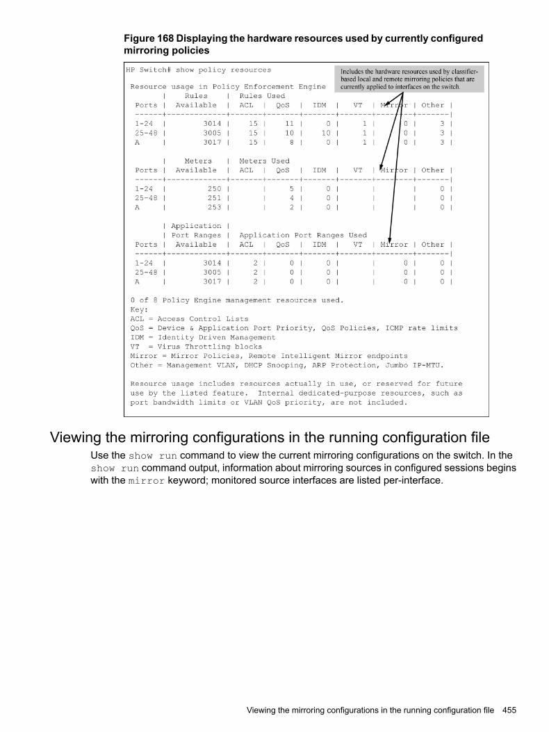
Figure 168 Displaying the hardware resources used by currently configuredmirroring policies
Viewing the mirroring configurations in the running configuration fileUse the show run command to view the current mirroring configurations on the switch. In theshow run command output, information about mirroring sources in configured sessions beginswith the mirror keyword; monitored source interfaces are listed per-interface.
Viewing the mirroring configurations in the running configuration file 455

Example
Figure 169 Displaying mirroring sources and sessions in the runningconfigurations
Information about remote endpoints configured for remote sessions on the switchbegin with the mirror endpoint keywords. In the following example, two remotesessions use the same exit port:
Figure 170 Displaying remote mirroring endpoints in the runningconfiguration
Compatibility modeTable 24 (page 456) shows how the v2 zl and zl modules behave in various combinations andsituations when Compatibility mode is enabled and when it is disabled.
Table 24 Compatibility mode enabled/disabled comparisons
Compatibility mode disabledCompatibility mode enabledModules
v2 zl modules are at full capacity.Can insert zl module and the module will comeup. Any v2 zl modules are limited to the zlconfiguration capacities.
v2 zlmodules only ZL modules are not allowed to power up.
ZL modules are not allowed to power up.Can insert zl module and the module will comeup. Any v2 zl modules are limited to the zlconfiguration capacities.
Mixed v2 zland zlmodules
If compatibility mode is disabled, the zl modulesgo down.
456 Monitoring and Analyzing Switch Operation

Table 24 Compatibility mode enabled/disabled comparisons (continued)
Compatibility mode disabledCompatibility mode enabledModules
The Management Module is the only module thatpowers up.
Same as exists already.If a v2 zl module is inserted, it operates in thesame mode as the zl module, but withperformance increases.
ZL modulesonly
If Compatibility Mode is disabled and then enabled,the startup config is erased and the chassisreboots.
In Compatibility Mode, no v2 zl features areallowed, whether the modules are all v2 zl or not.
Port and trunk group statistics and flow control statusThe features described in this section enable you to determine the traffic patterns for each portsince the last reboot or reset of the switch. You can display:
• A general report of traffic on all LAN ports and trunk groups in the switch, along with theper-port flow control status (On or Off.)
• A detailed summary of traffic on a selected port or trunk group.You can also reset the counters for a specific port.The menu interface provides a dynamic display of counters summarizing the traffic on each port.The CLI lets you see a static "snapshot" of port or trunk group statistics at a particular moment.As mentioned above, rebooting or resetting the switch resets the counters to zero. You can alsoreset the counters to zero for the current session. This is useful for troubleshooting. See the(page 457), below.
NOTE: The Reset action resets the counter display to zero for the current session, but doesnot affect the cumulative values in the actual hardware counters. (In compliance with the SNMPstandard, the values in the hardware counters are not reset to zero unless you reboot the switch.)Exiting from the console session and starting a new session restores the counter displays to theaccumulated values in the hardware counters.
Traffic mirroring overviewStarting in software release K.12.xx, traffic mirroring (Intelligent Mirroring) allows you to mirror(send a copy of) network traffic received or transmitted on a switch interface to a local or remotedestination, such as a traffic analyzer or IDS.)Traffic mirroring provides the following benefits:
• Allows you to monitor the traffic flow on specific source interfaces.
• Helps in analyzing and debugging problems in network operation resulting from a misbehavingnetwork or an individual client. The mirroring of selected traffic to an external device makesit easier to diagnose a network problem from a centralized location in a topology spreadacross a campus.
• Supports remote mirroring to simultaneously mirror switch traffic on one or more interfacesto multiple remote destinations. (In remote mirroring, you must first configure the remotemirroring endpoint—remote switch and exit port—before you specify a mirroring source fora session.)
Port and trunk group statistics and flow control status 457

Mirroring overviewFigure 171 (page 458) shows an example of the terms used to describe the configuration of asample local and remote mirroring session:
• In the local session, inbound traffic entering Switch A is monitored on port A2 and mirroredto a destination (host), traffic analyzer 1, through exit port A15 on the switch.A local mirroring session means that the monitored interface (A2) and exit port (A15) are onthe same switch.
• In the remote session, inbound traffic entering Switch A is monitored on port A1. A mirroredcopy of monitored traffic is routed through the network to a remote mirroring endpoint: exitport B7 on Switch B. A destination device, traffic analyzer 2, is connected to the remote exitport.A remote mirroring session means that:
• The monitored interface (A1) and exit port (B7) are on different switches.
• Mirrored traffic can be bridged or routed from a source switch to a remote switch.
Figure 171 Local and remote sessions showing mirroring terms
Mirroring destinationsTraffic mirroring supports destination devices that are connected to the local switch or to a remoteswitch:
• Traffic can be copied to a destination (host) device connected to the same switch as themirroring source in a local mirroring session. You can configure up to four exit ports to whichdestination devices are connected.
• Traffic can be bridged or routed to a destination device connected to a different switch in aremote mirroring session. You can configure up to 32 remote mirroring endpoints (IP addressand exit port) to which destination devices are connected.
Mirroring sources and sessionsTraffic mirroring supports the configuration of port and VLAN interfaces as mirroring sources inup to four mirroring sessions on a switch. Each session can have one or more sources (portsand/or static trunks, a mesh, or a VLAN interface) that monitor traffic entering and/or leaving theswitch.
458 Monitoring and Analyzing Switch Operation

NOTE: Using the CLI, you can make full use of the switch's local and remote mirroringcapabilities. Using the Menu interface, you can configure only local mirroring for either a singleVLAN or a group of ports, static trunks, or both.In remote mirroring, a 54-byte remote mirroring tunnel header is added to the front of eachmirrored frame for transport from the source switch to the destination switch. This may causesome frames that were close to the MTU size to exceed the MTU size. Mirrored frames exceedingthe allowed MTU size are dropped, unless the optional [truncation] parameter is set in themirror command.
Mirroring sessionsA mirroring session consists of a mirroring source and destination (endpoint.) Although a mirroringsource can be one of several interfaces, as mentioned above, for any session, the destinationmust be a single (exit) port. The exit port cannot be a trunk, VLAN, or mesh interface.You can map multiple mirroring sessions to the same exit port, which provides flexibility indistributing hosts, such as traffic analyzers or an IDS. In a remote mirroring endpoint, the IPaddress of the exit port and the remote destination switch can belong to different VLANs.Mirroring sessions can have the same or a different destination. You can configure an exit porton the local (source) switch and/or on a remote switch as the destination in a mirroring session.When configuring a mirroring destination, consider the following options:
• Mirrored traffic belonging to different sessions can be directed to the same destination or todifferent destinations.
• You can reduce the risk of oversubscribing a single exit port by:Directing traffic from different session sources to multiple exit ports.•
• Configuring an exit port with a higher bandwidth than the monitored source port.
• You can segregate traffic by type, direction, or source.
Mirroring session limitsA switch running software release K.12.xx or greater supports the following:
• A maximum of four mirroring (local and remote) sessions.
• A maximum of 32 remote mirroring endpoints (exit ports connected to a destination devicethat receive mirrored traffic originating from monitored interfaces on a different switch.)
Selecting mirrored trafficYou can use any of the following options to select the traffic to be mirrored on a port, trunk, mesh,or VLAN interface in a local or remote session:
• All trafficMonitors all traffic entering or leaving the switch on one or more interfaces (inbound andoutbound.)
• Direction-based traffic selectionMonitors traffic that is either entering or leaving the switch (inbound or outbound.) Monitoringtraffic in only one direction improves operation by reducing the amount of traffic sent to amirroring destination.
Traffic mirroring overview 459
• MAC-based traffic selectionMonitors only traffic with a matching source and/or destination MAC address in packetheaders entering and/or leaving the switch on one or more interfaces (inbound and/oroutbound.)
• Classifier-based service policyProvides a finer granularity of match criteria to zoom in on a subset of a monitored port orVLAN traffic (IPv4 or IPv6) and select it for local or remote mirroring (inbound only.)
Deprecation of ACL-based traffic selectionIn software release K.14.01 or greater, the use of ACLs for selecting traffic in a mirroring sessionhas been deprecated and is replaced by the use of advanced classifier-based service policies.As with ACL criteria, classifier-based match/ignore criteria allow you to limit a mirroring sessionto selected inbound packets on a given port or VLAN interface (instead of mirroring all inboundtraffic on the interface.)The following commands have been deprecated:
• interface port/trunk/mesh monitor ip access-group acl-name in mirror[ 1 - 4 | name-str ]
• vlan vid-# monitor ip access-group acl-name in mirror [ 1 - 4 |name-str ]
After you install and boot release K.14.01 or greater, ACL-based local and remote mirroringsessions configured on a port or VLAN interface are automatically converted to classifier-basedmirroring policies.If you are running software release K.13.XX or earlier, ACL permit/deny criteria are supportedto select IP traffic entering a switch to mirror in a local or remote session, using specified sourceand/or destination criteria.
Mirrored traffic destinations
Local destinationsA local mirroring traffic destination is a port on the same switch as the source of the traffic beingmirrored.
Remote destinationsA remote mirroring traffic destination is an switch configured to operate as the exit switch formirrored traffic sessions originating on other switches. As of June, 2007, switches capable ofthis operation include the following switches:
• 3500yl
• 5400zl
CAUTION: After you configure a mirroring session with traffic-selection criteria and a destination,the switch immediately starts to mirror traffic to each destination device connected to an exit port.In a remote mirroring session that uses IPv4 encapsulation, if the intended exit switch is notalready configured as the destination for the session, its performance may be adversely affectedby the stream of mirrored traffic. For this reason, Switch strongly recommends that you configurethe exit switch for a remote mirroring session before configuring the source switch for the samesession.
460 Monitoring and Analyzing Switch Operation
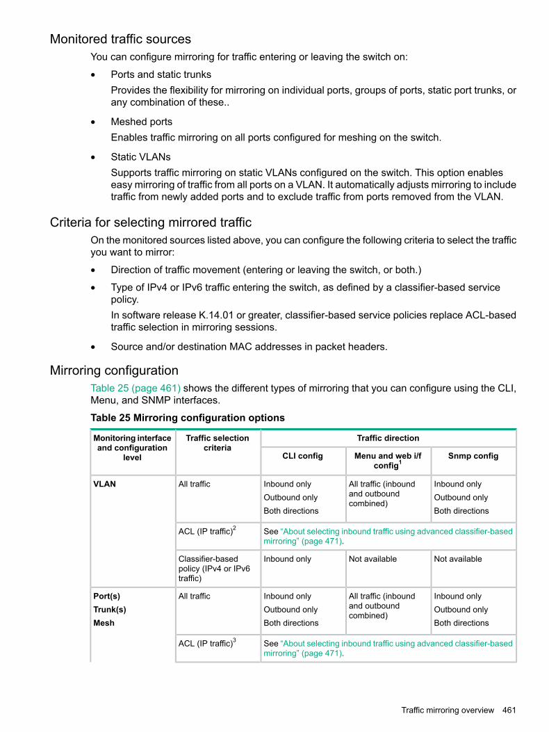
Monitored traffic sourcesYou can configure mirroring for traffic entering or leaving the switch on:
• Ports and static trunksProvides the flexibility for mirroring on individual ports, groups of ports, static port trunks, orany combination of these..
• Meshed portsEnables traffic mirroring on all ports configured for meshing on the switch.
• Static VLANsSupports traffic mirroring on static VLANs configured on the switch. This option enableseasy mirroring of traffic from all ports on a VLAN. It automatically adjusts mirroring to includetraffic from newly added ports and to exclude traffic from ports removed from the VLAN.
Criteria for selecting mirrored trafficOn the monitored sources listed above, you can configure the following criteria to select the trafficyou want to mirror:
• Direction of traffic movement (entering or leaving the switch, or both.)
• Type of IPv4 or IPv6 traffic entering the switch, as defined by a classifier-based servicepolicy.In software release K.14.01 or greater, classifier-based service policies replace ACL-basedtraffic selection in mirroring sessions.
• Source and/or destination MAC addresses in packet headers.
Mirroring configurationTable 25 (page 461) shows the different types of mirroring that you can configure using the CLI,Menu, and SNMP interfaces.
Table 25 Mirroring configuration options
Traffic directionTraffic selectioncriteria
Monitoring interfaceand configuration
level Snmp configMenu and web i/fconfig1
CLI config
Inbound onlyAll traffic (inboundand outboundcombined)
Inbound onlyOutbound onlyBoth directions
All trafficVLANOutbound onlyBoth directions
See “About selecting inbound traffic using advanced classifier-basedmirroring” (page 471).
ACL (IP traffic)2
Not availableNot availableInbound onlyClassifier-basedpolicy (IPv4 or IPv6traffic)
Inbound onlyAll traffic (inboundand outboundcombined)
Inbound onlyOutbound onlyBoth directions
All trafficPort(s)Trunk(s)Mesh
Outbound onlyBoth directions
See “About selecting inbound traffic using advanced classifier-basedmirroring” (page 471).
ACL (IP traffic)3
Traffic mirroring overview 461

Table 25 Mirroring configuration options (continued)
Traffic directionTraffic selectioncriteria
Monitoring interfaceand configuration
level Snmp configMenu and web i/fconfig1
CLI config
Not availableNot availableInbound onlyClassifier-basedpolicy (IPv4 or IPv6traffic)
Inbound onlyNot availableInbound onlyMACsource/destinationaddress
Switch (global)Outbound onlyBoth directions
Outbound onlyBoth directions
1 Configures only session 1, and only for local mirroring.2 In release K.14.01 and greater, the use of ACLs to select inbound traffic in a mirroring session (using the
[ interface | vlan ]monitor ip access-group in mirror
command) has been deprecated and is replaced with classifier-based mirroring policies.3 In release K.14.01 and greater, the use of ACLs to select inbound traffic in a mirroring session (using the
[ interface | vlan ]monitor ip access-group in mirror
command) has been deprecated and is replaced with classifier-based mirroring policies.
Configuration notesUsing the CLI, you can configure all mirroring options on a switch.Using the Menu, you can configure only session 1 and only local mirroring in session 1 for trafficin both directions on specified interfaces. (If session 1 has been already configured in the CLIfor local mirroring for inbound-only or outbound-only traffic, and you use the Menu to modify thesession 1 configuration, session 1 is automatically reconfigured to monitor both inbound andoutbound traffic on the assigned interfaces. If session 1 has been configured in the CLI with aclassifier-based mirroring policy or as a remote mirroring session, an error message is displayedif you try to use the Menu to configure the session.)You can use the CLI can configure sessions 1 to 4 for local or remote mirroring in any combination,and override a Menu configuration of session 1.You can also use SNMP configure sessions 1 to 4 for local or remote mirroring in any combinationand override a Menu configuration of session 1, except that SNMP cannot be used to configurea classifier-based mirroring policy.
Remote mirroring endpoint and intermediate devicesThe remote mirroring endpoint that is used in a remote mirroring session must be an switch thatsupports the mirroring functions described in this chapter. (A remote mirroring endpoint consistsof the remote switch and exit port connected to a destination device.) Because remote mirroringon an switch uses IPv4 to encapsulate mirrored traffic sent to a remote endpoint switch, theintermediate switches and routers in a layer 2/3 domain can be from any vendor if they supportIPv4.The following restrictions apply to remote endpoint switches and intermediate devices in a networkconfigured for traffic mirroring:
• The exit port for a mirroring destination must be an individual port and not a trunk, mesh, orVLAN interface.
• A switch mirrors traffic on static trunks, but not on dynamic LACP trunks.
• A switch mirrors traffic at line rate. When mirroring multiple interfaces in networks withhigh-traffic levels, it is possible to copy more traffic to a mirroring destination than the link
462 Monitoring and Analyzing Switch Operation

supports. However, some mirrored traffic may not reach the destination. If you are mirroringa high-traffic volume, you can reduce the risk of oversubscribing a single exit port by:• Directing traffic from different session sources to multiple exit ports.
• Configuring an exit port with a higher bandwidth than the monitored source port.
Migration to release K.12.xxOn a switch that is running a software release earlier than K.12.xx with one or more mirroringsessions configured, when you download and boot release K.12.xx, the existing mirroringconfigurations are managed as follows:
• A legacy mirroring configuration on a port or VLAN interface maps to session 1.
• Traffic-selection criteria for session 1 is set to both; both inbound and outbound traffic (trafficentering and leaving the switch) on the configured interface is selected for mirroring.
• In a legacy mirroring configuration, a local exit port is applied to session 1.
Booting from software versions earlier than K.12.xxIf it is necessary to boot the switch from a legacy (pre-K.12.xx) software version after usingversion K.12.xx or greater to configure mirroring, remove mirroring from the configuration beforebooting with the earlier software.
Maximum supported frame sizeThe IPv4 encapsulation of mirrored traffic adds a 54-byte header to each mirrored frame. If aresulting frame exceeds the MTU allowed in the path from the mirroring source to the mirroringdestination, the frame is dropped, unless the optional [truncation] parameter is set in themirror command.
Frame truncationMirroring does not truncate frames unless the truncation parameter in the mirror commandis set. If that parameter is not set, oversized mirroring frames are dropped. Also, remote mirroringdoes not allow downstream devices in a mirroring path to fragment mirrored frames.
Migration to release K.14.01 or greater
NOTE: If a switch is running software release K.12.xx, you must first upgrade to release K.13.xxbefore migrating the switch to release K.14.01 or greater.
When you download and boot software release K.14.01 or greater on a switch that is runningrelease K.13.xx and has one or more mirroring sessions configured, an ACL-based mirroringconfiguration on a port or VLAN interface is mapped to a class and policy configuration basedon the ACL.The new mirroring policy is automatically configured on the same port or VLAN interface on whichthe mirroring ACL was assigned. The behavior of the new class and mirroring-policy configurationexactly matches the traffic-selection criteria and mirroring destination used in the ACL-basedsession.)Figure 172 (page 464) and Figure 173 (page 464) show how ACL-based selection criteria in amirroring session are converted to a classifier-based policy and class configuration when youinstall release K.14.01 or greater on a switch.
Traffic mirroring overview 463

Figure 172 Mirroring configuration in show run output in release K.13.xx
Figure 173 Mirroring configuration in show run output in release K.14.01 or greater
Using the Menu to configure local mirroringMenu and WebAgent limits
You can use the Menu and WebAgent to quickly configure or reconfigure local mirroring onsession 1 and allow one of the following two mirroring source options:
• Any combination of source ports, trunks, and a mesh.
• One static, source VLAN interface.The Menu and WebAgent also has these limits:
• Configure and display only session 1 and only as a local mirroring session for traffic in bothdirections on the specified interface. (Selecting inbound-only or outbound-only is not anoption.)
• If session 1 has been configured in the CLI for local mirroring for inbound-only oroutbound-only traffic on one or more interfaces, using the Menu to change the session 1configuration automatically reconfigures the session to monitor both inbound and outboundtraffic on the designated interface(s.)
• If session 1 has been configured in the CLI with an ACL/classifier-based mirroring policy oras a remote mirroring session, the Menu is not available for changing the session 1configuration.
• The CLI (and SNMP) can be used to override any Menu configuration of session 1.
Remote mirroring overviewTo configure a remote mirroring session in which the mirroring source and destination are ondifferent switches, follow these general steps:
464 Monitoring and Analyzing Switch Operation

1. Determine the IP addressing, UDP port number, and destination (exit) port number for theremote session:a. Source VLAN or subnet IP address on the source switch.b. Destination VLAN or subnet IP address on the destination switch.c. Random UDP port number for the session (7933-65535.)d. Remote mirroring endpoint: Exit port and IP address of the remote destination switch
(In a remote mirroring endpoint, the IP address of the exit port and remote switch canbelong to different VLANs. Any loopback IP address can be used except the defaultloopback address 127.0.0.1.)
Requirement: For remote mirroring, the same IP addressing and UDP port number must beconfigured on both the source and destination switches.
2. On the remote destination (endpoint) switch, enter the mirror endpoint command withthe information from step 1 (page 465) to configure a mirroring session for a specific exit port.
3. Determine the session (1 to 4) and (optional) alphanumeric name to use on the sourceswitch.
4. Determine the traffic to be filtered by any of the following selection methods and theappropriate configuration level (VLAN, port, mesh, trunk, global):a. Direction: inbound, outbound, or both.b. Classifier-based mirroring policy: inbound only for IPv4 or IPv6 traffic.c. MAC source and/or destination address: inbound, outbound, or both.
5. On the source switch:a. Enter the mirror command with the session number (1 to 4) and the IP addresses
and UDP port number from step 1 (page 465) to configure a mirroring session. If desired,enter the [truncation] parameter to allow oversize packets to be truncated ratherthan dropped.
b. Enter one of the following commands to configure one or more of the traffic-selectionmethods in step 4 (page 465) for the configured session:interface port/trunk/mesh [ monitor | service-policy policy-namein ]vlan vid [ monitor | service-policy policy-name in ]monitor mac mac-addr
After you complete b, the switch begins mirroring traffic to the remote destination (endpoint)configured for the session.
Quick reference to remote mirroring setupThe commands beginning with “Configuring the mirroring destination on a remote switch”(page 439), configure mirroring for a remote session in which the mirroring source and destinationare on different switches:
• The mirror command identifies the destination in a mirroring session.
• The interface and vlan commands identify the monitored interface, traffic direction, andtraffic-selection criteria for a specified session.
CAUTION: When configuring a remote mirroring session, always configure the destinationswitch first. Configuring the source switch first can result in a large volume of mirrored,IPv4-encapsulated traffic arriving at the destination without an exit path, which can slow switchperformance.
Remote mirroring overview 465
High-level overview of the mirror configuration processDetermine the mirroring session and destination
For a local mirroring sessionDetermine the port number for the exit port (such as A5, B10, and so forth), then go to “Configurethe monitored traffic in a mirror session” (page 467).
For a remote mirroring sessionDetermine the following information and then go to “Configure a mirroring destination on a remoteswitch” (page 466).
• The IP address of the VLAN or subnet on which the exit port exists on the destination switch.
• The port number of the remote exit port on the remote destination switch. (In a remotemirroring endpoint, the IP address of the exit port and the remote destination switch canbelong to different VLANs.)
• The IP address of the VLAN or subnet on which the mirrored traffic enters or leaves thesource switch.
CAUTION: Although the switch supports the use of UDP port numbers from 1 to 65535,UDP port numbers below 7933 are reserved for various IP applications. Using these portnumbers for mirroring can result in an interruption of other IP functions, and in non-mirroredtraffic being received on the destination (endpoint) switch and sent to the device connectedto the remote exit port.
• The unique UDP port number to use for the session on the source switch. (The recommendedport range is from 7933 to 65535.)
Configure a mirroring destination on a remote switchThis step is required only if you are configuring a remote mirroring session in which the exit portis on a different switch than the monitored (source) interface. If you are configuring local mirroring,go to “Configure a mirroring session on the source switch” (page 466).For remote mirroring, you must configure the destination switch to recognize each mirroringsession and forward mirrored traffic to an exit port before you configure the source switch.Configure the destination switch with the values you determined for remote mirroring in “High-leveloverview of the mirror configuration process” (page 466).
NOTE: A remote destination switch can support up to 32 remote mirroring endpoints (exit portsconnected to a destination device in a remote mirroring session.)
Configure a destination switch in a remote mirroring sessionEnter the mirror endpoint ip command on the remote switch to configure the switch as aremote endpoint for a mirroring session with a different source switch.
Configure a mirroring session on the source switchTo configure local mirroring, only a session number and exit port number are required.If the exit port for a mirroring destination is on a remote switch instead of the local (source) switch,you must enter the source IP address, destination IP address, and UDP port number for theremote mirroring session. You may also wish to enable frame truncation to allow oversize framesto be truncated rather than dropped.Frames that exceed the maximum size (MTU) are either dropped or truncated, according to thesetting of the [truncation] parameter in the mirror command. Frames that are near the
466 Monitoring and Analyzing Switch Operation

MTU size may become oversize when the 54-byte remote mirroring tunnel header is added fortransport between source switch and destination switch. (The addition of the header is a frequentcause for frames becoming oversize, but note that all oversize frames, whatever the cause oftheir excess size, are dropped or truncated.) If a frame is truncated, bytes are removed from theend of the frame. This may cause the checksum in the original frame header to fail. Some protocolanalyzers may flag such a checksum mismatch as an alert.
NOTE: Note that if you enable jumbo frames to allow large frames to be transmitted, you mustenable jumbo frames on all switches in the path between source and destination switches.
Configure a source switch in a remote mirroring sessionEnter the mirror remote ip command on the source switch to configure a remote destinationswitch for a mirroring session on the source switch. The source IP address, UDP port number,and destination IP address that you enter must be the same values that you entered with themirror endpoint ip command.
CAUTION: After you configure a mirroring session with traffic-selection criteria and a destination,the switch immediately starts to mirror traffic to the destination device connected to each exitport. In a remote mirroring session that uses IPv4 encapsulation, if the remote (endpoint) switchis not already configured as the destination for the session, its performance may be adverselyaffected by the stream of mirrored traffic. For this reason, Switch strongly recommends that youconfigure the endpoint switch in a remote mirroring session, as described in “Configure a mirroringdestination on a remote switch” (page 466), before using the mirror remote ip command inthis section to configure the mirroring source for the same session.
Configure the monitored traffic in a mirror sessionThis step configures one or more interfaces on a source switch with traffic-selection criteria toselect the traffic to be mirrored in a local or remote session configured in section “Configure amirroring session on the source switch” (page 466).
Traffic selection optionsTo configure traffic mirroring, specify the source interface, traffic direction, and criteria to be usedto select the traffic to be mirrored by using the following options:
• Interface typePort, trunk, and/or mesh•
• VLAN
• Switch (global configuration level)
• Traffic direction and selection criteriaAll inbound and/or outbound traffic on a port or VLAN interface•
• Only inbound IP traffic selected with an ACL (deprecated in software release K.14.01and greater)
• Only inbound IPv4 or IPv6 traffic selected with a classifier-based mirroring policy
• All inbound and/or outbound traffic selected by MAC source and/or destination address
The different ways to configure traffic-selection criteria on a monitored interface are describedin the following sections.
High-level overview of the mirror configuration process 467

Mirroring-source restrictionsIn a mirroring session, you can configure any of the following sources of mirrored traffic:
• Multiple port and trunk, and/or mesh interfaces
• One VLANIf you configure a VLAN as the source interface in a mirroring session and assign a secondVLAN to the session, the second VLAN overwrites the first VLAN as the source of mirroredtraffic.
• One classifier-based policyIf you configure a mirroring policy on a port or VLAN interface to mirror inbound traffic in asession, you cannot configure a port, trunk, mesh, ACL, or VLAN as an additional sourceof mirrored traffic in the session.
• Up to 320 MAC addresses (used to select traffic according to source, destination MACaddress, or both) in all mirroring sessions configured on a switch
About selecting all inbound/outbound traffic to mirrorIf you have already configured session 1 with a local or remote destination, you can enter thevlan vid monitor or interface port monitor command without additional parametersfor traffic-selection criteria and session number to configure mirroring for all inbound and outboundtraffic on the specified VLAN or port interfaces in session 1 with the preconfigured destination.
Untagged mirrored packetsAlthough a VLAN tag is added (by default) to the mirrored copy of untagged outbound packetsto indicate the source VLAN of the packet, it is sometimes desirable to have mirrored packetslook exactly like the original packet. The no-tag-added parameter gives you the option of nottagging mirrored copies of outbound packets, as shown in Figure 174 (page 468) and Figure 175(page 468).
Figure 174 Mirroring commands with the no-tag-added option
Figure 175 Displaying a mirror session configuration with the no-tag-added option
About using SNMP to configure no-tag-added
The MIB object hpicfBridgeDontTagWithVlan is used to implement the no-tag-added option,as shown below:
hpicfBridgeDontTagWithVlan OBJECT-TYPE
468 Monitoring and Analyzing Switch Operation

SYNTAX INTEGER{enabled(1),disabled(2)}MAX-ACCESS read-writeSTATUS currentDESCRIPTION"This oid mentions whether VLAN tag is part of themirror'ed copy of the packet. The value ‘enabled'denotes that the VLAN tag shouldn't be partof the mirror'ed copy; ‘disabled' does putthe VLAN tag in the mirror'ed copy. Only onelogical port is allowed.This object is persistent and when writtenthe entitySHOULD save the change to non-volatile storage."
DEFVAL { 2 }::= { hpicfBridgeMirrorSessionEntry 2 }
Operating notesThe following conditions apply for the no-tag-added option:
• The specified port can be a physical port, trunk port, or mesh port.
• Only a single logical port (physical port or trunk) can be associated with a mirror sessionwhen the no-tag-added option is specified. No other combination of ACL mirroring, VLANmirroring, or port mirroring can be associated with the mirror session. If more than one logicalport is specified, the following error message is displayed:Cannot monitor more than one logical port with no-tag-added option
• If a port changes its VLAN membership and/or untagged status within the VLAN, the"untagged port mirroring" associated with that port is updated when the configuration changeis processed.
• Only four ports or trunks can be monitored at one time when all four mirror sessions are inuse (one logical port per mirror session) without VLAN tags being added to a mirrored copy.
• The no-tag-added option can also be used when mirroring is configured with SNMP.
• A VLAN tag is still added to the copies of untagged packets obtained via VLAN-basedmirroring.
About selecting inbound traffic using an ACL (deprecated)
Deprecation of ACL-based traffic selectionIn release K.14.01 or greater, the use of ACLs to select inbound traffic in a mirroring session hasbeen replaced with classifier-based mirroring policies.The following commands have been deprecated:
• interface port/trunk/mesh monitor ip access-group acl-name inmirror 1 - 4 | name-str
• vlan vid-# monitor ip access-group <ACL-NAME> inmirror 1 - 4 | <NAME-STR>
After you install and boot release K.14.01 or greater, ACL-based local and remote mirroringsessions configured on a port or VLAN interface are automatically converted to classifier-basedmirroring policies.
About selecting all inbound/outbound traffic to mirror 469

About selecting inbound/outbound traffic using a MAC addressUse the monitor mac mirror command at the global configuration level to apply a sourceand/or destination MAC address as the selection criteria used in a local or remote mirroringsession.While classifier-based mirroring allows you to mirror traffic using a policy to specify IP addressesas selection criteria, MAC-based mirroring allows you monitor switch traffic using a source and/ordestination MAC address. You can apply MAC-based mirroring in one or more mirroring sessionson the switch to monitor:
• Inbound traffic
• Outbound traffic
• Both inbound and outbound trafficMAC-based mirroring is useful in Switch Network Immunity security solutions that provide detectionand response to malicious traffic at the network edge. After isolating a malicious MAC address,a security administrator can mirror all traffic sent to and received from the suspicious addressfor troubleshooting and traffic analysis.The MAC address that you enter with the monitor mac mirror command is configured toselect traffic for mirroring from all ports and learned VLANs on the switch. Therefore, a suspicionsMAC address used in wireless applications can be continuously monitored as it re-appears inswitch traffic on different ports or VLAN interfaces.You can configure MAC-based mirroring from the CLI or an SNMP management station and useit to mirror:
• All inbound and outbound traffic from a group of hosts to one destination device.
• Inbound and/or outbound traffic from each host to a different destination device.
• Inbound and outbound traffic from all monitored hosts separately on two destination devices:mirroring all inbound traffic to one device and all outbound traffic to another device.
RestrictionsThe following restrictions apply to MAC-based mirroring:
• Up to 320 different MAC addresses are supported for traffic selection in all mirroring sessionsconfigured on the switch.
• A destination MAC address is not supported as mirroring criteria for routed traffic, becausein routed packets, the destination MAC address is changed to the next-hop address whenthe packet is forwarded. Therefore, the destination MAC address that you want to mirror willnot appear in routed packet headers.This restriction also applies to the destination MAC address of a host that is directly connectedto a routing switch. (Normally, a host is connected to an edge switch, which is directlyconnected to the router.)To mirror routed traffic, we recommend that you use classifier-based policies to select IPv4or IPv6 traffic for mirroring, as described in “About selecting inbound traffic using advancedclassifier-based mirroring” (page 471).
• On a switch, you can use a MAC address only once as a source MAC address and onlyonce as a destination MAC address to filter mirrored traffic.For example, after you enter the following commands:monitor mac 111111-222222 src mirror 1
monitor mac 111111-222222 dest mirror 2
The following commands are not supported:
470 Monitoring and Analyzing Switch Operation

monitor mac 111111-222222 src mirror 3
monitor mac 111111-222222 dest mirror 4
In addition, if you enter the monitor mac 111111-222222 both mirror 1 command,you cannot use the MAC address 111111-222222 in any other monitor mac mirrorconfiguration commands on the switch.
• To re-use a MAC address that has already been configured as a source and/or destinationaddress for traffic selection in a mirror session, you must first remove the configuration byentering the no form of the command and then re-enter the MAC address in a new monitormac mirror command.For example, if you have already configured MAC address 111111-222222 to filter inboundand outbound mirrored traffic, and you decide to use it to filter only inbound traffic in a mirrorsession, you could enter the following commands:monitor mac 111111-222222 both mirror 1
no monitor mac 111111-222222 both mirror 1
monitor mac 111111-222222 src mirror 1
• A mirroring session in which you configure MAC-based mirroring is not supported on a port,trunk, mesh, or VLAN interface on which a mirroring session with a classifier-based mirroringpolicy is configured.
About selecting inbound traffic using advanced classifier-based mirroringIn software release K.14.01 or greater, in addition to the traffic selection options described in“Configure the monitored traffic in a mirror session” (page 467), traffic mirroring supports the useof advanced classifier-based functions that provide:
• A finer granularity for selecting the inbound IP traffic that you want to mirror on an individualport or VLAN interface (instead of mirroring all inbound traffic on the interface)
• Support for mirroring both IPv4 and IPv6 traffic
• The ability to re-use the same traffic classes in different software-feature configurations; forexample, you can apply both a QoS rate-limiting and mirroring policy on the same class oftraffic.
Deprecation of ACL-based traffic selectionIn software release K.14.01 or greater, advanced classifier-based policies replace ACL-basedtraffic selection in mirroring configurations.Like ACL-based traffic-selection criteria, classifier-based service policies apply only to inboundtraffic flows and are configured on a per-port or per-VLAN basis. In a mirroring session,classifier-based service policies do not support:
• The mirroring of outbound traffic exiting the switch
• The use of meshed ports as monitored (source) interfacesClassifier-based mirroring is not designed to work with other traffic-selection methods in a mirroringsession applied to a port or VLAN interface:
• If a mirroring session is already configured with one or more traffic-selection criteria(MAC-based or all inbound and/or outbound traffic), the session does not support the additionof a classifier-based policy.
• If a mirroring session is configured to use a classifier-based mirroring policy, no othertraffic-selection criteria (MAC-based or all inbound and/or outbound traffic) can be added tothe session on the same or a different interface.
About selecting all inbound/outbound traffic to mirror 471
Classifier-based mirroring policies provide greater precision when analyzing and debugging anetwork traffic problem. Using multiple match criteria, you can finely select and define the classesof traffic that you want to mirror on a traffic analyzer or IDS device.
Classifier-based mirroring configuration1. Evaluate the types of traffic in your network and identify the traffic types that you want to
mirror.2. Create an IPv4 or IPv6 traffic class using the class command to select the packets that
you want to mirror in a session on a preconfigured local or remote destination device. (See“Configuring classifier-based mirroring” (page 445).)A traffic class consists of match criteria, which consist of match and ignore commands.
• match commands define the values that header fields must contain for a packet tobelong to the class and be managed by policy actions.
• ignore commands define the values which, if contained in header fields, exclude apacket from the policy actions configured for the class.
NOTE: Be sure to enter match/ignore statements in the precise order in which you wanttheir criteria to be used to check packets.
The following match criteria are supported in match/ignore statements for inbound IPv4/IPv6traffic:
• IP source address (IPv4 and IPv6)
• IP destination address (IPv4 and IPv6)
• IP protocol (such as ICMP or SNMP)
• Layer 3 IP precedence bits
• Layer 3 DSCP codepoint
• Layer 4 TCP/UDP application port (including TCP flags)
• VLAN IDEnter one or more match or ignore commands from the class configuration context to filtertraffic and determine the packets on which policy actions will be performed. (See (page 446).)
3. Create a mirroring policy to configure the session and destination device to which specifiedclasses of inbound traffic are sent by entering the policy mirror command from theglobal configuration context. (See (page 435).)
NOTE: Be sure to enter each class and its associated mirroring actions in the preciseorder in which you want packets to be checked and processed.
To configure the mirroring actions that you want to execute on packets that match the criteriain a specified class, enter one or more class action mirror commands from the policyconfiguration context. (See (page 446).)You can configure only one mirroring session (destination) for each class. However, youcan configure the same mirroring session for different classes.A packet that matches the match criteria in a class is mirrored to the exit (local or remote)port that has been previously configured for the session, where session is a value from 1 to4 or a text string (if you configured the session with a name when you entered the mirrorcommand.)
472 Monitoring and Analyzing Switch Operation

Prerequisite: The local or remote exit port for a session must be already configured beforeyou enter the mirror session parameter in a class action statement:
• In a local mirroring session, the exit port is configured with the mirror<SESSION-NUMBER> port command.
• In a remote mirroring session, the remote exit port is configured with the mirrorendpoint ip and mirror <SESSION-NUMBER> remote ip commands.
Restriction: In a policy, you can configure only one mirroring session per class. However,you can configure the same session for different classes.Mirroring is not executed on packets that match ignore criteria in a class.The execution of mirroring actions is performed in the order in which the classes arenumerically listed in the policy.The complete no form of the class action mirror command or the no <SEQ-NUMBER>command removes a class and mirroring action from the policy configuration.To manage packets that do not match the match or ignore criteria in any class in the policy,and therefore have no mirroring actions performed on them, you can enter an optional defaultclass. The default class is placed at the end of a policy configuration and specifies themirroring actions to perform on packets that are neither matched nor ignored.
4. (Optional) To configure a default-class in a policy, enter the default-class command atthe end of a policy configuration and specify one or more actions to be executed on packetsthat are not matched and not ignored. (See “Syntax” (page 447).)Prerequisite: The local or remote exit port for a session must be already configured with adestination device before you enter the mirror <SESSION> parameter in a default-classaction statement.
5. Apply the mirroring policy to inbound traffic on a port (interface service-policy incommand) or VLAN (vlan service-policy in command) interface.
CAUTION: After you apply a mirroring policy for one or more preconfigured sessions ona port or VLAN interface, the switch immediately starts to use the traffic-selection criteriaand exit port to mirror traffic to the destination device connected to each exit port.In a remote mirroring session that uses IPv4 encapsulation, if the remote switch is not alreadyconfigured as the destination for the session, its performance may be adversely affected bythe stream of mirrored traffic.For this reason, Switch strongly recommends that you first configure the exit switch in aremote mirroring session, as described in “Configure a mirroring destination on a remoteswitch” (page 466) and “Configure a mirroring session on the source switch” (page 466), beforeyou apply a mirroring service policy on a port or VLAN interface.
Restrictions: The following restrictions apply to a mirroring service policy:
• Only one mirroring policy is supported on a port or VLAN interface.
• If you apply a mirroring policy to a port or VLAN interface on which a mirroring policy isalready configured, the new policy replaces the existing one.
• A mirroring policy is supported only on inbound traffic.Because only one mirroring policy is supported on a port or VLAN interface, ensure that thepolicy you want to apply contains all the required classes and actions for your configuration.
Classifier-based mirroring configuration 473

Classifier-based mirroring restrictionsThe following restrictions apply to mirroring policies configured with the classifier-based model:
• A mirroring policy is supported only on inbound IPv4 or IPv6 traffic.
• A mirroring policy is not supported on a meshed port interface. (Classifier-based policiesare supported only on a port, VLAN, or trunk interface.)
• Only one classifier-based mirroring policy is supported on a port or VLAN interface. Youcan, however, apply a classifier-based policy of a different type, such as QoS.
• You can enter multiple class action mirror statements in a policy.
You can configure only one mirroring session (destination) for each class.•
• You can configure the same mirroring session for different classes.
• If a mirroring session is configured with a classifier-based mirroring policy on a port or VLANinterface, no other traffic-selection criteria (MAC-based or all inbound and/or outbound traffic)can be added to the session.
Figure 176 Mirroring configuration in which only a mirroring policy is supported
• If a mirroring session is already configured with one or more traffic-selection criteria(MAC-based or all inbound and/or outbound traffic), the session does not support the additionof a classifier-based policy.
Figure 177Mirroring configuration in which only traffic-selection criteria are supported
474 Monitoring and Analyzing Switch Operation

About applying multiple mirroring sessions to an interfaceYou can apply a mirroring policy to an interface that is already configured with anothertraffic-selection method (MAC-based or all inbound and/or outbound traffic) for a different mirroringsession.The classifier-based policy provides a finer level of granularity that allows you to zoom in on asubset of port or VLAN traffic and select it for local or remote mirroring.In the following example, traffic on Port b1 is used as the mirroring source for two different, localmirroring sessions:
• All inbound and outbound traffic on Ports b1, b2, and b3 is mirrored in session 4.
• Only selected voice traffic on Port b1 is mirrored in session 2.
Figure 178 Example of applying multiple sessions to the same interface
Classifier-based mirroring configuration 475

Mirroring configuration examples
Example 147 Local mirroring using traffic-direction criteria
An administrator wants to mirror the inbound traffic from workstation "X" on port A5 and workstation"Y" on port B17 to a traffic analyzer connected to port C24 (see Figure 179 (page 476).) In thiscase, the administrator chooses "1" as the session number. (Any unused session number from1 to 4 is valid.) Because the switch provides both the source and destination for the traffic tomonitor, local mirroring can be used. In this case, the command sequence is:
• Configure the local mirroring session, including the exit port.
• Configure the monitored source interfaces for the session.
Figure 179 Local mirroring topology
Figure 180 Configuring a local mirroring session for all inbound and outbound port traffic
476 Monitoring and Analyzing Switch Operation
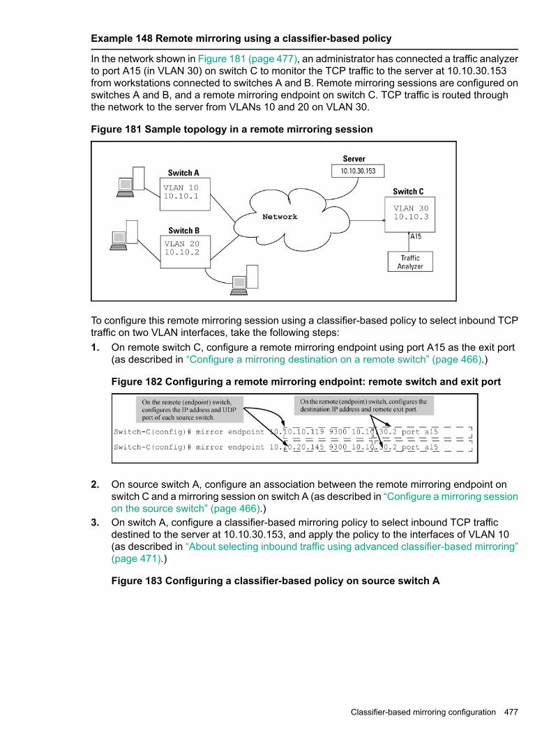
Example 148 Remote mirroring using a classifier-based policy
In the network shown in Figure 181 (page 477), an administrator has connected a traffic analyzerto port A15 (in VLAN 30) on switch C to monitor the TCP traffic to the server at 10.10.30.153from workstations connected to switches A and B. Remote mirroring sessions are configured onswitches A and B, and a remote mirroring endpoint on switch C. TCP traffic is routed throughthe network to the server from VLANs 10 and 20 on VLAN 30.
Figure 181 Sample topology in a remote mirroring session
To configure this remote mirroring session using a classifier-based policy to select inbound TCPtraffic on two VLAN interfaces, take the following steps:1. On remote switch C, configure a remote mirroring endpoint using port A15 as the exit port
(as described in “Configure a mirroring destination on a remote switch” (page 466).)
Figure 182 Configuring a remote mirroring endpoint: remote switch and exit port
2. On source switch A, configure an association between the remote mirroring endpoint onswitch C and a mirroring session on switch A (as described in “Configure a mirroring sessionon the source switch” (page 466).)
3. On switch A, configure a classifier-based mirroring policy to select inbound TCP trafficdestined to the server at 10.10.30.153, and apply the policy to the interfaces of VLAN 10(as described in “About selecting inbound traffic using advanced classifier-based mirroring”(page 471).)
Figure 183 Configuring a classifier-based policy on source switch A
Classifier-based mirroring configuration 477

4. On source switch B, repeat steps 2 and 3:a. Configure an association between the remote mirroring endpoint on switch C and a
mirroring session on switch B.b. Configure a classifier-based mirroring policy to select inbound TCP traffic destined to
the server at 10.10.30.153, and apply the policy to a VLAN interface for VLAN 20.Because the remote session has mirroring sources on different switches, you can use thesame session number (1) for both sessions.
Figure 184 Configuring a classifier-based policy on source switch B
478 Monitoring and Analyzing Switch Operation

Example 149 Remote mirroring using traffic-direction criteria
In the network shown in Figure 185 (page 479), the administrator connects another traffic analyzerto port B10 (in VLAN 40) on switch C to monitor all traffic entering switch A on port C12. For thismirroring configuration, the administrator configures a mirroring destination (with a remote exitport of B10) on switch C, and a remote mirroring session on switch A.If the mirroring configuration in the proceeding example is enabled, it is necessary to use adifferent session number (2) and UDP port number (9400.) (The IP address of the remote exitport [10.10.40.7] connected to traffic analyzer 2 [exit port B10] can belong to a different VLANthan the destination IP address of the VLAN used to reach remote switch C [10.20.40.1]).
Figure 185 Sample topology for remote mirroring from a port interface
To configure this remote mirroring session using a directional-based traffic selection on a portinterface, the operator must take the following steps:1. On remote switch C, configure the remote mirroring endpoint using port B10 as the exit port
for a traffic analyzer (as described in “Configure a mirroring destination on a remote switch”(page 466)):
Figure 186 Configuring a remote mirroring endpoint
2. On source switch A, configure session 2 to use UDP port 9400 to reach the remote mirroringendpoint on switch C (10.10.40.1):mirror 2 remote ip 10.10.10.119 9400 10.10.40.1
3. On source switch A, configure the local port C12 to select all inbound traffic to send to thepreconfigured mirroring destination for session 2:interface c12 monitor all in mirror 2
Figure 187 Configuring a remote mirroring session for inbound port traffic
Classifier-based mirroring configuration 479

Maximum supported frame sizeThe IPv4 encapsulation of mirrored traffic adds a 54-byte header to each mirrored frame. If aresulting frame exceeds the MTU allowed in the network, the frame is dropped or truncated.
NOTE: Oversized mirroring frames are dropped or truncated, according to the setting of the[truncation] parameter in the mirror command. Also, remote mirroring does not allowdownstream devices in a mirroring path to fragment mirrored frames.If jumbo frames are enabled on the mirroring source switch, the mirroring destination switch andall downstream devices connecting the source switch to the mirroring destination must beconfigured to support jumbo frames.
Enabling jumbo frames to increase the mirroring path MTUOn 1-Gbps and 10-Gbps ports in the mirroring path, you can reduce the number of droppedframes by enabling jumbo frames on all intermediate switches and routers. (The MTU on theswitches covered by this manual is 9220 bytes for frames having an 802.1Q VLAN tag, and 9216bytes for untagged frames.)
Table 26 Maximum frame sizes for mirroring
Frame mirrored to remoteport
Framemirrored
VLAN tagMaximumframe size
Frame type configuration
to localport
IPv4 headerDataData
541464151801518Non-jumbo (defaultconfig.)
Untagged
549162921609216Jumbo1 on all VLANs
541464n/a201518Jumbo1 On all but sourceVLAN
541468152241522Non-jumboTagged
549164921849220Jumbo1 on all VLANs
541468n/a241522Jumbo1 On all but sourceVLAN
480 Monitoring and Analyzing Switch Operation
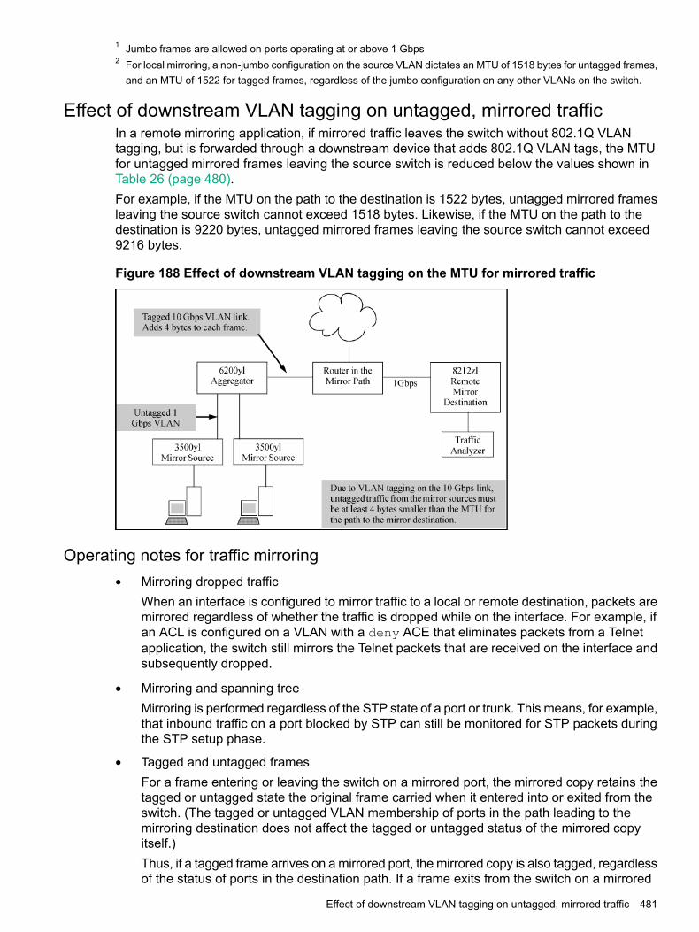
1 Jumbo frames are allowed on ports operating at or above 1 Gbps2 For local mirroring, a non-jumbo configuration on the source VLAN dictates an MTU of 1518 bytes for untagged frames,
and an MTU of 1522 for tagged frames, regardless of the jumbo configuration on any other VLANs on the switch.
Effect of downstream VLAN tagging on untagged, mirrored trafficIn a remote mirroring application, if mirrored traffic leaves the switch without 802.1Q VLANtagging, but is forwarded through a downstream device that adds 802.1Q VLAN tags, the MTUfor untagged mirrored frames leaving the source switch is reduced below the values shown inTable 26 (page 480).For example, if the MTU on the path to the destination is 1522 bytes, untagged mirrored framesleaving the source switch cannot exceed 1518 bytes. Likewise, if the MTU on the path to thedestination is 9220 bytes, untagged mirrored frames leaving the source switch cannot exceed9216 bytes.
Figure 188 Effect of downstream VLAN tagging on the MTU for mirrored traffic
Operating notes for traffic mirroring• Mirroring dropped traffic
When an interface is configured to mirror traffic to a local or remote destination, packets aremirrored regardless of whether the traffic is dropped while on the interface. For example, ifan ACL is configured on a VLAN with a deny ACE that eliminates packets from a Telnetapplication, the switch still mirrors the Telnet packets that are received on the interface andsubsequently dropped.
• Mirroring and spanning treeMirroring is performed regardless of the STP state of a port or trunk. This means, for example,that inbound traffic on a port blocked by STP can still be monitored for STP packets duringthe STP setup phase.
• Tagged and untagged framesFor a frame entering or leaving the switch on a mirrored port, the mirrored copy retains thetagged or untagged state the original frame carried when it entered into or exited from theswitch. (The tagged or untagged VLAN membership of ports in the path leading to themirroring destination does not affect the tagged or untagged status of the mirrored copyitself.)Thus, if a tagged frame arrives on a mirrored port, the mirrored copy is also tagged, regardlessof the status of ports in the destination path. If a frame exits from the switch on a mirrored
Effect of downstream VLAN tagging on untagged, mirrored traffic 481

port that is a tagged member of a VLAN, the mirrored copy is also tagged for the samereason.To prevent a VLAN tag from being added to the mirrored copy of an outbound packet sentto a mirroring destination, you must enter the no-tag-added parameter when you configurea port, trunk, or mesh interface to select mirrored traffic.
• Effect of IGMP on mirroringIf both inbound and outbound mirroring is operating when IGMP is enabled on a VLAN, twocopies of mirrored IGMP frames may appear at the mirroring destination.
• Mirrored traffic not encryptedMirrored traffic undergoes IPv4 encapsulation, but mirrored encapsulated traffic is notencrypted.
• IPv4 header addedThe IPv4 encapsulation of mirrored traffic adds a 54-byte header to each mirrored frame. Ifa resulting frame exceeds the maximum MTU allowed in the network, it is dropped ortruncated (according to the setting of the [truncation] parameter in the mirrorcommand.)To reduce the number of dropped frames, enable jumbo frames in the mirroring path, includingall intermediate switches and/or routers. (The MTU on the switch is 9220 bytes, whichincludes 4 bytes for the 802.1Q VLAN tag.)
• Intercepted or injected trafficThe mirroring feature does not protect against either mirrored traffic being intercepted ortraffic being injected into a mirrored stream by an intermediate host.
• Inbound mirrored IPv4-encapsulated frames are not mirroredThe switch does not mirror IPv4-encapsulated mirrored frames that it receives on an interface.This prevents duplicate mirrored frames in configurations where the port connecting theswitch to the network path for a mirroring destination is also a port whose inbound or outboundtraffic is being mirrored.For example, if traffic leaving the switch through ports B5, B6, and B7 is being mirroredthrough port B7 to a network analyzer, the mirrored frames from traffic on ports B5 and B6will not be mirrored a second time as they pass through port B7.
• Switch operation as both destination and sourceA switch configured as a remote destination switch can also be configured to mirror trafficto one of its own ports (local mirroring) or to a destination on another switch (remote mirroring.)
• Monitor command noteIf session 1 is already configured with a destination, you can enter the [no] vlan<VID>monitor or [no] interface <PORT> monitor command without mirroringcriteria and a mirror session number. In this case, the switch automatically configures orremoves mirroring for inbound and outbound traffic from the specified VLAN or ports to thedestination configured for session 1.
• Loss of connectivity suspends remote mirroringWhen a remote mirroring session is configured on a source switch, the switch sends an ARPrequest to the configured destination approximately every 60 seconds. If the source switchfails to receive the expected ARP response from the destination for the session, transmissionof mirrored traffic in the session halts. However, because the source switch continues tosend ARP requests for each configured remote session, link restoration or discovery of
482 Monitoring and Analyzing Switch Operation

another path to the destination enables the source switch to resume transmitting the session'smirrored traffic after a successful ARP response cycle occurs.Note that if a link's connectivity is repeatedly interrupted ("link toggling"), little or no mirroredtraffic may be allowed for sessions using that link. To verify the status of any mirroring sessionconfigured on the source switch, use the show monitor command.
Troubleshooting traffic mirroringIf mirrored traffic does not reach the configured remote destination (endpoint) switch or remoteexit port, check the following configurations:
• In a remote mirroring session, the mirror remote ip command parameters configuredon the source switch for source IP address, source UDP port, and destination IP addressmust be identical to the same parameters configured with the mirror endpoint ipcommand on the remote destination switch.
• The configured remote exit port must not be a member of a trunk or mesh.
• If the destination for mirrored traffic is on a different VLAN than the source, routing must becorrectly configured along the path from the source to the destination.
• On the remote destination (endpoint) switch, the IP addresses of the remote exit port andthe switch can belong to different VLANs.
• All links on the path from the source switch to the destination switch must be active.
CAUTION: A mirroring exit port should be connected only to a network analyzer, IDS, or othernetwork edge device that has no connection to other network resources. Configuring a mirroringexit port connection to a network can result in serious network performance problems, and isstrongly discouraged by Switch Networking.
Troubleshooting traffic mirroring 483

16 Virtual TechnicianHPE’s Virtual Technician is a set of tools aimed at aiding network switch administrators indiagnosing and caring for their networks. VT provides tools for switch diagnoses when faced withunforeseen issues.To improve the Virtual Technician features of our devices, HPE has added the following tools:
• Cisco Discovery Protocol
• Enabling Debug tracing for MOCANA code
• User diagnostic crash via front panel security button
• User diagnostic crash via the serial console
Cisco Discovery Protocol (CDP)Show cdp traffic
Syntaxshow cdp traffic
DescriptionDisplays the number of Cisco Discovery Protocol (CDP) packets transmitted, received anddropped.
Example 150 CDP frame Statistics
Port No|Transmitted Frames|Received Frames|Discarded Frames|Error Frames------- ----------------- -------------- --------------- ---------A1 46 26 6 7A2 30 35 7 9A3 120 420 670 670
Clear cdp counters
Syntaxclear cdp counters
DescriptionAllows a user to clear CDP statistics.
484 Virtual Technician

Example 151 Clear cdp counters
Port No|Transmitted Frames|Received Frames|Discarded Frames|Error Frames------- ----------------- -------------- --------------- ---------A1 46 26 6 7A2 30 35 7 9A3 120 420 670 670
Enable/Disable debug tracing for MOCANA codeDebug security
Syntaxdebug security ssl
DescriptionEnables the debug tracing for MOCANA code.Use the [no] parameter to disable debug tracing.ssl Display all SSL messages.
User diagnostic crash via Front Panel Security (FPS) buttonAllows the switch’s front panel Clear button to manually initiate a diagnostic reset. In the caseof an application hang, this feature allows you to perform reliable diagnostics by debugging viathe front panel Clear button. Diagnostic reset is controlled via Front Panel Security (FPS) options.
Front panel security password-clearFrom the configure context:
Syntax[no]front-panel-security password-clear <RESET-ON-CLEAR> | factory-reset| password-recovery | diagnostic-reset <CLEAR-BUTTON | SERIAL-CONSOLE>
DescriptionEnable the ability to clear the password(s) and/or configuration via the front panel buttons.[no] disables the password clear option.
Parameters
• If password-clear is disabled, the password(s) cannot be reset using the clear button onthe front panel of the device.
• If factory-reset is disabled, the configuration/password(s) can not be reset using theclear and reset button combination at boot time.
• When password-recovery is enabled (and the front panel buttons disabled), a lostpassword can be recovered by contacting HPE customer support.
• When password-recovery is disabled, there is no way to access a device after losing apassword with the front panel buttons disabled.
Enable/Disable debug tracing for MOCANA code 485

• If diagnostic-reset is disabled, the user cannot perform a diagnostic switch reset onthose rare events where the switch becomes unresponsive to user input because of unknownreason(s).
• If diagnostic-reset is enabled, the user can perform a diagnostic hard reset which willcapture valuable diagnostic data and reset the switch.
Optionsfactory-reset Enable/Disable factory-reset ability.password-clear Enable/Disable password clear.password-recovery Enable/Disable password recovery.diagnostic-reset Enable/Disable diagnostic reset.
Front-panel-security diagnostic-resetFrom the configure context:
Syntaxfront-panel-security diagnostic-reset <CLEAR-BUTTON | SERIAL-CONSOLE>
DescriptionEnables the diagnostic reset so that the switch can capture diagnostic data.• To initiate diagnostic reset via the clear button, press the clear button for at least 30 seconds
but not more than 40 seconds.• To initiate diagnostic switch reset via the serial console, enter the diagnostic reset sequence
on the serial console.
OptionsClear button Enables the diagnostics by choosing the clear button option.Serial console Enables the diagnostics by choosing the serial console option.
[no] front-panel-security diagnostic-resetFrom the configure context:
Syntax[no] front-panel-security diagnostic-reset
DescriptionDisables the diagnostic reset feature so that the user is prevented from capturing diagnostic dataand performing a diagnostic reset on the switch. Both the sub-optionsreset-via-serial-console and reset-via-clear-button will be disabled. This isnecessary if the switch becomes unresponsive (hangs) for unknown reasons.
486 Virtual Technician

Example 152 No front-panel-security diagnostic-reset
no front-panel-security diagnostic-reset
Clear Password - EnabledReset-on-clear - DisabledFactory Reset - EnabledPassword Recovery - EnabledDiagnostic Reset - Disabled
CAUTION: Disabling the diagnostic reset prevents the switch from capturing diagnostic dataon those rare events where the switch becomes unresponsive to user input because of unknownreasons. Ensure that you are familiar with the front panel security options before proceeding.
Front-panel-security diagnostic-reset clear-buttonFrom the configure context:
Syntaxfront-panel-security diagnostic-reset clear-button
DescriptionThis command will enable diagnostic-reset via clear button. The user will be allowed to performdiagnostic reset by depressing the clear button for 30 seconds and not more than 40 seconds.
Example 153 Front-panel-security diagnostic-rest clear-button
front-panel-security diagnostic-rest clear-button
Diagnostic Reset - Enabledclear-button - Enabledserial-console -Disabled
CAUTION: Disabling the diagnostic reset prevents the switch from capturing diagnostic dataon those rare events where the switch becomes unresponsive to user input because of unknownreasons. Ensure that you are familiar with the front panel security options before proceeding.
[No] front-panel-security diagnostic-reset clear-buttonFrom the configure context:
Syntax[no] front-panel-security diagnostic-reset clear-button
DescriptionDisables the diagnostic-reset via clear button.
CAUTION: Disabling the diagnostic reset prevents the switch from capturing diagnostic dataon those rare events where the switch becomes unresponsive to user input because of unknownreasons. Ensure that you are familiar with the front panel security options before proceeding.
User diagnostic crash via Front Panel Security (FPS) button 487

Show front-panel-security
Syntaxshow front-panel-security
Options
Example 154 Show front-panel-security
Clear Password - EnabledReset –on-clear - DisabledFactory Reset - EnabledPassword Recovery - EnabledDiagnostic Reset - Enabled
NOTE: By default, user initiated diagnostic reset is enabled.
Diagnostic table
ResultDo thisTo accomplish this
The switch operating system is clearedgracefully (such as data transfer completion,
Press and release the Reset buttonSoft Reset (Standaloneswitch)
temporary error conditions are cleared), thenreboots and runs self tests.
The switch reboots, similar to a power cycle.A hard reset is used, for example, when the
Press and hold the Reset button for morethan 5 seconds (until all LEDs turn on),then release.
Hard Reset (Standaloneswitch)
switch CPU is in an unknown state or notresponding.
Same as a standalone switch, except:Press and release the Reset buttonSoft Reset (Stackedswitch) • If the Commander, the Standby switch will
become Commander.
• If the Standby, a new Standby will beelected.
Same as a standalone switch, except:Press and hold the Reset button for morethan 5 seconds (until all LEDs turn on),then release.
Hard Reset (Stackedswitch) • If the Commander, the Standby switch will
become Commander.
• If the Standby, a new Standby will beelected.
The switch deletes all access password.Press Clear for at least one second, butnot longer than 5 seconds.
Delete console andmanagement accesspasswords
The switch removes all configuration changes,restores the factory default configuration, andruns self test.
Restore the factory defaultconfiguration
1. Press Clear and Resetsimultaneously.
2. While continuing to press Clear,release Reset.
3. When the Test LED begins blinking(after approximately 25 seconds),release Clear.
488 Virtual Technician
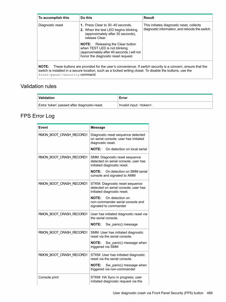
ResultDo thisTo accomplish this
This initiates diagnostic reset, collectsdiagnostic information, and reboots the switch.
Diagnostic reset 1. Press Clear to 30–40 seconds.2. When the test LED begins blinking
(approximately after 30 seconds),release Clear.
NOTE: Releasing the Clear buttonwhen TEST LED is not blinking(approximately after 40 seconds ) will nothonor the diagnostic reset request.
NOTE: These buttons are provided for the user’s convenience. If switch security is a concern, ensure that theswitch is installed in a secure location, such as a locked writing closet. To disable the buttons, use thefront-panel-security command.
Validation rules
ErrorValidation
Invalid input: <token>.Extra ‘token’ passed after diagnostic-reset.
FPS Error Log
MessageEvent
Diagnostic reset sequence detectedon serial console; user has initiateddiagnostic reset.
RMON_BOOT_CRASH_RECORD1
NOTE: On detection on local serial
SMM: Diagnostic reset sequencedetected on serial console; user hasinitiated diagnostic reset.
RMON_BOOT_CRASH_RECORD1
NOTE: On detection on SMM serialconsole and signaled to AMM
STKM: Diagnostic reset sequencedetected on serial console; user hasinitiated diagnostic reset.
RMON_BOOT_CRASH_RECORD1
NOTE: On detection onnon-commander serial console andsignaled to commander
User has initiated diagnostic reset viathe serial console.
RMON_BOOT_CRASH_RECORD1
NOTE: Sw_panic() message
SMM: User has initiated diagnosticreset via the serial console.
RMON_BOOT_CRASH_RECORD1
NOTE: Sw_panic() message whentriggered via SMM
STKM: User has initiated diagnosticreset via the serial console.
RMON_BOOT_CRASH_RECORD1
NOTE: Sw_panic() message whentriggered via non-commander
STKM: HA Sync in progress; userinitiated diagnostic request via the
Console print
User diagnostic crash via Front Panel Security (FPS) button 489

MessageEvent
serial console rejected. Retry aftersometime.
NOTE: Printed on the deviceconsole. When standby is in syncstate,we don’t want to crash thecommander. So we report to the userto retry later
STKM: Member is booting; userinitiated diagnostic request via the
Console print
serial console rejected. Retry aftersometime.
NOTE: Printed on the deviceconsole. When the member is tillbooting, it doesn’t have thecommander member number, thus wecan’t issue UIDC on the commander.So we report to the user to retry later.
User initiated diagnostic crash via the serial consoleRemotely triggers a diagnostic reset of the switch via a serial console. This reset reboots theswitch and collects diagnostic data for debugging an application hang, a system hang or anyother rare occurrence. Diagnostic reset is controlled via FPS options.The serial sequence to initiate the User Initiated Diagnostic Reset via Serial console is Ctrl+S,Ctrl+T, Ctrl+Q, Ctrl+T, Ctrl+S.
Front-panel-security diagnostic-reset serial-consoleIn the configure context:
Syntaxfront-panel-security diagnostic-reset serial-console
Enables the diagnostic-reset via serial console. Allows the user to perform diagnostic reset bykeying-in diagnostic reset sequence.
Example 155 Front-panel-security diagnostic-reset serial-console
front-panel-security diagnostic-reset serial-console
Diagnostic Reset - Enabledclear-button - Disabledserial-console - Enabled
[No] front-panel-security diagnostic-reset serial-consoleIn the configure context:
Syntax[no] front-panel-security diagnostic-reset serial-console
DescriptionDisables the diagnostic-reset via serial console.
490 Virtual Technician

Example 156 No front-panel-security diagnostic-reset serial-console
no front-panel-security diagnostic-reset serial-console
Diagnostic Reset - Disabled
CAUTION: Disabling the diagnostic reset prevents the switch from capturing diagnostic dataon those rare events where the switch becomes unresponsive to user input because of unknownreasons. Ensure that you are familiar with the front panel security options before proceeding.
Serial console error messages
MessageError
Diagnostic reset sequence detected on serial console;user has initiated diagnostic reset.
RMON_BOOT_CRASH_RECORD1
SMM: Diagnostic reset sequence detected on serialconsole; user has initiated diagnostic reset.
RMON_BOOT_CRASH_RECORD1
STKM: Diagnostic reset sequence detected on serialconsole; user has initiated diagnostic reset.
RMON_BOOT_CRASH_RECORD1
User has initiated diagnostic reset via the serial console.RMON_BOOT_CRASH_RECORD1
SMM: User has initiated diagnostic reset via the serialconsole.
RMON_BOOT_CRASH_RECORD1
STKM: User has initiated diagnostic reset via the serialconsole.
RMON_BOOT_CRASH_RECORD1
STKM: HA Sync in progress; user initiated diagnosticrequest via the serial console rejected. Retry aftersometime.
Console print
STKM: Member is booting; user initiated diagnosticrequest via the serial console rejected. Retry aftersometime.
Console print
User initiated diagnostic crash via the serial console 491

17 Scalability: IP Address, VLAN, and Routing MaximumValues
The following table lists the switch scalability values for the areas of VLANs, ACLs, hardware,ARP, and routing.
MaximumSubject
IPv4 ACLs
Up to 2048 (minus any IPv4 numeric standard or extendedACL assignments and any RADIUS-assigned ACLs)1
total named (extended orstandard)
Up to 991total numbered standard
Up to 1001total numbered extended
Up to 30721total ACEs in all IPv4 ACLs
IPv6 ACLs
Up to 20481total IPv6 ACLs
Up to 30721total ACEs in all IPv6 ACLs
Layer-3
512VLANs with at least one IP Address
2048 IPv4IP addresses per system2048 IPv62
323IP addresses per VLAN
256Static routes (IPv4 and IPv6combined)
72 K (8K internal, 64K external)IPv4 host hardware table
2 KIPv4 BMP hardware table
ARP
25,000ARP entries
25Packets held for ARP resolution
Dynamic Routing
IPv4 only: 10,000 (including ARP)Total routes supportedIPv4 and IPv6: 10 K (IPv4) and 3 K(IPv6)4
IPv6 only: 5 K5
IPv4 Routing Protocol
492 Scalability: IP Address, VLAN, and Routing Maximum Values

MaximumSubject
128RIP interfaces
OSPFv2
512 (128 active)Interfaces/subnets
16Max. areas supported
4ECMP next hops
IPv6 Routing Protocol
32 unique addresses; multiple instances of same addresscounts as 1 towards maximum
DHCPv6 Helper Addresses
OSPFv3
512 (128 active)Interfaces/subnets
16Max. areas supported
4ECMP next hops
1 Actual availability depends on combined resource usage on the switch.2 These limits apply only to user-configured addresses and not to auto-configured link local and prefix IPv6 addresses.
A maximum configuration could support up to 2048 user-configured and 2048 auto-configured IPv6 addresses for atotal of 4096.
3 There can be up to 32 IPv4 and 32 user-configured IPv6 addresses on a single VLAN. In addition, each VLAN is limitedto 3 auto-configured prefix-based IPv6 addresses.
4 Configured as an ABR for OSPF with four IPv4 areas and four IPv6 areas.5 Configured as an ABR for OSPF with two IPv6 OSPF areas.
493

18 Job SchedulerSupported PlatformsAruba 3810M Switch Series (JL071A, JL072A, JL073A, JL074A, JL075A, JL076A)Aruba 5400Rzl2 Switch Series (J8698A, J8700A, J9823A-J9824A, J9825A, J9826A, J9868A,J9447A, J9448A)Aruba 5406R Switch Series (JL002A, JL003A, JL095A,J9850A)Aruba 5406zl Switch Series (J9821A, J9822A) )Aruba 5412R Switch Series (J9851A, JL001A)HPE 3800 Switch Series (J9573A—J9576A, J9584A—J9588A)
Job SchedulerThe Job Scheduler feature enables the user to schedule commands or jobs on the switch forone time or multiple times. This is similar in concept to the UNIX ‘cron’ utility. The user canschedule any CLI command that the user would otherwise enter interactively. This includescommands to enable or disable ports, LEDs, and Power-Over-Ethernet. Jobs can also bescheduled to be triggered by certain pre-defined events such as switch reboot. The only majorrestriction on commands scheduled is that, it should not prompt/ask for any user inputs.
CommandsJob at | delay | enable | disable
Set schedule jobs using the options and set the count for the number of times the job is repeated.
Syntaxjob <JOB NAME> at | delay | enable | disable
DescriptionSchedule a command to run automatically. Jobs can be scheduled to run once, multiple timeson a recurring basis, or after certain events such as reboots. All commands run with managerprivilege in configuration context.The [no] form of the command deletes a scheduled job.By default, jobs will be repeated an infinite number of times.
RestrictionsJobs scheduled at any event will not be counted.Jobs that are scheduled at the event “reboot” will not work in some multi management switches.
Range
• <1-1000>: is the value range for the count option.
• ([[DD:]HH:]MM): is the format used for the specific delay.
Optionscount Specify the number of times the job should run.delay Specify the delay before running the job.enable Enable a job that is disabled or expired.disable Disable a job. By default, a job is enabled.
494 Job Scheduler
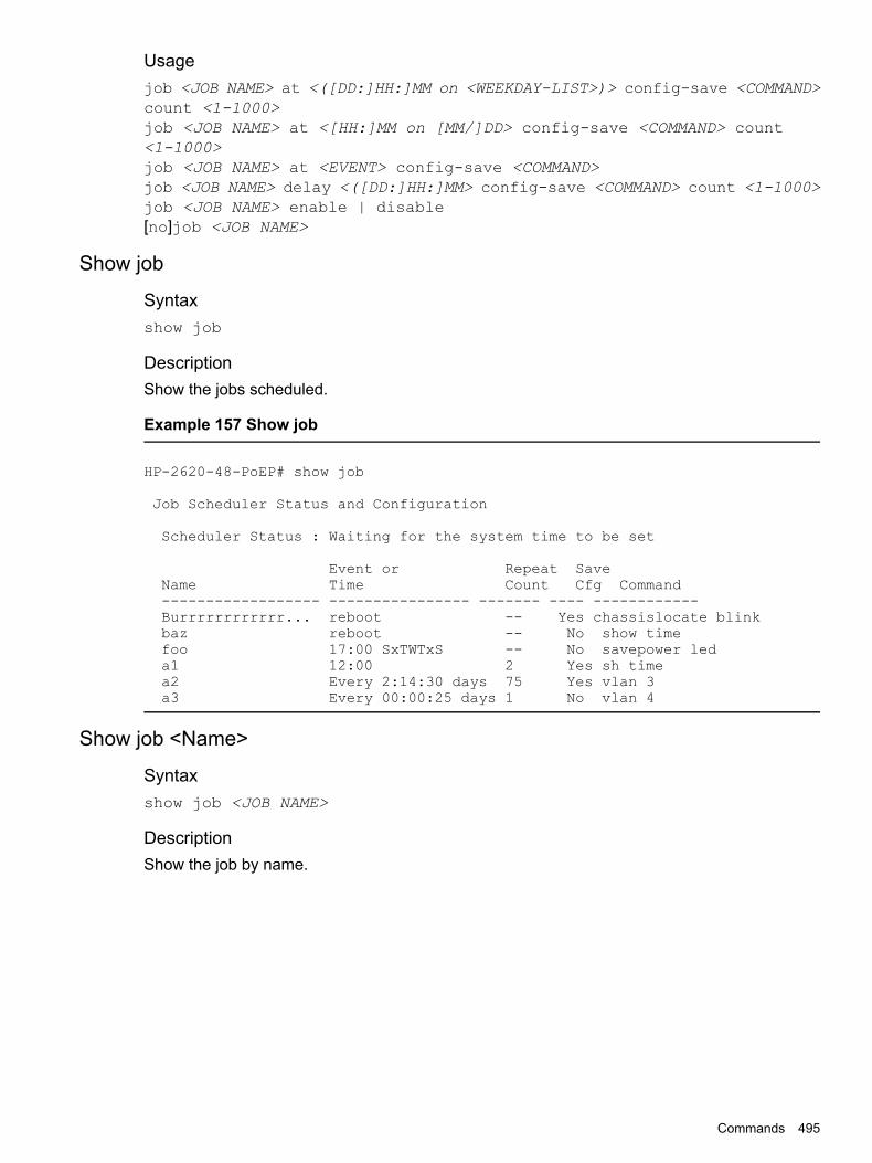
Usagejob <JOB NAME> at <([DD:]HH:]MM on <WEEKDAY-LIST>)> config-save <COMMAND>count <1-1000>job <JOB NAME> at <[HH:]MM on [MM/]DD> config-save <COMMAND> count<1-1000>job <JOB NAME> at <EVENT> config-save <COMMAND>job <JOB NAME> delay <([DD:]HH:]MM> config-save <COMMAND> count <1-1000>job <JOB NAME> enable | disable[no]job <JOB NAME>
Show job
Syntaxshow job
DescriptionShow the jobs scheduled.
Example 157 Show job
HP-2620-48-PoEP# show job
Job Scheduler Status and Configuration
Scheduler Status : Waiting for the system time to be set
Event or Repeat SaveName Time Count Cfg Command------------------ ---------------- ------- ---- ------------Burrrrrrrrrrrr... reboot -- Yes chassislocate blinkbaz reboot -- No show timefoo 17:00 SxTWTxS -- No savepower leda1 12:00 2 Yes sh timea2 Every 2:14:30 days 75 Yes vlan 3a3 Every 00:00:25 days 1 No vlan 4
Show job <Name>
Syntaxshow job <JOB NAME>
DescriptionShow the job by name.
Commands 495

Example 158 Show job <JOB NAME>
Aruba-3810M-16SFPP-2s # show job a1
Job Information
Job Name : a1Runs At : 01:24Config Save : NoRepeat Count: --Job Status : EnabledRun Count : 1Error Count : 0Command : show timeJob Status : Enabled
Output from Last Run--------------------Tue Dec 15 01:24:00 2015
HP-2530-24 # show job a2
Job Information
Job Name : a2Runs At : Every 2:14:30 daysConfig Save : YesRepeat Count: 75Run Count : 0Error Count : 0Command : vlan 3Job Status : Disabled
HP-2530-24 # show job foo
Job Information
Job Name : fooRuns At : 17:00 SxTWTxSConfig Save : YesRepeat Count: --Run Count : 0Error Count : 0Command : savepower ledJob Status : Enabled
496 Job Scheduler

19 Virtual Switching Framework (VSF)Supported devices
SwitchCode
Aruba 5400R Switch SeriesKB
NOTE: Only on v3 blades. When VSF is enabled, the switch will reboot in v3-only mode.
OverviewHPE Virtual Switching Framework (VSF) technology virtualizes two physical devices in the samelayer into one Virtual Fabric which provides high availability and scalability. A Virtual Fabric istherefore two physical devices in the same layer that utilize VSF technology.VSF allows supported switches connected to each other through normal ethernet connections(copper or fiber) to behave like a single switch.
Figure 189 Two devices using VSF technology appearing as a single node to the upper-layerand lower-layer devices
Benefits of VSFSimplified topology and easymanagement
A VSF fabric appears and behaves as one logical switchand is accessible by the network through a single IPaddress.
NOTE: Spanning tree features are not necessary amongVSF members.
1:1 redundancy One member acts as the Commander to manage andcontrol the entire VSF fabric. The other switch acts as aStandby and backs up the commander, and takes over ifthe commander fails.
Overview 497

VSF link aggregation Up to eight VSF ports can be assigned betweenneighboring members. This creates a load-balancedaggregate VSF connection with redundancy.
Multichassis link aggregation The Ethernet link aggregation feature can be used toaggregate physical links between the VSF and its upstreamor downstream devices across the VSF members. Thishelps eliminate the need for spanning tree and alsoprovides load balancing across across all ports of the linkaggregate.
Network scalability The processing power is equal to the Commander, theforwarding capacity is equal to both the Commander andthe Standby combined.
Member rolesVSF uses two member roles: Commander and Standby.
CommanderThis is the Commander for the VSF. Control and management plane protocols run on theCommander, which is responsible for managing the forwarding databases, synchronizing themwith the Standby and controlling all line cards including that of the Standby.
StandbyStandby is a stateful backup device for the Commander and is ready to take control of the VSFvirtual chassis if the Commander device crashes. This enables the VSF virtual chassis to continueits operations seamlessly in the event of a failure.
Commander electionCommander election occurs during some the VSF topology changes. Examples of topologychanges are:
• VSF is established.
• Independent VSFs merge.
• The VSF reboots.
Management module for the Aruba 5400R switchThe Aruba 5400R switch has two management module (MM) card slots available. Hewlett PackardEnterprise recommends that you have only one MM for each Aruba 5400R switch when VSF isenabled. A second MM, if present, will be shutdown. Hewlett Packard Enterprise recommendsthat the second MM be removed from the chassis to prevent it accidentally becoming active.
VSF member IDA VSF fabric uses member IDs to uniquely identify and manage its members. Member IDinformation is included as the first part of interface module numbers to uniquely identify interfacesin a VSF fabric.If two devices have the same VSF member ID, they cannot form a VSF fabric. The one that winselection and becomes Commander will keep its member ID while the other device will automaticallybe assigned a different unassigned member ID from the pool and reboot.
NOTE: If the VSF member ID changes when joining a VSF virtual chassis it will cause a rebootof that member not the whole VSF virtual chassis.
498 Virtual Switching Framework (VSF)

VSF linkA VSF link is a logical interface that connects VSF member devices. Every VSF-capable devicesupports a VSF link. The VSF link is referred to as I-Link<Member ID>_1.I-Link<Member ID>_1 is the default name.
NOTE: To enable a VSF link, you must bind a minimum of one physical interface to it. Thephysical interfaces assigned to a VSF link automatically form an aggregate VSF link. A VSF linkgoes down only if all its VSF physical interfaces are down.
vsf member <MEMBER-ID> link <LINK-ID>
Syntax[no] vsf member <MEMBER-ID> link <LINK-ID> [[ethernet] <PORT-LIST> |name <LINK-NAME>]
DescriptionCreate the VSF links. A set of physical ports between any 2 members, carrying VSF traffic, iscollectively referred to as an VSF link.
Optionslink Create the VSF links.1 The VSF link ID value.[ethernet] PORT-LIST A port number or a list of ports.name Specify the VSF link name.LINK-NAME The VSF link name. Default name is I-Link<Member ID>_1
Operating Notes
• An VSF link is a logical port dedicated to the internal connection of an VSF virtual device.
• An VSF link is effective only after it is bound to a physical port.
• When an Ethernet port is bound to a VSF link, it carries VSF data traffic and VSF protocolpackets.
Validation rules
Error/Warning/PromptValidation
Cannot configure VSF on port “A1”because that port is an LACP trunk.
When trunk static/manual and mesh isgetting configured as VSF port
Cannot configure VSF on port “A1”because that port is a Mesh.Cannot configure VSF on port “A1”because that port is a Distributed LACPtrunk.Cannot configure VSF on port “A1”because that port is a Distributed trunk.Cannot configure VSF on port “A1”because that port is a Dynamic trunk.Cannot configure VSF on port “A1”because that port is an InterSwitchConnect (ISC) port
VSF link 499

Error/Warning/PromptValidation
Error configuring VSF on port “A1”: Anunsupported trunking mode is alreadyconfigured on this port.
Cannot enable VSF on a port operating atother than 10G or 40G.
Adding a 1G port to a VSF linkAdding both 10G and 40G ports to a VSFlink Cannot mix different port speeds in the
same VSF link. All ports must be either10G or 40G.
Cannot configure more than 8 physicalports as an VSF link.
Max 8 ports per link.
VSF capabilities are not supported on port“A1”.
For other than physical ports.
Cannot configure the VSF link name. Thename is not a valid UI display string, or isblank, or exceeds 31 characters.
Cannot set a link name which is havingmore than 31 characters.
Cannot remove an VSF link when it hasphysical ports associated with it. First
Direct VSF port removal case
remove the associated physical ports andthen remove the VSF link.
Removing of binding between physicalports and VSF link is not allowed since itwould result in a stack split.
Removing the last VSF port in a VSF linkthat is "Up" is forbidden.
Cannot use stolen/reserved ports as VSFports.
Using a port reserved for internal use asa VSF port.
Physical VSF portsVSF ports connect VSF member devices and must be bound to using a VSF link. These VSFports forward VSF protocol packets and data traffic.
VSF domain IDOne VSF fabric forms one VSF domain. VSF uses VSF domain IDs to uniquely identify VSFfabrics and prevent VSF fabrics from interfering with one another.
500 Virtual Switching Framework (VSF)

Figure 190 Two VSF domains
VSF splitA VSF split can occur due to a VSF link failure where all ports in the VSF link go down. Thisfailure results in independent VSF fabric fragments each having its own Commander role. HewlettPackard Enterprise recommends configuring a Multiple Active Detection (MAD) mechanism toavoid duplicate IP addresses, routing issues and traffic forwarding problems when a VSF splitoccurs.
Figure 191 VSF split
VSF mergeVSF merge occurs when two split VSF fabrics reunite or when two independent VSF fabrics areunited. An election happens in this case and the winning member stays on as the Commanderwhile the member that loses the election will reboot and join. Devices will only merge if they havethe same domain ID and if both VSF fabrics are the same model. For example two Aruba 5406Rswitches or two Aruba 5412R switches are able to merge; however a combination of different
VSF split 501

switches, for example one Aruba 5406R switch and one Aruba 5412R switch, will not be able tomerge.
Figure 192 VSF Merge
Member priorityMember priority determines the possibility of a member device being elected as the Commander.A member with higher priority is more likely to be elected as the Commander. The default priorityis 128, but can be between 1 and 255.
Interface naming conventionsAn interface is named in the following format:
Interface name<member ID>/<interface-module><port-index>
Example1/A1, 2/L24
Definitionmember ID VSF member ID of the switch. The VSF member ID always takes effect,
whether or not the device has formed a VSF fabric with other devices.If the device is alone, the device is considered to be a standalone VSFfabric.This argument defaults to 1.
interface-module Slot letter of the front panel. Letter can be A-F for Aruba 5406R switchand A-L for Aruba 5412R switch.
port-index Index of the port on the device. Port index depends on the number ofports available on the linecard (or Interface Module).
502 Virtual Switching Framework (VSF)
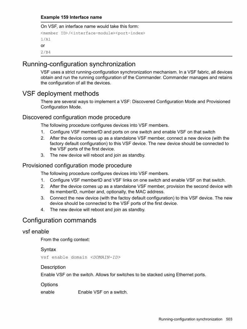
Example 159 Interface name
On VSF, an interface name would take this form:<member ID>/<interface-module><port-index>
1/A1
or2/B4
Running-configuration synchronizationVSF uses a strict running-configuration synchronization mechanism. In a VSF fabric, all devicesobtain and run the running configuration of the Commander. Commander manages and retainsthe configuration of all the devices.
VSF deployment methodsThere are several ways to implement a VSF: Discovered Configuration Mode and ProvisionedConfiguration Mode.
Discovered configuration mode procedureThe following procedure configures devices into VSF members.1. Configure VSF memberID and ports on one switch and enable VSF on that switch2. After the device comes up as a standalone VSF member, connect a new device (with the
factory default configuration) to this VSF device. The new device should be connected tothe VSF ports of the first device.
3. The new device will reboot and join as standby.
Provisioned configuration mode procedureThe following procedure configures devices into VSF members.1. Configure VSF memberID and VSF links on one switch and enable VSF on that switch.2. After the device comes up as a standalone VSF member, provision the second device with
its memberID, number and, optionally, the MAC address.3. Connect the new device (with the factoy default configuration) to this VSF device. The new
device should be connected to the VSF ports of the first device.4. The new device will reboot and join as standby.
Configuration commandsvsf enable
From the config context:
Syntaxvsf enable domain <DOMAIN-ID>
DescriptionEnable VSF on the switch. Allows for switches to be stacked using Ethernet ports.
Optionsenable Enable VSF on a switch.
Running-configuration synchronization 503

<DOMAIN-ID> The domain ID can be from 1 to 4294967296.
CAUTION: The command VSF enable causes all of the switches to reboot once and formthe fabric. Internally, this causes the VSF domain ID and discovered switch information to beupdated and pushed to all members of the topology.Upon reboot, the switches come up in the “VSF enabled” mode. Port numbers are prefixed withmember numbers, such as “1/A1,”. The configuration on the switch becoming Commander willbe retained, but any pre-existing configuration on other switches will be over-written.The switches will inherit the same switch software as the member becoming Commander. If thesoftware image of a switch needs to be updated, the switch will reboot twice.
Syntaxvsf disable
DescriptionDisable VSF on the virtual chassis.
Validation rules
Error/Warning/PromptValidation
This will save the current configuration andreboot the switch. Continue [y/n]?
When vsf enable is executed on an VSFdisabled switch following warning messagewill be displayed.
Run vsf enable on VSF virtual chassis.
VSF cannot be disabled when the VSFvirtual chassis is active.
Run VSF disable when VSF links is UP.
Run vsf disable command on VSFdisabled switch.
vsf domain
Syntaxvsf domain <DOMAIN-ID>
DescriptionChange a domain ID for the VSF virtual chassis.Once VSF is enabled and virtual chassis is formed, VSF domain ID can be changed using thiscommand.
Options<1-4294967296> The virtual chassis domain ID.
Validation rules
Error/Warning/PromptValidation
The domain ID cannot be zero.Domain-id must be 32bitunsigned integer.
504 Virtual Switching Framework (VSF)

vsf member
Syntaxvsf member <MEMBER-ID>
DescriptionConfigure VSF member parameters.
Options<1-2> The VSF member-ID for the member command/parameter.
vsf member shutdownFor a switch that physically exists, this command will cause the switch to shut down. shutdownis used in preparation to remove the switch from the virtual chassis. The switch will not becomea voting member of the virtual chassis again until it is rejoined.The shutdown command can not be used on the Commander. The shutdown command willsucceed only if the switch physically exists and is an active member of the virtual chassis.
Syntaxvsf member <MEMBER-ID> shutdown
DescriptionShut down the VSF virtual chassis member.
RestrictionShutdown will not be available until VSF is enabled.
Validation rules
Error/Warning/PromptValidation
The specified VSF virtual chassis memberwill be shut down. Continue [y/n]?
If member switch physically exists
The VSF virtual chassis commandercannot be shut down. Please fail over tothe standby first.
If member switch physically exists and isthe commander
The specified VSF virtual chassis memberdoes not exist.
If member switch does not physically exist
Shutting down this VSF virtual chassismember is not allowed since it would resultin a VSF virtual chassis split.
If shutting down a member will cause a VC–split
VSF is not enabled.If VSF not enabled, this command is notallowed.
vsf member reboot
Syntaxboot vsf <MEMBER-ID>
Configuration commands 505

DescriptionReboot the VSF member and have it rejoin the virtual chassis with the current configuration. Ifthe reboot option is specified, the switch will come back up with a new member-ID and rejointhe virtual chassis with the current configuration.
RestrictionReboot will not be available until VSF is enabled.
Validation rules
Error/Warning/PromptValidation
The commander will now reboot from thesecondary image. The standby will become
vsf member remove reboot
the commander. Do you want to continue[y/n]?Standby will be rebooted from secondaryimage. Continue [y/n]?
vsf member removeThis command removes the entire configuration for a specified member. If the member is aprovisioned switch, this process affects only the configuration tree. After issuing the command,the specified member-ID is available for re-use and may be provisioned or assigned to anotherdevice.If the member physically exists, its configuration will be erased. It will then be powered down bydefault.
Syntaxvsf member <MEMBER-ID> remove
DescriptionErase the VSF virtual chassis member configuration.
RestrictionRemove will not be available until VSF is enabled.
Validation rules
Error/Warning/PromptValidation
VSF is not enabled.If VSF not enabled, this command is notallowed.
The specified VSF virtual chassis membereither does not exist or is not provisioned.
VSF member neither exists nor provisioned
VSF virtual chassis members cannot beadded or removed while the standby isbooting.
VSF standby syncing add remove memberblocked
Removing this member is not allowed sinceit would result in a VSF virtual chassis split.
VSF member remove causes VSF virtualchassis split
The specified VSF virtual chassis memberwill be removed and its configuration will
VSF missing member remove
be erased. The resulting configuration willbe saved. Continue [y/n]?
506 Virtual Switching Framework (VSF)

Error/Warning/PromptValidation
The specified VSF virtual chassis memberdoes not exist.
VSF VC member does not exist
The specified VSF virtual chassis memberconfiguration will be erased. The resultingconfiguration will be saved. Continue [y/n]?
VSF provision member remove
The VSF virtual chassis commandercannot be removed. Please fail over to
VSF remove commander
standby before trying to remove thecommander.
The specified VSF virtual chassis memberwill be removed and its configuration will
VSF member remove
be erased. The resulting configuration willbe saved. The VSF member will be shutdown. Continue [y/n]?
The specified VSF virtual chassis memberwill be removed and its configuration will
VSF standby remove
be erased. The resulting configuration willbe saved. The VSF member will be shutdown. Continue [y/n]?
vsf member priority
Syntaxvsf member <MEMBER-ID> priority <PRIORITY>
DescriptionAssign a priority to the specified VSF virtual chassis member. The higher the priority, the morelikely that the virtual chassis member will become the commander at the next virtual chassisreboot. The default priority value is 128.
Options<1-255> The priority value for this member.
vsf member typeThis CLI command provisions a switch with the member ID and the type defined by the specifiedJ-number for the device. After provisioning the member, the user may perform any configurationon the device’s ports. The ifAdminStatus on the device’s ports will be configurable at thistime, however the ifOperStatus will remain down.A “strict” provisioning specifies a MAC address and allows for only one device with the matchingJ-number and MAC to be configured.A “loose” provisioning allows the device with the specified J-number to be configured without aMAC address being specified. This allows any device which matches the J-number to adopt thisconfiguration.If a provisioned configuration already exists with the member ID, the following command is usedto change the provisioning from “strict” and “loose” and visa versa.
Syntaxvsf member <MEMBER-ID> type <TYPE> [mac <MAC-ADDR>]
Configuration commands 507

DescriptionConfigure the family of the VSF member-switch being provisioned. After provisioning, the VSFmember-switch can be configured as if it were physically present. When an VSF member-switchmatching the provisioned details joins the VSF, it is provided this configuration. A new or missingVSF member can be configured as a provisioned device by using this command.
Optionsmac-address Configure the MAC address of the VSF member switch being provisioned.
Restrictions
• The allowed range for the member ID is 1 thru 2.
• If switch “N” physically exists, the command will fail.
• If switch “N” is provisioned, the command can be used to change the MAC or type.
• If the J-Number is known to not support stacking, or the J-Number is unknown, the commandwill fail.
• If the same MAC address is already provisioned or exists on another member ID, thecommand will fail.
Usage
• vsf member <2> type <J9850A> mac <001122-334455>
Updates the strict provisioning for VSF VC member 2, and changes the MAC address to001122-334455.
• vsf member <2> type <J9850A>
Changes the “strict” provisioning for VSF VC member #2 to “loose” provisioning. Theconfigured MAC address is then removed.
• vsf member <2> type <J9850A> mac <00aabb-cceedd>
Changes “loose” provisioning for VSF VC member 2 to “strict” provisioning with MAC address00aabb-cceedd.
Validation rules
Error/Warning/PromptValidation
The VSF member-ID value is not in range.If the member-ID is not between 1 to 2 forbolt then command will return an error.
The specified VSF virtual chassis membereither does not exist or is not provisioned.
The member-ID must physically exist oralready be provisioned.
This will save the current configuration.Continue [y/n]?
When each time new member isconfigured, write mem is called.
VSF virtual chassis members cannot beadded or removed while the standby isbooting.
The VSF commander cannot be removed.Please fail over to standby before trying toremove it.
An VSF member configuration is alreadyprovisioned with the specified MACaddress.
508 Virtual Switching Framework (VSF)

Error/Warning/PromptValidation
An VSF switch with the specifiedmember-Id is already present.
Shutting down this VSF member is notallowed since it would result in a VSFvirtual chassis split.
MAC address cannot be null.
MAC address cannot bebroadcast/multicast address.
A switch with the specified MAC addressalready exists.
A member configuration is alreadyprovisioned with the specified MACaddress.
snmp-server enable traps vsf
Syntax[no] snmp-server enable traps vsf
DescriptionEnable traps for the VSF functionality.
Validation rules
Error/Warning/PromptValidation
VSF is not enabled.This command cannot be executed if VSFis not enabled.
Show commandsshow vsf
Shows the current status and all current configurations of the provisioned VSF configuration ona switch.
Syntaxshow vsf
DescriptionShows the list of VSF virtual chassis members that are provisioned.
Optionsdetail Detailed information related to the current state of each member of the VSF virtual
chassis.
Restrictions
• show vsf can be run only after VSF is enabled.
Usageshow vsf [detail]
Show commands 509

Example 160 show vsf
hp-vsf-sws# show vsfVSF Domain ID : 44444MAC Address : 3464a9-b2533fVSF Topology : ChainVSF Status : ActiveUptime : 32d 4h 28mVSF Oobm-MAD : EnabledSoftware Version : KB.16.01.0004MbrID Mac Address Model Pri Status--- ------------- ---------------------------- --- ----------1 3464a9-b24300 HP J9850A Switch 5406Rzl2 255 Commander2 288023-98ae00 HP J9850A Switch 5406Rzl2 100 Standby
Validation rules
Error/Warning/PromptValidation
VSF is not enabled.If VSF not enabled, this commandis not allowed.
show vsf link
Syntaxshow vsf link
DescriptionShows the VSF port state of the VSF links for each VSF member.
Optionslink Shows the state of the VSF links for each VSF member.link detail The state of the VSF link for each VSF member in detail.
Usageshow vsf link [detail]
510 Virtual Switching Framework (VSF)

Example 161 show vsf link
HP-VSF-Switch$ show vsf linkVSF Member 1
Link Peer PeerLink Link-Name State Member Link---- ---------- -------- ------ ----1 I-Link1_1 Up 2 1
VSF Member 2Link Peer Peer
Link Link-Name State Member Link---- ---------- -------- ------ ----1 I-Link2_1 Up 1 1
Example 162 show vsf link detail
show vsf link detailvsf Member: 1 Link: 1Vsf-Port Port-State-------- -------------------------1/E1 Up: Connected to port 2/E1
vsf Member: 2 Link: 1Vsf-Port Port-State-------- -------------------------2/E1 Up: Connected to port 1/E1
show vsf member
Syntaxshow vsf member <MEMBER ID>
Optionsmember ID The member ID of the VSF member being queried.
Show commands 511

Example 163 show vsf member 1
HP-VSF-Switch# show vsf member 1Member ID : 1MAC Address : a01d48-8f6700Type : J9850AModel : HP J9850A Switch 5406Rzl2Priority : 128Status : StandbyROM Version : KB.16.01.0005Serial Number : SG4ZG95321Uptime : 21d 19h 5mCPU Utilization : 2%Memory - Total : 698,957,824 bytesFree : 528,240,524 bytesVSF Links -#1 : Active, Peer member 2
Example 164 show vsf member 2
vsf-sws# show vsf member 2Member ID : 2Mac Address : 288023-98ae00Type : J9850AModel : HP J9850A Switch 5406Rzl2Priority : 100Status : StandbyROM Version : KB.16.01.0005Serial Number : SG46G4906PUptime : 32d 4h 11mCPU Utilization : 0%Memory - Total : 709,357,568 bytesFree : 546,939,520 bytesVSF Links -#1 : Active, Peer member 1
OOBM-MAD commandsvsf oobm-mad
Syntax[no] vsf oobm-mad
DescriptionEnable OOBM-MAD (Multi-Active Detection) on the VSF device.
Optionsoobm-mad Enable OOBM-MAD for the VSF virtual chassis.
Validation rules
Error/Warning/PromptValidation
VSF is not enabled.This command cannot be executed if VSFis not enabled.
512 Virtual Switching Framework (VSF)

oobm vsf member
Syntaxoobm vsf member <MEMBER-ID> ip address <IP-ADDR>/<PREFIX-LENGTH>
DescriptionConfigure VSF member OOBM parameters.
Syntaxoobm vsf member <MEMBER-ID> ip default-gateway <IP-ADDR>
DescriptionSpecify the default gateway using this form of the command. Configure the IPv4 default gatewayaddress, which will be used when routing is not enabled on the switch. The <IP-ADDR> mustbe specified if the command is not preceded by [no]. Preceding the command with [no] deletesthe default gateway address.The [no] form of this command does not take effect on defaultgateway address obtained via dhcp.
OptionsVSF Configure VSF member OOBM parameters.member Configure VSF member OOBM parameters.<1-2> The VSF member-ID for the 'member' command/parameter.IP Configure various IP parameters for the OOBM.IP-ADDR IPv4 address of the default gateway.address Set IP parameters for communication within an IP network.
Usageoobm vsf member <VSF-MEMBER> ip
oobm vsf member <VSF-MEMBER> ip address
[no] ip default-gateway <IP-ADDR>
oobm vsf member interface speed-duplex
Syntaxoobm vsf member <VSF-MEMBER> interface <SPEED-DUPLEX>
DescriptionConfigure various interface parameters for OOBM. The interface command must be followedby a feature-specific keyword. This is an OOBM context command. It can be called directly fromthe OOBM context.
Optionsenable Enable OOBM port.disable Disable OOBM.member Configure VSF member OOBM parameters.speed-duplex Define mode of operation for the oobm port.
10-half 10 Mbps, half duplex.100-half 100 Mbps, half duplex.
OOBM-MAD commands 513
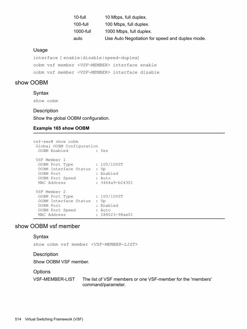
10-full 10 Mbps, full duplex.100-full 100 Mbps, full duplex.1000-full 1000 Mbps, full duplex.auto Use Auto Negotiation for speed and duplex mode.
Usageinterface [enable|disable|speed-duplex]
oobm vsf member <VSF-MEMBER> interface enable
oobm vsf member <VSF-MEMBER> interface disable
show OOBM
Syntaxshow oobm
DescriptionShow the global OOBM configuration.
Example 165 show OOBM
vsf-sws# show oobmGlobal OOBM ConfigurationOOBM Enabled : Yes
VSF Member 1OOBM Port Type : 100/1000TOOBM Interface Status : UpOOBM Port : EnabledOOBM Port Speed : AutoMAC Address : 3464a9-b24301
VSF Member 2OOBM Port Type : 100/1000TOOBM Interface Status : UpOOBM Port : EnabledOOBM Port Speed : AutoMAC Address : 288023-98ae01
show OOBM vsf member
Syntaxshow oobm vsf member <VSF-MEMBER-LIST>
DescriptionShow OOBM VSF member.
OptionsVSF-MEMBER-LIST The list of VSF members or one VSF-member for the 'members'
command/parameter.
514 Virtual Switching Framework (VSF)

Example 166 show OOBM vsf member 1
vsf-sws# show oobm vsf member 1
VSF Member 1OOBM Port Type : 100/1000TOOBM Interface Status : UpOOBM Port : EnabledOOBM Port Speed : Auto
MAC Address : 3464a9-b24301
show OOBM IP
Syntaxshow oobm ip
DescriptionShow OOBM IP.
OptionsVSF-MEMBER-LIST The list of VSF members or one vsf-member for the 'members'
command/parameter.
OOBM-MAD commands 515

Example 167 show oobm ip
show oobm ip
IPv4 Status : EnabledIPv4 Default Gateway : 120.93.49.1
| Address InterfaceVSF-member | IP Config IP Address/Prefix Length Status Status---------- + --------- ------------------------- -------- ---------Global | dhcp 120.93.49.9/24 Active Up1 | dhcp 120.93.49.9/24 Active Up2 | disabled Inactive Down
Example 168 show oobm ip vsf member 1
HP-VSF-Switch# show oobm ip vsf member 1IPv4 Status : EnabledIPv4 Default Gateway : 15.212.178.1
| Address InterfaceVSF-member | IP Config IP Address/Prefix Length Status Status---------- + --------- ------------------------- -------- ---------1 | dhcp 15.212.178.244/24 Active Up
Example 169 show oobm ip vsf member 1,2
HP-VSF-Switch(config)# sho oobm ip vsf member 1,2IPv4 Status : EnabledIPv4 Default Gateway :
| Address InterfaceVSF-member | IP Config IP Address/Prefix Length Status Status---------- + --------- ------------------------- -------- ---------1 | dhcp Active Down
HP-VSF-Switch(config)# sho oobm ip detailInternet (IP) Service for OOBM InterfaceGlobal ConfigurationIPv4 Status : EnabledIPv6 Status : DisabledIPv4 Default Gateway :IPv6 Default Gateway :
Origin | IP Address/Prefix Length Status---------- + ------------------------------------------- -----------dhcp |
VIPv4 SF Member 1Status : EnabledIPv6 Status : DisabledIPv4 Default Gateway :IPv6 Default Gateway :
Origin | IP Address/Prefix Length Status---------- + ------------------------------------------- -----------dhcp |
Usageshow oobm ip vsf member <MEMBER-LIST>
show oobm ip detail
516 Virtual Switching Framework (VSF)

show OOBM discovery
Syntaxshow oobm discovery
DescriptionShow the discovered virtual chassis information.
Example 170 show OOBM discovery
show oobm discovery
Active Stack (This fragment)VSF-member Mac Address StatusID---------- -------------- ----------------2 10604b-b7a140 Global Commander1 10604b-b66980 Global Member
show running-config OOBM
Syntaxshow running-config oobm
DescriptionShow running-config OOBM.
Example 171 show running-config oobm
show running-config oobm
Running configuration:oobm
ip address dhcp-bootpVSF-member 1
ip address dhcp-bootpexit
VSF-member 2ip address 192.168.10.1 255.255.255.0exit
exit
show vsf trunk-designated-forwarder
Syntaxshow vsf trunk-designated-forwarder
DescriptionShow the designated forwarders for each trunk.For each trunk, only one member of the trunk will forward L2 flood traffic (unknown destination,Broadcast & Multicast). Use the show vsf trunk-designated-forwarder command toknow which member will forward flood frames for a given trunk.
OOBM-MAD commands 517
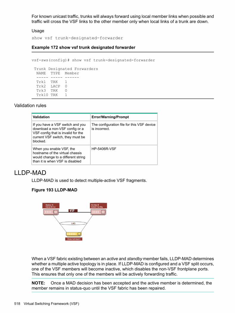
For known unicast traffic, trunks will always forward using local member links when possible andtraffic will cross the VSF links to the other member only when local links of a trunk are down.
Usageshow vsf trunk-designated-forwarder
Example 172 show vsf trunk designated forwarder
vsf-sws(config)# show vsf trunk-designated-forwarder
Trunk Designated ForwardersNAME TYPE Member----- ----- ------Trk1 TRK 1Trk2 LACP 0Trk3 TRK 0Trk10 TRK 1
Validation rules
Error/Warning/PromptValidation
The configuration file for this VSF deviceis incorrect.
If you have a VSF switch and youdownload a non-VSF config or aVSF-config that is invalid for thecurrent VSF switch, they must beblocked.
HP-5406R-VSFWhen you enable VSF, thehostname of the virtual chassiswould change to a different stringthan it is when VSF is disabled
LLDP-MADLLDP-MAD is used to detect multiple-active VSF fragments.
Figure 193 LLDP-MAD
When a VSF fabric existing between an active and standby member fails, LLDP-MAD determineswhether a multiple active topology is in place. If LLDP-MAD is configured and a VSF split occurs,one of the VSF members will become inactive, which disables the non-VSF frontplane ports.This ensures that only one of the members will be actively forwarding traffic.
NOTE: Once a MAD decision has been accepted and the active member is determined, themember remains in status-quo until the VSF fabric has been repaired.
518 Virtual Switching Framework (VSF)

VSF split explanationThe following sequence explains a MAD scheme for a simple 2-member, VSF virtual chassissplit scenario.1. When the VSF link goes down and the VSF virtual chassis splits:
• The Commander member ( Fragment-A for this example) would continue to stay active.
• The Standby member (Fragment B) would failover and become another commander.2. Fragment-B sends an SNMP request to the downstream device seeking port status
information of all non-local ports of the LACP Trunk. Non-local ports on Fragment-B refersto ports that are part of Fragment-A’s member.• The downstream device responds to the SNMP request with the appropriate port status
information.
◦ If Fragment-A receives an unsolicited response to the SNMP request, it is ignoredas Fragment A has the pre-split Commander as part of its fragment and thereforewill remain active.
3. Fragment-B sends 2 more SNMP queries downstream. If no response is received, thefrontplane ports are shut down and turned inactive.Alternatively, if Fragment-B receives an SNMP response:
• If Fragment A links are UP, the frontplane ports will be shut down.
• If Fragment-A links are DOWN, Fragment-B would stay UP.4. Consider that Fragment-A is actually DOWN which has caused the split:
• Request made to Fragment-B will be received by the downstream device and responsewill return to Fragment-B.
• The downstream links to Fragment-A are DOWN therefore Fragment-B will remain UP.
• Alternately, if Fragment-B is DOWN and caused the split then Fragment-A will neithersend a request or act on an unsolicited response and will remain UP.
MAD readiness checkThe MAD assist device must be connected over a LACP trunk interface to the VSF device. Onceyou configure the IP address of a MAD assist device, the VSF switch will perform a MAD readinesscheck to determine:• If the MAD assist device is reachable.
• If a trunk interface is used to reach the device.
• If the trunk interface has at least one, linked —up, physical port on each member of the VSFswitch.
If the above three conditions are not met, MAD will fail to detect dual active fragments in theevent of a VSF split. This error will create a log message.
NOTE: The MAD readiness check is repeated periodically. If MAD-probe parameters havechanged, an appropriate log message will be created.
vsf lldp-mad ipv4
Syntax[no] vsf lldp-mad ipv4 <IPV4_ADDR> v2c <COMMUNITY>
LLDP-MAD 519
DescriptionEnable LLDP-MAD on the VSF device.
NOTE: The command vsf lldp mad requires a peer switch to be configured as the “assist”device.
OptionIpv4 Specify the IPv4 address of the MAD device.IPV4_ADDR The IPv4 address of the MAD device.v2c Specify the SNMP version for the MAD device.COMMUNITY The SNMP community string for the MAD device.
Usagehp-vsf-sws(config)# vsf lldp-mad ipv4
hp-vsf-sws(config)# vsf lldp-mad ipv4 <IPv4_ADDR>
hp-vsf-sws(config)# vsf lldp-mad ipv4 <MAD-IP-ADDRESS> v2c
hp-vsf-sws(config)# vsf lldp-mad ipv4 210.10.0.12 v2c <COMMUNITY-STR>
Validation rules
Error/Warning/PromptValidation
VSF is not enabled.This command cannot be executed if VSFis not enabled.
Cannot configure VSF LLDP MAD IPaddress because the specified IP addressis a multicast IP address.Cannot configure VSF LLDP MAD IPaddress because the specified IP addressis a link-local IP address.Cannot configure VSF LLDP MAD IPaddress because the specified IP addressis configured on the loopback interface.Cannot configure VSF LLDP MAD IPaddress because the specified IP addressis configured on a local interface.
The MAD (Multi-Active Detection) deviceand the VSF device are not on the samenetwork.
The MAD assist device and the VSF devicemust be on a common IP subnet forLLDP-MAD to work.
show vsf lldp-mad [parameters | status]
Syntaxshow vsf lldp-mad [parameters | status]
DescriptionShow the VSF LLDP-MAD information on the switch.
Optionslldp-mad VSF LLDP-MADparameters Shows the MAD-assist configuration as well as the readiness state of the switch.
520 Virtual Switching Framework (VSF)

status Shows the current state of the MAD probe.
Usageshow vsf lldp-mad parameters
show vsf lldp-mad status
Example 173 show vsf lldp-mad parameters
show vsf lldp-mad parametersMAD device IP : 210.10.0.12
MAD readiness status : SuccessMAD device MAC : 5065f3-128cc5Reachable via Vlan : 916Local LAG interface : Trk10MAD-probe portset : 1/A21,2/A21,
LAG connectivity : Full
Example 174 show vsf lldp-mad status
show vsf lldp-mad status
MAD device IP : 210.10.0.12MAD-probe portset : 1/A21,2/A21,VSF split : NoMAD probe originator : NoNumber of probe requests sent : 0Number of probe responses received : 0MAD Active Fragment : Yes
VSF re-join after a splitIf split fragment(s) re-join the VSF and become a single device, MAD readiness checks will bere-run and a fresh set of readiness parameters determined.
NOTE: One of the devices will reboot to join the VSF.
MAD assist device requirements• A MAD assist device must have support for LACP (IEEE 802.1AX) LAG interfaces.
• It should be SNMPv2 enabled and community information must be configured on the VSFdevice as part of MAD configuration.
• It should have support for LLDP (IEEE 802.1ab rev) and the basic management TLV set asdefined there in.
• It should support SNMP GET access to the LLDP remote MIB (IEEE 802.1AB D13) and theifTable MIB (RFC 2683). Aruba switches have LLDP enabled by default.
• Support for ARP is assumed.
LLDP-MAD 521

Limitations of MADThe operating limitations of this feature are listed below.
• MAD will work with other vendor downstream/upstream devices that have an IEEE 802.1AX(formerly 802.3ad) standards based LACP trunk to the VSF pair.MAD can not work with non-LACP and DT-LACP trunks that Provision OS supports today.
• MAD should be configured when a VSF virtual chassis is active and not after a VSF virtualchassis split. Configuring MAD after a VSF split has occurred wouldn’t help detectingmultiple-active fragments for the current split event.
• Upon a split and once a fragment has been determined to become inactive, it cannotsubsequently become active if the originally determined ‘active’ fragment goes ‘down’. Thisis because the front plane (non-VSF) ports of the inactive fragment would have been brought‘down’ and there is no way to do an LLDP-MAD subsequently.
• The MAD assist device (downstream or upstream device) and the VSF device must belongto the same IPv4 subnet for MAD to work. This would be validated at the time of MADconfiguration (in the UI).
• The downstream/upstream helper device must support SNMPv2 and be able to handleifTable MIB object GET requests via SNMPv2 (RFC 2863). For the first VSF release,LLDP-MAD will not work with SNMPv3.
• Determination of the active/inactive fragment via MAD would take up anywhere between2-6 seconds.
• LLDP BPDU transmission on VSF enabled OOBM ports is currently not supported.
Changes to existing commandsBelow commands are existing. New usage, description and help strings appear only when VSFis enabled, otherwise it will be unchanged.
copy core-dumpCopy core-dump from the specified VSF member. User can copy available core-dump file frominterface module or management module.
Syntaxcopy core-dump vsf member <VSF-MEMBER> <SLOT-ID> | mm-active sftp |tftp | usb | xmodem <HOST-NAME-STR> | <IP-ADDR> | <IPV6-ADDR><FILENAME-STR>
DescriptionCopy core-dump file from flash.
Optionsvsf Copy core-dump for VSF.member Copy the VSF member’s core-dump file.1-2 The VSF member-ID for the 'member' command/parameter.SLOT-ID Copy interface module core-dump file.mm-active Copy active management module core-dump file.
522 Virtual Switching Framework (VSF)
core-dump vsf
SyntaxHP-VSF-Switch(config)# core-dump vsf
DescriptionPerform core dump for specific VSF members.
Optionsmember Enable/disable core dump on the specified VSF member.<1-2> Enter an integer number.interfaces Enable/disable core dump on the interface module of the specified
VSF member.management-module Enable/disable core dump on the management module of the specified
VSF member.
UsageHP-VSF-Switch(config)# core-dump vsf
HP-VSF-Switch(config)# core-dump vsf member
HP-VSF-Switch(config)# core-dump vsf member 1
copy fdr-logCopy FDR (Flight data recorder) logs. User can either copy from management module or interfacemodule or both.
Syntaxcopy fdr-log vsf member <VSF-MEMBER> all | mm-active sftp | tftp | usb| xmodem <HOST-NAME-STR> | <IP-ADDR> | <IPV6-ADDR> <FILENAME-STR>
DescriptionCopy FDR logs from the switch to an SFTP/TFTP server, USB or xmodem terminal.
Optionsall Copy all FDR logs from both management modules and all slots.mm-active Copy active management module's log.
copy crash-log
Syntaxcopy crash-log vsf member <VSF-MEMBER> | <SLOT-ID-RANGE> | mm | sftp |tftp | usb | xmodem sftp | tftp | usb | xmodem <HOST-NAME-STR> |<IP-ADDR> | <IPV6-ADDR> <FILENAME-STR>
DescriptionCopy the switch log file.
Optionsvsf Copy crash file for VSF.member Copy the VSF member’s crash file.
Changes to existing commands 523

1-2 The VSF member-ID for the 'member' command/parameter.SLOT-ID-RANGE Enter the single slot identifier.mm Copy from the management card.sftp Copy data to an SFTP server.tftp Copy data to a TFTP server.usb Copy data to a USB flash drive.xmodem Use xmodem on the terminal as the data destination.
copy crash-dataCopy the crash data file of the switch.
Syntaxcopy crash-data vsf member <VSF-MEMBER> <SLOT-ID-RANGE> | mm | sftp |tftp | usb | xmodem sftp | tftp | usb | xmodem <HOST-NAME-STR> |<IP-ADDR> | <IPV6-ADDR> <FILENAME-STR>
DescriptionCopy the switch crash data file.
Parametersvsf Copy crash data file for VSF.member Copy the VSF member’s crash data file.1-2 The VSF member-ID for the 'member' command/parameter.SLOT-ID-RANGE Enter the single slot identifier.sftp Copy data to an SFTP server.tftp Copy data to a TFTP server.mm Copy from the management card.usb Copy data to a USB flash drive.xmodem Use xmodem on the terminal as the data destination.
copy crash-files
Syntaxcopy crash-files vsf member <VSF-MEMBER> [<SLOT-ID-RANGE> | mm-activesftp | tftp | usb | xmodem] <HOST-NAME-STR> | <IP-ADDR> | <IPV6-ADDR><FILENAME-STR>
DescriptionCopy the switch crash files from the specific VSF member
Optionsall Copy all crash files from both management modules and all slots.mm-active Copy active management module crash files.<1-2> Enter an VSF member-ID for the 'member' command/parameter.SLOT-ID Enter single slot identifier.
524 Virtual Switching Framework (VSF)
UsageHP-VSF-Switch(config)# copy crash-files vsf member
HP-VSF-Switch(config)# copy crash-files vsf member 1
core-dumpEnable/disable core-dump for the specified member. User can enable/disable core-dump forinterface modules or management module.
Syntaxcore-dump interfaces | management-module | vsf | tftp-server member<MEMBER-ID> interfaces | management-module
DescriptionEnable/disable core-dump on the management module or the interface module.
Optionsinterfaces Enable/disable core dump on all the interfaces.management-module Enable/disable core-dump on the management module.vsf Enable/disable core-dump for VSF members.tftp-server Address of the auto TFTP server to which the files will be uploaded.member Enable/disable core dump on the specified VSF member.1-2 The VSF member-ID for the 'member' command/parameter.interfaces Enable/disable core dump on the interface module of the specified
VSF member.management-module Enable/disable core dump on the management module.
erase fdr-log vsfErase FDR log from the specified member.
Syntaxerase fdr-log vsf member <MEMBER-ID> [slot | mm-active]
DescriptionErase the FDR log files.
Optionsvsf Erase the FDR log for VSF.member Erase the FDR log for the VSF member.<1-2> The VSF member-ID for the 'member' command/parameter.mm-active Erase the active management module's log.slot Erase the log files on specified slots.
redundancy switchoverRedundancy configuration for management modules.
Syntaxredundancy switchover
Changes to existing commands 525

DescriptionThe command causes the VSF Commander switch to immediately switch over to the standbyswitch.
Power-over-ethernet slot and VSF-member configuration
Syntax[no] power-over-ethernet vsf member <MEMBER-ID> pre-std-detect [slot<SLOT-LIST>] [ports <PORT-LIST>]
DescriptionSet Power Over Ethernet (PoE) configuration parameters. Pre-standard detection and redundancycan be configured only at a per-member level when VSF is enabled.
Optionsmember Set PoE configuration for the specified VSF members.vsf Set PoE configuration for the specified VSF members.1-2 The VSF member-ID for the 'member' command/parameter.SLOT-ID-RANGE Enter an alphabetic device slot identifier or slot range preceded with the
VSF member-ID [VSF-MEMBER/SLOT].
Usagepower-over-ethernet vsf member <MEMBER-ID> slot <SLOT-LIST> threshold<THRESHOLD-VALUE>
power-over-ethernet vsf member <MEMBER-ID> redundancy [n+1 | full]
[no] power-over-ethernet vsf member <MEMBER-ID> redundancy
show boot-history
Syntaxshow boot-history vsf member <VSF-MEMBER-LIST>
DescriptionDisplay the system boot log for VSF.
Optionsvsf Display the system boot log for VSF.member Displays the system boot log of the specified VSF member.VSF-MEMBER-LIST The list of VSF members or one VSF-member for the 'members'
command/parameter.
show system information
Syntaxshow system information
DescriptionShow global configured and operational system parameters. If VSF is enabled, this shows thesystem information for all VSF members.
526 Virtual Switching Framework (VSF)

Usage
Example 175 Show system information
HP-vsf-sws# show system information
Status and Counters - General System InformationSystem Name: hp-vsf-swsSystem Contact:System LocationAllow V2 Modules: NoMAC Age Time (sec) : 300Time Zone: -480Daylight Time Rule : Continental-US-and-CanadaSoftware revision: KB.16.01.0004Base MAC Addr: 3464a9-b2533fVSF-Member :1ROM Version: KB.16.01.0005Up Time: 38 daysCPU Util (%): 0MAC Addr: 3464a9-b24300Serial Number: SG4BG491BLMemory- Total: 709,357,568
Free: 529,021,104
VSF-Member :2ROM Version: KB.16.01.0005Up Time: 38 daysCPU Util (%): 0MAC Addr : 288023-98ae00Serial Number: SG46G4906PMemory- Total: 709,357,568
Free: 538,152,024
show system information vsf member
Syntaxshow system information vsf member <VSF-MEMBER-LIST>
DescriptionShow global configured and operational system parameters of the specified VSF members.
Optionsinformation Show global configured and operational system parameters. If VSF is
enabled, this shows the system information for all VSF members.vsf Show global configured and operational system parameters of the
specified VSF members.member Show global configured and operational system parameters of the
specified VSF members.VSF-MEMBER-LIST <1-2>: The list of VSF members or one VSF-member for the 'members'
command/parameter.
Changes to existing commands 527
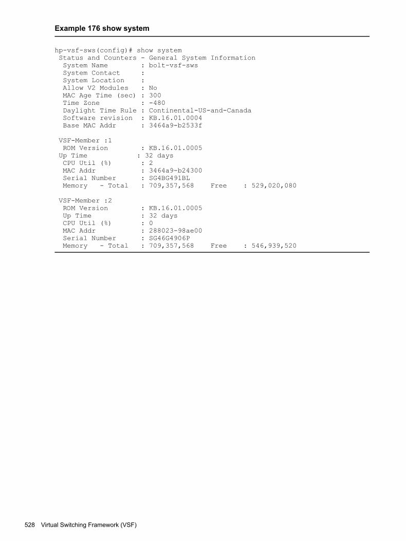
Example 176 show system
hp-vsf-sws(config)# show systemStatus and Counters - General System InformationSystem Name : bolt-vsf-swsSystem Contact :System Location :Allow V2 Modules : NoMAC Age Time (sec) : 300Time Zone : -480Daylight Time Rule : Continental-US-and-CanadaSoftware revision : KB.16.01.0004Base MAC Addr : 3464a9-b2533f
VSF-Member :1ROM Version : KB.16.01.0005Up Time : 32 daysCPU Util (%) : 2MAC Addr : 3464a9-b24300Serial Number : SG4BG491BLMemory - Total : 709,357,568 Free : 529,020,080
VSF-Member :2ROM Version : KB.16.01.0005Up Time : 32 daysCPU Util (%) : 0MAC Addr : 288023-98ae00Serial Number : SG46G4906PMemory - Total : 709,357,568 Free : 546,939,520
528 Virtual Switching Framework (VSF)

Example 177 show system information VSF member 2
hp-vsf-sws# show system information vsf member 1Status and Counters - General System InformationSystem Name : 'name'-vsf-swsSystem Contact :System Location :Allow V2 Modules : NoMAC Age Time (sec) : 300Time Zone : -480Daylight Time Rule : Continental-US-and-CanadaSoftware revision : KB.16.01.0004Base MAC Addr : 3464a9-b2533f
VSF-Member :1ROM Version : KB.16.01.0005Up Time : 32 daysCPU Util (%) : 0MAC Addr : 3464a9-b24300Serial Number : SG4BG491BLMemory - Total : 709,357,568 Free : 529,413,568
hp-vsf-sws# show system information vsf member 2Status and Counters - General System InformationSystem Name : 'name'-vsf-swsSystem Contact :System Location :Allow V2 Modules : NoMAC Age Time (sec) : 300Time Zone : -480Daylight Time Rule : Continental-US-and-CanadaSoftware revision : KB.16.01.0004Base MAC Addr : 3464a9-b2533f
VSF-Member :2ROM Version : KB.16.01.0005Up Time : 32 daysCPU Util (%) : 0MAC Addr : 288023-98ae00Serial Number : SG46G4906PMemory - Total : 709,357,568 Free : 546,939,520
show system temperature
Syntaxshow system temperature vsf member <VSF-MEMBER-LIST>
DescriptionShow current temperature sensor information. If VSF is enabled, this shows the temperaturesensor information for all VSF members.
Optionsvsf Show the current temperature sensor information for the specified VSF
members.temperature Show current temperature sensor information.member Show the current temperature sensor information for the specified VSF
members.
Changes to existing commands 529

VSF-MEMBER-LIST The list of VSF members or one VSF-member for the 'members'command/parameter.
Example 178 show system temperature
HP-VSF-Switch# show system temperature
System Air TemperaturesVSF-Member 1Temp Current Max Min AvgSensor Temp Temp Temp Threshold OverTemp Temp------- -------- ----- ----- ---------- --------- -------Chassis 31C 33C 27C 55C NO 29.46C
VSF-Member 2Temp Current Max Min AvgSensor Temp Temp Temp Threshold OverTemp Temp------- -------- ----- ----- ---------- --------- -------Chassis 30C 32C 28C 55C NO 29.08C
Example 179 show system temperature vsf member 2
HP-VSF-Switch# show system temperature vsf member 2
System Air TemperaturesVSF-Member 2Temp Current Max Min AvgSensor Temp Temp Temp Threshold OverTemp Temp------- -------- ----- ----- ---------- --------- -------Chassis 30C 32C 28C 55C NO 29.08C
show system fans
Syntaxshow system fans vsf member <VSF-MEMBER-LIST>
DescriptionShow system fan status. If VSF is enabled, this shows the system fan status for all VSF members.
Optionsvsf Show the system fan status for the specified VSF members.fans Show system fan status.member Show the system fan status for the specified VSF members.VSF-MEMBER-LIST The list of VSF members or one VSF-member for the 'members'
command/parameter.
530 Virtual Switching Framework (VSF)

Example 180 show system fans
show system fans
Fan InformationVSF-Member 1
Num | State | Failures-------+-------------+----------Sys-1 | Fan OK | 0Sys-2 | Fan OK | 0Sys-3 | Fan OK | 0Sys-4 | Fan OK | 0
0 / 4 Fans in Failure state0 / 4 Fans have been in Failure state
VSF-Member 2Num | State | Failures
-------+-------------+----------Sys-1 | Fan OK | 0Sys-2 | Fan OK | 0Sys-3 | Fan OK | 0Sys-4 | Fan OK | 0
0 / 4 Fans in Failure state0 / 4 Fans have been in Failure state
Example 181 show system fans vsf member 1
show system fans VSF member 1
Fan InformationVSF-Member 1
Num | State | Failures-------+-------------+----------Sys-1 | Fan OK | 0Sys-2 | Fan OK | 0Sys-3 | Fan OK | 0Sys-4 | Fan OK | 0
0 / 4 Fans in Failure state0 / 4 Fans have been in Failure state
show CPU
Syntaxshow cpu <SECONDS>
DescriptionShow average CPU utilization.
Optionsslot Display module CPU statistics.process Display the process usage statistics for the management module or specified interface
modules.
Usageshow cpu slot <SLOT-LIST> <SECONDS>show cpu process slot <SLOT-LIST> refresh <COUNT>
Changes to existing commands 531

Example 182 show cpu slot all
show cpu slot allVSF slot 1/a:-------------12 percent busy, from 18 sec ago
1 sec ave: 14 percent busy5 sec ave: 12 percent busy1 min ave: 12 percent busyVSF slot 1/f:-------------16 percent busy, from 17 sec ago1 sec ave: 27 percent busy5 sec ave: 16 percent busy1 min ave: 15 percent busy
VSF slot 2/a:-------------12 percent busy, from 18 sec ago1 sec ave: 14 percent busy5 sec ave: 12 percent busy1 min ave: 12 percent busy
VSF slot 2/f:-------------16 percent busy, from 17 sec ago1 sec ave: 27 percent busy5 sec ave: 16 percent busy1 min ave: 15 percent busy
Example 183 show cpu slot 1/A
show cpu slot 1/A
VSF slot 1/a:-------------12 percent busy, from 18 sec ago1 sec ave: 14 percent busy5 sec ave: 12 percent busy1 min ave: 12 percent busy
show CPU process slot
Syntaxshow cpu <SECONDS>
DescriptionShow average CPU utilization.
Optionsslot Physical CPU slot.process CPU process for slot list.
Usageshow cpu slot <SLOT-LIST> <SECONDS>show cpu process slot <SLOT-LIST> refresh <COUNT>
532 Virtual Switching Framework (VSF)

Example 184 show cpu process slot all
show cpu process slot all
VSF slot 1/A:-------------Process tracker state: ACTIVEProcess tracking time: 30 seconds
Total % Time Since Times MaxProcess Name Priority Time CPU Last Ran Ran Time----------------+----------+------+-----+-----------+-------+-------Hardware Mgmt-3 192 3 s 6 234 ms 214 35 msSystem Services-2 156 3 s 5 55 ms 110 50 msIdle-3 1 12 s 24 731 us 245918 193 usIdle-1 226 25 s 51 770 us 123627 319 usIdle-0 226 5 s 10 459 us 122921 170 us
VSF slot 2/F:-------------Process tracker state: ACTIVEProcess tracking time: 30 seconds
Total % Time Since Times MaxProcess Name Priority Time CPU Last Ran Ran Time------------------+----------+------+-----+------------+-------+-----Hardware Mgmt-3 192 3 s 8 54 ms 189 41 msSystem Services-2 156 3 s 8 2 s 131 50 msIdle-3 1 9 s 23 870 us 160197 199 usIdle-0 226 4 s 10 926 us 80053 162 usIdle-1 226 19 s 48 1 ms 80545 395 us
Example 185 show cpu process slot 1/A
show cpu process slot 1/A
VSF slot 1/A:-------------Process tracker state: ACTIVEProcess tracking time: 30 seconds
Total % Time Since Times MaxProcess Name Priority Time CPU Last Ran Ran Time----------------+----------+--------+-----+-----------+-------+-----Hardware Mgmt-3 192 3 s 6 234 ms 214 35 msSystem Services-2 156 3 s 5 55 ms 110 50 msIdle-3 1 12 s 24 731 us 245918 193 usIdle-1 226 25 s 51 770 us 123627 319 usIdle-0 226 5 s 10 459 us 122921 170 us
show power-over-ethernet
Syntaxshow power-over-ethernet vsf member <MEMBER-ID>
Syntaxshow power-over-ethernet slot all
Changes to existing commands 533

DescriptionShow power-over-ethernet for named slots or specified VSF member switches.
Example 186 show power-over-ethernet slot all
show power-over-ethernet slot all
Status and Counters - System Power Status for slot 1/AMaximum Power : 0 W Operational Status : OnPower In Use : 0 W +/- 6 W Usage Threshold (%) : 80
Status and Counters - System Power Status for slot 2/AMaximum Power : 0 W Operational Status : OnPower In Use : 0 W +/- 6 W Usage Threshold (%) : 80
Example 187 show power-over-ethernet slot 1/A
show power-over-ethernet slot 1/A
Maximum Power : 0 W Operational Status : OnPower In Use : 0 W +/- 6 W Usage Threshold (%) : 80
Example 188 show power-over-ethernet vsf member 1
HP-VSF-Switch(config)# show power-over-ethernet vsf member 1Status and Counters - System Power Status for member 1
Maximum Operational UsageSlot Power Status Power In Use Threshold (%)----- ------- ----------- ---------------- -------------1/A 266 W On 0 W +/- 6 W 801/L 0 W Faulty 0 W +/- 6 W 80
Example 189 show power-over-ethernet vsf member 2
HP-VSF-Switch# show power-over-ethernet vsf member 2Status and Counters - System Power Status for member 2
Maximum Operational UsageSlot Power Status Power In Use Threshold (%)----- ------- ----------- ---------------- -------------2/A 266 W On 0 W +/- 6 W 802/C 0 W On 0 W +/- 6 W 80
show modules
Syntaxshow modules details vsf member <MEMBER-ID> MM1 | MM2 | slot <SLOT-LIST>
DescriptionShow module details for VSF members.
Options<1-2> The VSF member-ID for the 'member' command/parameter.member Specify the VSF member.vsf Specify the VSF member.
534 Virtual Switching Framework (VSF)

MM1 Show MM1 module information of the specified VSF member.MM2 Show MM2 module information of the specified VSF member.slot Show SLOT module information of the specified VSF member.SLOT-LIST Enter an alphabetic device slot identifier or a slot range.
Changes to existing commands 535

Example 190 show modules
hp-vsf-sws# show modules
Status and Counters - Module InformationChassis: 5406Rzl2 J9850A Serial Number: SG4BG491BLAllow V2 Modules: No
Core ModSlot Module Description Serial Number Status Dump Ver----- -------------------------------------- -------------- -------- ----- ---1/MM1 HP J9827A Management Module 5400Rzl2 SG4BG4C0C0 Active YES 11/MM2 HP J9827A Management Module 5400Rzl2 A123456789 Offline YES 11/A HP J9992A 20p PoE+ / 1p 40GbE QSFP+... B123456789 Up YES 31/F HP J9991A 20p PoE+ / 4p 1/2.5/5/XGT... SG5ZGPH190 Up YES 32/MM1 HP J9827A Management Module 5400Rzl2 SG45G4C0VZ Active YES 12/A HP J9992A 20p PoE+ / 1p 40GbE QSFP+... c123456789 Up YES 32/F HP J9991A 20p PoE+ / 4p 1/2.5/5/XGT... SG5ZGPH183 Up YES 3
hp-vsf-sws# show modules details vsf member 1MM1 Show MM1 module information of the specified VSF member.MM2 Show MM2 module information of the specified VSF member.slot Show SLOT module information of the specified VSF member.
hp-vsf-sws# show modules details vsf member 1Status and Counters - Module InformationChassis: 5406Rzl2 J9850A Serial Number: SG4BG491BLAllow V2 Modules: No
Core ModSlot Module Description Serial Number Status Dump Ver----- -------------------------------------- -------------- -------- ----- ---1/MM1 HP J9827A Management Module 5400Rzl2 SG4BG4C0C0 Active YES 1
Core ModSlot Module Description Serial Number Status Dump Ver----- -------------------------------------- -------------- -------- ----- ---1/MM2 HP J9827A Management Module 5400Rzl2 D123456789 Offline YES 1
Core ModSlot Module Description Serial Number Status Dump Ver----- -------------------------------------- -------------- -------- ----- ---1/A HP J9992A 20p PoE+ / 1p 40GbE QSFP+... E123456789 Up YES 3
Core ModSlot Module Description Serial Number Status Dump Ver----- -------------------------------------- -------------- -------- ----- ---1/F HP J9991A 20p PoE+ / 4p 1/2.5/5/XGT... SG5ZGPH190 Up YES 3
hp-vsf-sws# show modules details vsf member 2Status and Counters - Module InformationChassis: 5406Rzl2 J9850A Serial Number: SG4BG491BLAllow V2 Modules: No
Core ModSlot Module Description Serial Number Status Dump Ver----- -------------------------------------- -------------- -------- ----- ---2/MM1 HP J9827A Management Module 5400Rzl2 SG45G4C0VZ Active YES 1
Core ModSlot Module Description Serial Number Status Dump Ver----- -------------------------------------- -------------- -------- ----- ---2/A HP J9992A 20p PoE+ / 1p 40GbE QSFP+... H123456789 Up YES 3
Core ModSlot Module Description Serial Number Status Dump Ver----- -------------------------------------- -------------- -------- ----- ---2/F HP J9991A 20p PoE+ / 4p 1/2.5/5/XGT... SG5ZGPH183 Up YES 3
536 Virtual Switching Framework (VSF)
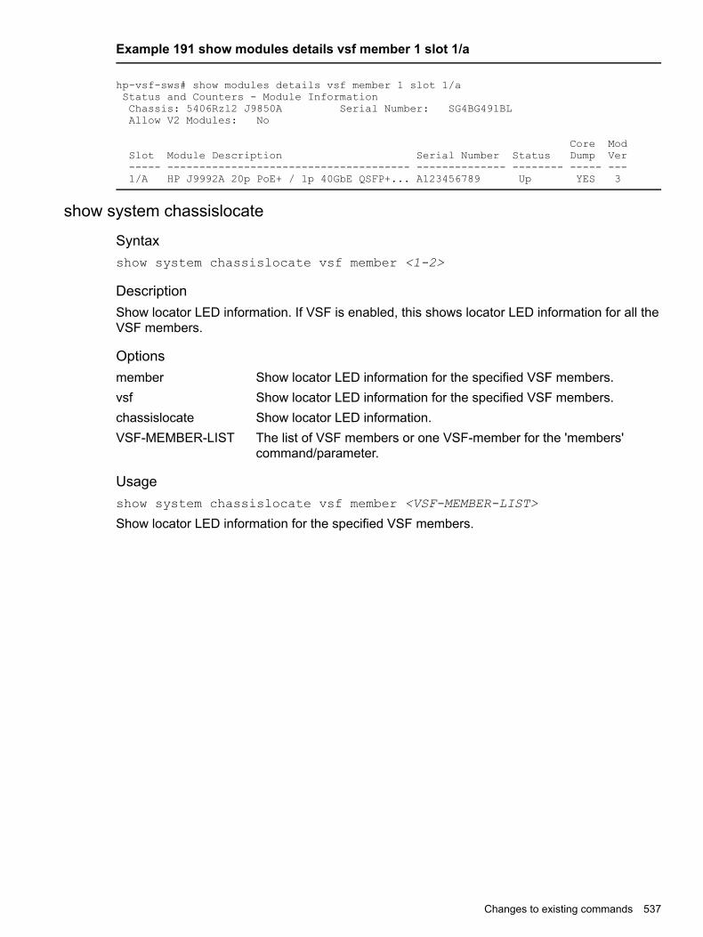
Example 191 show modules details vsf member 1 slot 1/a
hp-vsf-sws# show modules details vsf member 1 slot 1/aStatus and Counters - Module InformationChassis: 5406Rzl2 J9850A Serial Number: SG4BG491BLAllow V2 Modules: No
Core ModSlot Module Description Serial Number Status Dump Ver----- -------------------------------------- -------------- -------- ----- ---1/A HP J9992A 20p PoE+ / 1p 40GbE QSFP+... A123456789 Up YES 3
show system chassislocate
Syntaxshow system chassislocate vsf member <1-2>
DescriptionShow locator LED information. If VSF is enabled, this shows locator LED information for all theVSF members.
Optionsmember Show locator LED information for the specified VSF members.vsf Show locator LED information for the specified VSF members.chassislocate Show locator LED information.VSF-MEMBER-LIST The list of VSF members or one VSF-member for the 'members'
command/parameter.
Usageshow system chassislocate vsf member <VSF-MEMBER-LIST>
Show locator LED information for the specified VSF members.
Changes to existing commands 537

Example 192 show system chassislocate
HP-VSF-Switch# show system chassislocateLocator LED StatusVSF Current TimeMember State Remaining Configuration------ ------- --------- -------------1 off2 blink 00:29:10
Example 193 show system chassislocate vsf member 2
HP-VSF-Switch# show system chassislocate vsf member 2Locator LED StatusHP-VSF-Switch# show system chassislocate vsf member 2Locator LED StatusVSF Current TimeMember State Remaining Configuration------ ------- --------- -------------2 blink 00:29:45
show system power-supply
Syntaxshow system power-supply
DescriptionShow power-supply information.
Example 194 power supply status
HP-VSF-Switch# show system power-supplyPower Supply Status:VSFMember PS# Model Serial State AC/DC + V Wattage Max------- ----- --------- ----------- --------------- ----------------- --------- ------1 1 0957-2413 IN36G4D00L Not Powered AC 120V/240V 0 01 2 0957-2413 IN36G4D014 Powered AC 120V/240V 78 7002 1 Not Present -- --------- 0 02 2 0957-2413 IN36G4D01P Powered AC 120V/240V 76 700
VSF restrictions• VSF is mutually exclusive with DT, MESH and QinQ.
• VSF port restrictions:
Must be 10Gbps/40Gbps. 1Gbps links are not supported.◦◦ A VSF link can only comprise ports with the same speed; either all 10G or all 40G
◦ Maximum 8 ports in 1 VSF link.
◦ VSF ports must be directly connected and there should be no transit devices betweenmembers.
• In a VSF virtual chassis, flow-control is not supported between ports on different chassisacross VSF links.
538 Virtual Switching Framework (VSF)

Updates for a VSF virtual chassisTo update the firmware on a VSF virtual chassis, copy the new firmware to the VSF virtual chassisand reboot the VSF virtual chassis with the boot system flash <IMAGE> command.
Updates for a VSF virtual chassis 539

A Chassis Redundancy (HPE 5400R Switches)Viewing management module redundancy status
You can display the status of both the management and fabric redundant modules using thiscommand:
Syntaxshow redundancy
Displays the status of the management and fabric modules.
ExampleAll examples in this section are representative of the HPE 5400R switch. Only the module SKUsand descriptions will differ.The output for the show redundancy command is seen in Figure 194 (page 540).
Figure 194 show redundancy command for management and fabric modules
Enabling or disabling redundant managementThere are two modes for management module redundancy—warm standby mode (the default)and Nonstop switching mode. In warm-standby mode, the active management module does notsync continuously with the standby management module. The standby management moduleboots to a certain point, syncs basic files, and only finishes booting if the active managementmodule fails or you choose to change which module is the active management module. Thetransition is not seamless or immediate.In Nonstop switching mode, the standby management module is synced continuously with theactive management module so that all features and config files are the same on both managementmodules. The standby management module is ready to become the active management module.The transition is quick and seamless; switching continues without interruption.
Syntax[no] redundancy management-module [nonstop-switching]Allows enabling or disabling of redundant management. The current active module continues tobe the active module on boot unless you use the redundancy active-management commandto enable redundant behavior.(Default: Warm-standby redundancy mode)The nonstop-switching parameter sets the redundancy mode to Nonstop switching.You are prompted with "All configuration files and software images on the off-line managementmodule will be overwritten with the data from the current active management module. During
540 Chassis Redundancy (HPE 5400R Switches)

initial syncing from active to standby management module configuration changes are disallowed.Do you want to continue [y/n]?"When the nonstop-switching option is not selected, the switch enters warm-standbyredundancy mode.You are prompted with "All configuration files and software images on the off-line managementmodule will be overwritten with the data from the current active management module. Do youwant to continue [y/n]?"The no version of the command disables redundant management. You are prompted with thismessage: "The other management module may reboot and it will no longer be used for systemredundancy, except in the case of a hardware failure of the active management module. Do youwant to continue [y/n]?".
ExampleThe redundancy management-module command in Figure 195 (page 541) showswarm-standby redundant management being enabled. The show redundancy commanddisplays "Mgmt Redundancy" as warm-standby redundancy enabled. Management Module1 (MM1) is the active management module and Management Module 2 (MM2) is the standbymanagement module.
Figure 195 Enabling warm-standby redundancy
The redundancy management-module command in Figure Figure 196 (page 542) showsNon-stop switching redundant management being enabled. The show redundancy commanddisplays "Mgmt Redundancy" as Nonstop switching enabled. Management Module 1 (MM1)is the standby management module and Management Module 2 (MM2) is the active managementmodule.
Enabling or disabling redundant management 541

Figure 196 Enabling nonstop-switching redundancy
The no version of the redundancy management-module command is used to disablemanagement module redundancy on the switch, as seen in Figure Figure 197 (page 542). Theshow redundancy command displays "MgmtRedundancy" asNonstop switching disabled.The standby management module in slot MM1 is now offline. The management module in slotMM2 remains the active management module.
NOTE: Hewlett Packard Enterprise recommends that you leave management moduleredundancy enabled. If the active management module has a hardware failure, the standbymodule may take over and may have an old configuration since file synchronization has notoccurred when management module redundancy was disabled.
The no redundancy management-module command allows you to shut down a managementmodule that is not functioning correctly without physically removing the module. If you want toremove the module, first perform the shutdown procedure as explained in “Hotswapping out theactive management module” (page 548) and then remove the module.
Figure 197 Disabling redundancy
542 Chassis Redundancy (HPE 5400R Switches)

The redundancy management-module command shows Nonstop switching redundantmanagement being enabled. The show redundancy command displays “Mgmt Redundancy”as Nonstop switching enabled. Management Module 1 (MM1) is the standby management moduleand Management Module 2 (MM2) is the active management module.
ExampleEnabling non-stop switching redundancy.(HP_Switch_name#) redundancy management-module nonstop-switchingAll configuration files and software images on the off-line management modulewill be overwritten with the data from the current active management module.During initial syncing from active to standby management module configurationchanges are disallowed. Do you want to continue [y/n]? y(HP_Switch_name#) show redundancySettings--------Mgmt Redundancy : Nonstop switching enabledRapid Switchover Stale Timer : 0Statistics----------Failovers : 0Last Failover :Slot Module Description Status SW Version Boot Image---- ------------------------------------------ ---------- ------------MM1 HP J9092A Management Module 8200zl Standby K.15.01.000x PrimaryMM2 HP J9092A Management Module 8200zl Active K.15.01.000x PrimaryFM1 HP J9093A Fabric Module 8200zl EnabledFM2 HP J9093A Fabric Module 8200zl Enabled
The no version of the redundancy management-module command is used to disable managementmodule redundancy on the switch, as seen in Figure 7-4. The show redundancy commanddisplays “Mgmt Redundancy” as Nonstop switching disabled. The standby management modulein slot MM1 is now offline. The management module in slot MM2 remains the active managementmodule.
NOTE: Hewlett Packard Enterprise recommends that you leave management moduleredundancy enabled. If the active management module has a hardware failure, the standbymodule may take over and may have an old configuration since file synchronization has notoccurred when management module redundancy was disabled.
The no redundancy management-module command allows you to shut down a managementmodule that is not functioning correctly without physically removing the module. If you want toremove the module, first perform the shutdown procedure as explained in “Hotswapping Out theActive Management Module” on page 7-25, and then remove the module.
ExampleDisabling redundancy:(HP_Switch_name#) no redundancy management-moduleThe other management module may reboot and it will no longer be used for systemredundancy except in the case of a hardware failure of the active managementmodule. Do you want to continue[y/n]? y(HP_Switch_name#) show redundancySettings--------Mgmt Redundancy : Nonstop switching disabledRapid Switchover Stale Timer : 0Statistics----------Failovers : 1Last Failover : Tue Mar 19 12:42:31 2009Slot Module Description Status SW Version Boot Image---- --------- ------------------------ ------- ----------- ------------MM1 HP J9092A Management Module 8200zl Offline K.15.01.000x PrimaryMM2 HP J9092A Management Module 8200zl Active K.15.01.000x PrimaryFM1 HP J9093A Fabric Module 8200zl EnabledFM2 HP J9093A Fabric Module 8200zl Enabled
Enabling or disabling redundant management 543
Transitioning from no redundancy to nonstop switchingWhile the switch is transitioning from no redundancy mode to Nonstop switching mode, noconfiguration changes are allowed. The management modules are syncing information duringthe transition period.
Setting the Rapid Switchover Stale TimerUse the Rapid Switchover Stale Timer to set the amount of time that you want route and neighbortable entries to be re-added to the Forwarding Information Base on the active managementmodule after a failover has occurred.Layer 3 applications and protocols rely on existing routing information in the FIB. They restartand operate as if the switch performed a quick reset.When a failover occurs, the interface modules and the fabric modules continue forwarding Layer3 traffic based on the information in the FIB. The transitioning standby management modulemarks all routes in the FIB as “stale”. The routing protocols restart, reestablish their neighborsand reconverge. As the routes are added in again, the route’s stale designation is removed. Afterthe Rapid Switchover Stale Timer expires, the remaining stale route entries are removed. Multicastflows are also removed; the multicast application re-adds the flows after failover completes.
Syntaxredundancy rapid-switchover <0-2147483647>
Allows configuration of a timer (in seconds) for Layer 3 forwarding of packetswhen Nonstop switching is configured for redundancy. After failover, the routeand neighbor entries in the Forwarding Information Base (FIB) on the activemanagement module are marked as stale. As new routes are added, the staleflag is reset. This continues for the number of seconds indicated by the timer, afterwhich all remaining stale entries (entries not re-added) are removed.A setting of zero indicates that no Layer 3 Nonstop switching behavior is wanted.When the switch fails over, the FIB entries and corresponding hardware entriesare removed. Default: 90 seconds
To display information about stale FIB routes, enter the show tech route stale command. TheVLAN ID and IP route are shown, as well as other information used only for technical support.
Directing the standby module to become activeTo make the standby management module become the active management module, use theredundancy switchover command. The switch will switchover after all files have finishedsynchronizing.In Nonstop switching mode:• The switchover occurs quickly and seamlessly. No reboot is needed.• There is no interruption in switching operations.In warm-standby mode:• The switchover may take a couple of minutes if there have been recent configuration file
changes or if you have downloaded a new operating system.• The standby module finishes booting and becomes the active module.The formerly active module becomes the standby module if it passes selftest.
Syntaxredundancy switchover
Causes a switchover to the standby module.For Nonstop switching, the warning displays:A nonstop switching failoverwill occur; L2 operations will not be interrupted. This
544 Chassis Redundancy (HPE 5400R Switches)

management module will now reboot and will become the standbymodule! You will need to use the other management module’sconsole interface. Do you want to continue [y/n]?
In warm-standby mode the warning displays:A warm failover will occur;all networking operations will be interrupted. Thismanagement module will now reboot and will become the standbymodule! You will need to use the other management module’sconsole interface. Do you want to continue [y/n]?
If management module redundancy has been disabled, or there is no standby module, or thestandby module is not in standby mode, this message displays:The other managementmodule does not exist or is not in standby mode An example of theredundancy switchovercommand when the switch is in Nonstop switching mode is shown in the example below.
ExampleRedundancy switchover command when in nonstop switching mode.(HP_Switch_name#) redundancy switchoverA nonstop switching failover will occur; L2 operations will not be interrupted.This management module will now reboot and will become the standbymodule! You will need to use the other management module's console interface.Do you want to continue [y/n]? yThis management module will now boot from the primary image and willbecome the standby module! You will need to used the other management module’sconsole interface. Do you want to continue [y/n]? yROM information:Build directory: /sw/rom/build/bmrom(t2g)Build date: Oct 15 2009Build time: 08:24:27Build version: K.15.01Build number: 13040Select profile (primary):Booting Primary Software Image......Standby Console>
Setting the rapid switchover stale timerSyntaxredundancy rapid-switchover 0-2147483647
Allows configuration of a timer (in seconds) for Layer 3 forwarding of packets when nonstopswitching is configured for redundancy. After failover, the route and neighbor entries in theforwarding information base (FIB) on the active management module are marked as stale. Asnew routes are added, the stale flag is reset. This continues for the number of seconds indicatedby the timer, after which all remaining stale entries (entries not re-added) are removed.A setting of zero indicates that no Layer 3 Nonstop switching behavior is wanted. When the switchfails over, the FIB entries and corresponding hardware entries are removed.(Default: 45 seconds)To display information about stale FIB routes, enter the show tech route stale command.The VLAN ID and IP route are shown, as well as other information used only for technical support.
Directing the standby module to become activeSyntaxredundancy switchover
Causes a switchover to the standby module.
Setting the rapid switchover stale timer 545

For nonstop switching, the warning displays: "A nonstop switching failover will occur; L2 operationswill not be interrupted. This management module will now reboot and will become the standbymodule! You will need to use the other management module's console interface. Do you wantto continue [y/n]?"In warm-standby mode the warning displays: "A warm failover will occur; all networking operationswill be interrupted. This management module will now reboot and will become the standby module!You will need to use the other management module's console interface. Do you want to continue[y/n]?"If management module redundancy has been disabled, or if there is no standby module, or if thestandby module is not in standby mode, this message displays:
The other management module does not exist or is not in standby mode
ExampleFigure 198 (page 546) shows an example of the redundancy switchover command whenthe switch is in nonstop switching mode.
Figure 198 The redundancy switchover command when in nonstop switching mode
Setting the active management module for next bootSyntaxredundancy active-management [ management-module1 | management-module2| standby ]The specified module becomes the active management module at the next system boot. Thismessage displays:On the next system boot, the module specified will becomeactive.
This command does not take effect if the standby management module has failed selftest.
Configures management-module 1 as the active management module for thenext system boot.
management-module1
Configures management-module 2 as the active management module for thenext system boot.
management-module2
Configures the current standby module as the active management module forthe next system boot if management module redundancy is enabled. If
standby
546 Chassis Redundancy (HPE 5400R Switches)

redundancy is disabled, it becomes enabled as a standby module at the nextboot or failover event.
If the specified management module is not there or is in failed mode, this message displays:
The specified module is not present or is in failed state.
ExampleFigure 199 (page 547) shows an example of setting management module 2 to be the activemanagement module.
Figure 199 Setting a management module to be active on the next boot
If management module redundancy has been disabled and you specify the standby module withthe active-management command, upon rebooting, the offline module becomes the standbymodule. The state of redundancy (enabled or disabled) is based on the value in the configurationfile in the offline (now standby) module. The configuration files have not been synchronized ifmanagement module redundancy has been disabled. An example of making the offlinemanagement module become the standby management module when redundancy is disabledis shown in Figure 200 (page 548).
Setting the active management module for next boot 547

Figure 200 Showing the results of switching to standby module when redundancy isdisabled
Hotswapping out the active management module1. On the management module to be hotswapped out, press the MM Shutdown button. It is
located between the Module Operation and Component Status LEDs. (See Figure 201(page 548).)
Figure 201 The MM Shutdown button
2. The Dwn LED to the right of the MM Shutdown button begins flashing green. Filesynchronization will complete before shutdown occurs.
3. The standby module takes control and the switchover occurs. It is now the active managementmodule.
548 Chassis Redundancy (HPE 5400R Switches)

4. The Dwn LED on the management module being hotswapped out turns green and all otherLEDs go out when it is OK to remove the module.
5. The module being hotswapped out goes into offline mode. In the offline mode, the modulecannot take over when the active module fails over.
NOTE: If you remove the active management module without pressing the MM Shutdownbutton, any files that may have been in the process of synchronizing will not finish synchronizingto the standby module and all file transfer is aborted.
Resetting the management moduleThe MM Reset button, shown in Figure 202 (page 549), found on each management modulereboots its management module. If the management module is active and management moduleredundancy is enabled, switchover occurs. The standby management module is notifiedimmediately. It then takes over and becomes the active management module. If the MM Resetbutton is pressed on the standby management module, that module reboots but no other switchoperations are affected. The active management module remains in control.If management module redundancy is disabled, the active management module reboots andremains in control, as long as it passes selftest.
CAUTION: Hewlett Packard Enterprise does not recommend using the MM Reset button totrigger a switchover. Files being copied over at the time of the reset will be aborted.
Figure 202 The MM Reset button on the management module
Viewing management informationSyntaxshow modules [details]Displays information about the installed modules, including:• The slot in which the module is installed• The module description• The serial number• The status• Core dump• Model VersionAdditionally, the part number (J number) and serial number of the chassis is displayed.
Example
Status and Counters - Module InformationChassis: 8212zl J9091A Serial Number: LP713BX004Allow V1 Modules: Yes
Core ModSlot Module Description Serial Number Status Dump Ver---- -------------------------------------- -------------- -------- ----- ---
Resetting the management module 549

MM1 HP J9092A Management Module 8200zl sg844bp012 Active NO 1SSM HP J9095A System Support Module SG911BZ00NFM1 HP J9093A Fabric Module 8200zl SG911BQ015 Enabled - 1FM2 HP J9093A Fabric Module 8200zl SG911BQ04T Enabled - 1A HP J9536A 20p GT PoE+/2p SFP+ v2 zl... SG0607T124 Up YES 2B HP Enh Svs v2 zl Module Up YES 2C HP J8702A 24p Gig-T zl Module Up NO 1D HP J9840A Adv Svs v2 zl Module ID3ZG6N008 Up YES 2E HP J8705A Gig-T/SFP zl Module Up NO 1F HP J9857A Adv Svs v2 zl Module SG2ZFNX166 Up YES 2G HP J8708A 4p 10G CX4 zl Module Up NO 1H HP J9154A Services zl Module SG811GG01N Up NO 1I HP J9051A Wireless Edge Services zl... SG660ZB095 Up NO 1J HP J9545A ONE Adv Svs zl Module SG9604P933 Up NO 1K HP J9051A Wireless Edge Services zl... 1111 Up NO 1L HP J9154A Services zl Module SG811GG01M Up NO 1
Viewing information about the management and fabric modulesThe show redundancy command displays information about the management and fabricmodules. It displays the flash image last booted from, even if the boot set-default commandhas been set to change the flash booted from on the next boot.
Example
Figure 203 show redundancy command
Viewing information about the redundancy role of each management moduleThe show redundancy command with the detail option displays information about theredundancy role of each management module, as well as statistical information such as howlong the module has been up.
550 Chassis Redundancy (HPE 5400R Switches)

Example
Figure 204 show redundancy detail command
Viewing which software version is in each flash imageThe show flash command displays which software version is in each flash image. The DefaultBoot field displays which flash image will be used for the next boot.
Example
Figure 205 show flash command
Viewing system software image information for both management modulesThe show version command displays system software image information for both managementmodules, as well as which module is the active management module and which is the standbymanagement module. The Boot Image field displays which flash image last booted from, evenif the boot set-default command has been set to change the flash booted from on the nextboot. The output of the show version command when redundancy is enabled is shown inFigure 206 (page 551).
Example
Figure 206 show version command when redundancy is enabled
Viewing management information 551
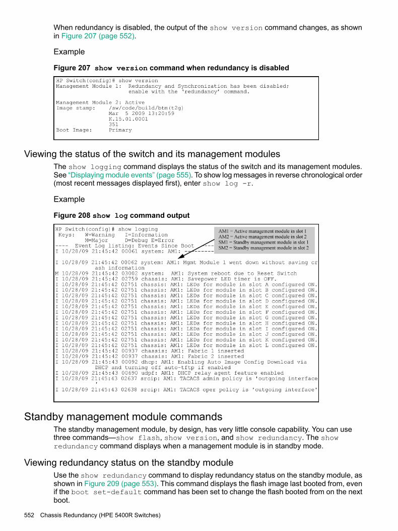
When redundancy is disabled, the output of the show version command changes, as shownin Figure 207 (page 552).
Example
Figure 207 show version command when redundancy is disabled
Viewing the status of the switch and its management modulesThe show logging command displays the status of the switch and its management modules.See “Displaying module events” (page 555). To show log messages in reverse chronological order(most recent messages displayed first), enter show log -r.
Example
Figure 208 show log command output
Standby management module commandsThe standby management module, by design, has very little console capability. You can usethree commands—show flash, show version, and show redundancy. The showredundancy command displays when a management module is in standby mode.
Viewing redundancy status on the standby moduleUse the show redundancy command to display redundancy status on the standby module, asshown in Figure 209 (page 553). This command displays the flash image last booted from, evenif the boot set-default command has been set to change the flash booted from on the nextboot.
552 Chassis Redundancy (HPE 5400R Switches)

Example
Figure 209 show redundancy command for standby module
Viewing the flash information on the standby moduleUse the show flash command to display the flash information on the standby module, as shownin Figure 210 (page 553). The Default Boot field displays which flash image will be used for thenext boot.
Example
Figure 210 show flash command for standby module
Viewing the version information on the standby moduleUse the show version command to display the version information on the standby module,as shown in Figure 211 (page 553). The Boot Image field displays which flash image was lastbooted from, even if the boot set-default command has been set to change the flash bootedfrom on the next boot. Unlike executing the show version command on an active managementmodule, this command shows only the running version of software on the standby managementmodule.
Example
Figure 211 show version command for standby module
Setting the default flash for bootYou can set which flash image to boot from as the default image on boot by using this command:
Setting the default flash for boot 553

Syntaxboot set-default flash [ primary | secondary ]Sets the flash image to boot from on the next boot.
Boots the primary flash image.primary
Boots the secondary flash image.secondary
ExampleFigure 212 (page 554) shows an example of the output when the command is used to set theboot default to secondary flash.
Figure 212 boot set-default command defaulting to secondary flash
Booting the active management module from the current default flashUse the reload command to boot the active management module from the current default flash(You can change the default flash with the boot set-default command. See “Setting thedefault flash for boot” (page 553).) Switchover occurs if redundancy is enabled and the standbymanagement module is in standby mode. If redundancy is disabled or the standby managementmodule is not present, the reload command boots the system.
NOTE: The reload command is a "warm" reboot; it skips the Power on Self Test routine.
Syntaxreload <cr>
Boots (warm reboot) the active management module. Switchover to the standby managementmodule occurs if management module redundancy is enabled. If redundancy is disabled or ifthere is no standby management module, the reload command boots the system.
NOTE: If the running config file is different from the stored config file, you are promptedto save the config file. The reload at/after versions of this command do not display a promptto save configuration file changes: the changes are lost on the scheduled reload.
554 Chassis Redundancy (HPE 5400R Switches)

Example
Figure 213 reload command with redundancy enabled
Displaying module eventsViewing log events
The log file displays messages about the activities and status of the management modules. Enterthis command to display the messages:
Syntaxshow logging [ -a, -b, -r, -s, -t, -m, -p, -w, -i, -d, option-str ]Displays log events.The event messages are tagged with the management module state and the management moduleslot (AM1 or AM2, SM1 or SM2.) Synchronization is maintained by syncing the standbymanagement module log events with the active management module. In this way, events areavailable for both management modules. Only the active management module events are shownunless you select the -s option. This option works like the -a option, except that the events forboth the active management module and standby management module are displayed.
Displaying module events 555

Example
Figure 214 Log file listing
Copying crash file information to another fileCrash logs for all modules are always available on the active management module. You can usethe copy crash-log and copy crash-data commands to copy the information to a file ofyour choice.
Syntaxcopy crash-log [ slot-id | mm ] tftp ip-address filename
Copies the crash logs of both the active and standby management modules to a user-specifiedfile. If no parameter is specified, files from all modules (management and interface) areconcatenated.
Retrieves the crash log from the module in the specified slot.slot-id
Retrieves the crash logs from both management modules and concatenatesthem.
mm
Syntaxcopy crash-data [ slot-id | mm ] tftp ip-address filename
Copies the crash data of both the active and standby management modules to a user-specifiedfile. If no parameter is specified, files from all modules (management and interface) areconcatenated.
Retrieves the crash data from the module in the specified slot.slot-id
Retrieves the crash data from both management modules and concatenatesthem.
mm
556 Chassis Redundancy (HPE 5400R Switches)

Viewing saved crash information
Syntaxshow boot-history
Displays the system boot log.
Example
Figure 215 The system boot log file
Enabling and disabling fabric modulesThe fabric modules can be enabled or disabled even if they are not present in the switch. Youcannot disable both fabric modules at the same time; one must be enabled.Use this command to enable or disable the redundant fabric modules. Disabling one fabric modulereduces the overall switching capacity of the series switches. On some networks where networkutilization is less than 50%, you may not notice any degradation of performance.
Syntaxredundancy fabric-module [ 1 | 2 ] [ enable | disable ]Allows enabling or disabling of fabric modules. (You cannot have both fabric modules disabledat the same time.)Default: Both fabric modules are enabled.
NOTE: The redundant fabric modules do not support nonstop switching.
Example
Figure 216 Disabling a fabric module
Enabling and disabling fabric modules 557

Overview of chassis redundancySome HPE switches provide high availability through the use of hot-swappable, redundantmanagement modules. In the event of a failure on the active management module, managementmodule redundancy allows a quick and unattended transition from the active management moduleto the standby management module. The standby management module now becomes the activemanagement module. Management module redundancy keeps the switch operating and reducesnetwork downtime.The advantages of redundant management are:• Maintaining switch operation if a hardware failure occurs on the active management module• Minimizing restart time caused by the failure of a management module• Hotswapping a failed management module with no downtime
Nonstop switching with redundant management modulesBeginning with software version K.15.01, you can use either nonstop switching or warm-standbyredundant management.The advantages of nonstop switching are:• Quick, seamless transition to the standby management module; no reboot is necessary• Switching of packets continues without interruption
How the management modules interactWhen the switch boots up, the management modules run selftest to decide which is the activemodule and which is the standby module. The module that becomes active finishes booting andthen brings up the interface modules and ports.If you are using nonstop switching mode, the standby management module is synced continuouslywith the active management module so that all features and config files are the same on bothmanagement modules. The standby management module is ready to become the activemanagement module. If the active management module fails or if there is a manual switchover,switching continues without interruption.If you are using warm-standby mode, the standby module boots to a certain point, syncs basicfiles such as the config and security files, and finishes booting only if the active managementmodule fails or you choose to change which module is the active module.The two management modules communicate by sending heartbeats back and forth.
About using redundant managementThe CLI commands for redundant management are shown at the beginning of the chapter.Additionally, some other commands are affected by redundant management (See “CLI commandsaffected by redundant management” (page 570).)
Transition from no redundancy to nonstop switchingWhile the switch is transitioning from no redundancy mode to nonstop switching mode, noconfiguration changes are allowed. The management modules are syncing information duringthe transition period.
About setting the rapid switchover stale timerAfter a failover has occurred, use the rapid switchover stale timer to set the amount of time thatyou want route and neighbor table entries to be re-added to the FIB on the active managementmodule.Layer 3 applications and protocols rely on existing routing information in the FIB. They restartand operate as if the switch performed a quick reset.
558 Chassis Redundancy (HPE 5400R Switches)

When a failover occurs, the interface modules and the fabric modules continue forwarding Layer3 traffic based on the information in the FIB. The transitioning standby management modulemarks all routes in the FIB as "stale". The routing protocols restart, reestablish their neighborsand reconverge. As a route is added in again, the route's stale designation is removed. After therapid switchover stale timer expires, the remaining stale route entries are removed. Multicastflows are also removed; the multicast application re-adds the flows after failover completes.
About directing the standby module to become activeTo make the standby management module become the active management module, use theredundancy switchover command. The switch will switchover after all files have finishedsynchronizing.In nonstop switching mode:• The switchover occurs quickly and seamlessly; no reboot is needed.• There is no interruption in switching operations.In warm-standby mode:• The switchover may take several minutes if there have been recent configuration file changes
or if you have downloaded a new operating system.• The standby module finishes booting and becomes the active module.The formerly active module becomes the standby module if it passes selftest.
Nonstop switching with VRRPWhen Nonstop VRRP is enabled, VRRP continues to operate in its current state when a failoverfrom the AMM to the SMM occurs. This provides an additional layer of redundancy in a switchednetwork. VRRP state information is maintained between MMs so that VRRP operations resumeimmediately after failover from the AMM to SMM. Because of this quick resumption of operationsthere is no failover to the backup VRRP router in the network. The Master VRRP router continuesto be active and operate as is.The command for enabling Nonstop mode for VRRP must be executed in VRRP context.
Syntax(vrrp#) [no]nonstop
Enabling Nonstop VRRP allows the VRRP router to retain control of IP addresses when the AMMfails over. The VRRP Backup router does not take control of the virtual IP addresses on thenetwork.The no version of the command disables Nonstop VRRP.When Nonstop behavior is disabled, failure of the AMM on the VRRP Master results in the VRRPBackup router taking control of the virtual IP addresses on the network.The commands must be executed in VRRP context.
NOTE: Before this command is executed, the command redundancy managementnonstop-switching should be configured. Any prerequisites required for VRRP configurationcommands, such as IP routing being enabled, remain as required prerequisites.
Default: Disabled
Nonstop switching with VRRP 559
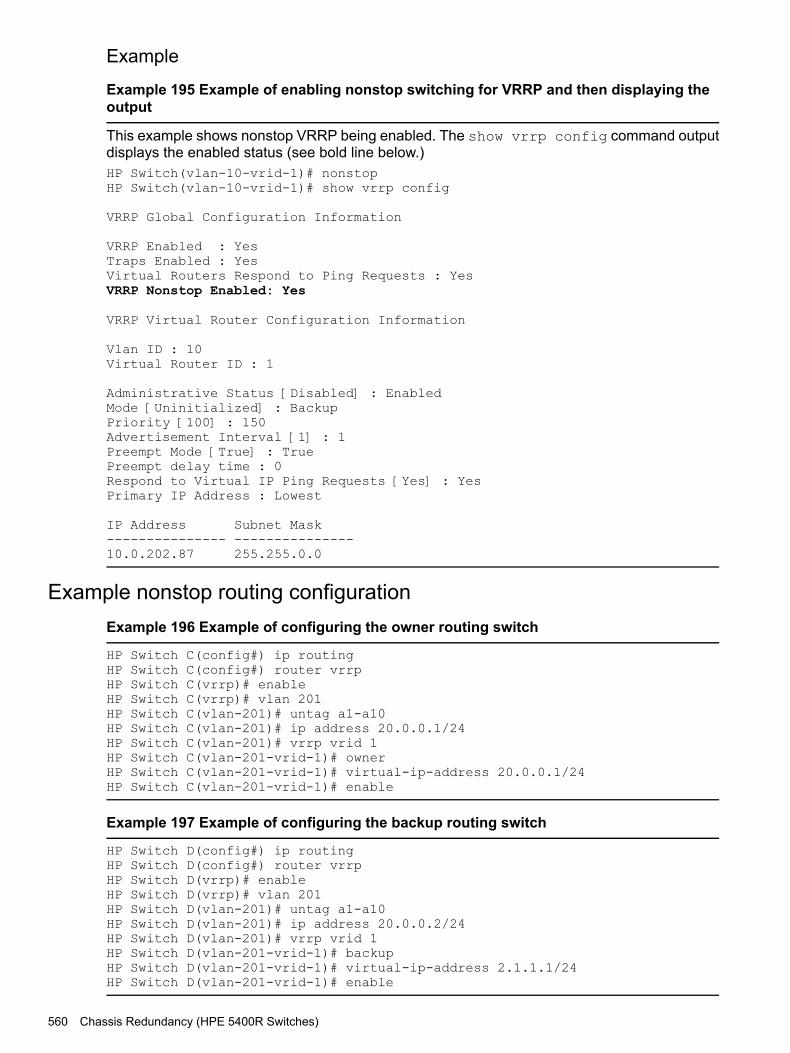
Example
Example 195 Example of enabling nonstop switching for VRRP and then displaying theoutput
This example shows nonstop VRRP being enabled. The show vrrp config command outputdisplays the enabled status (see bold line below.)HP Switch(vlan-10-vrid-1)# nonstopHP Switch(vlan-10-vrid-1)# show vrrp config
VRRP Global Configuration Information
VRRP Enabled : YesTraps Enabled : YesVirtual Routers Respond to Ping Requests : YesVRRP Nonstop Enabled: Yes
VRRP Virtual Router Configuration Information
Vlan ID : 10Virtual Router ID : 1
Administrative Status [Disabled] : EnabledMode [Uninitialized] : BackupPriority [100] : 150Advertisement Interval [1] : 1Preempt Mode [True] : TruePreempt delay time : 0Respond to Virtual IP Ping Requests [Yes] : YesPrimary IP Address : Lowest
IP Address Subnet Mask--------------- ---------------10.0.202.87 255.255.0.0
Example nonstop routing configurationExample 196 Example of configuring the owner routing switch
HP Switch C(config#) ip routingHP Switch C(config#) router vrrpHP Switch C(vrrp)# enableHP Switch C(vrrp)# vlan 201HP Switch C(vlan-201)# untag a1-a10HP Switch C(vlan-201)# ip address 20.0.0.1/24HP Switch C(vlan-201)# vrrp vrid 1HP Switch C(vlan-201-vrid-1)# ownerHP Switch C(vlan-201-vrid-1)# virtual-ip-address 20.0.0.1/24HP Switch C(vlan-201-vrid-1)# enable
Example 197 Example of configuring the backup routing switch
HP Switch D(config#) ip routingHP Switch D(config#) router vrrpHP Switch D(vrrp)# enableHP Switch D(vrrp)# vlan 201HP Switch D(vlan-201)# untag a1-a10HP Switch D(vlan-201)# ip address 20.0.0.2/24HP Switch D(vlan-201)# vrrp vrid 1HP Switch D(vlan-201-vrid-1)# backupHP Switch D(vlan-201-vrid-1)# virtual-ip-address 2.1.1.1/24HP Switch D(vlan-201-vrid-1)# enable
560 Chassis Redundancy (HPE 5400R Switches)

The configuration is shown graphically in Figure 217 (page 561).
Figure 217 Example of nonstop routing configuration
Nonstop forwarding with RIPOn a Nonstop RIP router, the traffic does not get re-routed when the MM fails over. A requestpacket is sent on failover that asks for the router’s peers to send routing updates to the requestingrouter. There is no loss of routed traffic.
Nonstop forwarding with OSPFv2 and OSPFv3On a Nonstop OSPFv2 router, failover of a MM does not result in the OSPF v2 router beingremoved from the OSPFv2 domain. A restart request is sent by the Nonstop OSPFv2 router tothe neighboring OSPFv2 routers, after which the graceful restart process begins. This behaviorapplies to OSPFv3 as well.A graceful restart allows an OSPF routing switch to stay on the forwarding path while beingrestarted. The routing switch sends “grace LSAs” that notify its neighbors that it intends to performa graceful restart. During the configurable grace period, the restarting switch’s neighbors continueto announce the routing switch in their LSAs as long as the network topology remains unchanged.The neighbors run in “helper mode” while the routing switch restarts.Graceful restart will fail under these conditions:• There is a topology change during the graceful restart period. The helper switches exit helper
mode and adjacencies are lost until the restarting switch rebuilds the adjacencies.• The neighbor switches do not support helper mode.For more information on OSPFv2 and OSPFv3 graceful restart, see RFC 3623 and RFC 5187.
Enabling nonstop forwarding for OSPFv2The routing switch must be in ospf context when enabling Nonstop forwarding for OSPFv2. Toenable Nonstop forwarding, enter this command.
Nonstop forwarding with RIP 561

Syntax(ospf)# [no]nonstop
Enables nonstop forwarding for OSPFv2.The no version of the command disables nonstop forwarding.The commands must be executed in ospf context.Default: Disabled
Example 198 Example of enabling nonstop forwarding for OSPFv2
HP Switch(ospf)# nonstop
Configuring restart parameters for OSPFv2
Syntax(ospf)# [no]restart interval 1-1800 [strict-lsa-checking]Specify the graceful restart timeout interval in seconds.The no version of the command sets the restart parameters to the default values.Default: Disabledinterval 1–1800 The graceful restart timeout interval (grace period) in seconds.
Default: 120 secondsstrict-lsa-checking Used in OSFPv2 context to enable or disable strict LSA operation
in a network segment for a neighboring router that is attemptinga graceful restart. When enabled, this operation halts Helper modesupport if a change in LSAs (topology change) is detected duringthe neighbor’s restart period.The no form of this command disables strict LSA operation.Default: Strict LSA operation enabled
Viewing OSPFv2 nonstop forwarding informationTo display the status of Nonstop forwarding information, enter the show ip ospf generalcommand.
562 Chassis Redundancy (HPE 5400R Switches)

Example 199 Example of output showing status of nonstop forwarding for OSPFv2
(HP_Switch_name#) show ip ospf general
OSPF General Status
OSPF protocol :enabledRouter ID :10.10.10.80...Nonstop forwarding : EnabledGraceful Restart Interval : 500Graceful Restart Helper Mode : Enabled...
Enabling nonstop forwarding for OSPFv3The routing switch must be in ospf3 context when enabling Nonstop forwarding for OSPFv3.To enable nonstop forwarding, enter this command.
Syntax(ospf3)# [no]nonstop
Enables nonstop forwarding for OSPFv3.The no version of the command disables nonstop forwarding.The commands must be executed in ospf3 context.Default: Disabled
Example 200 Example of enabling nonstop forwarding for OSPFv3
HP Switch(ospf3)# nonstop
Configuring restart parameters for OSPFv3
Syntax(ospf3)# [no]restart interval 1-1800 [strict-lsa-checking]Specify the graceful restart timeout interval in seconds.The no version of the command sets the restart parameters to the default values. Default: Disabledinterval 1-1800 The graceful restart timeout interval (grace period) in seconds.
Default: 120 secondsstrict-lsa-checking Used in OSFPv3 context to enable or disable strict LSA operation
in a network segment for a neighboring router that is attemptinga graceful restart. When enabled, this operation halts Helper modesupport if a change in LSAs (topology change) is detected duringthe neighbor’s restart period.The no form of this command disables strict LSA operation.Default: Strict LSA operation enabled
Viewing OSPFv3 nonstop forwarding informationTo display the status of Nonstop forwarding information, enter the show ipv6 ospf3 generalcommand.
Nonstop forwarding with OSPFv2 and OSPFv3 563

Example 201 Example of output showing status of nonstop forwarding for OSPFv3
(HP_Switch_name#) show ipv6 ospf3 general
OSPFv3 General Status
OSPFv3 protocol :enabledRouter ID :10.10.10.80...Nonstop forwarding : EnabledGraceful Restart Interval : 500Graceful Restart Helper Mode : Enabled...
Hotswapping management modulesManagement module switchover
Events that cause a switchoverThere are a number of events that can cause the active management module to switchover tothe standby management module when management module redundancy is enabled:• The active management module crashes• The standby management module does not receive a heartbeat from the active management
module• The redundancy switchover command is executed• The MM Reset button on the active management module is pressed• The MM Shutdown button on the active management module is pressed• The boot or boot active command is executed• The reload command is executed• There is a hardware failure on the active management moduleIn all of these cases, the standby management module takes control and performs the actualswitchover. The reason for the switchover is entered in log messages on the newly activemanagement module and to any configured Syslog servers.
What happens when switchover occursWhen a switchover occurs, the features that support nonstop switching continue to operate inan uninterrupted manner. See “Nonstop switching features” (page 577) for a list of the supportedfeatures.The features that do not support nonstop switching perform as if the switch had just finishedbooting; however, no actual boot time occurs.
NOTE: When meshing configuration changes are made on a redundant management system,you must execute write mem and then the boot system command to boot both managementmodules for the changes to be activated.Meshing is not supported by nonstop switching.NOTE: If the switch is a querier and a failover occurs, the querier continues to be the sameon the standby management module; no new querier election process occurs on the standbymanagement module.
564 Chassis Redundancy (HPE 5400R Switches)

When switchover will not occurThere are some events for which a switchover is not triggered:• When a boot system command is executed• When the Clear button on the System Support module is pressed• When management module redundancy is disabled, unless there is a hardware failure and
the system is rebooted.
When a management module crashes while the other management module is rebootingIf the uncommon situation occurs where the active management module (MM1) is trying to rebootand the standby management module (MM2) also crashes, the switch attempts to recover fromthe crash and eventually the standby management module becomes the active managementmodule if it passes self-test. However, traffic can be disrupted for as long as five minutes beforethe newly active management module (MM2) has finished rebooting.
Hotswapping out the active management moduleYou can hotswap out the active management module and have switch operations taken over bythe standby management module by following the correct shutdown procedure on the activemodule using the MM Shutdown button. When the MM Shutdown button is pressed, any filesynchronization in progress completes before the shutdown begins, and then a graceful shutdownof that management module occurs.
When the standby module is not availableIf you have disabled management module redundancy with the no redundancymanagement-module command, or the standby module failed selftest, the Dwn LED does notturn green to indicate it is OK to hotswap out the active management module.
NOTE: If you remove the active management module without pressing the MM Shutdownbutton, any files that may have been in the process of synchronizing will not finish synchronizingto the standby module and all file transfer is aborted.
Hotswapping in a management moduleIf another management module is hotswapped in while there is an active management modulebooted up, the newly hotswapped management module becomes the standby module.No negotiating is needed as to which module becomes the active management module, becausethere is already a functioning active management module. However, the following conditionsmust be met to determine if the hotswapped module can become a standby management module:• The hotswapped module must pass selftest• Management module redundancy is not administratively disabled (using the no redundancy
management-module command.) If the active management module's config file hasredundancy administratively disabled, the hotswapped management module goes into"offline" mode.
In nonstop switching mode—The active management module's files and features are syncedwith the standby management module. Heartbeats are sent back and forth, and the standbymanagement module is ready to quickly take over in the event of a switchover or a failure on theactive management module.In warm-standby mode—The standby management module partially boots up and heartbeatsare sent back and forth with the active management module.
Software version mismatch between active and hotswapped moduleIf the software version in the hotswapped module does not match the software version in theactive module, the following occurs:
Hotswapping management modules 565
1. The active module sends the primary and secondary images in flash to the hotswappedmodule.
2. The module that was hotswapped in then reboots if necessary to primary or secondary flash,whichever matches (if it does not already match.)
3. After the hotswapped management module finishes booting, it is sent the config and othercritical files from the active management module.
4. The hotswapped management module goes into standby mode and is ready to take over incase of a switchover.
NOTE: After the boot standby command is executed, if the software versions on the activemanagement module and the standby management module are not compatible, the standbymodule does not sync with the active management module. The standby module then enterswarm-standby redundancy mode.
Other software version mismatch conditionsThe following steps describe the behavior that may when a new software image is installed insecondary flash of the AMM and a redundancy switchover command is executed.1. A new software image, K.15.04.0002 containing ROM upgrade K.15.12 is installed in
secondary flash of the AMM/MM1.2. The AMM/MM1 automatically syncs the images to the secondary flash in the SMM/MM2.
Now both AMM/MM1 and SMM/MM2 have identical software and ROM in secondary flash.3. The SMM/MM2 is booted from secondary. It boots into the new K.15.04.0002 software
version. The new ROM is applied and the SMM/ MM2 reboots.4. After the SMM/MM2 finishes rebooting, it reconnects to the AMM/MM1 and prepares to take
the standby role by rebooting.5. However, the AMM/MM1 is running software version K.15.03.0008 in its primary flash, and
the SMM/MM2 is running software version K.15.04.0002 in its secondary flash, so theSMM/MM2 pauses its reboot because of the software mismatch.
6. If a redundancy switchover command is executed, the AMM/MM1 will give control tothe SMM/MM2, which can then finish booting and become the new AMM/MM2. This is thewarm-start behavior.
7. The SMM/MM1 (former AMM/MM1) reboots, but unless the reboot is executed from secondaryflash, it reboots into primary flash, which contains the older software version K.15.03.0008with no ROM upgrade.
8. If the SMM/MM1 is forced to boot from secondary before executing the redundancyswitchover command, it will boot into the new K.15.04.0002 software and upgrade theROM. After the reboot that occurs with the ROM upgrade, the SMM/MM1 connects to thenew AMM/MM2 and takes the standby role.
About downloading a new software versionFile synchronization after downloading
After downloading a new software version to either the primary or secondary flash of the activemanagement module, the software version is immediately copied to the corresponding flash(primary or secondary) of the standby module, unless the standby module failed selftest orredundancy was disabled with the no redundancy management-module command.The configuration files, including which configuration file to use for that flash image, aresynchronized. For example, if the active management module is using config1, the standbymodule is also synchronized to use config1.
566 Chassis Redundancy (HPE 5400R Switches)
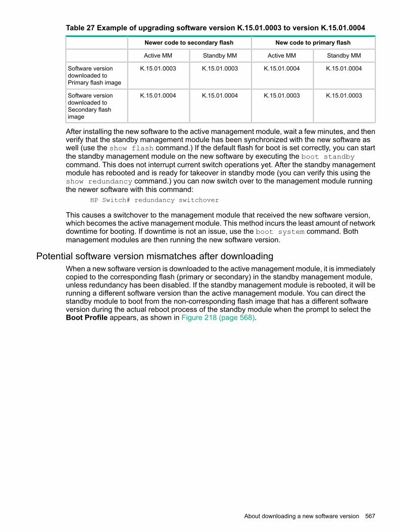
Table 27 Example of upgrading software version K.15.01.0003 to version K.15.01.0004
New code to primary flashNewer code to secondary flash
Standby MMActive MMStandby MMActive MM
K.15.01.0004K.15.01.0004K.15.01.0003K.15.01.0003Software versiondownloaded toPrimary flash image
K.15.01.0003K.15.01.0003K.15.01.0004K.15.01.0004Software versiondownloaded toSecondary flashimage
After installing the new software to the active management module, wait a few minutes, and thenverify that the standby management module has been synchronized with the new software aswell (use the show flash command.) If the default flash for boot is set correctly, you can startthe standby management module on the new software by executing the boot standbycommand. This does not interrupt current switch operations yet. After the standby managementmodule has rebooted and is ready for takeover in standby mode (you can verify this using theshow redundancy command.) you can now switch over to the management module runningthe newer software with this command:
HP Switch# redundancy switchover
This causes a switchover to the management module that received the new software version,which becomes the active management module. This method incurs the least amount of networkdowntime for booting. If downtime is not an issue, use the boot system command. Bothmanagement modules are then running the new software version.
Potential software version mismatches after downloadingWhen a new software version is downloaded to the active management module, it is immediatelycopied to the corresponding flash (primary or secondary) in the standby management module,unless redundancy has been disabled. If the standby management module is rebooted, it will berunning a different software version than the active management module. You can direct thestandby module to boot from the non-corresponding flash image that has a different softwareversion during the actual reboot process of the standby module when the prompt to select theBoot Profile appears, as shown in Figure 218 (page 568).
About downloading a new software version 567
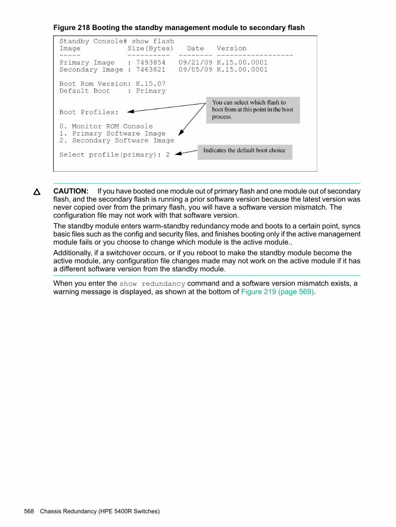
Figure 218 Booting the standby management module to secondary flash
CAUTION: If you have booted one module out of primary flash and one module out of secondaryflash, and the secondary flash is running a prior software version because the latest version wasnever copied over from the primary flash, you will have a software version mismatch. Theconfiguration file may not work with that software version.The standby module enters warm-standby redundancy mode and boots to a certain point, syncsbasic files such as the config and security files, and finishes booting only if the active managementmodule fails or you choose to change which module is the active module..Additionally, if a switchover occurs, or if you reboot to make the standby module become theactive module, any configuration file changes made may not work on the active module if it hasa different software version from the standby module.
When you enter the show redundancy command and a software version mismatch exists, awarning message is displayed, as shown at the bottom of Figure 219 (page 569).
568 Chassis Redundancy (HPE 5400R Switches)

Figure 219 Example of a software version mismatch between the active and standbymodules
Downloading a software version serially if the management module is corruptedIf the software version on a management module becomes corrupted, you may need to do aserial download to restore the affected module. The non-corrupted management module becomesthe active module. You can then use the serial port on the corrupted management module todownload a new software version. When the corrupted module is rebooted, the software versionin the corrupted module is immediately overwritten by the software version in the activemanagement module. Both management modules should now operate on the same softwareversion.
About turning off redundant managementDisable management module redundancy with two modules present
To troubleshoot a suspect management module, you may want to operate the switch withredundant management disabled by entering this command:
(HP_Switch_name#) no redundancy management-module
After executing this command, the second management module will not boot into standby mode—itis offline and no longer receives configuration file changes from the active module. The activemanagement module updates its config file with the information that redundancy is disabled.
About turning off redundant management 569

NOTE: Even if redundancy has been disabled, the specified management module becomesthe active management module at the next system boot if you use the redundancyactive-management command. You are warned that you may not be using currentconfigurations. See “Setting the active management module for next boot” (page 546).The second management module is enabled as the active management module in the event ofa hardware failure of the first management module.
Figure 220 (page 570) shows that redundant management was disabled.
Figure 220 Results of disabling redundancy
Disable management module redundancy with only one module presentIf you disable redundancy when there is only one management module in the switch, and thenyou insert a second management module, the second module never goes into standby mode.You must re-enable redundant management using this command:
(HP_Switch_name#) redundancy management-module
The currently active module remains active on boot (assuming no selftest failure) unless youmake the newly inserted management module active using this command:
(HP_Switch_name#) redundancy active-management standby
The standby management module becomes the active management module.
Active management module commandsViewing modules
The show modules command displays information about all the modules in the switch, as wellas additional component information for the following:• System Support Modules (SSM)—identification, including serial number• Mini-GBICS—a list of installed mini-GBICs displaying the type, "J" number, and serial number
(when available)
CLI commands affected by redundant managementSeveral existing commands have changes related to redundant management.
570 Chassis Redundancy (HPE 5400R Switches)

boot commandIn redundant management systems, the boot or boot active command causes a switchoverto the standby management module as long as the standby module is in standby mode. Thismessage displays:
This management module will now reboot and will become thestandby module! You will need to use the other managementmodule's console interface. Do you want to continue [y/n]?
If you select y, switchover is initiated by the standby management module, which becomes theactive management module after boot completes.If the standby module is not in standby mode (for example, it is in failed mode or offline mode),switchover to the standby module does not occur. The system is rebooted and this messagedisplays:
The other management module is not in standby mode and thiscommand will not cause a switchover, but will reboot thesystem, do you want to continue [y/n]?
If the other management module is not present in the switch, the system simply reboots.The boot command has these options.
ActionCommand
Reboots the active management module from the flash image that isspecified for the default boot. This can be changed with the boot
boot cr
set-default flash command. You can select which image to bootfrom during the boot process itself. (See Figure 221 (page 572).) Theswitch will switchover to the standby management module.
NOTE: This is changed from always booting from primary flash. Youare prompted with a message, which indicates the flash being bootedfrom.
Boots the active management module. The switch starts to boot from thedefault flash image. You can select which image to boot from during the
boot active
boot process itself. (See Figure 221 (page 572).) The switch will switchoverto the standby management module. If a second management moduleis not present in the switch, the system is rebooted.
Boots the standby management module. The switch does not switchover.boot standby
If the standby module is not present, this message displays: "The othermanagement module is not present."
Boots both the active and standby management modules. You can specifythe flash image to boot from.
boot system [flash [ primary |secondary ]]
Sets the default flash for the next boot to primary or secondary. You seethis message:
boot set-default flash primary| secondary
"This command changes the location of the default boot. This commandwill change the default flash image to boot from flash chosen>. Hereafter,‘reload' and ‘boot' commands will boot from flash chosen>. Do you wantto continue [y/n]?"
You can select a boot profile during the reboot process, as shown in Figure 221 (page 572). Ifyou make no selection, the boot defaults to the image displayed as the default choice (shown inparentheses.)
CLI commands affected by redundant management 571

Figure 221 The management module rebooting, showing boot profiles to select
An example of the boot command with the default flash set to secondary is shown in Figure 222(page 572).
Figure 222 Showing boot command with default flash set to secondary
CAUTION: For a given reboot, the switch automatically reboots from the startup-configfile assigned to the flash (primary or secondary) being used for the current reboot. Thestartup-default command can be used to set a boot configuration policy. This means thatboth the flash image and one of the three configuration files can be specified as the default bootpolicy.
Boot and reload commands with OSPFv2 or OSPFv3 enabledIt is now possible to gracefully shut down OSPFv2 or OSPFv3 routing on switches without losingpackets that are in transit. OSPF neighbors are informed that the router should not be used forforwarding traffic, which allows for maintenance on the switch without interrupting traffic in thenetwork. There is no effect on the saved switch configurationPrior to a switch shutdown, the CLI/SNMP reload command or the CLI boot command isexecuted to initiate the sending of OSPF "empty Hello list" messages on the interfaces that arepart of the OSPF routing configuration. After a small delay (approximately 2 seconds) that allowsthe messages to be transmitted on all applicable interfaces the boot or reload commandcontinues.
Modules operating in nonstop modeWhen a switch is in standalone mode and OSPF routing is enabled, the "empty Hello list" istransmitted whenever the boot or reload command is executed.When the switch is operating in nonstop switching mode (redundant), and a single module isbeing reloaded or booted, the standby module notifies neighboring switches of the management
572 Chassis Redundancy (HPE 5400R Switches)

module failover. If the failover fails, the "empty Hello list" is transmitted before the switch isrebooted.When a switch is operating with multiple management modules in warm standby mode, the"empty Hello list" is sent when a reload or boot command is executed. The standbymanagement module sends out OSPF Hello packets after becoming the active managementmodule.
Additional commands affected by redundant managementThe other existing commands operate with redundant management as shown below.
ActionCommand
If a new image is downloaded using auto-tftp, the active managementmodule downloads the new software version to both the active and
auto-tftp
standby modules. Rebooting after the auto-tftp completes rebootsthe entire system.
The banner will not been seen on the standby module, only the activemodule.
banner
If the management module performs a switchover, the LED does notremain lit.
chassislocate
The clear crypto command causes public keys to be deleted fromboth modules when the second module is in standby mode.
clear
Console settings, such as mode, flow-control, and baud-rate, are thesame on both management modules. There cannot be individual settingsfor each management module.
console
Files are automatically sync'd from the active management module tothe standby management module.
copy
When no parameter is specified with the copy crash-data or copycrash-log command, files from all modules (management and interface)are concatenated.
NOTE: If redundancy is disabled or the standby module failed selftest,the copy command affects only the active management module.
The copy core-dump standby flash command copies the standbymanagement module's coredump to the active management module's
copy core-dump [ mm | standby| flash | xmodem | usbfilename ] flash. The destination file is fixed as dumpM1.cor or dumpM2.cor,
depending on which module is the standby management module.Thecopy core-dump [ mm | standby | flash | xmodem |usb <filename> ]command copies the core file of the active management module or thestandby management module to a USB flash drive or to an xmodem host.
Enables or disables a core dump on a management module.core-dump management-module
Authentication files for ssh or the https server are copied to the standbymanagement module. The clear crypto command deletes the publickeys from both modules when the second module is in standby mode.
crypto
Erases the software version on the active and standby modules. Ifredundancy has been disabled, or if the standby module has not passedselftest, the flash is not erased on the standby module.
erase flash
Erases the config file on the active and standby modules. If redundancyhas been disabled, or if the standby module has not passed selftest, theconfig file is not erased on the standby module.
erase config
CLI commands affected by redundant management 573

ActionCommand
Affects both modules if the second module is in standby mode. Ifredundancy has been disabled, or if the standby module has not passedselftest, the startup-config file is not erased on the standby module.
erase startup-config
When fastboot is enabled, this information is saved to the standbymanagement module when the config files are sync'd. The fastboot valueis used during the next boot on both modules.
fastboot
This command and its options affect only the active management module.front-panel-security
factory-reset
password-clear
password-recovery
Does not affect the console on the standby module.kill
Log messages from a formerly active management module are availableon the current active management module after a switchover.
log
Affects only the active management module until a switchover occurs,at which time it affects the new active module.
password (set or clear)
Affects both modules. The config file is immediately sent to the standbymodule and also becomes the default on that module when the next bootoccurs.
startup-default
Affects only the active module. The standby may become the activemodule when the updated active module is booted.
update
A write memory updates the config file in flash on the active module.The file is then sync'd to the standby module.
write
Using the WebAgent for redundant managementThe WebAgent can be used to display information about the active and standby managementmodules.Online Help is available for the WebAgent, which you can open by clicking on the question mark(?) in the upper right corner of any of the WebAgent screens. An example redundancy screen isshown in Figure 223 (page 574).To access the redundancy information in the WebAgent:1. In the WebAgent navigation panel, click System.2. Click Redundancy. The following screen displays.
Figure 223 Example of redundancy screen in the WebAgent
574 Chassis Redundancy (HPE 5400R Switches)

Determining active moduleBoth management modules run selftest routines to determine which module becomes the activemanagement module and which becomes the standby management module. The module thatwas last active in the chassis is given precedence and becomes the "active" module. This moduleis the one that is booted going forward. If a module fails selftest and is unable to communicatewith the other module, it does not take control as the management module. The other managementmodule takes control and becomes the active module.If both modules fail selftest, the fault LED flashes and neither module is operational.
NOTE: You are not allowed to switchover to a management module that is not in standbymode. The module must have passed selftest and be in standby mode.
The entire boot decision process works as follows:1. If there is only one management module, that is the active management module.2. If one module is already booted and operational, a newly inserted module or the other
management module booting always becomes the standby module. The standby moduledoes not become active unless a switchover occurs.
3. If there are two management modules and one fails selftest, the one that passes selftestbecomes the active management module.
4. If only one of two modules was ever booted in the chassis, that module is given precedence.5. The module that was active on the last boot becomes the active management module. This
guarantees that the active module has the latest configuration data.6. If both management modules have previously booted in this chassis and were "active" the
last time booted, the module that booted most recently becomes the active managementmodule.
7. If none of the above conditions are applicable, the module in the lowest slot becomes theactive management module.
Determining active module 575
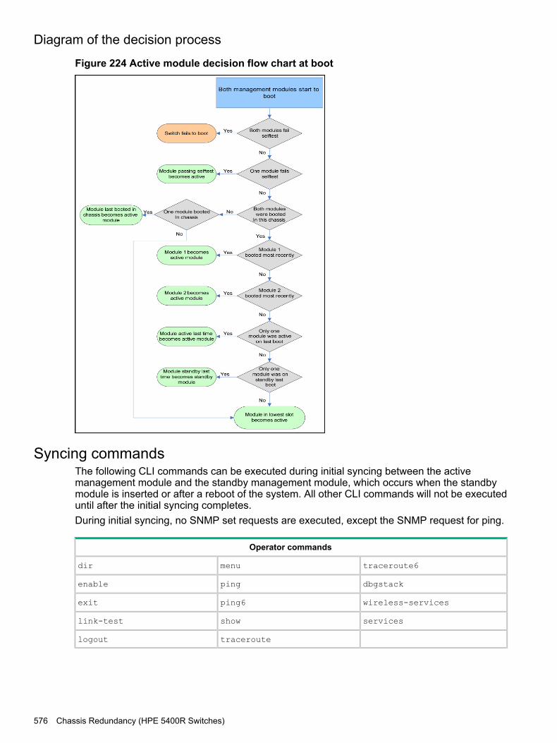
Diagram of the decision process
Figure 224 Active module decision flow chart at boot
Syncing commandsThe following CLI commands can be executed during initial syncing between the activemanagement module and the standby management module, which occurs when the standbymodule is inserted or after a reboot of the system. All other CLI commands will not be executeduntil after the initial syncing completes.During initial syncing, no SNMP set requests are executed, except the SNMP request for ping.
Operator commands
traceroute6menudir
dbgstackpingenable
wireless-servicesping6exit
servicesshowlink-test
traceroutelogout
576 Chassis Redundancy (HPE 5400R Switches)
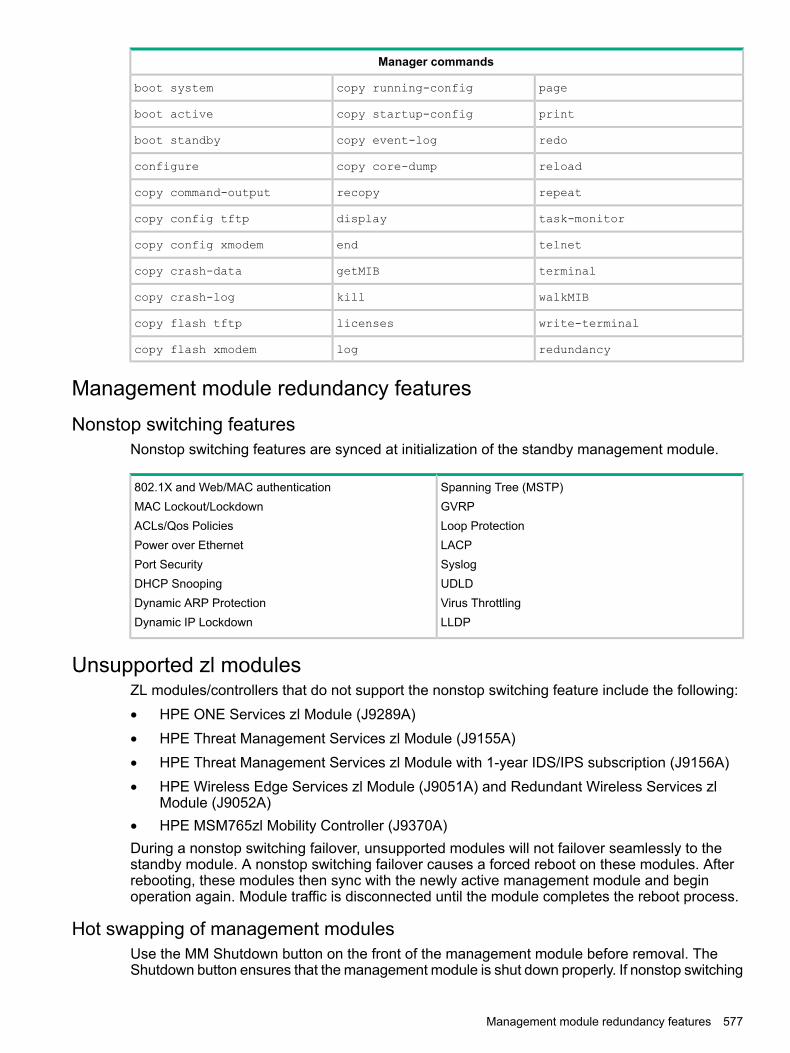
Manager commands
pagecopy running-configboot system
printcopy startup-configboot active
redocopy event-logboot standby
reloadcopy core-dumpconfigure
repeatrecopycopy command-output
task-monitordisplaycopy config tftp
telnetendcopy config xmodem
terminalgetMIBcopy crash-data
walkMIBkillcopy crash-log
write-terminallicensescopy flash tftp
redundancylogcopy flash xmodem
Management module redundancy featuresNonstop switching features
Nonstop switching features are synced at initialization of the standby management module.
Spanning Tree (MSTP)802.1X and Web/MAC authenticationGVRPMAC Lockout/LockdownLoop ProtectionACLs/Qos PoliciesLACPPower over EthernetSyslogPort SecurityUDLDDHCP SnoopingVirus ThrottlingDynamic ARP ProtectionLLDPDynamic IP Lockdown
Unsupported zl modulesZL modules/controllers that do not support the nonstop switching feature include the following:• HPE ONE Services zl Module (J9289A)• HPE Threat Management Services zl Module (J9155A)• HPE Threat Management Services zl Module with 1-year IDS/IPS subscription (J9156A)• HPE Wireless Edge Services zl Module (J9051A) and Redundant Wireless Services zl
Module (J9052A)• HPE MSM765zl Mobility Controller (J9370A)During a nonstop switching failover, unsupported modules will not failover seamlessly to thestandby module. A nonstop switching failover causes a forced reboot on these modules. Afterrebooting, these modules then sync with the newly active management module and beginoperation again. Module traffic is disconnected until the module completes the reboot process.
Hot swapping of management modulesUse the MM Shutdown button on the front of the management module before removal. TheShutdown button ensures that the management module is shut down properly. If nonstop switching
Management module redundancy features 577

is enabled, using the Shutdown button prior to removal ensures failover to the standby modulewill be successful.
Rapid routing switchover and stale timerWith K.15.01.0031, nonstop switching supports only Layer 2 functions on the switch. During afailover, traffic routed through the switch at Layer 3 will see an interruption. When a failover fromactive to standby occurs, the routing table is "frozen." All routes that existed at the time of thefailover are marked as "stale." While dynamic routing protocols running at the time may act asif the routing protocol has been restarted and rebuilds the table, the switch on which the failoveroccurred continues to rout traffic using the ‘stale routes.'The "stale timer" begins counting when the switchover occurs. When the "stale timer" expires,any routes that are still marked as stale are purged from the routing table. Because of the natureof rapid routing switchover, if there are multiple simultaneous failures, network loops could occuror traffic could flow through unpredictable paths.Use caution if setting the "rapid-switchover" timer higher than the default. To disable "rapid routingswitchover" and to ensure that all routing is based on the most current routing protocol information,set the "rapid-switchover" timer to 0.
Task Usage ReportingThe task usage reporting feature provides the ability to collect and display CPU usage data (witha refresh rate of 5 seconds) of running tasks on the switch. It includes the following commands:• process-tracking: This command is used to enable/disable the task-usage collecting
capability for a specific module on the switch.• show cpu process: This command is used to display task-usage statistics for a specific
module.
Help text
process-tracking helpUsage: [no] process-tracking [slot[SLOT-LIST] [<time>]] [<time>]
Description: Enable/disable module process-tracking functionality.
show cpu helpUsage:show cpu [<CHASSIS_MIN_CPU_UTIL_INDEX-CHASSIS_MAX_CPU_UTIL_INDEX>]
[slot <SLOT-LIST>[<CHASSIS_MIN_CPU_UTIL_INDEX-CHASSIS_MODULE_MAX_CPU_UTIL_INDEX>] ]
[process [[slot <SLOT-LIST>] [refresh <iterations>]]
[refresh <iterations>]
Description: Show average CPU utilization over the last 1, 5, and 60 seconds, or the number ofseconds specified.Use the 'slot' argument to display CPU utilization for the specified modules, rather than the chassisCPU.Use the 'process' argument to display module process usages.
show cpu process helpUsage: show cpu process [slot [SLOT-LIST][refresh <iterations>]]
[refresh <iterations>]
Description: Display module process usage.
578 Chassis Redundancy (HPE 5400R Switches)

Command tab
process-tracking
process-tracking <tab>slot Enable/disable process-tracking for a moduleINTEGER Specify time to track value between 1 second to 30 seconds<cr>
process-tracking slot <tab>SLOT-ID-RANGE Enter an alphabetic device slot identifier or slot range
process-tracking slot AINTEGER Specify time to track value between 1 second to 30 seconds<cr>
process-tracking slot A 10 <tab><cr>
process-tracking 10 <tab><cr>
show cpu process
show cpu <tab>process Display process usageslot Display module CPU statistics<1-300> Time (in seconds) over which to average CPU utilization<cr>
show cpu process <tab>refresh Number of times to refresh process usage displayslot Display module process usage<cr>
show cpu process refresh <tab>INTEGER Enter an integer number
show cpu process refresh 10 <tab><cr>
show cpu process slot <tab>SLOT-ID-RANGE Enter an alphabetic device slot identifier or slot range
show cpu process slot A <tab>refresh Number of times to refresh process usage display<cr>
show cpu process slot A refresh <tab>INTEGER Enter an integer number
Task Usage Reporting 579

show cpu process slot A refresh 10 <tab><cr>
Command ouput
show cpu processHPE-5406zl# show cpu process
| Recent | % | Time Since| Times | MaxProcess Name | Priority | Time | CPU | Last Ran | Ran | Time--------------------+----------+--------+-----+-----------+----------+-------
Idle-1 | 226 | 10 s | 41 | 57 us | 380986 | 69 usIdle-3 | 1 | 5 s | 20 | 52 us | 761665 | 55 usIdle-0 | 226 | 8 s | 33 | 19 us | 380867 | 66 us
Sessions & I/O-24 | 171 | 926 ms | 3 | 1 ms | 150 | 335 ms
show cpu process slot <SLOT-LIST>HPE-5406zl# show cpu process slot Aslot a:
| Recent | % | Time Since| Times | MaxProcess Name | Priority | Time | CPU | Last Ran | Ran | Time--------------------+----------+--------+-----+-----------+----------+-------System Services-2 | 156 | 253 ms | 2 | 767 ms | 12 | 35 ms
Idle-3 | 1 | 3 s | 28 | 13 ms | 101309 | 150 usHardware Mgmt-2 | 192 | 282 ms | 2 | 303 us | 44 | 12 ms
Idle-1 | 226 | 6 s | 55 | 13 ms | 50793 | 233 usIdle-0 | 226 | 1 s | 9 | 14 ms | 50633 | 106 us
580 Chassis Redundancy (HPE 5400R Switches)

B Smart Rate TechnologySmart Rate is a new technology designed to enable higher port link speeds on legacy cablingwhere an Ethernet RJ45 port type can link at 1Gbps, 2.5Gbps, 5Gbps, or 10Gbps.When situations occur where a network link establishes at a lower than expected speed (or notat all) due to marginal or bad cabling, the Smart Rate port technology allows administrators totriage cabling issues and determine root causes of lower than expected performance.Smart Rate Technology is available on the following products:Switch 5400R v3 zl2 modules (J9991A, J9995A)Switch 5400R chassis switch bundles (JL002A)
Show Smart Rate portSyntax
show interface PORT-LIST smartrate
Displays port diagnostics on a Smart Rate port.
Show Smart Rate port 581

Example 202 Unlinked Smart Rate port
show interface C5 smartrate
Status and Counters - Smart Rate information for Port C5
Model : 0x03a1Chip : 0xb4b3Firmware (major) : 0x0002Firmware (minor) : 0x0003Firmware (candidate) : 0x0005Firmware (provision) : 0x0001
Chan1 Chan2 Chan3 Chan4 (in db)Current SNR 9.000000 6.700000 3.500000 9.200000Minimum SNR 9.000000 6.700000 3.500000 9.200000
CRC8 errors: 0LDPC errors: 0LDPC 1 iteration: 27620089LDPC 2 iterations: 954117LDPC 3 iterations: 0LDPC 4 iterations: 0LDPC 5 iterations: 0LDPC 6 iterations: 0LDPC 7 iterations: 0LDPC 8 iterations: 0
23 Number of fast retrains requested by Local Device.32 Number of fast retrains requested by Link Partner.150 Accumulated time (ms) spent in fast retrain since last AN.9 Number of RFI Training Link Recovery Events since last AN.3 Number of Link Recover Events since last AN.
Established link speed : 5000MbpsNumber of attempts to establish link : 5Uptime since link was last established (ms) : 5099
Local port advertised speeds
1000Mbps 2500Mbps 5000Mbps 10GbpsNo Yes Yes No
Link partner speed capability
1000Mbps 2500Mbps 5000Mbps 10GbpsYes Yes Yes No
Link Partner matching vendor: Yes
582 Smart Rate Technology
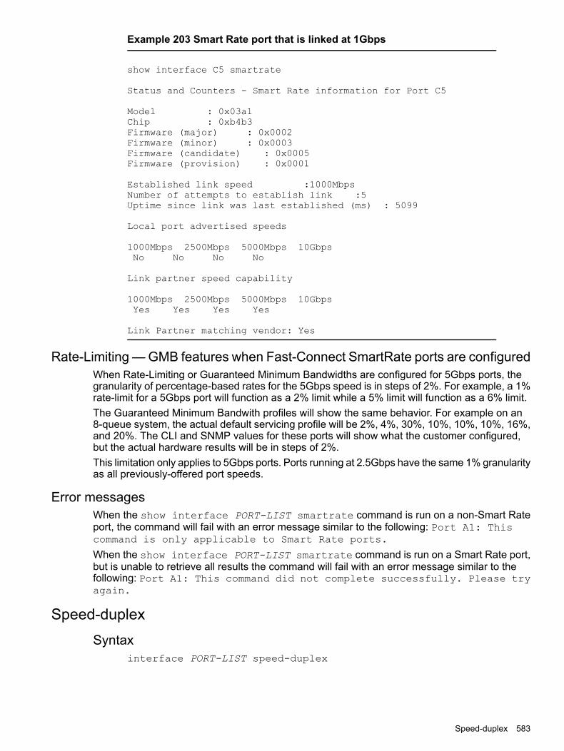
Example 203 Smart Rate port that is linked at 1Gbps
show interface C5 smartrate
Status and Counters - Smart Rate information for Port C5
Model : 0x03a1Chip : 0xb4b3Firmware (major) : 0x0002Firmware (minor) : 0x0003Firmware (candidate) : 0x0005Firmware (provision) : 0x0001
Established link speed :1000MbpsNumber of attempts to establish link :5Uptime since link was last established (ms) : 5099
Local port advertised speeds
1000Mbps 2500Mbps 5000Mbps 10GbpsNo No No No
Link partner speed capability
1000Mbps 2500Mbps 5000Mbps 10GbpsYes Yes Yes Yes
Link Partner matching vendor: Yes
Rate-Limiting — GMB features when Fast-Connect SmartRate ports are configuredWhen Rate-Limiting or Guaranteed Minimum Bandwidths are configured for 5Gbps ports, thegranularity of percentage-based rates for the 5Gbps speed is in steps of 2%. For example, a 1%rate-limit for a 5Gbps port will function as a 2% limit while a 5% limit will function as a 6% limit.The Guaranteed Minimum Bandwith profiles will show the same behavior. For example on an8-queue system, the actual default servicing profile will be 2%, 4%, 30%, 10%, 10%, 10%, 16%,and 20%. The CLI and SNMP values for these ports will show what the customer configured,but the actual hardware results will be in steps of 2%.This limitation only applies to 5Gbps ports. Ports running at 2.5Gbps have the same 1% granularityas all previously-offered port speeds.
Error messagesWhen the show interface PORT-LIST smartrate command is run on a non-Smart Rateport, the command will fail with an error message similar to the following: Port A1: Thiscommand is only applicable to Smart Rate ports.
When the show interface PORT-LIST smartrate command is run on a Smart Rate port,but is unable to retrieve all results the command will fail with an error message similar to thefollowing: Port A1: This command did not complete successfully. Please tryagain.
Speed-duplexSyntax
interface PORT-LIST speed-duplex
Speed-duplex 583
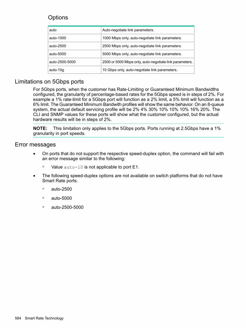
Options
Auto-negotiate link parameters.auto
1000 Mbps only, auto-negotiate link parameters.auto-1000
2500 Mbps only, auto-negotiate link parameters.auto-2500
5000 Mbps only, auto-negotiate link parameters.auto-5000
2500 or 5000 Mbps only, auto-negotiate link parameters.auto-2500-5000
10 Gbps only, auto-negotiate link parameters.auto-10g
Limitations on 5Gbps portsFor 5Gbps ports, when the customer has Rate-Limiting or Guaranteed Minimum Bandwidthsconfigured, the granularity of percentage-based rates for the 5Gbps speed is in steps of 2%. Forexample a 1% rate-limit for a 5Gbps port will function as a 2% limit, a 5% limit will function as a6% limit. The Guaranteed Minimum Bandwith profiles will show the same behavior. On an 8-queuesystem, the actual default servicing profile will be 2% 4% 30% 10% 10% 10% 16% 20%. TheCLI and SNMP values for these ports will show what the customer configured, but the actualhardware results will be in steps of 2%.
NOTE: This limitation only applies to the 5Gbps ports. Ports running at 2.5Gbps have a 1%granularity in port speeds.
Error messages• On ports that do not support the respective speed-duplex option, the command will fail with
an error message similar to the following:
◦ Value auto-10 is not applicable to port E1.
• The following speed-duplex options are not available on switch platforms that do not haveSmart Rate ports.
◦ auto-2500
◦ auto-5000
◦ auto-2500-5000
584 Smart Rate Technology

C Time Domain ReflectometryThe Time Domain Reflectometry (TDR) is a new port feature supported on Aruba 3810M switchesand Aruba 5400R v3 blades. TDR is introduced to detect cable faults on 100BASE-TX and1000BASE-T ports.
Supported PlatformsAruba 3810M switchesAruba 5400R v3 blades (J9986A, J9987A, J9989A, J9990A, J9991A [applicable only for ports1–20, rest of the four ports are Smart Rate ports], and J9992A)
Virtual cable testingThe Virtual Cable Test (VCT) uses the same command as TDR. It is applicable only for GigTtransceivers like copper transceiver (J8177C–ProCurve Gigabit 1000Base-T Mini-GBIC). TheVCT test results include distance to the fault, but not the cable length.
Test cable-diagnosticsSyntaxtest cable-diagnostics <PORT-LIST>
DescriptionUse the command to test for cable faults.
OptionPORT-LIST
Specify copper port as a input port number.
Virtual cable testing 585

Example 204 Test cable-diagnostics C21
test cable-diagnostics C21
The 'test cable-diagnostics' command will cause a loss of link and will take a few seconds per interface tocomplete.Continue [Y/N]? y
MDI Cable Distance Pair Pair MDIPort Pair Status to Fault Skew Polarity Mode--------- ------ -------- ----- ------ ------C21 1-2 Open 0 m 0 ns
3-6 Open 0 m 0 ns4-5 Open 0 m 0 ns7-8 Open 1 m 0 ns
Example 205 Test cable-diagnostics 1/1-1/10
switch# test cable-diagnostics 1/1-1/10
This command will cause a loss of link on all tested ports and will takeseveral seconds per port to complete. Use the ‘show cable-diagnostics’ command to viewthe results.
Continue (y/n)? Y
switch# show cable-diagnostics 1/1-1/10
Cable Diagnostic Status - Copper Ports
MDI Cable Cable Length orPort Pair Status Distance to Fault---- ------ ----------- ---------------------1/1 1-2 OK 5m
3-6 OK 5m4-5 OK 7m7-8 OK 7m
1/2 1-2 OK 7m3-6 OK 7m4-5 OK 7m7-8 OK 7m
1/3 1-2 OK 5m3-6 OK 7m4-5 OK 5m7-8 OK 7m
1/4 1-2 OK 7m3-6 OK 7m4-5 OK 7m7-8 OK 5m
1/5 1-2 OK 4m3-6 OK 5m4-5 OK 5m7-8 OK 4m
1/6 1-2 OK 4m3-6 OK 4m4-5 OK 4m7-8 OK 4m
1/7 1-2 OK 5m3-6 OK 4m4-5 OK 5m7-8 OK 4m
1/8 1-2 OK 4m3-6 OK 5m4-5 OK 4m7-8 OK 4m
1/9 1-2 OK 5m3-6 OK 5m4-5 OK 5m7-8 OK 5m
1/10 1-2 OK 7m3-6 OK 5m4-5 OK 5m7-8 OK 5m
586 Time Domain Reflectometry

Example 206 Good cable tests
switch# test cable-diagnostics 51
This command will cause a loss of link on all tested ports and will takeseveral seconds per port to complete. Use the 'show cable-diagnostics'command to view the results.
Continue (y/n)? Y
switch# show cable-diagnostics 51
Cable Diagnostic Status - Transceiver Ports
MDI Cable Distance Pair Pair MDIPort Pair Status to Fault Skew Polarity Mode---- ------ --------- -------- ----- ------- -----51 1-2 OK 0 m 8 ns Normal MDI
3-6 OK 0 m 8 ns Normal4-5 OK 0 m 8 ns Normal MDIX7-8 OK 0 m 0 ns Normal
switch# test cable-diagnostics 52
This command will cause a loss of link on all tested ports and will takeseveral seconds per port to complete. Use the 'show cable-diagnostics'command to view the results.
Continue (y/n)? Y
switch# show cable-diagnostics 52
Cable Diagnostic Status - Transceiver Ports
MDI Cable Distance Pair Pair MDIPort Pair Status to Fault Skew Polarity Mode---- ------ --------- -------- ----- ------- -----52 1-2 OK 0 m 0 ns Normal MDI
3-6 OK 0 m 0 ns Normal4-5 OK 0 m 0 ns Normal MDIX7-8 OK 0 m 0 ns Normal
Test cable-diagnostics 587

Example 207 Faulty cable test
switch# test cable-diagnostics 51This command will cause a loss of link on all tested ports and will takeseveral seconds per port to complete. Use the 'show cable-diagnostics'command to view the results.
Continue (y/n)? yswitch# show cable-diagnostics 51
Cable Diagnostic Status - Transceiver Ports
MDI Cable Distance Pair Pair MDIPort Pair Status to Fault Skew Polarity Mode---- ------ ----------- ---------- ------ ---------- ------51 1-2 OK 0 m 0 ns
3-6 Short 1 m 0 ns4-5 Short 1 m 0 ns7-8 OK 0 m 0 ns
switch# test cable-diagnostics 52
This command will cause a loss of link on all tested ports and will takeseveral seconds per port to complete. Use the 'show cable-diagnostics'command to view the results.
Continue (y/n)? Y
switch# show cable-diagnostics 52
Cable Diagnostic Status - Transceiver Ports
MDI Cable Distance Pair Pair MDIPort Pair Status to Fault Skew Polarity Mode---- ------ ----------- ---------- ------ ---------- ------52 1-2 Open 0 m 0 ns
3-6 Open 0 m 0 ns4-5 Open 1 m 0 ns7-8 Open 0 m 0 ns
Error message
CauseError Message
The transceiver on port 1/A1 doesnot support cable diagnostics.
• usage of invalid(fiber-SFP+) port
• The selected range includes an entry for an invalid port.
show cable-diagnosticsSyntaxshow cable-diagnostics <PORT-LIST>
DescriptionUse the command to generate results of completed tests on single or multiple ports. For incompletetests, a warning is displayed.
OptionPORT
588 Time Domain Reflectometry

Specify one copper port as an input port number.
clear cable-diagnosticsSyntaxclear cable-diagnostics
DescriptionUse the command to clear the result buffer.
Example 208
switch(config)# clear cable-diagnostics
LimitationsTDR has the following limitations:• TDR length accuracy is ± 5 m• Does not work on Smart Rate Interfaces with 10GBASE-T and NGBASE-T (2.5G, 5G copper)
ports available on:
◦ v3 bladesJ9991A — HP 20p PoE+ 4p 10GBT(SR)–
– J9995A — HP 8p 1/2.5/5/10GBT(SR)
◦ 3810M (HP JL076A 3810M 40G 8SR PoE+ 1-slot [Ports 1–8])
• Not supported on v2 zl modules• Valid only on 100BASE-TX and 1000BASE-T ports
clear cable-diagnostics 589

D HPE Networking 6th Generation Switch ASICIntroduction
The HPE Networking 6th Generation Switch ASIC based module creates compatibility betweenv2 and v3 blades on the 5400R Chassis Switches. When the 5400R Chassis Switch platformdetects a mix of v2 and v3 blades, the v3 feature will default the platform to v2 behavior. Thedefault behavior is v2.The compatibility mode of v2 and v3 modules are controlled by configuration. When thecompatibility mode is disabled, v2 modules in the system will be disabled.
CommandsConfiguration commands enable/disable the 5400R Chassis Switch platform v2/v3 interoperability.
Configuration setup
Syntax[no]allow-v2-modulesEnables support for V2 modules. When enabled, V3 modules will operate inV2-compatiblity mode. When disabled, V3 modules will have full functionality andthe ports of any V2 modules will be non-operable. Enabling the V2 module supporterases the current configuration of the device and reboots the device. Whereas,disabling the V2 module support clears all V2 module specific configuration fromstartup configuration and reboots the device.allow-v2-modules Enable support for V2 modules.
Example 209 Enabled/Disabled state
When V2 compatibility mode is disabled from an enabled state, the below messageis displayed for user input.
HP-5406Rzl2(config)# no allow-v2-modulesThis command will disable all V2 modules and reboot the switch.Continue (y/n)?
When V2 compatibility mode is enabled from disabled state, the below messageis displayed for user input.
HP-5406Rzl2(config)# allow-v2-modulesThis command will erase the current configuration of the switch and rebootit.Continue (y/n)?
Show commandsThe show module command shows the configuration status of allowed V2 modules. The outputwill be available only for the 5400R Chassis Switches.
Show system
Syntaxshow system
590 HPE Networking 6th Generation Switch ASIC

Example 210 Show system output
Status and Counters - General System Information
System Name : HP-5406Rzl2System Contact :System Location :Allow V2 Modules : YesMAC Age Time (sec) : 300Time Zone : 0Daylight Time Rule : NoneSoftware revision : KB.15.16.0000x Base MAC Addr :40a8f0-9d6f00ROM Version : KB.15.Z1.0012 Serial Number : SG44G490FZ
Opacity Shields : Not Installed
Up Time : 7 mins Memory - Total :763,846,656CPU Util (%) : 0 Free : 646,757,632
IP Mgmt - Pkts Rx : 106 Packet - Total : 6750Pkts Tx : 111 Buffers Free : 4830
Lowest : 4828Missed : 0
Show system information
Syntaxshow system information
Example 211 Show system information output
Status and Counters - General System Information
System Name : HP-5406Rzl2System Contact :System Location :Allow V2 Modules : YesMAC Age Time (sec) : 300Time Zone : 0Daylight Time Rule : NoneSoftware revision : KB.15.16.0000x Base MAC Addr :40a8f0-9d6f00ROM Version : KB.15.Z1.0012 Serial Number :SG44G490FZ
Opacity Shields : Not Installed
Up Time : 7 mins Memory - Total : 763,846,656CPU Util (%) : 0 Free : 646,757,632
IP Mgmt - Pkts Rx : 106 Packet - Total : 6750Pkts Tx : 111 Buffers Free : 4830
Lowest : 4828Missed : 0
Show running configurationThe show running-config command shows the entry when disabled. This output will beavailable on 5400R Chassis Switches only.
Syntaxshow running-config
Commands 591
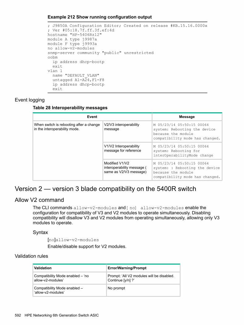
Example 212 Show running configuration output
; J9850A Configuration Editor; Created on release #KB.15.16.0000x; Ver #05:18.7f.ff.3f.ef:4dhostname "HP-5406Rzl2"module A type j9987amodule F type j9993ano allow-v2-modulessnmp-server community "public" unrestrictedoobmip address dhcp-bootpexit
vlan 1name "DEFAULT_VLAN"untagged A1-A24,F1-F8ip address dhcp-bootpexit
Event loggingTable 28 Interoperability messages
MessageEvent
M 05/23/14 05:50:15 00064system: Rebooting the device
V2/V3 interoperabilitymessage
When switch is rebooting after a changein the interoperability mode.
because the modulecompatibility mode has changed.
M 05/23/14 05:50:15 00064system: Rebooting forinterOperabilityMode change
V1/V2 Interoperabilitymessage for reference
M 05/23/14 05:50:15 00064system: : Rebooting the device
Modified V1/V2interoperability message (same as V2/V3 message) because the module
compatibility mode has changed.
Version 2 — version 3 blade compatibility on the 5400R switchAllow V2 command
The CLI commands allow-v2-modules and [no] allow-v2-modules enable theconfiguration for compatibility of V3 and V2 modules to operate simultaneously. Disablingcompatibility will disallow V3 and V2 modules from operating simultaneously, allowing only V3modules to operate.
Syntax[no]allow-v2-modulesEnable/disable support for V2 modules.
Validation rules
Error/Warning/PromptValidation
Prompt: ‘All V2 modules will be disabled.Continue [y/n] ?’
Compatibility Mode enabled – ‘noallow-v2-modules’
No promptCompatibility Mode enabled –‘allow-v2-modules’
592 HPE Networking 6th Generation Switch ASIC
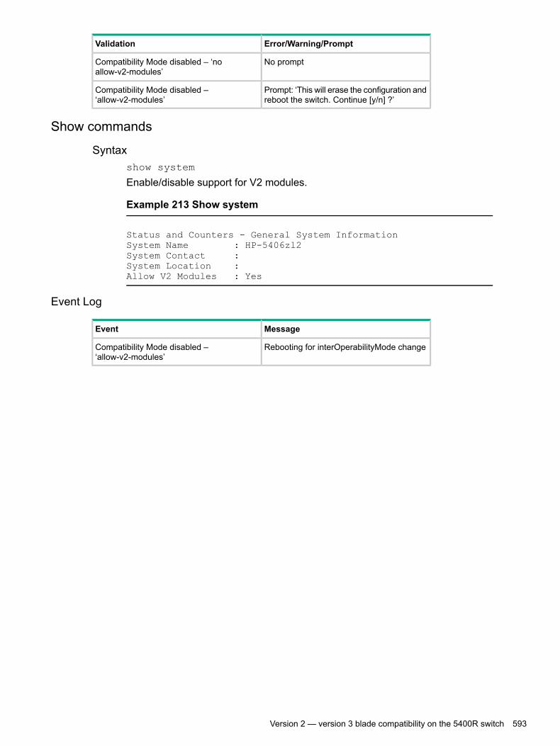
Error/Warning/PromptValidation
No promptCompatibility Mode disabled – ‘noallow-v2-modules’
Prompt: ‘This will erase the configuration andreboot the switch. Continue [y/n] ?’
Compatibility Mode disabled –‘allow-v2-modules’
Show commands
Syntaxshow system
Enable/disable support for V2 modules.
Example 213 Show system
Status and Counters - General System InformationSystem Name : HP-5406zl2System Contact :System Location :Allow V2 Modules : Yes
Event Log
MessageEvent
Rebooting for interOperabilityMode changeCompatibility Mode disabled –‘allow-v2-modules’
Version 2 — version 3 blade compatibility on the 5400R switch 593

E MAC Address ManagementOverview
The switch assigns MAC addresses in these areas:• For management functions, one Base MAC address is assigned to the default VLAN (VID
= 1.) (All VLANs on the switches covered in this guide use the same MAC address.)• For internal switch operations: One MAC address per port.MAC addresses are assigned at the factory. The switch automatically implements these addressesfor VLANs and ports as they are added to the switch.
NOTE: The switch’s base MAC address is also printed on a label affixed to the switch.
Determining MAC addressesUse the CLI to view the switch's port MAC addresses in hexadecimal format.Use the menu interface to view the switch's base MAC address and the MAC addressassigned to any VLAN you have configured on the switch. (The same MAC address is assignedto VLAN1 and all other VLANs configured on the switch.)
NOTE: The switch's base MAC address is used for the default VLAN (VID =1) that is alwaysavailable on the switch. This is true for dynamic VLANs as well; the base MAC address is thesame across all VLANs.
Viewing the MAC addresses of connected devicesSyntax
show mac-address [ <PORT-LIST> | mac-addr | vlan vid ]
Lists the MAC addresses of the devices the switch has detected, along with thenumber of the specific port on which each MAC address was detected.
Lists the MAC addresses of the devices the switch hasdetected, on the specified ports.
[<PORT-LIST>]
Lists the port on which the switch detects the specifiedMAC address.
[mac-addr]
Returns the following message if the specified MACaddress is not detected on any port in the switch:MAC address mac-addr not found.
Lists the MAC addresses of the devices the switch hasdetected on ports belonging to the specified VLAN, along
[vlan vid ]
with the number of the specific port on which each MACaddress was detected.
Viewing the switch's MAC address assignments for VLANs configuredon the switch
The Management Address Information screen lists the MAC addresses for:• Base switch (default VLAN; VID=1)• Any additional VLANs configured on the switch.Also, the Base MAC address appears on a label on the back of the switch.
594 MAC Address Management

NOTE: The Base MAC address is used by the first (default) VLAN in the switch. This is usuallythe VLAN named "DEFAULT_VLAN" unless the name has been changed (by using the VLANNames screen.) On the switches covered in this guide, the VID (VLAN identification number) forthe default VLAN is always "1," and cannot be changed.
• From the Main Menu, select1. Status and Counters2. Switch Management Address InformationIf the switch has only the default VLAN, the following screen appears. If the switchhas multiple static VLANs, each is listed with its address data.
Figure 225 Example of the Management Address Information screen
Viewing the port and VLAN MAC addressesThe MAC address assigned to each switch port is used internally by such features as Flow Controland the spanning-tree protocol. Using the walkmib command to determine the MAC addressassignments for individual ports can sometimes be useful when diagnosing switch operation.
Table 29 Switch series' and their MAC address allocations
MAC address allocationSwitch series
The switch allots 24 MAC addresses per slot. For a given slot, if afour-port module is installed, the switch uses the first four MAC
8212zl
addresses in the allotment for that slot, and the remaining 18 MACaddresses are unused.If a 24-port module is installed, the switch uses the first 24 MACaddresses in the allotment, and so on.
The switch's base MAC address is assigned to VLAN (VID) 1 andappears in the walkmib listing after the MAC addresses for the ports.(All VLANs in the switch have the same MAC address.)
All Models
NOTE: This procedure displays the MAC addresses for all ports and existing VLANs in theswitch, regardless of which VLAN you select.
1. If the switch is at the CLI Operator level, use the enable command to enter the Managerlevel of the CLI.
2. Enter the following command to display the MAC address for each port on the switch:
HP Switch# walkmib ifPhysAddress
(The above command is not case-sensitive.)
Viewing the switch's MAC address assignments for VLANs configured on the switch 595

ExampleA 8212zl switch with the following module configuration shows MAC addressassignments similar to those shown in Figure 226 (page 596):• A 4-port module in slot A, a 24-port module in slot C, and no modules in slots
B and D• Two non-default VLANs configured
Figure 226 Example of Port MAC address assignments on a switch
NOTE: When configuring an "out" monitor on a VLAN or an interface to a remote mirror, themirrored packet will always be untagged when the original packet arrives on a zlV2 module, ora 3800 series.When configuring a "both" monitor on an interface to a remote mirror, tags will not be present inthe mirrored packet in these specific situations:• For an interface monitor, packets transmitted by the monitored port that originally arrived on
a zlV2 module or 3800 port.• For a VLAN monitor, packets routed onto the monitored VLAN that originally arrived on a
zlV2 module or 3800 port.
596 MAC Address Management

F Network Out-of-Band Management (OOBM)OOBM Configuration
OOBM configuration commands can be issued from the global configuration context (config) orfrom a specific OOBM configuration context (oobm.)
Entering the OOBM configuration context from the general configuration context
Syntaxoobm
Enters the OOBM context from the general configuration context.
Example
HP Switch (config)# oobmHP Switch (oobm)#
Enabling and disabling OOBMFrom the OOBM context:
Syntaxenabledisable
From the general configuration context:
Syntaxoobm enableoobm disable
Enables or disables networked OOBM on the switch.OOBM is not compatible with either a management VLAN or stacking. If youattempt to enable OOBM when a management VLAN is enabled or when stackingis enabled, the command will be rejected and you will receive an error message.If an OOBM IP address exists and you disable OOBM, the OOBM IP addressconfiguration is maintained. If you enable OOBM and there is a pre-existing OOBMIP address, it will be reinstated.Network OOBM is enabled by default.
Examples
HP Switch (oobm)# enableHP Switch (oobm)# disableHP Switch (config)# oobm enableHP Switch (config)# oobm disable
Enabling and disabling the OOBM portThe OOBM interface command enables or disables the OOBM interface (that is, the OOBMport, as opposed to the OOBM function.)From the OOBM context:
OOBM Configuration 597
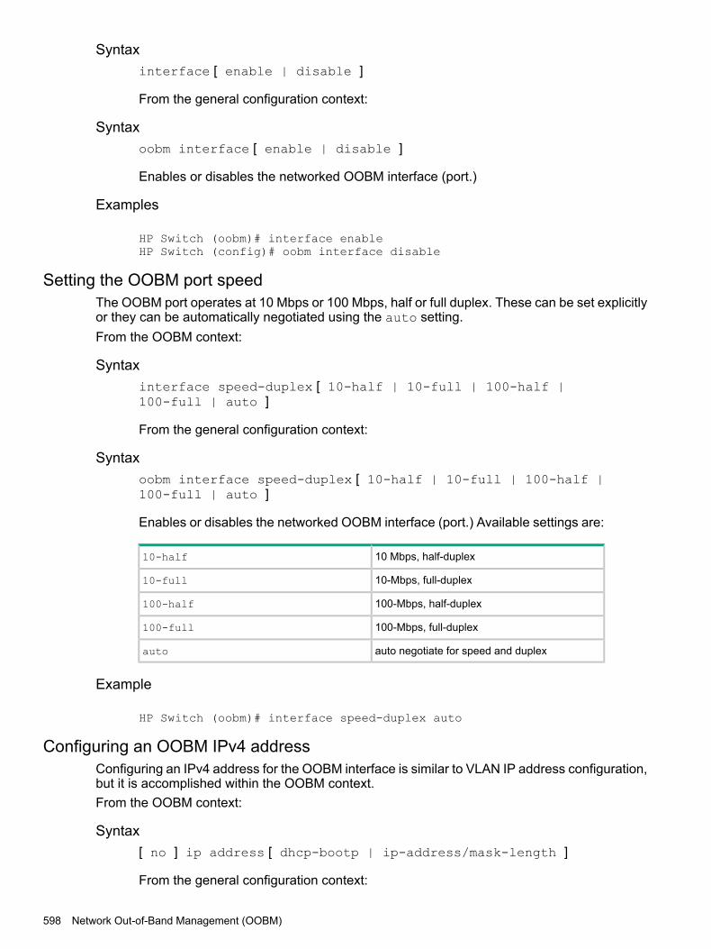
Syntaxinterface [ enable | disable ]
From the general configuration context:
Syntaxoobm interface [ enable | disable ]
Enables or disables the networked OOBM interface (port.)
Examples
HP Switch (oobm)# interface enableHP Switch (config)# oobm interface disable
Setting the OOBM port speedThe OOBM port operates at 10 Mbps or 100 Mbps, half or full duplex. These can be set explicitlyor they can be automatically negotiated using the auto setting.From the OOBM context:
Syntaxinterface speed-duplex [ 10-half | 10-full | 100-half |100-full | auto ]
From the general configuration context:
Syntaxoobm interface speed-duplex [ 10-half | 10-full | 100-half |100-full | auto ]
Enables or disables the networked OOBM interface (port.) Available settings are:
10 Mbps, half-duplex10-half
10-Mbps, full-duplex10-full
100-Mbps, half-duplex100-half
100-Mbps, full-duplex100-full
auto negotiate for speed and duplexauto
Example
HP Switch (oobm)# interface speed-duplex auto
Configuring an OOBM IPv4 addressConfiguring an IPv4 address for the OOBM interface is similar to VLAN IP address configuration,but it is accomplished within the OOBM context.From the OOBM context:
Syntax[ no ] ip address [ dhcp-bootp | ip-address/mask-length ]
From the general configuration context:
598 Network Out-of-Band Management (OOBM)

Syntax[ no ] oobm ip address [ dhcp-bootp | ip-address/mask-length]
Configures an IPv4 address for the switch's OOBM interface.You can configure an IPv4 address even when global OOBM is disabled; thataddress will become effective when OOBM is enabled.
Example
HP Switch (oobm)# ip address 10.1.1.17/24
Configuring an OOBM IPv4 default gatewayConfiguring an IPv4 default gateway for the OOBM interface is similar to VLAN default gatewayconfiguration, but it is accomplished within the OOBM context.From the OOBM context:
Syntax[ no ] ip default-gateway ip-address
From the general configuration context:
Syntax[ no ] oobm ip default-gateway ip-address
Configures an IPv4 default gateway for the switch's OOBM interface.
Example
HP Switch (oobm)# ip default-gateway 10.1.1.1
OOBM show commandsThe show commands for OOBM are similar to the analogous commands for the data plane. Notethat you must always include the oobm parameter to see the information for the OOBM interface,regardless of the context. For instance, even from the OOBM context, the show ip commanddisplays the IP configuration for the data plane; to see the IP configuration of the OOBM interface,you need to use show oobm ip.
Showing the global OOBM and OOBM port configuration
Syntaxshow oobm
Summarizes OOBM configuration information. This command displays the globalOOBM configuration (enabled or disabled), the OOBM interface status (up ordown), and the port status (enabled/disabled, duplex, and speed.)You can issue this command from any context
Example
HP Switch# show oobm
Global ConfigurationOOBM Enabled : YesOOBM Port Type : 10/100TX
OOBM show commands 599

OOBM Interface Status : UpOOBM Port : EnabledOOBM Port Speed : Auto
Showing OOBM IP configuration
Syntaxshow oobm ip
Summarizes the IP configuration of the OOBM interface. This command displaysthe status of IPv4 (enabled/disabled), the IPv4 default gateway, and the IPv4address configured for the interface.You can issue this command from any context.
Example
HP Switch# show oobm ip
Showing OOBM ARP information
Syntaxshow oobm arp
Summarizes the ARP table entries for the OOBM interface.You can issue this command from any context.
ExampleHP Switch# show oobm arp
Application server commandsApplication servers (as described in OOBM and server applications in “Concepts” (page 603))have added a listen keyword with oobm|data|both options to specify which interfaces areactive.Default value is both for all servers.
Syntaxtelnet-server [listen oobm | data | both ]
Syntaxip ssh [listen oobm | data | both ]
Syntaxsnmp-server [listen oobm | data | both ]
Syntaxtftp server [listen oobm | data | both ]
Syntaxweb-management [listen oobm | data | both ]In all cases, show running-config displays the server configurations.Use the no form of the command to prevent the server from running on either interface.
600 Network Out-of-Band Management (OOBM)

ExamplesTelnet: no telnet-server
SSH: no ip ssh …
SNMP: no snmp-server …
TFTP: no tftp server
HTTP: no web-management …
The show servers command shows the listen mode of the servers:
HP Switch# show serversServer listen mode
Server Listen mode-----------------------------Telnet | bothSsh | bothTftp | bothWeb-management | bothSnmp | both
Application client commandsCLI commands for client applications have added the oobm keyword to allow you to specify thatthe outgoing request be issued from the OOBM interface. If you do not specify the oobm keyword,the request will be issued from the appropriate in-band data interface. Command syntax is:Telnet:telnet ip-address [oobm]
Management and Configuration Guide
TFTP:copy tftp ... ip-address filename... [oobm]
Management and Configuration Guide
SNTP:[ no ] sntp server priority priority ip-address [oobm] [version]
Management and Configuration Guide
TIMEP:[ no ] ip timep [ dhcp | manual ip-address | [oobm]]
Management and Configuration Guide
RADIUS:[ no ] radius-server host ip-address [oobm]
Access Security Guide
TACACS+:[ no ] tacacs-server host ip-address [oobm]
Access Security Guide
DNS:[ no ] ip dns server-address priority priority ip-address [oobm]
Management and Configuration Guide
Syslog:[ no ] logging ip-address [[control-descr] | [oobm]]
Management and Configuration Guide
Ping:
Application client commands 601

ping [ ...] [source [ ip-address | vlan-id | oobm ]]Management and Configuration Guide
Traceroute:traceroute [...] [source [ ip-address | vlan-id | oobm ]]
Management and Configuration Guide
ExampleFigure 227 (page 602) shows setup and use of network OOBM using the commandsdescribed above.Assume that the figure below describes how you want to set up your data center.
Figure 227 Example data center
Assume that you are configuring the switch in the left-hand rack to communicateon both the data and management networks. You might do the following:• Configure an IP address on the data network.• Verify that out-of-band management is enabled. (It is enabled by default.)• Configure an IP address on the management network.• Verify that the switch can communicate on both networks.The CLI commands that follow would accomplish those tasks. (The first timethrough the process you might easily make the omission shown near the end ofthe example.)
Switch 41# configSwitch 41(config)# vlan 1Switch 41(vlan-1)# ip address 10.1.129.7/20 Set up IP address on data network.Switch 41(vlan-1)# end Exit back to manager context.Switch 41# show oobm Look at default OOBM configuration.
Global ConfigurationOOBM Enabled : YesOOBM Port Type : 10/100TXOOBM Interface Status : Up Defaults look appropriate.OOBM Port : EnabledOOBM Port Speed : Auto
Switch 41# configSwitch 41(config)# oobm Go to OOBM context andSwitch 41(oobm)# ip address 10.255.255.41/24 add IP address andSwitch 41(oobm)# ip default-gateway 10.255.255.1 default gateway.Switch 41(oobm)# end Exit back to manager context.
602 Network Out-of-Band Management (OOBM)

Switch 41# ping 10.1.131.44 Ping server in this rack (on data network.)10.1.131.44 is alive, time = 19 msSwitch 41# ping 10.1.131.51 Ping server in adjacent rack.10.1.131.51 is alive, time = 15 msSwitch 41# ping 10.255.255.42 Ping switch in adjacent rack.The destination address is unreachable. Oops! It’s on the management network.Switch 41# ping source oobm 10.255.255.42 Go through the management port10.255.255.42 is alive, time = 2 ms and it works fine.Switch 41#
ConceptsManagement communications with a managed switch can be:• In band—through the networked data ports of the switch• Out of band—through a dedicated management port (or ports) separate from the data portsOut-of-band ports have typically been serial console ports using DB-9 or specially wired 8-pinmodular (RJ-style) connectors. Some recent switches have added networked OOBM ports.Figure 228 (page 603) shows management connections for a typical switch.
Figure 228 Management ports
OOBM operates on a "management plane" that is separate from the "data plane" used by datatraffic on the switch and by in-band management traffic. That separation means that OOBM cancontinue to function even during periods of traffic congestion, equipment malfunction, or attackson the network. In addition, it can provide improved switch security: a properly configured switchcan limit management access to the management port only, preventing malicious attempts togain access via the data ports.Network OOBM typically occurs on a management network that connects multiple switches. Ithas the added advantage that it can be done from a central location and does not require anindividual physical cable from the management station to each switch's console port.Table 30 (page 603) summarizes the switch management ports.
Table 30 Switch management ports
Out of bandIn band
NetworkedDirectly connectedNetworked
Command line (CLI), menuCommand line (CLI), menuCommand line (CLI), menu,Web
Management interface
Management planeManagement planeData planeCommunication plane
Concepts 603
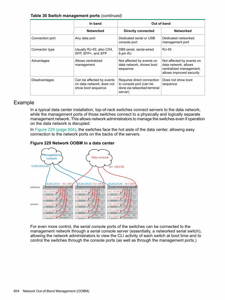
Table 30 Switch management ports (continued)
Out of bandIn band
NetworkedDirectly connectedNetworked
Dedicated networkedmanagement port
Dedicated serial or USBconsole port
Any data portConnection port
RJ-45DB9 serial, serial-wired8-pin RJ
Usually RJ-45; also CX4,SFP, SFP+, and XFP
Connector type
Not affected by events ondata network, allows
Not affected by events ondata network, shows bootsequence
Allows centralizedmanagement
Advantages
centralized management,allows improved security
Does not show bootsequence
Requires direct connectionto console port (can be
Can be affected by eventson data network; does notshow boot sequence
Disadvantages
done via networked terminalserver)
ExampleIn a typical data center installation, top-of-rack switches connect servers to the data network,while the management ports of those switches connect to a physically and logically separatemanagement network. This allows network administrators to manage the switches even if operationon the data network is disrupted.In Figure 229 (page 604), the switches face the hot aisle of the data center, allowing easyconnection to the network ports on the backs of the servers.
Figure 229 Network OOBM in a data center
For even more control, the serial console ports of the switches can be connected to themanagement network through a serial console server (essentially, a networked serial switch),allowing the network administrators to view the CLI activity of each switch at boot time and tocontrol the switches through the console ports (as well as through the management ports.)
604 Network Out-of-Band Management (OOBM)

OOBM and switch applicationsThe table below shows the switch applications that are supported on the OOBM interface as wellas on the data interfaces. In this list, some applications are client-only, some are server-only,and some are both.
Outbound dataplane (client)
Inbound data plane(server)
Outbound OOBM(client)
Inbound OOBM(server)
Application
yesyesyesyesTelnetN/AyesN/AyesSSH
yesyesyes*yesSNMP
yesyesyesyesTFTPN/AyesN/AyesHTTP
yesN/AyesN/ASNTP
yesN/AyesN/ATIMEP
yesN/AyesN/ARADIUS
yesN/AyesN/ATACACS
yesN/AyesN/ADNS**
yesN/AyesN/ASyslog
yesyes***yesyes***Ping
yesyes***yesyes***TracerouteN/AN/A = not applicable* *=SNMP client refers to SNMP traps as they originate from the switch.** **=DNS has a limit of two servers—primary and secondary. Either can be configured to use the OOBM interface.*** ***=Ping and Traceroute do not have explicit servers. Ping and Traceroute responses are sent by the host stack.
For applications that have servers, oobm/data/both options have been added to listen mode.There is now a listen keyword in the CLI commands to allow selection of those options. Defaultvalue is both for all servers.
Concepts 605

Index
AACL
transferring command files, 410ACL criteria
configuring inbound traffic, 435, 439Add-Ignore-Tag
configuring, 307show logging, 308
Add-ignore-tag, 306AirWave, 346
amp-server, 362best practices, 346configuring in DHCP (alternate method), 352configuring in DHCP (preferred method), 347configuring the switch, 347configuring the switch using CLI, 360debug ztp, 363limitations, 346requirements, 346stacking and chassis switches, 361troubleshooting, 361
viewing AMP server messages, 361using ZTP, 346validation rules, 361viewing configuration details, 362Zero Touch Provisioning, 359
AirWave Network Management, 346Aruba AP
auto configuration and detection, 364auto device configuration and detection, 364
limitations, 364requirements, 364
rogue AP isolation, 368feature interactions, 369limitations, 369
troubleshooting, 373using the show command, 374validation rules, 374
Authentication keysenryption keys, 384
Auto-MDI/MDI-Xconfiguring, 102
Autorunbehavior when USB port is disabled, 396configuring passwords, 395operations
secure-mode, 395secure mode, 395
BBootp/DHCP, LLDP, 281Broadcast limit
configuring, 193Broadcast mode
SNTP, 67Broadcast storm
definition, 150event logs, 150
CCaptive Portal, 336
authentication command, 344best practices, 337configuring a certificate, 341configuring on CPPM, 338configuring the switch, 340debug command, 344disabled, 338disabling, 338displaying configuration, 342features, 337
high availability, 337load balancing, 337redundancy, 337
limitations, 337requirements, 336show command, 344showing certificate, 342troubleshooting, 342
authenticated user redirected to login page, 343cannot enable Captive Portal, 342event timestamp not working, 342unable to configure a URL hash key, 343unable to enable feature, 343
CDP, 272configuring mode, 267enabling/disabling operation, 269filtering information, 269
CDP configurationviewing current configuration, 270
CDP neighborsviewing current table, 270
CDP operation, 272CDPv2
configuring voice transmission, 267Classifier-based mirroring
configuring, 445viewing configuration
viewing, 447ClearPass, 336CLI
context level, 99CLI passthrough
services, 93Command syntax
[no] front-panel-security diagnostic-reset, 486[no] front-panel-security diagnostic-reset clear-button,
487[no] front-panel-security diagnostic-reset serial-console,
490authoritative, 312auto-tftp, 381boot boot set-default flash, 554
606 Index

boot system flash, 379, 389, 391, 407bootfile-name<filename>, 312broadcast-limit, 193cdp enable, 269cdp mode pre-standard-voice, 267cdp moden, 267cdp run, 269chassislocate
blink|on|off, 419on|blink, 419
class ipv4|ipv6 , 435class ivp4|ipv6, 439clear cable diagnostics, 589clear cdp counters, 484clear lacp statistics, 376clear link-keepalive statistics, 111, 112clear statistics, 425copy command-output, 399copy config xmodem|unix, 406copy core-dump
mm|tftp|usb|xmodem, 403copy core-dump VSF member, 522copy crash-data, 400, 556
crash-data, 401copy crash-data vsf member, 524copy crash-files, 415, 416copy crash-files <options>, 416copy crash-log, 556
mm|tftp|usb|xmodem, 402copy crash-log vsf member, 523copy event-log smm, 400copy event-log tftp, 400copy fdr-log
mm-active | mm-standby, 403copy fdr-log vsf member, 523copy flash tftp, 398copy flash usb , 399copy flash xmodem
flash xmodem, 398copy running-config usb, 407copy source destination, 412copy startup-config
copy running-config, 404copy startup-config usb, 407copy startup-config|running-config xmodem, 406copy tftp command-file
tftp, 408copy TFTP config [destination ip address] detail, 406copy tftp flash, 378, 396
/os/primary os/secondary , 397copy tftp show-tech ipv4 or ipv6 address, 405copy tftp startup-config from remote
copy tftp running-config from remote, 404copy usb command-file, 409copy usb flash , 391copy usb startup-config, 408copy xmodem command-file
unix|pc, 409copy xmodem config
pc|xmodem, 407copy xmodem flash
xmodem, 389copy xmodem startup-config
pc|xmodem, 407core-dump vsf member, 525debug ntp, 31debug security ssl, 485default-router <IP-ADDR-STR> [IP-ADDR2 IP-ADDR8],
312dhcp-server [enable | disable], 311dhcp-server pool < pool-name>, 311distributed-trunking peer-keepalive, 157dns-server <IP-ADDR> [IP-ADDR2 IP-ADDR8], 312domain-name <name>, 313enable/disable, 597erase fdr-log vsf member , 525fault-finder broadcast storm, 149fault-finder link-flap, 222front-panel-security diagnostic-reset, 486front-panel-security diagnostic-reset clear-button, 487front-panel-security diagnostic-reset serial-console,
490front-panel-security password-clear, 485ignore-untagged-mac , 226int poe-lldp-detect, 127, 128int rate-limit icmp, 191interface <PORT-LIST> speed-duplex, 583interface enable/disable, 598interface lacp active, 151interface mdix-mode
auto-mdix, 103interface monitor ip access-group , 469interface name, 105interface PORT-LIST enable | disable, 99interface port/trunk/mesh, 435, 436interface power-over-ethernet, 124interface service-policy, 447interface speed-duplex, 598interfaces PORT-LIST flow-control, 101ip ssh listen, 600ip timep, 37, 42
dhcp | manual, 49, 75ip timep dhcp, 37, 74
ip timep manual, 72ip timep manual, 39, 73ip timep manual ip-addr, 74ip-address, 49job <JOB NAME> at | delay | enable | disable, 494jumbo ip-mtu size, 208jumbo max-frame-size, 208lease [DD:HH:MM | infinite], 313link-keepalive interval, 109, 233link-keepalive mode forward-then-verify, 233link-keepalive mode verify-then-forward, 233link-keepalive retries, 110, 234lldp admin-status, 281lldp admin-status oobm, 297lldp config, 128, 281, 282, 283
607

lldp config dot3TlvEnable poe_config, 130lldp enable-notification, 284lldp enable-notification oobm, 297lldp fast-start-count, 285lldp holdtime-multiplier, 286lldp refresh-interval, 285lldp run, 285lldp top-change-notify, 292llpd config, 304logging filter , 287, 288mac-count-notify traps, 235mac-notify traps, 236, 246mirror, 439mirror 1 - 4 port, 441mirror endpoint ip, 435, 439, 440mirror remote ip , 436mirror session, 436module type, 109monitor all, 436monitor ip access-group, 436monitor mac mac-addr, 436no allow-v1-modules
modules, 423no autorun, 393no class ipv4 | ipv6, 445no default-class action mirror, 447no fault-finder link-flap, 223no int bandwidth-min output, 199, 200no int rate-limit all, 188no interface lacp, 151, 376no interface link-keepalive, 109no interface link-keepalive vlan, 110no interface port/trunk/mesh, 434, 439, 443no interface vlan, 440no ip address, 598no ip default-gateway, 599no ip timep, 37, 73, 74, 75, 76no lacp active | passive, 152no lldp config , 305no mirror 1 - 4, 441no mirror 1 - 4 port
mirror, 434no module, 109no monitor mac, 435, 440, 444no oobm ip address, 599no oobm ip default-gateway, 599no policy mirror, 446no redundancy management-module, 540no rmon alarm , 230no seq-number , 446no services, 92no sflow receiver-instance, 239no sflow receiver-instance destination, 239no snmp-server enable traps startup-config-change,
258no snmp-server host, 254no sntp, 41, 55no sntp server priority, 67no task-monitor cpu, 420
no tftp client server, 379no timesync, 37, 40, 41, 50, 60, 73, 75no trunk, 148no uplink-failure-detection, 120no uplink-failure-detection track, 121no usb-port, 100, 390ntp, 26ntp authentication, 27ntp enable, 27ntp ipv6-multicast, 30ntp max-associations, 28ntp server, 29ntp trap, 31oobm, 597
enable/disable, 597oobm interface enable/disable, 598oobm interface speed-duplex, 598oobm vsf member, 513oobm vsf member interface speed-duplex, 513ospf no nonstop, 562ospf no restart interval, 562ospf3 no nonstop, 563ospf3 no restart interval, 563poe-allocate-by, 125policy mirror, 435, 440power slot threshold power-over-ethernet vsf member,
526power-over-ethernet pre-std-detect, 124power-over-ethernet redundancy, 127power-over-ethernet threshold, 127rate-limit bcast | mcast, 194redundancy active-management, 546redundancy fabric-module, 557redundancy rapid-switchover, 544, 545redundancy switchover, 525, 544, 545refresh-interval holdtime multiplier, 277reload, 379, 389, 391, 407, 554service-policy mirror-policy-name, 436services, 93services <Slot-id>, 92services <slot-id>, 91services <slot-id> <index>, 92services boot, 91services device , 93services reload, 94services serial, 94services shutdown, 94setmib, 277setmib lldpnotificationinterval.0 -i, 227setmib lldpReinitDelay.0 -i , 287setmib lldpTxDelay.0 -i , 286sflow receiver-instance destination, 238sflow receiver-instance polling, 238sflow receiver-instance sampling, 238show bandwidth output, 202show boot-history command, 557show boot-history vsf member, 526show cable-diagnostics, 588show cdp, 270
608 Index

show cdp neighbors, 270show cdp traffic, 484show chassislocate information
power-supply|temperature, 418show class ipv4, 453show class ipv4|ipv6, 447show clear statistics policy, 454show config, 106, 108, 193show cpu process slot, 532show cpu slot, 531show distributed-trunking peer-keepalive, 159show distributed‐trunk consistency‐parameters global,
158show fault-finder broadcast-storm, 149, 150show fault-finder link-flap, 224show front-panel-security, 488show interface, 106, 107show interface <PORT-LIST> smartrate, 581show interfaces, 87
interfaces, 424show interfaces brief, 103, 221, 228, 424show interfaces config, 103show interfaces custom, 96, 115show interfaces display, 95show interfaces status, 94show job, 495show job <name>, 495show lacp, 147show lacp counters, 376show lacp distributed, 158show lacp mad-passthrough counters, 376show link-keepalive, 111, 234show link-keepalive statistics, 111, 112show lldp config, 131, 288, 291, 297show lldp info, 298show lldp info local-device, 288show lldp info remote-device, 302, 303show lldp stats, 289, 301show logging, 555show mac-address, 426, 594show mac-notify traps, 237, 246, 247show management, 43, 50, 53, 55, 71, 421show modules, 422, 549show modules details vsf member, 534show monitor, 436, 448, 450show monitor endpoint, 449show name, 106, 107show ntp associations, 33show ntp associations detail, 33show ntp authentication, 33show ntp statistics, 32show ntp status, 32show oobm, 514, 599show oobm arp, 600show oobm discovery, 517show oobm ip, 515show oobm vsf member, 514show policy config, 447, 453show policy resources, 447, 454
show power-over-ethernet, 133, 136show power-over-ethernet brief, 134show power-over-ethernet slot all, 533show power-over-ethernet vsf member, 533show rate-limit all, 189show rate-limit icmp, 191show redundancy, 540show resources
qos | access-list | policy, 81show running-config, 193, 230show running-config changes-history, 226show running-config oobm, 517show services, 88, 89show services blink
off | on, 94show services device, 89, 90show services locator
show services detail, 89show sflow agent, 240show sflow instance, 240show sflow receiver instance, 240show sflow sampling-polling , 240show show oobm ip, 600show snmp-server, 261, 262show snmp-server traps, 265show snmpv3 enable, 252show snmpv3 only, 252show snmpv3 restricted-access, 252show snmpv3 user, 241show sntp, 51, 54show sntp statistics, 65show spanning-tree, 429show statistics policy, 447show switch-interconnect, 159show system chassislocate, 420show system chassislocate vsf member, 537show system fans vsf member, 530show system information vsf member, 527show system power-supply, 538show system temperature vsf member, 529show tech custom, 405show timep, 52, 71show trunk-designated-forwarder, 517show trunks, 146show trunks load-balance interface, 155show usb-port, 100
usb-port, 392show vlans, 207show vlans ports, 207show vsf, 509show vsf link, 510show vsf lldp-mad, 520show vsf member, 511snmp-server community, 263snmp-server enable traps, 264snmp-server enable traps link-change, 266snmp-server enable traps mac-count-notify, 234snmp-server enable traps mac-notify, 235snmp-server enable traps vsf, 509
609

snmp-server enable trapsfig-change, 258snmp-server host , 246, 253snmp-server listen, 266, 600snmp-server response-source, 242, 259snmp-server trap-source, 260snmpv3 community, 257snmpv3 enable, 250, 251snmpv3 group, 262snmpv3 notify, 255snmpv3 only, 252snmpv3 params , 256snmpv3 restricted-access, 252snmpv3 user, 251sntp
broadcast, 67unicast, 67
sntp authentication, 64sntp authentication key-id, 62, 63
trusted, 66sntp broadcast, 35, 56, 57SNTP broadcast | unicast, 34sntp broadcast | unicast, 79sntp broadcast|unicast, 56sntp disabled, 45sntp interval, 56sntp poll interval, 60sntp poll-interval, 45, 79sntp priority, 60sntp server, 35, 56, 58, 79
ip-address, 47version, 46
sntp server priority, 42, 46, 47, 56, 58, 61, 63, 79sntp unicast, 35, 58switch-interconnect, 156telnet-server listen, 600test cable-diagnostics, 585tftp client server, 379tftp server listen, 600timep disabled, 49timesync, 25, 26, 38timesync ntp, 26timesync sntp, 34, 56, 57, 58, 79timesync timep, 36, 72, 73, 74trunk <PORT-LIST> <trk1|trk2|...trkN> |lacp | dt-lacp |
dt-trunk, 156trunk PORT-LIST, 148trunk-load-balance, 154usb-port, 100vlan, 436vlan monitor all, 444vlan monitor ip access-group, 469vlan service-policy, 447vlan untagged
int qos priority, 293vlan vid jumbo, 208vrrp no nonstop, 559vsf [enable | disable], 503vsf domain, 504vsf lldp-mad ipv4, 519
vsf member, 505vsf member priority, 507vsf member reboot, 505vsf member remove, 506vsf member shutdown, 505vsf member type, 507vsf oobm-mad, 512web-management listen, 600
Component informationviewing, 422
Configurationtransferring, 410viewing, 229
Configuring auto-MDIXoperating notes, 115
Configuring portsmenu, 105
Connecting transceiversfixed-configuration devices, 113
Copy coredumpstandby management, 402
Copy crash logmm|tftp|usb|xmodem, 401
redundant management, 402Copy diagnotic data
remote host, 399Copying crash data
mm|tftp|usb|xmodem, 400redundant management, 401
Copying diagnostic dataremote host
USB/PC/Unix, 404croadcast-storm
viewing configuration, 149
DData change notifications
minimal interval, 227Debug MOCANA code
enable/disable, 485DHCP
auto deployment, 306options, 309
DHCP modeenabling TimeP, 37
DHCP serverbootP server, 309configuring lease time, 313DHCP request packets
ip pools, 310inform packets
authoritative, 309authoritative pools, 309dummy pools, 310
ip poolsauthoritative, 310dynamic pool, 309static pool, 309
DHCP/Bootp, LLDP, 281
610 Index

DHCPv4overview, 309
DHCPv4 serverconfiguration commands, 311configure authoritative, 312configuring default router, 312configuring DHCP address pool name, 311enable / disable server, 311specify boot file, 312
Distributed trunkingDT, 156
DNSconfiguring domain name, 313
DNS ip serversconfiguring, 312
DownloadTFTP, 381
DTconfiguring, 178configuring peer-keepalive, 157
UDP-based, 179configuring ports, 156forwarding traffic
spanning tree, 181interconnect protocol
DTIP, 178IP routing, 183ISC port config, 156maximum distributed links supposed, 180multicast traffic
forwarding broadcast, 182operating notes for updating software versions, 186overview
802.3ad, 176restrictions, 185unicast traffic
forwarding, 181viewing, 158viewing peer-keepalive configuration, 159viewing switch interconnect, 159
Dynamic LACP Trunkstandby links, 161
Dynamic LACP trunk, 161
EEgress rate-limiting, 195Enabling topology change notification
connecting/disconnecting LLDP-MED endpoint, 302Enabling/disabling modules
compatibility for v2 zl and zl, 423
FFault-Finder, 222
configuration, 222event log, 225overview, 222restrictions, 225
File transfermethods, 378
TFTPsoftware downloads, 378
Filtering untagged trafficconfiguring, 226
Flight data recordercopying runtime logs, 403
Flow controlenabling or disabling , 101
Frame truncation, 463Friendly port
configuring names, 116naming convention, 116searching configurations, 108statistics, 107viewing, 106viewing all or selected, 107
Friendly port namesconfiguring, 105
Front Panel Security (FPS)diagnoses, 485
GGMB, 216
operations, 217QoS queue configuration, 218Qos queue configuration , 217viewing configuration, 202
Guaranteed minimum bandwidth, 216configuring
outbound traffic, 198
IICMP port reset
traffic notification traps, 192ICMP rate-limiting, 212
all traffic rate-limiting, 214configuring, 190, 213operating notes, 214resetting trap function of the port, 192testing, 216viewing current configuration, 191
ICMP rate-limiting trap, 216IDM
resources, 84IGMP
viewing status, 430Ignore
exclusions, 308IP
time server address, 55IP MTU
configuring, 208
JJob Scheduler, 494
commands, 494Options, 494Range, 494Restrictions, 494
611

Show job commands, 495supported platforms, 494Usage, 495
Jumbo frameconfiguring, 206configuring maximum size, 208enabling/disabling traffic, 208maximum size, 220
operating notes, 209overview, 206viewing current configuration, 207viewing maximum frame size, 209
Jumbo framesexcessive undersize/giant frames, 221IP MTU, 221MTU, 218operating notes, 218traffic handling, 219troubleshooting, 221
LLACP
clear statistics, 376default port operation, 171port security, 172restrictions, 172
LACP configuration, 376LACP counters
viewing, 162LACP Peer
viewing, 162LACP port
port-based access control802.1X, 172
LACP trunkcontrolling dynamic LACP with keys, 162dynamic interoperation
static LACP interoperation, 174dynamic standby, 167enabling dynamic group, 151, 166group operations, 169half-duplex
802.3ad, 174key
acitve/passive, 152removing port from active trunk, 151spanning tree
IGMP, 174viewing, 162, 168viewing counters, 168viewing peer information, 168
LACP trunksblocked ports, 173dynamic, 172static, 172VLANs and dynamic LACP, 173
LACP-MADviewing configuration, 376
LACP-MED
Operatons, 376LAPC trunk
viewing static dataviewing dynamic data, 174
Link-Flapconfiguration, 222
Listening modeconfiguring snmp-server, 266
LLDP, 273802.1X blocking, 277802.1X effect, 301advertisement delay interval, 277change reinitialization delay interval, 287changing the delay interval, 286changing TTL, 274configuration options, 274configuring optional data, 278configuring remote management addresses
outbound LLDP advertisements, 281data read options, 276debug logging, 276disconnecting a neighbor device
keeping neighbor database, 302enable/disable LLDP, 285enabling SNMP trap receive data, 284enabling/disabling, 274IEEE P802.1AB/D9
RFC 2922, 276Inconsistent value, 286IP address advertisement, 276, 301IP address, DHCP/Bootp, 281mandatory advertisement data, 278mandatory TLVs, 302minimum trap notice interval, 278neighbor maximum, 301operations, 273, 277packet boundaries, 274packet forwarding
802.1D-compliant switch, 301packet transmission interval, 285per-port advertisement content, 278per-port outbound data options, 275port speed
duplex Advertisements, 278port trunks, 276port VLAN ID support, 279re-initialize delay interval, 277remote management address, 276RFC 2737
RFC 2863, 276SNMP support, 279SNMP trap notification, 277spanning-tree blocking, 277standards compatibility
LLDP-MED, 276time-to-live
changing transmitted advertisements, 286transmission frequency, 274transmit/receive modes, 274
612 Index

TTL advertisements, 277untagged VLAN packets
802.1Q, 301viewing advertisement neighbors MIB, 302viewing outbound advertisement, 288viewing port admin
view SNMP notification status, 291viewing port configuration, 288Viewing statistics, 289viewing statistics, 296
LLDP data managementCDP data management, 271
LLDP neighbor data managementCDP neighbor data management, 271
LLDP-MED, 273classes, 280configuring location data, 283enabling/disabling, 274enabling/disabling TLVs, 305fast start control, 285location data, 294operations, 281PoE advertisements, 294PoE status
advertising device capability, 292topology change notification, 292viewing port-speed
duplex configuration, 296VoIP support, 279
Local mirrorconfigure destination on local switch, 436traffic destination, 460
Local mirroringconfiguring, 433
menu, 437configuring a session, 434configuring a source switch, 441configuring for the local switch, 439
MMAC address
configuring table change option, 235Configuring the address count option, 234displaying detected devices, 594
MAC address assignmentsviewing VLANs, 594
MAC address tableaccessing and searching, 426
menu, 427viewing, 426
MAC based criteriaconfiguring traffic, 435, 440
MAC count notifyviewing, 236
MAC notifyconfiguring options, 235per port change options, 236viewing trap configuration, 237
Management mode
viewing redundancy, 540MDI/MDIX
manual override, 115Mirror session
Viewing configuration, 450Mirrored traffic
port/Trunk/Mesh/VLAN, 459VLAN tag/untagging traffic, 481
Mirrored traffic filterconfiguring MAC address, 444
Mirroringbooting earlier versions, 463configuration, 461Configuration examples, 476configuration on a remote switch, 466effect of STP state, 481endpoint and intermediate devices, 462maximum sessions
destinations, 458source, 458
maximum supported frame size, 463, 480Menu interface limit
WebAgent limits, 464migration to K.12.xx, 463migration to release K.14.xx, 463Operations, 469overview, 458remote session, 464
overview, 457quick reference, 465
RestrictionsClassifier-based, 474
selecting traffic on port interface, 443SNMP for no-tag-added mirroring, 468Source restrictions, 468Traffic selection
Classifier-based criteria, 471MAC-based criteria, 470
traffic selectiondirection-based criteria, 468
Untagged mirror packets, 468mirroring
ACL criteria (deprecated), 469Mirroring destination
configuring for a remote switch, 439Mirroring path
Enabling jumbo frames, 480Mirroring policy
Applying on a port or VLAN interface, 447configuring inbound traffic, 435, 439
Mirroring sessionconfiguration and denstination, 466configuration source switch, 466Configuring a destination
Remote, 466Configuring a source
Remote, 467configuring monitored traffic, 467limits, 459
613

Traffic selection, 467Viewing a remote, 451Viewing classifier-based configuration, 453Viewing classifier-based information, 452Viewing configurations
running config file, 455Viewing local, 451Viewing MAC-based, 451Viewing resource usage, 454Viewing statistics, 454
Mirroring sessionsdestination, 459Multiple application, 475Viewing configuration, 448
Mirroring trafficdestination, 460operations, 481selection criteria, 461sources, 461Troubleshooting, 483
MOCANA codedebug tracing, 485
Moduleclearing the configuration, 117configuring, 109
Module configurationclearing, 109restrictions, 117
Modulesport configuration, 117
Monitored trafficconfiguring, 436
MSTPaccessing data, 429
NNetwork management applications
configuring, 226Network policy advertisements, 293
OOOBM
application client commands, 601application server commands, 600configuring default gateway, 599enable/disable, 597enabling/disabling port, 597IPv4 address config, 598management port, 603show ARP information, 600show command, 599show OOBM IP config, 600show port configuration, 599
OSversion, 398
PPer-port transmit and receive
configuring modes, 281
Per-VLAN MAC addressesviewing and searching, 427
Percentdefinition, 150
PoEallocation using LLDP, 144applying security, 139assigning ports to VLANs, 139assigning priority policies, 139assigning priority with multiple modules, 141changing threshold
generating a power notice, 127configuration options, 140configuring operation, 142configuring thresholds for generating a power notice,
143controlling allocation, 125enabling detection
LLDP TLV advertisement, 128enabling LLDP, 144enabling ports for allocating power
disabling ports for allocating power, 127enabling support
pre-802.3af, 124EPS defined
RPS defined, 124global power status
viewing, 133initiating advertisement
PoE+ TLVs, 130LLDP negotiation, 144max module power, 140negotiating power
lldp, 128operation, 124operations, 139overview, 124PD support, 140planning and implementation, 138power priority, 141power requirements, 138re-enabling
disabling, 124SLOT-ID-RANGE option, 144viewing advertisements, 303viewing LLDP information, 131
PoE port priorityconfiguring, 124
PoE power levelsconfiguring, 126
PoE redundancyconfiguring chassis switches, 127
PoE statusviewing all ports, 134viewing specific ports, 136
PoE+enabling LLDP, 144IEEE 802.3at stnd, 144LLDP
614 Index

DLC, 144operating notes, 145
Policy enforcement engineresource usage, 85
Portcontext level, 99
Port and trunkaccessing group statistics, 424accessing statistics
menu, 425statics
flow control, 457Port configuration
broadcast storm, 149viewing
menu, 104Port connection
identify specific device, 428Port connections and configuration, 160Port counter
viewing summary report, 424Port counters
resetting statistics, 425Port mode
enabling and configuring port modedisabling port mode, 99
Port shutdownbroadcast storm, 148
Port specifiedconnected devices, 429viewing and searching for MAC addresses, 428
Port speedconfiguring duplex advertisements, 282
Port speed and duplexviewing current configuration, 228
Port Statusviewing
menu, 423Port status
viewing, 424menu, 424
Port status and configuration, 87Port traffic
controls, 188Port Trunk
operating, 160Port trunk
fault-tolerance, 161operating notes, 164removing port from static trunk, 148trunk group option, 174viewing and configuring static
menu, 152Port trunking, 146
configuring static trunkconfiguring static LACP trunk group, 148
overview, 159static or dynamic trunks, 166viewing and configuring, 146
viewing static LACPviewing dynamic LACP, 147
viewing static type and group, 146Port trunks
operating notes, 156Port utilization
view statistics, 97viewing statistics
operating notes, 98Port-level link-flap
overview, 222Ports
configuring, 105PPS
definition, 150PVID
Filtering mismatched log messages, 287
RRate-limit
multicast trafficenabling/disabling, 194
viewing current rate limit configuration, 189Rate-limiting
all traffic, 209configuring, 188configuring inbound rate-limiting
broadcast and multicast traffic, 194Inbound traffic, 188operating notes, 210unicast traffic
multicast traffic, 195Redundancy
Boot command affected, 571Booting active management module, 554Causes of switchover, 564Commands affected, 570Crash files, 556Determining active module, 575Disabling multiple management modules, 569Downloading software, 566enabling/disabling redundant management, 540Fabric modules enabling/disabling, 557Hotswapping active management module, 565Hotswapping management module, 565hotswapping module, 548Management module interaction, 558MM1/MM2 fail, 565Nonstop switching, 558nonstop switching commands, 540Nonstop switching features, 577OSPF nonstop mode, 572Rapid switchover stale timer, 558rapid-switchover, 545resetting management module, 549setting active module, 546setting default flash for boot, 553Software version mismatch, 565, 567Standby module fail, 565
615

Switchover, 559Switchover fail, 565Switchover operations, 564Syncing commands, 576Task Usage Reporting, 578Transitioning to nonstop switching, 558Unsupported zl modules, 577view switch status, 552viewing flash image, 551viewing management information
viewing fabric modules, 550Viewing modules, 570viewing redundancy role, 550viewing system software image, 551
Remote endpointsViewing configuration, 449
Remote mirroringtraffic destination, 460
Remote mirroring destinationconfiguring on local switch, 436
Remote mirroring sessionconfiguring destination, 440configuring source switch, 441
Resource monitorevent log, 84
Resource usageinsufficient resources, 84viewing, 81
RMON eventsUDLD mode, 234
RMON groups supportedadvanced management, 230
Running-configviewing change history, 226
SScalability
IP address/VLANrouting maximum values, 492
SCP and SFTPOperations, 384secure transfer and commands, 387
SCP/SFTPenabling, 387failure to exit, 386session limit, 386session unable to start, 386
Secondsdefinition, 150
Servicesconfigure context, 92
enable or disable services, 93graceful shutdown, 94operator/manager/configure context, 91reboot
grace shutdown and restart, 91reload services module, 94slot-name parameters, 88start serial-passthrough, 94
Services in Manager context, 92Services in operator context, 91Services locator
services module locator LED, 93Services with no parameters
pass through CLI, 89sFlow
CLI-owned versus SNMP-owned configurations, 239configuration and status, 240configuring, 238configuring multiple instances, 239sampling-polling information, 240
Show interfacescustomizing command, 96dynamic display, 95internal ports
internal port status, 87show redundancy, 550show resources
usage notes, 85Show services
services module information, 88show services device, 90
Single copy command, 412copying data files, 413crash file options, 416data files, 414destination, 414destination options, 416multiple management, 415multiple mananagement
destination, 415options, 416
operation notes and requirements, 415source
destination, 412stacking switches, 415
copy options, 416destination, 416
standalone switchescopy options, 416
Smart Rate technologyhigher port link speed, 581show interface, 581speed-duplex, 583troubleshooting cabling issues, 581
SNMPauthentication notification
network security notifications, 241community, 244community names
values, 262configuring community names and values, 263configuring coordinate-based locations
RFC 3825, 294configuring notifications, 245configuring source IP address notifications, 259configuring trap receiver, 253configuring trap receivers, 245
616 Index

SNMPv1 and SNMPv2c, 245enabling link-change traps, 266enabling traps
running configuration changes, 258Enabling traps in startup configuration, 258enabling/disabling notification traps
network security failures, 264LLDP notifications, 275management features, 248management tools, 248notifications, 244supported notifications, 245verify the configuration
replies and traps, 261viewing and configuring non-version 3
menu, 252viewing network security notifications, 265viewing notification configuration, 261
SNMP notificationssource IP address, 242
SNMP serverlistening mode, 243
SNMP trapconfiguring notification support, 247insert/remove power supply, 247MAC address table changes, 246
SNMP trapsrunning-config changes, 242
SNMPv1switch access
SNMPv2c, 249SNMPv2c
enabling informs, 244, 254SNMPv3
accessing the switch, 249adding users, 248assigning users, 261assigning users to groups, 247communities
mapping, 244configuring notifications, 255configuring users, 251enabling, 250enabling/disabling access, 251enabling/disabling restrictions
non-SNMPv3, 252enabling/disabling restrictions to access, 251Group access levels, 243mapping, 257viewing management stations, 241viewing message reception status, 252viewing messages, 252viewing operating status, 252
SNTPadding addresses, 47adding server addresses, 61associating a key, 63Associating a key to a server, 67broadcast mode, 67
enabling/disabling, 57unicast mode, 45
broadcast mode, requirement, 78broadcast switch
unicast switch, 34changing poll interval, 60changing server priority, 60configuring, 56configuring a trusted key-id, 66configuring other parameters, 45configuring trusted key-id, 63deleting addresses, 47deleting an SNTP server, 42deleting server addresses, 61disabled, 45disabling a server, 42disabling time synchronization, 60enable SNTP client authentication
requirements, 44enabling authentication
disabling authentication, 64enabling broadcast mode, 34
enabling unicast mode, 34enabling client authentication, 44enabling unicast mode, 35event log messages, 81include-credentials
security information, 69key-id
authentication mode, 62poll interval, 45saving include-credentials, 80selecting and configuring operation, 78server address, 46server priority
poll interval, 46software version, 46time synchronization
broadcast mode, 24unicast mode, 24
time synchronization operation, 78timesyncl, 25trusted key, 80unicast mode, 58, 67, 78unicast time polling, 79
multiple servers, 59multiple SNTP servers, 46
unicast, replacing servers, 46viewing all server addresses, 61viewing all SNTP server addresses, 43viewing and configuring
menu, 69viewing and configuring parameters
menu, 47viewing authentication config information, 64Viewing authentication configuration information, 68viewing authentication keys, 68viewing SNTP addresses
GUI, 43
617

viewing SNTP parametersconfiguring SNTP parameters, 43
viewing statistical information, 69viewing statistics for each server, 65
Software version, 101Spanning tree
mirroring blocked traffic, 481Specific ports
view traffic summary, 424SSH
disable secure file transfer, 384viewing SSH, 384
SSHv2enabling, 384
Static trunkconfiguring, 163
Status and countersstatus and counters
menu, 417Switch and network operations monitoring
analyzingtroubleshooting, 417
Switch locationphysical location by LED, 419
Switch location at boot, 419Switch Management
accessing address informationmenu, 421
Switch managementaccessing address information, 421
Switch softwaredownload rules, 411downloading from the web, 411
Switch software version, 382, 390System information
accessingmenu, 421
viewing information, 418
TTask monitor
collecting data, 420TDR
clear cable-diagnostics, 589limitations, 589show cable-diagnostics, 588test cable-diagnostics, 585
test cable-diagnosticsTDR, 585
TFTPauto-TFTP server
downloading software , 380copy command output, 399copy configuration file
USB, 407copy customized file, 405copy OS from another switch, 396copy software image
remote host, 398
copying a configurationremote host, 404
copying a configuration fileUSB, 408
copying configuration fileserially connected PC or Unix, 407
copying event log output, 400copying from a remote host
configuration file, 404copying software image, 398disable
secure, 382download flash, 396download switch to switch
menu, 397downloading from source
flash, 397downloading software using console, 381downloading to a flash
menu, 381enabling, 379software downloads, 378transferring ACL files, 408transferring switch configurations, 404troubleshooting switch software download failures, 411uploading ACL files, 408
Time protocoldisabling, 50
Time protocolsdisabling, 42disabling in DHCP, 42enable broadcast
enable unicast, 24enabling, 36
Time synchronizationdisabling, 40disabling SNTP mode, 41
TimePassignment methods, 25changing poll interval, 49changing the poll interval, 75disabling, 76disabling in manual mode, 74, 75disabling time synchronization, 75enabling for broadcast
enabling for unicast, 72enabling in DHCP mode, 74enabling in manual mode, 73viewing and configuring, 71
menu, 52viewing and configuring parameters, 49viewing, editing and modifying
menu, 77TimeP protocol
viewing, enabling and modifyingmenu, 39
TLV advertisementview TLV advertisement, 304
Traffic direction
618 Index

configuring, 434configuring to select traffic, 439
Transceiveroperating notes, 98
Transceiver statusviewing, 98
Transceiversconfiguring
inserted, 116port configurations, 116
Troubleshooting, 342autorun, 394broken SSH connection, 386jumbo frames ports drop inbound traffic, 221resource usage, 83SSH, SFTP, and SCP Operations, 385
TRTPswitch-to-switch software transfer, 396
Trunkchanging static to dynamic, 172configuration, 161enabling load balancing, 154load balancing on layer 4 ports, 176traffic distribution
outbound traffic over lines, 175viewing load balancing, 155
UUDLD, 117
changing the keepalive interval, 110changing the keepalive retries, 110configuring, 118configuring for tagged ports, 111enabling on a port, 110supported switches, 118viewing configuration, 111viewing port information, 112viewing summary information, 111
UDLD time delay, 232UFD
operating notes, 123UFD failure detection
overview, 119ULDL verify before forwarding
configuring, 232Unavailable resources, 83Unicast mode
SNTP, 67USB, 393
autorunreport outputs, 395
auxiliary port LED indications, 394copy software image
USB, 399copying configuration files, 387downloading software, 391enabling/disabling, 390software versions, 396uploading ACL files, 409
USB Autorunconfiguring, 393
USB autorunconfiguring autorun, 393creating a command file, 392security, 394viewing configuration, 393
USB portenabling or disabling, 100
VViewing port status
viewing port configuration, 87Virtual Switching Framework
overview, 497VSF, 497
Virtual TechnicianVT, 484
VLANviewing port and MAC address, 595
VLAN advertisementTLV, 293
VLAN IDconfiguring TLV advertisement, 303
VLAN informationviewing, 431
VLAN mirroringinterface for traffic direction, 444
VLAN tagged statusviewing, 94
VLAN voicepolicy, 293
VSFbenefits, 497commander, 498
election, 498copy core-dump, 522copy crash-data, 524copy crash-log, 523copy fdr-log, 523core dump, 525discovered configuration mode
provisioned configuration mode, 503domain ID, 500erase fdr-log, 525interface naming conventions, 502LLDP-MAD, 518, 519MAD assist device requirements, 521MAD limitations, 522member ID, 498member priority, 502member roles
commander, 498standby, 498
merge, 501overview, 497physical ports, 500provisioned configuration mode
discovered configuration mode, 503
619

re-join after a split, 521redundancy active-management, 525restrictions, 538running-configuration synchronization, 503show boot history, 526show system fans, 530Show system information, 526show system temperature, 529show vsf, 509SNMP based Dual Active Detection (DAD), 518split, 501standby, 498updates to a VSF virtual chassis, 539Validation rules, 510validation rules, 518VSF link, 499VSF virtual chassis split, 519
VTCisco Discovery Protocol
CDP, 484Diagnostic table, 488error log, 489serial console error messages, 491user initiated diagnostic crash via the serial console,
490validation rules, 489Virtual Technician, 484
WWarn
definition, 150Warn and disable
definition, 150WebAgent
status and counter screensTelnet, 417
status information, 433
XXmodem
copying a configuration fileserial connected PC, 406
copying a software imageserially connected PC, 398
downloading software, 389Downloading software to flash
terminal emulator, 389downloading software to flash
menu, 390uploading ACL files
serially connected PC or Unix, 409
ZZero Touch Provisioning, 359ZTP, 359
620 Index
Related Documents