Z:\HPA MOTORSPORTS INC\PRODUCTS\Intake Manifold 2.0 TSI FSI\I Sheets\Fsi\2.0T FSI Intake Manifold iSheet.docx 1/16/2014 2.0T FSI Intake Manifold: Featuring better flow, higher boost capacity, 40% larger plenum volume, and integrated flapper delete; this product will take your 2.0L VW TSI and FSI to the next level. A direct replacement for your OEM plastic intake manifold. Once installed, the finished result should look like this before installation of the engine cover: PLEASE NOTE: Disconnect battery negative terminal before installation. Cool down the engine before installation. Please note placement of parts and bolts during removal.

HPA 2.0T FSI Intake Manifold iSheet
Oct 22, 2015
Welcome message from author
This document is posted to help you gain knowledge. Please leave a comment to let me know what you think about it! Share it to your friends and learn new things together.
Transcript

Z:\HPA MOTORSPORTS INC\PRODUCTS\Intake Manifold 2.0 TSI FSI\I Sheets\Fsi\2.0T FSI Intake Manifold iSheet.docx 1/16/2014
2.0T FSI Intake Manifold: Featuring better flow, higher boost capacity, 40% larger plenum volume, and integrated flapper delete; this product will take your 2.0L VW TSI and FSI to the next level. A direct replacement for your OEM plastic intake manifold.
Once installed, the finished result should look like this before installation of the engine cover:
PLEASE NOTE:
Disconnect battery negative terminal before installation. Cool down the engine before installation. Please note placement of parts and bolts during removal.

Z:\HPA MOTORSPORTS INC\PRODUCTS\Intake Manifold 2.0 TSI FSI\I Sheets\Fsi\2.0T FSI Intake Manifold iSheet.docx 1/16/2014
INSTRUCTIONS: 1) Remove engine cover including duct to rad support.
a. Remove clamp and unplug connector
b. Remove duct from radiator support

Z:\HPA MOTORSPORTS INC\PRODUCTS\Intake Manifold 2.0 TSI FSI\I Sheets\Fsi\2.0T FSI Intake Manifold iSheet.docx 1/16/2014
2) Disconnect quick connect fuel lines near coolant reservoir.
3) Remove PVC Hose
CAUTION FUEL UNDER PRESSURE

Z:\HPA MOTORSPORTS INC\PRODUCTS\Intake Manifold 2.0 TSI FSI\I Sheets\Fsi\2.0T FSI Intake Manifold iSheet.docx 1/16/2014
4) Remove bolt holding coolant pipe to intake manifold and move coolant pipe aside. 5) Remove both vacuum hoses from crankcase breather and valve cover.

Z:\HPA MOTORSPORTS INC\PRODUCTS\Intake Manifold 2.0 TSI FSI\I Sheets\Fsi\2.0T FSI Intake Manifold iSheet.docx 1/16/2014
6) Unplug fuel pressure sender connector and disconnect fuel lines underneath high pressure fuel pump.
7) Remove nut and stud holding oil dipstick tube under intake manifold and remove
dipstick and tube.

Z:\HPA MOTORSPORTS INC\PRODUCTS\Intake Manifold 2.0 TSI FSI\I Sheets\Fsi\2.0T FSI Intake Manifold iSheet.docx 1/16/2014
8) Remove engine under cover (belly pan). For more access, remove 4 screws for electric fan shroud and pull fan shroud out from underneath.
9) Disconnect hose on left side of N249 and fold out of way.
10) Remove torx screw holding N249 recirculation valve bracket.

Z:\HPA MOTORSPORTS INC\PRODUCTS\Intake Manifold 2.0 TSI FSI\I Sheets\Fsi\2.0T FSI Intake Manifold iSheet.docx 1/16/2014
11) Remove 2 screws from charge air pipe and remove out through bottom of car. 12) Remove upper bolt from intake manifold brace.

Z:\HPA MOTORSPORTS INC\PRODUCTS\Intake Manifold 2.0 TSI FSI\I Sheets\Fsi\2.0T FSI Intake Manifold iSheet.docx 1/16/2014
13) Remove lower bolt from intake manifold brace and remove brace. Not to be re-installed.
14) Unplug connector on throttle body 15) Remove 4 bolts holding throttle body to intake manifold. Remove throttle body.
16) Remove nuts/bolts holding intake manifold to cylinder head.
17) Carefully pull intake manifold and fuel rail off cylinder head.
18) Remove air diverter plates from cylinder heads.
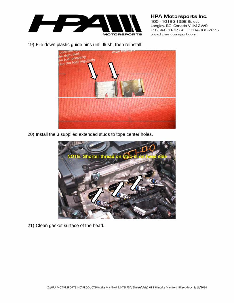
19) File 20) Insta
21) Clea
Z:\HPA MOTOR
down plast
all the 3 sup
an gasket s
RSPORTS INC\PRO
tic guide pin
pplied exte
NOTE: Sh
surface of th
DUCTS\Intake Ma
ns until flus
nded studs
horter threa
he head.
anifold 2.0 TSI FSI\
sh, then rein
s to tope ce
ad on stud
\I Sheets\Fsi\2.0T
nstall.
nter holes.
d is on hea
FSI Intake Manifol
ad side
ld iSheet.docx 1/116/2014

Z:\HPA MOTORSPORTS INC\PRODUCTS\Intake Manifold 2.0 TSI FSI\I Sheets\Fsi\2.0T FSI Intake Manifold iSheet.docx 1/16/2014
22) Remove breather pipe and fuel hard lines from intake manifold and fuel rail.
23) Remove fuel rail from intake manifold.
Z:\HPA MOTORSPORTS INC\PRODUCTS\Intake Manifold 2.0 TSI FSI\I Sheets\Fsi\2.0T FSI Intake Manifold iSheet.docx 1/16/2014
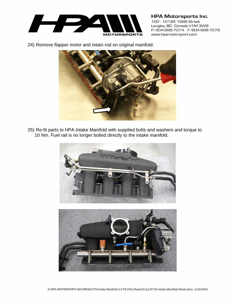
24) Remove flapper motor and retain rod on original manifold.
25) Re-fit parts to HPA Intake Manifold with supplied bolts and washers and torque to 10 Nm. Fuel rail is no longer bolted directly to the intake manifold.

Z:\HPA MOTORSPORTS INC\PRODUCTS\Intake Manifold 2.0 TSI FSI\I Sheets\Fsi\2.0T FSI Intake Manifold iSheet.docx 1/16/2014
26) Install provided breather fittings with crush washers and threaded brass fittings/plugs with supplied thread sealant to HPA Intake Manifold.

Z:\HPA MOTORSPORTS INC\PRODUCTS\Intake Manifold 2.0 TSI FSI\I Sheets\Fsi\2.0T FSI Intake Manifold iSheet.docx 1/16/2014
27) Remove G410 – low pressure switch and Schrader valve port and install in opposite
positions.
Original Positioning

Z:\HPA MOTORSPORTS INC\PRODUCTS\Intake Manifold 2.0 TSI FSI\I Sheets\Fsi\2.0T FSI Intake Manifold iSheet.docx 1/16/2014
28) Insert OEM outer intake manifold to cylinder head bolts to loosely hold the fuel rail
brackets to the intake manifold in preparation for mounting. Apply a 2-3mm bead of silicone sealant around each intake port. Make sure the mating surface of the intake manifold is cleaned with brake cleaner prior to application.
Final Positioning
Silicone Sealant
Z:\HPA MOTORSPORTS INC\PRODUCTS\Intake Manifold 2.0 TSI FSI\I Sheets\Fsi\2.0T FSI Intake Manifold iSheet.docx 1/16/2014
29) Apply a light film of synthetic engine oil to injector o-rings. Slide HPA Intake Manifold onto installed studs on the cylinder head and tighten OEM bolts and supplied nuts to 10 Nm.
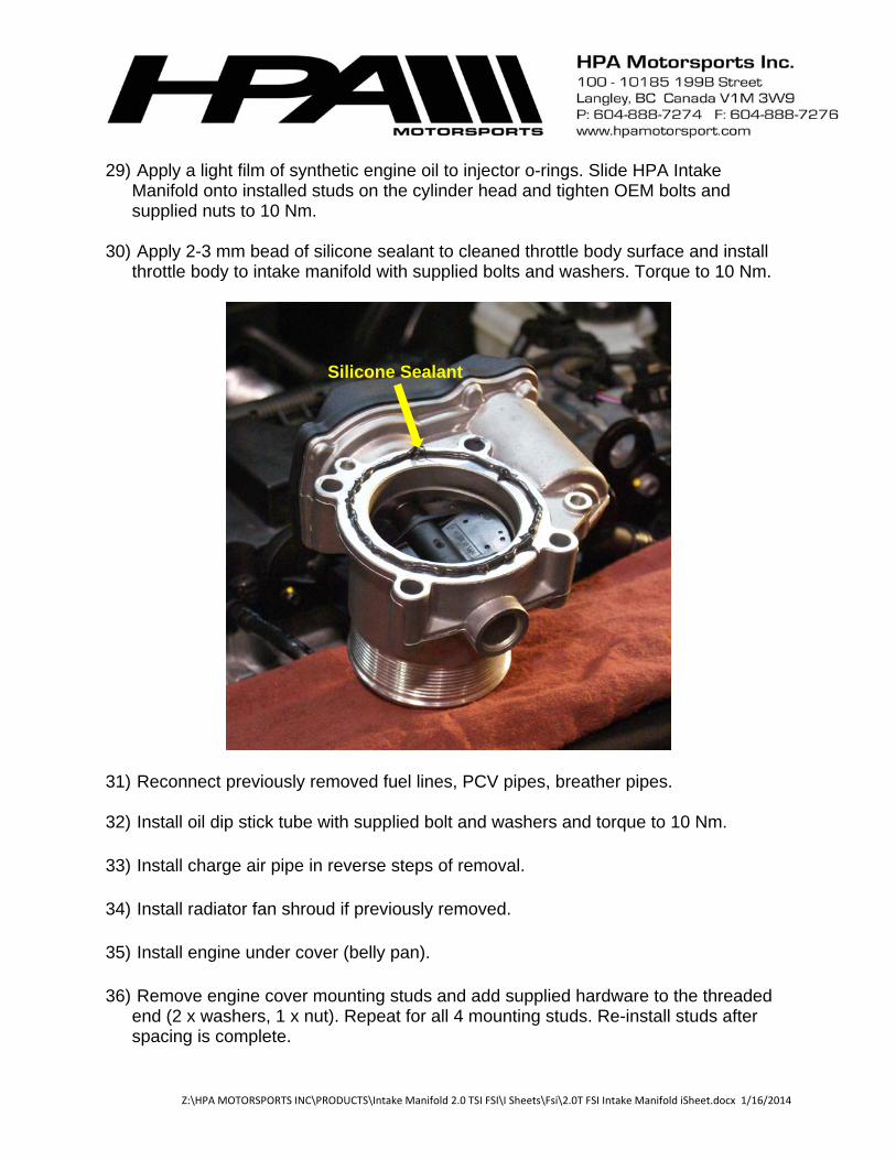
30) Apply 2-3 mm bead of silicone sealant to cleaned throttle body surface and install
throttle body to intake manifold with supplied bolts and washers. Torque to 10 Nm.
31) Reconnect previously removed fuel lines, PCV pipes, breather pipes. 32) Install oil dip stick tube with supplied bolt and washers and torque to 10 Nm.
33) Install charge air pipe in reverse steps of removal.
34) Install radiator fan shroud if previously removed.
35) Install engine under cover (belly pan).
36) Remove engine cover mounting studs and add supplied hardware to the threaded
end (2 x washers, 1 x nut). Repeat for all 4 mounting studs. Re-install studs after spacing is complete.
Silicone Sealant
Z:\HPA MOTORSPORTS INC\PRODUCTS\Intake Manifold 2.0 TSI FSI\I Sheets\Fsi\2.0T FSI Intake Manifold iSheet.docx 1/16/2014
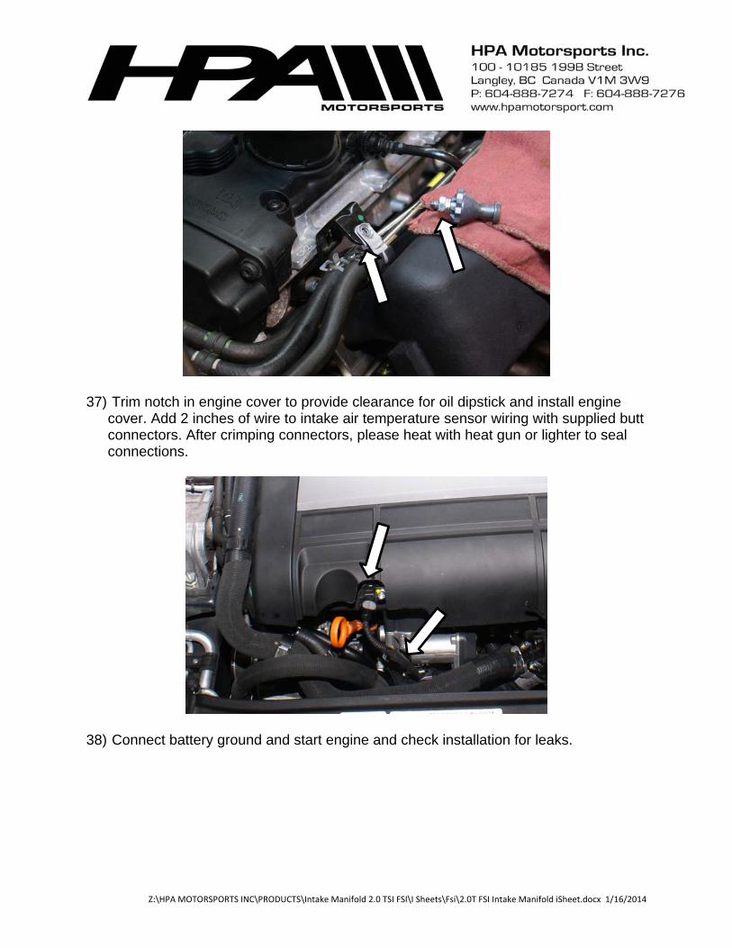
37) Trim notch in engine cover to provide clearance for oil dipstick and install engine cover. Add 2 inches of wire to intake air temperature sensor wiring with supplied butt connectors. After crimping connectors, please heat with heat gun or lighter to seal connections.
38) Connect battery ground and start engine and check installation for leaks.
Related Documents