HP Z210 SFF Workstation Maintenance and Service Guide

Welcome message from author
This document is posted to help you gain knowledge. Please leave a comment to let me know what you think about it! Share it to your friends and learn new things together.
Transcript

HP Z210 SFF Workstation
Maintenance and Service Guide

Copyright Information
© Copyright 2011 Hewlett-PackardDevelopment Company, L.P
645363–001
First Edition, February 2011
Warranty
Hewlett-Packard Company shall not beliable for technical or editorial errors oromissions contained herein or for incidentalor consequential damages in connectionwith the furnishing, performance, or use ofthis material. The information in thisdocument is provided “as is” withoutwarranty of any kind, including, but notlimited to, the implied warranties ofmerchantability and fitness for a particularpurpose, and is subject to change withoutnotice. The warranties for HP products areset forth in the express limited warrantystatements accompanying such products.
Nothing herein should be construed asconstituting an additional warranty.
This document contains proprietaryinformation that is protected by copyright.No part of this document may bephotocopied, reproduced, or translated toanother language without the prior writtenconsent of Hewlett-Packard Company.
Trademark Credits
Microsoft and Windows are U.S. registeredtrademarks of Microsoft Corporation.
Intel is a trademark of Intel Corporation inthe U.S. and other countries and are usedunder license.
ENERGY STAR is a U.S. registered mark ofthe United States Environmental ProtectionAgency.

About this guideThis guide provides service and maintenance information for the HP Z210 Small Form Factor (SFF)Workstation. It includes these topics:
Guide topics
Product overview on page 1
Setting up the operating system on page 16
Restoring the operating system on page 22
System management on page 25
Replacing components on page 53
Diagnostics and troubleshooting on page 128
Configuring RAID devices on page 163
Configuring password security and resetting CMOS on page 167
Connector pins on page 171
System board designators on page 177
Routine Care on page 179
Locating HP resources on page 181
ENWW iii

iv About this guide ENWW
Table of contents
1 Product overview ............................................................................................................. 1Product features ....................................................................................................................... 1
System board architecture .......................................................................................... 1Processor technology .................................................................................. 2Memory technology .................................................................................... 2Graphics cards .......................................................................................... 3Expansion card slots ................................................................................... 3Additional features ..................................................................................... 3
Computer components ............................................................................................... 4Chassis components ................................................................................... 4Front panel components .............................................................................. 5Rear panel components ............................................................................... 6
Computer specifications ............................................................................................................ 7Physical characteristics .............................................................................................. 7Power supply description ........................................................................................... 7
Power supply voltages ................................................................................ 7Power supply currents ................................................................................. 8Power supply specifications ......................................................................... 9Power consumption and heat dissipation ....................................................... 9System fans ............................................................................................. 10Resetting the power supply ........................................................................ 10
Environmental specifications ..................................................................................... 11ENERGY STAR Qualification .................................................................................... 12ERP compliance mode ............................................................................................. 13
Enabling ERP compliance mode ................................................................. 13Disabling ERP compliance mode ................................................................ 13
Accessibility ........................................................................................................... 13Hyper-threading ...................................................................................................... 13SATA Power Management ....................................................................................... 14Intel Turbo Boost Technology .................................................................................... 14HP Cool Tools ......................................................................................................... 14Ensuring proper ventilation ....................................................................................... 15
2 Setting up the operating system ..................................................................................... 16Setting up the Microsoft operating system .................................................................................. 17
Installing or upgrading device drivers ........................................................................ 17Transferring files and settings to your Windows workstation ......................................... 17
Setting up Red Hat Enterprise Linux .......................................................................................... 18Verifying hardware compatibility .............................................................................. 18
ENWW v

Installing from RHEL optical media ............................................................................. 18Installing with the HP driver CD ................................................................................. 18
Setting up Novell SLED ........................................................................................................... 19Setting up SLED on preloaded systems ....................................................................... 19Installing from SLED optical media ............................................................................. 19Installing with the HP driver CD ................................................................................. 19
Updating the workstation ........................................................................................................ 20Updating the workstation after first boot ..................................................................... 20Upgrading the BIOS ................................................................................................ 20
Determining current BIOS .......................................................................... 20Upgrading BIOS ...................................................................................... 21
Upgrading device drivers ......................................................................................... 21
3 Restoring the operating system ....................................................................................... 22Restore method ...................................................................................................................... 22Ordering backup software ...................................................................................................... 23Restoring Windows 7 ............................................................................................................. 23
Ordering the HP Recovery Manager media ................................................................ 23Restoring the operating system .................................................................................. 23
Restoring Novell SLED ............................................................................................................ 24Creating restore media ............................................................................................ 24
4 System management ...................................................................................................... 25BIOS ROM ............................................................................................................................ 25The Computer Setup (F10) Utility .............................................................................................. 25
Computer Setup (F10) functionality ............................................................................ 25Accessing the Computer Setup (F10) Utility ................................................................ 27The Computer Setup (F10) Utility menu ...................................................................... 28
Desktop management ............................................................................................................. 36Initial computer configuration and deployment ............................................................ 37Installing a remote system ......................................................................................... 37Replicating the setup ................................................................................................ 38
Copying a setup configuration to another computer ...................................... 38Updating and managing software ............................................................................. 39HP Client Manager Software .................................................................................... 39Altiris Client Management Solutions .......................................................................... 39HP SoftPaq Download Manager ............................................................................... 40System Software Manager ....................................................................................... 40ROM Flash ............................................................................................................. 40
Remote ROM Flash ................................................................................... 40HPQFlash ................................................................................................ 40
FailSafe Boot Block ROM ......................................................................................... 41Recovering the computer from Boot Block Recovery mode ............................. 41
vi ENWW

Workstation security ................................................................................................ 42Asset tracking .......................................................................................... 42SATA hard disk drive security .................................................................... 43
DriveLock applications ............................................................... 44Using DriveLock ........................................................................ 44
Password security ..................................................................................... 46Establishing a setup password using Computer Setup (F10) Utility . .. 46Establishing a power-on password using computer setup ................ 47Entering a power-on password .................................................... 47Entering a setup password ......................................................... 48Changing a power-on or setup password ..................................... 48Deleting a power-on or setup password ....................................... 49National keyboard delimiter characters ....................................... 49Clearing passwords ................................................................... 50
Chassis security ....................................................................................... 50Side access panel sensor (Smart Cover Sensor) (optional) .............. 50Side access panel solenoid lock .................................................. 50Cable lock (optional) ................................................................. 51
Fault notification and recovery .................................................................................. 51Drive Protection System ............................................................................. 51ECC fault prediction ................................................................................. 51Thermal sensors ....................................................................................... 51
Dual-state power button ........................................................................................... 52Changing the power button configuration ................................................... 52
5 Replacing components .................................................................................................... 53Warnings and cautions ........................................................................................................... 54Service considerations ............................................................................................................ 55
Cautions, warnings and safety precautions ................................................................. 55ESD information ...................................................................................................... 55
Generating static ...................................................................................... 55Preventing ESD equipment damage ............................................................ 56Personal grounding methods and equipment ................................................ 56
Grounding the work area ......................................................................................... 57Recommended ESD prevention materials and equipment .............................................. 57Tools and software requirements ............................................................................... 58Special handling of components ............................................................................... 58
Cables and connectors ............................................................................. 58Hard drives ............................................................................................. 59Lithium coin cell battery ............................................................................. 59
Customer Self-Repair .............................................................................................................. 59Removing and installing components ........................................................................................ 60
Component locations ............................................................................................... 61
ENWW vii

Predisassembly procedures ....................................................................................... 62Disassembly order ................................................................................................... 63Removing the cable lock (optional) ............................................................................ 63Access panel .......................................................................................................... 64
Removing the access panel ........................................................................ 64Installing the access panel ......................................................................... 64
Bezel ..................................................................................................................... 65Removing the front bezel ........................................................................... 65Installing the front bezel ............................................................................ 65Front bezel security .................................................................................. 65
Access panel sensor (optional) .................................................................................. 67Removing the access panel sensor .............................................................. 67Installing the access panel sensor ............................................................... 67
Access panel solenoid lock ....................................................................................... 68Removing the access panel solenoid lock .................................................... 68Installing the access panel solenoid lock ...................................................... 68
Removing and installing drives .................................................................................. 69Predisassembly for drives .......................................................................... 69
Follow all general predisassembly procedures .............................. 69Perform a data backup .............................................................. 69Gather required tools ................................................................. 69Verify drive position and information ........................................... 69Remove bezel blanks ................................................................. 70Locate system board drive connections ......................................... 71Locating extra guide screws ........................................................ 72Carefully handle hard disk drives ................................................ 72
Removing an optical drive ......................................................................... 73Installing an optical drive .......................................................................... 75Removing a hard disk or media card from the drive cage ............................. 77Installing a hard drive or media card reader into the drive cage .................... 79Removing a DX115 Dataport hard drive ..................................................... 81Installing a DX115 Dataport hard drive ....................................................... 85Removing and replacing the primary hard drive ........................................... 91
Cable management ................................................................................................. 96Power connections ................................................................................... 97
Using the computer in a tower orientation .................................................................. 98Front panel I/O device assembly .............................................................................. 99
Removing the front panel I/O device assembly ............................................ 99Installing the front panel I/O device assembly ........................................... 101
Speaker ............................................................................................................... 103Removing the speaker ............................................................................. 103Installing the speaker .............................................................................. 103
Power supply ........................................................................................................ 104Removing the power supply ..................................................................... 104
viii ENWW

Installing the power supply ...................................................................... 105System fan assembly .............................................................................................. 106
Removing the system fan assembly ........................................................... 106Installing the system fan assembly ............................................................. 108
Memory ............................................................................................................... 109Supported DIMM configurations ............................................................... 109DIMM installation guidelines .................................................................... 109DIMM installation order .......................................................................... 109BIOS errors and warnings ....................................................................... 109Removing a DIMM ................................................................................. 110Installing a DIMM ................................................................................... 112
Expansion card slot identification ............................................................................ 114Slot identification and description ............................................................. 114Card configuration restrictions for power supplies ...................................... 114Choosing an expansion card slot ............................................................. 115
Removing and installing expansion cards ................................................................. 116Expansion card slot description ................................................................ 116Removing an expansion card .................................................................. 116Installing an expansion card .................................................................... 117
Battery ................................................................................................................. 120Removing the battery .............................................................................. 120Installing the battery ............................................................................... 121
CPU heatsink ........................................................................................................ 121Removing the CPU heatsink ..................................................................... 121Installing the CPU heatsink ...................................................................... 123
CPU .................................................................................................................... 124Removing a CPU .................................................................................... 124Installing a CPU ..................................................................................... 125
System board ....................................................................................................... 126Removing the system board ..................................................................... 126Installing the system board ...................................................................... 127
Product recycling ................................................................................................................. 127
6 Diagnostics and troubleshooting ................................................................................... 128Calling technical support ....................................................................................................... 129Locating ID labels ................................................................................................................. 129Locating warranty information ............................................................................................... 130Diagnosis guidelines ............................................................................................................ 131
Diagnosis at startup ............................................................................................... 131Diagnosis during operation .................................................................................... 132
Troubleshooting checklist ....................................................................................................... 133HP troubleshooting resources and tools ................................................................................... 133
HP Support Assistant .............................................................................................. 133
ENWW ix

HP Performance Advisor ........................................................................................ 133E-support .............................................................................................................. 133
Troubleshooting a problem ...................................................................... 134Instant Support and Active Chat ............................................................... 134Helpful hints .......................................................................................... 134
At startup ............................................................................... 135During operation ..................................................................... 135Customizing the monitor display ............................................... 136
Troubleshooting scenarios and solutions .................................................................................. 136Solving minor problems ......................................................................................... 136Solving diskette problems ....................................................................................... 138Solving hard drive problems ................................................................................... 139Solving display problems ....................................................................................... 141Solving audio problems ......................................................................................... 143Solving printer problems ........................................................................................ 144
Self-troubleshooting with HP Vision Diagnostics ........................................................................ 144Accessing HP Vision Diagnostics ............................................................................. 145Using Vision Creator ............................................................................................. 145Accessing HP Vision Diagnostics Utilities .................................................................. 146
Creating and using a bootable USB key ................................................... 146Creating and using a bootable DVD/CD .................................................. 146Using the HP Memory Test utility .............................................................. 146
Downloading HP Vision Diagnostics ........................................................................ 147User interface ....................................................................................................... 148
Survey tab ............................................................................................. 148Test tab ................................................................................................. 149Status tab .............................................................................................. 150History tab ............................................................................................ 151Errors tab .............................................................................................. 151Help tab ............................................................................................... 151
Saving and printing information in HP Vision Diagnostics ........................................... 152Diagnostic codes and errors .................................................................................................. 152
Diagnostic LED and audible (beep) codes ................................................................ 152LED color definitions .............................................................................................. 156POST error messages ............................................................................................ 157
7 Configuring RAID devices .............................................................................................. 163Maximum RAID hard drive configurations ............................................................................... 163Configuring SATA RAID devices ............................................................................................ 164
Attaching SATA HDDs ........................................................................................... 164Configuring system BIOS ....................................................................................... 165Creating RAID volumes .......................................................................................... 166
x ENWW

8 Configuring password security and resetting CMOS ...................................................... 167Preparing to configure passwords .......................................................................................... 167Resetting the password jumper ............................................................................................... 168Clearing and Resetting the CMOS ......................................................................................... 168
Using the CMOS Button ......................................................................................... 169Using the Computer Setup (F10) Utility to Reset CMOS .............................................. 169
Appendix A Connector pins ............................................................................................. 171
Appendix B System board designators ............................................................................ 177
Appendix C Routine Care ................................................................................................. 179General cleaning safety precautions ....................................................................................... 179Cleaning the computer case .................................................................................................. 179Cleaning the keyboard ......................................................................................................... 179Cleaning the monitor ............................................................................................................ 180Cleaning the mouse .............................................................................................................. 180
Appendix D Locating HP resources ................................................................................... 181Product information .............................................................................................................. 182Product support .................................................................................................................... 183Product documentation ......................................................................................................... 184Product diagnostics .............................................................................................................. 186Product updates ................................................................................................................... 187
Index ............................................................................................................................... 188
ENWW xi

xii ENWW

1 Product overview
This chapter presents an overview of the hardware components of the computer. It includes these topics:
Topics
Product features on page 1
Computer specifications on page 7
Product featuresThe following sections describe the computer system board architecture and components, and includesthese topics:
Topics
System board architecture on page 1
Computer components on page 4
System board architectureThis section describes the system architecture.
ENWW Product features 1

The following figure shows the typical system board block diagram.
Figure 1-1 System board block diagram
NOTE: The x1 and x16 designators describe the mechanical length of the slot. The number inparentheses lists the number of electrical PCIe lanes routed to the expansion slot. For example, x16(4)means that the expansion slot is mechanically a x16 length connector, with four PCIe lanes connected.
Processor technology
This computer uses the Intel® Series C206 chipset, with support for the Intel® Xeon® Processor E3Family or 2nd generation Intel Core(TM) processors up to 95W. These processors incorporate anintegrated 2-channel memory controller, microarchitecture improvements, integrated graphics (somemodels) and Advanced Vector Extensions (AVX) to increase floating point performance. In addition, thecomputer uses Intel DMI2 interface to connect the processor to the I/O controller.
Memory technology
The computer dual in-line memory modules (DIMMs) are based on DDR3 1333MHz technology. Errorchecking and correcting (ECC) and non-ECC DIMMs are supported. Two direct-attach memorychannels permit low latency access and fast data transfer to improve performance. System memorysizes up to 16GB (using 4GB DIMMs) are supported.
NOTE: To optimize performance, distribute the DIMMs across both memory channels. See Memoryon page 109 for more information.
NOTE: Do not intermix non-ECC memory DIMMs with ECC memory DIMMs.
2 Chapter 1 Product overview ENWW

Graphics cards
The workstation supports discrete PCIe Gen2 graphics cards in its PCIe2 x16 and PCIe2 x16(4) slots.The system supports multiple graphics cards as long as the total power usage of these cards fits withinthe total graphics power budget of 45W.
To view supported graphic card configurations using HP QuickSpecs, visit http://www.hp.com/go/quickspecs. Select your geographic region, click on Workstations, then select your workstationmodel.
Some workstation models (depending on installed processor type) also support up to two displays withintegrated Intel HD graphics. Most supported Intel Core processors provide Intel HD Graphics 2000.Intel Xeon processors with model designations that end in "---5" provide Intel HD Graphics P3000. InWindows 7, you can view the model of CPU installed in the workstation by selecting Start > ControlPanel > System.
NOTE: Intermixing integrated Intel HD graphics and discrete graphics cards in order to drive morethan two displays can be enabled using the Computer (F10) Setup Utility. However, HP recommendsusing only discrete graphics cards when attaching three or more displays. To see graphics cardconfigurations that have been fully tested and validated by HP for use in this workstation, refer tohttp://www.hp.com/go/quickspecs.
Expansion card slots
The computer provides multiple graphics and I/O slots: one full PCIe Gen2 x16, one PCIe Gen2x16(4); one PCIe Gen2 x1; and one PCI 32/33. These slots provide extra I/O bandwidth for highspeed I/O cards.
NOTE: The total of all graphics cards cannot exceed 45W, and the total I/O power usage cannotexceed 80W.
Additional features
The computer provides these additional features:
● Ten external and four internal USB 2.0 ports
● 240W power supply that is 89% efficient and permits Energy Star Version 5.0 systemconfigurations
● Supports European Union ERP Lot 6 power limit of less than 1W in off mode
● HP Quiet Fan Technology, whichpermits quiet system operation
● Parallel and serial headers that can be used with an optional PCI bulkhead connector
ENWW Product features 3

Computer componentsThis section describes the computer components, including front and rear panel components.
For complete and current information on supported accessories and components for the computer, seehttp://partsurfer.hp.com.
Chassis components
The following image shows the components of a typical computer layout. Drive configurations can vary.
Figure 1-2 Computer components
Table 1-1 Computer component descriptions
Item Description Item Description
1 Access panel 8 System fan
2 Processor (CPU) 9 Chassis
3 Heatsink 10 Front bezel
4 Memory module (DIMM) 11 Speaker
5 System board 12 Optical drive
6 Hard disk drive 13 Optional media reader or second hard disk drive
7 Airflow guide
4 Chapter 1 Product overview ENWW

Front panel components
The following figure shows the layout of a typical front panel.
Figure 1-3 Front panel
Table 1-2 Front panel connectors
Item Symbol Description Item Symbol Description
1 Optical drive 6 Microphone or headphonesconnector (software selectable,default mode is microphone)
2 Optical drive activity light 7 Headphones connector
3 Optical drive manual eject button 8 Hard drive or optical driveactivity light
4 Power button 9 Optional media card reader(shown) or optional second harddisk drive
5 USB 2.0 ports (4)
ENWW Product features 5

Rear panel components
The following figure shows the layout of a typical rear panel.
Figure 1-4 Rear panel
NOTE: The labels for the rear panel connectors use industry-standard icons and colors.
Table 1-3 Rear panel connectors
Item Symbol Description Item Symbol Description
1 RJ–45 network connector 6 Display port (DP)1
2 Serial port 7 VGA (monitor)1
3 PS/2 mouse connector (green) 8 PS/2 keyboard connector(purple)
4 Power cord connector 9 Audio line-out connector (green)
5 USB 2.0 ports (6) 10 Audio line-in connector (blue)
1. The DP and VGA ports are disabled if used with Intel® Xeon quad–core processors.
6 Chapter 1 Product overview ENWW

Computer specificationsThis section provides computer chassis, power supply, and environmental specifications.
Physical characteristicsThe following table lists the computer physical characteristics.
Weight (Typical configuration) 7.6 kg (16.72 lb.)
Chassis Dimensions Height: 10.0 cm (3.95 in)
Width: 33.8 cm (13.0 in)
Depth: 37.9 cm (14.9 in)
Power supply descriptionThe computer includes a 240W 89% efficient power supply to provide power for the computer. Thepower supply is compatible with ENERGY STAR Version 5 requirements.
Power supply voltages
Table 1-4 Power supply source voltages
Source voltage Description
+12 V-CPU Input to onboard regulator that supplies power to CPU
+12 V-MAIN PCI, PCIe, system fans, storage (optical and hard disk drives), and input to onboard regulators
+12 V-SBY Input to onboard regulators
V12N PCI and serial ports
ENWW Computer specifications 7

Power supply currents
Table 1-5 Maximum current per rail
Output (240W) +12V Main +12Vcpu –12V 12Vsb
Nominal output voltage 12.1 12.1 -12.0 11.4
Maximum continuous current 14A 12A 0.15A 1.3A
240W combined
CAUTION: Do not exceed 240 watts of total continuous output power.
Maximum combined current on +12V(CPU,Main) is 20A.
8 Chapter 1 Product overview ENWW

Power supply specifications
Table 1-6 Power supply specifications
Item Description
Power supply 240W Wide Ranging, Active PFC and89% efficient
Operating voltage range 90 – 264 VAC
Rated voltage range 100–240 VAC
Rated line frequency 50–60 Hz
Operating line frequency range 47–63 Hz
Rated input current 4A
Heat dissipation
(Configuration and software dependent)
Typical 170 BTU/hr = (42.87 kg-cal/hr)
Maximum 1063 BTU/hr = (206.27 kg-cal/hr)
Power supply fan One fan, 92mm x 25mm, variable speed
FEMP Standby Power compliant @115V (<2W in S5 – Power Off) Yes
ERP Lot 6 (EuP) compliant @230V (<1w in S5 – Power Off) Yes
Built-in Self Test LED No
Surge tolerant full ranging power supply (withstands power surgesup to 2000V)
Yes
Power Consumption in sleep mode (as defined by ENERGY STAR) -Suspend to RAM (S3) (Instantly Available PC)
<6 watts
Power consumption and heat dissipation
Power consumption and heat dissipation specifications are available for multiple configurations. Toreview available specifications, see http://www.hp.com/go/quickspecs.
To reach zero power consumption, unplug the computer from the power outlet or use a power strip withan on/off switch. For additional information about power-saving features, see the operating systeminstallation instructions.
This product is in compliance with U.S. Executive Order 13221.
ENWW Computer specifications 9

System fans
This computer includes:
● One front system fan
● One power supply fan
In addition, some graphics cards include onboard fans.
Resetting the power supply
If an overload triggers the power supply overload protection, power is immediately disconnected.
To reset the power supply:
1. Disconnect the power cord from the computer.
2. Determine what caused the overload and fix the problem. For troubleshooting information, seeDiagnostics and troubleshooting on page 128.
3. Reconnect the power cord and restart the computer.
When you power off the computer through the operating system, power consumption falls below whatis considered low power consumption but does not reach zero. This low power consumption featureextends the life of the power supply.
10 Chapter 1 Product overview ENWW

Environmental specificationsThe following table lists the environmental specifications of HP Workstations.
Table 1-7 HP Workstation environmental specifications
Temperature
Operating: 5 to 35°C (40 to 95°F)
Non-operating: -40 to 60°C (-40 to 140°F)
NOTE: Derate by one degree C (1.8 degrees F) for every 305m (1,000 ft) altitude over1,524m (5,000 ft).
HumidityOperating: 8 to 85% Relative Humidity (RH), non-condensing
Non-operating: 8 to 90% Relative Humidity, non-condensing
AltitudeOperating: 0 to 3,048m (10,000 ft)
Non-operating: 0 to 9,144m (30,000 ft)
Shock
Operating: ½-sine: 40g, 2-3ms
Non-operating:
● ½-sine: 160 cm/s, 2-3ms (~100g)
● square: 422 cm/s, 20g
NOTE: Values represent individual shock events and do not indicate repetitive shock events.
Vibration
Operating Random: 0.5g (rms), 5-300 Hz
Non-Operating: random: 2.0g (rms), 10-500 Hz
NOTE: Values do not indicate continuous vibration.
ENWW Computer specifications 11

ENERGY STAR QualificationHP computers marked with the ENERGY STAR logo are compliant with the applicable U.S.Environmental Protection Agency (EPA) ENERGY STAR specifications for computers. The EPA ENERGYSTAR logo does not imply endorsement by the EPA. As an ENERGY STAR Partner, Hewlett-PackardCompany has determined the products marked with the ENERGY STAR logo are ENERGY STARqualified per the applicable ENERGY STAR guidelines for energy efficiency. The following logoappears on all ENERGY STAR qualified computers.
The ENERGY STAR Computers Program was created by the EPA to promote energy efficiency andreduce air pollution through more energy-efficient equipment in homes, offices, and factories. One wayproducts achieve this energy efficiency is by reducing power consumption when not being used throughthe Microsoft Windows Power Management feature.
The Power Management feature enables the computer to enter a low-power (or “sleep”) mode after aperiod of inactivity. When used with an external monitor that is ENERGY STAR qualified, this featurealso supports the similar power management features of the external monitor.
To take advantage of this energy savings:
● The Power Management feature has been preset to suspend the computer to a sleep state after 30minutes of inactivity.
● The Power Management feature has been preset to suspend the monitor to a sleep state after 15minutes of inactivity.
Both the computer and monitor can be woken from sleep mode through user interaction with any of thecomputer input devices (mouse, keyboard, and so on). when configured with Wake On LAN (WOL)enabled, the computer can also be woken by a network signal.
See the EPA ENERGY STAR Power Management Web site for more information about the energy andfinancial savings potential of the Power Management Feature: http://www.energystar.gov/powermanagement.
See the EPA ENERGY STAR Web site for more information about the ENERGY STAR program and itsenvironmental benefits: http://www.energystar.gov.
CAUTION: Using the Energy Save Monitor feature with monitors that are not ENERGY STARqualified can cause video distortion when an Energy Save timeout occurs.
NOTE: ENERGY STAR is not supported on Linux computers.
If it is necessary to restore the operating system, you must also reset the ENERGY STAR settings (ifapplicable) after the restore.
To verify the factory default power settings for your computer, select Start>Control Panel, and thendouble-click Power Options.
12 Chapter 1 Product overview ENWW

ERP compliance modeThis computer provides ERP compliance mode capability.
When enabled, this feature enables the computer to shut down to the lowest possible power state byremoving all power to the system board.
When disabled, the computer powers down conventionally.
When the computer is shut down in ERP compliance mode, it must be powered up with the computerpower button.
Enabling ERP compliance mode
To enable ERP compliance mode:
1. Press F10 during start up.
2. Using the arrow keys, select the Power>Hardware Power Management>S5 MaximumPower Savings, and then select Enable.
3. Press F10 to accept the change.
4. Select File>Save Change and Exit, and then press F10 to accept the change.
Disabling ERP compliance mode
To disable the ERP compliance mode:
1. Press F10 during start up.
2. Select Power>Hardware Power Management>S5 Maximum Power Savings, andthen select Disable.
3. Press F10 to accept the change.
4. Select File>Save Change and Exit, and then press F10 to accept the change.
AccessibilityHP is committed to developing products, services, and information that is easier to access for allcustomers, including customers with disabilities and age-related limitations. HP products withWindows® 7 preinstalled are designed for accessibility. These products are tested with industry-leading Assistive Technology products. For more information see http://www.hp.com/accessibility.
Hyper-threadingThis HP computer supports Hyper-threading.
Hyper-Threading Technology (HTT), is an Intel-proprietary technology used to provide processparallelization . The technology improves processor performance under certain workloads by providinguseful work for execution units that would otherwise be idle. A processor with Hyper-Threading enabledis treated by the operating system as two processors instead of one. Hyper-threading relies on supportin the operating system as well as the CPU.
ENWW Computer specifications 13

SATA Power ManagementSATA Power Management enables or disables SATA bus and/or device power management.
Intel Turbo Boost TechnologyThe HP Z Workstation series supports Intel® Turbo Boost Technology.
This feature enables the CPU to run at a higher than normal rate. When all CPU cores are notnecessary for the workload, inactive cores are turned off and power is diverted to the active cores toincrease their performance.
Turbo Boost is enabled and disabled in computer BIOS.
HP Cool ToolsHP workstations and computers installed with Windows include additional software tools. To access orlearn more about these tools that can enhance the computer experience:
1. Double-click the HP Cool Tools icon on the desktop.
2. To learn more about an HP Cool Tool application, just click on the application's "Learn More"link.
3. To install or launch the applications, select the appropriate application and follow the instructionsgiven.
14 Chapter 1 Product overview ENWW

Ensuring proper ventilationProper ventilation for the system is important for workstation operation. Follow these guidelines toensure adequate ventilation:
● Operate the workstation on a sturdy, level surface.
● Place the workstation in an area with adequate ventilation. Provide at least 15.24 cm (6 inches) ofclearance at the front and back of the workstation as shown in the following figure.
Your workstation might look different than the one shown.
Figure 1-5 Proper workstation ventilation
● Ensure that the ambient air temperature surrounding the workstation falls within the published limit.
NOTE: The ambient upper limit of 35 C is only good up to 1524 m (5000 ft) elevation. There isa 1 C per 304.8 m (1000 ft derating above 1524 m (5000 ft). So, at 3,048 m (10,000 ft), theupper ambient air temperature limit is 30 C.
● For cabinet installation, ensure adequate cabinet ventilation and ensure that the ambienttemperature within the cabinet does not exceed published limits.
● Never restrict the incoming or outgoing airflow of the workstation by blocking any vents or airintakes as shown in the following figure.
Figure 1-6 Proper workstation placement
ENWW Computer specifications 15

2 Setting up the operating system
This chapter provides setup and update information for the workstation operating system. It includesthese topics:
Topics
Setting up the Microsoft operating system on page 17
Setting up Red Hat Enterprise Linux on page 18
Setting up Novell SLED on page 19
Updating the workstation on page 20
This chapter also includes information on how to determine that you have the latest BIOS, drivers, andsoftware updates installed on the workstation.
CAUTION: Do not add optional hardware or third-party devices to the HP workstation until theoperating system is successfully installed. Adding hardware might cause errors and prevent theoperating system from installing correctly.
16 Chapter 2 Setting up the operating system ENWW

Setting up the Microsoft operating systemWhen you first apply power to the workstation, the operating system is installed. This process takesapproximately 5 to 10 minutes. Carefully follow the instructions on the screen to complete theinstallation.
CAUTION: After installation has started, do not turn off the workstation until the process is complete.Turning off the workstation during installation can damage the installation and operation of thesoftware.
For complete operating system installation and configuration instructions, see the operating systemdocumentation that was provided with the workstation. Additional information is available in the onlinehelp tool after you successfully install the operating system.
Installing or upgrading device driversTo install hardware devices after the operating system is installed, you must install the appropriatedevice drivers before you install the devices. Follow the installation instructions that came with thedevice. In addition, for optimum performance, your operating system must have the most recentupdates, patches, and software fixes. For additional driver and software update information, refer toUpgrading device drivers on page 21.
Transferring files and settings to your Windows workstationThe Microsoft Windows operating system offers data migration tools that helps you choose and transferfiles and data from another Windows computer to your Windows operating system workstation.
For instructions on how to use these tools, see the documents at http://www.microsoft.com.
ENWW Setting up the Microsoft operating system 17

Setting up Red Hat Enterprise LinuxHP offers an HP Installer Kit for Linux (HPIKL) to supplement Red Hat box sets and help HP Linuxcustomers customize their system image. The HPIKL contains the HP driver CD and device drivers tosuccessfully set up the Red Hat Enterprise Linux (RHEL) operating system. The HP Installer Kit for LinuxCDs are currently available for download at http://www.hp.com/support/workstation_swdrivers.
To use the drivers in the HP Installer kit for Linux other than RHEL, you must manually extract the driversfrom the HP Driver CD and install them. HP does not test the installation of these drivers on other Linuxdistributions nor does HP support this operation.
Verifying hardware compatibilityTo see which Linux versions have been qualified to work on HP Workstations visit http://www.hp.com/support/linux_hardware_matrix.
Installing from RHEL optical mediaWhen installing RHEL on your workstation, follow this procedure prior to booting and installing from theRHEL box set media:
1. With the RHEL install media in the DVD drive, restart the workstation and press the F9 key withinthree seconds to display the boot menu. If you miss the boot menu, press Ctrl-Alt-Del to restartand wait slightly more or less before pressing F9.
2. From the list of available boot sources, under Legacy boot sources, pick the optical drive thatcontains the RHEL install media.
NOTE: Be sure to pick from the list labeled Legacy boot sources when selecting the opticaldrive from which to boot. Do not select from UEFI boot sources. Doing so may result in the OSinstallation being unable to complete.
3. Press Enter to continue with system boot and the OS installation process.
Installing with the HP driver CDFor instructions on installing the HP driver CD, see “Installing with the HP Installer Kit for Linux” in theHP Workstations for Linux User Guide at http://www.hp.com/support/linux_user_manual.
18 Chapter 2 Setting up the operating system ENWW

Setting up Novell SLEDThe workstation can be ordered with Novell SLED preloaded.
HP offers an HP Installer Kit for Linux (HPIKL) to help HP Linux customers customize their system image.The HPIKL contains the HP driver CD and device drivers to successfully set up the SUSE Linux EnterpriseDesktop (SLED) operating system. The HP Installer Kit for Linux CDs are currently available fordownload at http://www.hp.com/support/workstation_swdrivers.
Setting up SLED on preloaded systemsTo set up the SUSE Linux Enterprise Desktop (SLED) on systems preloaded with the operating system:
1. Boot the workstation.
2. Start the Installation Settings and enter the password, network, graphics, time, keyboard settings,and Novell Customer Center Configuration for the workstation.
NOTE: During Installation Settings the Novell subscription can be activated from the NovellCustomer Center Configuration screen. Visit the full Novell Customer Center documentation athttp://www.novell.com/documentation/ncc/.
Installing from SLED optical mediaTo install SLED on your workstation, follow this boot procedure prior to installing from the SLED media:
1. With the SLED install media in the DVD drive, restart the workstation and press the F9 key withinthree seconds to display the boot menu. If you miss the boot menu, press Ctrl-Alt-Del to restartand wait slightly more or less before pressing F9.
2. From the list of available boot sources, under Legacy boot sources, pick the optical drive thatcontains the SLED install media.
NOTE: Be sure to pick from the list labeled Legacy boot sources when selecting the opticaldrive from which to boot. Do not select from UEFI boot sources. Doing so may result in the OSinstallation being unable to complete.
3. Press Enter to continue with system boot and the OS installation process.
Installing with the HP driver CDFor instructions on installing the HP driver CD, see “Installing with the HP Installer Kit for Linux” in theHP Workstations for Linux User Guide at http://www.hp.com/support/linux_user_manual.
ENWW Setting up Novell SLED 19

Updating the workstationHP is constantly working on improving your total workstation experience. To ensure that the workstationleverages the latest enhancements, HP recommends that you install the latest BIOS, driver, and softwareupdates on a regular basis.
Updating the workstation after first bootAfter successfully booting the workstation for the first time, you should follow these guidelines to ensurethat the workstation is up-to-date:
● Ensure that you have the latest system BIOS loaded. See Upgrading the BIOS on page 20 forinstructions.
● Ensure that you have the latest drivers for your system. See Upgrading device driverson page 21 for instructions.
● Become familiar with your available HP resources.
● Consider a subscription to Driver Alerts at http://www.hp.com/go/subscriberschoice.
Upgrading the BIOSFor optimum performance, determine the BIOS revision on the workstation, and upgrade it if necessary.
Determining current BIOS
To determine the current BIOS of the workstation during system power up:
1. Wait for F10=setup to appear on the lower right corner of the screen.
2. Press F10 to enter the F10 Setup utility.
The F10 Setup utility displays the workstation BIOS version under File > System Information.
3. Note the workstation BIOS version so that you can compare it with the BIOS versions that appearon the HP website.
20 Chapter 2 Setting up the operating system ENWW

Upgrading BIOS
To find and download the latest available BIOS, which includes the latest enhancements:
1. Go to http://www.hp.com/go/workstationsupport.
2. Select Download Drivers and Software from the left menu column under Tasks.
3. Follow the instructions to locate the latest BIOS available for the workstation.
4. If the BIOS on the Web site is the same as the version on your system, no further action isrequired.
5. If the BIOS on the Web site is a version later than the one on your system, download theappropriate version for the workstation. Follow the instructions in the release notes to complete theinstallation.
Upgrading device driversIf you install a peripheral device (such as a printer, display adapter, or network adapter), confirm youhave the latest device drivers loaded. If you purchased your device through HP, visit the HP Web site todownload the latest drivers for your device. These drivers have been tested to ensure the bestcompatibility between your device and your HP workstation.
If you did not purchase your device from HP, HP recommends visiting the HP Web site first to see ifyour device and its drivers have been tested for HP workstation compatibility. If no driver is available,visit the device manufacturer's Web site to download the latest drivers.
To upgrade device drivers:
1. Go to http://www.hp.com/go/workstationsupport.
2. Select Download Drivers and Software from the left menu column under Tasks.
3. Follow the instructions to find the latest drivers available for the workstation.
If a needed driver is not found, see the Web site of the manufacturer of the peripheral device.
ENWW Updating the workstation 21

3 Restoring the operating system
This chapter describes how to restore the Windows or Linux operating system. It includes these topics:
Topics
Restore method on page 22
Ordering backup software on page 23
Restoring Windows 7 on page 23
Restoring Novell SLED on page 24
Restore methodThe Windows 7 operating system can be reinstalled using the HP Recovery Manager
HP Recovery Manager reinstalls the Windows operating system and device drivers (for devicesincluded with the system) to a near-factory state. The process does not back up or recover data on thehard drive. Some application software might not be restored using this process and must be installedfrom the appropriate application CD.
CAUTION: This method restores the operating system, but not data. Data must be backed upregularly to avoid loss.
22 Chapter 3 Restoring the operating system ENWW

Ordering backup softwareYou can order a recovery disk set from the HP support center. To obtain the support center telephonenumber for your region see http://www.hp.com/support/contactHP. Request the Windows 7 32-bit or64-bit system recovery media kit.
Restoring Windows 7This section describes how to restore Windows 7.
Ordering the HP Recovery Manager mediaIf you ordered restore media with your workstation, the media is included with your workstationcomponents.
If you did not order restore media, call HP Support and request the Windows 7 32-bit or 64-bit systemrecovery media kit. For worldwide technical support phone numbers, see http://www.hp.com/support.
Restoring the operating systemNOTE: Windows 7 provides a backup and restore application as well. To learn more about thisapplication, see the Microsoft Web site.
CAUTION: Before you restore the operating system, back up your data.
When you run HP Recovery Manager from media, the process deletes all information on the primaryhard drive, including all partitions.
To restore Windows 7:
1. Boot from the first disk in the HP Recovery Manager DVD set to start the system recovery process.
2. Follow the prompts to restore your operating system.
Some application software might not be restored using this process. If software is not restored, install itfrom the appropriate application DVD.
ENWW Ordering backup software 23

Restoring Novell SLEDThe SLED restore media is required to restore the Linux operating system.
Creating restore mediaThe SUSE Linux Enterprise Desktop preload includes a SUSE ISO icon on the desktop. You can click thisicon to go to the /iso directory. The /iso directory contains all iso images used to preload yourworkstation. To recover or restore the original image, follow the instructions in the readme file in the /iso directory to copy the ISO image file onto a DVD.
NOTE: Make copies of the ISO recovery images on a DVD as backup files in case your workstationexperiences a hard drive failure.
24 Chapter 3 Restoring the operating system ENWW

4 System management
This section describes the tools and utilities that provide system management for the computer. Itincludes these topics:
Topics
BIOS ROM on page 25
The Computer Setup (F10) Utility on page 25
Desktop management on page 36
BIOS ROMThe BIOS ROM is a collection of machine language applications stored as firmware in ROM. It includesfunctions such as Power on Self Test (POST), PCI device initialization, Plug and Play support, powermanagement, and the Computer Setup (F10) Utility. The BIOS ROM is an 8MB Serial PeripheralInterface (SPI) port.
See http://www.hp.com/go/quickspecs to review the latest BIOS ROM specifications.
The Computer Setup (F10) UtilityThis section contains these topics:
Topics
Computer Setup (F10) functionality on page 25
Accessing the Computer Setup (F10) Utility on page 27
The Computer Setup (F10) Utility menu on page 28
Computer Setup (F10) functionalityThe Computer Setup (F10) Utility enables you to:
● Change factory default settings and set or change the workstation configuration, which might benecessary when you add or remove hardware.
● Determine if all devices installed on the workstation are recognized by the system and functioning.
● Determine information about the operating environment of the workstation.
● Solve system configuration errors that are detected but not fixed during the Power-On Self-Test(POST).
● Establish and manage passwords and other security features.
ENWW BIOS ROM 25

● Establish and manage energy-saving time-outs (not supported on Linux platforms).
● Modify or restore factory default settings.
● Set the computer date and time.
● Set, view, change or verify the computer configuration, including settings for CPU, graphics,memory, audio, storage, communications and input devices.
● Modify the boot order of installed mass storage devices such as SATA, optical disk drives, networkdrives, and USB boot devices.
● Configure the boot priority of SATA hard-drive controllers.
● Enable or disable Network Server Mode, which enables the computer to start the operating systemwhen the power-on password is enabled with or without a keyboard or mouse attached. Whenattached to the computer, the keyboard and mouse remain locked until the power-on password isentered.
● Enable or disable the display of POST messages. Disabling POST Messages suppresses mostPOST messages, such as memory count, product name, and other non-error text messages. If aPOST error occurs, the error is displayed regardless of the mode selected. To manually switch toPOST Messages Enabled during POST, press any key except F1 through F12.
● Specify an Ownership Tag, which appears when the computer is powered on or restarted.
● Specify the Asset Tag or property identification number assigned by the company to this computer.
● Enable power-on password prompts during system restarts (warm-starts) and power on.
● Hide or show the integrated I/O functionality, including serial, USB, or parallel ports, audio, orembedded NIC. Hidden devices are inaccessible, which increases system security.
● Enable or disable removable media boot ability.
● Enable or disable removable media write ability (if supported by hardware).
● Replicate the computer setup by saving system configuration information on USB removeablestorage devices and restoring it on computers.
● Execute self-tests on specified SATA hard disk drives (if supported by the drive).
26 Chapter 4 System management ENWW

Accessing the Computer Setup (F10) UtilityTo access the Computer Setup (F10) Utility menu:
1. Power on or restart the computer.
2. As the display first becomes active, press F10.
If you do not press F10 quickly enough at the appropriate time, try again. Turn the computer off,then on, and press F10 again to access the utility. You can also press Ctrl + Alt + Delete beforestarting if you miss the opportunity to press F10.
3. Select the language from the list and press Enter.
In the Computer Setup (F10) Utility menu, five headings are displayed: File, Storage, Security,Power, and Advanced.
4. Use the left and right arrow keys to select the appropriate heading, use the up and down arrowkeys to select an option, and then press Enter.
5. Choose from the following:
● To apply and save changes, select File > Save Changes, and then select F10=YES.
● To remove changes you have made, select Ignore Changes and then select F10=YES.
● To reset to factory settings, select File > Default Setup > Restore Factory Settings asDefault. Press F10 to accept the changes, and then select Apply Defaults and Exit. Thisrestores the original factory system defaults.
NOTE: Help screens (accessed by pressing F1) are available for many menus in the Computer Setup(F10) Utility.
CAUTION: Do not power off the computer while the ROM is saving the Computer Setup (F10) Utilitychanges to CMOS memory. A loss of power could corrupt the CMOS memory. After you exit the F10Setup screen, you can disconnect power from the computer.
ENWW The Computer Setup (F10) Utility 27

The Computer Setup (F10) Utility menuThe following table describes the functions available in the Computer Setup (F10) utility menu.
NOTE: With new BIOS releases, the following content is subject to change, so the menu might bedifferent than shown.
Table 4-1 Computer Setup (F10) Utility menu descriptions
Heading Option Description
File SystemInformation
Displays the following system characteristics:
● Product Name
● SKU Number
● Processor Type
● Processor Speed
● Processor Stepping (stepping designation and patch number)
● Cache Size (L1/L2/L3)
● Memory Size
● Integrated MAC (onboard NIC)
● System BIOS
● Chassis Serial Number
● Asset Tracking Number
● ME (Intel Management Engine) Firmware Version
● ME Management Mode
About Displays copyright information.
Set Time andDate
Lets you set system time and date. Use the keyboard Tab and arrow keys to make changes.
Flash SystemROM
Lets you upgrade the BIOS from a ROM image on optical media or USB.
Replicated Setup Provides these options:
● Save to Removable Media—Saves the computer configuration, including CMOS, to aUSB storage device. The saved configuration file is named cpqsetup.txt.
● Restore from Removable Media—Restores the computer configuration from a USBstorage device.
Default Setup Provides these options:
● Save Current Settings as Default—Saves the current settings as default settings for thenext operation.
● Restore Factory Settings as Default—Restores the factory settings as the default settingsfor the next operation.
Apply Defaultsand Exit
Restores the default settings defined in Default Setup.
28 Chapter 4 System management ENWW

Table 4-1 Computer Setup (F10) Utility menu descriptions (continued)
Heading Option Description
Ignore Changesand Exit
Exits computer setup without applying or saving changes.
Save Changesand Exit
Saves changes to system configuration and exits the computer setup.
Storage DeviceConfiguration
Lists installed SATA storage devices and provides specific information about each device:
● Hard Disk—Provides information about the hard disk drives.
● CD-ROM—Provides information about the optical disk drives.
● Default Values—Resets devices to their default configuration (SATA is the default).
◦ Translation Mode2—Enables the BIOS to determine the translation mode used toconfigure a formatted SATA or USB mass storage device. This prevents you fromneeding to know how the mass storage device was formatted. Options areAutomatic (default), Bit Shift, LBA Assisted, User (Cylinders, Heads, Sectors), andOff.
Ordinarily, you should not change the translation mode selected by the BIOS. Ifthe selected translation mode is not compatible with the translation mode that wasactive when the drive was partitioned and formatted, the data on the diskbecomes inaccessible.
Storage Options Provides these options:
● Removable Media Boot (Enabled/Disabled)—Enabling allows the workstation to bootfrom removable media, such as a USB flash drive.
● SATA Emulation—Sets the SATA emulation mode with the following options:
◦ RAID + AHCI—both the RAID and AHCI OPROMs execute. This emulation mode isthe default and offers the best performance and most functionality.
◦ IDE—offers standard SATA support. Some higher-numbered SATA ports may notbe available in this mode.
● eSATA Port—Displays the internal SATA port(s) that are configured to operate aseSATA. Changing this to None provisions the port(s) as internal SATA.
● Max eSATA Speed—Configures eSATA port speeds:
◦ Gen 2 (3.0 Gbps)
◦ Gen 1 (1.5 Gbps)
DPS Self-test Select a drive—Lets you execute self-tests on SATA hard drives capable of performing DriveProtection System (DPS) self-tests.
NOTE: This selection appears only when the system has one or more drives capable ofperforming the DPS self-tests.
ENWW The Computer Setup (F10) Utility 29

Table 4-1 Computer Setup (F10) Utility menu descriptions (continued)
Heading Option Description
Boot Order Lets you configure the boot order by physically reordering the menu entries. The default bootorder is:
● EFI Boot Sources
◦ USB Floppy/CD
◦ USB Hard Drive
◦ ATAPI CD/DVD Drive
● Legacy Boot Sources
◦ ATAPI CD/DVD Drive
◦ USB Floppy/CD
◦ Hard Drive
◦ Network Controller
You can take the following actions:
● Press Enter to drag a device with the arrow keys to a preferred place, then press Enteragain to drop the device in place.
● Press F5 to remove the device from consideration as a bootable device.
● You must confirm changes by selecting File>Save Changes and Exit and then pressEnter.The computer then stores boot order changes in the physical ROM.
To temporarily override the boot order and boot from a device other than the default devicespecified in Boot Order:
1. Restart the computer.
2. Press F9 when the F9=Boot Menu message appears on the screen.
3. Wait for POST to finish and for the list of bootable devices to display.
4. Use the arrow keys to select the preferred boot device.
5. Press Enter. The computer then starts from the selected nondefault device. (This does notchange the default boot device.)
Security Setup Password Lets you set and enable a setup password for the administrator.
If you create a setup password, you must use it to change computer setup options, to flashthe ROM, and to make changes to certain Plug and Play settings under Windows.
Power-OnPassword
Let you set and enable the power-on password.
30 Chapter 4 System management ENWW

Table 4-1 Computer Setup (F10) Utility menu descriptions (continued)
Heading Option Description
Password Options This option becomes available depending on the presence of setup or power-on passwords.It provides these options:
● Lock Legacy Resources (Enabled/Disabled)—Prevents the operating system fromchanging resources to serial, parallel, or diskette controller. (Appears if a setuppassword is set.)
● Setup Browse Mode (Enabled/Disabled)—Lets you view but not change the F10 SetupOptions without having to enter the setup password. (Appears if a setup password isset.)
● Password prompt on F9, F11, and F12 (Enabled/Disabled)—Lets you access menuswithout entering the setup password.
● Network Server Mode (Disabled/Enabled)—Enables network server mode. (Appears ifa power-on password is set.)
Smart Cover Lets you enable/disable the cover removal sensor1.
Device Security Makes the following devices available or hidden to the computer:
● Embedded Security Device (hidden by default)
● System Audio
● Network Controller
● SATA ports
With the exception of Embedded Security Device (TPM), Device Available is the defaultsetting for all devices (allows the operating system to access the device). Device Hiddendisables the device by the BIOS so that the operating system can no longer enable thedevice.
NOTE: An entry for enabling DriveLock appears in the setup menu if the computer has aDriveLock-compatible hard disk drive.
USB Security Set workstation USB ports to Enabled/Disabled:
● Front USB Ports
● Rear USB Ports
● Accessory USB Ports
Slot Security Lets you disable any PCI or PCI Express slot.
Network Boot Lets you enable/disable the ability to boot from the network using the F12 key or the bootorder.
System IDs Provides these options:
● Asset Tag—A user-editable, 16-byte string identifying the computer.
● Ownership Tag—A user-editable, 80-byte string identifying ownership of the computer.This tag appears on the screen during POST.
● Universal Unique Identifier (UUID)—An ID number set in the factory that uniquelyidentifies the computer.
● Keyboard—Lets you set the keyboard locale for System ID entry.
ENWW The Computer Setup (F10) Utility 31

Table 4-1 Computer Setup (F10) Utility menu descriptions (continued)
Heading Option Description
System Security With the exception of the first option, Data Execution Prevention, changing any of thesesystem security settings and choosing File > Save Changes and Exit will result in thecomputer performing a global reset, automatically turning itself off and then back on. Notealso that these options are hardware dependent and may not be available on some models:
● Data Execution Prevention (Enabled/Disabled)—Helps prevent operating systemsecurity breaches.
● Virtualization Technology (VTx)1 (Disabled/Enabled)—Controls the virtualizationfeatures of the processor.
● Virtualization Technology Directed I/O (VTd)1 (Disabled/Enabled)—Controlsvirtualization DMA remapping features of the chipset.
● Intel TXT(LT) Support1 (Enabled/Disabled)—Controls the underlying processor andchipset features needed to support a virtual appliance. To enable this feature you mustenable:
◦ Virtualization Technology (VTx)
◦ Virtualization Technology Directed I/O (VTd)
◦ Embedded Security Device
● Embedded Security Device1 (Disabled/Enabled)—Permits activation and deactivation ofthe Embedded Security Device.
NOTE: Embedded Security Device must be set to Device Available in the DeviceSecurity menu, and you must create a Setup Password, in order to configure theEmbedded Security Device.
● Reset to Factory Settings1 (Do not reset/Reset)—Restores factory defaults and erases allsecurity keys.
CAUTION: Choosing Reset to Factory Settings may result in significant data loss. Theembedded security device is a critical component of many security schemes. Erasing thesecurity keys prevent access to data protected by the Embedded Security Device.
● OS Management of Embedded Security Device1 (Disabled/Enabled)—Limits operatingsystem control of the Embedded Security Device.
● Reset of Embedded Security Device through OS1 (Enabled/Disabled)—Limits theoperating system ability to request a Reset to Factory Settings of the Embedded SecurityDevice.
NOTE: You must create a Setup Password to use this option.
Drive LockSecurity
Lets you assign or modify a master password or user password for hard drives. Whenenabled, this feature prompts the user to provide one of the DriveLock passwords duringPOST. If the user does not successfully enter one of the passwords, the hard drive remainsinaccessible until one of the passwords is successfully entered during a subsequent cold-bootsequence.
NOTE: This selection appears only when the system includes at least one drive thatsupports the DriveLock feature.
32 Chapter 4 System management ENWW

Table 4-1 Computer Setup (F10) Utility menu descriptions (continued)
Heading Option Description
Power OS PowerManagement
Enables or disables:
● Runtime Power Management
● Idle Power Savings: Extended (default) or Normal; extended mode reduces processorpower consumption when the CPU is idle
● ACPI S3 PS2 Mouse Wakeup
● Unique Sleep State Blink Rates
Hardware PowerManagement
Enables or disables:
● SATA Power Management
● S5 Maximum Power Savings
Thermal Lets you set the minimum speed of the system fan when the CPU is idle.
Advanced2 Power-OnOptions
Sets the following:
● POST Mode:
◦ QuickBoot—Do not clear memory or perform a memory test.
◦ FullBoot—Memory test (count) on cold boot. Clears memory on all boots.
◦ Clear Memory—No memory test (count) on cold boot. Clears memory on allboots.
◦ FullBoot Every x Days—Memory count on first cold boot on or after the Xth dayand no more memory counts until that boot occurs. Clears memory on all boots.
● POST Messages (Enabled/Disabled)
● Press the ESC key for Startup Menu (Enabled/Disabled)
● Option ROM Prompt (Enabled/Disabled)—Enabling this feature causes the computer todisplay a message before loading option ROMs.
● After Power Loss—Lets you specify computer behavior after a power loss:
◦ Power Off—Computer remains powered off when power is restored (default).
◦ Power On—Computer automatically powers on when power is restored. (Thislets you power on the computer using a power strip switch, if the computer isconnected to an electric power strip.)
◦ Previous state—Computer powers on automatically when power is restoredonly if computer was on when power was lost.
ENWW The Computer Setup (F10) Utility 33

Table 4-1 Computer Setup (F10) Utility menu descriptions (continued)
Heading Option Description
NOTE: If you turn off power to the computer using a power strip, you cannot usethe suspend/sleep feature or the Remote Management features.
● POST Delay (None (default), 5, 10, 15, 20 seconds)—Delays start of the POSTprocess. You might need a delay to:
◦ Allow time for some hard disk drives to spin up before POST is finished
◦ Give yourself more time to select F10 to enter the Computer Setup (F10) Utility.
● Remote Wakeup Boot Source (Local Hard Drive/Remote Server). Sets the boot devicefor the workstation when it is started using Remote Wakeup (takes precedence over theBoot Order menu setting) .
● System Recovery Boot Support (Enabled/Disabled). Enabling this feature displays anadditional prompt, F11=Recovery, during POST on systems with HP Backup andRecovery software installed and configured with a recovery partition on the boot harddrive. Pressing F11 causes the system to boot to the recovery partition and launch HPBackup and Recovery. You can hide the F11=Recovery prompt by using the F11prompt option described above.
● Bypass F1 Prompt on Confirmation Changes (Enabled/Disabled)—Prevents display of aconfirmation prompt when you make changes to the system.
BIOS Power-On Lets you disable or specify a weekday and time for BIOS power-on.
Onboard Devices Lets you disable or set resources (IRQ, DMA, I/O Rate) for onboard system devices such asthe serial port and parallel ports. Operating system parameters generally override OnboardDevices settings.
Bus options Enable/disable these options:
● PCI SERR# Generation (Enabled/Disabled)—Controls PCI SERR# generation for ill-behaved PCI add-in cards (that can generate SERR# spuriously)
● PCI VGA Palette Snooping (Disabled/Enabled)—Controls PCI VGA Palette Snoopingfor compatibility purposes
● PCI Latency Timer (32/64/128/160/192/224/248). 128 PCI Clocks is the default.
34 Chapter 4 System management ENWW

Table 4-1 Computer Setup (F10) Utility menu descriptions (continued)
Heading Option Description
Device Options Enable/disable the following device options:
● S5 Wake-on-LAN (Enabled/Disabled)
● Turbo Mode (Enabled/Disabled)
● Printer Mode (EPP+ECP, Output Only, Bi-Directional).
● Num Lock State at Power-On (On/Off)
● Integrated Video1 (Enabled/Disabled)
● IGD (Integrated Graphics Device) Memory—Displayed when Integrated Video isEnabled. Sets the maximum amount of system memory that can be allocated asgraphics memory (32, 64 (default), 128, 256, 512 MB)1
● Internal Speaker (Enabled/Disabled)
● NIC Option ROM2 Download (PXE/Disabled)
● SATA RAID Option ROM2 Download (Enabled/Disabled)
● Multi-Processor (Enabled/Disabled)
● Hyperthreading1 (Disabled/Enabled)
Slot Settings Lets you Enable/Disable Option ROM Download for each slot. Selective disabling of OptionROM downloads can help manage limited Option ROM space.
AMTConfiguration
Lets you set the following AMT (Intel Active Management Technology) configuration options:
● AMT (Enabled/Disabled)—Allows for remote discovery, repair and protection ofnetworked workstations. Enabling the AMT function also enables the Network Controller(required for AMT to function correctly).
● Unconfigure AMT/ME (Disabled/Enabled)2—Restores AMT/ME defaults. When yousave and exit after enabling this option, you will be prompted to complete the processupon restart. A Setup Password (even if one is set) does not need to be entered tocomplete the process.
NOTE: Information about Intel AMT can be found at www.intel.com.
● WatchDog Timer (Enabled/Disabled)—OS and BIOS WatchDog Timers can be setindependently (in minutes):
◦ OS WatchDog Timer—Sets the OS WatchDog Timer
◦ BIOS WatchDog Timer—Sets the BIOS WatchDog Timer.
1 Available on selected models2 These options should be used by advanced users only
ENWW The Computer Setup (F10) Utility 35

Desktop managementThis section summarizes capabilities, features, and key components of computer management,including:
Topics
Initial computer configuration and deployment on page 37
Installing a remote system on page 37
Replicating the setup on page 38
Updating and managing software on page 39
HP Client Manager Software on page 39
Altiris Client Management Solutions on page 39
System Software Manager on page 40
ROM Flash on page 40
FailSafe Boot Block ROM on page 41
Workstation security on page 42
Fault notification and recovery on page 51
Dual-state power button on page 52
NOTE: Support for specific features described in this guide can vary by model and software version.
36 Chapter 4 System management ENWW

Initial computer configuration and deploymentThe computer includes a preinstalled system software image. After a brief software unbundling process,the computer is ready to use.
If you prefer to replace the preinstalled software image with a customized set of system and applicationsoftware, several methods are available for deploying a customized software image, including:
● Installing additional software applications after unbundling the preinstalled software image
● Using a disk cloning process to copy the contents from one hard disk drive to another
The HP Recovery Manager DVDs, ROM-based setup, and ACPI hardware provide further assistancewith recovery of system software, configuration management and troubleshooting, and powermanagement.
Support for specific features described in this guide can vary by model and software version.
The best deployment method depends on the information technology environment and processes.
Installing a remote systemRemote system installation enables starting and setting up the computer using software andconfiguration information on a network server. This feature is usually used as a system setup andconfiguration tool and can be used for the following tasks:
● Deploying a software image on new PCs
● Formatting a hard disk drive
● Installing application software or drivers
● Updating the operating system, application software, or drivers
To initiate a remote system installation, press F12 when F12=Network Service Boot appears in thelower right corner of the HP logo screen. Follow the onscreen instructions to continue the installationprocess. The default boot order is a BIOS configuration setting that can be changed to always attempta PXE boot.
ENWW Desktop management 37

Replicating the setupThis section provides information about replicating the computer setup.
Copying a setup configuration to another computer
CAUTION: A setup configuration is model-specific. File system corruption can result if source andtarget computers are not the same model.
To copy a setup configuration:
1. Select a setup configuration to copy, and then restart the computer.
2. As soon as the computer powers on, press and hold F10 until you enter the Computer Setup (F10)Utility. If necessary, press Enter to bypass the title screen.
NOTE: If you do not press F10 at the appropriate time, you must restart the computer, and thenpress and hold F10 again to access the utility.
If you are using a PS/2 keyboard, you might see a keyboard error message. Disregard it.
3. Select File>Replicated Setup>Save to Removable Storage Device. Follow theinstructions on the screen to create the configuration file cpqsetup.txtand write it to a USB storagedevice.
4. Power off the computer you are configuring and insert the removeable USB media devicecontaining the configuration file.
5. Power on the computer you are configuring.
6. Press and hold the F10 key until you enter the Computer Setup (F10) Utility. If necessary, pressEnter to bypass the title screen.
7. Select File>Replicated Setup>Restore from Removable Storage Device, and thenfollow the instructions on the screen.
8. Restart the computer when the configuration is complete.
38 Chapter 4 System management ENWW

Updating and managing softwareHP provides several tools for managing and updating software on desktops and computers:
● HP Client Manager Software
● Altiris Client Management Solutions
● HP SoftPaq Download Manager
● System Software Manager
HP Client Manager SoftwareThe HP Client Manager Software offers these services:
● Detailed views of hardware inventory for asset management
● PC health-check monitoring and diagnostics
● Proactive notification of changes in the hardware environment
● Web-accessible reporting of business-critical details such as thermal warnings and memory alerts
● Remote updating of system software such as device drivers and ROM BIOS
● Remote changing of boot order
● Configuration of system BIOS settings
The HP Client Management Solutions (CMS), available for download from http://www.hp.com/go/easydeploy, are standards-based solutions for managing and controlling computers in a networkedenvironment.
For more information about the HP Client Manager, see http://www.hp.com/go/ssm.
Altiris Client Management SolutionsAltiris and HP have partnered to provide comprehensive, tightly integrated systems managementsolutions to reduce the cost of owning HP client PCs.
The HP CMS is the foundation for additional Altiris Client Management Solutions that address thefollowing topics.
● Inventory and asset management
● Deployment and migration
● Help desk and problem resolution
● Software and operations management
For more information about the following topics, go to http://www.hp.com/go/ssm.
● How HP CMS works
● Which solutions are compatible with the operating system
● How to download a fully functional, 30-day evaluation version of Altiris solutions
ENWW Desktop management 39

HP SoftPaq Download ManagerHP SoftPaq Download Manager is a free, easy-to-use interface for locating and downloading softwareupdates for the HP client PC models in your environment. By specifying your models, operating system,and language, you can quickly locate, sort, and select the softpaqs you need. To download HP SoftPaqDownload Manager, visit http://h20331.www2.hp.com/Hpsub/cache/509658-0-0-225-121.html.
System Software ManagerSystem Software Manager (SSM) is a utility available on Windows computers that enables you toupdate system-level software on multiple systems simultaneously. When executed on a PC client system,SSM detects hardware and software versions and then updates the software from a central repository,known as a file store. Driver versions supported by SSM are noted with a special icon on the software,the driver download Web site, and on the Support Software CD.
To download the utility or to obtain more information about SSM, see http://www.hp.com/go/ssm.
ROM FlashHP computers include a programmable flash ROM. By establishing a setup password in the ComputerSetup (F10) Utility, you can protect the ROM from being inadvertently updated or overwritten. Thisfunction is important to ensure the operating integrity of the computer.
To upgrade the ROM, download the latest SoftPaq images from http://www.hp.com/support/workstation_swdrivers.
For maximum ROM protection, establish a setup password. The setup password prevents unauthorizedROM upgrades. SSM enables you to create the setup password on several computers simultaneously.
Remote ROM Flash
Remote ROM Flash allows system administrators to safely upgrade the ROM on remote HP computersfrom a centralized network management console, resulting in a consistent deployment of, and greatercontrol over, HP PC ROM images over the network.
To use Remote ROM Flash, the computer must be powered on, or turned on using Remote Wakeup.
For more information about Remote ROM Flash and HPQFlash, see the HP Client Manager Software orSystem Software Manager sections at http://www.hp.com/go/ssm.
HPQFlash
The HPQFlash utility is used to locally update or restore the system ROM on PCs using a Windowsoperating system. For more information about HPQFlash, see http://www.hp.com/go/ssm, and enterthe name of the computer.
40 Chapter 4 System management ENWW

FailSafe Boot Block ROMThe FailSafe Boot Block ROM enables system recovery in the unlikely event of a ROM flash failure. Forexample, if a power failure occurs during a ROM upgrade, the Boot Block uses a flash-protectedsection of the ROM to verify a valid system ROM flash when power is restored to the computer.
If the system ROM is valid, the computer starts normally.
If the system ROM fails the validation check, the FailSafe Boot Block ROM provides enough support tostart the computer from a BIOS image CD created from a SoftPaq. The BIOS image CD programs thesystem ROM with a valid image.
When Boot Block detects an invalid system ROM, the computer power LED blinks red eight times andthe computer beeps eight times; then the computer pauses for two seconds. On some models, a BootBlock recovery mode message appears.
In preparation for system recovery, use the BIOS CD media file in the SoftPaq to create a BIOS imageCD.
Recovering the computer from Boot Block Recovery mode
To recover the computer after it enters Boot Block recovery mode:
1. Remove any media such as USB keys or disks in the optical disk drives.
2. Insert a BIOS image CD into the CD drive. You can also use USB media such as an HP DriveKey.
3. Power off, then power on the computer.
If no BIOS image CD or USB media is found, you are prompted to insert one and restart thecomputer.
If a setup password has been established, the Caps Lock light illuminates and you are promptedfor the password.
4. Enter the setup password.
If the computer starts from the CD or USB media and successfully reprograms the ROM, threekeyboard lights illuminate. A rising-tone series of beeps also signals successful recovery.
5. Remove the CD or USB media and power off the computer.
6. Restart the computer.
ENWW Desktop management 41

Workstation securityThis section provides information about providing system security through asset tracking, passwordsecurity, hard disk drive locking, and chassis locks.
Asset tracking
Asset tracking features incorporated into the computer provide asset tracking data that can bemanaged using HP Systems Insight Manager (HP SIM), HP CMS, or other systems-managementapplications.
Seamless, automatic integration between asset tracking features and these products enables you tochoose the management tool that is best suited to the environment and to leverage investments inexisting tools.
HP also offers several solutions for controlling access to valuable components and information:
● HP ProtectTools Embedded Security prevents unauthorized access to data, checks system integrity,and authenticates third-party users attempting system access.
● Security features such as ProtectTools and the Side access panel sensor (Smart Cover Sensor) helpprevent unauthorized access to the data and to the internal components of the computer.
● By disabling parallel, serial, or USB ports, or by disabling removable-media boot capability, youcan protect valuable data assets.
● Memory Change and Side access panel sensor (Smart Cover Sensor) alerts can be forwarded tosystem management applications to deliver proactive notification of tampering with a computer’sinternal components.
ProtectTools, the Side access panel sensor (Smart Cover Sensor), and the Side access panel solenoidlock (Hood Lock) are available as options on select systems.
Use the following utilities to manage security settings on the HP computer:
● Locally, using the Computer Setup (F10) Utility
● Remotely, using the HP CMS or System SSM, which enables the secure, consistent deployment andcontrol of security settings from a simple command line utility
For more information about the Computer Setup (F10) Utility, see The Computer Setup (F10) Utilitymenu on page 28.
The following table and sections refer to the management of computer security through the ComputerSetup (F10) Utility
Table 4-2 Security features overview
Feature Purpose How it is established
Removable Media Boot Control Prevents booting from removable mediadrives
From the Computer Setup (F10)Utility menu
Serial, Parallel, USB,or Infrared Interface Control
Prevents transfer of data through theintegrated serial, parallel, USB, or infraredinterface
From the Computer Setup (F10)Utility menu
42 Chapter 4 System management ENWW

Table 4-2 Security features overview (continued)
Feature Purpose How it is established
Power-On Password Prevents use of the computer until thepassword is entered (applies to initial systemstartup and restarts)
From the Computer Setup (F10)Utility menu
Setup Password Prevents reconfiguration of the computer (useof the Setup utility) until the password isentered
From the Computer Setup (F10)Utility menu
Network Server Mode Provides unique security features forcomputers used as servers
From the Computer Setup (F10)Utility menu
SATA hard disk drive security
HP computers include the HP DriveLock facility for SATA hard disk drives to prevent unauthorizedaccess to data.
WARNING! Enabling DriveLock can render a SATA hard disk drive permanently inaccessible if themaster password is lost or forgotten. No method exists to recover the password or access the data.
DriveLock has been implemented as an extension to Computer Setup (F10) functions. It is only availablewhen hard disk drives that support the ATA security command set are detected. On HP computers, it isnot available when the SATA emulation mode is RAID+AHCI or RAID.
DriveLock is for HP customers for whom data security is a paramount concern. For such customers, thecost of a hard disk drive and the loss of the data stored on it is inconsequential when compared to thedamage that could result from unauthorized access to its contents.
To balance this level of security with the need to address the issue of a forgotten password, the HPimplementation of DriveLock employs a two-password security scheme. One password is intended to beset and used by a system administrator, while the other is typically set and used by the user.
No "back door" can be used to unlock the drive if both passwords are lost. Therefore, DriveLock ismost safely used when the data contained on the hard disk drive is replicated on a corporateinformation system or is regularly backed up.
If both DriveLock passwords are lost, the hard disk drive is rendered unusable. For users who do not fitthe previously defined customer profile, this might not be acceptable. For users who fit this profile, itmight be a tolerable risk, given the nature of the data stored on the hard disk drive.
ENWW Desktop management 43

DriveLock applications
The most practical use of DriveLock is in a corporate environment. The system administrator would beresponsible for configuring the hard disk drive, which involves setting the DriveLock master passwordand a temporary user password. If you forget the user password or if the equipment is passed on toanother employee, the master password can be used to reset the user password and regain access tothe hard disk drive.
HP recommends that corporate system administrators who enable DriveLock also establish a corporatepolicy for setting and maintaining master passwords. This should be done to prevent a situation wherean employee sets both DriveLock passwords before leaving the company. In such a scenario, the harddisk drive is unusable and requires replacement. Likewise, by not setting a master password, systemadministrators might find themselves locked out of a hard disk drive and unable to perform routinechecks for unauthorized software, other asset control functions, and support.
For users with less stringent security requirements, HP does not recommend enabling DriveLock. Users inthis category include personal users, or users who do not maintain sensitive data on their hard diskdrives as a common practice. For these users, the potential loss of a hard disk drive resulting fromforgetting both passwords is much greater than the value of the data DriveLock protects.
Access to Computer Setup (F10) and DriveLock can be restricted through the setup password. Byspecifying a setup password and not giving it to users, system administrators can restrict users fromenabling DriveLock.
Using DriveLock
When hard disk drives that support the ATA security command set are detected, DriveLock appearsunder the Security menu in the Computer Setup (F10) menu. You are presented with options to set themaster password and to enable DriveLock. You must provide a user password to enable DriveLock.Because the initial configuration of DriveLock is typically performed by a system administrator, a masterpassword should be set first.
HP encourages system administrators to set a master password whether they plan to enable DriveLockor not. This gives the administrator the ability to modify DriveLock settings if the drive is locked in thefuture. After the master password is set, the system administrator can enable DriveLock or leave itdisabled.
If a locked hard disk drive is present, POST requires a password to unlock the device. If a power-onpassword is set and it matches the device’s user password, POST does not prompt the user to re-enterthe password. Otherwise, the user is prompted to enter a DriveLock password.
For a cold start, use the master or user password. For a warm start, enter the same password used tounlock the drive during the preceding cold start.
Users have two attempts to enter a correct password. During cold start, if neither attempt succeeds,POST continues but the drive remains inaccessible. During a warm-start or restart from Windows, ifneither attempt succeeds, POST halts and the user is instructed to cycle power.
44 Chapter 4 System management ENWW

Enabling DriveLock
To enable and set the DriveLock user password:
1. Power on or restart the computer.
2. As soon as the computer is powered on, press and hold F10 until you enter the Computer Setup(F10) Utility. Press Enter to bypass the title screen, if necessary.
If you do not press F10 at the appropriate time, you must restart the computer, and then press andhold F10 again to access the utility.
If you are using a PS2 keyboard, you might see a keyboard error message. Disregard it.
3. Select Security>DriveLock Security.
4. For each DriveLock-capable drive, select a drive by pressing F10 to accept.
5. Under Enable/Disable DriveLock options, select Enable, and then press F10 to enable DriveLockfor a specific drive.
CAUTION: Forgetting the DriveLock password renders the drive unusable.
6. Enter a new user password, and then press F10 to accept. This password may be 1 to 32characters long.
7. Enter the password again in the Enter New Password Again field. If you forget this password, thedrive is rendered permanently disabled.
8. Select File>Save Changes and Exit, and then press F10. After you press F10, the computerperforms a cold start before invoking the DriveLock function.
You can also use this process to set the DriveLock master password by selecting Master in Step5.
When the computer starts, you are prompted to enter the DriveLock password for each DriveLock-capable drive for which you have set a password. You have two attempts to enter the passwordcorrectly. If the password is not entered correctly, the computer attempts to start anyway.However, the boot process most likely fails because data from a locked drive cannot be accessed.
In a single drive computer, if the drive has DriveLock enabled, the computer might not be able toboot to the operating system, and might try to boot from the network or from another storagedevice (depending on the boot ordering options). Regardless of the outcome of the start attempts,the drive-locked drive remains inaccessible without the DriveLock password.
In a two-drive computer that has a boot drive and a data drive, you can apply the DriveLockfeature to the data drive only. In this case, the computer can always start, but the data drive isaccessible only when the DriveLock password is entered.
Cold starts require that you enter DriveLock passwords. However, DriveLock passwords are alsorequired for warm starts. For example, if you boot to DOS and press Ctrl+Alt+Del, you must enterthe DriveLock password before the computer completes the next start cycle. This warm-startbehavior is consistent with the DriveLock feature.
ENWW Desktop management 45

Password security
The power-on password prevents unauthorized use of the computer by requiring entry of a password toaccess applications or data when the computer is powered on or restarted. The setup passwordspecifically prevents unauthorized access to the Computer Setup (F10) Utility and can also be used asan override to the power-on password. When prompted for the power-on password, entering the setuppassword instead enables access to the computer.
You can establish a network-wide setup password to enable the system administrator to log in to allnetwork systems to perform maintenance without needing to know the power-on password.
Establishing a setup password using Computer Setup (F10) Utility
Establishing a setup password through the Computer Setup (F10) Utility prevents reconfiguration of thecomputer (through the use of the Computer Setup (F10) Utility) until the password is entered.
To establish a setup password using the Computer Setup (F10) menu:
1. Power on or restart the computer.
2. As soon as the computer is powered on, press and hold F10 until you enter the Computer Setup(F10) Utility. Press Enter to bypass the title screen, if necessary.
If you do not press F10 at the appropriate time, you must restart the computer, and then press andhold F10 again to access the utility.
If you are using a PS/2 keyboard, you might see a keyboard error message. Disregard it.
3. Select Security>Setup Password and then follow the onscreen instructions.
4. Before exiting, select File>Save Changes and Exit.
46 Chapter 4 System management ENWW

Establishing a power-on password using computer setup
Establishing a power-on password through the Computer Setup (F10) Utility prevents access to thecomputer when power is connected, unless you specify the password. When a power-on password isset, the Computer Setup (F10) Utility presents Password Options in the Security menu. The passwordoptions include Network Server Mode and Password Prompt on Warm Boot.
When Network Server Mode is disabled, you must enter the password when the computer is poweredon, when the key icon appears on the monitor. When Password Prompt on Warm Boot is enabled, youmust enter the password. The password must also be entered each time the computer is restarted.When Network Server Mode is enabled, the password prompt is not presented during POST, but anattached PS/2 keyboard remains locked until you enter the power-on password.
To enable Network Server Mode, you must set a power-on password under Advanced>PasswordOptions. This option enables the computer to start without requiring the power-on password, but thekeyboard and mouse are locked until you enter the password. The keyboard LEDs rotate constantlywhen the computer is in locked mode.
To establish a power-on password through the Computer (F10) menu:
1. Power on or restart the computer.
2. As soon as the computer is powered on, press and hold F10 until you enter the Computer Setup(F10) Utility. Press Enter to bypass the title screen, if necessary.
If you do not press F10 at the appropriate time, you must restart the computer and then press andhold F10 again to access the utility.
If you are using a PS/2 keyboard, you might see a keyboard error message. Disregard it.
3. Select Security>Power-On Password and then follow the onscreen instructions.
4. Before exiting, select File>Save Changes and Exit.
Entering a power-on password
To enter a power-on password:
1. Restart the computer.
2. When the key icon appears on the monitor, enter the current password, and then press Enter.
Type carefully. For security reasons, the characters you enter do not appear on the screen.
If you enter the password incorrectly, a broken key icon appears. Try again. After three unsuccessfultries, you will enter the F10 setup screen with read-only permission. (See the Setup Browse Mode optionunder the Power-On options.)
ENWW Desktop management 47
Entering a setup password
If a setup password has been established on the computer, you will be prompted to enter it each timeyou run the Computer Setup (F10) Utility.
To enter a setup password:
1. Restart the computer.
2. As soon as the computer is powered on, press and hold F10 until you enter the Computer Setup(F10) Utility. Press Enter to bypass the title screen, if necessary.
If you do not press F10 at the appropriate time, you must restart the computer and press and holdF10 again to access the utility.
If you are using a PS/2 keyboard, you might see a keyboard error message. Disregard it.
3. When the key icon appears on the monitor, enter the setup password, and press Enter.
Type carefully. For security reasons, the characters you enter do not appear on the screen.
If you enter the password incorrectly, a broken key icon appears. Try again. After three unsuccessfultries, you must restart the computer before you can continue.
Changing a power-on or setup password
To change a power-on or setup password:
1. Restart the computer.
2. To change the power-on password, go to step 4.
3. To change the setup password, as soon as the computer is powered on, press and hold F10 untilyou enter the Computer Setup (F10) Utility. Press Enter to bypass the title screen, if necessary.
If you do not press F10 at the appropriate time, you must restart the computer, and then press andhold the F10 key again to access the utility.
If you are using a PS/2 keyboard, you might see a keyboard error message. Disregard it.
4. When the key icon appears, enter the current password, a slash (/) or alternative delimitercharacter, the new password, another slash (/) or alternative delimiter character, and the newpassword again as shown:
current password/new password/new password
For information about the alternative delimiter characters, see National keyboard delimitercharacters on page 49.
Type carefully. For security reasons, the characters you enter do not appear on the screen.
5. Press Enter.
The new password takes effect the next time you power on the computer.
The power-on and setup passwords can also be changed using the Security options in the ComputerSetup (F10) Utility.
48 Chapter 4 System management ENWW

Deleting a power-on or setup password
To delete a power-on or setup password:
1. Power on or restart the computer.
2. Choose from the following:
● To delete the power-on password, go to step 4.
● To delete the setup password, as soon as the computer is powered on, press and hold F10until you enter the Computer Setup (F10) Utility. Press Enter to bypass the title screen, ifnecessary.
If you do not press F10 at the appropriate time, you must restart the computer and then pressand hold F10 again to access the utility.
Use the appropriate operating system shutdown process.
3. When the key icon appears, enter the current password followed by a slash (/) or alternativedelimiter character: current password/.
For information about the alternative delimiter characters see National keyboard delimitercharacters on page 49.
4. Press Enter.
National keyboard delimiter characters
Each keyboard meets country-specific requirements. The syntax and keys you use for changing ordeleting passwords depend on the keyboard included with the computer.
Table 4-3 National keyboard delimiter characters
Language Delimiter Language Delimiter Language Delimiter
Arabic / Greek - Russian /
Belgian = Hebrew . Slovakian -
BHCSY * - Hungarian - Spanish -
Brazilian / Italian - Swedish/Finnish /
Chinese / Japanese / Swiss -
Czech - Korean / Taiwanese /
Danish - Latin American - Thai /
French ! Norwegian - Turkish .
FrenchCanadian
é Polish - U.K. English /
German - Portuguese - U.S. English /
* Bosnia-Herzegovina, Croatia, Slovenia, and Yugoslavia
ENWW Desktop management 49

Clearing passwords
If you forget the password, you cannot access the computer.
For instructions about clearing passwords, see Configuring password security and resettingCMOS.
Chassis security
Side access panel sensor (Smart Cover Sensor) (optional)
The optional Side access panel sensor is a combination of hardware and software technology that canalert you when the computer side access panel has been removed (if the sensor has been configured inthe Computer Setup (F10) Utility).
The three levels of Side access panel sensor protection are shown in the following table:
Table 4-4 Side access panel sensor protection levels
Level Setting Description
Level 0 Disabled Side access panel sensor * is disabled (default).
Level 1 Notify User When the computer restarts, a message appears indicating that the computerside access panel has been removed.
Level 2 Setup Password When the computer is restarted, a message appears indicating that thecomputer side access panel has been removed. You must enter the setuppassword to continue.
* Side access panel sensor settings can be changed using the Computer Setup (F10) Utility.
Setting the side access panel sensor protection level
To set the side access panel sensor protection level:
1. Power on or restart the computer.
2. As soon as the computer is powered on, press and hold the F10 key until you enter the ComputerSetup (F10) Utility. Press Enter to bypass the title screen, if necessary.
NOTE: If you do not press the F10 key at the appropriate time, you must restart the computer,and then press and hold the F10 key again to access the Computer Setup (F10) Utility.
If you are using a PS/2 keyboard, you might see a keyboard error message. Disregard it.
3. Select Security>Smart Cover>Cover Removal Sensor, and follow the onscreeninstructions.
4. Before exiting, select File>Save Changes and Exit.
Side access panel solenoid lock
The side access panel solenoid locks the side access panel to the chassis. The solenoid is controlled bya local or remote signal.
To lock the solenoid, set a password for the solenoid lock in the Computer Setup (F10) Utility. To unlockthe solenoid, remove the solenoid lock password in the Computer Setup (F10) Utility.
50 Chapter 4 System management ENWW

The solenoid lock FailSafe Key–available from HP–is is a device for manually disabling the solenoidlock. You will need the FailSafe Key in case of forgotten password, power loss, or computermalfunction.
Cable lock (optional)
To prevent theft, the rear chassis panel of the computer accommodates a keyed cable lock. This cablelock attaches to the chassis and secures it to the work area.
Fault notification and recoveryFault notification and recovery features combine innovative hardware and software technology toprevent the loss of critical data and minimize unplanned downtime.
If the computer is connected to a network that is managed by HP CMS, the computer sends a faultnotice to the network management application. With HP CMS, you can also remotely schedulediagnostics to run on managed PCs and create a summary report of failed tests.
Drive Protection System
The Drive Protection System (DPS) is a diagnostic tool built into hard disk drives and is installed in selectHP computers. The DPS helps diagnose problems that might result in unwarranted hard disk drivereplacement.
When HP computers are built, each installed hard disk drive is tested using the DPS, and a permanentrecord of key information is written onto each drive. Every time the DPS is run, test results are written tothe hard disk drive. The service provider can use this information to help diagnose conditions thatrequired you to run the DPS software.
ECC fault prediction
When the computer encounters an excessive number of error checking and correcting (ECC) memoryerrors, it displays a local alert message. This message contains information about the errant DIMM,enabling you to take action before you experience noncorrectable memory errors. ECC DIMMs arestandard on this computer.
Thermal sensors
Several thermal sensors in the HP Workstation regulate computer fans to maintain an acceptable,efficient chassis temperature.
ENWW Desktop management 51

Dual-state power buttonWith ACPI enabled, the power button can function as an on/off switch or as a button. This feature doesnot completely turn off power, but instead causes the computer to enter a low-power standby state. Thisenables you to go to standby without closing applications, and to return to the same operational statewithout any data loss.
Changing the power button configuration
To change the power button configuration:
1. Select Start, and then select Control Panel>Power Options.
2. In Power Options Properties, select the Advanced tab.
3. In the Power Button section, select Hibernate.
NOTE: Hibernate must be enabled in the Hibernate tab.
After configuring the power button to function as a button, you can press the power button to put thecomputer in a very low power state. Press the button again to bring the computer out of this low powerstate to full power state. To completely turn off power to the computer, press and hold the power buttonfor four seconds.
CAUTION: Do not use the power button to power off the computer unless the system is notresponding; turning off the power without operating system interaction can cause data loss.
52 Chapter 4 System management ENWW

5 Replacing components
This chapter presents removal and installation procedures for most internal computer components. Itincludes these topics:
Topics
Warnings and cautions on page 54
Service considerations on page 55
Customer Self-Repair on page 59
Removing and installing components on page 60
Product recycling on page 127
ENWW 53

Warnings and cautionsWARNING! Any surface or area of the equipment marked with this symbol indicates thepresence of a hot surface or hot component. If this surface is contacted, the potential for injury exists.To reduce the risk of injury from a hot component, enable the surface to cool before touching.
WARNING! Any surface or area of the equipment marked with this symbol indicates thepresence of an electrical shock hazard. To reduce the risk of injury from electrical shock, do not openany enclosed area marked with this symbol.
WARNING! To reduce the risk of electric shock or damage to your equipment:
— Do not disable the power cord grounding plug. The grounding plug is an important safety feature.
— Plug the power cord in a grounded (earthed) outlet that is easily accessible at all times.
— Disconnect power from the equipment by unplugging the power cord from the electrical outlet.
WARNING! To reduce the risk of serious injury, read the Safety & Comfort Guide. It describesproper computer setup, posture, health, and work habits for computer users, and provides importantelectrical and mechanical safety information. This guide is located at http://www.hp.com/ergo.
WARNING! If a product is shipped in packaging marked with this symbol, , the product mustalways be lifted by two persons to avoid personal injury due to product weight.
CAUTION: Static electricity can damage the electronic components of the computer. Beforebeginning these procedures, be sure you discharge static electricity by briefly touching a groundedmetal object.
CAUTION: Observe the following cautions when removing or replacing a processor:
— Installing a processor incorrectly can damage the system board. Contact an HP authorized reselleror service provider to install the processor. If you plan to install the processor yourself, read all of theinstructions carefully before you begin.
— Failure to follow the computer preparation instructions can result in an improperly installedprocessor, causing extensive computer damage.
— Processor socket pins are delicate and bend easily. Use extreme care when placing the processor inthe socket.
CAUTION: To prevent damage to the computer, observe the following Electrostatic Discharge (ESD)precautions while performing the system parts removal and replacement procedures:
— Work on a static-free mat.
— Wear a static strap to ensure that any accumulated electrostatic charge is discharged from yourbody to the ground.
— Create a common ground for the equipment you are working on by connecting the static-free mat,static strap, and peripheral units to that piece of equipment.
54 Chapter 5 Replacing components ENWW

NOTE: HP accessories are for use in HP Workstation products. They have been extensively tested forreliability and are manufactured to high quality standards.
Service considerationsReview the following service considerations before replacing system components.
Cautions, warnings and safety precautionsReview the cautions, warnings, and safety precautions before accessing the computer components.Also, review the Safety and Regulatory Guide that came with the computer for more information.
ESD information
Generating static
The following table shows that different activities generate different amounts of static electricity throughelectrostatic discharge (ESD). Static electricity increases as humidity decreases.
Relative humidity
Event 55% 40% 10%
Walking across carpet
Walking across vinyl floor
Motions of bench worker
7,500V
3,000V
400V
15,000V
5,000V
800V
35,000V
12,000V
6,000V
Removing bubble pack fromPCB
Packing PCBs in foam-lined box
7,000V
5,000V
20,000V
11,000V
26,500V
21,000V
CAUTION: Static electricity in the amount of 700 volts might degrade a product.
ENWW Service considerations 55

Preventing ESD equipment damage
Many electronic components are sensitive to ESD. Circuitry design and structure determine the degreeof sensitivity. The following packaging and grounding precautions are necessary to prevent damage toelectric components and accessories:
● Transport products in static-safe containers such as tubes, bags, or boxes, to avoid hand contact.
● Protect electrostatic parts and assemblies with nonconductive or approved containers orpackaging.
● Keep electrostatic-sensitive parts in their containers until they arrive at static-free stations.
● Place items on a grounded surface before removing them from containers.
● When handling or touching a sensitive component or assembly, ground yourself by touching thechassis.
● Avoid contact with pins, leads, or circuitry.
● Place reusable electrostatic-sensitive parts from assemblies in protective packaging ornonconductive foam.
Personal grounding methods and equipment
Use the following items to help prevent ESD damage:
● Wrist straps—These are flexible straps with a maximum of one megohm ± 10% resistance in theground cords. To provide a proper ground, wear the strap against bare skin. The ground cordmust be connected and fit snugly into the banana plug connector on the grounding mat orcomputer.
● Heel straps, toe straps, and boot straps—These can be used at standing computers andare compatible with most types of shoes or boots. On conductive floors or dissipative floor mats,use them on both feet with a maximum of one megohm ± 10% resistance between the operatorand ground.
The following table shows protection levels available from static shielding materials.
Table 5-1 Static shieldingprotection levels
Method Voltage
Antistatic plastic
Carbon-loaded plastic
Metalized laminate
1,500V
7,500V
15,000V
This section provides guidelines to prevent ESD damage to equipment.
56 Chapter 5 Replacing components ENWW

Grounding the work areaTo prevent static damage in the work area:
● Cover the work surface with approved static-dissipative material. Use a wrist strap connected tothe work surface, and properly grounded tools and equipment.
● Use static-dissipative mats, foot straps, or air ionizers to give added protection.
● Handle electrostatic-sensitive components, parts, and assemblies by the case or PCB laminate.Handle them only in static-free work areas.
● Disconnect power and input signals before inserting and removing connectors or test equipment.
● Use fixtures made of static-safe materials when fixtures must directly contact dissipative surfaces.
● Keep work area free of nonconductive materials, such as plastic assembly aids and Styrofoam.
● Use field service tools (such as cutters, screwdrivers, and vacuums) that are conductive.
Recommended ESD prevention materials and equipmentThe recommended materials and equipment are:
● Antistatic tape
● Antistatic smocks, aprons, and sleeve protectors
● Conductive bins and other assembly or soldering aids
● Conductive foam
● Conductive tabletop computers with a ground cord of one megohm ± 10% resistance
● Static-dissipative table or floor mats with a hard-tie to ground
● Field service kits
● Static awareness labels
● Wrist straps and footwear straps providing one megohm ± 10% resistance
● Material-handling packages
● Conductive plastic bags
● Conductive plastic tubes
● Conductive tote boxes
● Opaque shielding bags
● Transparent metallized shielding bags
● Transparent shielding tubes
ENWW Service considerations 57
Tools and software requirementsThe tools necessary for computer component removal and installation are:
● Torx T-15 driver
● Flat blade and cross-tip screwdrivers
● Diagnostics software
Special handling of componentsThe components included in this section require special handling when servicing the computer.
WARNING! Do not use the front bezel as a handle or lifting point when lifting or moving thecomputer. Lifting the computer from the front bezel, or lifting it incorrectly, could cause the computer tofall, causing possible injury to you and damage to the computer. To properly and safely lift thecomputer, lift from the bottom of the computer.
Cables and connectors
Handle cables with care to avoid damage. Apply only the tension required to seat or unseat cablesduring insertion or removal from the connector. When possible, handle cables by the connector or pull-strap. In all cases, avoid bending or twisting the cables, and be sure that the cables are routed in sucha way that they cannot be caught or snagged by parts being removed or replaced.
When servicing the computer, be sure that cables are placed in their proper location during thereassembly process. Improper cable placement can damage the computer.
58 Chapter 5 Replacing components ENWW

Hard drives
Hard drives are fragile, precision components. Avoid subjecting them to physical shock and vibration.The following guidelines apply to all drives, including failed drives, replacement drives, and spares.
● Do not remove hard drives from the shipping package for storage. Keep hard drives in theirprotective packaging until they are mounted in the computer.
● Avoid dropping hard drives from any height.
● If you are inserting or removing a hard drive, power off the computer. Do not remove a hard drivewhile the computer is powered on or in standby mode.
● Before handling a drive, be sure that you discharge static electricity. While handling a drive,avoid touching the connector. For more information about preventing electrostatic damage, seeESD information on page 55.
To prevent possible ESD damage when the drive is installed, connect the drive power cable beforeconnecting the data cable. This discharges accumulated static electricity through the drive powercable to the computer chassis.
● When inserting a drive, do not use excessive force.
● Avoid exposing a hard drive to liquids, temperature extremes, or products with magnetic fieldssuch as monitors or speakers.
Lithium coin cell battery
The battery included with the computer provides power to the real-time clock and has a lifetime ofabout three years.
For instructions on battery removal and replacement, see Battery on page 120.
WARNING! This computer contains a lithium battery. There is a risk of fire and chemical burn if thebattery is handled improperly. Do not disassemble, crush, puncture, short the external contacts, disposeof in water or fire, or expose the battery to temperatures higher than 60° Centigrade (140° Fahrenheit).
NOTE: Do not dispose of batteries, battery packs, and accumulators with general household waste.
Customer Self-RepairCustomer Self-Repair enables you to obtain replacement parts and install them on the computer. Formore information, see http://www.hp.com/go/selfrepair/.
ENWW Customer Self-Repair 59

Removing and installing componentsTopics in this section:
Component locations on page 61 Using the computer in a towerorientation on page 98
Battery on page 120
Predisassembly procedureson page 62
Front panel I/O device assemblyon page 99
CPU heatsink on page 121
Disassembly order on page 63 Speaker on page 103 CPU on page 124
Removing the cable lock (optional)on page 63
Power supply on page 104 System board on page 126
Access panel on page 64 System fan assembly on page 106
Access panel solenoid lockon page 68
Memory on page 109
Removing and installing driveson page 69
Expansion card slot identificationon page 114
Cable management on page 96 Removing and installing expansioncards on page 116
60 Chapter 5 Replacing components ENWW

Component locationsThe following illustration and table identify computer system board components.
Figure 5-1 System board component locations
Table 5-2 System board components ID
Item Component Item Component Item Component
1 PCI 32/33 12 Speaker 23 Audio
2 Front system fan 13 Front audio 24 Keyboard/mouse
3 PCIe2 x16(16) 14 Front USB 25 VGA/1st serial
4 PCIe x16(4) 15 Front USB 26 First internal USB
5 PCIe x1 16 SATA power 27 Display port
6 CPU socket 17 Main power 28 USB
7 Battery 18 Power COMM 29 Network/USB
8 CPU power 19 Password jumper 30 Chassis intrusion switch
9 SATA ports (3) and eSATA port (1) 20 Second internal USB 31 Solenoid hood lock
10 Memory sockets 21 Parallel 32 Crisis recovery jumper
11 Front power button/LED 22 Second serial 33 Clear CMOS button
NOTE: Only the port labeled for eSATA on the system board is eSATA compatible.
For related system architecture information, see System board architecture on page 1.
ENWW Removing and installing components 61

Intel integrated video (iGFX) is supported on some workstation models depending on the installed CPU.Most supported non-Xeon processors (Core i3/i5/i7) support iGFX (Intel HD Graphics 2000). Xeonprocessors with model designations that end in "xxx5" support Intel HD Graphics P3000 iGFX. InWindows 7, you can view the model of CPU installed in the workstation by selecting Start > ControlPanel > System.
Predisassembly proceduresCAUTION: To avoid personal injury, equipment damage, or data loss, read the sections onWarnings and cautions and the Safety and Regulatory Information for the computer before servicingcomponents.
Perform the following steps before servicing a computer:
1. Locate and clear a suitable work area.
2. Close all open software applications.
3. Remove all USB keys, diskettes, CDs and DVDs from the computer.
4. Shut down the operating system.
5. Power off the computer and all peripheral devices connected to it.
6. Remove or disengage security devices that prevent you from opening the computer.
7. Disconnect the power cord from the electrical outlet and then from the computer.
8. Disconnect peripheral device cables from the computer.
9. If the computer is on a stand, remove the computer from the stand.
10. Gather the tools.
11. Service the computer.
12. Restore power to the computer when servicing is done.
62 Chapter 5 Replacing components ENWW

Disassembly orderFor convenience, disassembly procedures should be followed in a particular order. Use the followingtable to determine the sequence in which to access major computer components.
Table 5-3 computer component installation
To install/replace... Remove... Thenremove...
Thenremove...
Thenremove...
Thenremove...
Battery, front bezel, optical drive,hard drive, memory, power supply,hood sensor, or solenoid lock
Chassis lock Access panel
Heatsink Chassis lock Access panel Airflow guide
Processor Chassis lock Access panel Airflow guide Heatsink
Expansion card (PCI/PCIe) Chassis lock Access panel Expansion cardslot cover
Front panel I/O assembly, powerbutton assembly, system fan, orsystem speaker
Chassis lock Access panel Front bezel
System board Chassis lock Access panel Airflow guide Expansion cardsor DIMMs
Heatsink
Removing the cable lock (optional)If a cable lock is installed on the computer, remove it before servicing the computer.
Unlock it and pull it out of the cable lock slot as shown in the following figure.
Figure 5-2 Removing the cable lock
ENWW Removing and installing components 63

Access panelBefore accessing the internal components of the computer, you must remove the access panel.
This section describes how to remove and install the access panel.
Removing the access panel
WARNING! Power off the computer and disconnect the power cord from the electrical outlet beforeyou remove the computer access panel.
To remove the access panel:
1. Prepare the computer for servicing by following the Predisassembly procedures on page 62.
CAUTION: Failure to follow the predisassembly procedures can result in equipment damage ordata loss.
2. Remove locks that are present such as a cable lock.
3. Pull up on the handle (1) and then rotate the panel away from the chassis (2).
Figure 5-3 Removing the access panel
Installing the access panel
To install the access panel:
1. Align the front edge of the access panel with the slot on the front of the chassis.
2. Rotate the back of the panel down onto the chassis, then press firmly until the latch engages.
64 Chapter 5 Replacing components ENWW

BezelThis section describes how to remove and install the front chassis bezel.
Removing the front bezel
To remove the front bezel:
1. Prepare the computer for servicing by following the Predisassembly procedures on page 62.
CAUTION: Failure to follow the predisassembly procedures can result in equipment damage ordata loss.
2. Remove the access panel (see Removing the access panel on page 64).
3. If the security screw is installed (next to the middle front bezel release tab), remove the screw. (SeeFront bezel security on page 65.)
4. Lift the release tabs (1), and then rotate the front bezel off the chassis (2).
Figure 5-4 Removing the front bezel
Installing the front bezel
To install the front bezel:
1. Align the tabs discussed in the previous section and rotate the bezel until it snaps in place.
2. If you are using the bezel security screw, replace the screw next to the middle front bezel releasetab.
Front bezel security
You can lock the front bezel in place by installing a security screw provided by HP. To install thesecurity screw:
1. Prepare the computer for servicing by following the Predisassembly procedures on page 62.
CAUTION: Failure to follow the predisassembly procedures can result in equipment damage ordata loss.
2. Remove the access panel (see Removing the access panel on page 64).
ENWW Removing and installing components 65

3. Remove the front bezel (see Removing the access panel on page 64).
4. Remove one of the five silver 6-32 standard screws located on the front of the chassis behind thebezel.
Figure 5-5 Retrieving the front bezel security screw
5. Replace the front bezel.
6. Install the security screw next to the middle front bezel release tab to secure the front bezel inplace.
Figure 5-6 Installing the front bezel security screw
7. Replace the access panel.
8. Reconnect all connections and equipment listed in the Predisassembly procedures on page 62.
66 Chapter 5 Replacing components ENWW

Access panel sensor (optional)The access panel sensor is a remote solenoid that detects when the access panel is opened. This sectiondescribes how to remove and install the sensor.
Removing the access panel sensor
To remove the access panel sensor:
1. Prepare the computer for servicing by following the Predisassembly procedures on page 62.
CAUTION: Failure to follow the predisassembly procedures can result in equipment damage ordata loss.
2. Remove the access panel (see Removing the access panel on page 64).
3. Disconnect the sensor cable from the chassis intrusion switch port (1).
Figure 5-7 Removing the access panel sensor
4. Slide the sensor back in its slot, push the sensor down, and then remove it from the chassis (2).
Installing the access panel sensor
To replace the access panel sensor, reverse the previous steps.
ENWW Removing and installing components 67

Access panel solenoid lockThe access panel solenoid lock provides a method to lock the access panel by means of a local orremote signal-controlled solenoid. This section describes how to remove and install the access panelsolenoid lock.
Removing the access panel solenoid lock
To remove the access panel solenoid lock:
1. Prepare the computer for servicing by following the Predisassembly procedures on page 62.
CAUTION: Failure to follow the predisassembly procedures can result in equipment damage ordata loss.
2. Remove the access panel (see Removing the access panel on page 64).
3. Remove the screw that fastens the solenoid lock to the chassis (1).
4. Disconnect the access panel solenoid lock cable from the system board (2).
5. Pull the solenoid lock assembly inward and then up (3) to remove the assembly from the chassis.
Figure 5-8 Removing the access panel solenoid lock
Installing the access panel solenoid lock
Reverse the above steps to install the access panel solenoid lock. This involves connecting the solenoidlock cable to the system board and fastening the solenoid lock to the chassis.
68 Chapter 5 Replacing components ENWW

Removing and installing drivesThis section describes how to remove and install the Z210 SFF drives:
● Optical disk drive
● Internal hard disk drive
● Optional hard disk drive or media card reader
NOTE: For information about configuring SATA RAID devices, see Configuring RAID deviceson page 163.
Predisassembly for drives
Take these actions before you begin installing or removing a drive.
Follow all general predisassembly procedures
Prepare the computer for servicing by following the Predisassembly procedures on page 62.
CAUTION: Failure to follow the predisassembly procedures can result in equipment damage or dataloss.
Perform a data backup
CAUTION: Before removing a hard drive, make sure you back up all information on the drive up toan external storage device. Failure to do so can result in data loss. After replacing the primary harddrive, you must run the HP Recovery Manager DVDs to load the HP factory-installed files.
Gather required tools
You need a Torx T-15 screwdriver to remove and install the guide screws on a drive.
Verify drive position and information
To verify the type, size, and capacity of the storage devices installed in the computer, run the ComputerSetup (F10) Utility. The following figure illustrates the physical position of the drives.
Table 5-4 Drive positions
1 3.5-inch internal hard drive bay
2 3.5-inch internal/external drive bay for optional drives (media card reader shown)
ENWW Removing and installing components 69

Table 5-4 Drive positions (continued)
3 5.25-inch external drive bay for optional drives (optical drive shown)
NOTE: The drive configuration on your computer may differ from the drives shown above.
NOTE: You can install a maximum of two hard disk drives in the Z210 SFF.
NOTE: For additional information about configuring SATA RAID devices, see Configuring RAID devices on page 163.
Remove bezel blanks
On some models, you may need to remove the bezel blanks that cover the 3.5-inch and 5.25-inch drivebays before you install a drive. To remove a bezel blank:
1. Remove the access panel (see Removing the access panel on page 64).
2. Remove the front bezel (see Removing the access panel on page 64).
3. On the inside of the bezel, push the two retaining tabs that hold the bezel blank in place towardsthe outer right edge of the bezel (1), then slide the bezel blank back and to the left to remove it(2).
70 Chapter 5 Replacing components ENWW

Locate system board drive connections
Adding a new drive may require that you make new connections from the drive to the system board.Refer to the following illustration and table to identify the system board drive connectors.
Figure 5-9 System board drive connections
Table 5-5 System board drive connections
System Board Connector System Board Label Color
1 Media Card Reader MEDIA gray
2 SATA4 (eSATA) eSATA black
3 SATA2 SATA2 black
4 SATA1 SATA1 blue
5 SATA0 SATA0 blue
● The primary Serial ATA (SATA) hard drive must be connected to the dark blue primary SATAconnector on the system board labeled SATA0.
● Connect a secondary hard drive to SATA..
● Connect SATA optical drives to the black SATA2 connector.
● Connect an optional eSATA adapter cable to the black ESATA connector on the system board.
● Connect a media card reader USB cable to the USB connector on the system board labeledMEDIA. If the media card reader has a 1394 port, connect the 1394 cable to the 1394 PCI card.
NOTE: The system does not support Parallel ATA (PATA) optical drives or PATA hard drives.
ENWW Removing and installing components 71

Locating extra guide screws
Each drive requires four guide screws to ensure the drive lines up correctly in the drive cage and locksin place. HP provides extra guide screws for installing new drives.
● The extra screws are mounted in the front of the chassis, under the front bezel (see Removing thefront bezel on page 65).
● Four black M3 metric screws are used to install most drives.
● Four silver 6-32 standard screws are used to mount 3.5–inch hard disk drives. The fifth is used forbezel security (see Front bezel security on page 65).
● If you are replacing the primary hard drive, you must remove the four silver and blue 6-32isolation mounting guide screws from the old hard drive and install them in the new hard drive.
Figure 5-10
Table 5-6 Extra guide screw locations
No. Guide screw, color Device
1 Black M3 Metric Screws Optical disk drives, SSDs, 6.3 cm (2.5 in) small form factor harddrives, media card reader
2 Silver 6-32 Standard Screws 8.9 cm (3.5 in) hard disk drives, front bezel security
There are five extra silver 6-32 standard screws. Four are used as guide screws for a secondary hard drive. The fifth is used forbezel security.
Carefully handle hard disk drives
CAUTION: Take proper precautions when handling hard disk drives to prevent loss of work anddamage to the computer or drive.
● Always follow the Predisassembly procedures on page 62, which include shutting down theoperating system, turning off the power, and unplugging the power cord. Never remove a drivewhile the computer is on or in standby mode.
● Before handling a drive, ensure that you are discharged of static electricity. While handling adrive, avoid touching the connector.
● Handle a drive carefully; do not drop it.
● Do not use excessive force when inserting a drive.
72 Chapter 5 Replacing components ENWW

● Avoid exposing a hard drive to liquids, temperature extremes, or products that have magneticfields such as monitors or speakers.
● If you must mail a drive, use a bubble-pack mailer or other protective packaging and label thepackage “Fragile: Handle With Care.”
Removing an optical drive
To remove an optical drive from the drive cage:
1. Follow the procedures listed in the Predisassembly for drives on page 69 section.
CAUTION: Failure to follow the predisassembly procedures can result in equipment damage ordata loss.
2. Remove the access panel (see Removing the access panel on page 64).
3. Remove the front bezel (see Removing the front bezel on page 65).
4. Rotate the drive cage to its upright position.
Figure 5-11 Rotating the Drive Cage Up
ENWW Removing and installing components 73

5. Disconnect the power cable (1) and data cable (2) from the rear of the optical drive.
Figure 5-12 Disconnecting the power and data cables
6. Rotate the drive cage back down to its normal position.
CAUTION: Be careful not to pinch any cables or wires when rotating the drive cage down.
7. Press down on the green drive retainer button located on the left side of the drive to disengage thedrive from the drive cage (1). While pressing the drive retainer button, slide the drive back until itstops, then lift it up and out of the drive cage (2).
Figure 5-13 Removing the optical drive
8. If you are replacing the drive, transfer the four guide screws from the old drive to the new one.
74 Chapter 5 Replacing components ENWW

Installing an optical drive
To install or re-install an optical drive:
1. Follow the procedures listed in the Predisassembly for drives on page 69 section.
CAUTION: Failure to follow the predisassembly procedures can result in equipment damage ordata loss.
2. Remove the access panel (see Removing the access panel on page 64).
3. Remove the front bezel (see Removing the front bezel on page 65).
4. If necessary remove the bezel blank. (See Remove bezel blanks on page 70).
5. Install four M3 metric guide screws in the lower holes on each side of the drive. Either re-use thescrews used by your previous optical drive or use the extra HP—provided guide screws mountedon the front of the chassis. (See Locating extra guide screws on page 72.)
CAUTION: Use only 5-mm long screws as guide screws. Longer screws can damage theinternal components of the drive.
Figure 5-14 Installing Guide Screws in the Optical Drive
6. Position the guide screws on the drive into the J-slots in the drive bay. Then slide the drive towardthe front of the computer until it locks into place.
Figure 5-15 Installing the Optical Drive
ENWW Removing and installing components 75

7. Rotate the drive cage to its upright position.
Figure 5-16 Rotating the Drive Cage Up
8. If a cable is not already present and connected:
a. Connect the SATA data cable to the system board connector labeled SATA1.
b. Route the data cable through the cable guides. There are two cable guides that keep the datacable from being pinched by the drive cage when raising or lowering it. One is located onthe bottom side of the drive cage. The other is part of the chassis frame under the drive cage.Ensure that the data cable is routed through these guides before connecting it to the opticaldrive.
Figure 5-17 Routing the drive cable
9. If necessary, route the data cable through the cable guides. There are two cable guides that keepthe data cable from being pinched by the drive cage when raising or lowering it. One is locatedon the bottom side of the drive cage. The other is located on the chassis frame under the drive
76 Chapter 5 Replacing components ENWW

cage. Ensure that the data cable is routed through these guides before connecting it to the opticaldrive.
10. Connect the power cable (1) and data cable (2) to the rear of the optical drive.
Figure 5-18 Connecting the power and data cables
11. Carefully rotate the drive cage back down to its normal position.
CAUTION: Be careful not to pinch any cables or wires when rotating the drive cage down. SeeCable management on page 96.
12. Replace the front bezel (see Installing the front bezel on page 65).
13. Replace the access panel (see Installing the access panel on page 64).
14. Restore all connections and equipment that you removed during the Predisassembly procedureson page 62.
Removing a hard disk or media card from the drive cage
The 3.3 cm (3.5 in) drive is located underneath the 13.3 cm (5.25 in) optical drive. A media card canalso be installed at this location. If an optical drive is present, you must remove it before removing thehard drive.
To remove a hard drive or media card from the drive cage:
1. Follow the procedures listed in the Predisassembly for drives on page 69 section.
CAUTION: Failure to follow the predisassembly procedures can result in equipment damage ordata loss.
2. Remove the access panel (see Removing the access panel on page 64).
3. Remove the front bezel (see Removing the front bezel on page 65).
4. Remove the optical disk drive if it is present. (See Removing an optical drive on page 73.)
ENWW Removing and installing components 77
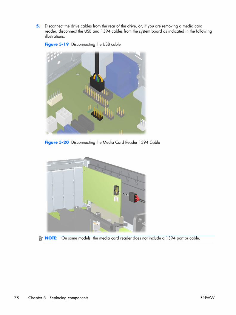
5. Disconnect the drive cables from the rear of the drive, or, if you are removing a media cardreader, disconnect the USB and 1394 cables from the system board as indicated in the followingillustrations.
Figure 5-19 Disconnecting the USB cable
Figure 5-20 Disconnecting the Media Card Reader 1394 Cable
NOTE: On some models, the media card reader does not include a 1394 port or cable.
78 Chapter 5 Replacing components ENWW

6. Press down on the green drive retainer button located on the left side of the drive to disengage thedrive from the drive cage (1). While pressing the drive retainer button, slide the drive back until itstops, then lift it up and out of the drive cage (2).
Figure 5-21 Removing a drive from the drive cage (media card reader shown)
7. Rotate the drive cage back down to its normal position.
CAUTION: Be careful not to pinch any cables or wires when rotating the drive cage down.
8. If you are replacing the drive, transfer the four guide screws from the old drive to the new one.
9. Replace the optical drive. (See Installing an optical drive on page 75.)
10. Replace the front bezel (see Installing the front bezel on page 65).
11. Replace the access panel (see Installing the access panel on page 64).
12. Restore all connections and equipment that you removed during the Predisassembly procedureson page 62.
Installing a hard drive or media card reader into the drive cage
You can install a 3.3 cm (3.5 in) hard drive underneath the 13.3 cm (5.25 in) optical drive. A mediacard reader can also be installed at this location. If an optical drive is present, you must remove it toinstall the hard drive.
To install a hard drive or media card in the drive cage:
1. Follow the procedures listed in the Predisassembly for drives on page 69 section.
CAUTION: Failure to follow the predisassembly procedures can result in equipment damage ordata loss.
2. Remove the access panel (see Removing the access panel on page 64).
3. Remove the front bezel (see Removing the front bezel on page 65).
4. Remove the optical disk drive if it is present. (See Removing an optical drive on page 73.)
ENWW Removing and installing components 79

5. Place the drive's guide screws into the J-slots in the drive bay. Then slide the drive toward the frontof the computer until it locks into place.
TIP: Angle the drive toward one side of the chassis to line up the guide screws with the slots.
Figure 5-22 Installing a drive into the drive cage (media card reader shown)
6. Connect the drive cables:
a. If installing a second hard drive, connect the power and data cables to the rear of the driveand connect the other end of the data cable to the next available (unpopulated) SATAconnector on the system board by following the numbered sequence of the connectors.
b. If installing a media card reader, connect the USB cable from the media card reader to theUSB connector on the system board labeled MEDIA. If the media card reader includes a1394 port, connect the 1394 cable to the 1394 PCI card.
NOTE: See Locate system board drive connections on page 71 for an illustration of thesystem board drive connectors.
7. Replace the optical drive. (See Installing an optical drive on page 75.)
8. Replace the front bezel (see Installing the front bezel on page 65).
9. Replace the access panel (see Installing the access panel on page 64).
10. Restore all connections and equipment that you removed during the Predisassembly procedureson page 62.
80 Chapter 5 Replacing components ENWW

Removing a DX115 Dataport hard drive
To remove a DX115 Dataport hard drive:
1. If a drive case is installed in the carrier, remove it:
CAUTION: Insert or remove the carrier (with a disk drive) only when the workstation is shutdown. Other procedures may result in system hangs, data loss, or even drive damage. Thecomponent supplier’s user guide describes a procedure for inserting or removing the carrier (withdrive) while the workstation is booted and then powering the drive via the power switch on theenclosure. However, Microsoft Windows XP and Windows Vista do not support this action.
a. Insert the key (1) and turn it clockwise (2).
Figure 5-23 Unlocking the carrier
b. Press on the left side of the door to open it (3).
c. Remove the drive carrier.
d. If shipping the unit, lock the carrier by inserting the key and turning it counterclockwise (3).
CAUTION: Always lock the drive before shipping or moving the computer. Failure to do somight result in damage to your removable hard drive system.
2. Follow the procedures listed in the Predisassembly for drives on page 69 section.
CAUTION: Failure to follow the predisassembly procedures can result in equipment damage ordata loss.
NOTE: For better clarity, the figures in this section do not show the front bezel. However, you donot need to remove the front bezel to remove the DX115 unit.
ENWW Removing and installing components 81
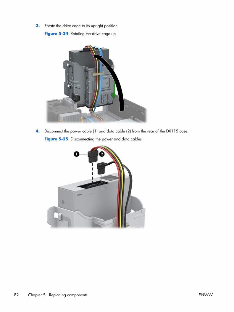
3. Rotate the drive cage to its upright position.
Figure 5-24 Rotating the drive cage up
4. Disconnect the power cable (1) and data cable (2) from the rear of the DX115 case.
Figure 5-25 Disconnecting the power and data cables
82 Chapter 5 Replacing components ENWW
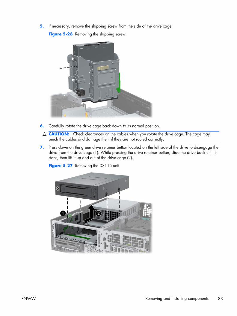
5. If necessary, remove the shipping screw from the side of the drive cage.
Figure 5-26 Removing the shipping screw
6. Carefully rotate the drive cage back down to its normal position.
CAUTION: Check clearances on the cables when you rotate the drive cage. The cage maypinch the cables and damage them if they are not routed correctly.
7. Press down on the green drive retainer button located on the left side of the drive to disengage thedrive from the drive cage (1). While pressing the drive retainer button, slide the drive back until itstops, then lift it up and out of the drive cage (2).
Figure 5-27 Removing the DX115 unit
ENWW Removing and installing components 83

8. If you are replacing the DX115 unit, remove and retain the four M3 x 5mm screws (black) fromthe lower four mounting holes of the DX115 case, and then transfer the screws to the new unit.(You can also store the screws in the chassis. See Locating extra guide screws on page 72 forscrew locations.)
Figure 5-28 Removing the guide screws
9. If it is necessary to remove the a hard disk drive from the carrier:
a. Remove the locking screws from the sides of the carrier.
Figure 5-29 Removing the locking screws
b. Remove the carrier cover by raising the front end of the cover (1) and pulling it away fromthe slot in the rear of the carrier (2).
Figure 5-30 Removing the cover
84 Chapter 5 Replacing components ENWW

c. Remove the drive by sliding it toward the front of the carrier until it disengages from thecarrier adapter and then lifting the drive out of the carrier.
Figure 5-31 Removing the drive
d. To replace the hard drive, see Installing a DX115 Dataport hard drive on page 85.
10. Replace the access panel (see Installing the access panel on page 64).
11. Restore all connections and equipment that you removed during the Predisassembly procedureson page 62.
Installing a DX115 Dataport hard drive
The optical disk drive bay can also accommodate a DX115 Dataport removable hard drive.
NOTE: The CRU Dataport DX115 does not fit in all optical drive bays. It is longer than most opticaldrives. Choose the optical bay for the CRU Dataport DX115 which best fits your computerconfiguration.
To install a DX115 unit:
1. Follow the procedures listed in the Predisassembly for drives on page 69 section.
CAUTION: Failure to follow the predisassembly procedures can result in equipment damage ordata loss.
NOTE: For better clarity, the figures in this section do not show the front bezel. However, you donot need to remove the front bezel to install the DX115 unit.
2. If you are replacing an existing optical disk drive, remove it. See Removing an optical driveon page 73.
ENWW Removing and installing components 85

3. If you are installing a new DX115 unit, remove and discard the counter-sunk shipping screw onthe side of the DX115 case.
Figure 5-32 Removing the shipping screw
4. Install four (supplied) M3 x 5mm screws (black) in the lower four mounting holes of the DX115case. (See Locating extra guide screws on page 72 for screw locations.)
Figure 5-33 Installing the guide screws
5. Position the guide screws on the drive into the J-slots in the drive bay. Then slide the drive towardthe front of the computer until it locks into place.
Figure 5-34 Installing the DX115 unit
86 Chapter 5 Replacing components ENWW

6. Rotate the drive cage to its upright position.
Figure 5-35 Rotating the drive cage up
7. If the cables are not already routed and attached to the system board:
a. Connect the SATA data cable to the system board connector labeled SATA1. (Refer to thehood label on the inside of the access panel for connector locations.)
b. Route the data cable through the cable guides to keep the data cable from being pinched bythe drive cage when raising or lowering it. One guide is located on the bottom side of thedrive cage (1). The other is part of the chassis frame under the drive cage (2). Routed thedata cable through these guides before connecting it to the optical drive.
Figure 5-36 Routing the drive cable
ENWW Removing and installing components 87

8. Connect the power cable (1) and data cable (2) to the rear of the DX115 case.
Figure 5-37 Connecting the power and data cables
9. Carefully rotate the drive cage back down to its normal position.
CAUTION: Check clearances on the cables when you rotate the drive cage. The cage maypinch the cables and damage them if they are not routed correctly.
10. If necessary, install a hard disk drive in the carrier:
a. Remove the locking screws from the sides of the carrier.
Figure 5-38 Removing the locking screws
88 Chapter 5 Replacing components ENWW
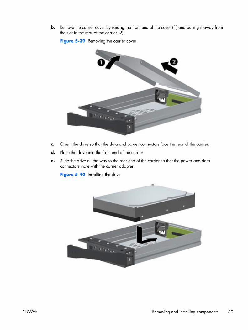
b. Remove the carrier cover by raising the front end of the cover (1) and pulling it away fromthe slot in the rear of the carrier (2).
Figure 5-39 Removing the carrier cover
c. Orient the drive so that the data and power connectors face the rear of the carrier.
d. Place the drive into the front end of the carrier.
e. Slide the drive all the way to the rear end of the carrier so that the power and dataconnectors mate with the carrier adapter.
Figure 5-40 Installing the drive
ENWW Removing and installing components 89

f. Replace the cover by aligning the tab on the rear of the cover with the slot on the rear of thecarrier (1) and then rotating the front of the cover onto the carrier (2).
Figure 5-41 Replacing the carrier cover
g. Replace the locking screws in the sides of the carrier.
Figure 5-42 Replacing the locking screws
11. Install the carrier in the drive case:
90 Chapter 5 Replacing components ENWW

CAUTION: Insert or remove the carrier (with a disk drive) only when the workstation is shutdown. Other procedures may result in system hangs, data loss, or even drive damage. Thecomponent supplier’s user guide describes a procedure for inserting or removing the carrier (withdrive) while the workstation is booted and then powering the drive via the power switch on theenclosure. However, Microsoft Windows XP and Windows Vista do not support this action.
a. Insert the key (1) and turn it clockwise (2).
Figure 5-43 Locking the carrier
b. Press the handle to open the door (3).
c. Insert the drive carrier.
d. Lock the carrier by inserting the key and turning it counterclockwise (3).
CAUTION: Always lock the drive before shipping or moving the computer. Failure to do somight result in damage to your removable hard drive system.
12. Replace the access panel (see Installing the access panel on page 64).
13. Restore all connections and equipment that you removed during the Predisassembly procedureson page 62.
Removing and replacing the primary hard drive
The preinstalled 3.5-inch hard drive is located under the power supply. To remove and replace thehard drive:
1. Follow the procedures listed in the Predisassembly for drives on page 69 section.
CAUTION: Failure to follow the predisassembly procedures can result in equipment damage ordata loss.
2. Remove the access panel (see Removing the access panel on page 64).
3. Remove the front bezel (see Removing the front bezel on page 65).
ENWW Removing and installing components 91

4. Rotate the drive cage to its upright position.
Figure 5-44 Rotating the drive cage up
5. Rotate the power supply to its upright position. The hard drive is located beneath the powersupply.
Figure 5-45 Rotating the power supply up
92 Chapter 5 Replacing components ENWW

6. Disconnect the power cable (1) and data cable (2) from the hard drive.
Figure 5-46 Removing the optical drive
7. Press down on the green release latch next to the hard drive (1). While holding the latch down,slide the drive forward until it stops, then lift the drive up and out of the bay (2).
Figure 5-47 Removing the primary hard drive
ENWW Removing and installing components 93

8. To install a new hard drive, move the silver and blue isolation mounting guide screws from the oldhard drive to the new hard drive.
Figure 5-48 Installing the hard drive guide screws
9. Align the guide screws with the slots on the chassis drive cage, press the hard drive down into thebay, then slide it back until it stops and locks in place.
Figure 5-49 Installing the hard drive
94 Chapter 5 Replacing components ENWW

10. Connect the drive cables:
a. Connect the power cable (1) and data cable (2) to the hard drive.
Figure 5-50 Removing the optical drive
b. Route the SATA and power cables through the cable guide on the bottom of the chassisframe behind the hard drive. (See Cable management on page 96.)
c. If the system has only one SATA hard drive, the data cable must be connected to the darkblue connector labeled SATA0 on the system board to avoid any hard drive performanceproblems. (See Locate system board drive connections on page 71.)
11. Rotate the drive cage and the power supply down to their normal positions.
12. Replace the front bezel (see Installing the front bezel on page 65).
13. Replace the access panel (see Installing the access panel on page 64).
14. Restore all connections and equipment that you removed during the Predisassembly procedureson page 62.
ENWW Removing and installing components 95

Cable managementThe HP Z210 SFF chassis is a very compact computer and proper routing of the internal cables iscritical to the operation of the computer. Follow good cable management practices when workinginside the computer.
● Keep cables away from direct contact with major heat sources like the heat sink. (The air flowguide has a cable guide that lets you route cables safely around the heatsink.)
● Do not jam cables on top of expansion cards or DIMMs. Circuit cards and DIMMs are notdesigned to take excessive pressure.
● Keep cables clear of movable or rotating parts like the power supply and drive cage to preventthem from being cut or crimped when the component is lowered into its normal position
● When folding a flat ribbon cable, never fold to a sharp crease. Sharp creases may damage thewires.
● Some flat ribbon cables come prefolded. Never change the folds on these cables.
● Do not bend any cable sharply. A sharp bend can break the internal wires.
● Never bend a SATA data cable tighter than a 30 mm (1.18 in) radius.
● Never crease a SATA data cable.
● Do not rely on components like the drive cage, power supply, or computer cover to push cablesdown into the chassis. Always position the cables to lay properly by themselves or in the cableguides and chassis areas designed for cable routing.
When removing the power supply power cables from the connector on the system board, always followthese steps:
1. Squeeze on the top of the retaining latch attached to the cable end of the connector.
2. Grasp the cable end of the connector and pull it straight up.
CAUTION: Always pull the connector - NEVER pull on the cable. Pulling on the cable coulddamage the cable and result in a failed power supply.
96 Chapter 5 Replacing components ENWW

Power connections
For help with identifying power cables, see the following figure and table. Ensure that all cables arerouted or tied so they cannot interfere with the processor heatsink fans.
Figure 5-51 Power connector identification for a typical configuration
Table 5-7 Power connector description
Item Description Item Description
P1 Main power P5 4–pin connector for legacy devices
P2 PWRCMD—Power command P6 (P9) Optical disk drive
P3 CPU power P7 SATA PWR1 (P160 on system board)for optical disk or hard disk drives
P4 Hard disk drive
ENWW Removing and installing components 97

Using the computer in a tower orientationThe HP Z210 SFF Workstation can be used in a tower orientation. The HP logo plate on the front bezelis adjustable for either desktop or tower orientation.
1. Follow the procedures listed in the Predisassembly procedures on page 62 section.
CAUTION: Failure to follow the predisassembly procedures can result in equipment damage ordata loss.
2. Orient the computer so that its right side (as seen from the front) is facing down and place thecomputer in the optional stand.
NOTE: To stabilize the computer in a tower orientation, HP recommends the use of the optionaltower stand.
Figure 5-52 Changing from desktop to tower orientation
3. Restore all connections and equipment that you removed during the Predisassembly procedureson page 62.
NOTE: Ensure at least 10.2 cm (4 in) of space on all sides of the computer remains clear andfree of obstructions.
98 Chapter 5 Replacing components ENWW

Front panel I/O device assemblyThis section describes how to remove and install a front panel I/O device assembly.
Removing the front panel I/O device assembly
To remove the front panel I/O device assembly:
1. Disconnect power from the computer (see Predisassembly procedures on page 62 ).
2. Remove the access panel (see Removing the access panel on page 64).
3. Remove the front bezel (see Removing the front bezel on page 65).
4. Remove the screws that attach the I/O device assembly to the chassis, as shown in the followingfigure (1).
5. Swing the assembly into the chassis to release it from the front panel, as shown in the followingfigure (2).
Figure 5-53 Disconnecting the front panel I/O device assembly
ENWW Removing and installing components 99

6. Disconnect the front panel I/O device assembly cables from the system board as shown below.
Figure 5-54 Disconnecting the front panel I/O cables
7. Carefully guide the cables through the chassis openings (1), as shown in the following figure.
Figure 5-55 Removing the front panel I/O device assembly
8. Carefully lift the front panel I/O device assembly and cables from the chassis (2).
100 Chapter 5 Replacing components ENWW

Installing the front panel I/O device assembly
To install the front panel I/O device assembly:
1. Prepare the computer for servicing by following the Predisassembly procedures on page 62.
CAUTION: Failure to follow the predisassembly procedures can result in equipment damage ordata loss.
2. Remove the access panel (see Removing the access panel on page 64).
3. Remove the front bezel (see Removing the front bezel on page 65).
4. Rotate the drive cage to its upright position.
Figure 5-56 Rotating the Drive Cage Up
5. Carefully guide the front panel I/O device assembly cables through the chassis openings fromwhich they were removed.
6. Place the front panel I/O device assembly in the chassis, and then install the fastening screw.
ENWW Removing and installing components 101

7. Connect the front panel USB (1 and 2), front audio (3), and front power/LED (4) cables to thesystem board as shown in the following diagram.
Figure 5-57 Connecting the front panel I/O device cables
8. Rotate the drive cage down to its normal position.
9. Replace the front bezel (see Installing the front bezel on page 65).
10. Replace the access panel (see Installing the access panel on page 64).
11. Restore all connections and equipment that you removed during the Predisassembly procedureson page 62.
102 Chapter 5 Replacing components ENWW

SpeakerThis section describes how to remove and install the speaker.
Removing the speaker
To remove the speaker:
1. Prepare the computer for servicing by following the Predisassembly procedures on page 62.
CAUTION: Failure to follow the predisassembly procedures can result in equipment damage ordata loss.
2. Remove the access panel (see Removing the access panel on page 64).
3. Remove the front bezel (see Removing the front bezel on page 65).
4. Disconnect the speaker cable from the system board (1) as shown in the figure below.
5. Remove the two screws as shown (2).
6. Slide the speaker away from the chassis and remove it from the chassis (3).
Figure 5-58 Removing the computer speaker
Installing the speaker
To install the speaker, reverse the previous steps.
ENWW Removing and installing components 103

Power supplyThis section describes how to remove and install a power supply.
Removing the power supply
To remove the power supply:
1. Prepare the computer for servicing by following the Predisassembly procedures on page 62.
CAUTION: Failure to follow the predisassembly procedures can result in equipment damage ordata loss.
2. Remove the access panel (see Removing the access panel on page 64).
3. Disconnect all of the power supply cables from the system board and all peripheral devices,including hard drives, optical drives, and others as needed. (See Power connections on page 97.)
4. Rotate the drive cage to its upright position.
Figure 5-59 Rotating the drive cage up
104 Chapter 5 Replacing components ENWW

5. Slide the power supply toward the chassis and then up to remove it from the chassis.
Figure 5-60 Removing the power supply
Installing the power supply
To install the power supply, reverse the previous steps.
ENWW Removing and installing components 105

System fan assemblyThis section describes how to remove and install the system fan assembly.
Removing the system fan assembly
To remove the system fan assembly:
1. Prepare the computer for servicing by following the Predisassembly procedures on page 62.
CAUTION: Failure to follow the predisassembly procedures can result in equipment damage ordata loss.
2. Remove the access panel (see Removing the access panel on page 64).
3. Remove the front bezel (see Removing the front bezel on page 65).
4. Remove the cables from the support arm on the airflow guide.
106 Chapter 5 Replacing components ENWW

5. Remove the airflow guide by pulling it straight up and out of the chassis, as shown in the followingfigure. (The processor heatsink is not shown.)
Figure 5-62 Removing the airflow guide
6. Disconnect the system fan assembly cable from the system board as shown in the following figure.
Figure 5-63 Disconnecting fan wires
ENWW Removing and installing components 107

7. Remove the fan assembly by pushing in on the four release tabs on the front of the chassis (1), andthen sliding the fan assembly into the chassis until you can lift it out.
Figure 5-64 Removing the fan assembly
Installing the system fan assembly
To install the system fan assembly, reverse the removal steps.
108 Chapter 5 Replacing components ENWW

MemoryThis section presents memory module (DIMM) configuration information and removal/installationprocedures.
Supported DIMM configurations
The computer supports these DIMM configurations:
● Four DIMM slots
● Memory configuration from 1 GB to 16GB
● No support for mirroring
● No support for DIMM sparing
● Error checking and correcting (ECC) and non-ECC DIMMs are supported.
DIMM installation guidelines
● Install only HP-approved DDR3 DIMMs
CAUTION: HP ships only DIMMs that are electrically and thermally compatible with thiscomputer. Because third-party DIMMs might not be electrically or thermally compatible, they arenot supported by HP.
● For ECC DIMMs, use only industry-standard ECC unbuffered DIMMs. See http://www.hp.com/go/quickspecs to find which DIMMs are compatible with the computer.
● Do not intermix non-ECC memory DIMMs with ECC memory DIMMs.
DIMM installation order
The numbers in the following figure show the correct installation order for DIMMs.
Figure 5-65 DIMM load order
BIOS errors and warnings
The BIOS generates warnings/errors on invalid memory configurations:
● If the BIOS can find a valid memory configuration by disabling plugged-in memory, it does so andreports a warning during POST. the computer can still be started. The warning will indicate thelocation of the failed DIMM on the system board or memory riser.
● If there is no way for the BIOS to obtain a valid memory configuration by disabling plugged-inmemory, the BIOS halts with a diagnostics code for memory error (five beeps and blinks).
ENWW Removing and installing components 109

Removing a DIMM
To remove a DIMM:
1. Prepare the computer for servicing by following the Predisassembly procedures on page 62.
CAUTION: Failure to follow the predisassembly procedures can result in equipment damage ordata loss.
2. Remove the access panel (see Removing the access panel on page 64).
3. Rotate the drive cage to its upright position.
Figure 5-66 Rotating the drive cage up
110 Chapter 5 Replacing components ENWW

4. Push gently outward on the DIMM socket levers (1) as shown in the following figure.
Figure 5-67 Removing a DIMM
5. Lift the DIMM straight up (2) and out of the socket, then store the DIMM in an antistatic bag.
ENWW Removing and installing components 111

Installing a DIMM
To install the DIMM:
1. Prepare the computer for servicing by following the Predisassembly procedures on page 62.
CAUTION: Failure to follow the predisassembly procedures can result in equipment damage ordata loss.
2. Remove the access panel (see Removing the access panel on page 64).
3. Rotate the drive cage to its upright position.
Figure 5-68 Rotating the drive cage up
4. Push gently outward on the DIMM socket levers.
112 Chapter 5 Replacing components ENWW

5. Align the DIMM connector key with the DIMM socket key, and then seat the DIMM firmly in thesocket (1).
CAUTION: DIMMs and their sockets are keyed for proper installation. To prevent socket orDIMM damage, align these guides properly when installing DIMMs.
Figure 5-69 Opening DIMM socket levers
6. Secure the socket levers (2).
7. Rotate the drive cage and the power supply down to their normal positions.
8. Replace the front bezel (see Installing the front bezel on page 65).
9. Replace the access panel (see Installing the access panel on page 64).
10. Restore all connections and equipment that you removed during the Predisassembly procedureson page 62.
ENWW Removing and installing components 113

Expansion card slot identificationThis section identifies and describes computer expansion card slots, and presents card configurationinformation.
Slot identification and description
The following figure identifies computer expansion card slots.
Figure 5-70 Identifying expansion card slots
The following table describes the computer PCIe card slots.
Table 5-8 PCI slots
Slot Type Slot power (maximum)
1 PCI 32b/33MHZ
45W for all graphics cards
80W for all I/O devices
2 PCIe2 - x16
3 PCIe2 - x16(4)
4 PCIe2 - x1
NOTE: The x1, x4, and x16 designators describe the mechanical length of the slot. The number inparentheses lists the number of electrical PCIe lanes routed to the expansion slot. For example, x16(4)means that the expansion slot is mechanically a x16 length connector, with four PCIe lanes connected.
Card configuration restrictions for power supplies
CAUTION: To prevent damage, the overall power consumption of the computer (including I/Ocards, CPU, and memory) must not exceed the maximum rating of the computer power supply. Forpower supply information, see Power supply specifications on page 9.
114 Chapter 5 Replacing components ENWW

Choosing an expansion card slot
Whenever possible, use the following tips to help you select the proper slot for an expansion card:
● Use the black PCIe x16 I/O slot for the primary graphics card; if you do not use this slot for thegraphics card, only cards certified as After Market Options are supported.
● Insert a second graphics card in the white PCIe x16 slot.
● Install a card in a slot that most closely matches its interface technology:
◦ Install a PCIe Gen1 x16 or a PCIe Gen1 x8 card in the PCIe Gen2 x16 slot.
◦ Install a PCIe Gen1 x4 card in the PCIe Gen1 x4 slot.
◦ Install a PCIe Gen1 x1 card in the PCIe Gen1 x1 slot.
◦ Install a PCI card in one of the PCI slots.
◦ Whenever possible, install a PCIe x1 card in an x1 slot.
● Leave as much space as possible between cards.
● For best operational efficiency, select a slot that:
◦ Electrically matches the number of PCIe card lanes (e.g., x1 in a x1 slot).
◦ Has more lanes electrically.
◦ Has fewer lanes, but is closer to your needs. For example, place an x16 card in an x4 slot,and an x4 card in a an x1 slot.
● An x1 connector supports an x1 card only. Although, an x1 card can be inserted into any slot,this may waste the potential for future card placement.
● To prevent electromagnetic interference, avoid installing a card with external cable connectionsnext to a graphics card.
ENWW Removing and installing components 115

Removing and installing expansion cardsPCIe I/O slots can support other PCIe cards with less bus bandwidth than what is physically defined forthe slot.
Expansion card slot description
NOTE: The x1, x4, and x16 designators describe the mechanical length of the slot. The number inparentheses lists the number of electrical PCIe lanes routed to the expansion slot. For example, x16(4)means that the expansion slot is mechanically a x16 length connector, with four PCIe lanes connected.
Use the following table to determine PCIe card compatibility.
Table 5-9 Computer PCIe compatibility matrix
Slot Mechanical compatibility Electrical compatibility Color
1 PCI 32–bit/33MHz PCI only White
2 x16 connector (x1, x4, x8, x16) Black
3 x16 connector (x1, x4) White
4 x1 connector (x1) Black
Removing an expansion card
To remove an expansion card:
1. Prepare the computer for servicing by following the Predisassembly procedures on page 62.
CAUTION: Failure to follow the predisassembly procedures can result in equipment damage ordata loss.
2. Remove the access panel (see Removing the access panel on page 64).
3. Remove any cables connected to the expansion card.
4. Push down on the expansion card retention clamp levers on the inside of the chassis to open theretention clamp.
Figure 5-71 Releasing the retention clamp
116 Chapter 5 Replacing components ENWW

5. Push the retention latch (1), and then carefully lift the card from the chassis (2).
Figure 5-72 Removing the expansion card
6. Push the retention latch and install an expansion slot cover if you do not intend to replace thecard.
7. Replace the access panel (see Installing the access panel on page 64).
8. Restore all connections and equipment that you removed during the Predisassembly procedureson page 62.
Installing an expansion card
Visit http://www.hp.com/go/quickspecs to learn which graphics cards are supported in the computer,how much memory each graphics card includes, and graphics card power requirements.
To install an expansion card:
1. Prepare the computer for servicing by following the Predisassembly procedures on page 62.
CAUTION: Failure to follow the predisassembly procedures can result in equipment damage ordata loss.
2. Remove the access panel (see Removing the access panel on page 64).
ENWW Removing and installing components 117

3. Push the expansion card retention clamp levers down on the outside of the chassis to release theretention clamp, as shown in the figure below.
Figure 5-73 Releasing the retention clamp
4. Remove the expansion card slot cover by pulling it up, out of the chassis.
TIP: Grasp the slot cover between two fingers—one from the inside of the chassis, and one fromthe outside.
Figure 5-74 Removing the slot cover
5. Angle the expansion card to Insert it into the expansion card guide.
118 Chapter 5 Replacing components ENWW

6. Align the PCIe card keyway with the slot key, push the retention clamp (1), and then firmly seat thecard in the slot (2).
● If the retention clamp does not close, ensure that all cards are properly seated, and then tryagain.
● If required by the card, connect the auxiliary power cable to the card (not illustrated).
Figure 5-75 Inserting the expansion card
7. Replace the access panel (see Installing the access panel on page 64).
8. Restore all connections and equipment that you removed during the Predisassembly procedureson page 62.
ENWW Removing and installing components 119

BatteryThis section describes how to remove and install the battery.
The battery that comes with the computer provides power to the real-time clock and has a minimumlifetime of about three years.
WARNING! This computer includes a lithium battery. There is a risk of fire and chemical burn if thebattery is handled improperly. Do not disassemble, crush, puncture, short external contacts, dispose ofin water or fire, or expose battery to temperatures higher than 60°C (140°F).
CAUTION: Before removing the battery, back up the CMOS settings in case they are lost when thebattery is removed. To back up the CMOS settings, select the Save to Diskette option in theComputer Setup (F10) Utility.
NOTE: Do not dispose of batteries, battery packs, and accumulators with general household waste.
Removing the battery
To remove the battery:
1. Prepare the computer for servicing by following the Predisassembly procedures on page 62.
CAUTION: Failure to follow the predisassembly procedures can result in equipment damage ordata loss.
2. Remove the access panel (see Removing the access panel on page 64).
3. On the system board, press the release tab of the battery holder.
4. Lift the battery straight up and out of the holder as shown in the following figure.
Figure 5-76 Removing the battery
120 Chapter 5 Replacing components ENWW

Installing the battery
To install the battery:
1. Confirm the polarity (positive or negative) of the battery to position it correctly in the batteryholder.
2. Angle the battery and place the battery edge under the plastic housing tab and press gently until itsnaps into place.
CPU heatsinkThis section describes how to remove and install a CPU heatsink.
Removing the CPU heatsink
To remove a heatsink:
1. Prepare the computer for servicing by following the Predisassembly procedures on page 62.
CAUTION: Failure to follow the predisassembly procedures can result in equipment damage ordata loss.
2. Remove the access panel (see Removing the access panel on page 64).
3. Remove the airflow guide.
4. Slowly and evenly loosen one pair of diagonally opposite screws (1) from the CPU until the screwshanks disengage from the system board, and then loosen the remaining pair (2) as shown below.
CAUTION: Do not fully loosen one screw, and then move on to the next. Instead, loosen allscrews a little at a time to ensure the CPU remains level.
Figure 5-77 Loosening heatsink screws in sequence
ENWW Removing and installing components 121

5. Disconnect the heatsink screws from the system board (1) as shown in the following figure.
Figure 5-78 Disconnecting the heatsink screws
6. Before lifting the heatsink, gently twist the heatsink to break the thermal compound between theCPU and the heatsink.
7. Lift the CPU heatsink out of the chassis (2).
8. Use alcohol and a soft cloth to clean the thermal interface residue from the CPU and the heatsink.Let the alcohol on the CPU and CPU heatsink dry completely.
122 Chapter 5 Replacing components ENWW

Installing the CPU heatsink
To install a heatsink:
1. Prepare the computer for servicing by following the Predisassembly procedures on page 62.
CAUTION: Failure to follow the predisassembly procedures can result in equipment damage ordata loss.
2. Remove the access panel (see Removing the access panel on page 64).
3. Remove the airflow guide.
4. Perform one of the following tasks:
● If you are reusing the original heatsink, clean the old themal compound from the bottom ofthe heatsink, then apply a new layer of thermal compound to the center of the CPU topsurface.
● If you are using a new CPU heatsink, remove the thermal compound protective liner from thebottom of the new heatsink. (New heatsinks already have thermal compound on the heatsinksurface.)
5. Align the heatsink's four mounting screws with the mounting holes in the chassis.
6. Carefully place the heatsink on the CPU.
7. Tighten each heatsink screw a little at a time to ensure that the CPU stays level. Do not fully tightenone screw and then move on to the next.
8. Tighten each set of diagonally opposed screws a little at a time to 6 in-lbs of torque.
CAUTION: Do not overtighten the heatsink screws. Overtightening can strip the threads in thechassis.
9. Replace the airflow guide.
10. Replace the access panel (see Installing the access panel on page 64).
11. Restore all connections and equipment that you removed during the Predisassembly procedureson page 62.
ENWW Removing and installing components 123

CPUThis section describes how to remove and install a CPU.
Removing a CPU
To remove a CPU:
1. Prepare the computer for servicing by following the Predisassembly procedures on page 62.
CAUTION: Failure to follow the predisassembly procedures can result in equipment damage ordata loss.
2. Remove the access panel (see Removing the access panel on page 64).
3. Remove the CPU heatsink (see Removing the CPU heatsink on page 121).
4. Raise the CPU socket lever (1) and open the cover (2) as shown in the following figure (fanassembly not shown).
Figure 5-79 Removing a CPU
CAUTION: Do not touch the CPU socket contacts or the gold pads underneath the CPU. Useextreme care and handle the CPU only by the edges.
5. Pull the CPU straight out of the socket (3), and store the CPU in a static free container in a safeplace where it cannot be damaged
124 Chapter 5 Replacing components ENWW

Installing a CPU
NOTE: HP recommends that you do not swap processors (CPUs) from one system board to another.
To install a CPU:
1. Prepare the computer for servicing by following the Predisassembly procedures on page 62.
CAUTION: Failure to follow the predisassembly procedures can result in equipment damage ordata loss.
2. Remove the access panel (see Removing the access panel on page 64).
3. Remove the airflow guide.
4. If necessary, remove the CPU heatsink (see Removing the CPU heatsink on page 121).
5. Using extreme care, fully raise the CPU socket lever and cover.
CAUTION: The CPU socket contacts are delicate. To avoid bending the contacts, use extremecare when installing the CPU in the socket.
6. Align the notches in the CPU base with the tabs on the socket as shown in the figure below.
Seat the CPU into the socket. Ensure that the underside of the CPU is level with the top of the CPUsocket.
Figure 5-80 Seating the CPU
7. Close the CPU cover plate by lightly pressing down on the CPU cover plate while closing thesocket lever.
8. Replace the CPU heatsink (see Installing the CPU heatsink on page 123),
9. Replace the access panel (see Installing the access panel on page 64).
10. Restore all connections and equipment that you removed during the Predisassembly procedureson page 62.
ENWW Removing and installing components 125
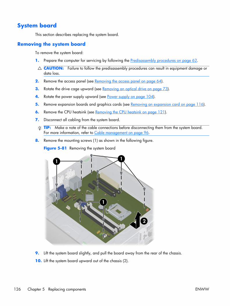
System boardThis section describes replacing the system board.
Removing the system board
To remove the system board:
1. Prepare the computer for servicing by following the Predisassembly procedures on page 62.
CAUTION: Failure to follow the predisassembly procedures can result in equipment damage ordata loss.
2. Remove the access panel (see Removing the access panel on page 64).
3. Rotate the drive cage upward (see Removing an optical drive on page 73).
4. Rotate the power supply upward (see Power supply on page 104).
5. Remove expansion boards and graphics cards (see Removing an expansion card on page 116).
6. Remove the CPU heatsink (see Removing the CPU heatsink on page 121).
7. Disconnect all cabling from the system board.
TIP: Make a note of the cable connections before disconnecting them from the system board.For more information, refer to Cable management on page 96.
8. Remove the mounting screws (1) as shown in the following figure.
Figure 5-81 Removing the system board
9. Lift the system board slightly, and pull the board away from the rear of the chassis.
10. Lift the system board upward out of the chassis (2).
126 Chapter 5 Replacing components ENWW

Installing the system board
To install the system board, reverse the steps for removing the board.:
Product recyclingHP encourages customers to recycle used electronic hardware, HP original print cartridges, andrechargeable batteries.
For information about recycling HP components or products, see http://www.hp.com/go/recycle.
ENWW Product recycling 127

6 Diagnostics and troubleshooting
This chapter describes the tools available for diagnosing and troubleshooting system issues, andincludes these topics:
Topics
Calling technical support on page 129
Locating ID labels on page 129
Locating warranty information on page 130
Diagnosis guidelines on page 131
Troubleshooting checklist on page 133
Troubleshooting scenarios and solutions on page 136
Self-troubleshooting with HP Vision Diagnostics on page 144
Diagnostic codes and errors on page 152
128 Chapter 6 Diagnostics and troubleshooting ENWW

Calling technical supportAt times you might encounter an issue that requires technical support. When you call technical support:
● Have the computer readily accessible.
● Write down the computer serial numbers, product numbers, model names, and model numbersand have them in front of you.
● Note any applicable error messages.
● Note any add-on options.
● Note the operating system.
● Note any third-party hardware or software.
● Note the details of any blinking LEDs on the front of the computer.
● Note the applications you were using when you encountered the problem.
NOTE: When calling in for service or support, you might be asked for the Product Number (example:PS988AV) of the computer. If the computer has a Product Number, it is generally located next to the10- or 12-digit Serial Number of the computer.
NOTE: On most models, the serial number and product number labels can be found on the top panelor side of the computer and at the rear of the computer.
For a listing of all worldwide technical support phone numbers, visit http://www.hp.com/support,select your region, and click Contact HP in the upper-left corner.
Locating ID labelsTo assist in troubleshooting, product, serial, and authentication numbers are available on eachcomputer.
ENWW Calling technical support 129

Typically each HP Workstation has two unique serial number labels (1) and a Certificate ofAuthentication (COA) label (2) as shown in the figure below.
Figure 6-1 Workstation label locations
In general, the serial number labels can be found on the top panel or on the side of the computer andat the rear of the computer (your computer may look different). Keep this number available whencontacting customer service for assistance.
A product number is generally located next to the serial number.
The COA is used for Windows-preinstalled systems only, and is generally located on the top panel orside of the computer near the serial number label. On some computers it is located on the bottom of thecomputer.
Locating warranty informationTo locate base warranty information, see http://www.hp.com/support/warranty-lookuptool.
To locate an existing Care Pack, see http://www.hp.com/go/lookuptool.
To extend a standard product warranty, visit http://www.hp.com/hps/carepack. HP Care PackServices offer upgraded service levels to extend and expand a standard product warranty.
130 Chapter 6 Diagnostics and troubleshooting ENWW

Diagnosis guidelinesIf you encounter a problem with the computer, monitor, or software, the following sections provide a listof general suggestions that help you isolate and focus on the problem before taking further action.
Diagnosis at startup● Verify that the computer and monitor are plugged into a working electrical outlet.
● Remove all diskettes, CDs, or USB drive keys from your system before turning it on.
● Verify that the computer is turned on and the green power light is on.
● If you have installed an operating system other than the factory-installed operating system, checkto be sure that it is supported on your system by visiting http://www.hp.com/go/quickspecs.
● Verify that the monitor is turned on and the green monitor light is on. Note that not all monitors areequipped with LED lights to indicate their functionality.
● Turn up the brightness and contrast controls of the monitor if the monitor is dim.
● If the computer has multiple video sources and only a single monitor, the monitor must beconnected to the primary display adapter. During startup, the other monitor connectors aredisabled; if the monitor is connected to one of these ports, it will not function after Power-on SelfTest (POST). You can select the default source in Computer Setup (F10).
ENWW Diagnosis guidelines 131

Diagnosis during operation● Look for blinking LEDs on the front of the computer. The blinking lights are error codes that will
help you diagnose the problem. Refer to the Diagnostic LED and audible (beep) codeson page 152 section of this document for information on interpreting diagnostic lights andaudible codes.
● Press and hold any key. If the system beeps, then your keyboard is operating correctly.
● Check all cables for loose or incorrect connections.
● Wake the computer by pressing any key on the keyboard or the power button. If the systemremains in suspend mode, shut down the system by pressing and holding the power button for atleast four seconds, then press the power button again to restart the system. If the system does notshut down, unplug the power cord, wait a few seconds, then plug it in again. If it does not restart,press the power button to start the computer.
● Reconfigure the computer after installing a non–plug and play expansion board or other option.
● Be sure that all required device drivers have been installed. For example, if you have connected aprinter, you must install a printer driver.
● If you are working on a network, plug another computer with a different cable into the networkconnection. There might be a problem with the network plug or cable.
● If you recently added new hardware, remove the hardware and verify if the computer functionsproperly.
● If you recently installed new software, uninstall the software and verify if the computer functionsproperly.
● If the screen is blank, plug the monitor into a different video port on the computer if one isavailable. Alternatively, replace the monitor with a monitor that you know is working properly.
● Upgrade the BIOS. A new release of the BIOS might have been released that supports newfeatures or fixes your problem.
132 Chapter 6 Diagnostics and troubleshooting ENWW

Troubleshooting checklistBefore running diagnostic utilities, use the following checklist to find possible solutions for computer orsoftware problems.
● Is the computer and monitor connected to a working electrical outlet?
● Is the computer powered on?
● Is the blue power light illuminated?
● Is the monitor on?
● Is the monitor power LED illuminated?
● If the monitor is dim, adjust the monitor brightness and contrast controls.
● Press and hold any key. If the system beeps, the keyboard is operating correctly.
● Check cables for loose or improper connections.
● After installing a non-plug and play (PnP) expansion board or other option (such as a diskettedrive), reconfigure the computer.
● Are all necessary device drivers installed?
● Have all printer drivers been installed for each application?
● Have you removed diskettes, optical disks, and USB drive keys from the drives before poweringon the computer?
● Are you running the latest version of BIOS, drivers, and software?
HP troubleshooting resources and toolsThis section provides information on the HP Help and Support Center, E-support, and Helpful Hints fortroubleshooting.
HP Support AssistantThe HP Support Assistant is a customized HP user interface that enhances the Windows 7 Help andSupport Center functions. This customized utility allows you to access specific information about an HPWorkstation such as configuration information by clicking Start > All Programs > HP. The interfacealso provides customized help and support links to the HP Web site related to the HP Workstation.
NOTE: The customized HP Support Assistant is not available on Linux.
HP Performance AdvisorThe HP Performance Advisor is an HP tool that offers a quick and easy way to configure and update HPworkstations. It improves workstation stability and performance while helping you work faster and moreproductively. To use this tool, select Start > All Programs > HP > HP Performance Advisor.
E-supportOnline access and support resources include Web-based troubleshooting tools, technical knowledgedatabases, driver and patch downloads, online communities, and product change notification services.
ENWW Troubleshooting checklist 133

The following Web sites are also available to you:
● http://www.hp.com—Provides useful product information.
● http://www.hp.com/support/workstation_manuals—Provides the latest online documentation.
● http://www.hp.com/go/workstationsupport—Provides technical support information forworkstations.
● http://www.hp.com/support—Provides a listing of the worldwide technical support phonenumbers. Access the telephone numbers by visiting the Web site, then select your region, and clickContact HP in the upper-left corner.
● http://www.hp.com/support/workstation_swdrivers—Provides access to software and drivers forworkstations.
Troubleshooting a problem
To help you troubleshoot problems with your system, HP provides the Business Support Center (BSC).The BSC is a portal to an extensive selection of online tools. To access BSC and troubleshoot a problemwith the workstation, complete the following:
1. Visit http://www.hp.com/go/workstationsupport.
2. Under the Business Support Center menu on the left, select Troubleshoot a problem.
3. Under Select your product (center window), select Workstations (under personalcomputing).
4. Under Select your product, continue with selections as appropriate to the workstation seriesand model, and to the problem you are troubleshooting.
Instant Support and Active Chat
HP Instant Support is a set of Web-based support tools that automate and speed up the resolution ofdesktop computing, tape storage, and printing problems.
Active Chat enables you to electronically submit a support ticket to HP over the Web. When you submita support ticket, Active Chat collects information about the computer and passes it to an online supportspecialist. The collection of information might take up to 30 seconds depending on the computerconfiguration. When you submit a support ticket, you receive a confirmation message containing yourcase ID, the support hours for your location, and the estimated time of response.
For more information about HP Instant Support and Active Chat and how to use them, visithttp://www.hp.com/hps/hardware/hw_professional.html.
NOTE: This feature is not available on Linux.
Helpful hints
If you encounter a problem with the workstation, monitor, or software, the following provides a list ofgeneral suggestions that help you isolate and focus on the problem before taking further action.
134 Chapter 6 Diagnostics and troubleshooting ENWW

At startup
● Verify that the workstation and monitor are plugged into a working electrical outlet.
● Remove all diskettes, optical disks, and USB drive keys from the drives before powering on theworkstation.
● Verify that the workstation is turned on and the blue power light is on.
● If you have installed an operating system other than the factory-installed operating system, checkto be sure that it is supported on your system by visiting http://www.hp.com/go/quickspecs.
● Verify that the monitor is turned on and the power LED is illuminated.
● Turn up the brightness and contrast controls of the monitor if the monitor is dim.
● If the workstation has multiple video sources and only a single monitor, the monitor must beconnected to the source selected as the primary video adapter. During startup, the other monitorconnectors are disabled; if the monitor is connected to one of these ports, it will not function afterPower-on Self Test (POST). You can select the default video source in Computer Setup (F10).
During operation
● Look for blinking LEDs on the front of the workstation. The blinking lights are error codes that willhelp you diagnose the problem. Refer to the Diagnostic lights and audible (beep) codes section ofthis document for information on interpreting diagnostic lights and audible codes.
● Press and hold any key. If the system beeps, then your keyboard is operating correctly.
● Check all cables for loose or incorrect connections.
● Wake the workstation by pressing any key on the keyboard or the power button. If the systemremains in suspend mode, shut down the system by pressing and holding the power button for atleast four seconds, then press the power button again to restart the system. If the system does notshut down, unplug the power cord, wait a few seconds, then plug it in again. If it does not restart,press the power button to start the workstation.
● Reconfigure the workstation after installing a non–plug and play expansion board or other option.Refer to the Troubleshooting scenarios and solutions on page 136 section of this document forinstructions.
● Be sure that all required device drivers have been installed. For example, if you have connected aprinter, you must install a printer driver.
● If you are working on a network, plug another workstation with a different cable into the networkconnection. There might be a problem with the network plug or cable.
● If you recently added new hardware, remove the hardware and verify if the workstation functionsproperly.
● If you recently installed new software, uninstall the software and verify if the workstation functionsproperly.
● If the screen is blank, plug the monitor into a different video port on the workstation if one isavailable. Alternatively, replace the monitor with a monitor that you know is working properly.
● Upgrade the BIOS. A new release of the BIOS might have been released that supports newfeatures or fixes your problem.
ENWW HP troubleshooting resources and tools 135

Customizing the monitor display
You can manually select or change the monitor model, refresh rates, screen resolution, color settings,font sizes, and power management settings. To do so, right-click the desktop, then click ScreenResolution to change display settings. For more information, see the online documentation providedwith the graphics controller utility or the documentation that came with your monitor.
Troubleshooting scenarios and solutionsThis section presents an extensive overview of various troubleshooting scenarios and possible solutionsfor a Windows-based computer.
NOTE: For Linux troubleshooting information, refer to the HP Workstations for Linux User Manual athttp://www.hp.com/support/linux_user_manual.
Solving minor problemsTable 6-1 Minor problems
Problem Cause Possible Solution
Workstation appears frozenand does not shut down whenthe power button is pressed.
Software control of the powerswitch is not functional.
1. Press and hold the power button for at least fourseconds until the computer shuts down.
2. Disconnect the electrical plug from the outlet.
3. Restart the computer.
Workstation seems to befrozen.
Program in use has stoppedresponding to commands.
1. If possible, use the Windows Task Manager to isolateand terminate the offending process.
2. Attempt the normal Windows shutdown procedure.
3. Restart the computer using the power button.
Workstation date and timedisplay is incorrect.
Real-time clock (RTC) batterymight need replacement.
1. Reset the date and time in the Control Panel.
2. Replace the RTC battery.
Workstation appears to pauseperiodically.
Network driver is loaded and nonetwork connection isestablished.
Establish a network connection, or use the Computer Setup(F10) Utility or the Microsoft Windows Device Manager todisable the network controller.
Cursor does not move usingthe arrow keys on the keypad.
The Num Lock key might be on. Press Num Lock. The Num Lock key can be disabled orenabled in the Computer Setup (F10) Utility.
Poor performance isexperienced.
Processor is hot. 1. Verify that airflow to the computer is not blocked.
2. Verify that chassis fans are connected and workingproperly. Some fans operate only when needed.
3. Verify that the processor heatsink is installed properly.
Hard drive is full. Transfer data from the hard drive to create more space onthe hard drive.
136 Chapter 6 Diagnostics and troubleshooting ENWW

Table 6-1 Minor problems (continued)
Problem Cause Possible Solution
Workstation powered offautomatically and the PowerLED flashes red 2 times (onceevery second), followed by a2-second pause, and then twosimultaneous beeps sounded.
Processor thermal protection isactivated.
A fan might be blocked or notturning.
OR
The processor heatsink is notproperly attached tothe processor.
1. Verify that the computer air vents are not blocked.
2. Open the access panel and press the computer powerbutton.
3. Verify that the system fan is running.
4. Verify that the processor heatsink fan spins. If the fan isnot spinning, verify that the heatsink fan cable isplugged into the system board connector and that theheatsink is properly seated.
5. Replace the processor heatsink.
System does not power on,and the LEDs on the front ofthe computer are not flashing.
System cannot power on. Press and hold the power button for less than four seconds.If the hard drive LED turns green, then perform the followingsteps.
1. To find a faulty device, remove all devices one at atime:
a. Disconnect AC power to the computer.
b. Remove a device.
c. Reconnect AC power and power on thecomputer.
2. Repeat this process until the faulty device is identified.Remove the graphics card last. Replace the faultydevice.
3. If no faulty device is found, replace the system board.
OR
1. Press and hold the power button for less than fourseconds. If the hard drive LED does not illuminate, thenperform the following tasks:
a. Verify that the computer is plugged into aworking AC outlet.
b. Verify that the power button harness is connectedto the inline front panel I/O device assemblyconnector.
2. Verify that the power supply cables are connected tothe system board.
ENWW Troubleshooting scenarios and solutions 137

Solving diskette problemsTable 6-2 Diskette problems
Problem Cause Solution
Diskette drive light stays on. Diskette is damaged. 1. Right-click Start, select Explore, and then select adrive.
2. Select File>Properties>Tools.
3. Under Error-checking, select Check Now.
Diskette is incorrectly inserted. Remove and reinsert diskette.
Files on the diskette aredamaged.
Verify the program diskettes.
Drive cable is not properlyconnected.
Reconnect the power cable and verify that all four pinsare connected.
Drive not found. Cable is loose. Reseat the diskette drive data and power cables.
Removable drive is not seatedproperly.
Reseat the drive.
Diskette drive cannot write to adiskette.
Diskette is not formatted. Format the diskette.
Diskette is write-protected. Use another diskette or remove the write protection.
Writing to the wrong drive. Verify the drive letter in the path statement.
There is not enough space onthe diskette.
Use another diskette.
Diskette write-control isenabled.
Use the Computer Setup (F10) Utility to verify the storagesecurity feature disabled settings.
Diskette is damaged. Replace the damaged disk.
Cannot format diskette. Invalid media reported. When formatting a disk in MS-DOS, you might need tospecify diskette capacity.
For example, to format a 1.44-MB diskette, enter thefollowing command at the MS-DOS prompt: FORMATA: /F:1440
A problem has occurred with a disktransaction.
The directory structure is bad,or there is a problem with afile.
1. Right-click Start, select Explore, and then select adrive.
2. Select File>Properties>Tools.
3. Under Error-checking, select Check Now.
Diskette drive cannot reada diskette.
Diskette is not formatted. Format the diskette.
You are using the wrongdiskette type for the drive type.
Verify the type of drive that you are using and use thecorrect diskette type.
You are reading the wrongdrive.
Verify the drive letter in the path statement.
Diskette is damaged. Replace the diskette with a new one.
138 Chapter 6 Diagnostics and troubleshooting ENWW

Table 6-2 Diskette problems (continued)
Problem Cause Solution
Invalid system disk isdisplayed.
A diskette that does not containthe system files needed to startthe computer has been insertedinto the drive.
When drive activity stops, remove the diskette and pressthe Spacebar. The computer attempts to boot from thenext device in the boot order.
Diskette error has occurred. Restart the computer by pressing the power button.
Cannot boot to diskette Diskette is not bootable. Replace with a bootable diskette.
Diskette boot has beendisabled in Computer Setup.
Run the Computer Setup (F10) Utility and enable disketteboot in Storage>Boot Order.
Removable media boot hasbeen disabled in ComputerSetup.
Run the Computer Setup (F10) Utility and enableRemovable Media Boot in Storage>StorageOptions.
Diskette MBR validation isenabled.
Run the Computer Setup (F10) Utility and disableDiskette MBR Validation in Storage>StorageOptions.
Solving hard drive problemsTable 6-3 Hard drive problems
Problem Cause Solution
Hard drive error occurs. Hard disk has bad sectors orhas failed.
Locate and block the usage of bad sectors. If necessary,reformat the hard disk.
If the drive is detected by the BIOS, run DPS Self-test.
Disk transaction problem. The directory structure is bad,or there is a problem with afile.
1. Right-click Start, select Explore, and select a drive.
2. Select File>Properties>Tools.
3. Under Error-checking, select Check Now.
ENWW Troubleshooting scenarios and solutions 139

Table 6-3 Hard drive problems (continued)
Problem Cause Solution
Drive not found (identified). Improper cable connection On computers with discreet data and power cables,ensure that the data and power cables are securelyconnected to the hard drive. (See the Hard drive section ofthis guide for connection details.)
Improperly seated hard drive On systems with blind-mate drive connections, check forconnector damage on the drive and in the chassis.
Reseat the hard drive and its carrier in the chassis toensure a proper connection. (See the Hard drive section ofthis guide for connection details.)
The system might not haveautomatically recognized anewly installed device.
1. Run the Computer Setup (F10) Utility.
2. If the system does not recognize the new device,verify that the device is listed in the Computer Setup(F10) Utility.
If it is listed, the probable cause is a driver problem.If it is not listed, the probable cause is a hardwareproblem.
3. If this drive is newly installed, enter Setup and tryadding a POST delay under Advanced>Power-On.
Drive responds slowlyimmediately after power-up.
Run the Computer Setup (F10) utility, and increase thePOST Delay in Advanced>Power-On Options.
Nonsystem disk or NTLDR missingmessage.
System is trying to start from anonbootable diskette.
Remove the diskette from the drive.
System is trying to start from adamaged hard drive.
1. Insert a bootable diskette into the drive and restartthe computer.
2. If the hard drive is still inaccessible and MBR Securityis enabled, try restoring the previously savedMBR image by entering Setup and selectingSecurity>Restore Master Boot Record.
System files missing or notproperly installed.
1. Insert a bootable system diskette and restart.
2. Verify that the hard drive is partitioned andformatted.
3. Install the system files for the appropriate operatingsystem, if necessary.
Hard drive boot disabled inComputer Setup.
Run the Computer Setup (F10) Utility and enable the harddrive entry in the Storage>Boot Order list.
Workstation will not start. Hard drive is damaged. Replace the hard drive.
140 Chapter 6 Diagnostics and troubleshooting ENWW

Solving display problemsTable 6-4 Display problems
Problem Cause Solution
Blank screen (no video). The cable connections are notcorrect.
Verify the cable connections from the monitor to thecomputer and to a working electrical outlet.
The monitor is off. Turn the monitor on (LED is on). You might need to refer tothe monitor manual for an explanation of LED signals.
Screen blanking utility installedor energy saver featuresenabled.
Press a key or the mouse button and, if set, enter yourpassword.
System ROM is bad; system isrunning in FailSafe Boot Blockmode (indicated by 8 beeps).
Reflash the ROM using a SoftPaq.
Fixed-sync monitor does notsync at the resolutionspecified.
Verify that the monitor can accept the same horizontalscan rate as the resolution specified.
Computer is in Hibernatemode.
Press the power button to resume from Hibernate mode.
Workstation monitor settingsare not compatible with themonitor.
1. When you see Press F8 in the bottom-right corner ofthe screen, restart the computer and press F8 duringstartup.
2. Using the keyboard arrow keys, select Enable VGAMode and then press Enter.
3. For Windows, double-click the Display icon in theControl Panel and then select the Settings tab.
4. Use the sliding control to reset the resolution.
The display works properly duringthe POST but goes blank when theoperating system starts.
The display settings in theoperating system areincompatible with yourgraphics card and monitor.
1. For Windows, restart your computer in VGA mode.
2. After the operating system starts, change the displaysettings to match those supported by your graphicscard and monitor.
3. Refer to your operating system and graphics carddocumentation for information about changingdisplay settings.
Power LED flashes red 6 times(once every second), followed by a2–second pause, and then thecomputer beeps 6 times.
Prevideo graphics error. For systems with a graphics card:
1. Reseat the graphics card.
2. If the card requires external power, make sure thepower cable is properly connected.
3. Replace the graphics card.
4. Replace the system board.
Monitor does not function whenused with Energy Saver features.
Monitor without Energy Savercapabilities is being used withEnergy Saver featuresenabled.
Disable the monitor Energy Saver feature.
ENWW Troubleshooting scenarios and solutions 141
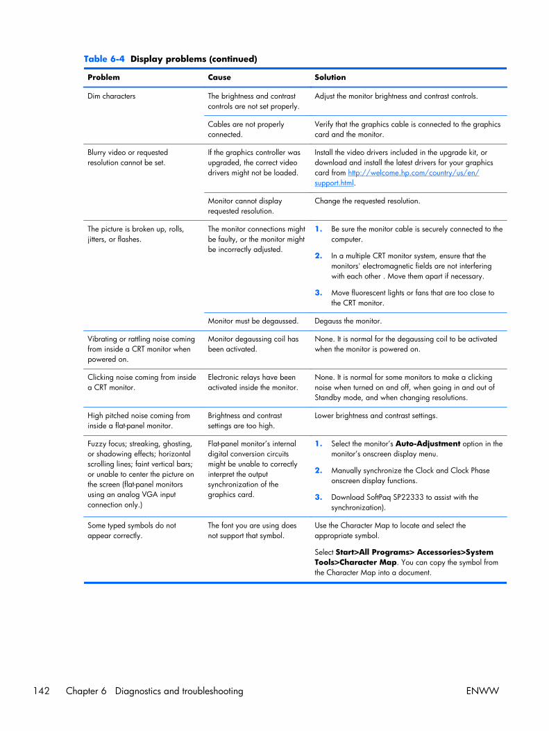
Table 6-4 Display problems (continued)
Problem Cause Solution
Dim characters The brightness and contrastcontrols are not set properly.
Adjust the monitor brightness and contrast controls.
Cables are not properlyconnected.
Verify that the graphics cable is connected to the graphicscard and the monitor.
Blurry video or requestedresolution cannot be set.
If the graphics controller wasupgraded, the correct videodrivers might not be loaded.
Install the video drivers included in the upgrade kit, ordownload and install the latest drivers for your graphicscard from http://welcome.hp.com/country/us/en/support.html.
Monitor cannot displayrequested resolution.
Change the requested resolution.
The picture is broken up, rolls,jitters, or flashes.
The monitor connections mightbe faulty, or the monitor mightbe incorrectly adjusted.
1. Be sure the monitor cable is securely connected to thecomputer.
2. In a multiple CRT monitor system, ensure that themonitors' electromagnetic fields are not interferingwith each other . Move them apart if necessary.
3. Move fluorescent lights or fans that are too close tothe CRT monitor.
Monitor must be degaussed. Degauss the monitor.
Vibrating or rattling noise comingfrom inside a CRT monitor whenpowered on.
Monitor degaussing coil hasbeen activated.
None. It is normal for the degaussing coil to be activatedwhen the monitor is powered on.
Clicking noise coming from insidea CRT monitor.
Electronic relays have beenactivated inside the monitor.
None. It is normal for some monitors to make a clickingnoise when turned on and off, when going in and out ofStandby mode, and when changing resolutions.
High pitched noise coming frominside a flat-panel monitor.
Brightness and contrastsettings are too high.
Lower brightness and contrast settings.
Fuzzy focus; streaking, ghosting,or shadowing effects; horizontalscrolling lines; faint vertical bars;or unable to center the picture onthe screen (flat-panel monitorsusing an analog VGA inputconnection only.)
Flat-panel monitor’s internaldigital conversion circuitsmight be unable to correctlyinterpret the outputsynchronization of thegraphics card.
1. Select the monitor’s Auto-Adjustment option in themonitor’s onscreen display menu.
2. Manually synchronize the Clock and Clock Phaseonscreen display functions.
3. Download SoftPaq SP22333 to assist with thesynchronization).
Some typed symbols do notappear correctly.
The font you are using doesnot support that symbol.
Use the Character Map to locate and select theappropriate symbol.
Select Start>All Programs> Accessories>SystemTools>Character Map. You can copy the symbol fromthe Character Map into a document.
142 Chapter 6 Diagnostics and troubleshooting ENWW

Solving audio problemsTable 6-5 Audio problems
Problem Cause Solution
Sound does not come out of thespeaker or headphones.
Software volume control isturned down.
Double-click the Speaker icon on the taskbar and use thevolume slider to adjust the volume.
The external speakers are notturned on.
Turn on the external speakers.
External speakers plugged intothe wrong audio jack.
See your sound card documentation for proper speakerconnection.
Digital CD audio isnot enabled.
Enable digital CD audio:
1. From the Control Panel, select System.
2. On the Hardware tab, select the Device Managerbutton.
3. Right-click the CD/DVD device and selectProperties.
4. On the Properties tab, select Enable digital CDaudio for this CD-ROM device.
Headphones or devicesconnected to the line-outconnector have muted theinternal speaker.
Turn on and use headphones or external speakers, ifconnected, or disconnect headphones or externalspeakers.
Volume is muted. 1. From the Control Panel, select Sound, Speech andAudio Devices, and then select Sounds andAudio Devices.
2. Deselect the Mute checkbox.
Computer is in Standby mode. Press the power button to resume from Standby mode.
Noise or no sound comes out ofthe speakers or headphones.
1. If you are using digital speakers that have a stereojack and you want the system to autoswitch to digital,use a stereo-to-mono adapter to engage the autosense feature, or use multimedia device propertiesto switch the audio signal from analog to digital.
2. If the headphones have a mono jack, use themultimedia device properties to switch the system toanalog out.
NOTE: If you set digital as the Output Mode, theinternal speaker and external analog speakers nolonger output audio until you switch back to an autosense or analog mode.
If you set analog as the Output Mode, external digitalspeakers do not function until you change the outputmode back to an auto-sense or digital mode.
ENWW Troubleshooting scenarios and solutions 143

Table 6-5 Audio problems (continued)
Problem Cause Solution
Sound occurs intermittently. Processor resources are beingused by other openapplications.
Shut down all open processor-intensive applications.
Workstation appears to be lockedup while recording audio.
The hard disk might be full. 1. Before recording, be sure there is enough free spaceon the hard disk.
2. Try recording the audio file in a compressed format.
Solving printer problemsTable 6-6 Printer problems
Problem Cause Solution
Printer does not print. Printer is not turned on andonline.
Turn the printer on and be sure it is online.
The correct printer driver forthe application is not installed.
1. Install the correct printer driver for the application.
2. Try printing using the MS-DOS command:
DIR C:\> [printer port]
Replace printer port with the address of the printerused. If the printer works, reload the printer driver.
If you are on a network, youmight not have made aconnection to the printer.
Make the proper network connection to the printer.
Printer might have failed. Run printer self-test.
Printer does not turn on. The cables might not beconnected properly.
Self-troubleshooting with HP Vision DiagnosticsHP Vision Diagnostics is a diagnostic tool that can be used by the end user or technical supportpersonnel to view information about the hardware configuration of the computer and perform hardwaretroubleshooting on HP Workstation and Desktop systems. Booted from either DVD/CD or USB flashkey, these diagnostics run outside the operating system and make it easier to isolate potential issuesand determine hardware failures.
HP Vision Diagnostics provides:
● Capture complete system configuration information that can be shared as an HTML file, including:
◦ System serial number
◦ System product number
◦ System BIOS revision
◦ Memory size and configuration
144 Chapter 6 Diagnostics and troubleshooting ENWW

◦ Processor information
◦ Storage device information and configuration
◦ Graphics / audio / communications information and configuration
● Comprehensive diagnostic tests with:
◦ Highly configurable testing options (quick / complete / custom / interactive / non-interactive)
◦ Specific failing memory DIMM identification
◦ Tests for video card memory
◦ DST Smart tests for both SATA and SAS drives
◦ Other tests and diagnostics
● Diagnostic Failure Code Output – A unique warranty code is generated for each failure which canbe used to validate diagnostic usage for a specific system
● Ease-of-use - uses similar user interface as previous field diagnostics, HP Insight Diagnostics
● True end-to-end diagnostics – same diagnostics modules as used in the factory
Use HP Vision Diagnostics to determine if all the devices installed on the computer are recognized bythe system and functioning properly. Running tests is optional but recommended after installing orconnecting a new device.
You can run tests, save the test results, and print them so that you have printed reports available beforeplacing a call to the Customer Support Center.
NOTE: Not all third-party devices may be detected by HP Vision Diagnostics.
Accessing HP Vision DiagnosticsThere are three ways to access, install and use HP Vision Diagnostics:
● Use the Vision Creator utility, pre-installed on your workstation, to burn HP Vision Diagnostics toCD or DVD.
● Use additional preinstalled utilities on your workstation to either:
◦ Create a bootable USB flash key or
◦ Create a bootable DVD or CD.
● If for some reason the above options are not available (for example, your primary hard drive waserased and then restored), you can download HP Vision Diagnostics from the HP Web site.
Using Vision CreatorHP Vision Creator is pre-installed on your workstation and makes it easy to burn HP Vision Diagnosticsonto a CD or DVD:
1. To initiate Vision Creator, select: Start > All Programs > PC Help & Tools > HP VisionDiagnostics Disc Creation.
2. Follow the prompts to burn HP Vision Diagnostics onto optical media.
ENWW Self-troubleshooting with HP Vision Diagnostics 145

Accessing HP Vision Diagnostics UtilitiesThese procedures describe how to access the HP Vision Diagnostics utilities that are included in thecomputer software.
Creating and using a bootable USB key
This section describes how to use a USB key to access the HP Vision Diagnostics.
NOTE: Using a USB key is the most convenient method to access HP Vision Diagnostics.
1. In the C:\VisionDiagnostics\ directory, double-click on VisionDiagUSB.exe. A setup menuappears.
2. Follow the setup prompts to create a bootable ISO image of the diagnostic utilities on a USB key.
3. Turn off the computer and restart it with the USB key installed. The computer will boot to the USBkey and initiate the HP Vision Diagnostics utility.
4. Follow the HP Vision Diagnostic prompts to troubleshoot the computer.
Creating and using a bootable DVD/CD
This section describes how to use a DVD/CD to run the HP Vision Diagnostics.
1. In the C:\VisionDiagnostics\ directory, double-click on the VisionDiagISO.exe file. A setup menuappears.
2. Follow the setup prompts to create a bootable ISO image of the diagnostic utilities on a DVD/CD.
3. Enable the computer to boot from DVD/CD.
4. Turn off the computer and restart it with the DVD/CD installed in the optical drive. The computerwill boot from the DVD/CD and initiate the HP Vision Diagnostics utility.
5. Follow the HP Vision Diagnostic prompts to troubleshoot the computer.
Using the HP Memory Test utility
This section describes how to access the HP Memory Test utility.
NOTE: The HP Memory Test is a comprehensive memory diagnostic utility that is run as a stand-aloneapplication, outside of HP Vision Diagnostics.
If the computer is booted from a DVD/CD, a separate boot DVD/CD will be required to use thememory diagnostic. Hence, HP recommends that a USB key be used to boot the diagnostic utilities. It isfaster than using a DVD/CD, and it accommodates both the Memory Test and Vision Diagnostics.
1. In the C:\VisionDiagnostics\ directory, double-click on the MemoryDiagISO.exe file. A setupmenu appears.
2. Follow the setup prompts to create a bootable ISO image of the memory diagnostic utility on aDVD/CD.
3. Turn off the computer and restart it with the DVD/CD installed in the optical drive. The computerwill boot from the DVD/CD and initiate the memory diagnostic utility.
4. Follow the diagnostic prompts to troubleshoot computer memory.
146 Chapter 6 Diagnostics and troubleshooting ENWW

Downloading HP Vision DiagnosticsIf for some reason neither Vision Creator nor HP Vision Diagnostics are available on your workstation,follow these steps to download HP Vision Diagnostics from the HP Web site and load onto a USB flashdrive or DVD/CD:
1. Go to http://www.hp.com/go/workstationsupport.
2. Select your workstation.
3. Click Download drivers and software.
4. Select your language and operating system.
5. Select the Diagnostic link.
6. Locate HP Vision Diagnostics under “Quick jump to downloads by category...” for either USBor CD (as desired) and select Download.
7. Depending on whether you chose USB or DVD/CD:
a. USB: Run the .exe file that is downloaded, then follow the prompts to save HP VisionDiagnostics and load it onto a USB flash key.
b. DVD/CD: Run the .exe file that is downloaded, then follow the installer prompts to extractand save the .iso file to your hard drive. Use CD-ROM burning software to copy the .iso fileto an optical medium.
8. When the DVD/CD or USB flash drive has the utility installed, insert the USB flash drive or DVD/CD into the computer (while it is on).
9. Shut down the workstation using the operating system.
10. Turn on the computer. The system should boot into HP Vision Diagnostics.
NOTE: If the system does not boot to the DVD/CD in the optical drive or to the USB flash drive,you may need to change the boot order. You may use the Computer Setup (F10) utility to changethe boot order, or you may press F9 to select the appropriate boot device.
11. At the boot menu, select either the HP Vision Diagnostics utility to test the various hardwarecomponents in the computer or the HP Memory Test utility to test memory only.
NOTE: The HP Memory Test is a comprehensive memory diagnostic utility that is run as a stand-alone application, outside of HP Vision Diagnostics.
If the computer is booted from a DVD/CD, a separate boot DVD/CD will be required to use thememory diagnostic. Hence, HP recommends that a USB key be used to boot the diagnosticutilities. It is faster than using a DVD/CD, and it accommodates both the Memory Test and VisionDiagnostics.
12. If running HP Vision Diagnostics, select the appropriate language and click Continue.
13. In the End User License Agreement page, select Agree if you agree with the terms. The HP VisionDiagnostics utility launches with the Survey tab displayed
ENWW Self-troubleshooting with HP Vision Diagnostics 147

User interfaceThe HP Vision Diagnostics application provides six major functions, accessible through Tabs. Thesefunctions are:
● Survey — Your current system hardware information.
● Test — List all diagnostics available for your system. Tests are started there.
● Status — This screen shows progress and status of currently running diagnostics.
● History — All past diagnostics runs and status are listed there.
● Errors — All past diagnostics failures are listed there.
● Help — User help about HP Vision Diagnostics.
There are also some common operations that are part of the utility. They include:
● Exit Diagnostics button — This button will close HP Vision Diagnostic application and rebootyour system. Any running test will be aborted.
● Reload button — If available, this button will rescan your system hardware and reload thediagnostics without the need to restart your entire system.
● Save button — If available, save your system survey, test history or error data as an HTML file toa floppy disk or a USB key drive.
Survey tab
The Survey tab shows your system hardware information, organized into eleven Categories (forexample "Processors") and device instances (for example "Processor 1").
The amount of information displayed can be controlled by selecting a combination of View Level andCategory.
The View Levels include:
● Overview — Shows high level summary of the system hardware. This is the default view level.
● Summary — Gives limited configuration data for each specific Category.
● Advanced — Offers more technical and low-level data for the computer-savvy user.
The Categories Levels include:
● All — Shows all Categories.
● Architecture — Shows system architecture information such as high level PCI devices, low levelSMBIOS, CMOS and PCI configuration space data.
● Audio — Shows all embedded and add-on audio devices.
● Asset Control — Shows asset control related information such as product name, serial number,asset tag, and universal unique ID information.
● Communication — Shows communication devices such as serial, parallel, USB, network,Firewire, modem, and Bluetooth ports and devices.
● Graphics — Shows all embedded and add-on video cards.
148 Chapter 6 Diagnostics and troubleshooting ENWW

● Input Devices — Shows user input devices such as all connected mice and keyboards.
● Memory — Shows system memory information.
● Miscellaneous — List any devices or data that doesn't belong to any other Category.
● Processors - Shows system processors.
● Storage — Shows mass storage devices such as floppy drives, optical drives, SATA, SAS harddisk drives and controllers, as well as any RAID arrays.
● System — Shows information about system board devices such as fans and cables.
Test tab
The Test tab lists all available diagnostics. The lists have been tailored according to your systemconfiguration. Individual test may be selected or unselected. The following Test Modes exist:
● Quick — This test selection was picked to perform quickly while covering your entire hardware.Test parameters cannot be modified.
● Complete — This test selection offers all available tests and may take a long time to complete.Test parameters cannot be modified.
● Custom — Like Complete this test selection offers all available tests. The test parameters may bemodified to fit specific needs. For advanced users only!
By default, the three test modes do not display prompts and require no interaction. If errors are found,they are displayed when testing is complete.
However, for each test type, you may also optionally add interactive tests by clicking the Includeinteractive tests box under Test mode. Selecting interactive tests provides the maximum control overthe testing process. The diagnostic software will prompt you for input during tests.
NOTE: Memory can not be tested from within the HP Vision Diagnostics application. To test thememory in your computer, exit HP Vision Diagnostic, boot to either the CD or USB flash drive andselect HP Memory Test from the boot menu.
The Duration of Test options control the duration of the test sequence. The following options areavailable:
● Number of loops — A test selection will run once by default. Enter a positive number to makea test selection run many times.
● Total test time (hours:minutes) — Alternatively, the test selection can be set to run for aspecified amount of time. This does not guarantee that all tests will run if the entered time is lessthan the necessary time to run all the tests
● Stop at first error— Check this option to stop test execution as soon as one error isencountered.
ENWW Self-troubleshooting with HP Vision Diagnostics 149

The following Test Controls exist:
● Select All, Unselect All button — This button toggles to select or unselect all the tests from thetest selection tree.
● Expand, Collapse button — This button toggles to expand or collapse the test selection tree.
● Start Test button — Click this button to start executing all selected tests. HP Vision Diagnosticswill automatically switch to the Status tab in order to keep track of the test execution and status.
WARNING! Once started, do not reboot or power off your computer until all the tests have beencompleted.
To begin testing:
1. Select the Test tab.
2. Select the type of tests you want to run: Quick, Complete, or Custom.
3. Include optional interactive tests by selecting Include interactive tests.
4. Choose how you want the test to be executed, either Number of Loops or Total Test Time.When choosing to run the test over a specified number of loops, enter the number of loops toperform. If you want the diagnostic test for a specified time period, enter the amount of time inminutes.
5. Click the Start Test button to start the testing. The Status tab, which allows you to monitor theprogress of the tests, is automatically displayed during the testing process. When the tests arecomplete, the Status tab shows whether the devices passed or failed.
6. If errors are found, go to the Errors tab to display detailed information and recommended actions.
Status tab
The Status tab shows the overall progress and status of the test scenario as well as the progress andstatus of each test. The color coded status are black, blue, green, red, and orange.
The Status tab colors are:
● Waiting (black) — No test is running.
● Running (blue) — At least one test is currently running.
● Passed (green) — All tests have run successfully, meaning that no hardware error or defect wasdetected.
● Failed (red) — The tests have detected at least one error with your system.
● Canceled (orange) — The test scenario has been explicitly canceled, in which case no pass orfail conclusion can be drawn.
The available data is:
● Current Loop — Shows the current execution loop out of total number of loops specified in theTest panel.
● Test Time — Shows the total time elapsed since the beginning of the test execution.
150 Chapter 6 Diagnostics and troubleshooting ENWW

● Test Complete — Shows the number of tests successfully completed out of the total number oftest to execute.
● Cancel button — Push the Cancel button to immediately terminate all currently running tests.
History tab
The History tab shows the history of the past test executions.
The History Log displays all tests that have been executed, the number of times of execution, the numberof times failed, the date each test was executed, and the time it took to complete each test. The ClearHistory button will clear the contents of the History Log.
The contents of the History Log may be saved as a HTML file to either floppy or USB flash drive byclicking the Save button.
Errors tab
The Errors tab displays detailed information about any errors found, as well as any recommendedactions.
The Error Log displays the tests for devices that have failed during the diagnostic testing and includesthe following columns of information.
● The Device section displays the device tested.
● The Test section displays the type of test run.
● The Times Failed is the number of times the device has failed a test.
● The Defect Code provides a numerical code for the failure. The error codes are defined in theHelp tab.
● The Description section describes the error that the diagnostic test found.
● The Reason section describes the likely cause of the error.
● The Recommended Repair will give a recommended action that should be performed to resolve thefailed hardware.
● The Warranty ID is a unique error code associated with the specific error on your computer.When contacting the HP Support Center for assistance with a hardware failure, please beprepared to provide the Warranty ID.
● The Clear Errors button will clear the contents of the Error Log.
The contents of the Error Log may be saved as a HTML file to either floppy or USB flash drive byclicking the Save button.
Help tab
The Help tab contains a Vision Help section, and a Test Components section. This tab includes searchand index features. You may also review the HP End User License Agreement (EULA), as well as the HPVision Diagnostic application version information on this tab.
ENWW Self-troubleshooting with HP Vision Diagnostics 151

The various sections located here are:
● The Vision Help section contains information on the major functions of HP Vision Diagnostics.
● The Test components section provides a description of each test, as well as the parameters thatmay be adjusted when running in Custom test mode.
● The Defect codes section contains information on the numerical error code that may appear in theErrors tab.
● The Memory test tab section provides information on the HP Memory Test application that may belaunched from the boot menu.
● The HP Support section provides information on obtaining technical support from HP.
Saving and printing information in HP Vision DiagnosticsYou can save the information displayed in the HP Vision Diagnostics Survey, History and Errors tabs toa diskette or a USB flash drive. You can not save to the hard drive. The system will automatically createan html file that has the same appearance as the information displayed on the screen.
1. Insert a diskette or USB flash drive if running HP Vision Diagnostics from CD.
2. Click Save in the bottom on any of the Survey, History or Errors tabs. All three log files will besaved regardless of from which tab the Save button was clicked.
3. Select the drive onto which you will save the log files and click the Save button. Three html fileswill be saved to the inserted diskette or USB flash drive.
NOTE: Do not remove the diskette or USB key until you see a message indicating that the htmlfiles have been written to the media.
4. Print the desired information from the storage device used to save it.
NOTE: To exit HP Vision Diagnostics, click the Exit Diagnostics button at the bottom of thescreen. Be sure to remove the USB flash drive or CD from the optical drive.
Diagnostic codes and errorsThis section presents information about diagnostic LED codes, LED color definitions, and POST errormessages to help you troubleshoot problems.
Diagnostic LED and audible (beep) codesThis section describes the front panel LED error and operation codes as well as the audible codes thatmight occur before or during the POST.
152 Chapter 6 Diagnostics and troubleshooting ENWW

Table 6-7 Diagnostic lights and audible codes
Activity Possible cause Recommended action
Blue Power LED* on. Nobeeps.
Computer on.
N/A
Blue Power LED* blinksevery two seconds.* Nobeeps.
Computer in Sleep mode(S3-Suspend to RAM).Select models only.
Blue Power LED* is off.*
No beeps.Computer in Hibernatemode (S4-Suspend todisk) or system is off(S5).
Blue Power LED* blinksthree times*, once persecond.* No beeps.
Computer in Sleep mode(S3-Suspend to RAM).Select models only.
Blue Power LED* blinksfour times*, once persecond.* No beeps.
Computer in Hibernatemode (S4-Suspend todisk).
*User-selectable. See The Computer Setup (F10)Utility menu on page 28 for details.
For the following LED activity and beeps, the beeps are heard through the chassis speaker. Blinks and beeps repeat for 5cycles, after which, only the blinks continue to repeat.
Red Power LED blinks twotimes, once every second,followed by a two-secondpause. Two beeps.
CPU thermal protectionactivated by either of thefollowing methods:
● A fan might beblocked or notturning.
● The heatsink andfan assembly is notproperly attachedto the CPU.
CAUTION: Internal components might be powered even whenthe computer is off. To prevent damage, disconnect the computerpower cord before you remove a component.
1. Ensure that the computer air vents are not blocked and thecooling fan is running.
2. Open the access panel, press power button, and verify thatthe CPU fan is spinning. If the CPU fan is not spinning, makesure the fan cable is plugged into the computer boardheader. Ensure the fan is fully and properly seated orinstalled.
3. If fan is plugged in and seated properly, but is not spinning,the problem might be in the CPU fan. Contact HP forassistance.
4. Verify that the fan assembly is properly attached. If problemspersist, there might be a problem with the CPU heatsink.Contact HP for assistance.
Red Power LED blinksthree times, once everysecond, followed by atwo-second pause. Threebeeps.
CPU not installed (not anindicator of bad CPU).
1. Verify that the CPU is present.
2. Reseat the CPU.
ENWW Diagnostic codes and errors 153

Table 6-7 Diagnostic lights and audible codes (continued)
Activity Possible cause Recommended action
Red Power LED blinks fourtimes, once every second,followed by a two-secondpause. Four beeps.
Power failure (powersupply is overloaded)
CAUTION: Internal components might be powered even whenthe computer is off. To prevent damage, disconnect the computerpower cord before you remove a component.
1. Open the access panel and ensure that all powerconnections (24-pin Main, 4-pin CPU) are secure on thesystem board.
2. Check if a device is causing the problem by removing allattached devices (such as hard, diskette, or optical diskdrives, and expansion cards.) Power on the computer. If thesystem enters the POST, power off and replace one device ata time; repeat this procedure until failure occurs. Replace thedevice that is causing the failure. Continue adding devicesone at a time to ensure all devices are functioning properly.
Red Power LED blinks fivetimes, once every second,followed by a two-secondpause. Five beeps.
Pre-video memory error CAUTION: Internal components might be powered even whenthe computer is off. To prevent damage, disconnect the computerpower cord before you remove a component.
1. Reseat DIMMs.
2. Replace DIMMs one at a time to isolate faulty module.
3. Replace third-party memory with HP memory.
4. The problem might be on the system board. Contact HP forassistance.
Red Power LED blinks sixtimes, once every second,followed by a two-secondpause. Six beeps.
Pre-video graphics error. CAUTION: Internal components might be powered even whenthe computer is off. To prevent damage, disconnect the computerpower cord before you remove a component.
1. Reseat the graphics card.
2. Verify the graphics auxiliary power cable is connected (ifapplicable).
3. Confirm the graphics card is in the appropriate slot (PCIex16).
4. The problem might be on the graphics card. Contact HP forassistance.
Red Power LED blinksseven times, once everysecond, followed by atwo- second pause. Sevenbeeps.
System board failure(ROM detected failureprior to video).
1. Clear CMOS.
NOTE: Refer to the Maintenance and Service Guide forthe computer model for detailed information on clearingCMOS.
2. The problem might be on the system board. Contact HP forassistance.
154 Chapter 6 Diagnostics and troubleshooting ENWW

Table 6-7 Diagnostic lights and audible codes (continued)
Activity Possible cause Recommended action
Red Power LED blinkseight times, once everysecond, followed by atwo-second pause. Eightbeeps.
Invalid ROM based onbad checksum.
CAUTION: Internal components might be powered even whenthe computer is off. To prevent damage, disconnect the computerpower cord before you remove a component.
1. Clear CMOS.
NOTE: Refer to the Maintenance and Service Guide forthe computer model for detailed information on clearingCMOS.
2. Upgrade the ROM using SoftPaq, either from the hard diskdrive, CD, diskette, or USB removable device (for example,HP Drive Key). See the ROM Flash section of theMaintenance and Service Guide at http://www.hp.com/support/workstation_manuals. SoftPaq is a self-extractingexecutable, which contains instructions for its use, thatenables you to upgrade the ROM. To download the Softpaqexecutable, visit http://www.hp.com/go/workstationsupport.
3. The problem might be on the system board. Contact HP forassistance.
Red Power LED blinks ninetimes, once every second,followed by a two-secondpause. Nine beeps.
System powers on butdoes not start.
1. The problem might be on the system board. Contact HP forassistance.
2. The problem might be in the CPU. Contact HP for assistance.
System does not power-onand LEDs are not blinking.No beeps.
System unable to poweron.
CAUTION: Internal components might be powered even whenthe computer is off. To prevent damage, disconnect the computerpower cord before you remove a component.
To resolve the problem, choose one of the following options:
Press and hold the power button for less than 4 seconds. If thehard disk drive LED turns green, then:
1. Remove the expansion cards one at a time and try holdingthe power button again for less than 4 seconds.
2. The problem might be on the system board. Contact HP forassistance.
Press and hold the power button for less than 4 seconds. If thehard disk drive LED does not turn on green then:
1. Check that unit is plugged into a working AC outlet.
2. Open the access panel and check that the power buttonharness is properly connected to the system board.
3. Check that all power supply cables are properly connectedto the system board.
* The BIOS option you select controls the blue LED function during these suspend modes.
ENWW Diagnostic codes and errors 155

LED color definitionsThe following table describes what each LED light on the computer front panel signifies.
Table 6-8 LED color definitions
LED state LED color System status
Solid Blue System is on.
Flashing Blue System is in Standby.
Solid or flashing Red System has experienced an error. (See POST errormessages on page 157.)
None No light System is in Hibernate, or is off.
156 Chapter 6 Diagnostics and troubleshooting ENWW

POST error messagesThe Power-On Self Text (POST) is a series of diagnostic tests that runs automatically when the computeris powered on.
Audible and visual messages occur before the operating system starts if the POST encounters aproblem. POST checks the following items to ensure that the computer system is functioning properly:
● Keyboard
● DIMMs
● Diskette drives
● All mass storage devices
● CPUs
● Controllers
● Fans
● Temperature sensors
● Cables (front/rear panels, audio, and USB ports)
The table shown next describes the POST error messages.
Table 6-9 POST error messages
Screen message Probable cause Recommended action
101—Option ROM ChecksumError
System ROM checksum. Verify the you have the latest ROM:
1. Flash the ROM, if needed.
2. If an expansion card was recently added, removeit to find out if the problem remains.
3. Clear CMOS. If the message disappears, theremight be a problem with the expansion card.
4. Replace the system board.
102—System Board Failure DMA, timers, and so forth, might beset improperly or might be defective.
1. Clear the CMOS.
2. Remove the expansion boards.
3. Replace the system board.
110—Out of memory spacefor option ROMs
Option ROM for a device could notrun because of memory constraints.
Run the Computer Setup (F10) Utility to disableunneeded option ROMs, and to enable ACP1/USBBuffers at Top of Memory.
162—Systems Options Error
163—Time and Date Not Set ● Invalid time or date inconfiguration memory.
● RTC battery might needreplacement.
● CMOS jumper might not beproperly installed.
1. Set the date and time from the Control Panel or inthe Computer Setup (F10) Utility (depending onthe operating system).
2. If the problem persists, replace the RTC battery.
ENWW Diagnostic codes and errors 157

Table 6-9 POST error messages (continued)
Screen message Probable cause Recommended action
164—Memory Size Error Memory configuration is incorrect. 1. Run the Computer Setup (F10) Utility or theWindows utilities.
2. Verify that the memory modules are installedproperly.
3. If third-party memory has been added, test thememory configuration using HP memory.
4. Verify the memory module type.
201—Memory Error RAM failure. 1. Run the Computer Setup (F10) utility or theWindows utilities.
2. Be sure that memory modules are installedcorrectly.
3. Verify the memory module type.
4. Remove and replace memory modules one at atime to isolate faulty modules.
5. Replace faulty memory modules.
6. If the error persists after replacing memorymodules, replace the system board.
202—Memory Type Mismatch Memory modules do not match. Replace the memory modules with matched sets.
203—Memory module failedself-test and failing rank wasdisabled
Defective memory module. Replace the memory module.
204—Memory module failedand user rank was disabled
Improper module load. Reseat the memory module correctly.
205—Memory hightemperature detected
Insufficient memory module cooling. Verify that a memory module cooling fan is installedand operating.
206—Memory setup invalid Memory configured incorrectly. Reconfigure the memory modules in the proper slots.
207—Incompatible DIMMsdetected
DIMMs are installed that do not fulfillsystem requirements.
1. Verify that the memory module type matchescomputer requirements.
2. Insert the DIMM in the proper memory socket.
3. Replace the DIMM if the problem persists.
208—Mismatched DIMMsdetected
Installed DIMMs are improperlymatched.
Verify that matching DIMMs are installed.
209—Memory warningcondition detected
Incorrect memory module type in use. Verify that the memory modules are compatible withcomputer requirements.
212—Failed Processor 0 Processor has failed to initialize. 1. Reseat the processor in its socket.
2. If the processor does not respond, replace it.
3. Replace the system board.
158 Chapter 6 Diagnostics and troubleshooting ENWW

Table 6-9 POST error messages (continued)
Screen message Probable cause Recommended action
213—Incompatible MemoryModules
A memory module in the memorysocket identified in the error messageis missing critical SPD information, oris incompatible with the chipset.
1. Verify the memory module type.
2. Insert the DIMM in another memory socket.
3. Replace the module with a DIMM conformingto the SPD standard.
214—DIMM ConfigurationWarning
DIMMs are not installed correctly (notpaired correctly).
See the service label on the computer access panel forthe correct memory configurations, and reseat theDIMMs accordingly.
215—DIMM ConfigurationError
216—Memory Size ExceedsMaximum Supported
The amount of memory installedexceeds that supported by thehardware.
1. Verify how much memory the computer supports.
2. Remove the excess memory.
301—Keyboard Error Keyboard failure. 1. Reconnect the keyboard with the computerpowered off.
2. Check the connector for bent or missing pins.
3. Be sure that none of the keys are pressed.
4. Replace the keyboard.
303—Keyboard ControllerError
I/O board keyboard controller isdefective or is not set properly.
1. Reconnect the keyboard with the computerpowered off.
2. Connect a keyboard directly to the computer(instead of through a switch box).
3. Replace the system board.
304—Keyboard or SystemUnit Error
Keyboard failure. 1. Reconnect the keyboard with the computerpowered off.
2. Connect a keyboard directly to the computer(instead of through a switch box).
3. Be sure that none of the keys are pressed.
4. Replace keyboard.
5. Replace system board.
510—Splash Screen imagecorrupted
Splash Screen image has errors. Update system BIOS.
511—CPU Fan not detected Fan is not connected or is defective. 1. Reseat the fan cable.
2. Reseat the fan.
3. Replace the fan.
512—Chassis fan notdetected
Fan missing, disconnected, ordefective.
1. Reseat the fan cable.
2. Reseat the fan.
3. Replace the fan.
ENWW Diagnostic codes and errors 159

Table 6-9 POST error messages (continued)
Screen message Probable cause Recommended action
513—Front Chassis fan notdetected
Front fan missing, disconnected, ordefective.
1. Reseat the fan cable.
2. Reseat the fan.
3. Replace the fan.
514—Memory fan notdetected
Memory fan missing, disconnected, ordefective.
1. Reseat the fan cable.
2. Reseat the fan.
3. Replace the fan.
515—CPU Overtempoccurred
Insufficient processor cooling orprocessor defect.
1. If necessary, add a heatsink to the processor andensure proper operation.
2. Replace the processor.
516—Chipset fan not detected Chipset fan missing, disconnected, ordefective.
1. Reseat the fan cable.
2. Reseat the fan.
3. Replace the fan.
517—Low power CPUheatsink(s) detected for highpower CPUs
Inadequate heatsink is installed. Replace the low power heatsink with a high powerheatsink.
518—Power supply wattageinsufficient for hardwareconfiguration
Computer configuration requires morepower than the power supply canprovide.
1. Reduce the computer power consumption.
2. Replace the power supply with a high outputpower supply.
601—Diskette Controller Error Diskette controller circuitry or diskettedrive circuitry incorrect.
1. Run the Computer Setup (F10) utility.
2. Verify cabling and replace defective cables ifnecessary.
3. Clear CMOS.
4. Replace the diskette drive.
5. Replace the system board.
605—Diskette Drive TypeError
Mismatch in drive type. 1. Run the Computer Setup (F10) Utility.
2. Disconnect any other diskette controller devices(tape drives).
3. Clear the CMOS.
610—External Storage DeviceFailure
External storage device is notdetected, is improperly connected, oris defective.
1. Verify that the external device is present andconnected properly.
2. Replace the external device.
611—Primary Floppy PortAddress Assignment Conflict
The flexible disk drive is configured ata previously assigned address.
Select a new address for the flexible disk drive.
912—Computer Cover HasBeen Removed Since LastSystem Start Up
N/A No action required.
160 Chapter 6 Diagnostics and troubleshooting ENWW

Table 6-9 POST error messages (continued)
Screen message Probable cause Recommended action
914— Hood Lock Coil is notConnected
Mechanism is missing or is notconnected.
1. Reconnect or replace the missing mechanism.
2. Reseat or replace the missing mechanism cable.
916—Power Button NotConnected
Power button cable is disconnectedfrom the system board.
Reconnect the cable and restart.
917—Front Audio NotConnected
Front Audio mechanism is missing or isnot connected.
1. Replace or reconnect the missing front audiomechanism to the system board.
2. Reseat or replace the missing mechanism cable.
918—Front USB NotConnected
Front USB mechanism is missing or isnot connected.
1. Replace or reconnect the missing Front USBmechanism to the system board.
2. Reseat or replace the missing mechanism cable.
919—Multi-Bay Riser NotConnected
Multi-Bay riser mechanism is missingor is not connected.
1. Replace or reconnect the missing Multi-Baymechanism to the system board.
2. Reseat or replace the missing mechanism cable.
920—Fatal error on QPI link X Fatal error detected on QPI link x,where x is 0 or 1. This type of error isidentified on the line following theerror message.
Potential system board problem; contact HP Support.
921—Fatal error on QPIProtocol link X
Fatal error detected in QPI link xprotocol, where x is 0 or 1. This typeof error is identified on the linefollowing the error message.
Potential system board problem; contact HP Support.
922—Fatal error on PCIe slotX
Fatal error occurred in the designatedslot.
Move the card to a different slot. If the problempersists, replace the card.
923—Fatal error on ESI port 0 A fatal error occurred on ESI port 0.slot.
Verify that the ESI port device is connected andworking properly.
924—Fatal error on IOH coreX
Fatal error detected on IOH core x,where x is 0 or 1. This type of error isidentified on the line following.
Potential system board problem; contact HP Support.
925—Fatal error on IOHmiscellaneous
Fatal miscellaneous error detected onIOH core x, where x is 0 or 1.
Potential system board problem; contact HP Support.
926—Fatal error on IOH Vtd Fatal error detected in the IntelVirtualization Technology.
Potential system board problem; contact HP Support.
927—Fatal error on DIMM inslot CPU X DIMM Y
Fatal multibit ECC error detected onthe DIMM in the slot labeled DIMM x(where x is 1 - 4), as labeled on thesystem board.
Replace the DIMM in the identified slot.
928—Fatal machine checkdetected on CPU X
Contact HP support.
ENWW Diagnostic codes and errors 161

Table 6-9 POST error messages (continued)
Screen message Probable cause Recommended action
1720—SMART Hard DriveDetects Imminent Failure
Hard drive is about to fail. (Some harddisk drives have a firmware patch thatfixes erroneous error messages.)
1. Determine if the hard disk drive is giving a correcterror message.
2. Run the Drive Protection System test (ifapplicable).
3. Apply firmware patch (if applicable). See http://www.hp.com/support.
4. Back up contents and replace the hard disk drive.
1783—Fixed Disk 0/1 locked Hard disk drive failure. Diagnose the hard disk drive, and replace it ifnecessary.
1796—SATA Cabling Error Missing or improperly attached cable. Verify that a cable is attached. Reattach the cable.
1797—SATA Drivelock is notsupported in RAID mode
SATA Drivelock is not supported inRAID mode.
Disable RAID mode, or disable SATA drivelock..
1801—Microcode UpdateError
Unknown or unsupported processorstepping.
The microcode update failed. Check the processorstepping to ensure it is a supported stepping. If it iscontact, HP Support.
1802—Processor NotSupported
The system board does not support theprocessor.
Replace the processor with a compatible one.
1803—Processor feature set isinsufficient for current systemsettings
Processor feature set is insufficient forcurrent system settings. The BIOSsettings do not match the supportprovided by the processor
Change the BIOS settings or upgrade the processor.
1804—A processor featureand the memory configurationare incompatible
A processor feature is incompatiblewith the memory configuration.
Restore the previous memory configuration.
ERROR: Invalid 1394 GUID(Invalid electronic serialnumber)
No electronic serial number is storedwith the system.
To assign a serial number , select Security>SystemIDs in the Computer Setup (F10) Utility.
ERROR: Invalid electronicserial number (no number)
No electronic serial number is storedwith the system
To assign a serial number , select Security>SystemIDs in the Computer Setup (F10) Utility.
ERROR: An unsupportedprocessor is installed. Systemhalted
Unsupported processor detected. Replace the processor.
ERROR: A processor requiringtoo much power is installed.System halted
Unsupported processor detected. Replace the processor.
Invalid electronic serialnumber
Incorrect serial number registered inthe system.
To assign a serial number , select Security>SystemIDs in the Computer Setup (F10) Utility.
Network Server Mode Activeand No Keyboard Attached
Keyboard not detected. Verify that a functioning keyboard is attached to thecomputer.
Processor initialization fails Processor defective. Replace the processor.
162 Chapter 6 Diagnostics and troubleshooting ENWW

7 Configuring RAID devices
This chapter describes how to configure SATA RAID devices on all Z-series workstations and includesthese topics:
Topics
Maximum RAID hard drive configurations on page 163
Configuring SATA RAID devices on page 164
For additional information about configuring RAIDs, see http://www.hp.com/support/RAID_FAQs. Forinformation about preparing the computer for RAID configuration, see http://www.hp.com/support/workstation_manuals.
Maximum RAID hard drive configurationsThis section lists the maximum number of hard drives supported on HP workstations for RAIDconfigurations.
NOTE: This section applies to internal workstation configurations that do not use add-in cards andJBODs.
TIP: Use the table values to determine the workstation model-specific maximum number of hard drivesas discussed in the sections below.
Table 7-1 Maximum hard drives
Workstation 8.5mm (3.5") SATA
hard drive
6.3mm (2.5") SATA
hard drive
Z800 5 6
Z600 3 4
Z400 4 4
Z210 CMT 3 3
Z210 SFF 2 2
ENWW Maximum RAID hard drive configurations 163

Configuring SATA RAID devicesThis section describes how to use the Intel® Rapid Storage Manager option ROM Configuration utilityto set up and manage SATA RAID volumes.
The following SATA RAID configurations are supported on this computer:
● Up to the computer-specific maximum number of internal SATA hard disk drives and eSATA drives(if you use an optional eSATA bulkhead cable)
● Intel Rapid Storage Manager (IRSM) for Windows
If only a single HDD is attached, the Intel Rapid Storage Manager option ROM does not execute.Associated messages are not displayed.
The Intel SATA AHCI BIOS executes when you select RAID+AHCI for the SATA emulation mode. ThisBIOS is only used to support serial-attached drives configured as a RAID array.
This section does not apply to configuring SATA RAID in the Linux environment. For Linux SATA RAID,refer to the Software RAID in Linux Workstations section in the HP Workstations for Linux User Guide athttp://www.hp.com/support/linux_user_manual.
Attaching SATA HDDsAttach the required minimum number of SATA hard drives for the desired RAID level:
● RAID 0 – Striped disk array
◦ Two drive minimum
◦ Improved I/O performance
◦ No fault tolerance
● RAID 1 — Mirrored disk array
◦ Two drives
◦ 100% redundancy
◦ Can recover from single drive failure
◦ Improved read performance
● RAID 5 — Striped disk array with distributed parity
◦ Three or more drives (for workstations that support three or more hard drives)
◦ Fault tolerant and provides I/O performance improvement, especially for write-biasedapplications
◦ Single drive failure does not cause data loss (performance is compromised until the faileddrive is replaced and the array rebuilt).
164 Chapter 7 Configuring RAID devices ENWW

Configuring system BIOSConfigure the system BIOS to enable embedded SATA RAID functionality.
1. To enter the system BIOS setup, press F10.
2. Use the arrow keys to highlight the desired language, and then press Enter.
3. Use the arrows to highlight Storage>Storage Options, and then press Enter.
4. Use the up or down arrow key to highlight SATA Emulation.
5. Use the left or right arrow key to select RAID+AHCI.
6. To accept the new setting, press F10.
7. Use the arrows to highlight Advanced>Power-On Options, and then press Enter.
8. Use the up or down arrow key to highlight POST Messages.
9. Use the left or right arrow key to select Enable.
10. To accept the new setting, press F10.
11. Use the arrow keys to highlight Advanced>Device Options, and then press Enter.
12. Use the up or down arrow key to highlight SATA RAID Option ROM Download, and thenpress Enter.
13. Use the left or right arrow key to select Enable.
14. To accept the new setting, press F10.
15. Use the arrows to highlight File>Save Changes and Exit, and then press Enter.
16. Press F10 when prompted.
ENWW Configuring SATA RAID devices 165

Creating RAID volumesTo create RAID volumes, use the Intel Rapid Storage Manager option ROM Configuration utility.
1. To enter the Intel Rapid Storage Manager option ROM Configuration utility, press Ctrl+l whenprompted.
2. If required, refer the computer Maintenance and Service Guide to make available enoughphysical drives to create the RAID volume.
3. Use the up or down arrow key to highlight 1. Create RAID Volume, and then press Enter.
4. Type the desired RAID volume name in the Name: field, and then press Tab.
5. Use the up or down arrow key to select the RAID level in the RAID Level: field, and then press Tab.
6. If three or more hard drives are installed (for workstations that support three or more hard drives):
a. Press Enter to display the Select dialog.
b. Use the up and down arrow keys and Space to mark individual physical as members of thevolume.
c. Press Enter to exit the Select dialog and return to the Create Volume Menu dialog.
7. If appropriate, use the up or down arrow key to select the Stripe Size in the Stripe Size: field, andthen press Tab.
8. Enter the desired volume size in the Capacity: field, and then press Tab.
9. Press Enter to initiate volume creation.
10. When prompted, press Y to acknowledge the warning message and create the volume.
11. Use the up or down arrow key to highlight 5. Exit, and then press Enter.
12. Press Y when prompted to confirm the exit.
166 Chapter 7 Configuring RAID devices ENWW

8 Configuring password security andresetting CMOS
This chapter describes how to configure password security and to reset CMOS, and includes thesetopics:
● Preparing to configure passwords on page 167
● Resetting the password jumper on page 168
● Clearing and Resetting the CMOS on page 168
Preparing to configure passwordsThe Computer Setup (F10) Utility enables you to create setup and power-on passwords.
There are three possibilities for setting passwords:
● Define a setup password only
● Define a power-on password only
● Define both
When defining a setup password only, you cannot enter the setup utility without the password.
No password is needed to boot from power-on.
When defining a power-on password only, the power-on password is needed to enter F10 Setupor to boot from power-on.
When defining both, the setup password is needed to enter F10 setup and can be used to bootfrom power-on.
The power-on password cannot be used to enter the F10 Setup Utility, but it can be used to bootfrom power-on.
One of the passwords will be required to boot from power on.
After you create both passwords, you can use the setup password in place of the power-on passwordas an override to log into the computer (a useful feature for a network administrator).
NOTE: You can only clear the passwords with the password jumper. Clearing CMOS does not clearthe passwords.
CAUTION: Before pressing the Clear CMOS button, back up your computer CMOS settings.
Pressing the Clear CMOS button resets CMOS values to factory defaults and erases customizedinformation, including asset numbers and special settings.
To back up the CMOS settings, run the Computer Setup (F10) Utility and select Save to Diskettefrom the File menu.
ENWW Preparing to configure passwords 167

Resetting the password jumperUse the following procedure to disable the power-on or setup password features and clear the power-on and setup passwords.
WARNING! To reduce the risk of personal injury from electrical shock and hot surfaces, be sure todisconnect the power cord from the wall outlet and allow the internal system components to cool beforetouching.
CAUTION: When the computer is plugged in, the power supply has voltage applied to the systemboard, even when the computer is turned off. Failure to disconnect the power cord can result indamage to the system.
CAUTION: Static electricity can damage the electronic components of the computer or optionalequipment. Before beginning these procedures, be sure that you are discharged of static electricity bybriefly touching a grounded metal object.
1. Shut down the operating system, power off the computer and external devices, and disconnect thecomputer power cord and external devices from power outlets.
2. Disconnect the keyboard, monitor, and other external devices that are connected to the computer.
3. Remove the access panel.
4. Locate the password header and jumper.
The password header is E49. The password jumper is green so it can be easily identified.
5. Verify that the AC power cord is disconnected from the power outlet.
6. Remove the jumper from pins 1 and 2.
7. Replace the access panel.
8. Reconnect the external equipment.
9. Reconnect AC power to the computer.
10. Power on the computer.
11. Wait for the workstation to display the HP splash screen.
12. Repeat steps 1 through 5.
13. Replace the jumper from pins 1 and 2.
14. Repeat steps 7 through 10.
15. Wait for the workstation to boot to the F10 (Setup) Utility.
16. Use the F10 (Setup) Utility to create new passwords.
Clearing and Resetting the CMOSThis section describes the steps necessary to successfully clear and reset the CMOS. The CMOS of thecomputer stores password information and information about the computer configuration.
168 Chapter 8 Configuring password security and resetting CMOS ENWW

Using the CMOS ButtonTo clear CMOS using the Clear CMOS button, use the following procedure:
WARNING! To reduce the risk of personal injury from electrical shock and hot surfaces, disconnectthe power cord from the wall outlet and allow the internal system components to cool before touching.
CAUTION: When the computer is plugged in, the power supply has voltage applied to the systemboard, even when the computer is powered off. Failure to disconnect the power cord can result indamage to the system.
Static electricity can damage the electronic components of the computer or optional equipment. Beforebeginning these procedures, be sure that you are discharged of static electricity by briefly touching agrounded metal object.
1. Shut down the operating system, power off the computer and any external devices, and thendisconnect the computer power cord and external devices from power outlets.
2. Disconnect the keyboard, monitor, and other external devices that are connected to the computer.
3. Remove the access panel.
CAUTION: Before pressing the Clear CMOS button, back up your computer CMOS settings.
Pressing the Clear CMOS button resets CMOS values to factory defaults and erases customizedinformation, including asset numbers and special settings.
To back up the CMOS settings, run the Computer Setup (F10) Utility and select Save toDiskette from the File menu.
4. Locate, press, and hold the CMOS button for five seconds.
NOTE: Verify that the AC power cord is disconnected from the power outlet.
The CMOS button does not clear CMOS if the power cord is connected.
For assistance locating the CMOS button and other system board components, see the systemboard layout in the Replacing components section.
5. Replace the access panel.
6. Reconnect external devices.
7. Plug in and power on the computer. The system boots to a F1 prompt and displays a message thatthe date/time has changed and that system options have changed.
8. Press F1. The system shuts down for three seconds and then powers back on.
9. Use the F10 (Setup) Utility to reset the date and time.
Using the Computer Setup (F10) Utility to Reset CMOS1. Access the Computer Setup (F10) Utility menu.
2. When the Computer Setup message appears in the lower-right corner of the screen, press F10,and then press Enter to bypass the title screen, if necessary.
If you do not press F10 while the message is displayed, the computer must be rebooted to accessthis utility.
ENWW Clearing and Resetting the CMOS 169

3. From the Computer Setup (F10) Utility menu, select File>Default Setup.
This restores the settings that include boot sequence order and other factory settings. However, itdoes not force hardware rediscovery.
4. Choose Restore Factory Settings as Default, and the press F10 to accept.
5. Select File->Apply Defaults and Exit, and then press F10 to accept.
6. Reset the computer passwords and configuration information, such as the system date and time.
NOTE: This step does not clear the passwords.
170 Chapter 8 Configuring password security and resetting CMOS ENWW

A Connector pins
Keyboard Pin Signal
1
2
3
Data
Unused
Ground
4
5
6
+5 VDC
Clock
Unused
Mouse Pin Signal
1
2
3
Data
Unused
Ground
4
5
6
+5 VDC
Clock
Unused
RJ-45 Ethernet Pin 10/100–MbSignal
1000–Mb signal
1
2
3
4
(+) Transmit Data
(-) Transmit Data
(+) Receive Data
Unused
TX/RX
TX/RX
TX/RX
TX/RX
0
0
1
2
+
–
+
+
5
6
7
8
Unused
(-) Receive Data
Unused
Unused
RX/RX
TX/RX
TX/RX
TX/RX
2
1
3
3
–
–
+
–
ENWW 171

USB Pin Signal
1
2
3
4
+5 VDC
- Data
+ Data
Ground
Microphone cable, 6.35 MM (1/8 inch) Pin Signal
1 (Tip)
2 (Ring)
3 (Shield)
Audio
Power
Ground
Headphone cable, 6.35 MM (1/8 inch) Pin Signal
1 (Tip)
2 (Ring)
3 (Shield)
Audio_Left
Audio_Right
Ground
Audio line-in cable, 6.35 MM (1/8 inch) Pin Signal
1 (Tip)
2 (Ring)
3 (Shield)
Audio_In_Left
Audio_In_Right
Ground
Line-out audio cable, 6.35 MM (1/8 inch) Pin Signal
1 (Tip)
2 (Ring)
3 (Shield)
Audio_Out_Left
Audio_Out_Right
Ground
SATA drive
Data Cable Power Cable Power Cable
Pin Signal Pin Signal Pin Signal
S1 Ground P1 3.3V power P8 5V power
172 Appendix A Connector pins ENWW

SATA drive
Data Cable Power Cable Power Cable
Pin Signal Pin Signal Pin Signal
S2* A+ P2 3.3V power P9 5V power
S3* A- P3 3.3V power P10 Ground
S4 Ground P4 Ground P11 Reserved
S5** B- P5 Ground P12 Ground
S6** B+ P6 Ground P13 12V power
S7 Ground P7 5V power P14 12V power
* S2 and S3 differential signal pair
**S5 and S6 differential signal pair
P15 12V power
VGA
Pin Signal Pin Signal Pin Signal
1
2
3
Red Analog
Green Analog
Blue Analog
6
7
8
GND
GND
GND
11
12
13
Monitor ID
DDC Serial Data
Horizontal Sync
4
5
Monitor ID
GND
9
10
+5 VDC
GND
14
15
Vertical Sync
DDC Serial Clock
Display port
Pin Signal Pin Signal
1 ML_Lane 0(p) 11 GND
2 GND 12 ML_Lane 3(n)
ENWW 173

Display port
3 ML_Lane 0(n) 13 GND
4 ML_Lane 1(p) 14 GND
5 GND 15 AUX CH(p)
6 ML_Lane 1(n) 16 GND
7 ML_Lane 2(p) 17 AUX CH(n)
8 GND 18 Hot Plug Detect
9 ML_Lane 2(n) 19 DP_PWR Return
10 ML_Lane 3(p) 20 DP_PWR
Main power cable, P1
Pin Signal Color
1 GND Black
2 GND Black
3 –12V Dark blue
4 12V-Main Yellow
5 12V-Main Yellow
6 12Vsb Purple
PWRCMD—Power command, P2
1 PWM White
2 Tach White
3 PS_ON Green
4 PWROK Gray
174 Appendix A Connector pins ENWW
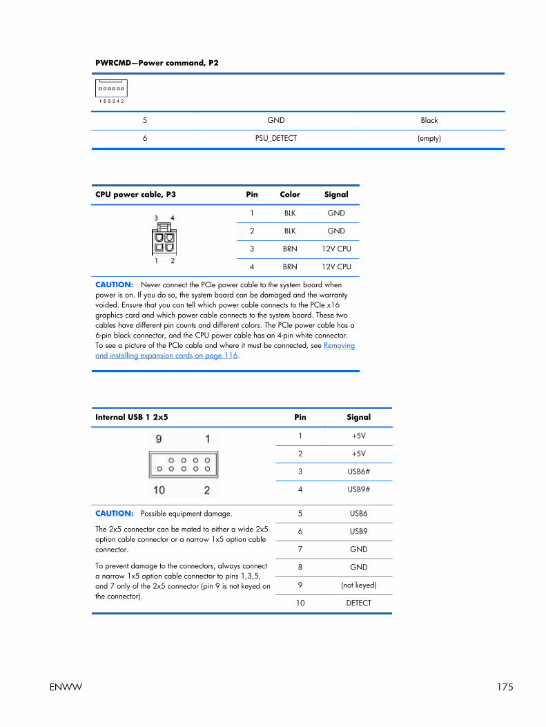
PWRCMD—Power command, P2
5 GND Black
6 PSU_DETECT (empty)
CPU power cable, P3 Pin Color Signal
1 BLK GND
2 BLK GND
3 BRN 12V CPU
4 BRN 12V CPU
CAUTION: Never connect the PCIe power cable to the system board whenpower is on. If you do so, the system board can be damaged and the warrantyvoided. Ensure that you can tell which power cable connects to the PCIe x16graphics card and which power cable connects to the system board. These twocables have different pin counts and different colors. The PCIe power cable has a6-pin black connector, and the CPU power cable has an 4-pin white connector.To see a picture of the PCIe cable and where it must be connected, see Removingand installing expansion cards on page 116.
Internal USB 1 2x5 Pin Signal
1 +5V
2 +5V
3 USB6#
4 USB9#
CAUTION: Possible equipment damage.
The 2x5 connector can be mated to either a wide 2x5option cable connector or a narrow 1x5 option cableconnector.
To prevent damage to the connectors, always connecta narrow 1x5 option cable connector to pins 1,3,5,and 7 only of the 2x5 connector (pin 9 is not keyed onthe connector).
5 USB6
6 USB9
7 GND
8 GND
9 (not keyed)
10 DETECT
ENWW 175

Internal USB 2 2x5 Pin Signal
1 +5V
2 +5V
3 USB7#
4 USB8#
CAUTION: Possible equipment damage.
The 2x5 connector can be mated to either a wide 2x5option cable connector or a narrow 1x5 option cableconnector.
To prevent damage to the connectors, always connecta narrow 1x5 option cable connector to pins 1,3,5,and 7 only of the 2x5 connector (pin 9 is not keyed onthe connector).
5 USB7
6 USB8
7 GND
8 GND
9 (not keyed)
10 DETECT
System fan, CHFAN1, P9 Pin Signal
1 GND
2 +12V
3 Tach
4 PWM
Internal serial Pin Signal Pin Signal
1 DTR1# 9 +5V
2 RXD1 10 +3.3V AUX
3 CTS1# 11 RTS1#
4 DSR1# 12 COM DETECT
5 TXD1 13 DCD21#
6 RI# 14 -12V
7 Ground 15 +12V
8 Ground
176 Appendix A Connector pins ENWW

B System board designators
This appendix describes the system board designators for this computer.
Designator Silk screen Component/Description
E15 E15 Crisis recovery header/jumper
E49 E49 Clear password header/jumper
J9 J9 RJ/USB LAN/DUAL USB
J10 J10 QUAD USB Quad rear USB
J20 J20 PCI PCI slot (white)
J31 J31 PCIe x1 slot (black)
J41 J41 X16PCIEXP PCIe x16(16) slot (black)
J42 J42 X4PCIEXP PCIe x16(4) slot (white)
J53 VGA/COMA Serial port connector stacked over VGA port
J64 DP Display port connector
J68 PS2 Mouse connector stacked over keyboard connector
J78 IN/OUT Audio line in stacked over audio line out
SW50 SW50 CMOS Clear CMOS switch/push button
P1 PWR Power supply, 6-pin (white)
P2 PWRCMD Power command, 6-pin (white)
P3 PWRCPU Power supply, 4-pin (white)
P5 P5 PB/LED Front power button/LED (black)
P6 SPRK Internal speaker (white)
P9 CHFAN1 Front chassis fan
P23 FRONT AUD Front audio (blue)
P24 FRONT USB Front I/O USB (yellow)
P25 FRONT USB2 Front I/O USB (green)
P52 COMB Serial port
P124 HLCK Hood lock solenoid (black)
P125 HSENSE Hood sensor
P126 PAR Flying parallel port (black)
P150 MEDIA Media card reader
ENWW 177

Designator Silk screen Component/Description
P151 MEDIA2 Media card reader
P160 SATAPWR1 HDD power (black)
XBT1 XBT1 BAT Battery holder
XMM1 - XMM4 XMM1 - XMM4
DIMM1 - DIMM4
Memory slots
XU1 XU1 Primary CPU socket
178 Appendix B System board designators ENWW

C Routine Care
General cleaning safety precautions● Never use solvents or flammable solutions to clean the computer.
● Never immerse any component in water or cleaning solutions; apply any liquids to a clean clothand then use the cloth on the component.
● Always unplug the computer before cleaning the keyboard, mouse, or air vents.
● Always disconnect the keyboard before cleaning it.
● Wear safety glasses equipped with side shields when cleaning the keyboard.
Cleaning the computer case● Follow the safety precautions presented in the Service Considerations section before cleaning
the computer.
● To remove light stains or dirt, use plain water with a clean, lint-free cloth or swab.
● For stronger stains, use a mild dish washing liquid diluted with water. Rinse well by wiping it witha cloth or swab dampened with clear water.
● For stubborn stains, use isopropyl (rubbing) alcohol. No rinsing is required because the alcoholevaporates quickly and does not leave a residue.
● After cleaning, always wipe the computer with a clean, lint-free cloth.
● Occasionally, clean the air vents on the computer. Lint and other foreign matter can block thevents and limit the airflow.
Cleaning the keyboardCAUTION: Use safety glasses equipped with side shields before attempting to clean debris fromunder the keys.
● Follow the safety precautions presented in the Service Considerations section before cleaningthe computer.
● Visible debris underneath or between the keys can be removed by vacuuming or shaking.
● Canned, pressurized air can be used to clean debris from under the keys. Use caution becausetoo much air pressure can dislodge lubricants applied under the wide keys.
● If you remove a key, use a specially designed key remover to prevent damage to the keys. Thistool is available from many electronic supply outlets.
CAUTION: Never remove a wide key (like the space bar key) from the keyboard. If these keysare improperly removed or installed, the keyboard might not function properly.
ENWW General cleaning safety precautions 179
● Clean under a key with a swab moistened with isopropyl alcohol and squeezed out. Be carefulnot to wipe away lubricants necessary for proper key functions. Allow the parts to air dry beforereassembly.
● Use tweezers to remove any fibers or dirt in confined areas.
Cleaning the monitor● Follow the safety precautions presented in the Service Considerations section before cleaning
the computer.
● To clean the monitor, wipe the monitor screen with a towelette designed for cleaning monitors or aclean cloth moistened with water.
CAUTION: Do not use sprays or aerosols directly on the screen—the liquid might seep into thehousing and damage a component.
Never use solvents or flammable liquids on the monitor because display or housing damage mayresult.
Cleaning the mouse1. Follow the safety precautions presented in the Service Considerations section before cleaning
the computer.
2. Remove the mouse ball from the housing by removing the retaining plate.
3. Clean the mouse ball.
4. Pull out any debris from the ball socket, and wipe the ball with a clean, dry cloth.
5. Reassemble the mouse.
180 Appendix C Routine Care ENWW

D Locating HP resources
This section provides information on the following HP resources for your workstation:
Topics
Product information on page 182
● Product data sheets
● HP Cool Tools
● Regulatory information
● Accessories
● System board
● Serial number and Certificate of Authenticity labels
Product support on page 183
● Additional information
● Technical support
● HP Support Assistant
● Business Support Center
● IT Resource Center
● HP Service Center
● HP Business and IT Services
● Warranty information
Product documentation on page 184
● User and third-party documentation, and white papers
● Product notifications
● QuickSpecs
● Customer Advisories, Security Bulletins, Notices
Product diagnostics on page 186
● Diagnostics tools
● Audible beeps and LED code definitions
● Web-based support tools
Product updates on page 187
● Driver and BIOS updates
● Operating systems
ENWW 181

Product informationTable D-1 Product information
Topic Location
Product data sheets See www.hp.com/go/quickspecs.
HP Cool Tools Most HP Microsoft Windows workstations are preloadedwith additional software that is not automatically installedduring first boot. Additionally, a number of valuable toolson your workstation are preinstalled that may enhancesystem performance. To access or learn more about theseapplications, choose one of the following options:
● Click the HP Cool Tools icon on the desktop, or
● Open the HP Cool Tools folder by selecting Start >All Programs > HP Cool Tools.
To learn more about these applications, click HP CoolTools—Learn More.
To install or launch the applications, click the appropriateapplication icon.
Regulatory information Refer to the Safety & Regulatory Information guide forproduct Class information. You can also refer to the labelon the workstation chassis.
Accessories For complete and current information on supportedaccessories and components, see http://www.hp.com/go/workstations.
System board A diagram of the system board is located on the inside ofthe side access panel. Also, additional information islocated in the Maintenance and Service Guide on the Webat http://www.hp.com/support/workstation_manuals/.
Serial number and Certificate ofAuthenticity (COA) labels (ifapplicable)
Serial number labels are on the top panel, or on the side ofthe unit at the rear, depending on the workstation model.The COA label is generally located on the top or sidepanel near the serial number label. Some workstationshave this label on the bottom of the unit.
Linux For information on running Linux on HP workstations, seehttp://www.hp.com/linux/.
182 Appendix D Locating HP resources ENWW

Product supportTable D-2 Product support
Topic Location
Additional information For online access to technical support information andtools, see http://www.hp.com/go/workstationsupport.
Support resources include Web-based troubleshootingtools, technical knowledge databases, driver and patchdownloads, online communities, and proactive notificationservices.
The following communication and diagnostic tools are alsoavailable:
● Instant Chat
● Instant Support
● Diagnose Problem
Refer to the workstation Maintenance and Service Guidefor more information on how to receive support.
Technical support Before you call technical support, refer to the workstationMaintenance and Service Guide for a listing of informationyou need to have available before you call.
For a listing of all worldwide technical support phonenumbers, see http://www.hp.com/support/, select yourregion, and click Contact HP in the upper-left corner.
HP Support Assistant HP Support Assistant is an HP application that helps youmaintain the performance of your workstation and resolveproblems through automated updates and tune-ups, built-indiagnostics, and guided assistance.
To access HP Support Assistant, double-click the HPSupport Assistant icon on your desktop.
NOTE: HP Support Assistant is pre-installed on all HPworkstations with Microsoft Windows 7 operating systems.HP Support Assistant is not available on workstationsrunning Linux.
Business Support Center (BSC) For software/driver downloads, warranty information,single-topic documents, user manuals, or service manuals,see http://www.hp.com/go/bizsupport.
IT Resource Center (ITRC) See http://www.itrc.hp.com/ for a searchable knowledgebase for IT professionals.
HP Business and IT Services. For business and IT information, see http://www.hp.com/hps/.
ENWW Product support 183

Table D-2 Product support (continued)
Topic Location
HP Hardware Support Services For hardware service information, seehttp://h20219.www2.hp.com/services/us/en/always-on/hardware-support-supporting-information.html?jumpid=reg_R1002_USEN.
Warranty information To locate base warranty information, seehttp://www.hp.com/support/warranty-lookuptool.
To locate an existing Care Pack, see http://www.hp.com/go/lookuptool.
To extend a standard product warranty, seehttp://h20219.www2.hp.com/services/us/en/warranty/carepack-overview.html?jumpid=hpr_R1002_USEN. HPCare Pack Services offer upgraded service levels to extendand expand a standard product warranty.
For some countries/regions, a printed HP Limited Warrantyis provided in the box. In countries/regions where thewarranty is not provided in printed format, you may requesta printed copy from www.hp.com/go/orderdocuments orwrite to:
● North America: Hewlett Packard, MS POD, 11311Chinden Blvd, Boise, ID 83714, USA
● Europe, Middle East, Africa: Hewlett-Packard,POD, Via G. Di Vittorio, 9, 20063, Cernusco s/Naviglio (MI), Italy
● Asia Pacific: Hewlett-Packard, POD, P.O. Box 200,Alexandra Post Office, Singapore 911507
Please include your product number, warranty period(found on your serial number label), name and postaladdress.
Product documentationTable D-3 Product documentation
Topic Location
HP user documentation, whitepapers, and third-partydocumentation
For the latest online documentation, seehttp://www.hp.com/support/workstation_manuals. Theseinclude this User Guide and the Maintenance and ServiceGuide.
Product notifications Subscriber's Choice is an HP program that allows you tosign up to receive driver and software alerts, proactivechange notifications (PCNs), the HP newsletter, customeradvisories, and more. Sign up at www.hp.com/united-states/subscribe/gateway/?jumpid=go/subscribe-gate1.
Customer advisories and product change notifications arealso available on http://www.hp.com/go/bizsupport/.
184 Appendix D Locating HP resources ENWW

Table D-3 Product documentation (continued)
Topic Location
Workstation technical overview andspecifications
The Product Bulletin contains QuickSpecs for HPWorkstations. QuickSpecs provide an overall specificationreview of your product. It includes information about itsfeatures including the operating system, power supply,memory, CPU, and many other components of the system.To access the QuickSpecs, see http://www.hp.com/go/quickspecs/.
Customer Advisories, SecurityBulletins, and Notices
To find advisories, bulletins, and notices:
1. See http://www.hp.com/go/workstationsupport.
2. Select the desired product.
3. From the Resources section, select See more…
4. Use the scroll bar to select Customer Advisories,Customer Bulletins, or Customer Notices.
ENWW Product documentation 185

Product diagnosticsTable D-4 Product diagnostics
Topic Location
Diagnostics tools The HP Vision Diagnostics utility can be found as aburnable ISO image on the workstation hard disk (under C:\VisionDiagnostics), or can be downloaded from theHP web site. For details on using this utility, refer to thesection that covers HP Vision Diagnostics in the workstationMaintenance and Service Guide.
Audible beep and LED codedefinitions
Refer to the appropriate section of the workstationMaintenance and Service Guide for detailed informationabout beep and Light Emitting Diode (LED) codesapplicable to the workstation.
186 Appendix D Locating HP resources ENWW

Product updatesTable D-5 Product updates
Topic Location
Driver and BIOS updates See http://www.hp.com/go/workstationsupport to verify thatyou have the latest drivers for the workstation.
To determine the current workstation BIOS on yourworkstation, follow these steps during system power up:
1. Power on the workstation, and wait for F10=setup toappear on the lower right corner of the screen.
2. Press F10 to enter the F10 Setup utility.
The F10 Setup utility displays the computer BIOS versionunder File > System Information.
3. Note the computer BIOS version so that you cancompare it with the BIOS versions that appear on the HPwebsite.
Operating systems For information on operating systems supported on HPworkstations, see http://www.hp.com/go/wsos.
For information on Windows operating systems, seehttp://www.microsoft.com/support.
For information on Linux operating systems, seehttp://www.hp.com/linux.
ENWW Product updates 187

Index
AAppendices
Connector pins 171System board designators 177
BBezel security 65BIOS
Determining version 20Updating 21
BIOS ROM 25
CCable management 96Card configuration restrictions
Power supplies 114Chassis components 4Components, removing and
installing 60Computer Setup (F10) Utility
Menu description 28Configuring RAID devices
SATA RAID 164Connector pins
Audio line-in 172Audio line-out 172CPU power cable 175Display port 173Ethernet 171Headphone 172Internal serial 176Internal USB 175, 176Keyboard 171Main power cable 174Microphone 172Mouse 171Rear system fan 176SATA drive 172USB 172VGA 173
DDesktop management
Altiris Client ManagementSolutions 39
Dual-state power button 52FailSafe Boot Block ROM 41Fault notification and recovery
51HP Client Manager Software
39HP SoftPaq Download
Manager 40HPQFlash 40Initial configuration 37Remote ROM Flash 40Remote system install 37Replicating the setup 38ROM Flash 40System Software Manager 40Updating software 39Workstation security 42
Diagnostic codes and errorsLED and beep codes 152LED colors 156POST errors 157
Diagnostics and troubleshootingDiagnosis guidelines 131HP Vision Diagnostics 144Locating ID labels 129Locating warranty info 130
DIMM configurations, supported109
DriversInstalling 17Updating 17, 21
drivesremoval and replacement 69
EExpansion card slots 3
FFan, system 106front bezel
removing blanks 70
GGraphics cards 3
HHP Recovery Manager 23HP resources
Locating 181Product diagnostics 186Product documentation 184Product information 182Product support 183Product updates 187Web links 184
Mmedia card reader; removal and
replacement 69Memory technology 2Microsoft Windows
Setting up 17Transferring files 17
monitorWindows 136
NNovell SLED
Restoring 24Setting up 19
OOperating system setup
Microsoft Windows 17Red Hat Linux 18
Operating system setup; NovellSLED 19
PPower supply
Card configuration restrictions114
Currents 8Power consumption 9Resetting power supply 10Specifications 9System fans 10Voltages 7
Processor technology 2
188 Index ENWW

Product featuresComputer components 4ERP compliance mode 13Front panel components 5HP Cool Tools 14Hyper-threading 13Physical characteristics 7Rear panel components 6SATA Power Management 14System board architecture 1Turbo Boost 14
Product overview 1
RRed Hat Linux
Setting up 18removal and replacement
drives 69removing
bezel blanks 70Replacing components
Access panel 64access panel sensor 67access panel solenoid 68Battery 120Bezel 65cable lock 63Component locations 61CPU 124CPU heatsink 121Disassembly order 63Expansion card slot
identification 114Front panel I/O device 99Memory 109PCIe card 116Power connections 97Power supply 104Predisassembly 62Service considerations 55Slot identification 114Speaker 103System board 126System fan 106
Restoring the operating systemRestore method 22
SSoftware
Ordering 23
Specifications 7Support
Locating HP resources 181System board components 61System board designators 177System management 25
TTower orientation 98
UUpdating the workstation
First boot update 20Updating drivers 21Updating the BIOS 21
WWindows 7
Setting up 17Windows operating system
monitor 136Workstation setup
Ensuring proper ventilation 15
ENWW Index 189
Related Documents