HP LTO Ultrium 6 Tape Drives Technical Reference Manual Volume 1: Hardware Integration Abstract This is one of five volumes that document HP LTO Ultrium 6 tape drives (Fibre Channel and SAS). This volume provides hardware integration information. See “Support and other resources” (page 127) for details of the other guides. HP Part Number: n/a Published: October 2012 Edition: First

Welcome message from author
This document is posted to help you gain knowledge. Please leave a comment to let me know what you think about it! Share it to your friends and learn new things together.
Transcript

HP LTO Ultrium 6 Tape Drives TechnicalReference ManualVolume 1: Hardware Integration
AbstractThis is one of five volumes that document HP LTO Ultrium 6 tape drives (Fibre Channel and SAS). This volume provides hardwareintegration information. See “Support and other resources” (page 127) for details of the other guides.
HP Part Number: n/aPublished: October 2012Edition: First

© Copyright 2012 Hewlett-Packard Development Company, L.P.
The information contained herein is subject to change without notice. The only warranties for HP products and services are set forth in the expresswarranty statements accompanying such products and services. Nothing herein should be construed as constituting an additional warranty. HP shallnot be liable for technical or editorial errors or omissions contained herein.
Acknowledgements
Windows is a U.S. registered trademarks of Microsoft Corporation.
UNIX is a registered trademark of The Open Group.
Warranty
WARRANTY STATEMENT: To obtain a copy of the warranty for this product, see the warranty information website:
http://www.hp.com/go/storagewarranty

Contents1 Physical dimensions....................................................................................7
Fixing dimensions.....................................................................................................................7Full-height drives..................................................................................................................7Half-height drives.................................................................................................................7
2 Electrical and environmental requirements......................................................9Electrical fit..............................................................................................................................9
Power requirements..............................................................................................................9Voltage and current requirements...........................................................................................9
Full-height drives..............................................................................................................9Half-height drives............................................................................................................9
Airflow requirements...............................................................................................................10Measuring internal drive temperatures..................................................................................10
Extracting internal temperature information.......................................................................10Optional fan plate.............................................................................................................11
3 Front panel and LEDs................................................................................12Front panel features................................................................................................................12
Full-height drives................................................................................................................12Reset switch..................................................................................................................12
Half-height drives...............................................................................................................13Usual meaning of LEDs............................................................................................................13LED patterns...........................................................................................................................14
Full-height drives................................................................................................................14Half-height drives...............................................................................................................16During firmware upgrade....................................................................................................18
Replacing the front panel.........................................................................................................18Parts needed.....................................................................................................................18Replacing the front panel on an full-height LTO Ultrium drive....................................................18Replacing the front panel on a half-height LTO Ultrium drive.....................................................19
4 Rear panel and connectors........................................................................20Rear panel components—full-height drives.................................................................................21Rear panel components—half-height drives................................................................................23LEDs.....................................................................................................................................24
Power-on self-test failure......................................................................................................24Port initialized...................................................................................................................24Port activity.......................................................................................................................25
Fibre Channel addressing........................................................................................................25Connectors............................................................................................................................26
Fibre Channel connector.....................................................................................................26SAS connector...................................................................................................................26Automation and remote LED connector.................................................................................26
Connector pins.............................................................................................................26ACI operation..........................................................................................................26ADI operation..........................................................................................................27
Remote LEDs.................................................................................................................28Automation and remote LED connector schematic..............................................................28iADT (Ethernet) port.......................................................................................................29
Diagnostic Serial Port connector...........................................................................................30Fan control connector.........................................................................................................30
Contents 3

5 Cartridges...............................................................................................31Choosing cartridges................................................................................................................31Labeling cartridges.................................................................................................................31Write-protecting cartridges.......................................................................................................31Cartridge life.........................................................................................................................32Caring for cartridges...............................................................................................................32
Avoiding condensation.......................................................................................................32Conditions in use..........................................................................................................32Conditions in storage.....................................................................................................32Maximizing tape life......................................................................................................32
LTO Cartridge Memory............................................................................................................33LTO Cartridge Memory issues..............................................................................................33More information...............................................................................................................34
6 Planning your system configuration.............................................................35Modes of usage.....................................................................................................................35Optimizing performance.........................................................................................................35
Dedicated bus...................................................................................................................35System performance...........................................................................................................35Data rate matching............................................................................................................35Performance checklist.........................................................................................................35
7 Installing and replacing drives....................................................................37Installing in a server................................................................................................................37
Identifying the model..........................................................................................................37Standards and safety.........................................................................................................37Requirements.....................................................................................................................38
Mounting requirements..................................................................................................38Server connections........................................................................................................38
Supported bus types.................................................................................................38Connecting the drive..........................................................................................................39
SAS connector..............................................................................................................39Backup software................................................................................................................39
Installing in a tape array..........................................................................................................40Appropriate HP rack-mount systems......................................................................................40Airflow requirements..........................................................................................................40Identifying the drive............................................................................................................40Modes of usage................................................................................................................40Attaching to SAS...............................................................................................................40Connecting to a Fibre Channel router or by SAS to a server or router........................................40
Fibre Channel connection...............................................................................................40Server SAS connection...................................................................................................40
Replacing a drive...............................................................................................................41Installing in a library...............................................................................................................41
Rear panel and connectors..................................................................................................41Installing standalone drives......................................................................................................42
Identifying the drive............................................................................................................42Connecting the drive..........................................................................................................42
SAS connection.............................................................................................................42Moving drives....................................................................................................................42
8 Operating the drive..................................................................................43Power-on self-test.....................................................................................................................43Loading a cartridge................................................................................................................44Unloading a cartridge.............................................................................................................45Cleaning...............................................................................................................................45
4 Contents

Resetting drives in a library......................................................................................................469 Troubleshooting........................................................................................47
Emergency unload (forced eject)...............................................................................................47General guidelines.................................................................................................................47Diagnosing the problem..........................................................................................................48
Problems with the host computer..........................................................................................48Computer does not boot up............................................................................................48Computer boots, but does not recognize the drive.............................................................48
Problems with the drive and cartridge...................................................................................48Tape drive does not power up.........................................................................................48The application does not recognize the drive....................................................................49The cartridge will not eject.............................................................................................49The drive will not accept a cartridge................................................................................49The computer no longer recognizes the drive in a tape array..............................................50
Problems with cleaning.......................................................................................................5010 Special features for automation.................................................................51
Introduction............................................................................................................................51Backup software................................................................................................................51
Drive Model ID String....................................................................................................51Front panel for automation use.................................................................................................52
Full-height drives................................................................................................................52Front panel for use in autoloaders....................................................................................53
Half-height drives...............................................................................................................54Automation interface...............................................................................................................54
Automation Control Interface (ACI).......................................................................................55Automation/Drive Interface (ADI).........................................................................................56Internet Automation Device interface (iADT)...........................................................................56Fan interface.....................................................................................................................58
Configuring autoload and library-controlled loads......................................................................58Cartridge positions during load and unload..........................................................................59Load scenarios..................................................................................................................60
Load scenario 1: Autoload..............................................................................................60Load scenario 2: Library controlled.............................................................................60Unload scenario 1: Autoload.....................................................................................60Unload scenario 2: Library controlled..........................................................................60
Load/unload forces............................................................................................................61Using Cartridge Memory (LTO-CM) in libraries...........................................................................61
Current libraries — barcodes...............................................................................................6111 Drive error codes.....................................................................................62
Generic module (from 0000h)..................................................................................................62Automation Control Interface (from 0400h)................................................................................62Buffer manager (from 0800h)...................................................................................................65Diagnostic control (from 1800h)................................................................................................66Drive control (from 1C00h)......................................................................................................68Drive monitor (from 2000h).....................................................................................................70External interfaces (from 2400h)...............................................................................................70Front panel interface (from 2800h)............................................................................................71Host interface (from 2C01h).....................................................................................................71Logical formatter (from 3000h).................................................................................................78Logical media (from 3400h).....................................................................................................82Logical pipeline control (from 3800h)........................................................................................83Mechanism control (from 3C00h).............................................................................................83Non-volatile data manager (from 4000h)..................................................................................84
Contents 5

Operating system (from 4400h)................................................................................................88Physical formatter (from 4C00h)...............................................................................................88Physical pipeline control (from 5000h).......................................................................................89Physical side error recovery (from 5400h)..................................................................................91Read/write control (from 5800h)..............................................................................................91System architecture (from 6400h)..............................................................................................93Tight integ (from 6800h)..........................................................................................................93Trace logger (from 6C00h)......................................................................................................93Mechanical interface (from 7400h)...........................................................................................94Exception handler (from 7800h).............................................................................................108SPI interface (from 7C00h).....................................................................................................108Cartridge Memory (from 8000h)............................................................................................108Fault log manager section (from 8400h)..................................................................................109Infrastructure section (from 8800h)..........................................................................................110Critical section (from 8C00h).................................................................................................111SCSI module (from 9400h).....................................................................................................111Automation/Drive Interface (from 9800h)................................................................................118Management API (from 9C00h)..............................................................................................120Servo (from A000h)..............................................................................................................121Certificate manager (from A400h)..........................................................................................125Cryptographic algorithms (from A800h)..................................................................................125Master channel (from 3C00h)................................................................................................126Hyper-drive (from F400h).......................................................................................................126
12 Support and other resources...................................................................127Related documents................................................................................................................127
Documents specific to HP LTO Ultrium drives........................................................................127Documentation map.........................................................................................................127
Drives—general..........................................................................................................127Installation and configuration........................................................................................127Operation..................................................................................................................127Cartridges..................................................................................................................128Interface....................................................................................................................128Maintenance and troubleshooting.................................................................................128Dealing with errors......................................................................................................128LTO Ultrium features.....................................................................................................128
General documents and standardization.............................................................................130Glossary..................................................................................................131Index.......................................................................................................135
6 Contents

1 Physical dimensionsFor the physical specification of the drive, see Chapter 1, “Physical Specification” in Specifications,Volume 4 of the HP LTO Ultrium Technical Reference Manual.
Fixing dimensions• All screws should be M3 threaded. Do not use spring washers.
• The recommended mounting torque is:
Full-height drives: 5.8 0.5 lb-in (0.60–0.70 Nm)◦◦ Half-height drives: 2.4 0.5 lb-in (0.24–0.30 Nm)
• HP recommends 0.3 mm mounting clearance around all covers for isolation mountingmovement.
Full-height drivesThe recommended screw length depends on the thickness of the rails or enclosure into which thedrive is mounted:
Recommended Screw LengthServer or Rail Thickness
M3 x 6.0 mm> 1.5 mm 2.0 mm
M3 x 6.0 mm> 1.0 mm 1.5 mm
M3 x 5.0 mm1.0 mm
Maximum Screw PenetrationMounting Points
5 mmSide
5 mmBottom
For the dimensions of full-height drives, see the following figures in the HP LTO Ultrium 6 TapeDrives Technical Reference Manual, Volume 4: Specifications:
Rear panelFront panelSide panelBottom panel
Figure 4Figure 3Figure 2Figure 1Full-height FibreChannel
Figure 5Figure 3Figure 2Figure 1Full-height SAS
• Full-height FC drives: Volume 4, Specifications, figures 1, 2 and
• Full-height SAS drives: Volume 4, Specifications, figure 2
Half-height drives
Maximum Screw PenetrationMounting Points
3 mmSide
2.1 mmBottom
Fixing dimensions 7

For the dimensions of half-height drives, see the following figures in the HP LTO Ultrium 6 TapeDrives Technical Reference Manual, Volume 4: Specifications:
Rear panelFront panelSide panelBottom panel
Figure 11Figure 10Figures 7 and 8Figure 6Half-height FibreChannel
Figure 12Figure 10Figures 7 and 9Figure 6Half-height SAS
8 Physical dimensions

2 Electrical and environmental requirementsElectrical fit
Power requirements
NOTE: SAS drives do not have a regular 4-pin power connector and should be powered throughthe SAS connector.
The following are the PSU requirements for FC and SAS full-height and half-height drives:
Maximum CurrentTypical CurrentVoltage
<4.10A3.50A5V
<2.60A0.60A12V
See also details in Chapter 2, “Electrical Requirements” in Specifications, Volume 4 of the HP LTOUltrium Technical Reference Manual.The drive is specified to operate at 5V 5% and 12V 10%.
Voltage and current requirementsVoltage and current requirement are as follows:
Full-height drives
SAS DrivesFC Drives
12V5V12V5VSpecification
13.2V5.25V13.2V5.25VMax voltage
10.8V4.75V10.8V4.75VMin voltage
TBD ATBD A0.54A3.44AMax steady-state current
TBD ATBD A2.01A3.75AMax transient current
TBD WTBD W7.20W17.20WMax steady-state power
TBD WTBD W24.12W18.75WMax transient power
150 mVpp150 mVpp150 mVpp150 mVppMax noise/ripple
Half-height drives
SAS DrivesFC Drives
12V5V12V5VSpecification
13.2V5.25V13.2V5.25VMax voltage
10.8V4.75V10.8V4.75VMin voltage
TBD ATBD A0.66A3.51AMax steady-state current
TBD ATBD A1.90A3.85AMax transient current
TBD WTBD W7.92W17.55WMax steady-state power
Electrical fit 9
SAS DrivesFC Drives
12V5V12V5VSpecification
TBD WTBD W22.80W19.25WMax transient power
150 mVpp150 mVpp150 mVpp150 mVppMax noise/ripple
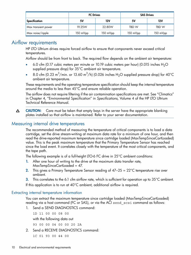
Airflow requirementsHP LTO Ultrium drives require forced airflow to ensure that components never exceed criticaltemperatures.Airflow should be from front to back. The required flow depends on the ambient air temperature:
• 6.0 cfm (0.17 cubic meters per minute or 10.19 cubic meters per hour) (0.015 inches H2Osupplied pressure drop) for 35°C ambient air temperature.
• 8.0 cfm (0.23 m3/min. or 13.60 m3/h) (0.026 inches H2O supplied pressure drop) for 40°Cambient air temperature.
These requirements and the operating temperature specification should keep the internal temperaturearound the media to less than 45°C and ensure reliable operation.The airflow does not require filtering if the air contamination specifications are met. See “Climatics”in Chapter 4, “Environmental Specification” in Specifications, Volume 4 of the HP LTO UltriumTechnical Reference Manual.
CAUTION: Care must be taken that empty bays in the server have the appropriate blankingplates installed so that airflow is maintained. Refer to your server documentation.
Measuring internal drive temperaturesThe recommended method of measuring the temperature of critical components is to load a datacartridge, set the drive stream-writing at maximum data rate for a minimum of one hour, and thenread the drive-reported maximum temperature since cartridge loaded (MaxTempSinceCartLoaded)value. This is the peak maximum temperature that the Primary Temperature Sensor has reachedsince the load event. It correlates closely with the temperature of the most critical components, andthe tape path.The following example is of a full-height LTO-6 FC drive in 25°C ambient conditions:1. After one hour of writing to the drive at the maximum data transfer rate,
MaxTempSinceCartLoaded = 47.2. This gives a Primary Temperature Sensor reading of 47–25 = 22°C temperature rise over
ambient.3. This correlates to the 6.1 cfm airflow rate, which is sufficient for operation up to 35°C ambient.If this application is to run at 40°C ambient, additional airflow is required.
Extracting internal temperature informationYou can extract the maximum temperature since cartridge loaded (MaxTempSinceCartLoaded)reading via a host command (FC or SAS), or via the ACI send_scsi command as follows:1. Send a SEND DIAGNOSTICS command:
1D 11 00 00 08 00
with the following data out93 00 00 04 00 00 20 2A
2. Send a RECEIVE DIAGNOSTICS command:1C 01 93 00 44 00
10 Electrical and environmental requirements

3. The MaxTempSinceCartLoaded value is ASCII encoded in bytes 22–29 of the incoming data.Example SCSI trace:SendDiagnostic |1D 11 00 00 08 00 |00008|00|00| Data Out |93 00 00 04 00 00 20 2A |ReceiveDiagResults |1C 01 93 01 00 00 |0009C|00|00| Data In |93 00 00 98 30 30 30 30 31 41 31 32 20 30 30 30 | Data In |30 31 41 31 32 20 30 30 30 30 31 41 37 34 20 30 | Data In |30 30 30 31 39 31 37 20 0D 0A 30 30 30 30 30 30 | Data In |30 30 20 30 30 30 30 30 30 30 30 20 30 30 30 30 | Data In |33 32 30 30 20 30 30 30 30 30 35 30 30 20 0D 0A | Data In |46 46 46 46 38 30 30 30 20 46 46 46 46 38 30 30 | Data In |30 20 46 46 46 46 38 30 30 30 20 46 46 46 46 38 | Data In |30 30 30 20 0D 0A 46 46 46 46 38 30 30 30 20 46 | Data In |46 46 46 38 30 30 30 20 30 30 30 30 30 35 30 30 | Data In |20 30 30 30 30 30 35 30 30 20 0D 0A |
4. Translate each character received from ASCI to hex numbers.For the example above: 30 30 30 30 31 41 37 34 = 00001A74h
5. Convert this number to decimal = 67726. Divide this number by 256 to give the temperature in °C = 26.4°C
Optional fan plateIf the airflow requirements cannot be met by the existing fans in a server then the optional fan platemay be required. This a plastic plate with an embedded fan that fits on the back of a half-heightdrive. The fan plugs into the Fan Connector (see “Rear panel components—half-height drives”(page 23) and “Fan control connector” (page 30)) and the drive controls this fan to self-manageits own internal temperature, turning the fan on and off as needed. For details of the optional FanPlate, contact your HP Technical Support Representative.
Airflow requirements 11
3 Front panel and LEDsHP LTO Ultrium 6 products have three front panel designs:
• System, for use in servers, rack mounts and other non-automation applications—see “Frontpanel features” below
• Automation, for use when the drive is embedded in automation applications—see “Front panelfor automation use” (page 52)
• A third front panel allowing drives to be used in autoloaders where the front panel cannotexceed the drive form factor in height and width—see “Front panel for use in autoloaders”(page 53)
The drive is not designed to operate without a front panel (even in automation applications). Thefront panel was designed to meet Section 508 of the Rehabilitation Act accessibility guidelines.
Front panel features
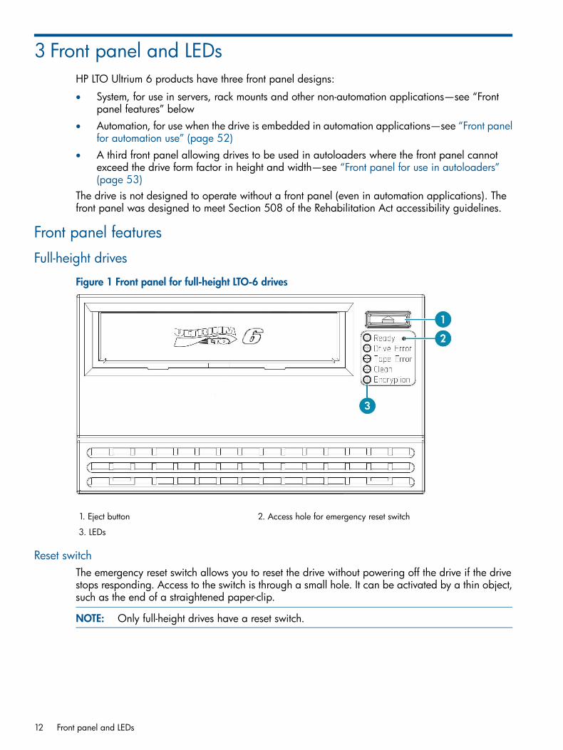
Full-height drives
Figure 1 Front panel for full-height LTO-6 drives
2. Access hole for emergency reset switch1. Eject button
3. LEDs
Reset switchThe emergency reset switch allows you to reset the drive without powering off the drive if the drivestops responding. Access to the switch is through a small hole. It can be activated by a thin object,such as the end of a straightened paper-clip.
NOTE: Only full-height drives have a reset switch.
12 Front panel and LEDs

Half-height drives
Figure 2 Front panel for half-height LTO-6 drives
2. Eject button1. LEDs
Usual meaning of LEDsThe five LEDs, Ready, Drive Error, Tape Error, Clean and Encryption usually have the followingmeanings:
Green. Indicates power and activity:Ready
Power off or self-test failureOff
Powered on and ready for use, but no activityOn
Engaged in activity, such as responding to Read, Write or Space commandsor performing a self-test
Flashing
Downloading new firmware.Fast flash
A repeating pattern of short and long flashes indicates that the drive is inOBDR mode.
Repeating pattern
Orange. Indicates drive problems:Drive Error
No faultOff
Unrecoverable hardware failure. A power cycle or successful tape load willturn the LED off, but the LED will start flashing again if the same operation isperformed and the hardware fault is still present
Flashing
Orange. Indicates tape problems:Tape Error
No faultOff
Current tape is faulty, such as unreadable cartridge memory or unsupportedtype. Do not use the cartridge; replace it. The LED will go out when a tapeload begins.
Flashing
Orange. Indicates whether the drive needs cleaning.Clean
Cleaning not requiredOff
Cleaning cartridge being used. The Ready LED flashes.On
Cleaning needed. The LED continues to flash if the drive is power cycled,and will only go out after a supported cleaning tape has been used.
Flashing
Blue/orange. Indicates whether encryption is enabled or not.Encryption
No key is present in the drive. Encryption and decryption are not enabled.Off
A key is present in the drive. Encryption and decryption are enabled.On (Blue)
Encryption/decryption error.Flashing(Blue/Orange)
Usual meaning of LEDs 13
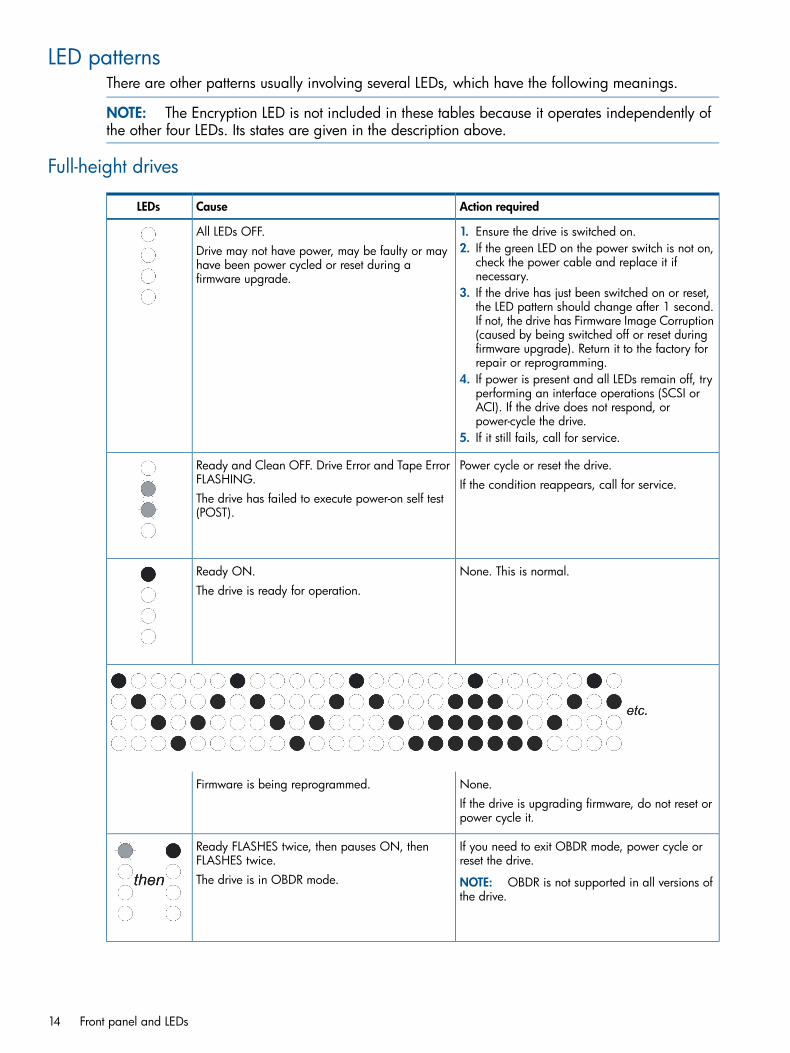
LED patternsThere are other patterns usually involving several LEDs, which have the following meanings.
NOTE: The Encryption LED is not included in these tables because it operates independently ofthe other four LEDs. Its states are given in the description above.
Full-height drives
Action requiredCauseLEDs
All LEDs OFF. 1. Ensure the drive is switched on.Drive may not have power, may be faulty or mayhave been power cycled or reset during afirmware upgrade.
2. If the green LED on the power switch is not on,check the power cable and replace it ifnecessary.
3. If the drive has just been switched on or reset,the LED pattern should change after 1 second.If not, the drive has Firmware Image Corruption(caused by being switched off or reset duringfirmware upgrade). Return it to the factory forrepair or reprogramming.
4. If power is present and all LEDs remain off, tryperforming an interface operations (SCSI orACI). If the drive does not respond, orpower-cycle the drive.
5. If it still fails, call for service.
Power cycle or reset the drive.Ready and Clean OFF. Drive Error and Tape ErrorFLASHING. If the condition reappears, call for service.The drive has failed to execute power-on self test(POST).
None. This is normal.Ready ON.The drive is ready for operation.
None.Firmware is being reprogrammed.If the drive is upgrading firmware, do not reset orpower cycle it.
If you need to exit OBDR mode, power cycle orreset the drive.
Ready FLASHES twice, then pauses ON, thenFLASHES twice.
NOTE: OBDR is not supported in all versions ofthe drive.
The drive is in OBDR mode.
14 Front panel and LEDs

Action requiredCauseLEDs
Load an LTO Ultrium Universal cleaning cartridgeto clean the heads. See “Cleaning” (page 45) forinstructions.
Clean FLASHING. (Other LEDs may be on orflashing.)The drive requires cleaning.
If the Clean LED is still flashing when you load anew or known data cartridge after cleaning, callfor service.
None. The cleaning cartridge will eject oncompletion.
Ready FLASHING and Clean ON. (Other LEDsmay be on or flashing.)
The cleaning cycle can take up to 5 minutes .Cleaning is in progress.
Unload the tape cartridge. Make sure that it is avalid format: an LTO Ultrium data cartridge or LTOUltrium Universal cleaning cartridge.
Tape Error FLASHING. (Other LEDs may be on orflashing.)The drive believes the current tape or the tape justejected is faulty. Reload the cartridge. If the Tape Error LED still
flashes or starts flashing during the next backup,load a new or known, good cartridge.If the Tape Error LED is now off, discard the‘suspect’ tape cartridge. If it is still on, call forservice.
Write-protect the cartridge by sliding the red switchon the cartridge. The tape can be loaded and the
Tape ejects immediately and Tape Error FLASHES.(Other LEDs may be on or flashing.)
data read. Once the data is recovered, discardthe cartridge.
The tape cartridge memory (CM) may be faulty.
Load a new cartridge. If the error persists, powercycle or reset the drive.
Drive Error FLASHING. (Other LEDs may be on orflashing.)
If the Drive Error LED remains on, call for service.The drive mechanism has detected an error.
Insert a cartridge to clear the LED sequence; thedrive will continue using the old firmware. If thecondition persists, call for service.
Drive Error, Tape Error and Ready FLASH.There is a firmware download problem.
Power cycle or reset the drive. If the sequencereoccurs, upgrade the firmware. If the conditionpersists, call for service.
Drive Error and Ready ON with Tape Error andClean OFF. Sequence alternates repeatedly.The drive has a firmware error.
LED patterns 15
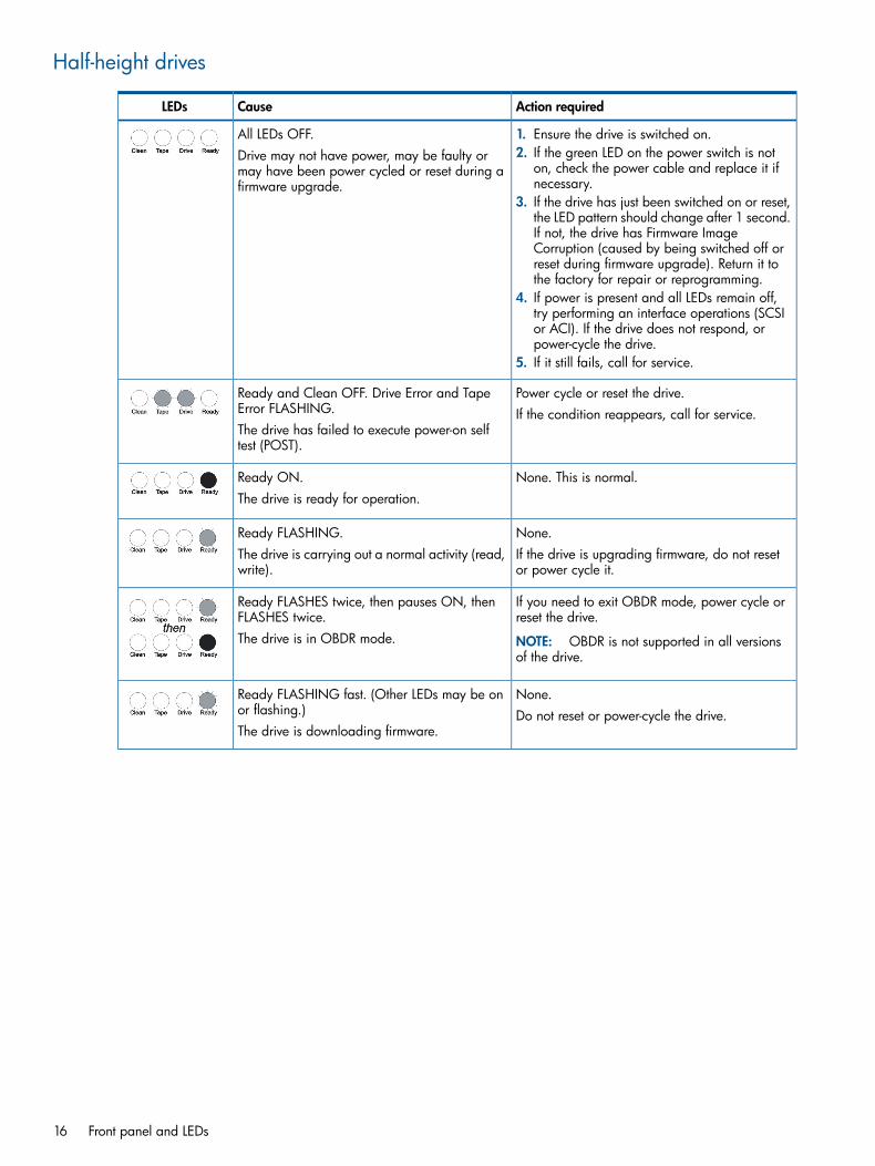
Half-height drives
Action requiredCauseLEDs
All LEDs OFF. 1. Ensure the drive is switched on.Drive may not have power, may be faulty ormay have been power cycled or reset during afirmware upgrade.
2. If the green LED on the power switch is noton, check the power cable and replace it ifnecessary.
3. If the drive has just been switched on or reset,the LED pattern should change after 1 second.If not, the drive has Firmware ImageCorruption (caused by being switched off orreset during firmware upgrade). Return it tothe factory for repair or reprogramming.
4. If power is present and all LEDs remain off,try performing an interface operations (SCSIor ACI). If the drive does not respond, orpower-cycle the drive.
5. If it still fails, call for service.
Power cycle or reset the drive.Ready and Clean OFF. Drive Error and TapeError FLASHING. If the condition reappears, call for service.The drive has failed to execute power-on selftest (POST).
None. This is normal.Ready ON.The drive is ready for operation.
None.Ready FLASHING.If the drive is upgrading firmware, do not resetor power cycle it.
The drive is carrying out a normal activity (read,write).
If you need to exit OBDR mode, power cycle orreset the drive.
Ready FLASHES twice, then pauses ON, thenFLASHES twice.
NOTE: OBDR is not supported in all versionsof the drive.
The drive is in OBDR mode.
None.Ready FLASHING fast. (Other LEDs may be onor flashing.) Do not reset or power-cycle the drive.The drive is downloading firmware.
16 Front panel and LEDs

Action requiredCauseLEDs
None.Ready OFF, others ON.Do not reset or power-cycle the drive.Firmware is being reprogrammed.
Load an LTO Ultrium Universal cleaning cartridgeto clean the heads. See “Cleaning” (page 45)for instructions.
Clean FLASHING. (Other LEDs may be on orflashing.)The drive requires cleaning.
If the Clean LED is still flashing when you load anew or known data cartridge after cleaning, callfor service.
None. The cleaning cartridge will eject oncompletion.
Ready FLASHING and Clean ON. (Other LEDsmay be on or flashing.)
The cleaning cycle can take up to 5 minutes .Cleaning is in progress.
Tape Error FLASHING. (Other LEDs may be onor flashing.)
1. Unload the tape cartridge. Make sure that itis a valid format: an LTO Ultrium datacartridge or LTO Ultrium Universal cleaningcartridge.
The drive believes the current tape or the tapejust ejected is faulty.
2. Reload the cartridge. If the Tape Error LED stillflashes or starts flashing during the nextbackup, load a new or known, goodcartridge.
3. If the Tape Error LED is now off, discard the‘suspect’ tape cartridge. If it is still on, call forservice.
Write-protect the cartridge by sliding the redswitch on the cartridge. The tape can be loaded
Tape ejects immediately and Tape ErrorFLASHES. (Other LEDs may be on or flashing.)
LED patterns 17

Action requiredCauseLEDs
and the data read. Once the data is recovered,discard the cartridge.
The tape cartridge memory (CM) may be faulty.
Load a new cartridge. If the error persists, powercycle or reset the drive.
Drive Error FLASHING. (Other LEDs may be onor flashing.)
If the Drive Error LED remains on, call for service.The drive mechanism has detected an error.
Power cycle or reset the drive. If the sequencereoccurs, upgrade the firmware. If the conditionpersists, call for service.
Drive Error and Ready ON with Tape Error andClean OFF. Sequence alternates repeatedly.The drive has a firmware error.
During firmware upgrade
CAUTION: Do not reset or power-cycle the drive until the firmware upgrade is complete, otherwisethe drive will be not be able to operate.
If a firmware upgrade is successful, the LEDs light in sequence during the download as shown inthe table above.If a corrupt or incompatible image is downloaded from tape, the Ready LED will remain on steadilyand the Tape Error LED will flash until a tape load is started. The other LEDs will be off.
Replacing the front panel
CAUTION: At all times please observe ESD precautions as indicated in the installation manualsupplied with the tape drive. Static electricity can damage electronic components. Touch a baremetal part of the computer, such as a back plate, before you attempt to install or remove the drive.
Parts needed• Replacement front panel
• Small bladed screwdriver (125x5 slotted or smaller)
Replacing the front panel on an full-height LTO Ultrium drive
1. Use the screwdriver to release the tabs at the top of the chassis and underneath.
18 Front panel and LEDs

2. Pull the front panel towards you and away from the drive.To replace the panel, line up the four tabs with the chassis and push the panel firmly intoplace. There will be a slight click when the lugs are located in the chassis.
Replacing the front panel on a half-height LTO Ultrium drive
1. Use the screwdriver to release the tab on the right side of the chassis (next to the red warrantysticker).
2. Swing the front panel out slowly, pulling it gently to the left, so that the lugs release on the leftside of the chassis.
NOTE:Do not swing the panel too far out or pull too hard, as the lugs are quite delicate.
3. To replace the panel, line up the lugs on the left side of the chassis and swing the panel firmlyinto place.There will be a slight click when the lug is located on the right side of the chassis.
Replacing the front panel 19

4 Rear panel and connectorsThe rear panel contains the connector interface that allows the tape drive to communicate with atape library or host computer system. The panel includes the following connectors:
• Two SFP duplex-LC optical fibre connectors (though only one might be installed)
• Or: An SAS connector
• Combined ACI/ADI and remote LED connector
• Diagnostic serial port
• Fan connector (SAS drives only)
• Power connector (Fibre Channel drives only)
• iADT (Ethernet) connector
20 Rear panel and connectors

Rear panel components—full-height drivesFigure 3 Rear panel components for a full-height Fibre Channel drive
2. 8 GB FC transceiver module, port 0 (A) (by default onlythe port 0 slot is filled)
1. iADT Ethernet (10-pin)
4. Power3. Port 1 (B) slot for optional transceiver
6. AL_PA jumpers (may not be loaded)5. ADI/ACI LEDs (16-pin)
8. Port 1 (B) LED7. Port 0 (A) LED
9. Diagnostic serial port (4-pin)
Position of pin 1 (which may be different from previous generation drives)
For the dimensions of the rear panel of full-height FC drives, see Figure 4 in the HP LTO Ultrium 6Tape Drives Technical Reference Manual, Volume 4: Specifications.
Rear panel components—full-height drives 21

Figure 4 Rear panel components for a full-height SAS drive
2. External fan support (6-pin)1. Diagnostic serial port (4-pin)
4. SAS SFF 8482 connector (includes power)3. iADT Ethernet (10-pin)
6. Active SAS management port (9-pin)5. ADI/ACI, LEDs (16-pin)
8. Host primary port LED7. Host secondary port LED
Position of pin 1 (which may be different from previous generation drives)
For the dimensions of the rear panel of full-height SAS drives, see Figure 5 in the HP LTO Ultrium6 Tape Drives Technical Reference Manual, Volume 4: Specifications.
22 Rear panel and connectors
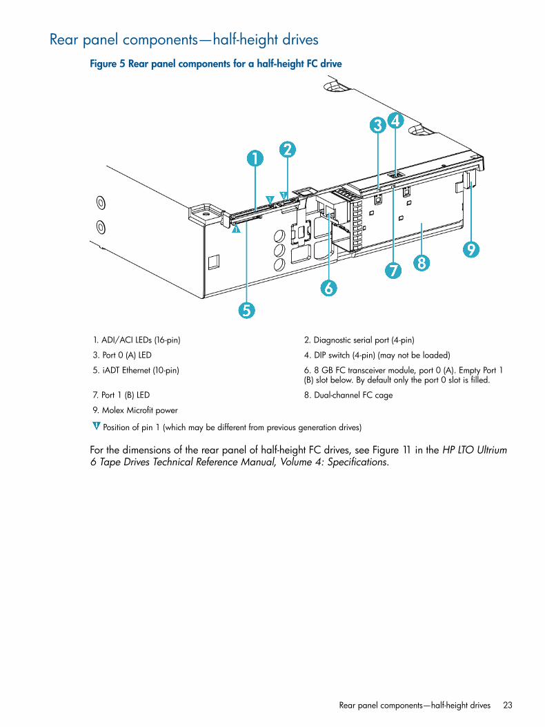
Rear panel components—half-height drivesFigure 5 Rear panel components for a half-height FC drive
2. Diagnostic serial port (4-pin)1. ADI/ACI LEDs (16-pin)
4. DIP switch (4-pin) (may not be loaded)3. Port 0 (A) LED
6. 8 GB FC transceiver module, port 0 (A). Empty Port 1(B) slot below. By default only the port 0 slot is filled.
5. iADT Ethernet (10-pin)
8. Dual-channel FC cage7. Port 1 (B) LED
9. Molex Microfit power
Position of pin 1 (which may be different from previous generation drives)
For the dimensions of the rear panel of half-height FC drives, see Figure 11 in the HP LTO Ultrium6 Tape Drives Technical Reference Manual, Volume 4: Specifications.
Rear panel components—half-height drives 23

Figure 6 Rear panel components for a half-height SAS drive
2. Active SAS management port (9-pin)1. ADI/ACI LEDs (16-pin)
4. SAS connector (includes power)3. Host secondary LED
6. Diagnostic serial port (4-pin)5. Host primary LED
8. iADT Ethernet (10-pin)7. External fan support (6-pin)
Position of pin 1 (which may be different from previous generation drives)
For the dimensions of the rear panel of half-height SAS drives, see Figure 12 in the HP LTO Ultrium6 Tape Drives Technical Reference Manual, Volume 4: Specifications.
LEDsThe rear panel has two LEDs. In Fibre Channel drives, they indicate Port 0 and Port 1. In SASdrives, they indicate the Primary and Secondary ports.
Power-on self-test failureIf the firmware encounters a Power-On Self-Test failure, the drive will not initialize the ports andso will not respond over the FC or SAS interface. The two port LEDs will flash together at 1cycle/second until the drive is reset or power-cycled.
Port initializedOnce the self-test in complete, the FC Port LEDs indicate whether the respective ports have beeninitialized, in other words, whether successful speed negotiation and loop initialization/old portmode has occurred.
24 Rear panel and connectors

Fibre Channel drives:
MeaningPort 1 LEDPort 0 LED
Neither port is initializedOffOff
Only port 0 is initializedOffOn
Only port 1 is initializedOnOff
Both ports are initializedOnOn
SAS drives:
MeaningSecondary Port LEDPrimary Port LED
Neither port is initializedOffOff
Only port 0 is initializedOffOn
Only port 1 is initializedOnOff
Both ports are initializedOnOn
Port activityWhen there is activity on a port, the appropriate port LED will flash with a periodicity of 1/10second.
Fibre Channel addressingThe drive’s hard AL_PA can be configured through an ACI Set Drive Configuration command orADI Mode Select commandThe value set is the Loop ID, an 8-bit value which is translated by the drive into a 7-bit ArbitratedLoop Physical Address (AL_PA) according to Table 1:
Table 1 AL_PA and Loop ID look-up table
Loop IDAL_PALoop IDAL_PALoop IDAL_PALoop IDAL_PALoop IDAL_PALoop IDAL_PA
FhCEh25hABh3Ch76h52h53h68h2Eh–00h
EhD1h24hACh3Bh79h51h54h67h31h7Dh01h
DhD2h23hADh3Ah7Ah50h55h66h32h7Ch02h
ChD3h22hAEh39h7Ch4Fh56h65h33h7Bh04h
BhD4h21hB1h38h80h4Eh59h64h34h7Ah08h
AhD5h20hB2h37h81h4Dh5Ah63h35h79h0Fh
9hD6h1FhB3h36h82h4Ch5Ch62h36h78h10h
8hD9h1EhB4h35h84h4Bh63h61h39h77h17h
7hDAh1DhB5h34h88h4Ah65h60h3Ah76h18h
6hDCh1ChB6h33h8Fh49h66h6Fh3Ch75h1Bh
5hE0h1BhB9h32h90h48h67h5Eh43h74h1Dh
4hE1h1AhBAh31h97h47h69h5Dh45h73h1Eh
3hE2h19hBCh30h98h46h6Ah5Ch46h72h1Fh
2hE4h18hC3h2Fh9Bh45h6Bh5Bh47h71h23h
Fibre Channel addressing 25

Table 1 AL_PA and Loop ID look-up table (continued)
Loop IDAL_PALoop IDAL_PALoop IDAL_PALoop IDAL_PALoop IDAL_PALoop IDAL_PA
1hE8h17hC5h2Eh9Dh44h6Ch5Ah49h70h25h
–EFh16hC6h2Dh9Eh43h6Dh59h4Ah6Fh26h
15hC7h2Ch9Fh42h6Eh58h4Bh6Eh27h
14hC9h2BhA3h41h71h57h4Ch6Dh29h
13hCAh2AhA5h40h72h56h4Dh6Ch2Ah
12hCBh29hA6h3Fh73h55h4Eh6Bh2Bh
11hCCh27hA9h3Eh74h54h51h6Ah2Ch
10hCDh26hAAh3Dh75h53h52h69h2Dh
Connectors
Fibre Channel connectorFC drives are equipped with two SFP duplex-LC short-wave 8 Gb/s fibre connectors. The drivesare capable of switched fabric attach, public loop or private loop and operate at 8 Gb/s, 4 Gb/sor 2 Gb/s after auto-speed negotiation.
SAS connectorSAS drives are equipped with a standard internal SAS connector. LTO-6 SAS drives do not havea regular power connector and should be powered via the SAS connector.
Automation and remote LED connectorThe combined Automation and Remote LED Connector is a 16-pin wafer surface-mount right-angleconnector. 10 pins are used for the ACI/ADI interface and 6 pins for the remote LEDs.
Connector pins
ACI operationWhen used for ACI communications, the pins of the ACI connector are as follows:
FunctionIDPin
RS-422 Receive (+ side of the differential RS-422 line)ACI_RX+1
RS-422 Receive (– side of the differential RS-422 line)ACI_RX-2
GroundGND3
RS-422 Transmit (– side of the differential RS-422 line)ACI_TX-4
RS-422 Transmit (+ side of the differential RS-422 line)ACI_TX+5
Drive Sense. It is tied low in the drive so that a library can sense the presence of the drive.The library should have a pull-up resistor on this line.
ACI_DRV_SEN_L6
Low: Drive presentHigh: Drive not present (3.3 volts)
Library Sense. The drive will not appear on the bus until commanded when low. The lineis pulled up to 5V in the tape drive. The automation controller should pull this pin low.
ACI_LIB_SEN_L7
Low: Drive is connected to an automation controllerHigh: Drive is standalone (3.3 volts)
26 Rear panel and connectors

FunctionIDPin
Tape drive reset. The line is pulled up to 3.3V in the drive. The drive will perform a DriveReset when this line is pulled low.
ACI_RST_L8
The drive sets this pin low to indicate to the automation controller that certain configuredconditions have arisen, such as a SCSI Surrogate CDB.
ACI_ATN_L9
No connection—10
Supported Baud rates
NotesBaud Rate
Default rate9600192003840057600115200
For details of ACI commands, see Chapter 5 “Supporting LTO Ultrium Features” of the SoftwareIntegration Guide, Volume 2 of the HP LTO Ultrium Technical Reference Manual.
ADI operationWhen used for ADI communications, the pins of the ADI connector are as follows:
FunctionIDPin
RS-422 Receive from automation controller+Txa–Rxd1
RS-422 Receive from automation controller–Txa–Rxd2
GroundGround3
RS-422 Transmit from tape drive–Txd–Rxa4
RS-422 Transmit from tape drive+Txd–Rxa5
Tied low in the drive so that a library can sense the presence of the drive.Sensed6
The drive will not appear on the bus until commanded when low.Sensed7
Hard reset (active low)Resetd8
Reserved for future useSignalaux9
No connection—10
The ID names correlate with the descriptions in the T10 Automation/Drive Interface TransportProtocol (ADT).
Supported Baud rates
NotesBaud Rate
Default rate960019200384005760076800
Connectors 27

NotesBaud Rate
115200153600230400460800921600
Remote LEDsThe pins for the remote LED connector are as follows:
GroundPin 11
SAS Secondary Port and FC Port A Status LED outputPin 12
SAS Primary Port and FC Port B Status LED outputPin 13
Host controlled (Beacon) LED outputPin 14
Encryption LED outputPin 15
5V supplyPin 16
Automation and remote LED connector schematic
Figure 7 ADI-LED connector schematic
Notes:
• The maximum LED current supported is 25 mA.
• There should be a current limiting resistor on each LED output.
• The maximum off voltage on the transistor collector must not exceed 5.5V.
• The maximum on voltage for the transistor is 0.4V.
• The same circuit configuration as shown in “LED driver circuit” (page 29) is used for all LEDports.
• The library-controlled or Beacon LED is driven by the AMI_LED_OUT signal.
28 Rear panel and connectors

Figure 8 LED driver circuit
iADT (Ethernet) port
Figure 9 iADT port schematic
Notes:
• The maximum LED current supported is 25 mA.
• There should be a current limiting resistor on each LED output.
• The maximum off voltage on the transistor collector must not exceed 5.5V.
• The maximum on voltage for the transistor is 0.4V.
• The same circuit configuration as shown in “LED driver circuit” (page 29) is used for all LEDports.
Connectors 29

Diagnostic Serial Port connector
Figure 10 Diagnostic Serial Port connector schematic
Fan control connector
Figure 11 Fan connector schematic
Notes:
• FAN SENSE is used to detect fan rotation.
• FAN PRESENT is used to detect that a fan has been connected to the drive. A fan is deemedto be present when this line is grounded. To achieve this, it is recommended that pins 5 and6 are tied together on the mating half of the connector.
• The power supply to the fan is a steady 12V.
• The fan speed is controlled via a PWM signal (pin3).
• A four-wire fan is required.
NOTE: If you intend to plug a fan into this connector to provide the necessary airflow throughthe drive, consult your HP Technical Support Representative for details of the fan specificationrequired.
30 Rear panel and connectors
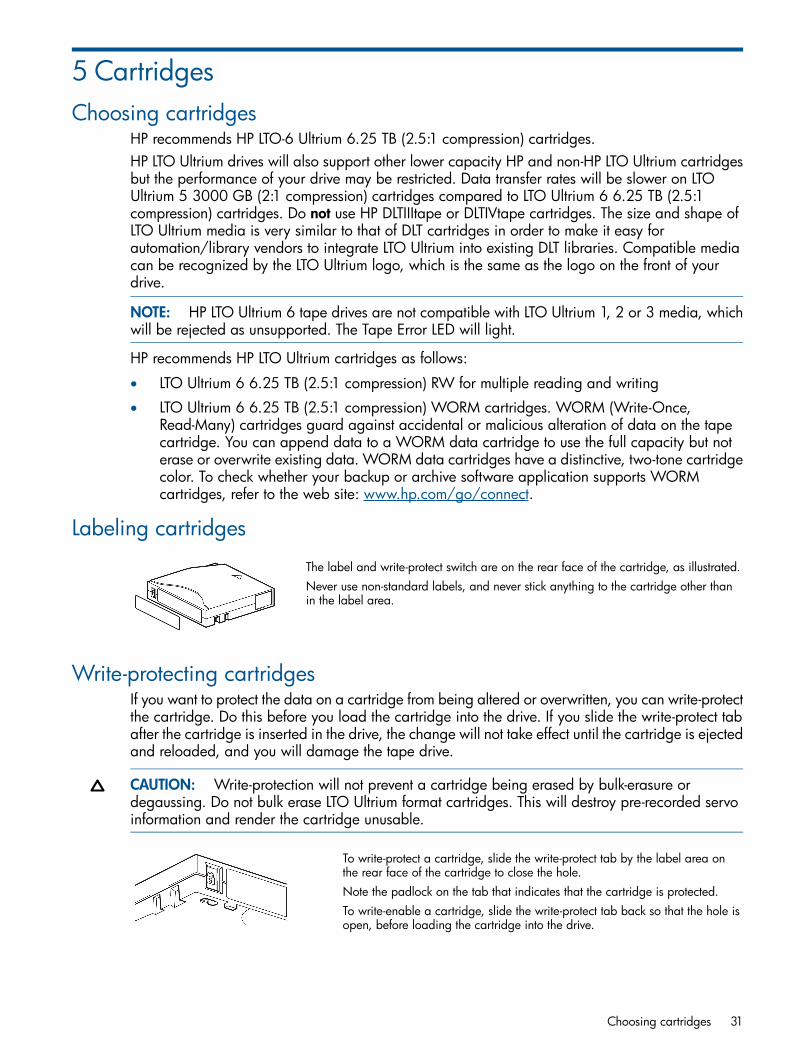
5 CartridgesChoosing cartridges
HP recommends HP LTO-6 Ultrium 6.25 TB (2.5:1 compression) cartridges.HP LTO Ultrium drives will also support other lower capacity HP and non-HP LTO Ultrium cartridgesbut the performance of your drive may be restricted. Data transfer rates will be slower on LTOUltrium 5 3000 GB (2:1 compression) cartridges compared to LTO Ultrium 6 6.25 TB (2.5:1compression) cartridges. Do not use HP DLTIIItape or DLTIVtape cartridges. The size and shape ofLTO Ultrium media is very similar to that of DLT cartridges in order to make it easy forautomation/library vendors to integrate LTO Ultrium into existing DLT libraries. Compatible mediacan be recognized by the LTO Ultrium logo, which is the same as the logo on the front of yourdrive.
NOTE: HP LTO Ultrium 6 tape drives are not compatible with LTO Ultrium 1, 2 or 3 media, whichwill be rejected as unsupported. The Tape Error LED will light.
HP recommends HP LTO Ultrium cartridges as follows:
• LTO Ultrium 6 6.25 TB (2.5:1 compression) RW for multiple reading and writing
• LTO Ultrium 6 6.25 TB (2.5:1 compression) WORM cartridges. WORM (Write-Once,Read-Many) cartridges guard against accidental or malicious alteration of data on the tapecartridge. You can append data to a WORM data cartridge to use the full capacity but noterase or overwrite existing data. WORM data cartridges have a distinctive, two-tone cartridgecolor. To check whether your backup or archive software application supports WORMcartridges, refer to the web site: www.hp.com/go/connect.
Labeling cartridges
The label and write-protect switch are on the rear face of the cartridge, as illustrated.Never use non-standard labels, and never stick anything to the cartridge other thanin the label area.
Write-protecting cartridgesIf you want to protect the data on a cartridge from being altered or overwritten, you can write-protectthe cartridge. Do this before you load the cartridge into the drive. If you slide the write-protect tabafter the cartridge is inserted in the drive, the change will not take effect until the cartridge is ejectedand reloaded, and you will damage the tape drive.
CAUTION: Write-protection will not prevent a cartridge being erased by bulk-erasure ordegaussing. Do not bulk erase LTO Ultrium format cartridges. This will destroy pre-recorded servoinformation and render the cartridge unusable.
To write-protect a cartridge, slide the write-protect tab by the label area onthe rear face of the cartridge to close the hole.Note the padlock on the tab that indicates that the cartridge is protected.To write-enable a cartridge, slide the write-protect tab back so that the hole isopen, before loading the cartridge into the drive.
Choosing cartridges 31
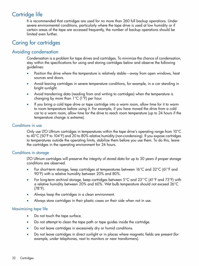
Cartridge lifeIt is recommended that cartridges are used for no more than 260 full backup operations. Undersevere environmental conditions, particularly where the tape drive is used at low humidity or ifcertain areas of the tape are accessed frequently, the number of backup operations should belimited even further.
Caring for cartridges
Avoiding condensationCondensation is a problem for tape drives and cartridges. To minimize the chance of condensation,stay within the specifications for using and storing cartridges below and observe the followingguidelines:
• Position the drive where the temperature is relatively stable—away from open windows, heatsources and doors.
• Avoid leaving cartridges in severe temperature conditions, for example, in a car standing inbright sunlight.
• Avoid transferring data (reading from and writing to cartridges) when the temperature ischanging by more than 1°C (1°F) per hour.
• If you bring a cold tape drive or tape cartridge into a warm room, allow time for it to warmto room temperature before using it. For example, if you have moved the drive from a coldcar to a warm room, allow time for the drive to reach room temperature (up to 24 hours if thetemperature change is extreme).
Conditions in useOnly use LTO Ultrium cartridges in temperatures within the tape drive’s operating range from 10°Cto 40°C (50°F to 104°F) and 20 to 80% relative humidity (non-condensing). If you expose cartridgesto temperatures outside the operating limits, stabilize them before you use them. To do this, leavethe cartridges in the operating environment for 24 hours.
Conditions in storageLTO Ultrium cartridges will preserve the integrity of stored data for up to 30 years if proper storageconditions are observed.
• For short-term storage, keep cartridges at temperatures between 16°C and 32°C (61°F and90°F) with a relative humidity between 20% and 80%.
• For long-term archival storage, keep cartridges between 5°C and 23˚°C (41°F and 73°F) witha relative humidity between 20% and 60%. Wet bulb temperature should not exceed 26°C(78°F).
• Always keep the cartridges in a clean environment.
• Always store cartridges in their plastic cases on their side when not in use.
Maximizing tape life
• Do not touch the tape surface.
• Do not attempt to clean the tape path or tape guides inside the cartridge.
• Do not leave cartridges in excessively dry or humid conditions.
• Do not leave cartridges in direct sunlight or in places where magnetic fields are present (forexample, under telephones, next to monitors or near transformers).
32 Cartridges

• Do not drop cartridges or handle them roughly.
• Stick labels onto the label area only.
LTO Cartridge MemoryLinear Tape Open—Cartridge Memory (LTO-CM) is an EEPROM that is embedded in every LTOUltrium tape cartridge. It is non-volatile and is contactless in that it is read by inductive couplingrather than electrical contact.The Cartridge Memory is used to store the tape directory and diagnostic and log information.Because of the speed at which it can be read, load and unload times are reduced, information isfound on the tape more quickly and fewer tape passes are needed, increasing tape reliability.The memory is primarily designed to speed up internal operations in the drive, but it also containsfree space that can be used by application software. This may be used to store “common”information (shared by all software vendors) and “vendor-unique” information (specific to theapplication).Hosts can use this free space using the SCSI Write Attribute and Read Attribute commands. Forinformation on these commands, see Chapter 4 of the Host Interface Guide, Volume 3 of thisHP LTO Ultrium Technical Reference Manual.To support CM fully, software vendors should ensure that their company names are registered withANSI T10 or the National Committee for Information Technology Standards (NCITS) as they arenow known. The list of Vendor IDs is displayed at http://www.t10.org/lists/vid-alph.htm, whichalso contains details of how to get a new name assigned.Cartridge Memory adheres to the Media Auxiliary Memory (MAM) standard. “MAM” indicatesthat the access method applies to all types of media, not just LTO Ultrium.The MAM standard provides for the storage and access of information held as a set of pre-definedand user-definable attributes that are divided into six main sections:
• Media Common Section—hard-coded by the media manufacturer. For example: manufacturer’sname, cartridge serial number, length, media type
• Drive Common Section—updated by the drive every time it accesses the media. For example:maximum and remaining tape capacity, TapeAlert flags
• Host Common Section—updated by the host’s software application every time it uses themedia. For example: software application vendor’s name and version, media text label, datelast written
• Media Vendor Unique Section—optional information written by the media vendor for theirown purposes. Unique to the media vendor.
• Media Vendor Unique Section—optional information written by the media vendor for theirown purposes. Unique to the media vendor.
• Host Vendor Unique Section—space reserved for use by software applications for their ownpurposes. Unique to the software vendor. Approximately 1 kilobyte.
For details of use of LTO-CM in library applications, see “Using Cartridge Memory (LTO-CM) inlibraries” (page 61).
LTO Cartridge Memory issuesThe LTO Cartridge Memory stores identification and usage information such as the number of timesthe cartridge has been loaded, location of the EOD (End of Data) marker, and error logs. In theunlikely event of the Cartridge Memory becoming damaged, you may experience difficulty withthe cartridge.
LTO Cartridge Memory 33
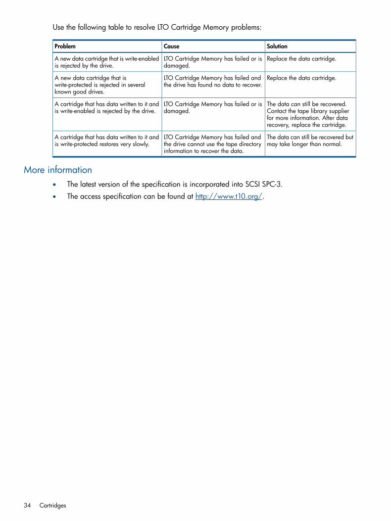
Use the following table to resolve LTO Cartridge Memory problems:
SolutionCauseProblem
Replace the data cartridge.LTO Cartridge Memory has failed or isdamaged.
A new data cartridge that is write-enabledis rejected by the drive.
Replace the data cartridge.LTO Cartridge Memory has failed andthe drive has found no data to recover.
A new data cartridge that iswrite-protected is rejected in severalknown good drives.
The data can still be recovered.Contact the tape library supplier
LTO Cartridge Memory has failed or isdamaged.
A cartridge that has data written to it andis write-enabled is rejected by the drive.
for more information. After datarecovery, replace the cartridge.
The data can still be recovered butmay take longer than normal.
LTO Cartridge Memory has failed andthe drive cannot use the tape directoryinformation to recover the data.
A cartridge that has data written to it andis write-protected restores very slowly.
More information• The latest version of the specification is incorporated into SCSI SPC-3.
• The access specification can be found at http://www.t10.org/.
34 Cartridges
6 Planning your system configurationModes of usage
HP LTO Ultrium tape drives and arrays can be used in different system configurations. They canbe used in a standalone (direct attach) or network environments (both Local Area Network andStorage Area Network).Network users may need to take additional steps to ensure that their system is configured foroptimum performance.
Optimizing performanceVarious factors can affect tape drive performance, particularly in a network environment or if thedrive is not on a dedicated bus. If your tape drive is not performing as well as expected, considerthe following points before contacting HP Support at www.hp.com/support.
Dedicated busFor optimum performance, we recommend that the tape drive is the only device on the bus.
System performanceDrives can write data at 160 MB/s (native) or 400 MB/s (2.5:1 compression). However, to getthis performance it is essential that your whole system can deliver this performance.Typical areas where bottlenecks can occur are:
• Disk system (a single hard disk drive will not be able to deliver 400 MB/s transfer rates).
• Some file systems are able to transfer data faster than others.
• The type of data being backed up can affect backup performance (for example, file sizes andcompressibility).
• Some backup software performs better than others.To improve performance you may like to consider a RAIDed disk solution with a large number ofphysical hard disks.Some enterprise class backup applications can be made to interleave data from multiple sources,such as clients or disks, to keep the tape drive working at optimum performance.
Data rate matchingData Rate Matching (DRM) enables the drive to “stream” data at variable tape speed, which meansthat it maintains a continuous data flow to tape even when the transfer speed from the host varies.This is automatically managed by the drive to keep the drive running at best performance. Whenusing LTO Ultrium 6 cartridges, the drive is able to keep streaming between 54 and 160 MB/s(native), so, if possible data transfer should remain within this range. In most cases, the backupapplication will provide details of the average time taken at the end of the backup.
NOTE: For optimum performance always use Ultrium 6 6.25 TB (2.5:1 compression) cartridges.
Performance checklistThe following list summarizes factors that can affect performance. They provide guideline only ofareas that may need further investigation. They do not attempt to explain how to configure individualsystems. For a more detailed discussion, including information about tools that allow you to test
Modes of usage 35

performance, refer to our white papers on www.hp.com. (Select the product first and look at theInformation Library.)
• Is the tape drive reading and writing data at the correct speed?
• Is the source system (hard disk) transferring data at the correct speed?
• Is the backup application writing buffers at the correct speed? You may need to tune thetransfer, buffer and block size settings to optimize the speed that the application writes datato the tape drive. HP LTO-6 Ultrium drives have an internal buffer of 512 MB.
• Is the operating system tuned for performance? You may need to adjust the data transferpacket size.
• If you are using an SAS drive or array in a SAN environment, are you are using one of therecommended fibre channel/SAS routers?
• Are user applications, such as Exchange or database servers, optimized for backupperformance?
• Are there other factors that could be affecting performance, such as interference or fibrechannel infrastructure?
36 Planning your system configuration

7 Installing and replacing drivesIf you are installing the tape drive on a UNIX system, refer to the UNIX Configuration Guide,Volume 5 of the HP LTO Ultrium Technical Reference Manual.
Installing in a serverFull details of how to install an internal LTO Ultrium tape drive into a server drive bay is given inthe Getting Started Guide.
Identifying the modelThe model name is on the front panel and the product and serial numbers are on a label on thetop of the drive.
Standards and safetyUse the drive only in equipment where the suitability of the combination has been determined byan appropriate certification organization (such as Underwriters Laboratories Inc. or the CanadianStandards Association in North America, and the British Standards Institution or Verband DeutscherElektrotechniker in Europe). Other considerations include the following:1. A drive must be installed in an enclosure to limit an operator’s access to live parts, to provide
system stability, and to give the drive the necessary grounding integrity.2. A drive must only be supplied by a Safety-Extra-Low-Voltage (secondary) circuit in accordance
with DIN VDE 0805. During incorporation of the equipment, all requirements of DIN VDE0805 must be observed and obeyed.
NOTE: The drives are only fused to protect them from excessive currents.
Installing in a server 37
Requirements
Mounting requirements
• Half-height drives require one industry standard 5¼-inch, half-height bay.
• Full-height drives require one industry standard 5¼-inch, full-height bay.HP recommends 0.3 mm mounting clearance around all covers to allow the Flexible MountingPoints (FMP) to operate correctly.For many servers, no mounting tray or rails are required. Devices simply slide into the computer’schassis and are fixed with screws. Other servers have built-in trays or rails. Yet others require aspecial mounting tray or rails to fix the drive into the empty bay.Refer to your server documentation for details on how to install drives.
Server connectionsYou need a properly installed and configured SAS host bus adapter (HBA) or a built-in SAScontroller on the server.The SAS drives have a 6 GB SAS interface, and are designed to work with most SAS devices. The6 GB SAS interface supports a maximum bus speed of 600 MB/s, as opposed to the 150 MB/sof the 1.5 GB SAS interface. Therefore, installing the drive onto a 1.5 GB bus is not recommendedas this may restrict performance.For optimum performance, use a dedicated host bus adapter for the tape drive.Do not connect to a RAID controller channel; these are for disk drives only. Consult your supplierfor details.For a SAS internal drive, you will need:
• 6 GB SAS host bus adapter or the server’s embedded HBA
• SAS-compliant cable
• Mounting hardware, if required
• Backup software that supports the tape drive
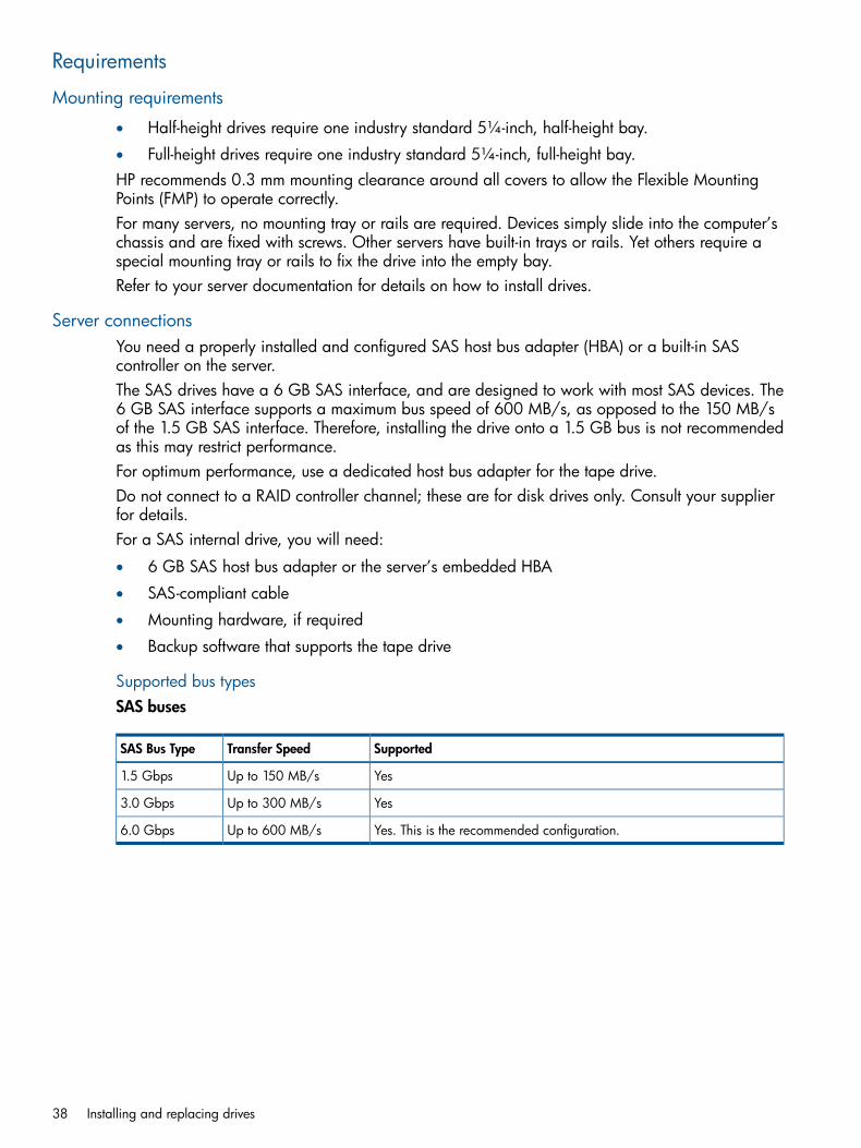
Supported bus typesSAS buses
SupportedTransfer SpeedSAS Bus Type
YesUp to 150 MB/s1.5 Gbps
YesUp to 300 MB/s3.0 Gbps
Yes. This is the recommended configuration.Up to 600 MB/s6.0 Gbps
38 Installing and replacing drives

Connecting the drive
SAS connectorFor the location of the rear panel SAS connector, see Figure 4 (page 22)The SAS drive is equipped with a 6 Gbps SAS plug connector as defined in SFF8482 [5.2.3.2].A SAS drive is hot pluggable but the connector location is not as defined in SFF8482.
NOTE: HP LTO-6 SAS tape drives do not have a normal power connector and must be poweredvia the SAS connector.
The rear connections of an SAS drive are as follows:
• Combined automation and remote LED connector port (for libraries)
• Standard internal SAS plug connector
• iADT (Ethernet) connector
• Fan connector
• Diagnostic Serial Port, see “Diagnostic Serial Port connector” (page 30) (contact HP for furtherdetails on this diagnostic port and its function)
Backup softwareYou need backup software that supports the HP LTO Ultrium drive within your system’s configuration.In a direct attach configuration, where the tape drive is attached to a standalone server, you canuse backup software that is designed for a single server environment. In network and SANconfigurations, you will need backup software that supports enterprise environments. As a generalrule, native backup applications (such as NTBackup and tar) do not provide the required datastreaming rate to get the full performance of your drive. For the latest list of backup packages thatsupport HP LTO Ultrium drives, please consult our World Wide Web site (www.hp.com/go/connect).Applications usually recognize tape drives by their manufacturers’ ID string rather than their modelnumber, so check the table below for the appropriate reference.
ID StringDrive Model
HP Ultrium 2-SCSILTO Ultrium 2 drive
HP Ultrium 3-SCSILTO Ultrium 3 drive
HP Ultrium 4-SCSILTO Ultrium 4 drive
HP Ultrium 5-SCSILTO Ultrium 5 drive
HP Ultrium 6-SCSILTO Ultrium 6 drive
Installing in a server 39

Installing in a tape array
Appropriate HP rack-mount systemsHP LTO Ultrium removable tape drives can be used with any compatible rack-mount tape arraysystem.The tape array is designed to be installed into any compatible 19” rack-mount systems. It must beproperly installed and configured. Refer to your tape array documentation for further details.
Airflow requirementsAs long as the tape array is fully populated, it will provide adequate airflow for HP LTO Ultriumdrives.If you have unused bays in the tape array, you must install the blanking plates provided with thetape array. This ensures that there is adequate airflow to the drives. See the documentation withthe tape array for details on installing blanking plates.You should ensure that ventilation is adequate at the front and rear of the tape array.HP LTO Ultrium drives require forced airflow. The required airflow depends on the ambient airtemperature and should be from back to front:
• 6 cfm for ambient air temperatures fluctuating in the range 10°C–35°C.
• 8 cfm for ambient air temperatures fluctuating in the range 10°C–40°C.For details of how to test if the airflow is adequate, see “Airflow requirements” (page 10).
Identifying the driveThe model name is on the front panel and the product and serial numbers are on a label attachedto the drive.
Modes of usageTape arrays can be used in different system configurations; direct attach, network attach andattached to a Storage Area Network (SAN). For details of these see “Modes of usage” (page 35).
Attaching to SASHP LTO Ultrium SAS drives are high performance 6 GB SAS devices. When installed in a tapearray in a compatible rack mount system they can be connected to a SAS connection on a serveror to an expander as part of a larger SAS network. To get the optimum performance from yourtape drive you need a SAS topology that can transfer data at a rate that supports the tape drive’smaximum transfer speed.
Connecting to a Fibre Channel router or by SAS to a server or routerIndividual SAS tape drives are connected to their hosts via the SAS connectors on the back of thetape array. They do not require any SAS cables to plug into the tape array. However, you doneed cables to connect the tape array with the SAS host or expander.
Fibre Channel connectionIf you are using your tape drive on a fibre channel (FC) network, you will need a FC/SAS router.If you are attaching your tape drive to a SAN environment supplied by HP, refer to your SANsolution collateral or configuration guides for further details.
Server SAS connectionIf you are attaching the drive to a server, you need a properly installed and configured SAS hostbus adapter (HBA) or a built-in SAS controller on your server with a spare SAS port. For optimum
40 Installing and replacing drives

performance, your tape drive should only be connected to a 6 GB SAS host bus adapter or SAScontroller, but the drive will also function with a 3 or 1.5 GB SAS connection.
Replacing a driveHP LTO Ultrium removable drives can be removed and replaced without powering down the tapearray and without interrupting operations to the other drives in the array. However, note thefollowing:
• In Berkeley mode, the tape position will remain unchanged by a device close operation.
• In AT&T mode, a device close operation will cause the tape to be repositioned just after thenext tape filemark (the start of the next file).
If all drives in the tape array are powered up when the system is turned on, the host will be awareof those drives. You can remove any drive and replace it with another without disrupting the system.If a drive is not powered up or you place a drive in an empty slot after the system has been poweredup, the system will have to be reset before the host will recognize the drive.Removable drives allow modules to be replaced while powered up as long as no data is beingtransmitted from the system to the module or vice versa.
Installing in a library
Rear panel and connectors
CAUTION: LTO Ultrium tape drives are not installable or replaceable by end-users, so theattachment or removal of FC, SAS, power and other cables between the tape drive and the tapelibrary should only be carried out be service-trained personnel authorized by the tape librarysupplier. The connectors are not field upgradeable.
The rear panel contains the connectors that allows the tape drive to communicate with the tapelibrary and host computer system. The panel includes the following connectors:
• Combined automation and remote LED connector (for automation use)For details of the combined automation and remote LED connector, see “Automation andremote LED connector” (page 26). For details of the use of the ADI connector in libraries, see“Automation interface” (page 54).
• Diagnostic serial port connectorThe proprietary serial HP LTO diagnostic port. To access this port via RS232 requires an HPLTO Diagnostic Interface Card. Diagnostic information from the drive can be accessed byconnecting to the serial communications port on a computer. Contact HP for further details onthis diagnostic port and its function.
On Fibre Channel drives only:
• Power connector (FC drives only)Full-height drives use a standard 4-pin power connector to supply the 5V and 12V power thetape drive. Half-height drives use a Molex microfit 4-pin power connector to supply the 5Vand 12V power to the tape drive.
• Fibre Channel connectorsTwo Small Form-factor Pluggable (SFP) duplex-LC fibre channel transceivers. Depending onthe specific configuration, only one SFP FC transceiver may be installed.
Installing in a library 41

On SAS drives:
• A standard internal SAS connector.SAS drives do not have a normal power connector and should be powered via the SASconnector.
Installing standalone drivesIf you are installing the tape drive on a UNIX system, refer to the UNIX, Linux, and OpenVMSConfiguration Guide, Volume 5 of the HP LTO Ultrium Technical Reference Manual.
Identifying the driveThe model name is on the front panel and the product and serial numbers are on a label on thebottom of the drive.
Connecting the drive
SAS connectionThe rear panel connections of external SAS standalone drives consist of a mains power connectorand a Mini-SAS connector. The drive should be connected to the host server/expander with agood quality external SAS cable that is as short as possible. If you are attaching a SAS drive toa server, you need a properly installed and configured SAS host bus adapter (HBA) or a built-inSAS controller on your server with a spare SAS port. For optimum performance your tape driveshould only be connected to a 6 Gbps SAS host bus adapter or SAS controller, but the drive willalso work with a 1.5 or 3 Gbps SAS bus.
Moving drivesIf there is a tape in the drive, unload it before powering down and moving the drive. When thedrive is powered down, there is no physical lock on the tape reels. If you leave a tape threadedin the drive with the power off, the reels could rotate, causing a loop of tape to occur in the tapepath. When the drive is next powered up, the tape could then fall off the guides and be damaged.If for any reason you must move a drive with a tape threaded, move it slowly and carefully, makingno sudden movements that could cause the reels to rotate.
42 Installing and replacing drives

8 Operating the drivePower-on self-test
When powered-on, the tape drive will run its hardware self-test:
• In a server, internal drives are powered on when you switch on your computer.
• In a tape array, removable drives are powered on when you switch on your tape array andcomputer.
• In a tape library, installed drives are controlled through the tape library operator panel. Referto the tape library documentation for details. See also “Resetting drives in a library” (page 46).
• For standalone drives, switch on external drives using the power switch on the front panel,and then switch on the host computer.
During the test the ‘Ready’ LED flashes and all the other LEDs are off. On successful completion the‘Ready’ LED is on. If the self-test fails, the ‘Drive Error’ and ‘Tape Error’ LEDs flash, while the ‘Ready’and ‘Clean’ LEDs are off. This continues until the drive is reset.
• If you have just installed the drive, check the installation for loose connections, reset the driveand repeat the self-test.
• Try “Troubleshooting” (page 47) to determine what the problem is.
• If the fault condition persists, call for assistance.
Power-on self-test 43

Loading a cartridgeNOTE: This section describes loading a cartridge in a standalone drive. The procedure is thesame for internal drives and those in tape arrays and libraries.
Half-height drives:Full-height drives:
1. Arrow indicating leading direction1. Arrow indicating leading direction
2. Drive door2. Cartridge label area
3. Cartridge label area
NOTE: Use HP LTO Ultrium cartridges.
1. Insert the cartridge into the slot in front of the drive with the arrow uppermost and facing thedrive door.
2. Apply gentle pressure on the rear of the cartridge until the drive takes the cartridge and loadsit.The Ready LED flashes green while the drive performs its load sequence. When the cartridgeis loaded, the Ready LED shows steady green.Do not try to force the cartridge if it does not load properly. The drive will eject the cartridgeafter about 10 seconds so you can load it again.
44 Operating the drive

Unloading a cartridgeNOTE: This section describes unloading a cartridge from a standalone drive. The procedure isthe same for internal drives and those in tape arrays and libraries.
Half-height drives:Full-height drives:
1. Eject button1. Eject button
1. Press the Eject button on the front panel.nl
During the unload sequence the READY LED flashes green. The drive completes any task it iscurrently performing, winds the tape to the beginning and ejects the cartridge. Once the tapehas rewound, the eject cycle will take less than 13 seconds.
2. Remove the cartridge and store it in its plastic case in a cool, dry atmosphere.
CleaningWhen the drive needs cleaning:
• The orange ‘Clean’ LED on the front of the tape drive will flash. Only insert a cleaning cartridgeinto the tape drive when the LED flashes.
• The drive’s TapeAlert feature will send a message to your backup application.
• In a library or tape array, the drive also tells the automation controller that a cleaning tapeneeds to be used via the ADI connector.See the “Automation interface” (page 54) for details.
CAUTION: It is essential to use only LTO Ultrium Universal cleaning cartridges C7978A (Orange)with HP LTO Ultrium tape drives as other format cleaning cartridges will not load and run. Use ofHP cleaning media will ensure your tape drive is fully protected. Do not use swabs or other meansof cleaning the heads.
LTO Ultrium Universal cleaning cartridges can be used up to 50 times.To clean the heads:1. Insert a cleaning cartridge into the drive. The tape drive automatically loads the cartridge and
cleans the heads.If the cleaning cartridge ejects or returns to the ready-to-eject position immediately with theTape Error LED on, it has expired or it is not an LTO Ultrium cleaning cartridge (or is an olderunsupported LTO Ultrium cleaning cartridge). In this case, discard the cleaning cartridge andrepeat the operation with a new one.The cleaning cycle can take up to 5 minutes, during which the orange ‘Clean’ LED will be onsteadily and the green ‘Ready’ LED will flash. When it has finished, the drive ejects the cartridgeor returns the cartridge to the ready-to-eject position.
Unloading a cartridge 45
2. Remove the cleaning cartridge from the drive.
Resetting drives in a libraryThe tape drive can be reset by the automation controller via the automation connector or by pullingthe ACI_RST_L line low (see “Automation interface” (page 54)).There are two levels of reset via the automation connector:
• ACI reset—resets the ACI port and all SAS/Fibre Channel ports
• Drive reset—equivalent to a power-on resetEither reset method will interrupt the interface between the drive and host, and a reset may resultin no End of Data mark being written. As a result, it is strongly recommended that a reset commandis not sent unless all other recovery methods have failed. Note that certain automation commands(Load, Unload, Set Drive Configuration, Reset and Set Baud Rate) can be queued behind outstandingSCSI commands giving the impression that the drive has stopped responding over the ADI connector.(All command packages will be still be ack’ed even though the command will be queued.)Following a Reset command with reset control set to Drive Reset or after pulling the ACI_RST_L linelow, the drive will behave as if it has powered up and will go off bus and lose all automationconnector configurations.An FCP reset will not affect the automation interface.Note that following an upgrade of the drive firmware the drive will be reset as if it had beenpowered up.
46 Operating the drive

9 TroubleshootingEmergency unload (forced eject)
If a cartridge fails to eject using the normal unload procedure, press and hold the Eject button for5 seconds. This instructs the drive mechanics to perform an emergency unload. Wait for thecartridge to be ejected. This may take up to 15 minutes (the maximum rewind time).If the cartridge is still jammed, for full-height drives press the emergency reset button (see “Frontpanel features” (page 12) or “Front panel for automation use” (page 52)), or pull pin 8 of theAutomation and Remote LED Connector low (see “Automation and remote LED connector”(page 26)). For half-height drives perform an emergency reset by pressing and holding the Ejectbutton for at least 35 seconds, and the drive will reset once the button is released. Wait for thedrive to reset and recover the tape to the loaded position. This may take up to 15 minutes. Againpress and hold the Eject button for 5 seconds to perform a second forced eject and emergencyunload if required.
General guidelinesIf you experience problems when using the tape drive, you need to isolate the cause of the problem.For example, if you have just installed a new host bus adapter and your system will not start, thecause of the problem is likely to be the adapter.When installing multiple items of hardware and software, we recommend that you install each inturn and restart the system each time. Similarly if you have already installed multiple devices andsoftware and you experience problems, remove or uninstall each in turn to establish which one iscausing the problem.Remember that the system recognizes devices during boot-up. If you swap or connect a productwhen your system is running, you will need to reboot the system. Rebooting the system will resetdevices and will often resolve problems. It is good practice to reboot every time you add a driveror install firmware.Most modern host bus adapters locate and display attached devices when the system is bootingup. On Windows systems, if you swap or connect a product when your system is running, you willneed to reboot the system. IA32 systems also usually need to be rebooted. UNIX systems may havepluggable drivers, which allow drives to be attached to a running system and detected withoutrebooting.If the device is not detected on boot up, there is probably a problem with the physical hardware:cables, termination, connections, power or the host bus adapter. If the device is displayed duringboot up but cannot be found in the operating system, this is more likely to be a software problem.
Emergency unload (forced eject) 47
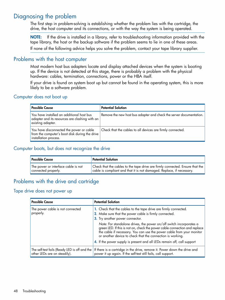
Diagnosing the problemThe first step in problem-solving is establishing whether the problem lies with the cartridge, thedrive, the host computer and its connections, or with the way the system is being operated.
NOTE: If the drive is installed in a library, refer to troubleshooting information provided with thetape library, the host or the backup software if the problem seems to lie in one of these areas.If none of the following advice helps you solve the problem, contact your tape library supplier.
Problems with the host computerMost modern host bus adapters locate and display attached devices when the system is bootingup. If the device is not detected at this stage, there is probably a problem with the physicalhardware: cables, termination, connections, power or the HBA itself.If your drive is found on system boot up but cannot be found in the operating system, this is morelikely to be a software problem.
Computer does not boot up
Potential SolutionPossible Cause
Remove the new host bus adapter and check the server documentation.You have installed an additional host busadapter and its resources are clashing with anexisting adapter.
Check that the cables to all devices are firmly connected.You have disconnected the power or cablefrom the computer’s boot disk during the driveinstallation process.
Computer boots, but does not recognize the drive
Potential SolutionPossible Cause
Check that the cables to the tape drive are firmly connected. Ensure that thecable is compliant and that it is not damaged. Replace, if necessary.
The power or interface cable is notconnected properly.
Problems with the drive and cartridge
Tape drive does not power up
Potential SolutionPossible Cause
The power cable is not connectedproperly.
1. Check that the cables to the tape drive are firmly connected.2. Make sure that the power cable is firmly connected.3. Try another power connector.
Note: For standalone drives, the power on/off switch incorporates agreen LED. If this is not on, check the power cable connection and replacethe cable if necessary. You can use the power cable from your monitoror another device to check that the connection is working.
4. If the power supply is present and all LEDs remain off, call support
If there is a cartridge in the drive, remove it. Power down the drive andpower it up again. If the self-test still fails, call support.
The self-test fails (Ready LED is off and theother LEDs are on steadily).
48 Troubleshooting
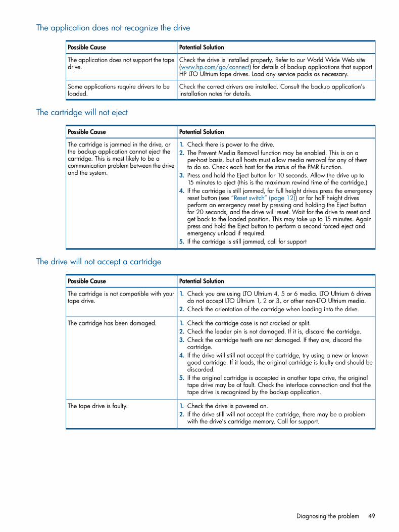
The application does not recognize the drive
Potential SolutionPossible Cause
Check the drive is installed properly. Refer to our World Wide Web site(www.hp.com/go/connect) for details of backup applications that supportHP LTO Ultrium tape drives. Load any service packs as necessary.
The application does not support the tapedrive.
Check the correct drivers are installed. Consult the backup application’sinstallation notes for details.
Some applications require drivers to beloaded.
The cartridge will not eject
Potential SolutionPossible Cause
The cartridge is jammed in the drive, orthe backup application cannot eject the
1. Check there is power to the drive.2. The Prevent Media Removal function may be enabled. This is on a
per-host basis, but all hosts must allow media removal for any of themto do so. Check each host for the status of the PMR function.
cartridge. This is most likely to be acommunication problem between the driveand the system. 3. Press and hold the Eject button for 10 seconds. Allow the drive up to
15 minutes to eject (this is the maximum rewind time of the cartridge.)4. If the cartridge is still jammed, for full height drives press the emergency
reset button (see “Reset switch” (page 12)) or for half height drivesperform an emergency reset by pressing and holding the Eject buttonfor 20 seconds, and the drive will reset. Wait for the drive to reset andget back to the loaded position. This may take up to 15 minutes. Againpress and hold the Eject button to perform a second forced eject andemergency unload if required.
5. If the cartridge is still jammed, call for support
The drive will not accept a cartridge
Potential SolutionPossible Cause
The cartridge is not compatible with yourtape drive.
1. Check you are using LTO Ultrium 4, 5 or 6 media. LTO Ultrium 6 drivesdo not accept LTO Ultrium 1, 2 or 3, or other non-LTO Ultrium media.
2. Check the orientation of the cartridge when loading into the drive.
The cartridge has been damaged. 1. Check the cartridge case is not cracked or split.2. Check the leader pin is not damaged. If it is, discard the cartridge.3. Check the cartridge teeth are not damaged. If they are, discard the
cartridge.4. If the drive will still not accept the cartridge, try using a new or known
good cartridge. If it loads, the original cartridge is faulty and should bediscarded.
5. If the original cartridge is accepted in another tape drive, the originaltape drive may be at fault. Check the interface connection and that thetape drive is recognized by the backup application.
The tape drive is faulty. 1. Check the drive is powered on.2. If the drive still will not accept the cartridge, there may be a problem
with the drive’s cartridge memory. Call for support.
Diagnosing the problem 49

The computer no longer recognizes the drive in a tape array
Potential SolutionPossible Cause
Most modern host bus adapters/host systems will only locate and display attacheddevices when the system is booting up. Try rebooting your host system after the tapearray is powered up.
You powered up the drive oradded it to the tape array afterthe host system was turned on.
Check the drive is properly inserted into the tape array so that it mates with theconnections at the rear of the enclosure. The extraction lever should be pushed in,locking the drive in position.
The drive is not inserted correctly.
There is a fault with the hostsystem.
1. Make sure that the system is configured to recognize the device.2. Ensure that the correct driver for the tape drive is installed. Look at the host
adapter documentation and backup software documentation for further advice.
Problems with cleaningUse the following table to resolve cleaning problems:
SolutionProblem
Clean the drive with an LTO Universal Cleaning Cartridge as instructed in the tapelibrary documentation. If the message reappears, replace the cleaning cartridgewith a new one.
Recurring cleaning message.
If the message reappears when a particular data cartridge is used, verify that thedata cartridge is readable by clearing the message and reading the tape again.If the data cartridge can be read, back up the data to another cartridge and thendiscard the damaged one.
Make sure that you are using an approved LTO Ultrium Universal cleaning cartridgeand that the cleaning cartridge is not expired.
The cleaning cartridge is ejectedimmediately after loading.
If the drive is installed in a library:
SolutionProblem
Clean the outside of the data cartridge with a barely damp, clean, lint-free cloth.Clean the drive as instructed by your tape library documentation.
A brand new data cartridge isused, and the library operator
If the operator panel indicates cleaning is required within a short period of time,replace the data cartridge.
panel indicates that cleaning isrequired.
50 Troubleshooting
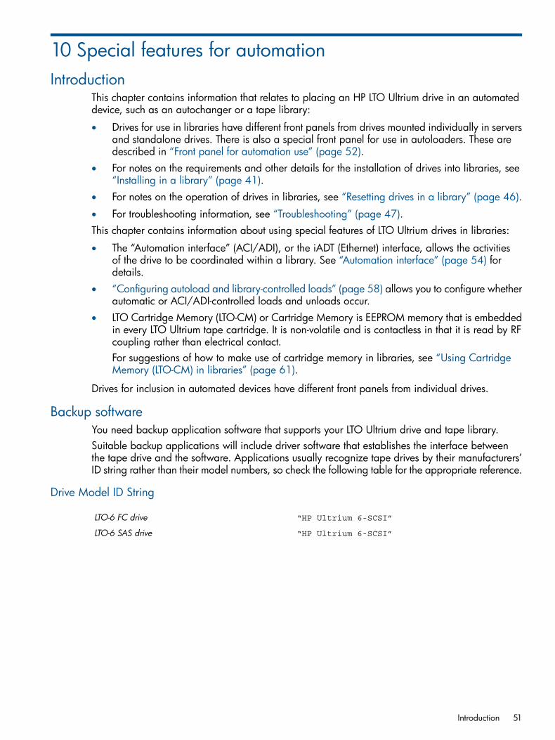
10 Special features for automationIntroduction
This chapter contains information that relates to placing an HP LTO Ultrium drive in an automateddevice, such as an autochanger or a tape library:
• Drives for use in libraries have different front panels from drives mounted individually in serversand standalone drives. There is also a special front panel for use in autoloaders. These aredescribed in “Front panel for automation use” (page 52).
• For notes on the requirements and other details for the installation of drives into libraries, see“Installing in a library” (page 41).
• For notes on the operation of drives in libraries, see “Resetting drives in a library” (page 46).
• For troubleshooting information, see “Troubleshooting” (page 47).This chapter contains information about using special features of LTO Ultrium drives in libraries:
• The “Automation interface” (ACI/ADI), or the iADT (Ethernet) interface, allows the activitiesof the drive to be coordinated within a library. See “Automation interface” (page 54) fordetails.
• “Configuring autoload and library-controlled loads” (page 58) allows you to configure whetherautomatic or ACI/ADI-controlled loads and unloads occur.
• LTO Cartridge Memory (LTO-CM) or Cartridge Memory is EEPROM memory that is embeddedin every LTO Ultrium tape cartridge. It is non-volatile and is contactless in that it is read by RFcoupling rather than electrical contact.For suggestions of how to make use of cartridge memory in libraries, see “Using CartridgeMemory (LTO-CM) in libraries” (page 61).
Drives for inclusion in automated devices have different front panels from individual drives.
Backup softwareYou need backup application software that supports your LTO Ultrium drive and tape library.Suitable backup applications will include driver software that establishes the interface betweenthe tape drive and the software. Applications usually recognize tape drives by their manufacturers’ID string rather than their model numbers, so check the following table for the appropriate reference.
Drive Model ID String
“HP Ultrium 6-SCSI”LTO-6 FC drive
“HP Ultrium 6-SCSI”LTO-6 SAS drive
Introduction 51

Front panel for automation use
Full-height drives
2. Access hole for emergency reset switch1. Eject button
4. LEDs3. Holes for optical sensors
The automation front panel has the following features:
• There is an eject button for manually ejecting a cartridge. Press this for approximately tenseconds to start a “forced eject” for recovering a cartridge manually. See “Emergency unload(forced eject)” (page 47) for details.
• Indicator LEDs provide a visible indicator of the state of health of the drive. See “LED patterns”(page 14) for details.
• There is no door. Instead there are two fixed guides to guide the cartridge into the drive.
• The indent for a label on the left just under the cartridge opening is left blank, exposing twoholes. These can be used to provide a target for the optical position sensor of a library picker.
• There are additional holes around the cartridge opening to allow a throat to be fitted ifnecessary, to help the smooth loading of cartridges.
52 Special features for automation
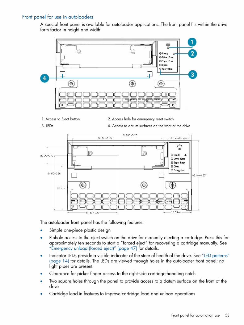
Front panel for use in autoloadersA special front panel is available for autoloader applications. The front panel fits within the driveform factor in height and width:
2. Access hole for emergency reset switch1. Access to Eject button
4. Access to datum surfaces on the front of the drive3. LEDs
The autoloader front panel has the following features:
• Simple one-piece plastic design
• Pinhole access to the eject switch on the drive for manually ejecting a cartridge. Press this forapproximately ten seconds to start a “forced eject” for recovering a cartridge manually. See“Emergency unload (forced eject)” (page 47) for details.
• Indicator LEDs provide a visible indicator of the state of health of the drive. See “LED patterns”(page 14) for details. The LEDs are viewed through holes in the autoloader front panel; nolight pipes are present.
• Clearance for picker finger access to the right-side cartridge-handling notch
• Two square holes through the panel to provide access to a datum surface on the front of thedrive
• Cartridge lead-in features to improve cartridge load and unload operations
Front panel for automation use 53
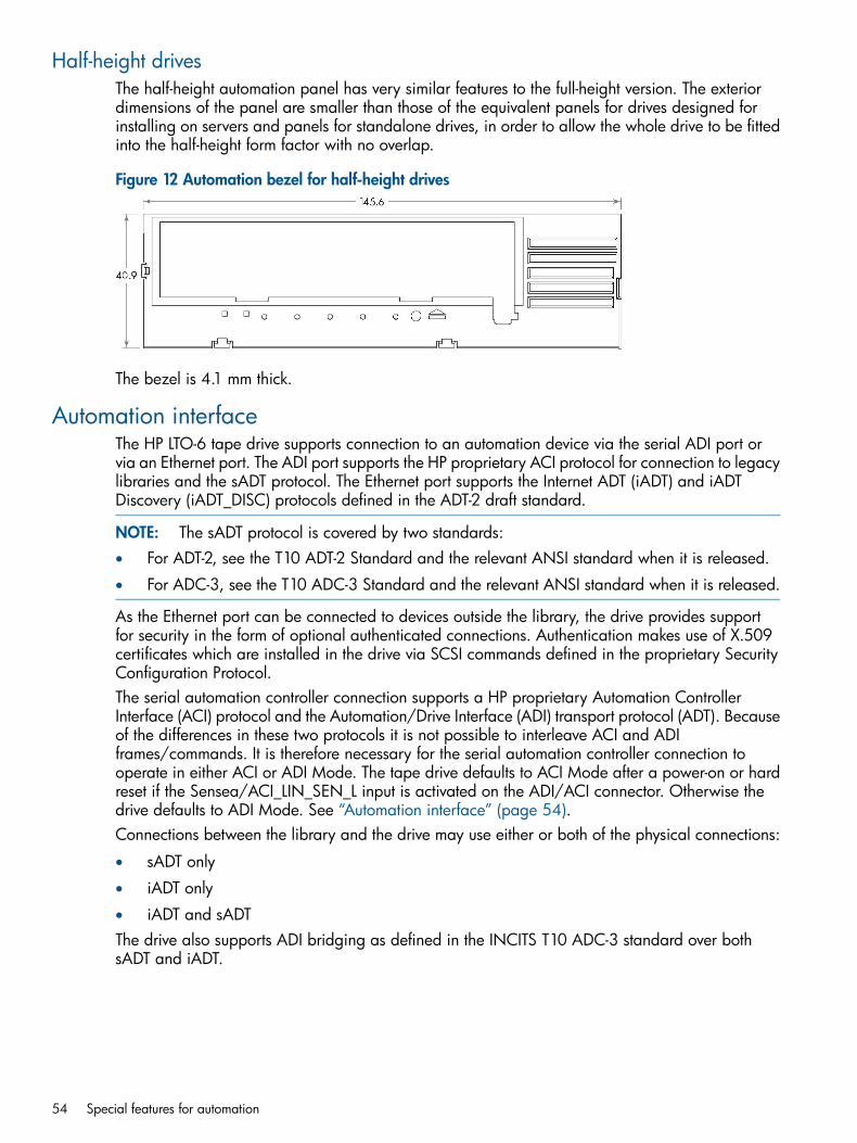
Half-height drivesThe half-height automation panel has very similar features to the full-height version. The exteriordimensions of the panel are smaller than those of the equivalent panels for drives designed forinstalling on servers and panels for standalone drives, in order to allow the whole drive to be fittedinto the half-height form factor with no overlap.
Figure 12 Automation bezel for half-height drives
The bezel is 4.1 mm thick.
Automation interfaceThe HP LTO-6 tape drive supports connection to an automation device via the serial ADI port orvia an Ethernet port. The ADI port supports the HP proprietary ACI protocol for connection to legacylibraries and the sADT protocol. The Ethernet port supports the Internet ADT (iADT) and iADTDiscovery (iADT_DISC) protocols defined in the ADT-2 draft standard.
NOTE: The sADT protocol is covered by two standards:• For ADT-2, see the T10 ADT-2 Standard and the relevant ANSI standard when it is released.
• For ADC-3, see the T10 ADC-3 Standard and the relevant ANSI standard when it is released.
As the Ethernet port can be connected to devices outside the library, the drive provides supportfor security in the form of optional authenticated connections. Authentication makes use of X.509certificates which are installed in the drive via SCSI commands defined in the proprietary SecurityConfiguration Protocol.The serial automation controller connection supports a HP proprietary Automation ControllerInterface (ACI) protocol and the Automation/Drive Interface (ADI) transport protocol (ADT). Becauseof the differences in these two protocols it is not possible to interleave ACI and ADIframes/commands. It is therefore necessary for the serial automation controller connection tooperate in either ACI or ADI Mode. The tape drive defaults to ACI Mode after a power-on or hardreset if the Sensea/ACI_LIN_SEN_L input is activated on the ADI/ACI connector. Otherwise thedrive defaults to ADI Mode. See “Automation interface” (page 54).Connections between the library and the drive may use either or both of the physical connections:
• sADT only
• iADT only
• iADT and sADTThe drive also supports ADI bridging as defined in the INCITS T10 ADC-3 standard over bothsADT and iADT.
54 Special features for automation

Table 2 Automation ports and ADT ports available on LTO-6 drives
CommentsTCP/IP Port#ProtocolPort
The ACI protocol was developedbefore the emergence of the T10
N/AHP ProprietaryAutomation Control Interface orAutochanger Interface
ACI
standard ADT protocol and is nolonger being actively developed.
Primary automation interface overRS-422 serial link.
N/AT10 standard sADTAutomation/Drive InterfaceADI
The same physical port as thediagnostic serial test port, but using
N/AT10 standard sADTDiagnostic Tools InterfaceDTI
the ADT protocol instead of the HPProprietary diagnostic protocol.
Ethernet equivalent of the ADI port.4169T10 standard iADT-TLSInternet Automation/DriveInterface
iADI
Auxiliary automation port used forKey Management and Host AccessControl.
4168T10 standard iADT-TLSInternet AutomationManagement Interface
iAMI
Ethernet equivalent of the DTI port.4167T10 standard iADT-TLSInternet Diagnostic ToolsInterface
iDTI-A
Ethernet equivalent of the DTI port.53670T10 standard iADT-TLSInternet Diagnostic ToolsInterface
iDTI-B
Ethernet equivalent of the DTI port.53671T10 standard iADT-TLSInternet Diagnostic ToolsInterface
iDTI-C
Secure Ethernet equivalent of the iADIport.
9614T10 standard iADT-TLSInternet Automation/DriveInterface using Transport LayerSecurity
iADI-TLS
Secure Ethernet equivalent of theiAMI port.
8614T10 standard iADT-TLSInternet AutomationManagement Interface usingTransport Layer Security
iAMI-TLS
Automation Control Interface (ACI)The Automation Control Interface (ACI) allows the activities of the drive to be coordinated withina library. The protocol has been designed so that it can be made into a standard feature of tapedrives. It provides a rich and extensible functionality to allow automation manufactures to addvalue in their application of it.The interface is a serial bus with additional control lines, designed to connect the LTO Ultrium tapedrive to an automation controller in a tape library. Each tape drive position has a separateautomation controller. The RS-422 serial port on the rear of the drive allows for ACI connection.The ACI protocol provides the following fundamental functions:
• Coordinating the automation controller and the tape drive for Load and Unload operations
• Allowing the automation controller to retrieve information from the tape drive
• Setting tape drive configuration informationIn addition, the following functions may be supported depending on the way that the tape libraryis configured:
• Providing upload and download of firmware images
• Providing access to the contents of the Cartridge Memory
Automation interface 55

• Providing a protocol for passing SCSI commands to the tape drive
• Providing a protocol for passing SCSI commands from the host to the library (surrogate SCSI).
NOTE: These notes refer to the “standard” automation drive variant.
For details of using ACI commands and the ACI protocol, see Chapter 5 of the Software IntegrationGuide, volume 2 of the HP LTO Ultrium Technical Reference Manual.
Automation/Drive Interface (ADI)The INCITS T10 (SCSI) committee has a working group devoted to the development of a commonAutomation-Drive Interface (ADI). ADI consists of two standards:
• Automation/Drive Interface—Commands (ADC-3), ANSI INCITS TBD, which specifies the SCSIcommand set used over ADI.
• Automation/Drive Interface—Transport Protocol (ADT-2), ANSI INCITS TBD, which specifiesa transport protocol for ADI.
The drive operates in either ACI or ADI mode. It is not possible to interleave ACI and ADI commandsbecause they are handled very differently. The drive defaults to ACI mode after a power-on orhard reset. The Automation Controller can then instruct the tape drive to switch to ADI mode bysending a Port Login frame under the following conditions:1. No ACI commands are outstanding. This not only means that the tape drive must have received
acknowledgement for all responses to all ACI commands received, but also that all immediateresponse commands have also finished. For example, if an Automation Controller initiates animmediate response Load command (see section 5.3 of ACI specification), it cannot issue anADI command until the tape drive has finished physically loading the cartridge. If an ACIcommand is outstanding when an ADI frame is received the drive will transmit an ACI <NAK>character in response.
2. An Encoded ADI frame received when the tape drive is in ACI Mode must not exceed theReceive Buffer size (see section 5.16 of the ACI Specification for details) and the frame mustbe received within the ACI Transmission Period (see section 4.6.6.3.2 of the ACI Specification).If either of these conditions is exceeded the tape drive will transmit a <NAK> character.
3. ADI frames received in ACI Mode must be Port Login frames otherwise the tape drive willrevert to ACI Mode after transmitting the appropriate ADI response.
4. The ADI protocol must be enabled; see the Set Drive Configuration command (section 5.6 ofthe ACI Specification) for details. If the tape drive receives an ADI frame when the ADI protocolhas been disabled the drive will transmit a <NAK> character.
When the tape drive is in ADI Mode it will not acknowledge or respond to any ACI command untilthe ADI port becomes logged out, either with an explicit Port Logout frame or an ADI reset.When the tape drive transitions from one mode to the other (ACI to ADI or ADI to ACI) it will notimplicitly change the drive’s configuration. However, Automation/Drive Interface (ADC-3) SCSImode parameters only apply when the tape drive is in ADI mode, so the tape drive behavior maychange after transitioning between the two modes.HP recommends that the drive is used in either exclusively ACI or ADI modes of operation. Avoidmixing operation of the two modes.
Internet Automation Device interface (iADT)The iADT or Ethernet port provides all the same functionality as the ACI/ADI port but can also beused for:
• drive management
• encryption control/key management
• diagnostic extraction
56 Special features for automation

The iADT port supports the following network services via the 10/100 Mbpa Ethernet port:
DescriptionPort Number/Base ProtocolService Name
Internet Automation Device Interface using non-secure ADTprotocol over TCP (see ADT-2).
4169/TCPiADT
Internet Automation Device Interface using secure ADTprotocol over TCP (see ADT-2).
9614/TCPiADI-TLS
iADT Discovery over UDP (see ADT-2).4169/TCPiADT-DISC
Internet Diagnostic Tools Interface using non-secure ADTprotocol over TCP.
4167/TCPiDTI
How the LTO-6 drive will be configured depends upon the overall configuration of the data storagesite. The site consists of a number of entities:
• Host computers performing backups
• Tape libraries (automation devices)
• LTO-6 tape drives installed in tape libraries (drives may provide connectivity between thelibrary and hosts)
• Management hosts performing security configuration
• Encryption key managers (EKMs)
• Hosts accessing the drives for debugging informationIt may be necessary for a drive to communicate directly with a network entity, such as an externalKey Manager, which requires network traffic to pass through a router on the edge of the library.This requires careful configuration of the router to ensure security of the network inside the library.The network inside a library is configured using techniques unique to that library. This section onlygives guidance on the goals of that configuration. The library network configuration has twopurposes:
• To permit communication among the library, all drives, and any other entities.
• To ensure the security of those communications.If the network connects only the library and drives, there should be no physical connection betweenthe network and any network outside the library. If this is not feasible, then IP packets to or fromthe following port numbers should be blocked:
• iADT (TCP/4169)
• iADT-TLS (TCP/9614)
• iADT-DISC (UDP/4169)If an external host (such as an external Key Manager) requires access to the library only and thelibrary has two Ethernet ports with a firewall between them, then one port should be used only forexternal access and the other for internal access. This is effectively the same as the situation in theprevious paragraph.If an external host requires access to drives, only the minimum number of protocols should beallowed to pass into and out of the library, and any connections carrying SCSI commands shouldbe secured either by using IKEv2-SCSI and ESPSCSI on the iADI port or by using the iADI-TLS port.Either of these will require security configuration to be performed on the drive.Public Key Infrastructure (PKI) credentials used by the HP LTO-6 drives consist of three classes ofX.509 certificates: root certification authority (CA), device, and management host. If the drive has
Automation interface 57

not received a root CA certificate and a device certificate, then SSL/TLS connections (such asiADT-TLS) will not be accepted.
• The root CA certificate is stored in non-volatile memory in the drive and is used to verifycredentials presented to the drive in the course of the TLS and IKEv2-SCSI protocols. To permitthis, it is used to sign the other certificates.
• The device certificate stored in non-volatile memory identifies the drive and contains the publickey programmed into the drive during manufacturing. The subject name field of the certificateis provided by the system administrator during certificate creation.
• The management host certificates are stored in volatile memory, and are used to verify andauthorize security configuration operations.
Use of PKI credentials requires the system administrator to replace compromised and expiredcertificates, and (when certificate validity dates are checked) ensure that the drive’s real-time clockis valid. The LTO-6 drive does not support certificate revocation lists (CRLs). In some circumstances,you can disable the checking of certificate validity dates.
Fan interfaceHP Ultrium LTO-6 SAS drives have the capability to control an external fan. The purpose of this isto provide the necessary airflow through the drive to keep the internal temperatures within normalparameters. For details of the Fan Connector, see “Fan control connector” (page 30). When thedrive detects a fan is present it will control the fan as required. Any fan used for this purpose shouldbe able to meet the following criteria:
• 12V supply
• 4-wire fan (Power, Ground, Speed Control and Fan Speed)
• Minimum airflow requirements as detailed in the environmental specification
• The enclosure used to house the fan and drive must be designed in such a way as to ensurethat the airflow generated by the fan is only pulled through the drive. There should be no pathoutside the drive.
NOTE: If you intend to plug a fan into this connector to provide the necessary airflow throughthe drive, consult your HP Technical Support Representative for details of the fan specificationrequired.
Configuring autoload and library-controlled loadsHP LTO Ultrium tape drives can be configured so that loads either occur automatically or underthe control of the library. A SCSI MODE SELECT command can set the Autoload field to do this.The field is byte 5, bits 0–2 of the Control Mode page, 0Ah.If the Autoload field = 0, Autoload is set and the drive automatically loads a cartridge when it isinserted and threads the tape so that it is ready for use.If the Autoload field = 1 or 2, the drive pulls the cartridge into the drive but does not thread thetape. In this position, the LTO-Cartridge Memory can be read. The drive requires a Load commandto thread the tape and make it ready for use.
58 Special features for automation

Cartridge positions during load and unloadThe following diagrams show the positions of importance during load and unload.
Figure 13 Load and unload positions for full-height drives
Figure 14 Load and unload positions for half-height drives
NOTE: Drives for library use the automation front panel, which has no door. The illustrationshows a standalone drive.
Cartridges are ejected to this point, which is 72.5 mm from the drive mounting points onfull–height drives, and 73.6 mm from the drive mounting points for half-height drives. The
Eject Point
Configuring autoload and library-controlled loads 59

position tolerance is 1 mm. The automation controller cannot configure the location ofthis position.
If Autoload is set (Autoload field = 0), the drive will start to load the cartridge when itreaches this point.
Load Point 1
If Autoload is not set (Autoload field = 1 or 2), the library must insert the cartridge into thedrive to a position between Load Point 1 and Load Point 2. The library can then issue aLoad command over the ADI connector to instruct the drive to load and thread the cartridge.Load Point 1 is the recommended minimum load point for commanded loads.
The maximum distance a cartridge can be inserted for optimal loading performance, sothat autoload or a Load command can load the cartridge. The automation controller cannotconfigure the location of this position.
Load Point 2
The maximum speed for inserting a cartridge into the drive is 80 mm/s.
There is one other point of note, the ready-to-eject position. If Auto-Eject is not set then when anunload command is received by the drive, the tape will be rewound and unthreaded. The drivewill then wait at this point until it is commanded to eject the cartridge by the ACI Unload command.
Load scenariosThe following scenarios describe the operation during the various types of load.
Load scenario 1: Autoload1. The library sends a Set Configuration command to enable Autoload. This is only necessary
after a drive power-on.2. The host sends a Move Medium command to the robotics.3. The picker gets a cartridge from a storage slot.4. The picker inserts the cartridge into the drive aperture.5. The picker lets go of the cartridge and pushes the cartridge to between Load Point 1 and Load
Point 2.6. The drive automatically takes the cartridge, loads it and threads it.
Load scenario 2: Library controlled1. The host sends a Move Medium command to the robotics.2. The picker gets a cartridge from a storage slot.3. The picker inserts the cartridge to between Load Point 1 and Load Point 2.4. The picker lets go of the cartridge.5. The library sends a Load command to the drive.6. The drive takes the cartridge, then loads and threads it.
Unload scenario 1: Autoload1. The library sends a Set Configuration command to enable Auto-Eject. This is only necessary
after a drive power-on.2. The host sends an Unload command to the tape drive.3. The drive rewinds, unthreads and ejects the cartridge to Eject Point.4. The host sends a Move Medium command to the robotics.5. The picker takes the cartridge from the tape drive and places it in its storage slot.
Unload scenario 2: Library controlled1. The host sends an Unload command to the drive.2. The drive rewinds and unthreads the tape. It then pauses with the cartridge at ready-to-eject
position.3. The library sends an Unload command to eject the cartridge.
60 Special features for automation

4. The drive ejects the tape to Eject Point.5. The picker takes the cartridge from drive and places it in its storage slot.
Load/unload forcesThe load force varies according to the speed at which the cartridge is inserted into the drive. Thepeak load force occurs when the cartridge begins to accelerate the drive carrier and only lasts fora short time. In any automation environment, it is recommended that the cartridge is inserted intothe drive with a speed of between a minimum of 25 mm/s and a maximum of 80 mm/s, but it isrecommended that a speed of 55 mm/s is used and that the cartridge is inserted to Load Point 1+8 mm. Going outside this range, or not inserting the cartridge far enough raises the possibilitythat the Autoload may not trigger and increases the risk of damaging the load mechanism.The unload force is 5.8N maximum; this is the force that an external mechanism must exert toremove a fully ejected cartridge from the drive.
Using Cartridge Memory (LTO-CM) in librariesCartridge memory offers possibilities for use in libraries as an adjunct to or replacement forbarcodes. The following diagram shows the architecture required.
Current libraries — barcodesMany libraries use sticky labels with barcodes on cartridges to identify them. These are read bya barcode reader attached to the picker arm. The application then needs to hold information asto the contents of the tape to which it can relate the bar code.Cartridge Memory can be used as a substitute for these barcodes. No human interaction is neededto fix barcode labels, reducing errors, though cartridges may still need labels that humans canread. A cartridge can be identified by its serial number.However, because Cartridge Memory has space that can be written by applications, it can holddetails of the contents and nature of the tape. This obviates the need for this information to be heldby the application. HP is working with other industry leaders, both hardware and software, on anIndustry Common Implementation Guide.
Using Cartridge Memory (LTO-CM) in libraries 61

11 Drive error codesThe following error codes may be reported in bytes 16 and 17 of the Request Sense data andalso reported in ACI Get Error Info RDATA, bytes 3 and 4. See the REQUEST SENSE commandin Chapter 4 of the Host Interface Guide, Volume 3 of the HP LTO Ultrium Technical ReferenceManual.
Generic module (from 0000h)
DescriptionCode
Good.0000h
Bad.0001h
Done.0002h
Aborted.0003h
Invalid configuration values.0004h
Invalid configuration name.0005h
Place holder until real status is known.0006h
Invalid parameter supplied to function.0007h
Automation Control Interface (from 0400h)
DescriptionCode
Unsupported command opcode.0401h
Busy—command rejected.0402h
RAMBIST failed.0403h
Invalid command checksums.0404h
Invalid baud rates.0405h
Invalid command while load/unload pending.0406h
Time-out waiting to end immediate command.0407h
RAM framing error.0408h
RAM overrun error.0409h
Invalid command length .040Ah
Byte buffer framing error.040Bh
Byte buffer overrun error.040Ch
Command active abort rejected.040Dh
Invalid response acknowledgement.040Eh
Transmission time-out.040Fh
Did not receive ETX.0410h
Cancel command packet timer error.0411h
Custom byte error.0412h
62 Drive error codes
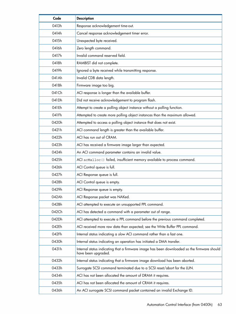
DescriptionCode
Response acknowledgement time-out.0413h
Cancel response acknowledgement timer error.0414h
Unexpected byte received.0415h
Zero length command.0416h
Invalid command reserved field.0417h
RAMBIST did not complete.0418h
Ignored a byte received while transmitting response.0419h
Invalid CDB data length.041Ah
Firmware image too big.041Bh
ACI response is longer than the available buffer.041Ch
Did not receive acknowledgement to program flash.041Dh
Attempt to create a polling object instance without a polling function.041Eh
Attempted to create more polling object instances than the maximum allowed.041Fh
Attempted to access a polling object instance that does not exist.0420h
ACI command length is greater than the available buffer.0421h
ACI has run out of CRAM.0422h
ACI has received a firmware image larger than expected.0423h
An ACI command parameter contains an invalid value.0424h
ACI acMalloc() failed, insufficient memory available to process command.0425h
ACI Control queue is full.0426h
ACI Response queue is full.0427h
ACI Control queue is empty.0428h
ACI Response queue is empty.0429h
ACI Response packet was NAKed.042Ah
ACI attempted to execute an unsupported PPL command.042Bh
ACI has detected a command with a parameter out of range.042Ch
ACI attempted to execute a PPL command before the previous command completed.042Dh
ACI received more raw data than expected; see the Write Buffer PPL command.042Eh
Internal status indicating a slow ACI command rather than a fast one.042Fh
Internal status indicating an operation has initiated a DMA transfer.0430h
Internal status indicating that a firmware image has been downloaded so the firmware shouldhave been upgraded.
0431h
Internal status indicating that a firmware image download has been aborted.0432h
Surrogate SCSI command terminated due to a SCSI reset/abort for the LUN.0433h
ACI has not been allocated the amount of DRAM it requires.0434h
ACI has not been allocated the amount of CRAM it requires.0435h
An ACI surrogate SCSI command packet contained an invalid Exchange ID.0436h
Automation Control Interface (from 0400h) 63

DescriptionCode
A CDB contained an invalid exchange ID.0437h
ACI Surrogate SCSI queue is full.0438h
ACI Surrogate SCSI queue is empty.0439h
A request for an invalid entry in Surrogate SCSI queue has been made.043Ah
ACI has received an acSurrogateNotifyOp with an unknown SCSI CDB type.043Bh
The SCSI Data Length parameter has changed unexpectedly.043Ch
Internal status indicating a PPL Command is being executed.043Dh
ACI too busy for fast command. Used in tracepoints to identify cause ofAC_BUSY_CMD_REJECTED error.
043Eh
ACI too busy for immediate command. Used in tracepoints to identify cause ofAC_BUSY_CMD_REJECTED error.
043Fh
ACI too busy for slow command. Used in tracepoints to identify cause ofAC_BUSY_CMD_REJECTED error.
0440h
ACI too busy for SCSI command. Used in tracepoints to identify cause ofAC_BUSY_CMD_REJECTED error.
0441h
ACI too busy because of overlapped commands. Used in tracepoints to identify cause ofAC_BUSY_CMD_REJECTED error.
0442h
ACI too busy because of comms resync. Used in tracepoints to identify cause ofAC_BUSY_CMD_REJECTED error.
0443h
ACI too busy because upgrading. Used in tracepoints to identify cause ofAC_BUSY_CMD_REJECTED error.
0444h
ACI too busy because out of memory. Used in tracepoints to identify cause ofAC_BUSY_CMD_REJECTED error.
0445h
ACI is resynchronizing comms with library after persistent comms failure.0446h
SCSI opcode is not supported in this firmware release.0447h
Internal status indicating an ACI reset is required.0448h
Internal status indicating a full drive reset is required.0449h
Command contains an invalid Memory ID.044Ah
All Command Control Blocks have been allocated.044Bh
The returned or referenced Command Control Block is invalid.044Ch
Response Time-out — command aborted and response sent.044Dh
Response Time-out — response sent but command allowed to continue.044Eh
Response Time-out — ACI failed to send response within the Response Period.044Fh
ACI too busy because the CCB queue is full. Used in tracepoints to identify the cause ofAC_BUSY_CMD_REJECTED error.
0450h
ACI command contains the sequence number of the previous command. The command isignored.
0451h
Internal status indicating a slow ACI command being executed before Drive Ready event.0452h
Failed to transmit ACK/NAK within the Packet Acknowledgement period.0453h
Internal status indicating a direct ACI command rather than a fast or slow one.0454h
64 Drive error codes

DescriptionCode
ACI too busy for a direct command. Used in tracepoints to identify cause ofAC_BUSY_CMD_REJECTED error.
0455h
Cannot perform operation because the SCSI burst size is zero or unknown.0456h
Command not supported because the primary interface has not been enabled.0457h
Unable to get a new task object.0458h
An ADI frame has been received while one or more ACI commands are outstanding.0459h
An SOF was received in ACI Mode which was not a valid frame.045Ah
The SSC device has not requested the amount of data supplied with the ACI SCSI command.045Bh
The specified automation port is not supported.045Ch
A function will send a response when it has finished.045Dh
ACI self-test failure — ACI should not be executing a direct Command while performing theself-test.
0480h
ACI self-test failure — ACI should not be executing a slow Command while performing theself-test.
0481h
ACI self-test failure — if ACI is idle, the Control queue should be empty.0482h
ACI self-test failure — if ACI is idle, the Response queue should be empty.0483h
ACI self-test failure — if ACI is idle, the Surrogate SCSI queue should be empty.0484h
ACI self-test failure — if ACI is idle, only the self-test command should be allocated in the smallData Region.
0485h
ACI self-test failure — if ACI is idle, no memory from the Large Data Region should be allocated.0486h
ACI self-test failure — if ACI is idle, no CRAM memory should be allocated.0487h
ACI self-test failure — if ACI is idle, only one CCB should be allocated.0488h
Buffer manager (from 0800h)
DescriptionCode
The buffer manager failed to initialize correctly.0800h
No Buffer Allocation description exists for the supplied Module ID0801h
The request queue has overflowed.0802h
The priority request queue has overflowed.0803h
Dataset index error: BMMDataSetIdxToAddr() has been passed an invalid Idx.0804h
Dataset information table index error: BMMDataSetIdxToDSITAddr() has been passed an invalidIdx.
0805h
ACN index error: BMMDataSetIdxToACNandLPOSAddr() has been passed an invalid Idx.0806h
Wrap index error: BMMDataSetIdxToWrapAddr() has been passed an invalid dataset Idx.0807h
The Notification queue has overflowed. See BMMXferComplete().0808h
The notification was not SDL signal for DSIT read. See BMMXferComplete().0809h
The Notification queue has underflowed. See BMMXferComplete().080Ah
Buffer manager (from 0800h) 65
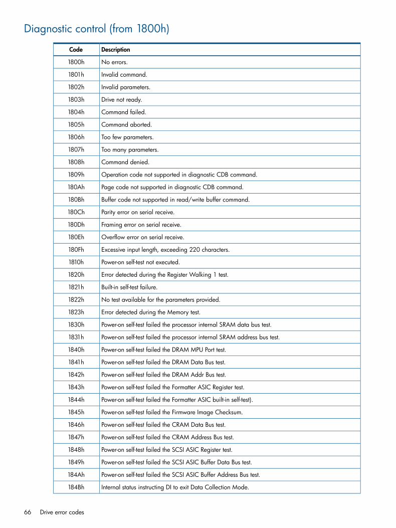
Diagnostic control (from 1800h)
DescriptionCode
No errors.1800h
Invalid command.1801h
Invalid parameters.1802h
Drive not ready.1803h
Command failed.1804h
Command aborted.1805h
Too few parameters.1806h
Too many parameters.1807h
Command denied.1808h
Operation code not supported in diagnostic CDB command.1809h
Page code not supported in diagnostic CDB command.180Ah
Buffer code not supported in read/write buffer command.180Bh
Parity error on serial receive.180Ch
Framing error on serial receive.180Dh
Overflow error on serial receive.180Eh
Excessive input length, exceeding 220 characters.180Fh
Power-on self-test not executed.1810h
Error detected during the Register Walking 1 test.1820h
Built-in self-test failure.1821h
No test available for the parameters provided.1822h
Error detected during the Memory test.1823h
Power-on self-test failed the processor internal SRAM data bus test.1830h
Power-on self-test failed the processor internal SRAM address bus test.1831h
Power-on self-test failed the DRAM MPU Port test.1840h
Power-on self-test failed the DRAM Data Bus test.1841h
Power-on self-test failed the DRAM Addr Bus test.1842h
Power-on self-test failed the Formatter ASIC Register test.1843h
Power-on self-test failed the Formatter ASIC built-in self-test).1844h
Power-on self-test failed the Firmware Image Checksum.1845h
Power-on self-test failed the CRAM Data Bus test.1846h
Power-on self-test failed the CRAM Address Bus test.1847h
Power-on self-test failed the SCSI ASIC Register test.1848h
Power-on self-test failed the SCSI ASIC Buffer Data Bus test.1849h
Power-on self-test failed the SCSI ASIC Buffer Address Bus test.184Ah
Internal status instructing DI to exit Data Collection Mode.184Bh
66 Drive error codes

DescriptionCode
Internal status instructing DI to execute the command as a Slow command.184Ch
Diagnostic Control has rejected a command because it is already executing a command.184Dh
Attempted to release Diagnostic Results memory that has not been allocated.184Eh
Unable to perform a Diagnostic command as the Diagnostic Results memory is already reserved.184Fh
Diagnostic Results data has overflow the memory allocated for results.1850h
DI has received an unsupported SCSI opcode in diExecScsiDiagOp.1851h
DI attempted to set an illegal baud rate.1852h
Set Config attempted to set a read-only configuration.1853h
Indicates DI needs to send response in the Port buffer before completing the command.1854h
Power-on self-test failed the external SRAM Data Bus test.1855h
Power-on self-test failed the external SRAM Address Bus test.1856h
Internal status indicating that a Log command specifies an FLM log.1857h
Returned by some log extraction functions to indicate there is more data to extract.1858h
Comms error (such as framing or overrun) detected on the Serial Test port.1859h
The Serial Test port has timed-out while receiving data.185Ah
A device server has requested an operation not supported by diPortIF.185Bh
Unable to get a new task object.185Ch
SCSI Command cannot be executed in Limited Operation Mode185Dh
Internal status instructing DI to send status before starting the protocol test.185Eh
Memory access denied to a READ/WRITE BUFFER command.185Fh
Memory access denied to a READ/WRITE MEMORY command.1860h
Power-on self-test failed; unrecoverable ECC error detected.1861h
A field is invalid in a diagnostic CDB command.1862h
POST failed. The image checksum is invalid.1863h
POST failed. The checksum is incomplete.1864h
Invalid length/address in READ/WRITE MEMORY command.1865h
The Drive Configuration Table returned permission denied in response to a Write CM/EEPROMoperation.
1866h
Verify root key failed as no root key found in OTP.1867h
Root key is incorrect.1868h
Drive unexpectedly in unsecured state.1869h
RSA public key not found.186Ah
RSA private key not found.186Bh
RSA key pair not found.186Ch
Data following encryption/decryption with RSA key is incorrect.186Dh
Root key generated when one already exists.186Eh
Drive in unexpected security state.186Fh
Diagnostic control (from 1800h) 67
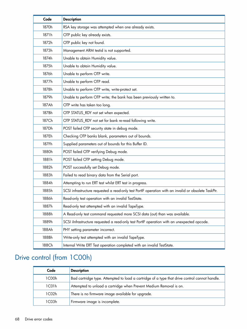
DescriptionCode
RSA key storage was attempted when one already exists.1870h
OTP public key already exists.1871h
OTP public key not found.1872h
Management ARM testid is not supported.1873h
Unable to obtain Humidity value.1874h
Unable to obtain Humidity value.1875h
Unable to perform OTP write.1876h
Unable to perform OTP read.1877h
Unable to perform OTP write, write-protect set.1878h
Unable to perform OTP write; the bank has been previously written to.1879h
OTP write has taken too long.187Ah
OTP STATUS_RDY not set when expected.187Bh
OTP STATUS_RDY not set for bank re-read following write.187Ch
POST failed OTP security state in debug mode.187Dh
Checking OTP banks blank, parameters out of bounds.187Eh
Supplied parameters out of bounds for this Buffer ID.187Fh
POST failed OTP verifying Debug mode.1880h
POST failed OTP setting Debug mode.1881h
POST successfully set Debug mode.1882h
Failed to read binary data from the Serial port.1883h
Attempting to run ERT test whilst ERT test in progress.1884h
SCSI infrastructure requested a read-only test PortIF operation with an invalid or obsolete TaskPtr.1885h
Read-only test operation with an invalid TestState.1886h
Read-only test attempted with an invalid TapeType.1887h
A Read-only test command requested more SCSI data (out) than was available.1888h
SCSI iInfrastructure requested a read-only test PortIF operation with an unexpected opcode.1889h
PHY setting parameter incorrect.188Ah
Write-only test attempted with an invalid TapeType.188Bh
Internal Write ERT Test operation completed with an invalid TestState.188Ch
Drive control (from 1C00h)
DescriptionCode
Bad cartridge type. Attempted to load a cartridge of a type that drive control cannot handle.1C00h
Attempted to unload a cartridge when Prevent Medium Removal is on.1C01h
There is no firmware image available for upgrade.1C02h
Firmware image is incomplete.1C03h
68 Drive error codes

DescriptionCode
Firmware image has checksum or other errors.1C04h
Firmware image is not compatible with the drive configuration.1C05h
Firmware image is too big to upgrade from.1C06h
Internal error in the Drive Control firmware upgrade code.1C07h
A firmware upgrade cartridge was in the drive when it powered on.1C08h
A load without threading has been requested for a cartridge with unusable Cartridge Memory.1C09h
Tried to load a writable cartridge with an unusable Cartridge Memory.1C0Ah
The write-protect tab setting was changed during a load.1C0Bh
A non-HP cleaning cartridge has been inserted in the drive.1C0Ch
Cannot determine the manufacturer of the cleaning cartridge.1C0Dh
No DRAM space reserved to hold the firmware image.1C0Eh
A cleaning cartridge was in the drive when it powered on.1C0Fh
Drive Control did an eject during the power-on sequence.1C10h
A firmware upgrade cartridge has been loaded when a data cartridge was expected.1C11h
A firmware upgrade cartridge was expected but some other type of cartridge has been inserted.1C12h
Failure due to drive temperature being out of acceptable range.1C13h
Cleaning cartridge initialized by a non-HP drive.1C14h
Trying to convert a non-data cartridge into a firmware upgrade cartridge.1C15h
Operation failed because cartridge is not present or not ready.1C16h
Cleaning cartridge loaded when a data cartridge was expected.1C17h
Expected a cleaning cartridge but got something else on load.1C18h
Cartridge Memory is unusable and failed to read the FID.1C19h
Firmware upgrade image information is unavailable.1C1Ah
Could not find firmware information in the new image.1C1Bh
A tape load has failed.1C1Ch
The EOD Validity field is not Good.1C1Dh
Firmware image is not compatible with drive sub-personality configuration.1C1Eh
A TMR timer fired but the ID does not match what was expected.1C1Fh
Firmware image has incorrect signature.1C20h
The firmware upgrade image is too old.1C21h
Firmware upgrade image version is too large.1C22h
Unknown tape format encountered during firmware upgrade.1C23h
Unknown host error during firmware upgrade.1C24h
Unable to change to the specified partition because no two partition tape is loaded, the currentposition is already in that partition, or there is no such partition.
1C25h
Cannot perform a multi-partition operation as partitions are not supported on this media.1C26h
The media does not support this number of partitions.1C27h
Drive control (from 1C00h) 69

DescriptionCode
No format is required because the tape is already formatted as required.1C28h
Requested sizes of partitions are outside the valid range for this media.1C29h
Drive monitor (from 2000h)
DescriptionCode
No error. Synonymous with GOOD status.2000h
Invalid parameter. The value of a parameter received with a Drive Monitor operation falls outsideits valid range.
2001h
External interfaces (from 2400h)
DescriptionCode
Command holder full.2400h
Bad command handle.2401h
Empty command handle.2402h
No tape loaded.2403h
Already loaded.2404h
In diagnostic mode.2405h
Not in diagnostic mode.2406h
Tried to write to write protected cartridge.2407h
Aborted an active command.2408h
Aborted a command before it became active.2409h
Tried to abort a command that was not queued.240Ah
Invalid state requested of the EII State Manager.240Bh
The EII tried to process a firmware upgrade type that is not supported.240Ch
The EII state manager could not handle an abort request.240Dh
Tried to abort a command that was already being aborted.240Eh
Tried to get a command for the wrong module.240Fh
Command specified in eiNotifyOp would not have been top of queue.2410h
Attempt to delete a queued EII command.2411h
Multiple attempts to delete an executing EII command.2412h
Attempt to queue a queued EII command.2413h
Attempt to queue an executing EII command.2414h
Attempt to remove a command from empty EII command queue.2415h
Attempt to execute a command still on the EII command queue.2416h
Attempt to execute an EII command when another is executing.2417h
Attempt to stop executing an EII command that was not executing.2418h
The module putting a command on the EII command queue is not the module that allocated it.2419h
70 Drive error codes

Front panel interface (from 2800h)
DescriptionCode
Failure due to use of forced eject.2801h
Host interface (from 2C01h)
DescriptionCode
Unknown opcode.2C01h
Reserved field set.2C02h
Unknown mode page.2C03h
Firmware bug.2C04h
Parameter list length error.2C05h
Already prevented.2C06h
Not prevented.2C07h
Too many hosts.2C08h
32-bit overflow.2C09h
Invalid space code.2C0Ah
Bad inquiry page.2C0Bh
Not the reserver.2C0Ch
Not reserved.2C0Dh
Third-party bad.2C0Eh
Third-party host.2C0Fh
Reserved.2C10h
Read Buffer ID.2C11h
Read Buffer mode.2C12h
Write Buffer ID.2C13h
Write Buffer mode.2C14h
Main Buffer mode.2C15h
Write Buffer header.2C16h
No EVPD.2C17h
Drive not ready.2C18h
Density medium no tape.2C19h
ARM firmware error code 0, used by the embedded ARM firmware.2C1Ah
ARM POST fail.2C1Bh
TX fail.2C1Ch
Inf host interface ARM POST — SDRAM test failed.2C1Dh
Inf host interface ARM POST — SDRAM BIST time-out.2C1Eh
Inf host interface ARM POST — SDRAM memory access.2C1Fh
Front panel interface (from 2800h) 71

DescriptionCode
Inf host interface ARM POST — Atmel memory test.2C20h
Inf host interface ARM POST — no Olga connected.2C21h
Inf host interface ARM POST — FC diagnostic CC12C22h
Inf host interface ARM POST — FC diagnostic counters.2C23h
Inf host interface ARM POST — FC diagnostic FIFO test.2C24h
Inf host interface ARM POST — FC diagnostic interface.2C25h
Inf host interface ARM POST — FC diagnostic register check.2C26h
SPI host interface report parity error status.2C27h
SPI host interface ARM POST — register diagnostics failed.2C28h
SPI host interface ARM POST — PDC BIST time-out.2C29h
SPI host interface ARM POST — PDC RAM BIST error.2C2Ah
SPI host interface ARM POST — BC BIST time-out.2C2Bh
SPI host interface ARM POST — BC RAM BIST error.2C2Ch
SPI buffer channel 1 CRC error.2C2Dh
SPI buffer channel 1 FIFO parity error.2C2Eh
SPI sync offset error.2C2Fh
SPI illegal write error.2C30h
SPI illegal command error.2C31h
SPI FIFO overflow or underflow error.2C32h
SPI IDE message received.2C33h
SPI BDR message received.2C34h
SPI abort task message received.2C35h
SPI parity error message received.2C36h
SPI host interface ARM POST record manager diagnostics failed.2C37h
SPI host interface ARM POST host port diagnostics failed.2C38h
Buffer manager Titov host port control premature DREQ.2C39h
Buffer manager Titov host port control parity error.2C3Ah
Buffer manager Titov host port control CRC error.2C3Bh
Buffer manager Titov host port control FIFO overflow.2C3Ch
Buffer manager Titov host port control DMA overrun.2C3Dh
Buffer manager Titov host port control outstanding error.2C3Eh
Buffer manager Titov host port control sync data error.2C3Fh
Buffer manager check buffer CRCs mismatch.2C40h
Buffer manager check CRC passed.2C41h
SAS active cable error.2C42h
Illegal SCSI command. The hardware or firmware does not recognize the CDB.2C50h
The SCSI Macro command was aborted because the drive was selected first.2C51h
72 Drive error codes

DescriptionCode
ATN was pulled by the initiator.2C52h
Initiator did not respond to reselect within the reselect time-out period.2C53h
The internal port interface task queue was empty.2C54h
Too many port interface tasks. There is no room left in the internal port interface task queue.2C55h
Parity error on the SCSI bus.2C56h
Parity error in the mini-buffer.2C57h
Attempted to use an invalid value internally.2C58h
The SCSI FIFO was not empty when attempting to write to it.2C59h
Not connected. Attempted to issue SCSI macro target command while not in target mode.2C5Ah
Wrong host. Attempted to communicate with Host X while connected to Host Y.2C5Bh
Wrong bus state. Attempted SCSI macro command while in the incorrect bus phase.2C5Ch
No information on host. This host has not communicated with us previously.2C5Dh
Invalid speed. The saved SCSI bus speed for this host is corrupt.2C5Eh
Invalid SCSI ID, outside the range 0-15.2C5Fh
The group code in CDB is not supported.2C60h
The host attempted to issue an overlapped command.2C61h
Not enough buffer space. The internal requestor asked for more space than was available in themini-buffer.
2C62h
The mini-buffer is non-functional.2C63h
Buffer in use. The internal requestor was denied access to the mini-buffer.2C64h
Status interrupted; the SCSI status phase failed.2C65h
Received an IDE (Initiator Detected Error) message.2C66h
Received an MPE (Message Parity Error) message.2C67h
Received a BDR (Bus Device Reset) message.2C68h
Received an Abort message.2C69h
Failed the Media Information check.2C6Ah
There is no tape in the drive.2C6Bh
Loading a tape.2C6Ch
Media changed. A tape is present in the drive but not loaded.2C6Dh
Cleaning the tape heads.2C6Eh
Received a PON or SCSI reset.2C6Fh
A mode change (LVD/SE) occurred on the SCSI bus.2C70h
Gross error detected by the SCSI Macro.2C71h
Illegal length record (ILI) — too long.2C72h
Illegal length record (ILI) — too short.2C73h
CRC error on read.2C74h
The requested burst size was larger than the drive supports.2C75h
Host interface (from 2C01h) 73

DescriptionCode
There was an invalid field in the mode parameter list for this MODE SELECT command2C76h
Unloading the tape.2C77h
A parameter supplied by the internal requestor was out of range.2C78h
The allocation length exceeded the permitted length.2C79h
Invalid (unsupported) page code.2C7Ah
Invalid (unsupported) page code in parameter list.2C7Bh
BOT encountered on space.2C7Ch
EOT encountered on space.2C7Dh
Blank Check, EOD was encountered. Returned by hiPerformPreExeChecks if a space or readis attempted on a virgin tape.
2C7Eh
Position lost. A temporary code for returning status after a write-behind error.2C7Fh
PCR error in the Log Select command.2C80h
The supplied Page Code is not a resettable page.2C81h
The supplied Page Code is not a writable page.2C82h
The reserved bit in the Log Page header has been set.2C83h
The Log Select Page Length is incorrect.2C84h
There is an error with the Log Parameter Header.2C85h
Log Select Parameter list length error.2C86h
The Log Sense Page Code is invalid.2C87h
The Log Sense PC Code is in error.2C88h
Log Select: error in the parameter header.2C89h
Restart the Logical Pipeline after a format error.2C8Ah
The Buffer Manager has been interrupted with an error.2C8Eh
Check the cables. The Host Interface has exhausted all of the retries for a data phase.2C8Fh
Log Select parameter list length error.2C90h
hiPopulateSenseBuffer() could not find any free sense data buffers.2C91h
The failure prediction threshold has been exceeded. This error code is sent when a check conditionis generated for a CDB as a result of the Test flag being set in the Information Exceptions Modepage.
2C92h
Reset after GE. Triggers the power-on self-test UA 2900 after LTO 1 SCSI ASIC GE has been detected.2C93h
Return GOOD status. Used to force GOOD status to be returned.2C94h
There is a firmware bug in the handling of an inquiry page.2C95h
There is a firmware bug in the execution of the Prevent/Allow Medium Removal command.2C96h
There is a firmware bug in the parsing of a Mode page.2C97h
An attempt was made to write data or filemarks inside EW-EOM.2C98h
Firmware incorrectly programmed the SCSI macro.2C99h
An unsupported LUN was specified in the SCSI Identify message.2C9Ah
Aborting a previous command.2C9Bh
74 Drive error codes

DescriptionCode
Aborting and no disconnect. A command was rejected that could not be queued while an abort wasin progress.
2C9Ch
The host interface has exhausted all of the retries for a command phase.2C9Dh
Parameter not supported. A request for an invalid page code has been sent.2C9Eh
Buffer offset good. This is used internally by the Read Write Buffer code and should never be reportedto the host.
2C9Fh
Operation in progress. Reported when an Immediate command is executing and a subsequentcommand is received.
2CA0h
Illegal length record (ILI) — too long, and there is an EOR in FIFO. This occurs when a record is longby less than the FIFO length.
2CA1h
Illegal length record (ILI) — too short with bad CRC.2CA2h
Illegal length record (ILI) — too long with bad CRC.2CA3h
LUN not configured. The drive is the process of becoming ready.2CA4h
ILI long has been detected but a read error was encountered during the residue flush.2CA5h
An init command is required; a tape has been loaded but not threaded.2CA6h
ILI long has been detected but flushing the residue timed out.2CA7h
LTO 1 drives only: The CD-ROM El Torito identifier is corrupt.2CA8h
The LTO 1 Formatter ASIC is not supported any more.2CA9h
The LTO 1 SCSI ASIC is an invalid revision.2CAAh
MAM attribute header truncated. The specified parameter list length has caused an attribute headerto be truncated.
2CABh
Reserved field set in a MAM attribute header.2CACh
MAM attribute IDs were not ascending order.2CADh
The MAM attribute header specified an unsupported attribute value.2CAEh
A MAM attribute ID is unsupported.2CAFh
A MAM attribute ID is in an incorrect format.2CB0h
The MAM attribute header specifies an incorrect length for this attribute.2CB1h
The host attribute area in MAM is full.2CB2h
A Write Attribute command attempted to delete a non-existent attribute.2CB3h
An invalid MAM service action was requested.2CB4h
A Read attribute command failed because the Host Attribute area was not valid.2CB5h
There is an invalid field in the MAM attribute data.2CB6h
Failure prediction threshold exceeded. A Tape Alert flag has been set and the next SCSI commandneeds to be check conditioned.
2CB7h
GWIF idle error, cause unknown. This will never be returned to the host.2CB8h
GWIF idle, read error. This will never be returned to the host.2CB9h
GWIF idle, write error. This will never be returned to the host.2CBAh
MAM is accessible but the cartridge is in the load “hold” position. Unit Attention is generated.2CBBh
MAM is accessible but the cartridge is in the load “hold” position. Not Ready is generated.2CBCh
Host interface (from 2C01h) 75

DescriptionCode
Internal port interface task queue error — invalid task.2CBDh
Unable to write due to bad Cartridge Memory.2CBEh
Selway ignored ATN on REQUEST SENSE.2CBFh
Invalid number of wraps requested for LEOT.2CC0h
Invalid LEOT request compared to current position.2CC1h
MAM not accessible for some indeterminate reason.2CC2h
SCSI sequencer was asked to reconnect during invalid nexus.2CC3h
SCSI sequencer received a hiRetryDataBurst which failed.2CC4h
INQUIRY data too long.2CC5h
REQUEST SENSE data too long.2CC6h
Invalid LUN for storing INQUIRY data in the mini-buffer.2CC7h
No free slot to store REQUEST SENSE data.2CC8h
Surrogate SCSI not configurable.2CC9h
Surrogate SCSI LUN not a valid LUN.2CCAh
Surrogate SCSI command arrived.2CCBh
Incompatible tape type.2CCCh
The supplied exchange is invalid.2CCDh
Invalid value for Dev Cfg SDCA.2CCEh
Bad length for WRITE BUFFER command.2CCFh
Echo buffer has been overwritten by another host.2CD0h
Never reported to host — used to signify a special entry in the Fault Log.2CD1h
Never reported to host—port interface gave good status2CD2h
Port interface detected a bus error.2CD3h
Port interface detected an unknown internal opcode2CD4h
Port interface detected a bad context ID.2CD5h
Port interface detected bad parameters for an internal operation.2CD6h
Port interface has encountered a FM/EOD. Should not be reported.2CD7h
Port interface SCSI reselection timeout2CD8h
Port interface internal operation failed due to a PIF/MIF buffer parity error2CD9h
Command outstanding. Should not be reported.2CDAh
No command outstanding. Should not be reported.2CDBh
Not in automode status. Should not be reported.2CDCh
ARM POST failure.2CDDh
Port interface detected Bad Data Length—FC_DPL mismatch to CDB allocation length.2CDEh
Selected while reselecting. Never reported to the host.2CDFh
Bad state—firmware defect.2CE0h
Bad configuration—firmware defect.2CE1h
76 Drive error codes

DescriptionCode
The Host Interface ASIC has not responded to a mail-box operation within 10 ms.2CE2h
Got an internal firmware reboot.2CE3h
SCSI Bus Reset signal asserted by host.2CE4h
Bus Device Reset message sent by host.2CE5h
Transceivers changed to SE.2CE6h
Transceivers changed to LVD.2CE7h
Got a power-on reset.2CE8h
Checksum failure when copying bootloader code into Lucan dual-port RAM.2CE9h
Amunsden has been reset before receiving the hiPowerOneEvent from Iona.2CEAh
LF stall on reads.2CEBh
Tape is threaded but the drive shows it as unloaded.2CECh
The ARM FW has determined that this is not a DR tape.2CEDh
There has been a change in the support Logical Unit inventory.2CEEh
An invalid Port ID has been logged in.2CEFh
An invalid LUN opcode has been passed to hiConfigureSurrogateLun().2CF0h
Fixed mode request was too large.2CF1h
Decompression size mismatch while expanding and programming the Lucan FPGA code.2CF2h
Host interface has more to do.2CF3h
SCSI command failed because another host has changed the log pages.2CFDh
SCSI command failed because new firmware has been downloaded.2CFEh
SCSI command failed because another host has changed the mode pages.2CFFh
Hebrides is reporting a failure due to a read-ahead error.2D00h
Hebrides is reporting a failure due to a write-behind error.2D01h
Drive requested single shot read/write while streaming.2D04h
Search for a handle for a given context ID failed.2D05h
The dispatcher has completed the handling of the extended reset rewind.2D06h
Firmware upgrade or unknown cartridge loaded but not threaded.2D07h
Cleaning tape loaded but not threaded.2D08h
Drive control has set drDriveStatus to DR_FW_UPGRADE.2D09h
Immediate LOAD/UNLOAD in progress.2D0Ah
Reported when an Immediate command is executing and a subsequent command is received.2D0Bh
I_T nexus loss occurred.2D0Ch
The maximum number of surrogate logical units have been defined.2D0Dh
The supplied surrogate inquiry page is incorrect.2D0Eh
The surrogate logical unit inquiry area is full.2D0Fh
The surrogate logical unit inquiry area has been corrupted.2D10h
The operation has been denied as the SCSI port is currently enabled.2D11h
Host interface (from 2C01h) 77
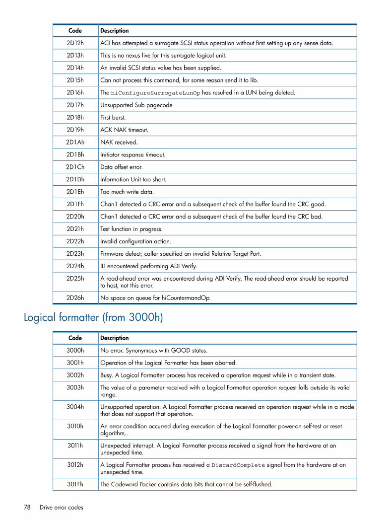
DescriptionCode
ACI has attempted a surrogate SCSI status operation without first setting up any sense data.2D12h
This is no nexus live for this surrogate logical unit.2D13h
An invalid SCSI status value has been supplied.2D14h
Can not process this command, for some reason send it to lib.2D15h
The hiConfigureSurrogateLunOp has resulted in a LUN being deleted.2D16h
Unsupported Sub pagecode2D17h
First burst.2D18h
ACK NAK timeout.2D19h
NAK received.2D1Ah
Initiator response timeout.2D1Bh
Data offset error.2D1Ch
Information Unit too short.2D1Dh
Too much write data.2D1Eh
Chan1 detected a CRC error and a subsequent check of the buffer found the CRC good.2D1Fh
Chan1 detected a CRC error and a subsequent check of the buffer found the CRC bad.2D20h
Test function in progress.2D21h
Invalid configuration action.2D22h
Firmware defect; caller specified an invalid Relative Target Port.2D23h
ILI encountered performing ADI Verify.2D24h
A read-ahead error was encountered during ADI Verify. The read-ahead error should be reportedto host, not this error.
2D25h
No space on queue for hiCountermandOp.2D26h
Logical formatter (from 3000h)
DescriptionCode
No error. Synonymous with GOOD status.3000h
Operation of the Logical Formatter has been aborted.3001h
Busy. A Logical Formatter process has received a operation request while in a transient state.3002h
The value of a parameter received with a Logical Formatter operation request falls outside its validrange.
3003h
Unsupported operation. A Logical Formatter process received an operation request while in a modethat does not support that operation.
3004h
An error condition occurred during execution of the Logical Formatter power-on self-test or resetalgorithm,.
3010h
Unexpected interrupt. A Logical Formatter process received a signal from the hardware at anunexpected time.
3011h
A Logical Formatter process has received a DiscardComplete signal from the hardware at anunexpected time.
3012h
The Codeword Packer contains data bits that cannot be self-flushed.301Fh
78 Drive error codes
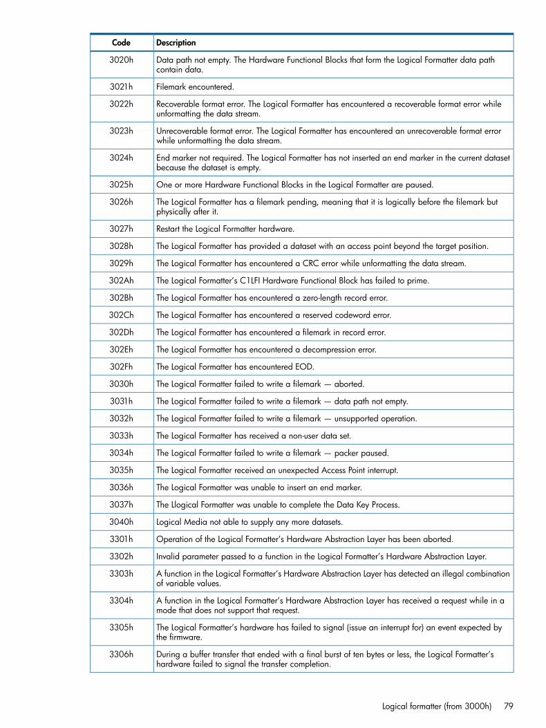
DescriptionCode
Data path not empty. The Hardware Functional Blocks that form the Logical Formatter data pathcontain data.
3020h
Filemark encountered.3021h
Recoverable format error. The Logical Formatter has encountered a recoverable format error whileunformatting the data stream.
3022h
Unrecoverable format error. The Logical Formatter has encountered an unrecoverable format errorwhile unformatting the data stream.
3023h
End marker not required. The Logical Formatter has not inserted an end marker in the current datasetbecause the dataset is empty.
3024h
One or more Hardware Functional Blocks in the Logical Formatter are paused.3025h
The Logical Formatter has a filemark pending, meaning that it is logically before the filemark butphysically after it.
3026h
Restart the Logical Formatter hardware.3027h
The Logical Formatter has provided a dataset with an access point beyond the target position.3028h
The Logical Formatter has encountered a CRC error while unformatting the data stream.3029h
The Logical Formatter’s C1LFI Hardware Functional Block has failed to prime.302Ah
The Logical Formatter has encountered a zero-length record error.302Bh
The Logical Formatter has encountered a reserved codeword error.302Ch
The Logical Formatter has encountered a filemark in record error.302Dh
The Logical Formatter has encountered a decompression error.302Eh
The Logical Formatter has encountered EOD.302Fh
The Logical Formatter failed to write a filemark — aborted.3030h
The Logical Formatter failed to write a filemark — data path not empty.3031h
The Logical Formatter failed to write a filemark — unsupported operation.3032h
The Logical Formatter has received a non-user data set.3033h
The Logical Formatter failed to write a filemark — packer paused.3034h
The Logical Formatter received an unexpected Access Point interrupt.3035h
The Logical Formatter was unable to insert an end marker.3036h
The Llogical Formatter was unable to complete the Data Key Process.3037h
Logical Media not able to supply any more datasets.3040h
Operation of the Logical Formatter’s Hardware Abstraction Layer has been aborted.3301h
Invalid parameter passed to a function in the Logical Formatter’s Hardware Abstraction Layer.3302h
A function in the Logical Formatter’s Hardware Abstraction Layer has detected an illegal combinationof variable values.
3303h
A function in the Logical Formatter’s Hardware Abstraction Layer has received a request while in amode that does not support that request.
3304h
The Logical Formatter’s hardware has failed to signal (issue an interrupt for) an event expected bythe firmware.
3305h
During a buffer transfer that ended with a final burst of ten bytes or less, the Logical Formatter’shardware failed to signal the transfer completion.
3306h
Logical formatter (from 3000h) 79

DescriptionCode
During a buffer transfer of ten bytes or less, the Logical Formatter’s hardware failed to signal thetransfer completion.
3307h
During a buffer transfer that ended with a final burst of ten bytes or less within the first 1k DRAMpage, the Logical Formatter’s hardware failed to signal the transfer completion.
3308h
A parity error was detected transferring data between Iona/Lucan and Amundsen.3309h
Wanted to start a timer for a potential missing NextDAEmpty interrupt but the pipeline was notempty.
330Ah
LF’s C1LFI block detected a parity error while reading a byte out of its FIFO.330Bh
Logical Formatter detected a correctable SDRAM corruption during Restore.330Ch
Logical Formatter detected an uncorrectable SDRAM corruption during Restore.330Dh
Logical Formatter SDRAM corruption.330Eh
Logical Formatter pipeline stalled.3310h
Logical Formatter compressor reset.3311h
Logical Formatter stall timer ID confusion.3312h
Logical Formatter packer overrun.3320h
Logical Formatter non-empty packed segment.3321h
Logical Formatter packer missed EOR.3322h
Logical Formatter unpacker overrun.3323h
Logical Formatter packer aligned EOR.3324h
Logical Formatter packer data in packer.3325h
Logical Formatter compressor at record boundary.3326h
Logical Formatter record boundary status.3327h
No end marker found in a partially full dataset while writing.332Ah
No end marker found in a partially full dataset while reading.332Bh
Bad valid data length detected while writing.332Ch
Bad valid data length detected while reading.332Dh
Logical Formatter unexpected current register value.3330h
Logical Formatter unexpected next register value.3331h
LF bad access point value detected while writing.3332h
LF bad access point value detected while reading.3333h
LF adjusting bad access point while writing.3334h
LF adjusting bad access point while reading.3335h
LF unable to find a good access point while writing.3336h
LF unable to find a good access point while reading.3337h
LF unable to adjust the access point.3338h
LF unable to release.3339h
Unsafe to insert an end marker.333Ah
End marker insertion was unsuccessful.333Bh
80 Drive error codes
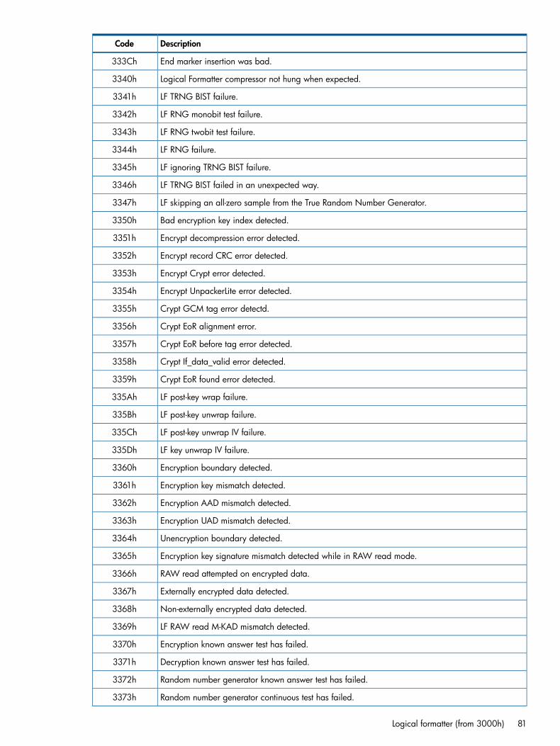
DescriptionCode
End marker insertion was bad.333Ch
Logical Formatter compressor not hung when expected.3340h
LF TRNG BIST failure.3341h
LF RNG monobit test failure.3342h
LF RNG twobit test failure.3343h
LF RNG failure.3344h
LF ignoring TRNG BIST failure.3345h
LF TRNG BIST failed in an unexpected way.3346h
LF skipping an all-zero sample from the True Random Number Generator.3347h
Bad encryption key index detected.3350h
Encrypt decompression error detected.3351h
Encrypt record CRC error detected.3352h
Encrypt Crypt error detected.3353h
Encrypt UnpackerLite error detected.3354h
Crypt GCM tag error detectd.3355h
Crypt EoR alignment error.3356h
Crypt EoR before tag error detected.3357h
Crypt If_data_valid error detected.3358h
Crypt EoR found error detected.3359h
LF post-key wrap failure.335Ah
LF post-key unwrap failure.335Bh
LF post-key unwrap IV failure.335Ch
LF key unwrap IV failure.335Dh
Encryption boundary detected.3360h
Encryption key mismatch detected.3361h
Encryption AAD mismatch detected.3362h
Encryption UAD mismatch detected.3363h
Unencryption boundary detected.3364h
Encryption key signature mismatch detected while in RAW read mode.3365h
RAW read attempted on encrypted data.3366h
Externally encrypted data detected.3367h
Non-externally encrypted data detected.3368h
LF RAW read M-KAD mismatch detected.3369h
Encryption known answer test has failed.3370h
Decryption known answer test has failed.3371h
Random number generator known answer test has failed.3372h
Random number generator continuous test has failed.3373h
Logical formatter (from 3000h) 81
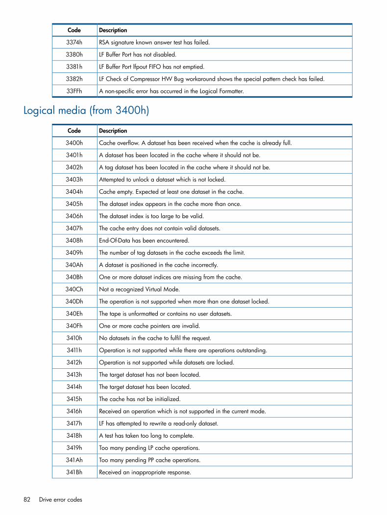
DescriptionCode
RSA signature known answer test has failed.3374h
LF Buffer Port has not disabled.3380h
LF Buffer Port lfpout FIFO has not emptied.3381h
LF Check of Compressor HW Bug workaround shows the special pattern check has failed.3382h
A non-specific error has occurred in the Logical Formatter.33FFh
Logical media (from 3400h)
DescriptionCode
Cache overflow. A dataset has been received when the cache is already full.3400h
A dataset has been located in the cache where it should not be.3401h
A tag dataset has been located in the cache where it should not be.3402h
Attempted to unlock a dataset which is not locked.3403h
Cache empty. Expected at least one dataset in the cache.3404h
The dataset index appears in the cache more than once.3405h
The dataset index is too large to be valid.3406h
The cache entry does not contain valid datasets.3407h
End-Of-Data has been encountered.3408h
The number of tag datasets in the cache exceeds the limit.3409h
A dataset is positioned in the cache incorrectly.340Ah
One or more dataset indices are missing from the cache.340Bh
Not a recognized Virtual Mode.340Ch
The operation is not supported when more than one dataset locked.340Dh
The tape is unformatted or contains no user datasets.340Eh
One or more cache pointers are invalid.340Fh
No datasets in the cache to fulfil the request.3410h
Operation is not supported while there are operations outstanding.3411h
Operation is not supported while datasets are locked.3412h
The target dataset has not been located.3413h
The target dataset has been located.3414h
The cache has not be initialized.3415h
Received an operation which is not supported in the current mode.3416h
LF has attempted to rewrite a read-only dataset.3417h
A test has taken too long to complete.3418h
Too many pending LP cache operations.3419h
Too many pending PP cache operations.341Ah
Received an inappropriate response.341Bh
82 Drive error codes

DescriptionCode
Linked-list ‘next’ pointer is invalid.341Ch
CRAM transfer started but not finished.341Dh
Allocated insufficient CRAM.341Eh
Dataset is available in LM but the drive is not positioned to append.341Fh
Datasets in LM, Flush WITH_EOD required before the current operation3420h
LM flushed but EOD is required before the current operation.3421h
The specified dataset type is not supported by the operation.3422h
The specified CRAM dataset type is not supported.3423h
LF has attempted an operation away from EOD that can only be performed at EOD.3424h
Search dataset available dataset number does not match the DSIT contents.3425h
LF has requested a dataset while LM is changing to backup mode.3426h
LM has received a PP space dataset with no access point.3427h
LM has received a previous PP space dataset with no access point.3428h
LM is generating an EOD dataset.3480h
Undefined error.37FFh
Logical pipeline control (from 3800h)
DescriptionError
No error. Synonymous with GOOD status.3800h
Aborted operation.3801h
Busy. An operation request was received while in a transient state.3802h
The value of a parameter received with a Logical Pipeline Control operation request falls outside itsvalid range.
3803h
Received an operation request while in a mode that does not allow that operation.3804h
Operation aborted because of a write-behind error.3805h
Logical Pipeline Control has detected an unexpected File Mark during a Space operation.3806h
A non-specific error has occurred in Logical Pipeline Control.3BFFh
Mechanism control (from 3C00h)
DescriptionError
No error.3C00h
Aborted command error.3C01h
Unsupported command error.3C02h
Bad parameter error.3C03h
Undefined data object error.3D01h
Wait for signal.3E01h
Object create failed.3E02h
Logical pipeline control (from 3800h) 83

DescriptionError
Object execute failed.3E03h
Cartridge memory LPOS values suspect.3E04h
Notify client list full.3E05h
Position notify list full.3E06h
Notify exists parameter different.3E07h
Notify event create failed.3E08h
Notify key map failed.3E09h
Notify index too large.3E0Ah
Too many MC command objects.3E0Bh
Cleaning cartridge expired.3E0Ch
Cannot determine, or do not recognize, the cartridge format.3E0Dh
Cleaning cartridge could not be threaded.3E0Eh
Too many MI command objects.3E0Fh
Listing command objects in queue.3E10h
C++ pure virtual function called.3FFEh
Undefined error.3FFFh
Non-volatile data manager (from 4000h)
DescriptionError
Invalid parameter.4002h
Data length exceeds table length.4003h
Not a valid EEPROM.4004h
Checksum error. A write to EEPROM failed because the EEPROM is invalid.4005h
Checksum read did not match the checksum written.4006h
An unsupported data type was requested from the Non-Volatile Data Manager.4007h
An unsupported data type was requested to be set in Non-Volatile Data Manager.4008h
PCA EEPROM missing.4011h
PCA EEPROM void.4012h
PCA EEPROM corrupt.4013h
PCA table invalid.4014h
A failure occurred while trying to update the Read ERT log in the PCA EEPROM.4015h
A failure occurred while trying to update the Write ERT log in the PCA EEPROM.4016h
A failure occurred while trying to update the Write Fault Counters log in the PCA EEPROM.4017h
A failure occurred while trying to update the Tapes Used logs in the PCA EEPROM.4018h
PCA Manufacturing Parameters Table is invalid.4019h
Head EEPROM absent.4021h
84 Drive error codes

DescriptionError
Head EEPROM void.4022h
Head EEPROM corrupt.4023h
Head/Flex Manufacturing Parameters table is invalid.4025h
Head Tuning Parameters table is invalid.4026h
Formatter Data Skew Parameters table is invalid.4028h
Mechanism EEPROM absent.4031h
Mechanism EEPROM void.4032h
Mechanism EEPROM corrupt.4033h
Mechanism table invalid.4034h
A failure occurred while trying to update the Drive Fault logs in the PCA EEPROM.4035h
An Algorithm error occurred while trying to update the Drive Fault Logs in the EEPROM.4036h
Mechanism table 3 invalid.4037h
Mechanism table 4 invalid.4038h
The Servo Fault could not be logged because of EEPROM access failure.4039h
nv_MECH_TABLE2 invalid.403Ah
nv_MECH_TABLE1 invalid.403Bh
CM EEPROM absent.4041h
CM EEPROM void.4042h
The CM could not be written before an unload causing probable corruption in the CM.4043h
An invalid protected page table was found.4044h
A CRC error was discovered over the unprotected page table.4045h
CM initialized. This is not really an error, it indicates a fresh cartridge.4046h
CM invalid CRC.4047h
An invalid CRC over the Cartridge Manufacturers Information page was found.4048h
An invalid CRC over the Media Manufacturers Information page was found.4049h
An invalid CRC over the Initialization Data page was found.404Ah
An initialization table was request to be created for a CM with a valid initialization table in it.404Bh
A failure occurred while trying to add a page descriptor to the unprotected page table.404Ch
An unprotected page table entry was attempted with an invalid page ID.404Dh
An invalid CRC over the Drive Manufacturers Support page was found.404Eh
An access to the tape directory was requested before it was read from the CM.4050h
A CRC error was detected in the tape directory while being read.4051h
Data for an illegal wrap section was requested from the tape directory.4052h
The Buffer Manager does not have enough CRAM to hold the CM.4053h
The write-protect operation was aborted because of a bogus initialization data address in CRAM.4054h
A consistency error was detected in the Tape Directory while being read.4055h
No more entries can be added to the Suspended Appends page.4056h
Non-volatile data manager (from 4000h) 85
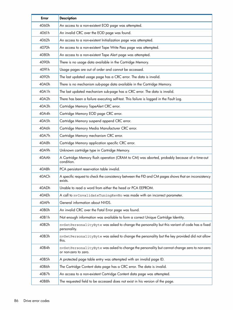
DescriptionError
An access to a non-existent EOD page was attempted.4060h
An invalid CRC over the EOD page was found.4061h
An access to a non-existent Initialization page was attempted.4062h
An access to a non-existent Tape Write Pass page was attempted.4070h
An access to a non-existent Tape Alert page was attempted.4080h
There is no usage data available in the Cartridge Memory.4090h
Usage pages are out of order and cannot be accessed.4091h
The last updated usage page has a CRC error. The data is invalid.4092h
There is no mechanism sub-page data available in the Cartridge Memory.40A0h
The last updated mechanism sub-page has a CRC error. The data is invalid.40A1h
There has been a failure executing self-test. This failure is logged in the Fault Log.40A2h
Cartridge Memory TapeAlert CRC error.40A3h
Cartridge Memory EOD page CRC error.40A4h
Cartridge Memory suspend append CRC error.40A5h
Cartridge Memory Media Manufacturer CRC error.40A6h
Cartridge Memory mechanism CRC error.40A7h
Cartridge Memory application specific CRC error.40A8h
Unknown cartridge type in Cartridge Memory.40A9h
A Cartridge Memory flush operation (CRAM to CM) was aborted, probably because of a time-outcondition.
40AAh
PCA persistant reservation table invalid.40ABh
A specific request to check the consistency between the FID and CM pages shows that an inconsistencyexists.
40ACh
Unable to read a word from either the head or PCA EEPROM.40ADh
A call to nvInvalidateTuningRevNo was made with an incorrect parameter.40AEh
General information about NVDS.40AFh
An invalid CRC over the Fatal Error page was found.40B0h
Not enough information was available to form a correct Unique Cartridge Identity.40B1h
nvSetPersonalityByte was asked to change the personality but this variant of code has a fixedpersonality.
40B2h
nvSetPersonalityByte was asked to change the personality but the key provided did not allowthis.
40B3h
nvSetPersonalityByte was asked to change the personality but cannot change zero to non-zeroor non-zero to zero.
40B4h
A protected page table entry was attempted with an invalid page ID.40B5h
The Cartridge Content data page has a CRC error. The data is invalid.40B6h
An access to a non-existent Cartridge Content data page was attempted.40B7h
The requested field to be accessed does not exist in his version of the page.40B8h
86 Drive error codes

DescriptionError
This product’s EEPROM configuration does not support the persistent storage for the Host Accesstable.
40B9h
The persistent storage area for the Host Access table has never been written to and is therefore notinitialized.
40BAh
The persistent storage area for the device ID has never been written to and is therefore not initialized.40BBh
The persistent storage area for the device ID only supports storage for 2 LUNs—more has beenrequested.
40BCh
A request to access an area of CM which is out of bounds has occurred. The access was disallowed.40BDh
Not enough information was available to form a correct Alternative Unique Cartridge Identity.40BEh
nvCMGetMechRelatedKAD() was asked to retrieve the KAD in the mechanism-related pages butnot KAD has been stored.
40BFh
The KAD length in the mechanism-related page which was asked to be stored or retrieved was toolarge.
40C0h
The mechanism-related page has not been created (or the tape not loaded) so storage or retrievalof the KAD data is not allowed.
40C1h
A request to access na STTF log idex was outside the permitted range.40C2h
The EEPROM does not contain previously saved snapshot event configuration data.40C3h
An access to a non-existent Suspended Append page was attempted.40C4h
An access to a non-existent Fatal Error page was attempted.40C5h
An access to a non-existent Mechanism Specific page was attempted.40C6h
An access to a non-existent Fatal Error page was attempted.40C7h
The Mechanism Specific page has a CRC error. The data is invalid.40C8h
nvCMGetMechSpecificKAD() was asked to retrieve the KAD in the Mechanism Specific pagebut no KAD has been stored.
40C9h
The Mechanism Specific page has not been created (or tape not loaded,) so storage or retrieval ofthe KAD data is not allowed now.
40CAh
The Certificate Storage table does not have an entry for the security parameter requested (in otherwords, it is not stored in the table).
40CBh
The Certificate Storage table does not have a free slot to place the security parameter into.40CCh
An unknown security parameter was asked for.40CDh
The security parameter to be stored is too large to fit in the table.40CEh
This security parameter is not allowed to be cleared.40CFh
The Initialization check of the security table showed a bad CRC on the directory entries. The wholetable must be cleared and rebuilt.
40D0h
Mechanism table 8 is invalid.40D1h
The security parameter was encrypted, but the encrypted record size is too large for storage.40D2h
The KMS security parameter to be stored is too large to fit in the table.40D3h
The PCA2 EEPROM is not supported on this platform.40D4h
An unknown KMS security parameter was asked for.40D5h
The KMS security parameter was encrypted, however the encrypted record size ends up being toolarge for storage
40D6h
Non-volatile data manager (from 4000h) 87

DescriptionError
The Initialization check of the KMS security table showed a bad CRC on the directory entries. Thewhole table must be cleared and rebuilt.
40D7h
The KMS Security table does not have an entry for the KMS security parameter requested (tha is, itis not stored in the table).
40D8h
The Secure EEPROM storage will only allow encryption of field sizes divisible by 16, such as 16,32, 48 and so on.
40D9h
A Decrypt/encrypt operation has been attempted when the OTP Public key is empty.40DAh
The check of the Drives RSA Key Pair failed.40DBh
A multi-partition type of operation was requested but the cartridge has only been formatted as asingle partition cartridge. The operation is invalid.
40DCh
The transponder serial number check byte does not agree with the transponder serial number.40DDh
The reported LTO CM Mfr Info CM size is not valid.40DEh
The transponder type is not valid.40DFh
Operation requested a partition number not supported for this cartridge type.40E0h
Access to a non-existent application-specific page was attempted.40E1h
An attempt to read or write to the CM failed, however the drive status indicates that no tape wasloaded, so this may be a spurious issue
40E2h
Insert into the tape roller usage log came across an unknown licencee. No data has been insertedinto the table.
40E4h
The Encryption parameter to be stored is too large to fit in the allowed space.40E5h
The POST test to check the Mech pairing with the PCA has shown that the EEPROM has not beenpaired or has been tampered with.
40E6h
The POST test to check the Head/Flex pairing with the PCA has shown that the EEPROM has notbeen paired or has been tampered with.
40E7h
Operating system (from 4400h)
DescriptionError
‘vGiveSem’ failed to signal a semaphore.4400h
Physical formatter (from 4C00h)
DescriptionError
C1 has finished before C2 is ready for the dataset.4C00h
The physical formatter has been sent an invalid configuration name.4C01h
The physical formatter has been sent an invalid configuration value4C02h
C2 hardware is busy. The physical formatter C2 hardware is currently processing a dataset.4C03h
The physical formatter C2 control DS0 register go bit is set.4C04h
The physical formatter C2 control DS1 register go bit is set.4C05h
The physical formatter C1 control register go bit is set.4C06h
The physical formatter CCQ Reader control register go bit is set.4C07h
The physical formatter Read Chain Controller control register go bit is set4C08h
88 Drive error codes

DescriptionError
The physical formatter has been asked for the error rate log for a channel which does not exist4C09h
The physical formatter has been asked for the error rate logs for a channel which does not exist.4C0Ah
The physical formatter could not set the callback timer to enable the Hyperion read gate.4C0Bh
The physical formatter Read Chain Controller DS0 is stuck.4C0Ch
The physical formatter Read Chain Controller DS1 is stuck.4C0Dh
Physical formatter WP update.4C0Eh
Format other than LTO1 or LTO2.4C0Fh
SDRAM error has been detected.4C10h
The number of CCPs presented has fallen below the warning threshold.4C11h
A CCP has been overwritten.4C12h
A C2 error has been reported.4C13h
General physical formatter information.4C14h
Unexpected format complete signal arrived.4C15h
Check CCQ Write Rewrite log: param 1 = CCQSetsWritten, param2 = CCQSetRewrites, param3 = pfStatus.
4C16h
Number of CCPS have rolled over causing a reset of the Write Error Rate log.4C17h
Number of CCPS have rolled over causing a reset of the Read Error Rate log.4C18h
Physical pipeline control (from 5000h)
DescriptionError
EOD not found.5000h
Black tape.5001h
EOD encountered.5002h
Undefined error.5003h
The start LPOS of the dataset is before the LPOS of the previous dataset.5004h
The start LPOS is more than 1 metre after the previous dataset.5005h
Invalid configuration has been requested.5008h
Abort reject continue not used.5009h
Search in progress.501Eh
Mechanism command time-out; the control command never responded.501Fh
Command not allowed in this variant.5020h
Invalid tape type.5080h
The Error Rate Test has been aborted.5081h
PF reported a write error (excessive RWWs).5083h
PF reported a read error (C2).5084h
PF reported a streamfail.5086h
The error-rate test reached the C1 threshold.5087h
Physical pipeline control (from 5000h) 89

DescriptionError
Unknown notification. An unexpected mechanism control.5088h
Data miscompare.5089h
The drive has gone 4 metres since last dataset was reported.508Ah
The speed requested for ERT s out of valid range.508Bh
The notify for 4m give-up point is missing.508Ch
EOT was reached before requested datasets were written.508Dh
Start position requested for ERT s out of valid range508Eh
Cannot find the expected dataset number508Fh
Blank check. Could not read anything off the tape in the last 4 metres.5090h
Too many datasets returned while flushing.5091h
Could not find the target during a space operation.5092h
Could not find the target ACN during a search operation.5093h
Write Pass on write has been corrupted.5094h
ERT read more datasets than expected.5095h
Logical Media has supplied an invalid dataset index.5096h
Dataset written before BOW.5097h
EOT reached during reading.5098h
Warning: Dataset flags non-zero.5099h
EOD has been read, but is not the one in the Cartridge Memory.509Ah
The dataset that has been read should not be on this wrap.509Bh
The SPACE command is to a logical position that is beyond EOD.509Ch
The current cartridge cannot be written to —Write ERT is not allowed.509Dh
The dataset that was reported as C2 uncorrectable is considered good.509Eh
The DSIT contains an invalid UCI.509Fh
The drive has determined that the WORM data may have been tampered with.50A0h
The logical media has given a illegal dataset index for an append.50A1h
A search operation appears to have found the target too early.50A2h
An LTO-5 dataset was encountered whose encryption algorithm ID was not 01h.50A3h
The value of TapeWritePassValue CurrentWrap and SDL sheet has been set.50A4h
Shows the value that the Max ATS has been set.50A5h
An error code of 7501h (Loss of LPOS) has been detected, causing a reduction in the servo MR bias.50A6h
A RampToSpeedRsp signal has arrived while trying to abort.50A7h
Excessive offtracks have been seen on a Fuji tape.50A8h
The drive tried to perform an ERT whilst the tape was not threaded.50A9h
The firmware may have followed a path in which the formatter was not aborted before a re-write.50AAh
The firmware has managed to write a dataset that finishes past EOW.50ABh
An LTO-5 dataset was encountered whose Encryption Algorithm ID was not 02h.50ACh
90 Drive error codes

DescriptionError
A call to an NVDS function returned with an unexpected error.50ADh
An LTO6 dataset was encountered whose Encryption Algorithm Id was not 0x03.50AEh
A dataset was started over 4M away from EOW but reached 4M giveup within 450 mm of EOW.50AFh
Physical side error recovery (from 5400h)
DescriptionError
Not an error—just requests a trace log bank switch.5400h
Shows the LPOS and MM position for the start of tuning.5401h
Read/write control (from 5800h)
DescriptionError
Success.5800h
Null point.5801h
Invalid parameter.5802h
No hardware.5803h
SPI transfer error.5804h
Prometheus set error.5805h
Hyperion set error.5806h
Daughter set error.5807h
Calibration did not complete.5808h
Servo bias status false.5809h
Wrong number of parameters.5810h
Could not set Prometheus 0 to default values.5820h
Could not set Prometheus 1 to default values.5821h
Could not set Prometheus 2 to default values.5822h
Could not set Prometheus 3 to default values.5823h
A valid Mod level was not received from the PCA EEPROM.5824h
Could not set Prometheus 4 to default values.5825h
A failure was detected during a Write Element Resistance test for Artemis.5826h
A failure was detected during a Read Element Resistance test for Apollo.5827h
Artemis did not achieve PLL lock. Parameter 1 is Artemis (0=BumpA, 1=BumpB, FFh=No Artemiswas specified). Parameter 2 is value of the Artemis PLL register.
5828h
Did not achieve PLL lock.5829h
Could not set Hyperion 0 to default values.5830h
Could not set Hyperion 1 to default values.5831h
Could not initialize the Diagnostic Data rwInitDiagnosticData.5840h
Did not get either INTODRIVE or INTOCARTRIDGE.5841h
Physical side error recovery (from 5400h) 91

DescriptionError
Delilah failed to autocalibrate.5850h
Gideon failed to autocalibrate: param1 = GideonRegisters, param2 = RegisterValue, param3 =nothing.
5851h
Gideon HyperTransport PLL failed to come out of reset: param1 = GideonRegisters, param2 =RegisterValue, param3 = nothing.
5852h
HyperTransport sync failure: param1 = bus, param2 = count, param3 = type.5853h
HyperTransport parity failure: param1 = bus, param2 = count, param3 = type.5854h
HyperTransport unexpected parity state at power-on: param1 = HT Parity Error, param2 = HT ParityError count 0, param3 = HT Parity Error count 1.
5855h
A valid Blo Dac Gideon Register setting could not be determined in the manual calibration mode.5856h
The Mech Interface firmware returned a failure to RWC firmware when requested to set an ATS clockfrequency for Gideon calibration.
5857h
The Random Bit Sequence generator failed to collect the required samples in the allowed time.5858h
A valid Blo Dac Gideon register setting could not be determined in the manual calibration mode,retrying the Gideon offset calibration.
5859h
HT_ALIGN_FAILED HT_CONTROL bits 30:28 not set to 1.585Ah
HT_IN_UNEXPECTED_STATE HT reg is not as expected should be enabled.585Bh
T_TURNING_OFF_PARITY_CHECKING Stop checking HT parity otherwise the FW will eventuallylock up.
585Ch
HT_PARITY_ERROR_THRESHOLD_EXCEEDED Have had too many HT parity errors.585Dh
Expected a compatible data tape but got something else.5860h
An invalid control word was found while parsing the Cal table to program a ASIC. Param 1 = controlword, Param 2 = an integer value unique to each ASIC.
5861h
Could not write to Amundsen’s WEQ Control register.5870h
Illegal WEQ setup requested.5871h
The EEPROM calibration table area contains at least one invalid entry.5880h
The Per Drive Cal table in the EEPROM contains one invalid entry.5881h
The Per Drive Cal table in the EEPROM contains a revision number that is less than the revisionnumber found in the base Cal table.
5882h
rwc_estimate_boost.5890h
rwc_adjust_boost.5891h
rwc_boost_datasets.5892h
A request to reset the Afirs on the channel, Parameter1, was made to the RWC.5893h
The drive will read using the alternate, or secondary, or writing, bump.5894h
The drive will return to using the primary bump for reading.5895h
The Write ERT operation executed as part of the FFIR calibration during load failed to completeenough datasets.
58A0h
A channel ERT result has indicated that an FFIR tuning pass is required.58A1h
An FFIR calibration attempt at Load has failed. Bad status was returned from the ERT operation.58A2h
rwc_VIWP_TEMP_FAULT_ENTRY_A58AAh
rwc_VIWP_TEMP_FAULT_ENTRY_B58ABh
92 Drive error codes

DescriptionError
rwc_VIWP_TEMP_FAULT_ENTRY_C58ACh
rwc_VIWP_VALUES58BAh
rwc_VIWP_TEMP_CALCULATED_A58BBh
rwc_VIWP_TEMP_CALCULATED_B58BCh
rwc_RMATCH_VALUES58CAh
rwc_MC_ADAPTION_CHANNEL_RESULT58DAh
Setup Servo.58F0h
SMUX.58F1h
BEN.58F2h
Undefined error.58FFh
System architecture (from 6400h)
DescriptionError
Formatter ASIC revision check failed. The ASIC is not a LTO 1 Formatter ASIC.6401h
The processor idle time is less than 30%.6402h
Tight integ (from 6800h)
DescriptionError
The Cmicro error handler function has been called (cm_ErrorHandler).6801h
An implicit signal consumption has occurred.6802h
No free SDL timer storage (in SDLTimerFreeList) to set new timer — increase MAX_SDL_TIMERSin TightInteg/cmTmr.c.
6803h
Trace logger (from 6C00h)
DescriptionError
TraceLogger initialization failed. BMM returned no good.6C00h
The last Live Trace entry has been reached. Not an error.6C01h
The drive has insufficient resources to set more Live Traces.6C02h
A flush has started and the initiator must wait to receive the SDL signal diTraceLogFlushed.6C03h
An operation has started but the caller must wait for the callback function to be executed.6C04h
The TraceLogging SysARM HW Flush All blocking function timed out.6C05h
The TraceLogging ServoARM HW Flush Trace channel blocking function timed out.6C06h
System architecture (from 6400h) 93

Mechanical interface (from 7400h)
DescriptionError
No error.7400h
Aborted command.7401h
Unsupported command.7402h
Wrong number of parameters.7403h
Invalid parameter.7404h
This command is already in progress.7405h
This command is not allowed now.7406h
Command processing error.7407h
A DSP event has occurred (most likely an off-track event unless the default was changed).7408h
The command is obsolete.7409h
Incomplete initialization of the mechanism740Ah
There was a timing fault in the servo interrupt.740Bh
The mechanism type (SensorRev) specified in the mechanism EEPROM is either obsolete orunsupported.
740Ch
Obsolete command 300C.740Dh
Obsolete command 300D.740Eh
Invalid task. The current task for the servo system is of an unknown type. This is most likely causedby a firmware bug.
740Fh
A Load command is not allowed at this time.7410h
An Unload command is not allowed at this time.7411h
A shuttle tape command cannot be executed at this time.7412h
A Set Cartridge Type command cannot be executed at this time.7413h
A Set Mechanism Type command cannot be executed at this time.7414h
A Set Tension command cannot be executed at this time.7415h
A Set Speed command cannot be executed at this time.7416h
An Adjust Speed command cannot be executed at this time.7417h
A Set Position command cannot be executed at this time.7418h
The Cancel Set Position command cannot be executed at this time. Most likely because there is noprevious set position command active.
7419h
A Set Position and Speed command cannot be executed at this time.741Ah
A Servo Calibration command cannot be executed at this time.741Bh
An End of Tape Servo Calibration command cannot be executed at this time.741Ch
A Servo Initialization command cannot be executed at this time.741Dh
A Load Cartridge command cannot be executed at this time.741Eh
A Grab Leader Pin command cannot be executed at this time.741Fh
A Load and Grab leader pin command cannot be executed at this time.7420h
94 Drive error codes

DescriptionError
An Ungrab Leader Pin command cannot be executed at this time.7421h
An Unload cartridge command cannot be executed at this time.7422h
A Thread command cannot be executed at this time.7423h
An Unthread command cannot be executed at this time.7424h
A Recover Tape command cannot be executed at this time.7425h
A Head Clean command cannot be executed at this time.7426h
A Power-on Calibration command cannot be executed at this time.7427h
A Set Notify command cannot be executed at this time.7428h
A Wait Until Event command cannot be executed at this time, probably because the tape is notmoving.
7429h
A Set Head Position command cannot be executed at this time, probably because a servo calibrationis in progress.
742Ah
A Set Tracking Offset command cannot be executed at this time, probably because a servo calibrationis in progress.
742Bh
A DSP command to learn the VI offset is not allowed now because the tape is moving or anothertask is in progress.
742Ch
The Set Gen command is not allowed now. The format cannot be changed at this time.742Dh
A Forced Eject command is not allowed at this time. Most likely another operation is in progress.742Eh
The command to try to unstick the tape from the head cannot be executed at this time.742Fh
Sensors are in a state that indicate that the sensors or Callisto is not working correctly.7430h
Sensors are in a state that indicate that the sensors or Callisto is not working correctly on a load.7431h
Sensors are in a state that indicate that the sensors or Callisto is not working correctly on a grab.7432h
Sensors are in a state that indicate that the sensors or Callisto is not working correctly on an ungrab.7433h
Sensors are in a state that indicate that the sensors or Callisto is not working correctly on an unload.7434h
The RD sensor has stopped toggling, probably because the loader mechanism is blocked or themotor is not working.
7435h
It is unsafe to load the cartridge. A runaway condition of the FRM has been detected, probablybecause the tape is broken.
7436h
Unexpected LP on a grab. One (and only one) of the LP sensors has been asserted at the beginningof the grab.
7437h
Unexpected LP at the start of a grab. One (and only one) of the LP sensors has been asserted at thebeginning of the grab. This is logged but not a failure.
7438h
The write protect sensor does not match the expected state.7439h
The Cartridge Present sensor does not match the expected state.743Ah
Rotate reel command can not be executed at this time.743Bh
Measure Kt command can not be executed at this time.743Ch
The fault line on the FRM driver asserted while the reel was rotating.743Dh
The fault line on the BRM driver asserted while the reel was rotating.743Eh
Set Speed command cannot be executed because the tape is snapped.7441h
Set Speed command cannot be executed because the tape is unthreaded.7442h
Mechanical interface (from 7400h) 95

DescriptionError
Set Position command cannot be executed because the tape is snapped.7443h
Set Position command cannot be executed because the tape is unthreaded.7444h
Set Position and Speed command cannot be executed because the tape is snapped.7445h
Set Position and Speed command cannot be executed because the tape is unthreaded.7446h
Adjust Speed command cannot be executed because the tape is snapped.7447h
Adjust Speed command cannot be executed because the tape is unthreaded.7448h
Servo Cal command cannot be executed because the tape is snapped.7449h
Servo Cal command cannot be executed because the tape is unthreaded.744Ah
Callisto Bus test error.7440h
In transit after initialization—no cartridge present.744Fh
In transit after initialization.7450h
Ungrab after initialization.7451h
Unknown after initialization.7452h
Timed out waiting to send a command to get DSP head-cleaning information.7453h
Timed out waiting for DSP response with head-cleaning information.7454h
Timed out waiting to set up DSP for a head-cleaning command.7455h
Timed out waiting for DSP response to head-cleaning setup.7456h
Timed out waiting for DSP to complete the head-cleaning command.7457h
Head-cleaning engagement time-out.7458h
Head-cleaning parking time-out.7459h
Head-cleaning cycling time-out.745Ah
The state of the sensor read at initialization are illegal. The results make no sense.745Bh
Timed out waiting to restore DSP after a head-cleaning command.745Ch
Timed out waiting for DSP during post-head-cleaning restoration.745Dh
Unable to send DSP compensator coefficients.745Fh
DSP download error.7460h
Invalid DSP opcode error.7461h
Unable to send a DSP command.7462h
Unable to send a DSP seek command.7463h
DSP failed to complete a seek command.7464h
Send long-term DSP command time-out.7465h
Send short-term DSP command time-out.7466h
DSP long-term command protocol error.7467h
DSP short-term command protocol error.7468h
Too many parameters on DSP Long-term command.7469h
Too many parameters on DSP Short-term command.746Ah
Too many results on DSP Long-term command.746Bh
96 Drive error codes

DescriptionError
Too many results on DSP Short-term command.746Ch
Long-term DSP command already in progress.746Dh
Short-term DSP command already in progress.746Eh
Long-term DSP command completed but not in progress.746Fh
Short-term DSP command completed but not in progress.7470h
Unable to send a DSP Learn VI offset command.7471h
DSP failed to complete a Learn VI offset.7472h
Unable to send a DSP Calibrate VI command.7473h
DSP failed to complete a Calibrate VI command.7474h
Too many data points requested.7475h
No scope data available from DSP7476h
DSP failed to complete the command during the initialization process.7477h
Unable to send DSP tuning parameters.7478h
DSP failed to boot properly.7479h
Time-out on sending the Clear DSP Fault log.747Ah
Time-out on completing the Clear DSP Fault log.747Bh
Unable to send DSP Head Clean command.747Ch
An abort command was requested while one is already in progress.747Dh
An abort command has timed-out while waiting for the tape to stop.747Eh
An Adjust Speed command was requested while one is already in progress.747Fh
General load failure.7480h
EP sensor did not transition on a load, probably because no cartridge was present.7481h
CD sensor did not transition on a load.7482h
CG sensor did not transition on a grab.7483h
LP sensor did not transition on a grab.7484h
Too many retries to recover on a load or unload.7485h
Cartridge not free to rotate when Cartridge Down.7486h
The RD sensor stopped toggling while EP during a load.7487h
The RD sensor stopped toggling while IT during a load.7488h
The RD sensor stopped toggling while CD during a load.7489h
The RD sensor stopped toggling while CD during a grab.748Ah
The RD sensor stopped toggling while LP during a grab.748Bh
Invoked tension ramp retry.748Ch
FRM runaway. Too much rotation was detected in the cartridge before it was threaded.748Dh
A grab was requested but the cartridge was not loaded.748Eh
Sensors indicate that the grabber unexpectedly moved into a grab position during a load operation.748Fh
While parking the LP, the LM voltage was increased from 0.25V to 0.5V.7490h
Mechanical interface (from 7400h) 97

DescriptionError
While parking the LP, the LM voltage was increased from 0.5V to 0.75V.7491h
While parking the LP, the LM voltage was increased from 0.75V to 1.0V.7492h
While threading, the LM voltage was increased from 0.25V to 0.5V.7493h
While threading, the LM voltage was increased from 0.5V to 0.75V.7494h
While threading, the LM voltage was increased from 0.75V to 1.0V.7495h
Load command failed and no CM was detected, therefore it is likely there is no cartridge present.749Ah
General unload failure.74A0h
EP sensor did not transition while unloading.74A1h
CD sensor did not transition while unloading.74A2h
CG sensor did not transition while ungrabbing74A3h
LP sensor did not transition while ungrabbing74A4h
RD sensor stopped toggling while CG during ungrab.74A6h
RD sensor stopped toggling while LP during ungrab.74A7h
RD sensor stopped toggling while CD during ungrab.74A8h
RD sensor stopped toggling while CD during unload.74A9h
RD sensor stopped toggling while IT during unload.74AAh
Too much rotation of the cartridge was detected while the tape was not threaded.74ACh
The load, unload, grab or ungrab operation timed out.74ADh
Time-out while deslacking the cartridge.74C0h
Emergency stop error.74C1h
Already past target position.74C2h
Set speed time-out error.74C3h
Time-out waiting for an LPOS.74C4h
Reels not synchronized.74C5h
Safety limit stop reached.74C6h
LPOS calculation with invalid LP0.74C7h
Missed target position.74C8h
Previous tape motion command in progress.74C9h
Set Speed timeout error.74CAh
Unthreading time-out error.74CBh
Remove slack process timed-out.74CCh
Leader may have disconnected.74CDh
Time-out waiting for radii estimate.74CEh
Radii estimation process failed.74CFh
Recover tape time-out error.74D0h
Invalid cartridge type.74D1h
Cal reel driver offset time-out.74D2h
98 Drive error codes

DescriptionError
Time-out waiting for the specified event.74D3h
Front-reel motor hall sensor fault.74D4h
Back-reel motor hall sensor fault.74D5h
The deslacking process timed out and did not complete, probably because the back reel motor failedto rotate.
74D6h
Threading time out while waiting for half moon to pass the first roller.74D7h
Timed out waiting for tape to reach position for speed-up during a thread.74D8h
Time out while waiting for tape to reach the position to stop threading.74D9h
An unthread command was issued and aborted a tape motion operation that was already in progress.74DAh
The cartridge type has not been specified either from LTO-CM or through a serial port command.74DBh
The tape speed reported by the DSP is significantly different from the tape speed indicated by thehall sensors.
74DCh
Specified value of tension is either too high or too low.74DDh
The panic stop process timed out and did not complete properly.74DEh
Timed-out waiting for the proper tape tension to be established.74DFh
Head selection time-out.74E0h
Unable to position the head.74E1h
Speed too low for enabling the heads.74E2h
Speed too low for the head servo.74E3h
Speed too low for sensor calibration.74E4h
A DSP seek command was attempted while the tape speed was zero.74E5h
DSP sensor calibration command was attempted while the tape speed was zero.74E6h
The speed is too low to attempt a VI offset command in recover tape. Most likely the tape is stuck tothe head.
74E7h
First write fault.7500h
Write fault: it has been too long since a valid LPOS was read, so writing is not allowed.7501h
Write fault: DSP tracking recovery operations are in progress so writing is not allowed.7502h
Write fault: tape motion start-up operations are incomplete so writing is not allowed.7503h
Write fault: DSP is not tracking properly on the tape, writing is not allowed.7504h
Write fault: the current tape speed is too low so writing is not allowed.7505h
Write fault: ATS clock frequency clipped, or DSP in idle mode.7508h
Write fault: DSP calibrating.7509h
Write fault: DSP VI track follow.750Ah
Write fault: DSP tape off-track.750Bh
Write fault: DSP demod channel out.750Ch
Write fault: DSP seek.750Dh
Write fault: DSP uPVI.750Eh
Write fault: write unsafe.750Fh
Mechanical interface (from 7400h) 99

DescriptionError
Unknown write fault.7510h
Multiple write faults.7511h
Last write fault.7512h
Write is not allowed; a power-on or reset occurred.7513h
Write is not allowed; a micro-jog is being applied.7514h
Write fault last.7515h
Write is not allowed; 12V power has been lost.7516h
Write fault last.7517h
Write cannot recommence while still offtrack.75BBh
Set Speed command invalid parameter.7600h
Adjust Speed command invalid parameter.7601h
Set Position command invalid parameter.7602h
Set Head Position command invalid parameter.7603h
Set Head Table command invalid parameter.7604h
DSP Statistics command invalid parameter.7605h
Get Servo Fault command invalid parameter.7606h
Set Tracking Offset command invalid parameter.7607h
Set Notify command invalid parameter.7608h
Clear Notify command null handle.7609h
ATS Diagnostics command invalid parameter.760Ah
Hall Calibrate command invalid parameter.760Bh
Radius Calibrate command invalid parameter.760Ch
Wait Until Event command invalid parameter.760Dh
Convert LPOS command invalid parameter.760Eh
Shuttle command invalid parameter.760Fh
Get DSP fault log invalid parameter.7610h
Set General Command Invalid parameter.7611h
Set TestMode command parameter is out of range or is invalid.7612h
EEPROM servo table command parameter is out of range or is invalid.7613h
Rotate command — invalid parameter.7614h
Measure Kt command — invalid parameter.7615h
Sleep Recursion fault in MechInterface.7616h
Set speed operation timed out during a recover tape command.7620h
Timed out waiting for the pin sensors to indicate almost parked.7621h
Timed out waiting for the pin sensors to indicate fully parked.7622h
An unthread timed out waiting for the full leader pin seating tension to be established.7623h
Cycling the pull-in tension did not achieve pin-park.7624h
100 Drive error codes

DescriptionError
Rethreading and then unthreading again did not get the leader pin parked.7625h
Timed out during the rethread/re-unthread recovery while waiting for almost parked.7626h
All recovery algorithms have been exhausted and still unable to park leader pin.7627h
Rethread recovery operation timed out waiting for the tape to come to a stop.7628h
Rethreading timed out while waiting for the tape to reach the required position.7629h
Deslacking process did not complete., probably because the back reel motor failed to rotate.762Ah
The leader pin was parked as indicated by both LP sensors but then came unparked.762Bh
The tape has been recovered and leader pin parked but the original operation failed and wasabandoned.
762Ch
Rethreading timed out while waiting for the tape to reach the required position.762Dh
Rethread recovery operation timed out waiting for the tape to come to a stop.762Eh
A special unthreading recovery operation was needed to un-jam the leader block.762Fh
An iteration of the special unthreading recovery operation did not succeed.7630h
The stop tape operation took longer than expected.7631h
An attempt was made to stop the tape while still too far away from the specified position.7632h
An abort command was issued and stopped the tape motion operation that was already in progress.7633h
The tape thickness is too great to be handled properly by the servo system.7634h
An ATS speed change operation (AdjustSpeed) timed out waiting for tape to reach target speed.7635h
An ATS speed change operation (AdjustSpeed) was attempted while the tape was not moving.7636h
While trying to park the pin, LP2 was seen, but LP1 was not seen after rotating the grabber CCW.7637h
Threading timed out while waiting for the half moon to seat onto the back reel.7638h
Tape motion apparently stopped while waiting for head positioning to complete.7639h
Unthread timed out during the initial rewind of tape back into the cartridge.763Ah
Timed out during an operation to set tape position and speed.763Bh
Timed out during an operation to set the tape position.763Ch
Timed out during a RecoverTape operation.763Dh
The front reel did not rotate during the tape slack removal process.763Eh
Timed out waiting for back reel to reach position where leader block is fully seated.763Fh
Timed out waiting for back reel to rotate to the threading reversal point.7640h
Timed out waiting for back reel to rotate to the reverse threaded position.7641h
Timed out waiting for tension to be established during the reverse threading process.7642h
Timed out waiting for the reverse threading target position.7643h
Timed out waiting for leader block to detach during an unthread.7644h
Timed out waiting for tension to be established during the reverse unthreading process.7645h
Timed out waiting for speed to be established during the reverse unthreading process.7646h
A fatal reel fault occurred during the time when the tape was being stopped.7647h
Back reel stalled and was not rotating when determining thread direction.7648h
Mechanical interface (from 7400h) 101

DescriptionError
An operation that determines thread direction timed out.7649h
Warning: Tape speed error integrator value is very large.764Ah
Timed out waiting for back reel to rotate to the unthreading reversal point.764Bh
Timed out waiting for tape to reach unthreading reversal slow down point.764Ch
Timed out waiting for tape to reach unthreading turn around point.764Dh
Front reel turning CCW but should be CW after going through critical point during recover tapeprocess.
764Eh
Tape motion unexpectedly stopped during recover tape process of rewinding based on radiusestimate.
764Fh
Unable to detach leader block during recover tape operation when reverse threaded.7650h
Unable to detach leader block during recover tape operation when forward threaded.7651h
Unable to identify cartridge type during recover-tape operation.7652h
The tape thickness reported by the Cartridge Memory is too large or too small.7653h
The tape thickness reported by the CM is invalid and cannot be used.7654h
The full pack radius reported by the CM appears to be invalid and will not be used.7655h
The tape length reported by the CM appears to be invalid and will not be used.7656h
The empty reel inertia reported by the CM appears to be invalid and will not be used.7657h
The empty reel radius reported by the CM appears to be invalid and will not be used.7658h
The front reel is not rotating properly. It is possible that some tape was spilled out from the back reel.7659h
Recovery process was unable to determine the best direction in which to move the tape.765Ah
Front reel did not reverse direction after passing through the critical region for threading reversal.765Bh
Back reel did not stop as expected during a tape recovery process.765Ch
Warning: Leader block demate process resorted to pushing the back reel clockwise.765Dh
Rethreading position time-out during the leader block demate retry process.765Eh
Leader block demate retry process was unsuccessful.765Fh
It was necessary to tug the tape to detach the leader block.7660h
Timed out waiting for the required number of layers to overwrap the leader block.7661h
Timed out waiting for the tape to unwrap from the leader block during a reverse thread.7662h
Timed out waiting for a return to the original lock-in position during a reverse thread.7663h
DSP tuning parameters were reloaded into the DSP before a VI-sensor calibration command. This isa recovery algorithm.
7664h
A special test mode has been enabled that will generate specific faults.7665h
The special test mode has now been disabled. Normal operation will resume.7666h
The front reel is not running in the reverse direction after the tension ramp after passing through thecritical region during a thread.
7667h
The front reel did not reverse direction after passing through the critical region during an unthread,step 1.
7668h
The front reel did not reverse direction after passing through the critical region during an unthread,step 2.
7669h
102 Drive error codes
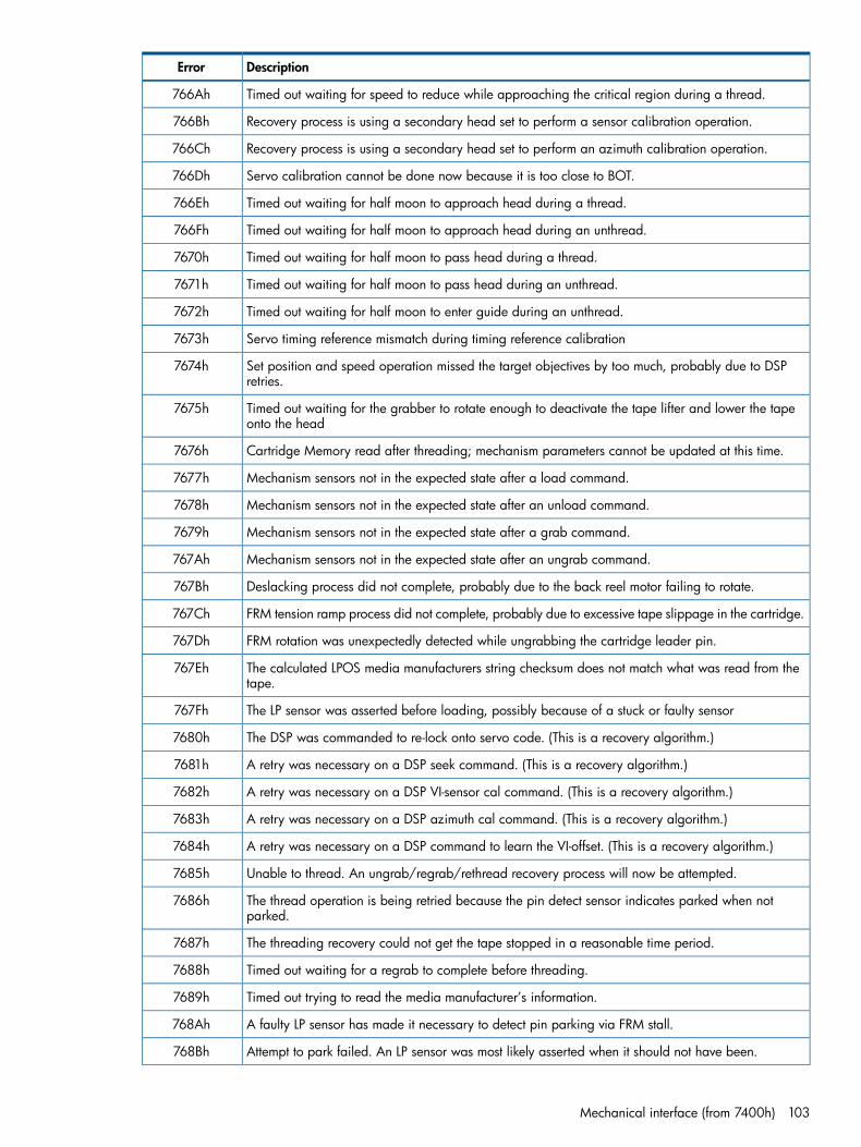
DescriptionError
Timed out waiting for speed to reduce while approaching the critical region during a thread.766Ah
Recovery process is using a secondary head set to perform a sensor calibration operation.766Bh
Recovery process is using a secondary head set to perform an azimuth calibration operation.766Ch
Servo calibration cannot be done now because it is too close to BOT.766Dh
Timed out waiting for half moon to approach head during a thread.766Eh
Timed out waiting for half moon to approach head during an unthread.766Fh
Timed out waiting for half moon to pass head during a thread.7670h
Timed out waiting for half moon to pass head during an unthread.7671h
Timed out waiting for half moon to enter guide during an unthread.7672h
Servo timing reference mismatch during timing reference calibration7673h
Set position and speed operation missed the target objectives by too much, probably due to DSPretries.
7674h
Timed out waiting for the grabber to rotate enough to deactivate the tape lifter and lower the tapeonto the head
7675h
Cartridge Memory read after threading; mechanism parameters cannot be updated at this time.7676h
Mechanism sensors not in the expected state after a load command.7677h
Mechanism sensors not in the expected state after an unload command.7678h
Mechanism sensors not in the expected state after a grab command.7679h
Mechanism sensors not in the expected state after an ungrab command.767Ah
Deslacking process did not complete, probably due to the back reel motor failing to rotate.767Bh
FRM tension ramp process did not complete, probably due to excessive tape slippage in the cartridge.767Ch
FRM rotation was unexpectedly detected while ungrabbing the cartridge leader pin.767Dh
The calculated LPOS media manufacturers string checksum does not match what was read from thetape.
767Eh
The LP sensor was asserted before loading, possibly because of a stuck or faulty sensor767Fh
The DSP was commanded to re-lock onto servo code. (This is a recovery algorithm.)7680h
A retry was necessary on a DSP seek command. (This is a recovery algorithm.)7681h
A retry was necessary on a DSP VI-sensor cal command. (This is a recovery algorithm.)7682h
A retry was necessary on a DSP azimuth cal command. (This is a recovery algorithm.)7683h
A retry was necessary on a DSP command to learn the VI-offset. (This is a recovery algorithm.)7684h
Unable to thread. An ungrab/regrab/rethread recovery process will now be attempted.7685h
The thread operation is being retried because the pin detect sensor indicates parked when notparked.
7686h
The threading recovery could not get the tape stopped in a reasonable time period.7687h
Timed out waiting for a regrab to complete before threading.7688h
Timed out trying to read the media manufacturer’s information.7689h
A faulty LP sensor has made it necessary to detect pin parking via FRM stall.768Ah
Attempt to park failed. An LP sensor was most likely asserted when it should not have been.768Bh
Mechanical interface (from 7400h) 103

DescriptionError
A VI cal was necessary to recover a DSP seek command failure. (This is a recovery algorithm.)768Ch
The FRM driver required a reset and was restarted. This is not a fault.768Dh
The BRM Driver required a reset and was restarted. This is not a fault.768Eh
The reel motor flex continuity check failed, the line is stuck high.768Fh
The reel motor flex continuity check failed, the line is stuck low.7690h
Unable to read the media manufacturers information from the LPOS bit stream.7691h
A full eject was invoked as part of a load fault recovery.7692h
Gently nudged grabber in order to help park leader pin. Information only, not a fault.7693h
Leader pin may have come ungrabbed. Regrabbing pin.7694h
A cartridge load as part of init failed.7695h
A special recovery to try to free a stuck LP sensor is in progress.7696h
The recovery effort to try to free a stuck LP sensor failed.7697h
The BRM over rotated during leader block demate in recover tape. Info only.7698h
The front reel motor DAC offset is too large or too small.7699h
The back reel motor DAC offset is too large or too small.769Ah
A forced eject command was invoked. This is not a fault.769Bh
The LPOS lock-up process 1 produced a value that does not pass the basic sanity check.769Ch
The LPOS lock-up process 2 produced a value that does not pass the basic sanity check.769Dh
The removing slack operation timed out while trying to determine the best direction for recovery.769Eh
The radii estimation process in recover tape yielded a negative result.769Fh
Unable to send a DspSetGen command.76A0h
Failed to complete a SetGen command.76A1h
Empty Dsp interrupt.76A2h
Time-out during ReadDspFaultLog.76A3h
Time-out during ClearDspFaultLog.76A4h
Unable to send a DspWriteDataMem command.76A5h
Dsp failed to complete a WriteDataMem command.76A6h
Unable to send DSP sample rate parameters.76A7h
A threading fault has occurred.76A8h
An unthreading fault has occurred.76A9h
Unable to send CSP PCA diagnostic command.76AAh
DSP failed to complete PCA diagnostic command.76ABh
Unable to initiate tape motion. The tape is stuck.76ACh
Unable to initiate tape motion even after using the tape lifter. The tape is stuck.76ADh
Unable to initiate tape motion even after relaxing hard pull. The tape is stuck.76AEh
The tape speed error integrator value is very large. The tape is stuck and not moving.76AFh
Unable to initiate tape motion even after pulling in the opposite direction. The tape is stuck.76B0h
104 Drive error codes

DescriptionError
The tape finally came free after pulling in the opposite direction.76B1h
Unable to read enough valid LPOS words from any servo head to determine LP0S.76B2h
Switching to a different speed or different head as part of a Servo Cal retry and recovery process.76B3h
This fault code is for firmware debug only. It simulates a DSP fault code.76B4h
Relaxed grabber during thread to help pull leader pin out of cartridge. This is for information only;it is not a fault.
76B5h
An Orion command returned more results than the maximum allowed.76B6h
The servo ASIC interrupted the system processor for no good reason.76B7h
The LPOS lock-up process produced a value that does not pass the basic sanity check.76B8h
The LPOS lock-up process produced a value that does not pass the basic sanity check.76B9h
RecoverTape completed successfully. This is for information only; it is not a fault.76BAh
An Orion command was sent with more than the maximum number of parameters allowed.76BBh
Hardware detected offtrack. This is for information only.76BCh
The servo ARM reported an unexpected reset.76BDh
No Orion command mailboxes were available76BEh
The write-protect sensor does not match the specified high state.76BFh
The write-protect sensor does not match the specified low state.76C0h
EEPROM values unavailable. Invalid table revision. Default servo tuning values are being usedinstead.
76C1h
EEPROM values unavailable. Invalid table revision. Default values are being used instead.76C2h
The drive is not in the correct state to allow the power mode to be changed.76C3h
The power mode requested is invalid.76C4h
The cooling fan is stalled or running significantly below normal operating speed.76C5h
The cooling fan was stalled but is now operating normally.76C6h
A servo ARM memory parity error was detected. The drive must be reset.76C7h
A servo ARM memory parity error was detected. The drive must be reset.76C8h
A servo ARM memory parity error was detected. This is for information only.76C9h
A servo ARM memory parity error was detected. The drive must be reset.76CAh
Mechanism Inetrface resetting the drive. A fatal servo ARM memory parity error was detected.76CBh
The servo ARM did not respond within the allotted timeout, shutting down the actuator motor.76CCh
The drive is LOAD inhibited. The reel driver offset is out of range. Loading a tape would put it atrisk.
76CDh
Deceleration to the head turn-off speed took longer than expected.76CEh
An AdjustSpeed command was terminated early because ATS mode was enabled.76CFh
Change to reel tuning parameters not allowed at this time.76D0h
Tape Position indicated via LPOS does not agree with Tape Position via Halls.76D1h
The speeds indicated by the reels do not agree with each other.76D2h
Speed fault when reels are being controlled in special reel servo mode.76D3h
Mechanical interface (from 7400h) 105

DescriptionError
An ATS command cannot be executed at this time.76D4h
Unable to pull in all the slack tape after the front reel stalled during a RecoverTape operation.76D5h
Front reel stalled and all retries have been exhausted.76D6h
Timed out while rotating back reel to confirm slack tape was removed.76D7h
Back reel stalled during process to confirm slack tape was removed.76D8h
Successfully recovered from when the front reel stalled.76D9h
A new tape lifter operation was attempted before the previous tape lifter operation completed.76DAh
A tape lift operation was attempted while a previous tape drop operation was still in progress.76DBh
A tape drop operation was attempted while a previous tape lift operation was still in progress.76DCh
Tape lifter target state is not valid. The operation cannot be completed.76DDh
Tape lifter did not drop the tape onto the head within the allotted time.76DEh
Tape lifter did not lift the tape off the head within the allotted time.76DFh
A tape lifter operation was requested prior to the mech mode being grabbed.76E0h
The tape lifter diag command timed out waiting for motion to complete.76E1h
Timed out waiting for the tape lifter to lift the tape off the head.76E2h
Timed out waiting for the tape lifter to drop the tape onto the head.76E3h
CG sensor not seen during pin parking grabber sweep.76E4h
Initial attempt to park the pin failed. Retrying with a larger grabber motion.76E5h
The fault line on the reel motor driver asserted during driver offset nulling.76E6h
The tape lifter did not drop the tape onto the head quickly enough.76E7h
The reel motor flex connection is suspect; the dataset field in the fault log indicates which lines arein error.
76E8h
Tape tilt calibration failed. Drive write inhibited.76E9h
EEPROM values unavailable. Default DSP servo compensator values are being used.76EAh
The drive has cooled and the cooling fan has been turned off.76EBh
The drive is getting too hot and the cooling fan has been turned on.76ECh
The drive has cooled; resuming normal tape speeds.76EDh
The drive is getting too hot; tape speed is now being reduced to a minimum.76EEh
ASIC temperatures are too high. Operations must stop and the cartridge must be ejected.76EFh
The address into the main DRAM buffer must be on an even byte boundary.76F0h
The address into the main DRAM buffer is outside the range allowed for the servo system to use.76F1h
The specified mode is not valid.76F2h
The specified scope channel bit width is not supported.76F3h
The specified scope trigger position is too large compared to the specified number of data packetsin the trace.
76F4h
The length of the buffer must be larger than zero and an even number.76F5h
The specified source number is not valid.76F6h
The specified scope buffer format parameter is not valid.76F7h
106 Drive error codes

DescriptionError
A reel driver calibration factor is out of range.76F8h
A reel driver calibration factor for static torque loss is out of range.76F9h
A reel driver calibration factor for dynamic torque loss is out of range.76FAh
The temperature is above the maximum limit.76FBh
The temperature is below the minimum limit.76FCh
EEPROM values are unavailable. The default servo tuning values are being used instead.76FDh
Previous fault conditions have made it unsafe to thread this cartridge.76FEh
The tape temperature is too high. Operations must stop and the cartridge must be ejected.76FFh
The base number for constructing DSP error codes. This is not an actual error.7700h
DSP fault: TMS320 was just reset due either to hardware pin assertion or receipt of the Resetcommand.
7701h
DSP fault: the DSP checksum failed after a hardware/software reset.7702h
DSP fault: unsupported command opcode7703h
DSP fault: illegal command sequence.7704h
DSP fault: the Alert bit was set during a seek or CalibrateVI command.7705h
DSP fault: the DSP was asked to do a tape seek when the microprocessor said this was not a safeoperation to do.
7706h
DSP fault: a seek or VI calibration command was issued but the mechanism has not learned the VIoffset yet.
7707h
DSP fault: the stroke measured by the VI sensor hardware was not large enough.7708h
DSP fault: excessive actuator power amp offset.7709h
DSP fault: main memory microprocessor time-out.770Ah
DSP fault: the tracking PLL in the servo front end did not lock up at power up. Info only.770Bh
DSP fault: the servo firmware was sent a command it could not interpret .770Ch
DSP fault: no timers were available for use in the servo firmware.770Dh
DSP fault: spare770Eh
DSP fault: spare770Fh
DSP fault: unable to find a top servo band.7710h
DSP fault: unable to lock to track 0 on a top servo band.7711h
DSP fault: unable to verify band ID on a top servo band.7712h
DSP fault: the track-following loop could not stay at the desired set point.7720h
DSP fault: could not stay locked to the tape servo code.7730h
DSP fault: no tape servo data during seek acceleration phase.7740h
DSP fault: acceleration time-out fault.7741h
DSP fault: no tape servo data during the seek deceleration phase.7743h
DSP fault: seek failure during VI gross settle.7746h
DSP fault: seek failure during tape gross settle.7747h
DSP fault: no tape servo data during seek fine settle phase.774Bh
Mechanical interface (from 7400h) 107

DescriptionError
DSP fault: too few samples to generate an azimuth correction.774Ch
DSP fault: too few samples to generate a valid timing reference.774Dh
MI task was awakened for no apparent good reason.7750h
Orion trace port FIFO not empty when preparing to hibernate.7751h
The RD sensor stopped toggling while IT during a head clean.7752h
The FRM Driver could not be enabled because the DACs are disabled.7753h
The BRM Driver could not be enabled because the DACs are disabled.7754h
12V power has been lost.7755h
A catastrophic servo fault occurred.7756h
Exception handler (from 7800h)
DescriptionError
Unrecognized exception.7800h
A Fatal assert has been seen. Parameter 1 shows the PC, parameter 2 the error code for the assert.7801h
A Logged assert has been called. Parameter 1 shows the PC, parameter 2 shows the File ID, parameter3 the line number.
7802h
An assert has been called. Parameter 1 shows the PC.7803h
SPI interface (from 7C00h)
DescriptionError
Buffer overflow.7C01h
Time-out error.7C02h
EEPROM write did not complete. It is still in progress.7C10h
Flash write did not complete.7C11h
Flash read did not complete.7C12h
Cartridge Memory (from 8000h)
DescriptionError
Address out of limits.8000h
SPI writing problems.8001h
Wrong number of bits returned.8002h
Nack error.8003h
Unrecognized data received.8004h
SPI reading problems.8005h
Parity error.8006h
Collision error.8007h
108 Drive error codes
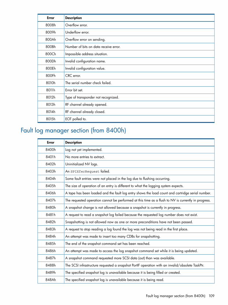
DescriptionError
Overflow error.8008h
Underflow error.8009h
Overflow error on sending.800Ah
Number of bits on data receive error.800Bh
Impossible address situation.800Ch
Invalid configuration name.800Dh
Invalid configuration value.800Eh
CRC error.800Fh
The serial number check failed.8010h
Error bit set.8011h
Type of transponder not recognized.8012h
RF channel already opened.8013h
RF channel already closed.8014h
EOT polled to.8015h
Fault log manager section (from 8400h)
DescriptionError
Log not yet implemented.8400h
No more entries to extract.8401h
Uninitialized NV logs.8402h
An SPIXferRequest failed.8403h
Some fault entries were not placed in the log due to flushing occurring.8404h
The size of operation of an entry is different to what the logging system expects.8405h
A tape has been loaded and the fault log entry shows the load count and cartridge serial number.8406h
The requested operation cannot be performed at this time as a flush to NV is currently in progress.8407h
A snapshot change is not allowed because a snapshot is currently in progress.8480h
A request to read a snapshot log failed because the requested log number does not exist.8481h
Snapshotting is not allowed now as one or more preconditions have not been passed.8482h
A request to stop reading a log found the log was not being read in the first place.8483h
An attempt was made to insert too many CDBs for snapshotting.8484h
The end of the snapshot command set has been reached.8485h
An attempt was made to access the log snapshot command set while it is being updated.8486h
A snapshot command requested more SCSI data (out) than was available.8487h
The SCSI infrastructure requested a snapshot PortIF operation with an invalid/obsolete TaskPtr.8488h
The specified snapshot log is unavailable because it is being filled or created.8489h
The specified snapshot log is unavailable because it is being read.848Ah
Fault log manager section (from 8400h) 109

DescriptionError
The specified snapshot log is unavailable because its status is unexpected.848Bh
The command set cannot be changed while it is being read.848Ch
The data structure that contains status has an illegal value.848Dh
The specified snapshot LogSize is too small.848Eh
No task objects are available in the SCSI Task Manager.848Fh
The Snapshot log sub-system is unable to save a snapshot log to flash because it is full.8490h
An operation was attempted that cannot be performed because there are protected STTF logs inflash.
8491h
Infrastructure section (from 8800h)
DescriptionError
Inf OnEvent: EventSet – the event list is full, so the event has not been set.8800h
Inf OnEvent: the event has not been found in the list.8801h
Inf OnEvent: EventGetIdx – the index is out of bounds.8802h
Inf ARM exception vector taken: undefined instruction.8803h
Inf ARM exception vector taken: software interrupt.8804h
Inf ARM exception vector taken: prefetch abort.8805h
Inf ARM exception vector taken: data abort.8806h
Inf ECC event: recoverable ECC error detected.8807h
Inf ECC event: unrecoverable ECC error detected.8808h
Inf Boot failure: firmware image failed to boot.8809h
The ACI_RST_L input on the ACI connector has been activated.880Ah
Inf ECC event: Recoverable ITCM ECC error detected.880Bh
Inf ECC event: Recoverable DTCM ECC error detected.880Ch
Inf the System ARM is about to enter DiagLite.880Dh
Inf the True Random Number Generator's init routine failed at the start.880Eh
Inf the True Random Number Generator's BIST never completed.880Fh
Inf the True Random Number Generator's BIST SIG never became non-zero.8810h
Inf the True Random Number Generator has failed to re-seed.8811h
Inf the True Random Number Generator has failed to fill its cache.8812h
RTKCritIntSectBeg() has detected that we are in a nested critical section but interrupts are enabledwhen they should not be.
8813h
FUG flash write and reads succeeded, but a subsequent compare failed.8814h
The True Random Number Generator's init routine failed to reset.8815h
The True Random Number Generator's logic self-test failed.8816h
The True Random Number Generator's entropy source logic test failed.8817h
The True Random Number Generator has timed out waiting for initialization.8818h
110 Drive error codes

DescriptionError
The True Random Number Generator's continuous test has failed.8819h
The True Random Number Generator has no data available to read.881Ah
The SysARM Watchdog Timer has fired. This indicates that the SysARM FW has locked up.881Bh
Critical section (from 8C00h)
DescriptionError
End section not begun. CRSEndCritIntSect was ended without CRSBegIntSect.8C00h
Begin section ints off. CRSBegCritIntSect found ints already off.8C01h
SCSI module (from 9400h)
DescriptionError
Power-on reset Unit Attention.9401h
Firmware reboot after upgrade Unit Attention.9402h
SCSI bus reset Unit Attention.9403h
BDR reset Unit Attention.9404h
Soft reset Unit Attention.9405h
Transceivers changed to SE Unit Attention.9406h
Transceivers changed to LVD Unit Attention.9407h
Nexus lost Unit Attention.9408h
Media changed Unit Attention.9409h
Mode parameters changed Unit Attention.940Ah
Log values changed Unit Attention.940Bh
Unsupported task management function.940Ch
LUN has too many task objects.940Dh
Unsupported LUN.940Eh
Invalid field in CDB.940Fh
Unsupported opcode.9410h
Unsupported command handler request.9412h
Unavailable opcode.9413h
Not a fast ACI command.9414h
Response pending.9415h
Aborted.9416h
Reserved.9417h
Invalid group code.9418h
Truncated mode page.9419h
Invalid field mode data.941Ah
Critical section (from 8C00h) 111

DescriptionError
BOT encountered on space to record.941Bh
BOT encountered on to space to filemark.941Ch
Firmware bug.941Dh
Echo buffer overwritten.941Eh
REPORT DENSITY media not present.941Fh
Overlapped command.9420h
Erase operation in progress.9421h
Locate operation in progress.9422h
Rewind operation in progress.9423h
Write inhibit tape drive.9424h
Device ID changed Unit Attention.9425h
Truncated Log data.9426h
Non-clearable Log page.9427h
Invalid field Log data.9428h
Forward task to library. Not a reportable error code.9429h
Invalid surrogate SCSI LUN.942Ah
Invalid surrogate SCSI inquiry pages.942Bh
Too many surrogate SCSI LUNs.942Ch
Inquiry cache corrupted.942Dh
Inquiry cache full.942Eh
Invalid Exchange ID.942Fh
No sense data provided.9430h
Invalid SCSI status.9431h
Reported LUNs data has changed Unit Attention.9432h
Parameter not supported in CDB.9433h
Load operation in progress.9434h
Unload operation in progress.9435h
Early Warning EOM encountered.9436h
Invalid field in Write buffer descriptor.9437h
Prediction threshold exceeded false failure.9438h
Prediction threshold exceeded failure.9439h
Echo buffer invalid.943Ah
LUN not configured.943Bh
Invalid field in PR Out data.943Ch
PR Out parameter list length error in CDB.943Dh
PR Out truncated data.943Eh
Reservations released Unit Attention.943Fh
112 Drive error codes

DescriptionError
Registrations preempted Unit Attention.9440h
Reservations preempted Unit Attention.9441h
Invalid release persistent reservation.9442h
WORM overwrite attempted.9443h
WORM cannot erase.9444h
Drive cleaning in progress.9445h
Loading media.9446h
Unloading media.9448h
Firmware upgrade in progress.9449h
Cartridge is write-protected.944Ah
Writing inhibited, caused by bad Cartridge Memory.944Bh
Unknown cartridge loaded but not threaded.944Ch
Tape is loaded but not threaded, initialize command is required.944Dh
MAM is accessible but the cartridge is in load ‘hold’ position — not ready.944Eh
The tape is threaded but the drive shows it as unloaded.944Fh
No media loaded.9450h
An invalid Port ID has been logged in.9451h
The RMC logical unit has been taken offline by the ADC RMC Logical Unit Mode page.9452h
Write inhibit—the media is the wrong generation.9453h
Tape position is past BOM.9454h
No default WWN. Used by the WWN module.9455h
No current WWN. Used by the WWN module.9456h
WWN not changed.9457h
No default value for the WWN. Used by the WWN module.9458h
Insufficient registration resources. Used in Fibre Channel when the maximum number of WWN hasbeen reached.
9459h
Library check condition surrogate SCSI command. Used in surrogate SCSI to cause the siSetScsiStatusto set task SCSI status to 2.
945Ah
Write inhibit caused by suspect integrity.945Bh
Busy command during LU Reset. This command should receive BUSY during the resetting of the LU.945Ch
Operation complete.945Dh
The maximum number of bridge LUNs has been reached.945Eh
Unit Attention condition has been detected for this initiation to the SMC LUN.945Fh
The remote SMC device server is in the Not Ready state.9460h
The Bridging Mode Sense cache has become corrupt due to a firmware defect.9461h
The Bridging Mode Sense cache is full, caching operation failed.9462h
Unable to forward command to the automation device because the ADT port is logged out.9463h
Used to instruct the Bridge Device server to resend a SCSI command to the remote SMC LUN.9464h
SCSI module (from 9400h) 113
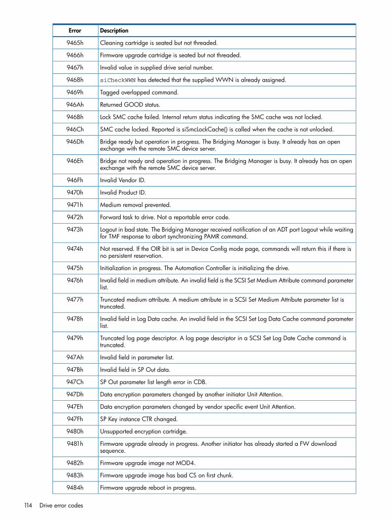
DescriptionError
Cleaning cartridge is seated but not threaded.9465h
Firmware upgrade cartridge is seated but not threaded.9466h
Invalid value in supplied drive serial number.9467h
siCheckWWN has detected that the supplied WWN is already assigned.9468h
Tagged overlapped command.9469h
Returned GOOD status.946Ah
Lock SMC cache failed. Internal return status indicating the SMC cache was not locked.946Bh
SMC cache locked. Reported is siSmcLockCache() is called when the cache is not unlocked.946Ch
Bridge ready but operation in progress. The Bridging Manager is busy. It already has an openexchange with the remote SMC device server.
946Dh
Bridge not ready and operation in progress. The Bridging Manager is busy. It already has an openexchange with the remote SMC device server.
946Eh
Invalid Vendor ID.946Fh
Invalid Product ID.9470h
Medium removal prevented.9471h
Forward task to drive. Not a reportable error code.9472h
Logout in bad state. The Bridging Manager received notification of an ADT port Logout while waitingfor TMF response to abort synchronizing PAMR command.
9473h
Not reserved. If the OIR bit is set in Device Config mode page, commands will return this if there isno persistent reservation.
9474h
Initialization in progress. The Automation Controller is initializing the drive.9475h
Invalid field in medium attribute. An invalid field is the SCSI Set Medium Attribute command parameterlist.
9476h
Truncated medium attribute. A medium attribute in a SCSI Set Medium Attribute parameter list istruncated.
9477h
Invalid field in Log Data cache. An invalid field in the SCSI Set Log Data Cache command parameterlist.
9478h
Truncated log page descriptor. A log page descriptor in a SCSI Set Log Date Cache command istruncated.
9479h
Invalid field in parameter list.947Ah
Invalid field in SP Out data.947Bh
SP Out parameter list length error in CDB.947Ch
Data encryption parameters changed by another initiator Unit Attention.947Dh
Data encryption parameters changed by vendor specific event Unit Attention.947Eh
SP Key instance CTR changed.947Fh
Unsupported encryption cartridge.9480h
Firmware upgrade already in progress. Another initiator has already started a FW downloadsequence.
9481h
Firmware upgrade image not MOD4.9482h
Firmware upgrade image has bad CS on first chunk.9483h
Firmware upgrade reboot in progress.9484h
114 Drive error codes
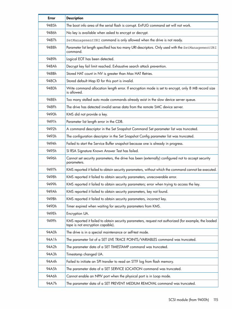
DescriptionError
The boot info area of the serial flash is corrupt. EnFUG command set will not work.9485h
No key is available when asked to encrypt or decrypt.9486h
SetManagementURI command is only allowed when the drive is not ready.9487h
Parameter list length specified has too many URI descriptors. Only used with the SetManagementURIcommand.
9488h
Logical EOT has been detected.9489h
Decrypt key fail limit reached. Exhaustive search attack prevention.948Ah
Stored HAT count in NV is greater than Max HAT Retries.948Bh
Stored default Map ID for this port is invalid.948Ch
Write command allocation length error. If encryption mode is set to encrypt, only 8 MB record sizeis allowed.
948Dh
Too many stalled auto mode commands already exist in the slow device server queue.948Eh
The drive has detected invalid sense data from the remote SMC device server.948Fh
KMS did not provide a key.9490h
Parameter list length error in the CDB.9491h
A command descriptor in the Set Snapshot Command Set parameter list was truncated.9492h
The configuration descriptor in the Set Snapshot Config parameter list was truncated.9493h
Failed to start the Service Buffer snapshot because one is already in progress.9494h
SI RSA Signature Known Answer Test has failed.9495h
Cannot set security parameters, the drive has been (externally) configured not to accept securityparameters.
9496h
KMS reported it failed to obtain security parameters, without which the command cannot be executed.9497h
KMS reported it failed to obtain security parameters, unrecoverable error.9498h
KMS reported it failed to obtain security parameters; error when trying to access the key.9499h
KMS reported it failed to obtain security parameters, key not found.949Ah
KMS reported it failed to obtain security parameters, incorrect key.949Bh
Timer expired when waiting for security parameters from KMS.949Dh
Encryption UA.949Eh
KMS reported it failed to obtain security parameters, request not authorized (for example, the loadedtape is not encryption capable).
949Fh
The drive is in a special maintenance or self-test mode.94A0h
The parameter list of a SET LIVE TRACE POINTS/VARIABLES command was truncated.94A1h
The parameter data of a SET TIMESTAMP command was truncated.94A2h
Timestamp changed UA.94A3h
Failed to initiate an SPI transfer to read an STTF log from flash memory.94A4h
The parameter data of a SET SERVICE LOCATION command was truncated.94A5h
Cannot enable an NPIV port when the physical port is in Loop mode.94A6h
The parameter data of a SET PREVENT MEDIUM REMOVAL command was truncated.94A7h
SCSI module (from 9400h) 115

DescriptionError
The device server does not have sufficient recourses to process all the initiators in the parameter list.94A8h
SET PREVENT MEDIUM REMOVAL command not allowed when SMC LUN enabled.94A9h
SET PREVENT MEDIUM REMOVAL command not allowed when an NPIV is not associated with theSMC logical unit.
94AAh
SET LEGACY RESERVATION command not allowed when SMC LUN enabled.94ABh
SET LEGACY RESERVATION command not allowed when an NPIV is not associated with the SMClogical unit.
94ACh
The parameter data of a SET LEGACY RESERVATIONS command was truncated.94ADh
The parameter data of a SET PERSISTENT RESERVATIONS command was truncated.94AEh
The device server does not have sufficient recourses to process all the reservation keys in the parameterlist.
94AFh
Error detected in an SP OUT command or its data, either when attempting to establish a CCS, orafter decrypting when the integrity is checked.
94B0h
Error detected in an SP OUT command Authentication step; SAI_AC or SAI_DS is wrong.94B1h
Error detected in an SP OUT command Authentication step; authentication failed.94B2h
A host tried to initiate a new SA while another is in progress.94B3h
The creation of a SA is in progress, the command is not allowed.94B4h
FUGImage too large for flash.94B5h
The bridging manager has attempted to send a SCSI command to the remote SMC LUN before thebridging port has been registered or configured.
94B6h
A Cryptographic Algorithm function returned an unexpected length.94B7h
The Set Beacon LED Config parameter list is truncated.94Bh8
No task objects available in the SCSI Task Manager. This is a fatal error.94B9h
The Set IP Config parameter list is truncated.94BAh
A Certificate Manager function returned an unexpected length.94BBh
A Certificate Manager function returned an unexpected length on a Security Configuration command.94BCh
A Cryptographic Algorithm function returned an unexpected length on a Security Configurationcommand.
94BDh
The SPOUT signature could not be authenticated because the Management Host Certificate publickey is not present.
94BEh
A Set Symbolic Name descriptor is truncated.94BFh
A cartridge is not loaded but it has been detected in the drive.94C0h
An Automation Device Attribute Descriptor header was truncated.94C1h
The Automation Device Attribute value was truncated.94C2h
The AER Control deescriptor was truncated.94C3h
The status indicates that the specified symbolic name is the same as the current symbolic name.94C4h
The SET ADVANCED PORT SETTINGS parameter list was truncated.94C5h
The specified symbolic name exceeds the maximum permitted length.94C6h
The specified symbolic name is not null-terminated.94C7h
The specified Live Trace point has been specified multiple times in the parameter list.94C8h
116 Drive error codes
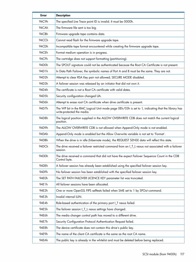
DescriptionError
The specified Live Trace point ID is invalid. It must be 0000h.94C9h
The firmware file sent is too big.94CAh
Firmware upgrade tape contains data.94CBh
Cannot read flash for the firmware upgrade tape.94CCh
Incompatible tape format encountered while creating the firmware upgrade tape.94CDh
Format medium operation is in progress.94CEh
The cartridge does not support formatting (partitioning).94CFh
The SPOUT signature could not be authenticated because the Root CA Certificate is not present.94D0h
In Data Path Failover, the symbolic names of Port A and B must be the same. They are not.94D1h
Attempt to clear RSA Key pair not allowed; SECURE MODE disabled.94D2h
A failover session was released by an initiator that did not own it.94D3h
The certificate is not a Root CA certificate with valid dates.94D4h
Security configuration changed UA.94D5h
Attempt to erase root CA certificate when drive certificate is present.94D6h
The WP bit in the RMC Logical Unit mode page 0Eh/03h is set to 1, indicating that the library haswrite-protected the media.
94D7h
The logical position supplied in the ALLOW OVERWRITE CDB does not match the current logicalposition.
94D8h
The ALLOW OVERWRITE CDB is not allowed when Append-Only mode is not enabled.94D9h
Append-Only mode is enabled but the Allow Overwrite variable is not set to 'Format'.94DAh
When the drive is in idle (hibernate mode), the REQUEST SENSE data will reflect this state.94DBh
The drive received a failover restricted command from an I_T_L nexus not associated with a failoversession.
94DCh
The drive received a command that did not have the expect Failover Sequence Count in the CDBControl byte.
94DDh
A failover session has already been established using the specified failover session key.94DEh
No failover session has been established with the specified failover session key.94DFh
The SET PATH FAILOVER LICENCE KEY parameter list was truncated.94E0h
All failover sessions have been allocated.94E1h
One or more OpenSSL FIPS selftests failed when SME set to 1 by SPOut command.94E2h
Invalid internal LUN.94E3h
Role-based authentication of the primary port I_T nexus failed.94E4h
The failover session I_T_L nexus settings have changed.94E5h
The media changer control path has moved to a different drive.94E6h
Security Configuration Protocol Authentication Request failed.94E7h
The device certificate does not contain this drive's public key.94E8h
The name of the client CA certificate is the same as the root CA name.94E9h
The public key is already in the whitelist and must be deleted before being replaced.94EAh
SCSI module (from 9400h) 117
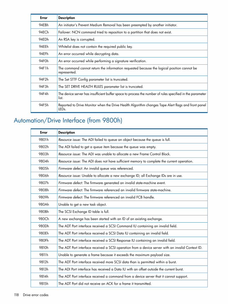
DescriptionError
An initiator's Prevent Medium Removal has been preempted by another initiator.94EBh
Failover: NCN command tried to reposition to a partition that does not exist.94ECh
An RSA key is corrupted.94EDh
Whitelist does not contain the required public key.94EEh
An error occurred while decrypting data.94EFh
An error occurred while performing a signature verification.94F0h
The command cannot return the information requested because the logical position cannot berepresented.
94F1h
The Set STTF Config parameter list is truncated.94F2h
The SET DRIVE HEALTH RULES parameter list is truncated.94F3h
The device server has insufficient buffer space to process the number of rules specified in the parameterlist.
94F4h
Reported to Drive Monitor when the Drive Health Algorithm changes Tape Alert flags and front panelLEDs.
94F5h
Automation/Drive Interface (from 9800h)
DescriptionError
Resource issue: The ADI failed to queue an object because the queue is full.9801h
The ADI failed to get a queue item because the queue was empty.9802h
Resource issue: The ADI was unable to allocate a new Frame Control Block.9803h
Resource issue: The ADI does not have sufficient memory to complete the current operation.9804h
Firmware defect: An invalid queue was referenced.9805h
Resource issue: Unable to allocate a new exchange ID; all Exchange IDs are in use.9806h
Firmware defect: The firmware generated an invalid state-machine event.9807h
Firmware defect: The firmware referenced an invalid firmware state-machine.9808h
Firmware defect: The firmware referenced an invalid FCB handle.9809h
Unable to get a new task object.980Ah
The SCSI Exchange ID table is full.980Bh
A new exchange has been started with an ID of an existing exchange.980Ch
The ADT Port interface received a SCSI Command IU containing an invalid field.980Dh
The ADT Port interface received a SCSI Data IU containing an invalid field.980Eh
The ADT Port interface received a SCSI Response IU containing an invalid field.980Fh
The ADT Port interface received a SCSI operation from a device server with an invalid Context ID.9810h
Unable to generate a frame because it exceeds the maximum payload size.9811h
The ADT Port interface received more SCSI data than is permitted within a burst.9812h
The ADI Port interface has received a Data IU with an offset outside the current burst.9813h
The ADT Port interface received a command from a device server that it cannot support.9814h
The ADT Port did not receive an ACK for a frame it transmitted.9815h
118 Drive error codes

DescriptionError
Temp need to replace with SI_ERR_TASK_QUEUE_FULL when available.9816h
Self-test failed: Unexpected FCBs allocated.9817h
Self-test failed: Unexpected exchange open.9818h
Self-test failed: Queue not empty.9819h
Self-test failed: SCSI Exchange not in the state IDLE.981Ah
The ADT port has detected an excessive number of framing errors.981Bh
Self-test failed: Non-zero library ACK offset.981Ch
Received Transfer Ready IU contained an invalid Buffer Offset field.981Dh
Received an ACK frame but not for frame it was expecting.981Eh
Received an NAK frame but not for frame it was expecting.981Fh
Giving up initiating a Port Login after a number of failed attempts.9820h
Discarding an ACK frame it received after the acknowledgement timeout.9821h
Did not receive acknowledgement within the Acknowledgement Period.9822h
Received a frame with a checksum error.9823h
Received a frame when the port was disabled.9824h
Received Transfer Ready IU was shorter than expected.9825h
Received Transfer Ready IU was longer than expected.9826h
Received Transfer Ready IU contained a Burst Length value of zero.9827h
Failed to execute a SCSI operation because it is logged-out.9828h
Failed to execute a SCSI operation because it is busy doing something else.9829h
Aborted bridged SCSI command due to a communication failure.982Ah
Unsupported task management function.982Bh
Invalid SCSI response code.982Ch
Invalid field in SCSI IU.982Dh
More data transferred than requested.982Eh
Task management function failed.982Fh
Service delivery failed.9830h
Invalid LUN in task management IU.9831h
Failed to transmit SCSI command or Task Management Function IU.9832h
Received zero length SCSI data IU.9833h
Received a data IU unexpectedly.9834h
Unexpected null frame pointer.9835h
The drive has detected a library firmware defect.9836h
Specified port is not a recognized ADT port.9837h
Instructs Bridging Manager not to resend a command with a UNIT ATTENTION sense key.9838h
A function will send a response when it has finished.9839h
The library NAKed a frame from the drive. Reported in the ADI/AMI command history log.983Ah
Automation/Drive Interface (from 9800h) 119

DescriptionError
Reported in the ADI/AMI Command History log to indicate a PORT RESET event occurred due to adiagnostic command.
983Bh
Not reported to a host but indicates a firmware defect sequencing a firmware reboot related to anADT RESET IU.
983Ch
Used for test purposes only.983Dh
The frame received was saved while the ADI port was being reset.983Eh
The previously saved frame was overwritten by another while the ADI port was being reset.983Fh
In the ADI Command History log: Indicates an Implicit Logout event.9840h
GWIF pending.F801h
GWIF no change.F802h
Management API (from 9C00h)
DescriptionError
The Ethernet RESET line has been activated.9C01h
The System ARM maHandleEvent() function has received an illegal event.9C02h
An invalid iADT port was specified for connection.9C03h
The iADT SENSEa input is asserted by the library controller.9C04h
The iADT SENSEa input is not asserted by the library controller.9C05h
The iADT SENSEa input has not been read yet.9C06h
Failure during socket read.9C07h
Failure during socket write.9C08h
MgmtArm rejected the maConfigNetworkIF options.9C09h
Requested self-test passed.9C0Ah
Requested self-test failed.9C0Bh
Fatal condition caused the Management ARM to fail.9C0Ch
Could not queue the message, the Mailbox is full.9C0Dh
Could not allocate memory to copy an ADT frame.9C0Eh
The awaited event has occurred.9C0Fh
The Mailbox is empty.9C10h
The command failed because the requested port does not exist.9C11h
Failed to connect to the remote host.9C12h
POST status not available.9C13h
Unable to get a new task object.9C14h
Cannot execute the SCSI command because another is in progress.9C15h
The KMS Agent Port interface received more SCSI data than permited within a burst.9C16h
PKI type invalid.9C17h
PKI format invalid.9C18h
120 Drive error codes
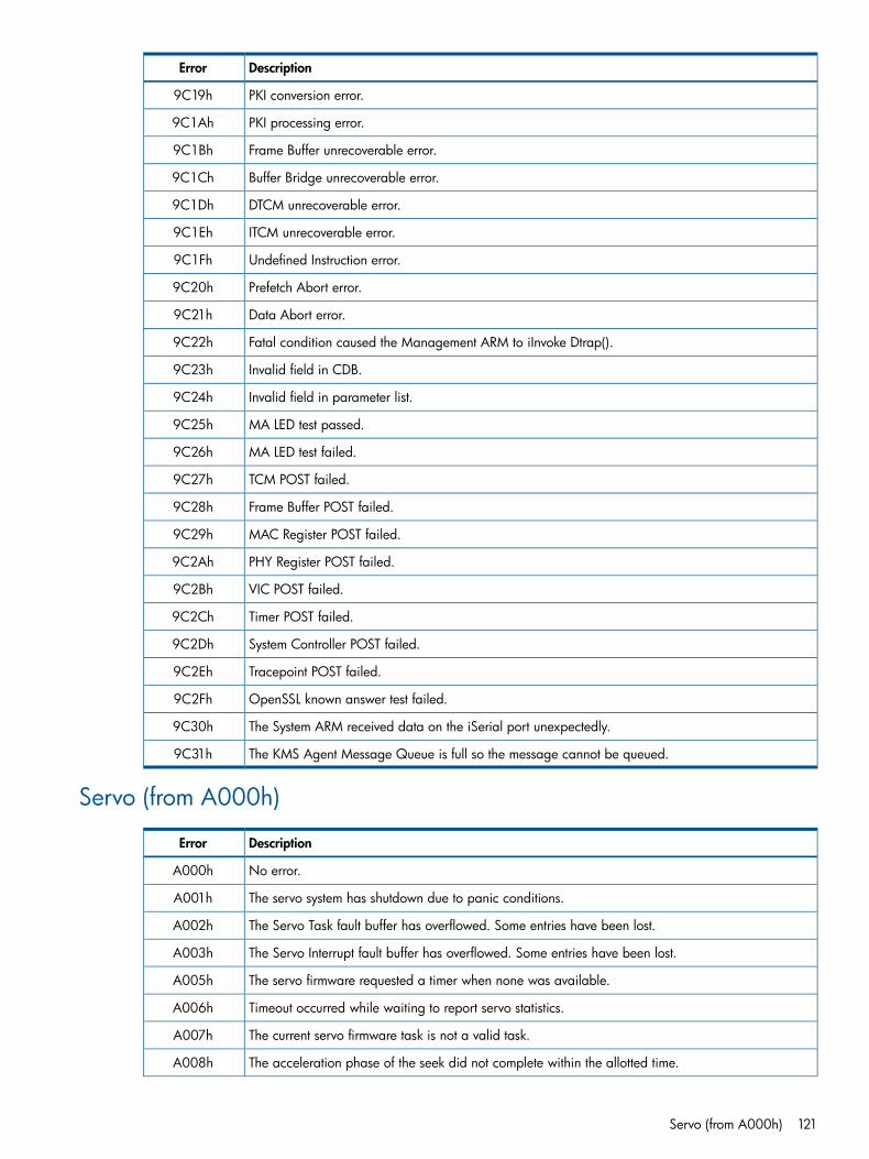
DescriptionError
PKI conversion error.9C19h
PKI processing error.9C1Ah
Frame Buffer unrecoverable error.9C1Bh
Buffer Bridge unrecoverable error.9C1Ch
DTCM unrecoverable error.9C1Dh
ITCM unrecoverable error.9C1Eh
Undefined Instruction error.9C1Fh
Prefetch Abort error.9C20h
Data Abort error.9C21h
Fatal condition caused the Management ARM to iInvoke Dtrap().9C22h
Invalid field in CDB.9C23h
Invalid field in parameter list.9C24h
MA LED test passed.9C25h
MA LED test failed.9C26h
TCM POST failed.9C27h
Frame Buffer POST failed.9C28h
MAC Register POST failed.9C29h
PHY Register POST failed.9C2Ah
VIC POST failed.9C2Bh
Timer POST failed.9C2Ch
System Controller POST failed.9C2Dh
Tracepoint POST failed.9C2Eh
OpenSSL known answer test failed.9C2Fh
The System ARM received data on the iSerial port unexpectedly.9C30h
The KMS Agent Message Queue is full so the message cannot be queued.9C31h
Servo (from A000h)
DescriptionError
No error.A000h
The servo system has shutdown due to panic conditions.A001h
The Servo Task fault buffer has overflowed. Some entries have been lost.A002h
The Servo Interrupt fault buffer has overflowed. Some entries have been lost.A003h
The servo firmware requested a timer when none was available.A005h
Timeout occurred while waiting to report servo statistics.A006h
The current servo firmware task is not a valid task.A007h
The acceleration phase of the seek did not complete within the allotted time.A008h
Servo (from A000h) 121

DescriptionError
The deceleration phase of the seek did not complete within the allotted time.A009h
Settle window criterion was not met at the end of the deceleration phase of the seek.A00Ah
Hand-off to the tracking phase of the seek did not complete within the allotted time.A00Bh
Servo mode was not recognized during a seek.A00Ch
A timer fault occurred during a negative stiction pulse.A00Dh
A timer fault occurred during a positive stiction pulse.A00Eh
A timer fault occurred during the bottom crash stop calibration.A00Fh
A timer fault occurred during the top crash stop calibration.A010h
The measured actuator stroke size is too small.A011h
A timer fault occurred during TSB calibration.A012h
TSB0 calibration did not complete within the allotted time.A013h
TSB1 calibration did not complete within the allotted time.A014h
TSB2 calibration did not complete within the allotted time.A015h
TSB3 calibration did not complete within the allotted time.A016h
An invalid servo track number was specified for a seek.A017h
The calculated final target for a VI seek was out of range.A018h
The calculated final target for a Tape seek was out of range.A019h
Unable to find the requested TSB.A01Ah
Unable to find Servo code on the tape; bad head.A01Bh
Unable to identify the current Top Servo band.A01Ch
Unable to identify the requested Seek type.A01Dh
Unable to lock to tape when not tracking on VI.A01Eh
Unable to lock to tape servo code within the allotted time.A01Fh
Primary servo bump went out while writing.A020h
System ARM is not allowing tape servo operations.A021h
VI offset calibration has not been done.A022h
The specified servo scope mode is not valid.A023h
The specified servo scope channel bit width is not supported.A024h
The specified servo source number is not valid.A025h
The specified servo scope trigger position is too large compared with the specified number of datapackets in the trace.
A026h
The specified servo scope source address was not found in the address array.A027h
The specified servo scope source bit size was not found in the size array.A028h
A Measure Servo Heads command did not complete within the allotted time.A029h
The main system ARM flagged the need to revert to VI.A02Ah
Band ID had good skew values from both bumps but was unable to identify the band.A02Bh
Band ID had good skew values from both bumps but identified different valid bands for each bump.A02Ch
122 Drive error codes

DescriptionError
Tape servo code available from at least one channel but unable to achieve tape lock. The head issuspect.
A02Dh
Not enough good demod channels to attempt band ID whilst searching for tape servo during TSBcalibration.
A02Eh
Tape servo code available from at least one channel but unable to achieve tape lock. The head issuspect.
A02Fh
The servo command is incorrectly formatted.A030h
The servo command cannot be executed now.A031h
Servo fault.A032h
Servo fault.A033h
Servo fault.A034h
Servo fault.A035h
Servo fault.A036h
One or more of the command parameters are invalid.A037h
The servo command sent is not supported.A038h
The servo command sent is out of sequence.A039h
The mechanism interface did not respond within the allotted timeout, shutting down the reel motors.A03Ah
Init servo command already in progress.A03Bh
Write memory servo command already in progress.A03Ch
Read memory servo command already in progress.A03Dh
Set generation servo command already in progress.A03Eh
Set scope mode servo command already in progress.A03Fh
PCA diagnostic servo command already in progress.A040h
Live statistics servo command already in progress.A041h
Seek command already in progress.A042h
Report TSBs servo command already in progress.A043h
Define Scope Sources servo command already in progress.A044h
Configure Oscillator servo command already in progress.A045h
Define Signal Nodes servo command already in progress.A046h
Calibrate VI Stroke servo command already in progress.A047h
Calibrate TSBs servo command already in progress.A048h
Report Servo Status servo command already in progress.A049h
Configure Test DACs servo command already in progress.A04Ah
Report Servo Configuration servo command already in progress.A04Bh
Measure Servo Heads servo command already in progress.A04Ch
Copy Memory Block servo command already in progress.A04Dh
Report Enum Address servo command already in progress.A04Eh
Set Compensator Coefficients servo command already in progress.A04Fh
Servo (from A000h) 123
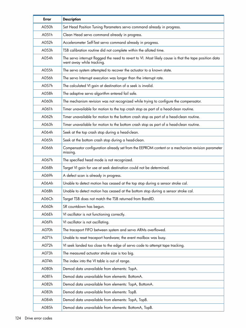
DescriptionError
Set Head Position Tuning Parameters servo command already in progress.A050h
Clean Head servo command already in progress.A051h
Accelerometer Self-Test servo command already in progress.A052h
TSB calibration routine did not complete within the alloted time.A053h
The servo interrupt flagged the need to revert to VI. Most likely cause is that the tape position datawent away while tracking.
A054h
The servo system attempted to recover the actuator to a known state.A055h
The servo Interrupt execution was longer than the interrupt rate.A056h
The calculated VI gain at destination of a seek is invalid.A057h
The adaptive servo algorithm entered fail safe.A058h
The mechanism revision was not recognized while trying to configure the compensator.A060h
Timer unavailable for motion to the top crash stop as part of a head-clean routine.A061h
Timer unavailable for motion to the bottom crash stop as part of a head-clean routine.A062h
Timer unavailable for motion to the bottom crash stop as part of a head-clean routine.A063h
Seek at the top crash stop during a head-clean.A064h
Seek at the bottom crash stop during a head-clean.A065h
Compensator configuration already set from the EEPROM content or a mechanism revision parametermissing.
A066h
The specified head mode is not recognized.A067h
Target VI gain for use at seek destination could not be determined.A068h
A defect scan is already in progress.A069h
Unable to detect motion has ceased at the top stop during a sensor stroke cal.A06Ah
Unable to detect motion has ceased at the bottom stop during a sensor stroke cal.A06Bh
Target TSB does not match the TSB returned from BandID.A06Ch
SR countdown has begun.A06Dh
VI oscillator is not functioning correctly.A06Eh
VI oscillator is not oscillating.A06Fh
The traceport FIFO between system and servo ARMs overflowed.A070h
Unable to reset traceport hardware; the event mailbox was busy.A071h
VI seek landed too close to the edge of servo code to attempt tape tracking.A072h
The measured actuator stroke size is too big.A073h
The index into the VI table is out of range.A074h
Demod data unavailable from elements: TopA.A080h
Demod data unavailable from elements: BottomA.A081h
Demod data unavailable from elements: TopA, BottomA.A082h
Demod data unavailable from elements: TopB.A083h
Demod data unavailable from elements: TopA, TopB.A084h
Demod data unavailable from elements: BottomA, TopB.A085h
124 Drive error codes

DescriptionError
Demod data unavailable from elements: TopA, BottomA, TopB.A086h
Demod data unavailable from elements: BottomB.A087h
Demod data unavailable from elements: TopA, BottomB.A088h
Demod data unavailable from elements: BottomA, BottomB.A089h
Demod data unavailable from elements: TopA, BottomA, BottomB.A08Ah
Demod data unavailable from elements: TopB, BottomB.A08Bh
Demod data unavailable from elements: TopA, TopB, BottomB.A08Ch
Demod data unavailable from elements: BottomA, TopB, BottomB.A08Dh
Demod data unavailable from elements: TopA, BottomA, TopB, BottomB.A08Eh
Reserved Servo fault.A08Fh
Certificate manager (from A400h)
DescriptionError
A Root CA certificate already exists and authentication is not possible without a Management Hostcertificate.
A401h
The Management Host certificate was rejected because the Root CA does not exist.A402h
Unknown or unexpected Certificate Manager state.A403h
The Management Host certificate failed verification.A404h
The Public Key length returned does not match the length in the Public Key descriptor.A405h
The certificate usage and index do not specify a valid certificate storage slot.A406h
The certificate usage and index do not specify a valid whitelist public key storage slot.A407h
The device certificate failed verification.A408h
The device certificate was rejected because the Root CA does not exist.A409h
Cryptographic algorithms (from A800h)
DescriptionError
Algorithm ID indicated an unsupported algorithm.A801h
Invalid key length specified.A802h
Algorithm index not found.A803h
One or more pointer arguments were null.A804h
Invalid algorithm database.A805h
Initiator message signature is invalid.A806h
Message digest buffer is too small.A807h
Insufficient entropy.A808h
Decryption authentication failure.A809h
Certification authority hash mismatch.A80Ah
Random number generation failed.A80Bh
Certificate manager (from A400h) 125

DescriptionError
Diffie-Hellman public value creation failed.A80Ch
Bignum conversion failed.A80Dh
Message digest failure.A80Eh
Signature failure.A80Fh
Encryption argument error.A810h
Encryption failure.A811h
OpenSSL initialization failure.A812h
OpenSSL d2i conversion failure.A813h
Buffer is too small.A814h
One or more CAVP tests failed.A815h
One or more OpenSSL FIPS self-tests failed at poweron with SME set to 1.A816h
Generation of new RSA key pair failed.A817h
OpenSSL memory allocation failure.A818h
Master channel (from 3C00h)
DescriptionError
Revi() failed, AFIR2 RS counter is zero.AC01h
Sandstrom read timeout.AC02h
PP adaptation failed to read. Possible No Data Detected.AC03h
AFIR2 adaptation failed to read. Possible No Data Detected.AC04h
Hyper-drive (from F400h)
DescriptionError
Sandstrom read failed waiting for status bit.F401h
Sandstrom read failed waiting for data.F402h
Hyper_init: failed to read READ_SSTROM_RDSP_CONTROL.F403h
Hyper_init: failed to read READ_DSP_TESPORT_ADDRESS.F404h
Hyper_init: failed to read DSP_TESPORT_DATA_BAD.F405h
Hyper_init: failed to read SSTROM_RDSP_PARITY_ERROR.F406h
Hyper_init: failed to read SSTROM_RDSP_SYNC_ERROR.F407h
Hyper_init: Orion page in use.F408h
Hyper_init: HT CONTROL check failed.F409h
Hyper_init: HT PARITY NOT ZERO.F40Ah
Hyper_init: HT SYNC NOT ZERO.F40Bh
126 Drive error codes

12 Support and other resourcesRelated documents
The following documents provide additional information:
Documents specific to HP LTO Ultrium drives• Software Integration Guide, volume 2 of the HP LTO Ultrium Technical Reference Manual
• Host Interface Guide, volume 3 of the HP LTO Ultrium Technical Reference Manual
• Specifications, volume 4 of the HP LTO Ultrium Technical Reference Manual
• UNIX, Linux and OpenVMS Configuration Guide, volume 5 of the HP LTO Ultrium TechnicalReference Manual
Please contact your HP supplier for copies.
• The features and benefits of HP LTO Ultrium drives are discussed in the HP LTO UltriumTechnology White Paper.
• For a general background to LTO technology and licensing, go tonl
http://www.lto-technology.com.
Documentation mapThe following will help you locate information in the Technical Reference Manual. A reference like“1 HW Integration: ch. 7” means Volume 1, Hardware Integration Guide, of the HP LTO UltriumTechnical Reference Manual, chapter 7.
Drives—general
1 HW Integration: ch. 4Connectors
1 HW Integration: ch. 3Front panel LEDs
4 SpecificationsSpecifications
Installation and configuration
1 HW Integration: ch. 4Connectors
2 SW Integration: ch. 2Determining the configuration
1 HW Integration: ch. 7Installation
5 UNIX, Linux, OpenVMS ConfigurationLinux configuration
n/aModes of usage
5 UNIX, Linux, OpenVMS ConfigurationOpenVMS configuration
1 HW Integration: ch. 6Optimizing performance
2 SW Integration: ch. 4
5 UNIX, Linux, OpenVMS ConfigurationUNIX configuration
Operation
1 HW Integration: ch. 8Operation
Related documents 127

Cartridges
2 SW Integration: ch. 5Cartridge Memory (LTO-CM)
1 HW Integration: ch. 5Cartridges
2 SW Integration: ch. 1Managing the use of cartridges
2 SW Integration: ch. 3Use of cartridges
Interface
3 Host InterfaceFC and SAS host interface guide
3 Host Interface: ch. 5Commands
1 HW Integration: ch. 11Error codes
3 Host Interface: ch. 1Implementation
2 SW Integration: ch. 6Interpreting sense data
3 Host Interface: ch. 2Messages
3 Host Interface: ch. 5Mode pages —see the MODE SENSE command
3 Host Interface: ch. 4Pre-execution checks
2 SW Integration: ch. 6Responding to sense keys and ASC/Q
3 Host Interface: ch. 3Response frames
3 Host Interface: ch. 5Sense keys and ASC/Q —see REQUEST SENSEcommand
3 Host Interface: ch. 3Task management functions
Maintenance and troubleshooting
2 SW Integration: ch. 1nl
Cleaning2 SW Integration: ch. 5
1 HW Integration: ch. 9Troubleshooting
2 SW Integration: ch. 7Monitoring drive and tape condition
2 SW Integration: ch. 1Software troubleshooting techniques
Dealing with errors
1 HW Integration: ch. 11Error codes
2 SW Integration: ch. 7Exception handling
3 Host Interface: ch. 5Logs—see the LOG SENSE command
2 SW Integration: ch. 7TapeAlert log
LTO Ultrium features
1 HW Integration: ch. 10Autoload
1 HW Integration: ch. 10Automation Control Interface (ACI)
1 HW Integration: ch. 5nl
Cartridge Memory (LTO-CM)
128 Support and other resources

2 SW Integration: ch. 5
2 SW Integration: ch. 5Data compression, managing
2 SW Integration: ch. 7OBDR and CD-ROM emulation
1 HW Integration: ch. 6Performance optimization
2 SW Integration: ch. 1
2 SW Integration: ch. 4Performance, factors affecting
2 SW Integration: ch. 1Software design
2 SW Integration: ch. 5Supporting LTO Ultrium features
Related documents 129

General documents and standardizationSee http://www.t10.org/t10_main.htm for INCITS SCSI Primary Commands—3 (SPC-3), SCSIStreaming Commands (SSC-3) and other specificationsCopies of documents of other standards bodies can be obtained from:
11 West 42nd Street New York, NY10036-8002 USA
INCITS
CP 56nl
ISOCH-1211 Geneva 20nl
Switzerland
Tel: +41 22 849 6000nl
114 Rue du Rhônenl
ECMAWeb URL: http://www.ecma.chCH-1204 Geneva
nl
Switzerland
Tel: 800 854 7179 or 714 261 14552805 McGawnl
Global EngineeringDocuments Irvine, CA 92714
nl
USA
130 Support and other resources

GlossaryAL_PA Arbitrated Loop Physical Address. A 1-byte value used in the arbitrated loop topology used to
identify L_ports. This value will then also become the last byte of the address identifier for eachpublic L_port on the loop. The AL_PA can be set through an ACI Set Drive Configuration command.
ANSI American National Standards Institute, which sets standards for, amongst other things, FibreChannel, SCSI and the safety of electrical devices.
arbitrated loop One of the three Fibre Channel topologies. Up to 126 NL_ports and 1 FL_port, or 127 NL_ports,are configured in a unidirectional loop. Ports arbitrate for access to the loop based on theirAL_PA. Ports with lower AL_PAs have higher priority than those with higher AL_PAs.
autoload When a tape cartridge is inserted, a tape drive with autoload will automatically load it withoutthe host having to send a load command. If a drive does not have autoload, the drive will takeno action until it receives a load command.
BOM Beginning Of Media. The first point on the tape that can be accessed by the drive.buffered mode A mode of data transfer in write operations that facilitates tape streaming. It is selected by setting
the Buffered Mode Field to 1 or 2 in the SCSI MODE SELECT Parameter List header.channel A means of data communication between processors and between processors and peripherals.
A channel provides a direct or switched point-to-point connection between the communicatingdevices. A channel is typically hardware-intensive and transports data at the high speed withlow overhead. Contrast this with Networks.
compression ratio A measure of how much compression has occurred, defined as the ratio of the amount ofuncompressed data to the amount of compressed data into which it is transformed. The LTO-DCalgorithm can typically achieve a compression ratio of between 2:1 and 4:1 depending on thenature of the data.
compression A procedure in which data is transformed by the removal of redundant information in order toreduce the number of bits required to represent the data.
decompression A procedure in which the original data is generated from compressed data.DFA Direct Fabric Attach. The connection between an N_port and an F_port.ECMA European Computer Manufacturers Association. The European equivalent of ANSI.EOD End Of Data. An area that signifies the end of the valid data. If new data is written over a larger
quantity of old data, it is possible for data to exist after EOD, but because it is after EOD, thisold data is no longer valid.
EOM End Of Media format. The last usable point on the tape.
131

EW-EOM Early Warning End Of Media. A physical mark or a device-computed position on the tape thattells the drive that it is approaching EOM.
F_port Fabric port. A port on a fabric switch operating according to point-to-point topology, to whichN_ports may be directly connected. An F_port uses the address identifier FFFFFEh.
fabric See switched fabric.fabric zoning Isolation of two separate switched fabric (FC_SW) zones by the switch.FC See fibre channel.FC-AL Fibre Channel Arbitrated Loop. An ANSI standard that describes how several Fibre Channel
ports can share a single communication ring. Using optical fiber to connect devices, FC-AL iscompatible with SCSI for high-performance storage systems.See also arbitrated loop[.
FC_FLA Fibre Channel Fabric Loop Attach. An ANSI standard that describes the rules by which NL_portsand FL_ports communicate with each other.
FC_GS Fibre Channel Generic Service. An ANSI standard that describes services such as DirectoryService that allow a host to identify which storage devices are available and what their addressesare.
FC_SW Fibre Channel Switch Fabric. An ANSI standard that describes how fibre channel switches arerequired to behave.See also switched fabric.
FCP Fibre Channel Protocol. There are three: arbitrated loop, point-to-point and switched fabric.fibre channel Fibre Channel provides an inexpensive yet expendable means of quickly transferring data between
workstations, mainframes, supercomputers, desktop computers, storage devices, displays andother peripherals. Although it is called Fibre Channel, its architecture represents neither a channelnor a real network topology. It allows for an active intelligent interconnection scheme, called afabric, to connect devices. All a Fibre Channel port has to do is to manage a simple point-to-pointconnection between itself and the fabric.Several common ULPs (Upper Level Protocols) including IP and SCSI can be used with FibreChannel, merging high-speed I/O and network functionality in a single connectivity technology.
filemark A mark written by the host. It does not necessarily separate files; it is up to the host to assign ameaning to the mark.
FL_port Fabric-Loop port. An F_port which is capable of supporting an attached arbitrated loop. AnFL_port on a loop will have the AL_PA 00h, giving the fabric highest priority access to the loop.An FL_port is the gateway to the fabric for NL_ports on a loop.
forced eject Functionality in the drive that should unload the cartridge in an emergency of if the cartridge failsto eject normally. To force ejection, press and hold the Eject button for 20 seconds. Wait for thecartridge to be ejected. This may take up to 15 minutes (the maximum rewind time).On full height drives, there is also an emergency reset button—see “Automation interface”(page 54).
FRU Field Replaceable Unit, an assembly or group of components that is replaced in its entirety byService Engineers when it contains a fault.
hard error An uncorrectable data error.host The host computer system acting as controller for the drive.L_port Loop port. A generic term for an NL_port or FL_port, in other words, any Fibre Channel port that
supports the arbitrated loop topology.load The process in which the drive takes in an inserted cartridge and goes online.LUN Logical Unit Number, by which different devices at a particular SCSI ID can be addressed
individually. The drive has a fixed LUN of 0.LVD Low-Voltage DifferentialN_port Node port. A port on a a device such as a computer system host bus adapter, disk drive or tape
drive, through which the device connects to a point-to-point or fabric Fibre Channel topology.
132 Glossary
network A collection of connected nodes (like workstations, file servers or peripherals) with its own protocolthat supports interaction among these nodes. A network has relatively high overhead since it issoftware-intensive, and consequently slower than a channel. Networks can handle a more extensiverange of tasks than channels as they operate in an environment of unanticipated connections,while channels operate among only a few devices with predefined addresses.
NL_port Node-Loop port. An N_port which can operate on the arbitrated loop topology.node A device that has at least one N_port or NL_port.offline The drive is offline if the tape is currently unloaded or not in the drive. The host has limited access,
and cannot perform any commands that would cause tape motion. The host can, however, loada tape, if one is inserted, and can execute any diagnostic tests that do not require tape motion.
online The drive is online when a tape is loaded. The host has access to all command operations,including those that access the tape, set configurations and run diagnostic tests.
point-to-point A Fibre Channel topology in which two points communicate directly.
port An access point in a device to which a link attaches.private loop An arbitrated loop that has no attached switch port (NL-port to NL_port). In theory, private loop
devices can only communicate with other devices on the same loop.private NL_port An NL_port that only communicates with other ports on the loop, not with the fabric. A private
NL_port may exist on either a private loop or a public loop.public loop An arbitrated loop where one of the ports on the loop is a switch port (an FL_port), thus allowing
ports or devices on the loop to communicate with hosts or devices attached to other switch ports.public NL_port An NL_port that can communicate with other ports on the loop as well as through an FL_port to
other N_ports connected to the fabric.RAW See read-after-write.read-after-write RAW improves data integrity by reading data immediately after it is written and writing the data
again if an error is found.ready-to-ejectposition
A point at which a cartridge is held after an unload command is received by the drive (whenAuto-Eject is not set) and the tape has be rewound and unthreaded. The drive will then wait atthis point until it is commanded to eject the cartridge by the ACI Unload command
SAN Storage Area Network. A dedicated, high-speed network that establishes a direct connectionbetween storage elements and servers. The hardware that connects workstations and servers tostorage devices in a SAN is referred to as a fabric. The SAN fabric enablesany-server-to-any-storage device connectivity through the use of Fibre Channel switching technology.
SFP Small Form Pluggable transceiver. See transceiver.switched fabric One of the three Fibre Channel topologies. An interconnected network of Fibre Channel host
ports, device ports and switch ports. In the fabric topology, N_ports are connected to F_ports ona switch. The link is the two unidirectional fibres transmitting in opposite directions. Each fibre isattached to a transmitter of a port at one end and a receiver of another port at the other end. Itis possible for fabric switches to be connected to support up to 16 million+ N_ports on a singlenetwork.
133

TapeAlert A set of 64 flags is held in the TapeAlert log that indicate faults or predicted faults with the driveor the media. By reading this log, host software can inform the user of existing or impendingconditions, and can, for example, advise the user to change the tape.
transceiver A device used to convert electrical signals in the drive to optical signals for transmission in a fibreoptic cable. Used in Fibre Channel drives only.
ULP Upper Level Protocol. The protocol which runs on top of Fibre Channel. Typical ULPs running overFibre Channel are SCSI (Small Computer System Interface), IP (Internet Protocol), HIPPI (HighPerformance Parallel Interface, and IPI (Intelligent Peripheral Interface).
VHD Very High Densityzoning A logical grouping of fabric-attached devices that is isolated from other devices and other zones
by the switch.
134 Glossary

Index
AACI, 51, 53, 54
connector, 20, 26connector pins, 26controlling loads, 58error codes, 62reset, 46
addresses, fibre channel, 25ADI, 54
pin layout, 27ADT, 54airflow, 10
tape arrays, 40airflow requirements, 10AL_PAs, 25, 131ANSI, 127, 130, 131arbitrated loop, 131arbitrated loop physical address, 131autochangers, 51autoload, configuring, 58autoloader front panel, 53autoloaders, 51autoloading, 131automation control interface, 51, 53, 54automation device interface, 54automation front panel, 52automation/drive interface, 54
error codes, 118
Bbackup software, 39, 51BOM, 131buffer manager error codes, 65buffered mode, 131bus types, supported, 38bus, dedicated, 35
Ccartridge memory, 33, 51, 61
access via ACI, 55error codes, 108problems with, 33
cartridges, 31jammed, 47life, 32loading, 44not ejected, 49positions during load and unload, 59problems with, 48unloading, 45
certificate manager, error codes, 125channel, 131cleaning
heads, 45problems with, 50
CM see cartridge memory, 51compression ratio, 131condensation, avoiding, 32connecting to server, 38connectors, 20, 41
automation, 26FC, 26internal SAS, 39remote LED, 26SAS, 20, 26
contactless memory, 51cooling, 10critical section error codes, 111cryptographic algorithms, error codes, 125current requirements, 9
Ddata compression, 131data rate matching, 35DC_GS, 132decompression, 131DFA, 131diagnostic control error codes, 66diagnostic port, 52, 53dimensions, 7direct fabric attach, 131DLT cartridges, 31documents, related, 127drive
ID, 39not recognized, 48
Drive Error LED, 13drive monitor error codes, 70drives
control error codes, 68error codes, 62ID, 51moving, 42operating, 43problems with, 48resetting, 46resetting in libraries, 46
DRM, 35duplex-LC connectors, 20
EECMA, 130, 131eject button, 52, 53eject point, 59eject, forced, 47electrical fit, 9emergency reset switch, 12emergency unload, 47Encryption LED, 13EOD, 131EOM, 131
135

error codes, 62errors, hard, 132Ethernet port see iADTEW-EOM, 132exception handler error codes, 108external drives
indentifying the drive, 42loading a cartridge, 44unloading a cartridge, 45
external fan, 58external interfaces error codes, 70
FF_port, 132fabric, 133fabric zoning, 132fan interface, 58FC connection, 40FC-AL, 132FC/SCSI router, 40FC_FLA, 132FC_SW, 132FCP, 132fibre channel, 132
addressing, 25arbitrated loop, 132fabric loop attach, 132generic service, 132ports, 24switched fabric, 132
fibre channel connector, 26filemarks, 132filtering, 10firmware upgrade, LED patterns, 18fixing dimensions, 7FL_port, 132forced airflow, 10forced eject, 47, 132formatter ASIC, 10front panel
autoloader, 53automation, 52interface error codes, 71LEDs, 13replacing, 18
FRU, 132fusing, 37
Ggeneric module error codes, 62grounding integrity, 37
Hhard error, 132HBA, 38head cleaning, 45host, 132
interface error codes, 71problems with, 48
hyper-drive, error codes, 126
IiADT, 54, 56ID
drive, 39, 51loop, 25
identifying the driveexternal, 42internal, 37removable, 40
INCITS, 130infrastructure, memory codes, 110installing drives
in libraries, 41internal, 37
internal drivesindentifying the drive, 37reset switch, 12
ISO, 130
LL_port, 132labeling cartridges, 31LEDs, 24
front panel, 13rear panel, 24
libraries, 51installation in, 41resetting drives in, 46
life of cartridges, 32load points, 60loading, 132loading cartridges
configuring, 58external drives, 44positions, 59positions of importance, 58
logical formatter error codes, 78logical media error codes, 82logical pipeline control error codes, 83logs, TapeAlert, 134loop IDs, 25loop topology, 131LTO-CM, 33, 51, 61LUNs, 132
MManagement API, error codes, 120master channel, error codes, 126mechanical interface error codes, 94mechanism control error codes, 83modes of usage, 35mounting requirements, 38moving drives, 42
NN_port, 132NL_port, 133
136 Index

node, 133non-volatile data manager error codes, 84
Ooffline, 133online, 133operating drives, 43operating system error codes, 88optimizing performance, 35
Pphysical formatter error codes, 88physical pipeline control error codes, 89pins
ACI connector, 26ADI connector, 27
point-to-point, 133port LEDs, 24ports, 24, 133power requirements, 9power-on self-test, 43primary temperature sensor, 10private loop, 133private NL_port, 133PSU requirements, 9public loop, 133public NL_port, 133
Rrack-mount systems, 40RAW, 133read/write control error codes, 91Ready LED, 13ready-to-eject position, 60, 133rear panel, 20, 41
LEDs, 24removable drives
identifying the drive, 40installing, 40
replacing drives in tape array, 41replacing front panel, 18reset switch, 12resetting drives in libraries, 46resetting drives via ACI, 46
Ssafety, 37SAN, 133
attaching a tape array, 40SAS connector, 20, 26, 39SCSI module, error codes, 111self-test, 43
failure, 24serial numbers
external drives, 42internal drives, 37
server, installing drive in, 37Servo, error codes, 121software, backup, 39
SPI interface error codes, 108storage area network, 133storing cartridges, 32switched fabric, 133system architecture error codes, 93system configurations, 35system performance, 35
Ttape arrays
airflow, 40installing drives, 40replacing a drive, 41
Tape Error LED, 13tape libraries see libraries, 51tape life, maximizing, 32TapeAlert log, 134temperature, measuring, 10tight integ error codes, 93trace logger error codes, 93
UULP, 134UNIX configuration, 7unloading cartridges
external drives, 45in emergency, 47positions of importance, 58
Use Cleaning Tape LED, 13
Vvoltage requirements, 9voltage supply requirements, 9
Wwrite-protecting cartridges, 31
Zzoning, 134
137
Related Documents