HP LaserJet M2727 MFP Series Service Manual

Welcome message from author
This document is posted to help you gain knowledge. Please leave a comment to let me know what you think about it! Share it to your friends and learn new things together.
Transcript
HP LaserJet M2727 MFP Series
Service Manual


HP LaserJet M2727 MFP SeriesService Manual

Copyright information
© 2007 Copyright Hewlett-PackardDevelopment Company, L.P.
Reproduction, adaptation, or translationwithout prior written permission is prohibited,except as allowed under the copyright laws.
The information contained herein is subjectto change without notice.
The only warranties for HP products andservices are set forth in the express warrantystatements accompanying such productsand services. Nothing herein should beconstrued as constituting an additionalwarranty. HP shall not be liable for technicalor editorial errors or omissions containedherein.
Part number CB532-90946
Edition 1, 11/2007
Safety information
WARNING!
Potential Shock Hazard
Always follow basic safety precautions whenusing the product to reduce risk of injury fromfire or electric shock.
Read and understand all instructions in theuser guide.
Observe all warnings and instructionsmarked on the product.
Use only a grounded electrical outlet whenconnecting the product to a power source. Ifyou do not know whether the outlet isgrounded, check with a qualified electrician.
Do not touch the contacts on the end of anyof the sockets on the product. Replacedamaged cords immediately.
Unplug the product from wall outlets beforecleaning.
Do not install or use the product near wateror when you are wet.
Install the product securely on a stablesurface.
Install the product in a protected locationwhere no one can step on or trip over thepower cord and where the power cord will notbe damaged.
If the product does not operate normally, seethe online user guide.
Refer all servicing questions to qualifiedpersonnel.
Information regarding FCC Class B, Parts 15and 68 requirements can be found in the userguide.
Trademark credits
Microsoft® and Windows® are U.S.registered trademarks of MicrosoftCorporation.
Windows Vista™ is either a registeredtrademark or trademark of MicrosoftCorporation in the United States and/or othercountries.
Linux is a U.S. registered trademark of LinusTorvalds.
UNIX® is a registered trademark of TheOpen Group.
PostScript® is a trademark of AdobeSystems Incorporated.
Energy Star® and the Energy Star logo® areU.S. registered marks of the United StatesEnvironmental Protection Agency.
Table of contents
1 Product informationQuick access to product information .................................................................................................... 2Product comparison ............................................................................................................................. 3Product features ................................................................................................................................... 4Product walkaround .............................................................................................................................. 5
Front view ............................................................................................................................ 5Back view ............................................................................................................................. 6Interface ports ...................................................................................................................... 6Control panel ....................................................................................................................... 7
Serial number and model number location ........................................................................................... 8Software description ............................................................................................................................. 9
Supported operating systems .............................................................................................. 9Supported printer drivers ..................................................................................................... 9Software included with the product ...................................................................................... 9
Recommended installation for Windows ........................................................... 10Express installation (USB or network) ............................................................... 10Macintosh software ........................................................................................... 10
Software for Windows ........................................................................................................................ 12HP ToolboxFX ................................................................................................................... 12Embedded Web server (EWS) .......................................................................................... 12
Software for Macintosh ....................................................................................................................... 13HP Director ........................................................................................................................ 13Macintosh Configure Device (Mac OS X v10.3, v10.4, and later) ..................................... 13PDEs (Mac OS X v10.3, v10.4, and later) ......................................................................... 14
Uninstall software ............................................................................................................................... 15Windows ............................................................................................................................ 15Macintosh .......................................................................................................................... 15
Media specifications ........................................................................................................................... 16Supported paper and print media sizes ............................................................................. 16Media to avoid ................................................................................................................... 17Media that can damage the product .................................................................................. 17
2 InstallationOperating environment ....................................................................................................................... 20
Minimum system requirements .......................................................................................... 21Unpack the product ............................................................................................................................ 22Install input devices ............................................................................................................................ 23
ADF input tray .................................................................................................................... 23250-sheet input tray (tray 3) ............................................................................................... 24
ENWW iii

Install the control-panel faceplate ....................................................................................................... 25Load paper and print media ............................................................................................................... 26
Load documents to fax, copy, or scan ............................................................................... 26Tray 1 ................................................................................................................................. 27Tray 2 or 3 ......................................................................................................................... 28Configure trays .................................................................................................................. 29Change tray selection ........................................................................................................ 29
Install memory DIMMs ........................................................................................................................ 30Information ......................................................................................................................... 30Install a memory DIMM ..................................................................................................... 30
3 MaintenanceManage supplies ................................................................................................................................ 34
Life expectancies of supplies and the product ................................................................... 34Order supplies ................................................................................................................... 34Store print cartridges ......................................................................................................... 35Replace and recycle supplies ............................................................................................ 35Replace print cartridge ....................................................................................................... 37Load staples ...................................................................................................................... 39Replace the tray 2 pickup roller ......................................................................................... 40Replace the tray 2 and optional tray 3 separation pad ...................................................... 45HP policy on non-HP supplies ........................................................................................... 48
Reset the product for non-HP supplies ............................................................. 48HP fraud hotline ................................................................................................................. 48
Clean the product ............................................................................................................................... 49Clean the exterior .............................................................................................................. 49Clean the flatbed scanner glass ........................................................................................ 49Clean the scanner-cover backing ...................................................................................... 51Clean the tray 2 pickup roller ............................................................................................ 52Clean the ADF pickup-roller assembly .............................................................................. 55Clean the paper path ......................................................................................................... 56
Clean the paper path from HP ToolboxFX ........................................................ 57Clean the paper path from the product control panel ........................................ 57
Manage the product ........................................................................................................................... 58HP ToolboxFX ................................................................................................................... 58
View the HP ToolboxFX .................................................................................... 58Status ................................................................................................................ 58
Event log ........................................................................................... 59Alerts ................................................................................................................. 59
Set up status alerts ........................................................................... 59Set up e-mail alerts ........................................................................... 59
Fax .................................................................................................................... 59Fax tasks .......................................................................................... 60Fax phone book ................................................................................ 60Fax send log ..................................................................................... 62Fax receive log ................................................................................. 62
Help (Documentation) ....................................................................................... 62System settings ................................................................................................. 63
Device information ............................................................................ 63Paper handling ................................................................................. 64
iv ENWW

Print quality ....................................................................................... 64Paper types ...................................................................................... 64System setup .................................................................................... 65Service .............................................................................................. 65Device Polling ................................................................................... 65
Print settings ..................................................................................................... 65Printing ............................................................................................. 65PCL 5e .............................................................................................. 66PostScript ......................................................................................... 66
Network settings ................................................................................................ 66Embedded Web server ...................................................................................................... 66
Features ............................................................................................................ 66Secure the embedded Web server ................................................................... 67
Macintosh Configure Device (Mac OS X v10.3, v10.4, and later) ..................................... 67
4 Theory of operationBasic operation ................................................................................................................................... 70
Sequence of operation for the base unit ............................................................................ 70Scanner and ADF functions and operation ........................................................................................ 72
Scanner functions ............................................................................................................. 72Scanner operation ............................................................................................................. 73ADF operation .................................................................................................................... 73ADF paper path and ADF sensors ..................................................................................... 74ADF jam detection ............................................................................................................. 75
Internal components (base unit) ......................................................................................................... 76Engine control system ........................................................................................................................ 78Laser/scanner system ........................................................................................................................ 80Pickup/feed/delivery system ............................................................................................................... 81Image-formation system .................................................................................................................... 83Fax functions and operation .............................................................................................................. 87
Computer and network security features ........................................................................... 87PSTN operation ................................................................................................................. 87Receive faxes when you hear fax tones ............................................................................ 87Distinctive ring function ...................................................................................................... 88Fax by using Voice over IP services .................................................................................. 88The fax subsystem ............................................................................................................. 89Fax card in the fax subsystem ........................................................................................... 89
Safety isolation .................................................................................................. 89Safety-protection circuitry .................................................................................. 89Data path ........................................................................................................... 90Hook state ......................................................................................................... 90Downstream device detection ........................................................................... 90Hook switch control ........................................................................................... 90Ring detect ........................................................................................................ 91Line current control ........................................................................................... 91Billing- (metering-) tone filters ........................................................................... 91
Fax page storage in flash memory .................................................................................... 91Stored fax pages ............................................................................................... 91Advantages of flash memory storage ............................................................... 91
ENWW v

5 Removal and replacementIntroduction ......................................................................................................................................... 94
Removal and replacement strategy .................................................................................. 94Electrostatic discharge ....................................................................................................... 94User-replaceable parts ...................................................................................................... 94Required tools ................................................................................................................... 95Before performing service .................................................................................................. 95After performing service ..................................................................................................... 96Post-service tests .............................................................................................................. 96
Test 1 (print-quality test) ................................................................................... 96Test 2 (copy-quality test) ................................................................................... 96Test 3 (fax-quality test) ...................................................................................... 97
Parts removal order ........................................................................................................... 98Remove the print cartridge ................................................................................................ 99
External panels, covers, and doors .................................................................................................. 100Right cover ....................................................................................................................... 100Left cover ......................................................................................................................... 102Print-cartridge door .......................................................................................................... 104Rear cover ....................................................................................................................... 106Top cover ......................................................................................................................... 108
Replace the ADF pickup-roller assembly ......................................................................................... 110ADF scanner glass ........................................................................................................................... 113ADF assembly .................................................................................................................................. 115Scanner/ADF assembly .................................................................................................................... 117Bezel and control panel .................................................................................................................... 119Internal assemblies .......................................................................................................................... 122
Convenience-stapler assembly (HP LaserJet M2727nfs only) ........................................ 122Convenience-stapler power supply (HP LaserJet M2727nfs only) .................................. 124Convenience-stapler AC inlet cable (HP LaserJet M2727nfs only) ................................. 126Convenience-stapler power supply bracket and strap (HP LaserJet M2727nfs only) ..... 127Speaker ........................................................................................................................... 128Power-switch PCA ........................................................................................................... 130Formatter ......................................................................................................................... 132Duplex assembly ............................................................................................................. 135Laser/scanner (print engine) ............................................................................................ 137Memory-tag-reader assembly (E-label reader) ................................................................ 139Fan ................................................................................................................................... 141Duplex-drive gears ........................................................................................................... 143Duplex solenoid ............................................................................................................... 145Fuser ................................................................................................................................ 147Interlock assembly ........................................................................................................... 152Engine controller assembly (ECU) ................................................................................... 153Main motor ....................................................................................................................... 158Pickup-and-feed assemblies ............................................................................................ 160
Transfer roller .................................................................................................. 160Registration-roller assembly ............................................................................................ 161Main gear assembly and tray 2 pickup solenoid .............................................................. 162
6 Solve problemsProblem-solving checklist ................................................................................................................. 166
vi ENWW

Control-panel messages .................................................................................................................. 169Alert and warning messages .......................................................................................... 169
Alert and warning message tables .................................................................. 169Critical error messages .................................................................................................... 177
Critical error message-tables .......................................................................... 177Clear jams ........................................................................................................................................ 179
Causes of jams ................................................................................................................ 179Where to look for jams ..................................................................................................... 180Clear jams from the ADF ................................................................................................. 180Clear jams from the input-tray areas ............................................................................... 182Clear jams from the duplexer ........................................................................................... 184Clear jams from the output-bin areas .............................................................................. 186
Top (face-down) output bin ............................................................................. 186Rear (face-up) output bin ................................................................................ 187
Clear jams from the print-cartridge area .......................................................................... 188Clear jams from the convenience stapler (HP LaserJet M2727nfs MFP only) ................ 189Avoid repeated jams ....................................................................................................... 190
Control-panel menus ........................................................................................................................ 191Use the control-panel main menus .................................................................................. 191Control-panel main menus ............................................................................................... 191Control-panel secondary menus ...................................................................................... 199
Use the control-panel secondary menus ......................................................... 199Control-panel secondary menus ..................................................................... 199
Print problems .................................................................................................................................. 204Print-quality problems ...................................................................................................... 204
Improve print quality ........................................................................................ 204Print-quality settings ....................................................................... 204
Identify and correct print defects ..................................................................... 205Print-quality checklist ...................................................................... 205General print-quality issues ............................................................ 205
Scan problems ................................................................................................................................. 211Solve scanned-image problems ...................................................................................... 211Scan-quality problems ..................................................................................................... 213
Prevent problems ............................................................................................ 213Solve scan-quality problems ........................................................................... 213
Copy problems ................................................................................................................................. 214Prevent problems ............................................................................................................. 214Image problems ............................................................................................................... 214Media-handling problems ................................................................................................ 215Performance problems .................................................................................................... 217
Fax problems .................................................................................................................................... 218General fax problem-solve ............................................................................................... 218Problems receiving faxes ................................................................................................. 219Problems sending faxes .................................................................................................. 222Voice-call problems ......................................................................................................... 224Media-handling problems ................................................................................................ 225Performance problems .................................................................................................... 226
Control-panel display problems ........................................................................................................ 227Convenience-stapler problems (HP LaserJet M2727nfs only) ......................................................... 227DSL problems ................................................................................................................................... 228
ENWW vii
PABX line problems ......................................................................................................... 228ADF problems .................................................................................................................................. 229Functional checks ............................................................................................................................. 230
Drum rotation test ............................................................................................................ 230Engine test ....................................................................................................................... 231Half self-test functional check .......................................................................................... 232Perform a half self-test check .......................................................................................... 232Perform other checks ....................................................................................................... 232Heating element check .................................................................................................... 233High-voltage contacts check ............................................................................................ 233
Check the print-cartridge contacts ................................................................ 233Check the high-voltage connector assembly ................................................. 234
Service-mode functions .................................................................................................................... 235NVRAM initialization ........................................................................................................ 235Super NVRAM initialization .............................................................................................. 235Service menu ................................................................................................................... 235
Problem-solve tools .......................................................................................................................... 237Product information pages and reports ............................................................................ 237
Configuration page .......................................................................................... 237Supplies Status page ...................................................................................... 237PCL, PCL 6, or PS font list .............................................................................. 237Demo page ...................................................................................................... 238
Usage page ..................................................................................................................... 238Menu map ........................................................................................................................ 238Network report ................................................................................................................. 238Fax reports ....................................................................................................................... 239
Fax activity log ................................................................................................ 239Fax call report ................................................................................................. 239Phone book report ........................................................................................... 239Billing-code report ........................................................................................... 240
HP ToolboxFX ................................................................................................................. 240To view HP ToolboxFX ................................................................................... 240Troubleshooting tab ........................................................................................ 240
Service menu .................................................................................................................. 241Restore the factory-set defaults ...................................................................... 241Clean the paper path ....................................................................................... 241T.30 protocol trace .......................................................................................... 242Archive print .................................................................................................... 242
Firmware updates ............................................................................................................................. 243Firmware update by using a flash executable file ............................................................ 243
7 PartsAccessories and ordering information .............................................................................................. 247Supplies ............................................................................................................................................ 248Memory ............................................................................................................................................ 248Cable and interface accessories ...................................................................................................... 248Paper-handling accessories ............................................................................................................ 249Whole unit replacement .................................................................................................................... 250Scanner/ADF replacement parts ...................................................................................................... 254Control-panel bezels ........................................................................................................................ 255
viii ENWW

Supplementary documentation and support ..................................................................................... 257Problem-solve diagrams ................................................................................................................... 259
Repetitive image defects ................................................................................................. 259Interface connectors ....................................................................................................... 260Formatter connectors ....................................................................................................... 260Fax card ........................................................................................................................... 261Solenoids ......................................................................................................................... 262Switches and sensors ...................................................................................................... 263Rollers and pads .............................................................................................................. 264PCAs (base unit) .............................................................................................................. 265Major components (base unit) ......................................................................................... 266Scanner and ADF ............................................................................................................ 267Circuit diagram (1 of 2) .................................................................................................... 268Circuit diagram (2 of 2) .................................................................................................... 268
Parts lists and diagrams ................................................................................................................... 270Types of screws ............................................................................................................... 271
Scanner and ADF assemblies .......................................................................................................... 272Scanner components ....................................................................................................................... 274ADF components .............................................................................................................................. 276Convenience stapler components (HP LaserJet M2727nfs only) .................................................... 278Formatter, fax card, HP jewel, and nameplate ................................................................................. 280External covers and panels .............................................................................................................. 282Cartridge door assembly .................................................................................................................. 284Internal components (1 of 4) ............................................................................................................ 286Internal components (2 of 4) ............................................................................................................ 288Internal components (3 of 4) ............................................................................................................ 290Internal components (4 of 4) ............................................................................................................ 292Engine-controller assembly (ECU) ................................................................................................... 294Main-drive assembly ........................................................................................................................ 296Duplexing-drive assembly ................................................................................................................ 298Tray 2 cassette and tray 3 cassette/feeder ...................................................................................... 300Duplexing assembly ......................................................................................................................... 302Fuser assembly ................................................................................................................................ 304Alphabetical parts list ....................................................................................................................... 306Numerical parts list ........................................................................................................................... 312
Appendix A Service and supportHewlett-Packard limited warranty statement .................................................................................... 319Print cartridge limited warranty statement ........................................................................................ 321
Appendix B SpecificationsPhysical specifications ..................................................................................................................... 324Electrical specifications .................................................................................................................... 324Power consumption .......................................................................................................................... 324Environmental specifications ............................................................................................................ 325Acoustic emissions ........................................................................................................................... 325
Appendix C Regulatory informationFCC compliance ............................................................................................................................... 328
ENWW ix

Environmental product stewardship program ................................................................................... 329Protecting the environment .............................................................................................. 329Ozone production ............................................................................................................ 329Power consumption ......................................................................................................... 329Toner consumption .......................................................................................................... 329Paper use ........................................................................................................................ 329Plastics ............................................................................................................................ 329HP LaserJet print supplies ............................................................................................... 329Return and recycling instructions ..................................................................................... 330
United States and Puerto Rico ........................................................................ 330Multiple returns (two to eight cartridges) ........................................ 330Single returns ................................................................................. 330Shipping .......................................................................................... 330
Non-US returns ............................................................................................... 330Paper ............................................................................................................................... 330Material restrictions .......................................................................................................... 330Disposal of waste equipment by users in private households in the European Union .... 331Material Safety Data Sheet (MSDS) ................................................................................ 331For more information ....................................................................................................... 332
Telephone Consumer Protection Act (United States) ...................................................................... 333IC CS-03 requirements ..................................................................................................................... 333EU statement for telecom operation ................................................................................................. 334New Zealand telecom statements .................................................................................................... 334Declaration of conformity .................................................................................................................. 335Safety statements ............................................................................................................................. 336
Laser safety ..................................................................................................................... 336Canadian DOC regulations .............................................................................................. 336EMI statement (Korea) ..................................................................................................... 336Laser statement for Finland ............................................................................................. 337Substances table (China) ................................................................................................ 338
Index ................................................................................................................................................................. 339
x ENWW

List of tables
Table 1-1 Product guides ................................................................................................................................... 2Table 1-2 Supported printer drivers .................................................................................................................... 9Table 1-3 Supported paper and print media sizes ........................................................................................... 16Table 1-4 Supported envelopes and postcards ............................................................................................... 17Table 1-5 ADF .................................................................................................................................................. 17Table 4-1 Sequence of operation ..................................................................................................................... 70Table 4-2 Power-on sequence ......................................................................................................................... 71Table 6-1 Alert and warning messages ......................................................................................................... 169Table 6-2 Alert and warning messages ......................................................................................................... 172Table 6-3 Critical error messages .................................................................................................................. 177Table 6-4 Fax Job status menu ...................................................................................................................... 191Table 6-5 Fax functions menu ........................................................................................................................ 191Table 6-6 Copy setup menu ........................................................................................................................... 192Table 6-7 Reports menu ................................................................................................................................. 193Table 6-8 Fax setup menu ............................................................................................................................. 194Table 6-9 System setup menu ....................................................................................................................... 197Table 6-10 Service menu ............................................................................................................................... 199Table 6-11 Secondary service menu .............................................................................................................. 200Table 6-12 Developer's menu ........................................................................................................................ 201Table 7-1 Whole unit replacement, product bundle CB532A ......................................................................... 250Table 7-2 Whole unit replacement, product bundle CB533A ......................................................................... 252Table 7-3 Control-panel bezels ...................................................................................................................... 255Table 7-4 Service and training support .......................................................................................................... 257Table 7-5 User guides .................................................................................................................................... 257Table 7-6 Getting started guide ...................................................................................................................... 258Table 7-7 Technical support Web sites .......................................................................................................... 258Table 7-8 Repetitive image defects ................................................................................................................ 259Table 7-9 Interface connectors ....................................................................................................................... 260Table 7-10 Formatter connectors ................................................................................................................... 260Table 7-11 Fax card ....................................................................................................................................... 261Table 7-12 Solenoids ..................................................................................................................................... 262Table 7-13 Switches and sensors .................................................................................................................. 263Table 7-14 Rollers and pads .......................................................................................................................... 264Table 7-15 PCAs (base unit) .......................................................................................................................... 265Table 7-16 Major components (base unit) ..................................................................................................... 266Table 7-17 Scanner and ADF ......................................................................................................................... 267Table 7-18 Scanner and ADF assemblies ..................................................................................................... 273Table 7-19 Scanner components ................................................................................................................... 275Table 7-20 ADF components ......................................................................................................................... 277
ENWW xi

Table 7-21 Convenience stapler components (HP LaserJet M2727nfs only) ................................................ 279Table 7-22 Formatter, Fax card, HP jewel, and nameplate ........................................................................... 281Table 7-23 External covers and panels .......................................................................................................... 283Table 7-24 Cartridge door assembly .............................................................................................................. 285Table 7-25 Internal components (1 of 4) ........................................................................................................ 287Table 7-26 Internal components (2 of 4) ........................................................................................................ 289Table 7-27 Internal components (3 of 4) ........................................................................................................ 291Table 7-28 Internal components (4 of 4) ........................................................................................................ 293Table 7-29 Engine-controller assembly .......................................................................................................... 295Table 7-30 Main-drive assembly .................................................................................................................... 297Table 7-31 Duplexing-drive assembly ............................................................................................................ 299Table 7-32 Tray 2 cassette and tray 3 cassette/feeder .................................................................................. 301Table 7-33 Duplexing assembly ..................................................................................................................... 303Table 7-34 Fuser assembly ............................................................................................................................ 305Table 7-35 Alphabetical parts list ................................................................................................................... 306Table 7-36 Numerical parts list ....................................................................................................................... 312Table B-1 Physical specifications ................................................................................................................... 324Table B-2 Electrical specifications .................................................................................................................. 324Table B-3 Power consumption (average, in watts), ...................................................................................... 324Table B-4 Environmental specifications ........................................................................................................ 325Table B-5 Acoustic emissions ....................................................................................................................... 325
xii ENWW
List of figures
Figure 2-1 Operating environment ................................................................................................................... 20Figure 2-2 HP LaserJet M2727 MFP package contents .................................................................................. 22Figure 2-3 Install the ADF input tray ................................................................................................................. 23Figure 2-4 Install the 250-sheet input tray ........................................................................................................ 24Figure 2-5 Install the control-panel faceplate ................................................................................................... 25Figure 2-6 Load a document onto the flatbed scanner .................................................................................... 26Figure 2-7 Load documents into the ADF (1 of 2) ............................................................................................ 27Figure 2-8 Load documents into the ADF (2 of 2) ............................................................................................ 27Figure 3-1 Replace the tray 2 pickup roller (1 of 7) .......................................................................................... 40Figure 3-2 Replace the tray 2 pickup roller (2 of 7) .......................................................................................... 41Figure 3-3 Replace the tray 2 pickup roller (3 of 7) .......................................................................................... 41Figure 3-4 Replace the tray 2 pickup roller (4 of 7) .......................................................................................... 42Figure 3-5 Replace the tray 2 pickup roller (5 of 7) .......................................................................................... 42Figure 3-6 Replace the tray 2 pickup roller (6 of 7) .......................................................................................... 43Figure 3-7 Replace the tray 2 pickup roller (7 of 7) .......................................................................................... 43Figure 3-8 Replace the tray 2 or tray 3 separation pad (1 of 6) ....................................................................... 45Figure 3-9 Replace the tray 2 or tray 3 separation pad (2 of 6) ....................................................................... 45Figure 3-10 Replace the tray 2 or tray 3 separation pad (3 of 6) ..................................................................... 46Figure 3-11 Replace the tray 2 or tray 3 separation pad (4 of 6) ..................................................................... 46Figure 3-12 Replace the tray 2 or tray 3 separation pad (5 of 6) ..................................................................... 47Figure 3-13 Replace the tray 2 or tray 3 separation pad (6 of 6) ..................................................................... 47Figure 3-14 Clean the scanner glass (1 of 2) ................................................................................................... 49Figure 3-15 Clean the scanner glass (2 of 2) ................................................................................................... 50Figure 3-16 Clean the scanner-cover backing ................................................................................................. 51Figure 3-17 Clean the tray 2 pickup roller (1 of 6) ............................................................................................ 52Figure 3-18 Clean the tray 2 pickup roller (2 of 6) ............................................................................................ 52Figure 3-19 Clean the tray 2 pickup roller (3 of 6) ............................................................................................ 52Figure 3-20 Clean the tray 2 pickup roller (4 of 6) ............................................................................................ 53Figure 3-21 Clean the tray 2 pickup roller (5 of 6) ............................................................................................ 53Figure 3-22 Clean the tray 2 pickup roller (6 of 6) ............................................................................................ 54Figure 3-23 Clean the ADF pickup-roller assembly (1 of 5) ............................................................................. 55Figure 3-24 Clean the ADF pickup-roller assembly (2 of 5) ............................................................................. 55Figure 3-25 Clean the ADF pickup-roller assembly (3 of 5) ............................................................................. 55Figure 3-26 Clean the ADF pickup-roller assembly (4 of 5) ............................................................................. 56Figure 3-27 Clean the ADF pickup-roller assembly (5 of 5) ............................................................................. 56Figure 4-1 HP LaserJet M2727 MFP system block diagram ............................................................................ 70Figure 4-2 Optical system ................................................................................................................................ 72Figure 4-3 ADF paper path ............................................................................................................................... 74Figure 4-4 Cross-section of printer ................................................................................................................... 76
ENWW xiii

Figure 4-5 Engine control system ..................................................................................................................... 78Figure 4-6 Engine-control-system circuit diagram ............................................................................................ 79Figure 4-7 Laser/scanner system ..................................................................................................................... 80Figure 4-8 Pickup/feed/delivery system ........................................................................................................... 82Figure 4-9 Image-formation system ................................................................................................................. 83Figure 4-10 Primary charging ........................................................................................................................... 83Figure 4-11 Developing .................................................................................................................................... 84Figure 4-12 Transfer ......................................................................................................................................... 85Figure 4-13 Separation ..................................................................................................................................... 85Figure 4-14 Fusing ........................................................................................................................................... 86Figure 4-15 Drum cleaning ............................................................................................................................... 86Figure 5-1 Phillips and pozidrive screwdriver comparison ............................................................................... 95Figure 5-2 Parts-removal tree .......................................................................................................................... 98Figure 5-3 Remove the print cartridge (1 of 2) ................................................................................................. 99Figure 5-4 Remove the print cartridge (2 of 2) ................................................................................................. 99Figure 5-5 Remove the right cover (1 of 4) .................................................................................................... 100Figure 5-6 Remove the right cover (2 of 4) .................................................................................................... 100Figure 5-7 Remove the right cover (3 of 4) .................................................................................................... 101Figure 5-8 Remove the right cover (4 of 4) .................................................................................................... 101Figure 5-9 Remove the left cover (1 of 3) ....................................................................................................... 102Figure 5-10 Remove the left cover (2 of 3) ..................................................................................................... 102Figure 5-11 Remove the left cover (3 of 3) ..................................................................................................... 103Figure 5-12 Remove the print-cartridge door (1 of 3) ..................................................................................... 104Figure 5-13 Remove the print-cartridge door (2 of 3) ..................................................................................... 104Figure 5-14 Remove the print-cartridge door (3 of 3) ..................................................................................... 105Figure 5-15 Remove the rear cover (1 of 3) ................................................................................................... 106Figure 5-16 Remove the rear cover (2 of 3) ................................................................................................... 106Figure 5-17 Remove the rear cover (3 of 3) ................................................................................................... 107Figure 5-18 Remove the top cover (1 of 4) .................................................................................................... 108Figure 5-19 Remove the top cover (2 of 4) .................................................................................................... 108Figure 5-20 Remove the top cover (3 of 4) .................................................................................................... 109Figure 5-21 Remove the top cover (4 of 4) .................................................................................................... 109Figure 5-22 Replace the ADF pickup-roller assembly (1 of 6) ....................................................................... 110Figure 5-23 Replace the ADF pickup-roller assembly (2 of 6) ....................................................................... 110Figure 5-24 Replace the ADF pickup-roller assembly (3 of 6) ....................................................................... 111Figure 5-25 Replace the ADF pickup-roller assembly (4 of 6) ....................................................................... 111Figure 5-26 Replace the ADF pickup-roller assembly (5 of 6) ....................................................................... 112Figure 5-27 Replace the ADF pickup-roller assembly (6 of 6) ....................................................................... 112Figure 5-28 Removing the ADF scanner glass (1 of 3) .................................................................................. 113Figure 5-29 Removing the ADF scanner glass (2 of 3) .................................................................................. 113Figure 5-30 Removing the ADF scanner glass (3 of 3) .................................................................................. 114Figure 5-31 Remove the ADF assembly (1 of 3) ............................................................................................ 115Figure 5-32 Remove the ADF assembly (2 of 3) ............................................................................................ 115Figure 5-33 Remove the ADF assembly (3 of 3) ............................................................................................ 116Figure 5-34 Remove the scanner/ADF assembly (1 of 4) .............................................................................. 117Figure 5-35 Remove the scanner/ADF assembly (2 of 4) .............................................................................. 117Figure 5-36 Remove the scanner/ADF assembly (3 of 4) .............................................................................. 118Figure 5-37 Remove the scanner/ADF assembly (4 of 4) .............................................................................. 118Figure 5-38 Remove the bezel and control panel (1 of 4) .............................................................................. 119Figure 5-39 Remove the bezel and control panel (2 of 4) .............................................................................. 119
xiv ENWW
Figure 5-40 Remove the bezel and control panel (3 of 4) .............................................................................. 120Figure 5-41 Remove the bezel and control panel (4 of 4) .............................................................................. 121Figure 5-42 Remove the convenience-stapler assembly (1 of 2) ................................................................... 122Figure 5-43 Remove the convenience-stapler assembly (2 of 2) ................................................................... 123Figure 5-44 Remove the convenience-stapler power assembly (1 of 3) ........................................................ 124Figure 5-45 Remove the convenience-stapler power assembly (2 of 3) ........................................................ 124Figure 5-46 Remove the convenience-stapler power assembly (3 of 3) ........................................................ 125Figure 5-47 Remove the convenience-stapler AC inlet cable ........................................................................ 126Figure 5-48 Remove the convenience-stapler bracket and strap .................................................................. 127Figure 5-49 Remove the speaker (1 of 2) ...................................................................................................... 128Figure 5-50 Remove the speaker (2 of 2) ...................................................................................................... 129Figure 5-51 Remove the power-switch PCA (HP LaserJet M2727nfs shown) ............................................... 130Figure 5-52 Remove the power-switch PCA mounting bracket ..................................................................... 131Figure 5-53 Remove the formatter (1 of 5) ..................................................................................................... 132Figure 5-54 Remove the formatter (2 of 5) ..................................................................................................... 133Figure 5-55 Install formatter protective sheet ................................................................................................. 133Figure 5-56 Remove the formatter (3 of 4) ..................................................................................................... 134Figure 5-57 Remove the formatter (4 of 4) ..................................................................................................... 134Figure 5-58 Remove the duplex assembly (1 of 2) ........................................................................................ 135Figure 5-59 Remove the duplex assembly (2 of 2) ........................................................................................ 136Figure 5-60 Remove the laser/scanner assembly .......................................................................................... 138Figure 5-61 Remove the memory-tag-reader assembly (1 of 2) .................................................................... 139Figure 5-62 Remove the memory-tag-reader assembly (2 of 2) .................................................................... 140Figure 5-63 Memory-tag-reader assembly spring .......................................................................................... 140Figure 5-64 Remove the fan (1 of 2) .............................................................................................................. 141Figure 5-65 Remove the fan (2 of 2) .............................................................................................................. 142Figure 5-66 Remove the duplex-drive gears .................................................................................................. 144Figure 5-67 Replace the duplex-drive gears .................................................................................................. 144Figure 5-68 Remove the duplex solenoid (1 of 2) .......................................................................................... 145Figure 5-69 Remove the duplex solenoid (2 of 2) .......................................................................................... 146Figure 5-70 Remove the fuser (1 of 9) ........................................................................................................... 147Figure 5-71 Remove the fuser (2 of 9) ........................................................................................................... 148Figure 5-72 Remove the fuser (3 of 9) ........................................................................................................... 148Figure 5-73 Remove the fuser (4 of 9) ........................................................................................................... 149Figure 5-74 Remove the fuser (5 of 9) ........................................................................................................... 149Figure 5-75 Remove the fuser (6 of 9) ........................................................................................................... 150Figure 5-76 Remove the fuser (7 of 9) ........................................................................................................... 150Figure 5-77 Remove the fuser (8 of 9) ........................................................................................................... 151Figure 5-78 Remove the fuser (9 of 9) ........................................................................................................... 151Figure 5-79 Remove the interlock assembly .................................................................................................. 152Figure 5-80 Remove the ECU (1 of 7) ............................................................................................................ 154Figure 5-81 Remove the ECU (2 of 7) ............................................................................................................ 154Figure 5-82 Remove the ECU (3 of 7) ............................................................................................................ 155Figure 5-83 Remove the ECU (4 of 7) ............................................................................................................ 155Figure 5-84 Remove the ECU (5 of 8) ............................................................................................................ 156Figure 5-85 Remove the ECU (6 of 7) ............................................................................................................ 156Figure 5-86 Remove the ECU (7 of 7) ............................................................................................................ 157Figure 5-87 Remove the main motor (1 of 2) ................................................................................................. 158Figure 5-88 Remove the main motor (2 of 2) ................................................................................................. 159Figure 5-89 Remove the transfer roller .......................................................................................................... 160
ENWW xv

Figure 5-90 Remove the registration-roller assembly .................................................................................... 161Figure 5-91 Remove the main gear assembly (1 of 5) ................................................................................... 162Figure 5-92 Remove the main gear assembly (2 of 5) ................................................................................... 163Figure 5-93 Remove the main gear assembly (3 of 5) ................................................................................... 163Figure 5-94 Remove the main gear assembly (4 of 5) ................................................................................... 164Figure 5-95 Remove the tray 2 pickup solenoid (5 of 5) ................................................................................ 164Figure 6-1 Engine test switch ......................................................................................................................... 231Figure 6-2 Print-cartridge high-voltage connection points (right side) ............................................................ 233Figure 6-3 Print-cartridge high-voltage connection points (left side) .............................................................. 234Figure 7-1 Interface connectors ..................................................................................................................... 260Figure 7-2 Formatter connectors .................................................................................................................... 260Figure 7-3 Fax card connectors ..................................................................................................................... 261Figure 7-4 Solenoids ...................................................................................................................................... 262Figure 7-5 Switches and sensors ................................................................................................................... 263Figure 7-6 Rollers and pads ........................................................................................................................... 264Figure 7-7 PCAs (base unit) ........................................................................................................................... 265Figure 7-8 Major components (base unit) ...................................................................................................... 266Figure 7-9 Scanner and ADF ......................................................................................................................... 267Figure 7-10 Circuit diagram (1 of 2) ............................................................................................................... 268Figure 7-11 Circuit diagram (2 of 2) ............................................................................................................... 269Figure 7-12 Scanner and ADF assemblies .................................................................................................... 272Figure 7-13 Scanner assemblies .................................................................................................................... 274Figure 7-14 ADF components ........................................................................................................................ 276Figure 7-15 Convenience stapler components (HP LaserJet M2727nfs only) ............................................... 278Figure 7-16 Formatter, fax card, HP jewel, and nameplate ........................................................................... 280Figure 7-17 External covers and panels ........................................................................................................ 282Figure 7-18 Cartridge door assembly ............................................................................................................. 284Figure 7-19 Internal components (1 of 4) ....................................................................................................... 286Figure 7-20 Internal components (2 of 4) ....................................................................................................... 288Figure 7-21 Internal components (3 of 4) ....................................................................................................... 290Figure 7-22 Internal components (4 of 4) ....................................................................................................... 292Figure 7-23 Engine-controller assembly ......................................................................................................... 294Figure 7-24 Main-drive assembly ................................................................................................................... 296Figure 7-25 Duplexing-drive assembly ........................................................................................................... 298Figure 7-26 Tray 2 cassette and tray 3 cassette/feeder ................................................................................. 300Figure 7-27 Duplexing assembly .................................................................................................................... 302Figure 7-28 Fuser assembly ........................................................................................................................... 304
xvi ENWW

1 Product information
● Quick access to product information
● Product comparison
● Product features
● Product walkaround
● Serial number and model number location
● Software description
● Software for Windows
● Software for Macintosh
● Uninstall software
● Media specifications
ENWW 1

Quick access to product informationUse the following Web site to find information about the product.
● www.hp.com/support/LJM2727
Table 1-1 Product guides
Guide Description
HP LaserJet M2727 MFP GettingStarted Guide
Provides step-by-step instructions for installing and setting up the product.
HP LaserJet M2727 MFP SeriesUser Guide
Provides detailed information for using the product and problem-solving. Available on theproduct CD or in the Windows Program Group if the software is installed on a computer.
HP ToolboxFX To check the product status and settings, and to view problem-solving information and onlinedocumentation, use the HP ToolboxFX. You must have performed a complete softwareinstallation in order to use the HP ToolboxFX. See the user guide for more information aboutsoftware installation.
Online Help Provides information about options that are available in the printer drivers. To view a Helpfile, open the online Help through the printer driver.
2 Chapter 1 Product information ENWW
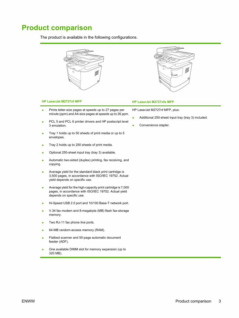
Product comparisonThe product is available in the following configurations.
HP LaserJet M2727nf MFP HP LaserJet M2727nfs MFP
● Prints letter-size pages at speeds up to 27 pages perminute (ppm) and A4-size pages at speeds up to 26 ppm.
● PCL 5 and PCL 6 printer drivers and HP postscript level3 emulation.
● Tray 1 holds up to 50 sheets of print media or up to 5envelopes.
● Tray 2 holds up to 250 sheets of print media.
● Optional 250-sheet input tray (tray 3) available.
● Automatic two-sided (duplex) printing, fax receiving, andcopying.
● Average yield for the standard black print cartridge is3,500 pages, in accordance with ISO/IEC 19752. Actualyield depends on specific use.
● Average yield for the high-capacity print cartridge is 7,000pages, in accordance with ISO/IEC 19752. Actual yielddepends on specific use.
● Hi-Speed USB 2.0 port and 10/100 Base-T network port.
● V.34 fax modem and 8-megabyte (MB) flash fax-storagememory.
● Two RJ-11 fax phone line ports.
● 64-MB random-access memory (RAM).
● Flatbed scanner and 50-page automatic documentfeeder (ADF).
● One available DIMM slot for memory expansion (up to320 MB).
HP LaserJet M2727nf MFP, plus:
● Additional 250-sheet input tray (tray 3) included.
● Convenience stapler.
ENWW Product comparison 3

Product featuresPerformance ● Prints up to 27 ppm (letter) or 26 ppm (A4).
Print quality ● 1,200 dots per inch (dpi) with Image REt 2400 text and graphics.
● Adjustable settings to optimize print quality.
● The HP UltraPrecise print cartridge has a finer toner formulation that provides sharper textand graphics.
Fax ● Full-functionality fax capabilities with a V.34 fax; includes a phone book, fax/tel, anddelayed-fax features.
Copy ● Includes ADF that allows faster, more efficient copy jobs with multiple-page documents.
Scan ● The product provides 1,200 pixels per inch (ppi), 24-bit full-color scanning from letter/A4-size scanner glass.
● The product provides 300 ppi, 24-bit full-color scanning from the automatic documentfeeder (ADF).
● Includes an ADF that allows faster, more efficient scan jobs with multiple-page documents.
Staple ● The HP LaserJet M2727nfs includes a convenience stapler for fast and convenientstapling of up to 20 sheets of 80 g/m2 or 20 lb media at the product.
● Large-capacity replaceable staple cassette holds 1,500 staples.
Networking ● TCP/IP
◦ IPv4
◦ IPv6
Printer driver features ● Fast printing performance, built-in Intellifont and TrueType scaling technologies, andadvanced imaging capabilities are benefits of the PCL 6 printer language.
Interface connections ● Hi-Speed USB 2.0 port.
● 10/100 Base-T ethernet network port (RJ-45).
● RJ-11 fax/phone cable ports.
Economical printing ● N-up printing (printing more than one page on a sheet).
● Two-sided printing using the automatic duplexer.
● EconoMode setting.
Supplies ● A supplies status page that displays the amount of life remaining in the print cartridge.
● No-shake cartridge design.
● Authentication for HP print cartridges.
● Enabled supplies-ordering capability.
Accessibility ● Online user guide that is compatible with text screen-readers.
● Print cartridges can be installed and removed using one hand.
● All doors and covers can be opened using one hand.
4 Chapter 1 Product information ENWW

Product walkaroundFront view
1 Tray 2
2 Tray 1
3 Print-cartridge door latch
4 Top (face-down) output bin
5 Control panel
6 Automatic document feeder (ADF) input tray
7 Automatic document feeder (ADF) output bin
8 Convenience stapler (HP LaserJet M2727nfs only)
9 Power switch
10 Optional tray 3 (standard on the HP LaserJet M2727nfs MFP)
ENWW Product walkaround 5
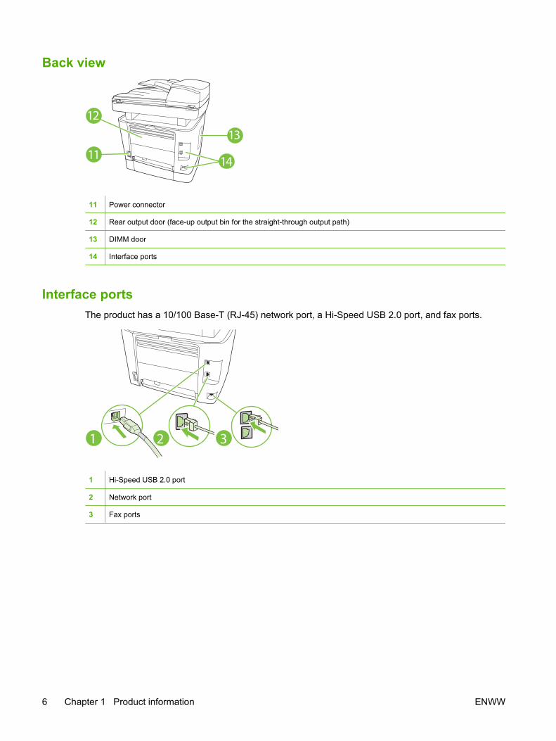
Back view
14
13
12
11
11 Power connector
12 Rear output door (face-up output bin for the straight-through output path)
13 DIMM door
14 Interface ports
Interface portsThe product has a 10/100 Base-T (RJ-45) network port, a Hi-Speed USB 2.0 port, and fax ports.
2 31
1 Hi-Speed USB 2.0 port
2 Network port
3 Fax ports
6 Chapter 1 Product information ENWW
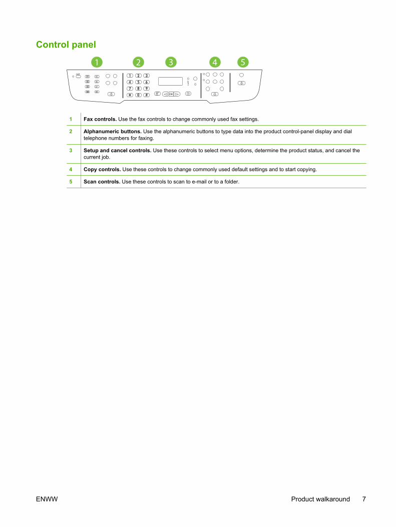
Control panel
51 32 405
06
07
08
Shift
1 Fax controls. Use the fax controls to change commonly used fax settings.
2 Alphanumeric buttons. Use the alphanumeric buttons to type data into the product control-panel display and dialtelephone numbers for faxing.
3 Setup and cancel controls. Use these controls to select menu options, determine the product status, and cancel thecurrent job.
4 Copy controls. Use these controls to change commonly used default settings and to start copying.
5 Scan controls. Use these controls to scan to e-mail or to a folder.
ENWW Product walkaround 7
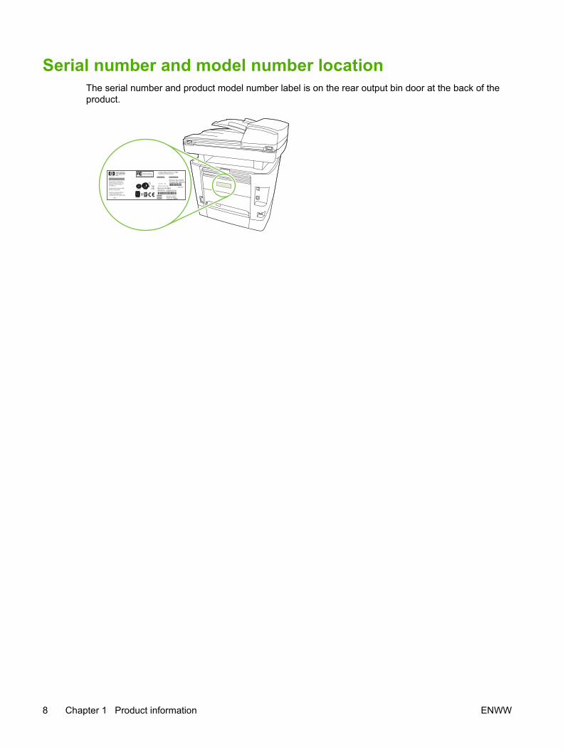
Serial number and model number locationThe serial number and product model number label is on the rear output bin door at the back of theproduct.
8 Chapter 1 Product information ENWW
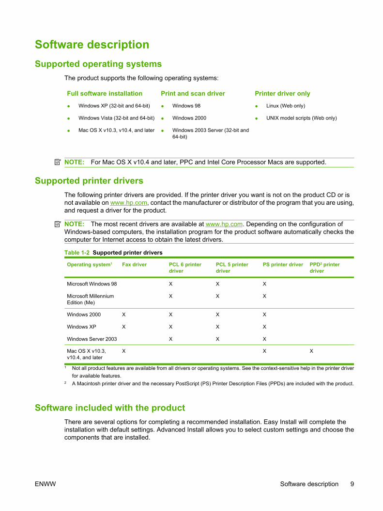
Software descriptionSupported operating systems
The product supports the following operating systems:
Full software installation
● Windows XP (32-bit and 64-bit)
● Windows Vista (32-bit and 64-bit)
● Mac OS X v10.3, v10.4, and later
Print and scan driver
● Windows 98
● Windows 2000
● Windows 2003 Server (32-bit and64-bit)
Printer driver only
● Linux (Web only)
● UNIX model scripts (Web only)
NOTE: For Mac OS X v10.4 and later, PPC and Intel Core Processor Macs are supported.
Supported printer driversThe following printer drivers are provided. If the printer driver you want is not on the product CD or isnot available on www.hp.com, contact the manufacturer or distributor of the program that you are using,and request a driver for the product.
NOTE: The most recent drivers are available at www.hp.com. Depending on the configuration ofWindows-based computers, the installation program for the product software automatically checks thecomputer for Internet access to obtain the latest drivers.
Table 1-2 Supported printer drivers
Operating system1 Fax driver PCL 6 printerdriver
PCL 5 printerdriver
PS printer driver PPD2 printerdriver
Microsoft Windows 98
Microsoft MillenniumEdition (Me)
X
X
X
X
X
X
Windows 2000
Windows XP
Windows Server 2003
X
X
X
X
X
X
X
X
X
X
X
Mac OS X v10.3,v10.4, and later
X X X
1 Not all product features are available from all drivers or operating systems. See the context-sensitive help in the printer driverfor available features.
2 A Macintosh printer driver and the necessary PostScript (PS) Printer Description Files (PPDs) are included with the product.
Software included with the productThere are several options for completing a recommended installation. Easy Install will complete theinstallation with default settings. Advanced Install allows you to select custom settings and choose thecomponents that are installed.
ENWW Software description 9
Recommended installation for Windows● HP drivers
◦ PCL 6 printer driver
◦ Scan driver
● HP MFP software
◦ HP ToolboxFX
◦ HP LaserJet Scan program
◦ HP Send Fax program and driver
◦ HP Fax Setup Wizard
◦ Uninstall program
● HP Update program
● HP Customer Participation Program
● Shop for HP Supplies program
● Other programs
◦ Readiris OCR (not installed with other software; separate installation is required)
Express installation (USB or network)The following software is included with an Express installation:
● PCL 6 printer driver
● HP LaserJet Scan program and driver
NOTE: Express installation supports faxing by using the control panel.
NOTE: PCL 5 and HP postscript level 3 emulation drivers can be installed using the Microsoft AddPrinter wizard.
Macintosh software● HP Product Setup Assistant
● HP Device Configuration
● HP Uninstaller
● HP LaserJet software
◦ HP Scan
◦ HP Director
◦ Fax program
10 Chapter 1 Product information ENWW

◦ Scan to e-mail program
◦ HP Photosmart
ENWW Software description 11

Software for WindowsWhen you install the software for Windows, you can directly connect the product to a computer by usinga USB cable, or you can connect the product to a network by using the internal print server. See thegetting started guide for installation instructions, and see the Readme file for the latest softwareinformation.
HP ToolboxFXPerform a typical installation in order to use HP ToolboxFX.
HP ToolboxFX provides links to product status information and Help information, such as the user guide,and tools for product problem-solving. See HP ToolboxFX on page 58.
Embedded Web server (EWS)The EWS is a Web-based interface that provides simple access to product status and configurations,including network configurations and Smart Printing Supplies (SPS) functionality.
You can gain access to the EWS through the network connection to the product. Type the product IPaddress in a Web browser to open the product EWS home page in the browser. From the home page,you can use the tabs and left navigation menu to check the status of the product, configure the product,or check the status of the supplies.
The following are supported browsers:
● Internet Explorer 5.0 or later
● Netscape Navigator 4.75 or later
● Opera 6.05 or later
● Safari 1.2 or later
12 Chapter 1 Product information ENWW

Software for MacintoshFor Mac OS X v10.3, v10.4, and later, use Print Center to print.
NOTE: For Macintosh computers, HP ToolboxFX is not supported.
HP DirectorHP Director is a software program for working with documents. When the document is loaded into theADF and the computer is connected directly to the product, HP Director appears on the computer screento initiate faxing, scanning, or changing settings on the product through Macintosh Configure Device.
Also included is the HP product Setup Assistant, which sets up the fax and print queues.
Macintosh Configure Device (Mac OS X v10.3, v10.4, and later)Macintosh Configure Device is a Web-based program that provides access to information about theproduct (or example, information about supplies status and product settings). Use Macintosh ConfigureDevice to monitor and manage the product from the computer.
NOTE: You must perform a complete software installation to use Macintosh Configure Device.
● Check the product status and print information pages.
● Check and change product settings.
● Check default print settings.
● Check and change fax settings, including IP configuration, Advanced, mDNS, SNMP, networkconfiguration, and fax reports.
You can view Macintosh Configure Device when the product is directly connected to a computer or whenit is connected to the network.
NOTE: You do not have to have Internet access to open and use Macintosh Configure Device.
To view Macintosh Configure Device when the product is connected to the computer
1. Open HP Director by clicking the HP Director icon in the dock.
2. In HP Director, click Settings.
3. Select Configure Device to open the Macintosh Configure Device home page in a browser.
To view Macintosh Configure Device when the product is connected to the network
1. Open one of the following browsers:
● Internet Explorer 5.0 or later
● Netscape Navigator 4.75 or later
● Opera 6.05 or later
● Safari 1.2 or later
2. Type the IP address of the product into the Web browser to open the Macintosh Configure Devicehome page.
ENWW Software for Macintosh 13

PDEs (Mac OS X v10.3, v10.4, and later)PDEs are code plug-ins that provide access to product features, such as information about the numberof copies, two-sided printing, and quality settings. An installation program for the PDEs and othersoftware is provided on the product CD for Macintosh.
14 Chapter 1 Product information ENWW

Uninstall softwareWindows
Use the Add or Remove Programs method in Windows to remove the product software. This methoddoes not require you to have the software CD.
1. Click Start, point to Settings, and then click Control Panel.
NOTE: In Windows XP, click Start, and then click Control panel.
2. Double-click Add or Remove Programs.
3. Scroll through the list of software programs and click HP LaserJet M2727.
4. Click Remove.
MacintoshTo remove the software, drag the PPD files to the trash can.
ENWW Uninstall software 15
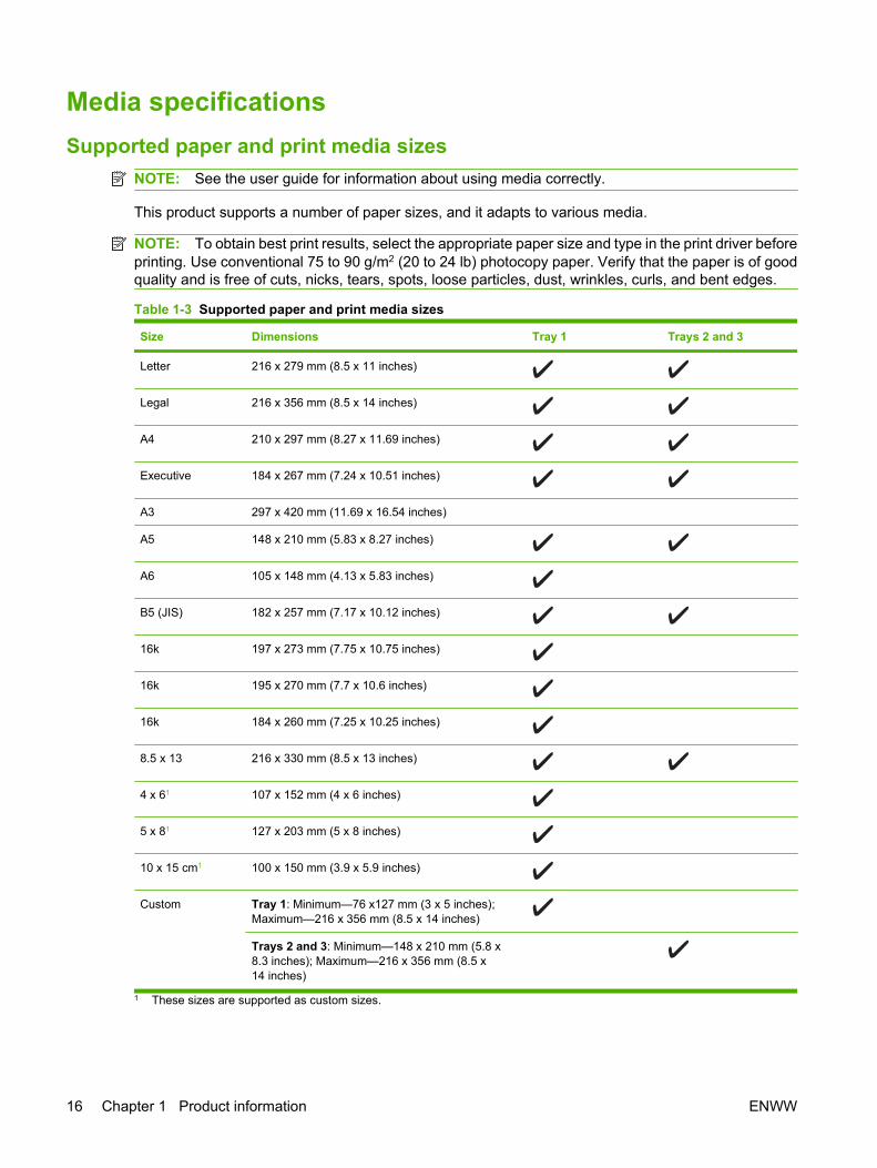
Media specificationsSupported paper and print media sizes
NOTE: See the user guide for information about using media correctly.
This product supports a number of paper sizes, and it adapts to various media.
NOTE: To obtain best print results, select the appropriate paper size and type in the print driver beforeprinting. Use conventional 75 to 90 g/m2 (20 to 24 lb) photocopy paper. Verify that the paper is of goodquality and is free of cuts, nicks, tears, spots, loose particles, dust, wrinkles, curls, and bent edges.
Table 1-3 Supported paper and print media sizes
Size Dimensions Tray 1 Trays 2 and 3
Letter 216 x 279 mm (8.5 x 11 inches)
Legal 216 x 356 mm (8.5 x 14 inches)
A4 210 x 297 mm (8.27 x 11.69 inches)
Executive 184 x 267 mm (7.24 x 10.51 inches)
A3 297 x 420 mm (11.69 x 16.54 inches)
A5 148 x 210 mm (5.83 x 8.27 inches)
A6 105 x 148 mm (4.13 x 5.83 inches)
B5 (JIS) 182 x 257 mm (7.17 x 10.12 inches)
16k 197 x 273 mm (7.75 x 10.75 inches)
16k 195 x 270 mm (7.7 x 10.6 inches)
16k 184 x 260 mm (7.25 x 10.25 inches)
8.5 x 13 216 x 330 mm (8.5 x 13 inches)
4 x 61 107 x 152 mm (4 x 6 inches)
5 x 81 127 x 203 mm (5 x 8 inches)
10 x 15 cm1 100 x 150 mm (3.9 x 5.9 inches)
Custom Tray 1: Minimum—76 x127 mm (3 x 5 inches);Maximum—216 x 356 mm (8.5 x 14 inches)
Trays 2 and 3: Minimum—148 x 210 mm (5.8 x8.3 inches); Maximum—216 x 356 mm (8.5 x14 inches)
1 These sizes are supported as custom sizes.
16 Chapter 1 Product information ENWW
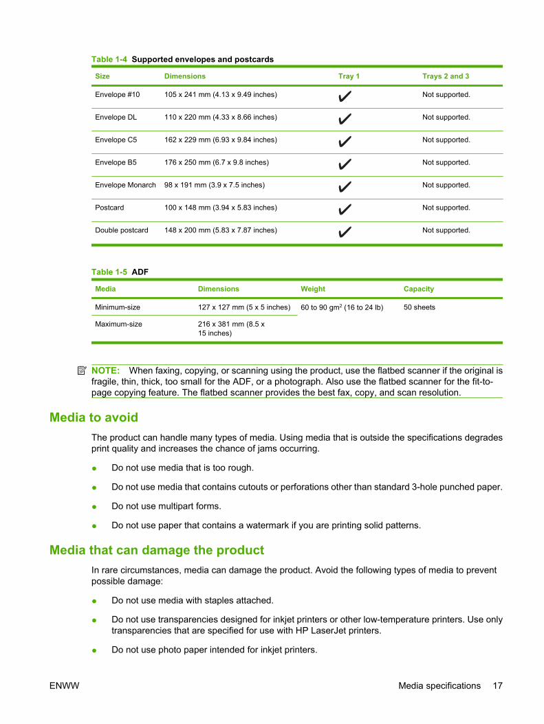
Table 1-4 Supported envelopes and postcards
Size Dimensions Tray 1 Trays 2 and 3
Envelope #10 105 x 241 mm (4.13 x 9.49 inches) Not supported.
Envelope DL 110 x 220 mm (4.33 x 8.66 inches) Not supported.
Envelope C5 162 x 229 mm (6.93 x 9.84 inches) Not supported.
Envelope B5 176 x 250 mm (6.7 x 9.8 inches) Not supported.
Envelope Monarch 98 x 191 mm (3.9 x 7.5 inches) Not supported.
Postcard 100 x 148 mm (3.94 x 5.83 inches) Not supported.
Double postcard 148 x 200 mm (5.83 x 7.87 inches) Not supported.
Table 1-5 ADF
Media Dimensions Weight Capacity
Minimum-size 127 x 127 mm (5 x 5 inches) 60 to 90 gm2 (16 to 24 lb) 50 sheets
Maximum-size 216 x 381 mm (8.5 x15 inches)
NOTE: When faxing, copying, or scanning using the product, use the flatbed scanner if the original isfragile, thin, thick, too small for the ADF, or a photograph. Also use the flatbed scanner for the fit-to-page copying feature. The flatbed scanner provides the best fax, copy, and scan resolution.
Media to avoidThe product can handle many types of media. Using media that is outside the specifications degradesprint quality and increases the chance of jams occurring.
● Do not use media that is too rough.
● Do not use media that contains cutouts or perforations other than standard 3-hole punched paper.
● Do not use multipart forms.
● Do not use paper that contains a watermark if you are printing solid patterns.
Media that can damage the productIn rare circumstances, media can damage the product. Avoid the following types of media to preventpossible damage:
● Do not use media with staples attached.
● Do not use transparencies designed for inkjet printers or other low-temperature printers. Use onlytransparencies that are specified for use with HP LaserJet printers.
● Do not use photo paper intended for inkjet printers.
ENWW Media specifications 17

● Do not use paper that is embossed or coated and is not designed for the temperature of the image-fuser. Select media that can tolerate temperatures of 200°C (392°F) for 0.1 second.HP manufactures a media that is designed for the product.
● Do not use letterhead paper that was produced with low-temperature dyes or thermography.Preprinted forms or letterhead must use inks that can tolerate temperatures of 200°C (392°F) for0.1 second.
● Do not use any media that produces emissions, or that melts, offsets, or discolors when exposedto 200°C (392°F) for 0.1 second.
To order HP LaserJet printing supplies, go to www.hp.com/go/ljsupplies in the U.S., or go towww.hp.com/go/ljsupplies worldwide.
18 Chapter 1 Product information ENWW

2 Installation
● Operating environment
● Unpack the product
● Install input devices
● Install the control-panel faceplate
● Load paper and print media
● Install memory DIMMs
ENWW 19
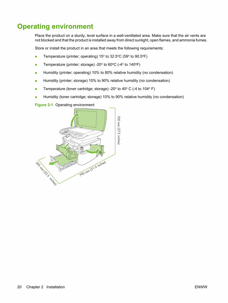
Operating environmentPlace the product on a sturdy, level surface in a well-ventilated area. Make sure that the air vents arenot blocked and that the product is installed away from direct sunlight, open flames, and ammonia fumes.
Store or install the product in an area that meets the following requirements:
● Temperature (printer; operating) 15o to 32.5oC (59o to 90.5oF)
● Temperature (printer; storage) -20o to 60oC (-4o to 140oF)
● Humidity (printer; operating) 10% to 80% relative humidity (no condensation)
● Humidity (printer; storage) 10% to 90% relative humidity (no condensation)
● Temperature (toner cartridge; storage) -20o to 40o C (-4 to 104o F)
● Humidity (toner cartridge; storage) 10% to 90% relative humidity (no condensation)
Figure 2-1 Operating environment700 m
m (27.5 inches)
595 mm (23.5 inches)790 mm (31.0 inches)
20 Chapter 2 Installation ENWW

Minimum system requirements● Windows OS (Win 98, Win 2000, 2003 Server, Millennium Edition (Me), XP, or Vista)
or
Mac OS X v10.3 and later
● 128 MB RAM for Windows operating systems
● 32 MB RAM for Macintosh operating systems
● 250 MB hard-disk space (full installation)
● CD-ROM drive
● USB port
ENWW Operating environment 21
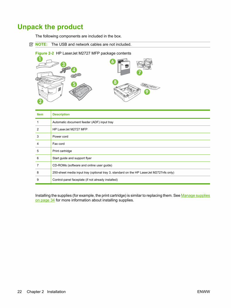
Unpack the productThe following components are included in the box.
NOTE: The USB and network cables are not included.
Figure 2-2 HP LaserJet M2727 MFP package contents
2
3
5
4
1 6
7
8
9
Item Description
1 Automatic document feeder (ADF) input tray
2 HP LaserJet M2727 MFP
3 Power cord
4 Fax cord
5 Print cartridge
6 Start guide and support flyer
7 CD-ROMs (software and online user guide)
8 250-sheet media input tray (optional tray 3, standard on the HP LaserJet M2727nfs only)
9 Control-panel faceplate (if not already installed)
Installing the supplies (for example, the print cartridge) is similar to replacing them. See Manage supplieson page 34 for more information about installing supplies.
22 Chapter 2 Installation ENWW

Install input devicesADF input tray
1. Open the ADF cover.
2. Align the two tabs on the input tray with the grooves in the ADF.
3. Slide the tray into the grooves until the tray snaps into place.
4. Close the ADF cover.
Figure 2-3 Install the ADF input tray
ENWW Install input devices 23
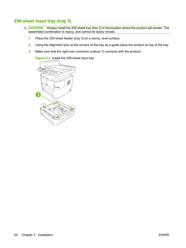
250-sheet input tray (tray 3)CAUTION: Always install the 250-sheet tray (tray 3) in the location where the product will remain. Theassembled combination is heavy, and cannot be easily moved.
1. Place the 250-sheet feeder (tray 3) on a sturdy, level surface.
2. Using the alignment pins at the corners of the tray as a guide place the product on top of the tray.
3. Make sure that the right-rear connector (callout 1) connects with the product.
Figure 2-4 Install the 250-sheet input tray
1
24 Chapter 2 Installation ENWW
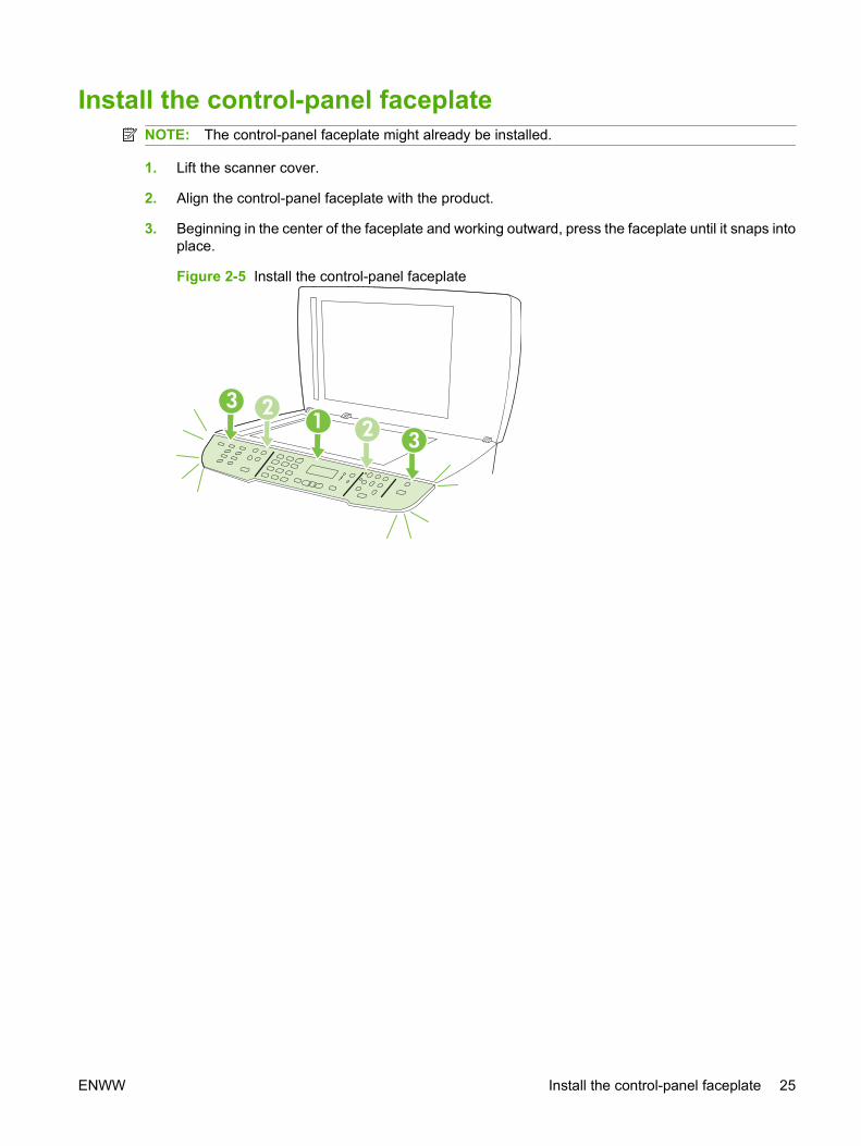
Install the control-panel faceplateNOTE: The control-panel faceplate might already be installed.
1. Lift the scanner cover.
2. Align the control-panel faceplate with the product.
3. Beginning in the center of the faceplate and working outward, press the faceplate until it snaps intoplace.
Figure 2-5 Install the control-panel faceplate
123
2 3
ENWW Install the control-panel faceplate 25

Load paper and print mediaLoad documents to fax, copy, or scan
NOTE: For the best-quality scans, use the flatbed scanner.
To load originals onto the flatbed scanner
1. Make sure that the automatic document feeder (ADF) contains no media.
2. Lift the scanner cover.
3. Place the original document face-down on the flatbed scanner glass with the upper-left corner ofthe document at the lower-right corner of the glass.
Figure 2-6 Load a document onto the flatbed scanner
4. Gently close the scanner cover.
The document is ready to be faxed/copied/scanned.
26 Chapter 2 Installation ENWW

To load originals into the ADF
NOTE: The ADF capacity for the product is up to 50 sheets of 75 g/m2 (20 lb) media.
1. Insert the stack of originals into the ADF input tray top-edge-first, with the media stack face-up andthe first page to be copied on the top of the stack. Slide the stack into the ADF until it does notmove any farther.
Figure 2-7 Load documents into the ADF (1 of 2)
2. Adjust the media guides until they are snug against the stack.
Figure 2-8 Load documents into the ADF (2 of 2)
3. The document is ready to be faxed, copied, or scanned.
Tray 1Tray 1 is accessed from the front of the product. The product prints from tray 1 before attempting to printfrom other trays.
ENWW Load paper and print media 27
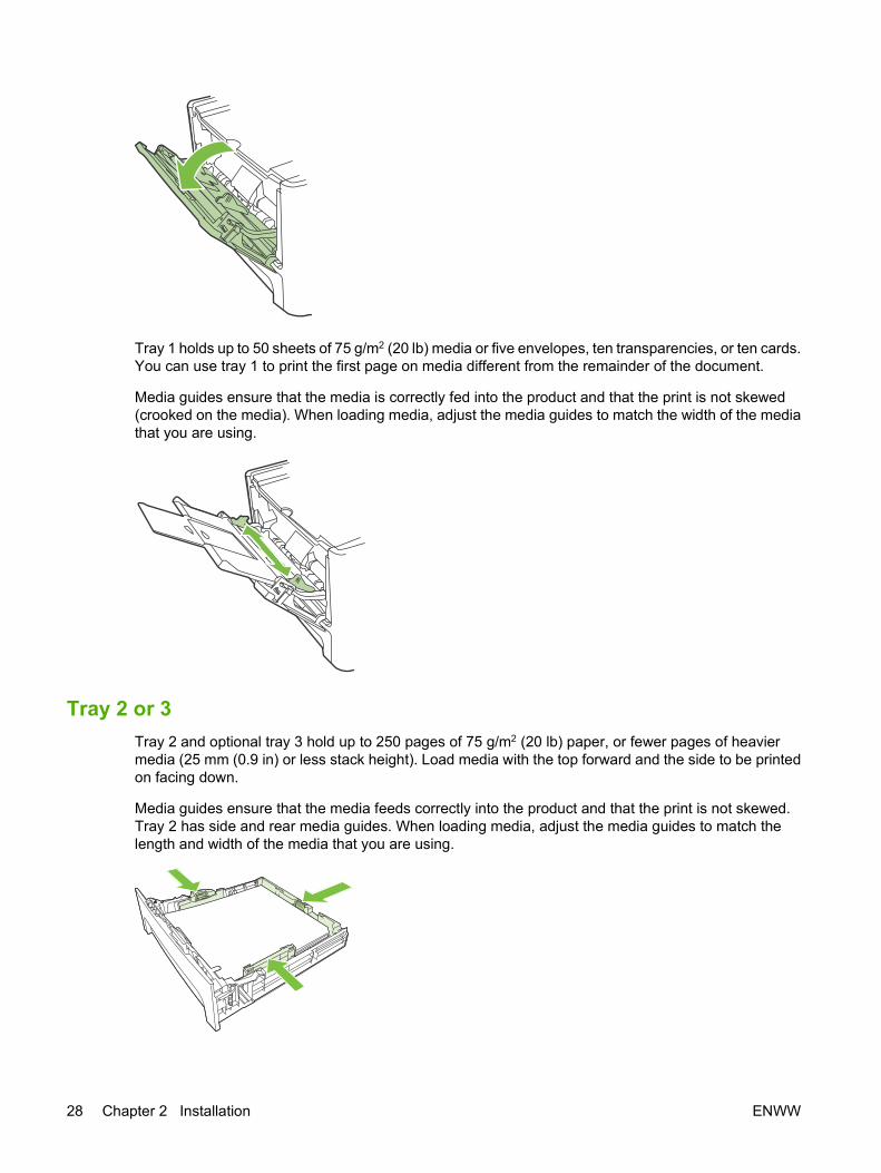
Tray 1 holds up to 50 sheets of 75 g/m2 (20 lb) media or five envelopes, ten transparencies, or ten cards.You can use tray 1 to print the first page on media different from the remainder of the document.
Media guides ensure that the media is correctly fed into the product and that the print is not skewed(crooked on the media). When loading media, adjust the media guides to match the width of the mediathat you are using.
Tray 2 or 3Tray 2 and optional tray 3 hold up to 250 pages of 75 g/m2 (20 lb) paper, or fewer pages of heaviermedia (25 mm (0.9 in) or less stack height). Load media with the top forward and the side to be printedon facing down.
Media guides ensure that the media feeds correctly into the product and that the print is not skewed.Tray 2 has side and rear media guides. When loading media, adjust the media guides to match thelength and width of the media that you are using.
28 Chapter 2 Installation ENWW
NOTE: When you add new media, make sure that you remove all of the media from the input tray andstraighten the stack of new media. Do not fan the media. This reduces jams by preventing multiplesheets of media from feeding through the product at one time.
Configure traysWhen using one of the trays for a specific size of paper, you can set the default size for the tray inHP ToolboxFX or from the control panel. In HP ToolboxFX, select Paper handling, and then select thesize for the tray you want to set. When you select that size of paper for a print job in the print dialog, theproduct automatically selects that tray for printing.
To set the default paper size or type from the control panel, complete the following steps:
1. On the product control panel, press Setup.
2. Use the arrow buttons to select System setup, and then press OK.
3. Use the arrow keys to select Paper setup, and then press OK.
4. Use the arrow keys to select the tray to be configured, and then press OK.
5. Use the arrow keys to select either Paper type or Paper size, and then press OK.
6. Use the arrow keys to select a default type or size for the tray, and then press OK.
Change tray selectionThe product is set to automatically pull media from trays that contain media. The product always pullsmedia from tray 1 if you insert media into tray 1. If there is no media in tray 1, the product attempts topull media from tray 3, if installed, and then from tray 2.
You can specify which tray you want to use by changing the tray selection. Auto select, Tray 1, Tray2, and Tray 3 are available settings. Auto select will pull media from the first available tray with theappropriate matching media loaded.
NOTE: Tray 3 is only available if a tray 3 is installed.
Change the tray selection for the current job
1. On the product control panel, press Tray Select.
2. Use the arrow buttons to select the input tray that you want to use.
3. Press Start Copy to save the selection and immediately start the copy job, or press OK to save theselection without starting the job.
Change the default tray selection
1. On the product control panel, press Setup.
2. Use the arrow buttons to select Copy setup, and then press OK.
3. Use the arrow buttons to select Def. Tray Select, and then press OK.
4. Use the arrow buttons to select a tray setting, and then press OK.
ENWW Load paper and print media 29
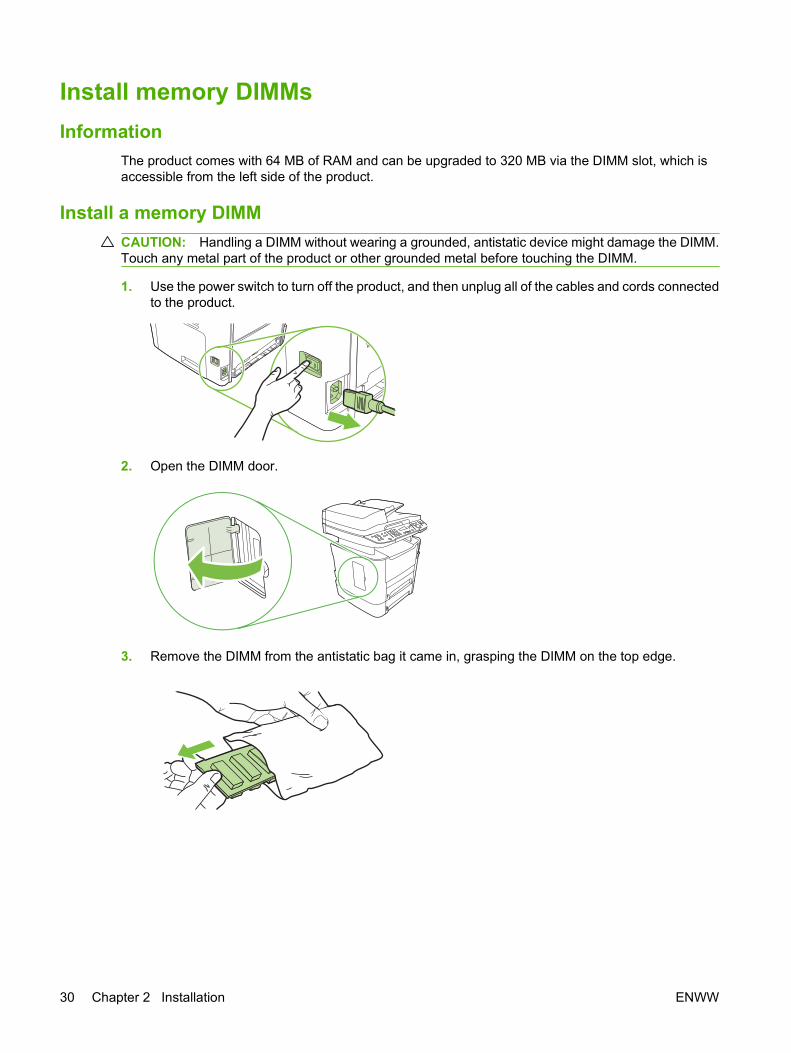
Install memory DIMMsInformation
The product comes with 64 MB of RAM and can be upgraded to 320 MB via the DIMM slot, which isaccessible from the left side of the product.
Install a memory DIMM CAUTION: Handling a DIMM without wearing a grounded, antistatic device might damage the DIMM.Touch any metal part of the product or other grounded metal before touching the DIMM.
1. Use the power switch to turn off the product, and then unplug all of the cables and cords connectedto the product.
2. Open the DIMM door.
3. Remove the DIMM from the antistatic bag it came in, grasping the DIMM on the top edge.
30 Chapter 2 Installation ENWW
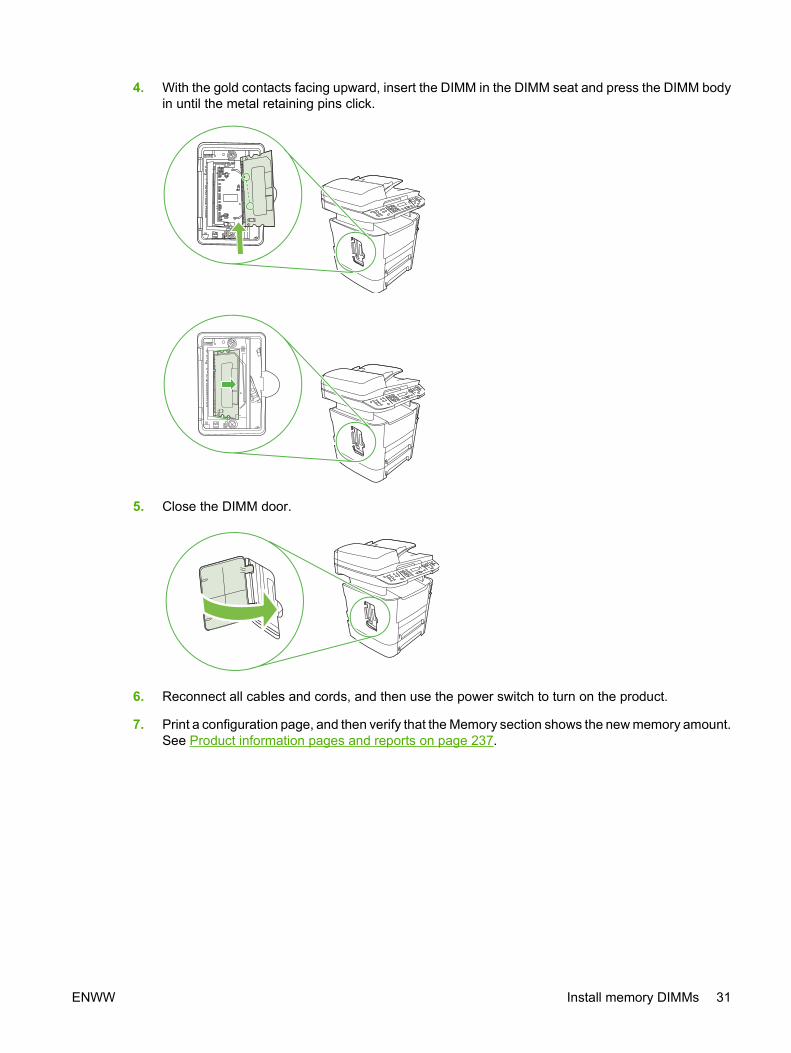
4. With the gold contacts facing upward, insert the DIMM in the DIMM seat and press the DIMM bodyin until the metal retaining pins click.
5. Close the DIMM door.
6. Reconnect all cables and cords, and then use the power switch to turn on the product.
7. Print a configuration page, and then verify that the Memory section shows the new memory amount.See Product information pages and reports on page 237.
ENWW Install memory DIMMs 31

32 Chapter 2 Installation ENWW

3 Maintenance
● Manage supplies
● Clean the product
● Manage the product
ENWW 33

Manage suppliesThis section describes replacing the print cartridge, staple cassette, tray 2 pickup roller, and the tray 2and optional tray 3 separation pad. For information about replacing the ADF pickup-roller assembly, seeReplace the ADF pickup-roller assembly on page 110.
Inspect any parts that wear when servicing the product. Replace them as needed, based on failure orwear rather than usage.
The following table lists approximate schedules for replacing consumables.
Life expectancies of supplies and the product
Item Capacity
HP LaserJet M2727 MFP Series Recommended maximum of 3,000 pages per month
Print cartridge 3,500 pages1 (standard)
7,000 pages1 (high-capacity)
Staple cassette 1,500 staples
1 The estimated print cartridge life is based on using letter- or A4-sized media with an average of 5% toner coverage and amedium density setting. Print cartridge life can be extended by using draft-mode settings to conserve toner.
Order suppliesNOTE: To locate part numbers for supplies, see Accessories and ordering informationon page 247.
To order supplies, go to one of the following Web sites.
● North America: www.hp.com/go/orders/supplies-na
● Europe and Middle East: www.hp.com/go/orders/supplies-emea
● Asia Pacific countries/regions: www.hp.com/go/orders/supplies-ap
● Latin America: www.hp.com/go/orders/supplies-la
34 Chapter 3 Maintenance ENWW

Store print cartridgesFollow these guidelines for storing print cartridges:
● Do not remove the print cartridge from its package until you are ready to use it.
CAUTION: To prevent damage, do not expose the print cartridge to light for more than a fewminutes.
● Make sure that you store print cartridges in accordance with the environmental operating andstorage specifications in this manual. See Environmental specifications on page 325.
● Store the print cartridges in a horizontal position.
● Store the print cartridges in a dark, dry location away from heat and magnetic sources.
Replace and recycle suppliesVisit www.hp.com/go/environment or www.hp.com/hpinf/community/environment/productinfo/saftey forinformation about the following environmental topics:
● Product environmental profile sheet for this and many related HP products
● Hewlett Packard's commitment to the environment
● Hewlett-Packard's environmental management system
● Hewlett Packard's end-of-life product return and recycling program
● Material safety data sheets (MSDSs), which are also available at: www.hp.com/go/msds, containinformation about supplies that contain chemical substances, such as toner.
It's easy to return and recycle your empty HP LaserJet print cartridges—free of charge—with HP PlanetPartners. HP is committed to providing inventive, high-quality products and services that areenvironmentally sound, from product design and manufacturing to distribution, operation, and recyclingprocesses. We ensure that returned HP LaserJet print cartridges are recycled properly, processing themto recover valuable plastics and metals for new products and diverting millions of tons of waste fromlandfills. Because this cartridge is being recycled and used in new materials, it will not be returned toyou. Empty HP LaserJet print cartridges are recycled responsibly when you participate in the HP PlanetPartners program. Thank you for being environmentally responsible!
In many countries/regions, this product's printing supplies (for example, the print cartridge) can bereturned to HP through the HP Printing Supplies Returns and Recycling Program. An easy-to-use andfree take-back program is available in more than 35 countries/regions. Multi-lingual program informationand instructions are included in every new HP LaserJet print cartridge and supplies package.
HP Printing Supplies Returns and Recycling Program information
Since 1992, HP has offered HP LaserJet supplies return and recycling free of charge. In 2004, HP PlanetPartners for LaserJet Supplies was available in 85% of the world market where HP LaserJet suppliesare sold. Postage-paid and pre-addressed labels are included within the instruction guide in most HPLaserJet print cartridge boxes. Labels and bulk boxes are also available through the Web sitewww.hp.com/go/recycle.
Use the label to return empty, original HP LaserJet print cartridges only. Please do not use this label fornon-HP cartridges, refilled or remanufactured cartridges, or warranty returns. Printing supplies or otherobjects that are inadvertently sent to the HP Planet Partners program cannot be returned.
ENWW Manage supplies 35

More than 10 million HP LaserJet print cartridges were recycled globally in 2004 through the HP PlanetPartners supplies recycling program. This record number represents 26 million pounds of print cartridgematerials diverted from landfills. In 2004, HP recycled an average of 59% of the print cartridge by weightconsisting primarily of plastic and metals. Plastics and metals are used to make new products such asHP products, plastic trays and spools. The remaining materials are disposed of in an environmentallyresponsible manner.
U.S. returns
For a more environmentally responsible return of used cartridges and supplies, HP encourages the useof bulk returns. Simply bundle two or more cartridges together and use the single, pre-paid, pre-addressed UPS label that is supplied in the package. For more information in the U.S., call1-800-340-2445 or visit the HP Web site at www.hp.com/go/recycle.
Non-U.S. returns
Non-U.S. customers should visit the www.hp.com/go/recycle Web site for further information regardingavailability of the HP Printing Supplies Returns and Recycling Program.
Paper
This product is capable of using recycled papers, when the paper meets the guidelines outlined in theHP LaserJet Printer Family Print Media Guide, which you can view on the Web at www.hp.com/support/ljpaperguide. This product is suitable for the use of recycled paper according to EN12281:2002.
Material restrictions
This HP product contains a battery and contains mercury in the fluorescent lamp or scanner that mightrequire special handling at end-of-life.
Type: Lithium carbon monofluoride (solid button cell)
Weight: Approximately .1 gram
Location: On formatter PC board (one battery per product)
User removable: No
36 Chapter 3 Maintenance ENWW

Replace print cartridge1. Open the print-cartridge door.
2. Grasp the handle on the print cartridge and then pull the cartridge straight out to remove it. Seethe recycling information inside the print cartridge box.
3. Remove the new print cartridge from its packaging, remove the orange cover from the printcartridge, and then pull the orange tab straight out to remove the sealing tape.
4. Insert the cartridge into the product until it is firmly in place.
ENWW Manage supplies 37

5. Close the print-cartridge door.
CAUTION: If toner gets on any clothing, wipe it off with a dry cloth and wash the clothing in cold water.Hot water sets toner into the fabric.
38 Chapter 3 Maintenance ENWW
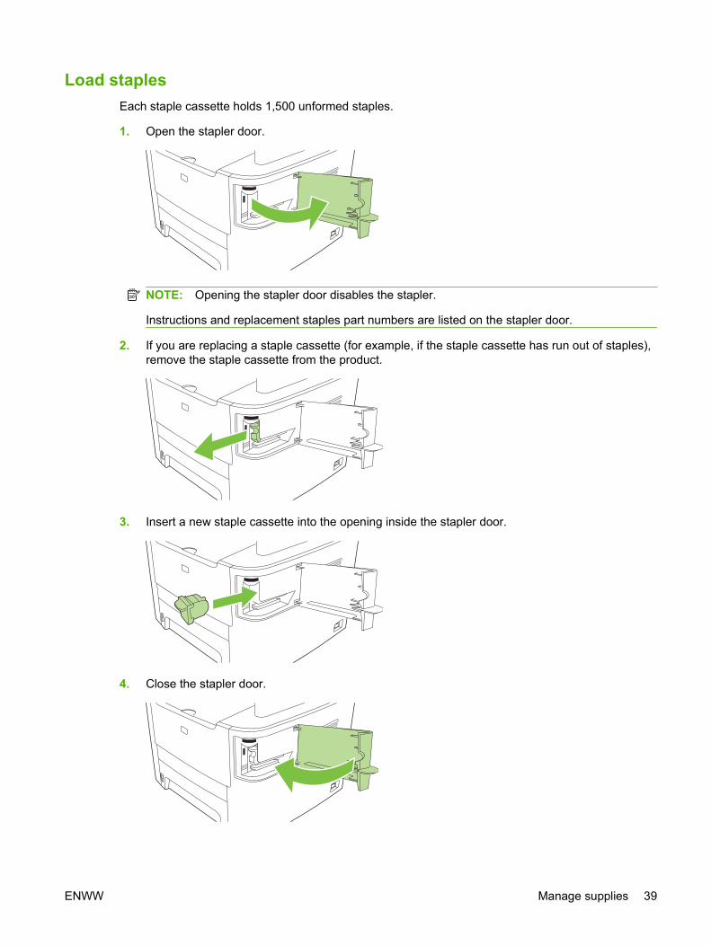
Load staplesEach staple cassette holds 1,500 unformed staples.
1. Open the stapler door.
NOTE: Opening the stapler door disables the stapler.
Instructions and replacement staples part numbers are listed on the stapler door.
2. If you are replacing a staple cassette (for example, if the staple cassette has run out of staples),remove the staple cassette from the product.
3. Insert a new staple cassette into the opening inside the stapler door.
4. Close the stapler door.
ENWW Manage supplies 39
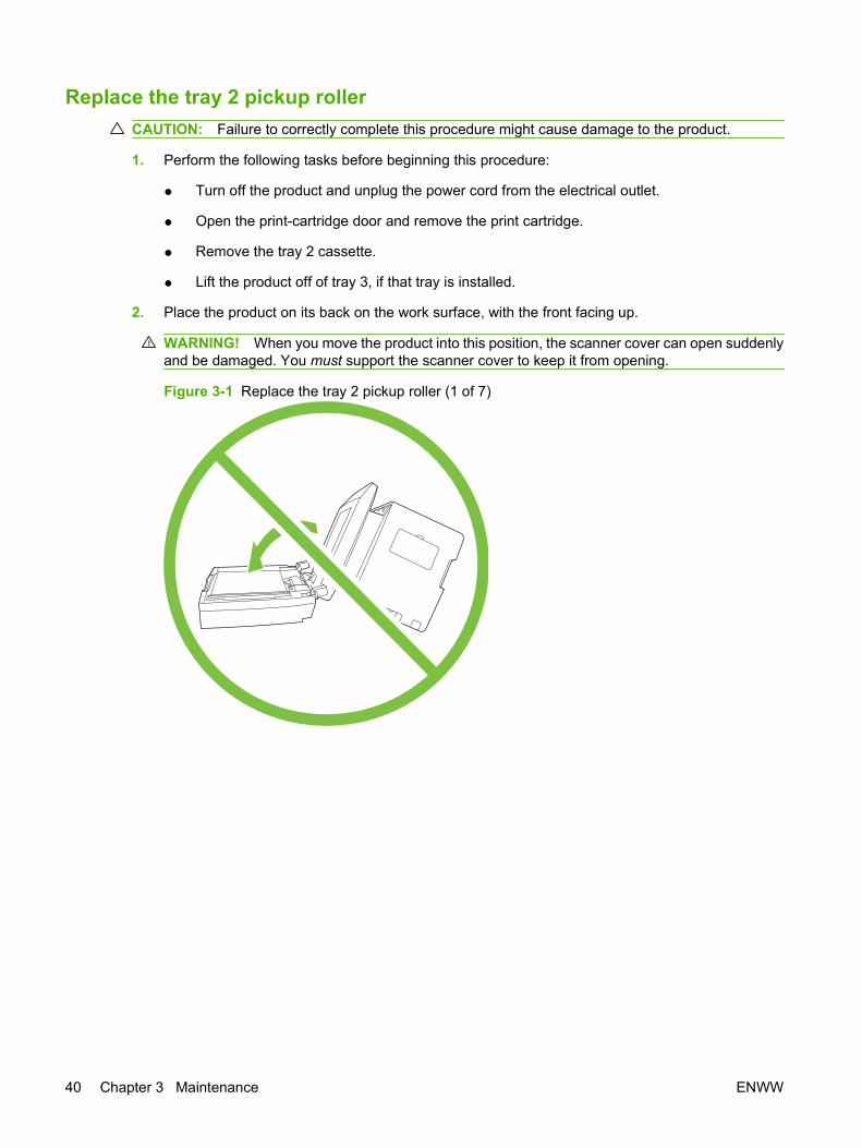
Replace the tray 2 pickup rollerCAUTION: Failure to correctly complete this procedure might cause damage to the product.
1. Perform the following tasks before beginning this procedure:
● Turn off the product and unplug the power cord from the electrical outlet.
● Open the print-cartridge door and remove the print cartridge.
● Remove the tray 2 cassette.
● Lift the product off of tray 3, if that tray is installed.
2. Place the product on its back on the work surface, with the front facing up.
WARNING! When you move the product into this position, the scanner cover can open suddenlyand be damaged. You must support the scanner cover to keep it from opening.
Figure 3-1 Replace the tray 2 pickup roller (1 of 7)
40 Chapter 3 Maintenance ENWW
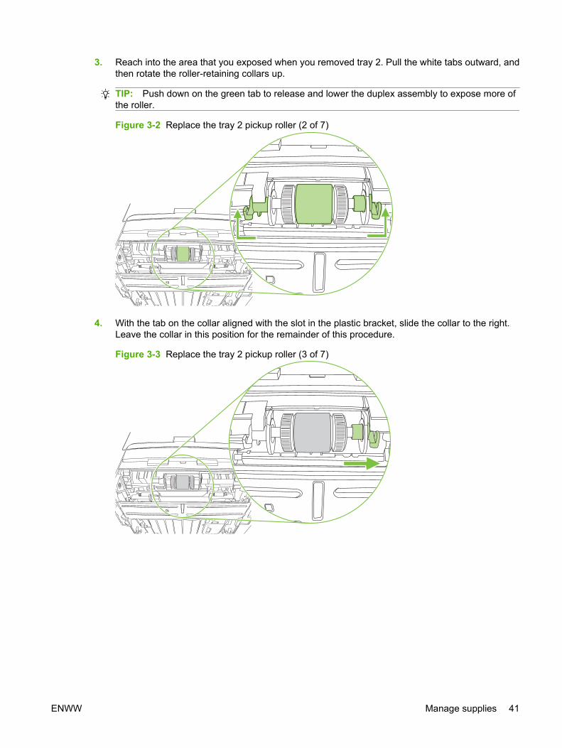
3. Reach into the area that you exposed when you removed tray 2. Pull the white tabs outward, andthen rotate the roller-retaining collars up.
TIP: Push down on the green tab to release and lower the duplex assembly to expose more ofthe roller.
Figure 3-2 Replace the tray 2 pickup roller (2 of 7)
4. With the tab on the collar aligned with the slot in the plastic bracket, slide the collar to the right.Leave the collar in this position for the remainder of this procedure.
Figure 3-3 Replace the tray 2 pickup roller (3 of 7)
ENWW Manage supplies 41

5. Remove the pickup roller.
Figure 3-4 Replace the tray 2 pickup roller (4 of 7)
6. Insert the left side of the replacement pickup-roller shaft into the left slot (callout 1), and then insertthe right side shaft (the side with the notch) into the right slot (callout 2).
Figure 3-5 Replace the tray 2 pickup roller (5 of 7)
7. Rotate the roller shaft until the notch engages with the drive shaft and clicks into place.
42 Chapter 3 Maintenance ENWW
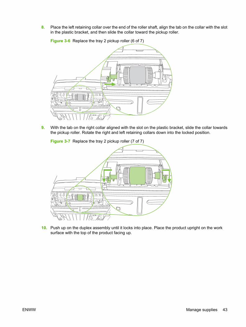
8. Place the left retaining collar over the end of the roller shaft, align the tab on the collar with the slotin the plastic bracket, and then slide the collar toward the pickup roller.
Figure 3-6 Replace the tray 2 pickup roller (6 of 7)
9. With the tab on the right collar aligned with the slot on the plastic bracket, slide the collar towardsthe pickup roller. Rotate the right and left retaining collars down into the locked position.
Figure 3-7 Replace the tray 2 pickup roller (7 of 7)
10. Push up on the duplex assembly until it locks into place. Place the product upright on the worksurface with the top of the product facing up.
ENWW Manage supplies 43
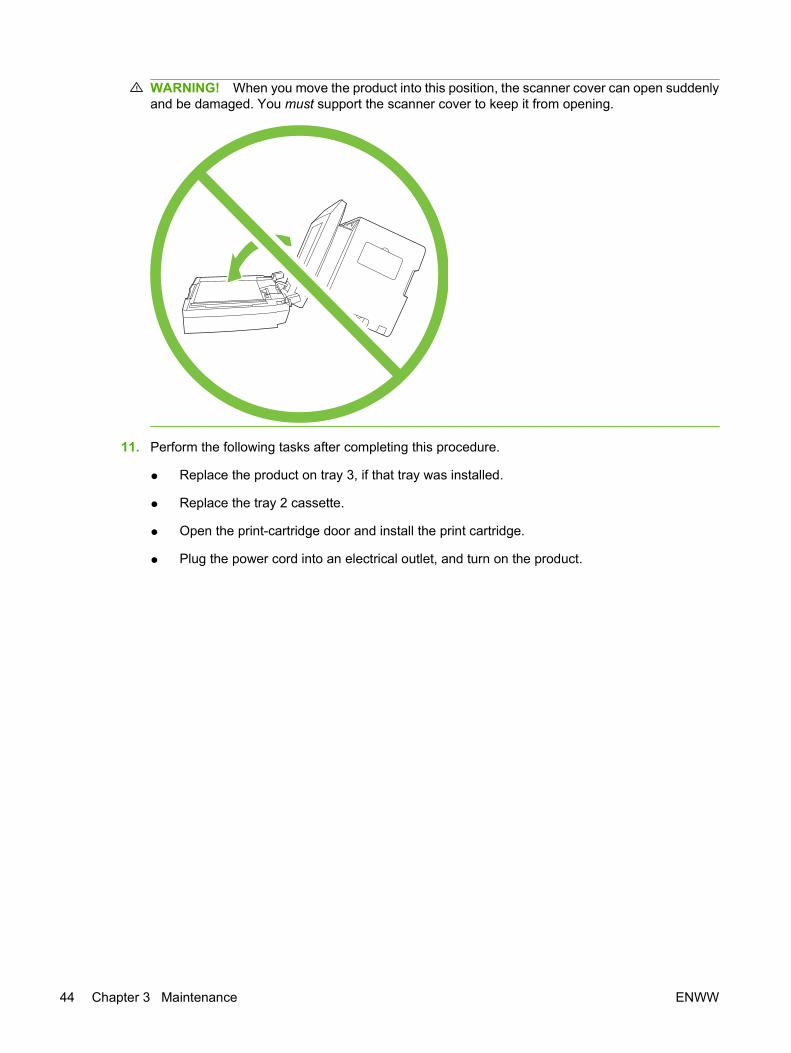
WARNING! When you move the product into this position, the scanner cover can open suddenlyand be damaged. You must support the scanner cover to keep it from opening.
11. Perform the following tasks after completing this procedure.
● Replace the product on tray 3, if that tray was installed.
● Replace the tray 2 cassette.
● Open the print-cartridge door and install the print cartridge.
● Plug the power cord into an electrical outlet, and turn on the product.
44 Chapter 3 Maintenance ENWW

Replace the tray 2 and optional tray 3 separation pad1. Remove tray 2 or tray 3.
Figure 3-8 Replace the tray 2 or tray 3 separation pad (1 of 6)
2. Locate the separation pad.
Figure 3-9 Replace the tray 2 or tray 3 separation pad (2 of 6)
ENWW Manage supplies 45

3. Remove two screws.
Figure 3-10 Replace the tray 2 or tray 3 separation pad (3 of 6)
4. Remove the separation pad.
CAUTION: Before you remove the separation pad, take note of how it is positioned in the tray.
Figure 3-11 Replace the tray 2 or tray 3 separation pad (4 of 6)
46 Chapter 3 Maintenance ENWW
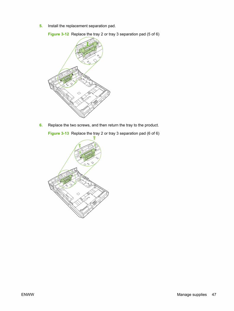
5. Install the replacement separation pad.
Figure 3-12 Replace the tray 2 or tray 3 separation pad (5 of 6)
6. Replace the two screws, and then return the tray to the product.
Figure 3-13 Replace the tray 2 or tray 3 separation pad (6 of 6)
ENWW Manage supplies 47
HP policy on non-HP suppliesHewlett-Packard Company cannot recommend the use of non-HP supplies, either new orremanufactured. Because they are not HP products, HP cannot influence their design or control theirquality. Service or repairs required as a result of using a non-HP supply will not be covered under thewarranty.
When you insert a supply into the product, the product will inform you if the supply is not a genuineHP supply. If you insert a genuine HP supply that has reached the low state from another HP device,the product identifies the supply as non-HP. Simply return the supply to the original device to reactivatethe HP features and functionality.
Reset the product for non-HP suppliesWhen you install a non-HP print cartridge, Unauthorized appears on the control-panel display. In orderto print with this supply, you must press OK when you install this non-HP supply.
CAUTION: The product will not stop printing when this type of supply is empty. Damage to the productcould occur if the product prints with an empty non-HP print cartridge. See Hewlett-Packard limitedwarranty statement on page 319 and Print cartridge limited warranty statement on page 321.
HP fraud hotlineCall the HP fraud hotline if the product or HP ToolboxFX indicates that the print cartridge is not anHP print cartridge and you think that it is genuine. HP will help determine if the product is genuine andtake steps to resolve the problem.
The print cartridge might not be a genuine HP product if you notice the following issues:
● You are experiencing a large number of problems with the print cartridge.
● The print cartridge does not look like it usually does (for example, the pull tab or the box is different).
In the United States, call toll-free: 1-877-219-3183.
Outside the United States, you can call collect. Dial the operator and ask to place a collect call to thistelephone number: 1-770-263-4745. If you do not speak English, a representative at the HP fraud hotlinewho speaks your language will assist you. Or, if someone who speaks your language is not available,a language line interpreter will connect approximately one minute after the beginning of the call. Thelanguage line interpreter is a service that will translate between you and the representative for the HPfraud hotline.
48 Chapter 3 Maintenance ENWW
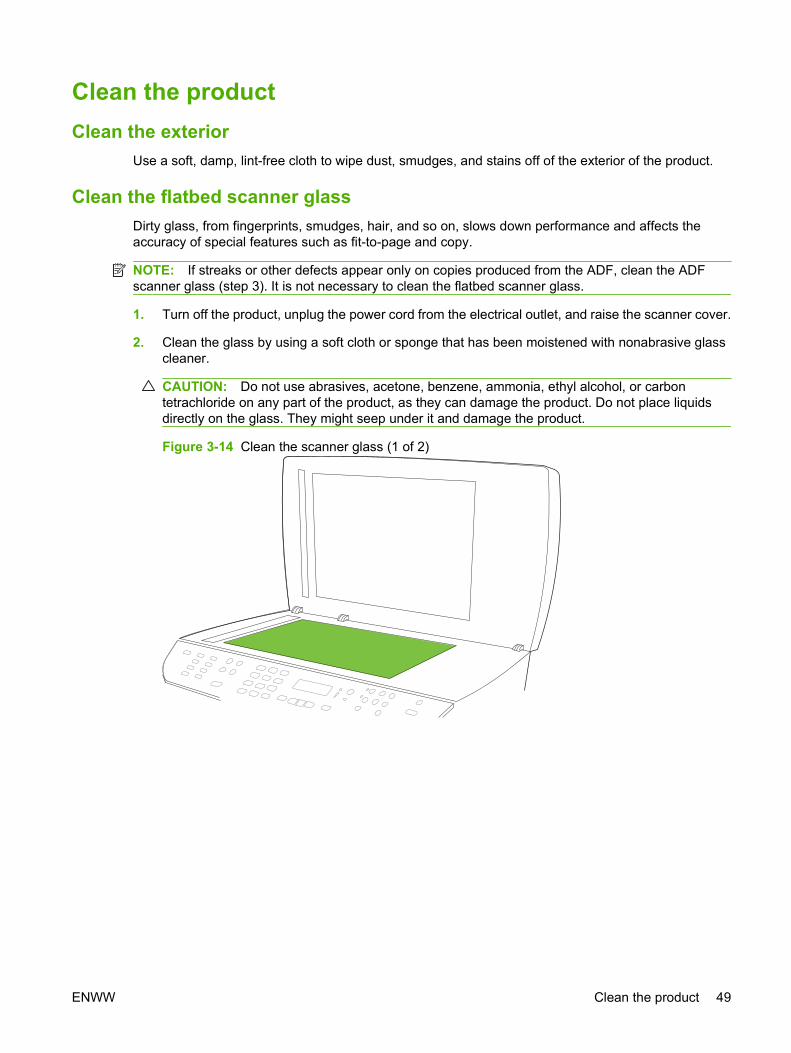
Clean the productClean the exterior
Use a soft, damp, lint-free cloth to wipe dust, smudges, and stains off of the exterior of the product.
Clean the flatbed scanner glassDirty glass, from fingerprints, smudges, hair, and so on, slows down performance and affects theaccuracy of special features such as fit-to-page and copy.
NOTE: If streaks or other defects appear only on copies produced from the ADF, clean the ADFscanner glass (step 3). It is not necessary to clean the flatbed scanner glass.
1. Turn off the product, unplug the power cord from the electrical outlet, and raise the scanner cover.
2. Clean the glass by using a soft cloth or sponge that has been moistened with nonabrasive glasscleaner.
CAUTION: Do not use abrasives, acetone, benzene, ammonia, ethyl alcohol, or carbontetrachloride on any part of the product, as they can damage the product. Do not place liquidsdirectly on the glass. They might seep under it and damage the product.
Figure 3-14 Clean the scanner glass (1 of 2)
ENWW Clean the product 49

3. Clean the ADF scanner glass by using a soft cloth or sponge that has been moistened withnonabrasive glass cleaner.
Figure 3-15 Clean the scanner glass (2 of 2)
50 Chapter 3 Maintenance ENWW

Clean the scanner-cover backing1. Turn off the product, unplug the power cord from the electrical outlet, and raise the scanner cover.
2. Clean the white scanner-cover backing by using a soft cloth or sponge that has been moistenedwith mild soap and warm water. Also, clean the ADF scanner glass (callout 1) next to the flatbedscanner glass.
Figure 3-16 Clean the scanner-cover backing
1
3. Wash the backing gently to loosen debris; do not scrub the backing.
4. Dry the backing by using a chamois or soft cloth.
CAUTION: Do not use paper-based wipes because they might scratch the backing.
5. If this does not clean the backing well enough, repeat the previous steps and use isopropyl alcoholto dampen the cloth or sponge, and then wipe the backing thoroughly with a damp cloth to removeany residual alcohol.
ENWW Clean the product 51
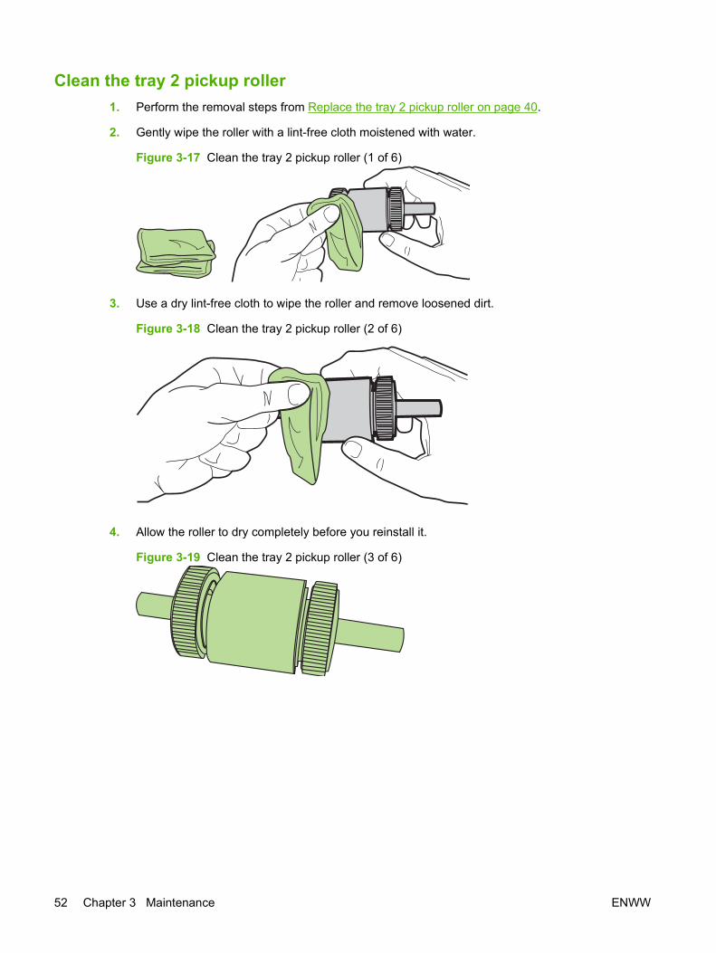
Clean the tray 2 pickup roller 1. Perform the removal steps from Replace the tray 2 pickup roller on page 40.
2. Gently wipe the roller with a lint-free cloth moistened with water.
Figure 3-17 Clean the tray 2 pickup roller (1 of 6)
3. Use a dry lint-free cloth to wipe the roller and remove loosened dirt.
Figure 3-18 Clean the tray 2 pickup roller (2 of 6)
4. Allow the roller to dry completely before you reinstall it.
Figure 3-19 Clean the tray 2 pickup roller (3 of 6)
52 Chapter 3 Maintenance ENWW

5. Insert the left side of the pickup-roller shaft into the left slot (callout 1), and then insert the right sideof the shaft (the side with the notch) into the right slot (callout 2).
Figure 3-20 Clean the tray 2 pickup roller (4 of 6)
6. Rotate the roller shaft until the notch engages with the drive shaft and clicks into place.
7. Place the left retaining collar over the end of the roller shaft, align the tab on the collar with the slotin the plastic bracket, and then slide the collar toward the pickup roller.
Figure 3-21 Clean the tray 2 pickup roller (5 of 6)
ENWW Clean the product 53
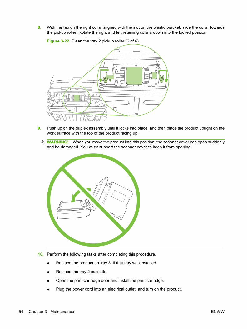
8. With the tab on the right collar aligned with the slot on the plastic bracket, slide the collar towardsthe pickup roller. Rotate the right and left retaining collars down into the locked position.
Figure 3-22 Clean the tray 2 pickup roller (6 of 6)
9. Push up on the duplex assembly until it locks into place, and then place the product upright on thework surface with the top of the product facing up.
WARNING! When you move the product into this position, the scanner cover can open suddenlyand be damaged. You must support the scanner cover to keep it from opening.
10. Perform the following tasks after completing this procedure.
● Replace the product on tray 3, if that tray was installed.
● Replace the tray 2 cassette.
● Open the print-cartridge door and install the print cartridge.
● Plug the power cord into an electrical outlet, and turn on the product.
54 Chapter 3 Maintenance ENWW
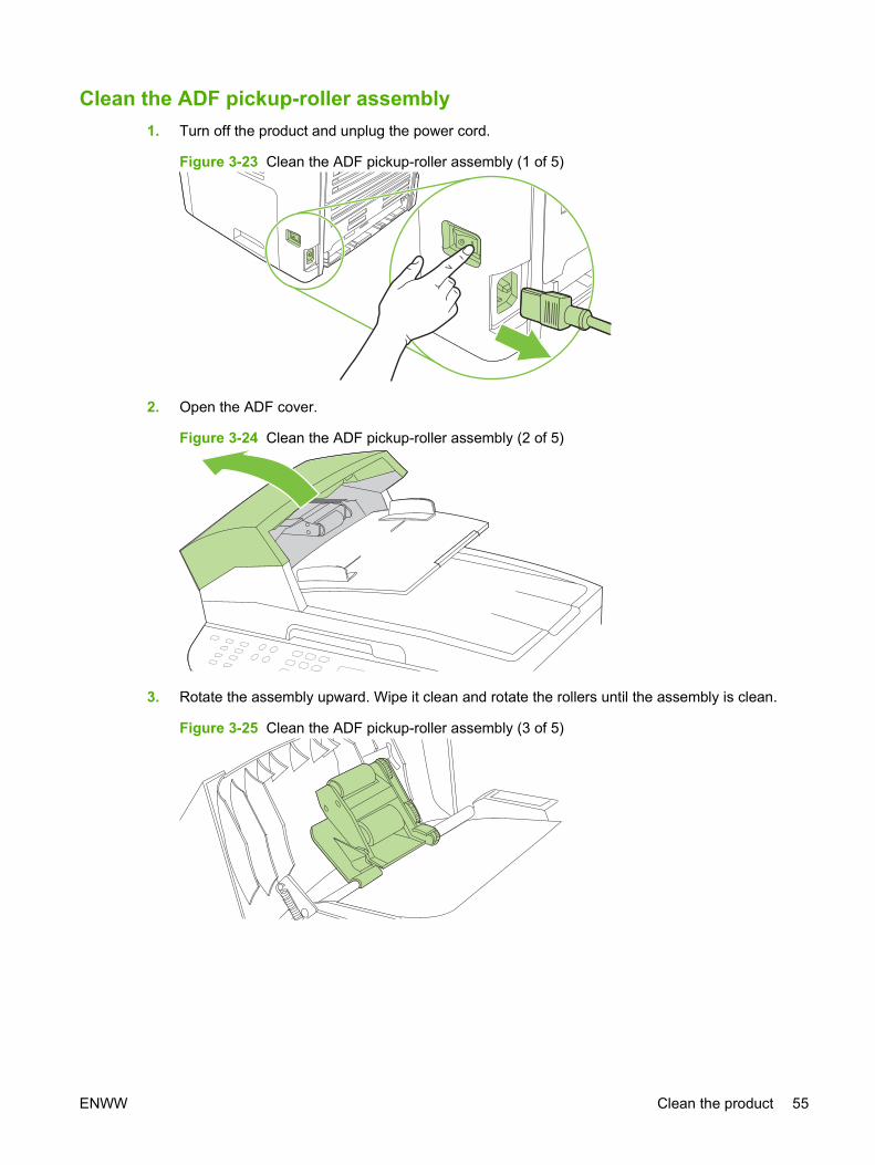
Clean the ADF pickup-roller assembly1. Turn off the product and unplug the power cord.
Figure 3-23 Clean the ADF pickup-roller assembly (1 of 5)
2. Open the ADF cover.
Figure 3-24 Clean the ADF pickup-roller assembly (2 of 5)
3. Rotate the assembly upward. Wipe it clean and rotate the rollers until the assembly is clean.
Figure 3-25 Clean the ADF pickup-roller assembly (3 of 5)
ENWW Clean the product 55
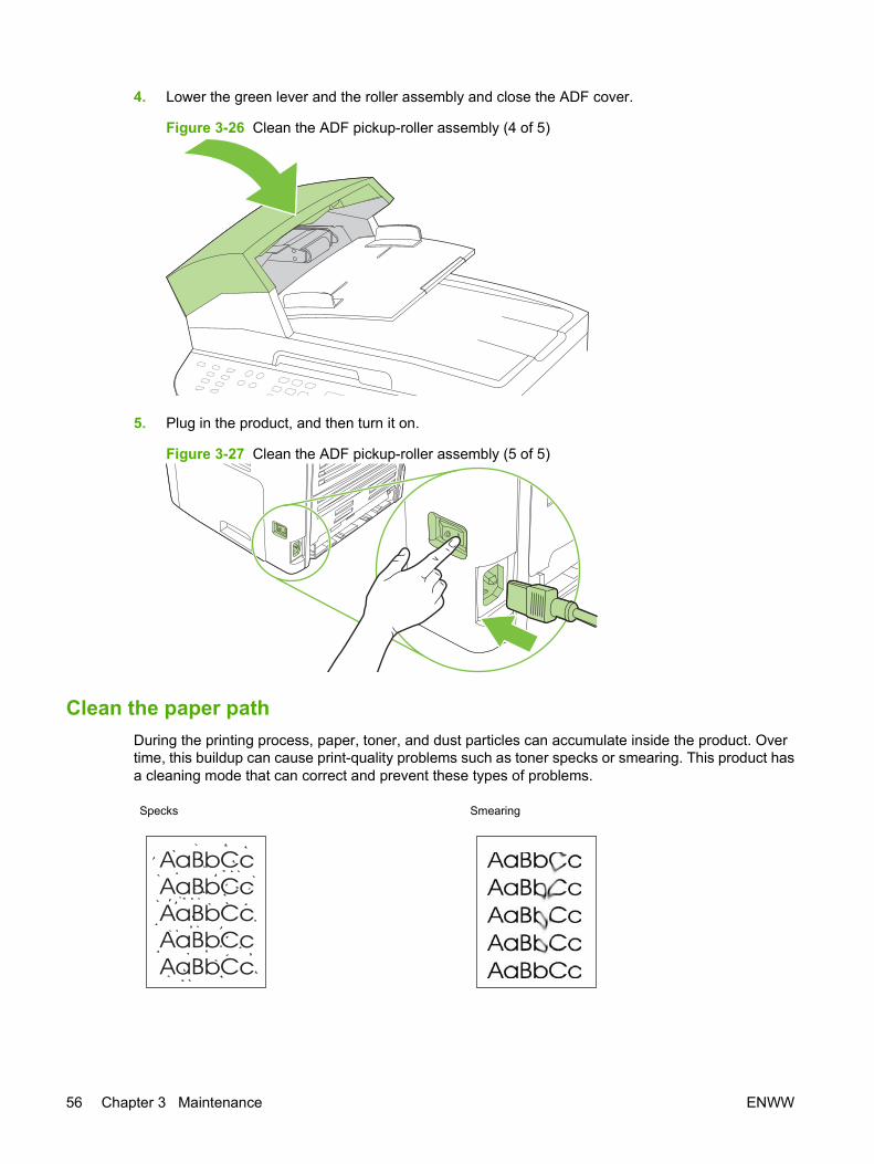
4. Lower the green lever and the roller assembly and close the ADF cover.
Figure 3-26 Clean the ADF pickup-roller assembly (4 of 5)
5. Plug in the product, and then turn it on.
Figure 3-27 Clean the ADF pickup-roller assembly (5 of 5)
Clean the paper pathDuring the printing process, paper, toner, and dust particles can accumulate inside the product. Overtime, this buildup can cause print-quality problems such as toner specks or smearing. This product hasa cleaning mode that can correct and prevent these types of problems.
Specks Smearing
56 Chapter 3 Maintenance ENWW

Clean the paper path from HP ToolboxFXUse HP ToolboxFX to clean the paper path. This is the recommended cleaning method. If you do nothave access to HP ToolboxFX, use the method in Clean the paper path from the product control panelon page 57.
1. Make sure that the product is turned on and in the Ready state, and that media is loaded in tray 1or tray 2.
2. Open HP ToolboxFX, click the product, and then click the System Settings tab.
3. Click the Service tab, and then click Start.
A page feeds through the product slowly. Discard the page when the process is completed.
Clean the paper path from the product control panelIf you do not have access to HP ToolboxFX, you can print and use a cleaning page from the productcontrol panel.
1. Press Setup.
2. Use the arrow buttons to select the Service menu, and then press OK.
3. Use the arrow buttons to select Cleaning mode, and then press OK.
4. Load plain letter or A4 paper when you are prompted.
5. Press OK again to confirm and begin the cleaning process.
A page feeds through the product slowly. Discard the page when the process is completed.
ENWW Clean the product 57

Manage the product
HP ToolboxFXThe HP ToolboxFX is a Web-based program that you can use to complete the following tasks:
● Check the product status.
● Configure the product settings.
● View problem-solving information.
● View online documentation.
You can view the HP ToolboxFX when the product is directly connected to your computer or when it isconnected to the network. You must perform a typical software installation to use HP ToolboxFX.
NOTE: The HP ToolboxFX is not supported for Windows 98 SE or Macintosh operating systems. Touse the HP ToolboxFX, the TCP/IP protocol must be installed on the computer. You do not have to haveInternet access to open and use the HP ToolboxFX.
View the HP ToolboxFXOpen the HP ToolboxFX in one of these ways:
● In the Windows system tray or on the desktop, double-click the HP ToolboxFX icon.
● On the Windows Start menu, click Programs (or All Programs in Windows XP), click HP, clickHP LaserJet M2727, and then click HP ToolboxFX.
The HP ToolboxFX software contains the following tabs, and the information about each tab is on thespecified page:
● Status on page 58
● Alerts on page 59
● Fax on page 59
● Help (Documentation) on page 62
● System settings on page 63
● Print settings on page 65
● Network settings on page 66
StatusThe HP ToolboxFX Status tab contains links to the following main pages:
● Device Status. View product status information. This page indicates product conditions such asa jam or an empty tray. After you correct a problem with the product, click Refresh Status to updatethe product status.
● Supplies Status. View detailed supplies status, such as the estimated percentage of tonerremaining in the print cartridge and the number of pages that have been printed with the currentprint cartridge. This page also has links to order supplies and to find recycling information.
58 Chapter 3 Maintenance ENWW

● Device configuration. View a detailed description of the current product configuration, includingthe amount of memory that is installed and whether optional trays are installed.
● Network configuration. View a detailed description of the current network configuration, includingthe IP address and network status.
● Print Info Pages. Print the Configuration page and various other information pages that areavailable for the product, such as the Supplies Status page and the Demo page.
● Event Log. View a history of product errors. The most recent error is at the top of the list.
Event log
The Event log is a four-column table where the product events are logged for your reference. The logcontains codes that correspond to the error messages that appear on the product control-panel display.The number in the Page Count column specifies the total number of pages that the product had printedwhen the error occurred. The Event log also contains a brief description of the error. For more informationabout error messages, see Control-panel messages on page 169.
AlertsThe HP ToolboxFX Alerts tab contains links to the following main pages:
● Set up Status Alerts. Set up the product to send pop-up alerts for certain events, such as lowtoner levels.
● Set up E-mail Alerts. Set up the product to send e-mail alert messages for certain events, suchas low toner levels.
Set up status alerts
Use HP ToolboxFX to set up the product so that it issues pop-up alerts when certain events occur.Events that trigger alerts include jams, low levels of toner in HP print cartridges, non-HP print cartridgein use, empty input trays, and specific error messages.
Select the pop-up format, the tray icon format, or both for the alerts. The pop-up alerts only appear whenthe product is printing from the computer on which you set up the alerts.
NOTE: You must click Apply before changes take effect.
Set up e-mail alerts
Use HP ToolboxFX to configure up to two e-mail addresses to receive alerts when certain events occur.You can specify different events for each e-mail address. Specify the information for the e-mail serverthat will send out the e-mail alert messages for the product.
NOTE: You must click Apply before changes take effect.
FaxUse the HP ToolboxFX Fax tab to perform fax tasks from the computer. The Fax tab contains links tothe following main pages:
● Fax Tasks. Perform such tasks as sending a fax or clearing the fax memory, or set the fax receivemode.
● Fax Phone Book. Add, edit, or delete entries in the product phone book.
ENWW Manage the product 59
● Fax Send Log. View all of the recent faxes that have been sent from the product.
● Fax Receive log. View all of the recent faxes that have been received by the product.
● Fax Dat Properties. Manage the space used to store faxes on a computer. These settings applyonly if you have chosen to send or receive faxes remotely from the computer.
Fax tasks
The following three options are available when receiving a fax:
● Print the fax. You can select an option to have a message appear on a computer to notify youwhen a fax is printed.
● Receive the fax on your computer. You can select an option to have a message appear on acomputer to notify you when a fax arrives. If the fax machine is connected to multiple computers,only one computer can be designated to receive faxes.
● Forward the fax to another fax machine.
For more information about fax tasks, see Fax on page 59.
NOTE: You must click Apply before changes take effect.
Fax phone book
Use the HP ToolboxFX Fax phone book to add and remove individuals or groups on a speed-dial list,import phone books from a variety of sources, and update and maintain a contact list.
● To add an individual contact to a speed-dial list:
1. Select the check box next to the speed dial number that you want to specify.
2. Type the contact name in the Contact Name window.
3. Type the fax number in the Fax number window.
4. Click Add/Edit.
● To add a group of contacts to a speed-dial list:
1. Select the check box next to the speed-dial number that you want to specify.
2. Click New/Edit Group.
3. Double-click a contact name from the list on the left to move it to the group list on the right, orselect a name on the left and then click the appropriate arrow to move it to the group list onthe right. You can also use these two methods to move names from right to left.
4. When you have created a group, type a name in the Group name window, and then clickOK.
● To edit an existing individual speed-dial entry:
1. Click anywhere on the row that contains the contact name to select it.
2. Type changes in the appropriate windows, and then click Add/Edit.
You can also make changes directly in the phone book directory list by clicking the entry andtyping your changes. Make sure that you do not have a check mark in the Select column.
60 Chapter 3 Maintenance ENWW
● To edit an existing group speed-dial entry:
1. Click anywhere on the row containing the group name to select it, and then click New/EditGroup.
2. Make any required changes, and then click OK.
You can make changes to the name of the group directly in the phone book directory list byclicking the entry and typing your changes. Make sure that you do not have a check mark inthe Select column.
● To delete an entry from the speed-dial list: Select the item and then click Delete.
● To move speed-dial entries:
1. Select the entry and then click Move, or you can select Move and then specify the entry inthe dialog box.
2. Select Next empty row, or specify the number of the row where you want to move the entry.
NOTE: If you specify a row that is occupied, the new entry will overwrite the existing entry.
● To import contacts from a phone book that exists in Lotus Notes, Outlook, or Outlook Express:
1. Click Import Phone Book.
2. Select the appropriate software program, navigate to the appropriate file, and then click OK.
You can also select individual entries from the phone book instead of importing the entirephone book.
● To select all of the entries in your speed-dial list: Click the Select column heading.
In addition to numerical digits, the following are valid characters for fax numbers:
● (
● )
● +
● -
● *
● #
● R
● W
● .
● ,
● <space>
NOTE: You must click Apply before changes take effect.
ENWW Manage the product 61
Fax send log
The HP ToolboxFX Fax send log lists all recently sent faxes and information about them, including thedate and time sent, job number, fax number, page count, and the results.
When you send a fax from a computer that is connected to the product, the fax contains a View link.Click this link to open a new page that provides information about the fax.
Click any column heading in the Fax send log to re-sort the information in that column in ascending ordescending order.
The Results column shows the status of the fax. If the fax attempt was unsuccessful, this columnprovides a description of why the fax was not sent.
NOTE: You must click Apply before changes take effect.
For more information about faxes, see Fax on page 59.
Fax receive log
The HP ToolboxFX Fax receive log provides a list of all recently received faxes and information aboutthem, including the date and time received, job number, fax number, page count, results, and anabbreviated fax image.
When you receive a fax on a computer that is connected to the product, the fax contains a View link.Click this link to open a new page that provides information about the fax.
Click on any column heading in the Fax receive log to re-sort the information in that column in ascendingor descending order.
The Results column provides the status of the fax. If the fax attempt was unsuccessful, this columnprovides a description of why the fax was not received.
NOTE: You must click Apply before changes take effect.
Help (Documentation)The HP ToolboxFX Documentation tab contains links to the following main pages:
● Troubleshooting
● How do I? View the How Do I? Help for help with specific tasks.
● Animated Demonstrations
● User Guide. View information about the product usage, warranty, specifications, and support. Theuser guide is available in both HTML and PDF format.
● Install Notes. View important information about the product that is not available in the user guide.The late-breaking Install Notes contain last-minute information about the product (in English only).
62 Chapter 3 Maintenance ENWW

System settingsThe HP ToolboxFX System Settings tab contains links to the following main pages:
● Device information. View information about the product, such as the product description and acontact person.
● Paper handling. Change the product paper-handling settings, such as default paper size anddefault paper type.
● Print quality. Change the product print-quality settings.
● Paper types. Change the product mode settings for a each media type, such as letterhead,prepunched, or glossy paper.
● System setup. Change the product system settings, such as product language and jam recovery.
● Service. Gain access to various procedures that help you maintain the product.
● Device polling. Change the product polling settings, which determine how often HP ToolboxFXcollects data from the product.
● Save/restore settings. Save the current settings for the product to a file on your computer. Usethis file to load the same settings onto another product or to restore these settings to this productat a later time.
Device information
The HP ToolboxFX Device information page stores data about your product for future reference. Theinformation that you type in these fields appears on the Configuration page. You can type any characterin each of these fields.
NOTE: You must click Apply before changes take effect.
ENWW Manage the product 63
Paper handling
Use the HP ToolboxFX paper-handling options to configure your default settings. These are the sameoptions that are available on the Paper Handling and Printing menus on the control panel.
You must set the asset number. The asset number is not set at the factory. This number is stored in theproduct for identification purposes.
Three options are available for handling print jobs when the product is out of media:
● Select Wait for paper to be loaded.
● Select Cancel from the Paper out action drop-down list to cancel the print job.
● Select Override from the Paper out time drop-down list to send the print job to another paper tray.
The Paper out time field specifies how long the product waits before acting on your selections. Youcan specify from 0 to 3600 seconds.
NOTE: You must click Apply before changes take effect.
Print quality
Use the HP ToolboxFX print-quality options to improve the appearance of your print jobs. These are thesame options that are available on the Print Quality menu on the control panel.
The four options provided for controlling print quality are resolution, REt (Resolution Enhancementtechnology), print density, and Economode.
● Resolution. Select 600 resolution for average print jobs and Fast Res 1200 for higher-quality printjobs. Select ProRes 1200 for the highest-quality print job, but a longer printing time.
● REt. You can turn on REt, which HP provides for improved print quality.
● Print density. For increased print density, select a higher number. For decreased print density,select a lower number.
● Economode. Turn Economode on when you are printing average print jobs. Economode reducesprint quality, but increases the life of your print cartridge. To increase print quality, turn Economodeoff. HP does not recommend full-time use of Economode.
NOTE: You must click Apply before changes take effect.
Paper types
Use the HP ToolboxFX paper-types options to configure print modes that correspond to the variousmedia types. When you select Restore Modes, all of the modes are reset to the factory settings.
NOTE: You must click Apply before changes take effect.
64 Chapter 3 Maintenance ENWW
System setup
Use the HP ToolboxFX system-settings options to configure the settings for printing, faxing, copying,and scanning. These are the same options that are available on the System Settings menu on thecontrol panel.
NOTE: You must click Apply before changes take effect.
Service
During the printing process, paper, toner, and dust particles can accumulate inside the product. Overtime, this buildup can cause print-quality problems, such as toner specks or smearing. HP ToolboxFXprovides an easy method for cleaning the paper path. For more information, see Clean the paper pathon page 56.
Device Polling
You can turn off HP ToolboxFX device polling to reduce network traffic, but you will also disable someHP ToolboxFX features: pop-up alerts, fax log updates, the ability to receive faxes to this computer, andscanning using the Scan To button.
To turn device polling on, do both of the following tasks:
● Clear Turn off device polling in HP ToolboxFX.
● Turn on one of the disabled device-polling features in HP ToolboxFX.
NOTE: You must click Apply before changes take effect.
Print settingsThe HP ToolboxFX Print Settings tab contains links to the following main pages:
● Printing. Change the default product print settings, such as number of copies and paperorientation.
● PCL5e. View and change the PCL5e settings.
● PostScript. View and change the PS settings.
Printing
Use the HP ToolboxFX printing-settings options to configure the settings for all print functions. Theseare the same options that are available on the Print Settings menu on the control panel.
NOTE: You must click Apply before changes take effect.
ENWW Manage the product 65
PCL 5e
Use the PCL5e options to configure the settings when you are using the PCL5e print personality. Theseare the same options that are available on the PCL5e menu on the control panel.
NOTE: You must click Apply before changes take effect.
PostScript
Use the PostScript option when you are using the PostScript print personality. When the PrintPostScript error option is turned on, the PostScript error page automatically prints when PostScripterrors occur.
NOTE: You must click Apply before changes take effect.
Network settingsThe network administrator can use the HP ToolboxFX Network Settings tab to control the network-related settings for the product when it is connected to an IP-based network.
Embedded Web serverThis product is equipped with an embedded Web server (EWS), which provides access to informationabout product and network activities. A Web server provides an environment in which Web programscan run, much in the same way that an operating system, such as Windows, provides an environmentfor programs to run on a computer. The output from these programs can then be displayed by a Webbrowser, such as Microsoft Internet Explorer, Safari, or Netscape Navigator.
An “embedded” Web server resides on a hardware device (such as an HP LaserJet product) or infirmware, rather than as software that is loaded on a network server.
The advantage of an EWS is that it provides an interface to the product that anyone with a network-connected product and computer can use. There is no special software to install or configure, but youmust have a supported Web browser on the computer. To gain access to the EWS, type the IP addressfor the product in the address line of the browser. (To find the IP address, print a configuration page.For more information about printing a configuration page, see Product information pages and reportson page 237.)
NOTE: For Macintosh operating systems, you can use the EWS over a USB connection after installingthe Macintosh software included with the product.
FeaturesThe EWS allows you to view product and network status and manage printing functions from a computer.With the EWS, you can complete the following tasks:
● View product status information.
● Determine the remaining life on all supplies and order new ones.
● View and change part of the product configuration.
● View and print some internal pages.
● Select the language in which to display the EWS pages.
66 Chapter 3 Maintenance ENWW

● View and change network configuration.
● Set, change, or clear the product security password.
NOTE: Changing network settings in the EWS might disable some product software or features.
Secure the embedded Web serverUse the EWS to set a password.
1. Open the EWS, and then click the System tab.
2. Click Password.
3. In the Password box, type the password you want to set, and then in the Confirm password box,type the same password again to confirm your choice.
4. Click Apply to save the password.
Macintosh Configure Device (Mac OS X v10.3, v10.4, and later)Macintosh Configure Device is a Web-based program that provides access to information about theproduct (for example, information about supplies status and product settings). Use Macintosh ConfigureDevice to monitor and manage the product from the computer
NOTE: You must perform a complete software installation to use Macintosh Configure Device.
● Check the product status and print information pages.
● Check and change product system settings.
● Check default print settings.
● Check and change fax settings, including fax send, fax receive, fax phone book and speed-dialsettings, and fax reports.
● Check and change network settings, including IP configuration, Advanced, mDNS, SNMP, networkconfiguration, and password.
You can view Macintosh Configure Device when the product is directly connected to your computer orwhen it is connected to the network.
NOTE: You do not have to have Internet access to open and use Macintosh Configure Device.
To view Macintosh Configure Device when the product is directly connected to the computer
1. Open HP Director by clicking the HP Director icon in the dock.
2. In HP Director, click Settings.
3. Select Configure device to open the Macintosh Configure Device home page in a browser.
To view Macintosh Configure Device when the product is connected to a network
1. Open one of the following supported Web browsers:
● Safari 1.2 or later
● Microsoft Internet Explorer 5.0 or later
ENWW Manage the product 67

● Netscape Navigator 4.75 or later
● Opera 6.05 or later
2. Type the IP address of the product into the Web browser to open the Macintosh Configure Devicehome page.
68 Chapter 3 Maintenance ENWW

4 Theory of operation
● Basic operation
● Scanner and ADF functions and operation
● Internal components (base unit)
● Engine control system
● Laser/scanner system
● Pickup/feed/delivery system
● Image-formation system
● Fax functions and operation
ENWW 69

Basic operationThis chapter presents an overview of the relationships between major components in the product, andincludes a detailed discussion of the image-formation system. The following systems are discussed:
● Engine control system
● Laser/scanner system
● Pickup/feed/delivery system
● Image-formation system
Figure 4-1 HP LaserJet M2727 MFP system block diagram
Sequence of operation for the base unitOperational sequences are controlled by the microprocessor and the DC controller.
Table 4-1 Sequence of operation
Name Timing Purpose
WAIT From power-on until the end of the main-motor initialdrive
Detects the presence of a print cartridge; clearspotential from the drum surface and cleans thetransfer roller
See Table 4-2 Power-on sequence on page 71 fora complete description of the WAIT (power-on)period.
STBY (standby) From the end of the WAIT or LSTR period until eithera print command is sent from the formatter or thepower is turned off
Prepares the product to receive print commands
INTR (initialrotation)
From the time of the print command until the pickupsolenoid is turned on
Prepares the photosensitive drum for printing
70 Chapter 4 Theory of operation ENWW
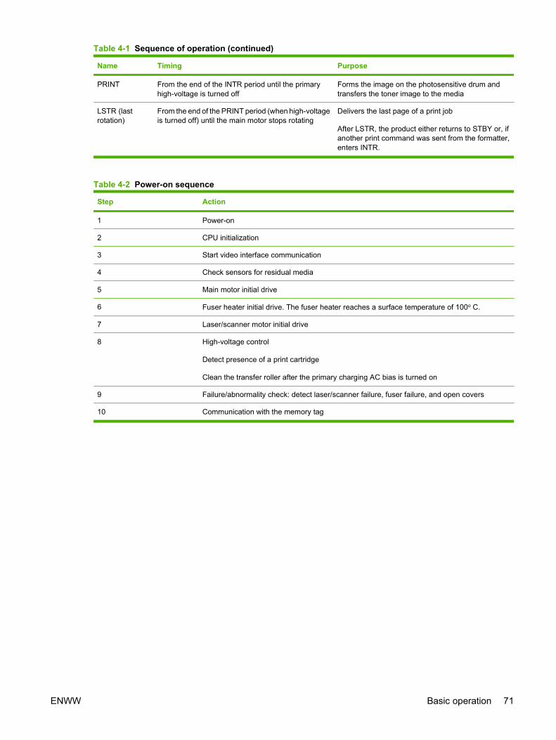
Name Timing Purpose
PRINT From the end of the INTR period until the primaryhigh-voltage is turned off
Forms the image on the photosensitive drum andtransfers the toner image to the media
LSTR (lastrotation)
From the end of the PRINT period (when high-voltageis turned off) until the main motor stops rotating
Delivers the last page of a print job
After LSTR, the product either returns to STBY or, ifanother print command was sent from the formatter,enters INTR.
Table 4-2 Power-on sequence
Step Action
1 Power-on
2 CPU initialization
3 Start video interface communication
4 Check sensors for residual media
5 Main motor initial drive
6 Fuser heater initial drive. The fuser heater reaches a surface temperature of 100o C.
7 Laser/scanner motor initial drive
8 High-voltage control
Detect presence of a print cartridge
Clean the transfer roller after the primary charging AC bias is turned on
9 Failure/abnormality check: detect laser/scanner failure, fuser failure, and open covers
10 Communication with the memory tag
Table 4-1 Sequence of operation (continued)
ENWW Basic operation 71
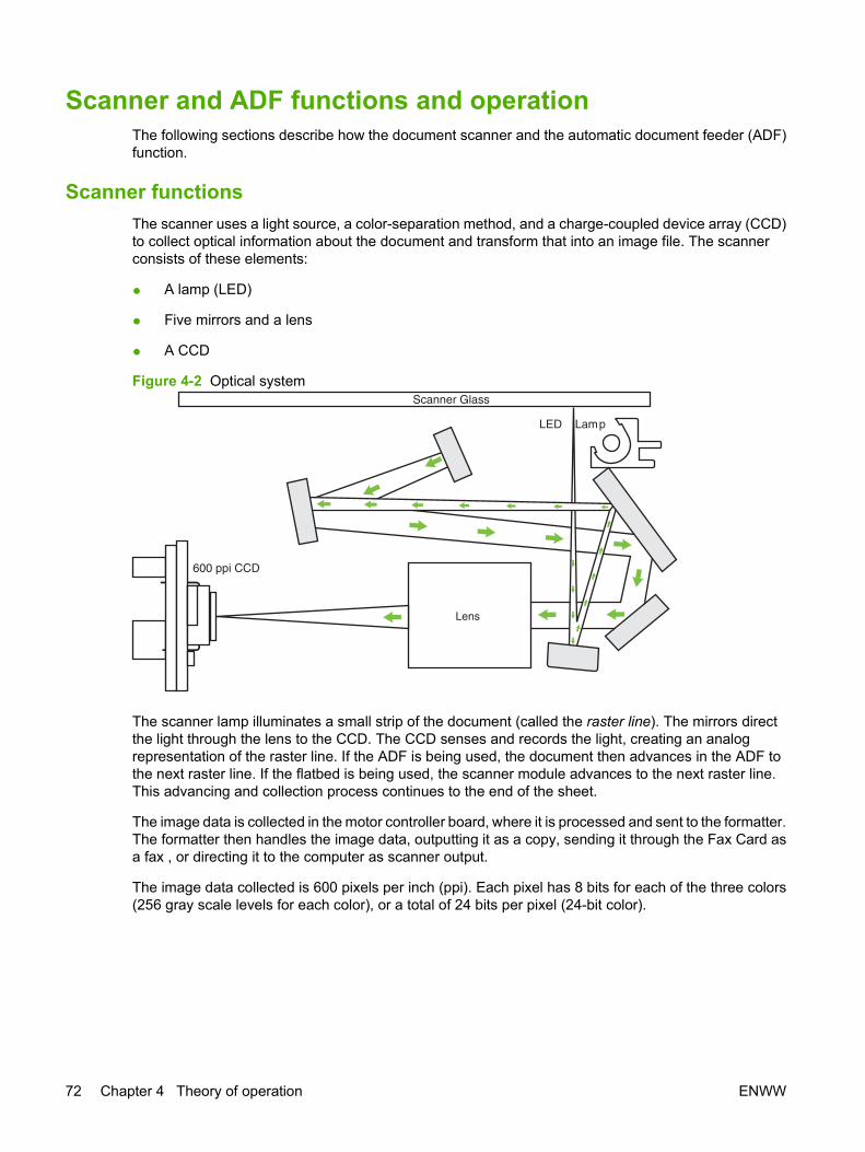
Scanner and ADF functions and operationThe following sections describe how the document scanner and the automatic document feeder (ADF)function.
Scanner functions The scanner uses a light source, a color-separation method, and a charge-coupled device array (CCD)to collect optical information about the document and transform that into an image file. The scannerconsists of these elements:
● A lamp (LED)
● Five mirrors and a lens
● A CCD
Figure 4-2 Optical system
Lens
LED Lamp
Scanner Glass
600 ppi CCD
The scanner lamp illuminates a small strip of the document (called the raster line). The mirrors directthe light through the lens to the CCD. The CCD senses and records the light, creating an analogrepresentation of the raster line. If the ADF is being used, the document then advances in the ADF tothe next raster line. If the flatbed is being used, the scanner module advances to the next raster line.This advancing and collection process continues to the end of the sheet.
The image data is collected in the motor controller board, where it is processed and sent to the formatter.The formatter then handles the image data, outputting it as a copy, sending it through the Fax Card asa fax , or directing it to the computer as scanner output.
The image data collected is 600 pixels per inch (ppi). Each pixel has 8 bits for each of the three colors(256 gray scale levels for each color), or a total of 24 bits per pixel (24-bit color).
72 Chapter 4 Theory of operation ENWW

Scanner operationAt power-on and periodically at other times, the scanner assembly moves systematically to locate itshome position. It then calibrates to a white strip located under the glass at the right end of the scan tub.
If the product detects a document in the ADF when a copy or scan is initiated (from the software or thecontrol panel), the scan module moves to the left side of the scan tub and stops. The image is acquiredas the paper is fed through the ADF past the scanner module.
If no document is detected in the ADF, the scan module acquires the image from the flatbed glass whileslowly moving within the scan tub.
ADF operationStandby (paper-loading) mode: In standby mode, the pickup roller is up and the stack-stop is down,preventing the user from inserting the original document too far. When a document is inserted correctly,the paper-present sensor detects its presence.
The standard operation of the ADF consists of the pick, feed, and lift steps.
Pick: When it receives a copy or scan command, the ADF motor engages the gear train to lower thepickup-roller assembly and raise the stack-stop. The first roller, called the pre-pick roller, moves the topfew sheets forward into the ADF. The next roller is the pickup roller. This roller contacts the ADFseparation pad, which separates multiple pages into single sheets.
Feed: The single sheet continues through the path. Along the way, the form sensor, which is a setdistance from the ADF glass, detects the sheet. This alerts the scanner to start when the page reachesthe glass. The scanner acquires the image, one raster line at a time, until it detects the end of the page.The page is then ejected. The pick and feed steps are repeated as long as paper is detected in the ADFinput tray.
Lift: When no more paper is detected in the ADF input tray and the form sensor detects the trailing edgeof the last page, the last sheet is ejected and the motor turns in a sequence that lifts the pick-rollerassembly to standby (paper-loading) mode again.
The ADF will not function when the ADF cover is open. The paper path is incomplete if the ADF coveris lifted from the glass.
ENWW Scanner and ADF functions and operation 73
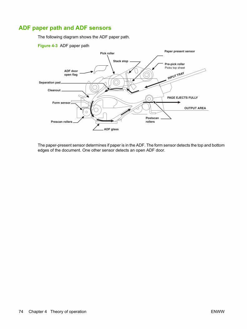
ADF paper path and ADF sensorsThe following diagram shows the ADF paper path.
Figure 4-3 ADF paper path
PAGE EJECTS FULLY
OUTPUT AREA
ADF glass
Prescan rollers
INPUT TRAY
Form sensor
Postscanrollers
Pre-pick rollerPicks top sheet
Stack stop
Pick rollerPaper present sensor
ADF dooropen flag
Separation pad
Cleanout
The paper-present sensor determines if paper is in the ADF. The form sensor detects the top and bottomedges of the document. One other sensor detects an open ADF door.
74 Chapter 4 Theory of operation ENWW

ADF jam detectionThe ADF has two sensors that detect paper. The paper-present sensor detects the presence of mediain the ADF input tray. The form sensor detects media moving through the ADF. If a jam is detected, theADF immediately stops the paper feeding and a jam message appears on the control-panel display.
A jam can be detected under any of the following conditions:
● Document-feeder jam. When documents are detected in the ADF input tray, and a command tocopy, scan or fax is received, the scan module travels to the left side of the scan assembly andstops beneath the ADF scanner glass. The ADF then attempts three times, or for about tenseconds, to advance the paper to the form sensor. If the paper does not advance, the scan moduletravels back to the home position on the right side of the scanner assembly. The messageDocument feeder mispick. Reload. appears on the control-panel display.
● Long-document jam. If the paper has advanced to trigger the form sensor, but the trailing edgeis not detected within the time allowed for a 381-mm (15-inch) document (the maximum allowablepage length for the ADF), the scanner returns to the home position on the right side of the scannerassembly. The message Doc feeder jam. Clear, Reload. appears on the control-panel display.
● Stall jam. When a page that is less than 381 mm (15 inches) long has advanced to the form sensorbut has not left it within the expected time, the paper has probably stalled or jammed. The scannerreturns to the home position on the right side of the scanner assembly. The message Doc feederjam. Clear, Reload. appears on the control-panel display.
● Other. If the paper stops in the ADF and the scan module remains under the ADF scanner glass,an internal firmware error has probably occurred. This is usually remedied by cycling the power.
ENWW Scanner and ADF functions and operation 75

Internal components (base unit)Figure 4-4 Cross-section of printer on page 76 highlights the major internal components.
Figure 4-4 Cross-section of printer
41 3 9
87652
19 18 17 16 15 1312
11 1014
1 Top output bin delivery roller
2 Fuser film
3 Laser/scanner
4 Primary charging roller
5 Developer roller
6 Print cartridge
7 Feed roller
8 Multipurpose pickup roller
9 Multipurpose separation pad
10 Separation pad
11 Pickup roller
12 Registration roller
13 Duplexer pickup roller
14 Registration shutter
76 Chapter 4 Theory of operation ENWW

15 Transfer roller
16 Photosensitive drum
17 Duplexer feed roller
18 Pressure roller
19 Rear output bin delivery roller
ENWW Internal components (base unit) 77
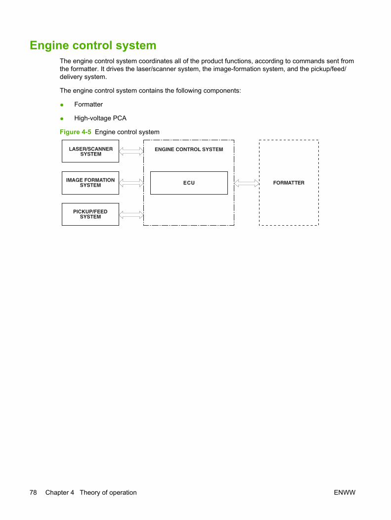
Engine control systemThe engine control system coordinates all of the product functions, according to commands sent fromthe formatter. It drives the laser/scanner system, the image-formation system, and the pickup/feed/delivery system.
The engine control system contains the following components:
● Formatter
● High-voltage PCA
Figure 4-5 Engine control system
78 Chapter 4 Theory of operation ENWW

Figure 4-6 Engine-control-system circuit diagram
High-voltagepower supply
circuitPressure roller
AC input
circuit
Low-voltage powersupply circuit
Main motor
Solenoids
Sensors
Laser driver
BD sensor
IC201
CPU
Duplex driverFan motor drive
circuitFan
Option
Memory tag
Memory tag circuit
ECU PCA
Fuser controlFuser
Transfer roller
Print cartridge
Formatter
Laser/scanner motor
IC502Reset IC
PCA
ENWW Engine control system 79
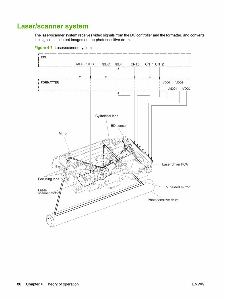
Laser/scanner systemThe laser/scanner system receives video signals from the DC controller and the formatter, and convertsthe signals into latent images on the photosensitive drum.
Figure 4-7 Laser/scanner system
80 Chapter 4 Theory of operation ENWW

Pickup/feed/delivery systemThe pickup/feed/delivery system consists of several types of feed rollers and sensors. The DC controlleruses two motors and two solenoids to drive the rollers. Three media-detection sensors detect media asit passes through the printer. If media does not reach or pass each sensor within a specified time period,the DC controller determines that a jam has occurred and alerts the formatter.
The following components are identified in Figure 4-8 Pickup/feed/delivery system on page 82:
● M1, main motor
● SL1, tray 2 pickup solenoid
● SL2, tray 1 pickup solenoid
● SL3, duplex solenoid
● PS911, width-detection sensor
● PS912, top-of-page sensor
● PS913, width-detection sensor
● PS914, tray 2 media sensor
● PS915, fuser-delivery sensor and duplex sensor
ENWW Pickup/feed/delivery system 81
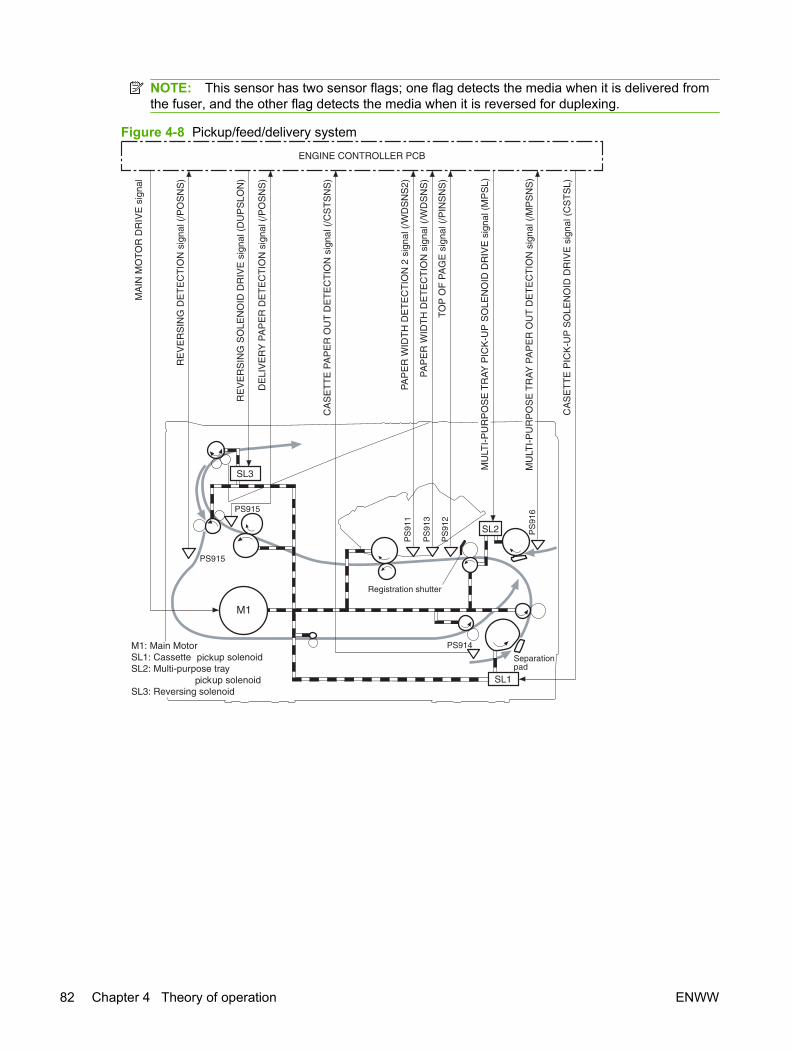
NOTE: This sensor has two sensor flags; one flag detects the media when it is delivered fromthe fuser, and the other flag detects the media when it is reversed for duplexing.
Figure 4-8 Pickup/feed/delivery system
82 Chapter 4 Theory of operation ENWW

Image-formation system Laser printing requires the interaction of several technologies, including electronics, optics, andelectrophotographics, to produce a printed page. Each process functions independently and must becoordinated with the other product processes. Image formation consists of the following five processes:
● Electrostatic latent-image formation
● Developing
● Transfer
● Fusing
● Drum cleaning
These five processes contain seven steps, which are shown in Figure 4-9 Image-formation systemon page 83 and described in the following sections.
Figure 4-9 Image-formation system
Step 1: Primary charging
DC and AC biases are applied to the primary charging roller, which transfers a uniform negative potentialto the photosensitive drum.
Figure 4-10 Primary charging
ENWW Image-formation system 83
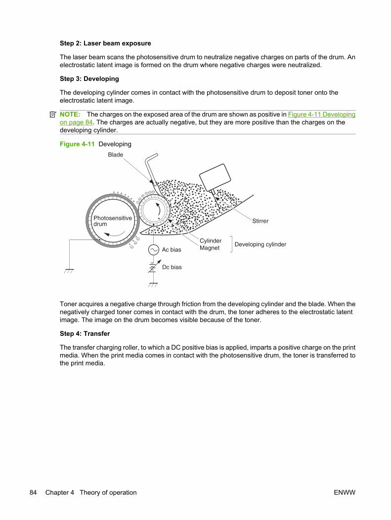
Step 2: Laser beam exposure
The laser beam scans the photosensitive drum to neutralize negative charges on parts of the drum. Anelectrostatic latent image is formed on the drum where negative charges were neutralized.
Step 3: Developing
The developing cylinder comes in contact with the photosensitive drum to deposit toner onto theelectrostatic latent image.
NOTE: The charges on the exposed area of the drum are shown as positive in Figure 4-11 Developingon page 84. The charges are actually negative, but they are more positive than the charges on thedeveloping cylinder.
Figure 4-11 Developing
Toner acquires a negative charge through friction from the developing cylinder and the blade. When thenegatively charged toner comes in contact with the drum, the toner adheres to the electrostatic latentimage. The image on the drum becomes visible because of the toner.
Step 4: Transfer
The transfer charging roller, to which a DC positive bias is applied, imparts a positive charge on the printmedia. When the print media comes in contact with the photosensitive drum, the toner is transferred tothe print media.
84 Chapter 4 Theory of operation ENWW
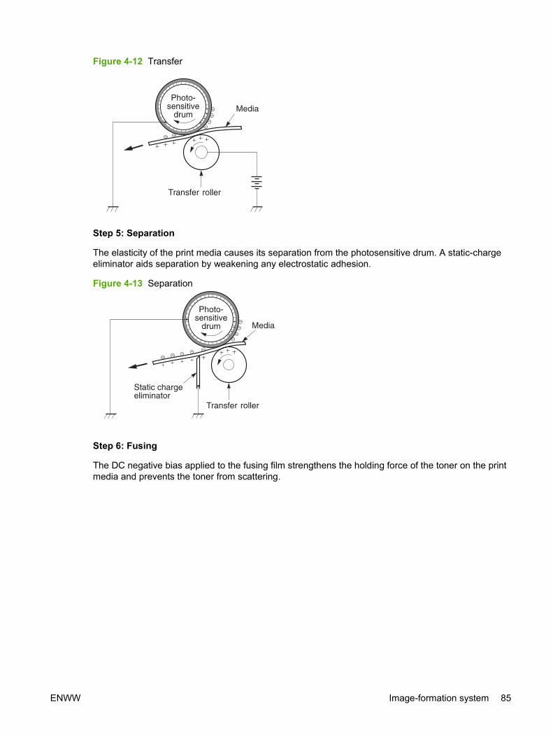
Figure 4-12 Transfer
Step 5: Separation
The elasticity of the print media causes its separation from the photosensitive drum. A static-chargeeliminator aids separation by weakening any electrostatic adhesion.
Figure 4-13 Separation
Step 6: Fusing
The DC negative bias applied to the fusing film strengthens the holding force of the toner on the printmedia and prevents the toner from scattering.
ENWW Image-formation system 85
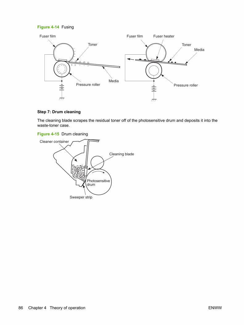
Figure 4-14 Fusing
Step 7: Drum cleaning
The cleaning blade scrapes the residual toner off of the photosensitive drum and deposits it into thewaste-toner case.
Figure 4-15 Drum cleaning
86 Chapter 4 Theory of operation ENWW
Fax functions and operation The following sections describe the product fax capabilities.
Computer and network security featuresThe product can send and receive fax data over telephone lines that conform to public switch telephonenetwork (PSTN) standards. The secure fax protocols make it impossible for computer viruses to betransferred from the telephone line to a computer or network.
The following product features prevent virus transmission:
● No direct connection exists between the fax line and any devices that are connected to the USBor Ethernet ports.
● The internal firmware cannot be modified through the fax connection.
● All fax communications go through the fax subsystem, which does not use Internet data-exchangeprotocols.
PSTN operationThe PSTN operates through a central office (CO) that generates a constant voltage on the TIP andRING wires (48 V, usually). A device goes on-hook by connecting impedance (such as 600 ohms forthe U.S.) across the TIP and RING so that a line current can flow. The CO can detect this current andcan send impulses like dial tones. The product generates more signaling tones, such as dialing digits,to tell the CO how to connect the call. The product can also detect tones, such as a busy tone from theCO, that tell it how to behave.
When the call is finally connected, the CO behaves like a piece of wire connecting the sender andreceiver. This is the period during which all of the fax signaling and data transfer occurs. When a call iscompleted, the circuit opens again and the line-current flow ceases, removing the CO connection fromboth the sender and the receiver.
On most phone systems, the TIP and RING wires appear on pins 3 and 4 of the RJ-11 modular jack(the one on the fax card). These two wires do not have to be polarized because all the equipment workswith either TIP or RING on pin 3 and the other wire on pin 4. This means that cables of either polaritycan interconnect and will still work.
These basic functions of PSTN operation are assumed in the design of the fax subsystem. The productgenerates and detects the signaling tones, currents, and data signals that are required to transmit andreceive faxes on the PSTN.
Receive faxes when you hear fax tonesIn general, incoming faxes to the product are automatically received. However, if other devices areconnected to the same phone line, the product might not be set to answer automatically.
If the product is connected to a phone line that receives both fax and phone calls, and you hear faxtones when you answer the extension phone, receive the fax in one of two ways:
● If you are near the product, press Start Fax on the control panel.
● Press 1-2-3 in sequence on the extension phone keypad, listen for fax transmission sounds, andthen hang up.
ENWW Fax functions and operation 87
NOTE: In order for the 1-2-3 sequence to work, the extension phone setting must be set to On in theFax setup menu.
Distinctive ring functionDistinctive ring is a service that a telephone company provides. The distinctive ring service allows threephone numbers to be assigned to one phone line. Each phone number has a distinctive ring. The firstphone number has a single ring, the second phone number has a double ring, and the third phonenumber has a triple ring.
NOTE: The product has not been tested with all of the distinctive-ring services that telephonecompanies provide in all countries/regions. HP does not guarantee that the distinctive-ring function willoperate correctly in all countries/regions. Contact the local phone service provider for assistance.
Set up the distinctive ring function
1. Press Setup. Use the arrow buttons to select Fax setup and then press OK.
2. Use the arrow buttons to select Fax recv. setup and then press OK.
3. Use the arrow buttons to select Answer ring type and then press OK.
4. Use the arrow buttons to select one of the following options:
NOTE: The control-panel display might show some of these options as abbreviations.
● All rings (default setting)
● Single
● Double
● Triple
● DoubleTriple
Press OK to save the setting.
Fax by using Voice over IP servicesVoice over IP (VoIP) services provide normal telephone service, including long distance service througha broadband Internet connection. These services use packets to break up the voice signal on atelephone line and transmit it digitally to the receiver, where the packets are reassembled. The VoIPservices are often not compatible with fax machines. The VoIP provider must state the service supportsfax over IP services.
Because the installation process varies, the VoIP service provider will have to assist in installing theproduct fax component.
Although a fax might work on a VoIP network, it can fail when the following events occur:
● Internet traffic becomes heavy and packets are lost.
● Latency (the time it takes for a packet to travel from its point of origin to its point of destination)becomes excessive.
88 Chapter 4 Theory of operation ENWW

If you experience problems using the fax feature on a VoIP network, ensure that all of the product cablesand settings are correct. Configuring the Fax Speed setting to Medium(V.17) or Slow(V.29) can alsoimprove your ability to send a fax over a VoIP network. See Table 6-8 Fax setup menu on page 194.
If you continue to have problems faxing, contact your VoIP provider.
The fax subsystemThe formatter, fax card, firmware, and software all contribute to the fax functionality. The designs of theformatter and fax card, along with parameters in the firmware, determine the majority of the regulatoryrequirements for telephony on the product.
The fax subsystem is designed to support V.34 fax transmission, lower speeds (such as V.17 fax), andolder fax machines.
Fax card in the fax subsystemTwo versions of the fax card are used in the HP LaserJet M2727 MFP. One is used in the NorthAmerican, South American, and Asian countries/regions. The other is used primarily in Europeancountries/regions.
The fax card contains the modem chipset (DSP and CODEC) that controls the basic fax functions oftone generation and detection, along with channel control for fax transmissions. The CODEC and itsassociated circuitry act as the third-generation silicon DAA to achieve compliance world-wide regulatoryrequirements.
The only difference between the two versions is that each version is compliant with the 2/4-wire phonejack system from the repective country/region.
Safety isolationThe most important function of the fax card is the safety isolation between the high-voltage, transient-prone environment of the telephone network (TNV [telephone network voltage]) and the low-voltageanalog and digital circuitry of the formatter (SELV [secondary extra-low voltage]). This safety isolationprovides both customer safety and product reliability in the telecom environment.
Any signals that cross the isolation barrier do so magnetically. The breakdown voltage rating of barrier-critical components is greater than 5 kV.
Safety-protection circuitryIn addition to the safety barrier, the fax card protects against over-voltage and over-current events.
Telephone over-voltage events can be either differential mode or common mode. The event can betransient in nature (a lightning-induced surge or ESD) or continuous (a power line crossed with a phoneline). The fax card protection circuitry provides margin against combinations of over-voltage and over-current events.
Common mode protection is provided by the selection of high-voltage-barrier critical components(transformer and relay). The safety barrier of the fax card PCB traces and the clearance between thefax card and surrounding components also contribute to common mode protection.
A voltage suppressor (a crowbar-type SIDACTOR) provides differential protection. This device becomeslow impedance at approximately 300 V differential, and crowbars to a low voltage. A series thermalswitch works in conjunction with the crowbar for continuous telephone line events, such as crossedpower lines.
ENWW Fax functions and operation 89

All communications cross the isolation barrier magnetically. The breakdown voltage rating of barrier-critical components is greater than 5 kV.
Data pathTIP and RING are the two-wire paths for all signals from the telephone network. All signaling and datainformation comes across them, including fax tones and fax data.
The telephone network uses DC current to determine the hook state of the telephone, so line currentmust be present during a call. The silicon DAA provides a DC holding circuit to keep the line currentconstant during a fax call.
The silicon DAA converts the analog signal to a digital signal for DSP processing, and also converts thedigital signal to an analog signal for transmitting data through a telephone line.
The magnetically coupled signals that cross the isolation barrier go either through a transformer or arelay.
The DSP in the fax card communicates with the ASIC in the formatter using the high-speed serialinterface.
Hook stateAnother magnetically coupled signal is the control signal that disconnects the downstream telephonedevices (such as a phone or answering machine). A control signal originating on the DSP can changethe relay state, causing the auxiliary jack (downstream jack) to be disconnected from the telephonecircuit.
The product takes control of calls that it recognizes as fax calls. If the product does not directly pick upthe call, it monitors incoming calls for the fax tone or for the user to direct it to receive a fax. This idlemode is also called eavesdropping. This mode is active when the product is on-hook but current existsin the downstream phone line because another device is off-hook. During eavesdropping, the receivecircuit is enabled but has a different gain from the current that is generated during normal faxtransmissions.
The product does not take control of the line unless it detects a fax tone or the user causes it to connectmanually. This feature allows the user to make voice calls from a phone that is connected to the productwithout being cut off if a fax is not being received.
Downstream device detectionThe line voltage monitoring module of the silicon DAA can detect the line state as well as the downstreamdevice. It tells DSP via DIB that an active device (telephone, modem, or answering machine) isconnected to the auxiliary port on the product (the right side of the RJ-11 jack). The DSP uses the signalto ensure that the product does not go off-hook (and disconnect a downstream call) until it has beenauthorized to do so (by a manual fax start or the detection of the appropriate tones).
Hook switch controlIn the silicon DAA the CODEC controls the hook switch directly. The CODEC is activated when itreceives commands from the DSP. When the circuit is drawing DC current from the central office it isconsidered off-hook. When no DC current flows the state is considered on-hook.
90 Chapter 4 Theory of operation ENWW

Ring detectRing detect is performed by the line voltage monitoring module of the silicon DAA, and is a combinationof voltage levels and cadence (time on and time off). Both must be present to detect a valid ring. TheCODEC works with DSP as well as the firmware to determine if an incoming signal is an answerablering.
Line current controlThe DC current from the CO needs to have a path to flow from TIP to RING. The DC impedanceemulation line modulator and DC terminations modules in the silicon DAA act as a DC holding circuit,and works with the firmware to achieve the voltage-current characteristic between TIP and RING. Theimpedance (the current-voltage characteristic) changes corresponding to certian special events, suchas pulse dialing or when the product goes on-hook.
Billing- (metering-) tone filtersSwitzerland and Germany provide high-frequency AC signals on the phone line in order to bill customers.
A filter in a special fax cable (for certain countries/regions), can filter these signals. Because thesebillings signals are not used in the U.S., these filters are not present in the U.S. fax cable.
To obtain a special fax cable, contact your local telephone service provider.
Fax page storage in flash memoryFax pages are the electronic images of the document page. They can be created in any of three ways:scanned to be sent to another fax machine, generated to be sent by the computer, or received from afax machine to be printed.
The product stores all fax pages in flash memory automatically. After these pages are written into flashmemory, they are stored until the pages are sent to another fax machine, printed on the product,transmitted to the computer, or erased by the user.
These pages are stored in flash memory, which is the nonvolatile memory that can be repeatedly readfrom, written to, and erased. The product has 8 MB of flash memory, of which 7.5 MB is available forfax storage. The remaining 0.5 MB is used for the file system and reclamation. Adding RAM does notaffect the fax page storage because the product does not use RAM for storing fax pages.
Stored fax pagesThe user can reprint stored fax receive pages in case of errors. For a fax send, the product will re-sendthe fax in case of errors. The product will re-send stored fax pages after a busy signal, comm error, noanswer, or power failure. Other fax devices store fax pages in either normal RAM or short-term RAM.Normal RAM immediately loses its data when power is lost, while short-term RAM loses its data about60 minutes after power failure. Flash memory maintains its data for years without any applied power.
Advantages of flash memory storage Fax pages that are stored in flash memory are persistent. They are not lost as a result of a power failure,no matter how long the power is off. Users can reprint faxes in case the print cartridge runs out of toneror the product experiences other errors while printing faxes.
The product also has scan-ahead functionality that makes use of flash memory. Scan-aheadautomatically scans pages into flash memory before a fax job is sent. This allows the sender to pick up
ENWW Fax functions and operation 91

the original document immediately after it is scanned, eliminating the need to wait until the fax istransmission is complete.
Because fax pages are stored in flash memory rather than RAM, more RAM is available to handle largerand more complicated copy and print jobs.
92 Chapter 4 Theory of operation ENWW

5 Removal and replacement
● Introduction
● External panels, covers, and doors
● Replace the ADF pickup-roller assembly
● ADF scanner glass
● ADF assembly
● Scanner/ADF assembly
● Bezel and control panel
● Internal assemblies
ENWW 93

IntroductionThis chapter documents the removal and replacement of field replaceable units (FRUs) only.
Replacing FRUs is generally the reverse of removal. Occasionally, notes and tips are included to providedirections for difficult or critical replacement procedures.
HP does not support repairing individual subassemblies or problem-solving at the component level.
Note the length, diameter, color, type, and location of each screw. Be sure to return each screw to itsoriginal location during reassembly.
Incorrectly routed or loose wire harnesses can interfere with other internal components and can becomedamaged or broken. Frayed or pinched harness wires can be difficult to locate. When replacing wireharnesses, always use the provided wire loops, lance points, or wire-harness guides.
Removal and replacement strategy WARNING! Turn the product off, wait 5 seconds, and then remove the power cord before attemptingto service the product. If this warning is not followed, severe injury can result, as well as damage to theproduct. The power must be on for certain functional checks during problem solving. However, the powersupply should be disconnected during parts removal.
Never operate or service the product with the protective cover removed from the laser/scannerassembly. The reflected beam, although invisible, can damage your eyes.
The sheet-metal parts can have sharp edges. Be careful when handling sheet-metal parts.
CAUTION: Do not bend or fold the flat flexible cables (FFCs) during removal or installation. Also, donot straighten pre-folds in the FFCs. You must make sure that all FFCs are fully seated in theirconnectors. Failure to fully seat an FFC into a connector can cause a short circuit in a PCA.
NOTE: To install a self-tapping screw, first turn it counterclockwise to align it with the existing threadpattern, and then carefully turn it clockwise to tighten. Do not overtighten. If a self-tapping screw holebecomes stripped, repair the screw hole or replace the affected assembly.
Electrostatic discharge
CAUTION: Some parts are sensitive to electrostatic discharge (ESD). Look for the ESDreminder when removing product parts. Always perform service work at an ESD-protected workstationor mat. If an ESD workstation or mat is not available, ground yourself by touching the sheet-metal chassisbefore touching an ESD-sensitive part.
Protect the ESD-sensitive parts by placing them in ESD pouches when they are out of the product.
User-replaceable partsTo remove and replace the tray 2 pickup roller or the tray 2 or tray 3 separation pad, see Replace thetray 2 pickup roller on page 40 or Replace the tray 2 and optional tray 3 separation pad on page 45.
94 Chapter 5 Removal and replacement ENWW
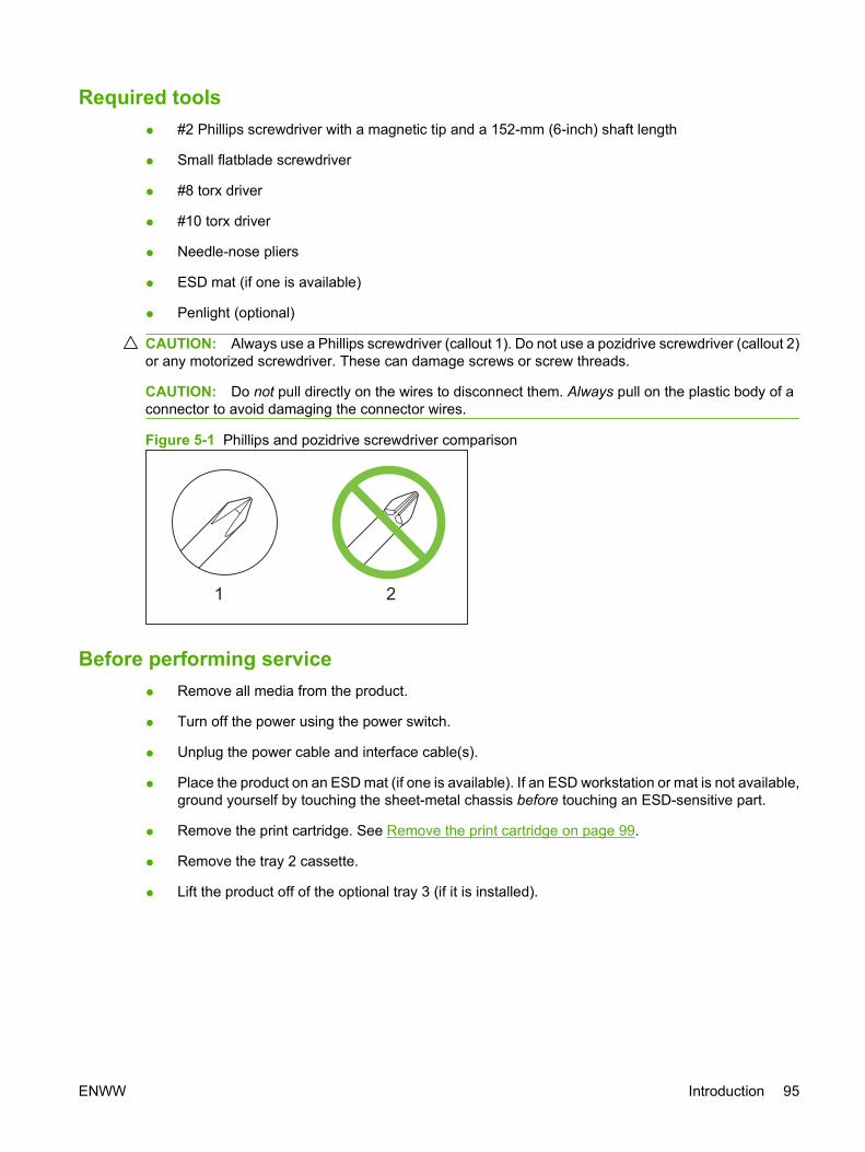
Required tools ● #2 Phillips screwdriver with a magnetic tip and a 152-mm (6-inch) shaft length
● Small flatblade screwdriver
● #8 torx driver
● #10 torx driver
● Needle-nose pliers
● ESD mat (if one is available)
● Penlight (optional)
CAUTION: Always use a Phillips screwdriver (callout 1). Do not use a pozidrive screwdriver (callout 2)or any motorized screwdriver. These can damage screws or screw threads.
CAUTION: Do not pull directly on the wires to disconnect them. Always pull on the plastic body of aconnector to avoid damaging the connector wires.
Figure 5-1 Phillips and pozidrive screwdriver comparison
Before performing service● Remove all media from the product.
● Turn off the power using the power switch.
● Unplug the power cable and interface cable(s).
● Place the product on an ESD mat (if one is available). If an ESD workstation or mat is not available,ground yourself by touching the sheet-metal chassis before touching an ESD-sensitive part.
● Remove the print cartridge. See Remove the print cartridge on page 99.
● Remove the tray 2 cassette.
● Lift the product off of the optional tray 3 (if it is installed).
ENWW Introduction 95

After performing service● Return all media to the trays.
● Plug in the power cable.
● Reinstall the print cartridge.
● Reinstall the tray 2 cassette.
● Replace the product on the optional tray 3 (if present).
Post-service testsAfter service has been completed, the following tests can be used to verify that the repair or replacementwas successful.
Test 1 (print-quality test)1. Verify that you have completed the necessary reassembly steps.
2. Ensure that the input tray contains clean, unmarked paper.
3. Attach the power cord and interface cable, and then turn on the product.
4. Verify that the expected start-up sounds occur.
5. Perform a control-panel test from the secondary service menu. Verify that the control-panel buttonsbeep when they are pressed.
NOTE: If the control-panel buttons do not beep, verify that the user did not disable this function.
6. Print a configuration page, and then verify that the expected printing sounds occur. See Productinformation pages and reports on page 237.
7. Print a demo page, and then verify that the print quality is as expected. See Product informationpages and reports on page 237.
8. Send a print job from the host computer, and then verify that the output meets expectations.
9. If necessary, restore any customer-specified settings.
10. Clean the outside of the product with a damp cloth.
Test 2 (copy-quality test)1. Verify that you have completed the necessary reassembly steps.
2. Ensure that the input tray contains clean, unmarked paper.
3. Attach the power cord and interface cable, and then turn on the product.
4. Verify that the expected start-up sounds occur.
5. Print a configuration page, and then verify that the expected printing sounds occur. See Productinformation pages and reports on page 237.
6. Place the configuration page in the ADF.
96 Chapter 5 Removal and replacement ENWW

7. Print a copy job, and then verify the results.
8. Place the configuration page on the scanner glass.
9. Print a copy job, and then verify the results.
10. Clean the outside of the product with a damp cloth.
Test 3 (fax-quality test)1. Place the configuration page in the ADF.
2. Type a valid fax number and send the fax job.
3. Verify that the send quality and receive quality meet expectations.
ENWW Introduction 97
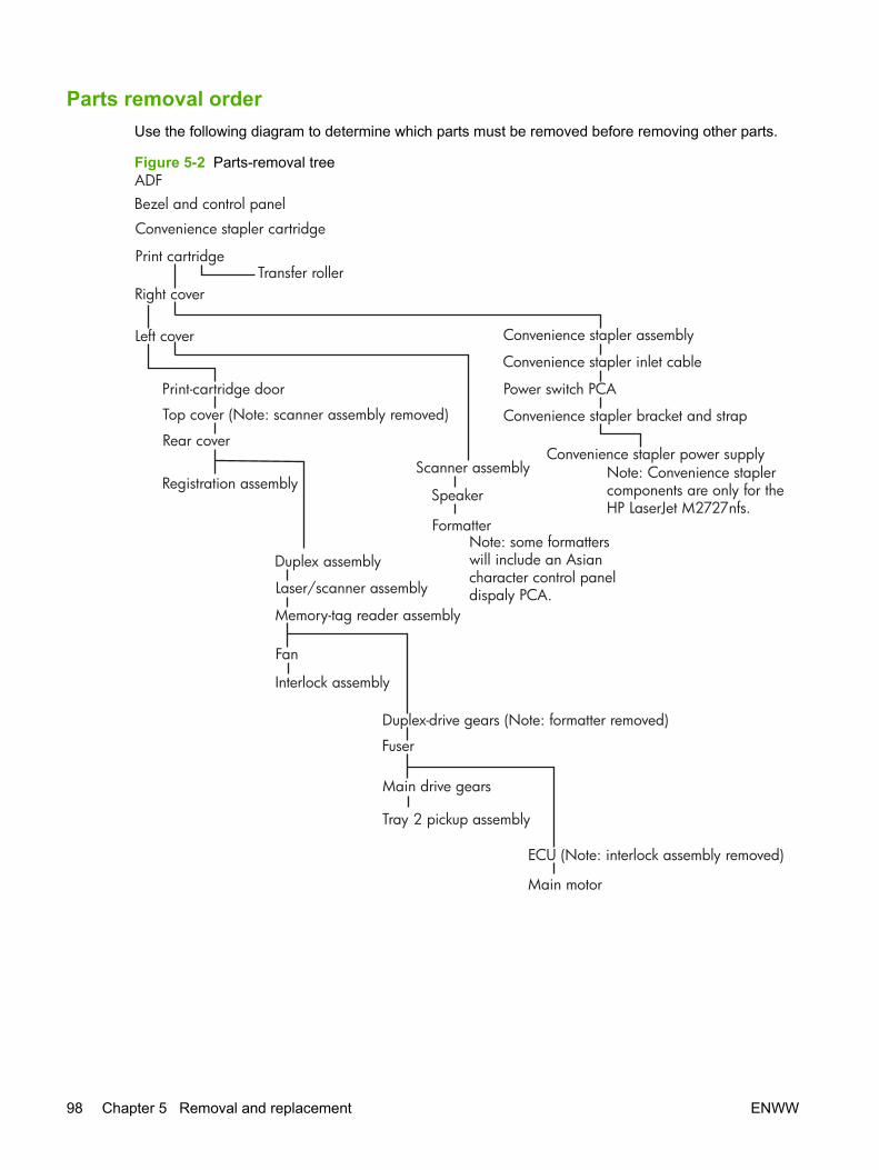
Parts removal orderUse the following diagram to determine which parts must be removed before removing other parts.
Figure 5-2 Parts-removal treeADFBezel and control panel
Convenience stapler cartridge
Print cartridgeTransfer roller
Right cover
Left cover Convenience stapler assembly
Convenience stapler inlet cable
Power switch PCAPrint-cartridge door
Top cover (Note: scanner assembly removed)
Rear coverConvenience stapler power supply
Convenience stapler bracket and strap
Note: Convenience staplercomponents are only for the HP LaserJet M2727nfs.
Registration assemblyScanner assembly
Speaker
Formatter
Duplex assembly
Laser/scanner assembly
Memory-tag reader assembly
Fan
Interlock assembly
Duplex-drive gears (Note: formatter removed)
Fuser
Main drive gears
Tray 2 pickup assembly
ECU (Note: interlock assembly removed)
Main motor
Note: some formatterswill include an Asiancharacter control paneldispaly PCA.
98 Chapter 5 Removal and replacement ENWW

Remove the print cartridgeCAUTION: If toner gets on your clothing, wipe it off with a dry cloth and wash the clothing in cold water.Hot water sets toner into the fabric.
1. Open the print-cartridge door.
Figure 5-3 Remove the print cartridge (1 of 2)
2. Grasp the handle on the print cartridge and then pull the cartridge straight out to remove it.
Figure 5-4 Remove the print cartridge (2 of 2)
ENWW Introduction 99
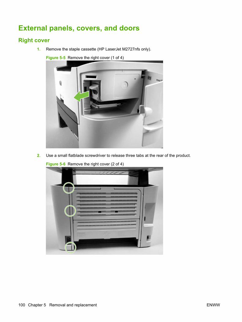
External panels, covers, and doorsRight cover
1. Remove the staple cassette (HP LaserJet M2727nfs only).
Figure 5-5 Remove the right cover (1 of 4)
2. Use a small flatblade screwdriver to release three tabs at the rear of the product.
Figure 5-6 Remove the right cover (2 of 4)
100 Chapter 5 Removal and replacement ENWW

3. Release one tab at the bottom of the cover.
Figure 5-7 Remove the right cover (3 of 4)
4. Rotate the back of the cover away from the product, and then slide it forward to remove it.
Figure 5-8 Remove the right cover (4 of 4)
ENWW External panels, covers, and doors 101
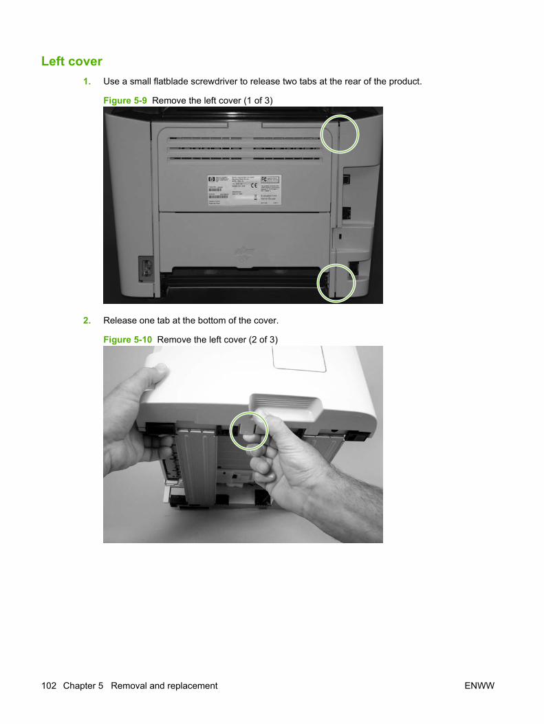
Left cover1. Use a small flatblade screwdriver to release two tabs at the rear of the product.
Figure 5-9 Remove the left cover (1 of 3)
2. Release one tab at the bottom of the cover.
Figure 5-10 Remove the left cover (2 of 3)
102 Chapter 5 Removal and replacement ENWW

3. Rotate the back of the cover away from the product, and then slide it forward to remove it.
Figure 5-11 Remove the left cover (3 of 3)
ENWW External panels, covers, and doors 103

Print-cartridge door1. Remove the following components.
● Right cover. See Right cover on page 100.
● Left cover. See Left cover on page 102.
2. Open the print-cartridge door, and use a flatblade screwdriver to gently pry the cartridge-door arm(callout 1) off of the print-cartridge door.
CAUTION: Be careful not to break the tabs on the cartridge-door arm.
Figure 5-12 Remove the print-cartridge door (1 of 3)
1
3. Close the print-cartridge door and remove two screws (callout 2).
Figure 5-13 Remove the print-cartridge door (2 of 3)
2
104 Chapter 5 Removal and replacement ENWW

4. Lift the cartridge-door assembly up and straight away from the product.
Figure 5-14 Remove the print-cartridge door (3 of 3)
ENWW External panels, covers, and doors 105
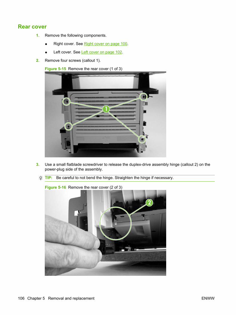
Rear cover1. Remove the following components.
● Right cover. See Right cover on page 100.
● Left cover. See Left cover on page 102.
2. Remove four screws (callout 1).
Figure 5-15 Remove the rear cover (1 of 3)
1
3. Use a small flatblade screwdriver to release the duplex-drive assembly hinge (callout 2) on thepower-plug side of the assembly.
TIP: Be careful to not bend the hinge. Straighten the hinge if necessary.
Figure 5-16 Remove the rear cover (2 of 3)
2
106 Chapter 5 Removal and replacement ENWW

4. Use a small flatblade screwdriver to release the duplex-drive assembly hinge (callout 3) on theopposite side of the assembly from the power plug, and then separate the rear cover from theproduct.
TIP: Be careful to not bend the hinge. Straighten the hinge if necessary.
Figure 5-17 Remove the rear cover (3 of 3)
3
NOTE: After removing the rear cover, the duplex assembly is disconnected at the rear of the product.
ENWW External panels, covers, and doors 107
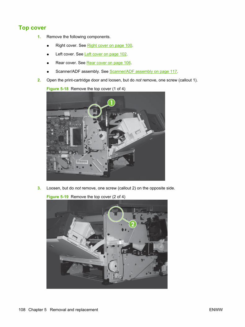
Top cover1. Remove the following components.
● Right cover. See Right cover on page 100.
● Left cover. See Left cover on page 102.
● Rear cover. See Rear cover on page 106.
● Scanner/ADF assembly. See Scanner/ADF assembly on page 117.
2. Open the print-cartridge door and loosen, but do not remove, one screw (callout 1).
Figure 5-18 Remove the top cover (1 of 4)
1
3. Loosen, but do not remove, one screw (callout 2) on the opposite side.
Figure 5-19 Remove the top cover (2 of 4)
2
108 Chapter 5 Removal and replacement ENWW
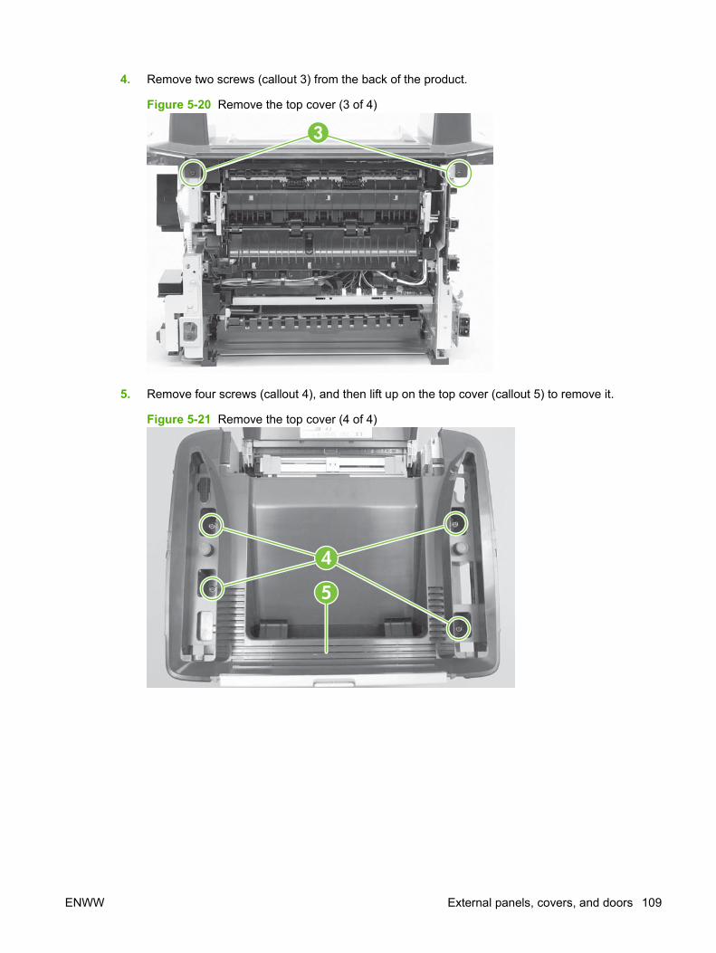
4. Remove two screws (callout 3) from the back of the product.
Figure 5-20 Remove the top cover (3 of 4)
3
5. Remove four screws (callout 4), and then lift up on the top cover (callout 5) to remove it.
Figure 5-21 Remove the top cover (4 of 4)
4
5
ENWW External panels, covers, and doors 109
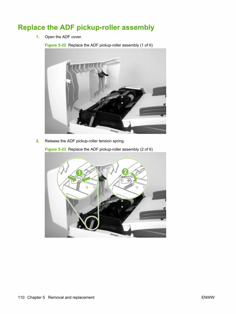
Replace the ADF pickup-roller assembly1. Open the ADF cover.
Figure 5-22 Replace the ADF pickup-roller assembly (1 of 6)
2. Release the ADF pickup-roller tension spring.
Figure 5-23 Replace the ADF pickup-roller assembly (2 of 6)
211
110 Chapter 5 Removal and replacement ENWW
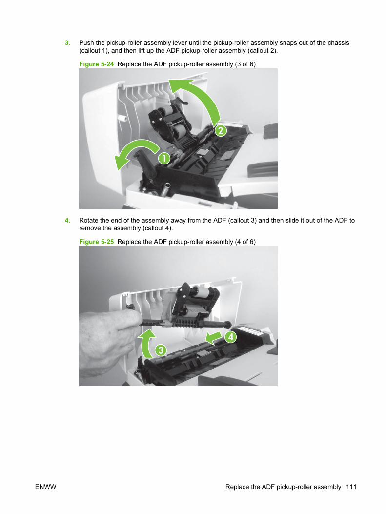
3. Push the pickup-roller assembly lever until the pickup-roller assembly snaps out of the chassis(callout 1), and then lift up the ADF pickup-roller assembly (callout 2).
Figure 5-24 Replace the ADF pickup-roller assembly (3 of 6)
1
2
4. Rotate the end of the assembly away from the ADF (callout 3) and then slide it out of the ADF toremove the assembly (callout 4).
Figure 5-25 Replace the ADF pickup-roller assembly (4 of 6)
34
ENWW Replace the ADF pickup-roller assembly 111

5. Install the replacement assembly.
Figure 5-26 Replace the ADF pickup-roller assembly (5 of 6)
56
6. Reattach the ADF pickup-roller tension spring, and then close the ADF cover.
Figure 5-27 Replace the ADF pickup-roller assembly (6 of 6)
1
112 Chapter 5 Removal and replacement ENWW
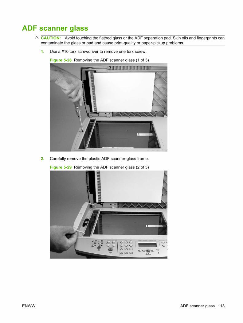
ADF scanner glassCAUTION: Avoid touching the flatbed glass or the ADF separation pad. Skin oils and fingerprints cancontaminate the glass or pad and cause print-quality or paper-pickup problems.
1. Use a #10 torx screwdriver to remove one torx screw.
Figure 5-28 Removing the ADF scanner glass (1 of 3)
2. Carefully remove the plastic ADF scanner-glass frame.
Figure 5-29 Removing the ADF scanner glass (2 of 3)
ENWW ADF scanner glass 113
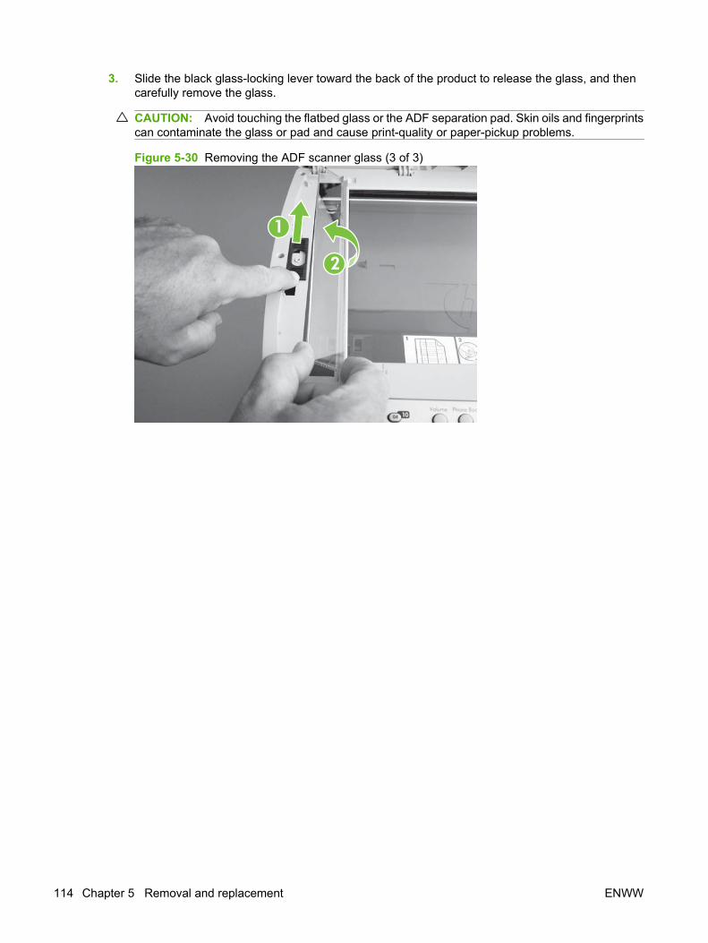
3. Slide the black glass-locking lever toward the back of the product to release the glass, and thencarefully remove the glass.
CAUTION: Avoid touching the flatbed glass or the ADF separation pad. Skin oils and fingerprintscan contaminate the glass or pad and cause print-quality or paper-pickup problems.
Figure 5-30 Removing the ADF scanner glass (3 of 3)
2
1
114 Chapter 5 Removal and replacement ENWW

ADF assembly1. Open the scanner cover (it contains the ADF assembly).
Figure 5-31 Remove the ADF assembly (1 of 3)
2. Squeeze the locking tabs on the ADF wire-harness plug (callout 1), and then disconnect the plugfrom the flatbed.
Figure 5-32 Remove the ADF assembly (2 of 3)
1
ENWW ADF assembly 115
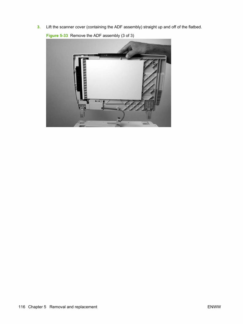
3. Lift the scanner cover (containing the ADF assembly) straight up and off of the flatbed.
Figure 5-33 Remove the ADF assembly (3 of 3)
116 Chapter 5 Removal and replacement ENWW
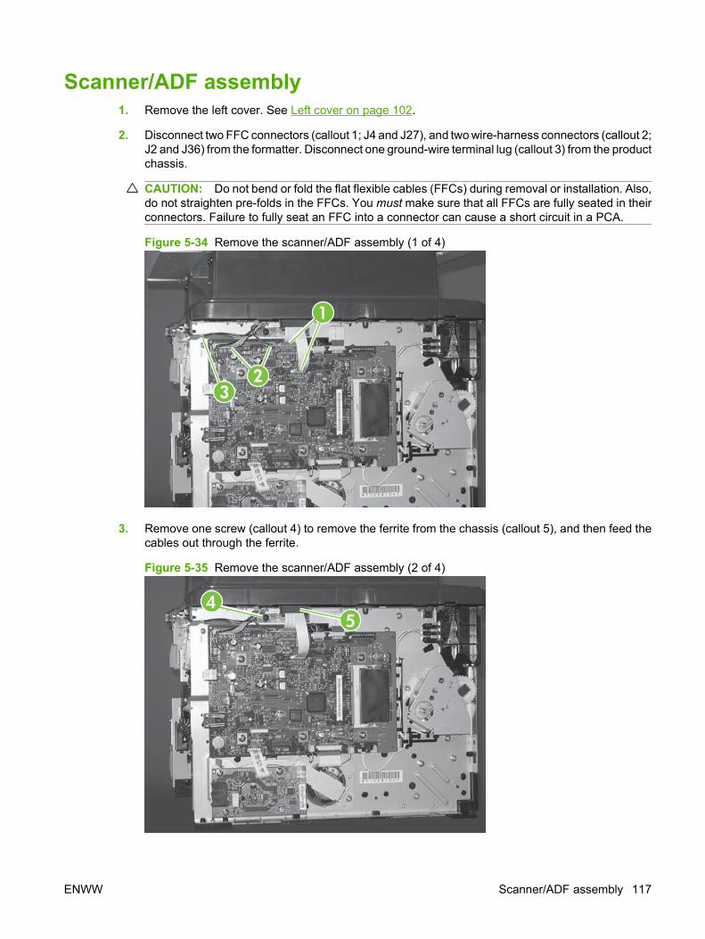
Scanner/ADF assembly1. Remove the left cover. See Left cover on page 102.
2. Disconnect two FFC connectors (callout 1; J4 and J27), and two wire-harness connectors (callout 2;J2 and J36) from the formatter. Disconnect one ground-wire terminal lug (callout 3) from the productchassis.
CAUTION: Do not bend or fold the flat flexible cables (FFCs) during removal or installation. Also,do not straighten pre-folds in the FFCs. You must make sure that all FFCs are fully seated in theirconnectors. Failure to fully seat an FFC into a connector can cause a short circuit in a PCA.
Figure 5-34 Remove the scanner/ADF assembly (1 of 4)
2
1
3
3. Remove one screw (callout 4) to remove the ferrite from the chassis (callout 5), and then feed thecables out through the ferrite.
Figure 5-35 Remove the scanner/ADF assembly (2 of 4)
45
ENWW Scanner/ADF assembly 117
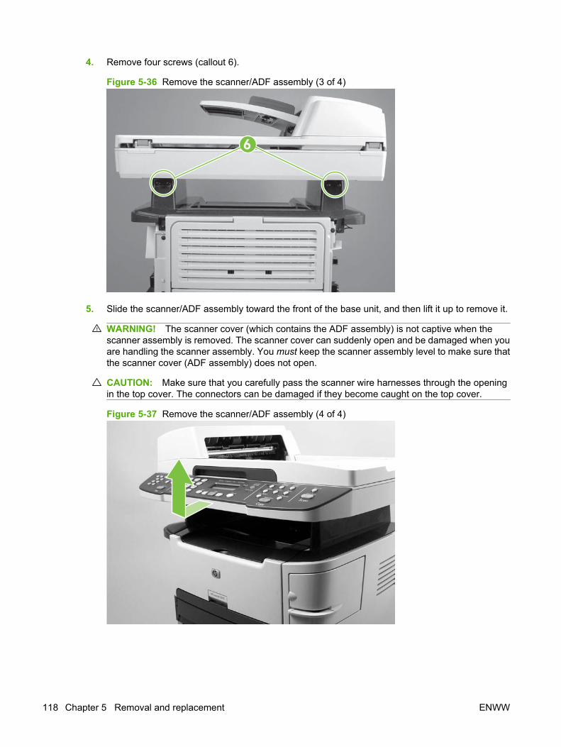
4. Remove four screws (callout 6).
Figure 5-36 Remove the scanner/ADF assembly (3 of 4)
6
5. Slide the scanner/ADF assembly toward the front of the base unit, and then lift it up to remove it.
WARNING! The scanner cover (which contains the ADF assembly) is not captive when thescanner assembly is removed. The scanner cover can suddenly open and be damaged when youare handling the scanner assembly. You must keep the scanner assembly level to make sure thatthe scanner cover (ADF assembly) does not open.
CAUTION: Make sure that you carefully pass the scanner wire harnesses through the openingin the top cover. The connectors can be damaged if they become caught on the top cover.
Figure 5-37 Remove the scanner/ADF assembly (4 of 4)
118 Chapter 5 Removal and replacement ENWW
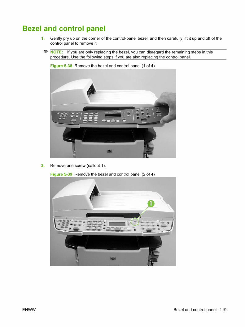
Bezel and control panel1. Gently pry up on the corner of the control-panel bezel, and then carefully lift it up and off of the
control panel to remove it.
NOTE: If you are only replacing the bezel, you can disregard the remaining steps in thisprocedure. Use the following steps if you are also replacing the control panel.
Figure 5-38 Remove the bezel and control panel (1 of 4)
2. Remove one screw (callout 1).
Figure 5-39 Remove the bezel and control panel (2 of 4)
1
ENWW Bezel and control panel 119

3. Use a small flatblade screwdriver to release the three locking tabs (callout 2) along the top of thecontrol panel.
Figure 5-40 Remove the bezel and control panel (3 of 4)
2
120 Chapter 5 Removal and replacement ENWW
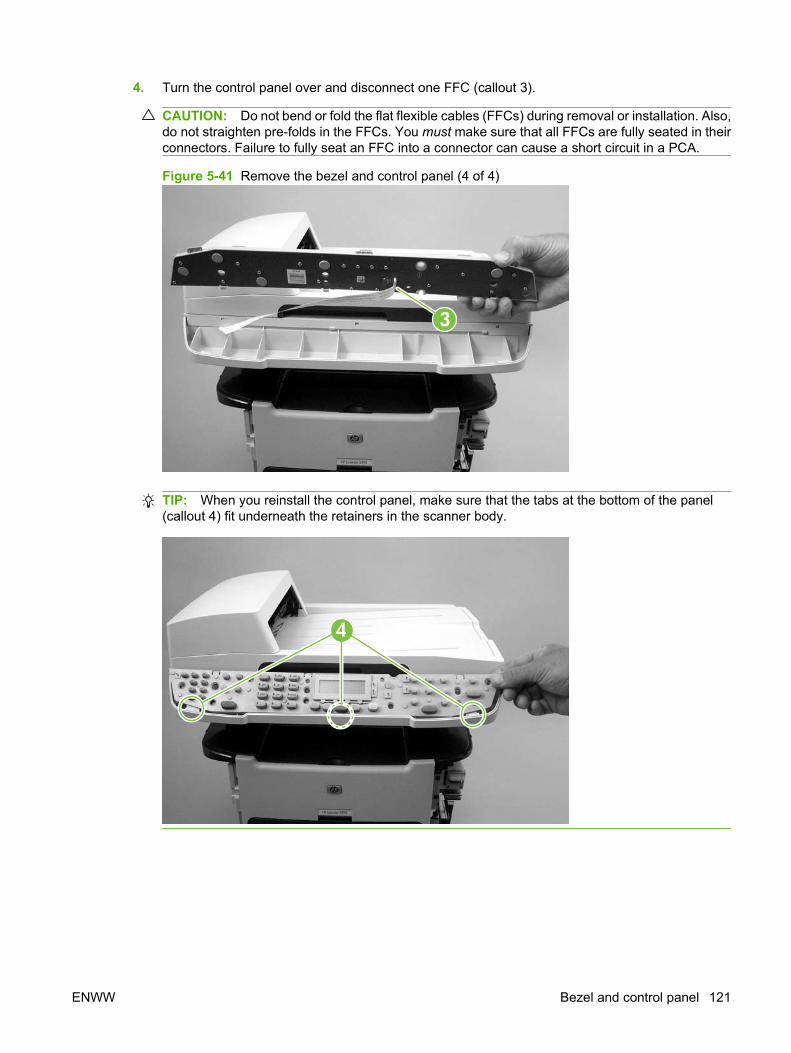
4. Turn the control panel over and disconnect one FFC (callout 3).
CAUTION: Do not bend or fold the flat flexible cables (FFCs) during removal or installation. Also,do not straighten pre-folds in the FFCs. You must make sure that all FFCs are fully seated in theirconnectors. Failure to fully seat an FFC into a connector can cause a short circuit in a PCA.
Figure 5-41 Remove the bezel and control panel (4 of 4)
3
TIP: When you reinstall the control panel, make sure that the tabs at the bottom of the panel(callout 4) fit underneath the retainers in the scanner body.
4
ENWW Bezel and control panel 121
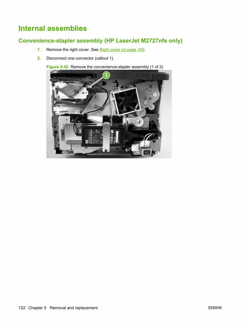
Internal assembliesConvenience-stapler assembly (HP LaserJet M2727nfs only)
1. Remove the right cover. See Right cover on page 100.
2. Disconnect one connector (callout 1).
Figure 5-42 Remove the convenience-stapler assembly (1 of 2)
1
122 Chapter 5 Removal and replacement ENWW

3. Remove two screws (callout 2), and then separate the stapler assembly from the chassis to removeit.
Figure 5-43 Remove the convenience-stapler assembly (2 of 2)
2
TIP: When you reinstall the convenience-stapler assembly, make sure that the hook on the topof the assembly bracket fits into the slot on the product chassis.
ENWW Internal assemblies 123
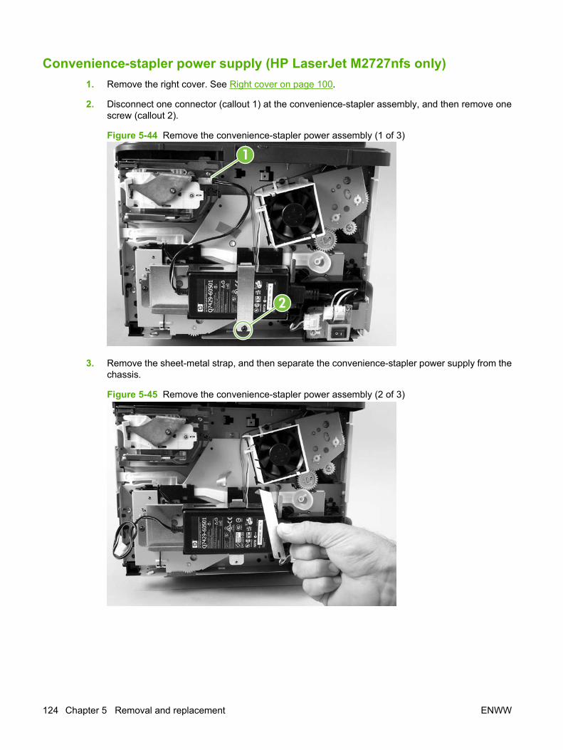
Convenience-stapler power supply (HP LaserJet M2727nfs only)1. Remove the right cover. See Right cover on page 100.
2. Disconnect one connector (callout 1) at the convenience-stapler assembly, and then remove onescrew (callout 2).
Figure 5-44 Remove the convenience-stapler power assembly (1 of 3)
1
2
3. Remove the sheet-metal strap, and then separate the convenience-stapler power supply from thechassis.
Figure 5-45 Remove the convenience-stapler power assembly (2 of 3)
124 Chapter 5 Removal and replacement ENWW

4. Disconnect one connector and then remove the convenience-stapler power supply.
Figure 5-46 Remove the convenience-stapler power assembly (3 of 3)
ENWW Internal assemblies 125
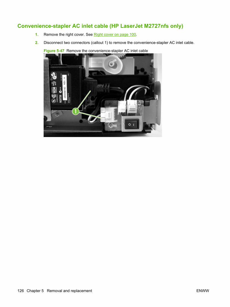
Convenience-stapler AC inlet cable (HP LaserJet M2727nfs only)1. Remove the right cover. See Right cover on page 100.
2. Disconnect two connectors (callout 1) to remove the convenience-stapler AC inlet cable.
Figure 5-47 Remove the convenience-stapler AC inlet cable
1
126 Chapter 5 Removal and replacement ENWW
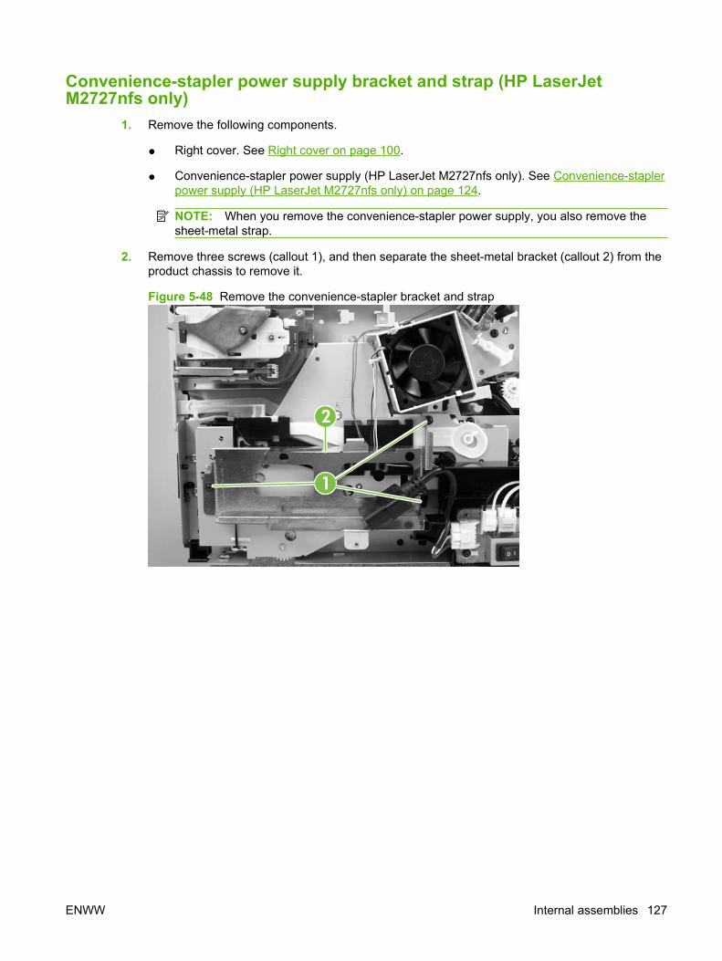
Convenience-stapler power supply bracket and strap (HP LaserJetM2727nfs only)
1. Remove the following components.
● Right cover. See Right cover on page 100.
● Convenience-stapler power supply (HP LaserJet M2727nfs only). See Convenience-staplerpower supply (HP LaserJet M2727nfs only) on page 124.
NOTE: When you remove the convenience-stapler power supply, you also remove thesheet-metal strap.
2. Remove three screws (callout 1), and then separate the sheet-metal bracket (callout 2) from theproduct chassis to remove it.
Figure 5-48 Remove the convenience-stapler bracket and strap
1
2
ENWW Internal assemblies 127

Speaker1. Remove the left cover. See Left cover on page 102.
2. Disconnect one FFC (callout 1; J2) from the fax card, remove three screws (callout 2), and removethe fax card (callout 3).
CAUTION: PCAs are sensitive to electrostatic discharge (ESD). Look for the ESDreminder when removing PCAs. Always perform service work at an ESD-protected workstation ormat. If an ESD workstation or mat is not available, ground yourself by touching the sheet-metalchassis before touching an ESD-sensitive part.
Protect the ESD-sensitive parts by placing them in ESD pouches when they are out of the product.
CAUTION: Do not bend or fold the flat flexible cables (FFCs) during removal or installation. Also,do not straighten pre-folds in the FFCs. You must make sure that all FFCs are fully seated in theirconnectors. Failure to fully seat an FFC into a connector can cause a short circuit in a PCA.
Figure 5-49 Remove the speaker (1 of 2)
2
1
3
3. Remove one screw (callout 4) and the metal plate (callout 5).
128 Chapter 5 Removal and replacement ENWW
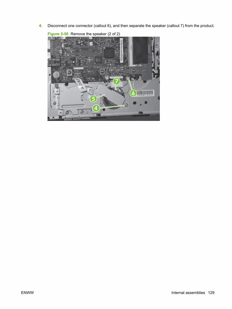
4. Disconnect one connector (callout 6), and then separate the speaker (callout 7) from the product.
Figure 5-50 Remove the speaker (2 of 2)
4
5
7
6
ENWW Internal assemblies 129
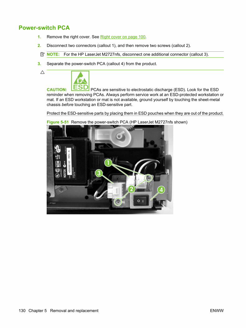
Power-switch PCA1. Remove the right cover. See Right cover on page 100.
2. Disconnect two connectors (callout 1), and then remove two screws (callout 2).
NOTE: For the HP LaserJet M2727nfs, disconnect one additional connector (callout 3).
3. Separate the power-switch PCA (callout 4) from the product.
CAUTION: PCAs are sensitive to electrostatic discharge (ESD). Look for the ESDreminder when removing PCAs. Always perform service work at an ESD-protected workstation ormat. If an ESD workstation or mat is not available, ground yourself by touching the sheet-metalchassis before touching an ESD-sensitive part.
Protect the ESD-sensitive parts by placing them in ESD pouches when they are out of the product.
Figure 5-51 Remove the power-switch PCA (HP LaserJet M2727nfs shown)
4
1
2
3
130 Chapter 5 Removal and replacement ENWW
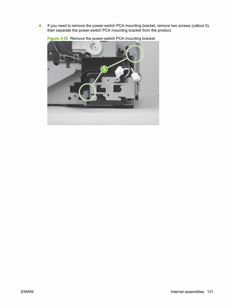
4. If you need to remove the power-switch PCA mounting bracket, remove two screws (callout 5),then separate the power-switch PCA mounting bracket from the product.
Figure 5-52 Remove the power-switch PCA mounting bracket
5
ENWW Internal assemblies 131

Formatter
CAUTION: PCAs are sensitive to electrostatic discharge (ESD). Look for the ESD reminderwhen removing PCAs. Always perform service work at an ESD-protected workstation or mat. If an ESDworkstation or mat is not available, ground yourself by touching the sheet-metal chassis before touchingan ESD-sensitive part.
Protect the ESD-sensitive parts by placing them in ESD pouches when they are out of the product.
CAUTION: Do not bend or fold the flat flexible cables (FFCs) during removal or installation. Also, donot straighten pre-folds in the FFCs. You must make sure that all FFCs are fully seated in theirconnectors. Failure to fully seat an FFC into a connector can cause a short circuit in a PCA.
1. Remove the left cover. See Left cover on page 102.
2. Disconnect five connectors (callout 1; GND wire lug, J36, J2, J32, J34) and five FFCs (callout 2;J4, J27, J28, J31, J26).
Figure 5-53 Remove the formatter (1 of 5)
12
1
132 Chapter 5 Removal and replacement ENWW

3. Remove six screws (callout 3), and then separate the formatter from the product.
Figure 5-54 Remove the formatter (2 of 5)
3
CAUTION: Make sure that you install the protective sheet behind the formatter when you reinstallit. Failure to install the protective sheet might cause a short circuit and damage the formatter.
Figure 5-55 Install formatter protective sheet
ENWW Internal assemblies 133

4. For products that use an Asian character control panel only: use a pair of needle nose pliersto release the Asian-character control-panel-display PCA spacer from the formatter.
Figure 5-56 Remove the formatter (3 of 4)
5. For products that use an Asian character control panel only: remove the Asian-charactercontrol-panel-display PCA from the formatter. Install the PCA on the replacement formatter(connector H3).
Figure 5-57 Remove the formatter (4 of 4)
134 Chapter 5 Removal and replacement ENWW
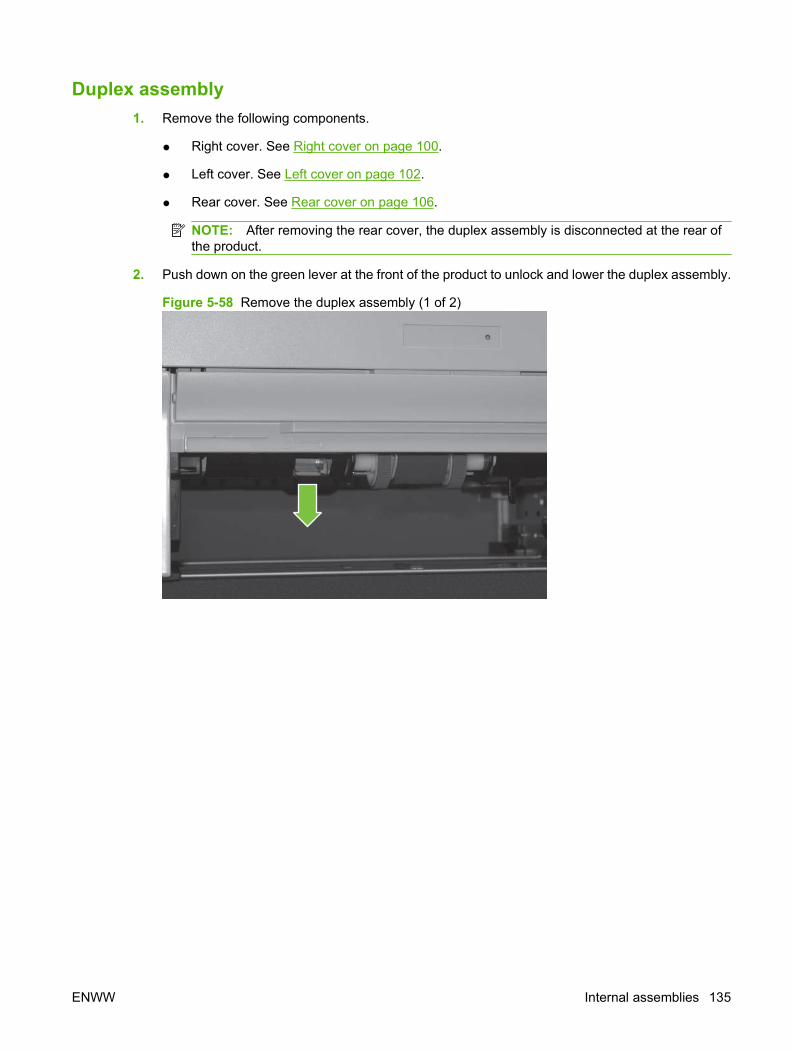
Duplex assembly1. Remove the following components.
● Right cover. See Right cover on page 100.
● Left cover. See Left cover on page 102.
● Rear cover. See Rear cover on page 106.
NOTE: After removing the rear cover, the duplex assembly is disconnected at the rear ofthe product.
2. Push down on the green lever at the front of the product to unlock and lower the duplex assembly.
Figure 5-58 Remove the duplex assembly (1 of 2)
ENWW Internal assemblies 135
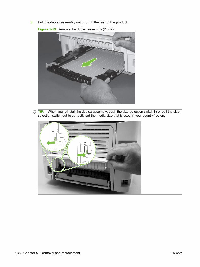
3. Pull the duplex assembly out through the rear of the product.
Figure 5-59 Remove the duplex assembly (2 of 2)
TIP: When you reinstall the duplex assembly, push the size-selection switch in or pull the size-selection switch out to correctly set the media size that is used in your country/region.
A4LTR,LGL
A4LTR,LGL
136 Chapter 5 Removal and replacement ENWW
Laser/scanner (print engine)
CAUTION: PCAs are sensitive to electrostatic discharge (ESD). Look for the ESD reminderwhen removing PCAs. Always perform service work at an ESD-protected workstation or mat. If an ESDworkstation or mat is not available, ground yourself by touching the sheet-metal chassis before touchingan ESD-sensitive part.
Protect the ESD-sensitive parts by placing them in ESD pouches when they are out of the product.
CAUTION: Do not bend or fold the flat flexible cables (FFCs) during removal or installation. Also, donot straighten pre-folds in the FFCs. You must make sure that all FFCs are fully seated in theirconnectors. Failure to fully seat an FFC into a connector can cause a short circuit in a PCA.
1. Remove the following components.
● Right cover. See Right cover on page 100.
● Left cover. See Left cover on page 102.
● Rear cover. See Rear cover on page 106.
● Scanner/ADF assembly. See Scanner/ADF assembly on page 117.
● Top cover. See Top cover on page 108.
2. Disconnect one FFC (callout 1) from the laser/scanner PCA.
3. Disconnect one connector (callout 2) from the top of the laser/scanner.
4. Remove all of the wire harnesses (callout 3) from the retainers.
NOTE: Examine the cable routing as you remove the wire harnesses.
ENWW Internal assemblies 137
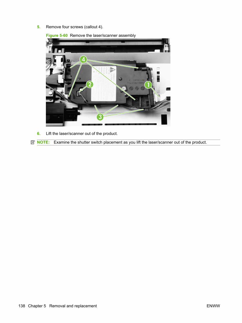
5. Remove four screws (callout 4).
Figure 5-60 Remove the laser/scanner assembly
2 1
3
4
6. Lift the laser/scanner out of the product.
NOTE: Examine the shutter switch placement as you lift the laser/scanner out of the product.
138 Chapter 5 Removal and replacement ENWW

Memory-tag-reader assembly (E-label reader)1. Remove the following components.
● Right cover. See Right cover on page 100.
● Left cover. See Left cover on page 102.
● Rear cover. See Rear cover on page 106.
● Scanner/ADF assembly. See Scanner/ADF assembly on page 117.
● Top cover. See Top cover on page 108.
2. Remove the fan from the product chassis (see step 3 of Fan on page 141).
3. Remove one cable (callout 1) from the cable holder on top of the memory-tag-reader cover.
4. Disconnect one cable from the formatter (callout 2).
Figure 5-61 Remove the memory-tag-reader assembly (1 of 2)
1
2
5. Remove all of the wire harnesses (callout 3) from the retainers.
NOTE: Examine the cable routing as you remove the wire harnesses.
ENWW Internal assemblies 139
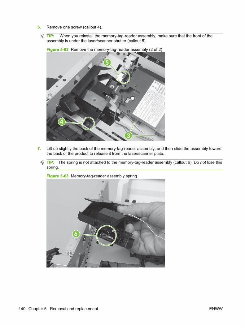
6. Remove one screw (callout 4).
TIP: When you reinstall the memory-tag-reader assembly, make sure that the front of theassembly is under the laser/scanner shutter (callout 5).
Figure 5-62 Remove the memory-tag-reader assembly (2 of 2)
4
5
3
7. Lift up slightly the back of the memory-tag-reader assembly, and then slide the assembly towardthe back of the product to release it from the laser/scanner plate.
TIP: The spring is not attached to the memory-tag-reader assembly (callout 6). Do not lose thisspring.
Figure 5-63 Memory-tag-reader assembly spring
6
140 Chapter 5 Removal and replacement ENWW
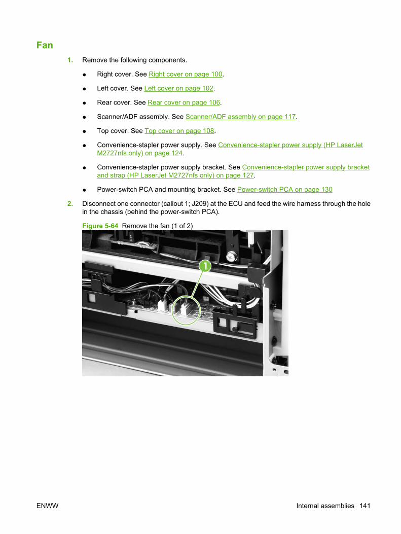
Fan1. Remove the following components.
● Right cover. See Right cover on page 100.
● Left cover. See Left cover on page 102.
● Rear cover. See Rear cover on page 106.
● Scanner/ADF assembly. See Scanner/ADF assembly on page 117.
● Top cover. See Top cover on page 108.
● Convenience-stapler power supply. See Convenience-stapler power supply (HP LaserJetM2727nfs only) on page 124.
● Convenience-stapler power supply bracket. See Convenience-stapler power supply bracketand strap (HP LaserJet M2727nfs only) on page 127.
● Power-switch PCA and mounting bracket. See Power-switch PCA on page 130
2. Disconnect one connector (callout 1; J209) at the ECU and feed the wire harness through the holein the chassis (behind the power-switch PCA).
Figure 5-64 Remove the fan (1 of 2)
1
ENWW Internal assemblies 141
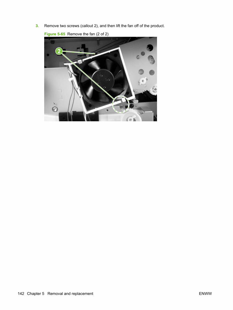
3. Remove two screws (callout 2), and then lift the fan off of the product.
Figure 5-65 Remove the fan (2 of 2)
2
142 Chapter 5 Removal and replacement ENWW

Duplex-drive gears1. Remove the following components.
● Right cover. See Right cover on page 100.
● Left cover. See Left cover on page 102.
● Rear cover. See Rear cover on page 106.
● Scanner/ADF assembly. See Scanner/ADF assembly on page 117.
● Top cover. See Top cover on page 108.
● Convenience-stapler power supply (HP LaserJet M2727nfs only). See Convenience-staplerpower supply (HP LaserJet M2727nfs only) on page 124.
● Convenience-stapler bracket and strap (HP LaserJet M2727nfs only). See Convenience-stapler power supply bracket and strap (HP LaserJet M2727nfs only) on page 127.
● Fan. See Fan on page 141.
ENWW Internal assemblies 143
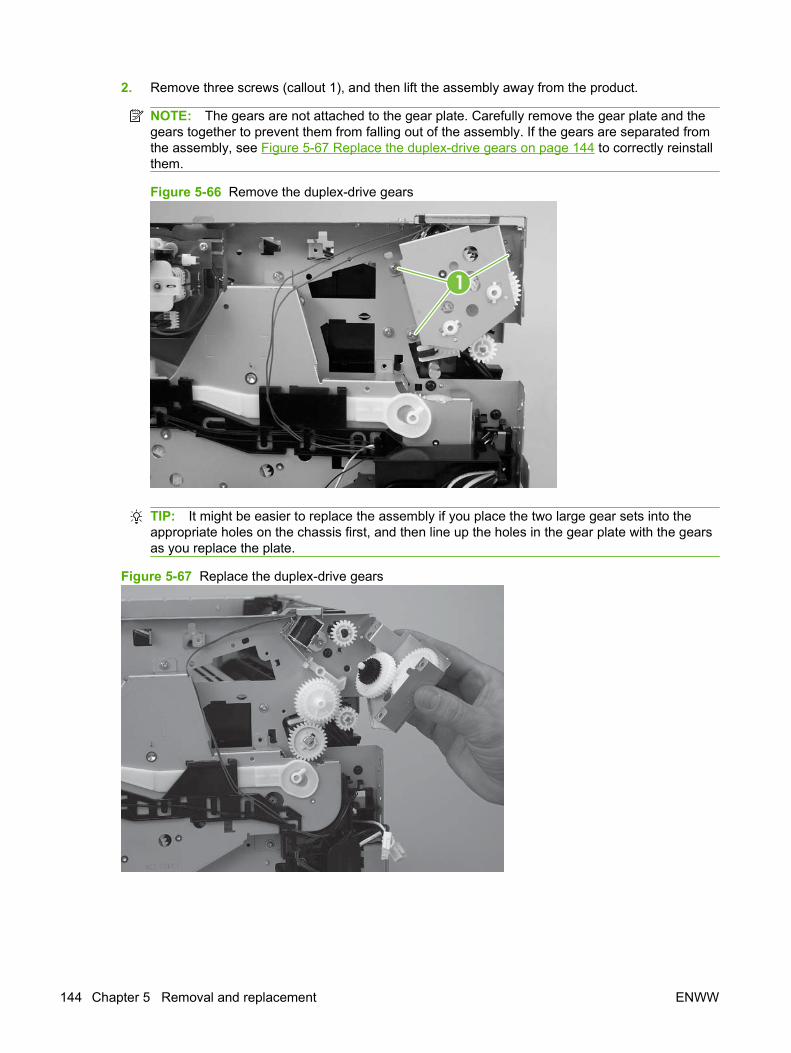
2. Remove three screws (callout 1), and then lift the assembly away from the product.
NOTE: The gears are not attached to the gear plate. Carefully remove the gear plate and thegears together to prevent them from falling out of the assembly. If the gears are separated fromthe assembly, see Figure 5-67 Replace the duplex-drive gears on page 144 to correctly reinstallthem.
Figure 5-66 Remove the duplex-drive gears
1
TIP: It might be easier to replace the assembly if you place the two large gear sets into theappropriate holes on the chassis first, and then line up the holes in the gear plate with the gearsas you replace the plate.
Figure 5-67 Replace the duplex-drive gears
144 Chapter 5 Removal and replacement ENWW
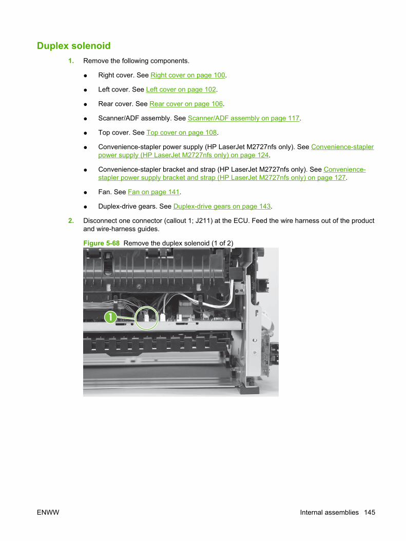
Duplex solenoid1. Remove the following components.
● Right cover. See Right cover on page 100.
● Left cover. See Left cover on page 102.
● Rear cover. See Rear cover on page 106.
● Scanner/ADF assembly. See Scanner/ADF assembly on page 117.
● Top cover. See Top cover on page 108.
● Convenience-stapler power supply (HP LaserJet M2727nfs only). See Convenience-staplerpower supply (HP LaserJet M2727nfs only) on page 124.
● Convenience-stapler bracket and strap (HP LaserJet M2727nfs only). See Convenience-stapler power supply bracket and strap (HP LaserJet M2727nfs only) on page 127.
● Fan. See Fan on page 141.
● Duplex-drive gears. See Duplex-drive gears on page 143.
2. Disconnect one connector (callout 1; J211) at the ECU. Feed the wire harness out of the productand wire-harness guides.
Figure 5-68 Remove the duplex solenoid (1 of 2)
1
ENWW Internal assemblies 145
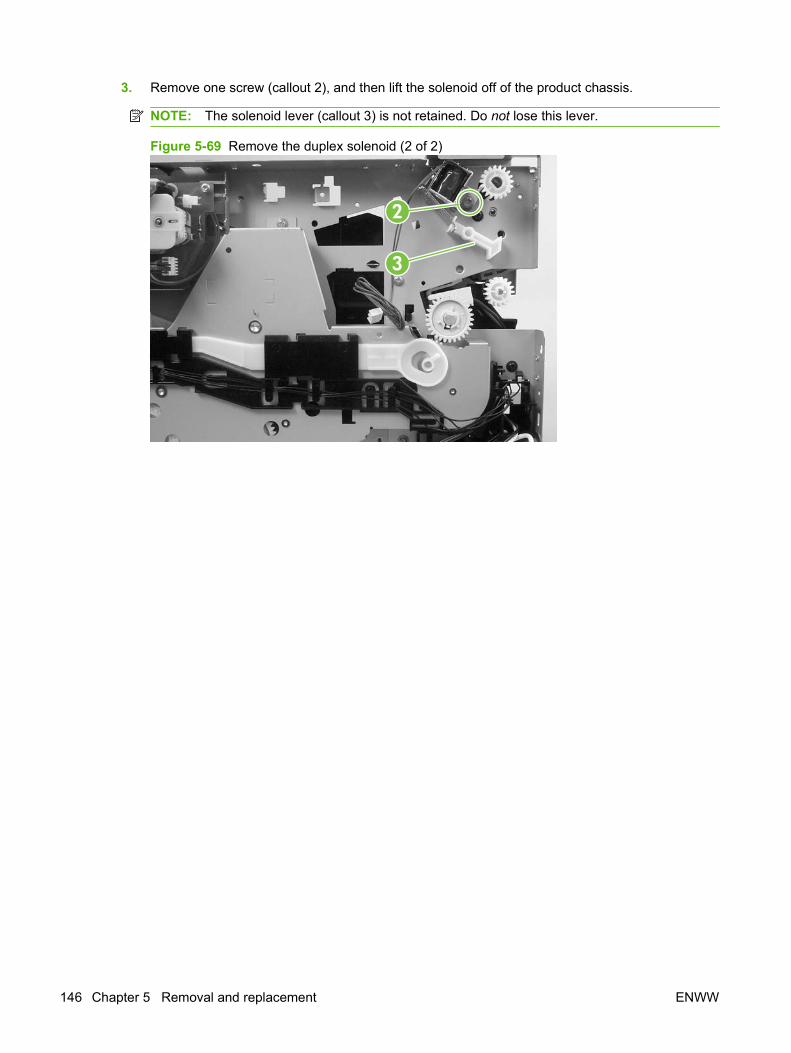
3. Remove one screw (callout 2), and then lift the solenoid off of the product chassis.
NOTE: The solenoid lever (callout 3) is not retained. Do not lose this lever.
Figure 5-69 Remove the duplex solenoid (2 of 2)
2
3
146 Chapter 5 Removal and replacement ENWW

Fuser1. Remove the following components.
● Right cover. See Right cover on page 100.
● Left cover. See Left cover on page 102.
● Rear cover. See Rear cover on page 106.
● Scanner/ADF assembly. See Scanner/ADF assembly on page 117.
● Top cover. See Top cover on page 108.
● Convenience-stapler power supply (HP LaserJet M2727nfs only). See Convenience-staplerpower supply (HP LaserJet M2727nfs only) on page 124.
● Convenience-stapler bracket and strap (HP LaserJet M2727nfs only). See Convenience-stapler power supply bracket and strap (HP LaserJet M2727nfs only) on page 127.
● Power-switch PCA. See Power-switch PCA on page 130.
● Formatter. See Formatter on page 132.
● Duplex assembly. See Duplex assembly on page 135.
● Fan. See Fan on page 141.
● Duplex-drive gears. See Duplex-drive gears on page 143.
● Duplex solenoid. See Duplex solenoid on page 145.
2. On the right side of the product, press the tabs on two gears (callout 1) to release the gears, andthen slide the gears off of the shafts.
Figure 5-70 Remove the fuser (1 of 9)
1
ENWW Internal assemblies 147

3. Disconnect the connectors along the edge of the ECU (callout 2). Remove the wire harness fromthe guides (callout 3).
Figure 5-71 Remove the fuser (2 of 9)
2
3
4. Remove one screw (callout 4) from the wire harness guide and separate it from the product.
Reinstallation tip You might find it easier to reassemble the wire harnesses and the wire harnessholder if you put the smaller wires in place first.
Figure 5-72 Remove the fuser (3 of 9)
4
148 Chapter 5 Removal and replacement ENWW
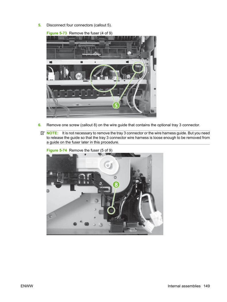
5. Disconnect four connectors (callout 5).
Figure 5-73 Remove the fuser (4 of 9)
5
6. Remove one screw (callout 8) on the wire guide that contains the optional tray 3 connector.
NOTE: It is not necessary to remove the tray 3 connector or the wire harness guide. But you needto release the guide so that the tray 3 connector wire harness is loose enough to be removed froma guide on the fuser later in this procedure.
Figure 5-74 Remove the fuser (5 of 9)
8
ENWW Internal assemblies 149

7. Remove three screws (callout 9) from the right side of the product.
Figure 5-75 Remove the fuser (6 of 9)
9
8. Remove three screws (callout 10) from the left side of the product.
Figure 5-76 Remove the fuser (7 of 9)
10
150 Chapter 5 Removal and replacement ENWW
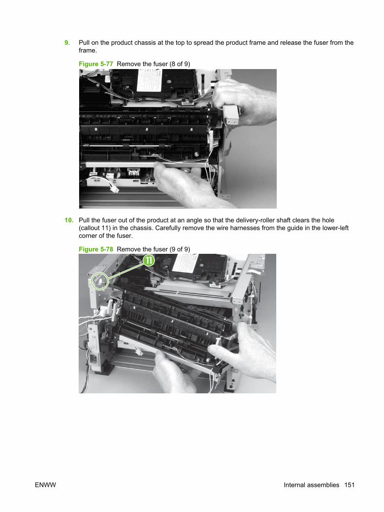
9. Pull on the product chassis at the top to spread the product frame and release the fuser from theframe.
Figure 5-77 Remove the fuser (8 of 9)
10. Pull the fuser out of the product at an angle so that the delivery-roller shaft clears the hole(callout 11) in the chassis. Carefully remove the wire harnesses from the guide in the lower-leftcorner of the fuser.
Figure 5-78 Remove the fuser (9 of 9)
11
ENWW Internal assemblies 151
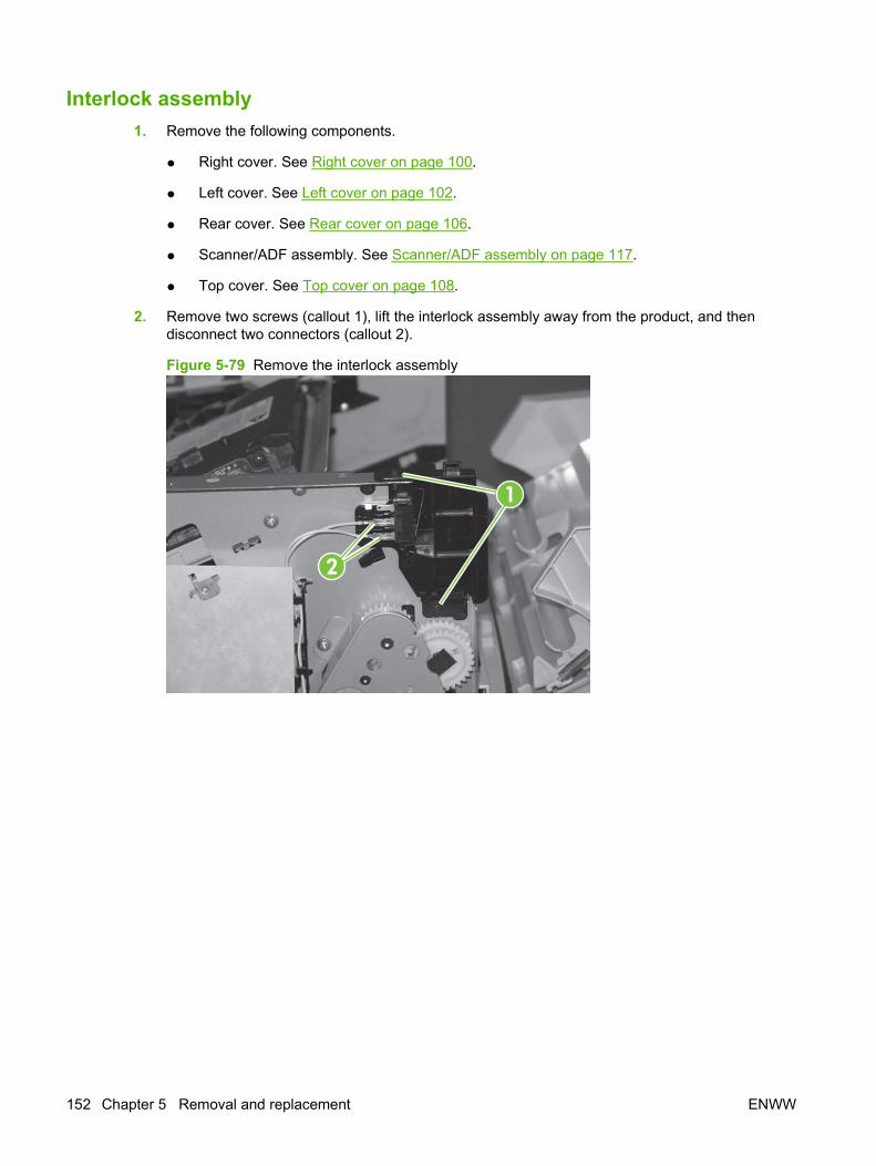
Interlock assembly1. Remove the following components.
● Right cover. See Right cover on page 100.
● Left cover. See Left cover on page 102.
● Rear cover. See Rear cover on page 106.
● Scanner/ADF assembly. See Scanner/ADF assembly on page 117.
● Top cover. See Top cover on page 108.
2. Remove two screws (callout 1), lift the interlock assembly away from the product, and thendisconnect two connectors (callout 2).
Figure 5-79 Remove the interlock assembly
1
2
152 Chapter 5 Removal and replacement ENWW

Engine controller assembly (ECU)
CAUTION: PCAs are sensitive to electrostatic discharge (ESD). Look for the ESD reminderwhen removing PCAs. Always perform service work at an ESD-protected workstation or mat. If an ESDworkstation or mat is not available, ground yourself by touching the sheet-metal chassis before touchingan ESD-sensitive part.
Protect the ESD-sensitive parts by placing them in ESD pouches when they are out of the product.
CAUTION: Do not bend or fold the flat flexible cables (FFCs) during removal or installation. Also, donot straighten pre-folds in the FFCs. You must make sure that all FFCs are fully seated in theirconnectors. Failure to fully seat an FFC into a connector can cause a short circuit in a PCA.
1. Remove the following components.
● Right cover. See Right cover on page 100.
● Left cover. See Left cover on page 102.
● Rear cover. See Rear cover on page 106.
● Scanner/ADF assembly. See Scanner/ADF assembly on page 117.
● Top cover. See Top cover on page 108.
● Power-switch PCA and mounting bracket. See Power-switch PCA on page 130
● Formatter. See Formatter on page 132.
● Duplex assembly. See Duplex assembly on page 135.
● Fan. See Fan on page 141.
● Duplex-drive gears. See Duplex-drive gears on page 143.
● Fuser. See Fuser on page 147.
● Interlock assembly. See Interlock assembly on page 152.
ENWW Internal assemblies 153
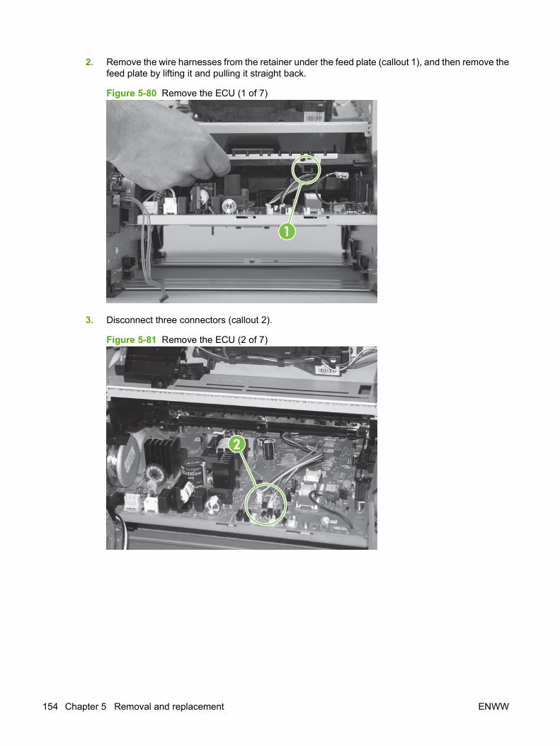
2. Remove the wire harnesses from the retainer under the feed plate (callout 1), and then remove thefeed plate by lifting it and pulling it straight back.
Figure 5-80 Remove the ECU (1 of 7)
1
3. Disconnect three connectors (callout 2).
Figure 5-81 Remove the ECU (2 of 7)
2
154 Chapter 5 Removal and replacement ENWW
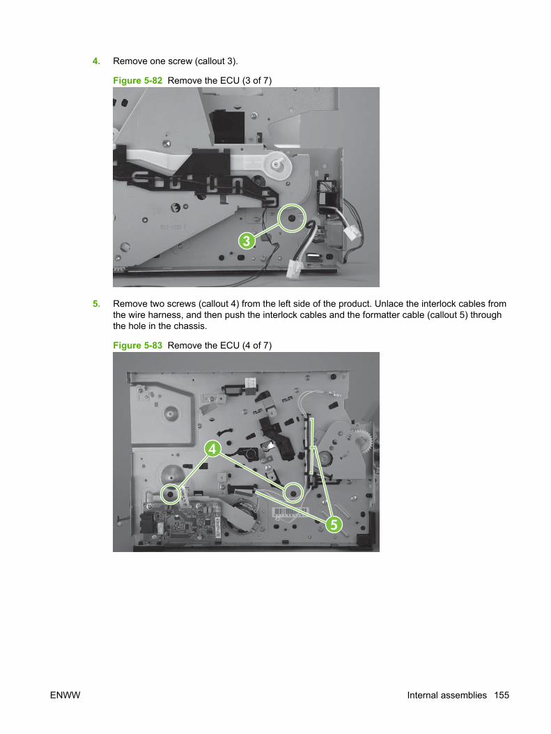
4. Remove one screw (callout 3).
Figure 5-82 Remove the ECU (3 of 7)
3
5. Remove two screws (callout 4) from the left side of the product. Unlace the interlock cables fromthe wire harness, and then push the interlock cables and the formatter cable (callout 5) throughthe hole in the chassis.
Figure 5-83 Remove the ECU (4 of 7)
4
5
ENWW Internal assemblies 155
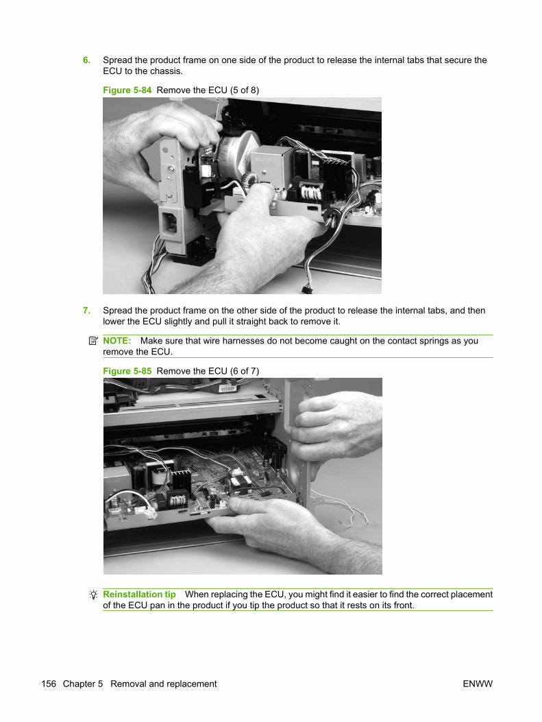
6. Spread the product frame on one side of the product to release the internal tabs that secure theECU to the chassis.
Figure 5-84 Remove the ECU (5 of 8)
7. Spread the product frame on the other side of the product to release the internal tabs, and thenlower the ECU slightly and pull it straight back to remove it.
NOTE: Make sure that wire harnesses do not become caught on the contact springs as youremove the ECU.
Figure 5-85 Remove the ECU (6 of 7)
Reinstallation tip When replacing the ECU, you might find it easier to find the correct placementof the ECU pan in the product if you tip the product so that it rests on its front.
156 Chapter 5 Removal and replacement ENWW

8. Remove four screws (callout 7), and then lift the ECU off of the ECU pan.
Figure 5-86 Remove the ECU (7 of 7)
7
ENWW Internal assemblies 157
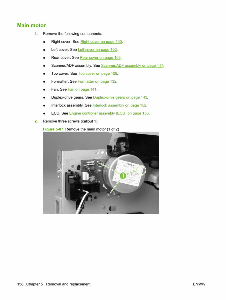
Main motor1. Remove the following components.
● Right cover. See Right cover on page 100.
● Left cover. See Left cover on page 102.
● Rear cover. See Rear cover on page 106.
● Scanner/ADF assembly. See Scanner/ADF assembly on page 117.
● Top cover. See Top cover on page 108.
● Formatter. See Formatter on page 132.
● Fan. See Fan on page 141.
● Duplex-drive gears. See Duplex-drive gears on page 143.
● Interlock assembly. See Interlock assembly on page 152.
● ECU. See Engine controller assembly (ECU) on page 153.
2. Remove three screws (callout 1).
Figure 5-87 Remove the main motor (1 of 2)
1
158 Chapter 5 Removal and replacement ENWW
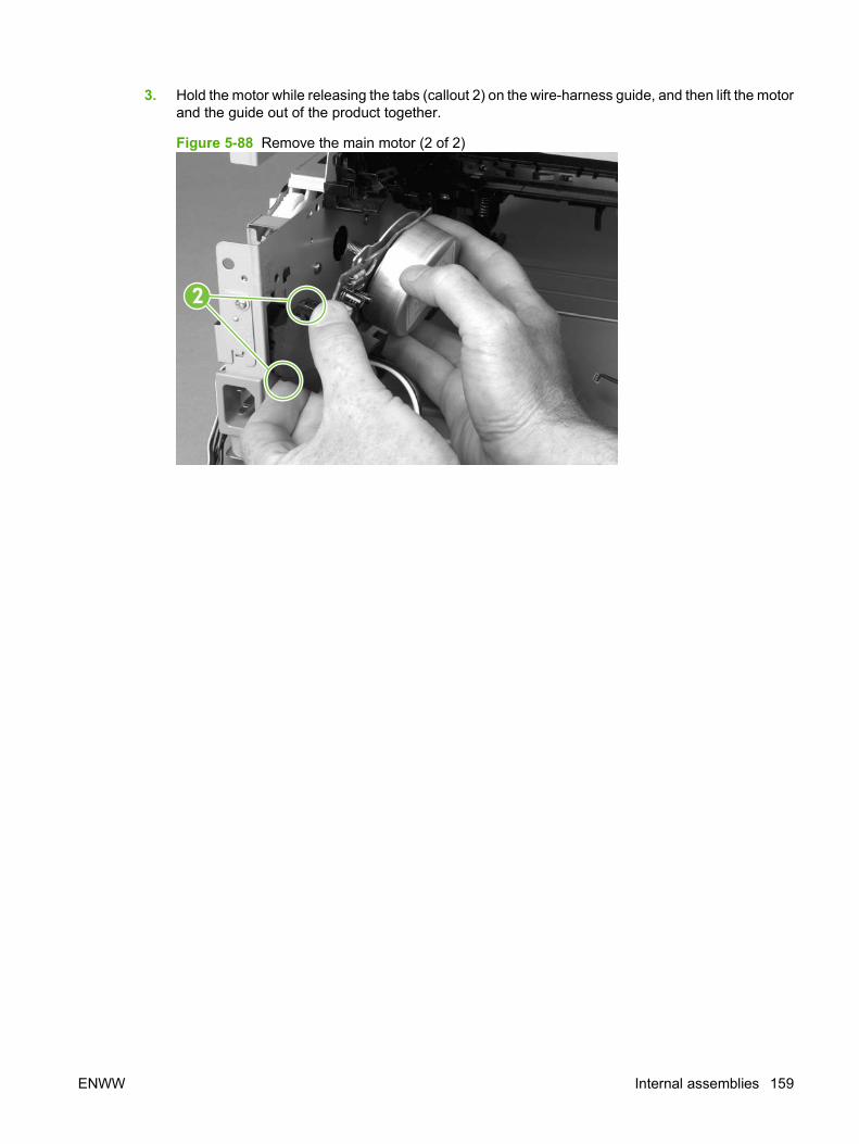
3. Hold the motor while releasing the tabs (callout 2) on the wire-harness guide, and then lift the motorand the guide out of the product together.
Figure 5-88 Remove the main motor (2 of 2)
2
ENWW Internal assemblies 159
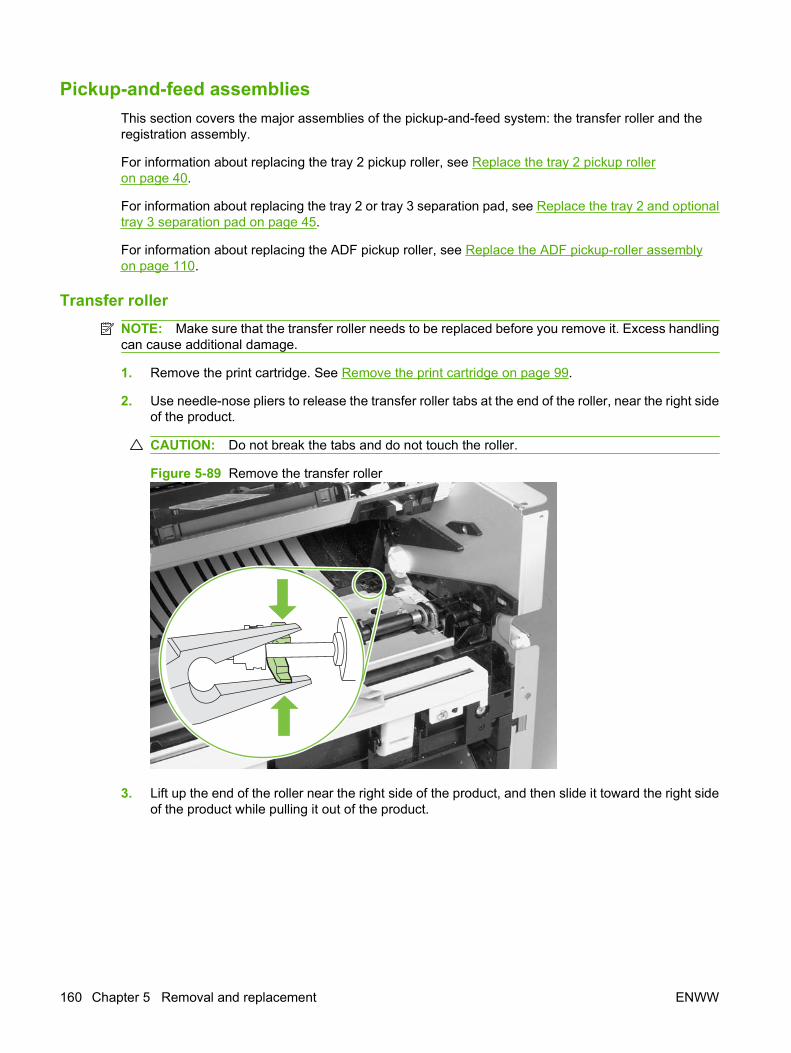
Pickup-and-feed assembliesThis section covers the major assemblies of the pickup-and-feed system: the transfer roller and theregistration assembly.
For information about replacing the tray 2 pickup roller, see Replace the tray 2 pickup rolleron page 40.
For information about replacing the tray 2 or tray 3 separation pad, see Replace the tray 2 and optionaltray 3 separation pad on page 45.
For information about replacing the ADF pickup roller, see Replace the ADF pickup-roller assemblyon page 110.
Transfer rollerNOTE: Make sure that the transfer roller needs to be replaced before you remove it. Excess handlingcan cause additional damage.
1. Remove the print cartridge. See Remove the print cartridge on page 99.
2. Use needle-nose pliers to release the transfer roller tabs at the end of the roller, near the right sideof the product.
CAUTION: Do not break the tabs and do not touch the roller.
Figure 5-89 Remove the transfer roller
3. Lift up the end of the roller near the right side of the product, and then slide it toward the right sideof the product while pulling it out of the product.
160 Chapter 5 Removal and replacement ENWW
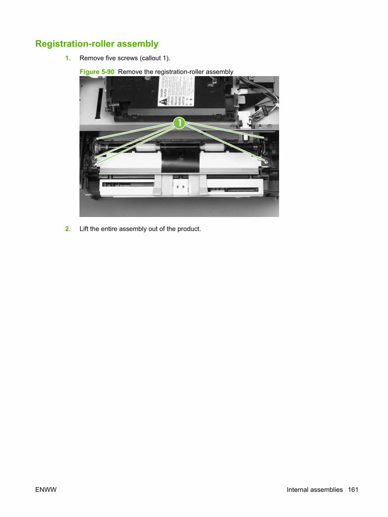
Registration-roller assembly1. Remove five screws (callout 1).
Figure 5-90 Remove the registration-roller assembly
1
2. Lift the entire assembly out of the product.
ENWW Internal assemblies 161

Main gear assembly and tray 2 pickup solenoid1. Remove the following components.
● Right cover. See Right cover on page 100.
● Left cover. See Left cover on page 102.
● Rear cover. See Rear cover on page 106.
● Top cover. See Top cover on page 108.
● Convenience-stapler power supply (HP LaserJet M2727nfs only). See Convenience-staplerpower supply (HP LaserJet M2727nfs only) on page 124.
● Convenience-stapler power supply bracket and strap (HP LaserJet M2727nfs only). SeeConvenience-stapler power supply bracket and strap (HP LaserJet M2727nfs only)on page 127.
● Power switch PCA. See Power-switch PCA on page 130.
● Fan. See Fan on page 141.
2. Disconnect one connector (callout 1; J206) at the ECU and pull the wires through the chassis.
Figure 5-91 Remove the main gear assembly (1 of 5)
1
162 Chapter 5 Removal and replacement ENWW
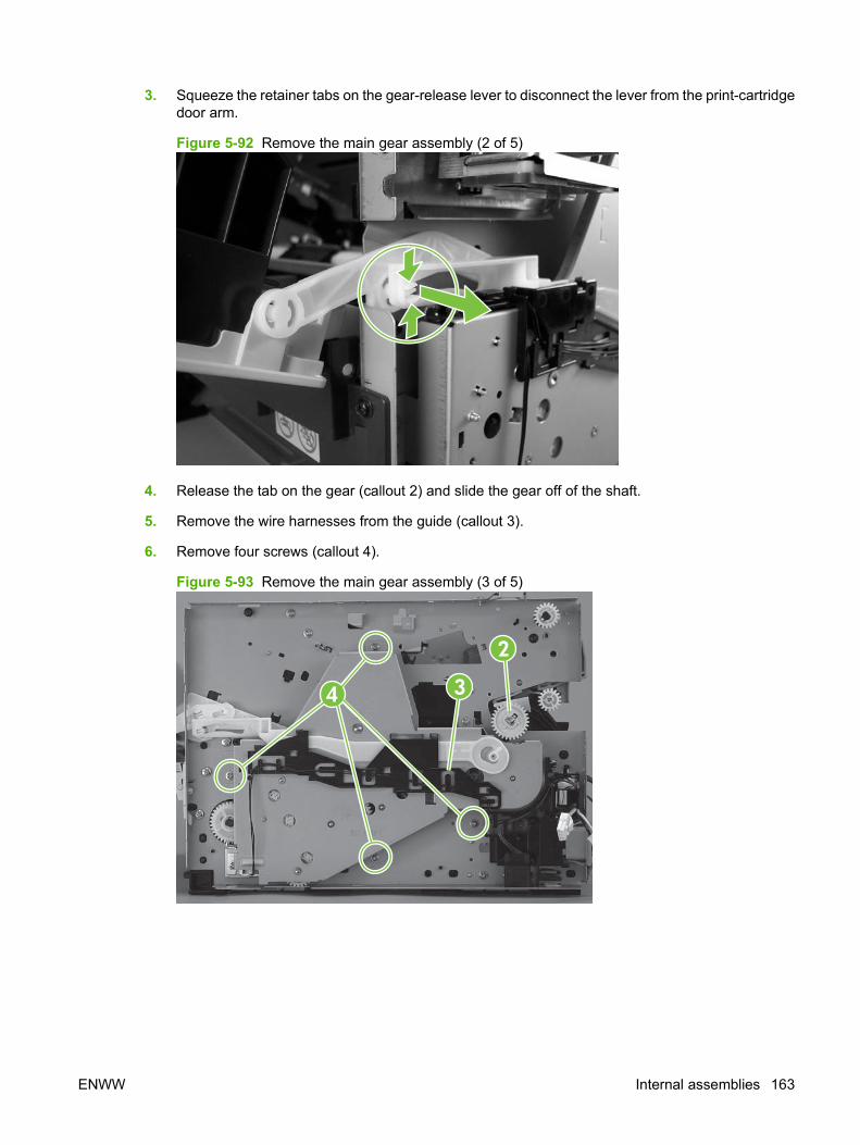
3. Squeeze the retainer tabs on the gear-release lever to disconnect the lever from the print-cartridgedoor arm.
Figure 5-92 Remove the main gear assembly (2 of 5)
4. Release the tab on the gear (callout 2) and slide the gear off of the shaft.
5. Remove the wire harnesses from the guide (callout 3).
6. Remove four screws (callout 4).
Figure 5-93 Remove the main gear assembly (3 of 5)
2
34
ENWW Internal assemblies 163
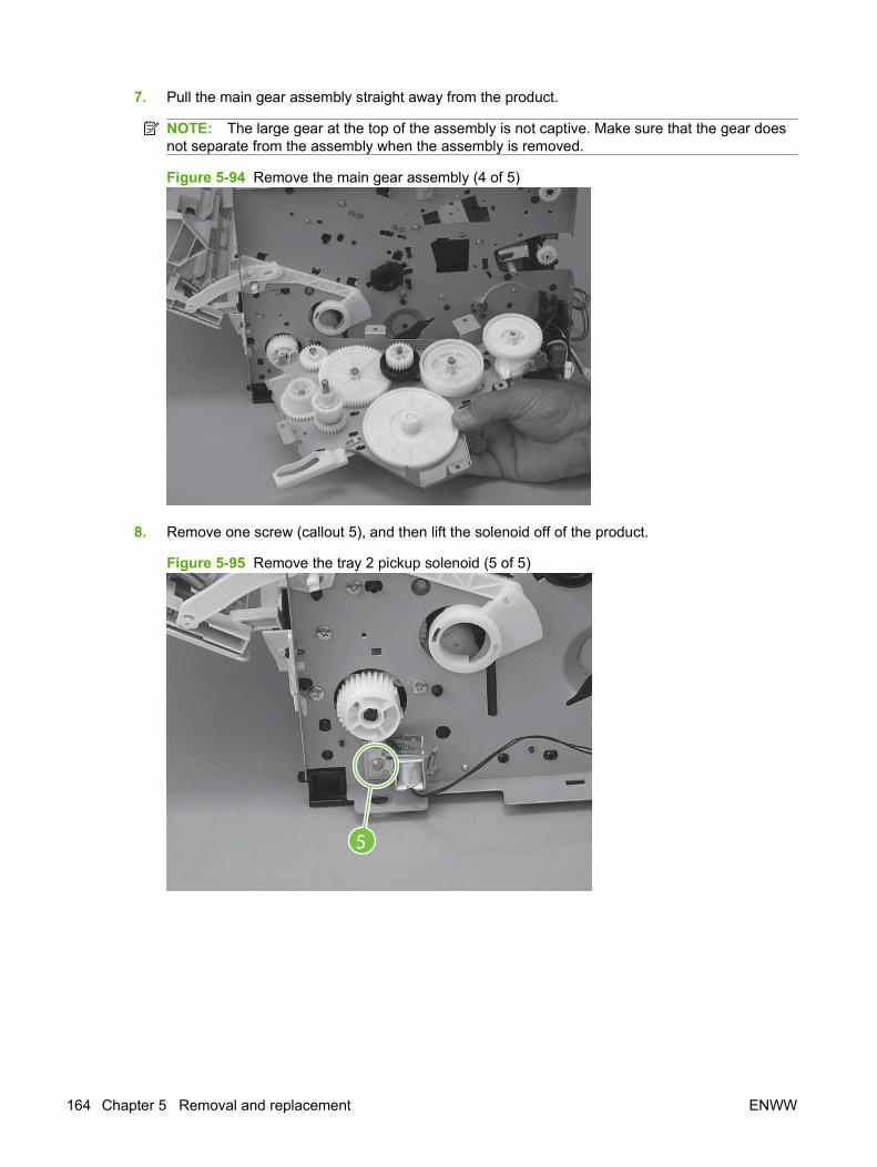
7. Pull the main gear assembly straight away from the product.
NOTE: The large gear at the top of the assembly is not captive. Make sure that the gear doesnot separate from the assembly when the assembly is removed.
Figure 5-94 Remove the main gear assembly (4 of 5)
8. Remove one screw (callout 5), and then lift the solenoid off of the product.
Figure 5-95 Remove the tray 2 pickup solenoid (5 of 5)
5
164 Chapter 5 Removal and replacement ENWW

6 Solve problems
● Problem-solving checklist
● Control-panel messages
● Clear jams
● Control-panel menus
● Print problems
● Scan problems
● Copy problems
● Fax problems
● Control-panel display problems
● Convenience-stapler problems (HP LaserJet M2727nfs only)
● DSL problems
● ADF problems
● Functional checks
● Service-mode functions
● Problem-solve tools
● Firmware updates
ENWW 165
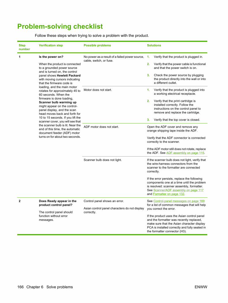
Problem-solving checklistFollow these steps when trying to solve a problem with the product.
Stepnumber
Verification step Possible problems Solutions
1 Is the power on?
When the product is connectedto a grounded power sourceand is turned on, the controlpanel shows Hewlett Packardwith moving cursors indicatingthat the firmware code isloading, and the main motorrotates for approximately 45 to60 seconds. When thefirmware is done loading,Scanner bulb warming upmight appear on the control-panel display, and the scanhead moves back and forth for10 to 15 seconds. If you lift thescanner cover, you will see thatthe scanner bulb is lit. Near theend of this time, the automaticdocument feeder (ADF) motorturns on for about two seconds.
No power as a result of a failed power source,cable, switch, or fuse.
1. Verify that the product is plugged in.
2. Verify that the power cable is functionaland that the power switch is on.
3. Check the power source by pluggingthe product directly into the wall or intoa different outlet.
Motor does not start. 1. Verify that the product is plugged intoa working electrical receptacle.
2. Verify that the print cartridge isinstalled correctly. Follow theinstructions on the control panel toremove and replace the cartridge.
3. Verify that the top cover is closed.
ADF motor does not start. Open the ADF cover and remove anyorange shipping tape inside the ADF.
Verify that the ADF connector is connectedcorrectly to the scanner.
If the ADF motor still does not rotate, replacethe ADF. See ADF assembly on page 115.
Scanner bulb does not light. If the scanner bulb does not light, verify thatthe wire-harness connectors from thescanner to the formatter are connectedcorrectly.
If the error persists, replace the followingcomponents one at a time until the problemis resolved: scanner assembly, formatter.See Scanner/ADF assembly on page 117and Formatter on page 132.
2 Does Ready appear in theproduct control panel?
The control panel shouldfunction without errormessages.
Control panel shows an error.
Asian control panel characters do not displaycorrectly.
See Control-panel messages on page 169for a list of common messages that will helpyou correct the error.
If the product uses the Asian control paneland the formatter was recently replaced,make sure that the Asian character displayPCA is installed correctly and fully seated inthe formatter connector (H3).
166 Chapter 6 Solve problems ENWW
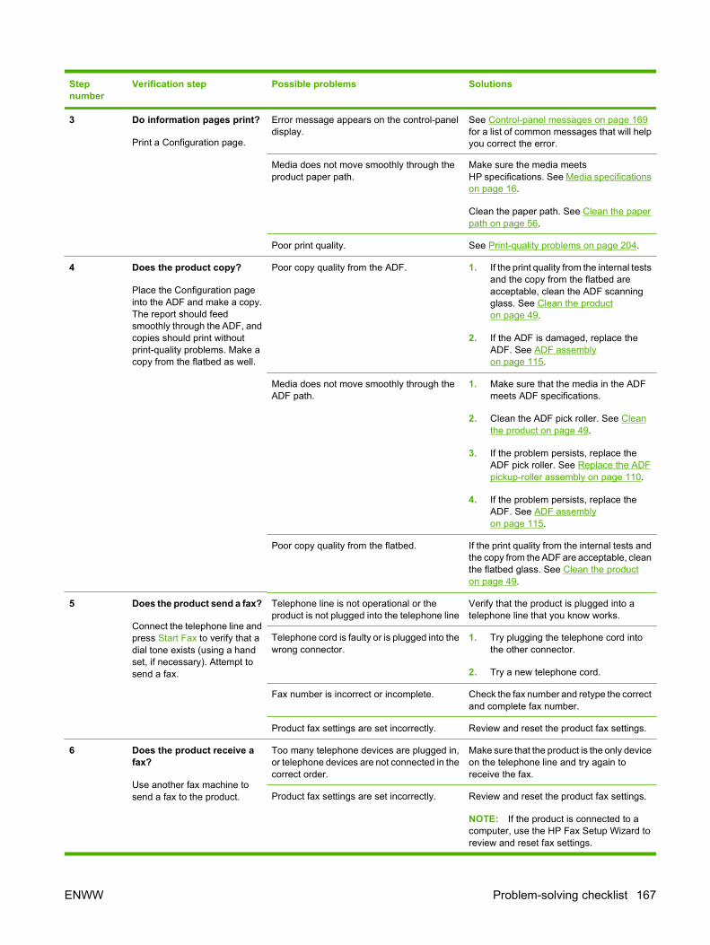
Stepnumber
Verification step Possible problems Solutions
3 Do information pages print?
Print a Configuration page.
Error message appears on the control-paneldisplay.
See Control-panel messages on page 169for a list of common messages that will helpyou correct the error.
Media does not move smoothly through theproduct paper path.
Make sure the media meetsHP specifications. See Media specificationson page 16.
Clean the paper path. See Clean the paperpath on page 56.
Poor print quality. See Print-quality problems on page 204.
4 Does the product copy?
Place the Configuration pageinto the ADF and make a copy.The report should feedsmoothly through the ADF, andcopies should print withoutprint-quality problems. Make acopy from the flatbed as well.
Poor copy quality from the ADF. 1. If the print quality from the internal testsand the copy from the flatbed areacceptable, clean the ADF scanningglass. See Clean the producton page 49.
2. If the ADF is damaged, replace theADF. See ADF assemblyon page 115.
Media does not move smoothly through theADF path.
1. Make sure that the media in the ADFmeets ADF specifications.
2. Clean the ADF pick roller. See Cleanthe product on page 49.
3. If the problem persists, replace theADF pick roller. See Replace the ADFpickup-roller assembly on page 110.
4. If the problem persists, replace theADF. See ADF assemblyon page 115.
Poor copy quality from the flatbed. If the print quality from the internal tests andthe copy from the ADF are acceptable, cleanthe flatbed glass. See Clean the producton page 49.
5 Does the product send a fax?
Connect the telephone line andpress Start Fax to verify that adial tone exists (using a handset, if necessary). Attempt tosend a fax.
Telephone line is not operational or theproduct is not plugged into the telephone line
Verify that the product is plugged into atelephone line that you know works.
Telephone cord is faulty or is plugged into thewrong connector.
1. Try plugging the telephone cord intothe other connector.
2. Try a new telephone cord.
Fax number is incorrect or incomplete. Check the fax number and retype the correctand complete fax number.
Product fax settings are set incorrectly. Review and reset the product fax settings.
6 Does the product receive afax?
Use another fax machine tosend a fax to the product.
Too many telephone devices are plugged in,or telephone devices are not connected in thecorrect order.
Make sure that the product is the only deviceon the telephone line and try again toreceive the fax.
Product fax settings are set incorrectly. Review and reset the product fax settings.
NOTE: If the product is connected to acomputer, use the HP Fax Setup Wizard toreview and reset fax settings.
ENWW Problem-solving checklist 167
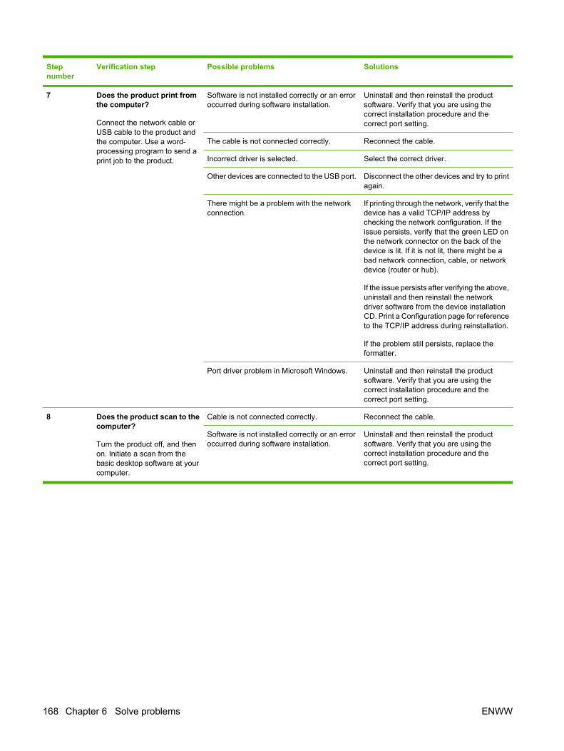
Stepnumber
Verification step Possible problems Solutions
7 Does the product print fromthe computer?
Connect the network cable orUSB cable to the product andthe computer. Use a word-processing program to send aprint job to the product.
Software is not installed correctly or an erroroccurred during software installation.
Uninstall and then reinstall the productsoftware. Verify that you are using thecorrect installation procedure and thecorrect port setting.
The cable is not connected correctly. Reconnect the cable.
Incorrect driver is selected. Select the correct driver.
Other devices are connected to the USB port. Disconnect the other devices and try to printagain.
There might be a problem with the networkconnection.
If printing through the network, verify that thedevice has a valid TCP/IP address bychecking the network configuration. If theissue persists, verify that the green LED onthe network connector on the back of thedevice is lit. If it is not lit, there might be abad network connection, cable, or networkdevice (router or hub).
If the issue persists after verifying the above,uninstall and then reinstall the networkdriver software from the device installationCD. Print a Configuration page for referenceto the TCP/IP address during reinstallation.
If the problem still persists, replace theformatter.
Port driver problem in Microsoft Windows. Uninstall and then reinstall the productsoftware. Verify that you are using thecorrect installation procedure and thecorrect port setting.
8 Does the product scan to thecomputer?
Turn the product off, and thenon. Initiate a scan from thebasic desktop software at yourcomputer.
Cable is not connected correctly. Reconnect the cable.
Software is not installed correctly or an erroroccurred during software installation.
Uninstall and then reinstall the productsoftware. Verify that you are using thecorrect installation procedure and thecorrect port setting.
168 Chapter 6 Solve problems ENWW

Control-panel messagesThe majority of the control-panel messages are intended to guide the user through typical operation.The control-panel messages indicate the status of the current operation, and include a page count onthe second line of the display, if appropriate. When the product is receiving fax data, print data, orscanning commands, control-panel messages indicate this status. In addition, alert messages, warningmessages, and critical error messages indicate situations that might require some action.
Alert and warning messages Alert and warning messages appear temporarily and might require the user to acknowledge themessage by pressing OK to resume or by pressing Cancel to cancel the job. With certain warnings, thejob might not complete or the print quality might be affected. If the alert or warning message is relatedto printing and the auto-continue feature is on, the product will attempt to resume the printing job afterthe warning has appeared for 10 seconds without acknowledgement.
Alert and warning message tablesTable 6-1 Alert and warning messages
Control panel message Description Recommended action
10.0000 Supply Memory Error A specific print cartridge has an e-label error. Reinstall the print cartridge.
Turn off and then turn on the product.
If the problem is not solved, replace thecartridge.
10.1000 Supply Memory Error A specific print cartridge has a missing e-label.
Reinstall the print cartridge.
Turn off and then turn on the product.
If the problem is not solved, replace thecartridge.
ADF door is open The ADF lid is open or a sensor ismalfunctioning.
Make sure that the ADF lid is closed.
Remove the ADF and reinstall it.
If the message persists, turn off the power byusing the power switch, wait at least 30seconds, and then turn on the power and waitfor the product to initialize.
If the error persists, contact HP. Seewww.hp.com/support/LJM2727 or thesupport flyer that came in the product box.
Canceled copy. Clear document The Cancel button was pressed to cancel thecurrent job while pages were feeding from theADF. The cancel process does notautomatically clear the ADF.
Remove the jammed item. See Clear jamsfrom the ADF on page 180. Then, clear theitems in the ADF tray and start over.
Canceled scan. Clear document The Cancel button was pressed to cancel thecurrent job while pages were feeding from theADF. The cancel process does notautomatically clear the ADF.
Remove the jammed item. See Clear jamsfrom the ADF on page 180. Then, clear theitems in the ADF tray and start over.
Canceled send. Clear document The Cancel button was pressed to cancel thecurrent job while pages were feeding from theADF tray. The cancel process does notautomatically clear the ADF.
Remove the jammed item. See Clear jamsfrom the ADF on page 180. Then, clear theitems in the ADF tray and start over.
ENWW Control-panel messages 169

Control panel message Description Recommended action
Comm. error [Receiver CSID] A fax communication error occurred betweenthe product and the receiver.
Allow the product to retry sending the fax.Unplug the product telephone cord from thewall, plug in a telephone, and try making acall. Plug the product phone cord into a jackfor another phone line.
Try a different phone cord.
If the error persists, contact HP. Seewww.hp.com/support/LJM2727 or thesupport flyer that came in the product box.
Comm. error [Sender CSID] A fax communication error occurred betweenthe product and the sender.
Allow the product to retry sending the fax.Unplug the product telephone cord from thewall, plug in a telephone, and try making acall. Plug the product phone cord into a jackfor another phone line.
Try a different phone cord.
If the error persists, contact HP. Seewww.hp.com/support/LJM2727 or thesupport flyer that came in the product box.
Device error, press OK Generic engine error. This is a warning message only. Job outputmight be affected.
Device is busy. Try again later The product is currently in use. Wait for the product to finish the current job.
Doc feeder jam Clear, Reload A piece of media is jammed in the ADF tray. Open the document release door, clear thejam, close the document release door, andreload the paper into the ADF tray.
If the error persists, contact HP. Seewww.hp.com/support/LJM2727 or thesupport flyer that came in the product box.
Doc feeder jam, DATE/TIME ADF has not been cleared since previousjam.
Clear the jam.
Document feeder mispick. Reload Media in the ADF tray was not picked up. Remove the media from the ADF tray, andthen reload it.
Clean the ADF pickup roller. See Clean theADF pickup-roller assembly on page 55.
If the error persists, contact HP. Seewww.hp.com/support/LJM2727 or thesupport flyer that came in the product box.
Door open The print-cartridge door is open. Close the print-cartridge door.
Engine comm. error The product experienced a print enginecommunication error.
This is a warning message only. Job outputmight be affected.
Engine error, press OK The product experienced a print engine error. This is a warning message only. Job outputmight be affected.
Fit to Page on flatbed only The copy reduce/enlarge feature (called "Fitto Page") applies only to copies made fromthe flatbed scanner.
Use the flatbed or select another reduction/enlargement setting.
Install black cartridge No cartridge installed with door closed. Install print cartridge.
Table 6-1 Alert and warning messages (continued)
170 Chapter 6 Solve problems ENWW
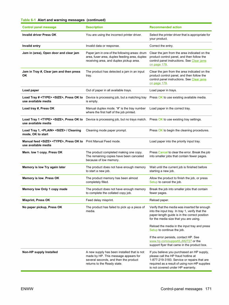
Control panel message Description Recommended action
Invalid driver Press OK You are using the incorrect printer driver. Select the printer driver that is appropriate foryour product.
Invalid entry Invalid data or response. Correct the entry.
Jam in (area), Open door and clear jam Paper jam in one of the following areas: drumarea, fuser area, duplex feeding area, duplexreceiving area, and duplex pickup area.
Clear the jam from the area indicated on theproduct control panel, and then follow thecontrol panel instructions. See Clear jamson page 179.
Jam in Tray #, Clear jam and then pressOK
The product has detected a jam in an inputtray.
Clear the jam from the area indicated on theproduct control panel, and then follow thecontrol panel instructions. See Clear jamson page 179.
Load paper Out of paper in all available trays. Load paper in trays.
Load Tray # <TYPE> <SIZE>, Press OK touse available media
Device is processing job, but a matching trayis empty.
Press OK to use existing available media.
Load tray #, Press OK Manual duplex mode. “#” is the tray numberwhere the first half of the job printed.
Load paper in the correct tray.
Load Tray 1 <TYPE> <SIZE>, Press OK touse available media
Device is processing job, but no trays match. Press OK to use existing tray settings.
Load Tray 1, <PLAIN> <SIZE> / Cleaningmode, OK to start
Cleaning mode paper prompt. Press OK to begin the cleaning procedures.
Manual feed <SIZE> <TYPE>, Press OK touse available media
Print Manual Feed mode. Load paper into the priority input tray.
Mem. low 1 copy. Press OK The product completed making one copy.The remaining copies have been canceledbecause of low memory.
Press Cancel to clear the error. Break the jobinto smaller jobs that contain fewer pages.
Memory is low Try again later The product does not have enough memoryto start a new job.
Wait until the current job is finished beforestarting a new job.
Memory is low. Press OK The product memory has been almostcompletely filled.
Allow the product to finish the job, or pressSetup to cancel the job.
Memory low Only 1 copy made The product does not have enough memoryto complete the collated copy job.
Break the job into smaller jobs that containfewer pages.
Misprint, Press OK Feed delay misprint. Reload paper.
No paper pickup, Press OK The product has failed to pick up a piece ofmedia.
Verify that the media was inserted far enoughinto the input tray. In tray 1, verify that thepaper-length guide is in the correct positionfor the media size that you are using.
Reload the media in the input tray and pressSetup to continue the job.
If the error persists, contact HP. Seewww.hp.com/support/LJM2727 or thesupport flyer that came in the product box.
Non-HP supply Installed A new supply has been installed that is notmade by HP. This message appears forseveral seconds, and then the productreturns to the Ready state.
If you believe you purchased an HP supply,please call the HP fraud hotline at1-877-219-3183. Service or repairs that arerequired as a result of using non-HP suppliesis not covered under HP warranty.
Table 6-1 Alert and warning messages (continued)
ENWW Control-panel messages 171

Control panel message Description Recommended action
Order black Cartridge Print cartridge is low. Order a new print cartridge.
Page too complex, press OK The product could not print the current pagebecause of its complexity.
Press Setup to clear the message.
Allow the product to finish the job, or pressCancel to cancel the job.
Scanner reserved for PC scan A computer is using the product to create ascan.
Wait until the computer scan has finished, orcancel the scan from the computer software,or press Cancel.
Scanning error Cannot connect The product cannot transmit scan informationto a computer.
Verify that the connection cable is not looseor damaged. Replace the cable if necessary,and try the scan again.
Settings cleared, DATE/TIME The product has cleared job settings. Re-enter any appropriate job settings.
Used black cartridge in use
alternates with
to accept, press OK
A used printer cartridge has been installed ormoved.
Press OK to return to the Ready state.
Table 6-2 Alert and warning messages
Control panel message Description Recommended action
Comm. error A fax communication error occurred betweenthe product and the sender or receiver.
Allow the product to retry sending the fax.Unplug the product telephone cord from thewall, plug in a telephone, and try making acall. Plug the product phone cord into a jackfor another phone line.
Try a different phone cord.
If the error persists, contact HP. Seewww.hp.com/support/LJM2727 or thesupport flyer that came in the product box.
Fax delayed – Send memory full Fax memory is full. Cancel the fax by pressing OK or Cancel.Resend the fax. You might need to send thefax in multiple sections if the error occursagain.
Fax is busy Canceled send The fax line to which you were sending a faxwas busy. The product has canceled sendingthe fax.
Call the recipient to ensure that the faxmachine is on and ready.
Check that you are dialing the correct faxnumber.
Check that the Redial if busy option isenabled.
Check for a dial tone on the phone line bypressing Start Fax.
Make sure that the phone is working bydisconnecting the product, plugging in atelephone to the phone line, and making avoice call.
Table 6-1 Alert and warning messages (continued)
172 Chapter 6 Solve problems ENWW
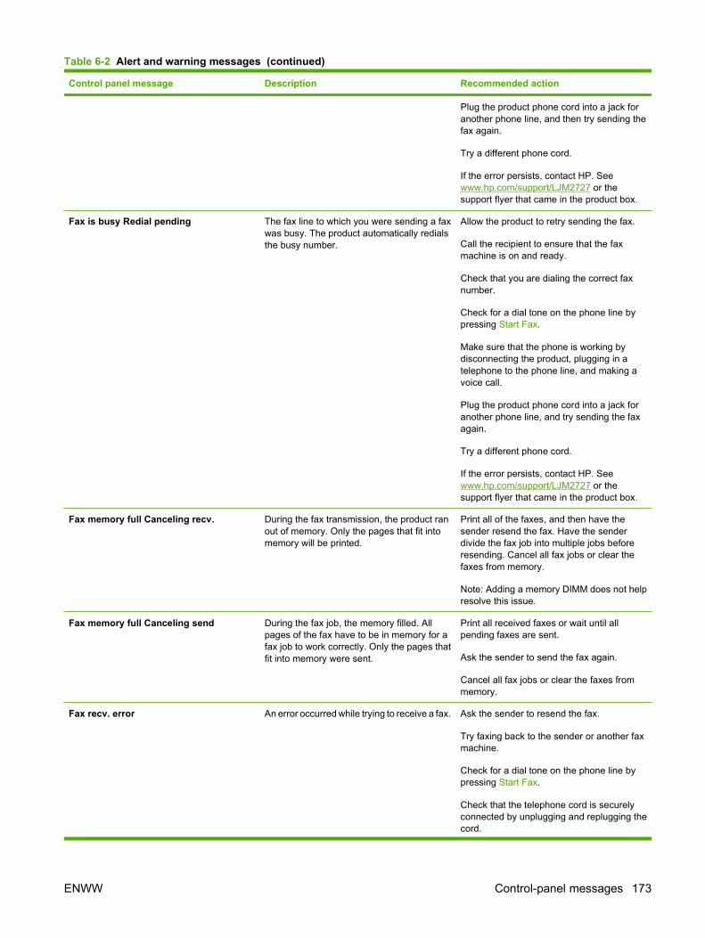
Control panel message Description Recommended action
Plug the product phone cord into a jack foranother phone line, and then try sending thefax again.
Try a different phone cord.
If the error persists, contact HP. Seewww.hp.com/support/LJM2727 or thesupport flyer that came in the product box.
Fax is busy Redial pending The fax line to which you were sending a faxwas busy. The product automatically redialsthe busy number.
Allow the product to retry sending the fax.
Call the recipient to ensure that the faxmachine is on and ready.
Check that you are dialing the correct faxnumber.
Check for a dial tone on the phone line bypressing Start Fax.
Make sure that the phone is working bydisconnecting the product, plugging in atelephone to the phone line, and making avoice call.
Plug the product phone cord into a jack foranother phone line, and try sending the faxagain.
Try a different phone cord.
If the error persists, contact HP. Seewww.hp.com/support/LJM2727 or thesupport flyer that came in the product box.
Fax memory full Canceling recv. During the fax transmission, the product ranout of memory. Only the pages that fit intomemory will be printed.
Print all of the faxes, and then have thesender resend the fax. Have the senderdivide the fax job into multiple jobs beforeresending. Cancel all fax jobs or clear thefaxes from memory.
Note: Adding a memory DIMM does not helpresolve this issue.
Fax memory full Canceling send During the fax job, the memory filled. Allpages of the fax have to be in memory for afax job to work correctly. Only the pages thatfit into memory were sent.
Print all received faxes or wait until allpending faxes are sent.
Ask the sender to send the fax again.
Cancel all fax jobs or clear the faxes frommemory.
Fax recv. error An error occurred while trying to receive a fax. Ask the sender to resend the fax.
Try faxing back to the sender or another faxmachine.
Check for a dial tone on the phone line bypressing Start Fax.
Check that the telephone cord is securelyconnected by unplugging and replugging thecord.
Table 6-2 Alert and warning messages (continued)
ENWW Control-panel messages 173
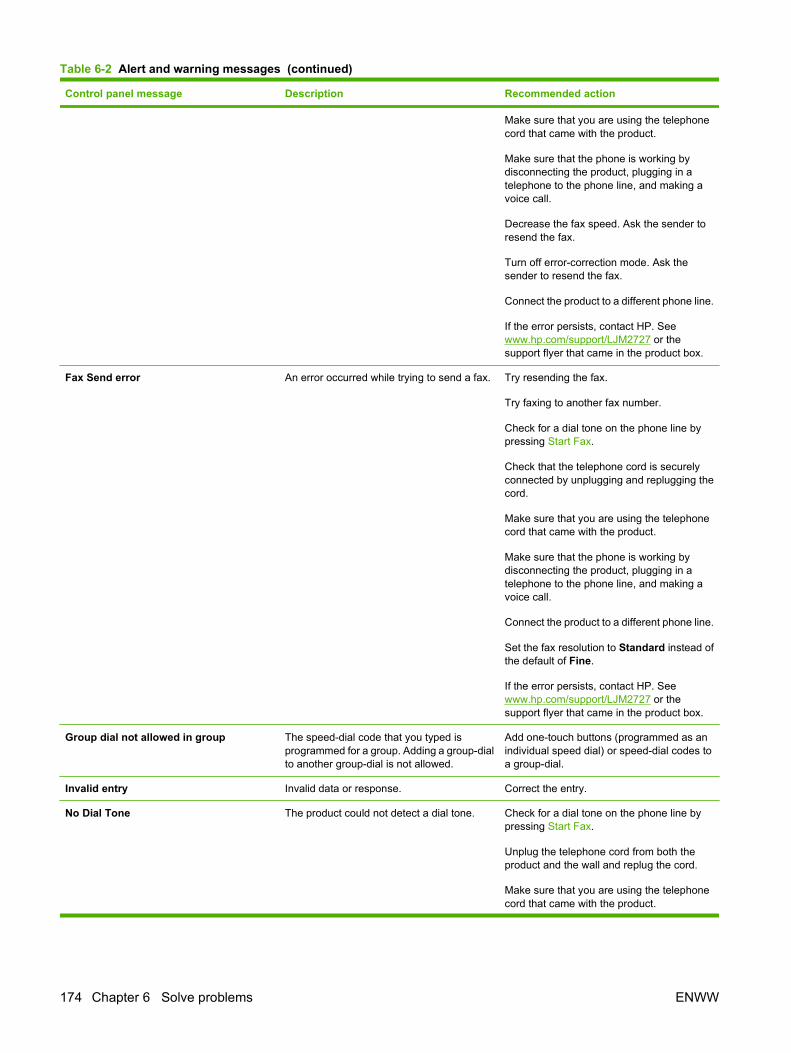
Control panel message Description Recommended action
Make sure that you are using the telephonecord that came with the product.
Make sure that the phone is working bydisconnecting the product, plugging in atelephone to the phone line, and making avoice call.
Decrease the fax speed. Ask the sender toresend the fax.
Turn off error-correction mode. Ask thesender to resend the fax.
Connect the product to a different phone line.
If the error persists, contact HP. Seewww.hp.com/support/LJM2727 or thesupport flyer that came in the product box.
Fax Send error An error occurred while trying to send a fax. Try resending the fax.
Try faxing to another fax number.
Check for a dial tone on the phone line bypressing Start Fax.
Check that the telephone cord is securelyconnected by unplugging and replugging thecord.
Make sure that you are using the telephonecord that came with the product.
Make sure that the phone is working bydisconnecting the product, plugging in atelephone to the phone line, and making avoice call.
Connect the product to a different phone line.
Set the fax resolution to Standard instead ofthe default of Fine.
If the error persists, contact HP. Seewww.hp.com/support/LJM2727 or thesupport flyer that came in the product box.
Group dial not allowed in group The speed-dial code that you typed isprogrammed for a group. Adding a group-dialto another group-dial is not allowed.
Add one-touch buttons (programmed as anindividual speed dial) or speed-dial codes toa group-dial.
Invalid entry Invalid data or response. Correct the entry.
No Dial Tone The product could not detect a dial tone. Check for a dial tone on the phone line bypressing Start Fax.
Unplug the telephone cord from both theproduct and the wall and replug the cord.
Make sure that you are using the telephonecord that came with the product.
Table 6-2 Alert and warning messages (continued)
174 Chapter 6 Solve problems ENWW
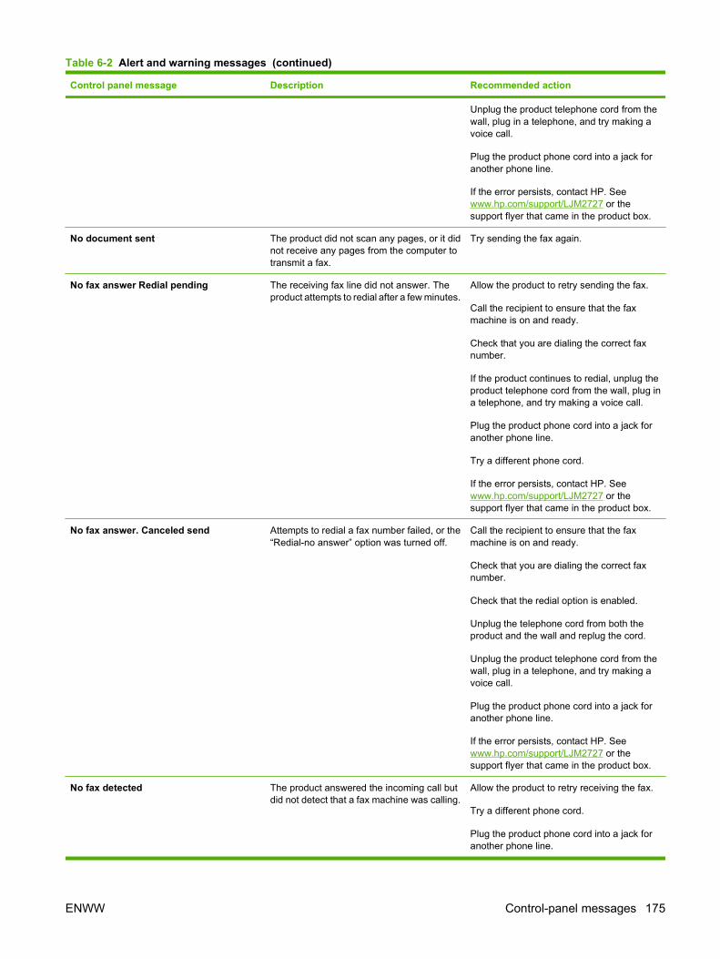
Control panel message Description Recommended action
Unplug the product telephone cord from thewall, plug in a telephone, and try making avoice call.
Plug the product phone cord into a jack foranother phone line.
If the error persists, contact HP. Seewww.hp.com/support/LJM2727 or thesupport flyer that came in the product box.
No document sent The product did not scan any pages, or it didnot receive any pages from the computer totransmit a fax.
Try sending the fax again.
No fax answer Redial pending The receiving fax line did not answer. Theproduct attempts to redial after a few minutes.
Allow the product to retry sending the fax.
Call the recipient to ensure that the faxmachine is on and ready.
Check that you are dialing the correct faxnumber.
If the product continues to redial, unplug theproduct telephone cord from the wall, plug ina telephone, and try making a voice call.
Plug the product phone cord into a jack foranother phone line.
Try a different phone cord.
If the error persists, contact HP. Seewww.hp.com/support/LJM2727 or thesupport flyer that came in the product box.
No fax answer. Canceled send Attempts to redial a fax number failed, or the“Redial-no answer” option was turned off.
Call the recipient to ensure that the faxmachine is on and ready.
Check that you are dialing the correct faxnumber.
Check that the redial option is enabled.
Unplug the telephone cord from both theproduct and the wall and replug the cord.
Unplug the product telephone cord from thewall, plug in a telephone, and try making avoice call.
Plug the product phone cord into a jack foranother phone line.
If the error persists, contact HP. Seewww.hp.com/support/LJM2727 or thesupport flyer that came in the product box.
No fax detected The product answered the incoming call butdid not detect that a fax machine was calling.
Allow the product to retry receiving the fax.
Try a different phone cord.
Plug the product phone cord into a jack foranother phone line.
Table 6-2 Alert and warning messages (continued)
ENWW Control-panel messages 175

Control panel message Description Recommended action
If the error persists, contact HP. Seewww.hp.com/support/LJM2727 or thesupport flyer that came in the product box.
Table 6-2 Alert and warning messages (continued)
176 Chapter 6 Solve problems ENWW

Critical error messagesCritical error messages can indicate some kind of failure. Turning off and then turning on the powermight fix the problem. If a critical error persists, the product might require service.
Critical error message-tablesTable 6-3 Critical error messages
Control panel message Description Recommended action
49 Error, Turn off then on The product has experienced an internalembedded software error.
Turn off the power by using the power switch,wait at least 30 seconds, and then turn on thepower and wait for the product to initialize.
If the error persists, contact HP. Seewww.hp.com/support/LJM2727 or thesupport flyer that came in the product box.
50.x Fuser Error The product has experienced an internalhardware error.
1. Turn off the power by using the powerswitch, and then wait at least 30seconds.
2. If a surge protector is being used,remove it. Plug the product directly intothe wall socket.
3. Turn on the power and wait for theproduct to initialize.
If the error persists, contact HP. Seewww.hp.com/support/LJM2727 or thesupport flyer that came in the product box.
52 Scanner Error The product has experienced an internalhardware error.
Turn off the power by using the power switch,wait at least 30 seconds, and then turn on thepower and wait for the product to initialize.
If a surge protector is being used, remove it.Plug the product directly into the wall socket.Use the power switch to turn the product on.
If the error persists, contact HP. Seewww.hp.com/support/LJM2727 or thesupport flyer that came in the product box.
55.4 Error, Turn off then on The product has experienced an enginecommunication timeout error.
Turn off the power by using the power switch,wait at least 30 seconds, and then turn on thepower and wait for the product to initialize.
If a surge protector is being used, remove it.Plug the product directly into the wall socket.Use the power switch to turn the product on.
If the error persists, contact HP. Seewww.hp.com/support/LJM2727 or thesupport flyer that came in the product box.
79 Error Turn off then on The product has experienced an internalfirmware error.
Turn off the power by using the power switch,wait at least 30 seconds, and then turn on thepower and wait for the product to initialize.
If you have recently installed a memory DIMMin the product, turn off the product, removethe memory DIMM, reinstall the DIMM to
ENWW Control-panel messages 177

Control panel message Description Recommended action
verify that it is seated properly, and then turnon the product.
If a surge protector is being used, remove it.Plug the product directly into the wall socket.Use the power switch to turn the product on.
If the error persists, contact HP. Seewww.hp.com/support/LJM2727 or thesupport flyer that came in the product box.
Scanner error #, Turn off then on The product has experienced an error in thescanner sub-assembly area.
Turn off the power by using the power switch,wait at least 30 seconds, and then turn on thepower and wait for the product to initialize.
If a surge protector is being used, remove it.Plug the product directly into the wall socket.Use the power switch to turn the product on.
If the error persists, contact HP. Seewww.hp.com/support/LJM2727 or thesupport flyer that came in the product box.
Table 6-3 Critical error messages (continued)
178 Chapter 6 Solve problems ENWW

Clear jamsCauses of jams
Occasionally, paper or other print media can become jammed during a print job. Some causes include:
● The input trays are loaded improperly or overfilled, or the media guides are not set properly.
● Media is added to or removed from an input tray during a print job or an input tray is removed fromthe product during a print job.
● The cartridge door is opened during a print job.
● Too many sheets have accumulated in an output area, or sheets are blocking an output area.
● The print media that is being used does not meet HP specifications. See Media specificationson page 16.
● The media is damaged or has foreign objects attached to it, such as staples or paper clips.
● The media has already passed through the product print path and is being reused.
● The environment in which the print media was stored is too humid or too dry. See Mediaspecifications on page 16.
ENWW Clear jams 179
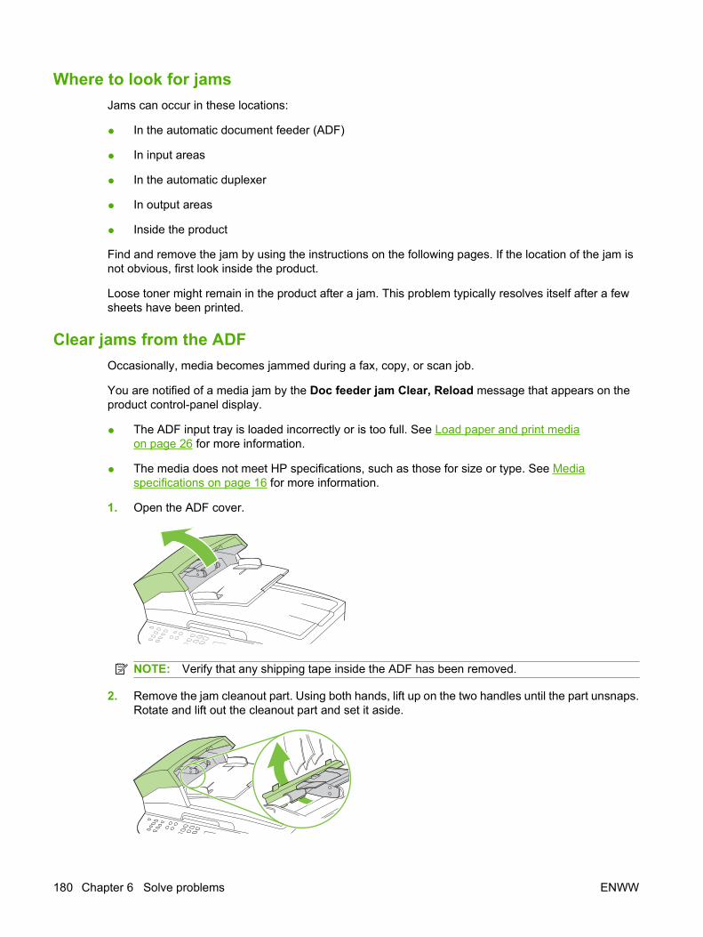
Where to look for jamsJams can occur in these locations:
● In the automatic document feeder (ADF)
● In input areas
● In the automatic duplexer
● In output areas
● Inside the product
Find and remove the jam by using the instructions on the following pages. If the location of the jam isnot obvious, first look inside the product.
Loose toner might remain in the product after a jam. This problem typically resolves itself after a fewsheets have been printed.
Clear jams from the ADFOccasionally, media becomes jammed during a fax, copy, or scan job.
You are notified of a media jam by the Doc feeder jam Clear, Reload message that appears on theproduct control-panel display.
● The ADF input tray is loaded incorrectly or is too full. See Load paper and print mediaon page 26 for more information.
● The media does not meet HP specifications, such as those for size or type. See Mediaspecifications on page 16 for more information.
1. Open the ADF cover.
NOTE: Verify that any shipping tape inside the ADF has been removed.
2. Remove the jam cleanout part. Using both hands, lift up on the two handles until the part unsnaps.Rotate and lift out the cleanout part and set it aside.
180 Chapter 6 Solve problems ENWW
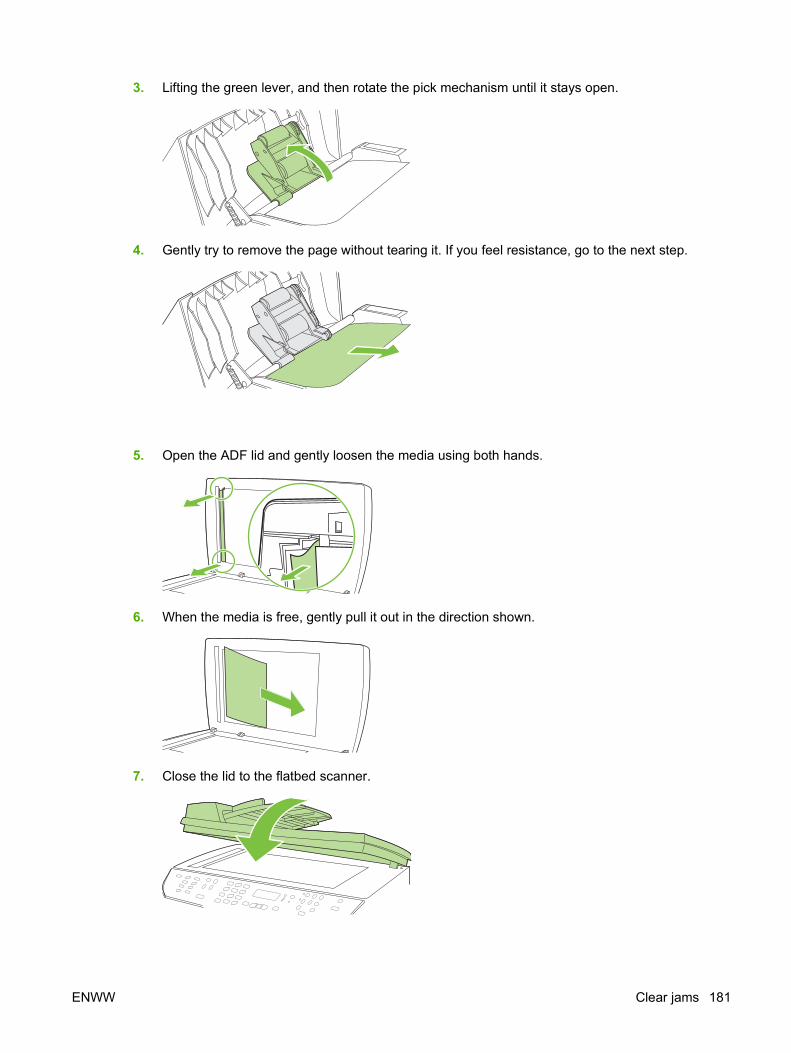
3. Lifting the green lever, and then rotate the pick mechanism until it stays open.
4. Gently try to remove the page without tearing it. If you feel resistance, go to the next step.
5. Open the ADF lid and gently loosen the media using both hands.
6. When the media is free, gently pull it out in the direction shown.
7. Close the lid to the flatbed scanner.
ENWW Clear jams 181
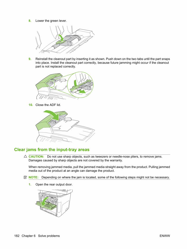
8. Lower the green lever.
9. Reinstall the cleanout part by inserting it as shown. Push down on the two tabs until the part snapsinto place. Install the cleanout part correctly, because future jamming might occur if the cleanoutpart is not replaced correctly.
10. Close the ADF lid.
Clear jams from the input-tray areasCAUTION: Do not use sharp objects, such as tweezers or needle-nose pliers, to remove jams.Damages caused by sharp objects are not covered by the warranty.
When removing jammed media, pull the jammed media straight away from the product. Pulling jammedmedia out of the product at an angle can damage the product.
NOTE: Depending on where the jam is located, some of the following steps might not be necessary.
1. Open the rear output door.
182 Chapter 6 Solve problems ENWW
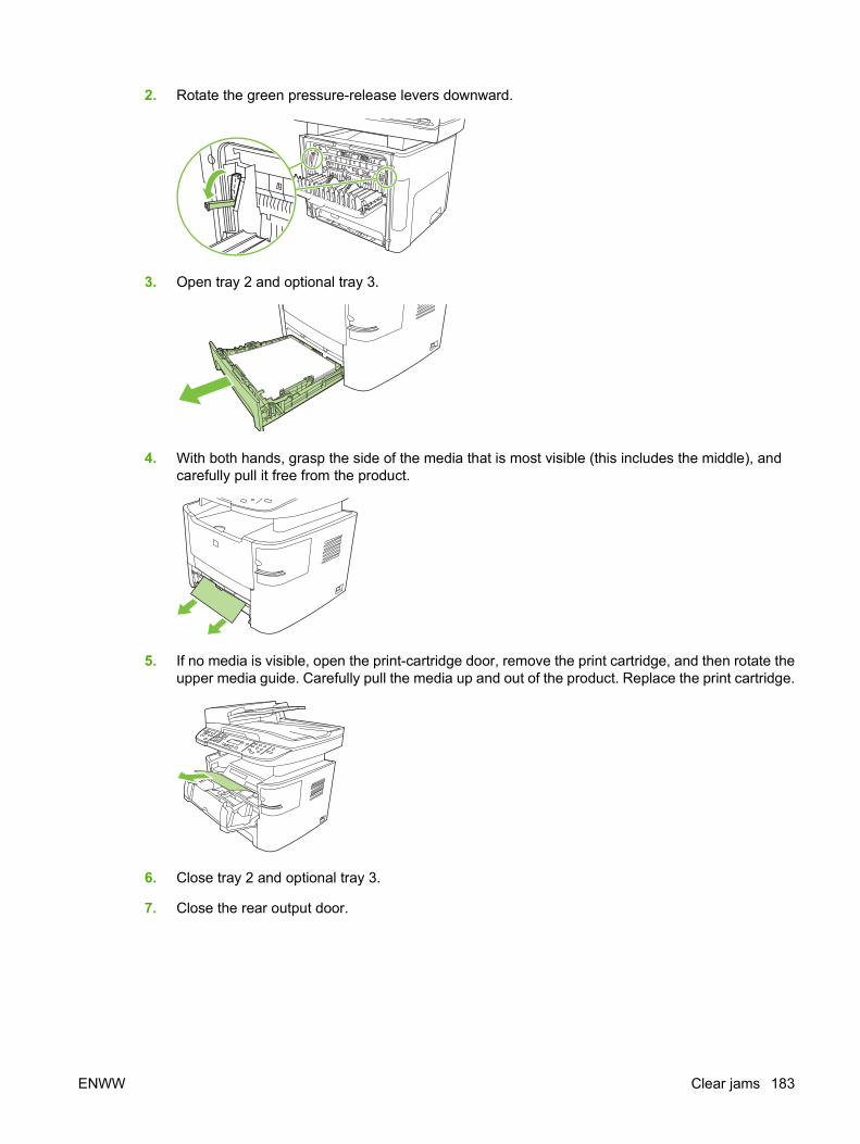
2. Rotate the green pressure-release levers downward.
3. Open tray 2 and optional tray 3.
4. With both hands, grasp the side of the media that is most visible (this includes the middle), andcarefully pull it free from the product.
5. If no media is visible, open the print-cartridge door, remove the print cartridge, and then rotate theupper media guide. Carefully pull the media up and out of the product. Replace the print cartridge.
6. Close tray 2 and optional tray 3.
7. Close the rear output door.
ENWW Clear jams 183
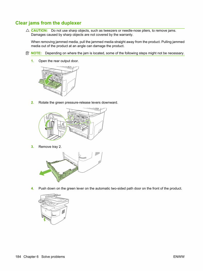
Clear jams from the duplexerCAUTION: Do not use sharp objects, such as tweezers or needle-nose pliers, to remove jams.Damages caused by sharp objects are not covered by the warranty.
When removing jammed media, pull the jammed media straight away from the product. Pulling jammedmedia out of the product at an angle can damage the product.
NOTE: Depending on where the jam is located, some of the following steps might not be necessary.
1. Open the rear output door.
2. Rotate the green pressure-release levers downward.
3. Remove tray 2.
4. Push down on the green lever on the automatic two-sided path door on the front of the product.
184 Chapter 6 Solve problems ENWW
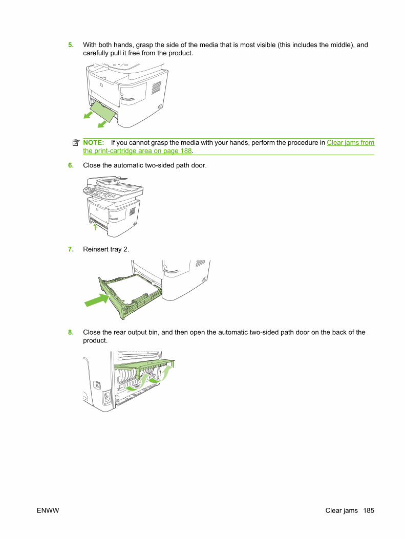
5. With both hands, grasp the side of the media that is most visible (this includes the middle), andcarefully pull it free from the product.
NOTE: If you cannot grasp the media with your hands, perform the procedure in Clear jams fromthe print-cartridge area on page 188.
6. Close the automatic two-sided path door.
7. Reinsert tray 2.
8. Close the rear output bin, and then open the automatic two-sided path door on the back of theproduct.
ENWW Clear jams 185
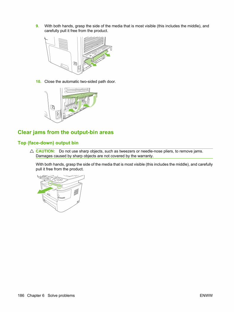
9. With both hands, grasp the side of the media that is most visible (this includes the middle), andcarefully pull it free from the product.
10. Close the automatic two-sided path door.
Clear jams from the output-bin areas
Top (face-down) output binCAUTION: Do not use sharp objects, such as tweezers or needle-nose pliers, to remove jams.Damages caused by sharp objects are not covered by the warranty.
With both hands, grasp the side of the media that is most visible (this includes the middle), and carefullypull it free from the product.
186 Chapter 6 Solve problems ENWW
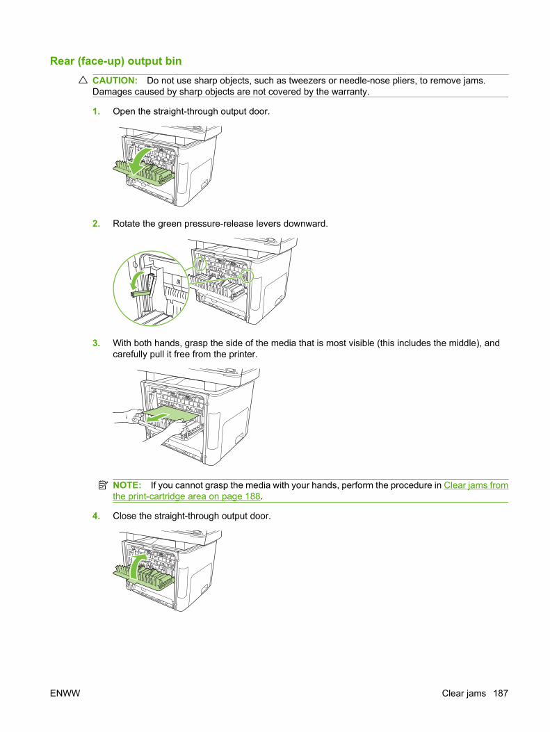
Rear (face-up) output binCAUTION: Do not use sharp objects, such as tweezers or needle-nose pliers, to remove jams.Damages caused by sharp objects are not covered by the warranty.
1. Open the straight-through output door.
2. Rotate the green pressure-release levers downward.
3. With both hands, grasp the side of the media that is most visible (this includes the middle), andcarefully pull it free from the printer.
NOTE: If you cannot grasp the media with your hands, perform the procedure in Clear jams fromthe print-cartridge area on page 188.
4. Close the straight-through output door.
ENWW Clear jams 187
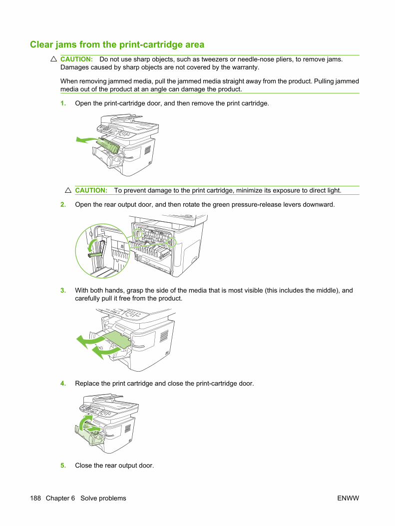
Clear jams from the print-cartridge areaCAUTION: Do not use sharp objects, such as tweezers or needle-nose pliers, to remove jams.Damages caused by sharp objects are not covered by the warranty.
When removing jammed media, pull the jammed media straight away from the product. Pulling jammedmedia out of the product at an angle can damage the product.
1. Open the print-cartridge door, and then remove the print cartridge.
CAUTION: To prevent damage to the print cartridge, minimize its exposure to direct light.
2. Open the rear output door, and then rotate the green pressure-release levers downward.
3. With both hands, grasp the side of the media that is most visible (this includes the middle), andcarefully pull it free from the product.
4. Replace the print cartridge and close the print-cartridge door.
5. Close the rear output door.
188 Chapter 6 Solve problems ENWW

Clear jams from the convenience stapler (HP LaserJet M2727nfs MFPonly)
To reduce the risk of staple jams, make sure that you staple 20 or fewer pages of media (80 g/m2 or 20lb) at a time.
1. Turn off the HP LaserJet M2727nfs MFP, and then open the stapler door.
NOTE: Opening the stapler door disables the stapler.
2. Remove the staple cassette from the product.
3. Clear any loose staples from the stapler and from the staple cassette.
4. Replace the staple cassette.
ENWW Clear jams 189
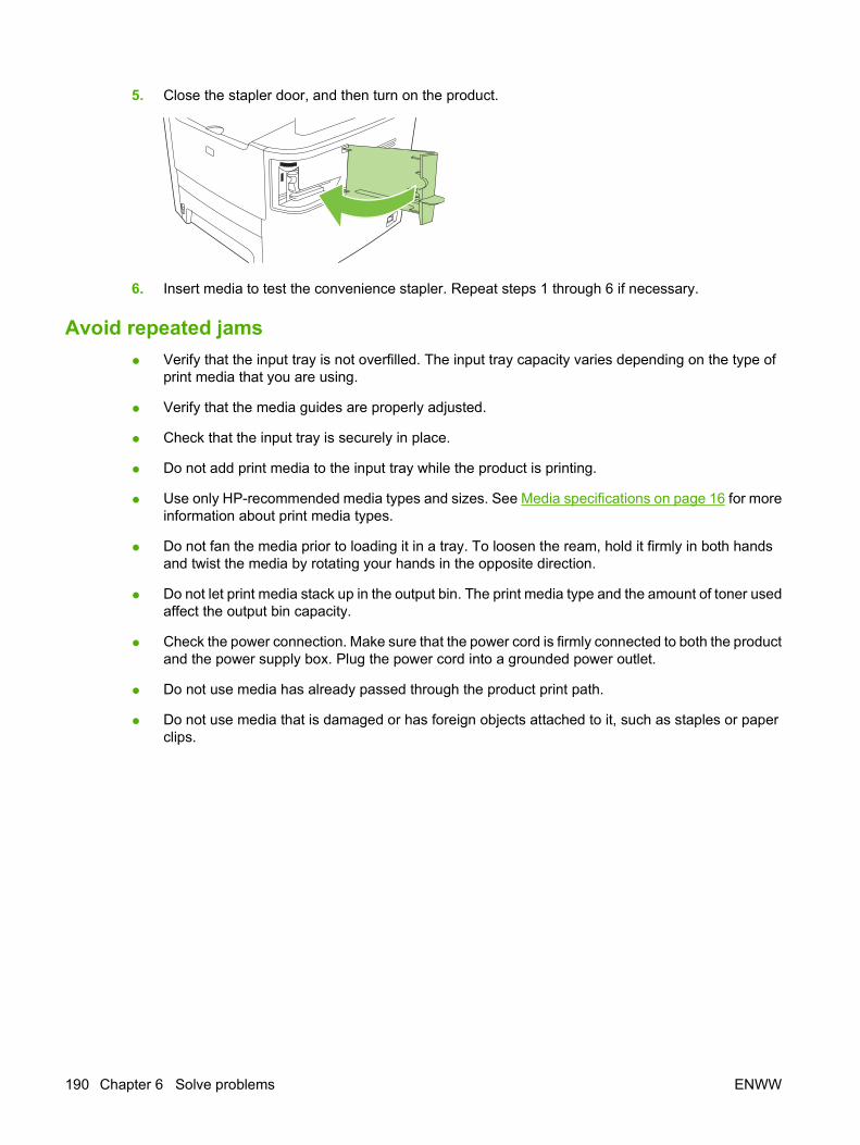
5. Close the stapler door, and then turn on the product.
6. Insert media to test the convenience stapler. Repeat steps 1 through 6 if necessary.
Avoid repeated jams ● Verify that the input tray is not overfilled. The input tray capacity varies depending on the type of
print media that you are using.
● Verify that the media guides are properly adjusted.
● Check that the input tray is securely in place.
● Do not add print media to the input tray while the product is printing.
● Use only HP-recommended media types and sizes. See Media specifications on page 16 for moreinformation about print media types.
● Do not fan the media prior to loading it in a tray. To loosen the ream, hold it firmly in both handsand twist the media by rotating your hands in the opposite direction.
● Do not let print media stack up in the output bin. The print media type and the amount of toner usedaffect the output bin capacity.
● Check the power connection. Make sure that the power cord is firmly connected to both the productand the power supply box. Plug the power cord into a grounded power outlet.
● Do not use media has already passed through the product print path.
● Do not use media that is damaged or has foreign objects attached to it, such as staples or paperclips.
190 Chapter 6 Solve problems ENWW

Control-panel menusUse the control-panel main menus
To gain access to the control-panel main menus, use the following steps.
NOTE: For information about the control-panel secondary menus, see Control-panel secondarymenus on page 199.
1. Press Setup.
2. Use the arrow buttons to navigate the listings.
● Press OK to select the appropriate option.
● Press Cancel to cancel an action or return to the Ready state.
Control-panel main menusThese menus are available from the control-panel main menu:
● Use the Fax Job status menu to display a list of all faxes that are waiting to be sent, or have beenreceived but are waiting to be printed, forwarded, or uploaded to the computer.
● Use the Fax functions menu to configure fax functions such as scheduling a delayed fax,cancelling the Receive to PC mode, reprinting faxes that were previously printed, or printing faxesthat are stored in memory.
● Use the Copy setup menu to configure basic copy default settings such as contrast, collation, orthe number of copies printed.
● Use the Reports menu to print reports that provide information about the product.
● Use the Fax setup menu to configure the fax phone book, the outgoing and incoming fax options,and the basic settings for all faxes.
● Use the System setup menu to establish basic product settings such as language, print quality,or volume levels.
● Use the Network config menu to configure network settings such as TCP/IP configuration.
● Use the Service menu to restore default settings, clean the product, and activate special modesthat affect print output.
NOTE: To print a detailed list of the entire control-panel menu and its structure, print a menu map.See Product information pages and reports on page 237.
Table 6-4 Fax Job status menu
Menu item Description
Fax Job status Displays pending fax jobs, and allows you to cancel pending fax jobs.
Table 6-5 Fax functions menu
Menu item Description
Send fax later Allows a fax to be sent at a later time and date.
ENWW Control-panel menus 191
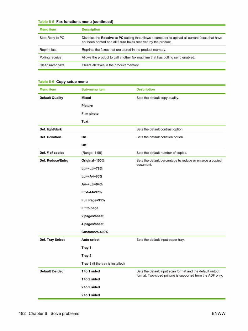
Menu item Description
Stop Recv to PC Disables the Receive to PC setting that allows a computer to upload all current faxes that havenot been printed and all future faxes received by the product.
Reprint last Reprints the faxes that are stored in the product memory.
Polling receive Allows the product to call another fax machine that has polling send enabled.
Clear saved faxs Clears all faxes in the product memory.
Table 6-6 Copy setup menu
Menu item Sub-menu item Description
Default Quality Mixed
Picture
Film photo
Text
Sets the default copy quality.
Def. light/dark Sets the default contrast option.
Def. Collation On
Off
Sets the default collation option.
Def. # of copies (Range: 1-99) Sets the default number of copies.
Def. Reduce/Enlrg Original=100%
Lgl->Ltr=78%
Lgl->A4=83%
A4–>Ltr=94%
Ltr->A4=97%
Full Page=91%
Fit to page
2 pages/sheet
4 pages/sheet
Custom:25-400%
Sets the default percentage to reduce or enlarge a copieddocument.
Def. Tray Select Auto select
Tray 1
Tray 2
Tray 3 (if the tray is installed)
Sets the default input paper tray.
Default 2-sided 1 to 1 sided
1 to 2 sided
2 to 2 sided
2 to 1 sided
Sets the default input scan format and the default outputformat. Two-sided printing is supported from the ADF only.
Table 6-5 Fax functions menu (continued)
192 Chapter 6 Solve problems ENWW

Menu item Sub-menu item Description
Def. Copy Draft On
Off
Sets the default draft mode option.
Def. Multi-page On
Off
Sets the default multi-page flatbed copy option.
Restore defaults Sets all customized copy settings to the factory defaultvalues.
Table 6-7 Reports menu
Menu Item Sub-menu item Sub-menu item Description
Demo page Prints a page that demonstrates print quality.
Fax Reports Fax Confirmation Never
Every fax
Send fax only
Receive fax
Sets whether or not the product prints a confirmation reportafter a successful sending or receiving job.
Include 1st page On
Off
Sets whether or not the product includes a thumbnail imageof the first page of the fax on the report.
Fax Error Report Every error
Send Error
Receive Error
Never
Sets whether or not the product prints a report after a failedsending or receiving job.
Last Call Report Prints a detailed report of the last fax operation, either sentor received.
Fax Activity log Print log now
Auto Log Print
Print log now: Prints a list of the faxes that have been sentfrom or received by this product.
Auto Log Print: Select On to automatically print a reportafter every fax job. Select Off to turn off the automatic printfeature.
PhoneBook report Prints a list of the speed dials that have been set up for thisproduct.
Block Fax list Prints a list of phone numbers that are blocked from sendingfaxes to this product.
Billing report Prints a list of billing codes that have been used for outgoingfaxes. This report shows how many sent faxes were billedto each code. This menu item appears only when the billingcodes feature is turned on.
All fax reports Prints all fax-related reports.
Menu structure Prints a control-panel menu layout map. The active settingsfor each menu are listed.
Table 6-6 Copy setup menu (continued)
ENWW Control-panel menus 193

Menu Item Sub-menu item Sub-menu item Description
Config report Prints a list of all the product settings. Includes networkinformation when the product is connected to the network.
Supplies status Prints the print-cartridge status. Includes the followinginformation:
● Estimated pages remaining
● Serial number
● Number of pages printed
Network report Displays status for:
● Network hardware configuration
● Enabled features
● TCP/IP and SNMP information
● Network statistics
Usage page Displays the number of pages printed, faxed, copied, andscanned by the product.
PCL font list Prints a list of all installed PCL 5 fonts.
PS font list Prints a list of all installed PS fonts.
PCL6 font list Prints a list of all installed PCL 6 fonts.
Service page Displays supported paper types, copy settings, andmiscellaneous product settings.
Table 6-8 Fax setup menu
Menu Item Sub-menu item Sub-menu item Description
Fax Header Your fax number
Company name
Sets the identifying information that is sent to the receivingproduct.
Phone Book Individual setup Add/Edit
Delete
Edits the fax phone book speed dials and group-dial entries.The product supports up to 120 phone book entries, whichcan be either individual or group entries.
Group setup Add/Edit group
Delete group
Del. # in group
Delete all
Table 6-7 Reports menu (continued)
194 Chapter 6 Solve problems ENWW
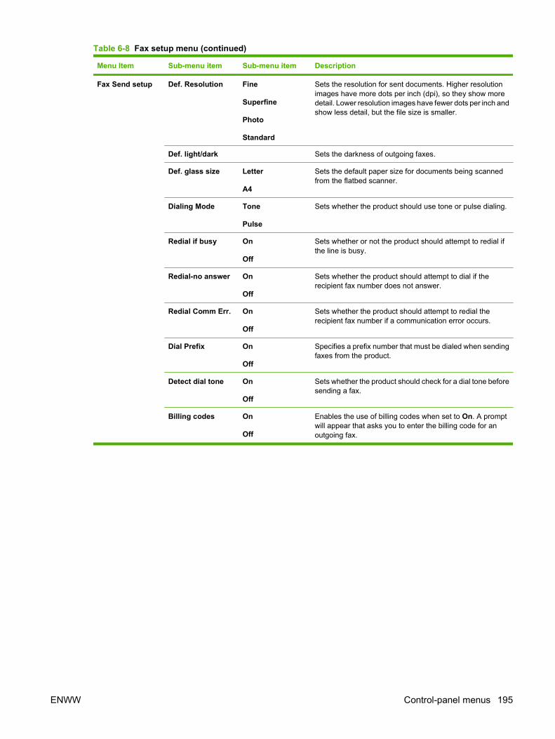
Menu Item Sub-menu item Sub-menu item Description
Fax Send setup Def. Resolution Fine
Superfine
Photo
Standard
Sets the resolution for sent documents. Higher resolutionimages have more dots per inch (dpi), so they show moredetail. Lower resolution images have fewer dots per inch andshow less detail, but the file size is smaller.
Def. light/dark Sets the darkness of outgoing faxes.
Def. glass size Letter
A4
Sets the default paper size for documents being scannedfrom the flatbed scanner.
Dialing Mode Tone
Pulse
Sets whether the product should use tone or pulse dialing.
Redial if busy On
Off
Sets whether or not the product should attempt to redial ifthe line is busy.
Redial-no answer On
Off
Sets whether the product should attempt to dial if therecipient fax number does not answer.
Redial Comm Err. On
Off
Sets whether the product should attempt to redial therecipient fax number if a communication error occurs.
Dial Prefix On
Off
Specifies a prefix number that must be dialed when sendingfaxes from the product.
Detect dial tone On
Off
Sets whether the product should check for a dial tone beforesending a fax.
Billing codes On
Off
Enables the use of billing codes when set to On. A promptwill appear that asks you to enter the billing code for anoutgoing fax.
Table 6-8 Fax setup menu (continued)
ENWW Control-panel menus 195
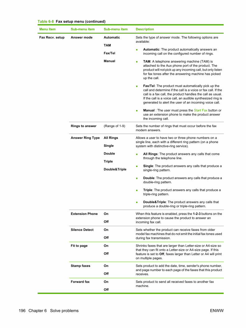
Menu Item Sub-menu item Sub-menu item Description
Fax Recv. setup Answer mode Automatic
TAM
Fax/Tel
Manual
Sets the type of answer mode. The following options areavailable:
● Automatic: The product automatically answers anincoming call on the configured number of rings.
● TAM: A telephone answering machine (TAM) isattached to the Aux phone port of the product. Theproduct will not pick up any incoming call, but only listenfor fax tones after the answering machine has pickedup the call.
● Fax/Tel: The product must automatically pick up thecall and determine if the call is a voice or fax call. If thecall is a fax call, the product handles the call as usual.If the call is a voice call, an audible synthesized ring isgenerated to alert the user of an incoming voice call.
● Manual : The user must press the Start Fax button oruse an extension phone to make the product answerthe incoming call.
Rings to answer (Range of 1-9) Sets the number of rings that must occur before the faxmodem answers.
Answer Ring Type All Rings
Single
Double
Triple
Double&Triple
Allows a user to have two or three phone numbers on asingle line, each with a different ring pattern (on a phonesystem with distinctive-ring service).
● All Rings: The product answers any calls that comethrough the telephone line.
● Single: The product answers any calls that produce asingle-ring pattern.
● Double: The product answers any calls that produce adouble-ring pattern.
● Triple: The product answers any calls that produce atriple-ring pattern.
● Double&Triple: The product answers any calls thatproduce a double-ring or triple-ring pattern.
Extension Phone On
Off
When this feature is enabled, press the 1-2-3 buttons on theextension phone to cause the product to answer anincoming fax call.
Silence Detect On
Off
Sets whether the product can receive faxes from oldermodel fax machines that do not emit the initial fax tones usedduring fax transmission.
Fit to page On
Off
Shrinks faxes that are larger than Letter-size or A4-size sothat they can fit onto a Letter-size or A4-size page. If thisfeature is set to Off, faxes larger than Letter or A4 will printon multiple pages.
Stamp faxes On
Off
Sets product to add the date, time, sender's phone number,and page number to each page of the faxes that this productreceives.
Forward fax On
Off
Sets product to send all received faxes to another faxmachine.
Table 6-8 Fax setup menu (continued)
196 Chapter 6 Solve problems ENWW
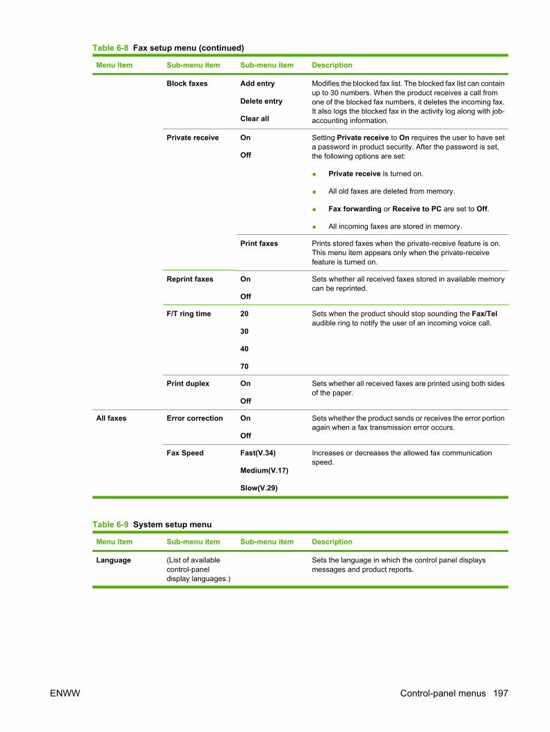
Menu Item Sub-menu item Sub-menu item Description
Block faxes Add entry
Delete entry
Clear all
Modifies the blocked fax list. The blocked fax list can containup to 30 numbers. When the product receives a call fromone of the blocked fax numbers, it deletes the incoming fax.It also logs the blocked fax in the activity log along with job-accounting information.
Private receive On
Off
Setting Private receive to On requires the user to have seta password in product security. After the password is set,the following options are set:
● Private receive is turned on.
● All old faxes are deleted from memory.
● Fax forwarding or Receive to PC are set to Off.
● All incoming faxes are stored in memory.
Print faxes Prints stored faxes when the private-receive feature is on.This menu item appears only when the private-receivefeature is turned on.
Reprint faxes On
Off
Sets whether all received faxes stored in available memorycan be reprinted.
F/T ring time 20
30
40
70
Sets when the product should stop sounding the Fax/Telaudible ring to notify the user of an incoming voice call.
Print duplex On
Off
Sets whether all received faxes are printed using both sidesof the paper.
All faxes Error correction On
Off
Sets whether the product sends or receives the error portionagain when a fax transmission error occurs.
Fax Speed Fast(V.34)
Medium(V.17)
Slow(V.29)
Increases or decreases the allowed fax communicationspeed.
Table 6-9 System setup menu
Menu Item Sub-menu item Sub-menu item Description
Language (List of availablecontrol-paneldisplay languages.)
Sets the language in which the control panel displaysmessages and product reports.
Table 6-8 Fax setup menu (continued)
ENWW Control-panel menus 197
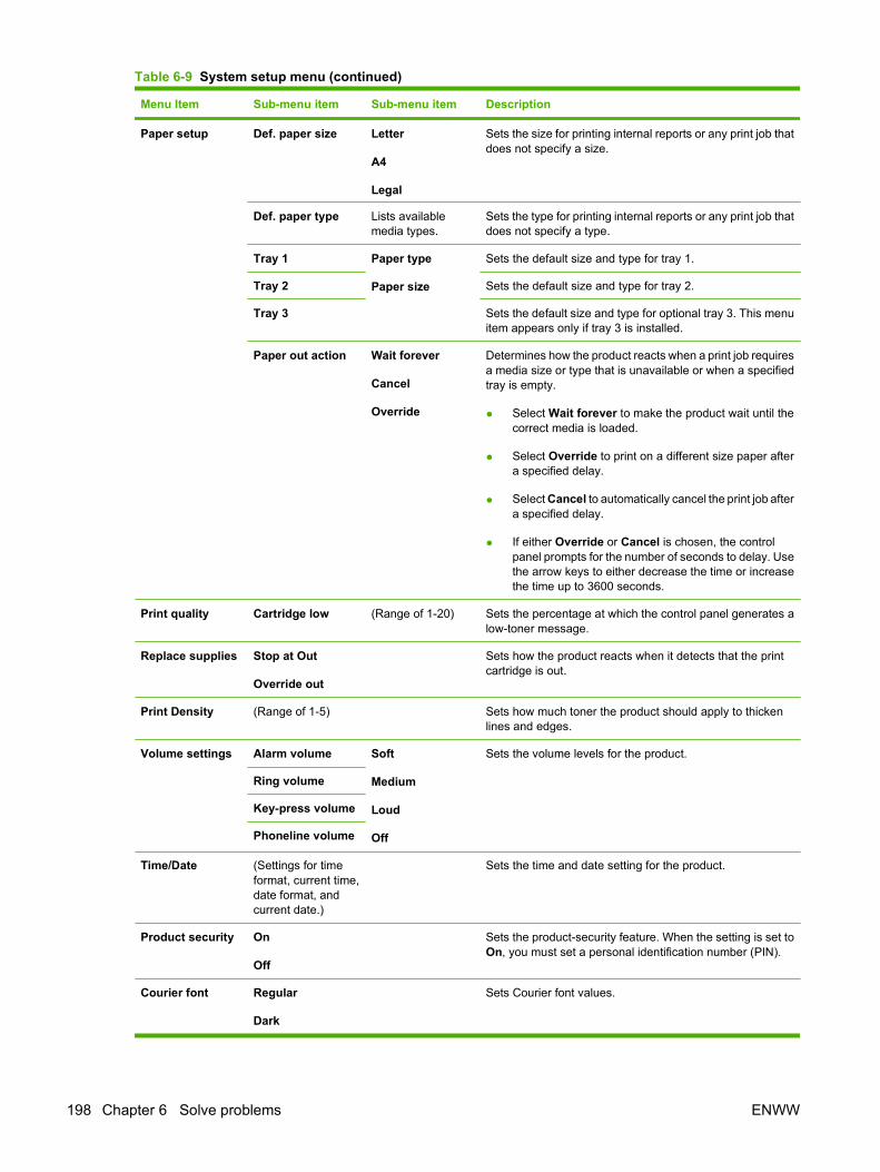
Menu Item Sub-menu item Sub-menu item Description
Paper setup Def. paper size Letter
A4
Legal
Sets the size for printing internal reports or any print job thatdoes not specify a size.
Def. paper type Lists availablemedia types.
Sets the type for printing internal reports or any print job thatdoes not specify a type.
Tray 1 Paper type
Paper size
Sets the default size and type for tray 1.
Tray 2 Sets the default size and type for tray 2.
Tray 3 Sets the default size and type for optional tray 3. This menuitem appears only if tray 3 is installed.
Paper out action Wait forever
Cancel
Override
Determines how the product reacts when a print job requiresa media size or type that is unavailable or when a specifiedtray is empty.
● Select Wait forever to make the product wait until thecorrect media is loaded.
● Select Override to print on a different size paper aftera specified delay.
● Select Cancel to automatically cancel the print job aftera specified delay.
● If either Override or Cancel is chosen, the controlpanel prompts for the number of seconds to delay. Usethe arrow keys to either decrease the time or increasethe time up to 3600 seconds.
Print quality Cartridge low (Range of 1-20) Sets the percentage at which the control panel generates alow-toner message.
Replace supplies Stop at Out
Override out
Sets how the product reacts when it detects that the printcartridge is out.
Print Density (Range of 1-5) Sets how much toner the product should apply to thickenlines and edges.
Volume settings Alarm volume Soft
Medium
Loud
Off
Sets the volume levels for the product.
Ring volume
Key-press volume
Phoneline volume
Time/Date (Settings for timeformat, current time,date format, andcurrent date.)
Sets the time and date setting for the product.
Product security On
Off
Sets the product-security feature. When the setting is set toOn, you must set a personal identification number (PIN).
Courier font Regular
Dark
Sets Courier font values.
Table 6-9 System setup menu (continued)
198 Chapter 6 Solve problems ENWW
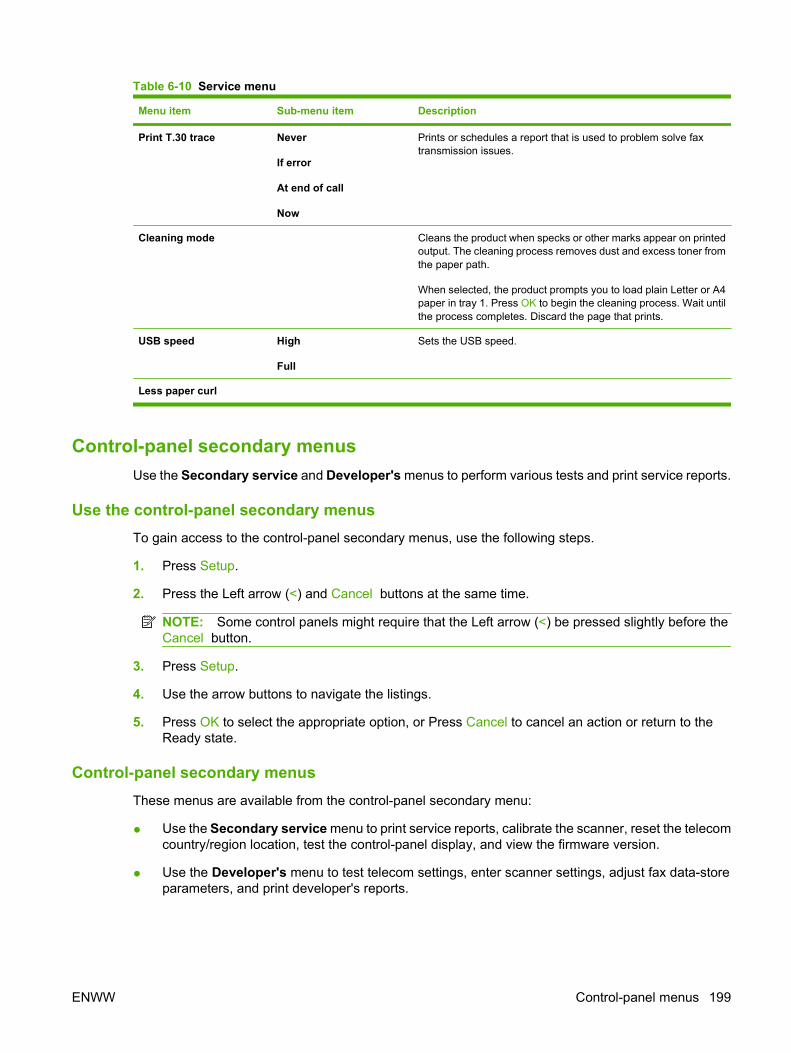
Table 6-10 Service menu
Menu item Sub-menu item Description
Print T.30 trace Never
If error
At end of call
Now
Prints or schedules a report that is used to problem solve faxtransmission issues.
Cleaning mode Cleans the product when specks or other marks appear on printedoutput. The cleaning process removes dust and excess toner fromthe paper path.
When selected, the product prompts you to load plain Letter or A4paper in tray 1. Press OK to begin the cleaning process. Wait untilthe process completes. Discard the page that prints.
USB speed High
Full
Sets the USB speed.
Less paper curl
Control-panel secondary menusUse the Secondary service and Developer's menus to perform various tests and print service reports.
Use the control-panel secondary menusTo gain access to the control-panel secondary menus, use the following steps.
1. Press Setup.
2. Press the Left arrow (<) and Cancel buttons at the same time.
NOTE: Some control panels might require that the Left arrow (<) be pressed slightly before theCancel button.
3. Press Setup.
4. Use the arrow buttons to navigate the listings.
5. Press OK to select the appropriate option, or Press Cancel to cancel an action or return to theReady state.
Control-panel secondary menusThese menus are available from the control-panel secondary menu:
● Use the Secondary service menu to print service reports, calibrate the scanner, reset the telecomcountry/region location, test the control-panel display, and view the firmware version.
● Use the Developer's menu to test telecom settings, enter scanner settings, adjust fax data-storeparameters, and print developer's reports.
ENWW Control-panel menus 199

To adjust fax data-store parameters
When you adjust fax data-store parameters, the product does not alert you to incorrect input values.Changing fax data-store parameters and render the product illegal or inoperable.
1. On the developer's menu, use the arrow buttons to navigate to R/W Parameter, and then pressOK.
2. Use the arrow buttons to locate the parameter that you want to change. The current setting appearson the control-panel display.
3. Type the new value for the fax data-store parameter, and then press OK.
To print a list of all the Fax data-store parameters
1. From the developer's menu select Dev. Reports.
2. Use the arrow buttons to select DS Fax, and then press OK.
To change the telecom country/region setting
Three situation can occur that necessitate changing the country/region settings for the product.
● The customer has moved to a different country/region from where the product was purchased.
● The information has been erased because of a NVRAM initialization, or parameters are set to “undefined.”
● The formatter was replaced.
1. On the developer's menu, use the arrow buttons to navigate to R/W Parameter, and then pressOK.
2. Press 3.
3. When the message LIU COUNTRY appears on the control-panel display, press OK.
4. Type the new telecom country/region number, and then press OK
5. After the product returns to the Ready state, turn the power off, and then on.
Table 6-11 Secondary service menu
Menu item Sub-menu item Sub-menu item
Service Reports Cont. Self-Test Cont. Self-Test [Cancel] to stop
Extended Keymap
Error Report
200 Chapter 6 Solve problems ENWW
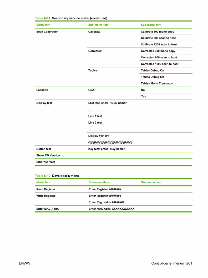
Menu item Sub-menu item Sub-menu item
Scan Calibration Calibrate Calibrate 300 mono copy
Calibrate 600 scan to host
Calibrate 1200 scan to host
Corrected Corrected 300 mono copy
Corrected 600 scan to host
Corrected 1200 scan to host
Tables Tables Debug On
Tables Debug Off
Tables Mono Tonemaps
Location USA No
Yes
Display test LED test, show: <LED name>
...................
Line 1 test
Line 2 test
...................
Display ###-###
@@@@@@@@@@@@@@@@
Button test Key test: press <key name>
Show FW Version
Ethernet reset
Table 6-12 Developer's menu
Menu item Sub-menu item Sub-menu item
Read Register Enter Register ########
Write Register Enter Register ########
Enter Reg. Value ########
Enter MAC Addr. Enter MAC Addr. XXXXXXXXXXXX
Table 6-11 Secondary service menu (continued)
ENWW Control-panel menus 201
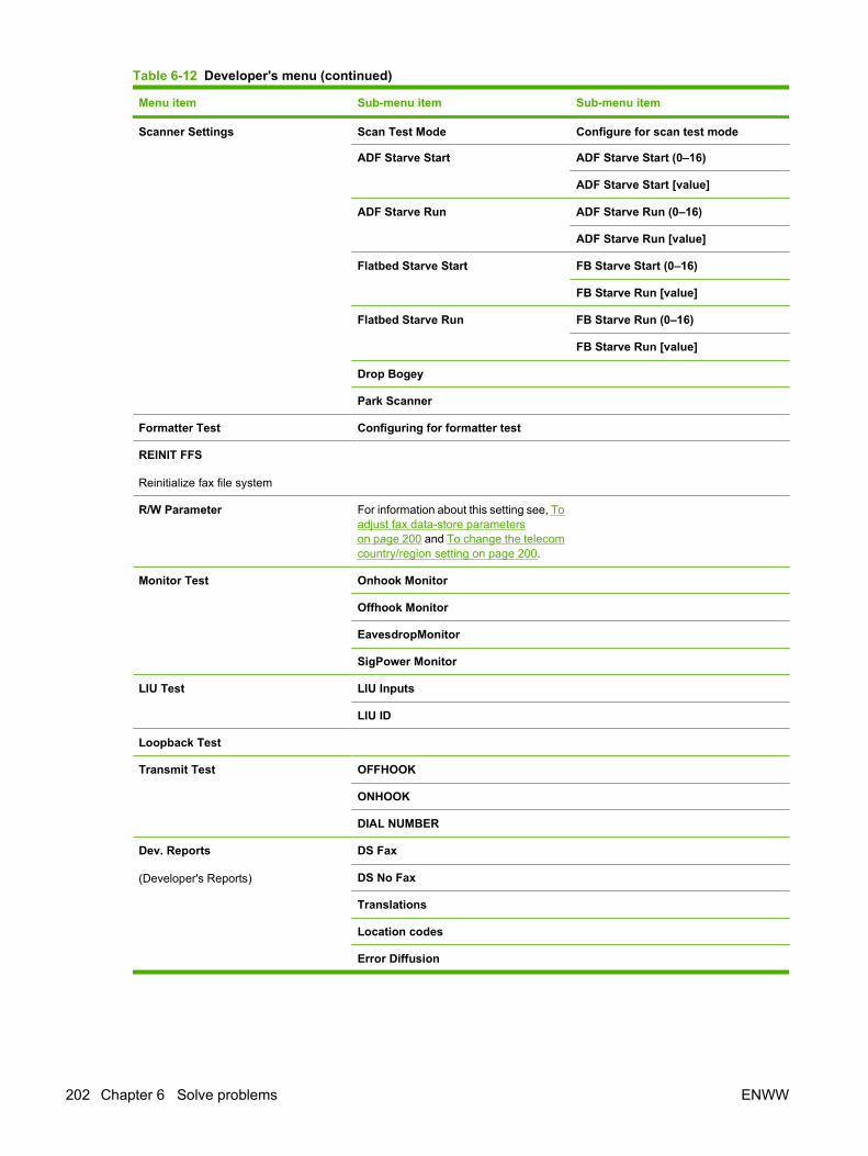
Menu item Sub-menu item Sub-menu item
Scanner Settings Scan Test Mode Configure for scan test mode
ADF Starve Start ADF Starve Start (0–16)
ADF Starve Start [value]
ADF Starve Run ADF Starve Run (0–16)
ADF Starve Run [value]
Flatbed Starve Start FB Starve Start (0–16)
FB Starve Run [value]
Flatbed Starve Run FB Starve Run (0–16)
FB Starve Run [value]
Drop Bogey
Park Scanner
Formatter Test Configuring for formatter test
REINIT FFS
Reinitialize fax file system
R/W Parameter For information about this setting see, Toadjust fax data-store parameterson page 200 and To change the telecomcountry/region setting on page 200.
Monitor Test Onhook Monitor
Offhook Monitor
EavesdropMonitor
SigPower Monitor
LIU Test LIU Inputs
LIU ID
Loopback Test
Transmit Test OFFHOOK
ONHOOK
DIAL NUMBER
Dev. Reports
(Developer's Reports)
DS Fax
DS No Fax
Translations
Location codes
Error Diffusion
Table 6-12 Developer's menu (continued)
202 Chapter 6 Solve problems ENWW

Menu item Sub-menu item Sub-menu item
Clock Dithering On
Off
Pick and Kick
Table 6-12 Developer's menu (continued)
ENWW Control-panel menus 203
Print problemsPrint-quality problems
The information in the following sections helps you identify and resolve print-quality issues.
NOTE: If you are having copy problems, see Copy problems on page 214.
Improve print qualityUse the print-quality settings to prevent print-quality problems.
Print-quality settings
Print-quality settings affect how light or dark the print is on the page and the style in which the graphicsare printed. You can also use the print-quality settings to optimize the print quality for a specific mediatype.
You can change the settings in the product properties to accommodate the types of jobs that you areprinting. The following settings are available, depending on the printer driver that you are using:
● 600 dpi
● FastRes 1200
● ProRes1200 (132 Ipi)
● ProRes1200 (180 Ipi)
NOTE: Changing the resolution can change the formatting of your text.
To temporarily change print-quality settings
To change the print-quality settings only for the current software program, open the print propertiesthrough the Print Setup menu in the program that you are using to print.
To change print-quality settings for all future jobs
NOTE: For Macintosh instructions, see the user guide.
For Windows 98, Windows 2000, and Windows Me:
1. In the Windows system tray, click Start, select Settings, and then click Printers.
2. Right-click the product icon.
3. Click Properties (in Windows 2000, you can also click Printing Preferences).
4. Change the settings, and then click OK.
For Windows XP:
1. In the Windows system tray, click Start, click Control Panel, and then click Printers and Faxes.
2. Right-click the product icon.
204 Chapter 6 Solve problems ENWW
3. Click Properties, or click Printing Preferences.
4. Change the settings, and click OK.
Identify and correct print defectsUse the checklist and print-quality issues charts in this section to solve print-quality problems.
Print-quality checklist
General print-quality problems can be solved by using the following checklist:
1. Make sure that the paper or print media that you are using meets specifications. Generally,smoother paper provides better results.
2. If you are using a special print media such as labels, transparencies, glossy paper, or letterhead,ensure that you have configured the product to printed by the correct type.
3. Print a Configuration page and Supplies Status page from the product control panel.
◦ Check the Supplies Status page to see if any supplies are low or empty. No information isprovided for non-HP print cartridges.
4. Print a Demo page from the HP ToolboxFX. If the page prints, the problem is with the printer driver.Try printing from another printer driver. For example, if you are using the PCL 6 printer driver, printfrom the PS printer driver.
◦ Use the Add Printer Wizard in the Printers (or Printers and Faxes in Windows XP) dialogbox to install the PS driver.
5. Try printing from a different program. If the page prints correctly, the problem is with the programfrom which you were printing.
6. Restart the computer and the product and try printing again. If the problem is not resolved, seeGeneral print-quality issues on page 205.
General print-quality issues
The following examples depict letter-size paper that has passed through the product short-edge-first.These examples illustrate problems that would affect all of the pages that you print. The examplesinclude the typical cause and solution for each of these problems.
ENWW Print problems 205
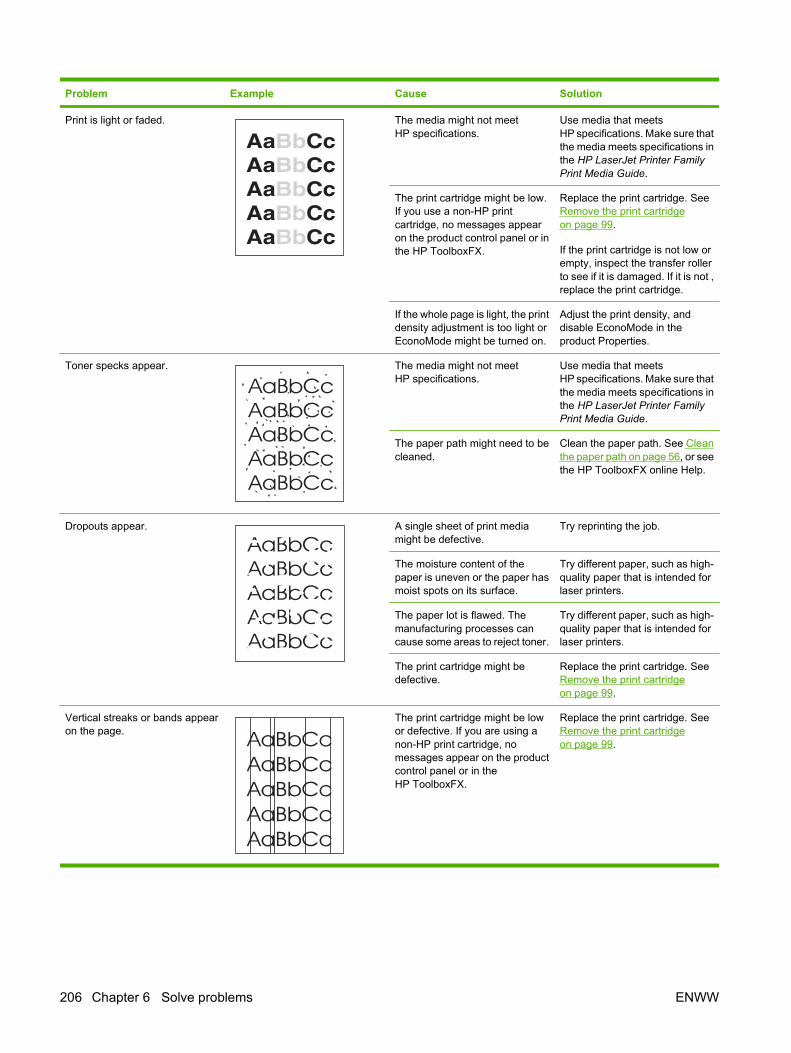
Problem Example Cause Solution
Print is light or faded. The media might not meetHP specifications.
Use media that meetsHP specifications. Make sure thatthe media meets specifications inthe HP LaserJet Printer FamilyPrint Media Guide.
The print cartridge might be low.If you use a non-HP printcartridge, no messages appearon the product control panel or inthe HP ToolboxFX.
Replace the print cartridge. SeeRemove the print cartridgeon page 99.
If the print cartridge is not low orempty, inspect the transfer rollerto see if it is damaged. If it is not ,replace the print cartridge.
If the whole page is light, the printdensity adjustment is too light orEconoMode might be turned on.
Adjust the print density, anddisable EconoMode in theproduct Properties.
Toner specks appear. The media might not meetHP specifications.
Use media that meetsHP specifications. Make sure thatthe media meets specifications inthe HP LaserJet Printer FamilyPrint Media Guide.
The paper path might need to becleaned.
Clean the paper path. See Cleanthe paper path on page 56, or seethe HP ToolboxFX online Help.
Dropouts appear. A single sheet of print mediamight be defective.
Try reprinting the job.
The moisture content of thepaper is uneven or the paper hasmoist spots on its surface.
Try different paper, such as high-quality paper that is intended forlaser printers.
The paper lot is flawed. Themanufacturing processes cancause some areas to reject toner.
Try different paper, such as high-quality paper that is intended forlaser printers.
The print cartridge might bedefective.
Replace the print cartridge. SeeRemove the print cartridgeon page 99.
Vertical streaks or bands appearon the page.
The print cartridge might be lowor defective. If you are using anon-HP print cartridge, nomessages appear on the productcontrol panel or in theHP ToolboxFX.
Replace the print cartridge. SeeRemove the print cartridgeon page 99.
206 Chapter 6 Solve problems ENWW
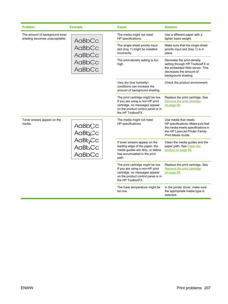
Problem Example Cause Solution
The amount of background tonershading becomes unacceptable.
The media might not meetHP specifications.
Use a different paper with alighter basis weight.
The single-sheet priority inputslot (tray 1) might be installedincorrectly.
Make sure that the single-sheetpriority input slot (tray 1) is inplace.
The print-density setting is toohigh.
Decrease the print-densitysetting through HP ToolboxFX orthe embedded Web server. Thisdecreases the amount ofbackground shading.
Very dry (low humidity)conditions can increase theamount of background shading.
Check the product environment.
The print cartridge might be low.If you are using a non-HP printcartridge, no messages appearon the product control panel or inthe HP ToolboxFX.
Replace the print cartridge. SeeRemove the print cartridgeon page 99.
Toner smears appear on themedia.
The media might not meetHP specifications.
Use media that meetsHP specifications. Make sure thatthe media meets specifications inthe HP LaserJet Printer FamilyPrint Media Guide.
If toner smears appear on theleading edge of the paper, themedia guides are dirty, or debrishas accumulated in the printpath.
Clean the media guides and thepaper path. See Clean theproduct on page 49.
The print cartridge might be low.If you are using a non-HP printcartridge, no messages appearon the product control panel or inthe HP ToolboxFX.
Replace the print cartridge. SeeRemove the print cartridgeon page 99.
The fuser temperature might betoo low.
In the printer driver, make surethe appropriate media type isselected.
ENWW Print problems 207

Problem Example Cause Solution
The toner smears easily whentouched.
The product is not set to print onthe type of media on which youwant to print.
In the printer driver, select thePaper tab and set Type is tomatch the type of media on whichyou are printing. Print speedmight be slower if you are usingheavy paper.
The media might not meetHP specifications.
Use media that meetsHP specifications. Make sure thatthe media meets specifications inthe HP LaserJet Printer FamilyPrint Media Guide.
The paper path might need to becleaned.
Clean the product. See Clean theproduct on page 49.
The power source might bedefective.
Plug the product directly into anAC outlet instead of into a powerstrip.
The print cartridge might be low.If you are using a non-HP printcartridge, no messages appearon the product control panel or inthe HP ToolboxFX.
Replace the print cartridge. SeeRemove the print cartridgeon page 99.
Marks repeatedly appear at evenintervals on the page.
The product is not set to print onthe type of media on which youwant to print.
In the printer driver, make surethat the appropriate media type isselected. Print speed might beslower if you are using heavypaper.
Internal parts might have toner onthem.
The problem typically correctsitself after a few more pages.
The paper path might need to becleaned.
Clean the product. See Clean theproduct on page 49.
The print cartridge might bedamaged.
If a repetitive mark occurs at thesame spot on the page, install anew HP print cartridge. SeeRemove the print cartridgeon page 99.
The printed page containsmisformed characters.
The media might not meetHP specifications.
Use a different paper, such ashigh-quality paper that isintended for laser printers.
If characters are incorrectlyformed so that they produce awavy effect, the laser scannermight need replacing.
Verify that the problem alsooccurs on the Configurationpage. If so, replace the laser/scanner. See Laser/scanner(print engine) on page 137.
208 Chapter 6 Solve problems ENWW
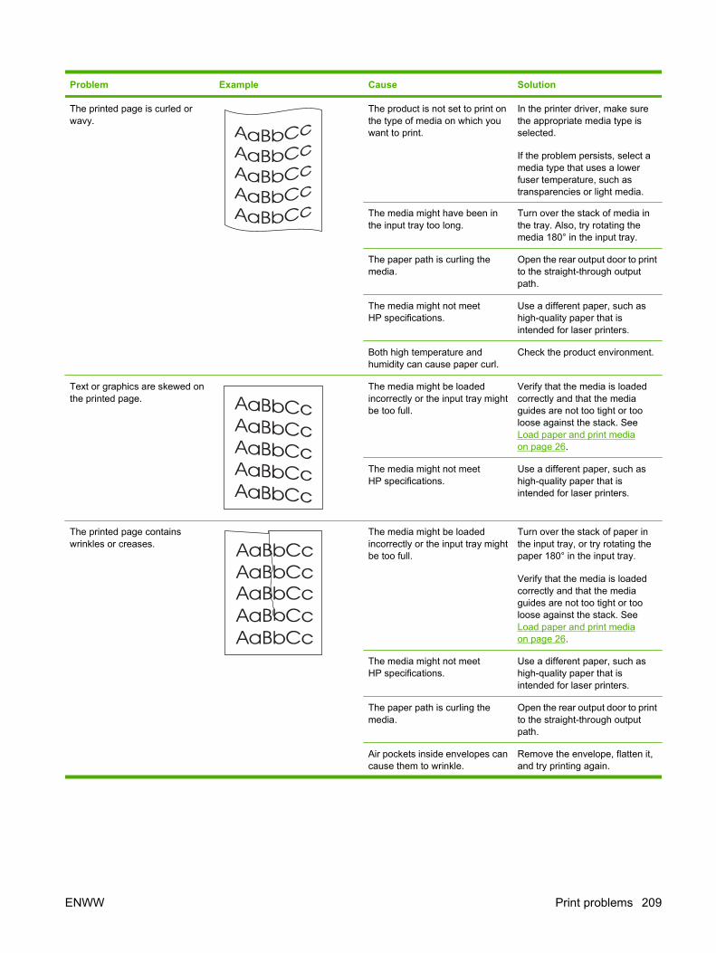
Problem Example Cause Solution
The printed page is curled orwavy.
The product is not set to print onthe type of media on which youwant to print.
In the printer driver, make surethe appropriate media type isselected.
If the problem persists, select amedia type that uses a lowerfuser temperature, such astransparencies or light media.
The media might have been inthe input tray too long.
Turn over the stack of media inthe tray. Also, try rotating themedia 180° in the input tray.
The paper path is curling themedia.
Open the rear output door to printto the straight-through outputpath.
The media might not meetHP specifications.
Use a different paper, such ashigh-quality paper that isintended for laser printers.
Both high temperature andhumidity can cause paper curl.
Check the product environment.
Text or graphics are skewed onthe printed page.
The media might be loadedincorrectly or the input tray mightbe too full.
Verify that the media is loadedcorrectly and that the mediaguides are not too tight or tooloose against the stack. SeeLoad paper and print mediaon page 26.
The media might not meetHP specifications.
Use a different paper, such ashigh-quality paper that isintended for laser printers.
The printed page containswrinkles or creases.
The media might be loadedincorrectly or the input tray mightbe too full.
Turn over the stack of paper inthe input tray, or try rotating thepaper 180° in the input tray.
Verify that the media is loadedcorrectly and that the mediaguides are not too tight or tooloose against the stack. SeeLoad paper and print mediaon page 26.
The media might not meetHP specifications.
Use a different paper, such ashigh-quality paper that isintended for laser printers.
The paper path is curling themedia.
Open the rear output door to printto the straight-through outputpath.
Air pockets inside envelopes cancause them to wrinkle.
Remove the envelope, flatten it,and try printing again.
ENWW Print problems 209

Problem Example Cause Solution
Toner appears around theprinted characters.
The media might be loadedincorrectly.
Turn over the stack of paper inthe tray.
If large amounts of toner havescattered around the characters,the paper might have highresistivity.
Use a different paper, such ashigh-quality paper that isintended for laser printers.
An image that appears at the topof the page (in solid black)repeats farther down the page (ina gray field).
Software settings might affectimage printing.
In your software program,change the tone (darkness) of thefield in which the repeated imageappears.
In your software program, rotatethe whole page 180° to print thelighter image first.
The order of images printedmight affect printing.
Change the order in which theimages are printed. For example,have the lighter image at the topof the page, and the darker imagefarther down the page.
A power surge might haveaffected the product.
If the defect occurs later in a printjob, turn the product off for 10minutes, and then turn on theproduct to restart the print job.
Droplets of water are depositedon the trailing edge of the page.
Moisture in the product iscondensing on the fuserassembly. In excessively hot andhumid areas, media retainsmoisture.
NOTE: Water droplets do notdamage the product.
Try moving the product to a lesshumid area. Try a differentmedia.
210 Chapter 6 Solve problems ENWW

Scan problemsSolve scanned-image problems
Problem Cause Solution
The scanned image is of poor quality. The original might be a second-generation photo or picture.
● To eliminate the patterns, tryreducing the size of the image afterscanning.
● Print the scanned image to see ifthe quality is better.
● Verify that your resolution and colorsettings are correct for the type ofscan job that you are performing.
● For best results, use the flatbedscanner for scanning, rather thanthe automatic document feeder(ADF).
The image that appears on the screenmight not be an accurate representationof the quality of the scan.
● Try adjusting your computermonitor settings to use more colors(or levels of gray). Typically, youmake this adjustment by openingDisplay in the Windows ControlPanel.
● Try adjusting the resolution andcolor settings in the scannersoftware.
The original might have been loadedincorrectly.
Use the media guides when you load theoriginals into the ADF. See Loaddocuments to fax, copy, or scanon page 26.
The scanner might be dirty. Clean the scanner. See Clean theproduct on page 49.
The graphics settings might not besuitable for the type of scan job that youare performing.
Try changing the graphics settings.
ENWW Scan problems 211
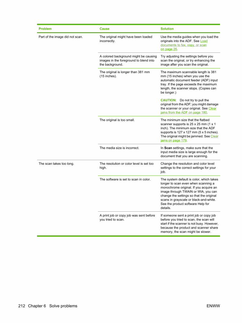
Problem Cause Solution
Part of the image did not scan. The original might have been loadedincorrectly.
Use the media guides when you load theoriginals into the ADF. See Loaddocuments to fax, copy, or scanon page 26.
A colored background might be causingimages in the foreground to blend intothe background.
Try adjusting the settings before youscan the original, or try enhancing theimage after you scan the original.
The original is longer than 381 mm(15 inches).
The maximum scannable length is 381mm (15 inches) when you use theautomatic document feeder (ADF) inputtray. If the page exceeds the maximumlength, the scanner stops. (Copies canbe longer.)
CAUTION: Do not try to pull theoriginal from the ADF; you might damagethe scanner or your original. See Clearjams from the ADF on page 180.
The original is too small. The minimum size that the flatbedscanner supports is 25 x 25 mm (1 x 1inch). The minimum size that the ADFsupports is 127 x 127 mm (5 x 5 inches).The original might be jammed. See Clearjams on page 179.
The media size is incorrect. In Scan settings, make sure that theinput media size is large enough for thedocument that you are scanning.
The scan takes too long. The resolution or color level is set toohigh.
Change the resolution and color levelsettings to the correct settings for yourjob.
The software is set to scan in color. The system default is color, which takeslonger to scan even when scanning amonochrome original. If you acquire animage through TWAIN or WIA, you canchange the settings so that the originalscans in grayscale or black-and-white.See the product software Help fordetails.
A print job or copy job was sent beforeyou tried to scan.
If someone sent a print job or copy jobbefore you tried to scan, the scan willstart if the scanner is not busy. However,because the product and scanner sharememory, the scan might be slower.
212 Chapter 6 Solve problems ENWW

Scan-quality problems
Prevent problemsThe following are a few simple steps you can take to improve copy and scan quality.
● Use the flatbed scanner, rather than the automatic document feeder (ADF) input tray, to scan.
● Use high-quality originals.
● Load the media correctly. If the media is loaded incorrectly, it might skew, which causes unclearimages. See Load paper and print media on page 26 for instructions.
● Adjust the software settings according to how you plan to use the scanned page.
● If your product frequently feeds more than one page at a time, you might need to replace theseparation pad. See Replace the tray 2 and optional tray 3 separation pad on page 45.
● Use or make a carrier sheet to protect your originals.
Solve scan-quality problems
Problem Description Solution
Blank pages. The original might have been loadedupside down.
In the automatic document feeder (ADF),put the top end of the stack of originalsinto the ADF input tray, with the mediastack face-up and the first page to bescanned on top of the stack.
On the flatbed scanner, place the originaldocument face-down with the upper-leftcorner of the document at the lower-rightcorner of the glass.
Too light or dark. The resolution and color levels might beset incorrectly.
Verify that you have the correctresolution and color settings.
Unwanted lines. Ink, glue, correction fluid, or an unwantedsubstance might be on the glass.
Clean the flatbed scanner surface. SeeClean the flatbed scanner glasson page 49.
The ADF glass might be dirty. Clean the ADF glass. See Clean thescanner-cover backing on page 51.
Black dots or streaks. Ink, glue, correction fluid, or an unwantedsubstance might be on the glass.
Clean the flatbed scanner surface. SeeClean the flatbed scanner glasson page 49.
Unclear text. The resolution and color levels may beset incorrectly.
Verify that you have the correctresolution and color settings.
ENWW Scan problems 213

Copy problemsPrevent problems
The following are a few simple steps you can take to improve copy quality:
● Copy from the flatbed scanner. This will produce a higher quality copy than copying from theautomatic document feeder (ADF).
● Use quality originals.
● Load the media correctly. If the media is loaded incorrectly, it might skew, causing unclear imagesand problems with the OCR program.
● Use or make a carrier sheet to protect your originals.
NOTE: Verify that the media meets HP specifications. If the media meets HP specifications, recurringfeed problems indicate the pickup roller or separation pad is worn.
Image problems
Problem Cause Solution
Images are missing or faded. The print-cartridge toner level might below.
Replace the print cartridge. See Removethe print cartridge on page 99.
The original might be of poor quality. If your original is too light or damaged,the copy might not be able tocompensate, even if you adjust thecontrast. If possible, find an originaldocument in better condition.
The original might have a coloredbackground.
Colored backgrounds might causeimages in the foreground to blend intothe background, or the background mightappear in a different shade. If possible,use an original document without acolored background.
Vertical white or faded stripes appear onthe copy.
The media might not meetHP specifications.
Use media that meets HP specifications.
The print-cartridge toner level might below.
Replace the print cartridge. See Removethe print cartridge on page 99.
214 Chapter 6 Solve problems ENWW
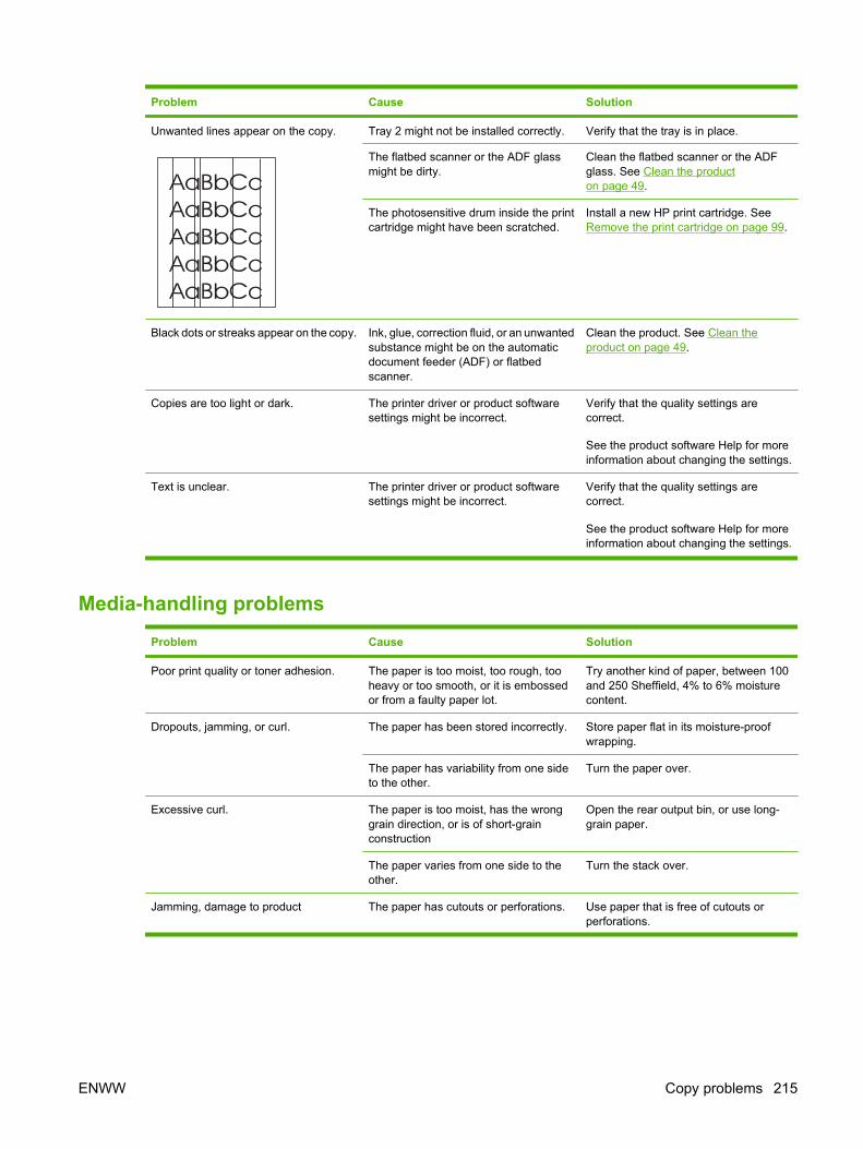
Problem Cause Solution
Unwanted lines appear on the copy. Tray 2 might not be installed correctly. Verify that the tray is in place.
The flatbed scanner or the ADF glassmight be dirty.
Clean the flatbed scanner or the ADFglass. See Clean the producton page 49.
The photosensitive drum inside the printcartridge might have been scratched.
Install a new HP print cartridge. SeeRemove the print cartridge on page 99.
Black dots or streaks appear on the copy. Ink, glue, correction fluid, or an unwantedsubstance might be on the automaticdocument feeder (ADF) or flatbedscanner.
Clean the product. See Clean theproduct on page 49.
Copies are too light or dark. The printer driver or product softwaresettings might be incorrect.
Verify that the quality settings arecorrect.
See the product software Help for moreinformation about changing the settings.
Text is unclear. The printer driver or product softwaresettings might be incorrect.
Verify that the quality settings arecorrect.
See the product software Help for moreinformation about changing the settings.
Media-handling problems
Problem Cause Solution
Poor print quality or toner adhesion. The paper is too moist, too rough, tooheavy or too smooth, or it is embossedor from a faulty paper lot.
Try another kind of paper, between 100and 250 Sheffield, 4% to 6% moisturecontent.
Dropouts, jamming, or curl. The paper has been stored incorrectly. Store paper flat in its moisture-proofwrapping.
The paper has variability from one sideto the other.
Turn the paper over.
Excessive curl. The paper is too moist, has the wronggrain direction, or is of short-grainconstruction
Open the rear output bin, or use long-grain paper.
The paper varies from one side to theother.
Turn the stack over.
Jamming, damage to product The paper has cutouts or perforations. Use paper that is free of cutouts orperforations.
ENWW Copy problems 215
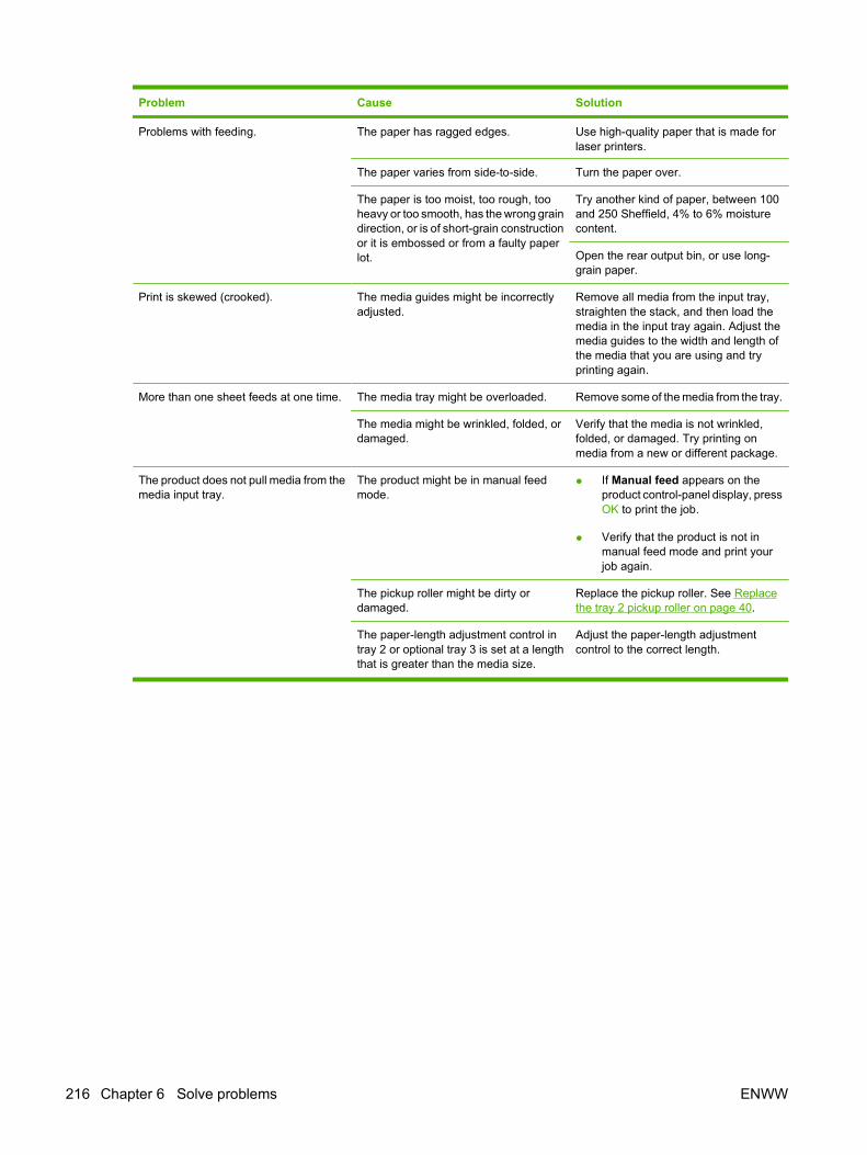
Problem Cause Solution
Problems with feeding. The paper has ragged edges. Use high-quality paper that is made forlaser printers.
The paper varies from side-to-side. Turn the paper over.
The paper is too moist, too rough, tooheavy or too smooth, has the wrong graindirection, or is of short-grain constructionor it is embossed or from a faulty paperlot.
Try another kind of paper, between 100and 250 Sheffield, 4% to 6% moisturecontent.
Open the rear output bin, or use long-grain paper.
Print is skewed (crooked). The media guides might be incorrectlyadjusted.
Remove all media from the input tray,straighten the stack, and then load themedia in the input tray again. Adjust themedia guides to the width and length ofthe media that you are using and tryprinting again.
More than one sheet feeds at one time. The media tray might be overloaded. Remove some of the media from the tray.
The media might be wrinkled, folded, ordamaged.
Verify that the media is not wrinkled,folded, or damaged. Try printing onmedia from a new or different package.
The product does not pull media from themedia input tray.
The product might be in manual feedmode.
● If Manual feed appears on theproduct control-panel display, pressOK to print the job.
● Verify that the product is not inmanual feed mode and print yourjob again.
The pickup roller might be dirty ordamaged.
Replace the pickup roller. See Replacethe tray 2 pickup roller on page 40.
The paper-length adjustment control intray 2 or optional tray 3 is set at a lengththat is greater than the media size.
Adjust the paper-length adjustmentcontrol to the correct length.
216 Chapter 6 Solve problems ENWW
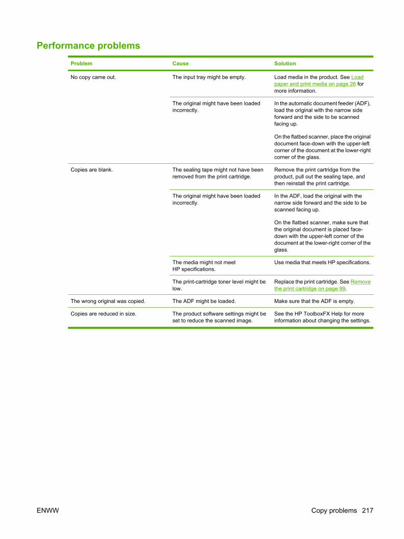
Performance problems
Problem Cause Solution
No copy came out. The input tray might be empty. Load media in the product. See Loadpaper and print media on page 26 formore information.
The original might have been loadedincorrectly.
In the automatic document feeder (ADF),load the original with the narrow sideforward and the side to be scannedfacing up.
On the flatbed scanner, place the originaldocument face-down with the upper-leftcorner of the document at the lower-rightcorner of the glass.
Copies are blank. The sealing tape might not have beenremoved from the print cartridge.
Remove the print cartridge from theproduct, pull out the sealing tape, andthen reinstall the print cartridge.
The original might have been loadedincorrectly.
In the ADF, load the original with thenarrow side forward and the side to bescanned facing up.
On the flatbed scanner, make sure thatthe original document is placed face-down with the upper-left corner of thedocument at the lower-right corner of theglass.
The media might not meetHP specifications.
Use media that meets HP specifications.
The print-cartridge toner level might below.
Replace the print cartridge. See Removethe print cartridge on page 99.
The wrong original was copied. The ADF might be loaded. Make sure that the ADF is empty.
Copies are reduced in size. The product software settings might beset to reduce the scanned image.
See the HP ToolboxFX Help for moreinformation about changing the settings.
ENWW Copy problems 217
Fax problemsGeneral fax problem-solve
Verify the following information before problem-solving fax problems.
● Is the fax set up correctly?
◦ Make sure that the fax cord that came with the product is the cord that is being used. Thiscord has been tested and meets the device specifications.
◦ Make sure that the fax cord is installed in the correct port. The fax cord (from the wall
receptacle) must be plugged into the line port ( ).
◦ Additional devices connected to the product must use the telephone port ( )
● What type of telephone line is being used?
◦ Dedicated telephone line: a unique telephone line that is assigned to receive or send a fax.The fax cord must be plugged into the line port.
◦ Shared telephone line: a telephone line that receives or sends voice calls and faxes. A single,shared telephone line can perform only one function at a time. A fax cannot be sent whilesomeone is talking on the telephone or while a computer is connecting to the Internet.
◦ Roll-over lines: a telephone system feature that allows an incoming call to be forwarded tothe next available telephone line (used with multiple-telephone-line systems). Try attachingthe device to the first incoming telephone line. The product will answer the telephone after itrings the number of times that is specified in the product rings-to-answer setting.
◦ Downstream phone: a phone that is plugged directly into the phone connector on the product.
◦ Extension phone: a phone that is uses the same phone line as the product, but is connectedto a separate phone wall recepticle.
◦ Distinctive ring service: a telephone system feature that can assign two telephone numbersto one physical line, and assign a distinctive ring pattern to each number. Make sure that thedevice is set to respond to the correct distinctive ring pattern that the telephone serviceprovider assigned to the fax number. This service is not available in all countries/regions.Make sure that the telephone company provides this service before changing the setting. Formore information about distinctive ring service, see Distinctive ring function on page 88.
● Is a telephone-line splitting device installed?
◦ A telephone-line splitter is a device that splits two or more telephone lines from the same jack.Not all splitters are compatible with the device, and not all countries/regions support the useof splitters.
Parallel splitters (also called T-splitters) split a single line into two phone jacks so that twodevices can share the same line. Line 1/Line 2 splitters provide two unique telephone lineoutlets from a single jack with two unique telephone numbers (two telephone lines areconnected to a single jack). A Line 1/Line 2 splitter must be used if both a fax line and a voiceline share the same jack.
218 Chapter 6 Solve problems ENWW
NOTE: Hewlett-Packard does not recommend using a parallel splitter (T-splitter) with theproduct because it might degrade the quality of the telephone signal. If a second device mustbe attached to the telephone line in addition to the product, plug the second device into thetelephone port on the product (the port on the back that is marked with a telephone icon).
● Is a surge-protection device installed?
◦ A surge-protection device might be installed between the telephone jack and the product toprotect the product from electrical power that passes through the telephone lines. Thesedevices might cause some fax communication problems by degrading the quality of thetelephone signal. If you are having problems sending or receiving faxes, connect the devicedirectly to the telephone jack to determine if the problem is in the surge-protection device.
● Is a telephone company voice-message service being used?
◦ If the messaging service rings-to-answer setting is lower than the product rings-to-answersetting, the messaging service answers the call and the product will not detect incoming faxes.If the product rings-to-answer setting is lower than that of the messaging service, the productanswers all calls and no calls will ever be sent to the messaging service. The only voice-messaging system that can be used with the product is a standard telephone-answeringmachine.
● Is a standard telephone-answering machine installed?
◦ An answering machine must be connected to the port that is labeled with the telephone icon(or it can be shared on the same telephone-line extension). Set the product rings-to-answersetting for at least one ring more than the number of rings that prompts the answering machineto answer an incoming call. For example, if the answering machine is set to answer calls afterthree rings, set the product rings-to-answer setting to four rings.
NOTE: If an answering machine is connected to the same telephone line, but is connected to adifferent jack (for example, in another room), it might interfere with the product fax reception.
Problems receiving faxesUse the table in this section to solve problems that might occur when receiving faxes.
NOTE: You must use the fax cord that came with the product in order to ensure that the productfunctions correctly.
Problem Cause Solution
The product cannot receive faxes froman extension telephone.
The extension-telephone setting mightbe disabled.
Verify that the extension-telephonesetting is enabled.
The fax cord might not be securelyconnected.
Verify that the fax cord is securelyconnected between the telephone jackand the product (or another device that isconnected to the product). Press 1-2-3 insequence (tone-dial mode only), wait forthree seconds, and then hang up.
The product dialing mode might beincorrectly set, or the extension phonemight be incorrectly set.
Verify that the product dialing mode is setto Tone. Verify that the extension phoneis set to On for tone dialing as well.
ENWW Fax problems 219

Problem Cause Solution
The product is not answering incomingfax calls.
The answer mode might be set toManual.
If the answer mode is set to Manual, theproduct does not answer calls. You haveto start the fax-receiving processmanually.
The rings-to-answer setting might not beset correctly.
Check the rings-to-answer setting foryour configuration.
The answer-ring pattern feature might beturned on, but you do not have theservice, or you do have the service andthe feature is not set correctly.
Check the answer-ring pattern feature toverify that it is set properly.
The fax cord might not be correctlyconnected, or the fax cord is not working.
See the Getting Started Guide to checkthe installation. Verify that you are usingthe fax cord that came with the product.
The product might not be able to detectincoming fax tones because theanswering machine is playing a voicemessage.
Re-record your answering machinemessage, leaving at least two seconds ofsilence at the beginning of the message.
Too many devices might be connected tothe telephone line.
You should not have more than threedevices attached to the line. Tryremoving the last device that wasconnected and determine whether theproduct works. If not, continue removingdevices one at a time and retry afterremoving each one.
The telephone line might not be working. Do one of the following:
● Increase the volume on the product,and then press Start Fax on thecontrol panel. If you hear a dial tone,the telephone line is working.
● Disconnect the product from thetelephone jack, and then connect atelephone. Try to make a telephonecall to verify that the telephone lineis working.
220 Chapter 6 Solve problems ENWW
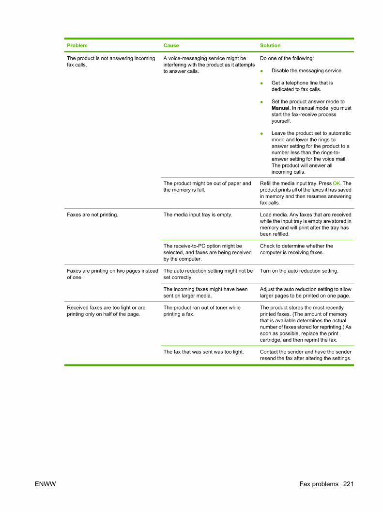
Problem Cause Solution
The product is not answering incomingfax calls.
A voice-messaging service might beinterfering with the product as it attemptsto answer calls.
Do one of the following:
● Disable the messaging service.
● Get a telephone line that isdedicated to fax calls.
● Set the product answer mode toManual. In manual mode, you muststart the fax-receive processyourself.
● Leave the product set to automaticmode and lower the rings-to-answer setting for the product to anumber less than the rings-to-answer setting for the voice mail.The product will answer allincoming calls.
The product might be out of paper andthe memory is full.
Refill the media input tray. Press OK. Theproduct prints all of the faxes it has savedin memory and then resumes answeringfax calls.
Faxes are not printing. The media input tray is empty. Load media. Any faxes that are receivedwhile the input tray is empty are stored inmemory and will print after the tray hasbeen refilled.
The receive-to-PC option might beselected, and faxes are being receivedby the computer.
Check to determine whether thecomputer is receiving faxes.
Faxes are printing on two pages insteadof one.
The auto reduction setting might not beset correctly.
Turn on the auto reduction setting.
The incoming faxes might have beensent on larger media.
Adjust the auto reduction setting to allowlarger pages to be printed on one page.
Received faxes are too light or areprinting only on half of the page.
The product ran out of toner whileprinting a fax.
The product stores the most recentlyprinted faxes. (The amount of memorythat is available determines the actualnumber of faxes stored for reprinting.) Assoon as possible, replace the printcartridge, and then reprint the fax.
The fax that was sent was too light. Contact the sender and have the senderresend the fax after altering the settings.
ENWW Fax problems 221
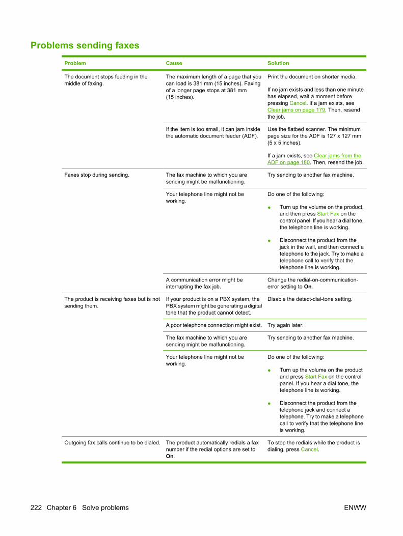
Problems sending faxes
Problem Cause Solution
The document stops feeding in themiddle of faxing.
The maximum length of a page that youcan load is 381 mm (15 inches). Faxingof a longer page stops at 381 mm(15 inches).
Print the document on shorter media.
If no jam exists and less than one minutehas elapsed, wait a moment beforepressing Cancel. If a jam exists, seeClear jams on page 179. Then, resendthe job.
If the item is too small, it can jam insidethe automatic document feeder (ADF).
Use the flatbed scanner. The minimumpage size for the ADF is 127 x 127 mm(5 x 5 inches).
If a jam exists, see Clear jams from theADF on page 180. Then, resend the job.
Faxes stop during sending. The fax machine to which you aresending might be malfunctioning.
Try sending to another fax machine.
Your telephone line might not beworking.
Do one of the following:
● Turn up the volume on the product,and then press Start Fax on thecontrol panel. If you hear a dial tone,the telephone line is working.
● Disconnect the product from thejack in the wall, and then connect atelephone to the jack. Try to make atelephone call to verify that thetelephone line is working.
A communication error might beinterrupting the fax job.
Change the redial-on-communication-error setting to On.
The product is receiving faxes but is notsending them.
If your product is on a PBX system, thePBX system might be generating a digitaltone that the product cannot detect.
Disable the detect-dial-tone setting.
A poor telephone connection might exist. Try again later.
The fax machine to which you aresending might be malfunctioning.
Try sending to another fax machine.
Your telephone line might not beworking.
Do one of the following:
● Turn up the volume on the productand press Start Fax on the controlpanel. If you hear a dial tone, thetelephone line is working.
● Disconnect the product from thetelephone jack and connect atelephone. Try to make a telephonecall to verify that the telephone lineis working.
Outgoing fax calls continue to be dialed. The product automatically redials a faxnumber if the redial options are set toOn.
To stop the redials while the product isdialing, press Cancel.
222 Chapter 6 Solve problems ENWW

Problem Cause Solution
Faxes that you send are not arriving atthe receiving fax machine.
The receiving fax machine might be offor might have an error condition, such asbeing out of paper.
Call the recipient to verify that the faxmachine is on and ready to receivefaxes.
The originals might be incorrectly loaded. Verify that the original documents arecorrectly loaded into the ADF input trayor flatbed scanner. See Load paper andprint media on page 26.
A fax might be in memory because it iswaiting to redial a busy number, otherjobs that are ahead of it are waiting to besent, or the fax is set up for a delayedsend.
If a fax job is in memory for any of thesereasons, an entry for the job appears inthe fax log. Print the fax activity log andcheck the Status column for jobs thatshow a Pending designation.
Faxes you send include a block of grayshading at the end of each page.
You might be sending a fax from theflatbed scanner with the glass-fax sizeset incorrectly.
Verify that the setting is correct.
Faxes you send have data missing fromthe end of each page.
You might be sending a fax from theflatbed scanner with the glass-fax sizeset incorrectly.
Verify that the setting is correct.
You receive a Low Memory error. You might be sending a fax that is toolarge, or the resolution might be too high.
Try one of the following:
● Divide a large fax into smallersections, and then fax themindividually.
● Clear stored faxes to make morememory available for outgoingfaxes.
● Configure the outgoing fax as adelayed fax, and then verify that itwill send completely.
● Make sure that you are using thelowest resolution setting(Standard).
● Turn the product power off and thenon.
ENWW Fax problems 223

Voice-call problems
Problem Cause Solution
The telephone or answering machinethat is connected to the line is notreceiving voice calls.
The fax cord might not be correctlyconnected.
See the Getting Started Guide to checkthe installation. The product must be thefirst device connected to the telephoneline.
The answer mode or rings-to-answersettings might not be correctly set.
The rings-to-answer must be set higherthan the answering machine setting.
The answering machine or telephonemight not be functioning.
Connect the telephone or answeringmachine directly to the telephone lineand determine if it works by itself.
The problem persists. See the Fax chapter in the product userguide.
224 Chapter 6 Solve problems ENWW

Media-handling problemsNOTE: For information about removing jams, see Clear jams on page 179.
Problem Cause Solution
Print is skewed (crooked). The media input tray might beoverloaded.
Remove some of the media from theinput tray.
The media guides might be incorrectlyset, broken, or missing.
Verify that the guides are not adjustedtoo tightly or too loosely against thepaper. Check for broken or missingguides, and replace them if necessary.
The media might not meetHP specifications.
Use media that meets HP specifications.
Pages are curled or wrinkled. The media might not meetHP specifications.
Use media that meets HP specifications.
The paper path might be affecting thepages.
Open the rear output door on the back ofthe product and use this paper path.
The media is not stored properly. When possible, store media in its sealedream at room temperature.
The media has been in the input tray toolong.
Turn over the stack of media in the trayor rotate the media 180° in the paper tray.
ENWW Fax problems 225

Performance problems
Problem Cause Solution
Faxes are transmitting or being receivedvery slowly.
The fax might be very complex, such asone with many graphics.
Complex faxes take longer to be sent orreceived. Breaking longer faxes intomultiple jobs can increase thetransmission speed.
The receiving fax machine might have aslow modem speed.
The product only sends the fax at thefastest modem speed that the receivingfax machine can accept.
The resolution at which the fax was sentor is being received might be very high.
If you are receiving the fax, call and askthe sender to lower the resolution andresend the fax. If you are sending the fax,lower the resolution and resend the fax.
Your telephone line might not beworking.
Hang up and resend the fax. Have thetelephone company check the telephoneline.
You are sending a fax via an internationalcall.
You must allow more time to transmit faxjobs internationally.
The fax activity logs or fax call reports areprinting at inappropriate times.
The fax activity log or fax call reportssettings are not correct.
Print a Configuration page and checkwhen the reports print.
The product sounds are too loud or toosoft.
The volume setting might not be adjustedcorrectly.
Adjust the volume setting.
226 Chapter 6 Solve problems ENWW
Control-panel display problemsCAUTION: Static electricity can cause unexpected black lines or dots to appear on the product control-panel display. Do not touch the product control-panel display if there is a chance that you have collecteda static electric charge (for example, by walking on carpet in a low-humidity environment).
Unexpected lines or dots might appear on the product control-panel display, or the display might becomeblank if the product is exposed to an electric or magnetic field. To resolve this problem, perform thefollowing procedure:
1. Turn the product off.
2. Remove the product from the electric or magnetic field.
3. Turn the product on again.
NOTE: If the product uses the Asian character display PCA and the formatter was recentlyreplaced, make sure that the PCA is installed correctly and fully seated in the formatterconnector (H3).
Convenience-stapler problems (HP LaserJet M2727nfsonly)
The convenience stapler is designed to be free of staple jams. To reduce the risk of staple jams, makesure that you staple 20 or fewer pages of media (80 g/m2 or 20 lb) at a time.
The convenience stapler does not staple pages.
Cause Solution
The convenience-stapler door is not completely closed. Make sure that the convenience-stapler door is completelyclosed.
The convenience stapler has a staple jam. Clear the staple jam. See Clear jams from the conveniencestapler (HP LaserJet M2727nfs MFP only) on page 189.
ENWW Control-panel display problems 227

DSL problemsA digital subscriber line (DSL) uses digital technology over standard copper phone wires. These DSLservices rely on an AM signal. The product is a Group 3 fax device, which operates below the DSLcapability and is not directly compatible with digital signals. However, if the configuration is specifiedduring the DSL line setup, the signal on a DSL line can be separated so that some of the bandwidth isused to transmit an analog signal (for voice and fax), while the remaining bandwidth transmits digitaldata. Split the signal to use both the telephone or fax and the computer on the same line and at thesame time.
NOTE: Not all printers and faxes are compatible with DSL services. HP does not guarantee that theHP LaserJet product will be compatible with all DSL service lines or providers.
The DSL modem requires a high-pass filter. When DSL service is installed, the service providersometimes supplies a splitter, which includes a low-pass filter, for the normal phone wiring. If not, theuser should contact the DSL provider to request a filter or splitter so that a fax modem can operate onthe line.
NOTE: HP recommends discussing the DSL-line setup options with the DSL service provider. Consultthe DSL provider for technical installation requirements.
An Asymmetric Digital Subscriber Line (ADSL) is a version of DSL that provides greater efficiency byallowing upload and download rates to differ. Because ADSL is a version of DSL, the previous DSLinformation also applies to ADSL.
PABX line problemsThe HP LaserJet product is an analog device that is not compatible with all digital phone environments(unless a digital-to-analog converter is used). It might be difficult for you to problem solve fax issueswithout assistance from someone who is familiar with the technical details of the customer’s digitalenvironment and the analog converter. HP does not guarantee that the HP LaserJet product will becompatible with digital environments or digital-to-analog converters.
228 Chapter 6 Solve problems ENWW

ADF problemsThe “Document loaded” message continually appears on the control-panel display.
Cause Solution
The ADF paper-sensor flag is damaged. Replace the ADF. See ADF assembly on page 115.
The “Scanner error” message continually appears on the control-panel display.
Cause Solution
The ADF-to-scanner connector is not connected correctly orthe ADF is not functioning.
Reseat the connector. If the problem persists, replace the ADF.See ADF assembly on page 115.
The ADF pickup roller does not move.
Cause Solution
The ADF-to-scanner connector is not connected correctly orthe ADF is not functioning.
Reseat the connector. If the problem persists, replace the ADF.See ADF assembly on page 115.
The ADF makes grinding, squeaking, or rubbing noises when a sheet feeds from the ADF input tray.
Cause Solution
The wrong ADF pickup-roller assembly is installed. Make sure that the correct roller assembly is installed. If theproblem persists, replace the ADF pickup-roller assembly. SeeReplace the ADF pickup-roller assembly on page 110.
The sheet begins to feed from the ADF input tray, but does not completely move through the ADF. The sheet can bepushed through the ADF by hand.
Cause Solution
The cleanout comb is not installed or is incorrectly installed. Make sure that the cleanout comb is installed correctly.
The ADF pickup rollers are dirty. Clean the rollers. See Clean the ADF pickup-roller assemblyon page 55.
The media is curled or was stored in a high-humidityenvironment.
Use media that meets HP recommendations. See the userguide for media specifications.
The ADF pickup-roller assembly is damaged or is notfunctioning.
Replace the ADF pickup-roller assembly. See Replace theADF pickup-roller assembly on page 110.
The sheet begins to feed from the ADF input tray, but does not move through the ADF completely. The sheet cannotbe pushed through the ADF by hand.
Cause Solution
The ADF pickup-roller assembly is damaged or is notfunctioning.
Replace the ADF pickup-roller assembly. See Replace theADF pickup-roller assembly on page 110.
ENWW ADF problems 229

Functional checksDrum rotation test
The photosensitive drum, located in the print cartridge, must rotate in order for the print process to work.The photosensitive drum receives its drive from the main-drive assembly.
NOTE: This test is especially important if refilled print cartridges have been used.
1. Open the print-cartridge door.
2. Remove the print cartridge.
3. Mark the drive gear on the cartridge with a felt-tipped marker. Note the position of the mark.
4. Install the print cartridge and close the print-cartridge door. The startup sequence should rotate thedrum enough to move the mark.
5. Open the print-cartridge door and inspect the gear that was marked in step 3. Verify that the markmoved.
If the mark did not move, inspect the main-drive assembly to make sure that it is meshing with the printcartridge gears. If the drive gears appear functional and the drum does not move, replace the printcartridge.
230 Chapter 6 Solve problems ENWW
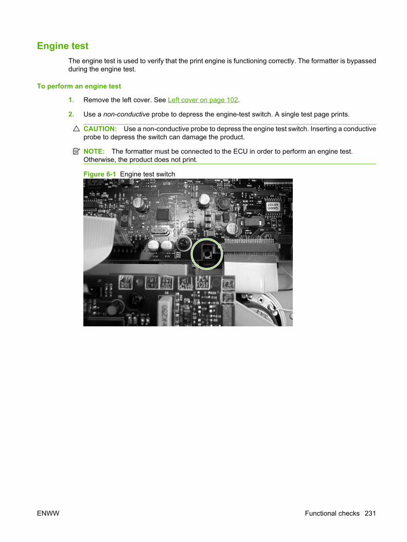
Engine testThe engine test is used to verify that the print engine is functioning correctly. The formatter is bypassedduring the engine test.
To perform an engine test
1. Remove the left cover. See Left cover on page 102.
2. Use a non-conductive probe to depress the engine-test switch. A single test page prints.
CAUTION: Use a non-conductive probe to depress the engine test switch. Inserting a conductiveprobe to depress the switch can damage the product.
NOTE: The formatter must be connected to the ECU in order to perform an engine test.Otherwise, the product does not print.
Figure 6-1 Engine test switch
ENWW Functional checks 231
Half self-test functional checkThe print process can be subdivided into the following stages:
● Image formation stage (charges the drum and writes a latent image to the drum with the laser)
● Development stage (forms a toner image on the drum)
● Transfer stage (transfers the image to the media)
● Cleaning stage (removes excess toner from the drum)
● Fusing stage (applies heat and pressure to the media to make the image permanent)
Perform a half self-test checkThe purpose of the half self-test check is to determine which process is malfunctioning.
1. Print a configuration page.
2. Open the print-cartridge access door after the paper advances halfway through the product(approximately five seconds after the motor begins rotating). The leading edge of the paper shouldhave advanced past the print cartridge.
3. Remove the print cartridge.
4. Open the print-cartridge drum shield to view the drum surface. If a dark and distinct toner image ispresent on the drum surface, assume that the first two functions of the electrophotographic processare functioning (image formation and development). Problem solve the failure as a transfer or fusingproblem.
Perform other checksIf no image appears on the photosensitive drum, perform these checks:
1. Make sure that you removed the entire length of the sealing tape from the print cartridge beforeyou installed the cartridge.
2. Perform a drum-rotation functional check to ensure that the drum is rotating (see Drum rotationtest on page 230).
3. Perform a high-voltage power-supply check. See Heating element check on page 233.
232 Chapter 6 Solve problems ENWW
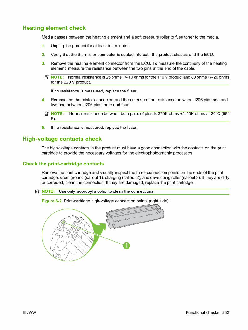
Heating element checkMedia passes between the heating element and a soft pressure roller to fuse toner to the media.
1. Unplug the product for at least ten minutes.
2. Verify that the thermistor connector is seated into both the product chassis and the ECU.
3. Remove the heating element connector from the ECU. To measure the continuity of the heatingelement, measure the resistance between the two pins at the end of the cable.
NOTE: Normal resistance is 25 ohms +/- 10 ohms for the 110 V product and 80 ohms +/- 20 ohmsfor the 220 V product.
If no resistance is measured, replace the fuser.
4. Remove the thermistor connector, and then measure the resistance between J206 pins one andtwo and between J206 pins three and four.
NOTE: Normal resistance between both pairs of pins is 370K ohms +/- 50K ohms at 20°C (68°F).
5. If no resistance is measured, replace the fuser.
High-voltage contacts checkThe high-voltage contacts in the product must have a good connection with the contacts on the printcartridge to provide the necessary voltages for the electrophotographic processes.
Check the print-cartridge contacts Remove the print cartridge and visually inspect the three connection points on the ends of the printcartridge: drum ground (callout 1), charging (callout 2), and developing roller (callout 3). If they are dirtyor corroded, clean the connection. If they are damaged, replace the print cartridge.
NOTE: Use only isopropyl alcohol to clean the connections.
Figure 6-2 Print-cartridge high-voltage connection points (right side)
1
ENWW Functional checks 233

Figure 6-3 Print-cartridge high-voltage connection points (left side)
2
3
Check the high-voltage connector assembly Visually inspect the cartridge connection points inside the product to make sure that they are not dirtyor corroded. If the pins are dirty, clean them by using isopropyl alcohol only.
234 Chapter 6 Solve problems ENWW

Service-mode functionsNVRAM initialization
An NVRAM initialization will return the following device settings to the factory-set defaults:
● All menu settings, including the fax header and company name
● Fax numbers and names that are associated with one-touch keys and speed-dial codes
Additionally, all faxes stored in memory are cleared.
Perform an NVRAM initialization
1. Turn off the product.
2. Simultaneously press and hold the Cancel button and the right arrow button (> ), and then turn onthe product.
3. Wait until the message Permanent storage init. appears, and then release the Cancel and rightarrow buttons.
When the NVRAM initialization process has been completed, the device control panel shows theReady message.
Super NVRAM initializationA Super NVRAM initialization will return all of the device settings to the factory-set defaults (genericproduct mode).
NOTE: When the product is turned on, you will be prompted to select the language and country/regionsetting before the product will initialize.
1. Turn off the product.
2. Simultaneously press and hold the Cancel button and the left arrow button (< ), and then turn onthe product.
3. Wait until the message Permanent storage init. appears, and then release the Cancel and leftarrow buttons.
Service menuNOTE: An asterisk (*) symbol next to a service submenu option indicates that this is the current settingfor that option.
For more information about using the service menu, see Service menu on page 241.
Access the service menu
1. Press the Setup button.
2. Use the arrow buttons to select Main Menu Service, and then press OK.
3. Use the arrow buttons to select the desired secondary-service option, and then press the OKbutton.
4. Use the arrow buttons to select the desired submenu option, and then press OK .
ENWW Service-mode functions 235
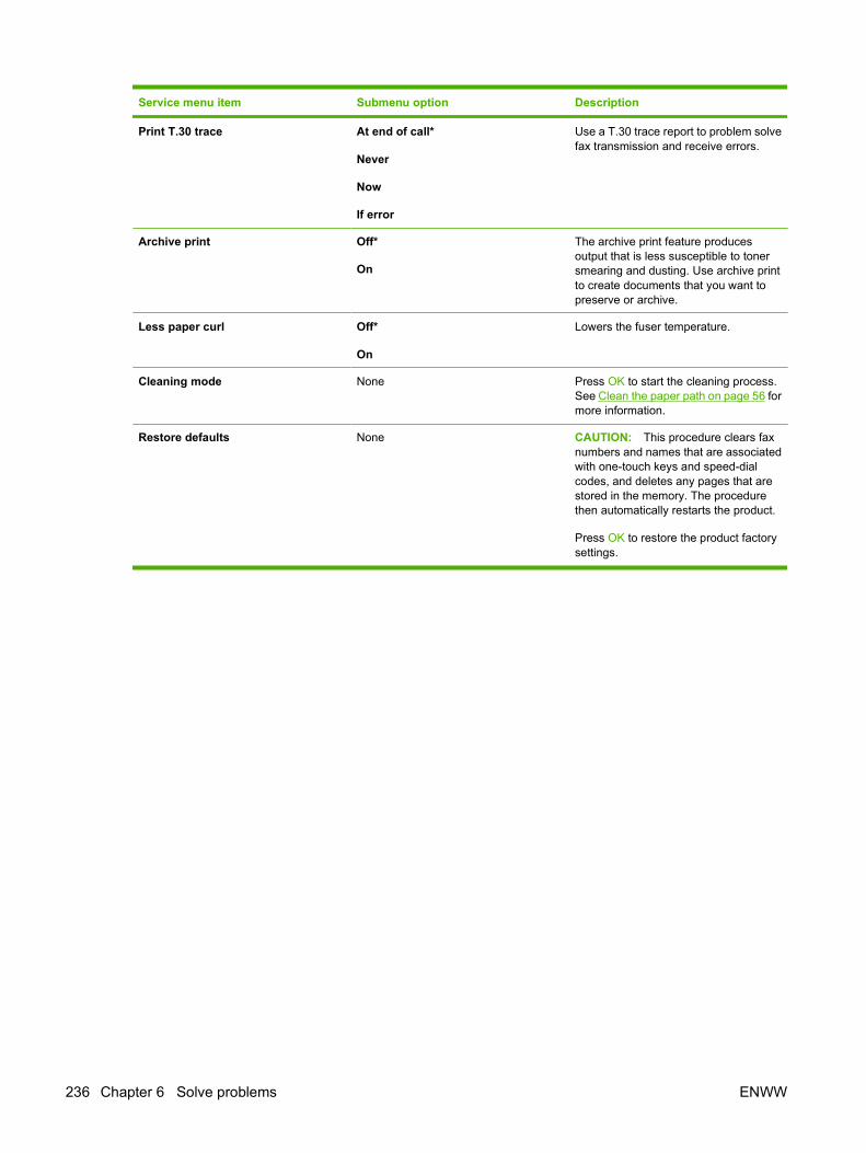
Service menu item Submenu option Description
Print T.30 trace At end of call*
Never
Now
If error
Use a T.30 trace report to problem solvefax transmission and receive errors.
Archive print Off*
On
The archive print feature producesoutput that is less susceptible to tonersmearing and dusting. Use archive printto create documents that you want topreserve or archive.
Less paper curl Off*
On
Lowers the fuser temperature.
Cleaning mode None Press OK to start the cleaning process.See Clean the paper path on page 56 formore information.
Restore defaults None CAUTION: This procedure clears faxnumbers and names that are associatedwith one-touch keys and speed-dialcodes, and deletes any pages that arestored in the memory. The procedurethen automatically restarts the product.
Press OK to restore the product factorysettings.
236 Chapter 6 Solve problems ENWW

Problem-solve tools
Product information pages and reportsInformation pages and reports reside within the product memory. These pages and reports helpdiagnose and solve problems with the product.
NOTE: If the product language was not correctly set during installation, you can set the languagemanually so the information pages print in one of the supported languages. Change the language byusing the System setup menu on the control panel or by using the embedded Web server.
Configuration pageThe Configuration page shows the current settings and product properties. Print a Configuration pagefrom the product or HP ToolboxFX. To print from the product, complete the following steps:
1. On the product control panel, press Setup.
2. Use the arrow buttons to select Reports, and then press OK.
3. Use the arrow buttons to select Config report, and then press OK.
A second page also prints. On that page, the Fax Settings section provides details about the productfax settings.
Supplies Status pageThe Supplies Status page shows the remaining life of the HP print cartridge, the estimated pagesremaining, the number of pages printed, and other supplies information. Print a Supplies Status pagefrom the product or HP ToolboxFX. To print from the product, complete the following steps:
1. On the product control panel, press Setup.
2. Use the arrow buttons to select Reports, and then press OK.
3. Use the arrow buttons to select Supplies Status, and then press OK.
PCL, PCL 6, or PS font listThe PCL, PCL 6, or PS font list shows which fonts are currently installed in the product. To print thePCL, PCL 6, or PS font list, complete the following steps:
1. On the product control panel, press Setup.
2. Use the arrow buttons to select Reports, and then press OK.
3. Use the arrow buttons to select PCL font list, PS font list, or PCL 6 font list, and then pressOK.
ENWW Problem-solve tools 237

Demo pageThe Demo page contains examples of text and graphics. To print the Demo page, complete the followingsteps:
1. On the product control panel, press Setup.
2. Use the arrow buttons to select Reports, and then press OK.
3. Use the arrow buttons to select Demo page, and then press OK.
Usage pageThe Usage page shows a page count for each size of paper printed, the number of one-sided (simplexed)or two-sided (duplexed) pages, and the avarage percentage of coverage. To print the Usage page,complete the following steps:
1. On the product control panel, press Setup.
2. Use the arrow buttons to select Reports, and then press OK.
3. Use the arrow buttons to select Usage page, and then press OK.
Menu mapThe Menu map shows the control-panel menus and available settings. To print the Menu map, completethe following steps:
1. On the product control panel, press Setup.
2. Use the arrow buttons to select Reports, and then press OK.
3. Use the arrow buttons to select Menu structure, and then press OK.
Network reportThe Menu map shows the product network settings. To print the Network report, complete the followingsteps:
1. On the product control panel, press Setup.
2. Use the arrow buttons to select Reports, and then press OK.
3. Use the arrow buttons to select Network report, and then press OK.
238 Chapter 6 Solve problems ENWW
Fax reportsThis section describes the fax reports that help you diagnose and solve problems with the product.
Fax activity logThe fax activity log provides a chronological history of the last 40 faxes that were received, sent, ordeleted, and any errors that occurred.
To print the fax activity log
1. On the product control panel, press Setup.
2. Use the arrow buttons to select Reports, and then press OK.
3. Use the arrow buttons to select Fax Activity log, and then press OK.
4. Press OK to select Print log now. The product exits the menu settings and prints the log.
Fax call reportA fax call report is a brief report that indicates the status of the last fax that was sent or received.
To print a fax call report
1. On the product control panel, press Setup.
2. Use the arrow buttons to select Reports, and then press OK.
3. Use the arrow buttons to select Fax Call report, and then press OK.
4. Press OK to select Print report now. The product exits the menu settings and prints the report.
Phone book reportA phone book report lists the fax numbers that are assigned to the one-touch buttons and speed-dialand group-dial entries.
To print a phone book report
1. On the product control panel, press Setup.
2. Use the arrow buttons to select Reports, and then press OK.
3. Use the arrow buttons to select PhoneBook report, and then press OK. The product exits themenu settings and prints the report.
ENWW Problem-solve tools 239

Billing-code reportThe billing-code report is a printed list of all of the fax billing codes and the total number of faxes thathave been billed to each code.
NOTE: After this report is printed, all billing data is deleted.
To print a billing-code report
1. On the product control panel, press Setup.
2. Use the arrow buttons to select Reports, and then press OK.
3. Use the arrow buttons to select Billing report, and then press OK. The product exits the menusettings and prints the report.
HP ToolboxFXHP ToolboxFX is a product configuration and problem solving tool.
To view HP ToolboxFXOpen HP ToolboxFX in one of these ways:
● On the Windows desktop, double-click the HP ToolboxFX icon.
● On the Windows Start menu, click Programs (All Programs in Windows XP), and then clickHP ToolboxFX.
Troubleshooting tabHP ToolboxFX includes a Troubleshooting tab that contains links to the following main pages:
● Control Panel Messages. View descriptions of product control-panel messages.
● Clearing Jams. View information about locating and clearing jams.
● Print Problems. View Help topics that can help you solve print problems.
● Scan Problems. View Help topics that can help you solve scan problems.
● Copy Problems. View Help topics that can help you solve copy problems.
● Fax Problems. View Help topics that can help you solve fax problems.
● Connectivity Problems. View Help topics that can help you solve networking problems.
● Troubleshooting Tools. Employ such problem-solving tools as a cleaning page to maintain theproduct.
● Animated Demonstrations. View animated Help demonstrations for the product.
NOTE: Other HP ToolboxFX tabs might be helpful in solving product problems.
240 Chapter 6 Solve problems ENWW
Service menu Use the control-panel Service menu to solve product problems.
Restore the factory-set defaultsRestoring the factory-set defaults returns all of the settings to the factory defaults, and it also clears thefax header name and phone number.
CAUTION: This procedure clears fax numbers and names that are associated with one-touch keysand speed-dial codes, and deletes any pages that are stored in the memory. The procedure thenautomatically restarts the product.
Restore the factory-set defaults
1. On the product control panel, press Setup.
2. Use the arrow buttons to select Service, and then press OK.
3. Use the arrow buttons to select Restore defaults, and then press OK.
The product automatically restarts.
Clean the paper pathThe product features a special cleaning mode to clean the paper path.
NOTE: If you have access to HP ToolboxFX, HP recommends cleaning the paper path by usingHP ToolboxFX.
Clean the paper path
1. On the product control panel, press Setup.
2. Use the arrow buttons to select Service, and then press OK.
3. Use the arrow buttons to select Cleaning Mode, and then press OK.
A page feeds through the product slowly. Discard the page when the process is completed.
4. Load plain letter or A4 paper when you are prompted.
5. Press OK again to confirm and begin the cleaning process.
A page feeds through the product slowly. Discard the page when the process is completed.
ENWW Problem-solve tools 241

T.30 protocol traceUse a T.30 protocol trace report to problem-solve fax transmission issues.
Print a T.30 protocol trace report
Send a fax from the product or receive a fax to the product from another fax machine, and then print aT.30 trace report after the fax prints.
1. On the product control panel, press Setup.
2. Use the arrow buttons to select Service, and then press OK.
3. Use the arrow buttons to select Print T.30, and then press OK.
The product exits the menu settings and prints the reports.
Archive printArchive print produces output that is less susceptible to toner smearing and dusting. Use archive printto create documents that you want to preserve or archive.
Turn on archive print
1. On the product control panel, press Setup.
2. Use the arrow buttons to select Service, and then press OK.
3. Use the arrow buttons to select Archive print, On, or Off, and then press OK.
242 Chapter 6 Solve problems ENWW

Firmware updatesThe product has a flash-memory-based formatter that enables the firmware code to be updated in theevent that new firmware is released for the product. Using flash memory also provides a way to recoverthe firmware in the event of code corruption or failure.
Firmware update by using a flash executable fileThe configuration page lists the firmware version of the product. On the flash-memory-based product,you can update the firmware code by downloading the latest flash executable file for the product andrunning the program according to the readme instructions that come with it (go to www.hp.com). Turnthe product off and then on before running the executable file. If the firmware becomes corrupted or fails(usually because of an interruption when attempting to update the firmware), the product no longerfunctions and will require the formatter be replaced.
ENWW Firmware updates 243

244 Chapter 6 Solve problems ENWW

7 Parts
● Accessories and ordering information
● Supplies
● Memory
● Cable and interface accessories
● Paper-handling accessories
● Whole unit replacement
● Scanner/ADF replacement parts
● Control-panel bezels
● Supplementary documentation and support
● Problem-solve diagrams
● Parts lists and diagrams
● Scanner and ADF assemblies
● Scanner components
● ADF components
● Convenience stapler components (HP LaserJet M2727nfs only)
● Formatter, fax card, HP jewel, and nameplate
● External covers and panels
● Cartridge door assembly
● Internal components (1 of 4)
● Internal components (2 of 4)
● Internal components (3 of 4)
● Internal components (4 of 4)
● Engine-controller assembly (ECU)
● Main-drive assembly
● Duplexing-drive assembly
ENWW 245

● Tray 2 cassette and tray 3 cassette/feeder
● Duplexing assembly
● Fuser assembly
● Alphabetical parts list
● Numerical parts list
246 Chapter 7 Parts ENWW

Accessories and ordering informationOrder replacement parts from the following Web sites:
● HP Parts Store: www.partsdirect.hp.com or www2.hp.com/hpparts/default.asp
Order supplies from the following Web sites:
● To order supplies in the U.S., go to www.hp.com/sbso/product/supplies.
● To order supplies worldwide, go to www.hp.com/ghp/buyonline.html.
● To order supplies in Canada, go to www.hp.ca/catalog/supplies.
● To order supplies in Europe, go to www.hp.com/go/ljsupplies.
● To order supplies in Asia-Pacific, go to www.hp.com/paper/.
● To order accessories, go to www.hp.com/go/accessories.
ENWW Accessories and ordering information 247
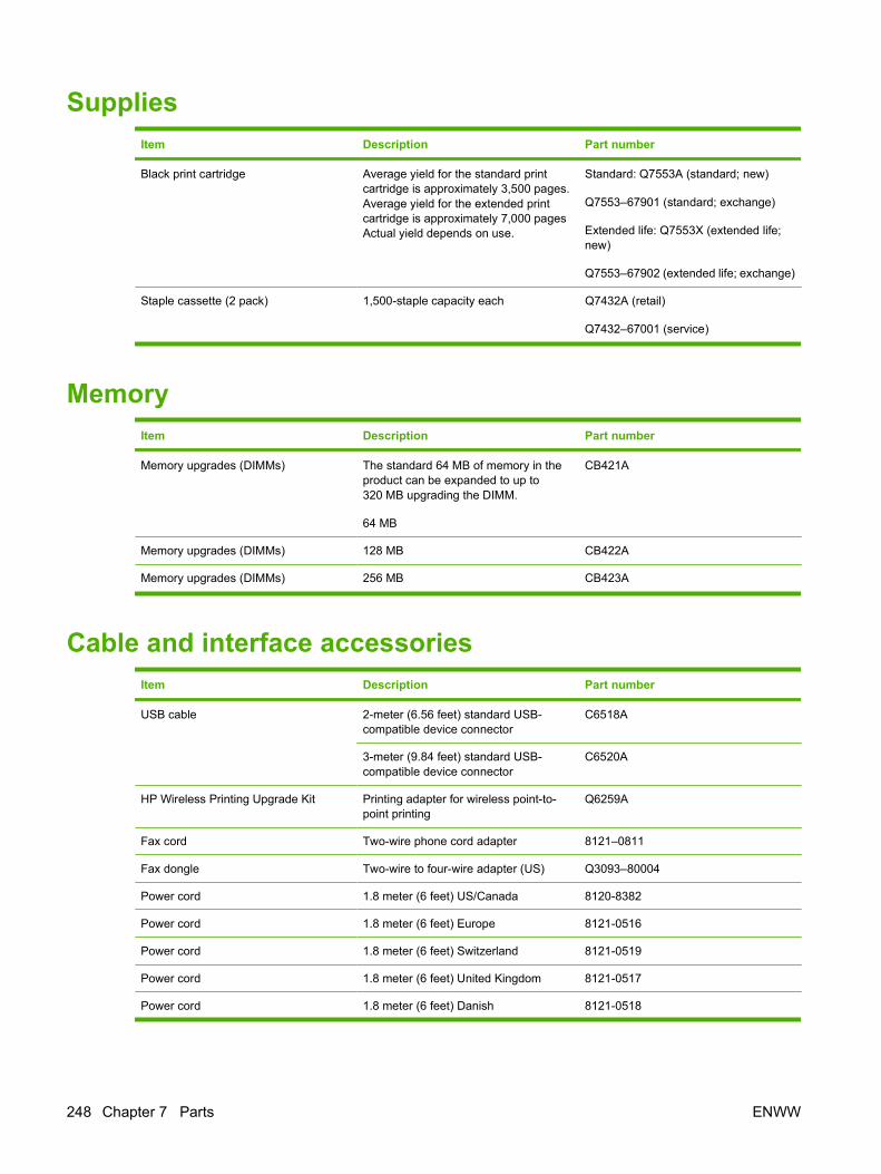
SuppliesItem Description Part number
Black print cartridge Average yield for the standard printcartridge is approximately 3,500 pages.Average yield for the extended printcartridge is approximately 7,000 pagesActual yield depends on use.
Standard: Q7553A (standard; new)
Q7553–67901 (standard; exchange)
Extended life: Q7553X (extended life;new)
Q7553–67902 (extended life; exchange)
Staple cassette (2 pack) 1,500-staple capacity each Q7432A (retail)
Q7432–67001 (service)
MemoryItem Description Part number
Memory upgrades (DIMMs) The standard 64 MB of memory in theproduct can be expanded to up to320 MB upgrading the DIMM.
64 MB
CB421A
Memory upgrades (DIMMs) 128 MB CB422A
Memory upgrades (DIMMs) 256 MB CB423A
Cable and interface accessoriesItem Description Part number
USB cable 2-meter (6.56 feet) standard USB-compatible device connector
C6518A
3-meter (9.84 feet) standard USB-compatible device connector
C6520A
HP Wireless Printing Upgrade Kit Printing adapter for wireless point-to-point printing
Q6259A
Fax cord Two-wire phone cord adapter 8121–0811
Fax dongle Two-wire to four-wire adapter (US) Q3093–80004
Power cord 1.8 meter (6 feet) US/Canada 8120-8382
Power cord 1.8 meter (6 feet) Europe 8121-0516
Power cord 1.8 meter (6 feet) Switzerland 8121-0519
Power cord 1.8 meter (6 feet) United Kingdom 8121-0517
Power cord 1.8 meter (6 feet) Danish 8121-0518
248 Chapter 7 Parts ENWW
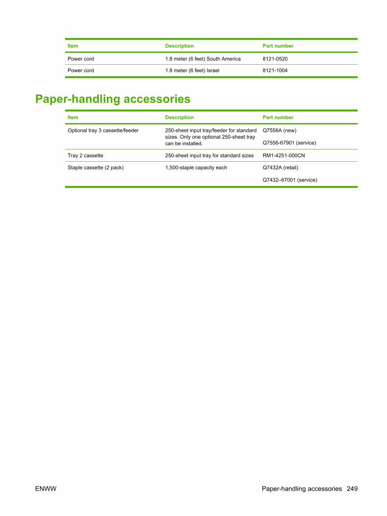
Item Description Part number
Power cord 1.8 meter (6 feet) South America 8121-0520
Power cord 1.8 meter (6 feet) Israel 8121-1004
Paper-handling accessories Item Description Part number
Optional tray 3 cassette/feeder 250-sheet input tray/feeder for standardsizes. Only one optional 250-sheet traycan be installed.
Q7556A (new)
Q7556-67901 (service)
Tray 2 cassette 250-sheet input tray for standard sizes RM1-4251-000CN
Staple cassette (2 pack) 1,500-staple capacity each Q7432A (retail)
Q7432–67001 (service)
ENWW Paper-handling accessories 249

Whole unit replacementUse the tables in this section to find the whole unit replacement part number for a specific product bundleand localized configuration.
Table 7-1 Whole unit replacement, product bundle CB532A
Country/region Localized configuration Replacement part number
Asia Pacific AB0 - Taiwan-Traditional Chinese CB532-67906
AB1 - Korea-Korean localization CB532-67907
AB2 - China-Simplified Chinese CB532-67908
AB3 - Thailand-Thai CB532-67909
AB4 - Singapore-English CB532-67910
BFV - Hong Kong SAR-English/Traditional Chinese CB532-67911
ABG - Australia-English CB532-67912
A2K - Philippines-English CB532-67913
ACJ - India-English CB532-67914
AK3 - Indonesia - Indonesia localizaton CB532-67915
AR7 - New Zealand-English CB532-67916
UUD - Vietnam-Vietnamese localization CB532-67917
ARR - Asia Pacific (Euro Cord)-English CB532-67918
ARS - Asia Pacific (UK Cord)-English CB532-67919
250 Chapter 7 Parts ENWW
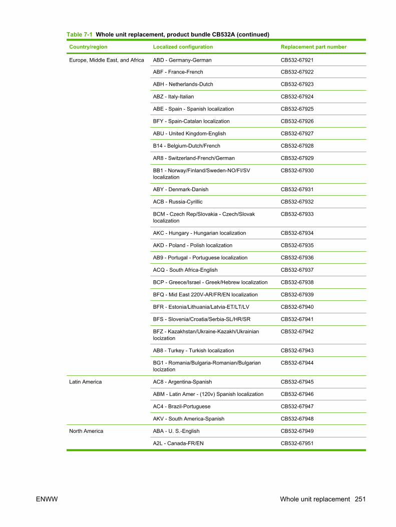
Country/region Localized configuration Replacement part number
Europe, Middle East, and Africa ABD - Germany-German CB532-67921
ABF - France-French CB532-67922
ABH - Netherlands-Dutch CB532-67923
ABZ - Italy-Italian CB532-67924
ABE - Spain - Spanish localization CB532-67925
BFY - Spain-Catalan localization CB532-67926
ABU - United Kingdom-English CB532-67927
B14 - Belgium-Dutch/French CB532-67928
AR8 - Switzerland-French/German CB532-67929
BB1 - Norway/Finland/Sweden-NO/FI/SVlocalization
CB532-67930
ABY - Denmark-Danish CB532-67931
ACB - Russia-Cyrillic CB532-67932
BCM - Czech Rep/Slovakia - Czech/Slovaklocalization
CB532-67933
AKC - Hungary - Hungarian localization CB532-67934
AKD - Poland - Polish localization CB532-67935
AB9 - Portugal - Portuguese localization CB532-67936
ACQ - South Africa-English CB532-67937
BCP - Greece/Israel - Greek/Hebrew localization CB532-67938
BFQ - Mid East 220V-AR/FR/EN localization CB532-67939
BFR - Estonia/Lithuania/Latvia-ET/LT/LV CB532-67940
BFS - Slovenia/Croatia/Serbia-SL/HR/SR CB532-67941
BFZ - Kazakhstan/Ukraine-Kazakh/Ukrainianlocization
CB532-67942
AB8 - Turkey - Turkish localization CB532-67943
BG1 - Romania/Bulgaria-Romanian/Bulgarianlocization
CB532-67944
Latin America AC8 - Argentina-Spanish CB532-67945
ABM - Latin Amer - (120v) Spanish localization CB532-67946
AC4 - Brazil-Portuguese CB532-67947
AKV - South America-Spanish CB532-67948
North America ABA - U. S.-English CB532-67949
A2L - Canada-FR/EN CB532-67951
Table 7-1 Whole unit replacement, product bundle CB532A (continued)
ENWW Whole unit replacement 251

Table 7-2 Whole unit replacement, product bundle CB533A
Country/region Localized configuration Replacement part number
Asia Pacific AB0 - Taiwan-Traditional Chinese CB533-67901
AB1 - Korea-Korean localization CB533-67902
AB2 - China-Simplified Chinese CB533-67903
AB3 - Thailand-Thai CB533-67904
AB4 - Singapore-English CB533-67905
BFV - Hong Kong SAR-English/Traditional Chinese CB533-67906
ABG - Australia-English CB533-67907
A2K - Philippines-English CB533-67908
ACJ - India-English CB533-67909
AK3 - Indonesia - Indonesia localizaton CB533-67910
AR7 - New Zealand-English CB533-67911
UUD - Vietnam-Vietnamese localization CB533-67912
ARR - Asia Pacific (Euro Cord)-English CB533-67913
ARS - Asia Pacific (UK Cord)-English CB533-67914
252 Chapter 7 Parts ENWW

Country/region Localized configuration Replacement part number
Europe, Middle East, and Africa ABD - Germany-German CB533-67916
ABF - France-French CB533-67917
ABH - Netherlands-Dutch CB533-67918
ABZ - Italy-Italian CB533-67919
ABE - Spain - Spanish localization CB533-67920
BFY - Spain-Catalan localization CB533-67921
ABU - United Kingdom-English CB533-67922
B14 - Belgium-Dutch/French CB533-67923
AR8 - Switzerland-French/German CB533-67924
BB1 - Norway/Finland/Sweden-NO/FI/SVlocalization
CB533-67925
ABY - Denmark-Danish CB533-67926
ACB - Russia-Cyrillic CB533-67927
BCM - Czech Rep/Slovakia - Czech/Slovaklocalization
CB533-67928
AKC - Hungary - Hungarian localization CB533-67929
AKD - Poland - Polish localization CB533-67930
AB9 - Portugal - Portuguese localization CB533-67931
ACQ - South Africa-English CB533-67932
BCP - Greece/Israel - Greek/Hebrew localization CB533-67933
BFQ - Mid East 220V-AR/FR/EN localization CB533-67934
BFR - Estonia/Lithuania/Latvia-ET/LT/LV CB533-67935
BFS - Slovenia/Croatia/Serbia-SL/HR/SR CB533-67936
BFZ - Kazakhstan/Ukraine-Kazakh/Ukrainianlocization
CB533-67937
AB8 - Turkey - Turkish localization CB533-67938
BG1 - Romania/Bulgaria-Romanian/Bulgarianlocization
CB533-67939
Latin America AC8 - Argentina-Spanish CB533-67940
ABM - Latin Amer - (120v) Spanish localization CB533-67941
AC4 - Brazil-Portuguese CB533-67942
AKV - South America-Spanish CB533-67943
North America ABA - U. S.-English CB533-67944
A2L - Canada-FR/EN CB533-67946
Table 7-2 Whole unit replacement, product bundle CB533A (continued)
ENWW Whole unit replacement 253

Scanner/ADF replacement partsItem Part number
PKG FGI ASSY HP LaserJet M2727 SSA (scanner assembly) CB532-67905
PKG FGI ASSY HP LaserJet M2727 ADF (ADF assembly) CB532-67903
HP LaserJet M2727 ADF cover replacement kit Q6500-67901
ADF flag replacement kit Q3948-67902
HP LaserJet M2727 input tray assembly Q6500-60119
Clean out ADF C7309-40153
ADF pick roller assembly 5851-2559
ADF separation pad Q2665-60125
ADF assembly hinge replacement kit Q3948-67905
HP LaserJet M2727 ADF window replacement kit Q6500-67904
254 Chapter 7 Parts ENWW
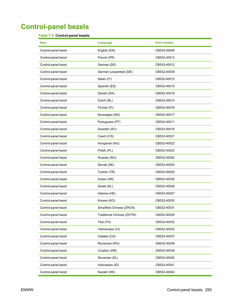
Control-panel bezelsTable 7-3 Control-panel bezels
Item Language Part number
Control-panel bezel English (EN) CB532-40009
Control-panel bezel French (FR) CB532-40013
Control-panel bezel German (DE) CB532-40012
Control-panel bezel German (unpainted) (DE) CB532-40036
Control-panel bezel Italian (IT) CB532-40015
Control-panel bezel Spanish (ES) CB532-40010
Control-panel bezel Danish (DA) CB532-40019
Control-panel bezel Dutch (NL) CB532-40014
Control-panel bezel Finnish (FI) CB532-40018
Control-panel bezel Norwegian (NO) CB532-40017
Control-panel bezel Portuguese (PT) CB532-40011
Control-panel bezel Swedish (SV) CB532-40016
Control-panel bezel Czech (CS) CB532-40021
Control-panel bezel Hungarian (HU) CB532-40022
Control-panel bezel Polish (PL) CB532-40023
Control-panel bezel Russian (RU) CB532-40020
Control-panel bezel Slovak (SK) CB532-40024
Control-panel bezel Turkish (TR) CB532-40025
Control-panel bezel Arabic (AR) CB532-40028
Control-panel bezel Greek (EL) CB532-40026
Control-panel bezel Hebrew (HE) CB532-40027
Control-panel bezel Korean (KO) CB532-40030
Control-panel bezel Simplified Chinese (ZHCN) CB532-40031
Control-panel bezel Traditional Chinese (ZHTW) CB532-40029
Control-panel bezel Thai (TH) CB532-40032
Control-panel bezel Vietnamese (VI) CB532-40033
Control-panel bezel Catalan (CA) CB532-40037
Control-panel bezel Romanian (RO) CB532-40038
Control-panel bezel Croation (HR) CB532-40039
Control-panel bezel Slovenian (SL) CB532-40040
Control-panel bezel Indonesian (ID) CB532-40041
Control-panel bezel Kazakh (KK) CB532-40042
ENWW Control-panel bezels 255

Item Language Part number
Control-panel bezel Bulgarian (BG) CB532-40043
Control-panel bezel Ukranian (UK) CB532-40044
Control-panel bezel Serbian (SR) CB532-40045
Control-panel bezel Lithuanian (LT) CB532-40046
Control-panel bezel Estonia (ET) CB532-400473
Control-panel bezel Latvian (LV) CB532-40048
Table 7-3 Control-panel bezels (continued)
256 Chapter 7 Parts ENWW

Supplementary documentation and supportTable 7-4 Service and training support
Item Part number
Service manual (this manual) CB532-90946
A printed copy of the user guide is available in the following languages.
Table 7-5 User guides
Language Part number
English CB532-90901
Chinese, simplified CB532-90908
Czech CB532-90910
Dutch CB532-90912
French CB532-90902
German CB532-90903
Hungarian CB532-90916
Italian CB532-90904
Korean CB532-90919
Polish CB532-90923
Portuguese, Brazil CB532-90924
Russian CB532-90926
Spanish, Mid Atlantic CB532-90905
Swedish CB532-90930
Thai CB532-90931
Traditional Chinese CB532-90932
Turkish CB532-90933
Catalan CB532-90906
Bulgarian CB532-90907
Croatian CB532-90909
Danish CB532-90911
Estonian CB532-90913
Finnish CB532-90914
Greek CB532-90915
Bahasa Indonesian CB532-90917
Kazakh CB532-90918
Latvian CB532-90920
ENWW Supplementary documentation and support 257

Language Part number
Lituanian CB532-90921
Norwegian CB532-90922
Romanian CB532-90925
Serbian CB532-90927
Slovak CB532-90928
Slovenian CB532-90929
Ukranian CB532-90934
Vietnamese CB532-90935
Arabic CB532-90936
Hebrew CB532-90937
A printed copy of the Getting Started Guide is available in the following languages.
Table 7-6 Getting started guide
Language Part number
English, Spanish, Portuguese, French CB532–90938
English, Spanish, Portuguese, Catalan, Dutch, French,German, Italian
CB532-90939
English, Danish, Finnish, French, Norwegian, Swedish, Arabic CB532-90940
English, Bulgarian, Czech, Hungarian, Polish, Romanian,Russian, Slovak
CB532-90941
English, Kazakh, Turkish, Ukrainian, Estonian, Latvian,Lithuanian
CB532-90942
English, Croation, Greek, Serbian, Slovenian, Hebrew CB532-90943
English, Korean, Indonesian, Simplified Chinese, TraditionalChinese, Thai, Vietnamese
CB532-90944
Table 7-7 Technical support Web sites
HP Customer Care Online
Software drivers, support documentation, and answers tofrequently asked questions
www.hp.com/support/LJM2727
HP Technical Training (North America)
Classes and schedules
www.hp.com/go/resellertraining
Table 7-5 User guides (continued)
258 Chapter 7 Parts ENWW
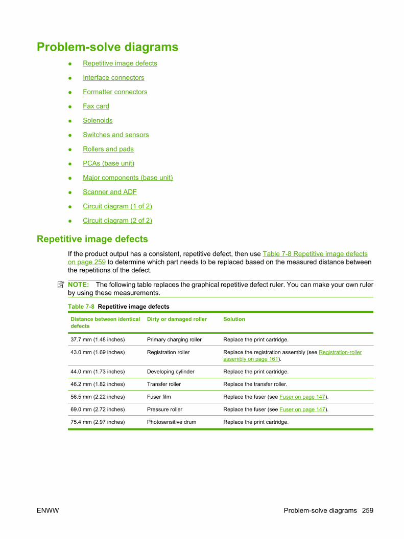
Problem-solve diagrams● Repetitive image defects
● Interface connectors
● Formatter connectors
● Fax card
● Solenoids
● Switches and sensors
● Rollers and pads
● PCAs (base unit)
● Major components (base unit)
● Scanner and ADF
● Circuit diagram (1 of 2)
● Circuit diagram (2 of 2)
Repetitive image defectsIf the product output has a consistent, repetitive defect, then use Table 7-8 Repetitive image defectson page 259 to determine which part needs to be replaced based on the measured distance betweenthe repetitions of the defect.
NOTE: The following table replaces the graphical repetitive defect ruler. You can make your own rulerby using these measurements.
Table 7-8 Repetitive image defects
Distance between identicaldefects
Dirty or damaged roller Solution
37.7 mm (1.48 inches) Primary charging roller Replace the print cartridge.
43.0 mm (1.69 inches) Registration roller Replace the registration assembly (see Registration-rollerassembly on page 161).
44.0 mm (1.73 inches) Developing cylinder Replace the print cartridge.
46.2 mm (1.82 inches) Transfer roller Replace the transfer roller.
56.5 mm (2.22 inches) Fuser film Replace the fuser (see Fuser on page 147).
69.0 mm (2.72 inches) Pressure roller Replace the fuser (see Fuser on page 147).
75.4 mm (2.97 inches) Photosensitive drum Replace the print cartridge.
ENWW Problem-solve diagrams 259
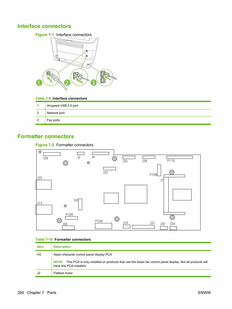
Interface connectors Figure 7-1 Interface connectors
2 31
Table 7-9 Interface connectors
1 Hi-speed USB 2.0 port
2 Network port
3 Fax ports
Formatter connectorsFigure 7-2 Formatter connectors
J36 J2 J4 J35 J28
P108
P110
J7
J32 J34 J31 J33 P104
P109
J26
J15
J22
H3
J27
Table 7-10 Formatter connectors
Item Description
H3 Asian character control panel display PCA
NOTE: This PCA is only installed on products that use the Asian fax control panel display. Not all products willhave this PCA installed.
J2 Flatbed motor
260 Chapter 7 Parts ENWW
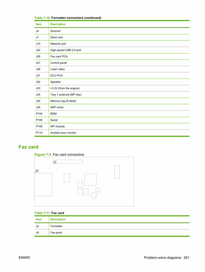
Item Description
J4 Scanner
J7 Dimm slot
J15 Network port
J22 High-speed USB 2.0 port
J26 Fax card PCA
J27 Control panel
J28 Laser video
J31 ECU PCA
J32 Speaker
J33 +3.3V (from the engine)
J34 Tray 1 solenoid (MP tray)
J35 Memory tag (E-label)
J36 ADF motor
P104 BDM
P108 Serial
P109 SPI module
P110 Ansible trace monitor
Fax cardFigure 7-3 Fax card connectors
J2
J9
Table 7-11 Fax card
Item Description
J2 Formatter
J9 Fax ports
Table 7-10 Formatter connectors (continued)
ENWW Problem-solve diagrams 261
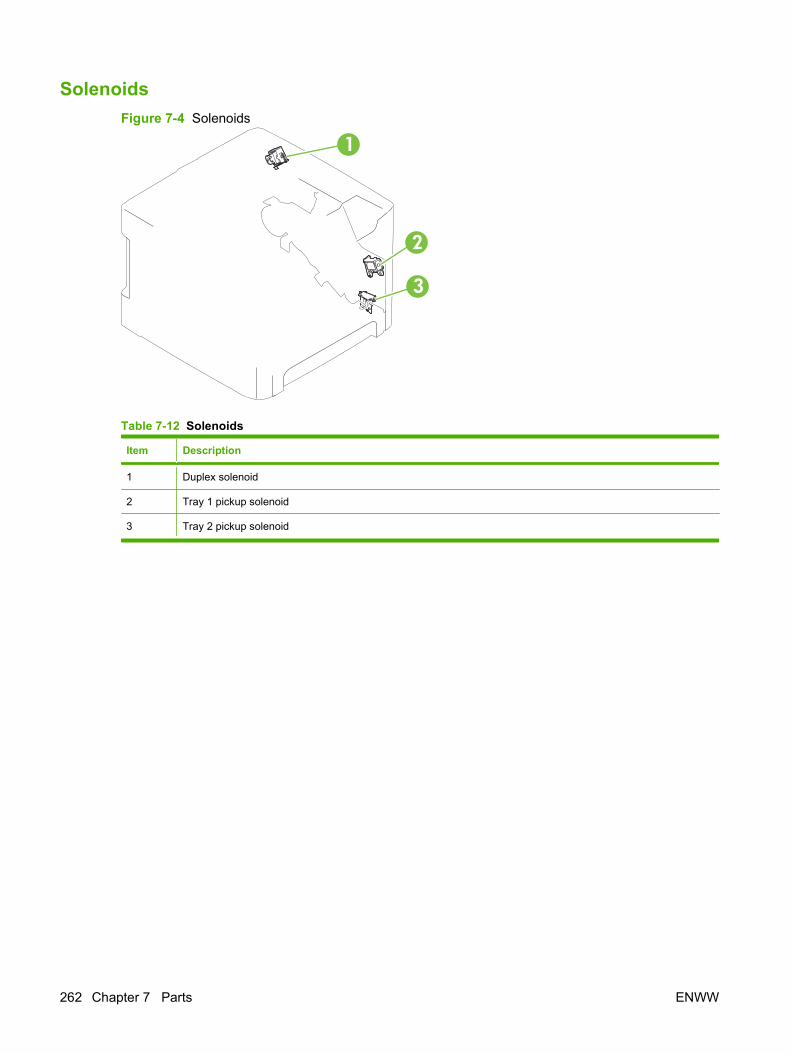
SolenoidsFigure 7-4 Solenoids
1
3
2
Table 7-12 Solenoids
Item Description
1 Duplex solenoid
2 Tray 1 pickup solenoid
3 Tray 2 pickup solenoid
262 Chapter 7 Parts ENWW

Switches and sensorsFigure 7-5 Switches and sensors
1
1
3
2
Table 7-13 Switches and sensors
Item Description
1 Interlock switch
2 Delivery sensor
3 Top-of-page sensor
ENWW Problem-solve diagrams 263
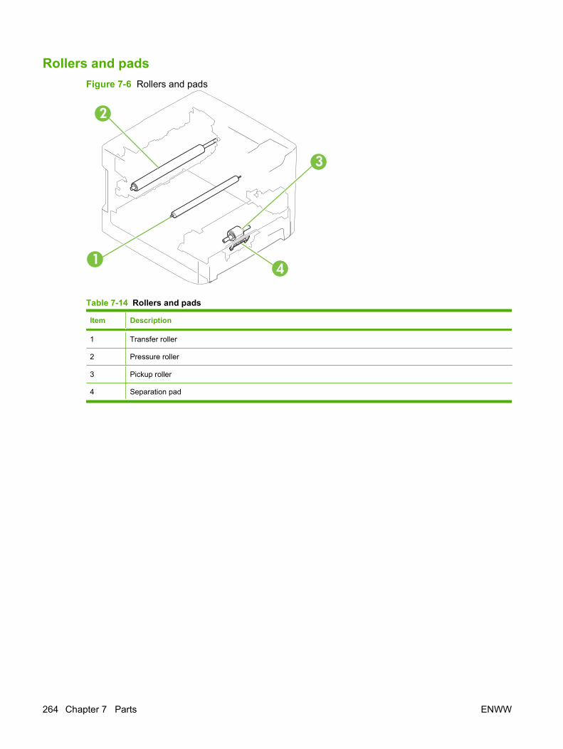
Rollers and padsFigure 7-6 Rollers and pads
1
3
2
4
Table 7-14 Rollers and pads
Item Description
1 Transfer roller
2 Pressure roller
3 Pickup roller
4 Separation pad
264 Chapter 7 Parts ENWW
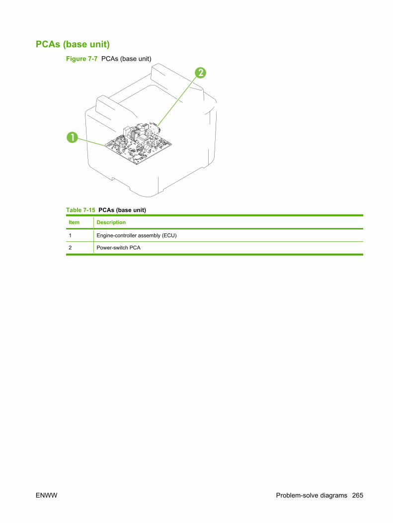
PCAs (base unit)Figure 7-7 PCAs (base unit)
1
2
Table 7-15 PCAs (base unit)
Item Description
1 Engine-controller assembly (ECU)
2 Power-switch PCA
ENWW Problem-solve diagrams 265
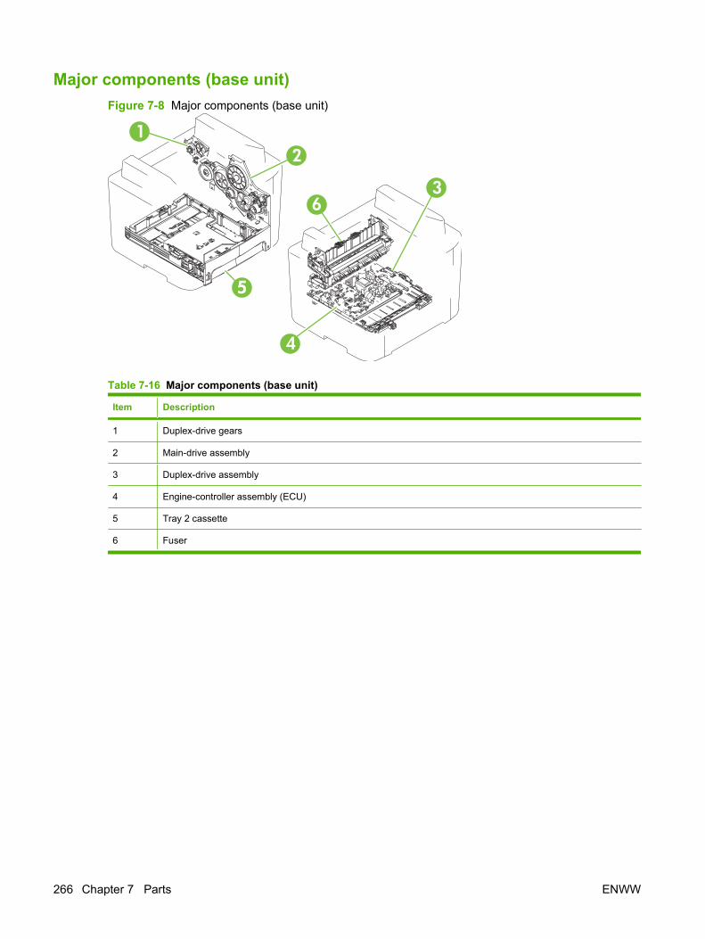
Major components (base unit)Figure 7-8 Major components (base unit)
1
3
2
4
55
6
Table 7-16 Major components (base unit)
Item Description
1 Duplex-drive gears
2 Main-drive assembly
3 Duplex-drive assembly
4 Engine-controller assembly (ECU)
5 Tray 2 cassette
6 Fuser
266 Chapter 7 Parts ENWW

Scanner and ADFFigure 7-9 Scanner and ADF
2
1
Table 7-17 Scanner and ADF
Item Description
1 Scanner
2 ADF
ENWW Problem-solve diagrams 267
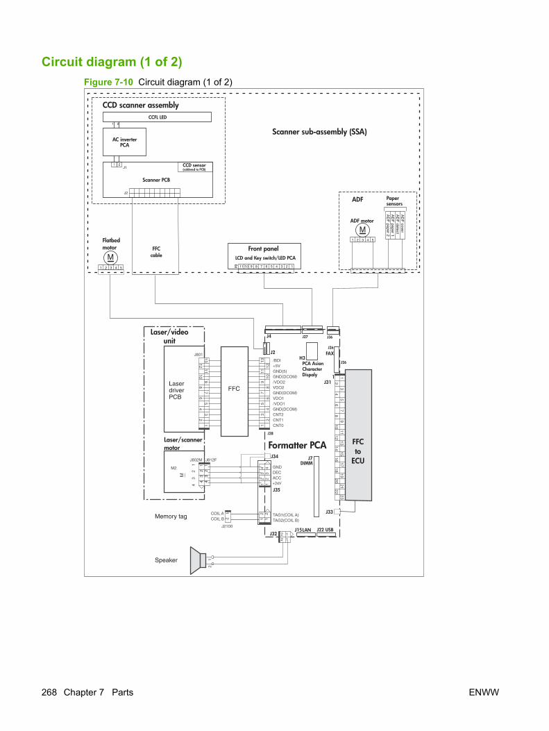
Circuit diagram (1 of 2)Figure 7-10 Circuit diagram (1 of 2)
Formatter PCAJ34
1
J4
J2
Scanner sub-assembly (SSA)
Flatbedmotor
1 2 3 4 5
AC inverterPCA
Scanner PCB
CCD sensor(soldered to PCB)J1
J2
FFCcable
Front panel
7891011 456 123
ADF
ADF motor
Papersensors
1 2 3 4 5
AD
F cove
rA
DF
detectA
DF
paper 1A
DF
paper 2
FAX
DIMM
LAN
CCD scanner assembly
Laser/scannermotor
LCD and Key switch/LED PCA
P2
FFCto
ECU
J26
J36J27
J28
J26
J35
J32J15 J22 USB
J33
J7
Laser/videounit
CCFL LED
+24V
J31
H3PCA AsianCharacterDispaly
268 Chapter 7 Parts ENWW

Circuit diagram (2 of 2)Figure 7-11 Circuit diagram (2 of 2)
Fuse
r
Engi
ne c
ont ro
ller
PCA
HP
LJ 2
727n
fs
Pape
r fe
eder
driv
er P
CA
FFC to formatter
ENWW Problem-solve diagrams 269

Parts lists and diagramsHow to use the parts lists and diagrams
The figures in this chapter show the major subassemblies in the product and their component parts. Aparts list table follows each exploded view assembly diagram. Each table lists the item number, theassociated part number, and the description of each part. If a part is not listed in the table, then it is nota field replaceable unit (FRU).
CAUTION: Be sure to order the correct part. When looking for part numbers for electrical components,pay careful attention to the voltage that is listed in the description column to ensure that the part numberselected is for the correct product model.
NOTE: In this manual, the abbreviation “PCA” stands for “printed circuit board assembly.” Componentsdescribed as a PCA might consist of a single circuit board or a circuit board plus other parts, such ascables and sensors.
270 Chapter 7 Parts ENWW

Types of screws
Illustration Description Size Part number Use
Screw, RS M3X6
M3X6
M3X8
XA9-1495-000CN
XA9-1561-000CN
XA9-1504-000CN
Used to secure metal tometal
Screw w/washer M3X8
M4X12
XA9-1420-000CN
XA9-1492-000CN
Used to secure metalcomponents to metalcomponents (for example,a ground wire to theframe)
Screw, tapping M3X6 XB9-1503-000CN Used to secure anythingto plastic
Screw, tapping, trusshead
M4X10 XB4-7401-005CN Used to secure anythingto plastic
Screw, tapping binding,head
M3X8 XB4-7300-809CN Used to secure anythingto plastic
Screw, toothed washer M4X6 XB2-7400-606CN Used to secure metalcomponents to metalcomponents
Screw, TP M3X8 XA-1648-000CN Used to secure anythingto plastic
12 mm12 mm
ENWW Parts lists and diagrams 271

Scanner and ADF assembliesFigure 7-12 Scanner and ADF assemblies
272 Chapter 7 Parts ENWW

Table 7-18 Scanner and ADF assemblies
Ref Description Part number Qty
1 ADF PKG FGI ASSY (automatic document feeder) CB532-67903 1
2 Input tray assembly HP LaserJet M2727 Q6500-60119 1
3 ADF hinge replacement kit Q3948-67905 1
4 SSA PKG FGI ASSY (scanner flatbed assembly) CB532-67905 1
ENWW Scanner and ADF assemblies 273
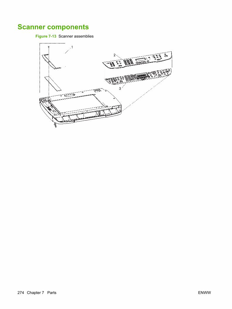
Scanner componentsFigure 7-13 Scanner assemblies
274 Chapter 7 Parts ENWW

Table 7-19 Scanner components
Ref Description Part number Qty
1 ADF window replacement kit Q6500-67904 1
2 Bezel, control panel See Control-panel bezelson page 255.
1
3 Control panel, Western fax CB532-60101 1
3 Control panel, Asian fax CB532-60102 1
NOTE: The Asian character control panel display PCA (see Formatter, fax card, HP jewel, andnameplate on page 280) must be installed on the formatter to support the Asian fax control panel(CB532-60102).
ENWW Scanner components 275
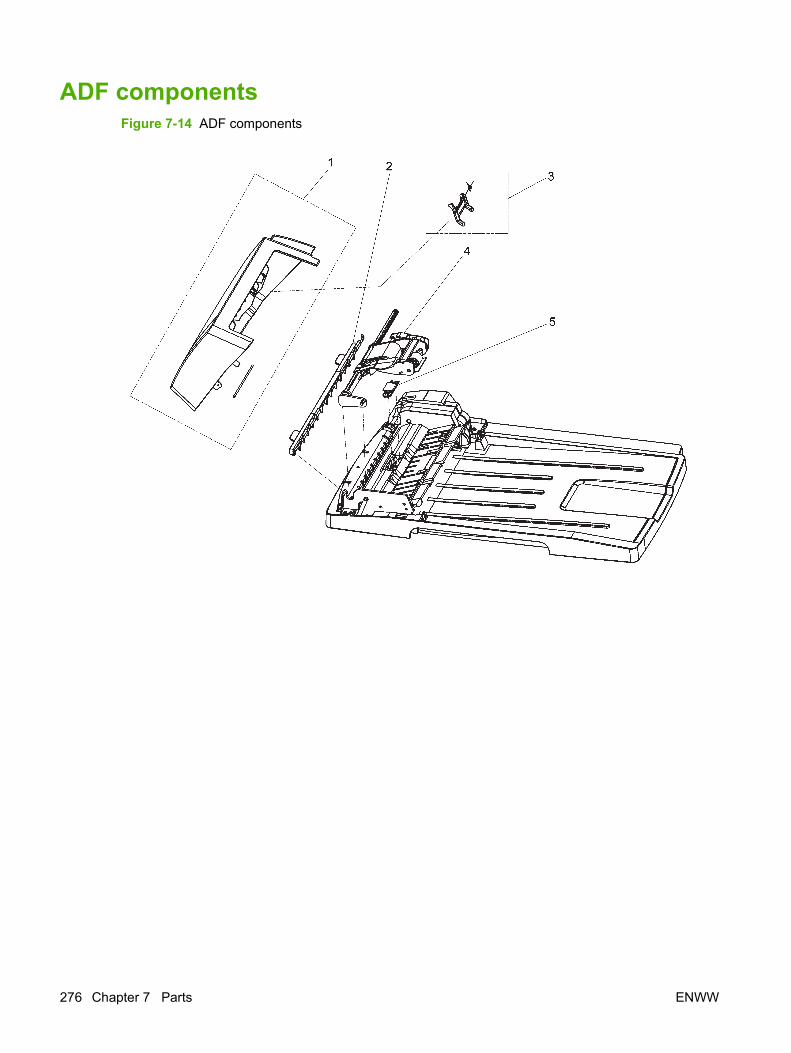
ADF componentsFigure 7-14 ADF components
276 Chapter 7 Parts ENWW

Table 7-20 ADF components
Ref Description Part number Qty
1 ADF cover replacement kit Q6500-67901 1
2 ADF cleanout part C7309-40153 1
3 ADF flag replacement kit Q3948-67902 1
4 ADF pickup roller assembly 5851-2559 1
5 ADF separation pad Q2665-60125 1
ENWW ADF components 277
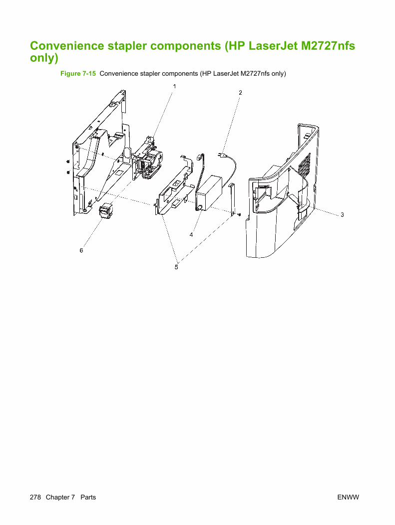
Convenience stapler components (HP LaserJet M2727nfsonly)
Figure 7-15 Convenience stapler components (HP LaserJet M2727nfs only)
278 Chapter 7 Parts ENWW

Table 7-21 Convenience stapler components (HP LaserJet M2727nfs only)
Ref Description Part number Qty
1 Convenience stapler mechanism HP LaserJet M2727nfs(replacement)
CB532-60105 1
2 Convenience stapler AC inlet cable HP LaserJet M2727nfs Q6501-60101 1
3 Convenience stapler cover door HP LaserJet M2727nfs RC1-7523-000CN 1
4 Convenience stapler power supply HP LaserJet M2727nfs Q7429-60501 1
5 Convenience stapler power supply bracket and strap HPLaserJet M2727nfs
CB532-67902 1
6 Convenience stapler cassette (2-pack) HP LaserJet M2727nfs Q7432-67001 1
NOTE: The convenience stapler components are used in the HP LJ3392 and the HP LaserJetM2727nfs.
ENWW Convenience stapler components (HP LaserJet M2727nfs only) 279
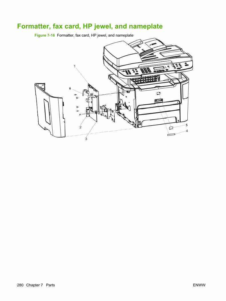
Formatter, fax card, HP jewel, and nameplateFigure 7-16 Formatter, fax card, HP jewel, and nameplate
5
6
280 Chapter 7 Parts ENWW

Table 7-22 Formatter, Fax card, HP jewel, and nameplate
Ref Description Part number Qty
1 Formatter PCA CC370-60001 1
2 Fax card/Formatter FFC CB534-60117 1
3 Fax card US/AP ROHS CC502-60001 1
3 Fax card EMEA ROHS CC369-60001 1
4 Nameplate HP LaserJet M2727nf CB532-00009 1
4 Nameplate HP LaserJet M2727nfs CB532-00003 1
5 Jewel, HP 7121-8285 1
6 PCA, Asian character display control panel (with spacer) CB532-67904 1
NOTE: The Asian character display control panel PCA (CB532-67904) is only installed on productsthat use the Asian fax control panel.
ENWW Formatter, fax card, HP jewel, and nameplate 281

External covers and panelsFigure 7-17 External covers and panels
See Cartridge door assembly
1
6
5
4
3
2
7
282 Chapter 7 Parts ENWW

Table 7-23 External covers and panels
Ref Description Part number Qty
1 Rear cover assembly RM1-4270-000CN 1
2 Cover right (with dummy stapler cover) RM1-4708-000CN 1
3 Cover top RC2-2940-000CN 1
4 Label, stapler prohibition RC1-3794-000CN 1
5 Cover front RC2-0330-000CN 1
6 Cover left (with DIMM door) RC1-4707-000CN 1
7 Cover dummy (stapler plug; HP LaserJet M2727nf) RC1-7523-000CN 1
ENWW External covers and panels 283
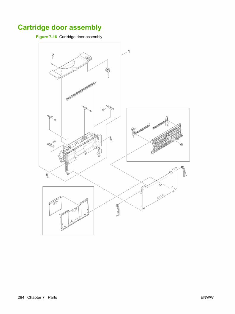
Cartridge door assemblyFigure 7-18 Cartridge door assembly
21
284 Chapter 7 Parts ENWW

Table 7-24 Cartridge door assembly
Ref Description Part number Qty
All Cartridge door assembly RM1-4711-000CN 1
1 Inner cover RM1-4712-000CN 1
2 Screw, tapping truss XB4-7401-000CN 2
ENWW Cartridge door assembly 285

Internal components (1 of 4)Figure 7-19 Internal components (1 of 4)
2
1
29
30
30 4
3
7
2122
21
23
2019
18
11
1314
15171626
6
4
2728
4
34
44
4
29
A
A
(PS916)
(J208)
(J5)
See Fuser assembly
See Duplexing-drive assembly
See Main-drive assembly
286 Chapter 7 Parts ENWW
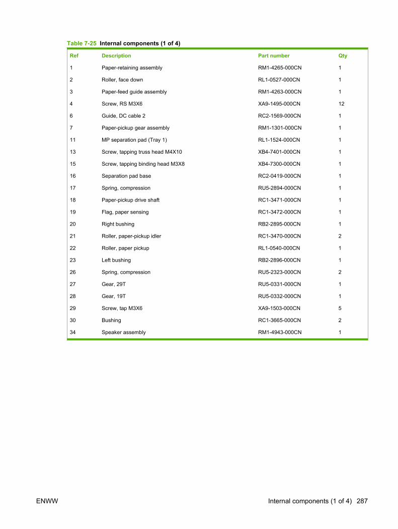
Table 7-25 Internal components (1 of 4)
Ref Description Part number Qty
1 Paper-retaining assembly RM1-4265-000CN 1
2 Roller, face down RL1-0527-000CN 1
3 Paper-feed guide assembly RM1-4263-000CN 1
4 Screw, RS M3X6 XA9-1495-000CN 12
6 Guide, DC cable 2 RC2-1569-000CN 1
7 Paper-pickup gear assembly RM1-1301-000CN 1
11 MP separation pad (Tray 1) RL1-1524-000CN 1
13 Screw, tapping truss head M4X10 XB4-7401-000CN 1
15 Screw, tapping binding head M3X8 XB4-7300-000CN 1
16 Separation pad base RC2-0419-000CN 1
17 Spring, compression RU5-2894-000CN 1
18 Paper-pickup drive shaft RC1-3471-000CN 1
19 Flag, paper sensing RC1-3472-000CN 1
20 Right bushing RB2-2895-000CN 1
21 Roller, paper-pickup idler RC1-3470-000CN 2
22 Roller, paper pickup RL1-0540-000CN 1
23 Left bushing RB2-2896-000CN 1
26 Spring, compression RU5-2323-000CN 2
27 Gear, 29T RU5-0331-000CN 1
28 Gear, 19T RU5-0332-000CN 1
29 Screw, tap M3X6 XA9-1503-000CN 5
30 Bushing RC1-3665-000CN 2
34 Speaker assembly RM1-4943-000CN 1
ENWW Internal components (1 of 4) 287
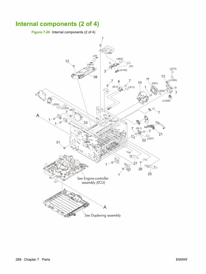
Internal components (2 of 4)Figure 7-20 Internal components (2 of 4)
1
33
22
8
12
383
1
1
1
7
11
25
2726
7
77
7
7
13
21
10117
31
A
A
(J3)
(J210)
(FM1)
(J209)
(J2)
(J802)
(J202)(J1202)
(M1)
(J2100)
(J1205)
(J1205)
(J211)(SL3)
(SL1)
(J207)
(J801)
See Engine-controller assembly (ECU)
See Duplexing assembly
288 Chapter 7 Parts ENWW
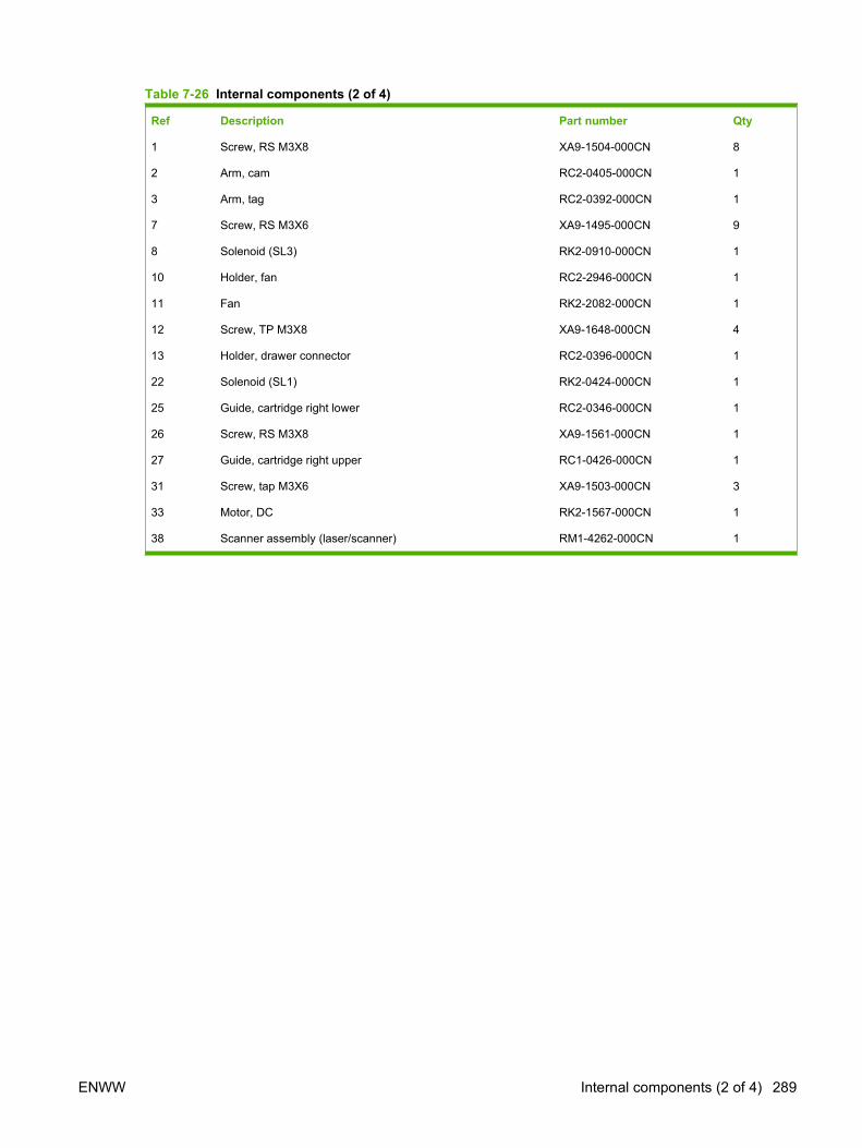
Table 7-26 Internal components (2 of 4)
Ref Description Part number Qty
1 Screw, RS M3X8 XA9-1504-000CN 8
2 Arm, cam RC2-0405-000CN 1
3 Arm, tag RC2-0392-000CN 1
7 Screw, RS M3X6 XA9-1495-000CN 9
8 Solenoid (SL3) RK2-0910-000CN 1
10 Holder, fan RC2-2946-000CN 1
11 Fan RK2-2082-000CN 1
12 Screw, TP M3X8 XA9-1648-000CN 4
13 Holder, drawer connector RC2-0396-000CN 1
22 Solenoid (SL1) RK2-0424-000CN 1
25 Guide, cartridge right lower RC2-0346-000CN 1
26 Screw, RS M3X8 XA9-1561-000CN 1
27 Guide, cartridge right upper RC1-0426-000CN 1
31 Screw, tap M3X6 XA9-1503-000CN 3
33 Motor, DC RK2-1567-000CN 1
38 Scanner assembly (laser/scanner) RM1-4262-000CN 1
ENWW Internal components (2 of 4) 289
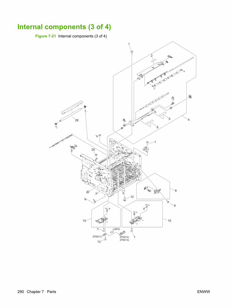
Internal components (3 of 4)Figure 7-21 Internal components (3 of 4)
6
5 4
1015
8
12
1
9
131
1
2
1
20
28
(PS912)(PS913)
(J203)
(PS911)
290 Chapter 7 Parts ENWW
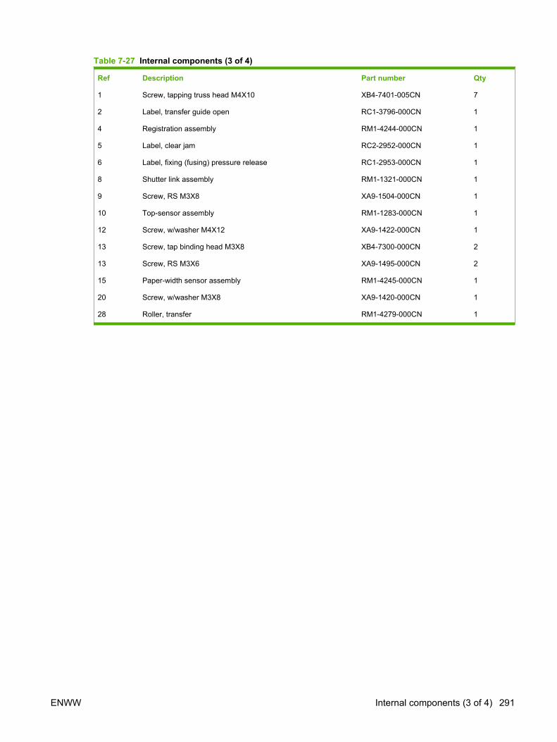
Table 7-27 Internal components (3 of 4)
Ref Description Part number Qty
1 Screw, tapping truss head M4X10 XB4-7401-005CN 7
2 Label, transfer guide open RC1-3796-000CN 1
4 Registration assembly RM1-4244-000CN 1
5 Label, clear jam RC2-2952-000CN 1
6 Label, fixing (fusing) pressure release RC1-2953-000CN 1
8 Shutter link assembly RM1-1321-000CN 1
9 Screw, RS M3X8 XA9-1504-000CN 1
10 Top-sensor assembly RM1-1283-000CN 1
12 Screw, w/washer M4X12 XA9-1422-000CN 1
13 Screw, tap binding head M3X8 XB4-7300-000CN 2
13 Screw, RS M3X6 XA9-1495-000CN 2
15 Paper-width sensor assembly RM1-4245-000CN 1
20 Screw, w/washer M3X8 XA9-1420-000CN 1
28 Roller, transfer RM1-4279-000CN 1
ENWW Internal components (3 of 4) 291
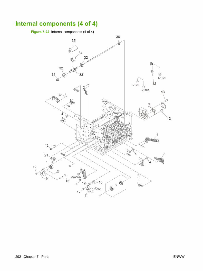
Internal components (4 of 4)Figure 7-22 Internal components (4 of 4)
11
34
32
35
33
32
36
31
3
1
4
421
4
12
4
412
12 1012
12
(SW301)
(SL2)(J4)
(J1101)
12
43(J1102)
42(J101)
292 Chapter 7 Parts ENWW
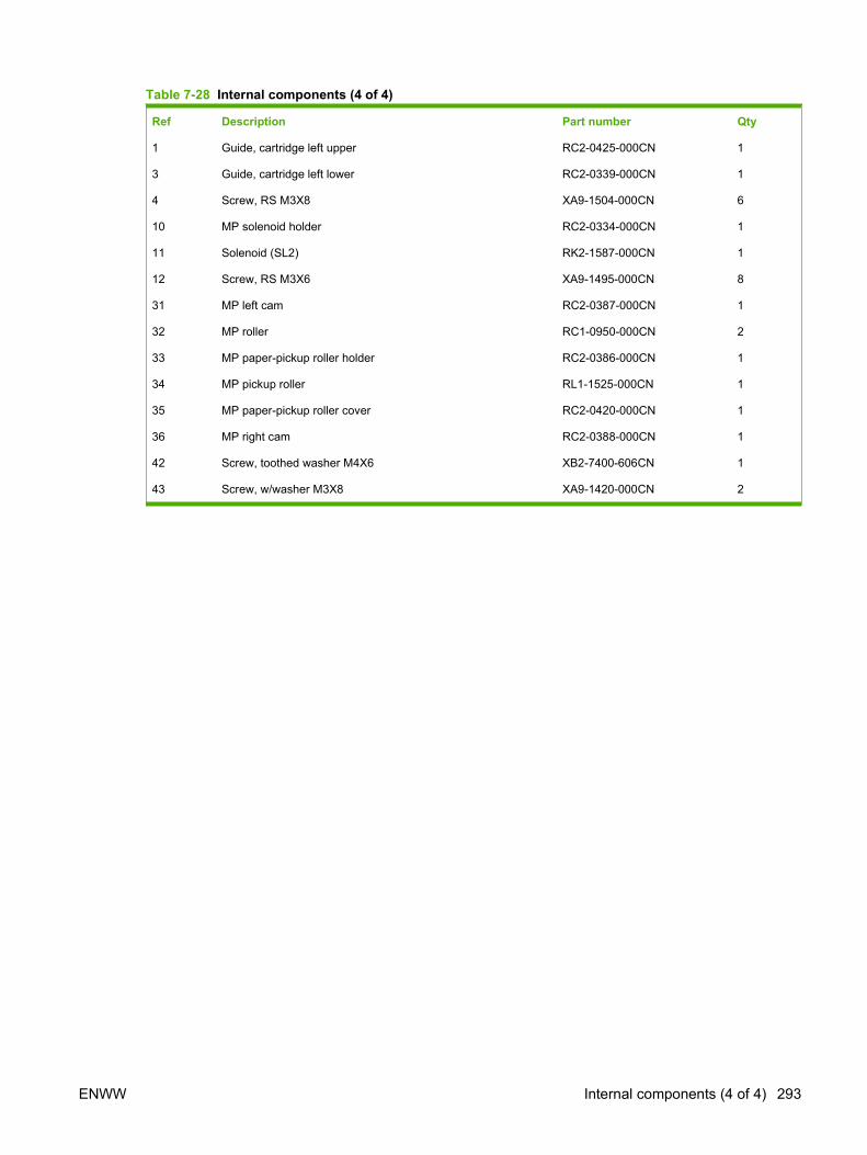
Table 7-28 Internal components (4 of 4)
Ref Description Part number Qty
1 Guide, cartridge left upper RC2-0425-000CN 1
3 Guide, cartridge left lower RC2-0339-000CN 1
4 Screw, RS M3X8 XA9-1504-000CN 6
10 MP solenoid holder RC2-0334-000CN 1
11 Solenoid (SL2) RK2-1587-000CN 1
12 Screw, RS M3X6 XA9-1495-000CN 8
31 MP left cam RC2-0387-000CN 1
32 MP roller RC1-0950-000CN 2
33 MP paper-pickup roller holder RC2-0386-000CN 1
34 MP pickup roller RL1-1525-000CN 1
35 MP paper-pickup roller cover RC2-0420-000CN 1
36 MP right cam RC2-0388-000CN 1
42 Screw, toothed washer M4X6 XB2-7400-606CN 1
43 Screw, w/washer M3X8 XA9-1420-000CN 2
ENWW Internal components (4 of 4) 293

Engine-controller assembly (ECU)Figure 7-23 Engine-controller assembly
(J7)
(J1)
2
1
3
2
2
2
294 Chapter 7 Parts ENWW

Table 7-29 Engine-controller assembly
Ref Description Part number Qty
1 Engine-controller PCA (110 to 127 v) RM1-4940-000CN 1
1 Engine-controller PCA (220 to 240 v) RM1-4941-000CN 1
2 Screw, w/washer M3X8 XA9-1420-000CN 4
3 Screw, RS M3X6 XA9-1495-000CN 1
ENWW Engine-controller assembly (ECU) 295
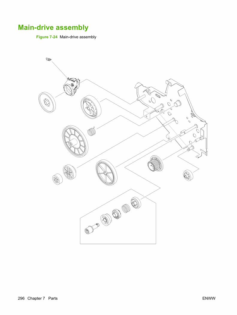
Main-drive assemblyFigure 7-24 Main-drive assembly
296 Chapter 7 Parts ENWW

Table 7-30 Main-drive assembly
Ref Description Part number Qty
all Main-drive assembly RM1-4253-000CN 1
ENWW Main-drive assembly 297
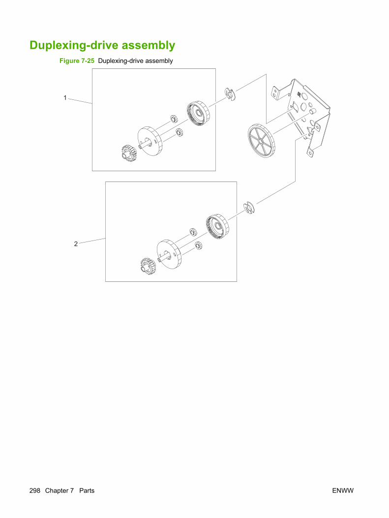
Duplexing-drive assemblyFigure 7-25 Duplexing-drive assembly
1
2
298 Chapter 7 Parts ENWW

Table 7-31 Duplexing-drive assembly
Ref Description Part number Qty
all Duplexing-drive assembly RM1-4255-000CN 1
1 Normal-rotation drive assembly RM1-4256-000CN 1
2 Reverse-rotation drive assembly RM1-4257-000CN 1
ENWW Duplexing-drive assembly 299
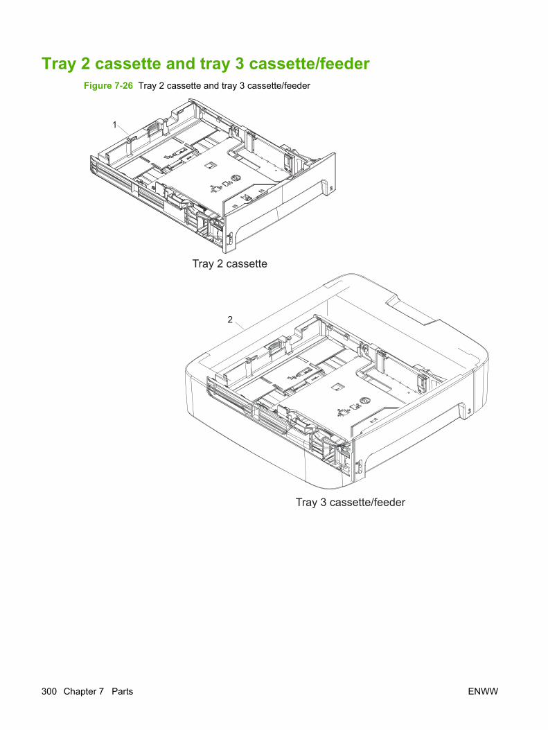
Tray 2 cassette and tray 3 cassette/feederFigure 7-26 Tray 2 cassette and tray 3 cassette/feeder
300 Chapter 7 Parts ENWW

Table 7-32 Tray 2 cassette and tray 3 cassette/feeder
Ref Description Part number Qty
1 Cassette, tray 2 (250-sheet) RM1-4251-000CN 1
2 Cassette/feeder, tray 3 (250-sheet) Q7556-67901 1
Not shown Separation pad, tray 2 and optional tray 3 RM1-1292-000CN 1
NOTE: Paper trays are not serviceable. Replace the entire tray if needed.
ENWW Tray 2 cassette and tray 3 cassette/feeder 301
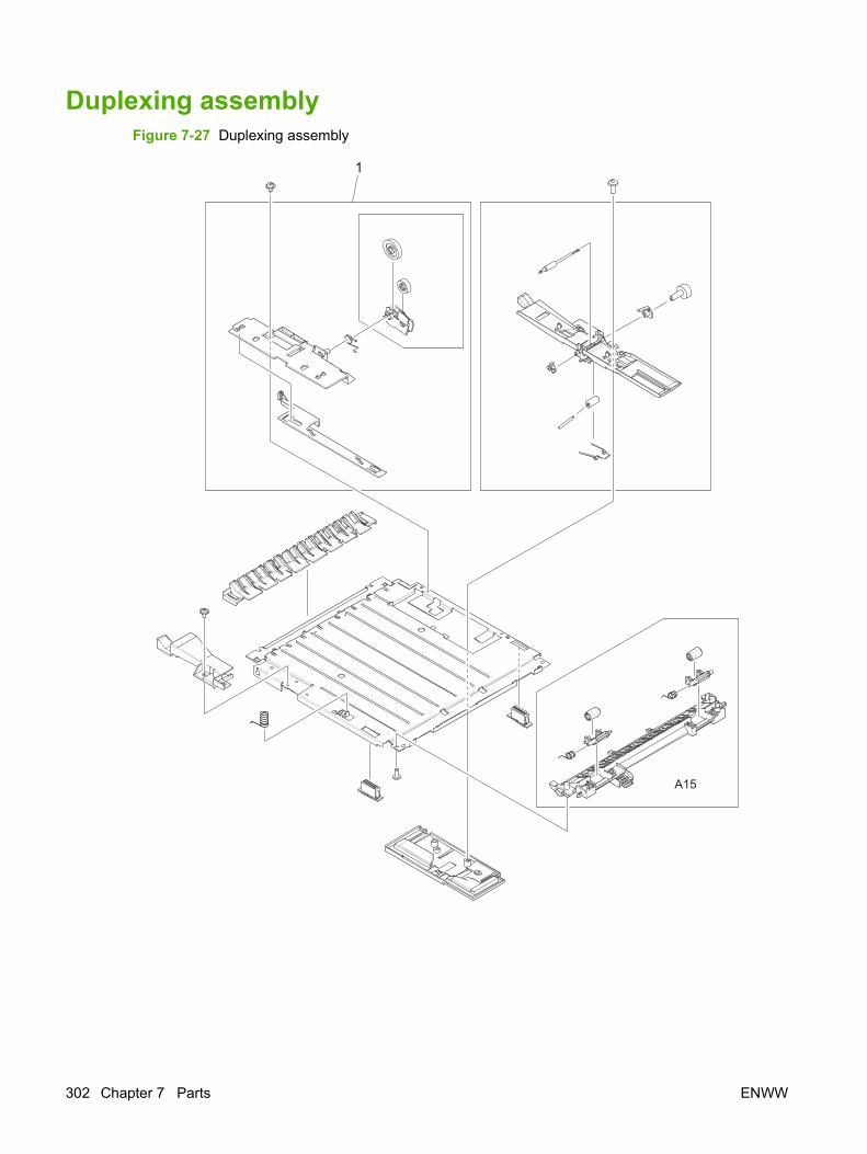
Duplexing assemblyFigure 7-27 Duplexing assembly
A15
1
302 Chapter 7 Parts ENWW

Table 7-33 Duplexing assembly
Ref Description Part number Qty
all Duplexing assembly RM1-4258-000CN 1
1 Size-change assembly RM1-1318-000CN 1
ENWW Duplexing assembly 303
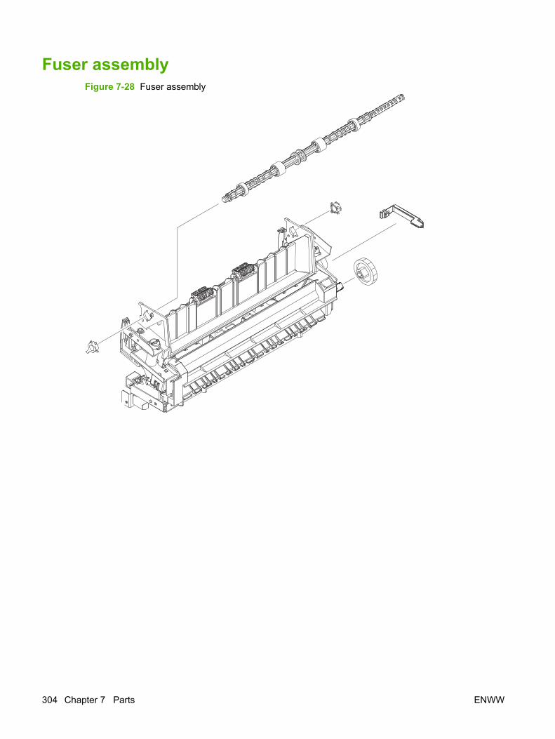
Fuser assemblyFigure 7-28 Fuser assembly
304 Chapter 7 Parts ENWW

Table 7-34 Fuser assembly
Ref Description Part number Qty
all Fuser (110 to 127 v) RM1-4247-000CN 1
all Fuser (220 to 240 v) RM1-4248-000CN 1
ENWW Fuser assembly 305
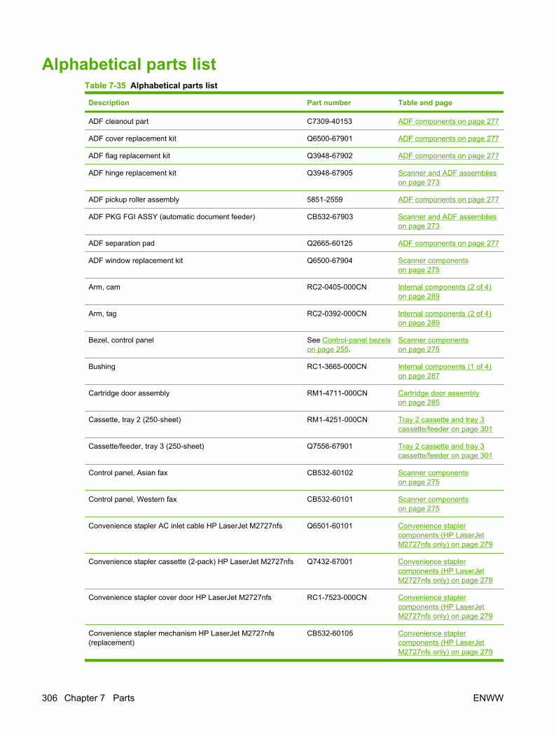
Alphabetical parts listTable 7-35 Alphabetical parts list
Description Part number Table and page
ADF cleanout part C7309-40153 ADF components on page 277
ADF cover replacement kit Q6500-67901 ADF components on page 277
ADF flag replacement kit Q3948-67902 ADF components on page 277
ADF hinge replacement kit Q3948-67905 Scanner and ADF assemblieson page 273
ADF pickup roller assembly 5851-2559 ADF components on page 277
ADF PKG FGI ASSY (automatic document feeder) CB532-67903 Scanner and ADF assemblieson page 273
ADF separation pad Q2665-60125 ADF components on page 277
ADF window replacement kit Q6500-67904 Scanner componentson page 275
Arm, cam RC2-0405-000CN Internal components (2 of 4)on page 289
Arm, tag RC2-0392-000CN Internal components (2 of 4)on page 289
Bezel, control panel See Control-panel bezelson page 255.
Scanner componentson page 275
Bushing RC1-3665-000CN Internal components (1 of 4)on page 287
Cartridge door assembly RM1-4711-000CN Cartridge door assemblyon page 285
Cassette, tray 2 (250-sheet) RM1-4251-000CN Tray 2 cassette and tray 3cassette/feeder on page 301
Cassette/feeder, tray 3 (250-sheet) Q7556-67901 Tray 2 cassette and tray 3cassette/feeder on page 301
Control panel, Asian fax CB532-60102 Scanner componentson page 275
Control panel, Western fax CB532-60101 Scanner componentson page 275
Convenience stapler AC inlet cable HP LaserJet M2727nfs Q6501-60101 Convenience staplercomponents (HP LaserJetM2727nfs only) on page 279
Convenience stapler cassette (2-pack) HP LaserJet M2727nfs Q7432-67001 Convenience staplercomponents (HP LaserJetM2727nfs only) on page 279
Convenience stapler cover door HP LaserJet M2727nfs RC1-7523-000CN Convenience staplercomponents (HP LaserJetM2727nfs only) on page 279
Convenience stapler mechanism HP LaserJet M2727nfs(replacement)
CB532-60105 Convenience staplercomponents (HP LaserJetM2727nfs only) on page 279
306 Chapter 7 Parts ENWW

Description Part number Table and page
Convenience stapler power supply bracket and strap HP LaserJetM2727nfs
CB532-67902 Convenience staplercomponents (HP LaserJetM2727nfs only) on page 279
Convenience stapler power supply HP LaserJet M2727nfs Q7429-60501 Convenience staplercomponents (HP LaserJetM2727nfs only) on page 279
Cover dummy (stapler plug; HP LaserJet M2727nf) RC1-7523-000CN External covers and panelson page 283
Cover front RC2-0330-000CN External covers and panelson page 283
Cover left (with DIMM door) RC1-4707-000CN External covers and panelson page 283
Cover right (with dummy stapler cover) RM1-4708-000CN External covers and panelson page 283
Cover top RC2-2940-000CN External covers and panelson page 283
Duplexing assembly RM1-4258-000CN Duplexing assemblyon page 303
Duplexing-drive assembly RM1-4255-000CN Duplexing-drive assemblyon page 299
Engine-controller PCA (110 to 127 v) RM1-4940-000CN Engine-controller assemblyon page 295
Engine-controller PCA (220 to 240 v) RM1-4941-000CN Engine-controller assemblyon page 295
Fan RK2-2082-000CN Internal components (2 of 4)on page 289
Fax card EMEA ROHS CC369-60001 Formatter, Fax card, HP jewel,and nameplate on page 281
Fax card US/AP ROHS CC502-60001 Formatter, Fax card, HP jewel,and nameplate on page 281
Fax card/Formatter FFC CB534-60117 Formatter, Fax card, HP jewel,and nameplate on page 281
Flag, paper sensing RC1-3472-000CN Internal components (1 of 4)on page 287
Formatter PCA CC370-60001 Formatter, Fax card, HP jewel,and nameplate on page 281
Fuser (110 to 127 v) RM1-4247-000CN Fuser assembly on page 305
Fuser (220 to 240 v) RM1-4248-000CN Fuser assembly on page 305
Gear, 19T RU5-0332-000CN Internal components (1 of 4)on page 287
Gear, 29T RU5-0331-000CN Internal components (1 of 4)on page 287
Guide, cartridge left lower RC2-0339-000CN Internal components (4 of 4)on page 293
Table 7-35 Alphabetical parts list (continued)
ENWW Alphabetical parts list 307

Description Part number Table and page
Guide, cartridge left upper RC2-0425-000CN Internal components (4 of 4)on page 293
Guide, cartridge right lower RC2-0346-000CN Internal components (2 of 4)on page 289
Guide, cartridge right upper RC1-0426-000CN Internal components (2 of 4)on page 289
Guide, DC cable 2 RC2-1569-000CN Internal components (1 of 4)on page 287
Holder, drawer connector RC2-0396-000CN Internal components (2 of 4)on page 289
Holder, fan RC2-2946-000CN Internal components (2 of 4)on page 289
Inner cover RM1-4712-000CN Cartridge door assemblyon page 285
Input tray assembly HP LaserJet M2727 Q6500-60119 Scanner and ADF assemblieson page 273
Jewel, HP 7121-8285 Formatter, Fax card, HP jewel,and nameplate on page 281
Label, clear jam RC2-2952-000CN Internal components (3 of 4)on page 291
Label, fixing (fusing) pressure release RC1-2953-000CN Internal components (3 of 4)on page 291
Label, stapler prohibition RC1-3794-000CN External covers and panelson page 283
Label, transfer guide open RC1-3796-000CN Internal components (3 of 4)on page 291
Left bushing RB2-2896-000CN Internal components (1 of 4)on page 287
Main-drive assembly RM1-4253-000CN Main-drive assemblyon page 297
Motor, DC RK2-1567-000CN Internal components (2 of 4)on page 289
MP left cam RC2-0387-000CN Internal components (4 of 4)on page 293
MP paper-pickup roller cover RC2-0420-000CN Internal components (4 of 4)on page 293
MP paper-pickup roller holder RC2-0386-000CN Internal components (4 of 4)on page 293
MP pickup roller RL1-1525-000CN Internal components (4 of 4)on page 293
MP right cam RC2-0388-000CN Internal components (4 of 4)on page 293
MP roller RC1-0950-000CN Internal components (4 of 4)on page 293
Table 7-35 Alphabetical parts list (continued)
308 Chapter 7 Parts ENWW
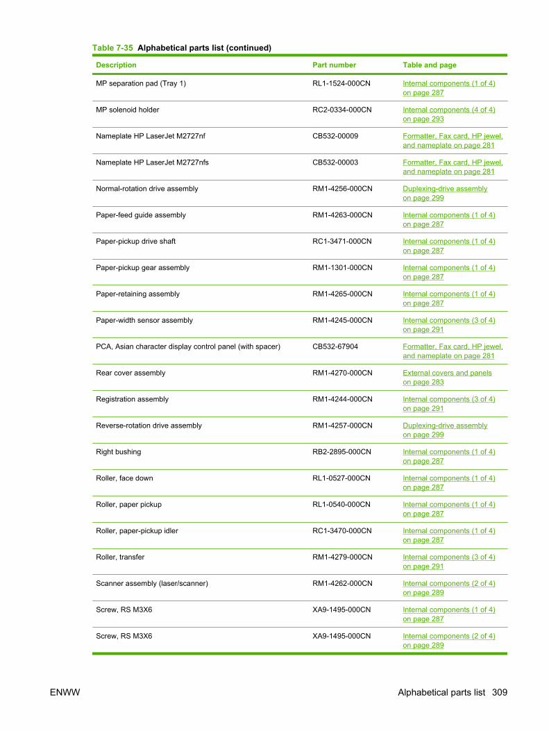
Description Part number Table and page
MP separation pad (Tray 1) RL1-1524-000CN Internal components (1 of 4)on page 287
MP solenoid holder RC2-0334-000CN Internal components (4 of 4)on page 293
Nameplate HP LaserJet M2727nf CB532-00009 Formatter, Fax card, HP jewel,and nameplate on page 281
Nameplate HP LaserJet M2727nfs CB532-00003 Formatter, Fax card, HP jewel,and nameplate on page 281
Normal-rotation drive assembly RM1-4256-000CN Duplexing-drive assemblyon page 299
Paper-feed guide assembly RM1-4263-000CN Internal components (1 of 4)on page 287
Paper-pickup drive shaft RC1-3471-000CN Internal components (1 of 4)on page 287
Paper-pickup gear assembly RM1-1301-000CN Internal components (1 of 4)on page 287
Paper-retaining assembly RM1-4265-000CN Internal components (1 of 4)on page 287
Paper-width sensor assembly RM1-4245-000CN Internal components (3 of 4)on page 291
PCA, Asian character display control panel (with spacer) CB532-67904 Formatter, Fax card, HP jewel,and nameplate on page 281
Rear cover assembly RM1-4270-000CN External covers and panelson page 283
Registration assembly RM1-4244-000CN Internal components (3 of 4)on page 291
Reverse-rotation drive assembly RM1-4257-000CN Duplexing-drive assemblyon page 299
Right bushing RB2-2895-000CN Internal components (1 of 4)on page 287
Roller, face down RL1-0527-000CN Internal components (1 of 4)on page 287
Roller, paper pickup RL1-0540-000CN Internal components (1 of 4)on page 287
Roller, paper-pickup idler RC1-3470-000CN Internal components (1 of 4)on page 287
Roller, transfer RM1-4279-000CN Internal components (3 of 4)on page 291
Scanner assembly (laser/scanner) RM1-4262-000CN Internal components (2 of 4)on page 289
Screw, RS M3X6 XA9-1495-000CN Internal components (1 of 4)on page 287
Screw, RS M3X6 XA9-1495-000CN Internal components (2 of 4)on page 289
Table 7-35 Alphabetical parts list (continued)
ENWW Alphabetical parts list 309
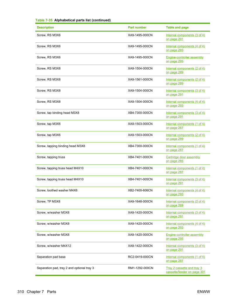
Description Part number Table and page
Screw, RS M3X6 XA9-1495-000CN Internal components (3 of 4)on page 291
Screw, RS M3X6 XA9-1495-000CN Internal components (4 of 4)on page 293
Screw, RS M3X6 XA9-1495-000CN Engine-controller assemblyon page 295
Screw, RS M3X8 XA9-1504-000CN Internal components (2 of 4)on page 289
Screw, RS M3X8 XA9-1561-000CN Internal components (2 of 4)on page 289
Screw, RS M3X8 XA9-1504-000CN Internal components (3 of 4)on page 291
Screw, RS M3X8 XA9-1504-000CN Internal components (4 of 4)on page 293
Screw, tap binding head M3X8 XB4-7300-000CN Internal components (3 of 4)on page 291
Screw, tap M3X6 XA9-1503-000CN Internal components (1 of 4)on page 287
Screw, tap M3X6 XA9-1503-000CN Internal components (2 of 4)on page 289
Screw, tapping binding head M3X8 XB4-7300-000CN Internal components (1 of 4)on page 287
Screw, tapping truss XB4-7401-000CN Cartridge door assemblyon page 285
Screw, tapping truss head M4X10 XB4-7401-000CN Internal components (1 of 4)on page 287
Screw, tapping truss head M4X10 XB4-7401-005CN Internal components (3 of 4)on page 291
Screw, toothed washer M4X6 XB2-7400-606CN Internal components (4 of 4)on page 293
Screw, TP M3X8 XA9-1648-000CN Internal components (2 of 4)on page 289
Screw, w/washer M3X8 XA9-1420-000CN Internal components (3 of 4)on page 291
Screw, w/washer M3X8 XA9-1420-000CN Internal components (4 of 4)on page 293
Screw, w/washer M3X8 XA9-1420-000CN Engine-controller assemblyon page 295
Screw, w/washer M4X12 XA9-1422-000CN Internal components (3 of 4)on page 291
Separation pad base RC2-0419-000CN Internal components (1 of 4)on page 287
Separation pad, tray 2 and optional tray 3 RM1-1292-000CN Tray 2 cassette and tray 3cassette/feeder on page 301
Table 7-35 Alphabetical parts list (continued)
310 Chapter 7 Parts ENWW
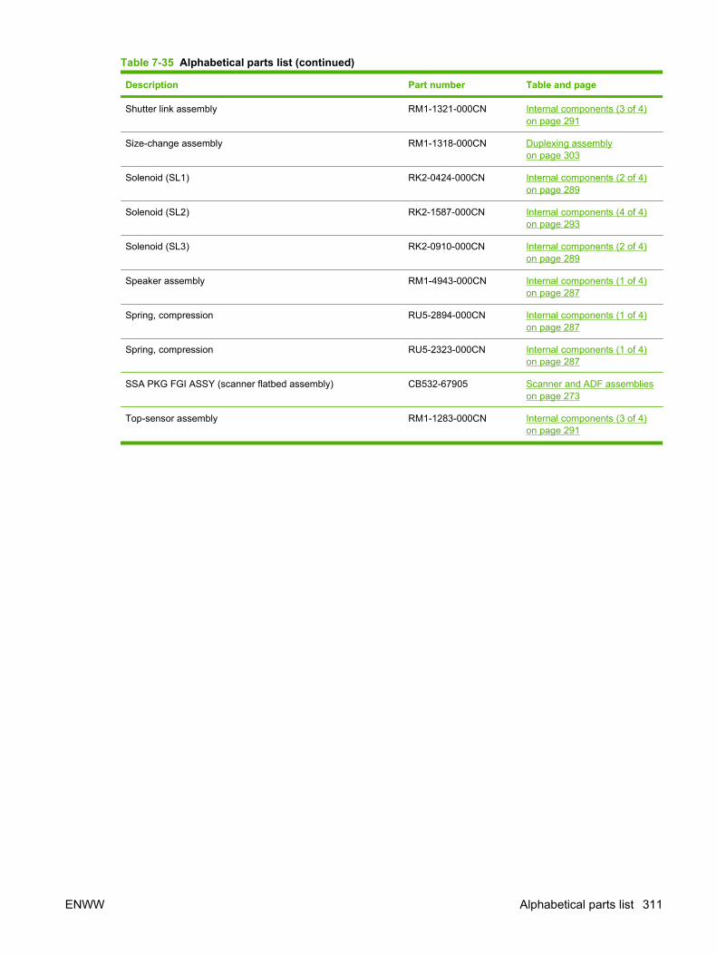
Description Part number Table and page
Shutter link assembly RM1-1321-000CN Internal components (3 of 4)on page 291
Size-change assembly RM1-1318-000CN Duplexing assemblyon page 303
Solenoid (SL1) RK2-0424-000CN Internal components (2 of 4)on page 289
Solenoid (SL2) RK2-1587-000CN Internal components (4 of 4)on page 293
Solenoid (SL3) RK2-0910-000CN Internal components (2 of 4)on page 289
Speaker assembly RM1-4943-000CN Internal components (1 of 4)on page 287
Spring, compression RU5-2894-000CN Internal components (1 of 4)on page 287
Spring, compression RU5-2323-000CN Internal components (1 of 4)on page 287
SSA PKG FGI ASSY (scanner flatbed assembly) CB532-67905 Scanner and ADF assemblieson page 273
Top-sensor assembly RM1-1283-000CN Internal components (3 of 4)on page 291
Table 7-35 Alphabetical parts list (continued)
ENWW Alphabetical parts list 311

Numerical parts listTable 7-36 Numerical parts list
Part number Description Table and page
5851-2559 ADF pickup roller assembly ADF components on page 277
7121-8285 Jewel, HP Formatter, Fax card, HP jewel,and nameplate on page 281
C7309-40153 ADF cleanout part ADF components on page 277
CB532-00003 Nameplate HP LaserJet M2727nfs Formatter, Fax card, HP jewel,and nameplate on page 281
CB532-00009 Nameplate HP LaserJet M2727nf Formatter, Fax card, HP jewel,and nameplate on page 281
CB532-60101 Control panel, Western fax Scanner componentson page 275
CB532-60102 Control panel, Asian fax Scanner componentson page 275
CB532-60105 Convenience stapler mechanism HP LaserJet M2727nfs(replacement)
Convenience staplercomponents (HP LaserJetM2727nfs only) on page 279
CB532-67902 Convenience stapler power supply bracket and strap HP LaserJetM2727nfs
Convenience staplercomponents (HP LaserJetM2727nfs only) on page 279
CB532-67903 ADF PKG FGI ASSY (automatic document feeder) Scanner and ADF assemblieson page 273
CB532-67904 PCA, Asian character display control panel (with spacer) Formatter, Fax card, HP jewel,and nameplate on page 281
CB532-67905 SSA PKG FGI ASSY (scanner flatbed assembly) Scanner and ADF assemblieson page 273
CB534-60117 Fax card/Formatter FFC Formatter, Fax card, HP jewel,and nameplate on page 281
CC369-60001 Fax card EMEA ROHS Formatter, Fax card, HP jewel,and nameplate on page 281
CC370-60001 Formatter PCA Formatter, Fax card, HP jewel,and nameplate on page 281
CC502-60001 Fax card US/AP ROHS Formatter, Fax card, HP jewel,and nameplate on page 281
Q2665-60125 ADF separation pad ADF components on page 277
Q3948-67902 ADF flag replacement kit ADF components on page 277
Q3948-67905 ADF hinge replacement kit Scanner and ADF assemblieson page 273
Q6500-60119 Input tray assembly HP LaserJet M2727 Scanner and ADF assemblieson page 273
Q6500-67901 ADF cover replacement kit ADF components on page 277
Q6500-67904 ADF window replacement kit Scanner componentson page 275
312 Chapter 7 Parts ENWW
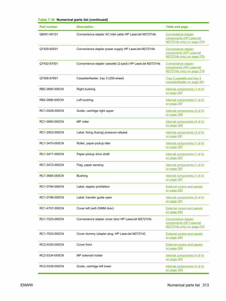
Part number Description Table and page
Q6501-60101 Convenience stapler AC inlet cable HP LaserJet M2727nfs Convenience staplercomponents (HP LaserJetM2727nfs only) on page 279
Q7429-60501 Convenience stapler power supply HP LaserJet M2727nfs Convenience staplercomponents (HP LaserJetM2727nfs only) on page 279
Q7432-67001 Convenience stapler cassette (2-pack) HP LaserJet M2727nfs Convenience staplercomponents (HP LaserJetM2727nfs only) on page 279
Q7556-67901 Cassette/feeder, tray 3 (250-sheet) Tray 2 cassette and tray 3cassette/feeder on page 301
RB2-2895-000CN Right bushing Internal components (1 of 4)on page 287
RB2-2896-000CN Left bushing Internal components (1 of 4)on page 287
RC1-0426-000CN Guide, cartridge right upper Internal components (2 of 4)on page 289
RC1-0950-000CN MP roller Internal components (4 of 4)on page 293
RC1-2953-000CN Label, fixing (fusing) pressure release Internal components (3 of 4)on page 291
RC1-3470-000CN Roller, paper-pickup idler Internal components (1 of 4)on page 287
RC1-3471-000CN Paper-pickup drive shaft Internal components (1 of 4)on page 287
RC1-3472-000CN Flag, paper sensing Internal components (1 of 4)on page 287
RC1-3665-000CN Bushing Internal components (1 of 4)on page 287
RC1-3794-000CN Label, stapler prohibition External covers and panelson page 283
RC1-3796-000CN Label, transfer guide open Internal components (3 of 4)on page 291
RC1-4707-000CN Cover left (with DIMM door) External covers and panelson page 283
RC1-7523-000CN Convenience stapler cover door HP LaserJet M2727nfs Convenience staplercomponents (HP LaserJetM2727nfs only) on page 279
RC1-7523-000CN Cover dummy (stapler plug; HP LaserJet M2727nf) External covers and panelson page 283
RC2-0330-000CN Cover front External covers and panelson page 283
RC2-0334-000CN MP solenoid holder Internal components (4 of 4)on page 293
RC2-0339-000CN Guide, cartridge left lower Internal components (4 of 4)on page 293
Table 7-36 Numerical parts list (continued)
ENWW Numerical parts list 313
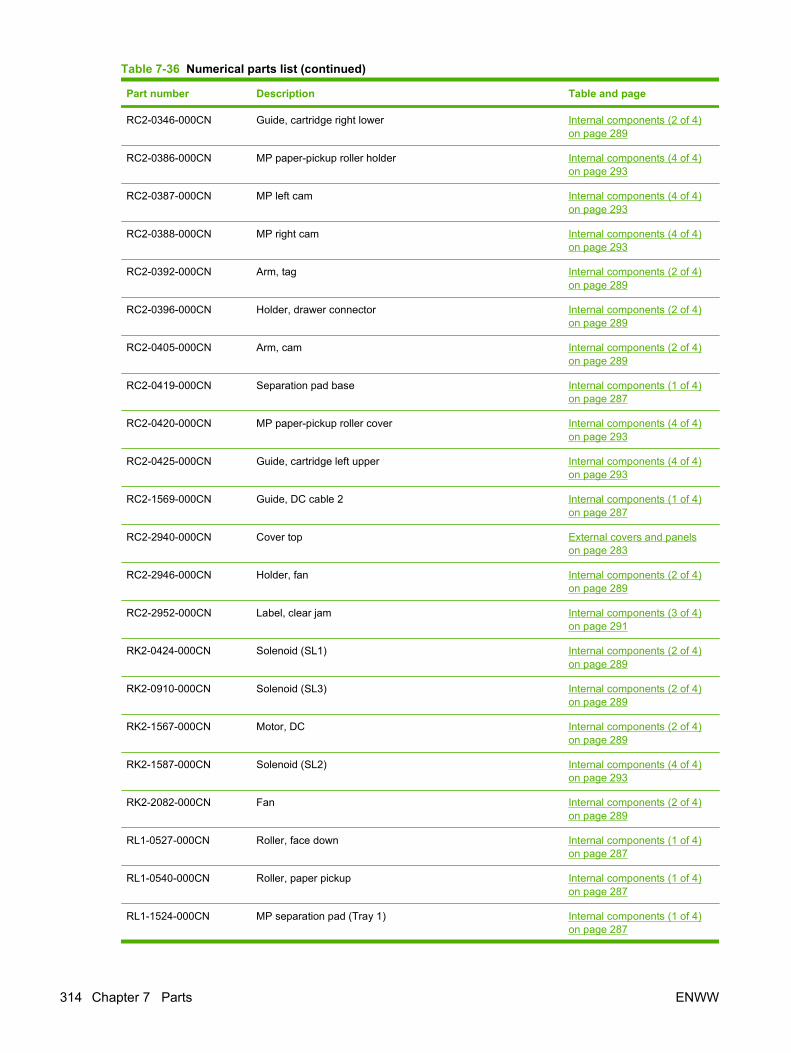
Part number Description Table and page
RC2-0346-000CN Guide, cartridge right lower Internal components (2 of 4)on page 289
RC2-0386-000CN MP paper-pickup roller holder Internal components (4 of 4)on page 293
RC2-0387-000CN MP left cam Internal components (4 of 4)on page 293
RC2-0388-000CN MP right cam Internal components (4 of 4)on page 293
RC2-0392-000CN Arm, tag Internal components (2 of 4)on page 289
RC2-0396-000CN Holder, drawer connector Internal components (2 of 4)on page 289
RC2-0405-000CN Arm, cam Internal components (2 of 4)on page 289
RC2-0419-000CN Separation pad base Internal components (1 of 4)on page 287
RC2-0420-000CN MP paper-pickup roller cover Internal components (4 of 4)on page 293
RC2-0425-000CN Guide, cartridge left upper Internal components (4 of 4)on page 293
RC2-1569-000CN Guide, DC cable 2 Internal components (1 of 4)on page 287
RC2-2940-000CN Cover top External covers and panelson page 283
RC2-2946-000CN Holder, fan Internal components (2 of 4)on page 289
RC2-2952-000CN Label, clear jam Internal components (3 of 4)on page 291
RK2-0424-000CN Solenoid (SL1) Internal components (2 of 4)on page 289
RK2-0910-000CN Solenoid (SL3) Internal components (2 of 4)on page 289
RK2-1567-000CN Motor, DC Internal components (2 of 4)on page 289
RK2-1587-000CN Solenoid (SL2) Internal components (4 of 4)on page 293
RK2-2082-000CN Fan Internal components (2 of 4)on page 289
RL1-0527-000CN Roller, face down Internal components (1 of 4)on page 287
RL1-0540-000CN Roller, paper pickup Internal components (1 of 4)on page 287
RL1-1524-000CN MP separation pad (Tray 1) Internal components (1 of 4)on page 287
Table 7-36 Numerical parts list (continued)
314 Chapter 7 Parts ENWW
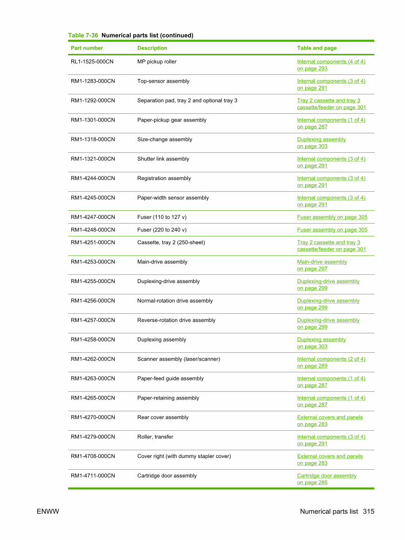
Part number Description Table and page
RL1-1525-000CN MP pickup roller Internal components (4 of 4)on page 293
RM1-1283-000CN Top-sensor assembly Internal components (3 of 4)on page 291
RM1-1292-000CN Separation pad, tray 2 and optional tray 3 Tray 2 cassette and tray 3cassette/feeder on page 301
RM1-1301-000CN Paper-pickup gear assembly Internal components (1 of 4)on page 287
RM1-1318-000CN Size-change assembly Duplexing assemblyon page 303
RM1-1321-000CN Shutter link assembly Internal components (3 of 4)on page 291
RM1-4244-000CN Registration assembly Internal components (3 of 4)on page 291
RM1-4245-000CN Paper-width sensor assembly Internal components (3 of 4)on page 291
RM1-4247-000CN Fuser (110 to 127 v) Fuser assembly on page 305
RM1-4248-000CN Fuser (220 to 240 v) Fuser assembly on page 305
RM1-4251-000CN Cassette, tray 2 (250-sheet) Tray 2 cassette and tray 3cassette/feeder on page 301
RM1-4253-000CN Main-drive assembly Main-drive assemblyon page 297
RM1-4255-000CN Duplexing-drive assembly Duplexing-drive assemblyon page 299
RM1-4256-000CN Normal-rotation drive assembly Duplexing-drive assemblyon page 299
RM1-4257-000CN Reverse-rotation drive assembly Duplexing-drive assemblyon page 299
RM1-4258-000CN Duplexing assembly Duplexing assemblyon page 303
RM1-4262-000CN Scanner assembly (laser/scanner) Internal components (2 of 4)on page 289
RM1-4263-000CN Paper-feed guide assembly Internal components (1 of 4)on page 287
RM1-4265-000CN Paper-retaining assembly Internal components (1 of 4)on page 287
RM1-4270-000CN Rear cover assembly External covers and panelson page 283
RM1-4279-000CN Roller, transfer Internal components (3 of 4)on page 291
RM1-4708-000CN Cover right (with dummy stapler cover) External covers and panelson page 283
RM1-4711-000CN Cartridge door assembly Cartridge door assemblyon page 285
Table 7-36 Numerical parts list (continued)
ENWW Numerical parts list 315

Part number Description Table and page
RM1-4712-000CN Inner cover Cartridge door assemblyon page 285
RM1-4940-000CN Engine-controller PCA (110 to 127 v) Engine-controller assemblyon page 295
RM1-4941-000CN Engine-controller PCA (220 to 240 v) Engine-controller assemblyon page 295
RM1-4943-000CN Speaker assembly Internal components (1 of 4)on page 287
RU5-0331-000CN Gear, 29T Internal components (1 of 4)on page 287
RU5-0332-000CN Gear, 19T Internal components (1 of 4)on page 287
RU5-2323-000CN Spring, compression Internal components (1 of 4)on page 287
RU5-2894-000CN Spring, compression Internal components (1 of 4)on page 287
See Control-panel bezelson page 255.
Bezel, control panel Scanner componentson page 275
XA9-1420-000CN Screw, w/washer M3X8 Internal components (3 of 4)on page 291
XA9-1420-000CN Screw, w/washer M3X8 Internal components (4 of 4)on page 293
XA9-1420-000CN Screw, w/washer M3X8 Engine-controller assemblyon page 295
XA9-1422-000CN Screw, w/washer M4X12 Internal components (3 of 4)on page 291
XA9-1495-000CN Screw, RS M3X6 Internal components (1 of 4)on page 287
XA9-1495-000CN Screw, RS M3X6 Internal components (2 of 4)on page 289
XA9-1495-000CN Screw, RS M3X6 Internal components (3 of 4)on page 291
XA9-1495-000CN Screw, RS M3X6 Internal components (4 of 4)on page 293
XA9-1495-000CN Screw, RS M3X6 Engine-controller assemblyon page 295
XA9-1503-000CN Screw, tap M3X6 Internal components (1 of 4)on page 287
XA9-1503-000CN Screw, tap M3X6 Internal components (2 of 4)on page 289
XA9-1504-000CN Screw, RS M3X8 Internal components (2 of 4)on page 289
XA9-1504-000CN Screw, RS M3X8 Internal components (3 of 4)on page 291
Table 7-36 Numerical parts list (continued)
316 Chapter 7 Parts ENWW

Part number Description Table and page
XA9-1504-000CN Screw, RS M3X8 Internal components (4 of 4)on page 293
XA9-1561-000CN Screw, RS M3X8 Internal components (2 of 4)on page 289
XA9-1648-000CN Screw, TP M3X8 Internal components (2 of 4)on page 289
XB2-7400-606CN Screw, toothed washer M4X6 Internal components (4 of 4)on page 293
XB4-7300-000CN Screw, tapping binding head M3X8 Internal components (1 of 4)on page 287
XB4-7300-000CN Screw, tap binding head M3X8 Internal components (3 of 4)on page 291
XB4-7401-000CN Screw, tapping truss Cartridge door assemblyon page 285
XB4-7401-000CN Screw, tapping truss head M4X10 Internal components (1 of 4)on page 287
XB4-7401-005CN Screw, tapping truss head M4X10 Internal components (3 of 4)on page 291
Table 7-36 Numerical parts list (continued)
ENWW Numerical parts list 317

318 Chapter 7 Parts ENWW

A Service and support
Hewlett-Packard limited warranty statementHP PRODUCT DURATION OF LIMITED WARRANTY
HP LaserJet M2727nf and M2727nfs One-year limited warranty
HP warrants to you, the end-user customer, that HP hardware and accessories will be free from defects in materialsand workmanship after the date of purchase, for the period specified above. If HP receives notice of such defectsduring the warranty period, HP will, at its option, either repair or replace products which prove to be defective.Replacement products may be either new or equivalent in performance to new.
HP warrants to you that HP software will not fail to execute its programming instructions after the date of purchase,for the period specified above, due to defects in material and workmanship when properly installed and used. IfHP receives notice of such defects during the warranty period, HP will replace software which does not executeits programming instructions due to such defects.
HP does not warrant that the operation of HP products will be uninterrupted or error free. If HP is unable, within areasonable time, to repair or replace any product to a condition as warranted, you will be entitled to a refund ofthe purchase price upon prompt return of the product.
HP products may contain remanufactured parts equivalent to new in performance or may have been subject toincidental use.
Warranty does not apply to defects resulting from (a) improper or inadequate maintenance or calibration, (b)software, interfacing, parts or supplies not supplied by HP, (c) unauthorized modification or misuse, (d) operationoutside of the published environmental specifications for the product, or (e) improper site preparation ormaintenance.
TO THE EXTENT ALLOWED BY LOCAL LAW, THE ABOVE WARRANTIES ARE EXCLUSIVE AND NO OTHERWARRANTY OR CONDITION, WHETHER WRITTEN OR ORAL, IS EXPRESSED OR IMPLIED AND HPSPECIFICALLY DISCLAIMS ANY IMPLIED WARRANTIES OR CONDITIONS OF MERCHANTABILITY,SATISFACTORY QUALITY, AND FITNESS FOR A PARTICULAR PURPOSE. Some countries/regions, states orprovinces do not allow limitations on the duration of an implied warranty, so the above limitation or exclusion mightnot apply to you. This warranty gives you specific legal rights and you might also have other rights that vary fromcountry/region to country/region, state to state, or province to province. HP's limited warranty is valid in any country/region or locality where HP has a support presence for this product and where HP has marketed this product. Thelevel of warranty service you receive may vary according to local standards. HP will not alter form, fit or functionof the product to make it operate in a country/region for which it was never intended to function for legal or regulatoryreasons.
TO THE EXTENT ALLOWED BY LOCAL LAW, THE REMEDIES IN THIS WARRANTY STATEMENT ARE YOURSOLE AND EXCLUSIVE REMEDIES. EXCEPT AS INDICATED ABOVE, IN NO EVENT WILL HP OR ITSSUPPLIERS BE LIABLE FOR LOSS OF DATA OR FOR DIRECT, SPECIAL, INCIDENTAL, CONSEQUENTIAL
ENWW Hewlett-Packard limited warranty statement 319

(INCLUDING LOST PROFIT OR DATA), OR OTHER DAMAGE, WHETHER BASED IN CONTRACT, TORT, OROTHERWISE. Some countries/regions, states or provinces do not allow the exclusion or limitation of incidental orconsequential damages, so the above limitation or exclusion may not apply to you.
THE WARRANTY TERMS CONTAINED IN THIS STATEMENT, EXCEPT TO THE EXTENT LAWFULLYPERMITTED, DO NOT EXCLUDE, RESTRICT OR MODIFY AND ARE IN ADDITION TO THE MANDATORYSTATUTORY RIGHTS APPLICABLE TO THE SALE OF THIS PRODUCT TO YOU.
320 Appendix A Service and support ENWW

Print cartridge limited warranty statementThis HP product is warranted to be free from defects in materials and workmanship.
This warranty does not apply to products that (a) have been refilled, refurbished, remanufactured ortampered with in any way, (b) experience problems resulting from misuse, improper storage, oroperation outside of the published environmental specifications for the device product or (c) exhibit wearfrom ordinary use.
To obtain warranty service, please return the product to place of purchase (with a written description ofthe problem and print samples) or contact HP customer support. At HP's option, HP will either replaceproducts that prove to be defective or refund your purchase price.
TO THE EXTENT ALLOWED BY LOCAL LAW, THE ABOVE WARRANTY IS EXCLUSIVE AND NOOTHER WARRANTY OR CONDITION, WHETHER WRITTEN OR ORAL, IS EXPRESSED ORIMPLIED AND HP SPECIFICALLY DISCLAIMS ANY IMPLIED WARRANTIES OR CONDITIONS OFMERCHANTABILITY, SATISFACTORY QUALITY, AND FITNESS FOR A PARTICULAR PURPOSE.
TO THE EXTENT ALLOWED BY LOCAL LAW, IN NO EVENT WILL HP OR ITS SUPPLIERS BELIABLE FOR DIRECT, SPECIAL, INCIDENTAL, CONSEQUENTIAL (INCLUDING LOST PROFIT ORDATA), OR OTHER DAMAGE, WHETHER BASED IN CONTRACT, TORT, OR OTHERWISE.
THE WARRANTY TERMS CONTAINED IN THIS STATEMENT, EXCEPT TO THE EXTENTLAWFULLY PERMITTED, DO NOT EXCLUDE, RESTRICT OR MODIFY AND ARE IN ADDITION TOTHE MANDATORY STATUTORY RIGHTS APPLICABLE TO THE SALE OF THIS PRODUCT TO YOU.
ENWW Print cartridge limited warranty statement 321

322 Appendix A Service and support ENWW

B Specifications
This section contains the following information about the product:
● Physical specifications
● Electrical specifications
● Power consumption
● Environmental specifications
● Acoustic emissions
ENWW 323
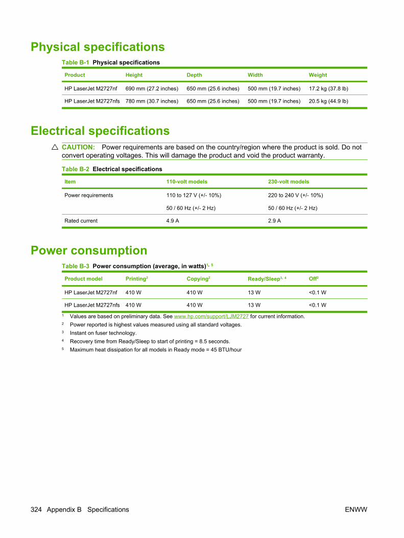
Physical specificationsTable B-1 Physical specifications
Product Height Depth Width Weight
HP LaserJet M2727nf 690 mm (27.2 inches) 650 mm (25.6 inches) 500 mm (19.7 inches) 17.2 kg (37.8 lb)
HP LaserJet M2727nfs 780 mm (30.7 inches) 650 mm (25.6 inches) 500 mm (19.7 inches) 20.5 kg (44.9 lb)
Electrical specificationsCAUTION: Power requirements are based on the country/region where the product is sold. Do notconvert operating voltages. This will damage the product and void the product warranty.
Table B-2 Electrical specifications
Item 110-volt models 230-volt models
Power requirements 110 to 127 V (+/- 10%)
50 / 60 Hz (+/- 2 Hz)
220 to 240 V (+/- 10%)
50 / 60 Hz (+/- 2 Hz)
Rated current 4.9 A 2.9 A
Power consumptionTable B-3 Power consumption (average, in watts)1, 5
Product model Printing2 Copying2 Ready/Sleep3, 4 Off2
HP LaserJet M2727nf 410 W 410 W 13 W <0.1 W
HP LaserJet M2727nfs 410 W 410 W 13 W <0.1 W
1 Values are based on preliminary data. See www.hp.com/support/LJM2727 for current information.2 Power reported is highest values measured using all standard voltages.3 Instant on fuser technology.4 Recovery time from Ready/Sleep to start of printing = 8.5 seconds.5 Maximum heat dissipation for all models in Ready mode = 45 BTU/hour
324 Appendix B Specifications ENWW

Environmental specificationsTable B-4 Environmental specifications1
Recommended Operating Storage
Temperature 15° to 32.5° C
(59° to 90.5° F)
15° to 32.5° C
(59° to 90.5° F)
-20° to 40° C
(-4° to 104° F)
Relative humidity 10% to 80% 10% to 80% 95% or less
1 Values are subject to change.
Acoustic emissionsTable B-5 Acoustic emissions2
Sound Power Level Declared per ISO 92961
Printing (26 ppm) LWAd = 6.4 Bels (A) [64 dB (A)]
Ready Inaudible
Sound Pressure Level - Bystander Position Declared per ISO 92961
Printing (26 ppm) LpAm = 50 dB(A)
Ready Inaudible
1 Values are based on preliminary data. See www.hp.com/support/LJM2727 for current information.2 Configuration tested: HP LaserJet M2727nf printing simplex using A4 paper at 26 ppm.
ENWW Environmental specifications 325

326 Appendix B Specifications ENWW

C Regulatory information
This section contains the following regulatory information:
● FCC compliance
● Environmental product stewardship program
● Telephone Consumer Protection Act (United States)
● IC CS-03 requirements
● EU statement for telecom operation
● New Zealand telecom statements
● Declaration of conformity
● Safety statements
ENWW 327

FCC compliance
This equipment has been tested and found to comply with the limits for a Class B digital device, pursuantto Part 15 of the FCC rules. These limits are designed to provide reasonable protection against harmfulinterference in a residential installation. This equipment generates, uses, and can radiate radiofrequency energy. If it is not installed and used in accordance with the instructions, it may cause harmfulinterference to radio communications. However, there is no guarantee that interference will not occurin a particular installation. If this equipment does cause harmful interference to radio or televisionreception, which can be determined by turning the equipment off and on, the user is encouraged to tryto correct the interference by one or more of the following measures:
● Reorient or relocate the receiving antenna.
● Increase separation between equipment and receiver.
● Connect equipment to an outlet on a circuit different from that to which the receiver is located.
● Consult your dealer or an experienced radio/TV technician.
NOTE: Any changes or modifications to the printer that are not expressly approved by Hewlett-Packard could void the user's authority to operate this equipment.
Use of a shielded interface cable is required to comply with the Class B limits of Part 15 of the FCCrules.
This equipment complies with FCC rules, Part 68. On the back of this equipment is a label that contains,among other information, the FCC registration number and ringer equivalence number (REN) for thisequipment. If requested, this information must be provided to the telephone company. The REN is usedto determine the quantity of devices that might be connected to the telephone line. Excessive RENs onthe telephone line may result in the devices not ringing in response to an incoming call. In most, but notall, areas, the sum of the RENs should not exceed five (5.0). To be certain of the number of devicesthat might be connected to the line, as determined by the total RENs, contact the telephone companyto determine the maximum REN for the calling area.
This equipment uses the following USOC jacks: RJ11C.
An FCC-compliant telephone cord and modular plug is provided with this equipment. This equipment isdesigned to be connected to the telephone network or premises wiring using a compatible modular jackthat is Part 68 compliant. This equipment cannot be used on telephone company-provided coin service.Connection to Party Line Service is subject to state tariffs. If this equipment causes harm to the telephonenetwork, the telephone company will notify you in advance that temporary discontinuance of servicemay be required. If advance notice is not practical, the telephone company will notify the customer assoon as possible. Also, you will be advised of your right to file a complaint with the FCC if you believeit is necessary. The telephone company may make changes in its facilities, equipment, operations, orprocedures that could affect the operation of the equipment. If this happens, the telephone companywill provide advance notice in order for you to make the necessary modifications in order to maintainuninterrupted service. If trouble is experienced with this equipment, please see the numbers in the frontof this manual for repair and (or) warranty information. If the trouble is causing harm to the telephonenetwork, the telephone company may request you remove the equipment from the network until theproblem is resolved. The following repairs can be done by the customer: Replace any original equipmentthat came with the device. This includes the print cartridge, the supports for trays and bins, the powercord, and the telephone cord. It is recommended that the customer install an AC surge arrestor in theAC outlet to which this device is connected. This is to avoid damage to the equipment caused by locallightning strikes and other electrical surges.
328 Appendix C Regulatory information ENWW

Environmental product stewardship programProtecting the environment
Hewlett-Packard Company is committed to providing quality products in an environmentally soundmanner. This product has been designed with several attributes to minimize impacts on our environment.
Ozone productionThis product generates no appreciable ozone gas (O3).
Power consumptionPower usage drops significantly while in Ready/Sleep mode, which saves natural resources and savesmoney without affecting the high performance of this product. To determine the ENERGY STAR®qualification status for this product see the Product Data Sheet or Specifications Sheet. Qualifiedproducts are also listed at:
http://www.hp.com/hpinfo/globalcitizenship/environment/productdesign/ecolabels.html
Toner consumptionEconoMode uses less toner, which might extend the life of the print cartridge.
Paper useThis device’s manual/automatic duplex feature (two-sided printing) and N-up printing (multiple pagesprinted on one page) capability can reduce paper usage and the resulting demands on naturalresources.
PlasticsPlastic parts over 25 grams are marked according to international standards that enhance the ability toidentify plastics for recycling purposes at the end of the product’s life.
HP LaserJet print suppliesIt’s easy to return and recycle your empty HP LaserJet print cartridges—free of charge—with HP PlanetPartners. Multilingual program information and instructions are included in every new HP LaserJet printcartridge and supplies package. You help reduce the toll on the environment further when you returnmultiple cartridges together rather than separately.
HP is committed to providing inventive, high-quality products and services that are environmentallysound, from product design and manufacturing to distribution, customer use and recycling. When youparticipate in the HP Planet Partners program, we ensure your HP LaserJet print cartridges are recycledproperly, processing them to recover plastics and metals for new products and diverting millions of tonsof waste from landfills. Since this cartridge is being recycled and used in new materials, it will not bereturned to you. Thank you for being environmentally responsible!
NOTE: Use the return label to return original HP LaserJet print cartridges only. Please do not use thislabel for HP inkjet cartridges, non-HP cartridges, refilled or remanufactured cartridges or warrantyreturns. For information about recycling your HP inkjet cartridges please go to http://www.hp.com/recycle.
ENWW Environmental product stewardship program 329
Return and recycling instructions
United States and Puerto RicoThe enclosed label in the HP LaserJet toner cartridge box is for the return and recycling of one or moreHP LaserJet print cartridges after use. Please follow the applicable instructions below.
Multiple returns (two to eight cartridges)
1. Package each HP LaserJet print cartridge in its original box and bag.
2. Tape up to eight single boxes together using strapping or packaging tape (up to 70 lbs).
3. Use a single pre-paid shipping label.
OR
1. Use your own suitable box, or request a free bulk collection box from the http://www.hp.com/recycle or 1-800-340-2445 (holds up to eight HP LaserJet print cartridges).
2. Use a single pre-paid shipping label.
Single returns
1. Package the HP LaserJet print cartridge in its original bag and box.
2. Place the shipping label on the front of the box.
Shipping
For all HP LaserJet print cartridge recycling returns, give the package to UPS during your next deliveryor pickup, or take it to an authorized UPS drop-off center. For the location of your local UPS drop-offcenter, call 1-800-PICKUPS or visit http://www.ups.com. If you are returning via USPS label, give thepackage to a U.S. Postal Service carrier or drop off at a U.S.Postal Service Office. For more information,or to order additional labels or boxes for bulk returns, visit http://www.hp.com/recycle or call1-800-340-2445. Requested UPS pickup will be charged normal pickup rates. Information subject tochange without notice.
Non-US returnsTo participate in HP Planet Partners return and recycling program, just follow the simple directions inthe recycling guide (found inside the packaging of your new printer supply item) or visithttp://www.hp.com/recycle. Select your country/region for information on how to return your HP LaserJetprinting supplies.
PaperThis product is capable of using recycled papers when the paper meets the guidelines outlined in theHP LaserJet Printer Family Print Media Guide. This product is suitable for the use of recycled paperaccording to EN12281:2002.
Material restrictionsThis HP product does not contain added mercury.
This HP product contains a battery that might require special handling at end-of-life. The batteriescontained in or supplied by Hewlett-Packard for this product include the following:
330 Appendix C Regulatory information ENWW

HP LaserJet M2727
Type Carbon monofluoride lithium
Weight 0.8 g
Location On formatter board
User-removable No
For recycling information, you can go to www.hp.com/recycle, or contact your local authorities or theElectronics Industries Alliance: www.eiae.org.
Disposal of waste equipment by users in private households in theEuropean Union
This symbol on the product or on its packaging indicates that this product must not be disposed of withyour other household waste. Instead, it is your responsibility to dispose of your waste equipment byhanding it over to a designated collection point for the recycling of waste electrical and electronicequipment. The separate collection and recycling of your waste equipment at the time of disposal willhelp to conserve natural resources and ensure that it is recycled in a manner that protects human healthand the environment. For more information about where you can drop off your waste equipment forrecycling, please contact your local city office, your household waste disposal service or the shop whereyou purchased the product.
Material Safety Data Sheet (MSDS)Material Safety Data Sheets (MSDS) for supplies containing chemical substances (for example, toner)can be obtained by contacting the HP Web site at www.hp.com/go/msds or www.hp.com/hpinfo/globalcitizenship/environment.
ENWW Environmental product stewardship program 331

For more informationTo obtain information about these environmental topics:
● Product environmental profile sheet for this and many related HP products
● HP’s commitment to the environment
● HP’s environmental management system
● HP’s end-of-life product return and recycling program
● Material Safety Data Sheets
Visit www.hp.com/go/environment or www.hp.com/hpinfo/globalcitizenship/environment/index.html.
332 Appendix C Regulatory information ENWW

Telephone Consumer Protection Act (United States)The Telephone Consumer Protection Act of 1991 makes it unlawful for any person to use a computeror other electronic device, including fax machines, to send any message unless such message clearlycontains, in a margin at the top or bottom of each transmitted page or on the first page of thetransmission, the date and time it is sent and an identification of the business, other entity, or individualsending the message and the telephone number of the sending machine or such business, other entity,or individual. (The telephone number provided cannot be a 900 number or any other number for whichcharges exceed local or long-distance transmission charges.)
IC CS-03 requirementsNotice: The Industry Canada label identifies certified equipment. This certification means the equipmentmeets certain telecommunications network protective, operational, and safety requirements asprescribed in the appropriate Terminal Equipment Technical Requirement document(s). TheDepartment does not guarantee the equipment will operate to the user’s satisfaction. Before installingthis equipment, users should ensure that it is permissible for the equipment to be connected to thefacilities of the local telecommunications company. The equipment must also be installed using anacceptable method of connection. The customer should be aware that compliance with the aboveconditions may not prevent degradation of service in some situations. Repairs to certified equipmentshould be coordinated by a representative designated by the supplier. Any repairs or alterations madeby the user to this equipment, or equipment malfunctions, may give the telecommunications companycause to request the user to disconnect the equipment. Users should ensure for their own protectionthat the electrical ground connections of the power utility, telephone lines, and internal metallic waterpipe system, if present, are connected together. This precaution can be particularly important in ruralareas.
CAUTION: Users should not attempt to make such connections themselves, but should contact theappropriate electric inspection authority, or electrician, as appropriate. The Ringer Equivalence Number(REN) of this device is 0.7.
Notice: The Ringer Equivalence Number (REN) assigned to each terminal device provides an indicationof the maximum number of terminals allowed to be connected to a telephone interface. The terminationon an interface may consist of any combination of devices subject only to the requirement that the sumof the Ringer Equivalence Number of all the devices does not exceed five (5.0). The standard connectingarrangement code (telephone jack type) for equipment with direct connections to the telephone networkis CA11A.
ENWW Telephone Consumer Protection Act (United States) 333

EU statement for telecom operationThis product is intended to be connected to the analog Public Switched Telecommunication Networks(PSTN) of European Economic Area (EEA) countries/regions. It meets requirements of EU R&TTEDirective 1999/5/EC (Annex II) and carries appropriate CE conformity marking. For more details, seeDeclaration of Conformity issued by the manufacturer in another section of this manual. However, dueto differences between individual national PSTNs, the product may not guarantee unconditionalassurance of successful operation on every PSTN termination point. Network compatibility depends onthe correct setting being selected by the customer in preparation of its connection to the PSTN. Pleasefollow the instructions provided in the user manual. If you experience network compatibility issues,please contact your equipment supplier or Hewlett-Packard help desk in the country/region of operation.Connecting to a PSTN termination point may be the subject of additional requirements set out by thelocal PSTN operator.
New Zealand telecom statementsThe grant of a Telepermit for any item of terminal equipment indicates only that Telecom has acceptedthat the item complies with minimum conditions for connection to its network. It indicates no endorsementof the product by Telecom, nor does it provide any sort of warranty. Above all, it provides no assurancethat any item will work correctly in all respects with another item of Telepermitted equipment of a differentmake or model, nor does it imply that any product is compatible with all of Telecom’s network services.
This equipment may not provide for the effective hand-over of a call to another device connected to thesame line.
This equipment shall not be set up to make automatic calls to the Telecom “111” Emergency Service.
This product has not been tested to ensure compatibility with the FaxAbility distinctive ring service forNew Zealand.
334 Appendix C Regulatory information ENWW

Declaration of conformityDeclaration of Conformityaccording to ISO/IEC 17050-1 and EN 17050-1Manufacturer's Name: Hewlett-Packard Company DoC#: BOISB-0602-01-rel.1.0Manufacturer's Address: 11311 Chinden Boulevard,
Boise, Idaho 83714-1021, USAdeclares, that the product
Product Name: HP LaserJet M2727 nf and M2727nfsRegulatory Model Number2) BOISB-0602-01
Including: Q7556A—Optional 250-Sheet Input TrayProduct Options: ALLPrint Cartridges: Q7553A / Q7553Xconforms to the following Product Specifications:
SAFETY: IEC 60950-1:2001 / EN60950-1: 2001 +A11IEC 60825-1:1993 +A1 +A2 / EN 60825-1:1994 +A1 +A2 (Class 1 Laser/LED Product)GB4943-2001
EMC: CISPR22:2005 / EN55022:2006 – Class B1)
EN 61000-3-2:2000 +A2EN 61000-3-3:1995 +A1EN 55024:1998 +A1 +A2FCC Title 47 CFR, Part 15 Class B1) / ICES-003, Issue 4GB9254-1998, GB17625.1-2003
TELECOM: ES 203 021; FCC Title 47 CFR, Part 683)
Supplementary Information:
The product herewith complies with the requirements of the EMC Directive 2004/108/EC and the Low Voltage Directive 2006/95/EC, theR&TTE Directive 1999/5/EC (Annex II), and carries the CE-Marking accordingly.
This Device complies with Part 15 of the FCC Rules. Operation is subject to the following two Conditions: (1) this device may not causeharmful interference, and (2) this device must accept any interference received, including interference that may cause undesired operation.
1) The product was tested in a typical configuration with Hewlett-Packard Personal Computer Systems.
2) For regulatory purposes, this product is assigned a Regulatory model number. This number should not be confused with the product nameor the product number(s).
3) Telecom approvals and standards appropriate for the target countries have been applied to this product, in addition to those listed above.
Boise, Idaho , USA
July 2007
For regulatory topics only:
European Contact: Your Local Hewlett-Packard Sales and Service Office or Hewlett-Packard GmbH, Department HQ-TRE / StandardsEurope,, Herrenberger Strasse 140, , D-71034, Böblingen, (FAX: +49-7031-14-3143)
USA Contact: Product Regulations Manager, Hewlett-Packard Company,, PO Box 15, Mail Stop 160, Boise, ID 83707-0015, , (Phone:208-396-6000)
ENWW Declaration of conformity 335

Safety statementsLaser safety
The Center for Devices and Radiological Health (CDRH) of the U.S. Food and Drug Administration hasimplemented regulations for laser products manufactured since August 1, 1976. Compliance ismandatory for products marketed in the United States. The device is certified as a “Class 1” laser productunder the U.S. Department of Health and Human Services (DHHS) Radiation Performance Standardaccording to the Radiation Control for Health and Safety Act of 1968. Since radiation emitted inside thedevice is completely confined within protective housings and external covers, the laser beam cannotescape during any phase of normal user operation.
WARNING! Using controls, making adjustments, or performing procedures other than those specifiedin this user guide may result in exposure to hazardous radiation.
Canadian DOC regulationsComplies with Canadian EMC Class B requirements.
« Conforme à la classe B des normes canadiennes de compatibilité électromagnétiques. « CEM ». »
EMI statement (Korea)
336 Appendix C Regulatory information ENWW

Laser statement for FinlandLuokan 1 laserlaite
Klass 1 Laser Apparat
HP LaserJet M2727nf, M2727nfs, laserkirjoitin on käyttäjän kannalta turvallinen luokan 1 laserlaite.Normaalissa käytössä kirjoittimen suojakotelointi estää lasersäteen pääsyn laitteen ulkopuolelle.Laitteen turvallisuusluokka on määritetty standardin EN 60825-1 (1994) mukaisesti.
VAROITUS !
Laitteen käyttäminen muulla kuin käyttöohjeessa mainitulla tavalla saattaa altistaa käyttäjänturvallisuusluokan 1 ylittävälle näkymättömälle lasersäteilylle.
VARNING !
Om apparaten används på annat sätt än i bruksanvisning specificerats, kan användaren utsättas förosynlig laserstrålning, som överskrider gränsen för laserklass 1.
HUOLTO
HP LaserJet M2727nf, M2727nfs - kirjoittimen sisällä ei ole käyttäjän huollettavissa olevia kohteita.Laitteen saa avata ja huoltaa ainoastaan sen huoltamiseen koulutettu henkilö. Tällaiseksihuoltotoimenpiteeksi ei katsota väriainekasetin vaihtamista, paperiradan puhdistusta tai muita käyttäjänkäsikirjassa lueteltuja, käyttäjän tehtäväksi tarkoitettuja ylläpitotoimia, jotka voidaan suorittaa ilmanerikoistyökaluja.
VARO !
Mikäli kirjoittimen suojakotelo avataan, olet alttiina näkymättömällelasersäteilylle laitteen ollessatoiminnassa. Älä katso säteeseen.
VARNING !
Om laserprinterns skyddshölje öppnas då apparaten är i funktion, utsättas användaren för osynliglaserstrålning. Betrakta ej strålen. Tiedot laitteessa käytettävän laserdiodin säteilyominaisuuksista:Aallonpituus 775-795 nm Teho 5 m W Luokan 3B laser.
ENWW Safety statements 337
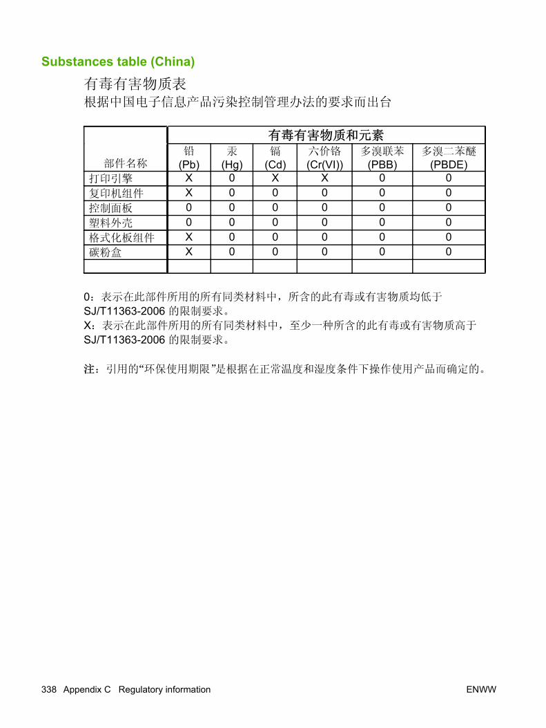
Substances table (China)
338 Appendix C Regulatory information ENWW

Index
Symbols/Numerics250–sheet tray. See tray 2 or tray 3
Aac inlet cable
removing 126stapler, removing 126
accessibility features 4accessories, part numbers 248acoustic emissions 325activity log, fax
printing 239troubleshooting 226
ADFassembly, removing 115cleaning pickup-roller
assembly 55components 276detection operations 75diagrams 267functions 73install input tray 23jam detection 75jams 180load originals 26locating 5operations 73page sizes supported 222paper path 74part numbers 254, 272pickup-roller assembly,
replacing 110removing scanner
assembly 117scanner assembly,
removing 117scanner glass, removing 113sensors 74trailing edge detection 75troubleshooting 229
ADF jam detectiondocument-feeder jam 75long-document jam 75stall jam 75trailing edge detection 75
ADF paper path 74ADF pickup-roller assembly
replacing 110ADF scanner glass
removing 113ADF sensors 74after service checklist 96alert messages 169Alerts tab
HP ToolboxFX 59answering machines,
troubleshooting 224Apple Macintosh. See Macintosharchive print setting 236, 242assembly
ADF, removing 115duplex, removing 135duplexing, part numbers 302duplexing-drive, part
numbers 298engine controller,
removing 153engine-controller 294fuser, part numbers 304interlock, removing 152laser/scanner, removing 137main gear, removing 162main-drive 296memory-tag-reader,
removing 139pick-up roller, replacing 110pickup-and-feed,
removing 160pickup-roller, removing 110
registration-roller,removing 161
scanner/ADF, removing 117stapler, removing 122
automatic document feeder (ADF)jams 180locating 5
Bbackground, gray 207bands, troubleshooting 206batteries included 330battery specifications 36bezels, control panel
part numbers 255removing 119
billing (metering) tone filters 91billing code report, fax 240billing filters
fax 91bins, output
jams, clearing 186locating 5
blank copies,troubleshooting 217
blank scans, troubleshooting 213box, unpacking 22
Ccables
flat flexible cables (FFCs) 137part numbers 248stapler, removing 126
call report, faxprinting 239troubleshooting 226
Canadian DOC regulations 336cartridge. See print cartridgecartridge door components, part
numbers 284
ENWW Index 339

cartridge-door release, locating 5cartridges
alerts 59drum rotation test 230high-voltage contacts 233HP fraud hotline 48non-HP 48part numbers 248recycle 35recycling 329status page, printing 237warranty 321
characters, troubleshooting 208checklist
print-quality 205checklists
after service 96before service 95preservice 95troubleshooting 166
checksdrum rotation 230engine 231half-self-test 232heating element 233high-voltage power
supply 233circuit diagram (1 of 2) 268circuit diagram (2 of 2) 269classes, HP Technical
Training 258cleaning
ADF pickup-rollerassembly 55
exterior of product 49flatbed scanner glass 49high-voltage connection
points 234high-voltage contacts 233paper path 56pickup roller 52product 49scanner-cover backing 51tray 2 pickup roller 52
cleaning page 56cleaning page, printing 241cleaning paper path
control panel 57HP ToolboxFX 57
clearingADF, jams 180duplexer 184input-tray areas 182output-bin areas 186print-cartridge areas 188stapler 189
clearing jamsADF 180
CO operations 87comparing
features 3component diagrams
major 266computer
security features 87Configuration page 237connectors
fax card 261formatter 260
control panelbezel part numbers 255bezel, removing 119button description 7cleaning paper path 57display, troubleshooting 227faceplate, install 25menus 191menus, access 191messages,
troubleshooting 169removing 119secondary menu 199Service menu 241service menu 235
controlshook switch control 90
convenience staplerjams, clearing 189specifications 4
copytray selection 29
copy qualitytest 96
copy setup menu 192copy-quality test 96copying
media, troubleshooting 215quality, troubleshooting 214setup menu 192
size, troubleshooting 217troubleshooting 214, 217
coversleft, removing 102part numbers 282rear, removing 106right, removing 100top, removing 108
creases, troubleshooting 209crooked pages 209curled media 209, 236current control, fax line 91Customer Care Online 258
Ddark copies 215data path
fax 90dc controller 78defaults, restoring 236, 241defects, repetitive 259Demo page, printing 238Developer's menu 201device detection, downstream
fax 90device information page
HP ToolboxFX 63device polling
HP ToolboxFX 65diagrams
troubleshooting 259dialing
fax 195troubleshooting 222
dialing, pulse 90digital subscriber line (DSL),
troubleshooting 228dimensions
media 16DIMM door, locating 6DIMMs
adding 30installing 30part numbers 248
Director, Macintosh 13display, troubleshooting control
panel 227disposal, end-of-life 330distinctive ring 88
340 Index ENWW

documentationgetting started guide,
languages 258user guide, languages 257Web sites, technical
support 258door
print-cartridge door,removing 104
dots per inch (dpi)print settings 204specifications 4
dots, troubleshooting 206downstream device detection
fax 90dpi (dots per inch)
faxing 195print settings 204specifications 4
driversspecifications 4supported 9
drum rotation test 230DSL, troubleshooting 228duplex assembly, removing 135duplex solenoid, removing 145duplex-drive gears, removing 143duplexer
jams, clearing 184duplexing assembly, part
numbers 302duplexing-drive assembly, part
numbers 298
Ee-label reader 139e-mail alerts 59electrical specifications 324electrostatic discharge (ESD) 94embedded Web server (EWS)
browsers supported 12features 66setting password 67
end-of-life disposal 330engine control system 78engine controller assembly (ECU),
removing 153engine test 231engine-controller assembly (ECU),
part numbers 294
environmental specifications 20,325
environmental stewardshipprogram 329
error mesagesADF paper jams 75paper jams, ADF 75
error messagescontrol panel 169critical 177
ESD (electrostatic discharge) 94EU statement for telecom
operation 334European Union, waste
disposal 331Event log
HP ToolboxFX 59express software installation
included components list 10
Ffaceplate, install control panel 25factory-set defaults,
restoring 236, 241faded print 206fan, removing 141fax
activity log 239answer mode 196billing (metering) tone
filters 91billing code report,
printing 240cables, part numbers 248call report, printing 239checklist, troubleshooting 218data path 90distinctive ring 88downstream current
detection 90error messages 172factory-set defaults,
restoring 241fax card 89fax pages, storage 91fax subsystem 89fax-quality test 97flash memory storage 91functions 87hook state 90
hook switch control 90jams, troubleshooting 179,
225line current control 91operations 87operations, PSTN 87page storage 91performance,
troubleshooting 226phone book 60phone book, printing 239PSTN operations 87pulse dialing 90receive log 62receiving 87receiving, troubleshooting 219report, printing 239reports 193reports, troubleshooting 226ring detect 91ring type 196safety isolation 89safety protection circuitry 89security features,
computer 87security features, network 87send log, HP ToolboxFX 62sending, troubleshooting 222stored fax pages 91T.30 protocol trace report 242test, fax quality 97troubleshooting 218voice-call,
troubleshooting 224fax card
CODEC 89connectors 261DSP 89fax subsystem 89hook switch control 90part numbers 280pulse dialing 90regional versions 89ring detect 91safety isolation 89safety-protection circuitry 89
fax functions menu 191fax job status menu 191fax page storage 91fax ports, locating 6
ENWW Index 341

fax reports, printing 193fax send log
HP ToolboxFX 62fax setup menu 194fax subsystem
fax card 89Fax tab
HP ToolboxFX 59fax tab, HP ToolboxFX
fax receive log 62fax send log 62log, fax receive 62log, fax send 62
fax, performance226
fax-quality test 97faxing
voice over IP (VoIP)services 88
FCC compliance 328features
product 4feed system, ADF 73field replaceable units (FRUs)
removing 93replacing 93
Finnish laser safetystatement 337
firmware updates 243flash memory, fax 91flat flexible cables (FFCs) 137flatbed scanner
cleaning glass 49load originals 26
font list 237formatter
connectors 260part numbers 280removing 132
fraud hotline 48fuser
error 177warranty 321
fuser assembly, part number 304fuser, removing 147
Ggears
duplex-drive, removing 143Getting Started Guide 2, 258
glass, cleaning 49gray background,
troubleshooting 207guides. See documentation
Hhalf-self-test functional check 232heating element check 233Help (Documentation) tab
HP ToolboxFX 62high-voltage PCA 78high-voltage power supply,
checking 233hook state
fax 90hook switch control 90HP Customer Care Online 258HP Director, Macintosh 13HP fraud hotline 48HP jewel, part number 280HP Printing Supplies Returns 35HP Recycling Program 35HP Technical Training 258HP ToolboxFX
Alerts tab 59cleaning paper path 57device information page 63device polling 65Event log 59factory-set defaults,
restoring 241fax phone book 60Fax tab 59features 58Help (Documentation) tab 62managing product 58Network Settings tab 66paper handling page 64Paper Types settings 64PCL 5e, print driver
settings 66PostScript, print driver
settings 66print driver settings, PCL
5e 66print driver settings,
PostScript 66Print Quality settings 64Print Settings tab 65Printing tab 65
Service tab 65status alerts 59Status tab 58system requirements 58System Settings tab 63system setup 65Troubleshooting tab 240viewing 58
HP ToolboxFX, fax tabfax receive log 62log, fax receive 62log, fax send 62send log 62
humidity specificationsenvironment 325
IIC CS-03 requirements 333image quality
archive print setting 236, 242cleaning page, printing 241copy, troubleshooting 214HP ToolboxFX settings 64print, troubleshooting 204,
205repetitive image defects 259scans, troubleshooting 211,
213image-formation system
operations 83testing 232
importingfax phone book, HP
ToolboxFX 60HP ToolboxFX, fax phone
book 60information pages
Configuration 237Demo 238menu map 237, 238Supplies Status 237T.30 protocol trace report 242usage 238
ink cartridges. See print cartridgesinput tray
load media 28input trays. See traysinput-tray areas
jams, clearing 182
342 Index ENWW

installADF input tray 23control-panel faceplate 25tray 3 24
installation, softwareincluded components list,
express 9included components list,
recommended 9installing
control-panel faceplate 25DIMMs 30memory, DIMMs 30
interface portscables, ordering 248locating 6, 260types included 4
interlock assembly, removing 152internal assembly
removing 122replacing 122
internal components 76internal components, part
numbers 286
Jjam detection
ADF 75trailing edge detection,
ADF 75jams
ADF, clearing 180alerts 59causes of 179duplexer, clearing 184fax 225fax, clearing 180locating 180output-bin, clearing 186preventing 190print cartridge area,
clearing 188stapler, clearing 189trays, clearing 182
jewel, part number 280
KKorean EMI statement 336
Llanguages, documentation 257
laser safety statements 336, 337laser/scanner
removing 137laser/scanner system
operations 80left cover, removing 102life expectancies, supplies 34light copies 215light print, troubleshooting 206line current control, fax 91lines, troubleshooting
copies 215printed pages 206scans 213
loadoriginals on flatbed scanner or
ADF 26load media
optional tray 3 28tray 1 27tray 2 28
loadingmedia 26paper 26stapler cassette 39staples 39
localized user guides 257locating
automatic document feeder(ADF) 5
bins 5cartridge-door release 5control panel 5DIMM door 5interface ports 5internal components 76jams, paper/media 180power connector 5power switch 5print cartridge 5print-cartridge door latch 5rear output door 5stapler 5trays 5
logs, faxactivity 239billing codes 240call (last fax sent or
received) 239
phone book 239troubleshooting 226
loose toner, troubleshooting 208
MMacintosh
drivers supported 9Intel Core Processor 9Macintosh Configure
Device 13PDEs 14PPC 9software components 13system requirements 21uninstall software 15
Macintosh Configure Deviceviewing 13, 67
main gear assembly,removing 162
main motor, removing 158main-drive assembly, part
numbers 296major component diagrams 266managing product
HP ToolboxFX 58manuals. See documentationmaterial restrictions 330Material Safety Data Sheet
(MSDS) 331media
ADF feeding operations 73ADF, sizes supported 222curled, troubleshooting 209,
236default size for tray 29feeding operations 81HP ToolboxFX settings 64jams 179loading 26pickup/feed/delivery
system 81specifications 16supported sizes 16types to avoid 17wrinkled 209See also paper
media jamsADF, clearing 180clearing 179See also jams
ENWW Index 343

media typesHP ToolboxFX settings 64
memoryerror messages 171flash, fax 91installing 30NVRAM initialization 235part numbers 248
memory, DIMMsinstalling 30
memory-tag-reader assembly,removing 139
menucontrol panel, access 191Copy setup 192Developer's 201Fax functions 191Fax Job status 191Fax setup 194Reports 193secondary service 200Service 199System setup 197
menu (secondary)control panel, access 199
menu map, printing 238menus
control panel 191Service 241service 235
mercury specifications 36mercury-free product 330messages
control panel 169critical 177
Microsoft Windowsdrivers supported 9
model number, locating 8moisture on the trailing edge,
troubleshooting 210motor, removing main 158multipurpose tray. See tray 2
Nnameplate, part numbers 280network
device polling, HP ToolboxFX 65
DSL, troubleshooting 228
HP ToolboxFX, devicepolling 65
security features 87network port
locating 6network report 238Network Settings tab
HP ToolboxFX 66New Zealand telecom
statements 334noise specifications 325non-HP print cartridges 48non-HP supplies
HP policy 48
Ooff-hook 90on-hook 90on/off switch, locating 5Online Customer Care, HP 258operating environment,
specifications 20, 325operating systems, supported 9operation sequence 70operations
ADF 73engine control system 78fax, PSTN 87image-formation system 83laser/scanner system 80pickup/feed/delivery
system 81PSTN 87
optical system operations 72options. See settingsorder supplies 34ordering supplies and
accessories 247, 248output bins
locating 5output quality
archive print setting 236, 242cleaning page, printing 241copy, troubleshooting 214HP ToolboxFX settings 64print, troubleshooting 204,
205repetitive image defects 259scans, troubleshooting 211,
213
PPABX lines, troubleshooting 228pages
skewed 209paper
ADF feeding operations 73ADF, sizes supported 222curled, troubleshooting 209,
236feeding operations 81HP ToolboxFX settings 64jams 179loading 26pickup/feed/delivery
system 81specifications 16supported sizes 16types to avoid 17wrinkled 209See also media
paper handling pageHP ToolboxFX 64
paper jamsADF detection operations 75ADF, clearing 180clearing 179detection operations, pickup/
feed/delivery system 81error messages, ADF 75locating 180trailing edge detection,
ADF 75See also jams
paper pathADF 74ADF feeding operations 74cleaning 56
paper path, cleaning 241paper types
HP ToolboxFX settings 64part numbers
ADF 272cables 248cartridge door
components 284control-panel bezels 255covers 282duplexing assembly 302duplexing-drive assembly 298
344 Index ENWW

engine-controllerassembly 294
fax card 280formatter 280fuser assembly 304internal components 286jewel 280main-drive assembly 296memory 248nameplate 280scanner 272screws 271stapler 278supplies 248trays 249, 300user guides 257
parts245
field replaceable units(FRUs) 93
internal assemblies 122ordering 247removal-order list 98removing 93replacing 93user-replaceable 94
PCAs, diagrams 265PCL 5e print drivers
HP ToolboxFX settings 66PCL, PCL6, PS font list 237PDEs, Macintosh 14performance
troubleshooting 217phone book
fax tab, HP ToolboxFX 60HP ToolboxFX, fax tab 60
phone book, faxHP ToolboxFX 60printing 239
phone numbersHP fraud hotline 48HP Printing Supplies Returns
and Recycling Program 36photosensitive drum rotation
test 230physical specifications 324pickup and feed system
ADF 73pickup rollers
ADF assembly, replacing 110
cleaning 52cleaning ADF 55diagrams 264replacing, tray 2 40
pickup solenoid (tray 2),removing 162
pickup-and-feed assembliesremoving 160
pickup-roller assembly, ADFreplacing 110
pickup/feed/delivery systemoperations 81
pliers, required 95ports
cables, ordering 248locating 6, 260types included 4
post-service tests 96PostScript print drivers
HP ToolboxFX settings 66power
high-voltage PCA 78requirements 324sequence of operations 71testing high-voltage 233
power connector, locating 6power consumption 324power cords, part numbers 248power supplies
fax line current control 91power supply
high-voltage contactscheck 233
stapler, removing 124stapler, removing bracket and
strap 127power switch, locating 5power-switch PCA, removing 130preservice checklist 95print cartridge area jams,
clearing 188print cartridges
alerts 59door release, locating 5drum rotation test 230high-voltage contacts 233HP fraud hotline 48non-HP 48part numbers 248recycle 35
recycling 329removing 99replacing 37status page, printing 237warranty 321
print defectstroubleshooting 205
print driverincluded components list 9included components list,
Macintosh 10print drivers
supported 9print drivers, PCL 5e
HP ToolboxFX settings 66print drivers, PostScript
HP ToolboxFX settings 66print engine
laser/scanner assembly,removing 137
removing laser/scannerassembly 137
print mediasupported 16
print qualityarchive print setting 236, 242checklist 205cleaning page, printing 241HP ToolboxFX settings 64repetitive image defects 259settings 204test 96troubleshooting 204, 205
Print Settings tabHP ToolboxFX 65
print-cartridge doorremoving 104
print-quality checklist 205print-quality setting, 600 dpi 204print-quality test 96printer drivers
specifications 4printing
change tray selection 29cleaning page 56fax report 239loading media 26loading paper 26menu map 237, 238network report 238
ENWW Index 345

Printing tabHP ToolboxFX 65
priority input slot. See tray 1problem solving. See
troubleshootingproduct
ADF functions 72back view description 6basic operation 70cleaning 49electrostatic discarge
(ESD) 94embedded Web server (EWS)
features 66fax, functions 87features 4front view description 5image-formation system 83information pages 237internal components 76managing 58model number, locating 8operation sequence 70pages per minute (ppm) 4performance 4scanner functions 72sequence of operations 70serial number, locating 8specifications 4, 323supplies, life expectancies 34supplies, managing 34unpacking 22user-replaceable parts 94
product information pages 237PSTN operations 87pulse dialing 90
Qquality
archive print setting 236, 242cleaning page, printing 241copy, troubleshooting 214print settings 204print, troubleshooting 204,
205repetitive image defects 259scans, troubleshooting 211,
213
Rrear cover, removing 106rear output bin, locating 6receiving
fax 87receiving faxes
activity log, printing 239call report, printing 239distinctive ring 88log, HP ToolboxFX 62T.30 protocol trace report 242troubleshooting 219
recommended software installationincluded components list 10
recycle suppliesWeb sites 35
recyclingbattery 36HP printing supplies returns and
environmental program 330mercury 36restrictions 36
refilled print cartridges 48regional versions
fax card 89registration-roller assembly,
removing 161regulatory information 328removing
ac inlet cable, stapler 126ADF assembly 115ADF pickup-roller
assembly 110ADF scanner glass 113assembly, ADF 115assembly, internal 122bezel, control panel 119bracket and strap, stapler 127control panel, bezel 119covers 100doors 100duplex assembly 135duplex solenoid 145duplex-drive gears 143engine controller
assembly 153external parts 100fan 141formatter 132fuser 147
interlock assembly 152internal assembly 122laser/scanner 137main gear assembly 162main motor 158memory-tag-reader
assembly 139order of parts 98panels 100parts 93parts, order 98pickup solenoid (tray 2) 162pickup-and-feed
assemblies 160pickup-roller assembly,
ADF 110power-switch PCA 130registration-roller
assembly 161scanner assembly 117scanner glass, ADF 113screws 94speaker 128stapler ac inlet cable 126stapler assembly 122stapler bracket and strap 127transfer roller 160
removing partsADF assembly 115ADF pickup-roller
assembly 110ADF scanner glass 113assembly, internal 122bezel, control panel 119cautions for 94checklists 95control panel, bezel 119duplex assembly 135duplex solenoid 145duplex-drive gears 143engine controller
assembly 153fan 141formatter 132fuser 147interlock assembly 152internal assembly 122laser/scanner 137main gear assembly 162main motor 158
346 Index ENWW

memory-tag-readerassembly 139
order 98pickup-and-feed
assemblies 160pickup-roller assembly,
ADF 110power supply, stapler 124power-switch PCA 130print cartridges 99print-cartridge door 104registration-roller
assembly 161scanner assembly 117scanner glass, ADF 113speaker 128stapler ac inlet cable 126stapler assembly 122stapler power supply 124stapler power supply bracket
and strap 127tools, required 95transfer roller 160
repair. See servicerepetitive defects,
troubleshooting 210, 259replace
supplies, life expectancies 34replacing
ADF pickup-rollerassembly 110
ADF scanner glass 113assemblies, internal 122internal assemblies 122pads, separation 45parts 93pickup roller, tray 2 40pickup-roller assembly,
ADF 110roller, pickup 40scanner glass, ADF 113screws 94separation pads 45tray 2 pickup roller 40
replacing partsADF pickup-roller
assembly 110assemblies, internal 122
internal assemblies 122pickup-roller assembly,
ADF 110replacing print cartridges 37report, product
fax 239network 238
reportsconfiguration page 194demo page 193fax 193menu map 193network report 194PCL 6 font list 194PCL font list 194PS font list 194service page 194supplies status page 194usage page 194
reports menu 193reports, fax
activity log 239billing codes 240call (last fax sent or
received) 239phone book 239troubleshooting 226
reports, productConfiguration page 237Demo page 238Supplies Status page 237T.30 protocol trace 242
required toolsuser-replaceable parts 95
requirementssystem 21
resolutionprint settings 204specifications 4
restoring factory-set defaults 236,241
right cover, removing 100ring detect
fax card 91RING operations 87rollers
ADF pickup assembly,replacing 110
cleaning ADF pickup 55cleaning tray 2 pickup 52
diagrams 264locating 76repetitive image defects 259replace tray 2 pickup 40transfer, removing 160
Ssafety isolation
fax 89safety statements 336, 337safety-protection circuitry
fax 89scanner
assembly, removing 117cleaning glass 49cleaning scanner-cover
backing 51components 274diagrams 267functions 72load originals 26optical system operations 72part numbers 254, 272removing assembly 117
scanner-cover backing,cleaning 51
scanningblank pages,
troubleshooting 213quality, troubleshooting 211,
213speed, troubleshooting 212troubleshooting 211
scatter, troubleshooting 210schedules, HP Technical
Training 258screwdrivers, required 95screws
removing 94replacing 94types of 271
secondary service menu 200security features
computer 87network 87
sending faxesactivity log, printing 239call report, printing 239log, HP ToolboxFX 62
ENWW Index 347

T.30 protocol trace report 242troubleshooting 222
sensorsADF 74, 75form sensor, ADF 75locating 263media detection 81paper-present sensor,
ADF 75trailing edge detection,
ADF 75separation pads
diagrams 264replacing 45
sequence of operations 70serial number, locating 8service
after-service check list 96before service checklist 95checklist, after service 96checklist, before service 95checklist, post-service 96checklist, preservice 95critical error messages 177HP ToolboxFX settings 65part numbers 248post-service checklist 96preservice checklist 95tools, required 95
Service menu 199, 241service menu 235service tab
HP ToolboxFX 65settings
Configuration page 237factory-set defaults,
restoring 236, 241NVRAM initialization 235
size 324skewed pages 209slow speed, troubleshooting
faxing 226scanning 212
smeared toner,troubleshooting 207
softwarecomponents 9drivers supported 9HP ToolboxFX 58Macintosh 13
Macintosh ConfigureDevice 67
supported operatingsystems 9
system requirements 21uninstall 15Windows 12
software installationincluded components list,
express 9included components list,
recommended 9solenoid
duplex, removing 145pickup (tray 2), removing 162
solenoids 262speaker, removing 128specifications
acoustic emissions 325electrical 324environmental 325media 16paper 16physical 324product features 4
specks, troubleshooting 206speed
fax, troubleshooting 226scanning, troubleshooting 212
spots, troubleshooting 206staple cassette
life expectancy 34loading 39part number 248specifications 4
staplerac inlet cable, removing 126assembly, removing 122jams, clearing 189loading staples 39locating 5part numbers 278power supply bracket and strap,
removing 127power supply, removing 124removing stapler
assembly 122staples, loading 39troubleshooting 227
stapler ac inlet cableremoving 126
stapler power supplybracket and strap,
removing 127removing 124
staples, loading 39static precautions 94status
fax job 191Supplies Status page,
printing 237status alerts
HP ToolboxFX 59Status tab
HP ToolboxFX 58stored fax pages 91storing
environmentalspecifications 325
fax pages in flash memory 91supplies 35
strategyparts, removal 94parts, replacement 94
streaks, troubleshooting 206supplies
alerts 59HP fraud hotline 48life expectancies 34managing 34non-HP 48non-HP supplies policy 48order 34ordering 247print cartridge, replacing 37print cartridge, storage 35recycling 35, 329replacing print cartridges 37status page 237storage 35
support, technical 258supported
drivers 9operating systems 9print drivers 9
supported media 16switches 263system requirements 21
348 Index ENWW

System Settings tabHP ToolboxFX 63
system setupHP ToolboxFX settings 65
System setup menu 197
TT.30 protocol trace report 242technical support 258Technical Training 258Telephone Consumer Protection
Act 333telephone numbers
HP fraud hotline 48HP Printing Supplies Returns
and Recycling Program 36temperature specifications
environment 325tests
copy-quality 96drum rotation 230engine 231fax-quality 97half-self functional check 232heating element 233high-voltage power
supply 233post-service 96print-quality 96
text, troubleshooting 208TIP operations 87toner
cleaning page, printing 241loose, troubleshooting 208scatter, troubleshooting 210smeared, troubleshooting 207specks, troubleshooting 206
toner cartridges. See printcartridges
tools, requireduser-replaceable parts 95
top cover, removing 108trailing edge detection
ADF 75Training, HP Technical 258transfer roller, removing 160transfer unit warranty 321tray 1
jams, clearing 182load 27
locating 5solenoids 262
tray 2cleaning pickup roller 52jams, clearing 182load 28locating 5part numbers 300pickup solenoid,
removing 162replacing pickup roller 40replacing separation pad 45separation pad, replace 45solenoids 262
tray 3install 24jams, clearing 182load 28locating 5part number 249part numbers 254, 300replacing separation pad 45separation pad, replace 45
traysalerts 59copy, changing selection 29default media size 29feeding operations 81install ADF input 23jams, clearing 182locating 5part numbers 249pickup/feed/delivery
system 81troubleshooting
ADF 229blank scans 213checklist 166checklist, fax 218cleaning page 241control panel display 227control panel messages 169copy quality 214copy size 217copying 214, 217critical error messages 177curled media 209, 236diagrams 259dialing 222drum rotation test 230
DSL 228engine test 231faded print 206fax 218fax jams 225fax reports 226half self-test 232heating element 233image formation 232image quality 204jams 179lines, copies 215lines, printed pages 206lines, scans 213loose toner 208media-handling 215moisture on the trailing
edge 210NVRAM initialization 235output quality 204PABX lines 228paper jams, clearing 179performance 217print defects 205print quality 204product information pages and
reports 237receiving faxes 219repetitive defects 210scan quality 211, 213scanned image 211scanning 211sending faxes 222skewed pages 209speed, faxing 226staple jams 189stapler 227T.30 protocol trace report 242text 208toner scatter 210toner smear 207toner specks 206voice-call 224wrinkles 209
Troubleshooting tab, HPToolboxFX 240
UUninstall software
Macintosh 15
ENWW Index 349

uninstall softwareAdd or Remove Programs 15Windows 15
unpack the product 22updating firmware 243usage page, printing 238USB port
locating 6types included 4
User Guide 2User guide
part numbers 257user-replaceable parts
required tools 95tools required 95
Vvertical lines,
troubleshooting 206vertical white or faded
stripes 214viewing
HP ToolboxFX 58Macintosh Configure
Device 67voice over IP (VoIP) services 88voice-call
troubleshooting 224voltage requirements 324volume
settings 198
Wwarning messages 169warranty
print cartridge 321product 319transfer unit and fuser 321
wavy paper, troubleshooting 209Web sites
HP Printing Supplies Returnsand Recycling www.hp.com/go/recycleProgram 36
Material Safety Data Sheet(MSDS) 331
order supplies 34ordering supplies 247recycle supplies 35technical support 258
weight 324
white or faded stripes 214Windows
software components 12system requirements 21uninstall software 15
wrinkles, troubleshooting 209
350 Index ENWW


*CB532-90946**CB532-90946*CB532-90946
© 2007 Hewlett-Packard Development Company, L.P.
www.hp.com
Related Documents