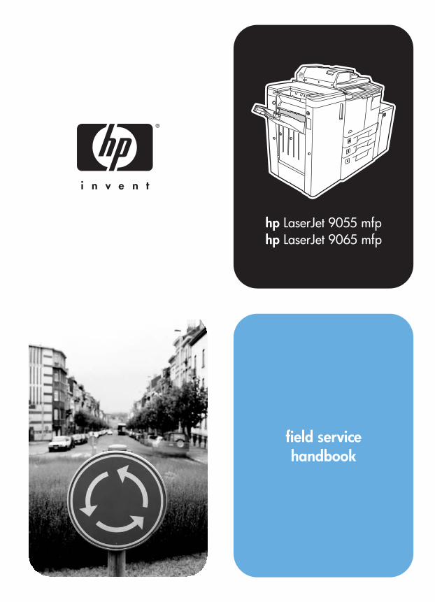
hp hp LaserJet 9055 mfp LaserJet 9065 mfp field service handbook

Welcome message from author
This document is posted to help you gain knowledge. Please leave a comment to let me know what you think about it! Share it to your friends and learn new things together.
Transcript
hphp
LaserJet 9055 mfpLaserJet 9065 mfp
field servicehandbook


field service handbook
hp LaserJet 9055mfp/9065mfp

Copyright Information
© 2003 Copyright Hewlett-Packard Development Company, L.P.
Reproduction, adaptation or translation without prior written permission is prohibited, except as allowed under the copyright laws.
The information contained herein is subject to change without notice.
The only warranties for HP products and services are set forth in the express warranty statements accompanying such products and services. Nothing herein should be construed as constituting an additional warranty. HP shall not be liable for technical or editorial errors or omissions contained herein.
Part number: Q3631-90909Edition 1, 11/2003
Trademark Credits
Microsoft®, Windows®, and Windows NT® are U.S. registered trademarks of Microsoft Corporation.
All other products mentioned herein may be trademarks of their respective companies.

Co
nte
nts
Contents
1 SafetySafety and important warning items . . . . . . . . . . 2
Important notices. . . . . . . . . . . . . . . . . . . . . 2Description items for Warning, Caution,
and Note . . . . . . . . . . . . . . . . . . . . . . . 2Safety warnings. . . . . . . . . . . . . . . . . . . . . . . . . . 3
Modifications not authorized by hp . . . . . . . 3Power supply. . . . . . . . . . . . . . . . . . . . . . . . 5Installation requirements . . . . . . . . . . . . . . . 7Measures to take in case of an accident. . 13Conclusion . . . . . . . . . . . . . . . . . . . . . . . . 13
Handling and disposition of consumables . . . . . 14Regulatory statements . . . . . . . . . . . . . . . . . . . 14
FCC Regulations. . . . . . . . . . . . . . . . . . . . 14Safety information . . . . . . . . . . . . . . . . . . . . . . . 15
Safety circuits . . . . . . . . . . . . . . . . . . . . . . 15Overall protection circuit . . . . . . . . . . . . . . 15
Safety labels on the MFPs . . . . . . . . . . . . . . . . 18Scanner section . . . . . . . . . . . . . . . . . . . . 20Laser/scanner assembly . . . . . . . . . . . . . . 20Rear cover. . . . . . . . . . . . . . . . . . . . . . . . . 20
2 AdjustmentsHow to use this section . . . . . . . . . . . . . . . . . . . 24
Scope and precautions . . . . . . . . . . . . . . . 24Adjustments made when replacing parts . . . . . 24
How to read tables . . . . . . . . . . . . . . . . . . 25List of adjustment items on 9055mfp/9065mfp . 26LCD adjustment . . . . . . . . . . . . . . . . . . . . . . . . 28
LCD control panel adjustment. . . . . . . . . . 28LCD panel contrast/key sound
adjustment . . . . . . . . . . . . . . . . . . . . 28Settings and adjustments made with the
P function . . . . . . . . . . . . . . . . . . . . . . . . . 28Checking and printing the P function . . . . 28Setting up the P function . . . . . . . . . . . . . . 28
Mode changing menu . . . . . . . . . . . . . . . . . . . . 29Mode selection . . . . . . . . . . . . . . . . . . . . . 29
2-5 mode . . . . . . . . . . . . . . . . . . . . . . . . . . . . . . 29Setting the 2-5 mode. . . . . . . . . . . . . . . . . 29List of adjustment items for 2-5 mode . . . . 30Setting software switches . . . . . . . . . . . . . 31List of software switches . . . . . . . . . . . . . . 32PM count resetting . . . . . . . . . . . . . . . . . . 45
Setting the PM cycle . . . . . . . . . . . . . . . . . 45Collecting data . . . . . . . . . . . . . . . . . . . . . 46Copy count by parts to be replaced (fixed
parts). . . . . . . . . . . . . . . . . . . . . . . . . 57Copy count parts counter . . . . . . . . . . . . . 58Copy count by parts to be replaced
(optional parts) . . . . . . . . . . . . . . . . . 61Setting passwords . . . . . . . . . . . . . . . . . . 62Setting the telephone number and/or fax
number of the service center . . . . . . 63Setting the serial number . . . . . . . . . . . . . 63
Setting date. . . . . . . . . . . . . . . . . . . . . . . . . . . . 643-6 mode. . . . . . . . . . . . . . . . . . . . . . . . . . . . . . 64
Setting method . . . . . . . . . . . . . . . . . . . . . 64List of adjustment items for 3-6 mode. . . . 65High voltage adjustment . . . . . . . . . . . . . . 67Charging grid voltage adjustment . . . . . . . 68Drum calibration adjustment . . . . . . . . . . . 68Drum calibration adjustment (manual) . . . 73Custom paper setting . . . . . . . . . . . . . . . . 73Recall standard data (process
adjustment) . . . . . . . . . . . . . . . . . . . . 73Image adjustment . . . . . . . . . . . . . . . . . . . 73Tray adjustment . . . . . . . . . . . . . . . . . . . . 73Magnification adjustment . . . . . . . . . . . . . 74Document feeder adjustment . . . . . . . . . . 80Distortion adjustment (MFP) . . . . . . . . . . . 83Non-image area erase check . . . . . . . . . . 83Recall standard data (Image adjustment). 84Running test mode . . . . . . . . . . . . . . . . . . 84Test pattern density setting. . . . . . . . . . . . 92Finisher adjustment . . . . . . . . . . . . . . . . . 92Stapling and folding stopper adjustment. . 92List output mode . . . . . . . . . . . . . . . . . . . . 96
4-7 Mode. . . . . . . . . . . . . . . . . . . . . . . . . . . . . . 964-7 Mode/multi-mode setting method . . . . 96Adjustment data display . . . . . . . . . . . . . . 98Hard disk check . . . . . . . . . . . . . . . . . . . . 98Input checklist . . . . . . . . . . . . . . . . . . . . . . . . 100Output checklist . . . . . . . . . . . . . . . . . . . 104
ENWW iii
Other adjustments. . . . . . . . . . . . . . . . . . . . . . 111Tray centering adjustment. . . . . . . . . . . . 111HCI: Paper size adjustment . . . . . . . . . . 113MFP skew adjustment. . . . . . . . . . . . . . . 114HCI pick roller pressure adjustment
(ledger/A3 only). . . . . . . . . . . . . . . . 114HCI lift plate horizontal adjustment . . . . . 115HCI skew adjustment . . . . . . . . . . . . . . . 117Trays 1-4, HCI, and PI spring pressure
adjustment . . . . . . . . . . . . . . . . . . . 118HCI paper feed height upper limit
adjustment . . . . . . . . . . . . . . . . . . . 120HCI pick-up release amount adjustment . 121ADF: aligning on top of scanner . . . . . . . 122ADF: alignment to ADF glass . . . . . . . . . 123ADF: paper skew adjustment . . . . . . . . . 124Finisher: adjusting the magnets on the
bypass conveyance guide plate . . . 125Finisher: adjusting the bypass gate. . . . . 126Finisher: adjusting the shift position . . . . 128Finisher: adjusting the paper exit
solenoid. . . . . . . . . . . . . . . . . . . . . . 129Finisher: adjusting the mount location
of the paper exit arm . . . . . . . . . . . . 130Finisher: adjusting the mount location
of the alignment plates/U . . . . . . . . 131Finisher: adjusting the mount location
of the alignment plates/L(Multifunction Finisher only) . . . . . . 132
Finisher: adjusting the staplingposition (flat stapling) . . . . . . . . . . . 133
Finisher: adjusting the stapler vertical positioning. . . . . . . . . . . . . . . . . . . . 134
Finisher: adjusting the stapling position (staple-and-fold) (MultifunctionFinisher only) . . . . . . . . . . . . . . . . . 136
Finisher: adjusting the angle of thefolding stopper (MultifunctionFinisher only) . . . . . . . . . . . . . . . . . 137
Finisher: adjusting the folding force (Multifunction Finisher only) . . . . . . 138
Finisher: adjusting the tri-fold positions (Multifunction Finisher only) . . . . . . 139
Adjusting the vertical skew of thepunch kit . . . . . . . . . . . . . . . . . . . . . 140
Sensor threshold adjustment for thepunch kit paper edge sensor. . . . . . 141
PI centering adjustment . . . . . . . . . . . . . 142Adjusting the vertical skew when
using the post inserter. . . . . . . . . . . 144Finisher: stapler driver belt position
adjustment . . . . . . . . . . . . . . . . . . . 145
Other adjustments. . . . . . . . . . . . . . . . . . . . . . 146MFP: Optics unit alignment. . . . . . . . . . . 146MFP: Scanner motor belt adjustment . . . 146MFP: Fuser temp sensor alignment . . . . 146MFP: Fuser thermostat alignment . . . . . 146Finisher: Up/down wire tension
adjustment . . . . . . . . . . . . . . . . . . . 146
3 Software toolsUpgrading ICB, PRCB, and Finisher firmware 148
ISW . . . . . . . . . . . . . . . . . . . . . . . . . . . . . 148Using ISW. . . . . . . . . . . . . . . . . . . . . . . . 148Firmware files required . . . . . . . . . . . . . . 148Preparing the MFP . . . . . . . . . . . . . . . . . 149Troubleshooting . . . . . . . . . . . . . . . . . . . 150Relationships between processing
states and operational LEDs. . . . . . 151Rewriting procedure after an error
interruption . . . . . . . . . . . . . . . . . . . 151Upgrading print controller firmware. . . . . . . . . 152
Upgrading firmware to the printcontroller . . . . . . . . . . . . . . . . . . . . . 152
Firmware upgrade methods . . . . . . . . . . 153Embedded Web Server (EWS) . . . . . . . . . . . . 156
System requirements . . . . . . . . . . . . . . . 156Opening the EWS . . . . . . . . . . . . . . . . . . 156Key components of EWS for Service . . . 157Useful hints . . . . . . . . . . . . . . . . . . . . . . . 157
HP90x5mfp Config Utility . . . . . . . . . . . . . . . . 158Features of the Config Utility . . . . . . . . . 158Useful hints . . . . . . . . . . . . . . . . . . . . . . . 159
4 Print controllerPrint controller components . . . . . . . . . . . . . . 162Troubleshooting . . . . . . . . . . . . . . . . . . . . . . . 164
Power-on time sequence . . . . . . . . . . . . 164LED indications. . . . . . . . . . . . . . . . . . . . 165
Internal pages . . . . . . . . . . . . . . . . . . . . . . . . . 166Print controller error codes . . . . . . . . . . . . . . . 167Print controller service modes. . . . . . . . . . . . . 170
Service Menu (PIN code 11905503 or 11906503). . . . . . . . . . . . . . . . . . . . 170
9-0 mode. . . . . . . . . . . . . . . . . . . . . . . . . 170
iv ENWW
Co
nte
nts
5 ServiceMain precautions for maintenance . . . . . . . . . 174
Points to be confirmed beforemaintenance . . . . . . . . . . . . . . . . . . 174
Copy sample . . . . . . . . . . . . . . . . . . . . . . 174Drum . . . . . . . . . . . . . . . . . . . . . . . . . . . . 174Service schedule. . . . . . . . . . . . . . . . . . . 175Maintenance items . . . . . . . . . . . . . . . . . 176Periodic inspection items . . . . . . . . . . . . 180Replacement parts list. . . . . . . . . . . . . . . 184Important maintenance parts . . . . . . . . . 186
Support materials . . . . . . . . . . . . . . . . . . . . . . 186PM kit (GA4GKC) . . . . . . . . . . . . . . . . . . 186Service tools and supplies . . . . . . . . . . . 187CE tool list . . . . . . . . . . . . . . . . . . . . . . . . 188
6 TroubleshootingElectronic parts layout drawing . . . . . . . . . . . . 192
9065 parts layout drawing . . . . . . . . . . . . 192ADF parts layout drawing . . . . . . . . . . . . 201HCI parts layout drawing. . . . . . . . . . . . . 202Stapler/stacker and multifunction
finisher parts layout drawing . . . . . . 203Post inserter parts layout drawing. . . . . . 206Punch kit parts layout drawing . . . . . . . . 206
Connector layout drawing . . . . . . . . . . . . . . . . 2079065 connector layout drawing . . . . . . . . 207Q3637A/Q3638A Connector layout
drawing . . . . . . . . . . . . . . . . . . . . . . 211Q3633A/Q3634A connector layout
drawing . . . . . . . . . . . . . . . . . . . . . . 212Q3636A connector layout drawing . . . . . 213Punch kit connector layout drawing . . . . 214
Jam code list . . . . . . . . . . . . . . . . . . . . . . . . . . 215Error code list . . . . . . . . . . . . . . . . . . . . . . . . . 221Timing chart . . . . . . . . . . . . . . . . . . . . . . . . . . 231
9065 timing chart (1) . . . . . . . . . . . . . . . . 2319065 timing chart (2) . . . . . . . . . . . . . . . . 232ADF timing chart (1) . . . . . . . . . . . . . . . . 233ADF timing chart (2) . . . . . . . . . . . . . . . . 234Q3637A/Q3638A timing chart . . . . . . . . . 235Q3633A/Q3634A timing chart (1) . . . . . . 236Q3633A/Q3634A timing chart (2) . . . . . . 237Q3633A/Q3634A timing chart (3) . . . . . . 238Q3633A/Q3634A timing chart (4) . . . . . . 239Q3636A timing chart . . . . . . . . . . . . . . . . 240Punch kit timing chart . . . . . . . . . . . . . . . 241
A Terminology cross-referenceTerminology cross-reference for the MFP . . . 244
Index
ENWW v

vi ENWW

ENWW 1
Saf
ety
1Safety
Safety and important warning items. . . . . . . . . . . . . . . . . . . . . . . . . . . . . . . . . 2Important notices . . . . . . . . . . . . . . . . . . . . . . . . . . . . . . . . . . . . . . . . . . . 2Description items for Warning, Caution, and Note . . . . . . . . . . . . . . . . . . 2
Safety warnings . . . . . . . . . . . . . . . . . . . . . . . . . . . . . . . . . . . . . . . . . . . . . . . . 3Modifications not authorized by hp. . . . . . . . . . . . . . . . . . . . . . . . . . . . . . 3Power supply . . . . . . . . . . . . . . . . . . . . . . . . . . . . . . . . . . . . . . . . . . . . . . 5Installation requirements . . . . . . . . . . . . . . . . . . . . . . . . . . . . . . . . . . . . . 7Measures to take in case of an accident . . . . . . . . . . . . . . . . . . . . . . . . 13Conclusion . . . . . . . . . . . . . . . . . . . . . . . . . . . . . . . . . . . . . . . . . . . . . . . 13
Handling and disposition of consumables . . . . . . . . . . . . . . . . . . . . . . . . . . . 14Regulatory statements . . . . . . . . . . . . . . . . . . . . . . . . . . . . . . . . . . . . . . . . . . 14
FCC Regulations . . . . . . . . . . . . . . . . . . . . . . . . . . . . . . . . . . . . . . . . . . 14Safety information . . . . . . . . . . . . . . . . . . . . . . . . . . . . . . . . . . . . . . . . . . . . . 15
Safety circuits. . . . . . . . . . . . . . . . . . . . . . . . . . . . . . . . . . . . . . . . . . . . . 15Overall protection circuit. . . . . . . . . . . . . . . . . . . . . . . . . . . . . . . . . . . . . 15
Safety labels on the MFPs . . . . . . . . . . . . . . . . . . . . . . . . . . . . . . . . . . . . . . . 18Scanner section . . . . . . . . . . . . . . . . . . . . . . . . . . . . . . . . . . . . . . . . . . . 20Laser/scanner assembly . . . . . . . . . . . . . . . . . . . . . . . . . . . . . . . . . . . . 20Rear cover . . . . . . . . . . . . . . . . . . . . . . . . . . . . . . . . . . . . . . . . . . . . . . . 20
Safety and important warning items
Read carefully the safety and important warning items described below to understand them before doing service work.
Important noticesBecause of possible hazards to an inexperienced person servicing this MFP as well as the risk of damage to the MFP, HP corporation strongly recommends that all servicing be performed only by HP-trained service technicians.
Changes may have been made to this MFP to improve its performance after this service manual was printed. Accordingly, HP corporation does not warrant, either explicitly or implicitly, that the information contained in this service manual is complete and accurate.
The user of this service manual must assume all risks of personal injury and/or damage to the MFP while servicing the MFP for which this service manual is intended.
Therefore, this service manual must be carefully read before doing service work both in the course of technical training and even after that, for performing maintenance and control of the MFP properly.
Keep this service manual also for future service.
When it is impossible to read the description about safety and warning (due to contamination or tear), the relevant page should be replaced.
Description items for Warning, Caution, and NoteIn this service manual, Warning, Caution, and Note are defined as follows together with a symbol mark to be used in a limited meaning.
When servicing the MFP, the relevant works (disassembling, reassembling, adjustment, repair, maintenance, and so forth) need to be conducted with utmost care.
WARNING! Warning messages alert the reader to a specific procedure or practice which, if not followed correctly, could cause personal injury or catastrophic loss of data or equipment.
CAUTION Caution messages appear before procedures which, if not observed, could result in loss of data or damage to equipment
Note Notes contain important information.
2 Safety ENWW

Saf
ety
Symbols used for safety and important warning items are defined as follows:
Safety warnings
Modifications not authorized by hpHP MFPs are renowned for their high reliability. This reliability is achieved through high-quality design and a solid service network.
MFP design is a highly complicated and delicate process where numerous mechanical, physical, and electrical aspects have to be taken into consideration, with the aim of arriving at proper tolerances and safety factors. For this reason, unauthorized modifications involve a high risk of degradation in performance and safety. Such modifications are therefore strictly prohibited. the points listed below are not exhaustive, but they illustrate the reasoning behind this policy.
Precaution when using the MFP
General precaution Electric hazard High temperature
Prohibition when using the MFP
General prohibition Do not touch with wet hand Do not disassemble
Direction when using the MFP
General instruction Unplug Ground/Earth
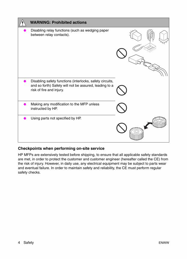
WARNING: Prohibited actions
● Using any cables or power cord not specified by HP.
● Using any fuse or thermostat not specified by HP.
● Safety will not be assured, leading to a risk of fire and injury.
● Disabling fuse functions or bridging fuse terminals with wire, metal clips, solder or similar object.
ENWW Safety warnings 3
Checkpoints when performing on-site service
HP MFPs are extensively tested before shipping, to ensure that all applicable safety standards are met, in order to protect the customer and customer engineer (hereafter called the CE) from the risk of injury. However, in daily use, any electrical equipment may be subject to parts wear and eventual failure. In order to maintain safety and reliability, the CE must perform regular safety checks.
● Disabling relay functions (such as wedging paper between relay contacts).
● Disabling safety functions (interlocks, safety circuits, and so forth) Safety will not be assured, leading to a risk of fire and injury.
● Making any modification to the MFP unless instructed by HP.
● Using parts not specified by HP.
WARNING: Prohibited actions
4 Safety ENWW

Saf
ety
Power supply
WARNING: Wall outlet
● Check that mains voltage is as specified. Plug the power cord into the dedicated wall outlet with a capacity greater than the maximum power consumption.
● If excessive current flows in the wall outlet, fire may result.
● If two or more power cords can be plugged into the wall outlet, the total load must not exceed the rating of the wall outlet.
● If excessive current flows in the wall outlet, fire may result.
WARNING: Power plug and cord
● Make sure the power cord is plugged in the wall outlet securely.
Contact problems may lead to increased resistance, overheating, and the risk of fire.
● Check whether the power cord is damaged. Check whether the sheath is damaged.
If the power plug, cord, or sheath is damaged, replace with a new power cord (with plugs on both ends) specified by HP. Using the damaged power cord may result in fire or electric shock.
● When using the power cord (inlet type) that came with this MFP, be sure to observe the following precautions:
a Make sure the MFP-side power plug is securely inserted in the socket on the rear panel of the MFP.Secure the cord with a fixture properly.
b If the power cord or sheath is damaged, replace with a new power cord (with plugs on both ends) specified by HP. If the power cord (inlet type) is not connected to the MFP securely, a contact problem may lead to increased resistance, overheating, and risk of fire.
kw
ENWW Safety warnings 5

● Check whether the power cord is not stepped on or pinched by a table and so on.
● Overheating may occur there, leading to a risk of fire.
● Do not bundle or tie the power cord.
Overheating may occur there, leading to a risk of fire.
● Check whether dust is collected around the power plug and wall outlet.
Using the power plug and wall outlet without removing dust may result in fire.
● Do not insert the power plug into the wall outlet with a wet hand.
The risk of electric shock exists.
● When unplugging the power cord, grasp the plug, not the cable.
The cable may be broken, leading to a risk of fire and electric shock.
WARNING: Wiring
● Never use multi-plug adapters to plug multiple power cords in the same outlet.
If used, the risk of fire exists.
● When an extension cord is required, use the specified type.
Current that can flow in the extension cord is limited, so using a too long extension cord may result in fire.
Do not use an extension cable reel with the cable taken up. Fire may result.
WARNING: Power plug and cord
6 Safety ENWW
Saf
ety
Installation requirements
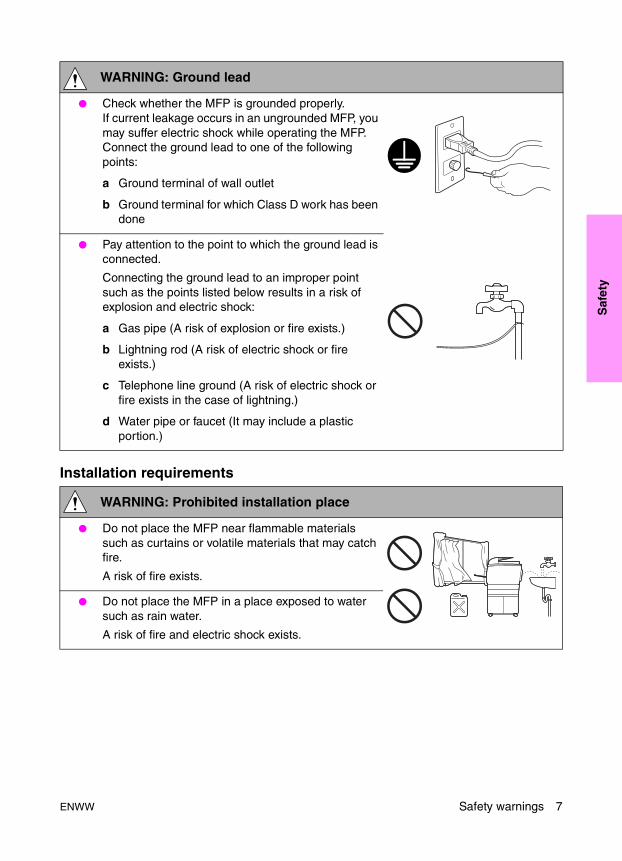
WARNING: Ground lead
● Check whether the MFP is grounded properly.If current leakage occurs in an ungrounded MFP, you may suffer electric shock while operating the MFP. Connect the ground lead to one of the following points:
a Ground terminal of wall outlet
b Ground terminal for which Class D work has been done
● Pay attention to the point to which the ground lead is connected.
Connecting the ground lead to an improper point such as the points listed below results in a risk of explosion and electric shock:
a Gas pipe (A risk of explosion or fire exists.)
b Lightning rod (A risk of electric shock or fire exists.)
c Telephone line ground (A risk of electric shock or fire exists in the case of lightning.)
d Water pipe or faucet (It may include a plastic portion.)
WARNING: Prohibited installation place
● Do not place the MFP near flammable materials such as curtains or volatile materials that may catch fire.
A risk of fire exists.
● Do not place the MFP in a place exposed to water such as rain water.
A risk of fire and electric shock exists.
ENWW Safety warnings 7
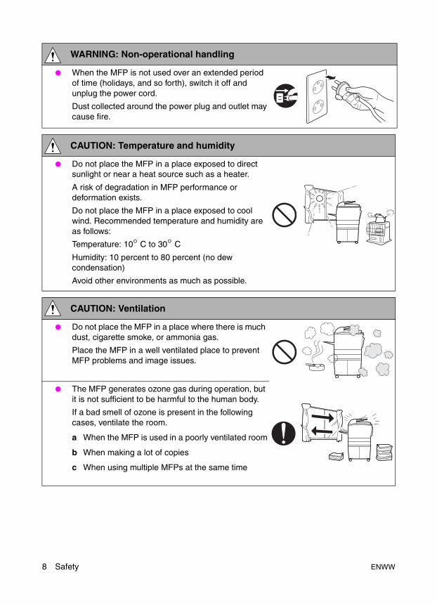
WARNING: Non-operational handling
● When the MFP is not used over an extended period of time (holidays, and so forth), switch it off and unplug the power cord.
Dust collected around the power plug and outlet may cause fire.
CAUTION: Temperature and humidity
● Do not place the MFP in a place exposed to direct sunlight or near a heat source such as a heater.
A risk of degradation in MFP performance or deformation exists.
Do not place the MFP in a place exposed to cool wind. Recommended temperature and humidity are as follows:
Temperature: 10° C to 30° C
Humidity: 10 percent to 80 percent (no dew condensation)
Avoid other environments as much as possible.
CAUTION: Ventilation
● Do not place the MFP in a place where there is much dust, cigarette smoke, or ammonia gas.
Place the MFP in a well ventilated place to prevent MFP problems and image issues.
● The MFP generates ozone gas during operation, but it is not sufficient to be harmful to the human body.
If a bad smell of ozone is present in the following cases, ventilate the room.
a When the MFP is used in a poorly ventilated room
b When making a lot of copies
c When using multiple MFPs at the same time
8 Safety ENWW
Saf
ety
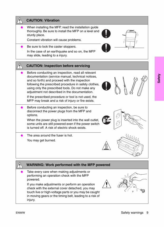
CAUTION: Vibration
● When installing the MFP, read the installation guide thoroughly. Be sure to install the MFP on a level and sturdy place.
Constant vibration will cause problems.
● Be sure to lock the caster stoppers.
In the case of an earthquake and so on, the MFP may slide, leading to a injury.
CAUTION: Inspection before servicing
● Before conducting an inspection, read all relevant documentation (service manual, technical notices, and so forth) and proceed with the inspection following the prescribed procedure in safety clothes, using only the prescribed tools. Do not make any adjustment not described in the documentation.
If the prescribed procedure or tool is not used, the MFP may break and a risk of injury or fire exists.
● Before conducting an inspection, be sure to disconnect the power plugs from the MFP and options.
When the power plug is inserted into the wall outlet, some units are still powered even if the power switch is turned off. A risk of electric shock exists.
● The area around the fuser is hot.
You may get burned.
WARNING: Work performed with the MFP powered
● Take every care when making adjustments or performing an operation check with the MFP powered.
If you make adjustments or perform an operation check with the external cover detached, you may touch live or high-voltage parts or you may be caught in moving gears or the timing belt, leading to a risk of injury.
ENWW Safety warnings 9
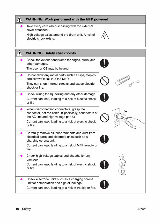
● Take every care when servicing with the external cover detached.
High-voltage exists around the drum unit. A risk of electric shock exists.
WARNING: Safety checkpoints
● Check the exterior and frame for edges, burrs, and other damages.
The user or CE may be injured.
● Do not allow any metal parts such as clips, staples, and screws to fall into the MFP.
They can short internal circuits and cause electric shock or fire.
● Check wiring for squeezing and any other damage.
Current can leak, leading to a risk of electric shock or fire.
● When disconnecting connectors, grasp the connector, not the cable. (Specifically, connectors of the AC line and high-voltage parts.)
Current can leak, leading to a risk of electric shock or fire.
● Carefully remove all toner remnants and dust from electrical parts and electrode units such as a charging corona unit.
Current can leak, leading to a risk of MFP trouble or fire.
● Check high-voltage cables and sheaths for any damage.
Current can leak, leading to a risk of electric shock or fire.
● Check electrode units such as a charging corona unit for deterioration and sign of leakage.
Current can leak, leading to a risk of trouble or fire.
WARNING: Work performed with the MFP powered
10 Safety ENWW
Saf
ety
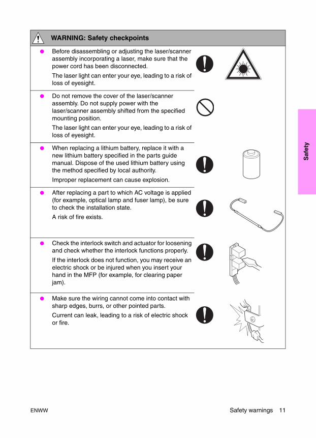
● Before disassembling or adjusting the laser/scanner assembly incorporating a laser, make sure that the power cord has been disconnected.
The laser light can enter your eye, leading to a risk of loss of eyesight.
● Do not remove the cover of the laser/scanner assembly. Do not supply power with the laser/scanner assembly shifted from the specified mounting position.
The laser light can enter your eye, leading to a risk of loss of eyesight.
● When replacing a lithium battery, replace it with a new lithium battery specified in the parts guide manual. Dispose of the used lithium battery using the method specified by local authority.
Improper replacement can cause explosion.
● After replacing a part to which AC voltage is applied (for example, optical lamp and fuser lamp), be sure to check the installation state.
A risk of fire exists.
● Check the interlock switch and actuator for loosening and check whether the interlock functions properly.
If the interlock does not function, you may receive an electric shock or be injured when you insert your hand in the MFP (for example, for clearing paper jam).
● Make sure the wiring cannot come into contact with sharp edges, burrs, or other pointed parts.
Current can leak, leading to a risk of electric shock or fire.
WARNING: Safety checkpoints
ENWW Safety warnings 11
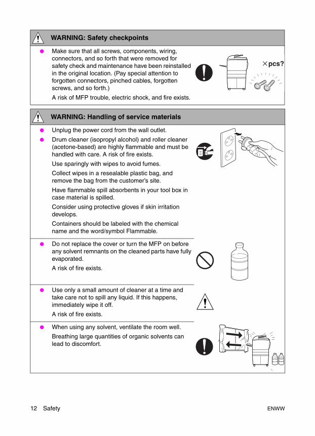
● Make sure that all screws, components, wiring, connectors, and so forth that were removed for safety check and maintenance have been reinstalled in the original location. (Pay special attention to forgotten connectors, pinched cables, forgotten screws, and so forth.)
A risk of MFP trouble, electric shock, and fire exists.
WARNING: Handling of service materials
● Unplug the power cord from the wall outlet.
● Drum cleaner (isopropyl alcohol) and roller cleaner (acetone-based) are highly flammable and must be handled with care. A risk of fire exists.
Use sparingly with wipes to avoid fumes.
Collect wipes in a resealable plastic bag, and remove the bag from the customer’s site.
Have flammable spill absorbents in your tool box in case material is spilled.
Consider using protective gloves if skin irritation develops.
Containers should be labeled with the chemical name and the word/symbol Flammable.
● Do not replace the cover or turn the MFP on before any solvent remnants on the cleaned parts have fully evaporated.
A risk of fire exists.
● Use only a small amount of cleaner at a time and take care not to spill any liquid. If this happens, immediately wipe it off.
A risk of fire exists.
● When using any solvent, ventilate the room well.
Breathing large quantities of organic solvents can lead to discomfort.
WARNING: Safety checkpoints
12 Safety ENWW

Saf
ety
Measures to take in case of an accidentIf an accident has occurred, the distributor who has been notified first must immediately take emergency measures to provide relief to affected persons and to prevent further damage.
If a report of a serious accident has been received from a customer, an on-site evaluation must be carried out quickly and HP Corporation must be notified.
To determine the cause of the accident, conditions and materials must be recorded through direct on-site checks, in accordance with instructions issued by HP Corporation.
ConclusionSafety of users and customer engineers depends highly on accurate maintenance and administration. Therefore, safety can be maintained by the appropriate daily service work conducted by the customer engineer.
When performing service, each MFP on the site must be tested for safety. The customer engineer must verify the safety of parts and ensure appropriate management of the equipment.
● Toner and developer are not harmful substances, but care must be taken not to breathe excessive amounts or let the substances come into contact with eyes, and so on. It may be stimulative.
If the substances get in the eye, rinse with plenty of water immediately. When symptoms are noticeable, consult a physician.
Avoid creating dust and inhaling dust, particularly wen removing waste developer and adding new developer.
Place waste toner and developer in a resealable plastic bag, and remove the bag from the customer’s site.
Use an explosion-proof vacuum with a HEPA filter for cleaning up toner and developer.
● Never throw the used cartridge and toner into fire.
You may be burned due to dust explosion.
WARNING: Handling of service materials
ENWW Safety warnings 13

Handling and disposition of consumablesAll preventive maintenance replacement parts, consumables, and associated supplies, including all wipes, waste developer, and so on, should be removed from the customer’s site. Wipes, in particular wipes used with drum cleaner and roller cleaner, should be placed in a resealable bag or other sealable container to avoid fumes and potential fire danger. Waste developer should also be placed in a resealable bag or other sealable container to avoid creating dust. Care should be taken when removing waste developer and when placing the waste in the sealable container to avoid creating dust.
All parts, consumables, and associated supplies should be returned to the service office location for appropriate recycling or disposal. Service office Environment, Health, and Safety staff should be consulted to determine the proper handling and disposition.
Regulatory statements
FCC RegulationsFCC Class A Statement
This equipment has been tested and found to comply with the limits for a Class A digital device, pursuant to Part 15 of the FCC Rules. These limits are designed to provide reasonable protection against harmful interference when the equipment is operated in a commercial environment. This equipment generates, uses, and can radiate radio frequency energy and, if not installed and used in accordance with the instruction manual, may cause harmful interference to radio communications. Operation of this equipment in a residential area is likely to cause harmful interference, in which case the user will be required to correct the interference at his own expense. The end user of this product should be aware that any changes or modifications made to this equipment without the approval of Hewlett-Packard could result in the product not meeting the Class A limits, in which case the FCC could void the user’s authority to operate the equipment.
● Reorient or relocate the receiving antenna.
● Increase separation between equipment and receiver.
● Connect equipment to an outlet on a circuit different from that to which the receiver is located.
● Consult your dealer or an experienced radio/TV technician.
Note Any changes or modifications to the MFP that are not expressly approved by HP could void the user’s authority to operate this equipment.
Use of a shielded interface cable is required to comply with the Class A limits of Part 15 of FCC rules.
14 Safety ENWW

Saf
ety
Safety information
Safety circuitsThis MFP is provided with the following safety circuits to prevent MFP issues from resulting in serious accidents.
Overall protection circuitL2 and L3 (fuser heater lamps) overheating prevention circuit
These safety circuits are described below to provide the service engineer with a renewed awareness of them in order to prevent servicing errors that may impair their functions.
Overall protection circuit
Protection by CBR1 and CBR2 (circuit breakers)
CBR1 and CBR2 interrupt the AC line instantaneously when an excessive current flows due to a short in the AC line.
CAUTION The CBR1 and CBR2 functions must not be deactivated under any circumstances.
NF
CBR2
CBR1
ENWW Safety information 15
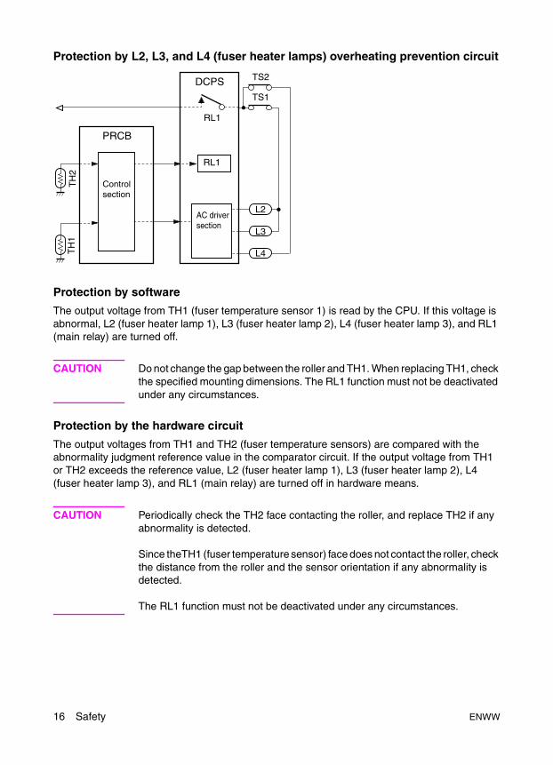
Protection by L2, L3, and L4 (fuser heater lamps) overheating prevention circuit
Protection by software
The output voltage from TH1 (fuser temperature sensor 1) is read by the CPU. If this voltage is abnormal, L2 (fuser heater lamp 1), L3 (fuser heater lamp 2), L4 (fuser heater lamp 3), and RL1 (main relay) are turned off.
CAUTION Do not change the gap between the roller and TH1. When replacing TH1, check the specified mounting dimensions. The RL1 function must not be deactivated under any circumstances.
Protection by the hardware circuit
The output voltages from TH1 and TH2 (fuser temperature sensors) are compared with the abnormality judgment reference value in the comparator circuit. If the output voltage from TH1 or TH2 exceeds the reference value, L2 (fuser heater lamp 1), L3 (fuser heater lamp 2), L4 (fuser heater lamp 3), and RL1 (main relay) are turned off in hardware means.
CAUTION Periodically check the TH2 face contacting the roller, and replace TH2 if any abnormality is detected.
Since theTH1 (fuser temperature sensor) face does not contact the roller, check the distance from the roller and the sensor orientation if any abnormality is detected.
The RL1 function must not be deactivated under any circumstances.
L3
L4
DCPS
PRCB
L2
Controlsection
TH
2T
H1
RL1
RL1
TS1
TS2
AC driversection
16 Safety ENWW

Saf
ety
Protection by TS1 (thermostat/U) and TS2 (thermostat/L)
When the temperature of the fuser roller (upper/lower) exceeds the specified value, TSs are turned off, thus interrupting the power to L2 (fuser heater lamp/1), L3 (fuser heater lamp/2), and L4 (fuser heater lamp/3) directly.
CAUTION Do not use any other electrical conductor in place of TS1 and TS2. Do not change the distance between the roller and TS (thermostat).
ENWW Safety information 17

Safety labels on the MFPsCaution labels shown below are attached in some areas on/in the MFP. When accessing these areas for maintenance, repair, or adjustment, special care should be taken to avoid burns and electric shock.
High temperature! Do not touch. Use care when clearing paper.
ÁTemperatura alta! No tocar. Tener cuidado al remover el papel.
Alta temperatura! Non toccare. Agire con prudenza nel rimuovere la carta.
Hei§e OberflŠche!Brandverletzungsgefahr. Bei Beseitigung von Papierstaus vorsichtig vorgehen.
Temp rature lev e! Risque de br lure. Soyez prudent en retirant la feuille coinc e.
VORSICHT
CAUTION
ATTENTION
PRECAUCION
ATTENZIONE
CAUTIONATTENTIONVORSICHTPRECAUCIONATTENZIONE
ATTENTIONVORSICHTPRECAUCIONATTENZIONE
CAUTION
This area generates high voltage. If touched, electrical shock may occur. DO NOT TOUCH.
DO NOT INSERT your finger into the two RADF hinge portions; otherwise you may be injured.
CAUTION
The fixing unit is very hot. To avoide getting burned, DO NOT TOUCH.
CAUTION
DO NOT put your hand between the main body and developing fixing unit; otherwise you may be injured.
CAUTION
WARNING
The conveyance fixing unit is heavy. Use care and draw it out gently; otherwise you may be injured.
CAUTION
18 Safety ENWW

Saf
ety
CAUTION You may be burned or injured if you touch any area that you are advised by any caution label to avoid.
ENWW Safety labels on the MFPs 19
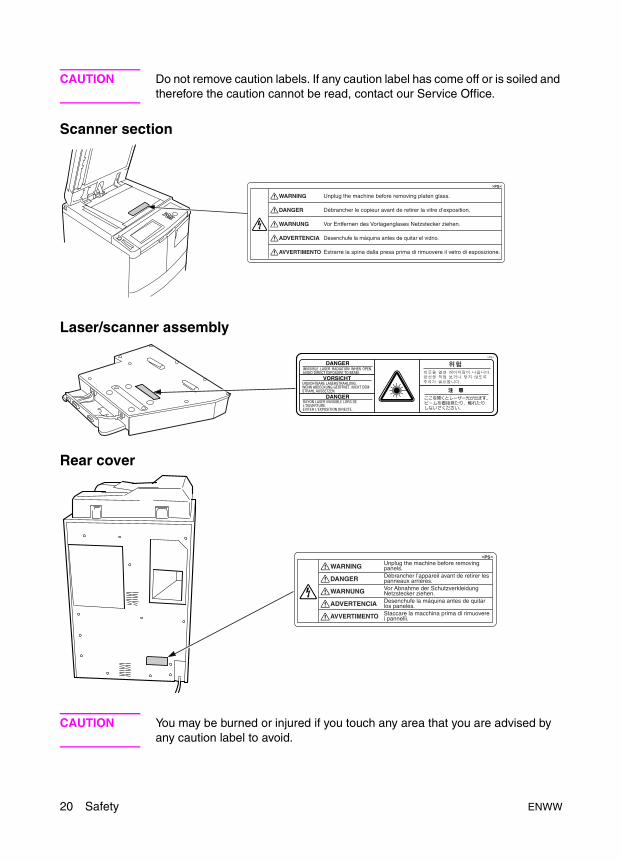
CAUTION Do not remove caution labels. If any caution label has come off or is soiled and therefore the caution cannot be read, contact our Service Office.
Scanner section
Laser/scanner assembly
Rear cover
CAUTION You may be burned or injured if you touch any area that you are advised by any caution label to avoid.
20 Safety ENWW
ENWW
Ad
just
men
ts
2Adjustments
How to use this section . . . . . . . . . . . . . . . . . . . . . . . . . . . . . . . . . . . . . . . . . 24Scope and precautions . . . . . . . . . . . . . . . . . . . . . . . . . . . . . . . . . . . . . 24
Adjustments made when replacing parts . . . . . . . . . . . . . . . . . . . . . . . . . . . . 24How to read tables . . . . . . . . . . . . . . . . . . . . . . . . . . . . . . . . . . . . . . . . . 25
List of adjustment items on 9055mfp/9065mfp . . . . . . . . . . . . . . . . . . . . . . . 26LCD adjustment . . . . . . . . . . . . . . . . . . . . . . . . . . . . . . . . . . . . . . . . . . . . . . . 28
LCD control panel adjustment . . . . . . . . . . . . . . . . . . . . . . . . . . . . . . . . 28LCD panel contrast/key sound adjustment . . . . . . . . . . . . . . . . . . . . . . 28
Settings and adjustments made with the P function . . . . . . . . . . . . . . . . . . . 28Checking and printing the P function . . . . . . . . . . . . . . . . . . . . . . . . . . . 28Setting up the P function . . . . . . . . . . . . . . . . . . . . . . . . . . . . . . . . . . . . 28
Mode changing menu. . . . . . . . . . . . . . . . . . . . . . . . . . . . . . . . . . . . . . . . . . . 29Mode selection . . . . . . . . . . . . . . . . . . . . . . . . . . . . . . . . . . . . . . . . . . . . 29
2-5 mode . . . . . . . . . . . . . . . . . . . . . . . . . . . . . . . . . . . . . . . . . . . . . . . . . . . . 29Setting the 2-5 mode . . . . . . . . . . . . . . . . . . . . . . . . . . . . . . . . . . . . . . . 29List of adjustment items for 2-5 mode . . . . . . . . . . . . . . . . . . . . . . . . . . 30Setting software switches. . . . . . . . . . . . . . . . . . . . . . . . . . . . . . . . . . . . 31List of software switches . . . . . . . . . . . . . . . . . . . . . . . . . . . . . . . . . . . . 32PM count resetting . . . . . . . . . . . . . . . . . . . . . . . . . . . . . . . . . . . . . . . . . 45Setting the PM cycle . . . . . . . . . . . . . . . . . . . . . . . . . . . . . . . . . . . . . . . 45Collecting data . . . . . . . . . . . . . . . . . . . . . . . . . . . . . . . . . . . . . . . . . . . . 46Copy count by parts to be replaced (fixed parts) . . . . . . . . . . . . . . . . . . 57Copy count parts counter . . . . . . . . . . . . . . . . . . . . . . . . . . . . . . . . . . . . 58Copy count by parts to be replaced (optional parts) . . . . . . . . . . . . . . . 61Setting passwords . . . . . . . . . . . . . . . . . . . . . . . . . . . . . . . . . . . . . . . . . 62Setting the telephone number and/or fax number of the
service center. . . . . . . . . . . . . . . . . . . . . . . . . . . . . . . . . . . . . . . . . 63Setting the serial number . . . . . . . . . . . . . . . . . . . . . . . . . . . . . . . . . . . . 63
Setting date . . . . . . . . . . . . . . . . . . . . . . . . . . . . . . . . . . . . . . . . . . . . . . . . . . 643-6 mode . . . . . . . . . . . . . . . . . . . . . . . . . . . . . . . . . . . . . . . . . . . . . . . . . . . . 64
Setting method . . . . . . . . . . . . . . . . . . . . . . . . . . . . . . . . . . . . . . . . . . . . 64List of adjustment items for 3-6 mode . . . . . . . . . . . . . . . . . . . . . . . . . . 65High voltage adjustment. . . . . . . . . . . . . . . . . . . . . . . . . . . . . . . . . . . . . 67Charging grid voltage adjustment . . . . . . . . . . . . . . . . . . . . . . . . . . . . . 68Drum calibration adjustment . . . . . . . . . . . . . . . . . . . . . . . . . . . . . . . . . 68Drum calibration adjustment (manual) . . . . . . . . . . . . . . . . . . . . . . . . . . 73Custom paper setting . . . . . . . . . . . . . . . . . . . . . . . . . . . . . . . . . . . . . . . 73Recall standard data (process adjustment) . . . . . . . . . . . . . . . . . . . . . . 73Image adjustment. . . . . . . . . . . . . . . . . . . . . . . . . . . . . . . . . . . . . . . . . . 73Tray adjustment . . . . . . . . . . . . . . . . . . . . . . . . . . . . . . . . . . . . . . . . . . . 73
21
22
Magnification adjustment . . . . . . . . . . . . . . . . . . . . . . . . . . . . . . . . . . . . 74Document feeder adjustment . . . . . . . . . . . . . . . . . . . . . . . . . . . . . . . . . 80Distortion adjustment (MFP) . . . . . . . . . . . . . . . . . . . . . . . . . . . . . . . . . 83Non-image area erase check . . . . . . . . . . . . . . . . . . . . . . . . . . . . . . . . . 83Recall standard data (Image adjustment) . . . . . . . . . . . . . . . . . . . . . . . 84Running test mode . . . . . . . . . . . . . . . . . . . . . . . . . . . . . . . . . . . . . . . . . 84Test pattern density setting . . . . . . . . . . . . . . . . . . . . . . . . . . . . . . . . . . 92Finisher adjustment . . . . . . . . . . . . . . . . . . . . . . . . . . . . . . . . . . . . . . . . 92Stapling and folding stopper adjustment . . . . . . . . . . . . . . . . . . . . . . . . 92List output mode. . . . . . . . . . . . . . . . . . . . . . . . . . . . . . . . . . . . . . . . . . . 96
4-7 Mode . . . . . . . . . . . . . . . . . . . . . . . . . . . . . . . . . . . . . . . . . . . . . . . . . . . . 964-7 Mode/multi-mode setting method. . . . . . . . . . . . . . . . . . . . . . . . . . . 96Adjustment data display . . . . . . . . . . . . . . . . . . . . . . . . . . . . . . . . . . . . . 98Hard disk check . . . . . . . . . . . . . . . . . . . . . . . . . . . . . . . . . . . . . . . . . . . 98Input checklist . . . . . . . . . . . . . . . . . . . . . . . . . . . . . . . . . . . . . . . . . . . . . . . . . 100Output checklist . . . . . . . . . . . . . . . . . . . . . . . . . . . . . . . . . . . . . . . . . . 104
Other adjustments . . . . . . . . . . . . . . . . . . . . . . . . . . . . . . . . . . . . . . . . . . . . 111Tray centering adjustment . . . . . . . . . . . . . . . . . . . . . . . . . . . . . . . . . . 111HCI: Paper size adjustment . . . . . . . . . . . . . . . . . . . . . . . . . . . . . . . . . 113MFP skew adjustment . . . . . . . . . . . . . . . . . . . . . . . . . . . . . . . . . . . . . 114HCI pick roller pressure adjustment (ledger/A3 only). . . . . . . . . . . . . . 114HCI lift plate horizontal adjustment . . . . . . . . . . . . . . . . . . . . . . . . . . . 115HCI skew adjustment . . . . . . . . . . . . . . . . . . . . . . . . . . . . . . . . . . . . . . 117Trays 1-4, HCI, and PI spring pressure adjustment . . . . . . . . . . . . . . . 118HCI paper feed height upper limit adjustment . . . . . . . . . . . . . . . . . . . 120HCI pick-up release amount adjustment . . . . . . . . . . . . . . . . . . . . . . . 121ADF: aligning on top of scanner. . . . . . . . . . . . . . . . . . . . . . . . . . . . . . 122ADF: alignment to ADF glass. . . . . . . . . . . . . . . . . . . . . . . . . . . . . . . . 123ADF: paper skew adjustment . . . . . . . . . . . . . . . . . . . . . . . . . . . . . . . . 124Finisher: adjusting the magnets on the bypass conveyance
guide plate . . . . . . . . . . . . . . . . . . . . . . . . . . . . . . . . . . . . . . . . . . 125Finisher: adjusting the bypass gate . . . . . . . . . . . . . . . . . . . . . . . . . . . 126Finisher: adjusting the shift position . . . . . . . . . . . . . . . . . . . . . . . . . . . 128Finisher: adjusting the paper exit solenoid. . . . . . . . . . . . . . . . . . . . . . 129Finisher: adjusting the mount location of the paper exit arm . . . . . . . . 130Finisher: adjusting the mount location of the alignment plates/U. . . . . 131Finisher: adjusting the mount location of the alignment plates/L
(Multifunction Finisher only) . . . . . . . . . . . . . . . . . . . . . . . . . . . . . 132Finisher: adjusting the stapling position (flat stapling) . . . . . . . . . . . . . 133Finisher: adjusting the stapler vertical positioning . . . . . . . . . . . . . . . . 134Finisher: adjusting the stapling position (staple-and-fold)
(Multifunction Finisher only) . . . . . . . . . . . . . . . . . . . . . . . . . . . . . 136Finisher: adjusting the angle of the folding stopper (Multifunction
Finisher only) . . . . . . . . . . . . . . . . . . . . . . . . . . . . . . . . . . . . . . . . 137Finisher: adjusting the folding force (Multifunction Finisher only) . . . . 138Finisher: adjusting the tri-fold positions (Multifunction Finisher only). . 139Adjusting the vertical skew of the punch kit . . . . . . . . . . . . . . . . . . . . . 140Sensor threshold adjustment for the punch kit paper edge sensor . . . 141PI centering adjustment . . . . . . . . . . . . . . . . . . . . . . . . . . . . . . . . . . . . 142Adjusting the vertical skew when using the post inserter. . . . . . . . . . . 144Finisher: stapler driver belt position adjustment. . . . . . . . . . . . . . . . . . 145
ENWW

ENWW
Ad
just
men
ts
Other adjustments . . . . . . . . . . . . . . . . . . . . . . . . . . . . . . . . . . . . . . . . . . . . 146MFP: Optics unit alignment . . . . . . . . . . . . . . . . . . . . . . . . . . . . . . . . . 146MFP: Scanner motor belt adjustment. . . . . . . . . . . . . . . . . . . . . . . . . . 146MFP: Fuser temp sensor alignment . . . . . . . . . . . . . . . . . . . . . . . . . . . 146MFP: Fuser thermostat alignment . . . . . . . . . . . . . . . . . . . . . . . . . . . . 146Finisher: Up/down wire tension adjustment . . . . . . . . . . . . . . . . . . . . . 146
23
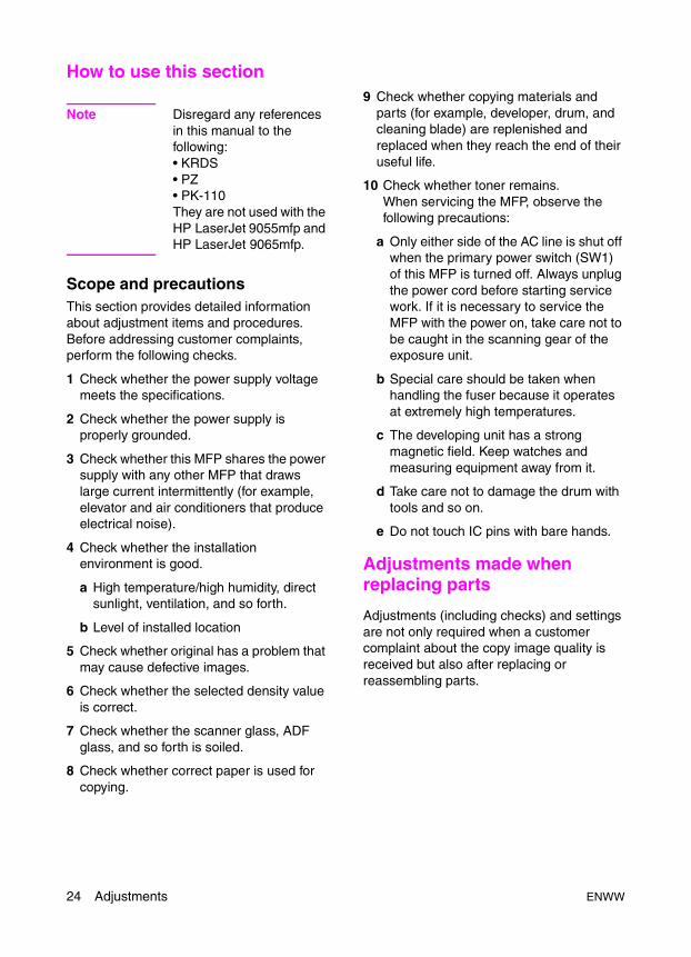
How to use this section
Note Disregard any references in this manual to the following:• KRDS• PZ• PK-110They are not used with the HP LaserJet 9055mfp and HP LaserJet 9065mfp.
Scope and precautionsThis section provides detailed information about adjustment items and procedures. Before addressing customer complaints, perform the following checks.
1 Check whether the power supply voltage meets the specifications.
2 Check whether the power supply is properly grounded.
3 Check whether this MFP shares the power supply with any other MFP that draws large current intermittently (for example, elevator and air conditioners that produce electrical noise).
4 Check whether the installation environment is good.
a High temperature/high humidity, direct sunlight, ventilation, and so forth.
b Level of installed location
5 Check whether original has a problem that may cause defective images.
6 Check whether the selected density value is correct.
7 Check whether the scanner glass, ADF glass, and so forth is soiled.
8 Check whether correct paper is used for copying.
9 Check whether copying materials and parts (for example, developer, drum, and cleaning blade) are replenished and replaced when they reach the end of their useful life.
10 Check whether toner remains.When servicing the MFP, observe the following precautions:
a Only either side of the AC line is shut off when the primary power switch (SW1) of this MFP is turned off. Always unplug the power cord before starting service work. If it is necessary to service the MFP with the power on, take care not to be caught in the scanning gear of the exposure unit.
b Special care should be taken when handling the fuser because it operates at extremely high temperatures.
c The developing unit has a strong magnetic field. Keep watches and measuring equipment away from it.
d Take care not to damage the drum with tools and so on.
e Do not touch IC pins with bare hands.
Adjustments made when replacing parts
Adjustments (including checks) and settings are not only required when a customer complaint about the copy image quality is received but also after replacing or reassembling parts.
24 Adjustments ENWW

Ad
just
men
ts
How to read tablesComponents of the tables used in this section are as follows:
1 ModeAdjustment mode to be selected.[P]: P mode [25]: 2-5 mode[36]: 3-6 mode [47]: 4-7 mode[?]: key operator mode
2 CodeCode and copy quantity setting button used in each mode.
3 PagePage in the “Adjustment” section.
4 Circled numbers Indicate that adjustments
(including checks) must be made in order of precedence.
(Circle without numeric character): Indicates that adjustments (including checks) can be made independently.
1 2
ENWW Adjustments made when replacing parts 25

List of adjustment items on 9055mfp/9065mfpIt
em N
o.
Cla
ssif
icat
ion
by
Ad
just
men
t
Ad
just
men
t It
em
Mo
de
Pag
e
Dru
m
Dev
elo
per
Las
er/s
can
ner
ass
emb
ly
Du
st-p
roo
f g
lass
Eac
h t
ray
un
it
Tray
1 p
aper
fee
d u
nit
Tray
up
/do
wn
wir
e
Reg
istr
atio
n r
olle
r
Reg
istr
atio
n u
nit
Reg
istr
atio
n c
lutc
h
Mis
-cen
teri
ng
det
ecti
on
sen
sor
AD
U u
nit
CC
D u
nit
Fu
ser
Mem
ory
bo
ard
AD
F
HC
I
Fin
ish
er
Sta
ple
r u
nit
PI
PK
(P
un
ch k
its)
1 Process adjustment
High voltage adjustment
Charging grid manual adjustment
36 1-48 O
2 Drum calibration adjustment
Blade setting mode 1-49 O
3 Auto maximum contrast adjustment
1-49 O
4 Auto dot diameter adjustment
1-50 O
5 LD1 offset adjustment 1-51 O
6 LD2 offset adjustment 1-52 O
7 Auto gamma adjustment (1dot)
1-53 O
8 Auto gamma adjustment (2dot)
1-54 O
9 Cartridge set mode (drum) 1-54 O
10 Image adjustment
Tray adjustment
1-56 O O O
11 Magnification adjustment
MFP vertical magnification adjustment
1-57 O O O
12 MFP horizontal magnification adjustment
1-58 O O O
13 Scanner drum clock adjustment
1-58 O O
14 ADF drum clock adjustment 1-59 O O
15 Timing adjustment
MFP leading edge timing adjustment
1-61 O O O O O
16 MFP registration loop adjustment
1-61 O
17 MFP pre-registration adjustment
1-62 O
18 MFP leading edge timing adjustment
1-62 O
19 Scanner restart timing adjustment
1-63 O O
20 ADF restart timing adjustment
1-63 O O O
21 Scanner (ADF) registration loop adjustment
1-64 O
22 Document feeder adjustment
Document feeder contrast adjustment
1-65 O
23 ADF original size adjustment
1-65 O O
24 ADF skew offset adjustment 1-66 O O
25 Centering adjustment
MFP centering adjustment 1-67 O O O
26 Scanner (platen) centering adjustment
1-67 O O
27 ADF centering adjustment 1-68 O O O
28 Warp adjustment (MFP)
Scanner (platen) warp (main scan)
1-68 O O
29 Scanner (platen) warp (secondary)
1-68 O O
30 Scanner (ADF) warp (main scan)
1-68 O O
31 Scanner (ADF) warp (secondary)
1-68 O O
32 Finisher adjustment
Stapling and folding stopper adjustment 1-79 O O
33 Folding stopper adjustment 1-79 O O
34 Cover sheet tray size adjustment 1-80 O O
35 Finisher adjustment
Punch adjustment
Punch vertical position adjustment
36 1-81 O O
36 Punch horizontalposition adjustment
1-81 O O
37 Punch registration loop adjustment
1-81-1 O O
26 Adjustments ENWW
Ad
just
men
ts
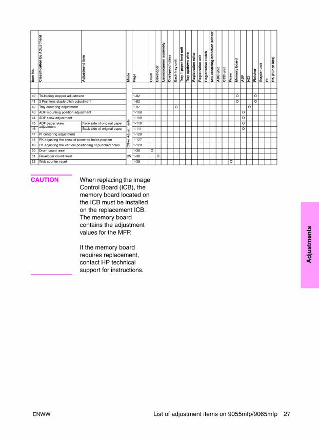
CAUTION When replacing the Image Control Board (ICB), the memory board located on the ICB must be installed on the replacement ICB. The memory board contains the adjustment values for the MFP.
If the memory board requires replacement, contact HP technical support for instructions.
Oth
er A
djus
tmen
ts
40 Tri-folding stopper adjustment 1-82 O O
41 2 Positions staple pitch adjustment 1-82 O O
42 Tray centering adjustment 1-97 O O
43 ADF mounting position adjustment 1-108 O
44 ADF skew adjustment 1-109 O
45 ADF paper skew adjustment
Face side of original paper 1-110 O
46 Back side of original paper 1-111 O
47 PI centering adjustment 1-129
48 PK adjusting the skew of punched holes position 1-127
49 PK adjusting the vertical positioning of punched holes 1-128
50 Drum count reset 1-38 O
51 Developer count reset 25 1-38 O
52 Web counter reset 1-38 O
Item
No
.
Cla
ssif
icat
ion
by
Ad
just
men
t
Ad
just
men
t It
em
Mo
de
Pag
e
Dru
m
Dev
elo
per
Las
er/s
can
ner
ass
emb
ly
Du
st-p
roo
f g
lass
Eac
h t
ray
un
it
Tray
1 p
aper
fee
d u
nit
Tray
up
/do
wn
wir
e
Reg
istr
atio
n r
olle
r
Reg
istr
atio
n u
nit
Reg
istr
atio
n c
lutc
h
Mis
-cen
teri
ng
det
ecti
on
sen
sor
AD
U u
nit
CC
D u
nit
Fu
ser
Mem
ory
bo
ard
AD
F
HC
I
Fin
ish
er
Sta
ple
r u
nit
PI
PK
(P
un
ch k
its)
ENWW List of adjustment items on 9055mfp/9065mfp 27
LCD adjustment
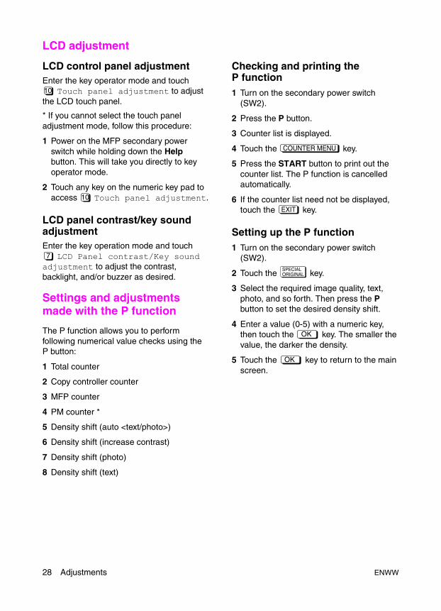
LCD control panel adjustmentEnter the key operator mode and touch
Touch panel adjustment to adjust the LCD touch panel.
* If you cannot select the touch panel adjustment mode, follow this procedure:
1 Power on the MFP secondary power switch while holding down the Help button. This will take you directly to key operator mode.
2 Touch any key on the numeric key pad to access Touch panel adjustment.
LCD panel contrast/key sound adjustmentEnter the key operation mode and touch
LCD Panel contrast/Key sound adjustment to adjust the contrast, backlight, and/or buzzer as desired.
Settings and adjustments made with the P function
The P function allows you to perform following numerical value checks using the P button:
1 Total counter
2 Copy controller counter
3 MFP counter
4 PM counter *
5 Density shift (auto <text/photo>)
6 Density shift (increase contrast)
7 Density shift (photo)
8 Density shift (text)
Checking and printing the P function1 Turn on the secondary power switch
(SW2).
2 Press the P button.
3 Counter list is displayed.
4 Touch the key.
5 Press the START button to print out the counter list. The P function is cancelled automatically.
6 If the counter list need not be displayed, touch the key.
Setting up the P function1 Turn on the secondary power switch
(SW2).
2 Touch the key.
3 Select the required image quality, text, photo, and so forth. Then press the P button to set the desired density shift.
4 Enter a value (0-5) with a numeric key, then touch the key. The smaller the value, the darker the density.
5 Touch the key to return to the main screen.
10
10
7
COUNTER MENU
EXIT
SPECIALORIGINAL
OK
OK
28 Adjustments ENWW
Ad
just
men
ts
Mode changing menu
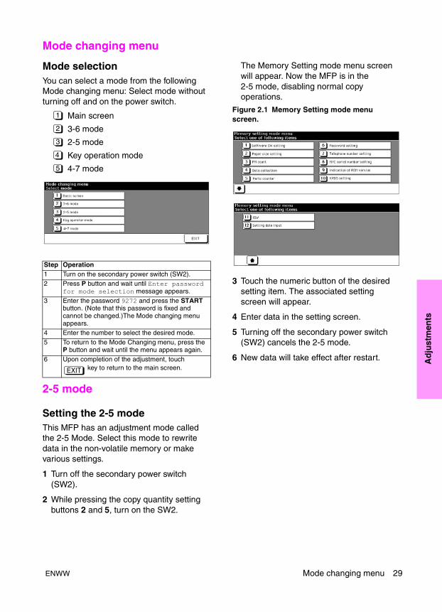
Mode selectionYou can select a mode from the following Mode changing menu: Select mode without turning off and on the power switch.
Main screen
3-6 mode
2-5 mode
Key operation mode
4-7 mode
2-5 mode
Setting the 2-5 modeThis MFP has an adjustment mode called the 2-5 Mode. Select this mode to rewrite data in the non-volatile memory or make various settings.
1 Turn off the secondary power switch (SW2).
2 While pressing the copy quantity setting buttons 2 and 5, turn on the SW2.
The Memory Setting mode menu screen will appear. Now the MFP is in the 2-5 mode, disabling normal copy operations.
Figure 2.1 Memory Setting mode menu screen.
3 Touch the numeric button of the desired setting item. The associated setting screen will appear.
4 Enter data in the setting screen.
5 Turning off the secondary power switch (SW2) cancels the 2-5 mode.
6 New data will take effect after restart.
Step Operation1 Turn on the secondary power switch (SW2).2 Press P button and wait until Enter password
for mode selection message appears.
3 Enter the password 9272 and press the START button. (Note that this password is fixed and cannot be changed.)The Mode changing menu appears.
4 Enter the number to select the desired mode.5 To return to the Mode Changing menu, press the
P button and wait until the menu appears again.6 Upon completion of the adjustment, touch
key to return to the main screen.
1
2
3
4
5
EXIT
ENWW Mode changing menu 29
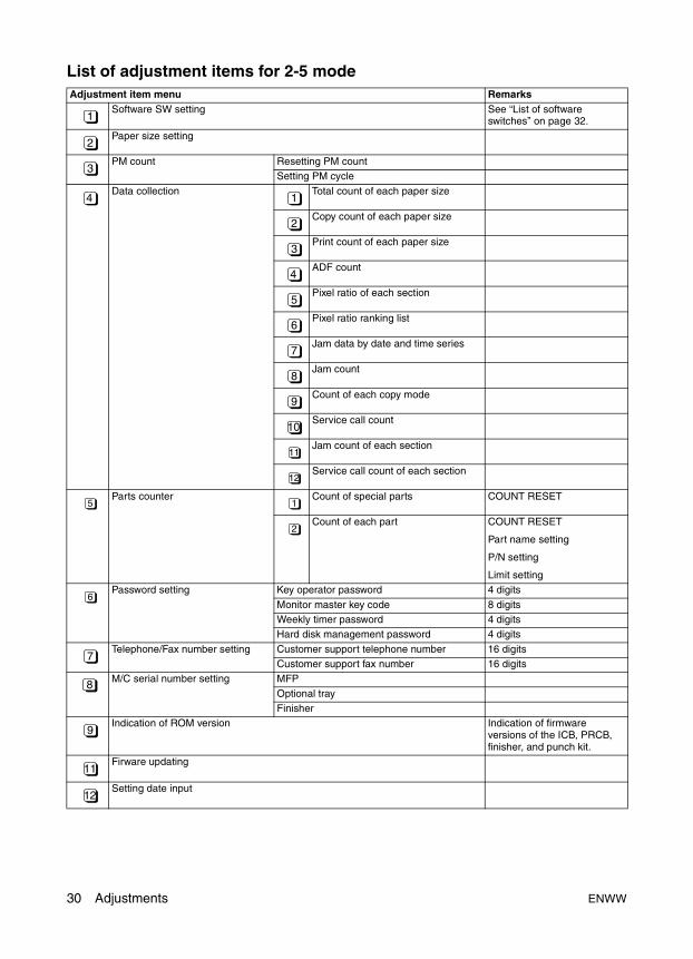
List of adjustment items for 2-5 modeAdjustment item menu Remarks
Software SW setting See “List of software switches” on page 32.
Paper size setting
PM count Resetting PM countSetting PM cycle
Data collection Total count of each paper size
Copy count of each paper size
Print count of each paper size
ADF count
Pixel ratio of each section
Pixel ratio ranking list
Jam data by date and time series
Jam count
Count of each copy mode
Service call count
Jam count of each section
Service call count of each section
Parts counter Count of special parts COUNT RESET
Count of each part COUNT RESET
Part name setting
P/N setting
Limit settingPassword setting Key operator password 4 digits
Monitor master key code 8 digitsWeekly timer password 4 digitsHard disk management password 4 digits
Telephone/Fax number setting Customer support telephone number 16 digitsCustomer support fax number 16 digits
M/C serial number setting MFP
Optional trayFinisher
Indication of ROM version Indication of firmware versions of the ICB, PRCB, finisher, and punch kit.
Firware updating
Setting date input
1
2
3
4 1
2
3
4
5
6
7
8
9
10
11
12
5 1
2
6
7
8
9
11
12
30 Adjustments ENWW

Ad
just
men
ts
Setting software switches
Procedure
Bring up the software SW setting screen and set software DIP switches.
For the function of each switch, see “List of software switches” on page 32.
Step Operation
1 Enter the 2-5 mode.
2 Memory setting mode menu screen
Touch Software DIP SW setting.
3 Software SW setting screen
Select a DIP switch number.
Use the or key or numeric keys.
To use numeric keys, touch the DIP switch number key at the left before entering a DIP switch number.
4 Select a bit number of the selected switch.
Use the or key or numeric keys.
To use numeric keys, touch the bit number key at the upper center before entering a DIP switch number.
5 Select On (1), or Off (0) of the switch.
Use the or key.
: Sets 1.
: Sets 0.
6 Touch the key to return to the Memory setting mode menu screen.
1
ON OFF
ON
OFF
RETURN
ENWW 2-5 mode 31

List of software switches
Note Do not change any bit settings that do not have a description in the Function column.
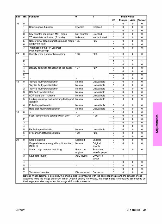
SW Bit Function 0 1 Initial valueUS Europe Asia Taiwan
1 0 Condition for stopping copying after indication of toner supply
* 1 * 1 1 1 1 1
1 0 0 0 02 Method for stopping copying after
indication of toner supply* 2 * 2 1 1 1 1
3 0 0 0 0
4 Inhibition of copying when PM count is reached
Disabled Inhibited 0 0 0 0
5 Number of copies made before inhibition of copying when PM count is reached
* 3 * 3 0 0 0 06 0 0 0 07 0 0 0 0
2 0 Hard disk connection Disconnected Connected 0 0 0 01 Electrode cleaning cycle (when power is
turned on, fuser temperature is 50º C or less)
* 4 * 4 0 0 0 02 0 0 0 0
3 0 0 0 04 Electrode cleaning cycle (after power is
turned on)* 5 * 5 0 0 0 0
5 0 0 0 0
6 - - - 0 0 0 07 - - - 0 0 0 0
3 0 - - - 0 0 0 0
1 Service call latch Unlatched Latched 0 0 0 02 2-5, 3-6, 4-7 mode password request
(9272) Not requested Requested 0 0 0 0
3 Charger cleaning function On Off 0 0 0 04 Transfer/separation cleaning function On Off 0 0 0 0
5 - - - 0 0 0 06 4-7 mode 15-01 data collection clearing Disabled Enabled 0 0 0 07 Job editor connection Disconnected Connected 0 0 0 0
4 0 ADF automatic skew adjustment Enabled Disabled 0 0 0 01 Inhibition of postcard double-sided copy Disabled Enabled 0 0 0 02 Destination Area * 6 * 6 1 0 0 0
3 Destination Area * 6 * 6 0 1 1 14 Key counter removal recovery Disabled Enabled 0 0 0 05 Inhibition of magnified auto paper Enabled Disabled 1 0 0 0
6 Fixed magnification rate setting change in key operator mode
Enabled Disabled 0 0 0 0
7 A3 (Ledger) counting method Increased by 1 Increased by 2 0 0 0 05 0 Image density selection (toner
concentration threshold)* 7 * 7 0 0 0 0
1 0 0 0 0
2 Image density selection (laser PWM) for MFP
* 8 * 8 1 1 1 13 0 0 0 04 - - - 0 0 0 0
5 - - - 0 0 0 06 - - - 0 0 0 07 - - - 0 0 0 0
32 Adjustments ENWW
Ad
just
men
ts
6 0 Transfer/separation output for plain paper * 9 * 9 0 0 0 01 0 0 0 0
2 0 0 0 03 Transfer/separation output for thick paper * 10 * 10 0 0 0 04 0 0 0 0
5 Transfer/separation output for thin paper * 11 * 11 0 0 0 06 0 0 0 07 - - - 0 0 0 0
7 0 Toner guide roller current correction * 12 * 12 0 0 0 01 0 0 0 02 - - - 0 0 0 0
3 TSL timing/location Under transfer corona
Under separation corona
1 1 1 1
4 - - - 0 0 0 0
5 Transfer/separation output for recycled paper
* 13 * 13 0 0 0 06 0 0 0 07 0 0 0 0
8 0 Image density selection (laser PWM) for IP
* 35 * 35 0 0 0 01 0 0 0 02 Fuser roller initial rotation * 14 * 14 0 0 0 0
3 1 1 1 14 Fuser roller initial rotation time setting * 15 * 15 1 1 1 15 0 0 0 0
6 A3 (Ledger) PM counter switch 1 count 2 count 0 0 0 07 Store on hard disk Enable Disable 0 0 0 0
9 0 Operation at key counter removal (copy) Same as stop key
Immediate stop (jam)
0 0 0 0
1 Operation at key counter removal (Q3639A print kit)
Ignored Same as DIPSW 9-0
0 0 0 0
2 Message switching * 16 * 16 0 0 0 0
3 0 0 0 04 Copy count limit * 17 * 17 0 0 0 05 0 0 0 0
6 0 0 0 07 0 0 0 0
10 0 Page memory allocation when powered. * 18 * 18 0 0 0 0
1 1 1 1 12 Page memory allocation when job starts * 19 * 19 0 0 0 03 Duplex shift printing from Adobe PS3
(Note1) Common shift Independent
shift0 0 0 0
4 Transfer/separation output for high-quality paper
* 20 * 20 0 0 0 0
5 0 0 0 06 0 0 0 07 0 0 0 0
Note 1: When printing from an Adobe PS3 driver in duplex mode with the image shift function, the shift amount of the copier (it can be set from “APPLICATION-Image sift”) is used for the print job.0: Both front and back side is decided by the front side shift amount data of copier.1: The shift data for each front and back side set in the copier is used for duplex print mode.
SW Bit Function 0 1 Initial valueUS Europe Asia Taiwan
ENWW 2-5 mode 33
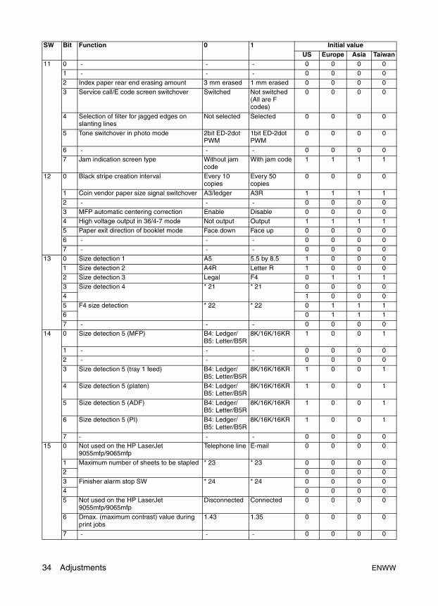
11 0 - - - 0 0 0 01 - - - 0 0 0 0
2 Index paper rear end erasing amount 3 mm erased 1 mm erased 0 0 0 03 Service call/E code screen switchover Switched Not switched
(All are F codes)
0 0 0 0
4 Selection of filter for jagged edges on slanting lines
Not selected Selected 0 0 0 0
5 Tone switchover in photo mode 2bit ED-2dot PWM
1bit ED-2dot PWM
0 0 0 0
6 - - - 0 0 0 07 Jam indication screen type Without jam
codeWith jam code 1 1 1 1
12 0 Black stripe creation interval Every 10 copies
Every 50 copies
0 0 0 0
1 Coin vendor paper size signal switchover A3/ledger A3R 1 1 1 12 - - - 0 0 0 0
3 MFP automatic centering correction Enable Disable 0 0 0 04 High voltage output in 36/4-7 mode Not output Output 1 1 1 15 Paper exit direction of booklet mode Face down Face up 0 0 0 0
6 - - - 0 0 0 07 - - - 0 0 0 0
13 0 Size detection 1 A5 5.5 by 8.5 1 0 0 0
1 Size detection 2 A4R Letter R 1 0 0 02 Size detection 3 Legal F4 0 1 1 13 Size detection 4 * 21 * 21 0 0 0 0
4 1 0 0 05 F4 size detection * 22 * 22 0 1 1 16 0 1 1 1
7 - - - 0 0 0 014 0 Size detection 5 (MFP) B4: Ledger/
B5: Letter/B5R8K/16K/16KR 1 0 0 1
1 - - - 0 0 0 02 - - - 0 0 0 0
3 Size detection 5 (tray 1 feed) B4: Ledger/ B5: Letter/B5R
8K/16K/16KR 1 0 0 1
4 Size detection 5 (platen) B4: Ledger/ B5: Letter/B5R
8K/16K/16KR 1 0 0 1
5 Size detection 5 (ADF) B4: Ledger/ B5: Letter/B5R
8K/16K/16KR 1 0 0 1
6 Size detection 5 (PI) B4: Ledger/ B5: Letter/B5R
8K/16K/16KR 1 0 0 1
7 - - - 0 0 0 015 0 Not used on the HP LaserJet
9055mfp/9065mfpTelephone line E-mail 0 0 0 0
1 Maximum number of sheets to be stapled * 23 * 23 0 0 0 02 0 0 0 0
3 Finisher alarm stop SW * 24 * 24 0 0 0 04 0 0 0 05 Not used on the HP LaserJet
9055mfp/9065mfpDisconnected Connected 0 0 0 0
6 Dmax. (maximum contrast) value during print jobs
1.43 1.35 0 0 0 0
7 - - - 0 0 0 0
SW Bit Function 0 1 Initial valueUS Europe Asia Taiwan
34 Adjustments ENWW
Ad
just
men
ts
16 0 - - - 0 0 0 01 Copy reserve function Enabled Disabled 0 0 0 0
2 - - - 0 0 0 03 Key counter counting in MFP mode Not counted Counted 0 0 0 04 TC start date indication (P mode) Indicated Not indicated 0 0 0 0
5 Non-original area automatic erasure mode judgement level
* 25 * 25 0 0 0 06 0 0 0 07 Not used on the HP LaserJet
9055mfp/9065mfp- - 0 0 0 0
17 0 Weekly timer summer time setting * 26 * 26 0 0 0 0
1 1 1 1 12 1 1 1 13 0 0 0 0
4 Density selection for scanning tab paper * 27 * 27 0 0 0 05 0 0 0 06 0 0 0 0
7 - - - 0 0 0 018 0 Tray 2's faulty part isolation Normal Unavailable 0 0 0 0
1 Tray 3's faulty part isolation Normal Unavailable 0 0 0 0
2 Tray 4's faulty part isolation Normal Unavailable 0 0 0 03 HCI faulty part isolation Normal Unavailable 0 0 0 04 ADF faulty part isolation Normal Unavailable 0 0 0 0
5 Folding, stapling, and tri-folding faulty part isolation
Normal Unavailable 0 0 0 0
6 PI faulty part isolation Normal Unavailable 0 0 0 07 Hard disk faulty part isolation Normal Unavailable 0 0 0 0
19 0 - - - 0 0 0 0
1 Fuser temperature setting switch over * 28 * 28 0 0 0 02 0 0 0 03 0 0 0 0
4 0 0 0 05 PK faulty part isolation Normal Unavailable 0 0 0 06 IP scanner default resolution * 29 * 29 0 0 0 0
7 0 0 0 020 0 Group stapling Disabled Enabled 0 0 0 0
1 Original size scanning with shift function (Note 2)
Normal Original priority
0 0 0 0
2 Stamp page number switching Based on original
Based on transfer paper
0 0 0 0
3 Keyboard layout ABC layout QWERTY layout
1 1 1 1
4 - - - 0 0 0 0
5 - - - 0 0 0 06 - - - 0 0 0 07 Tandem connection Disconnected Connected 0 0 0 0
Note 2: When Normal is selected, the original size is compared with the copy paper size and the smaller one is assumed to be the image area size. When Original priority is selected, the original size is compared assumed to be the image area size only when the image shift mode is selected.
SW Bit Function 0 1 Initial valueUS Europe Asia Taiwan
ENWW 2-5 mode 35

21 0 Mixed sized print stapling inhibition (Q3639A print kit)
Enabled (realtime output)
Disabled (batch processing)
0 0 0 0
1 HCI size setting in key operator mode Disabled Enabled 0 0 0 02 Original count display Displayed Not displayed 0 0 0 03 - - - 0 0 0 0
4 - - - 0 0 0 05 - - - 0 0 0 06 Special paper auto paper response Disabled Enabled
(except thick paper)
0 0 0 0
7 IP scanner 600/400 dpi Enabled Disabled 0 0 0 022 0 IP address setting Inhibited Allowed 1 1 1 1
1 Number of punched holes * 30 * 30 1 0 0 02 0 1 1 13 Image reference position of unspecified
size of paper - - 0 0 0 0
4 Sleep button function Enabled Disabled 0 0 0 0
5 - - - 0 0 0 06 Finisher no staple operation Staple supply
requestedRequest for staple supply and stapling canceled
0 0 0 0
7 Jam indication screen type Position Illustration 0 0 0 0
23 0 Print controller installed Not installed Installed 0 0 0 01 Operation when MFP monitor password is
not matchedCounted and output to monitor or other user domain
Not output (display it on the JOB list that is not produced)
0 0 0 0
2 Image density selection (toner density selection of developer)
* 31 * 31 0 0 0 03 0 0 0 0
4 - - - 0 0 0 05 - - - 0 0 0 06 Registration of tray 1 special paper setting
for job memoryProhibited Allowed 0 0 0 0
7 Ejection of the thick paper 2 to sub-tray (IP)
Face down Face up 0 0 0 0
24 0 Method of accessing hard disk job Password Password + file name
0 0 0 0
1 Job editor image transfer method default setting
Automatic Manual 0 0 0 0
2 - - - 0 0 0 0
3 - - - 0 0 0 04 Maximum number of sheets with Z-fold
(paper exit face down tray)* 33 * 33 0 0 0 0
5 0 0 0 0
6 Maximum number of sheets with Z-fold + stapling (paper exit face down tray)
* 34 * 34 0 0 0 07 0 0 0 0
SW Bit Function 0 1 Initial valueUS Europe Asia Taiwan
36 Adjustments ENWW
Ad
just
men
ts
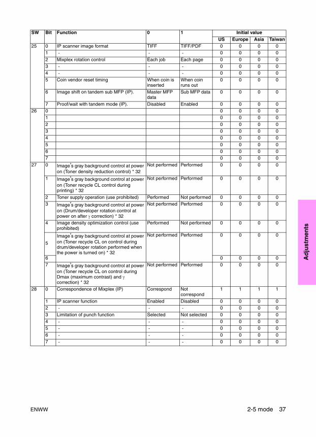
25 0 IP scanner image format TIFF TIFF/PDF 0 0 0 01 - - - 0 0 0 0
2 Mixplex rotation control Each job Each page 0 0 0 03 - - - 0 0 0 04 - - - 0 0 0 0
5 Coin vendor reset timing When coin is inserted
When coin runs out
0 0 0 0
6 Image shift on tandem sub MFP (IP). Master MFP data
Sub MFP data 0 0 0 0
7 Proof/wait with tandem mode (IP). Disabled Enabled 0 0 0 026 0 0 0 0 0
1 0 0 0 0
2 0 0 0 03 0 0 0 04 0 0 0 0
5 0 0 0 06 0 0 0 07 0 0 0 0
27 0 Image’s gray background control at power on (Toner density reduction control) * 32
Not performed Performed 0 0 0 0
1 Image’s gray background control at power on (Toner recycle CL control during printing) * 32
Not performed Performed 0 0 0 0
2 Toner supply operation (use prohibited) Performed Not performed 0 0 0 03 Image’s gray background control at power
on (Drum/developer rotation control at power on after γ correction) * 32
Not performed Performed 0 0 0 0
4 Image density optimization control (use prohibited)
Performed Not performed 0 0 0 0
5
Image’s gray background control at power on (Toner recycle CL on control during drum/developer rotation performed when the power is turned on) * 32
Not performed Performed 0 0 0 0
6 0 0 0 07 Image’s gray background control at power
on (Toner recycle CL on control during Dmax (maximum contrast) and γ correction) * 32
Not performed Performed 0 0 0 0
28 0 Correspondence of Mixplex (IP) Correspond Not correspond
1 1 1 1
1 IP scanner function Enabled Disabled 0 0 0 02 - - - 0 0 0 0
3 Limitation of punch function Selected Not selected 0 0 0 04 - - - 0 0 0 05 - - - 0 0 0 0
6 - - - 0 0 0 07 - - - 0 0 0 0
SW Bit Function 0 1 Initial valueUS Europe Asia Taiwan
ENWW 2-5 mode 37
Note IP refers to interaction with the Print Kit.
*1 Condition for stopping copying after indication of toner supply request
*2 Method for stopping copying after indication of toner supply request
29 0 Not used on the HP LaserJet 9055mfp/9065mfp
Not correspond
Correspond 0 0 0 0
1 Correspondence of memory overflow when IP printing
* 36 * 36 0 0 0 02 0 0 0 0
3 Include of proof copy to the set copy quantity
Not included Included 0 0 0 0
4 - - - 0 0 0 05 - - - 0 0 0 06 - - - 0 0 0 0
7 - - - 0 0 0 030 0 - - - 0 0 0 0
1 2-5 mode collection data 7-12 for checking
Display restriction
No display restriction
1 1 1 1
2 - - - 0 0 0 0
3 - - - 1 1 1 14 - - - 0 0 0 05 - - - 0 0 0 0
6 - - - 0 0 0 07 Passwords to save/access hard disk JOB Not displayed Displayed 0 0 0 0
31 0 1 1 1 1
1 0 0 0 02 0 0 0 03 0 0 0 0
4 1 1 1 15 0 0 0 06 0 0 0 0
7 0 0 0 032 0 0 0 0 0
1 1 1 1 1
2 0 0 0 03 0 0 0 04 0 0 0 1
5 0 0 0 06 0 0 0 07 0 0 0 0
SW Bit Function 0 1 Initial valueUS Europe Asia Taiwan
Mode 1-1 1-0Stops after printing 1,500 copies 0 0
Stops after printing 3,000 copies 0 1Stops after printing 4,000 copies 1 0Stops after printing 5,000 copies 1 1
Mode 1-3 1-2Stops after ejecting the paper remaining in the MFP
0 0
Stops after printing specified number of copies
0 1
Stops at the end of the current job 1 0
Does not stop 1 1
38 Adjustments ENWW
Ad
just
men
ts
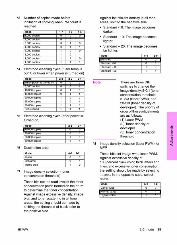
*3 Number of copies made before inhibition of copying when PM count is reached
*4 Electrode cleaning cycle (fuser temp is 50° C or lower when power is turned on)
*5 Electrode cleaning cycle (after power is turned on)
*6 Destination area
*7 Image density selection (toner concentration threshold)
These bits set the read level of the toner concentration patch formed on the drum to determine the toner concentration. Against image excessive density, image blur, and toner scattering in all tone areas, the setting should be made by shifting the threshold of black color to the positive side.
Against insufficient density in all tone areas, shift to the negative side.
• Standard -10: The image becomes darker.
• Standard +10: The image becomes lighter.
• Standard + 20: The image becomes far lighter.
Note There are three DIP switches to change the image density: 5-0/1 (toner concentration threshold, 5- 2/3 (laser PWM), and 23-2/3 (toner density of developer). The priority of order of these adjustments are as follows:(1) Laser PWM(2) Toner density of developer(3) Toner concentration threshold
*8 Image density selection (laser PWM) for MFP
These bits set image write laser PWM. Against excessive density of 100 percent black color, thick letters and lines, and excessive toner consumption, the setting should be made by selecting light. In the opposite case, select dark.
Mode 1-7 1-6 1-51,000 copies 0 0 02,000 copies 0 0 13,000 copies 0 1 0
4,000 copies 0 1 15,000 copies 1 0 01,000 copies 1 0 1
1,000 copies 1 1 01,000 copies 1 1 1
Mode 2-3 2-2 2-1When power is turned on 0 0 05,000 copies 0 0 1
10,000 copies 0 1 015,000 copies 0 1 120,000 copies 1 0 0
25,000 copies 1 0 130,000 copies 1 1 0Not cleaned 1 1 1
Mode 2-5 2-410,000 copies 0 0
20,000 copies 0 130,000 copies 1 040,000 copies 1 1
Mode 4-3 4-2Japan 0 0Inch area 0 1Metric area 1 0
Mode 5-1 5-0Standard 0 0Standard -10 0 1Standard +10 1 0
Standard +20 1 1
Mode 5-3 5-2Darker (255) 0 0Normal (235) 0 1Lighter (215) 1 0
ENWW 2-5 mode 39
Note There are three DIP switches to change the image density:5-0/1(toner concentration threshold), 5-2/3 (laser PWM), and 23-2/3 (toner density of developer). The priority of order of these adjustments are as follows:(1) Laser PWM(2) Toner density of developer(3) Toner concentration threshold
*9 Transfer/separation output for plain paper
These bits are used when Normal, Color, Special, or Seal is selected for paper type/special size setting in the key operator mode.
When Custom paper is selected with this bit, the transfer/separation output for the Custom paper setting made in the 3-6 mode is applied.
When No specification is selected, the output data by destination and paper size (metric or inch system) (Japan/metric: 64 g/m2 plain paper, inch: 20 lb plain paper, inch area/inch: 20 lb plain paper, metric: 75 g/m2 plain paper, metric area/metric: 75 g/m2 plain paper, inch: 20 lb plain paper) is used.
*10 Transfer/separation output for thick paper
This bit is used when Thick is selected for Paper type/special size setting in the key operator mode to change transfer/separation output, linear speed, and fuser temperature.
When No specification is selected, standard data for 170 g/m2 or heavier paper is used.
• 170 g/m2 or heavier (TSL off): When toner is scattered around the image.
• Plain paper: Transfer/separation data for plain paper of each destination is used to set only the line speed and fuser temperature for thick paper. This setting is applied when the fuser condition is insufficient even though paper is not so thick.
*11 Transfer/separation output for thin paper
This bit is used when Thin is selected for Paper type/special size setting in the key operator mode.
When No specification is selected, the output data by destination (Japan: 52.4 g/m2 paper, inch area: 16 lb paper, metric area: 48 g/m2 paper) is used.
*12 Toner guide roller current correction
When the room temperature causes defect cleaning, the bias value of the toner guide roller should be changed to +10 µA or +20 µA. If the original setting value is changed without any defective cleaning observed, the drum can be damaged, or the toner may be spilled. In this case, the use of the MFP is never recommended.
Mode 6-2 6-1 6-0No specification 0 0 0Not used 0 0 1
Not used 0 1 0Not used 0 1 1Recycled paper 1 (Japan) 1 0 0
Recycled paper 2 (inch area)
1 0 1
Recycled paper 3 (metric area)
1 1 0
Custom paper 1 1 1
Mode 6-4 6-3No specification 0 0
170 g/m2 or more (TSL off) 0 1
Plain paper 1 0
Mode 6-6 6-5No specification 0 0
52.4 g/m2 paper 0 1
64 g/m2 paper 1 0
40 Adjustments ENWW
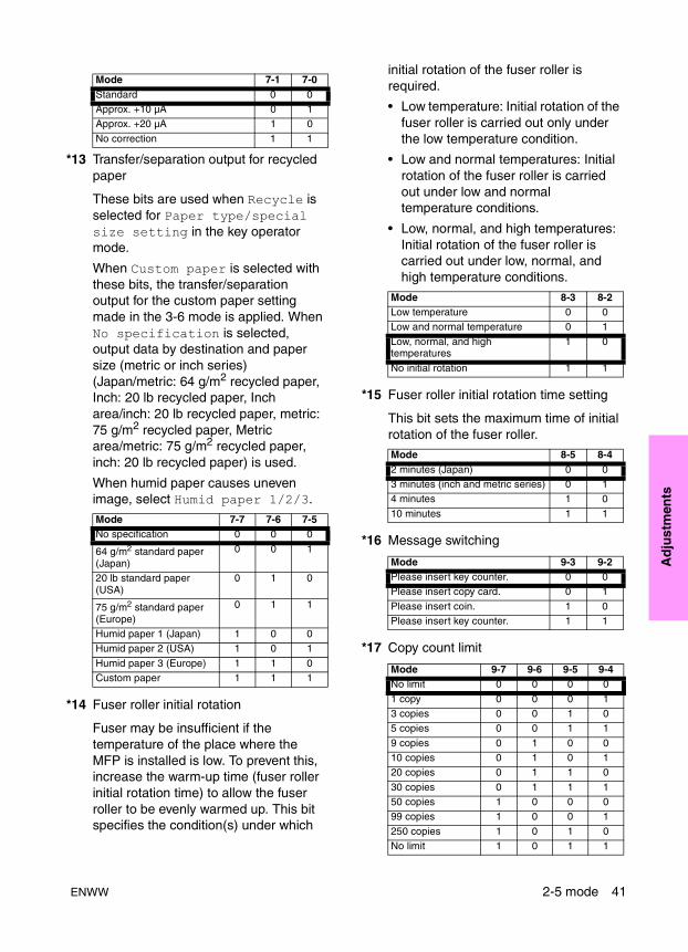
Ad
just
men
ts
*13 Transfer/separation output for recycled paper
These bits are used when Recycle is selected for Paper type/special size setting in the key operator mode.
When Custom paper is selected with these bits, the transfer/separation output for the custom paper setting made in the 3-6 mode is applied. When No specification is selected, output data by destination and paper size (metric or inch series) (Japan/metric: 64 g/m2 recycled paper, Inch: 20 lb recycled paper, Inch area/inch: 20 lb recycled paper, metric: 75 g/m2 recycled paper, Metric area/metric: 75 g/m2 recycled paper, inch: 20 lb recycled paper) is used.
When humid paper causes uneven image, select Humid paper 1/2/3.
*14 Fuser roller initial rotation
Fuser may be insufficient if the temperature of the place where the MFP is installed is low. To prevent this, increase the warm-up time (fuser roller initial rotation time) to allow the fuser roller to be evenly warmed up. This bit specifies the condition(s) under which
initial rotation of the fuser roller is required.
• Low temperature: Initial rotation of the fuser roller is carried out only under the low temperature condition.
• Low and normal temperatures: Initial rotation of the fuser roller is carried out under low and normal temperature conditions.
• Low, normal, and high temperatures: Initial rotation of the fuser roller is carried out under low, normal, and high temperature conditions.
*15 Fuser roller initial rotation time setting
This bit sets the maximum time of initial rotation of the fuser roller.
*16 Message switching
*17 Copy count limit
Mode 7-1 7-0Standard 0 0Approx. +10 µA 0 1Approx. +20 µA 1 0
No correction 1 1
Mode 7-7 7-6 7-5No specification 0 0 0
64 g/m2 standard paper (Japan)
0 0 1
20 lb standard paper (USA)
0 1 0
75 g/m2 standard paper (Europe)
0 1 1
Humid paper 1 (Japan) 1 0 0Humid paper 2 (USA) 1 0 1
Humid paper 3 (Europe) 1 1 0Custom paper 1 1 1
Mode 8-3 8-2Low temperature 0 0Low and normal temperature 0 1
Low, normal, and high temperatures
1 0
No initial rotation 1 1
Mode 8-5 8-42 minutes (Japan) 0 03 minutes (inch and metric series) 0 14 minutes 1 0
10 minutes 1 1
Mode 9-3 9-2Please insert key counter. 0 0Please insert copy card. 0 1
Please insert coin. 1 0Please insert key counter. 1 1
Mode 9-7 9-6 9-5 9-4No limit 0 0 0 0
1 copy 0 0 0 13 copies 0 0 1 05 copies 0 0 1 1
9 copies 0 1 0 010 copies 0 1 0 120 copies 0 1 1 0
30 copies 0 1 1 150 copies 1 0 0 099 copies 1 0 0 1
250 copies 1 0 1 0No limit 1 0 1 1
ENWW 2-5 mode 41

*18 Page memory allocation when powered
*19 Page memory allocation when starts
When memory overflow occurs in a mode where page memory is used, this bit allocates page memory at the start of job to print out copied paper, the data of which was already read in the memory.
Page memory quantity differs as in the following table, according to the number of gradation.
.
When Allocated is selected by DIP switch 10-0 or 10-1 with power supply on, this setting has priority.
*20 Transfer/separation output for high-quality paper
These bits are used when High-quality is selected for Paper type/special size setting in the key operator mode.
When No specification is selected, output data by paper size (metric or inch system) (metric: 64 g/m2 standard paper, inch: 20 lb standard paper) is used.
*21 Size detection 4
*22 F4 size detection
*23 Maximum number of sheets that can be stapled
*24 Finisher alarm stop SW
*25 Selection of area to be erased in non-original area automatic erasure
These bits are used to make a setting associated with the non-original automatic erasure mode (application function).
*26 Weekly timer summer time setting
No limit 1 1 0 0No limit 1 1 0 1No limit 1 1 1 0
No limit 1 1 1 1
Mode 10-1 10-0No allocation 0 0
32 MB (default for DP65) 0 164 MB 1 0
1 bit ED 18 MB (A3 by 2)2 bit ED 36 MB (A3 by 2)
Mode 10-2No allocation 0
Allocated 1
Mode 10-7 10-6 10-5 10-4No specification 0 0 0 0
64 g/m2 paper for printing press
0 0 0 1
75 g/m2 paper for printing press
0 0 1 0
Mode 9-7 9-6 9-5 9-4
Destination Mode 13-4 13-3Metric series A5R 0 0
B6R 0 1Inch series 5.5 by 8.5R 1 0
Mode 13-6 13-58 by 13 0 0
8.25 by 13 0 18.125 by 13.25 1 08.5 by 13 1 1
Mode 15-2 15-150 sheets 0 045 sheets 0 1
40 sheets 1 035 sheets 1 1
Mode 15-4 15-3Stop immediately after detection 0 0Stop at end of copy after detection 0 1
No alarm stop 1 0No alarm stop 1 1
Mode 16-6 16-5Standard 0 0Dark original 0 1
Coping with light interference 1 0
Mode 17-3 17-2 17-1 17-00 minute 0 0 0 010 minutes 0 0 0 1
20 minutes 0 0 1 030 minutes 0 0 1 140 minutes 0 1 0 0
50 minutes 0 1 0 160 minutes 0 1 1 070 minutes 0 1 1 1
80 minutes 1 0 0 0
42 Adjustments ENWW
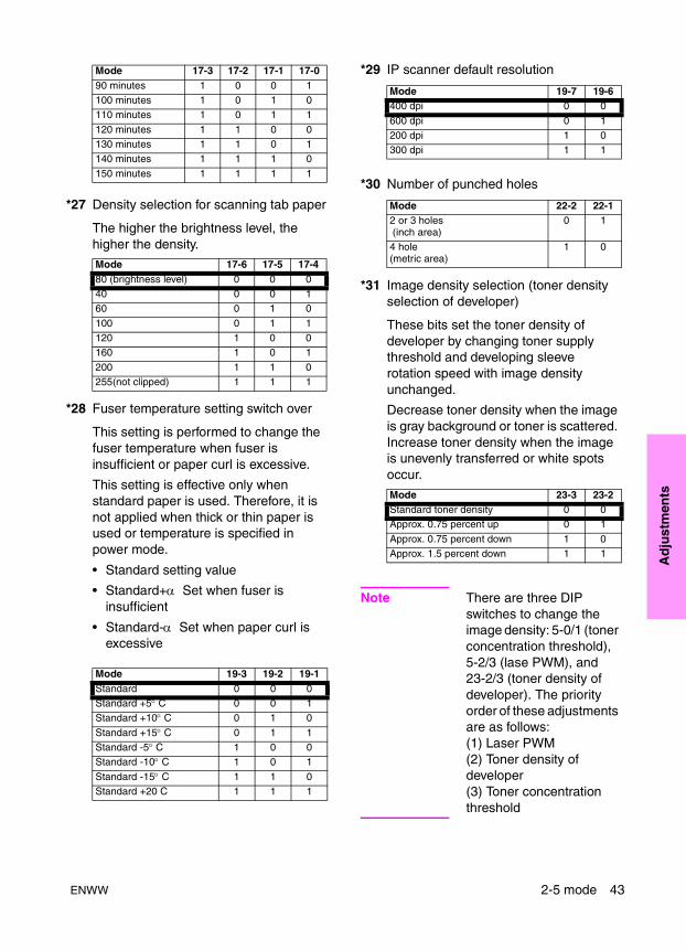
Ad
just
men
ts
*27 Density selection for scanning tab paper
The higher the brightness level, the higher the density.
*28 Fuser temperature setting switch over
This setting is performed to change the fuser temperature when fuser is insufficient or paper curl is excessive.
This setting is effective only when standard paper is used. Therefore, it is not applied when thick or thin paper is used or temperature is specified in power mode.
• Standard setting value
• Standard+α Set when fuser is insufficient
• Standard-α Set when paper curl is excessive
*29 IP scanner default resolution
*30 Number of punched holes
*31 Image density selection (toner density selection of developer)
These bits set the toner density of developer by changing toner supply threshold and developing sleeve rotation speed with image density unchanged.
Decrease toner density when the image is gray background or toner is scattered. Increase toner density when the image is unevenly transferred or white spots occur.
Note There are three DIP switches to change the image density: 5-0/1 (toner concentration threshold), 5-2/3 (lase PWM), and 23-2/3 (toner density of developer). The priority order of these adjustments are as follows: (1) Laser PWM(2) Toner density of developer(3) Toner concentration threshold
90 minutes 1 0 0 1100 minutes 1 0 1 0110 minutes 1 0 1 1
120 minutes 1 1 0 0130 minutes 1 1 0 1140 minutes 1 1 1 0
150 minutes 1 1 1 1
Mode 17-6 17-5 17-480 (brightness level) 0 0 040 0 0 160 0 1 0
100 0 1 1120 1 0 0160 1 0 1
200 1 1 0255(not clipped) 1 1 1
Mode 19-3 19-2 19-1Standard 0 0 0Standard +5° C 0 0 1Standard +10° C 0 1 0
Standard +15° C 0 1 1Standard -5° C 1 0 0Standard -10° C 1 0 1
Standard -15° C 1 1 0Standard +20 C 1 1 1
Mode 17-3 17-2 17-1 17-0
Mode 19-7 19-6400 dpi 0 0
600 dpi 0 1200 dpi 1 0300 dpi 1 1
Mode 22-2 22-12 or 3 holes (inch area)
0 1
4 hole(metric area)
1 0
Mode 23-3 23-2Standard toner density 0 0Approx. 0.75 percent up 0 1
Approx. 0.75 percent down 1 0Approx. 1.5 percent down 1 1
ENWW 2-5 mode 43
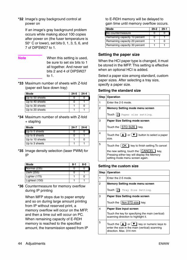
*32 Image's gray background control at power on
If an image's gray background problem occurs while making about 100 copies after power on (the fuser temperature is 50° C or lower), set bits 0, 1, 3, 5, 6, and 7 of DIPSW27 to 1.
Note When this setting is used, be sure to set six bits to 1 all together. And never set bits 2 and 4 of DIPSW27 to 1.
*33 Maximum number of sheets with Z-fold (paper exit face down tray)
*34 Maximum number of sheets with Z-fold + stapling
*35 Image density selection (laser PWM) for IP
*36 Countermeasure for memory overflow during IP printing
When MFP stops due to paper empty and so on during large amount printing from IP without reserved print, a memory overflow will occur on the MFP, and then a time out will occur on PC. When remaining capacity of E-RDH memory is reached to the specified amount, the transmission speed from IP
to E-RDH memory will be delayed to gain time until memory overflow occurs.
Setting the paper size
When the HCI paper type is changed, it must be stored in the MFP. This setting is effective when an optional HCI is added.
Select a paper size among standard, custom paper sizes. After selecting a tray size, specify a paper size.
Setting the standard size
Setting the custom size
Mode 24-5 24-4Up to 50 sheets 0 0
Up to 40 sheets 0 1Up to 30 sheets 1 0Up to 20 sheets 1 1
Mode 24-7 24-6Up to 5 sheets 0 0
Up to 8 sheets 0 1Up to 10 sheets 1 0Up to 3 sheets 1 1
Mode 8-1 8-0Normal (235) 0 0Dark (255) 0 1
Lighter (175) 1 0Lightest (150) 1 1
Mode 29-2 29-1No countermeasure 0 0Remaining capacity 10 percent 0 1Remaining capacity 20 percent 1 0
Remaining capacity 30 percent 1 1
Step Operation
1 Enter the 2-5 mode.
2 Memory Setting mode menu screen
Touch Paper size setting.
3 Paper Size Setting mode screen
Touch the key.
4Touch the or button to select a paper size.
5 Touch the key to finish setting.To cancel
the new setting, touch the key, Pressing either key will display the Memory setting mode menu screen again.
Step Operation
1 Enter the 2-5 mode.
2 Memory Setting mode menu screen
Touch Tray Size Setting.
3 Paper Size Setting mode screen
Touch the key.
4 Paper Size input screen
Touch the key for specifying the main (vertical) scanning direction to highlight it.
5Touch the or key or numeric keys to enter the size in the main (vertical) scanning direction. Max. 314 mm
2
STD SIZE
OK
CANCEL
2
Non STD size
44 Adjustments ENWW

Ad
just
men
ts
Setting the wide paper
Reference 1: Each time the current tray size is changed on this screen, the new setting will be written into the non-volatile memory.
PM count resettingCare should be taken not to reset the PM count by mistake. The PM count should only be reset after all PM has been completed.
Setting the PM cycleThis function allows you to change the PM cycle.
The PM cycle is factory-set. Use this function to change the factory-set PM cycle.
6 Touch the key for specifying the sub (horizontal) scanning direction to highlight it.
7Touch the or key or numeric keys to enter the size in the sub (horizontal) scanning direction. Max. 223 mm (HP 4000-sheet high capacity input [letter/A4]), 459 mm (HP 4000-sheet high capacity input [ledger/A3])
8Touch the key to finish setting.
To cancel the new setting, touch the key.
Pressing either key will display the Memory setting mode menu screen again.
Step Operation
1 Enter the 2-5 mode.
2 Memory Setting mode menu screen
Touch Paper size setting.
3 Paper Size Setting mode screen
Touch the key.
4 Paper Size Selecting screen
Touch the or key to select a wide paper size.
5 key.
6 Paper Size input screen
Touch the key for specifying the main (vertical) scanning direction to highlight it.
7Touch the or key or numeric keys to enter the size in the main (vertical) scanning direction. Max. 314 mm
8 Touch the button for specifying the sub (horizontal) scanning direction to highlight it.
9Touch the or key or numeric keys to enter the size in the sub (horizontal) scanning direction. Max. 223 mm (HP 4000-sheet high capacity input [letter/A4]), 459 mm (HP 4000-sheet high capacity input [ledger/A3])
10Touch the key to finish setting.
To cancel the new setting, touch the key.
Pressing either key will display the Memory setting mode menu screen again.
OK
CANCEL
2
Wide size paper
Input size
OK
CANCEL
Step Operation
1 Enter the 2-5 mode.
2 Memory Setting mode menu screen
Touch PM count.
3 PM Count/cycle screen
Touch the key.
4 Reset Confirmation screen
Touch the key.The PM count is reset and the start date is input automatically.
Pressing the key closes the Reset Confirmation screen at once.
5Touch the key to finish setting.
To cancel the new setting, touch the key.
Pressing either key will display the Memory setting mode menu screen again.
Step Operation
1 Enter the 2-5 mode.
2 Memory Setting mode menu screen
Touch PM count.
3 PM Count/Cycle screen
Touch the key.
4 After making sure that three digits of the cycle value are displayed in reverse video, enter a desired cycle value using numeric keys.
Only the three digits of the cycle value can be entered. The entered digits will be shifted to the left one after another.
3
COUNT RESET
YES
NO
OK
CANCEL
PM Cycle Setting
ENWW 2-5 mode 45
Collecting dataThis function allows you to view various data retained by the MFP.
Data that can be viewed
When bit 1 of DIP switch 30-1 is set to 0, only collected data 1 to collected data no. 6 can be viewed.
Viewing collecting data no.1 to no.6
Viewing collecting data no.7 to no.12
On the individual data view screen showing the jam count of each section (collected data
) or service call count of each section (collected data ), the key appears.
Pressing the key resets the selected data count.
5Touch the key to finish setting.
To cancel the new setting, touch the key.
Pressing either key will display the Memory setting mode menu screen again.
No. Data type Pre-operation1 Total count of each paper
size
2 Copy count of each paper size
3 Print count of each paper size
4 ADF count5 Pixel ratio of each section6 Pixel ratio ranking list
7 Jam data of time series Enter the 2-5 mode, select Software DIPSW Setting, and set bit 1 of address 30-1 to 1. (Note 1)
8 Jam count9 Count of each copy mode
10 Service call count11 Jam count of each
section12 Service call count of each
section
Step Operation
1 Enter the 2-5 mode.
2 Memory Setting mode menu screen
Touch Data collection.
3 Collecting Data menu screen
Select the collecting data you want to view by
touching one of numeric keys to .
4 Individual Data view screen
View the selected data by scrolling the screen
using the and keys.
5Touch the key to return to the Memory setting mode menu screen.
OK
CANCEL
4
1 6
RETURN
Step Operation
1 Enter the 2-5 mode.
2 Memory Setting mode menu screen
Touch Software DIP SW setting.
3 Software DIP SW Setting screen
Set bit 1 of DIP switch 30-1 to 1.
4Touch the key to return to the Memory setting mode menu screen.
5 Memory Setting mode menu screen
Touch Data Collection.
6 Collecting Data menu screen
Select the collected data you want to view by
pressing one of numeric keys to .
To select the key or later touch the key.
If the key is pressed with key displayed, the Collected data selection screen
containing keys to appears again.
7 Individual Data view screen
View the selected data by scrolling the screen
using the and keys. (Note)
8Touch the key to return to the Memory setting mode menu screen.
1
RETURN
4
7 12
11
11
1 12
RETURN
1112 COUNT RESET
COUNT RESET
46 Adjustments ENWW
Ad
just
men
ts
Details on display data
1 Collecting data No. 1 to No. 3: Total, copy, and print counts of each paper size
● Each time a printed copy is ejected, the counter is increased by 1 regardless of the paper size.
● Any size other than paper sizes 1-9 is counted as Special size. (SEF/LEF are counted as the same size.)
2 Collecting data No. 4: ADF mode
● The counter is increased each time one original side has been scanned in each mode.
● Counters 1 and 2 count original sides independently of counters 3-7.
3 Collecting data No. 5: Pixel ratio of each section *1
This allows checking the average pixel ratio of 5000 prints for latest 30 data.
4 Collecting data No. 6: Pixel ratio ranking list *1
This allows checking pixel ratio data, number of prints, transfer paper size, mode, and date for the top 15 job data ranked from highest rates of pixel ratio.The pixel ratio rank list is allowed to contain only those jobs which have five or more copies, so that jobs that have made erroneous copies will be excluded from the list.
No. Destination Maximum count RemarksJapan Inch area Metric area
1 A2 17 by 22 A2 99999999 All counters are 8-digit counters.
2 A3 Ledger A33 B4 Legal B4 (8K)4 A4 Letter A4
5 B5 5.5 by 8.5 B5 (16K)6 A5 - A57 B6 - F4
8 Legal - -9 Letter A4 -
10 Special Special Special
No. Items Maximum count Remarks1 Number of originals fed in ADF mode 99999999 All counters are 8-digit counters.
2 Number of originals fed in ADF mode3 Number of 1-sided mixed original fed4 Number of 2-sided mixed original fed
5 Number of 1-sided Z-fold mode original fed6 Number of 2-sided Z-fold mode original fed7 Undefined
8910
111213
141516
ENWW 2-5 mode 47
5 Collecting data No. 7: Jam data of time series
A jam code, total count, date and time of occurrence, tray type, paper size, and magnification can be displayed for the latest 100 jams.
*1 This pixel ratio is the theoretical value obtained by converting the black dot area on the image data and the area of the transfer paper, therefore it is different from the black ratio obtained by the actual printing.
6 Collecting data No. 8: Jam count/Collecting data; No. 11: Jam count of each section (can be reset)
No. Description of jam Jam position display on control panel
Maximum count
Counting conditionLocation of jam Code displayed when
display of jam code is selected by 25DIPSW
1 Tray 1 paper feed 10-1 6 999999 All counts are 6-digit counters.2 10-2 6
3 Tray 2 paper feed 11-1 1
4 11-2 15 Tray 3 paper feed 12-1 26 12-2 2
7 Tray 4 paper feed 13-1 38 13-2 39 Note: Not used on the HP LaserJet
9055mfp/9065mfp.14-1 4
10 14-2 411 HCI paper feed 15-1 512 15-2 5
13 Paper feed conveyance (common to all trays) 17-1 914 Paper feed conveyance (Tray 2) 17-2 715 Paper feed conveyance (Tray 3/4) 17-3 7
16 Paper feed conveyance (Tray 3) 17-4 717 Paper feed conveyance (Tray 4) 17-5 718 Note: Not used on the HP LaserJet
9055mfp/9065mfp.17-6 7
19 17-7 720 HCI 17-8 821 Drum 21-1 10
22 Second paper feed conveyance 31-1 923 31-2 1024 Fuser/Exit 32-1 11
25 32-2 1126 32-3 1127 32-4 11
28 32-5 1129 ADU 92-1 1230 92-2 12
31 93-1 1332 94-1 1333 94-2 13
34 Vertical conveyance door 19-1 -35 HCI 19-2 -36 Front door 51-1 -
48 Adjustments ENWW
Ad
just
men
ts
37 Finisher 71-1 - 999999 All counts are 6-digit counters.38 71-2 -
39 ADF 61-1 -40 61-2 -
41 62-1 1442 62-2 1443 62-3 14
44 62-4 1445 62-5 14
46 62-6 1447 62-7 1448 62-8 14
49 62-9 1450 62-10 1451 63-1 15
52 63-2 1553 63-3 1554 63-4 15
55 63-5 1556 Finisher 72-16 1657 72-17 16
58 72-18 1659 72-19 1660 72-20 16
61 72-21 1662 72-22 1763 72-23 17
64 72-24 1865 72-25 1866 72-26 18
67 72-27 1668 72-28 1669 72-29 16
70 72-30 1671 - 72-32 1972 72-33 19
73 72-34 1974 PI 72-35 1775 PZ 72-38 20
76 72-39 2077 72-40 2078 72-41 20
79 72-42 2080 PK 72-43 1681 PZ 72-44 20
82 72-45 2083 72-46 2084 72-47 20
85 Finisher 72-48 18
No. Description of jam Jam position display on control panel
Maximum count
Counting conditionLocation of jam Code displayed when
display of jam code is selected by 25DIPSW
ENWW 2-5 mode 49

When a jam occurs, the associated counter is increased by 1. (Static jams are not counted.)
7 Collecting Data No. 7: Count of each copy mode
86 PI 72-49 17 999999 All counts are 6-digit counters.87 72-50 17
88 72-51 1789 Finisher 72-81 16
90 72-82 1691 72-83 1692 72-90 16
93 PZ 72-60 2094 72-61 20
95 72-62 2096 72-63 2097 71-3 -
No. Item Maximum count Counting condition1 1-1 mode 99999999 All counters are 8-digit counters.
2 1-2 mode3 2-1 mode4 2-2 mode
5 ADF1-1 mode6 ADF1-2 mode7 Mixed original mode
8 Index original9 Z-fold original mode10 LEF/portrait, SEF/landscape normal set
11 LEF/landscape, SEF/portrait normal set12 LEF/portrait, SEF/landscape reverse set13 LEF/landscape, SEF/portrait reverse set
14 Auto (text/photo)15 Text16 Photo
17 Pencil18 custom size19 1 staple (upper-left)
20 1 staple (upper-right)21 2 staples (left side)22 2 staples (top side)
23 Stapled at left24 Stapled at right25 Stapled on top
26 Tri-fold27 Staple-and-fold28 Fold
29 Paper exit face down tray: Group30 Paper exit face down tray: Sort31 Paper exit face down tray: Non sort
32 Upper tray: Group (face down)
No. Description of jam Jam position display on control panel
Maximum count
Counting conditionLocation of jam Code displayed when
display of jam code is selected by 25DIPSW
50 Adjustments ENWW
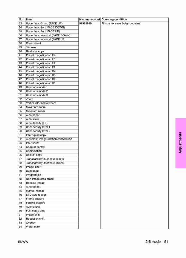
Ad
just
men
ts
33 Upper tray: Group (FACE UP) 99999999 All counters are 8-digit counters.34 Upper tray: Sort (FACE DOWN)35 Upper tray: Sort (FACE UP)
36 Upper tray: Non sort (FACE DOWN)37 Upper tray: Non sort (FACE UP)38 Cover sheet
39 Trimmer40 Real size copy41 Preset magnification E4
42 Preset magnification E343 Preset magnification E2
44 Preset magnification E145 Preset magnification R446 Preset magnification R3
47 Preset magnification R248 Preset magnification R149 User lens mode 1
50 User lens mode 251 User lens mode 352 Zoom
53 Vertical/Horizontal zoom54 Maximum zoom55 Minimum zoom
56 Auto paper57 Auto scale58 Auto density (EE)
59 User density level 160 User density level 261 Interrupted copy
62 Automatic image rotation cancellation63 Inter sheet64 Chapter control
65 Combination66 Booklet copy67 Transparency interleave (copy)
68 Transparency interleave (blank)69 Image insert70 Dual page
71 Program job72 Non-image area erase73 Reverse image
74 Auto repeat75 Manual repeat76 STD size repeat
77 Frame erasure78 Folding erasure79 Auto layout
80 Full-image area81 Image shift82 Reduction shift
83 Overlay84 Water mark
No. Item Maximum count Counting condition
ENWW 2-5 mode 51

85 Stamp 99999999 All counters are 8-digit counters.86 Date/time87 Page
88 Numbering89 Set quantity 190 Set quantity 2-5
91 Set quantity 6-1092 Set quantity 11 or more93 Energized time of power condition 1 Total period of time during which image control board
is energized. Total period of time during the operation of CPU.
94 Energized time of power condition 2 Total period of time during which remote power supply 2 is on.1 is counted per minute.
95 Unused96 Energized time of power condition 4 Total period of time during which remote power supply
3 is on. 1 is counted per minute.97 Time during low power mode Total period of time during which low power mode is
selected. The count is increased by 1 per minute.98 Time during WUP Total period of time during which fuser heater is on
when the fuser is UNREADY. The count is increased by 1 per second. Data is output per minute.
99 Time during front door open Total period of time during which front door is open. The count is increased by 1 per second. Data is output per minute.
100 Operation time in 1 side straight exit Total time from start to end of printing. The count is increased by 1 per second. Data is output per minute. (Halt time caused by jam stop, and so forth is not included.)
101 Operation time in 1 side reverse exit102 Operation time in 2 side print
103 Operation time in ADF mode Total operation time of ADF. The count is increased by 1 per second. Data is output per minute.
104 Morning correction count The count is increased by 1 each time correction is made before starting work in the morning.
105 Time during document size detection sensor on
Total period of time during which document size detection sensor is on. The count is increased by 1 per second. Data is output per minute.
106 N of paper exit face down tray used jobs Number of jobs
107 N of paper exit tray used jobs108 N of stapling folding used jobs109 N of folding jobs
110 N of ADF NF occurred111 N of ADF special error 1 occurred Original size detection error occurrence count112 N of ADF special error 2 occurred Next original information error occurrence count
113 N of ADF special error 3 occurred Mixed loading prohibited original size error occurrence count
114 N of scanner scanned The count is increased by 1 each time Platen Mode Copy button is pressed.115 N of electrode cleaned
116 N of memory overflow
117 N of fuser alarm occurred118 N of no toner stop occurred119 N of AGC retry
No. Item Maximum count Counting condition
52 Adjustments ENWW
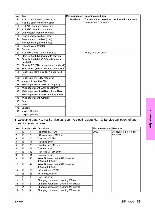
Ad
just
men
ts
8 Collecting data No. 10: Service call count /collecting data No. 12: Service call count of each section (can be reset)
120 N of sub scan beam correct error 99999999 The count is increased by 1 each time Platen Mode Copy button is pressed.121 N of mis-centering correct error
122 N of ADF distortion adjust error
123 N of ADF distortion data error124 Compression memory overflow125 Page memory overflow (scan)
126 Page memory overflow (print)127 Finisher alarm (tray/trimming)128 Finisher alarm (staple)
129 Scanner count130 N of ADF special error 4 occurred Ready-time out error
131 Store for hard disk (sync. with copying)132 Store for hard disk (SRV mode scan->
Hard disk)133 Store for PC (SRV mode scan-> hard disk)134 Store for PC (SRV mode hard disk-> PC)
135 Recall from Hard disk (SRV mode hard disk)
136 Recall from PC (SRV mode PC)137 Image edit count by SRV138 Wide paper count (A3W or LedgerW)
139 Wide paper count (A4W or LetterW)140 Wide paper count (A4RW or LetterRW)141 Wide paper count (A5W or 5.5 by 8.5W)
142 Wide paper count (Others)143 Punch144 Z-fold
145 Unused146 Mixplex (1-sided)147 Mixplex (2-sided)
No. Trouble code Description Maximum count Remarks1 13 1 Paper feed MT EM 9999 All counters are 4-digit
counters.2 13 2 HCI conveyance MT EM3 18 10 Tray 2 up MT EM
4 18 11 Tray 2 up error5 18 20 Tray 3 up MT EM error6 18 21 Tray 3 up error
7 18 30 Tray 4 up MT EM error8 18 31 Tray 4 up error9 18 40 Note: Not used on the HP LaserJet
9055mfp/9065mfp10 18 41 Note: Not used on the HP LaserJet
9055mfp/9065mfp11 18 50 HCI up/down MT EM
12 18 51 HCI up/down error13 18 60 Tray 1 up error14 21 1 Charging corona unit cleaning MT error 1
15 21 2 Charging corona unit cleaning MT error 216 21 3 Charging corona unit cleaning MT error 317 21 4 Charging corona unit cleaning MT error 4
No. Item Maximum count Counting condition
ENWW 2-5 mode 53
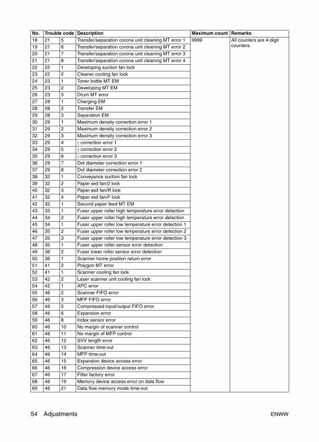
18 21 5 Transfer/separation corona unit cleaning MT error 1 9999 All counters are 4-digit counters.19 21 6 Transfer/separation corona unit cleaning MT error 2
20 21 7 Transfer/separation corona unit cleaning MT error 3
21 21 8 Transfer/separation corona unit cleaning MT error 422 22 1 Developing suction fan lock23 22 2 Cleaner cooling fan lock
24 23 1 Toner bottle MT EM25 23 2 Developing MT EM26 23 3 Drum MT error
27 28 1 Charging EM28 28 2 Transfer EM
29 28 3 Separation EM30 29 1 Maximum density correction error 131 29 2 Maximum density correction error 2
32 29 3 Maximum density correction error 333 29 4 γ correction error 134 29 5 γ correction error 2
35 29 6 γ correction error 336 29 7 Dot diameter correction error 137 29 8 Dot diameter correction error 2
38 32 1 Conveyance suction fan lock39 32 2 Paper exit fan/2 lock40 32 3 Paper exit fan/R lock
41 32 4 Paper exit fan/F lock42 32 1 Second paper feed MT EM43 33 1 Fuser upper roller high temperature error detection
44 34 2 Fuser upper roller high temperature error detection45 34 1 Fuser upper roller low temperature error detection 146 35 2 Fuser upper roller low temperature error detection 2
47 35 3 Fuser upper roller low temperature error detection 348 35 1 Fuser upper roller sensor error detection49 36 2 Fuser lower roller sensor error detection
50 36 1 Scanner home position return error51 41 2 Polygon MT error52 41 1 Scanner cooling fan lock
53 42 2 Laser scanner unit cooling fan lock54 42 1 APC error55 46 2 Scanner FIFO error
56 46 3 MFP FIFO error57 46 5 Compressed input/output FIFO error58 46 6 Expansion error
59 46 8 Index sensor error60 46 10 No margin of scanner control61 46 11 No margin of MFP control
62 46 12 SVV length error63 46 13 Scanner time-out64 46 14 MFP time-out
65 46 15 Expansion device access error66 46 16 Compression device access error67 46 17 Filter factory error
68 46 19 Memory device access error on data flow69 46 21 Data flow memory mode time-out
No. Trouble code Description Maximum count Remarks
54 Adjustments ENWW
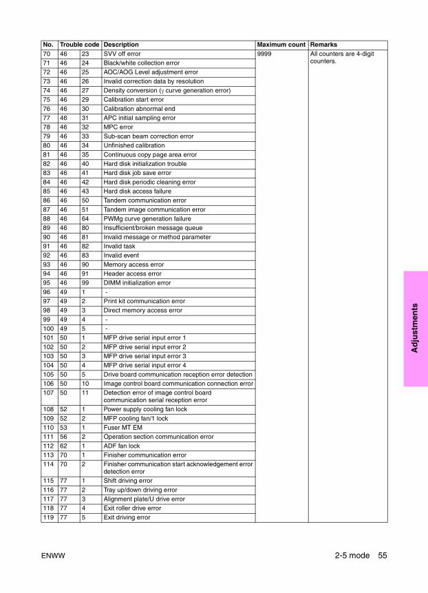
Ad
just
men
ts
70 46 23 SVV off error 9999 All counters are 4-digit counters.71 46 24 Black/white collection error
72 46 25 AOC/AOG Level adjustment error
73 46 26 Invalid correction data by resolution74 46 27 Density conversion (γ curve generation error)75 46 29 Calibration start error
76 46 30 Calibration abnormal end77 46 31 APC initial sampling error78 46 32 MPC error
79 46 33 Sub-scan beam correction error80 46 34 Unfinished calibration
81 46 35 Continuous copy page area error82 46 40 Hard disk initialization trouble83 46 41 Hard disk job save error
84 46 42 Hard disk periodic cleaning error85 46 43 Hard disk access failure86 46 50 Tandem communication error
87 46 51 Tandem image communication error88 46 64 PWMg curve generation failure89 46 80 Insufficient/broken message queue
90 46 81 Invalid message or method parameter91 46 82 Invalid task92 46 83 Invalid event
93 46 90 Memory access error94 46 91 Header access error95 46 99 DIMM initialization error
96 49 1 -97 49 2 Print kit communication error98 49 3 Direct memory access error
99 49 4 -100 49 5 -101 50 1 MFP drive serial input error 1
102 50 2 MFP drive serial input error 2103 50 3 MFP drive serial input error 3104 50 4 MFP drive serial input error 4
105 50 5 Drive board communication reception error detection106 50 10 Image control board communication connection error107 50 11 Detection error of image control board
communication serial reception error108 52 1 Power supply cooling fan lock
109 52 2 MFP cooling fan/1 lock110 53 1 Fuser MT EM111 56 2 Operation section communication error
112 62 1 ADF fan lock113 70 1 Finisher communication error114 70 2 Finisher communication start acknowledgement error
detection error115 77 1 Shift driving error
116 77 2 Tray up/down driving error117 77 3 Alignment plate/U drive error118 77 4 Exit roller drive error
119 77 5 Exit driving error
No. Trouble code Description Maximum count Remarks
ENWW 2-5 mode 55
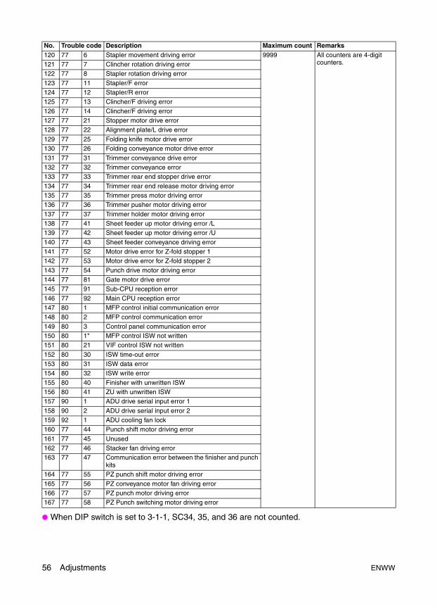
● When DIP switch is set to 3-1-1, SC34, 35, and 36 are not counted.
120 77 6 Stapler movement driving error 9999 All counters are 4-digit counters.121 77 7 Clincher rotation driving error
122 77 8 Stapler rotation driving error
123 77 11 Stapler/F error124 77 12 Stapler/R error125 77 13 Clincher/F driving error
126 77 14 Clincher/F driving error127 77 21 Stopper motor drive error128 77 22 Alignment plate/L drive error
129 77 25 Folding knife motor drive error130 77 26 Folding conveyance motor drive error
131 77 31 Trimmer conveyance drive error132 77 32 Trimmer conveyance error133 77 33 Trimmer rear end stopper drive error
134 77 34 Trimmer rear end release motor driving error135 77 35 Trimmer press motor driving error136 77 36 Trimmer pusher motor driving error
137 77 37 Trimmer holder motor driving error138 77 41 Sheet feeder up motor driving error /L139 77 42 Sheet feeder up motor driving error /U
140 77 43 Sheet feeder conveyance driving error141 77 52 Motor drive error for Z-fold stopper 1 142 77 53 Motor drive error for Z-fold stopper 2
143 77 54 Punch drive motor driving error144 77 81 Gate motor drive error145 77 91 Sub-CPU reception error
146 77 92 Main CPU reception error147 80 1 MFP control initial communication error148 80 2 MFP control communication error
149 80 3 Control panel communication error150 80 1* MFP control ISW not written151 80 21 VIF control ISW not written
152 80 30 ISW time-out error153 80 31 ISW data error154 80 32 ISW write error
155 80 40 Finisher with unwritten ISW 156 80 41 ZU with unwritten ISW 157 90 1 ADU drive serial input error 1
158 90 2 ADU drive serial input error 2159 92 1 ADU cooling fan lock160 77 44 Punch shift motor driving error
161 77 45 Unused162 77 46 Stacker fan driving error163 77 47 Communication error between the finisher and punch
kits164 77 55 PZ punch shift motor driving error
165 77 56 PZ conveyance motor fan driving error166 77 57 PZ punch motor driving error167 77 58 PZ Punch switching motor driving error
No. Trouble code Description Maximum count Remarks
56 Adjustments ENWW
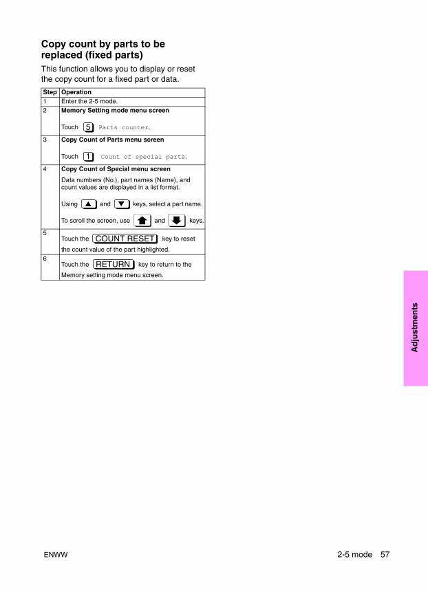
Ad
just
men
ts
Copy count by parts to be replaced (fixed parts)This function allows you to display or reset the copy count for a fixed part or data.
Step Operation1 Enter the 2-5 mode.2 Memory Setting mode menu screen
Touch Parts counter.
3 Copy Count of Parts menu screen
Touch Count of special parts.
4 Copy Count of Special menu screen
Data numbers (No.), part names (Name), and count values are displayed in a list format.
Using and keys, select a part name.
To scroll the screen, use and keys.
5Touch the key to reset
the count value of the part highlighted.6
Touch the key to return to the
Memory setting mode menu screen.
5
1
COUNT RESET
RETURN
ENWW 2-5 mode 57
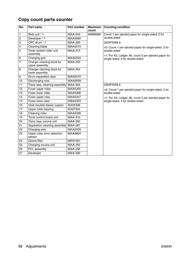
Copy count parts counter
No. Part name Part number Maximum count
Counting condition
1 Web unit * 1 56AA-543 99999999 Count 1 per ejected paper for single-sided, 2 for double-sided
25DIPSW8-6
=0: Count 1 per ejected paper for single-sided, 2 for double-sided
=1: For A3, Ledger, 8k, count 2 per ejected paper for single-sided, 4 for double-sided
2 Developer * 1 56AA30603 OPC drum * 1 56AA-2204 Cleaning blade 56AA2010
5 Toner reclaim roller unit assembly
56AA-213
6 Charging grid 56AA25037 Charger cleaning block for
upper assembly56AA-253
8 Charger cleaning block for lower assembly
56AA-254
9 Drum separation claw 56AA2070
10 Discharging wire 56AA260911 Trans./sep. cleaning assembly 56AA-264 25DIPSW8-6
=0: Count 1 per ejected paper for single-sided, 2 for double-sided
=1: For A3, Ledger, 8k, count 2 per ejected paper for single-sided, 4 for double-sided
12 Fuser upper roller 56AA5305
13 Fuser lower roller 56AA530614 Fuser upper claw 56AA542715 Fuser lower claw 25BA5333
16 Heat insulate sleeve (upper) 4540533917 Upper roller bearing 4540750418 Cleaning roller 56AA5308
19 Toner control board unit 56AA-91020 Trans./sep. corona unit 56AA-26021 Separation cleaning assembly 56AA-267
22 Charging wire 56AA250923 Upper roller error detection
sensor56AA8804
24 Ozone filter 56FA730125 Charging corona unit 56AA-250
26 PCL assembly 56AA-25627 Developer 56AA-300
58 Adjustments ENWW
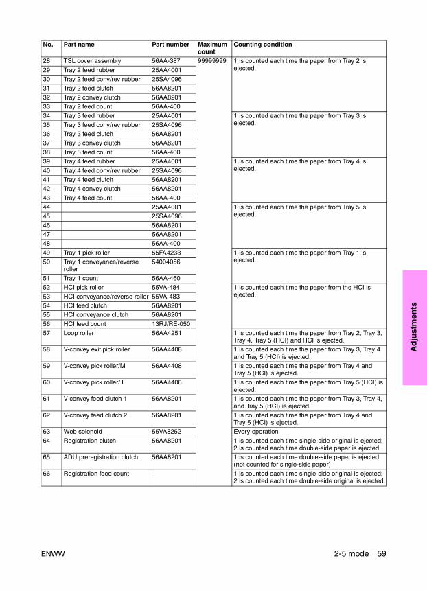
Ad
just
men
ts
28 TSL cover assembly 56AA-387 99999999 1 is counted each time the paper from Tray 2 is ejected.29 Tray 2 feed rubber 25AA4001
30 Tray 2 feed conv/rev rubber 25SA409631 Tray 2 feed clutch 56AA8201
32 Tray 2 convey clutch 56AA820133 Tray 2 feed count 56AA-40034 Tray 3 feed rubber 25AA4001 1 is counted each time the paper from Tray 3 is
ejected.35 Tray 3 feed conv/rev rubber 25SA409636 Tray 3 feed clutch 56AA820137 Tray 3 convey clutch 56AA8201
38 Tray 3 feed count 56AA-40039 Tray 4 feed rubber 25AA4001 1 is counted each time the paper from Tray 4 is
ejected.40 Tray 4 feed conv/rev rubber 25SA409641 Tray 4 feed clutch 56AA820142 Tray 4 convey clutch 56AA8201
43 Tray 4 feed count 56AA-40044 25AA4001 1 is counted each time the paper from Tray 5 is
ejected.45 25SA4096
46 56AA820147 56AA820148 56AA-400
49 Tray 1 pick roller 55FA4233 1 is counted each time the paper from Tray 1 is ejected.50 Tray 1 conveyance/reverse
roller54004056
51 Tray 1 count 56AA-46052 HCI pick roller 55VA-484 1 is counted each time the paper from the HCI is
ejected.53 HCI conveyance/reverse roller 55VA-48354 HCI feed clutch 56AA820155 HCI conveyance clutch 56AA8201
56 HCI feed count 13RJ/RE-05057 Loop roller 56AA4251 1 is counted each time the paper from Tray 2, Tray 3,
Tray 4, Tray 5 (HCI) and HCI is ejected.58 V-convey exit pick roller 56AA4408 1 is counted each time the paper from Tray 3, Tray 4
and Tray 5 (HCI) is ejected.59 V-convey pick roller/M 56AA4408 1 is counted each time the paper from Tray 4 and
Tray 5 (HCI) is ejected.60 V-convey pick roller/ L 56AA4408 1 is counted each time the paper from Tray 5 (HCI) is
ejected.61 V-convey feed clutch 1 56AA8201 1 is counted each time the paper from Tray 3, Tray 4,
and Tray 5 (HCI) is ejected.62 V-convey feed clutch 2 56AA8201 1 is counted each time the paper from Tray 4 and
Tray 5 (HCI) is ejected.63 Web solenoid 55VA8252 Every operation 64 Registration clutch 56AA8201 1 is counted each time single-side original is ejected;
2 is counted each time double-side paper is ejected.65 ADU preregistration clutch 56AA8201 1 is counted each time double-side paper is ejected
(not counted for single-side paper)66 Registration feed count - 1 is counted each time single-side original is ejected;
2 is counted each time double-side original is ejected.
No. Part name Part number Maximum count
Counting condition
ENWW 2-5 mode 59
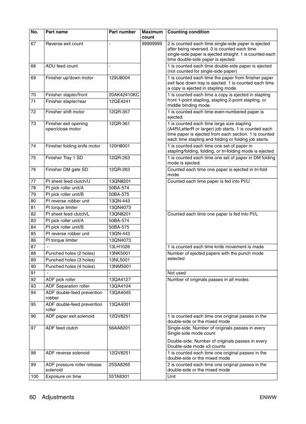
67 Reverse exit count - 99999999 2 is counted each time single-side paper is ejected after being reversed. 0 is counted each time single-side paper is ejected straight. 1 is counted each time double-side paper is ejected.
68 ADU feed count - 1 is counted each time double-side paper is ejected (not counted for single-side paper)
69 Finisher up/down motor 129U8004 1 is counted each time the paper from finisher paper exit face down tray is ejected. 1 is counted each time a copy is ejected in stapling mode.
70 Finisher stapler/front 20AK42410KC 1 is counted each time a copy is ejected in stapling front 1-point stapling, stapling 2-point stapling, or middle binding mode.
71 Finisher stapler/rear 12QE4241
72 Finisher shift motor 12QR-357 1 is counted each time even-numbered paper is ejected.
73 Finisher exit opening open/close motor
12QR-361 1 is counted each time large size stapling (A4R/LetterR or larger) job starts. 1 is counted each time paper is ejected from each section. 1 is counted each time stapling and folding or folding job starts.
74 Finisher folding knife motor 120H8001 1 is counted each time one set of paper in stapling/folding, folding, or tri-folding mode is ejected.
75 Finisher Tray 1 SD 12QR-263 1 is counted each time one set of paper in DM folding mode is ejected.
76 Finisher DM gate SD 12QR-263 Counted each time one paper is ejected in tri-fold mode
77 PI sheet feed clutch/U 13QN8201 Counted each time paper is fed into PI/U78 PI pick roller unit/A 50BA-57479 PI pick roller unit/B 50BA-575
80 PI reverse robber unit 13QN-44381 PI torque limiter 13QN407382 PI sheet feed clutch/L 13QN8201 Counted each time one paper is fed into PI/L
83 PI pick roller unit/A 50BA-57484 PI pick roller unit/B 50BA-57585 PI reverse robber unit 13QN-443
86 PI torque limiter 13QN407387 - 13LH1026 1 is counted each time knife movement is made88 Punched holes (2 holes) 13NK5001 Number of ejected papers with the punch mode
selected89 Punched holes (3 holes) 13NL500190 Punched holes (4 holes) 13NM500191 - - Not used
92 ADF pick roller 13QA4127 Number of originals passes in all modes93 ADF Separation roller 13QA410494 ADF double-feed prevention
robber13QA4045
95 ADF double-feed prevention roller
13QA4001
96 ADF paper exit solenoid 12QV8251 1 is counted each time one original passes in the double-side or the mixed mode
97 ADF feed clutch 56AA8201 Single-side: Number of originals passes in every Single-side mode count
Double-side: Number of originals passes in every Double-side mode x3 counts
98 ADF reverse solenoid 12QV8251 1 is counted each time one original passes in the double-side or the mixed mode
99 ADF pressure roller release solenoid
25SA8265 2 is counted each time one original passes in the double-side or the mixed mode
100 Exposure on time 55TA8301 Unit
No. Part name Part number Maximum count
Counting condition
60 Adjustments ENWW

Ad
just
men
ts
Copy count by parts to be replaced (optional parts)This function allows you to make the following settings for an optional part or data:
1 Copy count resetting
2 Limit value setting
3 Part number setting
4 Part name setting
The above settings can be made for 30 data numbers, No. 1 to No. 30. The copy count is increased by 1 for each side irrespective of the paper size.
Resetting the copy count by parts to be replaced (optional parts)
This function allows you to reset the copy count by parts to be replaced (optional parts).
Reference: If the copy count exceeds the limit, the * mark appears to the left of the limit value.
Changing the data on the copy count by parts to be replaced (optional parts)
This function allows you to change the limit value, part number, or part name for the desired optional copy count by parts to be replaced (optional parts).
101 Sub power switch 55GA8602 99999999 1 is counted each time sub power is switched off.
102 Door switch 40AA8501 1 is counted each time front door is opened.103 Drum separation claw
solenoid26NA8251 1 is counted each time a paper is ejected, 2 is counted
for double-sided.104 Main power switch 25AA8502 1 is counted each time image control turns on
(number of times CPU is activated from other than sub power supply (SK/SHUT OFF/WT))
105 PI registration clutch 13QN8201 1 is counted each time PI sheet is ejected.106 Punch motor 54008003 Number of papers ejected when punch mode is
selected.
124
125126127
128
No. Part name Part number Maximum count
Counting condition
Step Operation1 Enter the 2-5 mode.2 Memory Setting mode menu screen
Touch the Parts counter.
3 Copy Count of Part menu screen
Touch the Count of each parts.
5
2
4 Copy Count of Each Part screen
Data numbers (No.), part names (name), part numbers (P/N), and count/limit values are displayed in a list format.
Using and keys, select a part name.
To scroll the screen, use and keys.
5Touch the key to reset the count value of the part highlighted.
6Touch the key to return to the Memory setting mode menu screen.
Step Operation
COUNT RESET
RETURN
ENWW 2-5 mode 61
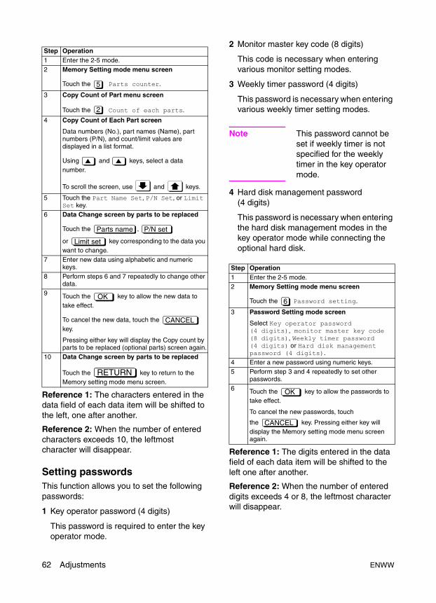
Reference 1: The characters entered in the data field of each data item will be shifted to the left, one after another.
Reference 2: When the number of entered characters exceeds 10, the leftmost character will disappear.
Setting passwordsThis function allows you to set the following passwords:
1 Key operator password (4 digits)
This password is required to enter the key operator mode.
2 Monitor master key code (8 digits)
This code is necessary when entering various monitor setting modes.
3 Weekly timer password (4 digits)
This password is necessary when entering various weekly timer setting modes.
Note This password cannot be set if weekly timer is not specified for the weekly timer in the key operator mode.
4 Hard disk management password (4 digits)
This password is necessary when entering the hard disk management modes in the key operator mode while connecting the optional hard disk.
Reference 1: The digits entered in the data field of each data item will be shifted to the left one after another.
Reference 2: When the number of entered digits exceeds 4 or 8, the leftmost character will disappear.
Step Operation1 Enter the 2-5 mode.2 Memory Setting mode menu screen
Touch the Parts counter.
3 Copy Count of Part menu screen
Touch the Count of each parts.
4 Copy Count of Each Part screen
Data numbers (No.), part names (Name), part numbers (P/N), and count/limit values are displayed in a list format.
Using and keys, select a data number.
To scroll the screen, use and keys.
5 Touch the Part Name Set, P/N Set, or Limit Set key.
6 Data Change screen by parts to be replaced
Touch the ,
or key corresponding to the data you want to change.
7 Enter new data using alphabetic and numeric keys.
8 Perform steps 6 and 7 repeatedly to change other data.
9 Touch the key to allow the new data to take effect.
To cancel the new data, touch the key.
Pressing either key will display the Copy count by parts to be replaced (optional parts) screen again.
10 Data Change screen by parts to be replaced
Touch the key to return to the Memory setting mode menu screen.
5
2
Parts name P/N set
Limit set
OK
CANCEL
RETURN
Step Operation1 Enter the 2-5 mode.2 Memory Setting mode menu screen
Touch the Password setting.
3 Password Setting mode screen
Select Key operator password (4 digits), monitor master key code (8 digits), Weekly timer password (4 digits) or Hard disk management password (4 digits).
4 Enter a new password using numeric keys.5 Perform step 3 and 4 repeatedly to set other
passwords.6 Touch the key to allow the passwords to
take effect.
To cancel the new passwords, touch
the key. Pressing either key will display the Memory setting mode menu screen again.
6
OK
CANCEL
62 Adjustments ENWW
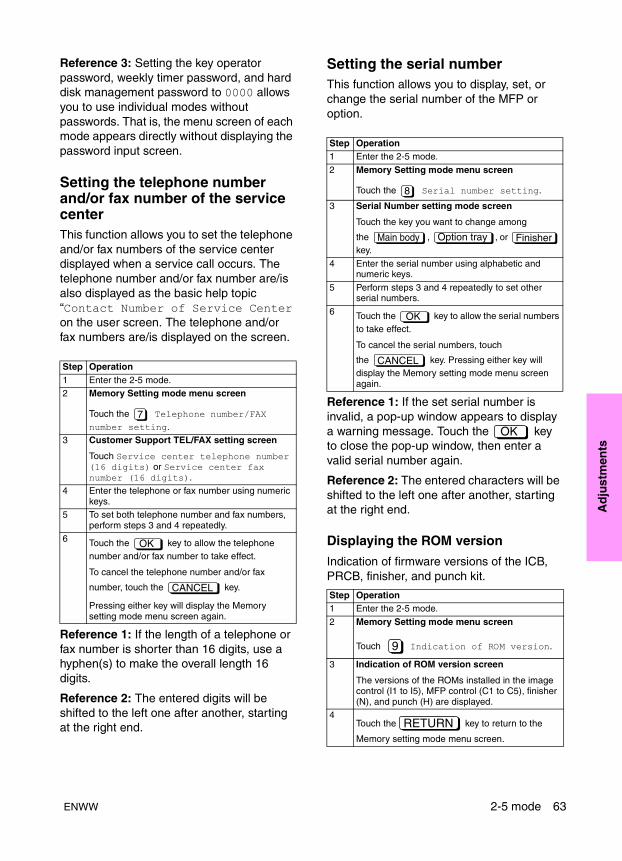
Ad
just
men
ts
Reference 3: Setting the key operator password, weekly timer password, and hard disk management password to 0000 allows you to use individual modes without passwords. That is, the menu screen of each mode appears directly without displaying the password input screen.
Setting the telephone number and/or fax number of the service centerThis function allows you to set the telephone and/or fax numbers of the service center displayed when a service call occurs. The telephone number and/or fax number are/is also displayed as the basic help topic “Contact Number of Service Center on the user screen. The telephone and/or fax numbers are/is displayed on the screen.
Reference 1: If the length of a telephone or fax number is shorter than 16 digits, use a hyphen(s) to make the overall length 16 digits.
Reference 2: The entered digits will be shifted to the left one after another, starting at the right end.
Setting the serial numberThis function allows you to display, set, or change the serial number of the MFP or option.
Reference 1: If the set serial number is invalid, a pop-up window appears to display a warning message. Touch the key to close the pop-up window, then enter a valid serial number again.
Reference 2: The entered characters will be shifted to the left one after another, starting at the right end.
Displaying the ROM version
Indication of firmware versions of the ICB, PRCB, finisher, and punch kit.
Step Operation1 Enter the 2-5 mode.2 Memory Setting mode menu screen
Touch the Telephone number/FAX number setting.
3 Customer Support TEL/FAX setting screen
Touch Service center telephone number (16 digits) or Service center fax number (16 digits).
4 Enter the telephone or fax number using numeric keys.
5 To set both telephone number and fax numbers, perform steps 3 and 4 repeatedly.
6 Touch the key to allow the telephone number and/or fax number to take effect.
To cancel the telephone number and/or fax
number, touch the key.
Pressing either key will display the Memory setting mode menu screen again.
7
OK
CANCEL
Step Operation1 Enter the 2-5 mode.
2 Memory Setting mode menu screen
Touch the Serial number setting.
3 Serial Number setting mode screen
Touch the key you want to change among
the , , or key.
4 Enter the serial number using alphabetic and numeric keys.
5 Perform steps 3 and 4 repeatedly to set other serial numbers.
6 Touch the key to allow the serial numbers to take effect.
To cancel the serial numbers, touch
the key. Pressing either key will display the Memory setting mode menu screen again.
Step Operation1 Enter the 2-5 mode.
2 Memory Setting mode menu screen
Touch Indication of ROM version.
3 Indication of ROM version screen
The versions of the ROMs installed in the image control (I1 to I5), MFP control (C1 to C5), finisher (N), and punch (H) are displayed.
4Touch the key to return to the
Memory setting mode menu screen.
8
Main body Option tray Finisher
OK
CANCEL
OK
9
RETURN
ENWW 2-5 mode 63

Setting dateSet the total count start day
Note Ends when the key is pressed without amending the entered date, and returns to the Memory setting mode menu screen.
3-6 mode
Setting methodThis MFP is provided with 3-6 mode as an adjustment mode.
1 Turn off the secondary power switch (SW2).
2 Turn on the SW2 while holding down both paper quantity buttons 3 and 6.
The Adjustment mode menu screen appears.
At this point, you are in 3-6 mode and normal copy operation is disabled.
3 Touch the number key corresponding to the item to adjust.
The setting screen for each item is displayed.
4 Enter data in each adjustment screen.
5 If there are several adjustment items, touch the or key to select the desired item. If there are more screens below, touch the key displayed on screen to change screen.
6 Enter data and touch the key if it is available, to confirm your entry.
7 Touch the key to end adjustment.
8 Turn off the SW2 and exit the 3-6 mode.
9 The new adjustment values take effect after restarting the MFP.
Step Operation1 Enter the 2-5 mode.2 Memory Setting mode menu screen
Touch Setting date input.
3 Setting Date input screen
Using the numeric keys, input the new setting date.
4Touch the key to return to the Memory setting mode menu screen.
12
OK
CANCEL
NEXT BACK
SET
RETURN
64 Adjustments ENWW
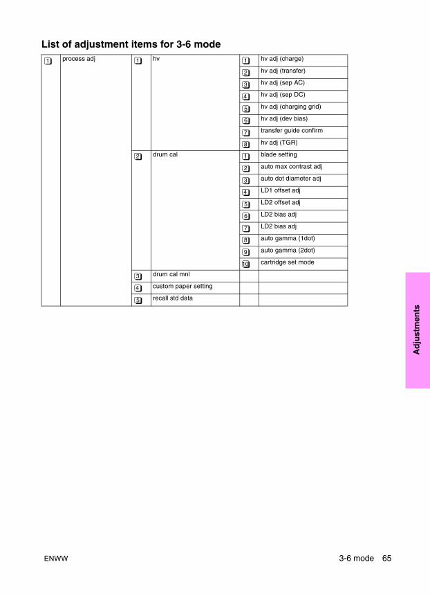
Ad
just
men
ts
List of adjustment items for 3-6 modeprocess adj hv hv adj (charge)
hv adj (transfer)
hv adj (sep AC)
hv adj (sep DC)
hv adj (charging grid)
hv adj (dev bias)
transfer guide confirm
hv adj (TGR)
drum cal blade setting
auto max contrast adj
auto dot diameter adj
LD1 offset adj
LD2 offset adj
LD2 bias adj
LD2 bias adj
auto gamma (1dot)
auto gamma (2dot)
cartridge set mode
drum cal mnl
custom paper setting
recall std data
1 1 1
2
3
4
5
6
7
8
2 1
2
3
4
5
6
7
8
9
10
3
4
5
ENWW 3-6 mode 65

image adj trayadj
magnification adj printer drum clk adj
printer horizontal adj
scanner drum clk adj
ADF drum clk adj
timing adj printer restart timing
printer regis loop adj
printer pre-regist adj
printer leading edge timing
scanner restart timing
ADF restart timing
ADF regist loop adj
document feeder adj doc feeder contrast adj
ADF original size adj
ADF skew offset adj
centering adj printer centering adj
scanner centering adj
ADF centering adj
warp adj (copier)
non-image area erase
recall std data
running test intermittent copy
paperless running
paperless
paperless endless
running
test pattern output
test pattern contrast
finisher stapling & folding
folding stopper
cover sheet tray size
(trimmer)
punch
tri-folding stopper
2-position staple pitch
2 1
2 1
2
3
4
3 1
2
3
4
5
6
7
4 1
2
3
5 1
2
3
6
7
8
3 1
2
3
4
5
4
5
6 1
2
3
4
5
6
7
66 Adjustments ENWW

Ad
just
men
ts
High voltage adjustment
Process adjustment
Adjusting the high voltage for charging, transfer, separation, and development.
1 Touch Process adjustment in the Adjustment mode menu screen to display the Process Adjustment mode menu screen.
2 Touch High voltage adjustment in the Process Adjustment mode menu screen to display the High Voltage Adjustment mode menu.
3 High Voltage Adjustment consists of the following:
HV adjustment (charge)
HV adjustment (transfer)
HV adjustment (separation AC)
HV adjustment (separation DC)
HV adjustment (charging grid voltage)
HV adjustment (bias of development)
Transfer guide confirm
HV adjustment (TGR)
4 Touch the number key corresponding to the item to be adjusted.
The adjustment screen of the selected item is displayed.
5 When adjustment completes, the screen returns to the High Voltage Adjustment mode menu screen.
6 Touch the key in the High Voltage Adjustment mode menu screen to return to the Process Adjustment mode menu screen.
1 Charging main manual adjustment
Charging main manual adjustment is inhibited in the field.
2 Transfer manual adjustment
Default setting value must be set under the guidance of HP support.
3 Separation (AC) manual adjustment
Default setting value must be set under the guidance of HP support.
4 Separation (DC) manual adjustment
Default setting value must be set under the guidance of HP support.
5 Charging grid manual adjustment
See “Charging grid voltage adjustment” below.
6 Developing bias manual adjustment
Default setting value must be set under the guidance of HP support.
7 Transfer guide confirm
Transfer guide confirm is inhibited in the field.
list output mode machine mgmt list1
adj data list
black ratio data list
machine mgmt list2
parameter list
memory dump list
font pattern
7 1
2
3
4
5
6
7
1
1
1
2
3
4
5
6
7
8
RETURN
ENWW 3-6 mode 67
8 TGR manual adjustment
TGR manual adjustment is inhibited in the field.
Charging grid voltage adjustmentAdjusting the charging grid voltage. Before performing this adjustment, check that the drum counter was reset.
Insert the door SW tool to interlock SW/L and interlock SW/R.
Drum calibration adjustmentAdjusting the blade set, maximum density (Dmax), dot diameter, laser offset and gamma.
1 Touch Process adjustment in the Adjustment mode menu screen to display the Process Adjustment mode menu screen.
2 Touch Drum calibration adjustment in the Process Adjustment mode menu screen to display the Drum Calibration Adjustment mode menu screen.
3 Drum calibration adjustment consists of the following:
Blade setting mode
Auto maximum contrast
Auto dot diameter adjustment
LD1 offset adjustment
LD2 offset adjustment
LD1 bias adjustment
LD2 bias adjustment
Auto gamma adjustment (1 dot)
Auto gamma adjustment (2 dot)
Cartridge set mode (drum)
4 Touch the number key corresponding to the item to be adjusted.
The adjustment screen of the selected item is displayed.
Step Operation1 Check the adjustment value of the charging grid
voltage on the drum flange.2 Connect the V tester as shown below.
+: Grid pin
-: GND (Earth)
Range: DC1000V
3 Enter the 3-6 mode.4 Adjustment mode menu screen
Touch Process adjustment.
5 Process Adjustment mode menu screen
Touch High voltage adjustment.
6 High Voltage Adjustment mode menu screen
Touch HV adjustment (charging grid voltage).
7 HV Adjustment (charging grid voltage) screen
Press START button, and check the voltage shown, then press the CANCEL button.
8 When the voltage measured is not satisfactory, change the data using the numeric keys on the
screen and touch the key.
9 Turn the secondary power switch (SW2) off.
Standard value specified value on the drum flange ±5V
Range of input: 0 to 255
1 step: 1.6V
1
1
5
SET
Metal frame Grid +
1
2
1
2
3
4
5
6
7
8
9
10
68 Adjustments ENWW
Ad
just
men
ts
5 When adjustment completes, the screen returns to the drum calibration adjustment mode menu screen.
6 Touch the key in the Drum Calibration Adjustment mode menu screen to return to the Process Adjustment mode menu screen.
Blade setting mode
In this mode, toner stuck on the drum surface during replacement of the cleaning blade or drum is removed to prevent damage to the drum and cleaning blade.
Preparation: Be sure the drum unit is set. Apply setting powder to all the surface of the drum.
Auto maximum contrast adjustment (Dmax adjustment)
Automatically adjusting the maximum density (Dmax). This adjustment should be performed when the drum, developer, laser/scanner assembly, or dust-proof glass is replaced.
Preparation: Be sure the drum unit is set and developer is in the developing unit.
Reference: If any one of the following error messages appears during auto maximum contrast adjustment, clean the TSCB (toner control sensor board), check its installation state, and retry the auto maximum contrast adjustment.
<1> Error 1: The Dmax (maximum contrast) sensor dirt correction has been corrected.
<2> Error 2: Maximum density adjustment is not complete when the number of rotation of developing sleeve reaches the specified value.
<3> Error 3: No signal is output from the Dmax (maximum contrast) sensor. No control patch is output.
Auto dot diameter adjustment
Automatically adjusting the dot diameter.
This adjustment should be performed when the drum, developer, laser/scanner assembly, or dust-proof glass is replaced.
Preparation: Be sure the drum unit is set and developer is in the developing unit. Auto maximum contrast adjustment must have been completed.
Step Operation1 Enter the 3-6 mode.
2 Adjustment mode menu screen
Touch Process adjustment.
3 Process Adjustment mode menu screen
Touch Drum calibration adjustment.
4 Drum Calibration Adjustment mode menu screen
Touch Blade setting mode.
5 Blade Setting mode screen
Touch the key.
Adjustment completes in about 1 second and a complete message is displayed.
6Touch the key to return to the Drum Calibration Adjustment mode menu screen.
Step Operation1 Enter the 3-6 mode.
RETURN
1
2
1
Start
RETURN
2 Adjustment mode menu screen
Touch Process adjustment.
3 Process Adjustment mode menu screen
Touch Drum calibration adjustment.
4 Drum Calibration Adjustment mode menu screen
Touch Auto maximum density adjustment
5 Auto Maximum Contrast Adjustment screen
Touch the key.
The maximum density (Dmax) is adjusted automatically.
Adjustment completes in about 15 seconds and an complete message is displayed.
6Touch the key to return to the Drum Calibration Adjustment mode menu screen.
Step Operation1 Enter the 3-6 mode.
1
2
2
Start
RETURN
ENWW 3-6 mode 69
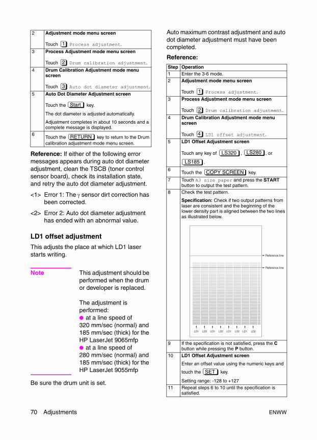
Reference: If either of the following error messages appears during auto dot diameter adjustment, clean the TSCB (toner control sensor board), check its installation state, and retry the auto dot diameter adjustment.
<1> Error 1: The γ sensor dirt correction has been corrected.
<2> Error 2: Auto dot diameter adjustment has ended with an abnormal value.
LD1 offset adjustment
This adjusts the place at which LD1 laser starts writing.
Note This adjustment should be performed when the drum or developer is replaced.
The adjustment is performed:● at a line speed of 320 mm/sec (normal) and 185 mm/sec (thick) for the HP LaserJet 9065mfp● at a line speed of 280 mm/sec (normal) and 185 mm/sec (thick) for the HP LaserJet 9055mfp
Be sure the drum unit is set.
Auto maximum contrast adjustment and auto dot diameter adjustment must have been completed.
Reference:
2 Adjustment mode menu screen
Touch Process adjustment.
3 Process Adjustment mode menu screen
Touch Drum calibration adjustment.
4 Drum Calibration Adjustment mode menu screen
Touch Auto dot diameter adjustment.
5 Auto Dot Diameter Adjustment screen
Touch the key.
The dot diameter is adjusted automatically.
Adjustment completes in about 10 seconds and a complete message is displayed.
6Touch the key to return to the Drum calibration adjustment mode menu screen.
1
2
3
Start
RETURN
Step Operation1 Enter the 3-6 mode.
2 Adjustment mode menu screen
Touch Process adjustment.
3 Process Adjustment mode menu screen
Touch Drum calibration adjustment.
4 Drum Calibration Adjustment mode menu screen
Touch LD1 offset adjustment.
5 LD1 Offset Adjustment screen
Touch any key of , , or
.
6Touch the key.
7 Touch A3 size paper and press the START button to output the test pattern.
8 Check the test pattern.
Specification: Check if two output patterns from laser are consistent and the beginning of the lower density part is aligned between the two lines as illustrated below.
9 If the specification is not satisfied, press the C button while pressing the P button.
10 LD1 Offset Adjustment screen
Enter an offset value using the numeric keys and
touch the key.
Setting range: -128 to +12711 Repeat steps 6 to 10 until the specification is
satisfied.
1
2
4
LS320 LS280
LS185
COPY SCREEN
LD1 LD2 LD1 LD2 LD1 LD2 LD1 LD2
Reference line
Reference line
SET
70 Adjustments ENWW
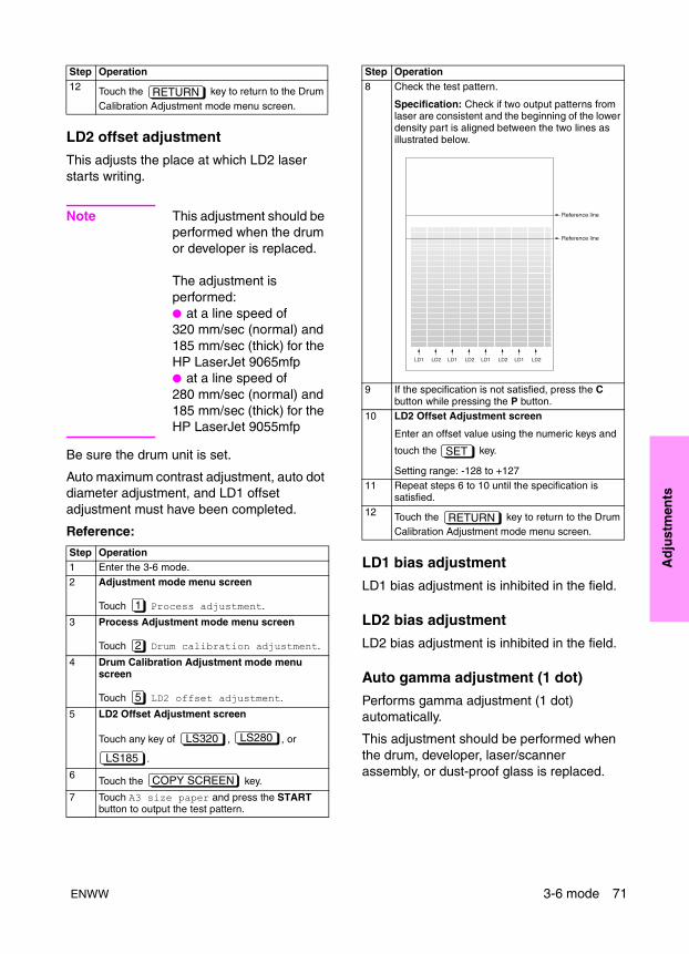
Ad
just
men
ts
LD2 offset adjustment
This adjusts the place at which LD2 laser starts writing.
Note This adjustment should be performed when the drum or developer is replaced.
The adjustment is performed:● at a line speed of 320 mm/sec (normal) and 185 mm/sec (thick) for the HP LaserJet 9065mfp● at a line speed of 280 mm/sec (normal) and 185 mm/sec (thick) for the HP LaserJet 9055mfp
Be sure the drum unit is set.
Auto maximum contrast adjustment, auto dot diameter adjustment, and LD1 offset adjustment must have been completed.
Reference:
LD1 bias adjustment
LD1 bias adjustment is inhibited in the field.
LD2 bias adjustment
LD2 bias adjustment is inhibited in the field.
Auto gamma adjustment (1 dot)
Performs gamma adjustment (1 dot) automatically.
This adjustment should be performed when the drum, developer, laser/scanner assembly, or dust-proof glass is replaced.
12 Touch the key to return to the Drum Calibration Adjustment mode menu screen.
Step Operation1 Enter the 3-6 mode.
2 Adjustment mode menu screen
Touch Process adjustment.
3 Process Adjustment mode menu screen
Touch Drum calibration adjustment.
4 Drum Calibration Adjustment mode menu screen
Touch LD2 offset adjustment.
5 LD2 Offset Adjustment screen
Touch any key of , , or
.
6Touch the key.
7 Touch A3 size paper and press the START button to output the test pattern.
Step Operation
RETURN
1
2
5
LS320 LS280
LS185
COPY SCREEN
8 Check the test pattern.
Specification: Check if two output patterns from laser are consistent and the beginning of the lower density part is aligned between the two lines as illustrated below.
9 If the specification is not satisfied, press the C button while pressing the P button.
10 LD2 Offset Adjustment screen
Enter an offset value using the numeric keys and
touch the key.
Setting range: -128 to +12711 Repeat steps 6 to 10 until the specification is
satisfied.12 Touch the key to return to the Drum
Calibration Adjustment mode menu screen.
Step Operation
LD1 LD2 LD1 LD2 LD1 LD2 LD1 LD2
Reference line
Reference line
SET
RETURN
ENWW 3-6 mode 71

Preparation: Be sure the drum unit is set. Auto maximum contrast adjustment, auto dot diameter adjustment, LD1 offset adjustment and, LD2 offset adjustment must have been completed.
Reference: If any one of the following error messages appears during auto gamma adjustment, clean the TSCB (toner control sensor board), check its installation state, and retry the auto gamma adjustment.
<1> Error 1: The γ sensor dirt correction has been corrected.
<2> Error 2: No signal is output from the γ sensor. No control patch is output.
<3> Error 3: A recurrence error occurred during γ curve calculation.
Auto gamma adjustment (2 dot)
Performs gamma adjustment (2 dot) automatically.
This adjustment should be performed when the drum, developer, laser/scanner assembly, or dust-proof glass is replaced.
Preparation: Be sure the drum unit is set. Auto maximum contrast adjustment, auto dot diameter adjustment, LD1 offset adjustment,
LD2 offset adjustment, and auto gamma adjustment (1 dot) must have been completed.
Reference: If any one of the following error messages appears during auto gamma adjustment, clean the TSCB (toner control sensor board), check its installation state, and retry the auto gamma adjustment.
<1> Error 1: The γ sensor dirt correction has been corrected.
<2> Error 2: No signal is output from the γ sensor. No control patch is output.
<3> Error 3: A recurrence error occurred during γ curve calculation.
Cartridge set mode (drum)
This adjustment should be performed when black dots appear on the copy after removing and installing the drum.
Step Operation1 Enter the 3-6 mode.2 Adjustment mode menu screen
Touch Process adjustment.
3 Process Adjustment mode menu screen
Touch Drum calibration adjustment.
4 Drum Calibration Adjustment mode menu screen
Touch Auto gamma adjustment (1 dot).
5 Auto Gamma Adjustment (1 dot) screen
Touch the key.
The drum and developer operate to automatically adjust gamma.
Adjustment completes in about 10 seconds and a complete message is displayed.
6Touch the key to return to the Drum Calibration Adjustment mode menu screen.
1
2
8
Start
RETURN
Step Operation1 Enter the 3-6 mode.
2 Adjustment mode menu screen
Touch Process adjustment.
3 Process Adjustment mode menu screen
Touch Drum calibration adjustment.
4 Drum Calibration Adjustment mode menu screen
Touch Auto gamma adjustment (2 dot).
5 Auto Gamma Adjustment (2 dot) screen
Touch the key.
The drum and developer operate to automatically adjust gamma.
Adjustment completes in about 10 seconds and an complete message is displayed.
6Touch the key to return to the Drum Calibration Adjustment mode menu screen.
Step Operation1 Enter the 3-6 mode.
2 Adjustment mode menu screen
Touch Process adjustment.
3 Process Adjustment mode menu screen
Touch Drum calibration adjustment.
1
2
9
Start
RETURN
1
2
72 Adjustments ENWW
Ad
just
men
ts
Drum calibration adjustment (manual)
Maximum density manual adjustment
This adjustment must be performed under the guidance of HP support.
Variable range: 0 to 41
Dot diameter manual adjustment
This adjustment must be performed under the guidance of HP support.
Variable range: 0 to 255
Custom paper settingThis adjustment is only performed when using special copy paper and the settings cannot be adjusted using the standard adjustment process.
This setting is applied when User is selected for Paper type/Special size setting in the key operator mode or when Custom paper is selected for Transfer/separation output for plain paper or Recycled paper in 2-5 Mode DIPSW.
The data for 64 g/m2 plain paper is input as the default.
Recall standard data (process adjustment)Restoring process adjustment settings to standard values (factory setting data).
Image adjustment
Tray adjustmentThis adjustment should be performed when the tray or bypass unit is replaced.
4 Drum Calibration Adjustment mode menu screen
Touch Cartridge set mode (drum).
5 Cartridge Set mode (drum) screen
Touch the key.
6 The developing unit and the drum rotate for two minutes, and return to Cartridge Set mode (drum) screen.
7Touch the key.
8 Select the wide paper (i.e. A3, A4, Ledger, Letter) in the direction of the drum shaft, set 10 copies, and press the START button.
9 If black dots still appear, press the C button while pressing the P button to return to the cartridge set mode (drum), and repeat the step 5 to 8.
10 Press the C button while pressing P button when black dots disappear.
11Touch key to return to the Drum Calibration Adjustment mode menu screen.
Step Operation
10
Start
COPY SCREEN
RETURN
Step Operation1 Enter the 3-6 mode.2 Adjustment mode menu screen
Touch Process adjustment.3 Process Adjustment mode menu screen
Touch Custom paper setting.
4 Transfer/separation output screen appears.
Enter data according to the user specified paper. Data should be input under the guidance of HP support.
Step Operation1 Enter the 3-6 mode.2 Adjustment mode menu screen
Touch Process adjustment.
3 Process Adjustment mode menu screen
Touch Recall standard data.
4 Recall Standard Data screen
Touch the key.
Various data is restored to standard values.5 Touch the key to return to the
Process Adjustment screen.
Step Operation1 Enter the 3-6 mode.2 Adjustment mode menu screen
Touch Image adjustment.
3 Image Adjustment mode menu screen
Touch Tray adjustment.
1
4
1
5
YES
RETURN
2
1
ENWW 3-6 mode 73

Magnification adjustmentAdjusting the MFP vertical and horizontal magnifications.
1 Touch Image adjustment in the Adjustment mode menu screen to display the Image Adjustment mode menu screen.
2 Touch Magnification adjustment in the Image Adjustment mode menu screen to display the Magnification Adjustment mode menu screen.
3 Magnification adjustment consists of the following:
MFP drum clock adjustment
MFP horizontal adjustment
Scanner drum clock adjustment
ADF drum clock adjustment
4 Touch the number key corresponding to the item to be adjusted.
5 After adjustment completes, return to the Magnification Adjustment menu screen.
6 Touch the key on the Magnification adjustment menu screen to return to the Image adjustment mode menu screen.
Note Check and adjust the MFP vertical magnification adjustment during maintenance. Also adjust the MFP restart timing because it changes with the MFP vertical magnification adjustment.
MFP drum clock magnification adjustment
Adjusting the MFP vertical magnification.
4 Tray adjustment screen
Touch the or key to select the tray to be adjusted.
The screen changes from Tray 2 to Tray 3 to Tray 4 to Tray 1-1 to Tray 1-2.
Using a scale, perform each adjustment individually, set the distance between (the inner surfaces of) the paper side guide plates of Trays 2, 3, and 4 to 210 mm (A4R).
Set the distance between (the inner surfaces of) the paper side guide plates of Tray 1-1 to 210 mm (A4R) and Tray 1-2 to 280 mm (Letter) respectively. The variable resistor is recalibrated.
5 Touch the key.
The selected tray is automatically adjusted.
After adjustment completes, a message is displayed.
6 Touch the key.
Step Operation
NEXT BACK
Start
RETURN
2
2
1
2
3
4
RETURN
Step Operation1 Enter the 3-6 mode.2 Adjustment mode menu screen
Touch Image adjustment.
3 Image Adjustment mode menu screen
Touch Magnification adjustment.
4 Magnification Adjustment mode menu screen
Touch MFP drum clock adjustment.
5 MFP Drum Clock Adjustment screen
Touch the key.
6 Touch A3 size paper and press the START button to output the test pattern (No.16).
7 Measure the vertical magnification with a ruler.± 0.5 percent or less (100 percent magnification) Within ± 1 mm with respect to 206 mm.
8 If the specification is not satisfied, press the C button while pressing the P button.
9 MFP Drum Clock Adjustment screen
Enter a value using the numeric keys and touch
the key.
Setting range: -27 to +100
1 step=0.05 percent10 Repeat steps 5 to 9 until the specification is
satisfied.11
Touch the key to return to the Magnification Adjustment mode menu screen.
2
2
1
COPY SCREEN
206 1
SET
RETURN
74 Adjustments ENWW

Ad
just
men
ts
MFP horizontal magnification adjustment
Adjusting the horizontal magnification.
Scanner drum clock magnification adjustment
Adjusting the vertical magnification for the scanner.
Step Operation1 Enter the 3-6 mode.
2 Adjustment mode menu screen
Touch Image adjustment.
3 Image Adjustment mode menu screen
Touch Magnification adjustment.
4 Magnification Adjustment mode menu screen
Touch MFP horizontal magnification adjustment.
5 MFP Horizontal Adjustment screen
Touch the key.
6 Touch A3 size paper and press the START button to output the test pattern (No.16).
7 Measure the horizontal magnification with a ruler.± 0.5 percent or less (100 percent magnification) Within ± 1 mm with respect to 190 mm.
8 If the specification is not satisfied, press the C button while pressing the P button.
9 MFP horizontal adjustment screen
Enter a value using the numeric keys and touch
the key.
Setting range: -10 to +10
1 step=0.1 percent10 Repeat steps 5 to 9 until the specification is
satisfied.11 Touch the key to return to the
Magnification Adjustment mode menu screen.
Step Operation1 Enter the 3-6 mode.
2
2
2
COPY SCREEN
190±1
SET
RETURN
2 Adjustment mode menu screen
Touch Image adjustment.
3 Image Adjustment mode menu screen
Touch Magnification adjustment.
4 Magnification adjustment mode menu screen
Touch Scanner drum clock adjustment.
5 Scanner drum clock adjustment screen
Touch the key.
6 Touch A3 size paper, set a pyramid chart on the original glass, and press the START button.
7 Measure the vertical magnification with a ruler.± 0.5 percent or less (100 percent magnification) Within ± 1 mm with respect to 200 mm.
8 If the specification is not satisfied, press the C button while pressing the P button.
9 Scanner drum clock adjustment screen
Enter a value with the numeric keys and press the
key.
Setting range: -40 to +40
1 step=0.05 percent10 Repeat steps 5 to 9 until the specification is
satisfied.11 Touch the key to return to the
Magnification Adjustment mode menu screen.
2
2
3
COPY SCREEN
200±1
SET
RETURN
ENWW 3-6 mode 75
Scanner (ADF) drum clock magnification adjustment
Adjusting the vertical magnification during ADF copy.
Timing adjustment
Adjusting the leading edge timing (paper feed restart timing), registration loop amount, and leading edge erasure amount.
1 Touch Image adjustment in the Adjustment mode menu screen to display the Image adjustment mode menu screen.
2 Touch Timing adjustment in the Image adjustment mode menu screen to display the Timing adjustment mode menu screen.
3 Timing adjustment consists of the following adjustments:
MFP restart timing adjustment
MFP registration loop adjustment
MFP pre-registration adjustment
MFP lead edge timing adjustment
Scanner restart timing adjustment
ADF restart timing adjustment
ADF Registration loop adjustment
4 Touch the number key corresponding to the item to be adjusted.
The adjustment screen of the selected item appears.
5 After adjustment completes, return to the Timing Adjustment mode menu screen.
6 Touch the key in the Timing Adjustment mode menu screen to return to the Image adjustment mode menu screen.
MFP restart timing adjustment
This adjusts the MFP restart timing (paper feed timing). The adjustment is performed at line speed of 320, 280, and 185 respectively.
Step Operation1 Enter the 3-6 mode.2 Adjustment mode menu screen
Touch Image adjustment.
3 Image Adjustment mode menu screen
Touch Magnification adjustment.
4 Magnification Adjustment mode menu screen
Touch ADF drum clock adjustment.
5 ADF Drum Clock Adjustment screen
Touch the or key to select the magnification to be adjusted.
The screen rotates from 100 percent to 50 percent to 200 percent to 400 percent.
6 Touch the key.
7 Touch A3 size paper, set an adjustment chart on ADF, and press the START button.
8 Measure the vertical magnification with a ruler.± 0.5 percent or less (100 percent magnification) Within ± 1 mm with respect to 190 mm.
9 If the specification is not satisfied, press the C button while pressing the P button.
10 ADF Drum Clock Adjustment screen
Enter a value with the numeric keys and touch the
key.
Setting range: -40 to +40
1 step=0.05 percent
11 Repeat steps 5 to 11 until the specification is satisfied.
12 Touch the key to return to the Magnification adjustment mode menu screen.
2
2
4
NEXT BACK
COPY SCREEN
190±1
SET
BACKStep Operation1 Enter the 3-6 mode.2 Adjustment mode menu screen
Touch Image adjustment.
3 Image Adjustment mode menu screen
Touch Timing adjustment.
2
3
1
2
3
4
5
6
7
RETURN
2
3
76 Adjustments ENWW

Ad
just
men
ts
MFP registration loop adjustment
Adjusting the MFP registration loop amount for Trays 1, 2, 3, and 4), and the ADF.
MFP pre-registration amount adjustment
Adjusting the pre-registration loop amount for Trays 1, 2, 3, the HCI, and the ADU.
4 Timing Adjustment mode menu screen
Touch MFP restart timing adjustment.
5 MFP Restart Timing Adjustment screen
Touch any key of , , or
.
6Touch the key.
7 Touch A3-size paper and press the START button to output the test pattern (No.16).
8 Check the leading edge detection timing.
Specification: 20 mm+1.0 mm-0 mm
9 If the specification is not satisfied, press the C button while pressing the P button.
10 MFP Restart Timing Adjustment screen
Enter a value with the numeric keys and touch the
key.
Setting range: -30 to +60
1 step=0.1 mm
11 Repeat steps 5 to 10 until the specification is satisfied.
12Touch the key to return to the
Timing Adjustment mode menu screen.
Step Operation1 Enter the 3-6 mode.2 Adjustment mode menu screen
Touch Image adjustment.
3 Image Adjustment mode menu screen
Touch Timing adjustment.
4 Timing Adjustment mode menu screen
Touch MFP registration loop adjustment.
Step Operation
1
LS320 LS280
LS185
COPY SCREEN
20
SET
RETURN
2
3
2
5 MFP Registration Loop Adjustment screen
Touch the or key to select the item to be adjusted.
The screen changes from Tray to Tray 1 to ADU.6
Touch the key.
7 Press the START button to make a copy.8 Check the MFP registration loop amount.9 If the MFP registration loop amount is not
appropriate, press the C button while pressing the P button.
10 MFP Registration Loop Adjustment screen
Enter a value with the numeric keys and touch the
key.
Tray (tray 2, 3, 4 and 5)Setting range: -5 to +51 step=2ms
Tray 1 Setting range: -10 to +101 step=2ms
ADUSetting range: -10 to +101 step=2ms
11 Repeat steps 5 to 10 until the MFP registration loop amount is appropriate.
12Touch the key to return to the Timing Adjustment mode menu screen.
Step Operation1 Enter the 3-6 mode.2 Adjustment mode menu screen
Touch Image adjustment.
3 Image adjustment mode menu screen
Touch Timing adjustment.
4 Timing adjustment mode menu screen
Touch MFP pre-registration adjustment.
5 MFP Pre-registration Adjustment screen
Touch the or key to select the item to be adjusted.
The screen changes from Tray 2 to Tray 3 to Tray 4 to HCI to ADU.
6 Touch the key.
7 Press the START button to make a copy.
Step Operation
NEXT BACK
COPY SCREEN
SET
RETURN
2
3
3
NEXT BACK
COPY SCREEN
ENWW 3-6 mode 77
MFP leading edge timing adjustment
Adjusting the MFP leading edge timing (image erasure amount).
Scanner (platen) restart timing adjustment
Adjusting the scanner restart timing during platen copy.
Note MFP restart timing adjustment must be completed before performing this adjustment.
8 Check the MFP pre-registration loop amount.9 If the MFP pre-registration loop amount is not
appropriate, press the C button while pressing the P button.
10 MFP Pre-registration Adjustment screen
Enter a value with the numeric keys and touch the
key.
Tray (Tray 2, 3, 4, and 5Setting range: -5 to +51 step=2ms
ADUSetting range: -10 to +101 step=2ms
11 Repeat steps 5 to 10 until the MFP preregistration loop amount is appropriate.
12Touch the key to return to the Timing Adjustment mode menu screen.
Step Operation1 Enter the 3-6 mode.2 Adjustment mode menu screen
Touch Image adjustment.
3 Image adjustment mode menu screen
Touch Timing adjustment.
4 Timing Adjustment mode menu screen
Touch MFP lead edge timing adjustment.
5 MFP lead edge timing adjustment screen
Touch the key.
6 Touch A3 size paper, place a pyramid chart on the original glass, and press the START button.
7 Check the MFP leading edge erasure amount.
Specification: Within 3 mm8 If the MFP leading edge erasure amount is not
appropriate, press the C button while pressing the P button.
9 MFP Lead Edge Timing Adjustment screen
Enter a value with the numeric keys and touch the
key.
Setting range: -20 to +40
1 step=0.1 mm10 Repeat steps 5 to 10 until the MFP leading edge
erasure amount is within specification.11
Touch the key to return to the Timing Adjustment mode menu screen.
Step Operation
SET
RETURN
2
3
4
COPY SCREEN
SET
RETURN
Step Operation1 Enter the 3-6 mode.
2 Adjustment mode menu screen
Touch Image adjustment.
3 Image Adjustment mode menu screen
Touch Timing adjustment.
4 Timing Adjustment mode menu screen
Touch Scanner restart timing adjustment.
5 Scanner (Platen) Restart Timing Adjustment screen
Touch the key.
6 Touch A3-size paper, set a pyramid chart on the original glass, and press the START button.
7 Check the restart timing.
Specification: Within 3 mm8 If the leading edge timing is not appropriate, press
the C button while pressing the P button.9 Scanner (Platen) Restart Timing Adjustment
screen
Enter a value with the numeric keys and touch the
key.
Setting range: -60 to +20
1 step=0.1 mm10 Repeat steps 5 to 10 until the leading edge timing
is within specification.11
Touch the key to return to the Timing Adjustment mode menu screen.
2
3
5
COPY SCREEN
SET
RETURN
78 Adjustments ENWW

Ad
just
men
ts
ADF restart timing adjustment
Adjusting the scanner leading edge timing during ADF copy.
Note MFP restart timing adjustment must be completed before performing this adjustment.
ADF registration loop amount adjustment
Adjusting the registration loop amount during ADF copy.
Note MFP restart timing adjustment must be completed before performing this adjustment.
Step Operation1 Enter the 3-6 mode.
2 Adjustment mode menu screen
Touch Image adjustment.
3 Image Adjustment mode menu screen
Touch Timing adjustment.
4 Timing Adjustment mode menu screen
Touch ADF Restart timing adjustment.
5 ADF Restart Timing Adjustment screen
Touch the key and then switch to double-sided /single-sided copy mode.
6 Touch A3 size paper, set an adjustment chart on ADF, and press the START button.
7 Check the leading edge timing on front and back side.
Specification: Within 3 mm
8 If the restart timing is not appropriate, press the C button while pressing the P button.
9 ADF Restart Timing Adjustment screen
Touch the or key to select the item to be adjusted.
The screen changes from single-side to double-side (front), to double-side (back) copy.
10 Enter a value with the numeric keys and touch the
key.
Setting range: -60 to +50
1 step=0.1 mm11 Repeat steps 5 to 10 until the leading edge timing
is within specification.12
Touch the key to return to the Timing Adjustment mode menu screen.
2
3
6
COPY SCREEN
NEXT BACK
SET
RETURN
Step Operation1 Enter the 3-6 mode.
2 Adjustment mode menu screen
Touch Image adjustment.
3 Image Adjustment mode menu screen
Touch Timing adjustment.
4 Timing Adjustment mode menu screen
Touch ADF Registration loop adjustment.
5 ADF Registration Loop Adjustment screen
Touch the key and then switch to double-sided/single-sided copy mode.
6 Touch A3 size paper, set an adjustment chart on ADF, and press the START button.
7 Check the loop amounts on the front and back side.
8 If the registration loop amount is not appropriate, press the C button while pressing the P button.
9 ADF Registration loop adjustment screen
Touch the or key to select the item to be adjusted.
The screen changes from single-sided to double-sided (front) to double-sided (back), to double-sided pre-registration.
10 Enter a value with the numeric keys and touch the
key.
Setting range: -10 to +10
1 step=0.5 mm
11 Repeat steps 5 to 11 until the registration loop amount is within specification.
12Touch the key to return to the Timing Adjustment mode menu screen.
2
3
7
COPY SCREEN
NEXT BACK
SET
RETURN
ENWW 3-6 mode 79
Document feeder adjustmentPerforming document feeder contrast adjustment, ADF original size adjustment and ADF skew offset adjustment.
1 Touch Image adjustment in the Adjustment mode menu screen to display the Image adjustment mode menu screen.
2 Touch Document feeder adjustment in the Image adjustment mode menu screen and display the Document feeder adjustment mode menu screen.
3 Document feeder adjustment consists of the following items:
Document feeder contrast adjustment
ADF original size adjustment
ADF skew offset adjustment
4 Touch the number key corresponding to the item to be adjusted.
The adjustment screen of the selected item appears.
5 After adjustment completes, return to the Document feeder adjustment mode menu screen.
6 Touch the key in the Document Feeder Adjustment mode menu screen to return to the Image adjustment mode menu screen.
Document feeder contrast adjustment
When the original reader ADF glass is replaced, the density when reading originals with the ADF must be adjusted.
Preparation: Wipe the original reader ADF glass clean. Check that the white chart is not dirty or folded.
Note Be sure to set the white chart in letter/A4 orientation.
CAUTION If the error message appears repeatedly, there is a possibility of a scanner system mechanical, optical, or electrical adjustment error or parts defect.
ADF original size adjustment
Perform this adjustment when the ADF original size detection does not operate properly.
Note ADF original size adjustment consists of letter/A4 and 5.5 x 8.5R/A5R. Use the
or key to select the desired adjustment item.
Step Operation1 Enter the 3-6 mode.2 Adjustment mode menu screen
Touch Image adjustment.
2
4
1
2
3
RETURN
2
3 Image adjustment mode menu screen
Touch Document feeder adjustment.
4 Document Feeder Adjustment mode menu screen
Touch Document feeder contrast adjustment.
5 Document Feeder Contrast Adjustment screen
Set white chart on ADF (Caution 1).
6Touch the key.
ADF density is adjusted automatically.
When adjustment completes, a message appears on the screen.
7 If an error message is displayed, repeat steps 5 and 6 (Caution 2).
8Touch the key to return to the Document Feeder Adjustment mode menu screen.
Step Operation1 Enter the 3-6 mode.
Step Operation
4
1
Start
RETURN
NEXT BACK
80 Adjustments ENWW
Ad
just
men
ts
ADF skew offset adjustment
Adjusting the standard value of the distortion adjustment (MFP).
Image centering adjustment
Perform this adjustment to center the image in a direction perpendicular to the paper feed direction.
1 Touch Image adjustment in the Adjustment mode menu screen to display the Image adjustment mode menu screen.
2 Touch Centering adjustment in the Image adjustment mode menu screen to display the centering adjustment menu screen.
3 Centering adjustment consists of the following:
MFP centering adjustment
Scanner centering adjustment
ADF centering adjustment
4 Touch the number key corresponding to the item to be adjusted.
The adjustment screen of the selected item appears.
5 After adjustment completes, return to the centering adjustment menu screen.
6 Touch the key in the Centering Adjustment menu screen to return to the Image Adjustment mode menu screen.
MFP centering adjustment
Adjusting the MFP centering.
2 Adjustment mode menu screen
Touch Image adjustment.
3 Image adjustment mode menu screen
Touch Document feeder adjustment.
4 Document feeder adjustment mode menu screen
Touch ADF Original size adjustment.
5 ADF original size adjustment screen
Touch the or key to select original size to adjust.
The screen changes between letter/A4 to A5R.6 Set the original of the selected size on ADF and
touch the key.
ADF original size is adjusted automatically.7 Repeat steps 5 and 6 and adjust both sizes.
8Touch the key to return to the Document Feeder Adjustment mode menu screen.
Step Operation1 Enter the 3-6 mode.
2 Adjustment mode menu screen
Touch Image adjustment.
3 Image adjustment mode menu screen
Touch Document feeder adjustment.
4 Document feeder adjustment mode menu screen
Touch ADF Skew offset adjustment.
5 ADF skew offset adjustment screen
Touch the key.
6 Touch A3 size paper, set an adjustment chart on ADF, and press the START button.
7 Check the ADF Skew offset amount.
Specification: 0.5 percent8 If the ADF incline offset amount is not appropriate,
press the C button while pressing the P button.9 ADF skew offset adjustment screen
Enter a value with the numeric keys and touch the
key.
Setting range: -60 to +60
1 step = 0.05 percent
Step Operation
2
4
2
NEXT BACK
Start
RETURN
2
4
3
COPY SCREEN
SET
10 If the ADF skew offset amount is not within specification, repeat steps 5 to 9.
11Touch the key to return to the Document Feeder Adjustment mode menu screen.
Step Operation1 Enter the 3-6 mode.2 Adjustment mode menu screen
Touch Image adjustment.
3 Image adjustment mode menu screen
Touch Centering adjustment.
Step Operation
RETURN
2
5
1
2
3
RETURN
2
5
ENWW 3-6 mode 81
Scanner (platen) centering adjustment
Adjusting the scanner (platen) centering.
Preparation: MFP centering adjustment must be completed before performing this adjustment.
ADF Centering adjustment
This adjusts centering for the ADF copy.
There are six adjustment items as follows:
● Single-sided small size
● Double-sided (front) small size
● Double-sided (back) small size
● Single-sided large size
● Double-sided (front) large size
● Double-sided (back) large size
4 centering adjustment mode menu screen
Touch MFP Centering adjustment.
5 MFP centering adjustment screen
Touch the key.
6 Touch A3-size paper and press the START button to output the test pattern (No.16).
7 Folding ledger/A3 size paper in half in the short edge (landscape) orientation and check whether the lines on the left and right overlap completely.
Specification: ± 1 mm or less
8 If the printed image is not appropriate, press the C button while pressing the P button.
9 MFP Centering adjustment screen
Enter a value with the numeric keys and touch the
key.
Setting range: -64 to +63
1 step = 0.1 mm10 Repeat steps 5 to 9 until the offset is within
specification.11
Touch the key to return to the Centering Adjustment mode menu screen.
Step Operation1 Enter the 3-6 mode.2 Adjustment mode menu screen
Touch Image adjustment.
3 Image Adjustment mode menu screen
Touch Centering adjustment.
4 Centering Adjustment mode menu screen
Touch Scanner centering adjustment.
5 Scanner (Platen) centering adjustment screen
Touch the key.
6 Touch A3 size paper, set a pyramid chart on the original glass, and press the START button.
7 Folding ledger/A3 size paper in half in the short edge (landscape) orientation and check whether the lines on the left and right overlap completely.
Specification: ± 2 mm
8 If the offset is not within specification, press the C button while pressing the P button.
Step Operation
1
COPY SCREEN
SET
RETURN
2
5
2
COPY SCREEN
9 Scanner (Platen) centering adjustment screen
Enter a value with the numeric keys and touch the
key.
Setting range: -30 to +30
1 step=0.1 mm10 Repeat steps 5 to 9 until the offset is within
specification.11
Touch the key to return to the centering adjustment mode menu screen.
Step Operation1 Enter the 3-6 mode.2 Adjustment mode menu screen
Touch Image adjustment.
3 Image adjustment mode menu screen
Touch Centering adjustment.
4 Centering adjustment mode menu screen
Touch ADF Centering adjustment.
5 ADF centering adjustment screen
Touch the key and enter double-sided/single-sided copy mode.
6 Load ledger/A3 size paper in the tray, place small size or large size original on ADF, and press the START button.
7 Folding ledger/A3 size paper in half in the short edge (landscape) orientation and check whether the lines on the left and right overlap completely.
Specification: ± 1 mm 8 If the offset is not within specification, press the C
button while pressing the P button.
Step Operation
SET
RETURN
2
5
3
COPY SCREEN
82 Adjustments ENWW
Ad
just
men
ts
Distortion adjustment (MFP)This is to correct distortion during platen/ADF copying. There are four adjustment items as follows:
● Scanner (platen) distortion (main scan)
● Scanner (platen) distortion (sub-scan)
● Scanner (ADF) distortion (main scan)
● Scanner (ADF) distortion (sub-scan)
Non-image area erase checkWhen this MFP is installed in a place or is moved to another location, research should be conducted on the conditions under which the MFP is placed.
Preparation: ADF must be opened. Nothing should be put on the original glass. The original glass must be clean and transparent.
Reference: Here are measures to be taken when the following error messages are indicated.
● <Error message 1>Adjust for Extreme Brightness. In many cases, the Non-image-area-erase function will not operate correctly. Please confirm “Adjustment” - “3-6 mode columns of the Service Manual.
● <Countermeasure1>If you use the non-original erasure function, or copy originals that have a dark
9 ADF centering adjustment screen
Touch the or key to select the item to be adjusted.
The screen changes from single-sided small size to double-sided (front) small size to double-sided (back) small size to single-sided large size to double-sided (front) large size to double-sided (back) large size.
10 Enter a value with the numeric keys and touch the
key.
Setting range: -30 to +30
1 step=0.1 mm11 Repeat steps 5 to 10 until the centering is within
specification.12
Touch the key to return to the centering adjustment mode menu screen.
Step Operation1 Enter the 3-6 mode.2 Adjustment mode menu screen
Touch Image adjustment.
3 Image adjustment mode menu screen
Touch Warp adjustment (MFP).
4 Scanner warp adjustment screen
Touch the key.
5 Touch A3 size paper. To check the platen, set an adjustment chart on the original glass. To check ADF, set it on ADF.
6 Check for platen copy distortion or ADF copy distortion.
Specification: The difference in lengths of two diagonals of a 200 mm square must be within 1.4 mm.
7 If the platen copy distortion or ADF copy distortion is not within specification, press the C button while pressing the P button.
8 Scanner warp adjustment screen
Touch the or key to select the desired adjustment item.
Step Operation
NEXT BACK
SET
RETURN
2
6
COPY SCREEN
NEXT BACK
9 Enter a value with the numeric keys and touch the
key.
Range of setting: -50 to +50
1 step=0.05 percent10 Repeat steps 6 to 9 until the distortion is within
specification.11
Touch the key to return to the Image Adjustment mode menu screen.
Step Operation1 Enter the 3-6 mode.2 Adjustment mode menu screen
Touch Image adjustment.
3 Image adjustment mode menu screen
Touch Non-image area erase check.
4 Non-image area erase check screen
Open the ADF, and touch the key.
5 Confirm that a message indicating that it operated normally is displayed in the message display. When a message indicating it did not operate properly is displayed, refer to Reference 1 shown below. Then, perform the non-original automatic erasure installation research again.
Step Operation
SET
RETURN
2
7
Start
ENWW 3-6 mode 83
background using the non-original erasure method, infrequently, use the MFP in its present installation environment.
If, however, you copy originals that have a dark background fairly frequently, move the MFP to a dark location and facing a direction such that external light does not get into it, then carry out the installation survey once again.
● <Error message2>A datum with potential not to function non-image-area-erase is found.Please confirm “Adjustment - “3-6 mode columns of the Service Manual.
● <Countermeasure2>If you use the non-original erasure function relatively infrequently, you can use the MFP in its present installation environment.
If, however, you copy originals that have a dark background fairly frequently, move the MFP to a dark location and facing a direction such that external light does not get into it, then carry out the installation survey once again. In this case, if there is a bright light source, such as a fluorescent light, directly above the MFP, reconsider the installation location and direction, or take steps to block off the light from the light source (by using a cover, for example), then carry out the installation survey once again.
Recall standard data (Image adjustment)Restoring image adjustment settings to standard values (factory setting data).
Running test modeTesting continuous copy operation.
Touch Running test mode in the Adjustment mode menu screen.
This adjustment consists of the following items:
Intermittent copy mode
In this mode, the MFP goes into the copy ready state after completing a set number of copy operations, waits 0.5 seconds, and then repeats the same operation.
Paper-less running mode
In this mode, the MFP goes into the copy ready state after completing a set number of copy operations without performing paper detection or jam detection, waits 0.5 seconds, and then repeats the same operation.
Paper-less mode
In this mode, the MFP makes a set number of copies at approximately the same timing as for normal copy without performing paper detection or jam detection.
Medialess endless mode
In this mode, the MFP makes copies at approximately the same timing as for normal copy without performing paper detection or jam detection. The copy quantity is set to infinity automatically.
Running mode
This mode consists of Paper-less mode with repetitive scanner scan and auto paper feed tray change.
Step Operation1 Enter the 3-6 mode.2 Adjustment mode menu screen
Touch Image adjustment.
3 Image adjustment mode menu screen
Touch Recall standard data.
2
8
4 Recall standard data screen
Touch the key.
Various data is restored to standard values.5 Touch the key to return to the Image
adjustment mode menu screen.
Step Operation
YES
RETURN
3
1
2
3
4
5
84 Adjustments ENWW

Ad
just
men
ts
Test pattern output mode
Output test pattern.
Touch Test pattern output mode in the Adjustment mode menu screen to display the Test pattern output mode screen.
CAUTION Do not touch any mode that is not specifically described.
Step Operation1 Enter the 3-6 mode.2 Adjustment mode menu screen
Touch Running test mode.
3 Running Test mode menu screen
Touch mode keys to .
4 Copy screen
Press the START button.
5 Check the copy operation and then press the STOP button to stop.
6 Turn the secondary power switch (SW2) off.
Step Operation1 Enter the 3-6 mode.
2 Adjustment mode menu screen
Touch Test pattern output mode.
3 Test pattern output mode screen
Use the numeric keys to enter the number of the
test pattern to output and touch the key.
4 Touch the key.
5 Copy screen
Touch A3 size paper and press the START button to output the test pattern.
6 To output another test pattern, press the C button while pressing the P button and repeat steps 3 to 5.
7 Touch the key to end.
3
1 5
4
4
SET
COPY SCREEN
RETURN
ENWW 3-6 mode 85
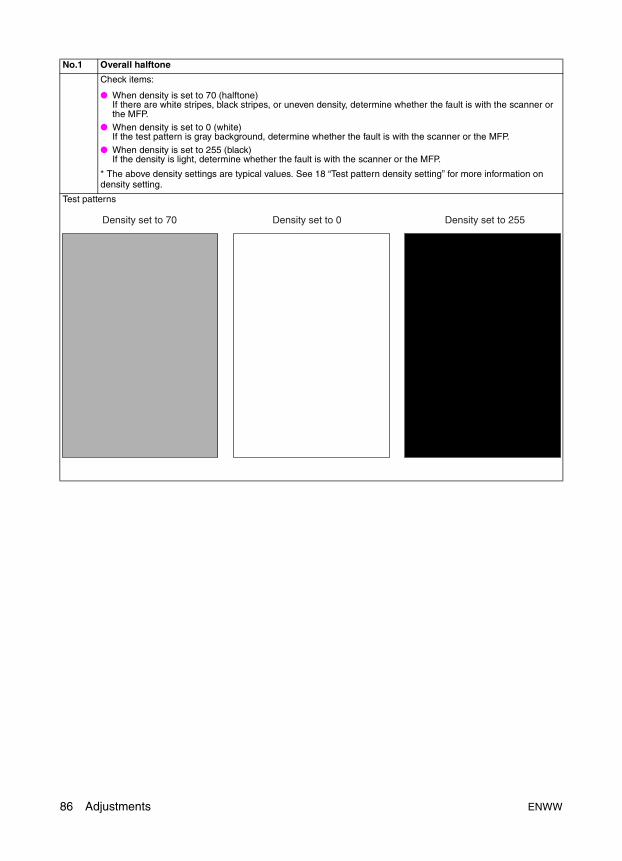
No.1 Overall halftone
Check items:
● When density is set to 70 (halftone)If there are white stripes, black stripes, or uneven density, determine whether the fault is with the scanner or the MFP.
● When density is set to 0 (white)If the test pattern is gray background, determine whether the fault is with the scanner or the MFP.
● When density is set to 255 (black)If the density is light, determine whether the fault is with the scanner or the MFP.
* The above density settings are typical values. See 18 “Test pattern density setting” for more information on density setting.
Test patterns
Density set to 70 Density set to 0 Density set to 255
86 Adjustments ENWW
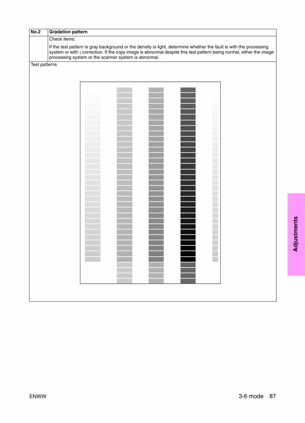
Ad
just
men
ts
No.2 Gradation pattern
Check items:
If the test pattern is gray background or the density is light, determine whether the fault is with the processing system or with γ correction. If the copy image is abnormal despite this test pattern being normal, either the image processing system or the scanner system is abnormal.
Test patterns
ENWW 3-6 mode 87
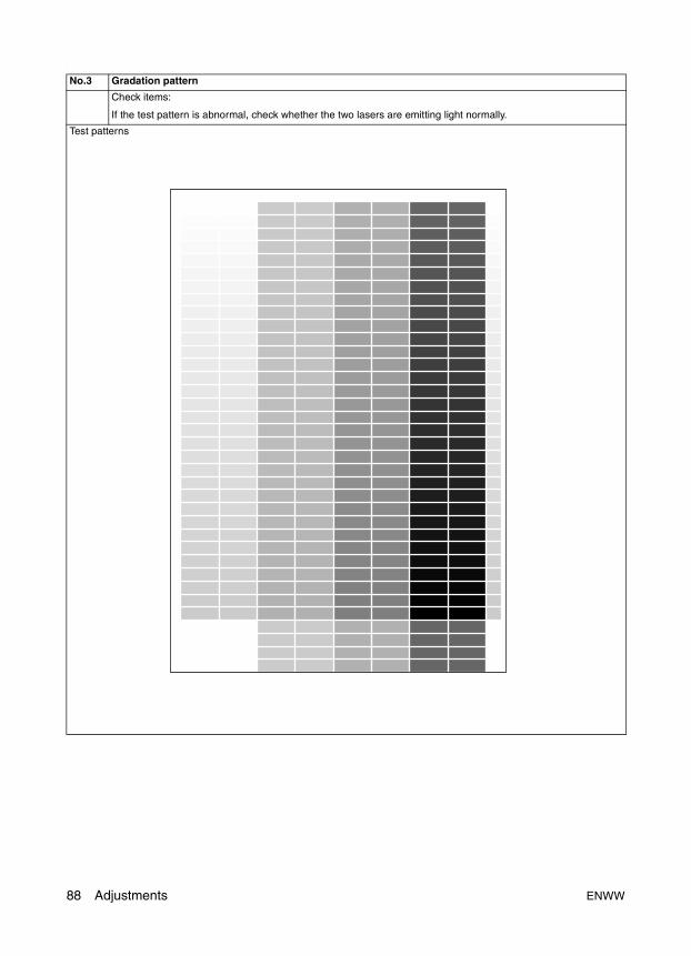
.
No.3 Gradation pattern
Check items:
If the test pattern is abnormal, check whether the two lasers are emitting light normally.
Test patterns
88 Adjustments ENWW
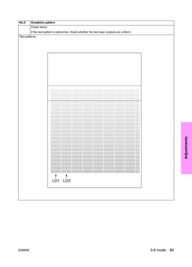
Ad
just
men
ts
No.5 Gradation pattern
Check items:
If the text pattern is abnormal, check whether the two laser outputs are uniform.
Test patterns
LD1 LD2
ENWW 3-6 mode 89
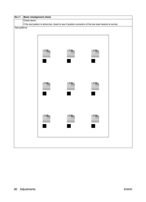
No.11 Beam misalignment check
Check items:
If the text pattern is abnormal, check to see if position correction of the two laser beams is normal.
Test patterns
90 Adjustments ENWW

Ad
just
men
ts
No.16 Linearity evaluation pattern
Check item:
Use this check pattern to determine whether the fault is with the scanner or the MFP. The MFP horizontal magnification, vertical magnification, tilt, and leading edge timing, and so forth can be checked. If the copy image is defective despite no abnormality in the test pattern, the scanner is at fault.
Test patterns
31mm
Edge of paper
Edge of paper237mm
190m
m19
0mm
280m
m
280mm
206m
m
20m
m
ENWW 3-6 mode 91
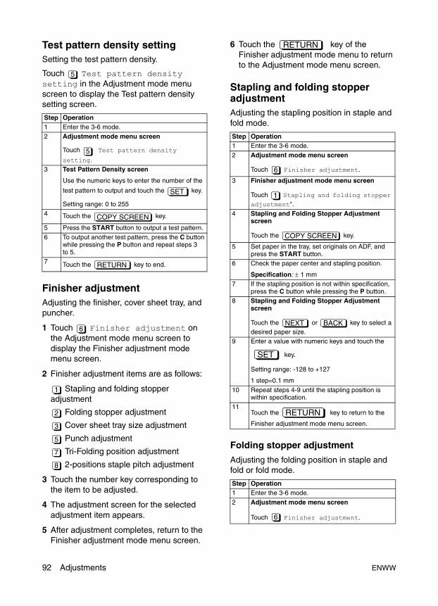
Test pattern density settingSetting the test pattern density.
Touch Test pattern density setting in the Adjustment mode menu screen to display the Test pattern density setting screen.
Finisher adjustmentAdjusting the finisher, cover sheet tray, and puncher.
1 Touch Finisher adjustment on the Adjustment mode menu screen to display the Finisher adjustment mode menu screen.
2 Finisher adjustment items are as follows:
Stapling and folding stopper adjustment
Folding stopper adjustment
Cover sheet tray size adjustment
Punch adjustment
Tri-Folding position adjustment
2-positions staple pitch adjustment
3 Touch the number key corresponding to the item to be adjusted.
4 The adjustment screen for the selected adjustment item appears.
5 After adjustment completes, return to the Finisher adjustment mode menu screen.
6 Touch the key of the Finisher adjustment mode menu to return to the Adjustment mode menu screen.
Stapling and folding stopper adjustmentAdjusting the stapling position in staple and fold mode.
Folding stopper adjustment
Adjusting the folding position in staple and fold or fold mode.
Step Operation1 Enter the 3-6 mode.
2 Adjustment mode menu screen
Touch Test pattern density
setting.3 Test Pattern Density screen
Use the numeric keys to enter the number of the
test pattern to output and touch the key.
Setting range: 0 to 255
4 Touch the key.
5 Press the START button to output a test pattern.
6 To output another test pattern, press the C button while pressing the P button and repeat steps 3 to 5.
7 Touch the key to end.
5
5
SET
COPY SCREEN
RETURN
6
1
2
3
5
7
8
Step Operation1 Enter the 3-6 mode.
2 Adjustment mode menu screen
Touch Finisher adjustment.
3 Finisher adjustment mode menu screen
Touch Stapling and folding stopper adjustment“.
4 Stapling and Folding Stopper Adjustment screen
Touch the key.
5 Set paper in the tray, set originals on ADF, and press the START button.
6 Check the paper center and stapling position.
Specification: ± 1 mm7 If the stapling position is not within specification,
press the C button while pressing the P button.8 Stapling and Folding Stopper Adjustment
screen
Touch the or key to select a desired paper size.
9 Enter a value with numeric keys and touch the
key.
Setting range: -128 to +127
1 step=0.1 mm
10 Repeat steps 4-9 until the stapling position is within specification.
11Touch the key to return to the
Finisher adjustment mode menu screen.
Step Operation1 Enter the 3-6 mode.
2 Adjustment mode menu screen
Touch Finisher adjustment.
RETURN
6
1
COPY SCREEN
NEXT BACK
SET
RETURN
6
92 Adjustments ENWW
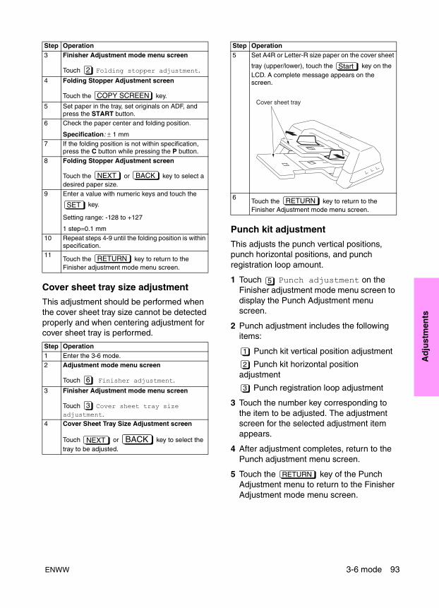
Ad
just
men
ts
Cover sheet tray size adjustment
This adjustment should be performed when the cover sheet tray size cannot be detected properly and when centering adjustment for cover sheet tray is performed.
Punch kit adjustment
This adjusts the punch vertical positions, punch horizontal positions, and punch registration loop amount.
1 Touch Punch adjustment on the Finisher adjustment mode menu screen to display the Punch Adjustment menu screen.
2 Punch adjustment includes the following items:
Punch kit vertical position adjustment
Punch kit horizontal position adjustment
Punch registration loop adjustment
3 Touch the number key corresponding to the item to be adjusted. The adjustment screen for the selected adjustment item appears.
4 After adjustment completes, return to the Punch adjustment menu screen.
5 Touch the key of the Punch Adjustment menu to return to the Finisher Adjustment mode menu screen.
3 Finisher Adjustment mode menu screen
Touch Folding stopper adjustment.
4 Folding Stopper Adjustment screen
Touch the key.
5 Set paper in the tray, set originals on ADF, and press the START button.
6 Check the paper center and folding position.
Specification: ± 1 mm7 If the folding position is not within specification,
press the C button while pressing the P button.
8 Folding Stopper Adjustment screen
Touch the or key to select a desired paper size.
9 Enter a value with numeric keys and touch the
key.
Setting range: -128 to +127
1 step=0.1 mm10 Repeat steps 4-9 until the folding position is within
specification.11
Touch the key to return to the Finisher adjustment mode menu screen.
Step Operation1 Enter the 3-6 mode.2 Adjustment mode menu screen
Touch Finisher adjustment.
3 Finisher Adjustment mode menu screen
Touch Cover sheet tray size adjustment.
4 Cover Sheet Tray Size Adjustment screen
Touch or key to select the tray to be adjusted.
Step Operation
2
COPY SCREEN
NEXT BACK
SET
RETURN
6
3
NEXT BACK
5 Set A4R or Letter-R size paper on the cover sheet
tray (upper/lower), touch the key on the LCD. A complete message appears on the screen.
6Touch the key to return to the Finisher Adjustment mode menu screen.
Step Operation
Start
Cover sheet tray
RETURN
5
1
2
3
RETURN
ENWW 3-6 mode 93
Punch kit vertical position adjustment
Adjusting the punch vertical position.
Punch kit horizontal position adjustment
Adjusting the punch horizontal position.
Punch registration loop adjustment
Adjusting the registration loop amount for the reversed paper exit (face up), the ADU paper exit (face down) and cover sheet upper/lower
Note This adjustment may be required when vertical hole skew is a problem with thicker papers.
Step Operation1 Enter the 3-6 mode.
2 Adjustment mode menu screen
Touch Finisher adjustment.
3 Finisher Adjustment mode menu screen
Touch Punch adjustment.
4 Punch Adjustment menu screen
Touch Punch kit vertical position
adjustment or “ Punch unit vertical position adjustment.
5 Punch Vertical Position Adjustment
Touch the key.
6 Set paper in the tray, set originals on ADF, and press the START button.
7 Check the punch vertical position.
8 If the punch vertical position is not appropriate, press the C button while pressing down the P button.
9 Punch Vertical Position Adjustment screen
Touch the or key to select a desired paper size.
10 Enter a value with numeric keys and touch the
key.
Setting range: -50 to +50
1 step=0.1 mm11 Repeat steps 5-10 until the punch vertical
position is appropriate.12
Touch the key to return to the Punch Adjustment menu screen.
Step Operation1 Enter the 3-6 mode.2 Adjustment mode menu screen
Touch Finisher adjustment.
3 Finisher Adjustment mode menu screen
Touch Punch adjustment.
6
5
1
3
COPY SCREEN
NEXT BACK
SET
RETURN
6
5
4 Punch Adjustment menu screen
Touch Punch kit horizontal
position adjustment or Punch unit horizontal position adjustment.
5 Punch Horizontal Position Adjustment.
Touch the key.
6 Load paper in the tray, place the original on ADF, and then press the START button.
7 Check the paper center and the position of punch holes.
Specification (length between the edge of paper and the center of punch hole): 10.5 mm (2 holes/4 holes/Swedish 4 holes), 9.5 mm (3 holes/inch 2 holes)
8 If the punch horizontal position is not appropriate, press the C button while pressing down the P button.
9 Punch Horizontal Position Adjustment screen
Touch the or key to select a desired paper size.
10 Enter a value with numeric keys and touch the
key.
Setting range: -50 to +50
1 step = 0.1 mm11 Repeat steps 5-9 until the punched position is
within the specification.12
Touch the key to return to the Punch Adjustment menu screen.
Step Operation1 Enter the 3-6 mode.2 Adjustment mode menu screen
Touch Finisher adjustment.
3 Finisher Adjustment mode menu screen
Touch Punch adjustment.
Step Operation
2
4
COPY SCREEN
NEXT BACK
SET
RETURN
6
5
94 Adjustments ENWW
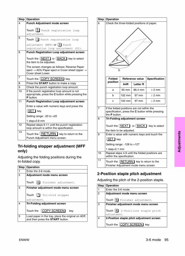
Ad
just
men
ts
Tri-folding stopper adjustment (MFF only)
Adjusting the folding positions during the tri-folded copy.
2-Position staple pitch adjustment
Adjusting the pitch of the 2-position staple.
4 Punch Adjustment mode screen
Touch Punch registration loop adjustment.
5Touch Punch registration loop
adjustment (MFP) or Punch registration loop adjustment (PI).
6 Punch Registration Loop adjustment screen
Touch the or key to select the item to be adjusted.
The screen changes as follows; Reverse Paper eject → ADU Paper eject or Cover sheet Upper → Cover sheet Lower.
7Touch the key.
8 Press the START button to make a copy.9 Check the punch registration loop amount.
10 If the punch registration loop amount is not appropriate, press the C button while pressing the P button.
11 Punch Registration Loop adjustment screen
Enter a value with numeric keys and press the
key.
Setting range: -20 to +20
1 step=0.8 mm
12 Repeat steps 6-11 until the punch registration loop amount is within the specification.
13Touch the key to return to the Punch Adjustment menu screen.
Step Operation1 Enter the 3-6 mode.2 Adjustment mode menu screen
Touch Finisher adjustment.
3 Finisher adjustment mode menu screen
Touch Tri-fold stopper
adjustment.4 Tri-Folding adjustment screen
Touch the key.
5 Load paper in the tray, place the original on ADF, and then press the START button.
Step Operation
5
1
2
NEXT BACK
COPY SCREEN
SET
RETURN
6
7
COPY SCREEN
6 Check the three-folded positions of paper.
7 If the folded positions are not within the specification, press the C button while pressing the P button.
8 Tri-Folding adjustment screen
Touch the or key to select
the item to be adjusted.9 Enter a value with numeric keys and touch the
key.
Setting range: -128 to +127
1 step=0.1 mm10 Repeat steps 4-9 until the folded positions are
within the specification.11 Touch the key to return to the
Finisher Adjustment mode menu screen.
Step Operation1 Enter the 3-6 mode.2 Adjustment mode menu screen
Touch Finisher adjustment.
3 Finisher adjustment mode menu screen
Touch 2-Positions staple pitch adjustment.
4 2-Position staple pitch adjustment screen
Touch the key.
Step Operation
a
b
c
Folded position
Reference value Specification
A4R Letter R
a 93 mm 86.4 mm ± 2 mm
b 102 mm 97 mm ± 2 mm
c 102 mm 97 mm ± 2 mm
NEXT BACK
SET
RETURN
6
8
COPY SCREEN
ENWW 3-6 mode 95
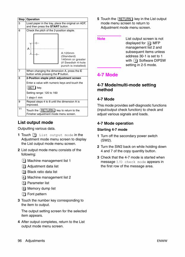
List output modeOutputting various data.
1 Touch List output mode in the Adjustment mode menu screen to display the List output mode menu screen.
2 List output mode menu consists of the following:
Machine management list 1
Adjustment data list
Black ratio data list
Machine management list 2
Parameter list
Memory dump list
Font pattern
3 Touch the number key corresponding to the item to output.
The output setting screen for the selected item appears.
4 After output completes, return to the List output mode menu screen.
5 Touch the key in the List output mode menu screen to return to Adjustment mode menu screen.
Note List output screen is not displayed for MFP management list 2 and subsequent items unless address 30-1 is set to 1 with Software DIPSW setting in 2-5 mode.
4-7 Mode
4-7 Mode/multi-mode setting method
4-7 Mode
This mode provides self-diagnostic functions (input/output check function) to check and adjust various signals and loads.
4-7 Mode operation
Starting 4-7 mode
1 Turn off the secondary power switch (SW2).
2 Turn the SW2 back on while holding down 4 and 7 of the copy quantity button.
3 Check that the 4-7 mode is started when message I/O check mode appears in the first row of the message area.
5 Load paper in the tray, place the original on ADF, and then press the START button.
6 Check the pitch of the 2-position staple.
7 When changing the dimension A, press the C button while pressing the P button.
8 2-Position staple pitch adjustment screen
Enter a value with numeric keys and touch the
key.
Setting range: 120 to 160
1 step=1 mm
9 Repeat steps 4 to 8 until the dimension A is improved.
11Touch the key to return to the Finisher adjustment mode menu screen.
Step Operation
SET
RETURN
7
1
2
3
4
5
6
7
RETURN
4
1
96 Adjustments ENWW
Ad
just
men
ts
Input/output check
1 Use the copy quantity button to enter the code (refer to the I/O check code list) for the desired signal sources (such as sensors).
2 The entered code appears enclosed in <> in the second row of the message area.
3 The numbers are shifted left as they are displayed.
4 Check the status of the signal displayed as H or L after IN: in the second row of the message display area.
Note H and L indicate the level of the signal input to PRCB (printer control board). Note the relationship between the status of the input signal source and the message display.
Output check
1 Use the copy quantity button to enter the code (refer to the I/O check code list) for the desired output load.
2 Press the START button.
Depending on the output, a load will be activated or a signal will be output.
Ending 4-7 mode
1 Press the STOP button to cancel the operation.
2 Turn off the primary power switch to exit the 4-7 mode.
Note No data appears on the second row of the message area when 4-7 mode is entered. Message appears when a number is entered.
Simply enter a new code to switch to another code.
A newly entered number is written over the previously entered number.
Multi mode
This MFP features multi modes among the 4-7 mode functions.
This enables multiple I/O checks using a single I/O check code.
Multi mode operation method
Start the 4-7 mode and proceed as follows:
To check the input
1 Using the copy quantity button, enter the check code for the desired I/O.
2 The 4-7 mode code appears enclosed in <> in the second row of the message area.
3 Press the P button.
4 Enter the desired multi number using the copy quantity button. (Refer to the multi mode list.)
Start button Code DescriptionBefore pressing indication Input Input signal levelAfter pressing Output Output load
operation/signal
Step Operation1 Turn on the secondary power switch (SW2) while
holding down 4 and 7 on the copy quantity button.
2 I/O check screen
Use the copy quantity button to enter the code.
3 Check the input signal check result displayed after “IN: in the second row of the message area.
4 To perform the output check, press the START button to check the output load.
5 Press the STOP button to end output check.
6 To perform other checks, enter a new code using the copy quantity button.
7 Turn off the primary power switch to exit the 4-7 mode.
Step Operation
ENWW 4-7 Mode 97
5 The multi number will be displayed enclosed in <>, following the 4-7 mode code and -.
6 Press the P button.
7 Check the status of the signal displayed as H or L after IN: in the second row of the message display area.
To check the output
1 Press the START button.
2 Press the STOP button after checking the output.
Ending multi mode
Turn off the primary power switch to exit the 4-7 mode (multi mode).
Note To check another multi number in the same code, press the P button after completing step 8. And enter another multi number. A newly entered number is written over the previously entered number.
Note To return to the normal 4-7 mode, press the STOP button while holding down the P button after completing step 8.
Adjustment data displayDisplaying a list of MFP adjustment values (factory-set values and current values).
No adjustment (data value change) can be made in this mode.
Hard disk checkThis adjustment is to be performed when checking the total capacity and remaining capacity of the optional hard disk and when error codes related to the hard disk occur.
I/O check mode
< 10-01 > IN: -- OUT: --
Step Operation1 Enter the 4-7 mode.2 I/O check screen
Use the copy quantity button and enter the code.
3 Press the P button.4 Enter the multi number using the copy quantity
button.5 Press the P button.6 Check the input signal check result displayed
after “IN: in the second row of the message area.
7 To perform the output check, press the START button to check the output load.
8 Press the STOP button to end the output check.9 Turn off the primary power switch to exit the
4-7 mode.
Step Operation1 Enter the 4-7 mode.
2 I/O check screen
Enter 94 with numeric keys.
Make sure 94 is displayed in the message display field.
3 Press the START button.4 Adjustment Data Display screen 1
Touch the or button to display a desired adjustment item.
5 Touch the key to return to the I/O check mode screen.
Step Operation1 Enter the 4-7 mode.2 Enter 99 with numeric keys.3 Checking the total capacity of the hard disk:
Press the P button and enter 1 with a numeric key. Make sure 99-01 is displayed in the message display field.
Checking the remaining capacity of the hard disk:Press the P button and enter 2 with a numeric key. Make sure 99-02 is displayed in the message display field.Checking and recovering bad sectors on the hard disk: Press the P button and enter 3 with a numeric key. Make sure 99-03 is displayed in the message display field.
4 Press the START button.
End
98 Adjustments ENWW
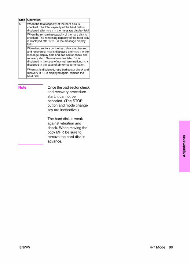
Ad
just
men
ts
Note Once the bad sector check and recovery procedure start, it cannot be canceled. (The STOP button and mode change key are ineffective.)
The hard disk is weak against vibration and shock. When moving the copy MFP, be sure to remove the hard disk in advance.
5 When the total capacity of the hard disk is checked: The total capacity of the hard disk is displayed after OUT: in the message display field.When the remaining capacity of the hard disk is checked: The remaining capacity of the hard disk is displayed after OUT: in the message display field.
When bad sectors on the hard disk are checked and recovered: NOW is displayed after OUT: in the message display field and bad sector check and recovery start. Several minutes later, OK is displayed in the case of normal termination, NG is displayed in the case of abnormal termination.
When NG is displayed, retry bad sector check and recovery. If NG is displayed again, replace the hard disk.
Step Operation
ENWW 4-7 Mode 99
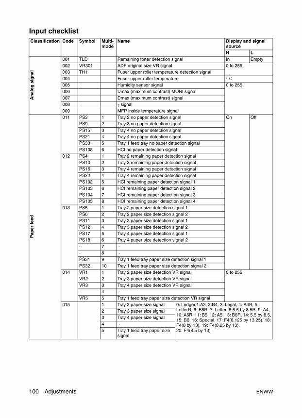
Input checklistClassification Code Symbol Multi-
modeName Display and signal
sourceH L
An
alo
g s
ign
al
001 TLD Remaining toner detection signal In Empty002 VR301 ADF original size VR signal 0 to 255003 TH1 Fuser upper roller temperature detection signal
004 Fuser upper roller temperature ° C005 Humidity sensor signal 0 to 255006 Dmax (maximum contrast) MONI signal
007 Dmax (maximum contrast) signal008 γ signal
009 MFP inside temperature signal
Pap
er f
eed
011 PS3 1 Tray 2 no paper detection signal On OffPS9 2 Tray 3 no paper detection signal
PS15 3 Tray 4 no paper detection signalPS21 4 Tray 4 no paper detection signalPS33 5 Tray 1 feed tray no paper detection signal
PS108 6 HCI no paper detection signal012 PS4 1 Tray 2 remaining paper detection signal
PS10 2 Tray 3 remaining paper detection signal
PS16 3 Tray 4 remaining paper detection signalPS22 4 Tray 4 remaining paper detection signalPS102 5 HCI remaining paper detection signal 1
PS103 6 HCI remaining paper detection signal 2PS104 7 HCI remaining paper detection signal 3PS105 8 HCI remaining paper detection signal 4
013 PS5 1 Tray 2 paper size detection signal 1PS6 2 Tray 2 paper size detection signal 2PS11 3 Tray 3 paper size detection signal 1
PS12 4 Tray 3 paper size detection signal 2PS17 5 Tray 4 paper size detection signal 1PS18 6 Tray 4 paper size detection signal 2
- 7 -- 8 -PS31 9 Tray 1 feed tray paper size detection signal 1
PS32 10 Tray 1 feed tray paper size detection signal 2014 VR1 1 Tray 2 paper size detection VR signal 0 to 255
VR2 2 Tray 3 paper size detection VR signal
VR3 3 Tray 4 paper size detection VR signal- 4 -VR5 5 Tray 1 feed tray paper size detection VR signal
015 1 Tray 2 paper size signal 0: Ledger,1:A3, 2:B4, 3: Legal, 4: A4R, 5: LetterR, 6: B5R, 7: Letter, 8:5.5 by 8.5R, 9: A4, 10: A5R, 11: B5, 12: A5, 13: B6R, 14: 5.5 by 8.5, 15: B6, 16: Special, 17: F4(8.125 by 13.25), 18: F4(8 by 13), 19: F4(8.25 by 13), 20: F4(8.5 by 13)
2 Tray 3 paper size signal3 Tray 4 paper size signal
4 -5 Tray 1 feed tray paper size
signal
100 Adjustments ENWW
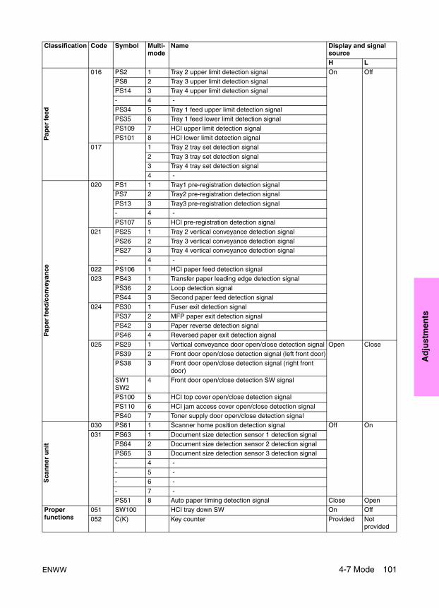
Ad
just
men
ts
Pap
er f
eed
016 PS2 1 Tray 2 upper limit detection signal On OffPS8 2 Tray 3 upper limit detection signalPS14 3 Tray 4 upper limit detection signal
- 4 -PS34 5 Tray 1 feed upper limit detection signalPS35 6 Tray 1 feed lower limit detection signal
PS109 7 HCI upper limit detection signalPS101 8 HCI lower limit detection signal
017 1 Tray 2 tray set detection signal
2 Tray 3 tray set detection signal3 Tray 4 tray set detection signal
4 -
Pap
er f
eed
/co
nvey
ance
020 PS1 1 Tray1 pre-registration detection signalPS7 2 Tray2 pre-registration detection signal
PS13 3 Tray3 pre-registration detection signal- 4 -PS107 5 HCI pre-registration detection signal
021 PS25 1 Tray 2 vertical conveyance detection signalPS26 2 Tray 3 vertical conveyance detection signalPS27 3 Tray 4 vertical conveyance detection signal
- 4 -022 PS106 1 HCI paper feed detection signal023 PS43 1 Transfer paper leading edge detection signal
PS36 2 Loop detection signalPS44 3 Second paper feed detection signal
024 PS30 1 Fuser exit detection signal
PS37 2 MFP paper exit detection signalPS42 3 Paper reverse detection signalPS46 4 Reversed paper exit detection signal
025 PS29 1 Vertical conveyance door open/close detection signal Open ClosePS39 2 Front door open/close detection signal (left front door)PS38 3 Front door open/close detection signal (right front
door)SW1SW2
4 Front door open/close detection SW signal
PS100 5 HCI top cover open/close detection signal
PS110 6 HCI jam access cover open/close detection signalPS40 7 Toner supply door open/close detection signal
Sca
nn
er u
nit
030 PS61 1 Scanner home position detection signal Off On
031 PS63 1 Document size detection sensor 1 detection signalPS64 2 Document size detection sensor 2 detection signalPS65 3 Document size detection sensor 3 detection signal
- 4 -- 5 -- 6 -
- 7 -PS51 8 Auto paper timing detection signal Close Open
Proper functions
051 SW100 HCI tray down SW On Off
052 C(K) Key counter Provided Not provided
Classification Code Symbol Multi- mode
Name Display and signal sourceH L
ENWW 4-7 Mode 101
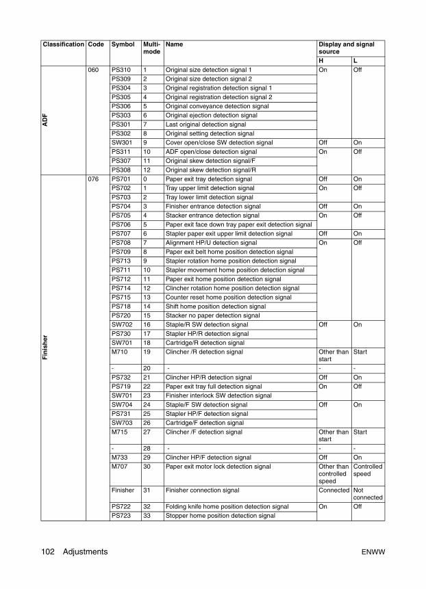
AD
F
060 PS310 1 Original size detection signal 1 On OffPS309 2 Original size detection signal 2PS304 3 Original registration detection signal 1
PS305 4 Original registration detection signal 2PS306 5 Original conveyance detection signalPS303 6 Original ejection detection signal
PS301 7 Last original detection signalPS302 8 Original setting detection signalSW301 9 Cover open/close SW detection signal Off On
PS311 10 ADF open/close detection signal On OffPS307 11 Original skew detection signal/F
PS308 12 Original skew detection signal/R
Fin
ish
er
076 PS701 0 Paper exit tray detection signal Off OnPS702 1 Tray upper limit detection signal On Off
PS703 2 Tray lower limit detection signalPS704 3 Finisher entrance detection signal Off OnPS705 4 Stacker entrance detection signal On Off
PS706 5 Paper exit face down tray paper exit detection signalPS707 6 Stapler paper exit upper limit detection signal Off OnPS708 7 Alignment HP/U detection signal On Off
PS709 8 Paper exit belt home position detection signalPS713 9 Stapler rotation home position detection signalPS711 10 Stapler movement home position detection signal
PS712 11 Paper exit home position detection signalPS714 12 Clincher rotation home position detection signalPS715 13 Counter reset home position detection signal
PS718 14 Shift home position detection signalPS720 15 Stacker no paper detection signalSW702 16 Staple/R SW detection signal Off On
PS730 17 Stapler HP/R detection signalSW701 18 Cartridge/R detection signalM710 19 Clincher /R detection signal Other than
startStart
- 20 - - -
PS732 21 Clincher HP/R detection signal Off OnPS719 22 Paper exit tray full detection signal On OffSW701 23 Finisher interlock SW detection signal
SW704 24 Staple/F SW detection signal Off OnPS731 25 Stapler HP/F detection signalSW703 26 Cartridge/F detection signal
M715 27 Clincher /F detection signal Other than start
Start
- 28 - - -M733 29 Clincher HP/F detection signal Off OnM707 30 Paper exit motor lock detection signal Other than
controlled speed
Controlled speed
Finisher 31 Finisher connection signal Connected Not connected
PS722 32 Folding knife home position detection signal On OffPS723 33 Stopper home position detection signal
Classification Code Symbol Multi- mode
Name Display and signal sourceH L
102 Adjustments ENWW
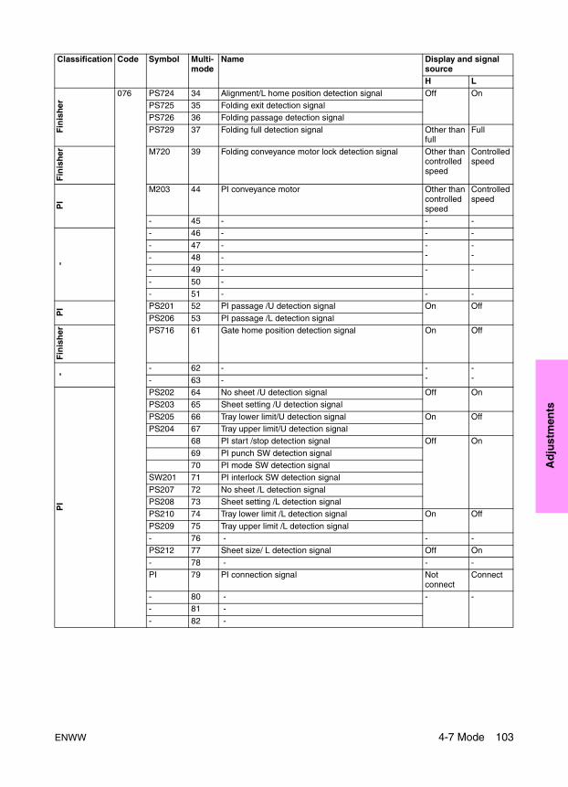
Ad
just
men
ts
Fin
ish
er
076 PS724 34 Alignment/L home position detection signal Off OnPS725 35 Folding exit detection signalPS726 36 Folding passage detection signal
PS729 37 Folding full detection signal Other than full
Full
Fin
ish
er M720 39 Folding conveyance motor lock detection signal Other than controlled speed
Controlled speed
PI
M203 44 PI conveyance motor Other than controlled speed
Controlled speed
- 45 - - -
-
- 46 - - -
- 47 - --
--- 48 -
- 49 - - -
- 50 -- 51 - - -
PI PS201 52 PI passage /U detection signal On Off
PS206 53 PI passage /L detection signal
Fin
ish
er PS716 61 Gate home position detection signal On Off
- - 62 - --
--- 63 -
PI
PS202 64 No sheet /U detection signal Off OnPS203 65 Sheet setting /U detection signal
PS205 66 Tray lower limit/U detection signal On OffPS204 67 Tray upper limit/U detection signal
68 PI start /stop detection signal Off On
69 PI punch SW detection signal70 PI mode SW detection signal
SW201 71 PI interlock SW detection signal
PS207 72 No sheet /L detection signalPS208 73 Sheet setting /L detection signalPS210 74 Tray lower limit /L detection signal On Off
PS209 75 Tray upper limit /L detection signal- 76 - - -PS212 77 Sheet size/ L detection signal Off On
- 78 - - -PI 79 PI connection signal Not
connectConnect
- 80 - - -- 81 -
- 82 -
Classification Code Symbol Multi- mode
Name Display and signal sourceH L
ENWW 4-7 Mode 103
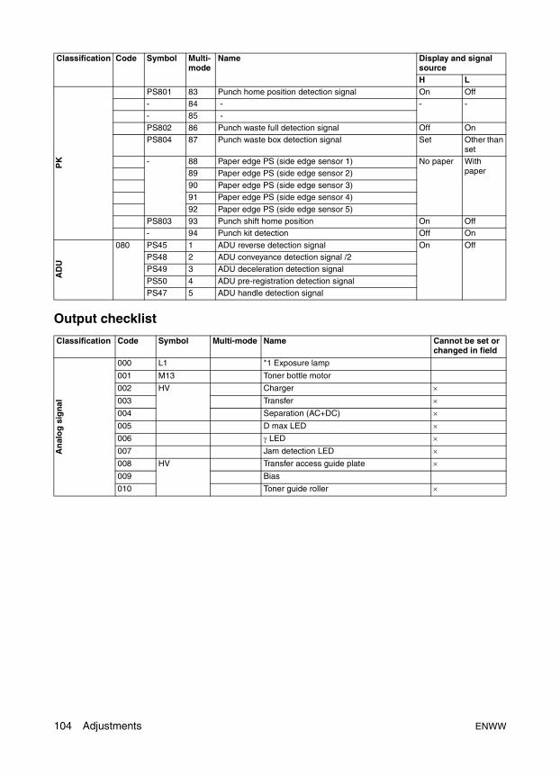
Output checklist
PK
PS801 83 Punch home position detection signal On Off- 84 - - -- 85 -
PS802 86 Punch waste full detection signal Off OnPS804 87 Punch waste box detection signal Set Other than
set- 88 Paper edge PS (side edge sensor 1) No paper With
paper89 Paper edge PS (side edge sensor 2)
90 Paper edge PS (side edge sensor 3)91 Paper edge PS (side edge sensor 4)
92 Paper edge PS (side edge sensor 5)PS803 93 Punch shift home position On Off- 94 Punch kit detection Off On
AD
U
080 PS45 1 ADU reverse detection signal On OffPS48 2 ADU conveyance detection signal /2PS49 3 ADU deceleration detection signal
PS50 4 ADU pre-registration detection signalPS47 5 ADU handle detection signal
Classification Code Symbol Multi-mode Name Cannot be set or changed in field
An
alo
g s
ign
al
000 L1 *1 Exposure lamp
001 M13 Toner bottle motor
002 HV Charger ×003 Transfer ×004 Separation (AC+DC) ×005 D max LED ×006 γ LED ×007 Jam detection LED ×008 HV Transfer access guide plate ×009 Bias
010 Toner guide roller ×
Classification Code Symbol Multi- mode
Name Display and signal sourceH L
104 Adjustments ENWW

Ad
just
men
ts
Pap
er f
eed
020 SD100 HCI paper feed pickup SD
021 Feed CL
CL3 1 Tray 2
CL5 2 Tray 3
CL7 3 Tray 4
- 4 -
CL101 5 HCI
CL11 6 Vertical conveyance CL1
CL12 7 Vertical conveyance CL2
022 Pre-registration CL
CL4 1 Tray 2
CL6 2 Tray 3
CL8 3 Tray 4
- 4 -
CL102 5 HCI
023 Tray up motor /HCI up/down motor
M16 1 Tray 2
M17 2 Tray 3
M18 3 Tray 4
- 4 -
M100 5 HCI up
6 HCI down
M20 7 Tray 1 up
8 Tray 1 down
025 CL1 Registration CL
026 M6 Loop roller motor
1 Loop motor H (470 mm/s), forward
2 Loop motor L (320 mm/s), forward
3 Loop motor L (280 mm/s), forward
4 Loop motor L (185 mm/s), forward
5 Loop motor H (470 mm/s), backward
6 Loop motor L (320 mm/s), backward
7 Loop motor L (280 mm/s), backward
8 Loop motor L (185 mm/s), backward
027 M7 Paper exit motor
1 Paper exit motor (320 mm/s)
2 Paper exit motor (280 mm/s)
3 Paper exit motor (185 mm/s)
4 Paper exit motor (660 mm/s)
028 M1 1 Paper feed motor
M101 2 HCI paper feed motor (470 mm/s)
029 SD1 Separation claw SD
Classification Code Symbol Multi-mode Name Cannot be set or changed in field
ENWW 4-7 Mode 105
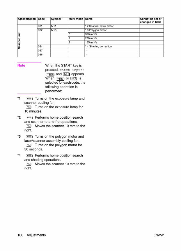
Note When the START key is pressed, Watch input?
and appears. When or is selected for each code, the following operation is performed:
*1 Turns on the exposure lamp and scanner cooling fan.
Turns on the exposure lamp for 10 minutes.
*2 Performs home position search and scanner to-and-fro operations.
Moves the scanner 10 mm to the right.
*3 Turns on the polygon motor and laser/scanner assembly cooling fan.
Turns on the polygon motor for 30 seconds.
*4 Performs home position search and shading operations.
Moves the scanner 10 mm to the right.
Sca
nn
er u
nit
031 M11 * 2 Scanner drive motor
032 M15 * 3 Polygon motor
0 320 mm/s
1 280 mm/s
2 185 mm/s
034 * 4 Shading correction
037 -038 -
Classification Code Symbol Multi-mode Name Cannot be set or changed in field
YES NO
YES NO
YES
NO
YES
NO
YES
NO
YES
NO
106 Adjustments ENWW

Ad
just
men
ts
Classification Code Symbol Multi- mode
Name Cannot be set or changed in field
MF
P
040 M4 Fuser motor
0 Fuser motor (320 mm/s)1 Fuser motor (280 mm/s)2 Fuser motor (185 mm/s)
041 M2/M3 Drum motor0 Drum motor/Developing motor (320 mm/s)1 Drum motor/Developing motor (280 mm/s)
2 Drum motor/Developing motor (185 mm/s)042 M Fan motor
FM9 1 Scanner cooling fan
FM2 2 Laser/scanner assembly cooling fan (high)3 Laser/scanner assembly cooling fan (low)
FM3 4 Conveyance suction fan
FM4 5 Developing suction fanFM1 6 MFP cooling fan (high)
7 MFP cooling low)
FM5 8 Cleaner cooling fan (high)9 Cleaner cooling fan (low)
FM8 10 MFP cooling fan/2
FM13 11 Power supply cooling fanFM10 12 ADU reverse motor cooling fan
043 Counter
- 1 Total counter2 Key counter
045 - 1 -
2 -3 -
SD2 4 Fuser web SD
046 M14 Charger cleaning motor0 To-and-fro operation1 Move to rear
2 Move to front047 M10 Transfer/separation cleaning motor
0 To-and-fro operation
1 Move to rear2 Move to front
048 - Illuminate all LEDs on the operation board
049 - Operation unit check050 M2/M3 Developing motor/drum motor051 PCL PCL
052 TSL TSL054 CL14 Toner recycle CL055 - Message test
056 M12 Toner supply motor057 -058 -059 -
ENWW 4-7 Mode 107
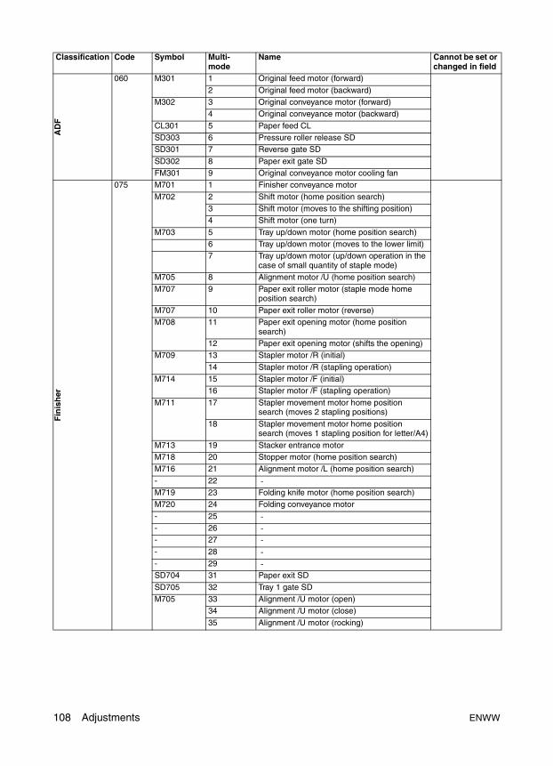
AD
F
060 M301 1 Original feed motor (forward)
2 Original feed motor (backward)M302 3 Original conveyance motor (forward)
4 Original conveyance motor (backward)
CL301 5 Paper feed CLSD303 6 Pressure roller release SDSD301 7 Reverse gate SD
SD302 8 Paper exit gate SDFM301 9 Original conveyance motor cooling fan
Fin
ish
er
075 M701 1 Finisher conveyance motor
M702 2 Shift motor (home position search)3 Shift motor (moves to the shifting position)4 Shift motor (one turn)
M703 5 Tray up/down motor (home position search)6 Tray up/down motor (moves to the lower limit)7 Tray up/down motor (up/down operation in the
case of small quantity of staple mode)M705 8 Alignment motor /U (home position search)
M707 9 Paper exit roller motor (staple mode home position search)
M707 10 Paper exit roller motor (reverse)M708 11 Paper exit opening motor (home position
search)12 Paper exit opening motor (shifts the opening)
M709 13 Stapler motor /R (initial)
14 Stapler motor /R (stapling operation)M714 15 Stapler motor /F (initial)
16 Stapler motor /F (stapling operation)
M711 17 Stapler movement motor home position search (moves 2 stapling positions)
18 Stapler movement motor home position search (moves 1 stapling position for letter/A4)
M713 19 Stacker entrance motorM718 20 Stopper motor (home position search)M716 21 Alignment motor /L (home position search)
- 22 -M719 23 Folding knife motor (home position search)M720 24 Folding conveyance motor
- 25 -- 26 -- 27 -- 28 -- 29 -SD704 31 Paper exit SD
SD705 32 Tray 1 gate SDM705 33 Alignment /U motor (open)
34 Alignment /U motor (close)
35 Alignment /U motor (rocking)
Classification Code Symbol Multi- mode
Name Cannot be set or changed in field
108 Adjustments ENWW
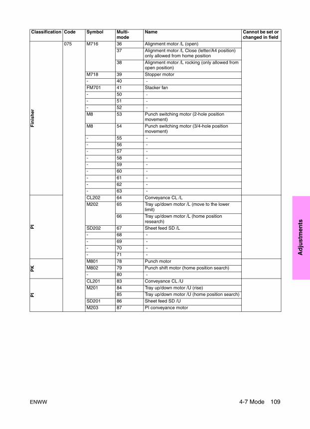
Ad
just
men
ts
Fin
ish
er
075 M716 36 Alignment motor /L (open)
37 Alignment motor /L Close (letter/A4 position) only allowed from home position
38 Alignment motor /L rocking (only allowed from open position)
M718 39 Stopper motor- 40 -FM701 41 Stacker fan
- 50 -- 51 -- 52 -M8 53 Punch switching motor (2-hole position
movement)
M8 54 Punch switching motor (3/4-hole position movement)
- 55 -- 56 -- 57 -
- 58 -- 59 -- 60 -
- 61 -- 62 -- 63 -
PI
CL202 64 Conveyance CL /LM202 65 Tray up/down motor /L (move to the lower
limit)66 Tray up/down motor /L (home position
research)SD202 67 Sheet feed SD /L- 68 -
- 69 -- 70 -- 71 -
PK
M801 78 Punch motorM802 79 Punch shift motor (home position search)- 80 -
PI
CL201 83 Conveyance CL /UM201 84 Tray up/down motor /U (rise)
85 Tray up/down motor /U (home position search)
SD201 86 Sheet feed SD /UM203 87 PI conveyance motor
Classification Code Symbol Multi- mode
Name Cannot be set or changed in field
ENWW 4-7 Mode 109

Fin
ish
er
075 M712 88 Gate drive motor (home position search: paper exit tray direction)
89 Gate drive motor (switches the stacker direction)
90 Gate drive motor (switches the paper exit face down tray direction)
M721 91 Sub-tray paper exit motor
M704 92 Clincher rotation motor (home position search)93 Clincher rotation motor (skew shift)
M706 94 Stapler rotation motor (home position search)
95 Stapler rotation motor (skew shift)SD706 96 Three folding SD
Fin
ish
er 99 Finisher paper-less running mode
AD
U
080 1 Reverse gate SD2 ADU lock SD
081 CL13 ADU conveyance CL082 CL2 ADU conveyance CL083 M5 Second paper feed motor
084 M9 ADU reverse motor1 Forward (320 mm/s)2 Forward (280 mm/s)
3 Forward (185 mm/s)4 Forward (600 mm/s)5 Forward (700 mm/s)
6 Backward (660 mm/s)7 Backward (577 mm/s)8 Backward (382 mm/s)
085 - - -086 M8 Reversed paper exit motor
1 Forward (320 mm/s)
2 Forward (280 mm/s)3 Forward (185 mm/s)4 Forward (600 mm/s)
5 Forward (700 mm/s)6 Backward (660 mm/s)
Ad
just
men
t p
roce
ss
092 Process initial set (prohibited in the field) X
093 -094 Adjustment mode display mode096 Finished process and shipment setting
(prohibited in the field)X
097 DIMM capacity check for electronics RDH
098 DIMM check for electronics RDH099 Hard disk 1 Hard disk total capacity check
2 Hard disk remaining capacity check
3 Hard disk bad sectors check and recovery
Classification Code Symbol Multi- mode
Name Cannot be set or changed in field
110 Adjustments ENWW
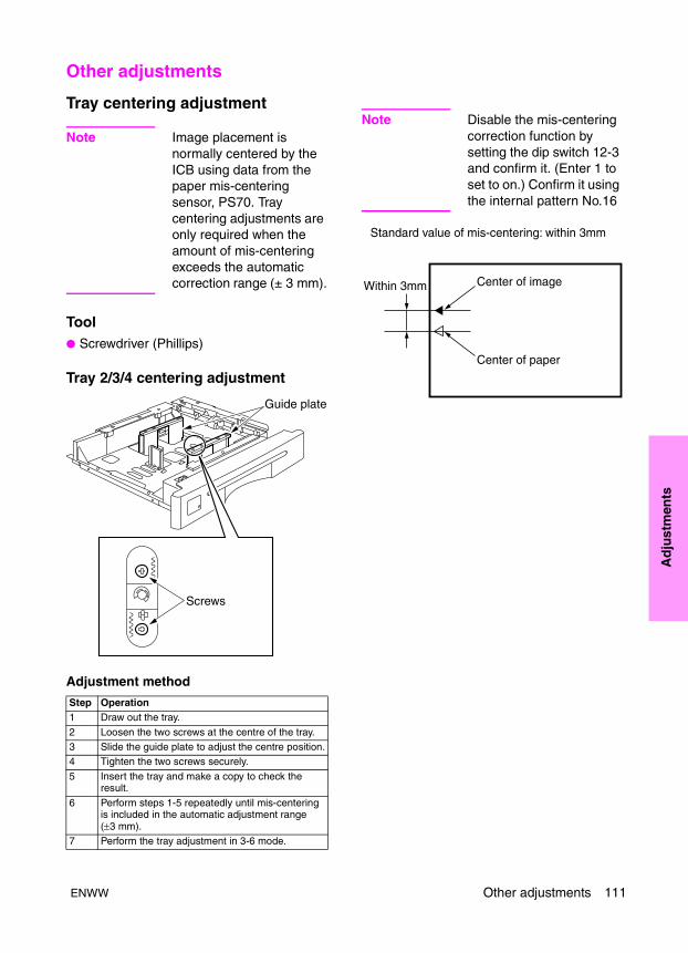
Ad
just
men
ts
Other adjustments
Tray centering adjustment
Note Image placement is normally centered by the ICB using data from the paper mis-centering sensor, PS70. Tray centering adjustments are only required when the amount of mis-centering exceeds the automatic correction range (± 3 mm).
Tool● Screwdriver (Phillips)
Tray 2/3/4 centering adjustment
Adjustment method
Note Disable the mis-centering correction function by setting the dip switch 12-3 and confirm it. (Enter 1 to set to on.) Confirm it using the internal pattern No.16
Step Operation1 Draw out the tray.
2 Loosen the two screws at the centre of the tray.3 Slide the guide plate to adjust the centre position.4 Tighten the two screws securely.
5 Insert the tray and make a copy to check the result.
6 Perform steps 1-5 repeatedly until mis-centering is included in the automatic adjustment range (±3 mm).
7 Perform the tray adjustment in 3-6 mode.
Guide plate
Screws
ENWW Other adjustments 111
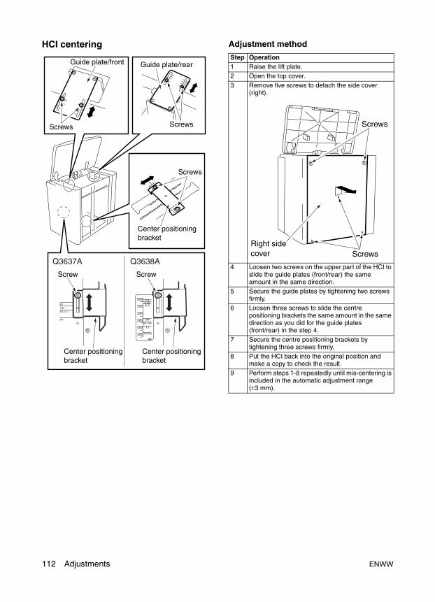
HCI centering Adjustment method
Q3637A Q3638A
Step Operation1 Raise the lift plate.2 Open the top cover.
3 Remove five screws to detach the side cover (right).
4 Loosen two screws on the upper part of the HCI to slide the guide plates (front/rear) the same amount in the same direction.
5 Secure the guide plates by tightening two screws firmly.
6 Loosen three screws to slide the centre positioning brackets the same amount in the same direction as you did for the guide plates (front/rear) in the step 4.
7 Secure the centre positioning brackets by tightening three screws firmly.
8 Put the HCI back into the original position and make a copy to check the result.
9 Perform steps 1-8 repeatedly until mis-centering is included in the automatic adjustment range (±3 mm).
Screws
ScrewsRight sidecover
112 Adjustments ENWW
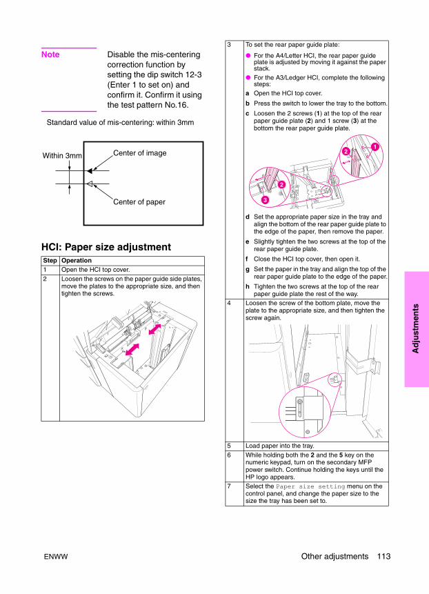
Ad
just
men
ts
Note Disable the mis-centering correction function by setting the dip switch 12-3 (Enter 1 to set on) and confirm it. Confirm it using the test pattern No.16.
HCI: Paper size adjustmentStep Operation1 Open the HCI top cover.
2 Loosen the screws on the paper guide side plates, move the plates to the appropriate size, and then tighten the screws.
3 To set the rear paper guide plate:
● For the A4/Letter HCI, the rear paper guide plate is adjusted by moving it against the paper stack.
● For the A3/Ledger HCI, complete the following steps:
a Open the HCI top cover.
b Press the switch to lower the tray to the bottom.
c Loosen the 2 screws (1) at the top of the rear paper guide plate (2) and 1 screw (3) at the bottom the rear paper guide plate.
d Set the appropriate paper size in the tray and align the bottom of the rear paper guide plate to the edge of the paper, then remove the paper.
e Slightly tighten the two screws at the top of the rear paper guide plate.
f Close the HCI top cover, then open it.
g Set the paper in the tray and align the top of the rear paper guide plate to the edge of the paper.
h Tighten the two screws at the top of the rear paper guide plate the rest of the way.
4 Loosen the screw of the bottom plate, move the plate to the appropriate size, and then tighten the screw again.
5 Load paper into the tray.
6 While holding both the 2 and the 5 key on the numeric keypad, turn on the secondary MFP power switch. Continue holding the keys until the HP logo appears.
7 Select the Paper size setting menu on the control panel, and change the paper size to the size the tray has been set to.
ENWW Other adjustments 113
MFP skew adjustment
Tool● Screwdriver (Phillips)
Adjustment method
HCI pick roller pressure adjustment (ledger/A3 only)
Note This adjustment may be required if paper will not feed from the HCI. Contact HP support for information on how to obtain weight plates.
Tool● Screwdriver (Phillips)
Adjustment method
Step Operation1 Make a copy to measure for skew.2 Loosen the five screws securing the second paper
feed unit.3 Rock the second paper feed unit to adjust using
the mark as a guide.4 Retighten the five screws.
5 Make adjustments by repeating steps 2 to 4 until the skew becomes within the specified range.
Specified range: Paper skew ±5 percent or less(Paper skew in the paper feed direction)
ScrewsScrews
Second paper feed section
Mark
Step Operation1 Open the top cover.
2 Remove the spring.3 Install a weight plate above the paper pick rollers
using the two screws.4 Make a copy to check whether paper is fed
properly.5 If paper is not fed properly, add another weight
plate and repeat steps 5 and 6.6 Install the spring.
Screw Spring
Piled plate
114 Adjustments ENWW
Ad
just
men
ts
HCI lift plate horizontal adjustment
CAUTION Lift plate horizontal adjustment must be carried out when a paper feed jam occurs frequently or after replacement of the up/down wires of a tray.
Tool● Screwdriver (Phillips)
HCI lift plate horizontal adjustment (Letter/A4)
Adjustment method
Up/down plate
Up/down plate
Up/down pulley
Up/down pulley
Screws
Screws
Adjustingscrews
Step Operation1 Raise the lift plate.2 Open the top cover.
3 Remove five screws to detach the side cover (right).
4 Open the jam access door, then remove six screws to detach the front cover.
Up/down plate
Up/down plate
Up/down pulley
Up/down pulley
Screws
Screws
Adjustingscrews
Jam access door
ScrewsScrews
Side cover (right)
ENWW Other adjustments 115
HCI lift plate horizontal adjustment (Ledger/A3)
Adjustment method
Step Operation5 Remove three screws to detach the clutch
replacement cover.
6 Remove twelve screws to detach the rear cover.
7 Loosen two screws and adjust the position for each up/down pulley using an adjustment screw so that the front and rear of the lift plate are at the same height.
8 Fasten two screws securely for each up/down pulley to fix its position.
9 Install the rear cover, clutch replacement cover, front cover, and side cover (right).
Clutchreplacementcover
Screws
Rear coverScrews
Screws
Screws
Screws
Step Operation1 Lift the lift plate up.2 Open the top cover.
3 Loosen the two screws and adjust the position using an adjustment screw and the mark so that the front and rear of the lift plate are at same height.
4 Fasten the two screws securely.
Adjustment screw
Mark
Up/down plate
Up/down plate
Adjustment screwsScrews
Mark
Screws
116 Adjustments ENWW

Ad
just
men
ts
HCI skew adjustment
CAUTION Skew adjustment is required when the paper supplied from the current tray is different from the paper supplied from other trays in the way it is skewed. However, this adjustment has little effect because skew of paper supplied from all trays is corrected in the second paper feed unit.
Tool● Screwdriver (Phillips)
HCI skew adjustment
Adjustment method (when all printed sheets are skewed)
Adjustment method (when some printed sheets are skewed irregularly)
Reference: The indicated size of each guide plate is about 2 mm wider than the size of regular paper. The 2 mm gap may cause paper skew depending on the paper type. To reduce this skew, press the guide plates (front and rear) against paper tightly.
Step Operation1 Print a test pattern (No. 16) in the continuous copy
mode to check for skew.
2 Open the jam access door of the HCI and adjust the installation position of the positioning bracket on the bottom plate.
Positioningbracket
Screws
Step Operation1 Print a test pattern (No. 16) in the continuous copy
mode to check for skew.
2 Remove the side cover (right).3 Loosen the five screws securing the guide plates
(front and rear) and the centering positioning bracket temporarily. Press the guide plates (front and rear) against paper, then tighten the five screws.
Q3638AQ3637A
Guide plate (front) Guide plate (rear)
Centeringpositioning bracket
Centeringpositioning bracket
ScrewsScrews
ENWW Other adjustments 117
Trays 1-4, HCI, and PI spring pressure adjustment
CAUTION Tray spring pressure adjustment must be performed when no feed or double feed of paper occurs. Tray spring pressure may be affected by the type of paper used or the operating environment (under low temperature conditions, no feed of paper tends to occur. Under high temperature conditions, double feed of paper tends to occur). Excessive adjustment of tray spring pressure may exacerbate the problem. Take care.
Tool● Screwdriver (Phillips)
● Flat-nose pliers
Tray 2/3/4 Spring pressure adjustment
Adjustment method
Tray 1 Paper feed spring pressure adjustment
Step Operation1 Remove the tray.2 Remove one screw, loosen one hold-down shaft
screw, and detach the paper feed unit.
Connector (CN814,834,854)
Fixing shaft screwPaper feed unit
Screw
3 Change the spring hooking position at the bottom of paper feed unit.
Double feed is prevented.
No feed is prevented.
Reference: The spring load changes about 10 percent each time the spring is hooked in the next slot.
4 Set the tray.
Step Operation
Spring
Strong
Weak
Screws
Bottom plate
Spring
Springmounting hole
Weak
Strong
118 Adjustments ENWW
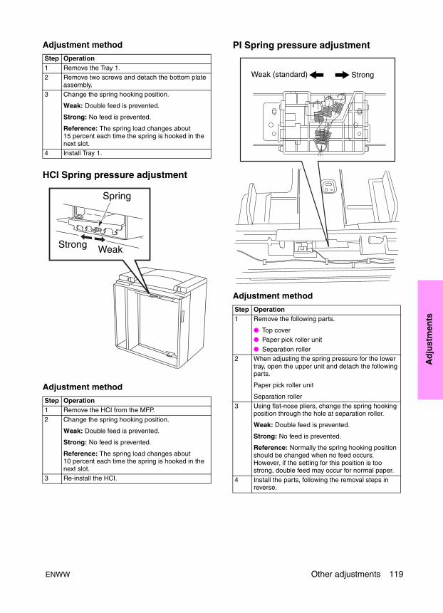
Ad
just
men
ts
Adjustment method
HCI Spring pressure adjustment
Adjustment method
PI Spring pressure adjustment
Adjustment method
Step Operation1 Remove the Tray 1.2 Remove two screws and detach the bottom plate
assembly.3 Change the spring hooking position.
Weak: Double feed is prevented.
Strong: No feed is prevented.
Reference: The spring load changes about 15 percent each time the spring is hooked in the next slot.
4 Install Tray 1.
Step Operation1 Remove the HCI from the MFP.
2 Change the spring hooking position.
Weak: Double feed is prevented.
Strong: No feed is prevented.
Reference: The spring load changes about 10 percent each time the spring is hooked in the next slot.
3 Re-install the HCI.
Spring
WeakStrong
Step Operation1 Remove the following parts.
● Top cover● Paper pick roller unit
● Separation roller2 When adjusting the spring pressure for the lower
tray, open the upper unit and detach the following parts.
Paper pick roller unit
Separation roller
3 Using flat-nose pliers, change the spring hooking position through the hole at separation roller.
Weak: Double feed is prevented.
Strong: No feed is prevented.
Reference: Normally the spring hooking position should be changed when no feed occurs. However, if the setting for this position is too strong, double feed may occur for normal paper.
4 Install the parts, following the removal steps in reverse.
Weak (standard) Strong
ENWW Other adjustments 119
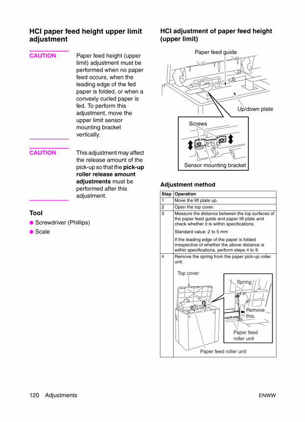
HCI paper feed height upper limit adjustment
CAUTION Paper feed height (upper limit) adjustment must be performed when no paper feed occurs, when the leading edge of the fed paper is folded, or when a convexly curled paper is fed. To perform this adjustment, move the upper limit sensor mounting bracket vertically.
CAUTION This adjustment may affect the release amount of the pick-up so that the pick-up roller release amount adjustments must be performed after this adjustment.
Tool● Screwdriver (Phillips)
● Scale
HCI adjustment of paper feed height (upper limit)
Adjustment method
Step Operation1 Move the lift plate up.
2 Open the top cover.3 Measure the distance between the top surfaces of
the paper feed guide and paper lift plate and check whether it is within specifications.
Standard value: 2 to 5 mm
If the leading edge of the paper is folded irrespective of whether the above distance is within specifications, perform steps 4 to 9.
4 Remove the spring from the paper pick-up roller unit.
Paper feed guide
Up/down plate
Screws
Sensor mounting bracket
Top cover
Spring
Removethis.
Paper feedroller unit
Paper feed roller unit
120 Adjustments ENWW
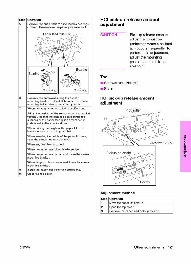
Ad
just
men
ts
HCI pick-up release amount adjustment
CAUTION Pick-up release amount adjustment must be performed when a no-feed jam occurs frequently. To perform this adjustment, adjust the mounting position of the pick-up solenoid.
Tool● Screwdriver (Phillips)
● Scale
HCI pick-up release amount adjustment
Adjustment method
5 Remove two snap rings to slide the two bearings outward, then remove the paper pick roller unit.
6 Remove two screws securing the sensor mounting bracket and install them in the outside mounting holes (oblong holes) temporarily.
7 When the heights are not within specifications
Adjust the position of the sensor mounting bracket vertically so that the distance between the top surfaces of the paper feed guide and paper lift plate is within the specifications.
When raising the height of the paper lift plate, lower the sensor mounting bracket.
When lowering the height of the paper lift plate, raise the sensor mounting bracket.
When any fault has occurred.
When the paper has folded leading edge.
When the paper has dented curl, raise the sensor mounting bracket.
When the paper has convex curl, lower the sensor mounting bracket.
8 Install the paper pick roller unit and spring.9 Close the top cover.
Step Operation
Step Operation1 Move the paper lift plate up.
2 Open the top cover.3 Remove the paper feed pick-up cover/B.
ENWW Other adjustments 121

ADF: aligning on top of scanner
CAUTION Make sure the power cord of the main unit has been unplugged from the wall outlet.
Procedure
1 Place the ADF on the top of the main unit and loosely secure each of the two fixing plates with two screws.
2 Secure the attachment and spacer to the left fixing plate, and loosely secure it with two screws.
3 Remove two screws to detach the original stopper plate (left).
4 Follow the removal procedure in reverse and install the cable conduit and four relay connectors (CN612 to CN615).
5 Install two ADF positioning tools in the mounting holes of the original stopper plates (left).
4 Remove the spring from the paper pick roller unit.
5 Pull the moving parts of the pick-up solenoid and check whether the distance between the bottom surface of the paper pick roller and the top surface of the lift plate is within specification.
Specification: 0.5 to 2.5 mm
If the distance is out of spec, perform steps 5 to 10.
6 Loosen one screw and adjust the mounting position for the pick-up solenoid.
Make a note to remember the initial mounting position.
7 Secure the pick-up solenoid by tightening the screw.
8 Install the spring.
9 Install the paper feed pick-up cover/B.10 Close the top cover.
Step Operation
Top cover
Spring
Paper feed roller unit
Paper feed roller unit
Fixing plate
Fixing plate
Screw (tighten temporarily)
Screws (tighten temporarily)
Screw (tighten temporarily)
Original stopper plate(left)
Attach-ment
Spacer
ScrewScrew
122 Adjustments ENWW
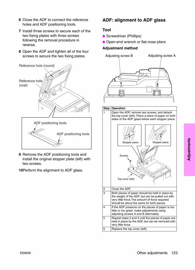
Ad
just
men
ts
6 Close the ADF to connect the reference holes and ADF positioning tools.
7 Install three screws to secure each of the two fixing plates with three screws following the removal procedure in reverse.
8 Open the ADF and tighten all of the four screws to secure the two fixing plates.
9 Remove the ADF positioning tools and install the original stopper plate (left) with two screws.
10Perform the alignment to ADF glass.
ADF: alignment to ADF glass
Tool● Screwdriver (Phillips)
● Open-end wrench or flat-nose pliers
Adjustment method
Step Operation1 Open the ADF, remove two screws, and detach
the top cover (left). Place a piece of paper on both sides of the ADF glass below each stopper piece.
2 Close the ADF.3 Both pieces of paper should be held in place by
the weight of the ADF, but can be pulled out with very little force.The amount of force required should be about the same for both pieces.
4 If the ADF pressure on the pieces of paper is too little or too great, make adjustments using adjusting screws A and B alternately.
5 Repeat steps 3 and 4 until the pieces of paper are held in place by the ADF, but can be removed with very little force.
6 Replace the top cover (left).
Adjusting screw B Adjusting screw A
Stopper piece Stopper piece
Screws
Top cover (left)
ENWW Other adjustments 123
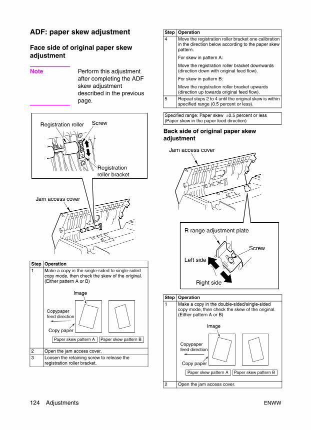
ADF: paper skew adjustment
Face side of original paper skew adjustment
Note Perform this adjustment after completing the ADF skew adjustment described in the previous page.
Back side of original paper skew adjustment
Step Operation1 Make a copy in the single-sided to single-sided
copy mode, then check the skew of the original. (Either pattern A or B)
2 Open the jam access cover.3 Loosen the retaining screw to release the
registration roller bracket.
Registrationroller bracket
Registration roller Screw
Jam access cover
Paper skew pattern A Paper skew pattern B
Image
Copy paper
Copypaperfeed direction
4 Move the registration roller bracket one calibration in the direction below according to the paper skew pattern.
For skew in pattern A:
Move the registration roller bracket downwards (direction down with original feed flow).
For skew in pattern B:
Move the registration roller bracket upwards (direction up towards original feed flow).
5 Repeat steps 2 to 4 until the original skew is within specified range (0.5 percent or less).
Specified range: Paper skew ±0.5 percent or less (Paper skew in the paper feed direction)
Step Operation1 Make a copy in the double-sided/single-sided
copy mode, then check the skew of the original. (Either pattern A or B)
2 Open the jam access cover.
Step Operation
Jam access cover
R range adjustment plate
Left side
Right side
Screw
Paper skew pattern A Paper skew pattern B
Image
Copy paper
Copypaperfeed direction
124 Adjustments ENWW
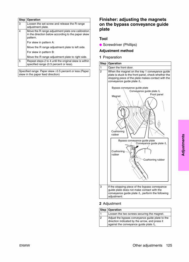
Ad
just
men
ts
Finisher: adjusting the magnets on the bypass conveyance guide plate
Tool● Screwdriver (Phillips)
Adjustment method
1 Preparation
2 Adjustment
3 Loosen the set screw and release the R range adjustment plate.
4 Move the R range adjustment plate one calibration in the direction below according to the paper skew pattern.
For skew in pattern A:
Move the R range adjustment plate to left side.
For skew in pattern B:
Move the R range adjustment plate to right side.5 Repeat steps 2 to 4 until the original skew is within
specified range (0.5 percent or less).
Specified range: Paper skew ±0.5 percent or less (Paper skew in the paper feed direction)
Step Operation
Step Operation1 Open the front door.2 When the magnet on the tray 1 conveyance guide
plate is stuck to the front panel, check whether the stopping piece of the plate makes contact with the conveyance guide plate /L.
3 If the stopping piece of the bypass conveyance guide plate does not make contact with the conveyance guide plate /L, perform the following adjustment:
Step Operation1 Loosen the two screws securing the magnet.2 Adjust the bypass conveyance guide plate to the
direction indicated by the arrow, and press it against the conveyance guide plate /L.
ENWW Other adjustments 125
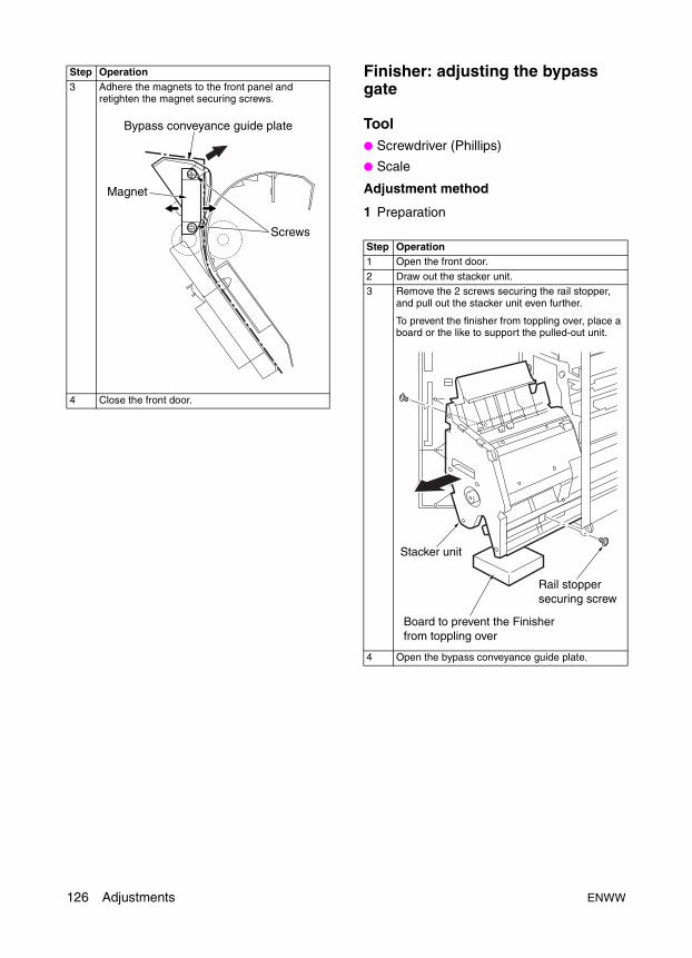
Finisher: adjusting the bypass gate
Tool● Screwdriver (Phillips)
● Scale
Adjustment method
1 Preparation
3 Adhere the magnets to the front panel and retighten the magnet securing screws.
4 Close the front door.
Step Operation
Step Operation1 Open the front door.
2 Draw out the stacker unit.3 Remove the 2 screws securing the rail stopper,
and pull out the stacker unit even further.
To prevent the finisher from toppling over, place a board or the like to support the pulled-out unit.
4 Open the bypass conveyance guide plate.
Stacker unit
Board to prevent the Finisherfrom toppling over
Rail stoppersecuring screw
126 Adjustments ENWW
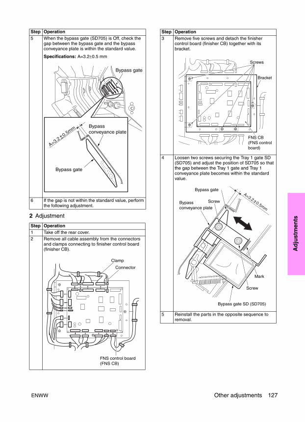
Ad
just
men
ts
2 Adjustment5 When the bypass gate (SD705) is Off, check the gap between the bypass gate and the bypass conveyance plate is within the standard value.
Specifications: A=3.2±0.5 mm
6 If the gap is not within the standard value, perform the following adjustment.
Step Operation1 Take off the rear cover.2 Remove all cable assembly from the connectors
and clamps connecting to finisher control board (finisher CB).
Step Operation
Clamp
Connector
FNS control board(FNS CB)
3 Remove five screws and detach the finisher control board (finisher CB) together with its bracket.
4 Loosen two screws securing the Tray 1 gate SD (SD705) and adjust the position of SD705 so that the gap between the Tray 1 gate and Tray 1 conveyance plate becomes within the standard value.
5 Reinstall the parts in the opposite sequence to removal.
Step Operation
Screws
Bracket
FNS CB(FNS controlboard)
ENWW Other adjustments 127
Finisher: adjusting the shift position
Tool● Screwdriver (Phillips)
Adjustment method
1 Preparation
2 Adjustment
Step Operation1 Remove the following parts.
● Top cover or option PI (if installed)● Top cover /2
2 Power on the MFP and drive the roller shift (M702) using the 4-7 mode (code 75-2/75-3).
3 At both the home position and shift position, check whether the edge of the actuator for the slide gear fits into the notched hole of the slide stay.
4 If the edge of the actuator for the slide gear does not fit into the notched hole of the slide stay, perform the following adjustment:
ActuatorNotch
Slide gear
Slide stay
Shift unit
Step Operation1 Loosen the screw fastening the bracket for the
roller shift home position PS (PS718), and shift the bracket to adjust the amount of discrepancy using the mark as a guide.
2 When the position is confirmed, fasten the screw securing the bracket.
3 Reassemble in the opposite sequence to removal.
Screw
Mark
BracketShift HP PS (PS718)
128 Adjustments ENWW
Ad
just
men
ts
Finisher: adjusting the paper exit solenoid
Tool● Screwdriver (Phillips)
● Scale
Adjustment method
1 Preparation
2 Adjustment
Step Operation1 Remove the following parts.
● Top cover /1 or option PI (if installed)
● Top cover /2● Rear cover
2 Power on the MFP, and turn on the paper exit solenoid (SD704) using the 4-7 mode (code 75-31).
3 With the paper exit solenoid (SD704) on, check whether the gap between the plunger of solenoid and the stopper of the bracket is within the spec value.
Spec value: A=6.5±0.5 mm
4 If the gap is out of spec, perform the following adjustment.
A=6.5 0.5mm
Paper exit nip SD(SD704)
Step Operation1 Remove two screws securing the solenoid
bracket and remove the solenoid together with the bracket.
2 Loosen the 2 screws holding the solenoid, move the solenoid to adjust its position, and retighten the screws.
Spec value: A=6.5±0.5 mm
Screws
Solenoid bracket
Paper exit SD (PS704)
Screws
ENWW Other adjustments 129

Finisher: adjusting the mount location of the paper exit arm
Tool● Screwdriver (Phillips)
Adjustment method
1 Preparation
3 Place the solenoid to its original position, and tighten the screw securing the solenoid bracket at the position where the paper exit guide makes contact with the cushioning rubber of the paper exit guide stay.
CAUTION Make sure that the difference in height between the paper exit guide and the paper exit guide stay is 1 mm and greater.
4 Reassemble in the opposite sequence to the removal.
Step Operation
1mm
Solenoid bracketScrews
Stoppingrubber Paper exit
guide stay
Paper exit guide
Paper exit guide
Step Operation1 Open the front door and pull out the stacker unit.
2 When aligning the actuator edge of the belt detection gear with the notch of panel /rear, check whether the top surface of paper exit belt arm is positioned in the middle of the two marks.
3 Perform the adjustment if it is out of spec.
Notch of panel /rear
Belt detection gearActuator edge
Marks
Top surface of paper exit belt arm
130 Adjustments ENWW
Ad
just
men
ts
2 Adjustment Finisher: adjusting the mount location of the alignment plates/U
Tool● Screwdriver (Phillips)
● Scale
Adjustment method
1 Preparation
Step Operation1 Remove the two screws securing the rail stopper
and pull out the stacker unit even further.
To prevent the finisher from toppling over, place a board underneath the finisher to support the pulled-out unit.
2 Remove the screw of the belt detection gear, align the paper exit belt arm with the specified position, and align the detection gear with the specified position to secure it.
3 Reassemble in the opposite sequence to the removal.
Stacker unit
Rail stoppersecuring screw
Board to prevent the Finisher from toppling over
Belt detection gear
Screw
Step Operation1 Power on the MFP, then power it off after the
finisher initial operation is finished.2 Open the front door and pull out the stacker unit.
3 Check whether the actuator of the alignment HP/U (PS708) is aligned with the home position.
Alignment HP PS (PS708)
Actuator
ENWW Other adjustments 131
2 Adjustment
Finisher: adjusting the mount location of the alignment plates/L (Multifunction Finisher only)
Tool● Screwdriver (Phillips)
● Scale
Adjustment method
1 Preparation
4 Check whether the distances A for the alignment plate /U are within specification.
5 If they are out of spec, perform the following adjustment:
Step Operation1 After loosening two screws to position the rear
side of the alignment plate /U to the center of marking lines, adjust the location of its front side so that the mounting location is within specification.
Step Operation
A=340.6 mm+0- 0.5
Rear panel
Alignment plate /U Alignment HP /U(PS708)
Spec values: A=340.6 mm (within)+0- 0.5
Alignment plate /U
Alignment plate /Urear
Screw
Screw
Screw
Step Operation1 Make sure that “Adjusting the mount location of
the alignment plates/U” is finished.2 Power on the MFP, drive the motor(s) using the
following codes in the 4-7 mode, and then power the MFP off.
Code 75-8: Alignment /U (M705) home position search
Code 75-21: Alignment /L (M716) home position search
Code 75-40: Stopper (M718) positioning shift (larger than A4R or Letter-R)
3 Open the front door and pull out the stacker unit.4 Remove the stapler unit cover.
5 Check whether the actuators for the alignment HP/ U (PS705) and the alignment HP/ L (PS724) are aligned with the home position.
Alignment plate /L
Alignment HP PS/L (PS724)
132 Adjustments ENWW
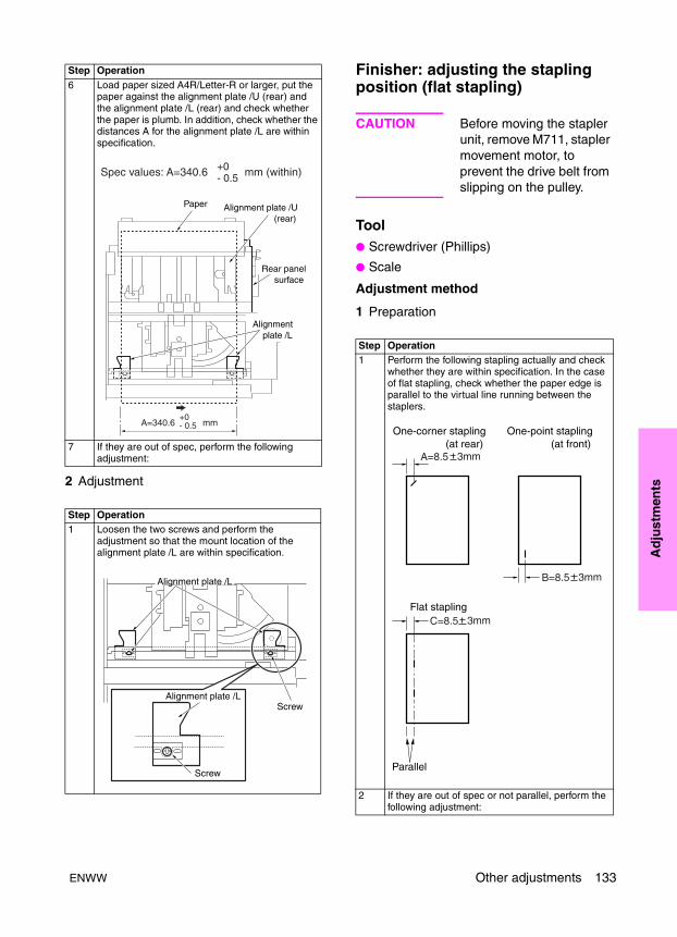
Ad
just
men
ts
2 AdjustmentFinisher: adjusting the stapling position (flat stapling)
CAUTION Before moving the stapler unit, remove M711, stapler movement motor, to prevent the drive belt from slipping on the pulley.
Tool● Screwdriver (Phillips)
● Scale
Adjustment method
1 Preparation
6 Load paper sized A4R/Letter-R or larger, put the paper against the alignment plate /U (rear) and the alignment plate /L (rear) and check whether the paper is plumb. In addition, check whether the distances A for the alignment plate /L are within specification.
7 If they are out of spec, perform the following adjustment:
Step Operation1 Loosen the two screws and perform the
adjustment so that the mount location of the alignment plate /L are within specification.
Step Operation
Paper Alignment plate /U (rear)
Rear panel surface
Alignment plate /L
A=340.6 mm+0- 0.5
Spec values: A=340.6 mm (within)+0- 0.5
Screw
ScrewAlignment plate /L
Alignment plate /L
Step Operation1 Perform the following stapling actually and check
whether they are within specification. In the case of flat stapling, check whether the paper edge is parallel to the virtual line running between the staplers.
2 If they are out of spec or not parallel, perform the following adjustment:
A=8.5 3mm
B=8.5 3mm
C=8.5 3mm
One-point stapling (at front)
One-corner stapling (at rear)
Flat stapling
Parallel
ENWW Other adjustments 133
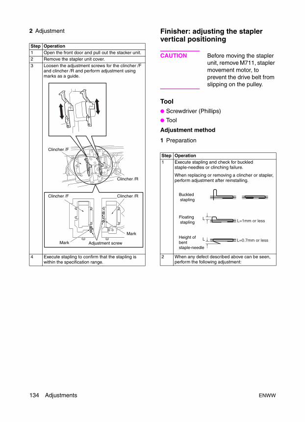
2 Adjustment Finisher: adjusting the stapler vertical positioning
CAUTION Before moving the stapler unit, remove M711, stapler movement motor, to prevent the drive belt from slipping on the pulley.
Tool● Screwdriver (Phillips)
● Tool
Adjustment method
1 Preparation
Step Operation1 Open the front door and pull out the stacker unit.2 Remove the stapler unit cover.
3 Loosen the adjustment screws for the clincher /F and clincher /R and perform adjustment using marks as a guide.
4 Execute stapling to confirm that the stapling is within the specification range.
Clincher /F
Clincher /F
Clincher /R
Clincher /R
Mark
Mark
Adjustment screw
Step Operation1 Execute stapling and check for buckled
staple-needles or clinching failure.
When replacing or removing a clincher or stapler, perform adjustment after reinstalling.
2 When any defect described above can be seen, perform the following adjustment:
L
L
Buckled stapling
Floating stapling
Height of bent staple-needle
L=1mm or less
L=0.7mm or less
134 Adjustments ENWW
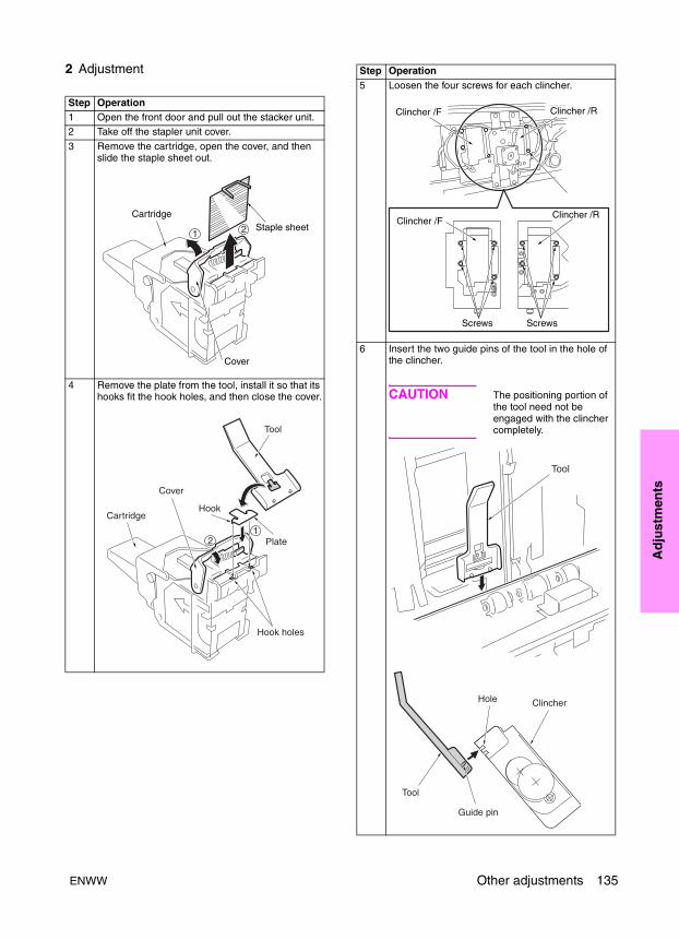
Ad
just
men
ts
2 Adjustment
Step Operation1 Open the front door and pull out the stacker unit.2 Take off the stapler unit cover.
3 Remove the cartridge, open the cover, and then slide the staple sheet out.
4 Remove the plate from the tool, install it so that its hooks fit the hook holes, and then close the cover.
21
CartridgeStaple sheet
Cover
5 Loosen the four screws for each clincher.
6 Insert the two guide pins of the tool in the hole of the clincher.
CAUTION The positioning portion of the tool need not be engaged with the clincher completely.
Step Operation
Clincher /F
Clincher /F
Clincher /R
Clincher /R
ScrewsScrews
ENWW Other adjustments 135

Finisher: adjusting the stapling position (staple-and-fold) (Multifunction Finisher only)
CAUTION Before moving the stapler unit, remove M711, stapler movement motor, to prevent the drive belt from slipping on the pulley.
Tool● Screwdriver (Phillips)
Adjustment method
1 Preparation
2 Adjustment
7 Rotate the stapler gears downward. Adjust the clincher position so that the plate on the cartridge fits smoothly into the groove on the tool. Rotate the stapler gear further to fit the plate in the groove in the tool and the tool in the clincher unit completely.
8 Tighten the four screws for each clincher.9 Rotate the stapler gears upwards to remove the
tool.
CAUTION When removing the tool, be careful not to break the myler of the clincher.
10 Remove the cartridge, detach the plate, insert the staple plate slide out on step 3, and place the cartridge to its original position.
11 Check that the stapler operates properly.
Step Operation
Gear
Plate
Stapler
Groove
Step Operation1 Execute stapling and check whether the paper
edge is parallel to the virtual line connecting the two staples or whether the amount of discrepancy is within specification.
Spec value: within 1 mm for the amount of discrepancy
2 If the amount of discrepancy for the booklet is out of spec, perform the following adjustment:
Step Operation1 Make sure that the “Adjusting the mount location
of the alignment plates/U” and “Adjusting the mount location of the alignment plates/L” are finished.
2 Open the front door and pull out the stacker unit.3 Remove the stapler unit cover.
Staple
Parallel Within1mm
136 Adjustments ENWW
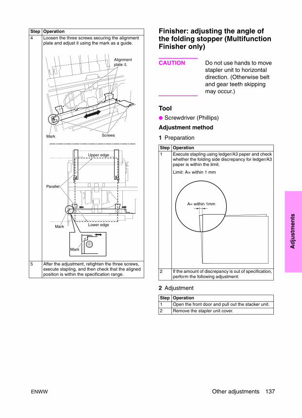
Ad
just
men
ts
Finisher: adjusting the angle of the folding stopper (Multifunction Finisher only)
CAUTION Do not use hands to move stapler unit to horizontal direction. (Otherwise belt and gear teeth skipping may occur.)
Tool● Screwdriver (Phillips)
Adjustment method
1 Preparation
2 Adjustment
4 Loosen the three screws securing the alignment plate and adjust it using the mark as a guide.
5 After the adjustment, retighten the three screws, execute stapling, and then check that the aligned position is within the specification range.
Step Operation
Alignmentplate /L
Mark
Mark
Mark
Screws
Lower edge
Upper edge
Parallel
Step Operation1 Execute stapling using ledger/A3 paper and check
whether the folding side discrepancy for ledger/A3 paper is within the limit.
Limit: A= within 1 mm
2 If the amount of discrepancy is out of specification, perform the following adjustment:
Step Operation1 Open the front door and pull out the stacker unit.
2 Remove the stapler unit cover.
A= within 1mm
ENWW Other adjustments 137

Finisher: adjusting the folding force (Multifunction Finisher only)
Tool● Flat-nose pliers
Adjustment method
1 Preparation
2 Adjustment
3 Loosen the five screws securing the folding stopper and adjust it using the mark as a guide.
4 After the adjustment, retighten the five screws and execute stapling to check that the amount of discrepancy is within the specified limit.
Step Operation
Do notLoosenscrew
Foldingstopper
Mark
Screws
Step Operation1 If necessary, change the force and pressure of the
folding rollers.
Step Operation1 Remove the rear cover.2 Open the front cover and pull out the stacker unit.
3 Remove the stacker unit cover.
138 Adjustments ENWW
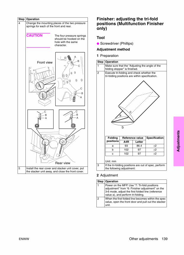
Ad
just
men
ts
Finisher: adjusting the tri-fold positions (Multifunction Finisher only)
Tool● Screwdriver (Phillips)
Adjustment method
1 Preparation
2 Adjustment
4 Change the mounting places of the two pressure springs for each of the front and rear.
CAUTION The four pressure springs should be hooked on the hole with the same character.
5 Install the rear cover and stacker unit cover, put the stacker unit away, and close the front cover.
Step Operation
A
A
B
B
C
C
Front view
Rear view
A AB B
C C
Step Operation1 Make sure that the “Adjusting the angle of the
folding stopper” is finished.2 Execute tri-folding and check whether the
tri-folding positions are within specification.
Unit: mm3 If the tri-folding positions are out of spec, perform
the following adjustment:
Step Operation1 Power on the MFP. Use “7: Tri-fold positions
adjustment” from “6: Finisher adjustment” on the 3-6 mode, adjust the first folded line (reference value a), and perform tri-folding.
2 When the first folded line becomes within the spec value, open the front door and pull out the stacker unit.
a
b
c
Folding positions
Reference value SpecificationA4R Letter
a 93 86.4 ±2b 102 97 ±2
c 102 97 ±2
ENWW Other adjustments 139
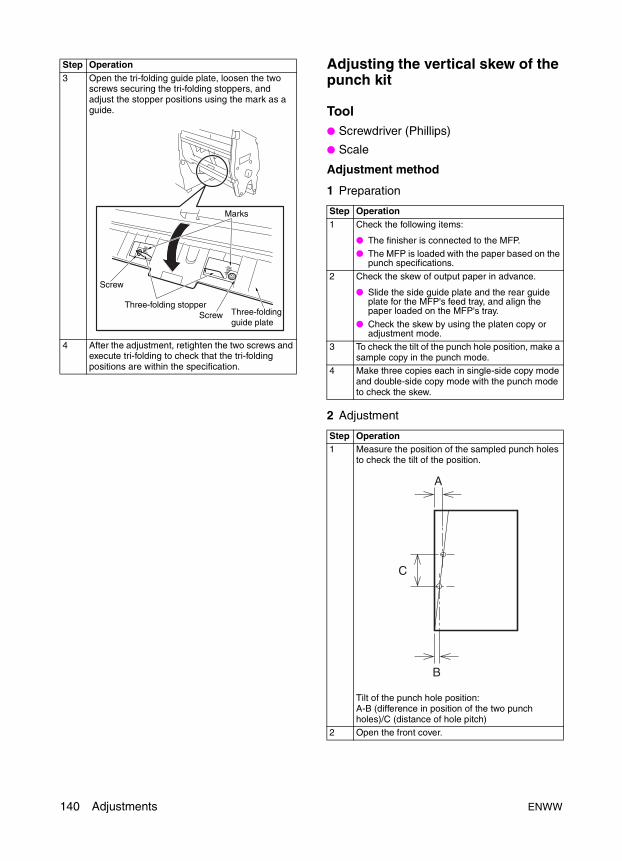
Adjusting the vertical skew of the punch kit
Tool● Screwdriver (Phillips)
● Scale
Adjustment method
1 Preparation
2 Adjustment
3 Open the tri-folding guide plate, loosen the two screws securing the tri-folding stoppers, and adjust the stopper positions using the mark as a guide.
4 After the adjustment, retighten the two screws and execute tri-folding to check that the tri-folding positions are within the specification.
Step Operation
Screw
ScrewThree-folding stopper
Three-foldingguide plate
Marks Step Operation1 Check the following items:
● The finisher is connected to the MFP.● The MFP is loaded with the paper based on the
punch specifications.
2 Check the skew of output paper in advance.
● Slide the side guide plate and the rear guide plate for the MFP's feed tray, and align the paper loaded on the MFP's tray.
● Check the skew by using the platen copy or adjustment mode.
3 To check the tilt of the punch hole position, make a sample copy in the punch mode.
4 Make three copies each in single-side copy mode and double-side copy mode with the punch mode to check the skew.
Step Operation1 Measure the position of the sampled punch holes
to check the tilt of the position.
Tilt of the punch hole position:A-B (difference in position of the two punch holes)/C (distance of hole pitch)
2 Open the front cover.
A
B
C
140 Adjustments ENWW
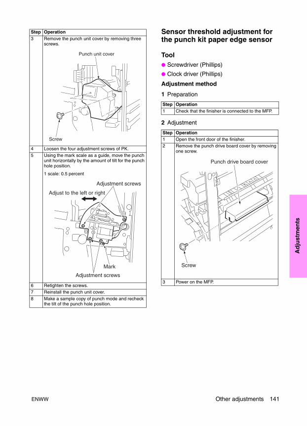
Ad
just
men
ts
Sensor threshold adjustment for the punch kit paper edge sensor
Tool● Screwdriver (Phillips)
● Clock driver (Phillips)
Adjustment method
1 Preparation
2 Adjustment
3 Remove the punch unit cover by removing three screws.
4 Loosen the four adjustment screws of PK.
5 Using the mark scale as a guide, move the punch unit horizontally by the amount of tilt for the punch hole position.
1 scale: 0.5 percent
6 Retighten the screws.7 Reinstall the punch unit cover.
8 Make a sample copy of punch mode and recheck the tilt of the punch hole position.
Step Operation
Screw
Punch unit cover
Mark
Adjustment screws
Adjustment screws
Adjust to the left or right
Step Operation1 Check that the finisher is connected to the MFP.
Step Operation1 Open the front door of the finisher.2 Remove the punch drive board cover by removing
one screw.
3 Power on the MFP.
Punch drive board cover
Screw
ENWW Other adjustments 141
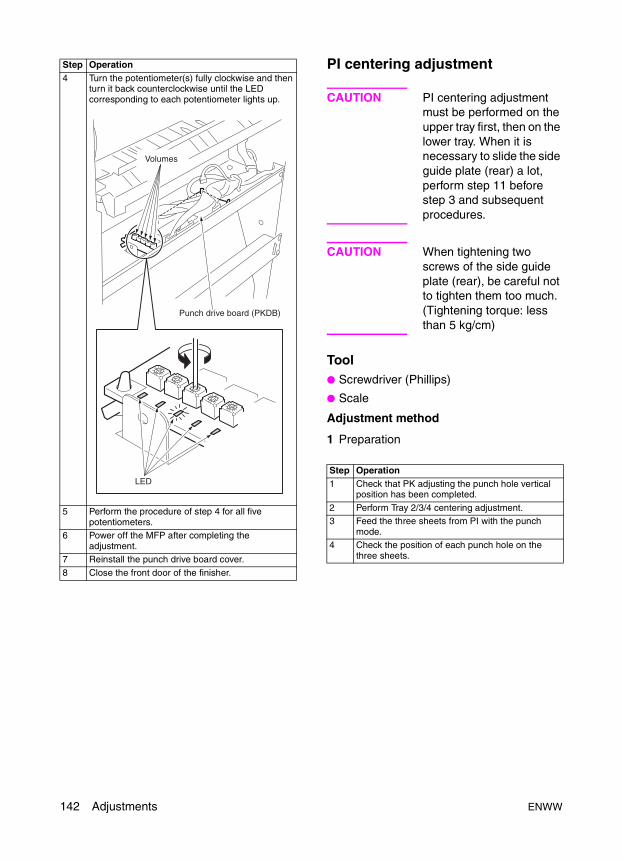
PI centering adjustment
CAUTION PI centering adjustment must be performed on the upper tray first, then on the lower tray. When it is necessary to slide the side guide plate (rear) a lot, perform step 11 before step 3 and subsequent procedures.
CAUTION When tightening two screws of the side guide plate (rear), be careful not to tighten them too much. (Tightening torque: less than 5 kg/cm)
Tool● Screwdriver (Phillips)
● Scale
Adjustment method
1 Preparation
4 Turn the potentiometer(s) fully clockwise and then turn it back counterclockwise until the LED corresponding to each potentiometer lights up.
5 Perform the procedure of step 4 for all five potentiometers.
6 Power off the MFP after completing the adjustment.
7 Reinstall the punch drive board cover.
8 Close the front door of the finisher.
Step Operation
LED
Punch drive board (PKDB)
Volumes
Step Operation1 Check that PK adjusting the punch hole vertical
position has been completed.
2 Perform Tray 2/3/4 centering adjustment.3 Feed the three sheets from PI with the punch
mode.4 Check the position of each punch hole on the
three sheets.
142 Adjustments ENWW
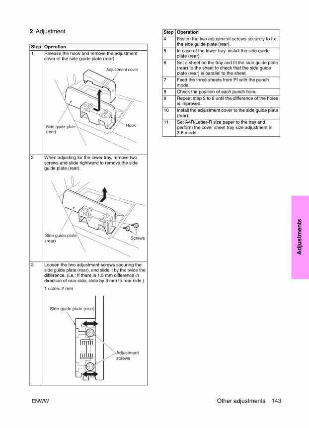
Ad
just
men
ts
2 Adjustment
Step Operation1 Release the hook and remove the adjustment
cover of the side guide plate (rear).
2 When adjusting for the lower tray, remove two screws and slide rightward to remove the side guide plate (rear).
3 Loosen the two adjustment screws securing the side guide plate (rear), and slide it by the twice the difference. (i.e.: If there is 1.5 mm difference in direction of rear side, slide by 3 mm to rear side.)
1 scale: 2 mm
Adjustment cover
HookSide guide plate(rear)
Side guide plate(rear)
Screws
Adjustment screws
Side guide plate (rear)
4 Fasten the two adjustment screws securely to fix the side guide plate (rear).
5 In case of the lower tray, install the side guide plate (rear).
6 Set a sheet on the tray and fit the side guide plate (rear) to the sheet to check that the side guide plate (rear) is parallel to the sheet.
7 Feed the three sheets from PI with the punch mode.
8 Check the position of each punch hole.
9 Repeat step 2 to 8 until the difference of the holes is improved.
10 Install the adjustment cover to the side guide plate (rear).
11 Set A4R/Letter-R size paper to the tray and perform the cover sheet tray size adjustment in 3-6 mode.
Step Operation
ENWW Other adjustments 143
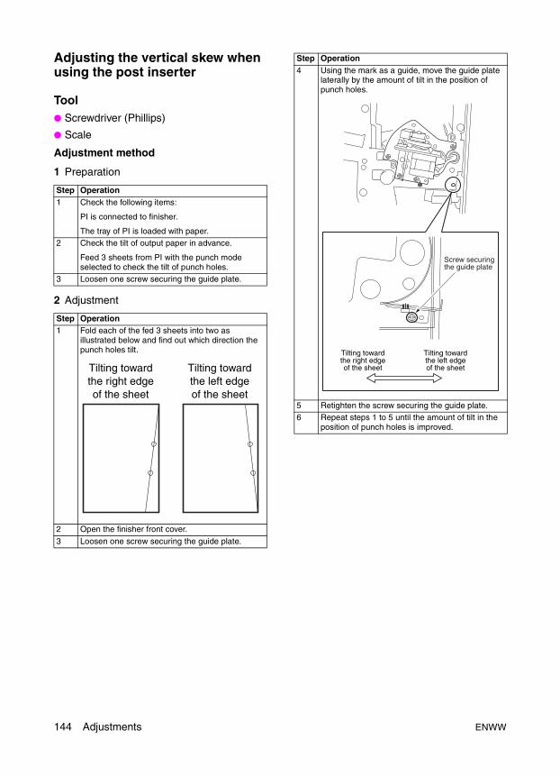
Adjusting the vertical skew when using the post inserter
Tool● Screwdriver (Phillips)
● Scale
Adjustment method
1 Preparation
2 Adjustment
Step Operation1 Check the following items:
PI is connected to finisher.
The tray of PI is loaded with paper.2 Check the tilt of output paper in advance.
Feed 3 sheets from PI with the punch mode selected to check the tilt of punch holes.
3 Loosen one screw securing the guide plate.
Step Operation1 Fold each of the fed 3 sheets into two as
illustrated below and find out which direction the punch holes tilt.
2 Open the finisher front cover.
3 Loosen one screw securing the guide plate.
Tilting towardthe right edgeof the sheet
Tilting towardthe left edgeof the sheet
4 Using the mark as a guide, move the guide plate laterally by the amount of tilt in the position of punch holes.
5 Retighten the screw securing the guide plate.6 Repeat steps 1 to 5 until the amount of tilt in the
position of punch holes is improved.
Step Operation
Screw securingthe guide plate
Tilting towardthe right edgeof the sheet
Tilting towardthe left edgeof the sheet
144 Adjustments ENWW

Ad
just
men
ts
Finisher: stapler driver belt position adjustment
CAUTION Stapler drive belt position adjustment is only performed when the positions of the drive belt and gear are misaligned after performing other adjustment procedures.
Tool● Screwdriver (Phillips)
● Stapler PS tool
● Hexagonal wrench
Adjustment method
1 Preparation
2 Adjustment
Step Operation1 Remove the following parts:
● Rear cover
● Stapler unit cover2 Insert the stacker unit.
Step Operation1 Loosen two M3 screws of the staple slide pulley/B
from the backside.
2 Move the stapler/clincher to the center at the same time until it stops at the bearing.
CAUTION Make sure to move them at the same time, otherwise, the flat-stapling stopper may fracture at the stapler plate.
ENWW Other adjustments 145
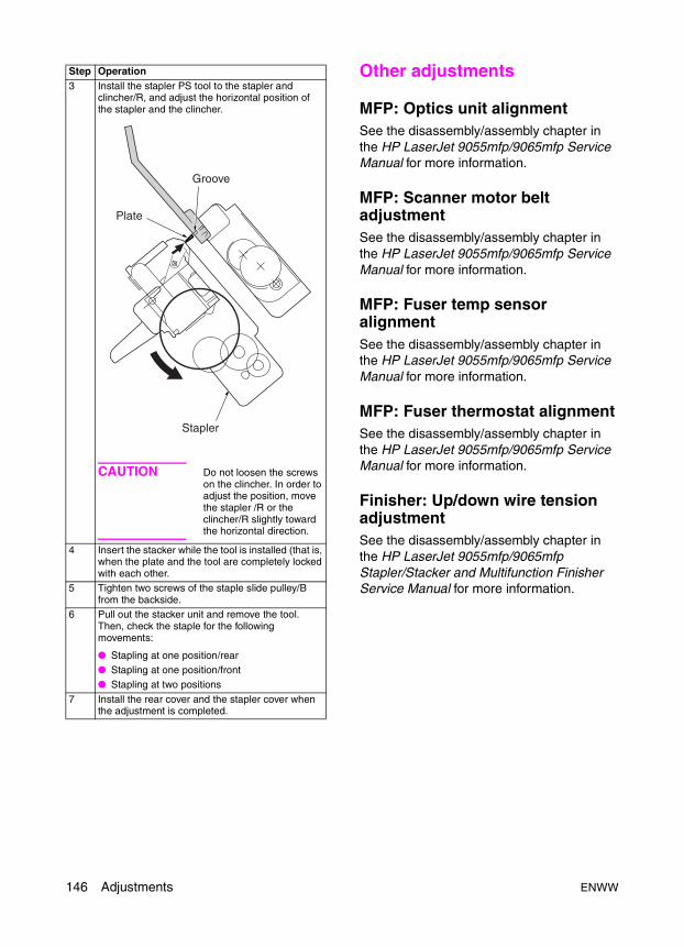
Other adjustments
MFP: Optics unit alignmentSee the disassembly/assembly chapter in the HP LaserJet 9055mfp/9065mfp Service Manual for more information.
MFP: Scanner motor belt adjustmentSee the disassembly/assembly chapter in the HP LaserJet 9055mfp/9065mfp Service Manual for more information.
MFP: Fuser temp sensor alignmentSee the disassembly/assembly chapter in the HP LaserJet 9055mfp/9065mfp Service Manual for more information.
MFP: Fuser thermostat alignmentSee the disassembly/assembly chapter in the HP LaserJet 9055mfp/9065mfp Service Manual for more information.
Finisher: Up/down wire tension adjustmentSee the disassembly/assembly chapter in the HP LaserJet 9055mfp/9065mfp Stapler/Stacker and Multifunction Finisher Service Manual for more information.
3 Install the stapler PS tool to the stapler and clincher/R, and adjust the horizontal position of the stapler and the clincher.
CAUTION Do not loosen the screws on the clincher. In order to adjust the position, move the stapler /R or the clincher/R slightly toward the horizontal direction.
4 Insert the stacker while the tool is installed (that is, when the plate and the tool are completely locked with each other.
5 Tighten two screws of the staple slide pulley/B from the backside.
6 Pull out the stacker unit and remove the tool. Then, check the staple for the following movements:
● Stapling at one position/rear● Stapling at one position/front● Stapling at two positions
7 Install the rear cover and the stapler cover when the adjustment is completed.
Step Operation
Groove
Plate
Stapler
146 Adjustments ENWW
ENWW 147
So
ftw
are
too
ls
3Software tools
Upgrading ICB, PRCB, and Finisher firmware . . . . . . . . . . . . . . . . . . . . . . . 148ISW . . . . . . . . . . . . . . . . . . . . . . . . . . . . . . . . . . . . . . . . . . . . . . . . . . . 148Using ISW . . . . . . . . . . . . . . . . . . . . . . . . . . . . . . . . . . . . . . . . . . . . . . 148Firmware files required. . . . . . . . . . . . . . . . . . . . . . . . . . . . . . . . . . . . . 148Preparing the MFP. . . . . . . . . . . . . . . . . . . . . . . . . . . . . . . . . . . . . . . . 149Troubleshooting . . . . . . . . . . . . . . . . . . . . . . . . . . . . . . . . . . . . . . . . . . 150Relationships between processing states and operational LEDs . . . . 151Rewriting procedure after an error interruption . . . . . . . . . . . . . . . . . . 151
Upgrading print controller firmware . . . . . . . . . . . . . . . . . . . . . . . . . . . . . . . 152Upgrading firmware to the print controller . . . . . . . . . . . . . . . . . . . . . . 152Firmware upgrade methods . . . . . . . . . . . . . . . . . . . . . . . . . . . . . . . . . 153
Embedded Web Server (EWS) . . . . . . . . . . . . . . . . . . . . . . . . . . . . . . . . . . 156System requirements . . . . . . . . . . . . . . . . . . . . . . . . . . . . . . . . . . . . . . 156Opening the EWS . . . . . . . . . . . . . . . . . . . . . . . . . . . . . . . . . . . . . . . . 156Key components of EWS for Service . . . . . . . . . . . . . . . . . . . . . . . . . . 157Useful hints . . . . . . . . . . . . . . . . . . . . . . . . . . . . . . . . . . . . . . . . . . . . . 157
HP90x5mfp Config Utility . . . . . . . . . . . . . . . . . . . . . . . . . . . . . . . . . . . . . . . 158Features of the Config Utility . . . . . . . . . . . . . . . . . . . . . . . . . . . . . . . . 158Useful hints . . . . . . . . . . . . . . . . . . . . . . . . . . . . . . . . . . . . . . . . . . . . . 159
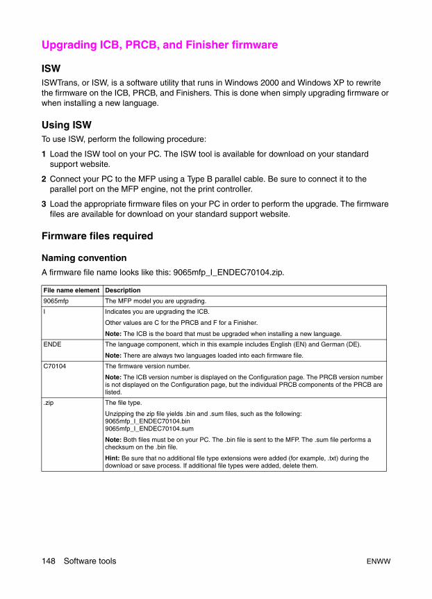
Upgrading ICB, PRCB, and Finisher firmware
ISWISWTrans, or ISW, is a software utility that runs in Windows 2000 and Windows XP to rewrite the firmware on the ICB, PRCB, and Finishers. This is done when simply upgrading firmware or when installing a new language.
Using ISWTo use ISW, perform the following procedure:
1 Load the ISW tool on your PC. The ISW tool is available for download on your standard support website.
2 Connect your PC to the MFP using a Type B parallel cable. Be sure to connect it to the parallel port on the MFP engine, not the print controller.
3 Load the appropriate firmware files on your PC in order to perform the upgrade. The firmware files are available for download on your standard support website.
Firmware files required
Naming convention
A firmware file name looks like this: 9065mfp_I_ENDEC70104.zip.
File name element Description
9065mfp The MFP model you are upgrading.
I Indicates you are upgrading the ICB.
Other values are C for the PRCB and F for a Finisher.
Note: The ICB is the board that must be upgraded when installing a new language.
ENDE The language component, which in this example includes English (EN) and German (DE).
Note: There are always two languages loaded into each firmware file.
C70104 The firmware version number.
Note: The ICB version number is displayed on the Configuration page. The PRCB version number is not displayed on the Configuration page, but the individual PRCB components of the PRCB are listed.
.zip The file type.
Unzipping the zip file yields .bin and .sum files, such as the following:9065mfp_I_ENDEC70104.bin 9065mfp_I_ENDEC70104.sum
Note: Both files must be on your PC. The .bin file is sent to the MFP. The .sum file performs a checksum on the .bin file.
Hint: Be sure that no additional file type extensions were added (for example, .txt) during the download or save process. If additional file types were added, delete them.
148 Software tools ENWW
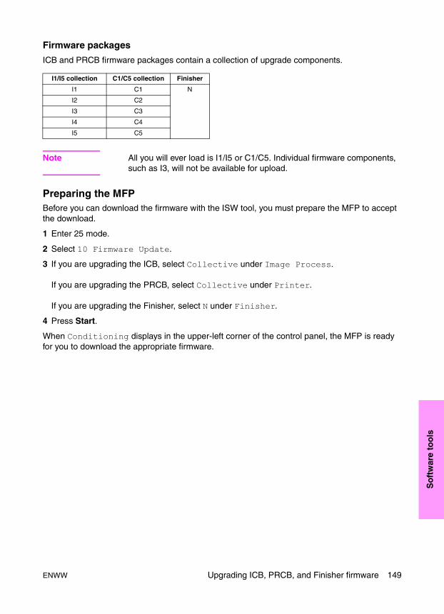
So
ftw
are
too
ls
Firmware packages
ICB and PRCB firmware packages contain a collection of upgrade components.
Note All you will ever load is I1/I5 or C1/C5. Individual firmware components, such as I3, will not be available for upload.
Preparing the MFPBefore you can download the firmware with the ISW tool, you must prepare the MFP to accept the download.
1 Enter 25 mode.
2 Select 10 Firmware Update.
3 If you are upgrading the ICB, select Collective under Image Process.
If you are upgrading the PRCB, select Collective under Printer.
If you are upgrading the Finisher, select N under Finisher.
4 Press Start.
When Conditioning displays in the upper-left corner of the control panel, the MFP is ready for you to download the appropriate firmware.
I1/I5 collection C1/C5 collection Finisher
I1 C1 N
I2 C2
I3 C3
I4 C4
I5 C5
ENWW Upgrading ICB, PRCB, and Finisher firmware 149
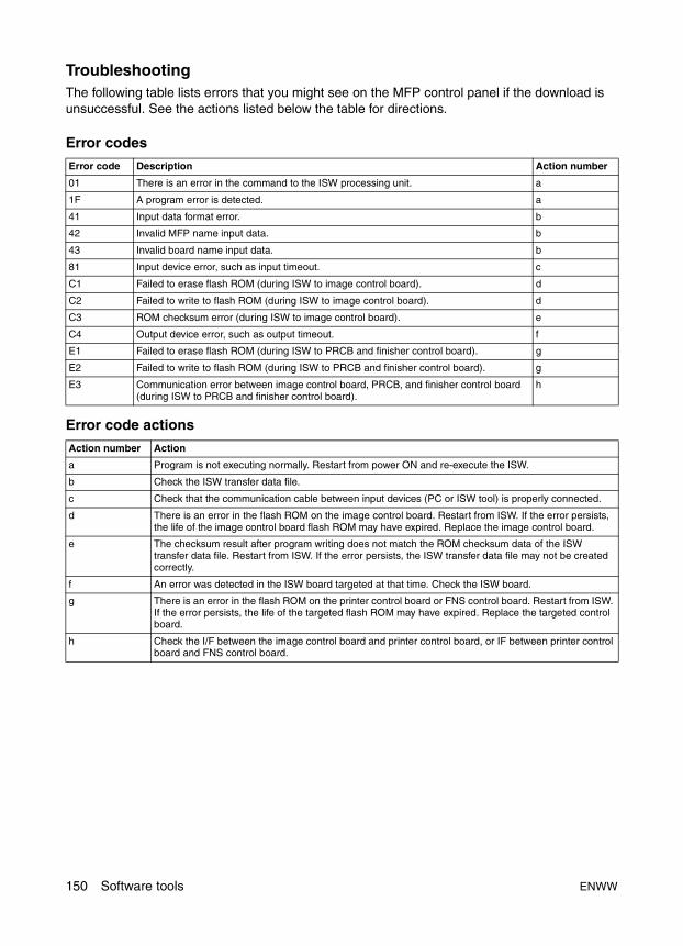
TroubleshootingThe following table lists errors that you might see on the MFP control panel if the download is unsuccessful. See the actions listed below the table for directions.
Error codes
Error code actions
Error code Description Action number
01 There is an error in the command to the ISW processing unit. a
1F A program error is detected. a
41 Input data format error. b
42 Invalid MFP name input data. b
43 Invalid board name input data. b
81 Input device error, such as input timeout. c
C1 Failed to erase flash ROM (during ISW to image control board). d
C2 Failed to write to flash ROM (during ISW to image control board). d
C3 ROM checksum error (during ISW to image control board). e
C4 Output device error, such as output timeout. f
E1 Failed to erase flash ROM (during ISW to PRCB and finisher control board). g
E2 Failed to write to flash ROM (during ISW to PRCB and finisher control board). g
E3 Communication error between image control board, PRCB, and finisher control board (during ISW to PRCB and finisher control board).
h
Action number Action
a Program is not executing normally. Restart from power ON and re-execute the ISW.
b Check the ISW transfer data file.
c Check that the communication cable between input devices (PC or ISW tool) is properly connected.
d There is an error in the flash ROM on the image control board. Restart from ISW. If the error persists, the life of the image control board flash ROM may have expired. Replace the image control board.
e The checksum result after program writing does not match the ROM checksum data of the ISW transfer data file. Restart from ISW. If the error persists, the ISW transfer data file may not be created correctly.
f An error was detected in the ISW board targeted at that time. Check the ISW board.
g There is an error in the flash ROM on the printer control board or FNS control board. Restart from ISW. If the error persists, the life of the targeted flash ROM may have expired. Replace the targeted control board.
h Check the I/F between the image control board and printer control board, or IF between printer control board and FNS control board.
150 Software tools ENWW
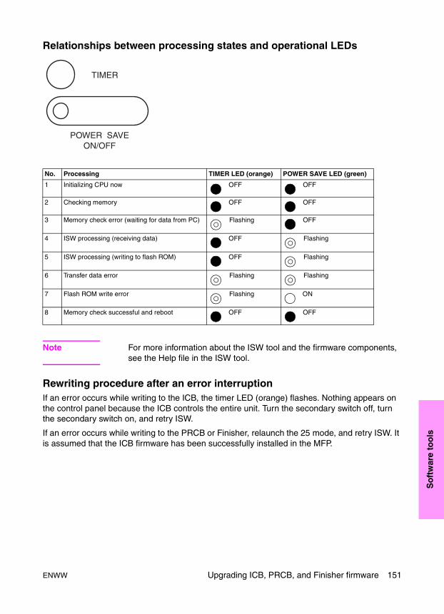
So
ftw
are
too
ls
Relationships between processing states and operational LEDs
Note For more information about the ISW tool and the firmware components, see the Help file in the ISW tool.
Rewriting procedure after an error interruptionIf an error occurs while writing to the ICB, the timer LED (orange) flashes. Nothing appears on the control panel because the ICB controls the entire unit. Turn the secondary switch off, turn the secondary switch on, and retry ISW.
If an error occurs while writing to the PRCB or Finisher, relaunch the 25 mode, and retry ISW. It is assumed that the ICB firmware has been successfully installed in the MFP.
No. Processing TIMER LED (orange) POWER SAVE LED (green)
1 Initializing CPU now OFF OFF
2 Checking memory OFF OFF
3 Memory check error (waiting for data from PC) Flashing OFF
4 ISW processing (receiving data) OFF Flashing
5 ISW processing (writing to flash ROM) OFF Flashing
6 Transfer data error Flashing Flashing
7 Flash ROM write error Flashing ON
8 Memory check successful and reboot OFF OFF
ENWW Upgrading ICB, PRCB, and Finisher firmware 151
Upgrading print controller firmwareDownloading firmware from http://www.hp.com to a PC and, ultimately, to an MFP requires an understanding of what the downloaded file contains.
The file downloaded from the website is compressed. The file is named, for example, lj9065mfp.exe. The .exe file contains the following files:
● The firmware file is an .rfu (remote firmware upgrade) file (for example, lj9065mfpfw.rfu).
● The other file is a README.txt file. This file provides information about what is included in the upgrade and who should use the upgrade. There are also instructions on how to perform the upgrade on one or more MFPs and a reference to what previous revisions of the firmware changed.
Upgrading firmware to the print controllerWhen upgrading firmware to the print controller, the following occurs:
● The firmware is downloaded through the network or parallel port on the workstation to the network or parallel port on the print controller.
● The firmware is written to the print controller hard disk.
Upgrade process
1 The firmware DIMM contains a full backup firmware image.
Note In most cases, the firmware DIMM contains an older version than the firmware image on the hard disk.
2 If a valid image exists on the disk, the MFP uses the image on the hard disk.
3 The MFP uses the image on the firmware DIMM only if one of the following occurs:
• The hard disk does not contain a firmware image yet.
• The hard disk has a corrupted firmware image.
• The hard disk is malfunctioning.
• There is no hard disk.
4 When an upgrade is sent to the MFP, the print controller firmware successfully upgrades if the hard disk is installed and working.
5 During the download and upgrade process, the control panel displays the following messages:
Receiving UpgradePerforming UpgradeProcessing Job
6 The MFP reboots.
152 Software tools ENWW
So
ftw
are
too
ls
Troubleshooting measures● If no disk is installed and the upgrade is performed, the job is performed as normal (as if a
hard disk was installed).
An upgrade appears to be processing, but when the firmware file tries to write to the hard disk, the upgrade cannot be accomplished because the file sees that there is no hard disk. The MFP reboots and no actual upgrade occurs.
There is no control panel message that warns the user that the upgrade was not successful. The user can determine that the upgrade was not performed by checking the firmware version on the Configuration page.
● If an upgrade begins and the MFP is turned off during the Receiving Upgrade message, the MFP can be booted from the disk. There is no control panel message that indicates that the upgrade did not occur.
● If an upgrade begins and the MFP is turned off during the Performing Upgrade message, the MFP boots from the DIMM. This means that the image on the disk is now bad. The control panel displays Resend Upgrade. Once the user successfully performs a remote firmware upgrade, the message disappears.
● If the ICB firmware is upgraded and requires a change in print controller firmware to remain compatible, the print controller firmware DIMM should be replaced at the same time. If the hard disk or remote firmware upgrade fails, the backup image would then be compatible.
Firmware upgrade methodsThis section describes the following firmware upgrade methods:
• FTP browser copy
• FTP put
• Parallel connection
• Network connection
• HP Web Jetadmin
FTP browser copy
This firmware upgrade method requires a setting in the Internet Options dialog box. To check this setting, perform the following procedure:
1 Access the Internet Options dialog box in one of the following ways:
• Open a Web browser. On the Tools menu, click Internet Options, and select the Advanced tab.
• On the Windows Start menu, point to Settings, and click Control Panel. Double-click Internet Options, and select the Advanced tab.
2 On the Advanced tab, make sure that the Enable folder view for FTP sites option is selected.
ENWW Upgrading print controller firmware 153

To perform an FTP browser copy, perform the following procedure:
1 Print a Configuration page, and note the firmware revision number.
2 Download the firmware from the Web, and copy it to a folder on the PC.
3 Unzip the downloaded file.
4 Open the folder containing the .rfu file.
5 Open a browser window.
6 In the Address field, type FTP:// followed by the IP address of the MFP (for example, FTP://192.168.0.1).
7 Click Go or press Enter.
A folder named Port 1 displays in the browser window.
8 Drag the .rfu file from the open folder to the browser window.
The control panel displays the messages Receiving Upgrade, Performing Upgrade, and Processing Job.
9 The MFP reboots, which means that the upgrade is complete.
FTP put
1 Print a Configuration page, and note the firmware revision number.
2 Download the firmware from the Web, and copy it to a folder on the PC.
3 Unzip the downloaded file.
4 Open the folder containing the .rfu file.
5 Open a DOS Command Prompt window, and find the firmware file.
6 At the C:\> prompt, type ftp followed by a space and the IP address (for example, ftp 16.32.55.21).
7 Press Enter.
8 When prompted for the user name and password, press Enter for each of them.
9 At the ftp> prompt, type bin.
10Press Enter.
11At the ftp> prompt, type put drive:\folder\filename (for example, put c:\lj9065\lj9065mfpfw.rfu).
Alternatively, perform the following procedure:
a Instead of typing the full path, open the folder where the upgrade file resides.
b Type put c:, and drag the upgrade file from the folder into the DOS Command Prompt window.
12 Press Enter.
13 After the MFP reboots, close the FTP session by typing BYE, and pressing Enter. The upgrade is complete.
154 Software tools ENWW
So
ftw
are
too
ls
Parallel connection
1 Print a Configuration page, and note the firmware revision number.
2 Download the firmware from the Web, and copy it to a folder on the PC.
3 Unzip the downloaded file.
4 Open a DOS Command Prompt window, and find the firmware file.
5 If connected to a parallel port, type copy /b filename portname (for example, copy /b lj9065mfpfw.rfu LPT1).
6 Press Enter.
The control panel displays the messages Receiving Upgrade, Performing Upgrade, and Processing Job.
7 The MFP reboots, which means that the upgrade is complete.
Network connection
1 Print a Configuration page, and note the firmware revision number.
2 Download the firmware from the Web, and copy it to a folder on the PC.
3 Unzip the downloaded file.
4 Open a DOS Command Prompt window, and find the firmware file.
5 Type copy /b filename \\computername\sharename.
6 Press Enter.
The control panel displays the messages Receiving Upgrade, Performing Upgrade, and Processing Job.
7 The MFP reboots, which means that the upgrade is complete.
HP Web Jetadmin
Note These instructions were written for HP Web Jetadmin version 6.5.
1 Print a Configuration page, and note the firmware revision number.
2 Go to the main page for HP Web Jetadmin, and perform one of the following.
• For a single MFP, type the MFP’s IP hostname or IP address in the Quick Device Find field in the top right corner, and click Go.
• For multiple MFP updates, see the HP Web Jetadmin user documentation.
3 Click the right arrow below the Go button to display the Update option.
4 Click Update, select Update Printer (rather than Update Jetdirect), and click Next.
5 Click Browse, and find the firmware image file downloaded from the Web.
6 Click Upload to move the firmware image file from the C: drive to the HP Web Jetadmin server.
7 Click the Refresh icon in the top right corner (it looks like a page with two arrows in a circle).
ENWW Upgrading print controller firmware 155
8 Select the date code that you want to send to the MFP. The date code format is YYYYMMDD, where YYYY is the year, MM the month, and DD the date.
9 Click Update Firmware. HP Web Jetadmin sends the selected firmware image file to the MFP.
Embedded Web Server (EWS)
The embedded Web server (EWS) allows users to view product and network status, create alerts for remote troubleshooting, and manage printing functions from a PC rather than at the MFP control panel. The EWS resides in the firmware. The EWS is accessed using a TCP/IP-based network connection.
No special software is required to access the EWS. All users who have access to a standard Web browser can use the EWS. Using the EWS allows users to perform the following tasks:
● view control panel messages and status information
● check supplies status
● review a list of MFP events
● view the Configuration, Event log, or other information pages
● set up e-mail status and alerts
● view reports for job accounting
● review and change the MFP configuration
System requirements● For best Web browser results, use one of the following:
• Microsoft Internet Explorer 5.0.1 or later
• Netscape Navigator 6.2 or later
● TCP/IP-based network connection
Opening the EWS
Note Users cannot access EWS pages from outside a firewall.
To open the EWS, perform the following procedure:
1 Open a Web browser.
2 In the Address field, type the IP address of the MFP. The IP address can be found on the Configuration page.
3 Click Go or press Enter.
156 Software tools ENWW

So
ftw
are
too
ls
Security
When accessing the EWS, the following levels of security are available:
● General user – If an administrative password is set, general users can access only the Information tab.
● IT administrator – The IT administrator defines the password. The service provider can change the administrative password.
● Service provider – The default password is 9272. The service provider can change the service password.
Note If you log off as one type of user, you must close the browser before logging on as another type of user.
Key components of EWS for ServiceThe following components of EWS are useful for a service technician:
● Alerts – Allows you to configure the MFP to send you e-mails if particular events occur. Maintenance alerts are only available to someone who is logged on as Service.
● Supplies Status – Allows you to view the status of the supplies (toner and staples). Maintenance information is only available to someone who is logged on as Service.
● AutoSend – Allows you to configure the MFP to automatically send XML data at a specified interval, either time based or page count based.
Useful hints● The following are the possible logins and associated passwords:
● If you change the default service password to something other than 9272, make sure you choose something that is easy for you to remember, but not obvious to a customer. If you forget the password you have set, a Cold Reset or NVRAM init is required to reset the password to 9272.
● If you try to access the Networking tab when logged on as Service and an Admin password has been set, you will be asked to enter your login and password. The Admin password is required.
● When choosing the desired attachments for your alerts, remember that the pages will be in HTML format. If you would like to have the service data available, including some of the internal pages (for example, Count of Special Parts), you must choose XML data.
● For more information about EWS (for example, what it is and descriptions of the tabs), see the HP LaserJet 9055/9065mfp EWS Guide.
Login Password
Admin Established by the administrator; no default password.
Service Default is 9272; can be changed.
ENWW Embedded Web Server (EWS) 157
HP90x5mfp Config Utility
The configuration utility can be used to reset the 25 Mode Software Switches (DIPSW) and the Key Operator Memory Switches back to a regional default value (or profile). The HP 9055/9065mfp Config Utility is installed via the Package Loader in the EWS. The URL is hostname/hp/device/this.loader.
When accessing the Package Loader, a prompt to configure a password prior to any further access displays. The password that needs to be entered is the Admin password in the EWS. If an Admin password has not ben previously set, you are prompted to create one. Once the Admin password has been set, change the URL in the browser back to hostname/hp/device/this.loader.
If the HP90x5Cfg.jar file does not appear in the Reloadable Packages list, you must download it from your standard support site and save it to your PC. Use the Install New Package section to browse to the file.
Features of the Config UtilityThe initial screen of the utility allows you to perform the following tasks:
● view the current SW settings and firmware versions on the MFP
● select a regional default profile to download
● set the appropriate switches needed when a Copy Controller HDD is installed
● create a deviation report
● save an uploaded profile from an MFP
● download a saved profile to an MFP
Viewing the current SW settings
The current settings and firmware versions automatically display once you have accessed the utility on an MFP. You can choose a printable page for easier viewing.
Downloading a regional default profile
To configure an MFP in its original default state (for switches only), select the regional profile to load, and click APPLY SELECTION. The new profile is loaded and the new configuration displays.
Setting the Copy Controller HDD switches
To configure the appropriate SW switches needed when a Copy Controller HDD has been installed, choose the appropriate regional profile, select the hard disk option in the Profile Modifiers section, and click Apply Selection.
Creating a deviation report
To create a deviation report that shows the differences in SW switch settings between the current configuration and the regional profile selected, select Create Deviation Report.
Note This option does not download any profiles.
158 Software tools ENWW

So
ftw
are
too
ls
Saving an uploaded profile
To save an MFP’s configuration for future downloads, perform the following procedure:
1 Select Save Current Config.
2 Choose Download the file.
3 Select Save this file to disk.
4 Choose the folder where you want to save the file.
5 Make sure that the file saves as a .bin document.
6 Once the file is saved, choose Return to Main Page.
Downloading a saved profile
To download a saved profile to an MFP, perform the following procedure:
1 Click Browse.
2 Select the file that you want to download. The file displays in the Select file for Restore box.
3 Click Restore Saved Config.
Useful hints● To access the loader page, type the IP address in the browser just as you would to access the
EWS. Once you access the EWS, delete LCDispatcher from the end of the URL in the Address box, and replace it with Loader.
● If you are troubleshooting an MFP and want to test it in a known state, it is useful to upload and save the existing settings, download a default profile, and download the saved profile once troubleshooting is complete.
● If you have multiple MFPs that you want to configure identically, it is useful to upload and save a profile, and download it to other MFPs.
ENWW HP90x5mfp Config Utility 159

160 Software tools ENWW
ENWW 161
Pri
nt
con
tro
ller4Print controller
Print controller components . . . . . . . . . . . . . . . . . . . . . . . . . . . . . . . . . . . . . 162Troubleshooting . . . . . . . . . . . . . . . . . . . . . . . . . . . . . . . . . . . . . . . . . . . . . . 164
Power-on time sequence . . . . . . . . . . . . . . . . . . . . . . . . . . . . . . . . . . . 164LED indications . . . . . . . . . . . . . . . . . . . . . . . . . . . . . . . . . . . . . . . . . . 165
Internal pages . . . . . . . . . . . . . . . . . . . . . . . . . . . . . . . . . . . . . . . . . . . . . . . 166Print controller error codes . . . . . . . . . . . . . . . . . . . . . . . . . . . . . . . . . . . . . . 167Print controller service modes . . . . . . . . . . . . . . . . . . . . . . . . . . . . . . . . . . . 170
Service Menu (PIN code 11905503 or 11906503). . . . . . . . . . . . . . . . 1709-0 mode . . . . . . . . . . . . . . . . . . . . . . . . . . . . . . . . . . . . . . . . . . . . . . . 170
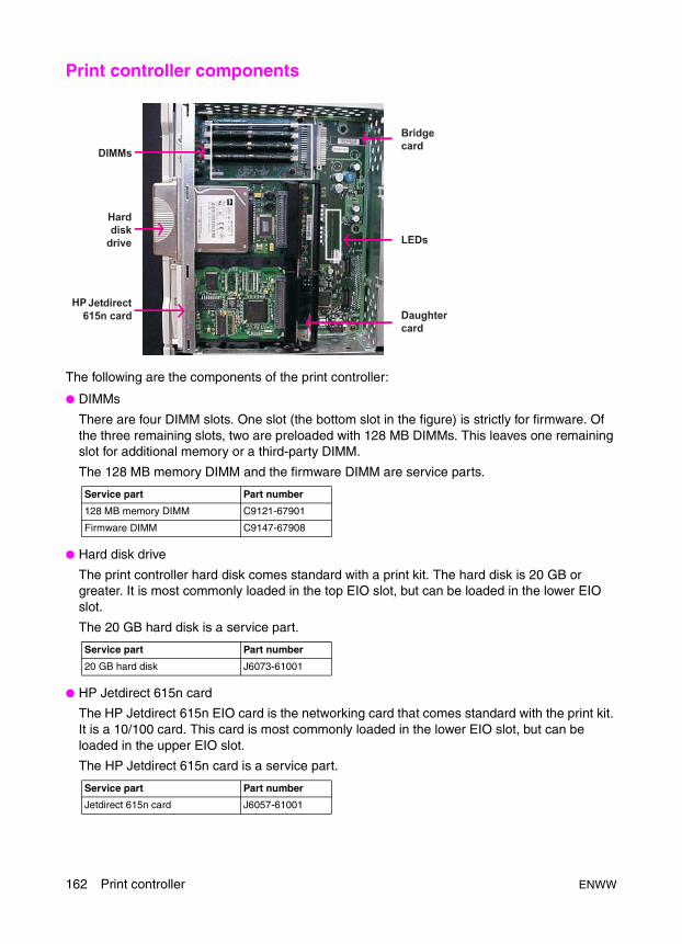
Print controller components
The following are the components of the print controller:
● DIMMs
There are four DIMM slots. One slot (the bottom slot in the figure) is strictly for firmware. Of the three remaining slots, two are preloaded with 128 MB DIMMs. This leaves one remaining slot for additional memory or a third-party DIMM.
The 128 MB memory DIMM and the firmware DIMM are service parts.
● Hard disk drive
The print controller hard disk comes standard with a print kit. The hard disk is 20 GB or greater. It is most commonly loaded in the top EIO slot, but can be loaded in the lower EIO slot.
The 20 GB hard disk is a service part.
● HP Jetdirect 615n card
The HP Jetdirect 615n EIO card is the networking card that comes standard with the print kit. It is a 10/100 card. This card is most commonly loaded in the lower EIO slot, but can be loaded in the upper EIO slot.
The HP Jetdirect 615n card is a service part.
Service part Part number
128 MB memory DIMM C9121-67901
Firmware DIMM C9147-67908
Service part Part number
20 GB hard disk J6073-61001
Service part Part number
Jetdirect 615n card J6057-61001
162 Print controller ENWW
Pri
nt
con
tro
ller
● Daughter card
The daughter card is standard in the print controller assembly. This card acts as an interface between the EIO cards and the formatter PCA.
The daughter card is not a separate service part. It is part of the print controller assembly.
● LEDs
The LEDs are located on the bridge card. There are eight LEDs that can be used to troubleshoot errors in the print controller or communication between the print controller and the ICB. See "Troubleshooting" on page 164 for more information about using the LEDs.
The LEDs are not separate service parts. They are mounted on the bridge card, which is part of the print controller assembly.
● Bridge card
The bridge card is simply an interface card that is required to allow the print controller to attach to the MFP. The bridge card contains the LEDs used in troubleshooting.
The bridge card is not a separate service part. It is part of the print controller assembly.
Service part Part number
Print controller assembly Q3639-67901
Service part Part number
Print controller assembly Q3639-67901
Service part Part number
Print controller assembly Q3639-67901
ENWW Print controller components 163
Troubleshooting
Power-on time sequenceThere are eight LEDs, which are numbered from 0 to 7, on the formatter. When the secondary power switch is turned on, the LEDs follow the pattern described in the following table until the MFP status is Ready. The times listed are approximate times.
Icon Description
LED is on.
LED is flashing.
LED is off.
Elapsed time (minutes:seconds)
LED activity
00:01 All LEDs turn on; 4 and 7 begin flashing and the other LEDs remain solid.
00:19 All LEDs turn off; 4 and 7 return to flashing.
00:21 0 turns on; 4 and 7 remain flashing.
00:46 1 turns on; 0 remains solid; 4 and 7 remain flashing.
01:31 2 turns on; 0 and 1 remain solid; 4 and 7 remain flashing.
01:42 5 and 6 begin flashing; 0, 1, and 2 remain solid; 4 and 7 remain flashing.
164 Print controller ENWW
Pri
nt
con
tro
ller
LED indicationsPower On Top LEDs turn on
At power up, the hardware turns on LEDs 0 through 3, indicating that there is power and a good connection.
Boot loader alive Top LEDs turn off
The LEDs in the MFP are on the interface board between the formatter and the engine controller. The interface between the interface board and the formatter is Peripheral Component Interconnect (PCI). The PCI interface communication must be established before the LEDs can be modified. This happens after the RAM test and takes several seconds. As soon as the PCI communication is started, LEDs 0 through 3 turn off.
LEDs 0, 1, 2, and 3 remain on
If LEDs 0 through 3 stay on, the boot loader cannot run.
● There might be no RAM. One or both of the 128 MB DIMMs could be missing, not seated correctly, or damaged.
● There might be no firmware DIMM. The firmware DIMM could be missing, not seated correctly, or damaged.
● There might be no firmware image on the DIMM.The firmware image could be missing, incomplete, or corrupt.
● The HP controller might be dead.
Communication LEDs 0, 1, 2, and 3 are off
When LEDs 0 through 3 turn off, the following has occurred:
● The HP formatter CPU can execute.● The unit has a boot loader image.● It has passed the RAM test.
● The PCI bus is functional.
If the LEDs remain off, there has been no ICB communication.
LED 0
The firmware waits for the ICB to indicate that it is functional. The ICB indicates that it is functioning by sending an Initialize command to the HP formatter. When the HP formatter successfully receives and responds to the Initialize command, LED 0 turns on.
If LED 0 does not turn on, there are problems establishing communication.
Driver installed LED 1
The operating system is loaded into memory. When the engine driver is successfully loaded and initialized, LED 1 turns on. LED 0 remains solid (on).
If there was no DIMM, the MFP would not reach this point.
Firmware LED 2
After LED 1, the firmware loads into memory. The firmware code begins communication with the engine by requesting its status. When the engine driver sees that the firmware code has received status from the ICB, LED 2 turns on.
LED 3
This LED is off during normal operation.
ENWW Troubleshooting 165
These LEDs are intended to assist you when troubleshooting a suspected print controller error. If the LEDs reach their final state, it is an indication that the print controller assembly is functioning and is not the cause of the error. Be sure to consider any internal or external components, such as DIMMs, additional third-party DIMMs, hard disk, HP Jetdirect card, other networking cards, or other job accounting devices.
Internal pages
The following internal pages can be accessed from the Print Menu:
All sequences LED 4
This is the PCI clock for the HP formatter.
● LEDs 4 and 7 flash steadily.● If this LED is not flashing, the HP formatter cannot communicate with the bridge board.
LED 5 and 6
These indicate that blocks of data are being transferred to or from the ICB.
● These LEDs always flash during printing.The LEDs flash about once per page.
● These LEDs are not useful for troubleshooting.
LED 7
This is the PCI clock for the engine controller.
● LEDs 4 and 7 flash steadily.● If this LED is not flashing, the engine controller cannot communicate with the bridge board.
Problem indications LED 0 is on alone
There might not be a valid firmware image available to load.
LEDs 0 and 1 are the only LEDs on
The firmware code died early in its initialization sequence.
Menu Internal page
Information Menu map
Displays the configurations of the MFP for printing, such as the default paper size and paper destination.
Note: This page displays the default settings for printing only.
Configuration
Displays device information, such as the firmware versions of the various components, and what is installed in the MFP. The second page provides networking information, such as the IP address of the HP Jetdirect card.
Supplies status page
Displays the level of supplies, such as toner and staples.
Usage page
Displays the totals for page output, both copy and print.
File directory
Displays the contents of the print controller hard disk.
Font lists
Displays the fonts that are internally available on the print controller.
Diagnostics Print event log
Displays the last 50 events that occurred on the print controller.
Note: These events include only print controller errors.
166 Print controller ENWW
Pri
nt
con
tro
ller
Print controller error codes
Note Print controller errors are displayed only on the Print Screen. To view a print controller error, press the Mode button twice to enter the Print Screen.
Note When performing a power cycle to clear a print controller error, you must power cycle the secondary and primary power switches. If you only power cycle the secondary switch, the error state remains on the print controller.
Message Description Action
20INSUFFICIENT MEMORY
The print controller received more data from the computer than fits in the available memory.
1 Press the OK button to resume printing.
Note: A loss of data will occur.
2 Reduce the complexity of the print job to avoid this error.
3 You may be able to print pages that are more complex if you add additional memory to the print controller.
22EIO X BUFFER OVERFLOW
The EIO card in slot X (in most cases, the HP Jetdirect 615n card) overflowed its I/O buffer during a busy state.
1 Press the OK button to resume printing.
Note: A loss of data will occur.
2 Check the configuration of the EIO card and the host computer.
3 If this error message persists, replace the EIO card.
22PARALLEL I/O BUFFER OVERFLOW
The print controller’s parallel buffer overflowed during a busy state.
1 Press the OK button to resume printing.
Note: A loss of data will occur.
2 Check the parallel I/O configuration. Set HIGH SPEED to NO and ADVANCED FUNCTIONS to OFF.
3 Replace the print controller assembly.
40EIO X BAD TRANSMISSION
A connection with the card in EIO slot X (in most cases, the HP Jetdirect 615n card) has been broken abnormally.
1 Press the OK button to resume printing.
Note: A loss of data will occur.
2 Check that the cable is connected to the EIO port and that the EIO card is seated properly.
3 If possible, print to another network device to verify that the network is working properly.
4 Check the configuration of the EIO card.
5 If this error message persists, replace the EIO card.
ENWW Print controller error codes 167
49.XXXXPRINTER ERRORTo continue turn off then on
A critical firmware error occurred that caused the processor on the formatter to abort the operation. This type of error can be caused by invalid print commands, corrupt data, or invalid operations. In some instances, electrical noise in the cable can corrupt data during transmission to the printer. Other causes include poor-quality parallel cables, poor connections, or specific applications.Sometimes, the formatter itself is at fault, which is usually indicated by a 79 SERVICE ERROR.
1 Press OK to clear the print job from the print controller memory.
2 Turn the MFP secondary and primary power off and then on.
3 If there is a newer version of the print controller firmware available, upgrade the firmware.
4 Try printing a job from a different software program. If the job prints, go back to the first program and try printing a different file. If the message appears only with a certain software program or print job, contact the software vendor for assistance.
5 If the message persists when using different software programs and attempting specific print jobs, disconnect all of the cables that connect the MFP to the network or computer.
6 Turn the MFP secondary and primary power off.
7 Remove all memory DIMMs or third-party DIMMs from the print controller. (Do not remove the firmware DIMM in slot J1.)
8 Remove all of the EIO devices from the printer.
9 Turn the printer on.
10 If the error message disappears, reinstall each DIMM and EIO device individually, turning the secondary and primary power off and then on again as you install each device.
68.XPERMANENT STORAGE ERROR
One or more print settings that were saved in a nonvolatile storage device are invalid and have been reset to the factory default. Pressing the OK button should clear the message. Printing can continue, but may behave unexpectedly in response to the changed settings.
X Description 0 onboard NVRAM1 flash DIMM or hard disk
1 Press the OK button to continue.
2 Turn the MFP secondary and primary power off and then on.
3 Check the print settings to determine which settings have been changed.
4 Perform an NVRAM initialization.
5 Replace the print controller assembly.
68.XPERMANENT STORAGE FULL
A nonvolatile storage device is full. Pressing the OK button should clear the message. Printing can continue, but may behave unexpectedly in response to the changed settings.
X Description 0 onboard NVRAM1 flash DIMM or hard disk
1 Press the OK button to continue.
2 For 68.0 errors, turn the MFP secondary and primary power off and then on.
3 If a 68.0 error persists, initialize the NVRAM.
4 For 68.1 errors, use the HP Web Jetadmin software to delete files from the disk drive.
5 If the 68.1 error persists, reinitialize the hard disk.
6 If the 68.1 error persists, replace the hard disk.
7 If this error message persists, replace the print controller assembly.
Message Description Action
168 Print controller ENWW

Pri
nt
con
tro
ller
68.XPERMANENT STORAGE WRITE FAIL
A nonvolatile storage device failed to write. Pressing the OK button should clear the message. Printing can continue, but may behave unexpectedly in response to the changed settings.
X Description 0 onboard NVRAM1 flash DIMM or hard disk
1 Press the OK button to continue.
2 Turn the MFP secondary and primary power off and then on.
3 If the 68.0 error persists, initialize the NVRAM.
4 If the 68.1 error persists, reinitialize the hard disk.
5 If the 68.1 error persists, replace the hard disk.
6 If this error message persists, replace the print controller assembly.
79.XXXXPRINTER ERRORTo continue turn off then on
A critical hardware error occurred. 1 Turn the MFP secondary and primary power off and then on.
2 If the problem persists, reseat the firmware DIMM.
3 Reseat the print controller.
4 If there is a newer version of the print controller firmware available, upgrade the firmware.
5 Replace the firmware DIMM.
6 Replace the print controller assembly.
8X.YYYYEIO ERROR
The EIO device in slot X encountered a critical error.
1 Turn the MFP secondary and primary power off and then on.
2 If the problem persists, reseat the EIO device.
3 Replace the EIO device.
4 Replace print controller assembly.
OPERATOR CALL ERROR:XX - X
The MFP requires some kind of action from the user (for example, the ADF cover is open).
1 Go to the Main Screen, the Copy UI, for specific action required.
Message Description Action
ENWW Print controller error codes 169
Print controller service modesThe following service modes are available on the print controller:
● Service Menu
● 9-0 Mode
Service Menu (PIN code 11905503 or 11906503)The Service Menu is the last item under Menus. You must use one of the following passwords to access the Service Menu:
The following items are available in the Service Menu:
● Clear event log
Allows you to clear all of the events that are currently in the print controller event log.
● Cold Reset Paper
Allows you to set the Cold Reset paper size (either Letter or A4) for printing. This is the paper size that will be the default for printing if and when a Cold Reset is performed.
9-0 mode
Note Accessing the 9-0 mode requires the 4-7 mode. You must hold down the 4 and 7 keys while you turn on the primary power and then turn on the secondary power. The shortcut using the P key does not work for 9-0 mode.
1 Turn off the secondary power.
2 Turn off the primary power.
3 To access the 4-7 mode, press the 4 and 7 keys on the control panel keypad and hold them down.
4 While continuing to hold down the 4 and 7 keys, turn on the primary power switch, and then turn on the secondary power switch. Hold the keys down until the HP logo appears on the control panel.
5 Type 90 on the control panel keypad. The following displays on the control panel:
I/O check mode<90-00> IN: OUT:----
6 Press START to enable the 9-0 mode.
MFP Password
HP LaserJet 9055mfp 11905503
HP LaserJet 9065mfp 11906503
170 Print controller ENWW

Pri
nt
con
tro
ller
The following items are available in 9-0 mode:
● Cold reset
Use this option to perform the following tasks:
• Reset the EWS password.
• Restore the factory defaults, such as the default paper size for print jobs.
Note Cold reset on the print controller does not reset the control panel language.
Note To clear ECM page counts or reset the language to the default, the service technician must access the 2-5 mode menus on the engine.
• Reset all of the menu reset user variables to the factory defaults.
• Clear the HP Jetdirect settings.
Note This option does not clear Service Menu values, such as the serial number.
● Skip disk load
Use this option to perform the following tasks:
• Troubleshoot hard disk drive problems without removing the drive.
• Eliminate firmware code that might be loading from the hard disk drive on boot up.
● Initialize disk
Use this option to perform the following tasks:
• Format the print controller hard disk drive, if it is installed. All of the data on the hard disk will be lost.
• Quickly erase the contents of the hard disk, excluding firmware, or for the initial setup of a new or replacement hard disk.
• Return the directory structure with a reboot.
ENWW Print controller service modes 171
● Initialize NVRAM
Use this option to perform the following tasks:
• Reformat NVRAM and delete regular PERMSTORE (permanent storage) disk files. This preserves the special backup files on the disk that are used to restore the PERMSTORE values for a NVRAM INIT.
• Reset the EWS password.
• Clear the HP Jetdirect settings.
• Restore the factory defaults, such as the default paper size for print jobs.
• Restore the following PERMSTORE values from the special backup files:
• Model Number
• Model Name
• Device Name (assigned by user)
• Print Controller Serial Number
• Service ID
• Default paper size for print jobs (assigned by user)
• Consumables reorder URL
• Error log
• Counters
Note In most cases, you should try a Cold Reset before performing an NVRAM initialization.
172 Print controller ENWW
ENWW 173
Ser
vice
5Service
Main precautions for maintenance . . . . . . . . . . . . . . . . . . . . . . . . . . . . . . . . 174Points to be confirmed before maintenance. . . . . . . . . . . . . . . . . . . . . 174Copy sample . . . . . . . . . . . . . . . . . . . . . . . . . . . . . . . . . . . . . . . . . . . . 174Drum . . . . . . . . . . . . . . . . . . . . . . . . . . . . . . . . . . . . . . . . . . . . . . . . . . 174Service schedule . . . . . . . . . . . . . . . . . . . . . . . . . . . . . . . . . . . . . . . . . 175Maintenance items . . . . . . . . . . . . . . . . . . . . . . . . . . . . . . . . . . . . . . . . 176Periodic inspection items . . . . . . . . . . . . . . . . . . . . . . . . . . . . . . . . . . . 180Replacement parts list . . . . . . . . . . . . . . . . . . . . . . . . . . . . . . . . . . . . . 184Important maintenance parts . . . . . . . . . . . . . . . . . . . . . . . . . . . . . . . . 186
Support materials . . . . . . . . . . . . . . . . . . . . . . . . . . . . . . . . . . . . . . . . . . . . . 186PM kit (GA4GKC). . . . . . . . . . . . . . . . . . . . . . . . . . . . . . . . . . . . . . . . . 186Service tools and supplies . . . . . . . . . . . . . . . . . . . . . . . . . . . . . . . . . . 187CE tool list . . . . . . . . . . . . . . . . . . . . . . . . . . . . . . . . . . . . . . . . . . . . . . 188
Main precautions for maintenance
Points to be confirmed before maintenanceBefore starting maintenance, ask a user and collect information about problems that occurred on the MFP before the maintenance and the conditions of the MFP to grasp key points for the maintenance.
Copy sampleBe sure to make copy samples at the start and the end of maintenance for checking images.
DrumNever expose the drum to the sunlight. Be also careful not to expose a drum to indoor light as far as possible.
When a drum unit or a drum is out of the MFP, never fail to cover it with a drum cover.
When replacing a drum, toner guide roller or cleaning blade, refer to “Removing and installing a cleaning blade.”
When replacing the drum and developer, you must perform necessary adjustments by referring to the list of adjustment Items.
After having completed maintenance work, you must reset the PM counter (using the 2-5 mode).
When replacing the fuser cleaning web, developer, and drum be sure to reset the part counters.
When replacing a toner bottle, wait until the toner supply LED on the control panel flashes before replacing the toner.
CAUTION Turn the primary power switch (SW1) off and remove the power plug before starting maintenance.
CAUTION Failure to reset the fuser web, developer, or drum count will cause print quality issues and premature failure of these units.
Note An asterisk (*) at the end of a part number indicates a revision level. Each part number ends in KC, except for part numbers in the format nnnnn-nnnnn.
174 Service ENWW

Ser
vice
Service scheduleService item No. of copies Estimated life (5 years or 5,000,000 copies) × 10,000 copies Service
count0 25 50 75 100 125 150 175 200 225 250 275 300 325 350 375 400 425 450 475 500
MFP Maintenance Every 250,000 copies
19 times
Periodic check (I)
Every 500,000 copies
9 times
Periodic check (II)
Every 1,000,000 copies
4 times
Periodic check (III)
Every 2,000,0000 copies
2 times
Periodic check (IV)
Every 2,500,000 copies
1 time
Periodic check (V)
Every 4,000,000 copies
1 time
ADF Maintenance Every 250,000 copies
19 times
Periodic check (I)
Every 500,000 copies
9 times
Periodic check (II)
Every 1,500,000 copies
3 times
Finisher (S/S or MFF)
Maintenance Every 250,000 copies
19 times
Periodic check (I)
Every 1,000,000 copies
4 times
Periodic check (II)
Every 2,500,000 copies
1 time
HCI Maintenance Every 250,000 copies
19 times
Periodic check (I)
Every 1,000,000 copies
4 times
Periodic check (II)
Every 4,000,000 copies
1 time
PI Maintenance Every 250,000 copies
19 times
Periodic check (I)
Every 500,000 copies
9 times
Periodic check (II)
Every 1,000,000 copies
4 times
Periodic check (III)
Every 3,000,000 copies
1 time
PK Maintenance Every 250,000 copies
19 times
ENWW Main precautions for maintenance 175
Maintenance items
MFP (every 250,000 copies)
No. Classification Service item Number of parts replaced
Implementation classification Materials/tools usedCleaning Inspection Lubrication Replacement
1 Preparation (1) Image check
2 Drum unit (1) Charge control grid56AA2503*
1
(2) Charging wire56AA2509*
1
(3) Charging corona unit (back plate and peripheral section, PCL)
Drum cleaner/waste/blower brush
(4) Charger cleaning base56AA2540*
1
(5) Charger slide block56AA2538*
1
(6) Charger cleaning block /U56AA-253*
1
(7) Snap ring45AA2040*
1
(8) Charger cleaning block /L56AA-254*
1
(9) Drum cartridge, bottom plate of the developing unit, toner control sensor, separation claw
Blower brush/cleaning pad/A drum cleaner is used only when cleaning a toner control sensor.
(10) Toner collection screw A Blower brush/cleaning pad
(11) Toner guide roller *156AA-213*
1 Electricity lubricant
(12) Cleaning blade (3-6 mode blade setting mode)56AA2010*
1
3 Developing unit
(1) Developing bias shaft Blower brush/cleaning pad
(2) Developer (2-5 mode counter resetting)E4Q0KC
1
(3) Developing unit Blower brush/cleaning pad
4 Transfer / separation corona
(1) Transfer separation corona unit (front and rear block), guide rail, separation bridge, entrance guide plate, lightning protection sheet, and back plate
Blower brush/cleaning pad/cotton swab/drum cleaner
(2) Discharge wire56AA2609*
3
(3) Transfer cleaning assembly56AA-264*
1
(4) Separation cleaning assembly56AA-267*
1
(5) Snap ring45AA2040*
2
(6) Corona wire support55VA2615*
3
5 Toner supply (1) Cartridge holder member Cleaning pad
6 Conveyance unit
(1) Conveyance section upper surface
Drum cleaner/cleaning pad
(2) Conveyance belt Drum cleaner/cleaning pad
(3) TSL Drum cleaner/cleaning pad
7 Registration (1) Paper dust removing brush Cleaning pad/blower brush
(2) 2nd paper pick roller Drum cleaner/cleaning pad
8 Drive section and filter
(1) Ozone filter K55FA7301*
1
(2) Developing suction filter56AA-735*
1
9 Paper exit unit (1) Sensor (one section) Blower brush
(2) Roller (two sections) Drum cleaner/cleaning pad
176 Service ENWW

Ser
vice
10 ADU (1) Roller cleaning Drum cleaner/cleaning pad
(2) Reverse/exit roller Drum cleaner/cleaning pad
(3) ADU reverse roller Drum cleaner/cleaning pad
(4) ADU conveyance roller /1-4 Drum cleaner/cleaning pad
(5) ADU registration roller Drum cleaner/cleaning pad
(6) Sensors Blower brush
(7) Gate sensor (two points) Blower brush
(8) ADU horizontal conveyance sections (four points)
Blower brush
(9) ADU reverse section (one point)
Blower brush
(10) Gears Plas guard No. 2
11 Trays 2, 3, 4 (1) Sensor (three points/tray) Blower brush
(2) Gears (separation roller) Plas guard No. 2
(3) Conveyance/driven roller (paper feed)
Drum cleaner/cleaning pad
(4) pick/feed rollers Drum cleaner/cleaning pad
(5) Separation roller Drum cleaner/cleaning pad
12 Tray 1 (1) Sensor (four points) Blower brush
(2) Gears Plas guard No. 2
(3) Conveyance rollers Drum cleaner/cleaning pad
(4) Pick/feed rollers Drum cleaner/cleaning pad
(5) Separation roller Drum cleaner/cleaning pad
13 Scanner section
(1) Original glass (including ADF glass)
Drum cleaner/cleaning pad
(2) Exposure lamp Blower brush
(3) Reflector Cleaning pad
(4) Lens Blower brush/cleaning pad
(5) First to third mirrors Blower brush/cleaning pad
(6) Document size detection sensor
Blower brush
(7) Photo interrupter Blower brush
(8) Optical guide rail Cleaning pad
14 Laser/scanner (1) Dust-proof glass (external) Blower brush/cleaning pad
15 Fuser (1) Fuser upper roller Roller cleaner/cleaning pad
(2) Fuser lower roller Roller cleaner/cleaning pad
(3) Fuser claw (L) Drum cleaner/cleaning pad
(4) Paper exit roller Drum cleaner/cleaning pad
(5) Paper exit conveyance roller (right) and guide rib
Drum cleaner/cleaning pad
(6) Fuser entrance and exit guide plate
Drum cleaner/cleaning pad
(7) Fuser temperature sensor /2 Blower brush/paper
(8) Decurler Cleaning pad
(9) Fuser gear Moly therm grease
(10) Fuser web unit (2-5 mode counter resetting)56AA-543*
1
(11) Fuser claw (U)56AA5427*
6
(12) Heat insulating sleeve Tri-flow
No. Classification Service item Number of parts replaced
Implementation classification Materials/tools usedCleaning Inspection Lubrication Replacement
ENWW Main precautions for maintenance 177

*1 After replacing the toner guide roller, be sure to apply an electricity lubricant on the edge of the guide roller shaft (on power supply pin side).
ADF (every 250,000 copies)
Stapler/stacker (S/S) (every 250,000 copies)
16 Vertical conveyance
(1) Horizontal conveyance roller Drum cleaner/cleaning pad
(2) Sensor Blower brush
17 Final check (1) W.U.T. check
(2) Peripheral and exterior cleaning
Drum cleaner/cleaning pad
(3) Image and paper through check
(4) PM counter resetting (2-5 mode)
No. Classification Service item Number of parts replaced
Implementation classification Materials/tools usedCleaning Inspection Lubrication Replacement
1 Preparation (1) Paper through check
2 Paper feed section
(1) Size detection sensor/1 Blower brush
(2) Size detection sensor/2 Blower brush
(3) Registration sensor Blower brush
(4) Pick roller Drum cleaner/cleaning pad
(5) Feed roller Drum cleaner/cleaning pad
(6) Separation roller Drum cleaner/cleaning pad
(7) Cleaning pad Blower brush
(8) Registration roller Drum cleaner/cleaning pad
3 Conveyance section
(1) Read sensor Blower brush
(2) Skew sensor (F) Blower brush
(3) Skew sensor (R) Blower brush
(4) Double side registration sensor
Blower brush
(5) Read roller (F) Drum cleaner/cleaning pad
(6) Read roller (R) Drum cleaner/cleaning pad
(7) White board Drum cleaner/cleaning pad
(8) Reverse conveyance roller/1 Drum cleaner/cleaning pad
(9) Reverse conveyance roller/2 Drum cleaner/cleaning pad
4 Paper exit section
(1) Paper exit roller Drum cleaner/cleaning pad
5 Final check (1) Paper through check
(2) Exterior cleaning Drum cleaner/cleaning pad
No. Classification Service item Number of parts replaced
Implementation classification Materials/tools usedCleaning Inspection Lubrication Replacement
1 Preparation (1) Paper through check
2 Conveyance section
(1) Conveyance roller Drum cleaner/cleaning pad
(2) Paper exit roller/A (sponge roller)122H4825*
10
(3) Conveyance roller/4 (sponge roller)13QE4531*
4
3 Drive section (1) Main drive unit ( ) Plas guard No. 2 *1
(2) Tray up/down unit ( ) Plas guard No. 2 *1
(3) Shift drive unit ( ) Plas guard No. 2 *1
(4) Paper exit drive unit ( ) Plas guard No. 2 *1
(5) Staple unit ( ) Plas guard No. 2 *1
No. Classification Service item Number of parts replaced
Implementation classification Materials/tools usedCleaning Inspection Lubrication Replacement
178 Service ENWW
Ser
vice
*1 Lubricate if gears are noisy.
*2 Clean the area around the paper exit sponge rollers.
*3 Check to see that the staple positions are correct.
Multifunction finisher (MFF) (every 250,000 copies)
*1 Lubricate if gears are noisy.
*2 Clean the area around the paper exit sponge rollers.
*3 Check to see that the staple positions are correct.
HCI (ledger/A3 and letter/A4) (every 250,000 copies)
Post inserter (PI) (every 250,000 copies)
4 Exterior (1) Exterior cleaning Drum cleaner/cleaning pad *2
5 Final check (1) Paper through check Stapler positioning tool *3
No. Classification Service item Number of parts replaced
Implementation classification Materials/tools usedCleaning Inspection Lubrication Replacement
1 Preparation (1) Paper through check
2 Conveyance section
(1) Conveyance roller Drum cleaner/cleaning pad
(2) Paper exit roller/A (sponge)122H4825*
10
(3) Conveyance roller/4 (sponge)13QE4531*
4
3 Drive section (1) Main drive unit ( ) Plas guard No. 2 *1
(2) Tray up/down unit ( ) Plas guard No. 2 *1
(3) Shift drive unit ( ) Plas guard No. 2 *1
(4) Paper exit drive unit ( ) Plas guard No. 2 *1
(5) Staple unit ( ) Plas guard No. 2 *1
(6) Folding unit ( ) Plas guard No. 2 *1
4 Folding unit (1) Folding roller
5 Exterior (1) Exterior cleaning Drum cleaner/cleaning pad *2
6 Final check (1) Paper through check Stapler positioning tool *3
No. Classification Service item Number of parts replaced
Implementation classification Materials/tools usedCleaning Inspection Lubrication Replacement
1 Preparation (1) Paper through check
2 Inside HCI (1) Sensors Blower brush
(2) Gears Plas guard No. 2
(3) Conveyance roller/driven roller Drum cleaner/cleaning pad
(4) Pick roller Drum cleaner/cleaning pad
(5) Feed roller Drum cleaner/cleaning pad
(6) Separation roller Drum cleaner/cleaning pad
3 Final check (1) Paper through check
(2) Exterior cleaning Drum cleaner/cleaning pad
No. Classification Service item Number of parts replaced
Implementation classification Materials/tools usedCleaning Inspection Lubrication Replacement
1 Conveyance section
(1) Conveyance roller Drum cleaner/cleaning pad
No. Classification Service item Number of parts replaced
Implementation classification Materials/tools usedCleaning Inspection Lubrication Replacement
ENWW Main precautions for maintenance 179
*1 Lubricate if gears are noisy.
Punch kit (PK) (every 250,000 copies)
Periodic inspection items
MFP
Periodic check (I) (every 500,000 copies)
2 Paper feed section
(1) Pick roller ( ) Drum cleaner/cleaning pad *1
(2) Feed roller ( ) Drum cleaner/cleaning pad *1
(3) Separation roller ( ) Drum cleaner/cleaning pad *1
3 Final check (1) Paper through check
(2) Exterior cleaning Drum cleaner/cleaning pad
No. Classification Service item Number of parts replaced
Implementation classification Materials/tools usedCleaning Inspection Lubrication Replacement
1 Punch unit MFP
(1) Punch die Blower brush
2 Punch dust collection section
(1) Punch dust box (for punch dust dump)
Drum cleaner/cleaning pad
(2) Punch dust detection sensor Drum cleaner/cleaning pad
3 Final check (1) Paper through check
(2) Internal cleaning Drum cleaner/cleaning pad
No. Classification Service item Number of parts replaced
Implementation classification Materials/tools usedCleaning Inspection Lubrication Replacement
1 Fuser (1) Fuser roller (U)56AA5305*
1
(2) Heat insulating sleeve (U)45405339*
2 Apply Tri flow oil when replacing the sleeve
(3) Upper roller bearing45407504*
2
(4) Fuser roller (L)56AA5306*
1
(5) Fuser claw (L)25BA5333*
3
(6) Fuser rolling bearing25SA7603*
2
(7) Decurler roller56AA5307*
1
2 Drum unit (1) Drum separation claw56AA2070*
3
(2) Drum replacement E4SKKC (2-5 mode counter resetting)
1
3 Trays 2, 3, 4 (1) Feed rollers56AA-457*
3 Actual replacement count: 125 K feeds
(2) Separation rollers56AA-408*
3
4 Tray 1 (1) Feed roller56AA-469*
1 Actual replacement count: 70 K feeds
(2) Separation roller56AA-475*
1
No. Classification Service item Number of parts replaced
Implementation classification Materials/tools usedCleaning Inspection Lubrication Replacement
180 Service ENWW
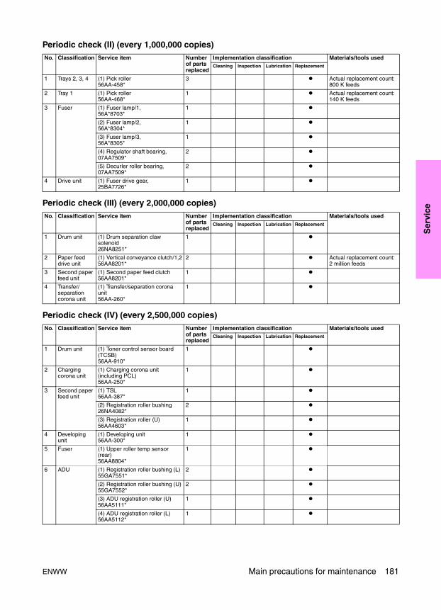
Ser
vice
Periodic check (II) (every 1,000,000 copies)
Periodic check (III) (every 2,000,000 copies)
Periodic check (IV) (every 2,500,000 copies)
No. Classification Service item Number of parts replaced
Implementation classification Materials/tools usedCleaning Inspection Lubrication Replacement
1 Trays 2, 3, 4 (1) Pick roller56AA-458*
3 Actual replacement count: 800 K feeds
2 Tray 1 (1) Pick roller56AA-468*
1 Actual replacement count: 140 K feeds
3 Fuser (1) Fuser lamp/1,56A*8703*
1
(2) Fuser lamp/2,56A*8304*
1
(3) Fuser lamp/3,56A*8305*
1
(4) Regulator shaft bearing,07AA7509*
2
(5) Decurler roller bearing,07AA7509*
2
4 Drive unit (1) Fuser drive gear,25BA7726*
1
No. Classification Service item Number of parts replaced
Implementation classification Materials/tools usedCleaning Inspection Lubrication Replacement
1 Drum unit (1) Drum separation claw solenoid26NA8251*
1
2 Paper feed drive unit
(1) Vertical conveyance clutch/1,256AA8201*
2 Actual replacement count: 2 million feeds
3 Second paper feed unit
(1) Second paper feed clutch56AA8201*
1
4 Transfer/ separation corona unit
(1) Transfer/separation corona unit56AA-260*
1
No. Classification Service item Number of parts replaced
Implementation classification Materials/tools usedCleaning Inspection Lubrication Replacement
1 Drum unit (1) Toner control sensor board (TCSB)56AA-910*
1
2 Charging corona unit
(1) Charging corona unit (including PCL)56AA-250*
1
3 Second paper feed unit
(1) TSL56AA-387*
1
(2) Registration roller bushing26NA4082*
2
(3) Registration roller (U)56AA4603*
1
4 Developing unit
(1) Developing unit56AA-300*
1
5 Fuser (1) Upper roller temp sensor (rear)56AA8804*
1
6 ADU (1) Registration roller bushing (L)55GA7551*
2
(2) Registration roller bushing (U)55GA7552*
2
(3) ADU registration roller (U)56AA5111*
1
(4) ADU registration roller (L)56AA5112*
1
ENWW Main precautions for maintenance 181
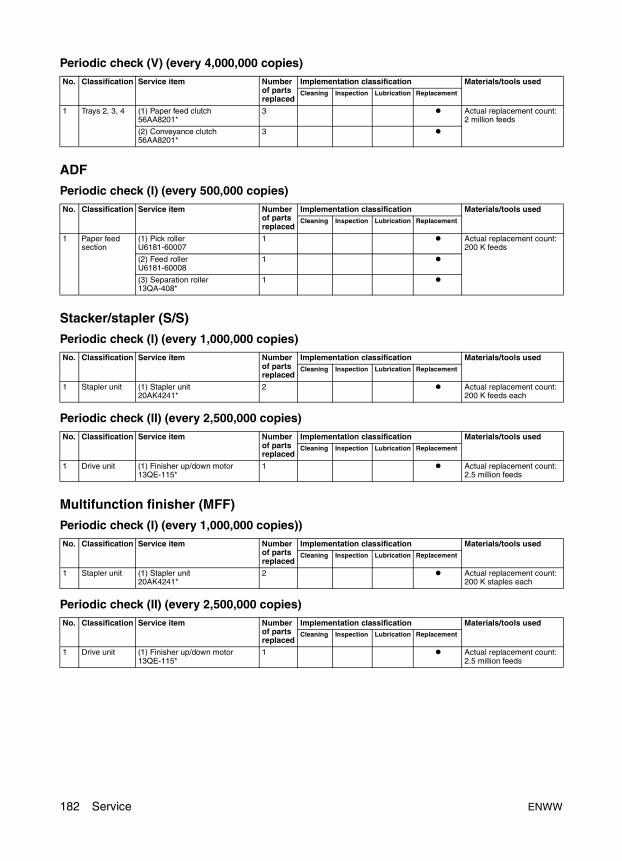
Periodic check (V) (every 4,000,000 copies)
ADF
Periodic check (I) (every 500,000 copies)
Stacker/stapler (S/S)
Periodic check (I) (every 1,000,000 copies)
Periodic check (II) (every 2,500,000 copies)
Multifunction finisher (MFF)
Periodic check (I) (every 1,000,000 copies))
Periodic check (II) (every 2,500,000 copies)
No. Classification Service item Number of parts replaced
Implementation classification Materials/tools usedCleaning Inspection Lubrication Replacement
1 Trays 2, 3, 4 (1) Paper feed clutch56AA8201*
3 Actual replacement count: 2 million feeds
(2) Conveyance clutch56AA8201*
3
No. Classification Service item Number of parts replaced
Implementation classification Materials/tools usedCleaning Inspection Lubrication Replacement
1 Paper feed section
(1) Pick rollerU6181-60007
1 Actual replacement count: 200 K feeds
(2) Feed rollerU6181-60008
1
(3) Separation roller13QA-408*
1
No. Classification Service item Number of parts replaced
Implementation classification Materials/tools usedCleaning Inspection Lubrication Replacement
1 Stapler unit (1) Stapler unit20AK4241*
2 Actual replacement count: 200 K feeds each
No. Classification Service item Number of parts replaced
Implementation classification Materials/tools usedCleaning Inspection Lubrication Replacement
1 Drive unit (1) Finisher up/down motor13QE-115*
1 Actual replacement count: 2.5 million feeds
No. Classification Service item Number of parts replaced
Implementation classification Materials/tools usedCleaning Inspection Lubrication Replacement
1 Stapler unit (1) Stapler unit20AK4241*
2 Actual replacement count: 200 K staples each
No. Classification Service item Number of parts replaced
Implementation classification Materials/tools usedCleaning Inspection Lubrication Replacement
1 Drive unit (1) Finisher up/down motor13QE-115*
1 Actual replacement count: 2.5 million feeds
182 Service ENWW

Ser
vice
HCI (Q3637A/Q3638A)
Periodic check (I) (every 1,000,000 copies)
Periodic check (II) (every 4,000,000 copies)
Post inserter (PI)
Periodic check (I) (every 500,000 copies)
Periodic check (II) (every 1,000,000 copies)
Periodic check (III) (every 3,000,000 copies)
No. Classification Service item Number of parts replaced
Implementation classification Materials/tools usedCleaning Inspection Lubrication Replacement
1 Inside HCI (1) pick roller55VA-484*
1 Actual replacement count: 500 K feeds each
(2) Feed roller55VA-483*
1
(3) Separation roller55VA-483*
1
No. Classification Service item Number of parts replaced
Implementation classification Materials/tools usedCleaning Inspection Lubrication Replacement
1 Inside HCI (1) Feed clutch56AA8201*
1 Actual replacement count: 2 million feeds
(2) Conveyance clutch56AA8201*
1
No. Classification Service item Number of parts replaced
Implementation classification Materials/tools usedCleaning Inspection Lubrication Replacement
1 Paper feed section
(1) Feed roller13QN-446*
2 Actual replacement count: 100 K feeds
(2) Separation roller13QN-443*
2
No. Classification Service item Number of parts replaced
Implementation classification Materials/tools usedCleaning Inspection Lubrication Replacement
1 Paper feed section
(1) Pick roller50BA-574*
2 Actual replacement count: 200 K feeds each
No. Classification Service item Number of parts replaced
Implementation classification Materials/tools usedCleaning Inspection Lubrication Replacement
1 Paper feed section
(1) Torque limiter13QN4073*
2 Actual replacement count: 600 K feeds
ENWW Main precautions for maintenance 183
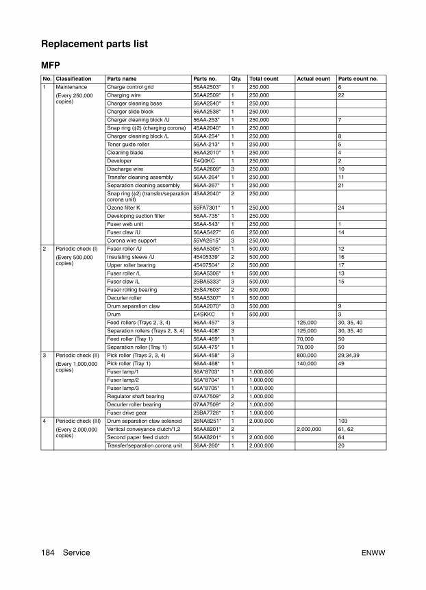
Replacement parts list
MFPNo. Classification Parts name Parts no. Qty. Total count Actual count Parts count no.
1 Maintenance
(Every 250,000 copies)
Charge control grid 56AA2503* 1 250,000 6
Charging wire 56AA2509* 1 250,000 22
Charger cleaning base 56AA2540* 1 250,000
Charger slide block 56AA2538* 1 250,000
Charger cleaning block /U 56AA-253* 1 250,000 7
Snap ring (φ2) (charging corona) 45AA2040* 1 250,000
Charger cleaning block /L 56AA-254* 1 250,000 8
Toner guide roller 56AA-213* 1 250,000 5
Cleaning blade 56AA2010* 1 250,000 4
Developer E4Q0KC 1 250,000 2
Discharge wire 56AA2609* 3 250,000 10
Transfer cleaning assembly 56AA-264* 1 250,000 11
Separation cleaning assembly 56AA-267* 1 250,000 21
Snap ring (φ2) (transfer/separation corona unit)
45AA2040* 2 250,000
Ozone filter K 55FA7301* 1 250,000 24
Developing suction filter 56AA-735* 1 250,000
Fuser web unit 56AA-543* 1 250,000 1
Fuser claw /U 56AA5427* 6 250,000 14
Corona wire support 55VA2615* 3 250,000
2 Periodic check (I)
(Every 500,000 copies)
Fuser roller /U 56AA5305* 1 500,000 12
Insulating sleeve /U 45405339* 2 500,000 16
Upper roller bearing 45407504* 2 500,000 17
Fuser roller /L 56AA5306* 1 500,000 13
Fuser claw /L 25BA5333* 3 500,000 15
Fuser rolling bearing 25SA7603* 2 500,000
Decurler roller 56AA5307* 1 500,000
Drum separation claw 56AA2070* 3 500,000 9
Drum E4SKKC 1 500,000 3
Feed rollers (Trays 2, 3, 4) 56AA-457* 3 125,000 30, 35, 40
Separation rollers (Trays 2, 3, 4) 56AA-408* 3 125,000 30, 35, 40
Feed roller (Tray 1) 56AA-469* 1 70,000 50
Separation roller (Tray 1) 56AA-475* 1 70,000 50
3 Periodic check (II)
(Every 1,000,000 copies)
Pick roller (Trays 2, 3, 4) 56AA-458* 3 800,000 29,34,39
Pick roller (Tray 1) 56AA-468* 1 140,000 49
Fuser lamp/1 56A*8703* 1 1,000,000
Fuser lamp/2 56A*8704* 1 1,000,000
Fuser lamp/3 56A*8705* 1 1,000,000
Regulator shaft bearing 07AA7509* 2 1,000,000
Decurler roller bearing 07AA7509* 2 1,000,000
Fuser drive gear 25BA7726* 1 1,000,000
4 Periodic check (III)
(Every 2,000,000 copies)
Drum separation claw solenoid 26NA8251* 1 2,000,000 103
Vertical conveyance clutch/1,2 56AA8201* 2 2,000,000 61, 62
Second paper feed clutch 56AA8201* 1 2,000,000 64
Transfer/separation corona unit 56AA-260* 1 2,000,000 20
184 Service ENWW
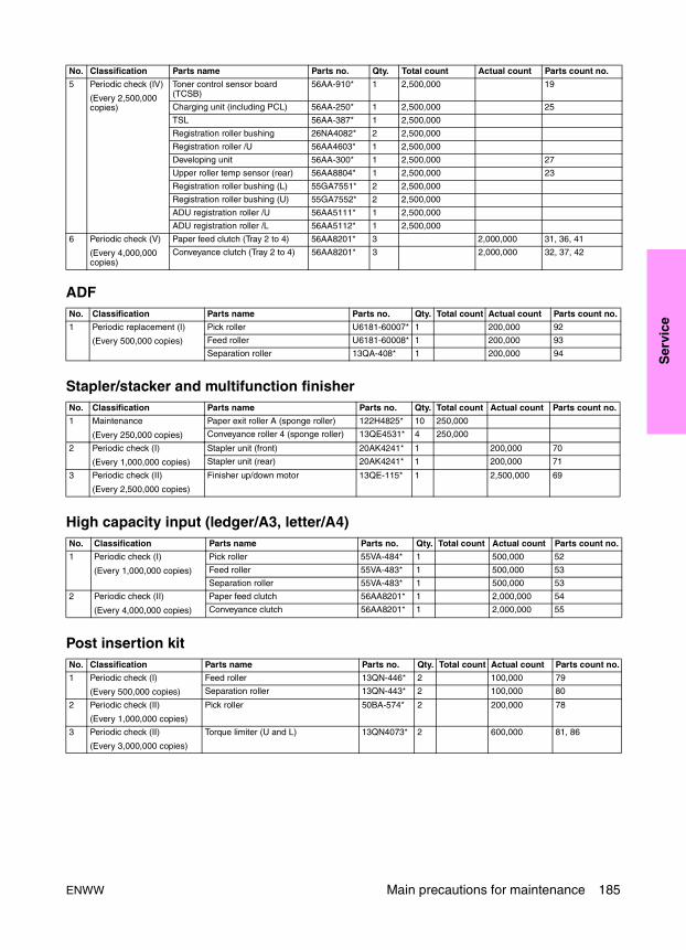
Ser
vice
ADF
Stapler/stacker and multifunction finisher
High capacity input (ledger/A3, letter/A4)
Post insertion kit
5 Periodic check (IV)
(Every 2,500,000 copies)
Toner control sensor board (TCSB)
56AA-910* 1 2,500,000 19
Charging unit (including PCL) 56AA-250* 1 2,500,000 25
TSL 56AA-387* 1 2,500,000
Registration roller bushing 26NA4082* 2 2,500,000
Registration roller /U 56AA4603* 1 2,500,000
Developing unit 56AA-300* 1 2,500,000 27
Upper roller temp sensor (rear) 56AA8804* 1 2,500,000 23
Registration roller bushing (L) 55GA7551* 2 2,500,000
Registration roller bushing (U) 55GA7552* 2 2,500,000
ADU registration roller /U 56AA5111* 1 2,500,000
ADU registration roller /L 56AA5112* 1 2,500,000
6 Periodic check (V)
(Every 4,000,000 copies)
Paper feed clutch (Tray 2 to 4) 56AA8201* 3 2,000,000 31, 36, 41
Conveyance clutch (Tray 2 to 4) 56AA8201* 3 2,000,000 32, 37, 42
No. Classification Parts name Parts no. Qty. Total count Actual count Parts count no.
1 Periodic replacement (I)
(Every 500,000 copies)
Pick roller U6181-60007* 1 200,000 92
Feed roller U6181-60008* 1 200,000 93
Separation roller 13QA-408* 1 200,000 94
No. Classification Parts name Parts no. Qty. Total count Actual count Parts count no.
1 Maintenance
(Every 250,000 copies)
Paper exit roller A (sponge roller) 122H4825* 10 250,000
Conveyance roller 4 (sponge roller) 13QE4531* 4 250,000
2 Periodic check (I)
(Every 1,000,000 copies)
Stapler unit (front) 20AK4241* 1 200,000 70
Stapler unit (rear) 20AK4241* 1 200,000 71
3 Periodic check (II)
(Every 2,500,000 copies)
Finisher up/down motor 13QE-115* 1 2,500,000 69
No. Classification Parts name Parts no. Qty. Total count Actual count Parts count no.
1 Periodic check (I)
(Every 1,000,000 copies)
Pick roller 55VA-484* 1 500,000 52
Feed roller 55VA-483* 1 500,000 53
Separation roller 55VA-483* 1 500,000 53
2 Periodic check (II)
(Every 4,000,000 copies)
Paper feed clutch 56AA8201* 1 2,000,000 54
Conveyance clutch 56AA8201* 1 2,000,000 55
No. Classification Parts name Parts no. Qty. Total count Actual count Parts count no.
1 Periodic check (I)
(Every 500,000 copies)
Feed roller 13QN-446* 2 100,000 79
Separation roller 13QN-443* 2 100,000 80
2 Periodic check (II)
(Every 1,000,000 copies)
Pick roller 50BA-574* 2 200,000 78
3 Periodic check (II)
(Every 3,000,000 copies)
Torque limiter (U and L) 13QN4073* 2 600,000 81, 86
No. Classification Parts name Parts no. Qty. Total count Actual count Parts count no.
ENWW Main precautions for maintenance 185
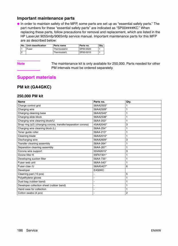
Important maintenance parts● In order to maintain safety of the MFP, some parts are set up as “essential safety parts.” The
part numbers for these “essential safety parts” are indicated as “SP00####KC.” When replacing these parts, follow precautions for removal and replacement, which are listed in the HP LaserJet 9055mfp/9065mfp service manual. Important maintenance parts for this MFP are as described below:
Note The maintenance kit is only available for 250,000. Parts needed for other PM intervals must be ordered separately.
Support materials
PM kit (GA4GKC)
250,000 PM kit
No. Unit classification Parts name Parts no. Qty.
1 Fuser Thermostat/U SP00-0020 1
2 Thermostat/L SP00-0010 1
Name Parts no. Qty.Charge control grid 56AA2503* 1Charging wire 56AA2509* 1
Charging cleaning base 56AA2540* 1Charging slide block 56AA2538* 1Charging wire cleaning block/U 56AA-253* 1
Snap ring (φ2) (charging corona, transfer/separation corona) 45AA2040* 3Charging wire cleaning block (L) 56AA-254* 1Toner guide roller 56AA-213* 1
Cleaning blade 56AA2010* 1Discharging wire 56AA2609* 3Transfer cleaning assembly 56AA-264* 1
Separation cleaning assembly 56AA-267* 1Corona wire support 55VA2615* 3Ozone filter K 55FA7301* 1
Developing suction filter 56AA-735* 1Fuser web unit 56AA-543* 1Fuser claw /U 56AA5427* 6
Developer E4Q0KCCleaning pad (10 pcs) - 5Polyethylene gloves - 1
Dust bag (rubber band) - 1Developer collection sheet (rubber band) - 1Hand case for collection - 1
Cotton swabs (4 pcs) - 2
186 Service ENWW

Ser
vice
Service tools and suppliesPart number Part description Appearance Remarks
Drum cleaner 200 ml Drum cleaner is 98% Isopropyl Alcohol. Used for drum and roller cleaning. Obtain locally.
Roller cleaner 200 ml Roller cleaner is 100% acetone. Used for fuser upper and lower roller cleaning ONLY. Obtain locally.
Tri-Flow lubricant Used to lubricate heat insulating sleeves on upper fuser roller ONLY. Obtain locally.
00GR00020KC Plas guard No. 2 25 g
00GR00150KC Molytherm grease 25 g Used to lubricate fuser gears ONLY.
00GR00200KC Electricity lubricant 25 g For toner guide roller
000V-19-0KC Setting powder 25 g Needed whenever the drum, cleaning blade, or toner guide roller are removed or replaced.
000V-18-0KC Cleaning pad 10 pc1 pack
Lint free; used for general cleaning.
ENWW Support materials 187
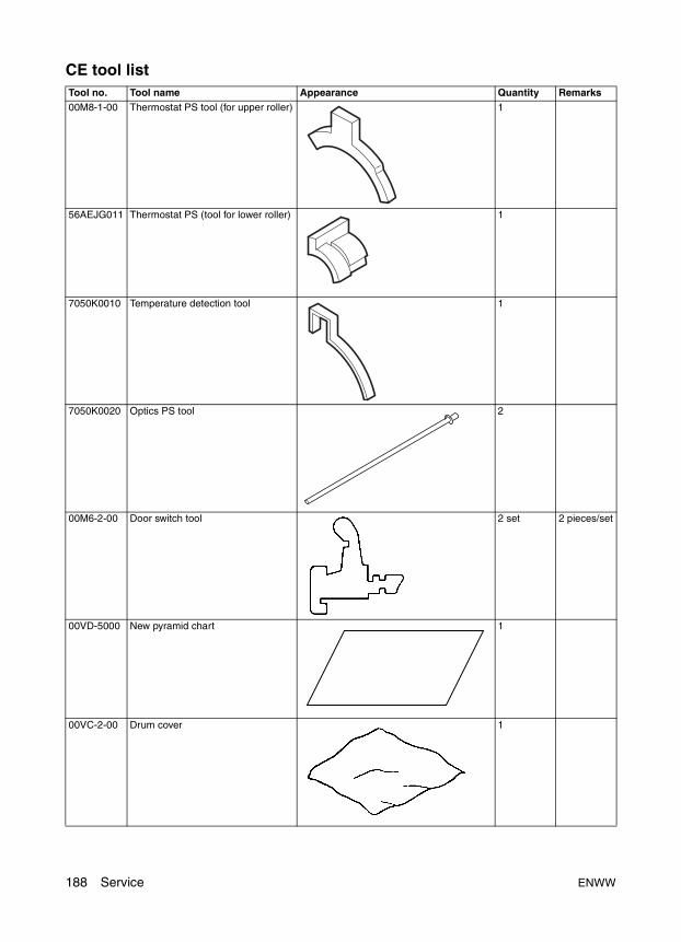
CE tool listTool no. Tool name Appearance Quantity Remarks00M8-1-00 Thermostat PS tool (for upper roller) 1
56AEJG011 Thermostat PS (tool for lower roller) 1
7050K0010 Temperature detection tool 1
7050K0020 Optics PS tool 2
00M6-2-00 Door switch tool 2 set 2 pieces/set
00VD-5000 New pyramid chart 1
00VC-2-00 Drum cover 1
188 Service ENWW
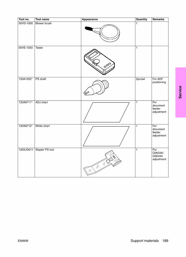
Ser
vice
00VD-1000 Blower brush 1
00VE-1003 Tester 1
120A1052* PS shaft 2pc/set For ADF positioning
120A9711* ADJ chart 1 For document feeder adjustment
120A9712* White chart 1 For document feeder adjustment
129XJG011 Stapler PS tool 1 For Q3633A/ Q3634A adjustment
Tool no. Tool name Appearance Quantity Remarks
ENWW Support materials 189

190 Service ENWW

ENWW 191
Tro
ub
lesh
oo
tin
g
6Troubleshooting
Electronic parts layout drawing . . . . . . . . . . . . . . . . . . . . . . . . . . . . . . . . . . 1929065 parts layout drawing . . . . . . . . . . . . . . . . . . . . . . . . . . . . . . . . . . 192ADF parts layout drawing. . . . . . . . . . . . . . . . . . . . . . . . . . . . . . . . . . . 201HCI parts layout drawing . . . . . . . . . . . . . . . . . . . . . . . . . . . . . . . . . . . 202Stapler/stacker and multifunction finisher parts layout drawing . . . . . . 203Post inserter parts layout drawing . . . . . . . . . . . . . . . . . . . . . . . . . . . . 206Punch kit parts layout drawing . . . . . . . . . . . . . . . . . . . . . . . . . . . . . . . 206
Connector layout drawing . . . . . . . . . . . . . . . . . . . . . . . . . . . . . . . . . . . . . . 2079065 connector layout drawing . . . . . . . . . . . . . . . . . . . . . . . . . . . . . . 207Q3637A/Q3638A Connector layout drawing . . . . . . . . . . . . . . . . . . . . 211Q3633A/Q3634A connector layout drawing. . . . . . . . . . . . . . . . . . . . . 212Q3636A connector layout drawing . . . . . . . . . . . . . . . . . . . . . . . . . . . . 213Punch kit connector layout drawing . . . . . . . . . . . . . . . . . . . . . . . . . . . 214
Jam code list . . . . . . . . . . . . . . . . . . . . . . . . . . . . . . . . . . . . . . . . . . . . . . . . 215Error code list . . . . . . . . . . . . . . . . . . . . . . . . . . . . . . . . . . . . . . . . . . . . . . . . 221Timing chart . . . . . . . . . . . . . . . . . . . . . . . . . . . . . . . . . . . . . . . . . . . . . . . . . 231
9065 timing chart (1) . . . . . . . . . . . . . . . . . . . . . . . . . . . . . . . . . . . . . . 2319065 timing chart (2) . . . . . . . . . . . . . . . . . . . . . . . . . . . . . . . . . . . . . . 232ADF timing chart (1) . . . . . . . . . . . . . . . . . . . . . . . . . . . . . . . . . . . . . . . 233ADF timing chart (2) . . . . . . . . . . . . . . . . . . . . . . . . . . . . . . . . . . . . . . . 234Q3637A/Q3638A timing chart . . . . . . . . . . . . . . . . . . . . . . . . . . . . . . . 235Q3633A/Q3634A timing chart (1). . . . . . . . . . . . . . . . . . . . . . . . . . . . . 236Q3633A/Q3634A timing chart (2). . . . . . . . . . . . . . . . . . . . . . . . . . . . . 237Q3633A/Q3634A timing chart (3). . . . . . . . . . . . . . . . . . . . . . . . . . . . . 238Q3633A/Q3634A timing chart (4). . . . . . . . . . . . . . . . . . . . . . . . . . . . . 239Q3636A timing chart . . . . . . . . . . . . . . . . . . . . . . . . . . . . . . . . . . . . . . 240Punch kit timing chart. . . . . . . . . . . . . . . . . . . . . . . . . . . . . . . . . . . . . . 241
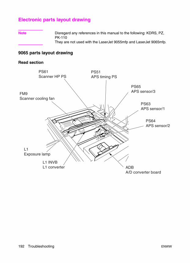
Electronic parts layout drawing
Note Disregard any references in this manual to the following: KDRS, PZ, PK-110They are not used with the LaserJet 9055mfp and LaserJet 9065mfp.
9065 parts layout drawing
Read section
FM9 Scanner cooling fan
PS61 Scanner HP PS
PS51 APS timing PS
PS65 APS sensor/3
ADB A/D converter board
L1 INVB L1 converter
L1 Exposure lamp
PS63 APS sensor/1
PS64 APS sensor/2
192 Troubleshooting ENWW

Tro
ub
lesh
oo
tin
g
Operation section
Charging corona section
SW2 Sub power switch
LCD indicator board
OB INVB OB inverter
OB1 Operation board/1
PS40 Toner supply door open / close PS
MS2 Interlock MS/L
PS39 Front door open / close PS/L
FM5Cleaner cooling fan
SD2 Web SD
C (T) Total counter
PAKB Panel key board
PS38 Front door open / close PS/R
MS1 Interlock MS/R
M14 Charger cleaning motor
PCL Pre-charging exposure lamp
ENWW Electronic parts layout drawing 193
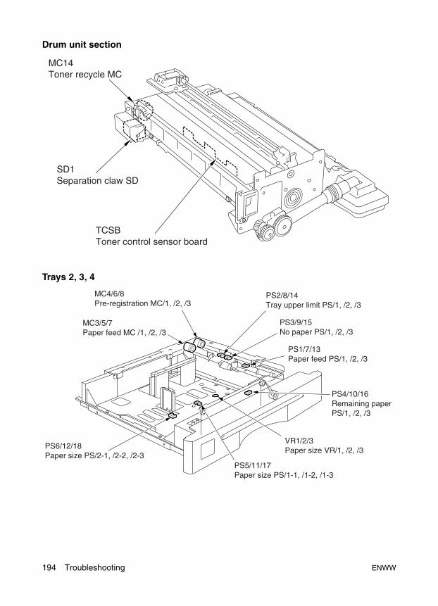
Drum unit section
Trays 2, 3, 4
TCSB Toner control sensor board
MC14 Toner recycle MC
SD1 Separation claw SD
MC3/5/7Paper feed MC /1, /2, /3
MC4/6/8Pre-registration MC/1, /2, /3
PS3/9/15No paper PS/1, /2, /3
PS1/7/13Paper feed PS/1, /2, /3
PS4/10/16Remaining paper PS/1, /2, /3
VR1/2/3Paper size VR/1, /2, /3
PS5/11/17 Paper size PS/1-1, /1-2, /1-3
PS6/12/18Paper size PS/2-1, /2-2, /2-3
PS2/8/14Tray upper limit PS/1, /2, /3
194 Troubleshooting ENWW

Tro
ub
lesh
oo
tin
g
Vertical conveyance section
Tray 1 feed section
PS25 Vertical conveyance PS/1
MC11 Vertical conveyance MC/1
MC12 Vertical conveyance MC/2
PS29 Vertical conveyance door open / close PS
PS27 Vertical conveyance PS/3
PS26 Vertical conveyance PS/2
PS28Vertical conveyance PS/4
PS32 Paper size PS/2-BP
PS34 Tray upper limit PS/BP
M20 Up/down motor/BP
PS35 Tray lower limit PS/BP
PS36 Loop PS
VR5 Paper size VR/BP
PS31 Paper size PS/1-BP
ENWW Electronic parts layout drawing 195
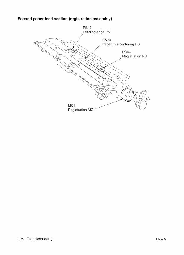
Second paper feed section (registration assembly)
PS43 Leading edge PS
MC1 Registration MC
PS44 Registration PS
PS70 Paper mis-centering PS
196 Troubleshooting ENWW

Tro
ub
lesh
oo
tin
g
ADU
*1 Not installed on the HP LaserJet 9055/9065mfp.
TSL Transfer synchronization Lamp
PS46 Reverse/exit PS2
M9 ADU reverse motor
M8 Reverse/exit motor3
PS42 Paper reverse PS
FM10 ADU reverse motor cooling fan
PS41 *1 ADU conveyance PS/1
PS45 ADU paper reverse PS
SD7 Reverse gate SD
MC13 ADU conveyance MC
ADU DB ADU drive board
MC2 ADU deceleration MC
M10 Transfer/Separation cleaning motor
M5 Conveyance motor
SD9 ADU lock SD
HTR3 Drum Heater (as supply part)
TSL Transfer synchronizationLamp
PS50 ADU pre-registration PS
PS49 ADU deceleration PS
FM3 Conveyance suction fan
PS47 ADU handle PS
PS48 ADU conveyance PS/2
PS48 ADU paper conveyance PS/2
PS46 Reverse/exit PS1
PS41 *1 ADU conveyance PS/1
PS37 Paper exit PS
PS42 Paper reverse PS
PS45 ADU paper reverse PS
PS49 ADU deceleration PS
PS50 ADU pre-registration PS
PS44 Registration PS
PS70 Paper mis-centering PS
PS43 Leading edge PS
2
2
ENWW Electronic parts layout drawing 197
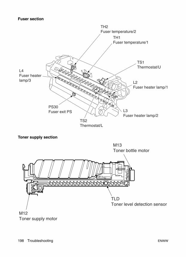
Fuser section
Toner supply section
M12 Toner supply motor
TLD Toner level detection sensor
M13 Toner bottle motor
198 Troubleshooting ENWW
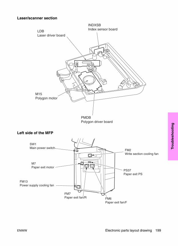
Tro
ub
lesh
oo
tin
g
Laser/scanner section
Left side of the MFP
LDB Laser driver board
M15 Polygon motor
PMDB Polygon driver board
INDXSB Index sensor board
SW1 Main power switch
M7 Paper exit motor
FM7 Paper exit fan/R FM6
Paper exit fan/F
FM13 Power supply cooling fan
FM2 Write section cooling fan
PS37 Paper exit PS
ENWW Electronic parts layout drawing 199

Rear side of the MFP
M3 Developing motor
C (K) Key counter
ICB Image control board
M12 Toner supply motor
M6 Loop roller motor
M16 Tray up drive motor/1
FM4 Developing suction fan
M17 Tray up drive motor/2
PRCB Printer control board
M18 Tray up drive motor/3
M1 Paper feed motor
HTR2 Heater/2
HTR1 Heater/1
CBR2 Circuit breaker/2
DCPS DC power supply unit
CBR1 Circuit breaker/1
NF Noise filter
TRANSFORMER Transformer
HV High voltage unit
M4 Fixing motor
FM8 Main cooling fan/2
M2 Drum motor
FM1 Main body cooling fan/1
SCDB Scanner drive board
M11 Scanner motor
MB Memory board
200 Troubleshooting ENWW

Tro
ub
lesh
oo
tin
g
ADF parts layout drawing
PS304 Original registration PS/1
M301 Original feed motor
PS302 Original size PS/2
MC301 Original feed MC
M302 Original conveyance motor
FM301 Original feed motor cooling fan
PS308 Original skew PS/R
PS305 Original registration PS/2
PS307 Original skew PS/F
PS306 Original conveyance PS
SD301 Reverse gate SD
PS311 ADF open/close PS
SD302 Exit gate SD
SD303 Pressure roller release SD
MS301 Cover open/close MS
VR301 Original size VR
PS309 Original size PS/2
PS310 Original size PS/1
PS301 Last original PS
PS303 Original exit PS
FRONT
ENWW Electronic parts layout drawing 201
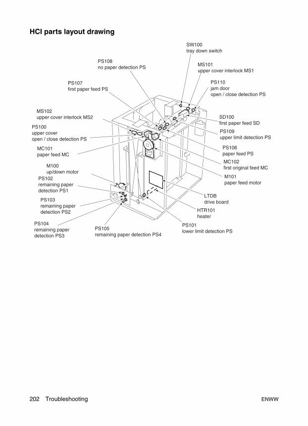
HCI parts layout drawing
202 Troubleshooting ENWW

Tro
ub
lesh
oo
tin
g
Stapler/stacker and multifunction finisher parts layout drawing
ENWW Electronic parts layout drawing 203
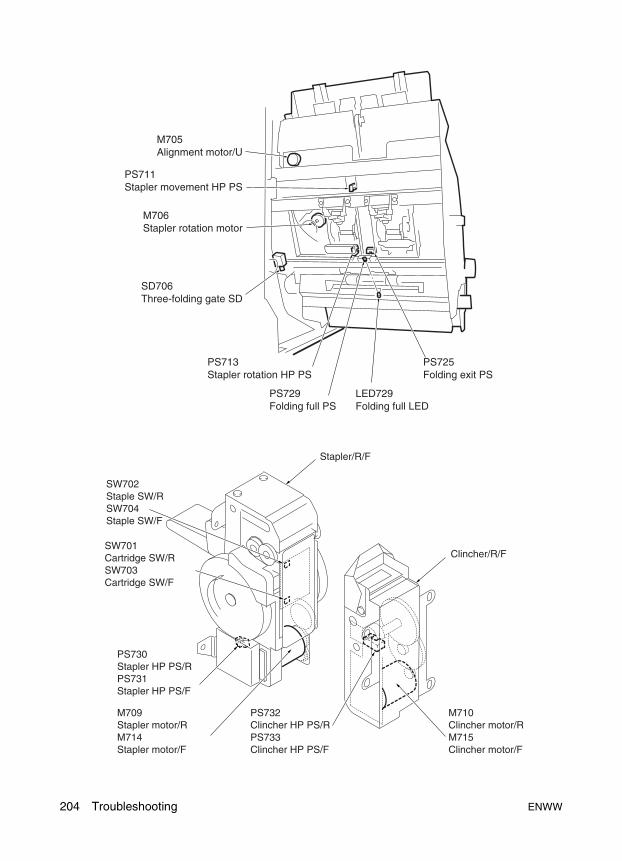
M705 Alignment motor/U
PS711 Stapler movement HP PS
M706 Stapler rotation motor
SD706 Three-folding gate SD
PS713 Stapler rotation HP PS
PS729Folding full PS
LED729Folding full LED
PS725 Folding exit PS
SW702 Staple SW/RSW704 Staple SW/F
SW701 Cartridge SW/RSW703Cartridge SW/F
PS730 Stapler HP PS/RPS731 Stapler HP PS/F
M709 Stapler motor/RM714 Stapler motor/F
PS732 Clincher HP PS/RPS733 Clincher HP PS/F
M710 Clincher motor/RM715 Clincher motor/F
Clincher/R/F
Stapler/R/F
204 Troubleshooting ENWW
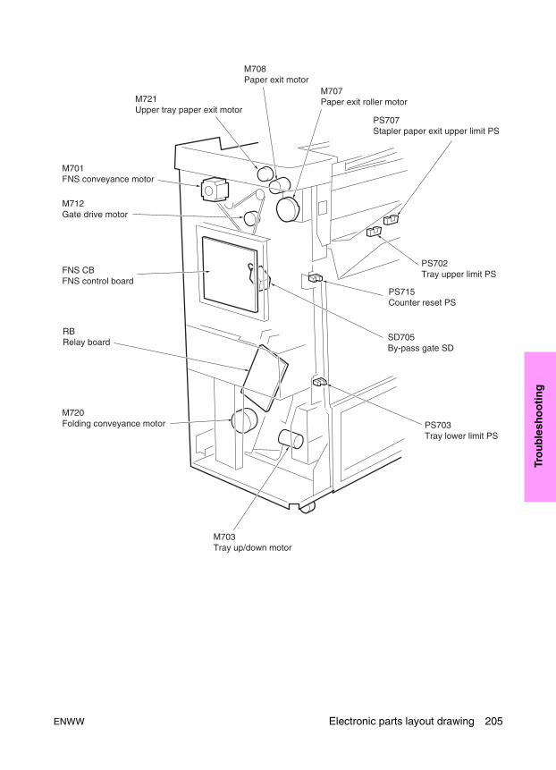
Tro
ub
lesh
oo
tin
g
ENWW Electronic parts layout drawing 205
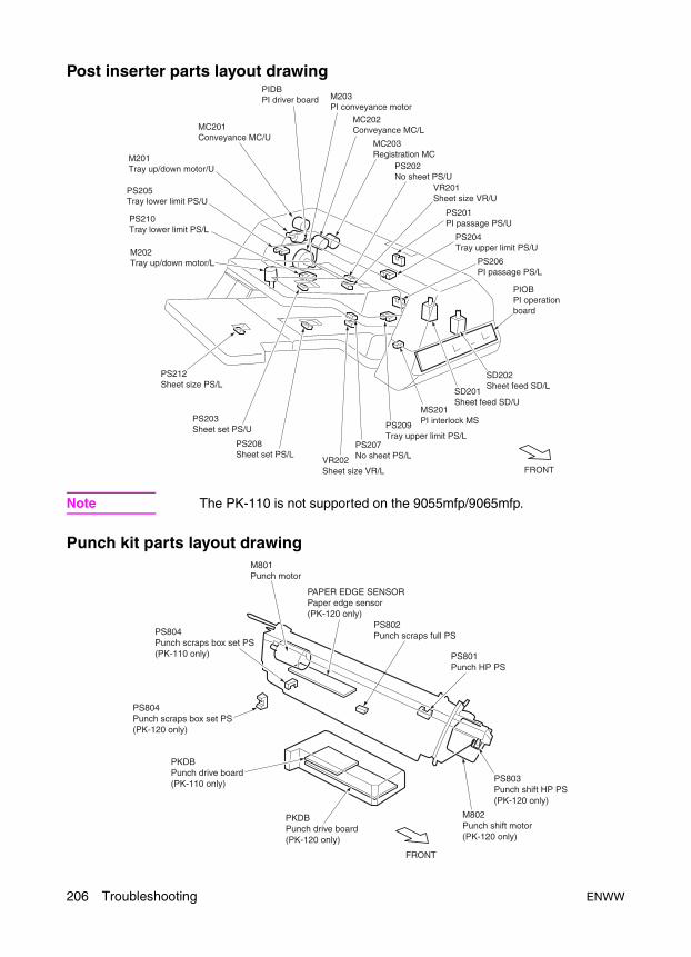
Post inserter parts layout drawing
Note The PK-110 is not supported on the 9055mfp/9065mfp.
Punch kit parts layout drawing
MC201 Conveyance MC/U
M201 Tray up/down motor/U
PS205 Tray lower limit PS/U
PS210 Tray lower limit PS/L
M202 Tray up/down motor/L
PS212 Sheet size PS/L
PS203 Sheet set PS/U
PS208 Sheet set PS/L
VR202 Sheet size VR/L
PS207 No sheet PS/L
PS209 Tray upper limit PS/L
MS201 PI interlock MS
SD201 Sheet feed SD/U
SD202 Sheet feed SD/L
PS206 PI passage PS/L
PIOB PI operation board
PS204 Tray upper limit PS/U
PS201 PI passage PS/U
VR201 Sheet size VR/U
PS202 No sheet PS/U
MC202 Conveyance MC/L
M203 PI conveyance motor
PIDB PI driver board
FRONT
MC203Registration MC
FRONT
M801Punch motor
PAPER EDGE SENSORPaper edge sensor (PK-120 only)
PS802Punch scraps full PS
PS801Punch HP PS
PS803Punch shift HP PS(PK-120 only)
M802Punch shift motor(PK-120 only)
PKDB Punch drive board (PK-120 only)
PKDB Punch drive board (PK-110 only)
PS804Punch scraps box set PS (PK-120 only)
PS804Punch scraps box set PS (PK-110 only)
206 Troubleshooting ENWW
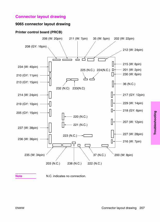
Tro
ub
lesh
oo
tin
g
Connector layout drawing
9065 connector layout drawing
Printer control board (PRCB)
Note N.C. indicates no connection.
211 (W: 7pin) 35 (W: 5pin) 202 (W: 22pin)206 (W: 20pin)
233(N.C)232 (N.C)
224(N.C.)225 (N.C.)
215 (W: 6pin)
212 (W: 24pin)
201 (W: 2pin)
230 (W: 6pin)
36 (N.C.)
217 (GY: 12pin)
229 (W: 14pin)
218 (GY: 6pin)
207 (W: 12pin)
220 (N.C.)
221 (N.C.)
227 (W: 28pin)
216 (W: 7pin)
234 (W: 40pin)
210 (GY: 11pin)
213 (GY: 15pin)
214 (W: 24pin)
219 (GY: 10pin)
205 (GY: 15pin)
237 (W: 38pin)
223 (N.C.)236 (W: 36pin)
235 (W: 34pin)
203 (N.C.) 238 (N.C.) 222 (N.C.)
37 (N.C.) 200 (W: 8pin)
208 (GY: 16pin)
ENWW Connector layout drawing 207

Image control board (ICB)
ADU drive board
Note N.C. indicates no connection.
401 (W: 2pin)407 (W: 2pin) 400 (W: 7pin)
404 (GY: 6pin) 406 (GY: 9pin)
402 (W: 40pin)
405 (W: 20pin)413 (N.C.)
410 (GY: 13pin)
403 (W: 12pin)
414 (N.C.)
208 Troubleshooting ENWW
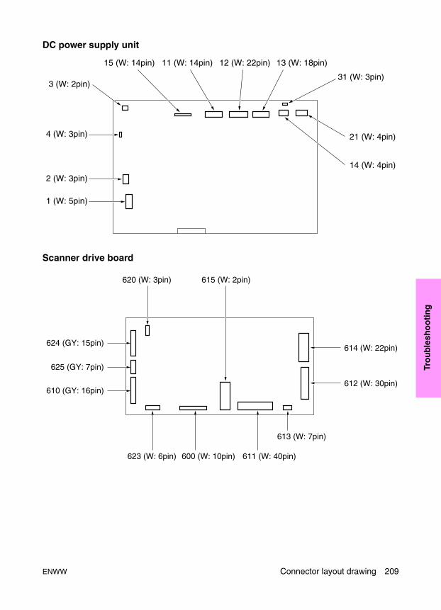
Tro
ub
lesh
oo
tin
g
DC power supply unit
Scanner drive board
21 (W: 4pin)
14 (W: 4pin)
31 (W: 3pin)
13 (W: 18pin)12 (W: 22pin)11 (W: 14pin)15 (W: 14pin)
3 (W: 2pin)
4 (W: 3pin)
2 (W: 3pin)
1 (W: 5pin)
610 (GY: 16pin)
625 (GY: 7pin)
624 (GY: 15pin)
620 (W: 3pin) 615 (W: 2pin)
623 (W: 6pin) 600 (W: 10pin) 611 (W: 40pin)
613 (W: 7pin)
614 (W: 22pin)
612 (W: 30pin)
ENWW Connector layout drawing 209

High voltage unit
L1 Inverter
Toner control sensor board
Operation board/1
OB Inverter
Index sensor board
A/D converter board
Laser driver board
323 (W: 2pin)322 (W: 2pin)
321 (W: 7pin) 320 (GY: 14pin)
2 (W: 4pin)
1 (W: 3pin)
362 (W: 12pin)
153 (W: 3pin)
158 (W: 2pin)
150 (W: 11pin)
152 (W: 4pin)
156 (W: 2pin)
151 (W: 14 pin)
165(W:3pin)
166(W:4pin)
51 (GY:5pin)
170 (W: 40pin)
180 (W: 22pin)
210 Troubleshooting ENWW

Tro
ub
lesh
oo
tin
g
Polygon drive board Memory board
HCI drive board
189 (W: 7pin)
141 (W: 40pin)
142 (W: 20pin)
721 (W:17pin) 720 (W:11pin)
700 (W:4pin)729
(W:6pin)
728 (W:8pin) 710
(GY:10pin)
723 (W:2pin) 722 (GY:15pin)
ENWW Connector layout drawing 211
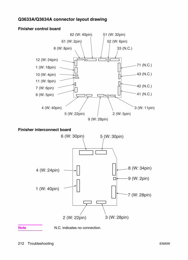
Q3633A/Q3634A connector layout drawing
Finisher control board
Finisher interconnect board
Note N.C. indicates no connection.
71 (N.C.)
33 (N.C.)8 (W: 8pin)
52 (W: 6pin)61 (W: 2pin)
51 (W: 32pin)62 (W: 40pin)
4 (W: 40pin)
5 (W: 22pin)
9 (W: 28pin)
2 (W: 5pin)
3 (W: 11pin)
43 (N.C.)
42 (N.C.)
41 (N.C.)
12 (W: 24pin)
1 (W: 18pin)
10 (W: 4pin)
11 (W: 9pin)
7 (W: 6pin)
6 (W: 5pin)
5 (W: 30pin)6 (W: 30pin)
2 (W: 22pin) 3 (W: 28pin)
8 (W: 34pin)
7 (W: 28pin)
9 (W: 2pin)
4 (W: 24pin)
1 (W: 40pin)
212 Troubleshooting ENWW

Tro
ub
lesh
oo
tin
g
Q3636A connector layout drawing
PI drive board
PI operation board
56(W:6pin)
58(GY:12pin)
54(W:6pin)
55(BK:24pin)
57(W:11pin)
52(W:38pin)
53(W:30pin)
1 (GY:12pin)
ENWW Connector layout drawing 213

Punch kit connector layout drawing
Punch kit drive board
Paper edge sensor
68(W:8pin)
70(W:15pin)
69(W:6pin)
65(W:5pin)
64(W:2pin)
67(W:3pin)
66(GY:9pin)
63(GY:38pin)
25(BK:7pin)
214 Troubleshooting ENWW
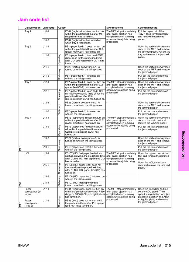
Tro
ub
lesh
oo
tin
g
Jam code list
Classification Jam code Cause MFP response Countermeasure
MF
P
Tray 1 J10-1
Ope
ratin
g
PS44 (registration) does not turn on within the predefined time after M6 (loop roller) has turned on.
The MFP stops immediately after paper ejection has completed when jamming occurs while a job is being processed.
Pull the paper out of the Tray 1 feed tray temporarily and remove the jammed paper.J10-2 PS44 (registration) has turned on
when Tray 1 feed starts.
Tray 2 J11-1 PS1 (paper feed /1) does not turn on within the predefined time after CL3 (paper feed CL/1) has turned on.
Open the vertical conveyance door on the MFP and remove the jammed paper. Pull out the tray and remove the jammed paper.
J11-2 PS1 (paper feed /1) is on and PS36 (loop) is off for the predefined time after CL4 (pre-registration CL/1) has turned on.
J11-3
Sta
tiona
ry
PS25 (vertical conveyance /1) is turned on while in the idling status.
- Open the vertical conveyance door on the MFP and remove the jammed paper.
J11-5 PS1 (paper feed /1) is turned on while in the idling status.
Pull out the tray and remove the jammed paper.
Tray 3 J12-1
Ope
ratin
g
PS7 (paper feed /2) does not turn on within the predefined time after CL5 (paper feed CL/2) has turned on.
The MFP stops immediately after paper ejection has completed when jamming occurs while a job is being processed.
Open the vertical conveyance door on the MFP and remove the jammed paper.
J12-2 PS7 (paper feed /2) is on and PS26 (vertical conveyance /2) is off for the predefined time after CL6 (pre-registration CL/2) has turned on.
Pull out the tray and remove the jammed paper.
J12-3
Sta
tiona
ry
PS26 (vertical conveyance /2) is turned on while in the idling status.
- Open the vertical conveyance door on the MFP and remove the jammed paper.
J12-5 PS7 (paper feed /2) is turned on while in the idling status.
Pull out the tray and remove the jammed paper.
Tray 4 J13-1
Ope
ratin
g
PS13 (paper feed 3) does not turn on within the predefined time after CL7 (paper feed CL/3) has turned on.
The MFP stops immediately after paper ejection has completed when jamming occurs while a job is being processed.
Open the vertical conveyance door on the main unit and remove the jammed paper.
Pull out the tray and remove the jammed paper.
J13-2 PS13 (paper feed /3) does not turn off, within the predefined time after CL8 (pre-registration CL/3) has turned on.
J13-3
Sta
tiona
ry
PS27 (vertical conveyance /3) is turned on while in the idling status.
- Open the vertical conveyance door on the MFP and remove the jammed paper.
J13-5 PS13 (paper feed PS/3) is turned on while in the idling status.
Pull out the tray and remove the jammed paper.
HC
I
HCI J15-1
Ope
ratin
g
PS107 (HCI first paper feed) does not turn on within the predefined time after CL102 (HCI first paper feed CL) has turned on.
The MFP stops immediately after paper ejection has completed when jamming occurs while a job is being processed.
Open the upper cover of the HCI and remove the jammed paper.
Open the HCI jam access door and remove the jammed paper.
J15-2 PS106 (HCI paper feed) does not turn on within the predefined time after CL101 (HCI paper feed CL) has turned on.
J15-3
Sta
tiona
ry PS106 (HCI paper feed) is turned on while in the idling status.
-
J15-4 PS107 (HCI first paper feed) is turned on while in the idling status.
MF
P
Paper conveyance (all trays)
J17-1
Ope
ratin
g
PS44 (registration) does not turn on within the predefined time after PS36 (loop) or PS50 (ADU pre-registration) has turned on.
The MFP stops immediately after paper ejection has completed when jamming occurs while a job is being processed.
Open the front door and pull out the ADU stand. Then, open the registration loop jam processing section and ADU exit guide plate, and remove the jammed paper.
Paper conveyance (Tray 2)
J17-2 PS36 (loop) does not turn on within the predefined time after PS1 (paper feed PS/1) has turned on.
ENWW Jam code list 215
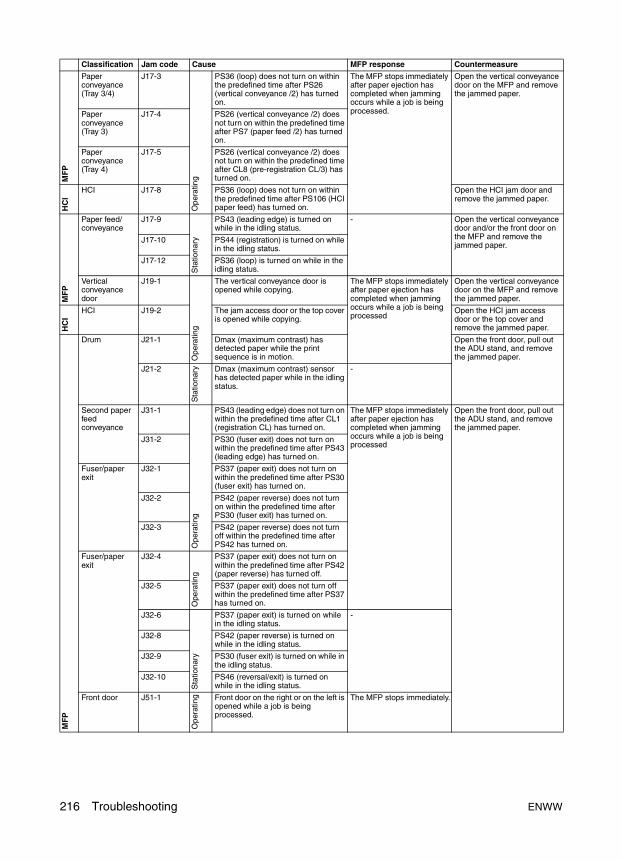
MF
P
Paper conveyance (Tray 3/4)
J17-3
Ope
ratin
g
PS36 (loop) does not turn on within the predefined time after PS26 (vertical conveyance /2) has turned on.
The MFP stops immediately after paper ejection has completed when jamming occurs while a job is being processed.
Open the vertical conveyance door on the MFP and remove the jammed paper.
Paper conveyance (Tray 3)
J17-4 PS26 (vertical conveyance /2) does not turn on within the predefined time after PS7 (paper feed /2) has turned on.
Paper conveyance (Tray 4)
J17-5 PS26 (vertical conveyance /2) does not turn on within the predefined time after CL8 (pre-registration CL/3) has turned on.
HC
I
HCI J17-8 PS36 (loop) does not turn on within the predefined time after PS106 (HCI paper feed) has turned on.
Open the HCI jam door and remove the jammed paper.
MF
P
Paper feed/ conveyance
J17-9
Sta
tiona
ry
PS43 (leading edge) is turned on while in the idling status.
- Open the vertical conveyance door and/or the front door on the MFP and remove the jammed paper.
J17-10 PS44 (registration) is turned on while in the idling status.
J17-12 PS36 (loop) is turned on while in the idling status.
Vertical conveyance door
J19-1
Ope
ratin
g
The vertical conveyance door is opened while copying.
The MFP stops immediately after paper ejection has completed when jamming occurs while a job is being processed
Open the vertical conveyance door on the MFP and remove the jammed paper.
HC
I
HCI J19-2 The jam access door or the top cover is opened while copying.
Open the HCI jam access door or the top cover and remove the jammed paper.
MF
P
Drum J21-1 Dmax (maximum contrast) has detected paper while the print sequence is in motion.
Open the front door, pull out the ADU stand, and remove the jammed paper.
J21-2
Sta
tiona
ry Dmax (maximum contrast) sensor has detected paper while in the idling status.
-
Second paper feed conveyance
J31-1
Ope
ratin
g
PS43 (leading edge) does not turn on within the predefined time after CL1 (registration CL) has turned on.
The MFP stops immediately after paper ejection has completed when jamming occurs while a job is being processed
Open the front door, pull out the ADU stand, and remove the jammed paper.
J31-2 PS30 (fuser exit) does not turn on within the predefined time after PS43 (leading edge) has turned on.
Fuser/paper exit
J32-1 PS37 (paper exit) does not turn on within the predefined time after PS30 (fuser exit) has turned on.
J32-2 PS42 (paper reverse) does not turn on within the predefined time after PS30 (fuser exit) has turned on.
J32-3 PS42 (paper reverse) does not turn off within the predefined time after PS42 has turned on.
Fuser/paper exit
J32-4
Ope
ratin
g
PS37 (paper exit) does not turn on within the predefined time after PS42 (paper reverse) has turned off.
J32-5 PS37 (paper exit) does not turn off within the predefined time after PS37 has turned on.
J32-6
Sta
tiona
ry
PS37 (paper exit) is turned on while in the idling status.
-
J32-8 PS42 (paper reverse) is turned on while in the idling status.
J32-9 PS30 (fuser exit) is turned on while in the idling status.
J32-10 PS46 (reversal/exit) is turned on while in the idling status.
Front door J51-1
Ope
ratin
g Front door on the right or on the left is opened while a job is being processed.
The MFP stops immediately.
Classification Jam code Cause MFP response Countermeasure
216 Troubleshooting ENWW
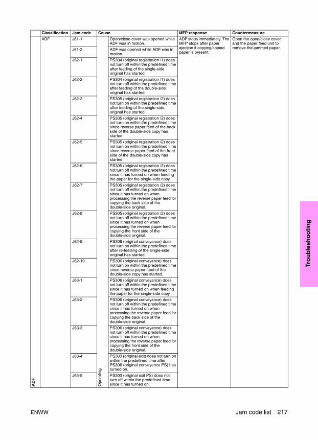
Tro
ub
lesh
oo
tin
g
AD
F
ADF J61-1
Ope
ratin
g
Open/close cover was opened while ADF was in motion.
ADF stops immediately. The MFP stops after paper ejection if copying/copied paper is present.
Open the open/close cover and the paper feed unit to remove the jammed paper.J61-2 ADF was opened while ADF was in
motion.
J62-1 PS304 (original registration /1) does not turn off within the predefined time after feeding of the single-side original has started.
J62-2 PS304 (original registration /1) does not turn off within the predefined time after feeding of the double-side original has started.
J62-3 PS305 (original registration /2) does not turn on within the predefined time after feeding of the single-side original has started.
J62-4 PS305 (original registration /2) does not turn on within the predefined time since reverse paper feed of the back side of the double-side copy has started.
J62-5 PS305 (original registration /2) does not turn on within the predefined time since reverse paper feed of the front side of the double-side copy has started.
J62-6 PS305 (original registration /2) does not turn off within the predefined time since it has turned on when feeding the paper for the single-side copy.
J62-7 PS305 (original registration /2) does not turn off within the predefined time since it has turned on when processing the reverse paper feed for copying the back side of the double-side original.
J62-8 PS305 (original registration /2) does not turn off within the predefined time since it has turned on when processing the reverse paper feed for copying the front side of the double-side original.
J62-9 PS306 (original conveyance) does not turn on within the predefined time after re-feeding of the single-side original has started.
J62-10 PS306 (original conveyance) does not turn on within the predefined time since reverse paper feed of the double-side copy has started.
J63-1 PS306 (original conveyance) does not turn off within the predefined time since it has turned on when feeding the paper for the single-side copy.
J63-2 PS306 (original conveyance) does not turn off within the predefined time since it has turned on when processing the reverse paper feed for copying the back side of the double-side original.
J63-3 PS306 (original conveyance) does not turn off within the predefined time since it has turned on when processing the reverse paper feed for copying the front side of the double-side original.
J63-4 PS303 (original exit) does not turn on within the predefined time after PS306 (original conveyance PS) has turned on.
J63-5 PS303 (original exit PS) does not turn off within the predefined time since it has turned on.
Classification Jam code Cause MFP response Countermeasure
ENWW Jam code list 217
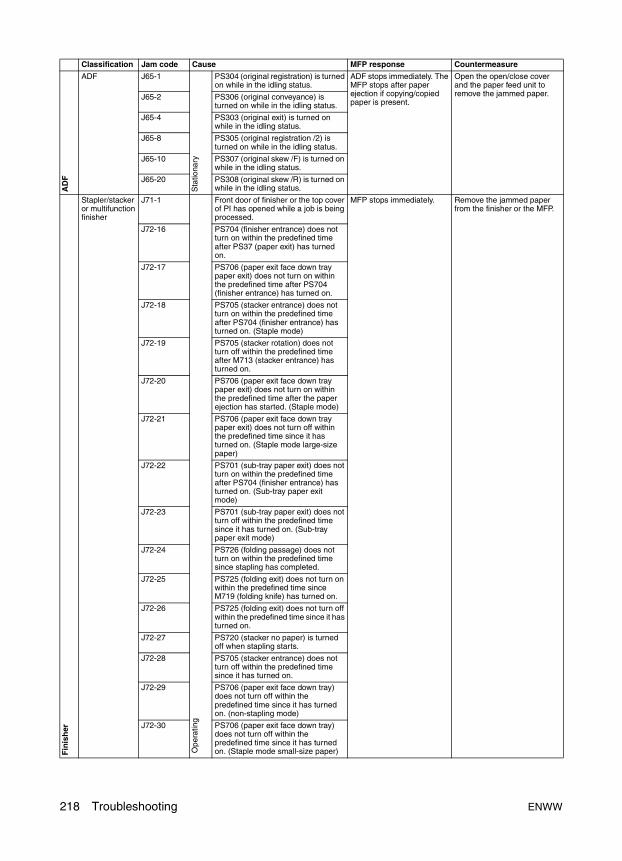
AD
F
ADF J65-1
Sta
tiona
ry
PS304 (original registration) is turned on while in the idling status.
ADF stops immediately. The MFP stops after paper ejection if copying/copied paper is present.
Open the open/close cover and the paper feed unit to remove the jammed paper.J65-2 PS306 (original conveyance) is
turned on while in the idling status.
J65-4 PS303 (original exit) is turned on while in the idling status.
J65-8 PS305 (original registration /2) is turned on while in the idling status.
J65-10 PS307 (original skew /F) is turned on while in the idling status.
J65-20 PS308 (original skew /R) is turned on while in the idling status.
Fin
ish
er
Stapler/stacker or multifunction finisher
J71-1 O
pera
ting
Front door of finisher or the top cover of PI has opened while a job is being processed.
MFP stops immediately. Remove the jammed paper from the finisher or the MFP.
J72-16 PS704 (finisher entrance) does not turn on within the predefined time after PS37 (paper exit) has turned on.
J72-17 PS706 (paper exit face down tray paper exit) does not turn on within the predefined time after PS704 (finisher entrance) has turned on.
J72-18 PS705 (stacker entrance) does not turn on within the predefined time after PS704 (finisher entrance) has turned on. (Staple mode)
J72-19 PS705 (stacker rotation) does not turn off within the predefined time after M713 (stacker entrance) has turned on.
J72-20 PS706 (paper exit face down tray paper exit) does not turn on within the predefined time after the paper ejection has started. (Staple mode)
J72-21 PS706 (paper exit face down tray paper exit) does not turn off within the predefined time since it has turned on. (Staple mode large-size paper)
J72-22 PS701 (sub-tray paper exit) does not turn on within the predefined time after PS704 (finisher entrance) has turned on. (Sub-tray paper exit mode)
J72-23 PS701 (sub-tray paper exit) does not turn off within the predefined time since it has turned on. (Sub-tray paper exit mode)
J72-24 PS726 (folding passage) does not turn on within the predefined time since stapling has completed.
J72-25 PS725 (folding exit) does not turn on within the predefined time since M719 (folding knife) has turned on.
J72-26 PS725 (folding exit) does not turn off within the predefined time since it has turned on.
J72-27 PS720 (stacker no paper) is turned off when stapling starts.
J72-28 PS705 (stacker entrance) does not turn off within the predefined time since it has turned on.
J72-29 PS706 (paper exit face down tray) does not turn off within the predefined time since it has turned on. (non-stapling mode)
J72-30 PS706 (paper exit face down tray) does not turn off within the predefined time since it has turned on. (Staple mode small-size paper)
Classification Jam code Cause MFP response Countermeasure
218 Troubleshooting ENWW

Tro
ub
lesh
oo
tin
g
Fin
ish
er
PI J72-35
Ope
ratin
g
PS206 (PI passage /L) does not turn on within the predefined time after CL202 (conveyance CL/L) has turned on.
MFP stops immediately. Remove the jammed paper from the finisher or the MFP.
Punch kit J72-43 PS801 (punch home position) does not turn on within the predefined time after M801 (punch) has turned on. Or, leading/trailing/side edge PS on paper edge PS does not turn off within the predefined time since M802 (Punch shift) has turned on.
Stapler/stacker and multifunction finisher
J72-48 PS726 (folding passage) does not turn off within the predefined time since it has turned on.
HCI J72-49 PS201 (PI passage /U) does not turn on within the predefined time after CL201 (conveyance CL/U) has turned on.
MFP stops immediately. Open the top cover of PI and remove the jammed paper.
J72-50 PS704 (finisher entrance) does not turn on within the predefined time after PS201 (PI passage /U) has turned on.
J72-51 PS704 (finisher entrance) does not turn on within the predefined time after PS206 (PI passage /L) has turned on.
Stapler/stacker and multifunction finisher
J72-81
Ope
ratin
g
PS730 (stapler home position /R) and PS732 (clincher HP /R) do not turn on within the predefined time after M709 (stapler /R) and M710 (clincher /R) have turned on.
MFP stops immediately. Remove the jammed paper from the finisher or the MFP.
J72-82 PS731 (stapler HP /F) and PS733 (clincher HP /F) do not turn on within the predefined time after M714 (stapler /F) and M715 (clincher /F) have turned on.
J72-83 PS730/731 (stapler HP /R, /F) and PS732/733 (clincher HP /R, /F) do not turn on within the predefined time after M709/714 (stapler/R, /F) and M710/715 (clincher /R, /F) have turned on.
J72-90 Finisher does not stop within the predefined time since the stop signal has been transmitted to finisher from the main unit.
Remove the jammed paper from the finisher or the MFP.
J73-1
Sta
tiona
ry
PS706 (paper exit face down tray) is turned on while in the idling status.
-
J73-2 PS705 (stacker entrance) is turned on while in the idling status.
J73-5 PS704 (finisher entrance) is turned on while in the idling status.
J73-7 PS701 (sub-tray paper exit) is turned on while in the idling status.
J73-8 PS720 (stacker no paper) is turned on when paper jam has occurred during paper ejection.
J73-9 PS726 (folding passage) is turned on while in the idling status.
J73-10 PS725 (folding exit) is turned on while in the idling status.
PI J73-14 PS206 (PI passage /L) is turned on while in the idling status.
J73-17 PS201 (PI passage /U) is turned on while in the idling status.
Classification Jam code Cause MFP response Countermeasure
ENWW Jam code list 219
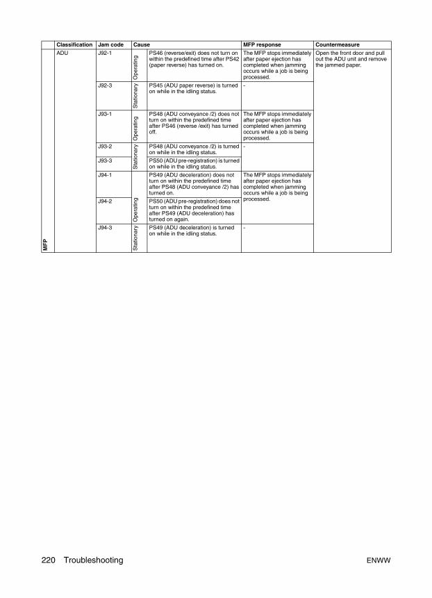
MF
P
ADU J92-1
Ope
ratin
g
PS46 (reverse/exit) does not turn on within the predefined time after PS42 (paper reverse) has turned on.
The MFP stops immediately after paper ejection has completed when jamming occurs while a job is being processed.
Open the front door and pull out the ADU unit and remove the jammed paper.
J92-3
Sta
tiona
ry PS45 (ADU paper reverse) is turned on while in the idling status.
-
J93-1
Ope
ratin
g
PS48 (ADU conveyance /2) does not turn on within the predefined time after PS46 (reverse /exit) has turned off.
The MFP stops immediately after paper ejection has completed when jamming occurs while a job is being processed.
J93-2
Sta
tiona
ry PS48 (ADU conveyance /2) is turned on while in the idling status.
-
J93-3 PS50 (ADU pre-registration) is turned on while in the idling status.
J94-1
Ope
ratin
g
PS49 (ADU deceleration) does not turn on within the predefined time after PS48 (ADU conveyance /2) has turned on.
The MFP stops immediately after paper ejection has completed when jamming occurs while a job is being processed.J94-2 PS50 (ADU pre-registration) does not
turn on within the predefined time after PS49 (ADU deceleration) has turned on again.
J94-3
Sta
tiona
ry PS49 (ADU deceleration) is turned on while in the idling status.
-
Classification Jam code Cause MFP response Countermeasure
220 Troubleshooting ENWW

Tro
ub
lesh
oo
tin
g
Error code listAs for the error codes, Please call service will be displayed for the F code, and Please switch off/on on E code. On the actual LCD screen, everything is displayed with service call codes.
Note E-RDH and MU-401/402 refer to the copy controller memory on the ICB.
Note The trays on the vendor product have been renumbered to reflect HP LaserJet tray numbering (for example, MP tray = Tray 1). The Service Manual has been edited to indicate these changes.
Old name HP LaserJet nameBypass Tray 1, Bypass, MP1 22 3
3 44 Not usedLCT Tray 5, HCI
Classification Error code Cause MFP response Countermeasure
MF
P
Drive F13-01 Error detection signal is detected continuously for one second when two seconds have passed since M1 (paper feed) has turned on.
The MFP stops immediately and turns off RL1 (main).
M1 (paper feed)
PRCB (printer control board)
F13-02 Error detection signal is detected continuously for one second when two seconds have passed since M101 (HCI paper feed) has turned on.
M101 (HCI paper feed)
LTDB (HCI drive board)
Tray 2 F18-10 Error detection signal for M16 (tray up drive /1) is detected while M16 is turned on.
M16 (tray up drive /1)
PRCB (printer control board)
PS2 (tray upper limit/1)F18-11 PS2 (tray upper limit/1) does not turn on within
20 seconds since the lifting motion triggered by activating M16 (tray up drive /1) has started while PS2 is turned off.
Error code is not displayed on the control panel. It is displayed only in data collection, and list output.
Tray 3 F18-20 Error detection signal for M17 (tray up drive /2) is detected while M17 is turned on.
The MFP stops immediately and turns off RL1 (main).
M17 (tray up drive /2)
PRCB (printer control board)
PS8 (tray upper limit/2)F18-21 PS8 (tray upper limit/2) does not turn on within 20 seconds since the lifting motion triggered by activating M17 (tray up drive /2) has started while PS8 is turned off.
Error code is not displayed on the control panel. It is displayed only in data collection, and list output.
Tray 4 F18-30 Error detection signal for M18 (tray up drive /3) is detected while M18 is turned on.
The MFP stops immediately and turns off RL1 (main).
M18 (tray up drive /3)
PRCB (printer control board)
PS14 (tray upper limit/3)F18-31 PS14 (tray upper limit/3) does not turn on within 20 seconds since the lifting motion triggered by activating M18 (tray up drive /3) has started while PS14 is turned off.
Error code is not displayed on the control panel. It is displayed only in data collection, and list output.
HC
I
HCI F18-50 Error detection signal for M100 (HCI up/down) is detected continuously for one second while M100 is turned on.
The MFP stops immediately and turns off RL1 (Main).
M100 (HCI up/down)
LTDB (HCI drive board)
PS101 (HCI lower limit detection)
PS109 (HCI upper limit detection)
F18-51 PS109 (HCI upper limit detection) or PS101 (HCI lower limit detection) does not turn on within 35 seconds since the lifting or descent motion triggered by activating M100 (HCI up/down) has started while PS109 or PS101 is turned off.
Error code is not displayed on the control panel. It is displayed only in data collection, and list output.
ENWW Error code list 221

MF
P
Tray 1 feed F18-60 PS34 (tray upper limit/BP) or PS35 (tray lower limit/BP) does not turn on within 10 seconds since the upward or downward motion triggered by activating M20 (up/down/BP) has started while PS34 or PS35 is turned off.
On the control panel, jam code J10-1 is displayed but no error code is displayed. For the data collection, and list output, the error and jam codes are displayed.
M20 (up/down/BP)
PRCB (printer control board)
PS34 (tray upper limit/BP)
PS35 (tray lower limit/BP)
Wire cleaning abnormality
F21-01 The lock signal for M14 (charger cleaning) is not detected when more than 25 seconds have passed since the return motion (back to front) of M14 has started.
The MFP stops immediately and turns off RL1 (main).
M14 (charger cleaning)
PRCB (printer control board)
F21-02 The lock signal for M14 (charger cleaning) is detected within 2 seconds since the return motion (back to front) of M14 has started.
M14 (charger cleaning)PRCB (printer control board)
F21-03 The lock signal for M14 (charger cleaning) is not detected when more than 25 seconds have passed since the return motion (back to front) of M14 has started while re-try process is in motion after lock detection.
F21-05 The lock signal for M10(transfer/separation cleaning) is not detected when more than 25 seconds have passed since the return motion (back to front) of M10 has started.
M10 (transfer/separation cleaning)
ADUDB (ADU drive board)
PRCB (printer control board)F21-06 The lock signal for M10 (transfer/separation cleaning) is detected within 2 seconds since the return motion (back to front) of M10 has started.
F21-07 The lock signal for M10 (transfer/separation cleaning) is not detected when more than 25 seconds have passed since the return motion (back to front) of M10 has started while re-try process is in motion after lock detection.
Fan abnormality
F22-01 An error for SFAN_EM signal is detected when 2 seconds have passed since FM4 (developing suction) has turned on. The error does not clear after 2 seconds from the off/on operation.
FM4 (developing suction)
PRCB (printer control board)
F22-02 An error for CLEAN_EM signal is detected when 2 seconds have passed since FM5 (cleaner cooling) has turned on. The error does not clear after 2 seconds from the off/on operation.
FM5 (cleaner cooling)
ADUDB (ADU drive board)
PRCB (printer control board)
Motor abnormality
F23-01 An error for TONERM_EM signal is detected when 7 seconds have passed since M13 (toner bottle) has turned on.
M13 (toner bottle)
PRCB (printer control board)
F23-02 An error for DEVM_EM signal is detected when more than 1 second has passed since M3 (developing) has turned on.
M3 (developing)
PRCB (printer control board)
F23-03 An error for DRUM_EM signal is detected when more than 3 seconds have passed since M2 (drum) has turned on.
M2 (drum)
PRCB (printer control board)
High-voltage power error
F28-01 Five consecutive charging on/off operations have been executed since the charging error detection signal has been detected while charging is turned on.
HV (high-voltage unit)
F28-02 FIve consecutive transfer on/off operations have been executed since the transfer error detection signal has been detected while transfer is turned on.
F28-03 Five consecutive separation on/off operations have been executed since the separation error detection signal has been detected while separation is turned on.
Classification Error code Cause MFP response Countermeasure
222 Troubleshooting ENWW

Tro
ub
lesh
oo
tin
g
Mai
n U
nit
Process abnormality
F29-01 Dirt correction failure of the Dmax (maximum contrast) sensor during maximum density adjustment. If this error is detected 10 successive times, the error code is displayed.
The MFP stops immediately and turns off RL1 (main).
TSCB (toner control sensor board)
PRCB (printer control board)
F29-03 Control patches are not output while Dmax (maximum contrast) correction is in process.
(No output from the Dmax (maximum contrast) sensor)
TSCB (toner control sensor board)
PRCB (printer control board)
F29-04 Dirt correction failure of the γ sensor during γ adjustment. If this error is detected 10 successive times, the error code is displayed.
F29-05 Control patches are not output while γ correction is in process.
(No output from the γ sensor)
No error code is displayed on the control panel. The code is registered in data collection, and list output. MFP control is performed using previous data.
F29-06 A recurrence error occurred when carry out γ curve for γ correction.
F29-07 Dirt correction failure of the γ sensor during dot diameter adjustment. If this error is detected 10 successive times, the corresponding error code is displayed.
The MFP stops immediately and turns off RL1 (main).
F29-08 The dot diameter correction ended with error value.
No error code is displayed on the control panel. The code is registered in data collection, and list output. MFP control is performed using previous data.
TCSB (toner control sensor board)
PRCB (printer control board)
Fan abnormality
F32-01 An error for SUC_EM signal is detected when 2 seconds have passed since FM3 (conveyance suction) has turned on. The error does not clear after 2 seconds from the off/on operation.
The MFP stops immediately and turns off RL1 (main).
FM3 (conveyance suction)
ADUDB (ADU drive board)
PRCB (printer control board)
MF
P
Fan abnormality
F32-02 An error for FIXFAN1_EM signal is detected when 2 seconds have passed since FM8 (main unit cooling /2) has turned on. The error does not clear after 2 seconds from the off/on operation.
The MFP body stops immediately and turns off RL1 (main).
FM8 (main cooling /2)
PRCB (printer control board)
F32-03 An error for FIXFAN2_EM signal is detected when 2 seconds have passed since FM7 (paper exit /R) has turned on. The error does not clear after 2 seconds from the off/on operation.
FM7 (paper exit /R)
PRCB (printer control board)
F32-04 An error for FIXFAN3_EM signal is detected when 2 seconds have passed since FM6 (paper exit /F) has turned on. The error does not clear after 2 seconds from the off/on operation.
FM6 (paper exit /F)
PRCB (printer control board)
Motor abnormality
F33-01 Error detection signal is detected continuously for 1 second when 2 seconds have passed since M5 (conveyance) has turned on.
M5 (conveyance)
PRCB (printer control board)
High fuser temperature abnormality
F34-01* TH1 (fuser temperature /1) detects more than 220° C for five consecutive times in a 1 second cycle.
PRCB (printer control board)
DCPS (DC power supply unit)
L2 (fuser heater lamp/1)
L3 (fuser heater lamp/2)
TH1 (fuser temperature /1)
TH2 (fuser temperature /2)
When F-34-∗∗, F35-∗∗ or F-36∗∗(Fuser temperature related abnormality) occurs, be sure to repair a defective part before setting the 25 DIPSW 3-1 to 0. If the 25 DIPSW 3-1 is set to 0 without repairing a defective part, this may cause a fire.
* DIPSW 3-1 must be reset to 0 (unlatched) to clear the error code.
F34-02* The output voltage of TH1 (fuser temperature/1) and TH2 (fuser temperature /2) is detected as abnormally high at the comparator circuit (more than 228° C).
Low fuser temperature abnormality
F35-01* TH1 (fuser temperature /1) has not reached the predefined temperature when the specified time has passed since the fuser on control has been processed after secondary power switch (SW2) is turned on.
F35-02* TH1 (fuser temperature /1) detects less than 120° C for 5 consecutive times in 1 second cycle while the fuser on control is processed after warm-up operation is complete.
F35-03* The output voltage of TH1 (fuser temperature/1) is detected as abnormality low at the comparator circuit (less than -6° C).
Classification Error code Cause MFP response Countermeasure
ENWW Error code list 223
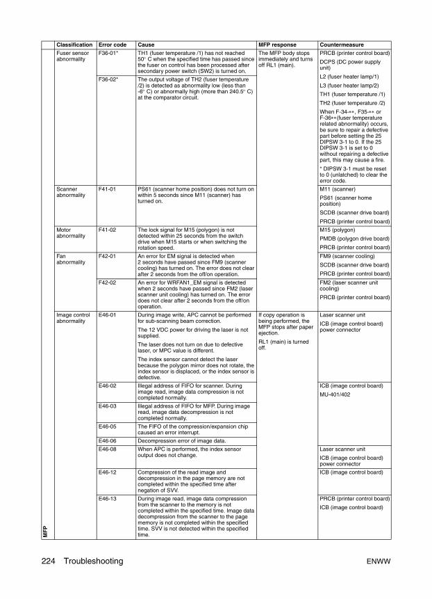
MF
P
Fuser sensor abnormality
F36-01* TH1 (fuser temperature /1) has not reached 50° C when the specified time has passed since the fuser on control has been processed after secondary power switch (SW2) is turned on.
The MFP body stops immediately and turns off RL1 (main).
PRCB (printer control board)
DCPS (DC power supply unit)
L2 (fuser heater lamp/1)
L3 (fuser heater lamp/2)
TH1 (fuser temperature /1)
TH2 (fuser temperature /2)
When F-34-∗∗, F35-∗∗ or F-36∗∗(fuser temperature related abnormality) occurs, be sure to repair a defective part before setting the 25 DIPSW 3-1 to 0. If the 25 DIPSW 3-1 is set to 0 without repairing a defective part, this may cause a fire.
* DIPSW 3-1 must be reset to 0 (unlatched) to clear the error code.
F36-02* The output voltage of TH2 (fuser temperature /2) is detected as abnormality low (less than -6° C) or abnormally high (more than 240.5° C) at the comparator circuit.
Scanner abnormality
F41-01 PS61 (scanner home position) does not turn on within 5 seconds since M11 (scanner) has turned on.
M11 (scanner)
PS61 (scanner home position)
SCDB (scanner drive board)
PRCB (printer control board)
Motor abnormality
F41-02 The lock signal for M15 (polygon) is not detected within 25 seconds from the switch drive when M15 starts or when switching the rotation speed.
M15 (polygon)
PMDB (polygon drive board)
PRCB (printer control board)
Fan abnormality
F42-01 An error for EM signal is detected when 2 seconds have passed since FM9 (scanner cooling) has turned on. The error does not clear after 2 seconds from the off/on operation.
FM9 (scanner cooling)
SCDB (scanner drive board)
PRCB (printer control board)
F42-02 An error for WRFAN1_EM signal is detected when 2 seconds have passed since FM2 (laser scanner unit cooling) has turned on. The error does not clear after 2 seconds from the off/on operation.
FM2 (laser scanner unit cooling)
PRCB (printer control board)
Image control abnormality
E46-01 During image write, APC cannot be performed for sub-scanning beam correction.
The 12 VDC power for driving the laser is not supplied.
The laser does not turn on due to defective laser, or MPC value is different.
The index sensor cannot detect the laser because the polygon mirror does not rotate, the index sensor is displaced, or the index sensor is defective.
If copy operation is being performed, the MFP stops after paper ejection.
RL1 (main) is turned off.
Laser scanner unit
ICB (image control board) power connector
E46-02 Illegal address of FIFO for scanner. During image read, image data compression is not completed normally.
ICB (image control board)
MU-401/402
E46-03 Illegal address of FIFO for MFP. During image read, image data decompression is not completed normally.
E46-05 The FIFO of the compression/expansion chip caused an error interrupt.
E46-06 Decompression error of image data.
E46-08 When APC is performed, the index sensor output does not change.
Laser scanner unit
ICB (image control board) power connector
E46-12 Compression of the read image and decompression in the page memory are not completed within the specified time after negation of SVV.
ICB (image control board)
E46-13 During image read, image data compression from the scanner to the memory is not completed within the specified time. Image data decompression from the scanner to the page memory is not completed within the specified time. SVV is not detected within the specified time.
PRCB (printer control board)
ICB (image control board)
Classification Error code Cause MFP response Countermeasure
224 Troubleshooting ENWW
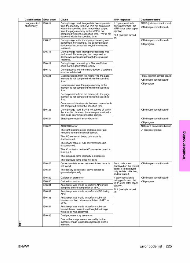
Tro
ub
lesh
oo
tin
g
MF
P
Image control abnormality
E46-14 During image read, image data decompression from the memory to the MFP is not completed within the specified time. Image data output from the page memory to the MFP is not completed within the specified time. PVV is not detected within the specified time.
If copy operation is being performed, the MFP stops after paper ejection.
RL1 (main) is turned off.
PRCB (printer control board)
ICB (image control board)
E46-15 During image write, improper processing was performed. For example, the decompression device was accessed although there was no resource.
ICB (image control board)
ICB program
E46-16 During image read, improper processing was performed. For example, the compression device was accessed although there was no resource.
E46-17 During image processing, a filter coefficient could not be generated properly.
E46-19 During access to the memory device, a software error was detected.
E46-21 Decompression from the memory to the page memory is not completed within the specified time.
Compression from the page memory to the memory is not completed within the specified time.
Decompression from the memory to the page memory is not completed within the specified time.
Compressed data transfer between memories is not completed within the specified time.
PRCB (printer control board)
ICB (image control board)
ICB program
E46-23 During image read, SVV is not turned off within the specified time and therefore preparation for next page scanning cannot be started.
ICB (image control board)
E46-24 Shading correction error (GA error) ICB (image control board)
ICB program
E46-25 AOC/AGC error
The light blocking cover and lens cover are removed from the scanner section.
The A/D converter board connector is disconnected.
The power cable of A/D converter board is disconnected.
The IC protector on the A/D converter board is blown out.
The exposure lamp intensity is excessive.
The exposure lamp does not light.
ADB (A/D conversion board)
L1 (exposure lamp)
E46-26 Correction data saved on a resolution basis is not found.
Error code is not displayed on the control panel. It is displayed only in data collection, and list output.
ICB (image control board)
E46-27 The density correction γ curve cannot be generated properly.
E46-29 Calibration start error If copy operation is being performed, the MFP stops after paper ejection.
RL1 (main) is turned off.
ICB (image control board)
ICB programE46-30 Calibration end error
E46-31 An attempt was made to perform APC initial sampling before completion of MPC.
E46-32 An attempt was made to perform MPC during APC.
E46-33 An attempt was made to perform sub-scan beam correction before completion of APC or MPC.
E46-34 An attempt was made to perform sub-scan beam interval correction although the image write clock was abnormal.
E46-35 Dual page memory area error
Due to the image area abnormality on the memory, image is not decompressed on the memory.
Classification Error code Cause MFP response Countermeasure
ENWW Error code list 225
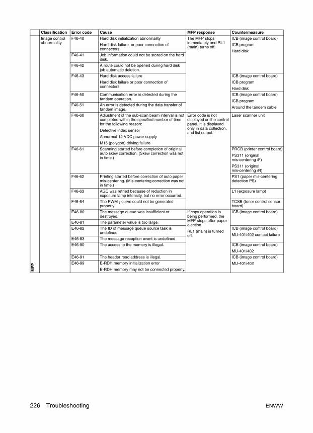
MF
P
Image control abnormality
F46-40 Hard disk initialization abnormality
Hard disk failure, or poor connection of connectors
The MFP stops immediately and RL1 (main) turns off.
ICB (image control board)
ICB program
Hard disk F46-41 Job information could not be stored on the hard
disk.
F46-42 A route could not be opened during hard disk job automatic deletion.
F46-43 Hard disk access failure
Hard disk failure or poor connection of connectors
ICB (image control board)
ICB program
Hard disk
F46-50 Communication error is detected during the tandem operation.
ICB (image control board)
ICB program
Around the tandem cable F46-51 An error is detected during the data transfer of
tandem image.
F46-60 Adjustment of the sub-scan beam interval is not completed within the specified number of time for the following reason:
Defective index sensor
Abnormal 12 VDC power supply
M15 (polygon) driving failure
Error code is not displayed on the control panel. It is displayed only in data collection, and list output.
Laser scanner unit
F46-61 Scanning started before completion of original auto skew correction. (Skew correction was not in time.)
PRCB (printer control board)
PS311 (original mis-centering /F)
PS311 (original mis-centering /R)
F46-62 Printing started before correction of auto paper mis-centering. (Mis-centering correction was not in time.)
PS1 (paper mis-centering detection PS)
F46-63 AGC was retried because of reduction in exposure lamp intensity, but no error occurred.
L1 (exposure lamp)
F46-64 The PWM γ curve could not be generated properly.
TCSB (toner control sensor board)
E46-80 The message queue was insufficient or destroyed.
If copy operation is being performed, the MFP stops after paper ejection.
RL1 (main) is turned off.
ICB (image control board)
E46-81 The parameter value is too large.
E46-82 The ID of message queue source task is undefined.
ICB (image control board)
MU-401/402 contact failureE46-83 The message reception event is undefined.
E46-90 The access to the memory is illegal. ICB (image control board)
MU-401/402
E46-91 The header read address is illegal. ICB (image control board)
MU-401/402E46-99 E-RDH memory initialization error
E-RDH memory may not be connected properly.
Classification Error code Cause MFP response Countermeasure
226 Troubleshooting ENWW
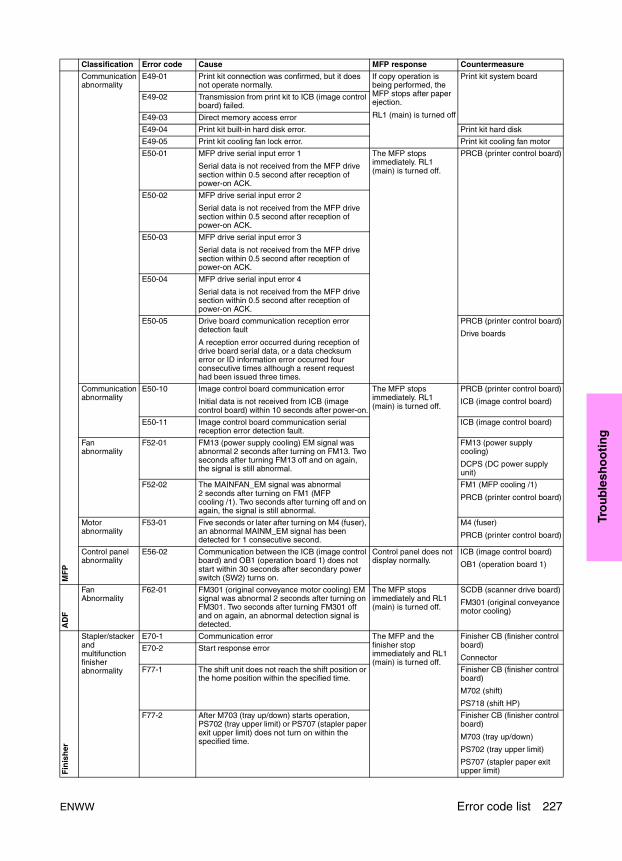
Tro
ub
lesh
oo
tin
g
MF
P
Communication abnormality
E49-01 Print kit connection was confirmed, but it does not operate normally.
If copy operation is being performed, the MFP stops after paper ejection.
RL1 (main) is turned off
Print kit system board
E49-02 Transmission from print kit to ICB (image control board) failed.
E49-03 Direct memory access error
E49-04 Print kit built-in hard disk error. Print kit hard disk
E49-05 Print kit cooling fan lock error. Print kit cooling fan motor
E50-01 MFP drive serial input error 1
Serial data is not received from the MFP drive section within 0.5 second after reception of power-on ACK.
The MFP stops immediately. RL1 (main) is turned off.
PRCB (printer control board)
E50-02 MFP drive serial input error 2
Serial data is not received from the MFP drive section within 0.5 second after reception of power-on ACK.
E50-03 MFP drive serial input error 3
Serial data is not received from the MFP drive section within 0.5 second after reception of power-on ACK.
E50-04 MFP drive serial input error 4
Serial data is not received from the MFP drive section within 0.5 second after reception of power-on ACK.
E50-05 Drive board communication reception error detection fault
A reception error occurred during reception of drive board serial data, or a data checksum error or ID information error occurred four consecutive times although a resent request had been issued three times.
PRCB (printer control board)
Drive boards
Communication abnormality
E50-10 Image control board communication error
Initial data is not received from ICB (image control board) within 10 seconds after power-on.
The MFP stops immediately. RL1 (main) is turned off.
PRCB (printer control board)
ICB (image control board)
E50-11 Image control board communication serial reception error detection fault.
ICB (image control board)
Fan abnormality
F52-01 FM13 (power supply cooling) EM signal was abnormal 2 seconds after turning on FM13. Two seconds after turning FM13 off and on again, the signal is still abnormal.
FM13 (power supply cooling)
DCPS (DC power supply unit)
F52-02 The MAINFAN_EM signal was abnormal 2 seconds after turning on FM1 (MFP cooling /1). Two seconds after turning off and on again, the signal is still abnormal.
FM1 (MFP cooling /1)
PRCB (printer control board)
Motor abnormality
F53-01 Five seconds or later after turning on M4 (fuser), an abnormal MAINM_EM signal has been detected for 1 consecutive second.
M4 (fuser)
PRCB (printer control board)
Control panel abnormality
E56-02 Communication between the ICB (image control board) and OB1 (operation board 1) does not start within 30 seconds after secondary power switch (SW2) turns on.
Control panel does not display normally.
ICB (image control board)
OB1 (operation board 1)
AD
F
Fan Abnormality
F62-01 FM301 (original conveyance motor cooling) EM signal was abnormal 2 seconds after turning on FM301. Two seconds after turning FM301 off and on again, an abnormal detection signal is detected.
The MFP stops immediately and RL1 (main) is turned off.
SCDB (scanner drive board)
FM301 (original conveyance motor cooling)
Fin
ish
er
Stapler/stacker and multifunction finisher abnormality
E70-1 Communication error The MFP and the finisher stop immediately and RL1 (main) is turned off.
Finisher CB (finisher control board)
ConnectorE70-2 Start response error
F77-1 The shift unit does not reach the shift position or the home position within the specified time.
Finisher CB (finisher control board)
M702 (shift)
PS718 (shift HP)
F77-2 After M703 (tray up/down) starts operation, PS702 (tray upper limit) or PS707 (stapler paper exit upper limit) does not turn on within the specified time.
Finisher CB (finisher control board)
M703 (tray up/down)
PS702 (tray upper limit)
PS707 (stapler paper exit upper limit)
Classification Error code Cause MFP response Countermeasure
ENWW Error code list 227
Fin
ish
er
Stapler/stacker and multifunction finisher abnormality
F77-3 After M705 (alignment /U) starts operation, PS708 (alignment HP/U) does not turn off within the specified time, or does not turns on after off.
The MFP and the finisher stop immediately and RL1 (main) is turned off.
Finisher CB (finisher control board)
RB (relay board)
M705 (alignment /U)
PS708 (alignment HP/U)
F77-4 After M707 (paper pick roller) starts operation, it does not reach the prescribed speed within the specified time.
Finisher CB (finisher control board)
M707 (paper exit roller)
F77-5 After M708 (paper exit opening) starts operation, its open/close operation does not finish within the specified time.
PS712 (paper exit opening home position) does not turn on or off.
Finisher CB (finisher control board)
M708 (paper exit opening)
PS712 (paper exit opening home position)
F77-6 After M711 (stapler movement) starts operation, PS711 (stapler movement home position) does not turn off, or does not turn on after off.
Finisher CB (finisher control board)
RB (relay board)
M711 (stapler movement)
PS711 (stapler movement home position)
F77-7 After M704 (clincher rotation) starts operation, PS714 (clincher rotation home position) does not turn off, or does not turn on after off.
Finisher CB (finisher control board)
RB (relay board)
M704 (clincher rotation)
PS714 (clincher rotation home position)
F77-8 After M706 (stapler rotation /R) starts operation, PS713 (stapler rotation home position) does not turn off, or does not turn on after off.
Finisher CB (finisher control board)
RB (relay board)
M706 (stapler rotation /R)
PS713 (stapler rotation home position)
F77-11 After M714 (stapler /F) starts operation, PS731 (stapler HP/F) does not turn on within the specified time.
Finisher CB (finisher control board)
RB (relay board)
M714 (stapler /F)
PS731 (stapler HP/F)
F77-12 After M709 (stapler /R) starts operation, PS730 (stapler HP/R) does not turn on within the specified time.
Finisher CB (finisher control board)
RB (relay board)
M709 (stapler /R)
PS730 (stapler HP/R)
F77-13 After M715 (clincher /F) starts operation, PS733 (clincher HP/F) does not turn on within the specified time.
Finisher CB (finisher control board)
RB (relay board)
M715 (clincher /F)
PS733 (clincher HP/F)
F77-14 After M710 (clincher /R) starts operation, PS732 (clincher HP/R) does not turn on within the specified time.
Finisher CB (finisher control board)
M710 (clincher /R)
PS732 (clincher HP/R)
Classification Error code Cause MFP response Countermeasure
228 Troubleshooting ENWW
Tro
ub
lesh
oo
tin
g
Fin
ish
er
Stapler/stacker and multifunction finisher abnormality
F77-21 After M718 (folding stopper) starts operation, PS723 (folding stopper home position) does not turn on within the specified time.
The MFP and the finisher stop immediately and RL1 (main) is turned off.
Finisher CB (finisher control board)
RB (relay board)
M718 (folding stopper)
PS723 (folding stopper home position)
F77-22 After M716 (alignment /L) starts operation, PS724 (alignment HP/L) does not turn on within the specified time.
Finisher CB (finisher control board)
RB (relay board)
M716 (alignment /L)
PS724 (alignment /L)
F77-25 After M719 (folding knife) starts the home position detecting operation, PS722 (folding knife home position) does not turn on within the specified time.
Finisher CB (finisher control board)
M719 (folding knife)
PS722 (folding knife home position)
F77-26 After M720 (folding conveyance) starts operation, it does not reach the prescribed speed within the specified time.
Finisher CB (finisher control board)
M720 (folding conveyance)
PI abnormality F77-41 After M202 (tray up/down /L) starts operation, PS209 (tray upper limit /L) or PS210 (tray lower limit /L) do not turn on within the specified time.
Finisher CB (finisher control board)
PIDB (PI drive board)
M202 (tray up/down /L)
M209 (tray upper limit /L)
PS210 (tray lower limit /L)
F77-42 After M201 (tray up/down/ U) starts operation, PS204 (tray upper limit /U) or PS205 (tray lower limit /U) do not turn on within the specified time.
Finisher CB (finisher control board)
PIDB (PI drive board)
M201 (tray up/down /U)
PS204 (tray upper limit /U)
PS205 (tray lower limit /U)
F77-43 After M203 (PI conveyance) starts operation, it does not reach the prescribed speed within the specified time.
Finisher CB (finisher control board)
M203 (PI conveyance)
Punch kit abnormality
F77-44 PS803 (punch shift home position) does not turn on within the specified time after M802 (punch shift) operation has been started.
Finisher CB (finisher control board)
PKDB (PK drive board)
M801 (punch)
PS803 (punch home position)
Finisher/punch kit abnormality
F77-47 Communication abnormality occurred between the finisher and punch kit. Abnormality remains even when retry operation is executed four times.
RB (relay board)
Finisher CB (finisher control board)
PKDB (PK drive board)
Punch kit abnormality
F77-54 After CL801 (punch) starts operation, PS801 (punch home position) does not turn on within the specified time.
Finisher CB (finisher control board)
PKDB (PK drive board)
M801 (punch)
PS801 (punch home position)
Stapler/stacker and multifunction finisher abnormality
F77-81 After CL712 (gate drive) starts operation, PS716 (gate home position) does not turn on within the specified time or does not turn off after on.
Finisher CB (finisher control board)
RB (relay board)
M712 (gate drive)
PS716 (gate home position)
F77-91 Communication abnormality in finisher CB (finisher control board) when sub-CPU receives data.
Finisher CB (finisher control board)
F77-92 Communication abnormality in finisher CB (finisher control board) when main CPU receives data.
Classification Error code Cause MFP response Countermeasure
ENWW Error code list 229

For the following abnormalities, the user can disconnect the faulty unit temporarily to continue using the MFP.
When an abnormality occurs, press the reset button following the LCD message, and turn the secondary power switch (SW2) off/on. This allows temporary use of MFP until the secondary power switch (SW2) is turned off/on next time.
MF
P
Communication abnormality
E80-01 No response from PRCB (printer control board) for 5 seconds after secondary power switch (SW2) is turned on.
The MFP stops immediately and RL1 (main) is turned off.
PRCB (printer control board)
E80-02 Communication abnormality in PRCB (printer control board).
PRCB (printer control board)
E80-03 Communication abnormality in operation unit. OB1 (operation board /1)
ISW abnormality
F80-11 When secondary power switch (SW2) was turned on, an area which had not been written by ISW was detected in the MFP control program.
PRCB program
F80-30 When data is transferred by ISW, normal header information cannot be received within the specified time.
MFP cable
PC parallel port
F80-31 When data is transferred by ISW, a checksum error or header error was detected in the downloaded data.
MFP cable
Program file error
F80-32 When data is transferred by ISW, data cannot be written to the flash ROM properly.
MFP cable
Program transfer destination board
F80-40 When secondary power switch (SW2) was turned on, an area which had not been written by ISW was detected in the finisher program.
Finisher program
ADU stand abnormality
E90-01 ADU drive serial input error 1.
Serial data from ADUDB (ADU drive board) (ID=0) cannot be received from ACK within 0.5 second when secondary power switch (SW2) turns on.
ADUDB (ADU drive board)
E90-02 ADU drive serial input error 2.
Serial data from ADUDB (ADU drive board) (ID=7) cannot be received from ACK within 0.5 second when secondary power switch (SW2) turns on.
Fan abnormality
F92-01 The FM10 (ADU reverse motor cooling) EM signal was abnormal 2 seconds after turning on of FM10. 2 seconds after turning FM10 off and on again, the signal is still abnormal.
FM10 (ADU reverse motor cooling)
ADUDB (ADU drive board)
PRCB (printer control board)
Warning code Cause Unit to be disconnectedF18-10 Tray 2 up drive motor abnormality Tray 2F18-11 Tray 2 up abnormalityF18-20 Tray 3 up drive motor abnormality Tray 3
F18-21 Tray 3 up abnormalityF18-30 Tray 4 up drive motor abnormality Tray 4F18-31 Tray 4 up abnormality
F13-02 HCI paper feed motor abnormality HCIF18-50 HCI UP/DOWN motor abnormalityF46-40 to 43 Hard disk abnormality Hard disk
F62-01 ADF motor cooling fan abnormality ADFF77-22,25,26 Folding, stapling and folding, three-folding abnormality Folding, stapling and folding, three-foldingF71-41 to 43 PI abnormality PI
F77-44,47,55 PK, PZ punch shift motor abnormality PK, PZ
Classification Error code Cause MFP response Countermeasure
230 Troubleshooting ENWW

Tro
ub
lesh
oo
tin
g
Timing chart
9065 timing chart (1)Letter/A4, life size, 1-1 mode, Tray 2, reversed paper exit, non AE, 2 sets
Sym
bol
Item
sT
ime
(sec
)
M1
Pap
er fe
ed m
otor
M2
Dru
m m
otor
M3
Dev
elop
ing
mot
or
M4
Fix
ing
mot
or
M5
Con
veya
nce
mot
or
M6
Loop
rol
ler
mot
or
M7
Pap
er e
xit m
otor
M8
Rev
erse
/ ex
it m
otor
M9
AD
U r
ever
se m
otor
M11
MC
1R
egis
trat
ion
MC
MC
2A
DU
dec
eler
atio
n M
C
MC
3P
aper
feed
MC
/1
MC
4P
re-r
egis
trat
ion
MC
/1
PC
LP
re-c
harg
ing
expo
sure
lam
p
HV
Cha
rge
Tra
nsfe
r
Sep
arat
ion
Dev
elop
ing
bias
Pap
er g
uide
pla
te
Ton
er g
uide
rol
ler
SD
1S
epar
atio
n cl
aw S
D
SD
7R
ever
se g
ate
SD
PS
1P
aper
feed
PS
/1
PS
36Lo
op P
S
PS
44R
egis
trat
ion
PS
PS
43Le
adin
g ed
ge P
S
PS
30F
ixin
g ex
it P
S
PS
42
PS
46R
ever
sed/
exit
PS
6
PS
45A
DU
pap
er r
ever
se P
S
PS
48A
DU
pap
er c
onve
yanc
e P
S/2
PS
49A
DU
dec
eler
atio
n P
S
PS
50A
DU
pre
-reg
istr
atio
n P
S
PS
37P
aper
exi
t PS
01
23
46
78
95
(sec
)
H L H L F RH L H L F F RR
Sto
p pr
int
ST
AR
T b
utto
n O
N
Sca
nner
mot
or
Pap
er r
ever
se P
S
ENWW Timing chart 231
9065 timing chart (2)Letter/A4, life size, 1-2 mode, Tray 2, 2 sets
Sym
bol
Item
sT
ime
(sec
)
M1
Pap
er fe
ed m
otor
M2
Dru
m m
otor
M3
Dev
elop
ing
mot
or
M4
Fix
ing
mot
or
M5
Con
veya
nce
mot
or
M6
Loop
rol
ler
mot
or
M7
Pap
er e
xit m
otor
M8
Rev
erse
pap
er
exit
mot
or
M9
AD
U r
ever
se m
otor
M11
Sca
nner
mot
or
MC
1R
egis
trat
ion
MC
MC
2A
DU
dec
eler
atio
n M
C
MC
3P
aper
feed
MC
/1
MC
4P
re-r
egis
trat
ion
MC
/1
PC
LP
re-c
harg
ing
expo
sure
lam
p
HV
Cha
rge
Tra
nsfe
r
Sep
arat
ion
Dev
elop
ing
bias
Pap
er g
uide
pla
te
Ton
er g
uide
rol
ler
SD
1S
epar
atio
n cl
aw S
D
SD
7R
ever
se g
ate
SD
PS
1P
aper
feed
PS
/1
PS
36Lo
op P
S
PS
44R
egis
trat
ion
PS
PS
43Le
adin
g ed
ge P
S
PS
30F
ixin
g ex
it P
S
PS
42P
aper
rev
erse
PS
PS
46R
ever
sed
pape
r ex
it P
S6
PS
45A
DU
pap
er r
ever
se P
S
PS
48A
DU
pap
er c
onve
yanc
e P
S/2
PS
49A
DU
dec
eler
atio
n P
S
PS
50A
DU
pre
-reg
istr
atio
n P
S
PS
37P
aper
exi
t PS
01
23
46
78
95
(sec
)
H L H L F RH L H L F F RR
Sto
p pr
int
Loop
Loop
Loop
Loop
Loop
Loop
232 Troubleshooting ENWW
Tro
ub
lesh
oo
tin
g
ADF timing chart (1)Letter/A4, 3 originals (single side)
Sym
bol
Item
sT
ime
(sec
)
PS
301
Last
orig
inal
PS
PS
302
Orig
inal
siz
e P
S/2
PS
304
Orig
inal
reg
istr
atio
n P
S/1
PS
305
Orig
inal
reg
istr
atio
n P
S/2
PS
306
Orig
inal
con
veya
nce
PS
PS
303
Orig
inal
exi
t PS
MC
301
Orig
inal
feed
MC
M30
1
M30
2O
rigin
al c
onve
yanc
e m
otor
SD
301
Rev
erse
gat
e S
D
SD
303
Pre
ssur
e ro
ller
rele
ase
SD
SD
302
Exi
t gat
e S
D
V-V
ALI
D s
igna
l
640m
m/s
320m
m/s
320m
m/s
F F
400m
m/s
640m
m/s
320m
m/s
R
01
23
45
67
89
10(s
ec)
Sca
nnin
g th
e 3r
d or
igin
al
Sca
nnin
g th
e 2n
d or
igin
al
Last
orig
inal
eje
cted
Sca
nnin
g th
e 1s
t orig
inal
ST
AR
T b
utto
n O
N
Orig
inal
feed
mot
or
ENWW Timing chart 233
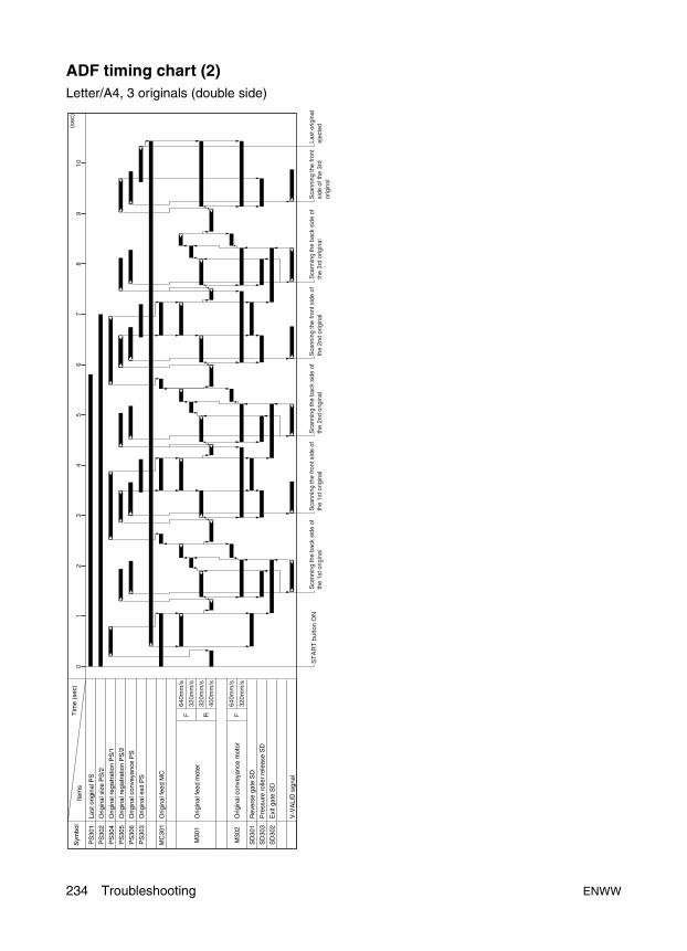
ADF timing chart (2)Letter/A4, 3 originals (double side)
Sym
bol
Item
sT
ime
(sec
)
PS
301
Last
orig
inal
PS
PS
302
Orig
inal
siz
e P
S/2
PS
304
Orig
inal
reg
istr
atio
n P
S/1
PS
305
Orig
inal
reg
istr
atio
n P
S/2
PS
306
Orig
inal
con
veya
nce
PS
PS
303
Orig
inal
exi
t PS
MC
301
Orig
inal
feed
MC
M30
1
M30
2O
rigin
al c
onve
yanc
e m
otor
SD
301
Rev
erse
gat
e S
D
SD
303
Pre
ssur
e ro
ller
rele
ase
SD
SD
302
Exi
t gat
e S
D
V-V
ALI
D s
igna
l
640m
m/s
320m
m/s
320m
m/s
F F
400m
m/s
640m
m/s
320m
m/s
R
01
23
45
67
89
10(s
ec)
ST
AR
T b
utto
n O
NS
cann
ing
the
back
sid
e of
th
e 1s
t orig
inal
Sca
nnin
g th
e fr
ont s
ide
of
the
1st o
rigin
alS
cann
ing
the
back
sid
e of
th
e 2n
d or
igin
alS
cann
ing
the
fron
t sid
e of
th
e 2n
d or
igin
alS
cann
ing
the
back
sid
e of
th
e 3r
d or
igin
alS
cann
ing
the
fron
t si
de o
f the
3rd
or
igin
al
Last
orig
inal
ej
ecte
d
Orig
inal
feed
mot
er
234 Troubleshooting ENWW
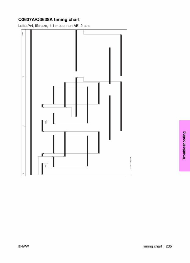
Tro
ub
lesh
oo
tin
g
Q3637A/Q3638A timing chartLetter/A4, life size, 1-1 mode, non AE, 2 sets
ST
AR
T b
utto
n O
N
01
2(s
ec)
Loop
Loop
ENWW Timing chart 235
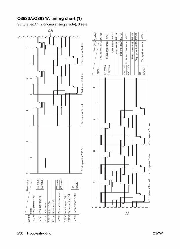
Q3633A/Q3634A timing chart (1)Sort, letter/A4, 2 originals (single side), 3 sets
PS
704
Sym
bol
Item
sT
ime
(sec
)
FN
S e
ntra
nce
PS
01
23
4
67
8
M70
1
SD
704
M70
2
PS
718
FN
S c
onve
yanc
e
Pap
er e
xit S
D
Shi
ft m
otor
Shi
ft H
P P
S
A
A
M70
3
PS
706
670m
m/s
400m
m/s
M70
7P
aper
exi
t rol
ler
mot
or25
3mm
/s
400m
m/s
UP
DO
WN
Tray
up/
dow
n m
otor
Mai
n tr
ay e
xit P
S
PS
702
Tray
upp
er li
mit
PS
PS
704
Sym
bol
Item
sT
ime
(sec
)
M70
1
SD
704
M70
2
PS
718
M70
3
PS
706
670m
m/s
400m
m/s
M70
725
3mm
/s
400m
m/s
UP
DO
WN
PS
702
FN
S e
ntra
nce
PS
FN
S c
onve
yanc
e
Pap
er e
xit S
D
Shi
ft m
otor
Shi
ft H
P P
S
Pap
er e
xit r
olle
r m
otor
Tray
up/
dow
n m
otor
Mai
n tr
ay e
xit P
S
Tray
upp
er li
mit
PS
Sta
rt s
igna
l for
FN
S O
N1s
t pap
er o
f 1st
set
2nd
pape
r of
1st
set
1st p
aper
of 2
nd s
et
2nd
pape
r of
3rd
set
2nd
pape
r of
2nd
set
1st p
aper
of 3
rd s
et
5
236 Troubleshooting ENWW

Tro
ub
lesh
oo
tin
g
Q3633A/Q3634A timing chart (2)2 staples (flat), letter/A4, 2 originals (single side), 6 sheets (single side)
A
A
PS
704
Sym
bol
Item
sT
ime
(sec
)
M70
1
FN
S e
ntra
nce
PS
FN
S c
onve
yanc
e
SD
705
By-
pass
gat
e S
D
01
23
45
67
89
1011
PS
705
Sta
cker
ent
ranc
e P
S
M71
3S
tack
er e
ntra
nce
mot
or
PS
709
Pap
er e
xit b
elt H
P P
S
PS
706
Mai
n tr
ay p
aper
exi
t PS
SD
704
Pap
er e
xit s
olen
oid
M70
7P
aper
exi
t rol
ler
mot
or
PS
707
Sta
pler
pap
er e
xit u
pper
lim
it
M70
3Tr
ay u
p/do
wn
mot
or
M70
5A
lignm
ent m
otor
/U
M71
1S
tapl
er m
ovem
ent m
otor
M7
09
M7
10
Sta
pler
,Clin
cher
mot
or/F
M7
14
M7
15
Sta
pler
,Clin
cher
mot
or/R
CLO
SE
OP
EN
670m
m/s
950m
m/s
660m
m/s
280m
m/s
UP
DO
WN
PS
704
Sym
bol
Item
sT
ime
(sec
)
M70
1F
NS
con
veya
nce
SD
705
PS
705
M71
3S
tack
er e
ntra
nce
mot
or
PS
709
PS
706
SD
704
Pap
er e
xit s
olen
oid
M70
7P
aper
exi
t rol
ler
mot
or
PS
707
M70
3Tr
ay u
p/do
wn
mot
or
M70
5A
lignm
ent m
otor
/U
M71
1S
tapl
er m
ovem
ent m
otor
M7
09
M7
10
Sta
pler
,Clin
cher
mot
or/F
M7
14
M7
15
Sta
pler
,Clin
cher
mot
or/R
CLO
SE
OP
EN
670m
m/s
950m
m/s
660m
m/s
280m
m/s
UP
DO
WN
Sta
t sig
nal f
or F
NS
ON
1st p
aper
of 1
st s
et
2nd
pape
r of
2nd
set
1st p
aper
of 3
rd s
et2n
d pa
per
of 3
rd s
et
1st p
aper
of 2
nd s
et2n
d pa
per
of 1
st s
et
FN
S e
ntra
nce
PS
By-
pass
gat
e S
D
Sta
cker
ent
ranc
e P
S
Pap
er e
xit b
elt H
P P
S
Mai
n tr
ay p
aper
exi
t PS
Sta
pler
pap
er e
xit u
pper
lim
it
ENWW Timing chart 237

Q3633A/Q3634A timing chart (3)Staple and fold, letter/A4, 2 originals (single side), 6 sheets (single side)
A
A
PS
704
Sym
bol
Item
sT
ime
(sec
)
M70
1
FN
S e
ntra
nce
PS
FN
S c
onve
yanc
e
01
23
45
67
89
1011
1213
1415
1617
18
PS
705
PS
708
Sta
cker
ent
ranc
e P
S
M71
3S
tack
er e
ntra
nce
mot
or
Alig
nmen
t HP
PS
/U
M70
5A
lignm
ent m
otor
/U
PS
724
Alig
nmen
t HP
PS
/L
M71
6A
lignm
ent m
otor
/L
PS
723
Sto
pper
HP
PS
M71
8F
oldi
ng s
topp
er m
otor
M72
0Fo
ldin
g co
nvey
ance
mot
or
M71
9F
oldi
ng k
nife
mot
or
M72
2F
oldi
ng k
nife
HP
PS
M70
8P
aper
exi
t mot
or
PS
726
Fol
ding
pas
sage
HP
PS
PS
712
Pap
er e
xit H
P P
S
PS
725
Fol
ding
exi
t PS
M714
M715
Sta
pler
,Clin
cher
mot
or/F
M709
M710
Sta
pler
,Clin
cher
mot
or/R
CLO
SE
OP
EN
CLO
SE
OP
EN
DO
WN
UP
670m
m/s
500m
m/s
400m
m/s
80m
m/s
FN
S e
ntra
nce
PS
FN
S c
onve
yanc
e
Sta
cker
ent
ranc
e P
S
Sta
cker
ent
ranc
e m
otor
Alig
nmen
t HP
PS
/U
Alig
nmen
t mot
or/U
Alig
nmen
t HP
PS
/L
Alig
nmen
t mot
or/L
Sto
pper
HP
PS
Fol
ding
sto
pper
mot
or
Fold
ing
conv
eyan
ce m
otor
Fol
ding
kni
fe m
otor
Fol
ding
kni
fe H
P P
S
Pap
er e
xit m
otor
Fol
ding
pas
sage
HP
PS
Pap
er e
xit H
P P
S
Fol
ding
exi
t PS
Sta
pler
,Clin
cher
mot
or/F
Sta
pler
,Clin
cher
mot
or/R
CLO
SE
OP
EN
CLO
SE
OP
EN
DO
WN
UP
PS
704
Sym
bol
Item
sT
ime
(sec
)
M70
1
PS
705
PS
708
M71
3
M70
5
PS
724
M71
6
M71
8
M72
0
M71
9
M72
2
M70
8
PS
726
PS
712
PS
725
M714
M715
M709
M710
670m
m/s
500m
m/s
400m
m/s
80m
m/s
PS
723
Sta
rt s
igna
l for
FN
S O
N
1st p
aper
of 1
st s
et2n
d pa
per
of 1
st s
et3r
d pa
per
of 1
st s
et
1st p
aper
of 2
nd s
et2n
d pa
per
of 2
nd s
et3r
d pa
per
of 2
nd s
et
238 Troubleshooting ENWW
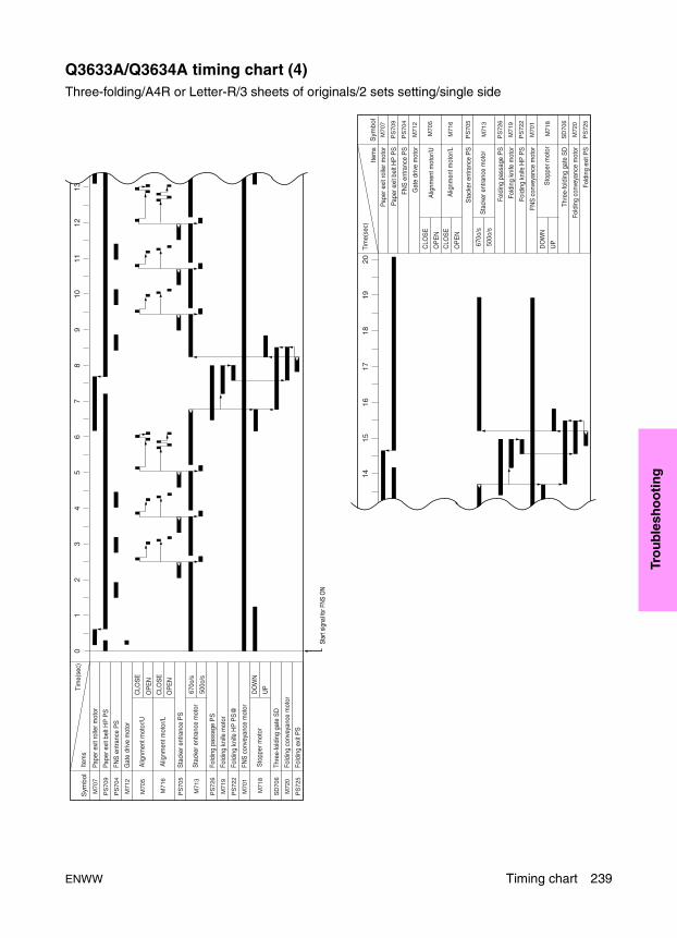
Tro
ub
lesh
oo
tin
g
Q3633A/Q3634A timing chart (4)Three-folding/A4R or Letter-R/3 sheets of originals/2 sets setting/single side
M70
7
PS
709
PS
704
M71
2
PS
705
PS
726
M71
9
PS
722
M70
1
SD
706
M72
0
PS
725
Sym
bol
Item
s
Pape
r exi
t rol
ler m
otor
Pape
r exi
t bel
t HP
PS
FNS
ent
ranc
e P
S
Gat
e dr
ive
mot
or
Sta
cker
ent
ranc
e P
S
Fold
ing
pass
age
PS
Fold
ing
knife
mot
or
Fold
ing
knife
HP
PS
FNS
con
veya
nce
mot
or
Thre
e-fo
ldin
g ga
te S
D
Fold
ing
conv
eyan
ce m
otor
Fold
ing
exit
PS
Star
t sig
nal f
or F
NS O
N
M70
5C
LOS
E
OP
EN
CLO
SE
OP
EN
Alig
nmen
t mot
or/U
M71
6A
lignm
ent m
otor
/L
670
/s
500
/sM
713
Sta
cker
ent
ranc
e m
otor
M71
8D
OW
N
UP
Sto
pper
mot
or
M70
7
PS
709
PS
704
M71
2
PS
705
PS
726
M71
9
PS
722
M70
1
SD
706
M72
0
PS
725
Sym
bol
Item
s
M70
5C
LOS
E
OP
EN
CLO
SE
OP
EN
M71
6A
lignm
ent m
otor
/L
670
/s
500
/sM
713
Sta
cker
ent
ranc
e m
otor
M71
8D
OW
N
UP
Sto
pper
mot
or
Pape
r exi
t rol
ler m
otor
Pape
r exi
t bel
t HP
PS
FNS
ent
ranc
e P
S
Gat
e dr
ive
mot
or
Sta
cker
ent
ranc
e P
S
Fold
ing
pass
age
PS
Fold
ing
knife
mot
or
Fold
ing
knife
HP
PS
FNS
con
veya
nce
mot
or
Thre
e-fo
ldin
g ga
te S
D
Fold
ing
conv
eyan
ce m
otor
Fold
ing
exit
PS
Alig
nmen
t mot
or/U
Tim
e(se
c)0
12
34
56
78
910
1112
13
1415
1617
1819
20Ti
me(
sec)
ENWW Timing chart 239

Q3636A timing chartPI automatic paper feed (bottom) /2 staples (flat) /letter or A4/2 sheets of original/2 sets setting/single side
253m
m/s
670m
m/s
01
23
45
67
89
1011
1213
14
1516
17
MC
202
M20
2
PS
209
SD
202
- -
PS
206
MC
203
PS
704
PS
705
Sym
bol
Item
s
M71
2
M70
1
M71
3
M70
7
PS
709
M714
M715
M709
M710
Star
t sig
nal f
or F
NS O
N
Tim
e(se
c)
M20
3P
I con
veya
nce
MC
/L
M70
5O
PE
N
CLO
SE
Alig
nmen
t mot
or/U
Con
veya
nce
MC
/L
Tray
up/
dow
n m
otor
/L
Tray
upp
er li
mit/
L
She
et fe
ed S
D/L
PI p
aper
feed
pre
-req
uest
PI p
aper
feed
requ
est
PI p
assa
ge P
S/L
Reg
istra
tion
MC
FNS
ent
ranc
e P
S
Sta
cker
ent
ranc
e P
S
Sta
pler
, clin
cher
mot
or/F
Sta
pler
, clin
cher
mot
or/R
Gat
e dr
ive
mot
or
FNS
con
veya
nce
mot
or
Sta
cker
ent
ranc
e m
otor
Pape
r exi
t rol
ler m
otor
Pape
r exi
t mot
or H
P P
S
240 Troubleshooting ENWW

Tro
ub
lesh
oo
tin
g
Punch kit timing chartPunch/2 staples (flat) /letter or A4/2 sheets of original/3 sets setting/single side
01
23
45
67
89
10
PS
37
M71
2
PS
704
M80
1
PS
801
M70
1
SD
705
PS
705
M71
3
Pape
r exi
t PS
Gat
e dr
ive
mot
or P
S
FNS
ent
ranc
e P
S
Pape
r edg
e se
nsor
Pun
ch m
otor
Pun
ch H
P P
S
FNS
con
veya
nce
mot
or
Byp
ass
gate
SD
Sta
cker
ent
ranc
e P
S
Sta
cker
ent
ranc
e m
otor
Sta
pler
, clin
cher
mot
or/F
Sta
pler
, clin
cher
mot
or/R
Pape
r exi
t rol
ler m
otor
Pape
r exi
t bel
t HP
PS
Mai
n tra
y pa
per e
xit P
S
Pape
r exi
t SD
M70
7
PS
709
PS
706
SD
704
M714
M715
M709
M710
Alig
nmen
t mot
or/U
M70
5C
LOS
E
OP
EN
F R
Sta
rt s
igna
l for
FN
S O
N
Sym
bol
Item
sTi
me(
sec)
Pun
ch s
hift
mot
orM
802
ENWW Timing chart 241

242 Troubleshooting ENWW

ENWW 243
Term
ino
log
y cr
oss
-ref
eren
ce
ATerminology cross-reference
Terminology cross-reference for the MFP . . . . . . . . . . . . . . . . . . . . . . . . . . 244
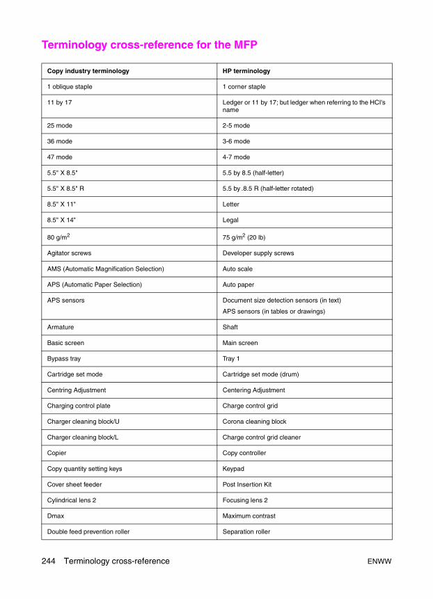
Terminology cross-reference for the MFP
Copy industry terminology HP terminology
1 oblique staple 1 corner staple
11 by 17 Ledger or 11 by 17; but ledger when referring to the HCI's name
25 mode 2-5 mode
36 mode 3-6 mode
47 mode 4-7 mode
5.5" X 8.5" 5.5 by 8.5 (half-letter)
5.5" X 8.5" R 5.5 by .8.5 R (half-letter rotated)
8.5" X 11" Letter
8.5" X 14" Legal
80 g/m2 75 g/m2 (20 lb)
Agitator screws Developer supply screws
AMS (Automatic Magnification Selection) Auto scale
APS (Automatic Paper Selection) Auto paper
APS sensors Document size detection sensors (in text)
APS sensors (in tables or drawings)
Armature Shaft
Basic screen Main screen
Bypass tray Tray 1
Cartridge set mode Cartridge set mode (drum)
Centring Adjustment Centering Adjustment
Charging control plate Charge control grid
Charger cleaning block/U Corona cleaning block
Charger cleaning block/L Charge control grid cleaner
Copier Copy controller
Copy quantity setting keys Keypad
Cover sheet feeder Post Insertion Kit
Cylindrical lens 2 Focusing lens 2
Dmax Maximum contrast
Double feed prevention roller Separation roller
244 Terminology cross-reference ENWW

Term
ino
log
y cr
oss
-ref
eren
ce
F0 lens Focusing lens 1 (F0)
Faults Issues
Feed roller Pick roller
Feeder cover Jam access cover
Fixing Fusing
Fixing unit Fuser
Flatbed unit Scanning glass
FNS Finisher
Fold Folding
HCI left side door HCI door
HCI lever HCI jam access lever
HCI top door HCI top cover
HP sensor Home position sensor
Jig Adjustment tool
Large Capacity Tray (LCT) Tray 5/HCI
Left-partition glass ADF glass
LT driver board HCI control board
Magnetic clutch Clutch
Main switch SW1 Primary power switch
Main tray or main bin Paper exit face down tray
MC (magnetic clutch) CL (clutch)
Measuring guides (glass) Alignment guides
MS SW (switch)
MT/MTEM Motor/motor error message
OHP interleave Transparency interleave
Oil-less metal Bushing
Operation panel Control panel
Original feed tray (ADF) ADF input tray
Original stopper plates Alignment guides (scanner glass)
Output tray (ADF) Original exit tray
Copy industry terminology HP terminology
ENWW Terminology cross-reference for the MFP 245

Paper up/down plate Paper lift plate
Platen glass Scanner glass
Platen guide cover White board
Power saver on/off Sleep on/off
Print controller Formatter assembly (when referring to contents of print kit)
Printer, copier, machine, or main body MFP
Proof output Proof and hold
RADF ADF
Relay connector Inline connector
Resin ring Snap ring
Resis or Resist Registration
Saddle stitch 2-position flat
Scan/server Send/store
SD (solenoid) SL (solenoid)
Semiconductor laser Laser diode
Shaft holder Bushing
Slit glass ADF glass
Start (copy/print) Start
Stitch and fold Staple and fold
Stop ring Snap ring
Stop/Scan Stop
Sub switch (SW2) Secondary power switch (SW2)
Sub tray Paper exit tray
Three-fold Tri-fold
To and fro Back and forth
Toner cartridge Toner bottle
Total counter, odometer, mechanical counter, or paper exit counter
Touch screen Touch display
Transparent film Transparency (OHT)
Copy industry terminology HP terminology
246 Terminology cross-reference ENWW

Term
ino
log
y cr
oss
-ref
eren
ce
Upper bin Paper exit tray
Upper unit release lever (post insertion kit) Release lever
Worktable Shelf
Write unit Laser/scanner assembly
/F or /R Front or Rear
/U or /L Upper or Lower
Copy industry terminology HP terminology
ENWW Terminology cross-reference for the MFP 247

248 Terminology cross-reference ENWW
Ind
ex
Index
Numerics2-5 mode
adjustments 29list of adjustments 30setting 29
2-position staple pitch adjustment 953-6 mode
adjustments 64setting 64
4-7 modeadjustments 96ending 97multi mode 97multi-mode setting method 96starting 96
9-0 mode 1709065
timing chart (1) 231timing chart (2) 232
9065 connector layout drawingsA/D converter board 210ADU drive board 208DC power supply unit 209HCI drive board 211high voltage unit 210image control board (ICB) 208index sensor board 210L1 inverter 210laser driver board 210memory board 211OB inverter 210operation board/1 210polygon drive board 211PRCB 207scanner drive board 209toner control sensor board 210
9065 parts layout drawingsADU 197charging corona section 193drum unit section 194fuser section 198laser/scanner section 199left side of MFP 199operation section 193read section 192rear side of MFP 200registration assembly 196second paper feed section 196toner supply section 198Tray 1 feed section 195Trays 2, 3, 4 194vertical conveyance section 195
AA/D converter board drawing 210accidents, handling 13ADF
aligning top of scanner 122alignment to ADF glass 123centering adjustment 82maintenance items 178original size adjustment 80paper skew adjustment 124parts layout drawing 201periodic checks 182registration loop amount adjustment 79replacement parts list 185restart timing adjustment 79service schedule 175skew offset adjustment 81timing chart (1) 233timing chart (2) 234
ADF glass, aligning 123adjustment data display 98adjustment precautions 24ADU drawing 197ADU drive board drawing 208alignment plates/L, mount location adjustment
132
ENWW 249
alignment plates/U, mount location adjustment 131
angle of folding stopper adjustment, finisher 137auto dot diameter adjustment 69auto gamma adjustment
1 dot 712 dot 72
auto maximum contrast adjustment 69
Bbeam misalignment check 90bias adjustment
LD1 71LD2 71
blade setting mode 69bridge card, print controller 163bypass conveyance guide plate, magnet
adjustment 125bypass gate adjustment, finisher 126
Ccartridge set mode (drum) adjustment 72caution labels 18CE tool list 188centering adjustment
ADF 82HCI 112image 81MFP 81PI 142scanner (platen) 82tray 111Tray 2/3/4 111
charging corona section drawing 193charging grid voltage adjustment 68checking P function 28checklist
input 100output 104
circuit safety information 15Clear event log 170Cold reset 171Cold Reset Paper 170collecting data 46Config Utility, HP90x5mfp 158Configuration page 166connector layout drawings
9065 207finisher 212PI 213punch kit 214
consumables, handling and disposing 14control board drawing, finisher 212
control panel adjustment, LCD 28control panel contrast/key sound adjustment, LCD
28Copy Control HDD switches 158copy count
by fixed parts 57by optional parts 61
cover sheet tray size adjustment 93custom paper setting adjustment 73
Ddata, collecting 46date, setting 64daughter card, print controller 163DC power supply unit drawing 209deviation report 158Diagnostics menu 166DIMMs, print controller 162DIP switches
list of 32setting 31
disposing of consumables 14distortion adjustment, MFP 83Dmax adjustment 69document feeder adjustment 80document feeder contrast adjustment 80dot diameter adjustment
auto 69manual 73
drive board drawingPI 213punch kit 214
drum calibrationadjustment 68manual adjustment 73
drum clock magnification adjustmentMFP 74scanner 75scanner (ADF) 76
drum unit section drawing 194
Eelectronic parts layout drawings
9065 192ADF 201HCI 202multifunction finisher 203PI 206punch kit 206stapler/stacker 203
embedded Web server 156emergency measures 13environmental safety requirements 7
250 Index ENWW
Ind
ex
error codesISW 150jam 215list 221print controller 167
essential safety parts 186event log
clearing 170printing 166
EWS 156
FFCC regulations 14File directory page 166finisher
2-position staple pitch adjustment 95adjustment 92angle of folding stopper adjustment 137bypass gate adjustment 126firmware version 63folding force adjustment 138magnets on bypass conveyance guide plate
adjustment 125mount location of alignment plates/L adjustment
132mount location of alignment plates/U adjustment
131mount location of paper exit arm adjustment 130paper exit solenoid adjustment 129service schedule 175shift position adjustment 128stapler driver belt position adjustment 145stapler vertical position adjustment 134stapling and folding stopper adjustment 92stapling position (flat stapling) adjustment 133stapling position (staple-and-fold) adjustment
136tri-fold position adjustment 139upgrading firmware 148
finisher connector layout drawingscontrol board 212interconnect board 212
finisher control board drawing 212finisher interconnect board drawing 212firmware upgrade
ICB, PRCB, finisher 148print controller 152
firmware upgrade methodsFTP browser copy 153FTP put 154HP Web Jetadmin 155network connection 155parallel connection 155
firmware versionsviewing 158
firmware versions, displaying 63flat stapling position adjustment, finisher 133folding force adjustment, finisher 138folding stopper adjustment
finisher 92multifunction finisher 137
Font lists page 166FTP browser copy 153FTP put 154fuser section drawing 198
Ggamma adjustment, auto
1 dot 712 dot 72
gradation pattern 87, 88, 89ground lead warnings 7
Hhalftone, overall 86handling
consumables 14service materials 12
hard disk check 98hard disk drive, print controller
initializing 171specifications 162
HCIcentering adjustment 112lift plate horizontal adjustment 115maintenance items 179paper feed height upper limit adjustment 120paper size adjustment 113parts layout drawing 202periodic checks 183pick roller pressure adjustment 114pick-up release amount adjustment 121replacement parts list 185service schedule 175skew adjustment 117spring pressure adjustment 119
HCI drive board drawing 211high voltage adjustment 67high voltage unit drawing 210horizontal magnification adjustment, MFP 75horizontal position adjustment, punch kit 94HP Jetdirect 615n card, print controller 162HP Web Jetadmin 155HP90x5mfp Config Utility 158humidity warnings 8
ENWW 251
IICB
upgrading firmware 148ICB drawing 208ICB firmware version 63image adjustment 73image adjustment settings, restoring 84image centering adjustment 81image control board drawing 208index sensor board drawing 210Information menu 166Initialize disk 171Initialize NVRAM 172input checklist 100input/output check 97inspection before servicing 9installation
requirements 7safety checkpoints 10
interconnect board drawing, finisher 212internal pages, Print Menu 166ISWTrans (ISW) tool 148
Jjam codes 215Jetdirect 615n card, print controller 162
LL1 inverter drawing 210laser driver board drawing 210laser/scanner section drawing 199LCD
control panel adjustment 28panel contrast/key sound adjustment 28
LD1bias adjustment 71offset adjustment 70
LD2 bias adjustment 71LD2 offset adjustment 71leading edge timing adjustment, MFP 78LEDs, print controller
location 163pattern definitions 165troubleshooting 164
lift plate horizontal adjustment, HCI 115linearity evaluation pattern 91list output mode 96
Mmagnets on bypass conveyance guide plate
adjustment 125magnification adjustment 74maintenance items
ADF 178HCI 179MFP 176multifunction finisher 179PI 179punch kit 180stapler/stacker 178
maintenance parts, important 186maintenance precautions 174maximum contrast adjustment, auto 69maximum density manual adjustment 73memory board drawing 211Menu map page 166MFP
centering adjustment 81displaying adjustment values 98distortion adjustment 83drum clock magnification adjustment 74horizontal magnification adjustment 75leading edge timing adjustment 78left side drawing 199list of adjustments 26maintenance items 176periodic checks 180pre-registration amount adjustment 77rear side drawing 200registration loop adjustment 77replacement parts list 184restart timing adjustment 76service schedule 175skew adjustment 114tri-folding stopper adjustment 95
MFP installation requirements 7mode changing menu 29modes
2-5 293-6 644-7 969-0 170selecting 29
modifications, unauthorized 3mount location of alignment plates/L adjustment,
finisher 132mount location of alignment plates/U adjustment,
finisher 131mount location of paper exit arm adjustment,
finisher 130
252 Index ENWW
Ind
ex
multi mode operationending 98starting 97
multifunction finishermaintenance items 179parts layout drawings 203periodic checks 182replacement parts list 185
Nnetwork connection 155non-image area erase check 83NVRAM, initializing 172
OOB inverter drawing 210offset adjustment
LD1 70LD2 71
on-site service checkpoints 4operation board drawing, PI 213operation board/1 drawing 210operation section drawing 193original size adjustment, ADF 80output check 97output checklist 104overall halftone 86
PP function
adjustments 28setting up 28
panel contrast/key sound adjustment, LCD 28paper edge sensor adjustment, punch kit 141paper edge sensor drawing, punch kit 214paper exit arm, mount location adjustment 130paper exit solenoid adjustment, finisher 129paper feed height upper limit adjustment, HCI 120paper feed pressure adjustment, Tray 1 118paper size adjustment, HCI 113paper size, setting 44paper skew adjustment, ADF 124parallel connection 155passwords, setting 62periodic checks
ADF 182HCI 183MFP 180multifunction finisher 182PI 183stapler/stacker 182
PIcentering adjustment 142maintenance items 179periodic checks 183replacement parts list 185service schedule 175spring pressure adjustment 119vertical skew adjustment 144
PI connector layout drawingsdrive board 213operation board 213
PI drive board drawing 213PI operation board drawing 213PI parts layout drawing 206pick roller pressure adjustment, HCI 114pick-up release amount adjustment, HCI 121PM count, resetting 45PM cycle, setting 45PM kit 186polygon drive board drawing 211power cord safety warnings 5power plug safety warnings 5power supply safety information 5powered on, work performed while 9power-on time sequence, print controller 164PRCB
upgrading firmware 148PRCB drawing 207PRCB firmware version 63precautions for adjustments 24precautions, maintenance 174pre-registration amount adjustment, MFP 77print controller
components 162error codes 167power-on time sequence 164service modes 170troubleshooting 164upgrading firmware 152
Print event log page 166Print Menu internal pages 166printer control board drawing 207printing P function 28process adjustment settings, restoring 73profiles
downloading saved 159saving uploaded 159
prohibited actions 3protection circuits 15
ENWW 253
punch kitadjustment 93firmware version 63horizontal position adjustment 94maintenance items 180paper edge sensor adjustment 141parts layout drawing 206timing chart 241vertical position adjustment 94vertical skew adjustment 140
punch kit connector layout drawingsdrive board 214paper edge sensor 214
punch registration loop adjustment 94
Rread section drawing 192regional default profile 158registration assembly drawing 196registration loop adjustment, MFP 77registration loop amount adjustment, ADF 79regulatory statements 14replacement parts list
ADF 185HCI 185MFP 184multifunction finisher 185PI 185stapler/stacker 185
replacing parts, adjustments 24restart timing adjustment
ADF 79MFP 76scanner (platen) 78
ROM version, displaying 63
Ssafety checkpoints, installation 10safety circuits 15safety information 2safety labels 18safety symbols 3safety warnings 3saved profiles, downloading 159scanner
aligning ADF 122centering adjustment, platen 82drum clock magnification adjustment 75drum clock magnification adjustment, ADF 76restart timing adjustment, platen 78
scanner drive board drawing 209schedule for servicing 175second paper feed section drawing 196
serial number, setting 63service center number, setting 63service checkpoints, on-site 4service materials, handling 12Service Menu 170service modes, print controller 170service precautions 174service schedule 175service tools and supplies 187servicing, inspection before 9shift position adjustment, finisher 128skew adjustment
HCI 117MFP 114
skew offset adjustment, ADF 81Skip disk load 171software settings, viewing 158software switches
list of 32setting 31
spring pressure adjustmentHCI 119PI 119Tray 2/3/4 118
standard data, restoringimage adjustment 84process adjustment 73
staple pitch adjustment, 2-position 95staple-and-fold position adjustment, finisher 136stapler driver belt position adjustment, finisher 145stapler vertical position adjustment 134stapler/stacker
maintenance items 178parts layout drawings 203periodic checks 182replacement parts list 185
stapling position (flat stapling) adjustment, finisher 133
stapling position (staple-and-fold) adjustment, finisher 136
stapling stopper adjustment 92Supplies status page 166support materials 186
Ttemperature warnings 8terminology cross-reference 243test mode, running 84test pattern density setting 92test pattern output mode 85timing adjustment 76
254 Index ENWW
Ind
ex
timing charts9065 (1) 2319065 (2) 232ADF (1) 233ADF (2) 234punch kit 241Q3633A/Q3634A (1) 236Q3633A/Q3634A (2) 237Q3633A/Q3634A (3) 238Q3633A/Q3634A (4) 239Q3636A 240Q3637A/Q3638A 235
toner control sensor board drawing 210toner supply section drawing 198total count start day, setting 64tray
adjustment 73centering adjustment 111
Tray 1 feed section drawing 195Tray 1 paper feed pressure adjustment 118Tray 2/3/4
centering adjustment 111spring pressure adjustment 118
Trays 2, 3, 4 drawing 194tri-fold position adjustment, finisher 139tri-folding stopper adjustment, MFP 95troubleshooting
print controller 164print controller firmware upgrade 153
Uunauthorized modifications 3uploaded profiles, saving 159Usage page 166
Vventilation warnings 8vertical conveyance section drawing 195vertical position adjustment, punch kit 94vertical skew adjustment
PI 144punch kit 140
vibration warnings 9viewing data 46
Wwall outlet warnings 5warning labels 18warning symbols 3warnings, safety 3wiring warnings 6
ENWW 255

256 Index ENWW


Q3631-90909
*Q3631-90909**Q3631-90909*
www.hp.com
© 2003 Hewlett-Packard Development Company, L.P.
Related Documents