HP Integrity rx6600 User Service Guide HP Part Number: AB464-9003C-ed8 Published: January 2010 Edition: 8

Welcome message from author
This document is posted to help you gain knowledge. Please leave a comment to let me know what you think about it! Share it to your friends and learn new things together.
Transcript
HP Integrity rx6600 User Service Guide
HP Part Number: AB464-9003C-ed8Published: January 2010Edition: 8

© Copyright 2006, 2010 Hewlett-Packard Development Company, L.P
Legal Notices
The information contained herein is subject to change without notice. The only warranties for HP products and services are set forth in the expresswarranty statements accompanying such products and services. Nothing herein should be construed as constituting an additional warranty. HPshall not be liable for technical or editorial errors or omissions contained herein.
Intel®, Pentium®, Intel Inside®, Itanium®, and the Intel Inside logo are trademarks or registered trademarks of Intel Corporation or its subsidiariesin the United States and other countries.
Microsoft® and Windows® are U.S. registered trademarks of Microsoft Corporation.
UNIX® is a registered trademark of The Open Group.
Warranty
To obtain a copy of the warranty for this product, see the warranty information website:
BCS Global Limited Warranty and Technical Support
Table of Contents
About This Document.......................................................................................................19Intended Audience................................................................................................................................19New and Changed Information in This Edition...................................................................................19Publishing History................................................................................................................................19Document Organization.......................................................................................................................19Typographic Conventions.....................................................................................................................20Related Documents...............................................................................................................................21Contacting HP.......................................................................................................................................21
Before You Contact HP....................................................................................................................21HP Contact Information..................................................................................................................21Subscription Service........................................................................................................................22Documentation Feedback................................................................................................................22
1 Overview.......................................................................................................................23Server Subsystems................................................................................................................................23
I/O....................................................................................................................................................23PCI/PCI-X IOBP..........................................................................................................................25PCI/PCI-X/PCIe IOBP.................................................................................................................26
PCIe MPS Optimization........................................................................................................26Processor..........................................................................................................................................27Memory...........................................................................................................................................27
Add-On Memory........................................................................................................................28Cooling.............................................................................................................................................30Power...............................................................................................................................................31Front Display Panel, DVD, and Diagnostic Panel...........................................................................33Mass Storage....................................................................................................................................33
Firmware...............................................................................................................................................34User Interface...................................................................................................................................35Event IDs for Errors and Events......................................................................................................35
Controls, Ports, and LEDs.....................................................................................................................35Front Panel.......................................................................................................................................35Storage and Media Devices.............................................................................................................37
Hot-Pluggable Disk Drive LEDs................................................................................................37Hot-Pluggable Disk Drive Slot Availability LEDs.....................................................................38DVD Drive..................................................................................................................................38
Diagnostic Panel..............................................................................................................................38Rear Panel........................................................................................................................................39
iLO 2 MP.....................................................................................................................................40iLO 2 MP Reset Button..........................................................................................................41Core I/O Board Ports.............................................................................................................41iLO 2 MP Status and LAN LEDs..........................................................................................42
System LAN...............................................................................................................................42Power Supply.............................................................................................................................43Rear Panel UID LED and Button................................................................................................44PCI/PCI-X/PCIe Card Slot..........................................................................................................44
2 System Specifications...................................................................................................45Server Specifications.............................................................................................................................45Dimensions and Weight........................................................................................................................45
Table of Contents 3
Grounding.............................................................................................................................................46Electrical Specifications.........................................................................................................................46
System Power Specifications...........................................................................................................46Power Consumption and Cooling...................................................................................................47
Environmental Specifications...............................................................................................................47
3 Installing the System.....................................................................................................49Safety Information................................................................................................................................49Installation Sequence and Checklist.....................................................................................................49Unpacking and Inspecting the Server...................................................................................................50
Verifying Site Preparation...............................................................................................................50Inspecting the Shipping Containers for Damage............................................................................50Unpacking the Server......................................................................................................................50Checking the Inventory...................................................................................................................51Returning Damaged Equipment.....................................................................................................51Unloading the Server with a Lifter..................................................................................................51
Installing Additional Components.......................................................................................................51Removing and Replacing the Top Cover.........................................................................................52
Removing the Top Cover............................................................................................................52Replacing the Top Cover............................................................................................................52
Removing and Replacing the Memory Carrier Assembly Cover...................................................53Removing the Memory Carrier Assembly Cover......................................................................53Replacing the Memory Carrier Assembly Cover.......................................................................54
Installing a Hot-Swappable Power Supply.....................................................................................54Power Supply Loading Guidelines............................................................................................54Installing a Power Supply..........................................................................................................54
Removing and Replacing Hot-Swappable Disk Drive Fillers.........................................................55Removing a Hot-Swappable Disk Drive Filler...........................................................................55Replacing a Hot-Swappable Disk Drive Filler...........................................................................56
Installing a Hot-Pluggable SAS Hard Drive....................................................................................57Installing a Hot-Pluggable Disk Drive.......................................................................................57
Installing a PCI/PCI-X/PCIe Card...................................................................................................58PCI/PCI-X/PCIe Configurations.................................................................................................59Offline Installation of a PCI Card...............................................................................................61
Removing and Replacing the Memory Carrier Assembly..............................................................62Removing the Memory Carrier Assembly.................................................................................62Replacing the Memory Carrier Assembly..................................................................................63
Installing System Memory DIMMs.................................................................................................64Memory Installation Conventions.............................................................................................66
Supported DIMM Sizes and Memory Configurations.........................................................66Memory Load Order.............................................................................................................67Memory Loading Rules and Guidelines...............................................................................68
Installing Memory......................................................................................................................69Removing and Replacing the Processor Board Assembly..............................................................71
Removing the Processor Board Assembly.................................................................................72Replacing the Processor Board Assembly..................................................................................73
Installing a Dual-Core Processor.....................................................................................................73Processor Load Order.................................................................................................................74Required Tools............................................................................................................................74Installing a Dual-Core Processor................................................................................................74
Installing the Server into a Rack or Pedestal Mount.............................................................................79Installing the Server into a Rack......................................................................................................79
HP Rack......................................................................................................................................79Non-HP Rack..............................................................................................................................80
4 Table of Contents
Installing the Server into a Pedestal Mount....................................................................................80Connecting the Cables..........................................................................................................................80
AC Input Power...............................................................................................................................80Power States...............................................................................................................................80Attaching the Hook-and-Loop Strap to the Bulk Power Supply and Power Cord....................81Applying Standby Power to the Server......................................................................................82
LAN.................................................................................................................................................82Console Setup.......................................................................................................................................83
Overview.........................................................................................................................................83Setup Checklist................................................................................................................................83Setup Flowchart...............................................................................................................................84Preparation......................................................................................................................................85
Determining the Physical iLO 2 MP Access Method.................................................................85Determining the iLO 2 MP LAN Configuration Method..........................................................86
Configuring the iLO 2 MP LAN Using DHCP and DNS................................................................87Configuring the iLO 2 MP LAN Using ARP Ping...........................................................................88Configuring the iLO 2 MP LAN Using the RS-232 Serial Port........................................................89Logging In to the iLO 2 MP.............................................................................................................90Additional Setup..............................................................................................................................91
Modifying User Accounts and Default Password.....................................................................91Setting Up Security.....................................................................................................................92
Security Access Settings........................................................................................................92Accessing the Host Console..................................................................................................................92
Accessing the iLO 2 MP With the Web Browser.............................................................................92Help............................................................................................................................................94
Accessing the Host Console With the TUI - CO Command............................................................94Accessing the Host Console With vKVM - Integrated Remote Console.........................................94Accessing the Host Console with the SMASH SM CLP..................................................................94Accessing the Graphic Console Using VGA ..................................................................................94
Powering Off and Powering On the Server..........................................................................................95Server Power Button........................................................................................................................95Power States.....................................................................................................................................95Powering Off the Server..................................................................................................................96
Powering Off the Server Using the iLO 2 MP............................................................................96Powering Off the Server Manually............................................................................................96
Powering On the Server...................................................................................................................96Powering On the Server Using the iLO 2 MP............................................................................97Powering On the Server Manually.............................................................................................97
Core I/O Card Configuration................................................................................................................97Integrated RAID..............................................................................................................................97
Integrated Mirror.......................................................................................................................97Global Hot Spare........................................................................................................................97
HP 8 Internal Port SAS HBA (SAS Controller)................................................................................98MPTUTIL Utility........................................................................................................................98
Flashing Firmware on First Controller.................................................................................99Flashing BIOS and EFI Driver on the First Controller..........................................................99Common Questions About Flashing Firmware....................................................................99Viewing the VPD Information for EFI Driver and RISC Firmware......................................99
EFI Commands.........................................................................................................................100DRVCFG Utility..................................................................................................................100
CFGGEN Utility.......................................................................................................................108Starting CFGGEN................................................................................................................108CFGGEN Operation............................................................................................................108Rules for creating IM volumes and hot spare disks...........................................................109CFGGEN Commands..........................................................................................................109
Table of Contents 5
Smart Array P400, P600 and P800 Controllers..............................................................................110Quick Installation Procedure....................................................................................................110Connecting External Storage....................................................................................................111SAS Cable Part Numbers..........................................................................................................111SAUPDATE Utility...................................................................................................................111
Syntax..................................................................................................................................112Commands..........................................................................................................................112List.......................................................................................................................................112UPDATE..............................................................................................................................113UPDATE all.........................................................................................................................113HELP or ?............................................................................................................................114Error Messages....................................................................................................................114
EBSU Utility..............................................................................................................................114Configuring the Array..............................................................................................................117Comparing the Utilities............................................................................................................117ORCA Utility............................................................................................................................118
Creating a Logical Drive Using ORCA...............................................................................118ACU Utility...............................................................................................................................119
Installation Troubleshooting...............................................................................................................119Troubleshooting Methodology......................................................................................................119Troubleshooting Using the Server Power Button..........................................................................120Server Does Not Power On............................................................................................................120EFI Menu is Not Available.............................................................................................................121Operating System Does Not Boot..................................................................................................121Operating System Boots with Problems........................................................................................121Intermittent Server Problems.........................................................................................................121DVD Problems...............................................................................................................................121Hard Drive Problems.....................................................................................................................122Console Problems..........................................................................................................................122Downloading and Installing the Latest Version of the Firmware.................................................122
Downloading the Latest Version of the Firmware...................................................................122Installing the Latest Version of the Firmware on the Server....................................................122
Enabling the Trusted Platform Module..............................................................................................122Introduction...................................................................................................................................123Enabling the TPM..........................................................................................................................123
4 Booting and Shutting Down the Operating System...............................................125Configuring System Boot Options......................................................................................................125Booting and Shutting Down HP-UX...................................................................................................127
Adding HP-UX to the Boot Options List.......................................................................................127Booting HP-UX in Standard Mode................................................................................................128
Booting HP-UX From the EFI Boot Manager...........................................................................128Booting HP-UX From the EFI Shell..........................................................................................129
Booting HP-UX in Single-User Mode............................................................................................130Booting HP-UX in LVM-Maintenance Mode.................................................................................131Shutting Down HP-UX..................................................................................................................131
Booting and Shutting Down HP OpenVMS.......................................................................................132Adding HP OpenVMS to the Boot Options List............................................................................132Booting HP Open VMS..................................................................................................................133
Booting HP OpenVMS from the EFI Boot Manager................................................................133Booting HP OpenVMS from the EFI Shell...............................................................................133
Shutting Down HP OpenVMS.......................................................................................................134Booting and Shutting Down Microsoft Windows..............................................................................135
Adding Microsoft Windows to the Boot Options List...................................................................135
6 Table of Contents
Booting the Microsoft Windows Operating System......................................................................136Shutting Down Microsoft Windows..............................................................................................137
Shutting Down Windows from the Start Menu......................................................................137Shutting Down Windows from the Command Line................................................................137
Booting and Shutting Down Linux.....................................................................................................138Adding Linux to the Boot Options List.........................................................................................138Booting the Red Hat Enterprise Linux Operating System............................................................139
Booting Red Hat Enterprise Linux from the EFI Boot Manager Menu....................................140Booting Red Hat Enterprise Linux from the EFI Shell.............................................................140
Booting the SuSE Linux Enterprise Server Operating System......................................................140Selecting a SuSE Linux Enterprise Server entry from the EFI Boot Manager menu................140Booting SuSE Linux Enterprise Server from the EFI Shell.......................................................140
Shutting Down Linux....................................................................................................................141
5 Troubleshooting..........................................................................................................143Methodology.......................................................................................................................................143
General Troubleshooting Methodology........................................................................................143Recommended Troubleshooting Methodology ............................................................................144Basic and Advanced Troubleshooting Tables................................................................................145
Troubleshooting Tools.........................................................................................................................151LEDs ..............................................................................................................................................151
Front Panel................................................................................................................................151External Health LED (EHLED)...........................................................................................152Internal Health LED (IHLED).............................................................................................152System Health LED (SHLED).............................................................................................153Locator Switch/LED (Unit Identifier or UID).....................................................................154
Diagnostics Panel LEDs............................................................................................................154Customer Replaceable Unit Health LEDs................................................................................155
Diagnostics.....................................................................................................................................155Online Diagnostics/Exercisers.......................................................................................................155
Online Support Tool Availability.............................................................................................156Online Support Tools List.........................................................................................................156
Linux Online Support Tools..........................................................................................................156Offline Support Tools List..............................................................................................................156General Diagnostic Tools...............................................................................................................157Fault Management Overview........................................................................................................157HP-UX Fault Management............................................................................................................157
WBEM indication providers and EMS Hardware Monitors....................................................158Errors and Reading Error Logs...........................................................................................................158
Event Log Definitions....................................................................................................................158Using Event Logs...........................................................................................................................158iLO 2 MP Event Logs.....................................................................................................................159System Event Log (SEL) Review....................................................................................................159
Supported Configurations..................................................................................................................161System Block Diagram...................................................................................................................161System Build-Up Troubleshooting Procedure...............................................................................164
CPU/Memory/SBA..............................................................................................................................165Troubleshooting the CPU..............................................................................................................166
IPF Processor Load Order........................................................................................................166Processor Module Behaviors....................................................................................................166Customer Messaging Policy.....................................................................................................166
Troubleshooting Memory..............................................................................................................168Memory DIMM Load Order....................................................................................................169Memory Subsystem Behaviors.................................................................................................169
Table of Contents 7
Customer Messaging Policy.....................................................................................................169Troubleshooting SBA.....................................................................................................................171
Power Subsystem (BPS and I/O VRM)................................................................................................171Power Subsystem Behavior...........................................................................................................171Power LED/Switch.........................................................................................................................172Power Supply Power LED.............................................................................................................173I/O VRM.........................................................................................................................................173
Cooling Subsystem..............................................................................................................................173Cooling Subsystem Behavior.........................................................................................................174
Common I/O Backplane (LBAs/Ropes/PDH/PCI-X Slots)..................................................................174I/O Subsystem Behaviors...............................................................................................................174Customer Messaging Policy..........................................................................................................174
Management Subsystem (iLO 2 MP/BMC).........................................................................................178Manageability LAN LED on the Core I/O board CRU bulkhead.................................................178Manageability Reset Button on Core I/O Board FRU’s Bulkhead.................................................178Manageability Status LED.............................................................................................................179
I/O Subsystem (SAS/SATA/SCSI/DVD/HDD/Core I/O).....................................................................179Verifying Hard Disk Drive Operation...........................................................................................179LAN LEDs......................................................................................................................................180
HBA Bulkhead LAN LEDs.......................................................................................................180LAN A Connector LEDs.....................................................................................................180LAN B Connector LEDs......................................................................................................180
Booting ...............................................................................................................................................180Firmware.............................................................................................................................................181
Identifying and Troubleshooting Firmware Problems..................................................................182Updates..........................................................................................................................................182
Server Interface (System Console)......................................................................................................182Troubleshooting Tips.....................................................................................................................183
Environment .......................................................................................................................................183Reporting Your Problems to HP.........................................................................................................183
Online Support..............................................................................................................................183Phone Support...............................................................................................................................184Information to Collect Before you Contact Support......................................................................184
6 Removing and Replacing Server Components.......................................................185Required Service Tools........................................................................................................................185Safety Information...............................................................................................................................186HP Integrity rx6600 Component Classification..................................................................................186
Hot-Swappable Components.........................................................................................................186Hot-Pluggable Components..........................................................................................................187Cold-Swappable Components.......................................................................................................187
Accessing a Rack-Installed Server.......................................................................................................187Extending the Server from the Rack..............................................................................................188Inserting the Server into the Rack..................................................................................................188
Accessing a Pedestal-Installed Server.................................................................................................188Removing and Replacing the Top Cover............................................................................................189
Removing the Top Cover...............................................................................................................189Replacing the Top Cover................................................................................................................190
Removing and Replacing the Memory Carrier Assembly Cover.......................................................191Removing the Memory Carrier Assembly Cover..........................................................................191Replacing the Memory Carrier Assembly Cover..........................................................................191
Removing and Replacing a Hot-Swappable Chassis Fan Unit...........................................................192Removing an Internal Hot-Swappable Chassis Fan Unit..............................................................192Replacing an Internal Hot-Swappable Chassis Fan Unit..............................................................193
8 Table of Contents
Removing a Rear External Hot-Swappable Chassis Fan Unit.......................................................194Replacing a Rear External Hot-Swappable Chassis Fan Unit.......................................................195
Removing and Replacing a Hot-Swappable Power Supply...............................................................195Power Supply Loading Guidelines................................................................................................196Removing a Hot-Swappable Power Supply..................................................................................196Replacing a Hot-Swappable Power Supply...................................................................................197
Removing and Replacing a Hot-Swappable Disk Drive Filler...........................................................197Removing a Hot-Swappable Disk Drive Filler..............................................................................198Replacing a Hot-Swappable Disk Drive Filler...............................................................................198
Removing and Replacing a Hot-Pluggable Disk Drive......................................................................199Removing a Hot-Pluggable Disk Drive.........................................................................................199Disk Drive Load Order..................................................................................................................201Replacing a Hot-Pluggable Disk Drive..........................................................................................202
Removing and Replacing PCI/PCI-X/PCIe Card Dividers.................................................................202Removing a PCI/PCI-X/PCIe Card Divider...................................................................................203Replacing a PCI/PCI-X/PCIe Card Divider...................................................................................204
Removing and Replacing a Hot-Pluggable PCI/PCI-X/PCIe Card.....................................................204PCI/PCI-X/PCIe Configurations....................................................................................................206
PCI/PCI-X/PCIe Card Path Logging.........................................................................................208Online Addition (OLA)..................................................................................................................211Online Replacement (OLR)............................................................................................................212Removing a PCI/PCI-X/PCIe Card Offline....................................................................................213Installing a PCI/PCI-X/PCIe Card Offline.....................................................................................214
Removing and Replacing the DVD Drive...........................................................................................215Removing the DVD Drive..............................................................................................................215Replacing the DVD Drive..............................................................................................................216
Removing and Replacing the Memory Carrier Assembly..................................................................216Removing the Memory Carrier Assembly....................................................................................216Replacing the Memory Carrier Assembly.....................................................................................218
Removing and Replacing System Memory........................................................................................218Removing System Memory...........................................................................................................218Memory Installation Conventions.................................................................................................221
Supported DIMM Sizes and Memory Configurations.............................................................221Memory Load Order................................................................................................................222Memory Loading Rules and Guidelines..................................................................................223
Installing Memory.........................................................................................................................224Removing and Replacing the Front Bezel...........................................................................................226
Removing the Front Bezel..............................................................................................................227Replacing the Front Bezel..............................................................................................................227
Removing and Replacing the Processor Board Assembly..................................................................228Removing the Processor Board Assembly.....................................................................................228Replacing the Processor Board Assembly.....................................................................................229
Removing and Replacing a Dual-Core Processor...............................................................................230Processor Load Order....................................................................................................................230Required Tools...............................................................................................................................231Removing a Dual-Core Processor..................................................................................................231Installing a Dual-Core Processor...................................................................................................235
Removing and Replacing the I/O Board Assembly............................................................................237Removing the I/O Board Assembly...............................................................................................237Replacing the I/O Board Assembly................................................................................................239
Removing and Replacing the System Battery.....................................................................................241Removing the System Battery........................................................................................................241Replacing the System Battery........................................................................................................243
Removing and Replacing the I/O Voltage Regulator Module............................................................243Removing the I/O VRM.................................................................................................................243
Table of Contents 9
Replacing the I/O VRM..................................................................................................................244Removing and Replacing the Trusted Platform Module....................................................................244
Removing the TPM........................................................................................................................245Replacing the TPM.........................................................................................................................246
Removing and Replacing the Core I/O Board....................................................................................247Removing the Core I/O Board.......................................................................................................248Replacing the Core I/O Board........................................................................................................248
Removing and Replacing the Core I/O Board Battery........................................................................249Removing the Core I/O Board Battery...........................................................................................249Replacing the Core I/O Board Battery...........................................................................................250
Removing and Replacing the SAS Core I/O Card..............................................................................250Removing the SAS Core I/O Card.................................................................................................251Replacing the SAS Core I/O Card..................................................................................................252
Removing and Replacing the LAN Core I/O Card.............................................................................252Removing the LAN Core I/O Card................................................................................................252Replacing the LAN Core I/O Card................................................................................................253
Removing and Replacing the Display Board......................................................................................253Removing the Display Board.........................................................................................................254Replacing the Display Board.........................................................................................................256
Removing and Replacing the SAS Backplane Board..........................................................................257Removing the SAS Backplane Board.............................................................................................258Replacing the SAS Backplane Board.............................................................................................259
Removing and Replacing the Interconnect Board..............................................................................260Removing the Interconnect Board.................................................................................................260Replacing the Interconnect Board..................................................................................................261
Removing and Replacing the Midplane Board...................................................................................262Removing the Midplane Board.....................................................................................................262Replacing the Midplane Board......................................................................................................265
A Customer Replaceable Units Information................................................................267Parts Only Warranty Service...............................................................................................................267Customer Self Repair..........................................................................................................................267Parts List..............................................................................................................................................268
B Upgrades....................................................................................................................273I/O Backplane Upgrade.......................................................................................................................273
I/O Backplane Upgrade Overview................................................................................................273Required Service Tools.............................................................................................................274Safety Information....................................................................................................................274I/O Backplane Upgrade Procedure..........................................................................................275
Installing Core I/O Cards....................................................................................................................279Installing the HP Eight-Internal Port SAS Host Bus Adapter.......................................................280Installing the HP Smart Array P600..............................................................................................281Installing the HP Smart Array P400..............................................................................................282
Completing the Adapter Installation on HP-UX......................................................................283Completing the Adapter Installation on Windows and Linux................................................285
Installing the HP Smart Array P800..............................................................................................286Windows Installation...............................................................................................................286
Connecting the Controller to Other Devices.......................................................................287Completing the Adapter Installation..................................................................................288
Linux Installation.....................................................................................................................288Connecting the Controller to Other Devices.......................................................................289Completing the Adapter Installation..................................................................................290
10 Table of Contents
Processor Upgrades............................................................................................................................291Upgrading Versus Adding On......................................................................................................291Firmware........................................................................................................................................292Operating systems.........................................................................................................................292
C Core I/O Card Utilities.............................................................................................293Integrated RAID..................................................................................................................................293
Integrated Mirror...........................................................................................................................293Global Hot Spare............................................................................................................................293
HP 8 Internal Port SAS HBA (SAS Controller)...................................................................................293MPTUTIL Utility............................................................................................................................293
Flashing Firmware on First Controller.....................................................................................294Flashing BIOS and EFI Driver on the First Controller.............................................................295Common Questions About Flashing Firmware.......................................................................295Viewing the VPD Information for EFI Driver and RISC Firmware.........................................295
EFI Commands..............................................................................................................................295DRVCFG Utility........................................................................................................................295
Starting the DRVCFG Utility...............................................................................................295Using the DRVCFG Utility..................................................................................................296Configuration Utility Screens.............................................................................................296DRVCFG Screens.................................................................................................................296
CFGGEN Utility.......................................................................................................................309Starting CFGGEN................................................................................................................309CFGGEN Operation............................................................................................................310Rules for creating IM volumes and hot spare disks...........................................................310CFGGEN Commands..........................................................................................................310
Smart Array P400, P600 and P800 Controllers....................................................................................316Quick Installation Procedure.........................................................................................................316Connecting External Storage.........................................................................................................317SAS Cable Part Numbers...............................................................................................................317SAUPDATE Utility........................................................................................................................317
Syntax.......................................................................................................................................318Commands...............................................................................................................................318List............................................................................................................................................318UPDATE...................................................................................................................................318UPDATE all..............................................................................................................................319HELP or ?..................................................................................................................................320Error Messages.........................................................................................................................320
EBSU Utility...................................................................................................................................320Configuring the Array...................................................................................................................323Comparing the Utilities.................................................................................................................323ORCA Utility.................................................................................................................................324
Creating a Logical Drive Using ORCA....................................................................................325ACU Utility....................................................................................................................................325
D Utilities........................................................................................................................327Extensible Firmware Interface Boot Manager.....................................................................................327
EFI Commands..............................................................................................................................328EFI/POSSE Commands.......................................................................................................................330
help................................................................................................................................................330Syntax.......................................................................................................................................330Parameters................................................................................................................................330Operation..................................................................................................................................330
Table of Contents 11
baud...............................................................................................................................................332Syntax.......................................................................................................................................333Parameters................................................................................................................................333Operation..................................................................................................................................333
boottest...........................................................................................................................................333Syntax.......................................................................................................................................333Parameters................................................................................................................................333
cpuconfig.......................................................................................................................................334Syntax.......................................................................................................................................334Parameters................................................................................................................................334Operation..................................................................................................................................334
conconfig........................................................................................................................................335Syntax.......................................................................................................................................335Parameters................................................................................................................................335Notes.........................................................................................................................................335
ioconfig..........................................................................................................................................336Syntax.......................................................................................................................................336Parameters................................................................................................................................336Operation..................................................................................................................................336
default............................................................................................................................................337Syntax.......................................................................................................................................337Parameters................................................................................................................................337Operation..................................................................................................................................337
errdump.........................................................................................................................................337Syntax.......................................................................................................................................338Parameters................................................................................................................................338Operation..................................................................................................................................338
info.................................................................................................................................................338Syntax.......................................................................................................................................338Parameters................................................................................................................................338
lanaddress......................................................................................................................................344Syntax:......................................................................................................................................344Parameters................................................................................................................................344
monarch.........................................................................................................................................344Syntax.......................................................................................................................................344Parameters................................................................................................................................344Operation..................................................................................................................................345
pdt..................................................................................................................................................345Syntax.......................................................................................................................................345Parameters................................................................................................................................345Operation..................................................................................................................................345
sysmode.........................................................................................................................................346Syntax.......................................................................................................................................346Parameters................................................................................................................................346Operation..................................................................................................................................346
Specifying SCSI Parameters................................................................................................................347Using the SCSI Setup Utility..........................................................................................................347
Using the Boot Option Maintenance Menu........................................................................................353Paths...............................................................................................................................................353
Boot From a File........................................................................................................................353Add a Boot Option...................................................................................................................354Delete Boot Option(s)...............................................................................................................355Change Boot Order...................................................................................................................355Manage BootNext Setting.........................................................................................................355Set Auto Boot TimeOut............................................................................................................356
12 Table of Contents

Select Active Console Output Devices.....................................................................................356Select Active Console Input Devices........................................................................................357Select Active Standard Error Devices.......................................................................................358
Using the System Configuration Menu.........................................................................................358Security/Password Menu..........................................................................................................358Resetting Passwords.................................................................................................................358
iLO 2 MP.............................................................................................................................................358
Index...............................................................................................................................361
E Physical and Environmental Specifications..............................................................367
Table of Contents 13
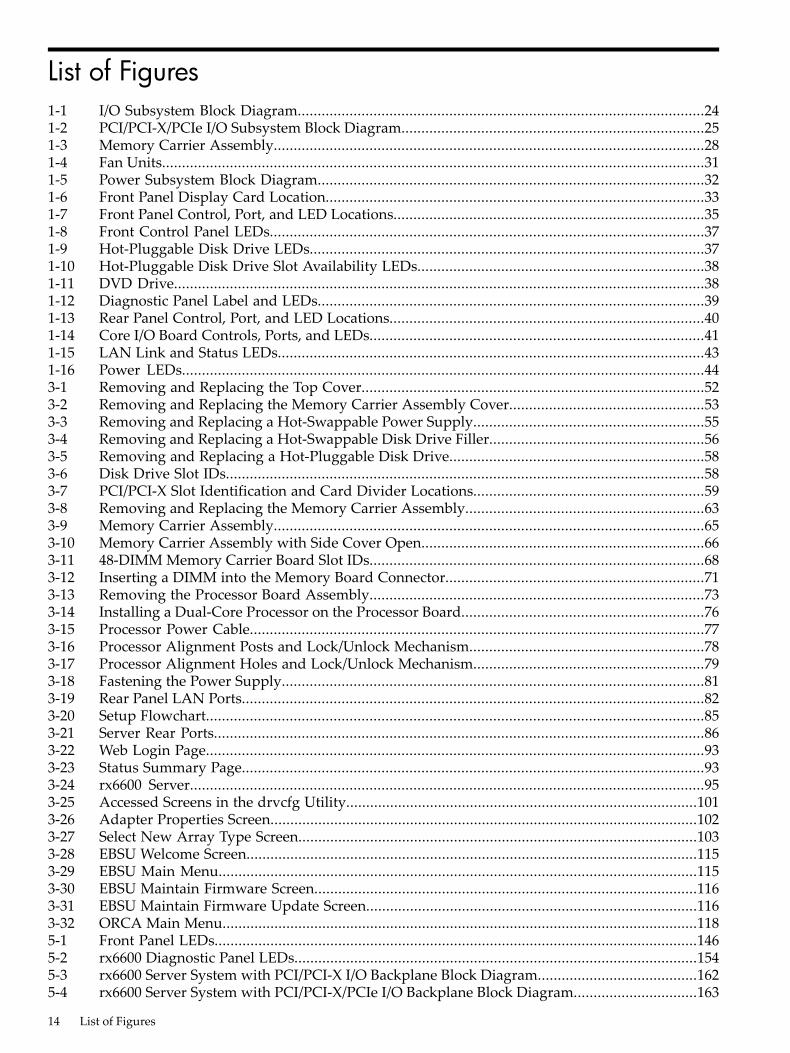
List of Figures1-1 I/O Subsystem Block Diagram......................................................................................................241-2 PCI/PCI-X/PCIe I/O Subsystem Block Diagram............................................................................251-3 Memory Carrier Assembly............................................................................................................281-4 Fan Units........................................................................................................................................311-5 Power Subsystem Block Diagram.................................................................................................321-6 Front Panel Display Card Location...............................................................................................331-7 Front Panel Control, Port, and LED Locations..............................................................................351-8 Front Control Panel LEDs.............................................................................................................371-9 Hot-Pluggable Disk Drive LEDs...................................................................................................371-10 Hot-Pluggable Disk Drive Slot Availability LEDs........................................................................381-11 DVD Drive.....................................................................................................................................381-12 Diagnostic Panel Label and LEDs.................................................................................................391-13 Rear Panel Control, Port, and LED Locations...............................................................................401-14 Core I/O Board Controls, Ports, and LEDs....................................................................................411-15 LAN Link and Status LEDs...........................................................................................................431-16 Power LEDs...................................................................................................................................443-1 Removing and Replacing the Top Cover......................................................................................523-2 Removing and Replacing the Memory Carrier Assembly Cover.................................................533-3 Removing and Replacing a Hot-Swappable Power Supply..........................................................553-4 Removing and Replacing a Hot-Swappable Disk Drive Filler......................................................563-5 Removing and Replacing a Hot-Pluggable Disk Drive................................................................583-6 Disk Drive Slot IDs........................................................................................................................583-7 PCI/PCI-X Slot Identification and Card Divider Locations..........................................................593-8 Removing and Replacing the Memory Carrier Assembly............................................................633-9 Memory Carrier Assembly............................................................................................................653-10 Memory Carrier Assembly with Side Cover Open.......................................................................663-11 48-DIMM Memory Carrier Board Slot IDs....................................................................................683-12 Inserting a DIMM into the Memory Board Connector.................................................................713-13 Removing the Processor Board Assembly....................................................................................733-14 Installing a Dual-Core Processor on the Processor Board.............................................................763-15 Processor Power Cable..................................................................................................................773-16 Processor Alignment Posts and Lock/Unlock Mechanism...........................................................783-17 Processor Alignment Holes and Lock/Unlock Mechanism..........................................................793-18 Fastening the Power Supply..........................................................................................................813-19 Rear Panel LAN Ports....................................................................................................................823-20 Setup Flowchart.............................................................................................................................853-21 Server Rear Ports...........................................................................................................................863-22 Web Login Page.............................................................................................................................933-23 Status Summary Page....................................................................................................................933-24 rx6600 Server.................................................................................................................................953-25 Accessed Screens in the drvcfg Utility........................................................................................1013-26 Adapter Properties Screen...........................................................................................................1023-27 Select New Array Type Screen....................................................................................................1033-28 EBSU Welcome Screen.................................................................................................................1153-29 EBSU Main Menu........................................................................................................................1153-30 EBSU Maintain Firmware Screen................................................................................................1163-31 EBSU Maintain Firmware Update Screen...................................................................................1163-32 ORCA Main Menu.......................................................................................................................1185-1 Front Panel LEDs.........................................................................................................................1465-2 rx6600 Diagnostic Panel LEDs.....................................................................................................1545-3 rx6600 Server System with PCI/PCI-X I/O Backplane Block Diagram........................................1625-4 rx6600 Server System with PCI/PCI-X/PCIe I/O Backplane Block Diagram...............................163
14 List of Figures
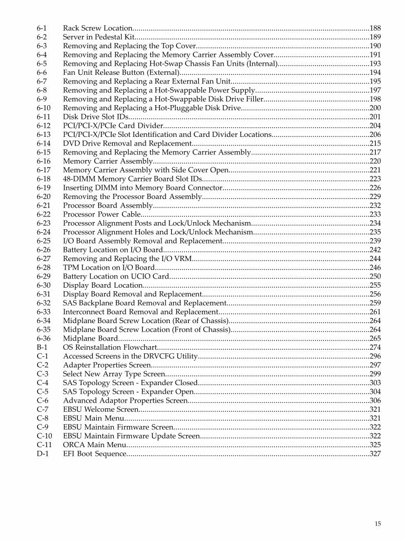
6-1 Rack Screw Location....................................................................................................................1886-2 Server in Pedestal Kit...................................................................................................................1896-3 Removing and Replacing the Top Cover.....................................................................................1906-4 Removing and Replacing the Memory Carrier Assembly Cover...............................................1916-5 Removing and Replacing Hot-Swap Chassis Fan Units (Internal).............................................1936-6 Fan Unit Release Button (External).............................................................................................1946-7 Removing and Replacing a Rear External Fan Unit....................................................................1956-8 Removing and Replacing a Hot-Swappable Power Supply........................................................1976-9 Removing and Replacing a Hot-Swappable Disk Drive Filler....................................................1986-10 Removing and Replacing a Hot-Pluggable Disk Drive...............................................................2006-11 Disk Drive Slot IDs......................................................................................................................2016-12 PCI/PCI-X/PCIe Card Divider.....................................................................................................2046-13 PCI/PCI-X/PCIe Slot Identification and Card Divider Locations................................................2066-14 DVD Drive Removal and Replacement.......................................................................................2156-15 Removing and Replacing the Memory Carrier Assembly..........................................................2176-16 Memory Carrier Assembly..........................................................................................................2206-17 Memory Carrier Assembly with Side Cover Open.....................................................................2216-18 48-DIMM Memory Carrier Board Slot IDs..................................................................................2236-19 Inserting DIMM into Memory Board Connector........................................................................2266-20 Removing the Processor Board Assembly..................................................................................2296-21 Processor Board Assembly..........................................................................................................2326-22 Processor Power Cable................................................................................................................2336-23 Processor Alignment Posts and Lock/Unlock Mechanism..........................................................2346-24 Processor Alignment Holes and Lock/Unlock Mechanism.........................................................2356-25 I/O Board Assembly Removal and Replacement........................................................................2396-26 Battery Location on I/O Board.....................................................................................................2426-27 Removing and Replacing the I/O VRM.......................................................................................2446-28 TPM Location on I/O Board.........................................................................................................2466-29 Battery Location on UCIO Card..................................................................................................2506-30 Display Board Location...............................................................................................................2556-31 Display Board Removal and Replacement..................................................................................2566-32 SAS Backplane Board Removal and Replacement......................................................................2596-33 Interconnect Board Removal and Replacement..........................................................................2616-34 Midplane Board Screw Location (Rear of Chassis).....................................................................2646-35 Midplane Board Screw Location (Front of Chassis)....................................................................2646-36 Midplane Board...........................................................................................................................265B-1 OS Reinstallation Flowchart........................................................................................................274C-1 Accessed Screens in the DRVCFG Utility....................................................................................296C-2 Adapter Properties Screen...........................................................................................................297C-3 Select New Array Type Screen....................................................................................................299C-4 SAS Topology Screen - Expander Closed....................................................................................303C-5 SAS Topology Screen - Expander Open......................................................................................304C-6 Advanced Adaptor Properties Screen.........................................................................................306C-7 EBSU Welcome Screen.................................................................................................................321C-8 EBSU Main Menu........................................................................................................................321C-9 EBSU Maintain Firmware Screen................................................................................................322C-10 EBSU Maintain Firmware Update Screen...................................................................................322C-11 ORCA Main Menu.......................................................................................................................325D-1 EFI Boot Sequence.......................................................................................................................327
15
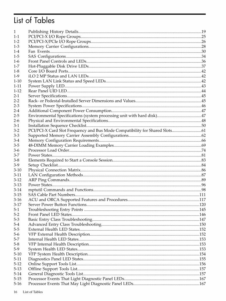
List of Tables1 Publishing History Details............................................................................................................191-1 PCI/PCI-X I/O Rope Groups..........................................................................................................251-2 PCI/PCI-X/PCIe I/O Rope Groups.................................................................................................261-3 Memory Carrier Configurations...................................................................................................281-4 Fan Events.....................................................................................................................................301-5 SAS Configurations.......................................................................................................................341-6 Front Panel Controls and LEDs.....................................................................................................361-7 Hot-Pluggable Disk Drive LEDs...................................................................................................371-8 Core I/O Board Ports.....................................................................................................................421-9 iLO 2 MP Status and LAN LEDs...................................................................................................421-10 System LAN Link Status and Speed LEDs....................................................................................421-11 Power Supply LED........................................................................................................................431-12 Rear Panel UID LED......................................................................................................................442-1 Server Specifications......................................................................................................................452-2 Rack- or Pedestal-Installed Server Dimensions and Values..........................................................452-3 System Power Specifications.........................................................................................................462-4 Additional Component Power Consumption...............................................................................472-5 Environmental Specifications (system processing unit with hard disk).......................................472-6 Physical and Environmental Specifications..................................................................................483-1 Installation Sequence Checklist.....................................................................................................503-2 PCI/PCI-X Card Slot Frequency and Bus Mode Compatibility for Shared Slots..........................613-3 Supported Memory Carrier Assembly Configurations................................................................623-4 Memory Configuration Requirements..........................................................................................663-5 48-DIMM Memory Carrier Loading Examples.............................................................................693-6 Processor Load Order....................................................................................................................743-7 Power States...................................................................................................................................813-8 Elements Required to Start a Console Session..............................................................................833-9 Setup Checklist..............................................................................................................................843-10 Physical Connection Matrix..........................................................................................................863-11 LAN Configuration Methods........................................................................................................873-12 ARP Ping Commands....................................................................................................................893-13 Power States...................................................................................................................................963-14 mptutil Commands and Functions...............................................................................................983-15 SAS Cable Part Numbers.............................................................................................................1113-16 ACU and ORCA Supported Features and Procedures...............................................................1173-17 Server Power Button Functions...................................................................................................1205-1 Troubleshooting Entry Points .....................................................................................................1455-2 Front Panel LED States................................................................................................................1465-3 Basic Entry Class Troubleshooting..............................................................................................1475-4 Advanced Entry Class Troubleshooting......................................................................................1505-5 External Health LED States.........................................................................................................1525-6 VFP External Health Description................................................................................................1525-7 Internal Health LED States..........................................................................................................1535-8 VFP Internal Health Description.................................................................................................1535-9 System Health LED States...........................................................................................................1535-10 VFP System Health Description..................................................................................................1545-11 Diagnostics Panel LED States......................................................................................................1555-12 Online Support Tools List............................................................................................................1565-13 Offline Support Tools List...........................................................................................................1575-14 General Diagnostic Tools List......................................................................................................1575-15 Processor Events That Light Diagnostic Panel LEDs..................................................................1675-16 Processor Events That May Light Diagnostic Panel LEDs..........................................................167
16 List of Tables
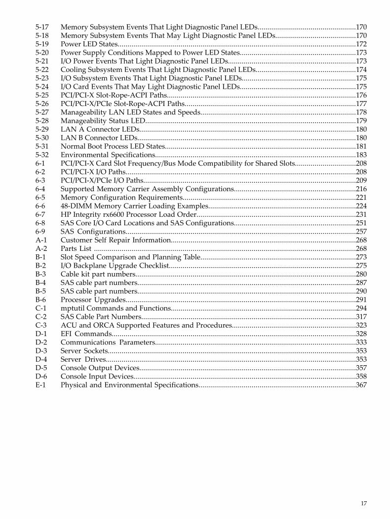
5-17 Memory Subsystem Events That Light Diagnostic Panel LEDs..................................................1705-18 Memory Subsystem Events That May Light Diagnostic Panel LEDs.........................................1705-19 Power LED States.........................................................................................................................1725-20 Power Supply Conditions Mapped to Power LED States...........................................................1735-21 I/O Power Events That Light Diagnostic Panel LEDs.................................................................1735-22 Cooling Subsystem Events That Light Diagnostic Panel LEDs...................................................1745-23 I/O Subsystem Events That Light Diagnostic Panel LEDs..........................................................1755-24 I/O Card Events That May Light Diagnostic Panel LEDs...........................................................1755-25 PCI/PCI-X Slot-Rope-ACPI Paths................................................................................................1765-26 PCI/PCI-X/PCIe Slot-Rope-ACPI Paths.......................................................................................1775-27 Manageability LAN LED States and Speeds...............................................................................1785-28 Manageability Status LED...........................................................................................................1795-29 LAN A Connector LEDs..............................................................................................................1805-30 LAN B Connector LEDs...............................................................................................................1805-31 Normal Boot Process LED States.................................................................................................1815-32 Environmental Specifications......................................................................................................1836-1 PCI/PCI-X Card Slot Frequency/Bus Mode Compatibility for Shared Slots...............................2086-2 PCI/PCI-X I/O Paths.....................................................................................................................2086-3 PCI/PCI-X/PCIe I/O Paths............................................................................................................2096-4 Supported Memory Carrier Assembly Configurations..............................................................2166-5 Memory Configuration Requirements........................................................................................2216-6 48-DIMM Memory Carrier Loading Examples...........................................................................2246-7 HP Integrity rx6600 Processor Load Order.................................................................................2316-8 SAS Core I/O Card Locations and SAS Configurations..............................................................2516-9 SAS Configurations.....................................................................................................................257A-1 Customer Self Repair Information..............................................................................................268A-2 Parts List .....................................................................................................................................268B-1 Slot Speed Comparison and Planning Table...............................................................................273B-2 I/O Backplane Upgrade Checklist...............................................................................................275B-3 Cable kit part numbers................................................................................................................280B-4 SAS cable part numbers...............................................................................................................287B-5 SAS cable part numbers...............................................................................................................290B-6 Processor Upgrades.....................................................................................................................291C-1 mptutil Commands and Functions..............................................................................................294C-2 SAS Cable Part Numbers.............................................................................................................317C-3 ACU and ORCA Supported Features and Procedures...............................................................323D-1 EFI Commands............................................................................................................................328D-2 Communications Parameters......................................................................................................333D-3 Server Sockets..............................................................................................................................353D-4 Server Drives...............................................................................................................................353D-5 Console Output Devices..............................................................................................................357D-6 Console Input Devices.................................................................................................................358E-1 Physical and Environmental Specifications................................................................................367
17
List of Examples6-1 Enabling the TPM........................................................................................................................247D-1 help command...........................................................................................................................331D-2 help bch command...................................................................................................................331D-3 help configuration command.............................................................................................331D-4 help cpuconfig command.....................................................................................................332D-5 help ioconfig command........................................................................................................332D-6 boottest command...................................................................................................................334D-7 boottest early_cpu off command....................................................................................334D-8 cpuconfig command................................................................................................................335D-9 cpuconfig 2 command............................................................................................................335D-10 conconfig command................................................................................................................335D-11 conconfig 2 primary command..........................................................................................336D-12 conconfig 3 off command...................................................................................................336D-13 conconfig 3 on command.....................................................................................................336D-14 ioconfig command...................................................................................................................337D-15 info all command...................................................................................................................339D-16 info cpu command...................................................................................................................342D-17 info mem command...................................................................................................................342D-18 info io command.....................................................................................................................343D-19 info boot command................................................................................................................344D-20 lanaddress command..............................................................................................................344D-21 monarch command.....................................................................................................................345D-22 pdt command..............................................................................................................................346D-23 pdt clear command................................................................................................................346D-24 sysmode command.....................................................................................................................347
18 List of Examples
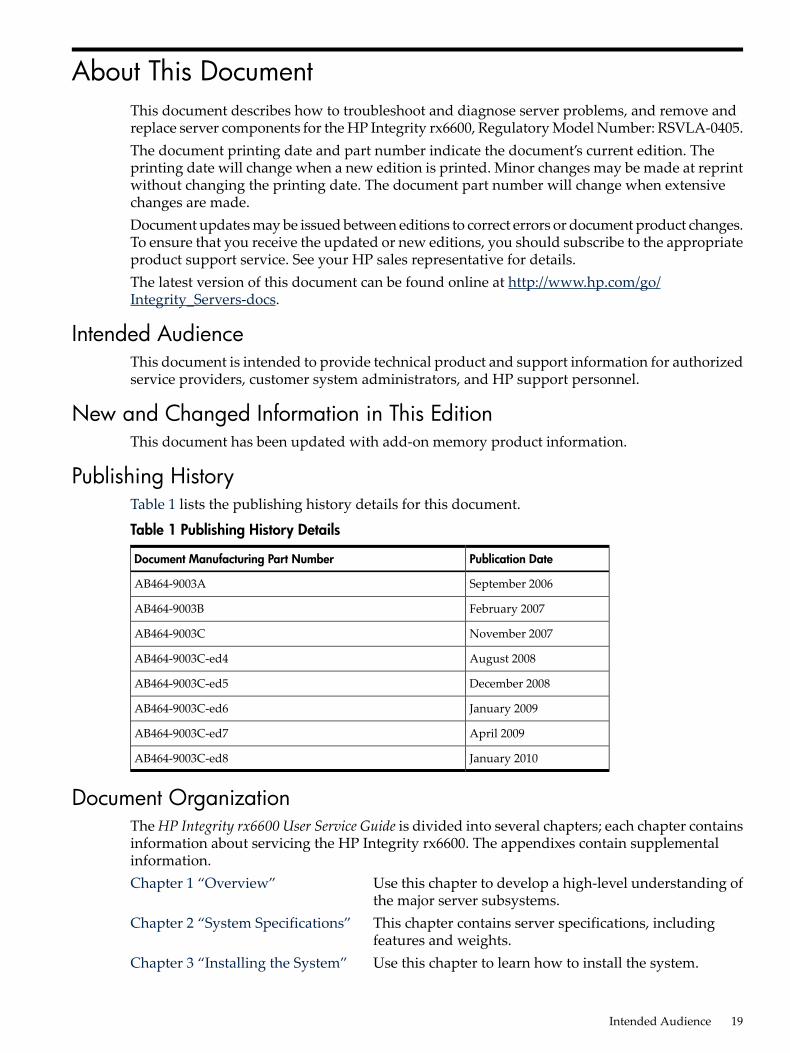
About This DocumentThis document describes how to troubleshoot and diagnose server problems, and remove andreplace server components for the HP Integrity rx6600, Regulatory Model Number: RSVLA-0405.The document printing date and part number indicate the document’s current edition. Theprinting date will change when a new edition is printed. Minor changes may be made at reprintwithout changing the printing date. The document part number will change when extensivechanges are made.Document updates may be issued between editions to correct errors or document product changes.To ensure that you receive the updated or new editions, you should subscribe to the appropriateproduct support service. See your HP sales representative for details.The latest version of this document can be found online at http://www.hp.com/go/Integrity_Servers-docs.
Intended AudienceThis document is intended to provide technical product and support information for authorizedservice providers, customer system administrators, and HP support personnel.
New and Changed Information in This EditionThis document has been updated with add-on memory product information.
Publishing HistoryTable 1 lists the publishing history details for this document.
Table 1 Publishing History Details
Publication DateDocument Manufacturing Part Number
September 2006AB464-9003A
February 2007AB464-9003B
November 2007AB464-9003C
August 2008AB464-9003C-ed4
December 2008AB464-9003C-ed5
January 2009AB464-9003C-ed6
April 2009AB464-9003C-ed7
January 2010AB464-9003C-ed8
Document OrganizationThe HP Integrity rx6600 User Service Guide is divided into several chapters; each chapter containsinformation about servicing the HP Integrity rx6600. The appendixes contain supplementalinformation.Chapter 1 “Overview” Use this chapter to develop a high-level understanding of
the major server subsystems.Chapter 2 “System Specifications” This chapter contains server specifications, including
features and weights.Chapter 3 “Installing the System” Use this chapter to learn how to install the system.
Intended Audience 19
Chapter 4 “Booting and ShuttingDown the Operating System”
This chapter provides information on how to boot and shutdown the operating systems supported on the server.
Chapter 5 “Troubleshooting” Use this chapter to help troubleshoot and diagnose serverproblems.
Chapter 6 “Removing and ReplacingServer Components”
Use this chapter to learn how to remove and replace servercomponents.
Appendix A “Customer ReplaceableUnits Information”
This appendix lists the field replaceable units (FRU).
Appendix B “Upgrades” Use this appendix to learn upgrade procedures.Appendix C “Core I/O CardUtilities”
Use this appendix for information on core I/O cards thatneed additional configuration.
Appendix D “Utilities” This appendix provides information on ExtensibleFirmware Interface (EFI) Boot Manager.
Typographic ConventionsThis document uses the following conventions.%, $, or # A percent sign represents the C shell system prompt. A dollar
sign represents the system prompt for the Bourne, Korn, andPOSIX shells. A number sign represents the superuser prompt.
Command A command name or qualified command phrase.Computer output Text displayed by the computer.Ctrl+x A key sequence. A sequence such as Ctrl+x indicates that you
must hold down the key labeled Ctrl while you press anotherkey or mouse button.
ENVIRONMENT VARIABLE The name of an environment variable, for example, PATH.[ERROR NAME] The name of an error, usually returned in the errno variable.Key The name of a keyboard key. Return and Enter both refer to the
same key.Term The defined use of an important word or phrase.User input Commands and other text that you type.Variable The name of a placeholder in a command, function, or other
syntax display that you replace with an actual value.[] The contents are optional in syntax. If the contents are a list
separated by |, you must choose one of the items.{} The contents are required in syntax. If the contents are a list
separated by |, you must choose one of the items.... The preceding element can be repeated an arbitrary number of
times.Indicates the continuation of a code example.
| Separates items in a list of choices.WARNING A warning calls attention to important information that if not
understood or followed will result in personal injury ornonrecoverable system problems.
CAUTION A caution calls attention to important information that if notunderstood or followed will result in data loss, data corruption,or damage to hardware or software.
20
IMPORTANT This alert provides essential information to explain a concept orto complete a task
NOTE A note contains additional information to emphasize orsupplement important points of the main text.
Related DocumentsYou can find other information on HP server hardware management and diagnostic supporttools in the following publications.HP Technical Documentation Websitehttp://www.hp.com/go/Integrity_Servers-docsWindows Operating System InformationFind information about administration of the Microsoft Windows operating system at thefollowing website:http://www.microsoft.com/technet/Diagnostics and Event Monitoring: Hardware Support ToolsComplete information about HP hardware support tools, including online and offline diagnosticsand event monitoring tools, is on the HP website at:http://www.docs.hp.com/HP-UX/diag/Website for HP Technical Supporthttp://h20219.www2.hp.com/services/cache/126868-0-0-225-121.html?jumpid=reg_R1002_USENBooks About HP-UX Published by Prentice HallYou can find the entire Prentice Hall Professional Series on HP at:http://www.informit.com/imprint/series_detail.aspx?st=61305
Contacting HP
Before You Contact HPBe sure to have the following information available before you call contact HP:• Technical support registration number (if applicable)• Product serial number• Product model name and number• Product identification number• Applicable error message• Add-on boards or hardware• Third-party hardware or software• Operating system type and revision level
HP Contact InformationFor the name of the nearest HP authorized reseller:• In the United States, see the HP US service locator webpage (http://welcome.hp.com/country/
us/en/wwcontact.html.)• In other locations, see the Contact HP worldwide (in English) webpage:
http://welcome.hp.com/country/us/en/wwcontact.html.
Related Documents 21

For HP technical support:• In the United States, for contact options see the Contact HP United States webpage: (http://
welcome.hp.com/country/us/en/contact_us.html)To contact HP by phone:— Call 1-800-HP-INVENT (1-800-474-6836). This service is available 24 hours a day, 7 days
a week. For continuous quality improvement, calls may be recorded or monitored.— If you have purchased a Care Pack (service upgrade), call 1-800-633-3600. For more
information about Care Packs, refer to the HP website: (http://www.hp.com/hps).
• In other locations, see the Contact HP worldwide (in English) webpage (http://welcome.hp.com/country/us/en/wwcontact.html).
Subscription ServiceHP recommends that you register your product at the Subscriber's Choice for Business website:http://www.hp.com/country/us/en/contact_us.html.
Documentation FeedbackHP welcomes your feedback. To make comments and suggestions about product documentation,send a message to [email protected] the document title and manufacturing part number. All submissions become the propertyof HP.
22
1 OverviewThe HP Integrity rx6600 server is a high performance, high availability server that provides thefollowing features:• Form factor - 7U rack- or pedestal installed• Internal peripherals - serial-attached SCSI (SAS) hard drives and a DVD or DVD+RW drive• High availability components -hot-swappable dual-rotor N+1 fans, 1+1 hot-swappable power
supplies, and hot-pluggable PCI-X or PCIe cards and SAS drives• Processors - up to four dual-core Intel® Itanium® processors• Memory - up to 384 GB of memoryThis chapter addresses the following topics:• “Server Subsystems” (page 23)
— “I/O” (page 23)— “Processor” (page 27)— “Memory” (page 27)— “Cooling” (page 30)— “Power” (page 31)— “Front Display Panel, DVD, and Diagnostic Panel” (page 33)— “Mass Storage” (page 33)
• “Firmware” (page 34)• “Controls, Ports, and LEDs” (page 35)
— “Front Panel” (page 35)— “Storage and Media Devices” (page 37)— “Diagnostic Panel” (page 38)— “Rear Panel” (page 39)
Server Subsystems
I/OThe server may contain either a 10-slot PCI/PCI-X IOBP or a 10-slot PCI/PCI-X/PCIe IOBP. ThePCI/PCI-X/PCIe interfaces are classified under two major categories: public and private.Public interfaces Public interfaces are PCI slot connectors that are left available to the customerfor the I/O-card adapters which they wish to install, based on their application needs, providedthe adapter is supported in the slot. All public slots support HP server traditional OL* hot-plugoperations.Private interfaces Private interfaces are interfaces dedicated to meeting the core I/O systemrequirements. There are two types of core-I/O: fast-core and slow-core, also known as the UCIO(Unified Core-I/O). The Private slots and UCIO are not hot-pluggable.Hot-plug PCI/PCI-X/PCIe hot-pluggable operations enable you to add or remove aPCI/PCI-X/PCIe card while the server is powered on. Each slot is physically separated with adivider that contains a card extraction mechanism and a mechanical retention latch (MRL). Slots3 - 10 on the 10 slot PCI/PCI-X IOBP and slots 5 - 10 on the 10 slot PCI/PCI-X/PCIe IOBP supportHP-server traditional OL* "hot-plug" operations. PDHP slots rely on the facilities of DHPC (DualHot-plug Controller) FPGAs to enable OL* hot-plug functionality. See Table 1-1 (page 25) andTable 1-2 (page 26) for details.LEDs Attention LEDs, doorbell buttons, and power LEDs for each hot-pluggable PCI/PCI-X/PCIeslot are located on the PCI bulkhead at the rear of the server chassis.
Server Subsystems 23
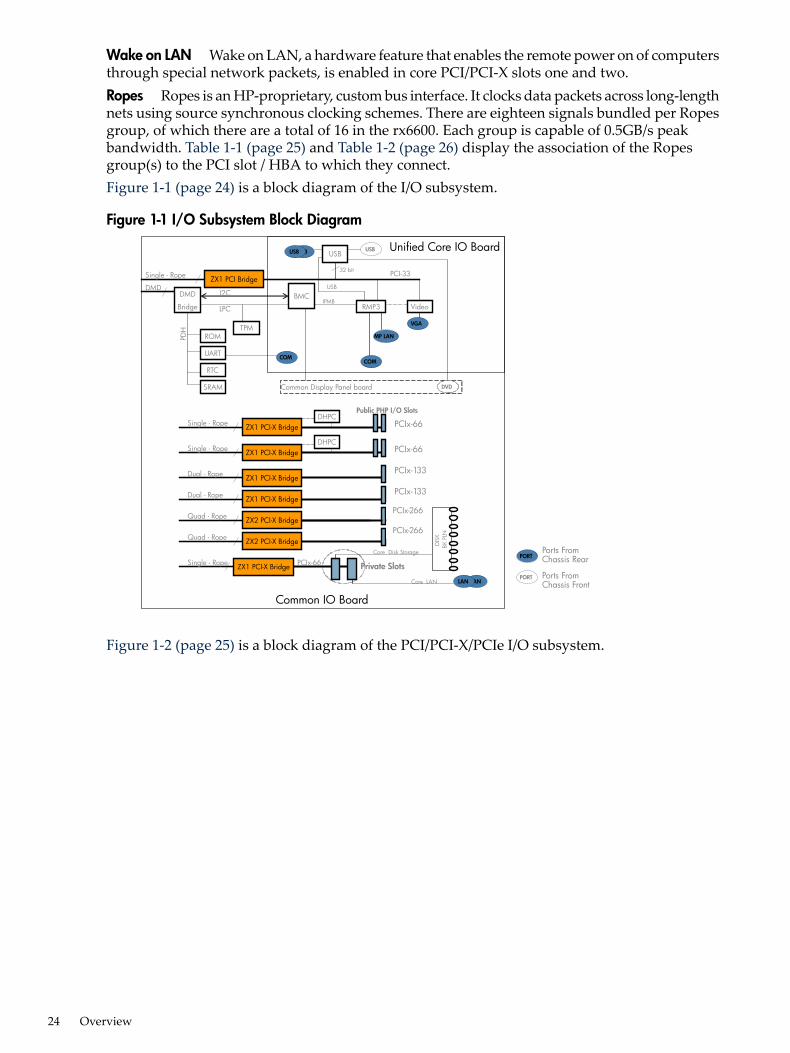
Wake on LAN Wake on LAN, a hardware feature that enables the remote power on of computersthrough special network packets, is enabled in core PCI/PCI-X slots one and two.Ropes Ropes is an HP-proprietary, custom bus interface. It clocks data packets across long-lengthnets using source synchronous clocking schemes. There are eighteen signals bundled per Ropesgroup, of which there are a total of 16 in the rx6600. Each group is capable of 0.5GB/s peakbandwidth. Table 1-1 (page 25) and Table 1-2 (page 26) display the association of the Ropesgroup(s) to the PCI slot / HBA to which they connect.Figure 1-1 (page 24) is a block diagram of the I/O subsystem.
Figure 1-1 I/O Subsystem Block Diagram
PORTPorts FromChassis Rear
PORT Ports FromChassis Front
Single - Rope
Dual - Rope
Single - Rope
ZX1 PCI-X Bridge PCIx-66
PCIx-66
PCIx-133
Public PHP I/O Slots
LANLAN
Single - Rope
PCIx-66
Dual - Rope PCIx-133
Private Slots
Core LAN
Core Disk Storage
DISK
BKPLN
Quad - Rope PCIx-267
DHPC
DHPC
Quad - RopePCIx-267
ZX1 PCI-X Bridge
ZX1 PCI-X Bridge
ZX1 PCI-X Bridge
ZX2 PCI-X Bridge
ZX2 PCI-X Bridge
ZX1 PCI-X Bridge
Common IO Board
Single - Rope
DMDDMD
Bridge Video
USB
RMP3BMC
PCI-33
LPC
PDH
ROM
UART
RTCCOM
MP LAN
VGA
USBUSB
Common Display Panel board DVD
TPM
USB
USB
IPMB
32 bit
ZX1 PCI Bridge
Unified Core IO Board
I2C
COM
SRAM
PCIx-266
PCIx-266
Figure 1-2 (page 25) is a block diagram of the PCI/PCI-X/PCIe I/O subsystem.
24 Overview
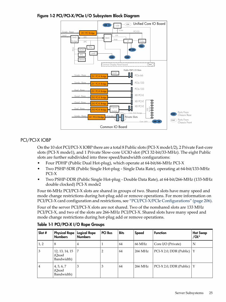
Figure 1-2 PCI/PCI-X/PCIe I/O Subsystem Block Diagram
PORTPorts FromChassis Rear
PORT Ports FromChassis Front
Single - Rope
Dual - Rope
Single - Rope
ZX1 PCI-X Bridge PCIx-66
PCIx-133
PCIx-133
Public PHP I/O Slots
LANLAN
Single - Rope
PCIx-66
Quad - Rope X8 PCI-E
Private Slots
Core LAN
Core Disk Storage
DISK
BKPLN
Quad - Rope X8 PCI-E
DHPC
Express
SwitchDual - Rope
X8 PCI-E
ZX1 PCI-X Bridge
ZX1 PCI-X Bridge
ZX2 PCI-E Bridge
ZX2 PCI-E Bridge
ZX2 PCI-E Bridge
ZX1 PCI-X Bridge
Common IO Board
Single - Rope
DMDDMD
Bridge Video
USB
SPBMC
PCI-33
LPC
PDH
ROM
RTC
SRAMCOM
MP LAN
VGA
USBUSB
Common Display Panel board DVD
TPM
USB
USB
IPMB
32 bit
ZX1 PCI Bridge
Unified Core IO Board
I2C
COM
UART
PCI/PCI-X IOBPOn the 10 slot PCI/PCI-X IOBP there are a total 8 Public slots (PCI-X mode1/2), 2 Private Fast-coreslots (PCI-X mode1), and 1 Private Slow-core UCIO slot (PCI 32-bit/33-MHz). The eight Publicslots are further subdivided into three speed/bandwidth configurations:• Four PDHP (Public Dual Hot-plug), which operate at 64-bit/66-MHz PCI-X• Two PSHP-SDR (Public Single Hot-plug - Single Data Rate), operating at 64-bit/133-MHz
PCI-X• Two PSHP-DDR (Public Single Hot-plug - Double Data Rate), at 64-bit/266-MHz (133-MHz
double clocked) PCI-X mode2Four 66-MHz PCI/PCI-X slots are shared in groups of two. Shared slots have many speed andmode change restrictions during hot-plug add or remove operations. For more information onPCI/PCI-X card configuration and restrictions, see “PCI/PCI-X/PCIe Configurations” (page 206).Four of the server PCI/PCI-X slots are not shared. Two of the nonshared slots are 133 MHzPCI/PCI-X, and two of the slots are 266-MHz PCI/PCI-X. Shared slots have many speed andmode change restrictions during hot-plug add or remove operations.
Table 1-1 PCI/PCI-X I/O Rope Groups
Hot Swap/OL*
FunctionSpeedBitsPCI BusLogical RopeNumbers
Physical RopeNumbers
Slot #
NCore I/O (Private)66 MHz641481, 2
YPCI-X 2.0, DDR (Public)266 MHz642712, 13, 14, 15(QuadBandwidth)
3
YPCI-X 2.0, DDR (Public)266 MHz64334, 5, 6, 7(QuadBandwidth)
4
Server Subsystems 25
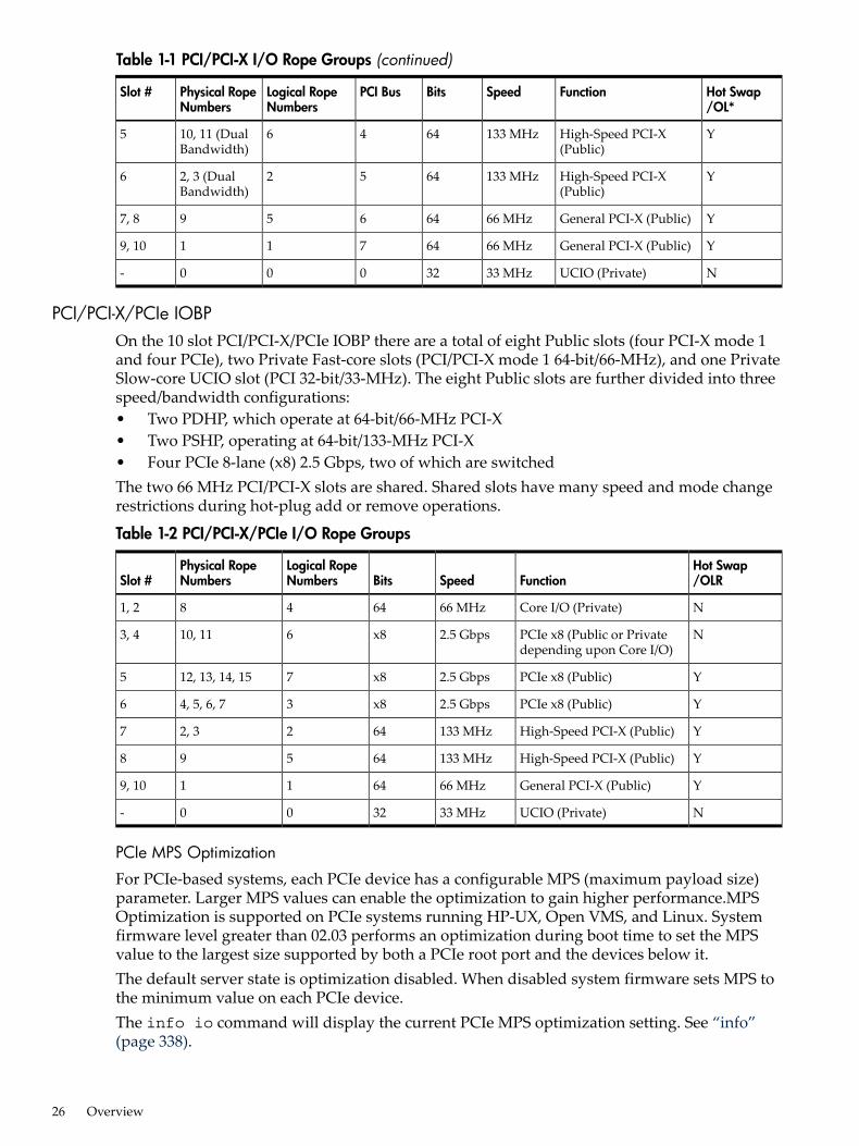
Table 1-1 PCI/PCI-X I/O Rope Groups (continued)
Hot Swap/OL*
FunctionSpeedBitsPCI BusLogical RopeNumbers
Physical RopeNumbers
Slot #
YHigh-Speed PCI-X(Public)
133 MHz644610, 11 (DualBandwidth)
5
YHigh-Speed PCI-X(Public)
133 MHz64522, 3 (DualBandwidth)
6
YGeneral PCI-X (Public)66 MHz646597, 8
YGeneral PCI-X (Public)66 MHz647119, 10
NUCIO (Private)33 MHz32000-
PCI/PCI-X/PCIe IOBPOn the 10 slot PCI/PCI-X/PCIe IOBP there are a total of eight Public slots (four PCI-X mode 1and four PCIe), two Private Fast-core slots (PCI/PCI-X mode 1 64-bit/66-MHz), and one PrivateSlow-core UCIO slot (PCI 32-bit/33-MHz). The eight Public slots are further divided into threespeed/bandwidth configurations:• Two PDHP, which operate at 64-bit/66-MHz PCI-X• Two PSHP, operating at 64-bit/133-MHz PCI-X• Four PCIe 8-lane (x8) 2.5 Gbps, two of which are switchedThe two 66 MHz PCI/PCI-X slots are shared. Shared slots have many speed and mode changerestrictions during hot-plug add or remove operations.
Table 1-2 PCI/PCI-X/PCIe I/O Rope Groups
Hot Swap/OLRFunctionSpeedBits
Logical RopeNumbers
Physical RopeNumbersSlot #
NCore I/O (Private)66 MHz64481, 2
NPCIe x8 (Public or Privatedepending upon Core I/O)
2.5 Gbpsx8610, 113, 4
YPCIe x8 (Public)2.5 Gbpsx8712, 13, 14, 155
YPCIe x8 (Public)2.5 Gbpsx834, 5, 6, 76
YHigh-Speed PCI-X (Public)133 MHz6422, 37
YHigh-Speed PCI-X (Public)133 MHz64598
YGeneral PCI-X (Public)66 MHz64119, 10
NUCIO (Private)33 MHz3200-
PCIe MPS Optimization
For PCIe-based systems, each PCIe device has a configurable MPS (maximum payload size)parameter. Larger MPS values can enable the optimization to gain higher performance.MPSOptimization is supported on PCIe systems running HP-UX, Open VMS, and Linux. Systemfirmware level greater than 02.03 performs an optimization during boot time to set the MPSvalue to the largest size supported by both a PCIe root port and the devices below it.The default server state is optimization disabled. When disabled system firmware sets MPS tothe minimum value on each PCIe device.The info io command will display the current PCIe MPS optimization setting. See “info”(page 338).
26 Overview
To enable PCIe MPS optimization use the ioconfig mps_optimize command. See “ioconfig”(page 336).For non-PCIe systems, ioconfig and info io will not display the MPS optimization policysetting. The Set PCIe MPS Optimization boot manager menu also will not be displayed. Runningthe ioconfig mps_optimize [on|off] command from a non-PCIe system, the followingoutput will be displayed:-------------Shell> ioconfig mps_optimizeioconfig: PCIe MPS optimization is not supported.
Shell> ioconfig mps_optimize onioconfig: PCIe MPS optimization is not supported.Exit status code: Unsupported
Shell>-----------------
To restore MPS to the default values use thedefault clear command. See “default” (page 337).
ProcessorThe server processor subsystem accommodates one, two, three, or four dual-core Itaniumprocessor modules. The processor subsystem consists of the following components:• zx2 CEC front side bus, memory, and I/O controller• System clock generation and distribution• Circuitry for manageability and fault detectionThe zx2 CEC and the processor modules are located on the processor board assembly. Eachprocessor connects to the processor board through a zero insertion force (ZIF) socket. The processorboard is mounted on a removable carrier tray that is attached to the processor board access door.Access this assembly from the front of the server after the memory carrier is removed.
MemoryThe server DIMMS are seated on memory boards that are enclosed in an extractable memorycarrier assembly.
Server Subsystems 27
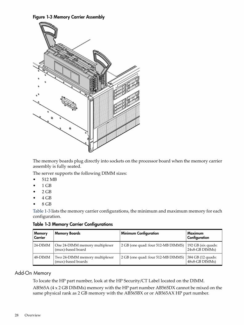
Figure 1-3 Memory Carrier Assembly
The memory boards plug directly into sockets on the processor board when the memory carrierassembly is fully seated.The server supports the following DIMM sizes:• 512 MB• 1 GB• 2 GB• 4 GB• 8 GBTable 1-3 lists the memory carrier configurations, the minimum and maximum memory for eachconfiguration.
Table 1-3 Memory Carrier Configurations
MaximumConfiguration
Minimum ConfigurationMemory BoardsMemoryCarrier
192 GB (six quads:24x8-GB DIMMs)
2 GB (one quad: four 512-MB DIMMS)One 24-DIMM memory multiplexer(mux)-based board
24-DIMM
384 GB (12 quads:48x8-GB DIMMs)
2 GB (one quad: four 512-MB DIMMS)Two 24-DIMM memory multiplexer(mux)-based boards
48-DIMM
Add-On MemoryTo locate the HP part number, look at the HP Security/CT Label located on the DIMM.AB565A (4 x 2 GB DIMMs) memory with the HP part number AB565DX cannot be mixed on thesame physical rank as 2 GB memory with the AB565BX or or AB565AX HP part number.
28 Overview
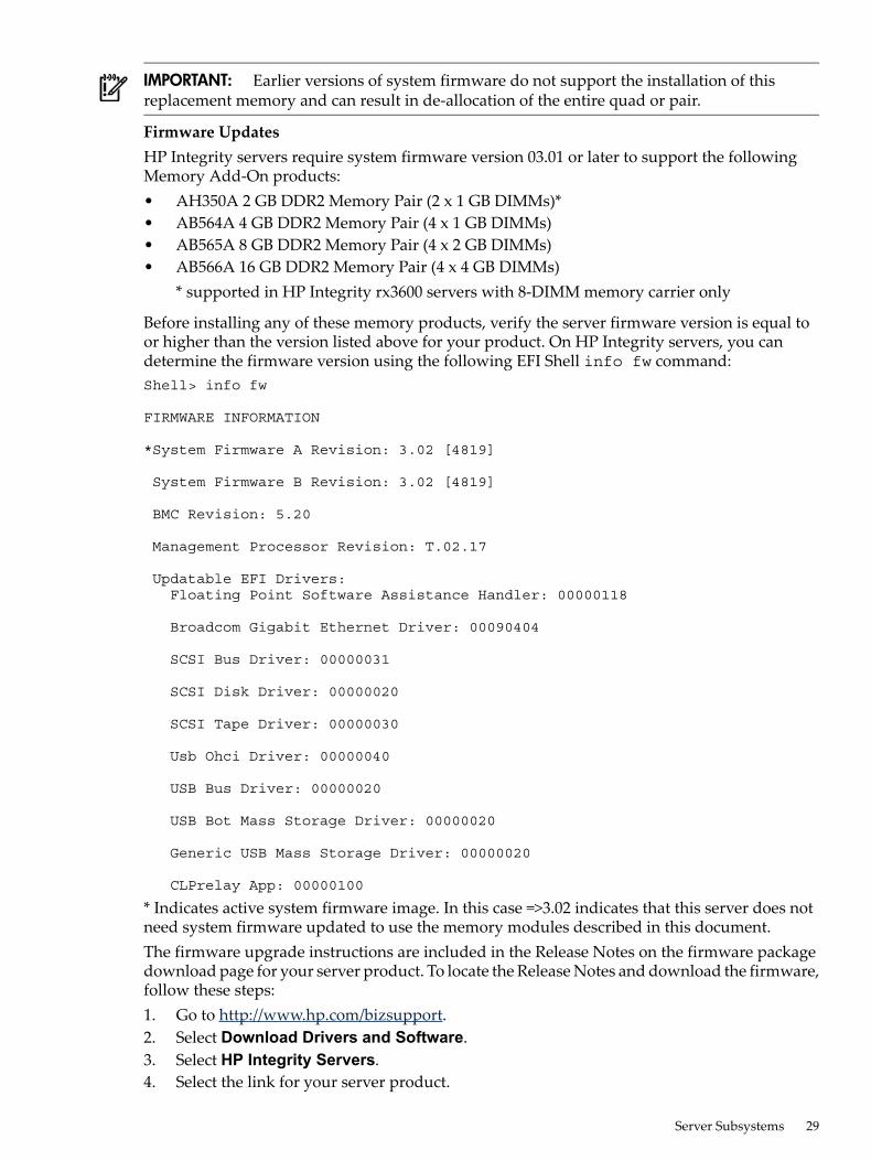
IMPORTANT: Earlier versions of system firmware do not support the installation of thisreplacement memory and can result in de-allocation of the entire quad or pair.
Firmware UpdatesHP Integrity servers require system firmware version 03.01 or later to support the followingMemory Add-On products:• AH350A 2 GB DDR2 Memory Pair (2 x 1 GB DIMMs)*• AB564A 4 GB DDR2 Memory Pair (4 x 1 GB DIMMs)• AB565A 8 GB DDR2 Memory Pair (4 x 2 GB DIMMs)• AB566A 16 GB DDR2 Memory Pair (4 x 4 GB DIMMs)
* supported in HP Integrity rx3600 servers with 8-DIMM memory carrier only
Before installing any of these memory products, verify the server firmware version is equal toor higher than the version listed above for your product. On HP Integrity servers, you candetermine the firmware version using the following EFI Shell info fw command:Shell> info fw
FIRMWARE INFORMATION
*System Firmware A Revision: 3.02 [4819]
System Firmware B Revision: 3.02 [4819]
BMC Revision: 5.20
Management Processor Revision: T.02.17
Updatable EFI Drivers: Floating Point Software Assistance Handler: 00000118
Broadcom Gigabit Ethernet Driver: 00090404
SCSI Bus Driver: 00000031
SCSI Disk Driver: 00000020
SCSI Tape Driver: 00000030
Usb Ohci Driver: 00000040
USB Bus Driver: 00000020
USB Bot Mass Storage Driver: 00000020
Generic USB Mass Storage Driver: 00000020
CLPrelay App: 00000100
* Indicates active system firmware image. In this case =>3.02 indicates that this server does notneed system firmware updated to use the memory modules described in this document.The firmware upgrade instructions are included in the Release Notes on the firmware packagedownload page for your server product. To locate the Release Notes and download the firmware,follow these steps:1. Go to http://www.hp.com/bizsupport.2. Select Download Drivers and Software.3. Select HP Integrity Servers.4. Select the link for your server product.
Server Subsystems 29
After the firmware has been downloaded, you can install the memory. To install DIMMs, see“Installing Memory” (page 224).
CoolingThere are six system fans assemblies that cool the server. The fans are hot-swappable,interchangeable and serviced through the top and rear of the chassis. The fan rotors are N+1,meaning that the server has 12 fan rotors (six fans), but can operate for a limited time with 11 or10 fan rotors running, see Table 1-4 (page 30). If the time threshold is reached, the serverautomatically shuts down to prevent an overtemperature condition.
Table 1-4 Fan Events
ActionEvent
All rotors to maximum speed1Server chassis top cover removed
All remaining rotors to maximum speedOne fan rotor fails or is too slow
All remaining rotors to maximum speed and hard shut down after twominutes of continuous failure
Two or more fan motors fail or are tooslow
All remaining rotors to maximum speed and hard shut down after twominutes of continuous failure2
One or more fan units removed
1NOTE: Although the fans speed up to provide cooling when the top cover is removed, HP recommends replacingthe top cover within 15 seconds.
2NOTE: HP recommends replacing fans within 20 seconds.
Airflow enters through the front and exhausts out the rear. Airflow baffles might be required tooptimize air circulation within the enclosure. Fans are monitored by the system to indicateperformance.The airflow strategy contains two thermal zones with three fan units in the bottom zone, andthree fan units in the upper zone along with two power supplies that provide their own individualcooling. Depending on the configuration, certain component locations will need filler panels.These installed airflow filler panels and blockers ensure airflow and EMI integrity. Internally,the system may require a CPU airflow baffle and a memory airflow baffle. Rear I/O bulkheadcovers are required in unoccupied slots. Each hot-swappable fan unit consists of two rotors.
30 Overview
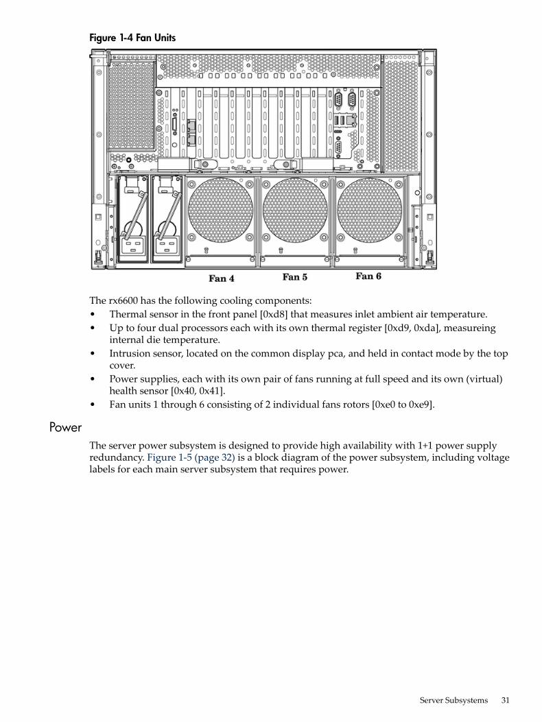
Figure 1-4 Fan Units
The rx6600 has the following cooling components:• Thermal sensor in the front panel [0xd8] that measures inlet ambient air temperature.• Up to four dual processors each with its own thermal register [0xd9, 0xda], measureing
internal die temperature.• Intrusion sensor, located on the common display pca, and held in contact mode by the top
cover.• Power supplies, each with its own pair of fans running at full speed and its own (virtual)
health sensor [0x40, 0x41].• Fan units 1 through 6 consisting of 2 individual fans rotors [0xe0 to 0xe9].
PowerThe server power subsystem is designed to provide high availability with 1+1 power supplyredundancy. Figure 1-5 (page 32) is a block diagram of the power subsystem, including voltagelabels for each main server subsystem that requires power.
Server Subsystems 31
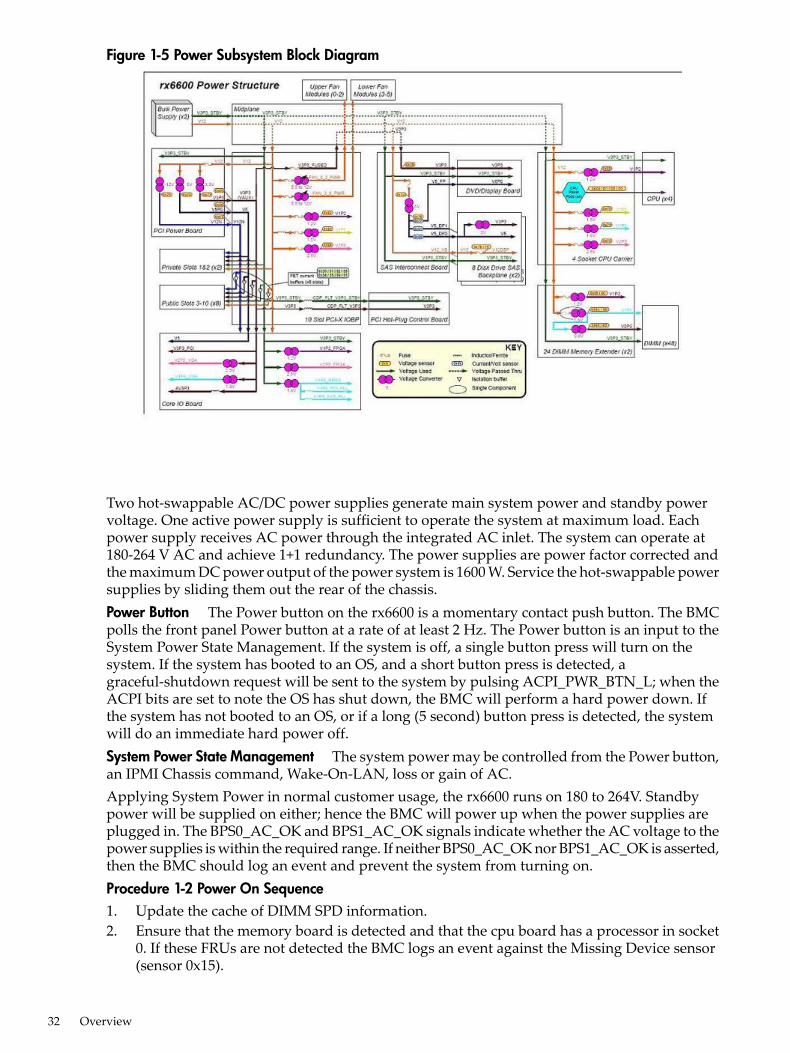
Figure 1-5 Power Subsystem Block Diagram
Two hot-swappable AC/DC power supplies generate main system power and standby powervoltage. One active power supply is sufficient to operate the system at maximum load. Eachpower supply receives AC power through the integrated AC inlet. The system can operate at180-264 V AC and achieve 1+1 redundancy. The power supplies are power factor corrected andthe maximum DC power output of the power system is 1600 W. Service the hot-swappable powersupplies by sliding them out the rear of the chassis.Power Button The Power button on the rx6600 is a momentary contact push button. The BMCpolls the front panel Power button at a rate of at least 2 Hz. The Power button is an input to theSystem Power State Management. If the system is off, a single button press will turn on thesystem. If the system has booted to an OS, and a short button press is detected, agraceful-shutdown request will be sent to the system by pulsing ACPI_PWR_BTN_L; when theACPI bits are set to note the OS has shut down, the BMC will perform a hard power down. Ifthe system has not booted to an OS, or if a long (5 second) button press is detected, the systemwill do an immediate hard power off.System Power State Management The system power may be controlled from the Power button,an IPMI Chassis command, Wake-On-LAN, loss or gain of AC.Applying System Power in normal customer usage, the rx6600 runs on 180 to 264V. Standbypower will be supplied on either; hence the BMC will power up when the power supplies areplugged in. The BPS0_AC_OK and BPS1_AC_OK signals indicate whether the AC voltage to thepower supplies is within the required range. If neither BPS0_AC_OK nor BPS1_AC_OK is asserted,then the BMC should log an event and prevent the system from turning on.Procedure 1-2 Power On Sequence1. Update the cache of DIMM SPD information.2. Ensure that the memory board is detected and that the cpu board has a processor in socket
0. If these FRUs are not detected the BMC logs an event against the Missing Device sensor(sensor 0x15).
32 Overview
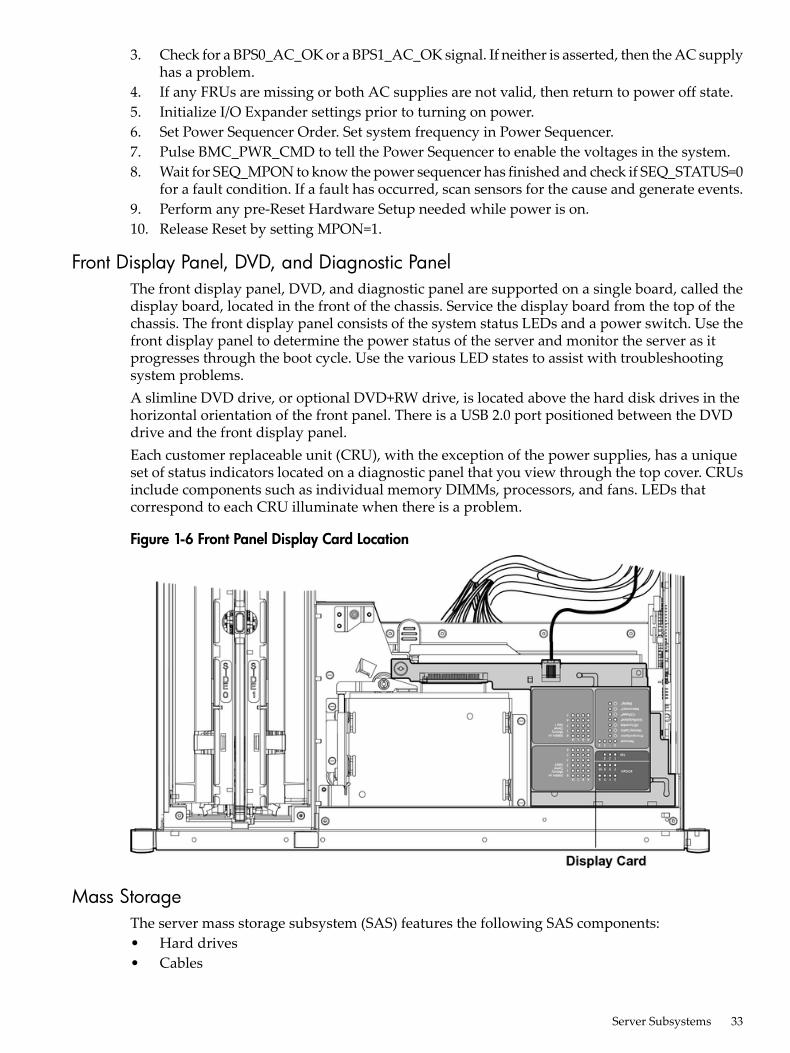
3. Check for a BPS0_AC_OK or a BPS1_AC_OK signal. If neither is asserted, then the AC supplyhas a problem.
4. If any FRUs are missing or both AC supplies are not valid, then return to power off state.5. Initialize I/O Expander settings prior to turning on power.6. Set Power Sequencer Order. Set system frequency in Power Sequencer.7. Pulse BMC_PWR_CMD to tell the Power Sequencer to enable the voltages in the system.8. Wait for SEQ_MPON to know the power sequencer has finished and check if SEQ_STATUS=0
for a fault condition. If a fault has occurred, scan sensors for the cause and generate events.9. Perform any pre-Reset Hardware Setup needed while power is on.10. Release Reset by setting MPON=1.
Front Display Panel, DVD, and Diagnostic PanelThe front display panel, DVD, and diagnostic panel are supported on a single board, called thedisplay board, located in the front of the chassis. Service the display board from the top of thechassis. The front display panel consists of the system status LEDs and a power switch. Use thefront display panel to determine the power status of the server and monitor the server as itprogresses through the boot cycle. Use the various LED states to assist with troubleshootingsystem problems.A slimline DVD drive, or optional DVD+RW drive, is located above the hard disk drives in thehorizontal orientation of the front panel. There is a USB 2.0 port positioned between the DVDdrive and the front display panel.Each customer replaceable unit (CRU), with the exception of the power supplies, has a uniqueset of status indicators located on a diagnostic panel that you view through the top cover. CRUsinclude components such as individual memory DIMMs, processors, and fans. LEDs thatcorrespond to each CRU illuminate when there is a problem.
Figure 1-6 Front Panel Display Card Location
Mass StorageThe server mass storage subsystem (SAS) features the following SAS components:• Hard drives• Cables
Server Subsystems 33
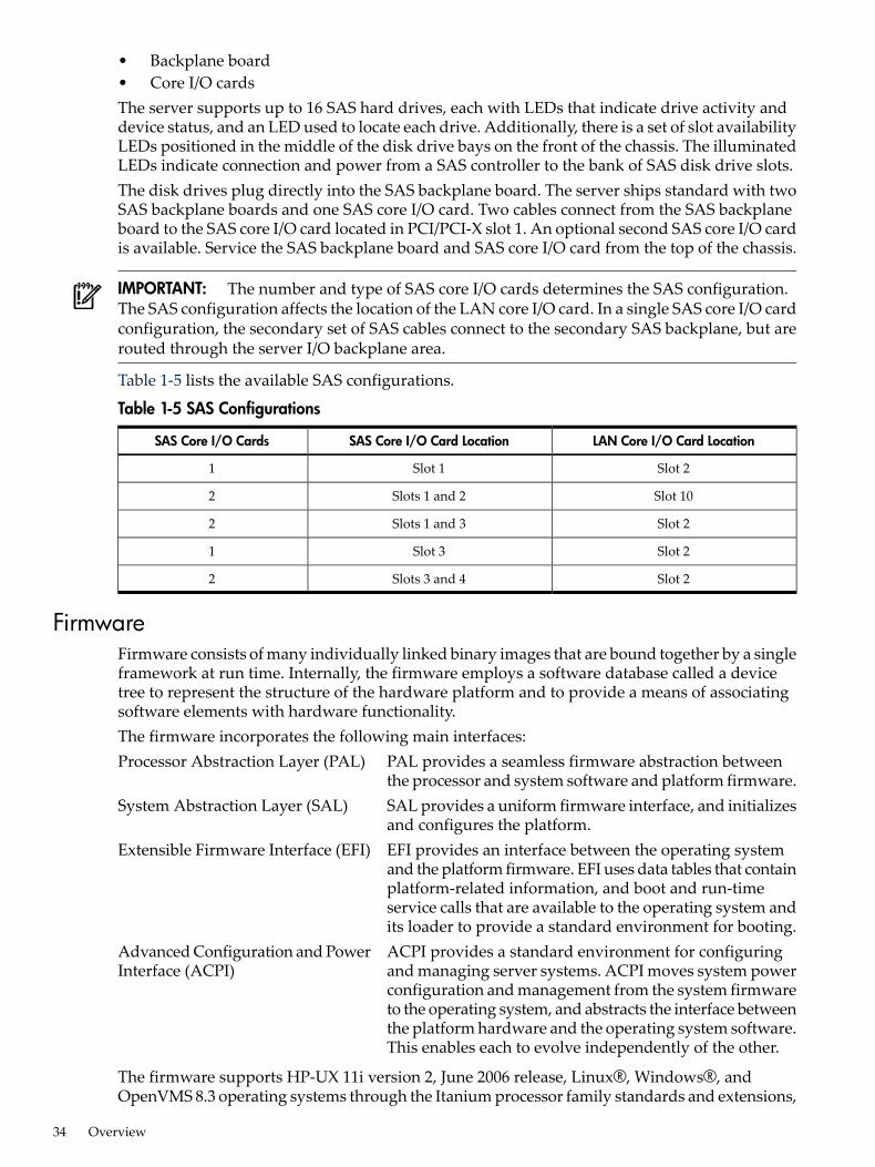
• Backplane board• Core I/O cardsThe server supports up to 16 SAS hard drives, each with LEDs that indicate drive activity anddevice status, and an LED used to locate each drive. Additionally, there is a set of slot availabilityLEDs positioned in the middle of the disk drive bays on the front of the chassis. The illuminatedLEDs indicate connection and power from a SAS controller to the bank of SAS disk drive slots.The disk drives plug directly into the SAS backplane board. The server ships standard with twoSAS backplane boards and one SAS core I/O card. Two cables connect from the SAS backplaneboard to the SAS core I/O card located in PCI/PCI-X slot 1. An optional second SAS core I/O cardis available. Service the SAS backplane board and SAS core I/O card from the top of the chassis.
IMPORTANT: The number and type of SAS core I/O cards determines the SAS configuration.The SAS configuration affects the location of the LAN core I/O card. In a single SAS core I/O cardconfiguration, the secondary set of SAS cables connect to the secondary SAS backplane, but arerouted through the server I/O backplane area.
Table 1-5 lists the available SAS configurations.
Table 1-5 SAS Configurations
LAN Core I/O Card LocationSAS Core I/O Card LocationSAS Core I/O Cards
Slot 2Slot 11
Slot 10Slots 1 and 22
Slot 2Slots 1 and 32
Slot 2Slot 31
Slot 2Slots 3 and 42
FirmwareFirmware consists of many individually linked binary images that are bound together by a singleframework at run time. Internally, the firmware employs a software database called a devicetree to represent the structure of the hardware platform and to provide a means of associatingsoftware elements with hardware functionality.The firmware incorporates the following main interfaces:Processor Abstraction Layer (PAL) PAL provides a seamless firmware abstraction between
the processor and system software and platform firmware.System Abstraction Layer (SAL) SAL provides a uniform firmware interface, and initializes
and configures the platform.Extensible Firmware Interface (EFI) EFI provides an interface between the operating system
and the platform firmware. EFI uses data tables that containplatform-related information, and boot and run-timeservice calls that are available to the operating system andits loader to provide a standard environment for booting.
Advanced Configuration and PowerInterface (ACPI)
ACPI provides a standard environment for configuringand managing server systems. ACPI moves system powerconfiguration and management from the system firmwareto the operating system, and abstracts the interface betweenthe platform hardware and the operating system software.This enables each to evolve independently of the other.
The firmware supports HP-UX 11i version 2, June 2006 release, Linux®, Windows®, andOpenVMS 8.3 operating systems through the Itanium processor family standards and extensions,
34 Overview
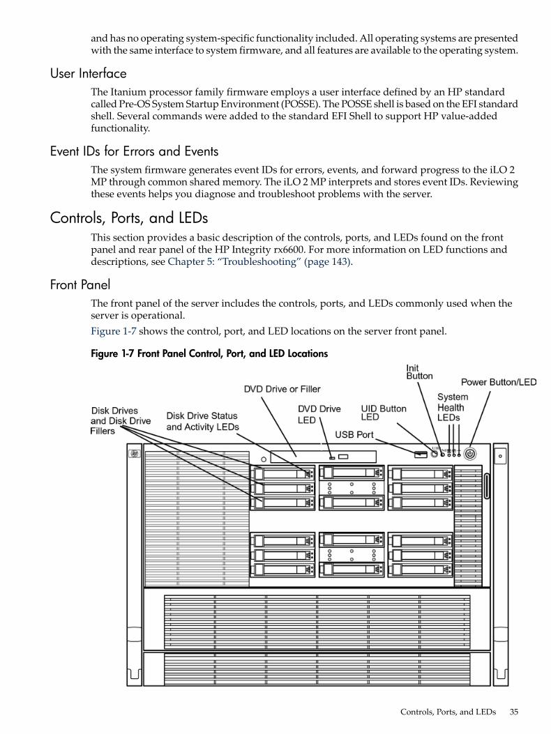
and has no operating system-specific functionality included. All operating systems are presentedwith the same interface to system firmware, and all features are available to the operating system.
User InterfaceThe Itanium processor family firmware employs a user interface defined by an HP standardcalled Pre-OS System Startup Environment (POSSE). The POSSE shell is based on the EFI standardshell. Several commands were added to the standard EFI Shell to support HP value-addedfunctionality.
Event IDs for Errors and EventsThe system firmware generates event IDs for errors, events, and forward progress to the iLO 2MP through common shared memory. The iLO 2 MP interprets and stores event IDs. Reviewingthese events helps you diagnose and troubleshoot problems with the server.
Controls, Ports, and LEDsThis section provides a basic description of the controls, ports, and LEDs found on the frontpanel and rear panel of the HP Integrity rx6600. For more information on LED functions anddescriptions, see Chapter 5: “Troubleshooting” (page 143).
Front PanelThe front panel of the server includes the controls, ports, and LEDs commonly used when theserver is operational.Figure 1-7 shows the control, port, and LED locations on the server front panel.
Figure 1-7 Front Panel Control, Port, and LED Locations
Controls, Ports, and LEDs 35
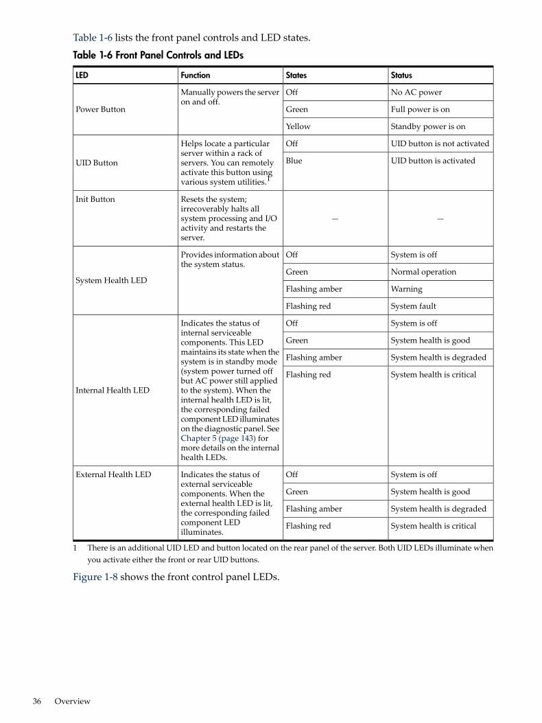
Table 1-6 lists the front panel controls and LED states.
Table 1-6 Front Panel Controls and LEDs
StatusStatesFunctionLED
No AC powerOffManually powers the serveron and off.
Power Button Full power is onGreen
Standby power is onYellow
UID button is not activatedOffHelps locate a particularserver within a rack ofservers. You can remotelyactivate this button usingvarious system utilities.1
UID Button UID button is activatedBlue
——
Resets the system;irrecoverably halts allsystem processing and I/Oactivity and restarts theserver.
Init Button
System is offOffProvides information aboutthe system status.
System Health LEDNormal operationGreen
WarningFlashing amber
System faultFlashing red
System is offOffIndicates the status ofinternal serviceablecomponents. This LEDmaintains its state when thesystem is in standby mode(system power turned offbut AC power still appliedto the system). When theinternal health LED is lit,the corresponding failedcomponent LED illuminateson the diagnostic panel. SeeChapter 5 (page 143) formore details on the internalhealth LEDs.
Internal Health LED
System health is goodGreen
System health is degradedFlashing amber
System health is criticalFlashing red
System is offOffIndicates the status ofexternal serviceablecomponents. When theexternal health LED is lit,the corresponding failedcomponent LEDilluminates.
External Health LED
System health is goodGreen
System health is degradedFlashing amber
System health is criticalFlashing red
1 There is an additional UID LED and button located on the rear panel of the server. Both UID LEDs illuminate whenyou activate either the front or rear UID buttons.
Figure 1-8 shows the front control panel LEDs.
36 Overview
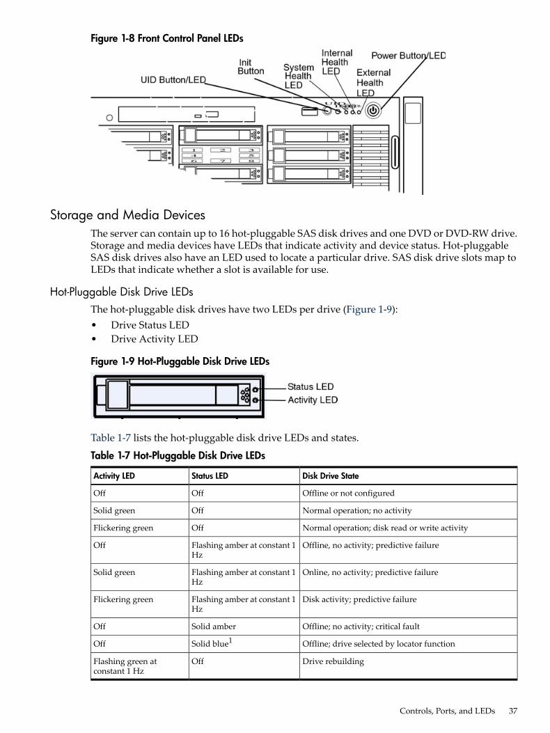
Figure 1-8 Front Control Panel LEDs
Storage and Media DevicesThe server can contain up to 16 hot-pluggable SAS disk drives and one DVD or DVD-RW drive.Storage and media devices have LEDs that indicate activity and device status. Hot-pluggableSAS disk drives also have an LED used to locate a particular drive. SAS disk drive slots map toLEDs that indicate whether a slot is available for use.
Hot-Pluggable Disk Drive LEDsThe hot-pluggable disk drives have two LEDs per drive (Figure 1-9):• Drive Status LED• Drive Activity LED
Figure 1-9 Hot-Pluggable Disk Drive LEDs
Table 1-7 lists the hot-pluggable disk drive LEDs and states.
Table 1-7 Hot-Pluggable Disk Drive LEDs
Disk Drive StateStatus LEDActivity LED
Offline or not configuredOffOff
Normal operation; no activityOffSolid green
Normal operation; disk read or write activityOffFlickering green
Offline, no activity; predictive failureFlashing amber at constant 1Hz
Off
Online, no activity; predictive failureFlashing amber at constant 1Hz
Solid green
Disk activity; predictive failureFlashing amber at constant 1Hz
Flickering green
Offline; no activity; critical faultSolid amberOff
Offline; drive selected by locator functionSolid blue1Off
Drive rebuildingOffFlashing green atconstant 1 Hz
Controls, Ports, and LEDs 37
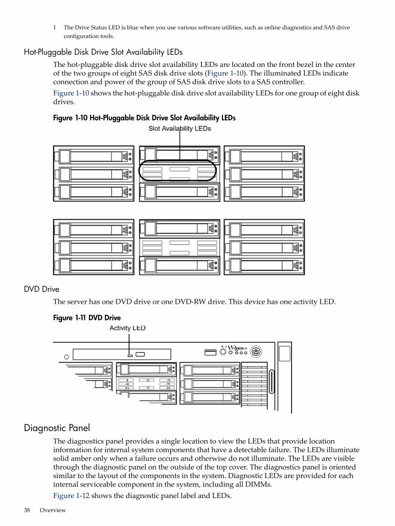
1 The Drive Status LED is blue when you use various software utilities, such as online diagnostics and SAS driveconfiguration tools.
Hot-Pluggable Disk Drive Slot Availability LEDsThe hot-pluggable disk drive slot availability LEDs are located on the front bezel in the centerof the two groups of eight SAS disk drive slots (Figure 1-10). The illuminated LEDs indicateconnection and power of the group of SAS disk drive slots to a SAS controller.Figure 1-10 shows the hot-pluggable disk drive slot availability LEDs for one group of eight diskdrives.
Figure 1-10 Hot-Pluggable Disk Drive Slot Availability LEDs
DVD DriveThe server has one DVD drive or one DVD-RW drive. This device has one activity LED.
Figure 1-11 DVD Drive
Diagnostic PanelThe diagnostics panel provides a single location to view the LEDs that provide locationinformation for internal system components that have a detectable failure. The LEDs illuminatesolid amber only when a failure occurs and otherwise do not illuminate. The LEDs are visiblethrough the diagnostic panel on the outside of the top cover. The diagnostics panel is orientedsimilar to the layout of the components in the system. Diagnostic LEDs are provided for eachinternal serviceable component in the system, including all DIMMs.Figure 1-12 shows the diagnostic panel label and LEDs.
38 Overview
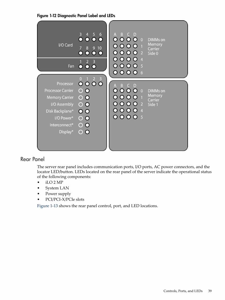
Figure 1-12 Diagnostic Panel Label and LEDs
Rear PanelThe server rear panel includes communication ports, I/O ports, AC power connectors, and thelocator LED/button. LEDs located on the rear panel of the server indicate the operational statusof the following components:• iLO 2 MP• System LAN• Power supply• PCI/PCI-X/PCIe slotsFigure 1-13 shows the rear panel control, port, and LED locations.
Controls, Ports, and LEDs 39
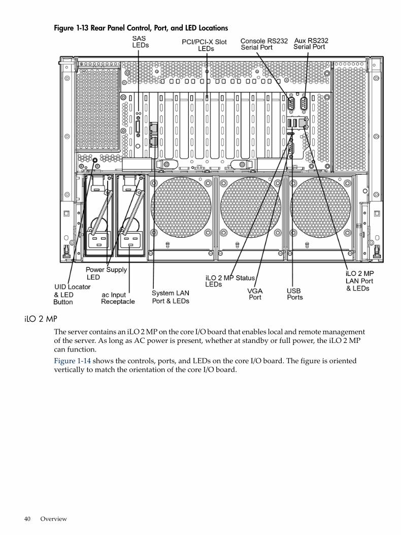
Figure 1-13 Rear Panel Control, Port, and LED Locations
iLO 2 MPThe server contains an iLO 2 MP on the core I/O board that enables local and remote managementof the server. As long as AC power is present, whether at standby or full power, the iLO 2 MPcan function.Figure 1-14 shows the controls, ports, and LEDs on the core I/O board. The figure is orientedvertically to match the orientation of the core I/O board.
40 Overview
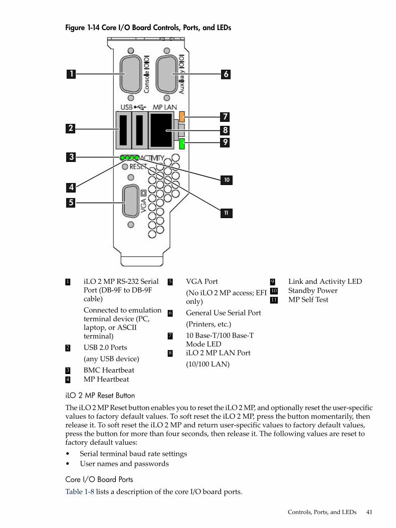
Figure 1-14 Core I/O Board Controls, Ports, and LEDs
4
1
2
3
5
6
7
89
10
11
9 Link and Activity LED5 VGA Port(No iLO 2 MP access; EFIonly)
1 iLO 2 MP RS-232 SerialPort (DB-9F to DB-9Fcable)Connected to emulationterminal device (PC,
10 Standby Power11 MP Self Test
6 General Use Serial Port(Printers, etc.)laptop, or ASCII
terminal) 7 10 Base-T/100 Base-TMode LED2 USB 2.0 Ports
(any USB device)8 iLO 2 MP LAN Port
(10/100 LAN)3 BMC Heartbeat4 MP Heartbeat
iLO 2 MP Reset Button
The iLO 2 MP Reset button enables you to reset the iLO 2 MP, and optionally reset the user-specificvalues to factory default values. To soft reset the iLO 2 MP, press the button momentarily, thenrelease it. To soft reset the iLO 2 MP and return user-specific values to factory default values,press the button for more than four seconds, then release it. The following values are reset tofactory default values:• Serial terminal baud rate settings• User names and passwords
Core I/O Board Ports
Table 1-8 lists a description of the core I/O board ports.
Controls, Ports, and LEDs 41
Table 1-8 Core I/O Board Ports
DescriptionPort
LAN port dedicated for remote access to the iLO 2 MP10 Base-T/100 Base-T LAN
Local serial port.Auxiliary Serial
Local serial port that provides a console connection to the serverConsole Serial (iLO 2 MP)
Two public USB 2.0 ports used primarily to connect to a keyboard and mousefor console input functions (Windows and Linux operating systems only)
USB
VGA port used primarily to connect to a monitor that displays console output(Windows and Linux operating systems only)
VGA (optional)
iLO 2 MP Status and LAN LEDs
Table 1-9 shows the states and status of the iLO 2 MP status and LAN LEDs.
Table 1-9 iLO 2 MP Status and LAN LEDs
StatusStatesiLO 2 MP LED
Standby power is onSolid greenStandby power
iLO 2 MP self test running1AmberiLO 2 MP Self test
Self test completedOff
Operational and functionalFlashing greeniLO 2 MP Heartbeat
Operational and functionalFlashing greenBMC Heartbeat
ActivityBlinking green
Link Status Link with no activitySolid green
No linkOff
100 Mb linkSolid amberLink Speed
10 Mb linkOff
1 The LED is solid amber when AC power is first applied. It remains solid amber for a few seconds until the iLO 2MP completes its self test; the LED then turns off.
System LANThe system LAN functionality is provided by the LAN core I/O card. The ports on the LAN coreI/O card are two RJ-45 style 10 Base-T/100 Base-T/1000 Base-T system LAN ports.Table 1-10 show the system LAN link status and speed LEDs states and status.
Table 1-10 System LAN Link Status and Speed LEDs
Link StatusStateLED
ActivityBlinking green
Link status Link with no activitySolid green
No linkOff
1000 MbSolid orange
Link speed 100 MbSolid green
10 MbOff
42 Overview

Figure 1-15 LAN Link and Status LEDs
Power SupplyThe server can have one or two power supplies, labeled PS0 and PS1. Each power supply has anAC input receptacle and an LED that shows the power state of the server (Figure 1-13).The server has three power states: standby power, full power, and off. Plug the power cord intothe appropriate receptacle on the rear of the chassis to achieve the standby power state. To bringthe server to full power plug the power cord into the appropriate receptacle, and either activatethe power using the iLO 2 MP PC command, or push the Power button. To bring the server tothe off state, unplug the power cords.Table 1-11 lists the power supply LED states.
Table 1-11 Power Supply LED
Power Supply ConditionPower Supply LED
No AC powerOff
AC power; standby power onBlinking green
Full power on; normal operationSolid green
Power supply failureBlinking amber
Figure 1-16 shows the power LEDs.
Controls, Ports, and LEDs 43
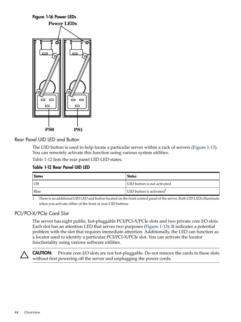
Figure 1-16 Power LEDs
Rear Panel UID LED and ButtonThe UID button is used to help locate a particular server within a rack of servers (Figure 1-13).You can remotely activate this function using various system utilities.Table 1-12 lists the rear panel UID LED states.
Table 1-12 Rear Panel UID LED
StatusStates
UID button is not activatedOff
UID button is activated1Blue
1 There is an additional UID LED and button located on the front control panel of the server. Both UID LEDs illuminatewhen you activate either of the front or rear UID buttons
PCI/PCI-X/PCIe Card SlotThe server has eight public, hot-pluggable PCI/PCI-X/PCIe slots and two private core I/O slots.Each slot has an attention LED that serves two purposes (Figure 1-13). It indicates a potentialproblem with the slot that requires immediate attention. Additionally, the LED can function asa locator used to identify a particular PCI/PCI-X/PCIe slot. You can activate the locatorfunctionality using various software utilities.
CAUTION: Private core I/O slots are not hot-pluggable. Do not remove the cards in these slotswithout first powering off the server and unplugging the power cords.
44 Overview
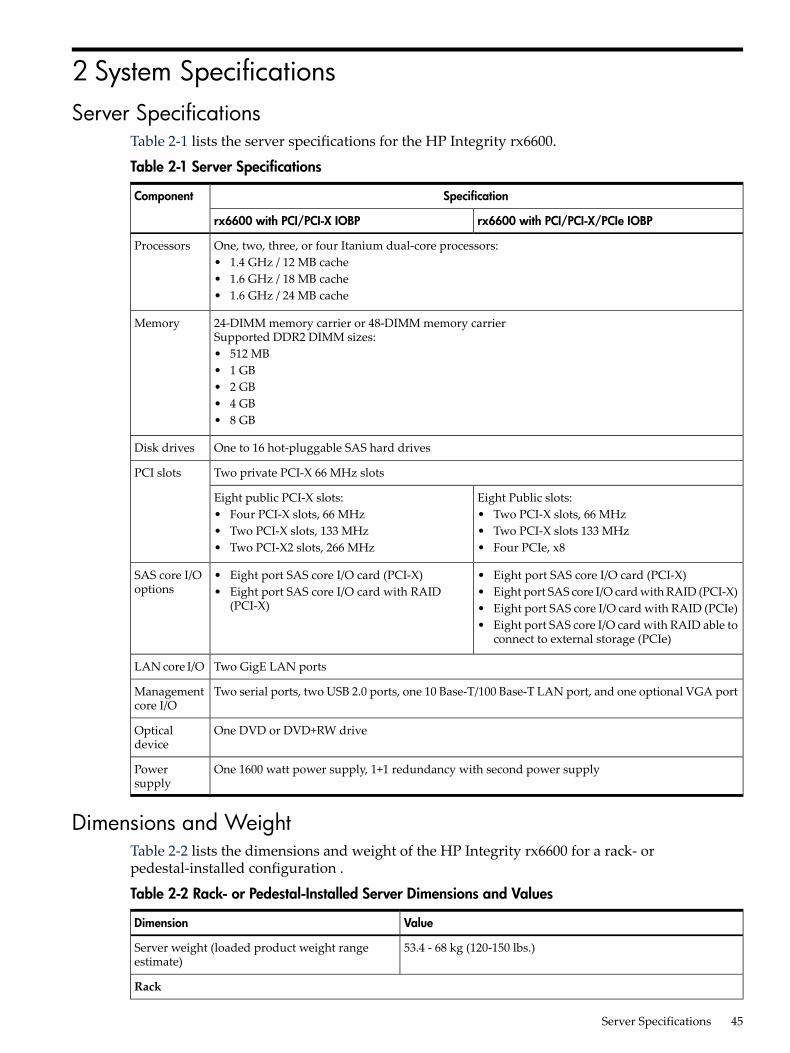
2 System SpecificationsServer Specifications
Table 2-1 lists the server specifications for the HP Integrity rx6600.
Table 2-1 Server Specifications
SpecificationComponent
rx6600 with PCI/PCI-X/PCIe IOBPrx6600 with PCI/PCI-X IOBP
One, two, three, or four Itanium dual-core processors:• 1.4 GHz / 12 MB cache• 1.6 GHz / 18 MB cache• 1.6 GHz / 24 MB cache
Processors
24-DIMM memory carrier or 48-DIMM memory carrierSupported DDR2 DIMM sizes:• 512 MB• 1 GB• 2 GB• 4 GB• 8 GB
Memory
One to 16 hot-pluggable SAS hard drivesDisk drives
Two private PCI-X 66 MHz slotsPCI slots
Eight Public slots:• Two PCI-X slots, 66 MHz• Two PCI-X slots 133 MHz• Four PCIe, x8
Eight public PCI-X slots:• Four PCI-X slots, 66 MHz• Two PCI-X slots, 133 MHz• Two PCI-X2 slots, 266 MHz
• Eight port SAS core I/O card (PCI-X)• Eight port SAS core I/O card with RAID (PCI-X)• Eight port SAS core I/O card with RAID (PCIe)• Eight port SAS core I/O card with RAID able to
connect to external storage (PCIe)
• Eight port SAS core I/O card (PCI-X)• Eight port SAS core I/O card with RAID
(PCI-X)
SAS core I/Ooptions
Two GigE LAN portsLAN core I/O
Two serial ports, two USB 2.0 ports, one 10 Base-T/100 Base-T LAN port, and one optional VGA portManagementcore I/O
One DVD or DVD+RW driveOpticaldevice
One 1600 watt power supply, 1+1 redundancy with second power supplyPowersupply
Dimensions and WeightTable 2-2 lists the dimensions and weight of the HP Integrity rx6600 for a rack- orpedestal-installed configuration .
Table 2-2 Rack- or Pedestal-Installed Server Dimensions and Values
ValueDimension
53.4 - 68 kg (120-150 lbs.)Server weight (loaded product weight rangeestimate)
Rack
Server Specifications 45
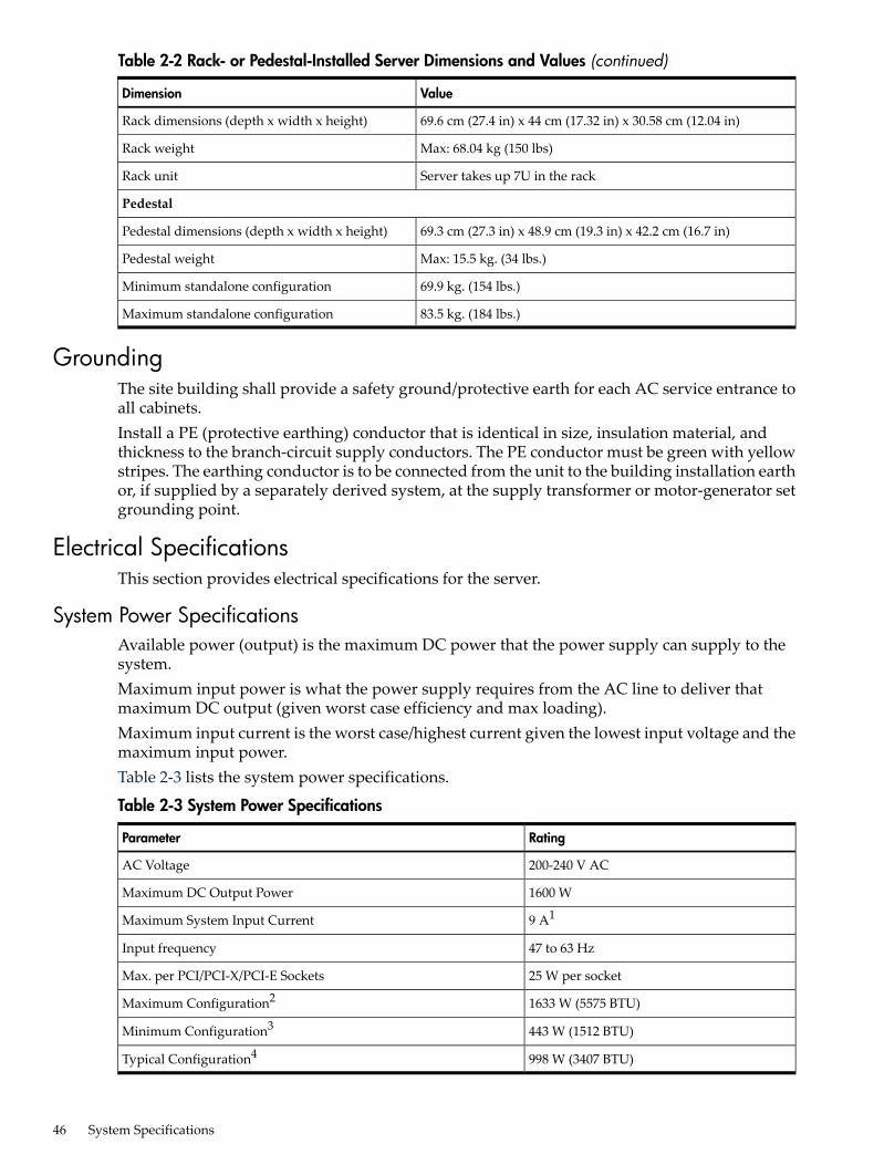
Table 2-2 Rack- or Pedestal-Installed Server Dimensions and Values (continued)
ValueDimension
69.6 cm (27.4 in) x 44 cm (17.32 in) x 30.58 cm (12.04 in)Rack dimensions (depth x width x height)
Max: 68.04 kg (150 lbs)Rack weight
Server takes up 7U in the rackRack unit
Pedestal
69.3 cm (27.3 in) x 48.9 cm (19.3 in) x 42.2 cm (16.7 in)Pedestal dimensions (depth x width x height)
Max: 15.5 kg. (34 lbs.)Pedestal weight
69.9 kg. (154 lbs.)Minimum standalone configuration
83.5 kg. (184 lbs.)Maximum standalone configuration
GroundingThe site building shall provide a safety ground/protective earth for each AC service entrance toall cabinets.Install a PE (protective earthing) conductor that is identical in size, insulation material, andthickness to the branch-circuit supply conductors. The PE conductor must be green with yellowstripes. The earthing conductor is to be connected from the unit to the building installation earthor, if supplied by a separately derived system, at the supply transformer or motor-generator setgrounding point.
Electrical SpecificationsThis section provides electrical specifications for the server.
System Power SpecificationsAvailable power (output) is the maximum DC power that the power supply can supply to thesystem.Maximum input power is what the power supply requires from the AC line to deliver thatmaximum DC output (given worst case efficiency and max loading).Maximum input current is the worst case/highest current given the lowest input voltage and themaximum input power.Table 2-3 lists the system power specifications.
Table 2-3 System Power Specifications
RatingParameter
200-240 V ACAC Voltage
1600 WMaximum DC Output Power
9 A1Maximum System Input Current
47 to 63 HzInput frequency
25 W per socketMax. per PCI/PCI-X/PCI-E Sockets
1633 W (5575 BTU)Maximum Configuration2
443 W (1512 BTU)Minimum Configuration3
998 W (3407 BTU)Typical Configuration4
46 System Specifications
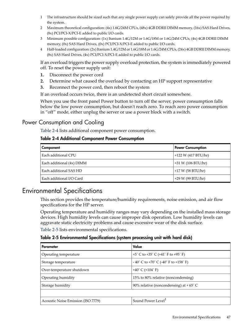
1 The infrastructure should be sized such that any single power supply can safely provide all the power required bythe system.
2 Maximum theoretical configuration: (4x) 1.6G/24M CPUs, (48x) 4GB DDRII DIMM memory, (16x) SAS Hard Drives,(8x) PCI/PCI-X/PCI-E added to public I/O cards.
3 Minimum possible configuration: (1x) Itanium 1.4G/12M or 1.6G/18M or 1.6G/24M CPUs, (4x) 4GB DDRII DIMMmemory, (0x) SAS Hard Drives, (0x) PCI/PCI-X/PCI-E added to public I/O cards.
4 Half-loaded configuration: (2x) Itanium 1.4G/12M or 1.6G/18M or 1.6G/24M CPUs, (24x) 4GB DDRII DIMM memory,(8x) SAS Hard Drives, (4x) PCI/PCI-X/PCI-E added to public I/O cards.
If an overload triggers the power supply overload protection, the system is immediately poweredoff. To reset the power supply unit:1. Disconnect the power cord2. Determine what caused the overload by contacting an HP support representative3. Reconnect the power cord, then reboot the systemIf an overload occurs twice, there is an undetected short circuit somewhere.When you use the front panel Power button to turn off the server, power consumption fallsbelow the low power consumption, but doesn't reach zero. To reach zero power consumptionin “off” mode, either unplug the server or use a power block with a switch.
Power Consumption and CoolingTable 2-4 lists additional component power consumption.
Table 2-4 Additional Component Power Consumption
Power ConsumptionComponent
+122 W (417 BTU/hr)Each additional CPU
+31 W (106 BTU/hr)Each additional (4x) DIMM
+17 W (58 BTU/hr)Each additional SAS HD
+29 W (99 BTU/hr)Each additional I/O Card
Environmental SpecificationsThis section provides the temperature/humidity requirements, noise emission, and air flowspecifications for the HP server.Operating temperature and humidity ranges may vary depending on the installed mass storagedevices. High humidity levels can cause improper disk operation. Low humidity levels canaggravate static electricity problems and cause excessive wear of the disk surface.Table 2-5 lists environmental specifications.
Table 2-5 Environmental Specifications (system processing unit with hard disk)
ValueParameter
+5˚ C to +35˚ C (+41˚ F to +95˚ F)Operating temperature
- 40˚ C to +70˚ C (-40˚ F to +158˚ F)Storage temperature
+40˚ C (+104˚ F)Over-temperature shutdown
15% to 80% relative (noncondensing)Operating humidity
90% relative (noncondensing) at + 65˚ CStorage humidity
Sound Power Level1Acoustic Noise Emission (ISO 7779)
Environmental Specifications 47
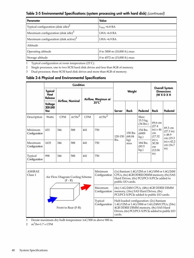
Table 2-5 Environmental Specifications (system processing unit with hard disk) (continued)
ValueParameter
LWA =6.8 BATypical configuration (disk idle)2
LWA =6.8 BAMaximum configuration (disk idle)3
LWA =6.9 BAMaximum configuration (disk active)3
Altitude
0 to 3000 m (10,000 ft.) maxOperating altitude
0 to 4572 m (15,000 ft.) maxStorage altitude
1 Typical configuration at room temperature (25˚C).2 Single processor, one to two SCSI hard disk drives and less than 8GB of memory.3 Dual processor, three SCSI hard disk drives and more than 8GB of memory.
Table 2-6 Physical and Environmental Specifications
Overall SystemDimensions(W X D X H
Weight
Condition
Airflow, Maximun at35ºC1Airflow, Nominal
TypicalHeat
Release
PedestalRackPedestalRackServer
Voltage200-240Vac
69.3 cm(27.3 in)x 48.9cm (19.3in) x 42.2cm (16.7in)
69.6 cm(27.4in) x 44cm(17.32in) x30.58cm(12.04in)
Max:15.5 kg.(34 lbs.)
150 lbs(68.04kg)max
120-150lbs.
m³/hr2CFMm³/hr2CFMWattsDescription
154 lbs.(6909kg.)
750441588346433MinimumConfiguration
184 lbs.(83.5kg.)
7504415883461633MaximumConfiguration
750441588346998TypicalConfiguration
(1x) Itanium 1.4G/12M or 1.6G/18M or 1.6G/24MCPUs, (4x) 4GB DDRII DIMM memory, (0x) SASHard Drives, (0x) PCI/PCI-X/PCIe added topublic I/O cards.
MinimumConfiguration
Air Flow Diagram Cooling Scheme(F - R)
Front to Rear (F-R)
ASHRAEClass 1
(4x) 1.6G/24M CPUs, (48x) 4GB DDRII DIMMmemory, (16x) SAS Hard Drives, (8x)PCI/PCI-X/PCIe added to public I/O cards.
MaximumConfiguration
Half-loaded configuration: (2x) Itanium1.4G/12M or 1.6G/18M or 1.6G/24M CPUs, (24x)4GB DDRII DIMM memory, (8x) SAS HardDrives, (4x) PCI/PCI-X/PCIe added to public I/Ocards.
TypicalConfiguration
1 Derate maximum dry bulb temperature 1oC/300 m above 900 m.2 m3/hr=1.7 x CFM
48 System Specifications
3 Installing the SystemThis chapter addresses the following topics:• “Safety Information” (page 49)• “Installation Sequence and Checklist” (page 49)• “Unpacking and Inspecting the Server” (page 50)• “Installing Additional Components” (page 51)• “Installing the Server into a Rack or Pedestal Mount” (page 79)• “Connecting the Cables” (page 80)• “Console Setup” (page 83)• “Accessing the Host Console” (page 92)• “Powering Off and Powering On the Server” (page 95)• “Core I/O Card Configuration” (page 97)• “Installation Troubleshooting” (page 119)• “Enabling the Trusted Platform Module” (page 122)
Safety InformationUse care to prevent injury and equipment damage when performing removal and replacementprocedures. Voltages can be present within the server even when it is powered off. Manyassemblies are sensitive to damage by electrostatic discharge (ESD).Follow the safety precautions listed below to ensure safe handling of components, to preventinjury, and to prevent damage to the server:• When removing or installing any server component, follow the instructions provided in this
guide.• If installing a hot-swappable or hot-pluggable component when power is applied (fans are
running), reinstall the server cover immediately to prevent overheating.• If installing a hot-pluggable component, complete the required software intervention prior
to removing the component.• If installing an assembly that is neither hot-swappable nor hot-pluggable, disconnect the
power cable from the external server power receptacle.
WARNING! Ensure that the system is powered off and all power sources are disconnectedfrom the server prior to removing or installing server hardware unless you are removingor installing a hot-swappable or hot-pluggable component.Voltages are present at various locations within the server whenever an AC power sourceis connected. This voltage is present even when the main power switch is turned off.Failure to observe this warning can result in personal injury or damage to equipment.
• Do not wear loose clothing that can snag or catch on the server or on other items.• Do not wear clothing subject to static charge buildup, such as wool or synthetic materials.• If installing an internal assembly, wear an antistatic wrist strap and use a grounding mat,
such as those included in the Electrically Conductive Field Service Grounding Kit (HP9300-1155).
• Handle accessory boards and components by the edges only. Do not touch any metal-edgeconnectors or any electrical components on accessory boards.
Installation Sequence and ChecklistTable 3-1 lists the server installation steps. Follow these steps in sequence to install the server.
Safety Information 49
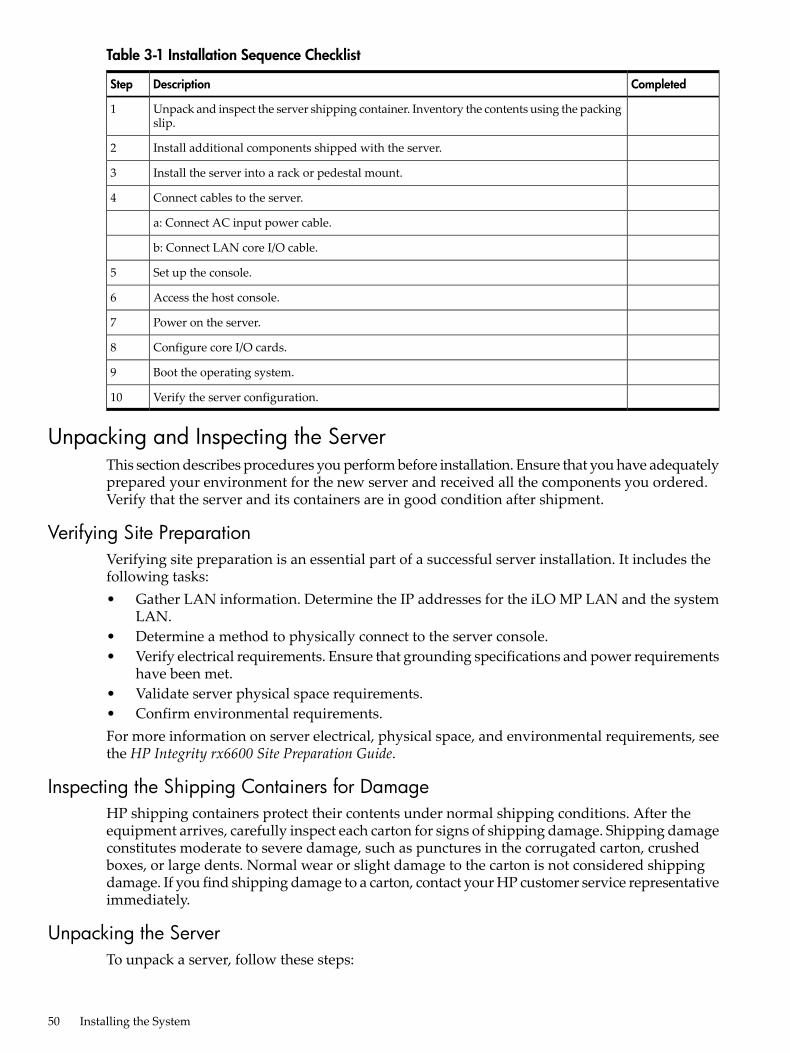
Table 3-1 Installation Sequence Checklist
CompletedDescriptionStep
Unpack and inspect the server shipping container. Inventory the contents using the packingslip.
1
Install additional components shipped with the server.2
Install the server into a rack or pedestal mount.3
Connect cables to the server.4
a: Connect AC input power cable.
b: Connect LAN core I/O cable.
Set up the console.5
Access the host console.6
Power on the server.7
Configure core I/O cards.8
Boot the operating system.9
Verify the server configuration.10
Unpacking and Inspecting the ServerThis section describes procedures you perform before installation. Ensure that you have adequatelyprepared your environment for the new server and received all the components you ordered.Verify that the server and its containers are in good condition after shipment.
Verifying Site PreparationVerifying site preparation is an essential part of a successful server installation. It includes thefollowing tasks:• Gather LAN information. Determine the IP addresses for the iLO MP LAN and the system
LAN.• Determine a method to physically connect to the server console.• Verify electrical requirements. Ensure that grounding specifications and power requirements
have been met.• Validate server physical space requirements.• Confirm environmental requirements.For more information on server electrical, physical space, and environmental requirements, seethe HP Integrity rx6600 Site Preparation Guide.
Inspecting the Shipping Containers for DamageHP shipping containers protect their contents under normal shipping conditions. After theequipment arrives, carefully inspect each carton for signs of shipping damage. Shipping damageconstitutes moderate to severe damage, such as punctures in the corrugated carton, crushedboxes, or large dents. Normal wear or slight damage to the carton is not considered shippingdamage. If you find shipping damage to a carton, contact your HP customer service representativeimmediately.
Unpacking the ServerTo unpack a server, follow these steps:
50 Installing the System
1. Read the instructions printed on the outside top flap of the carton; remove the banding andthe outer carton from the server pallet.
2. Remove all inner accessory cartons and the top foam cushions, leaving only the server.
IMPORTANT: Inspect each carton for shipping damage as you unpack the server.
Checking the InventoryThe sales order packing slip lists all the equipment shipped from HP. Use this packing slip toverify that all the equipment has arrived.
NOTE: To identify each item by part number, refer to the sales order packing slip.
Returning Damaged EquipmentIf the equipment is damaged, contact your HP customer service representative immediately. Theservice representative initiates appropriate action through the transport carrier or the factoryand assists you in returning the equipment.
Unloading the Server with a Lifter
WARNING! Use caution when using a lifter. Because of the weight of the HP Integrity rx6600server, you must center the server on the lifter forks before lifting it off the pallet to avoid injury.
NOTE: HP recommends that you follow local guidelines when lifting equipment.
To unload the server from the pallet using a lifter, follow these steps:1. Unpack the server.2. Unroll the bottom corrugated tray on the side where you will place the lifter, and slide the
server as close to that edge of the pallet as possible.3. Break off any foam packaging that can prevent you from fully inserting the lifter under the
server.
IMPORTANT: Do not remove the foam packaging from the corners of the server. This foamis required to elevate the server and enable the forks of the lifter to be inserted under theserver.
4. Insert the lifter forks under the server.5. Roll the lifter forward carefully until it is positioned against the side of the server.6. Raise the server slowly off the pallet until it clears the pallet cushions.7. Roll the lifter and server away from the pallet. Do not raise the server any higher than
necessary when moving it to the rack.
Installing Additional ComponentsThis section describes how to install components into the server that are not factory integrated.Most servers are preconfigured with all components installed prior to shipping from the HPfactory. If you do not have additional components to install, you can skip this chapter and installthe server.
Installing Additional Components 51
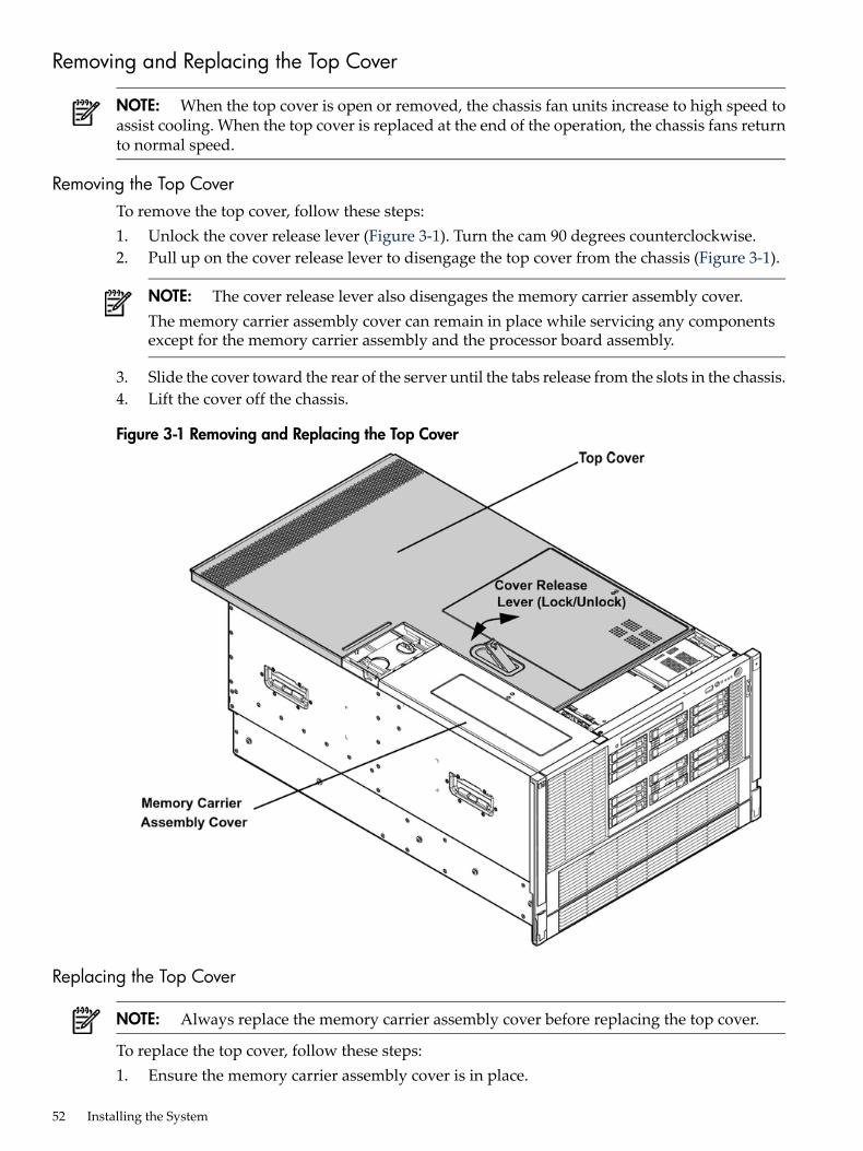
Removing and Replacing the Top Cover
NOTE: When the top cover is open or removed, the chassis fan units increase to high speed toassist cooling. When the top cover is replaced at the end of the operation, the chassis fans returnto normal speed.
Removing the Top CoverTo remove the top cover, follow these steps:1. Unlock the cover release lever (Figure 3-1). Turn the cam 90 degrees counterclockwise.2. Pull up on the cover release lever to disengage the top cover from the chassis (Figure 3-1).
NOTE: The cover release lever also disengages the memory carrier assembly cover.The memory carrier assembly cover can remain in place while servicing any componentsexcept for the memory carrier assembly and the processor board assembly.
3. Slide the cover toward the rear of the server until the tabs release from the slots in the chassis.4. Lift the cover off the chassis.
Figure 3-1 Removing and Replacing the Top Cover
Replacing the Top Cover
NOTE: Always replace the memory carrier assembly cover before replacing the top cover.
To replace the top cover, follow these steps:1. Ensure the memory carrier assembly cover is in place.
52 Installing the System
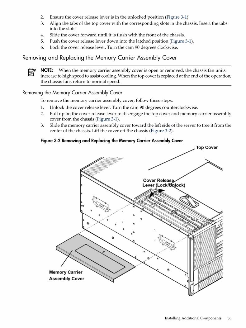
2. Ensure the cover release lever is in the unlocked position (Figure 3-1).3. Align the tabs of the top cover with the corresponding slots in the chassis. Insert the tabs
into the slots.4. Slide the cover forward until it is flush with the front of the chassis.5. Push the cover release lever down into the latched position (Figure 3-1).6. Lock the cover release lever. Turn the cam 90 degrees clockwise.
Removing and Replacing the Memory Carrier Assembly Cover
NOTE: When the memory carrier assembly cover is open or removed, the chassis fan unitsincrease to high speed to assist cooling. When the top cover is replaced at the end of the operation,the chassis fans return to normal speed.
Removing the Memory Carrier Assembly CoverTo remove the memory carrier assembly cover, follow these steps:1. Unlock the cover release lever. Turn the cam 90 degrees counterclockwise.2. Pull up on the cover release lever to disengage the top cover and memory carrier assembly
cover from the chassis (Figure 3-1).3. Slide the memory carrier assembly cover toward the left side of the server to free it from the
center of the chassis. Lift the cover off the chassis (Figure 3-2).
Figure 3-2 Removing and Replacing the Memory Carrier Assembly Cover
Installing Additional Components 53
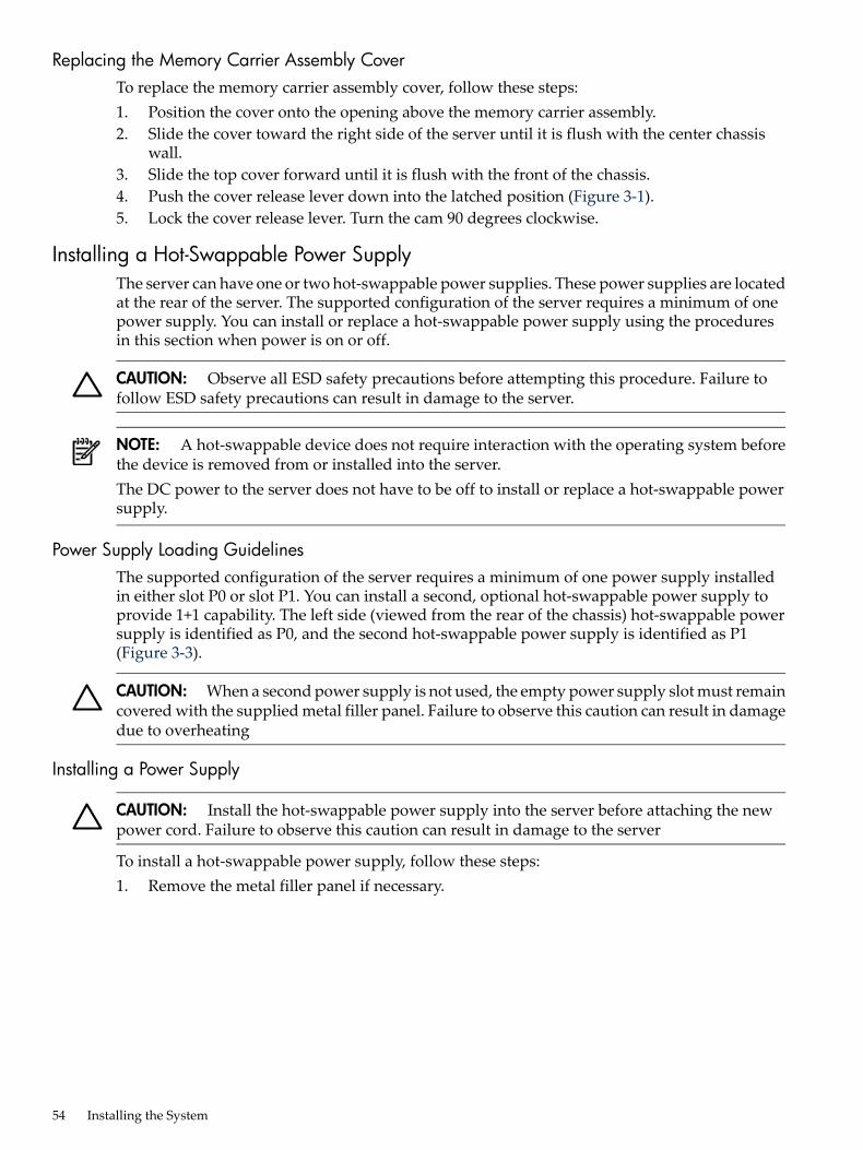
Replacing the Memory Carrier Assembly CoverTo replace the memory carrier assembly cover, follow these steps:1. Position the cover onto the opening above the memory carrier assembly.2. Slide the cover toward the right side of the server until it is flush with the center chassis
wall.3. Slide the top cover forward until it is flush with the front of the chassis.4. Push the cover release lever down into the latched position (Figure 3-1).5. Lock the cover release lever. Turn the cam 90 degrees clockwise.
Installing a Hot-Swappable Power SupplyThe server can have one or two hot-swappable power supplies. These power supplies are locatedat the rear of the server. The supported configuration of the server requires a minimum of onepower supply. You can install or replace a hot-swappable power supply using the proceduresin this section when power is on or off.
CAUTION: Observe all ESD safety precautions before attempting this procedure. Failure tofollow ESD safety precautions can result in damage to the server.
NOTE: A hot-swappable device does not require interaction with the operating system beforethe device is removed from or installed into the server.The DC power to the server does not have to be off to install or replace a hot-swappable powersupply.
Power Supply Loading GuidelinesThe supported configuration of the server requires a minimum of one power supply installedin either slot P0 or slot P1. You can install a second, optional hot-swappable power supply toprovide 1+1 capability. The left side (viewed from the rear of the chassis) hot-swappable powersupply is identified as P0, and the second hot-swappable power supply is identified as P1(Figure 3-3).
CAUTION: When a second power supply is not used, the empty power supply slot must remaincovered with the supplied metal filler panel. Failure to observe this caution can result in damagedue to overheating
Installing a Power Supply
CAUTION: Install the hot-swappable power supply into the server before attaching the newpower cord. Failure to observe this caution can result in damage to the server
To install a hot-swappable power supply, follow these steps:1. Remove the metal filler panel if necessary.
54 Installing the System
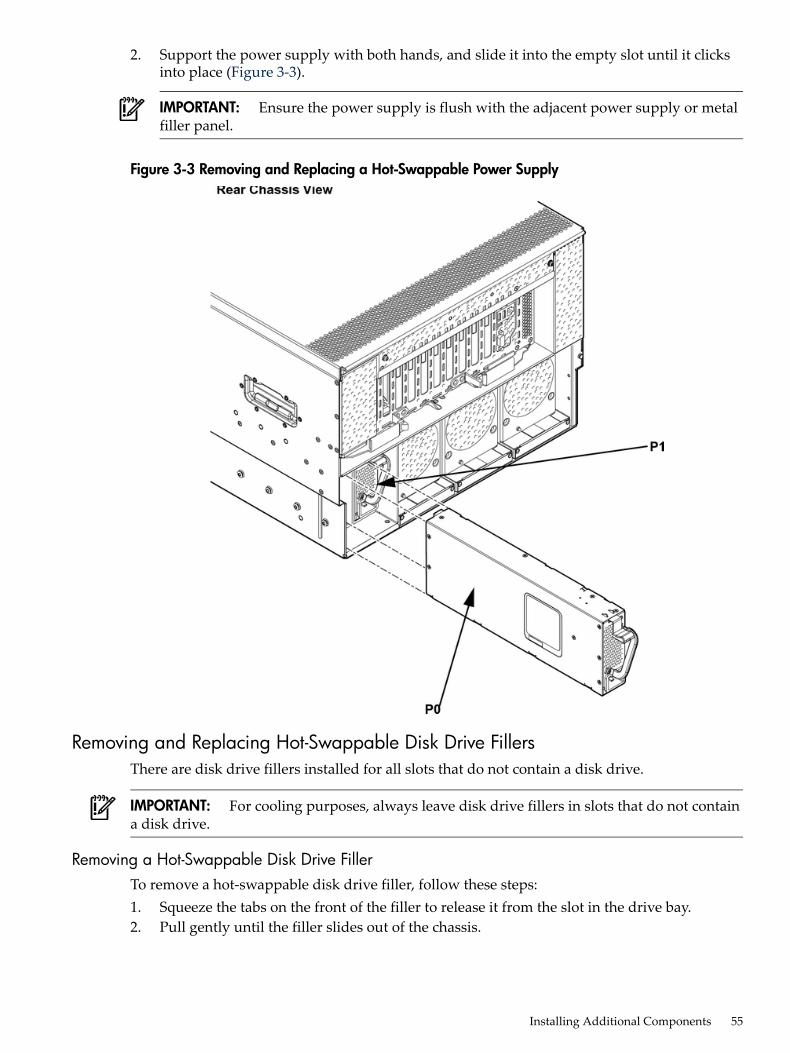
2. Support the power supply with both hands, and slide it into the empty slot until it clicksinto place (Figure 3-3).
IMPORTANT: Ensure the power supply is flush with the adjacent power supply or metalfiller panel.
Figure 3-3 Removing and Replacing a Hot-Swappable Power Supply
Removing and Replacing Hot-Swappable Disk Drive FillersThere are disk drive fillers installed for all slots that do not contain a disk drive.
IMPORTANT: For cooling purposes, always leave disk drive fillers in slots that do not containa disk drive.
Removing a Hot-Swappable Disk Drive FillerTo remove a hot-swappable disk drive filler, follow these steps:1. Squeeze the tabs on the front of the filler to release it from the slot in the drive bay.2. Pull gently until the filler slides out of the chassis.
Installing Additional Components 55
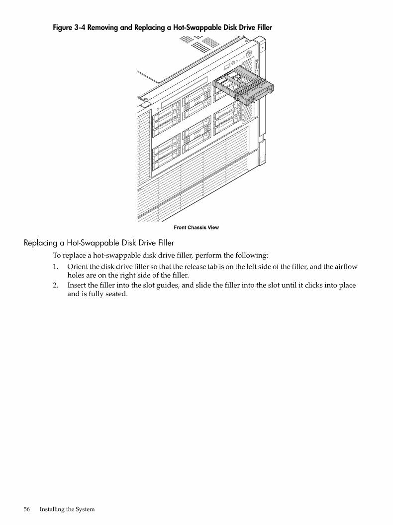
Figure 3-4 Removing and Replacing a Hot-Swappable Disk Drive Filler
Replacing a Hot-Swappable Disk Drive FillerTo replace a hot-swappable disk drive filler, perform the following:1. Orient the disk drive filler so that the release tab is on the left side of the filler, and the airflow
holes are on the right side of the filler.2. Insert the filler into the slot guides, and slide the filler into the slot until it clicks into place
and is fully seated.
56 Installing the System
Installing a Hot-Pluggable SAS Hard DriveThere are 16 hot-pluggable disk drives located in the front of the server. You can replace thehot-pluggable disk drives using the procedures in this section when the server power is on oroff.
CAUTION: Drives are loaded in the factory, starting with number 8, working from right to leftand bottom to top. If you have never changed your SAS configuration before, you can safelymove SAS devices downwards as a block. If you have bays 6, 7, and 8 occupied you can movethem down to bays 1, 2, and 3 without having the hardware paths change during a cold-installor recovery while the system is shut down, but youmustmove the disks in order and you cannotrearrange them. For example, you can move bay 6 to 1, 7 to 2, and 8 to 3. After doing this youcan safely populate the SAS enclosure from bay 4 onwards. The same procedure can be performedon bays 9 to 16.Never move devices from Bays 9-16 to Bays 1-8 as they are controlled by different SAS HBAs.
CAUTION: A hot-pluggable device may require interaction with the operating system beforeyou can safely remove it from or install it into the server. Verify that the operating system supportsremoving and replacing disk drives while the operating system is running. If the operatingsystem does not support this feature, shut down the operating system before attempting thisprocedure. Failure to observe this caution can result in system failure.
TIP: When you receive an HP Integrity rx3600 or HP Integrity rx6600 server from HP, if youever plan to add other SAS devices into the system, you should consider moving the SAS devicesso they start in bay 1 going upwards instead of Bay 8 going downwards.
Installing a Hot-Pluggable Disk Drive
NOTE: The replacement disk drive must have the same product number as the disk drive thatyou replace.
To install a hot-pluggable disk drive, follow these steps:1. Use Figure 3-6 to determine the next available disk drive installation slot.2. Remove the disk drive filler if required. See “Removing a Hot-Swappable Disk Drive Filler”
(page 55).
NOTE: Save the disk drive filler for future use. For cooling purposes, always place diskdrive fillers in slots that do not contain a disk drive.
3. Insert the hot-pluggable disk drive into the slot guides, and slide the drive into the slot untilit seats into the socket on the disk backplane.
4. Close the drive ejector handle by pushing it inward until it clicks into place.
Installing Additional Components 57
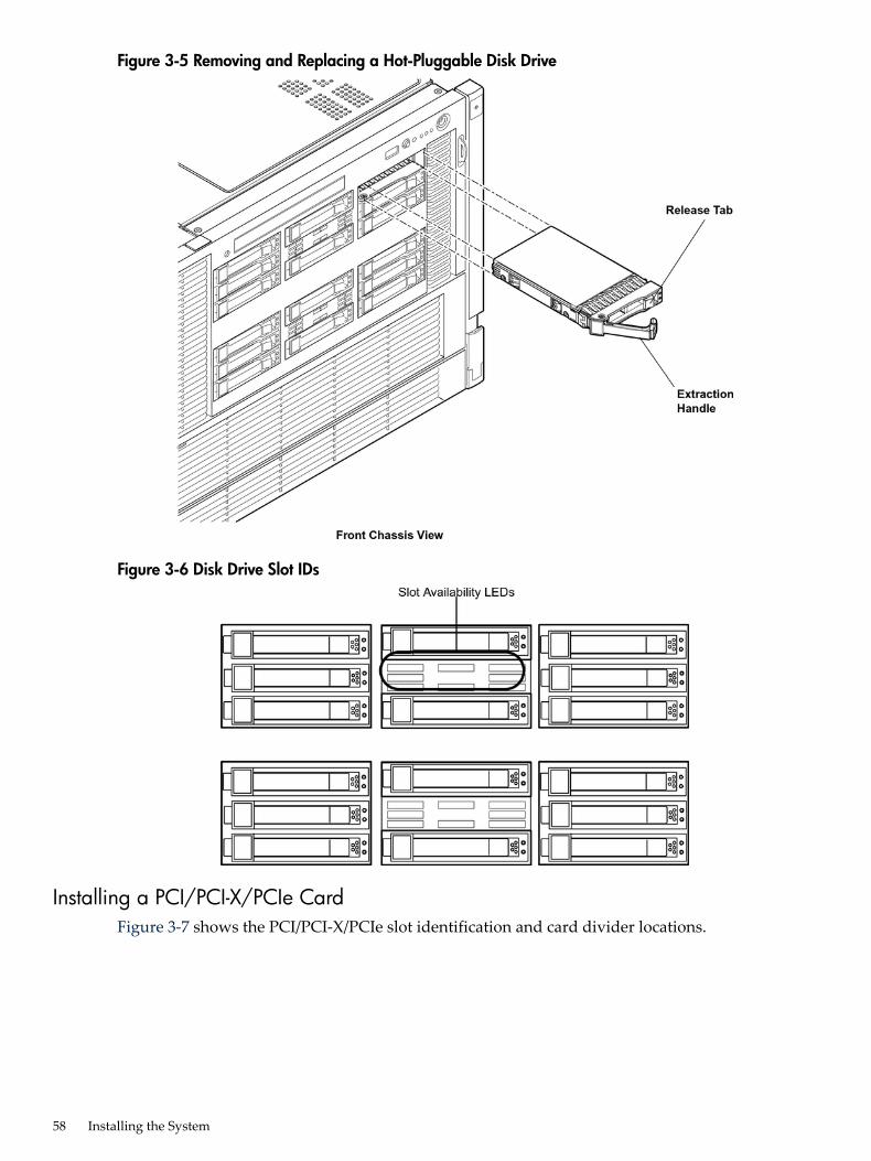
Figure 3-5 Removing and Replacing a Hot-Pluggable Disk Drive
Figure 3-6 Disk Drive Slot IDs
Installing a PCI/PCI-X/PCIe CardFigure 3-7 shows the PCI/PCI-X/PCIe slot identification and card divider locations.
58 Installing the System
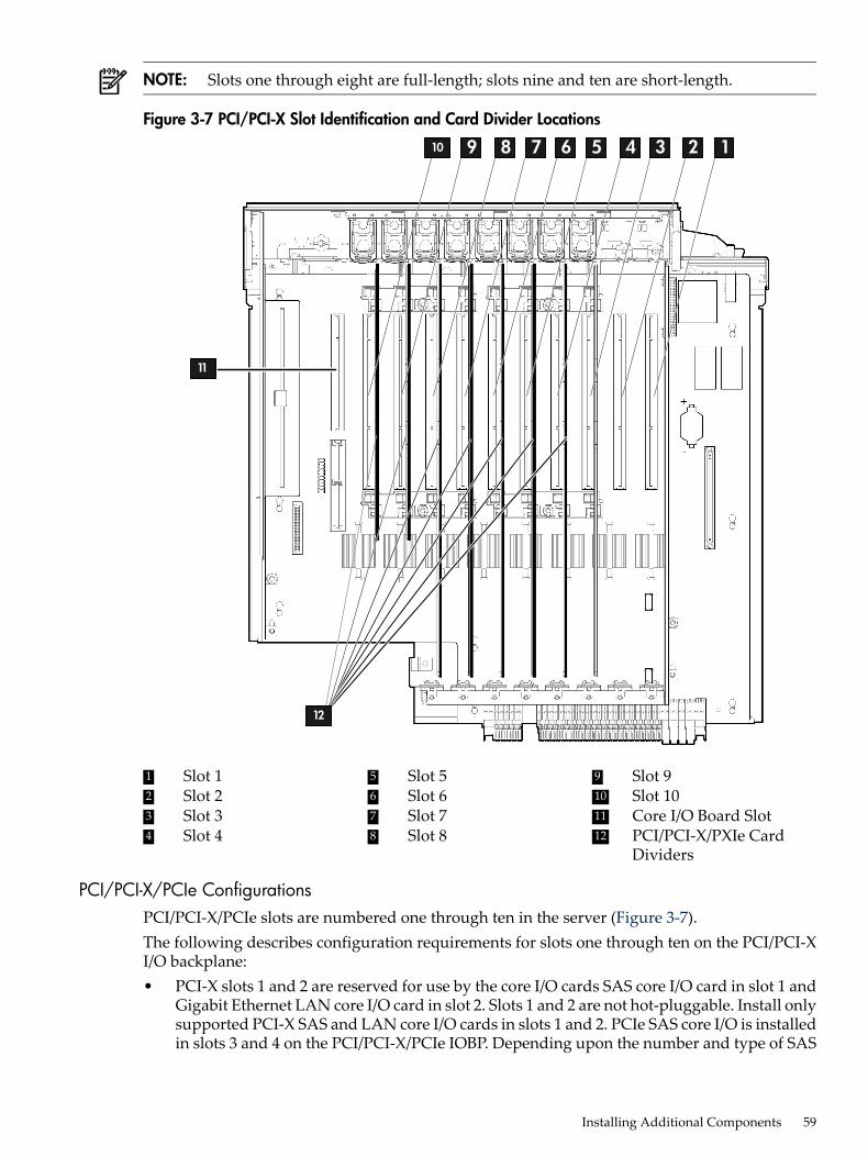
NOTE: Slots one through eight are full-length; slots nine and ten are short-length.
Figure 3-7 PCI/PCI-X Slot Identification and Card Divider Locations
12345678910
11
12
9 Slot 95 Slot 51 Slot 12 Slot 2 10 Slot 106 Slot 6
7 Slot 73 Slot 3 11 Core I/O Board Slot1284 PCI/PCI-X/PXIe Card
DividersSlot 8Slot 4
PCI/PCI-X/PCIe ConfigurationsPCI/PCI-X/PCIe slots are numbered one through ten in the server (Figure 3-7).The following describes configuration requirements for slots one through ten on the PCI/PCI-XI/O backplane:• PCI-X slots 1 and 2 are reserved for use by the core I/O cards SAS core I/O card in slot 1 and
Gigabit Ethernet LAN core I/O card in slot 2. Slots 1 and 2 are not hot-pluggable. Install onlysupported PCI-X SAS and LAN core I/O cards in slots 1 and 2. PCIe SAS core I/O is installedin slots 3 and 4 on the PCI/PCI-X/PCIe IOBP. Depending upon the number and type of SAS
Installing Additional Components 59
core I/O cards installed on the system, the Gigabit Ethernet LAN core I/O card may beinstalled in slot 10.
• Slots 3 and 4 are nonshared slots. The maximum speed for cards in slots 3 and 4 is PCI-X266 MHz.
• Slots 5 and 6 are nonshared slots. The maximum speed for cards in slots 5 and 6 is PCI-X133 MHz,
• Slots 7 and 8 are shared slots, and slots, 9 and 10 are shared slots. These four slots are limitedby bus mode or frequency-related incompatibilities.
NOTE: Shared slots have card compatibility restrictions. If one of the shared slots isoccupied, the card added to the second slot is limited by the configuration of the occupiedslot. If the new card has a slower capability than the current bus configuration, it fails. If thenew card has a faster capability than the current bus configuration, it only runs at the slowerbus mode and frequency of the current bus configuration.
The following are common configuration scenarios for cards that use shared slots. Theseexamples also apply to slots 9 and 10 because they are shared (both use a common bus).1. If there is a PCI-X 66 MHz card in slot 7, and you hot-plug insert a PCI 33 MHz card
into slot 8, the operation fails. The new PCI 33 MHz card does not initialize and the slotpowers down because you cannot change bus speed during hot-pluggable operations.The new card has a slower bus speed than the current card.
NOTE: If the server is rebooted in the new configuration, both cards initialize to runat PCI 33 MHz. This is because the system firmware can only change the bus capabilitydown to the lowest common value.
2. If there is a PCI 33 MHz card in slot 7, and you hot-plug insert a PCI-X 66 MHz cardinto slot 8, the new card works but it runs at PCI 33 MHz.
3. If the server is powered off and you insert a PCI 33 MHz card into slot 7 with a PCI-X66 MHz card is installed in slot 8), then both cards run at PCI 33 MHz when the serverpowers up.
The following describes configuration requirements for slots one through ten on thePCI/PCI-X/PCIe I/O backplane:• PCI-X slots 1 and 2 are reserved for use by the core I/O cards SAS core I/O card in slot 1 and
Gigabit Ethernet LAN core I/O card in slot 2. Slots 1 and 2 are not hot-pluggable. Install onlysupported SAS and LAN core I/O cards in slots 1 and 2.
• Slots 3 and 4 are swtiched PCIe x8• Slots 5 and 6 are nonswitched PCIe x8.• Slots 7 and 8 are nonshared slots. The maximum speed for cards in slots 7 and 8 is PCI-X
133 MHz.• Slots 9 and 10 are shared slots. These two slots are limited by bus mode or frequency-related
incompatibilities.
IMPORTANT: Slots 9 and 10 on the PCI/PCI-X/PCIe I/O backplane have the sameconfiguration limitations as slots 9 and 10 on the PCI/PCI-X/ I/O backplane.
Table 3-2 lists the PCI/PCI-X card slot frequency and bus mode compatibility for shared slots.
60 Installing the System
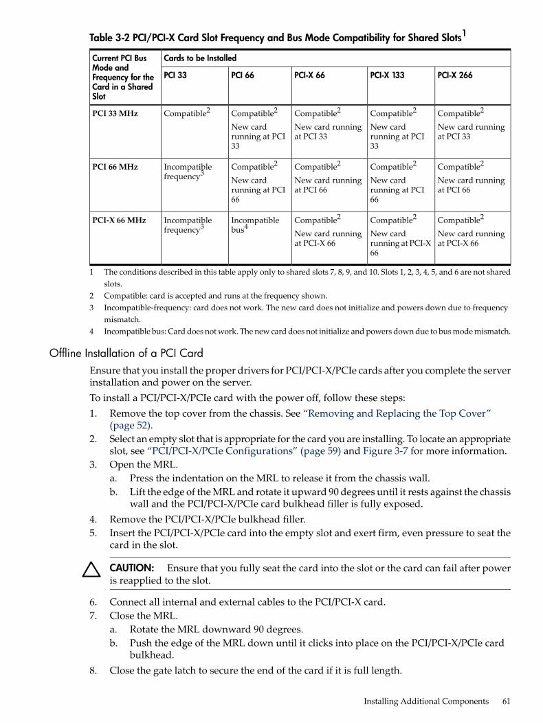
Table 3-2 PCI/PCI-X Card Slot Frequency and Bus Mode Compatibility for Shared Slots1
Cards to be InstalledCurrent PCI BusMode andFrequency for theCard in a SharedSlot
PCI-X 266PCI-X 133PCI-X 66PCI 66PCI 33
Compatible2
New card runningat PCI 33
Compatible2
New cardrunning at PCI33
Compatible2
New card runningat PCI 33
Compatible2
New cardrunning at PCI33
Compatible2PCI 33 MHz
Compatible2
New card runningat PCI 66
Compatible2
New cardrunning at PCI66
Compatible2
New card runningat PCI 66
Compatible2
New cardrunning at PCI66
Incompatiblefrequency3
PCI 66 MHz
Compatible2
New card runningat PCI-X 66
Compatible2
New cardrunning at PCI-X66
Compatible2
New card runningat PCI-X 66
Incompatiblebus4
Incompatiblefrequency3
PCI-X 66 MHz
1 The conditions described in this table apply only to shared slots 7, 8, 9, and 10. Slots 1, 2, 3, 4, 5, and 6 are not sharedslots.
2 Compatible: card is accepted and runs at the frequency shown.3 Incompatible-frequency: card does not work. The new card does not initialize and powers down due to frequency
mismatch.4 Incompatible bus: Card does not work. The new card does not initialize and powers down due to bus mode mismatch.
Offline Installation of a PCI CardEnsure that you install the proper drivers for PCI/PCI-X/PCIe cards after you complete the serverinstallation and power on the server.To install a PCI/PCI-X/PCIe card with the power off, follow these steps:1. Remove the top cover from the chassis. See “Removing and Replacing the Top Cover”
(page 52).2. Select an empty slot that is appropriate for the card you are installing. To locate an appropriate
slot, see “PCI/PCI-X/PCIe Configurations” (page 59) and Figure 3-7 for more information.3. Open the MRL.
a. Press the indentation on the MRL to release it from the chassis wall.b. Lift the edge of the MRL and rotate it upward 90 degrees until it rests against the chassis
wall and the PCI/PCI-X/PCIe card bulkhead filler is fully exposed.4. Remove the PCI/PCI-X/PCIe bulkhead filler.5. Insert the PCI/PCI-X/PCIe card into the empty slot and exert firm, even pressure to seat the
card in the slot.
CAUTION: Ensure that you fully seat the card into the slot or the card can fail after poweris reapplied to the slot.
6. Connect all internal and external cables to the PCI/PCI-X card.7. Close the MRL.
a. Rotate the MRL downward 90 degrees.b. Push the edge of the MRL down until it clicks into place on the PCI/PCI-X/PCIe card
bulkhead.8. Close the gate latch to secure the end of the card if it is full length.
Installing Additional Components 61
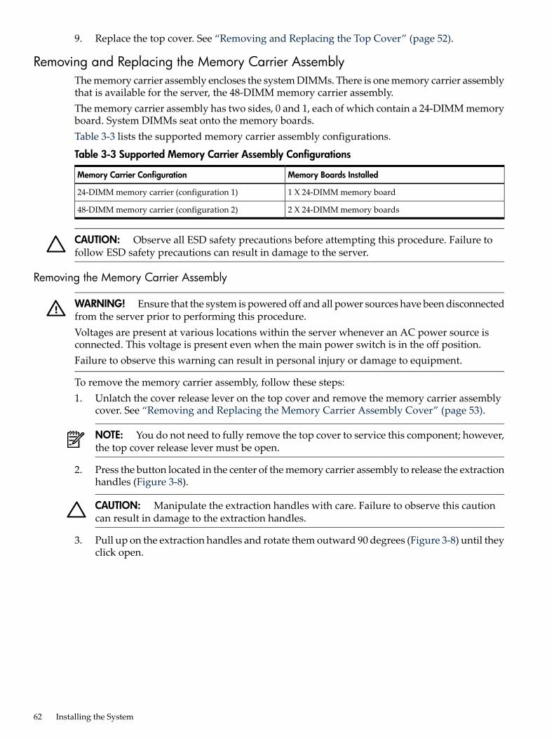
9. Replace the top cover. See “Removing and Replacing the Top Cover” (page 52).
Removing and Replacing the Memory Carrier AssemblyThe memory carrier assembly encloses the system DIMMs. There is one memory carrier assemblythat is available for the server, the 48-DIMM memory carrier assembly.The memory carrier assembly has two sides, 0 and 1, each of which contain a 24-DIMM memoryboard. System DIMMs seat onto the memory boards.Table 3-3 lists the supported memory carrier assembly configurations.
Table 3-3 Supported Memory Carrier Assembly Configurations
Memory Boards InstalledMemory Carrier Configuration
1 X 24-DIMM memory board24-DIMM memory carrier (configuration 1)
2 X 24-DIMM memory boards48-DIMM memory carrier (configuration 2)
CAUTION: Observe all ESD safety precautions before attempting this procedure. Failure tofollow ESD safety precautions can result in damage to the server.
Removing the Memory Carrier Assembly
WARNING! Ensure that the system is powered off and all power sources have been disconnectedfrom the server prior to performing this procedure.Voltages are present at various locations within the server whenever an AC power source isconnected. This voltage is present even when the main power switch is in the off position.Failure to observe this warning can result in personal injury or damage to equipment.
To remove the memory carrier assembly, follow these steps:1. Unlatch the cover release lever on the top cover and remove the memory carrier assembly
cover. See “Removing and Replacing the Memory Carrier Assembly Cover” (page 53).
NOTE: You do not need to fully remove the top cover to service this component; however,the top cover release lever must be open.
2. Press the button located in the center of the memory carrier assembly to release the extractionhandles (Figure 3-8).
CAUTION: Manipulate the extraction handles with care. Failure to observe this cautioncan result in damage to the extraction handles.
3. Pull up on the extraction handles and rotate them outward 90 degrees (Figure 3-8) until theyclick open.
62 Installing the System
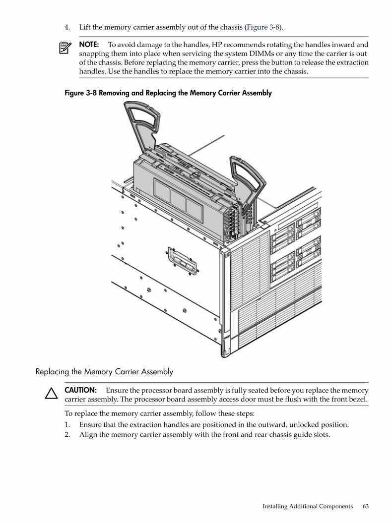
4. Lift the memory carrier assembly out of the chassis (Figure 3-8).
NOTE: To avoid damage to the handles, HP recommends rotating the handles inward andsnapping them into place when servicing the system DIMMs or any time the carrier is outof the chassis. Before replacing the memory carrier, press the button to release the extractionhandles. Use the handles to replace the memory carrier into the chassis.
Figure 3-8 Removing and Replacing the Memory Carrier Assembly
Replacing the Memory Carrier Assembly
CAUTION: Ensure the processor board assembly is fully seated before you replace the memorycarrier assembly. The processor board assembly access door must be flush with the front bezel.
To replace the memory carrier assembly, follow these steps:1. Ensure that the extraction handles are positioned in the outward, unlocked position.2. Align the memory carrier assembly with the front and rear chassis guide slots.
Installing Additional Components 63
NOTE: Assembly side 0 is on the left, and assembly side 1 is on the right as viewed fromthe front of the chassis.
3. Slide the memory carrier assembly into the chassis until it begins to seat into the socketlocated on the processor board.
CAUTION: Do not apply excessive force when closing the extraction handles and seatingthe memory carrier assembly into the socket on the processor board. Manipulate the extractionhandles with care; failure to observe these cautions can result in damage to the extractionhandles and other server components.
4. Rotate the extraction handles inward and press the handles straight down until they snapinto the locked position.
5. Replace the memory carrier assembly cover and latch the top cover release lever. See“Removing and Replacing the Memory Carrier Assembly Cover” (page 53).
Installing System Memory DIMMsSystem memory DIMMs are located on a pair of memory boards inside the memory carrierassembly.
WARNING! Ensure that the system is powered off and all power sources have been disconnectedfrom the server prior to performing this procedure.Voltages are present at various locations within the server whenever an AC power source isconnected. This voltage is present even when the main power switch is in the off position.Failure to observe this warning can result in personal injury or damage to equipment.
CAUTION: Observe all ESD safety precautions before attempting this procedure. Failure tofollow ESD safety precautions can result in damage to the server.
Figure 3-9 shows the memory carrier assembly removed from the chassis.
64 Installing the System
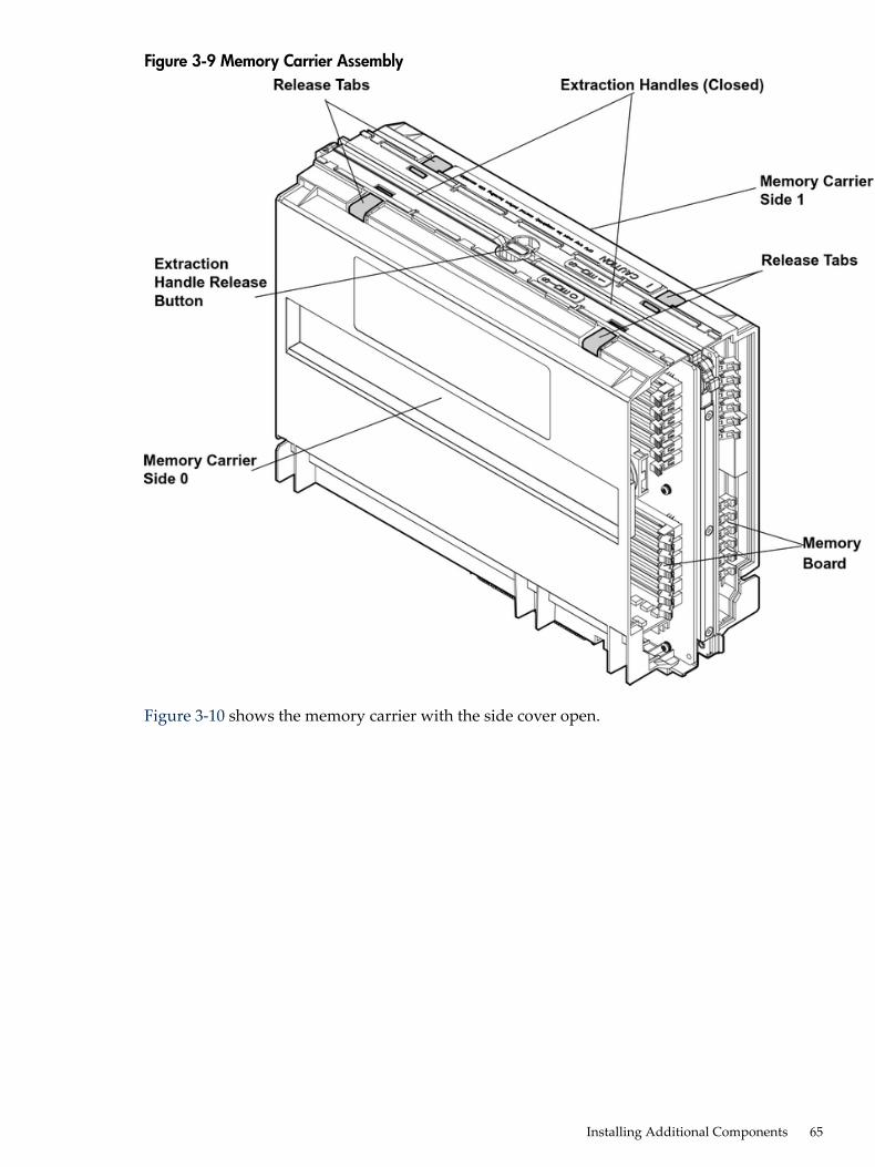
Figure 3-9 Memory Carrier Assembly
Figure 3-10 shows the memory carrier with the side cover open.
Installing Additional Components 65
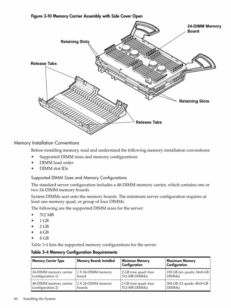
Figure 3-10 Memory Carrier Assembly with Side Cover Open
Memory Installation ConventionsBefore installing memory, read and understand the following memory installation conventions:• Supported DIMM sizes and memory configurations• DIMM load order• DIMM slot IDs
Supported DIMM Sizes and Memory Configurations
The standard server configuration includes a 48-DIMM memory carrier, which contains one ortwo 24-DIMM memory boards.System DIMMs seat onto the memory boards. The minimum server configuration requires atleast one memory quad, or group of four DIMMs.The following are the supported DIMM sizes for the server:• 512 MB• 1 GB• 2 GB• 4 GB• 8 GBTable 3-4 lists the supported memory configurations for the server.
Table 3-4 Memory Configuration Requirements
Maximum MemoryConfiguration
Minimum MemoryConfiguration
Memory Boards InstalledMemory Carrier Type
192 GB (six quads: 24x8-GBDIMMs)
2 GB (one quad: four512-MB DIMMs)
1 X 24-DIMM memoryboard
24-DIMM memory carrier(configuration 1)
384 GB (12 quads: 48x8-GBDIMMs)
2 GB (one quad: four512-MB DIMMs)
2 X 24-DIMM memoryboards
48-DIMM memory carrier(configuration 2)
66 Installing the System
Memory Load Order
When installing memory, use a minimum of one quad of like-sized DIMMs. Insert additionalDIMMs into the 48-DIMM memory carrier in the next available quad, in order of capacity fromlargest to smallest.Install DIMMs into the appropriate slots on the 48-DIMM memory carrier boards; each slot hasa unique ID. Use Figure 3-11 to determine where to install DIMMs on the memory carrier board.
CAUTION: Failure to observe these cautions results in system degradation or failure.• Do not mix DIMM sizes or types within a quad.• Load DIMM quads in order of size from largest to smallest. For example, if you have a quad
of 2 GB DIMMs and a quad of 1 GB DIMMs, install the quad of 2 GB DIMMs first.
24-DIMM Memory Carrier Load Order For a single 24-DIMM memory board configuration,load DIMMs in order from quad 0 to quad 5.48-DIMM Memory Carrier Load Order The 48-DIMM memory carrier has two sides, labeledside 0 and side 1, each of which can contain a memory carrier board. The 48-DIMM memorycarrier can contain up to 12 quads of memory. DIMM quads are loaded in order of capacity fromlargest to smallest.The DIMM slot IDs are the same for both 24-DIMM memory carrier boards. Unique slots areidentified within the carrier by the side in which they reside. For example, slot 0A is identifiedas slot 0A, side 0; or slot 0A, side 1.Figure 3-11 shows the DIMM slot IDs for the 48-DIMM memory carrier board.
Installing Additional Components 67
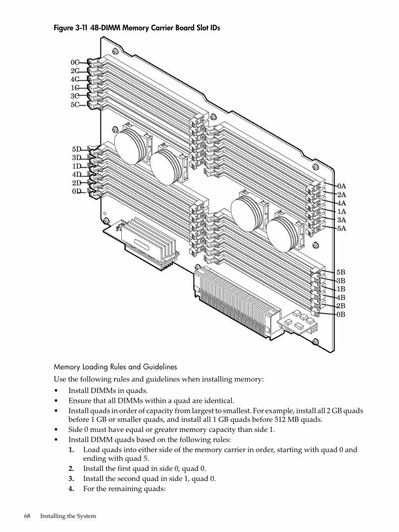
Figure 3-11 48-DIMM Memory Carrier Board Slot IDs
Memory Loading Rules and Guidelines
Use the following rules and guidelines when installing memory:• Install DIMMs in quads.• Ensure that all DIMMs within a quad are identical.• Install quads in order of capacity from largest to smallest. For example, install all 2 GB quads
before 1 GB or smaller quads, and install all 1 GB quads before 512 MB quads.• Side 0 must have equal or greater memory capacity than side 1.• Install DIMM quads based on the following rules:
1. Load quads into either side of the memory carrier in order, starting with quad 0 andending with quad 5.
2. Install the first quad in side 0, quad 0.3. Install the second quad in side 1, quad 0.4. For the remaining quads:
68 Installing the System
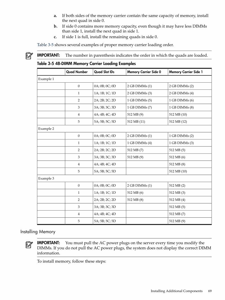
a. If both sides of the memory carrier contain the same capacity of memory, installthe next quad in side 0.
b. If side 0 contains more memory capacity, even though it may have less DIMMsthan side 1, install the next quad in side 1.
c. If side 1 is full, install the remaining quads in side 0.
Table 3-5 shows several examples of proper memory carrier loading order.
IMPORTANT: The number in parenthesis indicates the order in which the quads are loaded.
Table 3-5 48-DIMM Memory Carrier Loading Examples
Memory Carrier Side 1Memory Carrier Side 0Quad Slot IDsQuad Number
Example 1
2 GB DIMMs (2)2 GB DIMMs (1)0A; 0B; 0C; 0D0
2 GB DIMMs (4)2 GB DIMMs (3)1A; 1B; 1C; 1D1
1 GB DIMMs (6)1 GB DIMMs (5)2A; 2B; 2C; 2D2
1 GB DIMMs (8)1 GB DIMMs (7)3A; 3B; 3C; 3D3
512 MB (10)512 MB (9)4A; 4B; 4C; 4D4
512 MB (12)512 MB (11)5A; 5B; 5C; 5D5
Example 2
1 GB DIMMs (2)2 GB DIMMs (1)0A; 0B; 0C; 0D0
1 GB DIMMs (3)1 GB DIMMs (4)1A; 1B; 1C; 1D1
512 MB (5)512 MB (7)2A; 2B; 2C; 2D2
512 MB (6)512 MB (9)3A; 3B; 3C; 3D3
512 MB (8)4A; 4B; 4C; 4D4
512 MB (10)5A; 5B; 5C; 5D5
Example 3
512 MB (2)2 GB DIMMs (1)0A; 0B; 0C; 0D0
512 MB (3)512 MB (6)1A; 1B; 1C; 1D1
512 MB (4)512 MB (8)2A; 2B; 2C; 2D2
512 MB (5)3A; 3B; 3C; 3D3
512 MB (7)4A; 4B; 4C; 4D4
512 MB (9)5A; 5B; 5C; 5D5
Installing Memory
IMPORTANT: You must pull the AC power plugs on the server every time you modify theDIMMs. If you do not pull the AC power plugs, the system does not display the correct DIMMinformation.
To install memory, follow these steps:
Installing Additional Components 69
1. Unlatch the cover release lever on the top cover and remove the memory carrier assemblycover. See “Removing and Replacing the Memory Carrier Assembly Cover” (page 53).
NOTE: You do not need to fully remove the top cover to service this component. However,the top cover release lever must be open.
2. Remove the memory carrier assembly. See “Removing and Replacing the Memory CarrierAssembly” (page 62).
NOTE: To avoid damage to the handles, HP recommends rotating the handles inward andsnapping them into place when servicing the system DIMMs or any time the carrier is outof the chassis. Before replacing the memory carrier, press the button to release the extractionhandles. Use the handles to replace the memory carrier into the chassis.
3. Complete the following memory installation prerequisite tasks before installing the memory:a. Determine the DIMM load order for the 48-DIMM memory carrier. For more information,
see “Memory Load Order” (page 67).b. Use Figure 3-11 to determine the DIMM slots to populate.c. Read, understand, and follow the general guidelines to install memory in the server.
See “Memory Loading Rules and Guidelines” (page 68).4. Lay the memory carrier assembly on side 0 or side 1 so that the memory carrier side that
contains the DIMM slots that you will install DIMMs into faces upward (Figure 3-9).5. Remove the memory carrier assembly side cover.
a. Press the release tabs (Figure 3-9) on both sides of the extraction handle release buttonuntil the side cover releases from the top center of the assembly.
b. Rotate the side cover slightly to free the tabs from the retaining slots at the base of theassembly (Figure 3-10).
c. Lift the side cover off the assembly.
70 Installing the System
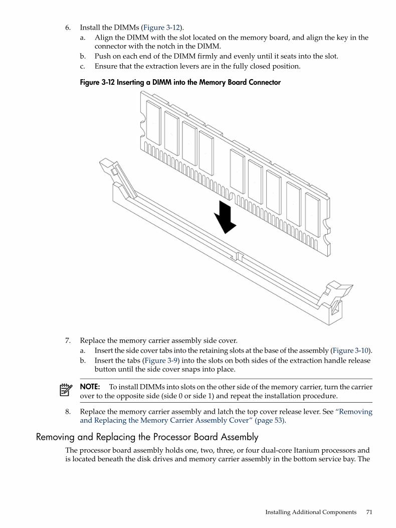
6. Install the DIMMs (Figure 3-12).a. Align the DIMM with the slot located on the memory board, and align the key in the
connector with the notch in the DIMM.b. Push on each end of the DIMM firmly and evenly until it seats into the slot.c. Ensure that the extraction levers are in the fully closed position.
Figure 3-12 Inserting a DIMM into the Memory Board Connector
7. Replace the memory carrier assembly side cover.a. Insert the side cover tabs into the retaining slots at the base of the assembly (Figure 3-10).b. Insert the tabs (Figure 3-9) into the slots on both sides of the extraction handle release
button until the side cover snaps into place.
NOTE: To install DIMMs into slots on the other side of the memory carrier, turn the carrierover to the opposite side (side 0 or side 1) and repeat the installation procedure.
8. Replace the memory carrier assembly and latch the top cover release lever. See “Removingand Replacing the Memory Carrier Assembly Cover” (page 53).
Removing and Replacing the Processor Board AssemblyThe processor board assembly holds one, two, three, or four dual-core Itanium processors andis located beneath the disk drives and memory carrier assembly in the bottom service bay. The
Installing Additional Components 71
processor board is mounted onto a removable carrier tray, which is retained in the service bayby a hinged access door.
WARNING! Ensure that the system is powered off and all power sources have been disconnectedfrom the server prior to performing this procedure.Voltages are present at various locations within the server whenever an AC power source isconnected. This voltage is present even when the main power switch is in the off position.Failure to observe this warning can result in personal injury or damage to equipment.
CAUTION: Observe all ESD safety precautions before attempting this procedure. Failure tofollow ESD safety precautions can result in damage to the server.
Removing the Processor Board AssemblyTo remove the processor board assembly, follow these steps:1. Unlatch the cover release lever on the top cover and remove the memory carrier assembly
cover. See “Removing and Replacing the Top Cover” (page 52). You do not need to fullyremove the top cover to service this component; however, the top cover release lever mustbe open.
2. Remove the memory carrier assembly. See “Removing and Replacing the Memory CarrierAssembly Cover” (page 53).
NOTE: You must remove the memory carrier because it attaches directly to the processorboard.
3. Press the button located on top of the bezel, directly in front of the memory carrier assemblyto release the processor board access door (Figure 3-13).
CAUTION: The processor board access door opens at a 30 degree angle. Do not force thedoor to open to a greater angle. Failure to observe this warning results in damage to servercomponents.
4. Use the processor board assembly access door as a handle and gently slide the assembly outof the chassis approximately six inches.
5. Grasp the handholds on the assembly carrier tray with both hands and carefully slide theassembly out of the chassis (Figure 3-13).
72 Installing the System
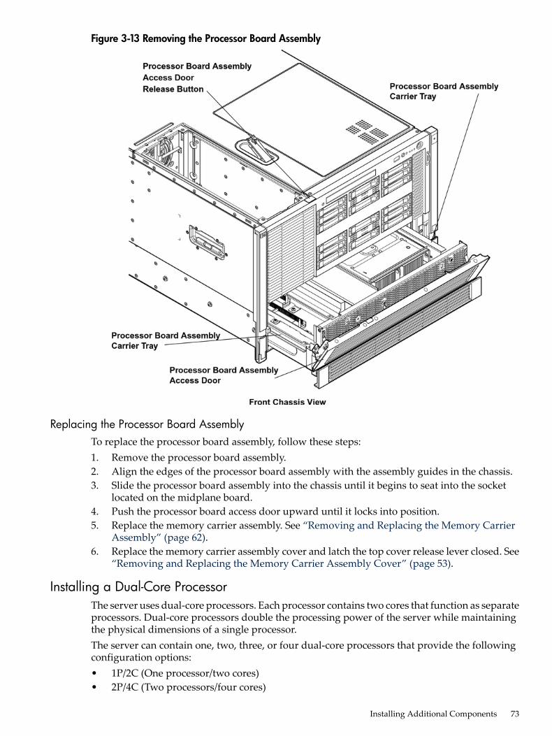
Figure 3-13 Removing the Processor Board Assembly
Replacing the Processor Board AssemblyTo replace the processor board assembly, follow these steps:1. Remove the processor board assembly.2. Align the edges of the processor board assembly with the assembly guides in the chassis.3. Slide the processor board assembly into the chassis until it begins to seat into the socket
located on the midplane board.4. Push the processor board access door upward until it locks into position.5. Replace the memory carrier assembly. See “Removing and Replacing the Memory Carrier
Assembly” (page 62).6. Replace the memory carrier assembly cover and latch the top cover release lever closed. See
“Removing and Replacing the Memory Carrier Assembly Cover” (page 53).
Installing a Dual-Core ProcessorThe server uses dual-core processors. Each processor contains two cores that function as separateprocessors. Dual-core processors double the processing power of the server while maintainingthe physical dimensions of a single processor.The server can contain one, two, three, or four dual-core processors that provide the followingconfiguration options:• 1P/2C (One processor/two cores)• 2P/4C (Two processors/four cores)
Installing Additional Components 73
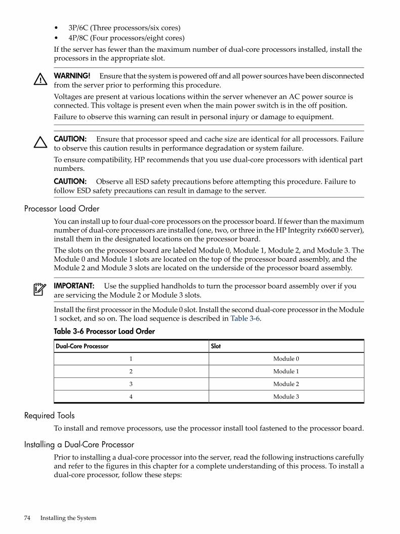
• 3P/6C (Three processors/six cores)• 4P/8C (Four processors/eight cores)If the server has fewer than the maximum number of dual-core processors installed, install theprocessors in the appropriate slot.
WARNING! Ensure that the system is powered off and all power sources have been disconnectedfrom the server prior to performing this procedure.Voltages are present at various locations within the server whenever an AC power source isconnected. This voltage is present even when the main power switch is in the off position.Failure to observe this warning can result in personal injury or damage to equipment.
CAUTION: Ensure that processor speed and cache size are identical for all processors. Failureto observe this caution results in performance degradation or system failure.To ensure compatibility, HP recommends that you use dual-core processors with identical partnumbers.
CAUTION: Observe all ESD safety precautions before attempting this procedure. Failure tofollow ESD safety precautions can result in damage to the server.
Processor Load OrderYou can install up to four dual-core processors on the processor board. If fewer than the maximumnumber of dual-core processors are installed (one, two, or three in the HP Integrity rx6600 server),install them in the designated locations on the processor board.The slots on the processor board are labeled Module 0, Module 1, Module 2, and Module 3. TheModule 0 and Module 1 slots are located on the top of the processor board assembly, and theModule 2 and Module 3 slots are located on the underside of the processor board assembly.
IMPORTANT: Use the supplied handholds to turn the processor board assembly over if youare servicing the Module 2 or Module 3 slots.
Install the first processor in the Module 0 slot. Install the second dual-core processor in the Module1 socket, and so on. The load sequence is described in Table 3-6.
Table 3-6 Processor Load Order
SlotDual-Core Processor
Module 01
Module 12
Module 23
Module 34
Required ToolsTo install and remove processors, use the processor install tool fastened to the processor board.
Installing a Dual-Core ProcessorPrior to installing a dual-core processor into the server, read the following instructions carefullyand refer to the figures in this chapter for a complete understanding of this process. To install adual-core processor, follow these steps:
74 Installing the System
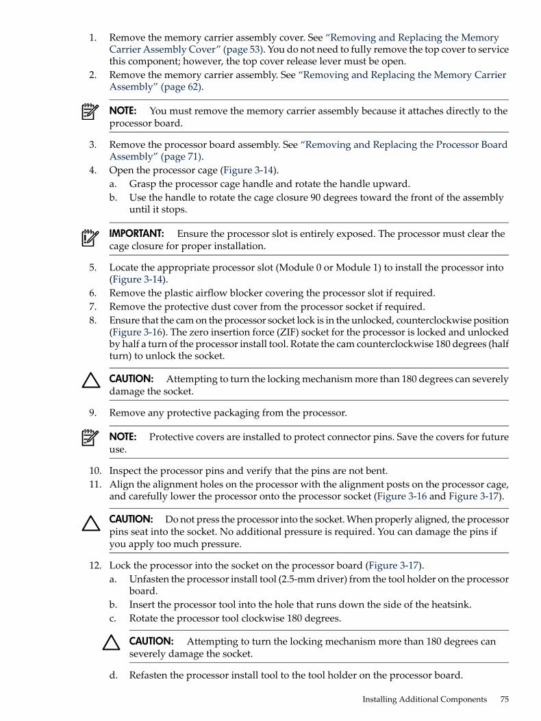
1. Remove the memory carrier assembly cover. See “Removing and Replacing the MemoryCarrier Assembly Cover” (page 53). You do not need to fully remove the top cover to servicethis component; however, the top cover release lever must be open.
2. Remove the memory carrier assembly. See “Removing and Replacing the Memory CarrierAssembly” (page 62).
NOTE: You must remove the memory carrier assembly because it attaches directly to theprocessor board.
3. Remove the processor board assembly. See “Removing and Replacing the Processor BoardAssembly” (page 71).
4. Open the processor cage (Figure 3-14).a. Grasp the processor cage handle and rotate the handle upward.b. Use the handle to rotate the cage closure 90 degrees toward the front of the assembly
until it stops.
IMPORTANT: Ensure the processor slot is entirely exposed. The processor must clear thecage closure for proper installation.
5. Locate the appropriate processor slot (Module 0 or Module 1) to install the processor into(Figure 3-14).
6. Remove the plastic airflow blocker covering the processor slot if required.7. Remove the protective dust cover from the processor socket if required.8. Ensure that the cam on the processor socket lock is in the unlocked, counterclockwise position
(Figure 3-16). The zero insertion force (ZIF) socket for the processor is locked and unlockedby half a turn of the processor install tool. Rotate the cam counterclockwise 180 degrees (halfturn) to unlock the socket.
CAUTION: Attempting to turn the locking mechanism more than 180 degrees can severelydamage the socket.
9. Remove any protective packaging from the processor.
NOTE: Protective covers are installed to protect connector pins. Save the covers for futureuse.
10. Inspect the processor pins and verify that the pins are not bent.11. Align the alignment holes on the processor with the alignment posts on the processor cage,
and carefully lower the processor onto the processor socket (Figure 3-16 and Figure 3-17).
CAUTION: Do not press the processor into the socket. When properly aligned, the processorpins seat into the socket. No additional pressure is required. You can damage the pins ifyou apply too much pressure.
12. Lock the processor into the socket on the processor board (Figure 3-17).a. Unfasten the processor install tool (2.5-mm driver) from the tool holder on the processor
board.b. Insert the processor tool into the hole that runs down the side of the heatsink.c. Rotate the processor tool clockwise 180 degrees.
CAUTION: Attempting to turn the locking mechanism more than 180 degrees canseverely damage the socket.
d. Refasten the processor install tool to the tool holder on the processor board.
Installing Additional Components 75
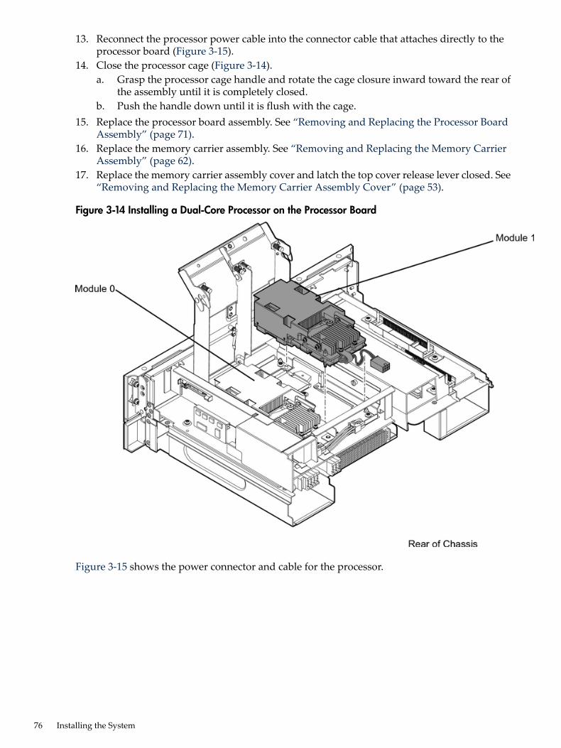
13. Reconnect the processor power cable into the connector cable that attaches directly to theprocessor board (Figure 3-15).
14. Close the processor cage (Figure 3-14).a. Grasp the processor cage handle and rotate the cage closure inward toward the rear of
the assembly until it is completely closed.b. Push the handle down until it is flush with the cage.
15. Replace the processor board assembly. See “Removing and Replacing the Processor BoardAssembly” (page 71).
16. Replace the memory carrier assembly. See “Removing and Replacing the Memory CarrierAssembly” (page 62).
17. Replace the memory carrier assembly cover and latch the top cover release lever closed. See“Removing and Replacing the Memory Carrier Assembly Cover” (page 53).
Figure 3-14 Installing a Dual-Core Processor on the Processor Board
Figure 3-15 shows the power connector and cable for the processor.
76 Installing the System
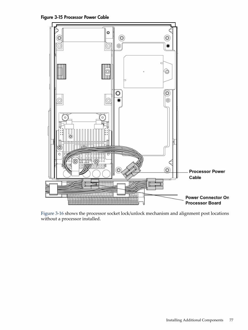
Figure 3-15 Processor Power Cable
Figure 3-16 shows the processor socket lock/unlock mechanism and alignment post locationswithout a processor installed.
Installing Additional Components 77
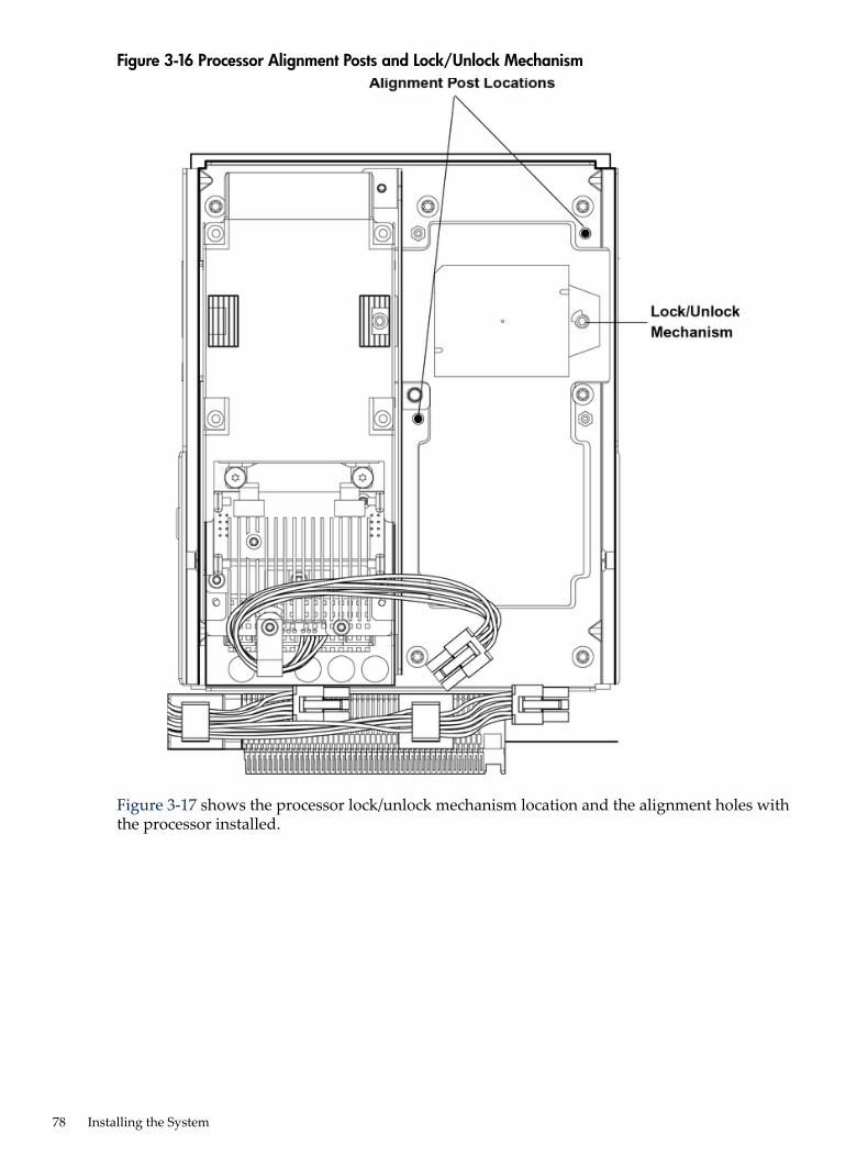
Figure 3-16 Processor Alignment Posts and Lock/Unlock Mechanism
Figure 3-17 shows the processor lock/unlock mechanism location and the alignment holes withthe processor installed.
78 Installing the System
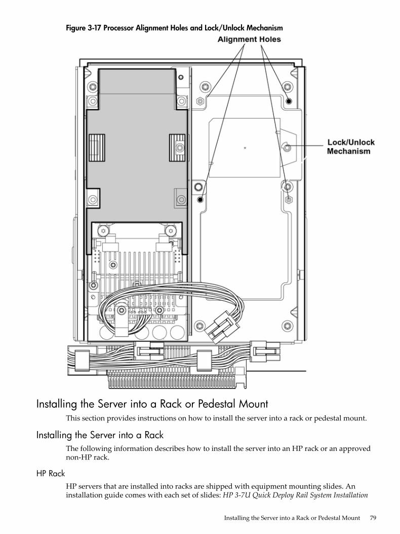
Figure 3-17 Processor Alignment Holes and Lock/Unlock Mechanism
Installing the Server into a Rack or Pedestal MountThis section provides instructions on how to install the server into a rack or pedestal mount.
Installing the Server into a RackThe following information describes how to install the server into an HP rack or an approvednon-HP rack.
HP RackHP servers that are installed into racks are shipped with equipment mounting slides. Aninstallation guide comes with each set of slides: HP 3-7U Quick Deploy Rail System Installation
Installing the Server into a Rack or Pedestal Mount 79
Instructions for HP Products. Follow the steps in this installation guide to determine where andhow to install the server into the rack.The following are additional instructions for installing the HP Integrity rx6600 server into therack:1. The cable management arm (CMA) is factory configured to mount on the left side of the
server as viewed from the rear of the chassis. You must switch the CMA to a right-mountconfiguration. Mount the CMA on the right side of the server to ensure easy removal of thepower supplies.
2. Remove two T25 screws from the server bezel; one screw from the same location on eachside of the server. The screws are located behind the pull handles.
Non-HP RackThe Guide for Evaluating the Installation of HP Equipment in Non-HP Racks enables you to evaluatethe installation of HP equipment into non-HP racks. Use this guide when you need to qualifywhether you can install, maintain, and service any HP equipment in a non-HP rack.The Guide for Evaluating the Installation of HP Equipment in Non-HP Racks is located on the webat:http://www.hp.com/racksolutions
Select mounting information from the menu, then select Mounting in non-HP racks.
Installing the Server into a Pedestal MountThe server ships with a pedestal mount if you order the rackless configuration option. Thepedestal mount is packaged in a separate carton that is attached to the server carton.To change the server from a rack mount to a rackless configuration, you need a Server RacklessMount Kit. The rackless mount kit comes with the HP Integrity rx6600 Rack to Pedestal ConversionGuide. Follow the steps in the HP Integrity rx6600 Rack to Pedestal Conversion Guide to attach thepedestal mount to the server.
Connecting the CablesThis section provides information on the cables that power the server and provide LANconnectivity for the server.
AC Input PowerThe server can receive AC input from two different AC power sources. If two separate powersources are available, you can plug the server into the separate power sources, increasing systemreliability if one power source fails. The power receptacles are located at the rear of the chassis.They are labeled PWR 0 and PWR 1.You can install a maximum of two bulk power supplies (BPS) in the server. Installing two BPSsin the server provides 1+1 redundancy, meaning that if one BPS fails, there is still enough powersupplied to the server for it to remain operational. You must promptly replace the failed BPS torestore 1+1 functionality.A minimum of one BPS is required to power the server. There is no 1+1 capability if only oneBPS is present.
Power StatesThe server has three power states:• Standby power• Full power• Off
80 Installing the System
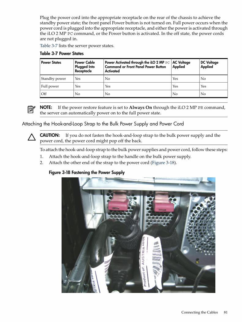
Plug the power cord into the appropriate receptacle on the rear of the chassis to achieve thestandby power state; the front panel Power button is not turned on. Full power occurs when thepower cord is plugged into the appropriate receptacle, and either the power is activated throughthe iLO 2 MP PC command, or the Power button is activated. In the off state, the power cordsare not plugged in.Table 3-7 lists the server power states.
Table 3-7 Power States
DC VoltageApplied
AC VoltageApplied
Power Activated through the iLO 2 MP PCCommand or Front Panel Power ButtonActivated
Power CablePlugged IntoReceptacle
Power States
NoYesNoYesStandby power
YesYesYesYesFull power
NoNoNoNoOff
NOTE: If the power restore feature is set to Always On through the iLO 2 MP PR command,the server can automatically power on to the full power state.
Attaching the Hook-and-Loop Strap to the Bulk Power Supply and Power Cord
CAUTION: If you do not fasten the hook-and-loop strap to the bulk power supply and thepower cord, the power cord might pop off the back.
To attach the hook-and-loop strap to the bulk power supplies and power cord, follow these steps:1. Attach the hook-and-loop strap to the handle on the bulk power supply.2. Attach the other end of the strap to the power cord (Figure 3-18).
Figure 3-18 Fastening the Power Supply
Connecting the Cables 81
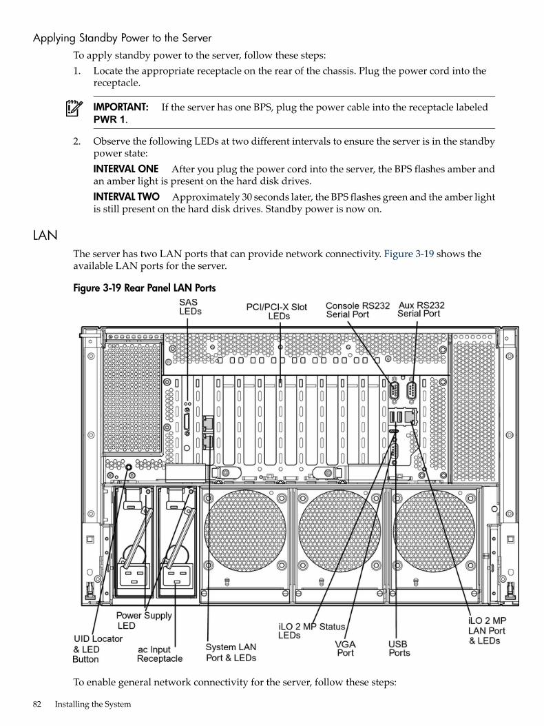
Applying Standby Power to the ServerTo apply standby power to the server, follow these steps:1. Locate the appropriate receptacle on the rear of the chassis. Plug the power cord into the
receptacle.
IMPORTANT: If the server has one BPS, plug the power cable into the receptacle labeledPWR 1.
2. Observe the following LEDs at two different intervals to ensure the server is in the standbypower state:INTERVAL ONE After you plug the power cord into the server, the BPS flashes amber andan amber light is present on the hard disk drives.INTERVAL TWO Approximately 30 seconds later, the BPS flashes green and the amber lightis still present on the hard disk drives. Standby power is now on.
LANThe server has two LAN ports that can provide network connectivity. Figure 3-19 shows theavailable LAN ports for the server.
Figure 3-19 Rear Panel LAN Ports
To enable general network connectivity for the server, follow these steps:
82 Installing the System
1. Obtain valid IP addresses for each LAN port you plan to activate.2. Connect the LAN cable from an available LAN port to a live connection on the network.
Console SetupSetting up the console involves the following:1. Determining the physical access method to connect cables. There are two physical connections
to the Integrity iLO 2 MP:• RS-232 serial port• iLO 2 MP LAN port
2. Configuring the Integrity iLO 2 MP and assigning an IP address if necessary. Though thereare several methods to configuring the LAN, DHCP with DNS is the preferred one. DHCPwith DNS comes preconfigured with default factory settings, including a default user accountand password. Other options include:• ARP-Ping• RS-232 serial port
OverviewA console is a tool consisting of display and input devices used to locally and remotely monitorand control the server. The console enables interaction with the following manageability,configuration, and diagnostic tools:• Integrated Lights-Out 2 Management Processor (iLO 2 MP). Provides a way to connect to
the server and perform administration or monitoring tasks for the server hardware. It controlspower, reset, and Transfer of Control (TOC) capabilities; provides console access; displaysand records system events; and displays detailed information about internal subsystems.The iLO 2 MP is available whenever the system is connected to a power source, even if theserver main power switch is turned off.
NOTE: For more information on iLO 2, see theHP Integrity Integrated Lights-Out 2OperationsGuide.
• Extensible Firmware Interface (EFI). Provides an interface between the operating systemand the firmware. Use the EFI to configure options, such as the server boot order, before theserver loads an operating system.
Table 3-8 lists the elements required to start a console session.
Table 3-8 Elements Required to Start a Console Session
DescriptionConsole Element
The server must have AC power to provide consolefunctionality. See “Applying Standby Power to the Server”(page 82).
AC power (standby power)
Includes the iLO 2 MP and console cable connectors.Server hardware components
Links the server console to the console device.Console cable
Provides display and input functionality using componentssuch as monitors, keyboards, and mouse devices.
Console device
Emulates the output from the server console and displays theoutput on the console device screen.
Console emulation software
Setup ChecklistUse the checklist in Table 3-9 to assist you with the console setup process.
Console Setup 83
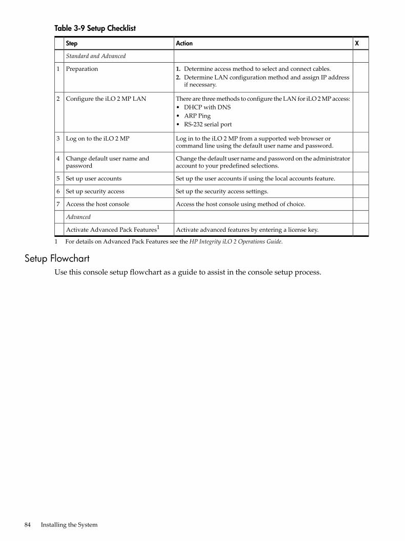
Table 3-9 Setup Checklist
XActionStep
Standard and Advanced
1. Determine access method to select and connect cables.2. Determine LAN configuration method and assign IP address
if necessary.
Preparation1
There are three methods to configure the LAN for iLO 2 MP access:• DHCP with DNS• ARP Ping• RS-232 serial port
Configure the iLO 2 MP LAN2
Log in to the iLO 2 MP from a supported web browser orcommand line using the default user name and password.
Log on to the iLO 2 MP3
Change the default user name and password on the administratoraccount to your predefined selections.
Change default user name andpassword
4
Set up the user accounts if using the local accounts feature.Set up user accounts5
Set up the security access settings.Set up security access6
Access the host console using method of choice.Access the host console7
Advanced
Activate advanced features by entering a license key.Activate Advanced Pack Features1
1 For details on Advanced Pack Features see the HP Integrity iLO 2 Operations Guide.
Setup FlowchartUse this console setup flowchart as a guide to assist in the console setup process.
84 Installing the System
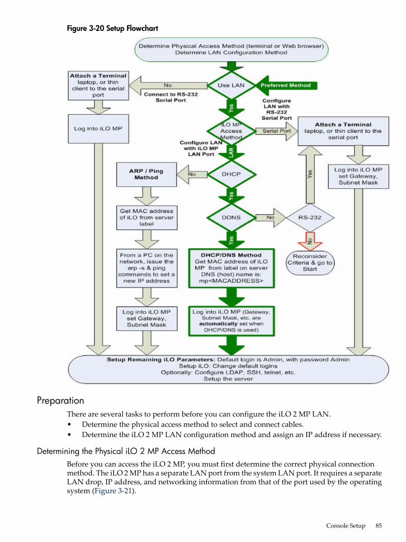
Figure 3-20 Setup Flowchart
PreparationThere are several tasks to perform before you can configure the iLO 2 MP LAN.• Determine the physical access method to select and connect cables.• Determine the iLO 2 MP LAN configuration method and assign an IP address if necessary.
Determining the Physical iLO 2 MP Access MethodBefore you can access the iLO 2 MP, you must first determine the correct physical connectionmethod. The iLO 2 MP has a separate LAN port from the system LAN port. It requires a separateLAN drop, IP address, and networking information from that of the port used by the operatingsystem (Figure 3-21).
Console Setup 85
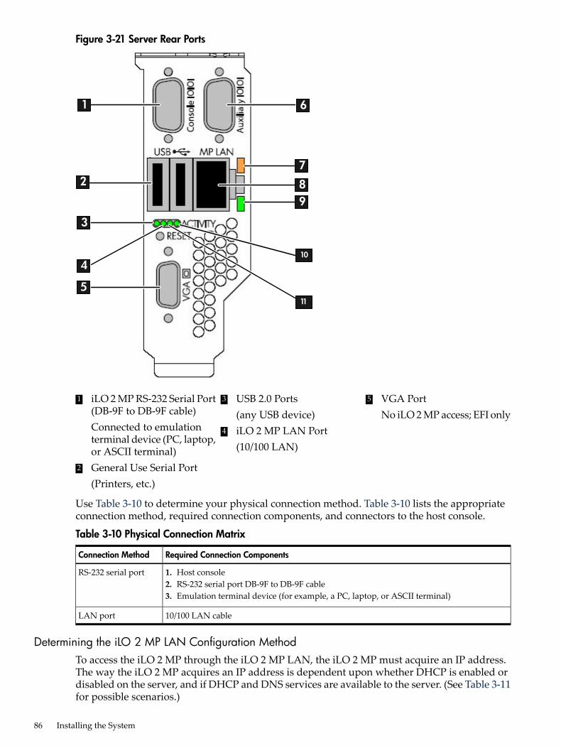
Figure 3-21 Server Rear Ports
4
1
2
3
5
6
7
89
10
11
53 USB 2.0 Ports(any USB device)
1 iLO 2 MP RS-232 Serial Port(DB-9F to DB-9F cable)Connected to emulationterminal device (PC, laptop,or ASCII terminal)
VGA PortNo iLO 2 MP access; EFI only
4 iLO 2 MP LAN Port(10/100 LAN)
2 General Use Serial Port(Printers, etc.)
Use Table 3-10 to determine your physical connection method. Table 3-10 lists the appropriateconnection method, required connection components, and connectors to the host console.
Table 3-10 Physical Connection Matrix
Required Connection ComponentsConnection Method
1. Host console2. RS-232 serial port DB-9F to DB-9F cable3. Emulation terminal device (for example, a PC, laptop, or ASCII terminal)
RS-232 serial port
10/100 LAN cableLAN port
Determining the iLO 2 MP LAN Configuration MethodTo access the iLO 2 MP through the iLO 2 MP LAN, the iLO 2 MP must acquire an IP address.The way the iLO 2 MP acquires an IP address is dependent upon whether DHCP is enabled ordisabled on the server, and if DHCP and DNS services are available to the server. (See Table 3-11for possible scenarios.)
86 Installing the System
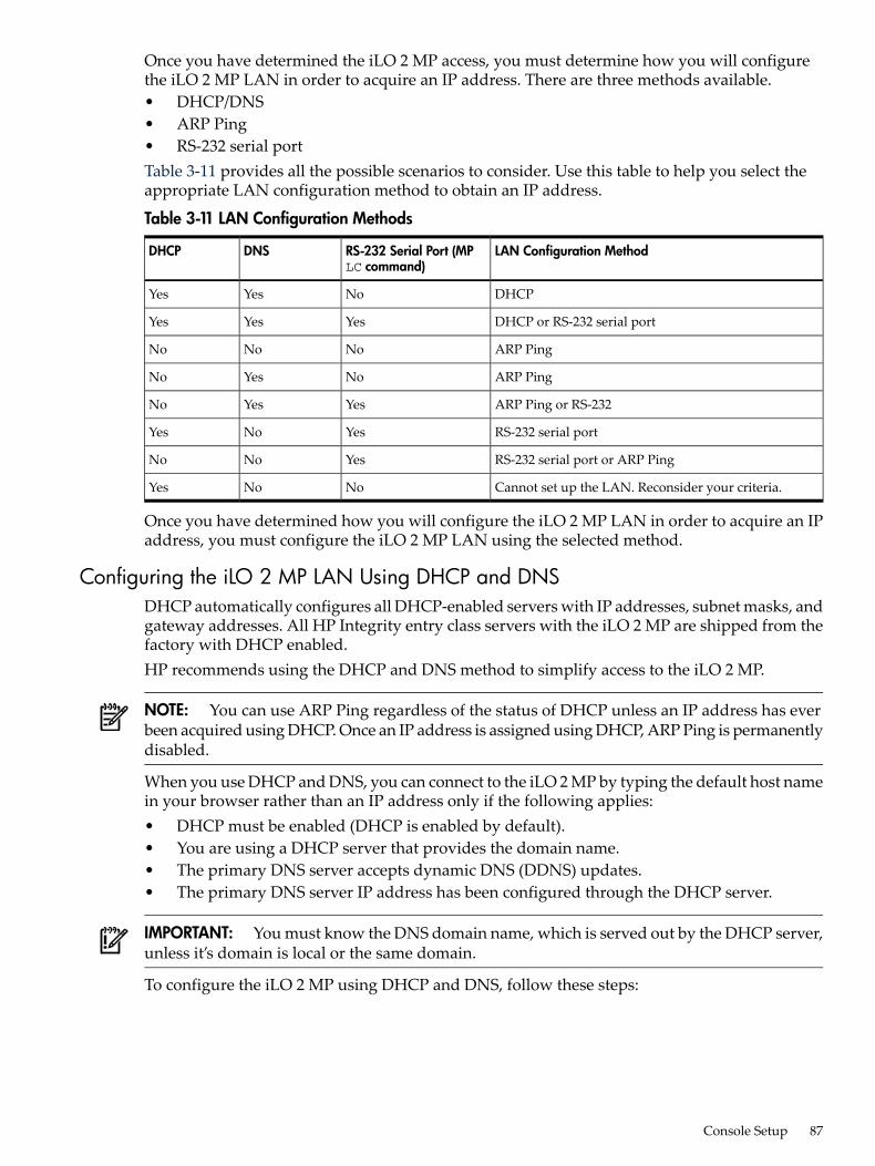
Once you have determined the iLO 2 MP access, you must determine how you will configurethe iLO 2 MP LAN in order to acquire an IP address. There are three methods available.• DHCP/DNS• ARP Ping• RS-232 serial portTable 3-11 provides all the possible scenarios to consider. Use this table to help you select theappropriate LAN configuration method to obtain an IP address.
Table 3-11 LAN Configuration Methods
LAN Configuration MethodRS-232 Serial Port (MPLC command)
DNSDHCP
DHCPNoYesYes
DHCP or RS-232 serial portYesYesYes
ARP PingNoNoNo
ARP PingNoYesNo
ARP Ping or RS-232YesYesNo
RS-232 serial portYesNoYes
RS-232 serial port or ARP PingYesNoNo
Cannot set up the LAN. Reconsider your criteria.NoNoYes
Once you have determined how you will configure the iLO 2 MP LAN in order to acquire an IPaddress, you must configure the iLO 2 MP LAN using the selected method.
Configuring the iLO 2 MP LAN Using DHCP and DNSDHCP automatically configures all DHCP-enabled servers with IP addresses, subnet masks, andgateway addresses. All HP Integrity entry class servers with the iLO 2 MP are shipped from thefactory with DHCP enabled.HP recommends using the DHCP and DNS method to simplify access to the iLO 2 MP.
NOTE: You can use ARP Ping regardless of the status of DHCP unless an IP address has everbeen acquired using DHCP. Once an IP address is assigned using DHCP, ARP Ping is permanentlydisabled.
When you use DHCP and DNS, you can connect to the iLO 2 MP by typing the default host namein your browser rather than an IP address only if the following applies:• DHCP must be enabled (DHCP is enabled by default).• You are using a DHCP server that provides the domain name.• The primary DNS server accepts dynamic DNS (DDNS) updates.• The primary DNS server IP address has been configured through the DHCP server.
IMPORTANT: You must know the DNS domain name, which is served out by the DHCP server,unless it’s domain is local or the same domain.
To configure the iLO 2 MP using DHCP and DNS, follow these steps:
Console Setup 87
1. Obtain the factory-set host name from the iLO 2 MP Media Access Protocol (MAC) addresslabel on the server. The default host name is 14 characters long, consisting of the letters mpfollowed by the 12 characters of the MAC address (example: mp0014c29c064f). This addressis assigned to the iLO 2 MP core IO board. The core IO board has a unique MAC addressthat identifies the hardware on the network.
IMPORTANT: Make sure you obtain the MAC address to the core IO board and not theMAC address to the server core LAN card.
2. Connect the LAN cable from the server to an active network port.3. Apply AC power to the server.4. Open a browser, telnet, or SSH client and enter the default host name. The default host name
is the letters mp followed by the 12 characters of the MAC address. The iLO 2 MP Log Inwindow opens.
5. Log in using the default user name and password.
CAUTION: When DHCP is enabled, the system is vulnerable to security risks because anyonecan access the iLO 2 MP until you change the default user name and password.HP strongly recommends you assign user groups and rights before proceeding.
Configuring the iLO 2 MP LAN Using ARP Ping
NOTE: You can use ARP Ping regardless of the status of DHCP unless an IP address has everbeen acquired using DHCP. Once an IP address is assigned using DHCP, ARP Ping is permanentlydisabled. Some DHCP server options can cause the apparent issuance of ARP Ping to the iLO 2MP which will negate the DHCP/DDNS method.
The Address Resolution Protocol (ARP) and Packet Internet Grouper (Ping) utility uses ARPpackets to ping, or discover, a device on the local network segment. The IP address you assignto the server must use the same network segment, or subnet, as the computer assigning theaddress. ARP does not work across routed or switched networks.Use the ARP Ping utility to assign a static IP address when you do not have access to the RS-232serial port or when DHCP is not available.
NOTE: ARP Ping operational issues:• The PC and the server must be on the same physical subnet.• When a new server is first booted, DHCP is automatically available (factory-set default);
but ARP Ping does not start for three minutes after the iLO 2 MP is booted. This applies toevery subsequent boot of the iLO 2 MP until an IP address is obtained by DHCP or has beenassigned by using the LC command.
• Upon successfully assigning an IP address using ARP Ping, DHCP is automatically disabled.
There are two methods to use the ARP Ping utility:1. Connect a PC to the network that is on the same physical subnet as the server and run the
ARP Ping commands from the PC.2. Locate an existing server on the network, log into it, and run the ARP Ping commands from
the server.Table 3-12 lists the ARP Ping commands.
88 Installing the System
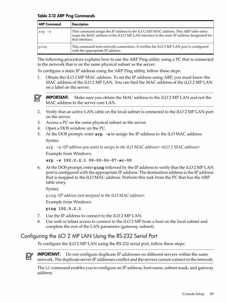
Table 3-12 ARP Ping Commands
DescriptionARP Command
This command assign the IP address to the iLO 2 MP MAC address. This ARP table entrymaps the MAC address of the iLO 2 MP LAN interface to the static IP address designated forthat interface.
arp -s
This command tests network connections. It verifies the iLO 2 MP LAN port is configuredwith the appropriate IP address.
ping
The following procedure explains how to use the ARP Ping utility using a PC that is connectedto the network that is on the same physical subnet as the server.To configure a static IP address using the ARP Ping utility, follow these steps:1. Obtain the iLO 2 MP MAC address. To set the IP address using ARP, you must know the
MAC address of the iLO 2 MP LAN. You can find the MAC address of the iLO 2 MP LANon a label on the server.
IMPORTANT: Make sure you obtain the MAC address to the iLO 2 MP LAN and not theMAC address to the server core LAN.
2. Verify that an active LAN cable on the local subnet is connected to the iLO 2 MP LAN porton the server.
3. Access a PC on the same physical subnet as the server.4. Open a DOS window on the PC.5. At the DOS prompt, enter arp -s to assign the IP address to the iLO MAC address.
Syntaxarp -s <IP address you want to assign to the iLO MAC address> <iLO 2 MAC address>Example from Windowsarp -s 192.0.2.1 00-00-0c-07-ac-00
6. At the DOS prompt, enter ping followed by the IP address to verify that the iLO 2 MP LANport is configured with the appropriate IP address. The destination address is the IP addressthat is mapped to the iLO MAC address. Perform this task from the PC that has the ARPtable entry.Syntaxping <IP address just assigned to the iLO MAC address>Example from Windowsping 192.0.2.1
7. Use the IP address to connect to the iLO 2 MP LAN.8. Use web or telnet access to connect to the iLO 2 MP from a host on the local subnet and
complete the rest of the LAN parameter (gateway, subnet).
Configuring the iLO 2 MP LAN Using the RS-232 Serial PortTo configure the iLO 2 MP LAN using the RS-232 serial port, follow these steps:
IMPORTANT: Do not configure duplicate IP addresses on different servers within the samenetwork. The duplicate server IP addresses conflict and the servers cannot connect to the network.
The LC command enables you to configure an IP address, host name, subnet mask, and gatewayaddress.
Console Setup 89
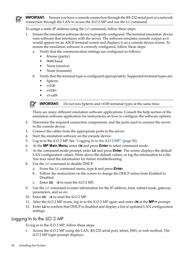
IMPORTANT: Ensure you have a console connection through the RS-232 serial port or a networkconnection through the LAN to access the iLO 2 MP and use the LC command.
To assign a static IP address using the LC command, follow these steps:1. Ensure the emulation software device is properly configured. The terminal emulation device
runs software that interfaces with the server. The software emulates console output as itwould appear on an ASCII terminal screen and displays it on a console device screen. Toensure the emulation software is correctly configured, follow these steps:a. Verify that the communication settings are configured as follows:
• 8/none (parity)• 9600 baud• None (receive)• None (transmit)
b. Verify that the terminal type is configured appropriately. Supported terminal types are:• hpterm• vt100• vt100+• vt-utf8
IMPORTANT: Do not mix hpterm and vt100 terminal types at the same time.
There are many different emulation software applications. Consult the help section of theemulation software application for instructions on how to configure the software options.
2. Determine the required connection components, and the ports used to connect the serverto the console device.
3. Connect the cables from the appropriate ports to the server.4. Start the emulation software on the console device.5. Log in to the iLO 2 MP. See “Logging In to the iLO 2 MP” (page 90).6. At the MP Main Menu, enter CM and press Enter to select command mode.7. At the command mode prompt, enter LS and press Enter. The screen displays the default
LAN configuration values. Write down the default values, or log the information to a file.You may need the information for future troubleshooting.
8. Use the LC command to disable DHCP.a. From the LC command menu, type D and press Enter.b. Follow the instructions on the screen to change the DHCP status from Enabled to
Disabled.c. Enter XD -R to reset the iLO 2 MP.
9. Use the LC command to enter information for the IP address, host, subnet mask, gatewayparameters, and so on.
10. Enter XD -R to reset the iLO 2 MP.11. After the iLO 2 MP resets, log in to the iLO 2 MP again and enter CM at the MP:> prompt.12. Enter LS to confirm that DHCP is disabled and display a list of updated LAN configuration
settings.
Logging In to the iLO 2 MPTo log in to the iLO 2 MP, follow these steps:1. Access the iLO 2 MP using the LAN, RS-232 serial port, telnet, SSH, or web method. The
iLO 2 MP login prompt displays.
90 Installing the System
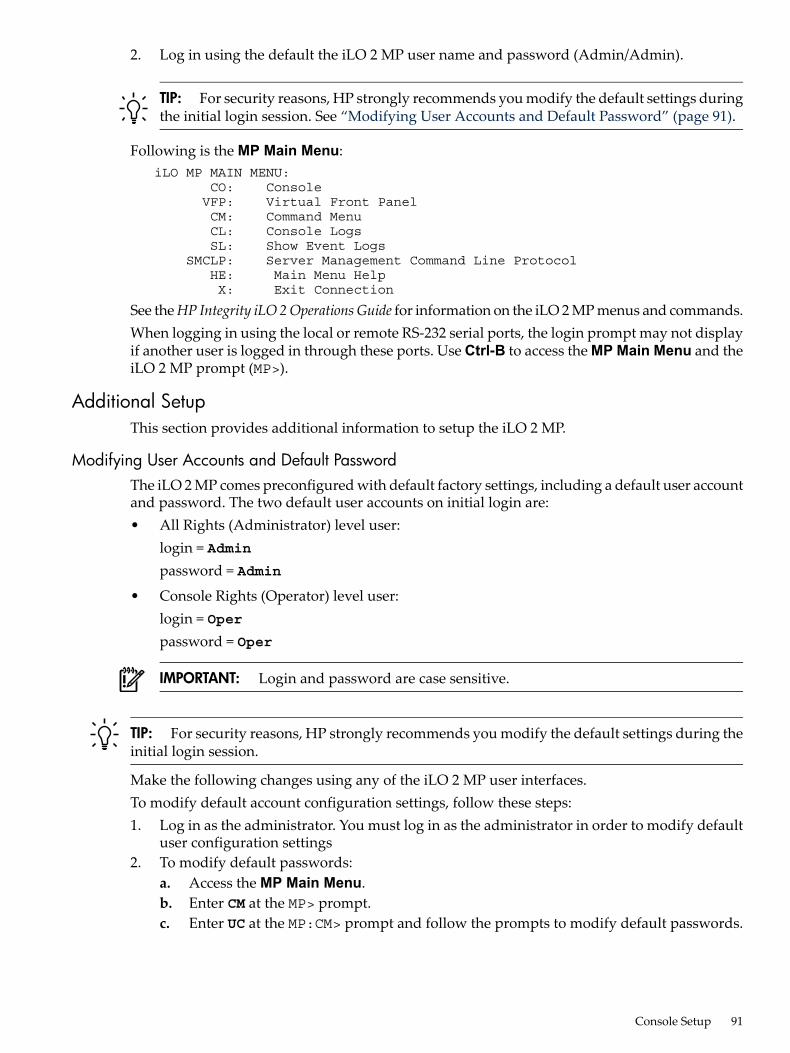
2. Log in using the default the iLO 2 MP user name and password (Admin/Admin).
TIP: For security reasons, HP strongly recommends you modify the default settings duringthe initial login session. See “Modifying User Accounts and Default Password” (page 91).
Following is the MP Main Menu: iLO MP MAIN MENU: CO: Console VFP: Virtual Front Panel CM: Command Menu CL: Console Logs SL: Show Event Logs SMCLP: Server Management Command Line Protocol HE: Main Menu Help X: Exit Connection
See theHP Integrity iLO 2OperationsGuide for information on the iLO 2 MP menus and commands.When logging in using the local or remote RS-232 serial ports, the login prompt may not displayif another user is logged in through these ports. Use Ctrl-B to access the MP Main Menu and theiLO 2 MP prompt (MP>).
Additional SetupThis section provides additional information to setup the iLO 2 MP.
Modifying User Accounts and Default PasswordThe iLO 2 MP comes preconfigured with default factory settings, including a default user accountand password. The two default user accounts on initial login are:• All Rights (Administrator) level user:
login = Adminpassword = Admin
• Console Rights (Operator) level user:login = Operpassword = Oper
IMPORTANT: Login and password are case sensitive.
TIP: For security reasons, HP strongly recommends you modify the default settings during theinitial login session.
Make the following changes using any of the iLO 2 MP user interfaces.To modify default account configuration settings, follow these steps:1. Log in as the administrator. You must log in as the administrator in order to modify default
user configuration settings2. To modify default passwords:
a. Access the MP Main Menu.b. Enter CM at the MP> prompt.c. Enter UC at the MP:CM> prompt and follow the prompts to modify default passwords.
Console Setup 91
3. To setup user accounts:a. Access the MP Main Menu.b. Enter CM at the MP> prompt.c. Enter UC at the MP:CM> prompt and follow the prompts to modify user accounts.
Setting Up SecurityFor greater security and reliability, HP generally recommends that iLO 2 MP management trafficbe on a separate dedicated management network and that only administrators be granted accessto that network. This not only improves performance by reducing traffic load across the mainnetwork, it also acts as the first line of defense against security attacks. A separate network allowsadministrators to physically control which workstations are connected to the network.HP also strongly recommends you modify the default settings during the initial logon sessionand determine the security access required and what user accounts and privileges are needed.Create local accounts or use directory services to control user access. See “Modifying UserAccounts and Default Password” (page 91).
Security Access Settings
Determine the security access required and what user accounts and privileges are needed. TheiLO 2 MP provides options to control user access. Select one of the following options to preventunauthorized access to the iLO 2 MP:• Change the default user name and password. See “Modifying User Accounts and Default
Password” (page 91)).
CAUTION: When DHCP is enabled, the system is vulnerable to security risks becauseanyone can access the iLO 2 MP until you change the default user name and password.HP strongly recommends you assign user groups and rights before proceeding.
• Create local accounts. You can store up to 19 user names and passwords to manage iLO 2MP access. This is ideal for small environments such as labs and small-to-medium sizedbusinesses.
• Use directory services. Use the corporate directory to manage iLO 2 MP user access. This isideal for environments with a large number of frequently changing users. If you plan to usedirectory services, HP recommends leaving at least one local account enabled as an alternatemethod of access.
Accessing the Host ConsoleThis section provides information on the different methods of accessing the host console of anHP Integrity server.
Accessing the iLO 2 MP With the Web BrowserWeb browser access is an embedded feature of the iLO 2 MP.The iLO 2 MP has a separate LAN port from the system LAN port. It requires a separate LANdrop, IP address, and networking information from that of the port used by the operating system.
IMPORTANT: Make sure you use the MAC address to the iLO 2 MP LAN and not the MACaddress to the server core LAN.
Before starting this procedure, you must have the following information:• IP address for the iLO 2 MP LAN• Host name (this is used when messages are logged or printed)To interact with the iLO 2 MP through the web GUI, follow these steps:
92 Installing the System
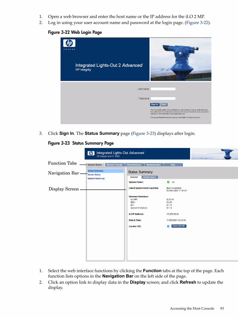
1. Open a web browser and enter the host name or the IP address for the iLO 2 MP.2. Log in using your user account name and password at the login page. (Figure 3-22).
Figure 3-22 Web Login Page
3. Click Sign In. The Status Summary page (Figure 3-23) displays after login.
Figure 3-23 Status Summary Page
1. Select the web interface functions by clicking the Function tabs at the top of the page. Eachfunction lists options in the Navigation Bar on the left side of the page.
2. Click an option link to display data in the Display screen; and click Refresh to update thedisplay.
Accessing the Host Console 93
3. Click the Remote Console tab. The remote console provides the following options to accessthe console:• A serial console that behaves similarly to the TUI of the following section• The virtual KVM console
HelpThe iLO 2 MP web interface has a robust help system. To launch iLO 2 MP help, click the Helptab in the Display screen or click the ? at the top right corner of each page to display help aboutthat page.
Accessing the Host Console With the TUI - CO CommandThis section provides the steps to access the host console using the text user interface (TUI).To access the host console through the iLO 2 MP, follow these steps:1. Log in using your user account name and password at the login page.2. At the iLO 2 MP login prompt (MP>), enter the CO command to switch the console terminal
from the MP Main Menu to mirrored/redirected console mode. All mirrored data is displayed.3. To return to the iLO 2 MP command interface, type Ctrl-B, or Esc and +.
Accessing the Host Console With vKVM - Integrated Remote ConsoleFor information on how to access the host console using the vKVM feature through the IntegratedRemote Console (IRC), see the HP Integrity iLO 2 Operations Guide.
Accessing the Host Console with the SMASH SM CLPFor information on how to access the host console using the SMASH SM CLP, see theHP IntegrityiLO 2 Operations Guide.
Accessing the Graphic Console Using VGAVGA is a method you can use to access the graphic console.
NOTE: You cannot access iLO 2 using VGA.
This method requires three elements:• Monitor (VGA connector)• Keyboard (USB connector)• Mouse (USB connector)The graphic console output displays on the monitor screen.
IMPORTANT: The server console output does not display on the console device screen untilthe server boots to the EFI Shell. Start a console session using the RS-232 serial port method toview console output prior to booting to the EFI Shell or to access the iLO 2 MP. See “Configuringthe iLO 2 MP LAN Using the RS-232 Serial Port” (page 89).
To access the graphic console with VGA, follow these steps:1. Perform preparation tasks.2. Connect the cables. See your user service guide for specific port information.
a. Connect the monitor VGA cable to the appropriate VGA port on your server.b. Connect the keyboard USB cable to the appropriate USB port on your server.c. Connect the mouse USB cable to the appropriate USB port on your server.
3. Power on the server. The EFI Shell prompt displays.
94 Installing the System
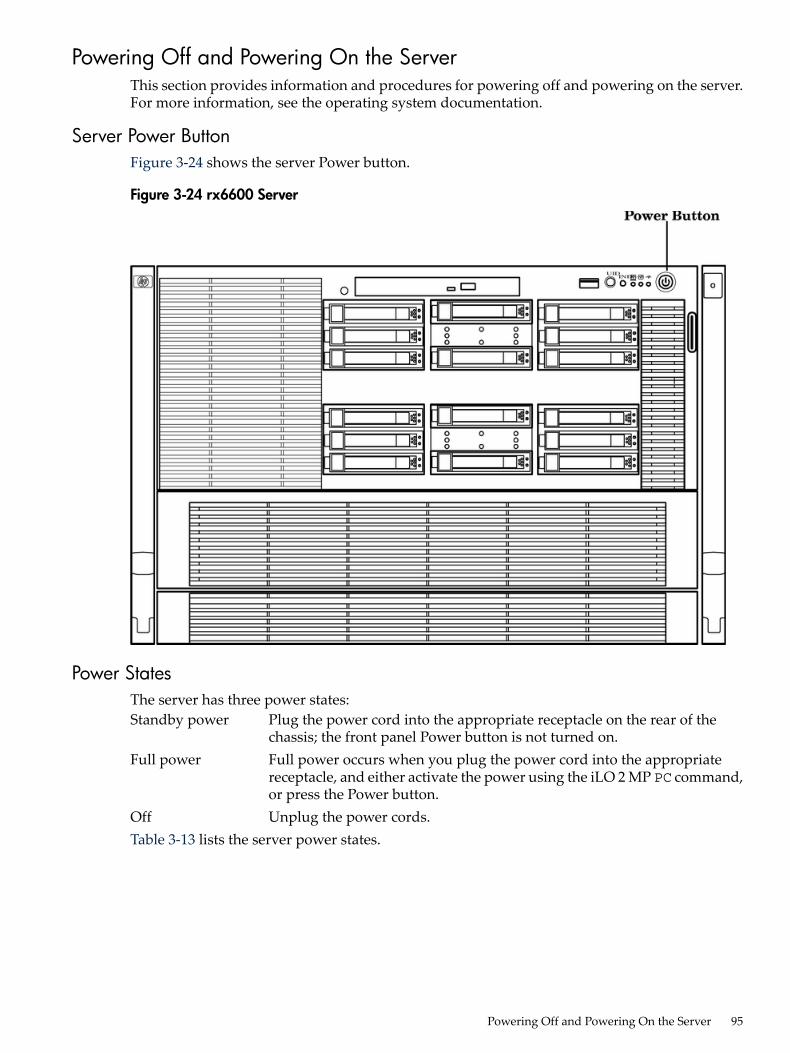
Powering Off and Powering On the ServerThis section provides information and procedures for powering off and powering on the server.For more information, see the operating system documentation.
Server Power ButtonFigure 3-24 shows the server Power button.
Figure 3-24 rx6600 Server
Power StatesThe server has three power states:Standby power Plug the power cord into the appropriate receptacle on the rear of the
chassis; the front panel Power button is not turned on.Full power Full power occurs when you plug the power cord into the appropriate
receptacle, and either activate the power using the iLO 2 MP PC command,or press the Power button.
Off Unplug the power cords.Table 3-13 lists the server power states.
Powering Off and Powering On the Server 95
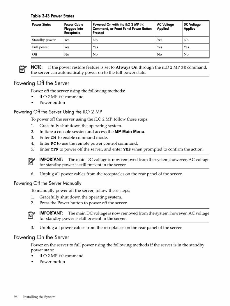
Table 3-13 Power States
DC VoltageApplied
AC VoltageApplied
Powered On with the iLO 2 MP PCCommand, or Front Panel Power ButtonPressed
Power CablePlugged intoReceptacle
Power States
NoYesNoYesStandby power
YesYesYesYesFull power
NoNoNoNoOff
NOTE: If the power restore feature is set to Always On through the iLO 2 MP PR command,the server can automatically power on to the full power state.
Powering Off the ServerPower off the server using the following methods:• iLO 2 MP PC command• Power button
Powering Off the Server Using the iLO 2 MPTo power off the server using the iLO 2 MP, follow these steps:1. Gracefully shut down the operating system.2. Initiate a console session and access the MP Main Menu.3. Enter CM to enable command mode.4. Enter PC to use the remote power control command.5. Enter OFF to power off the server, and enter YES when prompted to confirm the action.
IMPORTANT: The main DC voltage is now removed from the system; however, AC voltagefor standby power is still present in the server.
6. Unplug all power cables from the receptacles on the rear panel of the server.
Powering Off the Server ManuallyTo manually power off the server, follow these steps:1. Gracefully shut down the operating system.2. Press the Power button to power off the server.
IMPORTANT: The main DC voltage is now removed from the system; however, AC voltagefor standby power is still present in the server.
3. Unplug all power cables from the receptacles on the rear panel of the server.
Powering On the ServerPower on the server to full power using the following methods if the server is in the standbypower state:• iLO 2 MP PC command• Power button
96 Installing the System
Powering On the Server Using the iLO 2 MP
NOTE: If the power restore feature is set to Always On through the iLO 2 MP PR command,the server can automatically power on to the full power state.
To power on the server using the iLO 2 MP, follow these steps:1. Plug all power cables into the receptacles on the rear panel of the server.2. Initiate a console session and access the MP Main Menu.3. Enter CMto enable command mode.4. Enter PC to use the remote power control command.5. Enter ON to power on the server, and enter YES when prompted to confirm the action.6. Start the operating system.
Powering On the Server Manually
NOTE: If the power restore feature is set to Always On through the iLO 2 MP PR command,the server can automatically power on to the full power state.
To manually power on the server, follow these steps:1. Plug all power cables into the receptacles on the rear panel of the server.2. Press the Power button to start the server.3. Start the operating system.)
Core I/O Card ConfigurationThis section provides information on core I/O cards that need to be configured during installation.
Integrated RAIDUse Integrated RAID (IR) where either storage capacity, redundancy, or both of a RAIDconfiguration are required. Two components of IR are:• Integrated Mirror (IM)• Global Hot SpareTo flash firmware, use the mptutil command. To configure and maintain the IR functionalityof the SAS controller on the HP Integrity server, use the drvcfg and cfggen EFI commands.If you are scripting multiple devices, use thecfggencommand.
Integrated MirrorThe advantage of an IM is there is always a mirrored copy of the data. An IM provides dataprotection for the system boot volume to safeguard critical information such as the operatingsystem on servers and high performance workstations. An IM supports two simultaneousmirrored volumes, making an array, providing fault-tolerant protection for critical data. Typically,one of these volumes is the boot volume. If a disk in an IM fails, the hot swap capability enablesthe volume to be easily restored by replacing the failed disk. The firmware then automaticallyre-mirrors to the replaced disk.
Global Hot SpareEach SAS controller can have one global hot spare disk available to automatically replace a faileddisk in the one or two IM volumes configured on the controller. The hot spare makes the IMarray more fault tolerant. Up to two IM volumes are supported per SAS controller plus the hotspare.
Core I/O Card Configuration 97
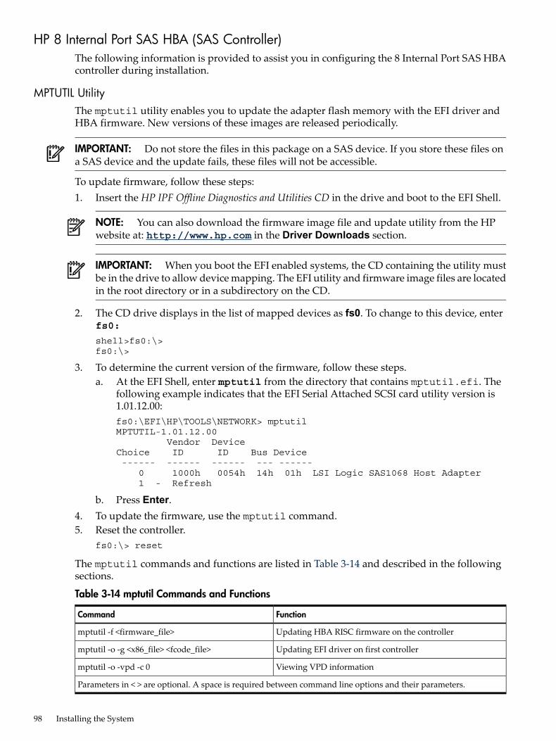
HP 8 Internal Port SAS HBA (SAS Controller)The following information is provided to assist you in configuring the 8 Internal Port SAS HBAcontroller during installation.
MPTUTIL UtilityThe mptutil utility enables you to update the adapter flash memory with the EFI driver andHBA firmware. New versions of these images are released periodically.
IMPORTANT: Do not store the files in this package on a SAS device. If you store these files ona SAS device and the update fails, these files will not be accessible.
To update firmware, follow these steps:1. Insert the HP IPF Offline Diagnostics and Utilities CD in the drive and boot to the EFI Shell.
NOTE: You can also download the firmware image file and update utility from the HPwebsite at: http://www.hp.com in the Driver Downloads section.
IMPORTANT: When you boot the EFI enabled systems, the CD containing the utility mustbe in the drive to allow device mapping. The EFI utility and firmware image files are locatedin the root directory or in a subdirectory on the CD.
2. The CD drive displays in the list of mapped devices as fs0. To change to this device, enterfs0:
shell>fs0:\>fs0:\>
3. To determine the current version of the firmware, follow these steps.a. At the EFI Shell, enter mptutil from the directory that contains mptutil.efi. The
following example indicates that the EFI Serial Attached SCSI card utility version is1.01.12.00:fs0:\EFI\HP\TOOLS\NETWORK> mptutilMPTUTIL-1.01.12.00 Vendor Device Choice ID ID Bus Device ------ ------ ------ --- ------ 0 1000h 0054h 14h 01h LSI Logic SAS1068 Host Adapter 1 - Refresh
b. Press Enter.4. To update the firmware, use the mptutil command.5. Reset the controller.
fs0:\> reset
The mptutil commands and functions are listed in Table 3-14 and described in the followingsections.
Table 3-14 mptutil Commands and Functions
FunctionCommand
Updating HBA RISC firmware on the controllermptutil -f <firmware_file>
Updating EFI driver on first controllermptutil -o -g <x86_file> <fcode_file>
Viewing VPD informationmptutil -o -vpd -c 0
Parameters in < > are optional. A space is required between command line options and their parameters.
98 Installing the System
The following sections describe the mptutil commands and functions.
Flashing Firmware on First Controller
To update the HBA RISC firmware on the first controller, follow these steps:1. At the fs0:\> prompt, enter mptutil -f <firmware_file> -c 0.2. At the fs0:\> prompt, enter reset.The filename is optional and you are prompted for a filename if omitted.Another way for the firmware to be flashed is done without your knowledge. When mptutilis executed, and a SAS HBA is in any state other than ready or operational, mptutil immediatelyperforms a firmware download boot. The firmware provided by you to do the firmware downloadboot is immediately flashed after the firmware download boot has completed. mptutil doesthis because the firmware only moves to the operational state if it is running from flash and notmemory. Operational state is needed to do everything else provided in the utility.
Flashing BIOS and EFI Driver on the First Controller
To update the EFI driver on the first controller, follow these steps:1. At the fs0:\> prompt, enter mptutil -o -g <Bios_File> <EFI_driver_file>
-c 0.2. At the fs0:\> prompt, enter reset.The filename is optional and you are prompted for a filename if omitted.
Common Questions About Flashing Firmware
Question After I update firmware on my SAS HBA, why doesn't the version string changein the menu?
Answer The firmware you just flashed on the HBA does not run until a diagnostic resetoccurs. If you exit the utility and reenter it, the version string is updated.
Question This image does not contain a valid nvdatawhen I try to flash the firmware, why?Answer You are expected to concatenate a proper nvdata image on to the firmware.
mptutil keeps you from flashing an image without one. To concatenate nvdataand firmware you need to run the mptutil -o -d64it__l.fw,sas106x.dat,output.fw command. .• 64it__l.fw is the firmware image without a nvdata image• sas106x.dat is the nvdata image. This file depends on the type/rev of HBA
on which the firmware is used• output.fw is the name of the file created with the firmware and nvdata
concatenated. This concatenated image can be used for all boards of this typeor revision.
Question How do I program multiple cards in a system from the command line?Answer mptutil (EFI) does not support this.Question Can I program a new flash and option ROM in the same command line argument?Answer Yes. Run the mptutil -f <firmware_name> -b <option_rom_name>
command.
Viewing the VPD Information for EFI Driver and RISC Firmware
To view the VPD information for the EFI driver and RISC firmware, enter mptutil -o -vpd-c 0 at the fs0:\> prompt.
Core I/O Card Configuration 99
EFI CommandsTo configure an Integrated Mirror (IM) Array on the SAS Controller, use the following EFIcommands:• drvcfg(GUI interface)• cfggen(command line interface)
NOTE: If you are not using the IM functionality, do not follow these procedures.
DRVCFG Utility
To configure an IM on the SAS controller, follow these steps:
Starting the DRVCFG Utility
To start thedrvcfgconfiguration utility, follow these steps:1. Select the EFI Shell from the console menu.2. Type drvcfg -s and press Enter.
Using the DRVCFG Utility
The configuration utility uses several input keys (F1, F2, HOME, END, and so on) that may notbe supported by all terminal emulation programs. Each of these keys has an alternate key thatperforms the same function. Review the terminal emulation program documentation to verifywhich input keys are supported. If problems occur using any of the function keys orHOME/END/PGUP/PGDN, it is recommended that the alternate keys be used.There are general key inputs throughout the configuration utility that apply on all screens:F1 Help Context sensitive help for the cursor-resident field.Arrow Keys Select Item - Up, down, left, right movement to position the cursor.Home/End Select Item - Up, down, left, right movement to position the cursor.+/- Change Item - Items with values in [ ] brackets are modifiable. Numeric keypad
+ and numeric keypad - (minus) update a modifiable field to its next relativevalue.
Esc Abort/Exit - Escape aborts the current context operation and/or exits the currentscreen. User confirmation is solicited as required if changes have been madeby user. If you are using a serial console, pressing Esc causes a delay of severalseconds before it takes effect. This is normal system behavior and is not an error.
Enter Execute <item> - Executable items are indicated by highlighted text and adifferent background color. Press Enter to execute the field's associated function.
Configuration Utility Screens
All SAS BIOS configuration utility screens contain the following areas, starting at the top of thescreen:Header area Identifies the utility and version number.Menu area Gives the title of the current screen, and on screens other than the Adapter
List screen also identifies the adapter.Main area The main area for presenting data. This area has a cursor for item selection,
and horizontal and vertical scroll bars if necessary.Footer area Provides general help information text.Figure 3-25 provides a map of how screens are accessed in the drvcfg utility.
100 Installing the System
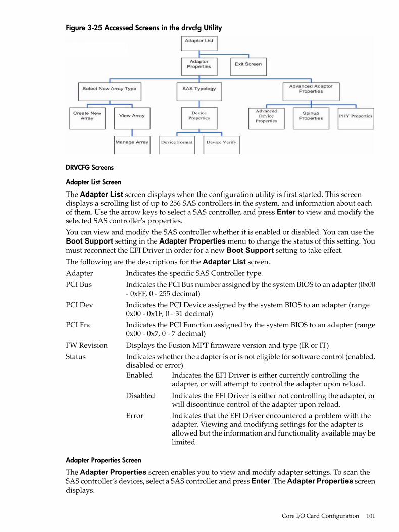
Figure 3-25 Accessed Screens in the drvcfg Utility
DRVCFG Screens
Adapter List Screen
The Adapter List screen displays when the configuration utility is first started. This screendisplays a scrolling list of up to 256 SAS controllers in the system, and information about eachof them. Use the arrow keys to select a SAS controller, and press Enter to view and modify theselected SAS controller's properties.You can view and modify the SAS controller whether it is enabled or disabled. You can use theBoot Support setting in the Adapter Properties menu to change the status of this setting. Youmust reconnect the EFI Driver in order for a new Boot Support setting to take effect.The following are the descriptions for the Adapter List screen.Adapter Indicates the specific SAS Controller type.PCI Bus Indicates the PCI Bus number assigned by the system BIOS to an adapter (0x00
- 0xFF, 0 - 255 decimal)PCI Dev Indicates the PCI Device assigned by the system BIOS to an adapter (range
0x00 - 0x1F, 0 - 31 decimal)PCI Fnc Indicates the PCI Function assigned by the system BIOS to an adapter (range
0x00 - 0x7, 0 - 7 decimal)FW Revision Displays the Fusion MPT firmware version and type (IR or IT)Status Indicates whether the adapter is or is not eligible for software control (enabled,
disabled or error)Enabled Indicates the EFI Driver is either currently controlling the
adapter, or will attempt to control the adapter upon reload.Disabled Indicates the EFI Driver is either not controlling the adapter, or
will discontinue control of the adapter upon reload.Error Indicates that the EFI Driver encountered a problem with the
adapter. Viewing and modifying settings for the adapter isallowed but the information and functionality available may belimited.
Adapter Properties Screen
The Adapter Properties screen enables you to view and modify adapter settings. To scan theSAS controller’s devices, select a SAS controller and press Enter. The Adapter Properties screendisplays.
Core I/O Card Configuration 101
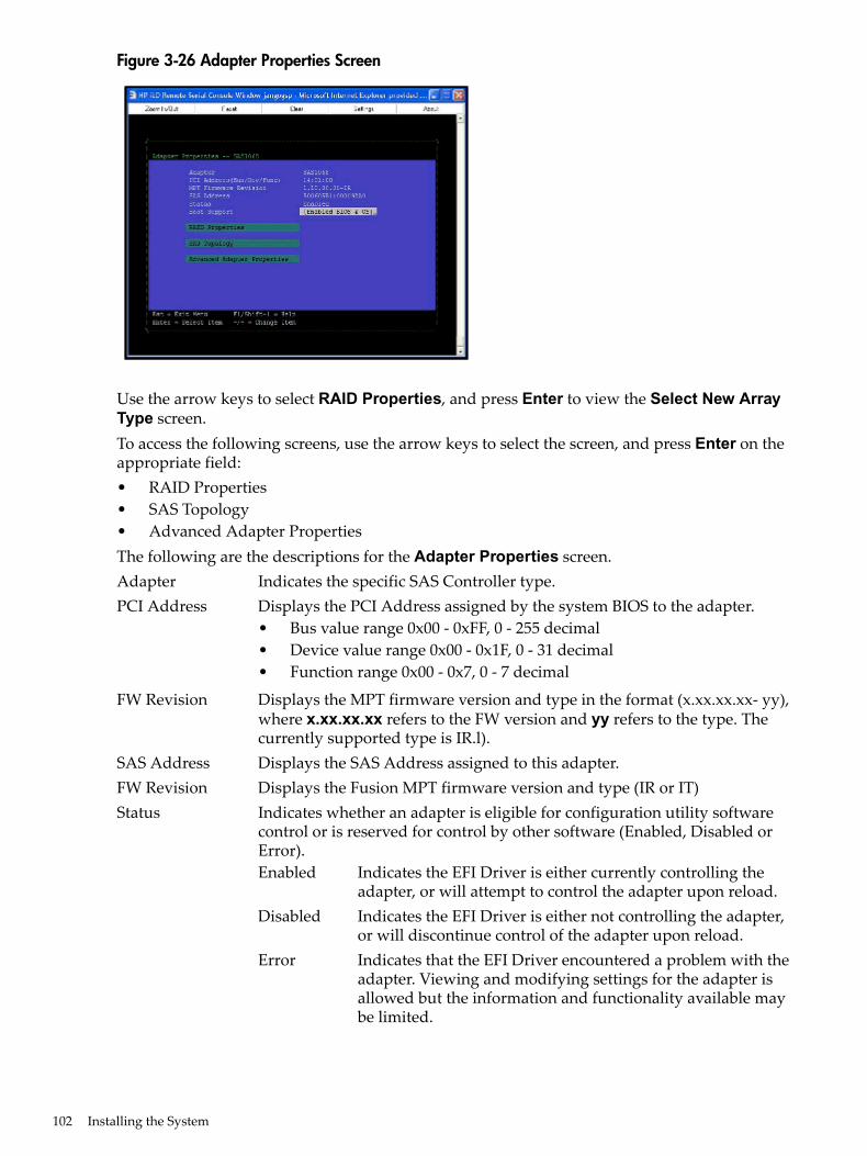
Figure 3-26 Adapter Properties Screen
Use the arrow keys to select RAID Properties, and press Enter to view the Select New ArrayType screen.To access the following screens, use the arrow keys to select the screen, and press Enter on theappropriate field:• RAID Properties• SAS Topology• Advanced Adapter PropertiesThe following are the descriptions for the Adapter Properties screen.Adapter Indicates the specific SAS Controller type.PCI Address Displays the PCI Address assigned by the system BIOS to the adapter.
• Bus value range 0x00 - 0xFF, 0 - 255 decimal• Device value range 0x00 - 0x1F, 0 - 31 decimal• Function range 0x00 - 0x7, 0 - 7 decimal
FW Revision Displays the MPT firmware version and type in the format (x.xx.xx.xx- yy),where x.xx.xx.xx refers to the FW version and yy refers to the type. Thecurrently supported type is IR.l).
SAS Address Displays the SAS Address assigned to this adapter.FW Revision Displays the Fusion MPT firmware version and type (IR or IT)Status Indicates whether an adapter is eligible for configuration utility software
control or is reserved for control by other software (Enabled, Disabled orError).Enabled Indicates the EFI Driver is either currently controlling the
adapter, or will attempt to control the adapter upon reload.Disabled Indicates the EFI Driver is either not controlling the adapter,
or will discontinue control of the adapter upon reload.Error Indicates that the EFI Driver encountered a problem with the
adapter. Viewing and modifying settings for the adapter isallowed but the information and functionality available maybe limited.
102 Installing the System
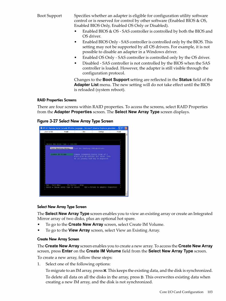
Boot Support Specifies whether an adapter is eligible for configuration utility softwarecontrol or is reserved for control by other software (Enabled BIOS & OS,Enabled BIOS Only, Enabled OS Only or Disabled).• Enabled BIOS & OS - SAS controller is controlled by both the BIOS and
OS driver.• Enabled BIOS Only - SAS controller is controlled only by the BIOS. This
setting may not be supported by all OS drivers. For example, it is notpossible to disable an adapter in a Windows driver.
• Enabled OS Only - SAS controller is controlled only by the OS driver.• Disabled - SAS controller is not controlled by the BIOS when the SAS
controller is loaded. However, the adapter is still visible through theconfiguration protocol.
Changes to the Boot Support setting are reflected in the Status field of theAdapter List menu. The new setting will do not take effect until the BIOSis reloaded (system reboot).
RAID Properties Screens
There are four screens within RAID properties. To access the screens, select RAID Propertiesfrom the Adapter Properties screen. The Select New Array Type screen displays.
Figure 3-27 Select New Array Type Screen
Select New Array Type Screen
The Select New Array Type screen enables you to view an existing array or create an IntegratedMirror array of two disks, plus an optional hot spare.• To go to the Create New Array screen, select Create IM Volume.• To go to the View Array screen, select View an Existing Array.
Create New Array Screen
The Create New Array screen enables you to create a new array. To access the Create New Arrayscreen, press Enter on the Create IM Volume field from the Select New Array Type screen.To create a new array, follow these steps:1. Select one of the following options:
To migrate to an IM array, pressM. This keeps the existing data, and the disk is synchronized.To delete all data on all the disks in the array, press D. This overwrites existing data whencreating a new IM array, and the disk is not synchronized.
Core I/O Card Configuration 103
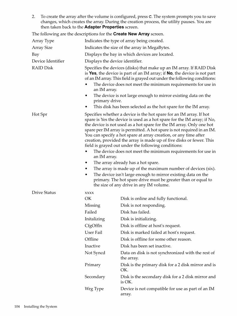
2. To create the array after the volume is configured, press C. The system prompts you to savechanges, which creates the array. During the creation process, the utility pauses. You arethen taken back to the Adapter Properties screen.
The following are the descriptions for the Create New Array screen.Array Type Indicates the type of array being created.Array Size Indicates the size of the array in MegaBytes.Bay Displays the bay in which devices are located.Device Identifier Displays the device identifier.RAID Disk Specifies the devices (disks) that make up an IM array. If RAID Disk
is Yes, the device is part of an IM array; if No, the device is not partof an IM array. This field is grayed out under the following conditions:• The device does not meet the minimum requirements for use in
an IM array.• The device is not large enough to mirror existing data on the
primary drive.• This disk has been selected as the hot spare for the IM array.
Hot Spr Specifies whether a device is the hot spare for an IM array. If hotspare is Yes the device is used as a hot spare for the IM array; if No,the device is not used as a hot spare for the IM array. Only one hotspare per IM array is permitted. A hot spare is not required in an IM.You can specify a hot spare at array creation, or any time aftercreation, provided the array is made up of five disks or fewer. Thisfield is grayed out under the following conditions:• The device does not meet the minimum requirements for use in
an IM array.• The array already has a hot spare.• The array is made up of the maximum number of devices (six).• The device isn't large enough to mirror existing data on the
primary. The hot spare drive must be greater than or equal tothe size of any drive in any IM volume.
Drive Status xxxxOK Disk is online and fully functional.Missing Disk is not responding.Failed Disk has failed.Initalizing Disk is initializing.CfgOffln Disk is offline at host's request.User Fail Disk is marked failed at host's request.Offline Disk is offline for some other reason.Inactive Disk has been set inactive.Not Syncd Data on disk is not synchronized with the rest of
the array.Primary Disk is the primary disk for a 2 disk mirror and is
OK.Secondary Disk is the secondary disk for a 2 disk mirror and
is OK.Wrg Type Device is not compatible for use as part of an IM
array.
104 Installing the System
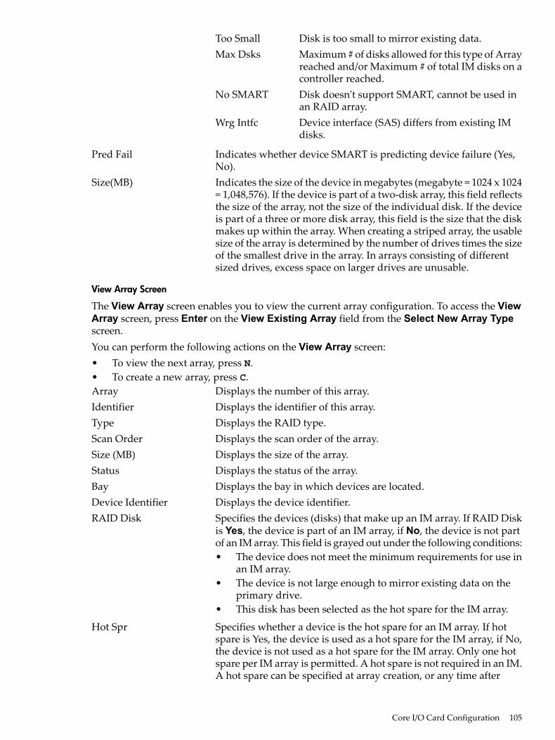
Too Small Disk is too small to mirror existing data.Max Dsks Maximum # of disks allowed for this type of Array
reached and/or Maximum # of total IM disks on acontroller reached.
No SMART Disk doesn't support SMART, cannot be used inan RAID array.
Wrg Intfc Device interface (SAS) differs from existing IMdisks.
Pred Fail Indicates whether device SMART is predicting device failure (Yes,No).
Size(MB) Indicates the size of the device in megabytes (megabyte = 1024 x 1024= 1,048,576). If the device is part of a two-disk array, this field reflectsthe size of the array, not the size of the individual disk. If the deviceis part of a three or more disk array, this field is the size that the diskmakes up within the array. When creating a striped array, the usablesize of the array is determined by the number of drives times the sizeof the smallest drive in the array. In arrays consisting of differentsized drives, excess space on larger drives are unusable.
View Array Screen
The View Array screen enables you to view the current array configuration. To access the ViewArray screen, press Enter on the View Existing Array field from the Select New Array Typescreen.You can perform the following actions on the View Array screen:• To view the next array, press N.• To create a new array, press C.Array Displays the number of this array.Identifier Displays the identifier of this array.Type Displays the RAID type.Scan Order Displays the scan order of the array.Size (MB) Displays the size of the array.Status Displays the status of the array.Bay Displays the bay in which devices are located.Device Identifier Displays the device identifier.RAID Disk Specifies the devices (disks) that make up an IM array. If RAID Disk
is Yes, the device is part of an IM array, if No, the device is not partof an IM array. This field is grayed out under the following conditions:• The device does not meet the minimum requirements for use in
an IM array.• The device is not large enough to mirror existing data on the
primary drive.• This disk has been selected as the hot spare for the IM array.
Hot Spr Specifies whether a device is the hot spare for an IM array. If hotspare is Yes, the device is used as a hot spare for the IM array, if No,the device is not used as a hot spare for the IM array. Only one hotspare per IM array is permitted. A hot spare is not required in an IM.A hot spare can be specified at array creation, or any time after
Core I/O Card Configuration 105
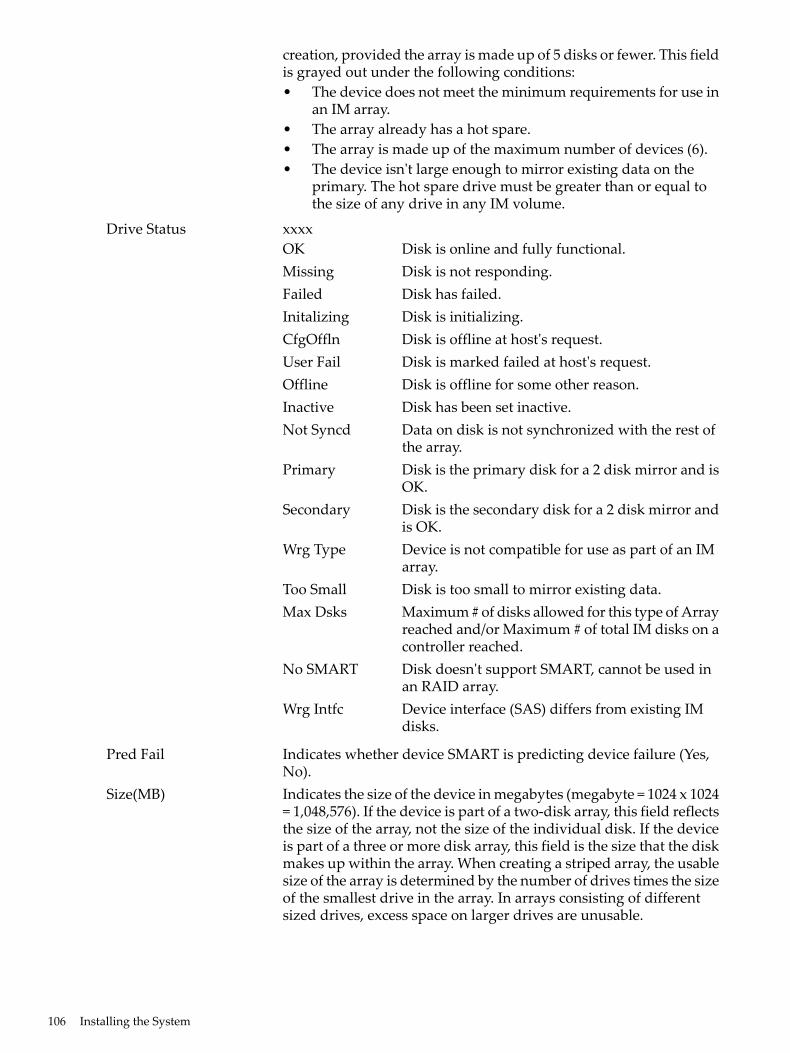
creation, provided the array is made up of 5 disks or fewer. This fieldis grayed out under the following conditions:• The device does not meet the minimum requirements for use in
an IM array.• The array already has a hot spare.• The array is made up of the maximum number of devices (6).• The device isn't large enough to mirror existing data on the
primary. The hot spare drive must be greater than or equal tothe size of any drive in any IM volume.
Drive Status xxxxOK Disk is online and fully functional.Missing Disk is not responding.Failed Disk has failed.Initalizing Disk is initializing.CfgOffln Disk is offline at host's request.User Fail Disk is marked failed at host's request.Offline Disk is offline for some other reason.Inactive Disk has been set inactive.Not Syncd Data on disk is not synchronized with the rest of
the array.Primary Disk is the primary disk for a 2 disk mirror and is
OK.Secondary Disk is the secondary disk for a 2 disk mirror and
is OK.Wrg Type Device is not compatible for use as part of an IM
array.Too Small Disk is too small to mirror existing data.Max Dsks Maximum # of disks allowed for this type of Array
reached and/or Maximum # of total IM disks on acontroller reached.
No SMART Disk doesn't support SMART, cannot be used inan RAID array.
Wrg Intfc Device interface (SAS) differs from existing IMdisks.
Pred Fail Indicates whether device SMART is predicting device failure (Yes,No).
Size(MB) Indicates the size of the device in megabytes (megabyte = 1024 x 1024= 1,048,576). If the device is part of a two-disk array, this field reflectsthe size of the array, not the size of the individual disk. If the deviceis part of a three or more disk array, this field is the size that the diskmakes up within the array. When creating a striped array, the usablesize of the array is determined by the number of drives times the sizeof the smallest drive in the array. In arrays consisting of differentsized drives, excess space on larger drives are unusable.
106 Installing the System
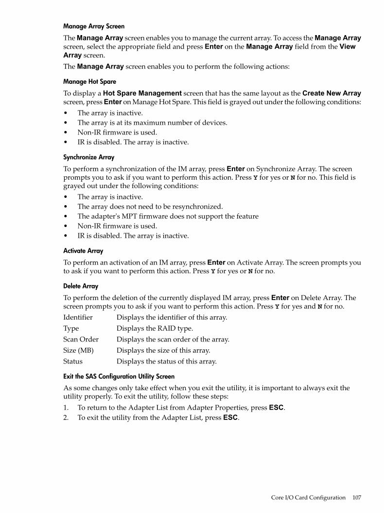
Manage Array Screen
The Manage Array screen enables you to manage the current array. To access the Manage Arrayscreen, select the appropriate field and press Enter on the Manage Array field from the ViewArray screen.The Manage Array screen enables you to perform the following actions:
Manage Hot Spare
To display a Hot Spare Management screen that has the same layout as the Create New Arrayscreen, press Enter on Manage Hot Spare. This field is grayed out under the following conditions:• The array is inactive.• The array is at its maximum number of devices.• Non-IR firmware is used.• IR is disabled. The array is inactive.
Synchronize Array
To perform a synchronization of the IM array, press Enter on Synchronize Array. The screenprompts you to ask if you want to perform this action. Press Y for yes or N for no. This field isgrayed out under the following conditions:• The array is inactive.• The array does not need to be resynchronized.• The adapter's MPT firmware does not support the feature• Non-IR firmware is used.• IR is disabled. The array is inactive.
Activate Array
To perform an activation of an IM array, press Enter on Activate Array. The screen prompts youto ask if you want to perform this action. Press Y for yes or N for no.
Delete Array
To perform the deletion of the currently displayed IM array, press Enter on Delete Array. Thescreen prompts you to ask if you want to perform this action. Press Y for yes and N for no.Identifier Displays the identifier of this array.Type Displays the RAID type.Scan Order Displays the scan order of the array.Size (MB) Displays the size of this array.Status Displays the status of this array.
Exit the SAS Configuration Utility Screen
As some changes only take effect when you exit the utility, it is important to always exit theutility properly. To exit the utility, follow these steps:1. To return to the Adapter List from Adapter Properties, press ESC.2. To exit the utility from the Adapter List, press ESC.
Core I/O Card Configuration 107
NOTE: A similar exit screen is used when exiting most other screens, and can be used to savesettings.
The exit screen shows some options that are grey, indicating that they are not available. You canonly select the available options. The exit choices are as follows:• Are you sure you want to exit?
• Cancel Exit
• Save changes and reboot
• Discard changes and reboot
• Exit the Configuration Utility and Reboot
CFGGEN UtilityThe cfggen utility is a command line utility that runs in the Linux, EFI, and WindowsPre-Installation (WinPE) environments. It is a minimally interactive program that you executefrom a command line prompt, or a shell script. The results from invoking this utility arecommunicated through the program status value that is returned when the program exits. Usethe cfggen utility to create IM storage configurations on SAS controllers. Some cfggencommands work only with SAS adaptors in the EFI environment.
Starting CFGGEN
Thecfggenutility is located on the HP IPF Offline Diagnostic and Utilities CD. To use cfggen,follow these steps:1. Insert the CD into the drive.2. Boot the system to the EFI Shell prompt.3. From the EFI Shell prompt, change to the CD drive.
shell> fs0: Enterfs0:\>
4. Change to the directory that containscfggen.efi.fs0:\> cd EFI\HP\TOOLS\NETWORK Enterfs0: EFI\HP\TOOLS\NETWORK>
From this directory use cfggen.
CFGGEN Operation
cfggenis not case sensitive. You can enter cfggen commands and parameters in uppercase,lowercase, or a mixture of the two. Use the following conventions in the command descriptions:• Text in italics must be entered exactly as shown on the command line• Text surrounded by <> must be replaced with a required parameter• Text surrounded by [ ] may be replaced by an optional parameter• Parameters surrounded by {} must be entered one or more times, as appropriate for the
executed command• Do not enter the command line definition characters (<>, [ ], and {}) on the command line.The cfggen command uses a command line interface.Syntax: cfggen <controller #> <command> <parameters>
NOTE: The program name, controller number, command, and parameters fields must beseparated by the ASCII space character. The format of the parameters is command specific.
The program return value is returned to the user when the program exits. A value of 0 is returnedif the command is successful. Otherwise, a value of 1 is returned.
108 Installing the System
Rules for creating IM volumes and hot spare disks
The following rules apply when creating IM volumes and hot spare disks:• All disks that are part of an IM volume or a hot spare for an IM volume must be on the same
SAS controller.• IM volumes are supported.• Only two IM volumes (plus a global hot spare) per controller can be created.• An IM array must have exactly two disks.• A hot spare disk cannot be created without at least one IM volume already created.• The utility does not allow adding a hot spare disk of type different from disk types in any
of the volume.• With the AUTO command all drives used are the same type as the first available disk found,
and the size is limited to the size of the smallest disk.
CFGGEN Commands
Using the CREATE Command
The create command creates IM volumes on the SAS controller. Firmware and hardwarelimitations for this family of cards limit the number of configurations that are possible.
Syntax
cfggen <controller #> create <volume type> <size> [qsync] [noprompt]
Parameters
<volume type> Volume type for the volume to be created. Valid value is IM.<size> Size of the IM volume in Mbytes or “MAX” for the maximum size available.[qsync] Quick synchronization of the volume created.[noprompt] Eliminates warnings and prompts.
Operation
Once a disk has been added to an IM volume, all of its storage capacity may or may not be useddepending on drive capacity and volume capacity. For example, if you add a 36 GB disk driveto a volume that only uses 9 GB of capacity on each disk drive, the remaining 27 GB of capacityon the disk drive is unusable.The disk identified by the first SCSI ID on the command line is assigned as the primary diskdrive when creating an IM volume. If the SAS controller is allowed to resync the disk drives, thedata on the primary disk drive is available by accessing the newly created volume.
Using the AUTO Command
The AUTO command automatically creates an IM volume on the SAS controllers. The volume iscreated with the maximum number of disks available for use in the specified volume type. Themain difference from the CREATE command is that with AUTO command user does not specifySCSI ID values for disks to use in the volume. The cfggen utility automatically uses the firstdisks it finds that are usable in the IM volume. Firmware and hardware limitations for the familyof controllers limit the number of configurations that are possible.
Syntax
cfggen <controller #> auto <volume type> <size> [qsync] [noprompt]
Parameters
<volume type> Volume type for the volume to be created. Valid value is IM.
Core I/O Card Configuration 109
<size> Size of the RAID volume in Mbytes or “MAX” for the maximum sizeavailable.
[qsync] Quick synchronization of the volume created.[noprompt] Eliminates warnings and prompts.
Operation
When AUTO creates an IM volume, the first disk found is assigned as the primary disk drive. Ifthe controller is allowed to resync the disk drives, the data on the primary disk drive is availableby accessing the newly created volume. Reply Yes if you want to complete the creation.
HOTSPARE
The HOTSPARE command creates a hot spare disk drive. The hot spare drive is added to hotspare pool 0.
Syntax
cfggen <controller #> HOTSPARE [DELETE] <Encl:Bay>
Parameters
<controller #> A SAS controller number between 0 and 255.[DELETE] Specifies that the hot-spare is to be deleted (Omit the DELETE keyword
to specify hot-spare creation).<Encl>:<Bay> Enclosure number and Bay number that identifying the disk drive that
will become the hot spare.
Operation
The number of disk drives in an IM array plus the hot spare disk cannot exceed three. You cancreate only one hot spare disk. You must make sure the capacity of the hot spare disk is greaterthan or equal to the capacity of the smallest disk in the logical drive. An easy way to verify thisis to use the DISPLAY command.
CAUTION: See “Rules for creating IM volumes and hot spare disks” (page 109).
Smart Array P400, P600 and P800 ControllersThe following information is provided to assist you in configuring the Smart Array P400, P600and P800 controllers during installation.
Quick Installation ProcedureTo install the controller, follow these steps:1. Power off the server.2. Install additional physical drives if necessary (see “Connecting External Storage” (page 111)).
The number of drives in the server determines the RAID level that is auto configured whenthe server is powered on.
3. Power on the server.4. Update the controller firmware (see “SAUPDATE Utility” (page 111)). When the firmware
update process is complete, the server reboots and runs through a POST procedure. ThisPOST procedure halts briefly during controller initialization and prompts you to open ORCA(Option ROM Configuration for Arrays).
5. Open ORCA. See “Configuring the Array” (page 117).• If using a headless console, press Esc+8.• Otherwise, press F8.
110 Installing the System
6. Configure the logical boot drive, and exit from ORCA.Depending on the OS, additional device drivers and management agents must be installed. Seethe User guide for the specific HP Smart Array Controller at:http://h20000.www2.hp.com/bizsupport/TechSupport/Home.jspunder the specificHP Smart Array Controller product for installation procedures.The latest firmware, drivers, utilities, software, and documentation for HP Integrity servers areavailable on the support page of the HP website at:http://www.hp.com/support/itaniumservers
Connecting External Storage
IMPORTANT: Not all OSs support external drives.
To connect external storage, follow these steps:1. Power off the server.2. Connect an external SAS cable to the external port of the controller.
NOTE: You do not have to disconnect any internal drives on shared internal port 1I becausethe controller preferentially discovers devices attached to port 1E. However, drives on theshared internal port are unavailable until you disconnect the external storage device.
3. Tighten the lock screws on the cable connector.4. Attach the other end of the cable to the SAS input connector of the external storage enclosure.
IMPORTANT: Drives that are to be used in the same array must be of the same type, eitherall SAS or all SATA. (Parallel SCSI drives cannot be used with this controller.)
5. Tighten the lock screws on the cable connector.6. Power on the enclosure.7. Power on the server.
SAS Cable Part NumbersIf you require additional cables, order them by the option kit number listed in Table 3-15.
Table 3-15 SAS Cable Part Numbers
Cable Assembly NumberOption Kit NumberCable Length
361317-001389664-B211.0 m (3.3 ft.)
361317-002389668-B212.0 m (6.6 ft.)
361317-004389671-B214.0 m (13 ft.)
361317-006389674-B216.0 m (20 ft.)
SAUPDATE UtilityUsesaupdate from the EFI Shell to update the firmware image on the HP Smart Array Controller.Command line options are described below. Follow one of these two procedures to run saupdate:.• If you are using saupdate from the Offline Diagnostic CD:1. Download the firmware and copy it to the EFI partition.2. The CD containing saupdate.efi must be in the drive before booting the system to allow
device mapping.
Core I/O Card Configuration 111
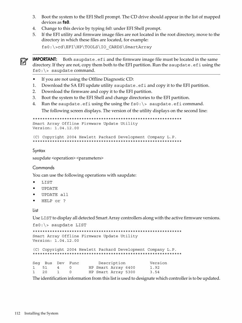
3. Boot the system to the EFI Shell prompt. The CD drive should appear in the list of mappeddevices as fs0.
4. Change to this device by typing fs0: under EFI Shell prompt.5. If the EFI utility and firmware image files are not located in the root directory, move to the
directory in which these files are located, for example:fs0:\>cd\EFI\HP\TOOLS\IO_CARDS\SmartArray
IMPORTANT: Both saupdate.efi and the firmware image file must be located in the samedirectory. If they are not, copy them both to the EFI partition. Run the saupdate.efi using thefs0:\> saupdate command.
• If you are not using the Offline Diagnostic CD:1. Download the SA EFI update utility saupdate.efi and copy it to the EFI partition.2. Download the firmware and copy it to the EFI partition.3. Boot the system to the EFI Shell and change directories to the EFI partition.4. Run the saupdate.efi using the using the fs0:\> saupdate.efi command.
The following screen displays. The version of the utility displays on the second line:
*************************************************************Smart Array Offline Firmware Update UtilityVersion: 1.04.12.00
(C) Copyright 2004 Hewlett Packard Development Company L.P.*************************************************************
Syntax
saupdate <operation> <parameters>
Commands
You can use the following operations with saupdate:• LIST
• UPDATE
• UPDATE all
• HELP or ?
List
Use LIST to display all detected Smart Array controllers along with the active firmware versions.fs0:\> saupdate LIST
*************************************************************Smart Array Offline Firmware Update UtilityVersion: 1.04.12.00
(C) Copyright 2004 Hewlett Packard Development Company L.P.*************************************************************
Seg Bus Dev Func Description Version1 51 4 0 HP Smart Array 6400 1.921 20 1 0 HP Smart Array 5300 3.54
The identification information from this list is used to designate which controller is to be updated.
112 Installing the System
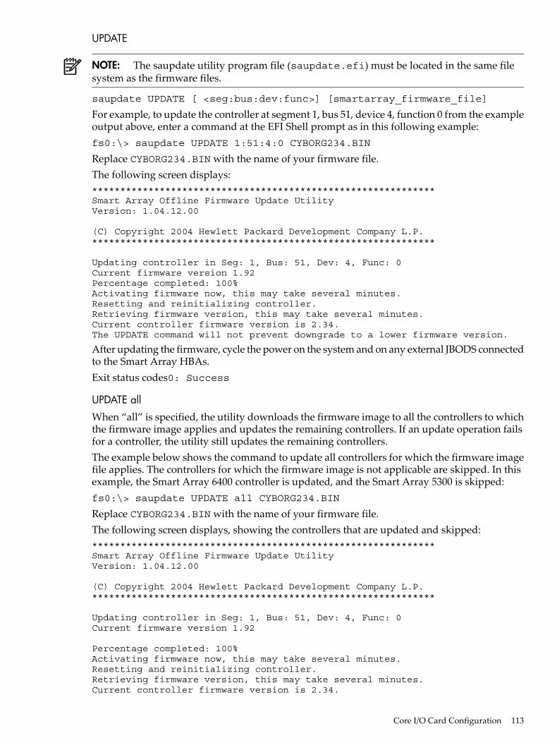
UPDATE
NOTE: The saupdate utility program file (saupdate.efi) must be located in the same filesystem as the firmware files.
saupdate UPDATE [ <seg:bus:dev:func>] [smartarray_firmware_file]
For example, to update the controller at segment 1, bus 51, device 4, function 0 from the exampleoutput above, enter a command at the EFI Shell prompt as in this following example:fs0:\> saupdate UPDATE 1:51:4:0 CYBORG234.BIN
Replace CYBORG234.BIN with the name of your firmware file.The following screen displays:*************************************************************Smart Array Offline Firmware Update UtilityVersion: 1.04.12.00
(C) Copyright 2004 Hewlett Packard Development Company L.P.*************************************************************
Updating controller in Seg: 1, Bus: 51, Dev: 4, Func: 0Current firmware version 1.92Percentage completed: 100%Activating firmware now, this may take several minutes.Resetting and reinitializing controller.Retrieving firmware version, this may take several minutes.Current controller firmware version is 2.34.The UPDATE command will not prevent downgrade to a lower firmware version.
After updating the firmware, cycle the power on the system and on any external JBODS connectedto the Smart Array HBAs.Exit status codes0: Success
UPDATE all
When “all” is specified, the utility downloads the firmware image to all the controllers to whichthe firmware image applies and updates the remaining controllers. If an update operation failsfor a controller, the utility still updates the remaining controllers.The example below shows the command to update all controllers for which the firmware imagefile applies. The controllers for which the firmware image is not applicable are skipped. In thisexample, the Smart Array 6400 controller is updated, and the Smart Array 5300 is skipped:fs0:\> saupdate UPDATE all CYBORG234.BIN
Replace CYBORG234.BIN with the name of your firmware file.The following screen displays, showing the controllers that are updated and skipped:*************************************************************Smart Array Offline Firmware Update UtilityVersion: 1.04.12.00
(C) Copyright 2004 Hewlett Packard Development Company L.P.*************************************************************
Updating controller in Seg: 1, Bus: 51, Dev: 4, Func: 0Current firmware version 1.92
Percentage completed: 100%Activating firmware now, this may take several minutes.Resetting and reinitializing controller.Retrieving firmware version, this may take several minutes.Current controller firmware version is 2.34.
Core I/O Card Configuration 113
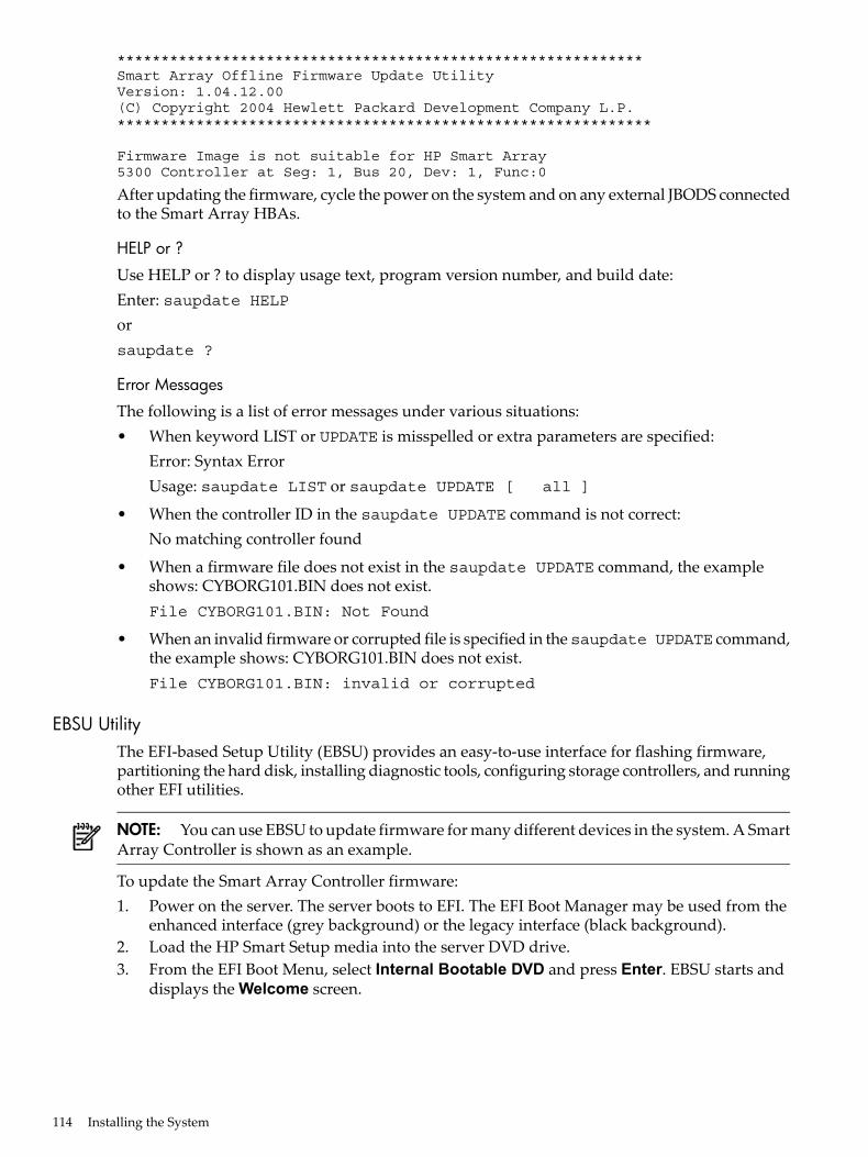
************************************************************Smart Array Offline Firmware Update UtilityVersion: 1.04.12.00(C) Copyright 2004 Hewlett Packard Development Company L.P.*************************************************************
Firmware Image is not suitable for HP Smart Array5300 Controller at Seg: 1, Bus 20, Dev: 1, Func:0
After updating the firmware, cycle the power on the system and on any external JBODS connectedto the Smart Array HBAs.
HELP or ?
Use HELP or ? to display usage text, program version number, and build date:Enter: saupdate HELPorsaupdate ?
Error Messages
The following is a list of error messages under various situations:• When keyword LIST or UPDATE is misspelled or extra parameters are specified:
Error: Syntax ErrorUsage: saupdate LIST or saupdate UPDATE [ all ]
• When the controller ID in the saupdate UPDATE command is not correct:No matching controller found
• When a firmware file does not exist in the saupdate UPDATE command, the exampleshows: CYBORG101.BIN does not exist.File CYBORG101.BIN: Not Found
• When an invalid firmware or corrupted file is specified in thesaupdate UPDATE command,the example shows: CYBORG101.BIN does not exist.File CYBORG101.BIN: invalid or corrupted
EBSU UtilityThe EFI-based Setup Utility (EBSU) provides an easy-to-use interface for flashing firmware,partitioning the hard disk, installing diagnostic tools, configuring storage controllers, and runningother EFI utilities.
NOTE: You can use EBSU to update firmware for many different devices in the system. A SmartArray Controller is shown as an example.
To update the Smart Array Controller firmware:1. Power on the server. The server boots to EFI. The EFI Boot Manager may be used from the
enhanced interface (grey background) or the legacy interface (black background).2. Load the HP Smart Setup media into the server DVD drive.3. From the EFI Boot Menu, select Internal Bootable DVD and press Enter. EBSU starts and
displays the Welcome screen.
114 Installing the System
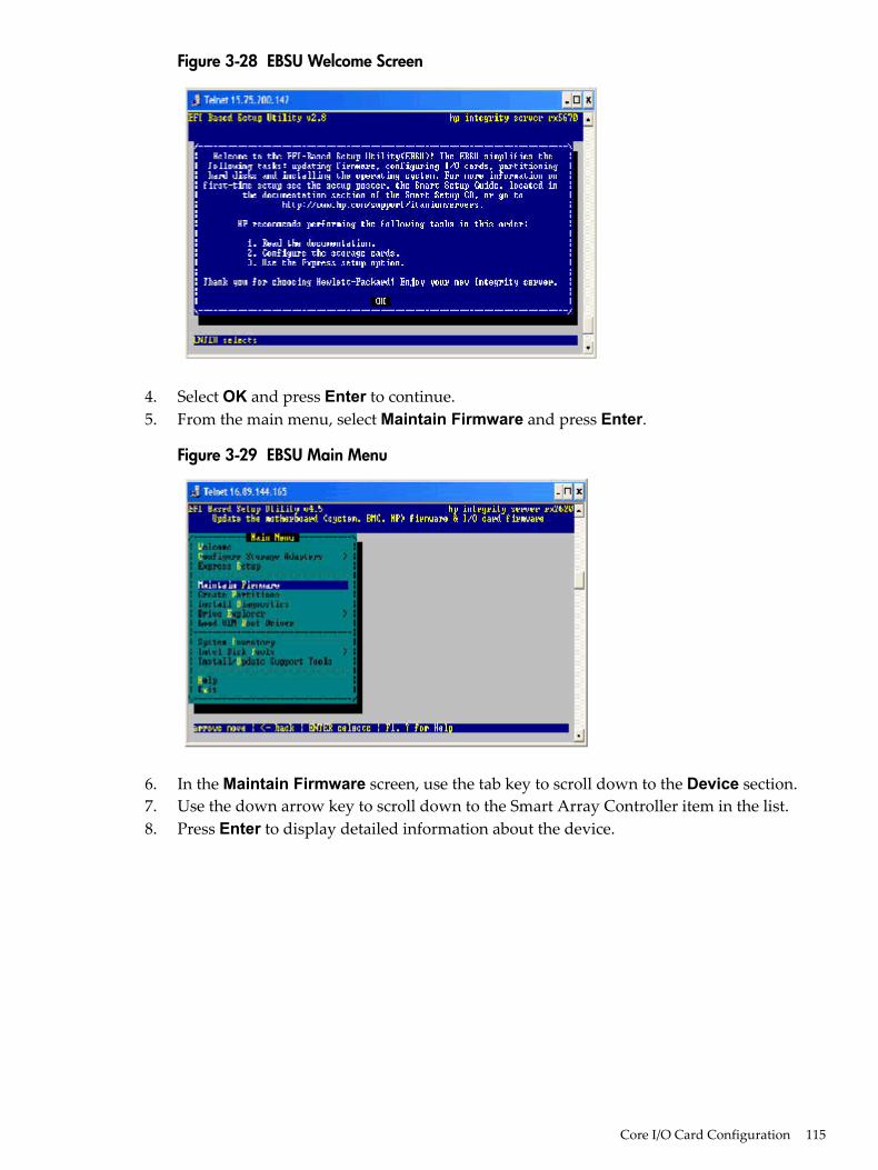
Figure 3-28 EBSU Welcome Screen
4. Select OK and press Enter to continue.5. From the main menu, select Maintain Firmware and press Enter.
Figure 3-29 EBSU Main Menu
6. In the Maintain Firmware screen, use the tab key to scroll down to the Device section.7. Use the down arrow key to scroll down to the Smart Array Controller item in the list.8. Press Enter to display detailed information about the device.
Core I/O Card Configuration 115
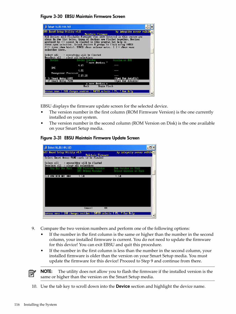
Figure 3-30 EBSU Maintain Firmware Screen
EBSU displays the firmware update screen for the selected device.• The version number in the first column (ROM Firmware Version) is the one currently
installed on your system.• The version number in the second column (ROM Version on Disk) is the one available
on your Smart Setup media.
Figure 3-31 EBSU Maintain Firmware Update Screen
9. Compare the two version numbers and perform one of the following options:• If the number in the first column is the same or higher than the number in the second
column, your installed firmware is current. You do not need to update the firmwarefor this device! You can exit EBSU and quit this procedure.
• If the number in the first column is less than the number in the second column, yourinstalled firmware is older than the version on your Smart Setup media. You mustupdate the firmware for this device! Proceed to Step 9 and continue from there.
NOTE: The utility does not allow you to flash the firmware if the installed version is thesame or higher than the version on the Smart Setup media.
10. Use the tab key to scroll down into the Device section and highlight the device name.
116 Installing the System
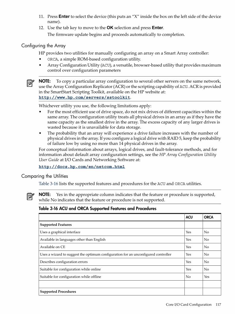
11. Press Enter to select the device (this puts an “X” inside the box on the left side of the devicename).
12. Use the tab key to move to the OK selection and press Enter.The firmware update begins and proceeds automatically to completion.
Configuring the ArrayHP provides two utilities for manually configuring an array on a Smart Array controller:• ORCA, a simple ROM-based configuration utility.• Array Configuration Utility (ACU), a versatile, browser-based utility that provides maximum
control over configuration parameters
NOTE: To copy a particular array configuration to several other servers on the same network,use the Array Configuration Replicator (ACR) or the scripting capability of ACU. ACR is providedin the SmartStart Scripting Toolkit, available on the HP website at:http://www.hp.com/servers/sstoolkit.
Whichever utility you use, the following limitations apply:• For the most efficient use of drive space, do not mix drives of different capacities within the
same array. The configuration utility treats all physical drives in an array as if they have thesame capacity as the smallest drive in the array. The excess capacity of any larger drives iswasted because it is unavailable for data storage.
• The probability that an array will experience a drive failure increases with the number ofphysical drives in the array. If you configure a logical drive with RAID 5, keep the probabilityof failure low by using no more than 14 physical drives in the array.
For conceptual information about arrays, logical drives, and fault-tolerance methods, and forinformation about default array configuration settings, see the HP Array Configuration UtilityUser Guide at I/O Cards and Networking Software at:http://docs.hp.com/en/netcom.html
Comparing the UtilitiesTable 3-16 lists the supported features and procedures for the ACU and ORCA utilities.
NOTE: Yes in the appropriate column indicates that the feature or procedure is supported,while No indicates that the feature or procedure is not supported.
Table 3-16 ACU and ORCA Supported Features and Procedures
ORCAACU
Supported Features
NoYesUses a graphical interface
NoYesAvailable in languages other than English
NoYesAvailable on CE
NoYesUses a wizard to suggest the optimum configuration for an unconfigured controller
NoYesDescribes configuration errors
NoYesSuitable for configuration while online
YesNoSuitable for configuration while offline
Supported Procedures
Core I/O Card Configuration 117
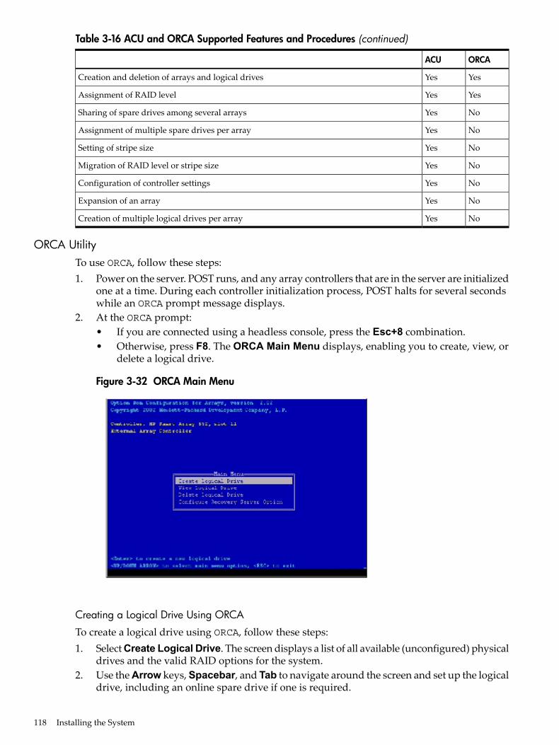
Table 3-16 ACU and ORCA Supported Features and Procedures (continued)
ORCAACU
YesYesCreation and deletion of arrays and logical drives
YesYesAssignment of RAID level
NoYesSharing of spare drives among several arrays
NoYesAssignment of multiple spare drives per array
NoYesSetting of stripe size
NoYesMigration of RAID level or stripe size
NoYesConfiguration of controller settings
NoYesExpansion of an array
NoYesCreation of multiple logical drives per array
ORCA UtilityTo use ORCA, follow these steps:1. Power on the server. POST runs, and any array controllers that are in the server are initialized
one at a time. During each controller initialization process, POST halts for several secondswhile an ORCA prompt message displays.
2. At the ORCA prompt:• If you are connected using a headless console, press the Esc+8 combination.• Otherwise, press F8. The ORCA Main Menu displays, enabling you to create, view, or
delete a logical drive.
Figure 3-32 ORCA Main Menu
Creating a Logical Drive Using ORCA
To create a logical drive using ORCA, follow these steps:1. Select Create Logical Drive. The screen displays a list of all available (unconfigured) physical
drives and the valid RAID options for the system.2. Use the Arrow keys, Spacebar, and Tab to navigate around the screen and set up the logical
drive, including an online spare drive if one is required.
118 Installing the System
NOTE: You cannot use ORCA to configure one spare drive to be shared among severalarrays. Only ACU enables you to configure shared spare drives.
3. Press Enter to accept the settings.4. Press F8 to confirm the settings and save the new configuration. After several seconds, the
Configuration Saved screen displays.5. Press Enter to continue. You can now create another logical drive by repeating the previous
steps.
NOTE: Newly created logical drives are invisible to the operating system. To make thenew logical drives available for data storage, format them using the instructions given inthe operating system documentation.
ACU UtilityFor detailed information about using ACU, see the HP Array Configuration Utility User Guide atI/O Cards and Networking Software at:http://docs.hp.com/en/netcom.html
Installation TroubleshootingThis section provides basic server troubleshooting information to help you diagnose commonissues that can occur during server installation. For more advanced troubleshooting tools andprocedures, see the HP Integrity rx6600 User Service Guide.
Troubleshooting MethodologyThe server was tested prior to shipping. Failures encountered during installation can be due todamage that occurred in transit. Reseating connectors can solve problems that result from roughhandling. If you are installing components or assemblies, compatibility problems or incorrectinstallations can be the cause of the problems. If you are installing components or assemblies,check that items are correctly installed and that all connectors are fully engaged. If the unit doesnot power on, check the power source before proceeding.If a problem is encountered during initial operation, remove any add-in or optional componentsand retest the server before continuing. Verify basic server operation before installing additionalcards and configuring software and hardware for the server requirements.Troubleshooting is based on observation of server status indications and error messages, and bychecking system event logs. You can also observe the LED indicators on the front and rear of theserver. Error messages are displayed on local and remote consoles. System history (console,event, and history logs) is available through the iLO 2 MP, and is accessed through the console.Additional information about troubleshooting is available in the HP Integrity rx6600 User ServiceGuide.Offline troubleshooting programs are available on the resource CD that is shipped with the HPserver. To troubleshoot the server, you must be familiar with the Offline Diagnostics Environment(ODE) which runs in the Extensible Firmware Interface (EFI).Descriptions and user information about offline troubleshooting tools are available at:http://www.docs.hp.com.The offline tools are available for download at http://www.software.hp.com.
Installation Troubleshooting 119
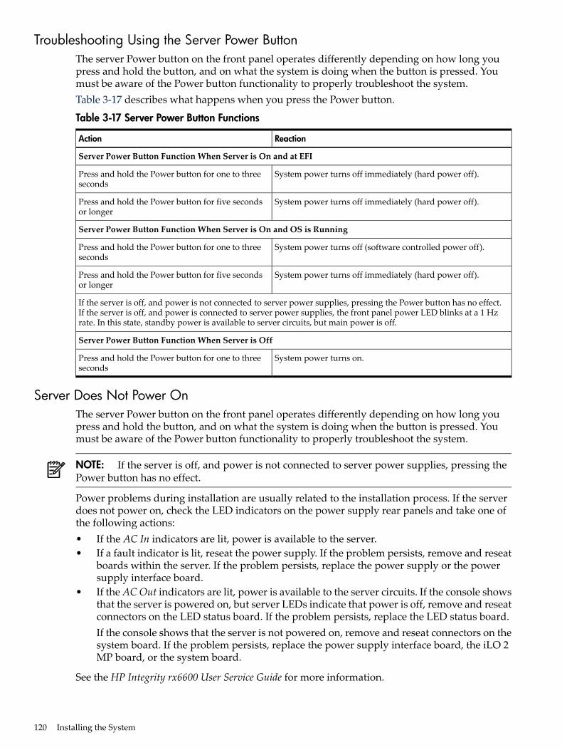
Troubleshooting Using the Server Power ButtonThe server Power button on the front panel operates differently depending on how long youpress and hold the button, and on what the system is doing when the button is pressed. Youmust be aware of the Power button functionality to properly troubleshoot the system.Table 3-17 describes what happens when you press the Power button.
Table 3-17 Server Power Button Functions
ReactionAction
Server Power Button Function When Server is On and at EFI
System power turns off immediately (hard power off).Press and hold the Power button for one to threeseconds
System power turns off immediately (hard power off).Press and hold the Power button for five secondsor longer
Server Power Button Function When Server is On and OS is Running
System power turns off (software controlled power off).Press and hold the Power button for one to threeseconds
System power turns off immediately (hard power off).Press and hold the Power button for five secondsor longer
If the server is off, and power is not connected to server power supplies, pressing the Power button has no effect.If the server is off, and power is connected to server power supplies, the front panel power LED blinks at a 1 Hzrate. In this state, standby power is available to server circuits, but main power is off.
Server Power Button Function When Server is Off
System power turns on.Press and hold the Power button for one to threeseconds
Server Does Not Power OnThe server Power button on the front panel operates differently depending on how long youpress and hold the button, and on what the system is doing when the button is pressed. Youmust be aware of the Power button functionality to properly troubleshoot the system.
NOTE: If the server is off, and power is not connected to server power supplies, pressing thePower button has no effect.
Power problems during installation are usually related to the installation process. If the serverdoes not power on, check the LED indicators on the power supply rear panels and take one ofthe following actions:• If the AC In indicators are lit, power is available to the server.• If a fault indicator is lit, reseat the power supply. If the problem persists, remove and reseat
boards within the server. If the problem persists, replace the power supply or the powersupply interface board.
• If the ACOut indicators are lit, power is available to the server circuits. If the console showsthat the server is powered on, but server LEDs indicate that power is off, remove and reseatconnectors on the LED status board. If the problem persists, replace the LED status board.If the console shows that the server is not powered on, remove and reseat connectors on thesystem board. If the problem persists, replace the power supply interface board, the iLO 2MP board, or the system board.
See the HP Integrity rx6600 User Service Guide for more information.
120 Installing the System
EFI Menu is Not AvailableIf you cannot access the EFI from either the main disk partition or the CD, use the following toolsto help solve the problem:• Front panel LEDs• iLO 2 MP
— Console messages— System event logs (SEL)
For a description of the front panel LEDs, see the HP Integrity rx6600 User Service Guide.
Operating System Does Not BootIf the operating system does not boot, but you are able to reach the EFI from either the main diskpartition or the CD, use the following tools to help solve the problem:• Using the EFI Shell, check the system logs and analyze any error messages.• Offline Diagnostic Environment (ODE)For more information, see the HP Integrity rx6600 User Service Guide.
Operating System Boots with ProblemsIf the operating system is running and you are experiencing problems, use the following toolsto help solve the problem:• LEDs• Error Messages and event logsFor more information, see the HP Integrity rx6600 User Service Guide.
Intermittent Server ProblemsYou can usually trace intermittent problems that occur during installation to power sourceproblems, a loose connector, or some other hardware problem. If you are experiencing intermittentproblems, follow these steps:1. Check iLO 2 MP logs and analyze the problem. Determine if there is more than one symptom
and if the problem is random.2. Verify that the AC power source is stable.3. Reseat all rear panel connectors.4. Reseat all hot-swappable fans and power supplies.5. Reseat all main memory DIMMs.6. Reseat all cable harnesses and board connectors.For more information, see the HP Integrity rx6600 User Service Guide.
DVD ProblemsDVD problems that occur during installation are usually related to faulty connections. If you areexperiencing DVD problems, follow these steps:1. Remove and reinsert the DVD.2. Replace the DVD.3. Remove and reinstall the DVD drive. Check that connectors are fully engaged.4. Replace the DVD drive.
Installation Troubleshooting 121
Hard Drive ProblemsHard drive problems that occur during installation are usually due to rough handling. The drivemay not be correctly seated or may have been damaged in transit. If you are experiencing harddrive problems, follow these steps:1. Remove and reinsert the hard drive.2. Swap the hard drive with one from another slot or with a known good spare.3. Remove and reinstall the hard drive backplane. Check that connectors are fully engaged.4. Replace the hard drive backplane.5. Replace the SAS core I/O card.
Console ProblemsConsole problems during installations can be caused by faulty interconnections. If you areexperiencing monitor, keyboard, or mouse problems, follow these steps:1. Check the monitor controls. Adjust contrast and brightness as required.2. Inspect all power and interconnecting cables. Check that all console connectors are fully
engaged.3. Check that all iLO 2 MP board connectors are fully engaged.4. Exercise the appropriate self-test features of the console software.
Downloading and Installing the Latest Version of the FirmwareHP makes every effort to provide you with the most current version of firmware. However, therecan be instances when your firmware is not up to date.To ensure you have the latest version of the firmware running on the server, download the latestversion of the firmware from the web, and create a CD to install the firmware on the server.
Downloading the Latest Version of the FirmwareTo download the latest version of the firmware from the web, follow these steps:1. Go to http://www.hp.com/go/bizsupport.2. Select download drivers and software.3. Select Itanium-based servers from the Server category.4. Select your server from the servers listed.5. Select your operating system.6. Select the firmware category you want to download.7. Download the firmware to a CD.
Installing the Latest Version of the Firmware on the ServerTo install the latest version of the firmware on the server, follow these steps:1. Start a server console session. See Section : “Console Setup” (page 83).2. Insert the CD with the copy of the latest version of the firmware.3. Using the EFI Boot Manager menu, boot to the drive that contains the CD with the updated
firmware.4. Follow the instructions to update the firmware.
Enabling the Trusted Platform ModuleThis section provides instructions on how to enable the trusted platform module (TPM).
122 Installing the System

IntroductionThe TPM is an optional security component which enhances security capabilities for the serverif it is running the HP-UX operating system. The TPM is a security chip that is unique to theserver. It performs key security processes independent of other hardware components. The TPMcreates and stores additional encryption keys from the root key of the system. The encryptionkeys created by the TPM encapsulate system application encryption keys to provide an additionallayer of security for sensitive system data.The fundamental capabilities of the TPM include:• Platform authentication• Sensitive information protection• Data integrity• System privacy
IMPORTANT: You must run the supported version of the HP-UX operating system to utilizethe TPM security component.
WARNING! Ensure that the system is powered off and all power sources have been disconnectedfrom the server prior to performing this procedure.Voltages are present at various locations within the server whenever an AC power source isconnected. This voltage is present even when the main power switch is in the off position.Failure to observe this warning can result in personal injury or damage to equipment.
CAUTION: Observe all ESD safety precautions before attempting this procedure. Failure tofollow ESD safety precautions can result in damage to the server.
Enabling the TPMTo enable the TPM, follow these steps:1. Power on the server.2. Enable the TPM.
a. Access the EFI Shell.b. Enterinfo sec to display the server security settings on the screen. The TPM is disabled
by default.c. Enter secconfig to display a list of configurable security settings.d. Enter secconfig tpm on to enable the TPM.
3. Reset the server.4. Boot the operating system.5. Restore the former TPM settings to the new TPM. See the HP-UX operating system
documentation for more information.6. Back up the TPM security information. See the HP-UX operating system documentation for
more information.
Enabling the Trusted Platform Module 123

124
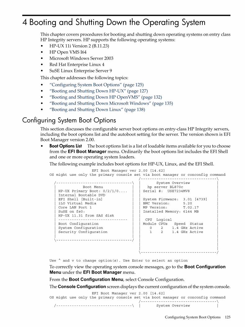
4 Booting and Shutting Down the Operating SystemThis chapter covers procedures for booting and shutting down operating systems on entry classHP Integrity servers. HP supports the following operating systems:• HP-UX 11i Version 2 (B.11.23)• HP Open VMS I64• Microsoft Windows Server 2003• Red Hat Enterprise Linux 4• SuSE Linux Enterprise Server 9This chapter addresses the following topics:• “Configuring System Boot Options” (page 125)• “Booting and Shutting Down HP-UX” (page 127)• “Booting and Shutting Down HP OpenVMS” (page 132)• “Booting and Shutting Down Microsoft Windows” (page 135)• “Booting and Shutting Down Linux” (page 138)
Configuring System Boot OptionsThis section discusses the configurable server boot options on entry-class HP Integrity servers,including the boot options list and the autoboot setting for the server. The version shown is EFIBoot Manager version 2.00.• Boot Options List The boot options list is a list of loadable items available for you to choose
from the EFI Boot Manager menu. Ordinarily the boot options list includes the EFI Shelland one or more operating system loaders.The following example includes boot options for HP-UX, Linux, and the EFI Shell. EFI Boot Manager ver 2.00 [14.62] OS might use only the primary console set via boot manager or conconfig command /----------------------------------\ /----------------------------------\ | System Overview | | Boot Menu | | hp server BL870c | | HP-UX Primary Boot: 0/2/1/0.... | | Serial #: USE7234MV8 | | Internal Bootable DVD | | | | EFI Shell [Built-in] | | System Firmware: 3.01 [4739] | | iLO Virtual Media | | BMC Version: 5.20 | | Core LAN Port 1 | | MP Version: T.02.17 | | SuSE on fs0: | | Installed Memory: 6144 MB | | HP-UX 11.31 from SAS disk | | | | ------------------------------- | | CPU Logical | | Boot Configuration | | Module CPUs Speed Status | | System Configuration | | 0 2 1.4 GHz Active | | Security Configuration | | 1 2 1.4 GHz Active | | | | | \----------------------------------/ | | | | | | \----------------------------------/
Use ^ and v to change option(s). Use Enter to select an option
To correctly view the operating system console messages, go to the Boot ConfigurationMenu under the EFI Boot Manager menu.From the Boot Configuration Menu, select Console Configuration.The Console Configuration screen displays the current configuration of the system console. EFI Boot Manager ver 2.00 [14.62] OS might use only the primary console set via boot manager or conconfig command /----------------------------------\ /----------------------------------\ | System Overview |
Configuring System Boot Options 125
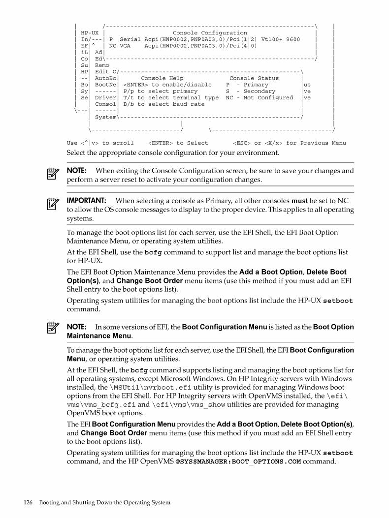
| /-----------------------------------------------------------\ | | HP-UX | Console Configuration | | | In/---| P Serial Acpi(HWP0002,PNP0A03,0)/Pci(1|2) Vt100+ 9600 | | | EF|^ | NC VGA Acpi(HWP0002,PNP0A03,0)/Pci(4|0) | | | iL| Ad| | | | Co| Ed\-----------------------------------------------------------/ | | Su| Remo | | HP| Edit O/---------------------------------------------------\ | | --| AutoBo| Console Help Console Status | | | Bo| BootNe| <ENTER> to enable/disable P - Primary |us | | Sy| ------| P/p to select primary S - Secondary |ve | | Se| Driver| T/t to select terminal type NC - Not Configured |ve | | | Consol| B/b to select baud rate | | \---| ------| | | | System\---------------------------------------------------/ | | | | | \-------------------------/ \----------------------------------/
Use <^|v> to scroll <ENTER> to Select <ESC> or <X/x> for Previous Menu
Select the appropriate console configuration for your environment.
NOTE: When exiting the Console Configuration screen, be sure to save your changes andperform a server reset to activate your configuration changes.
IMPORTANT: When selecting a console as Primary, all other consoles must be set to NCto allow the OS console messages to display to the proper device. This applies to all operatingsystems.
To manage the boot options list for each server, use the EFI Shell, the EFI Boot OptionMaintenance Menu, or operating system utilities.At the EFI Shell, use the bcfg command to support list and manage the boot options listfor HP-UX.The EFI Boot Option Maintenance Menu provides the Add a Boot Option, Delete BootOption(s), and Change Boot Order menu items (use this method if you must add an EFIShell entry to the boot options list).Operating system utilities for managing the boot options list include the HP-UX setbootcommand.
NOTE: In some versions of EFI, the Boot Configuration Menu is listed as the Boot OptionMaintenance Menu.
To manage the boot options list for each server, use the EFI Shell, the EFI Boot ConfigurationMenu, or operating system utilities.At the EFI Shell, the bcfg command supports listing and managing the boot options list forall operating systems, except Microsoft Windows. On HP Integrity servers with Windowsinstalled, the \MSUtil\nvrboot.efi utility is provided for managing Windows bootoptions from the EFI Shell. For HP Integrity servers with OpenVMS installed, the \efi\vms\vms_bcfg.efi and \efi\vms\vms_show utilities are provided for managingOpenVMS boot options.The EFI Boot Configuration Menu provides the Add a Boot Option, Delete Boot Option(s),and Change Boot Order menu items (use this method if you must add an EFI Shell entryto the boot options list).Operating system utilities for managing the boot options list include the HP-UX setbootcommand, and the HP OpenVMS @SYS$MANAGER:BOOT_OPTIONS.COM command.
126 Booting and Shutting Down the Operating System
For details, see the following sections:— Setting HP-UX boot options— Setting OpenVMS boot options— Setting Windows boot options— Setting Linux boot options
• Autoboot Setting The autoboot setting determines at startup whether a serverautomatically loads the first item in the boot options list, or remains at the EFI Boot Managermenu. When autoboot is enabled, EFI loads the first item in the boot options list after adesignated timeout period.Configure the autoboot setting for an HP Integrity server using either the autoboot EFIShell command, or the Set Auto Boot TimeOut menu item from the EFI Boot ConfigurationMenu.For example:To disable autoboot from the EFI Shell, enter:autoboot off
To enable autoboot with the default timeout value, enter:autoboot on
To enable autoboot with a timeout of 60 seconds, enter:autoboot time 60
To set autoboot from HP-UX, enter:setboot
To enable autoboot from HP-UX, enter:setboot -b on
To disable autoboot, enter:setboot -b off
Booting and Shutting Down HP-UXThis section covers booting and shutting down HP-UX on entry class HP Integrity servers.• To add an HP-UX entry to the boot options list, see “Adding HP-UX to the Boot Options
List” (page 127).• To boot HP-UX, use the following procedures:
— “Booting HP-UX From the EFI Boot Manager” (page 128) describes the standard waysto boot HP-UX. Typically this results in booting HP-UX in multi-user mode.
— “Booting HP-UX in Single-User Mode” (page 130) describes how to boot HP-UX insingle-user mode.
— “Booting HP-UX in LVM-Maintenance Mode” (page 131) describes how to boot HP-UXin LVM-maintenance mode
• To shut down the HP-UX operating system, see “Shutting Down HP-UX” (page 131).
Adding HP-UX to the Boot Options ListThis section describes how to add an HP-UX entry to the system boot options list.You can add the \EFI\HPUX\HPUX.EFI loader to the boot options list from the EFI Shell or EFIBoot Configuration menu (or in some versions of EFI, the Boot Option Maintenance Menu).
Booting and Shutting Down HP-UX 127
NOTE: The operating system installer automatically adds an entry to the boot options list.
To add an HP-UX boot option when logged in to HP-UX, use the setboot command. For moreinformation see the setboot(1M) manpage.To add an HP-UX item to the boot options list from the EFI Shell, follow these steps:1. Access the EFI Shell environment.
a. Log in to the iLO 2 MP and enter the CO command to access the system console.b. Confirm that you are at the EFI Boot Manager menu (the main EFI menu). If you are atanother EFI menu, select Exit option from the submenus until you return to the screenlabeled EFI Boot Manager.c. From the EFI Boot Manager menu, select the EFI Shell to access the EFI Shell environment.
2. Access the EFI System Partition (fsX: where X is the file system number) for the devicefrom which you want to boot HP-UX.For example, enter fs2: to access the EFI System Partition for the bootable file systemnumber 2. The EFI Shell prompt changes to reflect the file system currently accessed.The full path for the HP-UX loader is\EFI\HPUX\HPUX.EFI on the device you are accessing.
3. At the EFI Shell environment, use the bcfg command to manage the boot options list.The bcfg command includes the following options for managing the boot options list:bcfg boot dump Displays all items in the boot options list for the
system.bcfg boot rm # Removes the item number specified by # from the boot
options listbcfg boot mv #a #b Move the item number specified by #a to the position
specified by #b in the boot list.bcfg boot add # file.efi "Description" Add a new boot option to the position in the boot
options list specified by #. The new boot optionreferences file.efi and is listed with the title specifiedby Description.
For example, bcfg boot add1 \EFI\HPUX\HPUX.EFI “HP-UXi” adds an HP-UX 11i itemas the first entry in the boot options list.See the help bcfg command for details.
4. Exit the console and iLO 2 MP interfaces if you are finished using them.a. Press Control-B to exit the system console and return to the MP Main Menu.b. To exit the iLO 2 MP, enter X at the MP Main Menu.
Booting HP-UX in Standard ModeUse either of the following procedures to boot HP-UX:• “Booting HP-UX From the EFI Boot Manager” (page 128)• “Booting HP-UX From the EFI Shell” (page 129)
Booting HP-UX From the EFI Boot ManagerFrom the EFI Boot Manager menu, select an item from the boot options list to boot HP-UX.
128 Booting and Shutting Down the Operating System
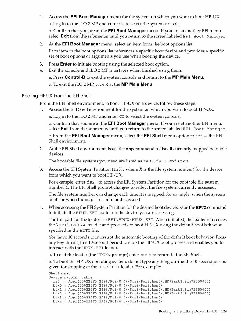
1. Access the EFI Boot Manager menu for the system on which you want to boot HP-UX.a. Log in to the iLO 2 MP and enter CO to select the system console.b. Confirm that you are at the EFI Boot Manager menu. If you are at another EFI menu,select Exit from the submenus until you return to the screen labeled EFI Boot Manager.
2. At the EFI Boot Manager menu, select an item from the boot options list.Each item in the boot options list references a specific boot device and provides a specificset of boot options or arguments you use when booting the device.
3. Press Enter to initiate booting using the selected boot option.4. Exit the console and iLO 2 MP interfaces when finished using them.
a. Press Control-B to exit the system console and return to the MP Main Menu.b. To exit the iLO 2 MP, type X at the MP Main Menu.
Booting HP-UX From the EFI ShellFrom the EFI Shell environment, to boot HP-UX on a device, follow these steps:1. Access the EFI Shell environment for the system on which you want to boot HP-UX.
a. Log in to the iLO 2 MP and enter CO to select the system console.b. Confirm that you are at the EFI Boot Manager menu. If you are at another EFI menu,select Exit from the submenus until you return to the screen labeled EFI Boot Manager.c. From the EFI Boot Manager menu, select the EFI Shell menu option to access the EFIShell environment.
2. At the EFI Shell environment, issue the map command to list all currently mapped bootabledevices.The bootable file systems you need are listed as fs0:, fs1:, and so on.
3. Access the EFI System Partition (fsX: where X is the file system number) for the devicefrom which you want to boot HP-UX.For example, enter fs2: to access the EFI System Partition for the bootable file systemnumber 2. The EFI Shell prompt changes to reflect the file system currently accessed.The file system number can change each time it is mapped, for example, when the systemboots or when the map -r command is issued.
4. When accessing the EFI System Partition for the desired boot device, issue theHPUX commandto initiate the HPUX.EFI loader on the device you are accessing.The full path for the loader is\EFI\HPUX\HPUX.EFI. When initiated, the loader referencesthe \EFI\HPUX\AUTO file and proceeds to boot HP-UX using the default boot behaviorspecified in the AUTO file.You have 10 seconds to interrupt the automatic booting of the default boot behavior. Pressany key during this 10-second period to stop the HP-UX boot process and enables you tointeract with the HPUX.EFI loader.a. To exit the loader (the HPUX> prompt) enter exit to return to the EFI Shell.b. To boot the HP-UX operating system, do not type anything during the 10-second periodgiven for stopping at the HPUX.EFI loader. For example:Shell> mapDevice mapping table fs0 : Acpi(000222F0,269)/Pci(0 0)/Scsi(Pun8,Lun0)/HD(Part1,Sig72550000) blk0 : Acpi(000222F0,269)/Pci(0 0)/Scsi(Pun8,Lun0) blk1 : Acpi(000222F0,269)/Pci(0 0)/Scsi(Pun8,Lun0)/HD(Part1,Sig72550000) blk2 : Acpi(000222F0,269)/Pci(0 0)/Scsi(Pun8,Lun0)/HD(Part2,Sig72550000) blk3 : Acpi(000222F0,2A8)/Pci(0 0)/Scsi(Pun8,Lun0) blk4 : Acpi(000222F0,2A8)/Pci(0 1)/Scsi(Pun2,Lun0)
Booting and Shutting Down HP-UX 129
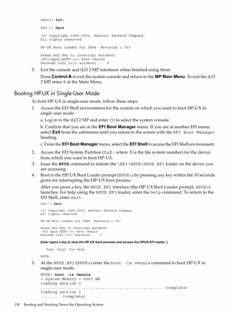
Shell> fs0:
fs0:\> hpux
(c) Copyright 1990-2002, Hewlett Packard Company.All rights reserved
HP-UX Boot Loader for IA64 Revision 1.723
Press Any Key to interrupt Autoboot\efi\hpux\AUTO ==> boot vmunixSeconds left till autoboot - 9
5. Exit the console and iLO 2 MP interfaces when finished using them.Press Control-B to exit the system console and return to the MP Main Menu. To exit the iLO2 MP, enter X at the Main Menu.
Booting HP-UX in Single-User ModeTo boot HP-UX in single-user mode, follow these steps:1. Access the EFI Shell environment for the system on which you want to boot HP-UX in
single-user mode.a. Log in to the iLO 2 MP and enter CO to select the system console.b. Confirm that you are at the EFI Boot Manager menu. If you are at another EFI menu,select Exit from the submenus until you return to the screen with the EFI Boot Managerheading.c. From the EFI Boot Manager menu, select the EFI Shell to access the EFI Shell environment.
2. Access the EFI System Partition (fsX: where X is the file system number) for the devicefrom which you want to boot HP-UX.
3. Issue the HPUX command to initiate the \EFI\HPUX\HPUX.EFI loader on the device youare accessing.
4. Boot to the HP-UX Boot Loader prompt (HPUX>) by pressing any key within the 10 secondsgiven for interrupting the HP-UX boot process.After you press a key, the HPUX.EFI interface (the HP-UX Boot Loader prompt, HPUX>)launches. For help using the HPUX.EFI loader, enter the help command. To return to theEFI Shell, enter exit.fs0:\> hpux
(c) Copyright 1990-2002, Hewlett Packard Company.All rights reserved
HP-UX Boot Loader for IA64 Revision 1.723
Press Any Key to interrupt Autoboot efi hpux AUTO ==> boot vmunixSeconds left till autoboot - 9
[User types a key to stop the HP-UX boot process and access the HPUX.EFI loader. ]
Type ’help’ for help
HPUX>
5. At the HPUX.EFI (HPUX>) enter the boot -is vmunix command to boot HP-UX insingle-user mode.HPUX> boot -is vmunix> System Memory = 4063 MBloading section 0................................................... (complete)loading section 1........ (complete)
130 Booting and Shutting Down the Operating System
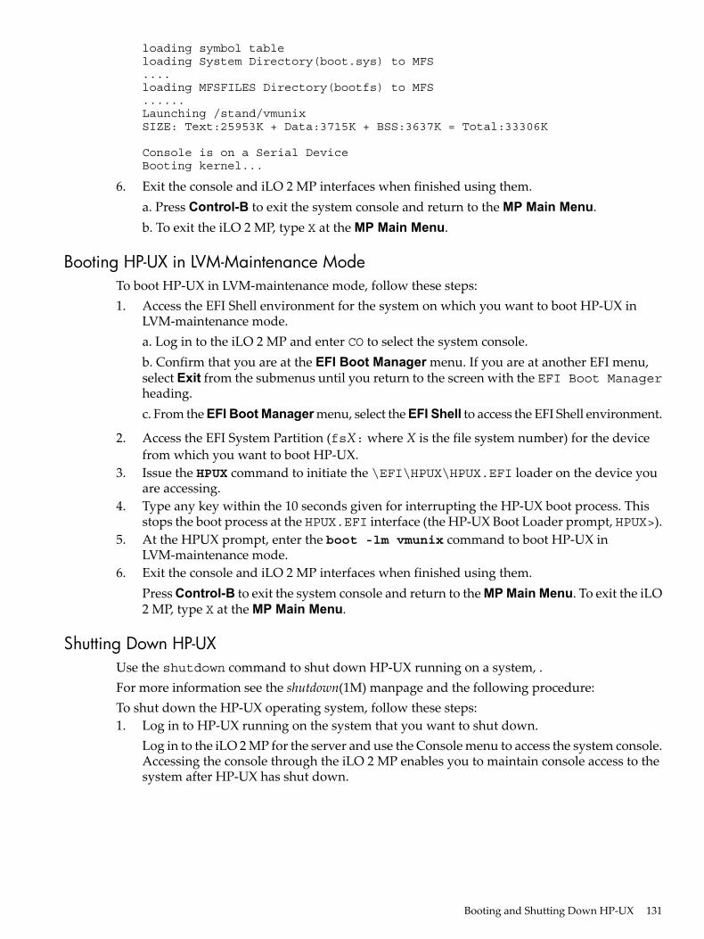
loading symbol tableloading System Directory(boot.sys) to MFS....loading MFSFILES Directory(bootfs) to MFS......Launching /stand/vmunixSIZE: Text:25953K + Data:3715K + BSS:3637K = Total:33306K
Console is on a Serial DeviceBooting kernel...
6. Exit the console and iLO 2 MP interfaces when finished using them.a. Press Control-B to exit the system console and return to the MP Main Menu.b. To exit the iLO 2 MP, type X at the MP Main Menu.
Booting HP-UX in LVM-Maintenance ModeTo boot HP-UX in LVM-maintenance mode, follow these steps:1. Access the EFI Shell environment for the system on which you want to boot HP-UX in
LVM-maintenance mode.a. Log in to the iLO 2 MP and enter CO to select the system console.b. Confirm that you are at the EFI Boot Manager menu. If you are at another EFI menu,select Exit from the submenus until you return to the screen with the EFI Boot Managerheading.c. From the EFI Boot Manager menu, select the EFI Shell to access the EFI Shell environment.
2. Access the EFI System Partition (fsX: where X is the file system number) for the devicefrom which you want to boot HP-UX.
3. Issue the HPUX command to initiate the \EFI\HPUX\HPUX.EFI loader on the device youare accessing.
4. Type any key within the 10 seconds given for interrupting the HP-UX boot process. Thisstops the boot process at the HPUX.EFI interface (the HP-UX Boot Loader prompt, HPUX>).
5. At the HPUX prompt, enter the boot -lm vmunix command to boot HP-UX inLVM-maintenance mode.
6. Exit the console and iLO 2 MP interfaces when finished using them.Press Control-B to exit the system console and return to the MP Main Menu. To exit the iLO2 MP, type X at the MP Main Menu.
Shutting Down HP-UXUse the shutdown command to shut down HP-UX running on a system, .For more information see the shutdown(1M) manpage and the following procedure:To shut down the HP-UX operating system, follow these steps:1. Log in to HP-UX running on the system that you want to shut down.
Log in to the iLO 2 MP for the server and use the Console menu to access the system console.Accessing the console through the iLO 2 MP enables you to maintain console access to thesystem after HP-UX has shut down.
Booting and Shutting Down HP-UX 131
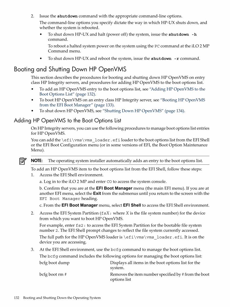
2. Issue the shutdown command with the appropriate command-line options.The command-line options you specify dictate the way in which HP-UX shuts down, andwhether the system is rebooted.• To shut down HP-UX and halt (power off) the system, issue the shutdown -h
command.To reboot a halted system power on the system using the PC command at the iLO 2 MPCommand menu.
• To shut down HP-UX and reboot the system, issue the shutdown -r command.
Booting and Shutting Down HP OpenVMSThis section describes the procedures for booting and shutting down HP OpenVMS on entryclass HP Integrity servers, and procedures for adding HP OpenVMS to the boot options list.• To add an HP OpenVMS entry to the boot options list, see “Adding HP OpenVMS to the
Boot Options List” (page 132).• To boot HP OpenVMS on an entry class HP Integrity server, see “Booting HP OpenVMS
from the EFI Boot Manager” (page 133).• To shut down HP OpenVMS, see “Shutting Down HP OpenVMS” (page 134).
Adding HP OpenVMS to the Boot Options ListOn HP Integrity servers, you can use the following procedures to manage boot options list entriesfor HP OpenVMS.You can add the \efi\vms\vms_loader.efi loader to the boot options list from the EFI Shellor the EFI Boot Configuration menu (or in some versions of EFI, the Boot Option MaintenanceMenu).
NOTE: The operating system installer automatically adds an entry to the boot options list.
To add an HP OpenVMS item to the boot options list from the EFI Shell, follow these steps:1. Access the EFI Shell environment.
a. Log in to the iLO 2 MP and enter CO to access the system console.b. Confirm that you are at the EFI Boot Manager menu (the main EFI menu). If you are atanother EFI menu, select the Exit from the submenus until you return to the screen with theEFI Boot Manager heading.c. From the EFI Boot Manager menu, select EFI Shell to access the EFI Shell environment.
2. Access the EFI System Partition (fsX: where X is the file system number) for the devicefrom which you want to boot HP OpenVMS.For example, enter fs2: to access the EFI System Partition for the bootable file systemnumber 2. The EFI Shell prompt changes to reflect the file system currently accessed.The full path for the HP OpenVMS loader is \efi\vms\vms_loader.efi. It is on thedevice you are accessing.
3. At the EFI Shell environment, use the bcfg command to manage the boot options list.The bcfg command includes the following options for managing the boot options list:bcfg boot dump Displays all items in the boot options list for the
system.bcfg boot rm # Removes the item number specified by # from the boot
options list
132 Booting and Shutting Down the Operating System
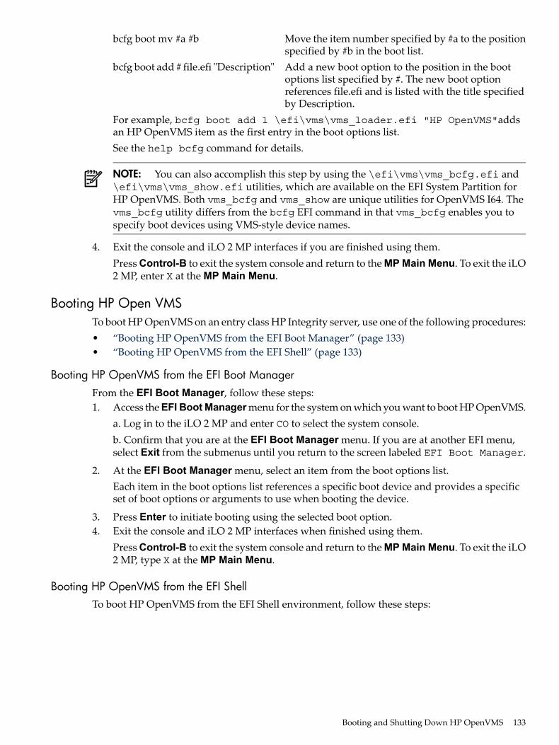
bcfg boot mv #a #b Move the item number specified by #a to the positionspecified by #b in the boot list.
bcfg boot add # file.efi "Description" Add a new boot option to the position in the bootoptions list specified by #. The new boot optionreferences file.efi and is listed with the title specifiedby Description.
For example, bcfg boot add 1 \efi\vms\vms_loader.efi "HP OpenVMS"addsan HP OpenVMS item as the first entry in the boot options list.See the help bcfg command for details.
NOTE: You can also accomplish this step by using the \efi\vms\vms_bcfg.efi and\efi\vms\vms_show.efi utilities, which are available on the EFI System Partition forHP OpenVMS. Both vms_bcfg and vms_show are unique utilities for OpenVMS I64. Thevms_bcfg utility differs from the bcfg EFI command in that vms_bcfg enables you tospecify boot devices using VMS-style device names.
4. Exit the console and iLO 2 MP interfaces if you are finished using them.Press Control-B to exit the system console and return to the MP Main Menu. To exit the iLO2 MP, enter X at the MP Main Menu.
Booting HP Open VMSTo boot HP OpenVMS on an entry class HP Integrity server, use one of the following procedures:• “Booting HP OpenVMS from the EFI Boot Manager” (page 133)• “Booting HP OpenVMS from the EFI Shell” (page 133)
Booting HP OpenVMS from the EFI Boot ManagerFrom the EFI Boot Manager, follow these steps:1. Access the EFI Boot Manager menu for the system on which you want to boot HP OpenVMS.
a. Log in to the iLO 2 MP and enter CO to select the system console.b. Confirm that you are at the EFI Boot Manager menu. If you are at another EFI menu,select Exit from the submenus until you return to the screen labeled EFI Boot Manager.
2. At the EFI Boot Manager menu, select an item from the boot options list.Each item in the boot options list references a specific boot device and provides a specificset of boot options or arguments to use when booting the device.
3. Press Enter to initiate booting using the selected boot option.4. Exit the console and iLO 2 MP interfaces when finished using them.
Press Control-B to exit the system console and return to the MP Main Menu. To exit the iLO2 MP, type X at the MP Main Menu.
Booting HP OpenVMS from the EFI ShellTo boot HP OpenVMS from the EFI Shell environment, follow these steps:
Booting and Shutting Down HP OpenVMS 133
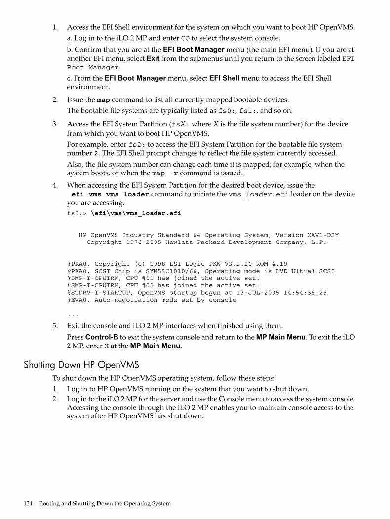
1. Access the EFI Shell environment for the system on which you want to boot HP OpenVMS.a. Log in to the iLO 2 MP and enter CO to select the system console.b. Confirm that you are at the EFI Boot Manager menu (the main EFI menu). If you are atanother EFI menu, select Exit from the submenus until you return to the screen labeled EFIBoot Manager.c. From the EFI Boot Manager menu, select EFI Shell menu to access the EFI Shellenvironment.
2. Issue the map command to list all currently mapped bootable devices.The bootable file systems are typically listed as fs0:, fs1:, and so on.
3. Access the EFI System Partition (fsX: where X is the file system number) for the devicefrom which you want to boot HP OpenVMS.For example, enter fs2: to access the EFI System Partition for the bootable file systemnumber 2. The EFI Shell prompt changes to reflect the file system currently accessed.Also, the file system number can change each time it is mapped; for example, when thesystem boots, or when the map -r command is issued.
4. When accessing the EFI System Partition for the desired boot device, issue the efi vms vms_loader command to initiate the vms_loader.efi loader on the deviceyou are accessing.fs5:> \efi\vms\vms_loader.efi
HP OpenVMS Industry Standard 64 Operating System, Version XAV1-D2Y Copyright 1976-2005 Hewlett-Packard Development Company, L.P.
%PKA0, Copyright (c) 1998 LSI Logic PKW V3.2.20 ROM 4.19%PKA0, SCSI Chip is SYM53C1010/66, Operating mode is LVD Ultra3 SCSI%SMP-I-CPUTRN, CPU #01 has joined the active set.%SMP-I-CPUTRN, CPU #02 has joined the active set.%STDRV-I-STARTUP, OpenVMS startup begun at 13-JUL-2005 14:54:36.25%EWA0, Auto-negotiation mode set by console
...
5. Exit the console and iLO 2 MP interfaces when finished using them.Press Control-B to exit the system console and return to the MP Main Menu. To exit the iLO2 MP, enter X at the MP Main Menu.
Shutting Down HP OpenVMSTo shut down the HP OpenVMS operating system, follow these steps:1. Log in to HP OpenVMS running on the system that you want to shut down.2. Log in to the iLO 2 MP for the server and use the Console menu to access the system console.
Accessing the console through the iLO 2 MP enables you to maintain console access to thesystem after HP OpenVMS has shut down.
134 Booting and Shutting Down the Operating System
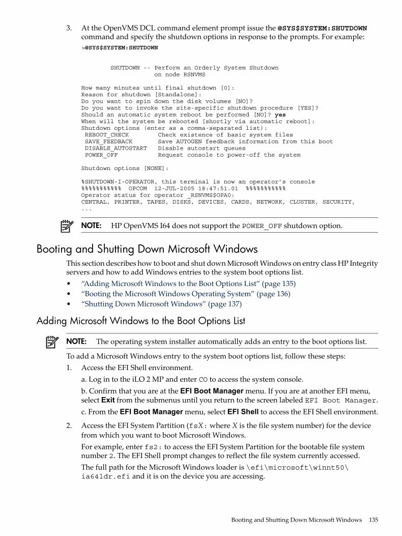
3. At the OpenVMS DCL command element prompt issue the @SYS$SYSTEM:SHUTDOWNcommand and specify the shutdown options in response to the prompts. For example:>@SYS$SYSTEM:SHUTDOWN
SHUTDOWN -- Perform an Orderly System Shutdown on node RSNVMS
How many minutes until final shutdown [0]: Reason for shutdown [Standalone]: Do you want to spin down the disk volumes [NO]? Do you want to invoke the site-specific shutdown procedure [YES]? Should an automatic system reboot be performed [NO]? yesWhen will the system be rebooted [shortly via automatic reboot]: Shutdown options (enter as a comma-separated list): REBOOT_CHECK Check existence of basic system files SAVE_FEEDBACK Save AUTOGEN feedback information from this boot DISABLE_AUTOSTART Disable autostart queues POWER_OFF Request console to power-off the system
Shutdown options [NONE]:
%SHUTDOWN-I-OPERATOR, this terminal is now an operator’s console%%%%%%%%%%% OPCOM 12-JUL-2005 18:47:51.01 %%%%%%%%%%%Operator status for operator _RSNVMS$OPA0:CENTRAL, PRINTER, TAPES, DISKS, DEVICES, CARDS, NETWORK, CLUSTER, SECURITY,...
NOTE: HP OpenVMS I64 does not support the POWER_OFF shutdown option.
Booting and Shutting Down Microsoft WindowsThis section describes how to boot and shut down Microsoft Windows on entry class HP Integrityservers and how to add Windows entries to the system boot options list.• “Adding Microsoft Windows to the Boot Options List” (page 135)• “Booting the Microsoft Windows Operating System” (page 136)• “Shutting Down Microsoft Windows” (page 137)
Adding Microsoft Windows to the Boot Options List
NOTE: The operating system installer automatically adds an entry to the boot options list.
To add a Microsoft Windows entry to the system boot options list, follow these steps:1. Access the EFI Shell environment.
a. Log in to the iLO 2 MP and enter CO to access the system console.b. Confirm that you are at the EFI Boot Manager menu. If you are at another EFI menu,select Exit from the submenus until you return to the screen labeled EFI Boot Manager.c. From the EFI Boot Manager menu, select EFI Shell to access the EFI Shell environment.
2. Access the EFI System Partition (fsX: where X is the file system number) for the devicefrom which you want to boot Microsoft Windows.For example, enter fs2: to access the EFI System Partition for the bootable file systemnumber 2. The EFI Shell prompt changes to reflect the file system currently accessed.The full path for the Microsoft Windows loader is \efi\microsoft\winnt50\ia64ldr.efi and it is on the device you are accessing.
Booting and Shutting Down Microsoft Windows 135
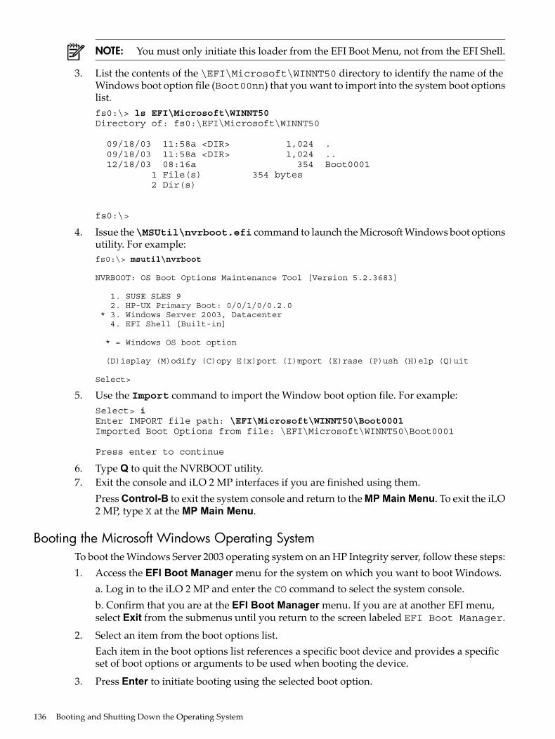
NOTE: You must only initiate this loader from the EFI Boot Menu, not from the EFI Shell.
3. List the contents of the \EFI\Microsoft\WINNT50 directory to identify the name of theWindows boot option file (Boot00nn) that you want to import into the system boot optionslist.fs0:\> ls EFI\Microsoft\WINNT50Directory of: fs0:\EFI\Microsoft\WINNT50
09/18/03 11:58a <DIR> 1,024 . 09/18/03 11:58a <DIR> 1,024 .. 12/18/03 08:16a 354 Boot0001 1 File(s) 354 bytes 2 Dir(s)
fs0:\>
4. Issue the\MSUtil\nvrboot.efi command to launch the Microsoft Windows boot optionsutility. For example:fs0:\> msutil\nvrboot
NVRBOOT: OS Boot Options Maintenance Tool [Version 5.2.3683]
1. SUSE SLES 9 2. HP-UX Primary Boot: 0/0/1/0/0.2.0 * 3. Windows Server 2003, Datacenter 4. EFI Shell [Built-in]
* = Windows OS boot option
(D)isplay (M)odify (C)opy E(x)port (I)mport (E)rase (P)ush (H)elp (Q)uit
Select>
5. Use the Import command to import the Window boot option file. For example:Select> iEnter IMPORT file path: \EFI\Microsoft\WINNT50\Boot0001Imported Boot Options from file: \EFI\Microsoft\WINNT50\Boot0001
Press enter to continue
6. Type Q to quit the NVRBOOT utility.7. Exit the console and iLO 2 MP interfaces if you are finished using them.
Press Control-B to exit the system console and return to the MP Main Menu. To exit the iLO2 MP, type X at the MP Main Menu.
Booting the Microsoft Windows Operating SystemTo boot the Windows Server 2003 operating system on an HP Integrity server, follow these steps:1. Access the EFI Boot Manager menu for the system on which you want to boot Windows.
a. Log in to the iLO 2 MP and enter the CO command to select the system console.b. Confirm that you are at the EFI Boot Manager menu. If you are at another EFI menu,select Exit from the submenus until you return to the screen labeled EFI Boot Manager.
2. Select an item from the boot options list.Each item in the boot options list references a specific boot device and provides a specificset of boot options or arguments to be used when booting the device.
3. Press Enter to initiate booting using the selected boot option.
136 Booting and Shutting Down the Operating System
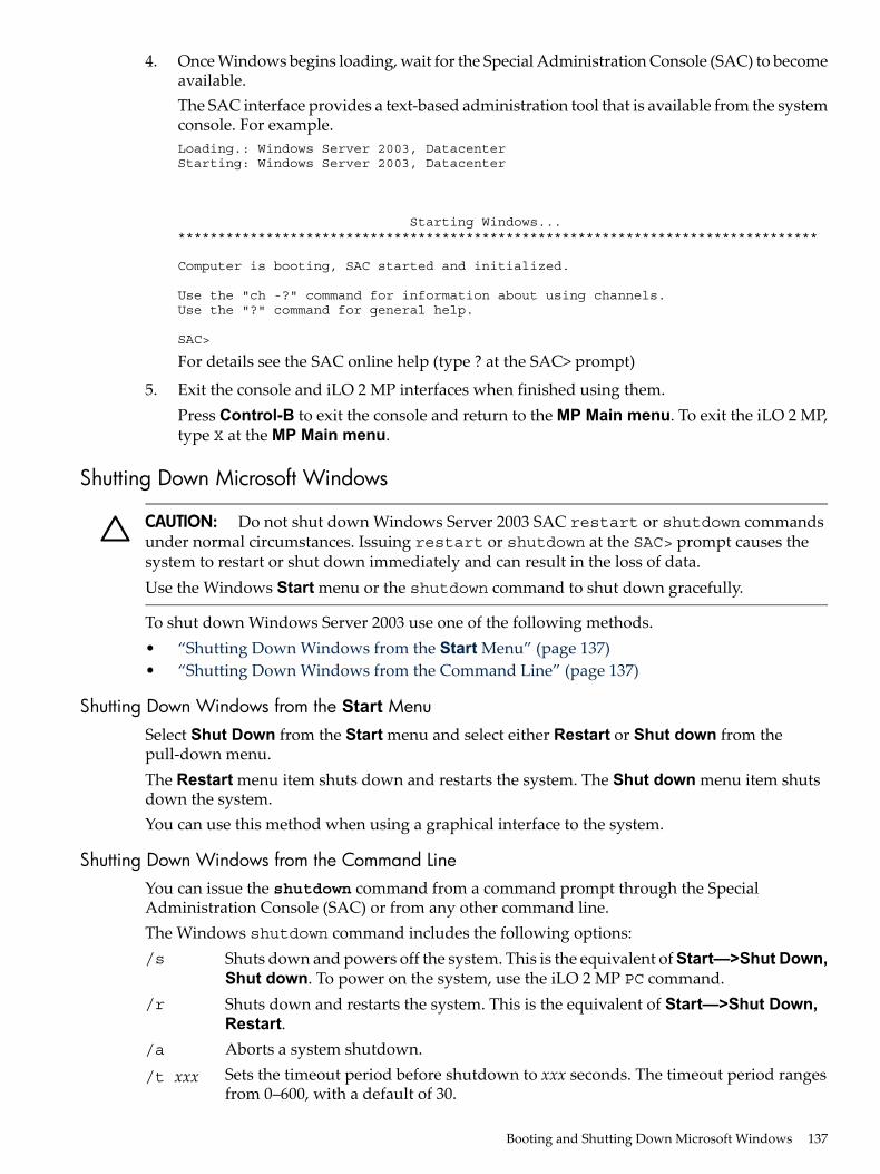
4. Once Windows begins loading, wait for the Special Administration Console (SAC) to becomeavailable.The SAC interface provides a text-based administration tool that is available from the systemconsole. For example.Loading.: Windows Server 2003, DatacenterStarting: Windows Server 2003, Datacenter
Starting Windows...********************************************************************************
Computer is booting, SAC started and initialized.
Use the "ch -?" command for information about using channels.Use the "?" command for general help.
SAC>
For details see the SAC online help (type ? at the SAC> prompt)
5. Exit the console and iLO 2 MP interfaces when finished using them.Press Control-B to exit the console and return to the MP Main menu. To exit the iLO 2 MP,type X at the MP Main menu.
Shutting Down Microsoft Windows
CAUTION: Do not shut down Windows Server 2003 SAC restart or shutdown commandsunder normal circumstances. Issuing restart or shutdown at the SAC> prompt causes thesystem to restart or shut down immediately and can result in the loss of data.Use the Windows Start menu or the shutdown command to shut down gracefully.
To shut down Windows Server 2003 use one of the following methods.• “Shutting Down Windows from the Start Menu” (page 137)• “Shutting Down Windows from the Command Line” (page 137)
Shutting Down Windows from the Start MenuSelect Shut Down from the Start menu and select either Restart or Shut down from thepull-down menu.The Restart menu item shuts down and restarts the system. The Shut down menu item shutsdown the system.You can use this method when using a graphical interface to the system.
Shutting Down Windows from the Command LineYou can issue the shutdown command from a command prompt through the SpecialAdministration Console (SAC) or from any other command line.The Windows shutdown command includes the following options:/s Shuts down and powers off the system. This is the equivalent of Start—>Shut Down,
Shut down. To power on the system, use the iLO 2 MP PC command./r Shuts down and restarts the system. This is the equivalent of Start—>Shut Down,
Restart./a Aborts a system shutdown./t xxx Sets the timeout period before shutdown to xxx seconds. The timeout period ranges
from 0–600, with a default of 30.
Booting and Shutting Down Microsoft Windows 137
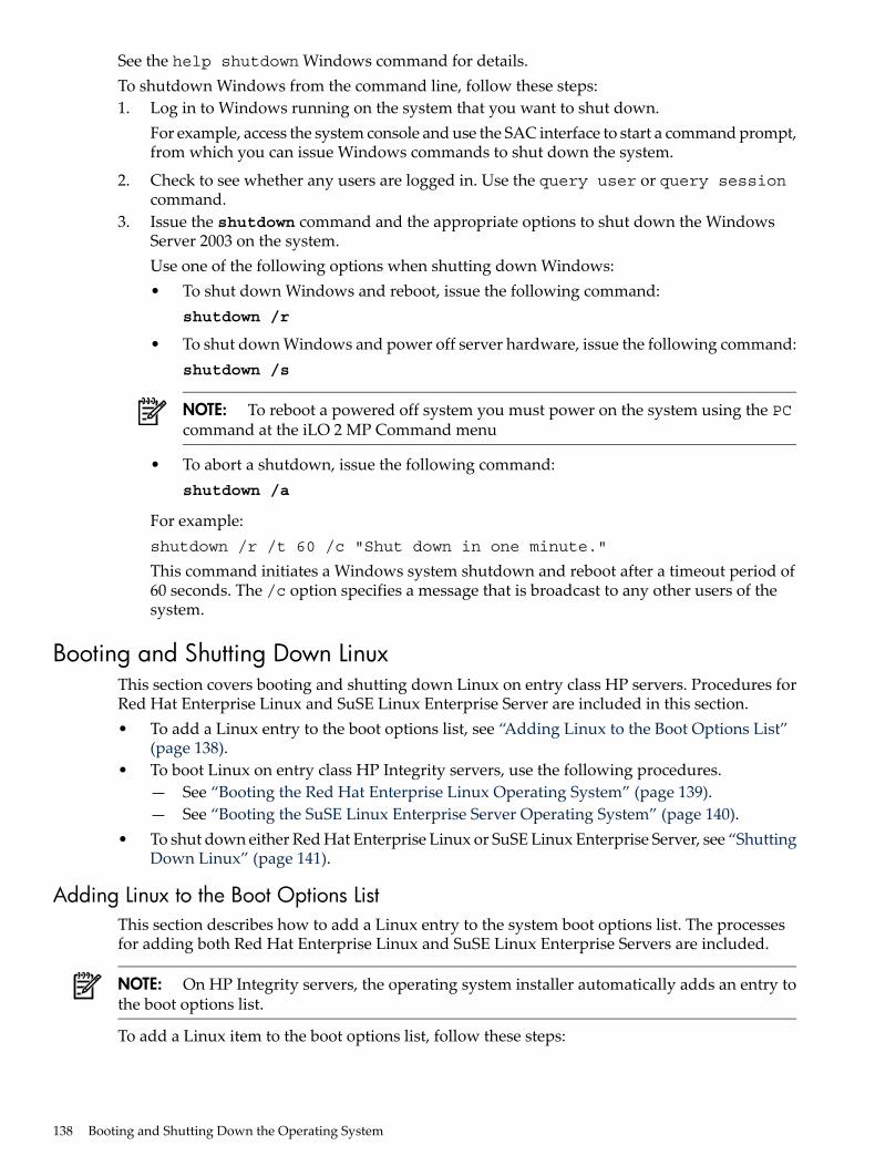
See the help shutdown Windows command for details.To shutdown Windows from the command line, follow these steps:1. Log in to Windows running on the system that you want to shut down.
For example, access the system console and use the SAC interface to start a command prompt,from which you can issue Windows commands to shut down the system.
2. Check to see whether any users are logged in. Use the query user or query sessioncommand.
3. Issue the shutdown command and the appropriate options to shut down the WindowsServer 2003 on the system.Use one of the following options when shutting down Windows:• To shut down Windows and reboot, issue the following command:
shutdown /r
• To shut down Windows and power off server hardware, issue the following command:shutdown /s
NOTE: To reboot a powered off system you must power on the system using the PCcommand at the iLO 2 MP Command menu
• To abort a shutdown, issue the following command:shutdown /a
For example:shutdown /r /t 60 /c "Shut down in one minute."
This command initiates a Windows system shutdown and reboot after a timeout period of60 seconds. The /c option specifies a message that is broadcast to any other users of thesystem.
Booting and Shutting Down LinuxThis section covers booting and shutting down Linux on entry class HP servers. Procedures forRed Hat Enterprise Linux and SuSE Linux Enterprise Server are included in this section.• To add a Linux entry to the boot options list, see “Adding Linux to the Boot Options List”
(page 138).• To boot Linux on entry class HP Integrity servers, use the following procedures.
— See “Booting the Red Hat Enterprise Linux Operating System” (page 139).— See “Booting the SuSE Linux Enterprise Server Operating System” (page 140).
• To shut down either Red Hat Enterprise Linux or SuSE Linux Enterprise Server, see “ShuttingDown Linux” (page 141).
Adding Linux to the Boot Options ListThis section describes how to add a Linux entry to the system boot options list. The processesfor adding both Red Hat Enterprise Linux and SuSE Linux Enterprise Servers are included.
NOTE: On HP Integrity servers, the operating system installer automatically adds an entry tothe boot options list.
To add a Linux item to the boot options list, follow these steps:
138 Booting and Shutting Down the Operating System
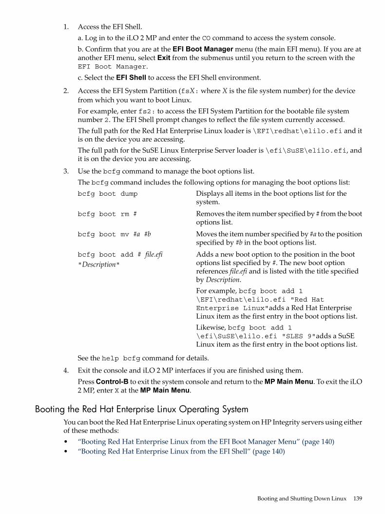
1. Access the EFI Shell.a. Log in to the iLO 2 MP and enter the CO command to access the system console.b. Confirm that you are at the EFI Boot Manager menu (the main EFI menu). If you are atanother EFI menu, select Exit from the submenus until you return to the screen with theEFI Boot Manager.c. Select the EFI Shell to access the EFI Shell environment.
2. Access the EFI System Partition (fsX: where X is the file system number) for the devicefrom which you want to boot Linux.For example, enter fs2: to access the EFI System Partition for the bootable file systemnumber 2. The EFI Shell prompt changes to reflect the file system currently accessed.The full path for the Red Hat Enterprise Linux loader is \EFI\redhat\elilo.efi and itis on the device you are accessing.The full path for the SuSE Linux Enterprise Server loader is \efi\SuSE\elilo.efi, andit is on the device you are accessing.
3. Use the bcfg command to manage the boot options list.The bcfg command includes the following options for managing the boot options list:bcfg boot dump Displays all items in the boot options list for the
system.bcfg boot rm # Removes the item number specified by # from the boot
options list.bcfg boot mv #a #b Moves the item number specified by #a to the position
specified by #b in the boot options list.bcfg boot add # file.efi"Description"
Adds a new boot option to the position in the bootoptions list specified by #. The new boot optionreferences file.efi and is listed with the title specifiedby Description.For example, bcfg boot add 1\EFI\redhat\elilo.efi "Red HatEnterprise Linux"adds a Red Hat EnterpriseLinux item as the first entry in the boot options list.Likewise, bcfg boot add 1\efi\SuSE\elilo.efi "SLES 9"adds a SuSELinux item as the first entry in the boot options list.
See the help bcfg command for details.
4. Exit the console and iLO 2 MP interfaces if you are finished using them.Press Control-B to exit the system console and return to the MP Main Menu. To exit the iLO2 MP, enter X at the MP Main Menu.
Booting the Red Hat Enterprise Linux Operating SystemYou can boot the Red Hat Enterprise Linux operating system on HP Integrity servers using eitherof these methods:• “Booting Red Hat Enterprise Linux from the EFI Boot Manager Menu” (page 140)• “Booting Red Hat Enterprise Linux from the EFI Shell” (page 140)
Booting and Shutting Down Linux 139
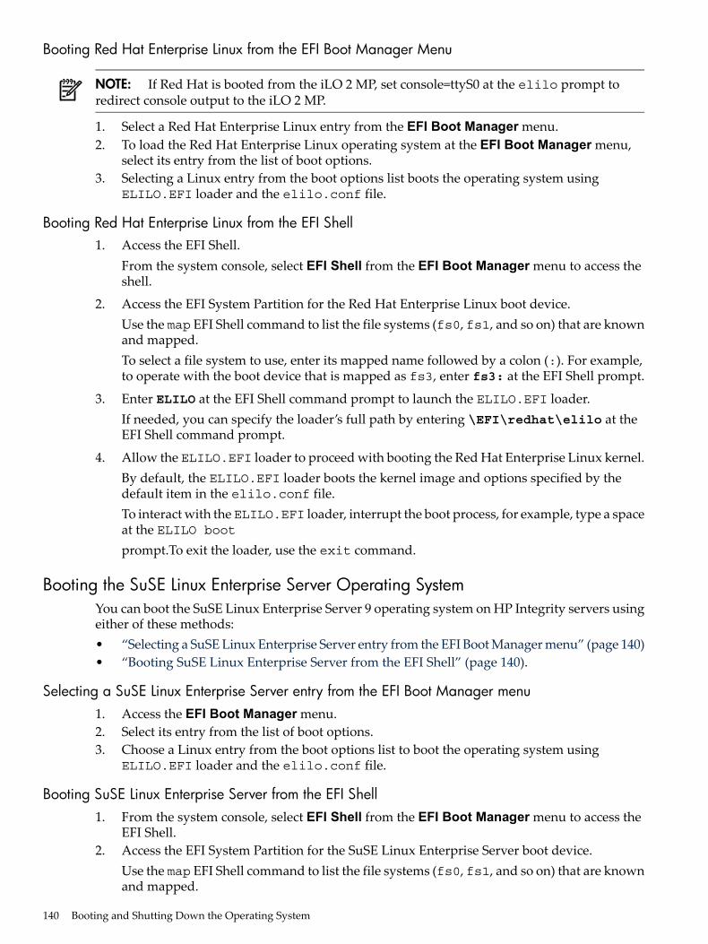
Booting Red Hat Enterprise Linux from the EFI Boot Manager Menu
NOTE: If Red Hat is booted from the iLO 2 MP, set console=ttyS0 at the elilo prompt toredirect console output to the iLO 2 MP.
1. Select a Red Hat Enterprise Linux entry from the EFI Boot Manager menu.2. To load the Red Hat Enterprise Linux operating system at the EFI Boot Manager menu,
select its entry from the list of boot options.3. Selecting a Linux entry from the boot options list boots the operating system using
ELILO.EFI loader and the elilo.conf file.
Booting Red Hat Enterprise Linux from the EFI Shell1. Access the EFI Shell.
From the system console, select EFI Shell from the EFI Boot Manager menu to access theshell.
2. Access the EFI System Partition for the Red Hat Enterprise Linux boot device.Use the map EFI Shell command to list the file systems (fs0, fs1, and so on) that are knownand mapped.To select a file system to use, enter its mapped name followed by a colon (:). For example,to operate with the boot device that is mapped as fs3, enter fs3: at the EFI Shell prompt.
3. Enter ELILO at the EFI Shell command prompt to launch the ELILO.EFI loader.If needed, you can specify the loader’s full path by entering \EFI\redhat\elilo at theEFI Shell command prompt.
4. Allow the ELILO.EFI loader to proceed with booting the Red Hat Enterprise Linux kernel.By default, the ELILO.EFI loader boots the kernel image and options specified by thedefault item in the elilo.conf file.To interact with theELILO.EFI loader, interrupt the boot process, for example, type a spaceat the ELILO bootprompt.To exit the loader, use the exit command.
Booting the SuSE Linux Enterprise Server Operating SystemYou can boot the SuSE Linux Enterprise Server 9 operating system on HP Integrity servers usingeither of these methods:• “Selecting a SuSE Linux Enterprise Server entry from the EFI Boot Manager menu” (page 140)• “Booting SuSE Linux Enterprise Server from the EFI Shell” (page 140).
Selecting a SuSE Linux Enterprise Server entry from the EFI Boot Manager menu1. Access the EFI Boot Manager menu.2. Select its entry from the list of boot options.3. Choose a Linux entry from the boot options list to boot the operating system using
ELILO.EFI loader and the elilo.conf file.
Booting SuSE Linux Enterprise Server from the EFI Shell1. From the system console, select EFI Shell from the EFI Boot Manager menu to access the
EFI Shell.2. Access the EFI System Partition for the SuSE Linux Enterprise Server boot device.
Use the map EFI Shell command to list the file systems (fs0, fs1, and so on) that are knownand mapped.
140 Booting and Shutting Down the Operating System
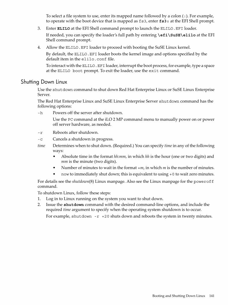
To select a file system to use, enter its mapped name followed by a colon (:). For example,to operate with the boot device that is mapped as fs3, enter fs3: at the EFI Shell prompt.
3. Enter ELILO at the EFI Shell command prompt to launch the ELILO.EFI loader.If needed, you can specify the loader’s full path by entering \efi\SuSE\elilo at the EFIShell command prompt.
4. Allow the ELILO.EFI loader to proceed with booting the SuSE Linux kernel.By default, the ELILO.EFI loader boots the kernel image and options specified by thedefault item in the elilo.conf file.To interact with theELILO.EFI loader, interrupt the boot process, for example, type a spaceat the ELILO boot prompt. To exit the loader, use the exit command.
Shutting Down LinuxUse the shutdown command to shut down Red Hat Enterprise Linux or SuSE Linux EnterpriseServer.The Red Hat Enterprise Linux and SuSE Linux Enterprise Server shutdown command has thefollowing options:-h Powers off the server after shutdown.
Use the PC command at the iLO 2 MP command menu to manually power on or poweroff server hardware, as needed.
-r Reboots after shutdown.-c Cancels a shutdown in progress.time Determines when to shut down. (Required.) You can specify time in any of the following
ways:• Absolute time in the format hh:mm, in which hh is the hour (one or two digits) and
mm is the minute (two digits).• Number of minutes to wait in the format +m, in which m is the number of minutes.• now to immediately shut down; this is equivalent to using +0 to wait zero minutes.
For details see the shutdown(8) Linux manpage. Also see the Linux manpage for the poweroffcommand.To shutdown Linux, follow these steps:1. Log in to Linux running on the system you want to shut down.2. Issue the shutdown command with the desired command-line options, and include the
required time argument to specify when the operating system shutdown is to occur.For example, shutdown -r +20 shuts down and reboots the system in twenty minutes.
Booting and Shutting Down Linux 141

142
5 TroubleshootingThis chapter provides strategies, procedures, and tools for troubleshooting server error and faultconditions.This chapter addresses the following topics:• “Methodology” (page 143)• “Troubleshooting Tools” (page 151)• “Errors and Reading Error Logs” (page 158)• “Supported Configurations” (page 161)• “CPU/Memory/SBA” (page 165)• “Power Subsystem (BPS and I/O VRM)” (page 171)• “Cooling Subsystem” (page 173)• “Common I/O Backplane (LBAs/Ropes/PDH/PCI-X Slots)” (page 174)• “Management Subsystem (iLO 2 MP/BMC)” (page 178)• “I/O Subsystem (SAS/SATA/SCSI/DVD/HDD/Core I/O)” (page 179)• “Booting ” (page 180)• “Firmware” (page 181)• “Server Interface (System Console)” (page 182)• “Environment ” (page 183)• “Reporting Your Problems to HP” (page 183)
Methodology
General Troubleshooting MethodologyThere are multiple entry points to the troubleshooting process, dependent upon your level oftroubleshooting expertise, the tools/processes/procedures which you have at your disposal, andthe nature of the system fault or failure.Typically, you select from a set of symptoms, ranging from very simple (System LED is blinking)to the most difficult (Machine Check Abort, for example, MCA, has occurred). The following isa list of symptom examples:• Front Panel LED blinking• System Alert present on console• System won’t power-up• System won’t boot• Error/Event Message received• Machine Check Abort (MCA) occurred
Methodology 143
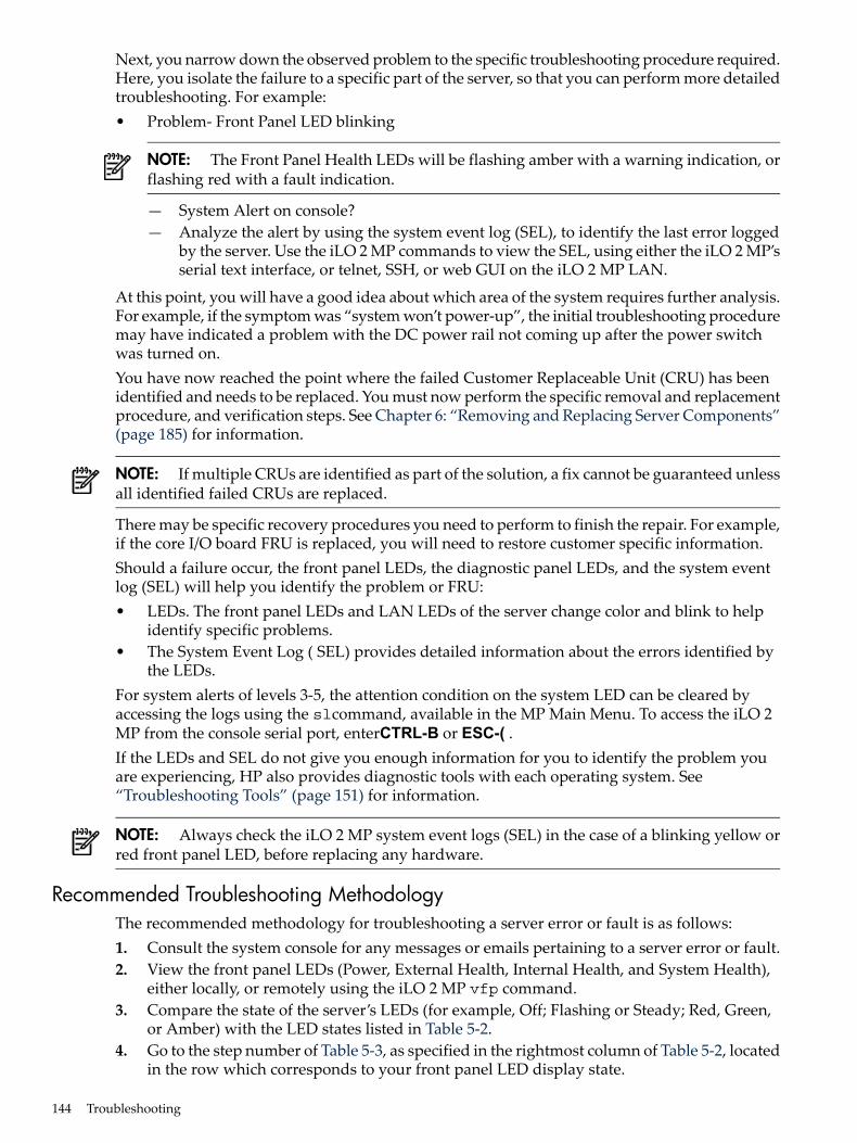
Next, you narrow down the observed problem to the specific troubleshooting procedure required.Here, you isolate the failure to a specific part of the server, so that you can perform more detailedtroubleshooting. For example:• Problem- Front Panel LED blinking
NOTE: The Front Panel Health LEDs will be flashing amber with a warning indication, orflashing red with a fault indication.
— System Alert on console?— Analyze the alert by using the system event log (SEL), to identify the last error logged
by the server. Use the iLO 2 MP commands to view the SEL, using either the iLO 2 MP’sserial text interface, or telnet, SSH, or web GUI on the iLO 2 MP LAN.
At this point, you will have a good idea about which area of the system requires further analysis.For example, if the symptom was “system won’t power-up”, the initial troubleshooting proceduremay have indicated a problem with the DC power rail not coming up after the power switchwas turned on.You have now reached the point where the failed Customer Replaceable Unit (CRU) has beenidentified and needs to be replaced. You must now perform the specific removal and replacementprocedure, and verification steps. See Chapter 6: “Removing and Replacing Server Components”(page 185) for information.
NOTE: If multiple CRUs are identified as part of the solution, a fix cannot be guaranteed unlessall identified failed CRUs are replaced.
There may be specific recovery procedures you need to perform to finish the repair. For example,if the core I/O board FRU is replaced, you will need to restore customer specific information.Should a failure occur, the front panel LEDs, the diagnostic panel LEDs, and the system eventlog (SEL) will help you identify the problem or FRU:• LEDs. The front panel LEDs and LAN LEDs of the server change color and blink to help
identify specific problems.• The System Event Log ( SEL) provides detailed information about the errors identified by
the LEDs.For system alerts of levels 3-5, the attention condition on the system LED can be cleared byaccessing the logs using the slcommand, available in the MP Main Menu. To access the iLO 2MP from the console serial port, enterCTRL-B or ESC-( .If the LEDs and SEL do not give you enough information for you to identify the problem youare experiencing, HP also provides diagnostic tools with each operating system. See“Troubleshooting Tools” (page 151) for information.
NOTE: Always check the iLO 2 MP system event logs (SEL) in the case of a blinking yellow orred front panel LED, before replacing any hardware.
Recommended Troubleshooting MethodologyThe recommended methodology for troubleshooting a server error or fault is as follows:1. Consult the system console for any messages or emails pertaining to a server error or fault.2. View the front panel LEDs (Power, External Health, Internal Health, and System Health),
either locally, or remotely using the iLO 2 MP vfp command.3. Compare the state of the server’s LEDs (for example, Off; Flashing or Steady; Red, Green,
or Amber) with the LED states listed in Table 5-2.4. Go to the step number of Table 5-3, as specified in the rightmost column of Table 5-2, located
in the row which corresponds to your front panel LED display state.
144 Troubleshooting
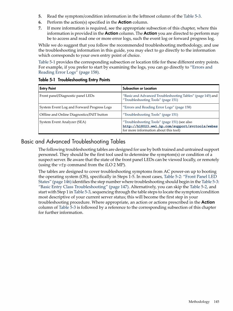
5. Read the symptom/condition information in the leftmost column of the Table 5-3.6. Perform the action(s) specified in the Action column.7. If more information is required, see the appropriate subsection of this chapter, where this
information is provided in the Action column. The Action you are directed to perform maybe to access and read one or more error logs, such the event log or forward progress log.
While we do suggest that you follow the recommended troubleshooting methodology, and usethe troubleshooting information in this guide, you may elect to go directly to the informationwhich corresponds to your own entry point of choice.Table 5-1 provides the corresponding subsection or location title for these different entry points.For example, if you prefer to start by examining the logs, you can go directly to “Errors andReading Error Logs” (page 158).
Table 5-1 Troubleshooting Entry Points
Subsection or LocationEntry Point
“Basic and Advanced Troubleshooting Tables” (page 145) and“Troubleshooting Tools” (page 151)
Front panel/Diagnostic panel LEDs
“Errors and Reading Error Logs” (page 158)System Event Log and Forward Progress Logs
“Troubleshooting Tools” (page 151)Offline and Online Diagnostics/INIT button
“Troubleshooting Tools” (page 151) (see alsohttp://h18023.ww1.hp.com/support/svctools/webesfor more information about this tool)
System Event Analyzer (SEA)
Basic and Advanced Troubleshooting TablesThe following troubleshooting tables are designed for use by both trained and untrained supportpersonnel. They should be the first tool used to determine the symptom(s) or condition of asuspect server. Be aware that the state of the front panel LEDs can be viewed locally, or remotely(using the vfp command from the iLO 2 MP).The tables are designed to cover troubleshooting symptoms from AC power-on up to bootingthe operating system (OS), specifically in Steps 1-5. In most cases, Table 5-2: “Front Panel LEDStates” (page 146) identifies the step number where troubleshooting should begin in the Table 5-3:“Basic Entry Class Troubleshooting” (page 147). Alternatively, you can skip the Table 5-2, andstart with Step 1 in Table 5-3, sequencing through the table steps to locate the symptom/conditionmost descriptive of your current server status; this will become the first step in yourtroubleshooting procedure. Where appropriate, an action or actions prescribed in the Actioncolumn of Table 5-3 is followed by a reference to the corresponding subsection of this chapterfor further information.
Methodology 145
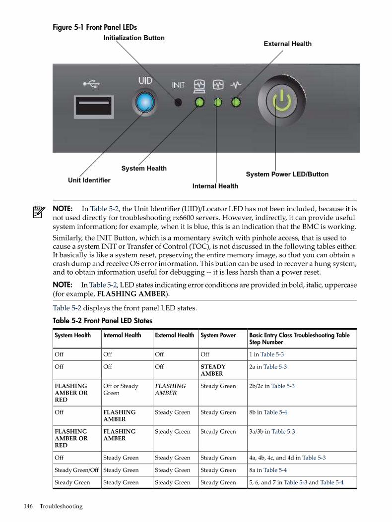
Figure 5-1 Front Panel LEDs
NOTE: In Table 5-2, the Unit Identifier (UID)/Locator LED has not been included, because it isnot used directly for troubleshooting rx6600 servers. However, indirectly, it can provide usefulsystem information; for example, when it is blue, this is an indication that the BMC is working.Similarly, the INIT Button, which is a momentary switch with pinhole access, that is used tocause a system INIT or Transfer of Control (TOC), is not discussed in the following tables either.It basically is like a system reset, preserving the entire memory image, so that you can obtain acrash dump and receive OS error information. This button can be used to recover a hung system,and to obtain information useful for debugging -- it is less harsh than a power reset.
NOTE: In Table 5-2, LED states indicating error conditions are provided in bold, italic, uppercase(for example, FLASHING AMBER).
Table 5-2 displays the front panel LED states.
Table 5-2 Front Panel LED States
Basic Entry Class Troubleshooting TableStep Number
System PowerExternal HealthInternal HealthSystem Health
1 in Table 5-3OffOffOffOff
2a in Table 5-3STEADYAMBER
OffOffOff
2b/2c in Table 5-3Steady GreenFLASHINGAMBER
Off or SteadyGreen
FLASHINGAMBER ORRED
8b in Table 5-4Steady GreenSteady GreenFLASHINGAMBER
Off
3a/3b in Table 5-3Steady GreenSteady GreenFLASHINGAMBER
FLASHINGAMBER ORRED
4a, 4b, 4c, and 4d in Table 5-3Steady GreenSteady GreenSteady GreenOff
8a in Table 5-4Steady GreenSteady GreenSteady GreenSteady Green/Off
5, 6, and 7 in Table 5-3 and Table 5-4Steady GreenSteady GreenSteady GreenSteady Green
146 Troubleshooting
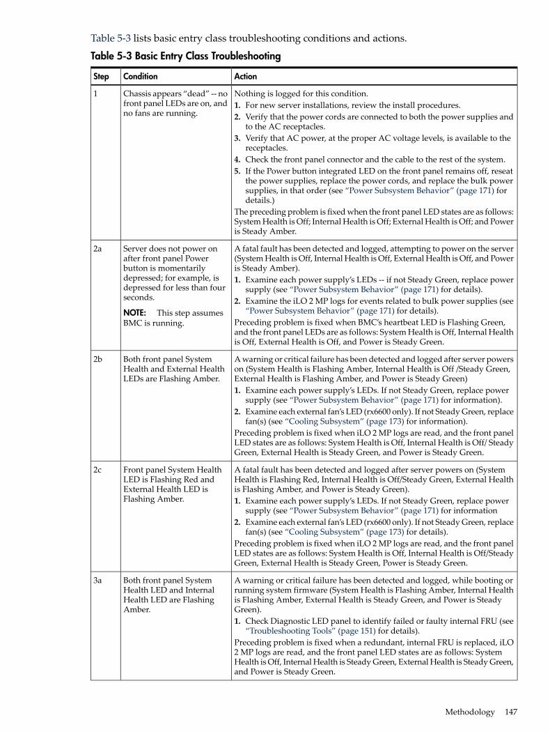
Table 5-3 lists basic entry class troubleshooting conditions and actions.
Table 5-3 Basic Entry Class Troubleshooting
ActionConditionStep
Nothing is logged for this condition.1. For new server installations, review the install procedures.2. Verify that the power cords are connected to both the power supplies and
to the AC receptacles.3. Verify that AC power, at the proper AC voltage levels, is available to the
receptacles.4. Check the front panel connector and the cable to the rest of the system.5. If the Power button integrated LED on the front panel remains off, reseat
the power supplies, replace the power cords, and replace the bulk powersupplies, in that order (see “Power Subsystem Behavior” (page 171) fordetails.)
The preceding problem is fixed when the front panel LED states are as follows:System Health is Off; Internal Health is Off; External Health is Off; and Poweris Steady Amber.
Chassis appears “dead” -- nofront panel LEDs are on, andno fans are running.
1
A fatal fault has been detected and logged, attempting to power on the server(System Health is Off, Internal Health is Off, External Health is Off, and Poweris Steady Amber).1. Examine each power supply’s LEDs -- if not Steady Green, replace power
supply (see “Power Subsystem Behavior” (page 171) for details).2. Examine the iLO 2 MP logs for events related to bulk power supplies (see
“Power Subsystem Behavior” (page 171) for details).Preceding problem is fixed when BMC’s heartbeat LED is Flashing Green,and the front panel LEDs are as follows: System Health is Off, Internal Healthis Off, External Health is Off, and Power is Steady Green.
Server does not power onafter front panel Powerbutton is momentarilydepressed; for example, isdepressed for less than fourseconds.
NOTE: This step assumesBMC is running.
2a
A warning or critical failure has been detected and logged after server powerson (System Health is Flashing Amber, Internal Health is Off /Steady Green,External Health is Flashing Amber, and Power is Steady Green)1. Examine each power supply’s LEDs. If not Steady Green, replace power
supply (see “Power Subsystem Behavior” (page 171) for information).2. Examine each external fan’s LED (rx6600 only). If not Steady Green, replace
fan(s) (see “Cooling Subsystem” (page 173) for information).Preceding problem is fixed when iLO 2 MP logs are read, and the front panelLED states are as follows: System Health is Off, Internal Health is Off/ SteadyGreen, External Health is Steady Green, and Power is Steady Green.
Both front panel SystemHealth and External HealthLEDs are Flashing Amber.
2b
A fatal fault has been detected and logged after server powers on (SystemHealth is Flashing Red, Internal Health is Off/Steady Green, External Healthis Flashing Amber, and Power is Steady Green).1. Examine each power supply’s LEDs. If not Steady Green, replace power
supply (see “Power Subsystem Behavior” (page 171) for information2. Examine each external fan’s LED (rx6600 only). If not Steady Green, replace
fan(s) (see “Cooling Subsystem” (page 173) for details).Preceding problem is fixed when iLO 2 MP logs are read, and the front panelLED states are as follows: System Health is Off, Internal Health is Off/SteadyGreen, External Health is Steady Green, Power is Steady Green.
Front panel System HealthLED is Flashing Red andExternal Health LED isFlashing Amber.
2c
A warning or critical failure has been detected and logged, while booting orrunning system firmware (System Health is Flashing Amber, Internal Healthis Flashing Amber, External Health is Steady Green, and Power is SteadyGreen).1. Check Diagnostic LED panel to identify failed or faulty internal FRU (see
“Troubleshooting Tools” (page 151) for details).Preceding problem is fixed when a redundant, internal FRU is replaced, iLO2 MP logs are read, and the front panel LED states are as follows: SystemHealth is Off, Internal Health is Steady Green, External Health is Steady Green,and Power is Steady Green.
Both front panel SystemHealth LED and InternalHealth LED are FlashingAmber.
3a
Methodology 147
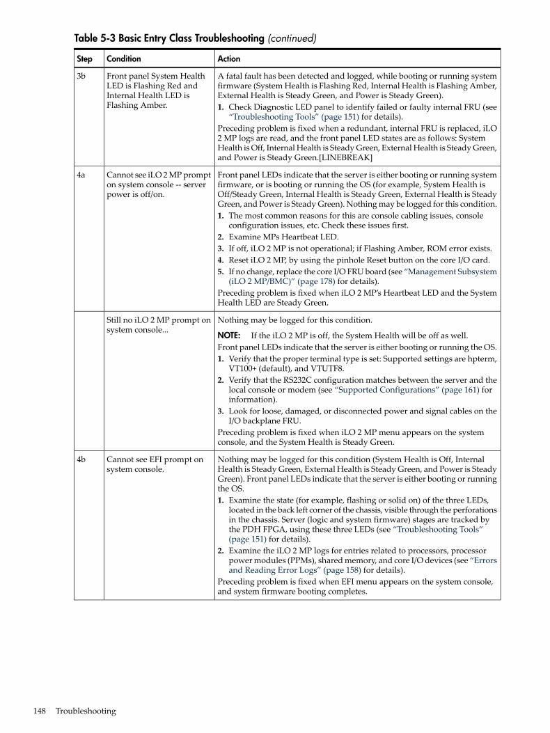
Table 5-3 Basic Entry Class Troubleshooting (continued)
ActionConditionStep
A fatal fault has been detected and logged, while booting or running systemfirmware (System Health is Flashing Red, Internal Health is Flashing Amber,External Health is Steady Green, and Power is Steady Green).1. Check Diagnostic LED panel to identify failed or faulty internal FRU (see
“Troubleshooting Tools” (page 151) for details).Preceding problem is fixed when a redundant, internal FRU is replaced, iLO2 MP logs are read, and the front panel LED states are as follows: SystemHealth is Off, Internal Health is Steady Green, External Health is Steady Green,and Power is Steady Green.[LINEBREAK]
Front panel System HealthLED is Flashing Red andInternal Health LED isFlashing Amber.
3b
Front panel LEDs indicate that the server is either booting or running systemfirmware, or is booting or running the OS (for example, System Health isOff/Steady Green, Internal Health is Steady Green, External Health is SteadyGreen, and Power is Steady Green). Nothing may be logged for this condition.1. The most common reasons for this are console cabling issues, console
configuration issues, etc. Check these issues first.2. Examine MPs Heartbeat LED.3. If off, iLO 2 MP is not operational; if Flashing Amber, ROM error exists.4. Reset iLO 2 MP, by using the pinhole Reset button on the core I/O card.5. If no change, replace the core I/O FRU board (see “Management Subsystem
(iLO 2 MP/BMC)” (page 178) for details).Preceding problem is fixed when iLO 2 MP’s Heartbeat LED and the SystemHealth LED are Steady Green.
Cannot see iLO 2 MP prompton system console -- serverpower is off/on.
4a
Nothing may be logged for this condition.
NOTE: If the iLO 2 MP is off, the System Health will be off as well.Front panel LEDs indicate that the server is either booting or running the OS.1. Verify that the proper terminal type is set: Supported settings are hpterm,
VT100+ (default), and VTUTF8.2. Verify that the RS232C configuration matches between the server and the
local console or modem (see “Supported Configurations” (page 161) forinformation).
3. Look for loose, damaged, or disconnected power and signal cables on theI/O backplane FRU.
Preceding problem is fixed when iLO 2 MP menu appears on the systemconsole, and the System Health is Steady Green.
Still no iLO 2 MP prompt onsystem console...
Nothing may be logged for this condition (System Health is Off, InternalHealth is Steady Green, External Health is Steady Green, and Power is SteadyGreen). Front panel LEDs indicate that the server is either booting or runningthe OS.1. Examine the state (for example, flashing or solid on) of the three LEDs,
located in the back left corner of the chassis, visible through the perforationsin the chassis. Server (logic and system firmware) stages are tracked bythe PDH FPGA, using these three LEDs (see “Troubleshooting Tools”(page 151) for details).
2. Examine the iLO 2 MP logs for entries related to processors, processorpower modules (PPMs), shared memory, and core I/O devices (see “Errorsand Reading Error Logs” (page 158) for details).
Preceding problem is fixed when EFI menu appears on the system console,and system firmware booting completes.
Cannot see EFI prompt onsystem console.
4b
148 Troubleshooting
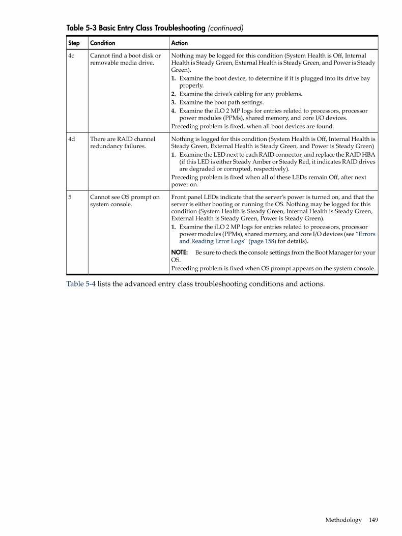
Table 5-3 Basic Entry Class Troubleshooting (continued)
ActionConditionStep
Nothing may be logged for this condition (System Health is Off, InternalHealth is Steady Green, External Health is Steady Green, and Power is SteadyGreen).1. Examine the boot device, to determine if it is plugged into its drive bay
properly.2. Examine the drive’s cabling for any problems.3. Examine the boot path settings.4. Examine the iLO 2 MP logs for entries related to processors, processor
power modules (PPMs), shared memory, and core I/O devices.Preceding problem is fixed, when all boot devices are found.
Cannot find a boot disk orremovable media drive.
4c
Nothing is logged for this condition (System Health is Off, Internal Health isSteady Green, External Health is Steady Green, and Power is Steady Green)1. Examine the LED next to each RAID connector, and replace the RAID HBA
(if this LED is either Steady Amber or Steady Red, it indicates RAID drivesare degraded or corrupted, respectively).
Preceding problem is fixed when all of these LEDs remain Off, after nextpower on.
There are RAID channelredundancy failures.
4d
Front panel LEDs indicate that the server’s power is turned on, and that theserver is either booting or running the OS. Nothing may be logged for thiscondition (System Health is Steady Green, Internal Health is Steady Green,External Health is Steady Green, Power is Steady Green).1. Examine the iLO 2 MP logs for entries related to processors, processor
power modules (PPMs), shared memory, and core I/O devices (see “Errorsand Reading Error Logs” (page 158) for details).
NOTE: Be sure to check the console settings from the Boot Manager for yourOS.Preceding problem is fixed when OS prompt appears on the system console.
Cannot see OS prompt onsystem console.
5
Table 5-4 lists the advanced entry class troubleshooting conditions and actions.
Methodology 149
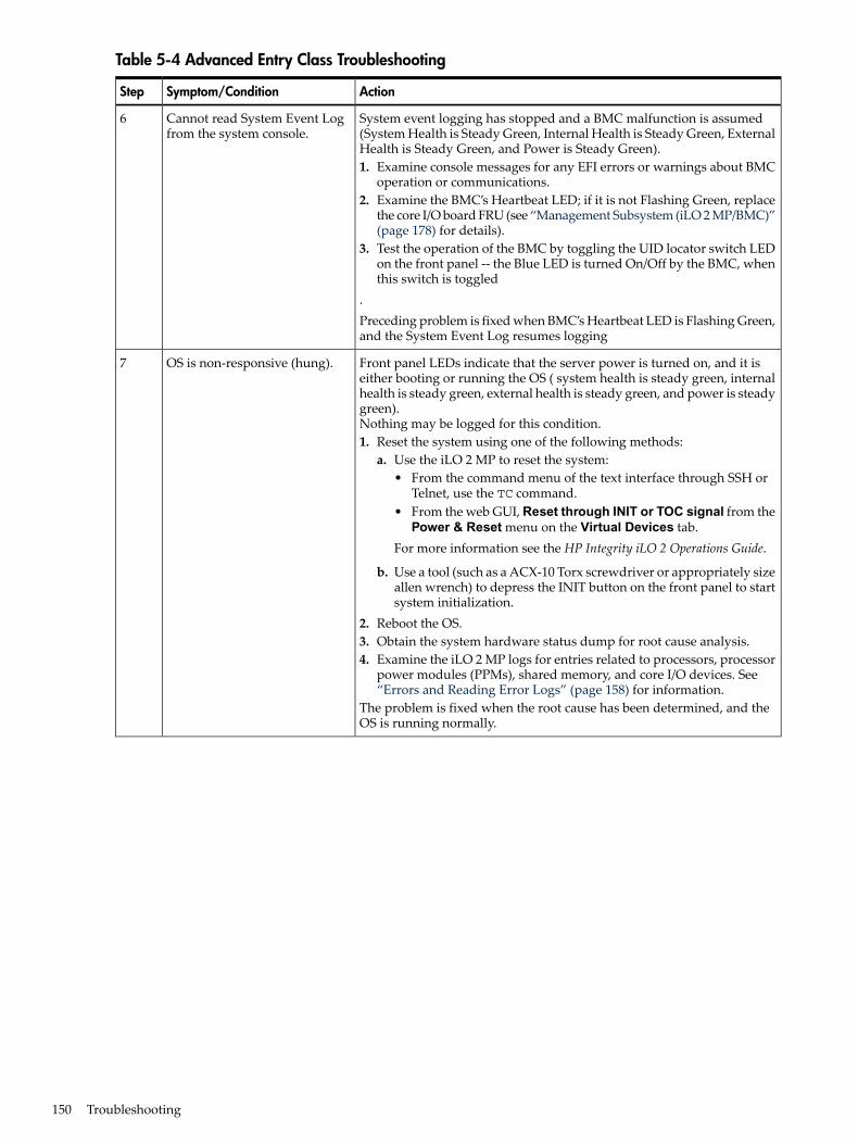
Table 5-4 Advanced Entry Class Troubleshooting
ActionSymptom/ConditionStep
System event logging has stopped and a BMC malfunction is assumed(System Health is Steady Green, Internal Health is Steady Green, ExternalHealth is Steady Green, and Power is Steady Green).1. Examine console messages for any EFI errors or warnings about BMC
operation or communications.2. Examine the BMC’s Heartbeat LED; if it is not Flashing Green, replace
the core I/O board FRU (see “Management Subsystem (iLO 2 MP/BMC)”(page 178) for details).
3. Test the operation of the BMC by toggling the UID locator switch LEDon the front panel -- the Blue LED is turned On/Off by the BMC, whenthis switch is toggled
.Preceding problem is fixed when BMC’s Heartbeat LED is Flashing Green,and the System Event Log resumes logging
Cannot read System Event Logfrom the system console.
6
Front panel LEDs indicate that the server power is turned on, and it iseither booting or running the OS ( system health is steady green, internalhealth is steady green, external health is steady green, and power is steadygreen).Nothing may be logged for this condition.1. Reset the system using one of the following methods:
a. Use the iLO 2 MP to reset the system:• From the command menu of the text interface through SSH or
Telnet, use the TC command.• From the web GUI, Reset through INIT or TOC signal from the
Power & Reset menu on the Virtual Devices tab.For more information see the HP Integrity iLO 2 Operations Guide.
b. Use a tool (such as a ACX-10 Torx screwdriver or appropriately sizeallen wrench) to depress the INIT button on the front panel to startsystem initialization.
2. Reboot the OS.3. Obtain the system hardware status dump for root cause analysis.4. Examine the iLO 2 MP logs for entries related to processors, processor
power modules (PPMs), shared memory, and core I/O devices. See“Errors and Reading Error Logs” (page 158) for information.
The problem is fixed when the root cause has been determined, and theOS is running normally.
OS is non-responsive (hung).7
150 Troubleshooting
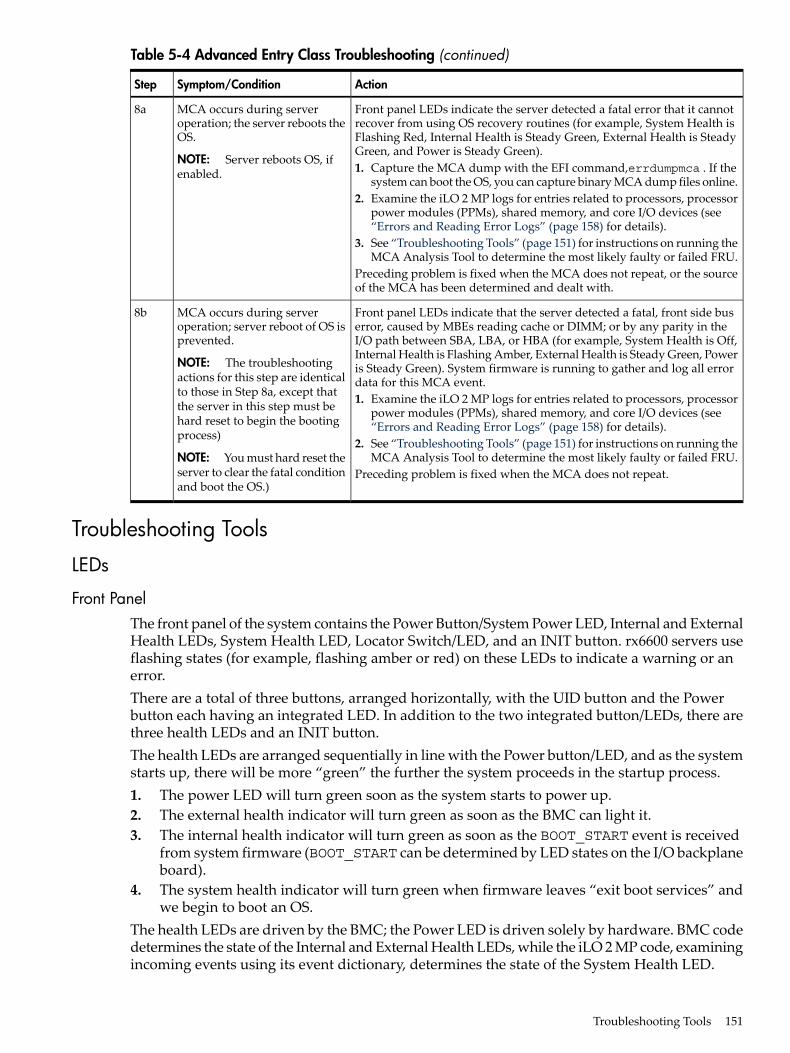
Table 5-4 Advanced Entry Class Troubleshooting (continued)
ActionSymptom/ConditionStep
Front panel LEDs indicate the server detected a fatal error that it cannotrecover from using OS recovery routines (for example, System Health isFlashing Red, Internal Health is Steady Green, External Health is SteadyGreen, and Power is Steady Green).1. Capture the MCA dump with the EFI command,errdumpmca . If the
system can boot the OS, you can capture binary MCA dump files online.2. Examine the iLO 2 MP logs for entries related to processors, processor
power modules (PPMs), shared memory, and core I/O devices (see“Errors and Reading Error Logs” (page 158) for details).
3. See “Troubleshooting Tools” (page 151) for instructions on running theMCA Analysis Tool to determine the most likely faulty or failed FRU.
Preceding problem is fixed when the MCA does not repeat, or the sourceof the MCA has been determined and dealt with.
MCA occurs during serveroperation; the server reboots theOS.
NOTE: Server reboots OS, ifenabled.
8a
Front panel LEDs indicate that the server detected a fatal, front side buserror, caused by MBEs reading cache or DIMM; or by any parity in theI/O path between SBA, LBA, or HBA (for example, System Health is Off,Internal Health is Flashing Amber, External Health is Steady Green, Poweris Steady Green). System firmware is running to gather and log all errordata for this MCA event.1. Examine the iLO 2 MP logs for entries related to processors, processor
power modules (PPMs), shared memory, and core I/O devices (see“Errors and Reading Error Logs” (page 158) for details).
2. See “Troubleshooting Tools” (page 151) for instructions on running theMCA Analysis Tool to determine the most likely faulty or failed FRU.
Preceding problem is fixed when the MCA does not repeat.
MCA occurs during serveroperation; server reboot of OS isprevented.
NOTE: The troubleshootingactions for this step are identicalto those in Step 8a, except thatthe server in this step must behard reset to begin the bootingprocess)
NOTE: You must hard reset theserver to clear the fatal conditionand boot the OS.)
8b
Troubleshooting Tools
LEDs
Front PanelThe front panel of the system contains the Power Button/System Power LED, Internal and ExternalHealth LEDs, System Health LED, Locator Switch/LED, and an INIT button. rx6600 servers useflashing states (for example, flashing amber or red) on these LEDs to indicate a warning or anerror.There are a total of three buttons, arranged horizontally, with the UID button and the Powerbutton each having an integrated LED. In addition to the two integrated button/LEDs, there arethree health LEDs and an INIT button.The health LEDs are arranged sequentially in line with the Power button/LED, and as the systemstarts up, there will be more “green” the further the system proceeds in the startup process.1. The power LED will turn green soon as the system starts to power up.2. The external health indicator will turn green as soon as the BMC can light it.3. The internal health indicator will turn green as soon as the BOOT_START event is received
from system firmware (BOOT_START can be determined by LED states on the I/O backplaneboard).
4. The system health indicator will turn green when firmware leaves “exit boot services” andwe begin to boot an OS.
The health LEDs are driven by the BMC; the Power LED is driven solely by hardware. BMC codedetermines the state of the Internal and External Health LEDs, while the iLO 2 MP code, examiningincoming events using its event dictionary, determines the state of the System Health LED.
Troubleshooting Tools 151
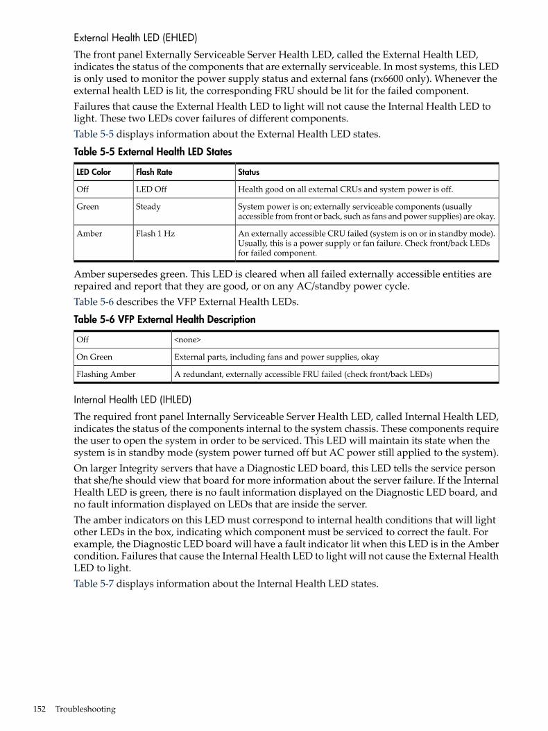
External Health LED (EHLED)
The front panel Externally Serviceable Server Health LED, called the External Health LED,indicates the status of the components that are externally serviceable. In most systems, this LEDis only used to monitor the power supply status and external fans (rx6600 only). Whenever theexternal health LED is lit, the corresponding FRU should be lit for the failed component.Failures that cause the External Health LED to light will not cause the Internal Health LED tolight. These two LEDs cover failures of different components.Table 5-5 displays information about the External Health LED states.
Table 5-5 External Health LED States
StatusFlash RateLED Color
Health good on all external CRUs and system power is off.LED OffOff
System power is on; externally serviceable components (usuallyaccessible from front or back, such as fans and power supplies) are okay.
SteadyGreen
An externally accessible CRU failed (system is on or in standby mode).Usually, this is a power supply or fan failure. Check front/back LEDsfor failed component.
Flash 1 HzAmber
Amber supersedes green. This LED is cleared when all failed externally accessible entities arerepaired and report that they are good, or on any AC/standby power cycle.Table 5-6 describes the VFP External Health LEDs.
Table 5-6 VFP External Health Description
<none>Off
External parts, including fans and power supplies, okayOn Green
A redundant, externally accessible FRU failed (check front/back LEDs)Flashing Amber
Internal Health LED (IHLED)
The required front panel Internally Serviceable Server Health LED, called Internal Health LED,indicates the status of the components internal to the system chassis. These components requirethe user to open the system in order to be serviced. This LED will maintain its state when thesystem is in standby mode (system power turned off but AC power still applied to the system).On larger Integrity servers that have a Diagnostic LED board, this LED tells the service personthat she/he should view that board for more information about the server failure. If the InternalHealth LED is green, there is no fault information displayed on the Diagnostic LED board, andno fault information displayed on LEDs that are inside the server.The amber indicators on this LED must correspond to internal health conditions that will lightother LEDs in the box, indicating which component must be serviced to correct the fault. Forexample, the Diagnostic LED board will have a fault indicator lit when this LED is in the Ambercondition. Failures that cause the Internal Health LED to light will not cause the External HealthLED to light.Table 5-7 displays information about the Internal Health LED states.
152 Troubleshooting
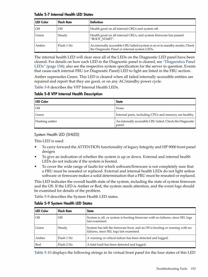
Table 5-7 Internal Health LED States
DefinitionFlash RateLED Color
Health good on all internal CRUs and system off.OffOff
Health good on all internal CRUs, and system firmware has passed“BOOT_START”.
SteadyGreen
An internally accessible CRU failed (system is on or in standby mode). Checkthe Diagnostic Panel or internal system LEDs.
Flash 1 HzAmber
The internal health LED will clear once all of the LEDs on the Diagnostic LED panel have beencleared. For details on how each LED in the Diagnostic panel is cleared, see “Diagnostics PanelLEDs” (page 154); also see the respective system specification for the server in question. Eventsthat cause each internal FRU (or Diagnostic Panel) LED to light are listed in the FRU section.Amber supersedes Green. This LED is cleared when all failed internally accessible entities arerepaired and report that they are good, or on any AC/standby power cycle.Table 5-8 describes the VFP Internal Health LEDs.
Table 5-8 VFP Internal Health Description
StateLED Color
None.Off
Internal parts, including CPUs and memory are healthy.Green
An internally accessible CRU failed. Check the Diagnosticpanel.
Flashing amber
System Health LED (SHLED)
This LED is used:• To carry forward the ATTENTION functionality of legacy Integrity and HP 9000 front panel
designs• To give an indication of whether the system is up or down. External and internal health
LEDs do not indicate if the system is booted.• To cover the wide range of faults for which software/firmware is not completely sure that
a FRU must be reseated or replaced. External and internal health LEDs do not light unlesssoftware or firmware makes a solid determination that a FRU must be reseated or replaced.
This LED indicates the overall health state of the system, including the state of system firmwareand the OS. If the LED is Amber or Red, the system needs attention, and the event logs shouldbe examined for details of the problem.Table 5-9 describes the System Health LED states.
Table 5-9 System Health LED States
StateFlash RateLED Color
System is off, or system is booting firmware with no failures, since SEL logslast examined.
OffOff
System has left the firmware boot, and an OS is booting or running with nofailures, since SEL logs last examined.
SteadyGreen
A warning or critical failure has been detected and logged.Flash 1 HzAmber
A fatal fault has been detected and logged.Flash 2 HzRed
Table 5-10 displays the following strings in its virtual front panel for the four states of this LED
Troubleshooting Tools 153
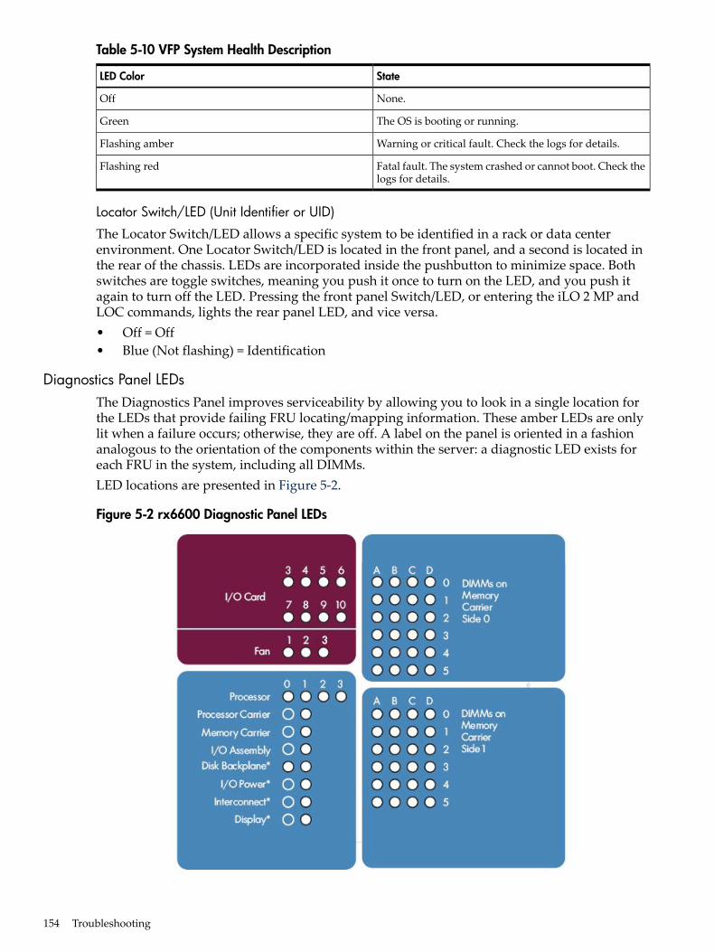
Table 5-10 VFP System Health Description
StateLED Color
None.Off
The OS is booting or running.Green
Warning or critical fault. Check the logs for details.Flashing amber
Fatal fault. The system crashed or cannot boot. Check thelogs for details.
Flashing red
Locator Switch/LED (Unit Identifier or UID)
The Locator Switch/LED allows a specific system to be identified in a rack or data centerenvironment. One Locator Switch/LED is located in the front panel, and a second is located inthe rear of the chassis. LEDs are incorporated inside the pushbutton to minimize space. Bothswitches are toggle switches, meaning you push it once to turn on the LED, and you push itagain to turn off the LED. Pressing the front panel Switch/LED, or entering the iLO 2 MP andLOC commands, lights the rear panel LED, and vice versa.• Off = Off• Blue (Not flashing) = Identification
Diagnostics Panel LEDsThe Diagnostics Panel improves serviceability by allowing you to look in a single location forthe LEDs that provide failing FRU locating/mapping information. These amber LEDs are onlylit when a failure occurs; otherwise, they are off. A label on the panel is oriented in a fashionanalogous to the orientation of the components within the server: a diagnostic LED exists foreach FRU in the system, including all DIMMs.LED locations are presented in Figure 5-2.
Figure 5-2 rx6600 Diagnostic Panel LEDs
154 Troubleshooting
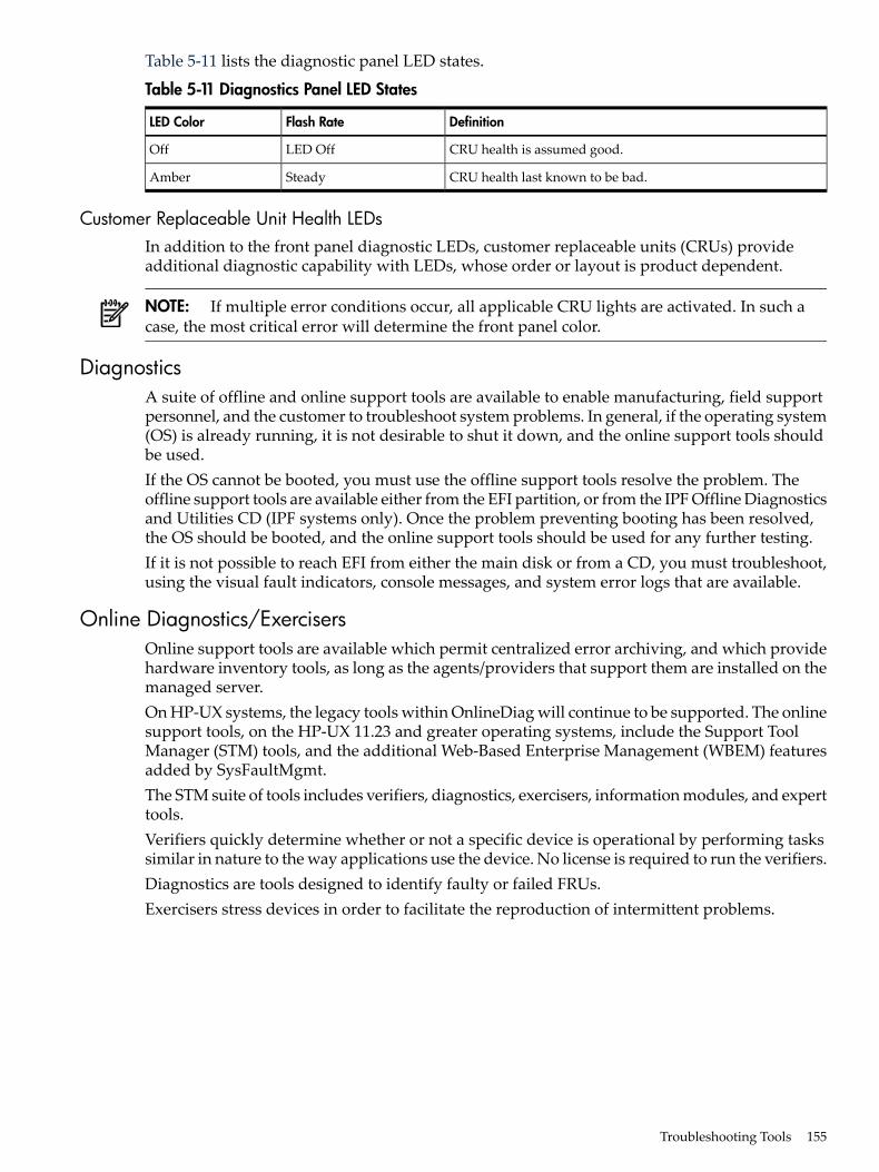
Table 5-11 lists the diagnostic panel LED states.
Table 5-11 Diagnostics Panel LED States
DefinitionFlash RateLED Color
CRU health is assumed good.LED OffOff
CRU health last known to be bad.SteadyAmber
Customer Replaceable Unit Health LEDsIn addition to the front panel diagnostic LEDs, customer replaceable units (CRUs) provideadditional diagnostic capability with LEDs, whose order or layout is product dependent.
NOTE: If multiple error conditions occur, all applicable CRU lights are activated. In such acase, the most critical error will determine the front panel color.
DiagnosticsA suite of offline and online support tools are available to enable manufacturing, field supportpersonnel, and the customer to troubleshoot system problems. In general, if the operating system(OS) is already running, it is not desirable to shut it down, and the online support tools shouldbe used.If the OS cannot be booted, you must use the offline support tools resolve the problem. Theoffline support tools are available either from the EFI partition, or from the IPF Offline Diagnosticsand Utilities CD (IPF systems only). Once the problem preventing booting has been resolved,the OS should be booted, and the online support tools should be used for any further testing.If it is not possible to reach EFI from either the main disk or from a CD, you must troubleshoot,using the visual fault indicators, console messages, and system error logs that are available.
Online Diagnostics/ExercisersOnline support tools are available which permit centralized error archiving, and which providehardware inventory tools, as long as the agents/providers that support them are installed on themanaged server.On HP-UX systems, the legacy tools within OnlineDiag will continue to be supported. The onlinesupport tools, on the HP-UX 11.23 and greater operating systems, include the Support ToolManager (STM) tools, and the additional Web-Based Enterprise Management (WBEM) featuresadded by SysFaultMgmt.The STM suite of tools includes verifiers, diagnostics, exercisers, information modules, and experttools.Verifiers quickly determine whether or not a specific device is operational by performing taskssimilar in nature to the way applications use the device. No license is required to run the verifiers.Diagnostics are tools designed to identify faulty or failed FRUs.Exercisers stress devices in order to facilitate the reproduction of intermittent problems.
Troubleshooting Tools 155
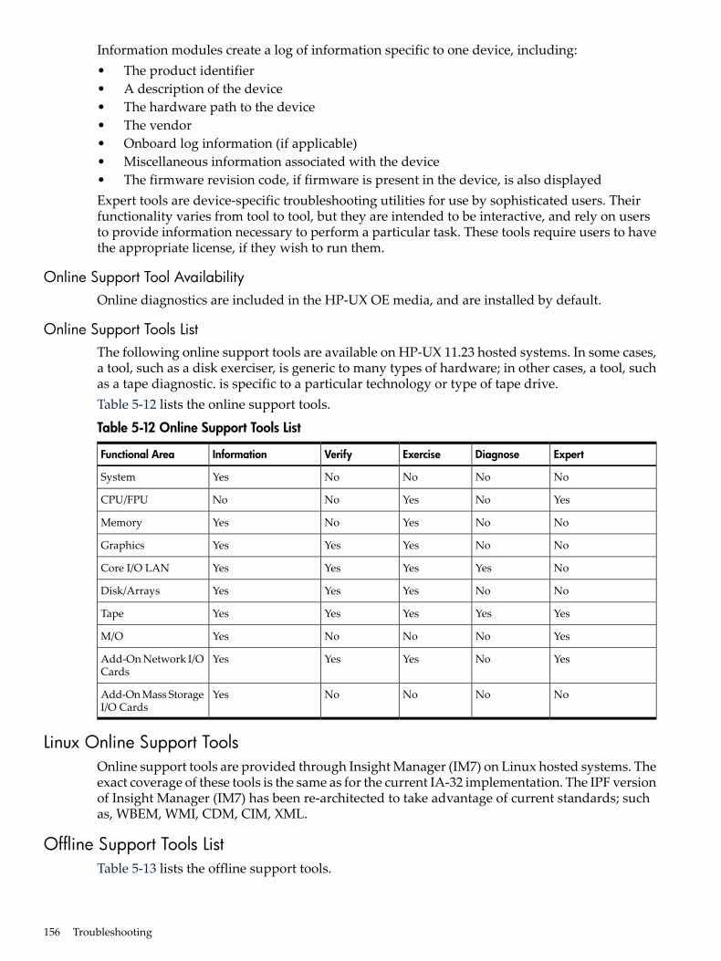
Information modules create a log of information specific to one device, including:• The product identifier• A description of the device• The hardware path to the device• The vendor• Onboard log information (if applicable)• Miscellaneous information associated with the device• The firmware revision code, if firmware is present in the device, is also displayedExpert tools are device-specific troubleshooting utilities for use by sophisticated users. Theirfunctionality varies from tool to tool, but they are intended to be interactive, and rely on usersto provide information necessary to perform a particular task. These tools require users to havethe appropriate license, if they wish to run them.
Online Support Tool AvailabilityOnline diagnostics are included in the HP-UX OE media, and are installed by default.
Online Support Tools ListThe following online support tools are available on HP-UX 11.23 hosted systems. In some cases,a tool, such as a disk exerciser, is generic to many types of hardware; in other cases, a tool, suchas a tape diagnostic. is specific to a particular technology or type of tape drive.Table 5-12 lists the online support tools.
Table 5-12 Online Support Tools List
ExpertDiagnoseExerciseVerifyInformationFunctional Area
NoNoNoNoYesSystem
YesNoYesNoNoCPU/FPU
NoNoYesNoYesMemory
NoNoYesYesYesGraphics
NoYesYesYesYesCore I/O LAN
NoNoYesYesYesDisk/Arrays
YesYesYesYesYesTape
YesNoNoNoYesM/O
YesNoYesYesYesAdd-On Network I/OCards
NoNoNoNoYesAdd-On Mass StorageI/O Cards
Linux Online Support ToolsOnline support tools are provided through Insight Manager (IM7) on Linux hosted systems. Theexact coverage of these tools is the same as for the current IA-32 implementation. The IPF versionof Insight Manager (IM7) has been re-architected to take advantage of current standards; suchas, WBEM, WMI, CDM, CIM, XML.
Offline Support Tools ListTable 5-13 lists the offline support tools.
156 Troubleshooting
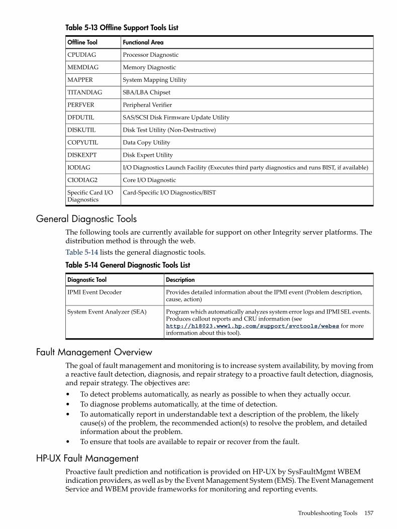
Table 5-13 Offline Support Tools List
Functional AreaOffline Tool
Processor DiagnosticCPUDIAG
Memory DiagnosticMEMDIAG
System Mapping UtilityMAPPER
SBA/LBA ChipsetTITANDIAG
Peripheral VerifierPERFVER
SAS/SCSI Disk Firmware Update UtilityDFDUTIL
Disk Test Utility (Non-Destructive)DISKUTIL
Data Copy UtilityCOPYUTIL
Disk Expert UtilityDISKEXPT
I/O Diagnostics Launch Facility (Executes third party diagnostics and runs BIST, if available)IODIAG
Core I/O DiagnosticCIODIAG2
Card-Specific I/O Diagnostics/BISTSpecific Card I/ODiagnostics
General Diagnostic ToolsThe following tools are currently available for support on other Integrity server platforms. Thedistribution method is through the web.Table 5-14 lists the general diagnostic tools.
Table 5-14 General Diagnostic Tools List
DescriptionDiagnostic Tool
Provides detailed information about the IPMI event (Problem description,cause, action)
IPMI Event Decoder
Program which automatically analyzes system error logs and IPMI SEL events.Produces callout reports and CRU information (seehttp://h18023.www1.hp.com/support/svctools/webes for moreinformation about this tool).
System Event Analyzer (SEA)
Fault Management OverviewThe goal of fault management and monitoring is to increase system availability, by moving froma reactive fault detection, diagnosis, and repair strategy to a proactive fault detection, diagnosis,and repair strategy. The objectives are:• To detect problems automatically, as nearly as possible to when they actually occur.• To diagnose problems automatically, at the time of detection.• To automatically report in understandable text a description of the problem, the likely
cause(s) of the problem, the recommended action(s) to resolve the problem, and detailedinformation about the problem.
• To ensure that tools are available to repair or recover from the fault.
HP-UX Fault ManagementProactive fault prediction and notification is provided on HP-UX by SysFaultMgmt WBEMindication providers, as well as by the Event Management System (EMS). The Event ManagementService and WBEM provide frameworks for monitoring and reporting events.
Troubleshooting Tools 157
SysFaultMgmt WBEM indication providers and the EMS Hardware Monitors allow users tomonitor the operation of a wide variety of hardware products, and alert them immediately ifany failure or other unusual event occurs. By using hardware event monitoring, users can virtuallyeliminate undetected hardware failures that could interrupt system operation or cause data loss.Complete information on installing and using EMS hardware event monitors, as well as a list ofsupported hardware, can be found in the EMSHardwareMonitors Users Guide. An electronic copyof this book is provided on the HP website at: http://docs.hp.com/hpux/diag.
WBEM indication providers and EMS Hardware MonitorsHardware monitors are available to monitor the following components (These monitors aredistributed free on the OE media.):• Chassis/Fans/Environment• CPU monitor• UPS monitor*• FC Hub monitor*• FC Switch monitor*• Memory monitor• Core Electronics Components• Disk drives• Ha_disk_array
NOTE: No SysFaultMgmt WBEM indication provider is currently available for componentsfollowed by an asterisk.
EMS HA Monitors High Availability monitors are also available through EMS to monitor disk,cluster, network, and system resources. These tools are available from HP at an additional cost.
Errors and Reading Error Logs
Event Log DefinitionsOften the underlying root cause of an MCA event is captured by system or BMC firmware inboth the System Event and Forward Progress Event Logs (SEL and FP, respectively). These errorsare easily matched with MCA events by their timestamps. For example, the loss of a CPU’s VRMmight cause a CPU fault. Decoding the MCA error logs would only identify the failed CPU asthe most likely faulty FRU. Following are some important points to remember about events andevent logs:• Event logs are the equivalent of the old chassis logs for status or error information output.• Symbolic names are used in the source code; for example, MC_CACHE_CHECK .• The hex code for each event log is 128 bits long with an architected format:
— Some enumerated fields can be mapped to defined text strings.— All can be displayed in hex, keyword, or text mode.
• Events are created by firmware or OS code, and are sent over the PDH bus to the BMC forstorage in either or both of the SEL and FP logs (HP-UX shows an I/O path for the BMC).
• The iLO 2 MP can display event logs: SEL events are sent over the IPMB, between the BMCand the iLO 2 MP.
• Event logs can also be read back over the PDH bus by software (IPMI driver or agent) forstorage on disk.
Using Event LogsTo consult the event logs:
158 Troubleshooting
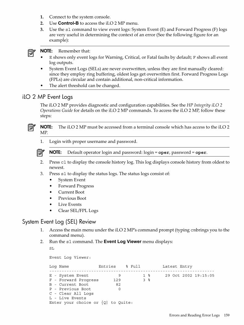
1. Connect to the system console.2. Use Control-B to access the iLO 2 MP menu.3. Use the sl command to view event logs: System Event (E) and Forward Progress (F) logs
are very useful in determining the context of an error (See the following figure for anexample):
NOTE: Remember that:• E shows only event logs for Warning, Critical, or Fatal faults by default; F shows all event
log outputs.• System Event Logs (SELs) are never overwritten, unless they are first manually cleared:
since they employ ring buffering, oldest logs get overwritten first. Forward Progress Logs(FPLs) are circular and contain additional, non-critical information.
• The alert threshold can be changed.
iLO 2 MP Event LogsThe iLO 2 MP provides diagnostic and configuration capabilities. See the HP Integrity iLO 2Operations Guide for details on the iLO 2 MP commands. To access the iLO 2 MP, follow thesesteps:
NOTE: The iLO 2 MP must be accessed from a terminal console which has access to the iLO 2MP.
1. Login with proper username and password.
NOTE: Default operator login and password: login = oper, password = oper.
2. Press cl to display the console history log. This log displays console history from oldest tonewest.
3. Press sl to display the status logs. The status logs consist of:• System Event• Forward Progress• Current Boot• Previous Boot• Live Events• Clear SEL/FPL Logs
System Event Log (SEL) Review1. Access the main menu under the iLO 2 MP’s command prompt (typing cmbrings you to the
command menu).2. Run the sl command. The Event Log Viewer menu displays:
SL
Event Log Viewer:
Log Name Entries % Full Latest Entry-------------------------------------------------------------------E - System Event 9 1 % 29 Oct 2002 19:15:05F - Forward Progress 129 3 %B - Current Boot 82P - Previous Boot 0C - Clear All LogsL - Live EventsEnter your choice or {Q] to Quite:
Errors and Reading Error Logs 159
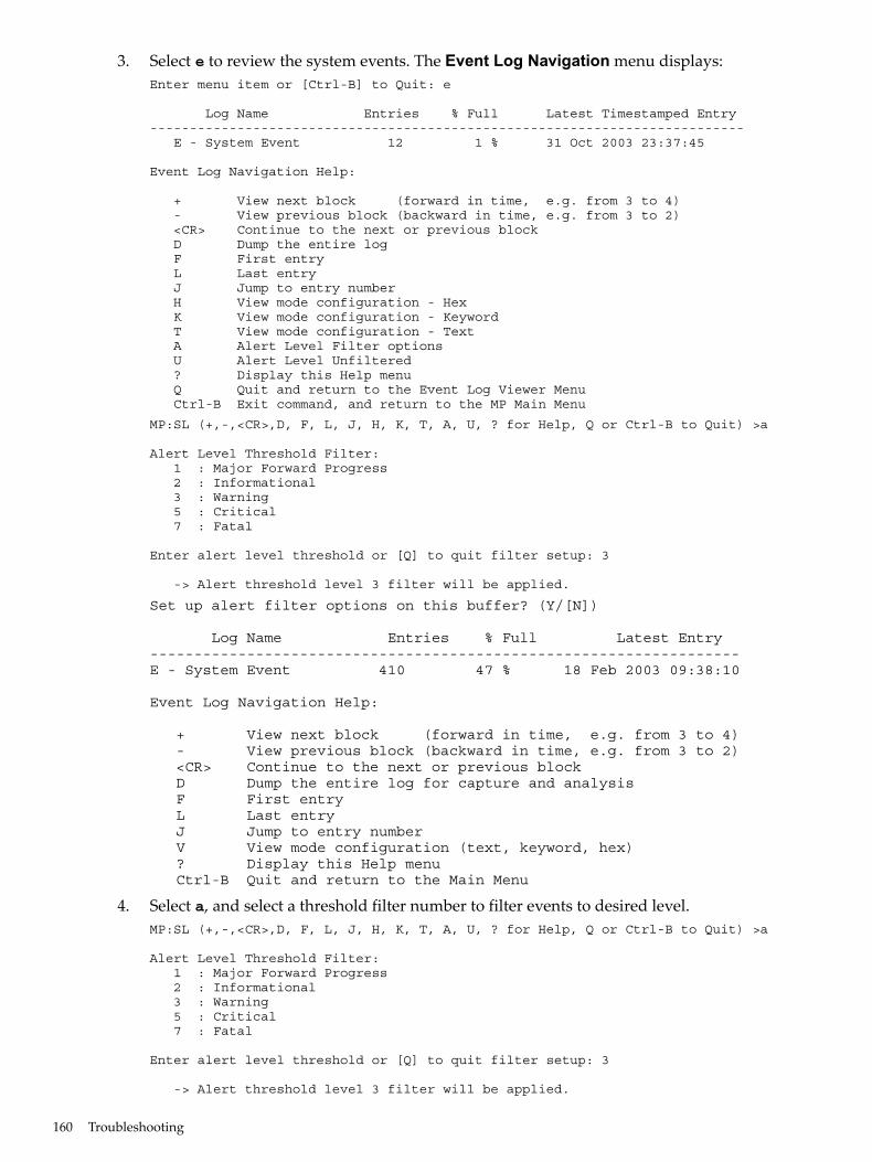
3. Select e to review the system events. The Event Log Navigation menu displays:Enter menu item or [Ctrl-B] to Quit: e
Log Name Entries % Full Latest Timestamped Entry--------------------------------------------------------------------------- E - System Event 12 1 % 31 Oct 2003 23:37:45
Event Log Navigation Help:
+ View next block (forward in time, e.g. from 3 to 4) - View previous block (backward in time, e.g. from 3 to 2) <CR> Continue to the next or previous block D Dump the entire log F First entry L Last entry J Jump to entry number H View mode configuration - Hex K View mode configuration - Keyword T View mode configuration - Text A Alert Level Filter options U Alert Level Unfiltered ? Display this Help menu Q Quit and return to the Event Log Viewer Menu Ctrl-B Exit command, and return to the MP Main Menu
MP:SL (+,-,<CR>,D, F, L, J, H, K, T, A, U, ? for Help, Q or Ctrl-B to Quit) >a
Alert Level Threshold Filter: 1 : Major Forward Progress 2 : Informational 3 : Warning 5 : Critical 7 : Fatal
Enter alert level threshold or [Q] to quit filter setup: 3
-> Alert threshold level 3 filter will be applied.
Set up alert filter options on this buffer? (Y/[N])
Log Name Entries % Full Latest Entry-------------------------------------------------------------------E - System Event 410 47 % 18 Feb 2003 09:38:10
Event Log Navigation Help:
+ View next block (forward in time, e.g. from 3 to 4) - View previous block (backward in time, e.g. from 3 to 2) <CR> Continue to the next or previous block D Dump the entire log for capture and analysis F First entry L Last entry J Jump to entry number V View mode configuration (text, keyword, hex) ? Display this Help menu Ctrl-B Quit and return to the Main Menu
4. Select a, and select a threshold filter number to filter events to desired level.MP:SL (+,-,<CR>,D, F, L, J, H, K, T, A, U, ? for Help, Q or Ctrl-B to Quit) >a
Alert Level Threshold Filter: 1 : Major Forward Progress 2 : Informational 3 : Warning 5 : Critical 7 : Fatal
Enter alert level threshold or [Q] to quit filter setup: 3
-> Alert threshold level 3 filter will be applied.
160 Troubleshooting
5. Select v, and select t to change the display to text mode:Display Mode Configuration: H - Hex mode Current -> K - Keyword mode T - Text modeEnter new value, or [Q] to Quit:
6. To decode the blinking state of system LED, review the entire SEL and look at events withalert level 3 and above.For example:Log Entry 24: 14 Feb 2003 15:27:02Alert Level 3: WarningKeyword: Type-02 1b0800 1771520Hot Swap Cage: SCSI cable removedLogged by: BMC; Sensor: Cable / Interconnect - SCSI ChExt CableData1: Device Removed/Device Absent0x203E4D0AC6020220 FFFF0008F61B0300
Log Entry 73: 00:00:12Alert Level 3: WarningKeyword: Type-02 050301 328449The server's built-in sensors have detected an open chassis door.Logged by: BMC; Sensor: Physical Security - Chassis OpenData1: State Asserted0x200000000C020570 FFFF010302050300
Supported ConfigurationsThis subsection provides a system build-up procedure.
System Block DiagramThe following is a system block diagram, showing the major rx6600 server functional componentsand their interconnections:
Supported Configurations 161
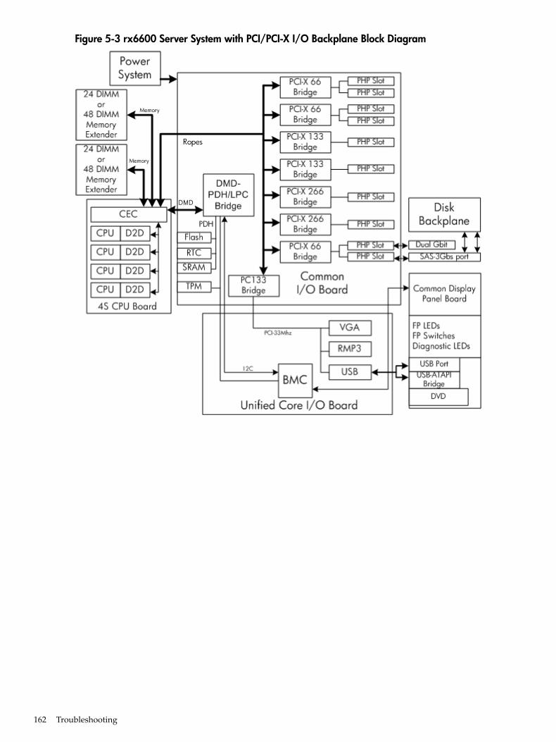
Figure 5-3 rx6600 Server System with PCI/PCI-X I/O Backplane Block Diagram
162 Troubleshooting
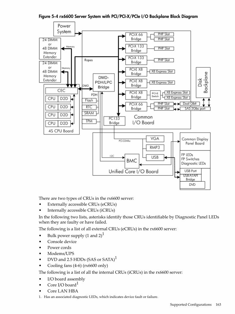
Figure 5-4 rx6600 Server System with PCI/PCI-X/PCIe I/O Backplane Block Diagram
There are two types of CRUs in the rx6600 server:• Externally accessible CRUs (eCRUs)• Internally accessible CRUs (iCRUs)In the following two lists, asterisks identify those CRUs identifiable by Diagnostic Panel LEDswhen they are faulty or have failed.The following is a list of all external CRUs (eCRUs) in the rx6600 server:• Bulk power supply (1 and 2)1
• Console device• Power cords• Modems/UPS• DVD and 2.5 HDDs (SAS or SATA)1
• Cooling fans (4-6) (rx6600 only)The following is a list of all the internal CRUs (iCRUs) in the rx6600 server:• I/O board assembly• Core I/O board1
• Core LAN HBA1. Has an associated diagnostic LEDs, which indicates device fault or failure.
Supported Configurations 163
• SAS Disk HBA• CPU board and CPUs1
• Disk BP board (1 and 2)• Memory extender and DIMMs1
• FP and Diagnostic LED board• HBAs (optional)• I/O VRM• Cooling Fans (1-3)1
• Midplane board• Interconnect board
System Build-Up Troubleshooting ProcedureUse this procedure only when the system powers on and remains powered on but does not enterinto or pass POST or does not boot to EFI menu.1. Remove the AC power cord from each bulk power supply and extend the server chassis, if
racked.2. Remove all of the HDDs from the front of the chassis, then the memory extender and CPU
board CRUs.3. Remove the top cover to gain access to, and remove, everything but the I/O backplane board
and core I/O board CRUs.4. Plug in the AC power cord(s) and the iLO 2 MP and system console should come alive and
you should have the following CRU IDs listed after executing the CM>DF command:CRU IDs: --------
02-Power Converter 03-Power Supply 0 04-Power Supply1
05-Diagnostic Panel 06-Front Panel 00-Motherboard
Log Entry 4: Dec 2005 00:00:09
Alert Level 5: Critical
Keyword: Type-02 257100 2453760
Missing CRU device - Mem Extender
Logged by: Baseboard Management Controller,
Sensor: Entity Presence
0x2000000009020050 FF01807115250300
If you do not see all of the above CRU IDs, concentrate on the missing CRU IDs. You shouldeventually end up with the following Alert (IPMI) event for this action as read from the SEL:If you do not get the above Alert Level 5 (IPMI) event, but get another sort of high levelalert, try replacing the I/O backplane board. Examine the pins on the midplane board, andif necessary, replace the midplane board.
5. The next step would be to add the memory extender (with at least one rank of DIMMs).Remember to remove the AC power cord(s) before making this configuration change.Here is the output of the iLO 2 MP> DF command you should expect at this point (thisexample has two ranks of DIMMs installed).CRU IDs:-------- 0152-DIMM0D 0001-Mem Extender 0002-Power Converter
164 Troubleshooting
0003-Power Supply 0 0004-Power Supply 1 0005-Diagnostic Panel
0006-Front Panel 0128-DIMM0A 0136-DIMM0B
0144-DIMM0C 0160-DIMM1A 0168-DIMM1
0176-DIMM1C 0184-DIMM1D 0000-Motherboard
If you do not see all of the above CRU IDs, concentrate on the missing CRU IDs. You shouldeventually end up with the following Alert (IPMI) event for this action as read from the SEL:If you do show the Alert level 5 “Missing CRU device - CPU 0 PIROM”, continue to the nextstep.Log Entry 3: Dec 2005 21:50:43
Alert Level 5: Critical
Keyword: Type-02 257100 2453760
Missing FRU device - CPU 0 PIROM
Logged by: Baseboard Management Controller,
Sensor: Entity Presence
0x2041CB3DB3020040 FF20807115250300
6. Insert the CPU board CRU with at least module 0 processor installed. When you add theCPU board CRU and turn on system power, the cooling fans should turn on and stay onand the DF command output should look something like the following:CRU IDs ------- 0001-Mem Extender 0002-Power Converter 0003-Power Supply 0
0004-Power Supply 1 0005-Diagnostic Panel 0006 Front Panel
0007-Disk Management 0008-Disk backplane 0010-Processor Board
0012-Power Pod 0 0013-Power Pod 1 0032-CPU 0 PIROM
0033-CPU 1 PIROM 0036-Processor 0 RAM 0037-Processor 1 RAM
0128-DIMM0A 0136-DIMM0B 0144-DIMM0C
0152-DIMM0D 0160-DIMM1A 0168-DIMM1B
0176-DIMM1C 0184-DIMM1D 0000-Motherboard
At this point, if the installed CRUs are all functional, the system should initiate POST on allprocessors. It is recommended to observe the system console output using “Live Logs” toensure that POST is initiated and completes without error.If POST does not start after a few seconds, suspect some sort of CPU board or processorproblem. Typical problems will show up in the SEL or FWP. If the IMPI event logs do notpoint to a root cause, escalate to bring in expert assistance.
CPU/Memory/SBAAll of the CPU, Memory controller, and System Bus Adapter (SBA or I/O rope controller) functionsreside on the Processor card CRU; memory DIMMs reside on memory extender CRUs; and theLocal Bus Adapter (LBAs or PCI-X bus controller chips) reside on the common I/O BackplaneFRU along with core and customer Host Bus Adapter (HBA device controller) I/O cards. This
CPU/Memory/SBA 165
section discusses the roles of logical CPUs, physical memory ranks, and the rope interfaces inthe SBA logic of the zx2 chip.
Troubleshooting the CPUEach rx6600 server supports from one to four IPF processor modules. Each processor modulecontains two individual CPU cores. This results in up to eight physical CPUs installed in rx6600servers.Furthermore, unlike previous IPF processor modules, each physical CPU core contains logic tosupport two physical threads. This results in up to eight physical threads, or the equivalent of16 logical CPUs in rx6600 servers when four processor modules are installed and enabled.
NOTE: The operating system kernel attaches one or more software processes to each availablethread. In multiple processor servers, having more threads means all software processes arelaunched and executed faster.
IPF Processor Load OrderFor a minimally loaded server, one IPF processor module must be installed in CPU socket 0 onthe Processor board CRU, and its threads must be enabled by user actions. Additional processormodules of the same revision are installed in CPU sockets 1-3 in rx6600 servers.
Processor Module BehaviorsAll enabled CPUs and their threads almost immediately become functional after system poweris applied. Each thread is in a race to fetch their instructions from their CPU’s instruction anddata caches to complete early self test and rendezvous.Early code fetches come from PDH, until memory is configured. Normal execution is fetchedfrom main memory.Local machine check abort (MCA) events cause the physical CPU core and one or both of itslogical CPUs within that IPF processor module to fail while all other physical and their logicalCPUs continue operating. Double-bit data cache errors in any physical CPU core will cause aGlobal MCA event that causes all logical and physical CPUs in the server to fail and reboot theoperating system.
Customer Messaging Policy• A diagnostic LED only lights for physical CPU core errors, when isolation is to a specific
IPF processor module. If there is any uncertainty about a specific CPU, the customer ispointed to the SEL for any action, and the suspect IPF processor module’s CRU LED on thediagnostic panel is not lighted.
• For configuration style errors, for example, when there is no IPF processor module installedin CPU socket 0, all of the CRU LEDs on the diagnostic LED panel are lighted for all of theIPF processor modules that are missing.
• No diagnostic messages are reported for single-bit errors that are corrected in both instructionand data caches, during corrected machine check (CMC) events to any physical CPU core.Diagnostic messages are reported for CMC events when thresholds are exceeded for single-biterrors; fatal processor errors cause global / local MCA events.
Table 5-15 lists the processor events that light the diagnostic panel LEDs.
166 Troubleshooting
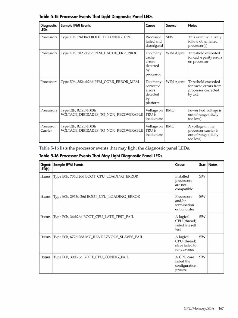
Table 5-15 Processor Events That Light Diagnostic Panel LEDs
NotesSourceCauseSample IPMI EventsDiagnosticLEDs
This event will likelyfollow other failedprocessor(s)
SFWProcessorfailed anddeconfigured
Type E0h, 39d:04d BOOT_DECONFIG_CPUProcessors
Threshold exceededfor cache parity errorson processor
WIN AgentToo manycacheerrorsdetectedbyprocessor
Type E0h, 5823d:26d PFM_CACHE_ERR_PROCProcessors
Threshold exceededfor cache errors fromprocessor correctedby zx2
WIN AgentToo manycorrectederrorsdetectedbyplatform
Type E0h, 5824d:26d PFM_CORR_ERROR_MEMProcessors
Power Pod voltage isout of range (likelytoo low)
BMCVoltage onFRU isinadequate
Type 02h, 02h:07h:03hVOLTAGE_DEGRADES_TO_NON_RECOVERABLE
Processors
A voltage on theprocessor carrier isout of range (likelytoo low)
BMCVoltage onFRU isinadequate
Type 02h, 02h:07h:03hVOLTAGE_DEGRADES_TO_NON_RECOVERABLE
ProcessorCarrier
Table 5-16 lists the processor events that may light the diagnostic panel LEDs.
Table 5-16 Processor Events That May Light Diagnostic Panel LEDs
NotesSourceCauseSample IPMI EventsDiagnosticLED(s)
SFWInstalledprocessorsare notcompatible
Type E0h, 734d:26d BOOT_CPU_LOADING_ERRORProcessors
SFWProcessorsand/orterminationout of order
Type E0h, 2953d:26d BOOT_CPU_LOADING_ERRORProcessors
SFWA logicalCPU (thread)failed late selftest
Type E0h, 36d:26d BOOT_CPU_LATE_TEST_FAILProcessors
SFWA logicalCPU (thread)slave failed torendezvous
Type E0h, 677d:26d MC_RENDEZVOUS_SLAVES_FAILProcessors
SFWA CPU corefailed theconfigurationprocess
Type E0h, 30d:26d BOOT_CPU_CONFIG_FAILProcessors
CPU/Memory/SBA 167
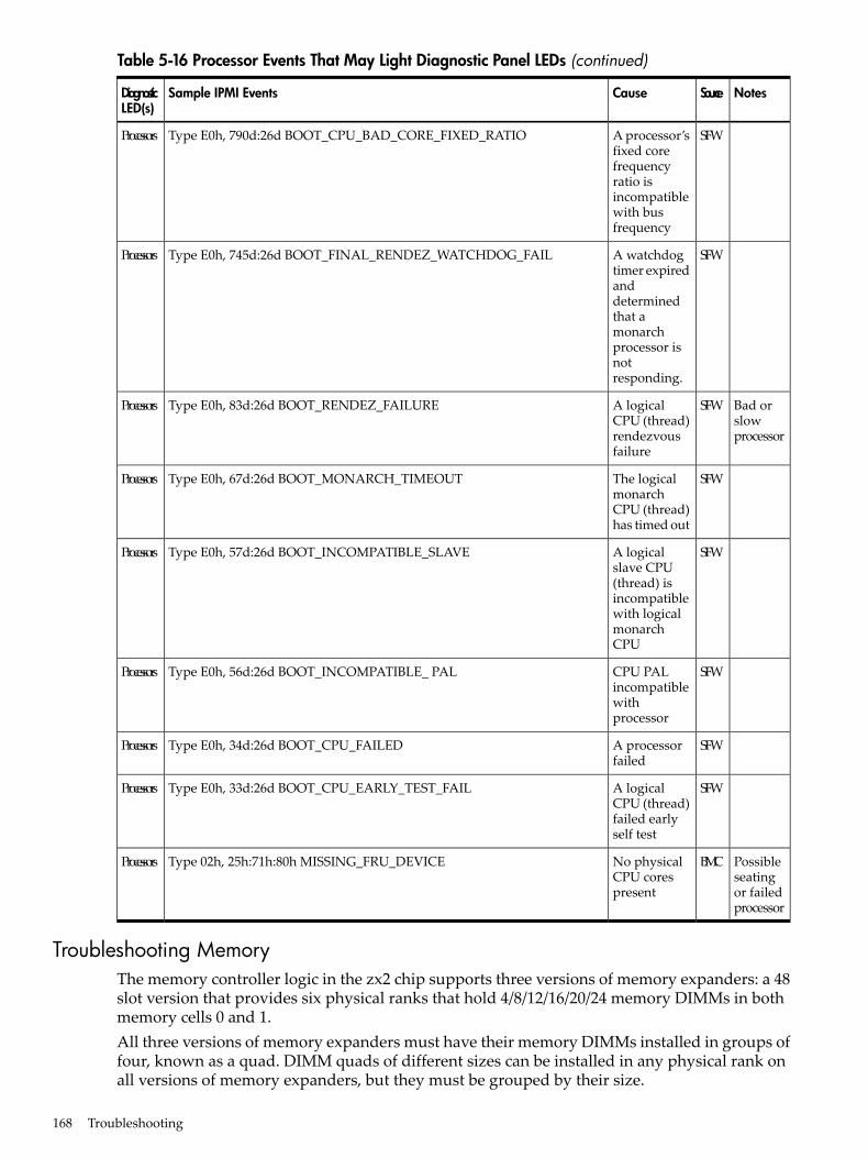
Table 5-16 Processor Events That May Light Diagnostic Panel LEDs (continued)
NotesSourceCauseSample IPMI EventsDiagnosticLED(s)
SFWA processor’sfixed corefrequencyratio isincompatiblewith busfrequency
Type E0h, 790d:26d BOOT_CPU_BAD_CORE_FIXED_RATIOProcessors
SFWA watchdogtimer expiredanddeterminedthat amonarchprocessor isnotresponding.
Type E0h, 745d:26d BOOT_FINAL_RENDEZ_WATCHDOG_FAILProcessors
Bad orslowprocessor
SFWA logicalCPU (thread)rendezvousfailure
Type E0h, 83d:26d BOOT_RENDEZ_FAILUREProcessors
SFWThe logicalmonarchCPU (thread)has timed out
Type E0h, 67d:26d BOOT_MONARCH_TIMEOUTProcessors
SFWA logicalslave CPU(thread) isincompatiblewith logicalmonarchCPU
Type E0h, 57d:26d BOOT_INCOMPATIBLE_SLAVEProcessors
SFWCPU PALincompatiblewithprocessor
Type E0h, 56d:26d BOOT_INCOMPATIBLE_ PALProcessors
SFWA processorfailed
Type E0h, 34d:26d BOOT_CPU_FAILEDProcessors
SFWA logicalCPU (thread)failed earlyself test
Type E0h, 33d:26d BOOT_CPU_EARLY_TEST_FAILProcessors
Possibleseatingor failedprocessor
BMCNo physicalCPU corespresent
Type 02h, 25h:71h:80h MISSING_FRU_DEVICEProcessors
Troubleshooting MemoryThe memory controller logic in the zx2 chip supports three versions of memory expanders: a 48slot version that provides six physical ranks that hold 4/8/12/16/20/24 memory DIMMs in bothmemory cells 0 and 1.All three versions of memory expanders must have their memory DIMMs installed in groups offour, known as a quad. DIMM quads of different sizes can be installed in any physical rank onall versions of memory expanders, but they must be grouped by their size.
168 Troubleshooting
Both the 24 and 48 slot memory expanders support physical memory ranks with four DIMMswhile the common 8 slot memory expander’s memory cells 0 and 1 each support physical rankswith two DIMMs. In the 8 slot memory expander, however, the logical quad of four DIMMsincludes ranks from both sides 0 and 1 running in lock step with each other.
Memory DIMM Load OrderFor a minimally loaded server, four equal-size memory DIMMs must be installed in slots 0A,0B, 0C, and 0D on the same side of the 24/48 slot memory expander; and in the 0A and 0B slotson both 0 and 1 sides of the 8 slot memory expander.The first quad of DIMMs are always loaded into rank 0’s slots for side 0 then in the rank 0’s slotsfor side 1. The next quad of DIMMs are loaded into rank 1’s slots for side 0, then for side 1, andso on, until all ranks slots for both sides are full.Best memory subsystem performance result when both memory sides 0 and 1 have the samenumber of DIMM quads in them.
Memory Subsystem BehaviorsThe zx2 chip in the rx6600 server provides increased reliability of memory DIMMs and memoryexpanders. For example, previous entry class servers with zx1 chips provided error detectionand correction of all memory DIMM single-bit errors and error detection of most multi-bit errorswithin a memory DIMM quad, or 4 bits per rank (this feature is called chip sparing).The zx2 chip doubles memory rank error correction from 4 bytes to 8 bytes of a 128 byte cacheline, during cache line misses initiated by processor cache controllers and by Direct MemoryAccess (DMA) operations initiated by I/O devices. This feature is called double DRAM sparing,as 2 of 72 DRAMs in any DIMM quad can fail without any loss of server performance.Corrective action, DIMM/memory expander replacement, is required when a threshold is reachedfor multiple double-byte errors from one or more memory DIMMs in the same rank. And whenany uncorrectable memory error (more than 2 bytes) or when no quad of like memory DIMMsis loaded in rank 0 of side 0. All other causes of memory DIMM errors are corrected by zx2 andreported to the Page Deallocation Table (PDT) / diagnostic LED panel.
Customer Messaging Policy• Only light a diagnostic LED for memory DIMM errors when isolation is to a specific memory
DIMM. If any uncertainty about a specific DIMM, point customer to the SEL for any actionand do not light the suspect DIMM CRU LED on the diagnostic panel.
• For configuration style errors, for example, no memory DIMMs installed in rank 0 of side0, follow the HP policy of lighting all of the CRU LEDs on the diagnostic LED panel for allof the DIMMs that are missing.
• No diagnostic messages are reported for single-byte errors that are corrected in both zx2caches and memory DIMMs during corrected platform error (CPE) events. Diagnosticmessages are reported for CPE events when thresholds are exceeded for both single-byteand double byte errors; all fatal memory subsystem errors cause global MCA events.
• PDT logs for all double byte errors will be permanent; single byte errors will initially belogged as transient errors. If the server logs 2 single byte errors within 24 hours, upgradethem to permanent in the PDT.
Table 5-17 lists the memory subsystem evens that light the diagnostic panel LEDs.
CPU/Memory/SBA 169
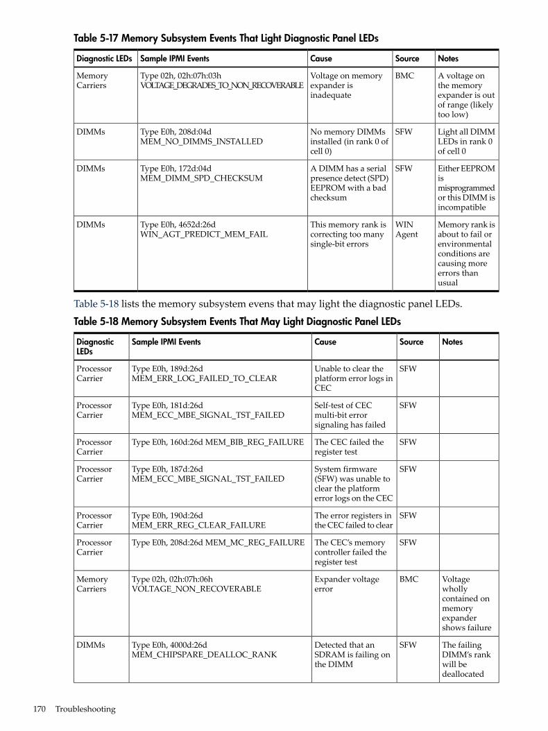
Table 5-17 Memory Subsystem Events That Light Diagnostic Panel LEDs
NotesSourceCauseSample IPMI EventsDiagnostic LEDs
A voltage onthe memoryexpander is outof range (likelytoo low)
BMCVoltage on memoryexpander isinadequate
Type 02h, 02h:07h:03hVOLTAGE_DEGRADES_TO_NON_RECOVERABLE
MemoryCarriers
Light all DIMMLEDs in rank 0of cell 0
SFWNo memory DIMMsinstalled (in rank 0 ofcell 0)
Type E0h, 208d:04dMEM_NO_DIMMS_INSTALLED
DIMMs
Either EEPROMismisprogrammedor this DIMM isincompatible
SFWA DIMM has a serialpresence detect (SPD)EEPROM with a badchecksum
Type E0h, 172d:04dMEM_DIMM_SPD_CHECKSUM
DIMMs
Memory rank isabout to fail orenvironmentalconditions arecausing moreerrors thanusual
WINAgent
This memory rank iscorrecting too manysingle-bit errors
Type E0h, 4652d:26dWIN_AGT_PREDICT_MEM_FAIL
DIMMs
Table 5-18 lists the memory subsystem evens that may light the diagnostic panel LEDs.
Table 5-18 Memory Subsystem Events That May Light Diagnostic Panel LEDs
NotesSourceCauseSample IPMI EventsDiagnosticLEDs
SFWUnable to clear theplatform error logs inCEC
Type E0h, 189d:26dMEM_ERR_LOG_FAILED_TO_CLEAR
ProcessorCarrier
SFWSelf-test of CECmulti-bit errorsignaling has failed
Type E0h, 181d:26dMEM_ECC_MBE_SIGNAL_TST_FAILED
ProcessorCarrier
SFWThe CEC failed theregister test
Type E0h, 160d:26d MEM_BIB_REG_FAILUREProcessorCarrier
SFWSystem firmware(SFW) was unable toclear the platformerror logs on the CEC
Type E0h, 187d:26dMEM_ECC_MBE_SIGNAL_TST_FAILED
ProcessorCarrier
SFWThe error registers inthe CEC failed to clear
Type E0h, 190d:26dMEM_ERR_REG_CLEAR_FAILURE
ProcessorCarrier
SFWThe CEC’s memorycontroller failed theregister test
Type E0h, 208d:26d MEM_MC_REG_FAILUREProcessorCarrier
Voltagewhollycontained onmemoryexpandershows failure
BMCExpander voltageerror
Type 02h, 02h:07h:06hVOLTAGE_NON_RECOVERABLE
MemoryCarriers
The failingDIMM’s rankwill bedeallocated
SFWDetected that anSDRAM is failing onthe DIMM
Type E0h, 4000d:26dMEM_CHIPSPARE_DEALLOC_RANK
DIMMs
170 Troubleshooting
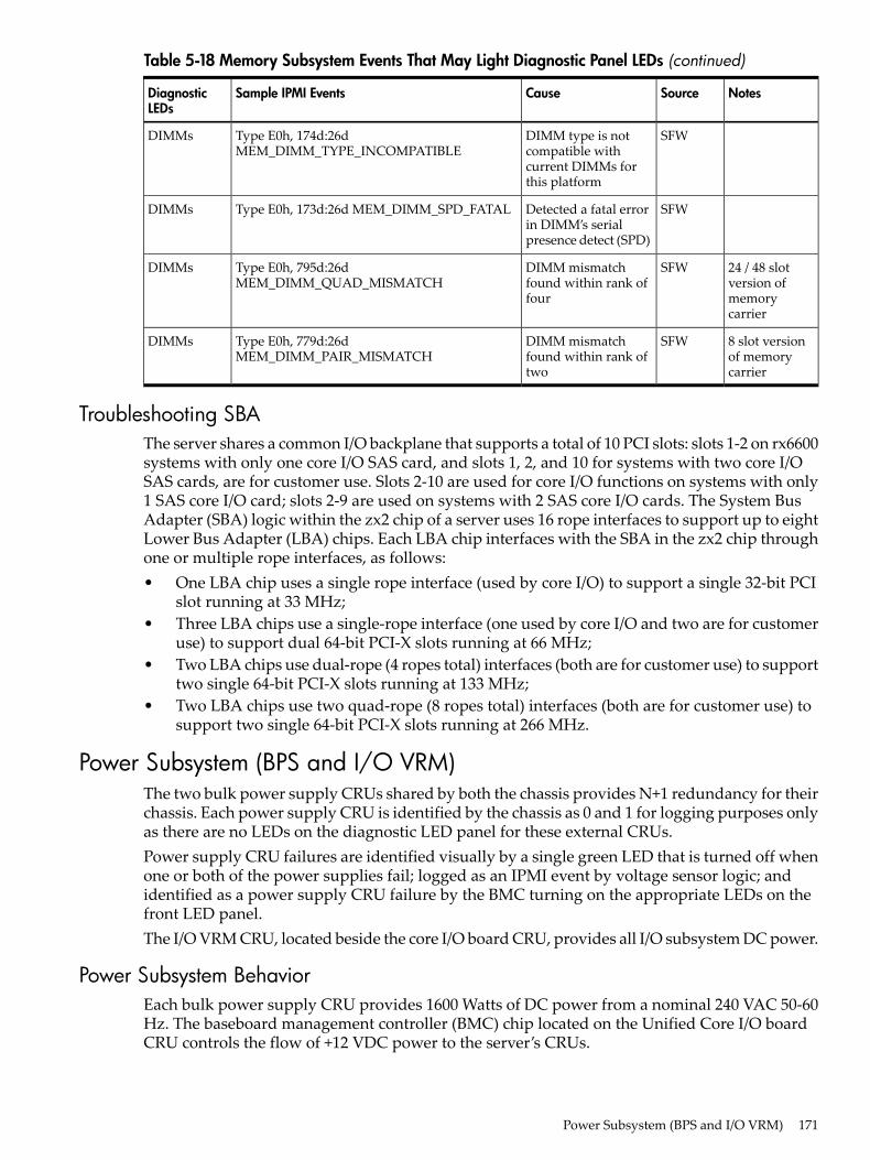
Table 5-18 Memory Subsystem Events That May Light Diagnostic Panel LEDs (continued)
NotesSourceCauseSample IPMI EventsDiagnosticLEDs
SFWDIMM type is notcompatible withcurrent DIMMs forthis platform
Type E0h, 174d:26dMEM_DIMM_TYPE_INCOMPATIBLE
DIMMs
SFWDetected a fatal errorin DIMM’s serialpresence detect (SPD)
Type E0h, 173d:26d MEM_DIMM_SPD_FATALDIMMs
24 / 48 slotversion ofmemorycarrier
SFWDIMM mismatchfound within rank offour
Type E0h, 795d:26dMEM_DIMM_QUAD_MISMATCH
DIMMs
8 slot versionof memorycarrier
SFWDIMM mismatchfound within rank oftwo
Type E0h, 779d:26dMEM_DIMM_PAIR_MISMATCH
DIMMs
Troubleshooting SBAThe server shares a common I/O backplane that supports a total of 10 PCI slots: slots 1-2 on rx6600systems with only one core I/O SAS card, and slots 1, 2, and 10 for systems with two core I/OSAS cards, are for customer use. Slots 2-10 are used for core I/O functions on systems with only1 SAS core I/O card; slots 2-9 are used on systems with 2 SAS core I/O cards. The System BusAdapter (SBA) logic within the zx2 chip of a server uses 16 rope interfaces to support up to eightLower Bus Adapter (LBA) chips. Each LBA chip interfaces with the SBA in the zx2 chip throughone or multiple rope interfaces, as follows:• One LBA chip uses a single rope interface (used by core I/O) to support a single 32-bit PCI
slot running at 33 MHz;• Three LBA chips use a single-rope interface (one used by core I/O and two are for customer
use) to support dual 64-bit PCI-X slots running at 66 MHz;• Two LBA chips use dual-rope (4 ropes total) interfaces (both are for customer use) to support
two single 64-bit PCI-X slots running at 133 MHz;• Two LBA chips use two quad-rope (8 ropes total) interfaces (both are for customer use) to
support two single 64-bit PCI-X slots running at 266 MHz.
Power Subsystem (BPS and I/O VRM)The two bulk power supply CRUs shared by both the chassis provides N+1 redundancy for theirchassis. Each power supply CRU is identified by the chassis as 0 and 1 for logging purposes onlyas there are no LEDs on the diagnostic LED panel for these external CRUs.Power supply CRU failures are identified visually by a single green LED that is turned off whenone or both of the power supplies fail; logged as an IPMI event by voltage sensor logic; andidentified as a power supply CRU failure by the BMC turning on the appropriate LEDs on thefront LED panel.The I/O VRM CRU, located beside the core I/O board CRU, provides all I/O subsystem DC power.
Power Subsystem BehaviorEach bulk power supply CRU provides 1600 Watts of DC power from a nominal 240 VAC 50-60Hz. The baseboard management controller (BMC) chip located on the Unified Core I/O boardCRU controls the flow of +12 VDC power to the server’s CRUs.
Power Subsystem (BPS and I/O VRM) 171
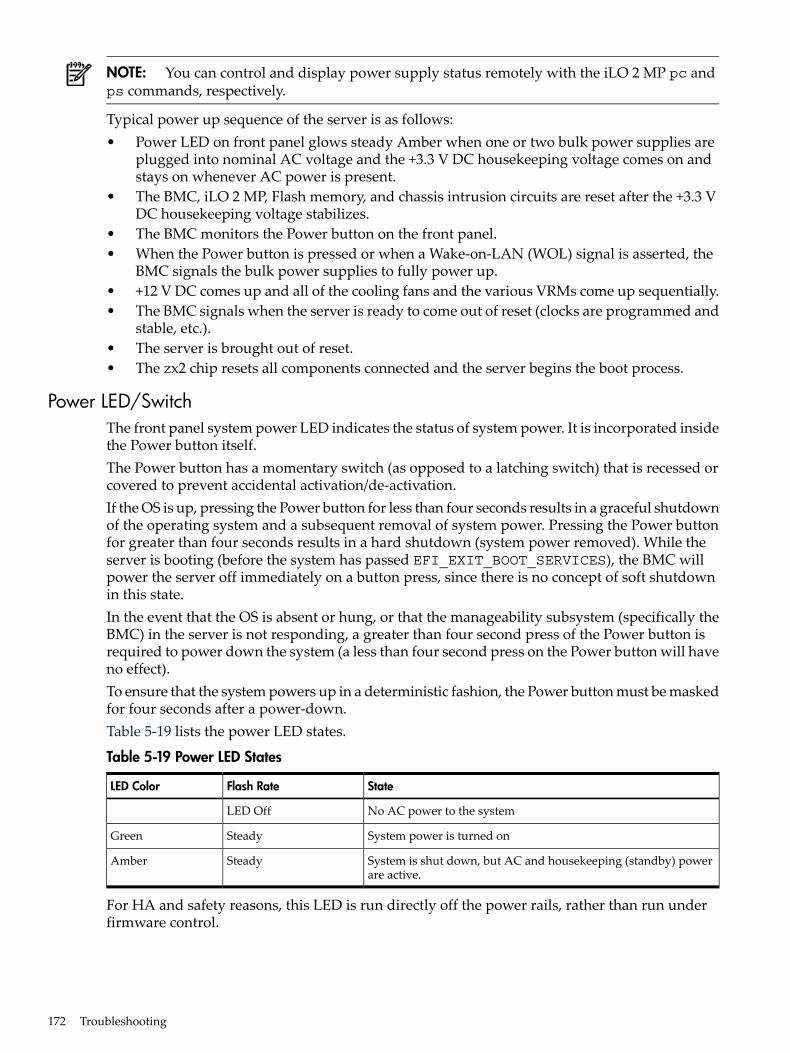
NOTE: You can control and display power supply status remotely with the iLO 2 MP pc andps commands, respectively.
Typical power up sequence of the server is as follows:• Power LED on front panel glows steady Amber when one or two bulk power supplies are
plugged into nominal AC voltage and the +3.3 V DC housekeeping voltage comes on andstays on whenever AC power is present.
• The BMC, iLO 2 MP, Flash memory, and chassis intrusion circuits are reset after the +3.3 VDC housekeeping voltage stabilizes.
• The BMC monitors the Power button on the front panel.• When the Power button is pressed or when a Wake-on-LAN (WOL) signal is asserted, the
BMC signals the bulk power supplies to fully power up.• +12 V DC comes up and all of the cooling fans and the various VRMs come up sequentially.• The BMC signals when the server is ready to come out of reset (clocks are programmed and
stable, etc.).• The server is brought out of reset.• The zx2 chip resets all components connected and the server begins the boot process.
Power LED/SwitchThe front panel system power LED indicates the status of system power. It is incorporated insidethe Power button itself.The Power button has a momentary switch (as opposed to a latching switch) that is recessed orcovered to prevent accidental activation/de-activation.If the OS is up, pressing the Power button for less than four seconds results in a graceful shutdownof the operating system and a subsequent removal of system power. Pressing the Power buttonfor greater than four seconds results in a hard shutdown (system power removed). While theserver is booting (before the system has passed EFI_EXIT_BOOT_SERVICES), the BMC willpower the server off immediately on a button press, since there is no concept of soft shutdownin this state.In the event that the OS is absent or hung, or that the manageability subsystem (specifically theBMC) in the server is not responding, a greater than four second press of the Power button isrequired to power down the system (a less than four second press on the Power button will haveno effect).To ensure that the system powers up in a deterministic fashion, the Power button must be maskedfor four seconds after a power-down.Table 5-19 lists the power LED states.
Table 5-19 Power LED States
StateFlash RateLED Color
No AC power to the systemLED Off
System power is turned onSteadyGreen
System is shut down, but AC and housekeeping (standby) powerare active.
SteadyAmber
For HA and safety reasons, this LED is run directly off the power rails, rather than run underfirmware control.
172 Troubleshooting
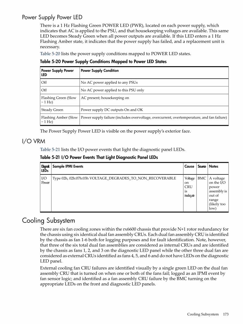
Power Supply Power LEDThere is a 1 Hz Flashing Green POWER LED (PWR), located on each power supply, whichindicates that AC is applied to the PSU, and that housekeeping voltages are available. This sameLED becomes Steady Green when all power outputs are available. If this LED enters a 1 HzFlashing Amber state, it indicates that the power supply has failed, and a replacement unit isnecessary.Table 5-20 lists the power supply conditions mapped to POWER LED states.
Table 5-20 Power Supply Conditions Mapped to Power LED States
Power Supply ConditionPower Supply PowerLED
No AC power applied to any PSUsOff
No AC power applied to this PSU onlyOff
AC present; housekeeping onFlashing Green (Slow~ 1 Hz)
Power supply DC outputs On and OKSteady Green
Power supply failure (includes overvoltage, overcurrent, overtemperature, and fan failure)Flashing Amber (Slow~ 1 Hz)
The Power Supply Power LED is visible on the power supply’s exterior face.
I/O VRMTable 5-21 lists the I/O power events that light the diagnostic panel LEDs.
Table 5-21 I/O Power Events That Light Diagnostic Panel LEDs
NotesSourceCauseSample IPMI EventsDiagnosticLEDs
A voltageon the I/Opowerassembly isout ofrange(likely toolow)
BMCVoltageonCRUisinadequate
Type 02h, 02h:07h:03h VOLTAGE_DEGRADES_TO_NON_RECOVERABLEI/OPower
Cooling SubsystemThere are six fan cooling zones within the rx6600 chassis that provide N+1 rotor redundancy forthe chassis using six identical dual fan assembly CRUs. Each dual fan assembly CRU is identifiedby the chassis as fan 1-6 both for logging purposes and for fault identification. Note, however,that three of the six total dual fan assemblies are considered as internal CRUs and are identifiedby the chassis as fans 1, 2, and 3 on the diagnostic LED panel while the other three dual fan areconsidered as external CRUs identified as fans 4, 5, and 6 and do not have LEDs on the diagnosticLED panel.External cooling fan CRU failures are identified visually by a single green LED on the dual fanassembly CRU that is turned on when one or both of the fans fail; logged as an IPMI event byfan sensor logic; and identified as a fan assembly CRU failure by the BMC turning on theappropriate LEDs on the front and diagnostic LED panels.
Cooling Subsystem 173
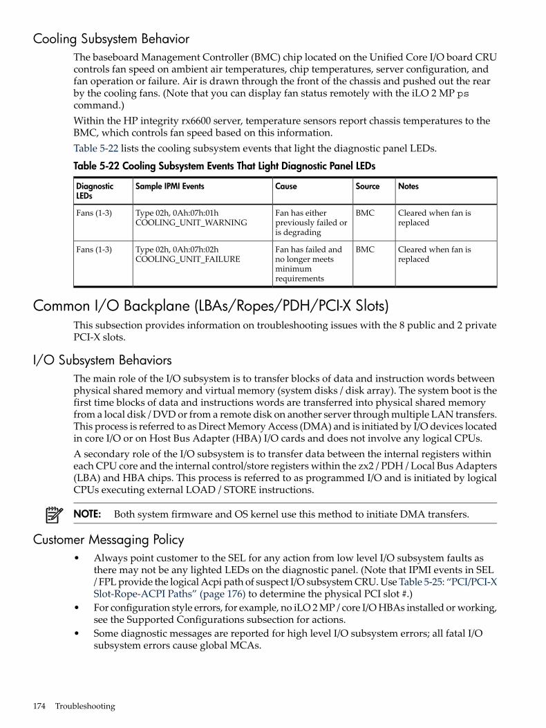
Cooling Subsystem BehaviorThe baseboard Management Controller (BMC) chip located on the Unified Core I/O board CRUcontrols fan speed on ambient air temperatures, chip temperatures, server configuration, andfan operation or failure. Air is drawn through the front of the chassis and pushed out the rearby the cooling fans. (Note that you can display fan status remotely with the iLO 2 MP pscommand.)Within the HP integrity rx6600 server, temperature sensors report chassis temperatures to theBMC, which controls fan speed based on this information.Table 5-22 lists the cooling subsystem events that light the diagnostic panel LEDs.
Table 5-22 Cooling Subsystem Events That Light Diagnostic Panel LEDs
NotesSourceCauseSample IPMI EventsDiagnosticLEDs
Cleared when fan isreplaced
BMCFan has eitherpreviously failed oris degrading
Type 02h, 0Ah:07h:01hCOOLING_UNIT_WARNING
Fans (1-3)
Cleared when fan isreplaced
BMCFan has failed andno longer meetsminimumrequirements
Type 02h, 0Ah:07h:02hCOOLING_UNIT_FAILURE
Fans (1-3)
Common I/O Backplane (LBAs/Ropes/PDH/PCI-X Slots)This subsection provides information on troubleshooting issues with the 8 public and 2 privatePCI-X slots.
I/O Subsystem BehaviorsThe main role of the I/O subsystem is to transfer blocks of data and instruction words betweenphysical shared memory and virtual memory (system disks / disk array). The system boot is thefirst time blocks of data and instructions words are transferred into physical shared memoryfrom a local disk / DVD or from a remote disk on another server through multiple LAN transfers.This process is referred to as Direct Memory Access (DMA) and is initiated by I/O devices locatedin core I/O or on Host Bus Adapter (HBA) I/O cards and does not involve any logical CPUs.A secondary role of the I/O subsystem is to transfer data between the internal registers withineach CPU core and the internal control/store registers within the zx2 / PDH / Local Bus Adapters(LBA) and HBA chips. This process is referred to as programmed I/O and is initiated by logicalCPUs executing external LOAD / STORE instructions.
NOTE: Both system firmware and OS kernel use this method to initiate DMA transfers.
Customer Messaging Policy• Always point customer to the SEL for any action from low level I/O subsystem faults as
there may not be any lighted LEDs on the diagnostic panel. (Note that IPMI events in SEL/ FPL provide the logical Acpi path of suspect I/O subsystem CRU. Use Table 5-25: “PCI/PCI-XSlot-Rope-ACPI Paths” (page 176) to determine the physical PCI slot #.)
• For configuration style errors, for example, no iLO 2 MP / core I/O HBAs installed or working,see the Supported Configurations subsection for actions.
• Some diagnostic messages are reported for high level I/O subsystem errors; all fatal I/Osubsystem errors cause global MCAs.
174 Troubleshooting
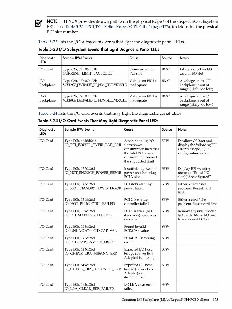
NOTE: HP-UX provides its own path with the physical Rope # of the suspect I/O subsystemFRU. Use Table 5-25: “PCI/PCI-X Slot-Rope-ACPI Paths” (page 176), to determine the physicalPCI slot number.
Table 5-23 lists the I/O subsystem events that light the diagnostic panel LEDs.
Table 5-23 I/O Subsystem Events That Light Diagnostic Panel LEDs
NotesSourceCauseSample IPMI EventsDiagnosticLEDs
Likely a short on I/Ocard or I/O slot.
BMCOver-current onPCI slot
Type 02h, 03h:05h:01hCURRENT_LIMIT_EXCEEDED
I/O Card
A voltage on the I/Obackplane is out ofrange (likely too low)
BMCVoltage on FRU isinadequate
Type 02h, 02h:07h:03hVOLTAGE_DEGRADES_TO_NON_RECOVERABLE
I/OBackplane
A voltage on the I/Obackplane is out ofrange (likely too low)
BMCVoltage on FRU isinadequate
Type 02h, 02h:07h:03hVOLTAGE_DEGRADES_TO_NON_RECOVERABLE
DiskBackplane
Table 5-24 lists the I/O card events that may light the diagnostic panel LEDs.
Table 5-24 I/O Card Events That May Light Diagnostic Panel LEDs
NotesSourceCauseSample IPMI EventsDiagnosticLEDs
Disallow OS boot anddisplay the following EFIerror message, “I/Oconfiguration exceed
SFWA non hot plug I/Oslot’s powerconsumption increasesthe total I/O powerconsumption beyondthe supported limit
Type E0h, 4658d:26dIO_PCI_POWER_OVERLOAD_ERR
I/O Card
Display EFI warningmessage “Failed I/Oslot(s) deconfigured”
SFWInsufficient power topower on a hot-plugPCI-X slot
Type E0h, 137d:26dIO_NOT_ENOUGH_POWER_ERROR
I/O Card
Either a card / slotproblem. Reseat cardfirst.
SFWPCI slot’s standbypower failed
Type E0h, 147d:26dIO_SLOT_STANDBY_POWER_ERROR
I/O Card
Either a card / slotproblem. Reseat card first
SFWPCI-X hot-plugcontroller failed
Type E0h, 131d:26dIO_HOT_PLUG_CTRL_FAILED
I/O Card
Remove any unsupportedI/O cards. Move I/O cardto an unused PCI slot
SFWPCI bus walk (I/Odiscovery) resourcesexceeded
Type E0h, 139d:26dIO_PCI_MAPPING_TOO_BIG
I/O Card
SFWFound invalidPCIXCAP value
Type E0h, 148d:26dIO_UNKNOWN_PCIXCAP_VAL
I/O Card
SFWPCIXCAP samplingerror
Type E0h, 141d:26dIO_PCIXCAP_SAMPLE_ERROR
I/O Card
SFWExpected I/O hostbridge (Lower BusAdapter) is missing
Type E0h, 123d:26dIO_CHECK_LBA_MISSING_ERR
I/O Card
SFWExpected I/O hostbridge (Lower BusAdapter) isdeconfigured
Type E0h, 619d:26dIO_CHECK_LBA_DECONFIG_ERR
I/O Card
SFWI/O LBA clear errorfailed
Type E0h, 133d:26dIO_LBA_CLEAR_ERR_FAILED
I/O Card
Common I/O Backplane (LBAs/Ropes/PDH/PCI-X Slots) 175
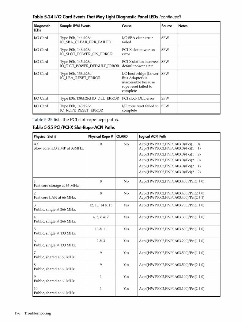
Table 5-24 I/O Card Events That May Light Diagnostic Panel LEDs (continued)
NotesSourceCauseSample IPMI EventsDiagnosticLEDs
SFWI/O SBA clear errorfailed
Type E0h, 144d:26dIO_SBA_CLEAR_ERR_FAILED
I/O Card
SFWPCI-X slot power onerror
Type E0h, 146d:26dIO_SLOT_POWER_ON_ERROR
I/O Card
SFWPCI-X slot has incorrectdefault power state
Type E0h, 145d:26dIO_SLOT_POWER_DEFAULT_ERROR
I/O Card
SFWI/O host bridge (LowerBus Adapter) isinaccessible becauserope reset failed tocomplete
Type E0h, 136d:26dIO_LBA_RESET_ERROR
I/O Card
SFWPCI clock DLL errorType E0h, 130d:26d IO_DLL_ERRORI/O Card
SFWI/O rope reset failed tocomplete
Type E0h, 143d:26dIO_ROPE_RESET_ERROR
I/O Card
Table 5-25 lists the PCI slot-rope-acpi paths.
Table 5-25 PCI/PCI-X Slot-Rope-ACPI Paths
Logical ACPI PathOLARDPhysical Rope #Physical Slot #
Acpi(HWP0002,PNP0A03,0)/Pci(1 |0)Acpi(HWP0002,PNP0A03,0)/Pci(1 | 1)Acpi(HWP0002,PNP0A03,0)/Pci(1 | 2)Acpi(HWP0002,PNP0A03,0)/Pci(2 | 0)Acpi(HWP0002,PNP0A03,0)/Pci(2 | 1)Acpi(HWP0002,PNP0A03,0)/Pci(2 | 2)
No0XXSlow core iLO 2 MP at 33MHz.
Acpi(HWP0002,PNP0A03,400)/Pci(1 | 0)No81Fast core storage at 66 MHz.
Acpi(HWP0002,PNP0A03,400)/Pci(2 | 0)Acpi(HWP0002,PNP0A03,400)/Pci(2 | 1)
No82Fast core LAN at 66 MHz.
Acpi(HWP0002,PNP0A03,700)/Pci(1 | 0)Yes12, 13, 14 & 153Public, single at 266 MHz.
Acpi(HWP0002,PNP0A03,300)/Pci(1 | 0)Yes4, 5, 6 & 74Public, single at 266 MHz.
Acpi(HWP0002,PNP0A03,600)/Pci(1 | 0)Yes10 & 115Public, single at 133 MHz.
Acpi(HWP0002,PNP0A03,200)/Pci(1 | 0)Yes2 & 36Public, single at 133 MHz.
Acpi(HWP0002,PNP0A03,500)/Pci(1 | 0)Yes97Public, shared at 66 MHz.
Acpi(HWP0002,PNP0A03,500)/Pci(2 | 0)Yes98Public, shared at 66 MHz.
Acpi(HWP0002,PNP0A03,100)/Pci(1 | 0)Yes19Public, shared at 66 MHz.
Acpi(HWP0002,PNP0A03,100)/Pci(2 | 0)Yes110Public, shared at 66 MHz.
176 Troubleshooting
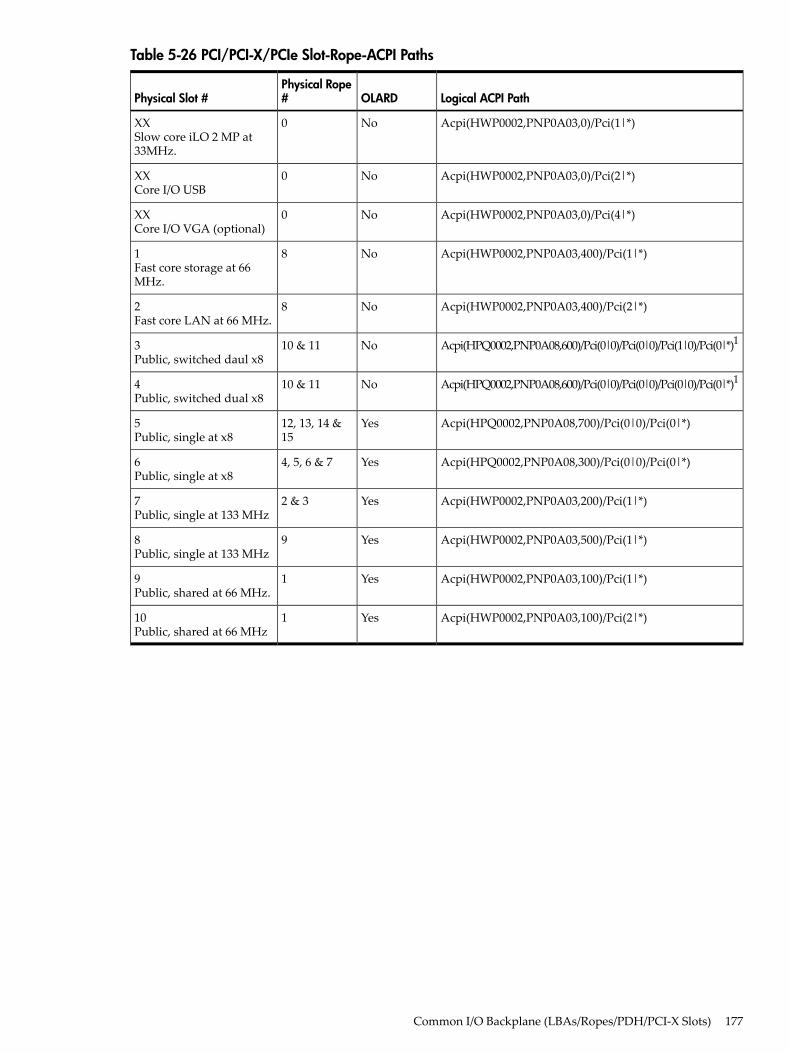
Table 5-26 PCI/PCI-X/PCIe Slot-Rope-ACPI Paths
Logical ACPI PathOLARDPhysical Rope#Physical Slot #
Acpi(HWP0002,PNP0A03,0)/Pci(1|*)No0XXSlow core iLO 2 MP at33MHz.
Acpi(HWP0002,PNP0A03,0)/Pci(2|*)No0XXCore I/O USB
Acpi(HWP0002,PNP0A03,0)/Pci(4|*)No0XXCore I/O VGA (optional)
Acpi(HWP0002,PNP0A03,400)/Pci(1|*)No81Fast core storage at 66MHz.
Acpi(HWP0002,PNP0A03,400)/Pci(2|*)No82Fast core LAN at 66 MHz.
Acpi(HPQ0002,PNP0A08,600)/Pci(0|0)/Pci(0|0)/Pci(1|0)/Pci(0|*)1No10 & 113Public, switched daul x8
Acpi(HPQ0002,PNP0A08,600)/Pci(0|0)/Pci(0|0)/Pci(0|0)/Pci(0|*)1No10 & 114Public, switched dual x8
Acpi(HPQ0002,PNP0A08,700)/Pci(0|0)/Pci(0|*)Yes12, 13, 14 &15
5Public, single at x8
Acpi(HPQ0002,PNP0A08,300)/Pci(0|0)/Pci(0|*)Yes4, 5, 6 & 76Public, single at x8
Acpi(HWP0002,PNP0A03,200)/Pci(1|*)Yes2 & 37Public, single at 133 MHz
Acpi(HWP0002,PNP0A03,500)/Pci(1|*)Yes98Public, single at 133 MHz
Acpi(HWP0002,PNP0A03,100)/Pci(1|*)Yes19Public, shared at 66 MHz.
Acpi(HWP0002,PNP0A03,100)/Pci(2|*)Yes110Public, shared at 66 MHz
Common I/O Backplane (LBAs/Ropes/PDH/PCI-X Slots) 177
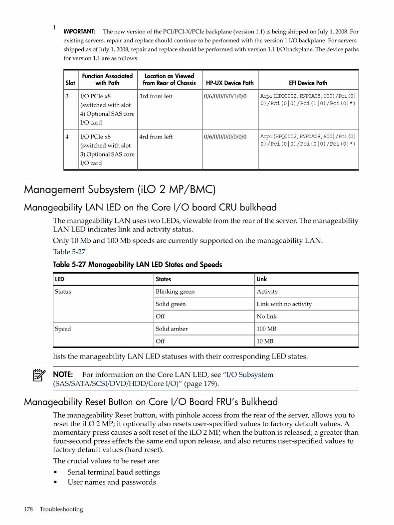
1IMPORTANT: The new version of the PCI/PCI-X/PCIe backplane (version 1.1) is being shipped on July 1, 2008. Forexisting servers, repair and replace should continue to be performed with the version 1 I/O backplane. For serversshipped as of July 1, 2008, repair and replace should be performed with version 1.1 I/O backplane. The device pathsfor version 1.1 are as follows.
EFI Device PathHP-UX Device PathLocation as Viewedfrom Rear of Chassis
Function Associatedwith PathSlot
Acpi(HPQ0002,PNP0A08,600)/Pci(0|0)/Pci(0|0)/Pci(1|0)/Pci(0|*)
0/6/0/0/0/0/1/0/03rd from leftI/O PCIe x8(switched with slot4) Optional SAS coreI/O card
3
Acpi(HPQ0002,PNP0A08,600)/Pci(0|0)/Pci(0|0)/Pci(0|0)/Pci(0|*)
0/6/0/0/0/0/0/0/04rd from leftI/O PCIe x8(switched with slot3) Optional SAS coreI/O card
4
Management Subsystem (iLO 2 MP/BMC)
Manageability LAN LED on the Core I/O board CRU bulkheadThe manageability LAN uses two LEDs, viewable from the rear of the server. The manageabilityLAN LED indicates link and activity status.Only 10 Mb and 100 Mb speeds are currently supported on the manageability LAN.Table 5-27
Table 5-27 Manageability LAN LED States and Speeds
LinkStatesLED
ActivityBlinking greenStatus
Link with no activitySolid green
No linkOff
100 MBSolid amberSpeed
10 MBOff
lists the manageability LAN LED statuses with their corresponding LED states.
NOTE: For information on the Core LAN LED, see “I/O Subsystem(SAS/SATA/SCSI/DVD/HDD/Core I/O)” (page 179).
Manageability Reset Button on Core I/O Board FRU’s BulkheadThe manageability Reset button, with pinhole access from the rear of the server, allows you toreset the iLO 2 MP; it optionally also resets user-specified values to factory default values. Amomentary press causes a soft reset of the iLO 2 MP, when the button is released; a greater thanfour-second press effects the same end upon release, and also returns user-specified values tofactory default values (hard reset).The crucial values to be reset are:• Serial terminal baud settings• User names and passwords
178 Troubleshooting
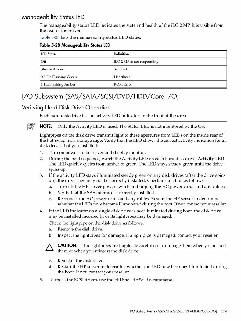
Manageability Status LEDThe manageability status LED indicates the state and health of the iLO 2 MP. It is visible fromthe rear of the server.Table 5-28 lists the manageability status LED states.
Table 5-28 Manageability Status LED
DefinitionLED State
iLO 2 MP is not respondingOff
Self TestSteady Amber
Heartbeat0.5 Hz Flashing Green
ROM Error1 Hz Flashing Amber
I/O Subsystem (SAS/SATA/SCSI/DVD/HDD/Core I/O)
Verifying Hard Disk Drive OperationEach hard disk drive has an activity LED indicator on the front of the drive.
NOTE: Only the Activity LED is used. The Status LED is not monitored by the OS.
Lightpipes on the disk drive transmit light to these apertures from LEDs on the inside rear ofthe hot-swap mass storage cage. Verify that the LED shows the correct activity indication for alldisk drives that you installed:1. Turn on power to the server and display monitor.2. During the boot sequence, watch the Activity LED on each hard disk drive: Activity LED:
The LED quickly cycles from amber to green. The LED stays steady green until the drivespins up.
3. If the activity LED stays illuminated steady green on any disk drives (after the drive spinsup), the drive cage may not be correctly installed. Check installation as follows:a. Turn off the HP server power switch and unplug the AC power cords and any cables.b. Verify that the SAS interface is correctly installed.c. Reconnect the AC power cords and any cables. Restart the HP server to determine
whether the LEDs now become illuminated during the boot. If not, contact your reseller.4. If the LED indicator on a single disk drive is not illuminated during boot, the disk drive
may be installed incorrectly, or its lightpipes may be damaged.Check the lightpipe on the disk drive as follows:a. Remove the disk drive.b. Inspect the lightpipes for damage. If a lightpipe is damaged, contact your reseller.
CAUTION: The lightpipes are fragile. Be careful not to damage them when you inspectthem or when you reinsert the disk drive.
c. Reinstall the disk drive.d. Restart the HP server to determine whether the LED now becomes illuminated during
the boot. If not, contact your reseller.
5. To check the SCSI drives, use the EFI Shell info io command.
I/O Subsystem (SAS/SATA/SCSI/DVD/HDD/Core I/O) 179
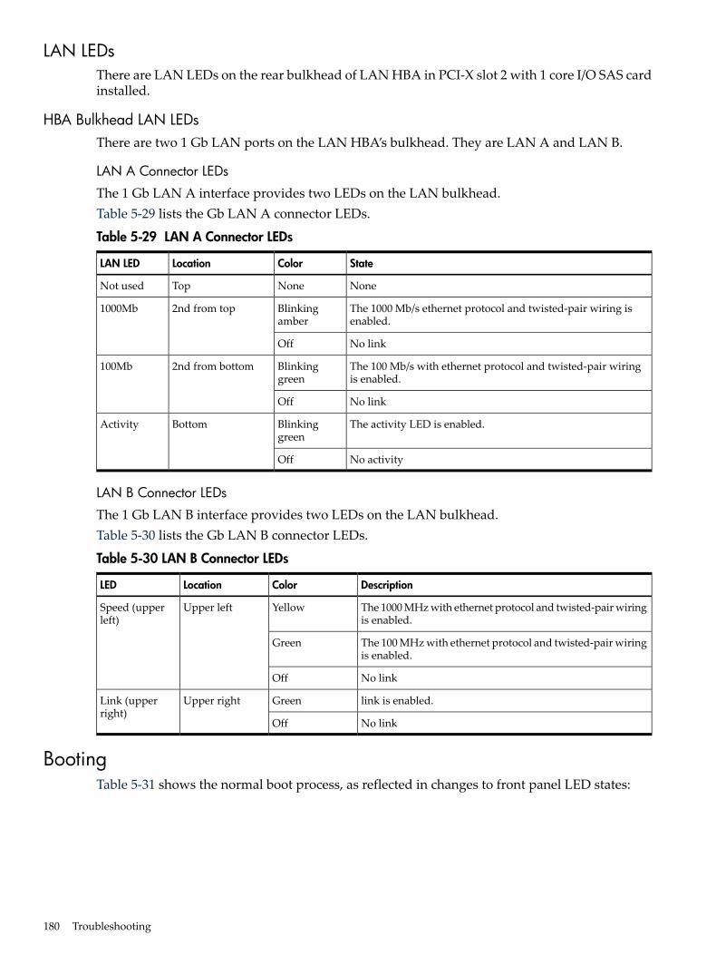
LAN LEDsThere are LAN LEDs on the rear bulkhead of LAN HBA in PCI-X slot 2 with 1 core I/O SAS cardinstalled.
HBA Bulkhead LAN LEDsThere are two 1 Gb LAN ports on the LAN HBA’s bulkhead. They are LAN A and LAN B.
LAN A Connector LEDs
The 1 Gb LAN A interface provides two LEDs on the LAN bulkhead.Table 5-29 lists the Gb LAN A connector LEDs.
Table 5-29 LAN A Connector LEDs
StateColorLocationLAN LED
NoneNoneTopNot used
The 1000 Mb/s ethernet protocol and twisted-pair wiring isenabled.
Blinkingamber
2nd from top1000Mb
No linkOff
The 100 Mb/s with ethernet protocol and twisted-pair wiringis enabled.
Blinkinggreen
2nd from bottom100Mb
No linkOff
The activity LED is enabled.Blinkinggreen
BottomActivity
No activityOff
LAN B Connector LEDs
The 1 Gb LAN B interface provides two LEDs on the LAN bulkhead.Table 5-30 lists the Gb LAN B connector LEDs.
Table 5-30 LAN B Connector LEDs
DescriptionColorLocationLED
The 1000 MHz with ethernet protocol and twisted-pair wiringis enabled.
YellowUpper leftSpeed (upperleft)
The 100 MHz with ethernet protocol and twisted-pair wiringis enabled.
Green
No linkOff
link is enabled.GreenUpper rightLink (upperright)
No linkOff
BootingTable 5-31 shows the normal boot process, as reflected in changes to front panel LED states:
180 Troubleshooting
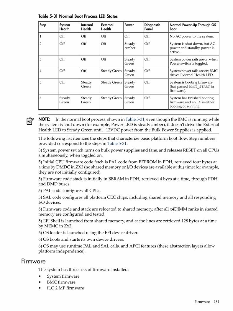
Table 5-31 Normal Boot Process LED States
Normal Power-Up Through OSBoot
DiagnosticPanel
PowerExternalHealth
InternalHealth
SystemHealth
Step
No AC power to the system.OffOffOffOffOff1
System is shut down, but ACpower and standby power isactive.
OffSteadyAmber
OffOffOff2
System power rails are on whenPower switch is toggled.
OffSteadyGreen
OffOffOff3
System power rails are on; BMCdrives External Health LED.
OffSteadyGreen
Steady GreenOffOff4
System is booting firmware(has passed BOOT_START infirmware).
OffSteadyGreen
Steady GreenSteadyGreen
Off5
System has finished bootingfirmware and an OS is eitherbooting or running.
OffSteadyGreen
Steady GreenSteadyGreen
SteadyGreen
6
NOTE: In the normal boot process, shown in Table 5-31, even though the BMC is running whilethe system is shut down (for example, Power LED is steady amber), it doesn’t drive the ExternalHealth LED to Steady Green until +12VDC power from the Bulk Power Supplies is applied.
The following list itemizes the steps that characterize basic platform boot flow. Step numbersprovided correspond to the steps in Table 5-31:3) System power switch turns on bulk power supplies and fans, and releases RESET on all CPUssimultaneously, when toggled on.5) Initial CPU firmware code fetch is PAL code from EEPROM in PDH, retrieved four bytes ata time by DMDC in ZX2 (no shared memory or I/O devices are available at this time; for example,they are not initially configured).5) Firmware code stack is initially in BBRAM in PDH, retrieved 4 byes at a time, through PDHand DMD buses.5) PAL code configures all CPUs.5) SAL code configures all platform CEC chips, including shared memory and all respondingI/O devices.5) Firmware code and stack are relocated to shared memory, after all x4DIMM ranks in sharedmemory are configured and tested.5) EFI Shell is launched from shared memory, and cache lines are retrieved 128 bytes at a timeby MEMC in Zx2.6) OS loader is launched using the EFI device driver.6) OS boots and starts its own device drivers.6) OS may use runtime PAL and SAL calls, and APCI features (these abstraction layers allowplatform independence).
FirmwareThe system has three sets of firmware installed:• System firmware• BMC firmware• iLO 2 MP firmware
Firmware 181
All firmware (SFW, BMC, iLO 2 MP, and so on.) must be from the same release. Independentupdates are not supported. Details about a specific release are available in the associated ReleaseNotes.Firmware updates are available at:http://www.hp.com under “Support and Drivers”.
Identifying and Troubleshooting Firmware ProblemsErratic system operation, or the fact that the server may not boot successfully to the EFI BootManager or to the EFI Shell, are symptoms of possible firmware problems.It should be noted that problems due to firmware are relatively rare, and you should look forother problem causes first.If you are dealing with a firmware problem, the probable failure areas are:• Unsupported firmware installation• Corrupt firmware installationTo troubleshoot firmware problems:1. Verify that all system and BMC firmware components are from the same release (use the
iLO 2 MPsr command).2. Reinstall all firmware.
UpdatesYour system has an EFI utility for updating your system, BMC, and iLO 2 MP firmware. Thisutility’s name is fwupdate.efiTo update your firmware, follow these steps:1. Start up the system and get to the EFI command prompt.2. Execute the following EFI command at the EFI Shell prompt, to determine the current
firmware version: Shell> info fw
3. Look for the latest firmware updates at http://www.hp.com. If a new version of the firmwareis available, download it and save it to CD, or copy it over the network to the system youare going to update
4. On the system you are updating, execute the fwupdate.efi command from the EFIcommand prompt, in the following manner: fweupdate -f <xxx>.binwhere <xxx> is the firmware version number for the firmware you need to install
The iLO 2 MP firmware can be updated in three ways:1. Using the same utilities that are used by system firmware and the BMC.2. Initiating a firmware upgrade from the iLO 2 MP user interface; the iLO 2 MP pulls its image
from the FTP server that you specify.3. Initiating a firmware upgrade from the HP System Insight Manager (SIM) as a “Group
Action”.
Server Interface (System Console)All system console connections (VGA, USB, local RS-232 and iLO 2 MP LAN) are located on thebulkhead of the core I/O board FRU at the rear of the chassis.HP-UX uses the RS-232 serial text connection to a (dumb) terminal or terminal emulator softwarerunning on a PC to control server operations locally.HP-UX alternatively uses the iLO 2 MP LAN connection over a private network to control serveroperations locally using telnet or SSH, and remotely over a public network through the webGUI.
182 Troubleshooting
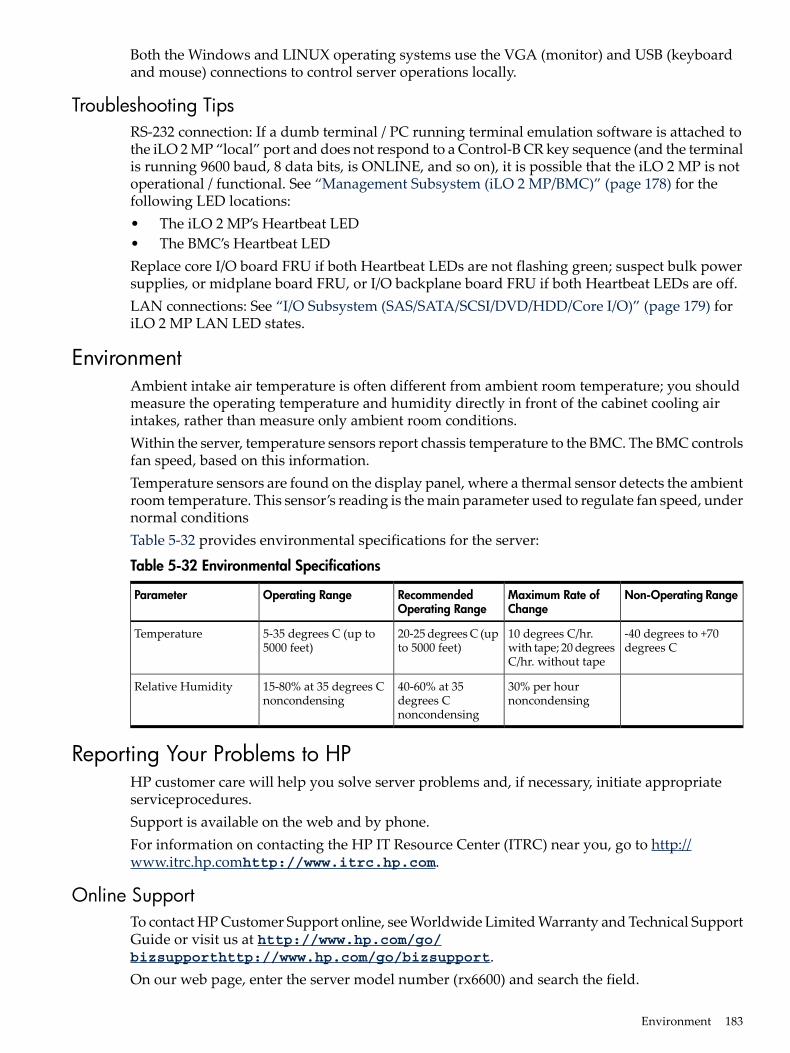
Both the Windows and LINUX operating systems use the VGA (monitor) and USB (keyboardand mouse) connections to control server operations locally.
Troubleshooting TipsRS-232 connection: If a dumb terminal / PC running terminal emulation software is attached tothe iLO 2 MP “local” port and does not respond to a Control-B CR key sequence (and the terminalis running 9600 baud, 8 data bits, is ONLINE, and so on), it is possible that the iLO 2 MP is notoperational / functional. See “Management Subsystem (iLO 2 MP/BMC)” (page 178) for thefollowing LED locations:• The iLO 2 MP’s Heartbeat LED• The BMC’s Heartbeat LEDReplace core I/O board FRU if both Heartbeat LEDs are not flashing green; suspect bulk powersupplies, or midplane board FRU, or I/O backplane board FRU if both Heartbeat LEDs are off.LAN connections: See “I/O Subsystem (SAS/SATA/SCSI/DVD/HDD/Core I/O)” (page 179) foriLO 2 MP LAN LED states.
EnvironmentAmbient intake air temperature is often different from ambient room temperature; you shouldmeasure the operating temperature and humidity directly in front of the cabinet cooling airintakes, rather than measure only ambient room conditions.Within the server, temperature sensors report chassis temperature to the BMC. The BMC controlsfan speed, based on this information.Temperature sensors are found on the display panel, where a thermal sensor detects the ambientroom temperature. This sensor’s reading is the main parameter used to regulate fan speed, undernormal conditionsTable 5-32 provides environmental specifications for the server:
Table 5-32 Environmental Specifications
Non-Operating RangeMaximum Rate ofChange
RecommendedOperating Range
Operating RangeParameter
-40 degrees to +70degrees C
10 degrees C/hr.with tape; 20 degreesC/hr. without tape
20-25 degrees C (upto 5000 feet)
5-35 degrees C (up to5000 feet)
Temperature
30% per hournoncondensing
40-60% at 35degrees Cnoncondensing
15-80% at 35 degrees Cnoncondensing
Relative Humidity
Reporting Your Problems to HPHP customer care will help you solve server problems and, if necessary, initiate appropriateserviceprocedures.Support is available on the web and by phone.For information on contacting the HP IT Resource Center (ITRC) near you, go to http://www.itrc.hp.comhttp://www.itrc.hp.com.
Online SupportTo contact HP Customer Support online, see Worldwide Limited Warranty and Technical SupportGuide or visit us at http://www.hp.com/go/bizsupporthttp://www.hp.com/go/bizsupport.On our web page, enter the server model number (rx6600) and search the field.
Environment 183
The following information is available on this website:• Software and firmware updates• The latest drivers and utilities• Additional documentation
Phone SupportTo contact HP customer support by phone, go to the HP IT Resource Center (ITRC) near you, athttp://www.itrc.hp.comhttp://www.itrc.hp.com.Local phone numbers are listed in your native language for help.
Information to Collect Before you Contact Support
NOTE: It is highly recommended that you keep detailed records of any changes to your system,and of how system behavior has changed over time, or as a result of changes made to yoursystem.
Before you contact HP support, you should:1. Check the previous sections of this chapter and attempt to solve the problem.
• Note failure symptoms and error indications (LEDs and messages).• Capture and permanently log the current SEL and FPL contents.• Try to determine precisely what did or did not happen.
2. Collect the following information:• The model number of your server (for example, rx6600).• The product number of your server. This can be found on the identification label, which
is found at the front of the unit.• The serial number of your server. This can be found on the identification label.
3. Be familiar with your system configuration.• Are you using the LAN, RS232, or web interface to monitor the server?• How many processors, DIMMs, and PCI cards have been installed?• What versions of processor, memory, and PCI cards are used and where are they
installed?• What accessories are installed?
4. Determine the following• Which firmware versions are in use?• When did the problem start?• Have recent changes been made to the system?• Which OS and version is in use?
184 Troubleshooting
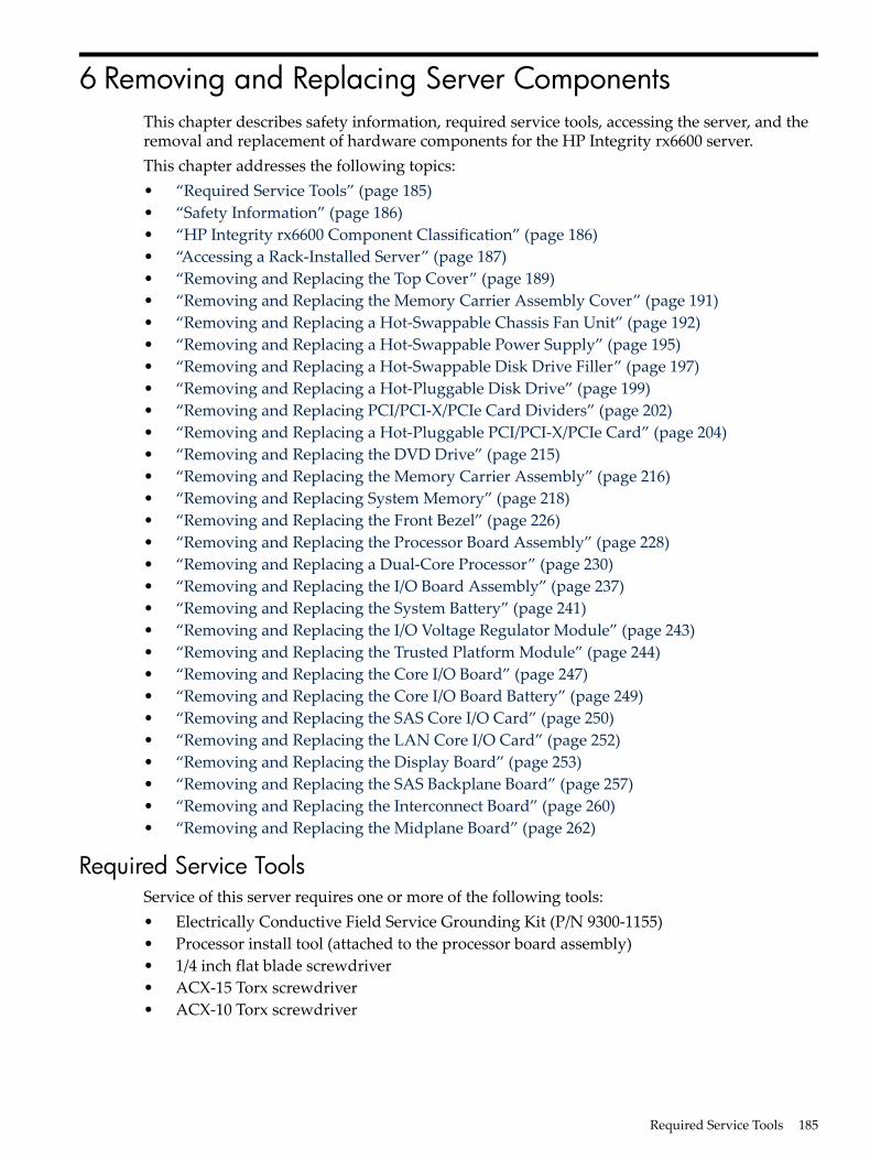
6 Removing and Replacing Server ComponentsThis chapter describes safety information, required service tools, accessing the server, and theremoval and replacement of hardware components for the HP Integrity rx6600 server.This chapter addresses the following topics:• “Required Service Tools” (page 185)• “Safety Information” (page 186)• “HP Integrity rx6600 Component Classification” (page 186)• “Accessing a Rack-Installed Server” (page 187)• “Removing and Replacing the Top Cover” (page 189)• “Removing and Replacing the Memory Carrier Assembly Cover” (page 191)• “Removing and Replacing a Hot-Swappable Chassis Fan Unit” (page 192)• “Removing and Replacing a Hot-Swappable Power Supply” (page 195)• “Removing and Replacing a Hot-Swappable Disk Drive Filler” (page 197)• “Removing and Replacing a Hot-Pluggable Disk Drive” (page 199)• “Removing and Replacing PCI/PCI-X/PCIe Card Dividers” (page 202)• “Removing and Replacing a Hot-Pluggable PCI/PCI-X/PCIe Card” (page 204)• “Removing and Replacing the DVD Drive” (page 215)• “Removing and Replacing the Memory Carrier Assembly” (page 216)• “Removing and Replacing System Memory” (page 218)• “Removing and Replacing the Front Bezel” (page 226)• “Removing and Replacing the Processor Board Assembly” (page 228)• “Removing and Replacing a Dual-Core Processor” (page 230)• “Removing and Replacing the I/O Board Assembly” (page 237)• “Removing and Replacing the System Battery” (page 241)• “Removing and Replacing the I/O Voltage Regulator Module” (page 243)• “Removing and Replacing the Trusted Platform Module” (page 244)• “Removing and Replacing the Core I/O Board” (page 247)• “Removing and Replacing the Core I/O Board Battery” (page 249)• “Removing and Replacing the SAS Core I/O Card” (page 250)• “Removing and Replacing the LAN Core I/O Card” (page 252)• “Removing and Replacing the Display Board” (page 253)• “Removing and Replacing the SAS Backplane Board” (page 257)• “Removing and Replacing the Interconnect Board” (page 260)• “Removing and Replacing the Midplane Board” (page 262)
Required Service ToolsService of this server requires one or more of the following tools:• Electrically Conductive Field Service Grounding Kit (P/N 9300-1155)• Processor install tool (attached to the processor board assembly)• 1/4 inch flat blade screwdriver• ACX-15 Torx screwdriver• ACX-10 Torx screwdriver
Required Service Tools 185
Safety InformationUse care to prevent injury and equipment damage when removing and replacing servercomponents. Voltages can be present within the server. Many assemblies are sensitive to damageby electrostatic discharge (ESD).Follow the safety conventions listed below to ensure safe handling of components, to preventinjury, and to prevent damage to the server:• When removing or installing any server component, follow the instructions provided in this
guide.• If installing a hot-swappable or hot-pluggable component when power is applied (fans are
running), reinstall the server cover immediately to prevent overheating.• If installing a hot-pluggable component, complete the required software intervention prior
to removing the component.• If installing an assembly that is neither hot-swappable nor hot-pluggable, disconnect the
power cable from the external server power receptacle.
WARNING! Ensure that the system is powered off and all power sources are disconnectedfrom the server prior to removing or installing server hardware (unless you are removingor installing a hot-swappable or hot-pluggable component).Voltages are present at various locations within the server whenever an AC power sourceis connected. This voltage is present even when the main power switch is turned off.Failure to observe this warning can result in personal injury or damage to equipment.
• Do not wear loose clothing that can snag or catch on the server or on other items.• Do not wear clothing subject to static charge buildup, such as wool or synthetic materials.• If installing an internal assembly, wear an antistatic wrist strap and use a grounding mat,
such as those included in the Electrically Conductive Field Service Grounding Kit (HP9300-1155).
• Handle accessory boards and components by the edges only. Do not touch any metal-edgeconnectors or any electrical components on accessory boards.
HP Integrity rx6600 Component ClassificationThe server components are classified into three major categories:• Hot-swappable• Hot-pluggable• Cold-swappableA brief explanation of each category and the classifications for the server components follow.
Hot-Swappable ComponentsA component is defined as hot-swappable if you can remove it from the chassis while the serverremains operational. Hot-swappable components require no software intervention prior toremoving the component.
NOTE: Hot-swappable components are marked with red touch points.
The following are hot-swappable components:• Fan units• Power supplies• Disk drive fillers
186 Removing and Replacing Server Components
Hot-Pluggable ComponentsA component is defined as hot-pluggable if you can remove it from the chassis while the serverremains operational. Software intervention is required prior to removing a hot-pluggablecomponent.
NOTE: Hot-pluggable components are marked with red touch points.
The following are hot-pluggable components:• Disk drives• PCI/PCI-X/PCIe cards
Cold-Swappable ComponentsTo remove and replace cold-swappable components, or components that are neither hot-swappablenor hot-pluggable, shut down the operating system, power off the server, and disconnect theAC power cable. For complete instructions on shutting down the operating system and poweringoff the server, see Chapter 4 (page 125).
NOTE: Cold-swappable components are marked with blue touch points.
The following are cold-swappable components:• Front bezel• DVD drive• Memory carrier assembly• Memory DIMMs• Processor board assembly• Dual-core processors• I/O board assembly• System battery• I/O voltage regulator module• Trusted Platform Module• PCI/PCI-X card divider• Core I/O board• Core I/O board battery• SAS core I/O card• LAN core I/O card• Doorbell board• Display board• SAS backplane board• Interconnect board• Midplane board
Accessing a Rack-Installed ServerThe following procedure explains how to gain access to the HP Integrity rx6600 that is installedin an approved rack. For rack installation instructions, review the document titled InstallationGuide, Mid-Weight Slide Kit, 5065-7291. You can access this document at:
Accessing a Rack-Installed Server 187
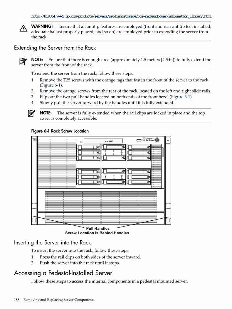
http://h18004.www1.hp.com/products/servers/proliantstorage/bcs-rackandpower/information_library.html
WARNING! Ensure that all antitip features are employed (front and rear antitip feet installed;adequate ballast properly placed, and so on) are employed prior to extending the server fromthe rack.
Extending the Server from the Rack
NOTE: Ensure that there is enough area (approximately 1.5 meters [4.5 ft.]) to fully extend theserver from the front of the rack.
To extend the server from the rack, follow these steps:1. Remove the T25 screws with the orange tags that fasten the front of the server to the rack
(Figure 6-1).2. Remove the orange screws from the rear of the rack located on the left and right slide rails.3. Flip out the two pull handles located on both ends of the front bezel (Figure 6-1).4. Slowly pull the server forward by the handles until it is fully extended.
NOTE: The server is fully extended when the rail clips are locked in place and the topcover is completely accessible.
Figure 6-1 Rack Screw Location
Inserting the Server into the RackTo insert the server into the rack, follow these steps:1. Press the rail clips on both sides of the server inward.2. Push the server into the rack until it stops.
Accessing a Pedestal-Installed ServerFollow these steps to access the internal components in a pedestal mounted server.
188 Removing and Replacing Server Components
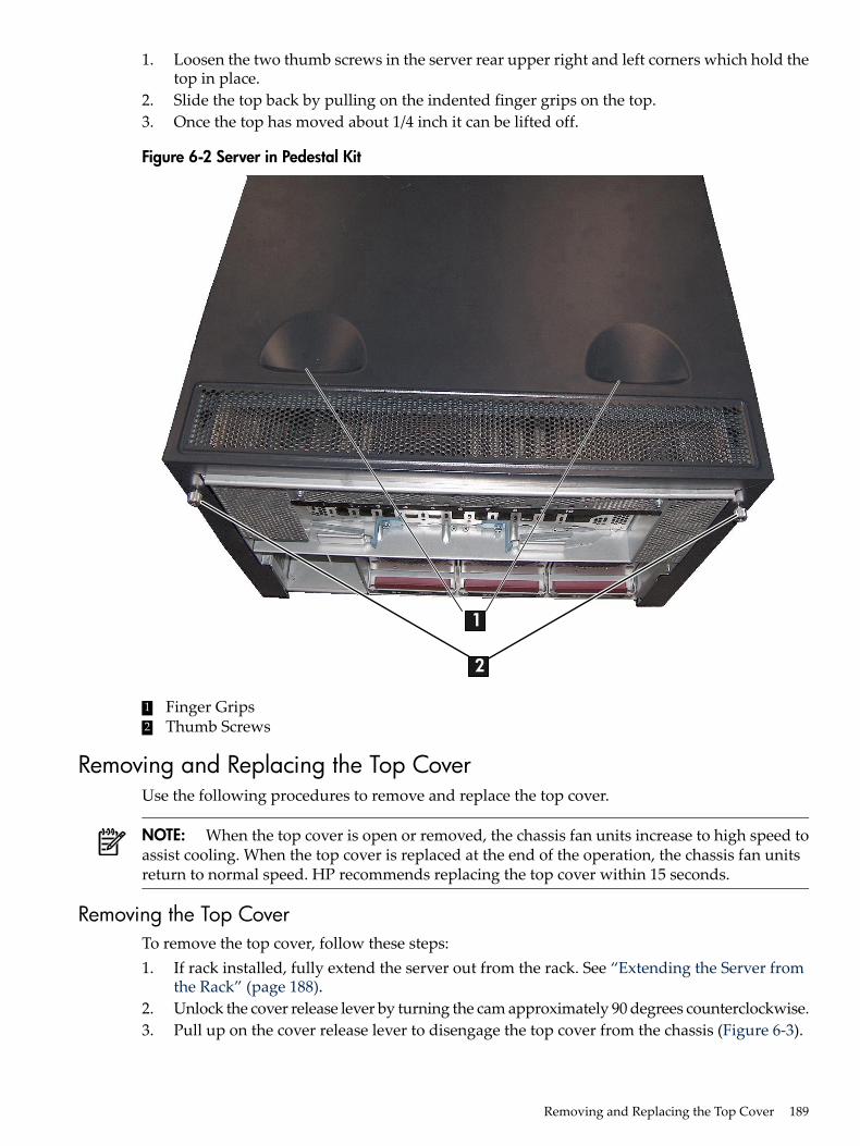
1. Loosen the two thumb screws in the server rear upper right and left corners which hold thetop in place.
2. Slide the top back by pulling on the indented finger grips on the top.3. Once the top has moved about 1/4 inch it can be lifted off.
Figure 6-2 Server in Pedestal Kit
1
2
1 Finger Grips2 Thumb Screws
Removing and Replacing the Top CoverUse the following procedures to remove and replace the top cover.
NOTE: When the top cover is open or removed, the chassis fan units increase to high speed toassist cooling. When the top cover is replaced at the end of the operation, the chassis fan unitsreturn to normal speed. HP recommends replacing the top cover within 15 seconds.
Removing the Top CoverTo remove the top cover, follow these steps:1. If rack installed, fully extend the server out from the rack. See “Extending the Server from
the Rack” (page 188).2. Unlock the cover release lever by turning the cam approximately 90 degrees counterclockwise.3. Pull up on the cover release lever to disengage the top cover from the chassis (Figure 6-3).
Removing and Replacing the Top Cover 189
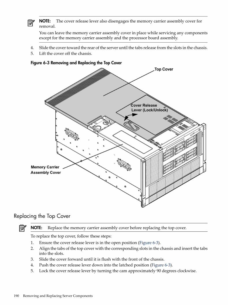
NOTE: The cover release lever also disengages the memory carrier assembly cover forremoval.You can leave the memory carrier assembly cover in place while servicing any componentsexcept for the memory carrier assembly and the processor board assembly.
4. Slide the cover toward the rear of the server until the tabs release from the slots in the chassis.5. Lift the cover off the chassis.
Figure 6-3 Removing and Replacing the Top Cover
Replacing the Top Cover
NOTE: Replace the memory carrier assembly cover before replacing the top cover.
To replace the top cover, follow these steps:1. Ensure the cover release lever is in the open position (Figure 6-3).2. Align the tabs of the top cover with the corresponding slots in the chassis and insert the tabs
into the slots.3. Slide the cover forward until it is flush with the front of the chassis.4. Push the cover release lever down into the latched position (Figure 6-3).5. Lock the cover release lever by turning the cam approximately 90 degrees clockwise.
190 Removing and Replacing Server Components
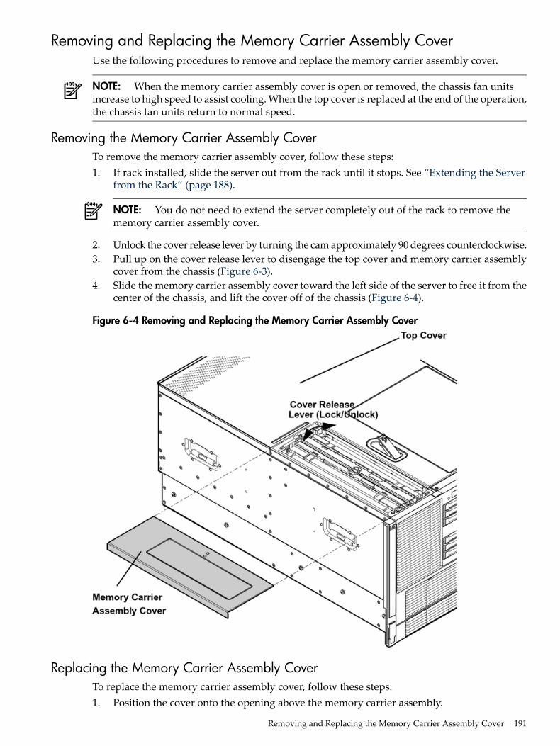
Removing and Replacing the Memory Carrier Assembly CoverUse the following procedures to remove and replace the memory carrier assembly cover.
NOTE: When the memory carrier assembly cover is open or removed, the chassis fan unitsincrease to high speed to assist cooling. When the top cover is replaced at the end of the operation,the chassis fan units return to normal speed.
Removing the Memory Carrier Assembly CoverTo remove the memory carrier assembly cover, follow these steps:1. If rack installed, slide the server out from the rack until it stops. See “Extending the Server
from the Rack” (page 188).
NOTE: You do not need to extend the server completely out of the rack to remove thememory carrier assembly cover.
2. Unlock the cover release lever by turning the cam approximately 90 degrees counterclockwise.3. Pull up on the cover release lever to disengage the top cover and memory carrier assembly
cover from the chassis (Figure 6-3).4. Slide the memory carrier assembly cover toward the left side of the server to free it from the
center of the chassis, and lift the cover off of the chassis (Figure 6-4).
Figure 6-4 Removing and Replacing the Memory Carrier Assembly Cover
Replacing the Memory Carrier Assembly CoverTo replace the memory carrier assembly cover, follow these steps:1. Position the cover onto the opening above the memory carrier assembly.
Removing and Replacing the Memory Carrier Assembly Cover 191
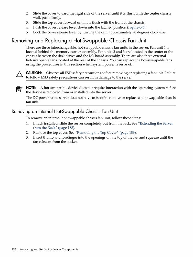
2. Slide the cover toward the right side of the server until it is flush with the center chassiswall, push firmly.
3. Slide the top cover forward until it is flush with the front of the chassis.4. Push the cover release lever down into the latched position (Figure 6-3).5. Lock the cover release lever by turning the cam approximately 90 degrees clockwise.
Removing and Replacing a Hot-Swappable Chassis Fan UnitThere are three interchangeable, hot-swappable chassis fan units in the server. Fan unit 1 islocated behind the memory carrier assembly. Fan units 2 and 3 are located in the center of thechassis between the disk drives and the I/O board assembly. There are also three externalhot-swappable fans located at the rear of the chassis. You can replace the hot-swappable fansusing the procedures in this section when system power is on or off.
CAUTION: Observe all ESD safety precautions before removing or replacing a fan unit. Failureto follow ESD safety precautions can result in damage to the server.
NOTE: A hot-swappable device does not require interaction with the operating system beforethe device is removed from or installed into the server.The DC power to the server does not have to be off to remove or replace a hot-swappable chassisfan unit.
Removing an Internal Hot-Swappable Chassis Fan UnitTo remove an internal hot-swappable chassis fan unit, follow these steps:1. If rack installed, slide the server completely out from the rack. See “Extending the Server
from the Rack” (page 188).2. Remove the top cover. See “Removing the Top Cover” (page 189).3. Insert thumb and forefinger into the openings on the top of the fan and squeeze until the
fan releases from the socket.
192 Removing and Replacing Server Components
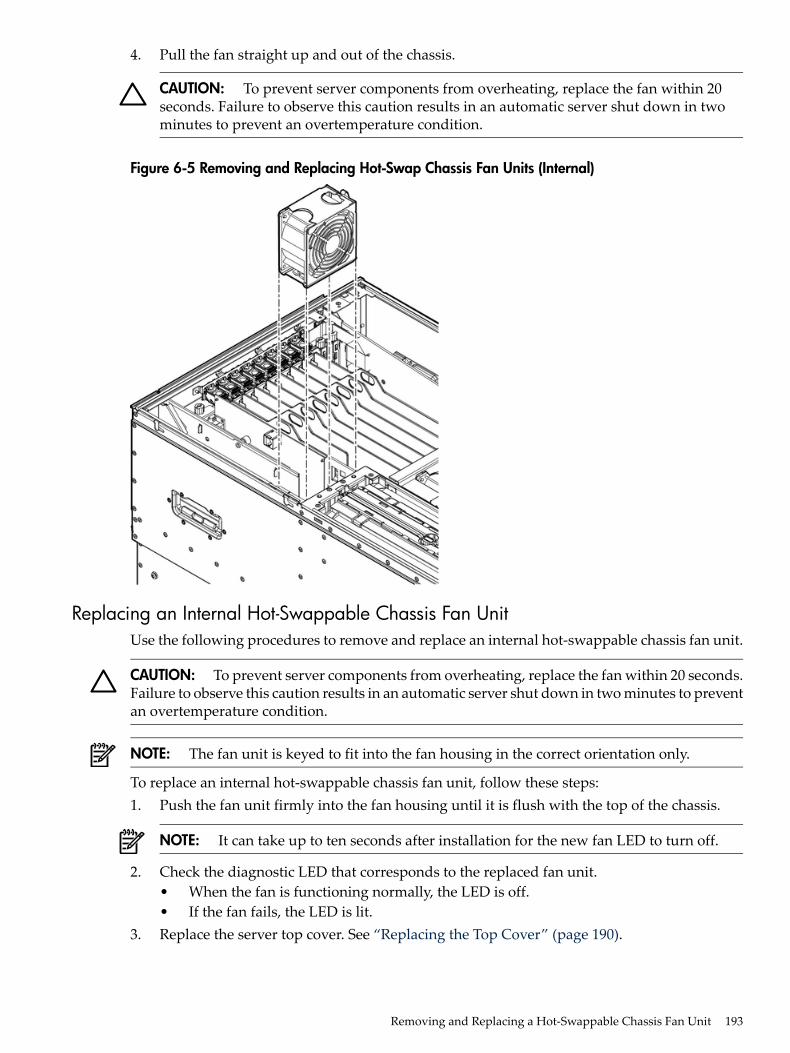
4. Pull the fan straight up and out of the chassis.
CAUTION: To prevent server components from overheating, replace the fan within 20seconds. Failure to observe this caution results in an automatic server shut down in twominutes to prevent an overtemperature condition.
Figure 6-5 Removing and Replacing Hot-Swap Chassis Fan Units (Internal)
Replacing an Internal Hot-Swappable Chassis Fan UnitUse the following procedures to remove and replace an internal hot-swappable chassis fan unit.
CAUTION: To prevent server components from overheating, replace the fan within 20 seconds.Failure to observe this caution results in an automatic server shut down in two minutes to preventan overtemperature condition.
NOTE: The fan unit is keyed to fit into the fan housing in the correct orientation only.
To replace an internal hot-swappable chassis fan unit, follow these steps:1. Push the fan unit firmly into the fan housing until it is flush with the top of the chassis.
NOTE: It can take up to ten seconds after installation for the new fan LED to turn off.
2. Check the diagnostic LED that corresponds to the replaced fan unit.• When the fan is functioning normally, the LED is off.• If the fan fails, the LED is lit.
3. Replace the server top cover. See “Replacing the Top Cover” (page 190).
Removing and Replacing a Hot-Swappable Chassis Fan Unit 193
Removing a Rear External Hot-Swappable Chassis Fan UnitTo remove a rear external hot-swappable chassis fan unit, follow these steps:1. Press down on the fan release button and pull the fan housing unit straight out from the
rear of the chassis until it stops (Figure 6-6).2. Insert thumb and forefinger into the openings on the top of the fan and squeeze until the
fan releases from the socket (Figure 6-7).3. Pull the fan straight up and out of the chassis.
CAUTION: To prevent server components from overheating, replace the fan within 20seconds. Failure to observe this caution results in an automatic server shut down in twominutes to prevent an overtemperature condition.
Figure 6-6 shows the external fan unit release button.
Figure 6-6 Fan Unit Release Button (External)
Figure 6-7 shows the fan and fan housing after the housing is pulled out of the chassis.
194 Removing and Replacing Server Components
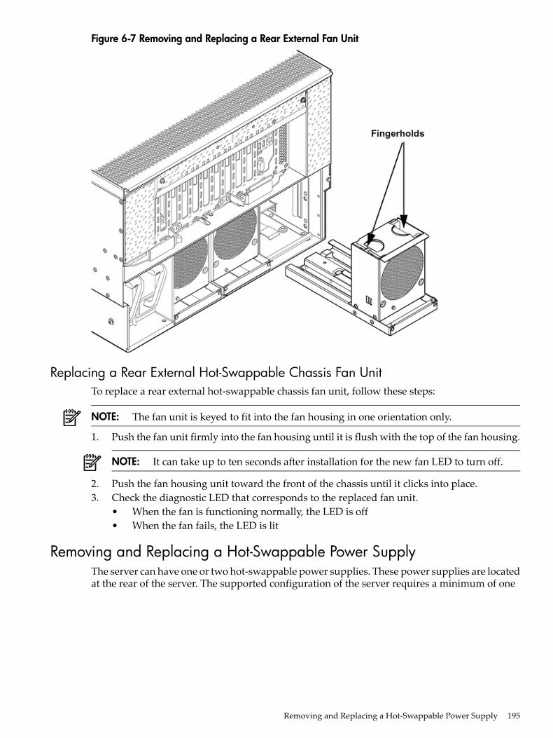
Figure 6-7 Removing and Replacing a Rear External Fan Unit
Replacing a Rear External Hot-Swappable Chassis Fan UnitTo replace a rear external hot-swappable chassis fan unit, follow these steps:
NOTE: The fan unit is keyed to fit into the fan housing in one orientation only.
1. Push the fan unit firmly into the fan housing until it is flush with the top of the fan housing.
NOTE: It can take up to ten seconds after installation for the new fan LED to turn off.
2. Push the fan housing unit toward the front of the chassis until it clicks into place.3. Check the diagnostic LED that corresponds to the replaced fan unit.
• When the fan is functioning normally, the LED is off• When the fan fails, the LED is lit
Removing and Replacing a Hot-Swappable Power SupplyThe server can have one or two hot-swappable power supplies. These power supplies are locatedat the rear of the server. The supported configuration of the server requires a minimum of one
Removing and Replacing a Hot-Swappable Power Supply 195
power supply. You can install or replace a hot-swappable power supply using the proceduresin this section when system power is on or off.
CAUTION: Observe all ESD safety precautions before removing or replacing a power supply.Failure to follow ESD safety precautions can result in damage to the server.
NOTE: A hot-swappable device does not require interaction with the operating system beforethe device is removed from or installed into the server.The DC power to the server does not have to be off to install or replace a hot-swappable powersupply.
Power Supply Loading GuidelinesThe supported configuration of the server requires a minimum of one power supply installedin slot P0 or slot P1. You can install a second, optional hot-swappable power supply to provide1+1 capability. The left side (viewed from the rear of the chassis) hot-swappable power supplyis identified as P0, and the second hot-swappable power supply is identified as P1 (Figure 6-8).
CAUTION: When a second power supply is not used, the empty power supply slot must remaincovered with the supplied metal filler panel. Failure to observe this caution can result in damagedue to overheating if the server top cover does not remain in place
CAUTION: Install the hot-swappable power supply into the server before attaching the newpower cord. Failure to observe this caution can result in damage to the server
Removing a Hot-Swappable Power SupplyTo remove a hot-swappable power supply, follow these steps:1. Move the cable management arm from the rack slide nearest the power supplies just enough
to allow access to the power supplies.2. Remove the power cord plug from the power supply receptacle.3. Grasp the handle and push the locking tab down with your thumb to release the power
supply from the socket on the midplane board.4. Support the power supply with both hands, and pull the power supply out of the server
(Figure 6-8).
196 Removing and Replacing Server Components
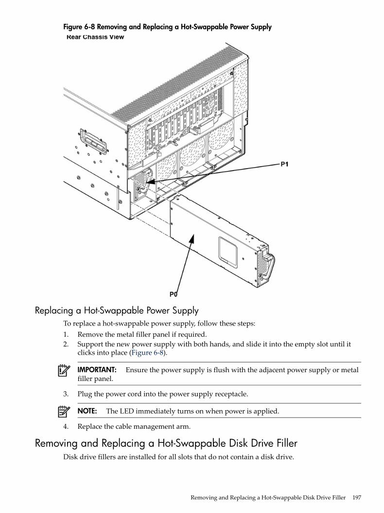
Figure 6-8 Removing and Replacing a Hot-Swappable Power Supply
Replacing a Hot-Swappable Power SupplyTo replace a hot-swappable power supply, follow these steps:1. Remove the metal filler panel if required.2. Support the new power supply with both hands, and slide it into the empty slot until it
clicks into place (Figure 6-8).
IMPORTANT: Ensure the power supply is flush with the adjacent power supply or metalfiller panel.
3. Plug the power cord into the power supply receptacle.
NOTE: The LED immediately turns on when power is applied.
4. Replace the cable management arm.
Removing and Replacing a Hot-Swappable Disk Drive FillerDisk drive fillers are installed for all slots that do not contain a disk drive.
Removing and Replacing a Hot-Swappable Disk Drive Filler 197
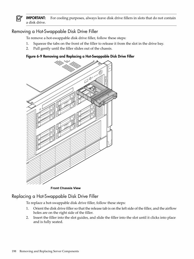
IMPORTANT: For cooling purposes, always leave disk drive fillers in slots that do not containa disk drive.
Removing a Hot-Swappable Disk Drive FillerTo remove a hot-swappable disk drive filler, follow these steps:1. Squeeze the tabs on the front of the filler to release it from the slot in the drive bay.2. Pull gently until the filler slides out of the chassis.
Figure 6-9 Removing and Replacing a Hot-Swappable Disk Drive Filler
Replacing a Hot-Swappable Disk Drive FillerTo replace a hot-swappable disk drive filler, follow these steps:1. Orient the disk drive filler so that the release tab is on the left side of the filler, and the airflow
holes are on the right side of the filler.2. Insert the filler into the slot guides, and slide the filler into the slot until it clicks into place
and is fully seated.
198 Removing and Replacing Server Components

Removing and Replacing a Hot-Pluggable Disk DriveThere are 16 hot-pluggable disk drives located in the front of the server. You can replace thehot-pluggable disk drives using the procedures in this section when server power is on or off.
CAUTION: A hot-pluggable device may require interaction with the operating system beforeyou can safely remove it from or install it into the server. Verify that the operating system supportsremoving and replacing disk drives while the operating system is running. If the operatingsystem does not support this feature, shut down the operating system before removing orinstalling a hot-swappable disk drive. Failure to observe this caution can result in system failure.
NOTE: The replacement disk drive must have the same product number as the disk drive thatyou replace.
Removing a Hot-Pluggable Disk DriveTo remove a hot-pluggable disk drive, follow these steps:1. Push the release tab away from the drive extraction handle and pull the extraction handle
outward.2. Pull gently until the hot-pluggable disk drive slides out of the chassis.
Removing and Replacing a Hot-Pluggable Disk Drive 199
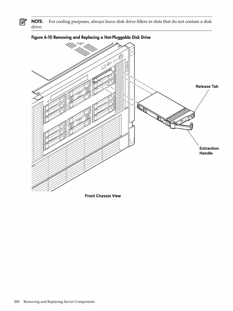
NOTE: For cooling purposes, always leave disk drive fillers in slots that do not contain a diskdrive.
Figure 6-10 Removing and Replacing a Hot-Pluggable Disk Drive
200 Removing and Replacing Server Components
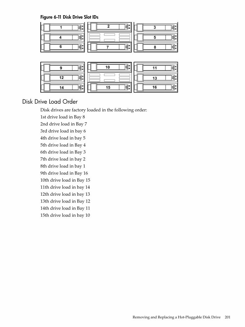
Figure 6-11 Disk Drive Slot IDs
Disk Drive Load OrderDisk drives are factory loaded in the following order:1st drive load in Bay 82nd drive load in Bay 73rd drive load in bay 64th drive load in bay 55th drive load in Bay 46th drive load in Bay 37th drive load in bay 28th drive load in bay 19th drive load in Bay 1610th drive load in Bay 1511th drive load in bay 1412th drive load in bay 1313th drive load in Bay 1214th drive load in Bay 1115th drive load in bay 10
Removing and Replacing a Hot-Pluggable Disk Drive 201
16th drive load in bay 9
CAUTION: Drives are loaded in the factory, starting with number 8, working from right to leftand bottom to top. If you have never changed your SAS configuration before, you can safelymove SAS devices downwards as a block. If you have bays 6, 7, and 8 occupied you can movethem down to bays 1, 2, and 3 without having the hardware paths change during a cold-installor recovery while the system is shut down, but youmustmove the disks in order and you cannotrearrange them. For example, you can move bay 6 to 1, 7 to 2, and 8 to 3. After doing this youcan safely populate the SAS enclosure from bay 4 onwards. The same procedure can be performedon bays 9 to 16.
TIP: When you receive an HP Integrity rx3600 or HP Integrity rx6600 server from HP, if youever plan to add other SAS devices into the system, you should consider moving the SAS devicesso they start in bay 1 going upwards instead of Bay 8 going downwards.
Replacing a Hot-Pluggable Disk Drive
NOTE: The replacement disk drive must have the same product number as the disk drive thatyou replace.
To install a hot-pluggable disk drive, follow these steps:1. Use Figure 6-11 to determine the next available disk drive installation slot.2. Remove the disk drive filler if required. See “Removing and Replacing a Hot-Swappable
Disk Drive Filler” (page 197).
NOTE: Save the disk drive filler for future use. For cooling purposes, always place diskdrive fillers in slots that do not contain a disk drive.
3. Insert the hot-pluggable disk drive into the slot guides, and slide the drive into the slot untilit seats into the socket on the disk backplane.
4. Close the extraction handle by pushing it inward until it clicks into place.5. Observe the following disk drive LEDs to ensure the drive is functional. For more information,
see “Hot-Pluggable Disk Drive LEDs” (page 37).• Drive status LED• Drive activity LED
Removing and Replacing PCI/PCI-X/PCIe Card DividersPCI/PCI-X/PCIe card dividers are located on the I/O board assembly, between the PCI/PCI-X/PCIecards. Eight dividers provide short circuit protection to the hot-pluggable PCI/PCI-X/PCIe cards
202 Removing and Replacing Server Components
by preventing inadvertent contact between cards during the replacement, addition, or removalof a card.
WARNING! Ensure that the system is powered off and all power sources have been disconnectedfrom the server prior to performing this procedure.Voltages are present at various locations within the server whenever an AC power source isconnected. This voltage is present even when the main power switch is in the off position.Failure to observe this warning can result in personal injury or damage to equipment.
CAUTION: Observe all ESD safety precautions before attempting this procedure. Failure tofollow ESD safety precautions can result in damage to the server.
Removing a PCI/PCI-X/PCIe Card DividerTo remove a PCI/PCI-X/PCIe card divider, follow these steps:1. Power off the server and disconnect the power cables. See “Powering Off the Server”
(page 96).2. If rack installed, slide the server completely out from the rack. See “Extending the Server
from the Rack” (page 188).3. Remove the top cover. See “Removing the Top Cover” (page 189).
CAUTION: When extracting the card divider, ensure you release the locking tabs completelyor you can damage them. If you damage the tabs, the divider does not seat properly whenyou reinsert it.
4. Use a tool to carefully push the two tabs that attach the card divider to the I/O boardassembly.
5. Pull the card divider up sharply by the handle to disengage it from the I/O board assembly(Figure 6-12).
Removing and Replacing PCI/PCI-X/PCIe Card Dividers 203
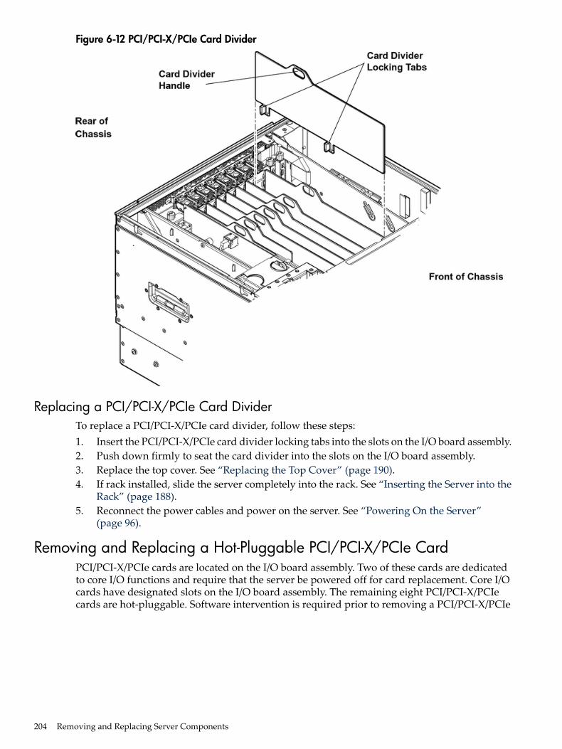
Figure 6-12 PCI/PCI-X/PCIe Card Divider
Replacing a PCI/PCI-X/PCIe Card DividerTo replace a PCI/PCI-X/PCIe card divider, follow these steps:1. Insert the PCI/PCI-X/PCIe card divider locking tabs into the slots on the I/O board assembly.2. Push down firmly to seat the card divider into the slots on the I/O board assembly.3. Replace the top cover. See “Replacing the Top Cover” (page 190).4. If rack installed, slide the server completely into the rack. See “Inserting the Server into the
Rack” (page 188).5. Reconnect the power cables and power on the server. See “Powering On the Server”
(page 96).
Removing and Replacing a Hot-Pluggable PCI/PCI-X/PCIe CardPCI/PCI-X/PCIe cards are located on the I/O board assembly. Two of these cards are dedicatedto core I/O functions and require that the server be powered off for card replacement. Core I/Ocards have designated slots on the I/O board assembly. The remaining eight PCI/PCI-X/PCIecards are hot-pluggable. Software intervention is required prior to removing a PCI/PCI-X/PCIe
204 Removing and Replacing Server Components
card. This section describes the following hot-plug operations and PCI/PCI-X/PCIe cardreplacement procedures:• “PCI/PCI-X/PCIe Configurations”
Describes PCI/PCI-X/PCIe capabilities and relates card functions and capabilities to specificslots.
• “Online Addition (OLA)”Describes the installation of new PCI/PCI-X/PCIe expansion cards in previously empty slotswithout powering down the server.
• “Online Replacement (OLR)”Describes the replacement of a PCI/PCI-X/PCIe card without powering down the server.This action requires suspending the associated driver. The existing driver for the old cardmust be compatible with the new card.
CAUTION: If you are performing OLR on HP-UX 11i version 1 (and later), the card youinstall must be exactly the same as the card you replace. This is also known as like-for-likereplacement.
• “Removing a PCI/PCI-X/PCIe Card Offline”Describes the removal of a PCI/PCI-X/PCIe card after powering down the server.
• “Installing a PCI/PCI-X/PCIe Card Offline”Describes the installation of a PCI/PCI-X/PCIe card after powering down the server.
Figure 6-13 shows the PCI/PCI-X/PCIe slot identification and card divider locations.
Removing and Replacing a Hot-Pluggable PCI/PCI-X/PCIe Card 205
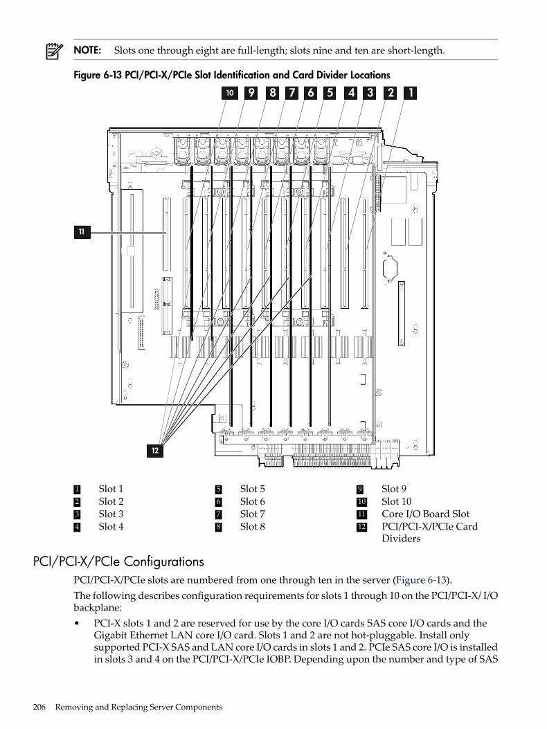
NOTE: Slots one through eight are full-length; slots nine and ten are short-length.
Figure 6-13 PCI/PCI-X/PCIe Slot Identification and Card Divider Locations
12345678910
11
12
9 Slot 95 Slot 51 Slot 12 Slot 2 10 Slot 106 Slot 6
7 Slot 73 Slot 3 11 Core I/O Board Slot1284 PCI/PCI-X/PCIe Card
DividersSlot 8Slot 4
PCI/PCI-X/PCIe ConfigurationsPCI/PCI-X/PCIe slots are numbered from one through ten in the server (Figure 6-13).The following describes configuration requirements for slots 1 through 10 on the PCI/PCI-X/ I/Obackplane:• PCI-X slots 1 and 2 are reserved for use by the core I/O cards SAS core I/O cards and the
Gigabit Ethernet LAN core I/O card. Slots 1 and 2 are not hot-pluggable. Install onlysupported PCI-X SAS and LAN core I/O cards in slots 1 and 2. PCIe SAS core I/O is installedin slots 3 and 4 on the PCI/PCI-X/PCIe IOBP. Depending upon the number and type of SAS
206 Removing and Replacing Server Components
core I/O cards installed on the system, the Gigabit Ethernet LAN core I/O card may beinstalled in slot 10.
• Slots 3 and 4 are nonshared slots. The maximum speed for cards in slots 3 and 4 is PCI-X266 MHz.
• Slots 5 and 6 are nonshared slots. The maximum speed for cards in slots 5 and 6 is PCI-X133 MHz.
• Slots 7, 8, 9, and 10 are shared slots. These four slots are limited by bus-mode orfrequency-related incompatibilities. If you use different modes, such as PCI instead of PCI-X,or different card speeds in a shared bus environment, the slot automatically downgrades tothe lesser mode or speed. The maximum capability of each slot is PCI-X 66 MHz.
NOTE: Shared slots have card compatibility restrictions. If one of the shared slots isoccupied, the card added to the second slot is limited by the configuration of the occupiedslot. If the new card has a slower capability than the current bus configuration, it fails. If thenew card has a faster capability than the current bus configuration, it only runs at the slowerbus mode and frequency of the current bus configuration.
The following are common configuration scenarios for cards that use shared slots. Theseexamples also apply to slots nine and ten because they are shared (both use a common bus).1. If there is a PCI-X 66 MHz card in slot 7, and you hot-plug a PCI 33 MHz card into slot
8, the operation fails. The new PCI 33 MHz card does not initialize and the slot powersdown because you cannot change bus speed during hot-plug operations. The new cardhas a slower bus speed than the current card.
NOTE: If the server is rebooted in this configuration, both cards initialize to run atPCI 33 MHz. The system firmware can only change the bus capability down to thelowest common value.
2. If there is a PCI 33 MHz card in slot 7, and you hot-plug insert a PCI-X 66 MHz cardinto slot 8, the new card works but it runs at PCI 33 MHz.
3. If the server is powered off, and you insert a PCI 33 MHz card into slot 7 (that shares acommon bus with a PCI-X 66 MHz card in slot 8), then both cards run at PCI 33 MHzwhen the server powers up.
The following describes configuration requirements for slots one through ten on thePCI/PCI-X/PCIe I/O backplane:• PCI-X slots 1 and 2 are reserved for use by the core I/O cards PCI-X SAS core I/O cards and
the Gigabit Ethernet LAN core I/O card. Slots 1 and 2 are not hot-pluggable. Install onlysupported PCI-X SAS and LAN core I/O cards in slots 1 and 2. PCIe slots 3 and 4 are usedfor the PCIe SAS Core I/O cards, but are public slots. If the PCIe core I/O is not installed,these slots are available for other PCIe I/O cards.
• Slots 3 and 4 are swtiched PCIe x8• Slots 5 and 6 are nonswitched PCIe x8.• Slots 7 and 8 are nonshared slots. The maximum speed for cards in slots 7 and 8 is PCI-X
133 MHz.• Slots 9 and 10 are shared slots. These two slots are limited by bus mode or frequency-related
incompatibilities.
IMPORTANT: Slots 9 and 10 on the PCI/PCI-X/PCIe I/O backplane have the sameconfiguration limitations as slots 9 and 10 on the PCI/PCI-X I/O backplane.
Table 6-1 lists the PCI/PCI-X card slot frequency and bus mode compatibility for shared slots.
Removing and Replacing a Hot-Pluggable PCI/PCI-X/PCIe Card 207
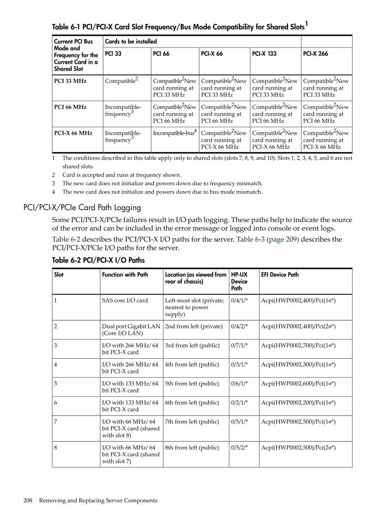
Table 6-1 PCI/PCI-X Card Slot Frequency/Bus Mode Compatibility for Shared Slots1
Cards to be installedCurrent PCI BusMode andFrequency for theCurrent Card in aShared Slot
PCI-X 266PCI-X 133PCI-X 66PCI 66PCI 33
Compatible2Newcard running atPCI 33 MHz
Compatible2Newcard running atPCI 33 MHz
Compatible2Newcard running atPCI 33 MHz
Compatible2Newcard running atPCI 33 MHz
Compatible2PCI 33 MHz
Compatible2Newcard running atPCI 66 MHz
Compatible2Newcard running atPCI 66 MHz
Compatible2Newcard running atPCI 66 MHz
Compatible2Newcard running atPCI 66 MHz
Incompatible-frequency3
PCI 66 MHz
Compatible2Newcard running atPCI-X 66 MHz
Compatible2Newcard running atPCI-X 66 MHz
Compatible2Newcard running atPCI-X 66 MHz
Incompatible-bus4Incompatible-frequency3
PCI-X 66 MHz
1 The conditions described in this table apply only to shared slots (slots 7, 8, 9, and 10). Slots 1, 2, 3, 4, 5, and 6 are notshared slots.
2 Card is accepted and runs at frequency shown.3 The new card does not initialize and powers down due to frequency mismatch.4 The new card does not initialize and powers down due to bus mode mismatch.
PCI/PCI-X/PCIe Card Path LoggingSome PCI/PCI-X/PCIe failures result in I/O path logging. These paths help to indicate the sourceof the error and can be included in the error message or logged into console or event logs.Table 6-2 describes the PCI/PCI-X I/O paths for the server. Table 6-3 (page 209) describes thePCI/PCI-X/PCIe I/O paths for the server.
Table 6-2 PCI/PCI-X I/O Paths
EFI Device PathHP-UXDevicePath
Location (as viewed fromrear of chassis)
Function with PathSlot
Acpi(HWP0002,400)/Pci(1 *)0/4/1/*Left-most slot (private;nearest to powersupply)
SAS core I/O card1
Acpi(HWP0002,400)/Pci(2 *)0/4/2/*2nd from left (private)Dual port Gigabit LAN(Core I/O LAN)
2
Acpi(HWP0002,700)/Pci(1 *)0/7/1/*3rd from left (public)I/O with 266 MHz/ 64bit PCI-X card
3
Acpi(HWP0002,300)/Pci(1 *)0/3/1/*4th from left (public)I/O with 266 MHz/ 64bit PCI-X card
4
Acpi(HWP0002,600)/Pci(1 *)0/6/1/*5th from left (public)I/O with 133 MHz/ 64bit PCI-X card
5
Acpi(HWP0002,200)/Pci(1 *)0/2/1/*6th from left (public)I/O with 133 MHz/ 64bit PCI-X card
6
Acpi(HWP0002,500)/Pci(1 *)0/5/1/*7th from left (public)I/O with 66 MHz/ 64bit PCI-X card (sharedwith slot 8)
7
Acpi(HWP0002,500)/Pci(2 *)0/5/2/*8th from left (public)I/O with 66 MHz/ 64bit PCI-X card (sharedwith slot 7)
8
208 Removing and Replacing Server Components
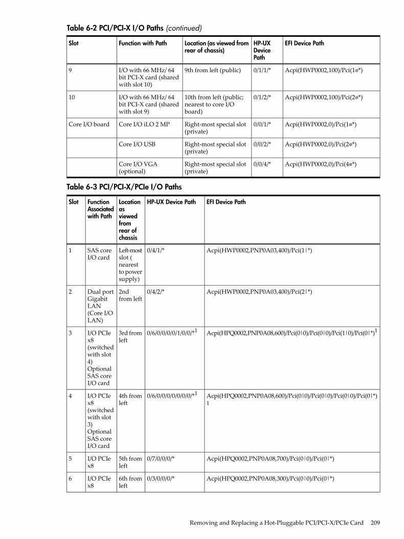
Table 6-2 PCI/PCI-X I/O Paths (continued)
EFI Device PathHP-UXDevicePath
Location (as viewed fromrear of chassis)
Function with PathSlot
Acpi(HWP0002,100)/Pci(1 *)0/1/1/*9th from left (public)I/O with 66 MHz/ 64bit PCI-X card (sharedwith slot 10)
9
Acpi(HWP0002,100)/Pci(2 *)0/1/2/*10th from left (public;nearest to core I/Oboard)
I/O with 66 MHz/ 64bit PCI-X card (sharedwith slot 9)
10
Acpi(HWP0002,0)/Pci(1 *)0/0/1/*Right-most special slot(private)
Core I/O iLO 2 MPCore I/O board
Acpi(HWP0002,0)/Pci(2 *)0/0/2/*Right-most special slot(private)
Core I/O USB
Acpi(HWP0002,0)/Pci(4 *)0/0/4/*Right-most special slot(private)
Core I/O VGA(optional)
Table 6-3 PCI/PCI-X/PCIe I/O Paths
EFI Device PathHP-UX Device PathLocationasviewedfromrear ofchassis
FunctionAssociatedwith Path
Slot
Acpi(HWP0002,PNP0A03,400)/Pci(1|*)0/4/1/*Left-mostslot (nearestto powersupply)
SAS coreI/O card
1
Acpi(HWP0002,PNP0A03,400)/Pci(2|*)0/4/2/*2ndfrom left
Dual portGigabitLAN(Core I/OLAN)
2
Acpi(HPQ0002,PNP0A08,600)/Pci(0|0)/Pci(0|0)/Pci(1|0)/Pci(0|*)10/6/0/0/0/0/1/0/0/*13rd fromleft
I/O PCIex8(switchedwith slot4)OptionalSAS coreI/O card
3
Acpi(HPQ0002,PNP0A08,600)/Pci(0|0)/Pci(0|0)/Pci(0|0)/Pci(0|*)1
0/6/0/0/0/0/0/0/0/*14th fromleft
I/O PCIex8(switchedwith slot3)OptionalSAS coreI/O card
4
Acpi(HPQ0002,PNP0A08,700)/Pci(0|0)/Pci(0|*)0/7/0/0/0/*5th fromleft
I/O PCIex8
5
Acpi(HPQ0002,PNP0A08,300)/Pci(0|0)/Pci(0|*)0/3/0/0/0/*6th fromleft
I/O PCIex8
6
Removing and Replacing a Hot-Pluggable PCI/PCI-X/PCIe Card 209
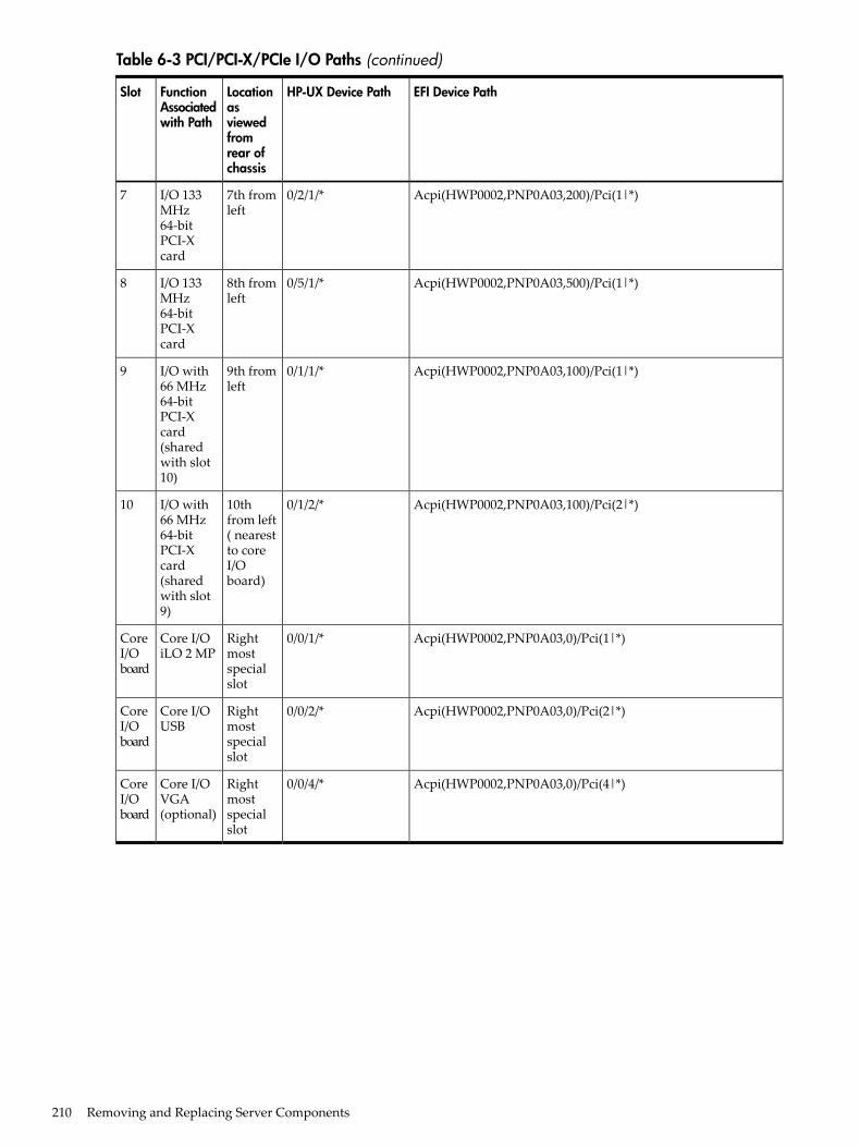
Table 6-3 PCI/PCI-X/PCIe I/O Paths (continued)
EFI Device PathHP-UX Device PathLocationasviewedfromrear ofchassis
FunctionAssociatedwith Path
Slot
Acpi(HWP0002,PNP0A03,200)/Pci(1|*)0/2/1/*7th fromleft
I/O 133MHz64-bitPCI-Xcard
7
Acpi(HWP0002,PNP0A03,500)/Pci(1|*)0/5/1/*8th fromleft
I/O 133MHz64-bitPCI-Xcard
8
Acpi(HWP0002,PNP0A03,100)/Pci(1|*)0/1/1/*9th fromleft
I/O with66 MHz64-bitPCI-Xcard(sharedwith slot10)
9
Acpi(HWP0002,PNP0A03,100)/Pci(2|*)0/1/2/*10thfrom left( nearestto coreI/Oboard)
I/O with66 MHz64-bitPCI-Xcard(sharedwith slot9)
10
Acpi(HWP0002,PNP0A03,0)/Pci(1|*)0/0/1/*Rightmostspecialslot
Core I/OiLO 2 MP
CoreI/Oboard
Acpi(HWP0002,PNP0A03,0)/Pci(2|*)0/0/2/*Rightmostspecialslot
Core I/OUSB
CoreI/Oboard
Acpi(HWP0002,PNP0A03,0)/Pci(4|*)0/0/4/*Rightmostspecialslot
Core I/OVGA(optional)
CoreI/Oboard
210 Removing and Replacing Server Components
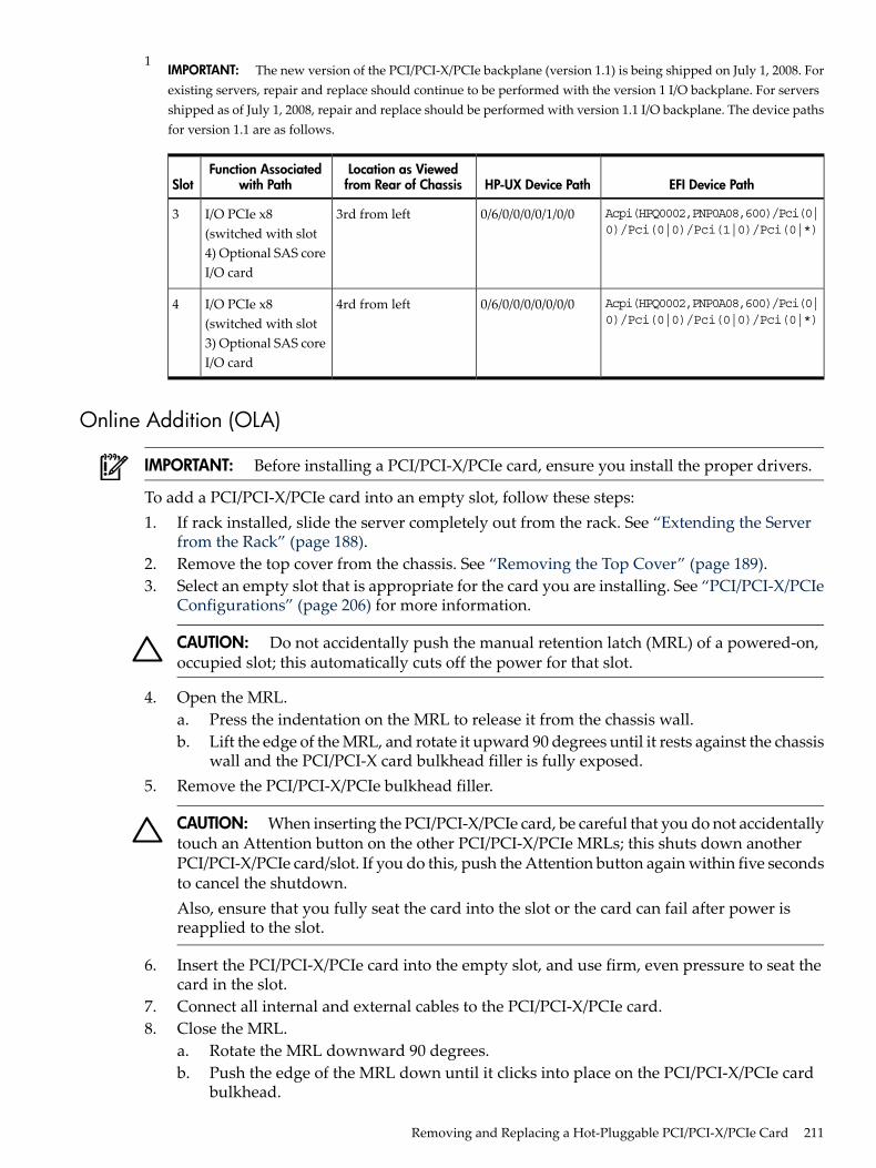
1IMPORTANT: The new version of the PCI/PCI-X/PCIe backplane (version 1.1) is being shipped on July 1, 2008. Forexisting servers, repair and replace should continue to be performed with the version 1 I/O backplane. For serversshipped as of July 1, 2008, repair and replace should be performed with version 1.1 I/O backplane. The device pathsfor version 1.1 are as follows.
EFI Device PathHP-UX Device PathLocation as Viewedfrom Rear of Chassis
Function Associatedwith PathSlot
Acpi(HPQ0002,PNP0A08,600)/Pci(0|0)/Pci(0|0)/Pci(1|0)/Pci(0|*)
0/6/0/0/0/0/1/0/03rd from leftI/O PCIe x8(switched with slot4) Optional SAS coreI/O card
3
Acpi(HPQ0002,PNP0A08,600)/Pci(0|0)/Pci(0|0)/Pci(0|0)/Pci(0|*)
0/6/0/0/0/0/0/0/04rd from leftI/O PCIe x8(switched with slot3) Optional SAS coreI/O card
4
Online Addition (OLA)
IMPORTANT: Before installing a PCI/PCI-X/PCIe card, ensure you install the proper drivers.
To add a PCI/PCI-X/PCIe card into an empty slot, follow these steps:1. If rack installed, slide the server completely out from the rack. See “Extending the Server
from the Rack” (page 188).2. Remove the top cover from the chassis. See “Removing the Top Cover” (page 189).3. Select an empty slot that is appropriate for the card you are installing. See “PCI/PCI-X/PCIe
Configurations” (page 206) for more information.
CAUTION: Do not accidentally push the manual retention latch (MRL) of a powered-on,occupied slot; this automatically cuts off the power for that slot.
4. Open the MRL.a. Press the indentation on the MRL to release it from the chassis wall.b. Lift the edge of the MRL, and rotate it upward 90 degrees until it rests against the chassis
wall and the PCI/PCI-X card bulkhead filler is fully exposed.5. Remove the PCI/PCI-X/PCIe bulkhead filler.
CAUTION: When inserting the PCI/PCI-X/PCIe card, be careful that you do not accidentallytouch an Attention button on the other PCI/PCI-X/PCIe MRLs; this shuts down anotherPCI/PCI-X/PCIe card/slot. If you do this, push the Attention button again within five secondsto cancel the shutdown.Also, ensure that you fully seat the card into the slot or the card can fail after power isreapplied to the slot.
6. Insert the PCI/PCI-X/PCIe card into the empty slot, and use firm, even pressure to seat thecard in the slot.
7. Connect all internal and external cables to the PCI/PCI-X/PCIe card.8. Close the MRL.
a. Rotate the MRL downward 90 degrees.b. Push the edge of the MRL down until it clicks into place on the PCI/PCI-X/PCIe card
bulkhead.
Removing and Replacing a Hot-Pluggable PCI/PCI-X/PCIe Card 211
9. Close the gate latch to secure the end of the card if it is full-length.10. Activate the PCI/PCI-X/PCIe card and slot.
a. Press the red Attention button located on the MRL of the appropriate slot. The powerLED starts to blink.
b. Wait until the power LED goes from blinking to steady on.
NOTE: After pushing the Attention button, you have five seconds to cancel the operationby pushing the Attention button again. After five seconds, pressing the Attention buttoninitiates slot powerdown.
11. Replace the top cover. See “Replacing the Top Cover” (page 190).
Online Replacement (OLR)
CAUTION: For HP-UX 11i version 1 (and later), you can only replace an existing card with alike card.
To remove and replace a PCI/PCI-X/PCIe card into a populated slot, follow these steps:1. If rack installed, slide the server completely out from the rack. See “Extending the Server
from the Rack” (page 188).2. Remove the top cover from the chassis. See “Removing the Top Cover” (page 189).3. Deactivate the PCI/PCI-X/PCIe card and slot.
a. Press the red Attention button located on the MRL of the appropriate slot, and the powerLED starts to blink.
b. Wait until the power LED goes from blinking to steady off.
NOTE: After pushing the Attention button, you have five seconds to cancel the operationby pushing the Attention button again.
4. Pull the gate latch toward the front of the chassis to completely unlock the PCI/PCI-X/PCIecard.
5. Open the MRL.a. Press the indentation on the MRL to release it from the chassis wall.b. Lift the edge of the MRL, and rotate it upward 90 degrees until it rests against the chassis
wall and the PCI/PCI-X/PCIe card bulkhead is fully exposed.6. Disconnect all external and internal cables attached to the PCI/PCI-X/PCIe card.7. Grasp the PCI/PCI-X/PCIe card divider by the handle, and pull upward to eject the
PCI/PCI-X/PCIe card from the slot.8. Grasp the PCI/PCI-X/PCIe card by the edges and lift it out of the chassis.
CAUTION: When inserting the PCI/PCI-X/PCIe card, be careful that you do not accidentallytouch an Attention button on the other MRLs; this shuts down that PCI/PCI-X/PCIe cardslot. If you do this, push the Attention button again within five seconds to cancel theshutdown.Also, ensure that you fully seat the card into the slot or the card can fail after power isreapplied to the slot.
9. Insert the PCI/PCI-X/PCIe card into the empty slot, and use firm, even pressure to seat thecard in the slot.
10. Reconnect all internal and external cables to the PCI/PCI-X/PCIe card.
212 Removing and Replacing Server Components
11. Close the MRL.a. Rotate the MRL downward 90 degrees.b. Push the edge of the MRL down until it clicks into place on the PCI/PCI-X/PCIe card
bulkhead.12. Close the gate latch to secure the end of the card if it is full-length.13. Activate the PCI/PCI-X/PCIe card and slot.
a. Press the red Attention button located on the MRL of the appropriate slot, and the powerLED starts to blink.
b. Wait until the power LED goes from blinking to steady on.
NOTE: After pushing the Attention button, you have five seconds to cancel the operationby pushing the Attention button again. After five seconds, pressing the Attention buttoninitiates slot powerdown for online replacement (OLR) of the card.
14. Replace the top cover. See “Replacing the Top Cover” (page 190).
Removing a PCI/PCI-X/PCIe Card OfflineObserve the following warning and cautions before performing an offline removal of aPCI/PCI-X/PCIe card.
WARNING! Ensure that the system is powered off and all power sources have been disconnectedfrom the server prior to performing this procedure.Voltages are present at various locations within the server whenever an AC power source isconnected. This voltage is present even when the main power switch is in the off position.Failure to observe this warning can result in personal injury or damage to equipment.
CAUTION: Observe all ESD safety precautions before removing a PCI/PCI-X/PCIe card offline.Failure to follow ESD safety precautions can result in damage to the server.
CAUTION: Record the slot location of all PCI cards as they are removed. Depending on theoperating system, replacing the PCI cards in a different location may require systemreconfiguration and may cause boot failure.
To remove a PCI card from the server with the power off, follow these steps:1. Power off the server and disconnect the power cables. See “Powering Off the Server”
(page 96).2. If rack installed, slide the server completely out from the rack. See “Extending the Server
from the Rack” (page 188).3. Remove the top cover from the chassis. See “Removing the Top Cover” (page 189).4. Pull the gate latch toward the front of the chassis to completely unlock the PCI/PCI-X/PCIe
card if it is full-length.5. Open the MRL.
a. Press the indentation on the MRL to release it from the chassis wall.b. Lift the edge of the MRL, and rotate it upward 90 degrees until it rests against the chassis
wall and the PCI/PCI-X/PCIe card bulkhead is fully exposed.6. Disconnect all external and internal cables attached to the PCI/PCI-X/PCIe card.7. Grasp the PCI/PCI-X/PCIe card divider by the handle, and pull upward to eject the
PCI/PCI-X/PCIe card from the slot.8. Grasp the PCI/PCI-X/PCIe card by the edges and lift it out of the chassis.
Removing and Replacing a Hot-Pluggable PCI/PCI-X/PCIe Card 213

Installing a PCI/PCI-X/PCIe Card Offline
NOTE: Before installing a PCI/PCI-X/PCIe card, ensure that you install the proper drivers forthe PCI/PCI-X/PCIe card.
To install a PCI/PCI-X/PCIe card with the server power off, follow these steps:1. Power off the server and disconnect the power cables. See “Powering Off the Server”
(page 96).2. If rack installed, slide the server completely out from the rack. See “Extending the Server
from the Rack” (page 188).3. Remove the top cover from the chassis. See “Removing the Top Cover” (page 189).4. Select an empty slot that is appropriate for the card you are installing. For more information
see “PCI/PCI-X/PCIe Configurations” (page 206) and Figure 6-13.5. Open the MRL.
a. Press the indentation on the MRL to release it from the chassis wall.b. Lift the edge of the MRL, and rotate it upward 90 degrees until it rests against the chassis
wall and the PCI/PCI-X/PCIe card bulkhead filler is fully exposed.6. Remove the PCI/PCI-X/PCIe bulkhead filler.7. Insert the PCI/PCI-X/PCIe card into the empty slot, and use firm, even pressure to seat the
card in the slot.
CAUTION: Ensure that you fully seat the card into the slot, or the card can fail after poweris reapplied to the slot.
8. Connect all internal and external cables to the PCI/PCI-X/PCIe card.9. Close the MRL.
a. Rotate the MRL downward 90 degrees.b. Push the edge of the MRL down until it clicks into place on the PCI/PCI-X/PCIe card
bulkhead.10. Close the gate latch to secure the end of the card if it is full-length.11. Replace the top cover. See “Replacing the Top Cover” (page 190).12. If rack installed, slide the server completely into the rack. See “Inserting the Server into the
Rack” (page 188).13. Reconnect the power cables and power on the server. See “Powering On the Server”
(page 96).
214 Removing and Replacing Server Components
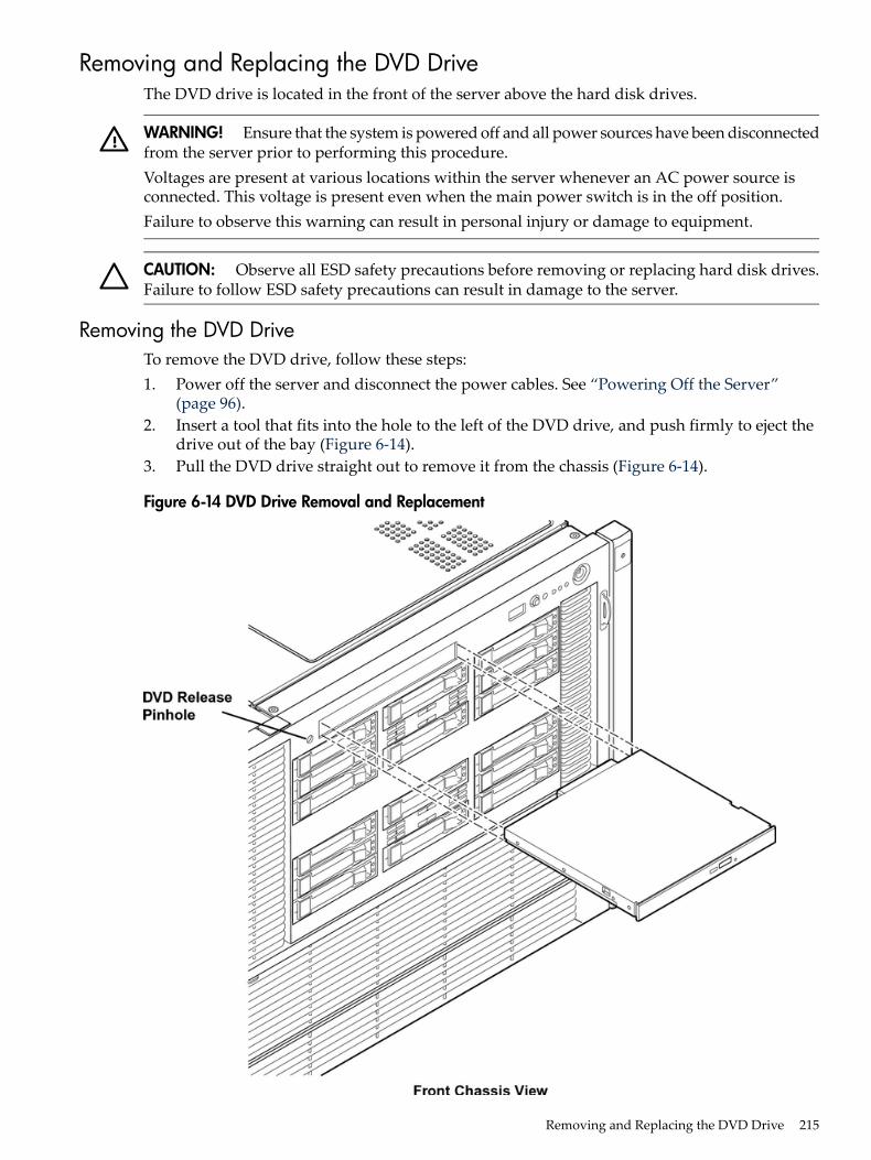
Removing and Replacing the DVD DriveThe DVD drive is located in the front of the server above the hard disk drives.
WARNING! Ensure that the system is powered off and all power sources have been disconnectedfrom the server prior to performing this procedure.Voltages are present at various locations within the server whenever an AC power source isconnected. This voltage is present even when the main power switch is in the off position.Failure to observe this warning can result in personal injury or damage to equipment.
CAUTION: Observe all ESD safety precautions before removing or replacing hard disk drives.Failure to follow ESD safety precautions can result in damage to the server.
Removing the DVD DriveTo remove the DVD drive, follow these steps:1. Power off the server and disconnect the power cables. See “Powering Off the Server”
(page 96).2. Insert a tool that fits into the hole to the left of the DVD drive, and push firmly to eject the
drive out of the bay (Figure 6-14).3. Pull the DVD drive straight out to remove it from the chassis (Figure 6-14).
Figure 6-14 DVD Drive Removal and Replacement
Removing and Replacing the DVD Drive 215
Replacing the DVD DriveTo replace a DVD drive, follow these steps:1. Insert the DVD drive, and push it straight into the drive bay until it clicks into place
(Figure 6-14).2. Reconnect the power cables and power on the server. See “Powering On the Server”
(page 96).
Removing and Replacing the Memory Carrier AssemblyThe memory carrier assembly encloses the system DIMMs. There is one memory carrier assemblythat is available for this server:• 48-DIMM memory carrier assemblyThe memory carrier assembly has two sides, 0 and 1, each of which contain a 24-DIMM memoryboard. System DIMMs seat onto the memory boards.Table 6-4 lists the supported memory carrier assembly configurations.
Table 6-4 Supported Memory Carrier Assembly Configurations
Memory Boards InstalledMemory Carrier Configuration
1 X 24-DIMM memory board24DIMM memory carrier assembly (configuration 1)
2 X 24-DIMM memory boards48-DIMM memory carrier assembly (configuration 2)
WARNING! Ensure that the system is powered off and all power sources have been disconnectedfrom the server prior to performing this procedure.Voltages are present at various locations within the server whenever an AC power source isconnected. This voltage is present even when the main power switch is in the off position.Failure to observe this warning can result in personal injury or damage to equipment.
CAUTION: Observe all ESD safety precautions before attempting this procedure. Failure tofollow ESD safety precautions can result in damage to the server.
Removing the Memory Carrier AssemblyTo remove the memory carrier assembly, follow these steps:1. Power off the server and disconnect the power cables. See “Powering Off the Server”
(page 96).2. If rack installed, slide the server out from the rack until it stops. See “Extending the Server
from the Rack” (page 188).3. Unlatch the cover release lever on the top cover and remove the memory carrier assembly
cover. See “Removing the Memory Carrier Assembly Cover” (page 191).
216 Removing and Replacing Server Components
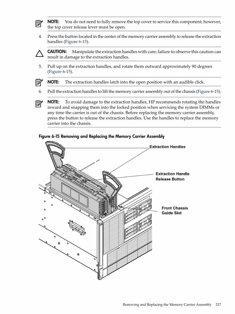
NOTE: You do not need to fully remove the top cover to service this component; however,the top cover release lever must be open.
4. Press the button located in the center of the memory carrier assembly to release the extractionhandles (Figure 6-15).
CAUTION: Manipulate the extraction handles with care; failure to observe this caution canresult in damage to the extraction handles.
5. Pull up on the extraction handles, and rotate them outward approximately 90 degrees(Figure 6-15).
NOTE: The extraction handles latch into the open position with an audible click.
6. Pull the extraction handles to lift the memory carrier assembly out of the chassis (Figure 6-15).
NOTE: To avoid damage to the extraction handles, HP recommends rotating the handlesinward and snapping them into the locked position when servicing the system DIMMs orany time the carrier is out of the chassis. Before replacing the memory carrier assembly,press the button to release the extraction handles. Use the handles to replace the memorycarrier into the chassis.
Figure 6-15 Removing and Replacing the Memory Carrier Assembly
Removing and Replacing the Memory Carrier Assembly 217
Replacing the Memory Carrier Assembly
CAUTION: Ensure the processor board assembly is fully seated before you replace the memorycarrier assembly. The processor board assembly access door must be flush with the front bezel.
To replace the memory carrier assembly, follow these steps:1. Ensure that the extraction handles are positioned in the outward, unlocked position.2. Align the memory carrier assembly with the front and rear chassis guide slots.
NOTE: Assembly side 0 is on the left, and assembly side 1 is on the right as viewed fromthe front of the chassis.
3. Slide the memory carrier assembly into the chassis until it begins to seat into the socketlocated on the processor board.
CAUTION: Do not apply excessive force when closing the extraction handles and seatingthe memory carrier assembly into the socket on the processor board. Manipulate the extractionhandles with care; failure to observe these cautions can result in damage to the extractionhandles and other server components.
4. Rotate the extraction handles inward and press the handles straight down until they snapinto the locked position.
5. Replace the memory carrier assembly cover and latch the top cover release lever closed. See“Replacing the Memory Carrier Assembly Cover” (page 191).
6. If rack installed, slide the server completely into the rack. See “Inserting the Server into theRack” (page 188).
7. Reconnect the power cables and power on the server. See “Powering On the Server”(page 96).
Removing and Replacing System MemorySystem memory, or DIMMs, are located on a pair of memory boards inside the memory carrierassembly.
WARNING! Ensure that the system is powered off and all power sources have been disconnectedfrom the server prior to performing this procedure.Voltages are present at various locations within the server whenever an AC power source isconnected. This voltage is present even when the main power switch is in the off position.Failure to observe this warning can result in personal injury or damage to equipment.
CAUTION: Observe all ESD safety precautions before attempting this procedure. Failure tofollow ESD safety precautions can result in damage to the server.
Removing System MemoryTo remove system memory, follow these steps:1. Power off the server and disconnect the power cables. See “Powering Off the Server”
(page 96).2. If rack installed, slide the server out from the rack until it stops. See “Extending the Server
from the Rack” (page 188).3. Unlatch the cover release lever on the top cover and remove the memory carrier assembly
cover. See “Removing the Memory Carrier Assembly Cover” (page 191).
218 Removing and Replacing Server Components
NOTE: You do not need to fully remove the top cover to service this component; however,the top cover release lever must be open. You must remove the memory carrier because itattaches directly to the processor board.
4. Remove the memory carrier assembly. See “Removing the Memory Carrier Assembly”(page 216).
NOTE: To avoid damage to the extraction handles, HP recommends rotating the handlesinward and snapping them into the locked position when servicing the system DIMMs orany time the carrier is out of the chassis. Before replacing the memory carrier assembly,press the button to release the extraction handles. Use the handles to replace the memorycarrier into the chassis.
5. Locate the DIMM you need to remove. Use Figure 6-18: “48-DIMM Memory Carrier BoardSlot IDs”,.
6. Lay the memory carrier assembly on side 0 or side 1 so that the memory board containingthe DIMMs that require servicing faces upward (Figure 6-16).
7. Remove the memory carrier assembly side cover.a. Press the release tabs (Figure 6-16) on both sides of the extraction handle release button
until the side cover releases from the top center of the assembly.b. Rotate the side cover slightly to free the tabs from the retaining slots at the base of the
assembly (Figure 6-17).c. Lift the side cover off the assembly.
8. Release the DIMM from the slot.a. Identify the DIMM you want to remove on the memory board.b. Push the appropriate extraction levers found on either side of the DIMM slot outward
to the open position (Figure 6-19).9. Remove the DIMM from the slot.Figure 6-16 shows the memory carrier assembly removed from the chassis.
Removing and Replacing System Memory 219
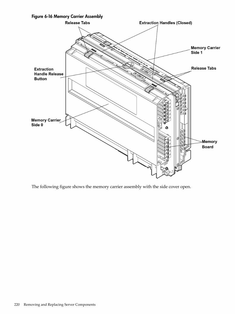
Figure 6-16 Memory Carrier Assembly
The following figure shows the memory carrier assembly with the side cover open.
220 Removing and Replacing Server Components
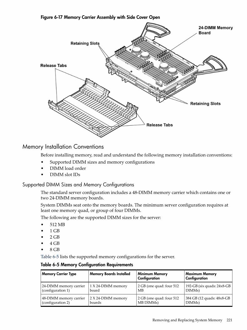
Figure 6-17 Memory Carrier Assembly with Side Cover Open
Memory Installation ConventionsBefore installing memory, read and understand the following memory installation conventions:• Supported DIMM sizes and memory configurations• DIMM load order• DIMM slot IDs
Supported DIMM Sizes and Memory ConfigurationsThe standard server configuration includes a 48-DIMM memory carrier which contains one ortwo 24-DIMM memory boards.System DIMMs seat onto the memory boards. The minimum server configuration requires atleast one memory quad, or group of four DIMMs.The following are the supported DIMM sizes for the server:• 512 MB• 1 GB• 2 GB• 4 GB• 8 GBTable 6-5 lists the supported memory configurations for the server.
Table 6-5 Memory Configuration Requirements
Maximum MemoryConfiguration
Minimum MemoryConfiguration
Memory Boards InstalledMemory Carrier Type
192-GB (six quads: 24x8-GBDIMMs)
2 GB (one quad: four 512MB
1 X 24-DIMM memoryboard
24-DIMM memory carrier(configuration 1)
384 GB (12 quads: 48x8-GBDIMMs)
2 GB (one quad: four 512MB DIMMs)
2 X 24-DIMM memoryboards
48-DIMM memory carrier(configuration 2)
Removing and Replacing System Memory 221
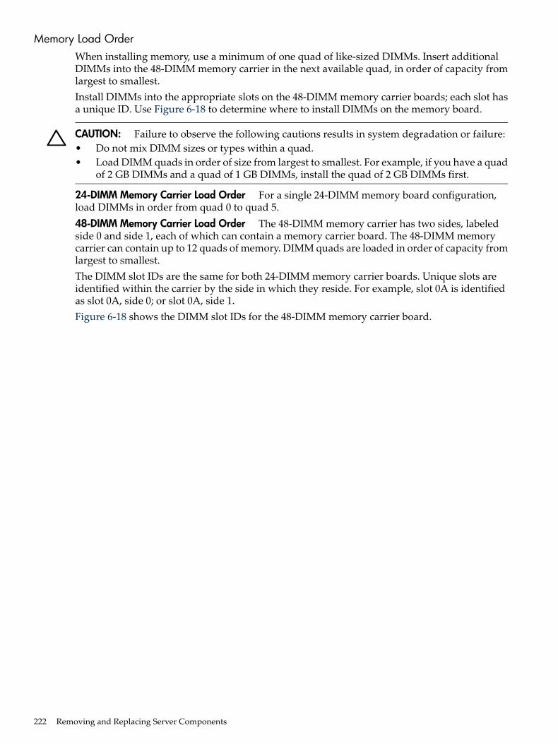
Memory Load OrderWhen installing memory, use a minimum of one quad of like-sized DIMMs. Insert additionalDIMMs into the 48-DIMM memory carrier in the next available quad, in order of capacity fromlargest to smallest.Install DIMMs into the appropriate slots on the 48-DIMM memory carrier boards; each slot hasa unique ID. Use Figure 6-18 to determine where to install DIMMs on the memory board.
CAUTION: Failure to observe the following cautions results in system degradation or failure:• Do not mix DIMM sizes or types within a quad.• Load DIMM quads in order of size from largest to smallest. For example, if you have a quad
of 2 GB DIMMs and a quad of 1 GB DIMMs, install the quad of 2 GB DIMMs first.
24-DIMM Memory Carrier Load Order For a single 24-DIMM memory board configuration,load DIMMs in order from quad 0 to quad 5.48-DIMM Memory Carrier Load Order The 48-DIMM memory carrier has two sides, labeledside 0 and side 1, each of which can contain a memory carrier board. The 48-DIMM memorycarrier can contain up to 12 quads of memory. DIMM quads are loaded in order of capacity fromlargest to smallest.The DIMM slot IDs are the same for both 24-DIMM memory carrier boards. Unique slots areidentified within the carrier by the side in which they reside. For example, slot 0A is identifiedas slot 0A, side 0; or slot 0A, side 1.Figure 6-18 shows the DIMM slot IDs for the 48-DIMM memory carrier board.
222 Removing and Replacing Server Components
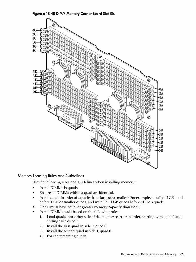
Figure 6-18 48-DIMM Memory Carrier Board Slot IDs
Memory Loading Rules and GuidelinesUse the following rules and guidelines when installing memory:• Install DIMMs in quads.• Ensure all DIMMs within a quad are identical.• Install quads in order of capacity from largest to smallest. For example, install all 2 GB quads
before 1 GB or smaller quads, and install all 1 GB quads before 512 MB quads.• Side 0 must have equal or greater memory capacity than side 1.• Install DIMM quads based on the following rules:
1. Load quads into either side of the memory carrier in order, starting with quad 0 andending with quad 5.
2. Install the first quad in side 0, quad 0.3. Install the second quad in side 1, quad 0.4. For the remaining quads:
Removing and Replacing System Memory 223
a. If both sides of the memory carrier contain the same capacity of memory, installthe next quad in side 0.
b. If side 0 contains more memory capacity than side 1, install the next quad in side1.
c. If side 1 is full, install the remaining quads in side 0.
Table 6-6 shows several examples of proper memory carrier loading order.
IMPORTANT: The number in parenthesis indicates the order in which the quads are loaded.
Table 6-6 48-DIMM Memory Carrier Loading Examples
Memory Carrier Side 1Memory Carrier Side 0Quad Slot IDsQuad Number
Example 1
2 GB DIMMs (2)2 GB DIMMs (1)0A, 0B, 0C, 0D0
2 GB DIMMs (4)2 GB DIMMs (3)1A, 1B, 1C, 1D1
1 GB DIMMs (6)1 GB DIMMs (5)2A, 2B, 2C, 2D2
1 GB DIMMs (8)1 GB DIMMs (7)3A, 3B, 3C, 3D3
512 MB (10)512 MB (9)4A, 4B, 4C, 4D4
512 MB (12)512 MB (11)5A, 5B, 5C, 5D5
Example 2
1 GB DIMMs (2)2 GB DIMMs (1)0A, 0B, 0C, 0D0
1 GB DIMMs (3)1 GB DIMMs (4)1A, 1B, 1C, 1D1
512 MB (5)512 MB (7)2A, 2B, 2C, 2D2
512 MB (6)512 MB (9)3A, 3B, 3C, 3D3
512 MB (8)4A, 4B, 4C, 4D4
512 MB (10)5A, 5B, 5C, 5D5
Example 3
512 MB (2)2 GB DIMMs (1)0A, 0B, 0C, 0D0
512 MB (3)512 MB (6)1A, 1B, 1C, 1D1
512 MB (4)512 MB (8)2A, 2B, 2C, 2D2
512 MB (5)3A, 3B, 3C, 3D3
512 MB (7)4A, 4B, 4C, 4D4
512 MB (9)5A, 5B, 5C, 5D5
Installing Memory
IMPORTANT: You must pull the AC power plugs on the server every time you modify theDIMMs. If you do not pull the AC power plugs, the system does not display the correct DIMMinformation.
To install memory, follow these steps:1. Power off the server and disconnect the power cables. See “Powering Off the Server”
(page 96).
224 Removing and Replacing Server Components
2. If rack installed, slide the server out from the rack until it stops. See “Extending the Serverfrom the Rack” (page 188).
3. Unlatch the cover release lever on the top cover and remove the memory carrier assemblycover. See “Removing the Memory Carrier Assembly Cover” (page 191).
NOTE: You do not need to fully remove the top cover to service this component; however,the top cover release lever must be open.
4. Remove the memory carrier assembly. See “Removing the Memory Carrier Assembly”(page 216).
NOTE: To avoid damage to the extraction handles, HP recommends rotating the handlesinward and snapping them the locked position when servicing the system DIMMs or anytime the carrier is out of the chassis. Before replacing the memory carrier, press the buttonto release the extraction handles. Use the handles to replace the memory carrier into thechassis.
5. Complete the following memory installation prerequisite tasks before installing the memory:a. Determine the DIMM load order for the 48-DIMM memory carrier. For more information,
see “Memory Load Order” (page 222).b. Determine the DIMM slots to populate. Use Figure 6-18: “48-DIMM Memory Carrier
Board Slot IDs”.c. Read, understand, and follow the general guidelines to install memory in the server.
See “Memory Loading Rules and Guidelines” (page 223).6. Lay the memory carrier assembly on side 0 or side 1 so that the memory carrier side that
contains the DIMM slots that require servicing faces upward (Figure 6-16).7. Remove the memory carrier assembly side cover.
a. Press the release tabs (Figure 6-16) on both sides of the extraction handle release buttonuntil the side cover releases from the top center of the assembly.
b. Rotate the side cover slightly to free the tabs from the retaining slots at the base of theassembly (Figure 6-17).
c. Lift the side cover off the assembly.
Removing and Replacing System Memory 225
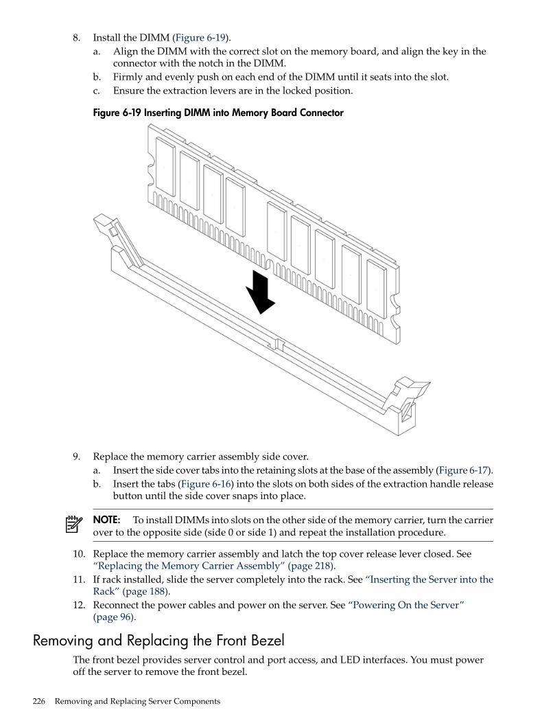
8. Install the DIMM (Figure 6-19).a. Align the DIMM with the correct slot on the memory board, and align the key in the
connector with the notch in the DIMM.b. Firmly and evenly push on each end of the DIMM until it seats into the slot.c. Ensure the extraction levers are in the locked position.
Figure 6-19 Inserting DIMM into Memory Board Connector
9. Replace the memory carrier assembly side cover.a. Insert the side cover tabs into the retaining slots at the base of the assembly (Figure 6-17).b. Insert the tabs (Figure 6-16) into the slots on both sides of the extraction handle release
button until the side cover snaps into place.
NOTE: To install DIMMs into slots on the other side of the memory carrier, turn the carrierover to the opposite side (side 0 or side 1) and repeat the installation procedure.
10. Replace the memory carrier assembly and latch the top cover release lever closed. See“Replacing the Memory Carrier Assembly” (page 218).
11. If rack installed, slide the server completely into the rack. See “Inserting the Server into theRack” (page 188).
12. Reconnect the power cables and power on the server. See “Powering On the Server”(page 96).
Removing and Replacing the Front BezelThe front bezel provides server control and port access, and LED interfaces. You must poweroff the server to remove the front bezel.
226 Removing and Replacing Server Components
NOTE: The procedures in this section refer to the upper portion of the front bezel; the lowerportion of the front bezel is the processor access door.
Removing the Front BezelTo remove the front bezel, follow these steps:1. Power off the server and disconnect the power cables. See “Powering Off the Server”
(page 96).2. If rack installed, slide the server out from the rack until it stops. See “Extending the Server
from the Rack” (page 188).3. Remove the memory carrier assembly cover. See “Removing the Memory Carrier Assembly
Cover” (page 191).
NOTE: You do not need to fully remove the top cover to service this component; however,the top cover release lever must be open.You must remove the memory carrier assembly because it attaches directly to the processorboard.
4. Remove the memory carrier assembly. See “Removing the Memory Carrier Assembly”(page 216).
5. Press the button located on top of the bezel and directly in front of the memory carrierassembly to release the processor board access door (Figure 6-20).
CAUTION: The processor board access door opens to approximately a 30 degree angle.Do not force the door to open to a greater angle. Failure to observe this caution results indamage to server components.
6. Use the processor board assembly access door as a handle and gently slide the assembly outof the chassis approximately six inches.
7. Remove the eight screws that attach the bezel to the chassis.8. Tilt the bezel away from the chassis.9. Flip out the two pull handles located on both ends of the front bezel.10. Remove the plastic server label located to the right of the front panel LEDs.
a. Grasp the label, and pull it out until it stops.b. Lift up on the notched retaining tab at the rear of the label until it clears the slot.c. Pull the label completely out of the chassis.
IMPORTANT: You must reinstall the plastic server label into the replacement bezel.
11. Slide the bezel to the right to release it from the chassis, and lift it off the chassis.
Replacing the Front BezelTo replace the front bezel, follow these steps:1. Align the bezel slots with the tabs on the chassis.2. Slide the bezel from right to left to lock it into place.3. Tilt the bezel toward the chassis until it is flush with the chassis.4. Flip in the two pull handles located on both ends of the front bezel.5. Replace the four screws that attach the bezel to the right side of the chassis.6. Replace the four screws that attach the bezel to the left side of the chassis.
Removing and Replacing the Front Bezel 227
7. Reinsert the plastic label with the notched end on the bottom, and push it into the slot inthe bezel.
8. Slide the processor board assembly into the chassis until it begins to seat into the socketlocated on the midplane board.
9. Push the processor board access door upward until it locks into position.10. Replace the memory carrier assembly. See “Replacing the Memory Carrier Assembly”
(page 218).11. Replace the memory carrier assembly cover. See “Replacing the Memory Carrier Assembly
Cover” (page 191).12. Close the top cover release lever.13. If rack installed, slide the server completely into the rack. See “Inserting the Server into the
Rack” (page 188).14. Reconnect the power cables and power on the server. See “Powering On the Server”
(page 96).
Removing and Replacing the Processor Board AssemblyThe processor board assembly holds one, two, three, or four dual-core Itanium processors. It islocated beneath the disk drives and memory carrier assembly in the bottom service bay. Theprocessor board is mounted onto a removable carrier tray that is retained in the service bay bya hinged access door.
WARNING! Ensure that the system is powered off and all power sources have been disconnectedfrom the server prior to performing this procedure.Voltages are present at various locations within the server whenever an AC power source isconnected. This voltage is present even when the main power switch is in the off position.Failure to observe this warning can result in personal injury or damage to equipment.
CAUTION: Observe all ESD safety precautions before attempting this procedure. Failure tofollow ESD safety precautions can result in damage to the server.
Removing the Processor Board AssemblyTo remove the processor board assembly, follow these steps:1. Power off the server and disconnect the power cables. See “Powering Off the Server”
(page 96).2. If rack installed, slide the server out from the rack until it stops. See “Extending the Server
from the Rack” (page 188).3. Unlatch the cover release lever on the top cover and remove the memory carrier assembly
cover. See “Removing the Memory Carrier Assembly Cover” (page 191).
NOTE: You do not need to fully remove the top cover to service this component; however,the top cover release lever must be open. You must remove the memory carrier because itattaches directly to the processor board.
4. Remove the memory carrier assembly. See “Removing the Memory Carrier Assembly”(page 216).
228 Removing and Replacing Server Components
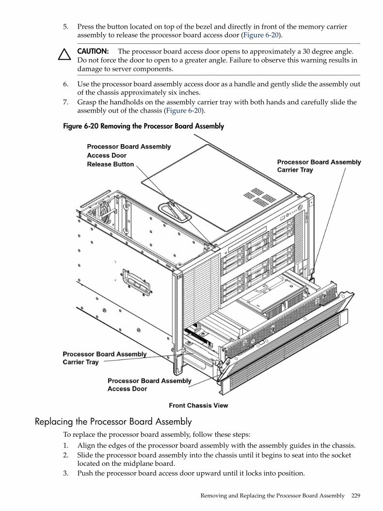
5. Press the button located on top of the bezel and directly in front of the memory carrierassembly to release the processor board access door (Figure 6-20).
CAUTION: The processor board access door opens to approximately a 30 degree angle.Do not force the door to open to a greater angle. Failure to observe this warning results indamage to server components.
6. Use the processor board assembly access door as a handle and gently slide the assembly outof the chassis approximately six inches.
7. Grasp the handholds on the assembly carrier tray with both hands and carefully slide theassembly out of the chassis (Figure 6-20).
Figure 6-20 Removing the Processor Board Assembly
Replacing the Processor Board AssemblyTo replace the processor board assembly, follow these steps:1. Align the edges of the processor board assembly with the assembly guides in the chassis.2. Slide the processor board assembly into the chassis until it begins to seat into the socket
located on the midplane board.3. Push the processor board access door upward until it locks into position.
Removing and Replacing the Processor Board Assembly 229
4. Replace the memory carrier assembly. See “Replacing the Memory Carrier Assembly”(page 218).
5. Replace the memory carrier assembly cover and latch the top cover release lever closed. See“Replacing the Memory Carrier Assembly Cover” (page 191).
6. If rack installed, slide the server completely into the rack. See “Inserting the Server into theRack” (page 188).
7. Reconnect the power cables and power on the server. See “Powering On the Server”(page 96).
Removing and Replacing a Dual-Core ProcessorThe HP Integrity rx6600 uses dual-core processors. That is, each processor contains two coresthat function as separate processors. Dual-core processors double the processing power of theserver while maintaining the physical dimensions of a single processor.The server can contain one, two, three, or four dual-core processors that provide the followingconfiguration options:• 1P/2C (One processor/two cores)• 2P/4C (Two processors/four cores)• 3P/6C (Three processors/six cores)• 4P/8C (Four processors/eight cores)If the server has fewer than the maximum number of dual-core processors installed, install theadditional processors in the appropriate slot.
WARNING! Ensure that the system is powered off and all power sources have been disconnectedfrom the server prior to performing this procedure.Voltages are present at various locations within the server whenever an AC power source isconnected. This voltage is present even when the main power switch is in the off position.Failure to observe this warning can result in personal injury or damage to equipment.
CAUTION: Ensure that processor speed and cache size are identical for all processors. Failureto observe this caution results in performance degradation or system failure.The easiest way to ensure compatibility is to use dual-core processors with identical part numbers.
CAUTION: Observe all ESD safety precautions before attempting this procedure. Failure tofollow ESD safety precautions can result in damage to the server.
Processor Load OrderYou can install up to four dual-core processors on the processor board. If fewer than the maximumnumber of dual-core processors are installed (one, two, or three in the HP Integrity rx6600 server),install them in the designated locations on the processor board.The slots on the processor board are labeled Module 0, Module 1, Module 2, and Module 3. TheModule 0 and Module 1 slots are located on the top of the processor board assembly, and theModule 2 and Module 3 slots are located on the underside of the processor board assembly.
IMPORTANT: Use the supplied handholds to turn the processor board assembly over if youare servicing the Module 2 or Module 3 slots.
Install the first processor in the Module 0 slot. Install the second dual-core processor in the Module1 socket, and so on. The load sequence is described in Table 6-7.
230 Removing and Replacing Server Components
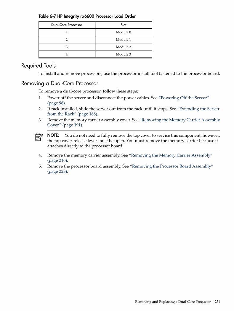
Table 6-7 HP Integrity rx6600 Processor Load Order
SlotDual-Core Processor
Module 01
Module 12
Module 23
Module 34
Required ToolsTo install and remove processors, use the processor install tool fastened to the processor board.
Removing a Dual-Core ProcessorTo remove a dual-core processor, follow these steps:1. Power off the server and disconnect the power cables. See “Powering Off the Server”
(page 96).2. If rack installed, slide the server out from the rack until it stops. See “Extending the Server
from the Rack” (page 188).3. Remove the memory carrier assembly cover. See “Removing the Memory Carrier Assembly
Cover” (page 191).
NOTE: You do not need to fully remove the top cover to service this component; however,the top cover release lever must be open. You must remove the memory carrier because itattaches directly to the processor board.
4. Remove the memory carrier assembly. See “Removing the Memory Carrier Assembly”(page 216).
5. Remove the processor board assembly. See “Removing the Processor Board Assembly”(page 228).
Removing and Replacing a Dual-Core Processor 231
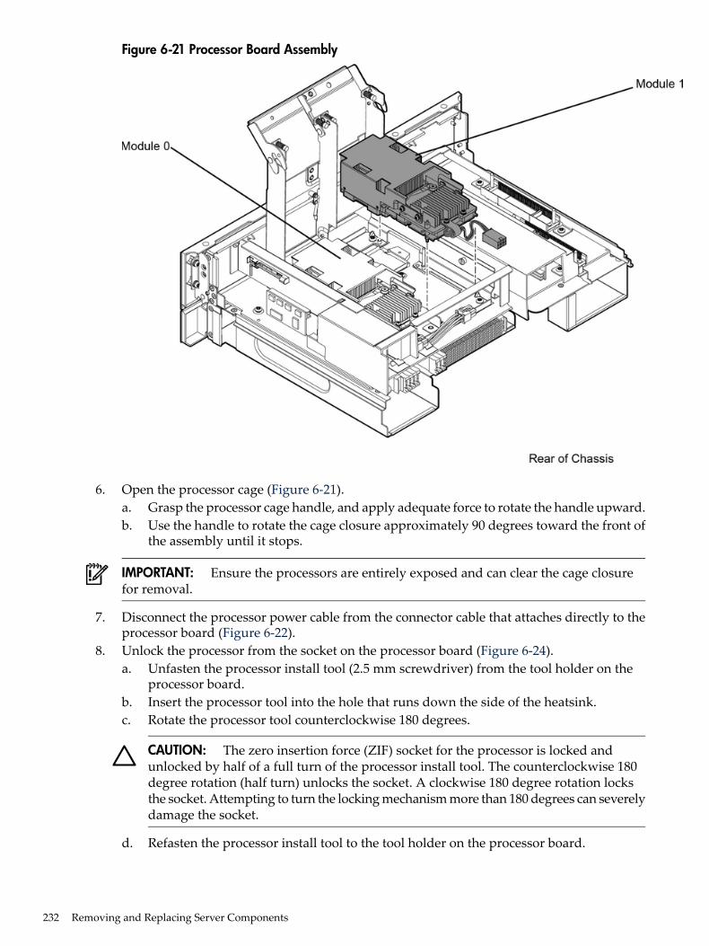
Figure 6-21 Processor Board Assembly
6. Open the processor cage (Figure 6-21).a. Grasp the processor cage handle, and apply adequate force to rotate the handle upward.b. Use the handle to rotate the cage closure approximately 90 degrees toward the front of
the assembly until it stops.
IMPORTANT: Ensure the processors are entirely exposed and can clear the cage closurefor removal.
7. Disconnect the processor power cable from the connector cable that attaches directly to theprocessor board (Figure 6-22).
8. Unlock the processor from the socket on the processor board (Figure 6-24).a. Unfasten the processor install tool (2.5 mm screwdriver) from the tool holder on the
processor board.b. Insert the processor tool into the hole that runs down the side of the heatsink.c. Rotate the processor tool counterclockwise 180 degrees.
CAUTION: The zero insertion force (ZIF) socket for the processor is locked andunlocked by half of a full turn of the processor install tool. The counterclockwise 180degree rotation (half turn) unlocks the socket. A clockwise 180 degree rotation locksthe socket. Attempting to turn the locking mechanism more than 180 degrees can severelydamage the socket.
d. Refasten the processor install tool to the tool holder on the processor board.
232 Removing and Replacing Server Components
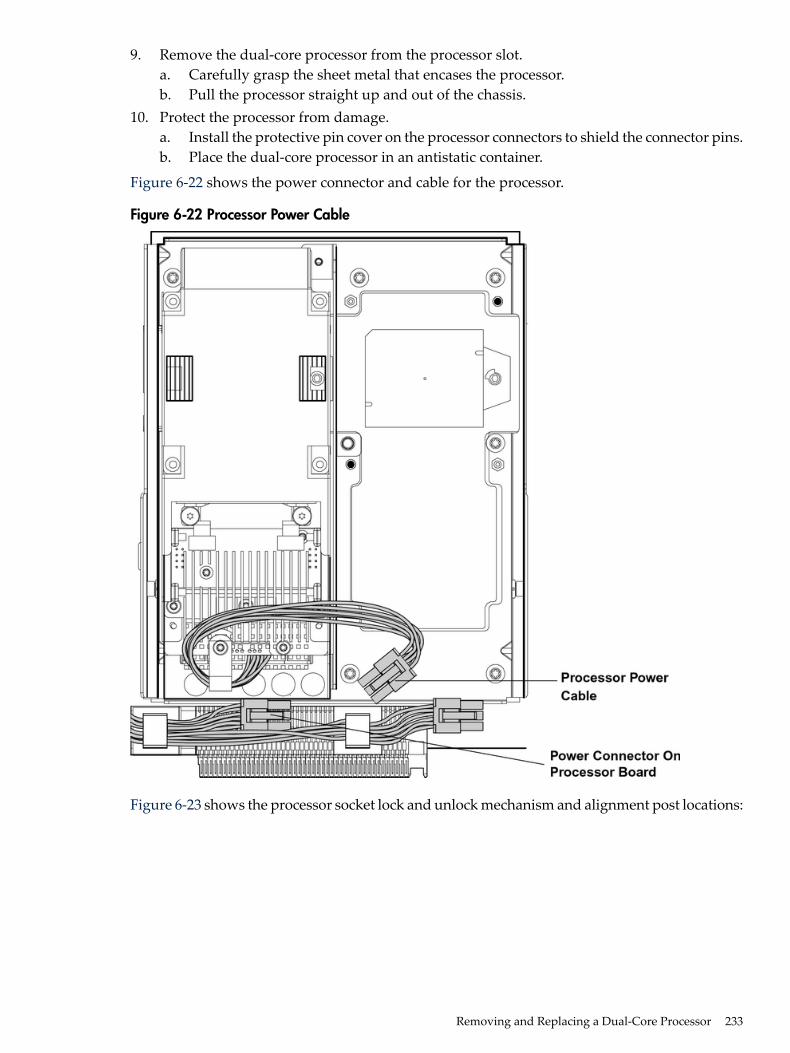
9. Remove the dual-core processor from the processor slot.a. Carefully grasp the sheet metal that encases the processor.b. Pull the processor straight up and out of the chassis.
10. Protect the processor from damage.a. Install the protective pin cover on the processor connectors to shield the connector pins.b. Place the dual-core processor in an antistatic container.
Figure 6-22 shows the power connector and cable for the processor.
Figure 6-22 Processor Power Cable
Figure 6-23 shows the processor socket lock and unlock mechanism and alignment post locations:
Removing and Replacing a Dual-Core Processor 233
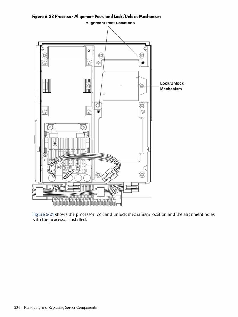
Figure 6-23 Processor Alignment Posts and Lock/Unlock Mechanism
Figure 6-24 shows the processor lock and unlock mechanism location and the alignment holeswith the processor installed:
234 Removing and Replacing Server Components
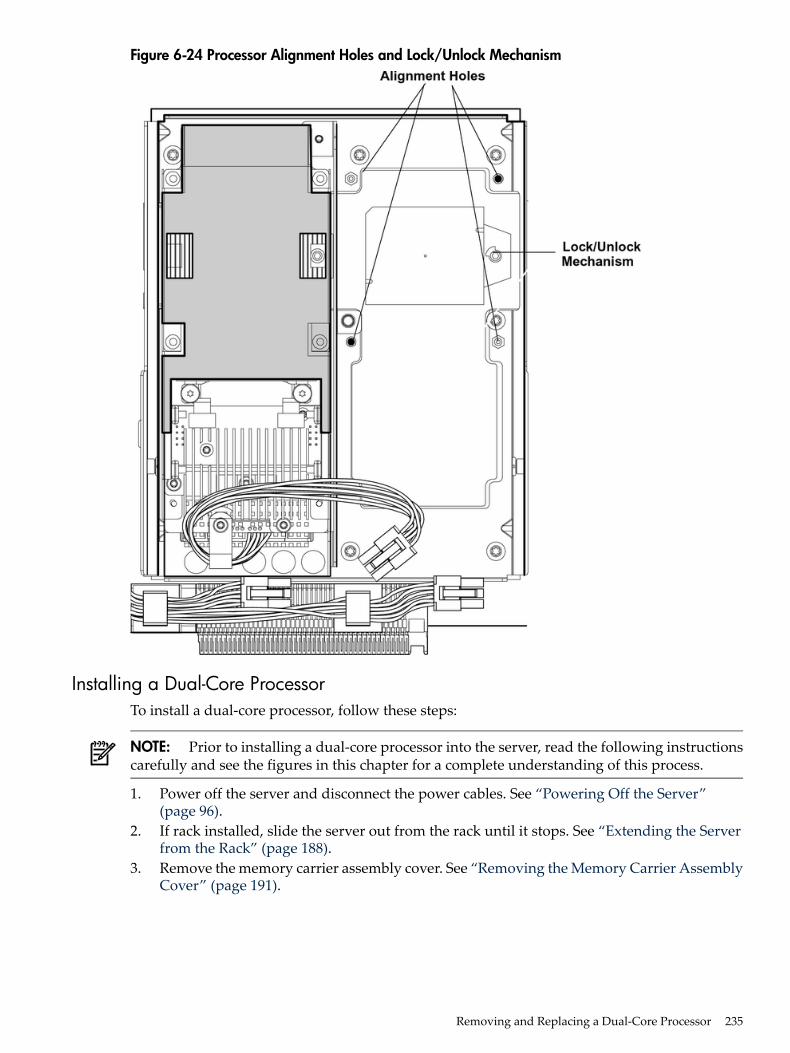
Figure 6-24 Processor Alignment Holes and Lock/Unlock Mechanism
Installing a Dual-Core ProcessorTo install a dual-core processor, follow these steps:
NOTE: Prior to installing a dual-core processor into the server, read the following instructionscarefully and see the figures in this chapter for a complete understanding of this process.
1. Power off the server and disconnect the power cables. See “Powering Off the Server”(page 96).
2. If rack installed, slide the server out from the rack until it stops. See “Extending the Serverfrom the Rack” (page 188).
3. Remove the memory carrier assembly cover. See “Removing the Memory Carrier AssemblyCover” (page 191).
Removing and Replacing a Dual-Core Processor 235
NOTE: You do not need to fully remove the top cover to service this component; however,the top cover release lever must be open. You must remove the memory carrier because itattaches directly to the processor board.
4. Remove the memory carrier assembly. See “Removing the Memory Carrier Assembly”(page 216).
5. Remove the processor board assembly. See “Removing the Processor Board Assembly”(page 228).
6. Open the processor cage (Figure 6-21).a. Grasp the processor cage handle, and apply adequate force to rotate the handle upward.b. Use the handle to rotate the cage closure approximately 90 degrees toward the front of
the assembly until it stops.
IMPORTANT: Ensure that the processor slot is entirely exposed. The processor must clearthe cage closure for proper installation.
7. Locate the appropriate processor slot (Module 0 or Module 1) for the processor installation(Figure 6-21).
8. Remove the plastic airflow blocker covering the processor slot, if required.9. Remove the protective dust cover from the processor socket, if required.10. Ensure the cam on the processor socket lock is in the unlocked, position (Figure 6-23).
CAUTION: The zero insertion force (ZIF) socket for the processor is locked and unlockedby half of a full turn of the processor install tool. The counterclockwise 180 degree rotation(half turn) unlocks the socket. A clockwise 180 degree rotation locks the socket. Attemptingto turn the locking mechanism more than 180 degrees can severely damage the socket.
11. Remove any protective packaging from the new processor.
NOTE: Protective covers are installed to protect connector pins. Save these covers for futureuse.
12. Inspect the processor pins and verify that the pins are not bent.13. Align the alignment holes on the processor with the alignment posts on the processor cage,
and carefully lower the processor onto the processor socket (Figure 6-23 and Figure 6-24).
CAUTION: Do not press the processor into the socket. When properly aligned, the processorpins seat into the socket. No additional pressure is required. Damage to the pins can occurif too much pressure is applied.
14. Lock the processor into the socket on the processor board (Figure 6-24).a. Unfasten the processor install tool (2.5 mm driver) from the tool holder on the processor
board.b. Insert the processor tool into the hole that runs down the side of the heatsink.c. Rotate the processor tool clockwise 180 degrees.d. Refasten the processor install tool to the tool holder on the processor board.
15. Reconnect the processor power cable to the connector cable that attaches directly to theprocessor board (Figure 6-22).
16. Close the processor cage (Figure 6-21).a. Grasp the processor cage handle and rotate the cage closure inward toward the rear of
the assembly until it is completely closed.b. Apply adequate force to push the handle down until it is flush with the cage.
236 Removing and Replacing Server Components
17. Replace the processor board assembly. See “Replacing the Processor Board Assembly”(page 229).
18. Replace the memory carrier assembly. See “Replacing the Memory Carrier Assembly”(page 218).
19. Replace the memory carrier assembly cover and latch the top cover release lever closed. See“Replacing the Memory Carrier Assembly Cover” (page 191).
20. If rack installed, slide the server completely into the rack. See “Inserting the Server into theRack” (page 188).
21. Reconnect the power cables and power on the server. See “Powering On the Server”(page 96).
22. Verify processor replacement and operation by using either the iLO 2 MP commands or theEFI commands.
Removing and Replacing the I/O Board Assembly
IMPORTANT: The new version of the PCI/PCI-X/PCIe backplane (version 1.1) is being shippedon July 1, 2008. For existing servers, repair and replace should continue to be performed withthe version 1 I/O backplane. For servers shipped as of July 1, 2008, repair and replace should beperformed with version 1.1 I/O backplane.
The I/O board assembly contains the following server components:• System battery• I/O voltage regulator module• Core I/O board• LAN core I/O card• SAS core I/O card• PCI/PCI-X cards• Trusted Platform Module (TPM)
IMPORTANT: System information is stored on the I/O board assembly. You must write theserial number and model string information to the new I/O board after installation.
WARNING! Ensure that the system is powered off and all power sources have been disconnectedfrom the server prior to performing this procedure.Voltages are present at various locations within the server whenever an AC power source isconnected. This voltage is present even when the main power switch is in the off position.Failure to observe this warning can result in personal injury or damage to equipment.
CAUTION: Observe all ESD safety precautions before attempting this procedure. Failure tofollow ESD safety precautions can result in damage to the server.
Removing the I/O Board AssemblyTo remove the I/O board assembly, follow these steps:1. Record the boot configuration settings. To find the settings, use the INFO ALL EFI Shell
command.2. Use Figure 6-28: “TPM Location on I/O Board”, to determine if there is a TPM on the I/O
board assembly. If so, record the TPM settings to transfer to the replacement I/O boardassembly. See the HP-UX operating system documentation for instructions.
Removing and Replacing the I/O Board Assembly 237
3. Power off the server and disconnect the power cables. See “Powering Off the Server”(page 96).
CAUTION: The removal and replacement of the I/O board assembly occurs through therear of the rack for rack-installed servers. Carefully follow the board removal and replacementprocedures. You must first perform several tasks with the server extended out from the frontof the rack.
4. If rack installed, slide the server completely out from the rack. See “Extending the Serverfrom the Rack” (page 188).
5. Remove the top cover. See “Removing the Top Cover” (page 189).6. Disconnect the internal USB cable from the connector on the core I/O board.7. Disconnect the SAS cables attached to the SAS core I/O card in PCI slot 1.
CAUTION: When disconnecting the SAS cables, note the labeling on the cables. Both cablesand sockets are clearly marked with the correct channel. When reconnecting these cables,match each cable with the appropriate socket on the SAS core I/O card. If the cables aremismatched, the server will not reboot.
8. Slide the server completely back into the rack.9. Open the cable management arm wide enough to slide the I/O board out the rear of the rack.10. Disconnect all external cabling attached to ports at the rear of the chassis.11. Press in on the retention levers to unlock the I/O board assembly extraction handles
(Figure 6-25).12. Pull the I/O board assembly extraction handles outward to unplug the I/O board assembly
from the socket on the midplane board.
238 Removing and Replacing Server Components
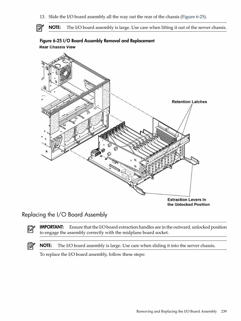
13. Slide the I/O board assembly all the way out the rear of the chassis (Figure 6-25).
NOTE: The I/O board assembly is large. Use care when lifting it out of the server chassis.
Figure 6-25 I/O Board Assembly Removal and Replacement
Replacing the I/O Board Assembly
IMPORTANT: Ensure that the I/O board extraction handles are in the outward, unlocked positionto engage the assembly correctly with the midplane board socket.
NOTE: The I/O board assembly is large. Use care when sliding it into the server chassis.
To replace the I/O board assembly, follow these steps:
Removing and Replacing the I/O Board Assembly 239
1. Transfer the following components from the removed I/O board assembly to the replacementI/O board assembly in the following order:a. SAS core I/O card. See “Removing and Replacing the SAS Core I/O Card” (page 250).b. LAN core I/O card. See “Removing and Replacing the LAN Core I/O Card” (page 252).c. Trusted Platform Module (TPM). Use Figure 6-28: “TPM Location on I/O Board”, to
determine if there is a TPM on the removed I/O board assembly. If so, transfer the TPMfrom the removed I/O board assembly to the replacement I/O board assembly. See“Removing and Replacing the Trusted Platform Module” (page 244).
d. Core I/O board. See “Removing and Replacing the Core I/O Board” (page 247).2. Align the I/O board assembly rails with the chassis slots, and slide the assembly into the
chassis until it stops against the midplane board socket (Figure 6-25).
IMPORTANT: Do not pinch the cable of the fan located behind the memory carrier assemblybetween the fan housing unit and the I/O board when sliding the board into the chassis
3. Ensure that the I/O board assembly is flush against the midplane board socket, and firmlypush the extraction handles inward until the assembly plugs completely into the midplaneboard socket.
4. Press in on the retention levers to lock the I/O board assembly extraction handles into place.5. Reconnect all external cabling into the ports at the rear of the chassis.6. Close and secure the cable management arm.7. Slide the server completely out from the front of the rack.8. Reconnect the internal SAS cables to the connectors on the SAS core I/O card in PCI slot 1.
CAUTION: When reconnecting the SAS cables, note the labeling on the channel cables.Both cables and sockets are clearly marked with the correct channel. Match each cable withthe appropriate socket on the SAS core I/O card. If the cables are mismatched, the serverwill not boot correctly.
9. Reconnect the USB cable to the connector on the core I/O board.10. Replace the top cover. See “Replacing the Top Cover” (page 190).11. Reconnect the power cables and power on the server. See “Powering On the Server”
(page 96).
IMPORTANT: Serial number and model string data information is stored on both theinterconnect board and the I/O board. When installing a new I/O board, copy this informationfrom the interconnect board to the new I/O board.
12. Respond YES to prompts regarding copying information onto the new board.
240 Removing and Replacing Server Components
13. Verify the serial number and model string data information copied onto the new I/O board.a. Boot to EFI.b. Enter service mode:
Shell> sysmode serviceCurrent System Mode: ADMINYou are now in SERVICE mode.
c. Use the sysset command to verify that all values are set:Shell> sysset
System Information:Manufacturer: hpProduct Name: server rx6600Product Number: AB464ASecondary Product Number is IdenticalSerial number: SGH43442VBSecondary Serial Number is IdenticalUUID: 3C33C58E-2E5A-11D8-A33B-4188C0AEFAE2 (Valid)Secondary UUID is IdenticalProduct ID: 0x301
14. Enable the TPM. See “Removing and Replacing the Trusted Platform Module” (page 244).15. Restore the TPM settings. See the HP-UX operating system documentation for instructions.16. Verify the system board replacement and operation using either the iLO 2 MP commands
or the EFI commands.
Removing and Replacing the System BatteryThe system battery is located on the I/O board assembly. Replace the battery with an identicalor equivalent battery only. Dispose of used batteries according to the manufacturer’s instructions.
WARNING! Lithium batteries can explode if mistreated. Do not recharge, disassemble, ordispose of batteries in a fire. Failure to observe this warning can result in personal injury ordamage to equipment.
Removing the System Battery
WARNING! Ensure that the system is powered off and all power sources have been disconnectedfrom the server prior to performing this procedure.Voltages are present at various locations within the server whenever an AC power source isconnected. This voltage is present even when the main power switch is in the off position.Failure to observe this warning can result in personal injury or damage to equipment.
CAUTION: Observe all ESD safety precautions before attempting this procedure. Failure tofollow ESD safety precautions can result in damage to the server.
IMPORTANT: Before removing the system battery, record all boot and LAN configurationsettings. (Find the settings using the INFO ALL EFI command.) You must reset these values afterreplacing the battery.
To remove and replace the system battery, follow these steps:
Removing and Replacing the System Battery 241
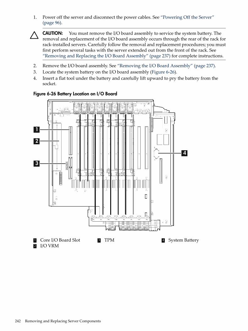
1. Power off the server and disconnect the power cables. See “Powering Off the Server”(page 96).
CAUTION: You must remove the I/O board assembly to service the system battery. Theremoval and replacement of the I/O board assembly occurs through the rear of the rack forrack-installed servers. Carefully follow the removal and replacement procedures; you mustfirst perform several tasks with the server extended out from the front of the rack. See“Removing and Replacing the I/O Board Assembly” (page 237) for complete instructions.
2. Remove the I/O board assembly. See “Removing the I/O Board Assembly” (page 237).3. Locate the system battery on the I/O board assembly (Figure 6-26).4. Insert a flat tool under the battery and carefully lift upward to pry the battery from the
socket.
Figure 6-26 Battery Location on I/O Board
1
2
3
4
431 Core I/O Board Slot System BatteryTPM2 I/O VRM
242 Removing and Replacing Server Components
Replacing the System Battery
CAUTION: You must remove the I/O board assembly to service the system battery. The removaland replacement of the I/O board assembly occurs through the rear of the rack for rack-installedservers. Carefully follow the removal and replacement procedures; you must perform severaltasks with the server extended out the front of the rack. See “Removing and Replacing the I/OBoard Assembly” (page 237) for complete instructions.
1. Insert the replacement battery into the socket on the I/O board assembly.
NOTE: The positive terminal of the battery is designated by the + sign. Install the batterywith the + sign facing up.
2. Replace the I/O board assembly. See “Replacing the I/O Board Assembly” (page 239).3. Reconnect the power cables and power on the server. See “Powering On the Server”
(page 96).4. Reset the server date and time using the EFI date and time commands.
Removing and Replacing the I/O Voltage Regulator ModuleThe I/O voltage regulator module (I/O VRM) is a stand alone component located on the I/O boardassembly that regulates voltage for all I/O operations.
WARNING! Ensure that the system is powered off and all power sources have been disconnectedfrom the server prior to performing this procedure.Voltages are present at various locations within the server whenever an AC power source isconnected. This voltage is present even when the main power switch is in the off position.Failure to observe this warning can result in personal injury or damage to equipment.
CAUTION: Observe all ESD safety precautions before attempting this procedure. Failure tofollow ESD safety precautions can result in damage to the server.
Removing the I/O VRMTo remove the I/O VRM, follow these steps:1. Power off the server and disconnect the power cables. See “Powering Off the Server”
(page 96).2. If rack installed, slide the server completely out from the rack. See “Extending the Server
from the Rack” (page 188).3. Remove the top cover. See “Removing the Top Cover” (page 189).4. Remove the I/O VRM cover (Figure 6-27).
a. Locate the knurled thumbscrew on top of the I/O VRM cover and turn itcounterclockwise until the cover disengages from the chassis wall.
b. Lift the cover off the I/O VRM.5. Push the extraction levers found on either side of the I/O VRM slot outward to the open
position to release the I/O VRM from the socket.6. Grasp the I/O VRM by the edges and lift it out of the chassis (Figure 6-27).
Removing and Replacing the I/O Voltage Regulator Module 243
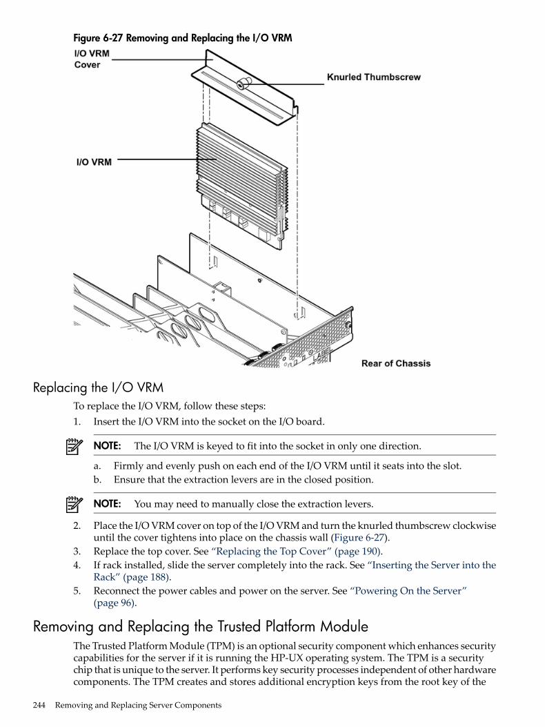
Figure 6-27 Removing and Replacing the I/O VRM
Replacing the I/O VRMTo replace the I/O VRM, follow these steps:1. Insert the I/O VRM into the socket on the I/O board.
NOTE: The I/O VRM is keyed to fit into the socket in only one direction.
a. Firmly and evenly push on each end of the I/O VRM until it seats into the slot.b. Ensure that the extraction levers are in the closed position.
NOTE: You may need to manually close the extraction levers.
2. Place the I/O VRM cover on top of the I/O VRM and turn the knurled thumbscrew clockwiseuntil the cover tightens into place on the chassis wall (Figure 6-27).
3. Replace the top cover. See “Replacing the Top Cover” (page 190).4. If rack installed, slide the server completely into the rack. See “Inserting the Server into the
Rack” (page 188).5. Reconnect the power cables and power on the server. See “Powering On the Server”
(page 96).
Removing and Replacing the Trusted Platform ModuleThe Trusted Platform Module (TPM) is an optional security component which enhances securitycapabilities for the server if it is running the HP-UX operating system. The TPM is a securitychip that is unique to the server. It performs key security processes independent of other hardwarecomponents. The TPM creates and stores additional encryption keys from the root key of the
244 Removing and Replacing Server Components
system. The encryption keys created by the TPM encapsulate system application encryption keysto provide an additional layer of security for sensitive system data.The fundamental capabilities of the TPM include:• Platform authentication• Sensitive information protection• Data integrity• System privacy
WARNING! Ensure that the system is powered off and all power sources have been disconnectedfrom the server prior to performing this procedure.Voltages are present at various locations within the server whenever an AC power source isconnected. This voltage is present even when the main power switch is in the off position.Failure to observe this warning can result in personal injury or damage to equipment.
CAUTION: Observe all ESD safety precautions before attempting this procedure. Failure tofollow ESD safety precautions can result in damage to the server.
IMPORTANT: You must run the supported version of the HP-UX operating system to utilizethe TPM security component.
Removing the TPMTo remove the TPM, follow these steps:1. Back up the current TPM settings. See the HP-UX operating system documentation for more
information.2. Power off the server and disconnect the power cables. See “Powering Off the Server”
(page 96).3. If rack installed, slide the server completely out from the rack. See “Extending the Server
from the Rack” (page 188).4. Remove the top cover. See “Removing the Top Cover” (page 189).5. Remove the core I/O board. See “Removing the Core I/O Board” (page 248).
Removing and Replacing the Trusted Platform Module 245
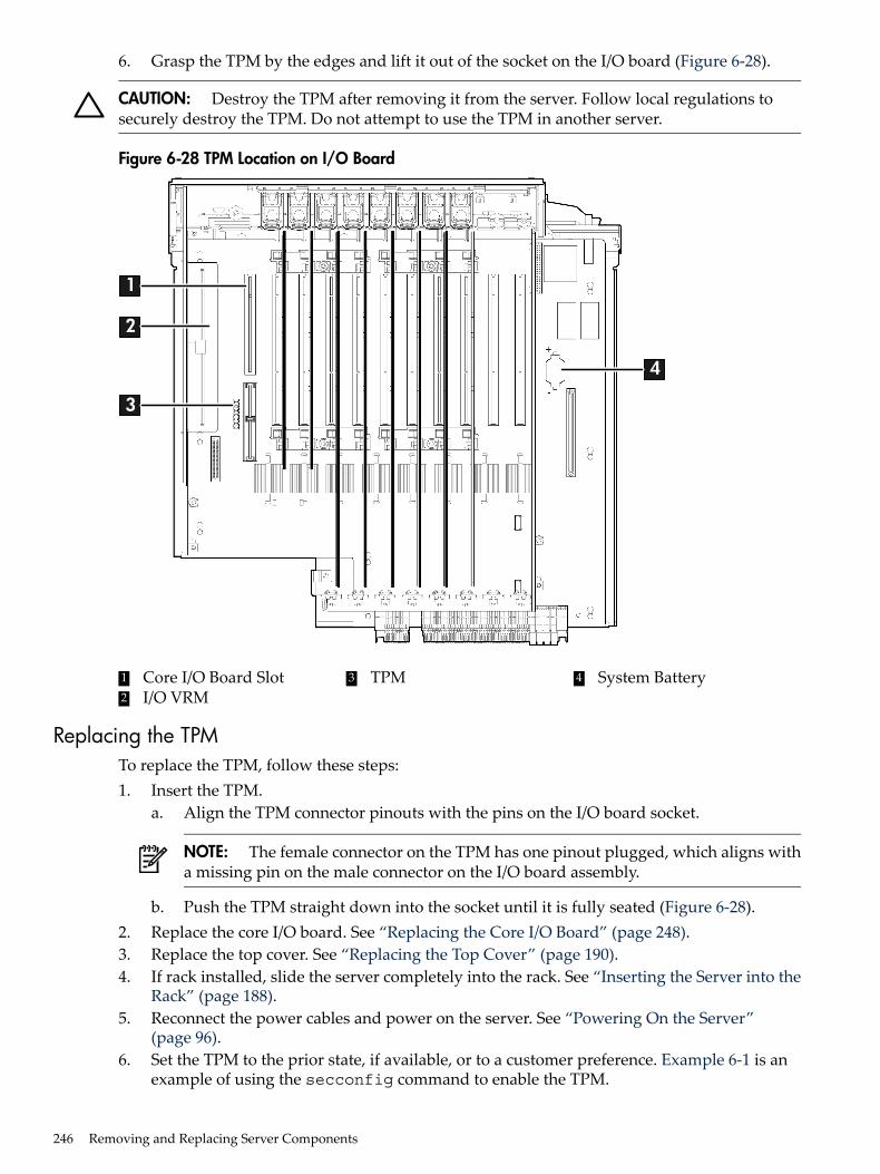
6. Grasp the TPM by the edges and lift it out of the socket on the I/O board (Figure 6-28).
CAUTION: Destroy the TPM after removing it from the server. Follow local regulations tosecurely destroy the TPM. Do not attempt to use the TPM in another server.
Figure 6-28 TPM Location on I/O Board
1
2
3
4
431 Core I/O Board Slot System BatteryTPM2 I/O VRM
Replacing the TPMTo replace the TPM, follow these steps:1. Insert the TPM.
a. Align the TPM connector pinouts with the pins on the I/O board socket.
NOTE: The female connector on the TPM has one pinout plugged, which aligns witha missing pin on the male connector on the I/O board assembly.
b. Push the TPM straight down into the socket until it is fully seated (Figure 6-28).2. Replace the core I/O board. See “Replacing the Core I/O Board” (page 248).3. Replace the top cover. See “Replacing the Top Cover” (page 190).4. If rack installed, slide the server completely into the rack. See “Inserting the Server into the
Rack” (page 188).5. Reconnect the power cables and power on the server. See “Powering On the Server”
(page 96).6. Set the TPM to the prior state, if available, or to a customer preference. Example 6-1 is an
example of using the secconfig command to enable the TPM.
246 Removing and Replacing Server Components
Example 6-1 Enabling the TPM
1. Access the EFI Shell.2. Enterinfo sec to display the server security settings on the screen. The TPM is disabled
by default.3. Enter secconfig to display a list of configurable security settings.4. Enter secconfig tpm on to enable the TPM.
7. Reset the server.8. Boot the operating system. See “Booting and Shutting Down HP-UX” (page 127).9. Restore the former TPM settings to the new TPM. See the HP-UX operating system
documentation for more information.10. Back up the TPM security information. See the HP-UX operating system documentation for
more information.
Removing and Replacing the Core I/O BoardThe core I/O board provides local and remote manageability access, and manages many criticalserver functions and components such as:• Power supplies• Fans• Main memory• Front panel• Processors• Remote interfaces• USB• VGA (optional)• Server boardsThe core I/O board has a unique, dedicated slot located to the left of the public PCI/PCI-X cardslots (as viewed from the front of the chassis) on the I/O board assembly. The core I/O boardincludes VGA (optional), iLO 2 MP LAN, iLO 2 MP USB, and iLO 2 MP serial ports, and locator
Removing and Replacing the Core I/O Board 247
and iLO 2 MP status LEDs. For more detail on the port locations and LEDs, see Chapter 5:“Troubleshooting” (page 143).
WARNING! Ensure that the system is powered off and all power sources have been disconnectedfrom the server prior to performing this procedure.Voltages are present at various locations within the server whenever an AC power source isconnected. This voltage is present even when the main power switch is in the off position.Failure to observe this warning can result in personal injury or damage to equipment.
CAUTION: The dedicated core I/O board slot is not hot-pluggable.
CAUTION: Observe all ESD safety precautions before attempting this procedure. Failure tofollow ESD safety precautions can result in damage to the server.
Removing the Core I/O Board
IMPORTANT: The replacement core I/O board may not be the same as the current core I/Oboard. If the server is running an operating system other than Windows or Linux, the currentcore I/O board may not have a VGA connector. The replacement core I/O board always shipswith a VGA connector. The VGA connector may not be functional depending on the serveroperating system. However, when you run system discovery utilities, such as MAPPER, theoutput includes VGA.
To remove the core I/O board, follow these steps:1. Power off the server and disconnect the power cables. See “Powering Off the Server”
(page 96).2. Disconnect all external cables attached to the board.3. If rack installed, slide the server completely out from the rack. See “Extending the Server
from the Rack” (page 188).4. Remove the top cover. See “Removing the Top Cover” (page 189).5. Disconnect the internal USB cable attached to the core I/O board.6. Remove the slotted T15 screw that attaches the card bulkhead to the chassis; use a T15
screwdriver to turn the screw counterclockwise until it is free from the chassis.
CAUTION: Do not rock the board side to side during removal, or you can damage the slotpins. Pull the board straight up and out of the chassis.
7. Grasp both edges of the board and apply even force to lift the board straight up and out ofthe chassis.
Replacing the Core I/O BoardTo replace the core I/O board, follow these steps:1. Insert the replacement card into the dedicated core I/O board slot.
CAUTION: Do not rock the board side to side during installation, or you can damage theslot pins. Push the board straight down into the slot for installation.
a. Insert the tab at the base of the card bulkhead into the slot in the chassis.b. Align the card connectors with the slots on the I/O board.c. Apply firm, even pressure to both sides of the card until it fully seats into the slot.
2. Replace the slotted T15 screw that attaches the card bulkhead to the chassis; use a T15screwdriver to turn the screw clockwise until it tightens to the chassis.
248 Removing and Replacing Server Components
3. Reconnect the USB cable to the card.4. Replace the top cover. See “Replacing the Top Cover” (page 190).5. If rack installed, slide the server completely into the rack. See “Inserting the Server into the
Rack” (page 188).6. Reconnect all external cables to the card.7. Reconnect the power cables and power on the server. See “Powering On the Server”
(page 96).
Removing and Replacing the Core I/O Board BatteryReplace the battery with an identical or equivalent battery only. Dispose of used batteriesaccording to the manufacturer’s instructions.
WARNING! Lithium batteries can explode if mistreated. Do not recharge, disassemble, ordispose of batteries in a fire. Failure to observe this warning can result in personal injury ordamage to equipment.
Removing the Core I/O Board Battery
WARNING! Ensure that the system is powered off and all power sources have been disconnectedfrom the server prior to performing this procedure.Voltages are present at various locations within the server whenever an AC power source isconnected. This voltage is present even when the main power switch is in the off position.Failure to observe this warning can result in personal injury or damage to equipment.
CAUTION: Observe all ESD safety precautions before attempting this procedure. Failure tofollow ESD safety precautions can result in damage to the server.
IMPORTANT: Before removing the system battery, record all boot and LAN configurationsettings. (Find the settings using the INFO ALL EFI command.) You must reset these values afterreplacing the battery.
To remove the core I/O board battery, follow these steps:1. Power off the server and disconnect the power cables. See “Powering Off the Server”
(page 96).2. If rack installed, slide the server completely out from the rack. See “Extending the Server
from the Rack” (page 188).3. Remove the top cover from the chassis. See “Removing the Top Cover” (page 189).4. Remove the core I/O board. See “Removing the Core I/O Board” (page 248).5. Locate the battery on the core I/O board (Figure 6-26).6. Insert a flat tool under the battery and carefully lift upward to pry the battery from the
socket.
Removing and Replacing the Core I/O Board Battery 249
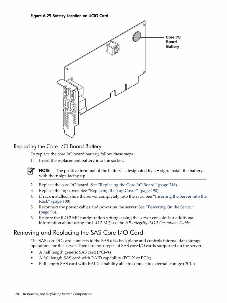
Figure 6-29 Battery Location on UCIO Card
Replacing the Core I/O Board BatteryTo replace the core I/O board battery, follow these steps:1. Insert the replacement battery into the socket.
NOTE: The positive terminal of the battery is designated by a + sign. Install the batterywith the + sign facing up.
2. Replace the core I/O board. See “Replacing the Core I/O Board” (page 248).3. Replace the top cover. See “Replacing the Top Cover” (page 190).4. If rack installed, slide the server completely into the rack. See “Inserting the Server into the
Rack” (page 188).5. Reconnect the power cables and power on the server. See “Powering On the Server”
(page 96).6. Restore the iLO 2 MP configuration settings using the server console. For additional
information about using the iLO 2 MP, see the HP Integrity iLO 2 Operations Guide.
Removing and Replacing the SAS Core I/O CardThe SAS core I/O card connects to the SAS disk backplane and controls internal data storageoperations for the server. There are four types of SAS core I/O cards supported on the server:• A half length generic SAS card (PCI-X)• A full length SAS card with RAID capability (PCI-X or PCIe)• Full length SAS card with RAID capability able to connect to external storage (PCIe)
250 Removing and Replacing Server Components
The server ships standard with two SAS backplane boards. Slots 1 and 2 are dedicated for thePCI-X core I/O cards. The LAN core I/O card is installed either in slot 2 or slot 10 depending onthe configuration. PCIe SAS core I/O cards are installed in slots 3 or 4 on the PCIe I/O backplane.
CAUTION: PCI/PCI-X slots 1 and 2 are dedicated for use by core I/O cards. Do not place anyother PCI/PCI-X expansion cards in slots 1 and 2. Slots 1 and 2 are not hot-plug capable.
IMPORTANT: The number of SAS core I/O cards determines the SAS configuration. The SASconfiguration affects the location of the LAN core I/O card. In a single SAS core I/O cardconfiguration, the secondary set of SAS cables connect to the secondary SAS backplane, but arerouted and lay loose in the server I/O backplane area.
Table 6-8 lists the SAS core I/O card locations and SAS configurations.
Table 6-8 SAS Core I/O Card Locations and SAS Configurations
LAN Core I/O Card LocationSAS Core I/O Card LocationSAS Core I/O Cards
Slot 2Slot 11
Slot 10Slot 22
Slot 2Slots 1 and 32
Slot 2Slot 31
Slot 2Slots 3 and 42
WARNING! Ensure that the system is powered off and all power sources have been disconnectedfrom the server prior to performing this procedure.Voltages are present at various locations within the server whenever an AC power source isconnected. This voltage is present even when the main power switch is in the off position.Failure to observe this warning can result in personal injury or damage to equipment.
CAUTION: Observe all ESD safety precautions before attempting this procedure. Failure tofollow ESD safety precautions can result in damage to the server.
Removing the SAS Core I/O Card
NOTE: You may need to remove the LAN core I/O card to access the SAS core I/O card.
To remove the SAS core I/O card, follow these steps:1. Power off the server and disconnect the power cables. See “Powering Off the Server”
(page 96).2. If rack installed, slide the server completely out from the rack. See “Extending the Server
from the Rack” (page 188).3. Remove the top cover. See “Removing the Top Cover” (page 189).
CAUTION: When disconnecting the SAS cables, note the labeling on the cables. Both cablesand sockets are clearly marked with the correct channel. When reconnecting these cables,match each cable with the appropriate socket on the SAS core I/O card. If the cables aremismatched, the server will not reboot.
4. Disconnect the internal SAS cables attached to the card.5. Remove the slotted T15 screw that attaches the card bulkhead to the chassis; use a T15
screwdriver to turn the screw counterclockwise until it is free from the chassis.
Removing and Replacing the SAS Core I/O Card 251
6. SAS RAID card only. Pull the gate latch toward the front of the chassis to unlock the SAScore I/O card.
7. Grasp the card by the edges and lift it out of the chassis.
Replacing the SAS Core I/O CardTo replace the SAS core I/O card, follow these steps:1. Insert the replacement card into the dedicated SAS core I/O card slot.
a. Insert the tab at the base of the card bulkhead into the slot in the chassis.b. Align the card connectors with the slots on the I/O board.c. Apply firm, even pressure to both sides of the card until it fully seats into the slot.
2. SAS RAID card only. Close the gate latch to secure the end of the card.3. Replace the slotted T15 screw that attaches the card bulkhead to the chassis; use a T15
screwdriver to turn the screw clockwise until it tightens to the chassis.
CAUTION: When reconnecting the SAS cables, note the labeling on the channel cables.Both cables and sockets are clearly marked with the correct channel. Match each cable withthe appropriate socket on the SAS core I/O card. If the cables are mismatched, the serverwill not reboot.
4. Reconnect the internal SAS cables to the card.5. Replace the top cover. See “Replacing the Top Cover” (page 190).6. If rack installed, slide the server completely into the rack. See “Inserting the Server into the
Rack” (page 188).7. Reconnect the power cables and power on the server. See “Powering On the Server”
(page 96).
Removing and Replacing the LAN Core I/O CardThe LAN core I/O card enables network connectivity for the server. The dedicated slot for theLAN core I/O card is slot 2 unless there are two PCI-X SAS core I/O cards installed. In this case,the dedicated slot for the LAN core I/O card is slot 10.
IMPORTANT: The number of SAS core I/O cards determines the SAS configuration. The SASconfiguration affects the location of the LAN core I/O card.
Table 6-8 (page 251) lists the LAN core I/O card location based on the number of installed SAScore I/O cards.
WARNING! Ensure that the system is powered off and all power sources have been disconnectedfrom the server prior to performing this procedure.Voltages are present at various locations within the server whenever an AC power source isconnected. This voltage is present even when the main power switch is in the off position.Failure to observe this warning can result in personal injury or damage to equipment.
CAUTION: PCI/PCI-X slots 1 and 2 are dedicated for use by core I/O cards. Do not place anyother PCI/PCI-X expansion cards in slots 1 and 2. Slots 1 and 2 are not hot-plug capable.
CAUTION: Observe all ESD safety precautions before attempting this procedure. Failure tofollow ESD safety precautions can result in damage to the server.
Removing the LAN Core I/O CardTo remove the LAN core I/O card, follow these steps:
252 Removing and Replacing Server Components
1. Power off the server and disconnect the power cables. See “Powering Off the Server”(page 96).
2. Disconnect all external cables attached to the card.3. If rack installed, slide the server completely out from the rack. See “Extending the Server
from the Rack” (page 188).4. Remove the top cover. See “Removing the Top Cover” (page 189).5. Remove the slotted T15 screw that attaches the card bulkhead to the chassis; use a T15
screwdriver to turn the screw counterclockwise until it is free from the chassis.6. Grasp the card by the edges and lift it out of the chassis.
Replacing the LAN Core I/O CardTo replace the LAN core I/O card, follow these steps:1. Insert the replacement card into the dedicated LAN core I/O slot.
a. Insert the tab at the base of the card bulkhead into the slot in the chassis.b. Align the card connectors with the slots on the I/O board.c. Apply firm, even pressure to both sides of the card until it fully seats into the slot.
2. Replace the slotted T15 screw that attaches the card bulkhead to the chassis; use a T15screwdriver to turn the screw clockwise until it tightens to the chassis.
3. Replace the top cover. See “Replacing the Top Cover” (page 190).4. If rack installed, slide the server completely into the rack. See “Inserting the Server into the
Rack” (page 188).5. Reconnect all external cables to the card.6. Reconnect the power cables and power on the server. See “Powering On the Server”
(page 96).
Removing and Replacing the Display BoardThe display board is a combination board that supports the following server components:• Power switch and status LEDs• DVD drive• Front panel USB port• Diagnostic panelThe display board attaches to an interconnect board that functions as a link between the midplaneboard and the display board.The display board contains the power switch and the following status LEDs:• Power LED• System health LED• Internal health LED• External health LED• Locator LEDFor more detailed information about front panel LED behavior, see Chapter 5: “Troubleshooting”(page 143).The display board includes a USB connector that supports USB 2.0 (480 Mbps).
Removing and Replacing the Display Board 253
The diagnostic panel provides failure identification for each component that has a detectableerror associated with it. For more information on the diagnostic panel LEDs, see Chapter 5:“Troubleshooting” (page 143).
WARNING! Ensure that the system is powered off and all power sources have been disconnectedfrom the server prior to performing this procedure.Voltages are present at various locations within the server whenever an AC power source isconnected. This voltage is present even when the main power switch is in the off position.Failure to observe this warning can result in personal injury or damage to equipment.
CAUTION: Observe all ESD safety precautions before attempting this procedure. Failure tofollow ESD safety precautions can result in damage to the server.
Removing the Display BoardTo remove the display board, follow these steps:1. Power off the server and disconnect the power cables. See “Powering Off the Server”
(page 96).2. If rack installed, slide the server completely out from the rack. See “Extending the Server
from the Rack” (page 188).3. Remove the top cover. See “Removing the Top Cover” (page 189).4. Remove the air baffle.5. Disconnect the USB cable from the connector on the display board.
NOTE: The USB cable connector is an RJ45 connector; it is not a typical USB connector.
6. Remove the DVD drive. See “Removing the DVD Drive” (page 215).7. Locate the knurled thumbscrew behind the DVD drive that holds the display board in place.8. Turn the thumbscrew counterclockwise until the board releases from the chassis.9. Remove the top two screws from the right side of the bezel. Pull the bezel out from the
chassis approximately one half inch so that the display board can clear the locator and Powerbuttons.
CAUTION: Do not pull the bezel out from the chassis more than one half inch. Do not usethe USB connector as a handle to remove the display board. Failure to observe these cautionscan result in damage to server components.
10. Hold the bezel out from the chassis, and use the diagnostic panel light guide as a handle tosimultaneously push the board to the left to unplug it from the socket on the interconnectboard.
11. Slide the board toward the rear of the chassis until it stops against the guide pins.
NOTE: Use the guide pins on the chassis and the L-shaped keyways on the display boardto help you with the display board removal procedure.
12. Tilt the board toward the front of the chassis, and lift it out at an angle.
254 Removing and Replacing Server Components
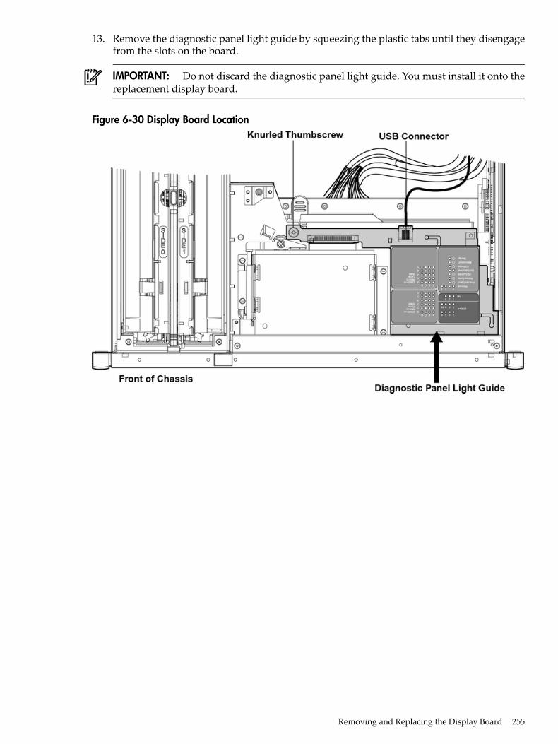
13. Remove the diagnostic panel light guide by squeezing the plastic tabs until they disengagefrom the slots on the board.
IMPORTANT: Do not discard the diagnostic panel light guide. You must install it onto thereplacement display board.
Figure 6-30 Display Board Location
Removing and Replacing the Display Board 255
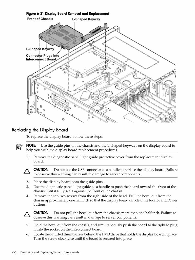
Figure 6-31 Display Board Removal and Replacement
Replacing the Display BoardTo replace the display board, follow these steps:
NOTE: Use the guide pins on the chassis and the L-shaped keyways on the display board tohelp you with the display board replacement procedures.
1. Remove the diagnostic panel light guide protective cover from the replacement displayboard.
CAUTION: Do not use the USB connector as a handle to replace the display board. Failureto observe this warning can result in damage to server components.
2. Place the display board onto the guide pins.3. Use the diagnostic panel light guide as a handle to push the board toward the front of the
chassis until it fully seats against the front of the chassis.4. Remove the top two screws from the right side of the bezel. Pull the bezel out from the
chassis approximately one half inch so that the display board can clear the locator and Powerbuttons.
CAUTION: Do not pull the bezel out from the chassis more than one half inch. Failure toobserve this warning can result in damage to server components.
5. Hold the bezel out from the chassis, and simultaneously push the board to the right to plugit into the socket on the interconnect board.
6. Locate the knurled thumbscrew behind the DVD drive that holds the display board in place.Turn the screw clockwise until the board is secured into place.
256 Removing and Replacing Server Components
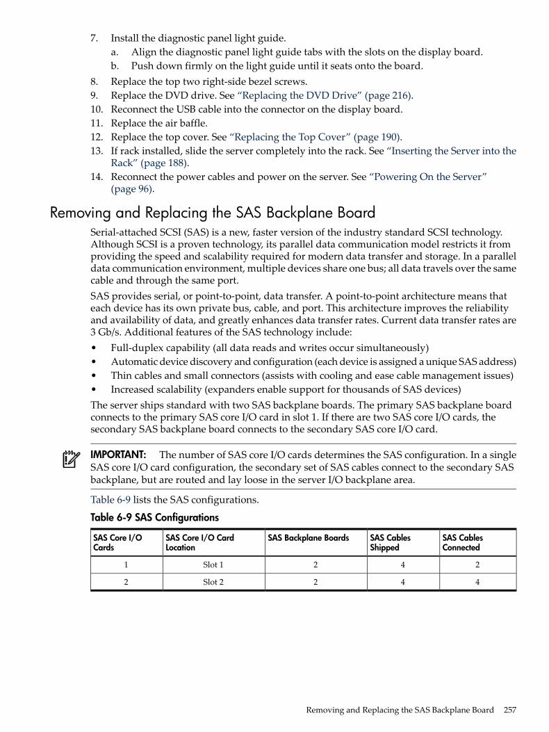
7. Install the diagnostic panel light guide.a. Align the diagnostic panel light guide tabs with the slots on the display board.b. Push down firmly on the light guide until it seats onto the board.
8. Replace the top two right-side bezel screws.9. Replace the DVD drive. See “Replacing the DVD Drive” (page 216).10. Reconnect the USB cable into the connector on the display board.11. Replace the air baffle.12. Replace the top cover. See “Replacing the Top Cover” (page 190).13. If rack installed, slide the server completely into the rack. See “Inserting the Server into the
Rack” (page 188).14. Reconnect the power cables and power on the server. See “Powering On the Server”
(page 96).
Removing and Replacing the SAS Backplane BoardSerial-attached SCSI (SAS) is a new, faster version of the industry standard SCSI technology.Although SCSI is a proven technology, its parallel data communication model restricts it fromproviding the speed and scalability required for modern data transfer and storage. In a paralleldata communication environment, multiple devices share one bus; all data travels over the samecable and through the same port.SAS provides serial, or point-to-point, data transfer. A point-to-point architecture means thateach device has its own private bus, cable, and port. This architecture improves the reliabilityand availability of data, and greatly enhances data transfer rates. Current data transfer rates are3 Gb/s. Additional features of the SAS technology include:• Full-duplex capability (all data reads and writes occur simultaneously)• Automatic device discovery and configuration (each device is assigned a unique SAS address)• Thin cables and small connectors (assists with cooling and ease cable management issues)• Increased scalability (expanders enable support for thousands of SAS devices)The server ships standard with two SAS backplane boards. The primary SAS backplane boardconnects to the primary SAS core I/O card in slot 1. If there are two SAS core I/O cards, thesecondary SAS backplane board connects to the secondary SAS core I/O card.
IMPORTANT: The number of SAS core I/O cards determines the SAS configuration. In a singleSAS core I/O card configuration, the secondary set of SAS cables connect to the secondary SASbackplane, but are routed and lay loose in the server I/O backplane area.
Table 6-9 lists the SAS configurations.
Table 6-9 SAS Configurations
SAS CablesConnected
SAS CablesShipped
SAS Backplane BoardsSAS Core I/O CardLocation
SAS Core I/OCards
242Slot 11
442Slot 22
Removing and Replacing the SAS Backplane Board 257
The SAS backplane boards attach to an interconnect board that functions as a link between themidplane board and the SAS backplane boards.
WARNING! Ensure that the system is powered off and all power sources have been disconnectedfrom the server prior to performing this procedure.Voltages are present at various locations within the server whenever an AC power source isconnected. This voltage is present even when the main power switch is in the off position.Failure to observe this warning can result in personal injury or damage to equipment.
CAUTION: Observe all ESD safety precautions before attempting this procedure. Failure tofollow ESD safety precautions can result in damage to the server.
Removing the SAS Backplane BoardTo remove the SAS backplane board, follow these steps:1. Power off the server and disconnect the power cables. See “Powering Off the Server”
(page 96).2. If rack installed, slide the server completely out from the rack. See “Extending the Server
from the Rack” (page 188).3. Remove the top cover. See “Removing the Top Cover” (page 189).4. Remove the air baffle.5. Slide the SAS drives and fillers approximately two inches out of the drive bays. See
“Removing a Hot-Pluggable Disk Drive” (page 199).6. Disconnect the SAS cables from the connectors on the SAS backplane board.
CAUTION: When disconnecting the SAS cables, note the labeling on the cables. Both cablesand sockets are clearly marked with the correct channel. When reconnecting these cables,match each cable with the appropriate socket on the SAS backplane board. If the cables aremismatched, the server will not function correctly.
7. Remove the interconnect board air baffle. See “Removing the Interconnect Board” (page 260).8. Push down on the release lever to disengage the SAS backplane board from the chassis.
CAUTION: Do not use the release lever as a handle to remove the SAS backplane board.Failure to observe this caution can result in damage to the release lever and the SAS backplaneboard.
9. Use the sheet metal bracket that surrounds the SAS backplane board as a handle and slidethe board to the left to unplug it from the socket on the interconnect board.
10. Pull the board straight back toward the rear of the chassis, and lift the board out of thechassis.
258 Removing and Replacing Server Components
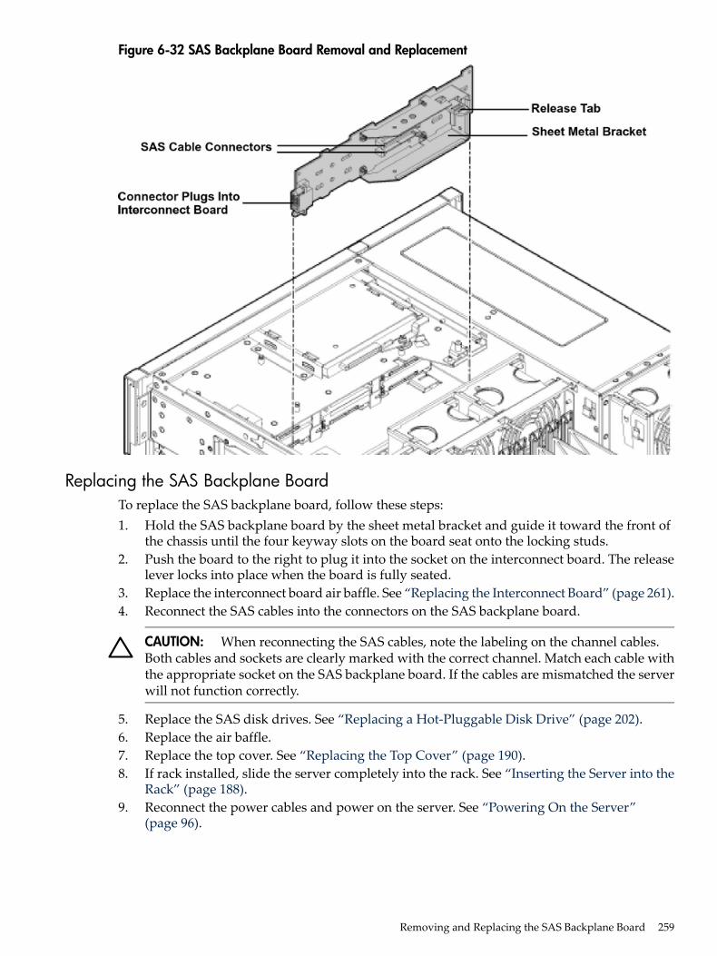
Figure 6-32 SAS Backplane Board Removal and Replacement
Replacing the SAS Backplane BoardTo replace the SAS backplane board, follow these steps:1. Hold the SAS backplane board by the sheet metal bracket and guide it toward the front of
the chassis until the four keyway slots on the board seat onto the locking studs.2. Push the board to the right to plug it into the socket on the interconnect board. The release
lever locks into place when the board is fully seated.3. Replace the interconnect board air baffle. See “Replacing the Interconnect Board” (page 261).4. Reconnect the SAS cables into the connectors on the SAS backplane board.
CAUTION: When reconnecting the SAS cables, note the labeling on the channel cables.Both cables and sockets are clearly marked with the correct channel. Match each cable withthe appropriate socket on the SAS backplane board. If the cables are mismatched the serverwill not function correctly.
5. Replace the SAS disk drives. See “Replacing a Hot-Pluggable Disk Drive” (page 202).6. Replace the air baffle.7. Replace the top cover. See “Replacing the Top Cover” (page 190).8. If rack installed, slide the server completely into the rack. See “Inserting the Server into the
Rack” (page 188).9. Reconnect the power cables and power on the server. See “Powering On the Server”
(page 96).
Removing and Replacing the SAS Backplane Board 259
Removing and Replacing the Interconnect BoardThe interconnect board attaches the midplane board to the display board and the SAS backplaneboard.
WARNING! Ensure that the system is powered off and all power sources have been disconnectedfrom the server prior to performing this procedure.Voltages are present at various locations within the server whenever an AC power source isconnected. This voltage is present even when the main power switch is in the off position.Failure to observe this warning can result in personal injury or damage to equipment.
CAUTION: Observe all ESD safety precautions before attempting this procedure. Failure tofollow ESD safety precautions can result in damage to the server.
IMPORTANT: System information is stored on the interconnect board. You must write serialnumber and model string information to the new interconnect board after installation.
Removing the Interconnect BoardTo remove the interconnect board, follow these steps:
NOTE: Use the guide posts located on the chassis and the keyways located on the interconnectboard to help you with the interconnect board removal and replacement procedures.
1. Power off the server and disconnect the power cables. See “Powering Off the Server”(page 96).
2. If rack installed, slide the server completely out from the rack. See “Extending the Serverfrom the Rack” (page 188).
3. Remove the top cover. See “Removing the Top Cover” (page 189).4. Remove the air baffle.5. Disconnect the USB cable from the connector on the display board.6. Remove the DVD drive. See “Removing the DVD Drive” (page 215).7. Remove the display board. See “Removing the Display Board” (page 254).8. Slide the SAS drives and fillers approximately two inches out of the drive bays. See
“Removing a Hot-Pluggable Disk Drive” (page 199).
CAUTION: When disconnecting the SAS cables, note the labeling on the cables. Both cablesand sockets are clearly marked with the correct channel. When reconnecting these cables,you must match each cable with the appropriate socket on the SAS core I/O card. If the cablesare mismatched, the server will not reboot.
9. Disconnect the SAS data and power cables from the connectors on the SAS backplanes.10. Remove the interconnect board air baffle.
a. Insert your finger into the opening on the interconnect board air baffle and pull upwardto release the air baffle from the chassis.
b. Lift the air baffle out of the chassis at an angle.11. Remove the lower SAS backplane. See “Removing the SAS Backplane Board” (page 258).12. Remove the upper SAS backplane. See “Removing the SAS Backplane Board” (page 258).13. Insert your fingers into the handle on the interconnect board and push the board toward
the front of the chassis to unplug it from the socket on the midplane board.14. Lift the interconnect board out of the chassis.
260 Removing and Replacing Server Components
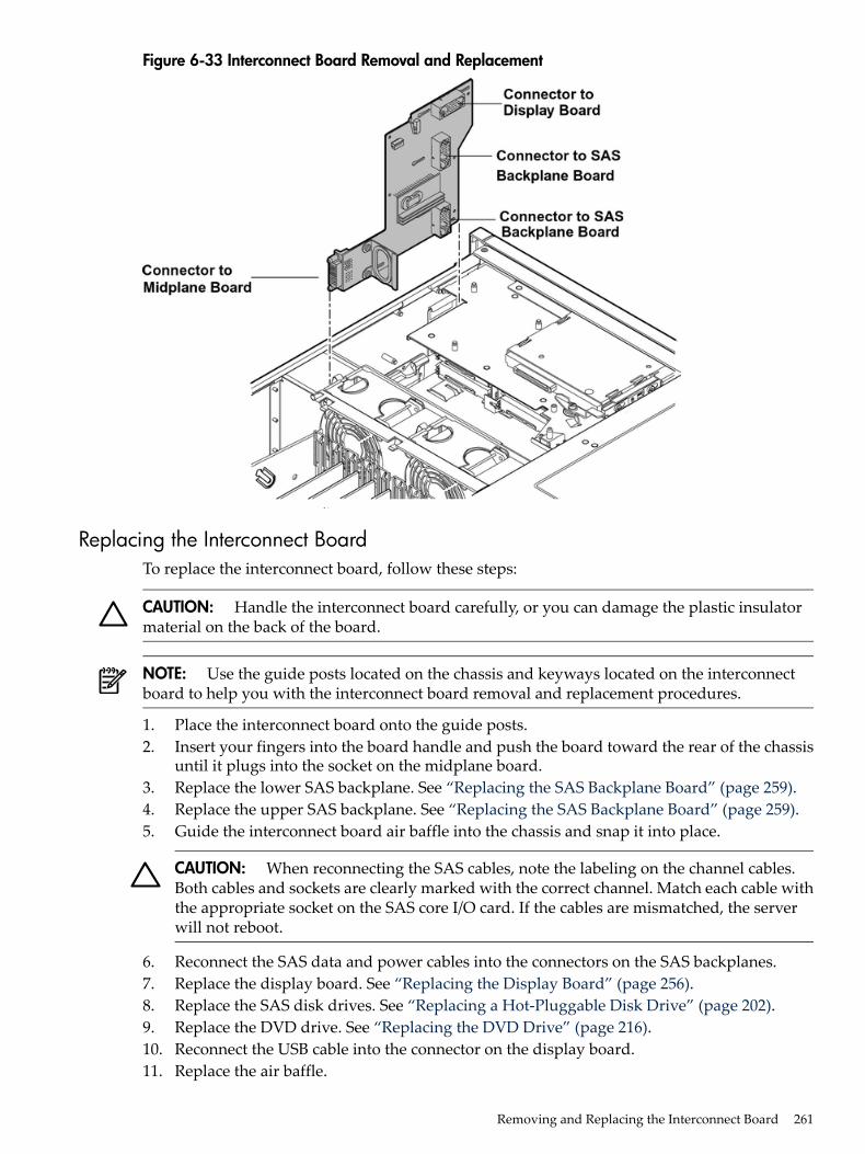
Figure 6-33 Interconnect Board Removal and Replacement
Replacing the Interconnect BoardTo replace the interconnect board, follow these steps:
CAUTION: Handle the interconnect board carefully, or you can damage the plastic insulatormaterial on the back of the board.
NOTE: Use the guide posts located on the chassis and keyways located on the interconnectboard to help you with the interconnect board removal and replacement procedures.
1. Place the interconnect board onto the guide posts.2. Insert your fingers into the board handle and push the board toward the rear of the chassis
until it plugs into the socket on the midplane board.3. Replace the lower SAS backplane. See “Replacing the SAS Backplane Board” (page 259).4. Replace the upper SAS backplane. See “Replacing the SAS Backplane Board” (page 259).5. Guide the interconnect board air baffle into the chassis and snap it into place.
CAUTION: When reconnecting the SAS cables, note the labeling on the channel cables.Both cables and sockets are clearly marked with the correct channel. Match each cable withthe appropriate socket on the SAS core I/O card. If the cables are mismatched, the serverwill not reboot.
6. Reconnect the SAS data and power cables into the connectors on the SAS backplanes.7. Replace the display board. See “Replacing the Display Board” (page 256).8. Replace the SAS disk drives. See “Replacing a Hot-Pluggable Disk Drive” (page 202).9. Replace the DVD drive. See “Replacing the DVD Drive” (page 216).10. Reconnect the USB cable into the connector on the display board.11. Replace the air baffle.
Removing and Replacing the Interconnect Board 261
12. Replace the top cover. See “Replacing the Top Cover” (page 190).13. If rack installed, slide the server completely into the rack. See “Inserting the Server into the
Rack” (page 188).14. Reconnect the power cables and power on the server. See “Powering On the Server”
(page 96).15. Respond YES to prompts regarding copying information onto the new board.
IMPORTANT: Serial number and model string data information is stored on both theinterconnect board and the I/O board. When you install a new interconnect board, you mustcopy this information from the I/O board to the new interconnect board.
16. Verify the serial number and model string data information copied onto the new interconnectboard.a. Boot to EFI.b. Enter service mode:
Shell> sysmode serviceCurrent System Mode: ADMINYou are now in SERVICE mode.
c. Use the sysset command to verify that all values are set:Shell> sysset
System Information:Manufacturer: hpProduct Name: server rx6600Product Number: AB464ASecondary Product Number is IdenticalSerial number: SGH43442VBSecondary Serial Number is IdenticalUUID: 3C33C58E-2E5A-11D8-A33B-4188C0AEFAE2 (Valid)Secondary UUID is IdenticalProduct ID: 0x301
Removing and Replacing the Midplane BoardThe midplane board is attached to the main bulkhead in the center of the chassis. It provides aconnection between the power supplies, the I/O board assembly, and the processor boardassembly.
WARNING! Ensure that the system is powered off and all power sources have been disconnectedfrom the server prior to performing this procedure.Voltages are present at various locations within the server whenever an AC power source isconnected. This voltage is present even when the main power switch is in the off position.Failure to observe this warning can result in personal injury or damage to equipment.
CAUTION: Observe all ESD safety precautions before attempting this procedure. Failure tofollow ESD safety precautions can result in damage to the server.
Removing the Midplane BoardTo remove the midplane board, perform the following steps:1. Power off the server and disconnect the power cables. See “Powering Off the Server”
(page 96).2. If rack installed, slide the server completely out from the rack. See “Extending the Server
from the Rack” (page 188).
262 Removing and Replacing Server Components
3. Remove the top cover. See “Removing and Replacing the Top Cover” (page 189).4. Remove the memory carrier assembly cover. See “Removing the Memory Carrier Assembly
Cover” (page 191).5. Remove the memory carrier assembly. See “Removing the Memory Carrier Assembly”
(page 216).6. Remove the processor board assembly. See “Removing the Processor Board Assembly”
(page 228).7. Unplug the USB cable from the connector on the display board.8. Remove the DVD drive. See “Removing the DVD Drive” (page 215).9. Remove the display board. See “Removing the Display Board” (page 254).10. Slide the SAS drives and fillers approximately two inches out of the drive bays. See
“Removing a Hot-Pluggable Disk Drive” (page 199).
CAUTION: When disconnecting the SAS cables, note the labeling on the cables. Both cablesand sockets are clearly marked with the correct channel. When reconnecting these cables,match each cable with the appropriate socket on the SAS core I/O card. If the cables aremismatched, your server will not boot the OS.
11. Unplug the SAS data and power cables from the connectors on the SAS backplane boards.12. Remove the upper SAS backplane board. See “Removing the SAS Backplane Board” (page 258).13. Remove the lower SAS backplane board. See “Removing the SAS Backplane Board” (page 258).14. Remove the interconnect board. See “Removing the Interconnect Board” (page 260).15. Remove the I/O board assembly. See “Removing the I/O Board Assembly” (page 237).16. Remove the power supplies. See “Removing a Hot-Swappable Power Supply” (page 196).17. Disconnect the fan cables from the fan 1 and fan 2/3 housing units.
a. Disconnect fan 1 cable connector.b. Disconnect the fan 2/fan 3 cable connector.
18. Open the trap door by pressing down on the button and sliding trap door toward the rearof the server. (Figure 6-35).
19. Disconnect external fan cables.20. Swing the hinged CPU panel up to expose the midplane screws.21. Use a Torx 10 screwdriver to remove the three Torx screws attaching the midplane board
to the sheet metal bracket through the front of the chassis (Figure 6-34).
Removing and Replacing the Midplane Board 263
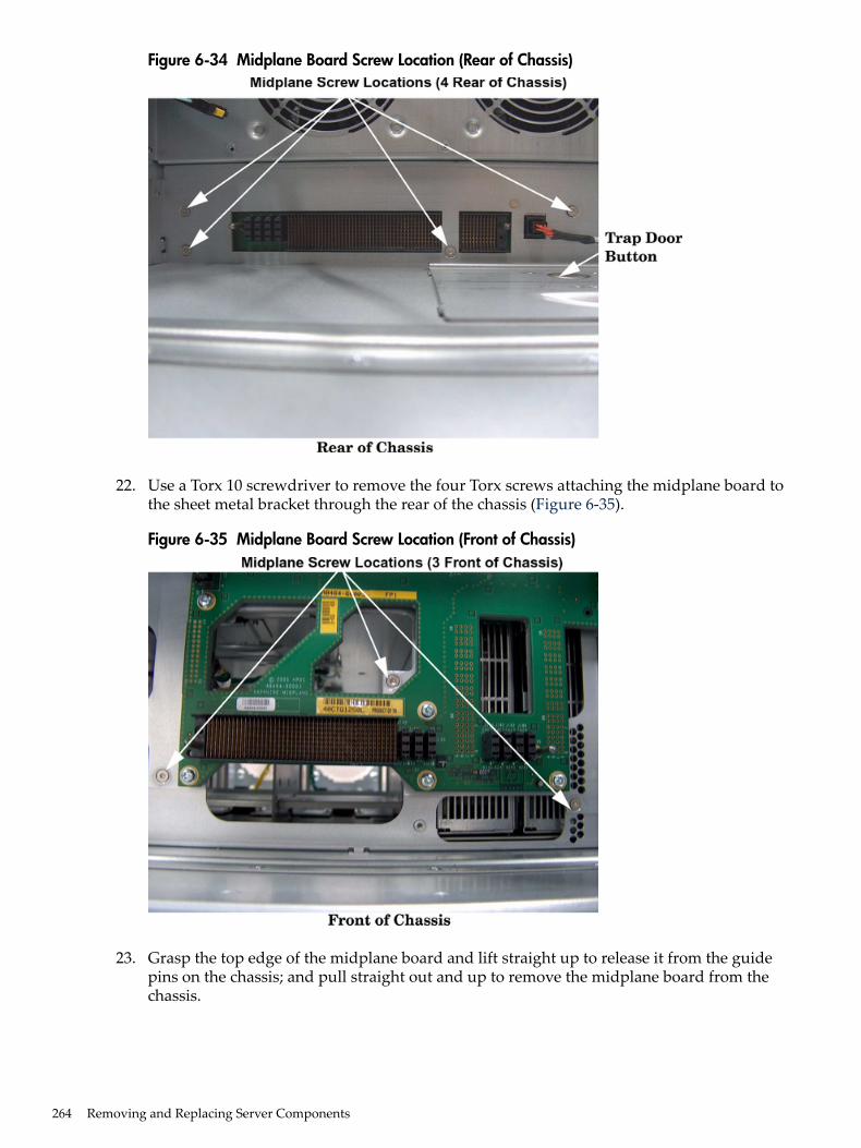
Figure 6-34 Midplane Board Screw Location (Rear of Chassis)
22. Use a Torx 10 screwdriver to remove the four Torx screws attaching the midplane board tothe sheet metal bracket through the rear of the chassis (Figure 6-35).
Figure 6-35 Midplane Board Screw Location (Front of Chassis)
23. Grasp the top edge of the midplane board and lift straight up to release it from the guidepins on the chassis; and pull straight out and up to remove the midplane board from thechassis.
264 Removing and Replacing Server Components
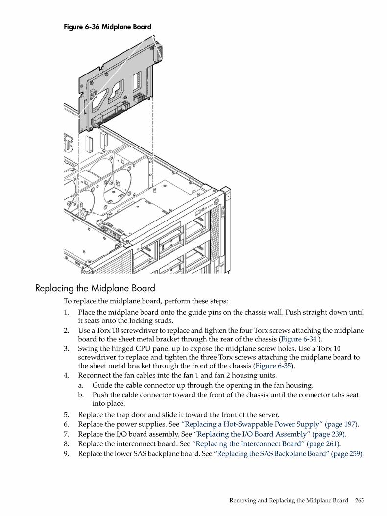
Figure 6-36 Midplane Board
Replacing the Midplane BoardTo replace the midplane board, perform these steps:1. Place the midplane board onto the guide pins on the chassis wall. Push straight down until
it seats onto the locking studs.2. Use a Torx 10 screwdriver to replace and tighten the four Torx screws attaching the midplane
board to the sheet metal bracket through the rear of the chassis (Figure 6-34 ).3. Swing the hinged CPU panel up to expose the midplane screw holes. Use a Torx 10
screwdriver to replace and tighten the three Torx screws attaching the midplane board tothe sheet metal bracket through the front of the chassis (Figure 6-35).
4. Reconnect the fan cables into the fan 1 and fan 2 housing units.a. Guide the cable connector up through the opening in the fan housing.b. Push the cable connector toward the front of the chassis until the connector tabs seat
into place.5. Replace the trap door and slide it toward the front of the server.6. Replace the power supplies. See “Replacing a Hot-Swappable Power Supply” (page 197).7. Replace the I/O board assembly. See “Replacing the I/O Board Assembly” (page 239).8. Replace the interconnect board. See “Replacing the Interconnect Board” (page 261).9. Replace the lower SAS backplane board. See “Replacing the SAS Backplane Board” (page 259).
Removing and Replacing the Midplane Board 265
10. Replace the upper SAS backplane board. See “Replacing the SAS Backplane Board” (page 259).
CAUTION: When reconnecting the SAS cables, note the labeling on the channel cables.Both cables and sockets are clearly marked with the correct channel. Match each cable withthe appropriate socket on the SAS core I/O card. If the cables are mismatched your serverwill not boot the OS.
11. Plug the SAS data and power cables into the connectors on the SAS backplane boards.12. Replace the SAS disk drives. See “Replacing a Hot-Pluggable Disk Drive” (page 202).13. Replace the display board. See “Replacing the Display Board” (page 256).14. Replace the DVD drive. See “Replacing the DVD Drive” (page 216).15. Plug the USB cable into the connector on the display board.16. Replace the processor board assembly. See “Replacing the Processor Board Assembly”
(page 229).17. Replace the memory carrier assembly. See “Replacing the Memory Carrier Assembly”
(page 218).18. Replace the memory carrier assembly cover. See “Replacing the Memory Carrier Assembly
Cover” (page 191).19. Replace the top cover. See “Replacing the Top Cover” (page 190).20. If rack installed, slide the server completely into the rack. See “Inserting the Server into the
Rack” (page 188).21. Reconnect the power cables and power on the server. See “Powering On the Server”
(page 96).
266 Removing and Replacing Server Components
A Customer Replaceable Units InformationThis appendix provides the following information for each field replaceable unit (FRU):• Manufacturing part number• Description• Replacement part number• Exchange part numberThis appendix addresses the following topics:• “Parts Only Warranty Service” (page 267)• “Customer Self Repair” (page 267)• “Parts List” (page 268)
Parts Only Warranty ServiceYour HP Limited Warranty may include a parts only warranty service. Under the terms of partsonly warranty service, HP will provide replacement parts free of charge. For parts only warrantyservice, Customer Self Repair (CSR) part replacement is mandatory. If you request HP to replacethese parts, you will be charged for the travel and labor costs of this service.
Customer Self RepairHP products are designed with many Customer Replaceable Unites (CRU) parts to minimizerepair time and allow for greater flexibility in performing defective parts replacement. If duringthe diagnosis period HP (or HP service providers or service partners) identifies that the repaircan be accomplished by the use of a CRU part, HP will ship that part directly to you forreplacement. There are three categories of CRU parts:Yes Parts for which customer self repair is mandatory. If you request HP to replace
these parts, you will be charged for the travel and labor costs of this service.Optional Parts for which customer self repair is optional. These parts are also designed for
customer self repair. If, however, you require that HP replace them for you, theremay or may not be additional charges, depending on the type of warranty servicedesignated for your product.
No Some HP parts are not designed for customer self repair. To satisfy the customerwarranty, HP requires that an authorized service provider replace the part.
Based on availability and where geography permits, CSR parts are shipped for next businessday delivery. Same-day or four-hour delivery may be offered at an additional charge wheregeography permits. If assistance is required, you can call the HP Technical Support Center anda technician will help you over the telephone.HP specifies in the materials shipped with a replacement CSR part whether a defective part mustbe returned to HP. In cases where it is required to return the defective part to HP, you must shipthe defective part back to HP within a defined period of time, normally five (5) business days.The defective part must be returned with the associated documentation in the provided shippingmaterial. Failure to return the defective part may result in HP billing you for the replacement.With a CSR, HP pays for all the shipping and part return costs and determines the courier to beused.For more information about HP's Customer Self Repair program, contact your local serviceprovider. For the North American program, see the HP website at:http://www.hp.com/go/selfrepair
Table A-1 provides CSR information.
Parts Only Warranty Service 267
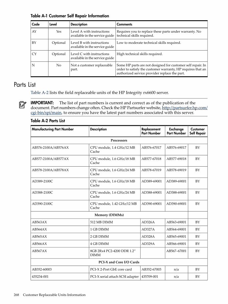
Table A-1 Customer Self Repair Information
CommentsDescriptionLevelCode
Requires you to replace these parts under warranty. Notechnical skills required.
Level A with instructionsavailable in the service guide
YesAY
Low to moderate technical skills required.Level B with instructionsavailable in the service guide
OptionalBY
High technical skills required.Level C with instructionsavailable in the service guide
OptionalCY
Some HP parts are not designed for customer self repair. Inorder to satisfy the customer warranty, HP requires that anauthorized service provider replace the part.
Not a customer replaceablepart.
NoN
Parts ListTable A-2 lists the field replaceable units of the HP Integrity rx6600 server.
IMPORTANT: The list of part numbers is current and correct as of the publication of thedocument. Part numbers change often. Check the HP Partsurfer website, http://partsurfer.hp.com/cgi-bin/spi/main, to ensure you have the latest part numbers associated with this server.
Table A-2 Parts List
CustomerSelf Repair
ExchangePart Number
ReplacementPart Number
DescriptionManufacturing Part Number
Processors
BYAB576-69017AB576-67017CPU module, 1.4 GHz/12 MBCache
AB576-2100A/AB576AX
BYAB577-69018AB577-67018CPU module, 1.6 GHz/18 MBCache
AB577-2100A/AB577AX
BYAB578-69019AB578-67019CPU module, 1.6 GHz/24 MBCache
AB578-2100A/AB578AX
BYAD389-69001AD389-69001CPU module, 1.6 GHz/18 MBCache
AD389-2100C
BYAD388-69001AD388-69001CPU module, 1.6 GHz/24 MBCache
AD388-2100C
BYAD390-69001AD390-69001CPU module, 1.42 GHz/12 MBCache
AD390-2100C
Memory (DIMMs)
BYAB563-69001AD326A512 MB DIMMAB563AX
BYAB564-69001AD327A1 GB DIMMAB564AX
BYAB565-69001AD328A2 GB DIMMAB565AX
BYAB566-69001AD329A4 GB DIMMAB566AX
BYAB567–670018GB 2Rx4 PC2-4200 DDR 1.2”DIMM
AB567AX
PCI-X and Core I/O Cards
BYn/aAB352-67003PCI-X 2-Port GbE core cardAB352-60003
BYn/a435709-001PCI-X serial attach SCSI adapter435234-001
268 Customer Replaceable Units Information
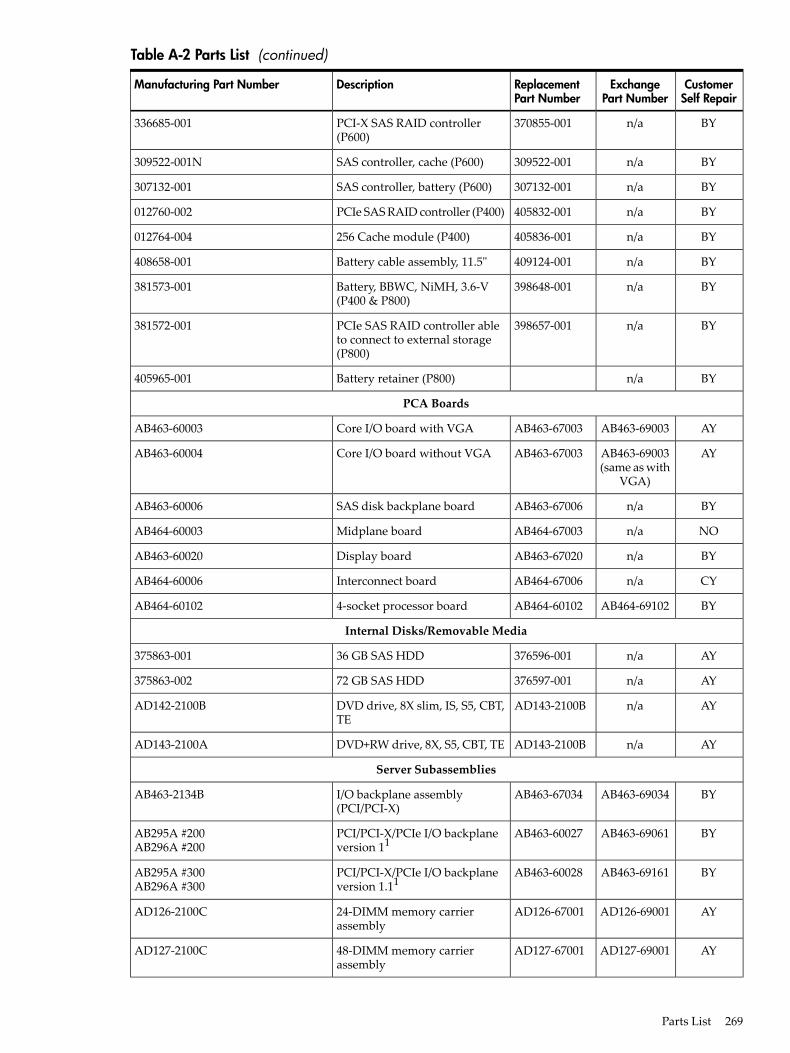
Table A-2 Parts List (continued)
CustomerSelf Repair
ExchangePart Number
ReplacementPart Number
DescriptionManufacturing Part Number
BYn/a370855-001PCI-X SAS RAID controller(P600)
336685-001
BYn/a309522-001SAS controller, cache (P600)309522-001N
BYn/a307132-001SAS controller, battery (P600)307132-001
BYn/a405832-001PCIe SAS RAID controller (P400)012760-002
BYn/a405836-001256 Cache module (P400)012764-004
BYn/a409124-001Battery cable assembly, 11.5"408658-001
BYn/a398648-001Battery, BBWC, NiMH, 3.6-V(P400 & P800)
381573-001
BYn/a398657-001PCIe SAS RAID controller ableto connect to external storage(P800)
381572-001
BYn/aBattery retainer (P800)405965-001
PCA Boards
AYAB463-69003AB463-67003Core I/O board with VGAAB463-60003
AYAB463-69003(same as with
VGA)
AB463-67003Core I/O board without VGAAB463-60004
BYn/aAB463-67006SAS disk backplane boardAB463-60006
NOn/aAB464-67003Midplane boardAB464-60003
BYn/aAB463-67020Display boardAB463-60020
CYn/aAB464-67006Interconnect boardAB464-60006
BYAB464-69102AB464-601024-socket processor boardAB464-60102
Internal Disks/Removable Media
AYn/a376596-00136 GB SAS HDD375863-001
AYn/a376597-00172 GB SAS HDD375863-002
AYn/aAD143-2100BDVD drive, 8X slim, IS, S5, CBT,TE
AD142-2100B
AYn/aAD143-2100BDVD+RW drive, 8X, S5, CBT, TEAD143-2100A
Server Subassemblies
BYAB463-69034AB463-67034I/O backplane assembly(PCI/PCI-X)
AB463-2134B
BYAB463-69061AB463-60027PCI/PCI-X/PCIe I/O backplaneversion 11
AB295A #200AB296A #200
BYAB463-69161AB463-60028PCI/PCI-X/PCIe I/O backplaneversion 1.11
AB295A #300AB296A #300
AYAD126-69001AD126-6700124-DIMM memory carrierassembly
AD126-2100C
AYAD127-69001AD127-6700148-DIMM memory carrierassembly
AD127-2100C
Parts List 269
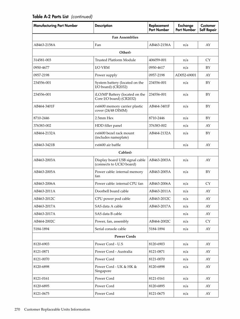
Table A-2 Parts List (continued)
CustomerSelf Repair
ExchangePart Number
ReplacementPart Number
DescriptionManufacturing Part Number
Fan Assemblies
AYn/aAB463-2158AFanAB463-2158A
Otherb
CYn/a406059-001Trusted Platform Module314581-003
BYn/a0950-4617I/O VRM0950-4677
AYAD052-690010957-2198Power supply0957-2198
BYn/a234556-001System battery (located on theI/O board) (CR2032)
234556-001
BYn/a234556-001iLO/MP Battery (located on theCore I/O board) (CR2032)
234556-001
BYn/aAB464-3401Frx6600 memory carrier plasticcover (24/48 DIMM)
AB464-3401F
BYn/a8710-24462.5mm Hex8710-2446
AYn/a376383-002HDD filler panel376383-002
BYn/aAB464-2132Arx6600 bezel rack mount(includes nameplate)
AB464-2132A
AYn/arx6600 air baffleAB463-3421B
Cablesb
AYn/aAB463-2003ADisplay board USB signal cable(connects to UCIO board)
AB463-2003A
BYn/aAB463-2005APower cable: internal memoryfan
AB463-2005A
CYn/aAB463-2006APower cable: internal CPU fanAB463-2006A
AYn/aAB463-2011ADoorbell board cableAB463-2011A
AYn/aAB463-2012CCPU power pod cableAB463-2012C
AYn/aAB463-2017ASAS data A cableAB463-2017A
AYn/aSAS data B cableAB463-2017A
CYn/aAB464-2002CPower, fan, assemblyAB464-2002C
AYn/a5184-1894Serial console cable5184-1894
Power Cords
AYn/a8120-6903Power Cord - U.S8120-6903
AYn/a8121-0871Power Cord - Australia8121-0871
AYn/a8121-0070Power Cord8121-0070
AYn/a8120-6898Power Cord - UK & HK &Singapore
8120-6898
AYn/a8121-0161Power Cord8121-0161
AYn/a8120-6895Power Cord8120-6895
AYn/a8121-0675Power Cord8121-0675
270 Customer Replaceable Units Information
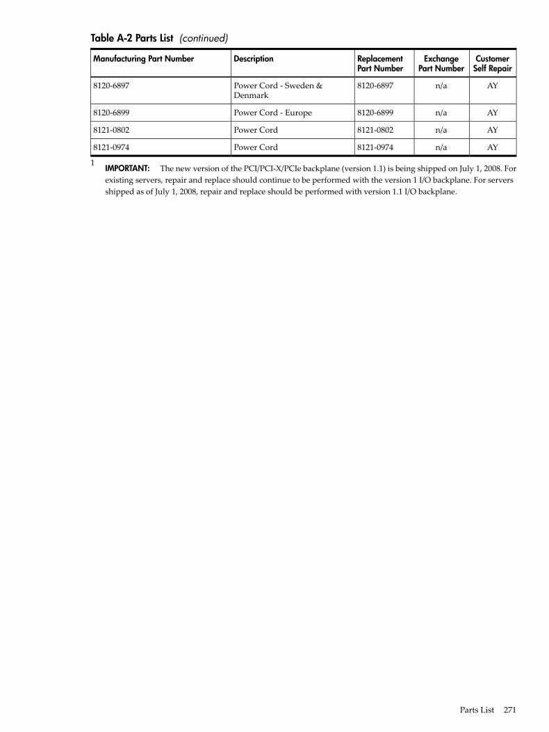
Table A-2 Parts List (continued)
CustomerSelf Repair
ExchangePart Number
ReplacementPart Number
DescriptionManufacturing Part Number
AYn/a8120-6897Power Cord - Sweden &Denmark
8120-6897
AYn/a8120-6899Power Cord - Europe8120-6899
AYn/a8121-0802Power Cord8121-0802
AYn/a8121-0974Power Cord8121-0974
1IMPORTANT: The new version of the PCI/PCI-X/PCIe backplane (version 1.1) is being shipped on July 1, 2008. Forexisting servers, repair and replace should continue to be performed with the version 1 I/O backplane. For serversshipped as of July 1, 2008, repair and replace should be performed with version 1.1 I/O backplane.
Parts List 271

272
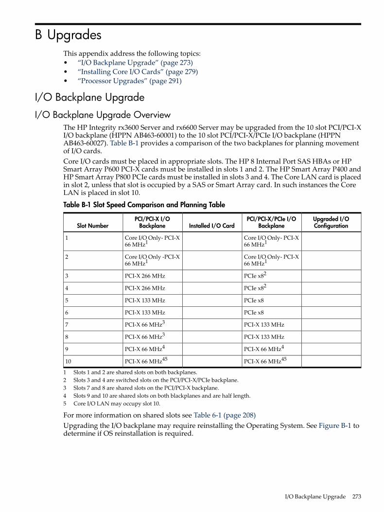
B UpgradesThis appendix address the following topics:• “I/O Backplane Upgrade” (page 273)• “Installing Core I/O Cards” (page 279)• “Processor Upgrades” (page 291)
I/O Backplane Upgrade
I/O Backplane Upgrade OverviewThe HP Integrity rx3600 Server and rx6600 Server may be upgraded from the 10 slot PCI/PCI-XI/O backplane (HPPN AB463-60001) to the 10 slot PCI/PCI-X/PCIe I/O backplane (HPPNAB463-60027). Table B-1 provides a comparison of the two backplanes for planning movementof I/O cards.Core I/O cards must be placed in appropriate slots. The HP 8 Internal Port SAS HBAs or HPSmart Array P600 PCI-X cards must be installed in slots 1 and 2. The HP Smart Array P400 andHP Smart Array P800 PCIe cards must be installed in slots 3 and 4. The Core LAN card is placedin slot 2, unless that slot is occupied by a SAS or Smart Array card. In such instances the CoreLAN is placed in slot 10.
Table B-1 Slot Speed Comparison and Planning Table
Upgraded I/OConfiguration
PCI/PCI-X/PCIe I/OBackplaneInstalled I/O Card
PCI/PCI-X I/OBackplaneSlot Number
Core I/O Only- PCI-X66 MHz1
Core I/O Only- PCI-X66 MHz1
1
Core I/O Only- PCI-X66 MHz1
Core I/O Only -PCI-X66 MHz1
2
PCIe x82PCI-X 266 MHz3
PCIe x82PCI-X 266 MHz4
PCIe x8PCI-X 133 MHz5
PCIe x8PCI-X 133 MHz6
PCI-X 133 MHzPCI-X 66 MHz37
PCI-X 133 MHzPCI-X 66 MHz38
PCI-X 66 MHz4PCI-X 66 MHz49
PCI-X 66 MHz45PCI-X 66 MHz4510
1 Slots 1 and 2 are shared slots on both backplanes.2 Slots 3 and 4 are switched slots on the PCI/PCI-X/PCIe backplane.3 Slots 7 and 8 are shared slots on the PCI/PCI-X backplane.4 Slots 9 and 10 are shared slots on both blackplanes and are half length.5 Core I/O LAN may occupy slot 10.
For more information on shared slots see Table 6-1 (page 208)Upgrading the I/O backplane may require reinstalling the Operating System. See Figure B-1 todetermine if OS reinstallation is required.
I/O Backplane Upgrade 273
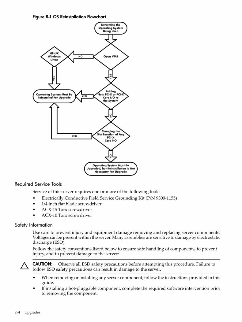
Figure B-1 OS Reinstallation Flowchart
Required Service ToolsService of this server requires one or more of the following tools:• Electrically Conductive Field Service Grounding Kit (P/N 9300-1155)• 1/4 inch flat blade screwdriver• ACX-15 Torx screwdriver• ACX-10 Torx screwdriver
Safety InformationUse care to prevent injury and equipment damage removing and replacing server components.Voltages can be present within the server. Many assemblies are sensitive to damage by electrostaticdischarge (ESD).Follow the safety conventions listed below to ensure safe handling of components, to preventinjury, and to prevent damage to the server:
CAUTION: Observe all ESD safety precautions before attempting this procedure. Failure tofollow ESD safety precautions can result in damage to the server.
• When removing or installing any server component, follow the instructions provided in thisguide.
• If installing a hot-pluggable component, complete the required software intervention priorto removing the component.
274 Upgrades
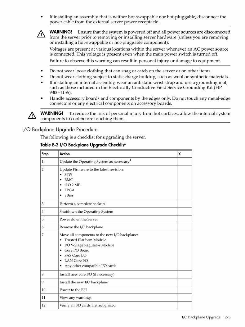
• If installing an assembly that is neither hot-swappable nor hot-pluggable, disconnect thepower cable from the external server power receptacle.
WARNING! Ensure that the system is powered off and all power sources are disconnectedfrom the server prior to removing or installing server hardware (unless you are removingor installing a hot-swappable or hot-pluggable component).Voltages are present at various locations within the server whenever an AC power sourceis connected. This voltage is present even when the main power switch is turned off.Failure to observe this warning can result in personal injury or damage to equipment.
• Do not wear loose clothing that can snag or catch on the server or on other items.• Do not wear clothing subject to static charge buildup, such as wool or synthetic materials.• If installing an internal assembly, wear an antistatic wrist strap and use a grounding mat,
such as those included in the Electrically Conductive Field Service Grounding Kit (HP9300-1155).
• Handle accessory boards and components by the edges only. Do not touch any metal-edgeconnectors or any electrical components on accessory boards.
WARNING! To reduce the risk of personal injury from hot surfaces, allow the internal systemcomponents to cool before touching them.
I/O Backplane Upgrade ProcedureThe following is a checklist for upgrading the server.
Table B-2 I/O Backplane Upgrade Checklist
XActionStep
Update the Operating System as necessary11
Update Firmware to the latest revision:• SFW• BMC• iLO 2 MP• FPGA• vBios
2
Perform a complete backup3
Shutdown the Operating System4
Power down the Server5
Remove the I/O backplane6
Move all components to the new I/O backplane:• Trusted Platform Module• I/O Voltage Regulator Module• Core I/O Board• SAS Core I/O• LAN Core I/O• Any other compatible I/O cards
7
Install new core I/O (if necessary)8
Install the new I/O backplane9
Power to the EFI10
View any warnings11
Verify all I/O cards are recognized12
I/O Backplane Upgrade 275
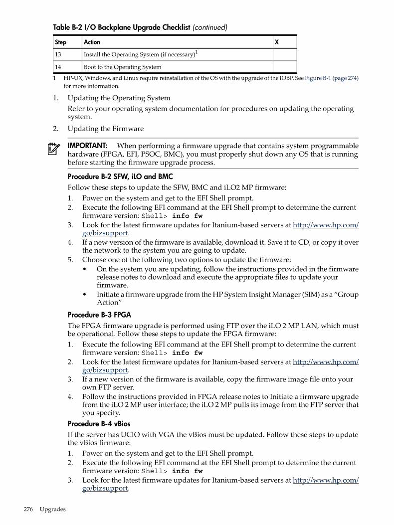
Table B-2 I/O Backplane Upgrade Checklist (continued)
XActionStep
Install the Operating System (if necessary)113
Boot to the Operating System14
1 HP-UX, Windows, and Linux require reinstallation of the OS with the upgrade of the IOBP. See Figure B-1 (page 274)for more information.
1. Updating the Operating SystemRefer to your operating system documentation for procedures on updating the operatingsystem.
2. Updating the Firmware
IMPORTANT: When performing a firmware upgrade that contains system programmablehardware (FPGA, EFI, PSOC, BMC), you must properly shut down any OS that is runningbefore starting the firmware upgrade process.
Procedure B-2 SFW, iLO and BMCFollow these steps to update the SFW, BMC and iLO2 MP firmware:1. Power on the system and get to the EFI Shell prompt.2. Execute the following EFI command at the EFI Shell prompt to determine the current
firmware version: Shell> info fw3. Look for the latest firmware updates for Itanium-based servers at http://www.hp.com/
go/bizsupport.4. If a new version of the firmware is available, download it. Save it to CD, or copy it over
the network to the system you are going to update.5. Choose one of the following two options to update the firmware:
• On the system you are updating, follow the instructions provided in the firmwarerelease notes to download and execute the appropriate files to update yourfirmware.
• Initiate a firmware upgrade from the HP System Insight Manager (SIM) as a “GroupAction”
Procedure B-3 FPGAThe FPGA firmware upgrade is performed using FTP over the iLO 2 MP LAN, which mustbe operational. Follow these steps to update the FPGA firmware:1. Execute the following EFI command at the EFI Shell prompt to determine the current
firmware version: Shell> info fw2. Look for the latest firmware updates for Itanium-based servers at http://www.hp.com/
go/bizsupport.3. If a new version of the firmware is available, copy the firmware image file onto your
own FTP server.4. Follow the instructions provided in FPGA release notes to Initiate a firmware upgrade
from the iLO 2 MP user interface; the iLO 2 MP pulls its image from the FTP server thatyou specify.
Procedure B-4 vBiosIf the server has UCIO with VGA the vBios must be updated. Follow these steps to updatethe vBios firmware:1. Power on the system and get to the EFI Shell prompt.2. Execute the following EFI command at the EFI Shell prompt to determine the current
firmware version: Shell> info fw3. Look for the latest firmware updates for Itanium-based servers at http://www.hp.com/
go/bizsupport.
276 Upgrades
4. If a new version of the Video Graphics Adapter (VGA) firmware is available, downloadit. Save it to CD, or copy it over the network to the system you are going to update.
5. From the EFI Shell, move to the directory in which the downloaded firmware file islocated.
6. Follow the installation instructions provided in the firmware release notes to updatethe VGA firmware using the provided flasher, efiflash_1p15.efi.
3. Performing a System BackupRecord the boot configuration settings. To find the settings, use the INFO ALL EFI Shellcommand.Use Figure 6-28: “TPM Location on I/O Board”, to determine if there is a TPM on the I/Oboard assembly. If so, record the TPM settings to transfer to the replacement I/O boardassembly. See the HP-UX operating system documentation for instructions.Back up the current TPM settings. See the HP-UX operating system documentation for moreinformation.
TIP: Running the info io command from the EFI shell will allow you to record the devicecodes, given in HEX, for your I/O devices. This may be helpful in verifying I/O cards afterthe upgrade.
4. Shutting Down the Operating SystemSee Chapter 4 (page 125) for this procedure.
5. Powering Off the ServerSee “Powering Off the Server” (page 96) for this procedure.
6. Removing the I/O BackplaneSee “Removing the I/O Board Assembly” (page 237) for this procedure.
7. Moving Backplane Componentsa. Move the Trusted Platform Module. See “Removing and Replacing the Trusted Platform
Module” (page 244) for this procedure.b. Move the I/O Voltage Regulator Module. See “Removing and Replacing the I/O Voltage
Regulator Module” (page 243) for this procedure.c. Move the Core I/O Board. See “Removing and Replacing the Core I/O Board” (page 247)
for this procedure.d. Move the LAN Core I/O Card. See “Removing and Replacing the LAN Core I/O Card”
(page 252) for this procedure.e. Move the SAS Core I/O Card.
TIP: If you are not migrating PCI-X SAS core I/O, skip this procedure.
See “Removing and Replacing the SAS Core I/O Card” (page 250) for this procedure.f. Move PCI/PCI-X Cards. See “Removing and Replacing a Hot-Pluggable PCI/PCI-X/PCIe
Card” (page 204) for this procedure.8. Installing New SAS Core I/O
TIP: If you are not installing new SAS core I/O, skip this procedure.
Section (page 279) contains installation procedures for new SAS core I/O cards. There arefour types of SAS core I/O cards supported on the server:• Half length generic PCI-X SAS card supported on HP-UX and Open VMS, see “Installing
the HP Eight-Internal Port SAS Host Bus Adapter” (page 280) for installation instructions.• Full length PCI-X SAS card with RAID capability, supported on Windows and Linux,
see“Installing the HP Smart Array P600” (page 281) for installation instructions.
I/O Backplane Upgrade 277
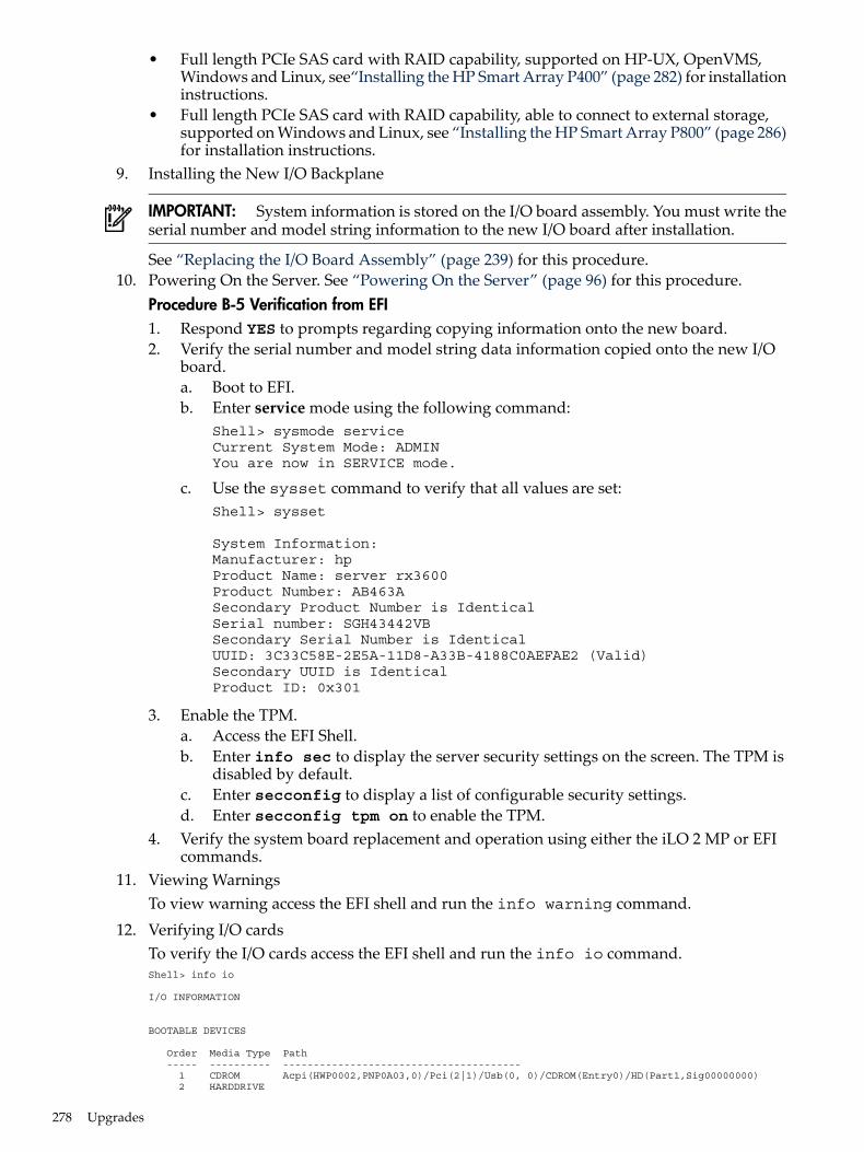
• Full length PCIe SAS card with RAID capability, supported on HP-UX, OpenVMS,Windows and Linux, see“Installing the HP Smart Array P400” (page 282) for installationinstructions.
• Full length PCIe SAS card with RAID capability, able to connect to external storage,supported on Windows and Linux, see “Installing the HP Smart Array P800” (page 286)for installation instructions.
9. Installing the New I/O Backplane
IMPORTANT: System information is stored on the I/O board assembly. You must write theserial number and model string information to the new I/O board after installation.
See “Replacing the I/O Board Assembly” (page 239) for this procedure.10. Powering On the Server. See “Powering On the Server” (page 96) for this procedure.
Procedure B-5 Verification from EFI1. Respond YES to prompts regarding copying information onto the new board.2. Verify the serial number and model string data information copied onto the new I/O
board.a. Boot to EFI.b. Enter service mode using the following command:
Shell> sysmode serviceCurrent System Mode: ADMINYou are now in SERVICE mode.
c. Use the sysset command to verify that all values are set:Shell> sysset
System Information:Manufacturer: hpProduct Name: server rx3600Product Number: AB463ASecondary Product Number is IdenticalSerial number: SGH43442VBSecondary Serial Number is IdenticalUUID: 3C33C58E-2E5A-11D8-A33B-4188C0AEFAE2 (Valid)Secondary UUID is IdenticalProduct ID: 0x301
3. Enable the TPM.a. Access the EFI Shell.b. Enter info sec to display the server security settings on the screen. The TPM is
disabled by default.c. Enter secconfig to display a list of configurable security settings.d. Enter secconfig tpm on to enable the TPM.
4. Verify the system board replacement and operation using either the iLO 2 MP or EFIcommands.
11. Viewing WarningsTo view warning access the EFI shell and run the info warning command.
12. Verifying I/O cardsTo verify the I/O cards access the EFI shell and run the info io command.Shell> info io
I/O INFORMATION
BOOTABLE DEVICES
Order Media Type Path ----- ---------- --------------------------------------- 1 CDROM Acpi(HWP0002,PNP0A03,0)/Pci(2|1)/Usb(0, 0)/CDROM(Entry0)/HD(Part1,Sig00000000) 2 HARDDRIVE
278 Upgrades
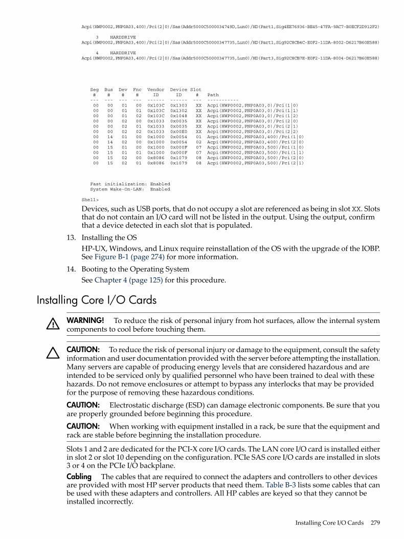
Acpi(HWP0002,PNP0A03,400)/Pci(2|0)/Sas(Addr5000C5000034749D,Lun0)/HD(Part1,Sig4EE76936-BE45-47FA-9AC7-B0ECF2D912F2)
3 HARDDRIVE Acpi(HWP0002,PNP0A03,400)/Pci(2|0)/Sas(Addr5000C50000347735,Lun0)/HD(Part1,Sig92C8CB4C-E0F2-11DA-8002-D6217B60E588)
4 HARDDRIVE Acpi(HWP0002,PNP0A03,400)/Pci(2|0)/Sas(Addr5000C50000347735,Lun0)/HD(Part3,Sig92C8CB7E-E0F2-11DA-8004-D6217B60E588)
Seg Bus Dev Fnc Vendor Device Slot # # # # ID ID # Path --- --- --- --- ------ ------ --- ----------- 00 00 01 00 0x103C 0x1303 XX Acpi(HWP0002,PNP0A03,0)/Pci(1|0) 00 00 01 01 0x103C 0x1302 XX Acpi(HWP0002,PNP0A03,0)/Pci(1|1) 00 00 01 02 0x103C 0x1048 XX Acpi(HWP0002,PNP0A03,0)/Pci(1|2) 00 00 02 00 0x1033 0x0035 XX Acpi(HWP0002,PNP0A03,0)/Pci(2|0) 00 00 02 01 0x1033 0x0035 XX Acpi(HWP0002,PNP0A03,0)/Pci(2|1) 00 00 02 02 0x1033 0x00E0 XX Acpi(HWP0002,PNP0A03,0)/Pci(2|2) 00 14 01 00 0x1000 0x0054 01 Acpi(HWP0002,PNP0A03,400)/Pci(1|0) 00 14 02 00 0x1000 0x0054 02 Acpi(HWP0002,PNP0A03,400)/Pci(2|0) 00 15 01 00 0x1000 0x000F 07 Acpi(HWP0002,PNP0A03,500)/Pci(1|0) 00 15 01 01 0x1000 0x000F 07 Acpi(HWP0002,PNP0A03,500)/Pci(1|1) 00 15 02 00 0x8086 0x1079 08 Acpi(HWP0002,PNP0A03,500)/Pci(2|0) 00 15 02 01 0x8086 0x1079 08 Acpi(HWP0002,PNP0A03,500)/Pci(2|1)
Fast initialization: Enabled System Wake-On-LAN: Enabled
Shell>
Devices, such as USB ports, that do not occupy a slot are referenced as being in slot XX. Slotsthat do not contain an I/O card will not be listed in the output. Using the output, confirmthat a device detected in each slot that is populated.
13. Installing the OSHP-UX, Windows, and Linux require reinstallation of the OS with the upgrade of the IOBP.See Figure B-1 (page 274) for more information.
14. Booting to the Operating SystemSee Chapter 4 (page 125) for this procedure.
Installing Core I/O Cards
WARNING! To reduce the risk of personal injury from hot surfaces, allow the internal systemcomponents to cool before touching them.
CAUTION: To reduce the risk of personal injury or damage to the equipment, consult the safetyinformation and user documentation provided with the server before attempting the installation.Many servers are capable of producing energy levels that are considered hazardous and areintended to be serviced only by qualified personnel who have been trained to deal with thesehazards. Do not remove enclosures or attempt to bypass any interlocks that may be providedfor the purpose of removing these hazardous conditions.
CAUTION: Electrostatic discharge (ESD) can damage electronic components. Be sure that youare properly grounded before beginning this procedure.
CAUTION: When working with equipment installed in a rack, be sure that the equipment andrack are stable before beginning the installation procedure.
Slots 1 and 2 are dedicated for the PCI-X core I/O cards. The LAN core I/O card is installed eitherin slot 2 or slot 10 depending on the configuration. PCIe SAS core I/O cards are installed in slots3 or 4 on the PCIe I/O backplane.Cabling The cables that are required to connect the adapters and controllers to other devicesare provided with most HP server products that need them. Table B-3 lists some cables that canbe used with these adapters and controllers. All HP cables are keyed so that they cannot beinstalled incorrectly.
Installing Core I/O Cards 279
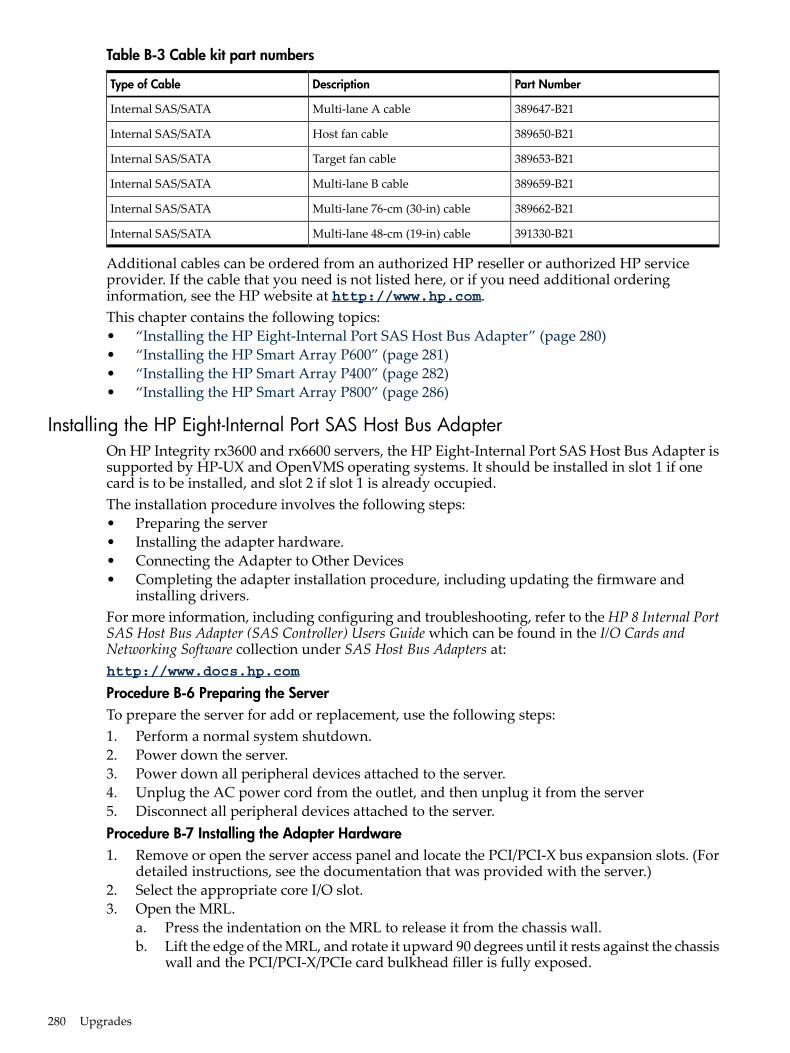
Table B-3 Cable kit part numbers
Part NumberDescriptionType of Cable
389647-B21Multi-lane A cableInternal SAS/SATA
389650-B21Host fan cableInternal SAS/SATA
389653-B21Target fan cableInternal SAS/SATA
389659-B21Multi-lane B cableInternal SAS/SATA
389662-B21Multi-lane 76-cm (30-in) cableInternal SAS/SATA
391330-B21Multi-lane 48-cm (19-in) cableInternal SAS/SATA
Additional cables can be ordered from an authorized HP reseller or authorized HP serviceprovider. If the cable that you need is not listed here, or if you need additional orderinginformation, see the HP website at http://www.hp.com.This chapter contains the following topics:• “Installing the HP Eight-Internal Port SAS Host Bus Adapter” (page 280)• “Installing the HP Smart Array P600” (page 281)• “Installing the HP Smart Array P400” (page 282)• “Installing the HP Smart Array P800” (page 286)
Installing the HP Eight-Internal Port SAS Host Bus AdapterOn HP Integrity rx3600 and rx6600 servers, the HP Eight-Internal Port SAS Host Bus Adapter issupported by HP-UX and OpenVMS operating systems. It should be installed in slot 1 if onecard is to be installed, and slot 2 if slot 1 is already occupied.The installation procedure involves the following steps:• Preparing the server• Installing the adapter hardware.• Connecting the Adapter to Other Devices• Completing the adapter installation procedure, including updating the firmware and
installing drivers.For more information, including configuring and troubleshooting, refer to the HP 8 Internal PortSAS Host Bus Adapter (SAS Controller) Users Guide which can be found in the I/O Cards andNetworking Software collection under SAS Host Bus Adapters at:http://www.docs.hp.com
Procedure B-6 Preparing the ServerTo prepare the server for add or replacement, use the following steps:1. Perform a normal system shutdown.2. Power down the server.3. Power down all peripheral devices attached to the server.4. Unplug the AC power cord from the outlet, and then unplug it from the server5. Disconnect all peripheral devices attached to the server.Procedure B-7 Installing the Adapter Hardware1. Remove or open the server access panel and locate the PCI/PCI-X bus expansion slots. (For
detailed instructions, see the documentation that was provided with the server.)2. Select the appropriate core I/O slot.3. Open the MRL.
a. Press the indentation on the MRL to release it from the chassis wall.b. Lift the edge of the MRL, and rotate it upward 90 degrees until it rests against the chassis
wall and the PCI/PCI-X/PCIe card bulkhead filler is fully exposed.
280 Upgrades
4. Remove the PCI/PCI-X/PCIe bulkhead filler. Save it to use for if you later decide to removethe adapter and leave the slot empty.
5. Insert the adapter into the slot, and press it firmly into place. The contacts on the adapteredge should be fully seated in the system board connector.
6. Close the MRL.a. Rotate the MRL downward 90 degrees.b. Push the edge of the MRL down until it clicks into place on the PCI/PCI-X/PCIe card
bulkhead.
Procedure B-8 Connecting the Adapter to Other Devices• Connect the Adapter to SAS backplane. See Table B-3 (page 280) for a listing of Cable kit part
numbers.Procedure B-9 Completing the Adapter Installation1. Verify that all cables are routed correctly and are not restricting or being pinched by other
components. For the correct routing of the cables, see the server documentation.2. Reconnect any peripheral devices to the server.3. Plug the AC power cord into the server, and then into a grounded AC outlet.4. Power on any peripheral devices attached to the server5. Power up the server.6. If necessary, update the server ROM. The required firmware files are on either a CD in the
adapter kit or the HP website, http://www.hp.com. Instructions are provided with thefiles (in the case of the CD, in a booklet provided with the CD).
7. Install the adapter drivers. The drivers are also on either the CD in the adapter kit or the HPwebsite, and instructions are again provided with the files.
Installing the HP Smart Array P600On HP Integrity rx3600 and rx6600 servers, the HP Smart Array P600 is supported by Windowsand Linux operating systems. It should be installed in slot 1 if one card is to be installed, andslot 2 if slot 1 is already occupied.For more information, including configuring and diagnosing array problems, refer to the HPSmart Array P600 Controller for Integrity Servers User Guide which can be found in the I/O Cardsand Networking Software collection under Smart Array at:http://www.docs.hp.com
The installation procedure involves the following steps:• Preparing the server• Installing the controller board.• Connecting the Controller to Other Devices• Completing the adapter installation procedure, including updating the firmware and
installing drivers.Procedure B-10 Preparing the Server1. Close all applications.2. Power down the server.3. Power down all peripheral devices that are attached to the server.4. Unplug the AC power cord from the outlet and then from the server.5. Disconnect all peripheral devices from the server.Procedure B-11 Installing the Controller Board1. Remove or open the access panel.2. Select the appropriate core I/O slot.
Installing Core I/O Cards 281
3. Open the MRL.a. Press the indentation on the MRL to release it from the chassis wall.b. Lift the edge of the MRL, and rotate it upward 90 degrees until it rests against the chassis
wall and the PCI/PCI-X/PCIe card bulkhead filler is fully exposed.4. Remove the PCI/PCI-X/PCIe bulkhead filler. Save it to use for if you later decide to remove
the adapter and leave the slot empty.5. Insert the adapter into the slot, and press it firmly into place. The contacts on the adapter
edge should be fully seated in the system board connector.6. Close the MRL.
a. Rotate the MRL downward 90 degrees.b. Push the edge of the MRL down until it clicks into place on the PCI/PCI-X/PCIe card
bulkhead.7. Close the gate latch to secure the end of the card.Procedure B-12 Connecting the Controller to Other Devices• Connect the Adapter to the SAS backplane. See Table B-3 (page 280) for a listing of Cable kit
part numbers.Procedure B-13 Completing the Adapter InstallationTo update the firmware on the server, controller, or hard drives, use Smart Components. Themost recent version of a particular component is available on the support page of the HP websitehttp://www.hp.com/support. Some components are also available on the Smart Setup media.1. Find the most recent version of the component that you require.2. Follow the instructions for installing the component on the server. These instructions are
provided on the same web page as the component.3. Follow the additional instructions that describe how to use the component to flash the ROM.
These instructions are provided with each component.
Installing the HP Smart Array P400On HP Integrity rx3600 and rx6600 servers, the HP Smart Array P400 is supported by HP-UX,OpenVMS, Windows and Linux operating systems. It should be installed in PCIe slot 3 or 4.For more information, including configuring and diagnosing array problems, refer to the HPSmart Array P400 Controller Support Guide which can be found in the I/O Cards and NetworkingSoftware collection under Smart Array at:http://www.docs.hp.com
The installation procedure involves the following steps:• Preparing the server• Installing the controller board.• Connecting the Controller to Other Devices• Completing the adapter installation procedure, including updating the firmware and
installing drivers.Procedure B-14 Preparing the Server1. Close all applications.2. Power down the server.3. Power down all peripheral devices that are attached to the server.4. Unplug the AC power cord from the outlet and then from the server.5. Disconnect all peripheral devices from the server.Procedure B-15 Installing the Controller Board1. Remove or open the access panel2. Select the appropriate PCI Express slot (3 or 4).
282 Upgrades
3. Open the MRL.a. Press the indentation on the MRL to release it from the chassis wall.b. Lift the edge of the MRL, and rotate it upward 90 degrees until it rests against the chassis
wall and the PCI/PCI-X/PCIe card bulkhead filler is fully exposed.4. Remove the PCI/PCI-X/PCIe bulkhead filler. Save it to use for if you later decide to remove
the adapter and leave the slot empty.5. Insert the adapter into the slot, and press it firmly into place. The contacts on the adapter
edge should be fully seated in the system board connector.6. Close the MRL.
a. Rotate the MRL downward 90 degrees.b. Push the edge of the MRL down until it clicks into place on the PCI/PCI-X/PCIe card
bulkhead.7. Close the gate latch to secure the end of the card.Procedure B-16 Connecting the Controller to Other Devices• Connect the Adapter to the SAS backplane. See Table B-3 (page 280) for a listing of Cable kit
part numbers.
Completing the Adapter Installation on HP-UXProcedure B-17 Downloading Software for the Smart Array Series ControllersThe drivers, utilities and manpages for the Smart Array series controllers are located at the HPSoftware Depot.1. Go to http://www.software.hp.com2. Search for “Smart Array”3. Click Receive for Free.4. Select the HP-UX version that your system runs, then complete the required registration
information and click Next.5. Click the depot that corresponds with the OS you are running to download the drivers,
utilities, and manpages for the Smart Array Controllers.6. In the Documents column next to the Download Software column, click Installation
Instructions to download instructions for using the Software Distributor tool to install thedrivers, utilities, and manpages.
Installing Software for Smart Array Series Controllers The drivers, utilities, and manpages forthe Smart Array Series Controllers contained in the RAID-01 bundle downloaded depot can beinstalled using Software Distributor (SD). SD is a tool for installing software on HP-UX hostsystems. SD can also be used to remove software from HP-UX systems. The RAID-01 bundle iscomposed of several files that will be copied to the appropriate directories on the host system.View these files in the /opt/raidsa/bin directory. The instructions for using SD to install or removethe drivers, utilities, and manpages for the Smart Array series controllers can be viewed at theHP Software Depot.Procedure B-18 Verifying the InstallationAfter the system reboots, verify that the installation was successful by following these steps:1. Enter the swlist command:
swlist
When running HP-UX 11i v2 the generated output will look like this:RAID-01 B.11.23.0612 RAID SA; Supptd HW=A7143A/A9890A/A9891A
Installing Core I/O Cards 283
2. Enter the ioscan -kfnd ciss command:ioscan -kfnd ciss
If the Smart Array Controller software is installed correctly, the generated output lookssimilar to this:# ioscan -kfnd cissClass I H/W Path Driver S/W State H/W Type Description==========================================================================ext_bus 5 0/6/0/0/0/0/1/0/0/0 ciss CLAIMED INTERFACE PCIe SAS SmartArray P400 RAIDController/dev/ciss5
If the software is not installed correctly, reinstall it using swinstall.
Procedure B-19 Updating the FirmwareUse the sautil command to confirm and update the firmware version currently installed onthe Smart Array Controller. HP recommends that you install the latest firmware. You must login as a superuser user to run the sautil command. Before running the sautil command toconfirm or update the controller firmware, you must know the device file name for the SmartArray Controller.1. Determine the device file for the Smart Array Controller by running the ioscan -kfnd
ciss command. The following is an example of the ioscan output listing the Smart ArrayController device files:# ioscan -kfnd cissClass I H/W Path Driver S/W State H/W Type Description==========================================================================ext_bus 5 0/6/0/0/0/0/1/0/0/0 ciss CLAIMED INTERFACE PCIe SAS SmartArray P400 RAIDController/dev/ciss5
In the example, /dev/ciss5 is the device file for Smart Array P400 Controller.2. Determine the Smart Array series controller firmware version that is in the ROM on the
Smart Array Controller by using either the sautil <device_file> command (extensiveoutput), or the sautil <device_file> -s command (shortened output). Entering thesautil <device_file -s> command provides an abbreviated listing of informationfor the Smart Array Controller and all connected devices, including the firmware versioncurrently in ROM.# sautil /dev/ciss5 -s********************************************************************************** ******** S A U T I L S u p p o r t U t i l i t y ******** ******** for the HP SmartArray RAID Controller Family ******** ******** version A.02.11 ******** ******** (C) Copyright 2003-2006 Hewlett-Packard Development Company, L.P. **********************************************************************************---- DRIVER INFORMATION ------------------------------------------------------Driver State........................ READY---- CONTROLLER INFORMATION --------------------------------------------------Controller Product Number........... P400Controller Product Name............. HP PCIe SmartArray P400Hardware Path....................... 0/6/0/0/0/0/1/0/0/0Serial Number....................... PA5360BBFSW2ONDevice File......................... /dev/ciss5Hardware Revision................... ‘B’Firmware Revision (in ROM).......... 1.96# of Logical Drives................. 2# of Physical Disks Configured...... 4# of Physical Disks Detected........ 4oo (content has been omitted)o********************************************************************************** End of SAUTIL Output **********************************************************************************
284 Upgrades
In this example, the Smart Array Controller /dev/ciss5 has ROM firmware revision 1.96.3. Update the Smart Array controller firmware by using the sautil command. The sautil
command syntax for updating Smart Array Controller firmware is:sautil <device_file> download_ctlr_fw <fw_image>
where:<device_file> The controller device file.<fw_image> The file path for the firmware version you want to install on the Smart
Array Controller.When you enter the sautil <device_file> download_ctlr_fw <fw_image>command, the currently installed firmware version is listed along with the firmware versionyou selected to replace it with. You can either proceed with the download or cancel.# sautil /dev/ciss5 download_ctlr_fw INCPTR_2.02.2.42.PAK********************************************************************************** ******** S A U T I L S u p p o r t U t i l i t y ******** ******** for the HP SmartArray RAID Controller Family ******** ******** version A.02.11 ******** ******** (C) Copyright 2003-2006 Hewlett-Packard Development Company, L.P. **********************************************************************************---- DRIVER INFORMATION ------------------------------------------------------Driver State........................ READY---- CONTROLLER INFORMATION --------------------------------------------------Controller Product Number........... P400Controller Product Name............. HP PCIe SmartArray P400Hardware Path....................... 0/6/0/0/0/0/1/0/0/0Device File......................... /dev/ciss5---- FIRMWARE DOWNLOAD -------------------------------------------------------** You are downloading the firmware image “INCPTR_2.02.2.42.PAK”** to the controller “/dev/ciss5”.Retrieving firmware image file from disk................... [Done]Validating the file’s signature and size................... [Done]Retrieving the firmware revision string from ROM........... [Done]Retrieving the firmware revision string from the file...... [Done]Current Revision (in ROM)....... 1.96New Revision (in file).......... 2.02WARNING: The firmware download process may take several minutes tocomplete. All I/O to this controller will be temporarilyhalted during this time.Are you sure you want to continue (y/n)? yPreparing for download..................................... [Done]Sending the new firmware to the controller................. [Done]Activating the new firmware................................ [Done]Resetting the controller................................... [Done]Retrieving the firmware revision string from ROM........... [Done]Current Revision (in ROM)....... 2.02FIRMWARE DOWNLOAD WAS SUCCESSFUL!********************************************************************************** End of SAUTIL Output **********************************************************************************
Completing the Adapter Installation on Windows and LinuxTo update the firmware on the server, controller, or hard drives, use Smart Components. Thesecomponents are available on the Firmware Maintenance CD. A more recent version of a particularserver or controller component might be available on the support page of the HP website(http://www.hp.com/support).1. Find the most recent version of the component that you require. Components for controller
firmware updates are available in offline and online formats2. Follow the instructions for installing the component on the server. These instructions are
given with the CD and are provided on the same web page as the component.
Installing Core I/O Cards 285
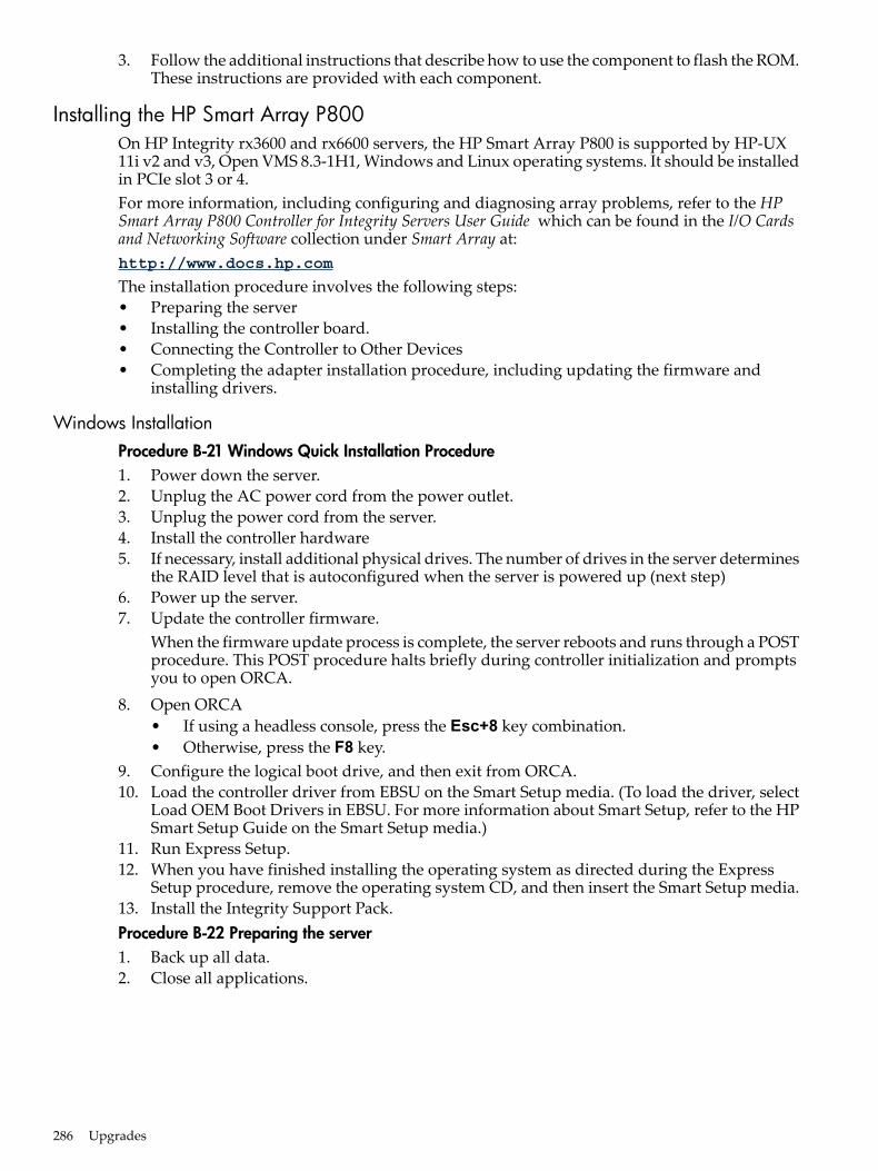
3. Follow the additional instructions that describe how to use the component to flash the ROM.These instructions are provided with each component.
Installing the HP Smart Array P800On HP Integrity rx3600 and rx6600 servers, the HP Smart Array P800 is supported by HP-UX11i v2 and v3, Open VMS 8.3-1H1, Windows and Linux operating systems. It should be installedin PCIe slot 3 or 4.For more information, including configuring and diagnosing array problems, refer to the HPSmart Array P800 Controller for Integrity Servers User Guide which can be found in the I/O Cardsand Networking Software collection under Smart Array at:http://www.docs.hp.com
The installation procedure involves the following steps:• Preparing the server• Installing the controller board.• Connecting the Controller to Other Devices• Completing the adapter installation procedure, including updating the firmware and
installing drivers.
Windows InstallationProcedure B-21 Windows Quick Installation Procedure1. Power down the server.2. Unplug the AC power cord from the power outlet.3. Unplug the power cord from the server.4. Install the controller hardware5. If necessary, install additional physical drives. The number of drives in the server determines
the RAID level that is autoconfigured when the server is powered up (next step)6. Power up the server.7. Update the controller firmware.
When the firmware update process is complete, the server reboots and runs through a POSTprocedure. This POST procedure halts briefly during controller initialization and promptsyou to open ORCA.
8. Open ORCA• If using a headless console, press the Esc+8 key combination.• Otherwise, press the F8 key.
9. Configure the logical boot drive, and then exit from ORCA.10. Load the controller driver from EBSU on the Smart Setup media. (To load the driver, select
Load OEM Boot Drivers in EBSU. For more information about Smart Setup, refer to the HPSmart Setup Guide on the Smart Setup media.)
11. Run Express Setup.12. When you have finished installing the operating system as directed during the Express
Setup procedure, remove the operating system CD, and then insert the Smart Setup media.13. Install the Integrity Support Pack.Procedure B-22 Preparing the server1. Back up all data.2. Close all applications.
286 Upgrades
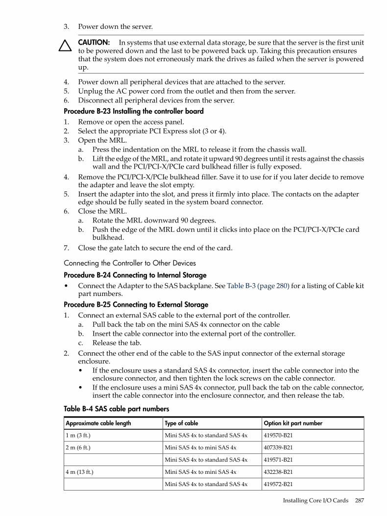
3. Power down the server.
CAUTION: In systems that use external data storage, be sure that the server is the first unitto be powered down and the last to be powered back up. Taking this precaution ensuresthat the system does not erroneously mark the drives as failed when the server is poweredup.
4. Power down all peripheral devices that are attached to the server.5. Unplug the AC power cord from the outlet and then from the server.6. Disconnect all peripheral devices from the server.Procedure B-23 Installing the controller board1. Remove or open the access panel.2. Select the appropriate PCI Express slot (3 or 4).3. Open the MRL.
a. Press the indentation on the MRL to release it from the chassis wall.b. Lift the edge of the MRL, and rotate it upward 90 degrees until it rests against the chassis
wall and the PCI/PCI-X/PCIe card bulkhead filler is fully exposed.4. Remove the PCI/PCI-X/PCIe bulkhead filler. Save it to use for if you later decide to remove
the adapter and leave the slot empty.5. Insert the adapter into the slot, and press it firmly into place. The contacts on the adapter
edge should be fully seated in the system board connector.6. Close the MRL.
a. Rotate the MRL downward 90 degrees.b. Push the edge of the MRL down until it clicks into place on the PCI/PCI-X/PCIe card
bulkhead.7. Close the gate latch to secure the end of the card.
Connecting the Controller to Other Devices
Procedure B-24 Connecting to Internal Storage• Connect the Adapter to the SAS backplane. See Table B-3 (page 280) for a listing of Cable kit
part numbers.Procedure B-25 Connecting to External Storage1. Connect an external SAS cable to the external port of the controller.
a. Pull back the tab on the mini SAS 4x connector on the cableb. Insert the cable connector into the external port of the controller.c. Release the tab.
2. Connect the other end of the cable to the SAS input connector of the external storageenclosure.• If the enclosure uses a standard SAS 4x connector, insert the cable connector into the
enclosure connector, and then tighten the lock screws on the cable connector.• If the enclosure uses a mini SAS 4x connector, pull back the tab on the cable connector,
insert the cable connector into the enclosure connector, and then release the tab.
Table B-4 SAS cable part numbers
Option kit part numberType of cableApproximate cable length
419570-B21Mini SAS 4x to standard SAS 4x1 m (3 ft.)
407339-B21Mini SAS 4x to mini SAS 4x2 m (6 ft.)
419571-B21Mini SAS 4x to standard SAS 4x
432238-B21Mini SAS 4x to mini SAS 4x4 m (13 ft.)
419572-B21Mini SAS 4x to standard SAS 4x
Installing Core I/O Cards 287
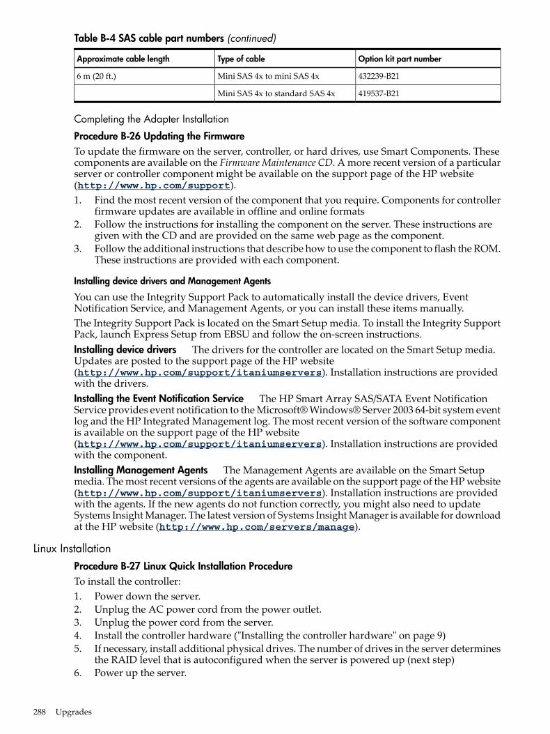
Table B-4 SAS cable part numbers (continued)
Option kit part numberType of cableApproximate cable length
432239-B21Mini SAS 4x to mini SAS 4x6 m (20 ft.)
419537-B21Mini SAS 4x to standard SAS 4x
Completing the Adapter Installation
Procedure B-26 Updating the FirmwareTo update the firmware on the server, controller, or hard drives, use Smart Components. Thesecomponents are available on the Firmware Maintenance CD. A more recent version of a particularserver or controller component might be available on the support page of the HP website(http://www.hp.com/support).1. Find the most recent version of the component that you require. Components for controller
firmware updates are available in offline and online formats2. Follow the instructions for installing the component on the server. These instructions are
given with the CD and are provided on the same web page as the component.3. Follow the additional instructions that describe how to use the component to flash the ROM.
These instructions are provided with each component.
Installing device drivers and Management Agents
You can use the Integrity Support Pack to automatically install the device drivers, EventNotification Service, and Management Agents, or you can install these items manually.The Integrity Support Pack is located on the Smart Setup media. To install the Integrity SupportPack, launch Express Setup from EBSU and follow the on-screen instructions.Installing device drivers The drivers for the controller are located on the Smart Setup media.Updates are posted to the support page of the HP website(http://www.hp.com/support/itaniumservers). Installation instructions are providedwith the drivers.Installing the Event Notification Service The HP Smart Array SAS/SATA Event NotificationService provides event notification to the Microsoft® Windows® Server 2003 64-bit system eventlog and the HP Integrated Management log. The most recent version of the software componentis available on the support page of the HP website(http://www.hp.com/support/itaniumservers). Installation instructions are providedwith the component.Installing Management Agents The Management Agents are available on the Smart Setupmedia. The most recent versions of the agents are available on the support page of the HP website(http://www.hp.com/support/itaniumservers). Installation instructions are providedwith the agents. If the new agents do not function correctly, you might also need to updateSystems Insight Manager. The latest version of Systems Insight Manager is available for downloadat the HP website (http://www.hp.com/servers/manage).
Linux InstallationProcedure B-27 Linux Quick Installation ProcedureTo install the controller:1. Power down the server.2. Unplug the AC power cord from the power outlet.3. Unplug the power cord from the server.4. Install the controller hardware ("Installing the controller hardware" on page 9)5. If necessary, install additional physical drives. The number of drives in the server determines
the RAID level that is autoconfigured when the server is powered up (next step)6. Power up the server.
288 Upgrades
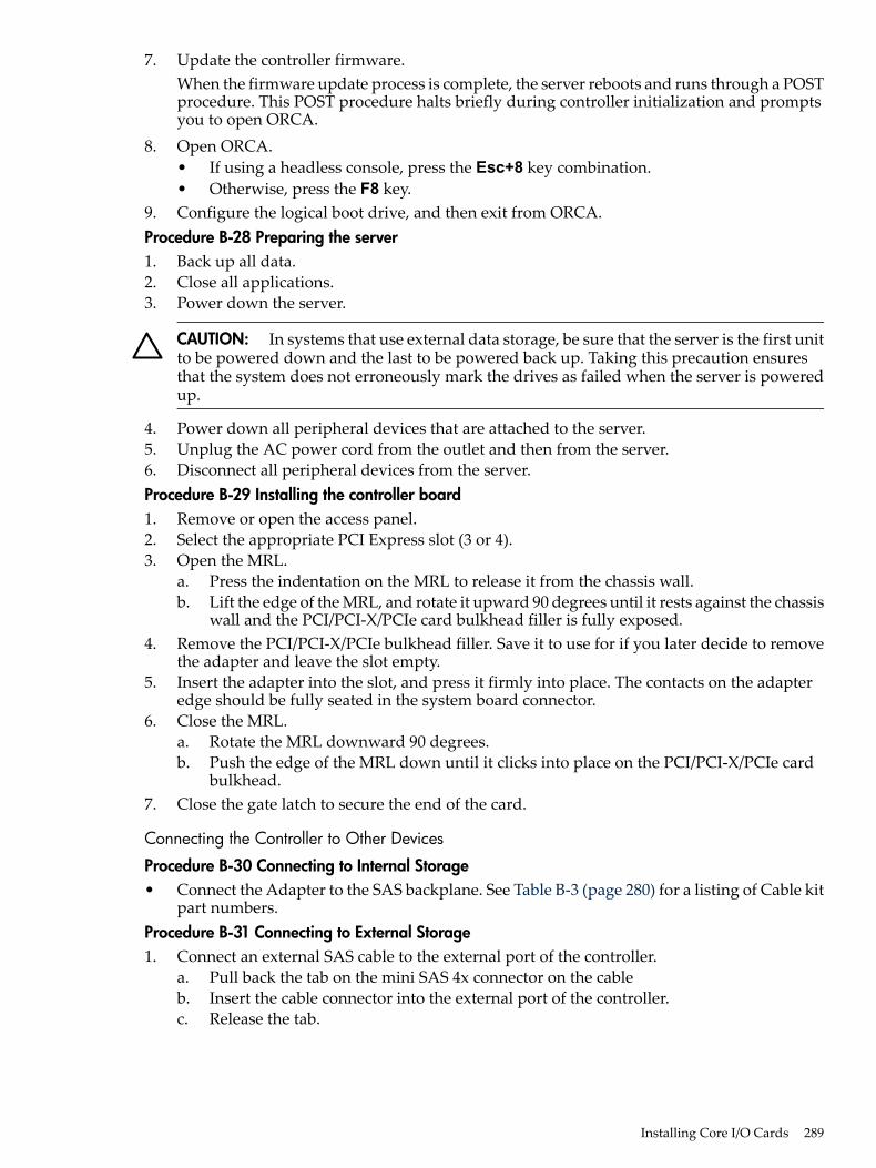
7. Update the controller firmware.When the firmware update process is complete, the server reboots and runs through a POSTprocedure. This POST procedure halts briefly during controller initialization and promptsyou to open ORCA.
8. Open ORCA.• If using a headless console, press the Esc+8 key combination.• Otherwise, press the F8 key.
9. Configure the logical boot drive, and then exit from ORCA.Procedure B-28 Preparing the server1. Back up all data.2. Close all applications.3. Power down the server.
CAUTION: In systems that use external data storage, be sure that the server is the first unitto be powered down and the last to be powered back up. Taking this precaution ensuresthat the system does not erroneously mark the drives as failed when the server is poweredup.
4. Power down all peripheral devices that are attached to the server.5. Unplug the AC power cord from the outlet and then from the server.6. Disconnect all peripheral devices from the server.Procedure B-29 Installing the controller board1. Remove or open the access panel.2. Select the appropriate PCI Express slot (3 or 4).3. Open the MRL.
a. Press the indentation on the MRL to release it from the chassis wall.b. Lift the edge of the MRL, and rotate it upward 90 degrees until it rests against the chassis
wall and the PCI/PCI-X/PCIe card bulkhead filler is fully exposed.4. Remove the PCI/PCI-X/PCIe bulkhead filler. Save it to use for if you later decide to remove
the adapter and leave the slot empty.5. Insert the adapter into the slot, and press it firmly into place. The contacts on the adapter
edge should be fully seated in the system board connector.6. Close the MRL.
a. Rotate the MRL downward 90 degrees.b. Push the edge of the MRL down until it clicks into place on the PCI/PCI-X/PCIe card
bulkhead.7. Close the gate latch to secure the end of the card.
Connecting the Controller to Other Devices
Procedure B-30 Connecting to Internal Storage• Connect the Adapter to the SAS backplane. See Table B-3 (page 280) for a listing of Cable kit
part numbers.Procedure B-31 Connecting to External Storage1. Connect an external SAS cable to the external port of the controller.
a. Pull back the tab on the mini SAS 4x connector on the cableb. Insert the cable connector into the external port of the controller.c. Release the tab.
Installing Core I/O Cards 289
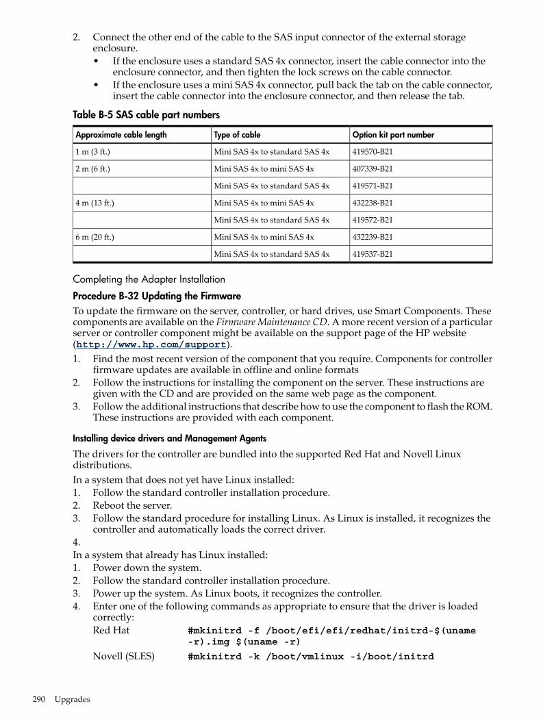
2. Connect the other end of the cable to the SAS input connector of the external storageenclosure.• If the enclosure uses a standard SAS 4x connector, insert the cable connector into the
enclosure connector, and then tighten the lock screws on the cable connector.• If the enclosure uses a mini SAS 4x connector, pull back the tab on the cable connector,
insert the cable connector into the enclosure connector, and then release the tab.
Table B-5 SAS cable part numbers
Option kit part numberType of cableApproximate cable length
419570-B21Mini SAS 4x to standard SAS 4x1 m (3 ft.)
407339-B21Mini SAS 4x to mini SAS 4x2 m (6 ft.)
419571-B21Mini SAS 4x to standard SAS 4x
432238-B21Mini SAS 4x to mini SAS 4x4 m (13 ft.)
419572-B21Mini SAS 4x to standard SAS 4x
432239-B21Mini SAS 4x to mini SAS 4x6 m (20 ft.)
419537-B21Mini SAS 4x to standard SAS 4x
Completing the Adapter Installation
Procedure B-32 Updating the FirmwareTo update the firmware on the server, controller, or hard drives, use Smart Components. Thesecomponents are available on the Firmware Maintenance CD. A more recent version of a particularserver or controller component might be available on the support page of the HP website(http://www.hp.com/support).1. Find the most recent version of the component that you require. Components for controller
firmware updates are available in offline and online formats2. Follow the instructions for installing the component on the server. These instructions are
given with the CD and are provided on the same web page as the component.3. Follow the additional instructions that describe how to use the component to flash the ROM.
These instructions are provided with each component.
Installing device drivers and Management Agents
The drivers for the controller are bundled into the supported Red Hat and Novell Linuxdistributions.In a system that does not yet have Linux installed:1. Follow the standard controller installation procedure.2. Reboot the server.3. Follow the standard procedure for installing Linux. As Linux is installed, it recognizes the
controller and automatically loads the correct driver.4.In a system that already has Linux installed:1. Power down the system.2. Follow the standard controller installation procedure.3. Power up the system. As Linux boots, it recognizes the controller.4. Enter one of the following commands as appropriate to ensure that the driver is loaded
correctly:Red Hat #mkinitrd -f /boot/efi/efi/redhat/initrd-$(uname
-r).img $(uname -r)
Novell (SLES) #mkinitrd -k /boot/vmlinux -i/boot/initrd
290 Upgrades
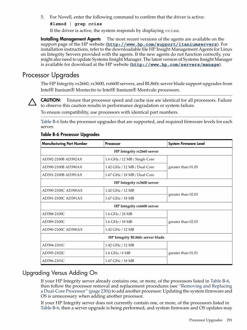
5. For Novell, enter the following command to confirm that the driver is active:#lsmod | grep cciss
If the driver is active, the system responds by displaying cciss.
Installing Management Agents The most recent versions of the agents are available on thesupport page of the HP website (http://www.hp.com/support/itaniumservers). Forinstallation instructions, refer to the downloadable file HP Insight Management Agents for Linuxon Integrity Servers provided with the agents. If the new agents do not function correctly, youmight also need to update Systems Insight Manager. The latest version of Systems Insight Manageris available for download at the HP website (http://www.hp.com/servers/manage).
Processor UpgradesThe HP Integrity rx2660, rx3600, rx6600 servers, and BL860c server blade support upgrades fromIntel® Itanium® Montecito to Intel® Itanium® Montvale processors.
CAUTION: Ensure that processor speed and cache size are identical for all processors. Failureto observe this caution results in performance degradation or system failure.To ensure compatibility, use processors with identical part numbers.
Table B-6 lists the processor upgrades that are supported, and required firmware levels for eachserver.
Table B-6 Processor Upgrades
System Firmware LevelProcessorManufacturing Part Number
HP Integrity rx2660 server
greater than 01.05
1.6 GHz / 12 MB / Single CoreAD392-2100B AD392AX
1.42 GHz / 12 MB / Dual CoreAD390-2100B AD390AX
1.67 GHz / 18 MB / Dual CoreAD391-2100B AD391AX
HP Integrity rx3600 server
greater than 02.031.42 GHz / 12 MBAD390-2100C AD390AX
1.67 GHz / 18 MBAD391-2100C AD391AX
HP Integrity rx6600 server
greater than 02.03
1.6 GHz / 24 MBAD388-2100C
1.6 GHz / 18 MBAD389-2100C
1.42 GHz / 12 MBAD390-2100C AD390AX
HP Integrity BL860c server blade
greater than 01.01
1.42 GHz / 12 MBAD394-2101C
1.6 GHz / 6 MBAD395-2102C
1.67 GHz / 18 MBAD396-2101C
Upgrading Versus Adding OnIf your HP Integrity server already contains one, or more, of the processors listed in Table B-6,then follow the processor removal and replacement procedures (see “Removing and Replacinga Dual-Core Processor” (page 230)) to add another processor. Updating the system firmware andOS is unnecessary when adding another processor.If your HP Integrity server does not currently contain one, or more, of the processors listed inTable B-6, then a server upgrade is being performed, and system firmware and OS updates may
Processor Upgrades 291
be necessary. After any necessary system firmware and OS updates are performed, follow theprocessor removal and replacement procedures (see “Removing and Replacing a Dual-CoreProcessor” (page 230)).
FirmwareBefore upgrading the processor, ensure the server is at the required system firmware level. Checkthe system firmware version by executing the info fw command at the EFI Shell prompt.
NOTE: HP recommends using the latest version of firmware.
Go to http://www.hp.com/support/itaniumservers to download firmware updates.
Operating systems
IMPORTANT: Check the HP IT Resource Center (ITRC) website at http://itrc.hp.com forany required OS patches.
HP-UX HP-UX supports the processor upgrade.OpenVMS OpenVMS must be upgraded to OpenVMS V8.3-1H1 to support the processorupgrade.
Windows Windows® supports the processor upgrade.Linux Linux supports the processor upgrade. If you choose to move any I/O cards or storageduring this upgrade, Linux must be reinstalled.
292 Upgrades
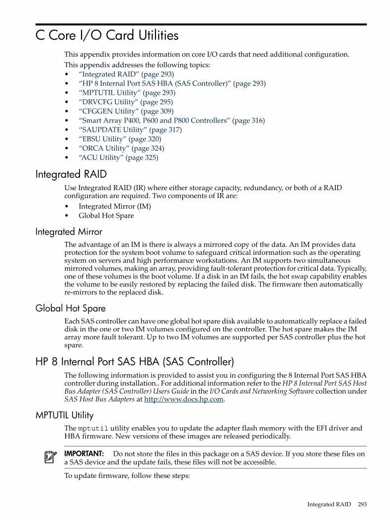
C Core I/O Card UtilitiesThis appendix provides information on core I/O cards that need additional configuration.This appendix addresses the following topics:• “Integrated RAID” (page 293)• “HP 8 Internal Port SAS HBA (SAS Controller)” (page 293)• “MPTUTIL Utility” (page 293)• “DRVCFG Utility” (page 295)• “CFGGEN Utility” (page 309)• “Smart Array P400, P600 and P800 Controllers” (page 316)• “SAUPDATE Utility” (page 317)• “EBSU Utility” (page 320)• “ORCA Utility” (page 324)• “ACU Utility” (page 325)
Integrated RAIDUse Integrated RAID (IR) where either storage capacity, redundancy, or both of a RAIDconfiguration are required. Two components of IR are:• Integrated Mirror (IM)• Global Hot Spare
Integrated MirrorThe advantage of an IM is there is always a mirrored copy of the data. An IM provides dataprotection for the system boot volume to safeguard critical information such as the operatingsystem on servers and high performance workstations. An IM supports two simultaneousmirrored volumes, making an array, providing fault-tolerant protection for critical data. Typically,one of these volumes is the boot volume. If a disk in an IM fails, the hot swap capability enablesthe volume to be easily restored by replacing the failed disk. The firmware then automaticallyre-mirrors to the replaced disk.
Global Hot SpareEach SAS controller can have one global hot spare disk available to automatically replace a faileddisk in the one or two IM volumes configured on the controller. The hot spare makes the IMarray more fault tolerant. Up to two IM volumes are supported per SAS controller plus the hotspare.
HP 8 Internal Port SAS HBA (SAS Controller)The following information is provided to assist you in configuring the 8 Internal Port SAS HBAcontroller during installation.. For additional information refer to the HP 8 Internal Port SASHostBus Adapter (SAS Controller) Users Guide in the I/O Cards and Networking Software collection underSAS Host Bus Adapters at http://www.docs.hp.com.
MPTUTIL UtilityThe mptutil utility enables you to update the adapter flash memory with the EFI driver andHBA firmware. New versions of these images are released periodically.
IMPORTANT: Do not store the files in this package on a SAS device. If you store these files ona SAS device and the update fails, these files will not be accessible.
To update firmware, follow these steps:
Integrated RAID 293
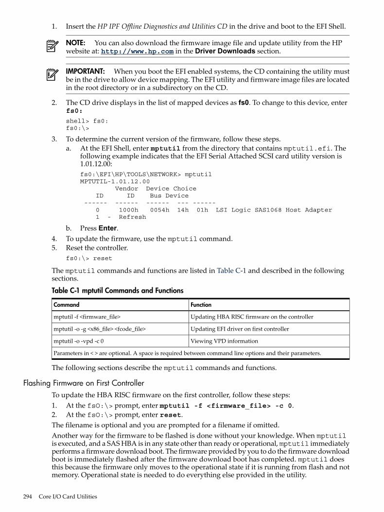
1. Insert the HP IPF Offline Diagnostics and Utilities CD in the drive and boot to the EFI Shell.
NOTE: You can also download the firmware image file and update utility from the HPwebsite at: http://www.hp.com in the Driver Downloads section.
IMPORTANT: When you boot the EFI enabled systems, the CD containing the utility mustbe in the drive to allow device mapping. The EFI utility and firmware image files are locatedin the root directory or in a subdirectory on the CD.
2. The CD drive displays in the list of mapped devices as fs0. To change to this device, enterfs0:
shell> fs0:fs0:\>
3. To determine the current version of the firmware, follow these steps.a. At the EFI Shell, enter mptutil from the directory that contains mptutil.efi. The
following example indicates that the EFI Serial Attached SCSI card utility version is1.01.12.00:fs0:\EFI\HP\TOOLS\NETWORK> mptutilMPTUTIL-1.01.12.00 Vendor Device Choice ID ID Bus Device ------ ------ ------ --- ------ 0 1000h 0054h 14h 01h LSI Logic SAS1068 Host Adapter 1 - Refresh
b. Press Enter.4. To update the firmware, use the mptutil command.5. Reset the controller.
fs0:\> reset
The mptutil commands and functions are listed in Table C-1 and described in the followingsections.
Table C-1 mptutil Commands and Functions
FunctionCommand
Updating HBA RISC firmware on the controllermptutil -f <firmware_file>
Updating EFI driver on first controllermptutil -o -g <x86_file> <fcode_file>
Viewing VPD informationmptutil -o -vpd -c 0
Parameters in < > are optional. A space is required between command line options and their parameters.
The following sections describe the mptutil commands and functions.
Flashing Firmware on First ControllerTo update the HBA RISC firmware on the first controller, follow these steps:1. At the fsO:\> prompt, enter mptutil -f <firmware_file> -c 0.2. At the fsO:\> prompt, enter reset.The filename is optional and you are prompted for a filename if omitted.Another way for the firmware to be flashed is done without your knowledge. When mptutilis executed, and a SAS HBA is in any state other than ready or operational, mptutil immediatelyperforms a firmware download boot. The firmware provided by you to do the firmware downloadboot is immediately flashed after the firmware download boot has completed. mptutil doesthis because the firmware only moves to the operational state if it is running from flash and notmemory. Operational state is needed to do everything else provided in the utility.
294 Core I/O Card Utilities
Flashing BIOS and EFI Driver on the First ControllerTo update the EFI driver on the first controller, follow these steps:1. At the fsO:\> prompt, enter mptutil -o -g <Bios_File> <EFI_driver_file>
-c 0.2. At the fsO:\> prompt, enter reset.The filename is optional and you are prompted for a filename if omitted.
Common Questions About Flashing FirmwareQuestion After I update firmware on my SAS HBA, why doesn't the version string change
in the menu?Answer The firmware you just flashed on the HBA does not run until a diagnostic reset
occurs. If you exit the utility and reenter it, the version string is updated.Question This image does not contain a valid nvdatawhen I try to flash the firmware, why?Answer You are expected to concatenate a proper nvdata image on to the firmware.
mptutil keeps you from flashing an image without one. To concatenate nvdataand firmware you need to run the mptutil -o -d64it__l.fw,sas106x.dat,output.fw command. .• 64it__l.fw is the firmware image without a nvdata image• sas106x.dat is the nvdata image. This file depends on the type/rev of HBA
on which the firmware is used• output.fw is the name of the file created with the firmware and nvdata
concatenated. This concatenated image can be used for all boards of this typeor revision.
Question How do I program multiple cards in a system from the command line?Answer mptutil (EFI) does not support this.Question Can I program a new flash and option ROM in the same command line argument?Answer Yes. Run the mptutil -f <firmware_name> -b <option_rom_name>
command.
Viewing the VPD Information for EFI Driver and RISC FirmwareTo view the VPD information for the EFI driver and RISC firmware, follow these steps:• At the fsO:\> prompt, enter mptutil -o -vpd -c 0.
EFI CommandsTo configure an Integrated Mirror (IM) Array on the SAS Controller, use one of the followingEFI commands:• DRVCFG (GUI interface)• CFGGEN (command line interface)
NOTE: If you are not using the IM functionality, do not follow these procedures.
DRVCFG UtilityTo configure an IM on the SAS controller, follow these steps:
Starting the DRVCFG UtilityTo start thedrvcfg configuration utility, follow these steps:1. Select the EFI Shell from the console menu.2. Type drvcfg -s and press Enter.
HP 8 Internal Port SAS HBA (SAS Controller) 295
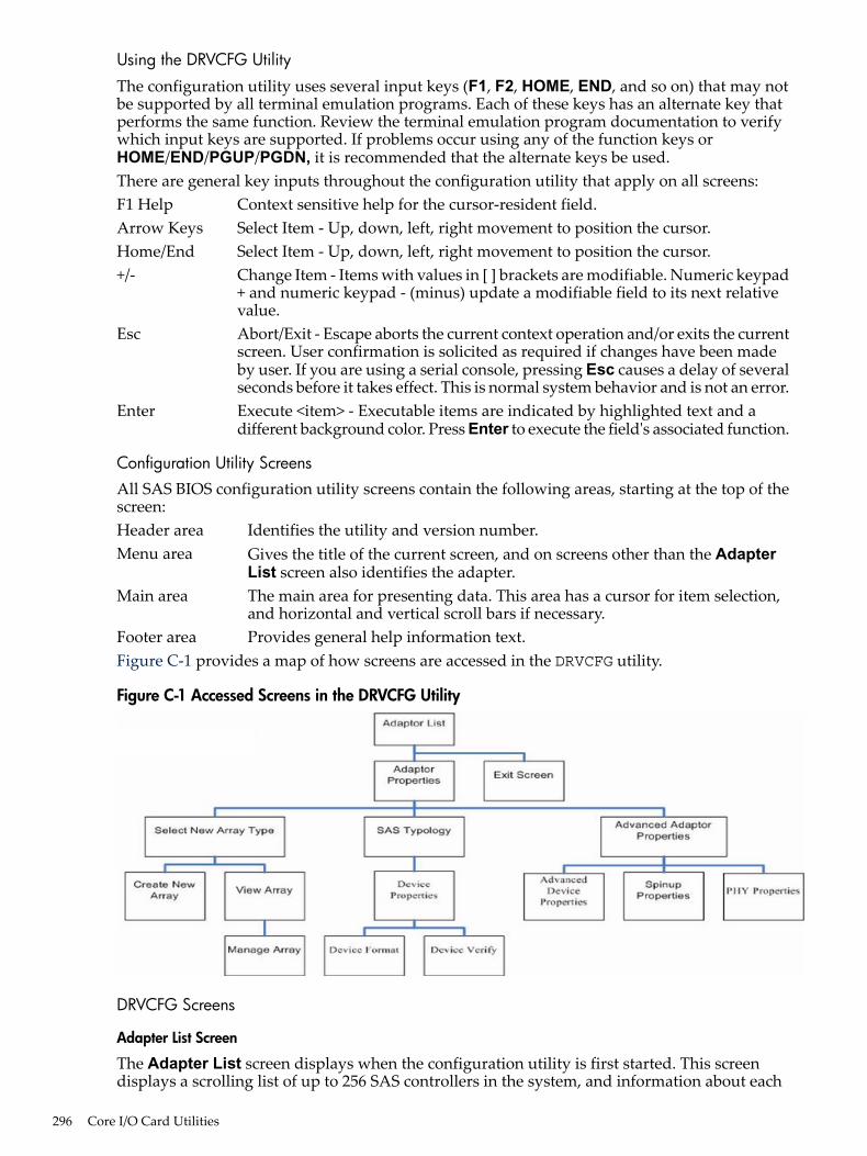
Using the DRVCFG UtilityThe configuration utility uses several input keys (F1, F2, HOME, END, and so on) that may notbe supported by all terminal emulation programs. Each of these keys has an alternate key thatperforms the same function. Review the terminal emulation program documentation to verifywhich input keys are supported. If problems occur using any of the function keys orHOME/END/PGUP/PGDN, it is recommended that the alternate keys be used.There are general key inputs throughout the configuration utility that apply on all screens:F1 Help Context sensitive help for the cursor-resident field.Arrow Keys Select Item - Up, down, left, right movement to position the cursor.Home/End Select Item - Up, down, left, right movement to position the cursor.+/- Change Item - Items with values in [ ] brackets are modifiable. Numeric keypad
+ and numeric keypad - (minus) update a modifiable field to its next relativevalue.
Esc Abort/Exit - Escape aborts the current context operation and/or exits the currentscreen. User confirmation is solicited as required if changes have been madeby user. If you are using a serial console, pressing Esc causes a delay of severalseconds before it takes effect. This is normal system behavior and is not an error.
Enter Execute <item> - Executable items are indicated by highlighted text and adifferent background color. Press Enter to execute the field's associated function.
Configuration Utility ScreensAll SAS BIOS configuration utility screens contain the following areas, starting at the top of thescreen:Header area Identifies the utility and version number.Menu area Gives the title of the current screen, and on screens other than the Adapter
List screen also identifies the adapter.Main area The main area for presenting data. This area has a cursor for item selection,
and horizontal and vertical scroll bars if necessary.Footer area Provides general help information text.Figure C-1 provides a map of how screens are accessed in the DRVCFG utility.
Figure C-1 Accessed Screens in the DRVCFG Utility
DRVCFG Screens
Adapter List Screen
The Adapter List screen displays when the configuration utility is first started. This screendisplays a scrolling list of up to 256 SAS controllers in the system, and information about each
296 Core I/O Card Utilities
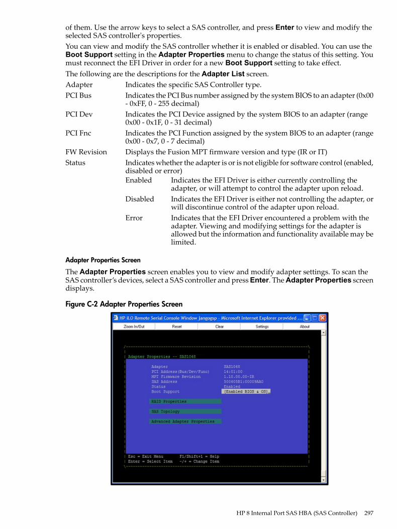
of them. Use the arrow keys to select a SAS controller, and press Enter to view and modify theselected SAS controller's properties.You can view and modify the SAS controller whether it is enabled or disabled. You can use theBoot Support setting in the Adapter Properties menu to change the status of this setting. Youmust reconnect the EFI Driver in order for a new Boot Support setting to take effect.The following are the descriptions for the Adapter List screen.Adapter Indicates the specific SAS Controller type.PCI Bus Indicates the PCI Bus number assigned by the system BIOS to an adapter (0x00
- 0xFF, 0 - 255 decimal)PCI Dev Indicates the PCI Device assigned by the system BIOS to an adapter (range
0x00 - 0x1F, 0 - 31 decimal)PCI Fnc Indicates the PCI Function assigned by the system BIOS to an adapter (range
0x00 - 0x7, 0 - 7 decimal)FW Revision Displays the Fusion MPT firmware version and type (IR or IT)Status Indicates whether the adapter is or is not eligible for software control (enabled,
disabled or error)Enabled Indicates the EFI Driver is either currently controlling the
adapter, or will attempt to control the adapter upon reload.Disabled Indicates the EFI Driver is either not controlling the adapter, or
will discontinue control of the adapter upon reload.Error Indicates that the EFI Driver encountered a problem with the
adapter. Viewing and modifying settings for the adapter isallowed but the information and functionality available may belimited.
Adapter Properties Screen
The Adapter Properties screen enables you to view and modify adapter settings. To scan theSAS controller’s devices, select a SAS controller and press Enter. The Adapter Properties screendisplays.
Figure C-2 Adapter Properties Screen
HP 8 Internal Port SAS HBA (SAS Controller) 297
Use the arrow keys to select RAID Properties, and press Enter to view the Select New ArrayType screen.To access the following screens, use the arrow keys to select the screen, and press Enter on theappropriate field:• RAID Properties• SAS Topology• Advanced Adapter PropertiesThe following are the descriptions for the Adapter Properties screen.Adapter Indicates the specific SAS Controller type.PCI Address Displays the PCI Address assigned by the system BIOS to the adapter.
• Bus value range 0x00 - 0xFF, 0 - 255 decimal• Device value range 0x00 - 0x1F, 0 - 31 decimal• Function range 0x00 - 0x7, 0 - 7 decimal
FW Revision Displays the MPT firmware version and type in the format (x.xx.xx.xx- yy),where x.xx.xx.xx refers to the FW version and yy refers to the type. Thecurrently supported type is IR.l).
SAS Address Displays the SAS Address assigned to this adapter.FW Revision Displays the Fusion MPT firmware version and type (IR or IT)Status Indicates whether an adapter is eligible for configuration utility software
control or is reserved for control by other software (Enabled, Disabled orError).Enabled Indicates the EFI Driver is either currently controlling the
adapter, or will attempt to control the adapter upon reload.Disabled Indicates the EFI Driver is either not controlling the adapter,
or will discontinue control of the adapter upon reload.Error Indicates that the EFI Driver encountered a problem with the
adapter. Viewing and modifying settings for the adapter isallowed but the information and functionality available maybe limited.
Boot Support Specifies whether an adapter is eligible for configuration utility softwarecontrol or is reserved for control by other software (Enabled BIOS & OS,Enabled BIOS Only, Enabled OS Only or Disabled).• Enabled BIOS & OS - SAS controller is controlled by both the BIOS and
OS driver.• Enabled BIOS Only - SAS controller is controlled only by the BIOS. This
setting may not be supported by all OS drivers. For example, it is notpossible to disable an adapter in a Windows driver.
• Enabled OS Only - SAS controller is controlled only by the OS driver.• Disabled - SAS controller is not controlled by the BIOS when the SAS
controller is loaded. However, the adapter is still visible through theconfiguration protocol.
Changes to the Boot Support setting are reflected in the Status field of theAdapter List menu. The new setting will do not take effect until the BIOSis reloaded (system reboot).
RAID Properties Screens
There are four screens within RAID properties. To access the screens, select RAID Propertiesfrom the Adapter Properties screen. The Select New Array Type screen displays.
298 Core I/O Card Utilities
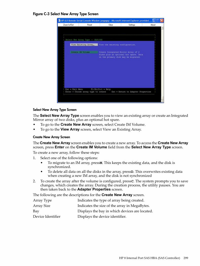
Figure C-3 Select New Array Type Screen
Select New Array Type Screen
The Select New Array Type screen enables you to view an existing array or create an IntegratedMirror array of two disks, plus an optional hot spare.• To go to the Create New Array screen, select Create IM Volume.• To go to the View Array screen, select View an Existing Array.
Create New Array Screen
The Create New Array screen enables you to create a new array. To access the Create New Arrayscreen, press Enter on the Create IM Volume field from the Select New Array Type screen.To create a new array, follow these steps:1. Select one of the following options:
• To migrate to an IM array, pressM. This keeps the existing data, and the disk issynchronized.
• To delete all data on all the disks in the array, pressD. This overwrites existing datawhen creating a new IM array, and the disk is not synchronized
2. To create the array after the volume is configured, pressC. The system prompts you to savechanges, which creates the array. During the creation process, the utility pauses. You arethen taken back to the Adapter Properties screen.
The following are the descriptions for the Create New Array screen.Array Type Indicates the type of array being created.Array Size Indicates the size of the array in MegaBytes.Bay Displays the bay in which devices are located.Device Identifier Displays the device identifier.
HP 8 Internal Port SAS HBA (SAS Controller) 299
RAID Disk Specifies the devices (disks) that make up an IM array. If RAID Diskis Yes, the device is part of an IM array; if No, the device is not partof an IM array. This field is grayed out under the following conditions:• The device does not meet the minimum requirements for use in
an IM array.• The device is not large enough to mirror existing data on the
primary drive.• This disk has been selected as the hot spare for the IM array.
Hot Spr Specifies whether a device is the hot spare for an IM array. If hotspare is Yes the device is used as a hot spare for the IM array; if No,the device is not used as a hot spare for the IM array. Only one hotspare per IM array is permitted. A hot spare is not required in an IM.You can specify a hot spare at array creation, or any time aftercreation, provided the array is made up of five disks or fewer. Thisfield is grayed out under the following conditions:• The device does not meet the minimum requirements for use in
an IM array.• The array already has a hot spare.• The array is made up of the maximum number of devices (six).• The device isn't large enough to mirror existing data on the
primary. The hot spare drive must be greater than or equal tothe size of any drive in any IM volume.
Drive Status xxxxOK Disk is online and fully functional.Missing Disk is not responding.Failed Disk has failed.Initalizing Disk is initializing.CfgOffln Disk is offline at host's request.User Fail Disk is marked failed at host's request.Offline Disk is offline for some other reason.Inactive Disk has been set inactive.Not Syncd Data on disk is not synchronized with the rest of
the array.Primary Disk is the primary disk for a 2 disk mirror and is
OK.Secondary Disk is the secondary disk for a 2 disk mirror and
is OK.Wrg Type Device is not compatible for use as part of an IM
array.Too Small Disk is too small to mirror existing data.Max Dsks Maximum # of disks allowed for this type of Array
reached and/or Maximum # of total IM disks on acontroller reached.
No SMART Disk doesn't support SMART, cannot be used inan RAID array.
Wrg Intfc Device interface (SAS) differs from existing IMdisks.
Pred Fail Indicates whether device SMART is predicting device failure (Yes,No).
Size (MB) Indicates the size of the device in megabytes (megabyte = 1024 x 1024= 1,048,576). If the device is part of a two-disk array, this field reflects
300 Core I/O Card Utilities
the size of the array, not the size of the individual disk. If the deviceis part of a three or more disk array, this field is the size that the diskmakes up within the array. When creating a striped array, the usablesize of the array is determined by the number of drives times the sizeof the smallest drive in the array. In arrays consisting of differentsized drives, excess space on larger drives are unusable.
View Array Screen
The View Array screen enables you to view the current array configuration. To access the ViewArray screen, press Enter on the View Existing Array field from the Select New Array Typescreen.You can perform the following actions on the View Array screen:• To view the next array, press N.• To create a new array, press C.Array Displays the number of this array.Identifier Displays the identifier of this array.Type Displays the RAID type.Scan Order Displays the scan order of the array.Size (MB) Displays the size of the array.Status Displays the status of the array.Bay Displays the bay in which devices are located.Device Identifier Displays the device identifier.RAID Disk Specifies the devices (disks) that make up an IM array. If RAID Disk
is Yes, the device is part of an IM array, if No, the device is not partof an IM array. This field is grayed out under the following conditions:• The device does not meet the minimum requirements for use in
an IM array.• The device is not large enough to mirror existing data on the
primary drive.• This disk has been selected as the hot spare for the IM array.
Hot Spr Specifies whether a device is the hot spare for an IM array. If hotspare is Yes, the device is used as a hot spare for the IM array, if No,the device is not used as a hot spare for the IM array. Only one hotspare per IM array is permitted. A hot spare is not required in an IM.A hot spare can be specified at array creation, or any time aftercreation, provided the array is made up of 5 disks or fewer. This fieldis grayed out under the following conditions:• The device does not meet the minimum requirements for use in
an IM array.• The array already has a hot spare.• The array is made up of the maximum number of devices (6).• The device isn't large enough to mirror existing data on the
primary. The hot spare drive must be greater than or equal tothe size of any drive in any IM volume.
Drive Status xxxxOK Disk is online and fully functional.Missing Disk is not responding.Failed Disk has failed.Initalizing Disk is initializing.CfgOffln Disk is offline at host's request.User Fail Disk is marked failed at host's request.
HP 8 Internal Port SAS HBA (SAS Controller) 301
Offline Disk is offline for some other reason.Inactive Disk has been set inactive.Not Syncd Data on disk is not synchronized with the rest of
the array.Primary Disk is the primary disk for a 2 disk mirror and is
OK.Secondary Disk is the secondary disk for a 2 disk mirror and
is OK.Wrg Type Device is not compatible for use as part of an IM
array.Too Small Disk is too small to mirror existing data.Max Dsks Maximum # of disks allowed for this type of Array
reached and/or Maximum # of total IM disks on acontroller reached.
No SMART Disk doesn't support SMART, cannot be used inan RAID array.
Wrg Intfc Device interface (SAS) differs from existing IMdisks.
Pred Fail Indicates whether device SMART is predicting device failure (Yes,No).
Size (MB) Indicates the size of the device in megabytes (megabyte = 1024 x 1024= 1,048,576). If the device is part of a two-disk array, this field reflectsthe size of the array, not the size of the individual disk. If the deviceis part of a three or more disk array, this field is the size that the diskmakes up within the array. When creating a striped array, the usablesize of the array is determined by the number of drives times the sizeof the smallest drive in the array. In arrays consisting of differentsized drives, excess space on larger drives are unusable.
Manage Array Screen
The Manage Array screen enables you to manage the current array. To access the Manage Arrayscreen, select the appropriate field and press Enter on the Manage Array field from the ViewArray screen.The Manage Array screen enables you to perform the following actions:
Manage Hot Spare
To display a Hot Spare Management screen that has the same layout as the Create New Arrayscreen, press Enter on Manage Hot Spare. This field is grayed out under the following conditions:• The array is inactive.• The array is at its maximum number of devices.• Non-IR firmware is used.• IR is disabled. The array is inactive.
Synchronize Array
To perform a synchronization of the IM array, press Enter on Synchronize Array. The screenprompts you to ask if you want to perform this action. Press Y for yes or N for no. This field isgrayed out under the following conditions:• The array is inactive.• The array does not need to be resynchronized.• The adapter's MPT firmware does not support the feature• Non-IR firmware is used.• IR is disabled. The array is inactive.
302 Core I/O Card Utilities
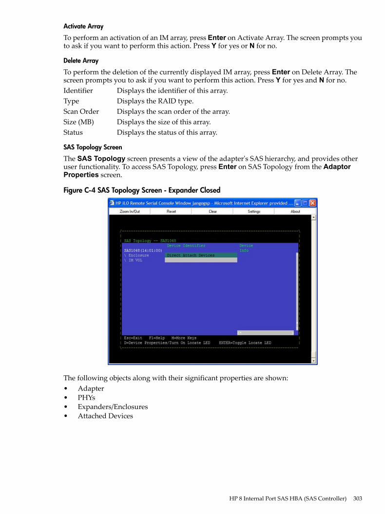
Activate Array
To perform an activation of an IM array, press Enter on Activate Array. The screen prompts youto ask if you want to perform this action. Press Y for yes or N for no.
Delete Array
To perform the deletion of the currently displayed IM array, press Enter on Delete Array. Thescreen prompts you to ask if you want to perform this action. Press Y for yes and N for no.Identifier Displays the identifier of this array.Type Displays the RAID type.Scan Order Displays the scan order of the array.Size (MB) Displays the size of this array.Status Displays the status of this array.
SAS Topology Screen
The SAS Topology screen presents a view of the adapter's SAS hierarchy, and provides otheruser functionality. To access SAS Topology, press Enter on SAS Topology from the AdaptorProperties screen.
Figure C-4 SAS Topology Screen - Expander Closed
The following objects along with their significant properties are shown:• Adapter• PHYs• Expanders/Enclosures• Attached Devices
HP 8 Internal Port SAS HBA (SAS Controller) 303
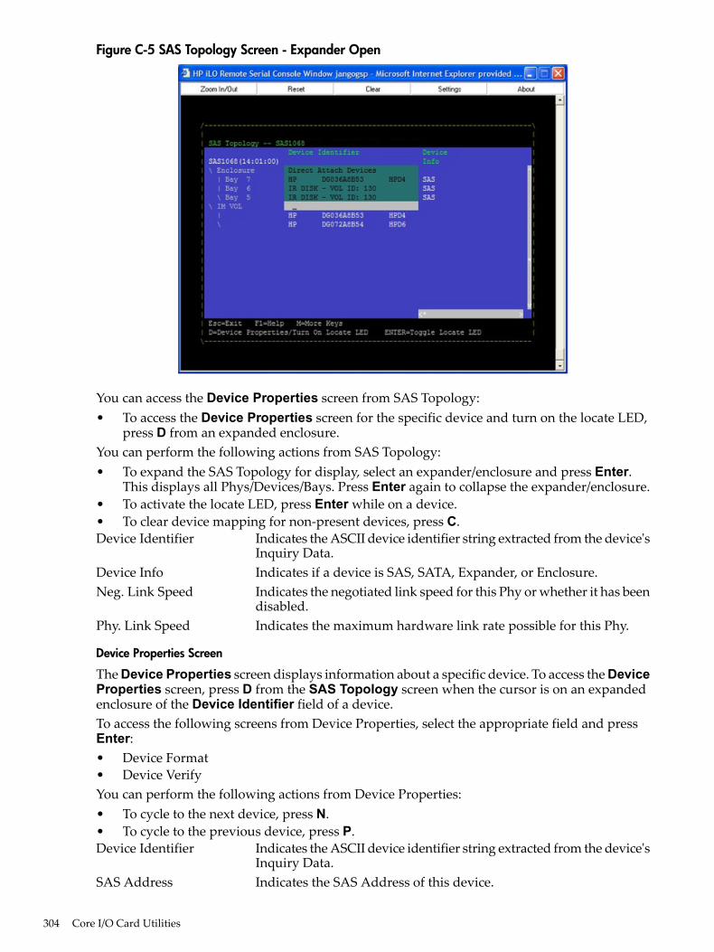
Figure C-5 SAS Topology Screen - Expander Open
You can access the Device Properties screen from SAS Topology:• To access the Device Properties screen for the specific device and turn on the locate LED,
press D from an expanded enclosure.You can perform the following actions from SAS Topology:• To expand the SAS Topology for display, select an expander/enclosure and press Enter.
This displays all Phys/Devices/Bays. Press Enter again to collapse the expander/enclosure.• To activate the locate LED, press Enter while on a device.• To clear device mapping for non-present devices, press C.Device Identifier Indicates the ASCII device identifier string extracted from the device's
Inquiry Data.Device Info Indicates if a device is SAS, SATA, Expander, or Enclosure.Neg. Link Speed Indicates the negotiated link speed for this Phy or whether it has been
disabled.Phy. Link Speed Indicates the maximum hardware link rate possible for this Phy.
Device Properties Screen
The Device Properties screen displays information about a specific device. To access the DeviceProperties screen, press D from the SAS Topology screen when the cursor is on an expandedenclosure of the Device Identifier field of a device.To access the following screens from Device Properties, select the appropriate field and pressEnter:• Device Format• Device VerifyYou can perform the following actions from Device Properties:• To cycle to the next device, press N.• To cycle to the previous device, press P.Device Identifier Indicates the ASCII device identifier string extracted from the device's
Inquiry Data.SAS Address Indicates the SAS Address of this device.
304 Core I/O Card Utilities
Serial Number Indicates the serial number for this device.Elapsed Time Displays the total time elapsed since Format or Verify Operation
started.Percent Complete Graphical status bar display that indicates the current relative
percentage complete of the operation.
Device Format and Device Verify Screens
The Format and Verify screens have a similar layout. To access the screens, press Enter on theappropriate field from the Device Properties screen. These screens include an elapsed time andstatus bar that begin incrementing once the operation is started, enabling you to determineprogress of the operation.Device Identifier Indicates the ASCII device identifier string extracted from the device's
Inquiry Data.SAS Address Indicates the SAS Address of this device.Serial Number Indicates the serial number for this device.Elapsed Time Displays the total time elapsed since Format or Verify Operation
started.Percent Complete Graphical status bar display that indicates the current relative
percentage complete of the operation.FormattingIf enabled, a low-level formatting on a disk drive is allowed on the Device Format screen.Low-level formatting completely and irreversibly erases all data on the drive. To begin the format,press F.
IMPORTANT: Formatting defaults the drive to a 512-byte sector size even if the drive hadpreviously been formatted to another sector size.
CAUTION: Once format has begun, you cannot stop or cancel the action.
VerifyingThe Verify screen enables you to verify all of the sectors on the device. If needed, you can reassigndefective Logical Block Addresses (LBAs). To start the verification, press Enter.
Advanced Device Properties Screen
The Advanced Device Properties screen enables you to view and modify infrequently accesseddevice settings. To access Advanced Device Properties, press Enter on the Advance DeviceProperties field from the Advanced Adaptor Properties screen.
HP 8 Internal Port SAS HBA (SAS Controller) 305
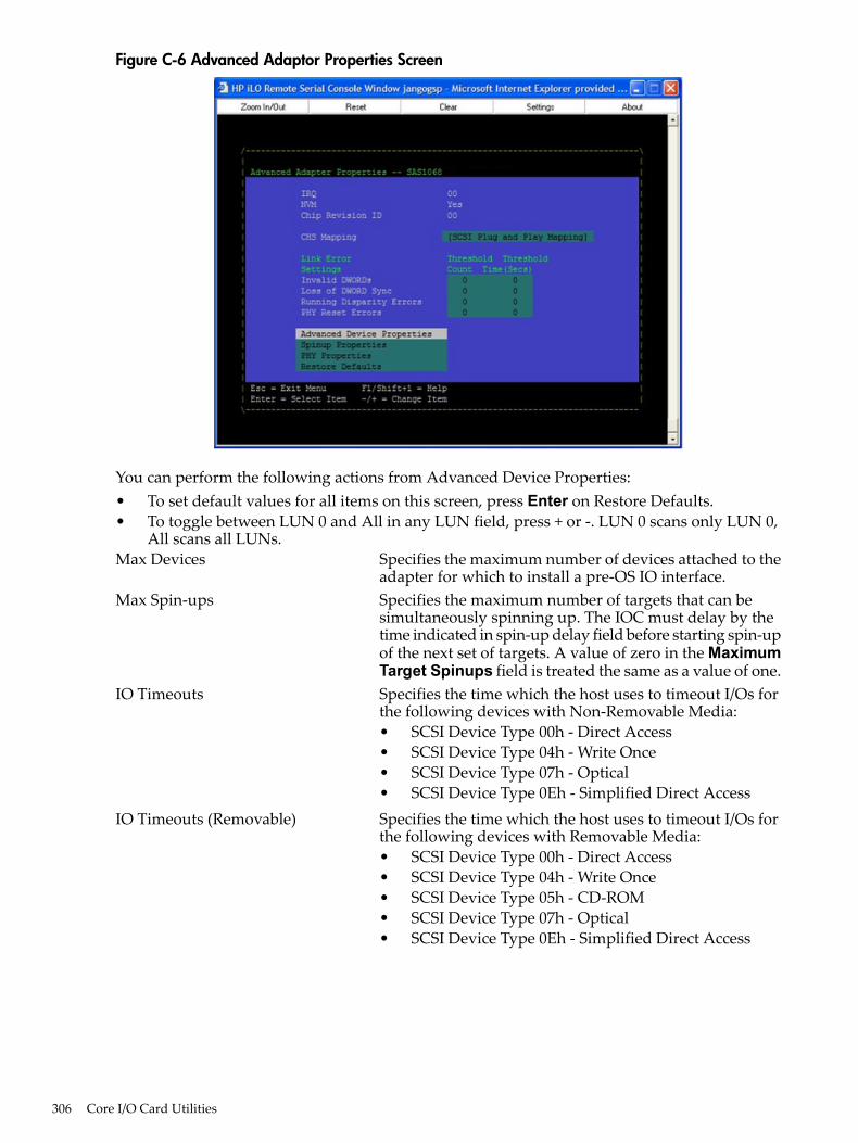
Figure C-6 Advanced Adaptor Properties Screen
You can perform the following actions from Advanced Device Properties:• To set default values for all items on this screen, press Enter on Restore Defaults.• To toggle between LUN 0 and All in any LUN field, press + or -. LUN 0 scans only LUN 0,
All scans all LUNs.Max Devices Specifies the maximum number of devices attached to the
adapter for which to install a pre-OS IO interface.Max Spin-ups Specifies the maximum number of targets that can be
simultaneously spinning up. The IOC must delay by thetime indicated in spin-up delay field before starting spin-upof the next set of targets. A value of zero in the MaximumTarget Spinups field is treated the same as a value of one.
IO Timeouts Specifies the time which the host uses to timeout I/Os forthe following devices with Non-Removable Media:• SCSI Device Type 00h - Direct Access• SCSI Device Type 04h - Write Once• SCSI Device Type 07h - Optical• SCSI Device Type 0Eh - Simplified Direct Access
IO Timeouts (Removable) Specifies the time which the host uses to timeout I/Os forthe following devices with Removable Media:• SCSI Device Type 00h - Direct Access• SCSI Device Type 04h - Write Once• SCSI Device Type 05h - CD-ROM• SCSI Device Type 07h - Optical• SCSI Device Type 0Eh - Simplified Direct Access
306 Core I/O Card Utilities
IO Timeouts for Sequential Devices Specifies the time (Time in seconds (0-999, 0 meansno-timeout)) which the host uses to timeout I/Os for thefollowing devices:• SCSI Device Type 01h - Sequential Access
IO Timeouts for Other Devices Specifies the time (Time in seconds (0-999, 0 meansno-timeout)) which the host uses to timeout I/Os for devicesother than:• SCSI Device Type 00h - Direct Access• SCSI Device Type 01h - Sequential Access• SCSI Device Type 04h - Write Once• SCSI Device Type 05h - CD-ROM• SCSI Device Type 07h - Optical• SCSI Device Type 0Eh - Simplified Direct Access
LUNs to Scan for Block Devices Controls LUN scans for the following devices withNon-Removable Media:• SCSI Device Type 00h - Direct Access• SCSI Device Type 04h - Write Once• SCSI Device Type 07h - Optical• SCSI Device Type 0Eh - Simplified Direct Access
LUNs to Scan for Block Devices(Removable)
Controls LUN scans for the following devices withRemovable Media:• SCSI Device Type 00h - Direct Access• SCSI Device Type 04h - Write Once• SCSI Device Type 05h - CD-ROM• SCSI Device Type 07h - Optical• SCSI Device Type 0Eh - Simplified Direct Access
LUNs to Scan for Sequential Devices Controls LUN scans for the following devices:• SCSI Device Type 01h - Sequential Access
LUNs to Scan for Other Devices Controls LUN scans for all devices other than the following:• SCSI Device Type 00h - Direct Access• SCSI Device Type 01h - Sequential Access• SCSI Device Type 04h - Write Once• SCSI Device Type 05h - CD-ROM• SCSI Device Type 07h - Optical• SCSI Device Type 0Eh - Simplified Direct Access
Spinup Properties Screen
To access Spinup Properties, press Enter on the Spinup Properties field from the AdvancedAdaptor Properties screen. This screen enables you to view and modify spin up specific settings.Spin up refers to the disk drives getting up to rotation speed during system boot. To reduce thepower requirement stress on the backplane a delay is introduced between drive spin ups.Direct Attached Spinup Delay Time, in seconds, between each disk drive spin up (default
3 seconds).Direct Attached Max Targets Number of disk drives that spin up at the same time
(default 1 drive).Expander Spinup Delay Expanders are not supported.Expander Max Target Devices Expanders are not supported.
HP 8 Internal Port SAS HBA (SAS Controller) 307
PHY Properties Screen
The PHY Properties screen enables you to view and modify PHY specific settings. To access PHYProperties, press Enter on the PHY Properties field from the Advanced Adaptor Propertiesscreen.You can perform the following actions from PHY Properties:.• To display the next PHY, press N.• To display the previous PHY, press P.• To reset the Link Error Counts for this PHY or all PHYs, press Enter on Reset Link Error
Counts. Resetting Link Error Counts issues a PHY Link Error Reset. The following promptdisplays when you press Enter:
Are you sure you want to reset Phy error counts? Reset error counts for this Phy only Reset error counts for all Phys Cancel
NOTE: The Link Error Settings values on this screen display the current values for this PHYonly, and are not modifiable. To modify the Threshold values, you must return to AdvancedAdapter Properties screen.
PHY Displays the PHY number current information.SAS Port Indicates the associated SAS Port (0 to N) as configured on this
adapter.Link Status Indicates the PHY link status. Possible values are:
• Enabled, Unknown Link Rate• PHY Disabled• Enabled, negotiation failed• Enabled, SATA OOB Complete• Enabled, 1.5 Gbs• Enabled, 3.0 Gbs
Discovery Status 32 bit hexidecimal value indicating the discovery status for the PHYor Expander. Currently defined values are:• Discovery completed successfully - 0x00000000• Loop Detected - 0x00000001• Unaddressable device exists - 0x00000002• Multiple Ports - 0x00000004• Expander Error - 0x00000008• SMP Timeout - 0x00000010• Out of route entries - 0x00000020• SMP Response Index Does Not Exist - 0x00000040• SMP Response Function Failed - 0x00000080• SMP CRC error - 0x00000100
Device Identifier Indicates the ASCII device identifier string extracted from thedevice's Inquiry Data.
Scan Order Indicates the scan order for this device (equivalent of a SCSI ID forparallel SCSI).
Device Information Indicates if a device is SAS.SAS Address Indicates the SAS Address of this device.
308 Core I/O Card Utilities
Link Error Setting Invalid DWORDs - Number of invalid dwords that have beenreceived outside of PHY reset sequences, since the last PHYLink Error Reset. a
•
• Loss of DWORD Sync - Number of times, since the last PHYLink Error Reset, that dword synchronization was lost and thelink reset sequence occurred.a
• Running Disparity Errors - Number of dwords with runningdisparity errors that have been received outside of PHY resetsequences, since the last PHY Link Error Reset.a
• PHY Reset Errors - Number of times the PHY reset sequencehas failed, since the last PHY Link Error Reset.a
Link Error Count Actual link error count values since the last PHY Link Error Reset.a
Threshold Count Link error count threshold values.b
Threshold Time Time, in seconds, over which to apply Threshold Count.ba. The count stops when it reaches the maximum value.b. When a Link Error Count exceeds a Threshold Count within the Threshold Time the link ratemay be reduced by the MPT firmware.
Exit the SAS Configuration Utility Screen
As some changes only take effect when you exit the utility, it is important to always exit theutility properly. To exit the utility, follow these steps:1. To return to the Adapter List from Adapter Properties, press ESC.2. To exit the utility from the Adapter List, press ESC.
NOTE: A similar exit screen is used when exiting most other screens, and can be used to savesettings.
The exit screen shows some options that are grey, indicating that they are not available. You canonly select the available options. The exit choices are as follows:• Are you sure you want to exit?• Cancel Exit• Save changes and reboot• Discard changes and reboot• Exit the Configuration Utility and Reboot
CFGGEN UtilityThe cfggen utility is a command line utility that runs in the Linux, EFI, and WindowsPre-Installation (WinPE) environments. It is a minimally interactive program that you executefrom a command line prompt, or a shell script. The results from invoking this utility arecommunicated through the program status value that is returned when the program exits. Usethe cfggen utility to create IM storage configurations on SAS controllers. Some cfggencommands work only with SAS adaptors in the EFI environment.
Starting CFGGENThecfggenutility is located on the HP IPF Offline Diagnostic and Utilities CD. To use cfggen,follow these steps:1. Insert the CD into the drive.2. Boot the system to the EFI Shell prompt.3. From the EFI Shell prompt, change to the CD drive.
shell> fs0: Enterfs0:\>
HP 8 Internal Port SAS HBA (SAS Controller) 309
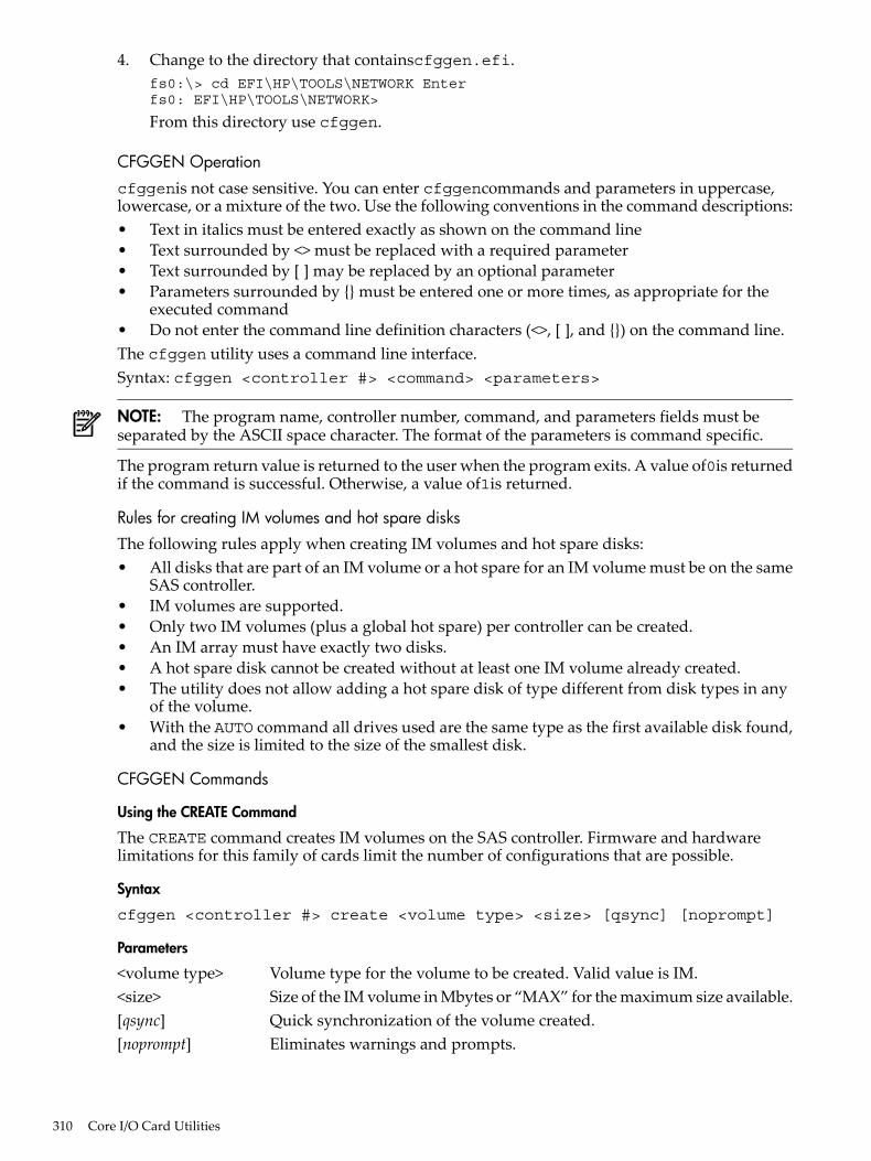
4. Change to the directory that containscfggen.efi.fs0:\> cd EFI\HP\TOOLS\NETWORK Enterfs0: EFI\HP\TOOLS\NETWORK>
From this directory use cfggen.
CFGGEN Operationcfggenis not case sensitive. You can enter cfggencommands and parameters in uppercase,lowercase, or a mixture of the two. Use the following conventions in the command descriptions:• Text in italics must be entered exactly as shown on the command line• Text surrounded by <> must be replaced with a required parameter• Text surrounded by [ ] may be replaced by an optional parameter• Parameters surrounded by {} must be entered one or more times, as appropriate for the
executed command• Do not enter the command line definition characters (<>, [ ], and {}) on the command line.The cfggen utility uses a command line interface.Syntax: cfggen <controller #> <command> <parameters>
NOTE: The program name, controller number, command, and parameters fields must beseparated by the ASCII space character. The format of the parameters is command specific.
The program return value is returned to the user when the program exits. A value of0is returnedif the command is successful. Otherwise, a value of1is returned.
Rules for creating IM volumes and hot spare disksThe following rules apply when creating IM volumes and hot spare disks:• All disks that are part of an IM volume or a hot spare for an IM volume must be on the same
SAS controller.• IM volumes are supported.• Only two IM volumes (plus a global hot spare) per controller can be created.• An IM array must have exactly two disks.• A hot spare disk cannot be created without at least one IM volume already created.• The utility does not allow adding a hot spare disk of type different from disk types in any
of the volume.• With the AUTO command all drives used are the same type as the first available disk found,
and the size is limited to the size of the smallest disk.
CFGGEN Commands
Using the CREATE Command
The CREATE command creates IM volumes on the SAS controller. Firmware and hardwarelimitations for this family of cards limit the number of configurations that are possible.
Syntax
cfggen <controller #> create <volume type> <size> [qsync] [noprompt]
Parameters
<volume type> Volume type for the volume to be created. Valid value is IM.<size> Size of the IM volume in Mbytes or “MAX” for the maximum size available.[qsync] Quick synchronization of the volume created.[noprompt] Eliminates warnings and prompts.
310 Core I/O Card Utilities
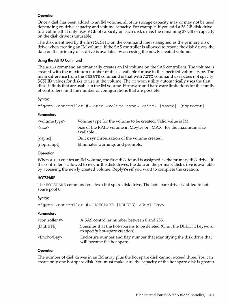
Operation
Once a disk has been added to an IM volume, all of its storage capacity may or may not be useddepending on drive capacity and volume capacity. For example, if you add a 36 GB disk driveto a volume that only uses 9 GB of capacity on each disk drive, the remaining 27 GB of capacityon the disk drive is unusable.The disk identified by the first SCSI ID on the command line is assigned as the primary diskdrive when creating an IM volume. If the SAS controller is allowed to resync the disk drives, thedata on the primary disk drive is available by accessing the newly created volume.
Using the AUTO Command
The AUTO command automatically creates an IM volume on the SAS controllers. The volume iscreated with the maximum number of disks available for use in the specified volume type. Themain difference from the CREATE command is that with AUTO command user does not specifySCSI ID values for disks to use in the volume. The cfggen utility automatically uses the firstdisks it finds that are usable in the IM volume. Firmware and hardware limitations for the familyof controllers limit the number of configurations that are possible.
Syntax
cfggen <controller #> auto <volume type> <size> [qsync] [noprompt]
Parameters
<volume type> Volume type for the volume to be created. Valid value is IM.<size> Size of the RAID volume in Mbytes or “MAX” for the maximum size
available.[qsync] Quick synchronization of the volume created.[noprompt] Eliminates warnings and prompts.
Operation
When AUTO creates an IM volume, the first disk found is assigned as the primary disk drive. Ifthe controller is allowed to resync the disk drives, the data on the primary disk drive is availableby accessing the newly created volume. ReplyYesif you want to complete the creation.
HOTSPARE
The HOTSPARE command creates a hot spare disk drive. The hot spare drive is added to hotspare pool 0.
Syntax
cfggen <controller #> HOTSPARE [DELETE] <Encl:Bay>
Parameters
<controller #> A SAS controller number between 0 and 255.[DELETE] Specifies that the hot-spare is to be deleted (Omit the DELETE keyword
to specify hot-spare creation).<Encl>:<Bay> Enclosure number and Bay number that identifying the disk drive that
will become the hot spare.
Operation
The number of disk drives in an IM array plus the hot spare disk cannot exceed three. You cancreate only one hot spare disk. You must make sure the capacity of the hot spare disk is greater
HP 8 Internal Port SAS HBA (SAS Controller) 311
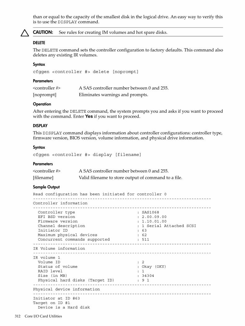
than or equal to the capacity of the smallest disk in the logical drive. An easy way to verify thisis to use the DISPLAY command.
CAUTION: See rules for creating IM volumes and hot spare disks.
DELETE
The DELETE command sets the controller configuration to factory defaults. This command alsodeletes any existing IR volumes.
Syntax
cfggen <controller #> delete [noprompt]
Parameters
<controller #> A SAS controller number between 0 and 255.[noprompt] Eliminates warnings and prompts.
Operation
After entering the DELETE command, the system prompts you and asks if you want to proceedwith the command. Enter Yes if you want to proceed.
DISPLAY
This DISPLAY command displays information about controller configurations: controller type,firmware version, BIOS version, volume information, and physical drive information.
Syntax
cfggen <controller #> display [filename]
Parameters
<controller #> A SAS controller number between 0 and 255.[filename] Valid filename to store output of command to a file.
Sample Output
Read configuration has been initiated for controller 0------------------------------------------------------------------------Controller information------------------------------------------------------------------------ Controller type : SAS1068 EFI BSD version : 2.00.09.00 Firmware version : 1.10.01.00 Channel description : 1 Serial Attached SCSI Initiator ID : 63 Maximum physical devices : 62 Concurrent commands supported : 511------------------------------------------------------------------------IR Volume information------------------------------------------------------------------------IR volume 1 Volume ID : 2 Status of volume : Okay (OKY) RAID level : 1 Size (in MB) : 34304 Physical hard disks (Target ID) : 9 1------------------------------------------------------------------------Physical device information------------------------------------------------------------------------Initiator at ID #63Target on ID #1 Device is a Hard disk
312 Core I/O Card Utilities
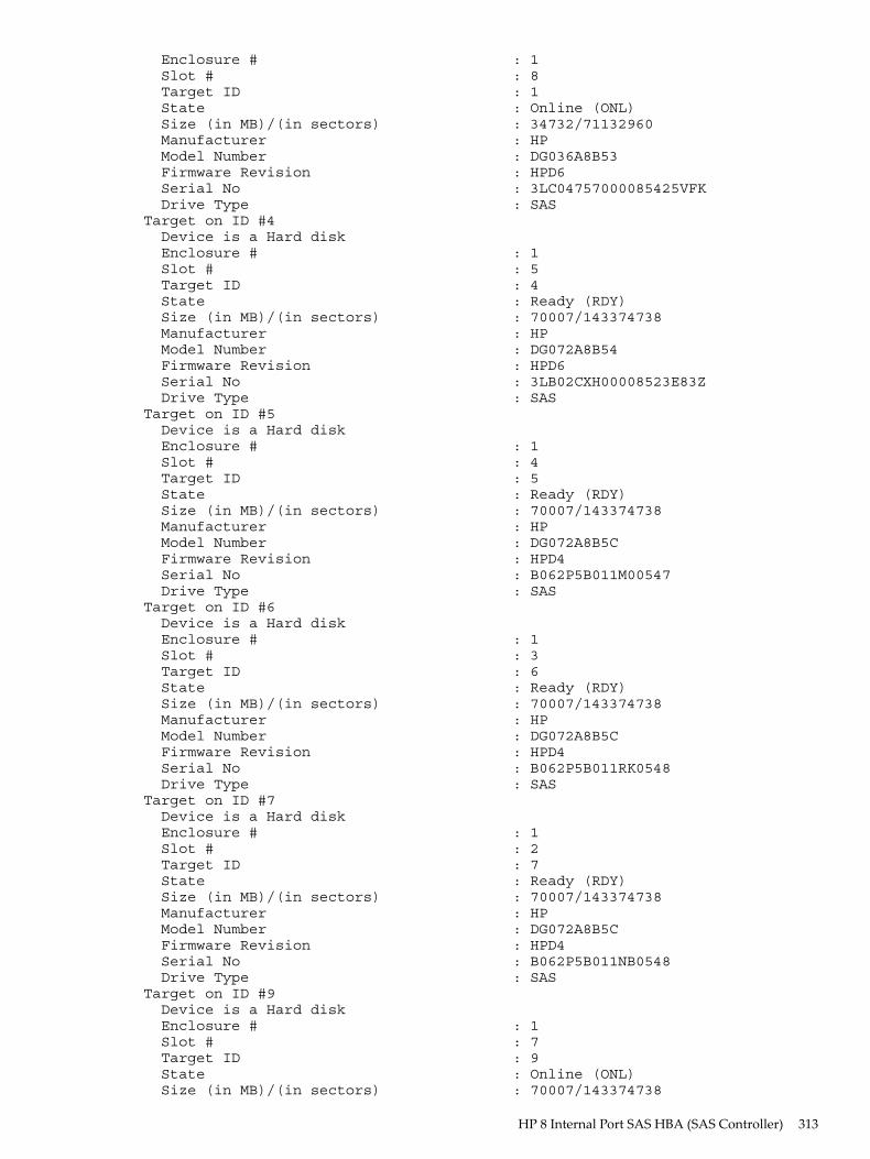
Enclosure # : 1 Slot # : 8 Target ID : 1 State : Online (ONL) Size (in MB)/(in sectors) : 34732/71132960 Manufacturer : HP Model Number : DG036A8B53 Firmware Revision : HPD6 Serial No : 3LC04757000085425VFK Drive Type : SASTarget on ID #4 Device is a Hard disk Enclosure # : 1 Slot # : 5 Target ID : 4 State : Ready (RDY) Size (in MB)/(in sectors) : 70007/143374738 Manufacturer : HP Model Number : DG072A8B54 Firmware Revision : HPD6 Serial No : 3LB02CXH00008523E83Z Drive Type : SASTarget on ID #5 Device is a Hard disk Enclosure # : 1 Slot # : 4 Target ID : 5 State : Ready (RDY) Size (in MB)/(in sectors) : 70007/143374738 Manufacturer : HP Model Number : DG072A8B5C Firmware Revision : HPD4 Serial No : B062P5B011M00547 Drive Type : SASTarget on ID #6 Device is a Hard disk Enclosure # : 1 Slot # : 3 Target ID : 6 State : Ready (RDY) Size (in MB)/(in sectors) : 70007/143374738 Manufacturer : HP Model Number : DG072A8B5C Firmware Revision : HPD4 Serial No : B062P5B011RK0548 Drive Type : SASTarget on ID #7 Device is a Hard disk Enclosure # : 1 Slot # : 2 Target ID : 7 State : Ready (RDY) Size (in MB)/(in sectors) : 70007/143374738 Manufacturer : HP Model Number : DG072A8B5C Firmware Revision : HPD4 Serial No : B062P5B011NB0548 Drive Type : SASTarget on ID #9 Device is a Hard disk Enclosure # : 1 Slot # : 7 Target ID : 9 State : Online (ONL) Size (in MB)/(in sectors) : 70007/143374738
HP 8 Internal Port SAS HBA (SAS Controller) 313
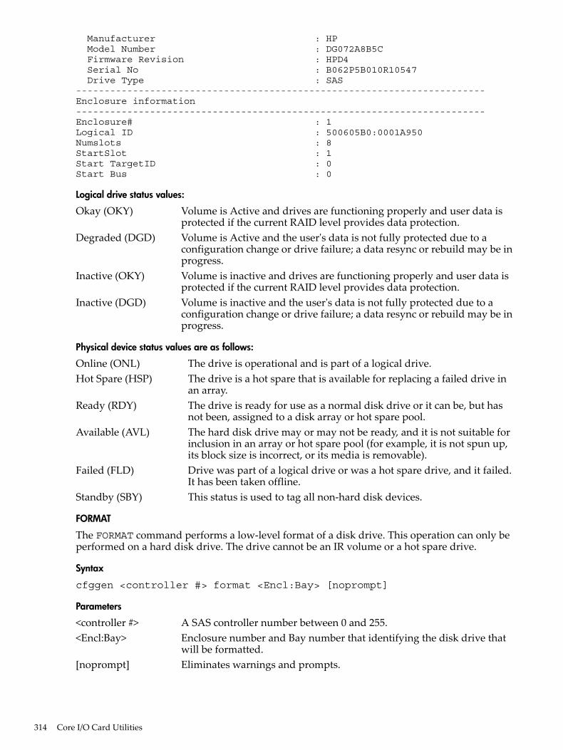
Manufacturer : HP Model Number : DG072A8B5C Firmware Revision : HPD4 Serial No : B062P5B010R10547 Drive Type : SAS------------------------------------------------------------------------Enclosure information------------------------------------------------------------------------Enclosure# : 1Logical ID : 500605B0:0001A950Numslots : 8StartSlot : 1Start TargetID : 0Start Bus : 0
Logical drive status values:
Okay (OKY) Volume is Active and drives are functioning properly and user data isprotected if the current RAID level provides data protection.
Degraded (DGD) Volume is Active and the user's data is not fully protected due to aconfiguration change or drive failure; a data resync or rebuild may be inprogress.
Inactive (OKY) Volume is inactive and drives are functioning properly and user data isprotected if the current RAID level provides data protection.
Inactive (DGD) Volume is inactive and the user's data is not fully protected due to aconfiguration change or drive failure; a data resync or rebuild may be inprogress.
Physical device status values are as follows:
Online (ONL) The drive is operational and is part of a logical drive.Hot Spare (HSP) The drive is a hot spare that is available for replacing a failed drive in
an array.Ready (RDY) The drive is ready for use as a normal disk drive or it can be, but has
not been, assigned to a disk array or hot spare pool.Available (AVL) The hard disk drive may or may not be ready, and it is not suitable for
inclusion in an array or hot spare pool (for example, it is not spun up,its block size is incorrect, or its media is removable).
Failed (FLD) Drive was part of a logical drive or was a hot spare drive, and it failed.It has been taken offline.
Standby (SBY) This status is used to tag all non-hard disk devices.
FORMAT
The FORMAT command performs a low-level format of a disk drive. This operation can only beperformed on a hard disk drive. The drive cannot be an IR volume or a hot spare drive.
Syntax
cfggen <controller #> format <Encl:Bay> [noprompt]
Parameters
<controller #> A SAS controller number between 0 and 255.<Encl:Bay> Enclosure number and Bay number that identifying the disk drive that
will be formatted.[noprompt] Eliminates warnings and prompts.
314 Core I/O Card Utilities
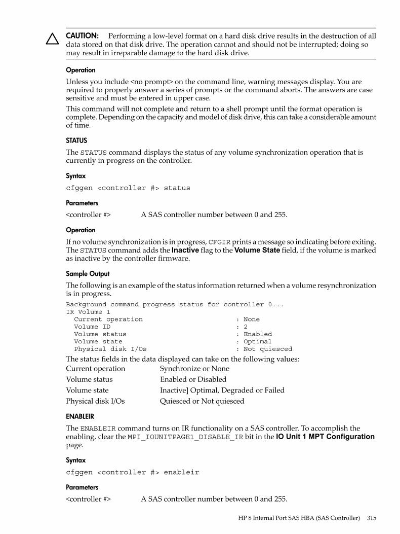
CAUTION: Performing a low-level format on a hard disk drive results in the destruction of alldata stored on that disk drive. The operation cannot and should not be interrupted; doing somay result in irreparable damage to the hard disk drive.
Operation
Unless you include <no prompt> on the command line, warning messages display. You arerequired to properly answer a series of prompts or the command aborts. The answers are casesensitive and must be entered in upper case.This command will not complete and return to a shell prompt until the format operation iscomplete. Depending on the capacity and model of disk drive, this can take a considerable amountof time.
STATUS
The STATUS command displays the status of any volume synchronization operation that iscurrently in progress on the controller.
Syntax
cfggen <controller #> status
Parameters
<controller #> A SAS controller number between 0 and 255.
Operation
If no volume synchronization is in progress, CFGIR prints a message so indicating before exiting.The STATUS command adds the Inactive flag to the Volume State field, if the volume is markedas inactive by the controller firmware.
Sample Output
The following is an example of the status information returned when a volume resynchronizationis in progress.Background command progress status for controller 0...IR Volume 1 Current operation : None Volume ID : 2 Volume status : Enabled Volume state : Optimal Physical disk I/Os : Not quiesced
The status fields in the data displayed can take on the following values:Current operation Synchronize or NoneVolume status Enabled or DisabledVolume state Inactive] Optimal, Degraded or FailedPhysical disk I/Os Quiesced or Not quiesced
ENABLEIR
The ENABLEIR command turns on IR functionality on a SAS controller. To accomplish theenabling, clear the MPI_IOUNITPAGE1_DISABLE_IR bit in the IO Unit 1 MPT Configurationpage.
Syntax
cfggen <controller #> enableir
Parameters
<controller #> A SAS controller number between 0 and 255.
HP 8 Internal Port SAS HBA (SAS Controller) 315
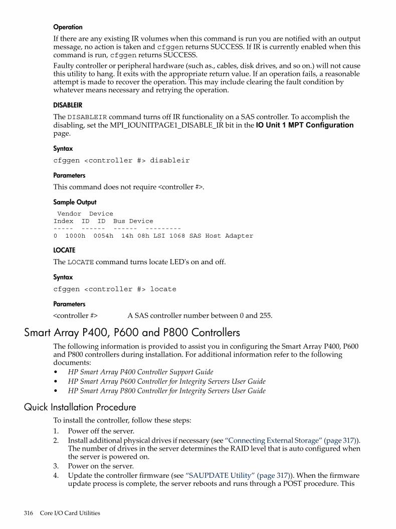
Operation
If there are any existing IR volumes when this command is run you are notified with an outputmessage, no action is taken and cfggen returns SUCCESS. If IR is currently enabled when thiscommand is run, cfggen returns SUCCESS.Faulty controller or peripheral hardware (such as., cables, disk drives, and so on.) will not causethis utility to hang. It exits with the appropriate return value. If an operation fails, a reasonableattempt is made to recover the operation. This may include clearing the fault condition bywhatever means necessary and retrying the operation.
DISABLEIR
The DISABLEIR command turns off IR functionality on a SAS controller. To accomplish thedisabling, set the MPI_IOUNITPAGE1_DISABLE_IR bit in the IO Unit 1 MPT Configurationpage.
Syntax
cfggen <controller #> disableir
Parameters
This command does not require <controller #>.
Sample Output
Vendor DeviceIndex ID ID Bus Device----- ------ ------ ---------0 1000h 0054h 14h 08h LSI 1068 SAS Host Adapter
LOCATE
The LOCATE command turns locate LED's on and off.
Syntax
cfggen <controller #> locate
Parameters
<controller #> A SAS controller number between 0 and 255.
Smart Array P400, P600 and P800 ControllersThe following information is provided to assist you in configuring the Smart Array P400, P600and P800 controllers during installation. For additional information refer to the followingdocuments:• HP Smart Array P400 Controller Support Guide• HP Smart Array P600 Controller for Integrity Servers User Guide• HP Smart Array P800 Controller for Integrity Servers User Guide
Quick Installation ProcedureTo install the controller, follow these steps:1. Power off the server.2. Install additional physical drives if necessary (see “Connecting External Storage” (page 317)).
The number of drives in the server determines the RAID level that is auto configured whenthe server is powered on.
3. Power on the server.4. Update the controller firmware (see “SAUPDATE Utility” (page 317)). When the firmware
update process is complete, the server reboots and runs through a POST procedure. This
316 Core I/O Card Utilities
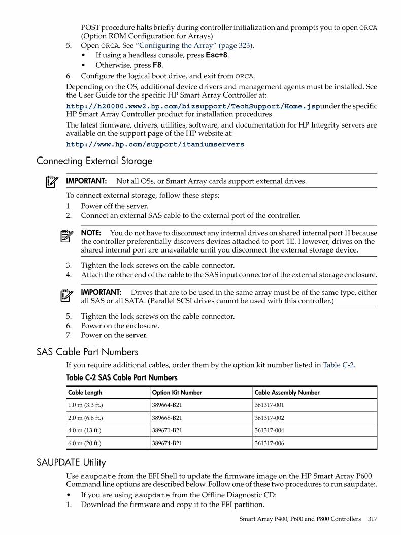
POST procedure halts briefly during controller initialization and prompts you to open ORCA(Option ROM Configuration for Arrays).
5. Open ORCA. See “Configuring the Array” (page 323).• If using a headless console, press Esc+8.• Otherwise, press F8.
6. Configure the logical boot drive, and exit from ORCA.Depending on the OS, additional device drivers and management agents must be installed. Seethe User Guide for the specific HP Smart Array Controller at:http://h20000.www2.hp.com/bizsupport/TechSupport/Home.jspunder the specificHP Smart Array Controller product for installation procedures.The latest firmware, drivers, utilities, software, and documentation for HP Integrity servers areavailable on the support page of the HP website at:http://www.hp.com/support/itaniumservers
Connecting External Storage
IMPORTANT: Not all OSs, or Smart Array cards support external drives.
To connect external storage, follow these steps:1. Power off the server.2. Connect an external SAS cable to the external port of the controller.
NOTE: You do not have to disconnect any internal drives on shared internal port 1I becausethe controller preferentially discovers devices attached to port 1E. However, drives on theshared internal port are unavailable until you disconnect the external storage device.
3. Tighten the lock screws on the cable connector.4. Attach the other end of the cable to the SAS input connector of the external storage enclosure.
IMPORTANT: Drives that are to be used in the same array must be of the same type, eitherall SAS or all SATA. (Parallel SCSI drives cannot be used with this controller.)
5. Tighten the lock screws on the cable connector.6. Power on the enclosure.7. Power on the server.
SAS Cable Part NumbersIf you require additional cables, order them by the option kit number listed in Table C-2.
Table C-2 SAS Cable Part Numbers
Cable Assembly NumberOption Kit NumberCable Length
361317-001389664-B211.0 m (3.3 ft.)
361317-002389668-B212.0 m (6.6 ft.)
361317-004389671-B214.0 m (13 ft.)
361317-006389674-B216.0 m (20 ft.)
SAUPDATE UtilityUse saupdate from the EFI Shell to update the firmware image on the HP Smart Array P600.Command line options are described below. Follow one of these two procedures to run saupdate:.• If you are using saupdate from the Offline Diagnostic CD:1. Download the firmware and copy it to the EFI partition.
Smart Array P400, P600 and P800 Controllers 317
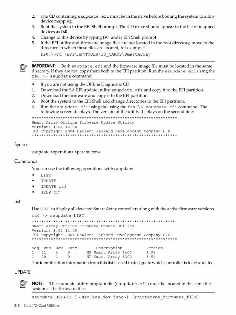
2. The CD containing saupdate.efi must be in the drive before booting the system to allowdevice mapping.
3. Boot the system to the EFI Shell prompt. The CD drive should appear in the list of mappeddevices as fs0.
4. Change to this device by typing fs0: under EFI Shell prompt.5. If the EFI utility and firmware image files are not located in the root directory, move to the
directory in which these files are located, for example:fs0:\>cd \EFI\HP\TOOLS\IO_CARDS\SmartArray
IMPORTANT: Both saupdate.efi and the firmware image file must be located in the samedirectory. If they are not, copy them both to the EFI partition. Run the saupdate.efi using thefs0:\> saupdate command.
• If you are not using the Offline Diagnostic CD:1. Download the SA EFI update utility saupdate.efi and copy it to the EFI partition.2. Download the firmware and copy it to the EFI partition.3. Boot the system to the EFI Shell and change directories to the EFI partition.4. Run the saupdate.efi using the using the fs0:\> saupdate.efi command. The
following screen displays. The version of the utility displays on the second line:*************************************************************Smart Array Offline Firmware Update UtilityVersion: 1.04.12.00(C) Copyright 2004 Hewlett Packard Development Company L.P.*************************************************************
Syntaxsaupdate <operation> <parameters>
CommandsYou can use the following operations with saupdate:• LIST• UPDATE• UPDATE all• HELP or?
ListUse LIST to display all detected Smart Array controllers along with the active firmware versions.fs0:\> saupdate LIST
*************************************************************Smart Array Offline Firmware Update UtilityVersion: 1.04.12.00(C) Copyright 2004 Hewlett Packard Development Company L.P.*************************************************************
Seg Bus Dev Func Description Version1 51 4 0 HP Smart Array 6400 1.921 20 1 0 HP Smart Array 5300 3.54
The identification information from this list is used to designate which controller is to be updated.
UPDATE
NOTE: The saupdate utility program file (saupdate.efi) must be located in the same filesystem as the firmware files.
saupdate UPDATE [ <seg:bus:dev:func>] [smartarray_firmware_file]
318 Core I/O Card Utilities
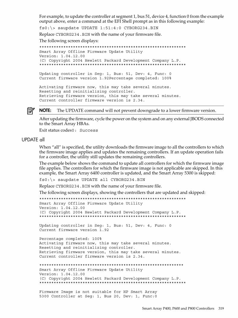
For example, to update the controller at segment 1, bus 51, device 4, function 0 from the exampleoutput above, enter a command at the EFI Shell prompt as in this following example:fs0:\> saupdate UPDATE 1:51:4:0 CYBORG234.BIN
Replace CYBORG234.BIN with the name of your firmware file.The following screen displays:*************************************************************Smart Array Offline Firmware Update UtilityVersion: 1.04.12.00(C) Copyright 2004 Hewlett Packard Development Company L.P.*************************************************************
Updating controller in Seg: 1, Bus: 51, Dev: 4, Func: 0Current firmware version 1.92Percentage completed: 100%
Activating firmware now, this may take several minutes.Resetting and reinitializing controller.Retrieving firmware version, this may take several minutes.Current controller firmware version is 2.34.
NOTE: The UPDATE command will not prevent downgrade to a lower firmware version.
After updating the firmware, cycle the power on the system and on any external JBODS connectedto the Smart Array HBAs.Exit status codes0: Success
UPDATE allWhen “all” is specified, the utility downloads the firmware image to all the controllers to whichthe firmware image applies and updates the remaining controllers. If an update operation failsfor a controller, the utility still updates the remaining controllers.The example below shows the command to update all controllers for which the firmware imagefile applies. The controllers for which the firmware image is not applicable are skipped. In thisexample, the Smart Array 6400 controller is updated, and the Smart Array 5300 is skipped:fs0:\> saupdate UPDATE all CYBORG234.BIN
Replace CYBORG234.BIN with the name of your firmware file.The following screen displays, showing the controllers that are updated and skipped:*************************************************************Smart Array Offline Firmware Update UtilityVersion: 1.04.12.00(C) Copyright 2004 Hewlett Packard Development Company L.P.*************************************************************
Updating controller in Seg: 1, Bus: 51, Dev: 4, Func: 0Current firmware version 1.92
Percentage completed: 100%Activating firmware now, this may take several minutes.Resetting and reinitializing controller.Retrieving firmware version, this may take several minutes.Current controller firmware version is 2.34.
************************************************************Smart Array Offline Firmware Update UtilityVersion: 1.04.12.00(C) Copyright 2004 Hewlett Packard Development Company L.P.*************************************************************
Firmware Image is not suitable for HP Smart Array5300 Controller at Seg: 1, Bus 20, Dev: 1, Func:0
Smart Array P400, P600 and P800 Controllers 319
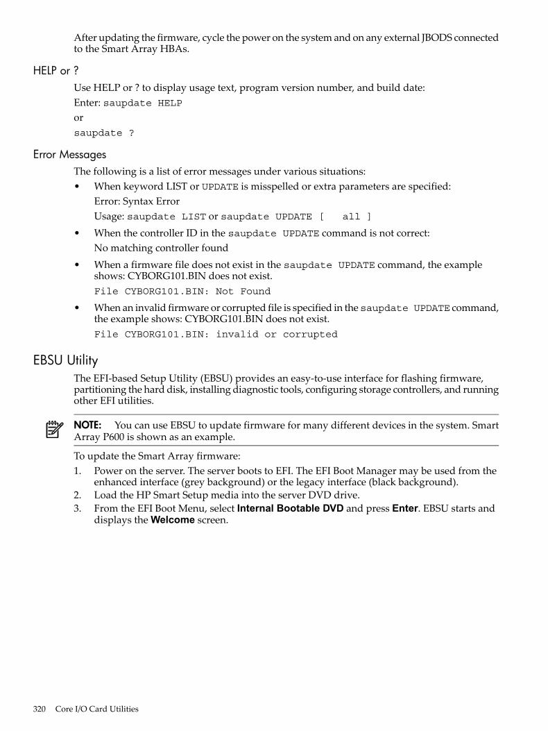
After updating the firmware, cycle the power on the system and on any external JBODS connectedto the Smart Array HBAs.
HELP or ?Use HELP or ? to display usage text, program version number, and build date:Enter: saupdate HELPorsaupdate ?
Error MessagesThe following is a list of error messages under various situations:• When keyword LIST or UPDATE is misspelled or extra parameters are specified:
Error: Syntax ErrorUsage: saupdate LIST or saupdate UPDATE [ all ]
• When the controller ID in the saupdate UPDATE command is not correct:No matching controller found
• When a firmware file does not exist in the saupdate UPDATE command, the exampleshows: CYBORG101.BIN does not exist.File CYBORG101.BIN: Not Found
• When an invalid firmware or corrupted file is specified in thesaupdate UPDATE command,the example shows: CYBORG101.BIN does not exist.File CYBORG101.BIN: invalid or corrupted
EBSU UtilityThe EFI-based Setup Utility (EBSU) provides an easy-to-use interface for flashing firmware,partitioning the hard disk, installing diagnostic tools, configuring storage controllers, and runningother EFI utilities.
NOTE: You can use EBSU to update firmware for many different devices in the system. SmartArray P600 is shown as an example.
To update the Smart Array firmware:1. Power on the server. The server boots to EFI. The EFI Boot Manager may be used from the
enhanced interface (grey background) or the legacy interface (black background).2. Load the HP Smart Setup media into the server DVD drive.3. From the EFI Boot Menu, select Internal Bootable DVD and press Enter. EBSU starts and
displays the Welcome screen.
320 Core I/O Card Utilities
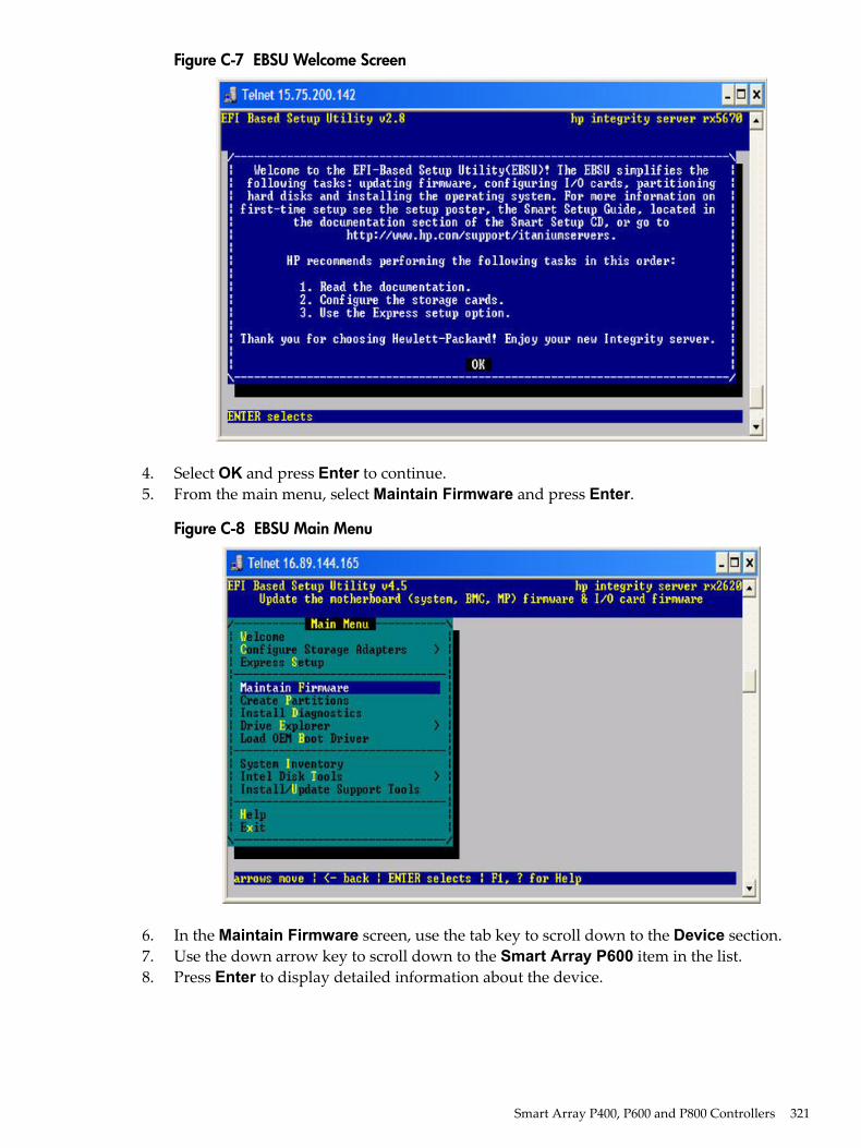
Figure C-7 EBSU Welcome Screen
4. Select OK and press Enter to continue.5. From the main menu, select Maintain Firmware and press Enter.
Figure C-8 EBSU Main Menu
6. In the Maintain Firmware screen, use the tab key to scroll down to the Device section.7. Use the down arrow key to scroll down to the Smart Array P600 item in the list.8. Press Enter to display detailed information about the device.
Smart Array P400, P600 and P800 Controllers 321
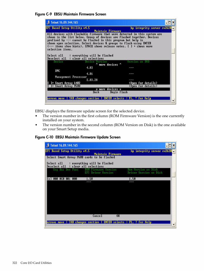
Figure C-9 EBSU Maintain Firmware Screen
EBSU displays the firmware update screen for the selected device.• The version number in the first column (ROM Firmware Version) is the one currently
installed on your system.• The version number in the second column (ROM Version on Disk) is the one available
on your Smart Setup media.
Figure C-10 EBSU Maintain Firmware Update Screen
322 Core I/O Card Utilities
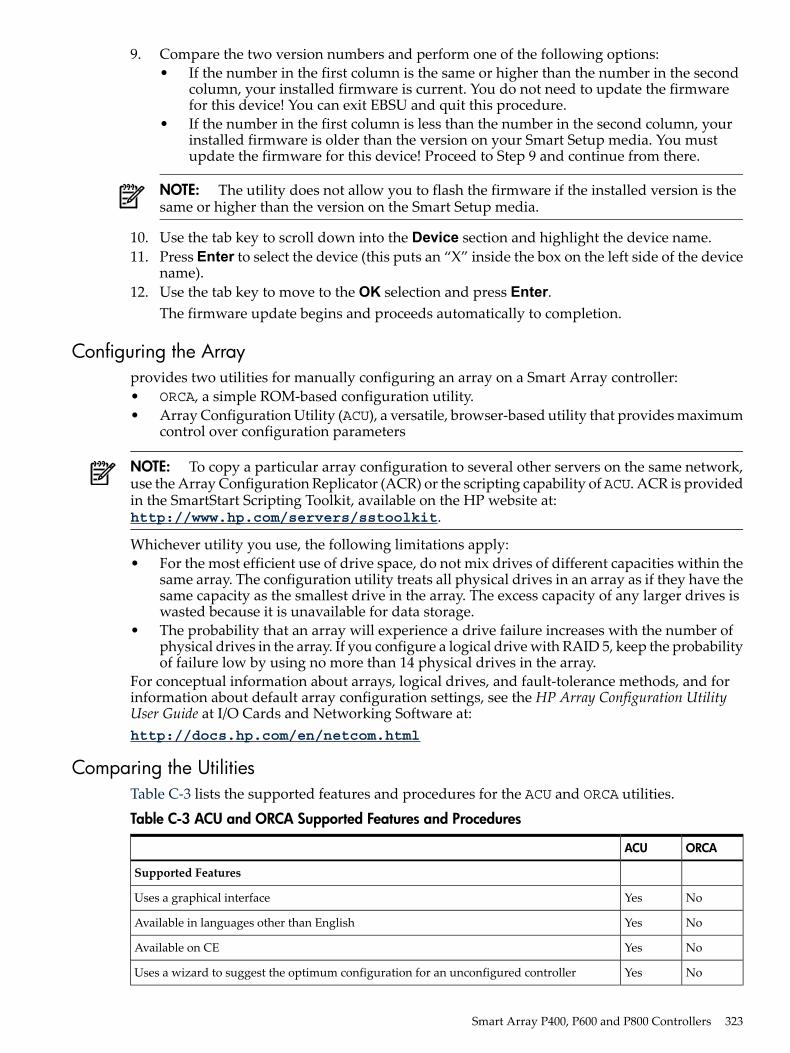
9. Compare the two version numbers and perform one of the following options:• If the number in the first column is the same or higher than the number in the second
column, your installed firmware is current. You do not need to update the firmwarefor this device! You can exit EBSU and quit this procedure.
• If the number in the first column is less than the number in the second column, yourinstalled firmware is older than the version on your Smart Setup media. You mustupdate the firmware for this device! Proceed to Step 9 and continue from there.
NOTE: The utility does not allow you to flash the firmware if the installed version is thesame or higher than the version on the Smart Setup media.
10. Use the tab key to scroll down into the Device section and highlight the device name.11. Press Enter to select the device (this puts an “X” inside the box on the left side of the device
name).12. Use the tab key to move to the OK selection and press Enter.
The firmware update begins and proceeds automatically to completion.
Configuring the Arrayprovides two utilities for manually configuring an array on a Smart Array controller:• ORCA, a simple ROM-based configuration utility.• Array Configuration Utility (ACU), a versatile, browser-based utility that provides maximum
control over configuration parameters
NOTE: To copy a particular array configuration to several other servers on the same network,use the Array Configuration Replicator (ACR) or the scripting capability of ACU. ACR is providedin the SmartStart Scripting Toolkit, available on the HP website at:http://www.hp.com/servers/sstoolkit.
Whichever utility you use, the following limitations apply:• For the most efficient use of drive space, do not mix drives of different capacities within the
same array. The configuration utility treats all physical drives in an array as if they have thesame capacity as the smallest drive in the array. The excess capacity of any larger drives iswasted because it is unavailable for data storage.
• The probability that an array will experience a drive failure increases with the number ofphysical drives in the array. If you configure a logical drive with RAID 5, keep the probabilityof failure low by using no more than 14 physical drives in the array.
For conceptual information about arrays, logical drives, and fault-tolerance methods, and forinformation about default array configuration settings, see the HP Array Configuration UtilityUser Guide at I/O Cards and Networking Software at:http://docs.hp.com/en/netcom.html
Comparing the UtilitiesTable C-3 lists the supported features and procedures for the ACU and ORCA utilities.
Table C-3 ACU and ORCA Supported Features and Procedures
ORCAACU
Supported Features
NoYesUses a graphical interface
NoYesAvailable in languages other than English
NoYesAvailable on CE
NoYesUses a wizard to suggest the optimum configuration for an unconfigured controller
Smart Array P400, P600 and P800 Controllers 323
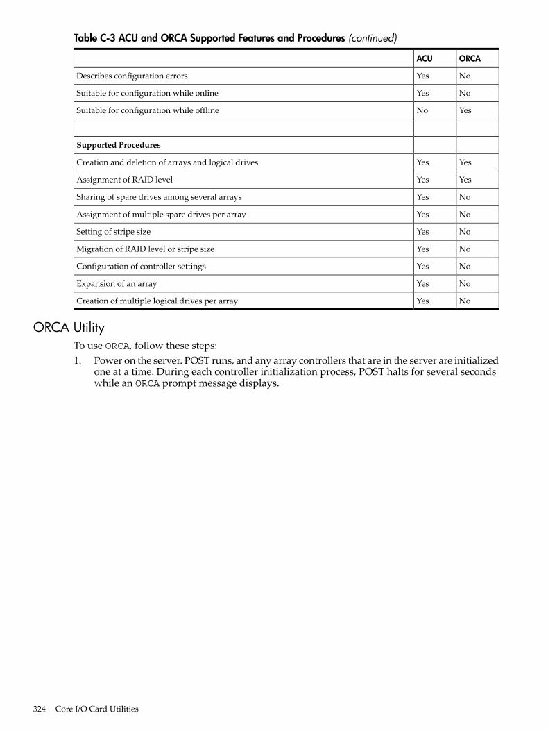
Table C-3 ACU and ORCA Supported Features and Procedures (continued)
ORCAACU
NoYesDescribes configuration errors
NoYesSuitable for configuration while online
YesNoSuitable for configuration while offline
Supported Procedures
YesYesCreation and deletion of arrays and logical drives
YesYesAssignment of RAID level
NoYesSharing of spare drives among several arrays
NoYesAssignment of multiple spare drives per array
NoYesSetting of stripe size
NoYesMigration of RAID level or stripe size
NoYesConfiguration of controller settings
NoYesExpansion of an array
NoYesCreation of multiple logical drives per array
ORCA UtilityTo use ORCA, follow these steps:1. Power on the server. POST runs, and any array controllers that are in the server are initialized
one at a time. During each controller initialization process, POST halts for several secondswhile an ORCA prompt message displays.
324 Core I/O Card Utilities
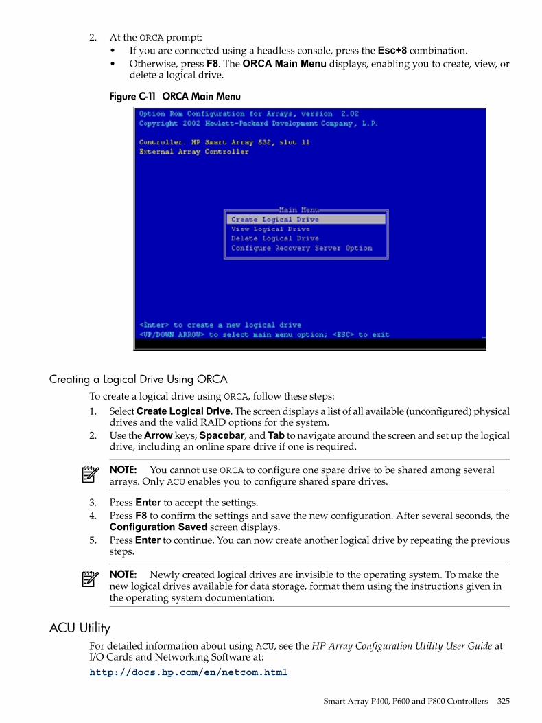
2. At the ORCA prompt:• If you are connected using a headless console, press the Esc+8 combination.• Otherwise, press F8. The ORCA Main Menu displays, enabling you to create, view, or
delete a logical drive.
Figure C-11 ORCA Main Menu
Creating a Logical Drive Using ORCATo create a logical drive using ORCA, follow these steps:1. Select Create Logical Drive. The screen displays a list of all available (unconfigured) physical
drives and the valid RAID options for the system.2. Use the Arrow keys, Spacebar, and Tab to navigate around the screen and set up the logical
drive, including an online spare drive if one is required.
NOTE: You cannot use ORCA to configure one spare drive to be shared among severalarrays. Only ACU enables you to configure shared spare drives.
3. Press Enter to accept the settings.4. Press F8 to confirm the settings and save the new configuration. After several seconds, the
Configuration Saved screen displays.5. Press Enter to continue. You can now create another logical drive by repeating the previous
steps.
NOTE: Newly created logical drives are invisible to the operating system. To make thenew logical drives available for data storage, format them using the instructions given inthe operating system documentation.
ACU UtilityFor detailed information about using ACU, see the HP Array Configuration Utility User Guide atI/O Cards and Networking Software at:http://docs.hp.com/en/netcom.html
Smart Array P400, P600 and P800 Controllers 325

326
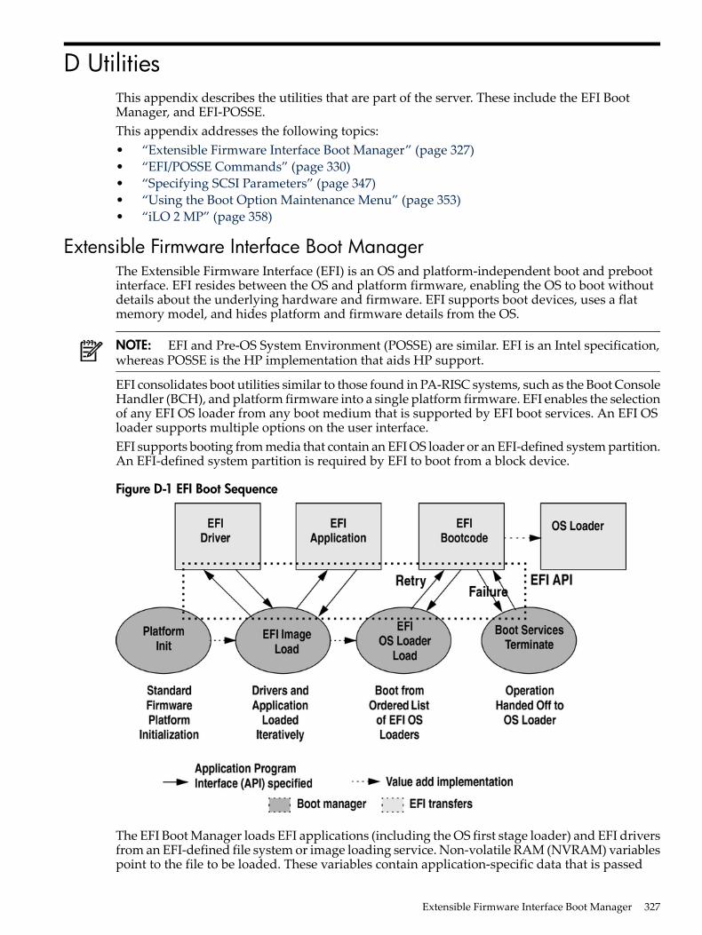
D UtilitiesThis appendix describes the utilities that are part of the server. These include the EFI BootManager, and EFI-POSSE.This appendix addresses the following topics:• “Extensible Firmware Interface Boot Manager” (page 327)• “EFI/POSSE Commands” (page 330)• “Specifying SCSI Parameters” (page 347)• “Using the Boot Option Maintenance Menu” (page 353)• “iLO 2 MP” (page 358)
Extensible Firmware Interface Boot ManagerThe Extensible Firmware Interface (EFI) is an OS and platform-independent boot and prebootinterface. EFI resides between the OS and platform firmware, enabling the OS to boot withoutdetails about the underlying hardware and firmware. EFI supports boot devices, uses a flatmemory model, and hides platform and firmware details from the OS.
NOTE: EFI and Pre-OS System Environment (POSSE) are similar. EFI is an Intel specification,whereas POSSE is the HP implementation that aids HP support.
EFI consolidates boot utilities similar to those found in PA-RISC systems, such as the Boot ConsoleHandler (BCH), and platform firmware into a single platform firmware. EFI enables the selectionof any EFI OS loader from any boot medium that is supported by EFI boot services. An EFI OSloader supports multiple options on the user interface.EFI supports booting from media that contain an EFI OS loader or an EFI-defined system partition.An EFI-defined system partition is required by EFI to boot from a block device.
Figure D-1 EFI Boot Sequence
The EFI Boot Manager loads EFI applications (including the OS first stage loader) and EFI driversfrom an EFI-defined file system or image loading service. Non-volatile RAM (NVRAM) variablespoint to the file to be loaded. These variables contain application-specific data that is passed
Extensible Firmware Interface Boot Manager 327
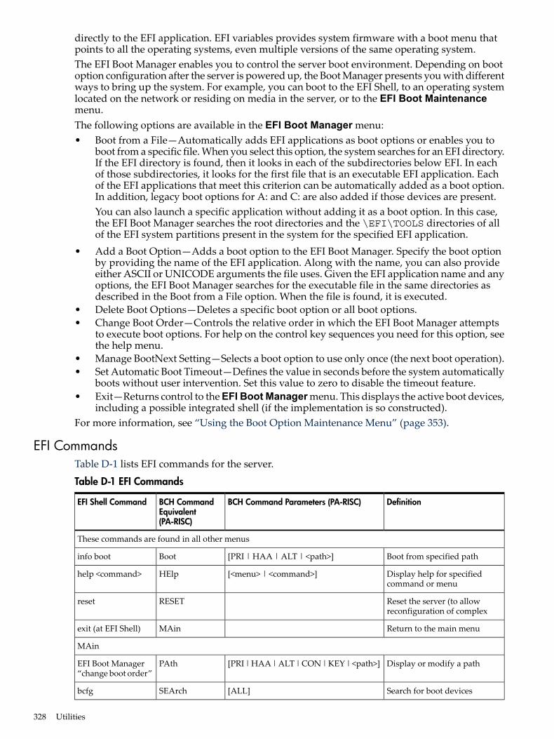
directly to the EFI application. EFI variables provides system firmware with a boot menu thatpoints to all the operating systems, even multiple versions of the same operating system.The EFI Boot Manager enables you to control the server boot environment. Depending on bootoption configuration after the server is powered up, the Boot Manager presents you with differentways to bring up the system. For example, you can boot to the EFI Shell, to an operating systemlocated on the network or residing on media in the server, or to the EFI Boot Maintenancemenu.The following options are available in the EFI Boot Manager menu:• Boot from a File—Automatically adds EFI applications as boot options or enables you to
boot from a specific file. When you select this option, the system searches for an EFI directory.If the EFI directory is found, then it looks in each of the subdirectories below EFI. In eachof those subdirectories, it looks for the first file that is an executable EFI application. Eachof the EFI applications that meet this criterion can be automatically added as a boot option.In addition, legacy boot options for A: and C: are also added if those devices are present.You can also launch a specific application without adding it as a boot option. In this case,the EFI Boot Manager searches the root directories and the \EFI\TOOLS directories of allof the EFI system partitions present in the system for the specified EFI application.
• Add a Boot Option—Adds a boot option to the EFI Boot Manager. Specify the boot optionby providing the name of the EFI application. Along with the name, you can also provideeither ASCII or UNICODE arguments the file uses. Given the EFI application name and anyoptions, the EFI Boot Manager searches for the executable file in the same directories asdescribed in the Boot from a File option. When the file is found, it is executed.
• Delete Boot Options—Deletes a specific boot option or all boot options.• Change Boot Order—Controls the relative order in which the EFI Boot Manager attempts
to execute boot options. For help on the control key sequences you need for this option, seethe help menu.
• Manage BootNext Setting—Selects a boot option to use only once (the next boot operation).• Set Automatic Boot Timeout—Defines the value in seconds before the system automatically
boots without user intervention. Set this value to zero to disable the timeout feature.• Exit—Returns control to the EFI Boot Manager menu. This displays the active boot devices,
including a possible integrated shell (if the implementation is so constructed).For more information, see “Using the Boot Option Maintenance Menu” (page 353).
EFI CommandsTable D-1 lists EFI commands for the server.
Table D-1 EFI Commands
DefinitionBCH Command Parameters (PA-RISC)BCH CommandEquivalent(PA-RISC)
EFI Shell Command
These commands are found in all other menus
Boot from specified path[PRI | HAA | ALT | <path>]Bootinfo boot
Display help for specifiedcommand or menu
[<menu> | <command>]HElphelp <command>
Reset the server (to allowreconfiguration of complex
RESETreset
Return to the main menuMAinexit (at EFI Shell)
MAin
Display or modify a path[PRI | HAA | ALT | CON | KEY | <path>]PAthEFI Boot Manager“change boot order”
Search for boot devices[ALL]SEArchbcfg
328 Utilities
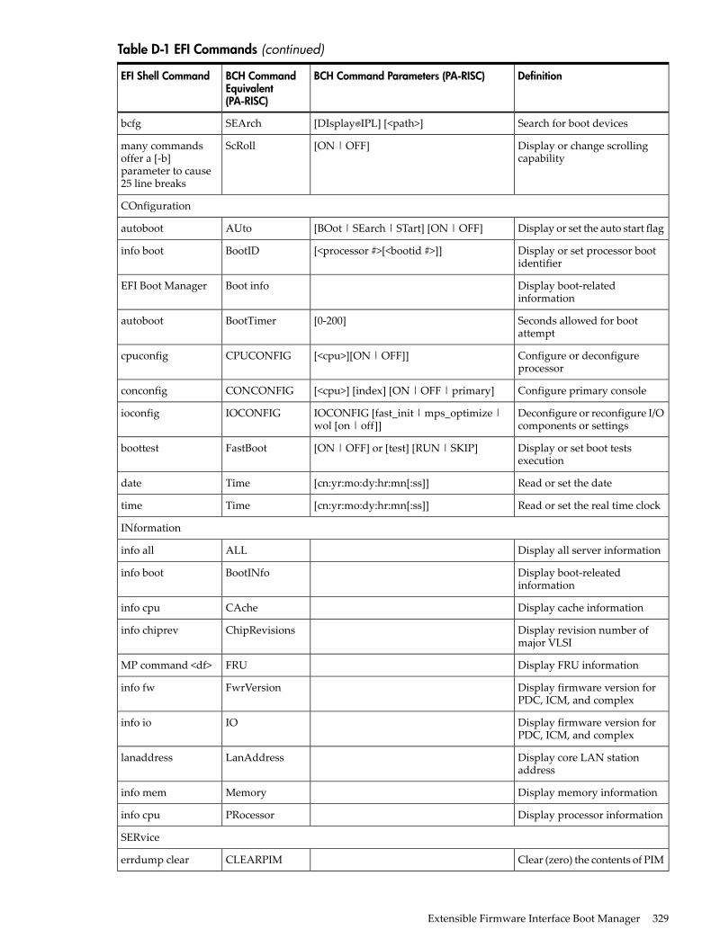
Table D-1 EFI Commands (continued)
DefinitionBCH Command Parameters (PA-RISC)BCH CommandEquivalent(PA-RISC)
EFI Shell Command
Search for boot devices[DIsplay IPL] [<path>]SEArchbcfg
Display or change scrollingcapability
[ON | OFF]ScRollmany commandsoffer a [-b]parameter to cause25 line breaks
COnfiguration
Display or set the auto start flag[BOot | SEarch | STart] [ON | OFF]AUtoautoboot
Display or set processor bootidentifier
[<processor #>[<bootid #>]]BootIDinfo boot
Display boot-relatedinformation
Boot infoEFI Boot Manager
Seconds allowed for bootattempt
[0-200]BootTimerautoboot
Configure or deconfigureprocessor
[<cpu>][ON | OFF]]CPUCONFIGcpuconfig
Configure primary console[<cpu>] [index] [ON | OFF | primary]CONCONFIGconconfig
Deconfigure or reconfigure I/Ocomponents or settings
IOCONFIG [fast_init | mps_optimize |wol [on | off]]
IOCONFIGioconfig
Display or set boot testsexecution
[ON | OFF] or [test] [RUN | SKIP]FastBootboottest
Read or set the date[cn:yr:mo:dy:hr:mn[:ss]]Timedate
Read or set the real time clock[cn:yr:mo:dy:hr:mn[:ss]]Timetime
INformation
Display all server informationALLinfo all
Display boot-releatedinformation
BootINfoinfo boot
Display cache informationCAcheinfo cpu
Display revision number ofmajor VLSI
ChipRevisionsinfo chiprev
Display FRU informationFRUMP command <df>
Display firmware version forPDC, ICM, and complex
FwrVersioninfo fw
Display firmware version forPDC, ICM, and complex
IOinfo io
Display core LAN stationaddress
LanAddresslanaddress
Display memory informationMemoryinfo mem
Display processor informationPRocessorinfo cpu
SERvice
Clear (zero) the contents of PIMCLEARPIMerrdump clear
Extensible Firmware Interface Boot Manager 329
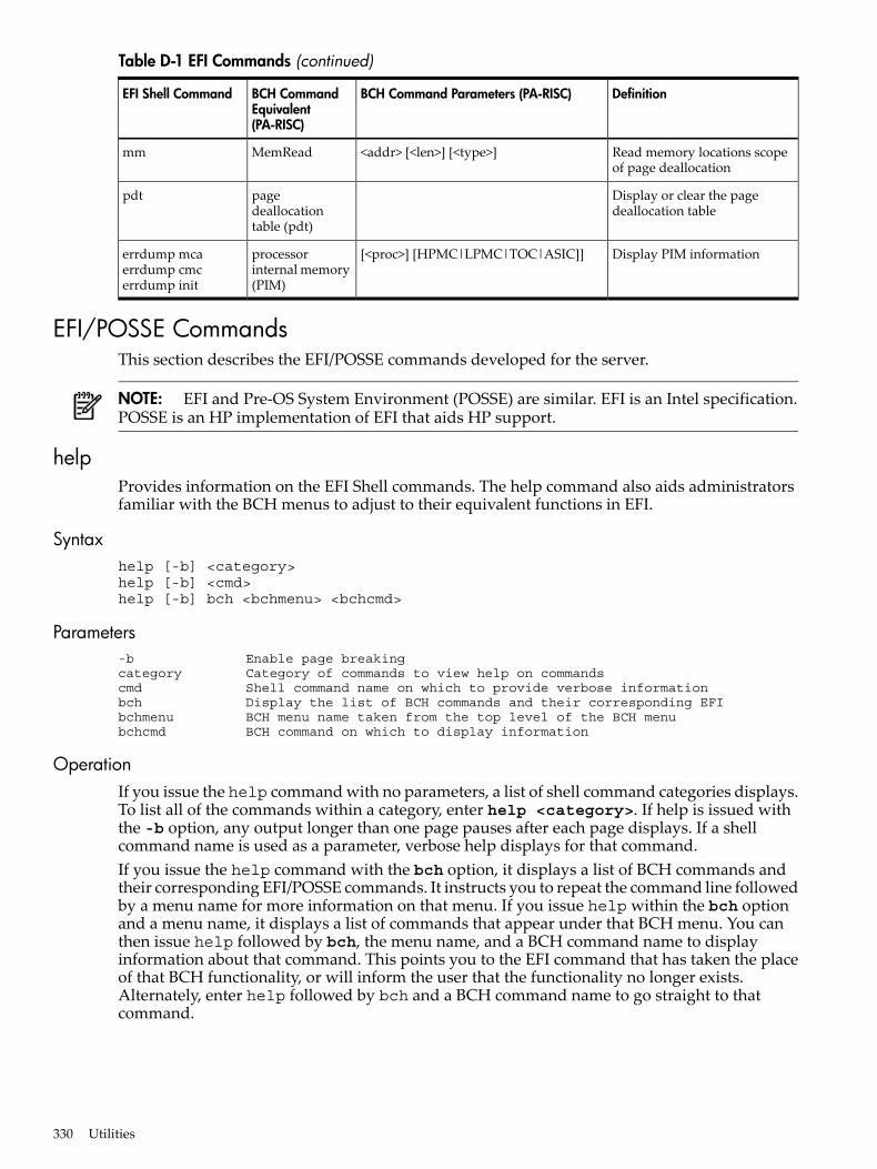
Table D-1 EFI Commands (continued)
DefinitionBCH Command Parameters (PA-RISC)BCH CommandEquivalent(PA-RISC)
EFI Shell Command
Read memory locations scopeof page deallocation
<addr> [<len>] [<type>]MemReadmm
Display or clear the pagedeallocation table
pagedeallocationtable (pdt)
pdt
Display PIM information[<proc>] [HPMC|LPMC|TOC|ASIC]]processorinternal memory(PIM)
errdump mcaerrdump cmcerrdump init
EFI/POSSE CommandsThis section describes the EFI/POSSE commands developed for the server.
NOTE: EFI and Pre-OS System Environment (POSSE) are similar. EFI is an Intel specification.POSSE is an HP implementation of EFI that aids HP support.
helpProvides information on the EFI Shell commands. The help command also aids administratorsfamiliar with the BCH menus to adjust to their equivalent functions in EFI.
Syntaxhelp [-b] <category>help [-b] <cmd>help [-b] bch <bchmenu> <bchcmd>
Parameters-b Enable page breakingcategory Category of commands to view help on commandscmd Shell command name on which to provide verbose informationbch Display the list of BCH commands and their corresponding EFI bchmenu BCH menu name taken from the top level of the BCH menubchcmd BCH command on which to display information
OperationIf you issue the help command with no parameters, a list of shell command categories displays.To list all of the commands within a category, enter help <category>. If help is issued withthe -b option, any output longer than one page pauses after each page displays. If a shellcommand name is used as a parameter, verbose help displays for that command.If you issue the help command with the bch option, it displays a list of BCH commands andtheir corresponding EFI/POSSE commands. It instructs you to repeat the command line followedby a menu name for more information on that menu. If you issue help within the bch optionand a menu name, it displays a list of commands that appear under that BCH menu. You canthen issue help followed by bch, the menu name, and a BCH command name to displayinformation about that command. This points you to the EFI command that has taken the placeof that BCH functionality, or will inform the user that the functionality no longer exists.Alternately, enter help followed by bch and a BCH command name to go straight to thatcommand.
330 Utilities
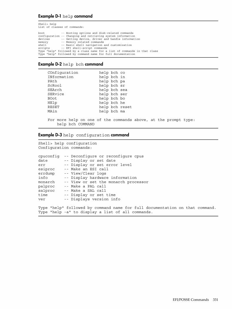
Example D-1 help command
Shell> helpList of classes of commands:
boot -- Booting options and disk-related commandsconfiguration -- Changing and retrieving system informationdevices -- Getting device, driver and handle informationmemory -- Memory related commandsshell -- Basic shell navigation and customizationscripts -- EFI shell-script commands Type "help" followed by a class name for a list of commands in that classType "help" followed by command name for full documentation
Example D-2 help bch command
COnfiguration help bch co INformation help bch in PAth help bch pa ScRool help bch sr SEArch help bch sea SERvice help bch ser BOot help bch bo HElp help bch he RESET help bch reset MAin help bch ma
For more help on one of the commands above, at the prompt type: help bch COMMAND
Example D-3 help configuration command
Shell> help configurationConfiguration commands:
cpuconfig -- Deconfigure or reconfigure cpusdate -- Display or set dateerr -- Display or set error levelesiproc -- Make an ESI callerrdump -- View/Clear logsinfo -- Display hardware informationmonarch -- View or set the monarch processorpalproc -- Make a PAL callsalproc -- Make a SAL calltime -- Display or set timever -- Displays version info
Type "help" followed by command name for full documentation on that command.Type "help -a" to display a list of all commands.
EFI/POSSE Commands 331
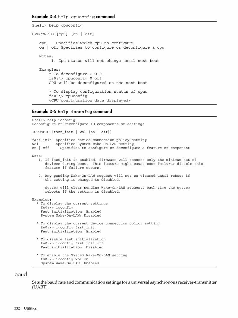
Example D-4 help cpuconfig command
Shell> help cpuconfig
CPUCONFIG [cpu] [on | off]
cpu Specifies which cpu to configure on | off Specifies to configure or deconfigure a cpu
Notes: 1. Cpu status will not change until next boot
Examples: * To deconfigure CPU 0 fs0:\> cpuconfig 0 off CPU will be deconfigured on the next boot
* To display configuration status of cpus fs0:\> cpuconfig <CPU configuration data displayed>
Example D-5 help ioconfig command
Shell> help ioconfigDeconfigure or reconfigure IO components or settings
IOCONFIG [fast_init | wol [on | off]]
fast_init Specifies device connection policy settingwol Specifies System Wake-On-LAN settingon | off Specifies to configure or deconfigure a feature or component
Note: 1. If fast_init is enabled, firmware will connect only the minimum set of devices during boot. This feature might cause boot failure; disable this feature if failure occurs.
2. Any pending Wake-On-LAN request will not be cleared until reboot if the setting is changed to disabled.
System will clear pending Wake-On-LAN requests each time the system reboots if the setting is disabled.
Examples: * To display the current settings fs0:\> ioconfig Fast initialization: Enabled System Wake-On-LAN: Disabled
* To display the current device connection policy setting fs0:\> ioconfig fast_init Fast initialization: Enabled
* To disable fast initialization fs0:\> ioconfig fast_init off Fast initialization: Disabled
* To enable the System Wake-On-LAN setting fs0:\> ioconfig wol on System Wake-On-LAN: Enabled
baudSets the baud rate and communication settings for a universal asynchronous receiver-transmitter(UART).
332 Utilities
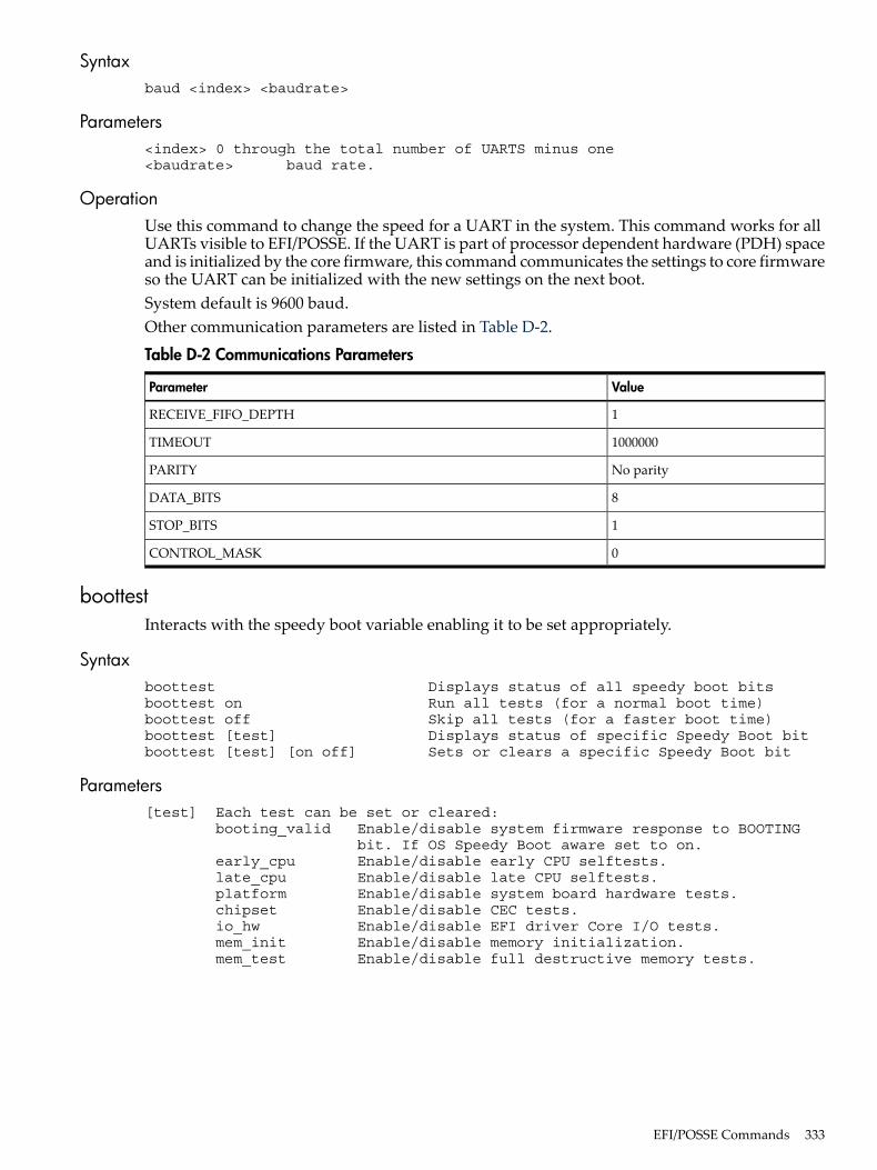
Syntaxbaud <index> <baudrate>
Parameters<index> 0 through the total number of UARTS minus one<baudrate> baud rate.
OperationUse this command to change the speed for a UART in the system. This command works for allUARTs visible to EFI/POSSE. If the UART is part of processor dependent hardware (PDH) spaceand is initialized by the core firmware, this command communicates the settings to core firmwareso the UART can be initialized with the new settings on the next boot.System default is 9600 baud.Other communication parameters are listed in Table D-2.
Table D-2 Communications Parameters
ValueParameter
1RECEIVE_FIFO_DEPTH
1000000TIMEOUT
No parityPARITY
8DATA_BITS
1STOP_BITS
0CONTROL_MASK
boottestInteracts with the speedy boot variable enabling it to be set appropriately.
Syntaxboottest Displays status of all speedy boot bitsboottest on Run all tests (for a normal boot time)boottest off Skip all tests (for a faster boot time)boottest [test] Displays status of specific Speedy Boot bitboottest [test] [on off] Sets or clears a specific Speedy Boot bit
Parameters[test] Each test can be set or cleared: booting_valid Enable/disable system firmware response to BOOTING bit. If OS Speedy Boot aware set to on. early_cpu Enable/disable early CPU selftests. late_cpu Enable/disable late CPU selftests. platform Enable/disable system board hardware tests. chipset Enable/disable CEC tests. io_hw Enable/disable EFI driver Core I/O tests. mem_init Enable/disable memory initialization. mem_test Enable/disable full destructive memory tests.
EFI/POSSE Commands 333
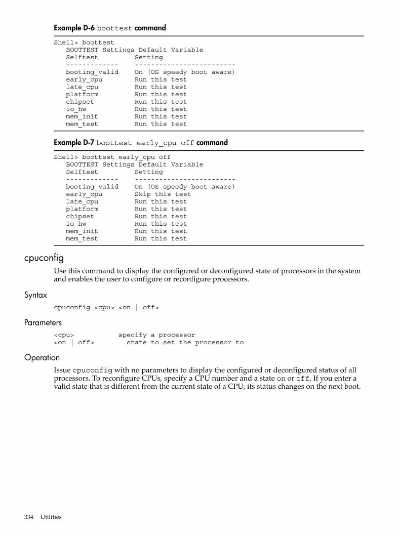
Example D-6 boottest command
Shell> boottest BOOTTEST Settings Default Variable Selftest Setting ------------- ------------------------- booting_valid On (OS speedy boot aware) early_cpu Run this test late_cpu Run this test platform Run this test chipset Run this test io_hw Run this test mem_init Run this test mem_test Run this test
Example D-7 boottest early_cpu off command
Shell> boottest early_cpu off BOOTTEST Settings Default Variable Selftest Setting ------------- ------------------------- booting_valid On (OS speedy boot aware) early_cpu Skip this test late_cpu Run this test platform Run this test chipset Run this test io_hw Run this test mem_init Run this test mem_test Run this test
cpuconfigUse this command to display the configured or deconfigured state of processors in the systemand enables the user to configure or reconfigure processors.
Syntaxcpuconfig <cpu> <on | off>
Parameters<cpu> specify a processor<on | off> state to set the processor to
OperationIssue cpuconfig with no parameters to display the configured or deconfigured status of allprocessors. To reconfigure CPUs, specify a CPU number and a state on or off. If you enter avalid state that is different from the current state of a CPU, its status changes on the next boot.
334 Utilities
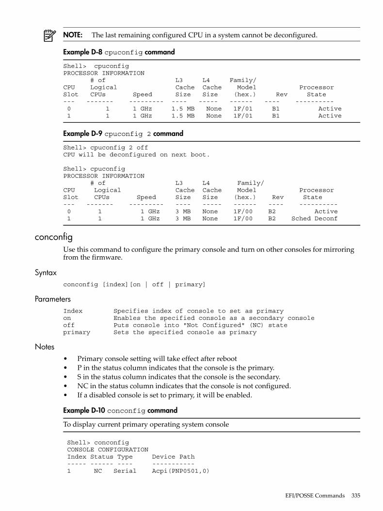
NOTE: The last remaining configured CPU in a system cannot be deconfigured.
Example D-8 cpuconfig command
Shell> cpuconfigPROCESSOR INFORMATION # of L3 L4 Family/CPU Logical Cache Cache Model ProcessorSlot CPUs Speed Size Size (hex.) Rev State--- ------- --------- ---- ----- ------ ---- ---------- 0 1 1 GHz 1.5 MB None 1F/01 B1 Active 1 1 1 GHz 1.5 MB None 1F/01 B1 Active
Example D-9 cpuconfig 2 command
Shell> cpuconfig 2 offCPU will be deconfigured on next boot.
Shell> cpuconfigPROCESSOR INFORMATION # of L3 L4 Family/CPU Logical Cache Cache Model ProcessorSlot CPUs Speed Size Size (hex.) Rev State--- ------- --------- ---- ----- ------ ---- ---------- 0 1 1 GHz 3 MB None 1F/00 B2 Active 1 1 1 GHz 3 MB None 1F/00 B2 Sched Deconf
conconfigUse this command to configure the primary console and turn on other consoles for mirroringfrom the firmware.
Syntaxconconfig [index][on | off | primary]
ParametersIndex Specifies index of console to set as primaryon Enables the specified console as a secondary consoleoff Puts console into "Not Configured" (NC) stateprimary Sets the specified console as primary
Notes• Primary console setting will take effect after reboot• P in the status column indicates that the console is the primary.• S in the status column indicates that the console is the secondary.• NC in the status column indicates that the console is not configured.• If a disabled console is set to primary, it will be enabled.
Example D-10 conconfig command
To display current primary operating system console
Shell> conconfig CONSOLE CONFIGURATION Index Status Type Device Path ----- ------ ---- ----------- 1 NC Serial Acpi(PNP0501,0)
EFI/POSSE Commands 335
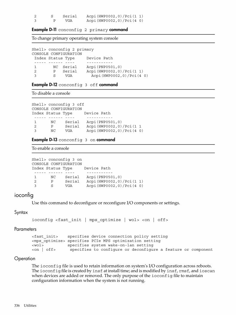
2 S Serial Acpi(HWP0002,0)/Pci(1 1) 3 P VGA Acpi(HWP0002,0)/Pci(4 0)
Example D-11 conconfig 2 primary command
To change primary operating system console
Shell> conconfig 2 primaryCONSOLE CONFIGURATION Index Status Type Device Path ----- ------ ---- ----------- 1 NC Serial Acpi(PNP0501,0) 2 P Serial Acpi(HWP0002,0)/Pci(1 1) 3 S VGA Acpi(HWP0002,0)/Pci(4 0)
Example D-12 conconfig 3 off command
To disable a console
Shell> conconfig 3 offCONSOLE CONFIGURATIONIndex Status Type Device Path ----- ------ ---- ----------- 1 NC Serial Acpi(PNP0501,0) 2 P Serial Acpi(HWP0002,0)/Pci(1 1 3 NC VGA Acpi(HWP0002,0)/Pci(4 0)
Example D-13 conconfig 3 on command
To enable a console
Shell> conconfig 3 onCONSOLE CONFIGURATIONIndex Status Type Device Path ----- ------ ---- ----------- 1 NC Serial Acpi(PNP0501,0) 2 P Serial Acpi(HWP0002,0)/Pci(1 1) 3 S VGA Acpi(HWP0002,0)/Pci(4 0)
ioconfigUse this command to deconfigure or reconfigure I/O components or settings.
Syntaxioconfig <fast_init | mps_optimize | wol> <on | off>
Parameters<fast_init> specifies device connection policy setting<mps_optimize> specifies PCIe MPS optimization setting<wol> specifies system wake-on-lan setting <on | off> specifies to configure or deconfigure a feature or component
OperationThe ioconfig file is used to retain information on system's I/O configuration across reboots.The ioconfig file is created by insf at install time; and is modified by insf, rmsf, and ioscanwhen devices are added or removed. The only purpose of the ioconfig file to maintainconfiguration information when the system is not running.
336 Utilities
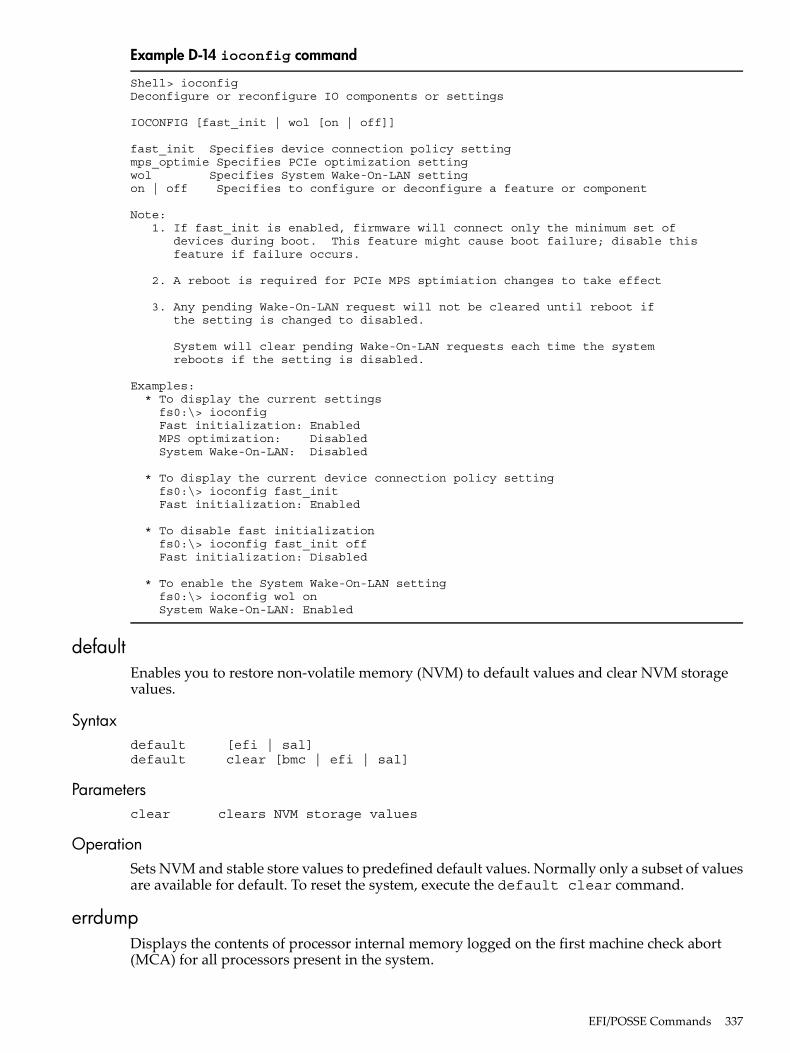
Example D-14 ioconfig command
Shell> ioconfigDeconfigure or reconfigure IO components or settings
IOCONFIG [fast_init | wol [on | off]]
fast_init Specifies device connection policy settingmps_optimie Specifies PCIe optimization settingwol Specifies System Wake-On-LAN settingon | off Specifies to configure or deconfigure a feature or component
Note: 1. If fast_init is enabled, firmware will connect only the minimum set of devices during boot. This feature might cause boot failure; disable this feature if failure occurs.
2. A reboot is required for PCIe MPS sptimiation changes to take effect
3. Any pending Wake-On-LAN request will not be cleared until reboot if the setting is changed to disabled.
System will clear pending Wake-On-LAN requests each time the system reboots if the setting is disabled.
Examples: * To display the current settings fs0:\> ioconfig Fast initialization: Enabled MPS optimization: Disabled System Wake-On-LAN: Disabled
* To display the current device connection policy setting fs0:\> ioconfig fast_init Fast initialization: Enabled
* To disable fast initialization fs0:\> ioconfig fast_init off Fast initialization: Disabled
* To enable the System Wake-On-LAN setting fs0:\> ioconfig wol on System Wake-On-LAN: Enabled
defaultEnables you to restore non-volatile memory (NVM) to default values and clear NVM storagevalues.
Syntaxdefault [efi | sal]default clear [bmc | efi | sal]
Parametersclear clears NVM storage values
OperationSets NVM and stable store values to predefined default values. Normally only a subset of valuesare available for default. To reset the system, execute the default clear command.
errdumpDisplays the contents of processor internal memory logged on the first machine check abort(MCA) for all processors present in the system.
EFI/POSSE Commands 337
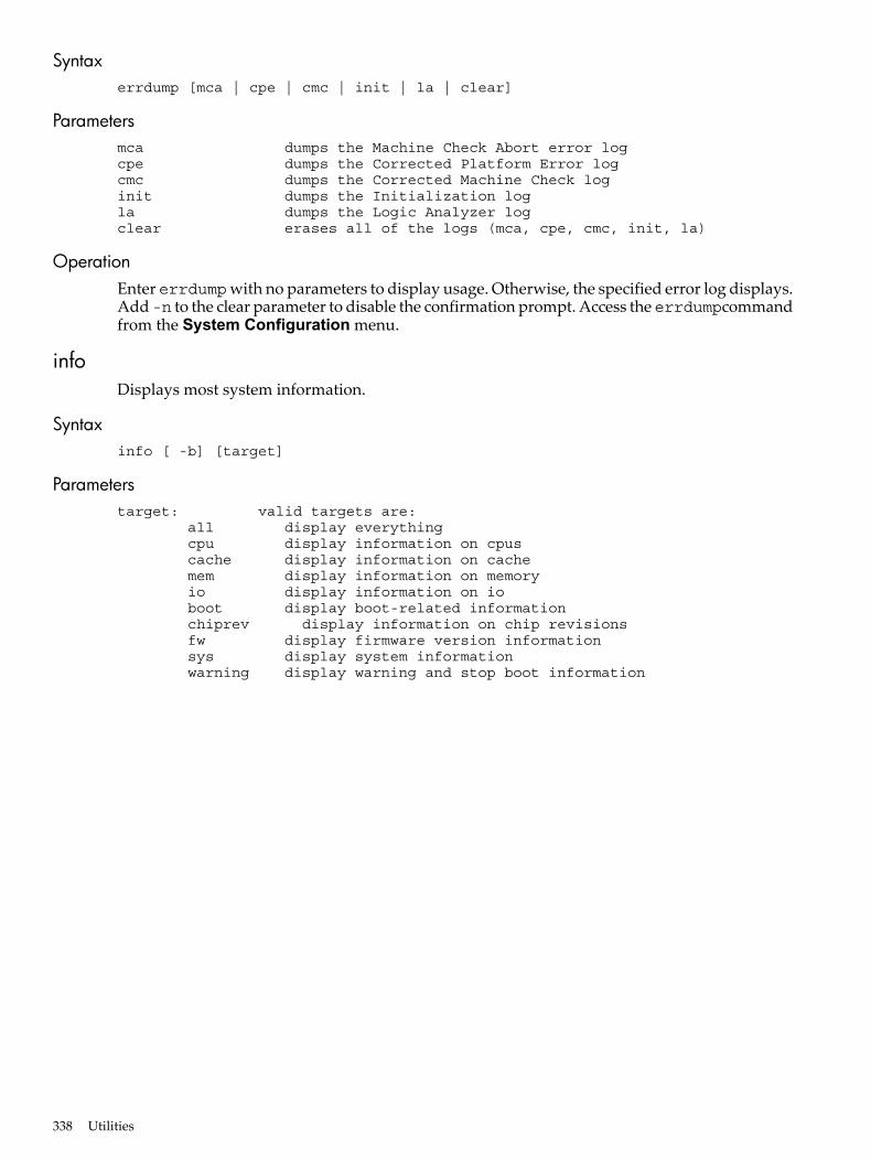
Syntaxerrdump [mca | cpe | cmc | init | la | clear]
Parametersmca dumps the Machine Check Abort error logcpe dumps the Corrected Platform Error logcmc dumps the Corrected Machine Check loginit dumps the Initialization logla dumps the Logic Analyzer logclear erases all of the logs (mca, cpe, cmc, init, la)
OperationEnter errdumpwith no parameters to display usage. Otherwise, the specified error log displays.Add-n to the clear parameter to disable the confirmation prompt. Access the errdumpcommandfrom the System Configuration menu.
infoDisplays most system information.
Syntaxinfo [ -b] [target]
Parameterstarget: valid targets are: all display everything cpu display information on cpus cache display information on cache mem display information on memory io display information on io boot display boot-related information chiprev display information on chip revisions fw display firmware version information sys display system information warning display warning and stop boot information
338 Utilities
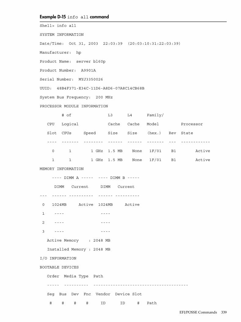
Example D-15 info all command
Shell> info all
SYSTEM INFORMATION
Date/Time: Oct 31, 2003 22:03:39 (20:03:10:31:22:03:39)
Manufacturer: hp
Product Name: server bl60p
Product Number: A9901A
Serial Number: MYJ3350026
UUID: 48B4F371-E34C-11D6-A8D6-07A8C14CB68B
System Bus Frequency: 200 MHz
PROCESSOR MODULE INFORMATION
# of L3 L4 Family/
CPU Logical Cache Cache Model Processor
Slot CPUs Speed Size Size (hex.) Rev State
---- ------- -------- ------ ------ ------- --- ------------
0 1 1 GHz 1.5 MB None 1F/01 B1 Active
1 1 1 GHz 1.5 MB None 1F/01 B1 Active
MEMORY INFORMATION
---- DIMM A ----- ---- DIMM B -----
DIMM Current DIMM Current
--- ------ ---------- ------ ----------
0 1024MB Active 1024MB Active
1 ---- ----
2 ---- ----
3 ---- ----
Active Memory : 2048 MB
Installed Memory : 2048 MB
I/O INFORMATION
BOOTABLE DEVICES
Order Media Type Path
----- ---------- ---------------------------------------
Seg Bus Dev Fnc Vendor Device Slot
# # # # ID ID # Path
EFI/POSSE Commands 339
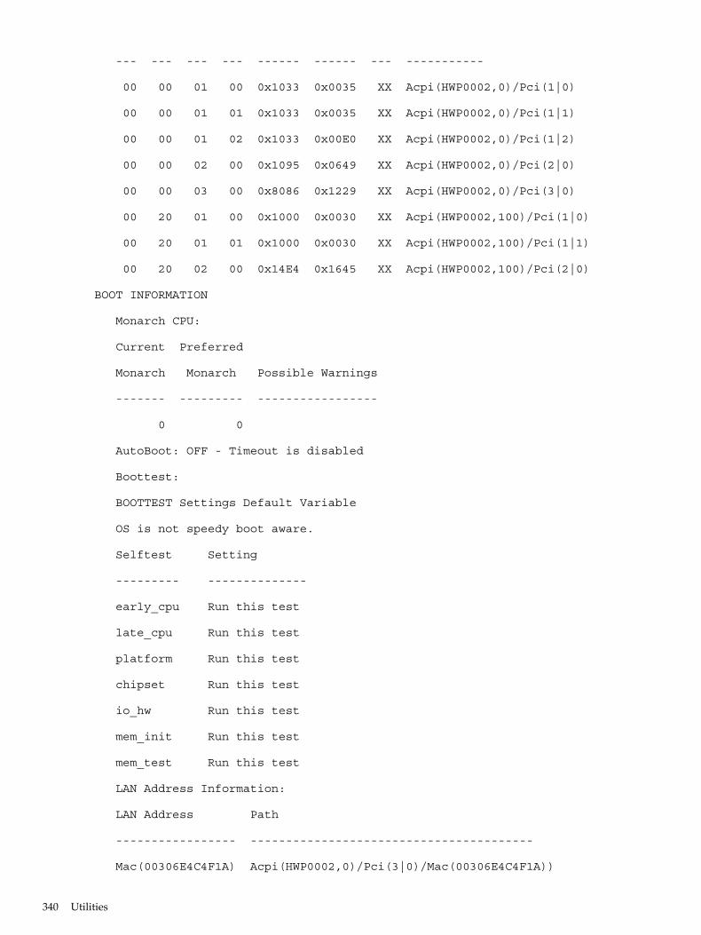
--- --- --- --- ------ ------ --- -----------
00 00 01 00 0x1033 0x0035 XX Acpi(HWP0002,0)/Pci(1|0)
00 00 01 01 0x1033 0x0035 XX Acpi(HWP0002,0)/Pci(1|1)
00 00 01 02 0x1033 0x00E0 XX Acpi(HWP0002,0)/Pci(1|2)
00 00 02 00 0x1095 0x0649 XX Acpi(HWP0002,0)/Pci(2|0)
00 00 03 00 0x8086 0x1229 XX Acpi(HWP0002,0)/Pci(3|0)
00 20 01 00 0x1000 0x0030 XX Acpi(HWP0002,100)/Pci(1|0)
00 20 01 01 0x1000 0x0030 XX Acpi(HWP0002,100)/Pci(1|1)
00 20 02 00 0x14E4 0x1645 XX Acpi(HWP0002,100)/Pci(2|0)
BOOT INFORMATION
Monarch CPU:
Current Preferred
Monarch Monarch Possible Warnings
------- --------- -----------------
0 0
AutoBoot: OFF - Timeout is disabled
Boottest:
BOOTTEST Settings Default Variable
OS is not speedy boot aware.
Selftest Setting
--------- --------------
early_cpu Run this test
late_cpu Run this test
platform Run this test
chipset Run this test
io_hw Run this test
mem_init Run this test
mem_test Run this test
LAN Address Information:
LAN Address Path
----------------- ----------------------------------------
Mac(00306E4C4F1A) Acpi(HWP0002,0)/Pci(3|0)/Mac(00306E4C4F1A))
340 Utilities
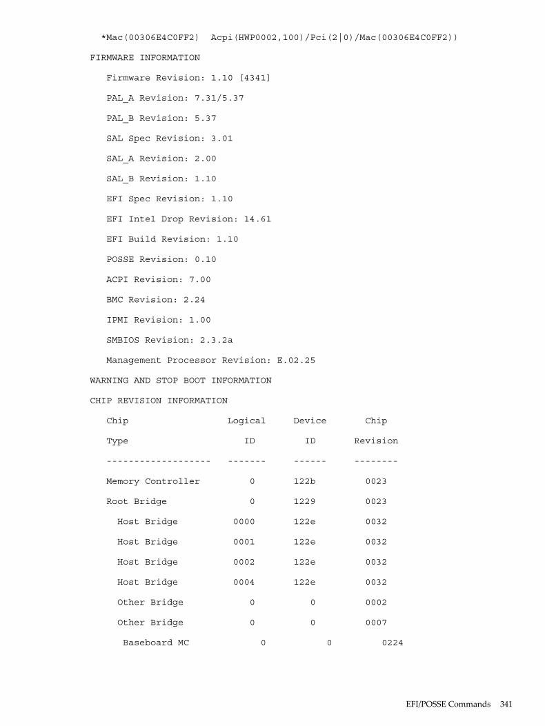
*Mac(00306E4C0FF2) Acpi(HWP0002,100)/Pci(2|0)/Mac(00306E4C0FF2))
FIRMWARE INFORMATION
Firmware Revision: 1.10 [4341]
PAL_A Revision: 7.31/5.37
PAL_B Revision: 5.37
SAL Spec Revision: 3.01
SAL_A Revision: 2.00
SAL_B Revision: 1.10
EFI Spec Revision: 1.10
EFI Intel Drop Revision: 14.61
EFI Build Revision: 1.10
POSSE Revision: 0.10
ACPI Revision: 7.00
BMC Revision: 2.24
IPMI Revision: 1.00
SMBIOS Revision: 2.3.2a
Management Processor Revision: E.02.25
WARNING AND STOP BOOT INFORMATION
CHIP REVISION INFORMATION
Chip Logical Device Chip
Type ID ID Revision
------------------- ------- ------ --------
Memory Controller 0 122b 0023
Root Bridge 0 1229 0023
Host Bridge 0000 122e 0032
Host Bridge 0001 122e 0032
Host Bridge 0002 122e 0032
Host Bridge 0004 122e 0032
Other Bridge 0 0 0002
Other Bridge 0 0 0007
Baseboard MC 0 0 0224
EFI/POSSE Commands 341
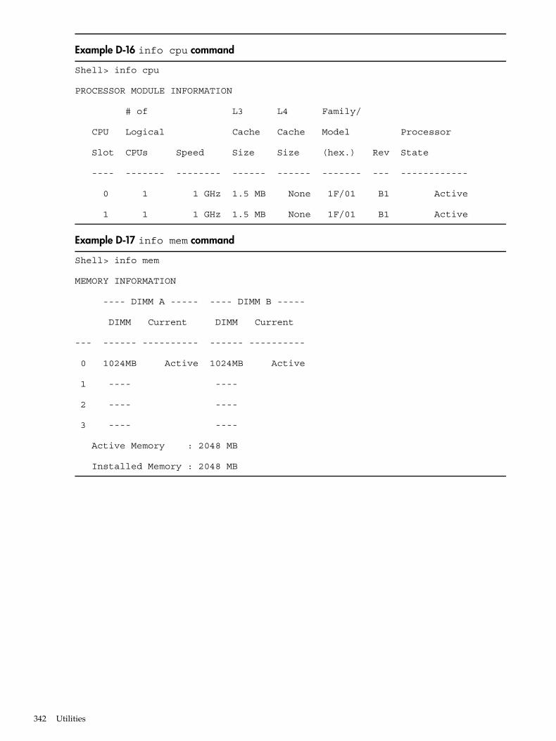
Example D-16 info cpu command
Shell> info cpu
PROCESSOR MODULE INFORMATION
# of L3 L4 Family/
CPU Logical Cache Cache Model Processor
Slot CPUs Speed Size Size (hex.) Rev State
---- ------- -------- ------ ------ ------- --- ------------
0 1 1 GHz 1.5 MB None 1F/01 B1 Active
1 1 1 GHz 1.5 MB None 1F/01 B1 Active
Example D-17 info mem command
Shell> info mem
MEMORY INFORMATION
---- DIMM A ----- ---- DIMM B -----
DIMM Current DIMM Current
--- ------ ---------- ------ ----------
0 1024MB Active 1024MB Active
1 ---- ----
2 ---- ----
3 ---- ----
Active Memory : 2048 MB
Installed Memory : 2048 MB
342 Utilities
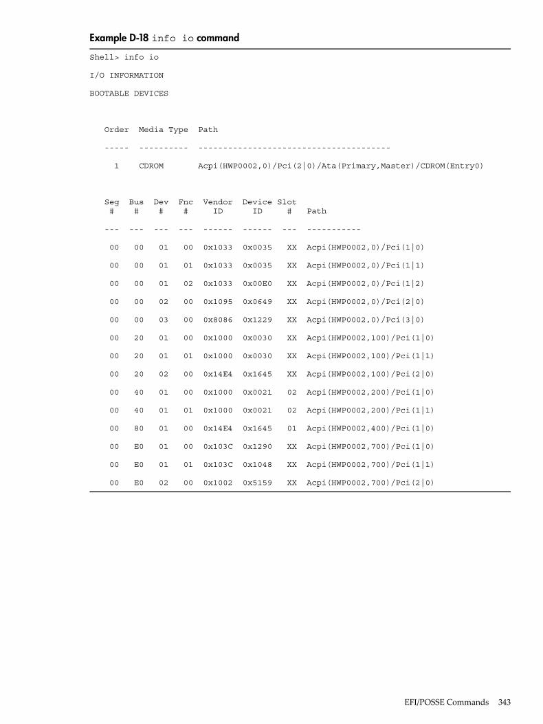
Example D-18 info io command
Shell> info io
I/O INFORMATION
BOOTABLE DEVICES
Order Media Type Path
----- ---------- ---------------------------------------
1 CDROM Acpi(HWP0002,0)/Pci(2|0)/Ata(Primary,Master)/CDROM(Entry0)
Seg Bus Dev Fnc Vendor Device Slot # # # # ID ID # Path
--- --- --- --- ------ ------ --- -----------
00 00 01 00 0x1033 0x0035 XX Acpi(HWP0002,0)/Pci(1|0)
00 00 01 01 0x1033 0x0035 XX Acpi(HWP0002,0)/Pci(1|1)
00 00 01 02 0x1033 0x00E0 XX Acpi(HWP0002,0)/Pci(1|2)
00 00 02 00 0x1095 0x0649 XX Acpi(HWP0002,0)/Pci(2|0)
00 00 03 00 0x8086 0x1229 XX Acpi(HWP0002,0)/Pci(3|0)
00 20 01 00 0x1000 0x0030 XX Acpi(HWP0002,100)/Pci(1|0)
00 20 01 01 0x1000 0x0030 XX Acpi(HWP0002,100)/Pci(1|1)
00 20 02 00 0x14E4 0x1645 XX Acpi(HWP0002,100)/Pci(2|0)
00 40 01 00 0x1000 0x0021 02 Acpi(HWP0002,200)/Pci(1|0)
00 40 01 01 0x1000 0x0021 02 Acpi(HWP0002,200)/Pci(1|1)
00 80 01 00 0x14E4 0x1645 01 Acpi(HWP0002,400)/Pci(1|0)
00 E0 01 00 0x103C 0x1290 XX Acpi(HWP0002,700)/Pci(1|0)
00 E0 01 01 0x103C 0x1048 XX Acpi(HWP0002,700)/Pci(1|1)
00 E0 02 00 0x1002 0x5159 XX Acpi(HWP0002,700)/Pci(2|0)
EFI/POSSE Commands 343
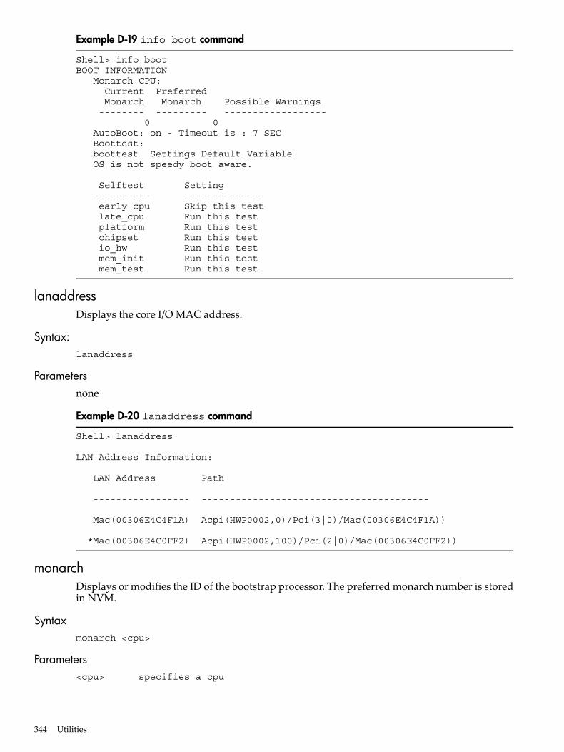
Example D-19 info boot command
Shell> info bootBOOT INFORMATION Monarch CPU: Current Preferred Monarch Monarch Possible Warnings -------- --------- ------------------ 0 0 AutoBoot: on - Timeout is : 7 SEC Boottest: boottest Settings Default Variable OS is not speedy boot aware.
Selftest Setting ---------- -------------- early_cpu Skip this test late_cpu Run this test platform Run this test chipset Run this test io_hw Run this test mem_init Run this test mem_test Run this test
lanaddressDisplays the core I/O MAC address.
Syntax:lanaddress
Parametersnone
Example D-20 lanaddress command
Shell> lanaddress
LAN Address Information:
LAN Address Path
----------------- ----------------------------------------
Mac(00306E4C4F1A) Acpi(HWP0002,0)/Pci(3|0)/Mac(00306E4C4F1A))
*Mac(00306E4C0FF2) Acpi(HWP0002,100)/Pci(2|0)/Mac(00306E4C0FF2))
monarchDisplays or modifies the ID of the bootstrap processor. The preferred monarch number is storedin NVM.
Syntaxmonarch <cpu>
Parameters<cpu> specifies a cpu
344 Utilities
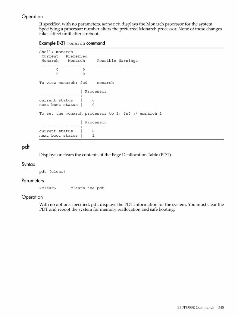
OperationIf specified with no parameters, monarch displays the Monarch processor for the system.Specifying a processor number alters the preferred Monarch processor. None of these changestakes affect until after a reboot.
Example D-21 monarch command
Shell> monarch Current Preferred Monarch Monarch Possible Warnings ------- --------- ----------------- 0 0 0 0
To view monarch: fs0 : monarch
| Processor-----------------+-----------current status | 0next boot status | 0
To set the monarch processor to 1: fs0 :\ monarch 1
| Processor-----------------+-----------current status | 0next boot status | 1
pdtDisplays or clears the contents of the Page Deallocation Table (PDT).
Syntaxpdt (clear)
Parameters<clear> clears the pdt
OperationWith no options specified, pdt displays the PDT information for the system. You must clear thePDT and reboot the system for memory reallocation and safe booting.
EFI/POSSE Commands 345
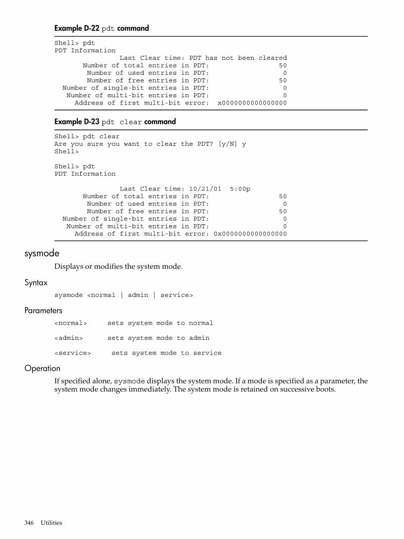
Example D-22 pdt command
Shell> pdtPDT Information Last Clear time: PDT has not been cleared Number of total entries in PDT: 50 Number of used entries in PDT: 0 Number of free entries in PDT: 50 Number of single-bit entries in PDT: 0 Number of multi-bit entries in PDT: 0 Address of first multi-bit error: x0000000000000000
Example D-23 pdt clear command
Shell> pdt clearAre you sure you want to clear the PDT? [y/N] yShell>
Shell> pdtPDT Information
Last Clear time: 10/21/01 5:00p Number of total entries in PDT: 50 Number of used entries in PDT: 0 Number of free entries in PDT: 50 Number of single-bit entries in PDT: 0 Number of multi-bit entries in PDT: 0 Address of first multi-bit error: 0x0000000000000000
sysmodeDisplays or modifies the system mode.
Syntaxsysmode <normal | admin | service>
Parameters<normal> sets system mode to normal
<admin> sets system mode to admin
<service> sets system mode to service
OperationIf specified alone, sysmode displays the system mode. If a mode is specified as a parameter, thesystem mode changes immediately. The system mode is retained on successive boots.
346 Utilities
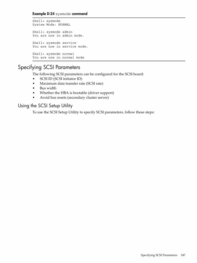
Example D-24 sysmode command
Shell> sysmodeSystem Mode: NORMAL
Shell> sysmode adminYou are now in admin mode.
Shell> sysmode serviceYou are now in service mode.
Shell> sysmode normalYou are now in normal mode
Specifying SCSI ParametersThe following SCSI parameters can be configured for the SCSI board:• SCSI ID (SCSI initiator ID)• Maximum data transfer rate (SCSI rate)• Bus width• Whether the HBA is bootable (driver support)• Avoid bus resets (secondary cluster server)
Using the SCSI Setup UtilityTo use the SCSI Setup Utility to specify SCSI parameters, follow these steps:
Specifying SCSI Parameters 347
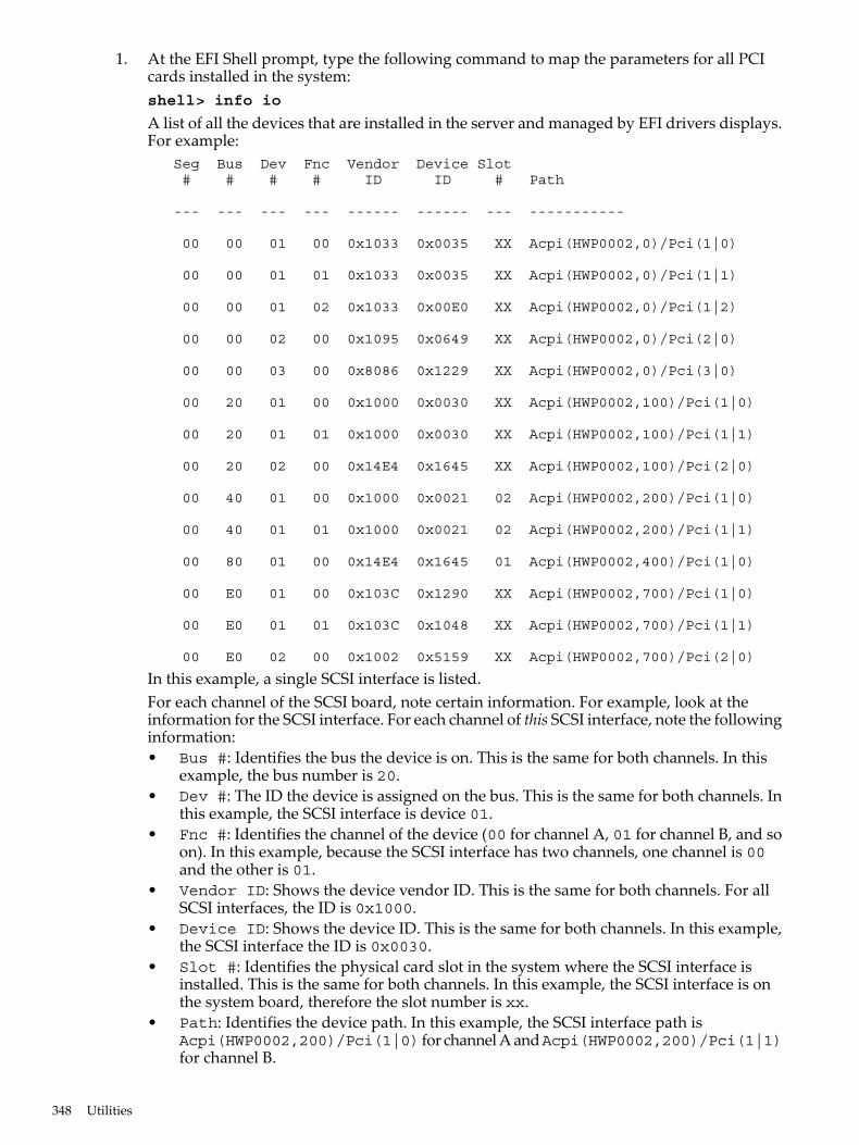
1. At the EFI Shell prompt, type the following command to map the parameters for all PCIcards installed in the system:shell> info io
A list of all the devices that are installed in the server and managed by EFI drivers displays.For example: Seg Bus Dev Fnc Vendor Device Slot # # # # ID ID # Path
--- --- --- --- ------ ------ --- -----------
00 00 01 00 0x1033 0x0035 XX Acpi(HWP0002,0)/Pci(1|0)
00 00 01 01 0x1033 0x0035 XX Acpi(HWP0002,0)/Pci(1|1)
00 00 01 02 0x1033 0x00E0 XX Acpi(HWP0002,0)/Pci(1|2)
00 00 02 00 0x1095 0x0649 XX Acpi(HWP0002,0)/Pci(2|0)
00 00 03 00 0x8086 0x1229 XX Acpi(HWP0002,0)/Pci(3|0)
00 20 01 00 0x1000 0x0030 XX Acpi(HWP0002,100)/Pci(1|0)
00 20 01 01 0x1000 0x0030 XX Acpi(HWP0002,100)/Pci(1|1)
00 20 02 00 0x14E4 0x1645 XX Acpi(HWP0002,100)/Pci(2|0)
00 40 01 00 0x1000 0x0021 02 Acpi(HWP0002,200)/Pci(1|0)
00 40 01 01 0x1000 0x0021 02 Acpi(HWP0002,200)/Pci(1|1)
00 80 01 00 0x14E4 0x1645 01 Acpi(HWP0002,400)/Pci(1|0)
00 E0 01 00 0x103C 0x1290 XX Acpi(HWP0002,700)/Pci(1|0)
00 E0 01 01 0x103C 0x1048 XX Acpi(HWP0002,700)/Pci(1|1)
00 E0 02 00 0x1002 0x5159 XX Acpi(HWP0002,700)/Pci(2|0)
In this example, a single SCSI interface is listed.For each channel of the SCSI board, note certain information. For example, look at theinformation for the SCSI interface. For each channel of this SCSI interface, note the followinginformation:• Bus #: Identifies the bus the device is on. This is the same for both channels. In this
example, the bus number is 20.• Dev #: The ID the device is assigned on the bus. This is the same for both channels. In
this example, the SCSI interface is device 01.• Fnc #: Identifies the channel of the device (00 for channel A, 01 for channel B, and so
on). In this example, because the SCSI interface has two channels, one channel is 00and the other is 01.
• Vendor ID: Shows the device vendor ID. This is the same for both channels. For allSCSI interfaces, the ID is 0x1000.
• Device ID: Shows the device ID. This is the same for both channels. In this example,the SCSI interface the ID is 0x0030.
• Slot #: Identifies the physical card slot in the system where the SCSI interface isinstalled. This is the same for both channels. In this example, the SCSI interface is onthe system board, therefore the slot number is xx.
• Path: Identifies the device path. In this example, the SCSI interface path isAcpi(HWP0002,200)/Pci(1|0) for channel A andAcpi(HWP0002,200)/Pci(1|1)for channel B.
348 Utilities
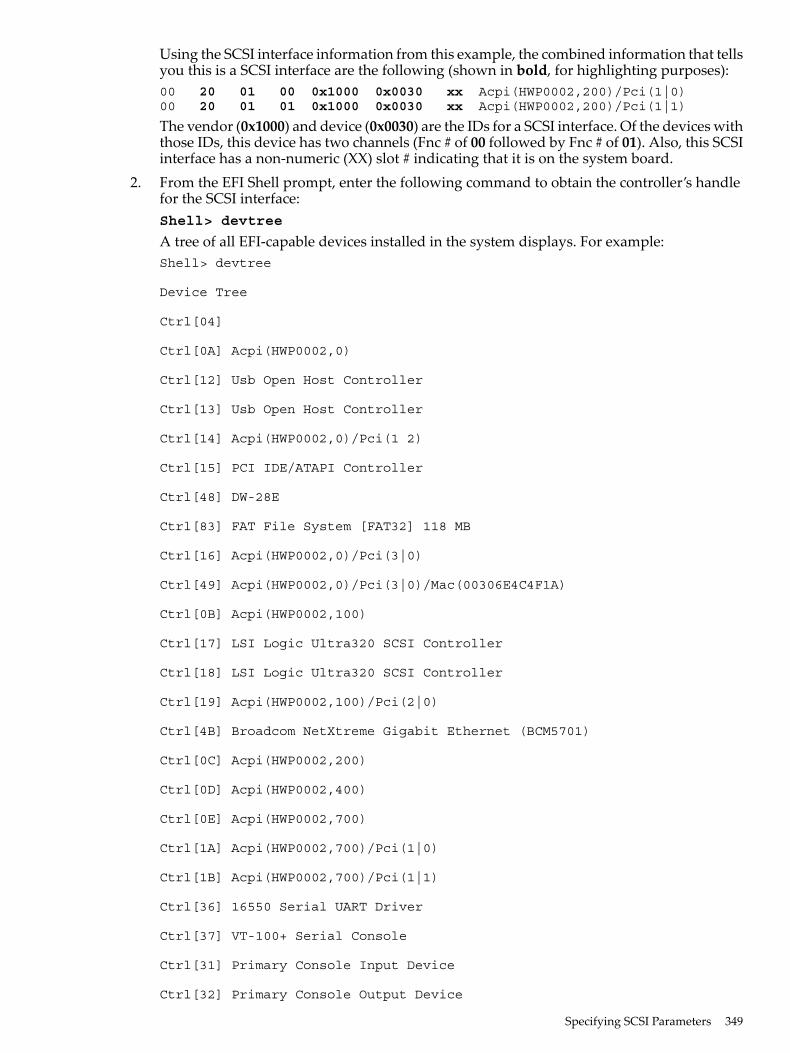
Using the SCSI interface information from this example, the combined information that tellsyou this is a SCSI interface are the following (shown in bold, for highlighting purposes):00 20 01 00 0x1000 0x0030 xx Acpi(HWP0002,200)/Pci(1|0)00 20 01 01 0x1000 0x0030 xx Acpi(HWP0002,200)/Pci(1|1)
The vendor (0x1000) and device (0x0030) are the IDs for a SCSI interface. Of the devices withthose IDs, this device has two channels (Fnc # of 00 followed by Fnc # of 01). Also, this SCSIinterface has a non-numeric (XX) slot # indicating that it is on the system board.
2. From the EFI Shell prompt, enter the following command to obtain the controller’s handlefor the SCSI interface:Shell> devtree
A tree of all EFI-capable devices installed in the system displays. For example:Shell> devtree
Device Tree
Ctrl[04]
Ctrl[0A] Acpi(HWP0002,0)
Ctrl[12] Usb Open Host Controller
Ctrl[13] Usb Open Host Controller
Ctrl[14] Acpi(HWP0002,0)/Pci(1 2)
Ctrl[15] PCI IDE/ATAPI Controller
Ctrl[48] DW-28E
Ctrl[83] FAT File System [FAT32] 118 MB
Ctrl[16] Acpi(HWP0002,0)/Pci(3|0)
Ctrl[49] Acpi(HWP0002,0)/Pci(3|0)/Mac(00306E4C4F1A)
Ctrl[0B] Acpi(HWP0002,100)
Ctrl[17] LSI Logic Ultra320 SCSI Controller
Ctrl[18] LSI Logic Ultra320 SCSI Controller
Ctrl[19] Acpi(HWP0002,100)/Pci(2|0)
Ctrl[4B] Broadcom NetXtreme Gigabit Ethernet (BCM5701)
Ctrl[0C] Acpi(HWP0002,200)
Ctrl[0D] Acpi(HWP0002,400)
Ctrl[0E] Acpi(HWP0002,700)
Ctrl[1A] Acpi(HWP0002,700)/Pci(1|0)
Ctrl[1B] Acpi(HWP0002,700)/Pci(1|1)
Ctrl[36] 16550 Serial UART Driver
Ctrl[37] VT-100+ Serial Console
Ctrl[31] Primary Console Input Device
Ctrl[32] Primary Console Output Device
Specifying SCSI Parameters 349
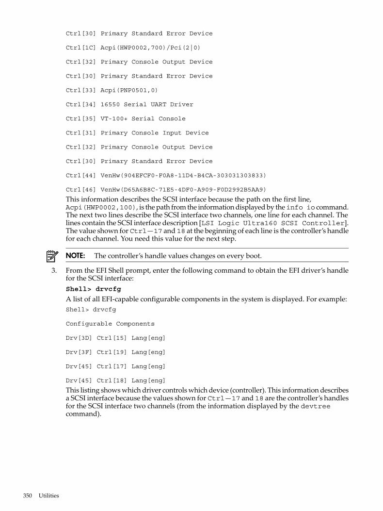
Ctrl[30] Primary Standard Error Device
Ctrl[1C] Acpi(HWP0002,700)/Pci(2|0)
Ctrl[32] Primary Console Output Device
Ctrl[30] Primary Standard Error Device
Ctrl[33] Acpi(PNP0501,0)
Ctrl[34] 16550 Serial UART Driver
Ctrl[35] VT-100+ Serial Console
Ctrl[31] Primary Console Input Device
Ctrl[32] Primary Console Output Device
Ctrl[30] Primary Standard Error Device
Ctrl[44] VenHw(904EFCF0-F0A8-11D4-B4CA-303031303833)
Ctrl[46] VenHw(D65A6B8C-71E5-4DF0-A909-F0D2992B5AA9)
This information describes the SCSI interface because the path on the first line,Acpi(HWP0002,100), is the path from the information displayed by theinfo io command.The next two lines describe the SCSI interface two channels, one line for each channel. Thelines contain the SCSI interface description [LSI Logic Ultra160 SCSI Controller].The value shown for Ctrl—17 and 18 at the beginning of each line is the controller’s handlefor each channel. You need this value for the next step.
NOTE: The controller’s handle values changes on every boot.
3. From the EFI Shell prompt, enter the following command to obtain the EFI driver’s handlefor the SCSI interface:Shell> drvcfg
A list of all EFI-capable configurable components in the system is displayed. For example:Shell> drvcfg
Configurable Components
Drv[3D] Ctrl[15] Lang[eng]
Drv[3F] Ctrl[19] Lang[eng]
Drv[45] Ctrl[17] Lang[eng]
Drv[45] Ctrl[18] Lang[eng]
This listing shows which driver controls which device (controller). This information describesa SCSI interface because the values shown for Ctrl—17 and 18 are the controller’s handlesfor the SCSI interface two channels (from the information displayed by the devtreecommand).
350 Utilities
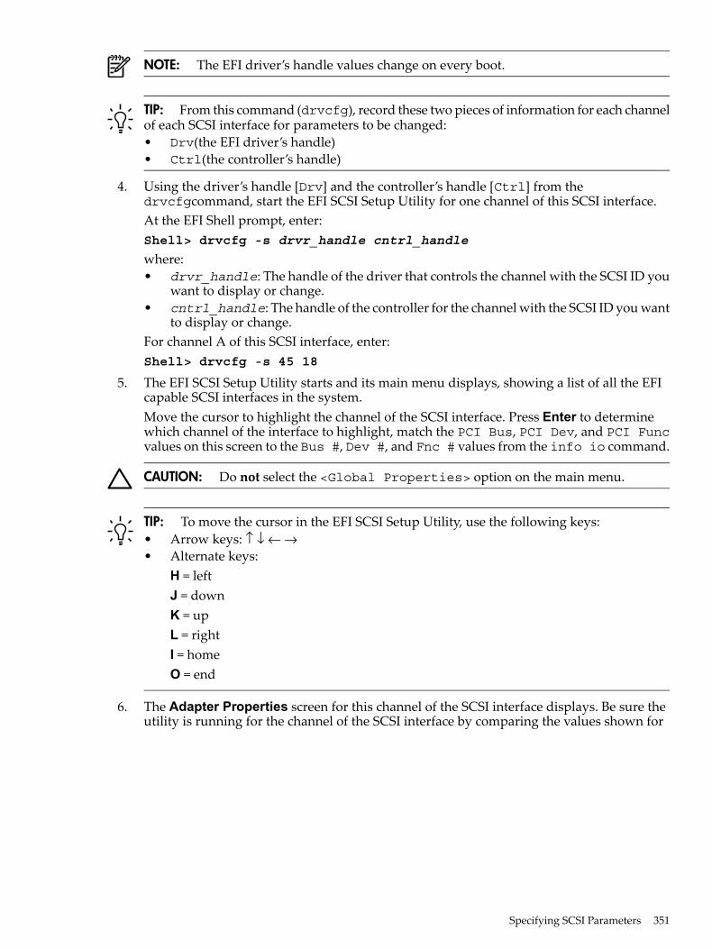
NOTE: The EFI driver’s handle values change on every boot.
TIP: From this command (drvcfg), record these two pieces of information for each channelof each SCSI interface for parameters to be changed:• Drv(the EFI driver’s handle)• Ctrl(the controller’s handle)
4. Using the driver’s handle [Drv] and the controller’s handle [Ctrl] from thedrvcfgcommand, start the EFI SCSI Setup Utility for one channel of this SCSI interface.At the EFI Shell prompt, enter:Shell> drvcfg -s drvr_handle cntrl_handle
where:• drvr_handle: The handle of the driver that controls the channel with the SCSI ID you
want to display or change.• cntrl_handle: The handle of the controller for the channel with the SCSI ID you want
to display or change.For channel A of this SCSI interface, enter:Shell> drvcfg -s 45 18
5. The EFI SCSI Setup Utility starts and its main menu displays, showing a list of all the EFIcapable SCSI interfaces in the system.Move the cursor to highlight the channel of the SCSI interface. Press Enter to determinewhich channel of the interface to highlight, match the PCI Bus, PCI Dev, and PCI Funcvalues on this screen to the Bus #, Dev #, and Fnc # values from the info io command.
CAUTION: Do not select the <Global Properties> option on the main menu.
TIP: To move the cursor in the EFI SCSI Setup Utility, use the following keys:• Arrow keys: ↑ ↓ ← →• Alternate keys:
H = leftJ = downK = upL = rightI = homeO = end
6. The Adapter Properties screen for this channel of the SCSI interface displays. Be sure theutility is running for the channel of the SCSI interface by comparing the values shown for
Specifying SCSI Parameters 351
PCI Bus, PCI Device, and PCI Function to the Bus #, Dev #, and Fnc # values fromthe info io command.
CAUTION: Do not change the value for any of the following fields on the AdapterProperties screen:• Auto Termination• SCSI Parity• SCSI Bus Scan Order• Spinup Delay (Secs)
Changing any of these fields can cause unpredictable results.
CAUTION: Donot change the value for any of the following fields on the Device Propertiesscreen:• Scan Id• Scan LUNs > 0• Disconnect• SCSI Timeout• Queue Tags• Format• Verify
Changing any of these fields can cause unpredictable results.
7. Display the SCSI parameters listed below for the channel of the SCSI interface and changethe parameters if necessary, or restore its SCSI parameters to their default values.• SCSI ID• Maximum data transfer rate• Bus width• Whether the SCSI interface is bootable (driver support)• Avoid bus resets (secondary cluster server)• Restore Defaults
8. Use the arrow keys to navigate to the appropriate SCSI parameter.9. Use the plus (+) and minus (-) keys to scroll through the values until the value you want
displays.10. Press Esc to exit the Adapter Properties screen.11. Move the cursor to the action (cancel, save, or discard) you want to take, and press
Enter.Select one of the following options:• Cancel the exit to stay on the Adapter Properties screen for the channel of the SCSI
interface.• Save the changes you made, then exit the screen.• Discard the changes you made, then exit the screen.If you select cancel, you remain in the Adapter Properties screen for the channel of theSCSI interface. You can still change the channel’s parameters.If you select save or discard, you go to the EFI SCSI Setup Utility main menu.
CAUTION: Do not select the <Global Properties> option on the main menu.
12. Press Esc to exit the main menu and the EFI SCSI Setup Utility.13. Select the option for exiting the utility.14. When prompted, press Enter to stop the SCSI interface; you are at the EFI Shell prompt.15. At the EFI Shell prompt, enter the following command:
Shell> reset
The system starts to reboot. This is required to enable the new SCSI setting.
352 Utilities
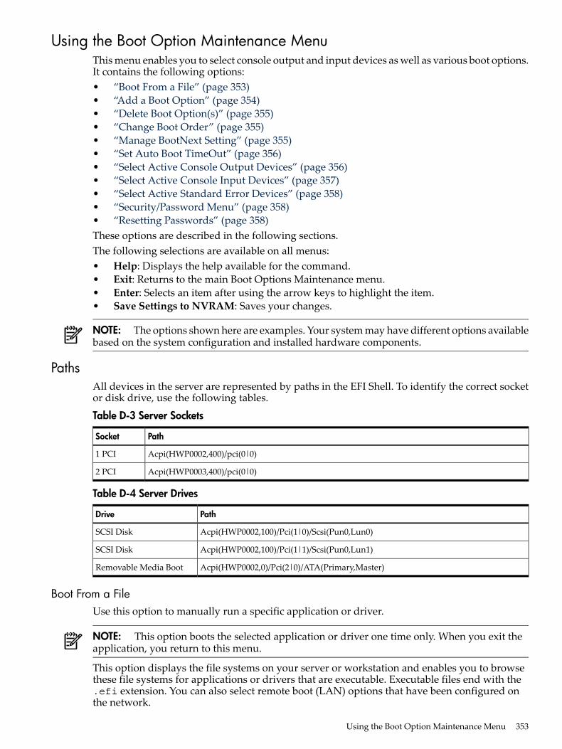
Using the Boot Option Maintenance MenuThis menu enables you to select console output and input devices as well as various boot options.It contains the following options:• “Boot From a File” (page 353)• “Add a Boot Option” (page 354)• “Delete Boot Option(s)” (page 355)• “Change Boot Order” (page 355)• “Manage BootNext Setting” (page 355)• “Set Auto Boot TimeOut” (page 356)• “Select Active Console Output Devices” (page 356)• “Select Active Console Input Devices” (page 357)• “Select Active Standard Error Devices” (page 358)• “Security/Password Menu” (page 358)• “Resetting Passwords” (page 358)These options are described in the following sections.The following selections are available on all menus:• Help: Displays the help available for the command.• Exit: Returns to the main Boot Options Maintenance menu.• Enter: Selects an item after using the arrow keys to highlight the item.• Save Settings to NVRAM: Saves your changes.
NOTE: The options shown here are examples. Your system may have different options availablebased on the system configuration and installed hardware components.
PathsAll devices in the server are represented by paths in the EFI Shell. To identify the correct socketor disk drive, use the following tables.
Table D-3 Server Sockets
PathSocket
Acpi(HWP0002,400)/pci(0|0)1 PCI
Acpi(HWP0003,400)/pci(0|0)2 PCI
Table D-4 Server Drives
PathDrive
Acpi(HWP0002,100)/Pci(1|0)/Scsi(Pun0,Lun0)SCSI Disk
Acpi(HWP0002,100)/Pci(1|1)/Scsi(Pun0,Lun1)SCSI Disk
Acpi(HWP0002,0)/Pci(2|0)/ATA(Primary,Master)Removable Media Boot
Boot From a FileUse this option to manually run a specific application or driver.
NOTE: This option boots the selected application or driver one time only. When you exit theapplication, you return to this menu.
This option displays the file systems on your server or workstation and enables you to browsethese file systems for applications or drivers that are executable. Executable files end with the.efi extension. You can also select remote boot (LAN) options that have been configured onthe network.
Using the Boot Option Maintenance Menu 353
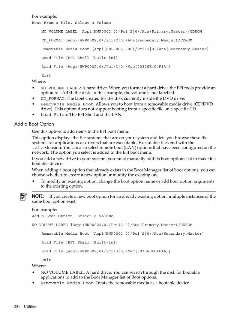
For example:Boot From a File. Select a Volume
NO VOLUME LABEL [Acpi(HWP0002,0)/Pci(2|0)/Ata(Primary,Master)/CDROM
CD_FORMAT [Acpi(HWP0002,0)/Pci(2|0)/Ata(Secondary,Master)/CDROM
Removable Media Boot [Acpi(HWP0002,500)/Pci(2|0)/Ata(Secondary,Master)
Load File [EFI Shell [Built-in]]
Load File [Acpi(HWP0002,0)/Pci(3|0)/Mac(00306E4C4F1A)]
Exit
Where:• NO VOLUME LABEL: A hard drive. When you format a hard drive, the EFI tools provide an
option to LABEL the disk. In this example, the volume is not labelled.• CD_FORMAT: The label created for the disk currently inside the DVD drive.• Removable Media Boot: Allows you to boot from a removable media drive (CD/DVD
drive). This option does not support booting from a specific file on a specific CD.• Load Files: The EFI Shell and the LAN.
Add a Boot OptionUse this option to add items to the EFI boot menu.This option displays the file systems that are on your system and lets you browse these filesystems for applications or drivers that are executable. Executable files end with the.efiextension. You can also select remote boot (LAN) options that have been configured on thenetwork. The option you select is added to the EFI boot menu.If you add a new drive to your system, you must manually add its boot options list to make it abootable device.When adding a boot option that already exists in the Boot Manager list of boot options, you canchoose whether to create a new option or modify the existing one.• To modify an existing option, change the boot option name or add boot option arguments
to the existing option.
NOTE: If you create a new boot option for an already existing option, multiple instances of thesame boot option exist.
For example:Add a Boot Option. Select a Volume
NO VOLUME LABEL [Acpi(HWP0002,0)/Pci(2|0)/Ata(Primary,Master)/CDROM
Removable Media Boot [Acpi(HWP0002,0)/Pci(2|0)/Ata(Secondary,Master)
Load File [EFI Shell [Built-in]]
Load File [Acpi(HWP0002,0)/Pci(3|0)/Mac(00306E4C4F1A)]
Exit
Where:• NO VOLUME LABEL: A hard drive. You can search through the disk for bootable
applications to add to the Boot Manager list of Boot options.• Removable Media Boot: Treats the removable media as a bootable device.
354 Utilities
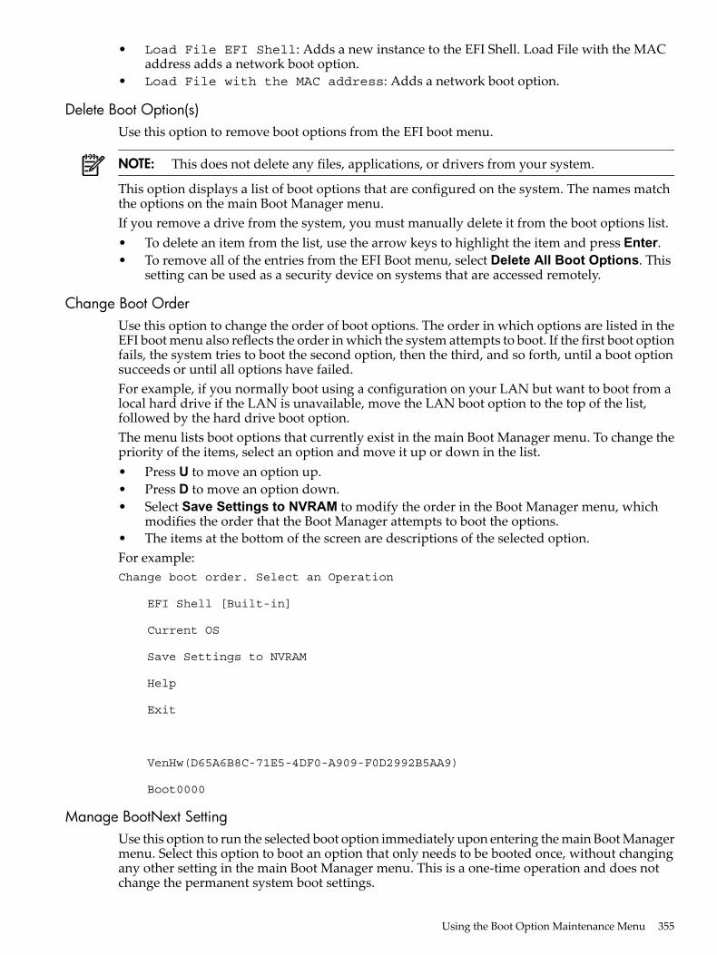
• Load File EFI Shell: Adds a new instance to the EFI Shell. Load File with the MACaddress adds a network boot option.
• Load File with the MAC address: Adds a network boot option.
Delete Boot Option(s)Use this option to remove boot options from the EFI boot menu.
NOTE: This does not delete any files, applications, or drivers from your system.
This option displays a list of boot options that are configured on the system. The names matchthe options on the main Boot Manager menu.If you remove a drive from the system, you must manually delete it from the boot options list.• To delete an item from the list, use the arrow keys to highlight the item and press Enter.• To remove all of the entries from the EFI Boot menu, select Delete All Boot Options. This
setting can be used as a security device on systems that are accessed remotely.
Change Boot OrderUse this option to change the order of boot options. The order in which options are listed in theEFI boot menu also reflects the order in which the system attempts to boot. If the first boot optionfails, the system tries to boot the second option, then the third, and so forth, until a boot optionsucceeds or until all options have failed.For example, if you normally boot using a configuration on your LAN but want to boot from alocal hard drive if the LAN is unavailable, move the LAN boot option to the top of the list,followed by the hard drive boot option.The menu lists boot options that currently exist in the main Boot Manager menu. To change thepriority of the items, select an option and move it up or down in the list.• Press U to move an option up.• Press D to move an option down.• Select Save Settings to NVRAM to modify the order in the Boot Manager menu, which
modifies the order that the Boot Manager attempts to boot the options.• The items at the bottom of the screen are descriptions of the selected option.For example:Change boot order. Select an Operation
EFI Shell [Built-in]
Current OS
Save Settings to NVRAM
Help
Exit
VenHw(D65A6B8C-71E5-4DF0-A909-F0D2992B5AA9)
Boot0000
Manage BootNext SettingUse this option to run the selected boot option immediately upon entering the main Boot Managermenu. Select this option to boot an option that only needs to be booted once, without changingany other setting in the main Boot Manager menu. This is a one-time operation and does notchange the permanent system boot settings.
Using the Boot Option Maintenance Menu 355
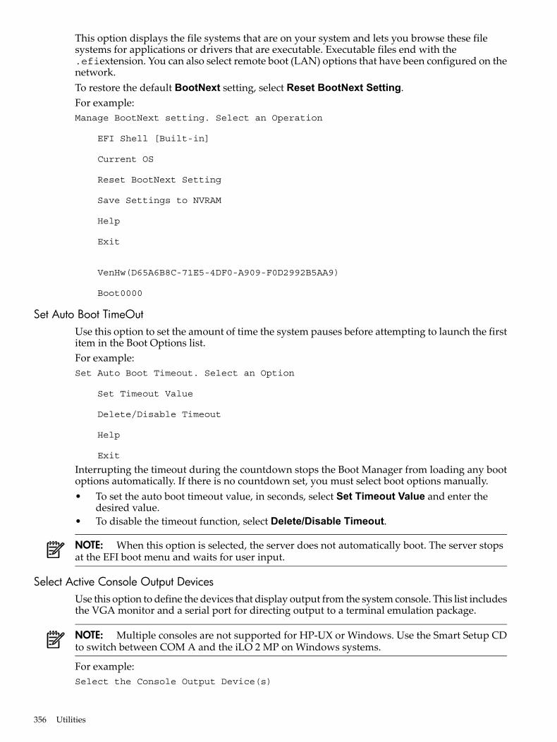
This option displays the file systems that are on your system and lets you browse these filesystems for applications or drivers that are executable. Executable files end with the.efiextension. You can also select remote boot (LAN) options that have been configured on thenetwork.To restore the default BootNext setting, select Reset BootNext Setting.For example:Manage BootNext setting. Select an Operation
EFI Shell [Built-in]
Current OS
Reset BootNext Setting
Save Settings to NVRAM
Help
Exit
VenHw(D65A6B8C-71E5-4DF0-A909-F0D2992B5AA9)
Boot0000
Set Auto Boot TimeOutUse this option to set the amount of time the system pauses before attempting to launch the firstitem in the Boot Options list.For example:Set Auto Boot Timeout. Select an Option
Set Timeout Value
Delete/Disable Timeout
Help
Exit
Interrupting the timeout during the countdown stops the Boot Manager from loading any bootoptions automatically. If there is no countdown set, you must select boot options manually.• To set the auto boot timeout value, in seconds, select Set Timeout Value and enter the
desired value.• To disable the timeout function, select Delete/Disable Timeout.
NOTE: When this option is selected, the server does not automatically boot. The server stopsat the EFI boot menu and waits for user input.
Select Active Console Output DevicesUse this option to define the devices that display output from the system console. This list includesthe VGA monitor and a serial port for directing output to a terminal emulation package.
NOTE: Multiple consoles are not supported for HP-UX or Windows. Use the Smart Setup CDto switch between COM A and the iLO 2 MP on Windows systems.
For example:Select the Console Output Device(s)
356 Utilities
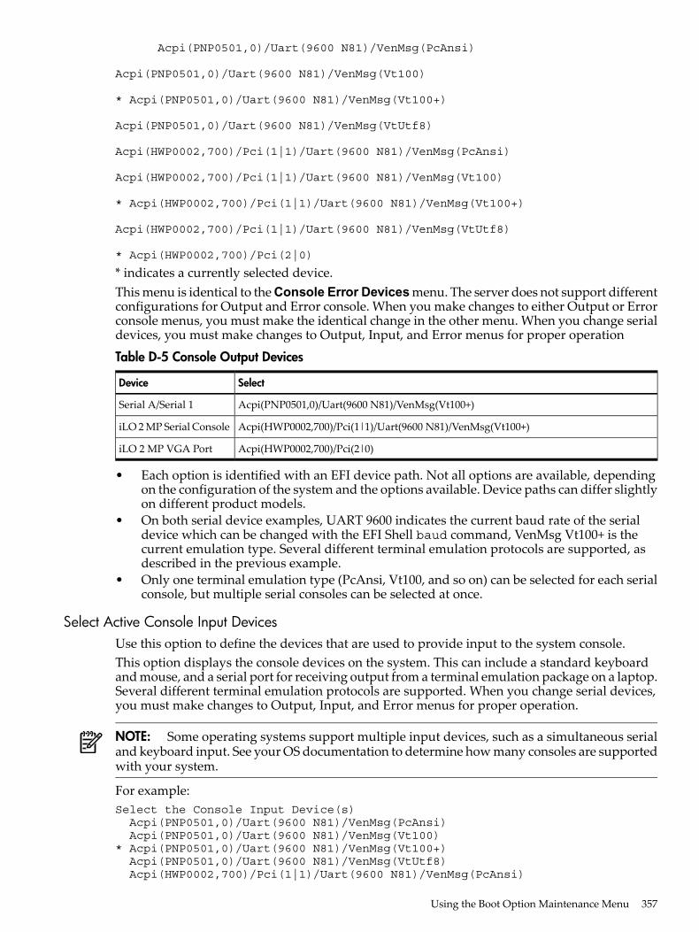
Acpi(PNP0501,0)/Uart(9600 N81)/VenMsg(PcAnsi)
Acpi(PNP0501,0)/Uart(9600 N81)/VenMsg(Vt100)
* Acpi(PNP0501,0)/Uart(9600 N81)/VenMsg(Vt100+)
Acpi(PNP0501,0)/Uart(9600 N81)/VenMsg(VtUtf8)
Acpi(HWP0002,700)/Pci(1|1)/Uart(9600 N81)/VenMsg(PcAnsi)
Acpi(HWP0002,700)/Pci(1|1)/Uart(9600 N81)/VenMsg(Vt100)
* Acpi(HWP0002,700)/Pci(1|1)/Uart(9600 N81)/VenMsg(Vt100+)
Acpi(HWP0002,700)/Pci(1|1)/Uart(9600 N81)/VenMsg(VtUtf8)
* Acpi(HWP0002,700)/Pci(2|0)
* indicates a currently selected device.This menu is identical to the Console Error Devices menu. The server does not support differentconfigurations for Output and Error console. When you make changes to either Output or Errorconsole menus, you must make the identical change in the other menu. When you change serialdevices, you must make changes to Output, Input, and Error menus for proper operation
Table D-5 Console Output Devices
SelectDevice
Acpi(PNP0501,0)/Uart(9600 N81)/VenMsg(Vt100+)Serial A/Serial 1
Acpi(HWP0002,700)/Pci(1|1)/Uart(9600 N81)/VenMsg(Vt100+)iLO 2 MP Serial Console
Acpi(HWP0002,700)/Pci(2|0)iLO 2 MP VGA Port
• Each option is identified with an EFI device path. Not all options are available, dependingon the configuration of the system and the options available. Device paths can differ slightlyon different product models.
• On both serial device examples, UART 9600 indicates the current baud rate of the serialdevice which can be changed with the EFI Shell baud command, VenMsg Vt100+ is thecurrent emulation type. Several different terminal emulation protocols are supported, asdescribed in the previous example.
• Only one terminal emulation type (PcAnsi, Vt100, and so on) can be selected for each serialconsole, but multiple serial consoles can be selected at once.
Select Active Console Input DevicesUse this option to define the devices that are used to provide input to the system console.This option displays the console devices on the system. This can include a standard keyboardand mouse, and a serial port for receiving output from a terminal emulation package on a laptop.Several different terminal emulation protocols are supported. When you change serial devices,you must make changes to Output, Input, and Error menus for proper operation.
NOTE: Some operating systems support multiple input devices, such as a simultaneous serialand keyboard input. See your OS documentation to determine how many consoles are supportedwith your system.
For example:Select the Console Input Device(s) Acpi(PNP0501,0)/Uart(9600 N81)/VenMsg(PcAnsi) Acpi(PNP0501,0)/Uart(9600 N81)/VenMsg(Vt100) * Acpi(PNP0501,0)/Uart(9600 N81)/VenMsg(Vt100+) Acpi(PNP0501,0)/Uart(9600 N81)/VenMsg(VtUtf8) Acpi(HWP0002,700)/Pci(1|1)/Uart(9600 N81)/VenMsg(PcAnsi)
Using the Boot Option Maintenance Menu 357
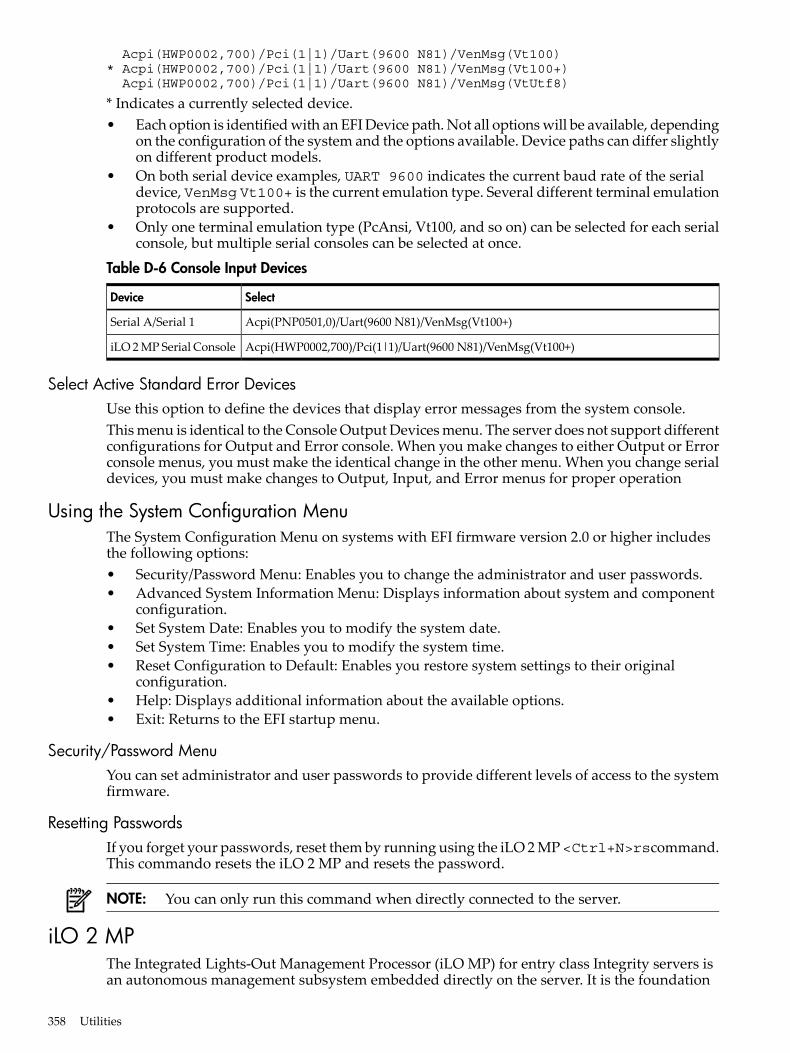
Acpi(HWP0002,700)/Pci(1|1)/Uart(9600 N81)/VenMsg(Vt100) * Acpi(HWP0002,700)/Pci(1|1)/Uart(9600 N81)/VenMsg(Vt100+) Acpi(HWP0002,700)/Pci(1|1)/Uart(9600 N81)/VenMsg(VtUtf8)
* Indicates a currently selected device.• Each option is identified with an EFI Device path. Not all options will be available, depending
on the configuration of the system and the options available. Device paths can differ slightlyon different product models.
• On both serial device examples, UART 9600 indicates the current baud rate of the serialdevice, VenMsg Vt100+ is the current emulation type. Several different terminal emulationprotocols are supported.
• Only one terminal emulation type (PcAnsi, Vt100, and so on) can be selected for each serialconsole, but multiple serial consoles can be selected at once.
Table D-6 Console Input Devices
SelectDevice
Acpi(PNP0501,0)/Uart(9600 N81)/VenMsg(Vt100+)Serial A/Serial 1
Acpi(HWP0002,700)/Pci(1|1)/Uart(9600 N81)/VenMsg(Vt100+)iLO 2 MP Serial Console
Select Active Standard Error DevicesUse this option to define the devices that display error messages from the system console.This menu is identical to the Console Output Devices menu. The server does not support differentconfigurations for Output and Error console. When you make changes to either Output or Errorconsole menus, you must make the identical change in the other menu. When you change serialdevices, you must make changes to Output, Input, and Error menus for proper operation
Using the System Configuration MenuThe System Configuration Menu on systems with EFI firmware version 2.0 or higher includesthe following options:• Security/Password Menu: Enables you to change the administrator and user passwords.• Advanced System Information Menu: Displays information about system and component
configuration.• Set System Date: Enables you to modify the system date.• Set System Time: Enables you to modify the system time.• Reset Configuration to Default: Enables you restore system settings to their original
configuration.• Help: Displays additional information about the available options.• Exit: Returns to the EFI startup menu.
Security/Password MenuYou can set administrator and user passwords to provide different levels of access to the systemfirmware.
Resetting PasswordsIf you forget your passwords, reset them by running using the iLO 2 MP<Ctrl+N>rscommand.This commando resets the iLO 2 MP and resets the password.
NOTE: You can only run this command when directly connected to the server.
iLO 2 MPThe Integrated Lights-Out Management Processor (iLO MP) for entry class Integrity servers isan autonomous management subsystem embedded directly on the server. It is the foundation
358 Utilities
of the server’s High Availability (HA), embedded server, and fault management. It also providessystem administrators secure remote management capabilities regardless of server status orlocation. The iLO MP is available whenever the system is connected to a power source, even ifthe server main power switch is in the off position.HP has used several different names over the years to describe the management functionalityembedded in their servers, including “the management processor.” In addition, HP uses theterm “management processor” to refer to any embedded microprocessor that manages a system.Management processor is a descriptive term (such as “server”), and iLO, is a brand name, orlabel (such as “Integrity”).Remote access is the key to maximizing efficiency of administration and troubleshooting forenterprise servers. Integrity servers have been designed so all administrative functions that canbe performed locally on the machine, can also be performed remotely. iLO enables remote accessto the operating system console, control over the server’s power and hardware reset functionality,and works with the server to enable remote network booting through a variety of methods.iLO 2 refers to an Integrated Lights Out 2 management processor (iLO 2 MP) with the latestadvanced digital video redirection technology. This new feature gives you a higher performancegraphics console redirection experience than with the previous iLO.See the HP Integrity iLO 2 Operations Guide for complete information on the iLO 2 MP.
iLO 2 MP 359

360
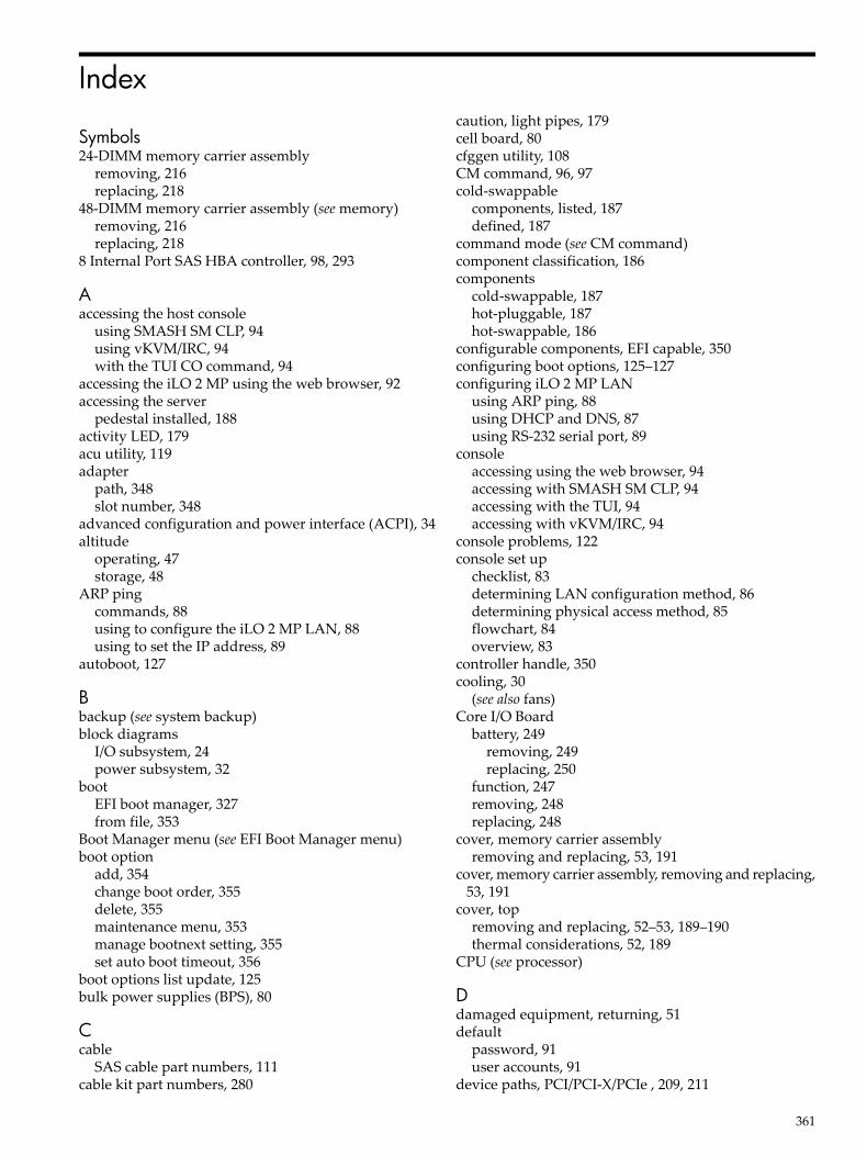
Index
Symbols24-DIMM memory carrier assembly
removing, 216replacing, 218
48-DIMM memory carrier assembly (see memory)removing, 216replacing, 218
8 Internal Port SAS HBA controller, 98, 293
Aaccessing the host console
using SMASH SM CLP, 94using vKVM/IRC, 94with the TUI CO command, 94
accessing the iLO 2 MP using the web browser, 92accessing the server
pedestal installed, 188activity LED, 179acu utility, 119adapter
path, 348slot number, 348
advanced configuration and power interface (ACPI), 34altitude
operating, 47storage, 48
ARP pingcommands, 88using to configure the iLO 2 MP LAN, 88using to set the IP address, 89
autoboot, 127
Bbackup (see system backup)block diagrams
I/O subsystem, 24power subsystem, 32
bootEFI boot manager, 327from file, 353
Boot Manager menu (see EFI Boot Manager menu)boot option
add, 354change boot order, 355delete, 355maintenance menu, 353manage bootnext setting, 355set auto boot timeout, 356
boot options list update, 125bulk power supplies (BPS), 80
Ccable
SAS cable part numbers, 111cable kit part numbers, 280
caution, light pipes, 179cell board, 80cfggen utility, 108CM command, 96, 97cold-swappable
components, listed, 187defined, 187
command mode (see CM command)component classification, 186components
cold-swappable, 187hot-pluggable, 187hot-swappable, 186
configurable components, EFI capable, 350configuring boot options, 125–127configuring iLO 2 MP LAN
using ARP ping, 88using DHCP and DNS, 87using RS-232 serial port, 89
consoleaccessing using the web browser, 94accessing with SMASH SM CLP, 94accessing with the TUI, 94accessing with vKVM/IRC, 94
console problems, 122console set up
checklist, 83determining LAN configuration method, 86determining physical access method, 85flowchart, 84overview, 83
controller handle, 350cooling, 30
(see also fans)Core I/O Board
battery, 249removing, 249replacing, 250
function, 247removing, 248replacing, 248
cover, memory carrier assemblyremoving and replacing, 53, 191
cover, memory carrier assembly, removing and replacing,53, 191
cover, topremoving and replacing, 52–53, 189–190thermal considerations, 52, 189
CPU (see processor)
Ddamaged equipment, returning, 51default
password, 91user accounts, 91
device paths, PCI/PCI-X/PCIe , 209, 211
361

DHCP and DNSusing to configure the iLO 2 MP LAN, 87
DHCP-enabled security risk, 88, 92diagnostic panel, 33
(see also display board)introduction, 33LEDs, 38
dimensionsserver, 45, 46, 47
dimensions and weights, 45dimensions, server, 45, 46, 47DIMM (see memory)disk drive
activity LED, location, 41, 86LEDs, 37–38load order, 57, 201, 202removing, 199replacing, 57, 202slot availability LEDs, 38slot IDs, 58, 201status LED, location, 41, 86status LEDs, 37
disk drive fillerremoving, 198replacing, 198
disk drive filler, removing and replacing, 55display board
functionality, 253introduction, 33removing, 254replacing, 256
drvcfg utility, 100dual-core processing, 73dual-core processing, defined, 230dual-core processor (see processor)DVD, 33
(see also display board)troubleshooting, 121
DVD driveintroduction, 33removing, 215replacing, 216
DVD+RW drive (see DVD drive)
Eebsu utility, 114EFI, 330
capable devicescontroller handles, 349
commands, 328acu, 323, 325cfggen, 309drvcfg, 295, 350, 351ebsu, 320mptutil, 293orca, 323, 324saupdate, 317
configurable components, 350device paths, PCI/PCI-X/PCIe, 209, 211
driver handle, 351info all command, 241POSSE commands, 330SCSI setup utility, 351
EFI Boot Manager menuentry-class servers, 125
EFI commandsinfo io, 278info warning, 278(see also viewing warnings)
EFI driver firmware update, 99emulation device, configuring, 90extender board, memory (see memory carrier assembly)extender board, processor (see processor board assembly)extensible firmware interface (see EFI)external health LEDs, 36
Ffan, hot-swappable
remove, 194replace, 195
fansintroduction, 30N+1, 30removing and replacing, 192
field replaceable unit, FRU list, 268firmware
introduction, 34operating system requirements, 35updating, 276
firmware flashebsu, 320mptutil, 293saupdate, 317
front control panel LEDs, 36front display panel, 33
(see also display board)front panel, functional overview, 35
Ggraphic console, accessing using VGA, 94
Hhandle, controller, 350hard disk drive (see disk drive)hard disk drive modules, 179hard drive problems, 122HBA RISC firmware update, 99, 294HDD (see disk drive)host console (see console)hot-pluggable
components, 187defined, 187
hot-pluggable disk drive (see disk drive)hot-pluggable disk drive filler (see disk drive filler)hot-swappable
components, 186hot-swappable disk drive module, 179hot-swappable fan (see fans)
362 Index

hot-swappable power supply (see power supply)HP Eight Port SAS Host Bus Adapter
completing installation, 281connecting devices, 281installing, 280overview, 280preparation, 280updating firmware, 281
HP Smart Array P400completing installation
HP-UX, 283–285Linux, 285Windows, 285
connecting device, 283controller board installation, 282overview, 282preparation, 282
HP Smart Array P600completing installation, 282connecting to devices, 282controller board installation, 281overview, 281preparation, 281updating firmware, 282
HP Smart Array P800Linux installation, 288–291
completing installation, 290connecting to devices, 289controller board installation, 289preparation, 289
overview, 286Windows installation, 286–288
completing installation, 288connecting to devices, 287controller board installation, 287preparing the server, 286
HP-UXdevice paths, PCI/PCI-X/PCIe, 209, 211
II./O backplane upgrade
checklist, 275I/O backplane (see I/O board assembly)I/O backplane upgrade
overview, 273tools required, 274
I/O board (see I/O board assembly)I/O board assembly
removing, 237replacing, 239
I/O card (see PCI/PCI-X/PCIe cards)I/O cards
verifying, 278I/O paths, 209, 211I/O subsystem, 24
(see also core I/O board)(see also I/O board assembly)block diagram, 24introduction, 23–27
I/O Voltage Regulator Module (see I/O VRM)I/O VRM
function, 243removing, 243replacing, 244
iLO 2 MPcontrols, ports, and LEDs, 41functional overview, 40LAN LEDs, 42LAN link speed LEDs, 42LAN link status LEDs, 42logging in, 90main menu, 91PC command, 96reset button, 41status LEDs, 42
indicators, LED, 179info
adapter path, 348adapter slot number, 348
info commandadapter path, 348adapter slot number, 348
init button function, 36input power, 83installing
a dual-core processor, 73a hot-pluggable disk drive, 57a hot-swappable power supply, 54memory DIMMs, 64
integrated lights-out 2 management processor (see iLO 2MP)
interconnect boardremoving, 260replacing, 261
intermittent server problems, 121internal health LEDs, 36
LLAN core I/O card
link speed LEDs, 42link status LEDs, 42ports, 42removing, 252replacing, 253slot restrictions, 252
LC command, using to configure IP address, 90LEDs, 179
diagnostic panel, 38disk drive, 37DVD activity, 38external health, 36front control panel, 36iLO 2 MP LAN link speed, 42iLO 2 MP LAN link status, 42iLO 2 MP status, 42internal health, 36power button, 36power supply, 43
363

rear panel UID, 44system health, 36UID button, 36
load orderdisk drive, 57, 201, 202memory, 67, 222power supply, 54processor, 74
logging in to the iLO 2 MP, 90
Mmanagement processor (see iLO 2 MP) (see iLO 2 MP)manual retention latch (see MRL)mass storage, 33
(see also SAS)mass storage subsystem (see mass storage)memory
24-DIMM memory board, 6524-DIMM memory board configuration, 67, 22248-DIMM memory carrier assembly slot IDs, 67installation conventions, 66, 221installing, 69, 224introduction, 27load order, 67load order, 24-DIMM memory carrier board, 67, 222load order, 48-DIMM memory carrier assembly, 67,
222removing, 218supported DIMM sizes, 66, 221
memory carrier assemblyremoving, 62, 216replacing, 63, 218
memory extender board (see memory carrier assembly)midplane board
function, 262removing, 262replacing, 265
midplane riser board (see midplane board)MP, 359
(see also iLO 2 MP)MPS optimization (see PCIe MPS optimization)mptutil utility, 98MRL, 211
OOLA, 205
procedures for PCI/PCI-X/PCIe cards, 211OLR, 205
procedures for PCI/PCI-X/PCIe cards, 212requirement, HP-UX, 205
OLX dividers (see PCI/PCI-X/PCIe card divider)Online Addition (see OLA)Online Replacement (see OLR)operating system
booting and shutting down HP-UX, 127booting and shutting down Linux, 138booting and shutting down OpenVMS, 132booting and shutting down Windows, 135boots with problems or does not boot, 121
reinstallation, 273updating, 276
orca utility, 118OS
reinstallation, 274
PPAL, 34password, modifying default, 91PC command, 96PCI card (see PCI/PCI-X/PCIe cards)PCI-X card (see PCI/PCI-X/PCIe cards)PCI/PCI-X/PCIe card divider
locations, 206removing, 203replacing, 204
PCI/PCI-X/PCIe cardsattention LED, 44card divider locations, 59, 206configurations, 59, 205, 206divider locations, 59EFI device path, 209, 211HP-UX device path, 209, 211I/O paths, 209, 211locator LED, 44offline installation, 61, 205, 214offline removal, 205, 213OLA, 205OLR, 205online addition, 211online replacement, 212removing, 204replacing, 204shared slots, bus mode compatibility, 61, 208shared slots, common configuration scenarios, 60, 207shared slots, frequency compatibility, 61, 208shared slots, restrictions, 60, 207slot IDs, 59, 206
PCIe card (see PCI/PCI-X/PCIe cards)PCIe MPS optimization, 26–27
enabling, 27support, 26
PCIe MPS optimizeioconfig command, 336
pedestal, converting from rack mount, 80power
apply standby, 82button, 120full state, defined, 95installing hot-swap power supply, 54introduction, 31off state, defined, 95PR command, 96problems, 120sources, 80standby state, defined, 95states, 80, 95subsystem, 31supply load order, 54
364 Index

supply replacing, 54power button
function, 36LED, 36
power reset command (see PR command)power supplies, removing and replacing, 83power supply
LEDs, 43removing, 196
powering off the server, 96manually, 96using the iLO 2 MP PC command, 96
powering on the server, 96, 97manually, 97using the iLO 2 MP PC command, 97
PR command, 96Pre-OS System Startup Environment (POSSE), 35processor
configuration options, 73, 230installing, 74, 235introduction, 27load order, 74, 230removing, 231required service tools, 74, 231restrictions, 74, 230
Processor Abstraction Layer (see PAL)processor board (see processor board assembly)processor board assembly
removing, 228removing and replacing, 72replacing, 229
Rrack
antitip features, 188extending the server from, 188extension clearance, 188inserting the server into, 188slide kit, 187
rack, installing, 79rack-mount server, accessing, 187rear panel, functional overview, 39remove and replace
PCI/PCI-X/PCIe cards, 58reset button, iLO 2 MP, 41RS-232 serial port, using to configure the iLO 2 MP LAN,
89
Ssafety information, 186, 274safety information, general, 49SAS
backplane boardremoving, 258replacing, 259
core I/O cardremoving, 251replacing, 252
core I/O card, supported card types, 250
features and capabilities, 257sas controller, 98SAS core I/O card
slot restrictions, 251saupdate utility, 111SCSI
setup utility, 347specifying parameters, 347
SCSI adapterpath, 348
securityaccess settings, 92risk with DHCP enabled, 92setting up, 92
serial attached SCSI (see SAS)service tools, 185smart array P400 controller, 110, 316smart array P600 controller, 110, 316smart array P800 controller, 110, 316static IP address
assigning with ARP Ping, 88assigning with LC command, 89
storage (see mass storage)system abstraction layer (SAL), 34system backup, 277system battery
recording configuration settings, 241removing, 241replacing, 243resetting system settings, 243
system configuration menu, 358system fans (see fans)system health LEDs, 36
Ttop cover (see cover, top)TPM
function, 244removing, 245replacing, 246
troubleshootingconsole problems, 122hard drive problems, 122methodology, 119operating system, 121
Trusted Platform Module (see TPM)trusted platform module (TPM)
enabling, 123introduction, 123
Trusted Platform Module (TPM), enabling, 122
UUID button
function, 36LED, 36
unpacking, inspecting for damage, 50user accounts, modifying default, 91
365
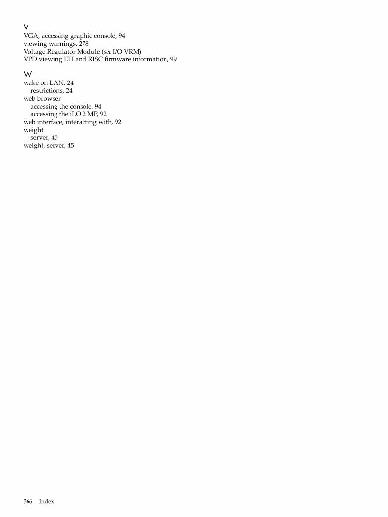
VVGA, accessing graphic console, 94viewing warnings, 278Voltage Regulator Module (see I/O VRM)VPD viewing EFI and RISC firmware information, 99
Wwake on LAN, 24
restrictions, 24web browser
accessing the console, 94accessing the iLO 2 MP, 92
web interface, interacting with, 92weight
server, 45weight, server, 45
366 Index
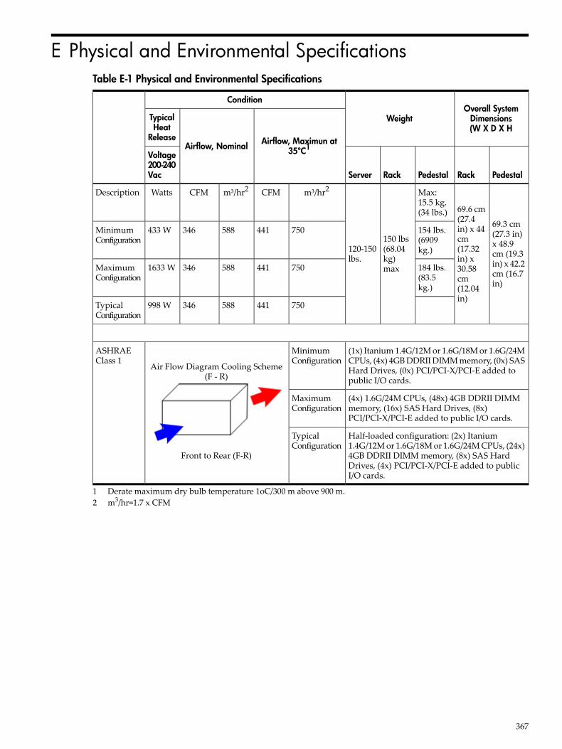
E Physical and Environmental SpecificationsTable E-1 Physical and Environmental Specifications
Overall SystemDimensions(W X D X H
Weight
Condition
Airflow, Maximun at35ºC1Airflow, Nominal
TypicalHeat
Release
PedestalRackPedestalRackServer
Voltage200-240Vac
69.3 cm(27.3 in)x 48.9cm (19.3in) x 42.2cm (16.7in)
69.6 cm(27.4in) x 44cm(17.32in) x30.58cm(12.04in)
Max:15.5 kg.(34 lbs.)
150 lbs(68.04kg)max
120-150lbs.
m³/hr2CFMm³/hr2CFMWattsDescription
154 lbs.(6909kg.)
750441588346433 WMinimumConfiguration
184 lbs.(83.5kg.)
7504415883461633 WMaximumConfiguration
750441588346998 WTypicalConfiguration
(1x) Itanium 1.4G/12M or 1.6G/18M or 1.6G/24MCPUs, (4x) 4GB DDRII DIMM memory, (0x) SASHard Drives, (0x) PCI/PCI-X/PCI-E added topublic I/O cards.
MinimumConfiguration
Air Flow Diagram Cooling Scheme(F - R)
Front to Rear (F-R)
ASHRAEClass 1
(4x) 1.6G/24M CPUs, (48x) 4GB DDRII DIMMmemory, (16x) SAS Hard Drives, (8x)PCI/PCI-X/PCI-E added to public I/O cards.
MaximumConfiguration
Half-loaded configuration: (2x) Itanium1.4G/12M or 1.6G/18M or 1.6G/24M CPUs, (24x)4GB DDRII DIMM memory, (8x) SAS HardDrives, (4x) PCI/PCI-X/PCI-E added to publicI/O cards.
TypicalConfiguration
1 Derate maximum dry bulb temperature 1oC/300 m above 900 m.2 m3/hr=1.7 x CFM
367
Related Documents