HP ENVY 15 Maintenance and Service Guide Document Part Number: 577090-001 September 2009 This guide is a troubleshooting reference used for maintaining and servicing the computer. It provides comprehensive information on identifying computer features, components, and spare parts; troubleshooting computer problems; and performing computer disassembly procedures.

Welcome message from author
This document is posted to help you gain knowledge. Please leave a comment to let me know what you think about it! Share it to your friends and learn new things together.
Transcript

HP ENVY 15Maintenance and Service Guide
Document Part Number: 577090-001
September 2009
This guide is a troubleshooting reference used for maintaining and servicing the computer. It provides comprehensive information on identifying computer features, components, and spare parts; troubleshooting computer problems; and performing computer disassembly procedures.

© Copyright 2009 Hewlett-Packard Development Company, L.P.
ATI and ATI Mobility Radeon are trademarks of Advanced Micro Devices, Inc. Bluetooth is a trademark owned by its proprietor and used by Hewlett-Packard Company under license. Intel and Core are trademarks of Intel Corporation in the U.S. and other countries. Microsoft and Windows are U.S. registered trademarks of Microsoft Corporation. SD Logo is a trademark of its proprietor.
The information contained herein is subject to change without notice. The only warranties for HP products and services are set forth in the express warranty statements accompanying such products and services. Nothing herein should be construed as constituting an additional warranty. HP shall not be liable for technical or editorial errors or omissions contained herein.
First Edition: September 2009Document Part Number: 577090-001

Safety warning notice
ÅWARNING: To reduce the possibility of heat-related injuries or of overheating the computer, do not place the computer directly on your lap or obstruct the computer air vents. Use the computer only on a hard, flat surface. Do not allow another hard surface, such as an adjoining optional printer, or a soft surface, such as pillows or rugs or clothing, to block airflow. Also, do not allow the AC adapter to contact the skin or a soft surface, such as pillows or rugs or clothing, during operation. The computer and the AC adapter comply with the user-accessible surface temperature limits defined by the International Standard for Safety of Information Technology Equipment (IEC 60950).
Contents
1 Product description
2 External component identification
Identifying hardware . . . . . . . . . . . . . . . . . . . . . . . . . . . . . . . . . . . . . . . . . . . . . . . . . . . . . . . . . . . . . . . . . . 2–1Top components . . . . . . . . . . . . . . . . . . . . . . . . . . . . . . . . . . . . . . . . . . . . . . . . . . . . . . . . . . . . . . . . . . . . . . 2–2
Display components . . . . . . . . . . . . . . . . . . . . . . . . . . . . . . . . . . . . . . . . . . . . . . . . . . . . . . . . . . . . . . . 2–2Button . . . . . . . . . . . . . . . . . . . . . . . . . . . . . . . . . . . . . . . . . . . . . . . . . . . . . . . . . . . . . . . . . . . . . . . . . . 2–3Keys . . . . . . . . . . . . . . . . . . . . . . . . . . . . . . . . . . . . . . . . . . . . . . . . . . . . . . . . . . . . . . . . . . . . . . . . . . . 2–4Lights . . . . . . . . . . . . . . . . . . . . . . . . . . . . . . . . . . . . . . . . . . . . . . . . . . . . . . . . . . . . . . . . . . . . . . . . . . 2–5TouchPad . . . . . . . . . . . . . . . . . . . . . . . . . . . . . . . . . . . . . . . . . . . . . . . . . . . . . . . . . . . . . . . . . . . . . . . 2–6TouchPad buttons . . . . . . . . . . . . . . . . . . . . . . . . . . . . . . . . . . . . . . . . . . . . . . . . . . . . . . . . . . . . . . . . . 2–7
Front components. . . . . . . . . . . . . . . . . . . . . . . . . . . . . . . . . . . . . . . . . . . . . . . . . . . . . . . . . . . . . . . . . . . . . 2–8Left-side components . . . . . . . . . . . . . . . . . . . . . . . . . . . . . . . . . . . . . . . . . . . . . . . . . . . . . . . . . . . . . . . . . . 2–8Right-side components. . . . . . . . . . . . . . . . . . . . . . . . . . . . . . . . . . . . . . . . . . . . . . . . . . . . . . . . . . . . . . . . . 2–9Bottom components . . . . . . . . . . . . . . . . . . . . . . . . . . . . . . . . . . . . . . . . . . . . . . . . . . . . . . . . . . . . . . . . . . 2–10
3 Illustrated parts catalog
Service tag . . . . . . . . . . . . . . . . . . . . . . . . . . . . . . . . . . . . . . . . . . . . . . . . . . . . . . . . . . . . . . . . . . . . . . . . . . 3–1Computer major components . . . . . . . . . . . . . . . . . . . . . . . . . . . . . . . . . . . . . . . . . . . . . . . . . . . . . . . . . . . . 3–3Display components . . . . . . . . . . . . . . . . . . . . . . . . . . . . . . . . . . . . . . . . . . . . . . . . . . . . . . . . . . . . . . . . . . . 3–9Mass storage devices . . . . . . . . . . . . . . . . . . . . . . . . . . . . . . . . . . . . . . . . . . . . . . . . . . . . . . . . . . . . . . . . . 3–11Miscellaneous parts . . . . . . . . . . . . . . . . . . . . . . . . . . . . . . . . . . . . . . . . . . . . . . . . . . . . . . . . . . . . . . . . . . 3–13Sequential part number listing . . . . . . . . . . . . . . . . . . . . . . . . . . . . . . . . . . . . . . . . . . . . . . . . . . . . . . . . . . 3–14
4 Removal and replacement procedures
Preliminary replacement requirements . . . . . . . . . . . . . . . . . . . . . . . . . . . . . . . . . . . . . . . . . . . . . . . . . . . . 4–1Tools required . . . . . . . . . . . . . . . . . . . . . . . . . . . . . . . . . . . . . . . . . . . . . . . . . . . . . . . . . . . . . . . . . . . . 4–1Service considerations. . . . . . . . . . . . . . . . . . . . . . . . . . . . . . . . . . . . . . . . . . . . . . . . . . . . . . . . . . . . . . 4–1Grounding guidelines . . . . . . . . . . . . . . . . . . . . . . . . . . . . . . . . . . . . . . . . . . . . . . . . . . . . . . . . . . . . . . 4–2
Service tag . . . . . . . . . . . . . . . . . . . . . . . . . . . . . . . . . . . . . . . . . . . . . . . . . . . . . . . . . . . . . . . . . . . . . . . . . . 4–5Component replacement procedures . . . . . . . . . . . . . . . . . . . . . . . . . . . . . . . . . . . . . . . . . . . . . . . . . . . . . . 4–6
Computer feet . . . . . . . . . . . . . . . . . . . . . . . . . . . . . . . . . . . . . . . . . . . . . . . . . . . . . . . . . . . . . . . . . . . . 4–6Battery. . . . . . . . . . . . . . . . . . . . . . . . . . . . . . . . . . . . . . . . . . . . . . . . . . . . . . . . . . . . . . . . . . . . . . . . . . 4–7Expansion memory module . . . . . . . . . . . . . . . . . . . . . . . . . . . . . . . . . . . . . . . . . . . . . . . . . . . . . . . . . 4–8Top cover . . . . . . . . . . . . . . . . . . . . . . . . . . . . . . . . . . . . . . . . . . . . . . . . . . . . . . . . . . . . . . . . . . . . . . 4–10Keyboard. . . . . . . . . . . . . . . . . . . . . . . . . . . . . . . . . . . . . . . . . . . . . . . . . . . . . . . . . . . . . . . . . . . . . . . 4–12Speaker assembly . . . . . . . . . . . . . . . . . . . . . . . . . . . . . . . . . . . . . . . . . . . . . . . . . . . . . . . . . . . . . . . . 4–14Primary memory module . . . . . . . . . . . . . . . . . . . . . . . . . . . . . . . . . . . . . . . . . . . . . . . . . . . . . . . . . . 4–15WLAN module . . . . . . . . . . . . . . . . . . . . . . . . . . . . . . . . . . . . . . . . . . . . . . . . . . . . . . . . . . . . . . . . . . 4–16RTC battery. . . . . . . . . . . . . . . . . . . . . . . . . . . . . . . . . . . . . . . . . . . . . . . . . . . . . . . . . . . . . . . . . . . . . 4–19Hard drive . . . . . . . . . . . . . . . . . . . . . . . . . . . . . . . . . . . . . . . . . . . . . . . . . . . . . . . . . . . . . . . . . . . . . . 4–20
Maintenance and Service Guide iv
Contents
Processor fan/heat sink assembly . . . . . . . . . . . . . . . . . . . . . . . . . . . . . . . . . . . . . . . . . . . . . . . . . . . . 4–22Processor . . . . . . . . . . . . . . . . . . . . . . . . . . . . . . . . . . . . . . . . . . . . . . . . . . . . . . . . . . . . . . . . . . . . . . . 4–24Power button board and cable. . . . . . . . . . . . . . . . . . . . . . . . . . . . . . . . . . . . . . . . . . . . . . . . . . . . . . . 4–25Power connector cable . . . . . . . . . . . . . . . . . . . . . . . . . . . . . . . . . . . . . . . . . . . . . . . . . . . . . . . . . . . . 4–26Video fan/heat sink assembly . . . . . . . . . . . . . . . . . . . . . . . . . . . . . . . . . . . . . . . . . . . . . . . . . . . . . . . 4–27System board. . . . . . . . . . . . . . . . . . . . . . . . . . . . . . . . . . . . . . . . . . . . . . . . . . . . . . . . . . . . . . . . . . . . 4–29Display assembly . . . . . . . . . . . . . . . . . . . . . . . . . . . . . . . . . . . . . . . . . . . . . . . . . . . . . . . . . . . . . . . . 4–33
5 Setup Utility (BIOS)
Starting Setup Utility . . . . . . . . . . . . . . . . . . . . . . . . . . . . . . . . . . . . . . . . . . . . . . . . . . . . . . . . . . . . . . . . . . 5–1Using Setup Utility. . . . . . . . . . . . . . . . . . . . . . . . . . . . . . . . . . . . . . . . . . . . . . . . . . . . . . . . . . . . . . . . . . . . 5–1
Changing the language of Setup Utility . . . . . . . . . . . . . . . . . . . . . . . . . . . . . . . . . . . . . . . . . . . . . . . . 5–1Navigating and selecting in Setup Utility . . . . . . . . . . . . . . . . . . . . . . . . . . . . . . . . . . . . . . . . . . . . . . . 5–2Displaying system information . . . . . . . . . . . . . . . . . . . . . . . . . . . . . . . . . . . . . . . . . . . . . . . . . . . . . . . 5–2Restoring default settings in Setup Utility . . . . . . . . . . . . . . . . . . . . . . . . . . . . . . . . . . . . . . . . . . . . . . 5–2Exiting Setup Utility . . . . . . . . . . . . . . . . . . . . . . . . . . . . . . . . . . . . . . . . . . . . . . . . . . . . . . . . . . . . . . . 5–3
Setup Utility menus . . . . . . . . . . . . . . . . . . . . . . . . . . . . . . . . . . . . . . . . . . . . . . . . . . . . . . . . . . . . . . . . . . . 5–3Main menu . . . . . . . . . . . . . . . . . . . . . . . . . . . . . . . . . . . . . . . . . . . . . . . . . . . . . . . . . . . . . . . . . . . . . . 5–3Security menu . . . . . . . . . . . . . . . . . . . . . . . . . . . . . . . . . . . . . . . . . . . . . . . . . . . . . . . . . . . . . . . . . . . . 5–3System Configuration menu . . . . . . . . . . . . . . . . . . . . . . . . . . . . . . . . . . . . . . . . . . . . . . . . . . . . . . . . . 5–4Diagnostics menu . . . . . . . . . . . . . . . . . . . . . . . . . . . . . . . . . . . . . . . . . . . . . . . . . . . . . . . . . . . . . . . . . 5–4
Updating the BIOS. . . . . . . . . . . . . . . . . . . . . . . . . . . . . . . . . . . . . . . . . . . . . . . . . . . . . . . . . . . . . . . . . . . . 5–5Updating the BIOS . . . . . . . . . . . . . . . . . . . . . . . . . . . . . . . . . . . . . . . . . . . . . . . . . . . . . . . . . . . . . . . . 5–5
6 Specifications
Computer specifications. . . . . . . . . . . . . . . . . . . . . . . . . . . . . . . . . . . . . . . . . . . . . . . . . . . . . . . . . . . . . . . . 6–115.6-in display specifications. . . . . . . . . . . . . . . . . . . . . . . . . . . . . . . . . . . . . . . . . . . . . . . . . . . . . . . . . . . . 6–2Hard drive specifications . . . . . . . . . . . . . . . . . . . . . . . . . . . . . . . . . . . . . . . . . . . . . . . . . . . . . . . . . . . . . . . 6–3
9.5-mm, 2.5-in hard drive . . . . . . . . . . . . . . . . . . . . . . . . . . . . . . . . . . . . . . . . . . . . . . . . . . . . . . . . . . . 6–38.0-mm, 1.8-in hard drive . . . . . . . . . . . . . . . . . . . . . . . . . . . . . . . . . . . . . . . . . . . . . . . . . . . . . . . . . . . 6–4
Blu-ray ROM DVD±R/RW SuperMulti Double-Layer Drive specifications . . . . . . . . . . . . . . . . . . . . . . . 6–5DVD±RW and CD-RW SuperMulti Double-Layer Combo Drive specifications. . . . . . . . . . . . . . . . . . . . 6–6System DMA specifications. . . . . . . . . . . . . . . . . . . . . . . . . . . . . . . . . . . . . . . . . . . . . . . . . . . . . . . . . . . . . 6–7System memory map specifications. . . . . . . . . . . . . . . . . . . . . . . . . . . . . . . . . . . . . . . . . . . . . . . . . . . . . . . 6–7System interrupt specifications . . . . . . . . . . . . . . . . . . . . . . . . . . . . . . . . . . . . . . . . . . . . . . . . . . . . . . . . . . 6–8System I/O address specifications . . . . . . . . . . . . . . . . . . . . . . . . . . . . . . . . . . . . . . . . . . . . . . . . . . . . . . . . 6–9
7 Screw listing
Phillips PM2.0×4.0 screw . . . . . . . . . . . . . . . . . . . . . . . . . . . . . . . . . . . . . . . . . . . . . . . . . . . . . . . . . . . . . . 7–1Phillips PM2.0×12.0 screw . . . . . . . . . . . . . . . . . . . . . . . . . . . . . . . . . . . . . . . . . . . . . . . . . . . . . . . . . . . . . 7–3Phillips PM2.0×5.0 screw . . . . . . . . . . . . . . . . . . . . . . . . . . . . . . . . . . . . . . . . . . . . . . . . . . . . . . . . . . . . . . 7–4Phillips PM2.0×2.0 screw . . . . . . . . . . . . . . . . . . . . . . . . . . . . . . . . . . . . . . . . . . . . . . . . . . . . . . . . . . . . . . 7–5Phillips PM1.5×1.5 screw . . . . . . . . . . . . . . . . . . . . . . . . . . . . . . . . . . . . . . . . . . . . . . . . . . . . . . . . . . . . . . 7–6Phillips PM2.0×4.0 broadhead screw . . . . . . . . . . . . . . . . . . . . . . . . . . . . . . . . . . . . . . . . . . . . . . . . . . . . . 7–7Phillips PM3.0×4.0 screw . . . . . . . . . . . . . . . . . . . . . . . . . . . . . . . . . . . . . . . . . . . . . . . . . . . . . . . . . . . . . . 7–8Phillips PM2.0×6.0 captive screw . . . . . . . . . . . . . . . . . . . . . . . . . . . . . . . . . . . . . . . . . . . . . . . . . . . . . . . . 7–9Phillips PM2.0×3.0 screw . . . . . . . . . . . . . . . . . . . . . . . . . . . . . . . . . . . . . . . . . . . . . . . . . . . . . . . . . . . . . 7–10Phillips PM2.5×6.0 screw . . . . . . . . . . . . . . . . . . . . . . . . . . . . . . . . . . . . . . . . . . . . . . . . . . . . . . . . . . . . . 7–13
v Maintenance and Service Guide
Contents
8 Backup and recovery
Creating recovery discs . . . . . . . . . . . . . . . . . . . . . . . . . . . . . . . . . . . . . . . . . . . . . . . . . . . . . . . . . . . . . . . . 8–2Backing up your information . . . . . . . . . . . . . . . . . . . . . . . . . . . . . . . . . . . . . . . . . . . . . . . . . . . . . . . . . . . . 8–3
Using Windows Backup and Restore . . . . . . . . . . . . . . . . . . . . . . . . . . . . . . . . . . . . . . . . . . . . . . . . . . 8–4Using system restore points . . . . . . . . . . . . . . . . . . . . . . . . . . . . . . . . . . . . . . . . . . . . . . . . . . . . . . . . . 8–4
Performing a recovery . . . . . . . . . . . . . . . . . . . . . . . . . . . . . . . . . . . . . . . . . . . . . . . . . . . . . . . . . . . . . . . . . 8–5Recovering from the recovery discs . . . . . . . . . . . . . . . . . . . . . . . . . . . . . . . . . . . . . . . . . . . . . . . . . . . 8–6
9 Connector pin assignments
Audio-in (microphone). . . . . . . . . . . . . . . . . . . . . . . . . . . . . . . . . . . . . . . . . . . . . . . . . . . . . . . . . . . . . . . . . 9–1Audio-out (headphone) . . . . . . . . . . . . . . . . . . . . . . . . . . . . . . . . . . . . . . . . . . . . . . . . . . . . . . . . . . . . . . . . 9–1HDMI . . . . . . . . . . . . . . . . . . . . . . . . . . . . . . . . . . . . . . . . . . . . . . . . . . . . . . . . . . . . . . . . . . . . . . . . . . . . . . 9–2RJ-45 (network) . . . . . . . . . . . . . . . . . . . . . . . . . . . . . . . . . . . . . . . . . . . . . . . . . . . . . . . . . . . . . . . . . . . . . . 9–3Universal Serial Bus. . . . . . . . . . . . . . . . . . . . . . . . . . . . . . . . . . . . . . . . . . . . . . . . . . . . . . . . . . . . . . . . . . . 9–4
10Power cord set requirements
Requirements for all countries and regions . . . . . . . . . . . . . . . . . . . . . . . . . . . . . . . . . . . . . . . . . . . . . . . . 10–1Requirements for specific countries and regions . . . . . . . . . . . . . . . . . . . . . . . . . . . . . . . . . . . . . . . . . . . . 10–2
11Recycling
Battery . . . . . . . . . . . . . . . . . . . . . . . . . . . . . . . . . . . . . . . . . . . . . . . . . . . . . . . . . . . . . . . . . . . . . . . . . . . . 11–1Display . . . . . . . . . . . . . . . . . . . . . . . . . . . . . . . . . . . . . . . . . . . . . . . . . . . . . . . . . . . . . . . . . . . . . . . . . . . . 11–1
Index
Maintenance and Service Guide vi
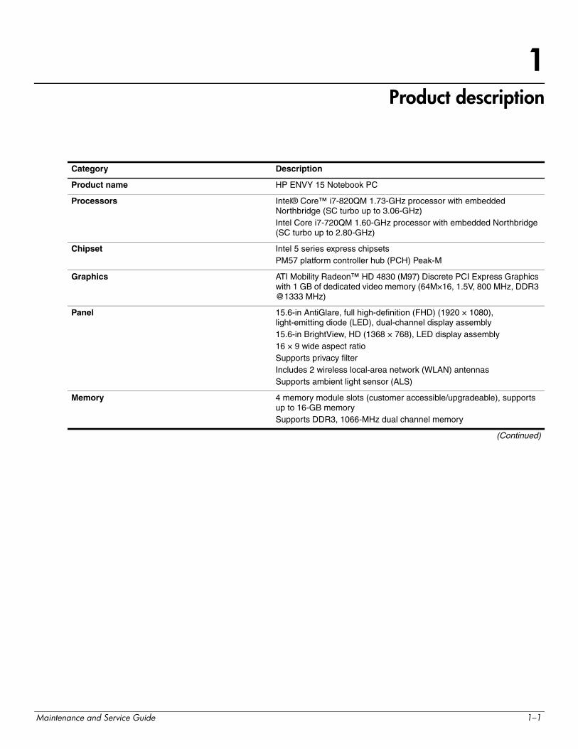
1Product description
Category Description
Product name HP ENVY 15 Notebook PC
Processors Intel® Core™ i7-820QM 1.73-GHz processor with embedded Northbridge (SC turbo up to 3.06-GHz)Intel Core i7-720QM 1.60-GHz processor with embedded Northbridge (SC turbo up to 2.80-GHz)
Chipset Intel 5 series express chipsetsPM57 platform controller hub (PCH) Peak-M
Graphics ATI Mobility Radeon™ HD 4830 (M97) Discrete PCI Express Graphics with 1 GB of dedicated video memory (64M×16, 1.5V, 800 MHz, DDR3 @1333 MHz)
Panel 15.6-in AntiGlare, full high-definition (FHD) (1920 × 1080), light-emitting diode (LED), dual-channel display assembly15.6-in BrightView, HD (1368 × 768), LED display assembly16 × 9 wide aspect ratioSupports privacy filterIncludes 2 wireless local-area network (WLAN) antennasSupports ambient light sensor (ALS)
Memory 4 memory module slots (customer accessible/upgradeable), supports up to 16-GB memorySupports DDR3, 1066-MHz dual channel memory
(Continued)
Maintenance and Service Guide 1–1
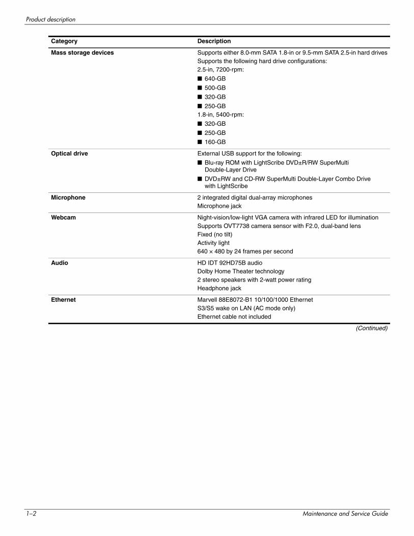
Product description
Mass storage devices Supports either 8.0-mm SATA 1.8-in or 9.5-mm SATA 2.5-in hard drivesSupports the following hard drive configurations:2.5-in, 7200-rpm:
■ 640-GB
■ 500-GB
■ 320-GB
■ 250-GB1.8-in, 5400-rpm:
■ 320-GB
■ 250-GB
■ 160-GB
Optical drive External USB support for the following:
■ Blu-ray ROM with LightScribe DVD±R/RW SuperMulti Double-Layer Drive
■ DVD±RW and CD-RW SuperMulti Double-Layer Combo Drive with LightScribe
Microphone 2 integrated digital dual-array microphonesMicrophone jack
Webcam Night-vision/low-light VGA camera with infrared LED for illuminationSupports OVT7738 camera sensor with F2.0, dual-band lensFixed (no tilt)Activity light640 × 480 by 24 frames per second
Audio HD IDT 92HD75B audioDolby Home Theater technology 2 stereo speakers with 2-watt power ratingHeadphone jack
Ethernet Marvell 88E8072-B1 10/100/1000 EthernetS3/S5 wake on LAN (AC mode only)Ethernet cable not included
(Continued)
Category Description
1–2 Maintenance and Service Guide
Product description
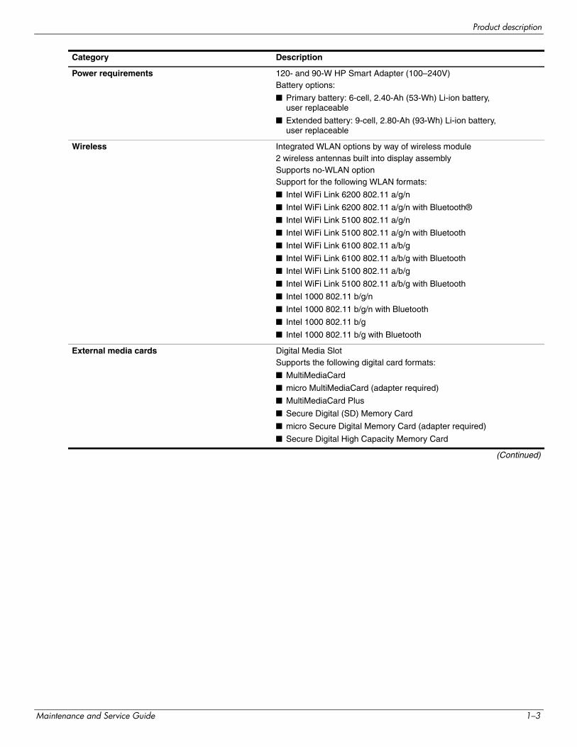
Power requirements 120- and 90-W HP Smart Adapter (100–240V)Battery options:
■ Primary battery: 6-cell, 2.40-Ah (53-Wh) Li-ion battery, user replaceable
■ Extended battery: 9-cell, 2.80-Ah (93-Wh) Li-ion battery, user replaceable
Wireless Integrated WLAN options by way of wireless module2 wireless antennas built into display assemblySupports no-WLAN optionSupport for the following WLAN formats:
■ Intel WiFi Link 6200 802.11 a/g/n
■ Intel WiFi Link 6200 802.11 a/g/n with Bluetooth®
■ Intel WiFi Link 5100 802.11 a/g/n
■ Intel WiFi Link 5100 802.11 a/g/n with Bluetooth
■ Intel WiFi Link 6100 802.11 a/b/g
■ Intel WiFi Link 6100 802.11 a/b/g with Bluetooth
■ Intel WiFi Link 5100 802.11 a/b/g
■ Intel WiFi Link 5100 802.11 a/b/g with Bluetooth
■ Intel 1000 802.11 b/g/n
■ Intel 1000 802.11 b/g/n with Bluetooth
■ Intel 1000 802.11 b/g
■ Intel 1000 802.11 b/g with Bluetooth
External media cards Digital Media SlotSupports the following digital card formats:
■ MultiMediaCard
■ micro MultiMediaCard (adapter required)
■ MultiMediaCard Plus
■ Secure Digital (SD) Memory Card
■ micro Secure Digital Memory Card (adapter required)
■ Secure Digital High Capacity Memory Card
(Continued)
Category Description
Maintenance and Service Guide 1–3
Product description
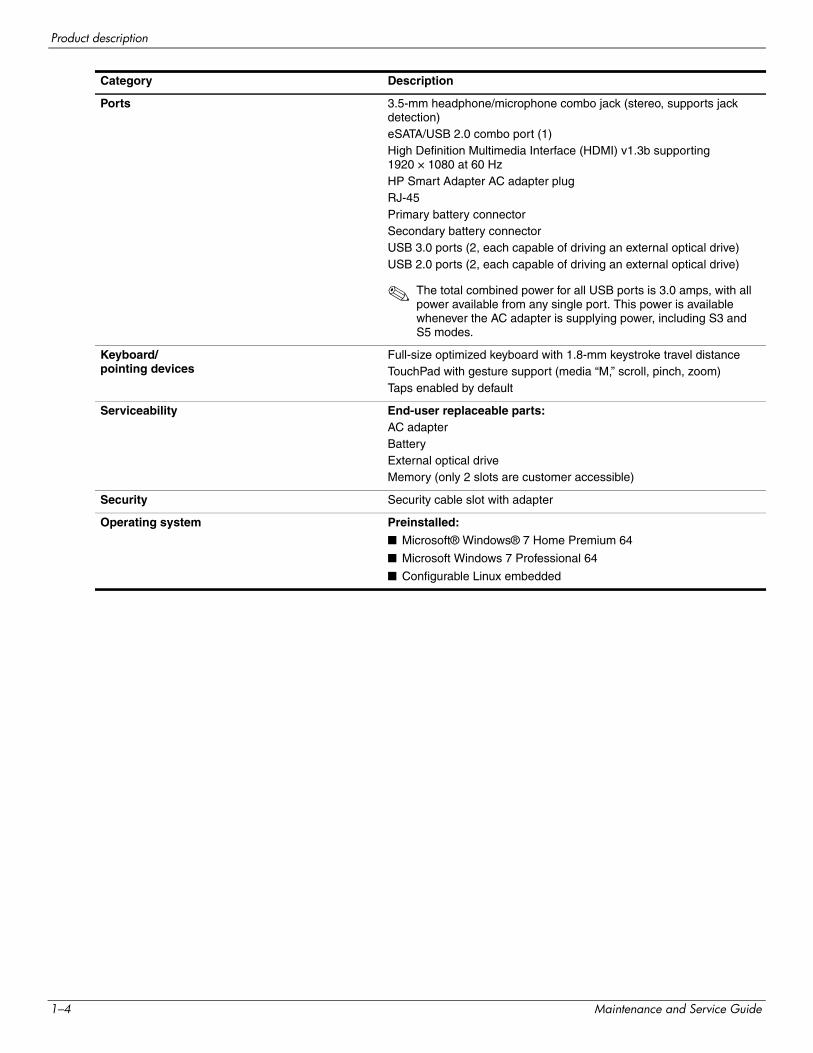
Ports 3.5-mm headphone/microphone combo jack (stereo, supports jack detection)eSATA/USB 2.0 combo port (1)High Definition Multimedia Interface (HDMI) v1.3b supporting 1920 × 1080 at 60 HzHP Smart Adapter AC adapter plugRJ-45Primary battery connectorSecondary battery connectorUSB 3.0 ports (2, each capable of driving an external optical drive)USB 2.0 ports (2, each capable of driving an external optical drive)
✎ The total combined power for all USB ports is 3.0 amps, with all power available from any single port. This power is available whenever the AC adapter is supplying power, including S3 and S5 modes.
Keyboard/pointing devices
Full-size optimized keyboard with 1.8-mm keystroke travel distanceTouchPad with gesture support (media “M,” scroll, pinch, zoom)Taps enabled by default
Serviceability End-user replaceable parts:AC adapterBatteryExternal optical driveMemory (only 2 slots are customer accessible)
Security Security cable slot with adapter
Operating system Preinstalled:
■ Microsoft® Windows® 7 Home Premium 64
■ Microsoft Windows 7 Professional 64
■ Configurable Linux embedded
Category Description
1–4 Maintenance and Service Guide
2External component identification
Identifying hardware
Components included with the computer may vary by region and model. The illustrations in this chapter identify the standard features on most computer models.
To see a list of hardware installed in the computer:
» Select Start > Control Panel > System and Security. Then in the System area, click Device Manager.
You can also add hardware or modify device configurations using Device Manager.
✎ Windows includes the User Account Control feature to improve the security of your computer. You may be prompted for your permission or password for tasks such as installing software, running utilities, or changing Windows settings. Refer to Help and Support for more information.
Maintenance and Service Guide 2–1
External component identification
Top components
Display components
Item Component Description
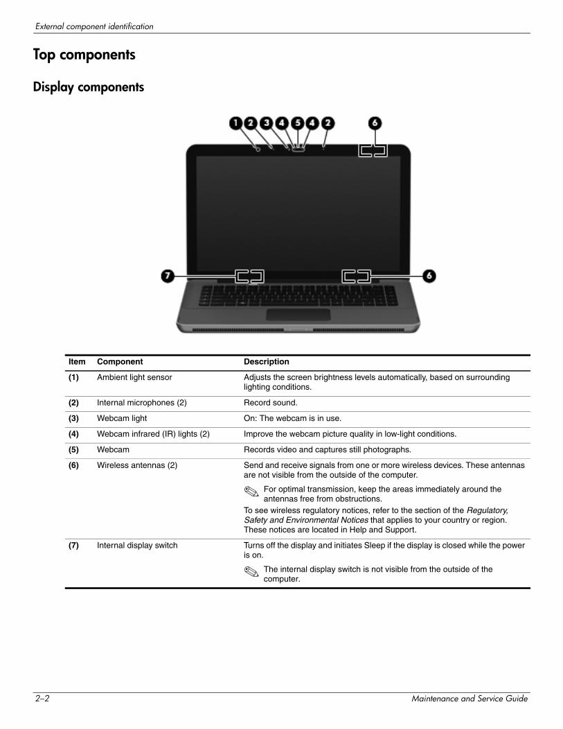
(1) Ambient light sensor Adjusts the screen brightness levels automatically, based on surrounding lighting conditions.
(2) Internal microphones (2) Record sound.
(3) Webcam light On: The webcam is in use.
(4) Webcam infrared (IR) lights (2) Improve the webcam picture quality in low-light conditions.
(5) Webcam Records video and captures still photographs.
(6) Wireless antennas (2) Send and receive signals from one or more wireless devices. These antennas are not visible from the outside of the computer.
✎ For optimal transmission, keep the areas immediately around the antennas free from obstructions.
To see wireless regulatory notices, refer to the section of the Regulatory, Safety and Environmental Notices that applies to your country or region. These notices are located in Help and Support.
(7) Internal display switch Turns off the display and initiates Sleep if the display is closed while the power is on.
✎ The internal display switch is not visible from the outside of the computer.
2–2 Maintenance and Service Guide
External component identification
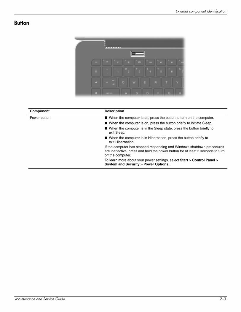
Button
Component Description
Power button ■ When the computer is off, press the button to turn on the computer.
■ When the computer is on, press the button briefly to initiate Sleep.
■ When the computer is in the Sleep state, press the button briefly to exit Sleep.
■ When the computer is in Hibernation, press the button briefly to exit Hibernation.
If the computer has stopped responding and Windows shutdown procedures are ineffective, press and hold the power button for at least 5 seconds to turn off the computer.To learn more about your power settings, select Start > Control Panel > System and Security > Power Options.
Maintenance and Service Guide 2–3
External component identification
Keys
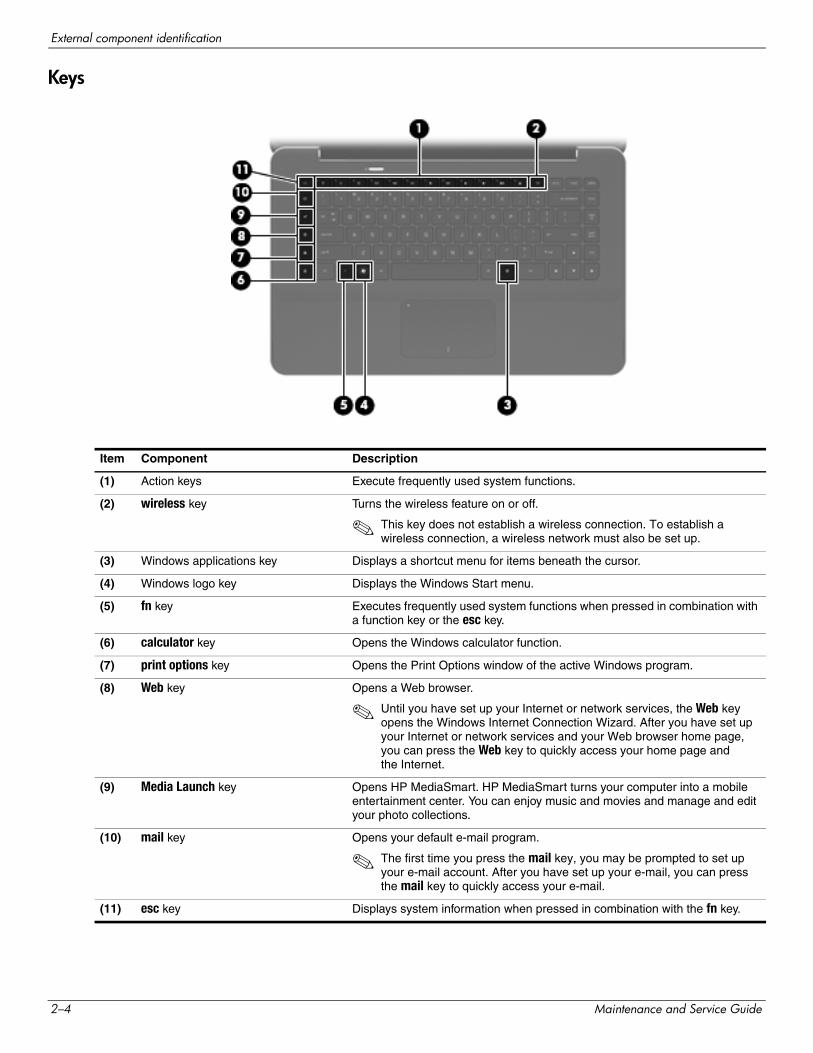
Item Component Description
(1) Action keys Execute frequently used system functions.
(2) wireless key Turns the wireless feature on or off.
✎ This key does not establish a wireless connection. To establish a wireless connection, a wireless network must also be set up.
(3) Windows applications key Displays a shortcut menu for items beneath the cursor.
(4) Windows logo key Displays the Windows Start menu.
(5) fn key Executes frequently used system functions when pressed in combination with a function key or the esc key.
(6) calculator key Opens the Windows calculator function.
(7) print options key Opens the Print Options window of the active Windows program.
(8) Web key Opens a Web browser.
✎ Until you have set up your Internet or network services, the Web key opens the Windows Internet Connection Wizard. After you have set up your Internet or network services and your Web browser home page, you can press the Web key to quickly access your home page and the Internet.
(9) Media Launch key Opens HP MediaSmart. HP MediaSmart turns your computer into a mobile entertainment center. You can enjoy music and movies and manage and edit your photo collections.
(10) mail key Opens your default e-mail program.
✎ The first time you press the mail key, you may be prompted to set up your e-mail account. After you have set up your e-mail, you can press the mail key to quickly access your e-mail.
(11) esc key Displays system information when pressed in combination with the fn key.
2–4 Maintenance and Service Guide
External component identification
Lights
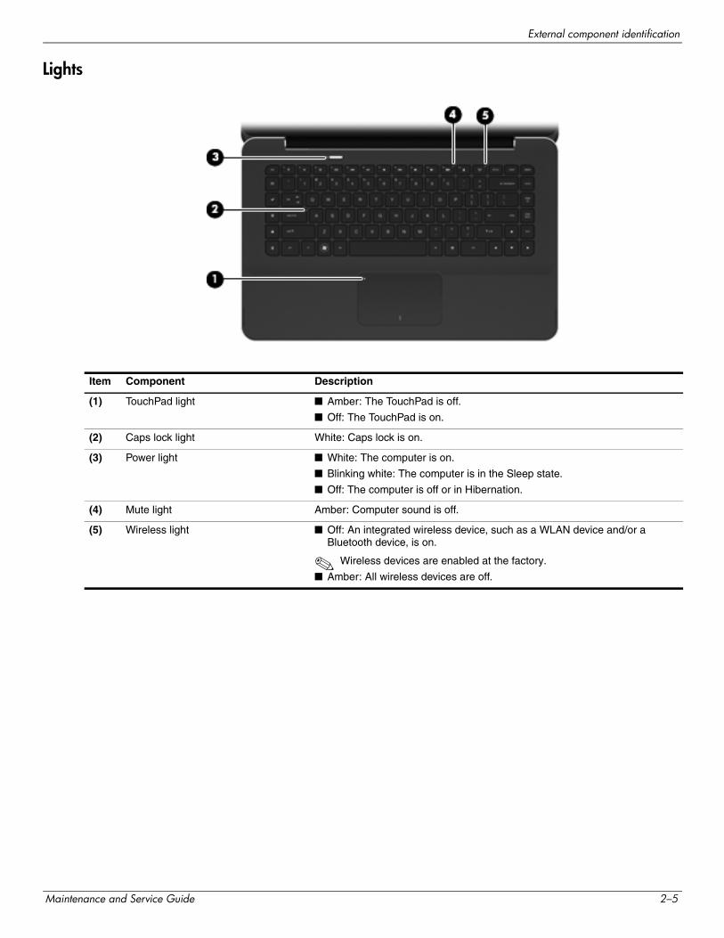
Item Component Description
(1) TouchPad light ■ Amber: The TouchPad is off.
■ Off: The TouchPad is on.
(2) Caps lock light White: Caps lock is on.
(3) Power light ■ White: The computer is on.
■ Blinking white: The computer is in the Sleep state.
■ Off: The computer is off or in Hibernation.
(4) Mute light Amber: Computer sound is off.
(5) Wireless light ■ Off: An integrated wireless device, such as a WLAN device and/or a Bluetooth device, is on.
✎ Wireless devices are enabled at the factory.
■ Amber: All wireless devices are off.
Maintenance and Service Guide 2–5
External component identification
TouchPad
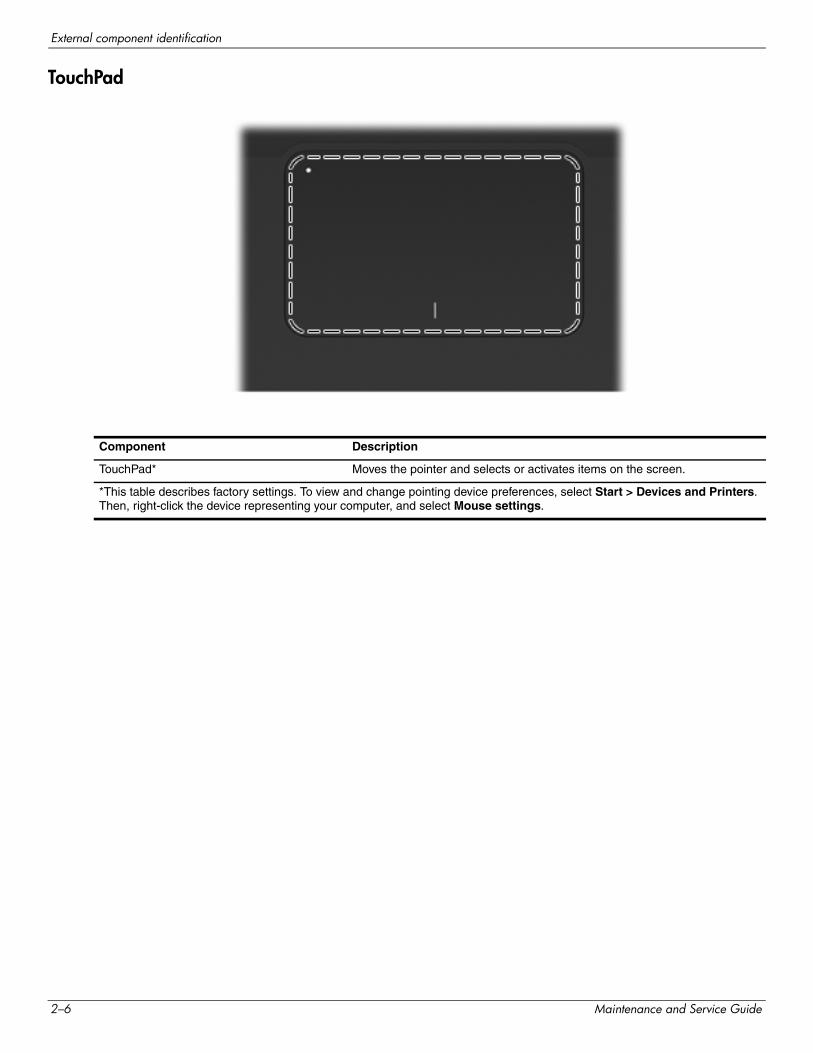
Component Description
TouchPad* Moves the pointer and selects or activates items on the screen.
*This table describes factory settings. To view and change pointing device preferences, select Start > Devices and Printers. Then, right-click the device representing your computer, and select Mouse settings.
2–6 Maintenance and Service Guide
External component identification
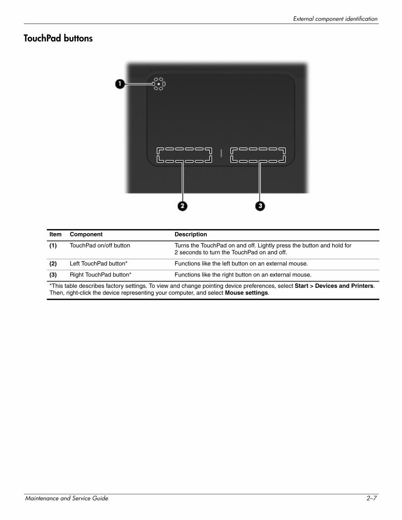
TouchPad buttons
Item Component Description
(1) TouchPad on/off button Turns the TouchPad on and off. Lightly press the button and hold for 2 seconds to turn the TouchPad on and off.
(2) Left TouchPad button* Functions like the left button on an external mouse.
(3) Right TouchPad button* Functions like the right button on an external mouse.
*This table describes factory settings. To view and change pointing device preferences, select Start > Devices and Printers. Then, right-click the device representing your computer, and select Mouse settings.
Maintenance and Service Guide 2–7
External component identification
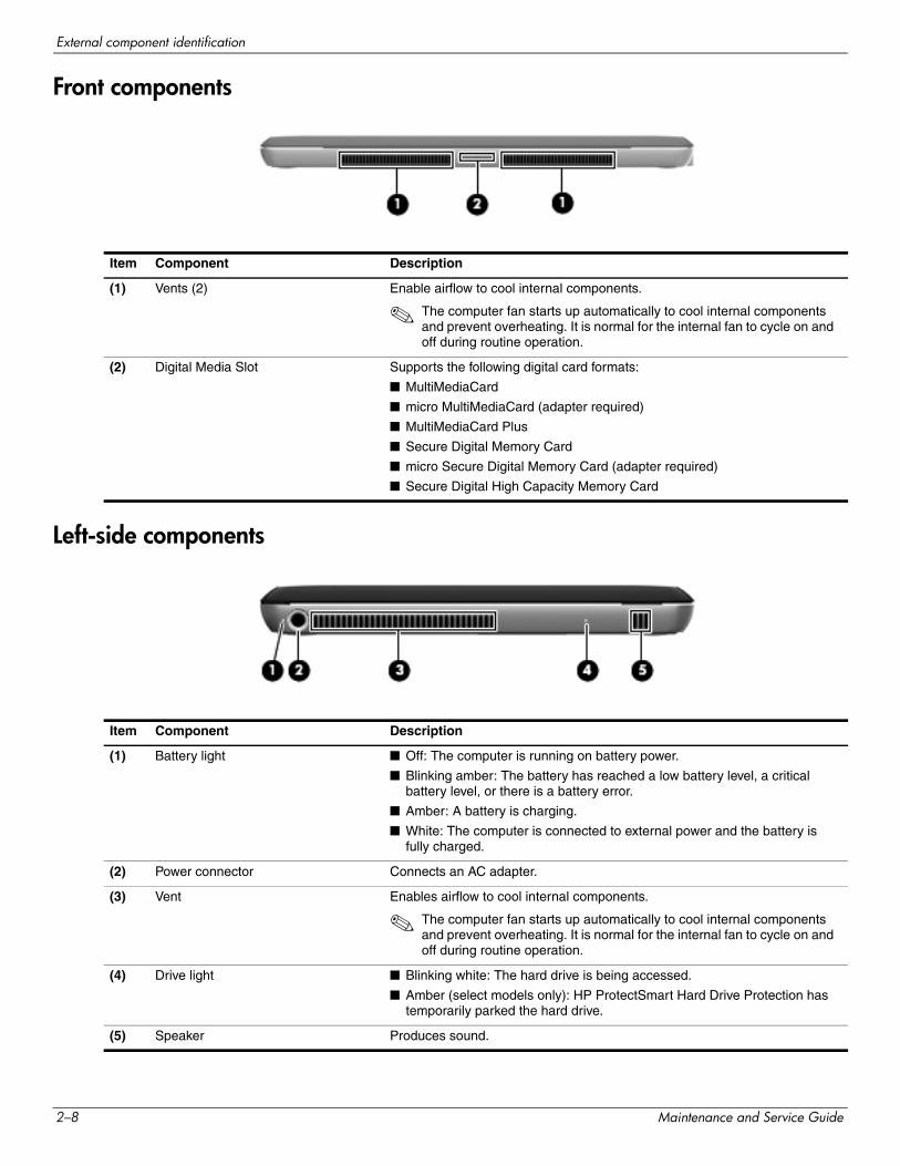
Front components
Left-side components
Item Component Description
(1) Vents (2) Enable airflow to cool internal components.
✎ The computer fan starts up automatically to cool internal components and prevent overheating. It is normal for the internal fan to cycle on and off during routine operation.
(2) Digital Media Slot Supports the following digital card formats:
■ MultiMediaCard
■ micro MultiMediaCard (adapter required)
■ MultiMediaCard Plus
■ Secure Digital Memory Card
■ micro Secure Digital Memory Card (adapter required)
■ Secure Digital High Capacity Memory Card
Item Component Description
(1) Battery light ■ Off: The computer is running on battery power.
■ Blinking amber: The battery has reached a low battery level, a critical battery level, or there is a battery error.
■ Amber: A battery is charging.
■ White: The computer is connected to external power and the battery is fully charged.
(2) Power connector Connects an AC adapter.
(3) Vent Enables airflow to cool internal components.
✎ The computer fan starts up automatically to cool internal components and prevent overheating. It is normal for the internal fan to cycle on and off during routine operation.
(4) Drive light ■ Blinking white: The hard drive is being accessed.
■ Amber (select models only): HP ProtectSmart Hard Drive Protection has temporarily parked the hard drive.
(5) Speaker Produces sound.
2–8 Maintenance and Service Guide
External component identification
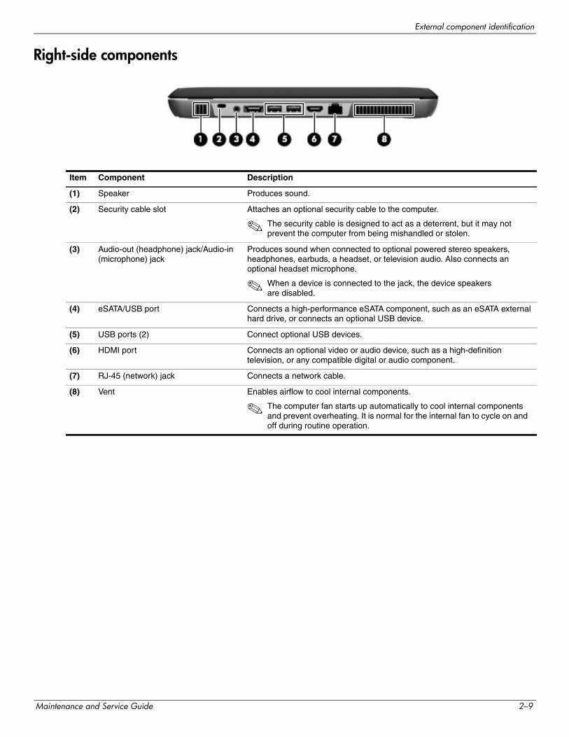
Right-side components
Item Component Description
(1) Speaker Produces sound.
(2) Security cable slot Attaches an optional security cable to the computer.
✎ The security cable is designed to act as a deterrent, but it may not prevent the computer from being mishandled or stolen.
(3) Audio-out (headphone) jack/Audio-in (microphone) jack
Produces sound when connected to optional powered stereo speakers, headphones, earbuds, a headset, or television audio. Also connects an optional headset microphone.
✎ When a device is connected to the jack, the device speakers are disabled.
(4) eSATA/USB port Connects a high-performance eSATA component, such as an eSATA external hard drive, or connects an optional USB device.
(5) USB ports (2) Connect optional USB devices.
(6) HDMI port Connects an optional video or audio device, such as a high-definition television, or any compatible digital or audio component.
(7) RJ-45 (network) jack Connects a network cable.
(8) Vent Enables airflow to cool internal components.
✎ The computer fan starts up automatically to cool internal components and prevent overheating. It is normal for the internal fan to cycle on and off during routine operation.
Maintenance and Service Guide 2–9
External component identification
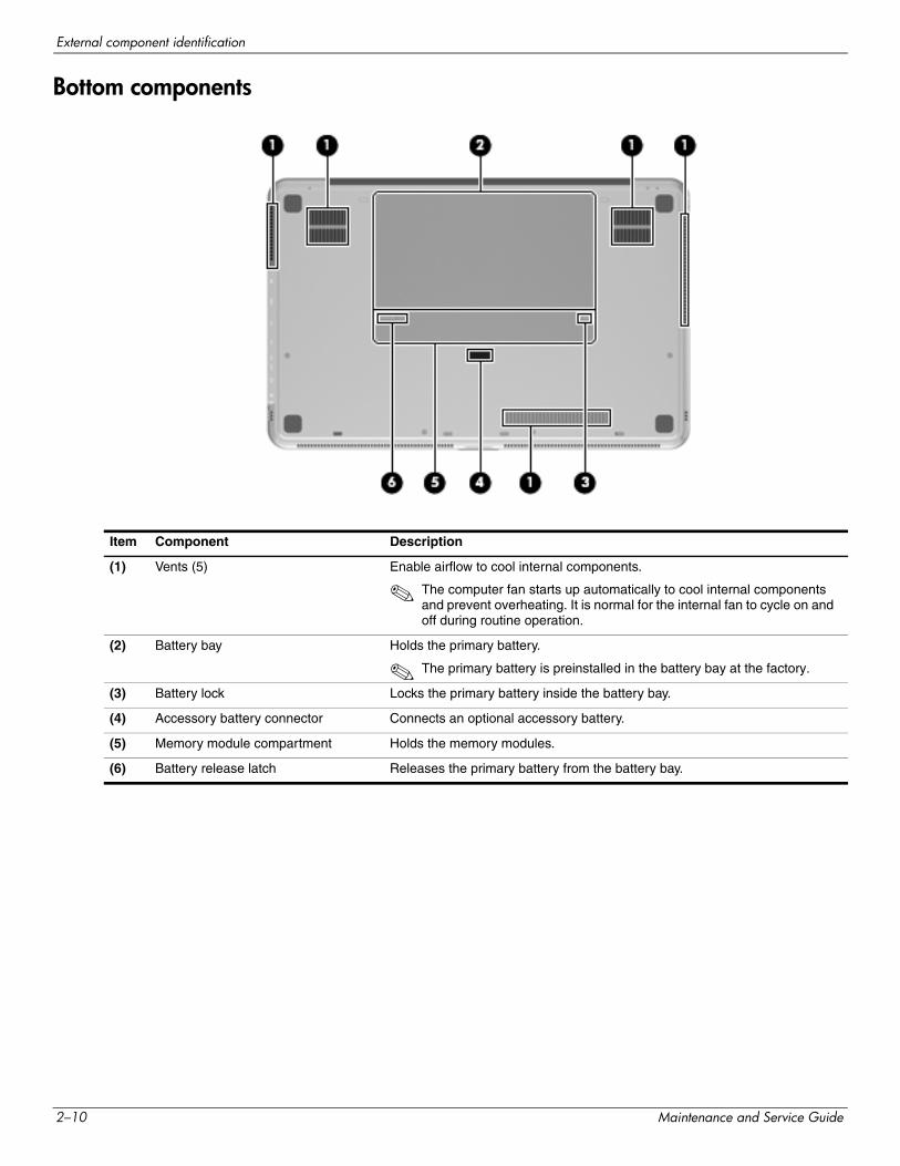
Bottom components
Item Component Description
(1) Vents (5) Enable airflow to cool internal components.
✎ The computer fan starts up automatically to cool internal components and prevent overheating. It is normal for the internal fan to cycle on and off during routine operation.
(2) Battery bay Holds the primary battery.
✎ The primary battery is preinstalled in the battery bay at the factory.
(3) Battery lock Locks the primary battery inside the battery bay.
(4) Accessory battery connector Connects an optional accessory battery.
(5) Memory module compartment Holds the memory modules.
(6) Battery release latch Releases the primary battery from the battery bay.
2–10 Maintenance and Service Guide
3Illustrated parts catalog
Service tag
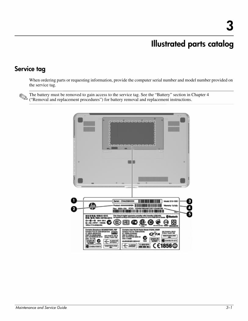
When ordering parts or requesting information, provide the computer serial number and model number provided on the service tag.
✎ The battery must be removed to gain access to the service tag. See the “Battery” section in Chapter 4 (“Removal and replacement procedures”) for battery removal and replacement instructions.
Maintenance and Service Guide 3–1
Illustrated parts catalog
Item Component Description
(1) Serial number (s/n) This is an alphanumeric identifier that is unique to each product.
(2) Product name This is the product name affixed to the front of the computer.
(3) Model description This is the alphanumeric identifier used to locate documents, drivers, and support for the computer.
(4) Warranty period This number describes the duration (in years) of the warranty period for the computer.
(5) Part number/Product number (p/n) This number provides specific information about the product’s hardware components. The part number helps a service technician determine what components and parts are needed.
3–2 Maintenance and Service Guide
Illustrated parts catalog
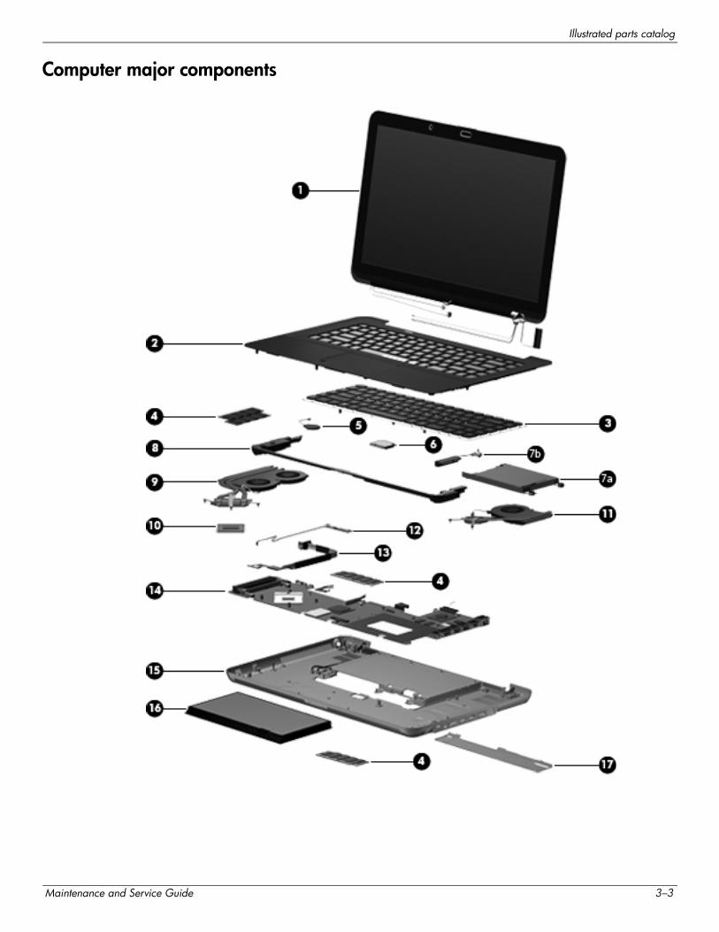
Computer major components
Maintenance and Service Guide 3–3
Illustrated parts catalog
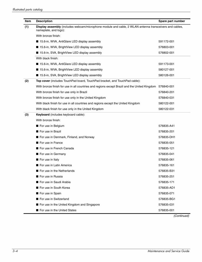
Item Description Spare part number
(1) Display assembly (includes webcam/microphone module and cable, 2 WLAN antenna transceivers and cables, nameplate, and logo):
With bronze finish:
■ 15.6-in, WVA, AntiGlare LED display assembly 591172-001
■ 15.6-in, WVA, BrightView LED display assembly 576803-001
■ 15.6-in, SVA, BrightView LED display assembly 576802-001
With black finish:
■ 15.6-in, WVA, AntiGlare LED display assembly 591173-001
■ 15.6-in, WVA, BrightView LED display assembly 580127-001
■ 15.6-in, SVA, BrightView LED display assembly 580126-001
(2) Top cover (includes TouchPad board, TouchPad bracket, and TouchPad cable):
With bronze finish for use in all countries and regions except Brazil and the United Kingdom 576840-001
With bronze finish for use only in Brazil 576840-201
With bronze finish for use only in the United Kingdom 576840-031
With black finish for use in all countries and regions except the United Kingdom 580122-001
With black finish for use only in the United Kingdom 580122-031
(3) Keyboard (includes keyboard cable):
With bronze finish:
■ For use in Belgium 576835-A41
■ For use in Brazil 576835-201
■ For use in Denmark, Finland, and Norway 576835-DH1
■ For use in France 576835-051
■ For use in French Canada 576835-121
■ For use in Germany 576835-041
■ For use in Italy 576835-061
■ For use in Latin America 576835-161
■ For use in the Netherlands 576835-B31
■ For use in Russia 576835-251
■ For use in Saudi Arabia 576835-171
■ For use in South Korea 576835-AD1
■ For use in Spain 576835-071
■ For use in Switzerland 576835-BG1
■ For use in the United Kingdom and Singapore 576835-031
■ For use in the United States 576835-001
(Continued)
3–4 Maintenance and Service Guide
Illustrated parts catalog
(3) Keyboard (includes keyboard cable) (continued):
With black finish:
■ For use in France 580132-051
■ For use in Saudi Arabia 580132-171
■ For use in the United Kingdom and Singapore 580132-031
■ For use in the United States 580132-001
Keyboard Hardware Kit (not illustrated, includes Mylar shield and screws) 576836-001
(4) Memory modules (1066-MHz, PC3):
4096-MB 576817-001
2048-MB 576816-001
(5) RTC battery (includes double-sided tape) 576848-001
(6) WLAN module:
802.11 a/g/n WLAN module:
■ Intel WiFi Link 6200 802.11 a/g/n WLAN module for use in Andorra, Antigua and Barbuda, Argentina, Aruba, Australia, Austria, Azerbaijan, Bahamas, Bahrain, Barbados, Belgium, Bermuda, Bolivia, Bosnia, Brazil, Brunei, Bulgaria, Canada, the Cayman Islands, Chile, Colombia, Costa Rica, Croatia, Cyprus, the Czech Republic, Denmark, the Dominican Republic, Ecuador, Egypt, El Salvador, Estonia, Finland, France, French Guiana, Georgia, Germany, Ghana, Greece, Guadeloupe, Guam, Guatemala, Haiti, Herzegovina, Honduras, Hong Kong, Hungary, Iceland, India, Indonesia, Ireland, Israel, Italy, the Ivory Coast, Jamaica, Japan, Jordan, Kenya, Kuwait, Kyrgyzstan, Latvia, Lebanon, Liechtenstein, Lithuania, Luxembourg, Malawi, Malaysia, Malta, Martinique, Mauritius, Mexico, Monaco, Montenegro, Morocco, the Nether Antilles, the Netherlands, New Zealand, Nicaragua, Nigeria, Norway, Oman, Panama, Paraguay, the People’s Republic China, Peru, the Philippines, Poland, Portugal, Puerto Rico, Qatar, Romania, San Marino, Saudi Arabia, Senegal, Serbia, Singapore, Slovakia, Slovenia, South Africa, South Korea, Spain, Sweden, Switzerland, Taiwan, Tanzania, Thailand, Trinidad and Tobago, Turkey, the United Arab Emirates, the United Kingdom, Uruguay, the U.S. Virgin Islands, the United States, Venezuela, and Vietnam
572509-001
■ Intel WiFi Link 5100 802.11 a/g/n WLAN module for use in Andorra, Antigua and Barbuda, Argentina, Aruba, Australia, Austria, Azerbaijan, Bahamas, Bahrain, Barbados, Belgium, Bermuda, Bolivia, Bosnia, Brazil, Brunei, Bulgaria, Canada, the Cayman Islands, Chile, Colombia, Costa Rica, Croatia, Cyprus, the Czech Republic, Denmark, the Dominican Republic, Ecuador, Egypt, El Salvador, Estonia, Finland, France, French Guiana, Georgia, Germany, Ghana, Greece, Guadeloupe, Guam, Guatemala, Haiti, Herzegovina, Honduras, Hong Kong, Hungary, Iceland, India, Indonesia, Ireland, Israel, Italy, the Ivory Coast, Jamaica, Japan, Jordan, Kenya, Kuwait, Kyrgyzstan, Latvia, Lebanon, Liechtenstein, Lithuania, Luxembourg, Malawi, Malaysia, Malta, Martinique, Mauritius, Mexico, Monaco, Montenegro, Morocco, the Nether Antilles, the Netherlands, New Zealand, Nicaragua, Nigeria, Norway, Oman, Panama, Paraguay, the People’s Republic China, Peru, the Philippines, Poland, Portugal, Puerto Rico, Qatar, Romania, San Marino, Saudi Arabia, Senegal, Serbia, Singapore, Slovakia, Slovenia, South Africa, South Korea, Spain, Sweden, Switzerland, Taiwan, Tanzania, Thailand, Trinidad and Tobago, Turkey, the United Arab Emirates, the United Kingdom, Uruguay, the U.S. Virgin Islands, the United States, Venezuela, and Vietnam
572507-001
(Continued)
Item Description Spare part number
Maintenance and Service Guide 3–5
Illustrated parts catalog
(6) WLAN module (continued):
802.11 a/b/g WLAN module:
■ Intel WiFi Link 6100 802.11 a/b/g WLAN module for use in Andorra, Antigua and Barbuda, Argentina, Aruba, Australia, Austria, Azerbaijan, Bahamas, Bahrain, Barbados, Belgium, Bermuda, Bolivia, Bosnia, Brazil, Brunei, Bulgaria, Canada, the Cayman Islands, Chile, Colombia, Costa Rica, Croatia, Cyprus, the Czech Republic, Denmark, the Dominican Republic, Ecuador, Egypt, El Salvador, Estonia, Finland, France, French Guiana, Georgia, Germany, Ghana, Greece, Guadeloupe, Guam, Guatemala, Haiti, Herzegovina, Honduras, Hong Kong, Hungary, Iceland, India, Indonesia, Ireland, Israel, Italy, the Ivory Coast, Jamaica, Japan, Jordan, Kenya, Kuwait, Kyrgyzstan, Latvia, Lebanon, Liechtenstein, Lithuania, Luxembourg, Malawi, Malaysia, Malta, Martinique, Mauritius, Mexico, Monaco, Montenegro, Morocco, the Nether Antilles, the Netherlands, New Zealand, Nicaragua, Nigeria, Norway, Oman, Panama, Paraguay, the People’s Republic China, Peru, the Philippines, Poland, Portugal, Puerto Rico, Qatar, Romania, San Marino, Saudi Arabia, Senegal, Serbia, Singapore, Slovakia, Slovenia, South Africa, South Korea, Spain, Sweden, Switzerland, Taiwan, Tanzania, Thailand, Trinidad and Tobago, Turkey, the United Arab Emirates, the United Kingdom, Uruguay, the U.S. Virgin Islands, the United States, Venezuela, and Vietnam
572510-001
■ Intel WiFi Link 5100 802.11 a/b/g WLAN module for use in Andorra, Antigua and Barbuda, Argentina, Aruba, Australia, Austria, Azerbaijan, Bahamas, Bahrain, Barbados, Belgium, Bermuda, Bolivia, Bosnia, Brazil, Brunei, Bulgaria, Canada, the Cayman Islands, Chile, Colombia, Costa Rica, Croatia, Cyprus, the Czech Republic, Denmark, the Dominican Republic, Ecuador, Egypt, El Salvador, Estonia, Finland, France, French Guiana, Georgia, Germany, Ghana, Greece, Guadeloupe, Guam, Guatemala, Haiti, Herzegovina, Honduras, Hong Kong, Hungary, Iceland, India, Indonesia, Ireland, Israel, Italy, the Ivory Coast, Jamaica, Japan, Jordan, Kenya, Kuwait, Kyrgyzstan, Latvia, Lebanon, Liechtenstein, Lithuania, Luxembourg, Malawi, Malaysia, Malta, Martinique, Mauritius, Mexico, Monaco, Montenegro, Morocco, the Nether Antilles, the Netherlands, New Zealand, Nicaragua, Nigeria, Norway, Oman, Panama, Paraguay, the People’s Republic China, Peru, the Philippines, Poland, Portugal, Puerto Rico, Qatar, Romania, San Marino, Saudi Arabia, Senegal, Serbia, Singapore, Slovakia, Slovenia, South Africa, South Korea, Spain, Sweden, Switzerland, Taiwan, Tanzania, Thailand, Trinidad and Tobago, Turkey, the United Arab Emirates, the United Kingdom, Uruguay, the U.S. Virgin Islands, the United States, Venezuela, and Vietnam
572508-001
Intel 1000 802.11 b/g/n WLAN module for use in Andorra, Antigua and Barbuda, Argentina, Aruba, Australia, Austria, Azerbaijan, Bahamas, Bahrain, Barbados, Belgium, Bermuda, Bolivia, Bosnia, Brazil, Brunei, Bulgaria, Canada, the Cayman Islands, Chile, Colombia, Costa Rica, Croatia, Cyprus, the Czech Republic, Denmark, the Dominican Republic, Ecuador, Egypt, El Salvador, Estonia, Finland, France, French Guiana, Georgia, Germany, Ghana, Greece, Guadeloupe, Guam, Guatemala, Haiti, Herzegovina, Honduras, Hong Kong, Hungary, Iceland, India, Indonesia, Ireland, Israel, Italy, the Ivory Coast, Jamaica, Japan, Jordan, Kenya, Kuwait, Kyrgyzstan, Latvia, Lebanon, Liechtenstein, Lithuania, Luxembourg, Malawi, Malaysia, Malta, Martinique, Mauritius, Mexico, Monaco, Montenegro, Morocco, the Nether Antilles, the Netherlands, New Zealand, Nicaragua, Nigeria, Norway, Oman, Panama, Paraguay, the People’s Republic China, Peru, the Philippines, Poland, Portugal, Puerto Rico, Qatar, Romania, San Marino, Saudi Arabia, Senegal, Serbia, Singapore, Slovakia, Slovenia, South Africa, South Korea, Spain, Sweden, Switzerland, Taiwan, Tanzania, Thailand, Trinidad and Tobago, Turkey, the United Arab Emirates, the United Kingdom, Uruguay, the U.S. Virgin Islands, the United States, Venezuela, and Vietnam
572520-001
(Continued)
Item Description Spare part number
3–6 Maintenance and Service Guide
Illustrated parts catalog
(6) WLAN module (continued):
Intel 1000 802.11 b/g WLAN module for use in Andorra, Antigua and Barbuda, Argentina, Aruba, Australia, Austria, Azerbaijan, Bahamas, Bahrain, Barbados, Belgium, Bermuda, Bolivia, Bosnia, Brazil, Brunei, Bulgaria, Canada, the Cayman Islands, Chile, Colombia, Costa Rica, Croatia, Cyprus, the Czech Republic, Denmark, the Dominican Republic, Ecuador, Egypt, El Salvador, Estonia, Finland, France, French Guiana, Georgia, Germany, Ghana, Greece, Guadeloupe, Guam, Guatemala, Haiti, Herzegovina, Honduras, Hong Kong, Hungary, Iceland, India, Indonesia, Ireland, Israel, Italy, the Ivory Coast, Jamaica, Japan, Jordan, Kenya, Kuwait, Kyrgyzstan, Latvia, Lebanon, Liechtenstein, Lithuania, Luxembourg, Malawi, Malaysia, Malta, Martinique, Mauritius, Mexico, Monaco, Montenegro, Morocco, the Nether Antilles, the Netherlands, New Zealand, Nicaragua, Nigeria, Norway, Oman, Panama, Paraguay, the People’s Republic China, Peru, the Philippines, Poland, Portugal, Puerto Rico, Qatar, Romania, San Marino, Saudi Arabia, Senegal, Serbia, Singapore, Slovakia, Slovenia, South Africa, South Korea, Spain, Sweden, Switzerland, Taiwan, Tanzania, Thailand, Trinidad and Tobago, Turkey, the United Arab Emirates, the United Kingdom, Uruguay, the U.S. Virgin Islands, the United States, Venezuela, and Vietnam
585984-001
(7a) Hard drive (includes bracket, rubber isolators, and screws):
2.5-in, 7200-rpm:
■ 640-GB 576821-001
■ 500-GB 576820-001
■ 320-GB 576819-001
■ 250-GB 576818-001
1.8-in, 5400-rpm:
■ 320-GB 576823-001
■ 250-GB 580129-001
■ 160-GB 591171-001
(7b) Hard drive cable:
For use only with 2.5-in hard drives 576828-001
For use only with 1.8-in hard drives 576830-001
Hard Drive Hardware Kit (not illustrated, includes bracket, rubber isolators, and screws):
For use only with 2.5-in hard drives 576827-001
For use only with 1.8-in hard drives 576829-001
(8) Speaker assembly 576842-001
(9) Processor fan/heat sink assembly (includes replacement thermal material) 576837-001
(10) Processor (includes replacement thermal material):
Intel Core i7-820QM 1.73-GHz processor (SC turbo up to 3.06-GHz) 583053-001
Intel Core i7-720QM 1.60-GHz processor (SC turbo up to 2.80-GHz) 586170-001
(11) Video fan/heat sink assembly (includes replacement thermal material) 576838-001
(12) Power button board and cable (includes double-sided tape) 576849-001
(13) Power connector cable (includes bracket) 576846-001
(Continued)
Item Description Spare part number
Maintenance and Service Guide 3–7
Illustrated parts catalog
(14) PM57 PCH Peak-M system board with 1 GB of dedicated video memory (includes replacement thermal material)
576772-001
(15) Base enclosure (includes 4 rubber feet):
With bronze finish 576839-001
With black finish 580121-001
Rubber Feet Kit (not illustrated, includes 4 rubber feet) 538346-001
(16) Battery:
9-cell, 2.80-Ah (93-Wh) Li-ion battery 576834-001
6-cell, 2.40-Ah (53-Wh) Li-ion battery 576833-001 and 586025-001
(17) Memory module compartment cover (included in the Plastics Kit, spare part number 576847-001)
Item Description Spare part number
3–8 Maintenance and Service Guide
Illustrated parts catalog
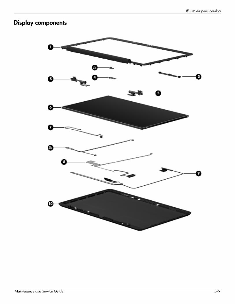
Display components
Maintenance and Service Guide 3–9
Illustrated parts catalog
Item Description Spare part number
(1) Display bezel 576810-001
(2a) Ambient light sensor module (includes cable and double-sided tape) 576815-001
(2b) Ambient light sensor module cable (included in the ambient light sensor module spare part kit)
(3) Webcam/microphone module 576812-001
(4) Bluetooth module 537921-001
✎ The Bluetooth module spare part kit does not include a Bluetooth module cable. The Bluetooth module cable is available using spare part number 576845-001.
(5) Display left and right hinges (included in the Display Hinge Kit, spare part number 576809-001)
(6) Display panel:
For use only with the 15.6-in, WVA, AntiGlare LED display assembly 591327-001
For use only with the 15.6-in, WVA, BrightView LED display assembly 576801-001
For use only with the 15.6-in, SVA, BrightView LED display assembly 576800-001
(7) Bluetooth module cable 576845-001
(8) Display panel cable (includes double-sided tape) 576813-001
(9) Wireless antenna transceivers and cables 576814-001
(10) Display enclosure:
With bronze finish 576811-001
With black finish 580128-001
Display Screw Kit (not illustrated) 576808-001
3–10 Maintenance and Service Guide
Illustrated parts catalog
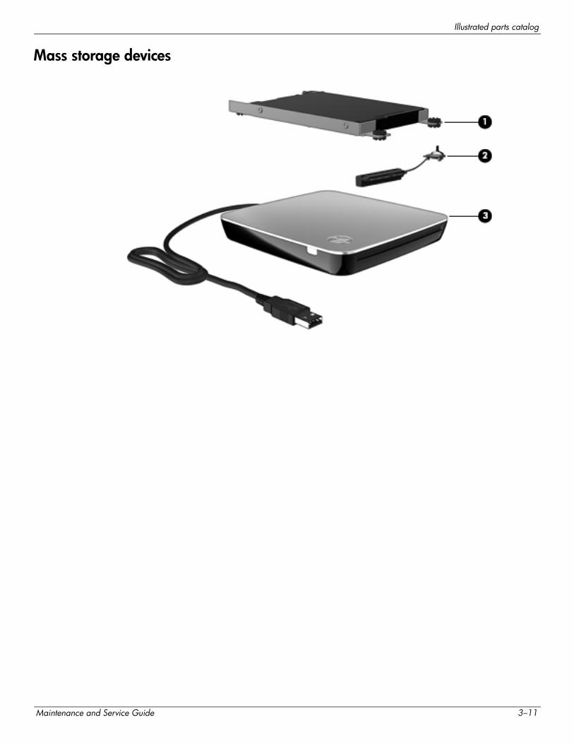
Mass storage devices
Maintenance and Service Guide 3–11
Illustrated parts catalog
Item Description Spare part number
(1) Hard drive (includes bracket, rubber isolators, and screws):
2.5-in, 7200-rpm:
■ 640-GB 576821-001
■ 500-GB 576820-001
■ 320-GB 576819-001
■ 250-GB 576818-001
1.8-in, 5400-rpm:
■ 320-GB 576823-001
■ 250-GB 580129-001
■ 160-GB 591171-001
(2) Hard drive cable:
For use only with 2.5-in hard drives 576828-001
For use only with 1.8-in hard drives 576830-001
Hard Drive Hardware Kit (not illustrated, includes bracket, rubber isolators, and screws):
For use only with 2.5-in hard drives 576827-001
For use only with 1.8-in hard drives 576829-001
(3) External optical drive:
With bronze finish:
■ Blu-ray ROM with LightScribe DVD±R/RW SuperMulti Double-Layer Drive 576832-001
■ DVD±RW and CD-RW SuperMulti Double-Layer Combo Drive with LightScribe 576831-001
With black finish:
■ Blu-ray ROM with LightScribe DVD±R/RW SuperMulti Double-Layer Drive 580131-001
■ DVD±RW and CD-RW SuperMulti Double-Layer Combo Drive with LightScribe 580130-001
3–12 Maintenance and Service Guide
Illustrated parts catalog
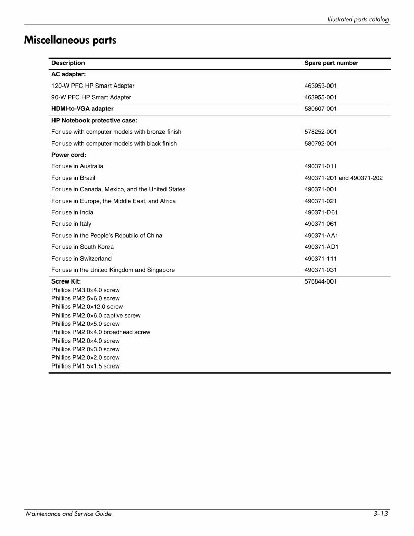
Miscellaneous parts
Description Spare part number
AC adapter:
120-W PFC HP Smart Adapter 463953-001
90-W PFC HP Smart Adapter 463955-001
HDMI-to-VGA adapter 530607-001
HP Notebook protective case:
For use with computer models with bronze finish 578252-001
For use with computer models with black finish 580792-001
Power cord:
For use in Australia 490371-011
For use in Brazil 490371-201 and 490371-202
For use in Canada, Mexico, and the United States 490371-001
For use in Europe, the Middle East, and Africa 490371-021
For use in India 490371-D61
For use in Italy 490371-061
For use in the People’s Republic of China 490371-AA1
For use in South Korea 490371-AD1
For use in Switzerland 490371-111
For use in the United Kingdom and Singapore 490371-031
Screw Kit:Phillips PM3.0×4.0 screwPhillips PM2.5×6.0 screwPhillips PM2.0×12.0 screwPhillips PM2.0×6.0 captive screwPhillips PM2.0×5.0 screwPhillips PM2.0×4.0 broadhead screwPhillips PM2.0×4.0 screwPhillips PM2.0×3.0 screwPhillips PM2.0×2.0 screwPhillips PM1.5×1.5 screw
576844-001
Maintenance and Service Guide 3–13
Illustrated parts catalog
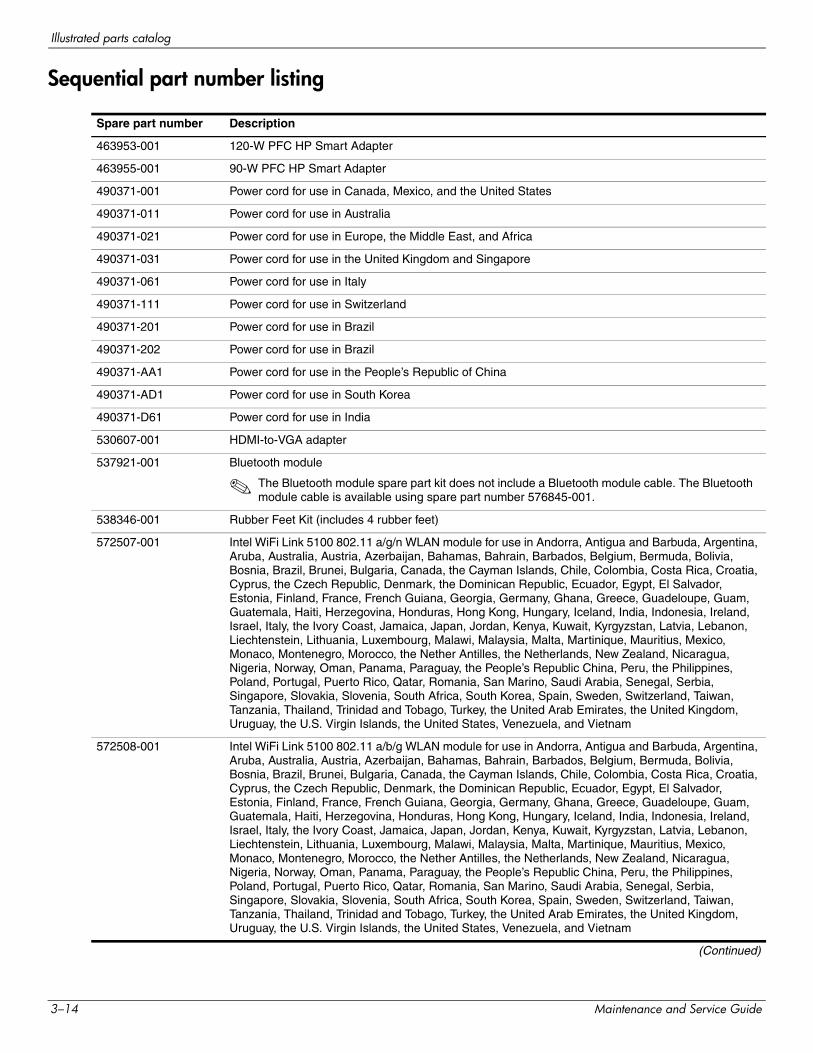
Sequential part number listing
Spare part number Description
463953-001 120-W PFC HP Smart Adapter
463955-001 90-W PFC HP Smart Adapter
490371-001 Power cord for use in Canada, Mexico, and the United States
490371-011 Power cord for use in Australia
490371-021 Power cord for use in Europe, the Middle East, and Africa
490371-031 Power cord for use in the United Kingdom and Singapore
490371-061 Power cord for use in Italy
490371-111 Power cord for use in Switzerland
490371-201 Power cord for use in Brazil
490371-202 Power cord for use in Brazil
490371-AA1 Power cord for use in the People’s Republic of China
490371-AD1 Power cord for use in South Korea
490371-D61 Power cord for use in India
530607-001 HDMI-to-VGA adapter
537921-001 Bluetooth module
✎ The Bluetooth module spare part kit does not include a Bluetooth module cable. The Bluetooth module cable is available using spare part number 576845-001.
538346-001 Rubber Feet Kit (includes 4 rubber feet)
572507-001 Intel WiFi Link 5100 802.11 a/g/n WLAN module for use in Andorra, Antigua and Barbuda, Argentina, Aruba, Australia, Austria, Azerbaijan, Bahamas, Bahrain, Barbados, Belgium, Bermuda, Bolivia, Bosnia, Brazil, Brunei, Bulgaria, Canada, the Cayman Islands, Chile, Colombia, Costa Rica, Croatia, Cyprus, the Czech Republic, Denmark, the Dominican Republic, Ecuador, Egypt, El Salvador, Estonia, Finland, France, French Guiana, Georgia, Germany, Ghana, Greece, Guadeloupe, Guam, Guatemala, Haiti, Herzegovina, Honduras, Hong Kong, Hungary, Iceland, India, Indonesia, Ireland, Israel, Italy, the Ivory Coast, Jamaica, Japan, Jordan, Kenya, Kuwait, Kyrgyzstan, Latvia, Lebanon, Liechtenstein, Lithuania, Luxembourg, Malawi, Malaysia, Malta, Martinique, Mauritius, Mexico, Monaco, Montenegro, Morocco, the Nether Antilles, the Netherlands, New Zealand, Nicaragua, Nigeria, Norway, Oman, Panama, Paraguay, the People’s Republic China, Peru, the Philippines, Poland, Portugal, Puerto Rico, Qatar, Romania, San Marino, Saudi Arabia, Senegal, Serbia, Singapore, Slovakia, Slovenia, South Africa, South Korea, Spain, Sweden, Switzerland, Taiwan, Tanzania, Thailand, Trinidad and Tobago, Turkey, the United Arab Emirates, the United Kingdom, Uruguay, the U.S. Virgin Islands, the United States, Venezuela, and Vietnam
572508-001 Intel WiFi Link 5100 802.11 a/b/g WLAN module for use in Andorra, Antigua and Barbuda, Argentina, Aruba, Australia, Austria, Azerbaijan, Bahamas, Bahrain, Barbados, Belgium, Bermuda, Bolivia, Bosnia, Brazil, Brunei, Bulgaria, Canada, the Cayman Islands, Chile, Colombia, Costa Rica, Croatia, Cyprus, the Czech Republic, Denmark, the Dominican Republic, Ecuador, Egypt, El Salvador, Estonia, Finland, France, French Guiana, Georgia, Germany, Ghana, Greece, Guadeloupe, Guam, Guatemala, Haiti, Herzegovina, Honduras, Hong Kong, Hungary, Iceland, India, Indonesia, Ireland, Israel, Italy, the Ivory Coast, Jamaica, Japan, Jordan, Kenya, Kuwait, Kyrgyzstan, Latvia, Lebanon, Liechtenstein, Lithuania, Luxembourg, Malawi, Malaysia, Malta, Martinique, Mauritius, Mexico, Monaco, Montenegro, Morocco, the Nether Antilles, the Netherlands, New Zealand, Nicaragua, Nigeria, Norway, Oman, Panama, Paraguay, the People’s Republic China, Peru, the Philippines, Poland, Portugal, Puerto Rico, Qatar, Romania, San Marino, Saudi Arabia, Senegal, Serbia, Singapore, Slovakia, Slovenia, South Africa, South Korea, Spain, Sweden, Switzerland, Taiwan, Tanzania, Thailand, Trinidad and Tobago, Turkey, the United Arab Emirates, the United Kingdom, Uruguay, the U.S. Virgin Islands, the United States, Venezuela, and Vietnam
(Continued)
3–14 Maintenance and Service Guide
Illustrated parts catalog
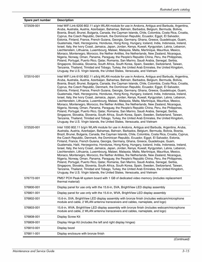
572509-001 Intel WiFi Link 6200 802.11 a/g/n WLAN module for use in Andorra, Antigua and Barbuda, Argentina, Aruba, Australia, Austria, Azerbaijan, Bahamas, Bahrain, Barbados, Belgium, Bermuda, Bolivia, Bosnia, Brazil, Brunei, Bulgaria, Canada, the Cayman Islands, Chile, Colombia, Costa Rica, Croatia, Cyprus, the Czech Republic, Denmark, the Dominican Republic, Ecuador, Egypt, El Salvador, Estonia, Finland, France, French Guiana, Georgia, Germany, Ghana, Greece, Guadeloupe, Guam, Guatemala, Haiti, Herzegovina, Honduras, Hong Kong, Hungary, Iceland, India, Indonesia, Ireland, Israel, Italy, the Ivory Coast, Jamaica, Japan, Jordan, Kenya, Kuwait, Kyrgyzstan, Latvia, Lebanon, Liechtenstein, Lithuania, Luxembourg, Malawi, Malaysia, Malta, Martinique, Mauritius, Mexico, Monaco, Montenegro, Morocco, the Nether Antilles, the Netherlands, New Zealand, Nicaragua, Nigeria, Norway, Oman, Panama, Paraguay, the People’s Republic China, Peru, the Philippines, Poland, Portugal, Puerto Rico, Qatar, Romania, San Marino, Saudi Arabia, Senegal, Serbia, Singapore, Slovakia, Slovenia, South Africa, South Korea, Spain, Sweden, Switzerland, Taiwan, Tanzania, Thailand, Trinidad and Tobago, Turkey, the United Arab Emirates, the United Kingdom, Uruguay, the U.S. Virgin Islands, the United States, Venezuela, and Vietnam
572510-001 Intel WiFi Link 6100 802.11 a/b/g WLAN module for use in Andorra, Antigua and Barbuda, Argentina, Aruba, Australia, Austria, Azerbaijan, Bahamas, Bahrain, Barbados, Belgium, Bermuda, Bolivia, Bosnia, Brazil, Brunei, Bulgaria, Canada, the Cayman Islands, Chile, Colombia, Costa Rica, Croatia, Cyprus, the Czech Republic, Denmark, the Dominican Republic, Ecuador, Egypt, El Salvador, Estonia, Finland, France, French Guiana, Georgia, Germany, Ghana, Greece, Guadeloupe, Guam, Guatemala, Haiti, Herzegovina, Honduras, Hong Kong, Hungary, Iceland, India, Indonesia, Ireland, Israel, Italy, the Ivory Coast, Jamaica, Japan, Jordan, Kenya, Kuwait, Kyrgyzstan, Latvia, Lebanon, Liechtenstein, Lithuania, Luxembourg, Malawi, Malaysia, Malta, Martinique, Mauritius, Mexico, Monaco, Montenegro, Morocco, the Nether Antilles, the Netherlands, New Zealand, Nicaragua, Nigeria, Norway, Oman, Panama, Paraguay, the People’s Republic China, Peru, the Philippines, Poland, Portugal, Puerto Rico, Qatar, Romania, San Marino, Saudi Arabia, Senegal, Serbia, Singapore, Slovakia, Slovenia, South Africa, South Korea, Spain, Sweden, Switzerland, Taiwan, Tanzania, Thailand, Trinidad and Tobago, Turkey, the United Arab Emirates, the United Kingdom, Uruguay, the U.S. Virgin Islands, the United States, Venezuela, and Vietnam
572520-001 Intel 1000 802.11 b/g/n WLAN module for use in Andorra, Antigua and Barbuda, Argentina, Aruba, Australia, Austria, Azerbaijan, Bahamas, Bahrain, Barbados, Belgium, Bermuda, Bolivia, Bosnia, Brazil, Brunei, Bulgaria, Canada, the Cayman Islands, Chile, Colombia, Costa Rica, Croatia, Cyprus, the Czech Republic, Denmark, the Dominican Republic, Ecuador, Egypt, El Salvador, Estonia, Finland, France, French Guiana, Georgia, Germany, Ghana, Greece, Guadeloupe, Guam, Guatemala, Haiti, Herzegovina, Honduras, Hong Kong, Hungary, Iceland, India, Indonesia, Ireland, Israel, Italy, the Ivory Coast, Jamaica, Japan, Jordan, Kenya, Kuwait, Kyrgyzstan, Latvia, Lebanon, Liechtenstein, Lithuania, Luxembourg, Malawi, Malaysia, Malta, Martinique, Mauritius, Mexico, Monaco, Montenegro, Morocco, the Nether Antilles, the Netherlands, New Zealand, Nicaragua, Nigeria, Norway, Oman, Panama, Paraguay, the People’s Republic China, Peru, the Philippines, Poland, Portugal, Puerto Rico, Qatar, Romania, San Marino, Saudi Arabia, Senegal, Serbia, Singapore, Slovakia, Slovenia, South Africa, South Korea, Spain, Sweden, Switzerland, Taiwan, Tanzania, Thailand, Trinidad and Tobago, Turkey, the United Arab Emirates, the United Kingdom, Uruguay, the U.S. Virgin Islands, the United States, Venezuela, and Vietnam
576772-001 PM57 PCH Peak-M system board with 1 GB of dedicated video memory (includes replacement thermal material)
576800-001 Display panel for use only with the 15.6-in, SVA, BrightView LED display assembly
576801-001 Display panel for use only with the 15.6-in, WVA, BrightView LED display assembly
576802-001 15.6-in, SVA, BrightView LED display assembly with bronze finish (includes webcam/microphone module and cable, 2 WLAN antenna transceivers and cables, nameplate, and logo)
576803-001 15.6-in, WVA, BrightView LED display assembly with bronze finish (includes webcam/microphone module and cable, 2 WLAN antenna transceivers and cables, nameplate, and logo)
576808-001 Display Screw Kit
576809-001 Display Hinge Kit (includes the left and right display hinges)
576810-001 Display bezel
576811-001 Display enclosure with bronze finish
(Continued)
Spare part number Description
Maintenance and Service Guide 3–15
Illustrated parts catalog
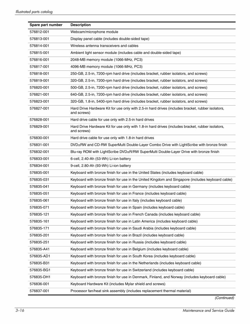
576812-001 Webcam/microphone module
576813-001 Display panel cable (includes double-sided tape)
576814-001 Wireless antenna transceivers and cables
576815-001 Ambient light sensor module (includes cable and double-sided tape)
576816-001 2048-MB memory module (1066-MHz, PC3)
576817-001 4096-MB memory module (1066-MHz, PC3)
576818-001 250-GB, 2.5-in, 7200-rpm hard drive (includes bracket, rubber isolators, and screws)
576819-001 320-GB, 2.5-in, 7200-rpm hard drive (includes bracket, rubber isolators, and screws)
576820-001 500-GB, 2.5-in, 7200-rpm hard drive (includes bracket, rubber isolators, and screws)
576821-001 640-GB, 2.5-in, 7200-rpm hard drive (includes bracket, rubber isolators, and screws)
576823-001 320-GB, 1.8-in, 5400-rpm hard drive (includes bracket, rubber isolators, and screws)
576827-001 Hard Drive Hardware Kit for use only with 2.5-in hard drives (includes bracket, rubber isolators, and screws)
576828-001 Hard drive cable for use only with 2.5-in hard drives
576829-001 Hard Drive Hardware Kit for use only with 1.8-in hard drives (includes bracket, rubber isolators, and screws)
576830-001 Hard drive cable for use only with 1.8-in hard drives
576831-001 DVD±RW and CD-RW SuperMulti Double-Layer Combo Drive with LightScribe with bronze finish
576832-001 Blu-ray ROM with LightScribe DVD±R/RW SuperMulti Double-Layer Drive with bronze finish
576833-001 6-cell, 2.40-Ah (53-Wh) Li-ion battery
576834-001 9-cell, 2.80-Ah (93-Wh) Li-ion battery
576835-001 Keyboard with bronze finish for use in the United States (includes keyboard cable)
576835-031 Keyboard with bronze finish for use in the United Kingdom and Singapore (includes keyboard cable)
576835-041 Keyboard with bronze finish for use in Germany (includes keyboard cable)
576835-051 Keyboard with bronze finish for use in France (includes keyboard cable)
576835-061 Keyboard with bronze finish for use in Italy (includes keyboard cable)
576835-071 Keyboard with bronze finish for use in Spain (includes keyboard cable)
576835-121 Keyboard with bronze finish for use in French Canada (includes keyboard cable)
576835-161 Keyboard with bronze finish for use in Latin America (includes keyboard cable)
576835-171 Keyboard with bronze finish for use in Saudi Arabia (includes keyboard cable)
576835-201 Keyboard with bronze finish for use in Brazil (includes keyboard cable)
576835-251 Keyboard with bronze finish for use in Russia (includes keyboard cable)
576835-A41 Keyboard with bronze finish for use in Belgium (includes keyboard cable)
576835-AD1 Keyboard with bronze finish for use in South Korea (includes keyboard cable)
576835-B31 Keyboard with bronze finish for use in the Netherlands (includes keyboard cable)
576835-BG1 Keyboard with bronze finish for use in Switzerland (includes keyboard cable)
576835-DH1 Keyboard with bronze finish for use in Denmark, Finland, and Norway (includes keyboard cable)
576836-001 Keyboard Hardware Kit (includes Mylar shield and screws)
576837-001 Processor fan/heat sink assembly (includes replacement thermal material)
(Continued)
Spare part number Description
3–16 Maintenance and Service Guide
Illustrated parts catalog
576838-001 Video fan/heat sink assembly (includes replacement thermal material)
576839-001 Base enclosure with bronze finish (includes 4 rubber feet)
576840-001 Top cover with bronze finish for use in all countries and regions except Brazil and the United Kingdom (includes TouchPad board, TouchPad bracket, and TouchPad cable)
576840-031 Top cover with bronze finish for use only in the United Kingdom (includes TouchPad board, TouchPad bracket, and TouchPad cable)
576840-201 Top cover with bronze finish for use only in Brazil (includes TouchPad board, TouchPad bracket, and TouchPad cable)
576842-001 Speaker assembly
576844-001 Screw Kit
576845-001 Bluetooth module cable
576846-001 Power connector cable (includes bracket)
576847-001 Plastics Kit (includes the memory module compartment cover)
576848-001 RTC battery (includes double-sided tape)
576849-001 Power button board and cable (includes double-sided tape)
578252-001 HP Notebook protective case for use with computer models with bronze finish
580121-001 Base enclosure with black finish (includes 4 rubber feet)
580122-001 Top cover with black finish for use in all countries and regions except the United Kingdom (includes TouchPad board, TouchPad bracket, and TouchPad cable)
580122-031 Top cover with black finish for use only in the United Kingdom (includes TouchPad board, TouchPad bracket, and TouchPad cable)
580126-001 15.6-in, SVA, BrightView LED display assembly with black finish (includes webcam/microphone module and cable, 2 WLAN antenna transceivers and cables, nameplate, and logo)
580127-001 15.6-in, WVA, BrightView LED display assembly with black finish (includes webcam/microphone module and cable, 2 WLAN antenna transceivers and cables, nameplate, and logo)
580128-001 Display enclosure with black finish
580129-001 250-GB, 1.8-in, 5400-rpm hard drive (includes bracket, rubber isolators, and screws)
580130-001 DVD±RW and CD-RW SuperMulti Double-Layer Combo Drive with LightScribe with black finish
580131-001 Blu-ray ROM with LightScribe DVD±R/RW SuperMulti Double-Layer Drive with black finish
580132-001 Keyboard with black finish for use in the United States (includes keyboard cable)
580132-031 Keyboard with black finish for use in the United Kingdom and Singapore (includes keyboard cable)
580132-051 Keyboard with black finish for use in France (includes keyboard cable)
580132-171 Keyboard with black finish for use in Saudi Arabia (includes keyboard cable)
580792-001 HP Notebook protective case for use with computer models with black finish
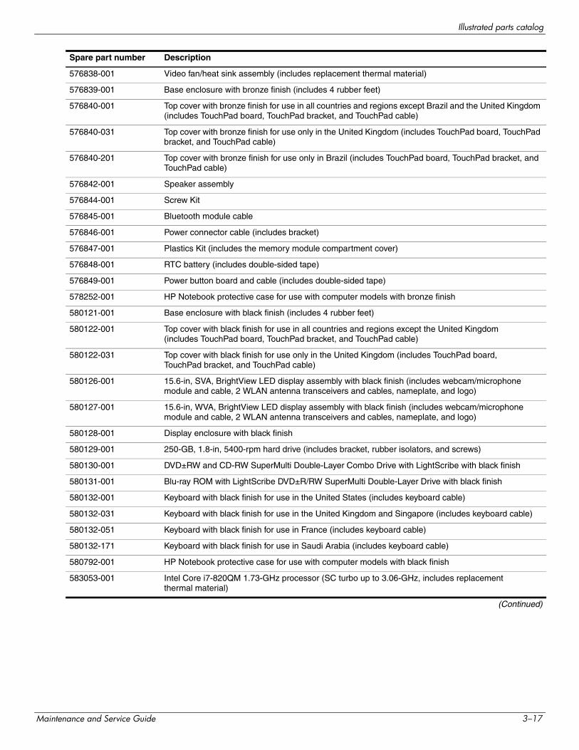
583053-001 Intel Core i7-820QM 1.73-GHz processor (SC turbo up to 3.06-GHz, includes replacement thermal material)
(Continued)
Spare part number Description
Maintenance and Service Guide 3–17
Illustrated parts catalog
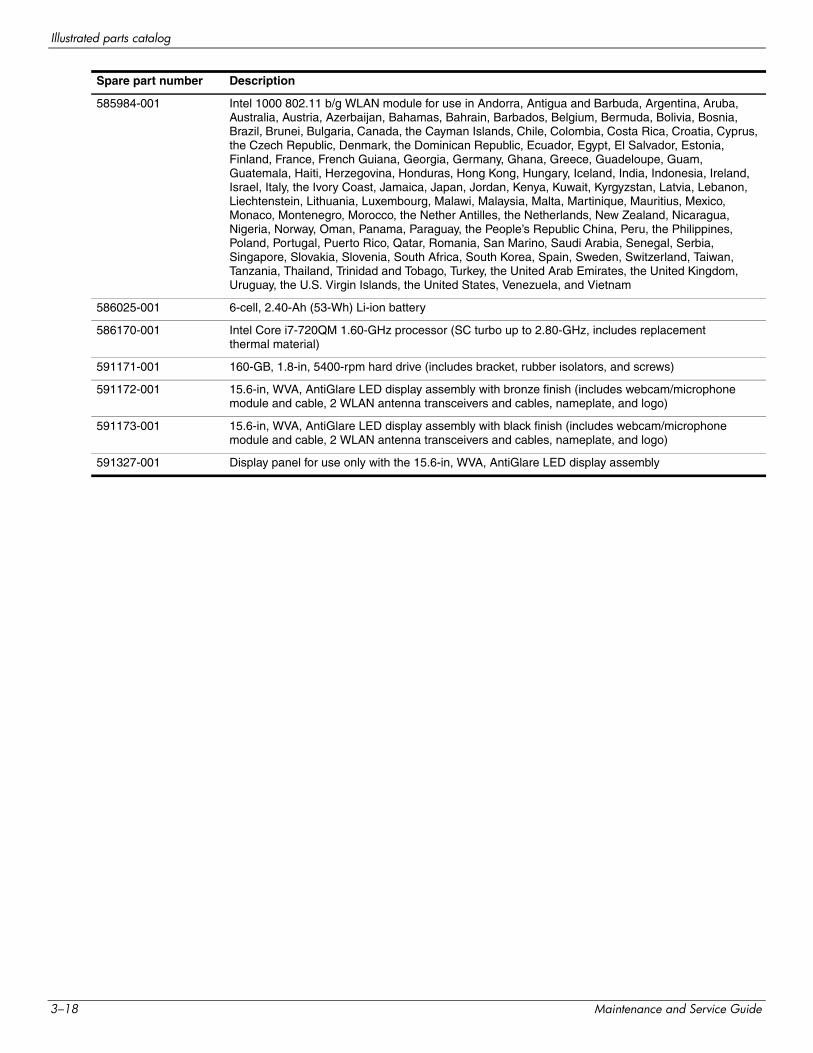
585984-001 Intel 1000 802.11 b/g WLAN module for use in Andorra, Antigua and Barbuda, Argentina, Aruba, Australia, Austria, Azerbaijan, Bahamas, Bahrain, Barbados, Belgium, Bermuda, Bolivia, Bosnia, Brazil, Brunei, Bulgaria, Canada, the Cayman Islands, Chile, Colombia, Costa Rica, Croatia, Cyprus, the Czech Republic, Denmark, the Dominican Republic, Ecuador, Egypt, El Salvador, Estonia, Finland, France, French Guiana, Georgia, Germany, Ghana, Greece, Guadeloupe, Guam, Guatemala, Haiti, Herzegovina, Honduras, Hong Kong, Hungary, Iceland, India, Indonesia, Ireland, Israel, Italy, the Ivory Coast, Jamaica, Japan, Jordan, Kenya, Kuwait, Kyrgyzstan, Latvia, Lebanon, Liechtenstein, Lithuania, Luxembourg, Malawi, Malaysia, Malta, Martinique, Mauritius, Mexico, Monaco, Montenegro, Morocco, the Nether Antilles, the Netherlands, New Zealand, Nicaragua, Nigeria, Norway, Oman, Panama, Paraguay, the People’s Republic China, Peru, the Philippines, Poland, Portugal, Puerto Rico, Qatar, Romania, San Marino, Saudi Arabia, Senegal, Serbia, Singapore, Slovakia, Slovenia, South Africa, South Korea, Spain, Sweden, Switzerland, Taiwan, Tanzania, Thailand, Trinidad and Tobago, Turkey, the United Arab Emirates, the United Kingdom, Uruguay, the U.S. Virgin Islands, the United States, Venezuela, and Vietnam
586025-001 6-cell, 2.40-Ah (53-Wh) Li-ion battery
586170-001 Intel Core i7-720QM 1.60-GHz processor (SC turbo up to 2.80-GHz, includes replacement thermal material)
591171-001 160-GB, 1.8-in, 5400-rpm hard drive (includes bracket, rubber isolators, and screws)
591172-001 15.6-in, WVA, AntiGlare LED display assembly with bronze finish (includes webcam/microphone module and cable, 2 WLAN antenna transceivers and cables, nameplate, and logo)
591173-001 15.6-in, WVA, AntiGlare LED display assembly with black finish (includes webcam/microphone module and cable, 2 WLAN antenna transceivers and cables, nameplate, and logo)
591327-001 Display panel for use only with the 15.6-in, WVA, AntiGlare LED display assembly
Spare part number Description
3–18 Maintenance and Service Guide
4Removal and replacement procedures
Preliminary replacement requirements
Tools required
You will need the following tools to complete the removal and replacement procedures:
■ Flat-bladed screwdriver
■ Phillips P1, P0, and P00 screwdrivers
Service considerations
The following sections include some of the considerations that you must keep in mind during disassembly and assembly procedures.
✎ As you remove each subassembly from the computer, place the subassembly (and all accompanying screws) away from the work area to prevent damage.
Plastic parts
ÄCAUTION: Using excessive force during disassembly and reassembly can damage plastic parts. Use care when handling the plastic parts. Apply pressure only at the points designated in the maintenance instructions.
Cables and connectors
ÄCAUTION: When servicing the computer, be sure that cables are placed in their proper locations during the reassembly process. Improper cable placement can damage the computer.
Cables must be handled with extreme care to avoid damage. Apply only the tension required to unseat or seat the cables during removal and insertion. Handle cables by the connector whenever possible. In all cases, avoid bending, twisting, or tearing cables. Be sure that cables are routed in such a way that they cannot be caught or snagged by parts being removed or replaced. Handle flex cables with extreme care; these cables tear easily.
Maintenance and Service Guide 4–1
Removal and replacement procedures
Drive handling
ÄCAUTION: Drives are fragile components that must be handled with care. To prevent damage to the computer, damage to a drive, or loss of information, observe these precautions:■ Before removing or inserting a mass storage device, shut down the computer.■ Before handling a drive, be sure that you are discharged of static electricity. While handling a drive, avoid
touching the connector.■ Before removing a diskette drive or optical drive, be sure that a diskette or disc is not in the drive and be sure
that the optical drive tray is closed.■ Handle drives on surfaces covered with at least one inch of shock-proof foam. ■ Avoid dropping drives from any height onto any surface.■ After removing a mass storage device, an optical drive, or a diskette drive, place it in a static-proof bag.■ Avoid exposing a mass storage device to products that have magnetic fields, such as monitors or speakers. ■ Avoid exposing a drive to temperature extremes or liquids. ■ If a drive must be mailed, place the drive in a bubble pack mailer or other suitable form of protective packaging
and label the package “FRAGILE.”
Grounding guidelines
Electrostatic discharge damage
Electronic components are sensitive to electrostatic discharge (ESD). Circuitry design and structure determine the degree of sensitivity. Networks built into many integrated circuits provide some protection, but in many cases, ESD contains enough power to alter device parameters or melt silicon junctions.
A discharge of static electricity from a finger or other conductor can destroy static-sensitive devices or microcircuitry. Even if the spark is neither felt nor heard, damage may have occurred.
An electronic device exposed to ESD may not be affected at all and may work perfectly throughout a normal cycle. Or, the device may function normally for a while, and then degrade in the internal layers, reducing its life expectancy.
ÄCAUTION: To prevent damage to the computer when you are removing or installing internal components, observe these precautions:■ Keep components in their electrostatic-safe containers until you are ready to install them.■ Use nonmagnetic tools. ■ Before touching an electronic component, discharge static electricity by using the guidelines described in
this section.■ Avoid touching pins, leads, and circuitry. Handle electronic components as little as possible.■ If you remove a component, place it in an electrostatic-safe container.
4–2 Maintenance and Service Guide
Removal and replacement procedures
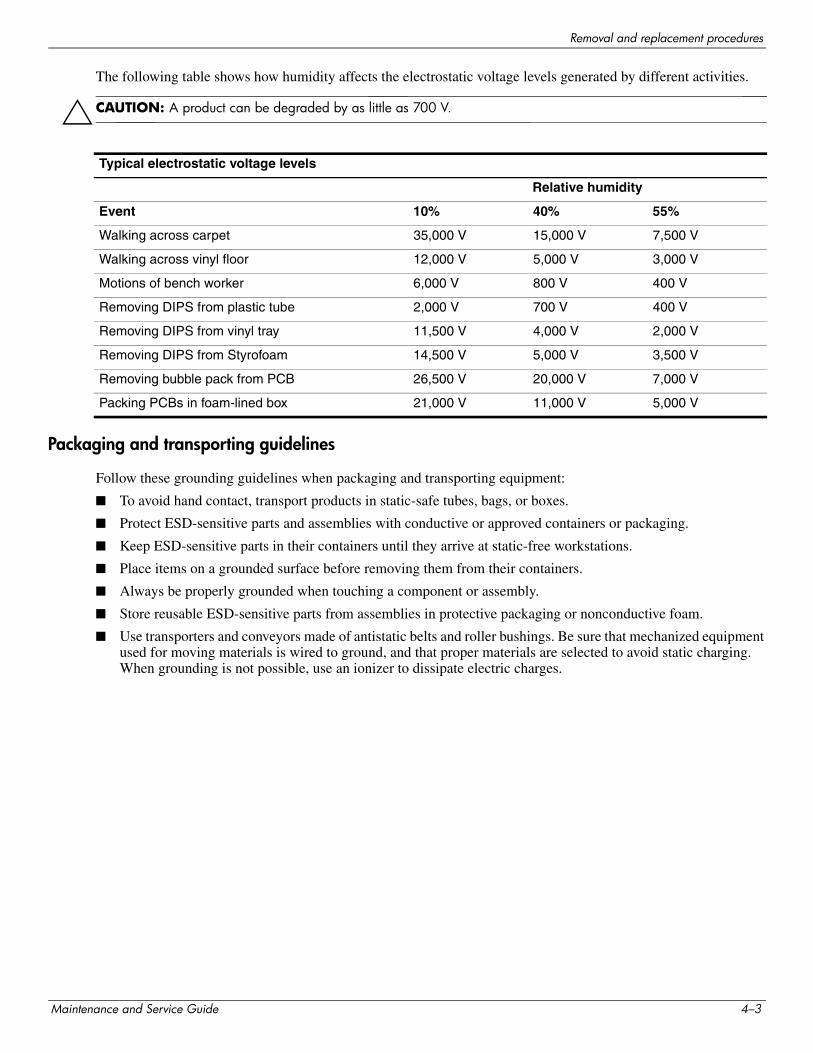
The following table shows how humidity affects the electrostatic voltage levels generated by different activities.
ÄCAUTION: A product can be degraded by as little as 700 V.
Packaging and transporting guidelines
Follow these grounding guidelines when packaging and transporting equipment:
■ To avoid hand contact, transport products in static-safe tubes, bags, or boxes.
■ Protect ESD-sensitive parts and assemblies with conductive or approved containers or packaging.
■ Keep ESD-sensitive parts in their containers until they arrive at static-free workstations.
■ Place items on a grounded surface before removing them from their containers.
■ Always be properly grounded when touching a component or assembly.
■ Store reusable ESD-sensitive parts from assemblies in protective packaging or nonconductive foam.
■ Use transporters and conveyors made of antistatic belts and roller bushings. Be sure that mechanized equipment used for moving materials is wired to ground, and that proper materials are selected to avoid static charging. When grounding is not possible, use an ionizer to dissipate electric charges.
Typical electrostatic voltage levels
Relative humidity
Event 10% 40% 55%
Walking across carpet 35,000 V 15,000 V 7,500 V
Walking across vinyl floor 12,000 V 5,000 V 3,000 V
Motions of bench worker 6,000 V 800 V 400 V
Removing DIPS from plastic tube 2,000 V 700 V 400 V
Removing DIPS from vinyl tray 11,500 V 4,000 V 2,000 V
Removing DIPS from Styrofoam 14,500 V 5,000 V 3,500 V
Removing bubble pack from PCB 26,500 V 20,000 V 7,000 V
Packing PCBs in foam-lined box 21,000 V 11,000 V 5,000 V
Maintenance and Service Guide 4–3
Removal and replacement procedures
Workstation guidelines
Follow these workstation grounding guidelines:
■ Cover the workstation with approved static-shielding material.
■ Use a wrist strap connected to a properly grounded work surface, and use properly grounded tools and equipment.
■ Use conductive field service tools, such as cutters, screwdrivers, and vacuums.
■ When fixtures must directly contact dissipative surfaces, use fixtures made only of static-safe materials.
■ Keep the work area free of nonconductive materials, such as ordinary plastic assembly aids and Styrofoam.
■ Handle ESD-sensitive components, parts, and assemblies by the case or PCM laminate. Handle these items only at static-free workstations.
■ Avoid contact with pins, leads, or circuitry.
■ Turn off power and input signals before inserting or removing connectors or test equipment.
Equipment guidelines
Grounding equipment must include either a wrist strap or a foot strap at a grounded workstation.
■ When seated, wear a wrist strap connected to a grounded system. Wrist straps are flexible straps with a minimum of one megohm ±10% resistance in the ground cords. To provide proper ground, wear a strap snugly against the skin at all times. On grounded mats with banana-plug connectors, use alligator clips to connect a wrist strap.
■ When standing, use foot straps and a grounded floor mat. Foot straps (heel, toe, or boot straps) can be used at standing workstations and are compatible with most types of shoes or boots. On conductive floors or dissipative floor mats, use foot straps on both feet with a minimum of one megohm resistance between the operator and ground. To be effective, the conductive strips must be worn in contact with the skin.
The following grounding equipment is recommended to prevent electrostatic damage:
■ Antistatic tape
■ Antistatic smocks, aprons, and sleeve protectors
■ Conductive bins and other assembly or soldering aids
■ Nonconductive foam
■ Conductive tabletop workstations with ground cords of one megohm resistance
■ Static-dissipative tables or floor mats with hard ties to the ground
■ Field service kits
■ Static awareness labels
■ Material-handling packages
■ Nonconductive plastic bags, tubes, or boxes
■ Metal tote boxes
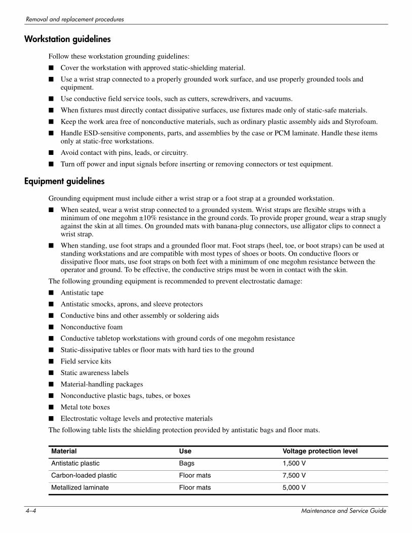
■ Electrostatic voltage levels and protective materials
The following table lists the shielding protection provided by antistatic bags and floor mats.
Material Use Voltage protection level
Antistatic plastic Bags 1,500 V
Carbon-loaded plastic Floor mats 7,500 V
Metallized laminate Floor mats 5,000 V
4–4 Maintenance and Service Guide
Removal and replacement procedures
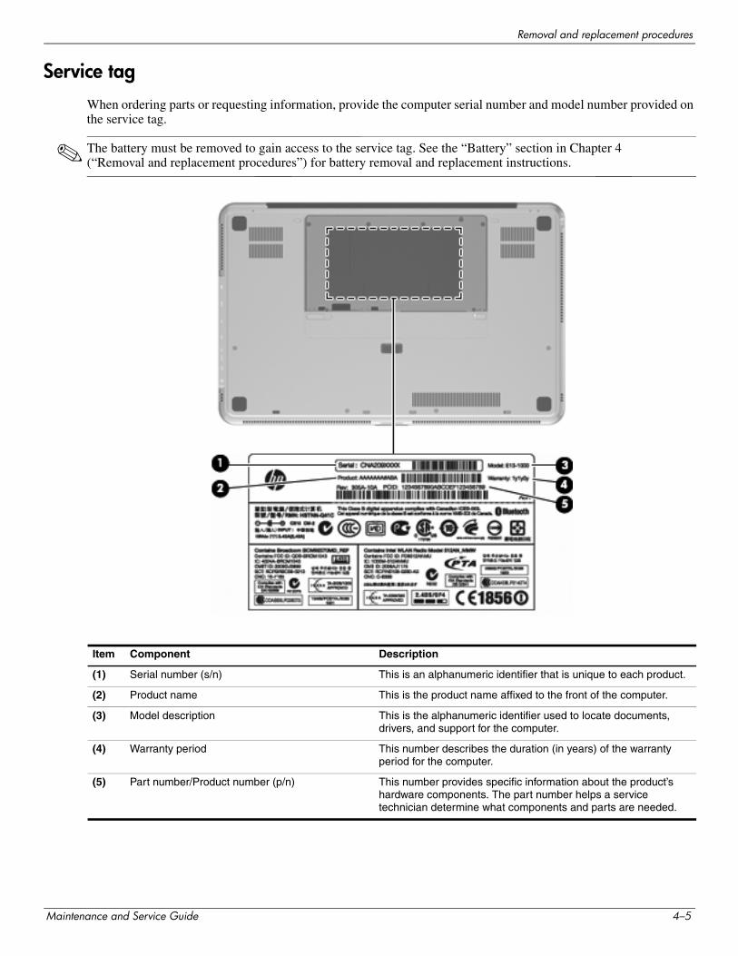
Service tag
When ordering parts or requesting information, provide the computer serial number and model number provided on the service tag.
✎ The battery must be removed to gain access to the service tag. See the “Battery” section in Chapter 4 (“Removal and replacement procedures”) for battery removal and replacement instructions.
Item Component Description
(1) Serial number (s/n) This is an alphanumeric identifier that is unique to each product.
(2) Product name This is the product name affixed to the front of the computer.
(3) Model description This is the alphanumeric identifier used to locate documents, drivers, and support for the computer.
(4) Warranty period This number describes the duration (in years) of the warranty period for the computer.
(5) Part number/Product number (p/n) This number provides specific information about the product’s hardware components. The part number helps a service technician determine what components and parts are needed.
Maintenance and Service Guide 4–5
Removal and replacement procedures
Component replacement procedures
This chapter provides removal and replacement procedures.
There are as many as 113 screws, in 9 different sizes, that must be removed, replaced, or loosened when servicing the computer. Make special note of each screw size and location during removal and replacement.
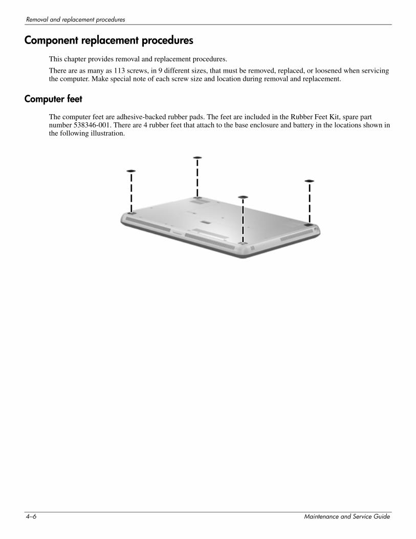
Computer feet
The computer feet are adhesive-backed rubber pads. The feet are included in the Rubber Feet Kit, spare part number 538346-001. There are 4 rubber feet that attach to the base enclosure and battery in the locations shown in the following illustration.
4–6 Maintenance and Service Guide
Removal and replacement procedures
Battery
Before removing the battery, follow these steps:
1. Shut down the computer.
2. Disconnect all external devices connected to the computer.
3. Disconnect the power from the computer by first unplugging the power cord from the AC outlet, and then unplugging the AC adapter from the computer.
Remove the battery:
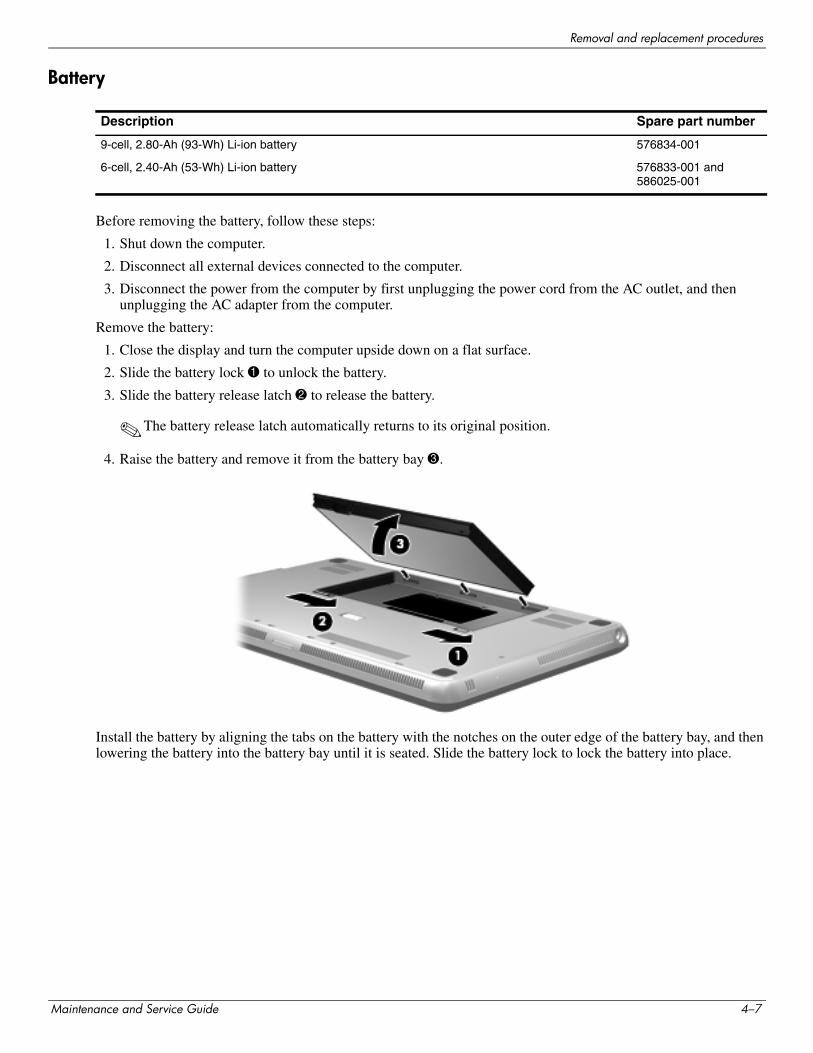
1. Close the display and turn the computer upside down on a flat surface.
2. Slide the battery lock 1 to unlock the battery.
3. Slide the battery release latch 2 to release the battery.
✎The battery release latch automatically returns to its original position.
4. Raise the battery and remove it from the battery bay 3.
Install the battery by aligning the tabs on the battery with the notches on the outer edge of the battery bay, and then lowering the battery into the battery bay until it is seated. Slide the battery lock to lock the battery into place.
Description Spare part number
9-cell, 2.80-Ah (93-Wh) Li-ion battery 576834-001
6-cell, 2.40-Ah (53-Wh) Li-ion battery 576833-001 and 586025-001
Maintenance and Service Guide 4–7
Removal and replacement procedures
Expansion memory module
Before removing the expansion memory module, follow these steps:
1. Shut down the computer.
2. Disconnect all external devices connected to the computer.
3. Disconnect the power from the computer by first unplugging the power cord from the AC outlet, and then unplugging the AC adapter from the computer.
4. Remove the battery (see “Battery” on page 4-7).
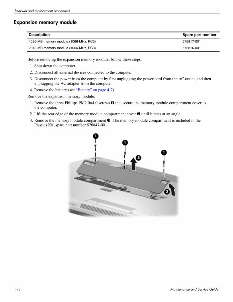
Remove the expansion memory module:
1. Remove the three Phillips PM2.0×4.0 screws 1 that secure the memory module compartment cover to the computer.
2. Lift the rear edge of the memory module compartment cover 2 until it rests at an angle.
3. Remove the memory module compartment 3. The memory module compartment is included in the Plastics Kit, spare part number 576847-001.
Description Spare part number
4096-MB memory module (1066-MHz, PC3) 576817-001
2048-MB memory module (1066-MHz, PC3) 576816-001
4–8 Maintenance and Service Guide
Removal and replacement procedures
4. Pull away the retention clips 1 on each side of the memory module to release the memory module. (The memory module tilts up.)
ÄCAUTION: To prevent damage to the memory module, hold it by the edges only. Do not touch the components on the memory module.
5. Grasp the edge of the memory module 2, and gently pull it out of the memory module slot.
✎Memory modules are designed with a notch 3 to prevent incorrect insertion into the memory module slot.
Reverse this procedure to install the expansion memory module.
Maintenance and Service Guide 4–9
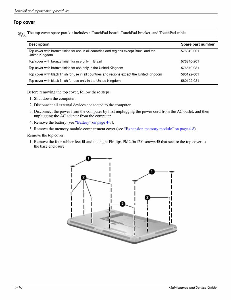
Removal and replacement procedures
Top cover
✎ The top cover spare part kit includes a TouchPad board, TouchPad bracket, and TouchPad cable.
Before removing the top cover, follow these steps:
1. Shut down the computer.
2. Disconnect all external devices connected to the computer.
3. Disconnect the power from the computer by first unplugging the power cord from the AC outlet, and then unplugging the AC adapter from the computer.
4. Remove the battery (see “Battery” on page 4-7).
5. Remove the memory module compartment cover (see “Expansion memory module” on page 4-8).
Remove the top cover:
1. Remove the four rubber feet 1 and the eight Phillips PM2.0×12.0 screws 2 that secure the top cover to the base enclosure.
Description Spare part number
Top cover with bronze finish for use in all countries and regions except Brazil and the United Kingdom
576840-001
Top cover with bronze finish for use only in Brazil 576840-201
Top cover with bronze finish for use only in the United Kingdom 576840-031
Top cover with black finish for use in all countries and regions except the United Kingdom 580122-001
Top cover with black finish for use only in the United Kingdom 580122-031
4–10 Maintenance and Service Guide
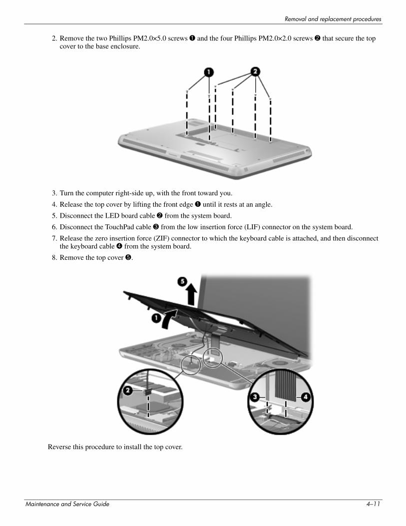
Removal and replacement procedures
2. Remove the two Phillips PM2.0×5.0 screws 1 and the four Phillips PM2.0×2.0 screws 2 that secure the top cover to the base enclosure.
3. Turn the computer right-side up, with the front toward you.
4. Release the top cover by lifting the front edge 1 until it rests at an angle.
5. Disconnect the LED board cable 2 from the system board.
6. Disconnect the TouchPad cable 3 from the low insertion force (LIF) connector on the system board.
7. Release the zero insertion force (ZIF) connector to which the keyboard cable is attached, and then disconnect the keyboard cable 4 from the system board.
8. Remove the top cover 5.
Reverse this procedure to install the top cover.
Maintenance and Service Guide 4–11
Removal and replacement procedures
Keyboard
✎ The keyboard spare part kit includes a keyboard cable.
Before removing the keyboard, follow these steps:
1. Shut down the computer.
2. Disconnect all external devices connected to the computer.
3. Disconnect the power from the computer by first unplugging the power cord from the AC outlet, and then unplugging the AC adapter from the computer.
4. Remove the battery (see “Battery” on page 4-7).
5. Remove the memory module compartment cover (see “Expansion memory module” on page 4-8).
6. Remove the top cover (see “Top cover” on page 4-10).
Keyboard for use in country or region Spare part number
Keyboard for use in country or region Spare part number
With bronze finish:
Belgium 576835-A41 The Netherlands 576835-B31
Brazil 576835-201 Russia 576835-251
Denmark, Finland, and Norway 576835-DH1 Saudi Arabia 576835-171
France 576835-051 South Korea 576835-AD1
French Canada 576835-121 Spain 576835-071
Germany 576835-041 Switzerland 576835-BG1
Italy 576835-061 The United Kingdom and Singapore 576835-031
Latin America 576835-161 The United States 576835-001
With black finish:
France 580132-051 The United Kingdom and Singapore 580132-031
Saudi Arabia 580132-171 The United States 580132-001
Keyboard Hardware Kit (includes Mylar shield and screws) 576836-001
4–12 Maintenance and Service Guide
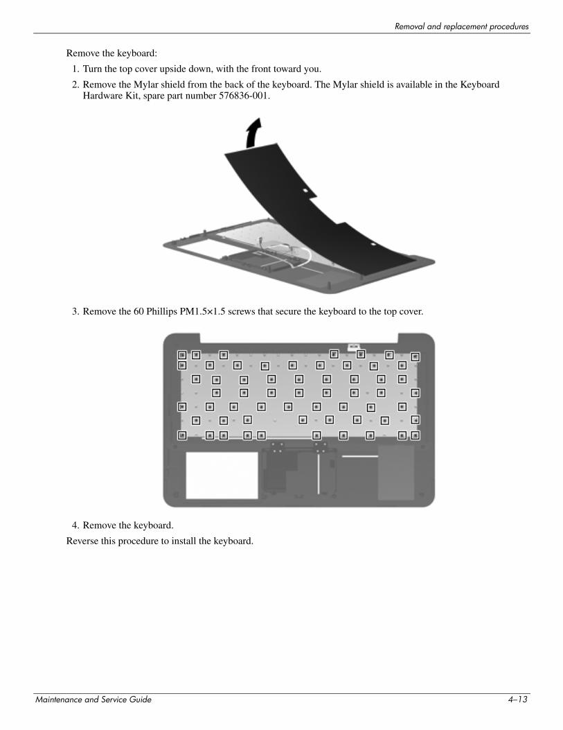
Removal and replacement procedures
Remove the keyboard:
1. Turn the top cover upside down, with the front toward you.
2. Remove the Mylar shield from the back of the keyboard. The Mylar shield is available in the Keyboard Hardware Kit, spare part number 576836-001.
3. Remove the 60 Phillips PM1.5×1.5 screws that secure the keyboard to the top cover.
4. Remove the keyboard.
Reverse this procedure to install the keyboard.
Maintenance and Service Guide 4–13
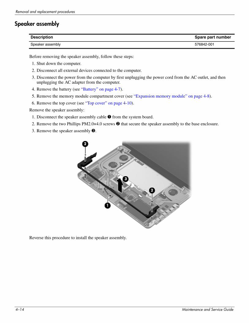
Removal and replacement procedures
Speaker assembly
Before removing the speaker assembly, follow these steps:
1. Shut down the computer.
2. Disconnect all external devices connected to the computer.
3. Disconnect the power from the computer by first unplugging the power cord from the AC outlet, and then unplugging the AC adapter from the computer.
4. Remove the battery (see “Battery” on page 4-7).
5. Remove the memory module compartment cover (see “Expansion memory module” on page 4-8).
6. Remove the top cover (see “Top cover” on page 4-10).
Remove the speaker assembly:
1. Disconnect the speaker assembly cable 1 from the system board.
2. Remove the two Phillips PM2.0×4.0 screws 2 that secure the speaker assembly to the base enclosure.
3. Remove the speaker assembly 3.
Reverse this procedure to install the speaker assembly.
Description Spare part number
Speaker assembly 576842-001
4–14 Maintenance and Service Guide
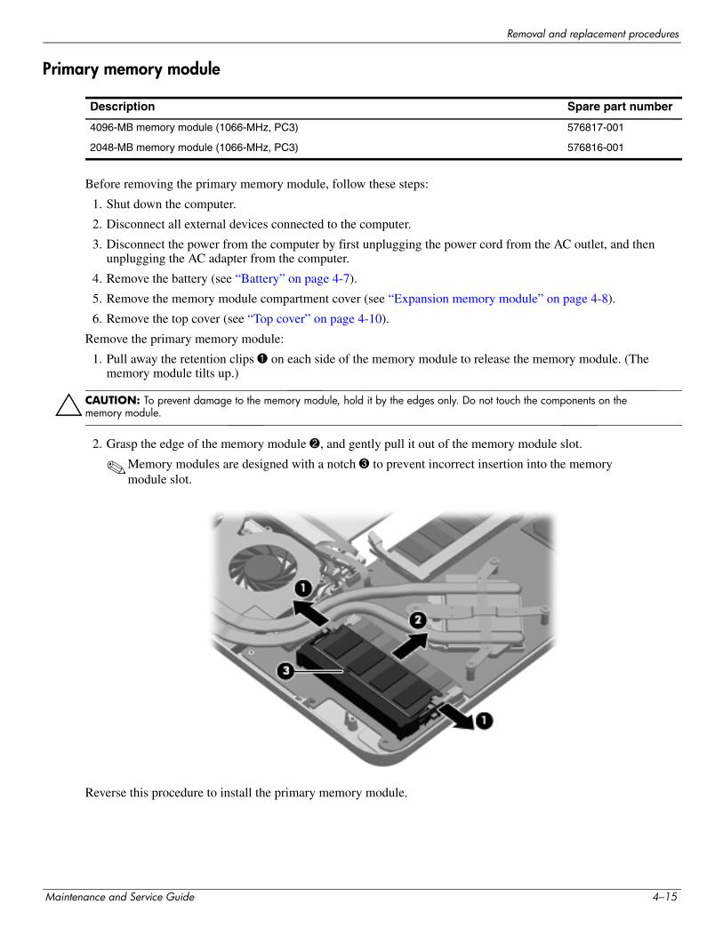
Removal and replacement procedures
Primary memory module
Before removing the primary memory module, follow these steps:
1. Shut down the computer.
2. Disconnect all external devices connected to the computer.
3. Disconnect the power from the computer by first unplugging the power cord from the AC outlet, and then unplugging the AC adapter from the computer.
4. Remove the battery (see “Battery” on page 4-7).
5. Remove the memory module compartment cover (see “Expansion memory module” on page 4-8).
6. Remove the top cover (see “Top cover” on page 4-10).
Remove the primary memory module:
1. Pull away the retention clips 1 on each side of the memory module to release the memory module. (The memory module tilts up.)
ÄCAUTION: To prevent damage to the memory module, hold it by the edges only. Do not touch the components on the memory module.
2. Grasp the edge of the memory module 2, and gently pull it out of the memory module slot.
✎Memory modules are designed with a notch 3 to prevent incorrect insertion into the memory module slot.
Reverse this procedure to install the primary memory module.
Description Spare part number
4096-MB memory module (1066-MHz, PC3) 576817-001
2048-MB memory module (1066-MHz, PC3) 576816-001
Maintenance and Service Guide 4–15
Removal and replacement procedures
WLAN module
Description Spare part number
Intel WiFi Link 6200 802.11 a/g/n WLAN module for use in Andorra, Antigua and Barbuda, Argentina, Aruba, Australia, Austria, Azerbaijan, Bahamas, Bahrain, Barbados, Belgium, Bermuda, Bolivia, Bosnia, Brazil, Brunei, Bulgaria, Canada, the Cayman Islands, Chile, Colombia, Costa Rica, Croatia, Cyprus, the Czech Republic, Denmark, the Dominican Republic, Ecuador, Egypt, El Salvador, Estonia, Finland, France, French Guiana, Georgia, Germany, Ghana, Greece, Guadeloupe, Guam, Guatemala, Haiti, Herzegovina, Honduras, Hong Kong, Hungary, Iceland, India, Indonesia, Ireland, Israel, Italy, the Ivory Coast, Jamaica, Japan, Jordan, Kenya, Kuwait, Kyrgyzstan, Latvia, Lebanon, Liechtenstein, Lithuania, Luxembourg, Malawi, Malaysia, Malta, Martinique, Mauritius, Mexico, Monaco, Montenegro, Morocco, the Nether Antilles, the Netherlands, New Zealand, Nicaragua, Nigeria, Norway, Oman, Panama, Paraguay, the People’s Republic China, Peru, the Philippines, Poland, Portugal, Puerto Rico, Qatar, Romania, San Marino, Saudi Arabia, Senegal, Serbia, Singapore, Slovakia, Slovenia, South Africa, South Korea, Spain, Sweden, Switzerland, Taiwan, Tanzania, Thailand, Trinidad and Tobago, Turkey, the United Arab Emirates, the United Kingdom, Uruguay, the U.S. Virgin Islands, the United States, Venezuela, and Vietnam
572509-001
Intel WiFi Link 5100 802.11 a/g/n WLAN module for use in Andorra, Antigua and Barbuda, Argentina, Aruba, Australia, Austria, Azerbaijan, Bahamas, Bahrain, Barbados, Belgium, Bermuda, Bolivia, Bosnia, Brazil, Brunei, Bulgaria, Canada, the Cayman Islands, Chile, Colombia, Costa Rica, Croatia, Cyprus, the Czech Republic, Denmark, the Dominican Republic, Ecuador, Egypt, El Salvador, Estonia, Finland, France, French Guiana, Georgia, Germany, Ghana, Greece, Guadeloupe, Guam, Guatemala, Haiti, Herzegovina, Honduras, Hong Kong, Hungary, Iceland, India, Indonesia, Ireland, Israel, Italy, the Ivory Coast, Jamaica, Japan, Jordan, Kenya, Kuwait, Kyrgyzstan, Latvia, Lebanon, Liechtenstein, Lithuania, Luxembourg, Malawi, Malaysia, Malta, Martinique, Mauritius, Mexico, Monaco, Montenegro, Morocco, the Nether Antilles, the Netherlands, New Zealand, Nicaragua, Nigeria, Norway, Oman, Panama, Paraguay, the People’s Republic China, Peru, the Philippines, Poland, Portugal, Puerto Rico, Qatar, Romania, San Marino, Saudi Arabia, Senegal, Serbia, Singapore, Slovakia, Slovenia, South Africa, South Korea, Spain, Sweden, Switzerland, Taiwan, Tanzania, Thailand, Trinidad and Tobago, Turkey, the United Arab Emirates, the United Kingdom, Uruguay, the U.S. Virgin Islands, the United States, Venezuela, and Vietnam
572507-001
Intel WiFi Link 6100 802.11 a/b/g WLAN module for use in Andorra, Antigua and Barbuda, Argentina, Aruba, Australia, Austria, Azerbaijan, Bahamas, Bahrain, Barbados, Belgium, Bermuda, Bolivia, Bosnia, Brazil, Brunei, Bulgaria, Canada, the Cayman Islands, Chile, Colombia, Costa Rica, Croatia, Cyprus, the Czech Republic, Denmark, the Dominican Republic, Ecuador, Egypt, El Salvador, Estonia, Finland, France, French Guiana, Georgia, Germany, Ghana, Greece, Guadeloupe, Guam, Guatemala, Haiti, Herzegovina, Honduras, Hong Kong, Hungary, Iceland, India, Indonesia, Ireland, Israel, Italy, the Ivory Coast, Jamaica, Japan, Jordan, Kenya, Kuwait, Kyrgyzstan, Latvia, Lebanon, Liechtenstein, Lithuania, Luxembourg, Malawi, Malaysia, Malta, Martinique, Mauritius, Mexico, Monaco, Montenegro, Morocco, the Nether Antilles, the Netherlands, New Zealand, Nicaragua, Nigeria, Norway, Oman, Panama, Paraguay, the People’s Republic China, Peru, the Philippines, Poland, Portugal, Puerto Rico, Qatar, Romania, San Marino, Saudi Arabia, Senegal, Serbia, Singapore, Slovakia, Slovenia, South Africa, South Korea, Spain, Sweden, Switzerland, Taiwan, Tanzania, Thailand, Trinidad and Tobago, Turkey, the United Arab Emirates, the United Kingdom, Uruguay, the U.S. Virgin Islands, the United States, Venezuela, and Vietnam
572510-001
(Continued)
4–16 Maintenance and Service Guide
Removal and replacement procedures
Before removing the WLAN module, follow these steps:
1. Shut down the computer.
2. Disconnect all external devices connected to the computer.
3. Disconnect the power from the computer by first unplugging the power cord from the AC outlet, and then unplugging the AC adapter from the computer.
4. Remove the battery (see “Battery” on page 4-7).
5. Remove the memory module compartment cover (see “Expansion memory module” on page 4-8).
6. Remove the top cover (see “Top cover” on page 4-10).
Intel WiFi Link 5100 802.11 a/b/g WLAN module for use in Andorra, Antigua and Barbuda, Argentina, Aruba, Australia, Austria, Azerbaijan, Bahamas, Bahrain, Barbados, Belgium, Bermuda, Bolivia, Bosnia, Brazil, Brunei, Bulgaria, Canada, the Cayman Islands, Chile, Colombia, Costa Rica, Croatia, Cyprus, the Czech Republic, Denmark, the Dominican Republic, Ecuador, Egypt, El Salvador, Estonia, Finland, France, French Guiana, Georgia, Germany, Ghana, Greece, Guadeloupe, Guam, Guatemala, Haiti, Herzegovina, Honduras, Hong Kong, Hungary, Iceland, India, Indonesia, Ireland, Israel, Italy, the Ivory Coast, Jamaica, Japan, Jordan, Kenya, Kuwait, Kyrgyzstan, Latvia, Lebanon, Liechtenstein, Lithuania, Luxembourg, Malawi, Malaysia, Malta, Martinique, Mauritius, Mexico, Monaco, Montenegro, Morocco, the Nether Antilles, the Netherlands, New Zealand, Nicaragua, Nigeria, Norway, Oman, Panama, Paraguay, the People’s Republic China, Peru, the Philippines, Poland, Portugal, Puerto Rico, Qatar, Romania, San Marino, Saudi Arabia, Senegal, Serbia, Singapore, Slovakia, Slovenia, South Africa, South Korea, Spain, Sweden, Switzerland, Taiwan, Tanzania, Thailand, Trinidad and Tobago, Turkey, the United Arab Emirates, the United Kingdom, Uruguay, the U.S. Virgin Islands, the United States, Venezuela, and Vietnam
572508-001
Intel 1000 802.11 b/g/n WLAN module for use in Andorra, Antigua and Barbuda, Argentina, Aruba, Australia, Austria, Azerbaijan, Bahamas, Bahrain, Barbados, Belgium, Bermuda, Bolivia, Bosnia, Brazil, Brunei, Bulgaria, Canada, the Cayman Islands, Chile, Colombia, Costa Rica, Croatia, Cyprus, the Czech Republic, Denmark, the Dominican Republic, Ecuador, Egypt, El Salvador, Estonia, Finland, France, French Guiana, Georgia, Germany, Ghana, Greece, Guadeloupe, Guam, Guatemala, Haiti, Herzegovina, Honduras, Hong Kong, Hungary, Iceland, India, Indonesia, Ireland, Israel, Italy, the Ivory Coast, Jamaica, Japan, Jordan, Kenya, Kuwait, Kyrgyzstan, Latvia, Lebanon, Liechtenstein, Lithuania, Luxembourg, Malawi, Malaysia, Malta, Martinique, Mauritius, Mexico, Monaco, Montenegro, Morocco, the Nether Antilles, the Netherlands, New Zealand, Nicaragua, Nigeria, Norway, Oman, Panama, Paraguay, the People’s Republic China, Peru, the Philippines, Poland, Portugal, Puerto Rico, Qatar, Romania, San Marino, Saudi Arabia, Senegal, Serbia, Singapore, Slovakia, Slovenia, South Africa, South Korea, Spain, Sweden, Switzerland, Taiwan, Tanzania, Thailand, Trinidad and Tobago, Turkey, the United Arab Emirates, the United Kingdom, Uruguay, the U.S. Virgin Islands, the United States, Venezuela, and Vietnam
572520-001
Intel 1000 802.11 b/g WLAN module for use in Andorra, Antigua and Barbuda, Argentina, Aruba, Australia, Austria, Azerbaijan, Bahamas, Bahrain, Barbados, Belgium, Bermuda, Bolivia, Bosnia, Brazil, Brunei, Bulgaria, Canada, the Cayman Islands, Chile, Colombia, Costa Rica, Croatia, Cyprus, the Czech Republic, Denmark, the Dominican Republic, Ecuador, Egypt, El Salvador, Estonia, Finland, France, French Guiana, Georgia, Germany, Ghana, Greece, Guadeloupe, Guam, Guatemala, Haiti, Herzegovina, Honduras, Hong Kong, Hungary, Iceland, India, Indonesia, Ireland, Israel, Italy, the Ivory Coast, Jamaica, Japan, Jordan, Kenya, Kuwait, Kyrgyzstan, Latvia, Lebanon, Liechtenstein, Lithuania, Luxembourg, Malawi, Malaysia, Malta, Martinique, Mauritius, Mexico, Monaco, Montenegro, Morocco, the Nether Antilles, the Netherlands, New Zealand, Nicaragua, Nigeria, Norway, Oman, Panama, Paraguay, the People’s Republic China, Peru, the Philippines, Poland, Portugal, Puerto Rico, Qatar, Romania, San Marino, Saudi Arabia, Senegal, Serbia, Singapore, Slovakia, Slovenia, South Africa, South Korea, Spain, Sweden, Switzerland, Taiwan, Tanzania, Thailand, Trinidad and Tobago, Turkey, the United Arab Emirates, the United Kingdom, Uruguay, the U.S. Virgin Islands, the United States, Venezuela, and Vietnam
585984-001
Description Spare part number
Maintenance and Service Guide 4–17
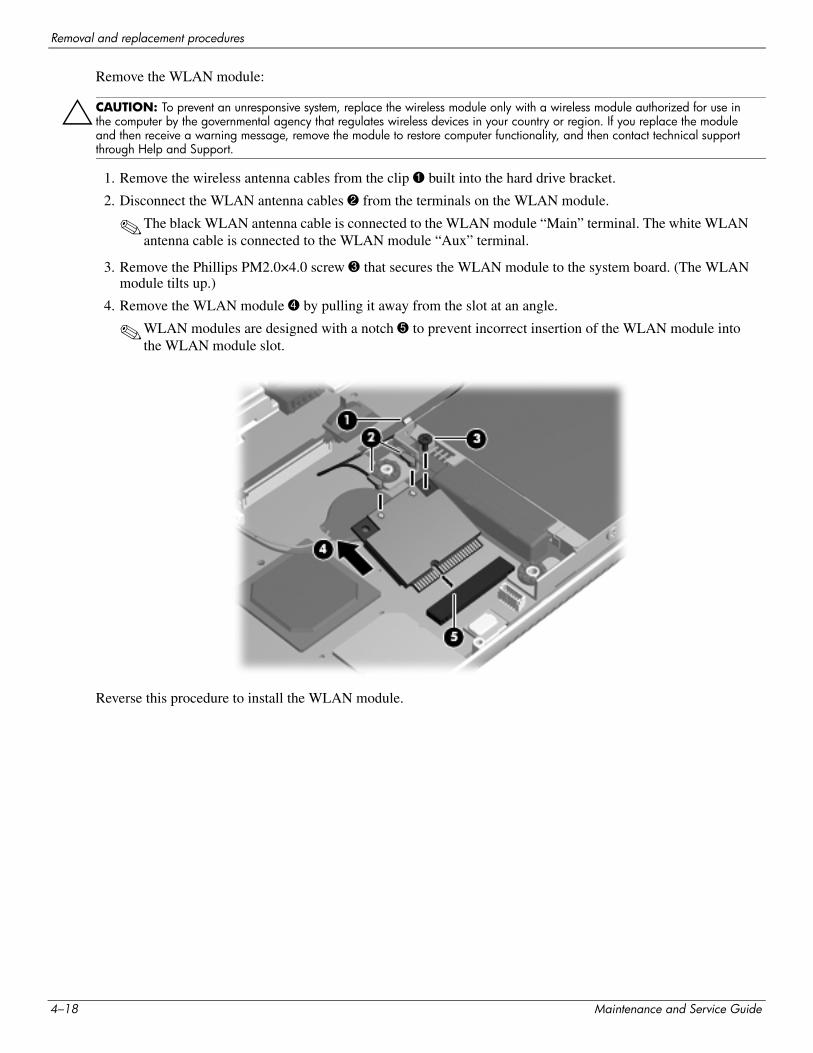
Removal and replacement procedures
Remove the WLAN module:
ÄCAUTION: To prevent an unresponsive system, replace the wireless module only with a wireless module authorized for use in the computer by the governmental agency that regulates wireless devices in your country or region. If you replace the module and then receive a warning message, remove the module to restore computer functionality, and then contact technical support through Help and Support.
1. Remove the wireless antenna cables from the clip 1 built into the hard drive bracket.
2. Disconnect the WLAN antenna cables 2 from the terminals on the WLAN module.
✎The black WLAN antenna cable is connected to the WLAN module “Main” terminal. The white WLAN antenna cable is connected to the WLAN module “Aux” terminal.
3. Remove the Phillips PM2.0×4.0 screw 3 that secures the WLAN module to the system board. (The WLAN module tilts up.)
4. Remove the WLAN module 4 by pulling it away from the slot at an angle.
✎WLAN modules are designed with a notch 5 to prevent incorrect insertion of the WLAN module into the WLAN module slot.
Reverse this procedure to install the WLAN module.
4–18 Maintenance and Service Guide
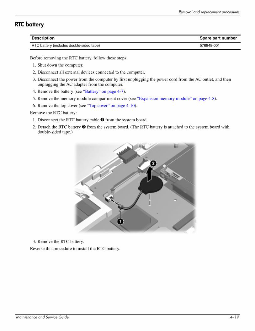
Removal and replacement procedures
RTC battery
Before removing the RTC battery, follow these steps:
1. Shut down the computer.
2. Disconnect all external devices connected to the computer.
3. Disconnect the power from the computer by first unplugging the power cord from the AC outlet, and then unplugging the AC adapter from the computer.
4. Remove the battery (see “Battery” on page 4-7).
5. Remove the memory module compartment cover (see “Expansion memory module” on page 4-8).
6. Remove the top cover (see “Top cover” on page 4-10).
Remove the RTC battery:
1. Disconnect the RTC battery cable 1 from the system board.
2. Detach the RTC battery 2 from the system board. (The RTC battery is attached to the system board with double-sided tape.)
3. Remove the RTC battery.
Reverse this procedure to install the RTC battery.
Description Spare part number
RTC battery (includes double-sided tape) 576848-001
Maintenance and Service Guide 4–19
Removal and replacement procedures
Hard drive
✎ The hard drive spare part kit includes a hard drive bracket, rubber isolators, and screws.
Before removing the hard drive, follow these steps:
1. Shut down the computer.
2. Disconnect all external devices connected to the computer.
3. Disconnect the power from the computer by first unplugging the power cord from the AC outlet, and then unplugging the AC adapter from the computer.
4. Remove the battery (see “Battery” on page 4-7).
5. Remove the memory module compartment cover (see “Expansion memory module” on page 4-8).
6. Remove the top cover (see “Top cover” on page 4-10).
Description Spare part number
2.5-in, 7200-rpm hard drive:
640-GB 576821-001
500-GB 576820-001
320-GB 576819-001
250-GB 576818-001
1.8-in, 5400-rpm hard drive:
320-GB 576823-001
250-GB 580129-001
160-GB 591171-001
Hard drive cable:
For use only with 2.5-in hard drives 576828-001
For use only with 1.8-in hard drives 576830-001
Hard Drive Hardware Kit (includes bracket, rubber isolators, and screws):
For use only with 2.5-in hard drives 576827-001
For use only with 1.8-in hard drives 576829-001
4–20 Maintenance and Service Guide
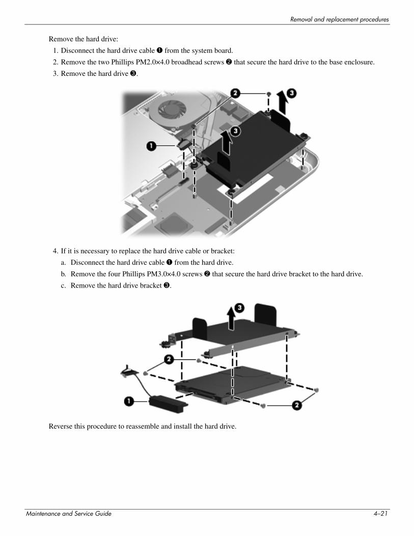
Removal and replacement procedures
Remove the hard drive:
1. Disconnect the hard drive cable 1 from the system board.
2. Remove the two Phillips PM2.0×4.0 broadhead screws 2 that secure the hard drive to the base enclosure.
3. Remove the hard drive 3.
4. If it is necessary to replace the hard drive cable or bracket:
a. Disconnect the hard drive cable 1 from the hard drive.
b. Remove the four Phillips PM3.0×4.0 screws 2 that secure the hard drive bracket to the hard drive.
c. Remove the hard drive bracket 3.
Reverse this procedure to reassemble and install the hard drive.
Maintenance and Service Guide 4–21
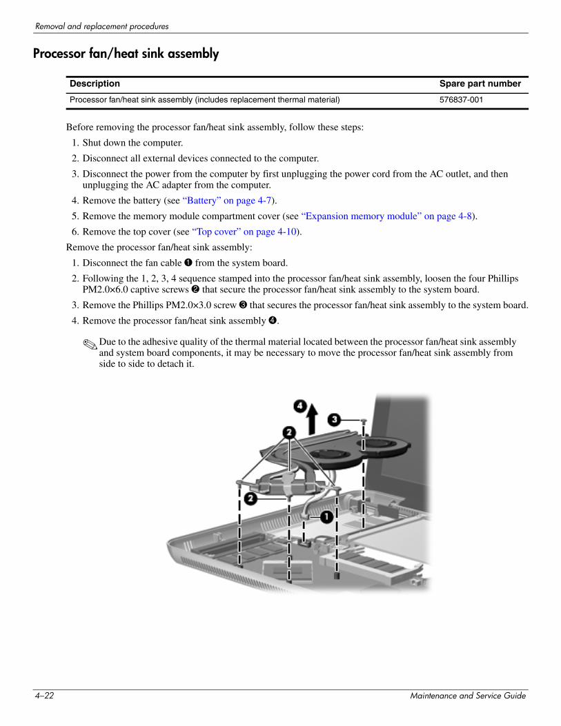
Removal and replacement procedures
Processor fan/heat sink assembly
Before removing the processor fan/heat sink assembly, follow these steps:
1. Shut down the computer.
2. Disconnect all external devices connected to the computer.
3. Disconnect the power from the computer by first unplugging the power cord from the AC outlet, and then unplugging the AC adapter from the computer.
4. Remove the battery (see “Battery” on page 4-7).
5. Remove the memory module compartment cover (see “Expansion memory module” on page 4-8).
6. Remove the top cover (see “Top cover” on page 4-10).
Remove the processor fan/heat sink assembly:
1. Disconnect the fan cable 1 from the system board.
2. Following the 1, 2, 3, 4 sequence stamped into the processor fan/heat sink assembly, loosen the four Phillips PM2.0×6.0 captive screws 2 that secure the processor fan/heat sink assembly to the system board.
3. Remove the Phillips PM2.0×3.0 screw 3 that secures the processor fan/heat sink assembly to the system board.
4. Remove the processor fan/heat sink assembly 4.
✎Due to the adhesive quality of the thermal material located between the processor fan/heat sink assembly and system board components, it may be necessary to move the processor fan/heat sink assembly from side to side to detach it.
Description Spare part number
Processor fan/heat sink assembly (includes replacement thermal material) 576837-001
4–22 Maintenance and Service Guide
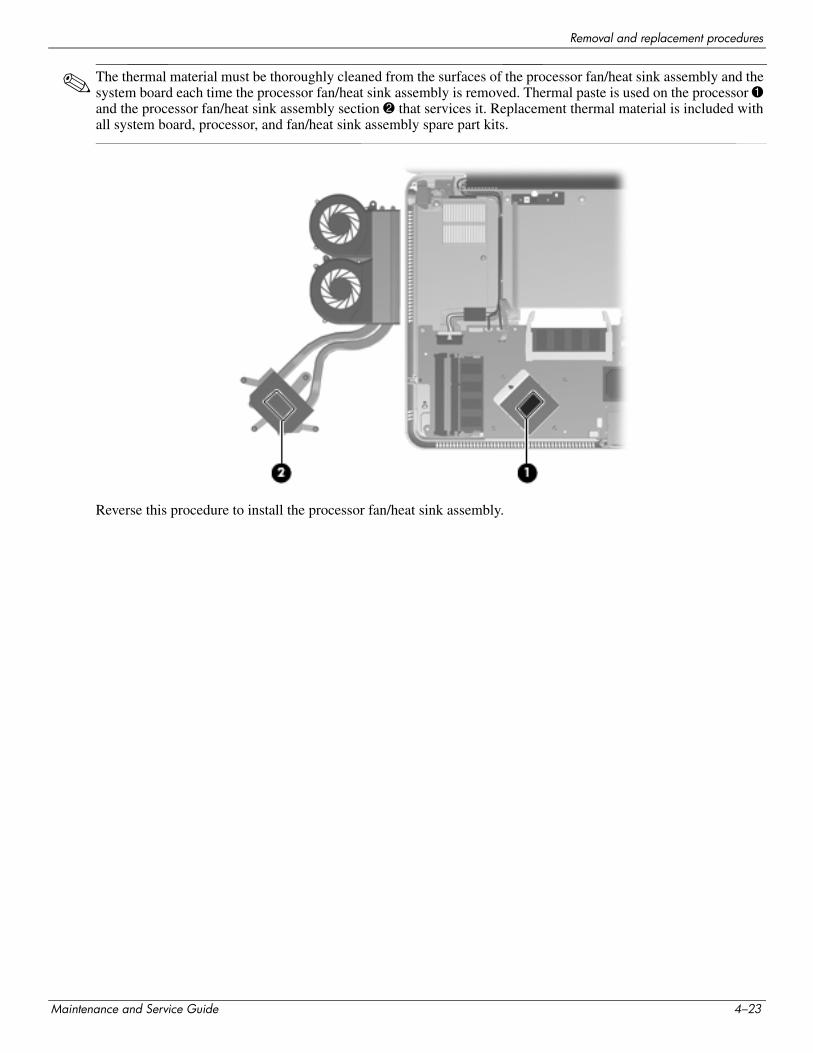
Removal and replacement procedures
✎ The thermal material must be thoroughly cleaned from the surfaces of the processor fan/heat sink assembly and the system board each time the processor fan/heat sink assembly is removed. Thermal paste is used on the processor 1 and the processor fan/heat sink assembly section 2 that services it. Replacement thermal material is included with all system board, processor, and fan/heat sink assembly spare part kits.
Reverse this procedure to install the processor fan/heat sink assembly.
Maintenance and Service Guide 4–23
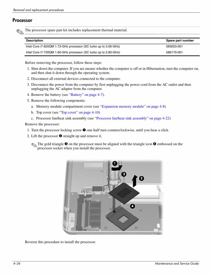
Removal and replacement procedures
Processor
✎ The processor spare part kit includes replacement thermal material.
Before removing the processor, follow these steps:
1. Shut down the computer. If you are unsure whether the computer is off or in Hibernation, turn the computer on, and then shut it down through the operating system.
2. Disconnect all external devices connected to the computer.
3. Disconnect the power from the computer by first unplugging the power cord from the AC outlet and then unplugging the AC adapter from the computer.
4. Remove the battery (see “Battery” on page 4-7).
5. Remove the following components:
a. Memory module compartment cover (see “Expansion memory module” on page 4-8)
b. Top cover (see “Top cover” on page 4-10)
c. Processor fan/heat sink assembly (see “Processor fan/heat sink assembly” on page 4-22)
Remove the processor:
1. Turn the processor locking screw 1 one-half turn counterclockwise, until you hear a click.
2. Lift the processor 2 straight up and remove it.
✎The gold triangle 3 on the processor must be aligned with the triangle icon 4 embossed on the processor socket when you install the processor.
Reverse this procedure to install the processor.
Description Spare part number
Intel Core i7-820QM 1.73-GHz processor (SC turbo up to 3.06-GHz) 583053-001
Intel Core i7-720QM 1.60-GHz processor (SC turbo up to 2.80-GHz) 586170-001
4–24 Maintenance and Service Guide
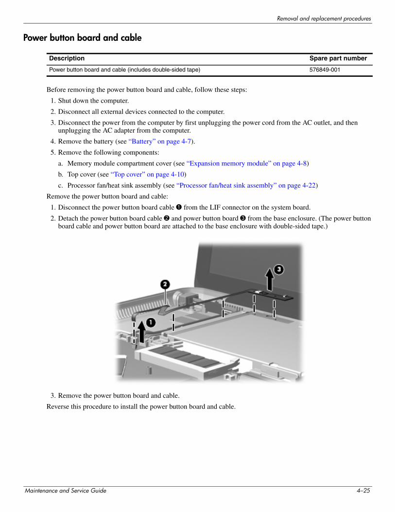
Removal and replacement procedures
Power button board and cable
Before removing the power button board and cable, follow these steps:
1. Shut down the computer.
2. Disconnect all external devices connected to the computer.
3. Disconnect the power from the computer by first unplugging the power cord from the AC outlet, and then unplugging the AC adapter from the computer.
4. Remove the battery (see “Battery” on page 4-7).
5. Remove the following components:
a. Memory module compartment cover (see “Expansion memory module” on page 4-8)
b. Top cover (see “Top cover” on page 4-10)
c. Processor fan/heat sink assembly (see “Processor fan/heat sink assembly” on page 4-22)
Remove the power button board and cable:
1. Disconnect the power button board cable 1 from the LIF connector on the system board.
2. Detach the power button board cable 2 and power button board 3 from the base enclosure. (The power button board cable and power button board are attached to the base enclosure with double-sided tape.)
3. Remove the power button board and cable.
Reverse this procedure to install the power button board and cable.
Description Spare part number
Power button board and cable (includes double-sided tape) 576849-001
Maintenance and Service Guide 4–25
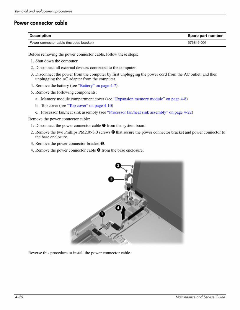
Removal and replacement procedures
Power connector cable
Before removing the power connector cable, follow these steps:
1. Shut down the computer.
2. Disconnect all external devices connected to the computer.
3. Disconnect the power from the computer by first unplugging the power cord from the AC outlet, and then unplugging the AC adapter from the computer.
4. Remove the battery (see “Battery” on page 4-7).
5. Remove the following components:
a. Memory module compartment cover (see “Expansion memory module” on page 4-8)
b. Top cover (see “Top cover” on page 4-10)
c. Processor fan/heat sink assembly (see “Processor fan/heat sink assembly” on page 4-22)
Remove the power connector cable:
1. Disconnect the power connector cable 1 from the system board.
2. Remove the two Phillips PM2.0×3.0 screws 2 that secure the power connector bracket and power connector to the base enclosure.
3. Remove the power connector bracket 3.
4. Remove the power connector cable 4 from the base enclosure.
Reverse this procedure to install the power connector cable.
Description Spare part number
Power connector cable (includes bracket) 576846-001
4–26 Maintenance and Service Guide
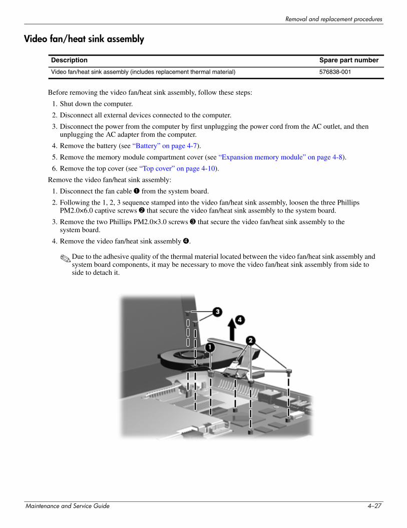
Removal and replacement procedures
Video fan/heat sink assembly
Before removing the video fan/heat sink assembly, follow these steps:
1. Shut down the computer.
2. Disconnect all external devices connected to the computer.
3. Disconnect the power from the computer by first unplugging the power cord from the AC outlet, and then unplugging the AC adapter from the computer.
4. Remove the battery (see “Battery” on page 4-7).
5. Remove the memory module compartment cover (see “Expansion memory module” on page 4-8).
6. Remove the top cover (see “Top cover” on page 4-10).
Remove the video fan/heat sink assembly:
1. Disconnect the fan cable 1 from the system board.
2. Following the 1, 2, 3 sequence stamped into the video fan/heat sink assembly, loosen the three Phillips PM2.0×6.0 captive screws 2 that secure the video fan/heat sink assembly to the system board.
3. Remove the two Phillips PM2.0×3.0 screws 3 that secure the video fan/heat sink assembly to the system board.
4. Remove the video fan/heat sink assembly 4.
✎Due to the adhesive quality of the thermal material located between the video fan/heat sink assembly and system board components, it may be necessary to move the video fan/heat sink assembly from side to side to detach it.
Description Spare part number
Video fan/heat sink assembly (includes replacement thermal material) 576838-001
Maintenance and Service Guide 4–27
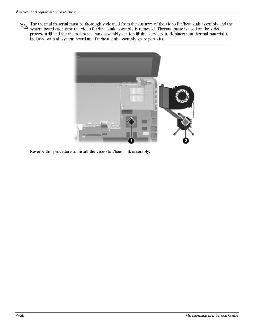
Removal and replacement procedures
✎ The thermal material must be thoroughly cleaned from the surfaces of the video fan/heat sink assembly and the system board each time the video fan/heat sink assembly is removed. Thermal paste is used on the video processor 1 and the video fan/heat sink assembly section 2 that services it. Replacement thermal material is included with all system board and fan/heat sink assembly spare part kits.
Reverse this procedure to install the video fan/heat sink assembly.
4–28 Maintenance and Service Guide
Removal and replacement procedures
System board
Before removing the system board, follow these steps:
1. Shut down the computer.
2. Disconnect all external devices connected to the computer.
3. Disconnect the power from the computer by first unplugging the power cord from the AC outlet, and then unplugging the AC adapter from the computer.
4. Remove the battery (see “Battery” on page 4-7).
5. Remove the following components:
a. Memory module compartment cover (see “Expansion memory module” on page 4-8)
b. Top cover (see “Top cover” on page 4-10)
c. Speaker assembly (see “Speaker assembly” on page 4-14)
d. Hard drive (see “Hard drive” on page 4-20)
e. Processor fan/heat sink assembly (see “Processor fan/heat sink assembly” on page 4-22)
f. Video fan/heat sink assembly (see “Video fan/heat sink assembly” on page 4-27)
When replacing the system board, be sure that the following additional components are removed from the defective system board and installed on the replacement system board:
■ Expansion and primary memory modules (see “Expansion memory module” on page 4-8 and “Primary memory module” on page 4-15)
■ WLAN module (see “WLAN module” on page 4-16)
■ RTC battery (see “RTC battery” on page 4-19)
■ Processor (see “Processor” on page 4-24)
Description Spare part number
PM57 PCH Peak-M system board with 1 GB of dedicated video memory (includes replacement thermal material)
576772-001
Maintenance and Service Guide 4–29
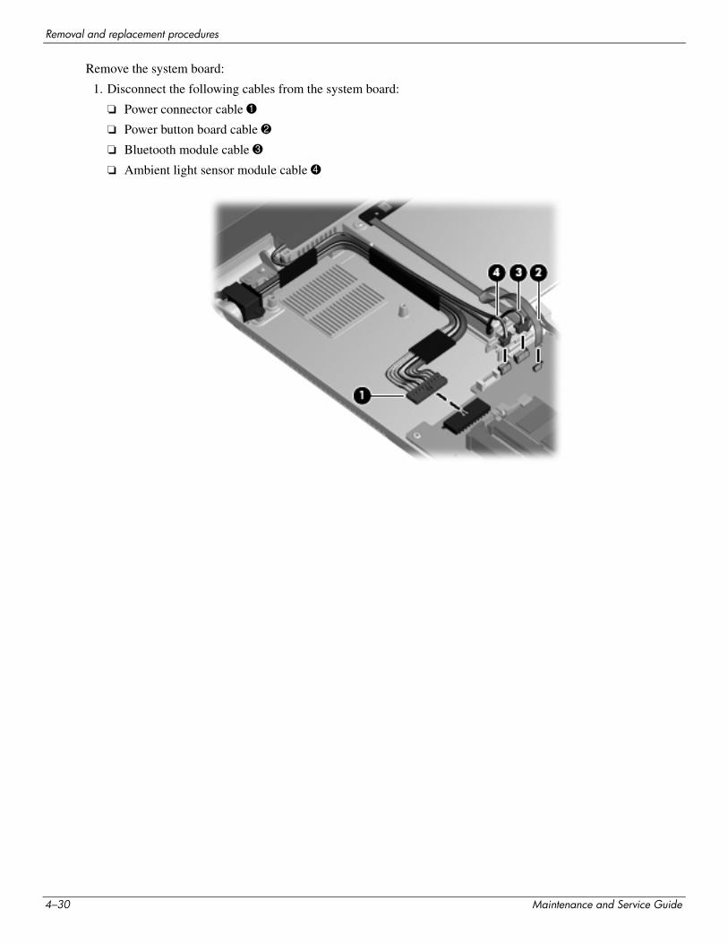
Removal and replacement procedures
Remove the system board:
1. Disconnect the following cables from the system board:
❏ Power connector cable 1
❏ Power button board cable 2
❏ Bluetooth module cable 3
❏ Ambient light sensor module cable 4
4–30 Maintenance and Service Guide
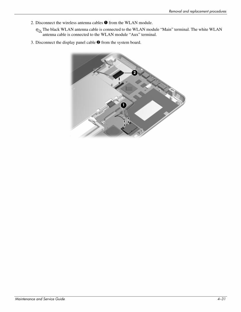
Removal and replacement procedures
2. Disconnect the wireless antenna cables 1 from the WLAN module.
✎The black WLAN antenna cable is connected to the WLAN module “Main” terminal. The white WLAN antenna cable is connected to the WLAN module “Aux” terminal.
3. Disconnect the display panel cable 2 from the system board.
Maintenance and Service Guide 4–31
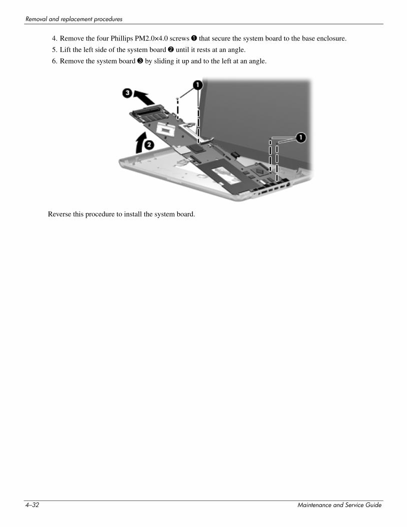
Removal and replacement procedures
4. Remove the four Phillips PM2.0×4.0 screws 1 that secure the system board to the base enclosure.
5. Lift the left side of the system board 2 until it rests at an angle.
6. Remove the system board 3 by sliding it up and to the left at an angle.
Reverse this procedure to install the system board.
4–32 Maintenance and Service Guide
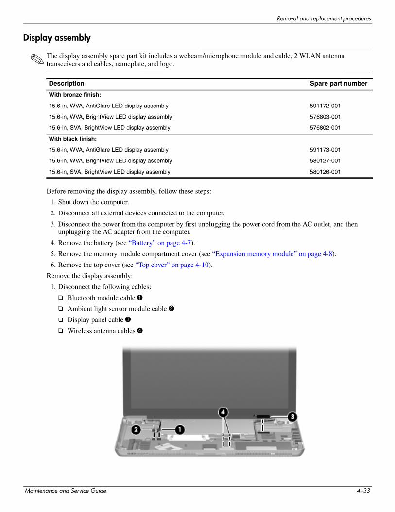
Removal and replacement procedures
Display assembly
✎ The display assembly spare part kit includes a webcam/microphone module and cable, 2 WLAN antenna transceivers and cables, nameplate, and logo.
Before removing the display assembly, follow these steps:
1. Shut down the computer.
2. Disconnect all external devices connected to the computer.
3. Disconnect the power from the computer by first unplugging the power cord from the AC outlet, and then unplugging the AC adapter from the computer.
4. Remove the battery (see “Battery” on page 4-7).
5. Remove the memory module compartment cover (see “Expansion memory module” on page 4-8).
6. Remove the top cover (see “Top cover” on page 4-10).
Remove the display assembly:
1. Disconnect the following cables:
❏ Bluetooth module cable 1
❏ Ambient light sensor module cable 2
❏ Display panel cable 3
❏ Wireless antenna cables 4
Description Spare part number
With bronze finish:
15.6-in, WVA, AntiGlare LED display assembly 591172-001
15.6-in, WVA, BrightView LED display assembly 576803-001
15.6-in, SVA, BrightView LED display assembly 576802-001
With black finish:
15.6-in, WVA, AntiGlare LED display assembly 591173-001
15.6-in, WVA, BrightView LED display assembly 580127-001
15.6-in, SVA, BrightView LED display assembly 580126-001
Maintenance and Service Guide 4–33
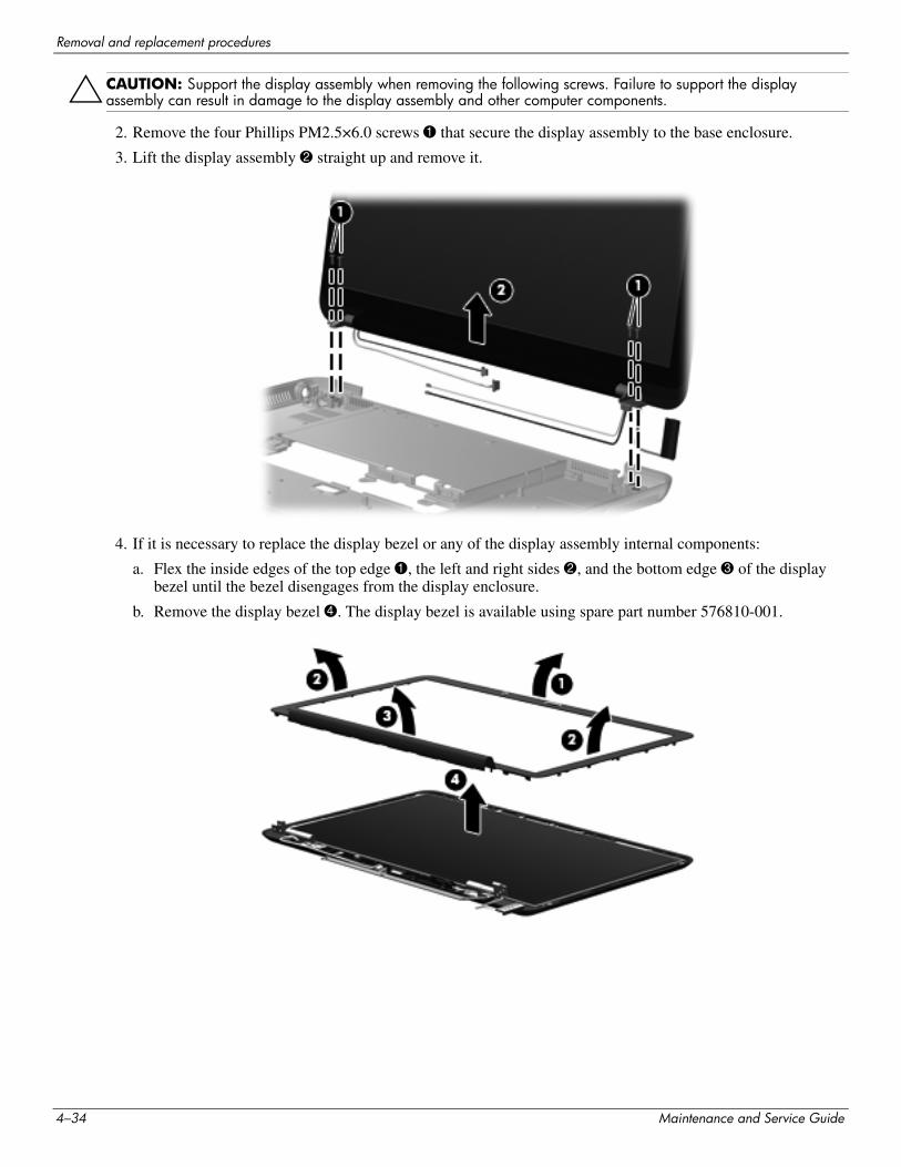
Removal and replacement procedures
ÄCAUTION: Support the display assembly when removing the following screws. Failure to support the display assembly can result in damage to the display assembly and other computer components.
2. Remove the four Phillips PM2.5×6.0 screws 1 that secure the display assembly to the base enclosure.
3. Lift the display assembly 2 straight up and remove it.
4. If it is necessary to replace the display bezel or any of the display assembly internal components:
a. Flex the inside edges of the top edge 1, the left and right sides 2, and the bottom edge 3 of the display bezel until the bezel disengages from the display enclosure.
b. Remove the display bezel 4. The display bezel is available using spare part number 576810-001.
4–34 Maintenance and Service Guide
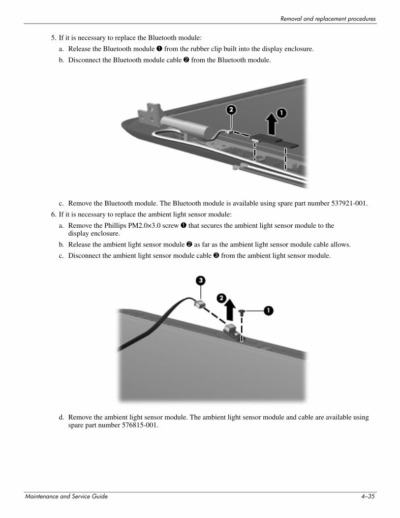
Removal and replacement procedures
5. If it is necessary to replace the Bluetooth module:
a. Release the Bluetooth module 1 from the rubber clip built into the display enclosure.
b. Disconnect the Bluetooth module cable 2 from the Bluetooth module.
c. Remove the Bluetooth module. The Bluetooth module is available using spare part number 537921-001.
6. If it is necessary to replace the ambient light sensor module:
a. Remove the Phillips PM2.0×3.0 screw 1 that secures the ambient light sensor module to the display enclosure.
b. Release the ambient light sensor module 2 as far as the ambient light sensor module cable allows.
c. Disconnect the ambient light sensor module cable 3 from the ambient light sensor module.
d. Remove the ambient light sensor module. The ambient light sensor module and cable are available using spare part number 576815-001.
Maintenance and Service Guide 4–35
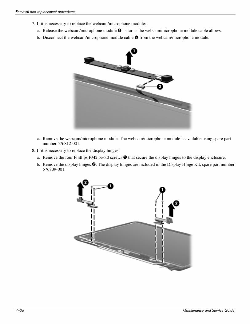
Removal and replacement procedures
7. If it is necessary to replace the webcam/microphone module:
a. Release the webcam/microphone module 1 as far as the webcam/microphone module cable allows.
b. Disconnect the webcam/microphone module cable 2 from the webcam/microphone module.
c. Remove the webcam/microphone module. The webcam/microphone module is available using spare part number 576812-001.
8. If it is necessary to replace the display hinges:
a. Remove the four Phillips PM2.5×6.0 screws 1 that secure the display hinges to the display enclosure.
b. Remove the display hinges 2. The display hinges are included in the Display Hinge Kit, spare part number 576809-001.
4–36 Maintenance and Service Guide
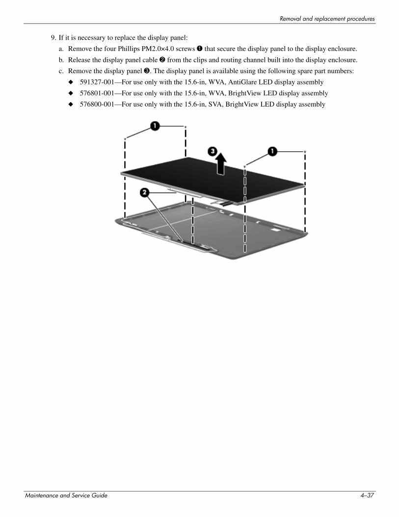
Removal and replacement procedures
9. If it is necessary to replace the display panel:
a. Remove the four Phillips PM2.0×4.0 screws 1 that secure the display panel to the display enclosure.
b. Release the display panel cable 2 from the clips and routing channel built into the display enclosure.
c. Remove the display panel 3. The display panel is available using the following spare part numbers:
◆ 591327-001—For use only with the 15.6-in, WVA, AntiGlare LED display assembly
◆ 576801-001—For use only with the 15.6-in, WVA, BrightView LED display assembly
◆ 576800-001—For use only with the 15.6-in, SVA, BrightView LED display assembly
Maintenance and Service Guide 4–37
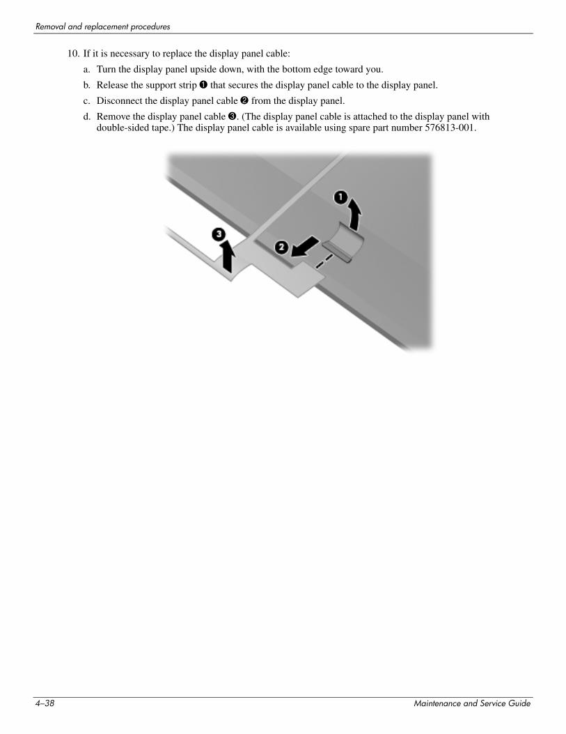
Removal and replacement procedures
10. If it is necessary to replace the display panel cable:
a. Turn the display panel upside down, with the bottom edge toward you.
b. Release the support strip 1 that secures the display panel cable to the display panel.
c. Disconnect the display panel cable 2 from the display panel.
d. Remove the display panel cable 3. (The display panel cable is attached to the display panel with double-sided tape.) The display panel cable is available using spare part number 576813-001.
4–38 Maintenance and Service Guide
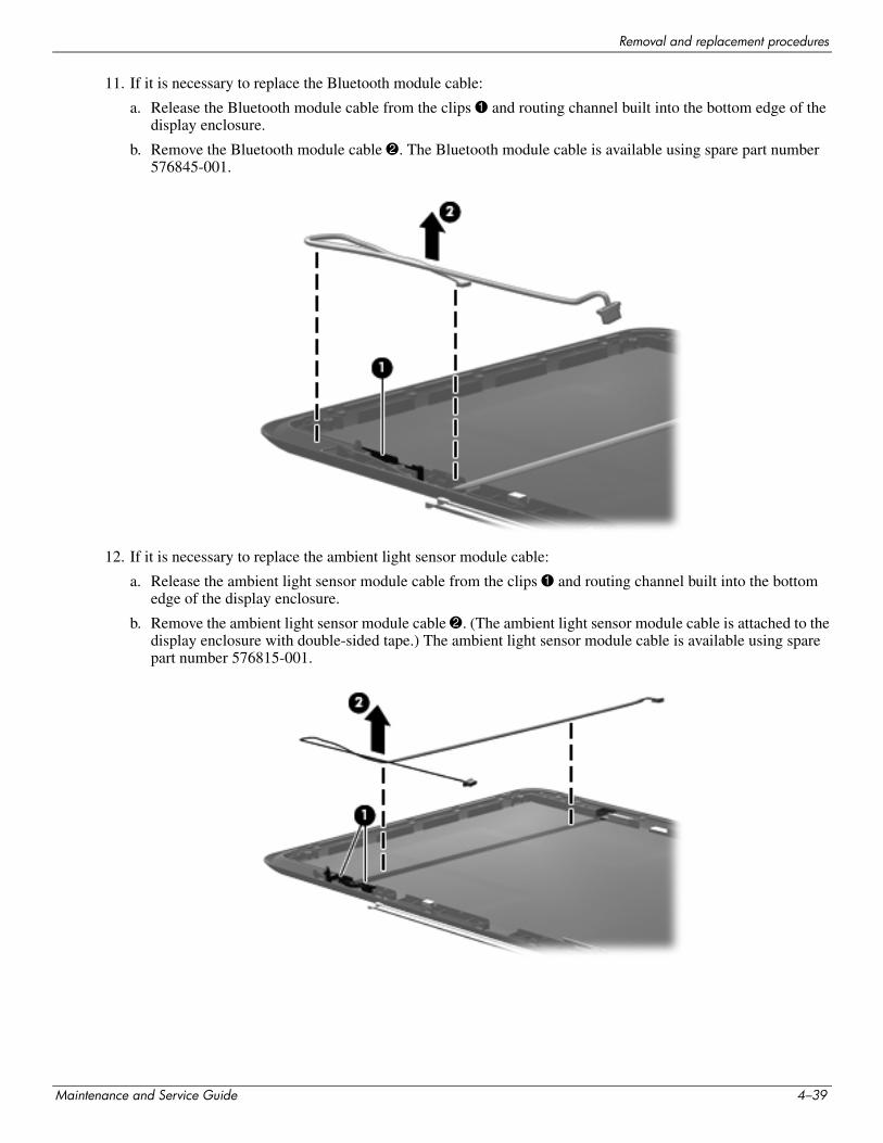
Removal and replacement procedures
11. If it is necessary to replace the Bluetooth module cable:
a. Release the Bluetooth module cable from the clips 1 and routing channel built into the bottom edge of the display enclosure.
b. Remove the Bluetooth module cable 2. The Bluetooth module cable is available using spare part number 576845-001.
12. If it is necessary to replace the ambient light sensor module cable:
a. Release the ambient light sensor module cable from the clips 1 and routing channel built into the bottom edge of the display enclosure.
b. Remove the ambient light sensor module cable 2. (The ambient light sensor module cable is attached to the display enclosure with double-sided tape.) The ambient light sensor module cable is available using spare part number 576815-001.
Maintenance and Service Guide 4–39
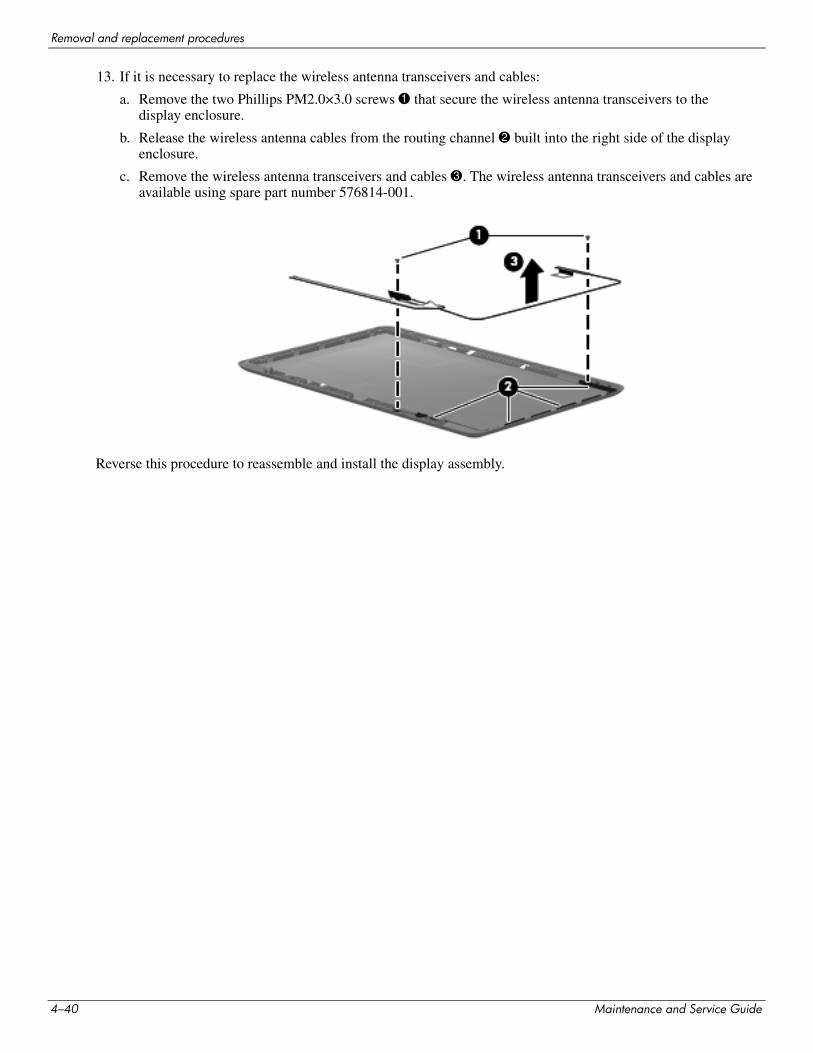
Removal and replacement procedures
13. If it is necessary to replace the wireless antenna transceivers and cables:
a. Remove the two Phillips PM2.0×3.0 screws 1 that secure the wireless antenna transceivers to the display enclosure.
b. Release the wireless antenna cables from the routing channel 2 built into the right side of the display enclosure.
c. Remove the wireless antenna transceivers and cables 3. The wireless antenna transceivers and cables are available using spare part number 576814-001.
Reverse this procedure to reassemble and install the display assembly.
4–40 Maintenance and Service Guide
5Setup Utility (BIOS)
Starting Setup UtilitySetup Utility is a ROM-based information and customization utility that can be used even when your Windows operating system is not working.
The utility reports information about the computer and provides settings for startup, security, and other preferences.
To start Setup Utility:
» Open Setup Utility by turning on or restarting the computer. While the “Press the ESC key for Startup Menu” message is displayed in the lower-left corner of the screen, press f10.
– or –1. Open Setup Utility by turning on or restarting the computer. While the “Press the ESC key for Startup Menu”
message is displayed in the lower-left corner of the screen, press esc.
2. When the Startup Menu is displayed, press f10.
Using Setup Utility
Changing the language of Setup Utility
The following procedure explains how to change the language of Setup Utility. If Setup Utility is not already running, begin at step 1. If Setup Utility is already running, begin at step 2.
1. Open Setup Utility by turning on or restarting the computer. While the “Press the ESC key for Startup Menu” message is displayed in the lower-left corner of the screen, press f10.
– or –
Open Setup Utility by turning on or restarting the computer. While the “Press the ESC key for Startup Menu” message is displayed in the lower-left corner of the screen, press esc. When the Startup Menu is displayed, press f10.
2. Use the arrow keys to select System Configuration > Language, and then press enter.
3. Use the arrow keys to select a language, and then press enter.
4. When a confirmation prompt with your language selected is displayed, press enter.
5. To save your change and exit Setup Utility, use the arrow keys to select Exit > Exit Saving Changes, and then press enter.
Your change goes into effect immediately.
Maintenance and Service Guide 5–1
Setup Utility (BIOS)
Navigating and selecting in Setup Utility
Because Setup Utility is not Windows based, it does not support the TouchPad. Navigation and selection are by keystroke.■ To choose a menu or a menu item, use the arrow keys.
■ To choose an item in a list or to toggle a field, for example an Enable/Disable field, use either the arrow keys or f5 or f6.
■ To select an item, press enter.
■ To close a text box or return to the menu display, press esc.
■ To display additional navigation and selection information while Setup Utility is open, press f1.
Displaying system information
The following procedure explains how to display system information in Setup Utility. If Setup Utility is not open, begin at step 1. If Setup Utility is open, begin at step 2.
1. Open Setup Utility by turning on or restarting the computer. While the “Press the ESC key for Startup Menu” message is displayed in the lower-left corner of the screen, press f10.
– or –
Open Setup Utility by turning on or restarting the computer. While the “Press the ESC key for Startup Menu message is displayed in the lower-left corner of the screen, press esc. When the Startup Menu is displayed, press f10.
2. Select the Main menu. System information such as the system time and date, and identification information about the computer is displayed.
3. To exit Setup Utility without changing any settings, use the arrow keys to select Exit > Exit Discarding Changes, and then press enter.
Restoring default settings in Setup Utility
The following procedure explains how to restore the Setup Utility default settings. If Setup Utility is not already running, begin at step 1. If Setup Utility is already running, begin at step 2.
1. Open Setup Utility by turning on or restarting the computer. While the “Press the ESC key for Startup Menu” message is displayed in the lower-left corner of the screen, press f10.
– or –
Open Setup Utility by turning on or restarting the computer. While the “Press the ESC key for Startup Menu” message is displayed in the lower-left corner of the screen, press esc. When the Startup Menu is displayed, press f10.
2. Use the arrow keys to select Exit > Load Setup Defaults, and then press enter.
3. When the Setup Confirmation is displayed, press enter.
4. To save your change and exit Setup Utility, use the arrow keys to select Exit > Exit Saving Changes, and then press enter.
The Setup Utility default settings go into effect when the computer restarts.
✎ Your password, security, and language settings are not changed when you restore the factory default settings.
5–2 Maintenance and Service Guide
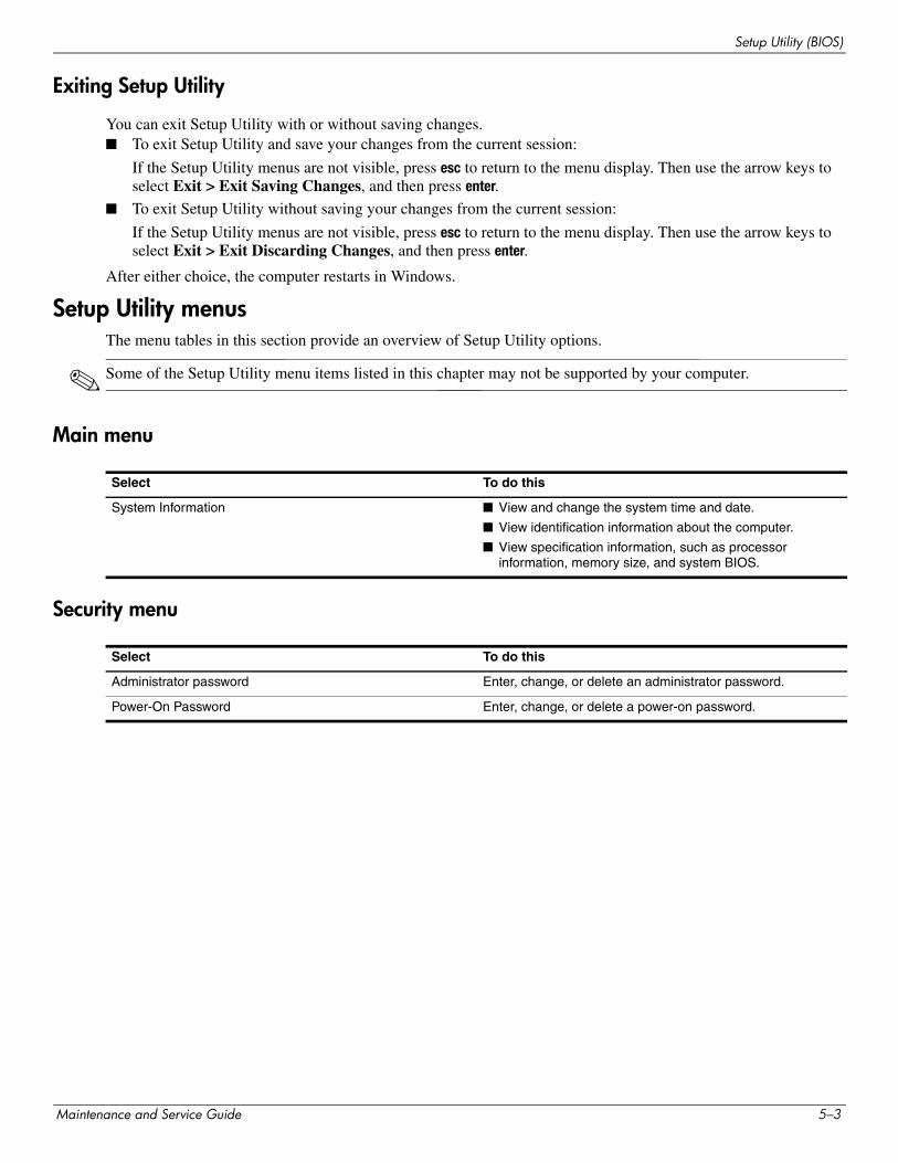
Setup Utility (BIOS)
Exiting Setup Utility
You can exit Setup Utility with or without saving changes.■ To exit Setup Utility and save your changes from the current session:
If the Setup Utility menus are not visible, press esc to return to the menu display. Then use the arrow keys to select Exit > Exit Saving Changes, and then press enter.
■ To exit Setup Utility without saving your changes from the current session:
If the Setup Utility menus are not visible, press esc to return to the menu display. Then use the arrow keys to select Exit > Exit Discarding Changes, and then press enter.
After either choice, the computer restarts in Windows.
Setup Utility menusThe menu tables in this section provide an overview of Setup Utility options.
✎ Some of the Setup Utility menu items listed in this chapter may not be supported by your computer.
Main menu
Security menu
Select To do this
System Information ■ View and change the system time and date.
■ View identification information about the computer.
■ View specification information, such as processor information, memory size, and system BIOS.
Select To do this
Administrator password Enter, change, or delete an administrator password.
Power-On Password Enter, change, or delete a power-on password.
Maintenance and Service Guide 5–3
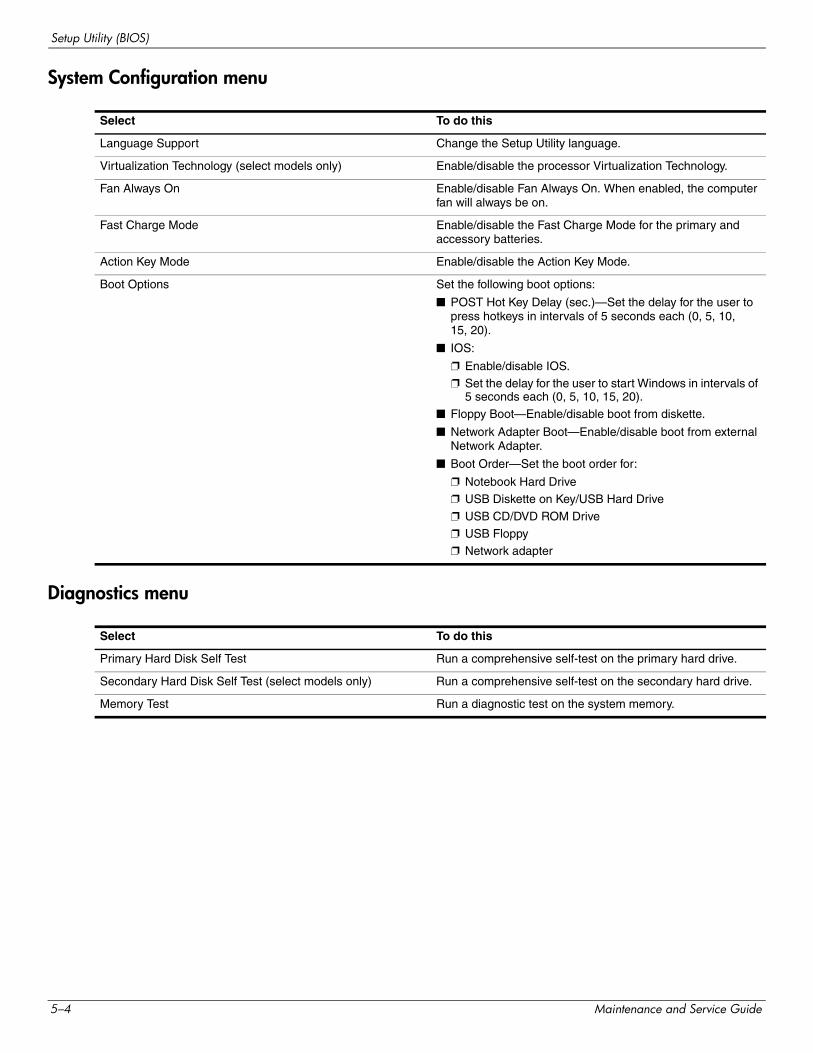
Setup Utility (BIOS)
System Configuration menu
Diagnostics menu
Select To do this
Language Support Change the Setup Utility language.
Virtualization Technology (select models only) Enable/disable the processor Virtualization Technology.
Fan Always On Enable/disable Fan Always On. When enabled, the computer fan will always be on.
Fast Charge Mode Enable/disable the Fast Charge Mode for the primary and accessory batteries.
Action Key Mode Enable/disable the Action Key Mode.
Boot Options Set the following boot options:
■ POST Hot Key Delay (sec.)—Set the delay for the user to press hotkeys in intervals of 5 seconds each (0, 5, 10, 15, 20).
■ IOS:
❐ Enable/disable IOS.❐ Set the delay for the user to start Windows in intervals of
5 seconds each (0, 5, 10, 15, 20).
■ Floppy Boot—Enable/disable boot from diskette.
■ Network Adapter Boot—Enable/disable boot from external Network Adapter.
■ Boot Order—Set the boot order for:
❐ Notebook Hard Drive❐ USB Diskette on Key/USB Hard Drive
❐ USB CD/DVD ROM Drive
❐ USB Floppy❐ Network adapter
Select To do this
Primary Hard Disk Self Test Run a comprehensive self-test on the primary hard drive.
Secondary Hard Disk Self Test (select models only) Run a comprehensive self-test on the secondary hard drive.
Memory Test Run a diagnostic test on the system memory.
5–4 Maintenance and Service Guide
Setup Utility (BIOS)
Updating the BIOSUpdated versions of the BIOS may be available on the HP Web site.
Most BIOS updates on the HP Web site are packaged in compressed files called SoftPaqs.
Some download packages contain a file named Readme.txt, which contains information regarding installing and troubleshooting the file.
Updating the BIOS
Determining the BIOS version
To determine whether available BIOS updates contain later BIOS versions than those currently installed on the computer, you need to know the version of the system BIOS currently installed.
BIOS version information (also known as ROM date and System BIOS) can be displayed by pressing fn+esc (if you are already in Windows) or by opening Setup Utility.
To use Setup Utility for displaying BIOS information:1. Open Setup Utility by turning on or restarting the computer. While the “Press the ESC key for Startup Menu”
message is displayed in the lower-left corner of the screen, press f10.
2. If Setup Utility does not open with the system information displayed, use the arrow keys to select the Main menu.
When the Main menu is selected, BIOS and other system information is displayed.
3. To exit Setup Utility, use the arrow keys to select Exit > Exit Discarding Changes, and then press enter.
Maintenance and Service Guide 5–5
Setup Utility (BIOS)
Downloading a BIOS update
ÄCAUTION: To prevent damage to the computer or an unsuccessful installation, download and install a BIOS update only when the computer is connected to reliable external power using the AC adapter. Do not download or install a BIOS update while the computer is running on battery power, docked in an optional docking device, or connected to an optional power source. During the download and installation, follow these instructions:Do not disconnect power from the computer by unplugging the power cord from the AC outlet.Do not shut down the computer or initiate Sleep or Hibernation.Do not insert, remove, connect, or disconnect any device, cable, or cord.
To download a BIOS update:1. Access the page on the HP Web site that provides software for your computer:
Select Start > Help and Support > Maintain.
2. Follow the instructions on the screen to identify your computer and access the BIOS update you want to download.
3. At the download area, follow these steps:
a. Identify the BIOS update that is later than the BIOS version currently installed on your computer. Make a note of the date, name, or other identifier. You may need this information to locate the update later, after it has been downloaded to your hard drive.
b. Follow the instructions on the screen to download your selection to the hard drive.
Make a note of the path to the location on your hard drive where the BIOS update will be downloaded. You will need to access this path when you are ready to install the update.
✎ If you connect your computer to a network, consult the network administrator before installing any software updates, especially system BIOS updates.
BIOS installation procedures vary. Follow any instructions that are displayed on the screen after the download is complete. If no instructions are displayed, follow these steps:
1. Open Windows Explorer by selecting Start > Computer.
2. Double-click your hard drive designation. The hard drive designation is typically Local Disk (C:).
3. Using the hard drive path you recorded earlier, open the folder on your hard drive that contains the update.
4. Double-click the file that has an .exe extension (for example, filename.exe).
The BIOS installation begins.
5. Complete the installation by following the instructions on the screen.
✎ After a message on the screen reports a successful installation, you can delete the downloaded file from your hard drive.
5–6 Maintenance and Service Guide
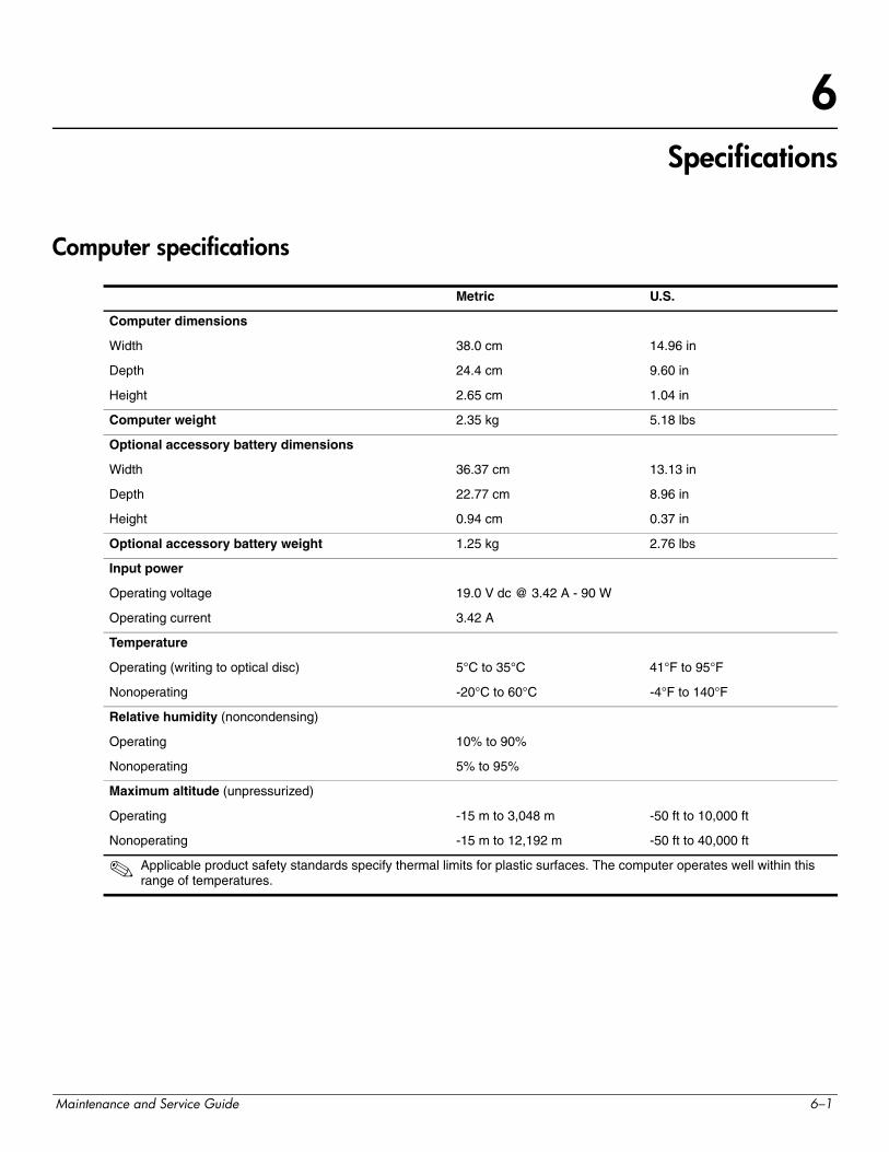
6Specifications
Computer specifications
Metric U.S.
Computer dimensions
Width 38.0 cm 14.96 in
Depth 24.4 cm 9.60 in
Height 2.65 cm 1.04 in
Computer weight 2.35 kg 5.18 lbs
Optional accessory battery dimensions
Width 36.37 cm 13.13 in
Depth 22.77 cm 8.96 in
Height 0.94 cm 0.37 in
Optional accessory battery weight 1.25 kg 2.76 lbs
Input power
Operating voltage 19.0 V dc @ 3.42 A - 90 W
Operating current 3.42 A
Temperature
Operating (writing to optical disc) 5°C to 35°C 41°F to 95°F
Nonoperating -20°C to 60°C -4°F to 140°F
Relative humidity (noncondensing)
Operating 10% to 90%
Nonoperating 5% to 95%
Maximum altitude (unpressurized)
Operating -15 m to 3,048 m -50 ft to 10,000 ft
Nonoperating -15 m to 12,192 m -50 ft to 40,000 ft
✎ Applicable product safety standards specify thermal limits for plastic surfaces. The computer operates well within this range of temperatures.
Maintenance and Service Guide 6–1
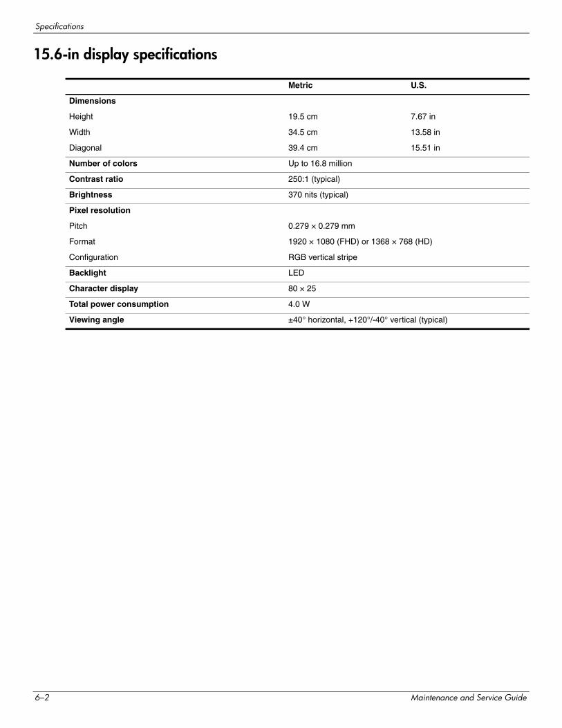
Specifications
15.6-in display specifications
Metric U.S.
Dimensions
Height 19.5 cm 7.67 in
Width 34.5 cm 13.58 in
Diagonal 39.4 cm 15.51 in
Number of colors Up to 16.8 million
Contrast ratio 250:1 (typical)
Brightness 370 nits (typical)
Pixel resolution
Pitch 0.279 × 0.279 mm
Format 1920 × 1080 (FHD) or 1368 × 768 (HD)
Configuration RGB vertical stripe
Backlight LED
Character display 80 × 25
Total power consumption 4.0 W
Viewing angle ±40° horizontal, +120°/-40° vertical (typical)
6–2 Maintenance and Service Guide
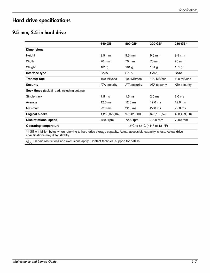
Specifications
Hard drive specifications
9.5-mm, 2.5-in hard drive
640-GB* 500-GB* 320-GB* 250-GB*
Dimensions
Height 9.5 mm 9.5 mm 9.5 mm 9.5 mm
Width 70 mm 70 mm 70 mm 70 mm
Weight 101 g 101 g 101 g 101 g
Interface type SATA SATA SATA SATA
Transfer rate 100 MB/sec 100 MB/sec 100 MB/sec 100 MB/sec
Security ATA security ATA security ATA security ATA security
Seek times (typical read, including setting)
Single track 1.5 ms 1.5 ms 2.0 ms 2.0 ms
Average 12.0 ms 12.0 ms 12.0 ms 12.0 ms
Maximum 22.0 ms 22.0 ms 22.0 ms 22.0 ms
Logical blocks 1,250,327,040 976,818,008 625,163,520 488,409,016
Disc rotational speed 7200 rpm 7200 rpm 7200 rpm 7200 rpm
Operating temperature 5°C to 55°C (41°F to 131°F)
*1 GB = 1 billion bytes when referring to hard drive storage capacity. Actual accessible capacity is less. Actual drive specifications may differ slightly.
✎ Certain restrictions and exclusions apply. Contact technical support for details.
Maintenance and Service Guide 6–3
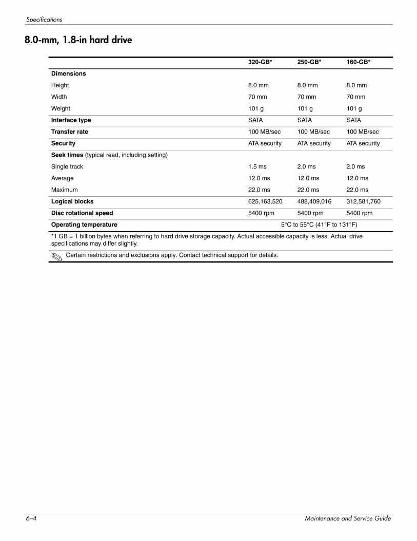
Specifications
8.0-mm, 1.8-in hard drive
320-GB* 250-GB* 160-GB*
Dimensions
Height 8.0 mm 8.0 mm 8.0 mm
Width 70 mm 70 mm 70 mm
Weight 101 g 101 g 101 g
Interface type SATA SATA SATA
Transfer rate 100 MB/sec 100 MB/sec 100 MB/sec
Security ATA security ATA security ATA security
Seek times (typical read, including setting)
Single track 1.5 ms 2.0 ms 2.0 ms
Average 12.0 ms 12.0 ms 12.0 ms
Maximum 22.0 ms 22.0 ms 22.0 ms
Logical blocks 625,163,520 488,409,016 312,581,760
Disc rotational speed 5400 rpm 5400 rpm 5400 rpm
Operating temperature 5°C to 55°C (41°F to 131°F)
*1 GB = 1 billion bytes when referring to hard drive storage capacity. Actual accessible capacity is less. Actual drive specifications may differ slightly.
✎ Certain restrictions and exclusions apply. Contact technical support for details.
6–4 Maintenance and Service Guide
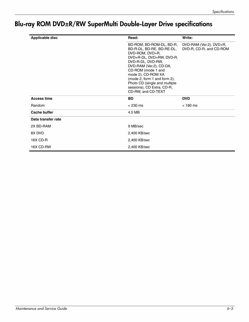
Specifications
Blu-ray ROM DVD±R/RW SuperMulti Double-Layer Drive specifications
Applicable disc Read: Write:
BD-ROM, BD-ROM-DL, BD-R, BD-R-DL, BD-RE, BD-RE-DL, DVD-ROM, DVD+R, DVD+R-DL, DVD+RW, DVD-R, DVD-R-DL, DVD-RW, DVD-RAM (Ver.2), CD-DA, CD-ROM (mode 1 and mode 2), CD-ROM XA (mode 2, form 1 and form 2), Photo CD (single and multiple sessions), CD Extra, CD-R, CD-RW, and CD-TEXT
DVD-RAM (Ver.2), DVD+R, DVD-R, CD-R, and CD-ROM
Access time BD DVD
Random < 230 ms < 180 ms
Cache buffer 4.5 MB
Data transfer rate
2X BD-RAM 9 MB/sec
8X DVD 2,400 KB/sec
16X CD-R 2,400 KB/sec
16X CD-RW 2,400 KB/sec
Maintenance and Service Guide 6–5
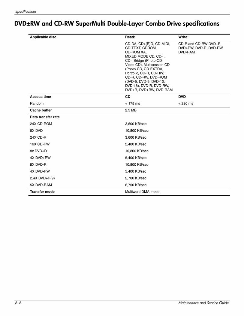
Specifications
DVD±RW and CD-RW SuperMulti Double-Layer Combo Drive specifications
Applicable disc Read: Write:
CD-DA, CD+(E)G, CD-MIDI, CD-TEXT, CDROM, CD-ROM XA, MIXED MODE CD, CD-I, CD-I Bridge (Photo-CD, Video CD), Multisession CD (Photo-CD, CD-EXTRA, Portfolio, CD-R, CD-RW), CD-R, CD-RW, DVD-ROM (DVD-5, DVD-9, DVD-10, DVD-18), DVD-R, DVD-RW, DVD+R, DVD+RW, DVD-RAM
CD-R and CD-RW DVD+R, DVD+RW, DVD-R, DVD-RW, DVD-RAM
Access time CD DVD
Random < 175 ms < 230 ms
Cache buffer 2.5 MB
Data transfer rate
24X CD-ROM 3,600 KB/sec
8X DVD 10,800 KB/sec
24X CD-R 3,600 KB/sec
16X CD-RW 2,400 KB/sec
8x DVD+R 10,800 KB/sec
4X DVD+RW 5,400 KB/sec
8X DVD-R 10,800 KB/sec
4X DVD-RW 5,400 KB/sec
2.4X DVD+R(9) 2,700 KB/sec
5X DVD-RAM 6,750 KB/sec
Transfer mode Multiword DMA mode
6–6 Maintenance and Service Guide
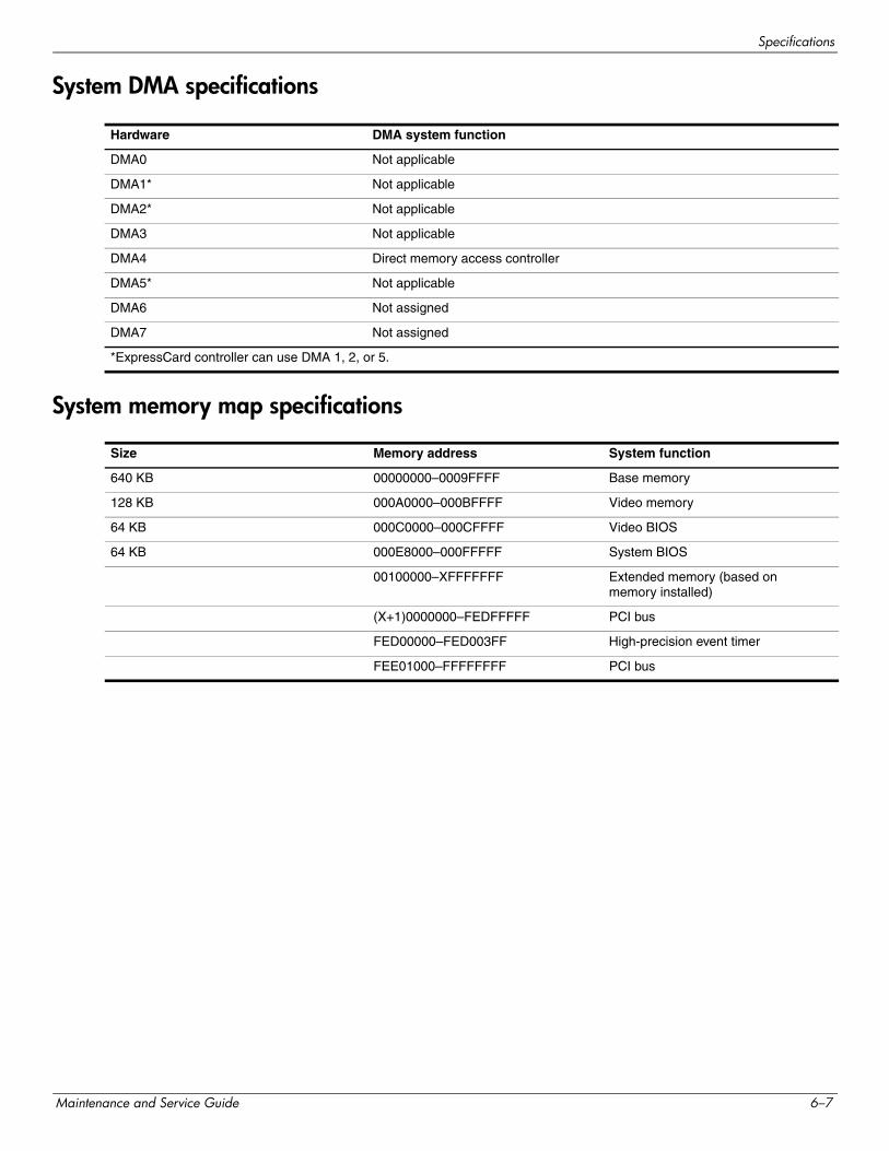
Specifications
System DMA specifications
System memory map specifications
Hardware DMA system function
DMA0 Not applicable
DMA1* Not applicable
DMA2* Not applicable
DMA3 Not applicable
DMA4 Direct memory access controller
DMA5* Not applicable
DMA6 Not assigned
DMA7 Not assigned
*ExpressCard controller can use DMA 1, 2, or 5.
Size Memory address System function
640 KB 00000000–0009FFFF Base memory
128 KB 000A0000–000BFFFF Video memory
64 KB 000C0000–000CFFFF Video BIOS
64 KB 000E8000–000FFFFF System BIOS
00100000–XFFFFFFF Extended memory (based on memory installed)
(X+1)0000000–FEDFFFFF PCI bus
FED00000–FED003FF High-precision event timer
FEE01000–FFFFFFFF PCI bus
Maintenance and Service Guide 6–7
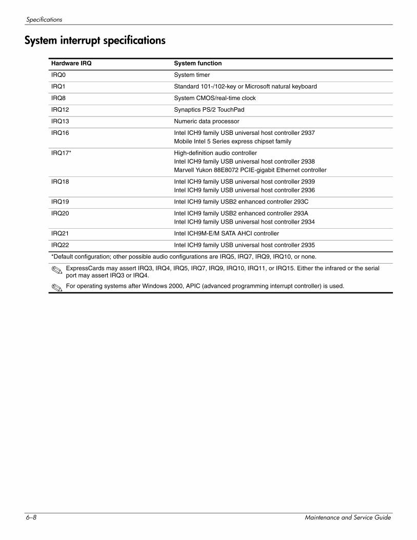
Specifications
System interrupt specifications
Hardware IRQ System function
IRQ0 System timer
IRQ1 Standard 101-/102-key or Microsoft natural keyboard
IRQ8 System CMOS/real-time clock
IRQ12 Synaptics PS/2 TouchPad
IRQ13 Numeric data processor
IRQ16 Intel ICH9 family USB universal host controller 2937Mobile Intel 5 Series express chipset family
IRQ17* High-definition audio controllerIntel ICH9 family USB universal host controller 2938 Marvell Yukon 88E8072 PCIE-gigabit Ethernet controller
IRQ18 Intel ICH9 family USB universal host controller 2939Intel ICH9 family USB universal host controller 2936
IRQ19 Intel ICH9 family USB2 enhanced controller 293C
IRQ20 Intel ICH9 family USB2 enhanced controller 293AIntel ICH9 family USB universal host controller 2934
IRQ21 Intel ICH9M-E/M SATA AHCI controller
IRQ22 Intel ICH9 family USB universal host controller 2935
*Default configuration; other possible audio configurations are IRQ5, IRQ7, IRQ9, IRQ10, or none.
✎ ExpressCards may assert IRQ3, IRQ4, IRQ5, IRQ7, IRQ9, IRQ10, IRQ11, or IRQ15. Either the infrared or the serial port may assert IRQ3 or IRQ4.
✎ For operating systems after Windows 2000, APIC (advanced programming interrupt controller) is used.
6–8 Maintenance and Service Guide
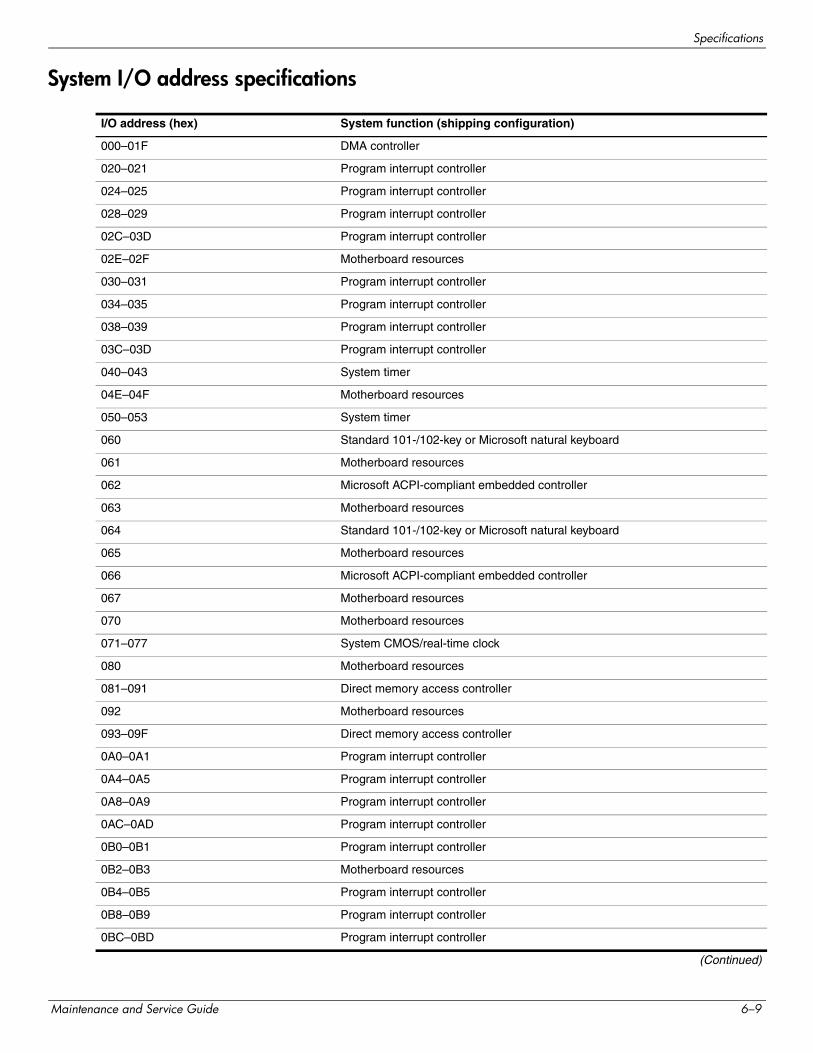
Specifications
System I/O address specifications
I/O address (hex) System function (shipping configuration)
000–01F DMA controller
020–021 Program interrupt controller
024–025 Program interrupt controller
028–029 Program interrupt controller
02C–03D Program interrupt controller
02E–02F Motherboard resources
030–031 Program interrupt controller
034–035 Program interrupt controller
038–039 Program interrupt controller
03C–03D Program interrupt controller
040–043 System timer
04E–04F Motherboard resources
050–053 System timer
060 Standard 101-/102-key or Microsoft natural keyboard
061 Motherboard resources
062 Microsoft ACPI-compliant embedded controller
063 Motherboard resources
064 Standard 101-/102-key or Microsoft natural keyboard
065 Motherboard resources
066 Microsoft ACPI-compliant embedded controller
067 Motherboard resources
070 Motherboard resources
071–077 System CMOS/real-time clock
080 Motherboard resources
081–091 Direct memory access controller
092 Motherboard resources
093–09F Direct memory access controller
0A0–0A1 Program interrupt controller
0A4–0A5 Program interrupt controller
0A8–0A9 Program interrupt controller
0AC–0AD Program interrupt controller
0B0–0B1 Program interrupt controller
0B2–0B3 Motherboard resources
0B4–0B5 Program interrupt controller
0B8–0B9 Program interrupt controller
0BC–0BD Program interrupt controller
(Continued)
Maintenance and Service Guide 6–9
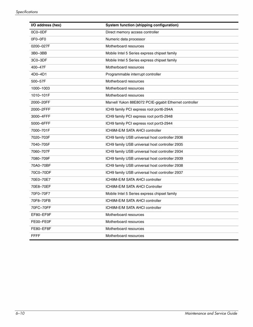
Specifications
0C0–0DF Direct memory access controller
0F0–0F0 Numeric data processor
0200–027F Motherboard resources
3B0–3BB Mobile Intel 5 Series express chipset family
3C0–3DF Mobile Intel 5 Series express chipset family
400–47F Motherboard resources
4D0–4D1 Programmable interrupt controller
500–57F Motherboard resources
1000–1003 Motherboard resources
1010–101F Motherboard resources
2000–20FF Marvell Yukon 88E8072 PCIE-gigabit Ethernet controller
2000–2FFF ICH9 family PCI express root port6-294A
3000–4FFF ICH9 family PCI express root port5-2948
5000–6FFF ICH9 family PCI express root port3-2944
7000–701F ICH9M-E/M SATA AHCI controller
7020–703F ICH9 family USB universal host controller 2936
7040–705F ICH9 family USB universal host controller 2935
7060–707F ICH9 family USB universal host controller 2934
7080–709F ICH9 family USB universal host controller 2939
70A0–70BF ICH9 family USB universal host controller 2938
70C0–70DF ICH9 family USB universal host controller 2937
70E0–70E7 ICH9M-E/M SATA AHCI controller
70E8–70EF ICH9M-E/M SATA AHCI Controller
70F0–70F7 Mobile Intel 5 Series express chipset family
70F8–70FB ICH9M-E/M SATA AHCI controller
70FC–70FF ICH9M-E/M SATA AHCI controller
EF80–EF9F Motherboard resources
FE00–FE0F Motherboard resources
FE80–EF8F Motherboard resources
FFFF Motherboard resources
I/O address (hex) System function (shipping configuration)
6–10 Maintenance and Service Guide
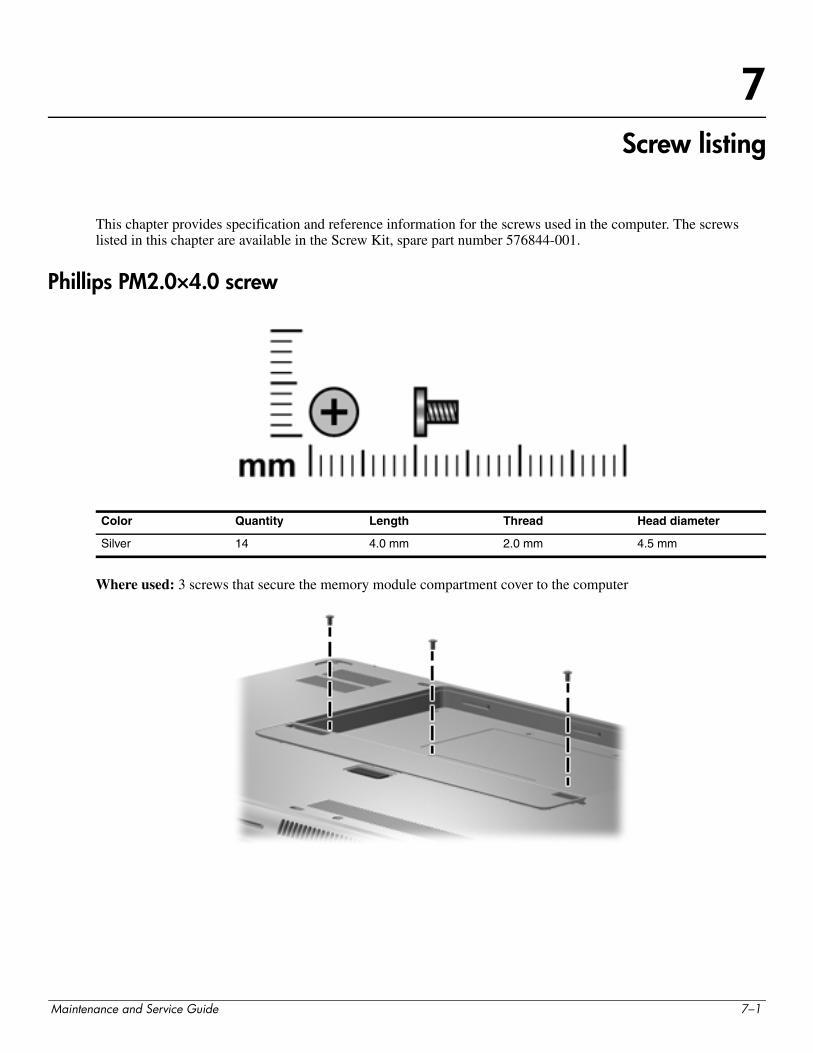
7Screw listing
This chapter provides specification and reference information for the screws used in the computer. The screws listed in this chapter are available in the Screw Kit, spare part number 576844-001.
Phillips PM2.0×4.0 screw
Where used: 3 screws that secure the memory module compartment cover to the computer
Color Quantity Length Thread Head diameter
Silver 14 4.0 mm 2.0 mm 4.5 mm
Maintenance and Service Guide 7–1
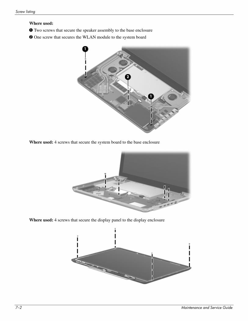
Screw listing
Where used:
1 Two screws that secure the speaker assembly to the base enclosure
2 One screw that secures the WLAN module to the system board
Where used: 4 screws that secure the system board to the base enclosure
Where used: 4 screws that secure the display panel to the display enclosure
7–2 Maintenance and Service Guide
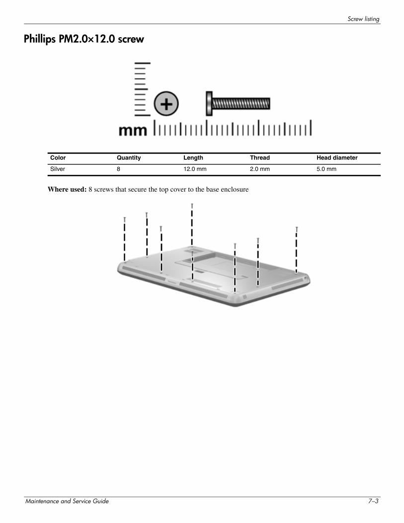
Screw listing
Phillips PM2.0×12.0 screw
Where used: 8 screws that secure the top cover to the base enclosure
Color Quantity Length Thread Head diameter
Silver 8 12.0 mm 2.0 mm 5.0 mm
Maintenance and Service Guide 7–3
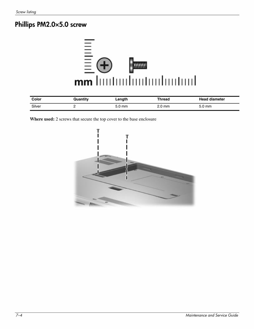
Screw listing
Phillips PM2.0×5.0 screw
Where used: 2 screws that secure the top cover to the base enclosure
Color Quantity Length Thread Head diameter
Silver 2 5.0 mm 2.0 mm 5.0 mm
7–4 Maintenance and Service Guide
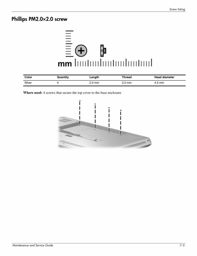
Screw listing
Phillips PM2.0×2.0 screw
Where used: 4 screws that secure the top cover to the base enclosure
Color Quantity Length Thread Head diameter
Silver 4 2.0 mm 2.0 mm 4.5 mm
Maintenance and Service Guide 7–5
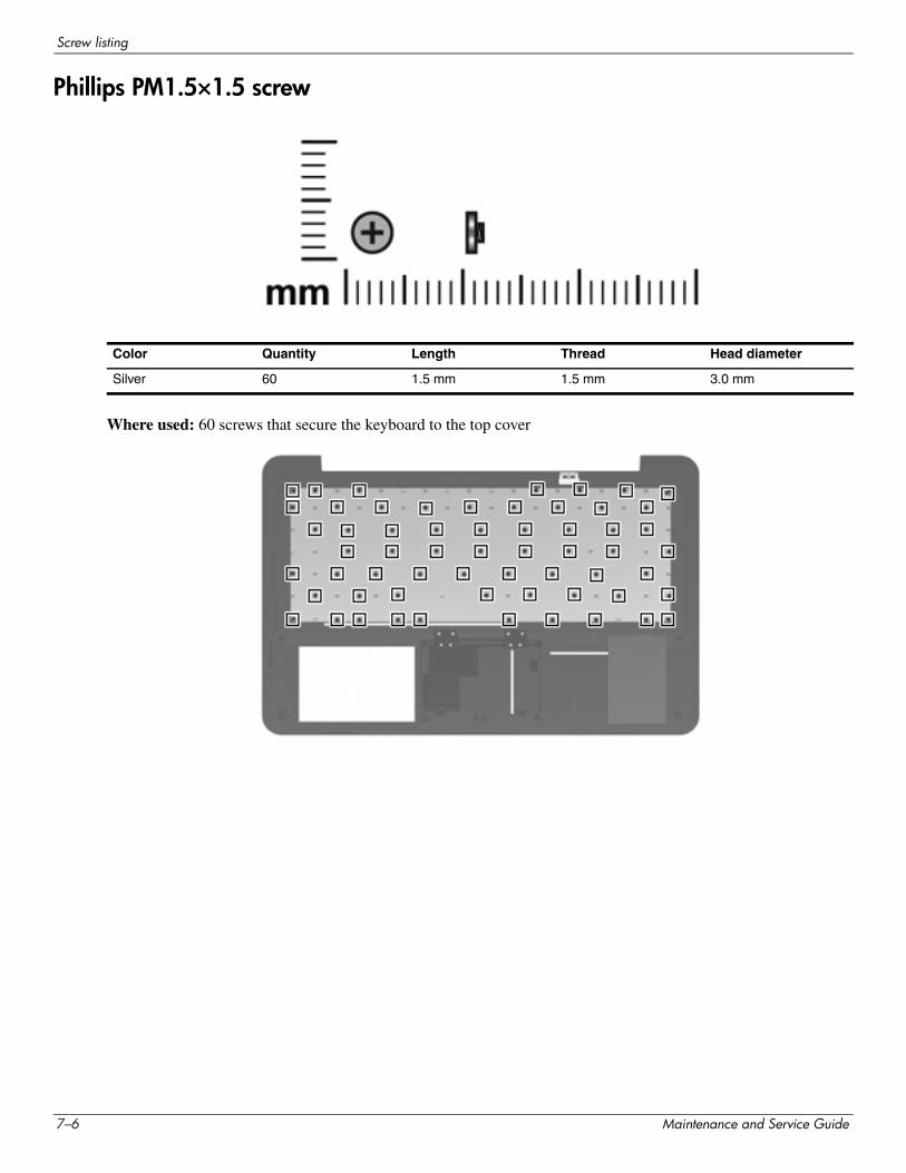
Screw listing
Phillips PM1.5×1.5 screw
Where used: 60 screws that secure the keyboard to the top cover
Color Quantity Length Thread Head diameter
Silver 60 1.5 mm 1.5 mm 3.0 mm
7–6 Maintenance and Service Guide
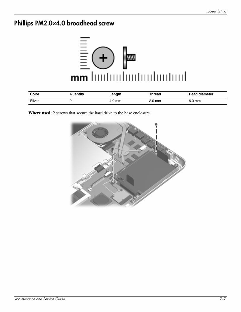
Screw listing
Phillips PM2.0×4.0 broadhead screw
Where used: 2 screws that secure the hard drive to the base enclosure
Color Quantity Length Thread Head diameter
Silver 2 4.0 mm 2.0 mm 6.0 mm
Maintenance and Service Guide 7–7
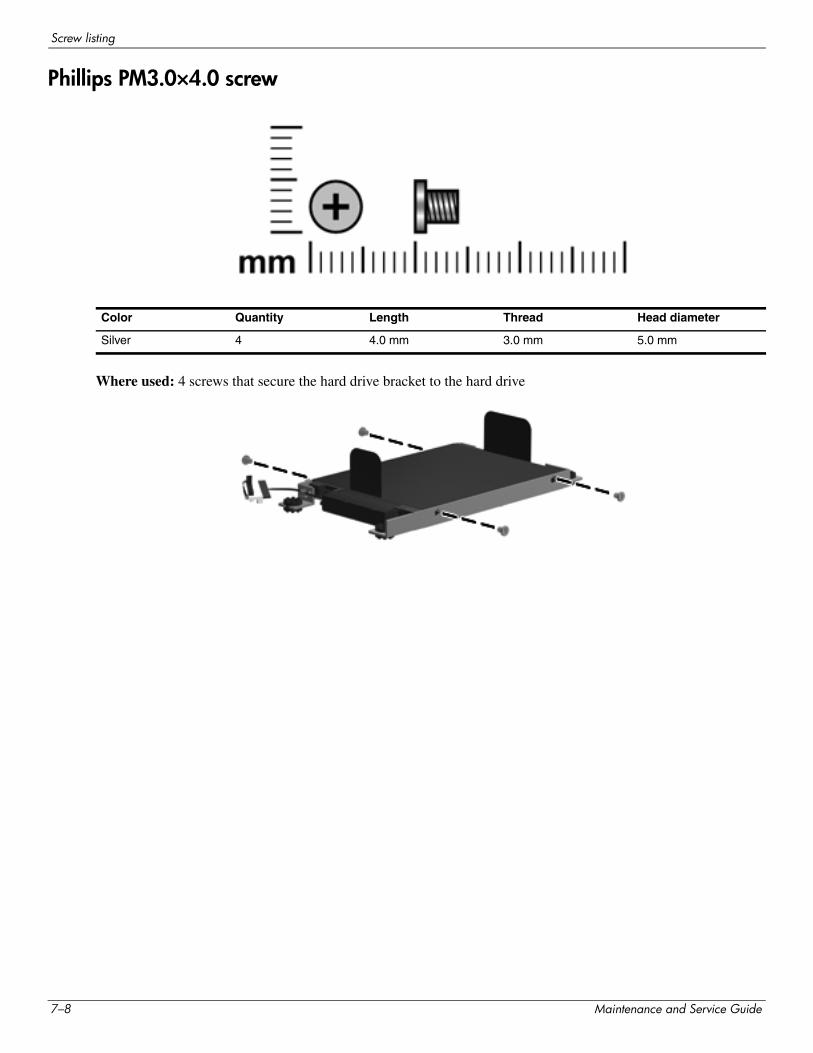
Screw listing
Phillips PM3.0×4.0 screw
Where used: 4 screws that secure the hard drive bracket to the hard drive
Color Quantity Length Thread Head diameter
Silver 4 4.0 mm 3.0 mm 5.0 mm
7–8 Maintenance and Service Guide
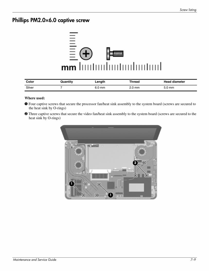
Screw listing
Phillips PM2.0×6.0 captive screw
Where used:
1 Four captive screws that secure the processor fan/heat sink assembly to the system board (screws are secured to the heat sink by O-rings)
2 Three captive screws that secure the video fan/heat sink assembly to the system board (screws are secured to the heat sink by O-rings)
Color Quantity Length Thread Head diameter
Silver 7 6.0 mm 2.0 mm 5.0 mm
Maintenance and Service Guide 7–9
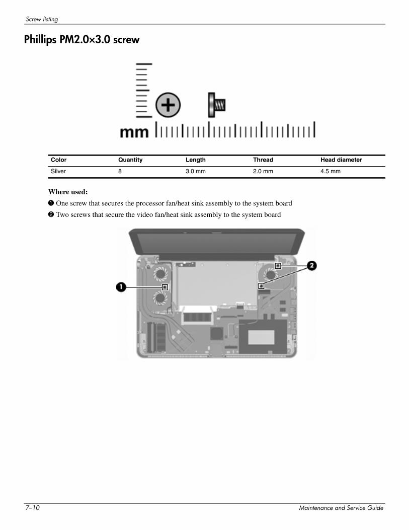
Screw listing
Phillips PM2.0×3.0 screw
Where used:
1 One screw that secures the processor fan/heat sink assembly to the system board
2 Two screws that secure the video fan/heat sink assembly to the system board
Color Quantity Length Thread Head diameter
Silver 8 3.0 mm 2.0 mm 4.5 mm
7–10 Maintenance and Service Guide
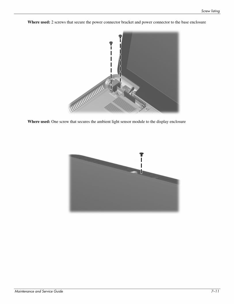
Screw listing
Where used: 2 screws that secure the power connector bracket and power connector to the base enclosure
Where used: One screw that secures the ambient light sensor module to the display enclosure
Maintenance and Service Guide 7–11
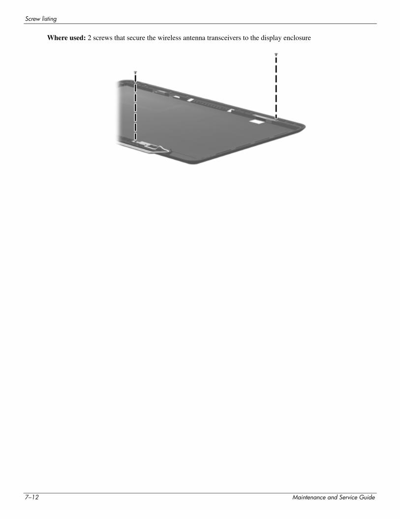
Screw listing
Where used: 2 screws that secure the wireless antenna transceivers to the display enclosure
7–12 Maintenance and Service Guide
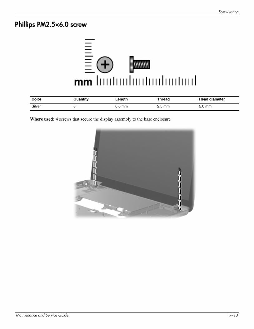
Screw listing
Phillips PM2.5×6.0 screw
Where used: 4 screws that secure the display assembly to the base enclosure
Color Quantity Length Thread Head diameter
Silver 8 6.0 mm 2.5 mm 5.0 mm
Maintenance and Service Guide 7–13
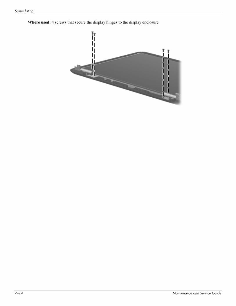
Screw listing
Where used: 4 screws that secure the display hinges to the display enclosure
7–14 Maintenance and Service Guide
8Backup and recovery
Recovery after a system failure is as complete as your most current backup. HP recommends that you create recovery discs immediately after software setup. As you add new software and data files, you should continue to back up your system on a regular basis to maintain a reasonably current backup.
Tools provided by the operating system and HP Recovery Manager software are designed to help you with the following tasks for safeguarding your information and restoring it in case of a system failure:
■ Creating a set of recovery discs (Recovery Manager software feature). Recovery discs are used to start up (boot) your computer and restore the operating system and software programs to factory settings in case of system failure or instability.
■ Backing up your information regularly to protect your important system files.
■ Creating system restore points (operating system feature). System restore points allow you to reverse undesirable changes to your computer by restoring the computer to an earlier state.
■ Recovering a program or driver (Recovery Manager software feature). This feature helps you reinstall a program or driver without performing a full system recovery.
■ Performing a full system recovery (Recovery Manager software feature). With Recovery Manager, you can recover your full factory image if you experience system failure or instability. Recovery Manager works from a dedicated recovery partition (select models only) on the hard drive or from recovery discs you create.
✎ Computers with a solid-state drive (SSD) may not have a recovery partition. Recovery discs have been included for computers that do not have a partition. Use these discs to recover your operating system and software. To check for the presence of a recovery partition, click Start, right-click Computer, click Manage, and then click Disk Management. If the partition is present, an HP Recovery drive is listed in the window.
Maintenance and Service Guide 8–1
Backup and recovery
Creating recovery discs
HP recommends that you create recovery discs to be sure that you can restore your system to its original factory state if you experience serious system failure or instability. Create these discs after setting up the computer for the first time.
Handle these discs carefully and keep them in a safe place. The software allows the creation of only one set of recovery discs.
✎ If your computer does not include an integrated optical drive, you can use an optional external optical drive (purchased separately) to create recovery discs, or you can purchase recovery discs for your computer from the HP Web site.
Note the following guidelines before creating recovery discs:
■ You will need high-quality DVD-R, DVD+R, BD-R (writable Blu-ray), or CD-R discs. All these discs are purchased separately. DVDs and BDs have a much higher capacity than CDs. If you use CDs, up to 20 discs may be required, whereas only a few DVDs or BDs are required.
✎ Read-write discs, such as CD-RW, DVD±RW, double-layer DVD±RW, and BD-RE (rewritable Blu-ray) discs, are not compatible with the Recovery Manager software.
■ The computer must be connected to AC power during this process.
■ Only one set of recovery discs can be created per computer.
■ Number each disc before inserting it into the optical drive.
■ If necessary, you can exit the program before you have finished creating the recovery discs. The next time you open Recovery Manager, you will be prompted to continue the disc creation process.
To create a set of recovery discs:
1. Select Start > All Programs > Recovery Manager > Recovery Disc Creation.
2. Follow the on-screen instructions.
8–2 Maintenance and Service Guide
Backup and recovery
Backing up your information
As you add new software and data files, you should back up your system on a regular basis to maintain a reasonably current backup. Back up your system at the following times:
■ At regularly scheduled times
✎ Set reminders to back up your information periodically.
■ Before the computer is repaired or restored
■ Before you add or modify hardware or software
Note the following when backing up:
■ Create system restore points using the Windows System Restore feature, and periodically copy them to disc.
■ Store personal files in the Documents library and back up this folder periodically.
■ Back up templates stored in their associated programs.
■ Save customized settings in a window, toolbar, or menu bar by taking a screen shot of your settings. The screen shot can be a time-saver if you have to reset your preferences.
To copy the screen and paste it into a word-processing document, follow these steps:
1. Display the screen.
2. Copy the screen:
To copy only the active window, press alt+prt sc.
To copy the entire screen, press prt sc.
3. Open a word-processing document, and then select Edit > Paste.
4. Save the document.
■ You can back up your information to an optional external hard drive, a network drive, or discs.
■ When backing up to discs, use any of the following types of discs (purchased separately): CD-R, CD-RW, DVD+R, DVD-R, or DVD±RW. The discs you use will depend on the type of optical drive installed in your computer.
✎ DVDs store more information than CDs, so using them for backup reduces the number of recovery discs required.
■ When backing up to discs, number each disc before inserting it into the optical drive of the computer.
Maintenance and Service Guide 8–3
Backup and recovery
Using Windows Backup and Restore
To create a backup using Windows Backup and Restore, follow these steps:
✎ Be sure that the computer is connected to AC power before you start the backup process.
✎ The backup process may take over an hour, depending on file size and the speed of the computer.
1. Select Start > All Programs > Maintenance > Backup and Restore.
2. Follow the on-screen instructions to set up and create a backup.
✎ Windows includes the User Account Control feature to improve the security of your computer. You may be prompted for your permission or password for tasks such as installing software, running utilities, or changing Windows settings. Refer to Help and Support for more information.
Using system restore points
When you back up your system, you are creating a system restore point. A system restore point allows you to save and name a snapshot of your hard drive at a specific point in time. You can then recover back to that point if you want to reverse subsequent changes made to your system.
✎ Recovering to an earlier restore point does not affect data files saved or e-mails created since the last restore point.
You also can create additional restore points to provide increased protection for your system files and settings.
When to create restore points
■ Before you add or extensively modify software or hardware
■ Periodically, whenever the system is performing optimally
✎ If you revert to a restore point and then change your mind, you can reverse the restoration.
8–4 Maintenance and Service Guide
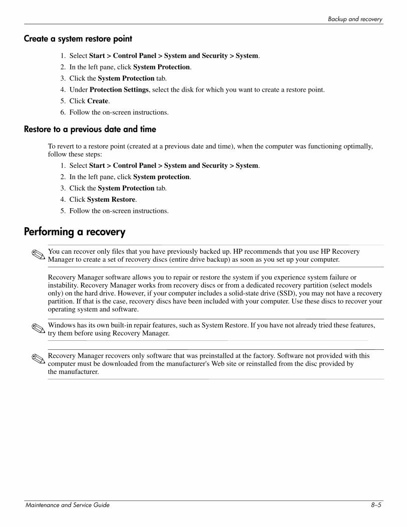
Backup and recovery
Create a system restore point
1. Select Start > Control Panel > System and Security > System.
2. In the left pane, click System Protection.
3. Click the System Protection tab.
4. Under Protection Settings, select the disk for which you want to create a restore point.
5. Click Create.
6. Follow the on-screen instructions.
Restore to a previous date and time
To revert to a restore point (created at a previous date and time), when the computer was functioning optimally, follow these steps:
1. Select Start > Control Panel > System and Security > System.
2. In the left pane, click System protection.
3. Click the System Protection tab.
4. Click System Restore.
5. Follow the on-screen instructions.
Performing a recovery
✎ You can recover only files that you have previously backed up. HP recommends that you use HP Recovery Manager to create a set of recovery discs (entire drive backup) as soon as you set up your computer.
Recovery Manager software allows you to repair or restore the system if you experience system failure or instability. Recovery Manager works from recovery discs or from a dedicated recovery partition (select models only) on the hard drive. However, if your computer includes a solid-state drive (SSD), you may not have a recovery partition. If that is the case, recovery discs have been included with your computer. Use these discs to recover your operating system and software.
✎ Windows has its own built-in repair features, such as System Restore. If you have not already tried these features, try them before using Recovery Manager.
✎ Recovery Manager recovers only software that was preinstalled at the factory. Software not provided with this computer must be downloaded from the manufacturer's Web site or reinstalled from the disc provided by the manufacturer.
Maintenance and Service Guide 8–5
Backup and recovery
Recovering from the recovery discs
To restore the system from the recovery discs:
1. Back up all personal files.
2. Insert the first recovery disc into the optional external optical drive and restart the computer.
3. Follow the on-screen instructions.
Recovering from the dedicated recovery partition (select models only)
✎ Computers with an SSD may not have a recovery partition. If the computer does not have a recovery partition, you will not be able to recover using this procedure. Recovery discs have been included for computers that do not have a partition. Use these discs to recover your operating system and software.
On some models, you can perform a recovery from the partition on the hard drive, accessed by pressing either the Start button or f11. This restores the computer to its factory condition.
To restore the system from the partition, follow these steps:
1. Access Recovery Manager in either of the following ways:
◆ Select Start > All Programs > Recovery Manager > Recovery Manager.
– or –
◆ Turn on or restart the computer, and then press esc while the “Press the ESC key for Startup Menu” message is displayed at the bottom of the screen. Then, press f11 while the “Press <F11> for recovery” message is displayed on the screen.
2. Click System Recovery in the Recovery Manager window.
3. Follow the on-screen instructions.
8–6 Maintenance and Service Guide
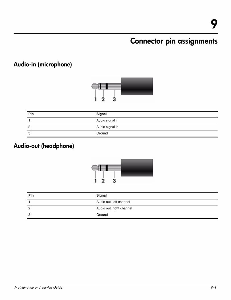
9Connector pin assignments
Audio-in (microphone)
Audio-out (headphone)
Pin Signal
1 Audio signal in
2 Audio signal in
3 Ground
Pin Signal
1 Audio out, left channel
2 Audio out, right channel
3 Ground
Maintenance and Service Guide 9–1
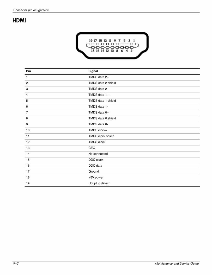
Connector pin assignments
HDMI
Pin Signal
1 TMDS data 2+
2 TMDS data 2 shield
3 TMDS data 2-
4 TMDS data 1+
5 TMDS data 1 shield
6 TMDS data 1-
7 TMDS data 0+
8 TMDS data 0 shield
9 TMDS data 0-
10 TMDS clock+
11 TMDS clock shield
12 TMDS clock-
13 CEC
14 No connected
15 DDC clock
16 DDC data
17 Ground
18 +5V power
19 Hot plug detect
9–2 Maintenance and Service Guide
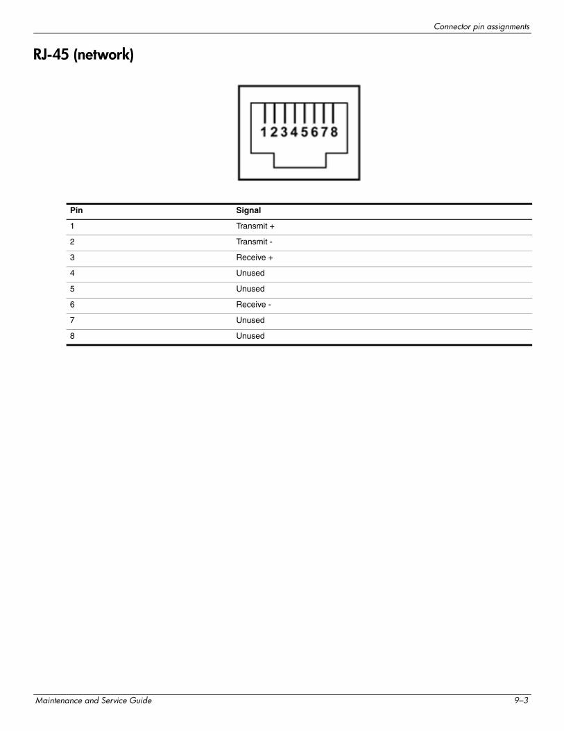
Connector pin assignments
RJ-45 (network)
Pin Signal
1 Transmit +
2 Transmit -
3 Receive +
4 Unused
5 Unused
6 Receive -
7 Unused
8 Unused
Maintenance and Service Guide 9–3
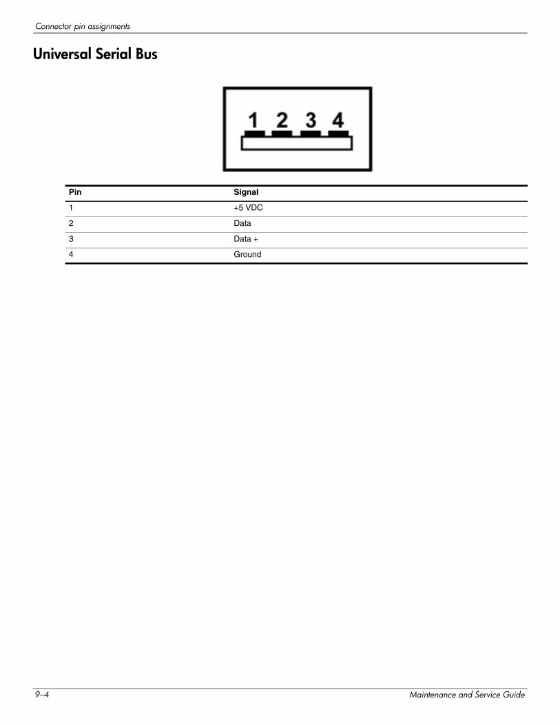
Connector pin assignments
Universal Serial Bus
Pin Signal
1 +5 VDC
2 Data
3 Data +
4 Ground
9–4 Maintenance and Service Guide
10Power cord set requirements
The wide-range input feature of the computer permits it to operate from any line voltage from 100 to 120 volts AC, or from 220 to 240 volts AC.
The 3-conductor power cord set included with the computer meets the requirements for use in the country or region where the equipment is purchased.
Power cord sets for use in other countries and regions must meet the requirements of the country or region where the computer is used.
Requirements for all countries and regions
The following requirements are applicable to all countries and regions:
■ The length of the power cord set must be at least 1.5 m (5.0 ft) and no more than 2.0 m (6.5 ft).
■ All power cord sets must be approved by an acceptable accredited agency responsible for evaluation in the country or region where the power cord set will be used.
■ The power cord sets must have a minimum current capacity of 10 amps and a nominal voltage rating of 125 or 250 V AC, as required by the power system of each country or region.
■ The appliance coupler must meet the mechanical configuration of an EN 60 320/IEC 320 Standard Sheet C13 connector for mating with the appliance inlet on the back of the computer.
Maintenance and Service Guide 10–1
Power cord set requirements
Requirements for specific countries and regions
Country/region Accredited agency Applicable note number
Australia EANSW 1
Austria OVE 1
Belgium CEBC 1
Canada CSA 2
Denmark DEMKO 1
Finland FIMKO 1
France UTE 1
Germany VDE 1
Italy IMQ 1
Japan METI 3
The Netherlands KEMA 1
Norway NEMKO 1
The People's Republic of China CCC 5
South Korea EK 4
Sweden SEMKO 1
Switzerland SEV 1
Taiwan BSMI 4
The United Kingdom BSI 1
The United States UL 2
1. The flexible cord must be Type HO5VV-F, 3-conductor, 1.0-mm² conductor size. Power cord set fittings (appliance coupler and wall plug) must bear the certification mark of the agency responsible for evaluation in the country or region where it will be used.
2. The flexible cord must be Type SPT-3 or equivalent, No. 18 AWG, 3-conductor. The wall plug must be a two-pole grounding type with a NEMA 5-15P (15 A, 125 V) or NEMA 6-15P (15 A, 250 V) configuration.
3. The appliance coupler, flexible cord, and wall plug must bear a “T” mark and registration number in accordance with the Japanese Dentori Law. The flexible cord must be Type VCT or VCTF, 3-conductor, 1.00-mm² conductor size. The wall plug must be a two-pole grounding type with a Japanese Industrial Standard C8303 (7 A, 125 V) configuration.
4. The flexible cord must be Type RVV, 3-conductor, 0.75-mm² conductor size. Power cord set fittings (appliance coupler and wall plug) must bear the certification mark of the agency responsible for evaluation in the country or region where it will be used.
5. The flexible cord must be Type VCTF, 3-conductor, 0.75-mm² conductor size. Power cord set fittings (appliance coupler and wall plug) must bear the certification mark of the agency responsible for evaluation in the country or region where it will be used.
10–2 Maintenance and Service Guide
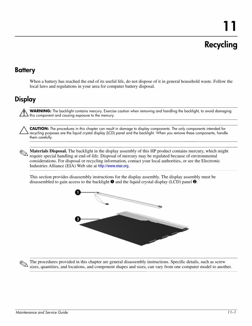
11Recycling
Battery
When a battery has reached the end of its useful life, do not dispose of it in general household waste. Follow the local laws and regulations in your area for computer battery disposal.
Display
ÅWARNING: The backlight contains mercury. Exercise caution when removing and handling the backlight, to avoid damaging this component and causing exposure to the mercury.
ÄCAUTION: The procedures in this chapter can result in damage to display components. The only components intended for recycling purposes are the liquid crystal display (LCD) panel and the backlight. When you remove these components, handle them carefully.
✎ Materials Disposal. The backlight in the display assembly of this HP product contains mercury, which might require special handling at end-of-life. Disposal of mercury may be regulated because of environmental considerations. For disposal or recycling information, contact your local authorities, or see the Electronic Industries Alliance (EIA) Web site at http://www.eiae.org.
This section provides disassembly instructions for the display assembly. The display assembly must be disassembled to gain access to the backlight 1 and the liquid crystal display (LCD) panel 2.
✎ The procedures provided in this chapter are general disassembly instructions. Specific details, such as screw sizes, quantities, and locations, and component shapes and sizes, can vary from one computer model to another.
Maintenance and Service Guide 11–1
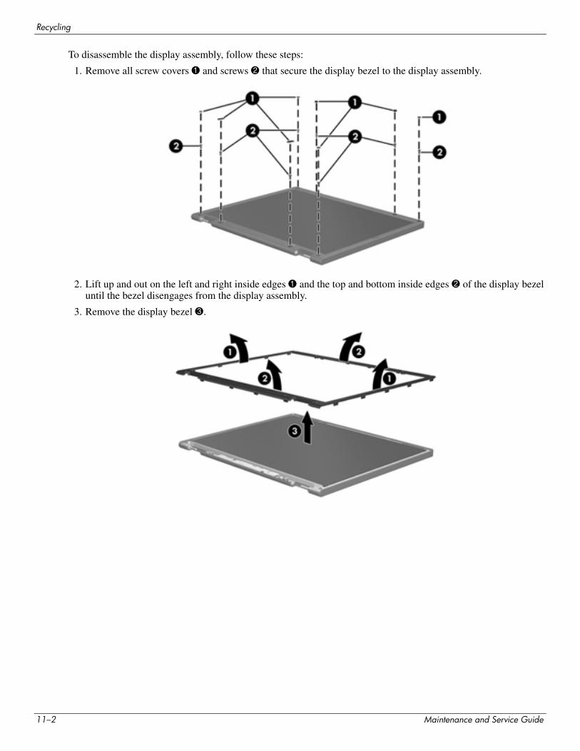
Recycling
To disassemble the display assembly, follow these steps:
1. Remove all screw covers 1 and screws 2 that secure the display bezel to the display assembly.
2. Lift up and out on the left and right inside edges 1 and the top and bottom inside edges 2 of the display bezel until the bezel disengages from the display assembly.
3. Remove the display bezel 3.
11–2 Maintenance and Service Guide
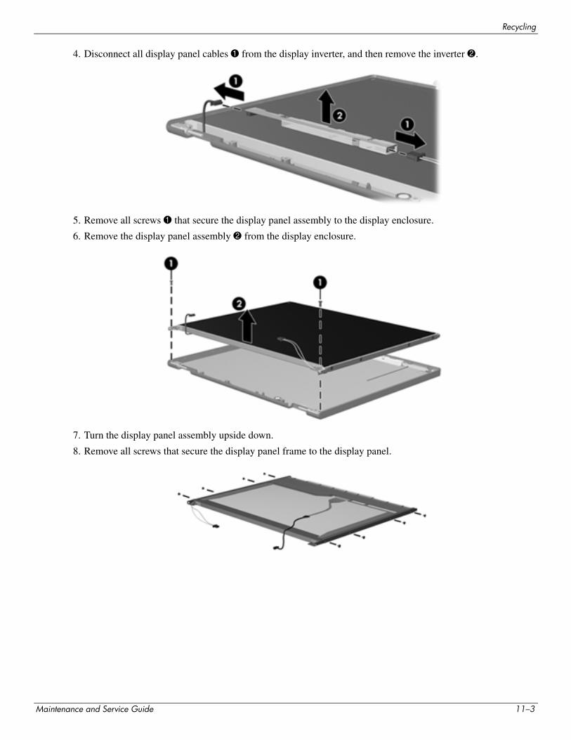
Recycling
4. Disconnect all display panel cables 1 from the display inverter, and then remove the inverter 2.
5. Remove all screws 1 that secure the display panel assembly to the display enclosure.
6. Remove the display panel assembly 2 from the display enclosure.
7. Turn the display panel assembly upside down.
8. Remove all screws that secure the display panel frame to the display panel.
Maintenance and Service Guide 11–3
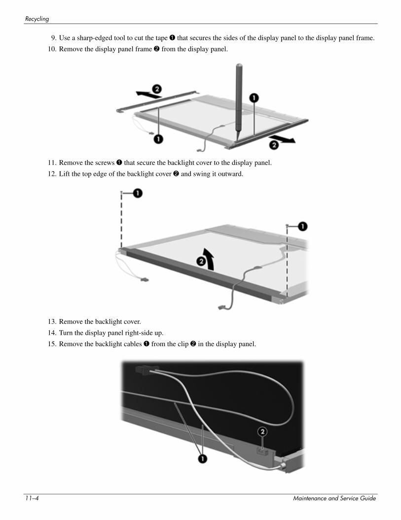
Recycling
9. Use a sharp-edged tool to cut the tape 1 that secures the sides of the display panel to the display panel frame.
10. Remove the display panel frame 2 from the display panel.
11. Remove the screws 1 that secure the backlight cover to the display panel.
12. Lift the top edge of the backlight cover 2 and swing it outward.
13. Remove the backlight cover.
14. Turn the display panel right-side up.
15. Remove the backlight cables 1 from the clip 2 in the display panel.
11–4 Maintenance and Service Guide
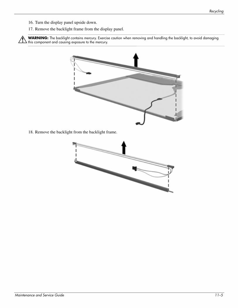
Recycling
16. Turn the display panel upside down.
17. Remove the backlight frame from the display panel.
ÅWARNING: The backlight contains mercury. Exercise caution when removing and handling the backlight, to avoid damaging this component and causing exposure to the mercury.
18. Remove the backlight from the backlight frame.
Maintenance and Service Guide 11–5
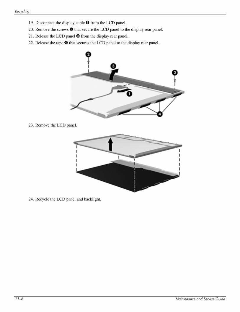
Recycling
19. Disconnect the display cable 1 from the LCD panel.
20. Remove the screws 2 that secure the LCD panel to the display rear panel.
21. Release the LCD panel 3 from the display rear panel.
22. Release the tape 4 that secures the LCD panel to the display rear panel.
23. Remove the LCD panel.
24. Recycle the LCD panel and backlight.
11–6 Maintenance and Service Guide
Index
AAC adapter, spare part numbers 3–13, 3–14accessory battery connector 2–10Action Key Mode 5–4action keys 2–4Administrator password 5–3ambient light sensor 2–2ambient light sensor module
removal 4–35spare part number 3–10, 3–16, 4–35, 4–39
ambient light sensor module cableremoval 4–39spare part number 3–10
antennasdisconnecting 4–18locations 2–2removal 4–40spare part number 3–10, 3–16, 4–40
audio, product description 1–2audio-in jack
connector pinout 9–1location 2–9
audio-out jackconnector pinout 9–1location 2–9
Bbase enclosure, spare part numbers 3–8, 3–17battery
removal 4–7spare part numbers 3–8, 3–16, 3–18, 4–7
battery bay 2–10battery light 2–8battery lock 2–10battery release latch 2–10BIOS
determining the version 5–5downloading an update 5–6updating 5–5
Bluetooth moduleremoval 4–35spare part number 3–10, 3–14, 4–35
Bluetooth module cableremoval 4–39spare part number 3–10, 3–17, 4–39
Blu-ray ROM DVD±R/RW SuperMulti Double-Layer Drive
precautions 4–2spare part number 3–12, 3–16, 3–17specifications 6–5
Boot Options 5–4bottom components 2–10button components 2–3buttons
power 2–3TouchPad 2–7TouchPad on/off 2–7
Ccables, service considerations 4–1calculator key 2–4caps lock light 2–5chipset, product description 1–1components
bottom 2–10button 2–3display 2–2front 2–8keys 2–4left-side 2–8lights 2–5right-side 2–9top 2–2TouchPad 2–6TouchPad buttons 2–7
computer feetlocations 4–6spare part number 4–6
computer specifications 6–1connector pinout
audio-in jack 9–1audio-out jack 9–1HDMI port 9–2headphone jack 9–1microphone jack 9–1network jack 9–3RJ-45 jack 9–3USB port 9–4
connectors, service considerations 4–1
Maintenance and Service Guide Index–1
Index
DDiagnostics menu 5–4Digital Media Slot, location 2–8display assembly
removal 4–33spare part numbers 3–4, 3–15, 3–17, 3–18, 4–33
display bezelremoval 4–34spare part number 3–10, 3–15, 4–34
display componentsillustrated 2–2recycling 11–1
display enclosure, spare part numbers 3–10, 3–15, 3–17Display Hinge Kit, spare part number 3–10, 3–15display hinges
removal 4–36spare part number 3–10, 3–15, 4–36
display inverter, removal 11–3display panel
product description 1–1removal 4–37spare part numbers 3–10, 3–15, 3–18, 4–37
display panel cableremoval 4–38spare part number 3–10, 3–16, 4–38
Display Screw Kit, spare part number 3–10, 3–15display switch 2–2drive light 2–8DVD±RW and CD-RW SuperMulti Double-Layer
Combo Driveprecautions 4–2spare part number 3–12, 3–16, 3–17specifications 6–6
Eelectrostatic discharge 4–2equipment guidelines 4–4eSATA/USB port, location 2–9esc key 2–4Ethernet, product description 1–2external media card, product description 1–3
FFan Always On 5–4fan/heat sink assembly
removal 4–22, 4–27spare part numbers 3–7, 3–16, 3–17, 4–22, 4–27
Fast Charge Mode 5–4feet
locations 4–6spare part number 4–6
fn key 2–4front components 2–8
Ggraphics, product description 1–1grounding equipment and methods 4–2
Hhard drive
precautions 4–2product description 1–2removal 4–20spare part numbers 3–7, 3–12, 3–16, 3–17, 3–18,
4–20specifications 6–3
hard drive cable, spare part numbers 3–7, 3–12, 3–16Hard Drive Hardware Kit, spare part numbers 3–7,
3–12, 3–16HDMI port
connector pinout 9–2location 2–9
HDMI-to-VGA adapter, spare part number 3–13, 3–14headphone jack
connector pinout 9–1location 2–9
HP Notebook protective case, spare part numbers 3–13, 3–17
Jjacks
audio-in 2–9audio-out 2–9headphone 2–9microphone 2–9network 2–9RJ-45 2–9
Kkey components 2–4keyboard
product description 1–4removal 4–12spare part numbers 3–4, 3–5, 3–16, 3–17, 4–12
Keyboard Hardware Kit, spare part number 3–5, 3–16, 4–12
keysaction 2–4calculator 2–4esc 2–4fn 2–4mail 2–4Media Launch 2–4print options 2–4Web 2–4Windows applications 2–4Windows logo 2–4wireless 2–4
Index–2 Maintenance and Service Guide
Index
LLanguage Support 5–4left-side components 2–8light components 2–5lights
battery 2–8caps lock 2–5drive 2–8mute 2–5power 2–5TouchPad 2–5webcam 2–2webcam infrared 2–2wireless 2–5
Mmail key 2–4Main menu 5–3mass storage device
illustrated 3–11product description 1–2removal 4–20spare part numbers 3–11, 4–20
Media Launch key 2–4memory module
removal 4–8, 4–15spare part numbers 3–5, 3–16, 4–8, 4–15
memory module compartment 2–10memory module compartment cover
removal 4–8spare part number 3–8, 3–17
Memory Test 5–4memory, product description 1–1microphone
locations 2–2product description 1–2
microphone jackconnector pinout 9–1location 2–9
model description 3–2, 4–5mute light 2–5
Nnetwork jack
connector pinout 9–3location 2–9
Ooperating system, product description 1–4optical drive
precautions 4–2product description 1–2
spare part numbers 3–12, 3–16, 3–17specifications 6–5, 6–6
Ppacking guidelines 4–3part number description 3–2, 4–5plastic parts 4–1Plastics Kit, spare part number 3–8, 3–17pointing device, product description 1–4ports
eSATA/USB 2–9HDMI 2–9product description 1–4Universal Serial Bus (USB) 2–9
power button 2–3power button board and cable
removal 4–25spare part number 3–7, 3–17, 4–25
power connector 2–8power connector cable
removal 4–26spare part number 3–7, 3–17, 4–26
power cordset requirements 10–1spare part numbers 3–13, 3–14
power light 2–5power requirements, product description 1–3Power-On Password 5–3Primary Hard Disk Self Test 5–4print options key 2–4processor
product description 1–1removal 4–24spare part numbers 3–7, 3–17, 3–18, 4–24
processor fan/heat sink assemblyremoval 4–22spare part number 3–7, 3–16, 4–22
product descriptionaudio 1–2chipset 1–1display panel 1–1Ethernet 1–2external media card 1–3graphics 1–1keyboard 1–4memory 1–1microphone 1–2operating system 1–4optical drive 1–2pointing device 1–4ports 1–4power requirements 1–3processor 1–1
Maintenance and Service Guide Index–3
Index
security 1–4serviceability 1–4wireless 1–3
product name 1–1, 3–2, 4–5product number description 3–2, 4–5
Rrecovery, system 8–1recycling
battery 11–1display components 11–1
removal/replacementpreliminaries 4–1procedures 4–6
right-side components 2–9RJ-45 jack
connector pinout 9–3location 2–9
RTC batteryremoval 4–19spare part number 3–5, 3–17, 4–19
Rubber Feet Kit, spare part number 3–8, 3–14, 4–6
SScrew Kit, spare part number 3–13, 3–17screw listing 7–1Secondary Hard Disk Self Test 5–4security cable slot 2–9Security menu 5–3security, product description 1–4serial number 3–2, 4–5service considerations 4–1service tag 3–1, 4–5serviceability, product description 1–4Setup Utility
changing the lanuage 5–1Diagnostics menu 5–4displaying system information 5–2exiting 5–3Main menu 5–3menus 5–3navigating 5–2restoring default settings 5–2Security menu 5–3selecting 5–2starting 5–1System Configuration menu 5–4using 5–1
speaker assemblyremoval 4–14spare part number 3–7, 3–17, 4–14
speaker, location 2–8, 2–9specifications
Blu-ray ROM DVD±R/RW SuperMulti Double-Layer Drive 6–5
computer 6–1display assembly 6–2DVD±RW and CD-RW SuperMulti Double-Layer
Combo Drive 6–6hard drive 6–3optical drive 6–5, 6–6system DMA 6–7system I/O address 6–9system interrupt 6–8system memory map 6–7
system boardremoval 4–29spare part number 3–8, 3–15, 4–29
System Configuration menu 5–4system DMA specifications 6–7system I/O address specifications 6–9System Information 5–3system interrupt specifications 6–8system memory map specifications 6–7system recovery 8–1
Ttools required 4–1top components 2–2top cover
removal 4–10spare part numbers 3–4, 3–17, 4–10
TouchPad 2–6TouchPad button 2–7TouchPad light 2–5TouchPad on/off button 2–7
UUniversal Serial Bus (USB) port
connector pinout 9–4location 2–9
Vvent 2–8, 2–9, 2–10video fan/heat sink assembly
removal 4–27spare part number 3–7, 3–17, 4–27
Virtualization Technology 5–4
Index–4 Maintenance and Service Guide
Index
Wwarranty period 3–2, 4–5Web key 2–4webcam 2–2webcam infrared light 2–2webcam light 2–2webcam/microphone module
removal 4–36spare part number 3–10, 3–16, 4–36
Windows applications key 2–4Windows logo key 2–4wireless antennas
disconnecting 4–18locations 2–2removal 4–40spare part number 3–10, 3–16, 4–40
wireless key 2–4wireless light 2–5wireless, product description 1–3WLAN module
removal 4–16spare part numbers 3–5, 3–6, 3–7, 3–14, 3–15,
3–18, 4–16workstation guidelines 4–4
Maintenance and Service Guide Index–5
Related Documents