HP Designjet T770 & T1200 printer series Service manual (v.3, 2009-10-21)

Welcome message from author
This document is posted to help you gain knowledge. Please leave a comment to let me know what you think about it! Share it to your friends and learn new things together.
Transcript

HP Designjet T770 & T1200 printer series
Service manual (v.3, 2009-10-21)

© 2009 Hewlett-Packard DevelopmentCompany, L.P.
Table of contents
1 Troubleshooting
Using the Front Panel ........................................................................................................................... 2
General Troubleshooting ...................................................................................................................... 3
The Media Basket was damaged during printer setup ......................................................................... 5
Print quality troubleshooting ................................................................................................................. 6
Ink Supplies Troubleshooting ............................................................................................................. 31
Connectivity troubleshooting .............................................................................................................. 46
2 System Error Codes
Introduction ......................................................................................................................................... 52
Printer logs ......................................................................................................................................... 52
What to do if the Front Panel is blank ................................................................................................ 53
Continuable and Non-Continuable Error Codes ................................................................................. 54
System Error Code Brief Descriptions ................................................................................................ 54
System Error Codes—Full Descriptions ............................................................................................. 56
Appendix A: How to troubleshoot SE 79:04 ....................................................................................... 73
Appendix B: Updating firmware in diagnostics boot mode ................................................................. 84
Appendix C: Obtaining the printer log and the diagnostics package .................................................. 85
3 Diagnostics Menu
Introduction ......................................................................................................................................... 88
Diagnostic Tests and Utilities ............................................................................................................. 88
4 Service Menu
Introduction ....................................................................................................................................... 122
Service Utilities ................................................................................................................................. 122
Service Calibrations ......................................................................................................................... 138
5 Parts and Diagrams
Printer Support ................................................................................................................................. 153
Center Covers (Front) ...................................................................................................................... 155
Roll Covers ....................................................................................................................................... 157
Center Covers (Rear) ....................................................................................................................... 159
Right Cover ...................................................................................................................................... 161
Left Cover ......................................................................................................................................... 163
Right Hand Assemblies .................................................................................................................... 165
ENWW iii
Left Hand Assemblies ...................................................................................................................... 167
Carriage Assembly ........................................................................................................................... 169
Scan-Axis Assemblies ...................................................................................................................... 171
Paper Path Assemblies (Front) ........................................................................................................ 173
Paper Path Assemblies (Rear) ......................................................................................................... 175
Roll Supports .................................................................................................................................... 177
Tool Kits ........................................................................................................................................... 179
Miscellaneous Parts ......................................................................................................................... 180
6 Removal and Installation
Introduction ....................................................................................................................................... 184
Service Calibration Guide to Removal and Installation .................................................................... 185
Belt Assembly ................................................................................................................................... 188
Bin Assembly .................................................................................................................................... 188
Bi-stable Springs (T1200 only) ......................................................................................................... 190
Bumpers, Left and Right ................................................................................................................... 196
Cable Harness .................................................................................................................................. 199
Carriage and Cutter Assembly ......................................................................................................... 205
Carriage Bushing, Rear .................................................................................................................... 213
Carriage Cover and Carriage Latch ................................................................................................. 215
Carriage Rail Oiler ............................................................................................................................ 219
Carriage PCA ................................................................................................................................... 220
Cleanout ........................................................................................................................................... 225
Converger ......................................................................................................................................... 226
Cover, Front ..................................................................................................................................... 228
Cover, Left ........................................................................................................................................ 229
Cover, Rear ...................................................................................................................................... 233
Cover, Right ..................................................................................................................................... 234
Cover, Top ........................................................................................................................................ 237
Cutter Assembly ............................................................................................................................... 240
Drop Detector ................................................................................................................................... 243
EE Box ............................................................................................................................................. 244
Electronics Module Main PCA and PSU .......................................................................................... 247
Encoder Disk and Encoder Sensor .................................................................................................. 250
Encoder Strip .................................................................................................................................... 252
Encoder Strip, spring and attachment nut ........................................................................................ 253
Formatter .......................................................................................................................................... 255
Freewheel Assembly ........................................................................................................................ 256
Front Panel ....................................................................................................................................... 258
Front Trim, Left ................................................................................................................................. 260
Front Trim, Right .............................................................................................................................. 262
Full Bleed Foam ............................................................................................................................... 263
Hard Disk Drive ................................................................................................................................ 264
Ink Cartridge Door, Left .................................................................................................................... 265
Ink Cartridge Door, Right .................................................................................................................. 266
Ink Supply Station, Left .................................................................................................................... 268
Ink Supply Tubes .............................................................................................................................. 272
iv ENWW

Ink Supply Tubes Support Rail ......................................................................................................... 279
Line Sensor ...................................................................................................................................... 280
Media Advance Drive ....................................................................................................................... 286
Media Lever ...................................................................................................................................... 292
Media Lever Position Sensor ........................................................................................................... 293
Media Output Assembly ................................................................................................................... 295
Out-of-paper Sensor ......................................................................................................................... 296
Panel, Left ........................................................................................................................................ 299
Pen to Paper Space (PPS) Solenoid ................................................................................................ 300
Pinch Arm Assembly ........................................................................................................................ 302
Pinchwheel Assembly ...................................................................................................................... 304
Print Zone Overdrive ........................................................................................................................ 312
PSU .................................................................................................................................................. 317
Real-time Clock Battery .................................................................................................................... 318
Roll Cover Bumpers, Lower ............................................................................................................. 318
Roll Cover Bumpers, Upper ............................................................................................................. 321
Roll Cover, Lower (T1200 only) ........................................................................................................ 324
Roll Cover, Upper ............................................................................................................................. 327
Roll Guide, Left ................................................................................................................................. 328
Roll Guide, Right .............................................................................................................................. 329
Roll Support, Lower Left (T1200 only) .............................................................................................. 330
Roll Support, Lower Right (T1200 only) ........................................................................................... 331
Roll Support Sensor, Lower Left (T1200 only) ................................................................................. 333
Roll Support Sensor, Upper Left ...................................................................................................... 333
Roll Support, Upper Left ................................................................................................................... 334
Roll Support, Upper Right ................................................................................................................ 336
Scan-axis Motor ............................................................................................................................... 337
Service Station ................................................................................................................................. 341
Single Sheet Sensor ......................................................................................................................... 345
Spindle ............................................................................................................................................. 346
Spittoon, Left .................................................................................................................................... 347
Starwheel Assembly ......................................................................................................................... 348
Starwheel Lifter, Left ........................................................................................................................ 350
Starwheel Lifter, Right ...................................................................................................................... 351
Starwheel Motor ............................................................................................................................... 354
Trailing Cable ................................................................................................................................... 356
Wall Spacers .................................................................................................................................... 363
Window ............................................................................................................................................. 365
Window Position Sensor .................................................................................................................. 368
7 Preventive Maintenance
Preventive Maintenance ................................................................................................................... 371
Preventive Maintenance Kits ............................................................................................................ 376
ENWW v

vi ENWW

1 Troubleshooting
● Using the Front Panel
● General Troubleshooting
● The Media Basket was damaged during printer setup
● Print quality troubleshooting
● Ink Supplies Troubleshooting
● Connectivity troubleshooting
ENWW 1
Tro
ub
lesh
oo
tin
g

Using the Front PanelHP Designjet T1200 series HP Designjet T770 series
The front panel has the following components, starting with the four direct-access keys:
1. View ink levels key.
2. View information key. By pressing this key repeatedly, you can see information about all loadedpapers (roll 1, roll 2, sheet) and about the printer's connection to the computer.
3. Pause printing key (T1200 series) pauses printing after finishing the current page. Press the keyagain to restart printing. This can be useful, for instance, when you want to change or load a roll.
Unload paper key (T770 series) unloads the currently-loaded paper (roll or sheet).
4. Form feed and cut key.
5. Front-panel display - Displays errors, warnings and information on using your printer.
6. Back key - To go to the previous step in a procedure or interaction. To go to the upper level, orleave the option in the menu, or when given an option.
7. Menu key - Press to return to the main menu of the front-panel display. If you are already on themain menu it will display the status screen.
8. Down key - To go down in a menu or option, or to decrease a value, for example when configuringthe front-panel display contrast or the IP address.
9. Power key - To turn the printer off or on, it also has a light to indicate the printer's status. If thepower key light is off the printer is off. If the power key light is blinking green, the printer is startingup. If the power key light is green on, the printer is on. If the power key light is amber on, the printeris in standby. If the power key light is blinking amber, the printer needs attention.
10. Cancel key - To abort a procedure or interaction.
11. Up key - To go up in a menu or option, or to increase a value, for example when configuring thefront-panel display contrast or the IP address.
12. OK key - To confirm an action while in a procedure or interaction. To enter in a submenu in themenu. To select a value when given an option. If the status screen is displayed, this key takes youto the main menu.
13. Status light - Indicates the printer's status. If the Status light is solid green, the printer is ready. If itis flashing green, the printer is busy. If it is solid amber, there is a system error. If it is flashingamber, the printer needs attention.
2 Chapter 1 Troubleshooting ENWW
Tro
ub
lesho
otin
g
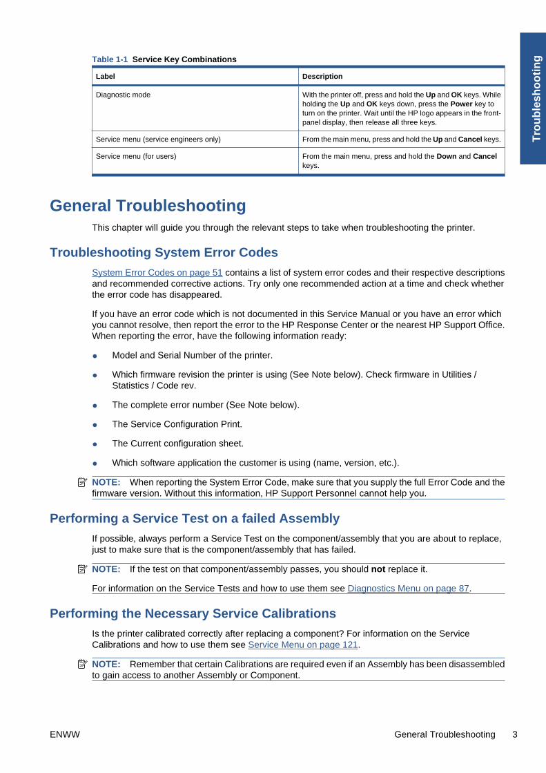
Table 1-1 Service Key Combinations
Label Description
Diagnostic mode With the printer off, press and hold the Up and OK keys. Whileholding the Up and OK keys down, press the Power key toturn on the printer. Wait until the HP logo appears in the front-panel display, then release all three keys.
Service menu (service engineers only) From the main menu, press and hold the Up and Cancel keys.
Service menu (for users) From the main menu, press and hold the Down and Cancelkeys.
General TroubleshootingThis chapter will guide you through the relevant steps to take when troubleshooting the printer.
Troubleshooting System Error Codes
System Error Codes on page 51 contains a list of system error codes and their respective descriptionsand recommended corrective actions. Try only one recommended action at a time and check whetherthe error code has disappeared.
If you have an error code which is not documented in this Service Manual or you have an error whichyou cannot resolve, then report the error to the HP Response Center or the nearest HP Support Office.When reporting the error, have the following information ready:
● Model and Serial Number of the printer.
● Which firmware revision the printer is using (See Note below). Check firmware in Utilities /Statistics / Code rev.
● The complete error number (See Note below).
● The Service Configuration Print.
● The Current configuration sheet.
● Which software application the customer is using (name, version, etc.).
NOTE: When reporting the System Error Code, make sure that you supply the full Error Code and thefirmware version. Without this information, HP Support Personnel cannot help you.
Performing a Service Test on a failed Assembly
If possible, always perform a Service Test on the component/assembly that you are about to replace,just to make sure that is the component/assembly that has failed.
NOTE: If the test on that component/assembly passes, you should not replace it.
For information on the Service Tests and how to use them see Diagnostics Menu on page 87.
Performing the Necessary Service Calibrations
Is the printer calibrated correctly after replacing a component? For information on the ServiceCalibrations and how to use them see Service Menu on page 121.
NOTE: Remember that certain Calibrations are required even if an Assembly has been disassembledto gain access to another Assembly or Component.
ENWW General Troubleshooting 3
Tro
ub
lesh
oo
tin
g

Solving Print Quality Problems
Whenever a Print Quality problem appears, it is advisable to print the Diagnostic Print to help diagnosethe problem. The Diagnostic Print will help you differentiate between possible printhead errors and otherproblems such as incorrect front-panel selection, driver or RIP configuration or mechanical problems.
The Front Panel is blank
See What to do if the Front Panel is blank on page 53.
The Printer does not power on
See What to do if the Front Panel is blank on page 53.
The Printer Continuously Rejects Printheads
1. Clean the flex contacts on the Printhead and in the Carriage Assembly using the CarriageInterconnect Wiper and try again.
2. If all the Printheads are rejected (the status message on the Front Panel does not show "OK"for all the Printheads) then perform the Electronic Module Test. See Electronics Module Teston page 98.
Cover Sensors are not Working
1. Perform the Sensors Test. See Sensors Test on page 105.
2. Check that the cable for the faulty sensor is not damaged and is connected correctly.
3. Replace the faulty Sensor.
The Line Sensor has Problems Detecting Media
1. Check the type of media that is being used since the Line sensor may have problems detectingtransparent media or some types of Non-HP media. Try loading white HP media in to the printerand check that the Line sensor detects it.
2. The Line Sensor is not calibrated correctly. Perform the Line Sensor Calibration. See Line SensorCalibration on page 147.
3. The Line Sensor is damaged or faulty. Replace the Line Sensor. See Line Sensor on page 280.
Troubleshooting Media Jams/Printhead Crashes
The failure modes "media jam" and "head crash" are grouped together because in many cases a mediajam causes the media to lift up into the Carriage path and cause a Printhead crash, thus causing manymedia jam failures to be reported as head crashes.
1. Did the media jam occur when loading media?
● If the client has had media jams, it is common for pieces of media to get stuck in the mediapath. Clear the media path.
NOTE: When clearing a media jam, sometimes media is stuck in the paper path. To clear this,you must lift the Media Lever and insert thicker media into the paper path to push out the mediathat is still stuck there.
2. Is the customer using non-HP media?
● The use of non-HP media can easily be the cause of media jams and head crashes (especiallyhead crashes because HP media is specially formulated to avoid cockle, one of the primary
4 Chapter 1 Troubleshooting ENWW
Tro
ub
lesho
otin
g

causes of head crashes). If the media is not HP approved, advise the customer to use HPmedia and check to see whether the problem is now solved.
Banding at variable extreme environmental conditions
Since the Accuracy Calibration has been done at normal environmental conditions, printing in extremeenvironmental conditions will cause banding because the advance of the Media Advance Roller doesnot correspond to the same conditions that the calibration was done in. To solve the problem, try thefollowing:
Perform the Accuracy Calibration in the new environmental conditions (Refer to the User’s Guide).
Worm marks on HP Coated media with light area fills
Light bands (S-shaped) in Paper axis direction where light area fills are printed, causing unacceptableImage Quality defect.
● Print the Service Configuration Print and check whether the humidity level is very low (below 30%).Increasing humidity may help in reducing the severity of the problem.
NOTE: The media is causing the problem and not the printer. Do not attempt to try to replace printerparts to solve this problem.
The Media Basket was damaged during printer setup1. There are three plastic parts that could break during printer installation and need replacing.
2. Check the parts table and graphics in Parts and Diagrams to identify what service parts you mustorder. See Printer Support on page 153.
3. Replace the component. See Bin Assembly on page 188.
Solving Paper-Handling Problems
Roll paper The Front Panel indicates that paper is misaligned or incorrectly positioned
● The roll may be loaded the wrong way. The paper should load over the roll toward you.
● Check that the paper is correctly loaded onto the spindle.
● The paper may be loaded at an angle. The right-hand edge must be aligned with the blue line on thePrint Platen.
● Check that the Right Roll Support is properly attached and screwed to the printer.
The Rewinder, located on the Right Roll Support, should maintain proper back tension. If the Right RollSupport is misaligned or not properly attached to the printer, the Rewinder will not function properly.
To further diagnose problems with the Rewinder, see Rewinder Test on page 107.
Sheet paper ● It must be loaded with the right-hand edge against the white line on the upper roll cover.
● The paper may be crumpled or warped or may have irregular edges.
● If hand-cut paper is used, the edges may not form a right-angle or they may be rough. If possible, hand-cut paper should not be used. Only purchased sheet paper should be used in the printer.
● If you have problems with paper jams, check that the Overdrive is not obstructed by bits of paper orusing the Turn Drive Roller Service Utility. See Turn Drive Roller on page 123.
Check that the Right Roll Support is properly attached and screwed to the printer.
ENWW The Media Basket was damaged during printer setup 5
Tro
ub
lesh
oo
tin
g

The Rewinder, located on the Right Roll Support, should maintain proper back tension. If the Right RollSupport is misaligned or not properly attached to the printer, the Rewinder will not function properly.
To further diagnose problems with the Rewinder, See Rewinder Test on page 107.
Print quality troubleshooting
Print Quality Troubleshooting Actions
NOTE: For some Print Quality problems, a Call Agent can try to troubleshoot the printer by requestingthe Customer to perform certain actions. Using this process, most problems can resolved without theneed of an on-site visit.
Use the Print Quality Troubleshooting Wizard to help customers with their print quality or color problems.For information about how to use the Print Quality Troubleshooting Wizard, see Print QualityTroubleshooting Wizard on page 29.
When faced with a Print Quality problem, perform the following actions in order to resolve the problem:
1. Printer Configuration:
● Check that the paper type loaded corresponds to the paper type selected in the front paneland in the software. You can check the paper type selected by pressing the Viewinformation key on the Front Panel.
● Make sure that the correct Print Quality settings are used for different types of print content.See Print Quality Troubleshooting Actions on page 6 for further information.
● Dry time should be set to “Optimal”.
2. Perform Printhead recovery (Main Menu/Image Quality Maintenance/Clean Printheads).
3. Paper:
● Select the correct paper type through the front panel when loading it.
● Make sure that HP or HP-approved paper is being used.
4. Perform the Printhead Alignment (Main Menu/Image Quality Maintenance/Align Printheads), usingthe same paper type with which you were experiencing unacceptable image quality, if feasible(some paper types are not suitable for Printhead Alignment).
5. Check whether the latest version of the firmware is installed. If not, install the latest firmwarerevision.
The Service Image Quality Diagnostic Print
What is the Service Image Quality Diagnostic Print?
The printer contains an internal Image Quality Test which helps you to diagnose the possible source ofany image quality defects. The Service IQ Diagnostic Print is available in the following options:
1. Image Quality Service Best Plot. This plot helps you to diagnose in more detail the possible sourceof any image quality defects. It is accessible through the Service Utility Menu.
6 Chapter 1 Troubleshooting ENWW
Tro
ub
lesho
otin
g

The Image Quality Service Best Plot uses the Best Print Mode and is divided in to three parts asfollows:
● Diagnostic Part 1: Printhead Reliability Test. The purpose of this test is to identify whichPrinthead is faulty.
● Diagnostic Part 2: Printhead Alignment Test. This test is designed to check any color-to-colorand bi-directional misalignment the printer may have.
● Diagnostic Part 3: Printheads and Paper Advance test. This test is designed to check whetherthe Printheads and the Media Advance Mechanism are working correctly.
2. Image Quality Service Normal Plot. This plot is the same as the Image Quality Service Best Plotbut uses the Normal Print Mode.
3. Advanced Diagnostic Plot. These tests provide more information of the IQ defects that we couldfind in the Image Quality Service plot. For more information, see The Advanced DiagnosticPrints on page 12.
Considerations for Printing the Diagnostic Print
1. The IQ Diagnostic Print prints in A3 and B sizes so you must have media loaded (roll or sheet) thatis this size or larger.
2. Use the same type of media that the customer was using when they found the image qualityproblem.
3. If the customer is using non-HP media and after the Image Quality Test you still have the sameimage quality problems, change to genuine HP media and repeat the Image Quality Test.
If you do see problems with the Image Quality Test, continue with the Advanced Diagnosticprocedures which will help you diagnose the problem.
Printing the Diagnostic Print
1. In the Service Utilities submenu, scroll to “Diagnostic Print” and press OK.
2. You will be given three options. Use the Arrow keys to make the selection and press the OK keyto start printing the required Diagnostic Print or to enter the Advanced Diagnostics menu.
ENWW Print quality troubleshooting 7
Tro
ub
lesh
oo
tin
g
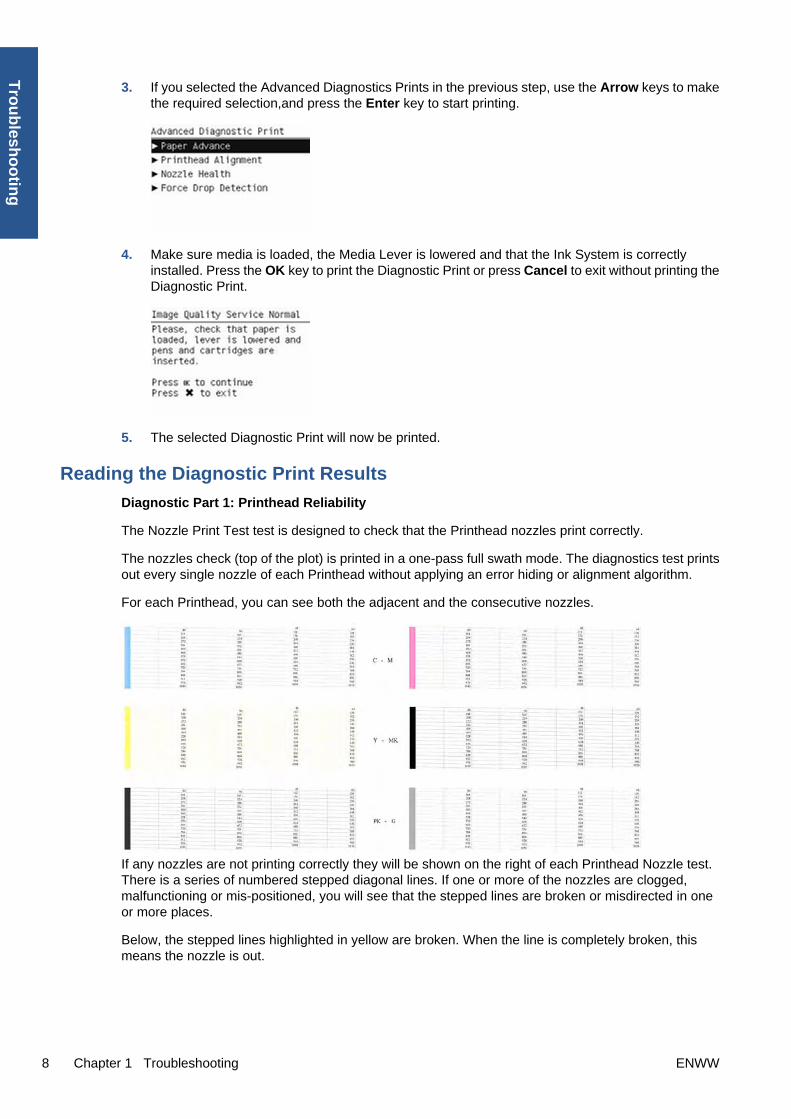
3. If you selected the Advanced Diagnostics Prints in the previous step, use the Arrow keys to makethe required selection,and press the Enter key to start printing.
4. Make sure media is loaded, the Media Lever is lowered and that the Ink System is correctlyinstalled. Press the OK key to print the Diagnostic Print or press Cancel to exit without printing theDiagnostic Print.
5. The selected Diagnostic Print will now be printed.
Reading the Diagnostic Print Results
Diagnostic Part 1: Printhead Reliability
The Nozzle Print Test test is designed to check that the Printhead nozzles print correctly.
The nozzles check (top of the plot) is printed in a one-pass full swath mode. The diagnostics test printsout every single nozzle of each Printhead without applying an error hiding or alignment algorithm.
For each Printhead, you can see both the adjacent and the consecutive nozzles.
If any nozzles are not printing correctly they will be shown on the right of each Printhead Nozzle test.There is a series of numbered stepped diagonal lines. If one or more of the nozzles are clogged,malfunctioning or mis-positioned, you will see that the stepped lines are broken or misdirected in oneor more places.
Below, the stepped lines highlighted in yellow are broken. When the line is completely broken, thismeans the nozzle is out.
8 Chapter 1 Troubleshooting ENWW
Tro
ub
lesho
otin
g

Below, the stepped lines highlighted in yellow are misdirected. When the line is misdirected, this meansthe nozzle is malfunctioning or out of position.
On the left of each Printhead Nozzle test, there is a series of horizontal straight lines. If one or morenozzles are misdirected there will be unequal spaces between the corresponding lines.
Corrective Action
If the printer has nozzle defects, you can still get perfect print quality results. The printer canautomatically compensate for nozzle defects, so there is no need to replace the Printhead.
The method of improving Nozzle Defects is to:
1. Recover the Printheads, using the Front Panel Main Menu/Image Quality Maintenance/CleanPrintheads option.
2. Reprint the Printhead Nozzles Test Plot to check that the defective nozzles have been corrected.
3. If the problem continues, replace the defective Printhead.
Diagnostic Part 2: Printhead Alignment
This test is designed to check any color-to-color and bi-directional misalignment the printer may have.
ENWW Print quality troubleshooting 9
Tro
ub
lesh
oo
tin
g

1. If the printer is experiencing horizontal misalignment problems, the Alignment Test will showsomething like this:
2. If the printer is experiencing vertical misalignment problems, the Alignment Test will showsomething like this:
3. If the printer is experiencing bi-directional misalignment problems, the Alignment Test will showsomething like this:
Corrective Action
Perform the Printhead Alignment (Main Menu/Image Quality Maintenance/Align Printheads), using thesame paper type with which you were experiencing unacceptable image quality, if feasible (some papertypes are not suitable for Printhead Alignment).
Diagnostic Part 3: Printheads & Paper Advance
This test is designed to check whether the Printheads and the Paper Advance Mechanism are workingcorrectly. This part of the Image Quality Test should not be used to check for color consistency oraccuracy.
10 Chapter 1 Troubleshooting ENWW
Tro
ub
lesho
otin
g

Banding
If the printer is experiencing a banding problem, you will see repetitive horizontal bands within the printedimage.
● Darker horizontal bands or lines repeated along the vertical band (from top to bottom at the samedistance).
● Whiter horizontal bands or lines along the vertical band (from top to bottom at the same distance).
The plot is printed in Best or Normal mode (according to the menu option selected) with Error HidingON. The top band has 100% ink density patches while the bottom band has 50% ink density patches.
Troubleshooting Banding Problems
If banding does not occur in all the colors, then it is more than likely a Printhead problem. In this case,try the following:
1. Check that the appropriate print quality settings are being used (refer to the User’s Guide for moreinformation).
2. Recover the printheads using the option through the Front Panel (Main Menu/Image QualityMaintenance/Clean Printheads). Reprint the Diagnostic Print or the print file and if the problempersists, replace the faulty Printhead.
If banding does occur in all the colors, then it is more than likely a Paper Advance problem:
● If the bands are light, it means that the paper has advanced too much.
● If the bands are dark, it means that the paper hasn’t advanced enough.
● In high quality modes, graininess in all colors can indicate problems either with alignment orPaper Advance.
ENWW Print quality troubleshooting 11
Tro
ub
lesh
oo
tin
g

Corrective Action
In order to solve problems that result in banding, try the following
1. Check that the appropriate print quality settings are being used (refer to the User’s Guide for moreinformation).
2. Check that the loaded media is the same type as selected in the printer. You can check the mediatype selected through the Front Panel (Main Menu/Paper menu/View loaded paper).
3. If the customer is using low quality paper, try recommending better quality paper (preferably HPpaper). Printer performance can only be guaranteed by using recommended papers.
4. Perform the Paper Advance Calibration using the same type of paper that will be used for the finalprint (Main Menu/Image Quality Maintenance/Paper Advance Calibration/Calibrate PaperAdvance).
If there is white point banding in only one color band and the problem cannot be fixed using thePrinthead recoveries, in some cases using the Force Drop Detection option can fix this issue.
No Printing Defects Found in the Diagnostic Print
If all the test patterns from the Diagnostic Print are correct and you still experience Image Qualityproblems, you can use the following procedures to resolve the problem.
● Reading the Advanced Diagnostic Print Results
● Printhead Alignment
● Nozzle Health
● Force Drop Detection
The Advanced Diagnostic Prints
What are the Advanced Diagnostic Prints?
These tests provide more information about the IQ defects found in the Image Quality Service plot.
The Advanced Diagnostic Print is divided into the following parts:
● Visual Media Advanced Diagnostic. Used to check advance reliability.
● Printhead Alignment Diagnostic. Used to check pen alignment reliability.
● Visual Nozzle health Diagnostic. Used to check nozzle health reliability.
● Force Drop Detection. Used to reset the nozzle health historic database and force new dropdetection.
Printing the Advanced Diagnostics Print
1. In the Service Utilities submenu, scroll to “Diagnostic Print” and press OK.
12 Chapter 1 Troubleshooting ENWW
Tro
ub
lesho
otin
g

2. You will be given three options. Use the Arrow keys to select the Advanced Diagnostics menu.
3. Use the Arrow keys to select the option you want, and press the OK key to start printing.
4. Make sure media is loaded, the Media Lever is lowered and that the Ink System is correctlyinstalled. Press the OK key to print the Diagnostic Print or press Cancel to exit without printing theDiagnostic Print.
5. The selected Advanced Diagnostic Print will now be printed and, if necessary, automaticallyscanned.
Reading the Advanced Diagnostic Print Results
Paper Advance
This plot helps you to visually check any alignment problems of the printer. You use it to preciselymeasure the media advance error with a one dot row accuracy, and to check the stability of the mediaadvance.
The whitest vertical line should be positioned in the 0 offset column with minor variations between +2and -2 columns. If the offset is not positioned on the 0 column or between +2 and -2 columns and thewhitest vertical varies greatly, the printer requires Paper Advance Calibration (Main Menu/Image QualityMaintenance/Paper Advance Calibration/Calibrate Paper Advance).
NOTE: It is very important to check that the loaded media is the same media type as selected in thefront panel. You can check the media type selected through the Front Panel (Main Menu/Paper menu/View loaded paper). The wrong type of paper selected will produce an offset error in the Paper Advance.
The following plot shows correct media advance, there is a straight white line positioned close to the 0column for the majority of the points.
ENWW Print quality troubleshooting 13
Tro
ub
lesh
oo
tin
g

The following plot shows a bad media advance, there is a straight white line positioned close to the -6column, instead of the 0 column for the majority of the points.
Corrective Action
To fix Paper Advance problems, try the following:
1. Check the Paper Advance Calibration Status. This can be done by going to Main Menu/Paper/ViewLoaded Paper. At the bottom, the Front Panel displays the Paper Advance Calibration status. Thereare three status messages:
● DEFAULT. The paper loaded is recognized as HP paper, which is already optimized andcalibrated for the printer. Do not calibrate the Paper Advance for this paper.
● RECOMMENDED. The paper loaded is not recognized as HP paper, and Paper Advancevalues have not been customized for this paper type. In this case, calibrate the Paper Advancefrom the user menu.
● OK. This indicates that the paper loaded has been calibrated before. If the printer continuesto have banding and graininess problems, calibrate the Paper Advance from the user menu.
14 Chapter 1 Troubleshooting ENWW
Tro
ub
lesho
otin
g

NOTE: Whenever the printer's firmware is upgraded, the paper advance calibration valueswill be reset to factory default.
2. To calibrate the Paper Advance from the user menu, go to Main Menu/Image Quality Maintenance/Paper Advance Calibration/Calibrate Paper Advance.
NOTE: It is very important to check that the loaded media is the same media type as selected inthe front panel. You can check the media type selected through the Front Panel (Main Menu/Papermenu/View loaded paper). The wrong type of paper selected will produce an offset error in thePaper Advance.
NOTE: Some paper types are not suitable for Paper Advance Calibration. Do not use coloredpapers or transparent materials such as translucent bond, clear film, matte film, tracing paper, orvellum.
Paper Advance calibration from the user menu will only calibrate the Paper Advance for the papertype loaded in the printer at that moment.
3. If Calibrate Paper Advance has mostly solved the problem, try Adjust Paper Advance to fine tunethe Paper Advance (Main Menu/Image Quality Maintenance/Paper Advance Calibration/AdjustPaper Advance).
Select the percentage of change from -100% to 100%. To correct light banding, decrease thepercentage. To correct dark banding, increase the percentage.
4. The Paper Advance calibration from the service menu will calibrate the Paper Advance for all papertypes. This action is recommended when:
● The Paper Advance calibration from the user menu does not solve the problem.
● The Paper Advance problems affect all paper types.
The procedure for Paper Advance Calibration from the service menu is documented in Chapter 5,Service Calibrations. See Paper Advance Calibration on page 139.
Printhead Alignment
NOTE: To ensure you obtain meaningful results, use the same type of media that the customer wasusing when they encountered the image quality problem.
This plot helps you to visually check any alignment problems of the printer. You use it to preciselymeasure the alignment error with a 3 dot row accuracy. For the printer to be considered correctly aligned,the results must be within ±3 dot row.
The illustration shows the complete Printhead Alignment that identifies each of the specific alignmenttest results covered.
ENWW Print quality troubleshooting 15
Tro
ub
lesh
oo
tin
g

The Printhead Alignment Diagnostic print shows the following diagnostic test results:
a Line Sensor Calibration
b Pen to Pen Align
c Carriage thetaZ
d Bidirectional align (high
e Bidirectional align (Low)
For tests a, b, and c, the order of the color band is:
For tests e and f, the order of the color band is:
Once the printer has correctly printed and scanned the Printhead Alignment Diagnostic print, the FrontPanel displays the results. The top row displays the printhead, and the left column displays the test.
The results are separated onto two screens. Use the Arrow keys to display the second results screen.
16 Chapter 1 Troubleshooting ENWW
Tro
ub
lesho
otin
g

Any printhead with a test result containing a number that is not within the ±3 dot row range is misaligned.
NOTE: The mK printhead is used as a reference to test the other printheads. If all the printheads failthe Pen to Pen tests, it is the mK printhead that is misaligned.
Reading the Printhead Alignment Diagnostic Print
The following plot shows correct printhead alignment for all patterns. The clear band is in the center ofthe pattern.
The following plot shows bad printhead alignment. The clear band is not in the center of the pattern.
Corrective Action
● If any of the printheads are misaligned beyond the ±3 dot row range, perform a Printhead Alignment.
● If a Printhead Alignment does not correct the problem, replace the bad printhead.
NOTE: If the customer is using non-HP media and after the Image Quality Test you still have the sameimage quality problems, change to genuine HP media and repeat the Image Quality Test. The bestalignment calibration is obtained using HP Photo Paper.
Nozzle Health
The print contains three separate parts.
a The Variable Frequency Nozzle health plot with odd/even nozzles separation. This is used to detectmisdirected nozzles, weak nozzles, or nozzles not working correctly at all frequencies.
b Inspector measuring tool test plot.
NOTE: Test b should not be used by Service Engineers.
c Nozzle Print Test which is also part of the Image Quality Service Plot. This test is designed to checkthat the Printhead nozzles print correctly. The test prints out every single nozzle of each Printhead. Noerror hiding or Printhead Alignment algorithm is applied. For each Printhead, you can see both theadjacent and the consecutive nozzles.
This is what you would see in the Nozzle Print Test part if there are nozzles not printing correctly:
ENWW Print quality troubleshooting 17
Tro
ub
lesh
oo
tin
g

1. On the right of each Printhead Nozzle test, there is a series of numbered stepped diagonal lines.If one or more of the nozzles are malfunctioning or mis-positioned, you will see that the steppedlines are broken or misdirected in one or more places.
2. On the left of each Printhead Nozzle test, there is a series of horizontal straight lines. If one or morenozzles are misdirected there will be unequal spaces between the corresponding lines.
Corrective Action for Nozzle Defects
If the printer has nozzle defects, it does not mean that you will not get perfect print quality results. Theprinter has automatic procedures to hide many nozzle defects.
1. Recover the Printheads using the option through the Front Panel (Main menu/Image qualitymaintenance/clean printheads).
2. Reprint the Nozzle Print test to check that the defective nozzles have been corrected.
3. If the problem continues, replace the defective Printhead.
Force Drop Detection
If the Nozzle Print Test plot has persistent white point banding in only one color that cannot be fixedwith a printhead recovery, you can use this option to resolve the problem by resetting the nozzle healthdatabase so that all nozzles are assumed to be correct.
Once the nozzle health database has been reset, drop detection is forced.
The normal cause of this white point banding in a single color is the incorrect detection of failed nozzlesby the drop detector.
Perform the test as follows.
1. Select Advanced Diagnostic Print.
2. Select Force Drop Detection.
3. Make sure the media lever is lowered and the ink system ready, then press OK.
18 Chapter 1 Troubleshooting ENWW
Tro
ub
lesho
otin
g

4. The printer runs the drop detection.
5. Press OK to end the test and return to the menu.
Troubleshooting Print Quality Problems
General advice
1. To achieve the best performance from the printer, only genuine HP accessories and suppliesshould be used.
2. Make sure that the paper type selected in the Front Panel is the same as the paper type loadedinto the printer.
3. Make sure to use the most appropriate print quality settings for your purposes. A lower print qualityis likely to be seen if the print quality slider has been moved to the Speed end of the scale, or thecustom quality level set to Fast.
4. Check that the environmental conditions (temperature, humidity) are within the temperature/humidity range as specified for the printer (refer to the User’s Guide for more information).
5. Check that the ink cartridges and printheads have not exceeded their expiration dates.
Horizontal Lines Across the Image (Banding)
When you look at the image you have printed, there are horizontal lines across the print. Here are twoexamples of what you might see if you have this problem:
ENWW Print quality troubleshooting 19
Tro
ub
lesh
oo
tin
g

Corrective Action
1. Check that the paper type loaded corresponds to the paper type selected in the front panel and inthe software. You can check the paper type selected by pressing the View information key on theFront Panel.
2. Check that the appropriate print quality settings are being used (refer to the User’s Guide for moreinformation) and reprint the image. In some cases print quality problems can be resolved byselecting a higher print quality level.
3. Print the Service Image Diagnostics Print, and clean any printheads that need cleaning. Reprintthe job in case the problem has been solved.
4. Check the paper advance calibration status. If the status is PENDING, calibrate the paper advance:at the Front Panel, select the Image Quality Maintenance icon, then Paper advance calibration> Calibrate paper advance.
5. After calibration, reprint the job.
6. Try again with a new roll of paper.
7. Watch the printer carriage when it reaches the end of its swath. If there is an unexpected delay,this may cause the banding.
If this is the case, the following corrective measures can be taken:
● Do not use the computer while printing. Close applications that use a large amount ofcomputer resources.
● Convert the file to PDF. Formats like PDF require less resources to print, which may solveyour banding problem.
This delay is possibly the result of the following:
● The user is performing tasks with other applications while printing (particularly imageprocessing applications). These applications are using too many computer resources, andthe computer cannot effectively process the print job.
● The file to be printed is complex, and the computer does not have the capacity to print suchcomplex files.
● If printing over a LAN, it is possible that the LAN is too slow to meet the requirements of theprint job.
Lines are Missing, Too Thin, or Too Thick
Shown below is an example of what you might see if you have this problem:
20 Chapter 1 Troubleshooting ENWW
Tro
ub
lesho
otin
g

Corrective Action
1. Check that the paper type loaded corresponds to the paper type selected in the front panel and inthe software. You can check the paper type selected by pressing the View information key on theFront Panel.
2. Check that the appropriate print quality settings are being used (refer to the User’s Guide for moreinformation). Select the custom print quality options in the Print dialog, and if you are using bestquality and glossy paper, try turning on the Maximum detail option. Reprint the job in case theproblem has been solved.
3. If the resolution of the image is greater than the printing resolution, a loss of line quality may beseen. You can find the Max. Application Resolution option in the Windows driver dialog's Advancedtab, under Document Options > Printer Features. Reprint the job in case the problem has beensolved.
4. Check the Printhead alignment status. If the status is PENDING, perform the Printhead Alignment(Main Menu/Image Quality Maintenance/Align Printheads). After alignment reprint the job.
5. Check the paper advance calibration status. If the status is PENDING, calibrate the paper advance:at the Front Panel, select the Image Quality Maintenance icon, then Paper advance calibration> Calibrate paper advance. After calibration, reprint the job.
6. Use Part 3 of the Image Quality Diagnostic Print, check if there are a significant amount of nozzlesout in the color that is actually causing the problem (if see you a problem with the Black color inthe customer print, then only check the Black printhead in the Image Quality Diagnostic Print). Ifthere is a significant amount of nozzles out then replace the defective Printhead.
Problems with Stepped Lines
When you look at the image you have printed there are 'stepped lines' in the borders of arrows anddiagonal lines. The lines should be straight with no stepping.
Shown below is an example of what you might see if you have problems with Stepped Lines:
Corrective Action
1. The problems may be inherent in the image that you are trying to print. Try to improve the imagewith the application that generated the file.
2. Check that the appropriate print quality settings are being used (refer to the User’s Guide for moreinformation).
3. Select the custom print quality options in your Print dialog, and if you are using Glossy media andBEST quality, turn on the Maximum Detail option.
4. Change the image rendering resolution to 300 dpi (only in EconoMode Printmode) or 600 dpidepending on the printing needs. You can find the Max. Application Resolution option in theWindows driver dialog's Advanced tab, under Document Options > Printer Features.
ENWW Print quality troubleshooting 21
Tro
ub
lesh
oo
tin
g

Lines are Printed Double or in Wrong Colors
This problem can have various visible symptoms, as shown below:
Corrective Action
▲ Reseat the printheads by removing them and then reinserting them.
NOTE: As you reseat the printheads, the printer will automatically align the printheads. It isimportant that the alignment is completed properly.
Lines are discontinuous
If the lines are broken in the following way:
1. Check that the appropriate print quality settings are being used (refer to the User’s Guide for moreinformation).
2. Reseat the printheads by removing them and then reinserting them.
NOTE: As you reseat the printheads, the printer will automatically align the printheads. It isimportant that the alignment is completed properly.
Lines are Blurred (Ink Bleeds from Lines)
This problem is often caused by the ink soaking into the paper, making the lines blurred and fuzzy. Thiscould be because of the humidity in the air.
22 Chapter 1 Troubleshooting ENWW
Tro
ub
lesho
otin
g

Corrective Action
1. Check that the environmental conditions (temperature, humidity) are suitable for high-qualityprinting.
2. Make sure that the paper type selected in the Front Panel is the same as the paper type loadedinto the printer.
3. Try using a heavier paper type. When printing dense colors, it is recommended to use HPHeavyweight Coated Paper or HP Super Heavyweight Coated Paper.
4. If glossy paper is being used, try changing to a different type of glossy paper.
5. Align the printheads. See Image Quality Maintenance Procedure on page 41.
6. Try rotating the image.
Problems with Graininess
Shown below is an example of what you might see if you have problems with graininess:
Corrective Action
1. Check that the paper type loaded corresponds to the paper type selected in the front panel and inthe software. You can check the paper type selected by pressing the View information key on theFront Panel.
2. Check that printing is on the correct side of the paper.
3. Check that the appropriate print-quality settings are being used (refer to the User’s Guide for moreinformation). In many cases, you can correct grainy printing by raising the print-quality level. Reprintthe job in case the problem has been solved.
4. Reseat the printheads by removing and then reinserting them.
ENWW Print quality troubleshooting 23
Tro
ub
lesh
oo
tin
g

NOTE: As you reseat the printheads, the printer will automatically align them. It is important thatthe alignment is completed properly.
5. Check the paper advance calibration status. If the status is PENDING, calibrate the paper advance:at the Front Panel, select the Image Quality Maintenance icon, then Paper advance calibration> Calibrate paper advance.
6. After paper advance calibration, reprint the job.
7. If there is only a strip of grain at the top of the job, try leaving a white margin of 5 cm before thejob, or load a new roll of paper (with less paper curl).
Paper is not Flat
If the paper does not lie flat when it comes out of the printer, but has shallow waves in it, you are likelyto see visible defects in the printed image, such as vertical stripes. This can happen when you use thinpaper that becomes saturated with ink.
Shown below is an example of what you might see if you have problems with the paper not being flat:
Corrective Action
1. Check that the paper type loaded corresponds to the paper type selected in the front panel and inthe software. You can check the paper type selected by pressing the View information key on theFront Panel.
2. Try using a heavier paper type. When printing dense colors, it is recommended to use HPHeavyweight Coated Paper or HP Super Heavyweight Coated Paper.
Ink marks on the paper
This problem may occur for different reasons.
Horizontal smears on the front of coated paper
If a lot of ink is used on plain or coated paper, the paper absorbs the ink quickly and expands. As theprintheads move over the paper, the printheads may come into contact with the paper and smear theprinted image. This problem is normally seen only on cut sheets of paper (not on roll paper).
24 Chapter 1 Troubleshooting ENWW
Tro
ub
lesho
otin
g
Corrective Action
1. Check that the paper type loaded corresponds to the paper type selected in the front panel and inthe software. You can check the paper type selected by pressing the View information key on theFront Panel.
2. Use a recommended paper type and the correct print settings.
3. If using sheet paper, try rotating the sheet 90 degrees. The orientation of the paper fibers mayaffect performance.
4. Try using a heavier paper type. When printing dense colors, it is recommended to use HPHeavyweight Coated Paper or HP Super Heavyweight Coated Paper.
5. Try to increase the margins by relocating the image to the center of the page with the softwareapplication being used.
Ink marks on the back of the paper
This can happen after a lot of border less printing, especially with non-standard paper sizes. Ink residueson the platen are likely to mark the back of the paper.
Corrective Action
● Clean the platen with a soft cloth. Clean each rib separately without touching the foam betweenthe ribs.
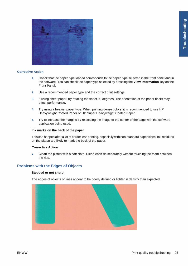
Problems with the Edges of Objects
Stepped or not sharp
The edges of objects or lines appear to be poorly defined or lighter in density than expected.
ENWW Print quality troubleshooting 25
Tro
ub
lesh
oo
tin
g
Corrective Action
● If the print quality slider has already been set to Quality in the Print dialog, select the custom printquality options, and try setting the quality level to Normal (refer to the User’s Guide for moreinformation).
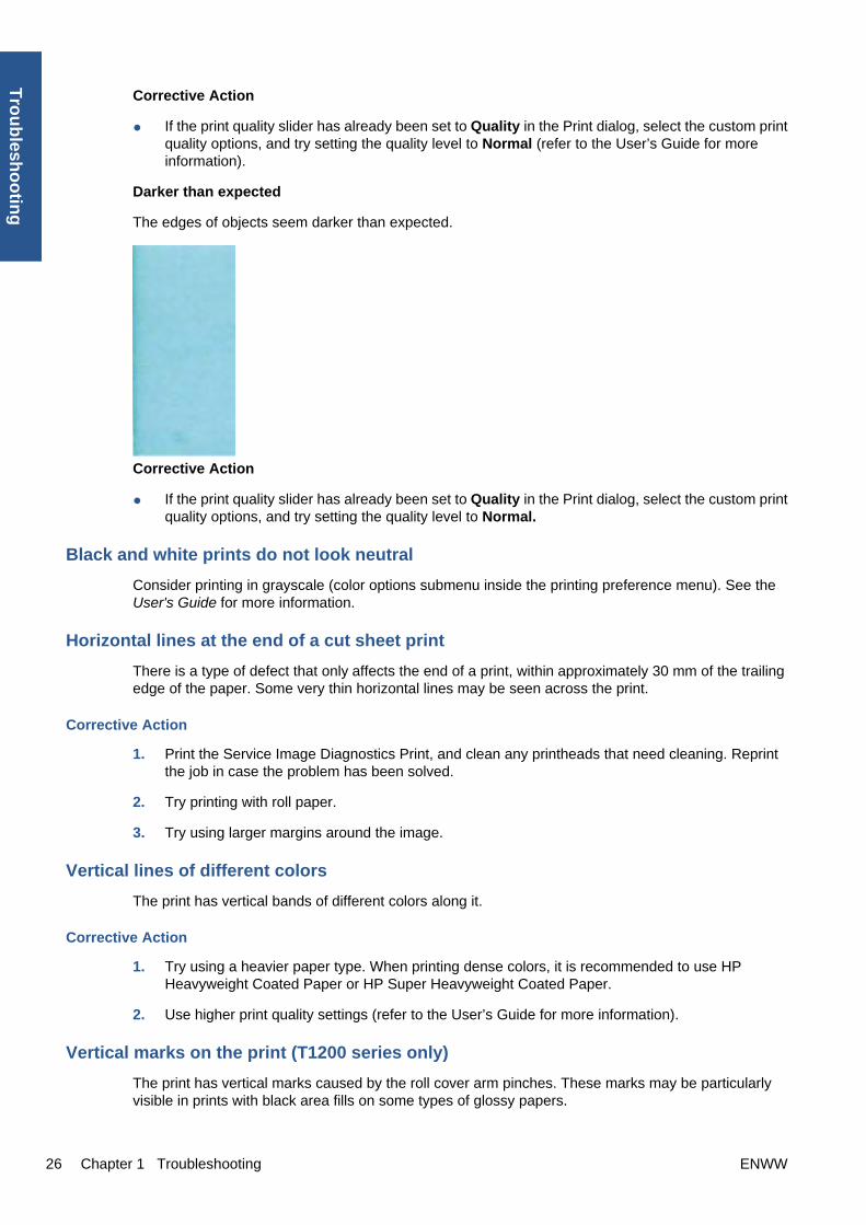
Darker than expected
The edges of objects seem darker than expected.
Corrective Action
● If the print quality slider has already been set to Quality in the Print dialog, select the custom printquality options, and try setting the quality level to Normal.
Black and white prints do not look neutral
Consider printing in grayscale (color options submenu inside the printing preference menu). See theUser's Guide for more information.
Horizontal lines at the end of a cut sheet print
There is a type of defect that only affects the end of a print, within approximately 30 mm of the trailingedge of the paper. Some very thin horizontal lines may be seen across the print.
Corrective Action
1. Print the Service Image Diagnostics Print, and clean any printheads that need cleaning. Reprintthe job in case the problem has been solved.
2. Try printing with roll paper.
3. Try using larger margins around the image.
Vertical lines of different colors
The print has vertical bands of different colors along it.
Corrective Action
1. Try using a heavier paper type. When printing dense colors, it is recommended to use HPHeavyweight Coated Paper or HP Super Heavyweight Coated Paper.
2. Use higher print quality settings (refer to the User’s Guide for more information).
Vertical marks on the print (T1200 series only)
The print has vertical marks caused by the roll cover arm pinches. These marks may be particularlyvisible in prints with black area fills on some types of glossy papers.
26 Chapter 1 Troubleshooting ENWW
Tro
ub
lesho
otin
g

Corrective Action
1. Try using a different glossy paper.
2. Load the roll on the upper spindle and disable the roll cover (only the upper roll cover can bedisabled). See Disable Upper Roll Cover (T1200 series only) on page 137.
White spots on the print
White spots are seen on the print. This is probably due to paper fibers, dust, or loose coating material.
Corrective Action
1. Clean the paper manually with a brush before printing, to remove any loose fibers or particles.
2. Always keep the cover of the printer closed.
3. Protect paper rolls and sheets by storing them in bags or boxes.
Problems with Color Accuracy
Corrective Action
1. Ensure that the paper type being used has been color calibrated, which will give color consistencyfrom print to print, and from printer to printer.
2. Check that printing is on the correct side of the paper.
3. Check that the appropriate print quality settings are being used (refer to the User’s Guide for moreinformation). Reprint the job in case the problem has been solved.
4. If the problem consists of color differences between your print and your monitor, please follow theinstructions in the "How to calibrate your monitor" section of the HP Color Center. At this point, youmay wish to reprint your job in case the problem has been solved.
5. Select suitable options in the application (refer to the User’s Guide for more information).
6. Print the Service Image Diagnostics Print, and clean any printheads that need cleaning. Reprintthe job in case the problem has been solved.
Color accuracy using EPS or PDF images in page layout applications
Page layout applications such as Adobe InDesign and QuarkXPress do not support color managementof EPS, PDF, or grayscale files.
If these types of files have to be used, try to ensure that the EPS, PDF, or grayscale images are alreadyin the same color space that is intended to be used later on in Adobe InDesign or QuarkXPress. Forinstance, if the final objective is to print the job in a press that follows the SWOP standard, at the timeof creating the EPS, PDF or grayscale the image should be converted into SWOP.
ENWW Print quality troubleshooting 27
Tro
ub
lesh
oo
tin
g

Output Only Contains a Partial Print
If the output that was expected only contains a partial image, then try the following to resolve the problem:
1. Was the Cancel key pressed before all the data was received by the printer? If so, send the fileagain and make sure that the Cancel key is not pressed.
2. The I/O Timeout setting may be too short. Increase the I/O timeout setting (Setup Menu/I/O Setup/IO Timeout) and then send the file again.
3. There might be a communications problem between the printer and computer. Check the USB ornetwork cable between the computer and the printer to make sure it is not damaged and isconnected correctly.
4. Make sure that the software settings are correct for the current page size (e.g. long-axis prints).
5. If network software is being used, make sure it has not timed out.
Problems with Image Clipping
This normally indicates a discrepancy between the actual printable area on the loaded paper and theprintable area as understood by the software. This kind of problem can often be identified before printingby previewing the print.
● Check the actual printable area for the paper size that is loaded. printable area = paper size –margins
● Check what the software understands to be the printable area (which it may call “printing area” or“imageable area”). For example, some software applications assume standard printable areas thatare larger than those used in this printer.
● If a custom page size with very narrow margins has been defined, the printer may impose its ownminimal margins, clipping the image slightly. Consider using a larger paper size, or border lessprinting.
● If the image contains its own margins, it may be possible to print it successfully by using the ClipContents by Margins option.
● If a very long image needs to be printed on a roll, check that the software is capable of printing animage of that size.
● The page may have been rotated from portrait to landscape on a paper size that is not wide enough.
● If necessary, change the printable area in the software.
● If necessary, reduce the size of the image or document in your software application, so it fitsbetween the margins
Another Possible Explanation
Some applications, such as Adobe Photoshop, Adobe Illustrator, and CorelDRAW, use an internal 16-bit coordinate system which means that they cannot handle an image of more than 32,768 pixels. If youtry to print an image larger than this from these applications, the bottom of the image will be clipped. Inthis case, the only way to print the whole image is to reduce the resolution so that the whole imagerequires fewer than 32,768 pixels. The HP-GL/2 printer driver contains an option called Compatibilitywith 16-bit applications, which can be used to reduce the resolution of such images automatically.This option can be found option in the Advanced tab, under Document Options > Printer Features.
Some objects are missing from the printed image
Large quantities of data may be necessary to print a high-quality large-format print job, and in somespecific workflow there may be issues that can lead to some objects missing from the output.
28 Chapter 1 Troubleshooting ENWW
Tro
ub
lesho
otin
g

Corrective Action
● In the Advanced tab, select Document options, Printer features, and set Send job as bitmap toEnabled (HP-GL/2 driver only).
● In the Advanced tab, select Document options, Printer features, and set 16-bit App. Compatibilityto Enabled.
● In the Advanced tab, select Document options, Printer features, and set Max. Application resolutionto 300.
The above settings are mentioned for troubleshooting purposes and may adversely affect the final outputquality or the time necessary to generate the print job. Therefore, they should be restored to their defaultvalues if they do not help to solve the problem.
When working under Mac OS, the above settings are not available. Instead, try reducing the resolutionof bitmap images in the application software being used.
A PDF file is clipped or objects are missing
In older versions of Adobe Acrobat or Adobe Reader, large PDF files could be clipped or lose someobjects when printing with the HP-GL/2 driver at high resolution. Upgrade the Adobe Acrobat or AdobeReader software to the latest version. From version 7 onwards, these problems should be solved.
Print Quality Troubleshooting Wizard
Here we describe the main guidelines to follow when troubleshooting print-quality and/or color issues.
The Print Quality (PQ) troubleshooting Wizard is a set of processes and corrective actions that thecustomer can trigger in the printer whenever the print quality of the printer does not meet theirexpectations.
Some of these corrective actions that the customer can perform to enhance the print and/or color qualityare: printhead cleaning, media advance calibration, printhead alignment, and color calibration.
The main benefits of this Print Quality Troubleshooting Wizard tool are that it creates a better customerexperience, solving customer PQ issues fast, efficiently, and with a minimum cost for them and also forHP Support.
Customers can perform PQ/color troubleshooting through the Printer Utility (PU), the Embedded WebServer (EWS) or by following the steps described in the User’s Manual or the HP Knowledge Center.
When to use the Print Quality troubleshooting tool:
ENWW Print quality troubleshooting 29
Tro
ub
lesh
oo
tin
g

The Print Quality Troubleshooting Wizard can help customers solve their PQ/color problems without theneed to call to HP Support. Some of the problems for which it can help are the following:
● Troubleshooting area fill uniformity issues such as:
– Horizontal lines across the image (banding)
– The entire image is blurry or grainy (graininess)
● Troubleshooting line and text quality issues such as:
– Lines are too thick, too thin, or missing
– Lines appear stepped or jagged
– Lines print double or in the wrong colors
– Lines are discontinuous
– Lines are blurred
● Troubleshooting color issues such as:
– Colors are inaccurate
● Troubleshooting printhead reliability issues
Corrective actions a customer can perform:
The corrective actions on the printer’s systems that the customer can perform to enhanced the printand/or color quality are:
● Clean Printheads is recommended only if the customer is experiencing problems with print qualitywhere we know that printhead cleaning will help.
● Calibrate Paper Advance is used to adjust the printer’s parameters for use with different types ofprint media. This only affects the physical movement of paper and does not affect the colorcalibration profiles.
● Align Printheads is recommended only if the customer is experiencing problems with print qualitywhere we know that proper printhead alignment will help (i.e. graininess).
● Calibrate Color is recommended only if the customer is experiencing problems with color printquality where we know that proper color calibration with help (i.e. color accuracy).
30 Chapter 1 Troubleshooting ENWW
Tro
ub
lesho
otin
g

How to start the Print Quality Troubleshooting Wizard
1. From the HP Printer Utility under Windows: go to the Support tab, and select Print qualitytroubleshooting.
2. From the Embedded Web Server: go to the Support tab, then select Print qualitytroubleshooting.
For Mac OS
1. From the HP Printer Utility under Mac OS: select Support, and then Print quality troubleshooting.
2. From the Mac OS Print dialog: go to the Services panel, select Device Maintenance, then selectPrint quality troubleshooting from the list of maintenance tasks.
Ink Supplies Troubleshooting● Introduction to ink supplies
● Ink Cartridge Levels, Information, and Replacement
● Printhead Information, Replacement and Alignment
● Ink Cartridge and Printhead Status Messages
● Solving Ink Supplies Problems
ENWW Ink Supplies Troubleshooting 31
Tro
ub
lesh
oo
tin
g

● Maintaining and Cleaning the Printheads
Introduction to ink supplies
Introduction to ink supplies
What are Ink Supplies?
For each of the ink colors used in the printer, there are two components, the Printhead and Ink Cartridge.These components are called Ink Supplies.
Ink Cartridges
The printer's six Ink Cartridges provide matte black, magenta, yeloow, cyan, gray and photo black inkto the Printheads. The color Ink Cartridges supplied with the printer have a capacity of 69ml but optional130 ml are also available.
All these Ink cartridges are physically the same size. Only the internal capacity varies.
The Ink Cartridges for the T printer series require no maintenance or cleaning. As long as each InkCartridge is inserted correctly into its slot, the ink will flow to the Printheads. Because the Printheadscontrol the amount of ink transferred to the page, you will continue to see high-quality printing resultseven when the ink levels are getting low.
The front panel displays the status of the Ink Cartridge. Using the front panel, detailed information canbe checked on the Ink Cartridges.
32 Chapter 1 Troubleshooting ENWW
Tro
ub
lesho
otin
g

Table 1-2 Available Ink Cartridges
Ink cartridge Part number
HP 72 69 ml Photo Black Ink Cartridge C9397A
HP 72 69 ml Cyan Ink Cartridge C9398A
HP 72 69 ml Magenta Ink Cartridge C9399A
HP 72 69 ml Yellow Ink Cartridge C9400A
HP 72 69 ml Gray Ink Cartridge C9401A
HP 72 130 ml Matte Black Ink Cartridge C9403A
HP 72 130 ml Photo Black Ink Cartridge C9370A
HP 72 130 ml Cyan Ink Cartridge C9371A
HP 72 130 ml Magenta Ink Cartridge C9372A
HP 72 130 ml Yellow Ink Cartridge C9373A
HP 72 130 ml Gray Ink Cartridge C9374A
HP 726 300 ml Matte Black Ink Cartridge (T1200 series only) CH575A
Printheads
The Printheads are extremely durable and do not need to be replaced every time an Ink Cartridge isreplaced. They are independent of the Ink Cartridges and will continue giving excellent image-qualityresults even if the Ink Cartridges are low on ink.
Table 1-3 Available Printheads
Printer Model Part number
HP 72 Gray & Photo Black Printhead All C9380A
HP 72 Magenta & Cyan Printhead C9383A
HP 72 Matte Black & Yellow Printhead C9384A
General Information About the Ink Supplies
ENWW Ink Supplies Troubleshooting 33
Tro
ub
lesh
oo
tin
g

For optimum results from the printer and modular ink delivery system always follow these guidelineswhen handling the ink supplies:
● Always install the Ink Cartridges and Printheads before the expiration date, which is on thepackaging.
● Install Ink Cartridges and Printheads in their color-coded slots.
● Follow the instructions on the front panel of the printer during installation.
● Avoid unnecessary removal of the Ink Cartridges and Printheads.
● When turning off the printer always use the Power key on the front panel. The Printheads are thenstored correctly which prevents them from drying out.
● The Ink Cartridges should never be removed while the printer is printing. They should only beremoved when the printer is ready for you to replace them. The front panel will guide you throughthe removal and installation procedure.
General Precautions When Handling Ink Supplies
Use the following precautions when handling Ink Supplies:
NOTE: Do not touch, wipe or attempt to clean the printhead nozzles. This can damage the printhead.
● Handle the ink supplies with care. In particular the Printhead, which is a high precision device andmust be handled carefully.
● Do not touch the Printhead nozzles.
● Do not put the Printhead down on the nozzles.
● Do not be rough when handling the Printheads. Always set them down gently
● Do not drop the Printheads.
● Proper handling will assure optimum performance throughout the Printhead life.
● Do not touch the end of the Ink Cartridge which is inserted into the printer as there may be a smallamount of ink on the connection.
● Avoid storing partially used Ink Cartridges on their ends.
When Should You Replace the Ink Supplies?
When to change the ink supplies is mostly determined by you with guidance from the front panel. Inconjunction with the messages displayed in the front panel and the message explanations in thischapter, you will be able to choose for yourself when is the right time to change the ink supplies.
The printer will also display the ink level and will tell you when the ink supply is low on ink. This meansyou have constantly updated information about the ink supplies.
Ink Cartridge Levels, Information, and Replacement
Ink Cartridge Levels
The front panel displays Ink Levels shown as level bars. These bars represent how much ink is remainingin the Ink Cartridges: as ink is used up the bars get shorter in length.
There are two methods for checking the ink levels of your Ink Cartridges.
“View Ink Levels” Direct Access Key
34 Chapter 1 Troubleshooting ENWW
Tro
ub
lesho
otin
g
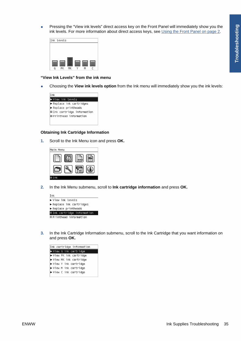
● Pressing the “View ink levels” direct access key on the Front Panel will immediately show you theink levels. For more information about direct access keys, see Using the Front Panel on page 2.
“View Ink Levels” from the ink menu
● Choosing the View ink levels option from the Ink menu will immediately show you the ink levels:
Obtaining Ink Cartridge Information
1. Scroll to the Ink Menu icon and press OK.
2. In the Ink Menu submenu, scroll to Ink cartridge information and press OK.
3. In the Ink Cartridge Information submenu, scroll to the Ink Cartridge that you want information onand press OK.
ENWW Ink Supplies Troubleshooting 35
Tro
ub
lesh
oo
tin
g

4. The front panel displays information on the selected Ink Cartridge. Use the Arrow keys to scrollthrough the information.
The information supplied is:
● The color of the Ink Cartridge.
● The make of the Ink Cartridge (HP no.72 is recommended).
● The product number of the Ink Cartridge.
● The serial number of the Ink Cartridge.
● The current status of the Ink Cartridge.
● The current ink level of the ink cartridge in milliliters.
● Original capacity of the ink cartridge in milliliters.
● The Expiration Date of the ink cartridge.
● The manufacturer of the Ink Cartridge (HP is recommended).
● The current warranty status of the Ink Cartridge.
The printer consumes more gray ink ink than M, C, or Y
This is not a problem, and no action should be taken to “correct” this attribute of the printer.
In general the higher frequency of change is because Matte Black ink is the one that is used for linesand black objects in technical papers (bond, coated, HW coated, natural tracing paper, etc.), which arethe types of contents that are more commonly printed with this type of printer.
About gray ink
The T Series printers are the first HP Designjet technical products to include Gray ink. One thing thatusers may notice is that Gray ink is used in higher quantities than Cyan, Magenta and Yellow inks. Thishappens because of the following reasons:
1. Gray areas (which are very typical in technical drawings) can now be printed by using only Grayink. In the past, these areas had to be printed by combining Cyan, Magenta and Yellow inks. Thismeans that Gray ink is used more frequently than the rest of the inks (C, M, Y) which are now usedless frequently, so the difference in consumption is noticeable. However overall the T Seriesprinters will actually need to use in total less ink to print gray areas than previous Designjet products.
2. Soft colors can now be printed by combining C, M and Y inks with Gray. The addition of Gray inksoftens the color, improving transition areas. It also allows printing soft colors by using less C, M
36 Chapter 1 Troubleshooting ENWW
Tro
ub
lesho
otin
g

and Y. These two types of contents are very typical and make the consumption of Gray to increaseand the consumption of C, M and Y to decrease.
Conclusion
However, no matter the combination of inks that are used, when the total cc’s of ink are added up, theT Series printers will always have a lower ink consumption than the HP Designjet 500, 800 and 1000series for equivalent contents with equivalent levels of print quality.
Changing an Ink Cartridge
There are two occasions when you need to remove an ink cartridge:
● The ink cartridge is very low and you want to replace it with a full cartridge for unattended printing(you can use up the remaining ink in the first cartridge at a more convenient time).
● The ink cartridge is empty or faulty, and you must replace it to continue printing.
NOTE: Do not try to remove an ink cartridge while printing. Remove an ink cartridge only if you areready to insert another one.
Make sure the printer wheels are locked (the brake lever is pressed down) to prevent the printer frommoving.
Change an ink cartridge using the following procedure:
1. Scroll to the Ink Menu icon and press OK.
2. In the Ink Menu submenu, scroll to Replace ink cartridges and press OK.
3. The front panel displays the status of the Ink Cartridges.
4. Press OK to continue.
5. Open the relevant Ink Cartridge cover for the Ink Cartridge you want to replace.
6. Pull the required Ink Cartridge straight up to remove it from the printer.
ENWW Ink Supplies Troubleshooting 37
Tro
ub
lesh
oo
tin
g
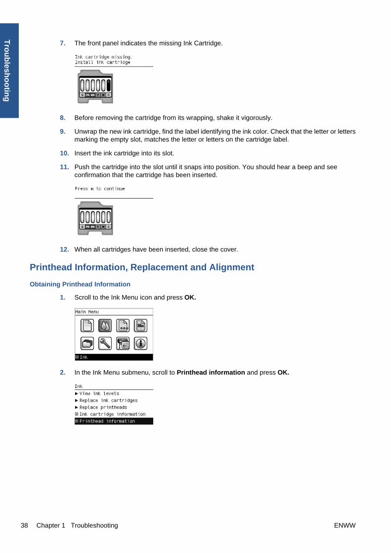
7. The front panel indicates the missing Ink Cartridge.
8. Before removing the cartridge from its wrapping, shake it vigorously.
9. Unwrap the new ink cartridge, find the label identifying the ink color. Check that the letter or lettersmarking the empty slot, matches the letter or letters on the cartridge label.
10. Insert the ink cartridge into its slot.
11. Push the cartridge into the slot until it snaps into position. You should hear a beep and seeconfirmation that the cartridge has been inserted.
12. When all cartridges have been inserted, close the cover.
Printhead Information, Replacement and Alignment
Obtaining Printhead Information
1. Scroll to the Ink Menu icon and press OK.
2. In the Ink Menu submenu, scroll to Printhead information and press OK.
38 Chapter 1 Troubleshooting ENWW
Tro
ub
lesho
otin
g

3. In the Printhead Information submenu, scroll to the Printhead that you want information on andpress OK.
4. The front panel displays information on the selected Printhead.
The information supplied is:
● The make of the printhead (HP no.72 is recommended).
● The product number of the Printhead.
● The serial number of the Printhead.
● The current status of the printhead.
● How much ink has been fired (consumed) by the printhead.
NOTE: It is possible for a printhead to consume more than one Ink Cartridge.
● The current warranty status of the Printhead.
Changing a Printhead
1. Scroll to the Ink Menu icon and press OK.
2. In the Ink Menu submenu, scroll to Replace printheads and press OK.
3. The printer moves the Carriage to the correct position to replace Printheads.
NOTE: If the carriage is left in the removal position for more than three minutes without insertingor removing any printheads, it will try to move back to its normal position at the right-hand end.
ENWW Ink Supplies Troubleshooting 39
Tro
ub
lesh
oo
tin
g
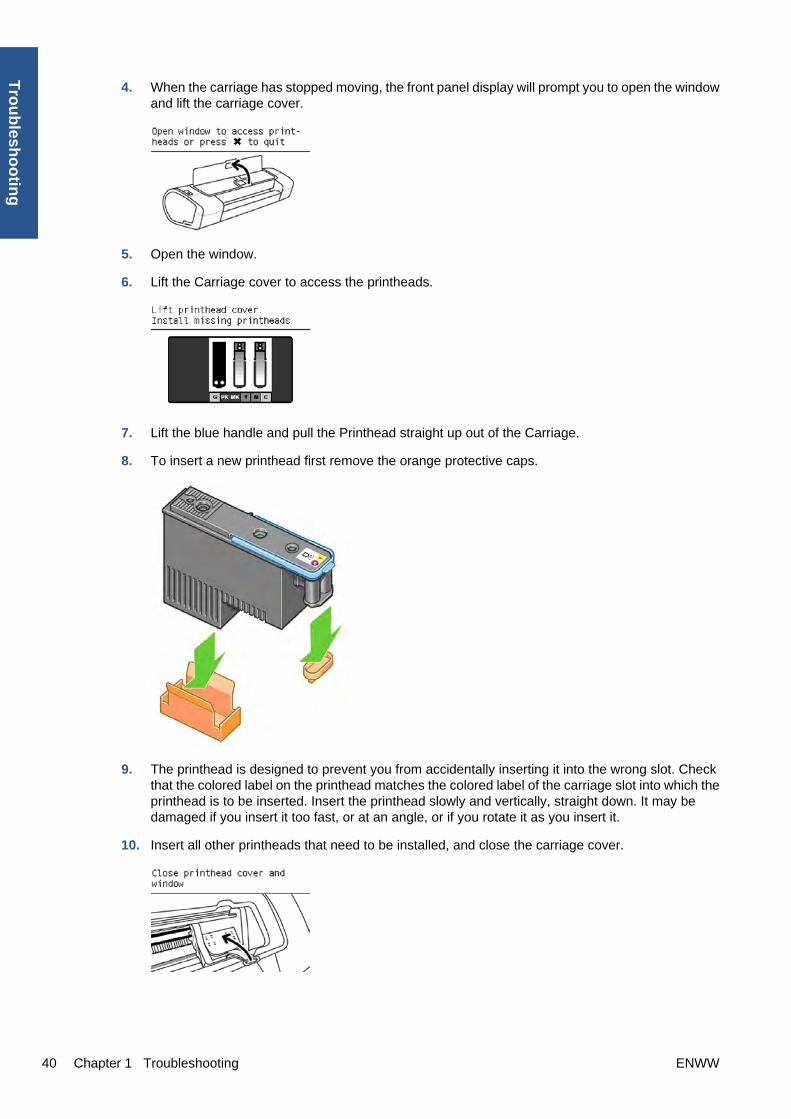
4. When the carriage has stopped moving, the front panel display will prompt you to open the windowand lift the carriage cover.
5. Open the window.
6. Lift the Carriage cover to access the printheads.
7. Lift the blue handle and pull the Printhead straight up out of the Carriage.
8. To insert a new printhead first remove the orange protective caps.
9. The printhead is designed to prevent you from accidentally inserting it into the wrong slot. Checkthat the colored label on the printhead matches the colored label of the carriage slot into which theprinthead is to be inserted. Insert the printhead slowly and vertically, straight down. It may bedamaged if you insert it too fast, or at an angle, or if you rotate it as you insert it.
10. Insert all other printheads that need to be installed, and close the carriage cover.
40 Chapter 1 Troubleshooting ENWW
Tro
ub
lesho
otin
g

11. Close the Window.
12. When all the printheads have been inserted correctly and accepted by the printer, the printer willbeep. If the printer does not beep when you insert the printhead and the Replace message appearson the front panel display, the printhead may need to be reinserted.
The front panel display confirms that all printheads are correctly inserted.
The printer will start checking and preparing the printheads. The default routine process, when allprintheads are changed, takes 25 minutes. If the printer finds problems in preparing the printheads,it will take longer, up to 55 minutes. For a single printhead insertion, the times vary between 15and 35 minutes. After all printheads are checked and prepared, for the printhead realignment.
Aligning Printheads
Precise alignment between printheads is essential for accurate colors, smooth color transitions, andsharp edges in graphical elements. Your printer has an automatic printhead alignment process whichruns whenever a printhead has been accessed or replaced.
In cases where the paper has jammed, you have used a custom paper, or are experiencing problemswith color accuracy you may need to align the printheads. If the paper has jammed, it is recommendedthat you reinsert the printheads and initiate the realignment procedure with the Image QualityMaintenance menu.
NOTE: Do not use transparent and semi-transparent paper to align the printheads. Photo paper isrecommended for the best quality.
Reinsert Printheads Procedure
1. If the realignment process is running and the wrong paper is loaded, press the Cancel key on thefront panel. Do not print if the realignment process has been canceled. You can restart thealignment with the Image Quality Maintenance menu procedure.
2. Load the paper you wish to use,. You can use a roll or cut sheet, however, it must be A3 landscapeor larger.
3. Remove and re-insert all the printheads, see Remove a printhead and Insert a printhead. This willstart the printhead alignment procedure.
4. Ensure the transparent window closed, as a strong light source near the printer during printheadrealignment can affect alignment.
5. The process will take about six minutes. Wait until the front panel display shows the processcomplete before using the printer.
Image Quality Maintenance Procedure
1. Load the paper you wish to use. You can use a roll or cut sheet, however, it must be A3 landscapeor larger (420 by 297 mm). Do not use transparent and semi-transparent paper to align theprintheads. Photo paper is recommended for the best results; plain, bond and thin coated papersprovide acceptable but marginal results.
2. Press the Menu key to return to the main menu and select the Image Quality Maintenance menuicon.
ENWW Ink Supplies Troubleshooting 41
Tro
ub
lesh
oo
tin
g

3. Select Align printheads. The printer will check to see if it has enough paper to run the realignment.
4. If the loaded paper is satisfactory, the printer will run the realignment and print a realignmentpattern. Ensure the transparent window is closed, as a strong light source near the printer duringprinthead realignment can affect alignment.
Plot:
5. The process will take about five minutes. Wait until the front panel display shows the processcomplete before using the printer.
Scanning errors during alignment
If the alignment process FAILs, a Scanning problems message appears on the front panel. This meansthat the alignment has not completed successfully. Therefore the printer is not aligned and the alignmentshould be repeated before printing with good image quality. The problem may be due to:
● The paper used was not valid, repeat the alignment with valid paper.
● Printhead health problems, clean printheads.
● The alignment was done with the transparent window open, repeat the alignment with the windowclosed.
If the problem persists after using valid paper, cleaning the printheads, and keeping the window closed,there may be a failure in the scanning system needing reparation or the printheads, although clean, maynot work and need to be replaced.
Ink Cartridge and Printhead Status Messages
Ink Cartridge Status Messages
OK The Ink Cartridge is operating correctly and no action is required.
Missing There is no Ink Cartridge present, or it is not properly connected to the printer
Low The Low message is an early warning sign and it is advisable that new supplies shouldbe obtained of that particular color. The amount of ink remaining in the Ink Cartridgedepends on it’s capacity, but there is approximately 14% of ink available for the user.
Very Low When theVery Low message is displayed, overnight printing should not be attempted.Changing the Ink Cartridge is strongly recommended to prevent the printer from stoppinghalfway through a print. There is approximately 8% of ink available for the user.
Empty The printer will stop and will not be able to continue printing until a new Ink Cartridge hasbeen installed. If this occurs halfway through printing an image, you should check thequality of this image, as stopping mid-plot can affect the print. It would be recommendedto reprint the image once a new Ink Cartridge has been installed.
Reseat You are recommended to remove the Ink Cartridge and then reinsert it.
42 Chapter 1 Troubleshooting ENWW
Tro
ub
lesho
otin
g
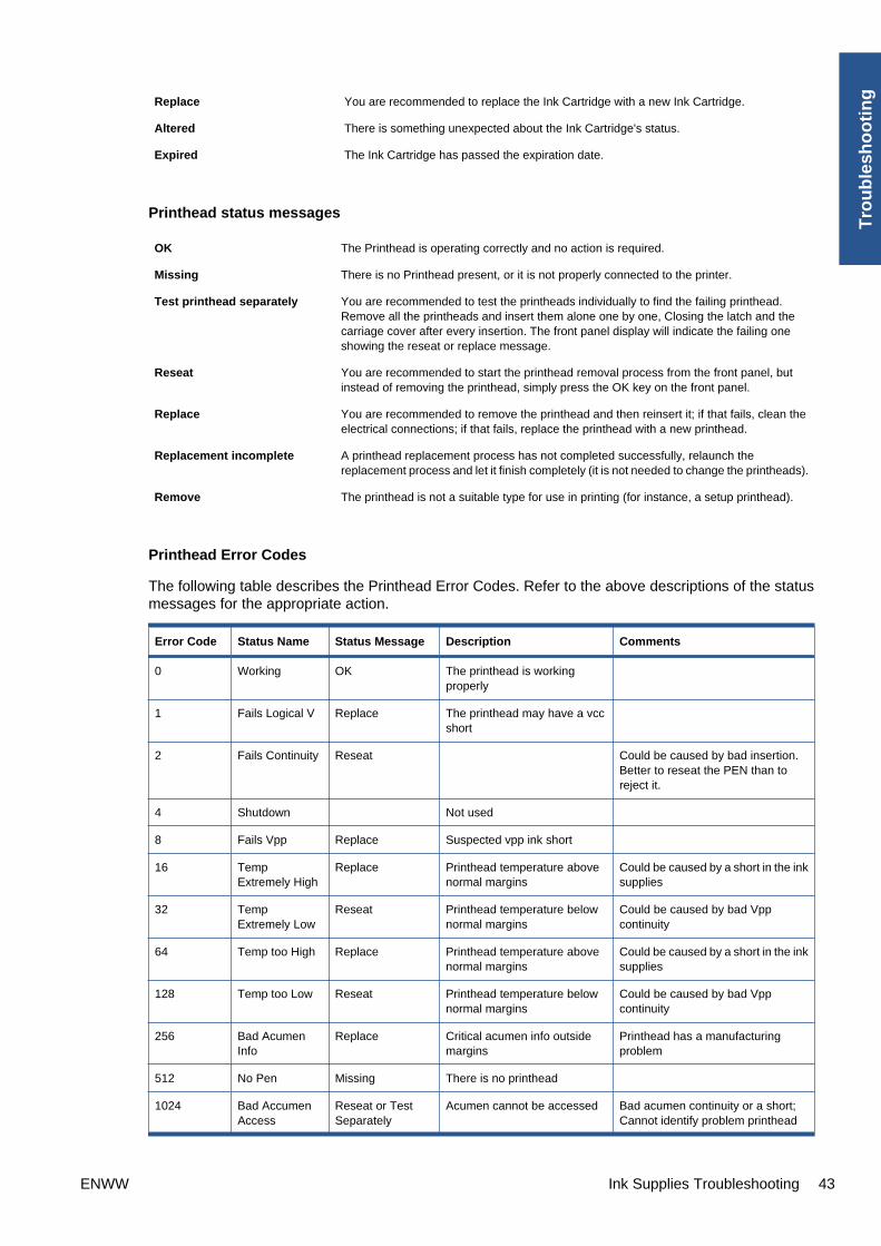
Replace You are recommended to replace the Ink Cartridge with a new Ink Cartridge.
Altered There is something unexpected about the Ink Cartridge's status.
Expired The Ink Cartridge has passed the expiration date.
Printhead status messages
OK The Printhead is operating correctly and no action is required.
Missing There is no Printhead present, or it is not properly connected to the printer.
Test printhead separately You are recommended to test the printheads individually to find the failing printhead.Remove all the printheads and insert them alone one by one, Closing the latch and thecarriage cover after every insertion. The front panel display will indicate the failing oneshowing the reseat or replace message.
Reseat You are recommended to start the printhead removal process from the front panel, butinstead of removing the printhead, simply press the OK key on the front panel.
Replace You are recommended to remove the printhead and then reinsert it; if that fails, clean theelectrical connections; if that fails, replace the printhead with a new printhead.
Replacement incomplete A printhead replacement process has not completed successfully, relaunch thereplacement process and let it finish completely (it is not needed to change the printheads).
Remove The printhead is not a suitable type for use in printing (for instance, a setup printhead).
Printhead Error Codes
The following table describes the Printhead Error Codes. Refer to the above descriptions of the statusmessages for the appropriate action.
Error Code Status Name Status Message Description Comments
0 Working OK The printhead is workingproperly
1 Fails Logical V Replace The printhead may have a vccshort
2 Fails Continuity Reseat Could be caused by bad insertion.Better to reseat the PEN than toreject it.
4 Shutdown Not used
8 Fails Vpp Replace Suspected vpp ink short
16 TempExtremely High
Replace Printhead temperature abovenormal margins
Could be caused by a short in the inksupplies
32 TempExtremely Low
Reseat Printhead temperature belownormal margins
Could be caused by bad Vppcontinuity
64 Temp too High Replace Printhead temperature abovenormal margins
Could be caused by a short in the inksupplies
128 Temp too Low Reseat Printhead temperature belownormal margins
Could be caused by bad Vppcontinuity
256 Bad AcumenInfo
Replace Critical acumen info outsidemargins
Printhead has a manufacturingproblem
512 No Pen Missing There is no printhead
1024 Bad AccumenAccess
Reseat or TestSeparately
Acumen cannot be accessed Bad acumen continuity or a short;Cannot identify problem printhead
ENWW Ink Supplies Troubleshooting 43
Tro
ub
lesh
oo
tin
g

Error Code Status Name Status Message Description Comments
2048 Wrong Model Replace Wrong printhead inserted Mechanical lockouts should preventthis. Error is redundant
4096 Mismatch Replace Wrong color inserted Mechanical lockouts should preventthis
8192 CSdata NotResponding
Reseat CSdata commuication failed Could be caused by bad insertion
16384 CSdataTransmit Error
Reseat CSdata commuicationincorrect
Could be caused by bad contact
32768 Fails EnergyCalibration
Reseat Energy calibration failed Could be caused by bad contact
65536 Empty Dummy OK during Purge Requested during purge, otherwiseshould be removed
131072 Full Dummy Remove Requested during purge
262144 End of Life Warning Printhead warranty expired
524288 Expired Warning Printhead has used expired ornon-HP ink
Solving Ink Supplies Problems
Most of the problems that you could encounter when working with the ink supplies are solved withguidance from the front panel. A full list of front panel messages are supplied in the User’s Guide.
You Cannot Insert the Ink Cartridge Into the Printer
1. Ensure that you have the correct HP no.72 Ink Cartridge.
2. Ensure that the Ink Cartridge is the correct color for that slot.
3. Ensure that the Ink Cartridge is the correct orientation, with the color coded label at the top.
NOTE: Never clean inside the Ink Cartridge slots as this can cause damage to the printer.
You Cannot Insert the Printhead Into the Printer
1. Ensure that you have the correct HP no.72 Printhead.
2. Ensure that the printhead is the correct color for that slot.
3. Ensure that the printhead is in the correct orientation.
4. Ensure that the protective cap is removed from the Printhead.
The front panel says to reset or replace a printhead
1. From the front panel, turn the power off then on.
2. Check the front panel display message, if it shows the ready message, the printer is ready to print.If the problem remains continue with the next step.
3. Remove the printhead.
44 Chapter 1 Troubleshooting ENWW
Tro
ub
lesho
otin
g

4. Clean the electrical connections on the backside of the printhead with a lint-free cloth. You cancarefully use a mild rubbing alcohol if moisture is needed to remove residue. Do not use water.You can use the Flex Contacts Cleaning Tool.
This is a delicate process and may damage the printhead. Do not touch the nozzles on the bottomside of the printhead, especially not with any alcohol.
5. Reinsert the printhead.
6. Check the front panel display message. If the problem remains, try a new printhead.
Maintaining and Cleaning the Printheads
Clean the printheads
As long as the printer is kept turned on, an automatic cleaning is performed periodically. This ensuresthere is fresh ink in the nozzles and prevents nozzle clogs, which ensures color accuracy.
If you have not already done so, please read Horizontal Lines Across the Image (Banding)on page 19 and The Service Image Quality Diagnostic Print on page 6 before proceeding.
To clean the printheads, press the Menu key to return to the main menu and select the Image QualityMaintenance menu icon, then Clean printheads. If you have gone through the Image Quality Diagnosticprint process, you know which colors are failing. Select to the pair of printheads which contain the failingcolors. If you are not sure which colors to clean, you can also select to clean all printheads.
Cleaning all printheads takes about nine minutes. Cleaning a single pair of printheads takes about sixminutes. Cleaning all printheads uses more ink than cleaning a single pair.
If you have cleaned the printheads using the Clean printheads procedure from the front panel and arestill experiencing image quality problems, you can try cleaning the printhead nozzles manually using thefollowing procedure.
NOTE: This is a delicate process and may damage the printhead. Do not touch the electricalconnections on the backside of the printhead.
You must remove the printhead (see Changing a Printhead on page 39) and using a cotton swab anda little de-ionized, distilled water, or Carriage Interconnect Wiper clean the bottom of the printhead untilthe residue is removed.
Flex Contacts Cleaning Tool
NOTE: The Flex Contacts Cleaning Tool is part of the Maintenance Tool Kit. All the instructions neededto use the Flex Contacts Cleaning Tool will be packaged with the kit.
ENWW Ink Supplies Troubleshooting 45
Tro
ub
lesh
oo
tin
g

Whenever you replace the Printhead, check the empty slots to see if they need cleaning. In extremecircumstances, when a Printhead is inserted, it is possible that the printer will not recognize it due to thebuild-up of ink on the electrical connection between the Printhead and the Carriage Assembly.
Included with the printer is a Flex Contacts Cleaning Tool. This tool is provided in a separate package.It also contains replacement sponges and an instruction sheet. This tool should be used for cleaningthe electrical interconnects of both the Carriage Assembly and the Printhead.
If the front panel displays the message “Reseat” or “Replace” next to the offending printhead, try cleaningthe flex circuits of the Carriage and the Printheads using the Carriage Interconnect Wiper.
NOTE: Do not touch, wipe or attempt to clean the printhead nozzles. This can damage the printheadand reduce print quality.
Connectivity troubleshootingConnectivity problems are resolved differently for USB, embedded LAN and Jetdirect connectivity.Follow the advice given in the appropriate section below.
46 Chapter 1 Troubleshooting ENWW
Tro
ub
lesho
otin
g

USB device connectivity troubleshooting
If the printer experiences problems with USB enumeration (the computer does not detect the printerwhen the USB cable is plugged in) or with USB performance (throughput is slow) then try the followingchecks.
● Check that the USB port in the computer is a “USB 2.0 High Speed” port. Some old computers andUSB hubs have slower “USB 1.1 Full Speed” ports, and those should not be used with Designjetprinters. Do not ignore a warning message on your computer such as:
● Check the USB cable.
◦ Check that the USB cable is USB 2.0 Certified: check the USB logo on the packaging of thecable, or on the cable itself, or check the specifications of the cable.
◦ Try a shorter USB cable. Cables close to the 5 m limit often cause problems.
◦ Make sure the USB cable doesn’t pass near possible sources of electrical interference (CRTmonitors, engines, etc.).
● Connect the printer to a different USB port on the computer. If possible, try using a differentcomputer.
● Remove any other USB devices from the computer, or connect them to different USB ports.
Embedded LAN connectivity troubleshooting
Perform the following procedure, checking the connectivity carefully after each step to see whether theproblem has been fixed.
1. Change the LAN cable.
a. Disconnect the LAN cable at both the remote end and the printer end of the cable.
b. Reconnect using the LAN cable. Use a different LAN cable if possible.
2. Try connecting to a different Ethernet socket in your network, router or switch.
3. If possible, try to reset the Ethernet switch or router. This may involve turning it off and on again.
4. Adjust the configuration settings.
a. Print out the original printer I/O settings: from the front panel, select the Internal Prints menu,then Service information prints > Print connectivity config.
b. Reset the I/O to factory defaults: from the front panel, select the Connectivity menu, thenAdvanced > Restore factory settings.
c. Restart the printer and wait 5 minutes.
d. Print out the new printer I/O settings: from the front panel, select the Internal Prints menu,then Service information prints > Print connectivity config.
e. Connect to the printer’s Embedded Web Server using the URL shown in the main page of thefront panel.
f. Compare the configuration information printed out before and after restoring to factory defaultsettings. Set any custom I/O settings that may have been lost back to their desired valuesusing the Configuration information printed.
ENWW Connectivity troubleshooting 47
Tro
ub
lesh
oo
tin
g

EIO Jetdirect card connectivity troubleshooting
Perform the following procedure, checking the connectivity carefully after each step to see whether theproblem has been fixed.
1. Change the LAN cable.
a. Disconnect the LAN cable at both the remote end and the printer end of the cable.
b. Reconnect using the LAN cable. Use a different LAN cable if possible.
2. Try connecting to a different Ethernet socket in your network, router or switch.
3. If possible, try to reset the Ethernet switch or router. This may involve turning it off and on again.
4. Adjust the configuration settings.
a. Print out the original Jetdirect I/O settings: from the front panel, select the Internal Printsmenu, then Service information prints > Print connectivity config.
b. Print out the original Jetdirect protocol settings: from the front panel, select the Connectivitymenu, then Jetdirect EIO > Modify configuration > Information > Print protocols > Yes.Return to the main menu.
c. Reset the Jetdirect I/O to factory defaults: from the front panel, select the Connectivity menu,then Jetdirect EIO > Restore factory settings.
d. Restart the printer and wait 5 minutes.
e. Print out the new Jetdirect I/O settings: from the front panel, select the Internal Prints menu,then Service information prints > Print connectivity config.
f. Print out the new Jetdirect protocol settings: from the front panel, select the Connectivitymenu, then Jetdirect EIO > Modify configuration > Information > Print protocols > Yes.Return to the main menu.
g. Connect to the printer’s Embedded Web Server using the URL shown in the main page of thefront panel.
h. Compare the configuration information printed out before and after restoring to factory defaultsettings. Set any custom I/O settings that may have been lost back to their desired valuesusing the Configuration information printed.
USB host features
A USB host port is available in the formatter to support new features available in the HP Designjet T770/T1200 series.
Accessories
Three different HP accessories can be plugged into the USB Host port:
● Memory Upgrade Dongle, part number Q6789A. This accessory is available for the HP DesignjetT770 only, and not for the HP Designjet T770 Hard Disk Version. It increases the processingmemory of the printer from the regular 2 GB to 8 GB. This increased memory allows more complexjobs to be printed.
● PostScript Upgrade Dongle, part number Q6789B. This accessory is available for the HP DesignjetT770 series, but not for the HP Designjet T1200 series. It enables the printer to accept PostScriptand PDF files.
● External Hard Disk Drive, part number Q1234X. This accessory is available for the HP DesignjetT770 and T1200 series. When this accessory is connected the printer will keep all user data stored
48 Chapter 1 Troubleshooting ENWW
Tro
ub
lesho
otin
g

in the external hard disk only, which can be removed from the printer and stored separately forconfidentiality or security reasons.
Copying the diagnostic package to a USB flash drive
The diagnostic package contains useful information from the printer to help you to find the cause of aproblem. The USB host port provides a quick and easy way to retrieve this information into a standardUSB flash drive. See Appendix C: Obtaining the printer log and the diagnostics packageon page 85.
Firmware upgrade with USB flash drive
The USB host port can be used to upgrade the printer's firmware of the printer using a standard USBflash drive. In this case only a valid .FMW firmware package may be stored in the drive, with no otherfiles. Connect the USB flash drive and follow the instructions on the front panel.
Special firmware upgrades
Emergency firmware upgrade
If it is not possible to perform a firmware upgrade using normal procedures (for instance, the printer hasa System Error and the Embedded Web Server is inaccessible), it is still possible to perform a firmwareupgrade in two different ways: start the printer in diagnostics mode and send a PLT file by FTP, or usea USB flash drive.
Send a PLT file via FTP in Diagnostics Mode
1. Ensure that the printer is connected to your local area network.
2. Open the printer's Diagnostics menu. See Entering the Diagnostics Menu on page 89.
3. Select I/O Information.
4. The front panel displays the I/O information.
5. Open an FTP session from a computer connected to the same network as the printer, and sendthe PLT firmware file to the printer. If you don't have the PLT file, please escalate using the normalescalation mode.
6. After about 15 minutes, the front panel displays the Diagnostics menu again.
7. Restart the printer.
ENWW Connectivity troubleshooting 49
Tro
ub
lesh
oo
tin
g

Use a USB flash drive to perform a firmware upgrade
1. Turn off the printer.
2. Ensure that your USB flash drive contains a valid FMW firmware file and no other files.
3. Connect the USB flash drive to the USB host port on the formatter.
4. Turn on the printer and follow the instructions on the front panel.
Forced firmware upgrade
When the printer is started for the first time, it may automatically request a firmware upgrade in order tofix some known issues. You can respond in one of the following ways.
● Use the USB flash drive provided in the box with the printer.
When a firmware upgrade is requested, you should find USB flash drive in the box, containing thenew FMW firmware file. Follow the instructions in the flier accompanying the USB flash drive.
● Download the FWM firmware file from the HP Web site.
If you cannot find the USB flash drive in the box, download the FWM firmware file from the HP Website. Store the file in a standard USB flash drive with no other files. Connect this alternative flashdrive to the formatter's USB host port to perform the firmware upgrade, following the instructionson the front panel.
● Skip the firmware upgrade.
If you cannot find the USB flash drive and you have no Internet connection, you can skip the forcedfirmware upgrade temporarily by pressing the OK key on the front panel three times, and the printerwill continue with the initialization sequence. Make sure that the firmware upgrade is performedlater. The printer will request the firmware upgrade every time that it starts, until the upgrade isperformed.
50 Chapter 1 Troubleshooting ENWW
Tro
ub
lesho
otin
g

2 System Error Codes
● Introduction
● Printer logs
● What to do if the Front Panel is blank
● Continuable and Non-Continuable Error Codes
● System Error Code Brief Descriptions
● System Error Codes—Full Descriptions
● Appendix A: How to troubleshoot SE 79:04
● Appendix B: Updating firmware in diagnostics boot mode
● Appendix C: Obtaining the printer log and the diagnostics package
ENWW 51
Sys
tem
Err
or
Co
des

Introduction
Understand System Error Codes
System error codes are generally used to report internal system errors. The following pages contain alist of system error codes and their respective descriptions and recommended corrective actions. Tryonly one recommended action at a time and check whether the error code has disappeared.
Reporting a system error to HP support
If you have an error code that you cannot resolve, then report the error to the HP Response Center orthe nearest HP Support Office. When reporting the error, have the following information ready:
NOTE: If you fail to provide any of the following information, HP Support cannot help you properly.Make sure you take time to gather all of this information.
● Model and Serial Number of the printer.
● The current firmware revision of the printer. Check firmware in Setup Menu / Information Menu /Show Printer Information.
● The internal error code, file, and line fields found on the Internal Error Screens available bypressing Up and Cancel at the same time when the System Error is shown on the front panel (asshown below). To get the file and line fields, you need to press the Down key on the front panel toscroll to the next screen.
NOTE: The file and line fields are important to identify the source of the problem because thesame internal Error Code can be reported in different files and line. In the File field, supply only thelast part of the value (from last slash “/” to the end of the line). For example: for a file: /ae/…./elektra/hal/motors/ControlledMotor/Elektra/ControlledMotorElektra.cpp you’ll only need to provide the“ControlledMotorElektra.cpp” part to HP support.
● The Service Configuration Print.
● The Current configuration sheet.
● Which software application the customer is using (name, version, etc.).
TIP: When investigating a system error, you are recommended to use the diagnostic package to furtherunderstand the problem. To obtain the diagnostic package (which takes a few minutes), see AppendixC: Obtaining the printer log and the diagnostics package on page 85.
Printer logsIt is possible to have the printer log all the activities it performs in a log file. To further understand asystem error code, it is useful to have a log showing the activities of the printer at the time when thesystem error occurred.
To get printer logs, see Appendix C: Obtaining the printer log and the diagnostics packageon page 85.
52 Chapter 2 System Error Codes ENWW
System
Erro
r Co
des

What to do if the Front Panel is blankThe LEDs of the formatter (visible through the cover) and the power supply can help you troubleshoota problem when the Front Panel is blank.
The following image shows the Power Supply LED, looking through the cover.
The following image shows the Formatter LEDs, which should be marked I, II and III.
Use the following table to interpret the LEDs and find the source of the problem. Remember that youshould read these LEDs when you push the Power button.
Some combinations may require the replacement of two or more components. In this case, alwaysreplace one component at a time. Test the printer to see if the problem has disappeared (check theLEDs again). If the same LED sequence continues, replace the next component indicated in the table.
PowersupplyLED
Formatter ILED
FormatterII LED
FormatterIII LED
Frontpanelstatus
Part to change
1 Off Off Off Off Off Power supply, see Electronics Module Main PCA andPSU on page 247.
2 On Off Off Off Off Main PCA, see Electronics Module Main PCA andPSU on page 247.
3 On On Off Off n/a Formatter, see Formatter on page 255.
4 On *Flashing* Off Off n/a Hard Disk Drive, see Formatter on page 255.
5 On On *Flashing* Off n/a Hard Disk Drive, see Formatter on page 255.
6 On On On Off n/a 1. Formatter, see Formatter on page 255.
2. Main PCA, see Electronics Module Main PCA andPSU on page 247.
7 On On On *Flashing* n/a Main PCA, see Electronics Module Main PCA andPSU on page 247.
8 On On On On Frontpanellight on
1. Front Panel, see Front Panel on page 258.
2. Formatter, see Formatter on page 255.
3. Main PCA, see Electronics Module Main PCA andPSU on page 247.
4. Front-panel cable, see Front Panel on page 258.
9 On On On On Off Front Panel, see Front Panel on page 258.
ENWW What to do if the Front Panel is blank 53
Sys
tem
Err
or
Co
des

Continuable and Non-Continuable Error CodesSome of the Error Codes are continuable, which means you can press OK on the front-panel andcontinue working with the printer. Non-Continuable Error Codes do not allow you to continue workingwith the printer, in this case power the printer OFF and ON again and see if the System Error disappears.If the Error Code reappears, then the printer requires an on-site visit in order to resolve the problem.
System Error Code Brief DescriptionsReading a System Error Code
System Error Codes explain which component/system is failing and what action should be taken toresolve the problem.
System Error Codes are displayed directly on the front panel (but can also be seen on the InformationPage) and have been defined in the format XX.YZ. or XX.n:YZ.m.
● XX: Subsystem or process (2 digits).
● n: Subsystem or process index (if more than one used in the product) – optional.
– e.g. Identify the Ink Supply (color and number).
● Y: Who should perform the action (1 digit) – (0 for User or 1 for Service Engineer).
● Z: Action to perform (1 digit).
System Error Code Table
The following table explains the XX part of the System Error Code or Warning:
Code Component/System
01.0 Main PCA/Electronics module
02.1 Carriage PCA
03 Power supply
06 Formatter
08 Formatter/Front panel
11 Trailing cable
21 Service station
22 Ink supply station
24 Tube assembly (IDS)
26.n Ink Cartridge (color = n)
27 Printhead error
38 Output Tray
39 Roll switches
41 Paper-axis motor
42 Scan-axis motor
45 Rewinder
47 Star wheel motor
48 PPS mechanism
54 Chapter 2 System Error Codes ENWW
System
Erro
r Co
des

Code Component/System
51 Window Sensor
52 Drop detector
55 Line sensor
56 Drive roller analog encoder sensor
59 Electrical system
60 Initialization
61 Print queue
63 Input/output through LAN card
64 Input/output through USB port
65 Input/output (not known what port)
68 Loss of engine counters tracking
71 Memory management
72 Calibration
73 Servo
74 Firmware upgrade
74.1 Media Profile Update
75 Preventive Maintenance Kits
76 Disk Full
78 Media settings
79 Firmware
81 Media advance
84 Roll Feed
86 Paper path
87 Scan axis
93 Ink Pumping
Corrective Actions Table
The following table explains the YZ part of the System Error Code or Warning:
ENWW System Error Code Brief Descriptions 55
Sys
tem
Err
or
Co
des
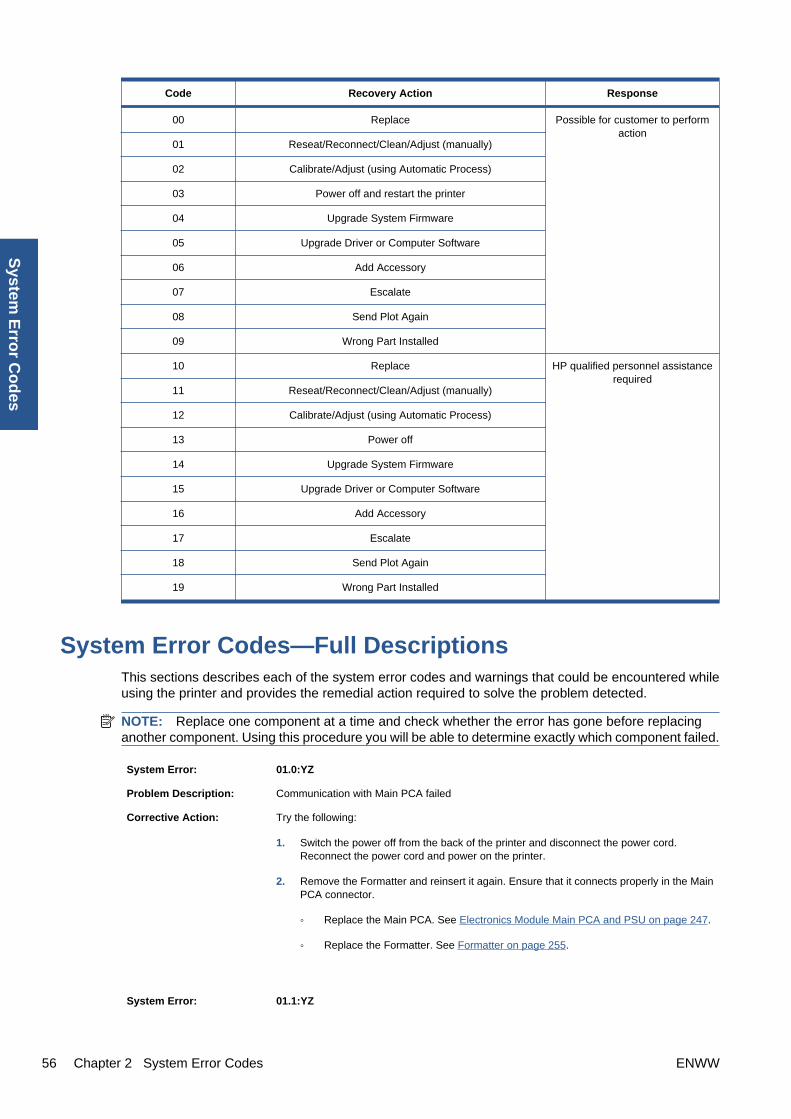
Code Recovery Action Response
00 Replace Possible for customer to performaction
01 Reseat/Reconnect/Clean/Adjust (manually)
02 Calibrate/Adjust (using Automatic Process)
03 Power off and restart the printer
04 Upgrade System Firmware
05 Upgrade Driver or Computer Software
06 Add Accessory
07 Escalate
08 Send Plot Again
09 Wrong Part Installed
10 Replace HP qualified personnel assistancerequired
11 Reseat/Reconnect/Clean/Adjust (manually)
12 Calibrate/Adjust (using Automatic Process)
13 Power off
14 Upgrade System Firmware
15 Upgrade Driver or Computer Software
16 Add Accessory
17 Escalate
18 Send Plot Again
19 Wrong Part Installed
System Error Codes—Full DescriptionsThis sections describes each of the system error codes and warnings that could be encountered whileusing the printer and provides the remedial action required to solve the problem detected.
NOTE: Replace one component at a time and check whether the error has gone before replacinganother component. Using this procedure you will be able to determine exactly which component failed.
System Error: 01.0:YZ
Problem Description: Communication with Main PCA failed
Corrective Action: Try the following:
1. Switch the power off from the back of the printer and disconnect the power cord.Reconnect the power cord and power on the printer.
2. Remove the Formatter and reinsert it again. Ensure that it connects properly in the MainPCA connector.
◦ Replace the Main PCA. See Electronics Module Main PCA and PSU on page 247.
◦ Replace the Formatter. See Formatter on page 255.
System Error: 01.1:YZ
56 Chapter 2 System Error Codes ENWW
System
Erro
r Co
des

Problem Description: Error in the Main PCA
Corrective Action: Try the following:
1. Switch the power off from the back of the printer and disconnect the power cord.Reconnect the power cord and power on the printer.
2. Replace the Main PCA. See Electronics Module Main PCA and PSU on page 247.
3. Replace the Formatter. See Formatter on page 255.
System Error: 01.2:YZ
Problem Description: Failure communicating with an Ink Supply
Corrective Action: Try the following:
1. Switch the power off from the back of the printer and disconnect the power cord.Reconnect the power cord and power on the printer.
2. Perform the Ink Delivery System diagnostic test. See Ink Delivery System (IDS) Teston page 109.
– If the test finds that the ink supply is defective, replace it.
– If the test does not find any errors, remove all the ink supplies from the ISS and rebootthe printer.
3. Install the ink cartridges with the printer booted in normal mode. Use the replacementoption available from the Front Panel and install the cartridges one by one. If an errorappears after installing a supply, the last supply you installed is defective. Replace it.
4. Check that the cables between the Left Ink Supply Station and Main PCA are not damagedand are correctly connected.
5. Replace the Left Ink Supply Station. See Ink Supply Station, Left on page 268.
6. Replace the Main PCA. See Electronics Module Main PCA and PSU on page 247.
System Error: 02.1:YZ
Problem Description: Problem with the Carriage PCA
Corrective Action: Try the following:
1. Switch the power off from the back of the printer and disconnect the power cord.Reconnect the power cord and power on the printer.
2. Check that the Trailing Cable is not damaged. Check that the Trailing Cable is correctlyconnected between the Main PCA and Carriage PCA.
3. Replace the Carriage PCA. See Carriage PCA on page 220.
4. Replace the Trailing Cable and Carriage PCA Covers. See Trailing Cable on page 356.
5. Replace the Main PCA. See Electronics Module Main PCA and PSU on page 247.
System Error: 03:YZ
ENWW System Error Codes—Full Descriptions 57
Sys
tem
Err
or
Co
des

Problem Description: Problem with Power Supply Unit
Corrective Action: Try the following:
1. Switch the power off from the back of the printer and disconnect the power cord.Reconnect the power cord and power on the printer.
2. Perform the Electronics Module Test Diagnostic to troubleshoot the problem further.See Electronics Module Test on page 98.
3. Replace the Power Supply Unit (PSU). See Electronics Module Main PCA and PSUon page 247.
System Error: 03.0:10
Problem Description: Battery of Real Time Clock ran down
Corrective Action: Replace the battery. See Real-time Clock Battery on page 318.
System Error: 06:YZ
Problem Description: Failure reading/writing NVM in Hard disk
Corrective Action: Try the following:
1. Switch the power off from the back of the printer and disconnect the power cord.Reconnect the power cord and power on the printer.
2. Replace the Hard Disk. See Hard Disk Drive on page 264.
System Error: 11:YZ
Problem Description: Trailing Cable does not seem to be detected
Corrective Action: Try the following:
1. Switch the power off from the back of the printer and disconnect the power cord.Reconnect the power cord and power on the printer.
2. Check that the Trailing Cable is not damaged; replace it if necessary. See TrailingCable on page 356. Check that the Trailing Cable is correctly connected between theMain PCA and Carriage PCA.
3. Replace the Carriage PCA. See Carriage PCA on page 220.
4. Replace the Main PCA. See Electronics Module Main PCA and PSU on page 247.
System Error: 21:YZ
58 Chapter 2 System Error Codes ENWW
System
Erro
r Co
des

Problem Description: Failure moving Service Station
Corrective Action: Try the following:
1. Switch the power off from the back of the printer and disconnect the power cord. Checkthe Primer Tubes. Reconnect the power cord and power on the printer.
2. Make sure that the Service Station path is clear. Remove any visible obstacles (screws,plastic parts, etc.) restricting the movement of the Service Station.
3. If the carriage has stopped over the service station, on the right side of the printer, checkthat the cutter is not activated. The cutter may be blocking the carriage over the servicestation, preventing the service station from performing the movement correctly. The cutteris on the left side of the carriage.
4. Perform the Service Station diagnostic test to troubleshoot the problem further. SeeService Station Test on page 114.
5. Replace the Service Station. See Service Station on page 341.
System Error: 21.1:YZ
Problem Description: Failure moving the Primer Motor of the Service Station
Corrective Action: Try the following:
1. Remove the Right Cover and make sure the cables from the Main PCA to the ServiceStation are connected and are not damaged.
2. Perform the Primer Motor diagnostic test (listed under the service station diagnostic test)to troubleshoot the problem further. See Primer motor on page 115.
3. Replace the Service Station. See Service Station on page 341.
System Error: 21.2:YZ
Problem Description: Failure testing the length of the Service Station path
Corrective Action: Try the following:
1. Switch the power off from the back of the printer and disconnect the power cord. Checkthe Primer Tubes. Reconnect the power cord and power on the printer.
2. Make sure that the Service Station path is clear. Remove any visible obstacles (screws,plastic parts, etc.) restricting the movement of the Service Station.
3. If the carriage has stopped over the service station, on the right side of the printer, checkthat the cutter is not activated. It may happen that the cutter is blocking the carriage overthe service station, preventing the service station from performing the movement correctly.The cutter is on the left side of the carriage.
4. Perform the Service Station diagnostic test to troubleshoot the problem further. SeeService Station Test on page 114.
5. Replace the Service Station. See Service Station on page 341.
System Error: 22.0:YZ
ENWW System Error Codes—Full Descriptions 59
Sys
tem
Err
or
Co
des

Problem Description: Left Ink Supply Station error, module 0.
Corrective Action: Try the following:
1. Switch the power off from the back of the printer and disconnect the power cord.Reconnect the power cord and power on the printer.
2. Check that the cables between the Left Ink Supply Station and Main PCA the are notdamaged and are correctly connected.
3. Perform the Ink Delivery System diagnostic test to troubleshoot the problem further.See Ink Delivery System (IDS) Test on page 109.
4. Replace the Left Ink Supply Station. See Ink Supply Station, Left on page 268.
5. Replace the Main PCA. See Electronics Module Main PCA and PSU on page 247.
System Error: 22.1:YZ
Problem Description: Left Ink Supply Station error, module 1
Corrective Action: Try the following:
1. Switch the power off from the back of the printer and disconnect the power cord.Reconnect the power cord and power on the printer.
2. Check that the cables between the Left Ink Supply Station and Main PCA are not damagedand are correctly connected.
3. Perform the Ink Delivery System diagnostic test to troubleshoot the problem further.See Ink Delivery System (IDS) Test on page 109.
4. Replace the Left Ink Supply Station. See Ink Supply Station, Left on page 268.
5. Replace the Main PCA. See Starwheel Assembly on page 348.
System Error: 24:YZ
60 Chapter 2 System Error Codes ENWW
System
Erro
r Co
des

Problem Description: Ink Setup failure
Corrective Action: Try the following:
1. Switch the power off from the back of the printer and disconnect the power cord. Insertthe new purgers, reconnect the power cord and power on the printer.
2. Perform the Ink Delivery System diagnostic test in order to check that the bongos(pushers) go up and down to pressurize ink in the tubes and the Out of Ink sensors workproperly. See Ink Delivery System (IDS) Test on page 109.
3. Try purging the Ink Supply Tubes again once the printer has been restarted.
4. If the diagnostic test does not find any problem, install new cartridges in the printer andtry purging the Ink Supply Tubes again. It could be that one of the cartridges is defective.
5. If the problem persists, replace the Ink Supply Tubes. You must bring purgers and inkcartridges. See Ink Supply Tubes on page 272.
Warning: 26:01
Problem Description: Ink supply error found during IDS diagnostic test. In the front panel message you will see lettersrepresenting the names of the colors of the faulty supplies.
Corrective Action: Try the following:
1. Reseat the faulty ink supply and repeat the Ink Delivery System diagnostic test.
2. If the problem persists, replace the faulty ink supply and repeat the Ink Delivery Systemdiagnostic test.
3. If the problem persists, replace the Left Ink Supply Station. See Ink Supply Station, Lefton page 268.
Warning: 39.1:01
Problem Description: Roll 1 switch failed (standby or resume). Roll 1 has been unloaded.
Corrective Action: There is no corrective action. This system warning code only notifies the user that the roll hasbeen unloaded because an unexpected error occurred with Roll 1 in standby or resumeoperation.
Warning: 39.2:01
Problem Description: Roll 2 switch failed (standby or resume). Roll 2 has been unloaded.
Corrective Action: There is no corrective action. This system warning code only notifies the user that the roll hasbeen unloaded because an unexpected error occurred with Roll 2 in standby or resumeoperation.
System Error: 41:YZ
ENWW System Error Codes—Full Descriptions 61
Sys
tem
Err
or
Co
des

Problem Description: Electrical fault or current limit in Media-Axis Motor
Corrective Action: Try the following:
1. Switch the power off from the back of the printer and disconnect the power cord.Reconnect the power cord and power on the printer.
2. Open the Window and check for any visible obstacles restricting the movement of theMedia Advance Roller. If there is a wrinkled mass of media inside the paper path, lift thePinch wheels (using Media Lever) and clear the obstruction.
3. Perform the Paper Drive diagnostic test to troubleshoot the problem furthe. See PaperDrive Test on page 96.
4. Perform the Rewinder diagnostic test to troubleshoot the problem further. See RewinderTest on page 107.
5. Check that the Media Advance Drive cable is not damaged and is correctly connected tothe Main PCA.
6. Replace the Media Advance Drive. See Media Advance Drive on page 286.
7. Replace the Main PCA. See Electronics Module Main PCA and PSU on page 247.
System Error: 42:YZ
Problem Description: Electrical problem (fault, current limit, overheating) in Scan-Axis Motor
Corrective Action: Try the following:
1. Switch the power off from the back of the printer and disconnect the power cord.Reconnect the power cord and power on the printer.
2. Open the Window and check for any visible obstacles restricting the movement of theCarriage Assembly. Remove any obstacle to let the carriage move freely along the wholescan axis. If there is a wrinkled mass of media inside the paper path, raise the pinch wheels(using the media lever) and clear the obstruction.
3. Check that the Scan-Axis Motor cable is not damaged and is correctly connected to theMain PCA.
4. Replace the Scan-Axis Motor. See Scan-axis Motor on page 337.
5. Replace the Main PCA. See Electronics Module Main PCA and PSU on page 247.
System Error: 45.1:YZ
Problem Description: An error with the Rewinder 1 System (Upper Rewinder) has been detected.
Corrective Action: Try the following:
1. Switch the power off from the back of the printer and disconnect the power cord. Removethe paper from Roll 1. Reconnect the power cord and power on the printer.
2. Check that the Rewinder 1 cable is not damaged and is correctly connected to the MainPCA.
3. Check that the Upper Right Roll Support is correctly attached to and aligned with the RightCover.
4. Perform the Rewinder diagnostic test to troubleshoot the problem further. See RewinderTest on page 107.
5. Replace the Upper Right Roll Support. See Roll Support, Upper Right on page 336.
System Error: 45.2:YZ
62 Chapter 2 System Error Codes ENWW
System
Erro
r Co
des

Problem Description: An error with the Rewinder 2 System (Lower Rewinder) has been detected (T1200 series only).
Corrective Action: Try the following:
1. Switch the power off from the back of the printer and disconnect the power cord. Removethe paper from Roll 2. Reconnect the power cord and power on the printer.
2. Check that the Rewinder 2 cable is not damaged and is correctly connected to the MainPCA.
3. Check that the Lower Right Roll Support is correctly attached to and aligned with the RightCover.
4. Perform the Rewinder diagnostic test to troubleshoot the problem further. See RewinderTest on page 107.
5. Replace the Lower Right Roll Support. See Roll Support, Lower Right (T1200 only)on page 331.
System Error: 47:YZ
Problem Description: Starwheels motor error
Corrective Action: Try the following:
1. Switch the power off from the back of the printer and disconnect the power cord.Reconnect the power cord and power on the printer.
2. Open the Window and check for any visible obstacles restricting the movement of theStarwheel Assembly, then clear the obstruction.
3. Check that the Starwheel Assembly cable is not damaged and is correctly connected tothe Main PCA.
4. Perform the Scan Axis Starwheel diagnostic test to troubleshoot the problem further.
5. Replace the Starwheel Motor. See Starwheel Motor on page 354.
6. Replace the Main PCA. See Electronics Module Main PCA and PSU on page 247.
System Error: 48:YZ
Problem Description: PPS system failure
Corrective Action: Try the following:
1. Switch the power off from the back of the printer and disconnect the power cord.Reconnect the power cord and power on the printer.
2. Check that the Pen to Paper Space (PPS) Solenoid cable is not damaged and is correctlyconnected to the Main PCA.
3. Perform the Scan Axis PRS diagnostic test to troubleshoot the problem further.
4. Replace the Pen to Paper Space (PPS) Solenoid. See Pen to Paper Space (PPS)Solenoid on page 300.
5. Replace the Main PCA. See Electronics Module Main PCA and PSU on page 247.
System Error: 51:YZ
ENWW System Error Codes—Full Descriptions 63
Sys
tem
Err
or
Co
des

Problem Description: Window Sensor failure
Corrective Action: Try the following:
1. Check that the Window Position Sensor cable is not damaged and is correctly connectedto the Main PCA.
2. Perform the Sensors Test to troubleshoot the problem further. See Sensors Teston page 105.
3. Replace the Window Position Sensor. See Window Position Sensor on page 368.
System Error: 52:10
Problem Description: The printer has detected a failure in the Drop Detector.
Corrective Action: Try the following:
1. Switch the power off from the back of the printer and disconnect the power cord.Reconnect the power cord and power on the printer.
2. Check that the Drop Detector cable is not damaged and is correctly connected to the MainPCA.
3. Replace the Drop Detector. See Drop Detector on page 243.
4. Replace the Main PCA. See Electronics Module Main PCA and PSU on page 247.
System Error: 55:YZ
Problem Description: Problem with the Line Sensor. The printer has detected a failure to access the Line SensorEEPROM.
Corrective Action: Try the following:
1. Switch the power off from the back of the printer and disconnect the power cord.Reconnect the power cord and power on the printer.
2. Perform the Carriage Test to troubleshoot the problem further. See Carriage AssemblyTest on page 102.
3. Check the Line Sensor connections to the Carriage PCA.
4. Replace the Line Sensor. See Line Sensor on page 280.
5. Replace the Carriage PCA. See Carriage PCA on page 220.
System Error: 56:YZ
Problem Description: Drive roller analog encoder homing (also known as “zero search”) failed.
Corrective Action: Try the following:
1. Switch the power off from the back of the printer and disconnect the power cord.Reconnect the power cord and power on the printer.
2. Perform the Media Path Test to troubleshoot the problem further. See Paper Drive Teston page 96.
3. Replace the Encoder Disk and Encoder Sensor. See Encoder Disk and EncoderSensor on page 250.
4. Replace the Main PCA. See Electronics Module Main PCA and PSU on page 247.
64 Chapter 2 System Error Codes ENWW
System
Erro
r Co
des

System Error: 59.1:09
Problem Description: Two electrical parts have been replaced at the same time.
Corrective Action: Replace one part at a time, and restart the printer before replacing another.
System Error: 59.2:00
Problem Description: An unsupported or reused part has been installed.
Corrective Action: Install only new parts recommended by HP for this printer.
System Error: 60.1:YZ
Problem Description: Initialization error
Corrective Action: Try the following:
1. Switch the power off from the back of the printer and disconnect the power cord.
2. Check that the printer is properly connected in all other respects.
3. Reconnect the power cord and power on the printer.
4. If the error persists, contact HP.
System Error: 60.2:YZ
Problem Description: Initialization error
Corrective Action: Contact HP.
System Error: 61:YZ
Problem Description: The file format is incorrect or not supported for the current printer configuration and the printercannot process the job.
Corrective Action: Try the following:
1. Check whether the printer supports the file format (formats such as PS, PDF, TIFF andJPEG are supported by PostScript printers only).
2. Switch the power off from the back of the printer and disconnect the power cord.Reconnect the power cord and power on the printer.
3. Check the graphic language setting of the printer (refer to the User's Guide).
4. Resend the file to the printer.
5. Check that the printer has the latest firmware version. If not, update the firmware to thelatest version.
System Error: 61:04.1
Problem Description: The PostScript fonts seem to be missing.
Corrective Action: Perform a firmware upgrade to re-install the fonts.
System Error: 61:08.1
ENWW System Error Codes—Full Descriptions 65
Sys
tem
Err
or
Co
des

Problem Description: The file cannot be printed because it is password-protected.
Corrective Action: Resend the file without password protection.
System Error: 63:YZ
Problem Description: Input/Output problem through the network interface of the Formatter
Corrective Action: Try the following:
1. Switch the power off from the back of the printer and disconnect the power cord.Reconnect the power cord and power on the printer.
2. Check that the Network cable is correctly connected to the Formatter.
3. Check that the printer has the latest firmware version. If not, update the firmware to thelatest version.
4. Replace the Formatter. See Formatter on page 255.
System Error: 64:YZ
Problem Description: Input/Output problem through the USB Port
Corrective Action: Try the following:
1. Switch the power off from the back of the printer and disconnect the power cord.Reconnect the power cord and power on the printer.
2. Check that the USB cable is correctly connected to the printer.
3. Check that the printer has the latest firmware version. If not, update the firmware to thelatest version.
4. Replace the Formatter. See Formatter on page 255.
System Error: 64.1:YZ
Problem Description: Printer does not recognize the USB HDD accessory connected.
Corrective Action: Try the following:
1. Switch the power off from the back of the printer. Connect the USB HDD accessory, checkthe USB cable is properly connected and power on the printer. If the USB HDD accessoryis not available (has been lost or broken), proceed with step 2.
2. If the problem persists, power off from the back of the printer. Power on the printer againwhile pressing the keys Menu, OK and Cancel keys simultaneously until the front panelasks “Printer configured to use External Hard Disk. Do you want to revert the printer toInternal Hard Disk?”. Confirm by pressing OK (twice). Remove the USB HDD accessory(if connected). The printer will restart.
3. After the printer reaches the Ready state, try connecting any other USB device (known towork properly) to the printer port where the hard disk accessory should be connected.
◦ If a message appears on the Front Panel reacting to the USB device just connected(such as “Please remove USB device” or “Press OK to...”), press Cancel and removethe USB Device. This means the HDD Accessory is faulty and should be replaced.See Formatter on page 255.
◦ If nothing appears on the Front Panel reacting to the USB device just connected, theFormatter is faulty and should be replaced. See Formatter on page 255.
System Error: 65:YZ
66 Chapter 2 System Error Codes ENWW
System
Erro
r Co
des
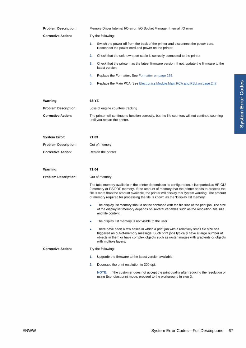
Problem Description: Memory Driver Internal I/O error, I/O Socket Manager Internal I/O error
Corrective Action: Try the following:
1. Switch the power off from the back of the printer and disconnect the power cord.Reconnect the power cord and power on the printer.
2. Check that the unknown port cable is correctly connected to the printer.
3. Check that the printer has the latest firmware version. If not, update the firmware to thelatest version.
4. Replace the Formatter. See Formatter on page 255.
5. Replace the Main PCA. See Electronics Module Main PCA and PSU on page 247.
Warning: 68:YZ
Problem Description: Loss of engine counters tracking
Corrective Action: The printer will continue to function correctly, but the life counters will not continue countinguntil you restart the printer.
System Error: 71:03
Problem Description: Out of memory
Corrective Action: Restart the printer.
Warning: 71:04
Problem Description: Out of memory.
The total memory available in the printer depends on its configuration. It is reported as HP-GL/2 memory or PS/PDF memory. If the amount of memory that the printer needs to process thefile is more than the amount available, the printer will display this system warning. The amountof memory required for processing the file is known as the ‘Display list memory’:
● The display list memory should not be confused with the file size of the print job. The sizeof the display list memory depends on several variables such as the resolution, file sizeand file content.
● The display list memory is not visible to the user.
● There have been a few cases in which a print job with a relatively small file size hastriggered an out-of-memory message. Such print jobs typically have a large number ofobjects in them or have complex objects such as raster images with gradients or objectswith multiple layers.
Corrective Action: Try the following:
1. Upgrade the firmware to the latest version available.
2. Decrease the print resolution to 300 dpi.
NOTE: If the customer does not accept the print quality after reducing the resolution orusing Econofast print mode, proceed to the workaround in step 3.
ENWW System Error Codes—Full Descriptions 67
Sys
tem
Err
or
Co
des
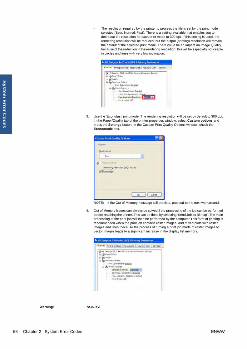
◦ The resolution required by the printer to process the file is set by the print modeselected (Best, Normal, Fast). There is a setting available that enables you todecrease the resolution for each print mode to 300 dpi. If this setting is used, therendering resolution will be reduced, but the output (printing) resolution will remainthe default of the selected print mode. There could be an impact on Image Qualitybecause of the reduction in the rendering resolution; this will be especially noticeablein circles and lines with very low inclination.
3. Use the ‘Econofast’ print mode. The rendering resolution will be set by default to 300 dpi.In the Paper/Quality tab of the printer properties window, select Custom options andpress the Settings button. In the Custom Print Quality Options window, check theEconomode box.
NOTE: If the Out of Memory message still persists, proceed to the next workaround.
4. Out of Memory issues can always be solved if the processing of the job can be performedbefore reaching the printer. This can be done by selecting ‘Send Job as Bitmap’. The mainprocessing of the print job will then be performed by the computer.This form of printing isrecommended when the print job contains raster images, and mixed plots with rasterimages and lines, because the process of turning a print job made of raster images tovector images leads to a significant increase in the display list memory.
Warning: 72.02:YZ
68 Chapter 2 System Error Codes ENWW
System
Erro
r Co
des

Problem Description: A service calibration should be performed.
Corrective Action: To find out which service calibration to perform, print the calibration status. At the front panel,select the Internal Prints icon, then Service information > Print calibration status. Performwhichever calibration is needed.
Warning: 74:YZ
Problem Description: Error uploading firmware update file
Corrective Action: Try the following:
1. Switch the power off from the back of the printer and disconnect the power cord.Reconnect the power cord and power on the printer.
2. Make sure the connection between the computer and the printer is functioning properly.
3. Try to update the firmware again.
Warning: 74.1:YZ
Problem Description: Error uploading media profile update file
Corrective Action: Try the following:
1. Switch the power off from the back of the printer and disconnect the power cord.Reconnect the power cord and power on the printer.
2. Make sure the connection between the computer and the printer is functioning properly.
3. Try to upload the media profile update file again.
4. Make sure the version of the media profile update file is compatible with the firmwareversion the printer is using. You can check this on the same Web page where youdownloaded the media profile update.
System Error: 75.21:YZ
Problem Description: The spittoons (Left Spittoon, Service Station) have reached 80% capacity.
Corrective Action: Use Preventive Maintenance Kit #2 to replace the Left Spittoon and Service Station.
System Error: 75.22:YZ
Problem Description: The spittoons (Left Spittoon, Service Station) are full.
Corrective Action: Use Preventive Maintenance Kit #2 to replace the Left Spittoon and Service Station.
System Error: 76:YZ
Problem Description: Hard disk drive is full.
Corrective Action: Remove any unnecessary files from the hard disk using the Embedded Web Server. Ifthe problem persists, run the Hard Disk Recovery Utility (see Hard Disk RecoveryUtility on page 119).
System Error: 78:08
ENWW System Error Codes—Full Descriptions 69
Sys
tem
Err
or
Co
des

Problem Description: The job received cannot be printed without borders on this paper.
Corrective Action: Use a paper that supports borderless printing.
NOTE: This system error code does not require service help. It should be resolved bythe customer.
System Error: 78.1:YZ
Problem Description: Media settings area missing in media settings file
Corrective Action: Try the following:
1. Switch the power off from the back of the printer and disconnect the power cord.Reconnect the power cord and power on the printer.
2. Check that the printer has the latest firmware version. If not, update the firmware tothe latest version.
System Error: 79:YZ
Problem Description: Generic firmware error
Corrective Action: Try the following:
1. Switch the power off from the back of the printer and disconnect the power cord.Reconnect the power cord and power on the printer.
2. Check that the printer has the latest firmware version. If not, update the firmware tothe latest version.
NOTE: If you see system error 79:04, see Appendix A: How to troubleshoot SE79:04 on page 73.
NOTE: A firmware upgrade will not always solve the problem. The best way tosolve this problem is to report the error to HP correctly. Make sure that you supplyall the information accessed by pressing the Up and Cancel keys together whileviewing the system error screen, or preferably provide the printer log and diagnosticpackage to HP. See Understand System Error Codes on page 52 and Appendix C:Obtaining the printer log and the diagnostics package on page 85.
System Error: 81:YZ
70 Chapter 2 System Error Codes ENWW
System
Erro
r Co
des

Initial checks: This error can occur because the printer has been dropped during transportation, causing structural damage. Beforecontinuing with the 81:YZ troubleshooting, first look for structural damage.
To identify the structural damage, look for the following three things:
● Consistent 81:YZ error codes.
● Platen fingers rubbing on the roller surface, leaving black marks on the roller.
● A gap on the platen beam. If there’s any gap in Z (vertical direction) between the plastic feature of the platen andthe metal side plate, then the chassis is damaged and the unit cannot be repaired.
ProblemDescription:
Problem with paper advance. This source of error could come from an error in any of the following systems: paper motor,disk encoder, cables or main electronics.
CorrectiveAction:
Try the following:
1. Open the Window and check for any visible obstacles restricting the movement of the Drive Roller. If there is awrinkled mass of media inside the paper path, lift the Pinchwheels (using the Media Lever) and clear the obstruction.
2. Perform the Media Drive diagnostic test to troubleshoot the problem further. See Paper Drive Test on page 96.
3. Perform the Rewinder diagnostic test to troubleshoot the problem further. See Rewinder Test on page 107.
4. Check the connections on the Main PCA; the Media Advance Drive is connected to the connector labeled PaperMotor.
5. Adjust the encoder disc and motor mount configuration using the Media Advance Drive installation instructions.See Media Advance Drive on page 286.
6. Replace the Media Advance Drive. See Media Advance Drive on page 286.
System Error: 86:01
ENWW System Error Codes—Full Descriptions 71
Sys
tem
Err
or
Co
des

Problem Description: Possible Paper Jam
Corrective Action: Try the following:
1. Open the Window and check for any visible obstacles restricting the movement ofthe Drive Roller. Remove any such obstacles. If there is a wrinkled mass of mediainside the paper path, lift the Pinch wheels (using the Media Lever) and clear theobstruction.
2. Perform the Scan Axis diagnostic test to troubleshoot the problem further. See ScanAxis Test on page 90
System Error: 86:11
Problem Description: Scan Axis movement requires too much force or energy.
Corrective Action: Try the following:
1. Check that the cutter disengages correctly.
2. Lubricate the scan axis.
3. Use Preventive Maintenance Kit 1.
System Error: 87:YZ
Problem Description: Problem with the Carriage Encoder Sensor readings
Corrective Action: Try the following:
1. Check that the encoder sensor is correctly connected to the Carriage PCA.
2. Make sure the Encoder Strip is not broken or damaged. If necessary, replace it.See Encoder Strip, spring and attachment nut on page 253.
3. Make sure that the Encoder Strip is clean. If it is dirty, clean it, paying specialattention to the area near the Service Station. See Cleaning the Encoder Stripon page 371.
4. Clean the Encoder Sensor.
5. Replace the Encoder Sensor.
6. Replace the Carriage PCA. See Carriage PCA on page 220.
7. Replace the Trailing Cables. See Trailing Cable on page 356.
System Error: 87.01
Problem Description: Problem finding the Scan-axis encoder reading
Corrective Action: Try the following:
1. Switch the power off from the back of the printer and disconnect the power cord.Reconnect the power cord and power on the printer.
2. Make sure that the encoder strip is clean. If the encoder strip is dirty, clean it, payingspecial attention to the area near the Service Station. See Cleaning the EncoderStrip on page 371.
3. Clean the encoder sensor.
4. Replace the Encoder Sensor.
72 Chapter 2 System Error Codes ENWW
System
Erro
r Co
des

System Error: 93:YZ
Problem Description: Unable to pressurize the Ink Delivery System
Corrective Action: Try the following:
1. Switch the power off from the back of the printer and disconnect the power cord.Reconnect the power cord and power on the printer.
2. Perform the Ink Delivery System diagnostic test to further troubleshoot the problem.See Ink Delivery System (IDS) Test on page 109.
3. Check that the cables between the Left Ink Supply Station and Main PCA are notdamaged and are correctly connected.
4. Replace the Left Ink Supply Station, depending on the results of the diagnostic test.See Ink Supply Station, Left on page 268.
5. Replace the Main PCA. See Electronics Module Main PCA and PSUon page 247.
Appendix A: How to troubleshoot SE 79:04
Introduction
The system error 79:04 is a generic firmware error (equivalent to a blue screen in Windows). It’s thesystem error that the printer will display when an unknown exception occurs that cannot be identifiedas relating to any specific subsystem of the printer.
Since this is a generic error, there can be multiple causes behind it. This document will cover the mostprobable causes behind a system error 79:04 and will recommend the most efficient troubleshootingsteps to resolve customer issues.
It is important to mention that, although 79:04 system errors can be caused by a hardware malfunction,the vast majority of 79:04 system errors are pure software or firmware issues. Before doing anythingelse, you are recommended to try the following general-purpose solutions.
1. Update the printer’s firmware to the very latest available firmware version, even if the printerappears to be running the latest firmware already.
2. Restore the factory settings from the front-panel's Setup menu.
If these do not solve the problem, continue reading about other possible solutions below.
Possible causes
Since the 79:04 system error is a generic error, the number of possible causes behind it is large. Themajority can be grouped, however, into the following groups.
Job related SE79:04
A specific print job that is not correctly formatted for the printer or that is not correctly processed by itcan trigger a 79:04 system error.
The incorrect format or processing can come from two sources:
● Incorrect commands in the job itself. For example, a PS job with some commands that do not havethe correct PS format.
● Issues applying to the settings in the job
Possible symptoms
ENWW Appendix A: How to troubleshoot SE 79:04 73
Sys
tem
Err
or
Co
des

79:04 caused by a print job always have the same symptoms:
1. The job is received by the printer and starts to process.
2. In the middle of the processing, the printer stops and displays 79:04.
3. The printer will display the 79:04 system error again immediately after reboot. This is due to thefact that the printer will try to reprint the job, which is pending in the queue, after reboot.
4. After the second reboot, the printer will start up normally
5. If the same job is sent again, it will always produce a 79:04 system error
These types of 79:04 system errors are normally caused by jobs that have been generated by 3rdparty applications (RIPs, 3rd party drivers, files exported by an application to PS, PDF, HP-GL/2,RTL, … or any other format supported by the printer). Jobs generated by HP drivers will not normallygenerate 79:04 system errors, since the output that our drivers generate is very controlled and hasbeen designed taking into consideration the characteristics of our printer’s language interpreters.
There is an exception to this general rule: there are certain applications that can generate theirown PS code (Adobe PhotoShop, Adobe Illustrator, Adobe Acrobat, Corel Draw, Freehand,QuarkXpress, …). When used with a PS driver, these applications generate the output PSthemselves, instead of using the driver’s rendering capabilities. This is known as PostScript pass-through. So, when using an HP PostScript driver together with an application that has PSpassthrough capabilities, the PS code that comes into the printer has not been rendered by the HPdriver, and, should the source file contain any PS commands that are not correctly processed bythe printer, a 79:04 system error could occur even though an HP driver is being used.
Solutions and workarounds
When a job consistently generates a 79:04 system error, it is either because of a issue in theprinter’s firmware or because of a defect in the job itself (when it has been generated by 3rd partySW). In order to identify the cause and find out a solution, these issues should always beimmediately escalated to the GBU through the GCC.
Also, there are some workarounds and short-term solutions that can be tested in order to get thecustomer up and running in the shortest possible time:
1. Send the job using a variety of different settings. Many times, the issue is caused by a combinationof the job contents combined with some specific setting(s).
2. If the customer is sending the file directly to the printer, try using the HP driver instead.
3. If the issue is occurring when printing through the HP PostScript driver from an application with PSpassthrough, try changing the options in the application so that it prints PS as raster (the option istypically located in the “Advanced” options of the application’s printing dialog).
4. In some cases, there may be an unfortunate interaction between the particular job and the I/Oconnection used to send that job to the printer. Try sending the same job using a print queue thatuses a different type of connection. For example, use a network connection instead of USB, or usethe LPD network printing protocol instead of port 9100.
Data related SE79:04
HP Designjet printers have Hard Disks and non-volatile memories that contain databases and files thatcan be modified with user data. Some examples include:
● The printer’s queue
● The hard drive partitions that contain user jobs
● The database that stores the printer settings
● The database that stores accounting information
74 Chapter 2 System Error Codes ENWW
System
Erro
r Co
des

Some of this data is accessed by the printer at start-up, and some others are accessed as needed.
If any of this fields contains corrupt data or data with characters or values that cannot be correctlyprocessed by the printer, a 79:04 system error may occur.
Possible symptoms
There are two different types of symptoms for data related 79:04 system errors:
1. When the corrupt data is accessed during start-up:
a. The printer will display a 79:04 during the start up process
b. Switching the printer off and on again will not solve the issue. The printer will continuedisplaying the 79:04 system error until the corrupt data has been cleared through a serviceprocedure
2. When the corrupt data is accessed during normal printer operation:
a. The printer will start up normally
b. When the data is accessed (for example while printing, while navigating the queue or whenchanging some settings), the printer displays a 79:04 system error
c. The printer can reboot normally
d. When the data is accessed again (typically, under the same conditions as in step “b”), the79:04 system error is displayed again
Solutions and workarounds
Many times, data-related 79:04 errors are resolved by means of hardware intervention. Since data arestored in physical components (RAM, EEROM and Hard Disk), replacing these components with newones that are empty usually solves the problem. However, there are quicker and more effective solutionsto these types of errors:
1. Clear all information that has been introduced by the user using the standard tools available in theprinter.
a. Delete all jobs from the queue (from the Front Panel or the EWS).
b. Reset to factory defaults to clear the user’s configurations and calibrations.
c. Delete any non-standard paper preset in the printer (both the ones that have been created bythe user and the ones that have been installed as OMES profiles through the EWS or the HPPrinter Utility).
2. If step 1 did not resolve the issue, you can use Service Tools to clear additional information thatcould be causing the issue.
a. Start the printer in Diagnostics Boot Mode.
b. Perform an EEROM reset.
ENWW Appendix A: How to troubleshoot SE 79:04 75
Sys
tem
Err
or
Co
des

3. If step 2 did not resolve the issue, it is possible to run a recovery of the hard disk.
a. Start the printer in Diagnostics Boot Mode.
b. Perform a Hard Disk Recovery. This will erase data from the hard disk and reinstall the currentfirmware. It may take up to half an hour.
4. If step 3 did not resolve the issue, you can check the hard disk's file system.
a. Start the printer in Diagnostics Boot Mode.
b. Perform a File System Check. This will fix any error in the file system structure. It may take afew minutes, or up to an hour, depending on the state of the hard disk.
Important note:
It is possible that the corrupt data came to be in the printer as a consequence of some activity in thecustomer’s workflow. In this case, it is possible that the issue will happen again. In these cases, it isvery important to understand the sequence of events in the customer’s workflow that led to the erroroccurring. Once the error can be traced in the customer’s workflow, escalate the issue to the GBU(through the GCC). This is done to implement any changes in the printer’s firmware that can preventthese issues occurring again.
Network related SE79:04
Most HP Designjet printers have built-in networking capabilities. Network settings can be set manually,but in the majority of cases, they are obtained automatically from the printer. These settings includemany different fields, such as IP address and subnet mask, available gateways, host and domain names,etc.
In some cases, there can be issues in the firmware that can cause a certain value in one of these fieldsto be interpreted incorrectly, and this can lead to a 79:04 system error.
Symptoms
There is no single set of symptoms that can absolutely pinpoint a network related 79:04 system error.However, the following guidelines can be applied:
● It can happen when the printer starts up or when accessing the Network Configuration section ofthe front panel or Embedded Web Server. It can also occur apparently randomly when the printeris connected to the network. It can also occur any time a particular network action is performed,for example when print jobs are sent to the printer, or when connecting to the Embedded WebServer.
● In all these cases, repeating the action after restarting the printer with the LAN cable disconnecteddoes not cause the 79:04 error to occur.
Solutions and workarounds
In the majority of cases, these issues are due to an issue in the printer’s firmware. As soon as theconditions in which the issue happens are understood, it should be escalated to the GBU through theGCC.
At the same time, the following short-term solutions and workarounds can help the customer to get upand running in the shortest possible time:
1. Disconnect the network cable in order to restart the printer and change network settings.
2. Try resetting the embedded networking settings or Jetdirect settings. See Connectivitytroubleshooting on page 46.
3. In the Network configuration menu in the Front Panel, disable any protocols that you are not using,including IPv6, IPSec, SNMP and WebServices.
76 Chapter 2 System Error Codes ENWW
System
Erro
r Co
des
NOTE: Disabling SNMP or WebServices means that customers may not be able to see printerstatus information; and Windows and Mac OS print-queue installers will require the user to specifythe printer’s IP address and printer model manually.
4. If the above steps do not work, try using a different type of print queue. For example, if the problemsoccur when printing to a Port 9100 Socket print queue, try using the LDP protocol instead, or USB.To do this, create a new print queue of the type required and try printing using the new queueinstead.
5. If the above steps do not work and the customer is using the printer’s embedded LAN connection,try using an accessory Jetdirect card instead. Similarly, if the customer is having problems usingan EIO Jetdirect card, try disconnecting the Jetdirect card and using the embedded networking.
In most cases, network problems that seem to occur randomly (when the printer is not being sent printjobs) are caused by an interaction between some other devices in the customer’s network and theprinter. Isolating the printer from other devices in the network as much as possible by connecting theprinter to a private network or a different network subnet may help the customer continue working untilthe root cause of the problem is understood and solved.
User Interaction related SE79:04
In some cases the printer may not react as expected when a certain set of conditions coincide. In thesecases, if the printer doesn’t know how to react, it may simple display a 79:04 system error and force areboot. Some examples (not real) that can help to illustrate this:
● An error occurs when a job is cancelled when it is at the “Finishing print” state and when the queueis disabled
● An error occurs if the Window is opened while the printer is checking the printheads
These errors will most likely only happen in very specific corner cases that have not been identifiedduring the development or the qualification of the printer, so normally, they do not severely impact thecustomer, as they do not affect their regular working flows.
Symptoms
The symptoms here are as numerous as the number of possible interactions between the user and theprinter. In any case, it’s possible to identify the steps that caused the error to occur and avoid them asthe steps will always be the same with no variance.
Important: An major element in determining the error is what the state the printer was in at the time theerror was displayed. Actions the user has made when the printer is drying for example can produce anerror, whereas the same action when the printer is doing something else (or is idle) may not produceany errors.
Solutions and workarounds
The recommended action plan in these cases is to identify the previous steps that caused the error and:
1. Escalate the issue to the GBU through the GCC in order to have it corrected in the firmware.
2. Recommend to the customer that they try to avoid the same steps to prevent the issue
3. If the conditions that cause the error are in the customer’s regular workflow, try to identify a differentway of achieving the same result out of the printer.
Random SE79:04: Concurrence issues and memory leaks
Some 79:04 errors happen randomly when the printer is being heavily used. However, it’s impossibleto find a single set of conditions that reproduce the problem. It just happens from time to time, withouta defined pattern.
ENWW Appendix A: How to troubleshoot SE 79:04 77
Sys
tem
Err
or
Co
des

These random 79:04 can have two different types of root causes:
● Memory leaks: before a program is executed, it allocates the memory it will need. After theexecution is complete, the allocated memory is freed to be used by other programs. If the allocationor the release of the memory are not properly programmed, every time the program is executedsome memory will be incorrectly labeled (either as used or as free). This is known as a memoryleak. When a program with a memory leak is executed a lot, the memory becomes progressivelyfull (since it is not properly freed). When the leak becomes too big, the printer is left ‘out of memory’to execute new processes and a 79:04 is triggered
● Concurrence issues: there are certain resources that can be accessed by multiple programs or bymultiple executions of the same program (what is known as multiple threads). Access to theseresources must be correctly controlled to prevent unexpected behavior. Issues caused by anincorrect control of these resources are concurrence issues.
In the following you have a simple example: let’s imagine that there is a counter that controls thecommunication between the Jetdirect card and the printer’s firmware. Whenever a new packet ofinformation is sent by the Jetdirect card to the printer, the counter increases. When the printer receivesthe packet and processes it correctly, the counter decreases. Another process checks the counter fromtime to time to see its value and take conclusions from it. If the counter is near 0, it means that the printeris processing correctly, and if it grows too big, it may mean that there is a bottleneck somewhere andmaybe the Jetdirect card throughput is decreased to control its speed to the printer. However, if theaccess to this counter is not properly controlled, undesirable effects may happen: in a real environment,a Jetdirect card processes thousands of information packets per second, so this counter is updatedfrequently, both by the Jetdirect and the printer. If at a certain point the Jetdirect and the printer try toaccess the counter at the same time and the code is not prepare to handle this, it may happen that theJetdirect cannot increase the counter because the printer is writing to it, and what’s worse, that it doesnot realize this fact. If this happens a few times each second, it may happen that the counter isdecreasing faster than it’s increasing and that at a certain point it has a negative value. And then, whatwill the process that is checking this counter do? Most likely, the process will not be prepared to reactto a negative value and will launch an exception that will trigger a 79:04 system error.
Symptoms
This type of 79:04 always occurs in heavy load conditions, so the symptoms will always be similar tothis pattern:
● A printer that is being heavily used (printing a project or in a reprographics environment) produces79:04 errors randomly, forcing the user to reboot.
● After rebooting, the printer can be used without any issues for an extended period of time, but ifthe workload is consistently high, a random error will occur again.
● The error can never be associated with a specific file. The file that was being printed when the erroroccurred the last time can be printed without issues after reboot. And a file that has been printedwithout issues several times can trigger the error in the future.
● This error is very dependant of the workflow the customer has. The most common user workflowshave been extensively tested both by HP and by our beta sites, so it is highly unlikely to see random79:04 issues in these cases. These random issues tend to occur in very specific corner cases, andcannot be reproduced unless the exact conditions of the workflow are replicated. They normallyhappen when sending files generated by external applications (RIPs, 3rd party drivers, etc.)
Workarounds and solutions
78 Chapter 2 System Error Codes ENWW
System
Erro
r Co
des

Random 79:04 errors are, by far, the most complex ones to diagnose and to fix. The only solutionsavailable in these cases are:
1. Run the Hard Disk Recovery utility (see Hard Disk Recovery Utility on page 119).
2. Identify the root cause (either in the files or in the firmware) and fix it in the code, which requiresthe intervention of the GBU.
3. Test any options available to modify the customer’s workflow and see if any combination of themsolves the issue.
In both cases, a profound understanding of the customer’s workflow is necessary. In particular, theinformation that is needed is:
● Printer front panel settings
● Application that is being used; RIP or driver that is being used
● Application/RIP/Driver settings
● Type of output files this application, RIP or driver is generating
● Some sample files that are representative of what the customer is using
● Operating System
● Method of connection to the printer
● A description of the normal flow when the issue occurs and the typical frequency of occurrence (forinstance, once every hour when sending several files non-stop, each of them with multiple copies)
You are recommended to use the Diagnostics Package to obtain this kind of information.
With this information, the environment can be replicated in order to try to find workarounds. This is alsothe information that will be needed at the GBU to investigate and fix the root cause of this issue once itis escalated.
Hardware related SE79:04
Hardware is, by far, the least likely cause of a 79:04 system error. Replacing hardware componentsdoes not normally fix the issue and increases the total turn around time in finding a workable solution.
In some cases, a failure in a component in the printer’s electronics may cause a 79:04 system error,since the printer’s electronics are involved in the execution of the firmware and the processing of jobs.It needs to be noted, however, that hardware failures in the electronics tend to produce specific systemerrors that point directly to the component that is failing.
Some HW causes that could be behind a 79:04 error are:
● Defective clusters in the Hard Disk drive. If these clusters are used to execute the firmware or toprocess a job, they may produce a 79:04. It needs to be noted however, that most 79:04 errorsthat are resolved by an HDD replacement are in fact, data related 79:04 that could have beensolved more efficiently and quickly following the steps in Section 3.
● Defective memory segments. If the RAM memory has some defective segments, a 79:04 may occurwhen these segments are used.
● Intermittent defects in the electronic components that are involved in the processing of a job:Carriage PCA, Trailing cable, Formatter and Main PCA. This is a highly unlikely cause, sincedefects in these components will produce subsystem specific errors.
Symptoms
ENWW Appendix A: How to troubleshoot SE 79:04 79
Sys
tem
Err
or
Co
des

There’s no single set of symptoms behind hardware related 79:04 system errors. The most usual ones,however are:
● 79:04 during start up. Rebooting the printer may or may not solve the problem
● 79:04 while processing or printing a job. Rebooting the printer and printing the same job does notalways produce the error.
Solutions and workarounds
In the following procedure perform each step as it appears in the list and only move on to the next steponce you are sure the 79:04 error has not been cleared:
1. Reboot the printer in Diagnostics Boot mode and execute the service tests to validate thefunctionality of all the electronics components
● Execute the troubleshooting for “data related” system errors, refer to page 3, Data relatedSE79:04
2. Replace the memory
3. Replace the HDD
4. Escalate the issue before replacing any additional parts.
Troubleshooting based on symptoms
This section will describe which troubleshooting steps to perform for a 79:04 system error based on thesymptoms of the issue. Perform each step as it appears in the list and only move on to the next steponce you are sure the 79:04 error has not been cleared:
Front panel displays 79:04 at Start-up
1. Reboot the printer twice. If the System error has been caused by a job because its in an incorrectformat, rebooting twice will clear the error (the first time after reboot, the printer will attempt to printthe job again, and this will cause the error to re-appear). If rebooting the printer twice solves theissue, then it is an issue related to the job and you should refer to page 2, Job related SE79:04.
2. Upgrade the printer’s firmware. Even if the currently installed firmware version is the latest one, re-install it. Since the printer cannot start normally, you will need to upgrade the firmware while bootingthe printer in Diagnostics Boot Mode. For this, a special file and a special upgrade process will beneeded. For more information, see Appendix B: Updating firmware in diagnostics boot modeon page 84 .
3. Disconnect the network cable and restart the printer. If this solves the problem, then it is a networkrelated 79:04 and you should follow the guidelines for this type of 79:04.
4. Remove all cartridges, printheads and printhead cleaners (if available). Unload the media. Restartthe printer. If the printer can start normally, insert the consumables one by one until you isolate theone that is causing the error. Do not insert any of the replaced consumables in another printer
5. Restart the printer in Diagnostics Boot Mode and perform the “Electronics test”. If an electroniccomponent is identified as faulty, replace it.
● Restart the printer in Diagnostics Boot Mode and Reset the EEROM. If the issue is solved bythis, this is a data related 79:04 system error and you should follow the guidelines, refer topage 3, Data related SE79:04.
6. If the unit has been used for some time and suddenly has started to show this behavior, replacethe Hard Disk Drive (it may be included with the Formatter in some models).
80 Chapter 2 System Error Codes ENWW
System
Erro
r Co
des

7. If the issue is new and the issue happens since the first boot, do not replace the HDD.
8. If none of the previous steps solved the issue, escalate the issue with the following information:
● Unit information: S/N, P/N, accessories
● Conditions where the problem occurs and conditions prior to the first occurrence of theproblem
● The results of the previous 8 steps
● The System Error detailed information (this can be obtained by pressing CANCEL + Down)
● The printer logs. In order to obtain the printer logs, see Appendix C: Obtaining the printer logand the diagnostics package on page 85.
Front panel displays 79:04 during printer operation – not while sending jobs
1. Reboot the printer.
2. Upgrade the printer’s firmware. Even if the currently installed firmware version is the latest one, re-install it.
3. Reset the printer to factory defaults
4. In order to narrow the scope of the issue, try the following:
a. Disable the queue
b. Disable any unused network protocols
c. Disable SNMP and WebServices (if they are available in the printer
d. Disable “Sleep mode” from the Service Utilities menu
e. Delete any Paper Presets that you may have uploaded or created using the printer'sSpectrophotometer
5. Restart the printer in Diagnostics Boot Mode and perform the “Electronics test”. If an electroniccomponent is identified as faulty, replace it.
6. Restart the printer in Diagnostics Boot Mode and Reset the EEROM. If the issue is solved by this,this is a data related 79:04 system error and you should follow the guidelines for this type error.
7. Format the Hard Disk drive. To do so, you will need to start the printer normally, enter the ServiceUtilities menu and then the Secure Disk Erase option. Set the Erase method to “Fast Erase” andthen perform the disk erase process. This will take 45-75 minutes and will erase all user informationfrom the disk, resolving any issue caused by corrupt data. After the erase process, a firmwareupdate will be required. If this solves the issue, this is a data related 79:04 system error and youshould follow the guidelines for this type of error.
8. Try to identify the combination of settings or actions that led to the system error and try to reachthe same result with a different combination. Escalate the issue to fix the original problem.
9. If none of the previous steps could solve the issue, escalate it with the following information:
● Unit information: S/N, P/N, accessories
● Conditions where the problem occurs and conditions prior to the first occurrence of theproblem
● The result of the previous 8 steps
● The printer information pages (either printed and faxed or obtained through the EmbeddedWeb Server)
ENWW Appendix A: How to troubleshoot SE 79:04 81
Sys
tem
Err
or
Co
des

● The System Error detailed information (it can be obtained by pressing CANCEL + Down)
● The printer logs. In order to obtain the printer logs, see Appendix C: Obtaining the printer logand the diagnostics package on page 85.
Front panel displays 79:04 while printing
While printing a single job
The error happens after a single job is sent. It’s easy to identify which job that has produced the error,since every time that this same job is sent, the error is replicated.
1. Reboot the printer twice (after the first reboot, the printer will show the 79:04 system error again,since the printer will attempt to reprint the last job in the queue, which is the one that caused theissue)
2. If you are using an HP driver, update the driver to the latest version
3. Upgrade the printer’s firmware. Even if the currently installed firmware version is the latest one, re-install it. Send the job using different print settings. The following ones can be helpful:
a. Try sending the job without selecting a media profile in the driver
b. Try changing the Image Quality settings
c. If you are using the HP-GL/2 driver, try the option “Send job as bitmap”
d. If you are using the PS driver, try using the HP-GL/2 driver instead
e. If you are using the PS driver from an Adobe application (or any other application that canhandle PS), try changing the application’s print settings so that the PS is generated as Raster.
4. Try the following Front Panel settings:
a. Change the Print Language option in the Front Panel from “Automatic” (which is the defaultsetting) to the language that is being printed (PS, HP-GL/2, …)
b. Queue = OFF
c. Start Printing = After processing
d. For PS SKUs, try changing the encoding setting (“Automatic” by default) to Binary or ASCII
5. If you are using a 3rd party application that does not print through the HP driver, try modifying theprinting workflow by:
a. Using an HP driver
b. Changing the settings in the application’s printing dialog
6. If you are using an accessory Jetdirect card, try using the internal network connector or USB (ifavailable).
7. Escalate the issue, providing the following information:
● Unit information: S/N, P/N, accessories
● Conditions where the problem occurs and conditions prior to the first occurrence of theproblem.
● The result of the previous 7 steps
● The printer information pages (either printed and faxed or obtained through the EmbeddedWeb Server)
82 Chapter 2 System Error Codes ENWW
System
Erro
r Co
des
● The System Error detailed information (it can be obtained by pressing CANCEL + Down)
● Information on the workflow:
◦ Operating System
◦ Application
◦ Driver
◦ Settings in the driver and the application
◦ Settings in the printer
◦ Connection method and settings
The original file along with the information on how to reproduce the issue
A print to file that can reproduce the issue
● The printer logs. In order to obtain the printer logs, see Appendix C: Obtaining the printer logand the diagnostics package on page 85.
Random 79:04 during continuous printing
The error does not happen with a single job. It happens randomly during continuous printing, normallywhile the printer is managing a heavy load (printing a project or in a reprographics environment).
This type of error is caused either by memory leaks or by concurrence issues in the printer’s firmware.They normally happen in non common environments where these memory leaks or concurrence issuesthat have not been detected during qualification have occurred. These issues cause the printer to crashat a completely random moment during printing, and are not associated to a specific job.
Because of this, troubleshooting these issues is normally quite complex.
1. Reboot the printer twice (after the first reboot, the printer will show the 79:04 system error again,since the printer will attempt to reprint the last job in the queue. If the issue continues occurringrandomly, continue troubleshooting
2. If you are using an HP driver, update the driver to the latest version
3. Upgrade the printer’s firmware. Even if the currently installed firmware version is the latest one, re-install it.
4. Try restoring the factory default settings from the printer's front panel.
5. Try the following changes in the workflow:
a. Change the Print Language option in the Front Panel from “Automatic” (which is the defaultsetting) to the language that is being printed (PS, HP-GL/2, …)
b. Queue = OFF
c. Start Printing = After processing
d. For PS SKUs, try changing the encoding setting (“Automatic” by default) to Binary or ASCII
e. If you are using the HP-GL/2 driver, try sending the job as a bitmap
ENWW Appendix A: How to troubleshoot SE 79:04 83
Sys
tem
Err
or
Co
des

6. If you are using a 3rd party application that does not print through the HP driver, try modifying theprinting workflow by:
a. Using an HP driver
b. Changing the settings in the application’s printing dialog
7. Escalate the issue with the following information:
● Unit information: S/N, P/N, accessories
● The printer information pages (either printed and faxed or obtained through the EmbeddedWeb Server
● The System Error detailed information (it can be obtained by pressing CANCEL + Down)
● Information on the workflow:
◦ Operating System
◦ Application
◦ Driver
◦ Settings in the driver and the application
◦ Settings in the printer
◦ Connection method and settings
● Exact information on how to replicate the environment that reproduces the issue, includingsome example files that can be sent to the printer to replicate a heavy load environment. Thesefiles will need to be:
◦ Original application files, if the issue happens printing from an application through ourdriver
◦ Print to files if the issue happens printing from a 3rd party application
● Information on the approximate frequency of the occurrence of the issue
● The printer logs. In order to obtain the printer logs, check the following appendix.
Appendix B: Updating firmware in diagnostics boot modeIf the printer is displaying a 79:04 system error during start up and will not start normally, then serviceslike the Embedded Web Server will not work.
Since the EWS is necessary to update the printer’s firmware using the FMW file which is provided inDesignjet Online, when the printer does not boot, an alternative method to update the firmware will berequired.
The following method can be used to upgrade the firmware of a printer that will not boot normally:
1. Start the printer in Diagnostics Boot mode. See Using the Front Panel on page 2.
2. Perform the I/O information test and take note of the printer’s IP address. See I/O InformationUtility on page 117.
84 Chapter 2 System Error Codes ENWW
System
Erro
r Co
des

3. Connect to the printer using FTP:
a. From a DOS console (or a Linux console in Mac), open a connection to the printer: ftp<printer's IP address>
b. Configure the connection to send the data correctly: bin > hash
4. Upload the firmware file (> put <firmware.plt>.Standard FMW files that are available in thecustomer Web site will not work with this method, since FMW files need to be uploaded throughthe EWS in order to work. You will need to use a firmware file in PLT format instead. You can obtainthe PLT firmware for the latest available firmware versions in the LFP Customer Assurance Website (http://bcnsite.bpo.hp.com/csw/).
Appendix C: Obtaining the printer log and the diagnosticspackage
The printer keeps an internal log of its own actions. When a system error occurs, the printer log mayhelp you to find the cause and the solution. By default, whenever it restarts, the printer deletes the currentlog and starts a new one, to avoid using a lot of hard disk space.
You can obtain the printer log through the diagnostics package. There are two types of diagnosticpackage:
● Diagnostic package (reduced level)
● Extended diagnostic package (full level)
And there are two ways of retrieving the information:
● From the Front Panel with a USB flash drive (reduced level only)
● From the Embedded Web Server (reduced or full level)
NOTE: If the extended diagnostic package is available, it will be the only one visible from theEmbedded Web Server. In order to use the reduced diagnostic package from the Embedded WebServer, you must disable the extended diagnostic package.
When you have obtained the information, it should be attached to the customer case.
Front panel method
This method works only if you have a standard USB flash drive. If you do not have a flash drive, use theEmbedded Web Server method. You are also recommended to use the Embedded Web Server if youneed the extended diagnostics package to solve a particularly difficult problem.
1. If you have a standard USB flash drive (formatted as FAT32), insert it in the USB connector.
2. Hold down the UP and DOWN arrow keys simultaneously until you hear a short beep. The printeris starting to copy the diagnostic package to the flash drive.
3. Wait for one or two minutes until you hear a second beep. You may hear several short beeps foreach file copied to the USB flash drive.
4. When you hear one long beep, that means the entire diagnostics package and the printer log havebeen copied to the USB flash drive. You can now remove the drive.
5. It will have created a folder with the name part number_serial number_time stamp, and in this folderyou’ll find one or more files with the extension trb. As the name of the folder contains the serialnumber, you can reuse the flash drive for different printers and the information will not be lost.
ENWW Appendix C: Obtaining the printer log and the diagnostics package 85
Sys
tem
Err
or
Co
des

Embedded Web server method
1. You can access the Embedded Web Server by typing the IP address of the printer in a Webbrowser. In the Support tab, click Service support to display the following page.
2. If the problem persists and is difficult to debug, try the extended diagnostics package. To enablethe extended diagnostics package, click Enable the extended diagnostics package. The printerneeds to be restarted after enabling or disabling the extended diagnostics package.
3. At any time after enabling the extended diagnostics package, you can download the package andthe printer logs by clicking Download the extended diagnostics package.
4. When you have finishing using the extended diagnostics package, remember to disable it;otherwise it could affect printer performance or even cause undesirable side-effects.
Retrieving logs without the diagnostic package
This method is recommended only if you are unable to use the diagnostic package for some reason.
1. Turn off the printer with the Power key on the front panel.
2. Hold down the OK key and the View information key at the same time, and turn on the printerwith the Power key. Continue to hold down all three keys for about 20 seconds, until you see theHP logo on the Front Panel display. This turns on permanent logging: printer logs will be savedinstead of being deleted at each restart.
3. After DO NOT REBOOT is displayed, retrieve at least the current printer log from the followingURL: http://<IP>/hp/device/3432/8828/tmp/, where <IP> is the IP address of the printer. Click thefile once to select it, then right-click and select Save target as.
4. The printer.log file contains a log of the printer activity since it was last restarted. Previous logsare compressed and stored in .gz files whose names contain the date and time of the printer restart.You may wish to download some of these files as well.
When you do not require permanent logging any more, remember to turn it off, to avoid filling up thehard disk and degrading printer performance. To disable permanent logging:
1. Turn off the printer with the Power key on the front panel.
2. Hold down the OK key and the Form feed and cut key at the same time, and turn on the printerwith the Power key. Continue to hold down all three keys for about 20 seconds, until you see theHP logo on the Front Panel display. Permanent printer logging is now deactivated.
86 Chapter 2 System Error Codes ENWW
System
Erro
r Co
des

3 Diagnostics Menu
● Introduction
● Diagnostic Tests and Utilities
ENWW 87
Dia
gn
ost
ics
Men
u

IntroductionThis chapter explains how to use the printer's diagnostic tests and utilities, and what to do in the eventof any failure.
NOTE: If possible, always perform a diagnostic test on a component that you are about to replace, tomake sure that is the component that has failed. If the test on that component passes, there is no needto replace it.
Initialization Self Test
Initialization sequences
Whenever the printer is switched on, it automatically performs a series of internal self-tests andmechanical initialization sequences. If any part fails, a system error will appear and you shouldconsult System Error Codes on page 51.
Auto-Diagnostics Test
In the event of a paper or scan-axis jam triggering a system error 86:01, the following message willappear on the front panel.
After restarting, the printer may ask you to launch an Auto-Diagnostics Test.
● In the event of a paper jam, if another paper jam occurs during the first 15 paper advancemovements after the printer restarts, the printer will ask you to launch the Paper Axis Auto-Diagnostics.
● In the event of a scan-axis jam, if another scan-axis jam occurs during the first 50 carriagemovements after the printer restarts, the printer will ask you to launch the Scan Axis Auto-Diagnostics.
Phone Support
NOTE: In certain circumstances, a Call Agent can try to troubleshoot the printer by requesting thecustomer to perform a Service Test over the phone. Using this process, it can be determined whetherthe printer requires any on-site maintenance.
Remember that the key combination for the customer to enter the Service Tests and Utilities is differentfrom the one that the engineer will use.
Diagnostic Tests and UtilitiesThe following is a list of all diagnostic test and and utilities available in the printer. For instructions onentering the Diagnostics menu, see Entering the Diagnostics Menu on page 89.
1. Scan Axis Test checks the star-wheel lifter, the PRS, the scan axis and the cutter. See Scan AxisTest on page 90.
2. Paper Drive Test checks paper drive components. See Paper Drive Test on page 96.
3. Electronics Module checks the power supply, the formatter, the engine board and plotterinformation. See Electronics Module Test on page 98.
88 Chapter 3 Diagnostics Menu ENWW
Diag
no
stics Men
u
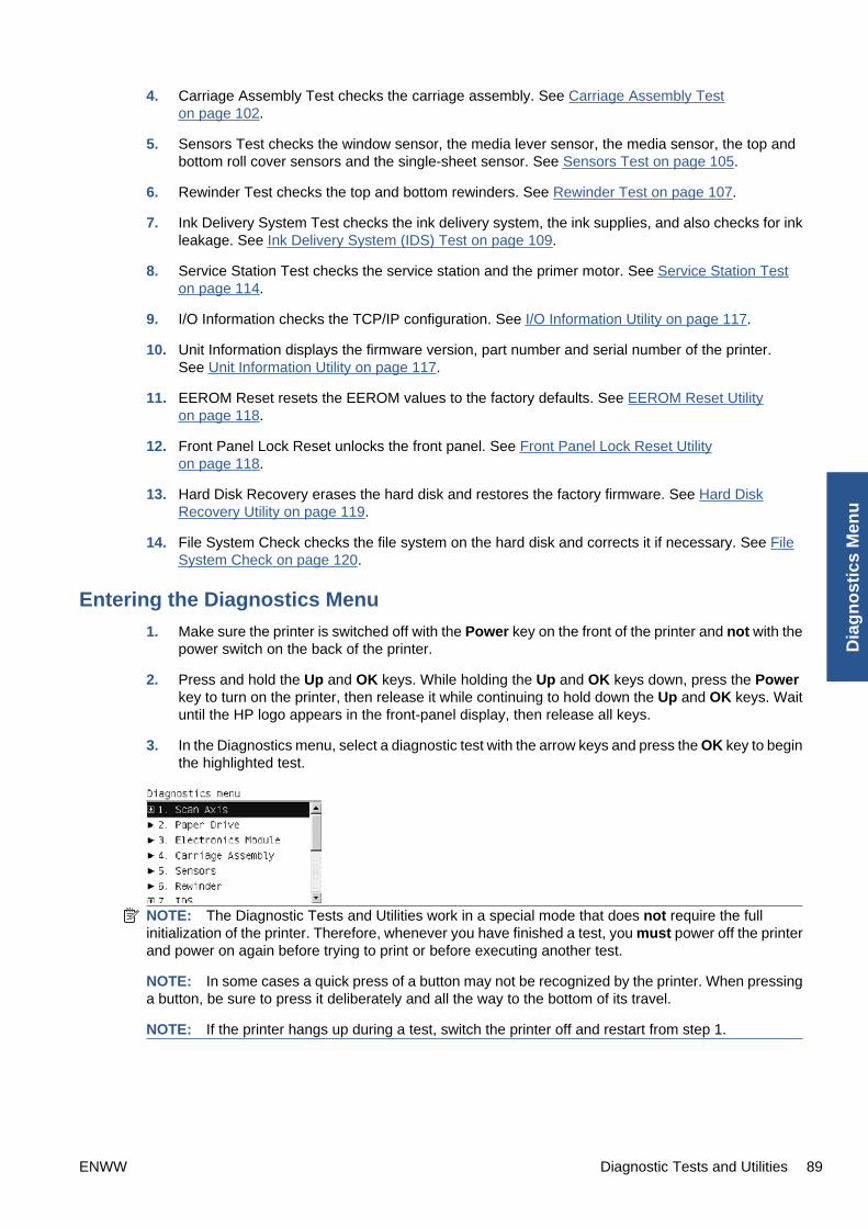
4. Carriage Assembly Test checks the carriage assembly. See Carriage Assembly Teston page 102.
5. Sensors Test checks the window sensor, the media lever sensor, the media sensor, the top andbottom roll cover sensors and the single-sheet sensor. See Sensors Test on page 105.
6. Rewinder Test checks the top and bottom rewinders. See Rewinder Test on page 107.
7. Ink Delivery System Test checks the ink delivery system, the ink supplies, and also checks for inkleakage. See Ink Delivery System (IDS) Test on page 109.
8. Service Station Test checks the service station and the primer motor. See Service Station Teston page 114.
9. I/O Information checks the TCP/IP configuration. See I/O Information Utility on page 117.
10. Unit Information displays the firmware version, part number and serial number of the printer.See Unit Information Utility on page 117.
11. EEROM Reset resets the EEROM values to the factory defaults. See EEROM Reset Utilityon page 118.
12. Front Panel Lock Reset unlocks the front panel. See Front Panel Lock Reset Utilityon page 118.
13. Hard Disk Recovery erases the hard disk and restores the factory firmware. See Hard DiskRecovery Utility on page 119.
14. File System Check checks the file system on the hard disk and corrects it if necessary. See FileSystem Check on page 120.
Entering the Diagnostics Menu
1. Make sure the printer is switched off with the Power key on the front of the printer and not with thepower switch on the back of the printer.
2. Press and hold the Up and OK keys. While holding the Up and OK keys down, press the Powerkey to turn on the printer, then release it while continuing to hold down the Up and OK keys. Waituntil the HP logo appears in the front-panel display, then release all keys.
3. In the Diagnostics menu, select a diagnostic test with the arrow keys and press the OK key to beginthe highlighted test.
NOTE: The Diagnostic Tests and Utilities work in a special mode that does not require the fullinitialization of the printer. Therefore, whenever you have finished a test, you must power off the printerand power on again before trying to print or before executing another test.
NOTE: In some cases a quick press of a button may not be recognized by the printer. When pressinga button, be sure to press it deliberately and all the way to the bottom of its travel.
NOTE: If the printer hangs up during a test, switch the printer off and restart from step 1.
ENWW Diagnostic Tests and Utilities 89
Dia
gn
ost
ics
Men
u

Scan Axis Test
The complete Scan Axis test consists of individual tests for the different components related to the ScanAxis. The subsystems included in this assembly are:
● Star Wheel Lifter
● Automatic PPS Adjustment.
● Scan Axis Servosystem
● Cutter
You must perform the Scan-Axis Test after:
● System Error Code 42:XZ.
● System Error Code 47:XZ.
● System Error Code 73:XZ.
● System Error Code 87:XZ.
● System Error Codes related to Scan-Axis shutdown or Carriage jam.
Diagnostic tests also need to be performed after removing or replacing certain printer components. Ifyou have removed or replaced printer components, check the Service Calibration Guide to Removaland Installation on page 185 to see which tests and calibrations you need to perform.
CAUTION: ALL THE COVER SENSORS ARE DISABLED WHEN IN THE SERVICE TESTS MENU.IF THE CARRIAGE IS MOVING IT WILL NOT STOP IF THE WINDOW IS OPENED, SO BE VERYCAREFUL NOT TO PUT YOUR HANDS INSIDE.
NOTE: IF POSSIBLE, ALWAYS PERFORM THIS TEST BEFORE REPLACING ANY COMPONENTOF THE SCAN-AXIS.
Star Wheel Lifter test
The Star Wheel Lifter subassembly is designed to move the Star Wheel support to the up and downpositions. This is used to load roll or sheet media and avoid damage to the Star Wheel caused by paperjams etc.
Perform the Scan Axis - Star Wheel Lifter test as follows:
NOTE: Perform this test with the Printheads and the Tubes System installed in order to get valuesthat can be compared correctly.
1. In the Diagnostics menu, scroll to Scan Axis and press OK.
90 Chapter 3 Diagnostics Menu ENWW
Diag
no
stics Men
u
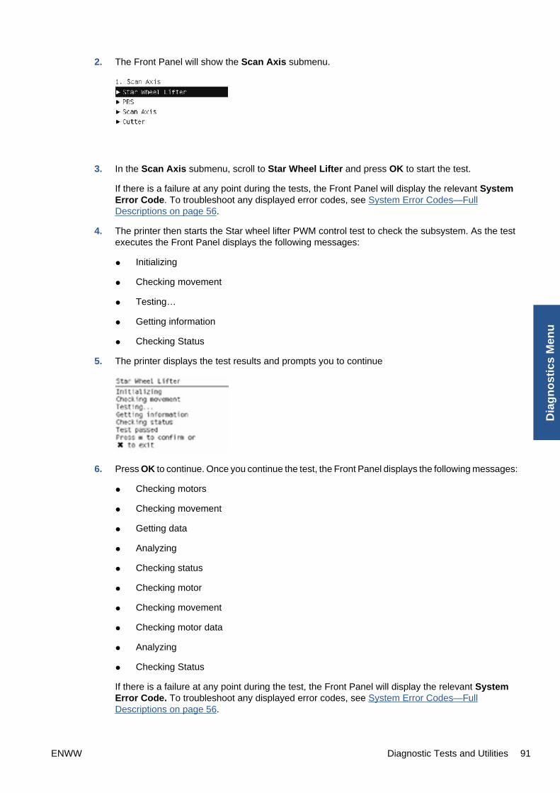
2. The Front Panel will show the Scan Axis submenu.
3. In the Scan Axis submenu, scroll to Star Wheel Lifter and press OK to start the test.
If there is a failure at any point during the tests, the Front Panel will display the relevant SystemError Code. To troubleshoot any displayed error codes, see System Error Codes—FullDescriptions on page 56.
4. The printer then starts the Star wheel lifter PWM control test to check the subsystem. As the testexecutes the Front Panel displays the following messages:
● Initializing
● Checking movement
● Testing…
● Getting information
● Checking Status
5. The printer displays the test results and prompts you to continue
6. Press OK to continue. Once you continue the test, the Front Panel displays the following messages:
● Checking motors
● Checking movement
● Getting data
● Analyzing
● Checking status
● Checking motor
● Checking movement
● Checking motor data
● Analyzing
● Checking Status
If there is a failure at any point during the test, the Front Panel will display the relevant SystemError Code. To troubleshoot any displayed error codes, see System Error Codes—FullDescriptions on page 56.
ENWW Diagnostic Tests and Utilities 91
Dia
gn
ost
ics
Men
u
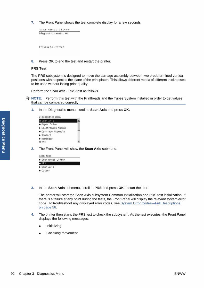
7. The Front Panel shows the test complete display for a few seconds.
8. Press OK to end the test and restart the printer.
PRS Test
The PRS subsystem is designed to move the carriage assembly between two predetermined verticalpositions with respect to the plane of the print platen. This allows different media of different thicknessesto be used without losing print quality.
Perform the Scan Axis - PRS test as follows.
NOTE: Perform this test with the Printheads and the Tubes System installed in order to get valuesthat can be compared correctly.
1. In the Diagnostics menu, scroll to Scan Axis and press OK.
2. The Front Panel will show the Scan Axis submenu.
3. In the Scan Axis submenu, scroll to PRS and press OK to start the test
The printer will start the Scan Axis subsystem Common Initialization and PRS test initialization. Ifthere is a failure at any point during the tests, the Front Panel will display the relevant system errorcode. To troubleshoot any displayed error codes, see System Error Codes—Full Descriptionson page 56.
4. The printer then starts the PRS test to check the subsystem. As the test executes, the Front Paneldisplays the following messages:
● Initializing
● Checking movement
92 Chapter 3 Diagnostics Menu ENWW
Diag
no
stics Men
u

5. Once the test has completed, the Front Panel prompts you to confirm that the PRS moved.
6. If the PRS moved, press OK to accept the results. If the PRS did not move, press Cancel to rejectthe results and exit the test.
7. Press OK to end the test and restart the printer.
Scan Axis Test
The Scan Axis subsystem is designed to move the carriage assembly between two predeterminedhorizontal positions with respect to the plane of the print platen. This allows media of different widths tobe used without losing print quality.
Perform the Scan Axis - Scan Axis test as follows:
NOTE: Perform this test with the Printheads and the Tubes System installed in order to get valuesthat can be compared correctly.
1. In the Diagnostics menu, scroll to Scan Axis and press OK.
2. The Front Panel will show the Scan Axis submenu.
3. In the Scan Axis submenu, scroll to Scan Axis and press OK to start the test.
4. The printer starts to check the Scan Axis motor. The Front Panel displays the following messages:
● Initializing
● Checking motors
5. Depending on the results of the tests, you may be asked to perform the following operations.
ENWW Diagnostic Tests and Utilities 93
Dia
gn
ost
ics
Men
u

a. Open the window.
b. Manually move the carriage to another position. The carriage should not offer resistance tomanual movement. Do not force any printer part while moving the carriage. The front panelwill show a text describing the action and an animation as an example of the requestedoperation. Press OK when you have finished moving the carriage.
c. Close the window.
6. Afterwards, the test will automatically continue checking for possible Scan Axis errors. The carriagewill move automatically along the Scan Axis several times, taking a few minutes. As the testexecutes, the Front Panel displays the following messages:
● Checking paper jam
● Checking movement
● Checking life counters status
7. If the Scan Axis passes the test, the Front Panel displays the following message, otherwise itdisplays an error code. Press OK to continue.
Cutter test
The Cutter is designed to cut roll media after printing to the defined sheet size. Before executing thistest you should run the Scan Axis, Media Drive and Carriage tests to ensure that each of thesesubsystems is operating correctly.
94 Chapter 3 Diagnostics Menu ENWW
Diag
no
stics Men
u

Perform the Scan Axis - Cutter test as follows.
1. In the Diagnostics menu, scroll to Scan Axis and press OK.
2. The Front Panel will show the Scan Axis submenu.
3. In the Scan Axis submenu, scroll to Cutter and press OK to start the test. The test prompts youto check that all paper is unloaded. Once the paper is unloaded, press OK.
If there is a failure at any point during the tests, the Front Panel will display the relevant systemerror code. To troubleshoot any displayed error codes, see System Error Codes—FullDescriptions on page 56.
4. The printer prompts you to feed the paper. With the lever lowered, feed roll paper (not a sheet) intothe paper path until it reaches the printer roller. Use the upper roll if you have a T1200 series printer.Then press OK to continue.
If you have not fed enough paper into the printer, the diagnostic will show a message saying thatthe paper was not detected. In this case, try again, taking care to feed more paper. If the problemcontinues, check that the sensors are working correctly. If necessary, perform the Sensors Test(see Sensors Test on page 105).
5. The printer then starts an actual test cut of the paper. As the test executes the Front Panel displaysthe following messages:
● Advancing paper
● Preparing cutter
● Cutting paper
● Disengaging cutter
ENWW Diagnostic Tests and Utilities 95
Dia
gn
ost
ics
Men
u

6. Once the test has completed the Front Panel displays the test result and prompts you to confirmthat the cutter worked.
7. Press OK if the cutter worked or Cancel if the cutter did not work.
8. Press OK to end the test and restart the printer.
Paper Drive Test
The Paper Drive test diagnoses failures of components of the Media-Axis.
You must perform the Paper Drive Test after:
● System Error Code 81:XZ.
● System Error Code 41:XZ.
● System Error Code 73:XZ.
Diagnostic tests also need to be performed after removing or replacing certain printer components. Ifyou have removed or replaced printer components, check the Service Calibration Guide to Removaland Installation on page 185 to see which tests and calibrations you need to perform.
CAUTION: ALL THE COVER SENSORS ARE DISABLED WHEN IN THE SERVICE TESTS MENU.IF THE CARRIAGE IS MOVING IT WILL NOT STOP IF THE WINDOW IS OPENED, SO BE VERYCAREFUL NOT TO PUT YOUR HANDS INSIDE.
NOTE: IF POSSIBLE ALWAYS PERFORM THIS TEST BEFORE REPLACING ANY COMPONENTOF THE MEDIA-AXIS.
Perform the Paper Drive test as follows:
96 Chapter 3 Diagnostics Menu ENWW
Diag
no
stics Men
u

NOTE: Perform this test with the Printheads and the Tubes System installed in order to get valuesthat can be compared correctly.
1. In the Diagnostics menu, scroll to Paper Drive and press OK.
2. The printer starts the Paper Drive test to check the subsystem. As the test executes the Front Paneldisplays the following messages:
● Starting Horsburgh and Mips
● Starting Nvm
● Starting Tests PWM
● Starting Tests GPIO
● Booting up the Carriage
● Starting DelSol1
● Starting Carriage
● Getting Part Number
● Part Number
3. The Front Panel will show information about what it is doing. It will ask you to press OK to continuewith the process. When prompted, unload paper if any is loaded.
4. The Front Panel then displays the Analog Encoder calibration results.
The GAIN for channels A and B should be lower than 5.
5. If the results are correct, press OK to accept the results. If the results are not correct, pressCancel to reject the results and fail the test.
6. If you accept the results, the front panel will continue with the tests. It will ask you to press OK tocontinue with the process. When prompted, unload paper if any is loaded.
7. The Front Panel then displays the test results.
ENWW Diagnostic Tests and Utilities 97
Dia
gn
ost
ics
Men
u

● The first PWM avg result (forward move) should be between 7700 and 10560 and the secondPwm avg (backward move) between 7600 and 10450.
● The first Speed error result should be no more than 78.65 and the second no more than 112.5.
● The first PWM StDev result should be no more than 162.5 and the second no more than 187.5.
● The first PWM max result should be no more than 12250 and the second no more than 12125.
8. If the results are correct, press OK to accept the results. If the results are not correct, press Back/Cancel to reject the results and FAIL the test.
9. If you accept the results, the Front Panel shows the test complete display for a few seconds:
10. The Front Panel prompts you to shut down the printer to complete the test.
11. Press any key to shut down the printer.
Electronics Module Test
The Electronics Module test diagnoses failures of the following components:
● Power Supply
● Formatter
● Engine Board
● Plotter Information
Diagnostic tests also need to be performed after removing or replacing certain printer components. Ifyou have removed or replaced printer components, check the Service Calibration Guide to Removaland Installation on page 185 to see which tests and calibrations you need to perform.
98 Chapter 3 Diagnostics Menu ENWW
Diag
no
stics Men
u

Perform the Electronics Module test as follows:
1. In the Diagnostics menu, scroll to Electronics Module and press OK.
2. The printer starts the Electronics Module test and displays the following messages:
● Initializing
3. The printer starts the Electronics Module test to check the subsystem and prompts you to test thePower Supply:
4. Press OK to the test the Power Supply. If you do not wish to test the power supply use theArrow keys to select NO and press OK.
5. The Power supply test starts and the Front Panel displays the following messages:
● Getting information
6. The Front Panel displays the Power Supply test results.
7. Press OK to continue.
8. The Front Panel displays more Power Supply test results.
9. Press OK to continue.
10. The Fan Speed test starts and the Front Panel displays:
● Getting information
ENWW Diagnostic Tests and Utilities 99
Dia
gn
ost
ics
Men
u

11. The Front Panel then displays the Fan Speed test result.
12. Press OK to continue.
13. The Front Panel then prompts you to test the Formatter.
14. Press OK to test the Formatter voltage. If you do not wish to test the Formatter voltage, use theArrow keys to select NO and press OK.
15. The Formatter voltage test starts and the Front Panel displays the following messages:
● Getting information
16. The Front Panel then displays the Formatter voltage test result.
17. Press OK to continue.
18. The Formatter memory size test starts and the Front Panel displays the following messages:
● Getting information
19. The Front Panel then displays the Formatter memory size.
20. Press OK to continue.
21. The Formatter hard disk test starts and the Front Panel displays the following messages:
● Getting information
100 Chapter 3 Diagnostics Menu ENWW
Diag
no
stics Men
u
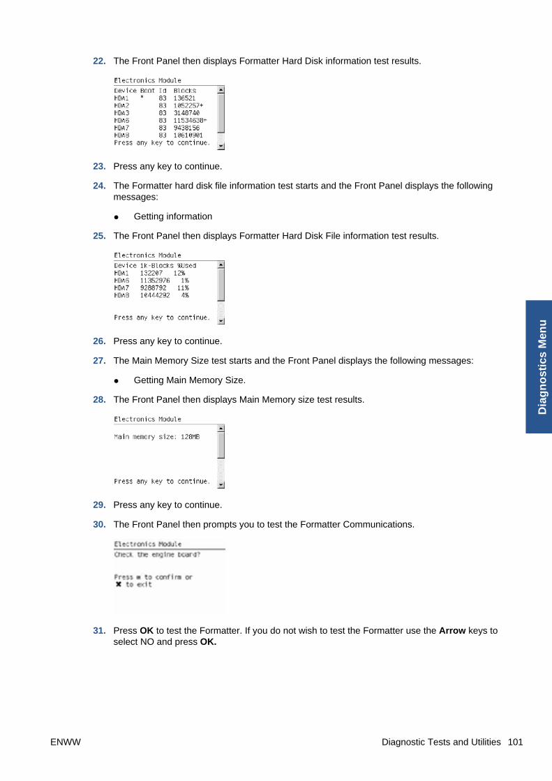
22. The Front Panel then displays Formatter Hard Disk information test results.
23. Press any key to continue.
24. The Formatter hard disk file information test starts and the Front Panel displays the followingmessages:
● Getting information
25. The Front Panel then displays Formatter Hard Disk File information test results.
26. Press any key to continue.
27. The Main Memory Size test starts and the Front Panel displays the following messages:
● Getting Main Memory Size.
28. The Front Panel then displays Main Memory size test results.
29. Press any key to continue.
30. The Front Panel then prompts you to test the Formatter Communications.
31. Press OK to test the Formatter. If you do not wish to test the Formatter use the Arrow keys toselect NO and press OK.
ENWW Diagnostic Tests and Utilities 101
Dia
gn
ost
ics
Men
u

32. The Formatter Communications test starts and the Front Panel displays the following messages:
● Starting Micci2Bus.
● Starting Micci2BusProxy.
● Checking Communications.
33. The Front Panel then displays Formatter Communications test results.
34. Press any key to continue.
35. The Front Panel then prompts you to check the Plotter Information.
36. Press OK to check the Plotter Information. If you do not wish to test the Plotter Information usethe Arrow keys to select NO and press OK.
37. The Plotter information test starts and the Front Panel displays the following messages:
● Getting information
38. If the test is successful, the Front Panel displays the following message.
39. Press OK to end the test and restart the printer.
Carriage Assembly Test
The Carriage Assembly test diagnoses failures of any components of the Carriage. This test should berun in any of the following circumstances.
● Before replacing the Carriage Assembly.
● After removing or replacing certain printer components. If you have removed or replaced printercomponents, check the Service Calibration Guide to Removal and Installation on page 185 to seewhich tests and calibrations you need to perform.
● If printhead alignment fails repeatedly.
● If, when loading paper, the search for the edge of the paper fails repeatedly.
102 Chapter 3 Diagnostics Menu ENWW
Diag
no
stics Men
u

● If no printheads are detected (check more than one).
● If the system error message 02.1:10 appears.
If an error is detected during the test, the Front Panel will display an error code and message. The testwill not continue after that point.
1. In the Diagnostics menu, scroll to Carriage Assembly and press OK.
2. The test starts and the Front Panel displays the following messages:
● Initializing
● Getting information
● Checking voltages
3. It will then display the actual values of various parameters, together with their permitted (valid)range. In each case, press OK to continue with the test.
4. Partway through the test, the Front Panel asks you to remove the printheads.
5. Open the Window.
6. Open the Carriage Cover.
7. Remove all the printheads from the Carriage.
8. Close the Carriage Cover.
9. Close the Window.
10. Press OK to continue.
NOTE: If the Front Panel reports that a printhead is still detected in the printer, remove theprinthead. If you are sure that you have already removed all the printheads, press Cancel tocontinue the test.
11. The test continues, displaying the values and valid ranges of some more parameters.
ENWW Diagnostic Tests and Utilities 103
Dia
gn
ost
ics
Men
u

12. The Front Panel then prompts you to load roll paper.
13. Load roll paper.
NOTE: For the LED test to work properly, the paper must be loaded completely through thecarriage path.
14. Press OK to continue or Cancel to exit.
15. The printer tests the carriage LEDs and sensors, which may take a few minutes.
16. The Front Panel then asks you to re-insert all the printheads that you removed earlier.
17. Open the Window.
18. Open the Carriage Cover.
19. Insert all the printheads.
20. Close the Carriage Cover.
21. Close the Window.
22. Press OK to continue.
NOTE: If the Front Panel reports that a printhead is not detected in the printer, insert theprinthead. If you are sure that you have already inserted all the printheads, press Cancel tocontinue the test.
104 Chapter 3 Diagnostics Menu ENWW
Diag
no
stics Men
u

23. The printer makes some further checks. If all is well, the Front Panel displays the followingmessage.
24. Press OK to end the test.
Sensors Test
The Sensors test diagnoses failures of any sensors of the printer. Always run this test before replacingany of the following sensors:
● Window sensor
● Media Lever position sensor
● Media sensor
● Upper or lower roll cover sensor (only for T1200 series)
● Single-sheet sensor
Diagnostic tests also need to be performed after removing or replacing certain printer components. Ifyou have removed or replaced printer components, check the Service Calibration Guide to Removaland Installation on page 185 to see which tests and calibrations you need to perform.
1. In the Diagnostics menu, scroll to Sensors and press OK.
2. The Sensors test starts and the Front Panel prompts you to check default sensor positions. Forthe T770 series, the cover sensors are not present and not tested.
Check that the sensors are in the default positions and press OK to continue.
NOTE: If the printer detects any sensor in a position that is not expected, a message will beshown. If the sensor is in the correct position, there must be a problem with the sensor (for example,the window is closed but the message indicates that it is not closed); in this case, replace the faultysensor.
ENWW Diagnostic Tests and Utilities 105
Dia
gn
ost
ics
Men
u

3. The Window sensor test starts and the Front Panel prompts you to open the Window.
Open the Window and press OK to continue.
NOTE: Make sure that no object is interfering with the window sensor.
4. The Front Panel prompts you to close the Window.
Close the Window and press OK to continue.
5. Follow the same procedure for the Pinchwheel Lever Sensor, the Paper Sensor, and the RollCovers (T1200 series only).
To test the Paper Sensor, you will have to feed paper into the printer until it reaches the sensor.
6. Eventually, the Front Panel asks you to remove the paper.
When you have removed the paper, press OK to continue.
7. The Front Panel may ask you to reinsert the paper.
106 Chapter 3 Diagnostics Menu ENWW
Diag
no
stics Men
u

8. When the tests are complete, the Front Panel displays a final message. Press OK to continue.
Rewinder Test
The Rewinder test diagnoses failures of the Rewinder located in the Paper Path Assemblies (Rear).Always run this test before replacing the Right Roll Support.
Perform this test after:
● System Error Code 41:YZ
● System Error Code 45:YZ
● System Error Code 81:YZ
Diagnostic tests also need to be performed after removing or replacing certain printer components. Ifyou have removed or replaced printer components, check the Service Calibration Guide to Removaland Installation on page 185 to see which tests and calibrations you need to perform.
NOTE: Perform this test with the Printheads and the Tubes System installed in order to get valuesthat can be compared correctly.
CAUTION: ALL THE COVER SENSORS ARE DISABLED WHEN IN THE DIAGNOSTICS MENU. IFTHE CARRIAGE IS MOVING IT WILL NOT STOP IF THE WINDOW IS OPENED, SO BE VERYCAREFUL NOT TO PUT YOUR HANDS INSIDE.
1. In the Diagnostics menu, scroll to Rewinder and press OK.
The printer will start the Open Loop, Rewinder Servo System, and Media Driver PWM tests.
If there is a failure at any point during the tests, the Front Panel will display the relevant SystemError Code. To troubleshoot any displayed error codes, see System Error Codes—FullDescriptions on page 56.
2. The Rewinder test starts and the front panel displays the following messages:
● Initializing
● Getting information
● Part Number: P/N
● Setting encoder position
ENWW Diagnostic Tests and Utilities 107
Dia
gn
ost
ics
Men
u

3. The Front Panel prompts you to make sure the media is unloaded and the spindle is removed.
4. Remove the media from the printer.
5. Remove the spindles from the roll supports.
6. Press OK to continue.
7. The Front Panel displays the results.
8. The front panel displays the test results. Press OK to end the test and restart the printer.
NOTE: Once you have completed the Rewinder diagnostic test, you must perform a Paper AdvanceCalibration. Paper Advance Calibration on page 139.
108 Chapter 3 Diagnostics Menu ENWW
Diag
no
stics Men
u

Ink Delivery System (IDS) Test
The complete Ink Delivery System test consists of three individual tests for the different componentsrelated to this subsystem. These three tests and their associated functions are:
● Ink Delivery System
◦ Check the Ink Supply Station subsystem.
◦ Show tubes usage (as a percentage of expected life).
◦ Test communication with Ink Supplies.
● Check Ink Supplies
◦ Test communication with Ink Supplies.
◦ Show ink levels.
◦ Check that Ink Supplies are ready for purging: the remaining ink is enough for the setupprocess and the ink supply is not faulty.
● Check Leakage
◦ Check the Ink Supply Station subsystem.
◦ Check for ink supplies or tubes leakage.
Diagnostic tests also need to be performed after removing or replacing certain printer components. Ifyou have removed or replaced printer components, check the Service Calibration Guide to Removaland Installation on page 185 to see which tests and calibrations you need to perform
Ink Delivery System
If there is a failure at any point during the tests, the Front Panel will display the relevant System ErrorCode. To troubleshoot any displayed error codes, see System Error Codes—Full Descriptionson page 56.
1. In the Diagnostics menu, scroll to IDS and press OK .
2. The Front Panel shows the IDS submenu.
3. In the IDS submenu, scroll to Ink Delivery System and press OK to start the test.
ENWW Diagnostic Tests and Utilities 109
Dia
gn
ost
ics
Men
u

4. The Ink Delivery System test starts and the Front Panel prompts you to remove all the Ink Supplies.
5. Remove all the Ink Cartridges.
6. Press OK to continue.
7. The Front Panel then prompts you push down Piston 0.
8. Press and hold down Piston 0, which is located at the furthest left Ink Cartridge position.
9. Press OK.
10. The Front Panel then prompts you to release Piston 0.
11. Release Piston 0.
12. Press OK to continue.
13. Repeat the steps above for each piston.
14. The Front Panel then displays the tubes usage, expressed in percentage of the expectedsubsystem life.
15. Press OK to continue.
110 Chapter 3 Diagnostics Menu ENWW
Diag
no
stics Men
u

16. The Front Panel prompts you to insert all the Ink Cartridges.
17. Install all the Ink Cartridges.
18. Press OK to continue.
19. The Front Panel then displays Acumen Supplies test results.
20. Press OK to end the test and return to the Diagnostics menu.
Check Ink Supplies
If there is a failure at any point during the tests, the Front Panel will display the relevant System ErrorCode. To troubleshoot any displayed error codes, see System Error Codes—Full Descriptionson page 56.
1. In the Diagnostics menu, scroll to IDS and press OK.
2. The Front Panel shows the IDS submenu.
3. In the IDS submenu, scroll to Check Ink Supplies and press OK to start the test.
ENWW Diagnostic Tests and Utilities 111
Dia
gn
ost
ics
Men
u

4. The front panel prompts you to insert all the ink cartridges.
5. The Front Panel shows the ink levels of all the cartridges. A list of the “colors not valid” for purgeare shown below. If all of the cartridges are valid for purging, the “Colors not valid” item will not beshown on the Front Panel.
6. Press OK to exit.
7. The Front Panel then displays the test results.
8. Press OK to end the test and return to the Diagnostics menu.
Check Leakage
If there is a failure at any point during the tests, the Front Panel will display the relevant System ErrorCode. To troubleshoot any displayed error codes, see System Error Codes—Full Descriptionson page 56.
1. In the Diagnostics menu, scroll to IDS and press OK.
2. In the IDS submenu, scroll to Check Leakage and press OK to start the test.
112 Chapter 3 Diagnostics Menu ENWW
Diag
no
stics Men
u

3. The Ink Delivery System test starts and the front panel prompts you to remove all the Ink Cartridges.
4. Remove all the Ink Cartridges and press OK to continue.
5. The front panel prompts you to push down all the pistons.
6. Use your finger to push all of the pistons down, and press OK to continue.
7. If the Ink Supply Station is working properly, the Front Panel prompts you to insert all the InkCartridges.
8. Install all the Ink Cartridges and press OK to continue.
9. The leakage check starts and the front panel displays the remaining time until the leakage checkis finished.
10. The Front Panel then displays Check Leakage test results.
11. Press OK to end the test and return to the Diagnostics menu.
ENWW Diagnostic Tests and Utilities 113
Dia
gn
ost
ics
Men
u
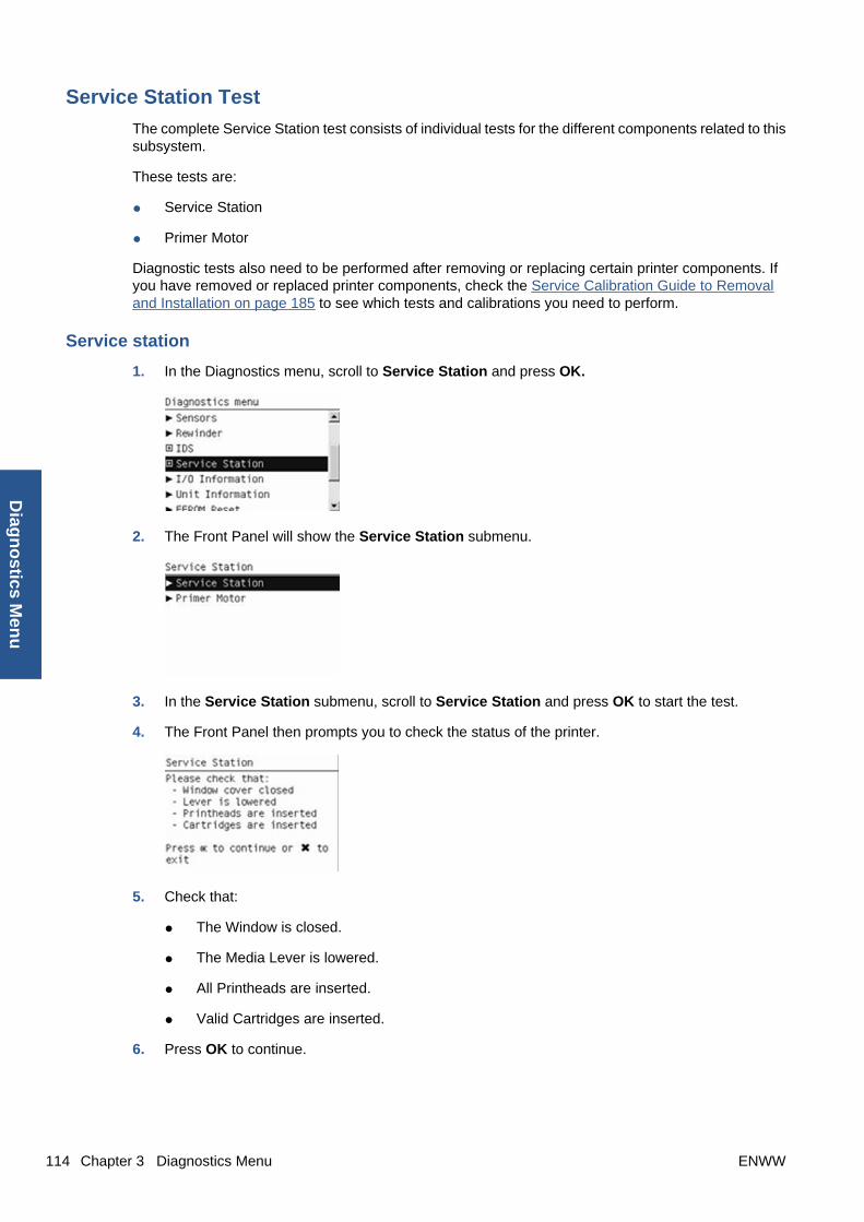
Service Station Test
The complete Service Station test consists of individual tests for the different components related to thissubsystem.
These tests are:
● Service Station
● Primer Motor
Diagnostic tests also need to be performed after removing or replacing certain printer components. Ifyou have removed or replaced printer components, check the Service Calibration Guide to Removaland Installation on page 185 to see which tests and calibrations you need to perform.
Service station
1. In the Diagnostics menu, scroll to Service Station and press OK.
2. The Front Panel will show the Service Station submenu.
3. In the Service Station submenu, scroll to Service Station and press OK to start the test.
4. The Front Panel then prompts you to check the status of the printer.
5. Check that:
● The Window is closed.
● The Media Lever is lowered.
● All Printheads are inserted.
● Valid Cartridges are inserted.
6. Press OK to continue.
114 Chapter 3 Diagnostics Menu ENWW
Diag
no
stics Men
u

7. The printer performs a series of movements numbered from 1 to 10. It takes about a minute toperform all movements.
8. The Front Panel then asks if you want to cap the printheads.
9. Press OK to cap the Service Station or Cancel to skip this test.
10. The Front Panel prompts you to shut down the printer to complete the test.
11. Press OK to shut down the printer.
TIP: If a system error message appears during the above procedure, follow the procedure describedin the System Errors section. A system error 21 indicates that the service station is not working properly.
Primer motor
1. In the Diagnostics menu, scroll to Service Station and press OK.
2. The Front Panel will show the Service Station submenu.
3. In the Service Station submenu, scroll to Primer Motor and press OK to start the test.
ENWW Diagnostic Tests and Utilities 115
Dia
gn
ost
ics
Men
u
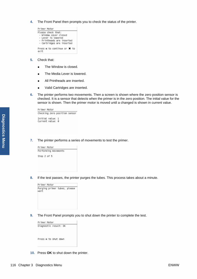
4. The Front Panel then prompts you to check the status of the printer.
5. Check that:
● The Window is closed.
● The Media Lever is lowered.
● All Printheads are inserted.
● Valid Cartridges are inserted.
6. The printer performs two movements. Then a screen is shown where the zero position sensor ischecked. It is a sensor that detects when the primer is in the zero position. The initial value for thesensor is shown. Then the primer motor is moved until a changed is shown in current value.
7. The printer performs a series of movements to test the primer.
8. If the test passes, the printer purges the tubes. This process takes about a minute.
9. The Front Panel prompts you to shut down the printer to complete the test.
10. Press OK to shut down the printer.
116 Chapter 3 Diagnostics Menu ENWW
Diag
no
stics Men
u

I/O Information Utility
The I/O Information utility retrieves the TCP/IP Network configuration parameters from the printer.
NOTE: In some cases, particularly after resetting the printer to factory defaults, it may take as long as5 minutes to obtain an IP configuration.
1. In the Diagnostics menu, scroll to I/O Information and press OK.
2. The Front Panel displays the I/O Information.
3. Press OK to finish.
Unit Information Utility
1. The Unit Information test retrieves the Firmware Version, Serial Number and Part Number of theprinter.
2. In the Diagnostics menu, scroll to Unit Information and press OK.
3. The Unit Information test starts and the Front Panel displays the following message:
● Initializing
● Getting information
4. The Front Panel shows the result of the test.
5. Press OK to continue and return to the menu.
ENWW Diagnostic Tests and Utilities 117
Dia
gn
ost
ics
Men
u

EEROM Reset Utility
The EEROM Reset test resets the printer to the factory defaults and delete any user information/files.
1. In the Diagnostics menu, scroll to EEROM and press OK.
2. The EEROM Reset test starts and the Front Panel asks whether you want to continue.
3. Press OK to continue the test or Cancel to cancel it.
4. The EEROM Reset test continues and the Front Panel displays the following message:
● Initializing
● Setting default configuration
5. The Front Panel prompts you to shut down the printer to complete the test.
6. Press OK to shut down the printer.
Front Panel Lock Reset Utility
This utility enables the front panel to be unlocked when it has been locked by mistake and cannot beremotely unlocked from Web JetAdmin.
1. In the Diagnostics menu, scroll to Front panel lock reset and press OK
.
118 Chapter 3 Diagnostics Menu ENWW
Diag
no
stics Men
u

2. The Front Panel prompts you to unlock front panel access. Press OK to unlock access orCancel to exit.
3. The Front Panel lock is reset. Press OK to end the utility and return to the main menu.
Hard Disk Recovery Utility
The Hard Disk Recovery utility erases the hard disk and restores the factory firmware.
1. In the Diagnostics menu, select Hard Disk Recovery and press OK.
2. The front panel gives the first of a two-part explanation of this utility, and asks whether you wantto proceed.
3. Press OK to proceed or Back/Cancel to exit.
If you press OK, the front panel then gives the second part of the explanation, and again askswhether you want to proceed.
4. Press OK to proceed or Back/Cancel to exit.
If you press OK, the printer begins to erase the hard disk and restore the factory firmware; it restartsautomatically during this process. The front panel displays a progress bar.
ENWW Diagnostic Tests and Utilities 119
Dia
gn
ost
ics
Men
u

CAUTION: Do not try to interrupt this process. All front-panel keys are disabled until it hasfinished.
File System Check
The File System Check checks the file system on the hard disk and automatically corrects any problemsthat it finds.
1. In the Diagnostics menu, select File System Check and press OK.
2. The front panel asks you if you want to proceed with the File System Check.
3. Press OK to proceed or Back/Cancel to exit.
If you press OK, the printer restarts and the File System Check is performed.
120 Chapter 3 Diagnostics Menu ENWW
Diag
no
stics Men
u

4 Service Menu
● Introduction
● Service Utilities
● Service Calibrations
ENWW 121
Ser
vice
Men
u

IntroductionThis chapter explains the printer's internal Service Utilities and Calibrations, available from the ServiceMenu.
Service UtilitiesThe following is a list of all internal Service Utilities available in the printer. To access them, see Enteringthe Service Utilities Menu on page 123.
1. Turn Drive Roller rotates the Drive Roller and the Overdrive in order to clean them. See Turn DriveRoller on page 123.
2. Purge Tubes primes the Ink Tubes if they need to be re-primed, or if automatic priming failed tocomplete correctly. See Purge Tubes on page 125.
3. Reset Life Counters resets some or all of the life counters relevant to a Preventive MaintenanceKit. See Reset Life Counters on page 127.
4. Diagnostic Print prints one of the available Diagnostic Prints in order to identify print qualityproblems. See Diagnostic Print on page 129.
5. Set Time and Date set the printer's Real-time Clock. See Set Date and Time on page 129.
6. Enable/Disable Firewall enables or disables the printer's built-in firewall. See Enable/DisableFirewall on page 130.
7. Enable/Disable Sleep Mode enables or disables Sleep Mode. See Enable/Disable Sleep Modeon page 131.
8. Disk Wipe DoD 5220.220M erases all of your own information from the hard disk to preventunauthorized access to it. See Disk Wipe DoD 5220.220M on page 131.
9. Hard Disk Recovery erases the hard disk and restores the factory firmware. This is the same utilityas in the Diagnostics Menu. See Hard Disk Recovery Utility on page 119.
10. File System Check checks the file system on the hard disk and corrects it if necessary. This is thesame utility as in the Diagnostics Menu. See File System Check on page 120.
11. SNMP Language Write Access prevents SNMP tools from changing the printer language remotely.See SNMP Language Write Access on page 133.
12. I/O Tests checks the Formatter's network hardware interface. See I/O Tests on page 134.
13. Show/Hide Front Panel Information shows or hides the printer's IP address and connectioninformation on the front panel. See Show/Hide Front Panel Information on page 135.
14. Enable/Disable Port 280 enables or disables communication with the printer's Embedded WebServer through port 280. See Enable/Disable Port 280 on page 135.
15. Rewinder Adjust sets the calibration parameters of the rewinders to default values when therewinders are replaced. See Rewinder Adjust on page 136.
16. Disable Upper Roll Cover disables detection of the upper roll cover's status. See Disable UpperRoll Cover (T1200 series only) on page 137.
17. Enable Upper Roll Cover enables detection of the upper roll cover's status. See Enable Upper RollCover (T1200 series only) on page 137.
18. Special Cutter Mode provides a special cutting mode for tracing papers. See Special CutterMode on page 138.
122 Chapter 4 Service Menu ENWW
Service M
enu

Entering the Service Utilities Menu
1. Once the message “Ready” or “Ready for paper” is displayed on the front panel, press the Menukey. For information regarding the front panel keys, see Using the Front Panel on page 2.
2. From the main menu, customers can execute certain service utilities from the Service Tools menuby pressing the Down key and the Cancel key together.
3. Also from the main menu, engineers can execute all service utilities from the Service menu bypressing the Up arrow key and the Cancel key together.
4. From the Service menu, select Service utilities and press the OK key.
5. From the Service Utilities menu, you can select any of the available utilities, and press the OK keyto begin the highlighted operation.
NOTE: If the printer is not used for 135 seconds, the printer exits the Service Utilities menu and youmust repeat the above steps to re-enter the menu.
NOTE: In some cases a quick press of a key may not be recognized by the printer. When pressing akey, be sure to press it deliberately and all the way to the bottom of its travel.
Turn Drive Roller
The purpose of this Service Utility is to rotate the Drive Roller and the Overdrive in order to clean them.
ENWW Service Utilities 123
Ser
vice
Men
u

NOTE: REMOVE THE MEDIA BEFORE PERFORMING THIS OPERATION.
NOTE: BEFORE PERFORMING THIS SERVICE UTILITY, OPEN THE WINDOW. WITH A FOLDEDPIECE OF PAPER, ACTIVATE THE MECHANICAL WINDOW SENSOR. THE PAPER SHOULD FITTIGHTLY SO IT DOES NOT FALL INTO THE SENSOR.
Perform the Turn Drive Roller utility as follows:
1. In the Service Utilities submenu, scroll to Turn Drive Roller and press OK.
2. The test begins and the Front Panel displays the following message:
● Checking Media Presence Sensor
3. If media is loaded, the service utility will be cancelled. In this case, unload the media and start againfrom step 1. If no media is loaded, the test will continue.
4. The Drive Roller begins to turn slowly and the following message is displayed on the Front Panel:
5. To clean the drive roller and overdrive, see Cleaning the Drive Roller and Overdriveon page 371.
6. Once you have finished cleaning the Drive Roller and the Overdrive, press the Cancel key to finishthe utility.
124 Chapter 4 Service Menu ENWW
Service M
enu

7. If the utility exits correctly, OK will be displayed on the Front Panel.
NOTE: REMEMBER TO REMOVE THE PIECE OF PAPER FROM THE WINDOW SENSORBEFORE CLOSING THE WINDOW AS THIS COULD DAMAGE THE WINDOW AND THE SENSOR.
Purge Tubes
The purpose of this Service Utility is to Prime the Tubes when the Ink Tubes are not new and they needto be re-primed or automatic priming was not completed correctly.
NOTE: Make sure that NEW Ink Cartridges are installed or that the ink volume remaining in the Inkcartridges is below 88% before starting to prime the tubes. If you do not comply, you will get a warningmessage and cannot finish the test.
NOTE: Before using the Purge Tubes utility, you must insert the dummy printheads using the ChangePrintheads procedure.
Once you have inserted the dummy printheads using the Change Printheads procedure, perform thePurge Tubes utility as follows:
1. In the Service Utilities submenu, scroll to Purge Tubes and press OK.
2. The Front Panel prompts you to confirm that the dummy printheads are correctly inserted. If thedummy printheads are correctly inserted, press OK.
NOTE: If you have not inserted the dummy printheads, press BACK or CANCEL to exit the test.Insert the dummy printheads using the Change Printheads procedure.
3. The Front Panel displays a message to say the printer is going to reboot.
ENWW Service Utilities 125
Ser
vice
Men
u
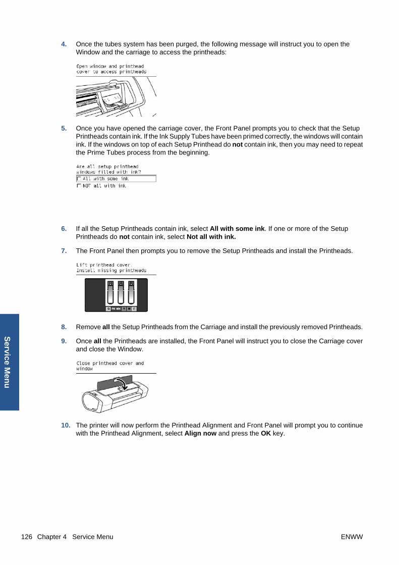
4. Once the tubes system has been purged, the following message will instruct you to open theWindow and the carriage to access the printheads:
5. Once you have opened the carriage cover, the Front Panel prompts you to check that the SetupPrintheads contain ink. If the Ink Supply Tubes have been primed correctly, the windows will containink. If the windows on top of each Setup Printhead do not contain ink, then you may need to repeatthe Prime Tubes process from the beginning.
6. If all the Setup Printheads contain ink, select All with some ink. If one or more of the SetupPrintheads do not contain ink, select Not all with ink.
7. The Front Panel then prompts you to remove the Setup Printheads and install the Printheads.
8. Remove all the Setup Printheads from the Carriage and install the previously removed Printheads.
9. Once all the Printheads are installed, the Front Panel will instruct you to close the Carriage coverand close the Window.
10. The printer will now perform the Printhead Alignment and Front Panel will prompt you to continuewith the Printhead Alignment, select Align now and press the OK key.
126 Chapter 4 Service Menu ENWW
Service M
enu

11. Once the Printhead Alignment is completed, the following message will be displayed on the FrontPanel. Press the OK key to continue.
Reset Life Counters
The purpose of this Service Utility is to reset the internal life counters.
There are two submenus that allow you to:
● Reset all the counters related to a Preventive Maintenance Kit (PMK).
● Reset only the counters related to a specific replaced part.
NOTE: ALWAYS RESET THE LIFE COUNTER OF A CORRESPONDING PART AFTERREPLACING IT.
Perform the Reset Life Counters utility as follows:
1. In the Service Utilities submenu, scroll to Reset Life Counters and press OK.
2. Select Reset Maintenance Kit usage to reset the Life Counter for all parts included in aPreventative Maintenance Kit (PMK).
You can choose from the following Preventive Maintenance Kits:
● Preventive Maintenance Kit 1 (PMK1). See Preventive Maintenance Kit #1 (CH538-67024)on page 376.
● Preventive Maintenance Kit 2 (PMK2). See Preventive Maintenance Kit #2 (CH538-67040)on page 377.
NOTE: For more information about the counters that are reset, See Preventive Maintenanceon page 370.
It is also advisable to check the status of the Life Counters related to the other PreventiveMaintenance Kits to avoid multiple trips to the customer.
3. Select Reset usage counters to reset the Life Counter of a single part.
ENWW Service Utilities 127
Ser
vice
Men
u

● Tubes and Trailing Cable
● Scan-Axis Belt
● Scan-Axis Motor
● Left Spittoon
● Right Spittoon
● Full Bleed Foams
● Carriage
● Service Station
If you replace a part, you should reset the Life Counters as follows:
Replaced part Reset Life Counters
Scan-axis motor SV Scan-Axis Motor
Belt assembly SV Scan-Axis Belt
Carriage assembly SV Carriage
Ink supply tubes SV (with trailing cables) Tubes and Trailing Cable
Service station SV Right Spittoon & Service Station
4. Once you have selected the Life Counters to reset, a message similar to the following will bedisplayed on the Front Panel. Press the OK key to reset the selected Life Counters or pressCancel to exit without resetting the Life Counters.
Example 1:
Example 2:
128 Chapter 4 Service Menu ENWW
Service M
enu
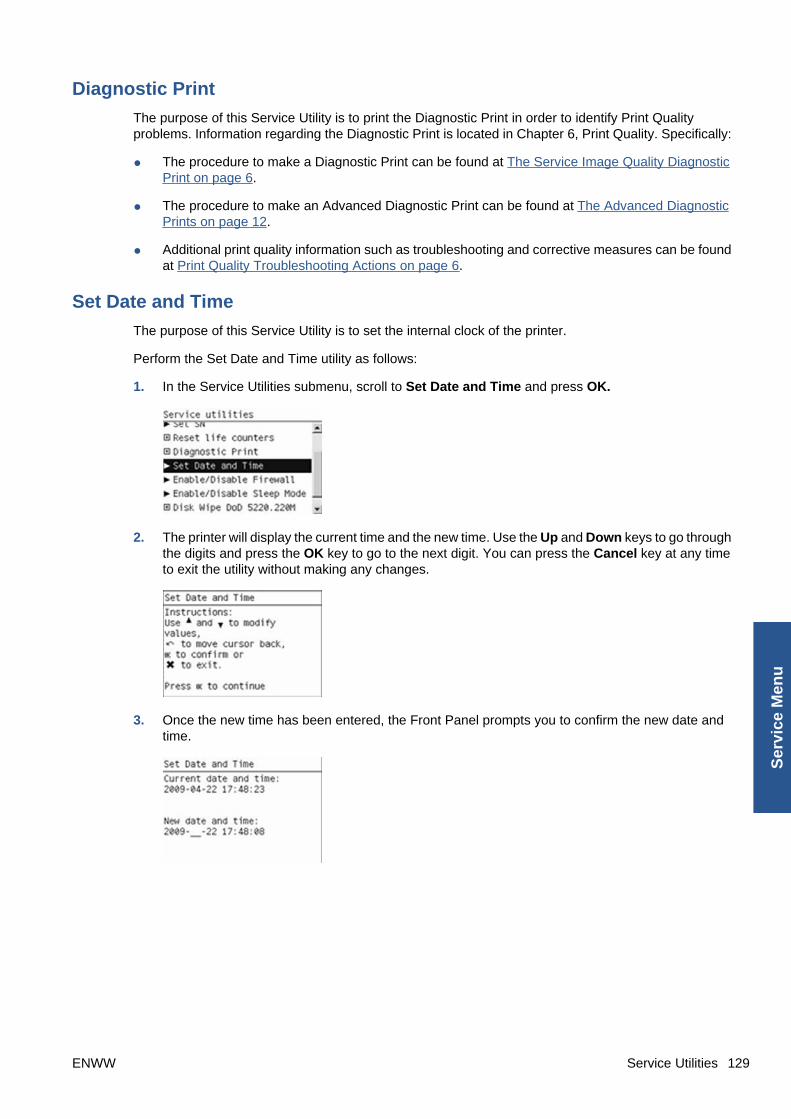
Diagnostic Print
The purpose of this Service Utility is to print the Diagnostic Print in order to identify Print Qualityproblems. Information regarding the Diagnostic Print is located in Chapter 6, Print Quality. Specifically:
● The procedure to make a Diagnostic Print can be found at The Service Image Quality DiagnosticPrint on page 6.
● The procedure to make an Advanced Diagnostic Print can be found at The Advanced DiagnosticPrints on page 12.
● Additional print quality information such as troubleshooting and corrective measures can be foundat Print Quality Troubleshooting Actions on page 6.
Set Date and Time
The purpose of this Service Utility is to set the internal clock of the printer.
Perform the Set Date and Time utility as follows:
1. In the Service Utilities submenu, scroll to Set Date and Time and press OK.
2. The printer will display the current time and the new time. Use the Up and Down keys to go throughthe digits and press the OK key to go to the next digit. You can press the Cancel key at any timeto exit the utility without making any changes.
3. Once the new time has been entered, the Front Panel prompts you to confirm the new date andtime.
ENWW Service Utilities 129
Ser
vice
Men
u
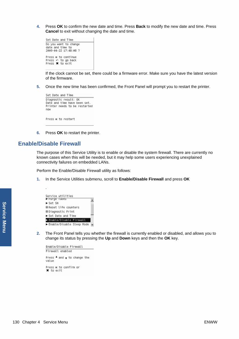
4. Press OK to confirm the new date and time. Press Back to modify the new date and time. PressCancel to exit without changing the date and time.
If the clock cannot be set, there could be a firmware error. Make sure you have the latest versionof the firmware.
5. Once the new time has been confirmed, the Front Panel will prompt you to restart the printer.
6. Press OK to restart the printer.
Enable/Disable Firewall
The purpose of this Service Utility is to enable or disable the system firewall. There are currently noknown cases when this will be needed, but it may help some users experiencing unexplainedconnectivity failures on embedded LANs.
Perform the Enable/Disable Firewall utility as follows:
1. In the Service Utilities submenu, scroll to Enable/Disable Firewall and press OK
.
2. The Front Panel tells you whether the firewall is currently enabled or disabled, and allows you tochange its status by pressing the Up and Down keys and then the OK key.
130 Chapter 4 Service Menu ENWW
Service M
enu
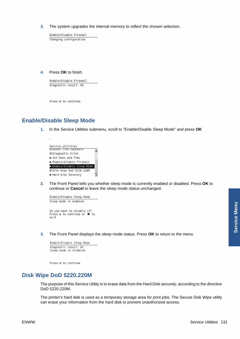
3. The system upgrades the internal memory to reflect the chosen selection.
4. Press OK to finish.
Enable/Disable Sleep Mode
1. In the Service Utilities submenu, scroll to "Enable/Disable Sleep Mode" and press OK
.
2. The Front Panel tells you whether sleep mode is currently enabled or disabled. Press OK tocontinue or Cancel to leave the sleep mode status unchanged.
3. The Front Panel displays the sleep mode status. Press OK to return to the menu.
Disk Wipe DoD 5220.220M
The purpose of this Service Utility is to erase data from the Hard Disk securely, according to the directiveDoD 5220.220M.
The printer's hard disk is used as a temporary storage area for print jobs. The Secure Disk Wipe utilitycan erase your information from the hard disk to prevent unauthorized access.
ENWW Service Utilities 131
Ser
vice
Men
u

Secure Disk Wipe provides three different levels of security:
● Unsecure Mode: All pointers to the information are erased. The information itself is not erased,and remains on the hard disk until the disk space it occupies is needed for new print jobs. The newprint information overwrites the old information. While the information remains on the disk, it isdifficult for most people to access, but may be accessed using software designed for that purpose.This is the normal method in which files are erased on most computer systems; it is the fastestmethod but the least secure. This is the default security level when using Secure Disk Erase.
● 1 Pass Mode: All pointers to the information are erased, and the information itself is immediatelyoverwritten with a fixed character pattern. This method is slower than Non-Secure Fast Erase, butmore secure. It may still be possible to access fragments of the erased information by using specialtools to detect residual magnetic traces.
● 5 Pass Mode: All pointers to the information are erased, and the information itself is repetitivelyoverwritten using an algorithm designed to eliminate any residual traces. This is the slowestmethod, but the most secure. Secure Sanitizing Erase meets the US Department of Defense5220-220M requirements for clearing and sanitization of disk media.
Execute the Disk Wipe DoD 5220.220M utility as follows:
1. In the Service Utilities submenu, scroll to Disk Wipe DoD 5220.220M and press OK.
2. In the Disk Wipe DoD 5220.220M submenu, scroll to Sanity Level and press OK.
3. In the Sanity Level submenu, scroll to the required Sanity Level and press OK.
NOTE: Erasing the Hard Disk drive using either of the Secure Sanitize Levels is a very slowprocess, 6 hours for the 1 Pass mode and 40 hours for the 5 Pass mode.
4. When the Sanity Level has been changed, the Front Panel displays the following message, or anerror message if there is some problem.
5. In the Disk Wipe DoD 5220.220M submenu, scroll to Disk Wipe (DoD 5220.220M) and pressOK.
132 Chapter 4 Service Menu ENWW
Service M
enu

6. When the following message appears on the Front Panel, you must select whether you would liketo perform a complete erase of the Hard Disk Drive using the previously selected erase mode bypressing OK. Press Cancel to exit the utility
7. When the following message appears on the Front Panel, you must select whether you want tocontinue and completely erase the Hard Disk Drive by pressing OK. Press Cancel to exit the utility.
8. The erase process starts and the Front Panel shows a setup progress bar.
9. The printer reboots into the Disk Wipe mode, and continues with the disk erase until it is completed.
CAUTION: Do not try to interrupt this process. All Front Panel keys are disabled while the printererases the Hard Disk Drive.
SNMP Language Write Access
The purpose of this utility is to prevent SNMP tools from changing the printer language remotely. Thisis provided as a possible workaround to an exotic problem that has been seen with some SNMP toolsthat set the printer language in order to control the localization applied to some SNMP OIDs, but do notrestore the printer language afterwards.
1. In the Service Utilities submenu, scroll to SNMP Language Write Access and press OK.
2. The utility checks whether the printer language can currently be changed using SNMP, and showsone of the following messages:
3. Use the Up and Down keys to choose the desired behavior and press OK to confirm your selection.The system updates the internal memory to reflect the chosen selection.
ENWW Service Utilities 133
Ser
vice
Men
u

4. The Front Panel shows the “test complete” display until you press OK.
I/O Tests
The I/O Tests service test checks the network interface hardware of the Formatter. To run this testsuccessfully, the printer’s embedded LAN connector must be connected to an Ethernet network.
Perform this test after replacing the Formatter.
1. In the Service Utilities submenu, scroll to I/O Tests and press OK.
2. The front panel asks you if you want to proceed with the I/O tests.
Press OK to proceed or Cancel to exit.
3. The front panel displays the I/O information.
4. Press OK to start the test.
5. The printer tests the I/O interfaces and displays the result as passed or failed after a few seconds.
NOTE: If the test fails when the printer is connected to a network, there may be a hardwareproblem with the network chip on the formatter board.
134 Chapter 4 Service Menu ENWW
Service M
enu

Show/Hide Front Panel Information
The purpose of this utility is to hide the IP address and connection information that is normally visibleon the Front Panel, in order to restrict access to the printer.
1. In the Service Utilities submenu, scroll to Show/Hide Front Panel Info and press OK.
2. The Front Panel tells you whether the information is currently shown or hidden, and allows you tochange the situation by using the Up and Down keys and pressing OK.
3. The system upgrades the internal memory to reflect the chosen selection.
4. Press OK to finish.
Enable/Disable Port 280
This security utility allows you to enable or disable port 280 communication with the Embedded WebServer using the embedded LAN connection.
1. In the Service Utilities submenu, scroll to Enable/Disable Port280 and press OK.
ENWW Service Utilities 135
Ser
vice
Men
u

2. The Front Panel tells you whether the port is currently enabled or disabled, and allows you tochange the situation by using the Up and Down keys and pressing OK.
3. Press OK to finish.
Rewinder Adjust
The Rewinder Adjust utility clears the calibration parameters associated with a Rewinder motor when ithas to be replaced.
The changes made by this utility take effect only after the printer has been restarted. Therefore, you arerecommended to proceed in the following order.
1. Use the Rewinder Adjust utility to reset the calibration parameters.
a. In the Service Utilities submenu, scroll to Rewinder Adjust and press OK.
b. Select the Rewinder for roll 1 or roll 2 and press OK.
c. Confirm your selection by pressing OK.
136 Chapter 4 Service Menu ENWW
Service M
enu
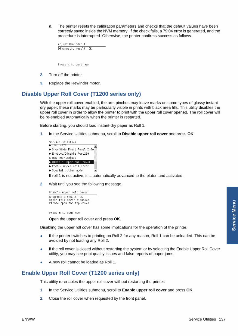
d. The printer resets the calibration parameters and checks that the default values have beencorrectly saved inside the NVM memory. If the check fails, a 79:04 error is generated, and theprocedure is interrupted. Otherwise, the printer confirms success as follows.
2. Turn off the printer.
3. Replace the Rewinder motor.
Disable Upper Roll Cover (T1200 series only)
With the upper roll cover enabled, the arm pinches may leave marks on some types of glossy instant-dry paper; these marks may be particularly visible in prints with black area fills. This utility disables theupper roll cover in order to allow the printer to print with the upper roll cover opened. The roll cover willbe re-enabled automatically when the printer is restarted.
Before starting, you should load instant-dry paper as Roll 1.
1. In the Service Utilities submenu, scroll to Disable upper roll cover and press OK.
If roll 1 is not active, it is automatically advanced to the platen and activated.
2. Wait until you see the following message.
Open the upper roll cover and press OK.
Disabling the upper roll cover has some implications for the operation of the printer.
● If the printer switches to printing on Roll 2 for any reason, Roll 1 can be unloaded. This can beavoided by not loading any Roll 2.
● If the roll cover is closed without restarting the system or by selecting the Enable Upper Roll Coverutility, you may see print quality issues and false reports of paper jams.
● A new roll cannot be loaded as Roll 1.
Enable Upper Roll Cover (T1200 series only)
This utility re-enables the upper roll cover without restarting the printer.
1. In the Service Utilities submenu, scroll to Enable upper roll cover and press OK.
2. Close the roll cover when requested by the front panel.
ENWW Service Utilities 137
Ser
vice
Men
u

3. Wait until you see the following message.
Press OK.
Special Cutter Mode
The purpose of this utility is to improve the cut quality for some papers that present some cut-qualityproblems (straightness problems) using the normal mode. When this mode is enabled, this utilitychanges the cutting mode for all generic natural tracing papers. This mode reduces the problems, butcuts more slowly.
1. In the Service Utilities submenu, scroll to Special cutter mode and press OK.
2. Press OK to enable special cutter mode or Cancel to disable it.
NOTE: Once enabled, this mode will remain in operation, even after the printer is restarted, until youdisable it using the same utility.
NOTE: Remember that only tracing papers are affected by this utility.
Service CalibrationsThe printer has several calibration procedures that must be performed under certain conditions.
NOTE: REMEMBER THAT CERTAIN CALIBRATIONS ARE REQUIRED EVEN IF AN ASSEMBLYHAS BEEN DISASSEMBLED TO GAIN ACCESS TO ANOTHER ASSEMBLY OR COMPONENT.
The following is a list of all internal service calibrations available in the printer. For instructions to enterthe service calibrations menu, see Entering the Service Calibrations Menu on page 139.
1. Paper Advance Calibration calibrates the nominal advance of the media to prevent print-qualityproblems. See Paper Advance Calibration on page 139.
2. Drop Detector Calibration calibrates the Drop Detector located in the Service Station with respectto the Carriage Assembly. See Drop Detector Calibration on page 145.
3. Line Sensor Calibration calibrates the intensity of the Line Sensor to ensure correct edge detectionand scan readings. See Line Sensor Calibration on page 147.
4. Calibrate Sheet Sensor calibrates the intensity of the Single Sheet Sensor to ensure correct sheet-edge detection. See Line Sensor Calibration on page 147.
138 Chapter 4 Service Menu ENWW
Service M
enu

NOTE: If all the Calibrations need to be performed (for example, when both the Formatter and theMain PCA have been replaced), you must perform them in the above order.
Entering the Service Calibrations Menu
1. Once the message “Ready” or “Ready for paper” is displayed on the front panel, press the Menukey.
2. To have the user to perform certain Service Utilities, once inside the “Main Menu”, press theDown arrow key and the Cancel key together. You are now in the Service Tools Menu.
3. For On-Site Engineers, once inside the “Main Menu”, press the Up arrow key and the Cancel keytogether. You are now in the Service Menu Menu.
NOTE: If the printer is not used for 135 seconds, the printer exits out of the Service Utilities Menuand you must repeat the above steps to enter Service Calibrations again.
NOTE: In some cases a quick press of a button may not be recognized by the printer. Whenpressing a button, be sure to press it deliberately and all the way to the bottom of its travel.
Paper Advance Calibration
The purpose of this Service Calibration is to calibrate the nominal advance of the media. This calibrationis necessary to control the exact movement of the media in order to avoid print quality problems likebanding.
If you need to perform a Paper Advance Calibration to solve a print quality problem, it is recommendedthat you first try the Paper Advance Calibration from the user's menu, which will calibrate the printer toa specific paper type.
NOTE: In order to perform the Paper Advance Calibration, you must order the Paper AdvanceCalibration Kit (Q6687-60093), which contains two sheets of HP Universal Instant-Dry Photo Glosspaper.
Perform the Service Accuracy Calibration whenever:
● Banding is detected in prints.
ENWW Service Calibrations 139
Ser
vice
Men
u

Service calibrations also need to be performed after removing or replacing certain printer components.If you have removed or replaced printer components, check the Service Calibration Guide to Removaland Installation on page 185 to see which tests and calibrations you need to perform.
The Paper Advance Calibration is split into two parts and should always be done in this order:
1. Print Calibration Pattern - The printer first calibrates the Analog Encoder and then prints the PaperAdvance Calibration pattern.
2. Scan Calibration Pattern - The printer scans the Paper Advance Calibration pattern in order tocalibrate the nominal advance of the media.
NOTE: Only scan the Calibration Pattern in the printer that was used to actually print it. Usingthe Calibration in a different printer could cause it to experience media advance problems. Afterscanning the Calibration Pattern, it should be discarded.
TIP: If the printer is a T1200 series, you are recommended to calibrate using the upper roll, which willgive better results.
Perform the Paper Advance Calibration as follows:
NOTE: Make sure that you unload media from the printer before performing the Paper AdvanceCalibration.
1. In the Service Calibrations submenu, scroll to Paper advance calibration and press OK.
2. In the Paper Advance Calibration submenu, scroll to Print Calibration Pattern and press OK.
3. When the following message appears on the front panel, you must select whether you would liketo continue with the calibration by pressing the OK key. Press Back or Cancel to exit the calibration.
4. If paper is detected, the printer will prompt you to remove the media. If paper is not detected, thecalibration will continue.
5. The printer will start to calibrate the Analog Encoder and the following message will be displayedon the Front Panel.
140 Chapter 4 Service Menu ENWW
Service M
enu

If the Calibration is not done or if the values are out of the limits, a warning message will appearon the Front Panel. In this case, try the following:
● Check that the printer has the latest firmware version. If not, update the firmware to the latestversion.
● Retry the Paper Advance Calibration.
6. Once the Analog Encoder has been calibrated correctly, the Front Panel prompts you to select thetype of media you will use. Use the Arrow keys to choose ROLL or SHEET media. Press theOK key to start the media load process.
7. The Front Panel prompts you to select the paper category you will use for the calibration. Usethe Arrow keys to scroll to your paper category and press the OK key to continue the media loadprocess.
8. The Front Panel prompts you to select the specific type of paper you will use for the calibration.Use the Arrow keys to scroll through the menu and the OK key to select your paper type.
9. The Front Panel prompts you to load the paper. Make sure you load the paper that correspondsto your paper type selection.
ENWW Service Calibrations 141
Ser
vice
Men
u

10. Once the media is loaded into the printer, the following message will appear on the Front Panel.
If roll media has been loaded instead of a cut sheet, it’s important that you open the cover of theloaded roll. After you press OK, the printer will automatically unroll 1 meter of media and roll it backagain to remove the back tension, and then start printing the pattern. Please note that opening theroll cover is crucial for avoiding potential paper jams during this operation. Press the OK key tocontinue.
11. Press OK to continue.
12. The printer advances and reels in about a meter of paper. The Front Panel displays the followingmessages:
● Advancing Paper
● Printing Pattern
13. The printer will start to print the Paper Advance Calibration Pattern. This could take several minutesduring which the following message will be displayed on the Front Panel.
14. Once the Accuracy Calibration Pattern has been printed successfully, the Front Panel will promptyou to continue.
15. Press the Enter key to continue.
16. If you used roll media to print the Paper Advance Calibration, the printer detects that media isloaded, and prompts you to lift the Media Lever.
17. Raise the media lever.
142 Chapter 4 Service Menu ENWW
Service M
enu
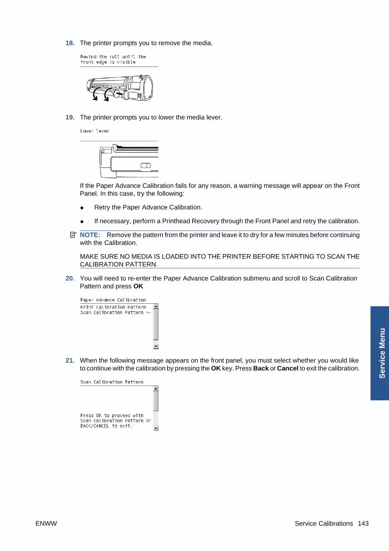
18. The printer prompts you to remove the media.
19. The printer prompts you to lower the media lever.
If the Paper Advance Calibration fails for any reason, a warning message will appear on the FrontPanel. In this case, try the following:
● Retry the Paper Advance Calibration.
● If necessary, perform a Printhead Recovery through the Front Panel and retry the calibration.
NOTE: Remove the pattern from the printer and leave it to dry for a few minutes before continuingwith the Calibration.
MAKE SURE NO MEDIA IS LOADED INTO THE PRINTER BEFORE STARTING TO SCAN THECALIBRATION PATTERN.
20. You will need to re-enter the Paper Advance Calibration submenu and scroll to Scan CalibrationPattern and press OK
21. When the following message appears on the front panel, you must select whether you would liketo continue with the calibration by pressing the OK key. Press Back or Cancel to exit the calibration.
ENWW Service Calibrations 143
Ser
vice
Men
u

22. A message will appear advising you that you will need to load the Calibration Pattern in to theprinter. Make sure that you rotate the printed pattern 90° clockwise and reload it printed-side down,so that the black arrows go into the printer first. Press the OK key to continue.
NOTE: Only scan the Calibration Pattern in the printer that was used to actually print it. Usingthe Calibration in a different printer could cause it to experience media advance problems.
After scanning the Calibration Pattern, it should be discarded. When loading the CalibrationPattern, use the Cutter blade on the Print Platen to align the edge of the sheet. If you follow thisadvice, you will prevent the cutter from cutting a section of the Calibration Pattern, which couldcause the Calibration to FAIL.
23. The Front Panel prompts you to select the paper category you used for the calibration. Select thesame paper that you used to perform the Paper Advance Calibration print. Use the Arrow keys toscroll to your paper category and press the OK key to continue the media load process.
24. The Front Panel prompts you to select the specific type of paper you used for the calibration. Usethe Arrow keys to scroll through the menu and the OK key to select your paper type.
25. Load the Calibration Pattern following the instructions on the Front Panel. Once the CalibrationPattern is loaded correctly, the following message will be displayed on the Front Panel. Pressthe OK key to continue.
26. The printer will scan the Calibration Pattern which could take several minutes. Once the calibrationis completed successfully, the following message will be displayed on the Front Panel. Pressthe OK key to continue.
144 Chapter 4 Service Menu ENWW
Service M
enu

If the Paper Advance Calibration fails for any reason, a warning message will appear on the FrontPanel. In this case, try the following:
● Check that the Calibration Pattern was not incorrectly cut (trimming the actual pattern) duringthe media load process. If this is the case, perform the Paper Advance Calibration againfrom step 1.
● Perform a Line Sensor Calibration. See Line Sensor Calibration on page 147.
● Replace the Line Sensor. See Line Sensor on page 280.
● If the problem continues, replace the Media Advance Driver. See Media Advance Driveon page 286.
Drop Detector Calibration
The purpose of this Service Calibration is to calibrate the Drop Detector (located in the Service Station)in relation to the Carriage Assembly. There are two menu options to calibrate the Drop Detector:
● Calibrate Drop Detector
● Reset Calibration Flag
Always perform the Reset Calibration Flag calibration BEFORE calibrating the drop detector.
Service calibrations also need to be performed after removing or replacing certain printer components.If you have removed or replaced printer components, check the Service Calibration Guide to Removaland Installation on page 185 to see which tests and calibrations you need to perform.
Reset Calibration Flag
Run this option before replacing the drop detector (service station), so that the printer will not try toperform a drop detection until the new drop detector has been calibrated.
1. In the Service Calibrations submenu, select Drop Detector calibration and press OK.
2. In the Drop Detector Calibration menu, scroll to Reset Calibration Flag and press OK
.
ENWW Service Calibrations 145
Ser
vice
Men
u
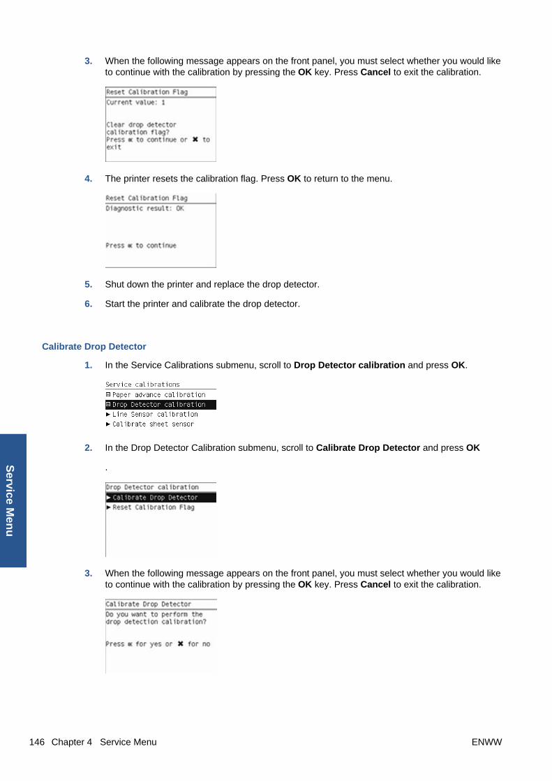
3. When the following message appears on the front panel, you must select whether you would liketo continue with the calibration by pressing the OK key. Press Cancel to exit the calibration.
4. The printer resets the calibration flag. Press OK to return to the menu.
5. Shut down the printer and replace the drop detector.
6. Start the printer and calibrate the drop detector.
Calibrate Drop Detector
1. In the Service Calibrations submenu, scroll to Drop Detector calibration and press OK.
2. In the Drop Detector Calibration submenu, scroll to Calibrate Drop Detector and press OK
.
3. When the following message appears on the front panel, you must select whether you would liketo continue with the calibration by pressing the OK key. Press Cancel to exit the calibration.
146 Chapter 4 Service Menu ENWW
Service M
enu

4. The printer will start to calibrate the Drop Detector, which takes about 30 seconds.
5. Once the Drop Detector has been calibrated, the results will be displayed on the Front Panel.Press OK to finish the calibration.
The offset is the displacement from the nominal carriage position for doing the drop detection.Window width refers to values captured by the drop detector sensor. The offset should be withinthe valid range, and the window width should be at least the minimum shown. If the values arecorrect, press OK to accept them. If not, the drop detector is not correctly installed, either becausethe service station has not been correctly installed in the scan axis or because the drop detectoris not correctly installed or not working properly. Press Cancel to reject the values.
CAUTION: Do not accept these values if they are not within the right range, as the printer will notwork properly.
6. Press OK to end the calibration.
Line Sensor Calibration
The purpose of this Service Calibration is to calibrate the intensity of the line sensor in the CarriagePCA. An incorrect calibration can result in edge-detection failures during media loading and incorrectreading of prints that are used for alignment or calibration.
Perform the Line Sensor Calibration in the following cases.
● If the edge detect procedure fails during media loading.
● If the Carriage is disassembled or replaced.
● If the Line Sensor is disassembled or replaced.
● If banding is detected in prints.
● If misalignment between colors is detected.
Service calibrations also need to be performed after removing or replacing certain printer components.If you have removed or replaced printer components, check the Service Calibration Guide to Removaland Installation on page 185 to see which tests and calibrations you need to perform.
ENWW Service Calibrations 147
Ser
vice
Men
u

CAUTION: Keep your hands away from the Print Platen during calibration, as the Carriage moves athigh speed and you could injure yourself or damage the Carriage Assembly.
The full calibration process
1. If possible, load a roll of glossy paper with a width of at least 24 inches into the printer before startingthe calibration. The printer will later reject paper that is too narrow or not glossy.
2. In the Service Calibrations submenu, scroll to Line Sensor calibration and press OK.
3. When the following message appears on the front panel, press the OK key to continue or theCancel key to exit the calibration. If the printer detects no paper, see The manual paper loadingprocess on page 149.
4. The printer calibrates the intensity of the LEDs and displays the results on the Front Panel.Press OK to continue or press Cancel to exit the calibration.
If the values are not within the range specified, an error appears on the Front Panel. In this case,repeat the calibration from the beginning. If necessary, replace the Line Sensor.
5. The next step is to calibrate the Line Sensor position. The printer prints a line of black dots andthen scans them.
6. Once the Line Sensor position has been calibrated, the results are displayed on the Front Panel.Press OK to continue or Cancel to exit.
148 Chapter 4 Service Menu ENWW
Service M
enu

7. If the calibration fails or the values are out of range, try the following solutions.
● Reseat the line sensor.
● Repeat the calibration again from the beginning.
● Replace the Line Sensor.
8. The printer now tries to align the printheads. When the following message appears on the frontpanel, press OK to continue or Cancel to exit.
9. If printhead alignment cannot be completed, try the following.
● Enter the Front Panel menu and retry printhead alignment from there. If the alignmentcompletes successfully, then perform color calibration.
● If the alignment fails again, check the alignment pattern to see whether any of the printheadsare printing incorrectly. If necessary, perform a printhead recovery through the Front Paneland retry printhead alignment.
10. If the printhead alignment ends successfully, you have completed the full Line Sensor calibrationprocess.
The manual paper loading process
1. If the printer detects no paper, the following message is displayed. If you think you can load papernormally, press Cancel and resume the full calibration process (see The full calibration processon page 148). Otherwise, press OK to proceed with manual loading.
NOTE: The manual loading process performs only a partial calibration, after which you shouldtry again to load roll paper and perform the full calibration.
2. The Front Panel prompts you to load the paper manually.
ENWW Service Calibrations 149
Ser
vice
Men
u

3. Feed a sheet of paper manually into the printer (the printer will not try to move it) until it fully coversthe right-hand size of the print platen. It must cover the line sensor so that the printer detects it. AnA4 or US Letter paper size is sufficient.
4. When you have loaded the paper, press OK. The printer starts the calibration process, and displaysthe results on the Front Panel if successful. Press OK to continue.
If the calibration fails, start again from the beginning. If necessary, try replacing the Line Sensor.
5. The Front Panel asks you to unload the paper. It then reminds you to reload roll paper in the normalway and perform the full Line Sensor calibration (see The full calibration process on page 148).
Calibrate Sheet Sensor
The purpose of this Service Calibration is to calibrate the single-sheet sensor. This sensor should becalibrated whenever a new sensor is installed, or if single sheets cannot be loaded.
1. In the Service Calibrations submenu, scroll to Calibrate sheet sensor and press OK.
2. Remove paper from the sheet sensor and press OK to continue.
150 Chapter 4 Service Menu ENWW
Service M
enu

3. When you see the following message, insert sheet paper into the sheet sensor and press OK tocontinue.
4. If the calibration was successful, a message appears such as the following. If you see an errormessage, check that the sheet sensor is connected, and retry the calibration.
ENWW Service Calibrations 151
Ser
vice
Men
u
5 Parts and Diagrams
● Printer Support
● Center Covers (Front)
● Roll Covers
● Center Covers (Rear)
● Right Cover
● Left Cover
● Right Hand Assemblies
● Left Hand Assemblies
● Carriage Assembly
● Scan-Axis Assemblies
● Paper Path Assemblies (Front)
● Paper Path Assemblies (Rear)
● Roll Supports
● Tool Kits
● Miscellaneous Parts
152 Chapter 5 Parts and Diagrams ENWW
Parts an
d D
iagram
s

Printer Support HP Part Number Part Description Printer Model Cross-reference
1 Q5669-60718 Leg Cover All
2 Q5669-60716 Leg Assembly All
3 Q6712-69001 Foot Assembly (includes 2 feet, graycolor)
T1200
3 CH639-69001 Foot Assembly (includes 2 feet,black color)
T770
4 Q6659-60237 Bin Assembly (includes Bin Support,gray color)
T1200 Bin Assemblyon page 188
4 CH639-69002 Bin Assembly (includes Bin Support,black color)
T770 Bin Assemblyon page 188
5 Q6659-60236 Cross-brace Assembly All
– Q5669-60730 Hardware Kit (Includes screws forLegs Assembly)
All
ENWW Printer Support 153
Par
ts a
nd
Dia
gra
ms
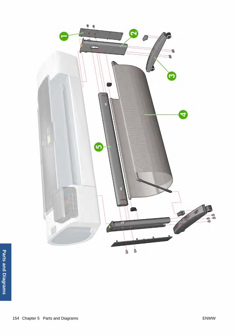
154 Chapter 5 Parts and Diagrams ENWW
Parts an
d D
iagram
s

Center Covers (Front) HP Part Number Part Description Printer Model Cross-reference
1 CH538-67030 Window All Window on page 365
2 CH538-67026 Top Cover T1200 Cover, Top on page 237
2 CH539-67011 Top Cover T770 Cover, Top on page 237
3 CK837-67025 Window Position Sensor All Window Position Sensoron page 368
4 Q6659-60089 Media Output Assembly All Media Output Assemblyon page 295
5 Q6687-60064 Front Cover All Cover, Front on page 228
6 CH538-67032 Front Panel T1200 Front Panel on page 258
6 CK837-67006 Front Panel T770 Front Panel on page 258
ENWW Center Covers (Front) 155
Par
ts a
nd
Dia
gra
ms

156 Chapter 5 Parts and Diagrams ENWW
Parts an
d D
iagram
s

Roll Covers HP Part Number Part Description Printer Model Cross-reference
1 CH538-67003 Upper Roll Cover Assembly withpinches
T1200 Roll Cover, Upperon page 327
1 CH539-67009 Upper Roll Cover Assembly BasicSV
T770 Roll Cover, Upperon page 327
2 CH538-67002 Lower Roll Cover Assembly withpinches
T1200 Roll Cover, Lower(T1200 only)on page 324
3 CH538-67050 Roll Cover Freewheel Assembly All Freewheel Assemblyon page 256
4 CH538-67037 Pinch Arm Assembly for Roll Cover T1200 Pinch Arm Assemblyon page 302
5 CH538-67047 Roll Cover Bi-stable Springs Leftand Right
T1200 Bi-stable Springs(T1200 only)on page 190
ENWW Roll Covers 157
Par
ts a
nd
Dia
gra
ms
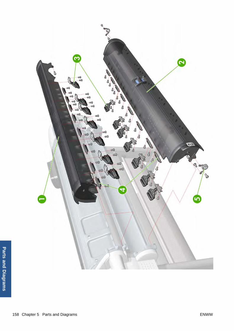
158 Chapter 5 Parts and Diagrams ENWW
Parts an
d D
iagram
s
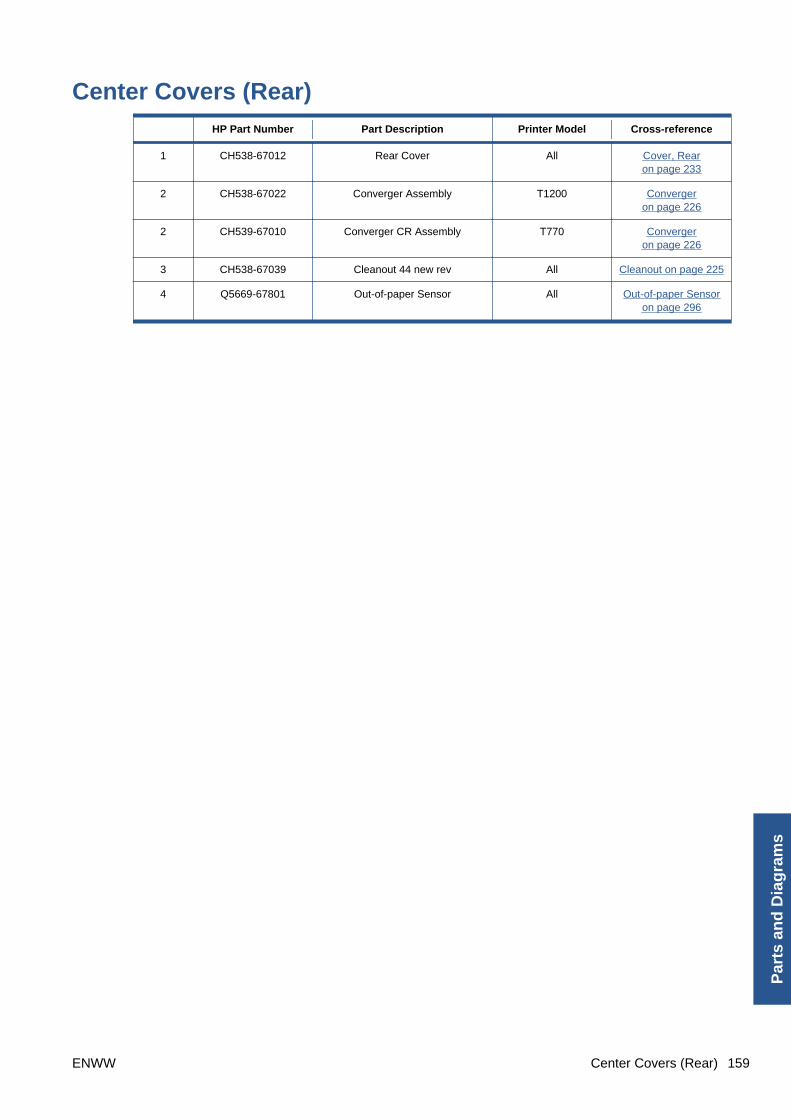
Center Covers (Rear) HP Part Number Part Description Printer Model Cross-reference
1 CH538-67012 Rear Cover All Cover, Rearon page 233
2 CH538-67022 Converger Assembly T1200 Convergeron page 226
2 CH539-67010 Converger CR Assembly T770 Convergeron page 226
3 CH538-67039 Cleanout 44 new rev All Cleanout on page 225
4 Q5669-67801 Out-of-paper Sensor All Out-of-paper Sensoron page 296
ENWW Center Covers (Rear) 159
Par
ts a
nd
Dia
gra
ms

160 Chapter 5 Parts and Diagrams ENWW
Parts an
d D
iagram
s

Right Cover HP Part Number Part Description Printer Model Cross-reference
1 CH538-67014 Right Cover T1200 Cover, Right on page 234
1 CH539-67006 Right Cover T770 Cover, Right on page 234
2 Q6675-60109 Integrated Front Trim (Left andRight)
All Front Trim, Right on page 262
3 CH538-67045 Right Ink Cartridge Door All Ink Cartridge Door, Righton page 266
ENWW Right Cover 161
Par
ts a
nd
Dia
gra
ms
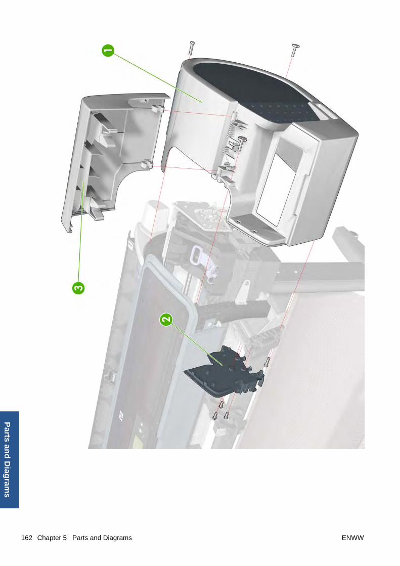
162 Chapter 5 Parts and Diagrams ENWW
Parts an
d D
iagram
s

Left Cover HP Part Number Part Description Printer Model Cross-reference
1 CH538-67017 Left Ink Cartridge Door T1200 Ink Cartridge Door, Lefton page 265
1 CH539-67008 Left Ink Cartridge Door T770 Ink Cartridge Door, Lefton page 265
2 Q6675-60109 Integrated Front Trim (Left andRight)
All Front Trim, Left on page 260
3 CH538-67005 Left Side Panel T1200 Panel, Left on page 299
3 CH539-67002 Left Side Panel T770 Panel, Left on page 299
4 CH538-67013 Left Cover with Ink Door T1200 Cover, Left on page 229
4 CH539-67005 Left Cover with Ink Door T770 Cover, Left on page 229
ENWW Left Cover 163
Par
ts a
nd
Dia
gra
ms

164 Chapter 5 Parts and Diagrams ENWW
Parts an
d D
iagram
s

Right Hand Assemblies HP Part Number Part Description Printer Model Cross-reference
1 Q6675-60043 Carriage Rail Oiler All Carriage Rail Oileron page 219
2 Q5669-67807 Pen to Paper Space (PPS)Solenoid
All Pen to Paper Space (PPS)Solenoid on page 300
3 CH538-67010 Scan-Axis Motor All Scan-axis Motor on page 337
4 Q5669-60667 Service Station Spittoon All Service Station on page 341
5 CH538-67040 Service Station (includes DropDetector and Service Station
Spittoon)
All Service Station on page 341
6 Q5669-60666 Drop Detector All Drop Detector on page 243
ENWW Right Hand Assemblies 165
Par
ts a
nd
Dia
gra
ms
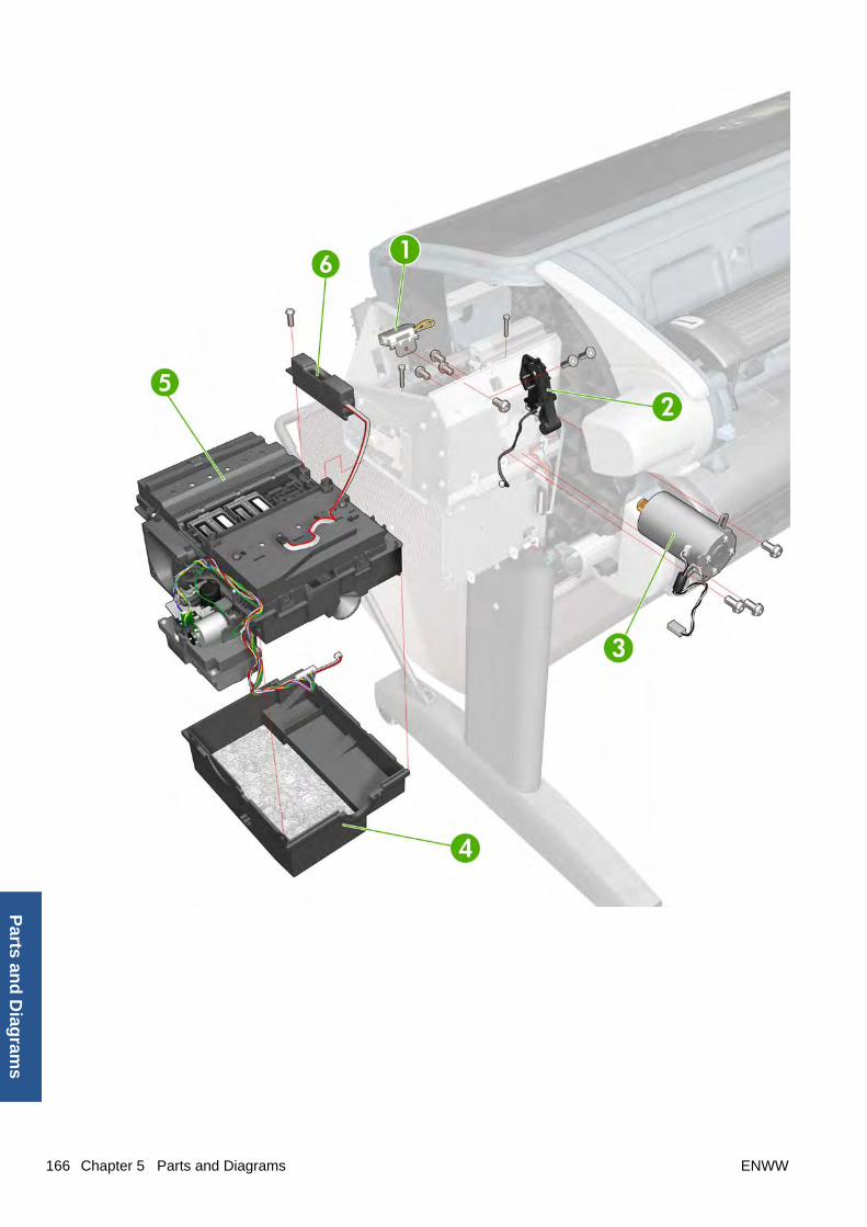
166 Chapter 5 Parts and Diagrams ENWW
Parts an
d D
iagram
s
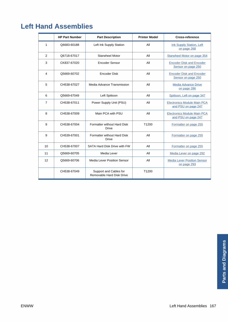
Left Hand Assemblies HP Part Number Part Description Printer Model Cross-reference
1 Q6683-60188 Left Ink Supply Station All Ink Supply Station, Lefton page 268
2 Q6718-67017 Starwheel Motor All Starwheel Motor on page 354
3 CK837-67020 Encoder Sensor All Encoder Disk and EncoderSensor on page 250
4 Q5669-60702 Encoder Disk All Encoder Disk and EncoderSensor on page 250
5 CH538-67027 Media Advance Transmission All Media Advance Driveon page 286
6 Q5669-67049 Left Spittoon All Spittoon, Left on page 347
7 CH538-67011 Power Supply Unit (PSU) All Electronics Module Main PCAand PSU on page 247
8 CH538-67009 Main PCA with PSU All Electronics Module Main PCAand PSU on page 247
9 CH538-67004 Formatter without Hard DiskDrive
T1200 Formatter on page 255
9 CH539-67001 Formatter without Hard DiskDrive
All Formatter on page 255
10 CH538-67007 SATA Hard Disk Drive with FW All Formatter on page 255
11 Q5669-60705 Media Lever All Media Lever on page 292
12 Q5669-60706 Media Lever Position Sensor All Media Lever Position Sensoron page 293
CH538-67049 Support and Cables forRemovable Hard Disk Drive
T1200
ENWW Left Hand Assemblies 167
Par
ts a
nd
Dia
gra
ms
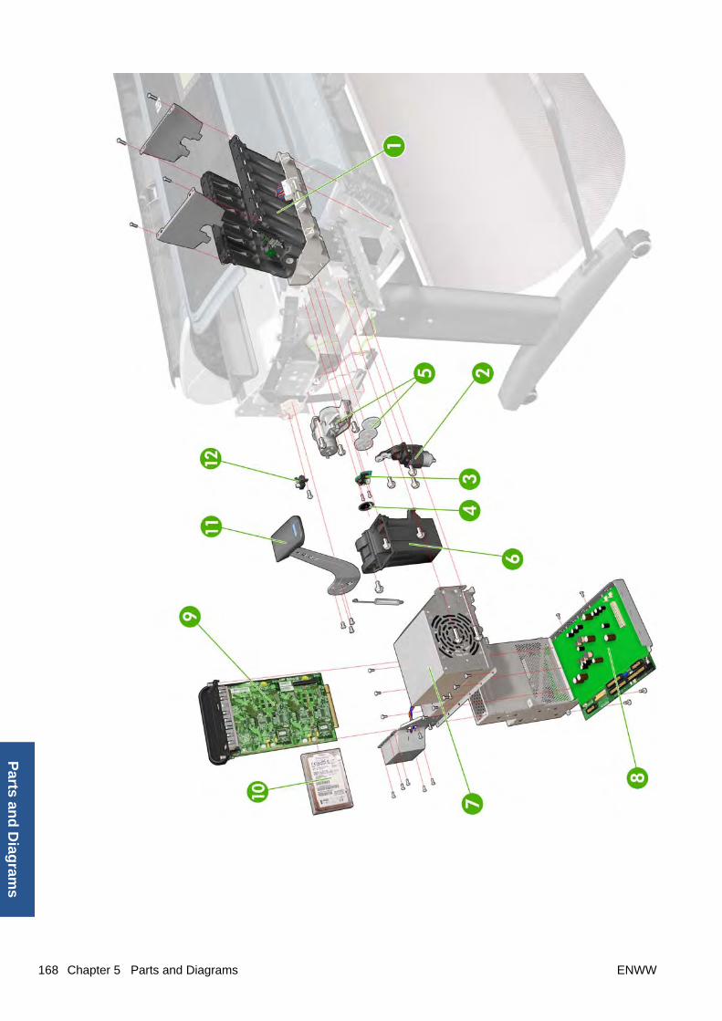
168 Chapter 5 Parts and Diagrams ENWW
Parts an
d D
iagram
s
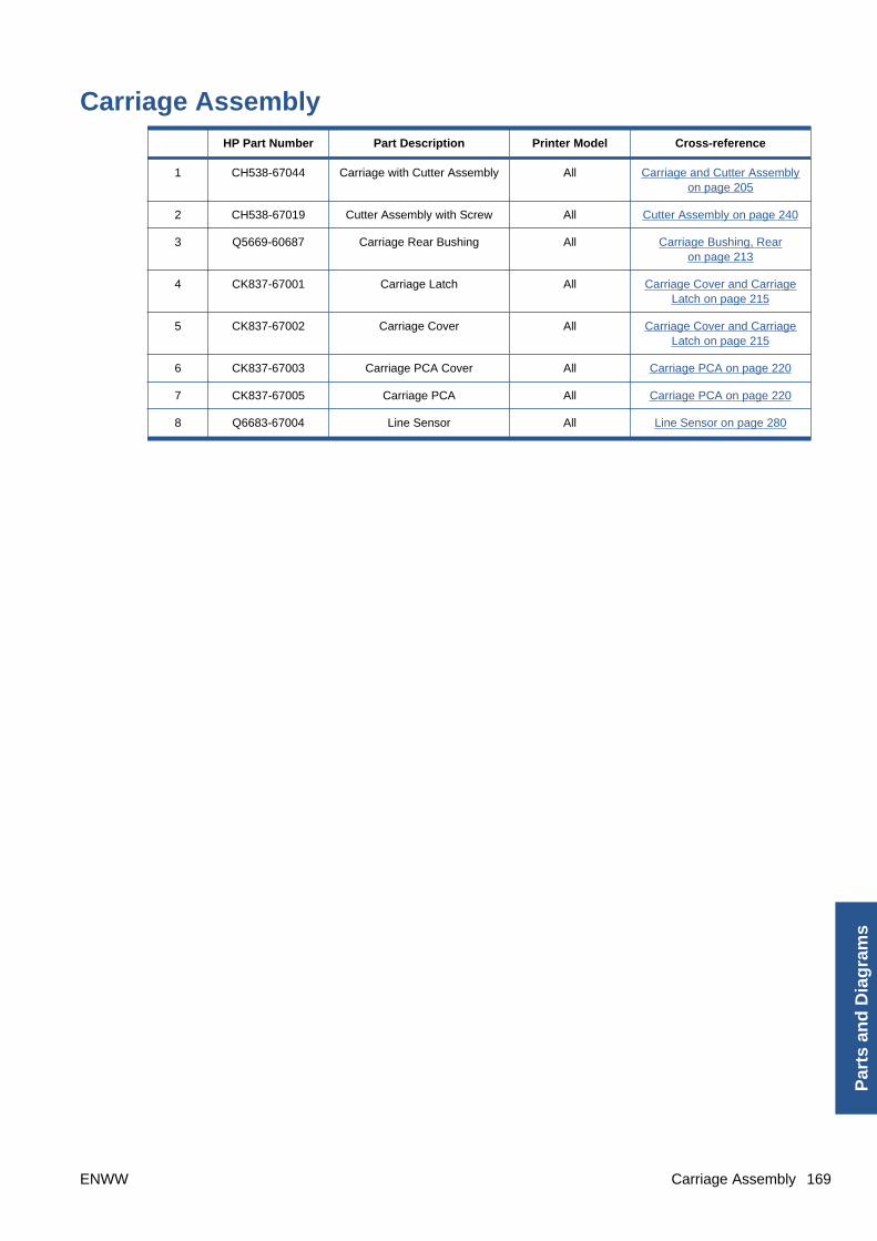
Carriage Assembly HP Part Number Part Description Printer Model Cross-reference
1 CH538-67044 Carriage with Cutter Assembly All Carriage and Cutter Assemblyon page 205
2 CH538-67019 Cutter Assembly with Screw All Cutter Assembly on page 240
3 Q5669-60687 Carriage Rear Bushing All Carriage Bushing, Rearon page 213
4 CK837-67001 Carriage Latch All Carriage Cover and CarriageLatch on page 215
5 CK837-67002 Carriage Cover All Carriage Cover and CarriageLatch on page 215
6 CK837-67003 Carriage PCA Cover All Carriage PCA on page 220
7 CK837-67005 Carriage PCA All Carriage PCA on page 220
8 Q6683-67004 Line Sensor All Line Sensor on page 280
ENWW Carriage Assembly 169
Par
ts a
nd
Dia
gra
ms

170 Chapter 5 Parts and Diagrams ENWW
Parts an
d D
iagram
s

Scan-Axis Assemblies HP Part Number Part Description Printer Model Cross-reference
1 CK839-67005 Encoder Strip (includingEncoder Strip Spring and Nut)
All Encoder Strip, spring andattachment nut on page 253
2 CH538-67018 Belt Assembly with BeltTensioner (3)
All Belt Assembly on page 188
4 CH538-67025 Tube System with Trailing Cable All Trailing Cable on page 356
ENWW Scan-Axis Assemblies 171
Par
ts a
nd
Dia
gra
ms

172 Chapter 5 Parts and Diagrams ENWW
Parts an
d D
iagram
s

Paper Path Assemblies (Front) HP Part Number Part Description Printer Model Cross-reference
1 Q6687-60060 Starwheel Assembly All Starwheel Assemblyon page 348
2 Q6677-60018 Print Zone Overdrive All Print Zone Overdriveon page 312
3 Q5669-67054 Starwheel Support Assembly All
4 Q6659-60182 Full Bleed Foam Kit All Full Bleed Foam on page 263
5 CH538-67064 Bumper Cutter Actuator (Leftand Right)
All
ENWW Paper Path Assemblies (Front) 173
Par
ts a
nd
Dia
gra
ms

174 Chapter 5 Parts and Diagrams ENWW
Parts an
d D
iagram
s

Paper Path Assemblies (Rear) HP Part Number Part Description Printer Model Cross-reference
1 Q6687-60085 Pinchwheel Assembly All Pinchwheel Assemblyon page 304
2 Q6677-60019 Left Roll Guide All Roll Guide, Left on page 328
3 Q6687-67001 Spindle All Spindle on page 346
4 Q6675-60044 Right Roll Guide All Roll Guide, Right on page 329
ENWW Paper Path Assemblies (Rear) 175
Par
ts a
nd
Dia
gra
ms
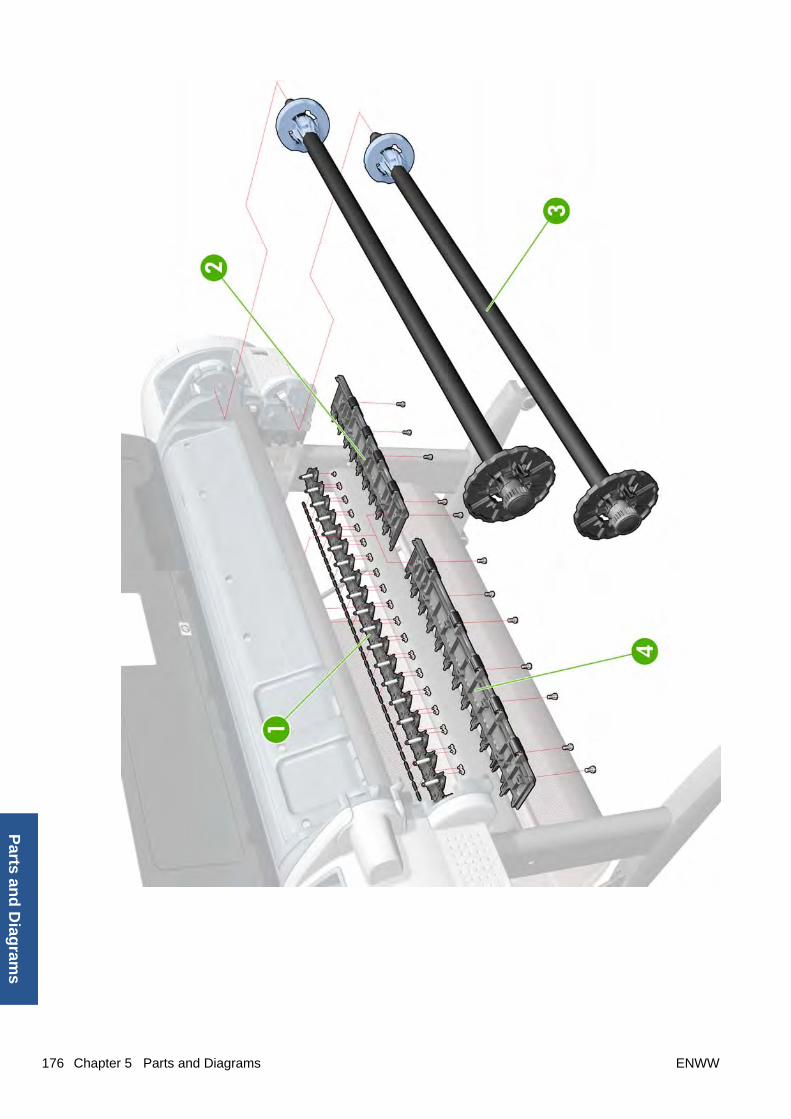
176 Chapter 5 Parts and Diagrams ENWW
Parts an
d D
iagram
s

Roll Supports HP Part Number Part Description Printer Model Cross-reference
1 CH538-67028 Upper Right Support All Roll Support, Upper Righton page 336
2 CH538-67015 Upper Left Support T1200 Roll Support, Upper Lefton page 334
2 CH539-67007 Upper Left Support withoutSensor
T770 Roll Support, Upper Lefton page 334
3 CH538-67065 Upper Left Support Sensor withCable
All Roll Support Sensor, UpperLeft on page 333
4 CH538-67046 Wall Spacers, Left and Right All Wall Spacers on page 363
5 CH538-67041 Lower Left Support Sensor withCable
T1200 Roll Support Sensor, Lower Left(T1200 only) on page 333
6 CH538-67016 Lower Left Support T1200 Roll Support, Lower Left (T1200only) on page 330
7 CH538-67052 Lower Roll Support Bumpers,Left and Right
T1200 Bumpers, Left and Righton page 196
8 CH538-67051 Upper Roll Support Bumpers,Left and Right
All Bumpers, Left and Righton page 196
9 CH538-67029 Lower Right Support T1200 Roll Support, Lower Right(T1200 only) on page 331
10 CH538-67033 Single Sheet Sensor All Single Sheet Sensoron page 345
ENWW Roll Supports 177
Par
ts a
nd
Dia
gra
ms

178 Chapter 5 Parts and Diagrams ENWW
Parts an
d D
iagram
s
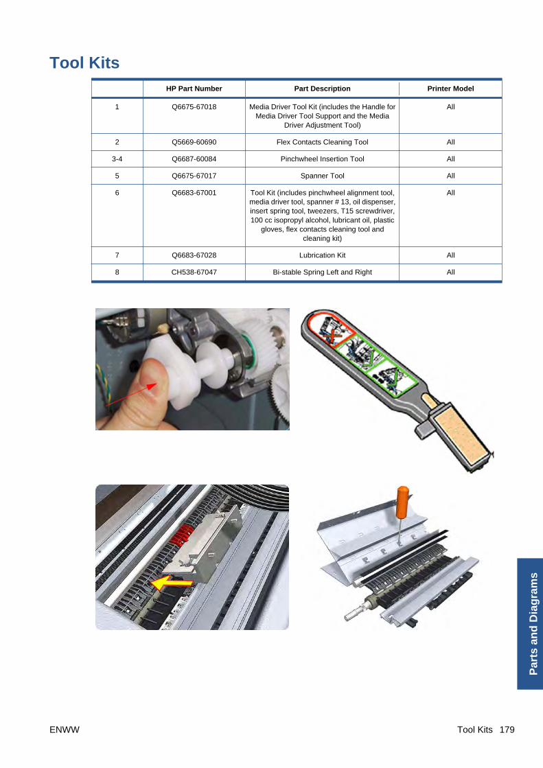
Tool Kits HP Part Number Part Description Printer Model
1 Q6675-67018 Media Driver Tool Kit (includes the Handle forMedia Driver Tool Support and the Media
Driver Adjustment Tool)
All
2 Q5669-60690 Flex Contacts Cleaning Tool All
3-4 Q6687-60084 Pinchwheel Insertion Tool All
5 Q6675-67017 Spanner Tool All
6 Q6683-67001 Tool Kit (includes pinchwheel alignment tool,media driver tool, spanner # 13, oil dispenser,insert spring tool, tweezers, T15 screwdriver,100 cc isopropyl alcohol, lubricant oil, plastic
gloves, flex contacts cleaning tool andcleaning kit)
All
7 Q6683-67028 Lubrication Kit All
8 CH538-67047 Bi-stable Spring Left and Right All
ENWW Tool Kits 179
Par
ts a
nd
Dia
gra
ms

Miscellaneous PartsHP Part Number Part Description Printer Model
CH538-67006 Cables Kit T1200
CH539-67003 Cables Kit T770
CH538-67020 Serial Number Label All
CH538-67024 Preventive Maintenance Kit #1 All
CH538-67040 Preventive Maintenance Kit #2 All
Q6687-60093 Paper Advance Calibration Kit All
CK837-67008 Harness Cables, Left and Right All
Q6675-67004 Ink System Purgers (6 units) All
Q6675-67005 Ink System Purgers (100 units) All
CH538-67005 Left Side Panel SV T1200
CH539-67002 Left Side Panel SV T770
CH538-67019 Cutter Assembly with Screw SV All
CH538-67037 Pinch Arm Assembly for Roll Cover SV T1200
CH538-67050 Roll Cover Freewheel SV All
CH538-67051 Roll Cover Upper Bumper Left and Right SV All
CH538-67053 Support Label CN375-80001 Nameplate SV All
CH538-67054 Support Label CH538-80023 Nameplate SV All
CH539-67019 Support Label CH539-80001 Nameplate SV All
CH539-67020 Support Label CK834-80001 Nameplate SV All
180 Chapter 5 Parts and Diagrams ENWW
Parts an
d D
iagram
s

6 Removal and Installation
● Introduction
● Service Calibration Guide to Removal and Installation
● Belt Assembly
● Bin Assembly
● Bi-stable Springs (T1200 only)
● Bumpers, Left and Right
● Cable Harness
● Carriage and Cutter Assembly
● Carriage Bushing, Rear
● Carriage Cover and Carriage Latch
● Carriage Rail Oiler
● Carriage PCA
● Cleanout
● Converger
● Cover, Front
● Cover, Left
● Cover, Rear
● Cover, Right
● Cover, Top
● Cutter Assembly
● Drop Detector
● EE Box
● Electronics Module Main PCA and PSU
● Encoder Disk and Encoder Sensor
● Encoder Strip
● Encoder Strip, spring and attachment nut
● Formatter
ENWW 181
Rem
ova
l an
d In
stal
lati
on

● Freewheel Assembly
● Front Panel
● Front Trim, Left
● Front Trim, Right
● Full Bleed Foam
● Hard Disk Drive
● Ink Cartridge Door, Left
● Ink Cartridge Door, Right
● Ink Supply Station, Left
● Ink Supply Tubes
● Ink Supply Tubes Support Rail
● Line Sensor
● Media Advance Drive
● Media Lever
● Media Lever Position Sensor
● Media Output Assembly
● Out-of-paper Sensor
● Panel, Left
● Pen to Paper Space (PPS) Solenoid
● Pinch Arm Assembly
● Pinchwheel Assembly
● Print Zone Overdrive
● PSU
● Real-time Clock Battery
● Roll Cover Bumpers, Lower
● Roll Cover Bumpers, Upper
● Roll Cover, Lower (T1200 only)
● Roll Cover, Upper
● Roll Guide, Left
● Roll Guide, Right
● Roll Support, Lower Left (T1200 only)
● Roll Support, Lower Right (T1200 only)
● Roll Support Sensor, Lower Left (T1200 only)
● Roll Support Sensor, Upper Left
182 Chapter 6 Removal and Installation ENWW
Rem
oval an
d In
stallation

● Roll Support, Upper Left
● Roll Support, Upper Right
● Scan-axis Motor
● Service Station
● Single Sheet Sensor
● Spindle
● Spittoon, Left
● Starwheel Assembly
● Starwheel Lifter, Left
● Starwheel Lifter, Right
● Starwheel Motor
● Trailing Cable
● Wall Spacers
● Window
● Window Position Sensor
ENWW 183
Rem
ova
l an
d In
stal
lati
on

IntroductionThis chapter is a step-by-step guide to the removal and installation of the key components of the printer.You may find it useful to check off the steps as they are performed. Use the illustrations for eachprocedure to identify the parts referred to in the text.
The procedures appear in order of removal. The whole machine can be stripped down by starting at thebeginning of this chapter and working through the subsequent procedures.
NOTE: Before using this chapter to remove and install a new component, always make sure that youhave performed the relevant service test from Chapter 4. If the test passes you will not need to replacethe component.
Safety Precautions
Review the instructions identified by WARNING and CAUTION symbols before you service the printer.Follow these warnings and cautions for your protection and to avoid damaging the printer.
NOTE: Serious shock hazard leading to death or injury may result if you do not take the followingprecautions:
● Ensure that the ac power outlet (mains) has a protective earth (ground) terminal.
● Switch the plotter off, and disconnect it from the power source prior to performing any maintenance.
● Prevent water or other liquids from running onto electrical components or circuits, or throughopenings in the module.
Electrostatic Discharge (ESD) Precautions
To prevent damage to the printer circuits from high-voltage electrostatic discharge (ESD):
1. Do not wear clothing that is subject to static build-up.
2. Do not handle integrated circuits (ICs) in carpeted areas.
3. Do not remove an IC or a printed circuit assembly (PCA) from its conductive foam pad or conductivepackaging until you are ready to install it.
4. Ground (earth) your body while disassembling and working on the printer.
5. After removing a cover from the printer, attach an earthing (ground) lead between the PCA commonand earth ground. Touch all tools to earth ground to remove static charges before using them onthe printer.
6. After removing any PCA from the printer, place it on a conductive foam pad or into its conductivepackaging to prevent ESD damage to any ICs on the PCA.
Required Tools
All the special tools and equipment required to disassemble, service and repair the printer are providedin the Toolkit P/N Q6683-67001. Some tools can be ordered separately from the toolkit. See ToolKits on page 179.
The Toolkit contains the following tools:
Description/Comments HP Part Number
13 mm Combination Spanner Q6675-67011
Alcohol Q6675-60091
184 Chapter 6 Removal and Installation ENWW
Rem
oval an
d In
stallation

Description/Comments HP Part Number
Allen Key #2 Q6675-60041
Cleaning Cloth 9300-2531
Flex Contacts Cleaning Support Q1271-40384
Lubricant Oil Q6675-60090
Media Driver Adjustment Tool Q6675-67009
Handle for Media Driver Tool Support Q6675-67010
Spanner Q6675-67011
Oil Dispenser Q6675-60062
Manual Pinch Arm Alignment Tool Q5669-20595
Spring Insertion Tool Q5669-20594
Protective Plastic Gloves Q6675-60035
Screwdriver 8710-2456
Tweezers Q6675-60037
T Series Cleaning Assembly C6071-60218
You will also need the following standard hand tools:
Standard Tool Requirements
Description/Comments Size
Long Torx Screwdriver 1/4 inch drive
Torx Bit (75 mm) 8
10
15
20
Philips Screwdriver 1
Pliers N/A
Snips N/A
Pipe Spanner 5.5 mm
Flat-bladed Screwdriver N/A
Service Calibration Guide to Removal and InstallationUsing the Service Calibration Guide
When you remove most printer components, you will need to perform a particular set of ServiceCalibrations and Diagnostic tests to ensure proper printer performance.
The Service Calibration Table explains which service calibrations and diagnostic tests need to beperformed whenever you remove and install particular printer components.
ENWW Service Calibration Guide to Removal and Installation 185
Rem
ova
l an
d In
stal
lati
on

The calibrations and tests must be performed in the order in which they are listed.
NOTE: Even if you do not replace the removed component with a new component, you still need toperform the calibrations indicated in the table.
The Service Calibration Table
Component Service calibrations and tests
Belt Assembly Carriage Assembly, Scan Axis, Line Sensor Calibration. After replacement, reset Life Counters.
Carriage Assembly Carriage Assembly, Scan Axis, Line Sensor Calibration, Cutter. After replacement, reset LifeCounters.
Carriage Cover Carriage Assembly, Line Sensor Calibration, Electronics Module.
Carriage Latch Carriage Assembly, Line Sensor Calibration, Electronics Module.
Carriage PCA Carriage Assembly, Line Sensor Calibration, Electronics Module.
Carriage Rear Bushing Carriage Assembly, Scan Axis, Line Sensor Calibration, Cutter.
Cleanout Assembly Carriage Assembly.
Cover, Top Electronics Module.
Cutter Assembly Cutter.
Drop Detector Reset Calibration Flag, Drop Detector Calibration, Service Station.
Encoder Disk Paper Drive, Paper Advance Calibration, Electronics Module.
Encoder Sensor Paper Drive, Paper Advance Calibration, Electronics Module.
Encoder Strip Scan Axis.
Formatter Electronics Module.
Front Panel Electronics Module.
Hard Disk Drive Electronics Module.
Ink Supply Station, Left Ink Delivery System. After replacement, reset Life Counters.
Ink Supply Station,Right
Ink Delivery System.
Ink Supply TubesSupport Rail
Electronics Module, Sensors.
Line Sensor Line Sensor Calibration, Electronics Module.
Main PCA Electronics Module.
Media Advance Drive Paper Drive, Paper Advance Calibration, Electronics Module.
Media Advance Roller Paper Drive, Paper Advance Calibration, Electronics Module, Sensors.
Media Lever PositionSensor
Sensors.
Out-of-paper Sensor Carriage Assembly.
Pen to Paper Space(PPS) Solenoid
PRS.
Pinch Roller Paper Drive, Sensors.
Pinchwheel Assembly Paper Drive, Sensors.
Power Supply Unit Electronics Module.
186 Chapter 6 Removal and Installation ENWW
Rem
oval an
d In
stallation

Component Service calibrations and tests
PreventiveMaintenance Kit #1
Carriage Assembly, Scan Axis, Line Sensor Calibration, Sensors. After replacement, reset LifeCounters.
PreventiveMaintenance Kit #2
Service Station, Drop Detector Calibration. After replacement, reset Life Counters.
Primer Assembly Service Station, Drop Detector Calibration.
Print Zone Overdrive Starwheel Lifter.
Roll Guide, Left andRight
Carriage Assembly.
Roll Support, Right Rewinder, Paper Advance Calibration.
Scan-Axis Motor Carriage Assembly, Scan Axis, Line Sensor Calibration. After replacement, reset Life Counters.
Service Station Reset Calibration Flag, Drop Detector Calibration, Service Station. After replacement, reset LifeCounters.
Service StationSpittoon
Service Station, Drop Detector Calibration.
Single Sheet Sensor Sensors.
Starwheel Assembly Starwheel Lifter.
Starwheel Lifter, Left Starwheel Lifter, Electronics Module.
Starwheel Lifter, Right –
Starwheel Motor Starwheel Lifter, Electronics Module.
Support Sensor, Upperand Lower Left
Sensors.
Trailing Cable and InkSupply Tubes
Carriage Assembly, Electronics Module, Scan Axis, Line Sensor Calibration. After replacement, resetLife Counters.
Window PositionSensor
Carriage Assembly, Electronics Module, Sensors.
Performing the Service Calibrations and Diagnostic Tests
When you are ready to perform the service calibrations and diagnostic tests that correspond to thecomponent you have installed or replaced, consult the following sections for procedures:
● Paper Drive Test on page 96.
● Electronics Module Test on page 98.
● Carriage Assembly Test on page 102.
● Sensors Test on page 105.
● Rewinder Test on page 107.
● Ink Delivery System (IDS) Test on page 109.
● Service Station Test on page 114.
● Paper Advance Calibration on page 139.
● Drop Detector Calibration on page 145.
● Line Sensor Calibration on page 147.
ENWW Service Calibration Guide to Removal and Installation 187
Rem
ova
l an
d In
stal
lati
on

Belt Assembly
Removal
1. Switch off the printer and remove the power cable.
2. Remove the Carriage Assembly. See Carriage Assembly on page 169.
3. Slide the Belt Assembly out of the attachment on the Carriage Assembly.
4. Remove the Belt Tensioner Assembly.
NOTE: When you finish installing or replacing this component, you must perform the necessaryService Calibrations. To find which calibrations you must perform, see Service Calibration Guide toRemoval and Installation on page 185.
Bin Assembly
Removal
1. Switch off the printer and remove the power cable.
2. Lay out the components of the basket.
188 Chapter 6 Removal and Installation ENWW
Rem
oval an
d In
stallation

3. Fit the basket supports to the stand legs, one to each leg.
4. Fit the two short tubes to the printer’s feet, one on the front of each foot. Each tube should clickinto place.
5. Attach the basket’s front tubes to the two short tubes on each foot.
ENWW Bin Assembly 189
Rem
ova
l an
d In
stal
lati
on
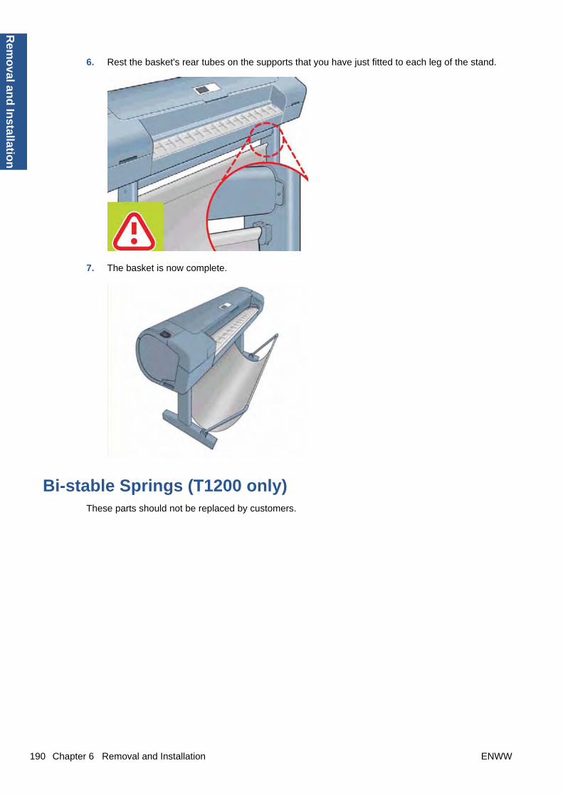
6. Rest the basket's rear tubes on the supports that you have just fitted to each leg of the stand.
7. The basket is now complete.
Bi-stable Springs (T1200 only)These parts should not be replaced by customers.
190 Chapter 6 Removal and Installation ENWW
Rem
oval an
d In
stallation

Removal
1. Remove the Roll Cover, Lower (T1200 only) on page 324.
2. Unscrew the Left Bi-stable Spring from the Lower Roll Cover.
3. Unscrew the Right Bi-stable Spring from the Lower Roll Cover.
Installation
1. There are two pre-loaded Bi-stable Springs, one for the left side (gold link) and one for the rightside (black link). There are two screws for each Bi-stable Spring (total four screws).
ENWW Bi-stable Springs (T1200 only) 191
Rem
ova
l an
d In
stal
lati
on

2. Screw the right Bi-stable Spring (black link) onto the right side of the Lower Roll Cover.
3. Screw the left Bi-stable Spring (gold link) onto the left side of the Lower Roll Cover.
4. Hold the Roll Cover with two hands while mounting it in the Roll Support.
5. Insert the Lower Roll Cover right-side hinge into the Lower Right Roll Support pin.
192 Chapter 6 Removal and Installation ENWW
Rem
oval an
d In
stallation

6. Insert the Lower Roll Cover left-side hinge into the Lower Left Roll Support pin.
7. Screw the Lower Roll Cover to the Lower Right Roll Support.
8. Screw the Lower Roll Cover to the Lower Left Roll Support.
ENWW Bi-stable Springs (T1200 only) 193
Rem
ova
l an
d In
stal
lati
on

9. Close the Lower Roll Cover until the other end of the Bi-stable Screw is in front of the hole on theLower Left Roll Support (if necessary, hold the Roll Cover for a moment with your head).
10. Screw the left pre-loaded Bi-stable Spring to the Lower Left Roll Support. Do not let the cover closecompletely.
11. Screw the right pre-loaded Bi-stable Spring to the Lower Right Roll Support.
12. Close the Lower Roll Cover completely.
194 Chapter 6 Removal and Installation ENWW
Rem
oval an
d In
stallation

13. Free one end of the right metal link of the right Bi-stable Spring.
14. Free the other end of the right metal link of the right Bi-stable Spring (if necessary, play slightly withthe Lower Roll Cover).
15. Free one end of the left metal link of the left Bi-stable Spring (if necessary, play slightly with theLower Roll Cover).
ENWW Bi-stable Springs (T1200 only) 195
Rem
ova
l an
d In
stal
lati
on

16. Free the other end of the metal link of the left Bi-stable Spring.
17. Store the metal links that you have removed.
Bumpers, Left and Right
Removal
1. Switch off the printer and remove the power cable.
2. Remove the Cover, Right on page 234.
3. Remove the Cover, Left on page 229.
4. Remove the T-15 screw that secures the right bumper.
196 Chapter 6 Removal and Installation ENWW
Rem
oval an
d In
stallation

5. Remove the right bumper.
6. Remove the T-15 screw that secures the left bumper.
7. Remove the left bumper.
Installation
1. Switch off the printer and remove the power cable.
2. Remove the Cover, Right on page 234.
3. Remove the Cover, Left on page 229.
ENWW Bumpers, Left and Right 197
Rem
ova
l an
d In
stal
lati
on

4. Attach the left bumper. Make sure to snap the bumper on to both parts shown.
5. Secure the left bumper to the printer with a T-15 screw.
198 Chapter 6 Removal and Installation ENWW
Rem
oval an
d In
stallation
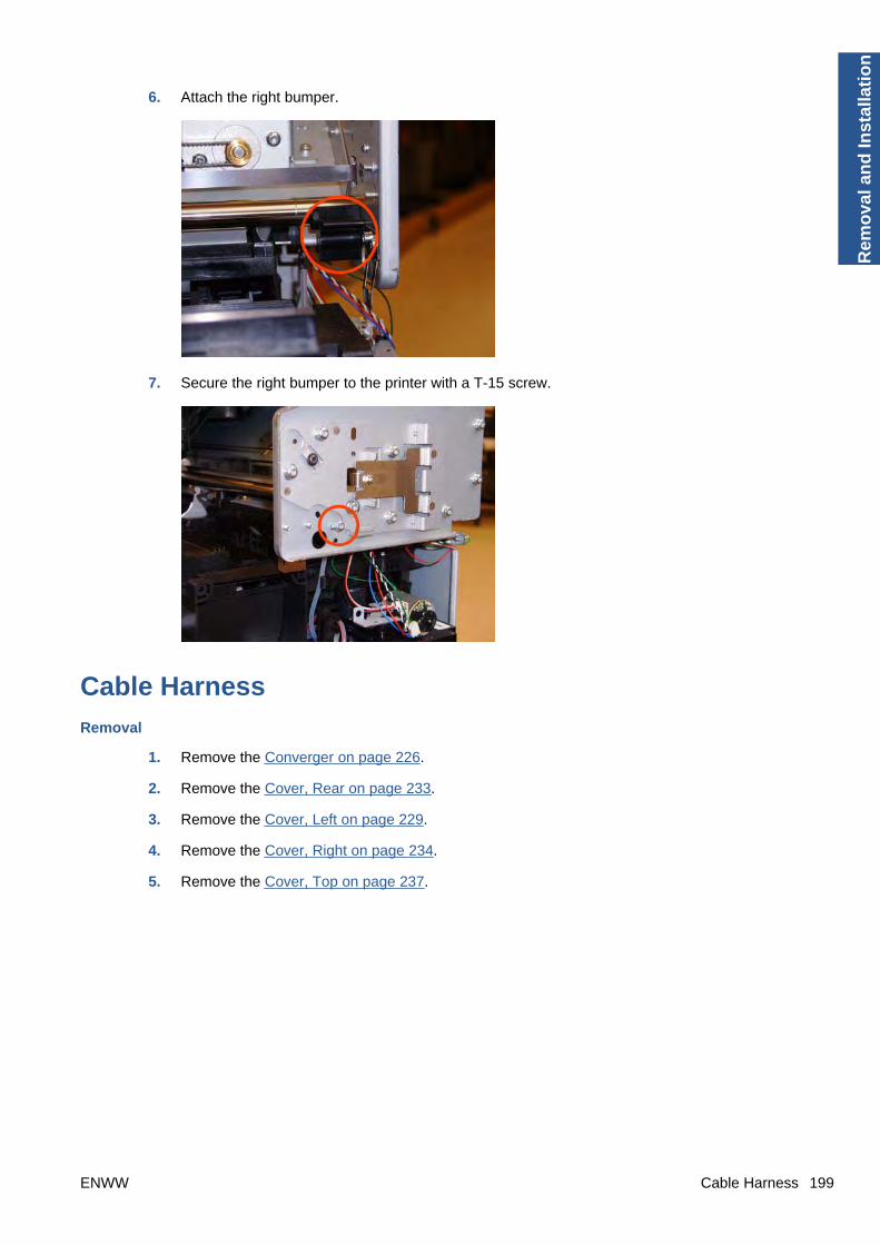
6. Attach the right bumper.
7. Secure the right bumper to the printer with a T-15 screw.
Cable Harness
Removal
1. Remove the Converger on page 226.
2. Remove the Cover, Rear on page 233.
3. Remove the Cover, Left on page 229.
4. Remove the Cover, Right on page 234.
5. Remove the Cover, Top on page 237.
ENWW Cable Harness 199
Rem
ova
l an
d In
stal
lati
on
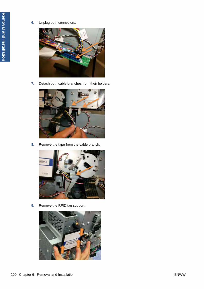
6. Unplug both connectors.
7. Detach both cable branches from their holders.
8. Remove the tape from the cable branch.
9. Remove the RFID tag support.
200 Chapter 6 Removal and Installation ENWW
Rem
oval an
d In
stallation

10. Detach both cable branches.
11. Unscrew all nine cable ties from the upper cable branch.
12. Keep the cable ties and screws to for reuse after replacing the cable.
13. Unplug both connectors shown in the picture.
ENWW Cable Harness 201
Rem
ova
l an
d In
stal
lati
on

14. Unplug the Window Sensor cable.
15. Pull both upper cable branches under the left arc.
16. Detach the cable from the cable tie.
17. Unplug the connector.
202 Chapter 6 Removal and Installation ENWW
Rem
oval an
d In
stallation
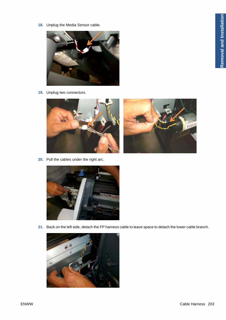
18. Unplug the Media Sensor cable.
19. Unplug two connectors.
20. Pull the cables under the right arc.
21. Back on the left side, detach the FP harness cable to leave space to detach the lower cable branch.
ENWW Cable Harness 203
Rem
ova
l an
d In
stal
lati
on

22. Detach the lower cable branch.
23. Unplug four connectors.
24. Pull the lower cable branch back under the right arc.
204 Chapter 6 Removal and Installation ENWW
Rem
oval an
d In
stallation

Carriage and Cutter Assembly
Removal
1. Switch off the printer and remove the power cable.
2. Remove the Cover, Front on page 228.
3. Remove the Cover, Right on page 234.
4. Remove the Cover, Left on page 229.
5. Remove the Front Panel on page 258.
6. Remove the Cover, Top on page 237.
7. Remove the Encoder Strip, spring and attachment nut on page 253.
8. If necessary, manually move the Carriage Assembly fully right into the docking station.
9. Disconnect the ribbon cable of the Trailing Cables from the Electronics Module.
10. Unroute the Trailing Cables.
ENWW Carriage and Cutter Assembly 205
Rem
ova
l an
d In
stal
lati
on
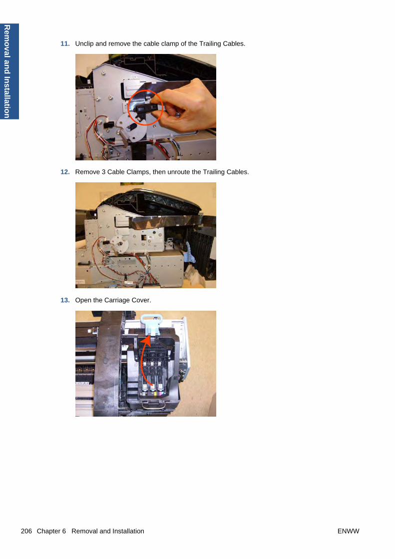
11. Unclip and remove the cable clamp of the Trailing Cables.
12. Remove 3 Cable Clamps, then unroute the Trailing Cables.
13. Open the Carriage Cover.
206 Chapter 6 Removal and Installation ENWW
Rem
oval an
d In
stallation

14. Remove all the Printheads.
15. Unscrew the small cover of the Carriage PCA.
16. Remove the small cover of the Carriage PCA.
ENWW Carriage and Cutter Assembly 207
Rem
ova
l an
d In
stal
lati
on

17. Disconnect the ribbon cable of the Trailing Cable from the Carriage PCA.
18. Open the latch, and remove the four T-15 screws that secure the Ink Supply Tubes to the CarriageAssembly.
19. Carefully lift out the Ink Supply Tubes and close the carriage cover at the same time.
208 Chapter 6 Removal and Installation ENWW
Rem
oval an
d In
stallation

20. Close and lock the Carriage Cover.
21. Loosen the T-10 uncapping screw sufficiently so you can manually move the Carriage Assemblyin step 26.
22. Push the Carriage Assembly into the print path.
ENWW Carriage and Cutter Assembly 209
Rem
ova
l an
d In
stal
lati
on
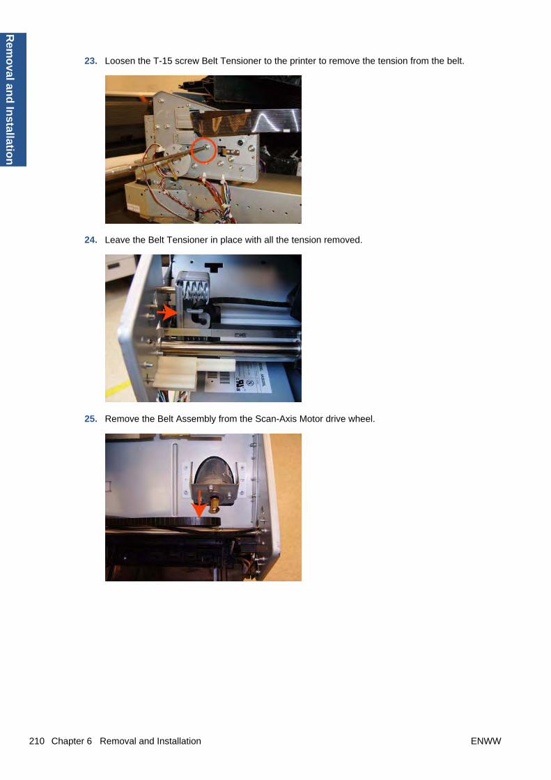
23. Loosen the T-15 screw Belt Tensioner to the printer to remove the tension from the belt.
24. Leave the Belt Tensioner in place with all the tension removed.
25. Remove the Belt Assembly from the Scan-Axis Motor drive wheel.
210 Chapter 6 Removal and Installation ENWW
Rem
oval an
d In
stallation
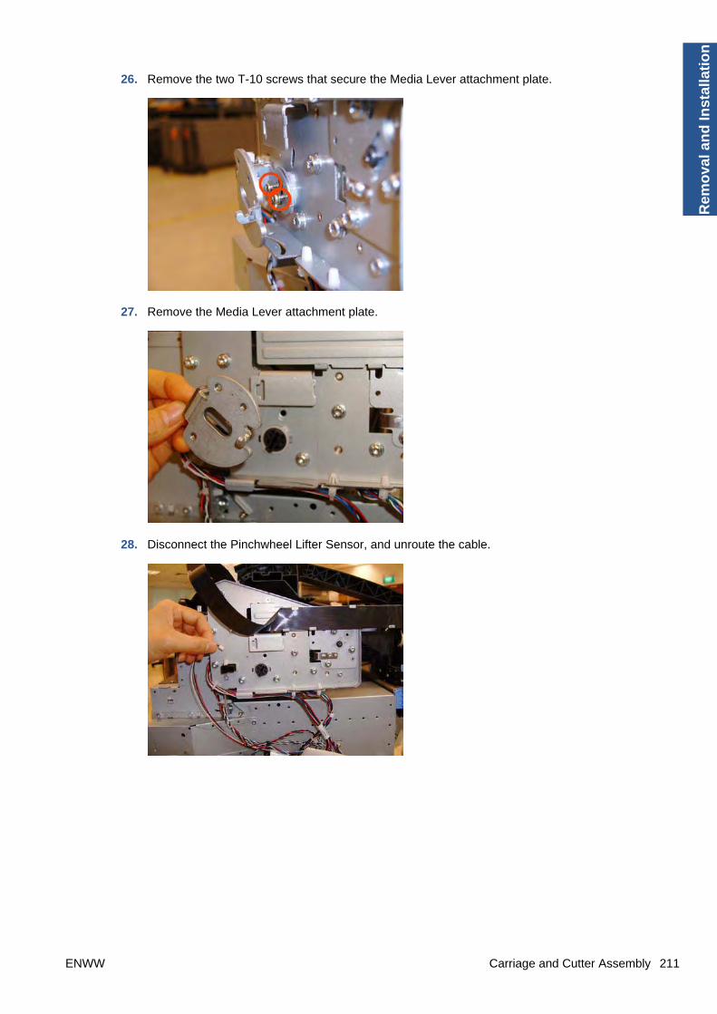
26. Remove the two T-10 screws that secure the Media Lever attachment plate.
27. Remove the Media Lever attachment plate.
28. Disconnect the Pinchwheel Lifter Sensor, and unroute the cable.
ENWW Carriage and Cutter Assembly 211
Rem
ova
l an
d In
stal
lati
on
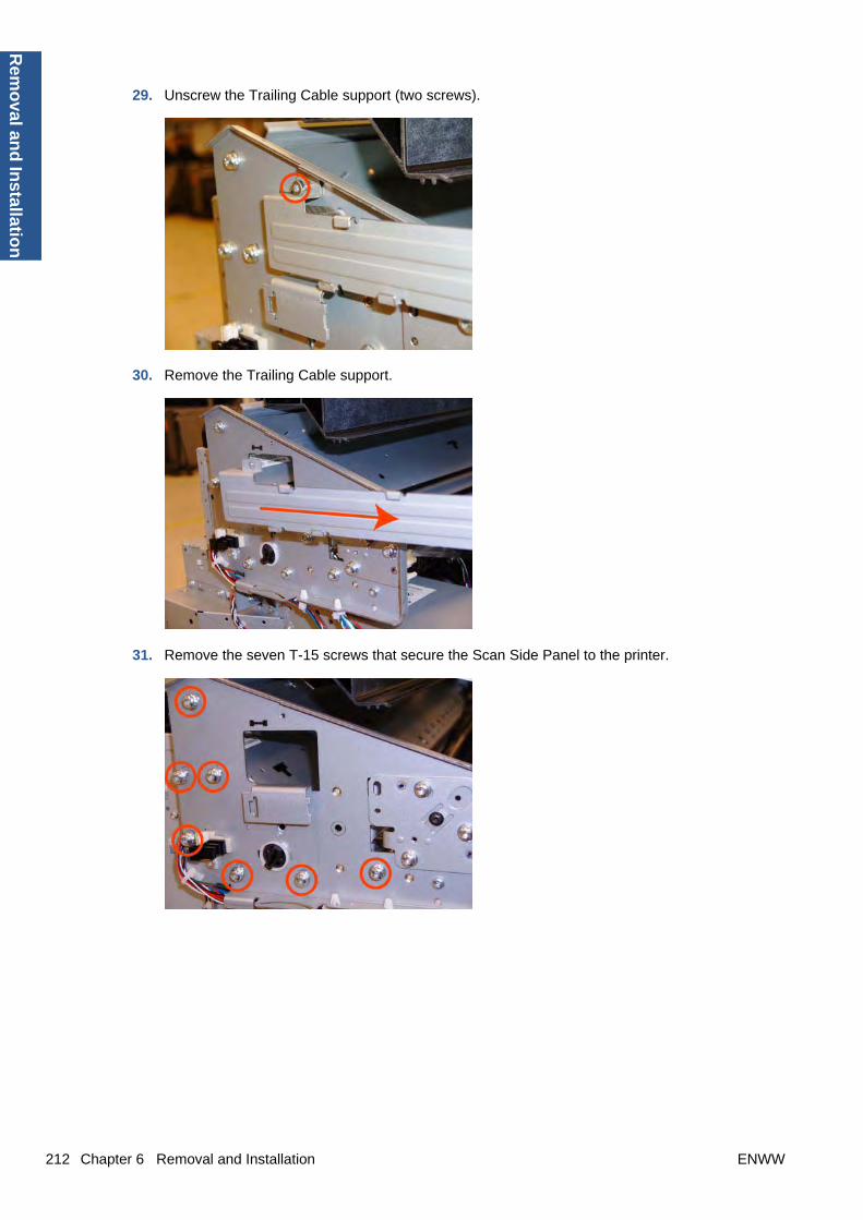
29. Unscrew the Trailing Cable support (two screws).
30. Remove the Trailing Cable support.
31. Remove the seven T-15 screws that secure the Scan Side Panel to the printer.
212 Chapter 6 Removal and Installation ENWW
Rem
oval an
d In
stallation

32. Remove the Scan Side Panel.
33. Carefully slide the Carriage Assembly and Belt Assembly out of the printer (and the Trailing Cableif you are removing it with the Carriage Assembly).
CAUTION: Be careful not to damage the PRS Slider.
NOTE: When you reinstall the Carriage Assembly, take care not to damage the PRS Slider.
NOTE: When you finish installing or replacing this component, you must perform the necessaryService Calibrations. To find which calibrations you must perform, see Service Calibration Guide toRemoval and Installation on page 185.
Carriage Bushing, Rear
Removal
1. Switch off the printer and remove the power cable.
2. Remove the Cover, Front on page 228.
3. Remove the Cover, Right on page 234.
4. Remove the Cover, Left on page 229.
5. Remove the Cutter Assembly on page 240.
6. Remove the Front Panel on page 258.
7. Remove the Cover, Top on page 237.
8. Remove the Window Position Sensor on page 368.
ENWW Carriage Bushing, Rear 213
Rem
ova
l an
d In
stal
lati
on

9. Remove the Encoder Strip, spring and attachment nut on page 253.
10. Remove the Carriage Assembly on page 169.
11. Squeeze the left hand clip of the Carriage Rear Bushing sufficiently to be able to release it fromthe Carriage Assembly.
12. Rotate the Carriage Rear Bushing vertically and remove it from the Carriage Assembly.
NOTE: When you reinstall the Carriage Rear Bushing, use the Oil and Oil Dispenser from theLubrication Kit to add 2 or 3 drops of oil to the small depression in it.
NOTE: When you finish installing or replacing this component, you must perform the necessaryService Calibrations. To find which calibrations you must perform, see Service Calibration Guide toRemoval and Installation on page 185.
214 Chapter 6 Removal and Installation ENWW
Rem
oval an
d In
stallation

Carriage Cover and Carriage Latch
Removal
1. Switch off the printer and remove the power cable.
2. Remove the Cover, Right on page 234.
3. Open the Carriage Cover.
4. Remove all the Printheads.
5. Unscrew the small cover of the Carriage PCA.
ENWW Carriage Cover and Carriage Latch 215
Rem
ova
l an
d In
stal
lati
on

6. Remove the small cover of the Carriage PCA.
7. Disconnect the ribbon Trailing Cable from the Carriage PCA.
8. Remove the four T-15 screws that secure the Ink Supply Tubes to the Carriage Assembly.
216 Chapter 6 Removal and Installation ENWW
Rem
oval an
d In
stallation

9. Carefully lift out the Ink Supply Tubes and close the carriage cover at the same time.
10. Close and lock the Carriage Cover.
11. Carefully move the Ink Supply Tubes into the print path.
ENWW Carriage Cover and Carriage Latch 217
Rem
ova
l an
d In
stal
lati
on
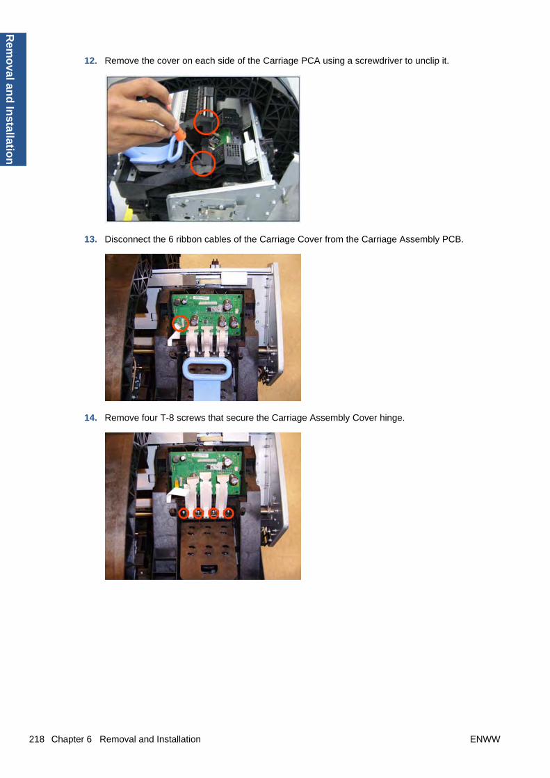
12. Remove the cover on each side of the Carriage PCA using a screwdriver to unclip it.
13. Disconnect the 6 ribbon cables of the Carriage Cover from the Carriage Assembly PCB.
14. Remove four T-8 screws that secure the Carriage Assembly Cover hinge.
218 Chapter 6 Removal and Installation ENWW
Rem
oval an
d In
stallation

15. Carefully lift the Carriage Cover in the vertical position to remove it from the Carriage Assembly.
When you finish installing or replacing this component, you must perform the necessary ServiceCalibrations. To find which calibrations you must perform, see Service Calibration Guide to Removaland Installation on page 185.
Carriage Rail Oiler
Removal
1. Switch off the printer and remove the power cable.
2. Remove the Cover, Right on page 234.
3. Remove the T-20 Carriage Rail Oiler attachment screw.
ENWW Carriage Rail Oiler 219
Rem
ova
l an
d In
stal
lati
on

4. Remove the Carriage Rail Oiler from the printer.
5. Add 2 or 3 drops of oil in the depression where the Slider fits.
NOTE: When you reinstall the Carriage Rail Oiler, use the Oil and Oil Dispenser from the LubricationKit to add 2 or 3 drops of oil to the foam of the Carriage Rail Oiler and in the small depression of theCarriage Rear Bushing.
Carriage PCA
Removal
1. Switch off the printer and remove the power cable.
2. Remove the Cover, Right on page 234.
220 Chapter 6 Removal and Installation ENWW
Rem
oval an
d In
stallation

3. Open the Carriage Cover.
4. Remove all the Printheads.
5. Unscrew the small cover of the Carriage PCA.
ENWW Carriage PCA 221
Rem
ova
l an
d In
stal
lati
on

6. Remove the small cover of the Carriage PCA.
7. Disconnect the ribbon Trailing Cable from the Carriage PCA.
8. Remove the four T-15 screws that secure the Ink Supply Tubes to the Carriage Assembly.
222 Chapter 6 Removal and Installation ENWW
Rem
oval an
d In
stallation

9. Carefully lift out the Ink Supply Tubes and close the carriage cover at the same time.
10. Close and lock the Carriage Cover.
11. Carefully move the Ink Supply Tubes into the print path.
ENWW Carriage PCA 223
Rem
ova
l an
d In
stal
lati
on
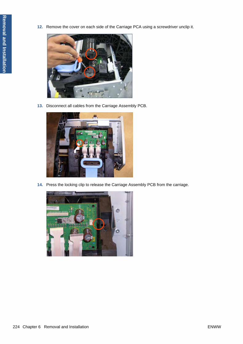
12. Remove the cover on each side of the Carriage PCA using a screwdriver unclip it.
13. Disconnect all cables from the Carriage Assembly PCB.
14. Press the locking clip to release the Carriage Assembly PCB from the carriage.
224 Chapter 6 Removal and Installation ENWW
Rem
oval an
d In
stallation
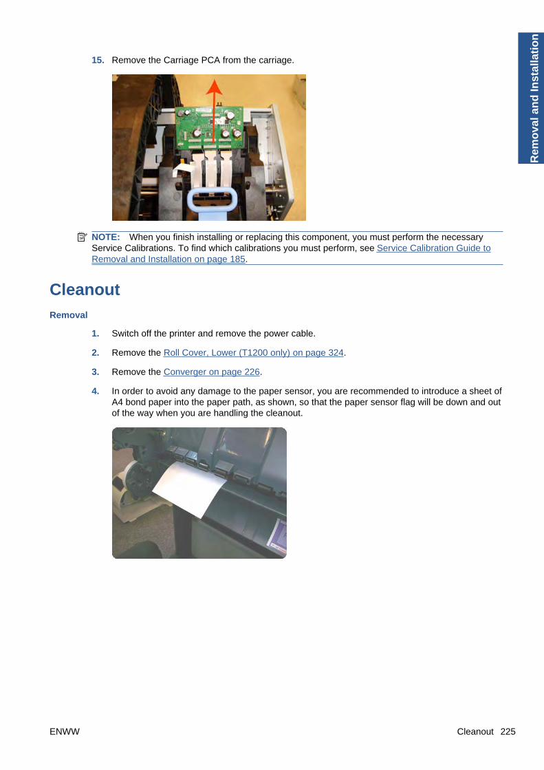
15. Remove the Carriage PCA from the carriage.
NOTE: When you finish installing or replacing this component, you must perform the necessaryService Calibrations. To find which calibrations you must perform, see Service Calibration Guide toRemoval and Installation on page 185.
Cleanout
Removal
1. Switch off the printer and remove the power cable.
2. Remove the Roll Cover, Lower (T1200 only) on page 324.
3. Remove the Converger on page 226.
4. In order to avoid any damage to the paper sensor, you are recommended to introduce a sheet ofA4 bond paper into the paper path, as shown, so that the paper sensor flag will be down and outof the way when you are handling the cleanout.
ENWW Cleanout 225
Rem
ova
l an
d In
stal
lati
on

5. Unscrew the screws as shown.
6. First extract the right side of the cleanout, as shown, and then the left side. Be careful with thepaper sensor cable.
7. Disconnect the paper sensor cable connector.
ConvergerSwitch off the printer and remove the power cable.
Removal
1. Open the upper roll cover and rewind the upper roll.
226 Chapter 6 Removal and Installation ENWW
Rem
oval an
d In
stallation

2. Remove the upper roll and spindle.
3. Rewind and remove the lower roll in the same way.
4. Remove the screw on the left side of the converger at the rear of the printer.
5. Move the converger slightly in the direction of the arrow.
ENWW Converger 227
Rem
ova
l an
d In
stal
lati
on
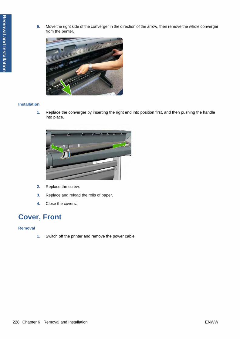
6. Move the right side of the converger in the direction of the arrow, then remove the whole convergerfrom the printer.
Installation
1. Replace the converger by inserting the right end into position first, and then pushing the handleinto place.
2. Replace the screw.
3. Replace and reload the rolls of paper.
4. Close the covers.
Cover, Front
Removal
1. Switch off the printer and remove the power cable.
228 Chapter 6 Removal and Installation ENWW
Rem
oval an
d In
stallation
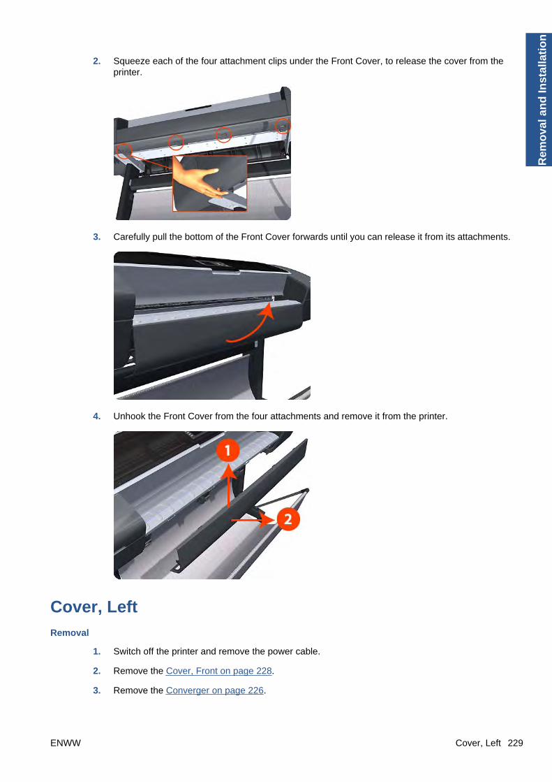
2. Squeeze each of the four attachment clips under the Front Cover, to release the cover from theprinter.
3. Carefully pull the bottom of the Front Cover forwards until you can release it from its attachments.
4. Unhook the Front Cover from the four attachments and remove it from the printer.
Cover, Left
Removal
1. Switch off the printer and remove the power cable.
2. Remove the Cover, Front on page 228.
3. Remove the Converger on page 226.
ENWW Cover, Left 229
Rem
ova
l an
d In
stal
lati
on

4. Remove the Panel, Left on page 299.
5. Unclip the spring from the attachment points on the Media Lever and Left Cover.Cover).
6. Remove three T-20 screws that secure the Media Lever.
7. Use a flat-bladed screwdriver to unclip the two attachment clips of the Formatter Housing.
230 Chapter 6 Removal and Installation ENWW
Rem
oval an
d In
stallation

8. Lift the Formatter Housing out of the printer.
9. Remove one T-15 screw that secures the Left Cover (top rear, accessible under the FormatterHousing).
10. Remove one T-15 screw that secures the Left Cover (bottom rear).
ENWW Cover, Left 231
Rem
ova
l an
d In
stal
lati
on
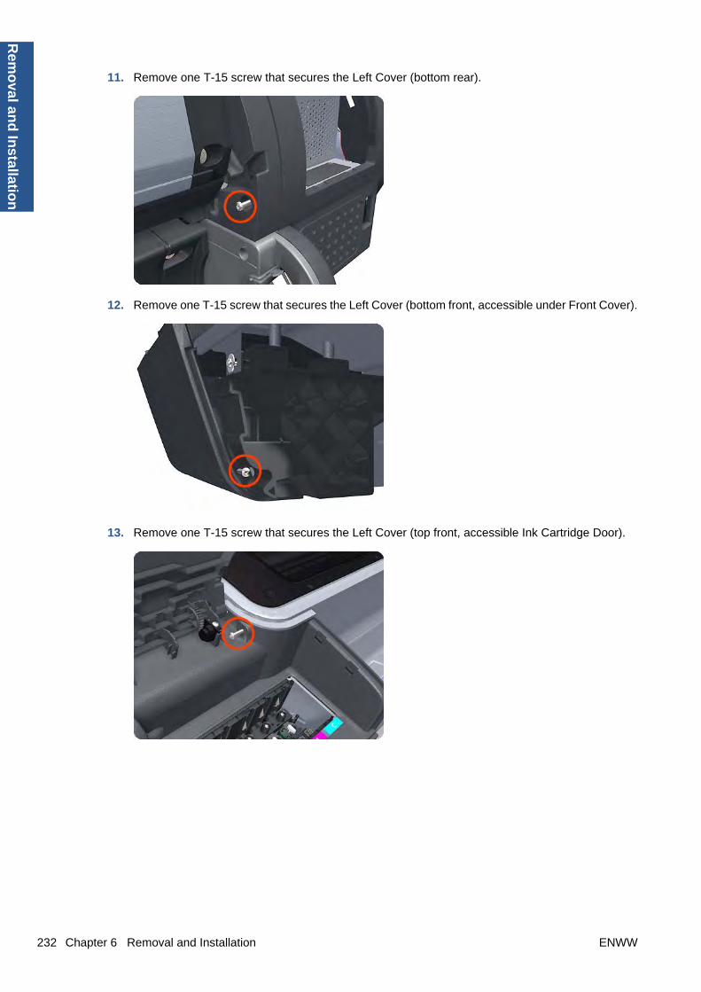
11. Remove one T-15 screw that secures the Left Cover (bottom rear).
12. Remove one T-15 screw that secures the Left Cover (bottom front, accessible under Front Cover).
13. Remove one T-15 screw that secures the Left Cover (top front, accessible Ink Cartridge Door).
232 Chapter 6 Removal and Installation ENWW
Rem
oval an
d In
stallation
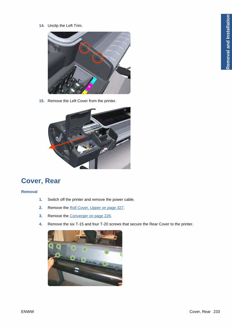
14. Unclip the Left Trim.
15. Remove the Left Cover from the printer.
Cover, Rear
Removal
1. Switch off the printer and remove the power cable.
2. Remove the Roll Cover, Upper on page 327.
3. Remove the Converger on page 226.
4. Remove the six T-15 and four T-20 screws that secure the Rear Cover to the printer.
ENWW Cover, Rear 233
Rem
ova
l an
d In
stal
lati
on

5. Remove the Rear Cover from the printer.
Cover, Right
Removal
1. Switch off the printer and remove the power cable.
2. Remove the Cover, Front on page 228.
3. Remove the Converger on page 226.
4. Open the Right Ink Cartridge Door by applying sharp pressure to the right side of the door andlifting firmly where the door meets the Right Cover. Use your hands. When the door is unclippedfrom the pressure applied to the right side of the door, you will hear a sound that corresponds tothe clip.
NOTE: Do not use a screwdriver or other tool to open the Right Ink Cartridge Door.
234 Chapter 6 Removal and Installation ENWW
Rem
oval an
d In
stallation

5. Remove one T-15 screw that secures the Right Cover to the printer (at the rear of the printer).
6. Remove one T-15 screw that secures the Right Cover to the printer (at the rear of the printer).
7. Remove one T-15 screw that secures the Right Cover to the printer (at the rear of the printer).
ENWW Cover, Right 235
Rem
ova
l an
d In
stal
lati
on

8. Remove one T-15 screw that secures the Right Cover to the printer (accessible under the FrontCover).
9. Remove one T-15 screw that secures the Right Cover to the printer.
10. Unclip the Right Trim.
236 Chapter 6 Removal and Installation ENWW
Rem
oval an
d In
stallation

11. Remove the Right Cover from the printer.
Cover, Top
Removal
1. Switch off the printer and remove the power cable.
2. Remove the Window on page 365.
3. Remove the Cover, Right on page 234.
4. Remove the Cover, Left on page 229.
5. Remove the Cover, Rear on page 233.
6. Remove the Front Panel on page 258.
7. Remove the four T-15 top screws that secure the Top Cover to the printer.
ENWW Cover, Top 237
Rem
ova
l an
d In
stal
lati
on

8. Remove the front T-15 screw that secures the front left side of the Top Cover to the printer.
9. Carefully pull the attachment clip forward until you can lift the bottom left corner of the Top Coverapproximately 10 mm.
10. Remove the front T-15 screw that secures the front left side of the Top Cover to the printer.
238 Chapter 6 Removal and Installation ENWW
Rem
oval an
d In
stallation

11. Carefully pull the attachment clip forward until you can lift the bottom left corner of the Top Coverapproximately 10 mm.
12. Lift the Top Cover of the printer sufficiently to gain access to the Front Panel ribbon cable.
13. Unroute the Front Panel ribbon cable from the two cable clamps on the bottom surface of the TopCover.
ENWW Cover, Top 239
Rem
ova
l an
d In
stal
lati
on

14. Lift the Top Cover off the printer.
Cutter AssemblyThis part can be replaced by customers who have the appropriate flier.
Removal and installation
1. At the front panel, select the Ink menu and then Replace printheads. The Carriage Assemblymoves to the left and stops in the correct position to remove the printheads.
2. Turn off the printer, using the Power key on the front panel and then the power switch at the rear.
240 Chapter 6 Removal and Installation ENWW
Rem
oval an
d In
stallation

3. Open the window.
4. Locate the cutter on the right, beside the printhead carriage.
5. Unscrew the cutter.
6. Move the cutter left and then up.
ENWW Cutter Assembly 241
Rem
ova
l an
d In
stal
lati
on
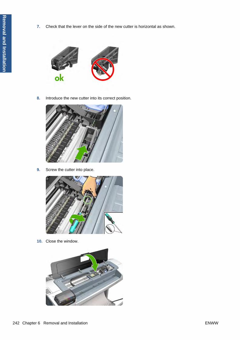
7. Check that the lever on the side of the new cutter is horizontal as shown.
8. Introduce the new cutter into its correct position.
9. Screw the cutter into place.
10. Close the window.
242 Chapter 6 Removal and Installation ENWW
Rem
oval an
d In
stallation

11. Turn the printer back on.
Drop Detector
Removal
1. Switch off the printer and remove the power cable.
2. Remove the Cover, Right on page 234.
3. Remove the Service Station on page 341.
4. Unroute the Drop Detector ribbon cable from the Service Station cable clamps.
5. Remove the T-10 screw that secures the Drop Detector to the Service Station.
ENWW Drop Detector 243
Rem
ova
l an
d In
stal
lati
on

6. Lift the Drop Detector off the Service Station.
NOTE: When you finish installing or replacing this component, you must perform the necessaryService Calibrations. To find which calibrations you must perform, see Service Calibration Guide toRemoval and Installation on page 185.
EE Box
Removal
1. Remove the Cover, Left on page 229.
2. Remove all connectors from the Wukong.
244 Chapter 6 Removal and Installation ENWW
Rem
oval an
d In
stallation

3. Unclip the cables from the cable ties.
4. Remove ferrite from the FP cable without cutting the cable tie.
5. Unclip the cables from the cable ties.
6. Unscrew the screws as shown.
ENWW EE Box 245
Rem
ova
l an
d In
stal
lati
on

7. Remove the RFID support.
8. Unscrew the screws as shown.
9. Unclip the ISS cable from the cable ties.
246 Chapter 6 Removal and Installation ENWW
Rem
oval an
d In
stallation

10. Unclip more cables from the cable ties.
11. Remove the EE box from the printer.
Electronics Module Main PCA and PSU
Removal
1. Switch off the printer and remove the power cable.
2. Remove the Cover, Left on page 229.
ENWW Electronics Module Main PCA and PSU 247
Rem
ova
l an
d In
stal
lati
on

3. Disconnect all the connectors on the Electronics Module. The ferrite on the left will be located underthe board, so take care.
NOTE: The two parallel connectors, white (A) and black (B), on the right of the board, cannot beconnected backwards or swapped.
The harness cable (A) connects to the white connector. The flat cable (B) connects to the blackconnector.
4. Unroute all the cables disconnected in the previous step.
5. Remove two T-20 screws that secure the Electronics Module to the printer.
248 Chapter 6 Removal and Installation ENWW
Rem
oval an
d In
stallation

6. Remove one T-15 screw that secures the Electronics Module to the printer.
7. Remove one T-20 screw that secures the Electronics Module to the printer.
8. Remove two T-20 screws that secure the Electronics Module to the printer.
ENWW Electronics Module Main PCA and PSU 249
Rem
ova
l an
d In
stal
lati
on

9. Remove one T-20 screw that secures the Electronics Module to the printer.
10. Carefully lift the Electronics Module out of the printer.
NOTE: When you install the Electronics Module, make sure it is correctly aligned with the mountingrail.
NOTE: When you finish installing or replacing this component, you must perform the necessaryService Calibrations. To find which calibrations you must perform, see Service Calibration Guide toRemoval and Installation on page 185.
Encoder Disk and Encoder SensorNOTE: Never install a previously used Encoder Sensor PCA. This can cause serious problems, andmay make the printer unusable.
250 Chapter 6 Removal and Installation ENWW
Rem
oval an
d In
stallation

Removal
1. Switch off the printer and remove the power cable.
2. Remove the Cover, Left on page 229.
3. Remove the Electronics Module Main PCA and PSU on page 247.
4. Remove the Spittoon, Left on page 347.
5. Remove the Encoder Disk from the Media Advance Roller spindle, and lift it straight out of theprinter.
NOTE: The Media Advance Roller spindle is delicate. Remove the Encoder Disk gently.
6. Disconnect the two Encoder Sensor connectors.
7. Remove two T-6 screws that secure the Encoder Sensor to the Media Advance Drive.
ENWW Encoder Disk and Encoder Sensor 251
Rem
ova
l an
d In
stal
lati
on
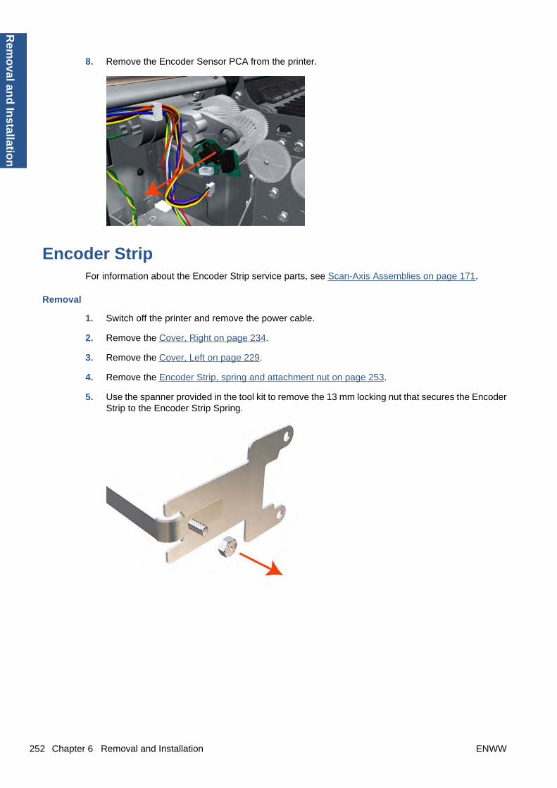
8. Remove the Encoder Sensor PCA from the printer.
Encoder StripFor information about the Encoder Strip service parts, see Scan-Axis Assemblies on page 171.
Removal
1. Switch off the printer and remove the power cable.
2. Remove the Cover, Right on page 234.
3. Remove the Cover, Left on page 229.
4. Remove the Encoder Strip, spring and attachment nut on page 253.
5. Use the spanner provided in the tool kit to remove the 13 mm locking nut that secures the EncoderStrip to the Encoder Strip Spring.
252 Chapter 6 Removal and Installation ENWW
Rem
oval an
d In
stallation
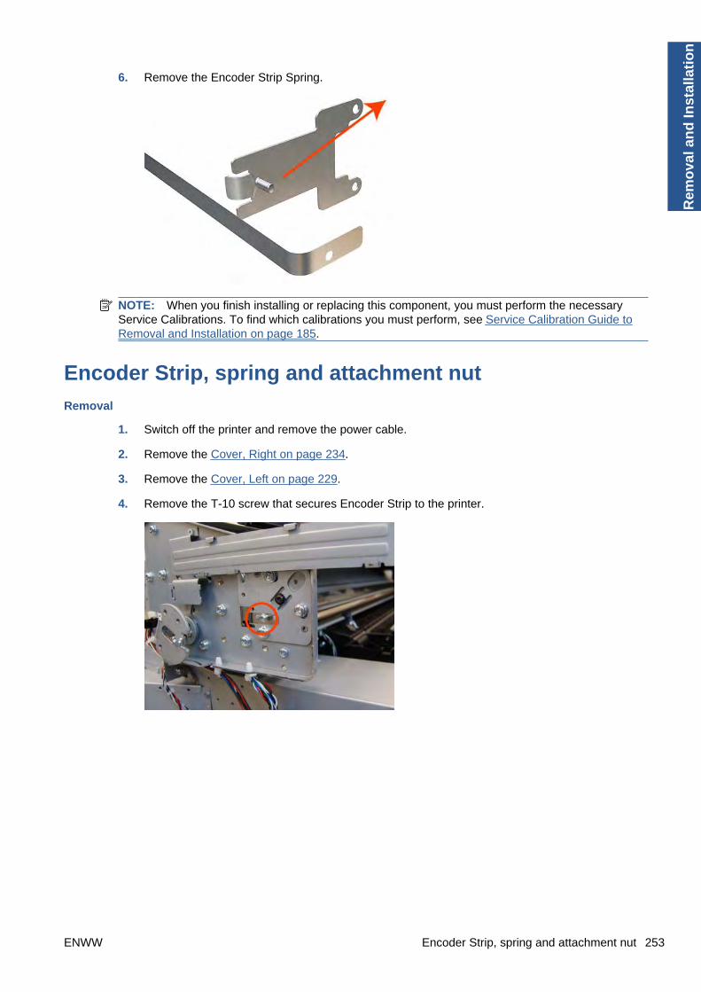
6. Remove the Encoder Strip Spring.
NOTE: When you finish installing or replacing this component, you must perform the necessaryService Calibrations. To find which calibrations you must perform, see Service Calibration Guide toRemoval and Installation on page 185.
Encoder Strip, spring and attachment nut
Removal
1. Switch off the printer and remove the power cable.
2. Remove the Cover, Right on page 234.
3. Remove the Cover, Left on page 229.
4. Remove the T-10 screw that secures Encoder Strip to the printer.
ENWW Encoder Strip, spring and attachment nut 253
Rem
ova
l an
d In
stal
lati
on

5. Grip the Encoder Strip and move it towards the left to take off the tension until you have completedthe next step.
6. Unclip the Encoder Strip from its attachment lugs.
7. Loosen the T-10 uncapping screw sufficiently so you can manually move the Carriage Assemblyin step 7.
254 Chapter 6 Removal and Installation ENWW
Rem
oval an
d In
stallation

8. Push the Carriage Assembly into the print path.
9. Unclip the Encoder Strip tensioner from the right hand end and pull the encoder strip straight out.
NOTE: When you finish installing or replacing this component, you must perform the necessaryService Calibrations. To find which calibrations you must perform, see Service Calibration Guide toRemoval and Installation on page 185.
Formatter
Removal
1. Turn off the printer and remove the power cable.
2. Fully loosen the two locking thumbscrews that secure the Formatter in the printer.
ENWW Formatter 255
Rem
ova
l an
d In
stal
lati
on

3. Lift the Formatter out of the printer.
Installation
1. When you install a new Formatter, follow the instructions provided on the flier that accompanies itto set up the printer.
2. If you try to install a Hard Disk Drive that was previously used in a different printer, the printerdisplays a System Error and will not start successfully. See Hard Disk Drive on page 264.
Freewheel AssemblyThese parts can be replaced by customers who have the appropriate flier.
Removal and installation
1. Open the roll cover.
2. Unscrew the freewheel assembly.
256 Chapter 6 Removal and Installation ENWW
Rem
oval an
d In
stallation

3. Remove the freewheel assembly.
4. Locate the new freewheel assembly and screws.
5. Fit the freewheel assembly to the roll cover.
6. Screw the freewheel assembly to the roll cover.
ENWW Freewheel Assembly 257
Rem
ova
l an
d In
stal
lati
on

7. Close the roll cover.
Front Panel
Removal
1. Switch off the printer and remove the power cable.
2. Open the Window.
3. Squeeze the top edge of the front panel strongly enough to release the attachment clips, and beginrotating the Front Panel vertically in the next step.
258 Chapter 6 Removal and Installation ENWW
Rem
oval an
d In
stallation

4. Rotate the front panel vertically.
5. Disconnect the interface cable from the Front Panel.
6. Push in the clip that prevents the Ferrite Core from being removed.
ENWW Front Panel 259
Rem
ova
l an
d In
stal
lati
on

7. Slide the Ferrite Core out of the brackets.
8. Remove the Front Panel.
NOTE: When you finish installing or replacing this component, you must perform the necessaryService Calibrations. To find which calibrations you must perform, see Service Calibration Guide toRemoval and Installation on page 185.
NOTE: When you reinstall the Front Panel, you must make sure that the Ferrite Core is correctlypositioned. The Ferrite Core is necessary to avoid electrostatic interference being generated.
Front Trim, Left
Removal
1. Switch off the printer and remove the power cable.
2. Remove the Cover, Front on page 228.
3. Remove the Media Output Assembly on page 295.
260 Chapter 6 Removal and Installation ENWW
Rem
oval an
d In
stallation
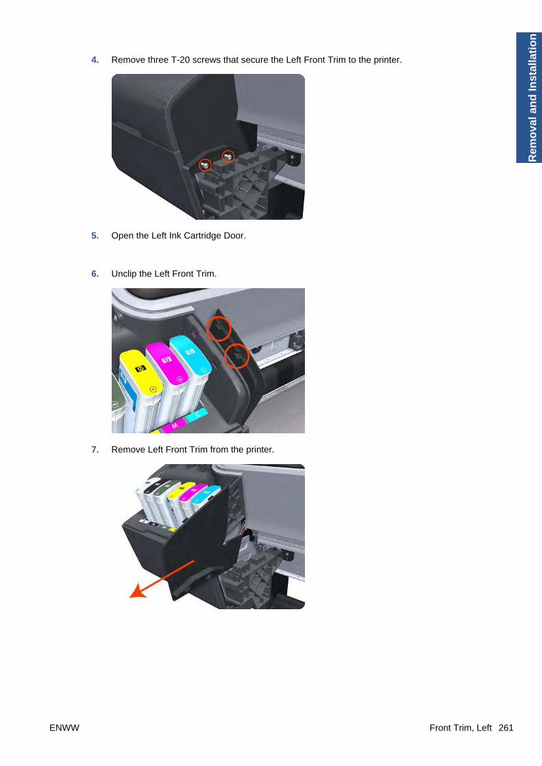
4. Remove three T-20 screws that secure the Left Front Trim to the printer.
5. Open the Left Ink Cartridge Door.
6. Unclip the Left Front Trim.
7. Remove Left Front Trim from the printer.
ENWW Front Trim, Left 261
Rem
ova
l an
d In
stal
lati
on

Front Trim, Right
Removal
1. Switch off the printer and remove the power cable.
2. Remove the Cover, Front on page 228.
3. Remove the Media Output Assembly on page 295.
4. Remove the two T-20 screws that secure the Right Front Trim to the printer.
5. Open the Right Ink Cartridge Door by applying sharp pressure to the right side of the door andlifting firmly where the door meets the Right Cover. Use your hands. When the door is unclippedfrom the pressure applied to the right side of the door, you will hear a sound that corresponds tothe clip.
NOTE: Do not use a screwdriver or other tool to open the Right Ink Cartridge Door.
262 Chapter 6 Removal and Installation ENWW
Rem
oval an
d In
stallation

6. Unclip the Right Front Trim.
7. Remove Right Front Trim from the printer.
Full Bleed Foam
Removal
The complete Full Bleed Foam is constructed of three separate sections, left, center and right. Thisprocedure describes how to remove the left section only. Removal of the other two sections is done inthe same way.
1. Switch off the printer and remove the power cable.
2. Open the Window.
ENWW Full Bleed Foam 263
Rem
ova
l an
d In
stal
lati
on

3. Remove the Left Full Bleed Foam from the left platen, and remove the Platen Middle Foams thatare exposed once the Full Bleed Foam has been removed.
NOTE: When you reinstall the full bleed foams, take care to correctly seat them to avoid possibledamage to the Carriage Assembly
Hard Disk Drive
Removal and installation
1. Remove the Formatter on page 255.
2. Unscrew four screws in the formatter.
3. Remove the hard disk drive from the formatter by applying force in the direction of the arrow.
264 Chapter 6 Removal and Installation ENWW
Rem
oval an
d In
stallation

4. Insert a new hard disk drive.
NOTE: If you try to insert a previously used hard disk drive, the printer displays a System Errorand will not start successfully.
5. Replace all screws that you removed earlier.
Ink Cartridge Door, Left
Removal
1. Switch off the printer and remove the power cable.
2. Open the Left Ink Cartridge Door.
3. Unclip the left side of the Left Ink Cartridge Door.
ENWW Ink Cartridge Door, Left 265
Rem
ova
l an
d In
stal
lati
on

4. Unclip the right side of the Left Ink Cartridge Door.
5. Remove the Left Ink Cartridge Door.
Ink Cartridge Door, Right
Removal
1. Switch off the printer and remove the power cable.
266 Chapter 6 Removal and Installation ENWW
Rem
oval an
d In
stallation

2. Open the Right Ink Cartridge Door by applying sharp pressure to the right side of the door andlifting firmly where the door meets the Right Cover. Use your hands. When the door is unclippedfrom the pressure applied to the right side of the door, you will hear a sound that corresponds tothe clip.
NOTE: Do not use a screwdriver or other tool to open the Right Ink Cartridge Door.
3. Unclip the right side of the Right Ink Cartridge Door.
4. Unclip the left side of the Right Ink Cartridge Door.
ENWW Ink Cartridge Door, Right 267
Rem
ova
l an
d In
stal
lati
on
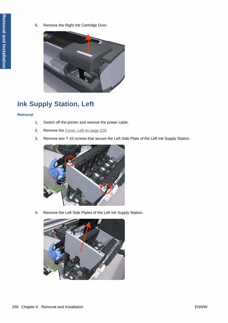
5. Remove the Right Ink Cartridge Door.
Ink Supply Station, Left
Removal
1. Switch off the printer and remove the power cable.
2. Remove the Cover, Left on page 229.
3. Remove two T-10 screws that secure the Left Side Plate of the Left Ink Supply Station.
4. Remove the Left Side Plates of the Left Ink Supply Station.
268 Chapter 6 Removal and Installation ENWW
Rem
oval an
d In
stallation

5. Remove two T-10 screws that secure the Right Side Plate of the Left Ink Supply Station.
6. Remove the two Left Ink Supply Station bonding cables.
7. Remove the Right Side Plate of the Left Ink Supply Station.
ENWW Ink Supply Station, Left 269
Rem
ova
l an
d In
stal
lati
on

8. Remove the T-20 screw that secures the Left Ink Supply Station to the printer.
9. Remove the two T-20 screws that secure the Left Ink Supply Station to the printer.
10. Disconnect the four connectors from the Left Ink Supply Station.
NOTE: If you need to change the ISS Harness Cable, make sure you keep the previously usedplastic connector. The new cable will arrive with a female end, which you will replace with theexisting male end.
270 Chapter 6 Removal and Installation ENWW
Rem
oval an
d In
stallation

11. Unroute the four cables from the Left Ink Supply Station.
12. Carefully lift the Cartridge Tubes Connector out of the Left Ink Supply Station.
13. Carefully lift the Left Ink Supply Station enough so that you can rotate it counterclockwise to releasethe front attachment from the printer.
ENWW Ink Supply Station, Left 271
Rem
ova
l an
d In
stal
lati
on
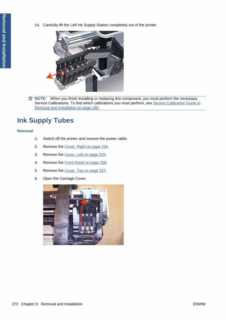
14. Carefully lift the Left Ink Supply Station completely out of the printer.
NOTE: When you finish installing or replacing this component, you must perform the necessaryService Calibrations. To find which calibrations you must perform, see Service Calibration Guide toRemoval and Installation on page 185.
Ink Supply Tubes
Removal
1. Switch off the printer and remove the power cable.
2. Remove the Cover, Right on page 234.
3. Remove the Cover, Left on page 229.
4. Remove the Front Panel on page 258.
5. Remove the Cover, Top on page 237.
6. Open the Carriage Cover.
272 Chapter 6 Removal and Installation ENWW
Rem
oval an
d In
stallation

7. Remove all the Printheads.
8. Unscrew the small cover of the Carriage PCA.
9. Remove the small cover of the Carriage PCA.
ENWW Ink Supply Tubes 273
Rem
ova
l an
d In
stal
lati
on

10. Disconnect the ribbon Trailing Cable from the Carriage PCA.
11. Remove the four T-15 screws that secure the Ink Supply Tubes to the Carriage Assembly.
12. Carefully lift out the Ink Supply Tubes and close the carriage cover at the same time.
274 Chapter 6 Removal and Installation ENWW
Rem
oval an
d In
stallation

13. Close and lock the Carriage Cover.
14. Carefully move the Ink Supply Tubes into the print path.
15. Remove the top T-15 screw that secures Ink Supply Tubes guide to the printer.
ENWW Ink Supply Tubes 275
Rem
ova
l an
d In
stal
lati
on

16. Remove the two front T-15 screws that secure Ink Supply Tubes guide to the printer.
17. Carefully lift the Ink Supply Tubes guide enough until you can slide it forwards out of the printer.
18. Use a flat-bladed screwdriver to release all the Ink Supply Tubes clamps from the printer.
276 Chapter 6 Removal and Installation ENWW
Rem
oval an
d In
stallation

19. Remove two T-10 screws that secure the Left Side Plate of the Left Ink Supply Station.
20. Remove the Left Side Plates of the Left Ink Supply Station.
21. Remove two T-10 screws that secure the Right Side Plate of the Left Ink Supply Station.
ENWW Ink Supply Tubes 277
Rem
ova
l an
d In
stal
lati
on

22. Remove the Left Ink Supply Station bonding cable.
23. Remove the Right Side Plate of the Left Ink Supply Station.
24. Carefully lift the Ink Supply Tubes out of the printer.
278 Chapter 6 Removal and Installation ENWW
Rem
oval an
d In
stallation

25. Carefully remove the Ink Supply Tubes from the assembly.
NOTE: When you finish installing or replacing this component, you must perform the necessaryService Calibrations. To find which calibrations you must perform, see Service Calibration Guide toRemoval and Installation on page 185.
Ink Supply Tubes Support Rail
Removal
1. Switch off the printer and remove the power cable.
2. Remove the Cover, Right on page 234.
3. Remove the Cover, Left on page 229.
4. Remove the Front Panel on page 258.
5. Remove the Cover, Rear on page 233.
6. Remove the Cover, Top on page 237.
7. Remove two T-15 screws that secure the Ink Supply Tubes Support Rail to the right Top CoverSupport.
ENWW Ink Supply Tubes Support Rail 279
Rem
ova
l an
d In
stal
lati
on

8. Carefully slide the Ink Supply Tubes Support Rail to the left until the right end is clear of the rightTop Cover Support.
9. Remove the Ink Supply Tubes Support Rail from the printer.
NOTE: When you finish installing or replacing this component, you must perform the necessaryService Calibrations. To find which calibrations you must perform, see Service Calibration Guide toRemoval and Installation on page 185.
Line Sensor
Removal
1. Switch off the printer and remove the power cable.
2. Remove the Cover, Right on page 234.
3. Remove the Cover, Left on page 229.
4. Remove the Front Panel on page 258.
5. Remove the Cover, Top on page 237.
6. Remove the Window Position Sensor on page 368.
280 Chapter 6 Removal and Installation ENWW
Rem
oval an
d In
stallation

7. Open the Carriage Cover.
8. Remove all the Printheads.
9. Unscrew the small cover of the Carriage PCA.
ENWW Line Sensor 281
Rem
ova
l an
d In
stal
lati
on

10. Remove the small cover of the Carriage PCA.
11. Disconnect the ribbon cable of the Trailing Cables from the Carriage PCA.
12. Remove the four T-15 screws that secure the Ink Supply Tubes to the Carriage Assembly.
282 Chapter 6 Removal and Installation ENWW
Rem
oval an
d In
stallation

13. Carefully lift out the Ink Supply Tubes and close the carriage cover at the same time.
14. Close and lock the Carriage Cover.
15. Loosen the T-10 uncapping screw sufficiently so you can move the Carriage Assembly manually.
ENWW Line Sensor 283
Rem
ova
l an
d In
stal
lati
on

16. Push the Carriage Assembly into the print path.
17. Remove the cover on each side of the Carriage PCA using a screwdriver unclip it.
18. Disconnect the Line Sensor electrical connection from the Carriage PCA.
284 Chapter 6 Removal and Installation ENWW
Rem
oval an
d In
stallation
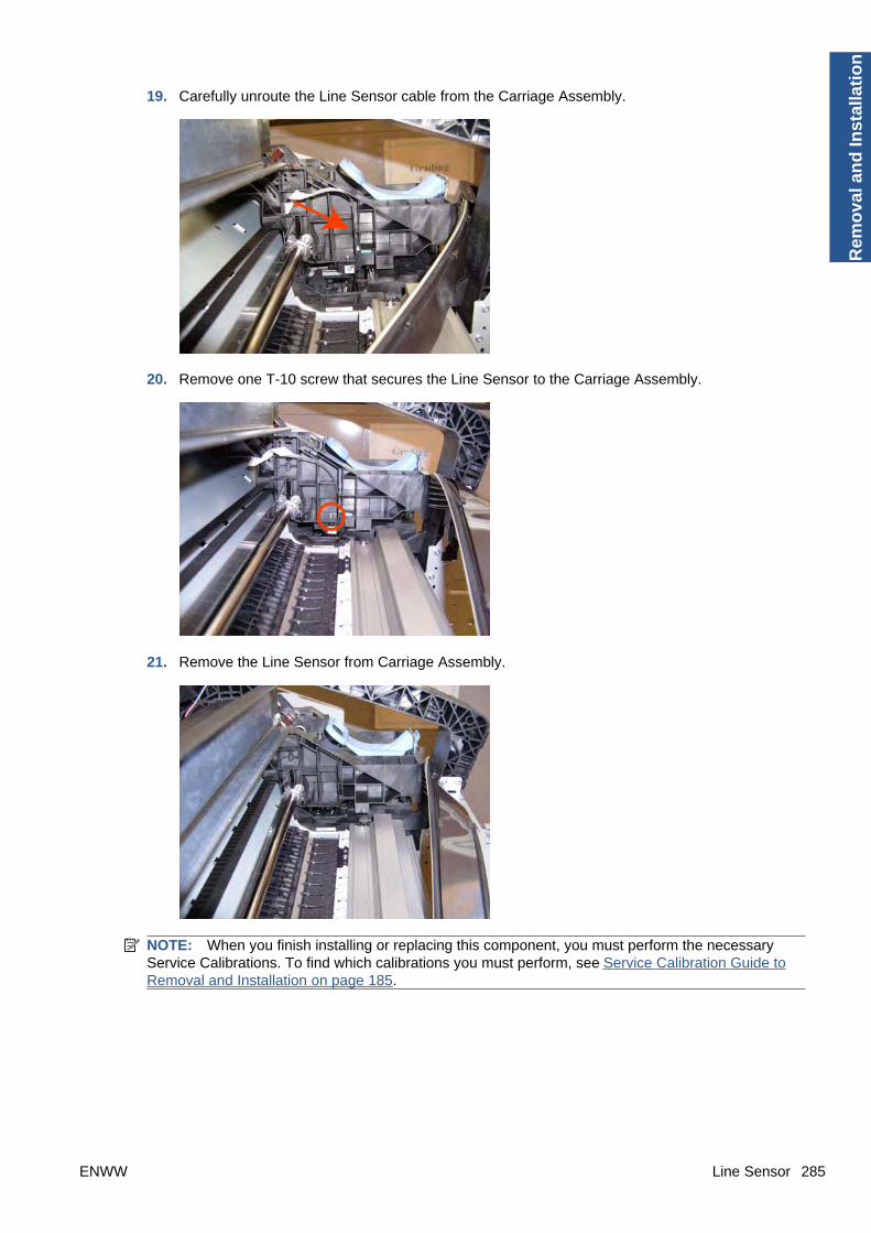
19. Carefully unroute the Line Sensor cable from the Carriage Assembly.
20. Remove one T-10 screw that secures the Line Sensor to the Carriage Assembly.
21. Remove the Line Sensor from Carriage Assembly.
NOTE: When you finish installing or replacing this component, you must perform the necessaryService Calibrations. To find which calibrations you must perform, see Service Calibration Guide toRemoval and Installation on page 185.
ENWW Line Sensor 285
Rem
ova
l an
d In
stal
lati
on
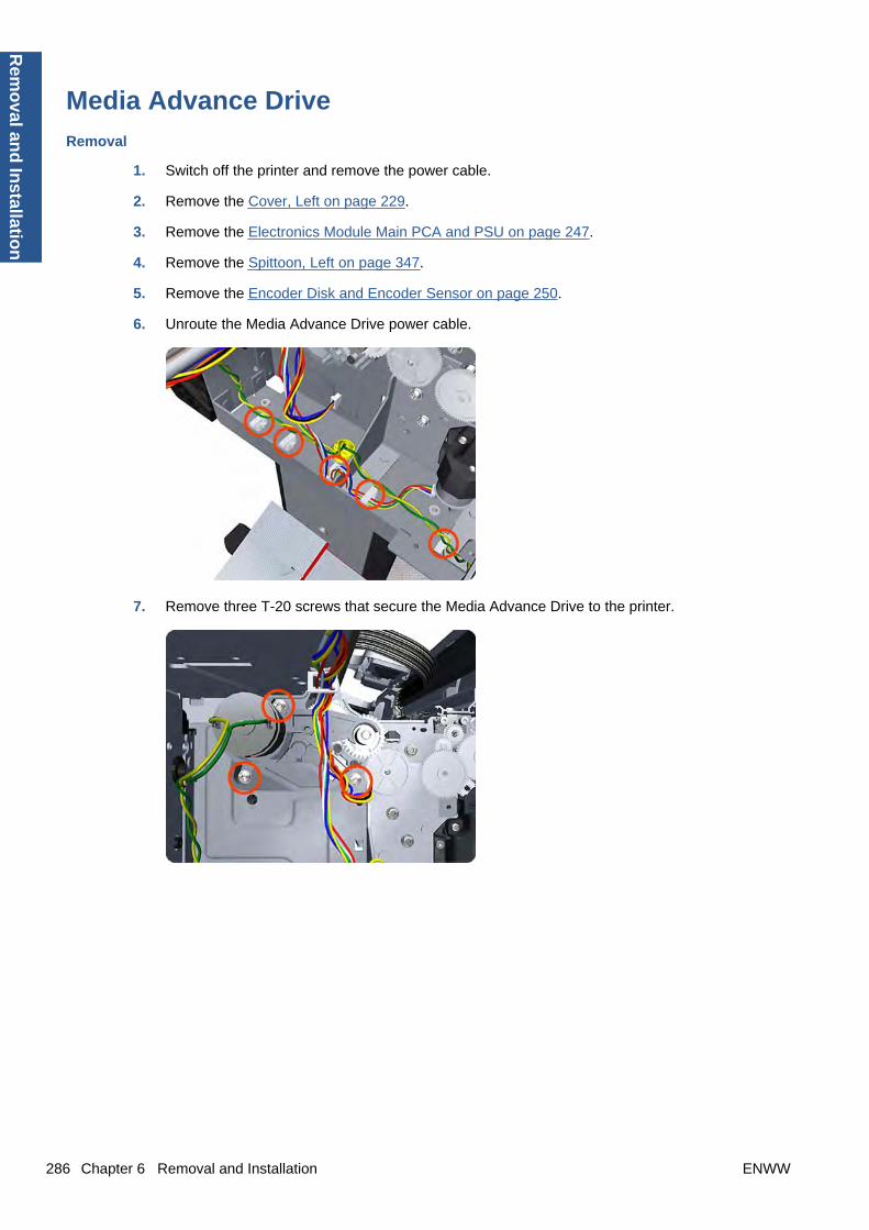
Media Advance Drive
Removal
1. Switch off the printer and remove the power cable.
2. Remove the Cover, Left on page 229.
3. Remove the Electronics Module Main PCA and PSU on page 247.
4. Remove the Spittoon, Left on page 347.
5. Remove the Encoder Disk and Encoder Sensor on page 250.
6. Unroute the Media Advance Drive power cable.
7. Remove three T-20 screws that secure the Media Advance Drive to the printer.
286 Chapter 6 Removal and Installation ENWW
Rem
oval an
d In
stallation

8. Grip the motor housing of the Media Advance Drive and gently pull it towards you sufficiently toallow you disengage the Media Advance Drive from the printer.
9. Carefully lift the Media Advance Drive out of the printer.
Installation without encoder sensor adjustment
Use the following procedure to install and adjust a new Media Advance Drive. This is the normalprocedure that should be followed in most cases. You will need Media Advance Drive Adjustment Toolfrom the Tool Kit (Q6683-67001).
1. Carefully position the Media Advance Drive in the printer.
ENWW Media Advance Drive 287
Rem
ova
l an
d In
stal
lati
on

2. Be careful not to touch the encoder sensor adjustment screw; not even when replacing the encoderdisc and sensor.
3. Insert the three T-15 attachment screws, but do not fully tighten them.
4. Position the Media Advance Drive Adjustment Tool on the end Media Advance Roller shaft, pushit firmly onto the shaft and maintain a constant pressure to ensure it is flush to the Media AdvanceDrive.
288 Chapter 6 Removal and Installation ENWW
Rem
oval an
d In
stallation

5. While maintaining pressure on the Media Advance Drive Adjustment Tool, fully tighten the threeT-15 attachment screws in the order shown.
6. Remove the Media Advance Drive Adjustment Tool.
Installation with encoder sensor adjustment
Use the following procedure to install and adjust a new Media Advance Drive, and to adjust the encodersensor. This procedure is recommended only when the motor mount has to be replaced or the encodersensor has to be readjusted. You will need Media Advance Drive Adjustment Tool from the Tool Kit(Q6683-67001).
1. Carefully position the Media Advance Drive in the printer.
2. Insert the three T-15 attachment screws, but do not fully tighten them.
ENWW Media Advance Drive 289
Rem
ova
l an
d In
stal
lati
on

3. Loosen the encoder sensor adjustment screw.
4. Add the Encoder Sensor Tool to the Media Drive Adjustment Tool.
5. Position the Media Advance Drive Adjustment Tool on the end Media Advance Roller shaft, pushit firmly onto the shaft and maintain a constant pressure to ensure it is flush to the Media AdvanceDrive.
290 Chapter 6 Removal and Installation ENWW
Rem
oval an
d In
stallation

6. While maintaining pressure on the Media Advance Drive Adjustment Tool, fully tighten the threeT-15 attachment screws in the order shown.
7. While maintaining pressure on the Media Advance Drive Adjustment Tool, fully tighten the encodersensor adjustment screw.
8. Remove the Media Advance Drive Adjustment Tool.
Encoder disk assembly
1. Remove the paper that protects the glue of a new encoder.
ENWW Media Advance Drive 291
Rem
ova
l an
d In
stal
lati
on

2. Pre-assemble the encoder on the roller without using pressure.
3. Press the encoder using the Media Advance Drive Adjustment Tool (reversed) so that it sticks tothe roller.
NOTE: When you finish installing or replacing these components, you must perform the necessaryService Calibrations. To find which calibrations you must perform, see Service Calibration Guide toRemoval and Installation on page 185.
Media Lever
Removal
1. Switch off the printer and remove the power cable.
2. Remove the Panel, Left on page 299.
3. Unclip the spring from the attachment points on the Media Lever and Left Cover.
292 Chapter 6 Removal and Installation ENWW
Rem
oval an
d In
stallation
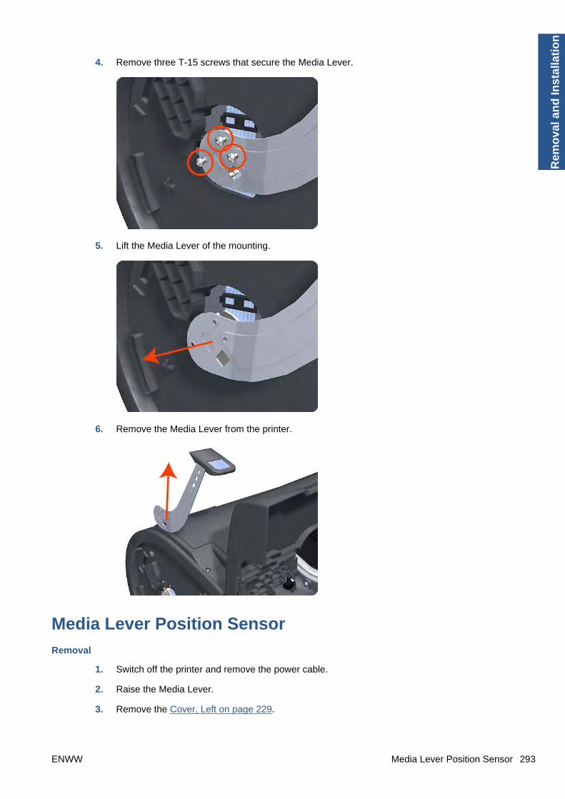
4. Remove three T-15 screws that secure the Media Lever.
5. Lift the Media Lever of the mounting.
6. Remove the Media Lever from the printer.
Media Lever Position Sensor
Removal
1. Switch off the printer and remove the power cable.
2. Raise the Media Lever.
3. Remove the Cover, Left on page 229.
ENWW Media Lever Position Sensor 293
Rem
ova
l an
d In
stal
lati
on
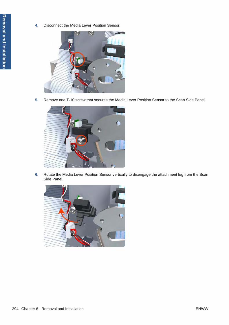
4. Disconnect the Media Lever Position Sensor.
5. Remove one T-10 screw that secures the Media Lever Position Sensor to the Scan Side Panel.
6. Rotate the Media Lever Position Sensor vertically to disengage the attachment lug from the ScanSide Panel.
294 Chapter 6 Removal and Installation ENWW
Rem
oval an
d In
stallation
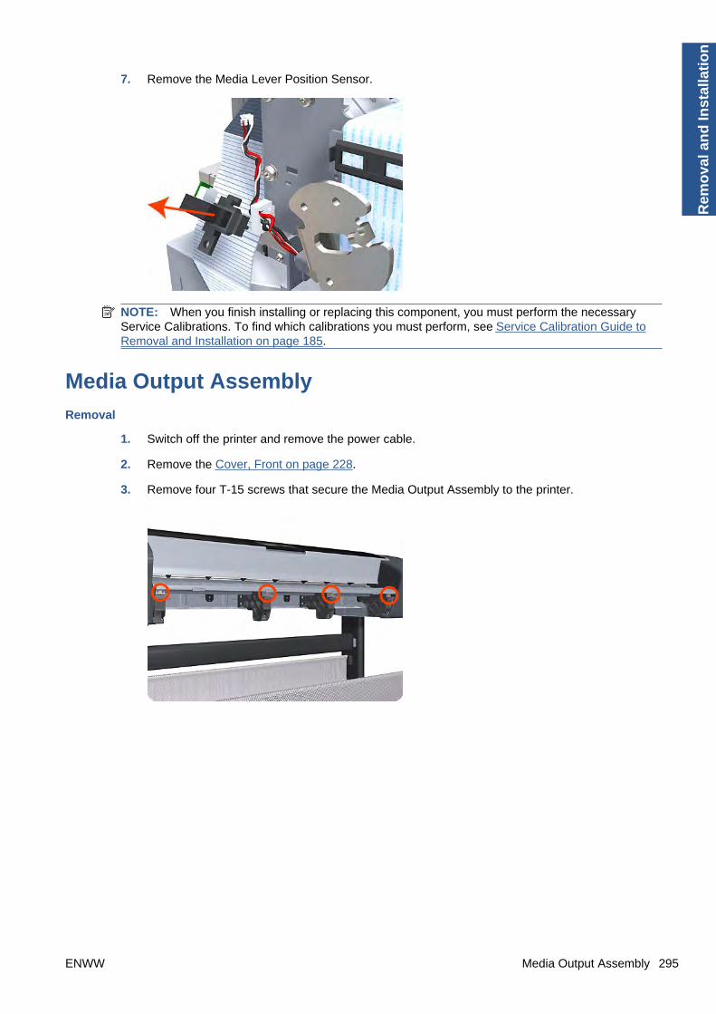
7. Remove the Media Lever Position Sensor.
NOTE: When you finish installing or replacing this component, you must perform the necessaryService Calibrations. To find which calibrations you must perform, see Service Calibration Guide toRemoval and Installation on page 185.
Media Output Assembly
Removal
1. Switch off the printer and remove the power cable.
2. Remove the Cover, Front on page 228.
3. Remove four T-15 screws that secure the Media Output Assembly to the printer.
ENWW Media Output Assembly 295
Rem
ova
l an
d In
stal
lati
on
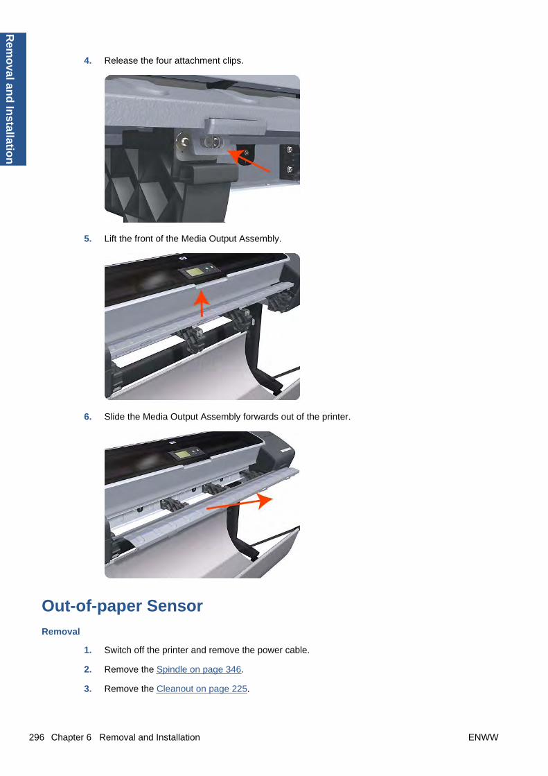
4. Release the four attachment clips.
5. Lift the front of the Media Output Assembly.
6. Slide the Media Output Assembly forwards out of the printer.
Out-of-paper Sensor
Removal
1. Switch off the printer and remove the power cable.
2. Remove the Spindle on page 346.
3. Remove the Cleanout on page 225.
296 Chapter 6 Removal and Installation ENWW
Rem
oval an
d In
stallation

4. Unroute the Out Of Paper Sensor electrical cables from the Clean Out Assembly.
5. Unroute (unwind) the Out Of Paper Sensor electrical cables from the Out Of Paper Sensor cover.
6. Press the clip to remove the Out Of Paper Sensor cover from the Clean Out Assembly.
ENWW Out-of-paper Sensor 297
Rem
ova
l an
d In
stal
lati
on

7. Rotate the Out Of Paper Sensor cover approximately 45 degrees.
8. Remove the Out Of Paper Sensor cover from the Clean Out Assembly.
9. Squeeze the Out Of Paper Sensor attachment clips to remove it from the Clean Out Assembly.
298 Chapter 6 Removal and Installation ENWW
Rem
oval an
d In
stallation
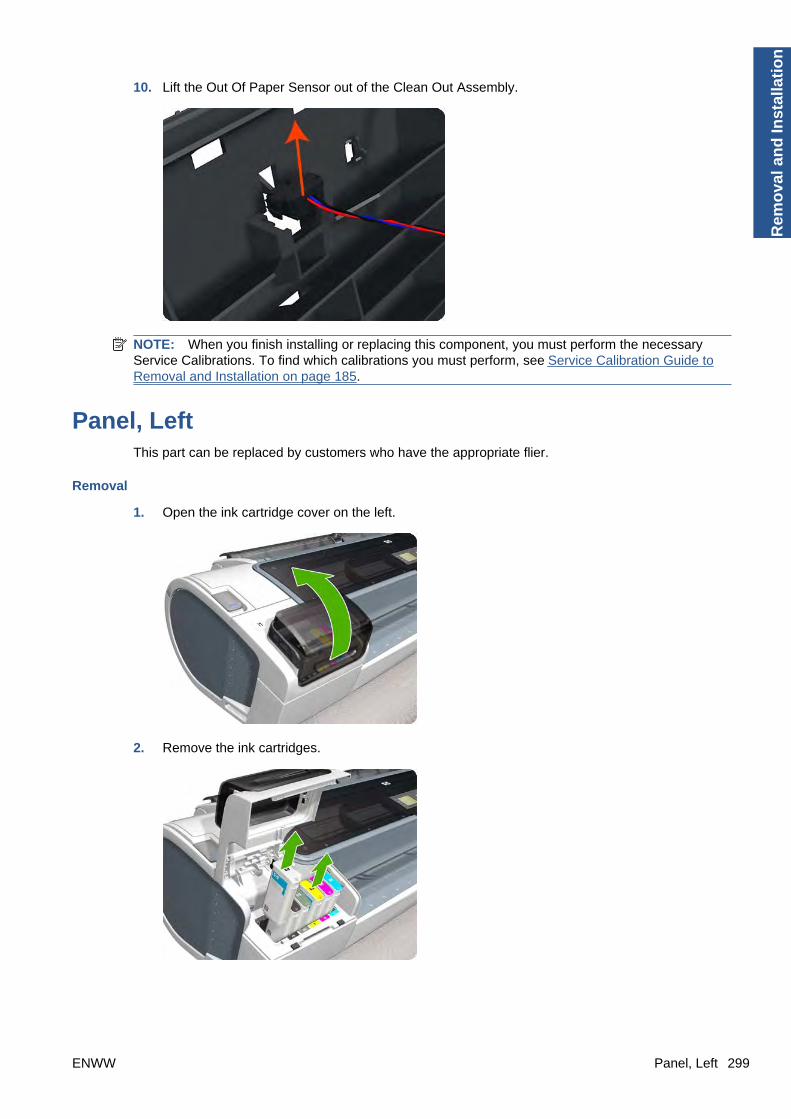
10. Lift the Out Of Paper Sensor out of the Clean Out Assembly.
NOTE: When you finish installing or replacing this component, you must perform the necessaryService Calibrations. To find which calibrations you must perform, see Service Calibration Guide toRemoval and Installation on page 185.
Panel, LeftThis part can be replaced by customers who have the appropriate flier.
Removal
1. Open the ink cartridge cover on the left.
2. Remove the ink cartridges.
ENWW Panel, Left 299
Rem
ova
l an
d In
stal
lati
on
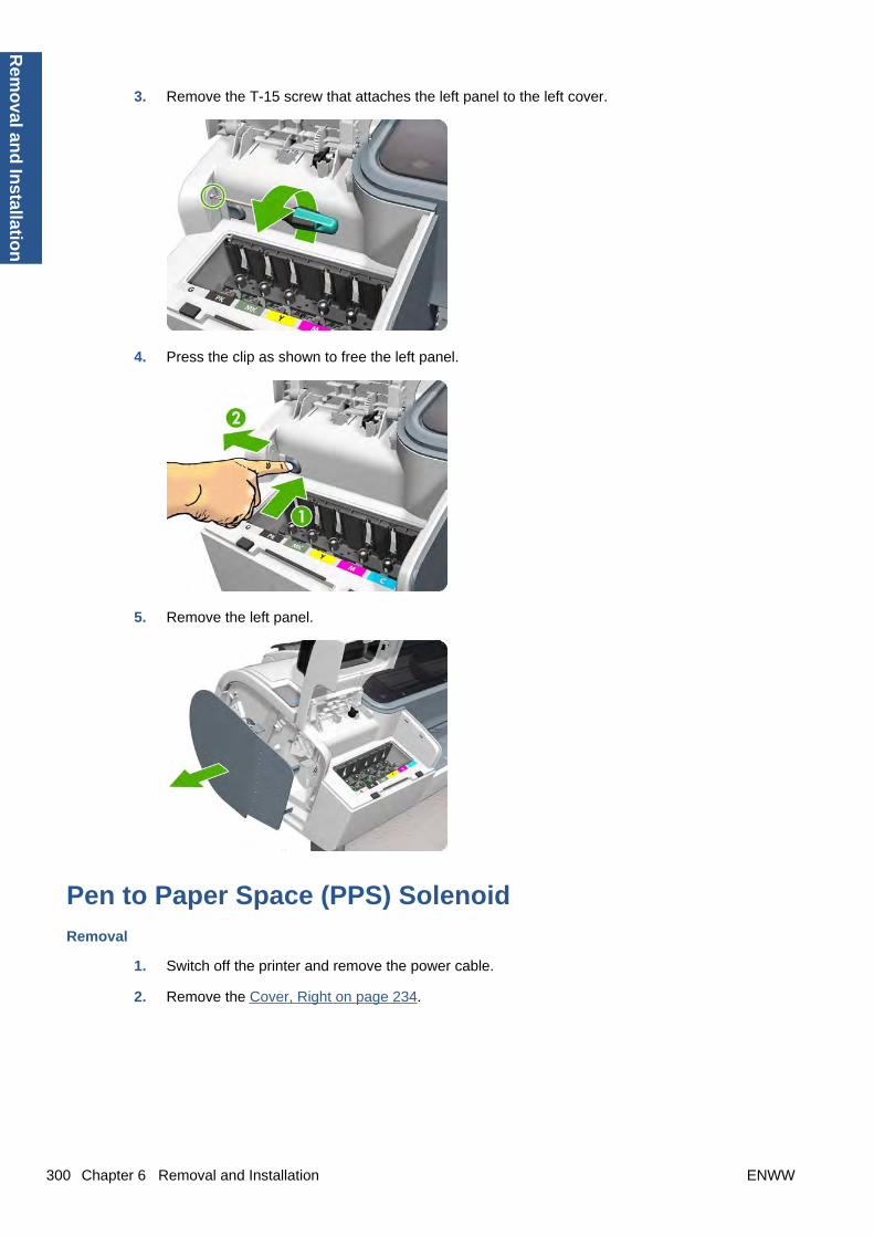
3. Remove the T-15 screw that attaches the left panel to the left cover.
4. Press the clip as shown to free the left panel.
5. Remove the left panel.
Pen to Paper Space (PPS) Solenoid
Removal
1. Switch off the printer and remove the power cable.
2. Remove the Cover, Right on page 234.
300 Chapter 6 Removal and Installation ENWW
Rem
oval an
d In
stallation

3. Unroute the Pen to Paper Space (PPS) Solenoid cable from the cable clamp.
4. Disconnect the Pen to Paper Space (PPS) Solenoid connector from the L1 Data Harness.
5. Remove two T-10 screws that secure the Pen to Paper Space (PPS) Solenoid to the printer.
ENWW Pen to Paper Space (PPS) Solenoid 301
Rem
ova
l an
d In
stal
lati
on

6. Remove the Pen to Paper Space (PPS) Solenoid from the printer.
NOTE: When you finish installing or replacing this component, you must perform the necessaryService Calibrations. To find which calibrations you must perform, see Service Calibration Guide toRemoval and Installation on page 185.
Pinch Arm AssemblyThese parts can be replaced by customers who have the appropriate flier.
Removal and installation
1. Open the upper or lower roll cover.
2. Remove the spindle.
302 Chapter 6 Removal and Installation ENWW
Rem
oval an
d In
stallation
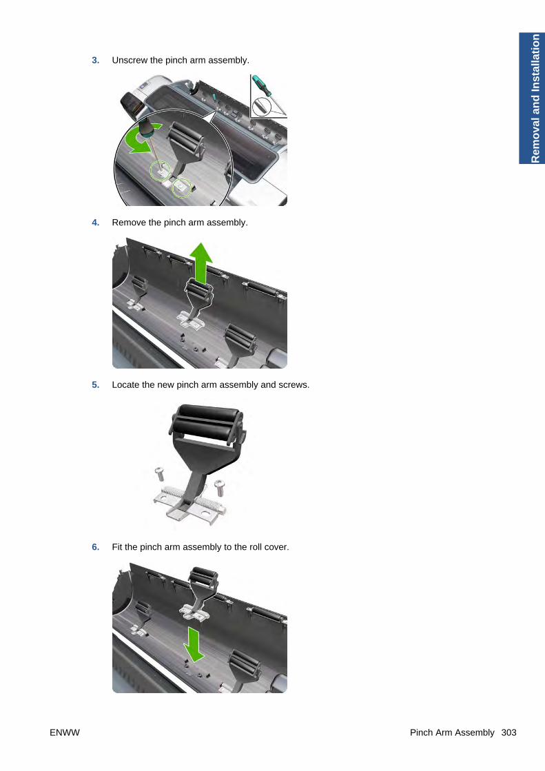
3. Unscrew the pinch arm assembly.
4. Remove the pinch arm assembly.
5. Locate the new pinch arm assembly and screws.
6. Fit the pinch arm assembly to the roll cover.
ENWW Pinch Arm Assembly 303
Rem
ova
l an
d In
stal
lati
on

7. Screw the pinch arm assembly to the roll cover.
8. Insert the spindle.
9. Close the roll cover.
Pinchwheel Assembly
Removal
1. Switch off the printer and remove the power cable.
2. Open the Window.
3. Remove the Spindle on page 346.
4. Remove the Roll Guide, Left on page 328.
5. Remove the Roll Guide, Right on page 329.
304 Chapter 6 Removal and Installation ENWW
Rem
oval an
d In
stallation
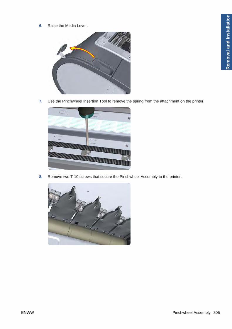
6. Raise the Media Lever.
7. Use the Pinchwheel Insertion Tool to remove the spring from the attachment on the printer.
8. Remove two T-10 screws that secure the Pinchwheel Assembly to the printer.
ENWW Pinchwheel Assembly 305
Rem
ova
l an
d In
stal
lati
on

9. Remove the Pinchwheel Assembly from the printer.
Installation
Use the following procedure to align the Pinchwheel Assembly using the Pinchwheel Alignment Toolduring reassembly.
NOTE: Never remove and replace all the Pinchwheel Assemblies at the same time. In order to aligna Pinchwheel Assembly, you need a minimum one Pinchwheel Assembly correctly aligned by themanufacturer.
1. Insert the Pinchwheel Insertion Tool through the appropriate access hole for the PinchwheelAssembly you are installing.
CAUTION: Be very careful not to damage the Encoder Strip or the Belt Assembly with thePinchwheel Insertion Tool.
306 Chapter 6 Removal and Installation ENWW
Rem
oval an
d In
stallation

2. Position the new Pinchwheel Assembly correctly on its hanger.
3. Hook the spring of the Pinchwheel Assembly you are installing with the Pinchwheel Insertion Tool.
4. Attach the spring to its attachment point on the hanger and remove the Pinchwheel Insertion Tool.
ENWW Pinchwheel Assembly 307
Rem
ova
l an
d In
stal
lati
on

5. Attach the new Pinchwheel Assembly with the two T-15 screws that secure to the printer but dofully not tighten the screws.
6. Lower the Media Lever.
7. Make sure the Pinchwheel Alignment Tool is in the collapsed position.
8. Fit the end of the Pinchwheel Alignment Tool to the Pinchwheel Assembly you need to align.
308 Chapter 6 Removal and Installation ENWW
Rem
oval an
d In
stallation
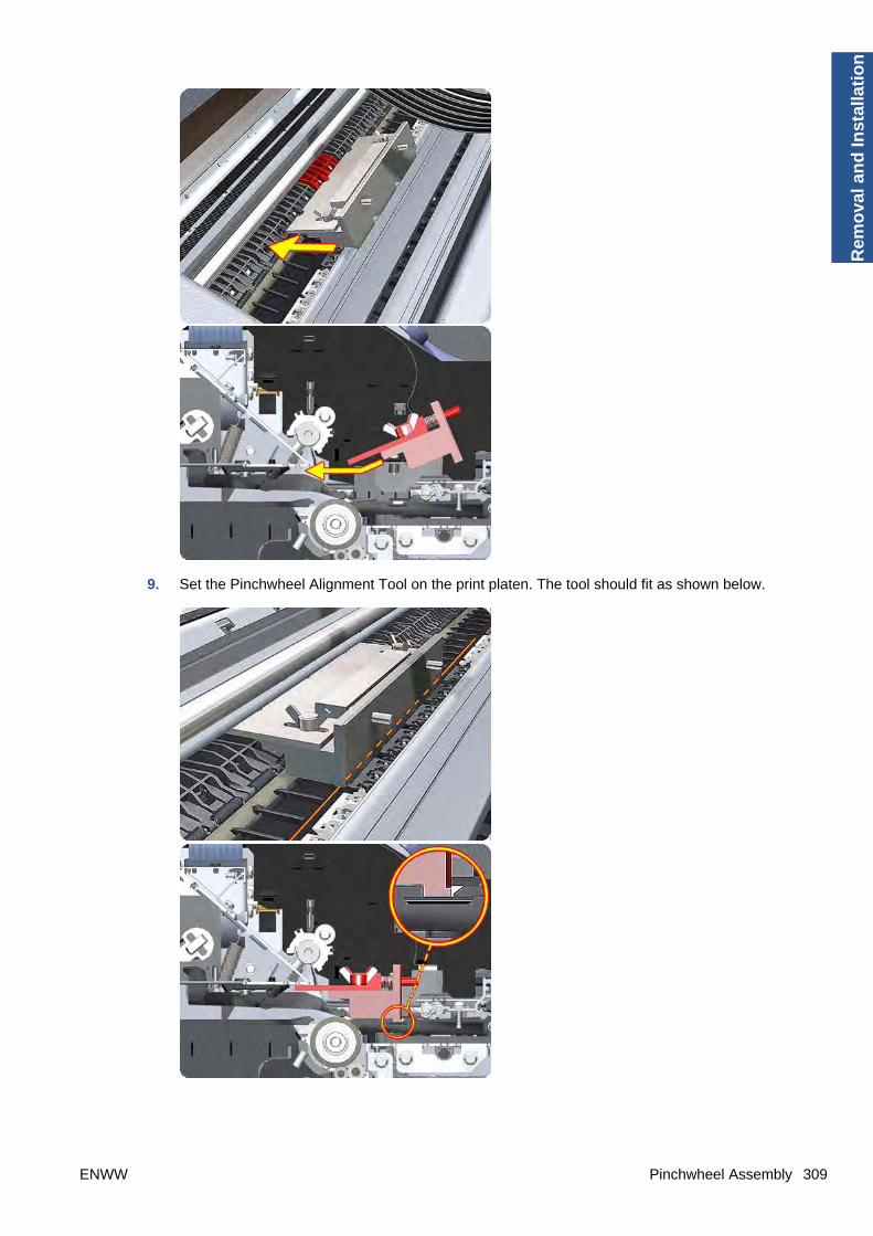
9. Set the Pinchwheel Alignment Tool on the print platen. The tool should fit as shown below.
ENWW Pinchwheel Assembly 309
Rem
ova
l an
d In
stal
lati
on

10. Loosen the wing nuts on the Pinchwheel Alignment Tool.
11. Allow the Pinchwheel Alignment Tool to expand. Make sure that the tool is fully expanded.
310 Chapter 6 Removal and Installation ENWW
Rem
oval an
d In
stallation

12. When the Pinchwheel Alignment Tool is fully expanded, the Pinchwheel Assembly is properlyaligned.
13. Fully tighten the two T-15 attachment screws that secure the Pinchwheel Assembly to the printer.
14. Collapse the Pinchwheel Alignment Tool to remove it.
ENWW Pinchwheel Assembly 311
Rem
ova
l an
d In
stal
lati
on
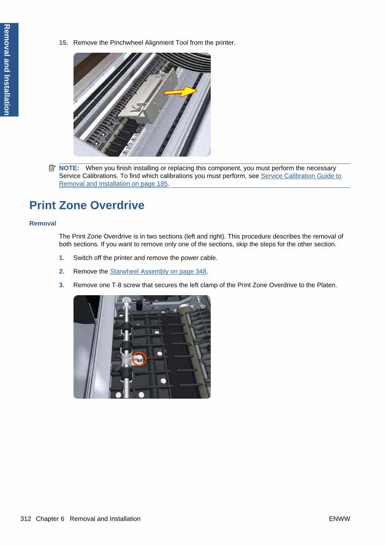
15. Remove the Pinchwheel Alignment Tool from the printer.
NOTE: When you finish installing or replacing this component, you must perform the necessaryService Calibrations. To find which calibrations you must perform, see Service Calibration Guide toRemoval and Installation on page 185.
Print Zone Overdrive
Removal
The Print Zone Overdrive is in two sections (left and right). This procedure describes the removal ofboth sections. If you want to remove only one of the sections, skip the steps for the other section.
1. Switch off the printer and remove the power cable.
2. Remove the Starwheel Assembly on page 348.
3. Remove one T-8 screw that secures the left clamp of the Print Zone Overdrive to the Platen.
312 Chapter 6 Removal and Installation ENWW
Rem
oval an
d In
stallation
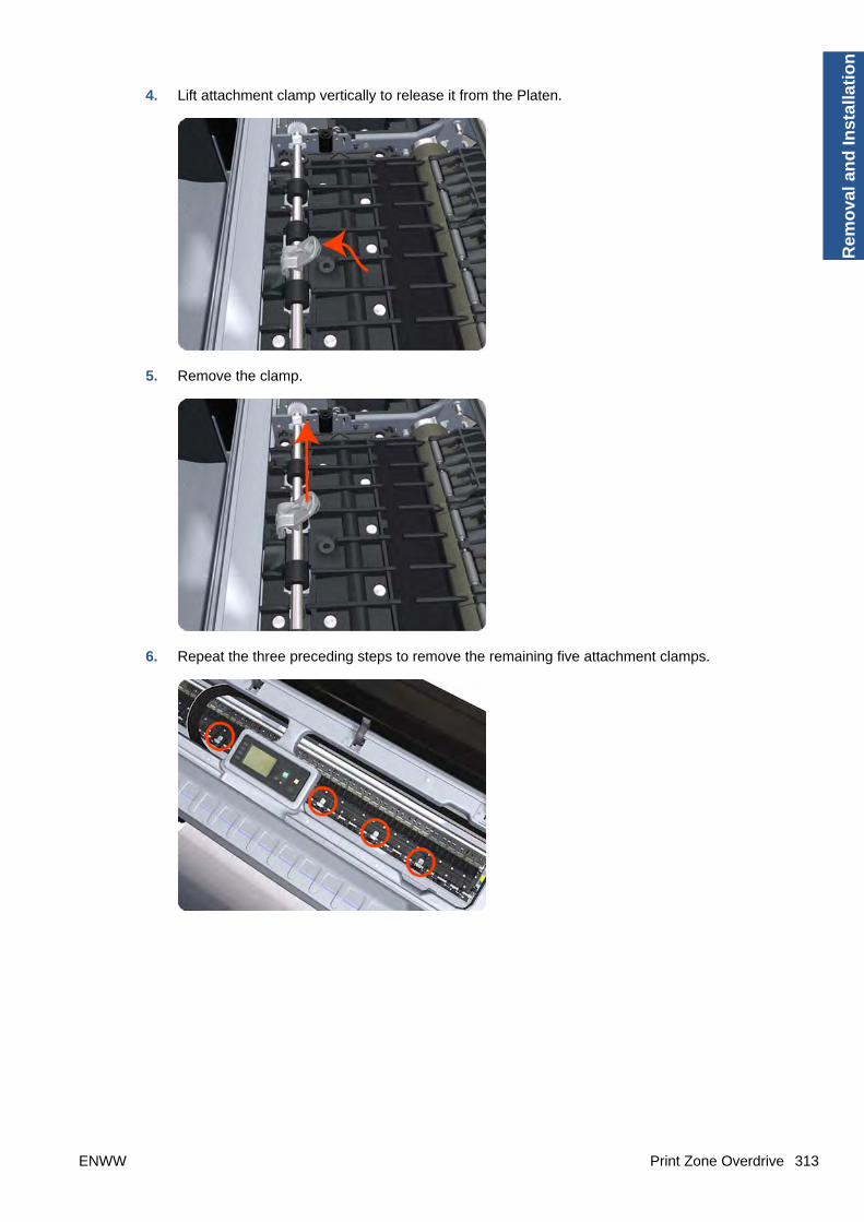
4. Lift attachment clamp vertically to release it from the Platen.
5. Remove the clamp.
6. Repeat the three preceding steps to remove the remaining five attachment clamps.
ENWW Print Zone Overdrive 313
Rem
ova
l an
d In
stal
lati
on

7. Use a flat-bladed screwdriver to unclip the left Print Zone Overdrive retaining clip and rotate theclip vertically.
8. Carefully lift the left Print Zone Overdrive enough (10 mm) so you can slide it to the left.
9. Slide the left Print Zone Overdrive to the left disengage the center coupling.
314 Chapter 6 Removal and Installation ENWW
Rem
oval an
d In
stallation

10. Carefully lift the left Print Zone Overdrive out of the printer.
11. Remove the center coupling.
12. Use a flat-bladed screwdriver to unclip the left Print Zone Overdrive retaining clip and rotate theclip vertically.
ENWW Print Zone Overdrive 315
Rem
ova
l an
d In
stal
lati
on

13. Carefully lift the right Print Zone Overdrive out of the printer.
NOTE: When you finish installing or replacing this component, you must perform the necessaryService Calibrations. To find which calibrations you must perform, see Service Calibration Guide toRemoval and Installation on page 185.
316 Chapter 6 Removal and Installation ENWW
Rem
oval an
d In
stallation
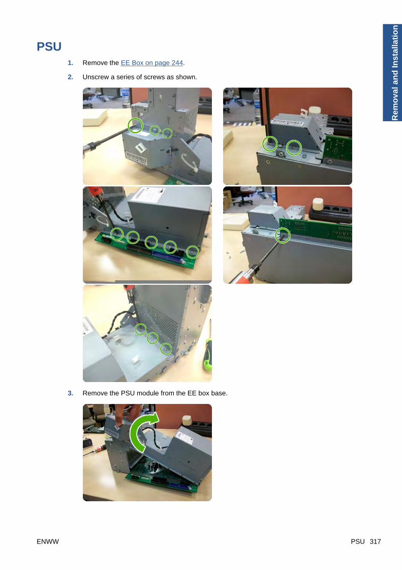
PSU1. Remove the EE Box on page 244.
2. Unscrew a series of screws as shown.
3. Remove the PSU module from the EE box base.
ENWW PSU 317
Rem
ova
l an
d In
stal
lati
on
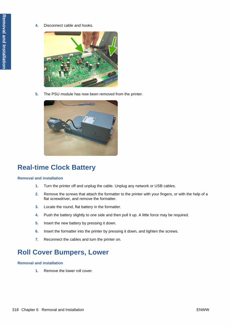
4. Disconnect cable and hooks.
5. The PSU module has now been removed from the printer.
Real-time Clock Battery
Removal and installation
1. Turn the printer off and unplug the cable. Unplug any network or USB cables.
2. Remove the screws that attach the formatter to the printer with your fingers, or with the help of aflat screwdriver, and remove the formatter.
3. Locate the round, flat battery in the formatter.
4. Push the battery slightly to one side and then pull it up. A little force may be required.
5. Insert the new battery by pressing it down.
6. Insert the formatter into the printer by pressing it down, and tighten the screws.
7. Reconnect the cables and turn the printer on.
Roll Cover Bumpers, Lower
Removal and installation
1. Remove the lower roll cover.
318 Chapter 6 Removal and Installation ENWW
Rem
oval an
d In
stallation

2. Identify the bumpers at the rear of the printer.
3. Use a screwdriver to lever off the bumper.
ENWW Roll Cover Bumpers, Lower 319
Rem
ova
l an
d In
stal
lati
on

4. Remove the other bumper in the same way.
5. Locate the new bumpers.
320 Chapter 6 Removal and Installation ENWW
Rem
oval an
d In
stallation

6. Fit the new bumpers into place.
7. Replace the lower roll cover.
Roll Cover Bumpers, UpperThese parts can be replaced by customers who have the appropriate flier.
Removal and installation
1. Identify the bumpers at the rear of the printer.
ENWW Roll Cover Bumpers, Upper 321
Rem
ova
l an
d In
stal
lati
on
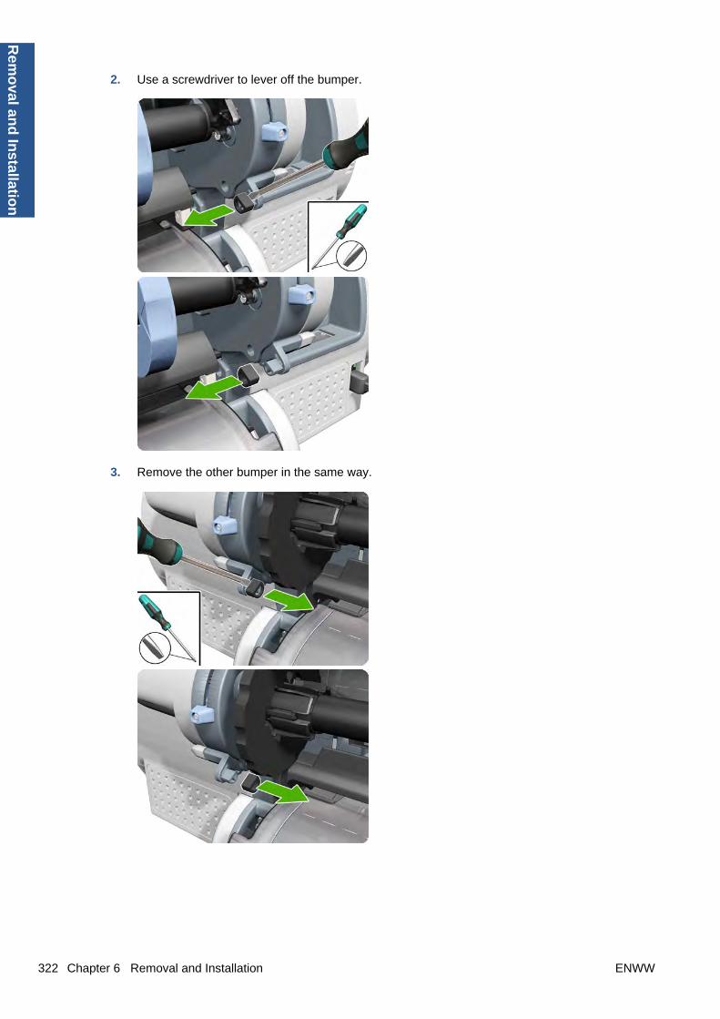
2. Use a screwdriver to lever off the bumper.
3. Remove the other bumper in the same way.
322 Chapter 6 Removal and Installation ENWW
Rem
oval an
d In
stallation

4. Locate the new bumpers.
5. Fit the new bumpers into place.
ENWW Roll Cover Bumpers, Upper 323
Rem
ova
l an
d In
stal
lati
on

Roll Cover, Lower (T1200 only)
Removal
1. Open the lower roll cover.
2. Remove the spindle.
3. Remove the screw connecting the roll cover to the printer on the left.
324 Chapter 6 Removal and Installation ENWW
Rem
oval an
d In
stallation

4. Remove the screw connecting the roll cover to the printer on the right.
5. Detach the roll cover from the printer on the left-hand side.
6. Leave the roll cover hanging from the bi-stable spring.
7. Detach the roll cover from the printer on the right-hand side.
ENWW Roll Cover, Lower (T1200 only) 325
Rem
ova
l an
d In
stal
lati
on

8. Leave the roll cover hanging from the bi-stable spring.
9. Both ends of the roll cover are now connected to the printer only by the bi-stable springs.
10. Hold the roll cover with one hand while unscrewing the bi-stable spring from the printer.
11. Leave one end of the roll cover resting on the floor.
326 Chapter 6 Removal and Installation ENWW
Rem
oval an
d In
stallation

12. Hold the roll cover with one hand while unscrewing the other bi-stable spring from the printer.
Roll Cover, Upper
Removal
1. Open the Upper Roll Cover.
2. Remove the screw on the Roll Cover's left side that attaches to the Upper Left Roll Support.
ENWW Roll Cover, Upper 327
Rem
ova
l an
d In
stal
lati
on

3. Remove the screw on the Roll Cover's right side that attaches to the Upper Right Roll Support.
4. Remove the Roll Cover hinge from the Roll Left Support Pin.
5. Remove the Roll Cover hinge from the Roll Right Support Pin.
Roll Guide, Left
Removal
1. Switch off the printer and remove the power cable.
2. Remove the Spindle on page 346.
3. Remove the Roll Cover, Lower (T1200 only) on page 324.
4. Remove the Converger on page 226.
5. Remove the Cleanout on page 225.
328 Chapter 6 Removal and Installation ENWW
Rem
oval an
d In
stallation

6. Remove five T-15 screws that secure the Left Roll Guide to the printer.
7. Lower the left end and remove the Left Roll Guide from the printer.
NOTE: When you finish installing or replacing this component, you must perform the necessaryService Calibrations. To find which calibrations you must perform, see Service Calibration Guide toRemoval and Installation on page 185.
Roll Guide, Right
Removal
1. Switch off the printer and remove the power cable.
2. Remove the Roll Guide, Left on page 328.
ENWW Roll Guide, Right 329
Rem
ova
l an
d In
stal
lati
on

3. Remove seven T-15 screws that secure the Right Roll Guide to the printer.
4. Lower the right end and remove the Right Roll Guide from the printer.
NOTE: When you finish installing or replacing this component, you must perform the necessaryService Calibrations. To find which calibrations you must perform, see Service Calibration Guide toRemoval and Installation on page 185.
Roll Support, Lower Left (T1200 only)
Removal
1. Remove the Converger on page 226.
2. Remove the Roll Cover, Lower (T1200 only) on page 324.
3. Remove the Cover, Rear on page 233.
4. Remove the Roll Support, Upper Left on page 334.
5. Remove screws as shown.
330 Chapter 6 Removal and Installation ENWW
Rem
oval an
d In
stallation

6. Unplug the Lower Left Roll Support, taking care not to damage the cables.
7. Disconnect the cable connector as shown.
Roll Support, Lower Right (T1200 only)
Removal
1. Remove the Cover, Right on page 234.
2. Remove the Roll Cover, Lower (T1200 only) on page 324.
ENWW Roll Support, Lower Right (T1200 only) 331
Rem
ova
l an
d In
stal
lati
on

3. Unplug the motor encoder cable.
4. Unplug the motor cable.
5. Remove the screw of the grounding cable.
6. Remove two screws as shown.
332 Chapter 6 Removal and Installation ENWW
Rem
oval an
d In
stallation

Roll Support Sensor, Lower Left (T1200 only)
Removal
1. Remove the Roll Support, Lower Left (T1200 only) on page 330.
2. Unscrew the screw as shown.
3. Remove the cable.
4. The sensor has been removed.
Roll Support Sensor, Upper Left
Removal
1. Remove the Roll Support, Upper Left on page 334.
ENWW Roll Support Sensor, Lower Left (T1200 only) 333
Rem
ova
l an
d In
stal
lati
on

2. Unscrew the screw as shown.
3. Remove the sensor.
Roll Support, Upper Left
Removal
1. Remove the Roll Cover, Upper on page 327.
2. Remove the Converger on page 226.
3. Remove the Cover, Rear on page 233.
4. Remove screws as shown.
334 Chapter 6 Removal and Installation ENWW
Rem
oval an
d In
stallation

5. Unplug the Upper Left Roll Support, taking care not to damage the cables. Detach all cables fromthe Roll Support.
6. Disconnect the cable connector as shown.
ENWW Roll Support, Upper Left 335
Rem
ova
l an
d In
stal
lati
on

7. Remove the Upper Left Roll Support.
Roll Support, Upper Right
Removal
1. Remove the Converger on page 226.
2. Remove the Roll Cover, Upper on page 327.
3. Remove the Cover, Rear on page 233.
4. Unscrew screws as shown.
336 Chapter 6 Removal and Installation ENWW
Rem
oval an
d In
stallation

5. Unplug the Upper Right Roll Support, taking care not to damage the cables. Detach all cables fromthe Roll Support.
6. Disconnect the cable connector as shown.
7. Remove the Upper Right Roll Support.
Scan-axis Motor
Removal
1. Switch off the printer and remove the power cable.
2. Remove the Cover, Right on page 234.
3. Remove the Cover, Left on page 229.
ENWW Scan-axis Motor 337
Rem
ova
l an
d In
stal
lati
on
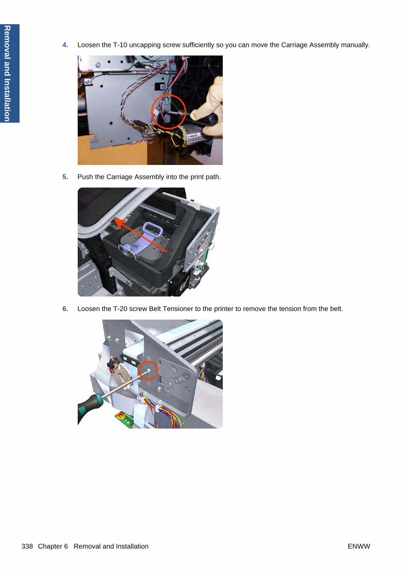
4. Loosen the T-10 uncapping screw sufficiently so you can move the Carriage Assembly manually.
5. Push the Carriage Assembly into the print path.
6. Loosen the T-20 screw Belt Tensioner to the printer to remove the tension from the belt.
338 Chapter 6 Removal and Installation ENWW
Rem
oval an
d In
stallation

7. Leave the Belt Tensioner in place.
8. Remove the Belt Assembly from the drive wheel of the Scan-Axis Motor.
9. Remove three T-20 screws that secure the Scan-Axis Motor to the printer.
ENWW Scan-axis Motor 339
Rem
ova
l an
d In
stal
lati
on
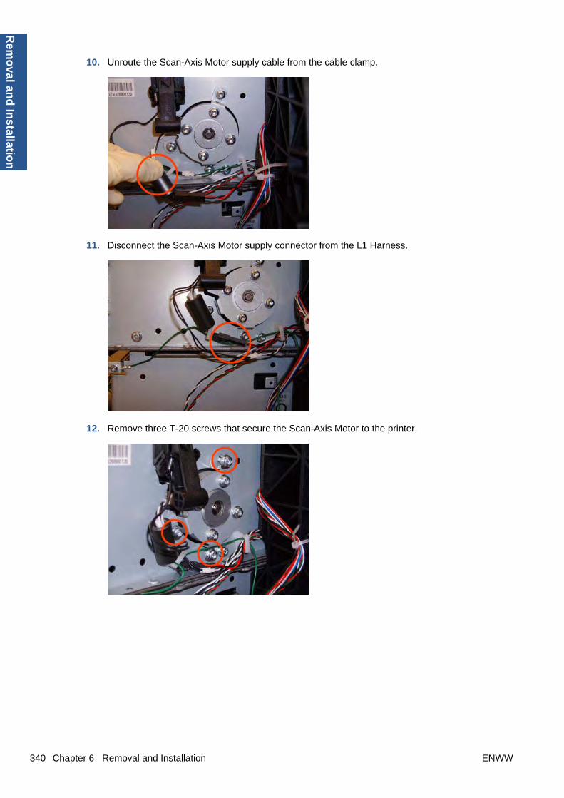
10. Unroute the Scan-Axis Motor supply cable from the cable clamp.
11. Disconnect the Scan-Axis Motor supply connector from the L1 Harness.
12. Remove three T-20 screws that secure the Scan-Axis Motor to the printer.
340 Chapter 6 Removal and Installation ENWW
Rem
oval an
d In
stallation

13. Carefully pull the Scan-Axis Motor out of the printer (10 mm) until you can rotate it approximately30 degrees counterclockwise.
14. Remove the Scan-Axis Motor from the printer.
NOTE: When you finish installing or replacing this component, you must perform the necessaryService Calibrations. To find which calibrations you must perform, see Service Calibration Guide toRemoval and Installation on page 185.
Service Station
Removal
1. Switch off the printer and remove the power cable.
2. Remove the Cover, Right on page 234.
ENWW Service Station 341
Rem
ova
l an
d In
stal
lati
on

3. Disconnect the two lower connectors.
4. Unsnap the clamp from the bottom of the metal sideplate.
5. Remove the grounding cable attachment T-10 screw from the metal sideplate.
342 Chapter 6 Removal and Installation ENWW
Rem
oval an
d In
stallation

6. Disconnect connector from the Primer Motor and Primer Sensor.
7. Unroute the cables disconnected in the previous two steps from the two cable clamps.
8. Loosen the T-10 uncapping screw enough that you can move the Carriage Assembly manually.
ENWW Service Station 343
Rem
ova
l an
d In
stal
lati
on

9. Push the Carriage Assembly into the print path to gain access to two T-10 screws that secure theService Station to the Carriage Rail.
10. Remove the two Allen T-8 screws that secure the Service Station to the Carriage Rail. To avoiddamaging the Encoder Strip, you can use a standard screwdriver.
NOTE: Support the Service Station so that it does not fall when you remove the attachmentscrews.
11. Unclip the clip to release the Service Station from the printer.
344 Chapter 6 Removal and Installation ENWW
Rem
oval an
d In
stallation
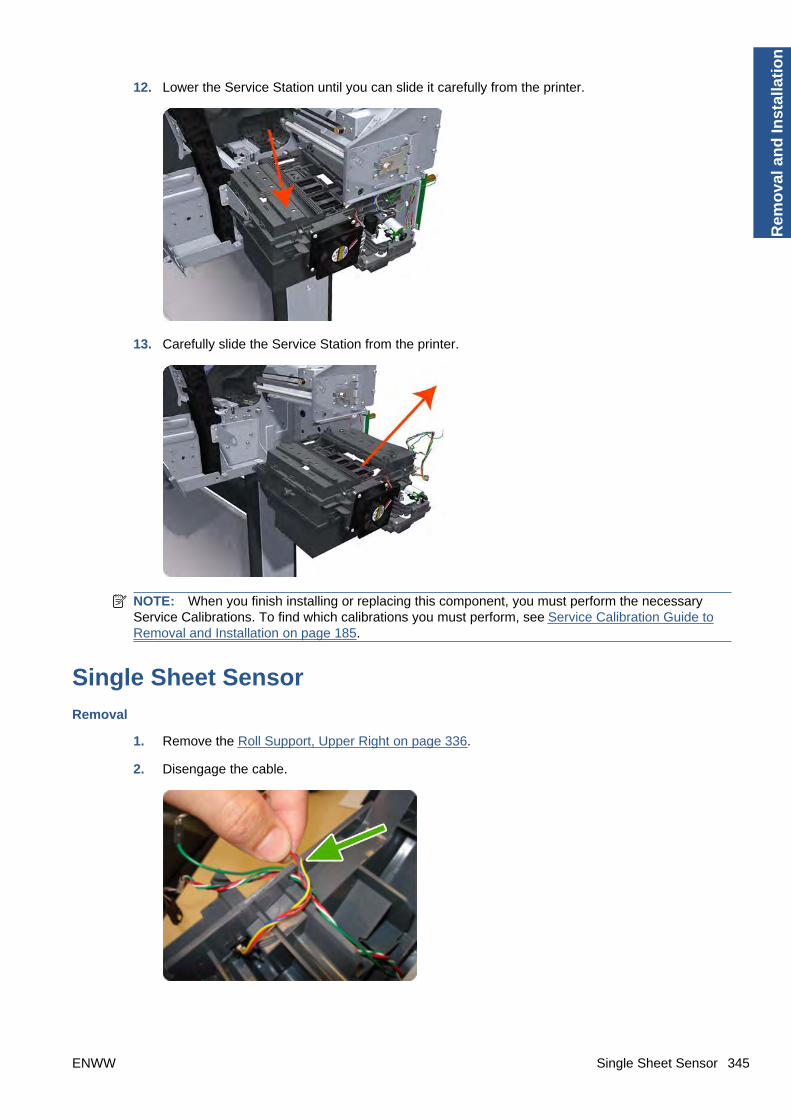
12. Lower the Service Station until you can slide it carefully from the printer.
13. Carefully slide the Service Station from the printer.
NOTE: When you finish installing or replacing this component, you must perform the necessaryService Calibrations. To find which calibrations you must perform, see Service Calibration Guide toRemoval and Installation on page 185.
Single Sheet Sensor
Removal
1. Remove the Roll Support, Upper Right on page 336.
2. Disengage the cable.
ENWW Single Sheet Sensor 345
Rem
ova
l an
d In
stal
lati
on
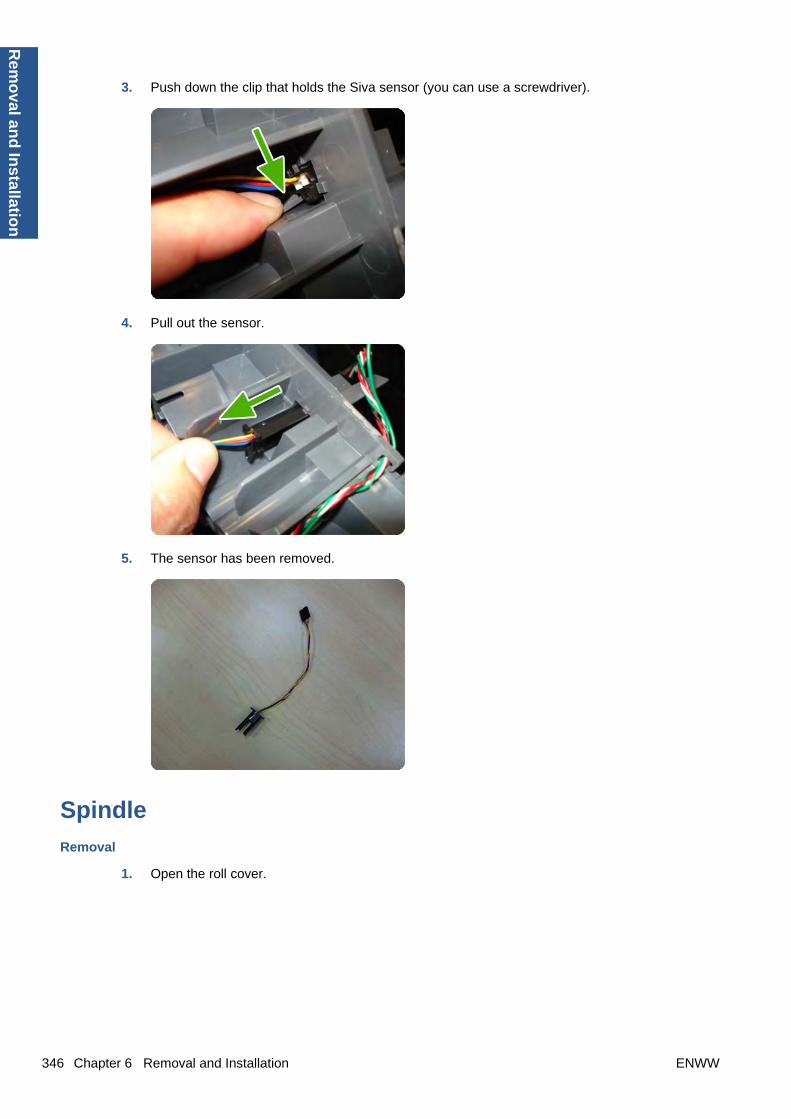
3. Push down the clip that holds the Siva sensor (you can use a screwdriver).
4. Pull out the sensor.
5. The sensor has been removed.
Spindle
Removal
1. Open the roll cover.
346 Chapter 6 Removal and Installation ENWW
Rem
oval an
d In
stallation

2. Remove the black end of the spindle from the printer, then the blue end.
CAUTION: Be sure to remove the black end first. Removing the blue end first could damage theblack end.
CAUTION: Do not insert your fingers into the spindle supports during the removal process.
Spittoon, LeftRemoval
This procedure describes how to remove the complete Left Spittoon which is necessary to gain accessto other components.
NOTE: Switch off the printer and remove the power cable.
1. Remove the Cover, Left on page 229.
2. Remove the Electronics Module Main PCA and PSUon page 247.
3. Remove two T-20 screws that secure the Left Spittoon tothe printer.
ENWW Spittoon, Left 347
Rem
ova
l an
d In
stal
lati
on

4. Remove one T-8 screw that secures the Left Spittoon to theprinter.
5. Rotate the Left Spittoon clockwise approximately 45degrees and carefully lift it out of the printer.
Starwheel Assembly
Removal
1. Switch off the printer and remove the power cable.
2. Open the Window.
348 Chapter 6 Removal and Installation ENWW
Rem
oval an
d In
stallation

3. Remove one T-10 screw that secures the Starwheel Assembly to the printer.
4. Remove another T-10 screw that secures the Starwheel Assembly to the printer.
5. Carefully lift the Starwheel Assembly out of the printer.
NOTE: When you finish installing or replacing this component, you must perform the necessaryService Calibrations. To find which calibrations you must perform, see Service Calibration Guide toRemoval and Installation on page 185.
ENWW Starwheel Assembly 349
Rem
ova
l an
d In
stal
lati
on

Starwheel Lifter, Left
Removal
1. Switch off the printer and remove the power cable.
2. Remove the Cover, Front on page 228.
3. Remove the Cover, Left on page 229.
4. Remove the Electronics Module Main PCA and PSU on page 247.
5. Remove the Spittoon, Left on page 347.
6. Remove the Starwheel Assembly on page 348.
7. Remove two T-8 screws that secure the Left Starwheel Lifter to the printer.
8. Rotate the Left Starwheel Lifter sufficiently to disengage the right attachment lug.
350 Chapter 6 Removal and Installation ENWW
Rem
oval an
d In
stallation

9. Tilt the Left Starwheel Lifter sufficiently to disengage the left attachment lug.
10. Remove the Left Starwheel Lifter from the printer.
NOTE: Do not remove the spring from the Left Starwheel Lifter, because it is difficult to reattach.
NOTE: When you finish installing or replacing this component, you must perform the necessaryService Calibrations. To find which calibrations you must perform, see Service Calibration Guide toRemoval and Installation on page 185.
Starwheel Lifter, Right
Removal
1. Switch off the printer and remove the power cable.
2. Remove the Cover, Right on page 234.
3. Remove the Starwheel Assembly on page 348.
ENWW Starwheel Lifter, Right 351
Rem
ova
l an
d In
stal
lati
on

4. Loosen the T-10 uncapping screw sufficiently so you can manually move the Carriage Assemblyin step 8.
5. Push the Carriage Assembly into the print path.
6. Remove one T-10 screw that secures the Drop Detector to the Service Station.
352 Chapter 6 Removal and Installation ENWW
Rem
oval an
d In
stallation

7. Rotate the Drop Detector vertically to gain access to the two screws that secure the Right StarwheelLifter.
8. Remove two T-8 screws that secure the Right Starwheel Lifter to the printer.
9. Rotate the Right Starwheel Lifter sufficiently to disengage the right attachment lug.
ENWW Starwheel Lifter, Right 353
Rem
ova
l an
d In
stal
lati
on

10. Tilt the Right Starwheel Lifter sufficiently to disengage the left attachment lug.
11. Remove the Right Starwheel Lifter from the printer.
NOTE: Do not remove the spring from the Right Starwheel Lifter, because it is difficult to reattach.
NOTE: When you finish installing or replacing this component, you must perform the necessaryService Calibrations. To find which calibrations you must perform, see Service Calibration Guide toRemoval and Installation on page 185.
Starwheel Motor
Removal
1. Switch off the printer and remove the power cable.
2. Remove the Cover, Front on page 228.
3. Remove the Cover, Left on page 229.
4. Remove the Electronics Module Main PCA and PSU on page 247.
5. Remove the Spittoon, Left on page 347.
354 Chapter 6 Removal and Installation ENWW
Rem
oval an
d In
stallation
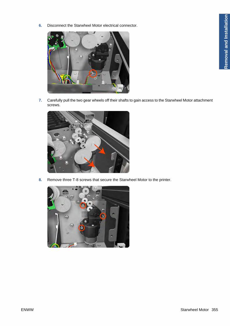
6. Disconnect the Starwheel Motor electrical connector.
7. Carefully pull the two gear wheels off their shafts to gain access to the Starwheel Motor attachmentscrews.
8. Remove three T-8 screws that secure the Starwheel Motor to the printer.
ENWW Starwheel Motor 355
Rem
ova
l an
d In
stal
lati
on

9. Lift the Starwheel Motor out of the printer.
NOTE: When you finish installing or replacing this component, you must perform the necessaryService Calibrations. To find which calibrations you must perform, see Service Calibration Guide toRemoval and Installation on page 185.
Trailing CableThe Trailing Cable, as a service part, is included with the Ink Supply Tubes. For information about theservice part, see Scan-Axis Assemblies on page 171.
For the disassembly procedure of the Ink Supply Tubes, see Ink Supply Tubes on page 272.
Removal
1. Switch off the printer and remove the power cable.
2. Remove the Cover, Left on page 229.
3. Remove the Cover, Right on page 234.
4. Remove the Front Panel on page 258.
5. Remove the Cover, Top on page 237.
6. Loosen the T-10 uncapping screw enough that you can move the Carriage Assembly manually.
356 Chapter 6 Removal and Installation ENWW
Rem
oval an
d In
stallation

7. Unscrew the small cover of the Carriage PCA.
8. Remove the small cover of the Carriage PCA.
9. Disconnect the ribbon Trailing Cable from the Carriage PCA.
ENWW Trailing Cable 357
Rem
ova
l an
d In
stal
lati
on

10. Unclip and remove the cable lid.
11. Straighten the ribbon cable of the Trailing Cables and remove the mylar.
12. Slide the Trailing Cables out of the attachment clips of the Carriage Assembly.
358 Chapter 6 Removal and Installation ENWW
Rem
oval an
d In
stallation

13. Slide the Trailing Cables out of the cable and tube holder.
14. Disconnect the ribbon cable of the Trailing Cables from the Electronics Module.
15. Unroute the Trailing Cable from the clip.
ENWW Trailing Cable 359
Rem
ova
l an
d In
stal
lati
on
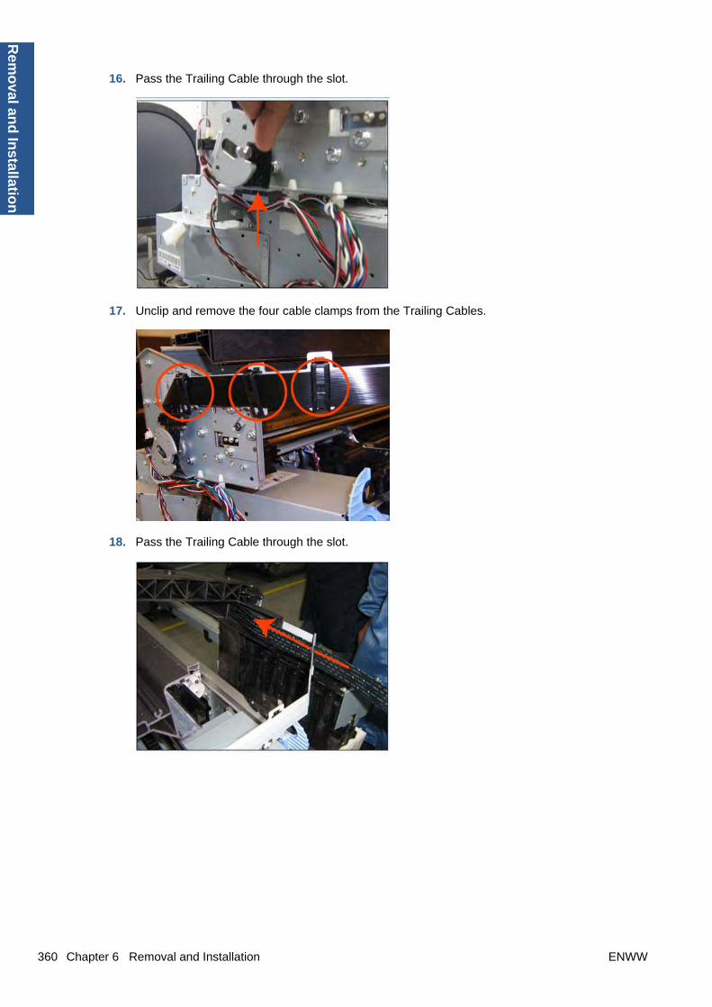
16. Pass the Trailing Cable through the slot.
17. Unclip and remove the four cable clamps from the Trailing Cables.
18. Pass the Trailing Cable through the slot.
360 Chapter 6 Removal and Installation ENWW
Rem
oval an
d In
stallation

19. Pass the Trailing Cable through the slot.
20. Continue to unroute and unclip the trailing cable.
21. Continue to unroute and unclip the trailing cable.
ENWW Trailing Cable 361
Rem
ova
l an
d In
stal
lati
on

22. Remove the Trailing Cables from the printer.
NOTE: When you finish installing or replacing this component, you must perform the necessaryService Calibrations. To find which calibrations you must perform, see Service Calibration Guide toRemoval and Installation on page 185.
Installation
1. Route the Trailing Cable as in the disassembly instructions, taking care not to damage the cable.
2. When you route the Trailing Cable around the bend, use your finger to leave a healthy bend forthe cable. Avoid creasing the cable.
362 Chapter 6 Removal and Installation ENWW
Rem
oval an
d In
stallation

Wall Spacers
Removal
The illustrations show the removal of the Right Wall Spacer; the procedure is the same for the Left WallSpacer.
1. Remove a screw.
2. Open the Upper Roll Cover.
3. Remove a screw.
ENWW Wall Spacers 363
Rem
ova
l an
d In
stal
lati
on

4. Remove the Upper Roll Cover Support.
5. Remove a screw.
6. Remove a blue Wall Spacer.
7. Remove a white slider.
364 Chapter 6 Removal and Installation ENWW
Rem
oval an
d In
stallation

After removing Right and Left Wall Spacers, here are the removed parts.
Window
Removal
NOTE: The Window can also be removed with the Top Cover to avoid scratching the Window. SeeCover, Top on page 237.
1. Switch off the printer and remove the power cable.
2. Open the Window.
3. Remove the two T-15 screws that secure the left Window hinge locking plate to the Top Cover.
ENWW Window 365
Rem
ova
l an
d In
stal
lati
on

4. Remove the left Window hinge locking plate from the Top Cover.
5. Remove the Damper Rotary from the Top Cover.
6. Remove the T-15 screws that secure each of the remaining three Window hinge locking plates tothe Top Cover.
366 Chapter 6 Removal and Installation ENWW
Rem
oval an
d In
stallation

7. Remove the remaining three Window hinge locking plates from the Top Cover.
8. Remove the remaining three Damper Rotary pieces from the Top Cover.
9. Grip the Window at the left and right edges and move it horizontally towards the right as far as itwill go.
ENWW Window 367
Rem
ova
l an
d In
stal
lati
on

10. Pull the Window towards the front to disengage the hinges.
11. Lift the Window vertically out of the printer.
Window Position Sensor
Removal
1. Switch off the printer and remove the power cable.
2. Remove the Cover, Right on page 234.
3. Remove the Cover, Left on page 229.
4. Remove the Front Panel on page 258.
5. Remove the Cover, Rear on page 233.
6. Remove the Cover, Top on page 237.
368 Chapter 6 Removal and Installation ENWW
Rem
oval an
d In
stallation

7. Disconnect the Window Position Sensor.
8. Remove one T-15 screw that secures the Window Position Sensor to the printer.
9. Remove the Window Position Sensor from the printer.
NOTE: When you finish installing or replacing this component, you must perform the necessaryService Calibrations. To find which calibrations you must perform, see Service Calibration Guide toRemoval and Installation on page 185.
ENWW Window Position Sensor 369
Rem
ova
l an
d In
stal
lati
on

7 Preventive Maintenance
● Preventive Maintenance
● Preventive Maintenance Kits
370 Chapter 7 Preventive Maintenance ENWW
Preven
tive Main
tenan
ce

Preventive Maintenance
Cleaning the Printer
To maintain the printer in good operating condition, keep it free of accumulated dust, ink, and othercontamination. Cleaning intervals are determined by the printer environment and by the types of printersupplies used.
General Cleaning
Proper general cleaning should include the following:
NOTE: To prevent an electric shock, make sure that the printer is switched OFF and unplugged beforeany cleaning is performed. Do not let any water get inside the printer.
1. Blow away dust accumulation with compressed air if available.
2. Clean the outer surface of the printer with a damp sponge or cloth. Use a mild soap and watersolution if necessary. Do not use abrasive cleaners.
3. Wipe the printer dry with a soft lint-free cloth.
Cleaning the Drive Roller and Overdrive
NOTE: If ink is spilled on the Overdrive, remove the ink immediately. Due to the ink's reflectance, inkon the Overdrive can disrupt the printer's edge-sensing function. To remove any ink from the Overdrive,perform the following procedure:Prevent water or other liquids from running onto electrical componentsor circuits, or through openings in the Electronics Module.
1. Perform the Turn Drive Roller Utility. See Turn Drive Roller on page 123.
2. Open the window and apply any common household cleaning solution (water based only) to a soft,lint-free rag and apply it to the Drive Roller and Overdrive surface while it is rotating. Make surethat you thoroughly clean the Drive Roller and Overdrive surface.
3. Press Enter when you have completed the cleaning procedure.
4. Allow the Drive Roller to dry before loading media in to the printer.
Cleaning the Encoder Strip
1. Make sure that the printer is not printing and that the Carriage Assembly is located at the ServiceStation on the far right side of the printer.
ENWW Preventive Maintenance 371
Pre
ven
tive
Mai
nte
nan
ce

2. Using tap water and a small cloth that will not leave fibers in the printer, dampen the cloth andremove any excess water so that the cloth is damp but not wet.
3. Open the printer window.
372 Chapter 7 Preventive Maintenance ENWW
Preven
tive Main
tenan
ce

4. Hold the cloth in an inverted “U” shape around the Encoder Strip and carefully wipe until no inkresidue appears on the cloth. Be very careful not to scratch the Encoder Strip with your fingernailor any other object.
Make sure that you are holding the cloth correctly.
NOTE: Do not move the Carriage Assembly away from the Service Station.
ENWW Preventive Maintenance 373
Pre
ven
tive
Mai
nte
nan
ce

5. Close the printer window.
6. On the front panel, select the Ink icon, and then select Replace Printheads. The Carriage Assemblymoves to the left and stops in the correct position to remove the printheads.
7. Turn off the printer by using the power switch on the back of the printer.
8. Open the printer window and move the Carriage Assembly further to the left, allowing you to accessthe Service Station.
374 Chapter 7 Preventive Maintenance ENWW
Preven
tive Main
tenan
ce

9. Clean the part of the encoder strip inside the Service Station by repeating steps 2 to 6.
10. Close the printer window.
11. Turn the printer back on.
Carriage Assembly Lubrication
To ensure correct operation of the printer you must lubricate the Carriage Assembly whenever any ofthe following are encountered if:
● The Front Panel displays "Maintenance #1 required".
● There is excessive noise when moving the Carriage Assembly.
● A shut down of the carriage PWM error message appears.
● There are IQ (vertical banding problems).
You should also lubricate the Carriage Assembly whenever you change any of the following serviceparts:
● The Carriage Rear Bushing.
● The Carriage Assembly.
● The Carriage Rail Oiler.
To lubricate the Carriage Assembly you will require the Lubrication Kit (Q5669-60692). Use the followingprocedure to lubricate the Carriage Assembly:
1. Use the IPA alcohol (Q6675-60070) and the cleaning cloth to clean the Carriage Rail and theCarriage Slider Rod.
2. Use an Oil Dispenser (Q6675-60062) to lubricate the Carriage Rail and the Carriage Slider Rod.
3. Replace the Carriage Rail Oiler on page 219 with the new one contained in the kit and add 2 or 3drops of oil to the foam of the Carriage Rail Oiler.
4. Use an Oil Dispenser (Q6675-60062) to lubricate the Carriage Rear Bushing.
Moisture on the Printer
Users should use the printer in an environment between 20% and 80% relative humidity. To recoverfrom moisture condensation, turn the printer Off, and, using the main roller as a reference, wait until theprinter is completely dry before using it again.
ENWW Preventive Maintenance 375
Pre
ven
tive
Mai
nte
nan
ce
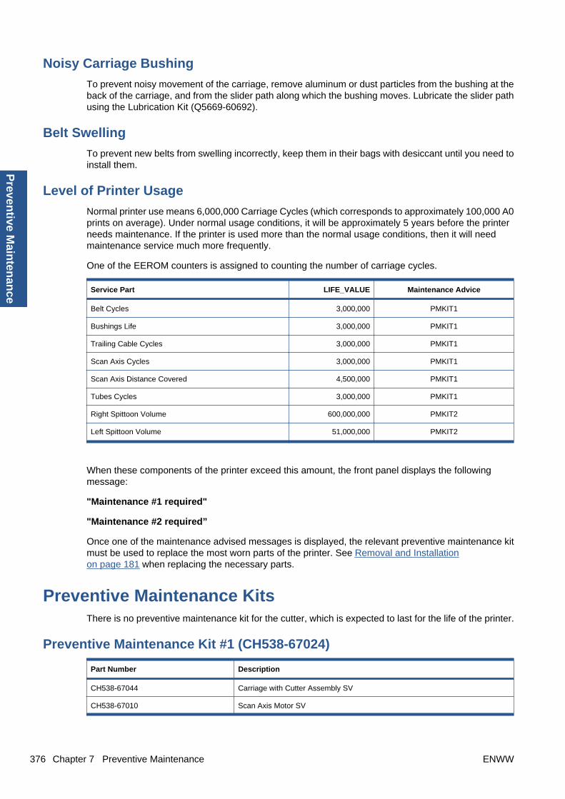
Noisy Carriage Bushing
To prevent noisy movement of the carriage, remove aluminum or dust particles from the bushing at theback of the carriage, and from the slider path along which the bushing moves. Lubricate the slider pathusing the Lubrication Kit (Q5669-60692).
Belt Swelling
To prevent new belts from swelling incorrectly, keep them in their bags with desiccant until you need toinstall them.
Level of Printer Usage
Normal printer use means 6,000,000 Carriage Cycles (which corresponds to approximately 100,000 A0prints on average). Under normal usage conditions, it will be approximately 5 years before the printerneeds maintenance. If the printer is used more than the normal usage conditions, then it will needmaintenance service much more frequently.
One of the EEROM counters is assigned to counting the number of carriage cycles.
Service Part LIFE_VALUE Maintenance Advice
Belt Cycles 3,000,000 PMKIT1
Bushings Life 3,000,000 PMKIT1
Trailing Cable Cycles 3,000,000 PMKIT1
Scan Axis Cycles 3,000,000 PMKIT1
Scan Axis Distance Covered 4,500,000 PMKIT1
Tubes Cycles 3,000,000 PMKIT1
Right Spittoon Volume 600,000,000 PMKIT2
Left Spittoon Volume 51,000,000 PMKIT2
When these components of the printer exceed this amount, the front panel displays the followingmessage:
"Maintenance #1 required"
"Maintenance #2 required”
Once one of the maintenance advised messages is displayed, the relevant preventive maintenance kitmust be used to replace the most worn parts of the printer. See Removal and Installationon page 181 when replacing the necessary parts.
Preventive Maintenance KitsThere is no preventive maintenance kit for the cutter, which is expected to last for the life of the printer.
Preventive Maintenance Kit #1 (CH538-67024)
Part Number Description
CH538-67044 Carriage with Cutter Assembly SV
CH538-67010 Scan Axis Motor SV
376 Chapter 7 Preventive Maintenance ENWW
Preven
tive Main
tenan
ce

Part Number Description
CH538-67025 Tube System 44 Assembly with Trailing Cable SV
CH538-67018 Belt 44 SV
NOTE: The Lubrication Kit is not included in the Preventive Maintenance Kit. See Tool Kitson page 179.
Preventive Maintenance Kit #2 (CH538-67040)
Part Number Description
CH538-60051 Service Station Assembly
ENWW Preventive Maintenance Kits 377
Pre
ven
tive
Mai
nte
nan
ce
Related Documents