Installation and Configuration Guide HP J3100B HP AdvanceStack Switch 2000

Welcome message from author
This document is posted to help you gain knowledge. Please leave a comment to let me know what you think about it! Share it to your friends and learn new things together.
Transcript

Installation and
Configuration Guide
HP J3100B
HP AdvanceStack Switch 2000
B_SCOTS.BK : b_cvrfrn.fm5 Page 1 Thursday, February 20, 1997 2:19 PM

B_SCOTS.BK : b_cvrfrn.fm5 Page 2 Thursday, February 20, 1997 2:19 PM
B_SCOTS.BK : b_perfsd.fm5 Page 1 Thursday, February 20, 1997 2:19 PM
HP Customer Support Services
How to get the latest software/agent firmware
You can download from the World Wide Web, HP FTP Library Service, CompuServe, and HP BBS a compressed file (j3100b.exe) containing the latest version of the HP Switch 2000 software and proprietary MIB, the HP J3108A FDDI Module software, and a software download utility file (update.exe). After you download the file, extract the file by typing filename�AND�PRESSING [Enter]. For example, j3100b [Enter].
World Wide Web
http://www.hp.com/go/network_city
Select the “Support” section.
From this web site, you can also download information on the HP networking products. If you have a growing network, download the Designing HP AdvanceStack
Workgroup Networks Guide or call 1-800-752-0900 in the U.S. to receive a copy through the mail.
HP FTP Library Service
1. FTP to Internet IP Address — ftp ftp.hp.com.2. Log in as anonymous and press [Return] at the password prompt. 3. Enter bin to set the transfer type. 4. Enter cd /pub/networking/software.5. Enter get filename to transfer the file to your computer, then quit.
CompuServe
1. Login to CompuServe.2. Go to the “hp” service.3. Select “HP Systems, Disks, Tapes, etc.”4. Select “Networking Products” library.5. $OWNLOAD filename and then quit.
HP BBS
Set your modem to no parity, eight bits, 1 stop bit, set speed up to 14400 bps, and with your telecommunication program (e.g., Windows Terminal) dial (208) 344-1691 in the U.S. to get the latest software for your HP networking product. For other countries, see http://www.hp.com/cposupport/eschome.html.
Perforate
✂(over for more services)
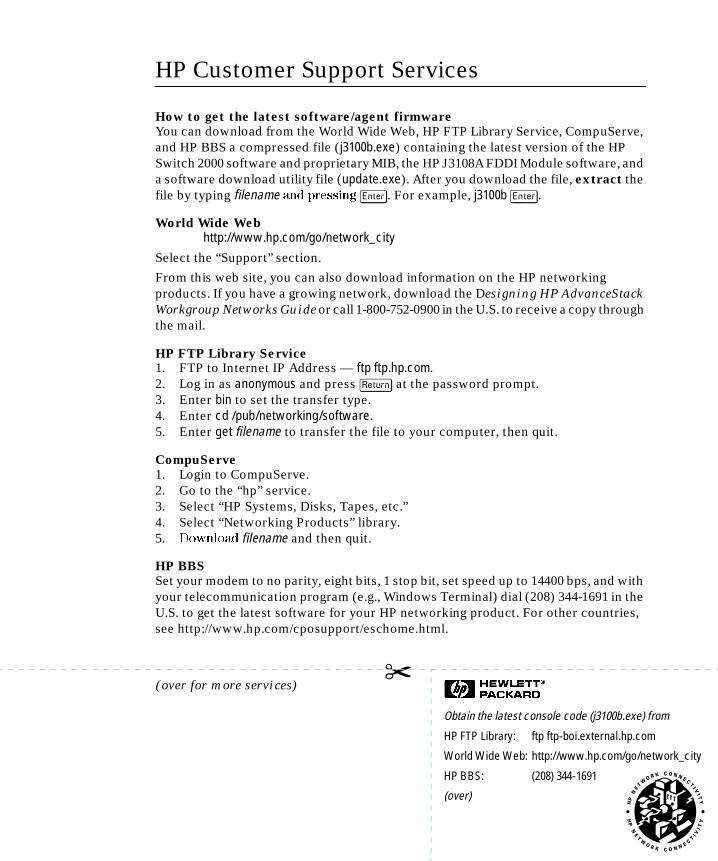
Obtain the latest console code (j3100b.exe) from
HP FTP Library: ftp ftp-boi.external.hp.com
World Wide Web: http://www.hp.com/go/network_city
HP BBS: (208) 344-1691
(over)

Compu
NetwoSuppor
B_SCOTS.BK : b_perfsd.fm5 Page 2 Thursday, February 20, 1997 2:19 PM
✂
HP FIRST Fax Retrieval Service
HP FIRST is an automated fax retrieval service that is available 24 hours a day, seven days a week. HP FIRST provides information on the following topics:■ Product information■ Troubleshooting instructions■ Technical reviews and articles■ Configuration information
To access HP FIRST, dial one of the following phone numbers:
Additional HP Support Services
In addition to the above services, you can purchase various HP telephone support services which provide you expert HP technical assistance:■ Network Phone-In Support provides you support at an hourly rate. In the U.S.,
call 1-800-790-5544. In other countries, please contact your local HP Response Center to see if this service is available in your country.
■ HP SupportPack Comprehensive Network Support provides complete prob-lem resolution for medium to large interconnected local and wide area networks. Contact your HP Authorized Reseller or the nearest HP Sales and Support Office for more information.
HP offers other hardware support services. Please contact your reseller for more information.
Location Phone Number
U.S. and Canada Only Dial 1 (800) 333-1917 with your fax machine or touch-tone phone and press 1.
Outside the U.S. and Canada Dial 1 (208) 344-4809 from your fax machine and press 9.
To receive a list of currently available documents, enter document number 19941. The information you requested will be sent to you by return fax. For other countries, see http://www.hp.com/cposupport/eschome.html.
Perforate
Serve: Go hpsys Lib 7.Download j3100b.exe
rk Phone-In t (hourly):
1-800-790-5544

B_SCOTS.BK : b_front.fm5 Page i Thursday, February 20, 1997 2:19 PM
HP AdvanceStack Switch 2000
Installation and Configuration GuideHP J3100B

Hewlett-Packard Company8000 Foothills Boulevard, m/s 5551Roseville, California 95747-5551http://www.hp.com/go/network_city
© Copyright 1997 Hewlett-Packard CompanyAll Rights Reserved.
This document contains information which is protected by copyright. Reproduction, adaptation, or translation without prior permission is prohibited, except as allowed under the copyright laws.
Publication Number
5966-5212March 1997
Applicable Product
HP J3100B
Disclaimer
The information contained in this document is subject to change without notice.
HEWLETT-PACKARD COMPANY MAKES NO WARRANTY OF ANY KIND WITH REGARD TO THIS MATERIAL, INCLUDING, BUT NOT LIMITED TO, THE IMPLIED WARRANTIES OF MERCHANTABILITY AND FITNESS FOR A PARTICULAR PURPOSE. Hewlett-Packard shall not be liable for errors contained herein or for incidental or consequential damages in connection with the furnishing, performance, or use of this material.
Hewlett-Packard assumes no responsibility for the use or reliability of its software on equipment that is not furnished by Hewlett-Packard.
Warranty
A copy of the specific warranty terms applicable to your Hewlett-Packard products and replacement parts can be obtained from your HP Sales and Service Office or authorized dealer.
B_SCOTS.BK : b_front.fm5 Page ii Thursday, February 20, 1997 2:19 PM
Preface
B_SCOTS.BK : b_front.fm5 Page iii Thursday, February 20, 1997 2:19 PM
Preface
Use of This Guide and Other Switch 2000 Documentation
This guide describes how to install the B-version of the Switch 2000 (HP J3100B) in your network and use the console interface for the HP AdvanceStack Switch 2000 (hereafter referred to as the “Switch 2000”).
O p e r a t i n g D i f f e r e n c e s
This manual describes features of the B-version of the Hewlett-Packard Switch 2000 (HP J3100B). In some cases, such as the Spanning Tree Protocol (operating within VLANs) and port trunking capabilities, there are significant operating differences between the A-version of the Switch 2000 (HP J3100A) and the B-version. For information on the features available in the A-version, refer to the manuals shipped with that product.
Important! Before installing or removing an interface module (or installing or removing a transceiver used with a module), refer to the specific module documentation describing these procedures.
■ If you need information on specific parameters in the console interface, refer to the online help provided in the interface.
■ If you need further information on Hewlett-Packard switch technology, refer to the HP AdvanceStack Products CD shipped with your Switch 2000.
iii
Preface
B_SCOTS.BK : b_front.fm5 Page iv Thursday, February 20, 1997 2:19 PM
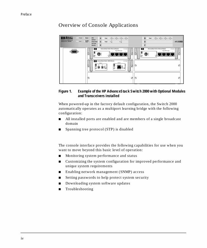
Overview of Console Applications
Figure 1. Example of the HP AdvanceStack Switch 2000 with Optional Modules and Transceivers installed
When powered-up in the factory default configuration, the Switch 2000 automatically operates as a multiport learning bridge with the following configuration:
■ All installed ports are enabled and are members of a single broadcast domain
■ Spanning tree protocol (STP) is disabled
The console interface provides the following capabilities for use when you want to move beyond this basic level of operation:
■ Monitoring system performance and status
■ Customizing the system configuration for improved performance and unique system requirements
■ Enabling network management (SNMP) access
■ Setting passwords to help protect system security
■ Downloading system software updates
■ Troubleshooting
iv

Contents
B_SCOTS.BK : b_toc.toc Page v Thursday, February 20, 1997 2:19 PM
1 Installing the Switch
Installation Summary . . . . . . . . . . . . . . . . . . . . . . . . . . . . . . . . . . . . . . . . . . 1-1
1. Install Add-In Modules (Optional) . . . . . . . . . . . . . . . . . . . . . . . . . . 1-3
2. Install the Redundant Power Supply (Optional) . . . . . . . . . . . . . . 1-4
3. Verify the Switch’s Operation . . . . . . . . . . . . . . . . . . . . . . . . . . . . . . . 1-5
4. Mount the Switch . . . . . . . . . . . . . . . . . . . . . . . . . . . . . . . . . . . . . . . . . . 1-7
5. Complete the Network Connections to the Switch . . . . . . . . . . 1-12
6. Connect a Console Device (Optional) . . . . . . . . . . . . . . . . . . . . . . 1-14
Where To Go from Here . . . . . . . . . . . . . . . . . . . . . . . . . . . . . . . . . . . . . . 1-18
2 Using the Console Interface
Overview . . . . . . . . . . . . . . . . . . . . . . . . . . . . . . . . . . . . . . . . . . . . . . . . . . . . . 2-1
Starting and Ending a Console Session . . . . . . . . . . . . . . . . . . . . . . . . . 2-2
Main Menu Features . . . . . . . . . . . . . . . . . . . . . . . . . . . . . . . . . . . . . . . . . . 2-4
Screen Structure and Navigation . . . . . . . . . . . . . . . . . . . . . . . . . . . . . . . 2-5
Using Password Security . . . . . . . . . . . . . . . . . . . . . . . . . . . . . . . . . . . . . . . 2-7
Rebooting the Switch . . . . . . . . . . . . . . . . . . . . . . . . . . . . . . . . . . . . . . . . . 2-10
Resetting the Switch . . . . . . . . . . . . . . . . . . . . . . . . . . . . . . . . . . . . . . . . . 2-12
Advanced Commands Features . . . . . . . . . . . . . . . . . . . . . . . . . . . . . . . . 2-12
v

B_SCOTS.BK : b_toc.toc Page vi Thursday, February 20, 1997 2:19 PM
3 Configuring the Switch
Overview . . . . . . . . . . . . . . . . . . . . . . . . . . . . . . . . . . . . . . . . . . . . . . . . . . . . . 3-1
Configurable Features . . . . . . . . . . . . . . . . . . . . . . . . . . . . . . . . . . . . . . . . . 3-3
System Features . . . . . . . . . . . . . . . . . . . . . . . . . . . . . . . . . . . . . . . . . . . . 3-5
Port Features . . . . . . . . . . . . . . . . . . . . . . . . . . . . . . . . . . . . . . . . . . . . . . . 3-6
IPX Service Features . . . . . . . . . . . . . . . . . . . . . . . . . . . . . . . . . . . . . . . . . 3-7
Internet (IP) Service Features . . . . . . . . . . . . . . . . . . . . . . . . . . . . . . . . . 3-9
SNMP Communities Features . . . . . . . . . . . . . . . . . . . . . . . . . . . . . . . . 3-11
Trap Receivers Features . . . . . . . . . . . . . . . . . . . . . . . . . . . . . . . . . . . . . 3-13
IP Multicast (IGMP) Service Features—Multimedia Traffic Control 3-14
Serial Link Features . . . . . . . . . . . . . . . . . . . . . . . . . . . . . . . . . . . . . . . . 3-15
Console Features . . . . . . . . . . . . . . . . . . . . . . . . . . . . . . . . . . . . . . . . . . . 3-16
Spanning Tree Features . . . . . . . . . . . . . . . . . . . . . . . . . . . . . . . . . . . . . 3-17
Traffic/Security Filter Features . . . . . . . . . . . . . . . . . . . . . . . . . . . . . . . 3-18
Virtual LAN (VLAN) Features . . . . . . . . . . . . . . . . . . . . . . . . . . . . . . . . 3-19
Network Monitoring Port Features . . . . . . . . . . . . . . . . . . . . . . . . . . . . 3-20
Automatic Broadcast Control (ABC) Features—Layer 3 Switching 3-23
4 Monitoring and Analyzing Switch Operation from the
Console
Overview . . . . . . . . . . . . . . . . . . . . . . . . . . . . . . . . . . . . . . . . . . . . . . . . . . . . . 4-1
Status and Counters Menu . . . . . . . . . . . . . . . . . . . . . . . . . . . . . . . . . . . . . 4-2
Switch Information . . . . . . . . . . . . . . . . . . . . . . . . . . . . . . . . . . . . . . . . . . 4-3
Port Status . . . . . . . . . . . . . . . . . . . . . . . . . . . . . . . . . . . . . . . . . . . . . . . . . 4-4
Port Counters . . . . . . . . . . . . . . . . . . . . . . . . . . . . . . . . . . . . . . . . . . . . . . . 4-5
Address Table . . . . . . . . . . . . . . . . . . . . . . . . . . . . . . . . . . . . . . . . . . . . . . 4-7
Port Address Table . . . . . . . . . . . . . . . . . . . . . . . . . . . . . . . . . . . . . . . . . . 4-8
Spanning Tree (STP) Information . . . . . . . . . . . . . . . . . . . . . . . . . . . . . 4-10
Module Information . . . . . . . . . . . . . . . . . . . . . . . . . . . . . . . . . . . . . . . . 4-12
IP Multicast (IGMP) Status . . . . . . . . . . . . . . . . . . . . . . . . . . . . . . . . . . 4-13
Automatic Broadcast Control (ABC) Information . . . . . . . . . . . . . . . 4-15
Event Log . . . . . . . . . . . . . . . . . . . . . . . . . . . . . . . . . . . . . . . . . . . . . . . . . . . . 4-16
vi

B_SCOTS.BK : b_toc.toc Page vii Thursday, February 20, 1997 2:19 PM
5 Using SNMP To Monitor and Manage the Switch
SNMP Management . . . . . . . . . . . . . . . . . . . . . . . . . . . . . . . . . . . . . . . . . . . . 5-1
SNMP Configuration Process . . . . . . . . . . . . . . . . . . . . . . . . . . . . . . . . . . 5-3
6 Using the Advanced Commands
Overview . . . . . . . . . . . . . . . . . . . . . . . . . . . . . . . . . . . . . . . . . . . . . . . . . . . . . 6-1
Commands . . . . . . . . . . . . . . . . . . . . . . . . . . . . . . . . . . . . . . . . . . . . . . . . . . . . 6-4
7 Advanced Concepts
Overview . . . . . . . . . . . . . . . . . . . . . . . . . . . . . . . . . . . . . . . . . . . . . . . . . . . . . 7-1
Spanning Tree Protocol (STP) . . . . . . . . . . . . . . . . . . . . . . . . . . . . . . . . . 7-2
Port Trunking . . . . . . . . . . . . . . . . . . . . . . . . . . . . . . . . . . . . . . . . . . . . . . . . . 7-5
Filters and Security . . . . . . . . . . . . . . . . . . . . . . . . . . . . . . . . . . . . . . . . . . . 7-8
Virtual LANs (VLANs) . . . . . . . . . . . . . . . . . . . . . . . . . . . . . . . . . . . . . . . . 7-14
Effect of VLANs on Other Switch Features . . . . . . . . . . . . . . . . . . . . . 7-15
How To Configure a VLAN . . . . . . . . . . . . . . . . . . . . . . . . . . . . . . . . . . . 7-17
VLAN Restrictions . . . . . . . . . . . . . . . . . . . . . . . . . . . . . . . . . . . . . . . . . . 7-21
IP Multicast (IGMP) . . . . . . . . . . . . . . . . . . . . . . . . . . . . . . . . . . . . . . . . . 7-23
How IGMP Operates . . . . . . . . . . . . . . . . . . . . . . . . . . . . . . . . . . . . . . . . 7-23
How To Configure IGMP . . . . . . . . . . . . . . . . . . . . . . . . . . . . . . . . . . . . 7-26
Automatic Broadcast Control (ABC) . . . . . . . . . . . . . . . . . . . . . . . . . . 7-30
How ABC Operates . . . . . . . . . . . . . . . . . . . . . . . . . . . . . . . . . . . . . . . . . 7-30
How To Configure ABC . . . . . . . . . . . . . . . . . . . . . . . . . . . . . . . . . . . . . 7-32
vii

B_SCOTS.BK : b_toc.toc Page viii Thursday, February 20, 1997 2:19 PM
8 File Transfers
Overview . . . . . . . . . . . . . . . . . . . . . . . . . . . . . . . . . . . . . . . . . . . . . . . . . . . . . 8-1
Downloading an Operating System . . . . . . . . . . . . . . . . . . . . . . . . . . . . . 8-2
Using TFTP To Download the OS File . . . . . . . . . . . . . . . . . . . . . . . . . . 8-3
Switch-to-Switch Download . . . . . . . . . . . . . . . . . . . . . . . . . . . . . . . . . . 8-6
Troubleshooting TFTP Downloads . . . . . . . . . . . . . . . . . . . . . . . . . . . . . 8-7
Transferring Switch 2000 Configurations . . . . . . . . . . . . . . . . . . . . . . . 8-9
9 Troubleshooting
Troubleshooting Approaches . . . . . . . . . . . . . . . . . . . . . . . . . . . . . . . . . . . 9-1
Diagnosing with the LEDs . . . . . . . . . . . . . . . . . . . . . . . . . . . . . . . . . . . . . 9-2
Installation Problems . . . . . . . . . . . . . . . . . . . . . . . . . . . . . . . . . . . . . . . . . 9-6
Incorrect Hardware Installation . . . . . . . . . . . . . . . . . . . . . . . . . . . . . . . 9-6
Console RS-232 Problems . . . . . . . . . . . . . . . . . . . . . . . . . . . . . . . . . . . . 9-6
Cabling Problems . . . . . . . . . . . . . . . . . . . . . . . . . . . . . . . . . . . . . . . . . . . 9-7
100VG Connection Problems . . . . . . . . . . . . . . . . . . . . . . . . . . . . . . . . . . 9-8
Unusual Network Activity . . . . . . . . . . . . . . . . . . . . . . . . . . . . . . . . . . . . . 9-8
Diagnostic Tests . . . . . . . . . . . . . . . . . . . . . . . . . . . . . . . . . . . . . . . . . . . . . . 9-9
Testing Twisted-Pair Cabling . . . . . . . . . . . . . . . . . . . . . . . . . . . . . . . . . . 9-9
Testing End-to-End Network Communications . . . . . . . . . . . . . . . . . . 9-9
Testing Switch-to-Device Network Communications . . . . . . . . . . . . 9-10
Customer Support Services . . . . . . . . . . . . . . . . . . . . . . . . . . . . . . . . . . . 9-10
A Cables and Connectors
Recommended Cables . . . . . . . . . . . . . . . . . . . . . . . . . . . . . . . . . . . . . . . . A-2
Twisted-Pair Cable/Connector Pin-Outs . . . . . . . . . . . . . . . . . . . . . . . A-3
Twisted-Pair Cable Pin Assignments . . . . . . . . . . . . . . . . . . . . . . . . . . A-6
RS-232 Connector and Cable Pin-Outs . . . . . . . . . . . . . . . . . . . . . . . . . A-7
RS-232-C “Null Modem” Cable . . . . . . . . . . . . . . . . . . . . . . . . . . . . . . . . A-8
Minimum Cable Pin-out for Direct Console Connection . . . . . . . . . . A-8
RS-232 Modem Cable . . . . . . . . . . . . . . . . . . . . . . . . . . . . . . . . . . . . . . . A-9
viii

B_SCOTS.BK : b_toc.toc Page ix Thursday, February 20, 1997 2:19 PM
B Specifications
Physical . . . . . . . . . . . . . . . . . . . . . . . . . . . . . . . . . . . . . . . . . . . . . . . . . . . B-1
Electrical . . . . . . . . . . . . . . . . . . . . . . . . . . . . . . . . . . . . . . . . . . . . . . . . . B-1
Environmental . . . . . . . . . . . . . . . . . . . . . . . . . . . . . . . . . . . . . . . . . . . . . B-1
Connectors . . . . . . . . . . . . . . . . . . . . . . . . . . . . . . . . . . . . . . . . . . . . . . . . B-2
Electromagnetic . . . . . . . . . . . . . . . . . . . . . . . . . . . . . . . . . . . . . . . . . . . B-2
Safety . . . . . . . . . . . . . . . . . . . . . . . . . . . . . . . . . . . . . . . . . . . . . . . . . . . . B-2
C Sample Console Configurations
Windows 3.1 Terminal Application . . . . . . . . . . . . . . . . . . . . . . . . . . . . C-1
Procomm Plus V2.01 . . . . . . . . . . . . . . . . . . . . . . . . . . . . . . . . . . . . . . . . . . C-2
Other Terminal Emulators . . . . . . . . . . . . . . . . . . . . . . . . . . . . . . . . . . . . C-3
D Switch Reference
Front of Switch . . . . . . . . . . . . . . . . . . . . . . . . . . . . . . . . . . . . . . . . . . . . . . D-1
Back of the Switch . . . . . . . . . . . . . . . . . . . . . . . . . . . . . . . . . . . . . . . . . . . D-7
E BOOTP Operation
Overview . . . . . . . . . . . . . . . . . . . . . . . . . . . . . . . . . . . . . . . . . . . . . . . . . . . . E-1
The Bootp Process . . . . . . . . . . . . . . . . . . . . . . . . . . . . . . . . . . . . . . . . . . . E-1
Bootp Database Record Entries . . . . . . . . . . . . . . . . . . . . . . . . . . . . . . . E-2
Configuring Bootp . . . . . . . . . . . . . . . . . . . . . . . . . . . . . . . . . . . . . . . . . . . . E-3
F MAC Address Management
Overview . . . . . . . . . . . . . . . . . . . . . . . . . . . . . . . . . . . . . . . . . . . . . . . . . . . . . F-1
Switch (Default) MAC Address . . . . . . . . . . . . . . . . . . . . . . . . . . . . . . . . F-2
VLAN MAC Addresses . . . . . . . . . . . . . . . . . . . . . . . . . . . . . . . . . . . . . . . . . F-3
MAC Addresses (for Spanning Tree Operation) . . . . . . . . . . . . . . . . . F-4
Safety and Regulatory Statements
Index
ix

B_SCOTS.BK : b_toc.toc Page x Thursday, February 20, 1997 2:19 PM
Installing the Switch
B_SCOTS.BK : b_chp1.fm5 Page 1 Thursday, February 20, 1997 2:19 PM
1
Installing the Switch
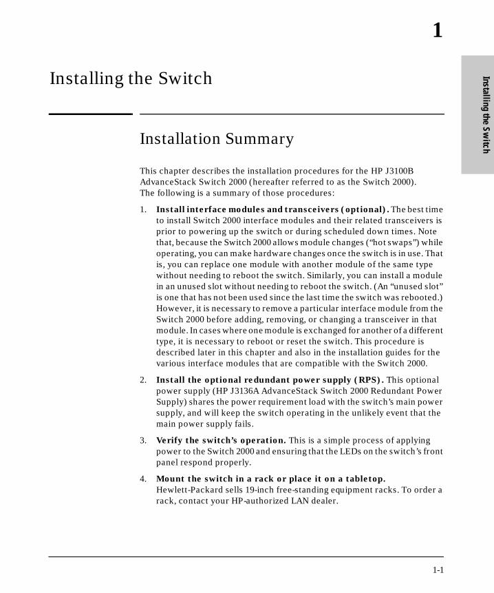
Installation Summary
This chapter describes the installation procedures for the HP J3100B AdvanceStack Switch 2000 (hereafter referred to as the Switch 2000). The following is a summary of those procedures:
1. Install interface modules and transceivers (optional). The best time to install Switch 2000 interface modules and their related transceivers is prior to powering up the switch or during scheduled down times. Note that, because the Switch 2000 allows module changes (“hot swaps”) while operating, you can make hardware changes once the switch is in use. That is, you can replace one module with another module of the same type without needing to reboot the switch. Similarly, you can install a module in an unused slot without needing to reboot the switch. (An “unused slot” is one that has not been used since the last time the switch was rebooted.) However, it is necessary to remove a particular interface module from the Switch 2000 before adding, removing, or changing a transceiver in that module. In cases where one module is exchanged for another of a different type, it is necessary to reboot or reset the switch. This procedure is described later in this chapter and also in the installation guides for the various interface modules that are compatible with the Switch 2000.
2. Install the optional redundant power supply (RPS). This optional power supply (HP J3136A AdvanceStack Switch 2000 Redundant Power Supply) shares the power requirement load with the switch’s main power supply, and will keep the switch operating in the unlikely event that the main power supply fails.
3. Verify the switch’s operation. This is a simple process of applying power to the Switch 2000 and ensuring that the LEDs on the switch’s front panel respond properly.
4. Mount the switch in a rack or place it on a tabletop. Hewlett-Packard sells 19-inch free-standing equipment racks. To order a rack, contact your HP-authorized LAN dealer.
1-1

Installing the SwitchInstallation Summary
Inst
allin
g th
e Sw
itch
B_SCOTS.BK : b_chp1.fm5 Page 2 Thursday, February 20, 1997 2:19 PM
W a r n i n g Install the Switch 2000 only on a tabletop or in an equipment rack or
cabinet designed for this product. The Switch 2000 weighs a minimum
of 17.3 lbs (7.86 kilos) with no interface modules or redundant power
supply installed. Rack or cabinet mounting should be done by two
people. If the rack or cabinet is empty, install the Switch 2000 at the
bottom; if not, install the switch as close to the bottom as possible.
(If a lightweight device is already installed at the bottom, you may
want to remove it, install the Switch 2000 at the bottom, then reinstall
the lightweight device above the Switch 2000.) If the Switch 2000 is
mounted high, the rack or cabinet may become unstable and possibly
fall over.
5. Connect the Switch 2000 to a network and connect computers and/
or other devices to the switch’s ports.
6. Configure the Switch 2000. The Switch 2000, in its factory default configuration, operates as a multiport transparent bridge. You will need to use the console interface to configure the switch for additional func-tionality. Initially, this requires one of the following:
• A PC with a terminal emulator connected to the Console RS-232 port on the switch either directly or via a modem
• An actual terminal directly connected to the Console RS-232 port on the switch
(For examples of terminal emulator configurations, refer to appendix C, “Sample Console Configurations”.)
7. After receiving a minimal IP or IPX configuration through one of the above options, you can also access the console interface via Telnet or use a network management tool for some configuration and monitoring func-tions.
1-2

Installing the Switch1. Install Add-In Modules (Optional)
Installing the Switch
B_SCOTS.BK : b_chp1.fm5 Page 3 Thursday, February 20, 1997 2:19 PM
1. Install Add-In Modules (Optional)
To begin operating in your network, the Switch 2000 needs at least one interface module. If you need to install a module, refer to the instructions you received with the module(s) you plan to use. Note that you must install any optional transceivers in a module before installing the module in the Switch 2000, or remove the module from the switch before installing an optional transceiver. (Refer to the documentation for the specific module.) For exam-ple, the HP J3102A AdvanceStack Switch 2000 4-Port 10Base-T module illus-trated below is shown with the optional HP J2608A ThinLAN transceiver installed. (Transceivers must be purchased separately.)
C a u t i o n If you will be installing or removing a module while the switch is operating, refer to the documentation you received with the module for important information, including any “readme” file on the disk shipped with the module. Also, refer to the module documentation if you will be installing or removing a transceiver from a module in an operating Switch 2000.
Figure 1-1. HP J3102A Interface Module With Optional Transceiver Installed
It may be more convenient to install a module before installing the Switch 2000 into a rack or other location. Inspect your installation site and identify whether the switch’s module slots will be accessible.
For a description of currently available modules, contact your HP-authorized LAN dealer.
Standard 10Base-T portsOptional Transceiver
1-3

Installing the Switch2. Install the Redundant Power Supply (Optional)
Inst
allin
g th
e Sw
itch
B_SCOTS.BK : b_chp1.fm5 Page 4 Thursday, February 20, 1997 2:19 PM
2. Install the Redundant Power Supply (Optional)
C a u t i o n Disconnect the power supply from the Switch 2000 before installing the redundant power supply (RPS). Otherwise, damage to the switch’s components could occur.
N o t e For important information on how to install the HP J3136A AdvanceStack
Switch 2000 Redundant Power Supply (RPS) in the Switch 2000, refer to
the documentation provided with the RPS.
The optional HP J3136A AdvanceStack Switch 2000 Redundant Power Supply (RPS) shares the power load with the Switch 2000’s main power supply. It is recommended that, if possible, you install the RPS before beginning to use the switch in your network. Otherwise, you must schedule downtime to install the RPS. (RPS installation requires removal of the Switch 2000’s back panel, which interrupts power to the switch.) When the RPS is installed in a Switch 2000 and power is applied to the RPS, the RPS LED on the Switch 2000’s front panel is lit.
Figure 1-2. RPS LED on the Switch 2000’s Front Panel
The RPS connects to the back of the Switch 2000. Thus, if you are going to install an RPS, it may be more convenient to install it before installing the Switch 2000 into a rack or other location. Inspect your installation site and identify whether the switch’s back panel will be accessible.
RPS LED
1-4

Installing the Switch3. Verify the Switch’s Operation
Installing the Switch
B_SCOTS.BK : b_chp1.fm5 Page 5 Thursday, February 20, 1997 2:19 PM
3. Verify the Switch’s Operation
This process verifies that the Switch 2000 is operating properly.
Verify the Switch Hardware
1. Connect the supplied power cord to the switch’s power receptacle.
Figure 1-3. Back Panel of the Switch 2000
2. Plug the power cord into a properly grounded electrical outlet.
N o t e Neither the Switch 2000 nor the RPS has a power switch. The Switch 2000 is powered on when the power cord for either the switch itself or an installed RPS is plugged into a power source.
If your installation requires a different power cord than the one supplied with the switch, be sure to use a power cord displaying the mark of the safety agency that defines the regulations for power cords in your country. The mark is your assurance that the power cord can be used safely with the switch.
3. Check the LEDs on the switch’s front panel.
Power Receptacle on the Back of the Switch, with Power Cord Connected
1-5

Installing the Switch3. Verify the Switch’s Operation
Inst
allin
g th
e Sw
itch
B_SCOTS.BK : b_chp1.fm5 Page 6 Thursday, February 20, 1997 2:19 PM
Figure 1-4. The Switch 2000 System LEDs
When the switch is powered on, it performs a self-diagnostic test. During the test, the following occurs:
• All LEDs turn on momentarily.
• The Power LED remains on; the Fault LED turns on.
• The RPS LED turns on if an RPS is connected and supplying power.
• The Self-test and Fault LEDs remain on for less than one minute.
When the self-test completes successfully, the following events occur:
• The power LED and, if an RPS is connected, the RPS LED, remain on.
• The self-test and Fault LEDs turn off.
N o t e If any Fault LED is flashing, the Switch 2000 has encountered a problem. Refer to chapter 9, “Troubleshooting”.
4. After the switch has passed its self-test, disconnect the power cord from the switch and proceed with the mounting instructions.
N o t e If the switch’s permanent location makes it difficult to access the Console RS-232 port from a terminal or PC running a terminal emulator, you may want to temporarily connect a terminal device now and configure the switch minimally for Telnet access. If you want to do this, refer to “Connect a Console Device” on page 1-14 before continuing here.
Power LED Power Fault LEDSelf-test LEDRPS LED
Fault LED
Security LED
Fan Fault LED
1-6

Installing the Switch4. Mount the Switch
Installing the Switch
B_SCOTS.BK : b_chp1.fm5 Page 7 Thursday, February 20, 1997 2:19 PM
4. Mount the Switch
A Switch 2000 can be mounted in two ways:
■ In a rack or cabinet
■ On a table
The hardware for mounting the switch is included in the accessory kit (5063-8544) packed with the switch.
Hewlett-Packard sells 19-inch free-standing equipment racks. For more infor-mation, contact your HP authorized LAN dealer.
M o u n t i n g P r e c a u t i o n s
Before mounting the switch, read and follow these mounting precautions:
■ Plan the switch’s location and orientation relative to other devices and equipment. Also consider the cabling that will be attached to the switch and ports that will be used. In the front of the switch, leave 3 inches (7.6 cm) of space for twisted-pair cables. In the back of the switch, leave 1-1/2 inches (3.8 cm) of space for the power cord.
■ Ensure that any installation of Switch 2000s, together with any other devices, does not overload the power circuits, wiring, and over-current protection. To determine the possibility of overloading the supply circuits, add together the ampere ratings from the nameplates of all devices installed on the same circuits and compare the total with the rating limits for the supply circuits.
■ Make sure that the power source circuits are properly grounded, then use the supplied power cord to connect the Switch 2000 to the circuit. Refer to the Safety and Regulatory Statements that follow the appendixes at the back of this manual.
■ Do not install the Switch 2000 in an environment where the operating ambient temperature might exceed 55°C (131°F).
■ Make sure the air flow around the sides and back of the switch is not restricted.
■ If an HP J3136A AdvanceStack Switch 2000 Redundant Power Supply is installed, make sure the air flow around the fan area of the RPS is not restricted.
1-7

Installing the Switch4. Mount the Switch
Inst
allin
g th
e Sw
itch
B_SCOTS.BK : b_chp1.fm5 Page 8 Thursday, February 20, 1997 2:19 PM
Rack or Cabinet Mounting
W a r n i n g The rack or cabinet should be adequately secured to prevent it from
becoming unstable and/or falling over.
Install the Switch 2000 only on a tabletop or in an equipment rack or
cabinet designed for this product. The Switch 2000 weighs a minimum
of 17.3 lbs (7.86 kilos) with no interface modules or redundant power
supply installed. Rack or cabinet mounting should be done by two
people. If the rack or cabinet is empty, install the Switch 2000 at the
bottom; if not, install the switch as close to the bottom as possible. If
a lightweight device is already installed at the bottom, you may want
to remove it, install the Switch 2000 at the bottom, then reinstall the
lightweight device above the Switch 2000. If the Switch 2000 is
mounted high, the rack or cabinet may become unstable and possibly
fall over.
1. As shown below, partially install one of the 5/8-inch number 12-24 screws in each rack upright. Install the screw in the upper hole of a close pair. (Some cabinets require number 10-32 screws instead, which are not included in the accessory kit.)
C a u t i o n Make sure you have screws that fit your cabinet or rack before mounting the switch.
Figure 1-5. Installing the Mounting Screws
One Upright of an EIA 19-Inch Telco Rack
Insert a screw into the top hole of a close pair (0.5-inch)—like one of these—one in each of the rack uprights.
1-8

Installing the Switch4. Mount the Switch
Installing the Switch
B_SCOTS.BK : b_chp1.fm5 Page 9 Thursday, February 20, 1997 2:19 PM
2. Using a Phillips cross-head screwdriver, attach the L-shaped mounting brackets to each side of the switch with four 10-mm M4 screws (included in the accessory kit).
Figure 1-6. Attach the Mounting Brackets
3. Place the switch in the rack and lower it so the notches in the bottom of the bracket slide onto the screws you installed in step 1. Tighten these screws—be careful not to overtighten.
mountingbracket
MountingBracket
10-mm M4 screws
10-mm M4 Screws
1-9

Installing the Switch4. Mount the Switch
Inst
allin
g th
e Sw
itch
B_SCOTS.BK : b_chp1.fm5 Page 10 Thursday, February 20, 1997 2:19 PM
Figure 1-7. Install the Switch in the Rack
4. Install the other two 5/8-inch 12-24 screws into the upper hole in each bracket. Tighten these screws—be careful not to overtighten.
5/8-inch#12-24 Screws
1-10

Installing the Switch4. Mount the Switch
Installing the Switch
B_SCOTS.BK : b_chp1.fm5 Page 11 Thursday, February 20, 1997 2:19 PM
Table Mounting
Place the switch on a table or other horizontal surface. (No special tools are necessary.) Attach the self-adhesive feet (included in the accessory kit) to the recessed areas on the bottom front area of the switch. Be certain to pick a sturdy table in an uncluttered area. You may want to secure the switch’s cables to the leg of the table to help prevent people from tripping over them.
C a u t i o n Make sure the air flow around the sides and back of the switch is not restricted. Also, if an HP J3136A AdvanceStack Switch 2000 Redundant Power Supply is installed, make sure the air flow around the fan area of the RPS is not restricted.
Route the power cord(s) and data cables so that they will not create a tripping hazard for people walking in the area of the switch installation.
1-11
Installing the Switch5. Complete the Network Connections to the Switch
Inst
allin
g th
e Sw
itch
B_SCOTS.BK : b_chp1.fm5 Page 12 Thursday, February 20, 1997 2:19 PM
5. Complete the Network Connections to the Switch
Reconnect the switch to the power source. With the switch mounted, you are now ready to connect it to your network. Typical switch connections are:
■ Switch-to-networked devices (i.e. computers, servers, and printers).
■ Switch-to-hub
■ Switch-to-switch
■ Switch-to-router
■ Switch-to-network backbones
N o t e For important information on connecting the Switch 2000 to other devices,
refer to the Connectivity Quick Reference that is shipped with the optional
HP AdvanceStack Switch 2000 modules and is also available on the “HP
AdvanceStack Product CD” shipped with your switch.
For other network design guidelines, refer to An Introduction to Ethernet
LAN Switches and Designing Switched Networks, both of which are included on the HP AdvanceStack Product CD shipped with the Switch 2000. For physical topology guidelines, refer to Designing HP AdvanceStack Work-
group Networks, available from HP authorized LAN dealers and also on the product CD shipped with your Switch 2000.
Network connections to the Switch 2000 are through ports on the optional modules and transceivers installed in the switch. For connections to these ports, see the documentation you received with the specific module or transceiver, and to the Quick Reference mentioned in the above note.
1-12
Installing the Switch5. Complete the Network Connections to the Switch
Installing the Switch
B_SCOTS.BK : b_chp1.fm5 Page 13 Thursday, February 20, 1997 2:19 PM
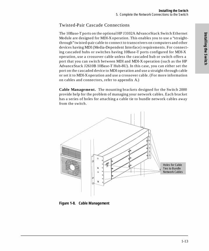
Twisted-Pair Cascade Connections
The 10Base-T ports on the optional HP J3102A AdvanceStack Switch Ethernet Module are designed for MDI-X operation. This enables you to use a “straight-through” twisted-pair cable to connect to transceivers on computers and other devices having MDI (Media-Dependent Interface) requirements. For connect-ing cascaded hubs or switches having 10Base-T ports configured for MDI-X operation, use a crossover cable unless the cascaded hub or switch offers a port that you can switch between MDI and MDI-X operation (such as the HP AdvanceStack J2610B 10Base-T Hub-8U). In this case, you can either set the port on the cascaded device to MDI operation and use a straight-through cable or set it to MDI-X operation and use a crossover cable. (For more information on cables and connectors, refer to appendix A.)
Cable Management. The mounting brackets designed for the Switch 2000 provide help for the problem of managing your network cables. Each bracket has a series of holes for attaching a cable tie to bundle network cables away from the switch.
Figure 1-8. Cable Management
Holes for Cable Ties to Bundle Network Cables
1-13

Installing the Switch6. Connect a Console Device (Optional)
Inst
allin
g th
e Sw
itch
B_SCOTS.BK : b_chp1.fm5 Page 14 Thursday, February 20, 1997 2:19 PM
6. Connect a Console Device (Optional)
The Switch 2000 console interface enables you to use a PC or a terminal to do the following:
■ Control password security
■ Monitor switch and port statistics
■ Modify the switch’s configuration
■ Use the switch’s event log and command line to help in troubleshooting
■ Download new software
N o t e The Switch 2000 is shipped with a factory default configuration that enables operation as a multiport transparent bridge when installed in a network. For this operation, connecting a console device is unnecessary. However, for some of the other uses listed above, you will probably want to have console access.
You can use either of the following methods for console access:
■ Console RS-232 using either a direct or modem connection to a PC terminal emulator program, or a direct connection to an actual terminal
■ In-Band using Telnet from a network management workstation. (To enable Telnet—or network management access—it is necessary to first use a direct-connect or modem-connect console device to configure an IP address and subnet mask for the switch.)
The Switch 2000 can simultaneously support one console session via the Console RS-232 port and one console session via Telnet.
1-14

Installing the Switch6. Connect a Console Device (Optional)
Installing the Switch
B_SCOTS.BK : b_chp1.fm5 Page 15 Thursday, February 20, 1997 2:19 PM
Direct Console Management, Using A Serial Cable and a Terminal or PC Terminal Emulator
You can use either a PC emulating an ASCII terminal (such as the terminal application included with Microsoft Windows 3.1 or HyperTerminal with Windows 95) or an ASCII terminal.
To directly connect a PC or terminal to a Switch 2000, follow these steps:
1. Connect the PC or terminal to the switch’s Console RS-232 port using an RS-232-C console cable (included). (If you need information on pin-outs and recommended cables, see appendix A, “Cables and Connectors”)
Figure 1-9. Connecting a PC or Terminal to the Console RS-232 Port
2. Turn on the terminal or PC’s power (and, if using a PC, start the PC terminal emulation program). For recommended parameter settings, refer to appendix C, “Sample Console Configurations”.
3. When you see this message:
Waiting for speed sense. Press enter to continue.
Press [Enter]. You will then see the Switch 2000’s Main Menu.
Console RS-232 Port
1-15

Installing the Switch6. Connect a Console Device (Optional)
Inst
allin
g th
e Sw
itch
B_SCOTS.BK : b_chp1.fm5 Page 16 Thursday, February 20, 1997 2:19 PM
Figure 1-10. The Main Menu
4. If you want to continue with direct console management at this time, refer to chapter 2, “Using the Console Interface”.
Remote Console Management Using a Modem and a Terminal or PC Terminal Emulator
N o t e For remote, console management, use a full-duplex, asynchronous (character-mode) modem.
1. At the Switch 2000 site:
a. Connect the modem to the Switch 2000’s console port using an RS-232-C modem cable. (For pin-outs and recommended cables refer to appendix A, “Cables and Connectors”.)
b. If necessary, configure the modem to operate with the current con-figuration of the Switch 2000. (The modem’s default configuration may be sufficient.)
2. At the remote site, connect the terminal (or PC emulating a terminal) to the remote modem using a modem cable. Make sure the terminal and modems are functioning properly, then establish the link between the terminal’s modem and the Switch 2000’s modem according to the modem instructions.
1-16

Installing the Switch6. Connect a Console Device (Optional)
Installing the Switch
B_SCOTS.BK : b_chp1.fm5 Page 17 Thursday, February 20, 1997 2:19 PM
Figure 1-11. Example of Remote Access via a Modem
3. When you see this message:
Waiting for speed sense. Press enter to continue.
Press [Enter]. You will then see the Switch 2000’s Main Menu.
4. If you want to continue with direct console management at this time, refer to chapter 2, “Using the Console Interface”.
PC (with Internal Modem) Running a Terminal Emulator
Telephone Line “Straight Through” Modem Cable
1-17

Installing the SwitchWhere To Go from Here
Inst
allin
g th
e Sw
itch
B_SCOTS.BK : b_chp1.fm5 Page 18 Thursday, February 20, 1997 2:19 PM
Where To Go from Here
Chapter Topics
2 and 3 To use the console, to configure the switch features, and to monitor and manage switch operation
4 To monitor and analyze switch operation from the console
5 To prepare the switch for SNMP management and to learn which MIBs are supported by the switch
6 To use the “Advanced Commands” functions
7 To find further information on the following features and to configure them:• Spanning Tree Protocol• Port Trunking• Filters and Security• Virtual LANs• Internet Group Management Protocol (IGMP)• Automatic Broadcast Control (ABC)
8 To download a new operating system or transfer a switch configuration
9 Troubleshooting information
Appendixes To access the following:• A: Cable and connector information• B: Switch specifications• C: Sample console configurations• D: LED reference• E: Bootp information• F: MAC address management• Safety and Regulatory information
1-18
Using the Console Interface
B_SCOTS.BK : b_chp2.fm5 Page 1 Thursday, February 20, 1997 2:19 PM
2
Using the Console Interface
Overview
This chapter describes the following features:
■ Starting and ending a console session (page 2-2)
■ The Main Menu (page 2-4)
■ Screen structure and navigation (page 2-5)
■ Using password security (page 2-7)
■ Rebooting the switch (page 2-10)
■ Resetting the switch (page 2-12)
About the Console Interface. The console interface enables you to recon-figure the switch and to monitor the switch status and performance. It consists of a series of management screens accessed through a menu-driven screen structure that begins at the Main Menu, and is organized as described in this section.
The Switch 2000 offers two methods of access to the console interface:
■ Console RS-232 (out-of-band) access:
• Directly connected to the Console RS-232 port, using a serial cable and a PC running a terminal emulator or an actual terminal
• Remotely connected to the Console RS-232 port, using modems and a PC running a terminal emulator or an actual terminal
Refer to chapter 1, “Installation”, for information on making RS-232 hardware connections.
■ In-Band access using Telnet from a PC or UNIX station on the network. This method requires that you first configure an IP address and subnet mask by using either out-of-band console access or Bootp. The Switch 2000 allows one outbound and one inbound Telnet session to be running simultaneously.
Console access can be limited by setting Manager-level and Operator-level passwords.
2-1

Using the Console InterfaceStarting and Ending a Console Session
Usi
ng th
e Co
nsol
e In
terf
ace
B_SCOTS.BK : b_chp2.fm5 Page 2 Thursday, February 20, 1997 2:19 PM
Starting and Ending a Console Session
N o t e This manual assumes that either a terminal device is already configured and connected to your Switch 2000 (as described in chapter 1, “Installation”) or that you have already enabled Telnet access to the switch. (To enable Telnet access, refer to “Console Features” on page 3-16.)
How To Start a Console Session:
1. Start your PC terminal emulator, terminal, or Telnet session on a remote terminal device.
2. Do one of the following:
• If you are using Telnet, go to the next step.
• If you are using a PC terminal emulator or a terminal, you should then see the following prompt:
Waiting for speed sense. Press <enter> to continue.
Note: If the console displays a series of random and/or unread-
able characters instead of the above prompt, the Baud Rate
setting for the terminal may be different from that of the console
interface. The switch’s autosensing feature remedies this prob-
lem when you press a key.
Press [Enter] and go to the next step.
3. The display then briefly displays a message indicating the baud rate at which the serial interface (Console RS-232 port) is operating, followed by the copyright screen. Do one of the following:
• If a password has been set, the Password prompt appears. Type the password and press [Enter] to display the Main Menu (figure 2-1).
• If no password has been set, you will see this prompt:
Press any key to continue.
Press [Enter] to display the Main Menu (figure 2-1).
If there is any system-down information to report, the switch displays it in this step and in the Event Log.
2-2

Using the Console InterfaceStarting and Ending a Console Session
Using the Console Interface
B_SCOTS.BK : b_chp2.fm5 Page 3 Thursday, February 20, 1997 2:19 PM
Figure 2-1. The Main Menu
For a description of Main Menu features, refer to “Main Menu Features” on page 2-4.
How To End a Console Session:
1. If you have not made configuration changes in the current session, go to step 3.
2. Configuration changes requiring a reboot of the switch are indicated by an asterisk (*) next to the configured item in the Configuration menu. (See “Rebooting To Activate Configuration Changes” on page 2-11) If you have made configuration changes that require a reboot of the switch in order to take effect:
a. Return to the Main Menu.
b. Use the arrow keys ( [<] , [>] , [v] , and [^] ) to highlight Reboot Switch in the Main Menu and press [Enter] to reboot.
3. Do one of the following:
• If you have accessed the switch through a direct connection from a terminal device, exit from the terminal application.
• If you have accessed the switch through Telnet or a modem connec-tion:i. Return to the Main Menu.ii. Highlight LOGOUT in the Main Menu and press [Enter].
2-3
Using the Console InterfaceMain Menu Features
Usi
ng th
e Co
nsol
e In
terf
ace
B_SCOTS.BK : b_chp2.fm5 Page 4 Thursday, February 20, 1997 2:19 PM
Main Menu Features
The Main Menu (figure 2-1 on page 2-3) gives you access to these console interface features:
• Status and Counters: Displays information on the switch, individual ports, the address tables, protocols and spanning tree. (Refer to chapter 4, “Monitoring and Analyzing Switch Operation from the Console”.)
• Event Log: Enables you to read progress and error messages that are useful for checking and troubleshooting switch operation. A listing of Event Log messages is included on the CD shipped with your switch. (Refer to “Event Log” on page 4-16.)
• Configuration: Enables you to display the current configuration settings and to reconfigure individual parameters. (Refer to chapter 3, “Configuring the Switch”.)
• LOGOUT: Disconnects Telnet or modem access to the switch. (Refer to “How To End a Console Session” on page 2-3.)
• Advanced Commands: Provides access to a set of system manage-ment, monitoring, and troubleshooting commands. (Refer to chapter 6, “Using the Advanced Commands”.)
• Set Passwords: Enables you to set Operator and Manager pass-words to help restrict who has access to the console interface. (Refer to “Using Password Security” on page 2-7.)
• Download OS: Enables you to download a new software version to the switch. (Refer to chapter 8, “File Transfers”.)
• Reboot Switch: Performs a software reboot, which is required (in some cases) to activate configuration changes that have been made. (Refer to “Rebooting To Activate Configuration Changes” on page 2-11.)
2-4

Using the Console InterfaceScreen Structure and Navigation
Using the Console Interface
B_SCOTS.BK : b_chp2.fm5 Page 5 Thursday, February 20, 1997 2:19 PM
Screen Structure and Navigation
Console screens include these three elements:
■ Parameter fields and/or read-only information such as statistics
■ Navigation and configuration actions, such as Save, Edit, and Cancel
■ Help banner to describe navigation options, and individual parameters
For example, in the System configuration screen:
Figure 2-2. Elements of Screen Structure
Help describing each of the items in the parameter menu
Parameter Fields
Actions Line
Help banner describing the selected action (in this case, the Cancel option) Navigation Instructions
System name
2-5

Using the Console InterfaceScreen Structure and Navigation
Usi
ng th
e Co
nsol
e In
terf
ace
B_SCOTS.BK : b_chp2.fm5 Page 6 Thursday, February 20, 1997 2:19 PM
Table 2-1. How To Navigate in the Console
Task: Actions:
Execute an action from an “Actions"-[>] menu:
Use either of the following methods:■ Use the arrow keys ( [<] , [>] , [v] , or [^] ) to
highlight the action you want to execute, then press [Enter].
■ Press the key corresponding to the capital letter in the action name. For example, in a configuration menu, press [E] to begin editing parameter values.
Reconfigure (edit) a parameter setting or a field:
1. Select a configuration area, such as System. (See figure 2-2.)
2. Press [E] (for Edit on the Actions line).3. Use [Tab] or the arrow keys ([<], [>], [^], or [v]) to highlight
the item or field.4. Do one of the following:
• If the parameter has preconfigured values, use the Space bar to select a new option
• If there are no preconfigured values, type in a value.5. If you want to change another parameter value, return to
step 3.6. If you're finished editing parameters in the displayed
screen, press [Enter] and do one of the following:• To save any configuration changes you have made (or
if you have made no changes), press [S] (for the Save action).
• To exit from the screen without saving any changes that you have made, press [C] (for Cancel).
Note: Some parameter changes are activated when you execute Save, and it is therefore not necessary to reboot the switch after making these changes. But if an asterisk appears next to any menu item you reconfigure, it is necessary to reboot the switch to implement the change. In this case, rebooting should be done after you have made all desired changes and then returned to the Main Menu.
7. When you are finished editing parameters, return to the Main Menu.
8. If necessary, reboot the switch by highlighting Reboot Switch and pressing [Enter]. (Refer to the Note, above.)
Exit from a read-only screen. Press [B] (for the Back action).
2-6

Using the Console InterfaceUsing Password Security
Using the Console Interface
B_SCOTS.BK : b_chp2.fm5 Page 7 Thursday, February 20, 1997 2:19 PM
Using Password Security
There are two levels of console access: Manager and Operator. For security, you can set a password on each of these levels.
To use password security:
1. Set a Manager password (and an Operator password, if applicable for your system).
2. Exit from the current console session. A Manager password will now be needed for full access to the console.
If you do steps 1 and 2, above, then the next time a console session is started, the console interface will prompt for a password. Assuming that both a Manager password and an Operator password have been set, the level of access to the console interface will be determined by which password is entered in response to the prompt.
If you set a Manager password, you may also want to configure the Connection Inactivity Time parameter in the Serial Link configuration screen (page 3-15). This causes the console session to end after the specified period of inactivity, thus giving you added security against unauthorized console access. (Once a Manager password is set and the console session is ended, access to the full console interface for any subsequent sessions requires the Manager password to be entered.)
Level Actions Permitted
Manager: Access to all console interface areas. This is the default level. (That is, if a Manager password has not been set prior to starting the current console session, then anyone having access to the console can access any area of the console interface.)
Operator: Access to the Status and Counters, Event Log, and minimal Configuration areas (System, Console, and Ports) for display only.Use of the LOGOUT command.On the Operator level, the Advanced Commands, Set Passwords, Download OS, and Reboot options are not available in the Main menu.
2-7

Using the Console InterfaceUsing Password Security
Usi
ng th
e Co
nsol
e In
terf
ace
B_SCOTS.BK : b_chp2.fm5 Page 8 Thursday, February 20, 1997 2:19 PM
N o t e If there is only a Manager password set (with no Operator password), and the Manager password is not entered correctly when the console session begins, the switch operates on the Operator level.
If there are both a Manager password and an Operator password, but neither is entered correctly, access to the console will be denied.
If a Manager password is not set, anyone having access to the console
interface can operate the console with full manager privileges, regardless of
whether an Operator password is set.
Passwords are case-sensitive.
The rest of this section covers how to:
■ Set a Password
■ Delete a Password
■ Recover from a Lost Password
To set Manager and Operator passwords:.
1. From the Main menu select Set Passwords. This screen appears:
Figure 2-3. The Set Password Screen
2. To set a new password:
a. Select Set Manager Password or Set Operator Password. You will then be prompted with Enter new password.
2-8

Using the Console InterfaceUsing Password Security
Using the Console Interface
B_SCOTS.BK : b_chp2.fm5 Page 9 Thursday, February 20, 1997 2:19 PM
b. Type a password of up to 16 characters and press [Enter]. (Remember that passwords are case-sensitive.)
c. When prompted with Enter new password again, retype the new password and press [Enter].
d. To set another password, return to step 2a. Otherwise, go to step 3.
3. Select Return to Main Menu to exit from the Set Password screen.
After a password is set, if you use LOGOUT or reboot or reset the Switch 2000, you will be prompted to enter the password to start a new console session.
To Delete Password Protection (Including Recovery from a Lost
Password): This procedure deletes both passwords (Manager and Opera-tor). If you have physical access to the switch, press the Config Clear button to clear all password protection, then enter new passwords as described earlier in this chapter. If you do not have physical access to the switch, you will need the Manager password:
1. Enter the console at the Manager level.
2. From the Main menu select Set Passwords. You will then see the screen shown in figure 2-3.
3. Select Delete Password Protection. You will then see the following prompt:
Continue Deletion of password protection? No
4. Press the Space bar or press [Y] to select Yes, then press [Enter].
5. Press [Enter] to clear the Password protection message.
6. Select Return to Main Menu to exit from the Set Password screen.
To Recover from a Lost Manager Password:
If you cannot start a console session at the manager level because of a lost Manager password, you can clear the password by getting physical access to the switch and pressing and holding the Config Clear button for at least one second.
2-9
Using the Console InterfaceRebooting the Switch
Usi
ng th
e Co
nsol
e In
terf
ace
B_SCOTS.BK : b_chp2.fm5 Page 10 Thursday, February 20, 1997 2:19 PM
Rebooting the Switch
Rebooting the switch terminates the current console session and performs a reset of the operating system. Some of the reasons for performing a reboot include:
■ Activating certain configuration changes that require a reboot
■ Activating port modules that have been changed since the last reboot. (That is, where a port module has been replaced with a different type of port module.)
■ Resetting statistical counters to zero
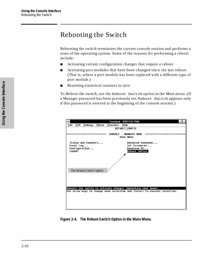
To Reboot the switch, use the Reboot Switch option in the Main menu. (If a Manager password has been previously set, Reboot Switch appears only if this password is entered at the beginning of the console session.)
Figure 2-4. The Reboot Switch Option in the Main Menu
The Reboot Switch option
2-10

Using the Console InterfaceRebooting the Switch
Using the Console Interface
B_SCOTS.BK : b_chp2.fm5 Page 11 Thursday, February 20, 1997 2:19 PM
Rebooting To Activate Configuration Changes. Configuration changes for some parameters become effective as soon as you save them. However, you must reboot the switch in order to implement any changes to any parameters in the following areas:
■ IPX Service
■ Internet (IP) Service
■ Serial Link
■ Console Parameters
■ New VLAN Names
■ System Parameters
If configuration changes requiring a reboot have been made, the switch displays an asterisk next to the configuration menu item in which the change has been made. For example, if you change and save parameter values for the switch’s IP configuration, the need for rebooting the switch would be indicated by an asterisk appearing in the following screen:
Figure 2-5. Example of a Configuration Change Requiring a Reboot
Reminder to Reboot the Switch to Activate Configuration Changes
Asterisk indicates a configuration change that requires a reboot in order to take effect.
2-11

Using the Console InterfaceResetting the Switch
Usi
ng th
e Co
nsol
e In
terf
ace
B_SCOTS.BK : b_chp2.fm5 Page 12 Thursday, February 20, 1997 2:19 PM
Resetting the Switch
Resetting requires physical access to the front of the Switch 2000. There are two levels of reset:
■ Hardware reset: Momentarily interrupts switch operation and performs a complete hardware self-test. This also clears the Event Log.
■ Configuration reset: This is a drastic action that interrupts switch operation, clears any passwords, clears the event log, performs a com-plete self-test, and reboots the switch in its factory default configuration. You should consider performing a configuration reset only if you want all configurable parameters reset to the factory default values.
To perform a hardware or configuration reset: Refer to appendix D, “Switch Reference”. Refer to the table on page D-5.
Advanced Commands Features
The Advanced Commands prompt enables you to perform advanced manage-ment, monitoring, and troubleshooting activities. Below is a command listing.
Refer to chapter 6, “Using the Advanced Commands” for more on the com-mand prompt and on individual commands.
Listing of Advanced Commands Available at the Commands Prompt
! Get (TFTP) Ping Time
ClearLED Help Print Version
Config History Put (TFTP) VLAN
Date IPXPing Redo WalkMIB
Delete LinkTest Repeat Zget
Exit Log SetMIB Zput
GetMIB Page Telnet
2-12

Configuring the Switch
B_SCOTS.BK : b_chp3.fm5 Page 1 Thursday, February 20, 1997 2:19 PM
3
Configuring the Switch
Overview
This chapter provides an overview of the Switch 2000 configuration features.
In its factory default configuration, the Switch 2000 automatically operates as a multiport learning bridge with network connectivity provided by the particular modules that you have installed. However, to “fine-tune” your switch for the specific performance and security needs in your network, you may choose to reconfigure certain switch parameters.
Configuration Features. The Switch 2000 enables you to configure the following switch features. For information on individual configuration parameters, use the online Help provided with each configuration screen in the console user interface.
■ System (page 3-5)
■ Ports (page 3-6)
■ IPX Service (page 3-7)
■ Internet (IP) Service (page 3-9)
■ Virtual LANs (VLANs) (page 3-19)
■ IP Multicast (IGMP) Service (page 3-14)
■ SNMP Communities (page 3-11)
■ Trap Receivers (page 3-13)
■ Serial Link (page 3-15)
■ Console (page 3-16)
■ Network Monitoring Port (page 3-20)
■ Spanning Tree (page 3-17)
■ Traffic/Security Filters (page 3-18)
■ Automatic Broadcast Control (ABC) (page 3-23)
3-1

Configuring the SwitchOverview
Conf
igur
ing
the
Switc
h
B_SCOTS.BK : b_chp3.fm5 Page 2 Thursday, February 20, 1997 2:19 PM
N o t e In the factory default configuration, the Spanning Tree Protocol (STP) is off. However, if the topology of your network includes any redundant loops between switches or bridges, you should enable STP. See “Spanning Tree” (page 3-17).
To get Help on individual parameter descriptions. In all screens except the Advanced Commands screen there is a Help option in the Actions menu. Whenever the Actions menu is active, you can display Help for that screen’s parameters by pressing [H]. (The Actions menu is active whenever any of the choices in the Action menu is highlighted.) For example:
Figure 3-1. Example Showing How To Display Help
To get Help on the actions or data fields in each screen: Use the arrow keys ( [<], [>], [^], or [v]) to select an action or data field. The banner under the action items will describe the currently selected action or data field. (For guidance in how to navigate in a configuration screen, see the instructions provided at the bottom of the screen, or refer to “Screen Structure and Navigation” on page 2-5.)
Highlight on any item in the Actions menu indicates that the Actions menu is active.
Pressing [H] or highlighting Help and pressing [Enter] displays Help for the parameters listed in the upper part of the screen.
Banner
3-2

Configuring the SwitchConfigurable Features
Configuring the Switch
B_SCOTS.BK : b_chp3.fm5 Page 3 Thursday, February 20, 1997 2:19 PM
Configurable Features
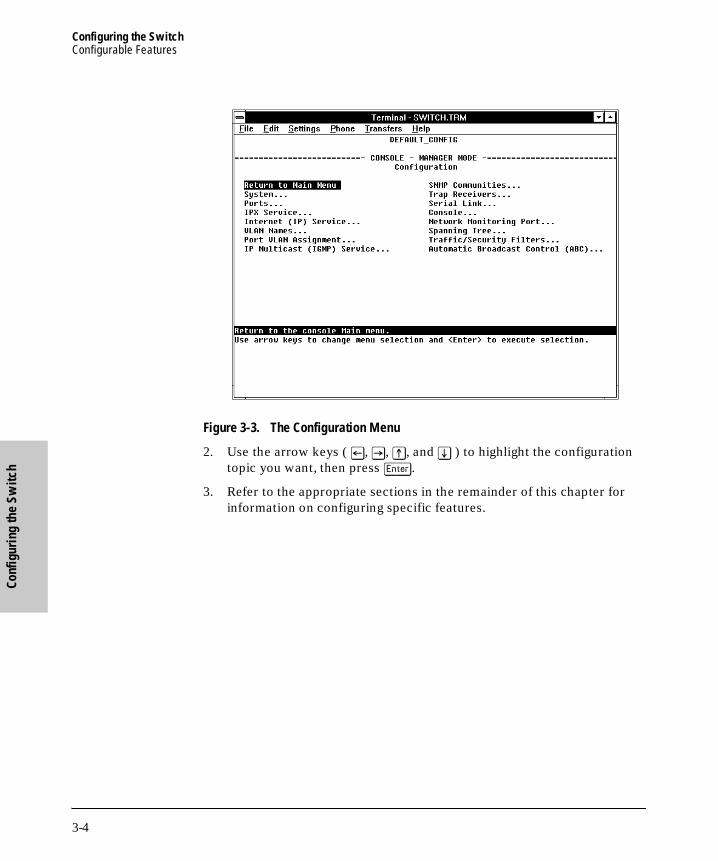
How To Access the Switch 2000 Configuration: Use this procedure to access the switch’s configurable features.
1. Begin at the Main Menu and select Configuration (figure 3-2):
Figure 3-2. Select “Configuration” in the Main Menu
After you select Configuration, the Configuration menu appears as shown in (figure 3-3).
Access to Configurable Features
3-3
Configuring the SwitchConfigurable Features
Conf
igur
ing
the
Switc
h
B_SCOTS.BK : b_chp3.fm5 Page 4 Thursday, February 20, 1997 2:19 PM
Figure 3-3. The Configuration Menu
2. Use the arrow keys ( [<], [>], [^], and [v] ) to highlight the configuration topic you want, then press [Enter].
3. Refer to the appropriate sections in the remainder of this chapter for information on configuring specific features.
3-4

Configuring the SwitchConfigurable Features
Configuring the Switch
B_SCOTS.BK : b_chp3.fm5 Page 5 Thursday, February 20, 1997 2:19 PM
System Features
Configures basic switch management information, including system data, address aging, and time zone parameters:
Figure 3-4. The System Configuration Screen (Default Values)
N o t e To help simplify administration, it is recommended that you configure System Name to a character string that is meaningful within your system.
To set the time and date, set the Time Protocol parameters under "Internet (IP) Service Features" (page 3-9) for your time server or use the time and date commands described in chapter 6.
System Name
3-5

Configuring the SwitchConfigurable Features
Conf
igur
ing
the
Switc
h
B_SCOTS.BK : b_chp3.fm5 Page 6 Thursday, February 20, 1997 2:19 PM
Port Features
Configures the operating state for each port and optionally assigns selected ports to a port trunk. (For more on port trunking, refer to chapter 7.) Also optionally enables you to restrict the amount of broadcast traffic on the port. The read-only fields in this screen display the port names and port types.
Figure 3-5. Example of the Port Configuration Screen with 100VG and Ethernet Modules Installed in the Switch
Port names are assigned by slot letter and port number. For example, if an HP J3102A AdvanceStack Switch Ethernet Module is installed in slot B, then the four ports in this module are identified as ports B1, B2, B3, and B4. Similarly, if an HP J3103A AdvanceStack Switch 100VG Module is installed in slot A, then the two ports in this module are identified as ports A1 and A2.
N o t e Broadcast limit (the Bcast Limit parameter) can be set for all ports in the switch (or VLAN, if VLANs are configured) from the Automatic Broadcast Control (ABC) screen (page 7-30 and following) if ABC is enabled. Setting the broadcast limit (Bcast Limit) in the above screen is on a per-port basis and overrides any settings done in Automatic Broadcast Control.
Read-Only Fields
3-6

Configuring the SwitchConfigurable Features
Configuring the Switch
B_SCOTS.BK : b_chp3.fm5 Page 7 Thursday, February 20, 1997 2:19 PM
IPX Service Features
Enables the switch to be managed in an IPX network. The Switch 2000 automatically enables IPX, configures the IPX node address, and learns the IPX network number. Thus, in the factory default configuration, IPX is auto-matically enabled for the switch.
N o t e In this case, the factory-assigned node address is displayed as shown below. (The switch automatically detects the IPX network number.)
Figure 3-6. The IPX Service Configuration Screen
N o t e If VLANs are configured, the above parameters appear in a horizontally formatted screen.
You can also configure an IPX gateway frame encapsulation type and gateway node so that the switch can be managed from a remote IPX network.
If VLANs are configured, the switch can automatically learn the IPX network number of each attached VLAN. For more on VLANs, refer to chapter 7, “Advanced Concepts”.
Read-Only Field
Appears if Gateway Encap Configured
3-7

Configuring the SwitchConfigurable Features
Conf
igur
ing
the
Switc
h
B_SCOTS.BK : b_chp3.fm5 Page 8 Thursday, February 20, 1997 2:19 PM
(Optional) How To Configure IPX for Management from a Remote IPX
Network. In the factory default, IPX is already enabled. If you want to enable management from a remote IPX network, you must configure the gateway encapsulation type and gateway node.
1. From the Configuration screen, select IPX Service to display the above screen.
2. If the IPX Enabled parameter is not already set to “Yes” (the factory default), then select this parameter and press the Space bar to select Yes.
3. Select the Gateway Encap field and use the Space bar to select the appropriate gateway encapsulation for the gateway device.
4. Press [v] to display and select the Gateway Node field.
5. Type the IPX node address (MAC address) of the gateway device that is using the encapsulation defined in step 3.
6. Press [Enter], then [S] (for Save).
7. Return to the Main Menu and reboot the switch.
3-8

Configuring the SwitchConfigurable Features
Configuring the Switch
B_SCOTS.BK : b_chp3.fm5 Page 9 Thursday, February 20, 1997 2:19 PM
Internet (IP) Service Features
Enables you to configure:
■ IP address, subnet mask, and (optionally) the gateway address for the switch so that it can be managed in an IP network
■ The time server information (used if you want the switch to get its time information from another device operating as a Timep server)
You can manually configure an IP address, subnet mask, and a Gateway IP address by setting the IP Config parameter to Manual. Or, you can use Bootp to configure IP for the switch from a Bootp server. In this case you must also configure your Bootp server accordingly. If you plan to use Bootp, refer to appendix E, “Bootp Operation”. Otherwise, set the IP Config parameter to Manual and then manually enter the IP address and subnet mask you want for the Switch 2000.
Figure 3-7. Example of the IP Service Configuration Screen
If VLANs are configured, then enable IP on a “per VLAN” basis. This is because each VLAN is a separate network and requires a unique IP address, plus a subnet mask. A gateway (IP) address is optional. For more on VLANs, refer to “Virtual LANs (VLANs)” on page 3-19 and in chapter 7, “Advanced Con-cepts”.
The default setting for Time Protocol Enabled is No. Setting it to Yes as shown here, then pressing [v] or [Tab] causes the Timep Server Address and Timep Poll Interval parameters to appear. For descriptions of these parameters, refer to the online Help for this screen.
3-9

Configuring the SwitchConfigurable Features
Conf
igur
ing
the
Switc
h
B_SCOTS.BK : b_chp3.fm5 Page 10 Thursday, February 20, 1997 2:19 PM
How To Manually Configure for IP.
1. From the Configuration screen, select Internet (IP) Service to display the above screen.
2. Press [E] (for Edit).
3. Select the IP Config field and use the Space bar to select Manual.
4. Select the IP Address field and enter the IP address you want to assign to the switch.
5. Select the Subnet Mask field and enter the subnet mask for the IP address.
6. If you want to reach off-subnet destinations, select the Gateway field and enter the IP address of the gateway router.
7. Press [Enter], then [S] (for Save).
8. Return to the Main Menu and reboot the switch.
3-10

Configuring the SwitchConfigurable Features
Configuring the Switch
B_SCOTS.BK : b_chp3.fm5 Page 11 Thursday, February 20, 1997 2:19 PM
SNMP Communities Features
Enables you to add, edit, or delete SNMP communities. Use this feature if you expect to manage the switch from an SNMP management station. You can configure up to five SNMP communities, each with either an operator-level or a manager-level view, and either restricted or unrestricted write access. (For more on this topic, refer to chapter 5, “Using SNMP To Monitor and Manage the Switch”, and to the online Help.)
Figure 3-8. The SNMP Communities Screen (Default Values)
C a u t i o n Deleting the community named “public” disables many network management functions (such as auto-discovery, traffic monitoring, and threshold setting). If security for network management is a concern, it is recommended that you change the write access for the “public” community to “Restricted”.
How To Configure for SNMP Communities.
Ensure that the switch has been configured for IP and/or IPX.
1. From the Configuration screen, select SNMP Communities to display a screen similar to the one above.
This screen gives an overview of the SNMP communities that are currently configured. All fields in this screen are read-only.
Add and Edit options are used to modify the SNMP options. See figure 3-9.
3-11

Configuring the SwitchConfigurable Features
Conf
igur
ing
the
Switc
h
B_SCOTS.BK : b_chp3.fm5 Page 12 Thursday, February 20, 1997 2:19 PM
2. Press [A] (for Add) to display the following screen:
Figure 3-9. The SNMP Add or Edit Screen
N o t e In the default configuration, no manager addresses are configured. In this case, all management stations using the correct community name may access the switch with the corresponding View and Access levels. If you want to restrict access to one or more specific nodes, you can enter up to ten IP and/or IPX addresses of such nodes into the Manager Address field. Entering one or more IP or IPX addresses in the Manager Address field limits access to only those addresses.
3. Enter the appropriate value in each of the above fields (use the [Tab] key to move from one field to the next).
4. Press [Enter], then [S] (for Save).
If you are adding a community, the fields in this screen are blank.
If you are editing an existing community, the values for the currently selected community appear in the fields.
Type the Value for this Field
Use the Space Bar to Select Values for Other Fields
3-12

Configuring the SwitchConfigurable Features
Configuring the Switch
B_SCOTS.BK : b_chp3.fm5 Page 13 Thursday, February 20, 1997 2:19 PM
Trap Receivers Features
Enables you to configure up to ten IP and/or IPX management stations (trap receivers) to receive SNMP trap packets sent from the switch. Trap packets describe specific event types. (These events are the same as the log messages displayed in the event log.) The protocol, address, and community define which management stations receive the traps. An authentication trap is sent and the Security LED on the front panel of the switch begins flashing if a management station attempts an unauthorized access. (The ClearLED command turns off the Security LED—page 6-6.) Check the event log to help determine why the authentication trap was sent. (Refer to chapter 4 for information on the event log.)
Figure 3-10. The Trap Receivers Configuration Screen (Default Values)
3-13

Configuring the SwitchConfigurable Features
Conf
igur
ing
the
Switc
h
B_SCOTS.BK : b_chp3.fm5 Page 14 Thursday, February 20, 1997 2:19 PM
IP Multicast (IGMP) Service Features—Multimedia Traffic Control
The IGMP (Internet Group Management Protocol) feature helps to reduce network congestion and improve security by reducing unnecessary multicast traffic on a per-port basis. This is useful in multimedia applications such as LAN TV, desktop conferencing, and collaborative computing, where there is multipoint communication; that is, communication from one to many hosts, or communication originating from many hosts and destined for many other hosts. In such multipoint applications, IGMP will be configured on the hosts, and multicast traffic will be generated by one or more servers (inside or outside of the local network). Switches in the network (such as the Switch 800T or the B-version of the Switch 2000) can then be configured to direct the multicast traffic to only the ports where needed.
In the factory default state (IGMP disabled), the switch forwards all IGMP traffic. When IGMP is enabled, you can configure the switch to any of the following states on a per-port basis:
■ Automatic (the default): Causes the switch to interpret IGMP packets and to filter IP multicast traffic based on the IGMP packet information for that port.
■ Blocking: Causes the switch to drop all IGMP transmissions received and block all outgoing IP Multicast packets for that port.
■ Forwarding: Causes the switch to forward all IGMP and IP multicast transmissions through the port.
For more information on IGMP and how to configure it, refer to “IP Multicast (IGMP)” on 7-23.
3-14

Configuring the SwitchConfigurable Features
Configuring the Switch
B_SCOTS.BK : b_chp3.fm5 Page 15 Thursday, February 20, 1997 2:19 PM
Serial Link Features
Enables you to adjust the Console RS-232 configuration to customize the connection with the PC, terminal, or modem you are using for console access. Refer to the online Help for information on modem settings. Refer also to “Console Features” on page 3-16.
Figure 3-11. The Serial Link Configuration Screen (Default Values)
3-15

Configuring the SwitchConfigurable Features
Conf
igur
ing
the
Switc
h
B_SCOTS.BK : b_chp3.fm5 Page 16 Thursday, February 20, 1997 2:19 PM
Console Features
Lets you enable or disable inbound Telnet access and control the types of events displayed in the event log. Also specifies the terminal type and the console screen refresh interval used by the statistics screens (that is, the frequency with which statistics are updated on the statistics screens).
N o t e “Inbound” Telnet is Telnet access to the switch console from another device. “Outbound” Telnet, which is using Telnet through the switch console to access another device, is always enabled as long as the switch has been configured with a valid IP address. (To configure an IP address for the switch, refer to “Internet (IP) Service Features” on page 3-9.) The switch supports one inbound and one outbound Telnet session simultaneously.
Figure 3-12. The Console Configuration Screen (Default Values)
Default Inbound Telnet Setting
3-16

Configuring the SwitchConfigurable Features
Configuring the Switch
B_SCOTS.BK : b_chp3.fm5 Page 17 Thursday, February 20, 1997 2:19 PM
Spanning Tree Features
Enables you to activate the IEEE 802.1d Spanning Tree Protocol (STP) and to adjust spanning tree parameters. In the factory default, STP is off. Thus, if there are any redundant paths (loops) between nodes in your network, you should set the Spanning Tree Enabled parameter to Yes. This ensures that all redundant ports (those providing backup parallel connections) are in a block-ing state and not used to forward data. In the event of a topology change such as a switch, bridge, or data link failure, STP develops a new spanning tree that may result in changing some ports from the blocking state to the forwarding state.
If VLANs are configured, then you can configure STP separately for each VLAN.
C a u t i o n Because the switch automatically gives faster links a higher priority, the default STP parameter settings are usually adequate for spanning tree operation. Because incorrect STP settings can adversely affect network performance, you should avoid making changes without having a strong understanding of how STP operates. For more on STP, refer to chapter 7, “Advanced Concepts”, and examine the IEEE 802.1d standard.
The switch automatically senses port identity and type, and automatically defines port cost and priority for each type. The interface allows you to adjust the Cost and Priority for each port, as well as the global STP parameter values for the switch.
To configure STP, refer to “Spanning Tree Protocol (STP)” on page 7-2.
3-17

Configuring the SwitchConfigurable Features
Conf
igur
ing
the
Switc
h
B_SCOTS.BK : b_chp3.fm5 Page 18 Thursday, February 20, 1997 2:19 PM
Traffic/Security Filter Features
Enables you to control traffic and increase network security by creating filters based on any of the following criteria:
■ Multicast address
■ Source port only
■ Source MAC address and source port
■ Protocol frame type
• IP (Ethernet or 802.3 SAP)
• ARP
• DEC LAT
• AppleTalk
• SNA
• NetBIOS
• IPX (Ethernet or 802.3 SAP)
• VINES IP or ECHO
If you are using VLANs, they will affect source port and source MAC filter configuration. For more information on filtering, using filters with VLANs, and configuring filters, refer to “Filters and Security” on page 7-8.
3-18

Configuring the SwitchConfigurable Features
Configuring the Switch
B_SCOTS.BK : b_chp3.fm5 Page 19 Thursday, February 20, 1997 2:19 PM
Virtual LAN (VLAN) Features
Enables you to create up to eight port-based VLANs. A VLAN is a group of ports designated by the Switch 2000 as belonging to the same broadcast domain. This feature enables you to configure port-based virtual LANs to help isolate broadcast traffic and increase security. Typically, if VLANs are used, all ports carrying traffic for a particular subnet address should be configured to the same VLAN. For more on when, why, and how to use VLANs, refer to “Virtual LANS (VLANs)” on page 7-14.
In the factory default state, VLANs are not configured. All ports belong to the same broadcast/multicast domain. This domain is called “DEFAULT_VLAN” and appears in the “VLAN Names” screen. You can create up to seven addi-tional VLANs by adding new VLAN names, and then assigning one or more ports to each VLAN. (The switch accepts a maximum of eight VLANs, includ-ing the default VLAN.) Note that each port can be assigned to only one VLAN. DEFAULT_VLAN can be renamed, but not deleted. Any ports not specifically assigned to another VLAN will remain assigned to DEFAULT_VLAN.
N o t e Before you delete a VLAN, you must re-assign its ports to another VLAN.
When VLANs are used, and are managed from an SNMP workstation, you should configure the IPX and/or IP services for each VLAN. (Refer to pages 3-7 and 3-9.)
Spanning Tree protocol (STP), ABC, IGMP, and some other features operate on a “per VLAN” basis. This means you must configure such features sepa-rately for each VLAN in which you want them to operate.
For more information on VLANs and how to configure them, refer to “Virtual LANs (VLANs)” on page 7-14.
3-19
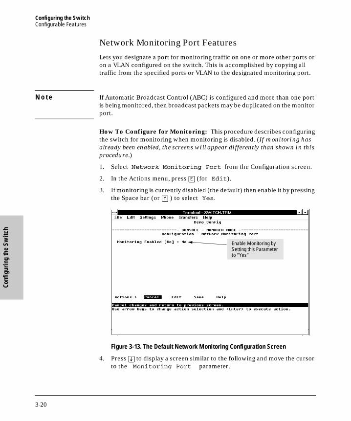
Configuring the SwitchConfigurable Features
Conf
igur
ing
the
Switc
h
B_SCOTS.BK : b_chp3.fm5 Page 20 Thursday, February 20, 1997 2:19 PM
Network Monitoring Port Features
Lets you designate a port for monitoring traffic on one or more other ports or on a VLAN configured on the switch. This is accomplished by copying all traffic from the specified ports or VLAN to the designated monitoring port.
N o t e If Automatic Broadcast Control (ABC) is configured and more than one port is being monitored, then broadcast packets may be duplicated on the monitor port.
How To Configure for Monitoring: This procedure describes configuring the switch for monitoring when monitoring is disabled. (If monitoring has
already been enabled, the screens will appear differently than shown in this
procedure.)
1. Select Network Monitoring Port from the Configuration screen.
2. In the Actions menu, press [E] (for Edit).
3. If monitoring is currently disabled (the default) then enable it by pressing the Space bar (or [Y] ) to select Yes.
Figure 3-13. The Default Network Monitoring Configuration Screen
4. Press [v] to display a screen similar to the following and move the cursor to the Monitoring Port parameter.
Enable Monitoring by Setting this Parameter to “Yes”
3-20

Configuring the SwitchConfigurable Features
Configuring the Switch
B_SCOTS.BK : b_chp3.fm5 Page 21 Thursday, February 20, 1997 2:19 PM
Figure 3-14. Example of Selecting a Monitoring Port
5. Press the Space bar to select which port to use for the monitoring port, then press [v] to move to the Monitor parameter. (The default setting is Ports, which you will use if you want to monitor one or more individual ports on the switch.)
6. Do one of the following:
• If you want to monitor individual ports, leave the Monitor param-eter set to Ports and press [v] to move the cursor to the Action column for the individual ports. Press the Space bar to select Mon-itor for each port that you want monitored. (Use [v] to move from one port to the next in the Action column.) When you are finished, press [Enter], then press [S] (for Save) to save your changes and exit from the screen.
• If, instead of individual ports, you want to monitor all of the ports in a VLAN, press the Space bar to select VLAN in the Monitor parame-ter, then press [v] to move to the VLAN parameter (figure 3-15). Then press the Space bar again to select the VLAN that you want to monitor. When you are finished, press [Enter] , then press [S] (for Save) to save your changes and exit from the screen.
7. Return to the Main Menu.
Note:Ports listed in this screen depend on the modules currently installed in the switch.
Move the Cursor to the Monitoring Port Parameter
3-21

Configuring the SwitchConfigurable Features
Conf
igur
ing
the
Switc
h
B_SCOTS.BK : b_chp3.fm5 Page 22 Thursday, February 20, 1997 2:19 PM
Figure 3-15. Example of Selecting a VLAN to Monitor
N o t e It is possible in networks with high traffic levels to copy more traffic to a monitor port than the link can support. In this situation, some packets may not be copied to the monitor port.
Example of a VLAN Monitoring Parameter
Note:This screen appears instead of the one in figure 3-14 if the Monitor parameter is set to VLAN.
3-22

Configuring the SwitchConfigurable Features
Configuring the Switch
B_SCOTS.BK : b_chp3.fm5 Page 23 Thursday, February 20, 1997 2:19 PM
Automatic Broadcast Control (ABC) Features—Layer 3 Switching
ABC reduces the amount of IP and/or IPX broadcast traffic on a network by enabling the switch to serve as a proxy for the ultimate destination of broad-cast IP ARP and RIP packets, and IPX NSQ, and RIP or SAP packets. This reduces the number of ports over which IP and/or IPX broadcasts are sent, increases the amount of network bandwidth available for other purposes, and can reduce the need for routers within a network. These factors can lower costs and reduce latency in the network. (While communication between VLANs—broadcast domains—still requires a router, ABC functions within VLANs and, by using multiple subnets (multi-netting), can reduce or eliminate the need for routers within the VLAN.)
When enabled, ABC also allows you to set the broadcast limit parameter (Bcast Limit) in the Port Configuration screen (figure 3-5) for all ports on the switch (or all ports on the VLAN, if VLANs are configured and ABC is enabled for the VLAN).
In the factory default state, ABC is disabled. For more information on ABC and how to configure it, refer to “Automatic Broadcast Control (ABC)” on page 7-30.
3-23

B_SCOTS.BK : b_chp3.fm5 Page 24 Thursday, February 20, 1997 2:19 PM
Monitoring and A
nalyzing Sw
itch Operation from
the
B_SCOTS.BK : b_chp4.fm5 Page 1 Thursday, February 20, 1997 2:19 PM
4
Monitoring and Analyzing Switch Operation from the Console
Overview
The Main Menu in the switch’s console interface gives you access to the following sources of read-only data for helping you to monitor, analyze, and troubleshoot switch operation:
Table 4-1. Read-Only Monitoring and Analyzing Features
Main Menu Item
Data Type Purpose
Status andCountersMenus
Switch Information Lists switch-level operating information.
Port Status Displays the operational status of each port.
Port Counters Summarizes port activity.
Address (forwarding) Table Lists the MAC addresses of nodes the switch has detected on the network, along with the corresponding switch port.
Port Address Table Lists the MAC addresses that the switch has learned from the selected port.
Spanning Tree Information Lists Spanning Tree data for the switch and for individual ports. If VLANs are configured, reports on a per-VLAN basis.
Module Information Lists the modules currently installed and detected by the switch.
IP Multicast (IGMP) Status Lists IGMP groups, report, query, and type of device access on ports. If VLANs are configured, reports on a per-VLAN basis.
Automatic Broadcast Control (ABC) Information
If VLANs are configured, reports on a per-VLAN basis.
Event Log Lists event messages generated by the switch.
4-1
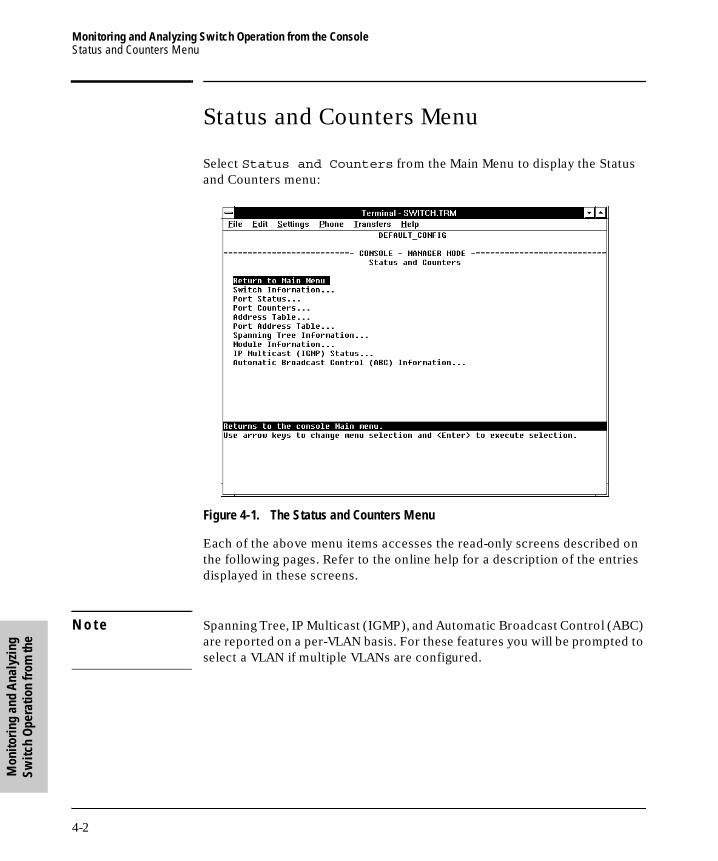
Monitoring and Analyzing Switch Operation from the ConsoleStatus and Counters Menu
Mon
itori
ng a
nd A
naly
zing
Sw
itch
Ope
ratio
n fr
om th
e
B_SCOTS.BK : b_chp4.fm5 Page 2 Thursday, February 20, 1997 2:19 PM
Status and Counters Menu
Select Status and Counters from the Main Menu to display the Status and Counters menu:
Figure 4-1. The Status and Counters Menu
Each of the above menu items accesses the read-only screens described on the following pages. Refer to the online help for a description of the entries displayed in these screens.
N o t e Spanning Tree, IP Multicast (IGMP), and Automatic Broadcast Control (ABC) are reported on a per-VLAN basis. For these features you will be prompted to select a VLAN if multiple VLANs are configured.
4-2

Monitoring and Analyzing Switch Operation from the ConsoleStatus and Counters Menu
Monitoring and A
nalyzing Sw
itch Operation from
the
B_SCOTS.BK : b_chp4.fm5 Page 3 Thursday, February 20, 1997 2:19 PM
Switch Information
Figure 4-2. Example of Switch Information
This screen tells you which version of the OS (operating system) and ROM (low-level startup code located in read-only memory) the switch is using, and dynamically indicates how individual switch resources are being used.
4-3

Monitoring and Analyzing Switch Operation from the ConsoleStatus and Counters Menu
Mon
itori
ng a
nd A
naly
zing
Sw
itch
Ope
ratio
n fr
om th
e
B_SCOTS.BK : b_chp4.fm5 Page 4 Thursday, February 20, 1997 2:19 PM
Port Status
Figure 4-3. Example of Port Status
For each port, this screen tells you the type of port and media, whether the port is enabled and up or down, and the port’s operating mode. (Included is the port ID number to use for SNMP MIB access.)
4-4

Monitoring and Analyzing Switch Operation from the ConsoleStatus and Counters Menu
Monitoring and A
nalyzing Sw
itch Operation from
the
B_SCOTS.BK : b_chp4.fm5 Page 5 Thursday, February 20, 1997 2:19 PM
Port Counters
Figure 4-4. Example of Port Counters
This screen enables you to determine the traffic patterns for each port. Port Counter features include:
■ Dynamic display of counters summarizing the traffic on each port since the last reboot or reset
■ Option to reset the counters to zero (for the current console session). This is useful for troubleshooting. Refer to the Note, below.
■ An option to display the link status, MAC address, and further port activity details for a specific port ( Show details ).
N o t e The Reset action resets the counter display to zero for the current session, but does not affect the cumulative values in the actual hardware counters. (In compliance with the SNMP standard, the values in the hardware counters are not reset to zero unless you reboot the switch.) Thus, using the Reset action resets the displayed counters to zero for the current session only. Exiting from the console session and starting a new session restores the counter displays to the accumulated values in the hardware counters.
4-5

Monitoring and Analyzing Switch Operation from the ConsoleStatus and Counters Menu
Mon
itori
ng a
nd A
naly
zing
Sw
itch
Ope
ratio
n fr
om th
e
B_SCOTS.BK : b_chp4.fm5 Page 6 Thursday, February 20, 1997 2:19 PM
To view the elements that comprise the traffic on a particular port, highlight that port number (figure 4-5), then select Show details. For example, selecting port A4 displays a screen similar to figure 4-5, below.
Figure 4-5. Example of the Display for Show details on a Selected Port
This screen also includes the Reset action. Refer to the note on page 4-5.
SelectedPort
4-6

Monitoring and Analyzing Switch Operation from the ConsoleStatus and Counters Menu
Monitoring and A
nalyzing Sw
itch Operation from
the
B_SCOTS.BK : b_chp4.fm5 Page 7 Thursday, February 20, 1997 2:19 PM
Address Table
Figure 4-6. Example of the Address Table
This screen lets you easily determine which switch port is being used to access a specific device on the network. The listing includes:
■ The MAC addresses that the switch has learned from network devices attached to the switch
■ The port on which each MAC address was learned
You can use the Search action at the bottom of the screen to locate a specific device (MAC address).
4-7
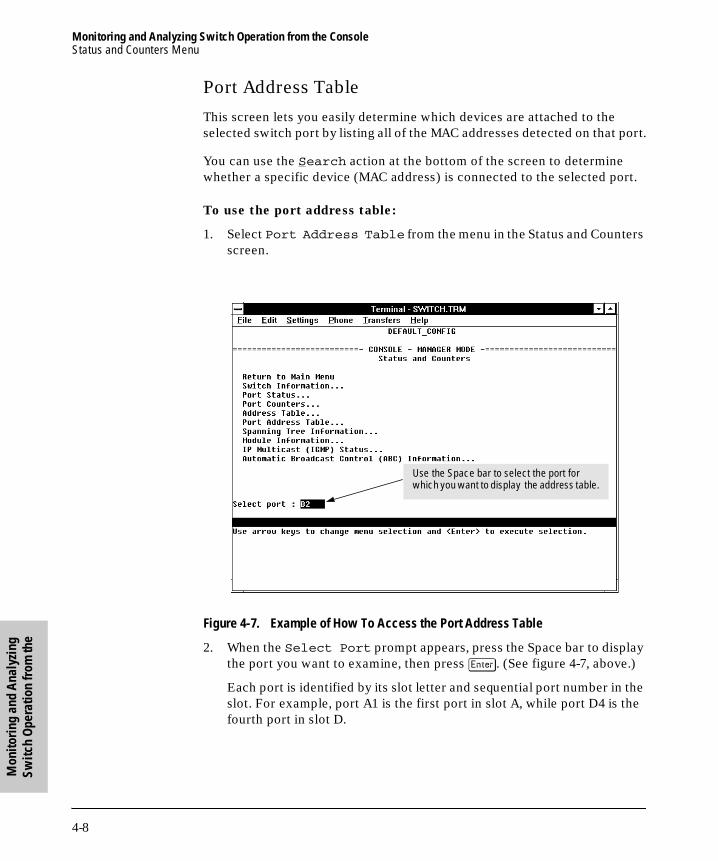
Monitoring and Analyzing Switch Operation from the ConsoleStatus and Counters Menu
Mon
itori
ng a
nd A
naly
zing
Sw
itch
Ope
ratio
n fr
om th
e
B_SCOTS.BK : b_chp4.fm5 Page 8 Thursday, February 20, 1997 2:19 PM
Port Address Table
This screen lets you easily determine which devices are attached to the selected switch port by listing all of the MAC addresses detected on that port.
You can use the Search action at the bottom of the screen to determine whether a specific device (MAC address) is connected to the selected port.
To use the port address table:
1. Select Port Address Table from the menu in the Status and Counters screen.
Figure 4-7. Example of How To Access the Port Address Table
2. When the Select Port prompt appears, press the Space bar to display the port you want to examine, then press [Enter]. (See figure 4-7, above.)
Each port is identified by its slot letter and sequential port number in the slot. For example, port A1 is the first port in slot A, while port D4 is the fourth port in slot D.
Use the Space bar to select the port for which you want to display the address table.
4-8

Monitoring and Analyzing Switch Operation from the ConsoleStatus and Counters Menu
Monitoring and A
nalyzing Sw
itch Operation from
the
B_SCOTS.BK : b_chp4.fm5 Page 9 Thursday, February 20, 1997 2:19 PM
Figure 4-8. Example of a Port Address Table for a Specific Port
In this example, several MAC addresses accessed through port B2 appear in the initial listing. To view any additional addresses that may be in the listing, use the Next page action.
4-9

Monitoring and Analyzing Switch Operation from the ConsoleStatus and Counters Menu
Mon
itori
ng a
nd A
naly
zing
Sw
itch
Ope
ratio
n fr
om th
e
B_SCOTS.BK : b_chp4.fm5 Page 10 Thursday, February 20, 1997 2:19 PM
Spanning Tree (STP) Information
N o t e If multiple VLANs are configured on the switch, you will be prompted to select a VLAN (by using the Space bar, then pressing [Enter]) to display this screen.
Figure 4-9. Example of Spanning Tree Information
Use this screen to determine current switch-level STP parameter settings and statistics.
4-10
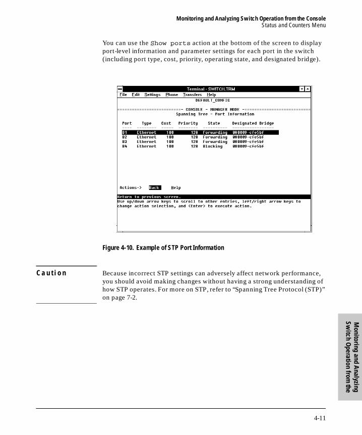
Monitoring and Analyzing Switch Operation from the ConsoleStatus and Counters Menu
Monitoring and A
nalyzing Sw
itch Operation from
the
B_SCOTS.BK : b_chp4.fm5 Page 11 Thursday, February 20, 1997 2:19 PM
You can use the Show ports action at the bottom of the screen to display port-level information and parameter settings for each port in the switch (including port type, cost, priority, operating state, and designated bridge).
Figure 4-10. Example of STP Port Information
C a u t i o n Because incorrect STP settings can adversely affect network performance, you should avoid making changes without having a strong understanding of how STP operates. For more on STP, refer to “Spanning Tree Protocol (STP)” on page 7-2.
4-11

Monitoring and Analyzing Switch Operation from the ConsoleStatus and Counters Menu
Mon
itori
ng a
nd A
naly
zing
Sw
itch
Ope
ratio
n fr
om th
e
B_SCOTS.BK : b_chp4.fm5 Page 12 Thursday, February 20, 1997 2:19 PM
Module Information
Figure 4-11. Example of Module Information
This screen tells you which type of module the switch detects in each slot.
4-12

Monitoring and Analyzing Switch Operation from the ConsoleStatus and Counters Menu
Monitoring and A
nalyzing Sw
itch Operation from
the
B_SCOTS.BK : b_chp4.fm5 Page 13 Thursday, February 20, 1997 2:19 PM
IP Multicast (IGMP) Status
N o t e If multiple VLANs are configured on the switch, you will be prompted to select a VLAN (by using the Space bar, then pressing [Enter]) to display this screen.
This screen identifies the active IP multicast groups the switch has detected, along with the number of report packets and query packets seen for each group. It also indicates which port is used for connecting to the querier.
Figure 4-12. Example of IGMP Status Screen
4-13

Monitoring and Analyzing Switch Operation from the ConsoleStatus and Counters Menu
Mon
itori
ng a
nd A
naly
zing
Sw
itch
Ope
ratio
n fr
om th
e
B_SCOTS.BK : b_chp4.fm5 Page 14 Thursday, February 20, 1997 2:19 PM
You can also display the port status of the individual multicast groups. (That is, you can display the ports, port types, and whether the IGMP devices connected to the switch via the port are hosts, routers, or both.) To do so, select the group from the above screen and press [S] for Show ports. For example, suppose you wanted to view the status of the IP multicast group 227.111.122.122 shown in the above screen. You would highlight the row beginning with that group number, then press [S]. You would then see a screen similar to the following:
Figure 4-13. Example of an IGMP Status Screen for a Selected Multicast Group
4-14

Monitoring and Analyzing Switch Operation from the ConsoleStatus and Counters Menu
Monitoring and A
nalyzing Sw
itch Operation from
the
B_SCOTS.BK : b_chp4.fm5 Page 15 Thursday, February 20, 1997 2:19 PM
Automatic Broadcast Control (ABC) Information
N o t e If multiple VLANs are configured on the switch, you will be prompted to select a VLAN (by using the Space bar, then pressing [Enter]) to display this screen
This screen displays the number of IP ARP and IPX NSQ replies sent per port and whether RIP and SAP packets are being forwarded or not forwarded per port. If VLANs are configured, this data is on a per-VLAN basis.
Figure 4-14. Example of Automatic Broadcast Control (ABC) Screen
4-15

Monitoring and Analyzing Switch Operation from the ConsoleEvent Log
Mon
itori
ng a
nd A
naly
zing
Sw
itch
Ope
ratio
n fr
om th
e
B_SCOTS.BK : b_chp4.fm5 Page 16 Thursday, February 20, 1997 2:19 PM
Event Log
The Event Log records operating events as single-line entries listed in chrono-logical order. Each entry is composed of five fields:
Severity is one of the following codes:
I (information) indicates routine events.
W (warning) indicates that a service has behaved unexpectedly.
C (critical) indicates that a severe switch error has occurred.
D (debug) reserved for HP internal diagnostic information.
Date is the date in mm/dd/yy format that the entry was placed in the log.
Time is the time in hh:mm:ss format that the entry was placed in the log.
System Module is the internal module (such as “ports” for port manager) that generated the log entry. If VLANs are configured, then a VLAN name also appears for an event that is specific to an individual VLAN.
Event Message is a brief description of the operating event.
Severity Date Time System Module Event Message
I 08/05/96 10:52:32 ports: port 1 enabled
4-16

Monitoring and Analyzing Switch Operation from the ConsoleEvent Log
Monitoring and A
nalyzing Sw
itch Operation from
the
B_SCOTS.BK : b_chp4.fm5 Page 17 Thursday, February 20, 1997 2:19 PM
Entering and Navigating in the Event Log Display. To enter the event log, select Event Log from the Main menu.
Figure 4-15. Example of an Event Log Display
To display various portions of the Event Log, either preceding or following the currently visible portion, use either the actions listed at the bottom of the display (Next page, Prev page, or End), or the keys described in the following table:
Table 4-2. Event Log Control Keys
Key Action
[N] Advance the display by one page (next page).
[P] Roll back the display by one page (previous page).
[v] Advance display by one event (down one line).
[^] Roll back display by one event (up one line).
[E] Advance to the end of the log.
[H] Display Help for the event log.
Range of Log Events DisplayedRange of Events in the LogLog Status Line
4-17

Monitoring and Analyzing Switch Operation from the ConsoleEvent Log
Mon
itori
ng a
nd A
naly
zing
Sw
itch
Ope
ratio
n fr
om th
e
B_SCOTS.BK : b_chp4.fm5 Page 18 Thursday, February 20, 1997 2:19 PM
The event log holds up to 100 lines in chronological order, from the oldest to the newest. Each line consists of one complete event message. Once the log has received 100 entries, it discards the current oldest line each time a new line is received. The event log window contains 20 lines and can be positioned to any location in the log.
The log status line at the bottom of the display identifies where in the sequence of event messages the display is currently positioned.
The event log will be erased if any of the following occurs:
■ The switch is reset using the Reset button.
■ Power to the switch is interrupted.
■ A new operating system is downloaded to the switch.
(The event log is not erased by using the Reboot Switch command in the Main Menu.)
4-18

Using SN
MP To M
onitor and M
anage the Switch
B_SCOTS.BK : b_chp5.fm5 Page 1 Thursday, February 20, 1997 2:19 PM
5
Using SNMP To Monitor and Manage the Switch
You can manage the switch via SNMP from a network management station. (The switch supports SNMP v1 and SNMP v2c, except as noted below for SNMP v2 Notifications.) If you are using IP, you must either configure the switch with the appropriate IP address or, if you are using Bootp to configure the switch, ensure that the Bootp process provides the IP address. (The IPX address is automatically configured.) If multiple VLANs are configured, each VLAN interface should have its own IP or IPX network address. This chapter provides an overview of SNMP management for the switch and describes the configuration process for the various features. For parameter-specific infor-mation, refer to the Help provided in the individual configuration screens.
SNMP Management
SNMP management features on the switch include:
■ Security via configuration of SNMP communities
■ Event reporting via SNMP traps and RMON (SNMP v2 Notifications are not supported at this time.)
■ Managing the switch with a network management tool such as HP AdvanceStack Assistant
■ Monitoring data normally associated with the SNMP agent (“Get” _operations). Supported Standard MIBs include:
• Bridge MIB (RFC 1493)
• Etherlike MIB (RFC 1650)
• Ethernet MAU MIB (RFC 1515)
• Interfaces Evolution MIB (RFC 1573)
• Novell Standard IPX MIB (ipx.mib)
• RMON MIB (RFC 1757)—etherstats, events, alarms, and history
• SNMP MIB-II (RFC 1213)
5-1
Using SNMP To Monitor and Manage the SwitchSNMP Management
Usi
ng S
NM
P To
Mon
itor a
nd
Man
age
the
Switc
h
B_SCOTS.BK : b_chp5.fm5 Page 2 Thursday, February 20, 1997 2:19 PM
HP Proprietary MIBs include:
• Statistics for message and packet buffers, tcp, telnet, and timep (netswtst.mib)
• Port counters, forwarding table, and CPU statistics (stat.mib)
• tftp download (downld.mib)
• 802.12 (100VG) information (vg.mib)
• Integrated Communications Facility Authentication Manager and SNMP communities (icf.mib)
• HP AdvanceStack Switch 2000 configuration (config.mib)
• HP VLAN configuration information (vlan.mib) supporting hpVlanGeneralGroup
• HP EASE MIB version 4 to allow EASE sampling
• HP Linktest MIB for basic device management (linktest.mib)
• HP ICF Linktest MIB for link test features (icfbasic.mib)
The switch SNMP agent also uses certain variables that are included in a Hewlett-Packard proprietary MIB file you can add to the SNMP database in your network management tool. You can copy the MIB file from the compact disk (CD) shipped with the switch, or from following World Wide Web site:
http://www.hp.com/go/network_city
For more information, refer to the card at the front of this manual.
5-2

Using SNMP To Monitor and Manage the SwitchSNMP Configuration Process
Using SN
MP To M
onitor and M
anage the Switch
B_SCOTS.BK : b_chp5.fm5 Page 3 Thursday, February 20, 1997 2:19 PM
SNMP Configuration Process
The general steps to configuring for SNMP access to the preceding features are:
1. From the Main menu, select Configuration.
2. Enable and configure an IP address for the switch, including any neces-sary gateways. An IPX address is automatically configured. (For more on configuring IPX and IP, refer to page 3-7 and page 3-9.)
3. Configure the appropriate SNMP communities. (The “public” community exists by default and is used by HP’s network management applications.) (For more on configuring SNMP communities, refer to page 3-11.)
4. Configure the appropriate trap receivers. (For more on configuring trap receivers, refer to page 3-13.)
In many networks, manager addresses are not used. In this case, all manage-ment stations using the correct community name may access this device with the View and Access levels that have been set for that community. If you want to restrict access to one or more specific nodes, you can enter up to 10 IP and/or IPX addresses of such nodes into the Manager Address field. Configuring
one or more IP or IPX addresses in the Manager Address field means that
only the network management stations at those addresses are authorized to
use the community name to access the switch.
C a u t i o n Deleting the community named “public” disables many network management functions (such as auto-discovery, traffic monitoring, and threshold setting). If security for network management is a concern, it is recommended that you change the write access for the “public” community to “Restricted”.
N o t e SNMP community and trap receiver configurations are activated when saved. Rebooting the switch is not necessary unless you have also configured other parameters that require rebooting in order to be activated. (For more on when it is necessary to reboot, refer to “Rebooting the Switch” on page 2-10.)
5-3

B_SCOTS.BK : b_chp5.fm5 Page 4 Thursday, February 20, 1997 2:19 PM

Using the A
dvanced Com
mands
B_SCOTS.BK : b_chp6.fm5 Page 1 Thursday, February 20, 1997 2:19 PM
6
Using the Advanced Commands
Overview
The Advanced Commands , which are accessed from the Main Menu, gives you access to the following system management commands:
■ Help
■ Date
■ Time
■ History
■ Ping
■ IpxPing
■ LinkTest
■ Telnet
■ VLAN
■ ClearLED
■ Config
■ Delete
■ GetMIB
■ SetMIB
■ WalkMIB
■ Exit
■ Get/Put (TFTP)
■ ZGet/ZPut (ZMODEM)
■ Version
■ Log
■ !
■ Repeat
■ Page
■ Redo
6-1
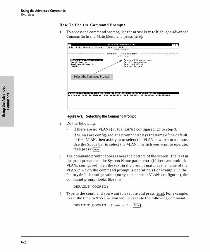
Using the Advanced CommandsOverview
Usi
ng th
e A
dvan
ced
Com
man
ds
B_SCOTS.BK : b_chp6.fm5 Page 2 Thursday, February 20, 1997 2:19 PM
How To Use the Command Prompt:
1. To access the command prompt, use the arrow keys to highlight Advanced Commands in the Main Menu and press [Enter].
Figure 6-1. Selecting the Command Prompt
2. Do the following:
• If there are no VLANs (virtual LANs) configured, go to step 3.
• If VLANs are configured, the prompt displays the name of the default, or first VLAN, then asks you to select the VLAN in which to operate. Use the Space bar to select the VLAN in which you want to operate, then press [Enter].
3. The command prompt appears near the bottom of the screen. The text in the prompt matches the System Name parameter. (If there are multiple VLANs configured, then the text in the prompt matches the name of the VLAN in which the command prompt is operating.) For example, in the factory default configuration (no system name or VLANs configured), the command prompt looks like this:
DEFAULT_CONFIG:
4. Type in the command you want to execute and press [Enter]. For example, to set the time to 9:55 a.m. you would execute the following command:
DEFAULT_CONFIG: time 9:55 [Enter]
Select the Command Prompt
6-2

Using the Advanced CommandsOverview
Using the A
dvanced Com
mands
B_SCOTS.BK : b_chp6.fm5 Page 3 Thursday, February 20, 1997 2:19 PM
How To Exit from the command prompt:
Type exit and press [Enter] to return to the Main Menu.
How To List Available Commands:
At the command prompt, type h and press [Enter].
When you see — MORE — at the bottom of the screen:
■ To advance the display one line at a time, use [Enter].
■ To advance the display one screen at a time, use the Space bar.
How To Stop the Help Listing: Press [Q].
6-3
Using the Advanced CommandsCommands
Usi
ng th
e A
dvan
ced
Com
man
ds
B_SCOTS.BK : b_chp6.fm5 Page 4 Thursday, February 20, 1997 2:19 PM
Commands
To execute any of these commands, select Advanced Commands from the Main Menu, type the command, and press [Enter].
Conventions:
■ Commands are shown in the normal typeface.
■ Required parameters are shown in italics.
■ Optional parameters are shown in italics, with brackets ( […] ).
For example:
Command Required Parameters Optional Parameters
ping ip-addr [repetitions] [timeout]
Command Syntax Description
H (help) Lists the commands available at the command prompt.
date [mm/dd/yy] Without parameters, displays the date and time currently held by the switch.With parameters in the month/date/year format, resets the date.
time [hh:mm:ss] Without parameters, displays the date and time currently held by the switch.With parameters in the hours:minutes:seconds format, resets the time.
history displays the times and reasons for the last four occasions on which the switch was rebooted or restarted.
ping ip-addr [repetitions] [timeout]
where:ip-addr is the IP address of thetarget node in dotted decimalnotation.
repetitions is the number of times to repeat the echo request.Default: send packet once.
timeout is how many seconds towait for a response. Default: 5 seconds.
Sends an Internet Control Message Protocol (ICMP) echo request message to a specific IP address, as a network-layer test of the reachability of the node. Ping does not support loopback (pinging this switch) or broadcast addresses. The switch must have IP configured. After transmitting the request message to the node, the switch waits for a response. If it is received within the specified or default timeout interval, the console displays a message indicating that the target is “alive”. If an echo response is not received within the specified or default timeout interval, the console displays a message indicating that the target did not respond.
VLANs: If multiple VLANs are configured, the Ping command sends requests to the ports in the VLAN environment specified when the command prompt was selected.
6-4

Using the Advanced CommandsCommands
Using the A
dvanced Com
mands
B_SCOTS.BK : b_chp6.fm5 Page 5 Thursday, February 20, 1997 2:19 PM
ipxping ipx-addr [repetitions] [timeout][size]
where:ipx-addr is the IPX address of the
target node in this format:
network number :mac address
repetitions is the number of times to repeat the echo request.Default: send packet once.
timeout is how many seconds towait for a response. Default: 5 seconds.
size is the size in bytes of the data to besent.Default: 40 bytes.
Sends an IPX echo request message to a specific IPX address, as a network-layer test of the reachability of the node. The switch must have IPX enabled. After transmitting the request message to the node, the switch waits for a response. If it is received within the specified or default timeout interval, the console displays a message indicating that the target is “alive”. If an echo response is not received within the specified or default timeout interval, the console displays a message indicating that the target did not respond.
VLANs: If multiple VLANs are configured, ipxping sends requests to the ports in the VLAN environment specified when the command prompt was selected.
linktest mac_addr [count] [delay]
where:mac_addr is the MAC address ofthe target node in 12-characterhexadecimal format.
count is the number of test packets to send.Default: 1 packet
delay is how many seconds towait for a response to each packet.Default: 2 seconds.
Verifies communication to a MAC address on the LAN. Sends an 802.2 Test Packet to a specific target node on a network in the VLAN environment specified in the command prompt. The target node must be able to respond to an 802.2 Test Packet with an 802.2 Test Response packet in order for the test to work. (HP managed hubs, bridges, routers, and switches automatically respond to 802.2 Test Packets. Most HP LAN adapters can be configured to operate as a responder.
VLANs: If multiple VLANs are configured, the linktest command sends requests to the nodes in the VLAN environment specified when the command prompt was selected.
telnet ip-addr
where:ip-addr is the IP address of the targetnode in dotted decimal notation.
Used to establish a Transmission Control Protocol (TCP) virtual terminal connection to a remote node, allowing you to interact with the remote node's interface. IP must be configured, and the remote node must have Telnet service enabled. The Switch 2000 supports one inbound and one outbound Telnet session. In the factory default configuration, the Inbound Telnet Enabled parameter is set to Yes. (To change the Inbound Telnet Enabled parameter, use the Console configuration screen, which is accessed from the Configuration screen selected from the Main menu.) Outbound Telnet is always enabled. To exit from an inbound Telnet session, select LOGOUT from the Main menu and answer the confirmation prompt by typing y. To exit from an HP router, another Switch 2000, or a UNIX login, press [Ctrl] [D]. To force a disconnection from any device, use [Ctrl] [R]. To interrupt command processing without halting an outbound Telnet session, use [Ctrl] [C].
Command Syntax Description
6-5

Using the Advanced CommandsCommands
Usi
ng th
e A
dvan
ced
Com
man
ds
B_SCOTS.BK : b_chp6.fm5 Page 6 Thursday, February 20, 1997 2:19 PM
vlan vlan_name
where:vlan_name is the name of thevirtual LAN you want to access.
Used where VLANs are configured. Used to select a different VLAN environment in which to execute Command Prompt commands. The command prompt will change to show the VLAN name specified by the vlan_name parameter.
clearled Turns off the Security LED on the front panel of the Switch 2000.
config Displays the configuration currently saved in flash memory. When — MORE — is displayed, pressing [Enter] displays the next line of the configuration, and pressing the Space bar displays the next screen of the configuration. To halt a config listing and return to the command line prompt, press [Q].
delete Deletes the configuration file currently in use, returns the switch to its factory default configuration, and reboots the switch.
getmib objectname.index
where:objectname identifies the MIB object by name or number format.
index identifies the instance ofeach object name.
Retrieves the value of an individual MIB object in the switch.
Example: The following command returns the enable/disable status for a port having a port ID of 1. (For an example of port ID numbering, see the example of the Port Status screen on page 4-4.)
getmib ifAdminStatus.1
setmib objectname.index type value
where:objectname identifies the MIB object by name or number format.
index identifies the instance ofeach object name.
Sets a MIB object to a specific value. Valid types are:
type
value identifies the numeric value for the MIB object.
-i (integer) -g (gauge)-o (octet) -t (time_ticks)-d (object identifier) -u (unsigned integer 32)-a (ip_addr) -D (Display String)-c (counter) -N (NULL)
Example: This command sets port 1 to disabled status.
setmib ifAdminStatus.1 -i 2
Command Syntax Description
6-6

Using the Advanced CommandsCommands
Using the A
dvanced Com
mands
B_SCOTS.BK : b_chp6.fm5 Page 7 Thursday, February 20, 1997 2:19 PM
walkmib objectname Retrieves the MIB subtree for the specified MIB object. When — MORE — is displayed, pressing [Enter] displays the next line of the configuration, and pressing the Space bar displays the next screen of the configuration. To halt a walkmib listing and return to the command line prompt, press [Q].
Examples: walkmib ifSpeed displays the speed for each port installed in the switch.walkmib ifPhysAddress displays the MAC address of each port installed in the switch.
exit Returns you to the Main Menu.
get ip-addr config filenameget ipx-addr config filename
where:ip_addr or ipx-addr is the IP or IPXaddress of the file server.
filename is the directory path andname of the file containing theconfiguration.
Uses TFTP to transfer a configuration from a TFTP server on an attached network. The switch must have IP or IPX configured, and the configuration must have been previously transferred from a switch to the file server. TFTP must be enabled on the server.
Progress of the transfer, plus successful or unsuccessful completion of the transfer are indicated in the Event Log.
Note: After transferring a configuration to the switch, the switch automatically reboots to invoke the new configuration.
put ip-addr object filenameput ipx-addr object filename
where:ip_addr or ipx-addr is the IP or IPXaddress of the remote host.
object is config, crashrec, or acommand that generates an outputthat can be stored in a file.
filename is the directory path andname of the configuration file onthe remote host.
Uses TFTP to transfer a configuration, a “crash record”, or the output of a command from the switch to a file on a remote host. The switch must have IP or IPX configured. TFTP must be enabled on the remote host. The target file on the remote host must also exist and have write permissions. A command used as an object must have an output that can be stored in a file.
Progress of the transfer, plus successful or unsuccessful completion of the transfer are indicated in the Event Log.
Note: When the switch reboots itself due to an internal error, a “crash record” (crashrec) is generated. This is a binary file holding internal data needed to troubleshoot the cause of the internal error.
zget CONFIG [remote-file] [dos/unix]
where:remote-file is a file name on theconsole PC.
dos = 0 (specifies DOS format)unix = 1 (specifies unix format)
Copies a switch configuration from a file on the console PC to the switch. The PC must be emulating a VT100 or ANSI terminal. Also, the PC must be running a Zmodem-compatible terminal emulation program such as PROCOMM PLUS.
Command Syntax Description
6-7

Using the Advanced CommandsCommands
Usi
ng th
e A
dvan
ced
Com
man
ds
B_SCOTS.BK : b_chp6.fm5 Page 8 Thursday, February 20, 1997 2:19 PM
zput file remote-file overwrite dos/unixwhere:
file is CONFIG or a command.remote-file is a file name on theconsole PC.overwrite is: 0 (don’t overwrite a file of the same name). 1 (create or overwrite a file of the same name).dos = 0 (specifies DOS format)unix = 1 (specifies unix format)
Copies a switch configuration from the switch to the console PC. The PC must be emulating a VT100 or ANSI terminal. Also, the PC must be running a Zmodem-compatible terminal emulation program such as PROCOMM PLUS.
Version Displays the version of operating system (OS) software currently running in the switch. If an FDDI Module is installed, also displays the current version of the FDDI Module OS.
log [-a] ‘[keywrd] Displays the event log.(Press the Space bar when prompted by the -- MORE -- message.)
Examples:log Displays100 lines of the current event log, since the
last reboot. log -a Displays the entire event log. log -a ‘telnet Displays all event log lines containing the keyword “telnet”log ‘telnet Displays any event log lines, since the last reboot, of the
current log that contain the keyword “telnet”.
! [repetitions] Repeat the last command.
Examples:! Repeats the last command once.! 3 Repeats the last command three times.
Repeat Continuously repeats the last command until a key is pressed on the console.
Page Toggles paging mode for display commands.
Print Send the output of a Command Prompt command to a printer or to a file.
Redo [?] / [number] / [string] Display or redo a command from the command history.
Examples:Redo Re-executes the most recent command.Redo ? Causes the last ten commands to be listed.Redo n Re-executes the previous nth command (1-10).Redo string Re-executes a previous command that begins with the text string.
Command Syntax Description
6-8

Advanced Concepts
B_SCOTS.BK : b_chp7.fm5 Page 1 Thursday, February 20, 1997 2:19 PM
7
Advanced Concepts
Overview
The switch provides support for these advanced features:
■ Spanning Tree Protocol—STP (page 7-2)
■ Port trunking (page 7-5)
■ Filtering for enhanced bandwidth usage and in-band security (page 7-8)
■ Virtual LANs—VLANs (page 7-14)
■ IP Multicast—IGMP (page 7-23)
■ Automatic Broadcast Control—ABC (page 7-30)
7-1

Advanced ConceptsSpanning Tree Protocol (STP)
Adv
ance
d Co
ncep
ts
B_SCOTS.BK : b_chp7.fm5 Page 2 Thursday, February 20, 1997 2:19 PM
Spanning Tree Protocol (STP)
The switch uses the IEEE 802.1d Spanning Tree Protocol (STP) to ensure that only one path at a time is active between any two nodes on the network. In networks where there is more than one physical path between any two nodes, STP ensures a single active path between them by blocking all redundant paths. STP is necessary in such networks because having more than one path between a pair of nodes causes loops in the network, which can result in a switch detecting the same node on more than one port. This results in duplication of messages, leading to a “broadcast storm” that can bring down the network.
N o t e The default STP setting in the Switch 2000 is “Off”. If you are using the switch to provide redundant links, you should reconfigure the Spanning Tree Proto-col to “On”. Also, when multiple VLANs are configured, you must enable STP separately for each VLAN in which you want spanning tree to operate.
While allowing only one active path through a network at any time, STP retains any redundant physical path to serve as a backup (blocked) path in case the existing active path fails. Thus, if a active path fails, STP automatically activates (unblocks) an available backup to serve as the new active path for as long as the original active path is down. For example:
Figure 7-1. Example of Logical and Redundant Paths Between Two Nodes
nodeA
switch A
nodeB
switch Dswitch B switch C
1path cost: 100
3path cost: 100
4path cost:200
• Active path from node A to node B: 1—> 3• Backup (redundant) path from node A to node B: 4 —> 2 —> 3
2path cost: 100
7-2

Advanced ConceptsSpanning Tree Protocol (STP)
Advanced Concepts
B_SCOTS.BK : b_chp7.fm5 Page 3 Thursday, February 20, 1997 2:19 PM
How To Configure Spanning Tree: In most cases, the default STP param-eter settings are adequate. In cases where it is not, use this procedure to make configuration changes.
C a u t i o n If you enable STP (step 5), it is recommended that you leave the remainder of the STP parameter settings at their default values until you have had an opportunity to evaluate STP performance in your network. Because incorrect STP settings can adversely affect network performance, you should avoid making changes without having a strong understanding of how STP operates. To learn the details of STP operation, refer to the IEEE 802.1d standard.
1. From the Main menu, select Configuration.
2. In the Configuration screen, select Spanning Tree .
3. If multiple VLANs are configured, select the VLAN in which you want to configure STP. If multiple VLANs are not configured, skip this step.
4. Select Edit to highlight the STP Enabled parameter.
5. Press the Space bar to select Yes . (This enables STP.)
Figure 7-2. Example of the STP Configuration Screen with Ethernet Modules Installed in the Switch
Read-Only Fields
7-3

Advanced ConceptsSpanning Tree Protocol (STP)
Adv
ance
d Co
ncep
ts
B_SCOTS.BK : b_chp7.fm5 Page 4 Thursday, February 20, 1997 2:19 PM
6. If the remaining STP parameter settings are adequate for your network, go to step 9.
7. Use [Tab] or the arrow keys to select the next parameter you want to change, then type in the new value. (If you need information on STP parameters, press [Enter] to select the Actions line, then press H to get help.)
8. Repeat step 7 for each additional parameter you want to change.
9. When you are finished editing parameters, press [Enter] to return to the Actions line.
10. Press [S] to save the currently displayed STP parameter settings and return to the Configuration menu.
11. When you are finished configuring the switch, return to the Main Menu.
7-4
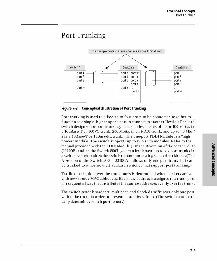
Advanced ConceptsPort Trunking
Advanced Concepts
B_SCOTS.BK : b_chp7.fm5 Page 5 Thursday, February 20, 1997 2:19 PM
Port Trunking
Figure 7-3. Conceptual Illustration of Port Trunking
Port trunking is used to allow up to four ports to be connected together to function as a single, higher-speed port to connect to another Hewlett-Packard switch designed for port trunking. This enables speeds of up to 400 Mbit/s in a 100Base-T or 100VG trunk, 200 Mbit/s in an FDDI trunk, and up to 40 Mbit/s in a 10Base-T or 10Base-FL trunk. (The one-port FDDI Module is a “high power” module. The switch supports up to two such modules. Refer to the manual provided with the FDDI Module.) On the B-version of the Switch 2000 (J3100B) and on the Switch 800T, you can implement up to six port trunks in a switch, which enables the switch to function as a high-speed backbone. (The A-version of the Switch 2000—J3100A—allows only one port trunk, but can be trunked to other Hewlett-Packard switches that support port trunking.)
Traffic distribution over the trunk ports is determined when packets arrive with new source MAC addresses. Each new address is assigned to a trunk port in a sequential way that distributes the source addresses evenly over the trunk.
The switch sends broadcast, multicast, and flooded traffic over only one port within the trunk in order to prevent a broadcast loop. (The switch automati-cally determines which port to use.)
Switch 1 Switch 2
The multiple ports in a trunk behave as one logical port
port a port wport b port xport c port y... port zport n ... port n
port 1 port 2 port 3 ... port n
port 5 port 6 port 7 port 8... port n
Switch 3
7-5

Advanced ConceptsPort Trunking
Adv
ance
d Co
ncep
ts
B_SCOTS.BK : b_chp7.fm5 Page 6 Thursday, February 20, 1997 2:19 PM
N o t e Using more than one media type and/or link speed in a port trunk is not supported. The console interface allows only links of the same media type within the same trunk. Similarly, it is recommended that all links in the same trunk have the same speed. You should also apply these rules when using a network management application to configure a port trunk.
A configured trunk appears as a single port (labeled Trk1, Trk2...Trk6) on other configuration screens, such as the Spanning Tree and Port VLAN Assignment screens. Also, when assigning a port trunk to a VLAN, all ports in that trunk must be assigned to that same VLAN.
When trunks are used in conjunction with filters and port monitoring, if a port is removed from the trunk, the filters and port monitoring for that port are returned to their default configuration settings.
How To Configure the Port Trunk: Use the Port Configuration screen to configure trunks.
1. From the Main menu, select Configuration.
2. In the Configuration menu, select Ports.
3. To assign a port to the trunk:
a. Select Edit.
b. Move the cursor to the Trunk column.
c. Select the row for a port you want in the trunk.
d. Press the Space bar to select the trunk you want. (To remove a port from a trunk, repeat the space bar until the trunk assignment is blank.)
For example, in the following screen, ports B1, B2, B3, and B4 have been assigned to trunk Trk1:
7-6
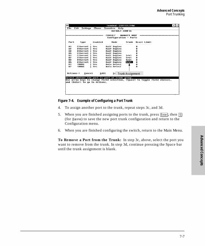
Advanced ConceptsPort Trunking
Advanced Concepts
B_SCOTS.BK : b_chp7.fm5 Page 7 Thursday, February 20, 1997 2:19 PM
Figure 7-4. Example of Configuring a Port Trunk
4. To assign another port to the trunk, repeat steps 3c, and 3d.
5. When you are finished assigning ports to the trunk, press [Enter], then [S] (for Save) to save the new port trunk configuration and return to the Configuration menu.
6. When you are finished configuring the switch, return to the Main Menu.
To Remove a Port from the Trunk: In step 3c, above, select the port you want to remove from the trunk. In step 3d, continue pressing the Space bar until the trunk assignment is blank.
Trunk Assignment
7-7

Advanced ConceptsFilters and Security
Adv
ance
d Co
ncep
ts
B_SCOTS.BK : b_chp7.fm5 Page 8 Thursday, February 20, 1997 2:19 PM
Filters and Security
To enhance the switch’s bandwidth usage and in-band security, configure per-port filters to forward desired traffic or drop unwanted traffic, as described below. The switch can support up to 50 filters.
Table 7-1. Filter Types and Criteria
Multicast Filters. This filter type enables the switch to send multicast traffic to a specified set of destination ports. This helps to preserve bandwidth by reducing multicast traffic on ports where it is unnecessary, and to isolate multicast traffic to enhance security.
N o t e IP multicast addresses occur in the range from 224.0.0.0 through 239.255.255.255. When IGMP is enabled, any Traffic/Security filters configured with a “Multicast” filter type and a “Multicast Address” within the above range are disabled and an event log message indicating this action is logged . That is, IGMP will control the IP multicast traffic flow and the Traffic/Security filter will control any multicast traffic that is not IP multicast. (Multicast addresses are entered in the “Traffic/Security Filters” screen as Ethernet addresses in the range of 01005e-000000 through 01995e-7fffff.)
If Spanning Tree is enabled, then the Spanning Tree multicast MAC address should not be filtered. (STP will not operate properly if the multicast MAC address is filtered.)
Filter Type Selection Criteria
Multicast Traffic having a specified multicast address will be forwarded or dropped on a per-port (destination) basis.
Protocol Traffic having the selected frame (protocol) type will be forwarded or dropped on a per-port (destination) basis.
Source Port Traffic from a designated source port will be forwarded or dropped on a per-port (destination) basis within the same VLAN.
Source MAC Traffic from a specified source MAC address and coming through a particular source port will be forwarded or dropped on a per-port (destination) basis within the same VLAN.
7-8

Advanced ConceptsFilters and Security
Advanced Concepts
B_SCOTS.BK : b_chp7.fm5 Page 9 Thursday, February 20, 1997 2:19 PM
Protocol Filters. This filter type enables the switch to restrict traffic of a particular protocol type to a specific destination port or ports on the switch (or to be dropped for all ports on the switch). Filtered protocol types include:
■ IP (Ethernet)
■ IP (802.3 SAP)
■ ARP
■ DEC LAT
■ AppleTalk
■ SNA
■ NetBIOS
■ IPX (Ethernet)
■ IPX (802.3 SAP)
■ VINES IP
■ VINES Echo
N o t e The switch provides filtering only for Ethernet and 802.3 format packets.
Source Port Filters. This filter type enables the switch to restrict traffic from all end nodes on the indicated source port to specific destination ports (or to be dropped for all destination ports on the switch). If VLANs are configured, the destination port must be in the same VLAN as the source port.
N o t e If more than one VLAN is configured, then the set of destination ports (Dest Port parameter) can consist of only the destination ports that are in the same VLAN as the source port.
Source MAC Filters. This filter type enables the switch to specify the port through which a node having a specified (source) MAC address can send traffic. Only ports that are selected are allowed to send and receive traffic for the specified node. For additional security, if traffic from the source MAC address appears on any port other than the selected one, the traffic from that source will be dropped and the Security LED on the front of the switch begins flashing. (To clear the Security LED, use the Advanced Command ClearLED command.)
7-9

Advanced ConceptsFilters and Security
Adv
ance
d Co
ncep
ts
B_SCOTS.BK : b_chp7.fm5 Page 10 Thursday, February 20, 1997 2:19 PM
N o t e If a node designated by the Source MAC parameter is moved to a different port than its original source port, any traffic to or from that node will not be forwarded by the switch. Forwarding will resume if the node is moved back to the original source port.
Traffic between ports not designated as a “Source Port” is not affected by the filter.
How To Configure Traffic/Security Filters: Use this procedure to spec-ify the type of filters to use on the switch and whether to forward or drop filtered packets for each filter you specify. You can create up to fifty filters.
1. From the Main menu, select Configuration.
2. In the Configuration menu, select Traffic/Security Filters to display the following screen.
Figure 7-5. The Traffic/Security Filters List Screen (Default Values)
3. In the Actions line, press [A] (for Add) to display the Traffic/Security Filters Configuration screen shown in figure 7-6.
7-10

Advanced ConceptsFilters and Security
Advanced Concepts
B_SCOTS.BK : b_chp7.fm5 Page 11 Thursday, February 20, 1997 2:19 PM
Figure 7-6. Example of the Traffic/Security Filters Configuration Screen
4. Press the Space bar to select the type of filter you want to configure. The options are:
• Multicast (the default)
• Protocol
• Source Port
• Source MAC
5. Press [v] once to highlight the next line. Depending on the type of filter you selected in step 4, select one of the options listed in the following table:
Filter Type Parameter
7-11

Advanced ConceptsFilters and Security
Adv
ance
d Co
ncep
ts
B_SCOTS.BK : b_chp7.fm5 Page 12 Thursday, February 20, 1997 2:19 PM
6. Configure the filter action for each destination port. For example:
Figure 7-7. Example of Specifying Filter Actions for Individual Ports
Filter Type Option Selected in Step 4
Next Line for Filter Type Option
Action for Selected Filter Option
Multicast Multicast Address Type in the multicast address.
Protocol Frame Type Use the Space bar to select the frame type.
Source Port Source Port Use the Space bar to select the source port.
Source MAC Source Port and Source MAC (address)
a. Use the Space bar to select the source port.
b. Press [>] to highlight the Source MAC parameter.
c. Type the MAC address of the source device whose packets you want to filter.
a “Source Port “ filter type has been selected for port D1
A Drop action has been specified for ports B2 and B3. Thus, traffic from port D1 will not be forwarded by ports B2 and B3.
7-12

Advanced ConceptsFilters and Security
Advanced Concepts
B_SCOTS.BK : b_chp7.fm5 Page 13 Thursday, February 20, 1997 2:19 PM
a. Press [v] to highlight the Action option for a destination port ( Dest Port ).
b. Press the Space bar to select the filter action for that port ( Forward filtered packets--the default--or Drop filtered packets).
c. Do one of the following:– To configure the filter action for another destination port, return
to step 6a. – If you are finished configuring actions for the current filter, go to
step 7.
7. Press [Enter] to return to the Actions line, then press [S] (for Save ) to save the current filter configuration.
8. Do one of the following:
• If you want to configure another filter, return to step 3.
• If you are finished configuring filters, press [B] (for Back ) to return to the Configuration menu.
9. When you are finished configuring the switch, return to the Main Menu.
7-13

Advanced ConceptsVirtual LANs (VLANs)
Adv
ance
d Co
ncep
ts
B_SCOTS.BK : b_chp7.fm5 Page 14 Thursday, February 20, 1997 2:19 PM
Virtual LANs (VLANs)
The switch supports port-based virtual LANs (VLANs). A VLAN is a collection of ports that belong to a single broadcast domain. (That is, all ports carrying traffic for a particular subnet address would belong to the same VLAN.) This allows workgroups to be defined on the basis of their logical function instead of their physical location, and does not require recabling.
Port-based VLANs are typically used to enable broadcast traffic reduction and increased security. By using port groupings, traffic is isolated to specific domains. A group of network users assigned to a VLAN are a separate traffic domain so that packets are forwarded only between ports that are designated for the same VLAN. Cross-domain broadcast traffic is eliminated and band-width is saved by not allowing packets to flood throughout the network.
For example, if ports 1 through 5 belong to VLAN_1 and ports 6 through 10 belong to VLAN_2, traffic from end-node stations on ports 2 through 5 is restricted to only VLAN 1, while traffic from ports 6 through 9 is restricted to only VLAN 2. For nodes on VLAN_1 to communicate with VLAN_2, their traffic must go through an external router via ports 1 and 10.
Figure 7-8. Example of Routing Between VLANs via an External Router
ExternalRouter
VLAN_2
VLAN_1
Port 1
Port 10
Port 2Port 3Port 4Port 5
Port 6Port 7Port 8Port 9
Switch with Two VLANs Configured
7-14

Advanced ConceptsVirtual LANs (VLANs)
Advanced Concepts
B_SCOTS.BK : b_chp7.fm5 Page 15 Thursday, February 20, 1997 2:19 PM
Effect of VLANs on Other Switch Features
IPX and IP Interfaces. There is a one-to-one relationship between a VLAN and an IP or IPX network interface. Since the VLAN is defined by a group of ports, the state (up/down) of those ports determines the state of the IP or IPX network interface associated with that VLAN. When a VLAN comes up because one or more of its ports is up, the IP or IPX interface for that VLAN is also activated. Likewise, when a VLAN is deactivated because all of its ports are down, the corresponding IP or IPX interface is also deactivated.
VLAN MAC Addresses. The switch has one unique MAC address for each of its VLAN interfaces. You can send an 802.2 test packet to this MAC address to verify connectivity to the switch. Likewise, you can assign an IP address to the VLAN interface, and when you Ping that address, ARP will resolve the IP address to this MAC address. (For IPX networks, each VLAN interface is automatically assigned a node address that is equivalent to the MAC address for that VLAN interface.) The switch allows up to eight VLAN MAC addresses (one per possible VLAN). If STP is enabled for a VLAN, the Spanning Tree source MAC address in the STP configuration BPDU packets for the VLAN will be the VLAN MAC address itself.
N o t e If multiple VLANs are configured on the switch, you will need to configure a separate instance of Spanning Tree for each VLAN in which you want Spanning Tree to operate.
Port Trunks. When assigning a port trunk to a VLAN, all ports in the trunk must be assigned to the same VLAN. You cannot split trunk members across multiple VLANs.
Port Monitoring. If you designate a port on the switch for network moni-toring, this port will not appear in the Port VLAN Assignment screen and cannot be configured as a member of any VLAN.
VLANs Spanning Multiple Switches. It is possible to have ports on more than one switch that are members of the same VLAN. Switches having VLANs that cross multiple switches must be interconnected by one link per VLAN. For example, if VLAN A and VLAN B span two switches, the switches must be interconnected by two independent links; one for VLAN A and one for VLAN B. This concept is illustrated in figure 7-9 on the next page.
7-15

Advanced ConceptsVirtual LANs (VLANs)
Adv
ance
d Co
ncep
ts
B_SCOTS.BK : b_chp7.fm5 Page 16 Thursday, February 20, 1997 2:19 PM
Adding a Switch 2000 Module. If you install a Switch 2000 module in a previously unoccupied slot, the ports in the module will be automatically added to the default VLAN. (To properly install a Switch 2000 module, refer to the documentation you received with the module.)
Figure 7-9. Example of VLANs Spanning Multiple Switches
Overview of Using VLANs
To use VLANs, you will need to follow these general steps:
■ Configure at least one VLAN in addition to the default VLAN (DEFAULT_VLAN). Refer to “How To Configure a VLAN” on the next page.
■ If you are managing VLANs with SNMP in an IP network, either configure an IP address and subnet mask for each VLAN or use the (default) Bootp feature to download an IP configuration from a Bootp server. Refer to “Internet (IP) Service Features” on page 3-9 or to appendix E, “Bootp Operation”.
Switch 1 Switch 2
VLAN A
Interswitch Link for VLAN A
Interswitch Link for VLAN B
workstation
server server
workstation
workstation
100 VG Hubworkstation
workstation
workstation workstationworkstation
server
VLAN B
7-16

Advanced ConceptsVirtual LANs (VLANs)
Advanced Concepts
B_SCOTS.BK : b_chp7.fm5 Page 17 Thursday, February 20, 1997 2:19 PM
■ If you are managing VLANs with SNMP in an IPX network, configure the IPX gateway encapsulation and gateway node. (An IPX node address is automatically assigned to each VLAN interface.) Refer to “IPX Service Features'' on page 3-7.
How To Configure a VLAN
In the factory default configuration, all ports on the Switch 2000 belong to a physical broadcast domain named “DEFAULT_VLAN”. You can divide the switch ports into multiple virtual broadcast domains by adding one or more VLANs. Because the default VLAN permanently exists in the switch, adding one new VLAN results in two VLANs existing in the switch. Adding another VLAN results in three VLANs existing in the switch, and so on.
N o t e If you add one or more new VLAN(s), you should then reboot the switch. (A new VLAN will not appear as an option in the Port VLAN Assignment screen until after the switch is rebooted.) If you create a new VLAN without also rebooting the switch, you will be prompted to choose whether to reboot the switch before entering the Port VLAN Assignment screen. When you move a port to a VLAN, the new assignment is automatically enabled, and it is not necessary to reboot the switch a second time.
To create a new VLAN and/or move ports into a VLAN, use the following two procedures.
To Create a New VLAN. Use this procedure to add a new VLAN or to edit the name of an existing VLAN.
1. Beginning at the Main Menu, select Configuration to display the configuration menu.
7-17

Advanced ConceptsVirtual LANs (VLANs)
Adv
ance
d Co
ncep
ts
B_SCOTS.BK : b_chp7.fm5 Page 18 Thursday, February 20, 1997 2:19 PM
Figure 7-10. The VLAN Options in the Configuration Menu
2. From the Configuration menu, select VLAN Names. You will then see a screen similar to the following:
Figure 7-11. The (Default) VLAN Names Screen
List of VLAN Names(up to 8)
VLAN Names Access
Port VLAN Assignment Access
7-18

Advanced ConceptsVirtual LANs (VLANs)
Advanced Concepts
B_SCOTS.BK : b_chp7.fm5 Page 19 Thursday, February 20, 1997 2:19 PM
3. Press [A] (for Add). You will then be prompted for a new VLAN name:
Name : _
4. Type the name (up to 12 characters, with no spaces) of a new VLAN that you want to add, then press [Enter].
5. Press [S] (for Save).
6. Do one of the following:
• If you want to add another VLAN name, return to step 3.
• If you are finished entering VLAN names, press [B] (for Back) to return to the Configuration menu.
7. Return to the Main Menu and reboot the switch to activate the new VLAN(s) you have just entered.
N o t e You can rename “DEFAULT_VLAN”, but you cannot delete it from the Switch, regardless of which name you assign to it.
To Move a Port to a VLAN. Use this procedure to move a port into a VLAN. (Ports you do not specifically assign to a VLAN are automatically placed in the default VLAN.)
1. If you have just added a new VLAN name and have not yet rebooted the switch, do so now (step 7 in the previous procedure).
2. Return to the Main Menu and select Configuration to display the Config-uration menu.
3. Select Port VLAN Assignment . You will then see a Port VLAN Assignment screen similar to the following:
7-19
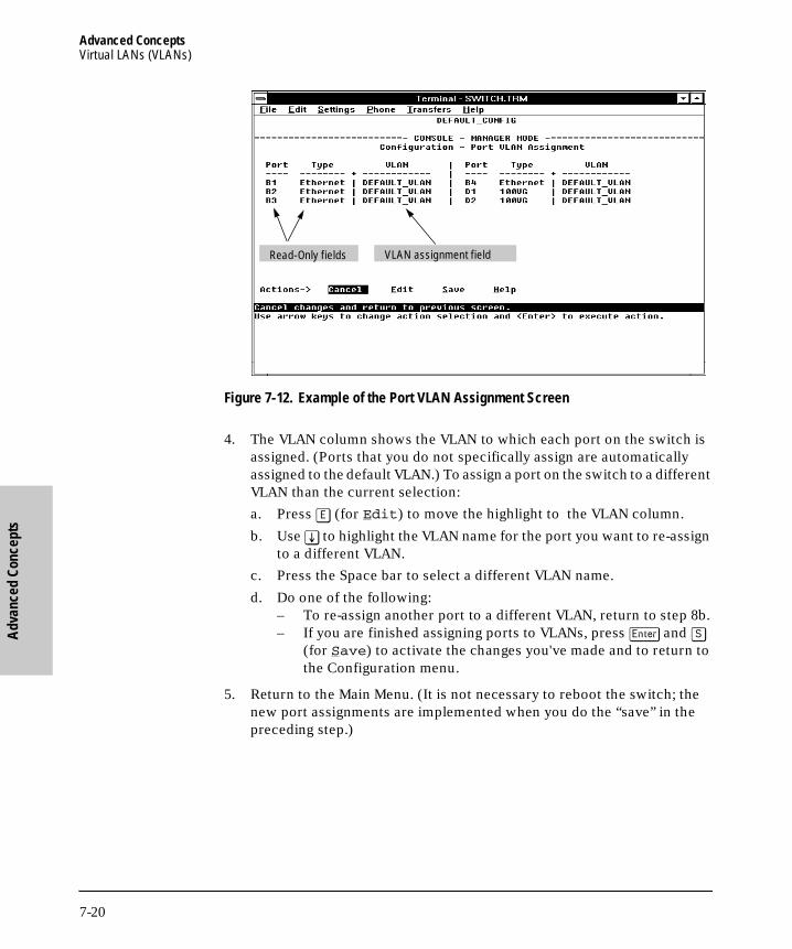
Advanced ConceptsVirtual LANs (VLANs)
Adv
ance
d Co
ncep
ts
B_SCOTS.BK : b_chp7.fm5 Page 20 Thursday, February 20, 1997 2:19 PM
Figure 7-12. Example of the Port VLAN Assignment Screen
4. The VLAN column shows the VLAN to which each port on the switch is assigned. (Ports that you do not specifically assign are automatically assigned to the default VLAN.) To assign a port on the switch to a different VLAN than the current selection:
a. Press [E] (for Edit) to move the highlight to the VLAN column.
b. Use [v] to highlight the VLAN name for the port you want to re-assign to a different VLAN.
c. Press the Space bar to select a different VLAN name.
d. Do one of the following:– To re-assign another port to a different VLAN, return to step 8b.– If you are finished assigning ports to VLANs, press [Enter] and [S]
(for Save) to activate the changes you've made and to return to the Configuration menu.
5. Return to the Main Menu. (It is not necessary to reboot the switch; the new port assignments are implemented when you do the “save” in the preceding step.)
VLAN assignment fieldRead-Only fields
7-20

Advanced ConceptsVirtual LANs (VLANs)
Advanced Concepts
B_SCOTS.BK : b_chp7.fm5 Page 21 Thursday, February 20, 1997 2:19 PM
VLAN Restrictions
■ Each port can be assigned to only one VLAN.
■ An external router must be used to communicate between two VLANs.
■ Duplicate MAC addresses on different VLANs are not supported and can cause VLAN operating problems. These duplicates are possible and com-mon in situations involving Sun workstations with multiple network interface cards, with DECnet routers, and with certain Hewlett-Packard routers using OS versions earlier than A09.70 where any of the following are enabled:
• IPX
• IP Host-Only
• STP
• XNS
• DECnet
Currently, the problem of duplicate MAC addresses in IPX and IP Host-Only environments is addressed through the HP router OS version described below. However, for XNS and DECnet environments, a satis-factory solution is not available from any vendor at this time.
N o t e Operating problems associated with duplicate MAC addresses are likely to occur in VLAN environments where XNS and DECnet are used. For this reason, using VLANs in XNS and DECnet environments is not currently supported on the Switch 2000.
■ If you assign a port to be the Network Monitoring Port, that port cannot be configured as a member of any VLAN. If the port was previously assigned to a VLAN (including the default VLAN), it will be automatically removed from the VLAN when the Monitoring Port assignment is made. When you subsequently disable the monitoring port assignment, the port will be returned to the default VLAN.
■ Before you can delete a VLAN, you must move all of its ports to another VLAN.
7-21

Advanced ConceptsVirtual LANs (VLANs)
Adv
ance
d Co
ncep
ts
B_SCOTS.BK : b_chp7.fm5 Page 22 Thursday, February 20, 1997 2:19 PM
HP Router Requirements. Use the Hewlett-Packard version A.09.70 (or
later) router OS release if any of the following Hewlett-Packard routers are
installed in networks in which you will be using VLANs:
HP Router 440 (formerly Router ER)HP Router 470 (formerly Router LR)HP Router 480 (formerly Router BR)HP Router 650
Release A.09.70 (or later) is available electronically through the HP BBS service and the World Wide Web. Refer to the “Customer Support Services” card at the beginning of this manual.
Symptoms of Duplicate MAC Addresses in VLAN Environments
There are no definitive events or statistics to indicate the presence of duplicate MAC addresses in a VLAN environment. However, one symptom that may occur is that a duplicate MAC address can appear in the Port Address Table screen to be linked with one port, and then later appear to be linked to another port.
7-22

Advanced ConceptsIP Multicast (IGMP)
Advanced Concepts
B_SCOTS.BK : b_chp7.fm5 Page 23 Thursday, February 20, 1997 2:19 PM
IP Multicast (IGMP)
In a network where IP multicast traffic is transmitted for various multimedia applications, you can use the switch to reduce unnecessary bandwidth usage on a per-port basis by configuring IGMP.
How IGMP Operates
The Internet Group Management Protocol (IGMP) is an internal protocol of the Internet Protocol (IP) suite. IP manages multicast traffic by using switches, multicast routers, and hosts that support IGMP. (In Hewlett-Pack-ard’s implementation of IGMP, a multicast router is not necessary as long as the switch is configured to support IGMP with the querier feature enabled.) A set of hosts, routers, and/or switches that send or receive multicast data streams to or from the same source(s) are termed a multicast group, and have the same multicast group address. The multicast group running version 2 of IGMP uses three fundamental types of messages to communicate:
■ Query: A message sent from the querier (multicast router or switch) asking for a response from each host belonging to the multicast group. If a multicast router supporting IGMP is not present, then the switch must assume this function in order to elicit group membership information from the hosts on the network.
■ Report: A message sent by a host to the querier to indicate that the host wants to be or is a member of a given group indicated in the report message.
■ Leave Group: A message sent by a host to the querier to indicate that the host has ceased to be a member of a specific multicast group.
Thus, IGMP identifies members of a multicast group (within a subnet) and allows IGMP-configured hosts (and routers) to join or leave multicast groups.
Role of the Switch. When IGMP is enabled on the switch, it examines the IGMP packets it receives:
■ To learn which of its ports are linked to IGMP hosts and multicast routers/queriers belonging to any multicast group
■ To become a querier if a multicast router/querier is not discovered on the network
7-23
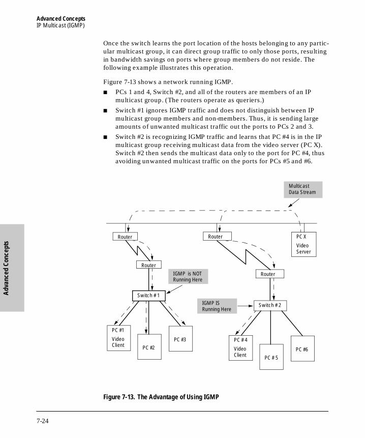
Advanced ConceptsIP Multicast (IGMP)
Adv
ance
d Co
ncep
ts
B_SCOTS.BK : b_chp7.fm5 Page 24 Thursday, February 20, 1997 2:19 PM
Once the switch learns the port location of the hosts belonging to any partic-ular multicast group, it can direct group traffic to only those ports, resulting in bandwidth savings on ports where group members do not reside. The following example illustrates this operation.
Figure 7-13 shows a network running IGMP.
■ PCs 1 and 4, Switch #2, and all of the routers are members of an IP multicast group. (The routers operate as queriers.)
■ Switch #1 ignores IGMP traffic and does not distinguish between IP multicast group members and non-members. Thus, it is sending large amounts of unwanted multicast traffic out the ports to PCs 2 and 3.
■ Switch #2 is recognizing IGMP traffic and learns that PC #4 is in the IP multicast group receiving multicast data from the video server (PC X). Switch #2 then sends the multicast data only to the port for PC #4, thus avoiding unwanted multicast traffic on the ports for PCs #5 and #6.
Figure 7-13. The Advantage of Using IGMP
PC X
Video Server
RouterRouter
PC #1
Video Client
Switch # 1
Router
Router
Switch # 2
PC #2PC #3 PC # 4
Video Client PC # 5
PC #6
Multicast Data Stream
IGMP is NOT Running Here
IGMP IS Running Here
7-24

Advanced ConceptsIP Multicast (IGMP)
Advanced Concepts
B_SCOTS.BK : b_chp7.fm5 Page 25 Thursday, February 20, 1997 2:19 PM
The next figure (7-14) shows a network running IP multicasting using IGMP without a multicast router. In this case, the IGMP-configured switch runs as a querier.
PCs 2, 5, and 6 are members of the same IP multicast group.
IGMP is configured on switches 3 and 4. Either of these switches can operate as querier because a multicast router is not present on the network. (If an IGMP switch does not detect a querier, it automatically assumes this role, assuming the querier feature is enabled—the default—within IGMP.)
Figure 7-14. Isolating IP Multicast Traffic in a Network■ In the above figure, the multicast group traffic does not go to switch 1 and
beyond because either the port on switch 3 that connects to switch 1 has been configured as blocked or there are no hosts off of switch 1 or switch 2 that belong to the multicast group.
■ For PC #1 to become a member of the same multicast group without flooding IP multicast traffic on all ports of switches 1 and 2, IGMP must be configured on both switches 1 and 2.
Switch # 1
Switch #4
PC #1
PC #2
PC # 5 PC #6
Multicast Data Stream
IGMP IS Running Here
Switch # 1
Switch # 2
IGMP is NOT Running Here
Switch # 3
7-25

Advanced ConceptsIP Multicast (IGMP)
Adv
ance
d Co
ncep
ts
B_SCOTS.BK : b_chp7.fm5 Page 26 Thursday, February 20, 1997 2:19 PM
N o t e IP multicast addresses occur in the range from 224.0.0.0 through 239.255.255.255. When IGMP is enabled, any Traffic/Security filters (page 7-8) configured with a “Multicast” filter type and a “Multicast Address” within the above range are disabled and an event log message indicating this action is logged . That is, IGMP will control the IP multicast traffic flow and the Traffic/Security filter will control any multicast traffic that is not IP multicast traffic.
How To Configure IGMP
In the factory default configuration, IGMP is disabled. If multiple VLANs are configured, you can configure IGMP on a per-VLAN basis. The configuration options include:
■ Enabling or disabling IGMP. Disabling IGMP (the default) causes all ports on the switch or VLAN to simply forward IP multicast traffic. Enabling IGMP allows the ports to detect IGMP queries and report packets and manage IP multicast traffic through the switch. If no other querier is detected, the switch will then also function as the querier. (If you need to disable the querier feature, you can do so through the IGMP configuration MIB. Refer to “Changing the Querier Configuration Setting” on page 7-29.)
■ High-priority forwarding. Disabling this parameter (the default) causes the switch or VLAN to process IP multicast traffic, along with other traffic, in the order received. If priority forwarding is supported by the network technology you are using (such as Hewlett-Packard’s implementation of 100Base-TX), enabling this parameter causes the switch or VLAN to give a higher priority to IP multicast traffic than to other traffic.
Per-Port handling of IP multicast traffic. In the factory default state (IGMP disabled), the switch forwards all IGMP traffic. When IGMP is enabled, you can configure the switch to do any of the following on a per-port basis:
• Automatic (the default): Causes the switch to interpret IGMP packets and to filter IP multicast traffic based on the IGMP packet information for that port.
• Blocking: Causes the switch to drop all IGMP transmissions received and block all outgoing IP Multicast packets for that port.
• Forwarding: Causes the switch to forward all IGMP and IP multicast transmissions through the port.
7-26

Advanced ConceptsIP Multicast (IGMP)
Advanced Concepts
B_SCOTS.BK : b_chp7.fm5 Page 27 Thursday, February 20, 1997 2:19 PM
N o t e If you move a port from one VLAN to another, that port will retain its IP multicast (IP Mcast) parameter setting. For example, suppose port A1 is in DEFAULT_VLAN with an IP Mcast setting of “Blocked”. If you create another VLAN named VLAN2 and then move port A1 to VLAN2, the IP Mcast setting will remain the same (Blocked).
To Configure IGMP. Use this procedure to configure or edit the IGMP settings for a switch or VLAN.
1. Beginning at the Main Menu, select Configuration to display the Configuration menu.
Figure 7-15. The IGMP Option in the Configuration Menu
2. Select IP Multicast (IGMP) Service.
3. If VLANs are configured, select the VLAN in which you want to configure IGMP and press [E] (for Edit). You will then see a screen similar to the following:
IGMP Option
7-27
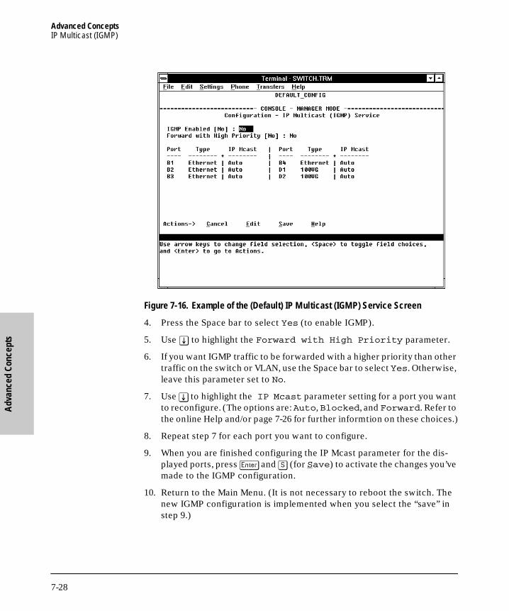
Advanced ConceptsIP Multicast (IGMP)
Adv
ance
d Co
ncep
ts
B_SCOTS.BK : b_chp7.fm5 Page 28 Thursday, February 20, 1997 2:19 PM
Figure 7-16. Example of the (Default) IP Multicast (IGMP) Service Screen
4. Press the Space bar to select Yes (to enable IGMP).
5. Use [v] to highlight the Forward with High Priority parameter.
6. If you want IGMP traffic to be forwarded with a higher priority than other traffic on the switch or VLAN, use the Space bar to select Yes. Otherwise, leave this parameter set to No.
7. Use [v] to highlight the IP Mcast parameter setting for a port you want to reconfigure. (The options are: Auto, Blocked, and Forward. Refer to the online Help and/or page 7-26 for further informtion on these choices.)
8. Repeat step 7 for each port you want to configure.
9. When you are finished configuring the IP Mcast parameter for the dis-played ports, press [Enter] and [S] (for Save) to activate the changes you’ve made to the IGMP configuration.
10. Return to the Main Menu. (It is not necessary to reboot the switch. The new IGMP configuration is implemented when you select the “save” in step 9.)
7-28
Advanced ConceptsIP Multicast (IGMP)
Advanced Concepts
B_SCOTS.BK : b_chp7.fm5 Page 29 Thursday, February 20, 1997 2:19 PM
Changing the Querier Configuration Setting.. The Querier feature, by default, is enabled and in most cases should be left in this setting. If you need to change the querier setting, you can do so using the IGMP Configuration MIB. To disable the querier setting, select the Advanced Command prompt from the Main Menu and enter this command:
setmib hpSwitchIgmpQuerierState.<vlan number> -i 2
To enable the querier setting, select the Advanced Command prompt from the Main Menu and enter this command:
setmib hpSwitchIgmpQuerierState.<vlan number> -i 1
To view the current querier setting, select the Advanced Command prompt from the Main Menu and enter this command:
getmib hpSwitchIgmpQuerierState.<vlan number>
where:
<vlan number> is the sequential (index) number of the specific VLAN. If no VLANs are configured, use “1”. For example:
getmib hpSwitchIgmpQuerierState.1
7-29

Advanced ConceptsAutomatic Broadcast Control (ABC)
Adv
ance
d Co
ncep
ts
B_SCOTS.BK : b_chp7.fm5 Page 30 Thursday, February 20, 1997 2:19 PM
Automatic Broadcast Control (ABC)
ABC helps to conserve bandwidth and processing power for IP and/or IPX traffic within a broadcast domain without adding the levels of cost and latency normally associated with routers. ABC achieves this by using the switch to reduce IP ARP and RIP broadcast traffic and IPX NSQ, RIP, and SAP broadcast traffic normally found on a network. Also, when enabled, ABC allows you to set the broadcast limit (Bcast Limit parameter) for all ports on the switch (or, if VLANs are configured, for all ports in the specified VLAN).
How ABC Operates
Reducing ARP Broadcast Traffic. When enabled on the switch or a VLAN, ABC does the following to reduce ARP (Address Resolution Protocol) broad-cast traffic:
1. Learning which port various hosts reside on by reading the address information in broadcast ARP (Address Resolution Protocol) packets and unicast ARP response packets
2. Proxy responding to subsequent ARP broadcast requests for those hosts from other devices instead of forwarding such requests out all ports and requiring each host to respond
For example, assume that host A has traffic for host D.
Figure 7-17. Example of a Network Using ABC
SwitchServer #1
Server #2
Host D
HubHub
Host CHost BHost A
7-30

Advanced ConceptsAutomatic Broadcast Control (ABC)
Advanced Concepts
B_SCOTS.BK : b_chp7.fm5 Page 31 Thursday, February 20, 1997 2:19 PM
To learn host D’s MAC address, host A sends a broadcast ARP request. Because the switch does not yet know the location of host D, it floods the request out all ports. However, the switch also learns from the ARP request the location of host A and stores this information in its ARP cache. Host D receives the ARP request (as will all other hosts conected to the switch), and responds with a unicast packet through the switch to host A. The switch monitors this response, learns the location of host D, and stores this informa-tion in its ARP cache. Thus, the switch now knows the address information for both host A and host D. Now, hosts A and D can send unicast packets to each other because they have learned each other’s addresses. Suppose that host C now wants to communicate with host A. C sends a broadcast ARP request to the switch. Because the switch already has A’s address information, it does not flood C’s ARP request out all ports, but instead sends a proxy ARP reply to C that tells C the address information for host A. Host C can now send unicast packets directly to host A. From these packets, host A will learn host C’s addressing information and be able to respond with unicast packets addressed to host C. The result is reduced network traffic because host C’s broadcast ARP request was not flooded on the switch’s ports. Similarly, for IPX networks, the switch learns service and route information from SAPs and RIPs respectively, and maintains SAP and RIP tables that contain the addresses of known servers. Using this data, the switch sends proxy responses to NSQ requests for these servers instead of flooding the requests on all ports.
N o t e The switch sends proxy ARP replies to hosts (ARP initiators) that are on a different port than the target host. However, the switch does not send a proxy ARP reply when both the initiator and the target host are on the same port. For example, the switch does not send a proxy ARP reply for host B (figure 7-17) in replying to an ARP request from host A.
The switch does not translate encapsulation types (such as 802.2 to SNAP in IPX). As a result, if a host client sends an NSQ request for a server, the switch will always send a proxy response containing the address of a server support-ing the same encapsulation type. If the switch has not learned of a server using the same encapsulation type as the host client, then the switch will flood the host client’s NSQ request to all ports. However, if a local server supporting the same encapsulation type exists on a port from which the NSQ request is received, the switch will not forward the request to other ports.
If Automatic Broadcast Control (ABC) is configured and more than one port is monitored, then broadcast packets may be duplicated on the monitor port.
7-31
Advanced ConceptsAutomatic Broadcast Control (ABC)
Adv
ance
d Co
ncep
ts
B_SCOTS.BK : b_chp7.fm5 Page 32 Thursday, February 20, 1997 2:19 PM
Reducing RIP and SAP Broadcast Traffic. You can also configure ABC to limit IP RIP and IPX RIP and SAP broadcasts, which can further reduce broadcast traffic on your network. RIP and SAP broadcasts are normally forwarded on all ports. However, with ABC enabled and additional RIP and SAP parameters configured, the switch will forward IP RIP and IPX RIP and SAP broadcasts only to the ports on which these types of broadcasts have been received earlier. This means that other ports are relieved of some unnecessary traffic because the RIP and SAP broadcasts will be forwarded only to ports where there are routers or servers that would use the broadcast information.
How To Configure ABC
In the factory default configuration, ABC is disabled. If multiple VLANs are configured, you can configure ABC on a per-VLAN basis. Otherwise, the configuration is on the switch level. You can enable ABC for IP only, IPX only, or for both. When ABC is disabled (the default), all broadcasts are sent out either all ports in the switch or, if VLANs are configured, out all ports in VLANs where ABC is disabled. ABC can be enabled with the options described below.
Enabling IP Only
Enabling ABC for IP causes the switch to send a proxy ARP reply for hosts whose addresses the switch has learned. Enabling for IP also:
■ Allows you to choose whether to enable ABC for IP RIP Control. If enabled, IP RIP Control causes IP RIP broadcasts to be forwarded only to ports where IP RIPs have been previously received. This avoids sending IP RIP broadcasts to ports where there is no indication of devices that would use them.
■ Activates a broadcast limit for either all ports in the switch or, if VLANs are configured, for all ports in the selected VLAN. (You can accept the default broadcast limit setting, change it, or turn it off.)
Enabling IPX Only
Enabling ABC for IPX causes the switch to send a proxy NSQ (nearest server query) reply for services the switch has learned. Enabling for IPX also:
■ Allows you to choose whether to enable ABC for IPX RIP/SAP control. If enabled, IPX RIP/SAP control causes IPX RIP and SAP broadcasts to be forwarded only to ports where IPX RIPs and SAPs have previously been received. This avoids sending IPX RIP and SAP broadcasts to ports where there is no indication of devices that would use them.
7-32

Advanced ConceptsAutomatic Broadcast Control (ABC)
Advanced Concepts
B_SCOTS.BK : b_chp7.fm5 Page 33 Thursday, February 20, 1997 2:19 PM
■ Activates a broadcast limit for either all ports in the switch or, if VLANs are configured, for all ports in the selected VLAN. (You can accept the default broadcast limit setting, change it, or turn it off.)
Enabling Both IP and IPX (IP_IPX)
Enabling ABC for IP and IPX causes the switch to:
■ Send a proxy IP ARP reply for hosts whose addresses the switch has learned.
■ Send a proxy NSQ (nearest server query) reply for services the switch has learned.
Enabling for both IP and IPX also allows you to choose whether to:
■ Enable ABC for IP RIP Control and/or IPX RIP/SAP control, as described in the preceeding subsections.
■ Set a broadcast limit for either all ports in the switch or, if VLANs are configured, for all ports in the selected VLAN.
7-33
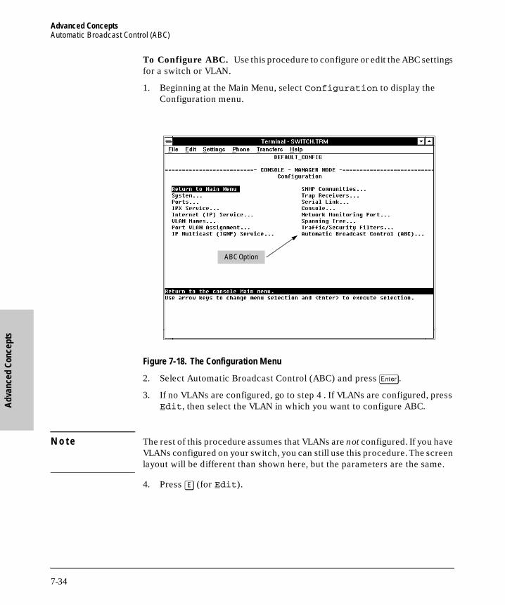
Advanced ConceptsAutomatic Broadcast Control (ABC)
Adv
ance
d Co
ncep
ts
B_SCOTS.BK : b_chp7.fm5 Page 34 Thursday, February 20, 1997 2:19 PM
To Configure ABC. Use this procedure to configure or edit the ABC settings for a switch or VLAN.
1. Beginning at the Main Menu, select Configuration to display the Configuration menu.
Figure 7-18. The Configuration Menu
2. Select Automatic Broadcast Control (ABC) and press [Enter].
3. If no VLANs are configured, go to step 4 . If VLANs are configured, press Edit, then select the VLAN in which you want to configure ABC.
N o t e The rest of this procedure assumes that VLANs are not configured. If you have VLANs configured on your switch, you can still use this procedure. The screen layout will be different than shown here, but the parameters are the same.
4. Press [E] (for Edit).
ABC Option
7-34

Advanced ConceptsAutomatic Broadcast Control (ABC)
Advanced Concepts
B_SCOTS.BK : b_chp7.fm5 Page 35 Thursday, February 20, 1997 2:19 PM
Figure 7-19. The Default ABC Screen (No VLANs Configured)
5. Use the Space bar to enable ABC. Select one of these options:
• IP_IPX: Enables ABC for both the IP and IPX protocols.
• IP: Enables ABC only for the IP protocol.
• IPX: Enables ABC only for the IPX protocol.
• Disabled
6. If you want broadcast control disabled for IP RIP and/or IPX RIP and SAP broadcasts, leave the remaining parameters set to No and go to step 7.
If you do want broadcast control for RIP or SAP broadcasts, press an arrow key to display the remaining ABC parameters. (If VLANs are configured, these parameters already appear.) Then do one of the follow-ing:
Note: This is the screen layout when no VLANs are configured. The screen has a different appearance if VLANs are configured.
7-35

Advanced ConceptsAutomatic Broadcast Control (ABC)
Adv
ance
d Co
ncep
ts
B_SCOTS.BK : b_chp7.fm5 Page 36 Thursday, February 20, 1997 2:19 PM
• If you enabled ABC for IP_IPX and pressed an arrow key (figure 7-20), below):
Figure 7-20. ABC Enabled With IP_IPX Option (No VLANs Configured)
i. If you want IP RIP broadcast control, then select the IP RIP Control parameter and use the Space bar to select Yes.
ii. If you want IPX RIP/SAP broadcast control, select the IPX RIP/SAP Control parameter and use the Space bar to select Yes.
iii. If you want to specify a different global broadcast limit for the switch or selected VLAN (if VLANs are configured), select the Bcast Limit parameter and type a value from 0 to 99. (A “0” disables broadcast limits; 40 is the default setting.)
iv. Go to step 7.
N o t e The broadcast limit (Bcast Limit) parameter in the ABC screen sets a global broadcast limit value for all ports in the switch or selected VLAN (if VLANs are configured). If you want to set broadcast limits on a per-port basis, you can override the setting in this screen by going to the Port Configuration screen (page 3-6) and setting the broadcast limit value individually for one or more specific ports.
Note: This is the screen layout when no VLANs are configured. The screen has a different appearance if VLANs are configured.
7-36

Advanced ConceptsAutomatic Broadcast Control (ABC)
Advanced Concepts
B_SCOTS.BK : b_chp7.fm5 Page 37 Thursday, February 20, 1997 2:19 PM
• If you enabled ABC for IP (figure 7-21, below):
Figure 7-21. ABC Enabled With IP Option (No VLANs Configured)
i. Select IP RIP Control.ii. Use the Space bar to select Yes.iii. If you want to specify a different global broadcast limit for the
switch or selected VLAN (if VLANs are configured), select the Bcast Limit parameter and type a value from 0 to 99. (A “0” disables broadcast limits; 40 is the default setting.) Refer to the Note on page 7-36.
iv. Go to step 7.
Note: This is the screen layout when no VLANs are configured. The screen has a different appearance if VLANs are configured.
7-37

Advanced ConceptsAutomatic Broadcast Control (ABC)
Adv
ance
d Co
ncep
ts
B_SCOTS.BK : b_chp7.fm5 Page 38 Thursday, February 20, 1997 2:19 PM
• If you enabled ABC for IPX (figure 7-22, below):
Figure 7-22. ABC Enabled With IPX Option (No VLANs Configured)
i. Select IPX RIP/SAP Control.ii. Use the Space bar to select Yes.iii. If you want to specify a different global broadcast limit for the
switch or selected VLAN (if VLANs are configured), select the Bcast Limit parameter and type a value from 0 to 99. (A “0” disables broadcast limits; 40 is the default setting.) Refer to the Note on page 7-36.
iv. Go to step 7.
7. Press [Enter] to return to the Actions menu.
8. Press [S] (for Save) to activate the changes you have made to the ABC parameters.
9. Return to the Main Menu. (It is not necessary to reboot the switch. The new ABC configuration is implemented when you select the “save” in step 8.)
Note: This is the screen layout when no VLANs are configured. The screen has a different appearance if VLANs are configured.
7-38

File Transfers
B_SCOTS.BK : b_chp8.fm5 Page 1 Thursday, February 20, 1997 2:19 PM
8
File Transfers
Overview
You can download new switch software (operating system—OS) and upload or download switch configuration files. These features are useful for acquiring periodic switch software upgrades and for storing or retrieving a switch configuration.
8-1
File TransfersDownloading an Operating System
File
Tra
nsfe
rs
B_SCOTS.BK : b_chp8.fm5 Page 2 Thursday, February 20, 1997 2:19 PM
Downloading an Operating System
You can use the switch console’s TFTP feature (Download OS), HP’s SNMP Download Manager, or the HP Update Utility (update.exe) to download a new operating system (OS) to the switch. Downloading a new OS does not change the current switch configuration.
Using the Download OS option from the switch Main Menu (described on the following pages):
■ The switch must be configured for either IP or IPX service.
■ The OS software to download must be stored in a file on a TFTP server in your network or VLAN (if configured).
■ The switch must be properly connected to the network.
Using the HP Download Manager:
■ At a minimum, use a 386 8-megabyte IBM-compatible PC with a network interface.
■ Obtain software and instructions from HP’s BBS or World Wide Web site. (Refer to the “Customer Support Services” section in appendix G, “Trou-bleshooting”.)
You can access Download Manager in the HP AdvanceStack Assistant net-work management application by clicking the right-side mouse button on the background topology view.
Using the HP Update Utility:
■ Use a PC with a direct-connect RS-232 serial cable.
■ Obtain the update utility and refer to the instructions in the readme.txt file included with the utility. The utility is on disks shipped with some Switch 2000 modules and in a compressed, self-extracting file available from World Wide Web site and BBS. (Refer to the “Customer Support Services” card at the front of this manual.) Updates are routinely supplied free from HP’s BBS and WWW services.
8-2

File TransfersDownloading an Operating System
File Transfers
B_SCOTS.BK : b_chp8.fm5 Page 3 Thursday, February 20, 1997 2:19 PM
Using TFTP To Download the OS File
This procedure assumes that an OS file for the switch has previously been stored on a TFTP server accessible to the switch. (The OS file is typically available from HP’s electronic services—refer to the card at the front of this manual.) Before you use the procedure, do the following:
■ Determine the IP or IPX address of the TFTP server in which the OS file has been stored.
■ If VLANs are configured on the switch, determine the name of the VLAN in which the TFTP server is operating.
■ Determine the name of the OS file stored in the TFTP server for the switch (for example, B_03_01.swi).
N o t e Software versions A.02.01 and later include two OS files; one for the Switch 2000 and one for the optional FDDI Module that you can install in the switch. These two files are named as follows:
filename.swifilename.fdd
where filename (version number) will be the same for both files. For example:
B_03_01.swi OS for the B-version of the Switch 2000 chassis andall Switch 2000 modules that operate with versionA_03_01 or earlier software.
B_03_01.fdd OS for the FDDI module. (Necessary if an FDDIModule is installed.)
Important: If you are using the FDDI module in the switch, the version numbers of the FDDI OS and the Switch 2000 OS must match. Otherwise, the
FDDI Module may not operate properly even though it is recognized by the
switch. If the FDDI module is installed in the switch, you can compare the version numbers of the FDDI OS and the switch OS by executing the Version command. To execute Version, select Advanced Commands from the Main Menu, then type Version and press [Enter]. (If VLANs are configured, select the VLAN to which the FDDI port is assigned before you execute Version.
Ensure that both OS files (filename.swi and filename.fdd) are in the same TFTP server directory when using this procedure to download an OS to the Switch 2000. If your TFTP server is a Unix workstation, ensure that the case
8-3

File TransfersDownloading an Operating System
File
Tra
nsfe
rs
B_SCOTS.BK : b_chp8.fm5 Page 4 Thursday, February 20, 1997 2:19 PM
(upper or lower) that you specify for the filename in the Switch 2000
Download OS screen is the same case as the characters in the OS filenames
in the TFTP server.
1. In the Main Menu, select Download OS. You will then see this screen:
Figure 8-1. The Download OS Screen (Default Values)
2. Press [E] (for Edit).
3. With the Protocol field highlighted, use the Space bar to select either IP or IPX, depending on the protocol in use in your network.
4. Highlight the TFTP Server field and type in the IP or IPX address of the TFTP server in which the OS file has been stored.
5. If VLANs are configured, highlight the VLAN field. Then use the Space bar to select the VLAN in which the TFTP Server is operating.
6. Highlight the Remote File Name field, then type the name of the OS file. If you are using a UNIX system, remember that the filename is case-sensitive.
7. Press [Enter], then [X] (for eXecute) to begin the OS download. The following screen then appears:
This line appears only if VLANs are configured.
8-4

File TransfersDownloading an Operating System
File Transfers
B_SCOTS.BK : b_chp8.fm5 Page 5 Thursday, February 20, 1997 2:19 PM
Figure 8-2. Example of the Download OS Screen During a Download
8. A “progress” bar indicates the progress of the download. When the entire operating system has been received, all activity on the switch halts and the following message appears:
WRITING SYSTEM SOFTWARE TO FLASH, BACK SOON
After the system flash memory has been updated with the new operating system, the switch reboots itself and begins running with the new operat-ing system.
9. To confirm that the operating system downloaded correctly:
a. Select Status and Counters from the Main Menu
b. Select Switch Information from the Status and Counters screen.
c. Check the OS Version line.
Example of a TFTP Server Address
Example of a Remote File Name on a TFTP Server
8-5

File TransfersDownloading an Operating System
File
Tra
nsfe
rs
B_SCOTS.BK : b_chp8.fm5 Page 6 Thursday, February 20, 1997 2:19 PM
Switch-to-Switch Download
If you have two or more Switch 800Ts and/or the B-version of the Switch 2000 (HP J3100B) networked together, you can download the OS software from one switch to another by using the Download OS feature in the switch console interface. (The Switch 800T and the B-version of the Switch 2000 use the same OS.) To do so:
1. Go to the Download OS screen in the switch to receive the download.
2. Enter the IP or IPX address of the remote switch containing the OS you want to download.
3. Enter “OS” for the Remote File Name.
4. Execute the download.
N o t e The “A” version of the Switch 2000 uses OS software that is different from the OS software used by the “B” version of the Switch 2000 and the Switch 800T. For this reason, transferring OS software between an “A” version of the Switch 2000 and either a Switch 800T or a “B” version of the Switch 2000 is not supported.
8-6

File TransfersTroubleshooting TFTP Downloads
File Transfers
B_SCOTS.BK : b_chp8.fm5 Page 7 Thursday, February 20, 1997 2:19 PM
Troubleshooting TFTP Downloads
If a TFTP download fails, the Download OS screen indicates the failure.
Figure 8-3. Example of Message for Download Failure
To find more information on the cause of a download failure, examine the messages in the switch’s Event Log. (See “Event Log” on page 4-16.)
Some of the causes of download failures include:
■ Wrong protocol specified for the Protocol parameter
■ Incorrect or unreachable address specified for the TFTP Server parame-ter. This may include network problems.
■ Incorrect name specified for the Remote File Name parameter, or the specified file cannot be found on the TFTP server. This can also occur if the TFTP server is a Unix machine and the case (upper or lower) for the filename on the server does not match the case for the filename entered for the Remote File Name parameter in the Download OS screen.
■ One or more of the switch’s IP or IPX configuration parameters are incorrect.
Message Indicating TFTP Download Failure
8-7

File TransfersTroubleshooting TFTP Downloads
File
Tra
nsfe
rs
B_SCOTS.BK : b_chp8.fm5 Page 8 Thursday, February 20, 1997 2:19 PM
■ For a Unix TFTP server, the file permissions for the OS file do not allow the file to be copied.
■ Another console session (through either a direct connection to a terminal device or through Telnet) was already running when you started the session in which the download was attempted.
N o t e If an error occurs in which normal switch operation cannot be restored, the switch automatically reboots itself. In this case, an appropriate message is displayed in the copyright screen that appears after the switch reboots. You can display the same information by selecting the Advanced Commands option from the Main Menu and executing the History command.
8-8

File TransfersTransferring Switch 2000 Configurations
File Transfers
B_SCOTS.BK : b_chp8.fm5 Page 9 Thursday, February 20, 1997 2:19 PM
Transferring Switch 2000 Configurations
You can use the following commands to transfer Switch 2000 configurations between the switch and a PC or Unix workstation.
Using Get and Put To Transfer a Configuration Between the Switch and a Networked PC or Unix Workstation
To use Get or Put, you need the following:
■ The IP or IPX address of the remote PC or Unix workstation that is acting as a TFTP server
■ The name assigned to the configuration file you will use on the remote PC or Unix workstation
N o t e Get or Zget overwrites the switch’s current configuration with the downloaded configuration. The switch then automatically reboots itself.
1. From the Main Menu select Advanced Commands line.
2. At the command prompt, execute one of the following commands:
To upload a configuration to a file on a PC or Unix workstation:
put IP_address CONFIG remote_file
put IPX_address CONFIG remote_file
Command Function
Get Download a Switch 2000 configuration file from a networked PC or Unix workstation using TFTP.
Put* Upload a Switch 2000 configuration to a file in a networked PC or Unix workstation using TFTP.
ZGet Uses a Zmodem-compatible terminal emulation program to download a Switch 2000 configuration file from a PC or Unix workstation connected to the switch’s console port (either directly or via a modem).
ZPut* Uses a Zmodem-compatible terminal emulation program to upload a Switch 2000 configuration to a file in a PC or Unix workstation connected to the switch’s console port (either directly or via a modem).
*Can also be used to send the output of certain commands to a file on another device. Refer to chapter 6, “Using the Advanced Commands”.
8-9

File TransfersTransferring Switch 2000 Configurations
File
Tra
nsfe
rs
B_SCOTS.BK : b_chp8.fm5 Page 10 Thursday, February 20, 1997 2:19 PM
To download a configuration from a file on a PC or Unix workstation:
get IP_address CONFIG remote_file
get IPX_address CONFIG remote_file
where: IP address or IPX address is the address of the PC or Unixworkstation in which the configuration is to be stored.
remote_file is the name of the configuration file in the PC orUnix workstation
Using ZGet and ZPut To Transfer a Configuration Between the Switch and a PC or Unix Workstation
The PC or workstation must be operating as a VT100 or ANSI terminal, and can be connected either directly or via a modem to the switch’s console port. Also, the PC or workstation must be running a Zmodem-compatible terminal emulation program. If a manager password has been set, you must log on to the switch using that password in order to execute the Zget or Zput commands.
N o t e ZGet overwrites the switch’s current configuration with the downloaded configuration. The switch then reboots itself.
To use ZGet or ZPut, you need the name assigned to the configuration file on the PC or workstation.
1. On the PC or workstation, start the Zmodem-compatible terminal emula-tion program, then follow the instructions provided with the program to prepare for a file transfer.
2. From the switch’s Main Menu select Advanced Commands line.
3. At the command prompt, execute one of the following commands:
To upload a configuration to a file on a PC or Unix workstation:
zput config remote_file [overwrite] [dos/unix]
To download a configuration from a file on a PC or Unix workstation:
zget config remote_file [dos/unix]
where: remote_file is the name of the file in which the configuration is stored
[overwrite] is one of the following optional values:
8-10

File TransfersTransferring Switch 2000 Configurations
File Transfers
B_SCOTS.BK : b_chp8.fm5 Page 11 Thursday, February 20, 1997 2:19 PM
0 (the default) allows a new file to be created, butdoes not allow an existing file to be overwritten.
1 creates a new file or overwrites an existing file.
[dos/unix] is one of the following optional values:
0 (the default) specifies the DOS file format.
1 specifies the Unix file format.
If the PC or workstation does not respond to a ZPut or ZGet command within approximately 70 seconds, the command times out and control returns to the Advanced Command line.
8-11

B_SCOTS.BK : b_chp8.fm5 Page 12 Thursday, February 20, 1997 2:19 PM

Troubleshooting
B_SCOTS.BK : b_chp9.fm5 Page 1 Thursday, February 20, 1997 2:19 PM
9
Troubleshooting
■ Troubleshooting Approaches
■ Diagnosing with the LEDs
■ Installation Problems
■ Unusual Network Activity
■ Diagnostic Tests
■ Customer Support Services
■ Replacement Instructions
Troubleshooting Approaches
There are four primary ways to diagnose switch problems:
■ Checking the LEDs
■ Checking the installation
■ Checking the cables
■ Checking the Console RS-232 interface
9-1
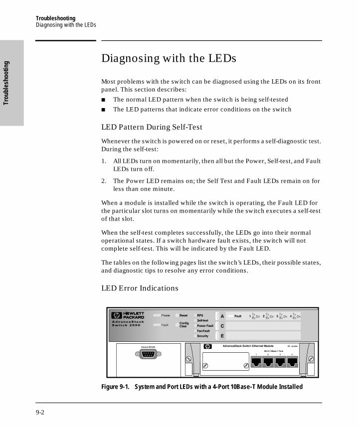
TroubleshootingDiagnosing with the LEDs
Trou
bles
hoot
ing
B_SCOTS.BK : b_chp9.fm5 Page 2 Thursday, February 20, 1997 2:19 PM
Diagnosing with the LEDs
Most problems with the switch can be diagnosed using the LEDs on its front panel. This section describes:
■ The normal LED pattern when the switch is being self-tested
■ The LED patterns that indicate error conditions on the switch
LED Pattern During Self-Test
Whenever the switch is powered on or reset, it performs a self-diagnostic test. During the self-test:
1. All LEDs turn on momentarily, then all but the Power, Self-test, and Fault LEDs turn off.
2. The Power LED remains on; the Self Test and Fault LEDs remain on for less than one minute.
When a module is installed while the switch is operating, the Fault LED for the particular slot turns on momentarily while the switch executes a self-test of that slot.
When the self-test completes successfully, the LEDs go into their normal operational states. If a switch hardware fault exists, the switch will not complete self-test. This will be indicated by the Fault LED.
The tables on the following pages list the switch’s LEDs, their possible states, and diagnostic tips to resolve any error conditions.
LED Error Indications
Figure 9-1. System and Port LEDs with a 4-Port 10Base-T Module Installed
9-2

TroubleshootingDiagnosing with the LEDs
Troubleshooting
B_SCOTS.BK : b_chp9.fm5 Page 3 Thursday, February 20, 1997 2:19 PM
LED Error Indications
LED State Diagnostic Tip
Power(green)
Off If the Power LED is off and the fans are not running, verify that the power cord is plugged into an active power source and to the switch. Make sure these connections are snug. Try power cycling the switch by unplugging and plugging the switch back in.
If the Power LED is still not on, verify that the AC power source works by plugging another device into the outlet. Or try plugging the switch into a different outlet or try a different power cord.
If this condition persists, the switch may have failed. Call your HP-authorized LAN dealer or HP representative for assistance.
On then turns off
Make sure the power cord connection is snug into the switch and into the power outlet.
Verify that the fans are running and that the chassis intake vents and exhaust ports are clear, and that the area around them is unobstructed.
Check the power outlet for power losses or surges.
If this condition persists, the switch may have failed. Call your HP-authorized LAN dealer or HP representative for assistance.
Fault(orange)
Remains On
Flashing
The Fault LED should remain off during normal operation. If it is on, a self-test failure or a software error has occurred. Power cycle the Switch 2000. If this condition persists, the switch may have failed. Call your HP-authorized LAN dealer or HP representative for assistance.
The switch is operable, but a fault condition has occurred in the switch or an installed module, a fan, or a connected redundant power supply (RPS). The corresponding fault LED for the affected component will flash simultaneously. Check the event log for an indication of the problem source.
RPS(green)
Off Should be on if an RPS is installed and operating properly.
If there is an RPS problem, this LED is off and the Fault and Power Fault LEDs flash simultaneously. (Check the Event Log in the console user interface for further information on the failure.) Check the connection between the RPS and the power outlet. Verify that power is being supplied to the power outlet. Remove and then reinstall the RPS according to the documentation shipped with the RPS. If the fault condition continues, schedule down time and replace the RPS.
Self-Test(green)
On
Flashing
The Self-test LED should be steadily on (for up to 40 seconds) only during the power-on, module installation, and reset self-tests.
The Self-test LED flashes simultaneously with the Fault LED and a slot Fault LED if the slot has failed its self-test. Check the Event Log. (It also flashes during a reset if the Config Clear button is pressed.)
If the self-test LED remains on at other times, especially in conjunction with the Fault LED, the switch may have failed. Call your HP authorized LAN representative for assistance.
9-3
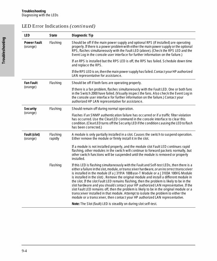
TroubleshootingDiagnosing with the LEDs
Trou
bles
hoot
ing
B_SCOTS.BK : b_chp9.fm5 Page 4 Thursday, February 20, 1997 2:19 PM
Power Fault(orange)
Flashing Should be off if the main power supply and optional RPS (if installed) are operating properly. If there is a power problem with either the main power supply or the optional RPS, flashes simultaneously with the Fault LED (above). (Check the RPS LED and the Event Log in the console user interface for further information on the failure.)
If an RPS is installed but the RPS LED is off, the RPS has failed. Schedule down time and replace the RPS.
If the RPS LED is on, then the main power supply has failed. Contact your HP authorized LAN representative for assistance.
Fan Fault(orange)
Flashing Should be off if both fans are operating properly.
If there is a fan problem, flashes simultaneously with the Fault LED. One or both fans in the Switch 2000 have failed. (Visually inspect the fans. Also check the Event Log in the console user interface for further information on the failure.) Contact your authorized HP LAN representative for assistance.
Security(orange)
Flashing Should remain off during normal operation.
Flashes if an SNMP authentication failure has occurred or if a traffic filter violation has occurred. Use the ClearLED command in the console interface to clear this condition. (ClearLED turns off the Security LED if the condition causing the LED to flash has been corrected.)
Fault (slot)(orange)
Flashing rapidly
Flashing
A module is only partially installed in a slot. Causes the switch to suspend operation. Either remove the module or firmly install it in the slot.
If a module is not installed properly, and the module slot Fault LED continues rapid flashing, other modules in the switch will continue to forward packets normally, but other switch functions will be suspended until the module is removed or properly installed.
If this LED is flashing simultaneously with the Fault and Self-test LEDs, then there is a either a failure in the slot, module, or transceiver hardware, or an incorrect transceiver is installed in the module (if a J3191A 100Base-T Module or a J3103A 100VG Module is installed in the slot) . Remove the original module and install a different module in the slot. If the slot Fault LED remains flashing, then the problem is likely to be in the slot hardware and you should contact your HP authorized LAN representative. If the slot Fault LED remains off, then the problem is likely to be in the original module or a transceiver installed in that module. Attempt to isolate the problem to either the module or a transceiver, then contact your HP authorized LAN representative.
Note: The Slot (fault) LED is steadily on during slot self-test.
LED Error Indications (continued)
LED State Diagnostic Tip
9-4

TroubleshootingDiagnosing with the LEDs
Troubleshooting
B_SCOTS.BK : b_chp9.fm5 Page 5 Thursday, February 20, 1997 2:19 PM
1, 2, 3, 4(Port Enabled)(green)
Off The port is not enabled or the link is not operational.
If the Switch 2000 port is either a 10Base-T port on an HP J3102A Ethernet Module or 100Base-TX port (HP J3192A or B transceiver) on an HP J3191A 100Base-T Module connected to a hub or another switch, then the port is preconfigured to operate as MDI-X. In this case, ensure that the port on the connected hub or other switch is either an MDI port connected by a straight-through cable, or (if the port on the other device is an MDI-X port) that a crossover cable is used to connect them.
Note: If an Ethernet port is using an AUI or 10Base2 transceiver, the port is enabled regardless of whether a connection is present.
Rx and TxPort Receive and Transmit(green)
Off The Rx and Tx LEDs should be on or flashing as packets are forwarded from or to other ports. If the LEDs do not flash, check the Port Enabled (1, 2, 3, 4) LED. If it is off, the port is not enabled. If the Port Enabled LED is on, then verify that the physical network configuration is correct. Check the console interface for proper configuration and operation.
Dx(Full Duplex)
Off If the Port Enabled LED (above) is on, then the Full Duplex (Dx) LED should be on for Ethernet 10Base-T ports that have been configured for full-duplex mode. The Dx LED should be off for Ethernet 10Base-T ports that are disabled or have been configured for half-duplex operation (the default). Check the port configuration in the console interface to ensure that the Mode parameter for the port has been set to Full Duplex.
Note: Full-duplex should be used only if it is also configured and supported on the media and in the device to which the port is connected.
LED Error Indications (continued)
LED State Diagnostic Tip
9-5

TroubleshootingInstallation Problems
Trou
bles
hoot
ing
B_SCOTS.BK : b_chp9.fm5 Page 6 Thursday, February 20, 1997 2:19 PM
Installation Problems
By carefully following the installation procedures described in chapter 1, “Installing the Switch”, you can avoid most problems caused by improper installation of the switch or one of its components.
Incorrect Hardware Installation
Incorrectly installing the switch or power cord can result in one or both of these components malfunctioning or not functioning at all. If one or both of these components appear not to be functioning, recheck the installation procedure and, if necessary, reinstall the component correctly.
If the switch will not power on or intermittently resets itself, the switch’s processor may be faulty or the hardware/software setup may be wrong.
Console RS-232 Problems
If the switch powers on but the console interface will not start up, follow these steps:
■ Check the external Console RS-232 connection. If you are not using a modem connection, ensure that the cable is a null modem cable.
■ Check the console device settings against the settings listed in appendix C, Sample Console Configurations.
■ Try a different baud rate setting in your console device. The Switch 2000’s default setting, “Speed Sense”, automatically matches the Console RS-232 baud rate to the rate used by your PC, terminal, or modem. (However, if the Baud Rate parameter in the switch’s Serial Link screen has been configured to a specific value, the Speed Sense operation is disabled.) The Switch 2000 operates at 300, 600, 1200, 2400, 4800, 9600, 19200, or 38400 bps.
■ If you are using a terminal emulation program, try exiting the program and then restarting it.
If the diagnostic information does not appear, or is unintelligible, try changing the baud rate on your terminal or PC terminal emulator. Try 9600 first. If the problem continues, try each of the other rates listed above.
9-6

TroubleshootingInstallation Problems
Troubleshooting
B_SCOTS.BK : b_chp9.fm5 Page 7 Thursday, February 20, 1997 2:19 PM
Cabling Problems
A high percentage of network problems are due to faulty cabling. Cabling problems usually result in the failure of a switch to connect to a network, a hub, or the end nodes.
Connections
All cables attached to the switch should be checked to see that they are properly connected.
If a PC or network device cannot communicate through the switch, check the following:
■ The cable and its connection
■ The LED that corresponds to the network device
If the PC or network device establishes a connection with the switch (the port LED is on), but does not communicate reliably through the switch, check the cable and the connection.
Non-standard Cables
Miswired cables may cause numerous network collisions, and can seriously impair network performance. Before connecting cables into your network, you should verify that they comply with the applicable standards. For a list of compatible cables and a description of the pin-outs for each port on the switch (which can be used to confirm the compatibility of unlisted cables), see appendix A, “Cables and Connectors”. Note that the optional 100VG operation requires that all four pairs in a cable function properly.
Topology
It is important to make sure you have a valid network topology. Common topology faults include excessive cable length and excessive repeater delays between nodes. Refer to the following sources for further topology information:
■ For connecting the Switch 2000 to other switches and hubs: HP
AdvanceStack Switch 2000 Connectivity Quick Reference (shipped with all Switch 2000 modules)
■ For network design guidelines: An Introduction to Ethernet LAN
Switches and Designing Switched Networks, both of which are included on the CD shipped with your switch.
9-7
TroubleshootingUnusual Network Activity
Trou
bles
hoot
ing
B_SCOTS.BK : b_chp9.fm5 Page 8 Thursday, February 20, 1997 2:19 PM
■ For physical layer topology guidelines: Designing HP AdvanceStack Workgroup Networks available on the CD shipped with your switch.
100VG Connection Problems
If you are having trouble with a connection between a 100VG end node and a two-port 100VG module installed in the Switch 2000, try the following:
1. Configure the 100VG port in the module to Master (MAC).
2. If the connection still does not operate, use HPVGSET on the end node to set the 10/100 NIC on the end node to 100 mode.
Unusual Network Activity
Network activity that exceeds accepted norms often indicates a hardware problem with one or more of the network components, possibly including the switch. Unusual network activity is usually indicated by the LEDs on the front of the switch or measured with the ASCII console interface or with a network management tool such as the HP AdvanceStack Assistant. Refer to “Diagnos-ing with LEDs” earlier in this chapter for information on using LEDs to identify unusual network activity.
Duplicate MAC Addresses Across VLANs. Duplicate MAC addresses on different VLANs are not supported and can cause VLAN operating problems. There are no explicit events or statistics to indicate the presence of duplicate MAC addresses in a VLAN environment. However, one symptom that may occur is that a duplicate MAC address can appear in the Port Address Table of one port, and then later appear to be linked to another port. (This can also occur in a LAN where there are redundant paths between nodes and Spanning Tree is turned off.) For more information, refer to “VLAN Restrictions” on page 7-21.)
9-8

TroubleshootingDiagnostic Tests
Troubleshooting
B_SCOTS.BK : b_chp9.fm5 Page 9 Thursday, February 20, 1997 2:19 PM
Diagnostic Tests
If you believe that the switch is not operating correctly, you can test the switch’s circuitry by removing, then reinstalling the switch’s power cord.
This procedure power-cycles the switch and executes the switch self-test. If the Fault LED stays on, the switch may have failed its self-test. See “Diagnosing with the LEDs” earlier in this chapter to interpret the LED display.
Testing Twisted-Pair Cabling
The twisted-pair cable attached to 10Base-T ports on the switch must be compatible with the IEEE 802.3 10Base-T standard for Cat. 3 cable. Similarly, the twisted-pair cable attached to 100Base-T ports on the switch must be compatible with the IEEE 802.3u 100Base-TX standard for Cat. 5 cable. To verify that your cable is compatible with this standard, use a qualified cable test device. HP also offers a wire testing service. Contact your HP-authorized LAN dealer or your local HP sales office for more information. Refer also to “Recommended Cables” on page A-2.
Note that the optional 100VG operation requires that all four pairs in a cable function properly.
Testing End-to-End Network Communications
Both the switch and the cabling can be tested by running an end-to-end communications test — a test that sends known data from one network device to another through the switch — such that you can verify that the data was correctly transmitted between the devices. For example, if you have two PCs on the network that have HP LAN adapter cards, you can use the “Link Test” option from the card’s test program to verify the entire communication path between the two PCs.
See your LAN adapter card’s manual for information on running an end-to-end communication test.
9-9

TroubleshootingCustomer Support Services
Trou
bles
hoot
ing
B_SCOTS.BK : b_chp9.fm5 Page 10 Thursday, February 20, 1997 2:19 PM
Testing Switch-to-Device Network Communications
You can do the following communication tests to verify that the network is operating correctly between the switch and any connected device that can respond correctly to the test.
■ Link Test —a physical layer test that sends IEEE 802.2 test packets to any device identified by its MAC address
■ Ping Test—a network layer test used on IP networks that sends test packets to any device identified by its IP address
■ IPX Ping Test—a network layer test used on IPX networks that sends test packets to any device identified by its IPX address
These tests can also be done from an SNMP network management station running a program that can manage the switch; for example, HP AdvanceStack Assistant.
Customer Support Services
Hewlett-Packard offers switch support 24 hours a day, seven days a week through the use of automated electronic services including:
■ World Wide Web
■ Hewlett-Packard FTP Library Service on the Internet
■ CompuServ
■ Hewlett-Packard BBS
■ HP FIRST FAX Retrieval Service
■ HP Network Phone-In Support (NPS)
These services are described on the card at the front of this manual.
Your reseller can also provide you with assistance, both with services that they offer and with services offered by Hewlett-Packard.
9-10
Cables and Connectors
B_SCOTS.BK : b_apa.fm5 Page 1 Thursday, February 20, 1997 2:19 PM
A
Cables and Connectors
■ Recommended Cables
■ Twisted-Pair Cable/Connector Pin-Outs
■ Twisted-Pair Cable Pin Assignments
■ RS-232 Connector and Cable Pin-Out
This appendix lists cables that have been tested and verified for use with the Switch 2000. It also includes minimum pin-out information so, if you wish to use an unlisted cable, you can verify that the cables used in your installation are correctly wired. Note that each pin-out diagram does not necessarily match the pin-out for the corresponding HP cable, but cables manufactured to follow the minimum pin-out will function correctly.
N o t e Incorrectly wired cabling is the most common cause of problems for LAN communications. HP recommends that you work with a qualified LAN cable installer for assistance with your cabling requirements.
A-1

Cables and ConnectorsRecommended Cables
Cabl
es a
nd C
onne
ctor
s
B_SCOTS.BK : b_apa.fm5 Page 2 Thursday, February 20, 1997 2:19 PM
Recommended Cables
You can contact your HP-authorized dealer or (in the U.S.A.) call HP at 1-800-538-8787 to order these parts.
Cable Function Port Type on PC,or Modem
Cable Type Specification or HP Product Number
Network connections to the switch:
module-based or trans-ceiver-based RJ-45 connection from switch to networked device
— Twisted-pair “straight-through” cable
Hewlett-Packard recommends category 5 or better, four-pair, 100 ohm unshielded twisted-pair (UTP) cable. (Category 5 cable is required for 100Base-T Twisted-Pair connections.)
Transceiver-based SC fiber-optic connection from switch to networked devices
— Multimode Fiber-Optic cable
1300nm wavelength cable conforming to the ISO/IEC 793-2 type B1 and ITU-T G.652 standards
Console PC connection to the switch’s Console RS-232 port:
Connecting the PCdirectly to the switch’s Console RS-232 port
9-pin male RS-232-C 9-pin female to 9-pin female null modem or “crossover” cable
RS-232-C cable provided with the switch(HP p/n 5182-4794)
25-pin male RS-232-C 9-pin female to 25-pin female null modem or “crossover” cable
HP 24542H
Connecting a modem to the switch’s Console RS-232 port
25-pin female RS-232-C 9-pin female to 25-pin male standard modem or “straight-through” cable
HP 24542M
A-2

Cables and ConnectorsTwisted-Pair Cable/Connector Pin-Outs
Cables and Connectors
B_SCOTS.BK : b_apa.fm5 Page 3 Thursday, February 20, 1997 2:19 PM
Twisted-Pair Cable/Connector Pin-Outs
Twisted-Pair Cable from Switch-Based MDI-X Module or Transceiver to an MDI Networked Device
To connect PCs or other MDI network devices to an MDI-X port on the switch, use a “straight-through” cable. The twisted-pair wires must be twisted through the entire length of the cable. The wiring sequence must conform to AT&T 258A (not USOC). See “Twisted-Pair Cable Pin Assignments” on page A-6 for a listing of the signals used on each pin.
N o t e Pins 1 and 2 must be wired to a twisted pair.Pins 3 and 6 must be wired to a twisted pair.
Pins 4, 5, 7, and 8 are not used in this application, although they may be wired in the cable.
A-3

Cables and ConnectorsTwisted-Pair Cable/Connector Pin-Outs
Cabl
es a
nd C
onne
ctor
s
B_SCOTS.BK : b_apa.fm5 Page 4 Thursday, February 20, 1997 2:19 PM
Twisted-Pair Cable from Switch-Based MDI-X Module to an MDI-X Hub Port
To connect an MDI-X port on a hub to an MDI-X port on the switch, use a “crossover” cable. The twisted-pair wires must be twisted through the entire length of the cable. The wiring sequence must conform to AT&T 258A (not USOC). See “Twisted-Pair Cable Pin Assignments” on page A-6 for a listing of the signals used on each pin.
N o t e Pins 1 and 2 on connector “A” must be wired as a twisted pair to pins 3 and 6 on connector “B”.Pins 3 and 6 on connector “A” must be wired as a twisted pair to pins 1 and 2 on connector “B”.
Pins 4, 5, 7, and 8 are not used in this application, although they may be wired in the cable.
A-4

Cables and ConnectorsTwisted-Pair Cable/Connector Pin-Outs
Cables and Connectors
B_SCOTS.BK : b_apa.fm5 Page 5 Thursday, February 20, 1997 2:19 PM
Twisted-Pair Cable for HP 100VG LAN Ports
To connect a server or other devices to the 100VG LAN ports, use a “straight-through” 4-pair twisted-pair cable. The twisted-pair wires must be twisted through the entire length of the cable.
The illustration below shows the RJ-45 pin connections, color code, and pair configuration for an HP 100VG LAN cable (unbundled) that conforms to the EIA/TIA 568B wiring standard for a straight-through cable.
N o t e Pins 1 and 2 must be wired to a twisted pair.Pins 3 and 6 must be wired to a twisted pair.Pins 4 and 5 must be wired to a twisted pairPins 7 and 8 must be wired to a twisted pair.
A-5

Cables and ConnectorsTwisted-Pair Cable Pin Assignments
Cabl
es a
nd C
onne
ctor
s
B_SCOTS.BK : b_apa.fm5 Page 6 Thursday, February 20, 1997 2:19 PM
Twisted-Pair Cable Pin Assignments
Twisted-Pair Straight-Through Cable for a 10/100Base-T Connection From the Switch to a Networked Device
Twisted-Pair Crossover Cable for Module-Based 10/100Base-T Connection from the Switchto an MDI-X Port
Switch End (MDI-X)End Node (NIC or Transceiver)or Other MDI Port
Signal Pins Pins Signal
(receive +)(receive –)(transmit +)(transmit –)
1236
1236
(transmit +)(transmit –)(receive +)(receive –)
Switch End (MDI-X)Switch Port or OtherMDI-X Port
Signal Pins Pins Signal
(receive +)(receive –)(transmit +)(transmit –)
1236
3612
(transmit +)(transmit –)(receive +)(receive –)
A-6

Cables and ConnectorsRS-232 Connector and Cable Pin-Outs
Cables and Connectors
B_SCOTS.BK : b_apa.fm5 Page 7 Thursday, February 20, 1997 2:19 PM
RS-232 Connector and Cable Pin-Outs
The switch’s Console RS-232 connector is wired as if it is a terminal (DTE), ready to be connected to a modem (DCE). The switch includes a null modem cable that can be used to directly connect a PC to be used as the console. To connect a modem to the switch, use a standard RS-232-C modem cable.
This section provides pin assignment information for the cables you can use on the RS-232 port.
Pin-Out for Switch’s RS-232 Port Connector
PIN US CCITT DIN
1 DCD 109 M5
2 Rx 104 D2
3 Tx 103 D1
4 DTR 108 S1
5 GND 102 –
6 DSR 107 M1
7 RTS 105 S2
8 CTS 106 M2
9 RI 125 M3
A-7

Cables and ConnectorsRS-232 Connector and Cable Pin-Outs
Cabl
es a
nd C
onne
ctor
s
B_SCOTS.BK : b_apa.fm5 Page 8 Thursday, February 20, 1997 2:19 PM
RS-232-C “Null Modem” Cable
This cable type is supplied with the switch for connection to a PC having a 9-pin connector.
Minimum Cable Pin-out for Direct Console Connection
PC End9-pin male
Switch End9-pin male
1 1 DCD
2 2 Rx
3 3 Tx
4 4 DTR
5 5 GND
6 6 DSR
7 7 RTS
8 8 CTS
9 9 RI
PC End9-pin male
Switch End9-pin male
2 2 Rx
3 3 Tx
5 5 GND
1
4
6
7
8
A-8
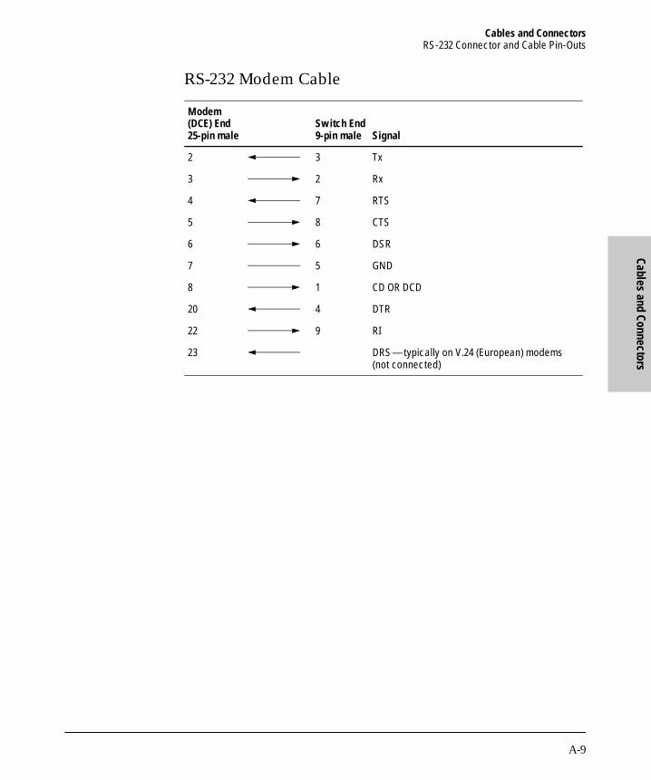
Cables and ConnectorsRS-232 Connector and Cable Pin-Outs
Cables and Connectors
B_SCOTS.BK : b_apa.fm5 Page 9 Thursday, February 20, 1997 2:19 PM
RS-232 Modem Cable
Modem (DCE) End 25-pin male
Switch End9-pin male Signal
2 3 Tx
3 2 Rx
4 7 RTS
5 8 CTS
6 6 DSR
7 5 GND
8 1 CD OR DCD
20 4 DTR
22 9 RI
23 DRS—typically on V.24 (European) modems (not connected)
A-9

B_SCOTS.BK : b_apa.fm5 Page 10 Thursday, February 20, 1997 2:19 PM

Specifications
B_SCOTS.BK : b_apb.fm5 Page 1 Thursday, February 20, 1997 2:19 PM
B
Specifications
Physical
Electrical
Environmental
Width: 44 cm (17.3 in)
Depth: 30 cm (11.8 in)
Height: 18 cm (7.0 in)
Weight (without Modules or RPS: 7.86 kg (17.3 lbs)
AC voltage: 100 - 127 volts 200-240 volts
Maximum current: 2.5A max 1.5A max
Frequency range: 50/60 Hz 50/60 Hz
Operating Non-Operating
Temperature: 0°C to 55°C (32°F to 131°F) -40°C to 70°C (-40°F to 158°F)
Relative humidity:(non-condensing)
15% to 95% at 40°C (104°F) 15% to 90% at 65°C (149°F)
Maximum altitude: 4.6 km (15,000 ft) 4.6 km (15,000 ft)
B-1

Specifications
Spec
ifica
tions
B_SCOTS.BK : b_apb.fm5 Page 2 Thursday, February 20, 1997 2:19 PM
Connectors
The RS-232-C console port conforms to V.22 bis.
Electromagnetic
Safety
EN60950 (1992) + A1, A2 / IEC950: 1991 + A1, A2UL 1950CSA 950NOM-019-SCFI-1993
Emissions: FCC part 15 Class AEN 55022 / CISPR-22 Class AVCCI Level I
Complies with Canadian EMC Class A requirements.
Immunity: See the Declaration of Conformity for details at the end of the Regulatory Statements in this guide.
B-2

Sample Console
Configurations
B_SCOTS.BK : b_apc.fm5 Page 1 Thursday, February 20, 1997 2:19 PM
C
Sample Console Configurations
Windows 3.1 Terminal Application
You can use a PC with the Windows 3.1 Terminal Application for console management access to the switch. This section provides an example of the configuration settings to use with the Windows 3.1 Terminal Application.
Option Settings:
■ Terminal Emulation: DEC VT-100 (ANSI)
■ Terminal Preferences:
• Terminal Modes:– Line-Wrap: On– Sound: On
• CR > CR/LF: No
• Use Function, Arrow, Ctrl keys for Windows: NO
Communications:
■ 9600 Baud or 19.2 baud recommended
■ No Parity
■ 8 bits
■ 1 stop bit
■ Xon/Xoff
■ Carrier Detect
C-1
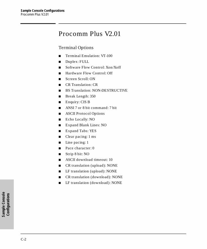
Sample Console ConfigurationsProcomm Plus V2.01
Sam
ple
Cons
ole
Conf
igur
atio
ns
B_SCOTS.BK : b_apc.fm5 Page 2 Thursday, February 20, 1997 2:19 PM
Procomm Plus V2.01
Terminal Options
■ Terminal Emulation: VT-100
■ Duplex: FULL
■ Software Flow Control: Xon/Xoff
■ Hardware Flow Control: Off
■ Screen Scroll: ON
■ CR Translation: CR
■ BS Translation: NON-DESTRUCTIVE
■ Break Length: 350
■ Enquiry: CIS B
■ ANSI 7 or 8 bit command: 7 bit
■ ASCII Protocol Options
■ Echo Locally: NO
■ Expand Blank Lines: NO
■ Expand Tabs: YES
■ Clear pacing: 1 ms
■ Line pacing: 1
■ Pace character: 0
■ Strip 8 bit: NO
■ ASCII download timeout: 10
■ CR translation (upload): NONE
■ LF translation (upload): NONE
■ CR translation (download): NONE
■ LF translation (download): NONE
C-2

Sample Console ConfigurationsOther Terminal Emulators
Sample Console
Configurations
B_SCOTS.BK : b_apc.fm5 Page 3 Thursday, February 20, 1997 2:19 PM
Other Terminal Emulators
For other communication programs, use the following table as a configuration guide:
Option Setting
Baud rate 300, 600, 1200, 2400, 9600, 19200, or 38400. (9600 or 19200 recommended)
Parity None
Data bits and stop bits 8, 1
Autobaud upon break On
Handshaking None
Terminal emulation VT100. For Windows, disable the “Use Function, Arrow, and Ctrl Keys for Windows” option, located in the Terminal Preference menu.
Duplex Full
Soft flow control (XON/XOFF) On (input and output)
Hard flow control (RTS/CTS) Off
Line wrap On
Screen scroll On
CR translation CR
Backspace (BS) translation
Destructive
Break length (milliseconds) 350
Enquiry (ENQ) Off
EGA/VGA true underline Off
Terminal width 80
ANSI 7 or 8 bit commands 7
C-3

B_SCOTS.BK : b_apc.fm5 Page 4 Thursday, February 20, 1997 2:19 PM
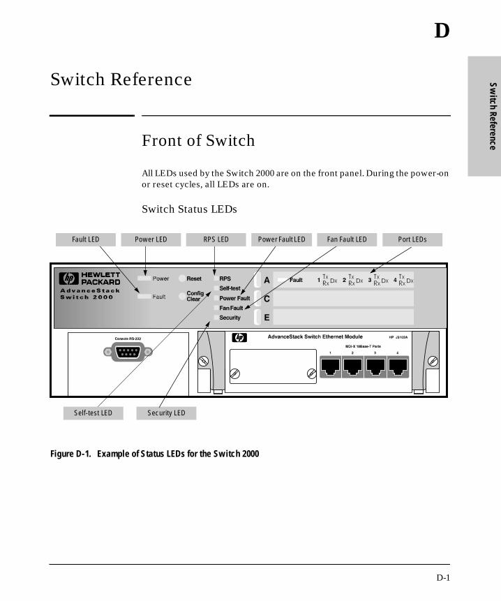
Switch Reference
B_SCOTS.BK : b_apd.fm5 Page 1 Thursday, February 20, 1997 2:19 PM
D
Switch Reference
Front of Switch
All LEDs used by the Switch 2000 are on the front panel. During the power-on or reset cycles, all LEDs are on.
Switch Status LEDs
Figure D-1. Example of Status LEDs for the Switch 2000
Fan Fault LEDFault LED Power LED RPS LED Port LEDsPower Fault LED
Self-test LED Security LED
D-1

Switch ReferenceFront of Switch
Switc
h Re
fere
nce
B_SCOTS.BK : b_apd.fm5 Page 2 Thursday, February 20, 1997 2:19 PM
LED State Meaning of LED
Power (green)
on
off
The switch is receiving power from the main power supply and/or from the optional RPS (redundant power supply).
The switch is not receiving power. See chapter 9, “Troubleshooting”.
Fault (orange)
on(steady)
flashing
Either the switch hardware has failed the self-test or a software error has occurred and auto-reboot is off. In this case, push the Reset button. See chapter 9, “Troubleshooting”.
The switch is operable, but a fault condition has occurred in the switch, an installed module, a fan, or a redundant power supply (RPS—if installed). The corresponding fault LED for the affected component will flash simultaneously. Refer to chapter 9, “Troubleshooting”.
RPS (green)
on
off
An (optional) Redundant Power Supply (RPS) is connected and functioning properly.
No RPS is connected to the switch, or the RPS has failed. See chapter 9, “Troubleshooting”.
Self-test (green)
off
on (steady)
flashing
Normal operation, except as described below.
Power-on or reset self-test. During this time the Fault LED is also on and the switch is inoperable.
Indicates one of the following:• A self-test failure has occurred, but the switch remains
partially operable.• The Config Clear button is being pressed during a reset.
Release the button. (Refer to “Reset and Config Clear Buttons” on page D-4.)
Power Fault (orange)
flashing An RPS (redundant power supply) is present and either the RPS or the main power supply is not operating properly. Flashes simultaneously with the switch's Fault LED. Refer to chapter 9, “Troubleshooting”.
Fan Fault (orange)
flashing One or both ventilation fans are not operating properly. Flashes simultaneously with the switch's Fault LED. Refer to chapter 9, “Troubleshooting”.
Security (orange)
flashing Either an SNMP Authentication failure or a traffic filter violation has occurred. Refer to chapter 9, “Troubleshooting”.
D-2

Switch ReferenceFront of Switch
Switch Reference
B_SCOTS.BK : b_apd.fm5 Page 3 Thursday, February 20, 1997 2:19 PM
Slot and Port Status LEDs
Figure D-2. Example of Slot and Port Status LEDs for a 10Base-T Module in the Switch 2000
Port TxPort Rx
Slot FaultLED
Port Full-Duplex (10Base-T Only)
Port Enabled LED
LED State Meaning of LED
Fault (slot) (orange)
rapid flash
slow flashing
A module hot-swap condition is occurring.
Either the indicated slot has failed self-test or an incorrect transceiver (for a J3191A 100Base-T Module or a J3103A 100VG Module) has been installed. For this condition, flashes simultaneously with the switch’s Fault and Self-test LEDs. Refer to chapter 9, “Troubleshooting”.
1, 2, 3, 4 (port enabled LED) (green)
on The indicated port on the indicated module is enabled and the link is operational.
Tx (green)
on or flashing
The indicated port is transmitting packets.
Rx (green)
on or flashing
The indicated port is receiving packets.
Dx (green)
on The indicated port is enabled and configured for full-duplex operation.
D-3

Switch ReferenceFront of Switch
Switc
h Re
fere
nce
B_SCOTS.BK : b_apd.fm5 Page 4 Thursday, February 20, 1997 2:19 PM
Reset and Config Clear Buttons
Figure D-3. Reset and Config Clear Buttons on the Switch 2000
ResetButton
Config ClearButton
D-4
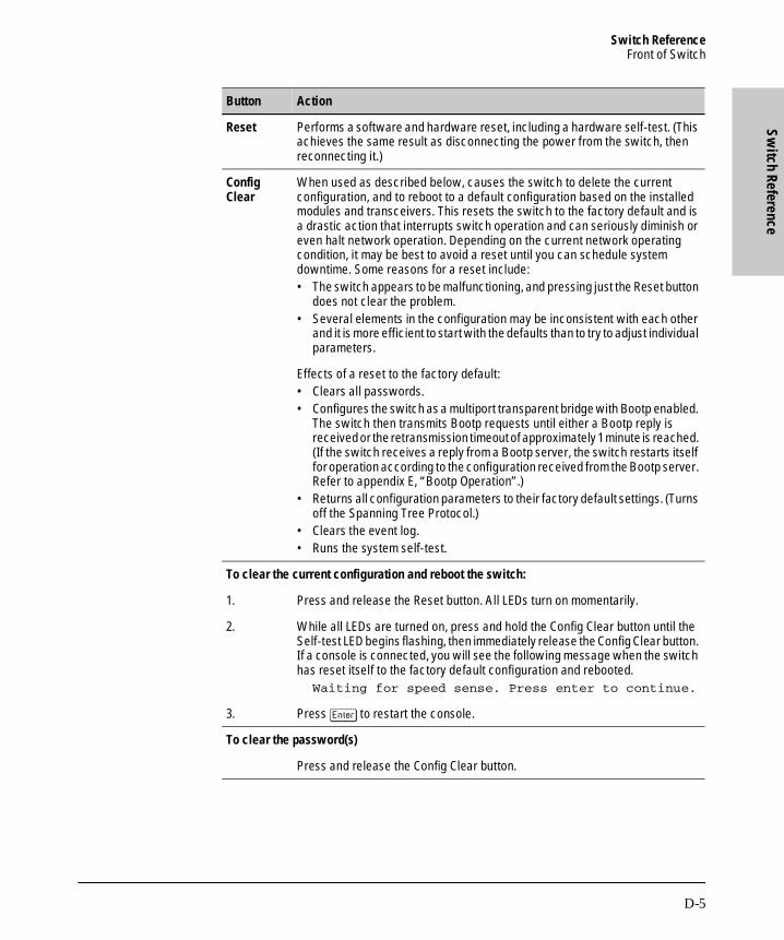
Switch ReferenceFront of Switch
Switch Reference
B_SCOTS.BK : b_apd.fm5 Page 5 Thursday, February 20, 1997 2:19 PM
Button Action
Reset Performs a software and hardware reset, including a hardware self-test. (This achieves the same result as disconnecting the power from the switch, then reconnecting it.)
Config Clear
When used as described below, causes the switch to delete the current configuration, and to reboot to a default configuration based on the installed modules and transceivers. This resets the switch to the factory default and is a drastic action that interrupts switch operation and can seriously diminish or even halt network operation. Depending on the current network operating condition, it may be best to avoid a reset until you can schedule system downtime. Some reasons for a reset include:• The switch appears to be malfunctioning, and pressing just the Reset button
does not clear the problem.• Several elements in the configuration may be inconsistent with each other
and it is more efficient to start with the defaults than to try to adjust individual parameters.
Effects of a reset to the factory default:• Clears all passwords.• Configures the switch as a multiport transparent bridge with Bootp enabled.
The switch then transmits Bootp requests until either a Bootp reply is received or the retransmission timeout of approximately 1 minute is reached. (If the switch receives a reply from a Bootp server, the switch restarts itself for operation according to the configuration received from the Bootp server. Refer to appendix E, “Bootp Operation”.)
• Returns all configuration parameters to their factory default settings. (Turns off the Spanning Tree Protocol.)
• Clears the event log.• Runs the system self-test.
To clear the current configuration and reboot the switch:
1. Press and release the Reset button. All LEDs turn on momentarily.
2. While all LEDs are turned on, press and hold the Config Clear button until the Self-test LED begins flashing, then immediately release the Config Clear button. If a console is connected, you will see the following message when the switch has reset itself to the factory default configuration and rebooted.
Waiting for speed sense. Press enter to continue.
3. Press [Enter] to restart the console.
To clear the password(s)
Press and release the Config Clear button.
D-5

Switch ReferenceFront of Switch
Switc
h Re
fere
nce
B_SCOTS.BK : b_apd.fm5 Page 6 Thursday, February 20, 1997 2:19 PM
Console RS-232 Port
The switch’s Console RS-232 port is a standard RS-232 serial link used to connect a Windows-based PC, a terminal, or a modem. (For pinouts, refer to appendix A, Cables and Connectors.)
Figure D-4. Front Panel of the Switch 2000
Interface Module Expansion Slots
The Switch 2000 offers six universal port expansion slots, each of which can accept any Hewlett-Packard module designed for the Switch 2000.
ConsoleRS-232 Port
Module Expansion Slots
D-6
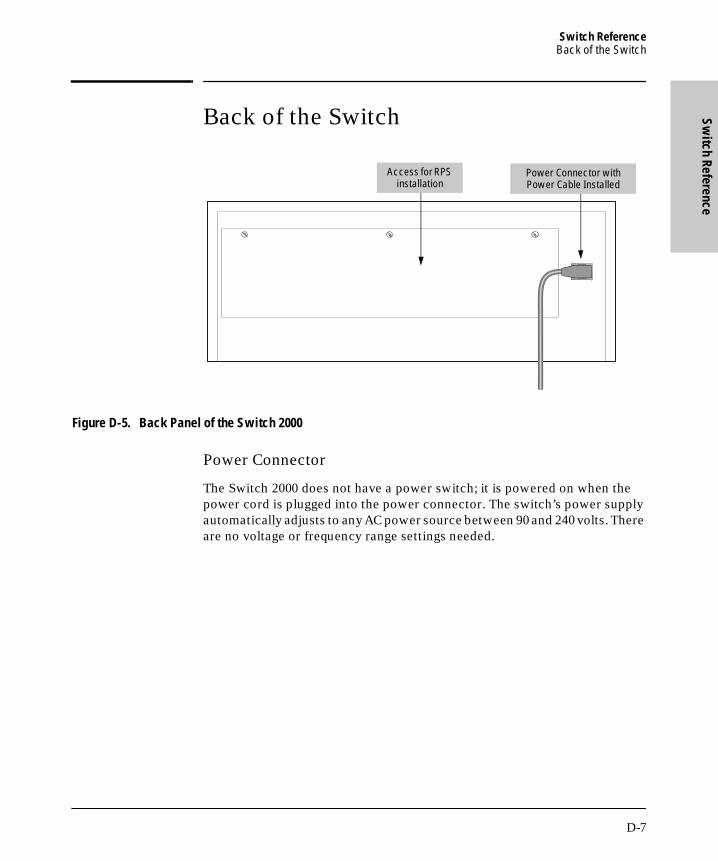
Switch ReferenceBack of the Switch
Switch Reference
B_SCOTS.BK : b_apd.fm5 Page 7 Thursday, February 20, 1997 2:19 PM
Back of the Switch
Figure D-5. Back Panel of the Switch 2000
Power Connector
The Switch 2000 does not have a power switch; it is powered on when the power cord is plugged into the power connector. The switch’s power supply automatically adjusts to any AC power source between 90 and 240 volts. There are no voltage or frequency range settings needed.
Access for RPS installation
Power Connector with Power Cable Installed
D-7

Switch ReferenceBack of the Switch
Switc
h Re
fere
nce
B_SCOTS.BK : b_apd.fm5 Page 8 Thursday, February 20, 1997 2:19 PM
HP J3136 AdvanceStack Switch 2000 Redundant Power Supply (RPS—Optional)
The RPS is an optional power supply you can connect to your Switch 2000 for backup power in case the main power supply fails. Also, adding an RPS to your switch helps to extend the life of the main power supply because the two power units work together to share the power load. For more on the RPS, refer to “Install the Redundant Power Supply (Optional)” on page 1-5, and to the documentation provided with the RPS.
C a u t i o n Power to the Switch 2000 should be off before you install the RPS. For this reason, you should perform an RPS installation only during a scheduled down time, when you can remove power from the switch.
Refer to the documentation provided with the RPS before connecting it to the Switch 2000.
D-8

BO
OTP O
peration
B_SCOTS.BK : b_ape.fm5 Page 1 Thursday, February 20, 1997 2:19 PM
E
BOOTP Operation
Overview
Bootp is used to download configuration data from a Bootp server to the switch or to a VLAN configured on the switch. Either a minimal IP configura-tion or a full configuration can be retrieved from the Bootp server.
N o t e The Switch 2000 supports only the DHCP (Dynamic Host Configuration Protocol) implementations that are backwards compatible with Bootp.
The Bootp Process
Whenever the switch reboots with the IP Config parameter set to Use Bootp (the default), Bootp requests are broadcast on all local networks. When the Bootp server receives the request it searches its Bootp database for a record entry that matches the MAC address in the Bootp request. If a match is found, the configuration data in the associated database record is returned to the switch. For most Unix systems, the Bootp database is contained in the /etc/bootptab file.
E-1

BOOTP OperationBootp Database Record Entries
BO
OTP
Ope
ratio
n
B_SCOTS.BK : b_ape.fm5 Page 2 Thursday, February 20, 1997 2:19 PM
Bootp Database Record Entries
An entry in the Bootp table file /etc/bootptab to update an IP address and subnet mask to the switch or a VLAN configured in the switch would be similar to this entry:
j3100switch:\
ht=ether:\
ha=080009123456:\
sm=255.255.248.0:\
lg=11.22.33.44:\
hn:\
ip=55.66.77.88:\
vm=rfc1048
An entry in the Bootp table file /etc/bootptab to tell the switch or VLAN where to obtain a configuration file download would be similar to this entry:
j3100switch:\
ht=ether:\
ha=080009123456:\
sm=255.255.248.0:\
lg=11.22.33.44:\
hn:\
ip=55.66.77.88:\
T144=”switch.cfg”:\
vm=rfc1048
where:
j3100switch is a user-defined symbolic name to help you find the correct section of the bootptab file. If you have multiple switches that will be using Bootp to get their IP configuration, you should use a unique symbolic name for each switch.
ht is the “hardware type” . For the HP AdvanceStack Switch 2000, set this to ether (for Ethernet). This tag must precede the ha tag.
ha is the “hardware address” . Use the switch's (or VLAN's) 12-digit MAC address.
sm is the subnet mask of the subnet in which the switch (or VLAN) is installed.
lg TFTP server address (source of final configuration file)
hn send nodename (boolean flag, no “=value” needed)
ip is the IP address to be assigned to the switch (or VLAN).
T144 is the vendor-specific “tag” identifying the configuration file to download.
vm is a required entry that specifies the Bootp report format. For the HP AdvanceStack Switch 2000, set this parameter to rfc1048.
E-2

BOOTP OperationConfiguring Bootp
BO
OTP O
peration
B_SCOTS.BK : b_ape.fm5 Page 3 Thursday, February 20, 1997 2:19 PM
Configuring Bootp
In its default configuration, the switch is configured for Bootp operation. However, if an IP address has previously been configured or if the IP Config parameter has been set to Disabled, then you will need to use this procedure to reconfigure the parameter to enable Bootp operation.
This procedure assumes that a Bootp database record has already been entered into an appropriate Bootp server, and that the necessary network connections are in place.
To configure the switch or a VLAN for Bootp:
1. In the Main Menu, select Configuration .
2. In the Configuration screen select Internet (IP) Service.
3. Press [E] (for Edit mode), then use [v] to move the cursor to the IP Config parameter field.
4. Use the Space bar to select the Use Bootp option for the IP Config parameter. (This disables access to the IP Address, Subnet Mask, and Gateway parameters.)
5. Press [Enter] to exit from edit mode, then press [S] to save the configuration change.
When you reboot the switch with Bootp enabled, it will do one of the following:
■ Receive a minimal configuration (IP address and subnet mask).
■ If the reply provides information for downloading a configuration file, the switch then uses TFTP to download the file from the designated source, then reboots itself. (This assumes that the switch or VLAN has connectiv-ity to the TFTP file server specified in the Bootp database configuration record and that the Bootp database record is correctly configured.)
E-3

B_SCOTS.BK : b_ape.fm5 Page 4 Thursday, February 20, 1997 2:19 PM
MA
C Address M
anagement
B_SCOTS.BK : b_apf.fm5 Page 1 Thursday, February 20, 1997 2:19 PM
F
MAC Address Management
Overview
The Switch 2000 assigns MAC addresses in the following three areas:
■ Default MAC address assigned at the factory
■ Automatically assigned MAC address(es) corresponding to any VLANs you configure in the switch
■ The Spanning Tree Protocol (STP) uses either the default MAC address for the switch or, if VLANs are configured, the MAC addresses automati-cally assigned to the VLANs.
F-1

MAC Address ManagementSwitch (Default) MAC Address
MA
C A
ddre
ss M
anag
emen
t
B_SCOTS.BK : b_apf.fm5 Page 2 Thursday, February 20, 1997 2:19 PM
Switch (Default) MAC Address
A default MAC address is assigned to each Switch 2000 at the factory. This address is on the label below the Console RS-232 port (shown below):
Figure F-1. Location of the Default MAC Address Assigned to the Switch
If there are no VLANs configured on the Switch 2000, then the factory-assigned MAC address is the same for all ports on the switch.
To display the MAC address assigned to a port:
1. Select Status and Counters from the Main Menu.
2. Select Port Counters in the Statistics menu.
3. Select the desired port.
4. Select the Show details option to display the port counter details for the selected port. Included will be the MAC address assigned to that port. If VLANs are configured, refer to “VLAN MAC Address” on page F-3.
Label Showing Default MAC Address
F-2

MAC Address ManagementVLAN MAC Addresses
MA
C Address M
anagement
B_SCOTS.BK : b_apf.fm5 Page 3 Thursday, February 20, 1997 2:19 PM
VLAN MAC Addresses
If you add VLANs to the Switch 2000, each VLAN is automatically assigned a different MAC address. All ports in a particular VLAN will have the same MAC address. To determine the MAC address assigned to a particular VLAN, display the port data for any port assigned to that VLAN.
To display the MAC address and other data for a selected port:
1. From the Main Menu, select Status and Counters.
2. Display the Port Counters screen.
3. Select a port that is assigned to the VLAN for which you want to determine the corresponding MAC address.
4. Select the Show details option to display the port counter details for the selected port. Included will be the MAC address assigned to that port (and the corresponding VLAN).
Figure F-2. Example of the Port Counter Details for a Selected Port
F-3

MAC Address ManagementMAC Addresses (for Spanning Tree Operation)
MA
C A
ddre
ss M
anag
emen
t
B_SCOTS.BK : b_apf.fm5 Page 4 Thursday, February 20, 1997 2:19 PM
MAC Addresses (for Spanning Tree Operation)
When no VLANs are configured, STP uses the MAC address assigned to the switch. (This is the MAC address printed on the label on the front of the switch.) When VLANs are configured, STP must be configured separately for each VLAN. In this case, the MAC address assigned to each instance of STP is the MAC address assigned to the corresponding VLAN. These addresses appear in the Spanning Tree Information screen . Refer to the “Switch (Default) MAC Address” on page F-2, or “VLAN MAC Addresses” on page F-3.)
F-4

Safety and Regulatory Statem
ents
B_SCOTS.BK : b_safety.fm5 Page 1 Thursday, February 20, 1997 2:19 PM
Safety and Regulatory Statements
Safety Information
Safety Symbols.
Grounding.
These are safety class I products and have protective earthing terminals. There must be an uninterruptible safety earth ground from the main power source to the product’s input wiring terminals, power cord, or supplied power cord set. Whenever it is likely that the protection has been impaired, disconnect the power cord until the ground has been restored.
For LAN cable grounding:
■ If your LAN covers an area served by more than one power distribution system, be sure their safety grounds are securely interconnected.
■ LAN cables may occasionally be subject to hazardous transient voltages (such as lightning or disturbances in the electrical utilities power grid). Handle exposed metal components of the network with caution.
Servicing.
There are no user-serviceable parts inside these products. Any servicing, adjustment, maintenance, or repair must be performed only by service-trained personnel.These products do not have a power switch; they are powered on when the power cord is plugged in.
Documentation reference symbol. If the product is marked with this symbol, refer to the product documentation to get more information about the product.
WARNING A WARNING in the manual denotes a hazard that can cause injury or death.
CAUTION A CAUTION in the manual denotes a hazard that can damage equipment.
Do not proceed beyond a WARNING or CAUTION notice until you have understood the hazardous conditions and have taken appropriate steps.
Safety-1

Safety and Regulatory StatementsInformations concernant la sécurité
Safe
ty a
nd R
egul
ator
y St
atem
ents
B_SCOTS.BK : b_safety.fm5 Page 2 Thursday, February 20, 1997 2:19 PM
Informations concernant la sécurité
Symboles de sécurité
Cet appareil est un produit de classe I et possède une borne de mise à la terre. La source d’alimentation principale doit être munie d’une prise de terre de sécurité installée aux bornes du câblage d’entrée, sur le cordon d'alimentation ou le cordon de raccordement fourni avec le produit. Lorsque cette protection semble avoir été endommagée, débrancher le cordon d’alimentation jusqu’à ce que la mise à la terre ait été réparée.
Mise à la terre du câble de réseau local:
■ si votre réseau local s’étend sur une zone desservie par plus d’un système de distribution de puissance, assurez-vous que les prises de terre de sécurité soient convenablement interconnectées.
■ Les câbles de réseaux locaux peuvent occasionnellement être soumis à des surtensions transitoires dangereuses (telles que la foudre ou des perturbations dans le réseau d’alimentation public). Manipulez les composants métalliques du réseau avec précautions.
Aucune pièce contenue à l’intérieur de ce produit ne peut être réparée par l’utilisateur. Tout dépannage, réglage, entretien ou réparation devra être confié exclusivement à un personnel qualifié.
Cet appareil ne comporte pas de commutateur principal ; la mise sous tension est effectuée par branchement du cordon d’alimentation.
Symbole de référence à la documentation. Si le produit est marqué de ce symbole, reportez-vous à la documentation du produit afin d’obtenir des informations plus détaillées.
WARNING Dans la documentation, un WARNING indique un danger susceptible d’entraîner des dommages corporels ou la mort.
CAUTION Un texte de mise en garde intitulé CAUTION indique un danger susceptible de causer des dommages à l’équipement.
Ne continuez pas au-delà d’une rubrique WARNING ou CAUTION avant d’avoir bien compris les conditions présentant un danger et pris les mesures appropriées.
Safety-2

Safety and Regulatory StatementsHinweise zur Sicherheit
Safety and Regulatory Statem
ents
B_SCOTS.BK : b_safety.fm5 Page 3 Thursday, February 20, 1997 2:19 PM
Hinweise zur Sicherheit
Sicherheitssymbole.
Dies ist ein Gerät der Sicherheitsklasse I und verfügt über einen schützenden Erdungsterminal. Der Betrieb des Geräts erfordert eine ununterbrochene Sicherheitserdung von der Hauptstromquelle zu den Geräteingabeterminals, den Netzkabeln oder dem mit Strom belieferten Netzkabelsatz voraus. Sobald Grund zur Annahme besteht, daß der Schutz beeinträchtigt worden ist, das Netzkabel aus der Wandsteckdose herausziehen, bis die Erdung wiederhergestellt ist.
Für LAN-Kabelerdung:
■ Wenn Ihr LAN ein Gebiet umfaßt, das von mehr als einem Stromverteilungssystem beliefert wird, müssen Sie sich vergewissern, daß die Sicherheitserdungen fest untereinander verbunden sind.
■ LAN-Kabel können gelegentlich gefährlichen Übergangsspannungen ausgesetzt werden (beispielsweise durch Blitz oder Störungen in dem Starkstromnetz des Elektrizitätswerks). Bei der Handhabung exponierter Metallbestandteile des Netzwerkes Vorsicht walten lassen.
Dieses Gerät enthält innen keine durch den Benutzer zu wartenden Teile. Wartungs-, Anpassungs-, Instandhaltungs- oder Reparaturarbeiten dürfen nur von geschultem Bedienungspersonal durchgeführt werden.
Dieses Gerät hat keinen Netzschalter; es wird beim Anschließen des Netzkabels eingeschaltet.
Symbol für Dokumentationsverweis. Wenn das Produkt mit diesem Symbol markiert ist, schlagen Sie bitte in der Produktdokumentation nach, um mehr Informationen über das Produkt zu erhalten.
WARNING Eine WARNING in der Dokumentation symbolisiert eine Gefahr, die Verletzungen oder sogar Todesfälle verursachen kann.
CAUTION CAUTION in der Dokumentation symbolisiert eine Gefahr, die das Gerät beschädigen kann.
Fahren Sie nach dem Hinweis WARNING oder CAUTION erst fort, nachdem Sie den Gefahrenzustand verstanden und die entsprechenden Maßnahmen ergriffen haben.
Safety-3

Safety and Regulatory StatementsConsiderazioni sulla sicurezza
Safe
ty a
nd R
egul
ator
y St
atem
ents
B_SCOTS.BK : b_safety.fm5 Page 4 Thursday, February 20, 1997 2:19 PM
Considerazioni sulla sicurezza
Simboli di sicurezza.
Questo prodotto è omologato nella classe di sicurezza I ed ha un terminale protettivo di collegamento a terra. Dev’essere installato un collegamento a terra di sicurezza, non interrompibile che vada dalla fonte d’alimentazione principale ai terminali d’entrata, al cavo d’alimentazione oppure al set cavo d’alimentazione fornito con il prodotto. Ogniqualvolta vi sia probabilità di danneggiamento della protezione, disinserite il cavo d’alimentazione fino a quando il collegamento a terra non sia stato ripristinato.
Per la messa a terra dei cavi LAN:
■ se la vostra LAN copre un’area servita da più di un sistema di distribuzione elettrica, accertatevi che i collegamenti a terra di sicurezza siano ben collegati fra loro;
■ i cavi LAN possono occasionalmente andare soggetti a pericolose tensioni transitorie (ad esempio, provocate da lampi o disturbi nella griglia d’alimentazione della società elettrica); siate cauti nel toccare parti esposte in metallo della rete.
Nessun componente di questo prodotto può essere riparato dall’utente. Qualsiasi lavoro di riparazione, messa a punto, manutenzione o assistenza va effettuato esclusivamente da personale specializzato.
Questo apparato non possiede un commutatore principale; si mette scotto tensione all’inserirsi il cavo d’alimentazione.
Simbolo di riferimento alla documentazione. Se il prodotto è contrassegnato da questo simbolo, fare riferimento alla documentazione sul prodotto per ulteriori informazioni su di esso.
WARNING La dicitura WARNING denota un pericolo che può causare lesioni o morte.
CAUTION La dicitura CAUTION denota un pericolo che può danneggiare le attrezzature.
Non procedere oltre un avviso di WARNING o di CAUTION prima di aver compreso le condizioni di rischio e aver provveduto alle misure del caso.
Safety-4

Safety and Regulatory StatementsConsideraciones sobre seguridad
Safety and Regulatory Statem
ents
B_SCOTS.BK : b_safety.fm5 Page 5 Thursday, February 20, 1997 2:19 PM
Consideraciones sobre seguridad
Símbolos de seguridad.
Este aparato se enmarca dentro de la clase I de seguridad y se encuentra protegido por una borna de puesta a tierra. Es preciso que exista una puesta a tierra continua desde la toma de alimentación eléctrica hasta las bornas de los cables de entrada del aparato, el cable de alimentación o el juego de cable de alimentación suministrado. Si existe la probabilidad de que la protección a tierra haya sufrido desperfectos, desenchufar el cable de alimentación hasta haberse subsanado el problema.
Puesta a tierra del cable de la red local (LAN):
■ Si la LAN abarca un área cuyo suministro eléctrico proviene de más de una red de distribución de electricidad, cerciorarse de que las puestas a tierra estén conectadas entre sí de modo seguro.
■ Es posible que los cables de la LAN se vean sometidos de vez en cuando a voltajes momentáneos que entrañen peligro (rayos o alteraciones en la red de energía eléctrica). Manejar con precaución los componentes de metal de la LAN que estén al descubierto.
Este aparato no contiene pieza alguna susceptible de reparación por parte del usuario. Todas las reparaciones, ajustes o servicio de mantenimiento debe realizarlos solamente el técnico.
Este producto no tiene interruptor de potencia; se activa cuando se enchufa el cable de alimentación.
Símbolo de referencia a la documentación. Si el producto va marcado con este símbolo, consultar la documentación del producto a fin de obtener mayor información sobre el producto.
WARNING Una WARNING en la documentación señala un riesgo que podría resultar en lesiones o la muerte.
CAUTION Una CAUTION en la documentación señala un riesgo que podría resultar en averías al equipo.
No proseguir después de un símbolo de WARNING o CAUTION hasta no haber entendido las condiciones peligrosas y haber tomado las medidas apropiadas.
Safety-5

Safety and Regulatory StatementsSafety Information
Safe
ty a
nd R
egul
ator
y St
atem
ents
B_SCOTS.BK : b_safety.fm5 Page 6 Thursday, February 20, 1997 2:19 PM
Safety Information
Safety-6

Safety and Regulatory StatementsRegulatory Statements
Safety and Regulatory Statem
ents
B_SCOTS.BK : b_safety.fm5 Page 7 Thursday, February 20, 1997 2:19 PM
Regulatory Statements
FCC Statement (U.S.A.)
This equipment has been tested and found to comply with the limits for a Class A digital device, pursuant to Part 15 of the FCC Rules. These limits are designed to provide reasonable protection against harmful interference when the equipment is operated in a commercial environment. This equipment generates, uses, and can radiate radio frequency energy and, if not installed and used in accordance with the instruction manual, may cause harmful interference to radio communications.
This device complies with part 15 of the FCC Rules. Operation is subject to the following two conditions: (1) This device may not cause harmful interfer-ence, and (2) this device must accept any interference received, including interference that may cause undesired operation.
VCCI Class 1 (For Japan Only).
Safety-7

Safety and Regulatory StatementsRegulatory Statements
Safe
ty a
nd R
egul
ator
y St
atem
ents
B_SCOTS.BK : b_safety.fm5 Page 8 Thursday, February 20, 1997 2:19 PM
European Community
This equipment complies with CISPR22/EN55022 Class A.
N o t e This is a class A product. In a domestic environment this product may cause radio interference in which case the user may be required to take adequate measures.
DOC Statement (Canada)
Complies with Canadian EMC Class A requirements.
Safety-8

Safety and Regulatory StatementsDeclaration of Conformity
Safety and Regulatory Statem
ents
B_SCOTS.BK : b_safety.fm5 Page 9 Thursday, February 20, 1997 2:19 PM
Declaration of Conformity
The following Declaration of Conformity for the HP AdvanceStack Switch 2000 complies with ISO/IEC Guide 22 and EN 45014. The declaration identifies the product and related accessories, the manufacturer’s name and address, and the applicable specifications that are recognized in the European community.
Safety-9

B_SCOTS.BK : b_safety.fm5 Page 10 Thursday, February 20, 1997 2:19 PM

Index
Index
B_SCOTS.BK : b_realix.ix Page 1 Thursday, February 20, 1997 2:19 PM
Numerics
100VG troubleshooting … 9-8802.2 … 7-31802.3 SAP … 3-18
A
A.09.70 router release … 7-22ABC … 3-23
configuration … 7-32, 7-38encapsulation type … 7-31example … 7-30operation … 7-30overview … 7-30use … 7-30VLAN … 7-30, 3-23
accessory kit … 1-7, 1-9actions … 2-5, 2-6Actions menu … 3-2active path … 7-2address aging … 3-5address resolution protocol … 7-30address table … 4-1, 4-7address, manager … 3-12address, network manager … 5-3advanced command list … 2-12advanced commands … 6-1AdvanceStack Assistant … 5-1, 8-2air flow, ventilation … 1-7ANSI terminal … 8-10ARP … 7-30, 7-31ARP filter … 3-18ARP, proxy … 7-31ASCII terminal … 1-15asterisk … 2-6authentication trap … 3-13auto-discovery … 5-3automatic broadcast control
See ABC.automatic reboot … D-2
B
backbone connection … 1-12
backbone, high speed … 7-5bandwidth
conserving … 7-30savings … 3-23, 7-24reduce usage … 7-23usage, filters … 7-8
baud rate … 2-2, 9-6, C3BBS … 9-10blocked port … 7-2blocking state … 3-17Bootp … 2-1, 3-9, 5-1, D-5, E-1Bootp table file … E-2Bootp, configuring … E-3Bootp, Unix systems … E-1Bootptab file … E-2brackets, mounting … 1-9bridge … 1-2, 1-14, D-5broadcast … 7-32
ARP … 7-30control … 7-30, 7-35domain … iv, 3-19, 3-23, 7-14, 7-30loop … 7-5restricting … 3-6storm … 7-2traffic, IP/IPX … 3-23traffic, port trunk … 7-5
buffers, message … 4-3buffers, packet … 4-3button … D-5
Config Clear … D-2, D-5Reset … D-2, D-5
C
cabinet, rack … 1-8
Index - 1

Inde
x
B_SCOTS.BK : b_realix.ix Page 2 Thursday, February 20, 1997 2:19 PM
cable … 1-11100VG straight-through … A-5cabling problems … 9-7crossover … 1-13, A-4network connections … A-2RS-232 … 1-16RS-232 console port … A-2serial port … A-8space … 1-7straight-through … A-3twisted-pair connector pin-outs … A-3
CD … 1-12clearled … 6-6ClearLED command … 3-13command prompt … 2-4, 2-12, 6-2
exit … 6-3VLAN … 6-2
command, advanced … 2-12, 6-1communities, SNMP … 3-11compact disk … 1-12config … 6-6Config Clear button … 2-9, D-2, D-5configuration … 2-4, 7-2
access … 3-3activating … 5-3Bootp … E-2clear … D-5console … 3-16factory default … iv, 1-2, 1-14, 2-12, 3-1, 3-2, 3-17,
3-19, 6-2, D-5features … 3-1IP … 3-9IPX … 3-7network monitoring … 3-20port … 3-6port trunk … 7-6reset … 2-12screen … 3-3serial link … 3-15SNMP … 3-11, 5-3spanning tree … 3-17, 7-2system … 3-5traffic/security filter … 3-18traffic/security filters … 7-10transfer … 8-9trap receivers … 3-13VLAN … 3-19
connection, network … 1-12
connector specifications … B-2console … 1-2, 1-14, 1-16, 9-6, 9-8
navigation … 2-5, 2-6operation … 2-6
console configurationProComm Plus V2.01 … C-2terminal emulators … C-3Windows 3.1 terminal … C-1
Console Configuration screen … 3-16console connection … 2-3console interface … 2-1console port … 2-1, 2-2, D-6console RS-232 … 1-6, 2-1, 2-2, 3-15console session … 2-2console, remote … 1-16copyright screen … 2-2crash information … 2-2crossover cable … A-4
cable … 1-13
D
date format … 4-16date parameter … 3-5DEC LAT filter … 3-18default MAC address … F-2DEFAULT_CONFIG … 6-2DEFAULT_VLAN … 3-19, 7-17delete config … 6-6DHCP … E-1diagnosing with the LEDs … 9-2diagnostic test … 1-6, 9-9
testing twisted-pair cabling … 9-9direct-connect console … 2-3domain … 3-19domain, broadcast … iv, 3-23, 7-30down time … 2-2download
configuration … 8-9IP … 8-2IPX … 8-2Manager … 8-2Manager, OS … 8-2operating system … 2-4OS … 4-18, 8-6TFTP … 8-2, 8-4
duplicate MAC address … 7-22, 9-8
Index - 2

Index
B_SCOTS.BK : b_realix.ix Page 3 Thursday, February 20, 1997 2:19 PM
E
ECHO filter … 3-18electrical outlet, grounded … 1-5electrical specifications … B-1electromagnetic specifications … B-2enabled, port … 4-4environmental specifications … B-1equipment rack … 1-2event log … 2-2, 2-4, 2-12, 3-13, 3-16, 4-16, 4-18, 9-4
navigation … 4-17severity code … 4-16
exit … 6-7exit from command prompt … 6-3expansion slot
See slot.
F
factory default configuration … 3-2failure, OS download … 8-7fan … 9-3fan fault LED … D-2fault
See LED.fault LED … D-2feet, rubber … 1-11filter … 3-18
protocol types … 3-18types … 7-8
filters … 7-8filters, configuration … 7-10filters, effect of IGMP … 7-26filters, port trunk … 7-6flooded traffic, port trunk … 7-5format, date … 4-16format, time … 4-16forwarding state … 3-17forwarding table … 4-1four-port 10Base-T module … D-3, D-4FTP library service … 9-10
G-H
gatewayframe encapsulation type … 3-7IPX … 3-7router … 3-10
Get … 6-7, 8-9
getmib … 6-6, 7-29ground, electrical … 1-7grounded power supply … 1-5hardware reset … 2-12Help … 2-5, 3-2, 6-3, 6-4Help, stop listing … 6-3history … 6-4History command … 8-8host-only … 7-21hot swap, module … 1-1hot-swap … D-3HP J2610A/B hub … 1-13HP J3102A Ethernet module
MDI-X … 1-13HP proprietary MIB … 5-2HP Router 440 … 7-22HP Router 470 … 7-22HP Router 480 … 7-22HP Router 650 … 7-22hub, HP J2610A/B … 1-13hub connection … 1-12
I
ID, port … 4-4IEEE 802.1d … 3-17, 7-2, 7-3IGMP
configuring … 7-26, 7-27, 7-28effect on filters … 7-26enable or disable … 7-26example … 7-24, 7-25high-priority forwarding … 7-26IP multicast address range … 7-26leave group … 7-23multicast group … 7-23, 7-25multicast traffic … 3-14multimedia … 3-14operation … 7-23querier setting, changing … 7-29query … 7-23report … 7-23VLAN, port moves … 7-27
in-band … 1-14, 2-1in-band security … 7-8inbound Telnet … 3-16installation problems … 9-6Interconnect Manager
See AdvanceStack Assistant.
Index - 3

Inde
x
B_SCOTS.BK : b_realix.ix Page 4 Thursday, February 20, 1997 2:19 PM
IPaddress … 1-14, 3-16address, for SNMP … 5-1broadcast traffic … 3-23configuration … 3-9download … 8-2gateway address … 3-9host-only … 7-21Mcast, moving port … 7-27mgmt. … 4-3multicast … 7-26subnet mask … 3-9, 3-10
IPX … 3-7broadcast traffic … 3-23configuration … 3-7download … 8-2encapsulation … 3-7factory default configuration … 3-7gateway … 3-7Gateway Encap … 3-8gateway encapsulation … 7-17mgmt. … 4-3MIB … 5-1node number … 3-7See also VLAN. … 3-7
ipxping … 6-5
L
LAN adapter cardsto test end-to-end communications … 9-9
latency … 3-23, 7-30learning bridge … 3-1leave group
See IGMP.
LED … 1-6diagnosing the switch status … 9-2Dx … 9-5fan fault … 9-4, D-1, D-2fault … 1-6, 9-2, 9-3, 9-9, D-1, D-2fault slot … D-3four-port 10Base-T module … D-1meanings described … D-2pattern during self test … 9-2port … D-1port enabled … 9-5port Rx … D-3port Tx … D-3power … 9-3, D-1power fault … 9-4, D-1, D-2Power LED … D-2power-on … D-1power-on cycle … D-1Reset cycle … D-1RPS … 1-4, D-1, D-2Rx … 9-5security … 3-13, 9-4, D-1, D-2self-test … 9-3, D-1, D-2slot … D-3slot fault … 9-4Tx … 9-5
link speed, port trunk … 7-6link status, port … 4-5Link, serial … 3-15linktest … 6-5log … 6-8LOGOUT … 2-3, 2-4, 2-9loop, broadcast … 7-5loop, redundant … 3-2
M
MAC address … E-1, F-1VLAN … 7-15, F-2, F-3default … F-2duplicate … 9-8label … F-2learned … 4-7on port … 4-8port … F-2port counters screen … F-3
Main menu … 1-15, 2-4, 3-3, 4-1
Index - 4

Index
B_SCOTS.BK : b_realix.ix Page 5 Thursday, February 20, 1997 2:19 PM
manager access … 3-11address … 3-12address field … 5-3password … 2-7 - 2-10
Manual, IP address … 3-10Master (MAC) … 9-8MDI … 1-13, 9-5MDI-X … 1-13, 9-5media type, port trunk … 7-6media, port … 4-4memory … 4-3message buffers … 4-3MIB … 7-29
access, port ID … 4-4HP proprietary … 5-1IPX … 5-1listing … 5-1standard … 5-1walkmib … 6-7
Microsoft Windows 3.1 … 1-15mode, port … 4-4modem … 1-14, 1-16, 2-3, 2-4, D-6modem access … 2-1modem cable pin-out … A-9Module … D-6module … 1-1, 1-3, 1-8
hot swap … 1-1, 1-3HP J3102A Ethernet … 1-13install … 1-3installation … 1-1
modules installed … 4-12modules, new … 2-10Monitor parameter … 3-21monitoring … 4-1monitoring a VLAN … 3-22monitoring traffic … 3-20MORE … 6-3mounting … 1-2, 1-7
brackets … 1-9precautions … 1-7table … 1-11
multicast address range … 7-8multicast address, spanning tree … 7-8multicast filter … 7-8multicast group
See IGMP.multicast traffic, port trunk … 7-5
multimedia … 3-14multiple VLAN … 5-1multiport bridge … 3-1multiport transparent bridge
bridge … 1-2
N
navigation … 2-5, 2-6navigation, event log … 4-17NETBIOS filter … 3-18network
backbone … 1-12cable requirements … A-5connection … 1-12design guidelines … 1-12
network management … 1-2network management functions … 5-3network manager address … 5-3network monitoring
VLAN monitoring parameter … 3-22network monitoring port, traffic overload … 3-22Network Monitoring Port screen … 3-20network number, IPX … 3-7network topology … 9-7networked device connection … 1-12node address, IPX … 3-7Novell Standard IPX MIB … 5-1NSQ reply, proxy … 7-32
O
operating temperature … 1-7operator access … 3-11operator mode … 2-8operator password … 2-7, 2-8, 2-9optional modules, … 1-1OS
download failure … 8-7download, troubleshooting … 8-7FDDI Module … 8-3switch-to-switch download … 8-6update utility … 8-2version … 8-5
OS download, TFTP … 8-3OS version … 4-3OS, download … 4-18outbound Telnet … 3-16
Index - 5

Inde
x
B_SCOTS.BK : b_realix.ix Page 6 Thursday, February 20, 1997 2:19 PM
out-of-band access … 2-1out-of-band management
RS-232 port pin-out … A-7
P
packet buffers … 4-3packet traffic … 4-3page … 6-8password … 2-1, 2-2, 2-4
case-sensitive … 2-9clear … 2-12, D-5delete … 2-9incorrect … 2-8length … 2-9lost … 2-9setting … 2-8
path cost … 7-2performance … 4-3physical specifications of hubs … B-1ping … 6-4pin-outs
minimum cable … A-8port address table … 4-7Port Address Table screen … 7-22port configuration screen … 7-6port cost
See spanning treeport counters … 4-5Port Counters screen … F-2, F-3port counters, reset … 4-5port data … 4-4port module, new … 2-10port monitoring … 7-15port monitoring, port trunk … 7-6port name … 3-6port trunk … 3-6, 7-5
configuration … 7-6filters … 7-6limit … 7-5media type … 7-6network management … 7-6number allowed … 7-5source MAC address … 7-5VLAN … 7-6, 7-15
Port VLAN Assignment screen … 7-19port, blocked … 7-2, 7-27port, console. See console port.
port, MAC address … F-2port, traffic patterns … 4-5power
grounded … 1-7LED pattern during … 9-2overload … 1-7
power connector … D-7power cord … 1-5, 1-11, D-7
space … 1-7power fault LED … D-2Power LED … D-2power receptacle … 1-5power supply … 1-4, D-2power supply, grounded … 1-5power-on cycle … D-1precautions for mounting … 1-7print … 6-8priority
See spanning treeproprietary MIB … 5-2protocol filter … 7-8protocol filter types … 3-18protocol filters … 7-9proxy ARP … 7-31proxy NSQ reply … 7-32public SNMP community … 5-3Put … 8-9put … 6-7
Q-R
querier … 7-23, 7-25, 7-29query
See IGMP.rack … 1-1, 1-7, 1-9rack mount … 1-2, 1-8readme.txt … 8-2reboot … 2-4, 2-6, 2-10, 2-12, 5-3, D-5
automatic … D-2recommended cables … A-2reconfigure … 2-6redo … 6-8redundant loops … 3-2redundant path … 7-2
spanning tree … 3-17redundant power supply … D-8
RPS … 1-1refresh interval, screen … 3-16
Index - 6

Index
B_SCOTS.BK : b_realix.ix Page 7 Thursday, February 20, 1997 2:19 PM
Regulatory statements … 7remote console … 1-16repeat … 6-8report
See IGMP.reset … 2-10, 2-12, 4-18Reset button … 4-18, D-1, D-2, D-5Reset cycle … D-1reset port counters … 4-5restricted access … 3-11restricted write access … 3-11RFC 1213 … 5-1RFC 1493 … 5-1RFC 1515 … 5-1RFC 1573 … 5-1RFC 1650 … 5-1RFC 1757 … 5-1RIP … 7-30, 7-32RJ-45 connectors
wiring diagram … A-5RMON … 5-1ROM version … 4-3router … 3-23, 7-22, 7-23, 7-30
gateway … 3-10router connection … 1-12router release A.09.70 … 7-22router, multicast … 7-25RPS … 1-2, 1-5, 1-7, 1-8, 1-11, 9-3, D-8
install … 1-4installation … D-8LED … 1-4
RPS LED … D-2RS-232 … 1-2, 1-14, 1-16, 2-1, 2-2, 9-6
cables for connecting … A-2RS-232 cable … 8-2RS-232 console … 3-15RS-232 port … 1-6, D-6, F-2Rx
see LED
S
SAP … 7-30, 7-32security … 3-19, 7-14security filter … 3-18Security LED … 3-13, D-2security, in-band … 7-8
self-test … 1-6, 2-12, 9-2failure … D-2, D-3
self-test LED … D-2serial cable. See RS-232. … 8-2serial link … D-6Serial Link Configuration screen … 3-15server, Bootp … 3-9server, TFTP … 8-9setmib … 6-6, 7-29setting a password … 2-8severity … 4-16severity code, event log … 4-16slot name … 3-6slot, module installed … 4-12slots … D-6SNA filter … 3-18SNAP … 7-31SNMP … 5-1
authentication failure … 9-4, D-2communities … 3-11, 5-3Communities screen … 3-11configure … 5-3IP address … 5-1manager address … 3-12MIB access, port ID … 4-4public community … 3-11traps … 5-1v1 agent … 5-1restricted access … 3-11public community … 5-3restricted access … 3-11
software, OS … 2-4source MAC filter … 7-8source MAC filters … 7-9source port filter … 7-8source port filters … 7-9
Index - 7

Inde
x
B_SCOTS.BK : b_realix.ix Page 8 Thursday, February 20, 1997 2:19 PM
spanning tree … 3-2, 7-2blocked port … 7-2blocking … 3-17caution … 4-11Configuration screen … 3-17default … 3-17disabled by VLANs … 3-17filter … 7-8forwarding state … 3-17global information … 4-10link priority … 3-17multiple VLANs … 7-15not in menu … 3-17port cost … 3-17priority … 3-17protocol … iv, D-5
specifications … B-1connectors … B-2electrical … B-1electromagnetic … B-2environmental … B-1physical … B-1
speed sense … 1-15, 1-17, 2-2, 9-6, D-5standard MIB … 5-1statistics … 2-4, 4-1
clear counters … 2-10update frequency … 3-16
status and counters menu … 4-2status LED
see LEDstatus, port … 4-4STP
See spanning tree.spanning tree … 3-2
STP, duplicate MAC … 7-21straight-through cable … A-3straight-through cable, 100VG … A-5subnet … 7-23subnet address … 3-19, 7-14subnet mask … 1-14, 3-9, 3-10subnet mask, IP … 3-9subnetting, multiple … 3-23Sun workstation … 7-21switch 2000, "A" version … 7-5switch connection … 1-12system configuration screen … 3-5system down … 2-2system name … 6-2
T
table mount … 1-11Telnet … 1-2, 1-6, 1-14, 2-1, 2-2, 2-3, 2-4, 6-5
disable or enable … 3-16Telnet, inbound … 3-16Telnet, outbound … 3-16temperature, operating … 1-7terminal emulator … 1-2, 1-6terminal, ANSI … 8-10terminal, VT100 … 8-10testing twisted-pair cabling … 9-9TFTP download … 8-2, 8-4TFTP OS download … 8-3TFTP server, Unix … 8-3TFTP server … 8-9threshold setting … 5-3time … 6-4time command … 6-2time format … 4-16time parameter … 3-5Time Protocol Enabled … 3-5Time Protocol parameter … 3-9time server … 3-9timep … 3-9Timep Poll Interval … 3-9Timep Server … 3-9topology faults … 9-7traffic filter violation … 9-4, D-2traffic monitoring … 5-3traffic, monitoring … 3-20traffic, port … 4-5Traffic/Security Filters screen … 3-18transceiver … iii
install … 1-3remove … 1-3
transceiver, 10Base2 … 9-5transceiver, AUI … 9-5transceiver, changing … 1-1trap … 3-13
authentication trap … 3-13limit … 3-13receiver … 5-3SNMP … 3-13Trap Receivers Configuration screen … 3-13
Index - 8

Index
B_SCOTS.BK : b_realix.ix Page 9 Thursday, February 20, 1997 2:19 PM
troubleshooting … 4-1approaches … 9-1cabling problems … 9-7diagnosing with the LEDs … 9-2diagnostic tests … 9-9installation problems … 9-6LED pattern during power-on … 9-2OS download … 8-7testing the twisted-pair cables … 9-9topology faults … 9-7unusual network activity … 9-8
trunk. See port trunk.twisted-pair cable
pin assignments … A-6pin-outs … A-3switch-to-computer connection … A-3, A-4testing … 9-9
twisted-pair cascade … 1-13Tx
see LEDtype, port … 4-4
U
unauthorized access … 3-13Unix TFTP server … 8-3Unix, Bootp … E-1unrestricted write access … 3-11unusual network activity … 9-8update utility, OS … 8-2upload configuration … 8-9
V
ventilation … 1-7, 1-11, 9-3version, OS … 6-8, 8-5version, OS and ROM … 4-3Vines IP filter … 3-18virtual LAN. See VLAN.
VLAN … 3-9, 3-19, 3-21, 3-22, 6-6, 7-14, 7-15, 7-22, 9-8ABC … 7-30, 7-32, 7-34Bootp … E-1, E-2command prompt … 6-2configuration … 7-20configuring … 7-19configuring Bootp … E-2DEFAULT_VLAN … 3-19deleting … 7-21event log entries … 4-16IPX network number … 3-7limit … 3-19MAC address … F-2, F-3management … 3-19multiple … 5-1, 6-2network monitoring … 3-20network monitoring port, effect … 7-21OS download … 8-2, 8-3, 8-4port monitoring … 7-15port trunk … 7-15restrictions … 7-21source port filters … 7-9spanning tree disabled … 3-19spanning tree enabled … 3-17spanning tree usage … 7-15switch capacity … 3-19
VLAN, address … 5-1VLAN, port trunk … 7-6VT100 terminal … 8-10
W - Z
walkmib … 6-7warranty … 2-iiweb … 9-10web site, HP … 5-2weight … 1-2, 1-8world wide web … 9-10world wide web site … 5-2write access … 3-11XNS … 7-21Zget … 6-7, 8-9ZModem … 8-9ZPut … 6-8, 8-9
Index - 9

B_SCOTS.BK : b_realix.ix Page 10 Thursday, February 20, 1997 2:19 PM

B_SCOTS.BK : b_cvrbak.fm5 Page 1 Thursday, February 20, 1997 2:19 PM

B_SCOTS.BK : b_cvrbak.fm5 Page 2 Thursday, February 20, 1997 2:19 PM
Technical information in this document is subject to change without notice.
© Copyright 1997Hewlett-Packard CompanyPrinted in Singapore 3/97
Manual Part Number5966-5212
*5966-5212*
Related Documents


