HP-5026-3 Inverter FE100/FE200 OPERATING MANUAL Thank you for purchasing an Oriental Motor product. This Operating Manual describes product handling procedures and safety precautions. • Please read it thoroughly to ensure safe operation. • Always keep the manual where it is readily available.

Welcome message from author
This document is posted to help you gain knowledge. Please leave a comment to let me know what you think about it! Share it to your friends and learn new things together.
Transcript

HP-5026-3
Inverter FE100/FE200 OPERATING MANUAL
Thank you for purchasing an Oriental Motor product. This Operating Manual describes product handling procedures and safety precautions. • Please read it thoroughly to ensure safe operation. • Always keep the manual where it is readily available.

Table of contents
-2-
1 Introduction ......................................3 2 Safety precautions ...........................5 3 Precautions for use ........................10 4 Preparation.....................................14
4.1 Checking the inverter ....................14 4.2 Motor/Inverter combinations .........15 4.3 Name and function of each part....17 4.4 Removing/installing the front
panel .............................................19 4.5 Installing/removing the front cover
(sold separately) ...........................21 5 Installation ......................................22
5.1 Installation location .......................22 5.2 Installation condition .....................22 5.3 Installation method........................23 5.4 Installing and wiring in compliance
with EMC Directive........................24 6 Connection .....................................27
6.1 List of connection terminals ..........27 6.2 Connecting the main circuit
terminals .......................................29 6.3 Connecting the I/O signal
terminals .......................................32 6.4 Example of inverter connection.....36
7 Operation....................................... 37 7.1 Setup before operation .................37 7.2 Setting position of motor output
selector switch ..............................38 7.3 Operating the motor......................39 7.4 Operation via external input
signals...........................................41 7.5 Setting the speed..........................42 7.6 Timing chart ..................................43
8 Various functions ........................... 44 8.1 Setting the acceleration time and
deceleration time ..........................44 8.2 Switching the display mode ..........45 8.3 Setting the gear ratio ....................46 8.4 Switching the carrier frequency ....50 8.5 Switching between sink input and
source input ..................................51 9 Inspection ...................................... 52 10 Troubleshooting and remedial
actions ........................................... 53 10.1 Troubleshooting ............................53 10.2 Inverter alarms..............................54
11 Appendix........................................ 57 11.1 Cables (sold separately) ...............57 11.2 Front cover (sold separately) ........57 11.3 Recommended peripherals...........58 11.4 Specifications................................60

1 Introduction
– 3 –
1 Introduction
Before using the FE100/FE200 inverter, please read 2 “Safety precautions” on p.5 and Instruction Sheet to understand the correct use of the inverter. The FE100/FE200 inverter is designed and manufactured for installation in general industrial equipment. Do not use it for any other purpose. Oriental Motor accepts no liability for any loss arising from usage of the inverter contrary to this warning.
Overview of this inverter The FE100/FE200 is a compact inverter that allows for easy operation of a three-phase induction motor. Since all required motor operation data are already set in the inverter, all the user needs is to connect a motor and set the applicable motor output (V/f pattern) to the inverter, and the motor can be operated right away.
Standards and CE Marking This product is recognized by UL and certified by CSA, and bears the CE Marking (Low Voltage Directive and EMC Directives) in compliance with the EN Standards.
Applicable standards
Certification body Standards file No. CE Marking
UL 508C CSA C22.2 No.14 UL E171462 −
EN 50178 EN 61000-6-2 EN 61000-6-4
Conform to EN standards Low Voltage Directives EMC Directives
∗ The I/O signal terminals are insulated to the reinforced insulation standard.
Installation conditions Installation in equipment (class I equipment) Overvoltage category II Pollution degree 2 • If your equipment requires conformance to overvoltage category III, supply the
power via an insulated transformer. • If your equipment requires conformance to pollution degree 3, store the inverter in
an IP54-compliant enclosure.
Low Voltage Directive The FE100/FE200 inverter is designed for installation in equipment.

1 Introduction
– 4 –
EMC Directives The EMC performance of the FE100/FE200 inverter has been measured in accordance with “Example of inverter and motor installation/wiring” on p.26. The user must measure the EMC performance of the final equipment with the FE100/FE200 assembled into the equipment by referring to 5.4 “Installing and wiring in compliance with EMC Directive” on p.24
WARNING FOR UL/cUL LISTING MARKING ON INVERTER • Use 60/75 °C CU wire only or equivalent.
• Maximum surrounding air temperature 50 °C.
• Install device in pollution degree 2 environment.
• Tightening torque and wire range for field wiring terminals are listed as below.
Location Tightening torque Wire rangePower connection terminal and cable Motor connection terminal and cable
0.86 to 0.96 N·m AWG14
• This inverter is not designed for use with a power supply of 18000 (12000) Arms or above [maximum voltage: 240 (120) VAC].
• Always use this inverter in combination with a compatible motor by Oriental Motor (refer to p.15). The compatible motors listed in this manual are recognized by UL and certified by CSA and provide an overheat protection function based on impedance protection or thermal protection.
Hazardous substances RoHS (Directive 2002/95/EC 27Jan.2003) compliant
2 Safety precautions
– 5 –
2 Safety precautions
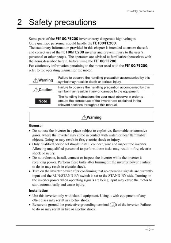
Some parts of the FE100/FE200 inverter carry dangerous high voltages. Only qualified personnel should handle the FE100/FE200. The cautionary information provided in this chapter is intended to ensure the safe and correct use of the FE100/FE200 inverter and prevent injury to the user’s personnel or other people. The operators are advised to familiarize themselves with the items described herein, before using the FE100/FE200. For cautionary information pertaining to the motor used with the FE100/FE200, refer to the operating manual for the motor.
Warning Failure to observe the handling precaution accompanied by this symbol may result in death or serious injury.
Caution Failure to observe the handling precaution accompanied by this symbol may result in injury or damage to the equipment.
NoteNote
The handling instructions the user must observe in order to ensure the correct use of the inverter are explained in the relevant sections throughout this manual.
Warning
General • Do not use the inverter in a place subject to explosive, flammable or corrosive
gases, where the inverter may come in contact with water, or near flammable objects. Doing so may result in fire, electric shock or injury.
• Only qualified personnel should install, connect, wire and inspect the inverter. Allowing unqualified personnel to perform these tasks may result in fire, electric shock or injury.
• Do not relocate, install, connect or inspect the inverter while the inverter is receiving power. Perform these tasks after turning off the inverter power. Failure to do so may result in electric shock.
• Turn on the inverter power after confirming that no operating signals are currently input and the RUN/STAND-BY switch is set to the STAND-BY side. Turning on the inverter power when operating signals are being input may cause the motor to start automatically and cause injury.
Installation • Use this inverter only with class I equipment. Using it with equipment of any
other class may result in electric shock. • Be sure to ground the protective grounding terminal ( ) of the inverter. Failure
to do so may result in fire or electric shock.

2 Safety precautions
– 6 –
Connection and wiring • Connect the inverter properly in accordance with the connection diagram. Failure
to do so may result in fire or electric shock. • Use cables of the specified sizes. Failure to do so may result in fire. • Do not forcibly bend, pull or pinch the power supply cable and lead wires or other
inverter cables. Doing so may result in electric shock or fire. • After connecting the inverter, be sure to install terminal covers (supplied with the
inverter) on the main circuit terminals of the inverter. Failure to do so may result in electric shock.
• After wiring an emergency-stop circuit, always conduct operation check. Failure to do so may result in injury.
• Connect the inverter to the power supply via a protective device (such as a molded-case circuit breaker). Failure to do so may result in fire, injury or damage to the equipment.
Operation • Do not operate the inverter with its live parts exposed. Doing so may result in
electric shock. • Turn off the inverter power in the event of power outage. If not, the motor may
suddenly start once the power is restored, thus causing injury or damage to the equipment.
• Do not operate the switches with wet hands. Doing so may result in electric shock. • Do not touch the inverter terminals even when the inverter is not operating.
Install/remove the covers or set the DIP switches after confirming that the inverter power has been turned off. Failure to observe these instructions may result in electric shock.
• Provide a separate emergency-stop switch. Absence of an emergency-stop switch may result in injury.
Maintenance and inspection • Some of the inverter terminals carry high voltage. To protect against the danger of
electric shock, do not touch the terminals with bare hands within 1 minute after turning off the inverter power.
• Before commencing any maintenance or inspection work, turn off the inverter power, confirm that all indicator lamps have turned off, and then wait at least 20 minutes thereafter. The inverter surface and radiating fins are still very hot immediately after the power is turned off, so touching the inverter in this condition may result in skin burn(s).
• Do not perform withstand voltage test on the inverter or megger test on its control circuit. Doing so may result in injury or damage to the equipment.
• Keep the inverter’s radiating fins from collecting dust or other foreign deposits. Foreign deposits on the radiating fins may cause fire.
• No one other than qualified personnel should be allowed to perform maintenance or inspection of the inverter or replace any of its parts. When performing maintenance or inspection or replacing parts, always use insulated tools. Failure to observe these instructions may result in electric shock or injury.
2 Safety precautions
– 7 –
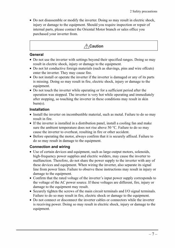
• Do not disassemble or modify the inverter. Doing so may result in electric shock, injury or damage to the equipment. Should you require inspection or repair of internal parts, please contact the Oriental Motor branch or sales office you purchased your inverter from.
Caution
General • Do not use the inverter with settings beyond their specified ranges. Doing so may
result in electric shock, injury or damage to the equipment. • Do not let conductive foreign materials (such as shavings, pins and wire offcuts)
enter the inverter. They may cause fire. • Do not install or operate the inverter if the inverter is damaged or any of its parts
is missing. Doing so may result in fire, electric shock, injury or damage to the equipment.
• Do not touch the inverter while operating or for a sufficient period after the operation was stopped. The inverter is very hot while operating and immediately after stopping, so touching the inverter in these conditions may result in skin burn(s).
Installation • Install the inverter on incombustible material, such as metal. Failure to do so may
result in fire. • If the inverter is installed in a distribution panel, install a cooling fan and make
sure the ambient temperature does not rise above 50 °C. Failure to do so may cause the inverter to overheat, resulting in fire or other accident.
• Before operating the motor, always confirm that it is securely affixed. Failure to do so may result in damage to the equipment.
Connection and wiring • Use of certain devices and equipment, such as large-output motors, solenoids,
high-frequency power supplies and electric welders, may cause the inverter to malfunction. Therefore, do not share the power supply to the inverter with any of these devices and equipment. When wiring the inverter, also separate its signal line from power lines. Failure to observe these instructions may result in injury or damage to the equipment.
• Confirm that the rated voltage of the inverter’s input power supply corresponds to the voltage of the AC power source. If these voltages are different, fire, injury or damage to the equipment may result.
• Securely tighten the screws of the main circuit terminals and I/O signal terminals. Failure to do so may result in fire, electric shock or damage to the equipment.
• Do not connect or disconnect the inverter cables or connectors while the inverter is receiving power. Doing so may result in electric shock, injury or damage to the equipment.

2 Safety precautions
– 8 –
Operation • Before turning on the power to the inverter, set the motor output selector switch to
an appropriate position according to the output of the motor to be used with the inverter. Failure to do so may result in injury or damage to the equipment.
• Use the inverter together with one of the specified motors. Use of any other motor may result in fire.
• Start the inverter after confirming that an emergency stop can be actuated promptly in case of problem. Failure to do so may result in injury.
• If any abnormality is observed, immediately turn off the inverter power. Failure to do so may result in fire, electric shock or injury.
• The motor speed can be easily changed on the inverter to a desired level from low to high. Before starting the inverter, thoroughly check the allowable speed ranges of the motor and equipment. Failure to do so may result in injury.
• Do not perform signal checks while the inverter is operating. Doing so may result in damage to the equipment.
Maintenance and inspection • Do not let your hands or body touch the inverter’s radiating fins immediately after
the inverter is stopped. It may cause skin burn(s). • Do not connect or disconnect the inverter cables or connectors while the inverter
is receiving power. Doing so may result in electric shock, injury or damage to the equipment.
Other • To dispose of the inverter, disassemble it into parts and components as much as
possible and dispose of individual parts/components as industrial waste.

2 Safety precautions
– 9 –
Warning labels Labels bearing warning messages on inverter handling are found on the inverter in the following locations (the messages are written in Japanese, English and French). When handling the inverter, be sure to observe the instructions given on these warning labels.

3 Precautions for use
– 10 –
3 Precautions for use
This chapter explains the limitations and other items the user must note when using the inverter.
Selection • Always use the inverter with Oriental Motor’s three-phase motor. Check the
permitted inverter/motor combinations in 4.2, “Motor/Inverter combinations” on p.15.
• If a large-capacity power transformer (600 kVA or more) is connected to the inverter, always install a DC reactor. Installing a DC reactor will improve the power factor of the power supply. If any thyristor converter, such as a DC drive, is connected to the inverter’s power supply, always install a DC reactor regardless of the condition of power supply. For the peripherals that should be used with the inverter, refer to 11.3 “Recommended peripherals” on p.58. Installing a DC reactor will lower the DC voltage of the inverter’s main circuit. Therefore, in a high-speed range the motor torque may drop and thereby cause the inverter’s output current to rise beyond the rated output current. Therefore, if you are connecting a DC reactor, keep the load to 80% of the allowable torque or below so as not to cause the output current to exceed the rated current.
• The explanations given in this manual assume an operating configuration consisting of one motor and one inverter. If you need to operate multiple motors with one inverter, please contact our Customer Service Center.
• Upon detection of abnormality, an appropriate protective function of the inverter will actuate to automatically stop the inverter output. However, the inverter’s protective functions cannot stop the motor quickly enough to ensure higher levels of safety for your equipment. If your equipment requires an emergency-stop function, provide a mechanical means for stopping the motor/retain the load.
Installation • When installing the inverter, select a place with clean air free from oil mist, cotton
fly, dust or other suspended matters. Also, install the inverter in a fully sealed enclosure that shuts out any suspended matters. If the inverter is installed in a panel, select an appropriate cooling method and enclosure dimensions to keep the inverter ambience from exceeding the allowable temperature.
• So that the heat generated from the inverter can be effectively exhausted, always install the inverter vertically with the display side facing up. For the installation method, refer to 5.2 “Installation condition” on p.22.

3 Precautions for use
– 11 –
Handling • Impressing voltage on the motor terminals (U, V and W) on the rear of the
inverter may damage the inverter. Before turning on the power, confirm that the power supply is wired correctly.
• If an electromagnetic contactor is connected between the power supply and inverter, do not start or stop the inverter using the electromagnetic contactor. Doing so may damage the inverter.
Peripherals Installation and selection of protective devices Install a protective device between the power supply and inverter to protect the inverter’s primary circuit. For details on selecting an appropriate protective device for this purpose, refer to 11.3 “Recommended peripherals” on p.58. Since a fully electromagnetic molded-case circuit breaker can change the operating characteristics of the inverter by generating harmonic current, select a breaker with a large capacity if this type of circuit breaker is used. In the case of an earth-leakage breaker, use of a special earth-leakage breaker for inverter, or a general earth-leakage breaker with a current sensitivity of 200 mA or more, is recommended.
Use of an electromagnetic contactor between the power supply and inverter The inverter can be used without an electromagnetic contactor between the power supply and inverter. An electromagnetic contactor is sometimes installed between the power supply and inverter for the purpose of preventing the inverter from starting automatically upon recovery from a momentary power outage. In this case, do not use the electromagnetic contactor to start or stop the inverter. Doing so may damage the inverter. If an electromagnetic contactor is installed between the inverter and motor, as a rule do not turn on/off the inverter power while the motor is operating. If an electromagnetic contactor is provided to switch between the mains and other power source, always stop the inverter and motor before switching to the mains. If an electromagnetic contactor is used as a safety device in the event of momentary power outage, use a delayed-release type electromagnetic contactor.
Improvement of power factor (Elimination of phase-advanced capacitor) To improve the power factor of the inverter, connect a DC reactor to the reactor terminals on the inverter. Connecting a capacitor or surge killer to the inverter’s output side for the purpose of improving the power factor may generate harmonics in the inverter output, thus causing the motor to overheat or sustain damage. Also, overcurrent may flow into the inverter and activate the inverter’s overcurrent protection function. Therefore, do not connect a capacitor or surge killer to the inverter.

3 Precautions for use
– 12 –
Radio interference The inverter’s main circuit generates harmonics. Therefore, communication equipment used near the inverter may suffer from radio interference. To minimize the radio interference caused by the inverter, install a mains filter to the inverter circuit. Radio interference can also be suppressed by housing the cables between the inverter and motor/power supply in metal ducts and ground the metal ducts.
Cable size and wiring distance Use a power cable of AWG14 (2.0 mm2) in size. For the wiring between the inverter and motor, always use a dedicated optional cable (p.57). The maximum wiring distance between the inverter and motor is 20 m (65.6 ft.) including extensions. If the wiring distance between the inverter and motor must exceed 20 m (65.6 ft.), please contact our Customer Service Center. When operating the inverter via external input signals, keep the control lines as short as possible. Also, wire the control lines away from the main circuits, relay sequence circuits and other high-power circuits of peripherals, in order to prevent induction by peripherals.
Noise elimination This inverter adopts PWM control based on high carrier frequency and is therefore subject to higher levels of electromagnetic noise. Eliminate noise by referring to the following examples. • Connect a mains filter to prevent sensor malfunctions and also eliminate AM radio
noise. • To prevent negative effects by the inductive noise from the inverter’s power lines,
wire the inverter’s signal lines using twisted-pair shielded cables at least 300 mm (11.8 in.) away from the power lines.
Use a twisted-pair shielded cable
Ground the shielded cable to 0 V
Connect a capacitor (0.1 µF)Do not ground the sensor through the inverter
Mains filterMains filter
Keep a minimum distance of300 mm (11.8 in.) betweenthe inverter's power linesand signal lines
Powersupply
Sensor
Inverter circuit M
Enclosure
Sensor power supply

3 Precautions for use
– 13 –
Countermeasure against harmonic leak current Stray capacitance exists between the inverter’s power lines and other power lines, the ground or the connected motor. Harmonic leak current may flow from the inverter to the motor or peripherals through this stray capacitance, giving unwanted effects to the motor/peripherals. Since leak current is determined by the wiring distance between the inverter and motor and also by the inverter’s carrier frequency, provide the following measures to minimize leak current. • Use an earth-leakage breaker incorporating harmonic elimination measures (refer
to “Recommended peripherals” on p.58). • Set the carrier frequency to 10 kHz using the carrier-frequency selector switch
provided on the rear of the inverter. • Connect a zero-phase reactor (p.58).
A zero-phase reactor can be connected to either the output or input side of the inverter. It also has the effect of reducing noise.
FE inverterZero-phase reactor Zero-phase reactor
Powersupply
M
L1
L2
L3
R
S
T
U
V
W
Wrap R/S/T and U/V/W lines around cores three times each.

4 Preparation
– 14 –
4 Preparation
This chapter explains the items the user should check before using the inverter, as well as the name and function of each part of the inverter.
4.1 Checking the inverter Confirm that both of the items shown below are included. If you find either of them missing or damaged, please contact the Oriental Motor branch or sales office you purchased your inverter from. Check the inverter model specified on the nameplate. For the motors that can be used with the FE100/FE200 inverter, refer to 4.2 “Motor/Inverter combinations” on p.15.
• Inverter 1 unit • Operation manual 1 copy
• Instruction Sheet 1 copy
Meaning of the model number
FE 100 APower supply input A: Single-phase, 100-120 VC: Single-phase, 200-240 VS: Three-phase, 200-240 V
Maximum supported motor capacity100: 100 W200: 200 W

4 Preparation
– 15 –
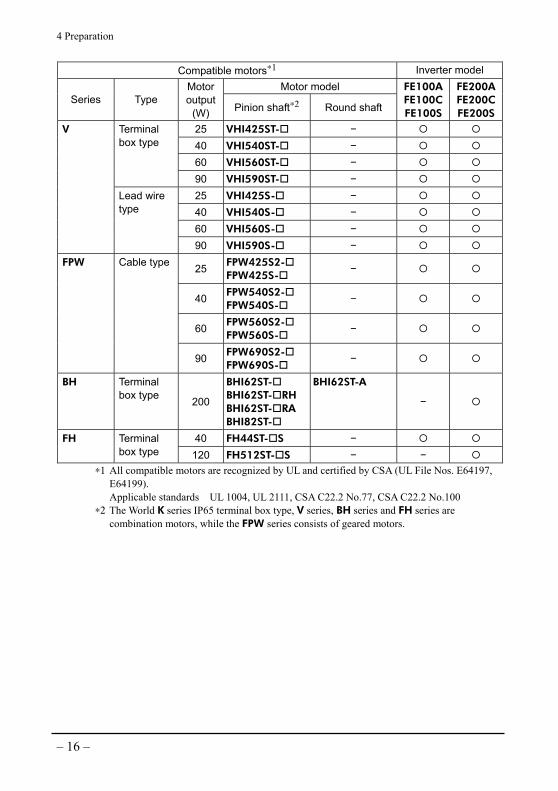
4.2 Motor/Inverter combinations The FE100/FE200 inverter can be used with the motors listed in the table below. Some motor models are shown with represents a number indicating the applicable gearhead gear ratio. Set the motor output selector switch correctly by referring to 7.1 “Setup before operation” on p.37.
Compatible motors∗1 Inverter model Motor model
Series Type Motor output
(W) Pinion shaft∗2 Round shaft
FE100AFE100CFE100S
FE200A FE200C FE200S
2IK6GN-SW2B 2IK6A-SW2B 2IK6SB- S − 6 2IK6GN-SWT 2IK6A-SWT
−
25 4IK25GN-SW2T 4IK25GN-SWT4IK25SB- S
4IK25A-SW2T 4IK25A-SWT 4IK25A-SW2B
40 5IK40GN-SW2T 5IK40GN-SWT5IK40SB- S
5IK40A-SW2T 5IK40A-SWT 5IK40A-SW2B
60 5IK60GE-SW2T5IK60GU-SWT
5IK60A-SW2T 5IK60A-SWT
Terminal box type
90 5IK90GE-SW2T5IK90GU-SWT
5IK90A-SW2T 5IK90A-SWT
6 2IK6GN-SW2 2IK6GN-SW
2IK6A-SW2 2IK6A-SW
−
15 3IK15GN-SW2 3IK15A-SW2 −
25 4IK25GN-SW24IK25GN-SW
4IK25A-SW2 4IK25A-SW
40 5IK40GN-SW25IK40GN-SW
5IK40A-SW2 5IK40A-SW
60 5IK60GE-SW25IK60GU-SW
5IK60A-SW2 5IK60A-SW
World K
Lead wire type
90 5IK90GE-SW25IK90GU-SW
5IK90A-SW2 5IK90A-SW
∗1 All compatible motors are recognized by UL and certified by CSA (UL File Nos. E64197, E64199). Applicable standards UL 1004, UL 2111, CSA C22.2 No.77, CSA C22.2 No.100
∗2 The World K series IP65 terminal box type, V series, BH series and FH series are combination motors, while the FPW series consists of geared motors.
4 Preparation
– 16 –
Compatible motors∗1 Inverter model Motor model
Series Type Motor output
(W) Pinion shaft∗2 Round shaft
FE100AFE100CFE100S
FE200A FE200C FE200S
25 VHI425ST- − 40 VHI540ST- − 60 VHI560ST- −
Terminal box type
90 VHI590ST- − 25 VHI425S- − 40 VHI540S- − 60 VHI560S- −
V
Lead wire type
90 VHI590S- −
25 FPW425S2- FPW425S-
−
40 FPW540S2- FPW540S-
−
60 FPW560S2- FPW560S-
−
FPW Cable type
90 FPW690S2- FPW690S-
−
BH Terminal box type 200
BHI62ST- BHI62ST- RH BHI62ST- RA BHI82ST-
BHI62ST-A
−
40 FH44ST- S − FH Terminal box type 120 FH512ST- S − −
∗1 All compatible motors are recognized by UL and certified by CSA (UL File Nos. E64197, E64199). Applicable standards UL 1004, UL 2111, CSA C22.2 No.77, CSA C22.2 No.100
∗2 The World K series IP65 terminal box type, V series, BH series and FH series are combination motors, while the FPW series consists of geared motors.

4 Preparation
– 17 –
4.3 Name and function of each part
Front view of the inverter
Speed displayThe set frequency and speed of the motor, as well as the alarm code, if any, are displayed.
Speed potentiometerThis potentiometer is used to adjust the motor speed.
Vent holes (bottom) ∗Vent holes are also provided on the opposite side of the radiating fins.
POWER LED A green lamp illuminateswhen the power is turned on.
RUN/STAND-BY switch This switch is used to run/stop the motor.
Radiating fins
Set frequency display LEDAn orange light is lit while a frequency is displayed.
Set speed display LEDAn orange light is lit while an rpm value is displayed.
Front panel
• When the front panel is removed
Motor output selector switchThis switch is used to set the motor output.
Mounting hole
Deceleration-time potentiometerThis potentiometer is used to set the motor deceleration time.
Gear ratio setting switchesThese switches are used to set the gearhead gear ratio. The set speed is converted to a gear output shaft speed and displayed.
Motor output selector switchThis switch is used to set the motor output.
Acceleration-time potentiometerThis potentiometer is used to set the motor acceleration time.
Refer to p.39.
Refer to p.39.
Refer to p.40.
Refer to p.38.
Refer to p.46.
Refer to p.44.
Refer to p.44.

4 Preparation
– 18 –
Rear view of the inverter
SW1: DIP switches Use these switches for various settings.
Protective EarthTerminal
Protective EarthTerminal
Shorting barThe inverter is shipped with these terminals shorted by a shorting bar.
TB1: Main circuit terminals Connect the motor, DC reactor and power supply to these terminals.
TB2: Input signal terminals Connect input signals to these terminals.
TB3: Output signal terminals Connect output signals to these terminals.
Refer to p.28.
Refer to p.28.
Refer to p.28.
Refer to p.27.
Refer to p.27.
Refer to p.27.
Refer to p.27.

4 Preparation
– 19 –
4.4 Removing/installing the front panel
• How to remove the front panel
1. Press the top (2 locations) and bottom (1 location) of the front panel with you fingers and detach the bottom of the panel.
Press the top (2 locations) and bottom (1 location) with your fingers.
Detach the bottom ofthe front panel.
2. Once the bottom is detached, slide the front panel slightly upward to release the hooks at the back of the panel. The front panel will come off.
Note You cannot force open the top of the front panel first. Applying a force to the top side first may damage the front panel.
Hook
∗ There are a total of four hooks, including two at the top and two at the bottom.

4 Preparation
– 20 –
• How to install the front panel
1. Hold both sides of the front panel and hook it onto the top edge of the inverter’s front face.
Hold both sides of the front panel.
Hook the front panel onto the top edge of the inverter's front face.
2. Guide the two upper hooks at the back of the front panel to engage with the corresponding holes in the inverter body.
Hook hole

4 Preparation
– 21 –
3. Insert the two lower hooks into the corresponding holes. Push in the bottom of the front panel until a “click” is heard.
Push in the bottom of the front panel until a click is heard.
4.5 Installing/removing the front cover (sold separately)
• How to install the front cover Install the front cover on the front panel by fitting it from the front side. • How to remove the front cover Hold both ends of the front cover at the top and pull out the cover.
To remove the front cover, hold both ends of the cover at the top and pull out the cover.
Note The front cover cannot be removed properly if pressure is applied to both the top and bottom or only to the bottom of the cover. Particularly when both the top and bottom of the front cover are held, the front panel will come off together with the front cover.

5 Installation
– 22 –
5 Installation
5.1 Installation location This inverter is designed and manufactured for installation in equipment. Install it in a well-ventilated place satisfying the following conditions, where the inverter can be inspected easily:
• Inside an enclosure • Ambient temperature: −10 to +50 °C
(+14 to +122 °F) (non-freezing) • Ambient humidity: 95% or less
(non-condensing) • Free from explosive or toxic gases
(sulfide gas, etc.) or liquids • Not exposed to the direct sunlight • Not subject to significant dust, iron
powder, etc.
• Not subject to water (rain or water droplets), oil (oil droplets) or other liquids
• Not subject to air of high salt content • Not subject to continuous vibration or
excessive impact • Not subject to significant electromagnetic
noise (near a welder, power equipment, etc.)
• Free from radioactive materials, magnetic fields or vacuum
• Altitude of 1000 m or below
5.2 Installation condition The inverter generates heat. So that the heat generated from the inverter can be exhausted efficiently, always install the inverter vertically, as shown below. The inverter should also be installed on a flat metal plate offering excellent vibration resistance. Provide a minimum clearance of 30 mm (1.18 in.) in the horizontal direction, or 100 mm (3.94 in.) in the vertical direction, between the inverter and its enclosure or other equipment inside the enclosure. If two or more inverters are installed side by side, provide a minimum clearance of 30 mm (1.18 in.) in the horizontal direction, or 100 mm (3.94 in.) in the vertical direction, between the adjacent inverters.
Note Do not block the radiating fins or vent holes on the sides and bottom of the inverter.
30 (
1.1
8)
or
mo
re
30 (
1.1
8)
or
mo
re
100 (3.94) or more
Unit: mm (in.)
30 (1.18)or more
100 (3.94) or more
20
(0
.79
)o
r m
ore

5 Installation
– 23 –
5.3 Installation method Note • Do not install equipment generating large amounts of heat or high levels
of noise around the inverter. • If the ambient temperature of the inverter exceeds 50 °C (122 °F),
review the ventilation condition or use a fan to cool the inverter.
1. Open square holes in the metal mounting plate.
2. Remove the inverter’s front panel. (Refer to 4.4 “Removing/installing the front panel” on p.19.)
3. Use the two mounting holes opened earlier to affix the inverter with screws (M4 pan-head screw: not supplied with the inverter) and nuts. Securely tighten the screws/nuts by making sure no gaps remain between the inverter and metal plate. Tightening torque: 0.4 to 0.7 N·m (56 to 99 oz-in)
Note The distance between the inverter’s end face and the front panel is 4.5 mm (1.77 in.). Therefore, do not allow the screw heads to project more than 4.5 mm (1.77 in.) from the inverter’s end face. If the screw heads project more than 4.5 mm (1.77 in.), the front panel cannot be installed.
4. Install the front panel. (Refer to 4.4 “Removing/installing the front panel” on p.19.)
• Metal panel dimensions [Unit: mm (in.)]
• Installation method
Pan-head screw (2 pcs.×M4) (Not supplied with the inverter)
2×Ø4.5 (Ø0.18)
90
±0.2
(3
.54
±0
.00
8)
53 (2.09 )+ 1 0
+ 0.04 0
81
(3.1
9
)+
1
0
+ 0
.04
0
Installing the motor Install the motor by referring to the operating manual for the motor.

5 Installation
– 24 –
5.4 Installing and wiring in compliance with EMC Directive
EMC Directives (89/336/EEC, 92/31/EEC) This inverter is designed and manufactured for installation in equipment. The requirements of the EMC Directives must be satisfied by the user’s equipment in which the inverter is assembled. The following explains the basic methods for installing/wiring the inverter that are effective in achieving conformance to the EMC Directives by your mechanical equipment. Please note that the final conformance of your mechanical equipment to the EMC Directives will be determined, among others, by the configuration, wiring, installation condition and degree of hazard of the motor and other control system equipment or electrical parts used with the inverter. Therefore, it is imperative that the user conducts EMC tests on their mechanical equipment to confirm the actual EMC performance level of the equipment.
Applicable Standards EMI Emission Tests EN 61000-6-4 Radiated Emission Test EN 55011 Conducted Emission Test EN 55011
EMS Immunity Tests EN 61000-6-2 Electrostatic Discharge Immunity Test IEC 61000-4-2 Radiation Field Immunity Test IEC 61000-4-3 Fast Transient/Burst Immunity Test IEC 61000-4-4 Surge Immunity Test IEC 61000-4-5 Conductive Noise Immunity Test IEC 61000-4-6 Voltage Dip Immunity Test IEC 61000-4-11 Voltage Interruption Immunity Test IEC 61000-4-11
Installing and wiring in compliance with EMC Directive Unless effective measures are provided to reduce the EMI (electromagnetic interference) caused by the inverter in the control system equipment located nearby, or the inverter’s EMS (electromagnetic susceptibility), EMI/EMS can become a serious hindrance to the function of the user’s mechanical equipment. Refer to the installation/wiring methods explained on the following pages to provide appropriate measures required for conformance to the EMC Directive.
5 Installation
– 25 –
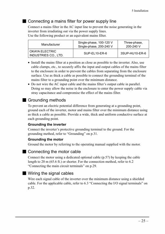
Connecting a mains filter for power supply line Connect a mains filter in the AC input line to prevent the noise generating in the inverter from irradiating out via the power supply lines. Use the following product or an equivalent mains filter.
Manufacturer Single-phase, 100-120 V Single-phase, 200-240 V
Three-phase, 200-240 V
OKAYA ELECTRIC INDUSTRIES CO., LTD. SUP-EL10-ER-6 3SUP-HU10-ER-6
• Install the mains filter at a position as close as possible to the inverter. Also, use cable clamps, etc., to securely affix the input and output cables of the mains filter to the enclosure in order to prevent the cables from separating from the enclosure surface. Use as thick a cable as possible to connect the grounding terminal of the mains filter to a grounding point over the minimum distance.
• Do not wire the AC input cable and the mains filter’s output cable in parallel. Doing so may allow the noise in the enclosure to enter the power supply cable via stray capacitance and compromise the effect of the mains filter.
Grounding methods To prevent an electric potential difference from generating at a grounding point, ground each of the inverter, motor and mains filter over the minimum distance using as thick a cable as possible. Provide a wide, thick and uniform conductive surface at each grounding point.
Grounding the inverter Connect the inverter’s protective grounding terminal to the ground. For the grounding method, refer to “Grounding” on p.31. Grounding the motor Ground the motor by referring to the operating manual supplied with the motor.
Connecting the motor cable Connect the motor using a dedicated optional cable (p.57) by keeping the cable length to 20 m (65.6 ft.) or shorter. For the connection method, refer to 6.2 “Connecting the main circuit terminals” on p.29.
Wiring the signal cables Wire each signal cable of the inverter over the minimum distance using a shielded cable. For the applicable cable, refer to 6.3 “Connecting the I/O signal terminals” on p.32.

5 Installation
– 26 –
Wiring a shielded cable Ground each shielded cable using a metal cable clamp that contacts the entire periphery of the shielded cable. Install the cable clamp at the tip of the shielded cable and connect it to an appropriate grounding point.
Cable clamp Shielded cable
Notes about installation and wiring • Connect the motor and inverter directly to their grounding points so as not to
generate difference in grounding electrical potential between the motor/inverter and control system equipment nearby.
• If a relay or electromagnetic switch is used with the inverter, connect a mains filter or surge absorber to absorb any surge voltage that may generate from the relay or electromagnetic switch.
• Minimize the wiring length of each cable and do not loop or bundle any extra length.
• Wire the power cables such as the motor cable and power supply cable separately from the signal cables, and keep a minimum distance of 300 mm (11.8 in.) between the two sets of cables. Also keep as much distance as possible between the AC input cable and output cable of the mains filter. Provide a minimum distance of 20 mm (0.79 in.) between the motor cable and power supply cable.
Example of inverter and motor installation/wiring
Motor
Inverter
Power supply cable
Motor cable [20 m (65.6 ft.)]
Mains filter
Signal cable[10 m (32.8 ft.)]
(Shielded cable)
(Shielded cable)
6 Connection
– 27 –
6 Connection
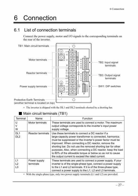
6.1 List of connection terminals Connect the power supply, motor and I/O signals to the corresponding terminals on the rear of the inverter.
TB2: Input signal terminals
TB3: Output signal terminals
SW1: DIP switches
TB1: Main circuit terminals
Protective Earth Terminals (another terminal is located on top)
Motor terminals
Reactor terminals
Power supply terminals
∗ The inverter is shipped with the DL1 and DL2 terminals shorted by a shorting bar.
Main circuit terminals (TB1) Terminal Name Function U V W
Motor terminals These terminals are used to connect a motor. The maximum output voltage corresponds to the inverter’s input power supply voltage.
DL1 DL2
Reactor terminals Use these terminals to connect a DC reactor if a large-capacity power transformer is connected, harmonics must be suppressed or the inverter’s power factor must be improved. When connecting a DC reactor, remove the shorting bar. Do not use the removed shorting bar for other purposes. Also, when connecting a DC reactor, keep the load to 80% of the allowable torque or below so as not to cause the output current to exceed the rated current.
L1 L2 L3
Power supply terminals
These terminals are used to connect a power supply. If your inverter is of the single-phase type, connect a power supply to the L1 and L2 terminals. If it is of the three-phase type, connect a power supply to the L1, L2 and L3 terminals.
∗ With the single-phase type, only two power supply terminals (L1 and L2) are provided.
6 Connection
– 28 –
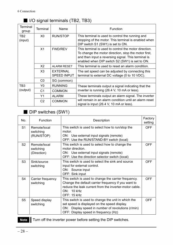
I/O signal terminals (TB2, TB3) Terminal
group Terminal Name Function
X0 RUN/STOP This terminal is used to control the running and stopping of the motor. This terminal is enabled when DIP switch S1 (SW1) is set to ON.
X1 FWD/REV This terminal is used to control the motor direction. To change the motor direction, stop the motor first, and then input a reversing signal. This terminal is enabled when DIP switch S2 (SW1) is set to ON.
X2 ALARM RESET This terminal is used to reset an alarm condition. X3 EXTERNAL
SPEED INPUTThe set speed can be adjusted by connecting this terminal to external DC voltage (0 to 10 VDC).
TB2 (input)
C0 SG (common) Y0 RUNNING C1 COMMON
These terminals output a signal indicating that the inverter is running (26.4 V, 10 mA or less).
Y1 ALARM
TB3 (output)
C2 COMMON These terminals output an alarm signal. The inverter will remain in an alarm condition until an alarm reset signal is input (26.4 V, 10 mA or less).
DIP switches (SW1)
No. Function Description Factory setting
S1 Remote/local switching (RUN/STOP)
This switch is used to select how to run/stop the motor. ON: Use external input signals (remote) OFF: Use the RUN/STAND-BY switch (local)
OFF
S2 Remote/local switching (Direction)
This switch is used to select how to change the motor direction. ON: Use external input signals (remote) OFF: Use the direction selector switch (local)
OFF
S3 Sink/source switching
This switch is used to select the sink and source input for external control. ON: Source input OFF: Sink input
OFF
S4 Carrier frequency switching
This switch is used to change the carrier frequency. Change the default carrier frequency if you want to reduce the leak current from the inverter-motor cable.ON: 10 kHz OFF: 15 kHz
OFF
S5 Speed display switching
This switch is used to change the unit in which the set speed is displayed on the speed display. ON: Display speed in number of revolutions (r/min)OFF: Display speed in frequency (Hz)
OFF
Note Turn off the inverter power before setting the DIP switches.

6 Connection
– 29 –
Protective grounding terminal
Protective grounding terminal (2 locations)
These terminals are used to ground the inverter.
6.2 Connecting the main circuit terminals Connect the power supply and motor to the corresponding main circuit terminals (TB1) using round crimp terminals with insulating cover. Example: Three-phase, 200-240 V
Power supplyinput, molded-case circuitbreaker, earth-leakage breakeror fuse
R
S
T
Motor
Terminal thread size and applicable cable size Terminal thread size Tightening torque Applicable cable size
M3.5 0.86 to 0.96 N·m (123 to 136 oz-in) AWG14(2.0 mm2
)
∗ The cable size specified above is based on an assumed maximum ambient temperature of 75 °C (167 °F) and use of copper wire.
Use a power supply cable of AWG14 in size. Always use a dedicated optional cable (p.57) for wiring between the inverter and motor.
Applicable crimp terminal [unit: mm (in.)]
Round terminal with insulating cover
3.8 (0.15) or less
7.2 (0.283) or less
Ø3.6 (0.142) or more

6 Connection
– 30 –
Connecting the power supply Connect the power supply to the power supply terminals via a molded-case circuit breaker, earth-leakage breaker or fuse as shown in the table below. If your inverter is of the single-phase type, connect the power supply to the L1 and L2 terminals. If it is of the three-phase type, connect the power supply to the L1, L2 and L3 terminals.
Note • Be sure to connect a protective device to protect the cable. • Always connect the power supply to the power supply terminals.
Connecting it to any other terminal will damage the inverter. • When reconnecting the power, turn off the power, wait at least
1 minute, and then turn the power back on.
Model number FE100A FE100C, FE100S FE200C, FE200S FE200A
Protective device rating 10 A 5 A 15 A Molded-case circuit breaker NF30 (Mitsubishi Electric Corporation)
Earth-leakage breaker When connecting an earth-leakage breaker, use a product with a current sensitivity of 200 mA or more and operating time of 0.1 second or more. Whenever possible, select an earth-leakage breaker incorporating harmonic measures. • NV Series [Mitsubishi Electric Corporation (models
manufactured in or after 1998)] • EG Series, SG Series [Fuji Electric FA Components &
Systems Co., Ltd. (models manufactured in or after 1984)] Fuse UL class RK5 (or equivalent)
Connecting the motor Connect the U, V and W terminals on the motor to the U, V and W motor terminals on the inverter, respectively. Also provide protecting grounding for the motor. If the grounding resistance exceeds 0.1 Ω, ground the motor directly. In addition, be sure to use a dedicated optional cable (p.57) for wiring between the inverter and motor. The maximum wiring distance between the inverter and motor is 20 m (65.6 ft.). If the motor and inverter must be apart by more than 20 m (65.6 ft.), please contact our Customer Service Center. For details on connecting the motor to a terminal box, refer to the operating manual that came with the motor.
6 Connection
– 31 –
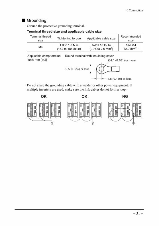
Grounding Ground the protective grounding terminal. Terminal thread size and applicable cable size
Terminal thread size Tightening torque Applicable cable size Recommended
size
M4 1.0 to 1.3 N·m (142 to 184 oz-in)
AWG 18 to 14 (0.75 to 2.0 mm2)
AWG14 (2.0 mm2
)
Applicable crimp terminal [unit: mm (in.)]
Round terminal with insulating cover
4.8 (0.189) or less
9.5 (0.374) or less
Ø4.1 (0.161) or more
Do not share the grounding cable with a welder or other power equipment. If multiple inverters are used, make sure the link cables do not form a loop.
OK OK NG
6 Connection
– 32 –
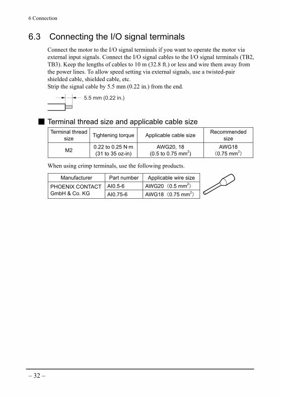
6.3 Connecting the I/O signal terminals Connect the motor to the I/O signal terminals if you want to operate the motor via external input signals. Connect the I/O signal cables to the I/O signal terminals (TB2, TB3). Keep the lengths of cables to 10 m (32.8 ft.) or less and wire them away from the power lines. To allow speed setting via external signals, use a twisted-pair shielded cable, shielded cable, etc. Strip the signal cable by 5.5 mm (0.22 in.) from the end.
5.5 mm (0.22 in.)
Terminal thread size and applicable cable size Terminal thread
size Tightening torque Applicable cable size Recommended size
M2 0.22 to 0.25 N·m(31 to 35 oz-in)
AWG20, 18 (0.5 to 0.75 mm2)
AWG18 (0.75 mm2
)
When using crimp terminals, use the following products.
Manufacturer Part number Applicable wire sizeAI0.5-6 AWG20 (0.5 mm2
) PHOENIX CONTACT GmbH & Co. KG AI0.75-6 AWG18 (0.75 mm2
)

6 Connection
– 33 –
Input signal circuit The input signals of this inverter are photo-coupler inputs. The input circuit terminals are insulated to the reinforced insulation standard for protection against dangerous voltages. If a relay is connected to the input circuit, select a small-capacity contact-type relay that can switch 24 VDC, 10 mA. The circuit uses sink input by default. Select sink input or source input in accordance with the external control equipment used with the inverter. • Sink input circuit
SG (common)
3.3 kΩ
+15 V
0 V
RUN/STOPFWD/REV
ALARM RESET
X0X1X2
C0
Input circuit
• Source input circuit
3.3 kΩ
0 V
RUN/STOPFWD/REV
ALARM RESET
SG (common)
Input circuit
X0X1X2
C0
To support a sequence connection via a source transistor, an external power supply with a voltage range of +15 to 24 V is required. • Connecting external DC voltage
Analog frequency command
SG (common)
0 to 10 VDC1 mA or more
+5 V
10 kΩ
0 V
X3
C0
10 kΩ

6 Connection
– 34 –
Output signal circuit The output signals of this inverter are open-collector outputs. Therefore, an external power supply is needed to operate the output signals. Use an external power supply with a voltage range not exceeding 26.4 V, and connect a limiting resistor appropriate for the power supply voltage so as not to cause the current to exceed 10 mA. No external power supply is required if the output signals are not used. The output circuit terminals are insulated to the reinforced insulation standard for protection against dangerous voltages. The output signals of this inverter are transistor open-collector outputs. In other words, the status of each output signal does not indicate the signal voltage level, but it represents the ON (energized) or OFF (not energized) status of the internal photocoupler.
COM
Output circuitRUNNINGALARM
Y0Y1
C1C2
The RUNNING output remains ON when the inverter is running, and turns OFF when it is stopped (normally closed). The ALARM output remains ON when the inverter is normal, and turns OFF when an alarm generates (normally closed).
Normal
Alarm
ON
OFF
Output
The ALARM output produces a pulsed output waveform while a blinking alarm code is displayed.
• Output waveform when a blinking alarm code is displayed
Output
ON
0.3 s 0.3 s
OFF

6 Connection
– 35 –
• ALARM RESET input When an alarm is generated, in most cases it will be automatically reset by an appropriate protective function of the inverter. Set the RUN/STAND-BY switch to the STAND-BY side, or also set the X0 (RUN/STOP) input to the STOP side if external input control is used. Then, after confirming that the motor has stopped completely, turn the ALARM RESET input ON for at least 20 ms. Input an alarm reset signal, and once the alarm has been reset, turn the ALARM RESET input OFF.
ALARM outputON
ALARM RESET inputON
ON
20 msOFF
OFF
OFF
Note • Always input an alarm reset signal after removing the cause of the alarm. Continuing to operate the motor without removing the cause of the alarm may damage the motor.
• The ALARM RESET input is enabled only while the motor is stopped.
Using a controller with a built-in clamp diode When a controller with a built-in clamp diode is used, a sneak current path may sometime cause the motor to run even though the controller power is off, if the inverter power is on. The motor may also run when the controller power and inverter power are turned on/off simultaneously, because the power capacity of the controller is different from that of the inverter. When turning on the power, turn on the controller power first, and then turn on the inverter power. When turning off the power, turn off the inverter power first, and then turn off the controller power.
Controller Inverter
X0 to X2
C0
+15 V
0 V
0 V
+Vcc
Clampdiode

6 Connection
– 36 –
6.4 Example of inverter connection
RUNNING
Output signal (26.4 VDC, 10 mA or less)
COM
TB3
L1
L2
L3
R
S
T
Molded-casecircuit breaker
ALARM
COM
Y0
Inverter
Y1
DL1
DL2
C1
C2
EXTERNAL SPEEDINPUT
SG (common)
0 to 10 VDC1 mAor more
TB2
+15 V
0 V
X0
X1
X2
X3
C0
W
V
U
TB1
Motor
Input circuit
DC reactor∗2
Shorting bar∗2
∗1
∗4
RUN/STOP∗3
FWD/REV∗3
ALARM RESET∗3Output circuit
∗1 Ground the motor directly if the grounding resistance exceeds 0.1 Ω. ∗2 When connecting a DC reactor, remove the shorting bar. ∗3 The above connections of input signals X0, X1 and X2 assume a sequence connection (0 V
common) via mechanical contacts or a sink transistor. If using a sequence connection (+15 to 24 V common) via a source transistor, an external power supply with a voltage range of +15 to 24 V is required.
∗4 The I/O signal terminals are based on SELV circuit. The terminals are insulated to the reinforced insulation standard for protection and isolation from dangerous voltages.

7 Operation
– 37 –
7 Operation
7.1 Setup before operation Before operating the motor, set to the inverter to the correct output of the connected motor. Once the motor output is set, the inverter will automatically determine the appropriate V/f pattern.
1. Remove the front panel. (Refer to 4.4 “Removing/installing the front panel” on p.19.)
2. Set the motor output selector switch on the inverter in accordance with the output of the motor to be used. Factory setting: Dial setting “5” (90 W) for FE100A, FE100C, FE100S Dial setting “4” (200 W) for FE200A, FE200C, FE200S For the setting of each motor, refer to 4.2 “Motor/Inverter combinations” on p.15.
3. Install the front panel. (Refer to 4.4 “Removing/installing the front panel” on p.19.)
• FE100A
FE100C
or FE100S
• FE200A
FE200C
or FE200S
Note Always set the motor output to the inverter before operating the motor. The inverter will not accept any changes to the motor output setting while the motor is running. If the motor output is different from the output setting on the inverter, abnormal heat generation or insufficient torque may occur, resulting in an alarm.

7 Operation
– 38 –
7.2 Setting position of motor output selector switch
Inverter model: FE100A, FE100C, FE100S Compatible motor output Setting position of SW
6 W 0 15 W 1 25 W 2 40 W 3 60 W 4 90 W 5∗1
FH series 40 W∗2 6∗2 ∗1 Factory-set position ∗2 This setting position applies only to the FH series 40 W model. For 40 W type motors in all
other series, set the switch to the “40 W” position (corresponding to the graduation mark “3” on the switch).
Inverter model: FE200A, FE200C, FE200S Compatible motor output Setting position of SW
25 W 0 40 W 1 60 W 2 90 W 3
200 W 4∗1 FH series 40 W∗2 5∗2 FH series 120 W 6
∗1 Factory-set position ∗2 This setting position applies only to the FH series 40 W model. For 40 W type motors in all
other series, set the switch to the “40 W” position (corresponding to the graduation mark “3” on the switch).
7 Operation
– 39 –
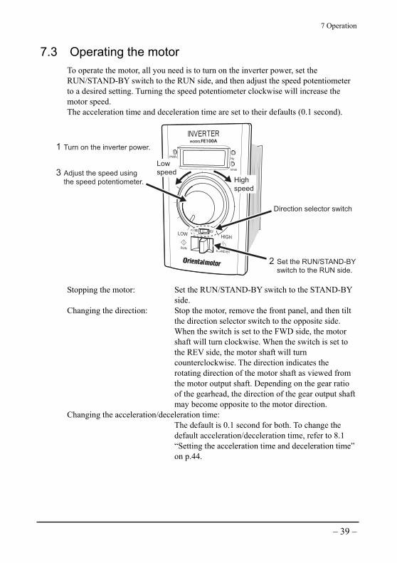
7.3 Operating the motor To operate the motor, all you need is to turn on the inverter power, set the RUN/STAND-BY switch to the RUN side, and then adjust the speed potentiometer to a desired setting. Turning the speed potentiometer clockwise will increase the motor speed. The acceleration time and deceleration time are set to their defaults (0.1 second).
2 Set the RUN/STAND-BY switch to the RUN side.
Direction selector switch
High speed
Low speed3 Adjust the speed using
the speed potentiometer.
1 Turn on the inverter power.
Stopping the motor: Set the RUN/STAND-BY switch to the STAND-BY side.
Changing the direction: Stop the motor, remove the front panel, and then tilt the direction selector switch to the opposite side. When the switch is set to the FWD side, the motor shaft will turn clockwise. When the switch is set to the REV side, the motor shaft will turn counterclockwise. The direction indicates the rotating direction of the motor shaft as viewed from the motor output shaft. Depending on the gear ratio of the gearhead, the direction of the gear output shaft may become opposite to the motor direction.
Changing the acceleration/deceleration time: The default is 0.1 second for both. To change the
default acceleration/deceleration time, refer to 8.1 “Setting the acceleration time and deceleration time” on p.44.

7 Operation
– 40 –
Display examples during operation Examples of what the display shows when the power is input, while the motor is running, and in the set speed display mode are given below.
Lit(green)
Lit(orange)
Unlit
Lit(green)
Lit(orange)
Unlit
Lit(green) Unlit
Lit (orange)
Power is input Motor is running (set frequency display)
Motor is running (set speed display): DIP switch S5 (SW1) is ON

7 Operation
– 41 –
7.4 Operation via external input signals
1. Connect external input signals to the X0 terminal (RUN/STOP) and X1 terminal (FWD/REV) by referring to 6.3 “Connecting the I/O signal terminals” on p.32. To enable speed change using external DC voltage, connect DC voltage to the X3 terminal (EXTERNAL SPEED INPUT).
2. Set DIP switches S1 and S2 (SW1) to ON.
Set S1 to ON
SG (common)
Set S2 to ON
RUN/STOPFWD/REV
EXTERNAL SPEED INPUT
3. Set the motor direction using the X1 terminal (FWD/REV). OFF: Clockwise ON: Counterclockwise (The direction indicates the rotating direction of the motor shaft as viewed from the motor output shaft.)
4. Run/stop the motor using the X0 terminal (RUN/STOP). ON: Run the motor OFF: Stop the motor The acceleration time and deceleration time are set to their defaults (0.1 second).
5. Set the motor speed using the DC voltage connected to the X3 terminal (EXTERNAL SPEED INPUT). (Refer to 7.5 “Setting the speed” on p.42.)
Note • When external DC voltage is connected to the inverter, either the speed set by the X3 terminal (EXTERNAL SPEED SETTING) or speed set by the inverter’s speed potentiometer, whichever is higher, will be given priority.
• If you want to set the speed via external DC voltage, turn the speed potentiometer all the way to the LOW end.
6. To stop the motor, set the X0 terminal (RUN/STOP) to OFF.
7 Operation
– 42 –
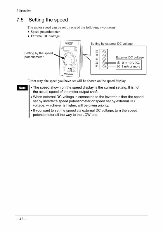
7.5 Setting the speed The motor speed can be set by one of the following two means: • Speed potentiometer • External DC voltage
External DC voltage
Setting by external DC voltage
Setting by the speedpotentiometer
0 to 10 VDC, 1 mA or more
Either way, the speed you have set will be shown on the speed display.
Note • The speed shown on the speed display is the current setting. It is not the actual speed of the motor output shaft.
• When external DC voltage is connected to the inverter, either the speed set by inverter’s speed potentiometer or speed set by external DC voltage, whichever is higher, will be given priority.
• If you want to set the speed via external DC voltage, turn the speed potentiometer all the way to the LOW end.

7 Operation
– 43 –
7.6 Timing chart
Clockwise(FWD)
Counterclockwise(REV)
RUN RUN RUN STAND-BY
FWD REV FWD
Speed potentiometer on the inverter
External speed input via external DC voltage
Stopped Running Running
FWD REV
Local Remote
Local Remote
Motor direction
Switches at
inverter frontRUN/STAND-BY
FWD/REV
Speed (frequency) setting
Input signals
X0_C0(RUN/STOP)
ON
OFF
ON
OFF
ON
OFF
X1_C0(FWD/REV)
DIP
switches
S1: Remote/local (RUN/STOP)
S2: Remote/local (FWD/REV)
Output signalY0_C1
(RUNNING)
∗1 The DIP switches are enabled only when the motor is stopped.
If any of the DIP switches is changed while the motor is running, the new setting will take effect after the motor stops.
∗2 When external DC voltage is connected to the inverter, either the speed set by the X3 terminal (EXTERNAL SPEED SETTING) or speed set by the inverter’s speed potentiometer, whichever is higher, will be given priority.
∗3 To switch the motor direction, stop the motor first, and then input a reversing signal. Changing the motor direction instantaneously while the motor is running may damage the gearhead or motor due to an impact load.
∗4 The direction indicates the rotating direction of the motor shaft as viewed from the motor output shaft (FWD: clockwise, REV: counterclockwise). Depending on the gear ratio of the gearhead, the direction of the gear output shaft may become opposite to the motor direction.

8 Various functions
– 44 –
8 Various functions
8.1 Setting the acceleration time and deceleration time The default acceleration/deceleration time is 0.1 second. If necessary, you can set a desired acceleration/deceleration time in the range of 0.1 to 30 seconds. The acceleration/deceleration time indicates the setting on the inverter. It does not indicate how the motor actually behaves.
1. Remove the front panel. (Refer to 4.4 “Removing/installing the front panel” on p.19.)
2. Set desired acceleration time and deceleration time using the acceleration-time potentiometer and deceleration-time potentiometer, respectively.
Acceleration-timepotentiometer
Deceleration-timepotentiometer
3. Install the front panel. (Refer to 4.4 “Removing/installing the front panel” on p.19.)
Note Depending on the load condition, the motor may not start if the acceleration time is too short. In this case, increase the acceleration time.
8 Various functions
– 45 –
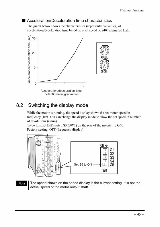
Acceleration/Deceleration time characteristics The graph below shows the characteristics (representative values) of acceleration/deceleration time based on a set speed of 2400 r/min (80 Hz).
010
Acce
lera
tio
n/d
ece
lera
tio
n t
ime
(se
c)
Acceleration/deceleration-time potentiometer graduation
10
20
30
8.2 Switching the display mode While the motor is running, the speed display shows the set motor speed in frequency (Hz). You can change the display mode to show the set speed in number of revolutions (r/min). To do this, set DIP switch S5 (SW1) on the rear of the inverter to ON. Factory setting: OFF (frequency display)
Set S5 to ON
Note The speed shown on the speed display is the current setting. It is not the actual speed of the motor output shaft.

8 Various functions
– 46 –
8.3 Setting the gear ratio The inverter displays the speed of the motor output shaft. To check the speed of the gearhead output shaft, you can display the gear ratio instead. Set the gear ratio of the gearhead you are using.
Note This function is enabled when the set speed is displayed in number of revolutions on the inverter [DIP switch S5 (SW1) is ON]. The following operation will not be effective if the frequency is displayed.
1. Remove the front panel. (Refer to 4.4 “Removing/installing the front panel” on p.19.)
2. Use the gear-ratio setting switches to set the code corresponding to the gear ratio. Set the 10’s place using switch 1, and 1’s place using switch 2. Factory setting: Gear ratio 1 (both switches 1 and 2 are set to “0”.) Check the gear ratio codes in “List of gear ratios and codes” on p.47. For the setting method, refer to “Code setting example” on p.48.
Note Do not set a value other than the codes shown in “List of gear ratios and codes” It will disable the speed display function.
Gear-ratio setting switches 1(set the 10's place)
Gear-ratio setting switches 2(set the 1's place)
3. Install the front panel. (Refer to 4.4 “Removing/installing the front panel” on p.19.)
8 Various functions
– 47 –
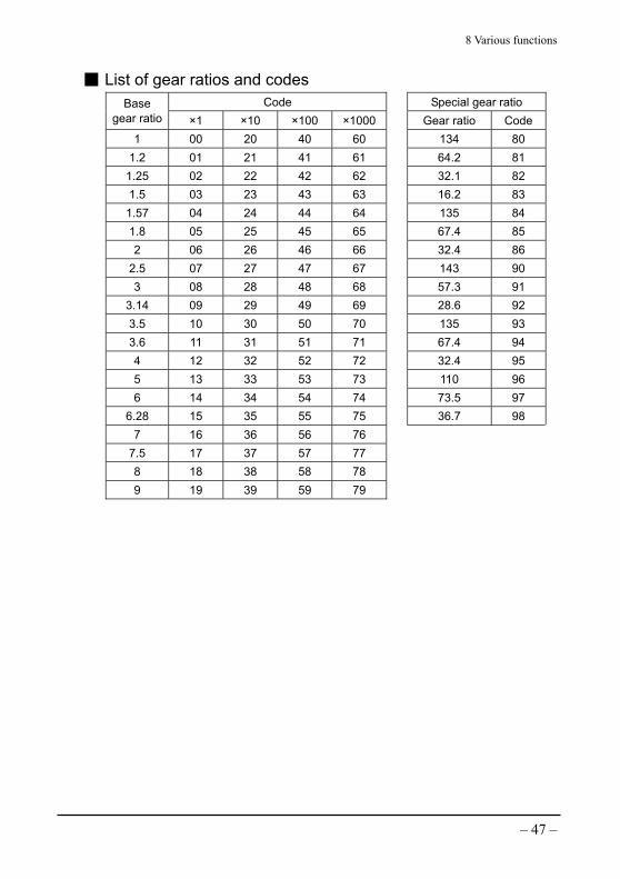
List of gear ratios and codes Code Special gear ratio Base
gear ratio ×1 ×10 ×100 ×1000 Gear ratio Code1 00 20 40 60 134 80
1.2 01 21 41 61 64.2 81 1.25 02 22 42 62 32.1 82 1.5 03 23 43 63 16.2 83
1.57 04 24 44 64 135 84 1.8 05 25 45 65 67.4 85 2 06 26 46 66 32.4 86
2.5 07 27 47 67 143 90 3 08 28 48 68 57.3 91
3.14 09 29 49 69 28.6 92 3.5 10 30 50 70 135 93 3.6 11 31 51 71 67.4 94 4 12 32 52 72 32.4 95 5 13 33 53 73 110 96 6 14 34 54 74 73.5 97
6.28 15 35 55 75 36.7 98 7 16 36 56 76
7.5 17 37 57 77 8 18 38 58 78 9 19 39 59 79

8 Various functions
– 48 –
Code setting example An example of setting the output shaft speed when a gearhead with a gear ratio of 100 is used is given below.
1. Determine the base gear ratio and multiplication. A gear ratio of 100 consists of “1 (base gear ratio) ×100 (multiplication)”.
2. Using the base gear ratio and multiplication determined above, look for a code corresponding to gear ratio 100, and set the gear-ratio setting switches to indicate the applicable code. In this example, the corresponding code is “40”.
Code Base gear ratio
×1 ×10 ×100 ×10001 00 20 40 60
3. Set gear-ratio setting switch 1 to “4”, and gear-ratio setting switch 2 to “0”.

8 Various functions
– 49 –
Gear ratio and displayed digits The speed display shows up to four digits. Since the effective integer digits will vary depending on the gear ratio, the position of the decimal point in the displayed/input value will also move.
Gear ratios Codes Displayed position of decimal point 1 to 3 00 to 08
Not displayed.
3.14 to 30 09 to 28, 83, 92
At the second digit from the right
31.4 to 300 29 to 48, 80, 81, 82, 84, 85, 86, 90, 91, 93 to 98
At the third digit from the right
314 to 9000 49 to 79 At the fourth digit from the right
Example: When the speed is 1800 r/min
Gear ratio Code set by gear-ratio setting switches Value on speed display
1×1 00 1800 1×10 20 180.0
1.25×1 02 1440 1.25×100 42 14.40
3.14×1 09 573.2 3.14×1000 69 0.573
64.2 81 28.04

8 Various functions
– 50 –
8.4 Switching the carrier frequency If the cable between the inverter and motor is long, the leak current from the cable will increase. To reduce the leak current, lower the carrier frequency from the default setting of 15 kHz to 10 kHz. (Note, however, that doing so will increase the buzzing sound from the motor.) Set DIP switch S4 (SW1) on the rear of the inverter to ON. Factory setting: OFF (15 kHz)
Set S4 to ON

8 Various functions
– 51 –
8.5 Switching between sink input and source input You can switch between the sink mode and source mode for the inverter’s input circuit using DIP switch S3 (SW1) on the rear of the inverter. Setting S3 to ON will enable the source input mode. In a sink circuit, a signal turns ON when current flows out from an applicable input signal terminal. In a source circuit, a signal turns ON when current flows into an applicable input signal terminal. Factory setting: OFF (sink input)
Set S3 to ON
• Sink input circuit
SG (common)
3.3 kΩ
+15 V
0 V
RUN/STOPFWD/REV
ALARM RESET
X0X1X2
C0
Input circuit
• Source input circuit
3.3 kΩ
0 V
RUN/STOPFWD/REV
ALARM RESET
SG (common)
Input circuit
X0X1X2
C0
To use the inverter in the source input mode, an external power supply with a voltage range of +15 to 24 V is required.

9 Inspection
– 52 –
9 Inspection
It is recommended that the user inspect the items listed below on a regular basis. If any abnormality is found, stop using the inverter and contact our Customer Service Center.
Inspection items • Blockage of the vent holes in the inverter • Loosening of the inverter mounting screws as well as screws on the main circuit
terminals and I/O signal terminals • Attachment of dirt and dust to the inverter’s radiator fins • Deposits of conductive dust or oil mist on the printed circuit boards inside the
inverter
Note The inverter uses semiconductor elements, so exercise due caution when handling the inverter. Subjecting it to electrostatic or other external forces may damage the semiconductor elements in the inverter.

10 Troubleshooting and remedial actions
– 53 –
10 Troubleshooting and remedial actions
While the motor is running, the motor and/or inverter may malfunction due to data setting or connection errors. If the motor does not operate correctly, refer to the information provided in this chapter to take appropriate remedial actions. If the motor still malfunctions after taking the relevant actions, please contact our Customer Service Center near you.
10.1 Troubleshooting Phenomenon Likely cause Remedial action
Poor connection of the motor cable
Check if the motor is connected correctly.
Activation of the inverter’s protective function
If this is the cause, an alarm code should be displayed on the inverter. Refer to 10.2 “Inverter alarms” on p.54 to remove the cause that activated the protective function.
The motor does not run.
Short acceleration time Depending on the load condition, the motor may not start if the acceleration time is too short. In this case, increase the acceleration time.
Wrong connection of the motor cable
Check if the motor is connected correctly.
Direction input error Input the forward or reverse direction correctly.
The motor direction is opposite to the specified direction. Use of a gearhead that
reverses the motor direction
Change the setting of the direction selector switch or reverse the direction input.
Misalignment of the motor (gearhead) output shaft and the load shaft
Check the connection condition of the motor (gearhead) output shaft and load shaft.
Motor operation is unstable.
Effect of noise Check the operation only with the motor and inverter. If effect of noise is observed, review the current method of isolating the inverter from noise-generating sources, as well as wiring, and implement appropriate measures such as connecting a mains filter.
Long acceleration time Change the acceleration time to an appropriate value.
The motor starts too slow.
Large load inertia Check the inertial moment of the load. Long deceleration time Change the deceleration time to an appropriate
value. The motor stops too slow.
Large load inertia Check the inertial moment of the load.

10 Troubleshooting and remedial actions
– 54 –
10.2 Inverter alarms When any abnormality occurs in the inverter, the motor will stop and the corresponding alarm code will be shown on the inverter’s speed display. Check the meaning of each alarm code by referring to the table below. The alarm output behavior of the inverter will vary depending on how the alarm code is displayed (steady or blinking). For the alarm output, refer to “Output signal circuit” on p.34. When resetting an alarm, be sure to remove the cause of the alarm before resuming the operation. The reset method will vary depending on how the alarm code is displayed (steady or blinking). Check an appropriate reset method in “Resetting an alarm” on p.56.
Alarm code (as displayed)
Display condition
Meaning of alarm Description Remedial action
Steady Overcurrent
The inverter’s output current exceeded approx. 200% of the rated output current.
• Reduce the load. • Increase the acceleration/
deceleration time. • Check if the output part of
the inverter is shorted or shorted to the ground.
Steady∗1 Blinking∗1
Overheated circuit
The inverter’s internal temperature rose above the allowable level.
• Reduce the load. • Increase the acceleration/
deceleration time. • Check if the inverter’s
ambient temperature exceeds the specification.
• Check the orientation of the inverter and change the installation layout if the inverter’s vent holes are blocked.
Steady∗1 Blinking∗1 Overvoltage
The inverter’s internal voltage exceeded the allowable level.
• Reduce the load. • Increase the acceleration/
deceleration time. • Check if the power supply
voltage is within the specification range.
• Check if the inverter is set to operate on regenerative power (the inverter cannot operate on regenerative power).

10 Troubleshooting and remedial actions
– 55 –
Alarm code (as displayed)
Display condition
Meaning of alarm Description Remedial action
Blinking Low voltage
The inverter’s internal voltage dropped below the allowable level.
• Check if the power supply voltage is within the specification range.
• In the case of a three-phase input inverter, check if any of the three power phases is missing or a single-phase power supply is connected.∗5
Steady Overheated motor∗2
• The built-in thermal protector of the motor actuated.
• Missing phase in the wiring between the motor and inverter
• Reduce the load. • Increase the acceleration
/deceleration time. • Lower the ambient
temperature of the motor. • Check the motor
connection.
Steady Circuit error∗3
Error in the CPU or other built-in component of the inverter
If the alarm persists after inputting an alarm reset signal, turn off, and then on the power.
Steady Overload
The inverter’s output current remained above approx. 150% of the rated output current for 1 min.
• Reduce the load. • Increase the acceleration
/deceleration time. • Set the motor output
selector switch to an appropriate output level.
Blinking Setting error
The output selector switch or gear-ratio setting switches is/are set to a value outside the applicable setting range.
• Check if the output selector switch is set to the correct output of the motor used with the inverter.
• Set a code appropriate for the gear ratio of the gearhead (87, 88 and 89 on the gear-ratio setting switches are invalid).
Steady Ground fault∗4
The output side of the inverter was shorted to the ground and ground fault current flowed into the inverter as a result.
Check the wiring between the inverter and motor to look for any part that is shorted to the ground.
10 Troubleshooting and remedial actions
– 56 –
∗1 If the protective function is actuated while the motor is running, the alarm code on the display will remain steady. If the protective function is actuated while the motor is stopped, the alarm code will blink.
∗2 If the alarm cannot be reset when a motor with a built-in thermal protector is used, the motor’s thermal protector may not have been reset. In this case, force-cool the motor using a fan or otherwise lower the motor temperature.
∗3 If the inverter still malfunctions after the power was turned off, and then on following a circuit error, the internal circuit may have been damaged. Please contact the Oriental Motor branch or sales office near you.
∗4 The ground-fault protection will actuate when the motor is started via generation of ground-fault current while the inverter is receiving power. If the inverter-motor line is shorted to the ground while the motor is running, large current will flow into the inverter, prompting the overcurrent protection (AL20) or overvoltage protection (AL22) to be actuated (These protective functions do not actuate if the line was already shorted to the ground when the power was input. Always connect an earth-leakage breaker if ground fault is anticipated).
∗5 In the case of a three-phase input inverter, if any one of the three power leads is missing, the inverter's protective function may not work accurately under no load or small load.
Resetting an alarm • When a steady alarm code is displayed Confirm that the RUN/STAND-BY switch is set to the STAND-BY side, or the X0 input is stopped if external input signal control is used, and then input an alarm reset signal to reset the alarm. (For the ALARM RESET input, refer to “ALARM RESET input” on p.35.) An alarm can also be reset by turning off and then on the inverter power. In this case, be sure to wait at least 1 minute after turning off the power, before turning it back on.
Note • When resetting an alarm, always remove the cause of the alarm first. Resuming the operation without removing the cause may result in damage.
• The ALARM RESET input is enabled only when the motor is stopped.
• When a blinking alarm code is displayed Removing the cause of the alarm will automatically reset the alarm.

11 Appendix
– 57 –
11 Appendix
11.1 Cables (sold separately) The following cables are used to connect the motor and inverter or extend the wiring length between the two.
Model number Cable length [m (ft.)] CC01AC04 1 (3.3) CC02AC04 2 (6.6) CC03AC04 3 (9.8) CC05AC04 5 (16.4) CC10AC04 10 (32.8) CC20AC04 20 (65.6)
11.2 Front cover (sold separately) This cover is used to prevent accidental contacts with the inverter’s speed potentiometer and consequent changes to the correct speed setting. (The front cover is not waterproof.) Model number: PAFC01
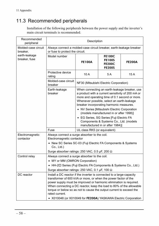
11 Appendix
– 58 –
11.3 Recommended peripherals Installation of the following peripherals between the power supply and the inverter’s main circuit terminals is recommended.
Recommended peripheral Description
Always connect a molded-case circuit breaker, earth-leakage breaker or fuse to protect the circuit. Model number
FE100A
FE100C FE100S FE200C FE200S
FE200A
Protective device rating 10 A 5 A 15 A
Molded-case circuit breaker NF30 (Mitsubishi Electric Corporation)
Earth-leakage breaker
When connecting an earth-leakage breaker, use a product with a current sensitivity of 200 mA or more and operating time of 0.1 second or more. Whenever possible, select an earth-leakage breaker incorporating harmonic measures. • NV Series [Mitsubishi Electric Corporation
(models manufactured in or after 1998)] • EG Series, SG Series [Fuji Electric FA
Components & Systems Co., Ltd. (models manufactured in or after 1984)]
Molded-case circuit breaker, earth-leakage breaker, fuse
Fuse UL class RK5 (or equivalent) Electromagnetic contactor
Always connect a surge absorber to the coil. Electromagnetic contactor • New SC Series SC-03 (Fuji Electric FA Components & Systems
Co., Ltd.) Surge absorber ratings: 250 VAC, 0.5 µF, 200 Ω
Control relay Always connect a surge absorber to the coil. • MY or MM (OMRON Corporation) • HH-2 Series (Fuji Electric FA Components & Systems Co., Ltd.) Surge absorber ratings: 250 VAC, 0.1 µF, 100 Ω
DC reactor Install a DC reactor if the inverter is connected to a large-capacity transformer of 600 kVA or more, or when the power factor of the power supply must be improved or harmonic elimination is required. When connecting a DC reactor, keep the load to 80% of the allowable torque or below so as not to cause the output current to exceed the rated current. • X010048 (or X010049 for FE200A) YASKAWA Electric Corporation

11 Appendix
– 59 –
Recommended peripheral Description
Zero-phase reactor Insert a zero-phase reactor when implementing the countermeasure against harmonic leak current. • FT-3KM F6045GB Fine Met zero-phase reactor (Hitachi Metals,
Ltd.)
Manufacture
Single-phase, 100-120 V
Single-phase, 200-240 V
Three-phase, 200-240 V
Mains filter
OKAYA ELECTRIC INDUSTRIES CO., LTD. SUP-EL10-ER-6 3SUP-HU10-ER-6
Note • Never connect a general LC/RC filter to the inverter’s output circuit.
• Do not connect a phase-advanced capacitor or surge killer to the input/output sides of the inverter.
• Do not turn on/off the electromagnetic contactor installed between the inverter and motor while the motor is running.

11 Appendix
– 60 –
11.4 Specifications
Inverter specifications • Maximum supported motor capacity FE100A, FE100C, FE100S 100 W FE200A, FE200C, FE200S 200 W
• Ratings Input
(Single-phase or Three-phase)
Output (Three-phase) Model
number Voltage (V) Current (A) Voltage (V) Current (A) Frequency
(Hz) FE100A 100-120 2.8 0-200 0.7 0-80 FE200A 100-120 5.4 0-200 1.4 0-80 FE100C 200-240 1.6 0-200 0.7 0-80 FE200C 200-240 3.1 0-200 1.4 0-80 FE100S 200-240 1.0 0-200 0.7 0-80 FE200S 200-240 1.6 0-200 1.4 0-80
• Control characteristics Control method Sine-wave PWM method (V/f control) Speed setting range 6.6 to 80 Hz (200 to 2400 r/min) Frequency setting method
Speed potentiometer at inverter front/DC voltage input (0 to 10 VDC)
Acceleration/deceleration time
0.1 to 30 seconds (at set speed of 80 Hz) (factory setting: 0.1 second)
Voltage/frequency characteristics
Use the rotary switch to select an appropriate setting according to the motor output.
• Display 7-segment display Set speed, alarm code LED indicators Power, speed display modes (r/min, Hz)
• Wiring distance between the inverter and motor Maximum 20 m (65.6 ft.) • Cooling condition Natural cooling

11 Appendix
– 61 –
• Functions External input signals Photocoupler input
RUN/STOP, FWD/REV, ALARM RESET External output signals Open-collector output
RUNNING, ALARM Speed display Set speed of the motor is displayed.∗ Remote/local switching (“RUN/STOP”, “FWD/REV”)
Switching between operation by the RUN/STAND-BY switch or operation using external input signals (factory setting: local)
Carrier frequency switching Change the default setting if leak current from the inverter-motor cable must be reduced. (factory setting: 15 kHz).
Sink/source switching Switching between sink input using 0 V common or source input using 24 V common. (factory setting: sink)
Frequency/rpm switching Either the set frequency or speed can be shown on the speed display (factory setting: frequency).
Speed display switching based on gear ratio
The set speed shown on the speed display can be switched to a desired speed matching the gear ratio. Up to 96 speeds can be set using two rotary switches (factory-set gear ratio: 1:1).
∗ This is not the actual speed of the motor shaft.
• Protective functions When any of the protective functions has been actuated, the inverter will stop the motor via the base blocking function. The inverter’s protective functions cover the following abnormalities and errors: overcurrent, overheated circuit, overvoltage, low voltage, overheated motor, circuit error, overload (150% of the rated output current for 1 minute), setting error, ground fault • Weight FE100A, FE100C, FE100S 0.4 kg (0.88 lb.) FE200A, FE200C, FE200S 0.5 kg (1.1 lb.)

11 Appendix
– 62 –
General specifications • Insulation resistance The insulation resistance measured by a 500 VDC megger between the main circuit terminals and the grounding terminal (control circuit terminal) after continuous operation in normal temperature and humidity is 100 MΩ or more. • Withstand voltage No abnormality has been observed after impressing 1.85 kV of 50 or 60 Hz for 1 minute between the main circuit terminals and the grounding terminal (control circuit terminal) after continuous operation in normal temperature and humidity. • Service conditions Service location Indoor (free from corrosive gases or dust) Ambient temperature −10 to +50 °C (+14 to +122 °F), non-freezing Storage temperature −15 to +60 °C (+5 to +140 °F) Humidity 95% or below (non-condensing) Altitude 1000 m or below Vibration Free from continuous vibration or excessive impact.
Measure vibration in accordance with the sine-wave vibration test method under JIS C 60068-2-6. Frequency range: 10 to 55 Hz, single amplitude: 0.15 mm Sweep directions: 3 directions (X, Y, Z) Number of sweeps: 20 times
• Protection structure IP10 (The front side of the inverter is IP20-compliant.)


• Unauthorized reproduction or copying of all or part of this manual is prohibited. If a new copy is required to replace an original manual that has been damaged or lost, please contact your nearest Oriental Motor branch or sales office.
• Oriental Motor shall not be liable whatsoever for any problems relating to industrial property rights arising from use of any information, circuit, equipment or device provided or referenced in this manual.
• Characteristics, specifications and dimensions are subject to change without notice. • While we make every effort to offer accurate information in the manual, we welcome
your input. Should you find unclear descriptions, errors or omissions, please contact the nearest office.
• is a registered trademark or trademark of Oriental Motor Co., Ltd., in Japan and other countries. Other product names and company names mentioned in this manual may be registered trademarks or trademarks of their respective companies and are hereby acknowledged. The third-party products mentioned in this manual are recommended products, and references to their names shall not be construed as any form of performance guarantee. Oriental Motor is not liable whatsoever for the performance of these third-party products.
© Copyright ORIENTAL MOTOR CO., LTD. 2008
Printed on Recycled Paper
• Please contact your nearest Oriental Motor office for further information.
Technical Support Tel:(800)468-39828:30 A.M. to 5:00 P.M., P.S.T. (M-F)7:30 A.M. to 5:00 P.M., C.S.T. (M-F)E-mail: [email protected]
Headquarters and Düsseldorf OfficeTel:0211-52067-00 Fax:0211-52067-099Munich Office Tel:089-3181225-00 Fax:089-3181225-25Hamburg OfficeTel:040-76910443 Fax:040-76910445
Tel:01256-347090 Fax:01256-347099
Tel:01 47 86 97 50 Fax:01 47 82 45 16
Tel:02-93906346 Fax:02-93906348
Tel:(02)8228-0707 Fax:(02)8228-0708
Tel:(6745)7344 Fax:(6745)9405
Tel:(03)22875778 Fax:(03)22875528
KOREATel:(032)822-2042~3 Fax:(032)819-8745
Headquarters Tokyo, JapanTel:(03)3835-0684 Fax:(03)3835-1890
Tel:66-2-254-6113 Fax:66-2-254-6114
Related Documents