www.atxled.com 512-377-6052 | [email protected] INSTALLATION GUIDE How2Wire R13g-12/01/21 1 HOW to WIRE WIRING GUIDE FOR THE ATX LED SYSTEM Overview ATX LED offers home builders a lower-cost, flicker-free, perfectly-dimmable LED lighting system using low-voltage DC power without changing the look and feel of traditional fixtures or switches. ATX LED’s solution converts 120 V AC to DC just once per house to provide DC power to lights, fans, and chargers and reduce labor cost, save copper, and improve the end-user experience with higher reliability. ATX LED’s innovative technology eliminates the need to run high-voltage ROMEX™ throughout the home and instead uses 18/5 or 18/3 for home runs and 20/2 between switches and lights. The end product can be value priced with simple on/off standard wall switches, or smart and full-featured without significant additional cost. Designed for volume builders, the labor and schedule savings allow projects to be completed more quickly and at lower costs. AL-CBOX4 Rough-in Junction Box for easy code-compliant installation Typical ATX LED System Example 120 V AC in Standard Media Enclosure Redundant Power Supplies - + - + Single Homerun 18/5 AWG AL-WS-DR2 Smart Dimmer Switch AL-PSE-4D 4-Outlet Power Distribution Module P023R6 / DL-120 LED Lights P023R11-SL LED Strip Lights E12/E26 Edison Style LED Lamps 51 V DC 20/2 AWG up to 100 W Complete System Solution ATX LED’s innovative system features redundant power conversion hardware to insure continuous operation even in the case of unexpected failure. The system includes a selection of LED lighting, switches, power management hardware, and accessories. All ATX LED products are UL listed and compliant with California Title 24 standards, as well as compatible with common smart home controls. The ATX LED DAbus provides smart home connectivity and control. Flexibility to Choose ATX LED gives builders the ability to offer home buyers a simple and seamless upgrade path at any stage of the build process because no changes to wiring or other buildout are required. Simply choose lights and switches from the same line to create the optimal lighting experience. Value Line Signature Line The entry-level products in the Value Line offer a starting point for installing energy-efficient DC lighting, with a selection of fixed true white light colors and standard switches. The Signature Line is for customers who want a fully program- mable system that integrates with common wireless smart home controls. Lights in the Signature Line can be color tuned to a wide range of colors and programmed to adjust throughout the day.

Welcome message from author
This document is posted to help you gain knowledge. Please leave a comment to let me know what you think about it! Share it to your friends and learn new things together.
Transcript

www.atxled.com512-377-6052 | [email protected]
INSTALLATION GUIDE
How2Wire R13g-12/01/211
HOW to WIREWIRING GUIDE FORTHE ATX LED SYSTEM
Overview ATX LED offers home builders a lower-cost, flicker-free, perfectly-dimmable LED lighting system using low-voltage DC power without changing the look and feel of traditional fixtures or switches. ATX LED’s solution converts 120 V AC to DC just once per house to provide DC power to lights, fans, and chargers and reduce labor cost, save copper, and improve the end-user experience with higher reliability. ATX LED’s innovative technology eliminates the need to run high-voltage ROMEX™ throughout the home and instead uses 18/5 or 18/3 for home runs and 20/2 between switches and lights.
The end product can be value priced with simple on/off standard wall switches, or smart and full-featured without significant additional cost. Designed for volume builders, the labor and schedule savings allow projects to be completed more quickly and at lower costs.
AL-CBOX4 Rough-in Junction Box for easy code-compliant installation
Typical ATX LED System Example
120 V AC in
Standard Media
EnclosureRedundantPower Supplies
-+-+
Sing
le H
omer
un18
/5 A
WG
AL-WS-DR2Smart
Dimmer Switch
AL-PSE-4D4-Outlet Power
Distribution Module
P023R6 / DL-120 LED Lights
P023R11-SL LED Strip Lights
E12/E26Edison Style LED Lamps
51 V DC
20/2 AWG
up to 100 W
Complete System SolutionATX LED’s innovative system features redundant power conversion hardware to insure continuous operation even in the case of unexpected failure. The system includes a selection of LED lighting, switches, power management hardware, and accessories. All ATX LED products are UL listed and compliant with California Title 24 standards, as well as compatible with common smart home controls. The ATX LED DAbus provides smart home connectivity and control.
Flexibility to Choose ATX LED gives builders the ability to offer home buyers a simple and seamless upgrade path at any stage of the build process because no changes to wiring or other buildout are required. Simply choose lights and switches from the same line to create the optimal lighting experience.
Value Line Signature Line
The entry-level products in the Value Line offer a starting point for installing energy-efficient DC lighting, with a selection of fixed true white light colors and standard switches.
The Signature Line is for customers who want a fully program-mable system that integrates with common wireless smart home controls. Lights in the Signature Line can be color tuned to a wide range of colors and programmed to adjust throughout the day.
www.atxled.com512-377-6052 | [email protected]
INSTALLATION GUIDE
How2Wire R13g-12/01/212
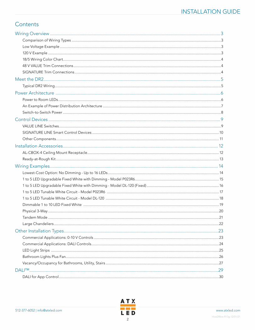
Contents
Wiring Overview ...............................................................................................................................................3Comparison of Wiring Types .........................................................................................................................................................3
Low Voltage Example .....................................................................................................................................................................3
120 V Example .................................................................................................................................................................................3
18/5 Wiring Color Chart..................................................................................................................................................................4
48 V VALUE Trim Connections .......................................................................................................................................................4
SIGNATURE Trim Connections ......................................................................................................................................................4
Meet the DR2 ....................................................................................................................................................5Typical DR2 Wiring ..........................................................................................................................................................................5
Power Architecture ..........................................................................................................................................6Power to Room LEDs .......................................................................................................................................................................6
An Example of Power Distribution Architecture .........................................................................................................................7
Switch-to-Switch Power ..................................................................................................................................................................8
Control Devices ................................................................................................................................................9VALUE LINE Switches ......................................................................................................................................................................9
SIGNATURE LINE Smart Control Devices ..................................................................................................................................10
Other Components ....................................................................................................................................................................... 11
Installation Accessories .................................................................................................................................. 12AL-CBOX-4 Ceiling Mount Receptacle .......................................................................................................................................12
Ready-at-Rough Kit .......................................................................................................................................................................13
Wiring Examples............................................................................................................................................. 14Lowest-Cost Option: No Dimming - Up to 16 LEDs ..................................................................................................................14
1 to 5 LED Upgradable Fixed White with Dimming - Model P023R6 ......................................................................................15
1 to 5 LED Upgradable Fixed White with Dimming - Model DL-120 (Fixed) ..........................................................................16
1 to 5 LED Tunable White Circuit - Model P023R6 ...................................................................................................................17
1 to 5 LED Tunable White Circuit - Model DL-120 ....................................................................................................................18
Dimmable 1 to 10 LED Fixed White ...........................................................................................................................................19
Physical 3-Way ...............................................................................................................................................................................20
Tandem Mode ...............................................................................................................................................................................21
Large Chandeliers .........................................................................................................................................................................22
Other Installation Types .................................................................................................................................23Commercial Applications: 0-10 V Controls ................................................................................................................................23
Commercial Applications: DALI Controls...................................................................................................................................24
LED Light Strips ............................................................................................................................................................................25
Bathroom Lights Plus Fan .............................................................................................................................................................26
Vacancy/Occupancy for Bathrooms, Utility, Stairs ....................................................................................................................27
DALI™..............................................................................................................................................................29DALI for App Control ....................................................................................................................................................................30
www.atxled.com512-377-6052 | [email protected]
INSTALLATION GUIDE
How2Wire R13g-12/01/213
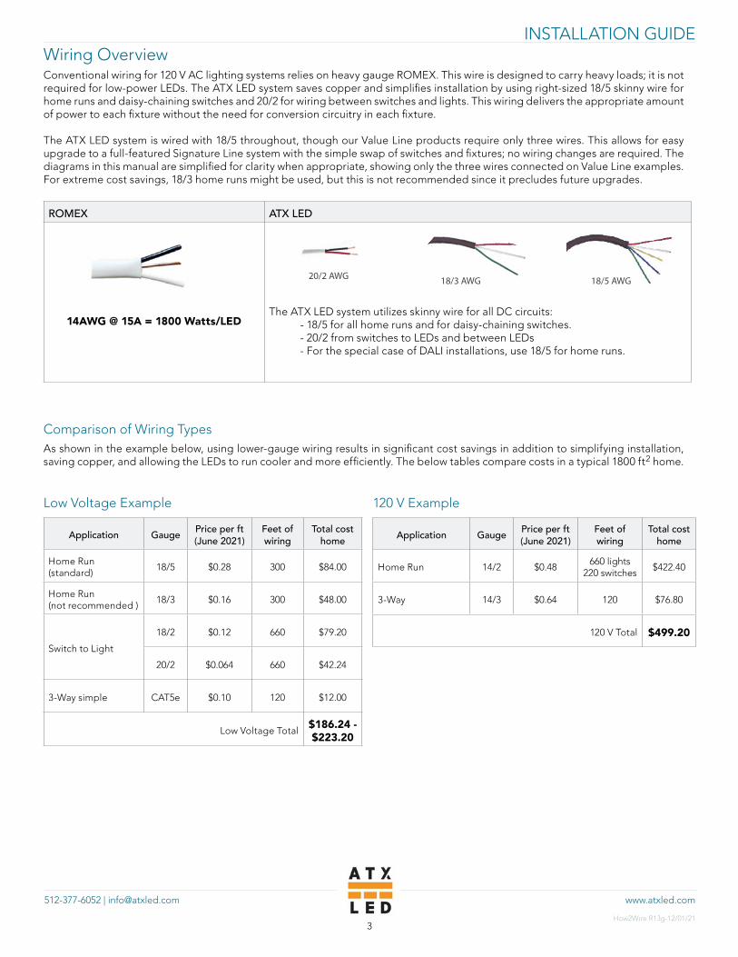
Wiring OverviewConventional wiring for 120 V AC lighting systems relies on heavy gauge ROMEX. This wire is designed to carry heavy loads; it is not required for low-power LEDs. The ATX LED system saves copper and simplifies installation by using right-sized 18/5 skinny wire for home runs and daisy-chaining switches and 20/2 for wiring between switches and lights. This wiring delivers the appropriate amount of power to each fixture without the need for conversion circuitry in each fixture.
The ATX LED system is wired with 18/5 throughout, though our Value Line products require only three wires. This allows for easy upgrade to a full-featured Signature Line system with the simple swap of switches and fixtures; no wiring changes are required. The diagrams in this manual are simplified for clarity when appropriate, showing only the three wires connected on Value Line examples. For extreme cost savings, 18/3 home runs might be used, but this is not recommended since it precludes future upgrades.
ROMEX ATX LED
14AWG @ 15A = 1800 Watts/LED
The ATX LED system utilizes skinny wire for all DC circuits: - 18/5 for all home runs and for daisy-chaining switches. - 20/2 from switches to LEDs and between LEDs - For the special case of DALI installations, use 18/5 for home runs.
Comparison of Wiring TypesAs shown in the example below, using lower-gauge wiring results in significant cost savings in addition to simplifying installation, saving copper, and allowing the LEDs to run cooler and more efficiently. The below tables compare costs in a typical 1800 ft2 home.
Low Voltage Example
Application Gauge Price per ft (June 2021)
Feet of wiring
Total cost home
Home Run (standard)
18/5 $0.28 300 $84.00
Home Run (not recommended )
18/3 $0.16 300 $48.00
Switch to Light
18/2 $0.12 660 $79.20
20/2 $0.064 660 $42.24
3-Way simple CAT5e $0.10 120 $12.00
Low Voltage Total$186.24 - $223.20
20/2 AWG
120 V Example
Application Gauge Price per ft (June 2021)
Feet of wiring
Total cost home
Home Run 14/2 $0.48660 lights
220 switches$422.40
3-Way 14/3 $0.64 120 $76.80
120 V Total $499.20
18/3 AWG 18/5 AWG

www.atxled.com512-377-6052 | [email protected]
INSTALLATION GUIDE
How2Wire R13g-12/01/214
18/5 Wiring Color Chart
Color Function Comment
Red Power to the Wall switches (48 to 52 V) Up to 100 Watts
Blue Return power
Green Earth ground for static discharge Detours static electricity from people to earth
White DALI bus (-) Polarity not significant
Yellow DALI bus (+) Polarity not significant
48 V VALUE Trim Connections
Color Wire Marking Function Comment
Red UP + voltage to the first LED in a string
White UP - voltage to the first LED in a string
Red DOWN + voltage to the last LED in a string Reserved for future use
White DOWN- voltage to the last LED in a string
Reserved for future use
SIGNATURE Trim Connections
Color Wire Marking Function Comment
Red UP + voltage to the first LED in a string Warm White +
White UP - voltage to the first LED in a string Cool White -
Red DOWN - voltage to the last LED in a string Warm White -
White DOWN+ voltage to the last LED in a string
Cool White +
Use blue tape to mark UP. DOWN is not marked.
www.atxled.com512-377-6052 | [email protected]
INSTALLATION GUIDE
How2Wire R13g-12/01/215
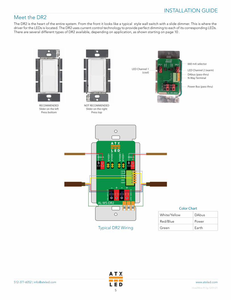
Meet the DR2The DR2 is the heart of the entire system. From the front it looks like a typical style wall switch with a slide dimmer. This is where the driver for the LEDs is located. The DR2 uses current control technology to provide perfect dimming to each of its corresponding LEDs. There are several different types of DR2 available, depending on application, as shown starting on page 10 .
LED Channel 1 (cool)
LED Channel 2 (warm)
660 mA selector
N-Way Terminal
Power Bus (pass thru)
Typical DR2 Wiring
+ -
DADADADAGNDNWAY
300mA + -300mA
+360mA
+60mA
+60mA
+360mA
24
V-5
6V
IN
24
V-5
6V
OU
T
+ +
AL-WS-DR2
- -
Color Chart
White/Yellow DAbus
Red/Blue Power
Green Earth
RECOMMENDEDSlider on the left
Press bottom
NOT RECOMMENDEDSlider on the right
Press top
DAbus (pass-thru)

www.atxled.com512-377-6052 | [email protected]
INSTALLATION GUIDE
How2Wire R13g-12/01/216
Power Architecture The system is powered by one or more 51 V AC/DC converters. There are two or more contained in the network panel. Only one is needed for each 100 Watts of load, but two are recommended for rendundancy. The AL-PSE-4D power distribution board is equipped with automatic fail-over, meaning that if a power supply fails, the AL-PSE-4D will automatically go to backup. Backup can also be a battery system. For houses over 3000 ft2, 350 and 500 Watt supplies are recommended. See the AL-DF10 or use multiple PSE-4Ds.
120 V AC in
Standard Media
EnclosureRedundantPower Supplies
16/2
AW
G
AL-
PSE-
4D
16/2
AW
G
Power to Room LEDsThis diagram shows an example arrangement of three wall switches controlling three separate zones of LEDs, all powered from the same home run. Each home run of the AL-PSE-4D (power distribution board) may carry up to 100 Watts. Due to DC line losses, however, it is recommended that only 15 of the 6 Watt LEDs be used in this manner.
Wall switch power may be daisy-chained, as long as the total power demand does not exceed 100 Watts. Again, it is important to consider line losses. Though the max DC power is 100 Watts per home run, 90 Watts of load is recommended. Please see “Typical DR2 Wiring” on page 5 for more detail on complete wiring.
120 V AC in
Standard Media
EnclosureRedundantPower Supplies
16/2
AW
G
AL-
PSE-
4D
16/2
AW
G
AL-WS-DR2
AL-WS-DR2
AL-WS-DR2
www.atxled.com512-377-6052 | [email protected]
INSTALLATION GUIDE
How2Wire R13g-12/01/217
AL-
PSE-
4D
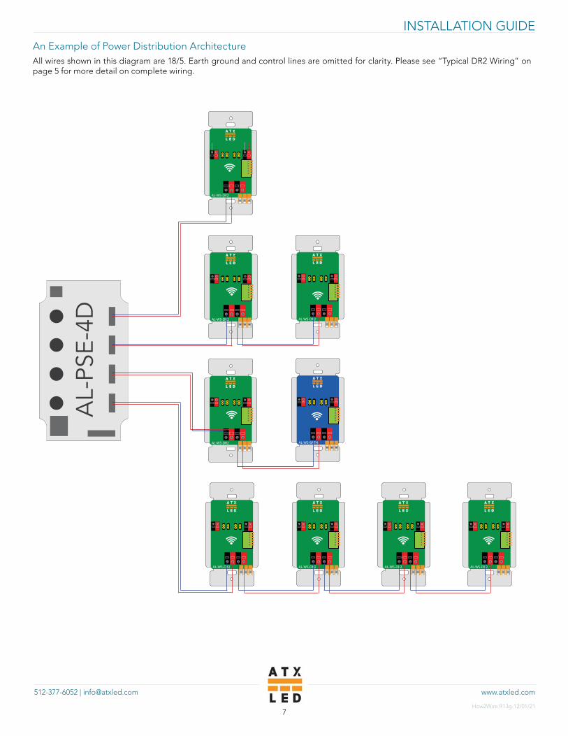
An Example of Power Distribution ArchitectureAll wires shown in this diagram are 18/5. Earth ground and control lines are omitted for clarity. Please see “Typical DR2 Wiring” on page 5 for more detail on complete wiring.
AL-WS-DR2
AL-WS-DR2 AL-WS-DR2
AL-WS-DR2
AL-WS-DR2
AL-WS-BATH
AL-WS-DR2 AL-WS-DR2 AL-WS-DR2

www.atxled.com512-377-6052 | [email protected]
INSTALLATION GUIDE
How2Wire R13g-12/01/218
Switch-to-Switch PowerATX LED switches can be daisy-chained as shown below. Control and ground are omitted for simplicity; please see “Typical DR2 Wiring” on page 5 for more detail on complete wiring.
AL-
PSE-
4D
18/5 AWG
AL-WS-DR2 AL-WS-DR2 AL-WS-DR2
DC

www.atxled.com512-377-6052 | [email protected]
INSTALLATION GUIDE
How2Wire R13g-12/01/219
Control DevicesVALUE LINE SwitchesThe following switches provide simple on/off control and smooth dimming and can be used with fixed-color true white LEDs from the Value Line.
Lighting Wattage Dimming N-way Capable Fan Tunable White
AL-WS-DR2C
24
V-5
6V
IN
24
V-5
6V
OU
T
+ +
--
AL-WS-DR2C
00=DUAL 01=FAN11= 4CCT10=8x
MODE
NWAYGNDPIR+
AL-WS-DR2C
- -
+ + 60 WattsFixed
30 WattsTunable
1% Yes Yes Yes
AL-WS-DR1
24
V-5
6V
IN
+
+
+
+--
-
-
LED
AL-WS-DR1
30 Watts 10% Yes No No
Simple Switch
96 Watts None Yes No No
www.atxled.com512-377-6052 | [email protected]
INSTALLATION GUIDE
How2Wire R13g-12/01/2110
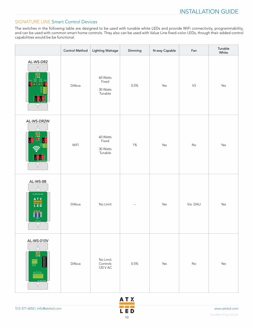
SIGNATURE LINE Smart Control DevicesThe switches in the following table are designed to be used with tunable white LEDs and provide WiFi connectivity, programmability, and can be used with common smart home controls. They also can be used with Value Line fixed-color LEDs, though their added control capabilities would be be functional.
Control Method Lighting Wattage Dimming N-way Capable Fan Tunable White
AL-WS-DR2
+ -
DADADADAGNDNWAY
300mA + -300mA
+360mA
+60mA
+60mA
+360mA
24
V-5
6V
IN
24
V-5
6V
OU
T
+ +
AL-WS-DR2
DAbus
60 WattsFixed
30 WattsTunable
0.5% Yes V3 Yes
AL-WS-DR2W
ON / OFF
CCT
24
V-5
6V
IN
24
V-5
6V
OU
T
+ +
--
NWAYGNDPIR+
AL-WS-DR2W
+ +
WiFi
60 WattsFixed
30 WattsTunable
1% Yes No Yes
AL-WS-8B
DAbus No Limit -- Yes Via DALI Yes
AL-WS-010V
GN
DN
WAY
GN
D0-
10v
BG
ND
0-10
v A
GN
DPW
M
DA
DA
DA
DA
AL-WS-010V
DAbusNo Limit Controls 120 V AC
0.5% Yes No Yes
AL-WS-DALI-8B
DALI
ATXLED.COM
www.atxled.com512-377-6052 | [email protected]
INSTALLATION GUIDE
How2Wire R13g-12/01/2111
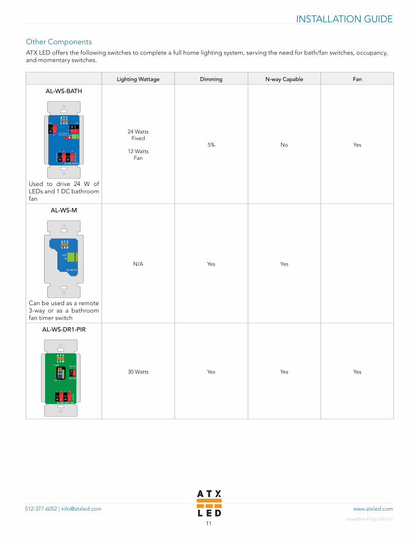
Other ComponentsATX LED offers the following switches to complete a full home lighting system, serving the need for bath/fan switches, occupancy, and momentary switches.
Lighting Wattage Dimming N-way Capable Fan
AL-WS-BATH
INDEPENDENTFAN SWITCH
24
V-5
6V
IN
24
V-5
6V
OU
T
+
+
+
+--
-
-
FANLED
AL-WS-BATH
Used to drive 24 W of LEDs and 1 DC bathroom fan
24 WattsFixed
12 Watts Fan
5% No Yes
AL-WS-M
OUTIN
AL-WS-M
Can be used as a remote 3-way or as a bathroom fan timer switch
N/A Yes Yes
AL-WS-DR1-PIR
+ -
+ +
AL-WS-DR1-PIR
44-5
2 V
660 mA
LED/FANDA + -
N-WAY
_ _
30 Watts Yes Yes Yes
www.atxled.com512-377-6052 | [email protected]
INSTALLATION GUIDE
How2Wire R13g-12/01/2112
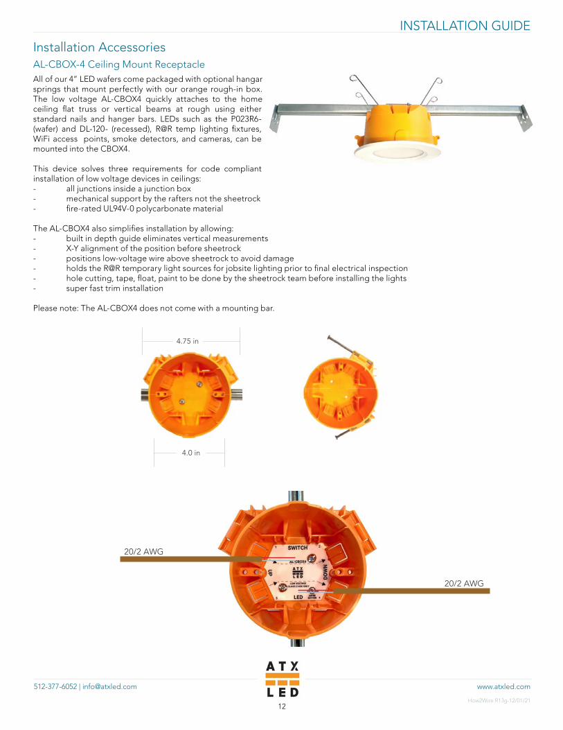
Installation AccessoriesAL-CBOX-4 Ceiling Mount ReceptacleAll of our 4” LED wafers come packaged with optional hangar springs that mount perfectly with our orange rough-in box. The low voltage AL-CBOX4 quickly attaches to the home ceiling flat truss or vertical beams at rough using either standard nails and hanger bars. LEDs such as the P023R6- (wafer) and DL-120- (recessed), R@R temp lighting fixtures, WiFi access points, smoke detectors, and cameras, can be mounted into the CBOX4.
This device solves three requirements for code compliant installation of low voltage devices in ceilings:- all junctions inside a junction box- mechanical support by the rafters not the sheetrock - fire-rated UL94V-0 polycarbonate material
The AL-CBOX4 also simplifies installation by allowing:- built in depth guide eliminates vertical measurements- X-Y alignment of the position before sheetrock- positions low-voltage wire above sheetrock to avoid damage- holds the R@R temporary light sources for jobsite lighting prior to final electrical inspection- hole cutting, tape, float, paint to be done by the sheetrock team before installing the lights - super fast trim installation
Please note: The AL-CBOX4 does not come with a mounting bar.
4.75 in
4.0 in
20/2 AWG
20/2 AWG

www.atxled.com512-377-6052 | [email protected]
INSTALLATION GUIDE
How2Wire R13g-12/01/2113
Ready-at-Rough KitATX LED’s Ready@Rough kit allows lighting installers to validate proper function of the lighting system prior to drywall installation and to cover and protect wiring during the rest of the buildout process. After the CBOX4 and electrical boxes for the switches are installed, lighting installers can use the corresponding components of the R@R “Work” and “Wall” kits to verify the lighting system and protect from accidental cuts during the rest of the buildout process.
Additionally, the included LED lighting works from the moment the wiring is installed and provides lighting for the jobsite during the weeks of finishing work. If a wire is cut during finishing work, the temporary R@R light goes out immediately, making it easy to identify and remedy problems as they arise.
− Protects wires from Rotozip tools, sheetrock mud, and paint
− Provides light during construction before sheetrock
− Verifies all wiring prior to sheetrock
− Saves time at trim
− Optional washable clear lens to allow reuse
− No deformation of the wires
Ceiling Ready-at-Rough Kit
Temporary LEDs
Cover Plate
AL-R@R Work – Temporary LED AL-R@R Wall – Temporary Switch
www.atxled.com512-377-6052 | [email protected]
INSTALLATION GUIDE
How2Wire R13g-12/01/2114
Connection Detail
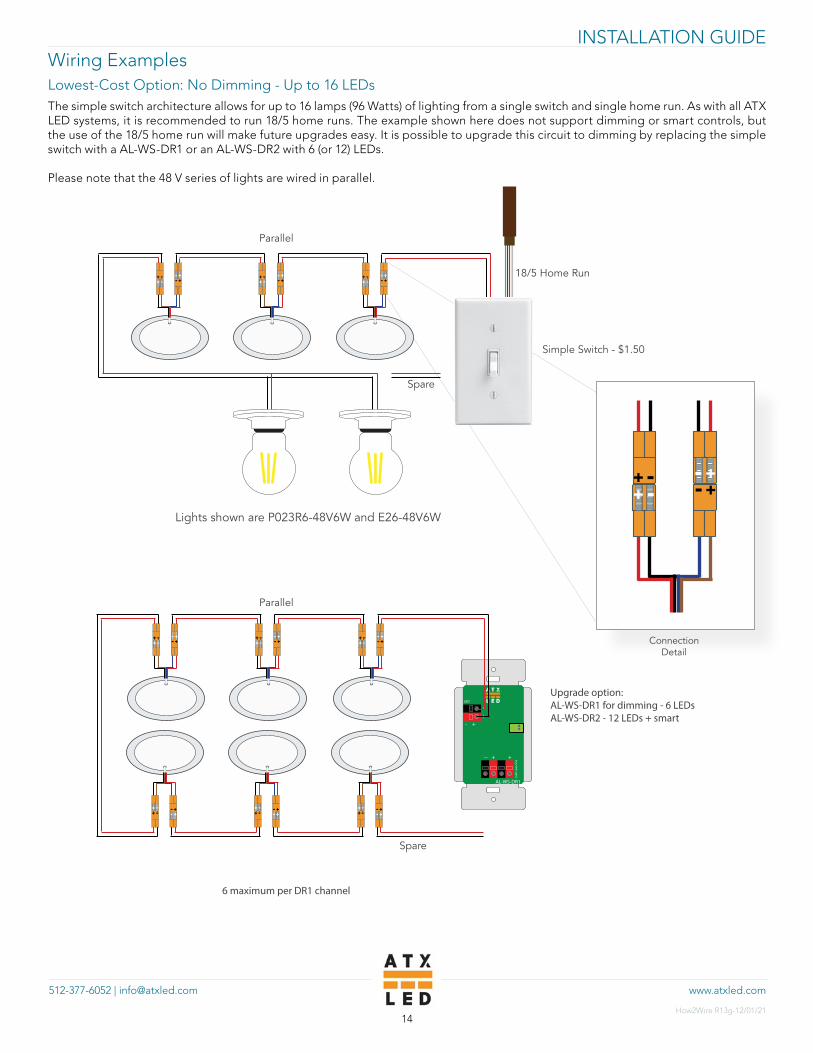
Wiring ExamplesLowest-Cost Option: No Dimming - Up to 16 LEDsThe simple switch architecture allows for up to 16 lamps (96 Watts) of lighting from a single switch and single home run. As with all ATX LED systems, it is recommended to run 18/5 home runs. The example shown here does not support dimming or smart controls, but the use of the 18/5 home run will make future upgrades easy. It is possible to upgrade this circuit to dimming by replacing the simple switch with a AL-WS-DR1 or an AL-WS-DR2 with 6 (or 12) LEDs.
Please note that the 48 V series of lights are wired in parallel.
18/5 Home Run
Lights shown are P023R6-48V6W and E26-48V6W
Simple Switch - $1.50
24
V-5
6V
IN
+
+
+
+--
-
-
LED
AL-WS-DR1
Upgrade option: AL-WS-DR1 for dimming - 6 LEDsAL-WS-DR2 - 12 LEDs + smart
Parallel
6 maximum per DR1 channel
+-
+-+-
+ -+-
+-+-
+ -+-
+-+-
+ -
Spare
+-
+-+-
+ -+-
+-+-
+ -+-
+-+-
+ -
+-+-+-
+ -+-+-+-
+ -+-+-+-
+ -
Spare
+-
+-+-
+ -
Parallel

www.atxled.com512-377-6052 | [email protected]
INSTALLATION GUIDE
How2Wire R13g-12/01/2115
1 to 5 LED Upgradable Fixed White with Dimming - Model P023R6If you might be interested in upgrading to Tunable White LEDs in your system in the future, wire it using this method. Run an additional (unconnected) 18/2 leg from the location of the last LED in the circuit to the available channel on the DR2.
+ -
DADADADAGNDNWAY
300mA + -300mA
+360mA
+60mA
+60mA
+360mA
24
V-5
6V
IN
24
V-5
6V
OU
T
+ +
AL-WS-DR2
660 mA
Series
Spare pair
for upgrades
+-
+-
+-
+-
+-
+ -
+-
+ -
Color Options2700K 3000K 3500 4000K 5000K
Connection Detail
+-
+ -

www.atxled.com512-377-6052 | [email protected]
INSTALLATION GUIDE
How2Wire R13g-12/01/2116
1 to 5 LED Upgradable Fixed White with Dimming - Model DL-120 (Fixed)If you might be interested in upgrading to Tunable White LEDs in your system in the future, wire it using this method. Run an additional (unconnected) 18/2 leg from the location of the last LED in the circuit to the available channel on the DR2.
+ -
DADADADAGNDNWAY
300mA + -300mA
+360mA
+60mA
+60mA
+360mA
24
V-5
6V
IN
24
V-5
6V
OU
T
+ +
AL-WS-DR2
Spare
-+
-+
-+
-+
UP
DOWN
Series
20/2
Color Options
2700K 3000K 3500K 4000K 5000K
TW C F C TW
www.atxled.com512-377-6052 | [email protected]
INSTALLATION GUIDE
How2Wire R13g-12/01/2117
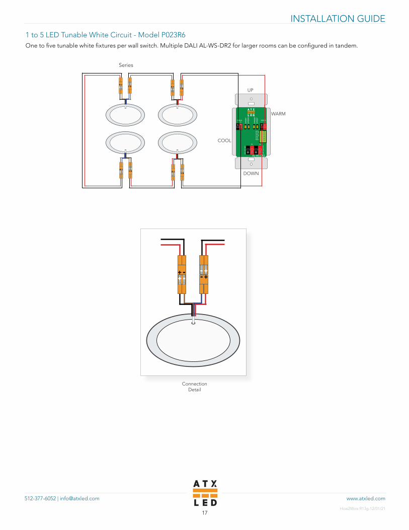
1 to 5 LED Tunable White Circuit - Model P023R6 One to five tunable white fixtures per wall switch. Multiple DALI AL-WS-DR2 for larger rooms can be configured in tandem.
+ -
DADADADAGNDNWAY
300mA + -300mA
+360mA
+60mA
+60mA
+360mA
24
V-5
6V
IN
24
V-5
6V
OU
T
+ +
AL-WS-DR2
UP
DOWN
Series
+-
+ - +-
+-+-
+-+-
+ -
+-
+-+-
+ - +-
+ - +-
+-
Connection Detail
+-
+ - +-
+-
WARM
COOL

www.atxled.com512-377-6052 | [email protected]
INSTALLATION GUIDE
How2Wire R13g-12/01/2118
1 to 5 LED Tunable White Circuit - Model DL-120 One to five tunable white fixtures per wall switch. Multiple DALI AL-WS-DR2 for larger rooms can be configured in tandem.
+ -
DADADADAGNDNWAY
300mA + -300mA
+360mA
+60mA
+60mA
+360mA
24
V-5
6V
IN
24
V-5
6V
OU
T
+ +
AL-WS-DR2
UP
DOWN
Series
20/2
2700- 5000+
2700+ 5000-
2700- 5000+
2700+ 5000-
5000- 2700-
5000+ 2700+5000- 2700-
5000+ 2700+

www.atxled.com512-377-6052 | [email protected]
INSTALLATION GUIDE
How2Wire R13g-12/01/2119
Dimmable 1 to 10 LED Fixed White The example below includes two seperate channels of 1 to 5 LEDs each. Each group of five is connected in series. The red (+) wire first connects to the positive connection of the first LED, then leaves from the negative connector and goes to the positive connector of the next. The idea is that you are making a single series circuit for each channel of LEDs.
18/5 Home Run20/2
Lights shown are P023R6-600mA and E26-660mA bulbs or E12-660mA
20/2
AL-WS-DR2
+-
+-+-
+-
+-
+ -+-
+ -
Series
+-
+ -
Connection Detail
Series
www.atxled.com512-377-6052 | [email protected]
INSTALLATION GUIDE
How2Wire R13g-12/01/2120
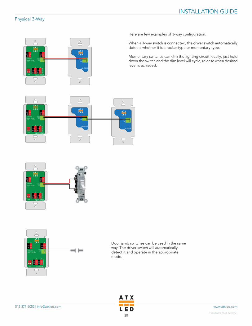
Physical 3-Way
Here are few examples of 3-way configuration.
When a 3-way switch is connected, the driver switch automatically detects whether it is a rocker type or momentary type.
Momentary switches can dim the lighting circuit locally, just hold down the switch and the dim level will cycle, release when desired level is achieved.
Door jamb switches can be used in the same way. The driver switch will automatically detect it and operate in the appropriate mode.
24
V-5
6V
IN
24
V-5
6V
OU
T
+ +
--
AL-WS-DR2C
00=DUAL 01=FAN11= 4CCT10=8x
MODE
NWAYGNDPIR+
AL-WS-DR2C
- -
+ +
OUTIN
AL-WS-M
24
V-5
6V
IN
24
V-5
6V
OU
T
+ +
--
AL-WS-DR2C
00=DUAL 01=FAN11= 4CCT10=8x
MODE
NWAYGNDPIR+
AL-WS-DR2C
- -
+ +
OUTIN
AL-WS-M
OUTIN
AL-WS-M
24
V-5
6V
IN
24
V-5
6V
OU
T
+ +
--
AL-WS-DR2C
00=DUAL 01=FAN11= 4CCT10=8x
MODE
NWAYGNDPIR+
AL-WS-DR2C
- -
+ +
24
V-5
6V
IN
24
V-5
6V
OU
T
+ +
--
AL-WS-DR2C
00=DUAL 01=FAN11= 4CCT10=8x
MODE
NWAYGNDPIR+
AL-WS-DR2C
- -
+ +

www.atxled.com512-377-6052 | [email protected]
INSTALLATION GUIDE
How2Wire R13g-12/01/2121
Tandem ModeLarge rooms typically have more than one entry point. A 3-way switch is typically used to allow the lights at each entry point, or door in a hallway, or level in a stairway, to control all the lights. The physical 3-Way switch documented in the previous section handles this very well and at low cost.
In situations where the lighting requirement exceeds the Watts available from one AL-WS-DR2, then Tandem mode is useful. In this mode, two or more DR2 switches operate in unison. The lights can be turned on and off, dimmed or the color changed as one. This mode requires a powered DAbus. The AL-WS-DR2 switches are configured either on-site or off-site for Tandem mode, also known as virtual 3-Way. Once configured, the tandem set of AL-WS-DR2 operate together as long as the DAbus has power - no internet or hub is required. Thus - any large space can be fully operate by DC lighting, in a low cost and simple setup.
+ -
DADADADAGNDNWAY
300mA + -300mA
+360mA
+60mA
+60mA
+360mA
24
V-5
6V
IN
24
V-5
6V
OU
T
+ +
AL-WS-DR2
+ -
DADADADAGNDNWAY
300mA + -300mA
+360mA
+60mA
+60mA
+360mA
24
V-5
6V
IN
24
V-5
6V
OU
T
+ +
AL-WS-DR2
www.atxled.com512-377-6052 | [email protected]
INSTALLATION GUIDE
How2Wire R13g-12/01/2122
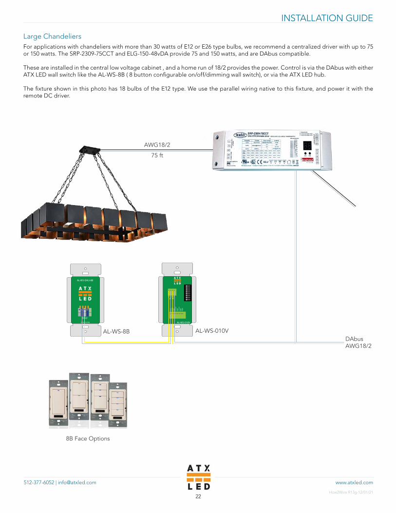
Large ChandeliersFor applications with chandeliers with more than 30 watts of E12 or E26 type bulbs, we recommend a centralized driver with up to 75 or 150 watts. The SRP-2309-75CCT and ELG-150-48vDA provide 75 and 150 watts, and are DAbus compatible.
These are installed in the central low voltage cabinet , and a home run of 18/2 provides the power. Control is via the DAbus with either ATX LED wall switch like the AL-WS-8B ( 8 button configurable on/off/dimming wall switch), or via the ATX LED hub.
The fixture shown in this photo has 18 bulbs of the E12 type. We use the parallel wiring native to this fixture, and power it with the remote DC driver.
AL-WS-DALI-8B
DALI
ATXLED.COM
GN
DN
WAY
GN
D0-
10v
BG
ND
0-10
v A
GN
DPW
M
DA
DA
DA
DA
AL-WS-010V
AL-WS-8B AL-WS-010VDAbusAWG18/2
AWG18/2
75 ft
8B Face Options

www.atxled.com512-377-6052 | [email protected]
INSTALLATION GUIDE
How2Wire R13g-12/01/2123
Other Installation TypesCommercial Applications: 0-10 V ControlsOur DR2 delivers 50 Watts per switch. Some cases, however, call for much more lighting power per switch.
High power lighting products are powered by AC. Manufacturers offer control by 0-10v violet and grey wire pair. This pair is used to control the on/off/dim functions of the lamp.
To interface this type of fixture with the ATX-LED system, simply wire the 120v power as with conventional, but run the violet/grey pair to our AL-WS-010v switch.
Please note that “0-10v” is a classification of dimming method. There are actually two sub-types of “0-10v.” One being the “0-10v” and the other being “1-10v.” The difference is that with 0-10v fixtures, the switch can only dim the lamp, whereas with a 1-10v fixture the switch can completely shut off the lamp. If 0-10v fixtures are being used, there will have to be a 120v switch to completely shut off the lighting. Therefore, use 1-10v only.
Multiple 0-10 V Fixtureswith 120 V AC300 Watts total
AL-WS-DALI-8B
DALI
ATXLED.COM
GN
DN
WAY
GN
D0-
10v
BG
ND
0-10
v A
GN
DPW
M
DA
DA
DA
DA
AL-WS-010V
AL-WS-8B AL-WS-010V
Purple: 0-10 V+Gray: 0-10 V –
DAbusAWG18/2
120 V AC line
DAbusAWG18/2
8B Face Options
www.atxled.com512-377-6052 | [email protected]
INSTALLATION GUIDE
How2Wire R13g-12/01/2124
AL-WS-DALI-8B
DALI
ATXLED.COM
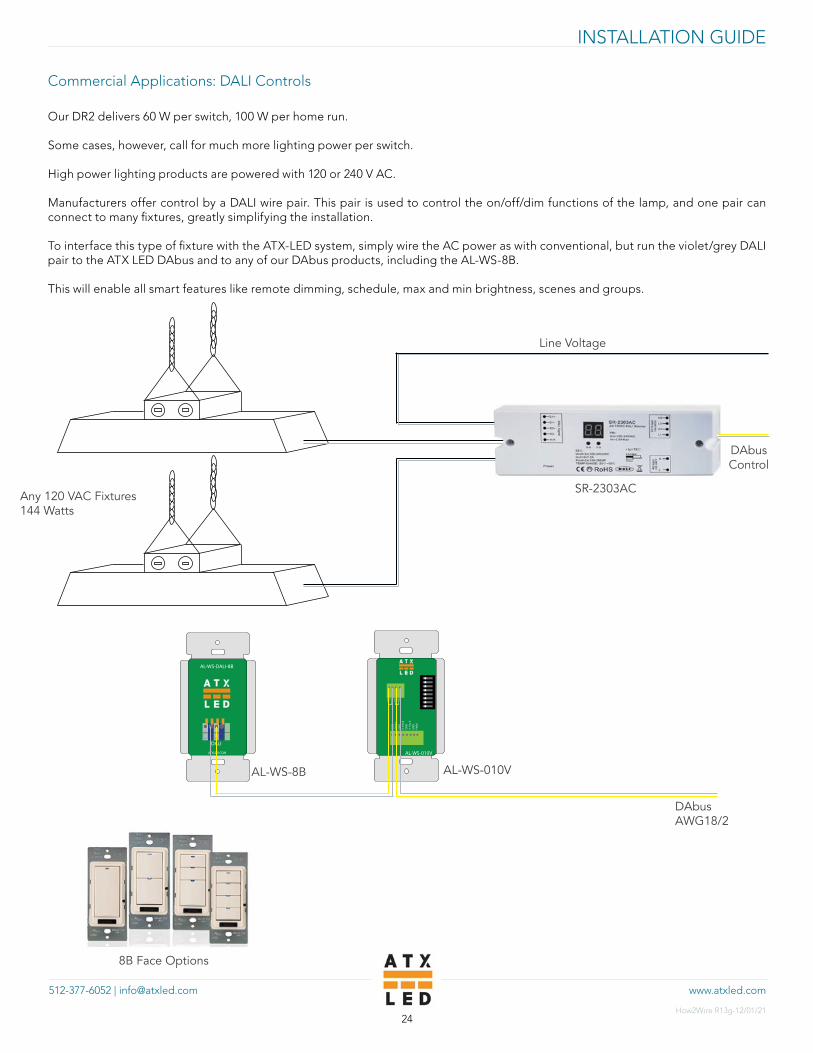
Commercial Applications: DALI Controls
Our DR2 delivers 60 W per switch, 100 W per home run.
Some cases, however, call for much more lighting power per switch.
High power lighting products are powered with 120 or 240 V AC.
Manufacturers offer control by a DALI wire pair. This pair is used to control the on/off/dim functions of the lamp, and one pair can connect to many fixtures, greatly simplifying the installation.
To interface this type of fixture with the ATX-LED system, simply wire the AC power as with conventional, but run the violet/grey DALI pair to the ATX LED DAbus and to any of our DAbus products, including the AL-WS-8B.
This will enable all smart features like remote dimming, schedule, max and min brightness, scenes and groups.
SR-2303AC
DAbus Control
8B Face Options
GN
DN
WAY
GN
D0-
10v
BG
ND
0-10
v A
GN
DPW
MD
AD
AD
AD
A
AL-WS-010V
AL-WS-8B AL-WS-010V
DAbus AWG18/2
Any 120 VAC Fixtures144 Watts
Line Voltage

www.atxled.com512-377-6052 | [email protected]
INSTALLATION GUIDE
How2Wire R13g-12/01/2125
LED Light Strips Wire strip lights to any of our DR2 switches in a similar manner to our other LEDs. 24v strip lights are the most common on the market and they work well with DR2s. Take care to follow the wattage rules - 24watts per channel. For fixed color, used up to 8ft or 24 watts on each channel. For Tunable White, use 2 different color temperature strips of your choice and wire it the same way, but with the selecter on the switch set to “CCT”.
Strip Light OptionsA) 2 W/ft, up to 30 ft fixed or 15 ft tunableB) 4 W/ft, up to 15 ft fixed pr 7.5 tunableC) Use tandem mode for longer runsD) 1.5 W/ft, 24 V - See Application NoteE) 3 W/ft, up to 20 ft fixed or 10 ft tunable
24
V-5
6V
IN
24
V-5
6V
OU
T
+ +
--
AL-WS-DR2C
00=DUAL 01=FAN11= 4CCT10=8x
MODE
NWAYGNDPIR+
AL-WS-DR2C
- -
+ +
-+ -+
Fixed color temp
18”
Spare
Spare Spare7”
9”
12”
24
V-5
6V
IN
24
V-5
6V
OU
T
+ +
--
AL-WS-DR2C
00=DUAL 01=FAN11= 4CCT10=8x
MODE
NWAYGNDPIR+
AL-WS-DR2C
- -
+ +
-+
Tunable white

www.atxled.com512-377-6052 | [email protected]
INSTALLATION GUIDE
How2Wire R13g-12/01/2126
Bathroom Lights Plus Fan
Either the AL-WS-DR2 or AL-WS-Bath are used for bathrooms. They have the capability of running a 12 V DC bathroom fan and up to 24 Watts of LEDs. The switch may be used standalone or with a AL-WS-M remote switch.
When the remote switch is used, every time the momentary switch is engaged, the bath fan will run for 5 minutes and an additional 5 minutes will be added for each button press. Press and hold the switch for 10 seconds to cancel the timer and shut off the fan.
INDEPENDENTFAN SWITCH
24
V-5
6V
IN
24
V-5
6V
OU
T
+
+
+
+--
-
-
FANLED
AL-WS-BATH
OUTIN
AL-WS-M
+-
Optional remote switch can be used as a fan timer
www.atxled.com512-377-6052 | [email protected]
INSTALLATION GUIDE
How2Wire R13g-12/01/2127
+ -
+ +
AL-WS-DR1-PIR
44-5
2 V
660 mA
LED/FANDA + -
N-WAY
_ _
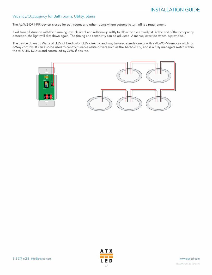
Vacancy/Occupancy for Bathrooms, Utility, Stairs
The AL-WS-DR1-PIR device is used for bathrooms and other rooms where automatic turn off is a requirement.
It will turn a fixture on with the dimming level desired, and will dim up softly to allow the eyes to adjust. At the end of the occupancy detection, the light will dim down again. The timing and sensitivity can be adjusted. A manual override switch is provided.
The device drives 30 Watts of LEDs of fixed color LEDs directly, and may be used standalone or with a AL-WS-M remote switch for 3-Way controls. It can also be used to control tunable white drivers such as the AL-WS-DR2, and is a fully managed switch within the ATX LED DAbus and controlled by ZWD if desired.
www.atxled.com512-377-6052 | [email protected]
INSTALLATION GUIDE
How2Wire R13g-12/01/2128
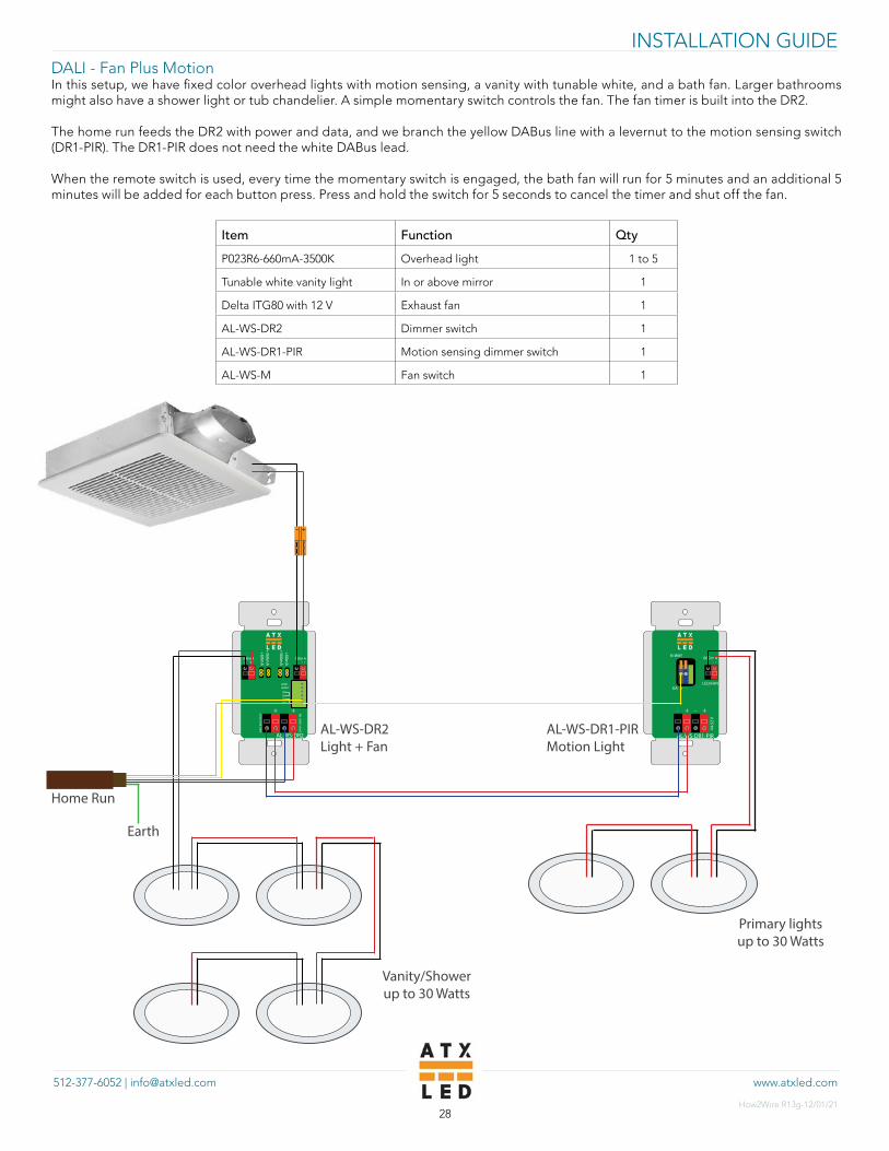
DALI - Fan Plus Motion In this setup, we have fixed color overhead lights with motion sensing, a vanity with tunable white, and a bath fan. Larger bathrooms might also have a shower light or tub chandelier. A simple momentary switch controls the fan. The fan timer is built into the DR2.
The home run feeds the DR2 with power and data, and we branch the yellow DABus line with a levernut to the motion sensing switch (DR1-PIR). The DR1-PIR does not need the white DABus lead.
When the remote switch is used, every time the momentary switch is engaged, the bath fan will run for 5 minutes and an additional 5 minutes will be added for each button press. Press and hold the switch for 5 seconds to cancel the timer and shut off the fan.
Item Function Qty
P023R6-660mA-3500K Overhead light 1 to 5
Tunable white vanity light In or above mirror 1
Delta ITG80 with 12 V Exhaust fan 1
AL-WS-DR2 Dimmer switch 1
AL-WS-DR1-PIR Motion sensing dimmer switch 1
AL-WS-M Fan switch 1
Earth
+ -
DADADADA
GNDNWAY
300mA + -300mA
+360mA
+60mA
+60mA
+360mA
24
V-5
6V
IN
24
V-5
6V
OU
T
+ +
AL-WS-DR2
+ -
+ +
AL-WS-DR1-PIR
44-5
2 V
660 mA
LED/FANDA + -
N-WAY
_ _
AL-WS-DR2Light + Fan
Home Run
+-
Vanity/Showerup to 30 Watts
Primary lightsup to 30 Watts
AL-WS-DR1-PIRMotion Light
www.atxled.com512-377-6052 | [email protected]
INSTALLATION GUIDE
How2Wire R13g-12/01/2129
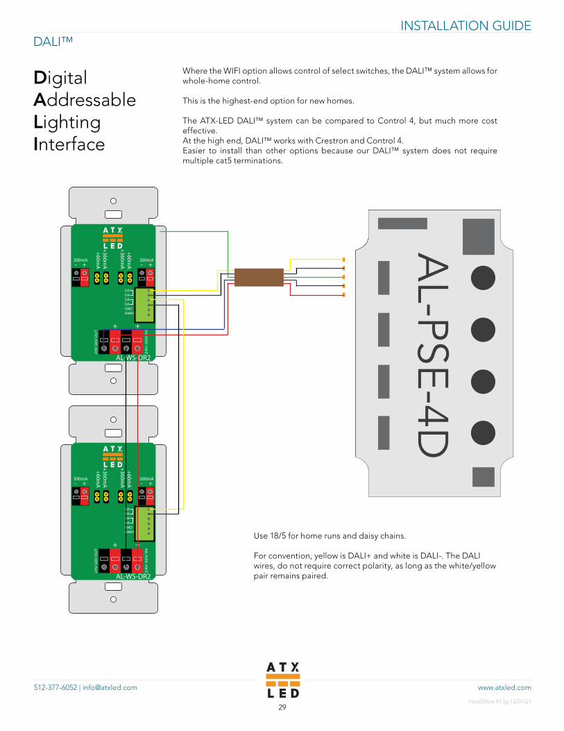
DALI™
DigitalAddressableLightingInterface
Where the WIFI option allows control of select switches, the DALI™ system allows for whole-home control.
This is the highest-end option for new homes.
The ATX-LED DALI™ system can be compared to Control 4, but much more cost effective.At the high end, DALI™ works with Crestron and Control 4.Easier to install than other options because our DALI™ system does not require multiple cat5 terminations.
Use 18/5 for home runs and daisy chains.
For convention, yellow is DALI+ and white is DALI-. The DALI wires, do not require correct polarity, as long as the white/yellow pair remains paired.
+ -
DADADADAGNDNWAY
300mA + -300mA
+360mA
+60mA
+60mA
+360mA
24
V-5
6V
IN
24
V-5
6V
OU
T
+ +
AL-WS-DR2
AL-PSE-4D
+ -
DADADADAGNDNWAY
300mA + -300mA
+360mA
+60mA
+60mA
+360mA
24
V-5
6V
IN
24
V-5
6V
OU
T
+ +
AL-WS-DR2

www.atxled.com512-377-6052 | [email protected]
INSTALLATION GUIDE
How2Wire R13g-12/01/2130
DALI for App ControlDALI power architecture is similar to that of the standard system, with just a few differences. In this case, we use the AL-PSE-4D as our power distribution board. The “brain” of the system, the AL-DALI-Pi, is connected directly to the AL-PSE-4D via a non-Ethernet RJ-45 jumper connection.
DALI as a DIIA trademark for the IEC62386 standard. For more information, please visit https://atxled.wiki.zoho.com/public/ZWD-Control-Suite.html.
+ -
DADADADAGNDNWAY
300mA + -300mA
+360mA
+60mA
+60mA
+360mA
24
V-5
6V
IN
24
V-5
6V
OU
T
+ +
AL-WS-DR2
AL-PSE-4D
ATX LEDHUB
ETHERNET USB USB
TO ROUTER

Related Documents