057KA–02 05–638 – DIAGNOSTICS COMBINATION METER 803 AuthorĂ: DateĂ: 2004 COROLLA (RM1037U) COMBINATION METER HOW TO PROCEED WITH TROUBLESHOOTING 1 Vehicle Brought to Workshop 2 Customer Problem Analysis (See page 05–639) 3 Problem Symptom Confirmation (See page 05–647) 4 Circuit Inspection (See page 05–648 – 05–668) 5 Repair or Replace 6 Confirmation Test 7 End

Welcome message from author
This document is posted to help you gain knowledge. Please leave a comment to let me know what you think about it! Share it to your friends and learn new things together.
Transcript

057KA–02
05–638–DIAGNOSTICS COMBINATION METER
803Author: Date:
2004 COROLLA (RM1037U)
COMBINATION METERHOW TO PROCEED WITH TROUBLESHOOTING
1 Vehicle Brought to Workshop
2 Customer Problem Analysis (See page 05–639)
3 Problem Symptom Confirmation (See page 05–647)
4 Circuit Inspection (See page 05–648 – 05–668)
5 Repair or Replace
6 Confirmation Test
7 End

057KB–02
I30045
COMBINATION METER Check Sheet Inspector’s name:
Customer’s Name
Date of VehicleBrought in
Registration Year
Frame No.
Registration No.
Odometer Reading KmMile
Date Problem First Occurred
How Often Problem Occurs Continuous Intermittent ( Times a day)
Malfunction in tachometer
Fine Cloudy Snowy OtherWeather
Temperature
Pro
blem
Sym
ptom
Approx.
Gau
ge
Malfunction in speedometer
Malfunction in fuel receiver gauge
Malfunction in water temperature receivergauge
Buz
zer
Key unlock warning buzzer does not sound
Light auto–turn off warning buzzer does not sound
Malfunction in driver’s seat belt warning buzzer
All buzzers do not sound
–DIAGNOSTICS COMBINATION METER05–639
804Author: Date:
2004 COROLLA (RM1037U)
CUSTOMER PROBLEM ANALYSIS CHECK

057KC–02
I32723
Brake Fluid Level Warning Switch
Combination Meter
Front Door Courtesy Switch
Engine Room J/B, R/B DOME Fuse
Fuel Sender Gauge
Rear Door Courtesy Switch
05–640–DIAGNOSTICS COMBINATION METER
805Author: Date:
2004 COROLLA (RM1037U)
LOCATION

I32724
Passenger Seat Belt WarningLight Assembly
Transmission Control Switch
Key Unlock Warning Switch
ECM
Parking Brake Switch
Separate Type Front Seat Cushion Pad
Front Seat Belt Inner Belt (Passenger’s)
Front Seat Belt Inner Belt (Driver’s)
RH J/B
Center J/B
Instrument Panel J/B GAUGE Fuse AM1 Fuse
–DIAGNOSTICS COMBINATION METER05–641
806Author: Date:
2004 COROLLA (RM1037U)

I30037
05–642–DIAGNOSTICS COMBINATION METER
807Author: Date:
2004 COROLLA (RM1037U)

I32739
28
1317
1
39
31
33336
35
34
23
32
10
4
5
246
14
18
2
20
8
111216
722
269
19
30
37
21
25
D–BELT
FUEL WRN
LCD
OUTSIDE TEMP
BUZZER
WASHER LEVEL (Canada)
CRUISE
DOOR
BEAM–
I/F I/F
I/F
I/F
I/F
I/F
I/F
I/F
I/FI/F
CPU
CHG
CHK E/G
O/D OFF
BRAKE
ABS
OIL P
AIR BAG
TEMP
FUEL
TACHO
SPEED
LCD
ODO/TRIP
TURN L
TURN R
–DIAGNOSTICS COMBINATION METER05–643
808Author: Date:
2004 COROLLA (RM1037U)

C9
Terminal No. Wire harness side
1
2
3
4
5
7
8
9
10
13
14
15
16
17
18
19
20
21
22
23
24
25
31
32
33
35
36
GAUGE Fuse
ECM
Tail Relay (USA), Combination Switch (Canada)
Fuel sender gauge
Ground (Signal Ground)
DOME Fuse
Turn Signal Flasher
Skid Control ECU with Actuator (w/ ABS), Ground (w/o ABS)
Cruise Control ECU, ECM
Ground (Power Ground)
HEAD RH UPR Fuse
Driver Side Courtesy Switch
Skid Control ECU (w/ ABS), Vehicle Speed Control Sensor (w/o ABS)
Cruise Control ECU
Alternator
37
38
39
40
GAUGE Fuse
ECM
Ground
–
Unlock Warning Switch
ECM
Except Driver Side Courtesy Switch
Engine Oil Pressure Switch
Fuel sender gauge
Turn Signal Flasher
ECM
Brake Fluid Level Warning Switch
–
Airbag Sensor Assembly
–
34
28
26
30
12
11
6 Front Passenger Seat Belt Warning Indicator
Buckle Switch RH
Buckle Switch LH
Skid Control ECU with Actuator (w/ ABS), Ground (w/o ABS)
Washer Level Sensor (Canada)
Ambient Temperature Sensor
Ambient Temperature Sensor
Rheostat
05–644–DIAGNOSTICS COMBINATION METER
809Author: Date:
2004 COROLLA (RM1037U)

057KD–04
I32850
20 19 18 17 16 15 14 13 12 11 10 9 8 7 6 5 4 3 2 1
40 39 38 37 36 35 34 33 32 31 30 29 28 27 26 25 24 23 22 21
C9
–DIAGNOSTICS COMBINATION METER05–645
810Author: Date:
2004 COROLLA (RM1037U)
TERMINALS OF ECU
Terminals No. (Symbols) Wiring Color Condition STD Voltage (V)
1 ↔ Body ground(SIGNAL EARTH ↔ Bodyground)
BR Constant Continuity
2 ↔ Body ground(POWER EARTH ↔ Bodyground)
W–B Constant Continuity
3 ↔ Body ground(O/D ↔ Body ground)
LG O/D off indicator light ON → OFF Below 1V → 10 – 14 V
4 ↔ Body ground(IG1+ ↔ Body ground)
R–W Ignition switch OFF or ACC → ON Below 1V → 10 – 14 V
5 ↔ Body ground(+B ↔ Body ground)
L–W Constant 10 – 14 V
6 ↔ Body ground(P–BELT OUT ↔ Body ground)
L Passenger seat belt warning ON → OFF Below 1V ↔ 10 – 14 V
7 ↔ Body ground(FUEL ↔ Body ground)
Y Fuel level is full → empty Below 1V → 4 – 7 V
8 ↔ Body ground(TEMP ↔ Body ground)
Y–R Ignition switch ON Pulse generation
9 ↔ Body ground(SP IN ↔ Body ground)
W–G Ignition switch ON and slowly turn drive wheel Below 1 V ↔ 10 – 14 V
10 ↔ Body ground(4P OUT ↔ Body ground)
V–W Ignition switch ON and slowly turn drive wheel Below 1 V ↔ 10 – 14 V
11 ↔ Body groundL W
Ignition switch ON and passenger seat belt buckle switch ON(Belt unfastened)
Below 1 V11 ↔ Body ground(P BELT SW ↔ Body ground)
L–WIgnition switch ON and passenger seat belt buckle switch OFF(Belt fastened)
10 – 14 V
12 ↔ Body groundG Y
Ignition switch ON and driver seat belt buckle switch ON (Beltunfastened)
Below 1 V12 ↔ Body ground(D BELT SW ↔ Body ground)
G–YIgnition switch ON and driver seat belt buckle switch OFF (Beltfastened)
10 – 14 V
13 ↔ Body ground(BEAM– ↔ Body ground)
W–B Hi beam indicator light ON → OFF Below 1V → 10 – 14 V
14 ↔ Body ground(BEAM+ ↔ Body ground)
R Constant 10 – 14 V

05–646–DIAGNOSTICS COMBINATION METER
811Author: Date:
2004 COROLLA (RM1037U)
16 ↔ Body groundL B
Ignition key inserted Below 1 V16 ↔ Body ground(KEY SW ↔ Body ground)
L–BNo ignition key inserted 10 – 14 V
17 ↔ Body ground(D DOOR ↔ Body ground)
R–W Driver door opened → closed Below 1V → 10 – 14 V
18 ↔ Body ground(ILL+ ↔ Body ground)
G Tail light switch OFF → ON Below 1V → 10 – 14 V
19 ↔ Body ground(TACHO ↔ Body ground)
B Engine running Pulse generation
20 ↔ Body ground(EXCEPT D DOOR ↔ Bodyground)
R Passenger door opened → closed Below 1V → 10 – 14 V
21 ↔ Body ground(OIL P ↔ Body ground)
W Oil pressure warning light ON → OFF Below 1V → 10 – 14 V
22 ↔ Body ground(FUEL EARTH ↔ Body ground)
BR Constant Continuity
23 ↔ Body ground(CRUISE ↔ Body ground)
G–R Ignition switch ON and cruise indicator light ON → OFF Below 1V → 10 – 14 V
24 ↔ Body ground(TURN L ↔ Body ground)
G–B Left turn indicator light OFF → ON Below 1V → 10 – 14 V
25 ↔ Body ground(TURN R ↔ Body ground)
G–Y Right turn indicator light OFF → ON Below 1V → 10 – 14 V
26 ↔ 30(OUT SIDE TEMP+ ↔ OUTSIDE TEMP–)
B – B–L Outside temperature at +25C (77F) 1.6 – 1.8KΩ
28 ↔ Body ground(ILL– ↔ Body ground)
W–R Ignition switch On and light control rheostat volume minimum No voltage
31 ↔ Body ground(CHG– ↔ Body ground)
Y Discharge indicator light OFF → ON Below 1V → 10 – 14 V
32 ↔ Body ground(IG2 ↔ Body ground)
B–O Ignition switch OFF → ON Below 1V → 10 – 14 V
33 ↔ Body ground(CHK ENG ↔ Body ground)
R–Y Malfunction indicator light ON → OFF Below 1V → 10 – 14 V
34 ↔ Body ground(WASHER LEVEL ↔ Bodyground)
* L–W Washer level indicator light ON → OFF Below 1V → 10 – 14 V
35 ↔ Body ground(BRAKE LEVEL SW ↔ Bodyground)
R–W Ignition switch ON and brake fluid level warning light ON → OFF Below 1V → 10 – 14 V
36 ↔ Body ground(EBD ↔ Body ground)
R Brake warning light ON → OFF 4 – 8 V → Below 1V
37 ↔ Body ground(ABS ↔ Body ground)
W–R ABS warning light ON → OFF 4 – 8 V → Below 1V
39 ↔ Body ground(A/B ↔ Body ground)
B–Y A/B warning light ON → OFF Below 1V → 6 – 11 V
*: Canada

057KE–02
–DIAGNOSTICS COMBINATION METER05–647
812Author: Date:
2004 COROLLA (RM1037U)
PROBLEM SYMPTOMS TABLESymptom Suspect Area See page
Entire combination meter does not operate.
3. Fuse
4. Wire–harness and connector
5. Combination meter assembly
05–648
Malfunction in speed meter.
1. Brake system
2. Wire–harness and connector
3. Combination meter assembly
05–650
Malfunction in tacho meter.
1. ECM
2. Wire–harness and connector
3. Combination meter assembly
05–653
Malfunction in fuel receiver gauge.
1. Fuel sender gauge
2. Wire–harness and connector
3. Combination meter assembly
05–655
Malfunction in water temperature gauge.
1. ECM
2. Wire–harness and connector
3. Combination meter assembly
05–657
”Key unlock warning bozzer” or ”Light auto turn off warning buzz-er” does not operate.
1. Front door courtesy switch
2. Key unlock warning switch
3. Wire–harness and connector
4. Combination meter assembly
05–659
Driver seat belt warning buzzer does not sound.
1. Driver seat belt buckle switch
2. Wire–harness and connector
3. Combination meter assembly
05–663
Seat belt warning lamp for front passenger seat does not flash.
1. Front seat inner belt assembly
2. Separate type front seat cushion pad
3. Combination meter assembly
4. Passenger seat belt warning light assembly
05–663
Malfunction in clock.
1. Fuse
2. Wire–harness and connector
3. Clock assembly
05–666
The ambient temperature does not display.
1. Fuse
2. Wire–harness and connector
3. Ambient temperature sensor
05–668

I32767
4C
16
Combination Meter
IG1
+B
POWEREARTH
C9R–W
RH J/BInstrument Panel J/B
I10 Ignition Switch
Engine Room J/B, R/B
Battery
C9
C9
L–W
W–B
3B
4B
4C
3B
4B
19
18
22
20
21
R–W
L–W
IG2
IL4
IF4
IB1AM1
IG1 Relay GAUGE
2
3
1
5IA1
IC7
IF2
IF12
W
B–Y
W
Center J/B
W–B
W–B
AM1IG12 1
W
ALT
DOME
2 1
2 1
1C
1
1D1
1A1
B
FL MAIN
IE
AA
J6J/C
L–W
4
5
2
1
05–648–DIAGNOSTICS COMBINATION METER
813Author: Date:
2004 COROLLA (RM1037U)
ENTIRE COMBINATION METER DOES NOT OPERATE
WIRING DIAGRAM
INSPECTION PROCEDERE
1 CHECK FUSE
(a) Check that continuity exists of DOME fuse.(b) Check that continuity exists of GAUGE fuse.(c) Check that continuity exists of AM1 fuse.
NG REPLACE FUSE
OK
057T2–02

I32115
POWER EARTH
I32115
IG1+B
–DIAGNOSTICS COMBINATION METER05–649
814Author: Date:
2004 COROLLA (RM1037U)
2 INSPECT COMBINATION METER ASSY
(a) Check continuity.(1) Disconnect the ”C9” connector from combination
meter assy.(2) Check continuity between terminal C9–2 of com-
bination meter assy connector and body ground.OK: Continuity exists
(b) Check voltage.(1) Disconnect the ”C9” connector from combination
meter assy.(2) Measure voltage between terminal C9–5 of com-
bination meter assy connector and body ground.Voltage: 10 – 14 V(3) Turn the ignition switch to ON.(4) Measure voltage between terminal C9–4 of com-
bination meter assy connector and body ground.Voltage: 10 – 14 V
NG REPAIR OR REPLACE HARNESS ORCONNECTOR
OK
CHECK AND REPLACE COMBINATION METER ASSY

I32764
Combination Meter
C99
W–G
(*1)V13
SP1
Vehicle Speed Sensor
Skid Control ECU with Actuator
S117
SP1W–G
*1: w/o ABS*2: w/ ABS
(*2)IA614
SP IN
W–G
II24
W–GW–G(*1)
(*2)
I30040
SP IN
10 – 14V
0 Turn the wheel
05–650–DIAGNOSTICS COMBINATION METER
815Author: Date:
2004 COROLLA (RM1037U)
MALFUNCTION IN SPEEDOMETER
WIRING DIAGRAM
INSPECTION PROCEDURE
1 CHECK COMBINATION METER ASSY
(a) Remove the combination meter assy with connector stillconnected.
(b) Check voltage.(1) Jack up either of the front wheels.(2) Shift the shift lever to neutral.(3) Turn the ignition switch to ON.(4) Measure the voltage between terminals C9–9 of
combination meter assy and body ground whenfront wheel is turning slowly.
Standard voltage:Voltage is generated intermittently.
057KG–04

–DIAGNOSTICS COMBINATION METER05–651
816Author: Date:
2004 COROLLA (RM1037U)
Result:A B C
OK NG (w/ ABS) NG (w/o ABS)
B Go to step 2
C Go to step 3
A
CHECK AND REPLACE COMBINATION METER ASSY
2 CHECK OBD II SCAN TOOL OR HAND–HELD TESTER
(a) Check output value of skid control ECU.(1) Connect the hand–held tester to DLC3.(2) Turn the ignition switch to ON and push the hand–held tester main switch ON.(3) Select the DATA LIST mode on the hand–held tester.(4) Check that there is no difference between the speed value output from the speed sensor dis-
played by the hand–held tester and the speed value displayed by the speedometer when drivingthe vehicle.
OK: There is almost no difference from the displayed speed value.
NG GO TO BRAKE SYSTEM
OK
REPAIR OR REPLACE HARNESS OR CONNECTOR

I31248
10 – 14V
0 Turn the wheel
05–652–DIAGNOSTICS COMBINATION METER
817Author: Date:
2004 COROLLA (RM1037U)
3 INSPECT SPEEDOMETER SENSOR
(a) Check voltage.(1) Shift the shift lever to neutral.(2) Jack up either of the front wheel.(3) Turn the ignition switch to ON.(4) Measure voltage between terminals 3 and 2 of
speed sensor when the front wheel is turning slowly.Standard voltage:Voltage is generated intermittently.
NG CHECK AND REPLACE SPEEDOMETERSENSOR
OK
REPAIR OR REPLACE HARNESS OR CONNECTOR

I32725
Combination Meter
C919
E65
TACH
ECM
B TACHO
–DIAGNOSTICS COMBINATION METER05–653
818Author: Date:
2004 COROLLA (RM1037U)
MALFUNCTION IN TACHOMETER
WIRING DIAGRAM
INSPECTION PROCEDURE
1 READ VALUE OF HAND–HELD TESTER
(a) Check output value of ECM.(1) Connect the hand–held tester to DLC3.(2) Turn the ignition switch to ON and push the hand–held tester main switch ON.(3) Select the DATA LIST mode on the hand–held tester.
Item Condition Specified ConditionMesurement Item / Range
(Display)
ENGINE SPD With Engine Idling 650 – 750rpmEngine Speed /
Min.: 0 rpm, Max.: 16,383rpm
NG GO TO ENGINE CONTROL SYSTEM
OK
057KH–02

I30040
TACHO
E50835
05–654–DIAGNOSTICS COMBINATION METER
819Author: Date:
2004 COROLLA (RM1037U)
2 INSPECT COMBINATION METER ASSY
(REFERENCE) INSPECTION USING OSCILLOSCOPE(a) Check the input signal waveform.
(1) Remove the combination meter assy with connec-tors still connected.
(2) Connect the oscilloscope to the terminals C9–19 ofcombination meter assy and body ground.
(3) Start engine.(4) Check the signal waveform.
Item Contents
Tool setting 10 V/ DIV, 20 ms/ DV
Vehicle condition Engine idle speed
OK CHECK AND REPLACE COMBINATION METERASSY
NG
3 CHECK HARNESS AND CONNECTOR(BETWEEN ECM AND COMBINATIONMETER ASSY)
(a) Remove the combination meter.(b) Check the continuity between terminals 5 (TACH) of ECM and C9–19 of combination meter connector.
Standard: There is continuity.
NG REPAIR OR REPLACE HARNESS ORCONNECTOR
OK
CHECK AND REPLACE ECM

I32726
Combination Meter
C922
7
BR
Y
ID213
5ID2
BR
32
F10 Fuel Pump Fuel Sender
YC9
FUELEARTH
FUEL
e–3–1–B
123
E51362
I32082
F
1/2
E
12mm(0 in.)
–DIAGNOSTICS COMBINATION METER05–655
820Author: Date:
2004 COROLLA (RM1037U)
MALFUNCTION IN FUEL RECEIVER GAUGE
WIRING DIAGRAM
INSPECTION PROCEDERE
1 INSPECT FUEL SENDER GAGE ASSY
(a) Disconnect the connector fuel sender gauge.(b) Check the float position between E and F and measure
the resistance between terminals 2 and 3 of the connec-tor. Check that the resistance value changes continuous-ly.
Standard:Float level Float position mm (in.) Resistance (Ω)
F 64.5 (2.53) 3 (0.12) 15.0 1
1/2 11.6 (0.45) 3 (0.12) 54.7 3
E 52.7 (2.07) 3 (0.12) 107.0 1
NG REPLACE FUEL SENDER GAGE ASSY
OK
057KJ–02

05–656–DIAGNOSTICS COMBINATION METER
821Author: Date:
2004 COROLLA (RM1037U)
2 CHECK HARNESS AND CONNECTOR(BETWEEN FUEL SENDER GAGE ANDCOMBINATION METER ASSY)
NG REPAIR OR REPLACE HARNESS ORCONNECTOR
OK
CHECK AND REPLACE COMBINATION METER ASSY
I32725
Combination Meter
C98
E514
THWO
ECM
Y–RTEMP
–DIAGNOSTICS COMBINATION METER05–657
822Author: Date:
2004 COROLLA (RM1037U)
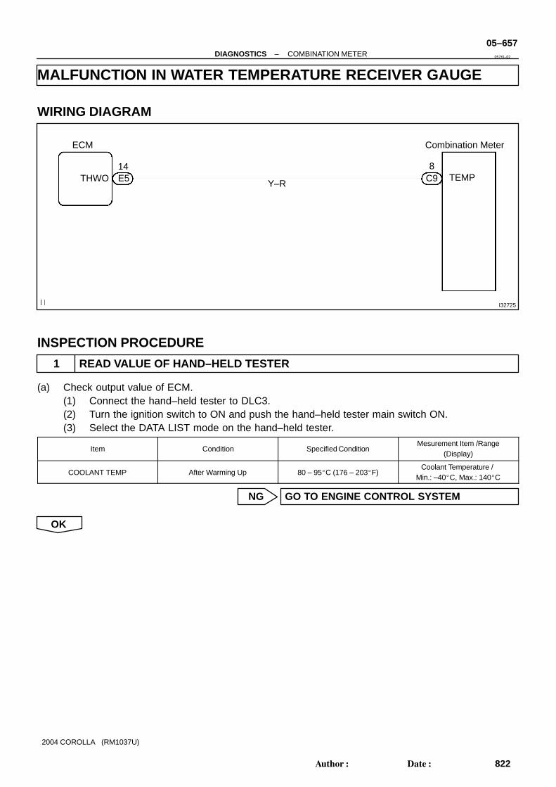
MALFUNCTION IN WATER TEMPERATURE RECEIVER GAUGE
WIRING DIAGRAM
INSPECTION PROCEDURE
1 READ VALUE OF HAND–HELD TESTER
(a) Check output value of ECM.(1) Connect the hand–held tester to DLC3.(2) Turn the ignition switch to ON and push the hand–held tester main switch ON.(3) Select the DATA LIST mode on the hand–held tester.
Item Condition Specified ConditionMesurement Item /Range
(Display)
COOLANT TEMP After Warming Up 80 – 95C (176 – 203F)Coolant Temperature /
Min.: –40C, Max.: 140C
NG GO TO ENGINE CONTROL SYSTEM
OK
057KI–02

I32114
TEMP
I32122
05–658–DIAGNOSTICS COMBINATION METER
823Author: Date:
2004 COROLLA (RM1037U)
2 INSPECT COMBINATION METER ASSY
(REFERENCE) INSPECTION USING OSCILLOSCOPE(a) Check the input signal waveform.
(1) Remove the combination meter with connectors stillconnected.
(2) Connect the oscilloscope to the terminals C9–8 ofcombination meter assy and body ground.
(3) Start engine.(4) Check the signal waveform.
Item Contents
Tool setting 5 V/ DIV, 100 ms/ DV
Vehicle condition Ignition switch ON
OK CHECK AND REPLACE COMBINATION METERASSY
NG
3 CHECK HARNESS AND CONNECTOR(BETWEEN ECM AND COMBINATIONMETER ASSY)
(a) Remove the combination meter.(b) Check the continuity between terminals 14 (THWO) of ECM and C9–8 of combination meter connector.
Standard: There is continuity.
NG REPAIR OR REPLACE HARNESS ORCONNECTOR
OK
CHECK AND REPLACE ECM

I32381
Combination Meter
KEY SW
D–DOOR
RH J/B
Instrument Panel J/B
Integration Relay
C9
C9
L–B(*1)
W–B
4A14
IL3
ID1
DCTY
U1Unlock Warning SW
21
R–W5
IE
AJ6J/C
16
17
R–W
L–B(*2)
4A15
D4Door Courtesy SW (Driver’s Side)
1
L–B(*1)
*1: w/ Door Lock Control*2: w/o Door Lock Control
–DIAGNOSTICS COMBINATION METER05–659
824Author: Date:
2004 COROLLA (RM1037U)
WARNING BUZZER DOES NOT SOUND (KEY REMINDERWARNING, LIGHT REMINDER WARNING)
WIRING DIAGRAM
INSPECTION PROCEDERE
1 CHECK BUZZER
(a) Check that all of the warning buzzers sound.A B
Some buzzers sound No buzzer sounds
B CHECK AND REPLACE COMBINATION METERASSY
A
057T3–02

05–660–DIAGNOSTICS COMBINATION METER
825Author: Date:
2004 COROLLA (RM1037U)
2 INSPECT FRONT DOOR COURTESY LAMP SWITCH ASSY(See Page 65–7)
NG REPLACE FRONT DOOR COURTESY LAMPSWITCH ASSY
OK
3 INSPECT UN–LOCK WARNING SWITCH ASSY(See Page 05–682)
NG REPLACE UN–LOCK WARNING SWITCH ASSY
OK
4 CHECK HARNESS AND CONNECTOR(BETWEEN UN–LOCK WARNING SWITCHAND COMBINATION METER ASSY)
NG REPAIR OR REPLACE HARNESS ORCONNECTOR
OK
5 CHECK HARNESS AND CONNECTOR(BETWEEN COURTESY LAMP SWITCH ANDCOMBINATION METER ASSY)
NG REPAIR OR REPLACE HARNESS ORCONNECTOR
OK
CHECK AND REPLACE COMBINATION METER ASSY

I32384
IG
A
J7J/C
B6Buckle SW LH Seat Position SensorAirbag Sensor Assy
C912
L D–BELT SW
Combination Meter
A1211
A123
A124
LBE+
LSP+
LSP–
LBE+
LSP+
LSP–
2
4
5
G
G–W
R–BLBE–
3
1
G–Y G–YIG11
IG12
W–B
W–B
3A15
3A11
RH J/B
W–B
I30040
D BELT SW
–DIAGNOSTICS COMBINATION METER05–661
826Author: Date:
2004 COROLLA (RM1037U)
SEAT BELT WARNING LAMP FOR DRIVER’S SEAT DOES NOTOPERATE
WIRING DIAGRAM
INSPECTION PROCEDURE
1 CHECK COMBINATION METER ASSY
(a) Ground terminal C9–12 on the combination meter side.(b) Check that the warning lightlights up.
OK: Warning light lights up.
NG CHECK AND REPLACE COMBINATION METERASSY
OK
057T4–02

I30985
05–662–DIAGNOSTICS COMBINATION METER
827Author: Date:
2004 COROLLA (RM1037U)
2 INSPECT FRONT SEAT INNER BELT ASSY LH
(a) Disconnect the front seat inner belt assy.(b) Check continuity front seat inner belt assy.
Belt condition Terminal Specified condition
Belt unfastend 1 – 2 Continuity
Belt fastend 1 – 2 No continuity
NG REPLACE FRONT SEAT INNER BELT ASSY LH
OK
REPAIR OR REPLACE HARNESS OR CONNECTOR

I32383
A
J7J/C
C96
P–BELT OUT
Combination Meter
L3B11
3A11
W–B
ODS
Buckle SW RHOccupant Detection Sensor
P–BELT SW
F7Front Passenger Seat Belt Warning Light
3B22
RH J/B
to GAUGE FuseR–WR–W
C911
L–WIG13
IG
3A14
IG14
BMR
WS+
E
3L–W
2
4
1
B
B
W–B
A148
W–B
Airbag Sensor Assy
RBE+
RH J/B
1B 3LAPL
B
–DIAGNOSTICS COMBINATION METER05–663
828Author: Date:
2004 COROLLA (RM1037U)
SEAT BELT WARNING LAMP FOR FRONT PASSENGER’S SEATDOES NOT FLASH
WIRING DIAGRAM
057KM–04

I30040
P BELT SW
I30040
P–BELT OUT
I32727
05–664–DIAGNOSTICS COMBINATION METER
829Author: Date:
2004 COROLLA (RM1037U)
INSPECTION PROCEDURE
1 INSPECT COMBINATION METER ASSY
(a) Ground terminal C9–11 on the combination meter side.(b) Check that the warning lightlights up.
OK: Warning light lights up.
OK Go to step 3
NG
2 INSPECT PASSENGER SEAT BELT WARNING LAMP ASSY
(a) Ground terminal C9–6 on the combination meter side.(b) Check that the warning lightlights up.
OK: Warning light lights up.
NG CHECK AND REPLACE PASSENGER SEATBELT WARNING LAMP ASSY
OK
CHECK AND REPLACE COMBINATION METER ASSY
3 INSPECT FRONT SEAT INNER BELT ASSY RH
(a) Check continuity.(1) Disconnect the front seat inner belt assy.(2) Check the continuity in between terminals 1 and 2
of front seat inner belt assy RH.OK:
Condition Continuity
Seat belt is fastened Continuity
Seat belt is unfastened No continuity
NG CHECK AND REPLACE FRONT SEAT INNERBELT ASSY RH
OK

I30048
Connector
Press
Released
–DIAGNOSTICS COMBINATION METER05–665
830Author: Date:
2004 COROLLA (RM1037U)
4 INSPECT SEPARATE SEAT TYPE FRONT SEAT CUSHION PAD
(a) Disconnect the separate type front seat cushion pad.(b) Check continuity separate type front seat cushion pad.
Sear condition Terminal Specified condition
Released 1 – 2 No continuity
Pressed 1 – 2 Continuity
NG CHECK AND REPLACE SEPARATE SEAT TYPEFRONT SEAT CUSHION PAD
OK
REPAIR OR REPLACE HARNESS AND CONNECTOR

I32382
AJ7J/C
IF12
L–W
Clock
3
2
4
1
L–W4C16
4C20
RH J/B
Engine Room J/B, R/B
FL MAIN
Battery
DOME
ALT
12
121
1
11C 1A
IG
I10 Ignition SW
ACCAM131
IL4
W L–R
IF6CIG
AM1IB1
IC7
IF8
L–W
Instrument Panel J/B
3A18
GTAIL Relay (USA)Combination SW (Canada)
W–B3A11
3A10
3A5
W
W–B
GR
GR
Center J/B
B
05–666–DIAGNOSTICS COMBINATION METER
831Author: Date:
2004 COROLLA (RM1037U)
MALFUNCTION IN CLOCK
WIRING DIAGRAM
INSPECTION PROCEDURE
1 INSPECT FUSE
(a) Check the continuity in CIG fuse.(b) Check the continuity in DOME fuse.
NG REPLACE FUSE
OK
057T5–02

I32727
+B ILL ACCE
–DIAGNOSTICS COMBINATION METER05–667
832Author: Date:
2004 COROLLA (RM1037U)
2 INSPECT HARNESS OR CONNECTOR
(a) Check voltage.(1) Remove the clock assy with connector still con-
nected.(2) Measure voltage between terminal 1 (+B) of clock
assy connector and body ground.Standard voltage: 10 – 14 V(3) Turn the ignition switch to ACC.(4) Measure voltage between terminal 4 (ACC) of clock
assy connector and body ground.Standard voltage: 10 – 14 V
(b) Check continuity.(1) Check continuity Between terminal 2 (E) of clock
assy connector and body ground.OK: Continuity exists
NG REPAIR OR REPLACE HARNESS ORCONNECTOR
OK
REPLACE CLOCK ASSY

I37764
Combination Meter
BIA63
A7AmbientTemperatureSensor
B
IA610
B–LB–L
1
2
C926
30C9
OUT SIDE TEMP+
OUT SIDE TEMP–
05–668–DIAGNOSTICS COMBINATION METER
833Author: Date:
2004 COROLLA (RM1037U)
THE AMBIENT TEMPERATURE DOES NOT DISPLAY
WIRING DIAGRAM
057KO–04

I30487
1 2
I30156
Resistance (kΩ)
Temperature (C)
–DIAGNOSTICS COMBINATION METER05–669
834Author: Date:
2004 COROLLA (RM1037U)
INSPECTION PROCEDURE
1 INSPECT OUTER AMBIENT TEMPERATURE SENSOR
(a) Remove cooler (ambient temp. sensor) thermistor.(b) Measure resistance between terminals 1 and 2 of cooler
(ambient temp. sensor) thermistor connector at each tem-perature.Resistance: at 0 C (0 F) : 9.097 – 9.701 kΩat 25 C (77 F) : 2.725 – 2.865 kΩ
HINT:As the temperature increases, the resistance decreases.
Resistance:
NG REPLACE OUTER AMBIENT TEMPERATURESENSOR
OK
2 CHECK HARNESS AND CONNECTOR
NG REPAIR OR REPLACE HARNESS ORCONNECTOR
OK
CHECK AND REPLACE COMBINATION METER ASSY
Related Documents