How to perform BLE RF-PHY and telecommunication regulatory tests on Apollo-based wireless products Ambiq Micro, Inc. December, 2018 1

Welcome message from author
This document is posted to help you gain knowledge. Please leave a comment to let me know what you think about it! Share it to your friends and learn new things together.
Transcript

How to perform BLE RF-PHY and telecommunication regulatory tests on Apollo-based wireless products
Ambiq Micro, Inc.
December, 2018
1

2
Table of Contents
Preparations 1RF-PHY Test Setup2Regulatory Test Setup3Precautions4

3
Table of Contents
Preparations1RF-PHY Test Setup2Regulatory Test Setup3Precautions4
Preparation before Testing
• Lead the VDD, GND, SWD interface, 2-wire UART test interface and RF port out from EUT board.
• Burn test program (test_bridge.bin) over J-link to make MCU enter into Direct Test Mode (Frequency hopping off, fixed frequency).
• The general J-Flash programming parameters shall be set as follows:
• Connect 2-wire UART test interface of EUT and USB interface of PC or BLE tester with one USB-to-Serial adapter (driver must be installed at first).
• Note: Apollo series MCU family has two power supply schemes: 3.3V or 1.8V. The interface level of USB-to-Serial adapter must be compatible with EUT power supply.
• Connect antenna port of EUT to the tester via a 50Ω connector by using an RF coaxial cable or soldering a pig-tail from feed point pad on PCBA.
4
MCU Type Target Device Type Debug Interface Speed Burning Start Address
Apollo2-Blue AMAPH1KK-KBR SWD 1000 0x00000000
Apollo3-Blue AMAPH1KK-KBR SWD 1000 0x0000C000

5
Table of Contents
Preparations1RF-PHY Test Setup2Regulatory Test Setup3Precautions4
BLE RF-PHY Test Setup 1
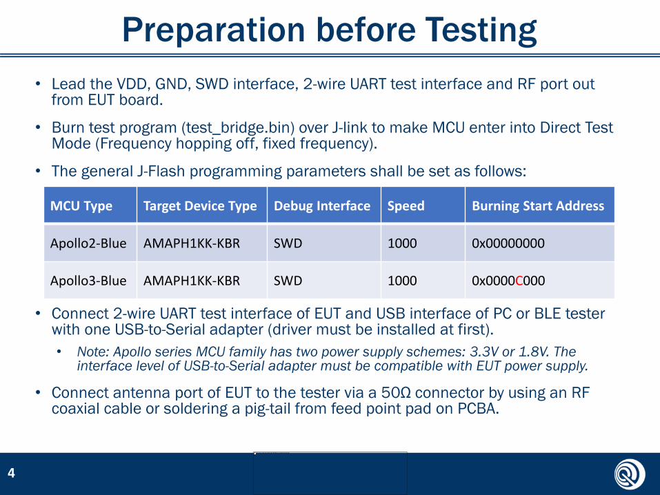
• There are two main test methods: Bluetooth signaling and non-signaling. And two
common models of Bluetooth testers: R&S CMW series and Anritsu MT8852B.
• For Bluetooth signaling test method, RF testing commands are generated by tester
automatically to control EUT and the test setup is shown as follows:
6
USB-to-Serial
Adapter
EUT
RF PortUART
Bluetooth® Tester RF I/O
USB
RF Cable
USB-to-GPIB/LAN
Running Test Scripts Automatically
Optional
2-wire UART
Host Computer
BLE RF-PHY Test Setup 2
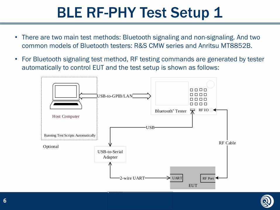
• For non-signaling test method, RF testing commands are sent by PC software
manually to control EUT and the test setup is shown as follows:
• There are two kinds of commonly used PC testing software: SSCOM tool and BLE
Connector tool .
• Only R&S CMW series testers can support Bluetooth non-signaling test method.
7
USB-to-Serial
AdapterEUT
RF PortUART
Bluetooth® Tester RF I/O
USB RF Cable
Running PC Testing Software
2-wire UART

HCI Testing Commands
• For both of Apollo2-Blue and Apollo3-Blue, HCI testing commands used in RF-PHY
non-signaling test mode are defined as follows:
• ‘XX’ in all transmitter and receiver testing commands above means channel to be
tested (within range: 0x00~0x27).
• Note that If each command processed successfully, the last octet of LE_STATUS
packet returned by EUT will be 0x00.
8
Packaged HCI Commands SSCOM Strings Description
HCI_RESET 01 03 0C 00 Reset EUT before testing
HCI_LE_TRANSMITTER_TEST
01 1E 20 03 XX 25 00’00’: sending LE test packets with PRBS9 in payload
01 1E 20 03 XX 25 01’01’: sending LE test packets with repeated ‘11110000’ sequence in payload
01 1E 20 03 XX 25 02’02’: sending LE test packets with repeated ‘10101010’ sequence in payload
HCI_LE_RECEIVER_TEST 01 1D 20 01 XX Set EUT in direct RX mode
HCI_LE_TEST_END 01 1F 20 00 End current test and be ready for next one

PC Testing Software – SSCOM
9
• The UART test Interface
characteristics of Bluetooth
tester or PC testing software
shall be set to use following
parameters:
• Baud rate: 115200
• Number of data bits: 8
• Number of stop bits: 1
• No parity
• No flow control

PC Testing Software – BLE Connector
10
Parameter Value
TX_Channel Channel for testing
Length_of_Test_Data 0x25 (37 octets)
Packet_Payload As specific

Transmitter Tests (TRM-LE)
No. Test Case Requirement Channels for Testing
1 Output Power-20 ≤ PAVG ≤ +10 dBmPPEAK – PAVG ≤ 3 dB
Ch0, 12, 19, 39
2 In-band emissionsPTX ≤ -20 dBm for (fTX ± 2 MHz);PTX ≤ -30 dBm for (fTX ± n MHz]); where n ≥ 3
Ch0, 2, 12, 19, 37,39
3Modulation Characteristics
225 kHz ≤ Δf1avg ≤ 275 kHz99.9% Δf2max>185 kHzΔf2avg / Δf1avg ≥ 0.8
Ch0, 12, 19, 39
4Carrier frequency offset and drift
Freq Offset (Accuracy) ≤ ±150 kHzFreq Drift ≤ ±50 kHzInitial frequency drift ≤ ±23 kHzMaximum drift rate ≤ 20kHz/50μs
Ch0, 12, 19, 39
11

Receiver Tests (RCV-LE)
No. Test Case Requirement Channels for Testing
1 Receiver sensitivityPER ≤ 30.8% when input power level = -70 dBm in dirty TX mode
Ch0, 12, 19, 39
2Maximum input signal level
PER ≤ 30.8% when input power level = -10 dBm
Ch0, 12, 19, 39
3 PER Report Integrity50% ≤ PER ≤ 65.4% when input power level = -30 dBm and every test packet has an intentionally corrupted CRC value
Ch12, 19
4 Blocking Performance See RF-PHY.TS.4.2.2 for details Ch12
5C/I and Receiver Selectivity Performance
See RF-PHY.TS.4.2.2 for details Ch0, 2, 12, 19, 37,39
6Intermodulation Performance
See RF-PHY.TS.4.2.2 for details Ch0, 12, 19, 39
12

Declarations in RCV-LE
• Due to different receiver design inside chip, below two values shall be
declared to test facility by manufacturer when performing receiver tests:
No. Identifier Channel Apollo2-Blue Apollo3-Blue Unit
1In-band image frequency for C/I and receiver selectivity test
Low
78 -4 MHzMiddle
High
2 Value n for intermodulation test
Low
3 5 integerMiddle
High
13

Tips for Tester Model Selection
14
• Generally, R&S CMW series Bluetooth testers, such as CMW270/500, are
recommended for R&D use since they could be operated more flexibly.
• While Anritsu MT8852B series are more suitable for production tests
since they can run testing scripts and generate test results automatically.

15
Table of Contents
Preparations1RF-PHY Test Setup2Regulatory Test Setup3Precautions4

Overview
• Telecommunication regulatory tests indicate mandatory regional radio type
approval for where those radio products intend to be sold.
• The primary approval standards include SRRC, FCC and CE corresponding
to marketplace in China, North America and Europe respectively.
• Some test cases in FCC and CE certification require radiated measurement
in SAR or FAR similar as EMC tests, in this case conducted measurement
may be used instead for reference.
16

Applicable Standards
• All telecommunication regulatory tests shall follow these standards listed
as below respectively:
17
Category Standard Code Document Title
SRRC MIIT regulation [2002]353 微功率(短距离)无线电发射设备技术要求
FCC
47 CFR Part 15 Subpart C Miscellaneous Wireless Communication Services
ANSI C63.10-2013 American National Standard for Testing Unlicensed Wireless Devices
CE
ETSI EN 300 328 V2.1.1 Wideband transmission systems; Data transmission equipment operating in the 2.4 GHz ISM band and using wideband modulation techniques
ETSI EN 300 440 V2.1.1Short Range Devices (SRD); Radio equipment to be used in the 1 GHz to 40 GHz frequency range
ETSI EN 301 489-17 V2.1.1Electromagnetic compatibility and Radio spectrum Matters (ERM); ElectroMagnetic Compatibility (EMC) standard for radio equipment

Regulatory Test Setup
• The regulatory test configuration is similar as BLE RF-PHY non-signaling test, the
only difference is spectrum analyzer used instead of Bluetooth tester.
• All RF testing commands are sent by upper host computer to control EUT and the
brief test setup is shown as follows:
18
USB-to-Serial
AdapterEUT
RF PortUART
USB
Spectrum Analyzer
RFUSB
RF Cable
Running PC Testing Software
2-wire UART
Host Computer
USB-GPIB/LAN

RF Testing Commands
• As provided in ANSI C63.10, the EUT shall be set to operate in the worst case
transmission situation i.e. continuous transmit mode with 100% duty cycle no
matter carrier wave or modulated data during testing.
• For Apollo3-Blue, RF testing commands to be used in regulatory tests are defined
as follows:
19
Packaged HCI Commands SSCOM Strings Description
HCI_RESET 01 03 0C 00 Reset EUT before testing
HCI_LE_TRANSMITTER_TEST
01 1E 20 03 XX 25 08’08’: Set EUT in continuous carrier wave mode at center frequency
01 1E 20 03 XX 25 09’09’: Set EUT in continuous modulation transmit mode with duty cycle = 100%
HCI_LE_RECEIVER_TEST 01 1D 20 01 XX Set EUT in direct RX mode
HCI_LE_TEST_END 01 1F 20 00 End current test and be ready for next one

RF Testing Commands (continued)
• For Apollo2-Blue, RF testing commands to be used in regulatory tests are defined
as follows:
• Note:
• The frequency tolerance test item in SRRC requires to configure EUT in carrier wave transmit mode.
• The receiver spurious emission and receiver blocking test items in SRRC and CE require to configure
EUT in direct receiver mode.
• All other test items are performed in continuous transmit mode (PRBS9, 100% duty cycle) of EUT.
20
Packaged HCI Commands SSCOM Strings Description
HCI_RESET 01 03 0C 00 Reset EUT before testing
HCI_EM_9304_TRANSMITTER_TEST
01 11 fc 04 01 XX 25 00’01’: Set EUT in continuous modulation transmit mode with duty cycle = 100%
01 11 fc 04 04 XX 25 00’04’: Set EUT in continuous carrier wave transmit mode at center frequency
HCI_LE_RECEIVER_TEST 01 1D 20 01 XX Set EUT in direct RX mode
HCI_LE_TEST_END 01 1F 20 00 End current test and be ready for next one

SRRC Requirements
No. Test Items Requirement Channel for Testing EUT Status
1 Peak Output Power EIRP ≤ 20 dBm Low/Mid/HighContinuous transmit mode
2 Frequency Tolerance ±20 ppm Low/Mid/HighCarrier wave transmit mode
3Out-of-band Emissions (Band Edge)
EIRP≤-80 dBm/Hz out of 2.4-2.4835 GHz band
Low/HighContinuous transmit mode
4Spurious emissions of transmitter
See table on next page
Low/Mid/HighContinuous transmit mode
5Spurious emissions of receiver
Same as above Low/Mid/High Receiver mode
21
• Note:• The frequency tolerance mainly depends on the frequency accuracy of
external HF crystal (32 or 48 MHz), so be careful of crystal selection.

Limitation of Spurious Emission
Frequency Range Measurement BW Detector Limit
30 - 1000 MHz 100 kHz Peak -36 dBm
2.4 – 2.4835 GHz 100 kHz Peak -33 dBm
3.4 - 3.53 GHz 1 MHz Peak -40 dBm
5.725 - 5.85 GHz 1 MHz Peak -40 dBm
Others within 1 - 12.75GHz 1MHz Peak -30 dBm
22
✓ Note:• The frequency range should be set outside 2.5 times channel bandwidth
of the center frequency to be tested.• e.g., when measuring at 2402MHz (lowest channel), the lower stop frequency should
be set to 2397MHz and the upper start frequency should be set to 2407MHz.
• However, when measuring at 2480MHz (highest channel), the upper start frequency
should be set to 2483.5MHz.
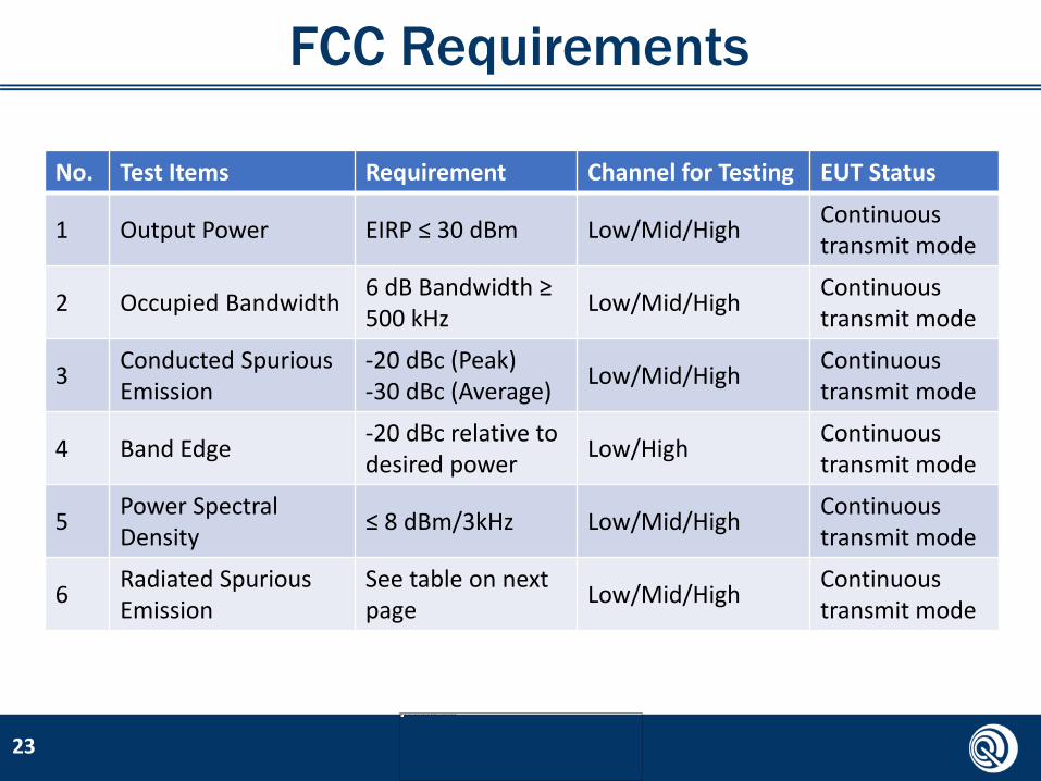
FCC Requirements
No. Test Items Requirement Channel for Testing EUT Status
1 Output Power EIRP ≤ 30 dBm Low/Mid/HighContinuous transmit mode
2 Occupied Bandwidth6 dB Bandwidth ≥ 500 kHz
Low/Mid/HighContinuous transmit mode
3Conducted Spurious Emission
-20 dBc (Peak)-30 dBc (Average)
Low/Mid/HighContinuous transmit mode
4 Band Edge-20 dBc relative to desired power
Low/HighContinuous transmit mode
5Power Spectral Density
≤ 8 dBm/3kHz Low/Mid/HighContinuous transmit mode
6Radiated Spurious Emission
See table on next page
Low/Mid/HighContinuous transmit mode
23
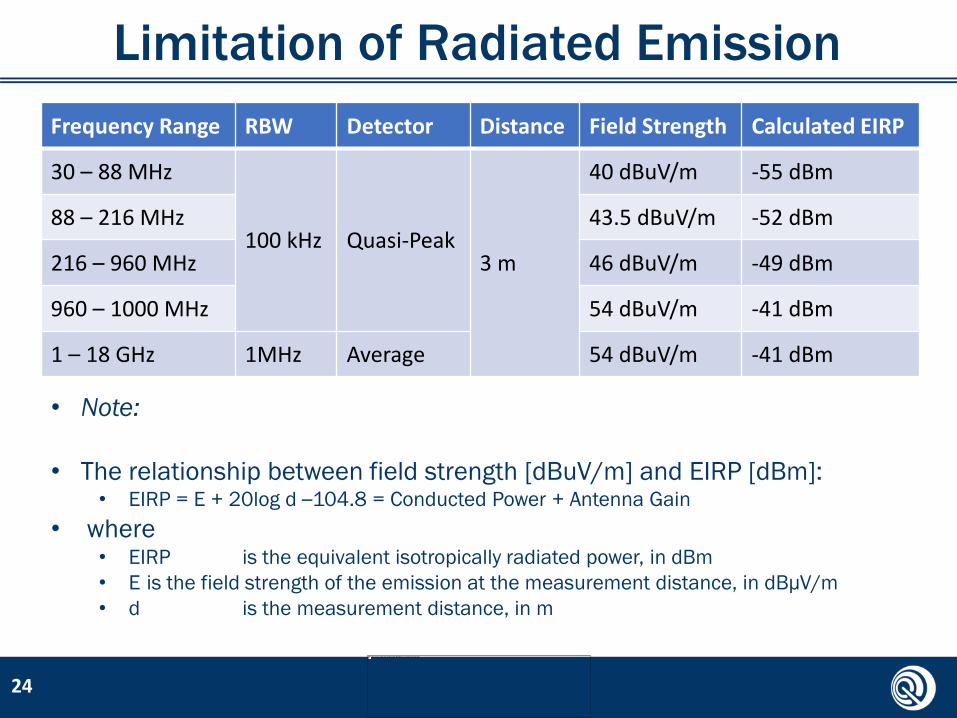
Limitation of Radiated Emission
Frequency Range RBW Detector Distance Field Strength Calculated EIRP
30 – 88 MHz
100 kHz Quasi-Peak3 m
40 dBuV/m -55 dBm
88 – 216 MHz 43.5 dBuV/m -52 dBm
216 – 960 MHz 46 dBuV/m -49 dBm
960 – 1000 MHz 54 dBuV/m -41 dBm
1 – 18 GHz 1MHz Average 54 dBuV/m -41 dBm
24
• Note:
• The relationship between field strength [dBuV/m] and EIRP [dBm]:• EIRP = E + 20log d –104.8 = Conducted Power + Antenna Gain
• where • EIRP is the equivalent isotropically radiated power, in dBm
• E is the field strength of the emission at the measurement distance, in dBμV/m
• d is the measurement distance, in m

CE Requirements
No. Test Items RequirementChannel for Testing
EUT Status
1 RF Output Power EIRP ≤ 20 dBm Low/Mid/HighContinuous transmit mode
2Power Spectral Density
≤ 10 dBm/MHz Low/Mid/HighContinuous transmit mode
2Occupied Channel Bandwidth (similar as band edge)
99% power BW fall within 2.4 – 2.4835 GHz completely
Low/HighContinuous transmit mode
3Unwanted Emissions in out-of-band domain
-10 dBc at 2399 or 2484.5 MHz-20 dBc at 2398 or 2485.5 MHz
Low/HighContinuous transmit mode
4Unwanted Emissions in spurious domain
See table on next two pages
Low/HighContinuous transmit mode
5Receiver Spurious Emissions
Low/High Receiver mode
6 Receiver Blocking Low/High Receiver mode
25

Transmitter Spurious Emissions
Frequency Range Maximum Power (dBm) Measurement BW Detector
30 – 47 MHz -36
100 kHzPeak
47 – 74 MHz -54
74 – 87.5 MHz -36
87.5 – 118 MHz -54
118 – 174 MHz -36
174 – 230 MHz -54
230 – 470 MHz -36
470 – 862 MHz -54
862 – 1000 MHz -36
1 – 12.75 GHz -30 1MHz
26

Receiver Measurement
Frequency Range Emission Limits (dBm) Measurement BW Detector
30 – 1000 MHz -57 100 kHzPeak
1 – 12.75 GHz -47 1 MHz
27
Wanted signal mean power (dBm)
Blocking signal frequency (MHz)
Blocking signal power (dBm)
PER LimitBlocking signal type
Pmin + 6 dB2380
-57
10%Continuous Wave
2503.5
Pmin + 6 dB2300
-472583.5
• Receiver Spurious Emissions
• Receiver Blocking Parameters (2 vector signal generators required)
• Note: Pmin is the minimum level of the wanted signal power (in dBm) at PER less
than or equal to 10%.
28
Table of Contents
Preparations1RF-PHY Test Setup2Regulatory Test Setup3Precautions4

Precautions
• Proper impedance matching between chip and antenna is
necessary for decreasing mismatch loss.
• If possible, shield box is recommended for placing EUT to
eliminate uncertain coupling interference.
• The conducted RF path loss between EUT and tester must be
set appropriately to acquire more meaningful data.
• All RF measurement instruments shall be calibrated every 1
year or less to guarantee testing accuracy.
29

30
Example–CW Frequency Tolerance

Example–Band Edge Emission
31
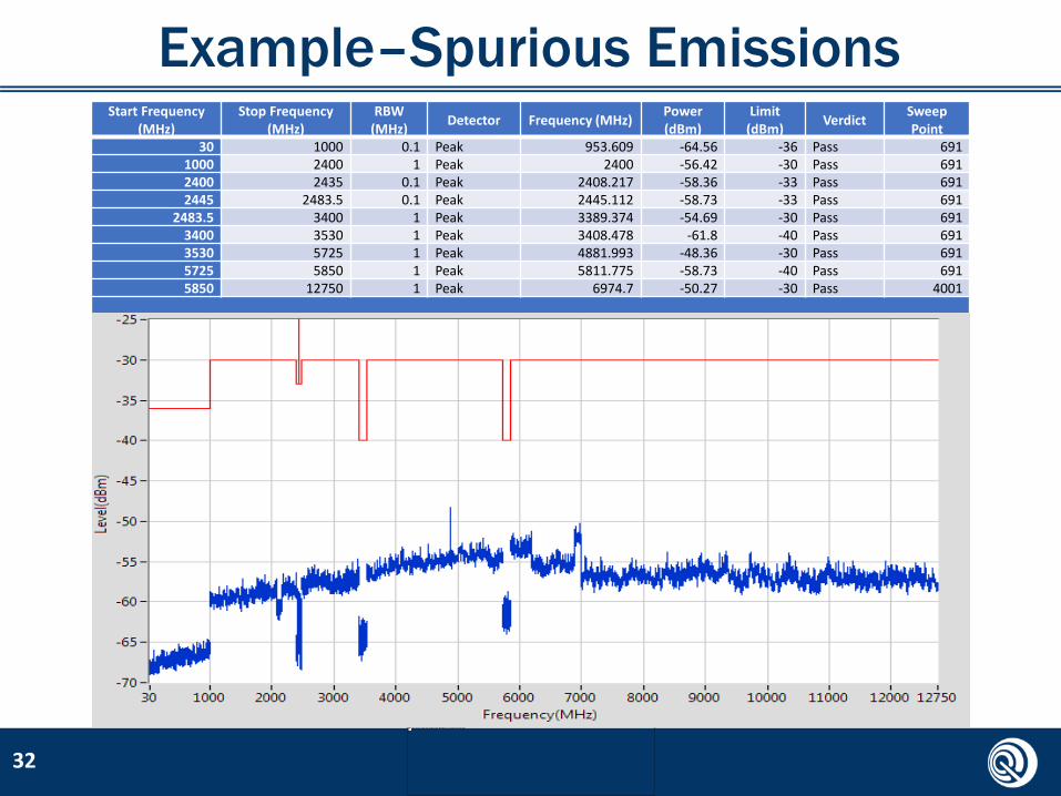
Example–Spurious Emissions
32
Start Frequency (MHz)
Stop Frequency (MHz)
RBW (MHz)
Detector Frequency (MHz)Power (dBm)
Limit (dBm)
VerdictSweep Point
30 1000 0.1 Peak 953.609 -64.56 -36 Pass 6911000 2400 1 Peak 2400 -56.42 -30 Pass 6912400 2435 0.1 Peak 2408.217 -58.36 -33 Pass 6912445 2483.5 0.1 Peak 2445.112 -58.73 -33 Pass 691
2483.5 3400 1 Peak 3389.374 -54.69 -30 Pass 6913400 3530 1 Peak 3408.478 -61.8 -40 Pass 6913530 5725 1 Peak 4881.993 -48.36 -30 Pass 6915725 5850 1 Peak 5811.775 -58.73 -40 Pass 6915850 12750 1 Peak 6974.7 -50.27 -30 Pass 4001

Thanks and best regards.
Related Documents