How to Manage a Device with the Firepower Management Center First Published: 2018-11-28 Last Modified: 2018-11-28 Americas Headquarters Cisco Systems, Inc. 170 West Tasman Drive San Jose, CA 95134-1706 USA http://www.cisco.com Tel: 408 526-4000 800 553-NETS (6387) Fax: 408 527-0883

Welcome message from author
This document is posted to help you gain knowledge. Please leave a comment to let me know what you think about it! Share it to your friends and learn new things together.
Transcript
How to Manage a Device with the Firepower Management CenterFirst Published: 2018-11-28
Last Modified: 2018-11-28
Americas HeadquartersCisco Systems, Inc.170 West Tasman DriveSan Jose, CA 95134-1706USAhttp://www.cisco.comTel: 408 526-4000
800 553-NETS (6387)Fax: 408 527-0883

THE SPECIFICATIONS AND INFORMATION REGARDING THE PRODUCTS IN THIS MANUAL ARE SUBJECT TO CHANGE WITHOUT NOTICE. ALL STATEMENTS,INFORMATION, AND RECOMMENDATIONS IN THIS MANUAL ARE BELIEVED TO BE ACCURATE BUT ARE PRESENTED WITHOUT WARRANTY OF ANY KIND,EXPRESS OR IMPLIED. USERS MUST TAKE FULL RESPONSIBILITY FOR THEIR APPLICATION OF ANY PRODUCTS.
THE SOFTWARE LICENSE AND LIMITED WARRANTY FOR THE ACCOMPANYING PRODUCT ARE SET FORTH IN THE INFORMATION PACKET THAT SHIPPED WITHTHE PRODUCT AND ARE INCORPORATED HEREIN BY THIS REFERENCE. IF YOU ARE UNABLE TO LOCATE THE SOFTWARE LICENSE OR LIMITED WARRANTY,CONTACT YOUR CISCO REPRESENTATIVE FOR A COPY.
The Cisco implementation of TCP header compression is an adaptation of a program developed by the University of California, Berkeley (UCB) as part of UCB's public domain version ofthe UNIX operating system. All rights reserved. Copyright © 1981, Regents of the University of California.
NOTWITHSTANDING ANY OTHERWARRANTY HEREIN, ALL DOCUMENT FILES AND SOFTWARE OF THESE SUPPLIERS ARE PROVIDED “AS IS" WITH ALL FAULTS.CISCO AND THE ABOVE-NAMED SUPPLIERS DISCLAIM ALL WARRANTIES, EXPRESSED OR IMPLIED, INCLUDING, WITHOUT LIMITATION, THOSE OFMERCHANTABILITY, FITNESS FOR A PARTICULAR PURPOSE AND NONINFRINGEMENT OR ARISING FROM A COURSE OF DEALING, USAGE, OR TRADE PRACTICE.
IN NO EVENT SHALL CISCO OR ITS SUPPLIERS BE LIABLE FOR ANY INDIRECT, SPECIAL, CONSEQUENTIAL, OR INCIDENTAL DAMAGES, INCLUDING, WITHOUTLIMITATION, LOST PROFITS OR LOSS OR DAMAGE TO DATA ARISING OUT OF THE USE OR INABILITY TO USE THIS MANUAL, EVEN IF CISCO OR ITS SUPPLIERSHAVE BEEN ADVISED OF THE POSSIBILITY OF SUCH DAMAGES.
Any Internet Protocol (IP) addresses and phone numbers used in this document are not intended to be actual addresses and phone numbers. Any examples, command display output, networktopology diagrams, and other figures included in the document are shown for illustrative purposes only. Any use of actual IP addresses or phone numbers in illustrative content is unintentionaland coincidental.
All printed copies and duplicate soft copies of this document are considered uncontrolled. See the current online version for the latest version.
Cisco has more than 200 offices worldwide. Addresses and phone numbers are listed on the Cisco website at www.cisco.com/go/offices.
Cisco and the Cisco logo are trademarks or registered trademarks of Cisco and/or its affiliates in the U.S. and other countries. To view a list of Cisco trademarks, go to this URL: www.cisco.comgo trademarks. Third-party trademarks mentioned are the property of their respective owners. The use of the word partner does not imply a partnership relationship between Cisco and anyother company. (1721R)
© 2018 Cisco Systems, Inc. All rights reserved.

C H A P T E R 1About This Guide
This how-to guide explains how to set up a Firepower Management Center Version 6.2.3 device to managea Firepower Threat Defense Version 6.2.3 device to provide inspection and security for a sample networkthat includes an inside network and outside network (that is, the internet). If you follow all the steps in thisguide, you can configure a system identical to this one.
• What's In This Guide, on page 1• About the Network Setup, on page 2• Network Setup Task Overview, on page 4
What's In This GuideThis guide discusses setting up a basic network with the Firepower Version 6.2.3 System (that is, FirepowerManagement Center and a Firepower Threat Defense device both running Version 6.2.3). This basic setup isrequired to use the Firepower Management Center for access control, intrusion prevention, and monitoring.You must perform these tasks before you can do anything else with the Firepower System.
This guide has sample IP addresses that you can use in your system, provided they do not conflict withaddresses in your network. You can either use the same IP addresses described in this guide or you can useIP addresses that are compatible with your network. If you change IP addresses to conformwith your network,make sure that the Firepower Threat Defense management interface and the Firepower Management Centerinterface are on the same subnet.
Note
Setup Tasks Covered in this Guide
This guide uses sample values to tell you step by step how to:
• Configure a Firepower Management Center on the network.
• Configure a Firepower Threat Defense on the network.
• License the Firepower Management Center.
• Manage the Firepower Threat Defense device using Firepower Management Center.
• Configure a NAT policy and a static route.
How to Manage a Device with the Firepower Management Center1

• Set up an initial access control rule that allows all traffic so you can test internet access from a clientconnected to the inside network and make sure the managed device is filtering the traffic.
Who Should Use This Guide
Anyone who wants to configure the Firepower System, including administrators and integrators.
What You'll Need
To complete the tasks discussed in this guide, you'll need:
• Firepower Management Center (any model, physical or virtual) running version 6.2.3
• Firepower Threat Defense (any model, physical or virtual) running version 6.2.3
For information about upgrading a Firepower Management Center or Firepower Threat Defense device,see the Firepower Management Center Upgrade Guide.
You can use another version of the Firepower System software but additionaltasks, or different tasks, might be required. Consult the appropriate configurationor quick start guide for the version you're using for details.
Note
• For virtual devices, a hypervisor manager and client.
• A private network so the IP addresses used in this system don't conflict with IP addresses used in yournetwork. For example, you can set up a Virtual LAN (VLAN). Explaining how to isolate this systemfrom the rest of your network is beyond the scope of this guide.
• (Optional.) Cisco Smart License. If you don't have a Smart License, you can use a 90-day evaluationlicense.
For more information about Smart Licenses in version 6.2.3, see Smart Licensing for the FirepowerSystem.
Related TopicsAbout the Network Setup, on page 2Network Setup Task Overview, on page 4
About the Network SetupThis guide walks you through setting up the following network:
How to Manage a Device with the Firepower Management Center2
About This GuideAbout the Network Setup

Figure 1: Sample network used in this guide
Firepower Threat Defense Interfaces
In this example network, the Firepower Threat Defense device has three interfaces: management, inside, andoutside. The outside interface connects directly to the internet. Using an allow access control rule, clientsattached to the inside network can connect to the internet through the Firepower Threat Defense device. Thistype of configuration is sometimes referred to as a bootstrap because this is the minimum amount ofconfiguration you need to connect to the internet.
Management (1 / 1)IP address 10.10.2.45. Used only to communicate with the Firepower Management Center. Themanagement IP address must be on the same subnet as the Firepower Management Center.
Inside (GigabitEthernet 1 / 2)IP address 10.10.2.1. Computers attached to the inside interface can have access control and intrusionprevention policies applied to them. The default gateway for the inside network is 10.10.2.254.
Outside (GigabitEthernet 1 / 1)IP address 209.165.200.255. Used to connect to the internet. The default gateway for the outside networkis 209.165.200.254.
This guide has sample IP addresses that you can use in your system, provided they do not conflict withaddresses in your network. You can either use the same IP addresses described in this guide or you can useIP addresses that are compatible with your network. If you change IP addresses to conformwith your network,make sure that the Firepower Threat Defense management interface and the Firepower Management Centerinterface are on the same subnet.
Note
How to Manage a Device with the Firepower Management Center3
About This GuideAbout the Network Setup

Depending on what type of device you're managing, the interfaces might be identified differently than thepreceding. For example, a virtual managed device has interfaces numbered GigabitEthernet0/0,GigabitEthernet0/1, and so on. A Firepower Threat Defense 4100 or 9300 series device has interfaces numberedEthernet1/1, Ethernet2/1, Ethernet3/1, and so on.
Note
Firepower Management Center
The Firepower Management Center has one interface with an IP address of 10.10.2.2. This interface is usedto manage Firepower Threat Defense devices, each of which must all have a management IP address on thesame subnet.
Network Setup Task OverviewThis topic provides a high-level overview of setting up the network discussed in About the Network Setup,on page 2.
Procedure
PurposeCommand or Action
What's In This Guide, on page 1Prerequisites.Step 1
Connect the Firepower Management Center to a switchthat connects it to the Firepower Threat Defense and to a
Step 2
network that is accessible by the computer you'll use toaccess the Firepower Management Center.
Access the device using SSH or a terminal server and runthe configure-network command to set the device's
Set up the Firepower Management Center on the network.Step 3
management IP address, subnet, DNS servers, and so on.See Connect the Firepower Management Center to theNetwork, on page 7.
Firepower Threat Defense has a setup script that performsthe same tasks as Firepower Management Center and also
Set up the Firepower Threat Defense on the network.Step 4
enables you to choose routed mode and to allow the deviceto be managed by Firepower Management Center. SeeConnect the Managed Device to the Network, on page 8.
Access the Firepower Management Center with a webbrowser and set additional options, including time zone,
Initially configure the Firepower Management Center.Step 5
time servers, automatic backup, and so on. See Configurethe Firepower Management Center for the First Time, onpage 11.
Apply either a Smart License or a 90-day evaluationlicense. The evaluation license is fully functional but for
License the Firepower Management Center.Step 6
production use, you need a Smart License. See Configure
How to Manage a Device with the Firepower Management Center4
About This GuideNetwork Setup Task Overview
PurposeCommand or Action
the Firepower Management Center for the First Time, onpage 11.
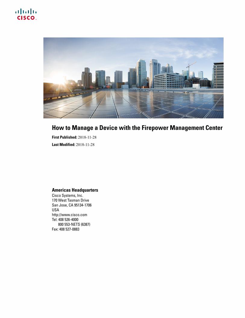
After adding the managed device, you perform all furtherconfiguration in the Firepower Management Center. See
Add Firepower Threat Defense as a managed device tothe Firepower Management Center.
Step 7
Add a Managed Device to the Firepower ManagementCenter, on page 15.
Configure the inside and outside interfaces and a NAT ruleto send traffic from any network to the outside interface.
Configure Firepower Threat Defense interfaces, staticroute, and NAT rule.
Step 8
Configure a static route to the outside interface. SeeConfigure the Managed Device, on page 15.
This temporary access control rule allows traffic to theoutside interface. See Edit the Access Control Policy, onpage 25.
Edit an access control policy to allow internet access.Step 9
Make sure the client can access the internet and make surethemanaged device is filtering the traffic. See Troubleshootthe System, on page 30.
Connect a client to the inside network and make sure itcan access the internet.
Step 10
Typically, issues are related either to physical networkingproblems or improperly configured static route or NATpolicy. See Test the System, on page 27.
Troubleshoot issues you might encounter.Step 11
How to Manage a Device with the Firepower Management Center5
About This GuideNetwork Setup Task Overview

How to Manage a Device with the Firepower Management Center6
About This GuideNetwork Setup Task Overview

C H A P T E R 2Set Up Devices and Connect them to the Network
The first thing you must do is connect your Firepower Management Center and Firepower Threat Defensedevices to the network. Depending on how your organization manages network devices, you might needassistance to install the devices in a rack.
• Set Up Devices, on page 7• Connect the Firepower Management Center to the Network, on page 7• Connect the Managed Device to the Network, on page 8
Set Up DevicesBecause the various models of physical and virtual devices are set up differently, consult the documentationfor your Firepower Management Center and Firepower Threat Defense device to:
• (Physical appliances): Unpack, rack, and connect the device to the network using the hardware installationguide.
• (Virtual devices): Install the virtual machine image and power it up using the virtual device quick startguides.
After performing those tasks, continue with the next section to configure IP addresses and to perform theother tasks necessary to get the Firepower System running.
Connect the Firepower Management Center to the NetworkThis task enables you to initially configure the FirepowerManagement Center for access to the internet. You'llprovide an IP address, subnet mask, and other parameters. Refer to the sample network diagram About theNetwork Setup, on page 2.
Before you begin
See Set Up Devices and Connect them to the Network, on page 7.
Step 1 Connect to the virtual machine's console in vSphere or the physical appliance's Console port or using Secure Shell (SSH).Step 2 Log in to the Firepower Management Center as the admin user. (By default, the password is Admin123.)Step 3 At the prompt, enter the following command:
How to Manage a Device with the Firepower Management Center7

sudo configure-network
Step 4 When prompted, enter the password Admin123.Step 5 Enter the following information at the prompts:
Do you want to configure IPv4 (y or n)? yManagement IP address [192.168.45.45]? 10.10.2.2Management netmask [255.255.255.0]? 255.255.255.0Management default gateway? 10.10.2.254Are these settings correct (y or n)? yDo you wish to configure IPv6? n
Step 6 The following messages are displayed to indicate configuration was successful:
Updated network configurationUpdated comms. channel communication
What to do next
See Connect the Managed Device to the Network, on page 8.
Connect the Managed Device to the NetworkConnecting a Firepower Threat Defense to the network is very similar to connecting a FirepowerManagementCenter to the network. You'll provide an IP address and subnet mask for its management interface, DNS, and,in addition, specify the device should operate in routed mode and be managed by a Firepower ManagementCenter. Refer to the sample network diagram About the Network Setup, on page 2.
For more information about routed mode, see About Routed Firewall Mode.
Before you begin
See Set Up Devices and Connect them to the Network, on page 7.
Step 1 Connect to the virtual machine's console in vSphere or the physical appliance's Console port or using Secure Shell(SSH).
Step 2 Log in to the device with the default username admin and password Admin123.Step 3 If required by your device, enter connect ftd.Step 4 Press Enter to display the EULA and press Space to page through it.Step 5 When prompted, enter yes to accept the EULA.Step 6 At the Enter new password prompt, enter a password for your managed device and confirm the password when
prompted.Step 7 Enter the following information at the next prompts:
Do you want to configure IPv4 (y/n)? [y] yDo you want to configure IPv6 (y/n)? [n] nConfigure IPv4 via DHCP or manually? (dhcp/manually) [manual] manualEnter an IPv4 address for the management interface [192.168.45.1] 10.10.2.45Enter an IPv4 netmask for the management interface [255.255.255.0] 255.255.255.0Enter an IPv4 default gateway for the management interface 10.10.2.254
How to Manage a Device with the Firepower Management Center8
Set Up Devices and Connect them to the NetworkConnect the Managed Device to the Network

Enter a fully qualified hostname for this device [firepower] firepowerEnter a comma-separated list of DNS servers or 'none' [208.67.222.222,208.67.202.202] 8.8.8.8Enter a comma-separated list of search domains or 'none' [] noneAre these settings correct (y or n)? y
Step 8 The following prompts are displayed:If your networking information has changed, you will need to reconnect.For HTTP Proxy configuration, run 'configure network http-proxy'
Step 9 Enter the following information:Manage the device locally? (yes/no) [yes] noConfigure firewall mode (routed/transparent) [routed] routed
Step 10 The following prompt is displayed:Configuring firewall mode ...
Step 11 At the next prompt, enter the following command:configure manager add 10.10.2.2 cisco123
Step 12 The following prompt confirms the action was successful:Manager successfully configured.
What to do next
See Configure the Firepower Management Center, on page 11.
How to Manage a Device with the Firepower Management Center9
Set Up Devices and Connect them to the NetworkConnect the Managed Device to the Network

How to Manage a Device with the Firepower Management Center10
Set Up Devices and Connect them to the NetworkConnect the Managed Device to the Network
C H A P T E R 3Configure the Firepower Management Center
Before you can manage devices and control access to the network, you must configure the FirepowerManagement Center with additional internet settings and a license.
• Configure the Firepower Management Center for the First Time, on page 11• License the Firepower Management Center, on page 14
Configure the Firepower Management Center for the First TimeBefore you begin
See Connect the Firepower Management Center to the Network, on page 7.
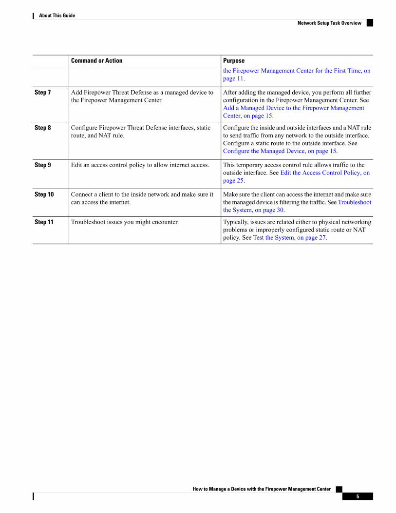
Step 1 In your browser's address or location field, enter https://10.10.2.2.Step 2 Log in with username admin and password Admin123.
An initial configuration page is displayed. The following steps walk you through the configuration one section at a time.Step 3 Enter a new Firepower Management Center password in the following fields.
Step 4 Enter the network settings shown in the following figure. Enter DNS server specific to your organization, if applicable.
How to Manage a Device with the Firepower Management Center11
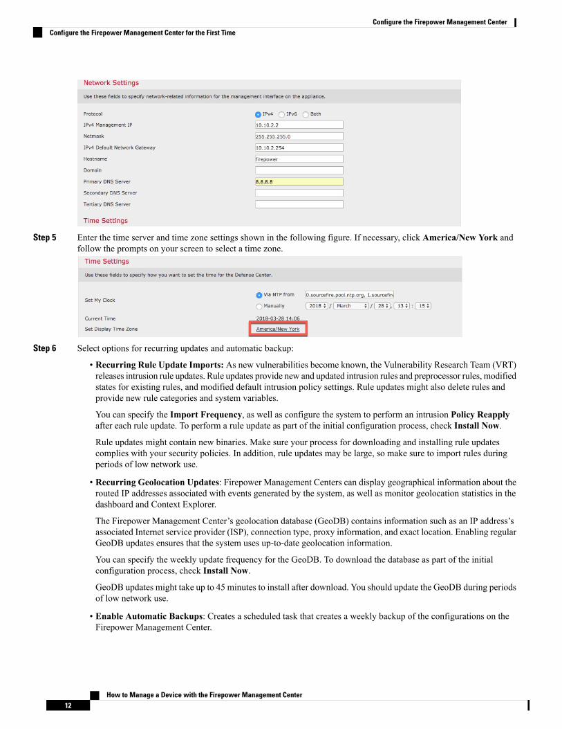
Step 5 Enter the time server and time zone settings shown in the following figure. If necessary, click America/New York andfollow the prompts on your screen to select a time zone.
Step 6 Select options for recurring updates and automatic backup:
• Recurring Rule Update Imports: As new vulnerabilities become known, the Vulnerability Research Team (VRT)releases intrusion rule updates. Rule updates provide new and updated intrusion rules and preprocessor rules, modifiedstates for existing rules, and modified default intrusion policy settings. Rule updates might also delete rules andprovide new rule categories and system variables.
You can specify the Import Frequency, as well as configure the system to perform an intrusion Policy Reapplyafter each rule update. To perform a rule update as part of the initial configuration process, check Install Now.
Rule updates might contain new binaries. Make sure your process for downloading and installing rule updatescomplies with your security policies. In addition, rule updates may be large, so make sure to import rules duringperiods of low network use.
• Recurring Geolocation Updates: Firepower Management Centers can display geographical information about therouted IP addresses associated with events generated by the system, as well as monitor geolocation statistics in thedashboard and Context Explorer.
The Firepower Management Center’s geolocation database (GeoDB) contains information such as an IP address’sassociated Internet service provider (ISP), connection type, proxy information, and exact location. Enabling regularGeoDB updates ensures that the system uses up-to-date geolocation information.
You can specify the weekly update frequency for the GeoDB. To download the database as part of the initialconfiguration process, check Install Now.
GeoDB updates might take up to 45 minutes to install after download. You should update the GeoDB during periodsof low network use.
• Enable Automatic Backups: Creates a scheduled task that creates a weekly backup of the configurations on theFirepower Management Center.
How to Manage a Device with the Firepower Management Center12
Configure the Firepower Management CenterConfigure the Firepower Management Center for the First Time

Step 7 Leave the License Settings section blank because it applies to Classic licenses only; you'll apply a Smart License later.
Step 8 Scroll through the license agreement and, if you agree, check I have read and agree to the EndUser License Agreementand click Apply.
Step 9 Wait until the Firepower Management Center processes the information you entered. At that point, the Dashboard isdisplayed.
How to Manage a Device with the Firepower Management Center13
Configure the Firepower Management CenterConfigure the Firepower Management Center for the First Time
What to do next
See License the Firepower Management Center, on page 14.
License the Firepower Management CenterThis task discusses how to use a 90-day evaluation license with the Firepower Management Center andmanaged devices. If you have a Smart License, you can use it instead.
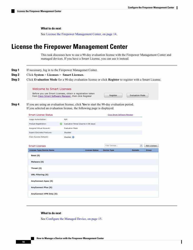
Step 1 If necessary, log in to the Firepower Managemet Center.Step 2 Click System > Licenses > Smart Licenses.Step 3 Click Evaluation Mode for a 90-day evaluation license or click Register to register with a Smart License.
Step 4 If you are using an evaluation license, click Yes to start the 90-day evaluation period.If you selected an evaluation license, the following page is displayed.
What to do next
See Configure the Managed Device, on page 15.
How to Manage a Device with the Firepower Management Center14
Configure the Firepower Management CenterLicense the Firepower Management Center
C H A P T E R 4Configure the Managed Device
Configuring a managed device means adding it to the Firepower Management Center and setting up itsinterfaces.
• Add a Managed Device to the Firepower Management Center, on page 15• Configure Managed Device Interfaces, on page 17• Add Static Routes, on page 19• Add a NAT Policy, on page 20
Add a Managed Device to the Firepower Management CenterAfter you add a Firepower Threat Defense as a managed device, you configure it further using the FirepowerManagement Center.
Before you begin
You must complete all of the following tasks first:
• Connect the Firepower Management Center to the Network, on page 7
• Connect the Managed Device to the Network, on page 8
• Configure the Firepower Management Center, on page 11
Step 1 In the Firepower Management Center, click Devices > Device Management.Step 2 Click Add > Device.
Enter the information shown in the following figure.
How to Manage a Device with the Firepower Management Center15
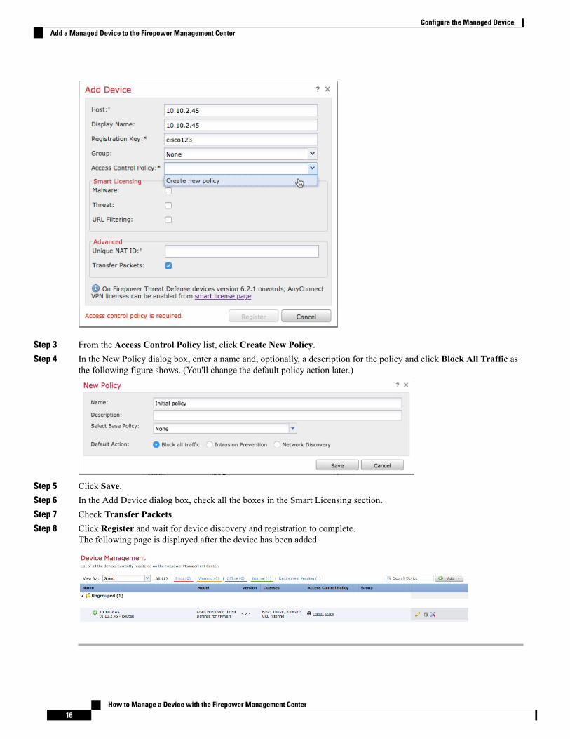
Step 3 From the Access Control Policy list, click Create New Policy.Step 4 In the New Policy dialog box, enter a name and, optionally, a description for the policy and click Block All Traffic as
the following figure shows. (You'll change the default policy action later.)
Step 5 Click Save.Step 6 In the Add Device dialog box, check all the boxes in the Smart Licensing section.Step 7 Check Transfer Packets.Step 8 Click Register and wait for device discovery and registration to complete.
The following page is displayed after the device has been added.
How to Manage a Device with the Firepower Management Center16
Configure the Managed DeviceAdd a Managed Device to the Firepower Management Center
What to do next
See Configure Managed Device Interfaces, on page 17.
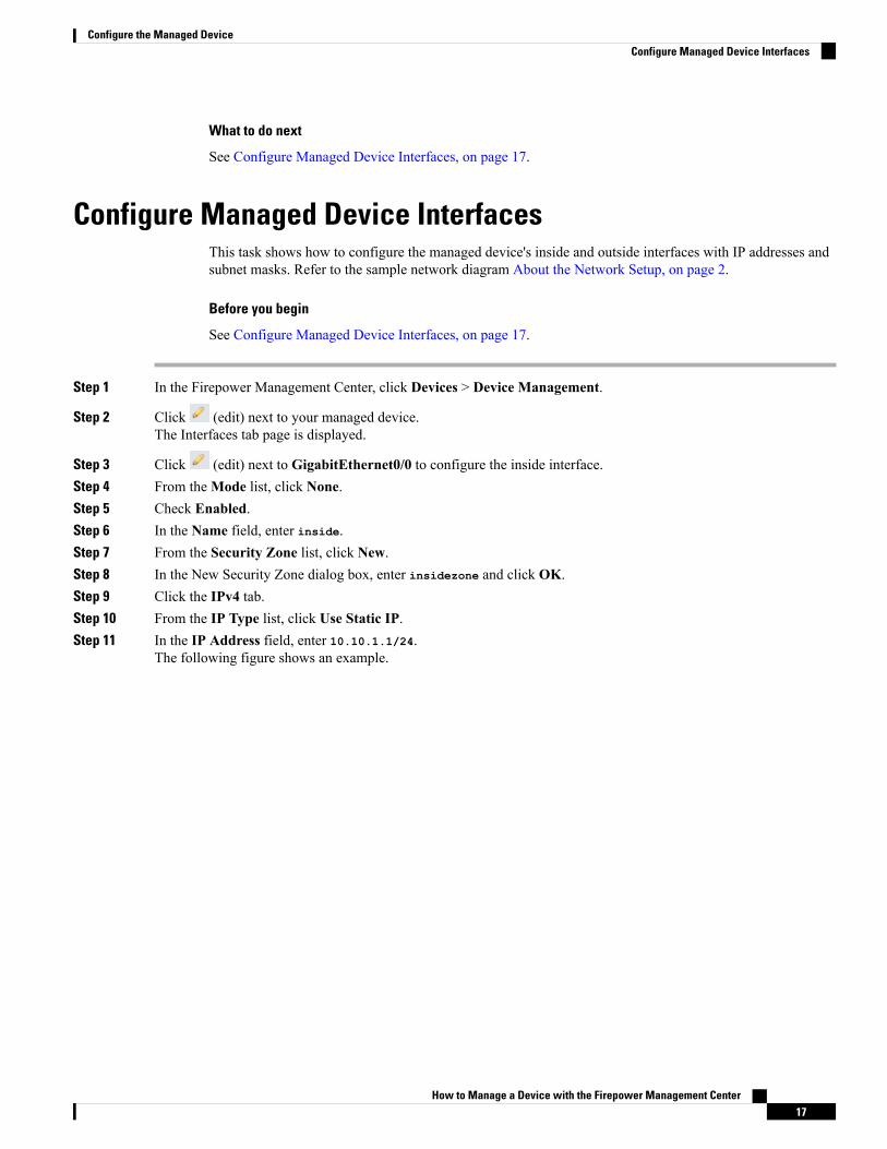
Configure Managed Device InterfacesThis task shows how to configure the managed device's inside and outside interfaces with IP addresses andsubnet masks. Refer to the sample network diagram About the Network Setup, on page 2.
Before you begin
See Configure Managed Device Interfaces, on page 17.
Step 1 In the Firepower Management Center, click Devices > Device Management.
Step 2 Click (edit) next to your managed device.The Interfaces tab page is displayed.
Step 3 Click (edit) next to GigabitEthernet0/0 to configure the inside interface.Step 4 From theMode list, click None.Step 5 Check Enabled.Step 6 In the Name field, enter inside.Step 7 From the Security Zone list, click New.Step 8 In the New Security Zone dialog box, enter insidezone and click OK.Step 9 Click the IPv4 tab.Step 10 From the IP Type list, click Use Static IP.Step 11 In the IP Address field, enter 10.10.1.1/24.
The following figure shows an example.
How to Manage a Device with the Firepower Management Center17
Configure the Managed DeviceConfigure Managed Device Interfaces
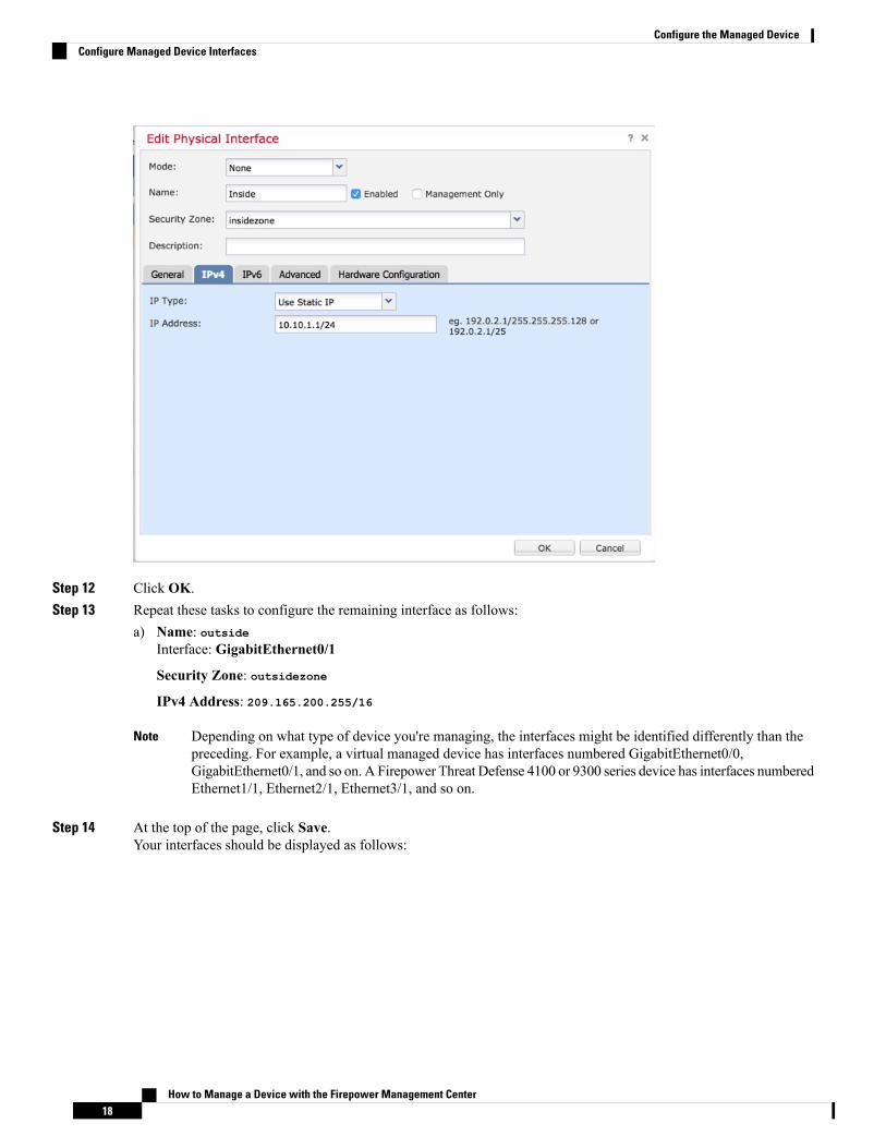
Step 12 Click OK.Step 13 Repeat these tasks to configure the remaining interface as follows:
a) Name: outsideInterface: GigabitEthernet0/1
Security Zone: outsidezone
IPv4 Address: 209.165.200.255/16
Depending on what type of device you're managing, the interfaces might be identified differently than thepreceding. For example, a virtual managed device has interfaces numbered GigabitEthernet0/0,GigabitEthernet0/1, and so on. A Firepower Threat Defense 4100 or 9300 series device has interfaces numberedEthernet1/1, Ethernet2/1, Ethernet3/1, and so on.
Note
Step 14 At the top of the page, click Save.Your interfaces should be displayed as follows:
How to Manage a Device with the Firepower Management Center18
Configure the Managed DeviceConfigure Managed Device Interfaces

What to do next
See Add Static Routes, on page 19.
Add Static RoutesA static route is a one-hop route that causes network traffic to go directly to a mapped resource; in this case,the outside gateway. We recommend setting up a static route in a simple network such as this.
For more information about static and dynamic routing, see Supported Route Types.
Step 1 In the Firepower Management Center, click Devices > Device Management.
Step 2 Click (edit) next to your managed device.Step 3 Click the Routing tab.Step 4 Click Static Route.Step 5 Click Add Route.Step 6 Enter the following information in the Add Static Route Configuration dialog box:
InterfaceClick outside.Available NetworkAdd any-ipv4 to Selected NetworksGateway
Click (add) and Name the gateway outsidegateway with a Network value of 209.165.200.254.
The following figure shows an example.
How to Manage a Device with the Firepower Management Center19
Configure the Managed DeviceAdd Static Routes

Step 7 Click OK.Step 8 At the top of the page, click Save.
What to do next
See Add a NAT Policy, on page 20.
Add a NAT PolicyThe managed device uses NAT to enable communication between internal, non-routable IP addresses (like10.10.2.1) and the internet. Routable, public IP addresses are scarce; without NAT, you would be severelyrestricted in the IP addresses you could use. The NAT policy you set up in this task forwards packets fromthe inside interface to the outside interface.
For more information about NAT, see Why Use NAT?
Step 1 In the Firepower Management Center, click Devices > NAT.
How to Manage a Device with the Firepower Management Center20
Configure the Managed DeviceAdd a NAT Policy

Step 2 Click New Policy > Threat Defense NAT.Step 3 In the New Policy dialog box, enter the following information:
NameEnter Inside-Outside-NATDescriptionEnter an optional description.Selected DevicesAdd 10.10.2.45 to Selected Devices.
Step 4 Click Save.Step 5 After the page refreshes, click Add Rule.Step 6 Click the Interface Objects tab.Step 7 Add the security zones you created earlier as source and destination interface objects as follows:
Step 8 Click the Translation tab.
Step 9 Click (Add) next to Original Source.Step 10 In the New Network Objects dialog box, enter the following information:
NameEnter insidesubnetDescriptionEnter an optional description.NetworkEnter 10.10.2.0/24
Step 11 From the Translated Source list, click Destination Interface IP.The following figure shows an example Add NAT Rule dialog box.
How to Manage a Device with the Firepower Management Center21
Configure the Managed DeviceAdd a NAT Policy

Step 12 Click OK.Step 13 At the top of the page, click Save.Step 14 Deploy your changes.
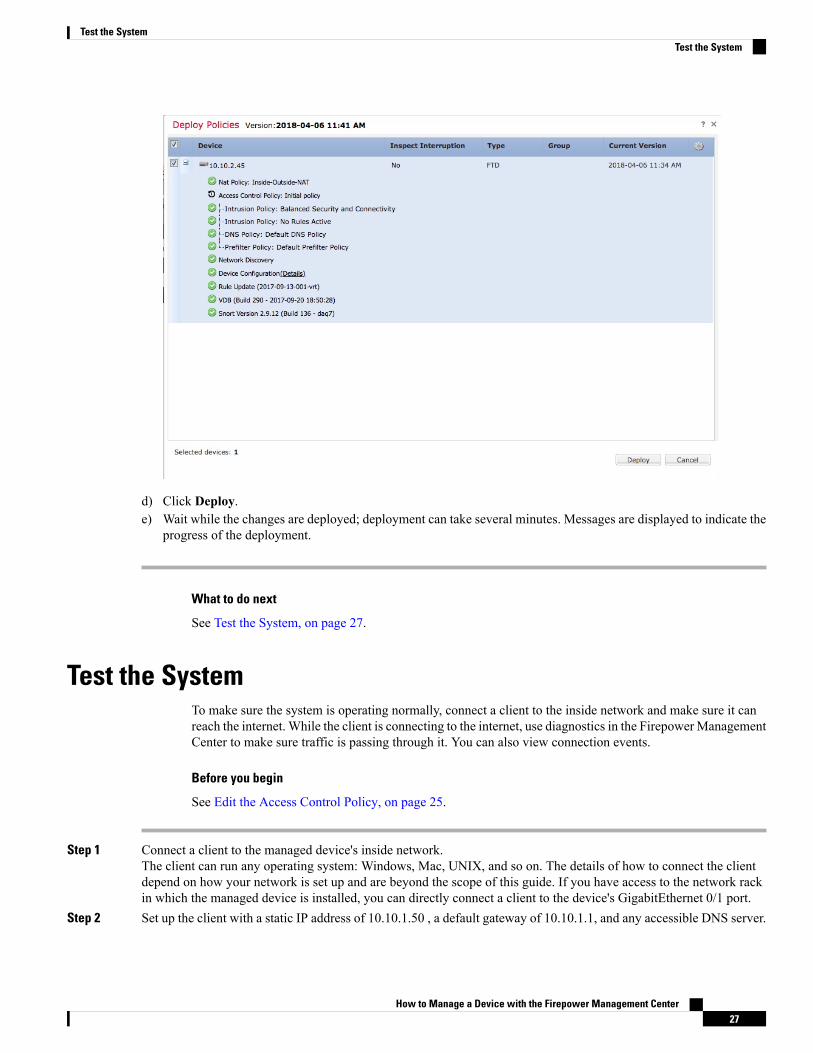
a) At the top of the page, click Deploy.b) Optional. Expand the device to display the changes you're about to make.c) Check the box to the left of the device.
The following figure shows an example.
How to Manage a Device with the Firepower Management Center22
Configure the Managed DeviceAdd a NAT Policy

d) Click Deploy.e) Wait while the changes are deployed; deployment can take several minutes. Messages are displayed to indicate the
progress of the deployment.
What to do next
See Test the System, on page 25.
How to Manage a Device with the Firepower Management Center23
Configure the Managed DeviceAdd a NAT Policy

How to Manage a Device with the Firepower Management Center24
Configure the Managed DeviceAdd a NAT Policy
C H A P T E R 5Test the System
To make sure everything is set up properly, you'll create an access control policy to allow all traffic, connecta client to the inside network, and make sure the client can connect to the internet. Finally, you'll monitortraffic on the managed device directly as well as on the Firepower Management Center.
• Edit the Access Control Policy, on page 25• Test the System, on page 27• Troubleshoot the System, on page 30
Edit the Access Control PolicyYou'll create a temporary access control policy to allow all traffic, with no inspection, from the inside networkto the outside network to test the following:
• A client connected to the inside network can connect to the internet.
• Traffic is being filtered through the Firepower Threat Defense device. (The managed device should "see"all the traffic even if it's not being filtered.)
Before you begin
Make sure you have completed all other tasks discussed in this guide before continuing.
Step 1 In the Firepower Management Center, click Policies > Access Control > Access Control.
Step 2 Click (edit) next to Initial Policy.Step 3 Click Add Rule.Step 4 Enter the following information in the Add Rule dialog box:
How to Manage a Device with the Firepower Management Center25

Step 5 Click the Logging tab.Step 6 Check Log at end of connection.Step 7 Click Add.
The policy page is displayed.Step 8 On the Initial Policy page, from the Default Action list, click Intrusion Prevention: Balanced Security and
Connectivity.
Step 9 Next to the list, click (logging).Step 10 Check Log at end of connection.Step 11 Click OK.Step 12 At the top of the page, click Save.Step 13 Deploy the changes:
a) At the top of the page, click Deploy.b) Optional. Expand the device to display the changes you're about to make.c) Check the box to the left of the device.
The following figure shows an example.
How to Manage a Device with the Firepower Management Center26
Test the SystemEdit the Access Control Policy
d) Click Deploy.e) Wait while the changes are deployed; deployment can take several minutes. Messages are displayed to indicate the
progress of the deployment.
What to do next
See Test the System, on page 27.
Test the SystemTo make sure the system is operating normally, connect a client to the inside network and make sure it canreach the internet. While the client is connecting to the internet, use diagnostics in the FirepowerManagementCenter to make sure traffic is passing through it. You can also view connection events.
Before you begin
See Edit the Access Control Policy, on page 25.
Step 1 Connect a client to the managed device's inside network.The client can run any operating system: Windows, Mac, UNIX, and so on. The details of how to connect the clientdepend on how your network is set up and are beyond the scope of this guide. If you have access to the network rackin which the managed device is installed, you can directly connect a client to the device's GigabitEthernet 0/1 port.
Step 2 Set up the client with a static IP address of 10.10.1.50 , a default gateway of 10.10.1.1, and any accessible DNS server.
How to Manage a Device with the Firepower Management Center27
Test the SystemTest the System

The default gateway should be the IP address of the inside interface. The client contacts this gateway first before sendingany traffic to inside or outside addresses.
Step 3 Log in to the Firepower Management Center.Step 4 Click Devices > Device Management.
Step 5 Next to your managed device, click (Troubleshoot).Step 6 Click Advanced Troubleshooting.Step 7 Click the Packet Tracer tab.Step 8 Enter the following information in the Packet Tracer tab page.
The values for Source IP address and Source Port can be anything. What's being tested is whether or not traffic isforwarded from the inside interface to the outside interface. Only the Destination IP address and Destination Portvalues are used in this example.
Step 9 On your client, ping or browse to an internet site.Step 10 On the Packet Tracer tab page, click Start.
For information about interpreting the results, see Interpret the Results, on page 31.
Step 11 Click the Capture w/ Trace tab.Step 12 Check Enable Auto-Refresh and change the refresh interval if desired.Step 13 Click Add Capture.Step 14 Enter the following information in the Add Capture dialog box.
How to Manage a Device with the Firepower Management Center28
Test the SystemTest the System

Step 15 Click Save.Step 16 On your client, ping or browse to an internet site.
Step 17 In the bottom pane, click (Refresh).The Firepower Management Center bottom pane displays results of the packet capture and trace. Look for messageslike the following, which confirms traffic from the managed device's inside interface is matching your access controlpolicy:Phase: 5Type: SNORTSubtype:Result: ALLOWConfig:Additional Information:Snort Trace:Packet: TCP, ACK, seq 2101701398, ack 3091508482AppID: service HTTP (676), application Adobe Analytics (2846), out-of-orderFirewall: allow rule, 'Temporary Allow Policy' , allowSnort id 1, NAP id 1, IPS id 0, Verdict PASSSnort Verdict: (pass-packet) allow this packet
For additional information about interpreting the results, see Interpret the Results, on page 31.
For more information about the packet tracer, see Packet Tracer Overview.
Step 18 Click Analysis > Connections > Events.
Step 19 In the upper right corner, click to adjust the frequency of page updates.Step 20 Click the Preferences tab.Step 21 In the Refresh Interval (minutes) field, enter 1.Step 22 Click Apply.Step 23 Navigate away from the page and come back to the Connection Events page.Step 24 Wait for the page to refresh.
How to Manage a Device with the Firepower Management Center29
Test the SystemTest the System

Connection events similar to the following should be displayed.
Step 25 To customize the view, click Table View of Connection Events.
For more information, see Connection and Security Intelligence Event Fields and Using Connection and SecurityIntelligence Event Tables.
Step 26 If you see packet capture messages and connection events, congratulations! You have set up your system successfully.
What to do next
If errors are displayed or if your client cannot connect to the internet, see Troubleshoot the System, on page30.
Troubleshoot the SystemThis topic discusses solutions to problems you might encounter with your system; typically, no internet accessfor your network client.
Check the Static Route and Default Gateway
Check the static route and default gateway by pinging an internet site from your managed device as follows:
1. Using an SSH client or a virtual device's management console, log in to your managed device.
2. If required by your managed device, enter connect ftd
3. Enter ping 8.8.8.8
Successful results are displayed as follows:Type escape sequence to abort.Sending 5, 100-byte ICMP Echoes to 8.8.8.8, timeout is 2 seconds:!!!!!Success rate is 100 percent (5/5), round-trip min/av/max = 60/62/70 ms
If you cannot ping an internet IP address, make sure the managed device interfaces are connected properly.Make sure the link and activity LEDs on both ends of the cable are on (activity LED should flash).
Connection Events Not Displayed
The most likely reason connection events are not displayed is that you didn't enable logging in your accesscontrol rule or access control policy. See Edit the Access Control Policy, on page 25.
How to Manage a Device with the Firepower Management Center30
Test the SystemTroubleshoot the System

Interpret the ResultsThis topic discusses how to interpret the results of the packet capture and traceroute command.
Interpret Packet Tracer
The following excerpts from the packet tracer show the significant information and decisions made inforwarding traffic from the inside interface to the outside interface. Some of the configuration informationdiscussed in this guide is highlighted. Note the following:
• Phase 3 resolves the outside gateway to 209.165.200.254
• Phase 4 shows the first time the Temporary Allow Policy is invoked
• Phase 6 shows the NAT policy forwarding from the inside client to the outside interface
• Phase 16 shows the inspection engine (Snort) allowing the traffic according to the Temporary AllowPolicy
A failure at any of these phases could result in traffic being rejected or dropped, depending on whether policieswere configured incorrectly or configured to block the traffic.Phase: 3Type: ROUTE-LOOKUPSubtype: Resolve Egress InterfaceResult: ALLOWConfig:Additional Information:found next-hop 209.165.200.254 using egress ifc Outside
Phase: 4Type: ACCESS-LISTSubtype: logResult: ALLOWConfig:access-group CSM_FW_ACL_ globalaccess-list CSM_FW_ACL_ advanced permit ip ifc Inside any ifc Outside any rule-id 268434433
access-list CSM_FW_ACL_ remark rule-id 268434433: ACCESS POLICY: Initial Policy - Mandatoryaccess-list CSM_FW_ACL_ remark rule-id 268434433: L7 RULE: Temporary Allow PolicyAdditional Information:This packet will be sent to snort for additional processing where a verdict will be reached
Phase: 6Type: NATSubtype:Result: ALLOWConfig:object network insidesubnetnat (Inside,Outside) dynamic interfaceAdditional Information:Dynamic translate 10.10.1.50/52177 to 209.165.200.225/52177Phase: 15Type: EXTERNAL-INSPECTSubtype:Result: ALLOWConfig:Additional Information:Application: 'SNORT Inspect'
Phase: 16
How to Manage a Device with the Firepower Management Center31
Test the SystemInterpret the Results

Type: SNORTSubtype:Result: ALLOWConfig:Additional Information:Snort Trace:Packet: UDPSession: new snort sessionAppID: service DNS (617), application unknown (0)Firewall: allow rule, 'Temporary Allow Policy' , allowSnort id 1, NAP id 1, IPS id 0, Verdict PASSSnort Verdict: (pass-packet) allow this packet
Packet Tracker and Capture w/ Trace might display different phase numbers but the information displayed ineach phase should be very similar.
Note
If there is no final SNORT phase, look for errors in the ROUTE-LOOKUP phase. For example, the followingcould indicate there is a problem with your outside interface. Verify its IP address and the IP address of theoutside gateway.Phase: 15Type: ROUTE-LOOKUPSubtype: Resolve Egress InterfaceResult: ALLOWConfig:Additional Information:found next-hop 209.165.200.254 using egress ifc outside
Result:input-interface: insideinput-status: upinput-line-status: upoutput-interface: outsideoutput-status: upoutput-line-status: upAction: dropDrop-reason: (no-adjacency) No valid adjacency
Note
Symptom: No Network Translation
If your packet capture does not have a line similar to the following, it likely means NAT is set up incorrectly.Dynamic translate 10.10.1.50/65413 to 209.165.200.225/65413
Solution: Set up dynamic NAT as discussed in Add a NAT Policy, on page 20.
Symptom: Access Control Policy is Blocking Traffic
If your access control policy is configured to block traffic instead of allowing it, your packet capture containsthe following line:Drop-reason: (acl-drop) Flow is denied by configured rule
You can confirm this is the case by looking at connection events: Analysis > Connections > Events.
How to Manage a Device with the Firepower Management Center32
Test the SystemInterpret the Results

Solution: Configure your access control policy to allow traffic as discussed in Edit the Access Control Policy,on page 25.
How to Manage a Device with the Firepower Management Center33
Test the SystemInterpret the Results

How to Manage a Device with the Firepower Management Center34
Test the SystemInterpret the Results
Related Documents