How to configure Inter‐VLAN routing (Router‐on‐a‐stick) Router‐on‐a‐stick or Inter‐VLAN routing is a term frequently used to describe a setup up that consists of a router and switch connected using one Ethernet link configured as an 802.1q trunk link. In this setup, the switch is configured with multiple VLANs and the router performs all routing between the different networks/VLANs. While some believe the term 'router‐on‐a‐stick' sounds a bit silly, it's a very popular term and commonly used in networks where no layer‐3 switch exists. LAB Diagram: Networking devices and notes for this LAB 1‐ Cisco Switch WS‐C2960+24TC‐L: 2 Units 2‐ Mikrotik RouterBoard (hAP lite): 1 Unit 3‐ PCs 4‐ UTP Cat6 cables

Welcome message from author
This document is posted to help you gain knowledge. Please leave a comment to let me know what you think about it! Share it to your friends and learn new things together.
Transcript
How to configure Inter‐VLAN routing (Router‐on‐a‐stick)
Router‐on‐a‐stick or Inter‐VLAN routing is a term frequently used to describe a setup up that
consists of a router and switch connected using one Ethernet link configured as an 802.1q trunk link. In this setup, the switch is configured with multiple VLANs and the router performs all routing between the different networks/VLANs.
While some believe the term 'router‐on‐a‐stick' sounds a bit silly, it's a very popular term and commonly used in networks where no layer‐3 switch exists.
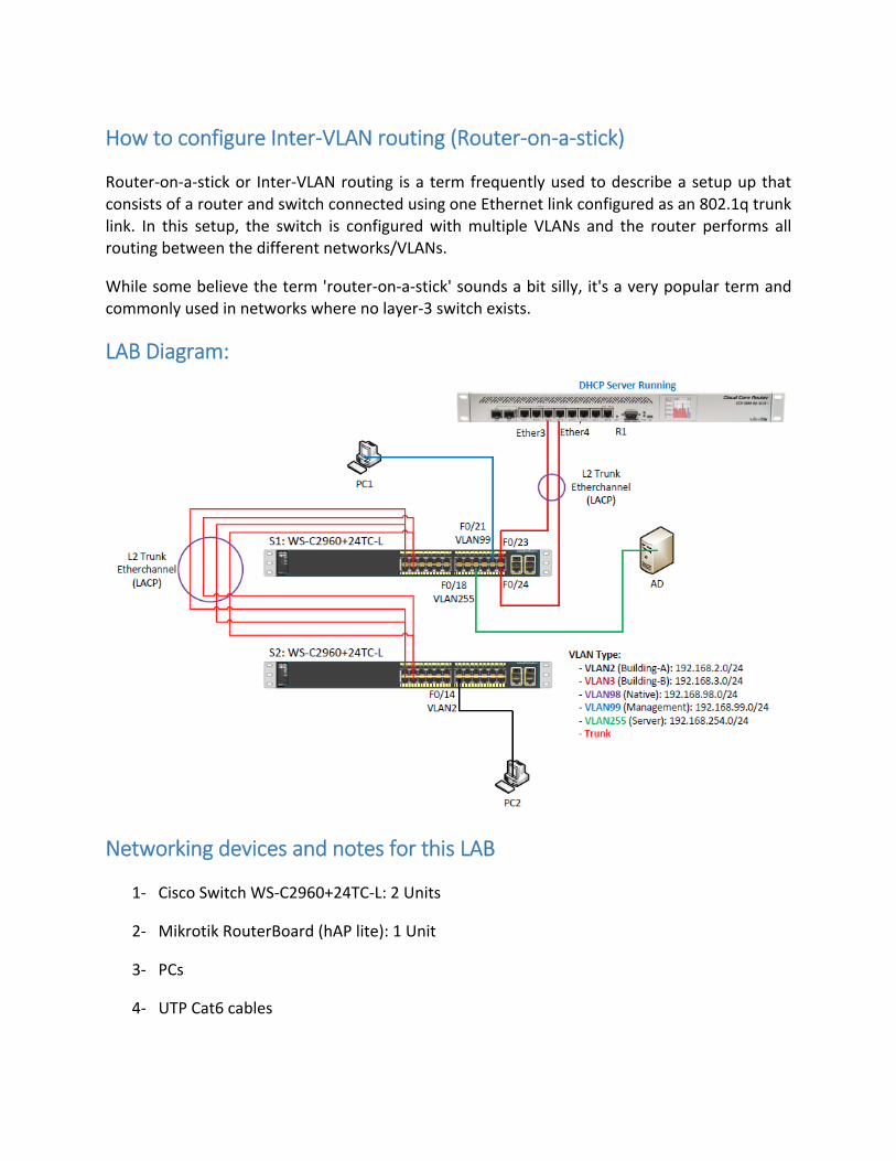
LAB Diagram:
Networking devices and notes for this LAB
1‐ Cisco Switch WS‐C2960+24TC‐L: 2 Units
2‐ Mikrotik RouterBoard (hAP lite): 1 Unit
3‐ PCs
4‐ UTP Cat6 cables
5‐ Console cable
Task to be completed 1‐ Configure VLAN
2‐ Configure VTP
3‐ Assign ports to VLANs for switches
4‐ Configure Etherchannel on switches
5‐ Configure Bonding interface on Mikrotik RB
6‐ Enable RSTP for both switches and assign root bridge
7‐ Configure Trunk ports
8‐ Create sub‐interfaces for VLANs on Mikrotik RB
9‐ Configure DHCP on Mikrotik RB for all VLANs
10‐ Challenging Problem (How to offer IP addresses to all VLANs by using DHCP server which is not
running on Mikrotik RB)
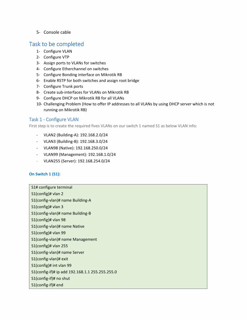
Task 1 ‐ Configure VLAN First step is to create the required fives VLANs on our switch 1 named S1 as below VLAN info:
‐ VLAN2 (Building‐A): 192.168.2.0/24
‐ VLAN3 (Building‐B): 192.168.3.0/24
‐ VLAN98 (Native): 192.168.250.0/24
‐ VLAN99 (Management): 192.168.1.0/24
‐ VLAN255 (Server): 192.168.254.0/24
On Switch 1 (S1):
S1# configure terminal
S1(config)# vlan 2
S1(config‐vlan)# name Building‐A
S1(config)# vlan 3
S1(config‐vlan)# name Building‐B
S1(config)# vlan 98
S1(config‐vlan)# name Native
S1(config)# vlan 99
S1(config‐vlan)# name Management
S1(config)# vlan 255
S1(config‐vlan)# name Server
S1(config‐vlan)# exit
S1(config)# int vlan 99
S1(config‐if)# ip add 192.168.1.1 255.255.255.0
S1(config‐if)# no shut
S1(config‐if)# end
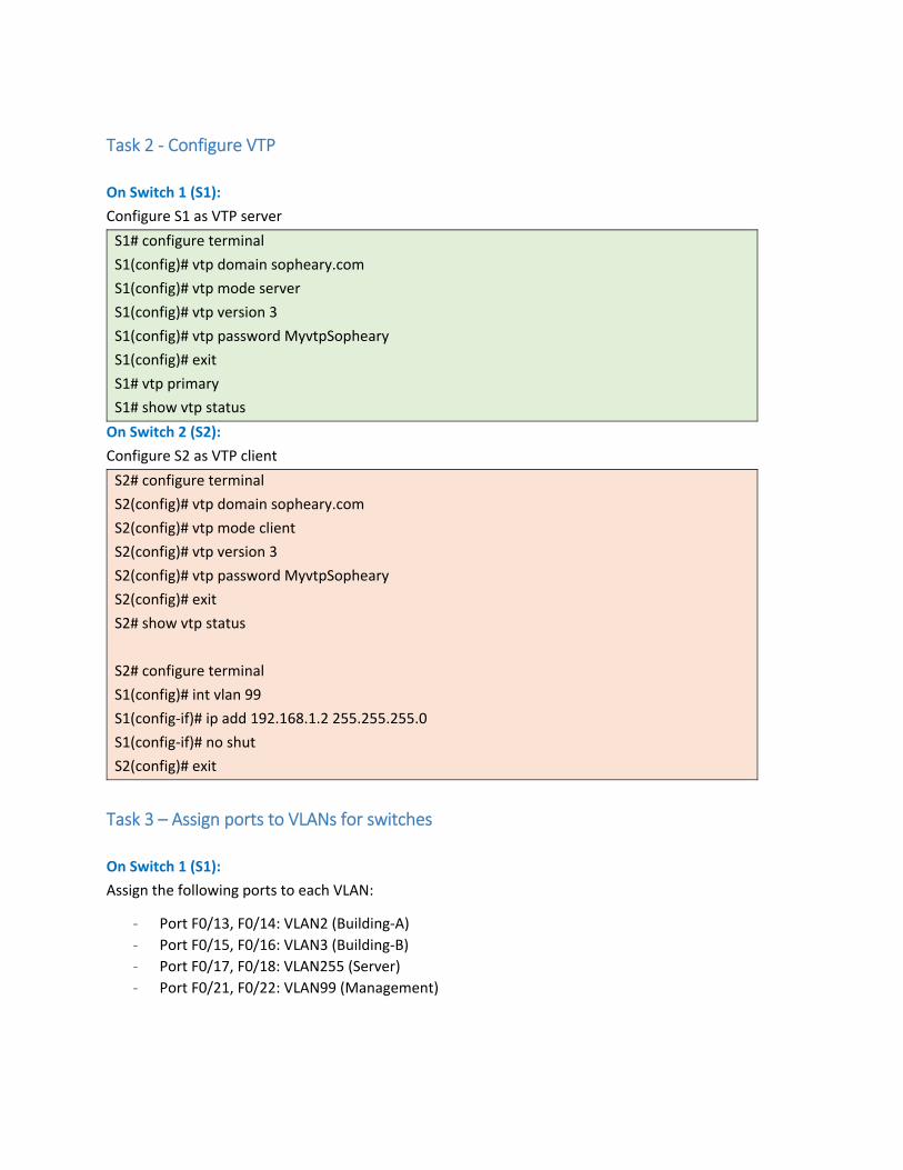
Task 2 ‐ Configure VTP
On Switch 1 (S1):
Configure S1 as VTP server
S1# configure terminal
S1(config)# vtp domain sopheary.com
S1(config)# vtp mode server
S1(config)# vtp version 3
S1(config)# vtp password MyvtpSopheary
S1(config)# exit
S1# vtp primary
S1# show vtp status
On Switch 2 (S2):
Configure S2 as VTP client
S2# configure terminal
S2(config)# vtp domain sopheary.com
S2(config)# vtp mode client
S2(config)# vtp version 3
S2(config)# vtp password MyvtpSopheary
S2(config)# exit
S2# show vtp status
S2# configure terminal
S1(config)# int vlan 99
S1(config‐if)# ip add 192.168.1.2 255.255.255.0
S1(config‐if)# no shut
S2(config)# exit
Task 3 – Assign ports to VLANs for switches
On Switch 1 (S1):
Assign the following ports to each VLAN:
‐ Port F0/13, F0/14: VLAN2 (Building‐A)
‐ Port F0/15, F0/16: VLAN3 (Building‐B)
‐ Port F0/17, F0/18: VLAN255 (Server)
‐ Port F0/21, F0/22: VLAN99 (Management)
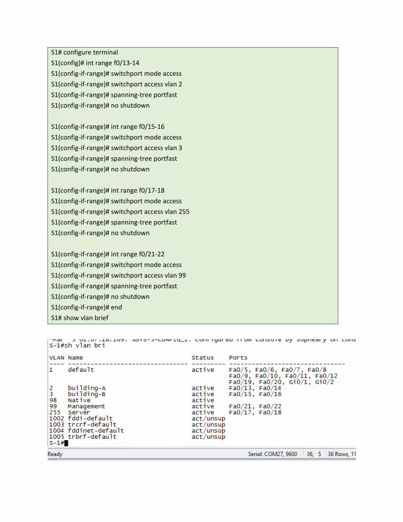
S1# configure terminal
S1(config)# int range f0/13‐14
S1(config‐if‐range)# switchport mode access
S1(config‐if‐range)# switchport access vlan 2
S1(config‐if‐range)# spanning‐tree portfast
S1(config‐if‐range)# no shutdown
S1(config‐if‐range)# int range f0/15‐16
S1(config‐if‐range)# switchport mode access
S1(config‐if‐range)# switchport access vlan 3
S1(config‐if‐range)# spanning‐tree portfast
S1(config‐if‐range)# no shutdown
S1(config‐if‐range)# int range f0/17‐18
S1(config‐if‐range)# switchport mode access
S1(config‐if‐range)# switchport access vlan 255
S1(config‐if‐range)# spanning‐tree portfast
S1(config‐if‐range)# no shutdown
S1(config‐if‐range)# int range f0/21‐22
S1(config‐if‐range)# switchport mode access
S1(config‐if‐range)# switchport access vlan 99
S1(config‐if‐range)# spanning‐tree portfast
S1(config‐if‐range)# no shutdown
S1(config‐if‐range)# end
S1# show vlan brief
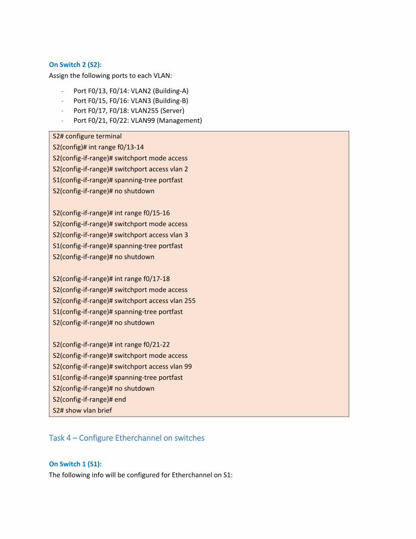
On Switch 2 (S2):
Assign the following ports to each VLAN:
‐ Port F0/13, F0/14: VLAN2 (Building‐A)
‐ Port F0/15, F0/16: VLAN3 (Building‐B)
‐ Port F0/17, F0/18: VLAN255 (Server)
‐ Port F0/21, F0/22: VLAN99 (Management)
S2# configure terminal
S2(config)# int range f0/13‐14
S2(config‐if‐range)# switchport mode access
S2(config‐if‐range)# switchport access vlan 2
S1(config‐if‐range)# spanning‐tree portfast
S2(config‐if‐range)# no shutdown
S2(config‐if‐range)# int range f0/15‐16
S2(config‐if‐range)# switchport mode access
S2(config‐if‐range)# switchport access vlan 3
S1(config‐if‐range)# spanning‐tree portfast
S2(config‐if‐range)# no shutdown
S2(config‐if‐range)# int range f0/17‐18
S2(config‐if‐range)# switchport mode access
S2(config‐if‐range)# switchport access vlan 255
S1(config‐if‐range)# spanning‐tree portfast
S2(config‐if‐range)# no shutdown
S2(config‐if‐range)# int range f0/21‐22
S2(config‐if‐range)# switchport mode access
S2(config‐if‐range)# switchport access vlan 99
S1(config‐if‐range)# spanning‐tree portfast
S2(config‐if‐range)# no shutdown
S2(config‐if‐range)# end
S2# show vlan brief
Task 4 – Configure Etherchannel on switches
On Switch 1 (S1):
The following info will be configured for Etherchannel on S1:
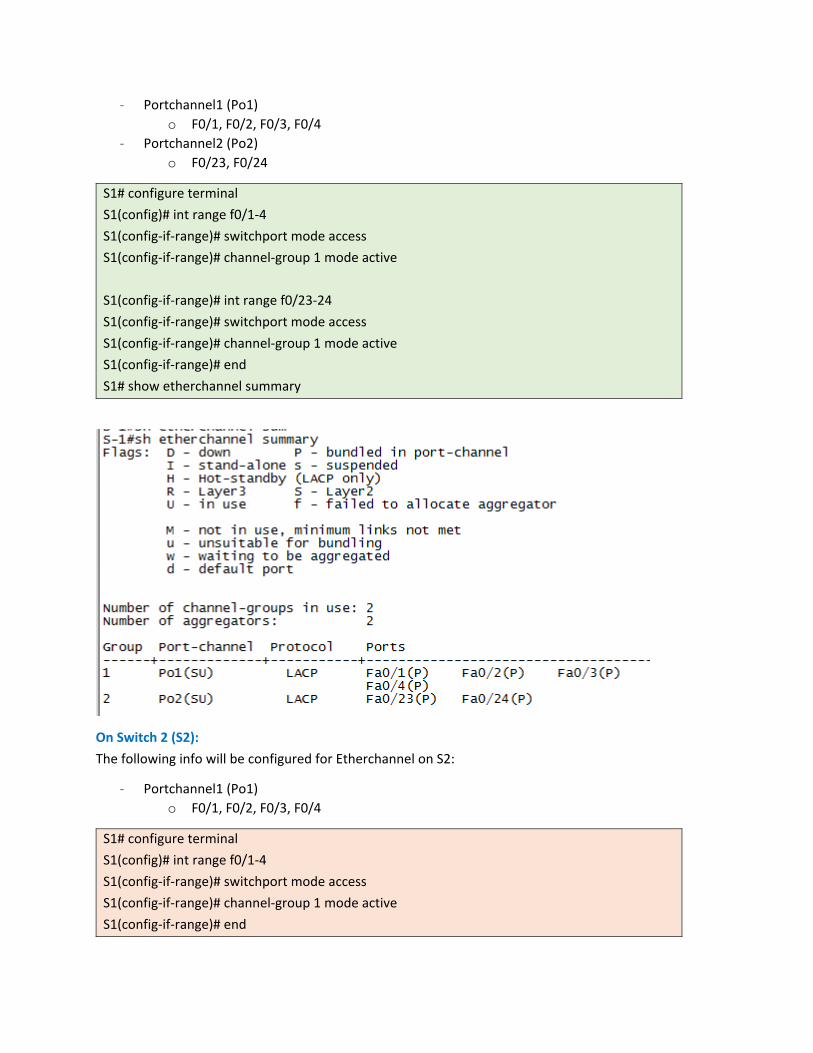
‐ Portchannel1 (Po1)
o F0/1, F0/2, F0/3, F0/4
‐ Portchannel2 (Po2)
o F0/23, F0/24
S1# configure terminal
S1(config)# int range f0/1‐4
S1(config‐if‐range)# switchport mode access
S1(config‐if‐range)# channel‐group 1 mode active
S1(config‐if‐range)# int range f0/23‐24
S1(config‐if‐range)# switchport mode access
S1(config‐if‐range)# channel‐group 1 mode active
S1(config‐if‐range)# end
S1# show etherchannel summary
On Switch 2 (S2):
The following info will be configured for Etherchannel on S2:
‐ Portchannel1 (Po1)
o F0/1, F0/2, F0/3, F0/4
S1# configure terminal
S1(config)# int range f0/1‐4
S1(config‐if‐range)# switchport mode access
S1(config‐if‐range)# channel‐group 1 mode active
S1(config‐if‐range)# end
S1# show etherchannel summary
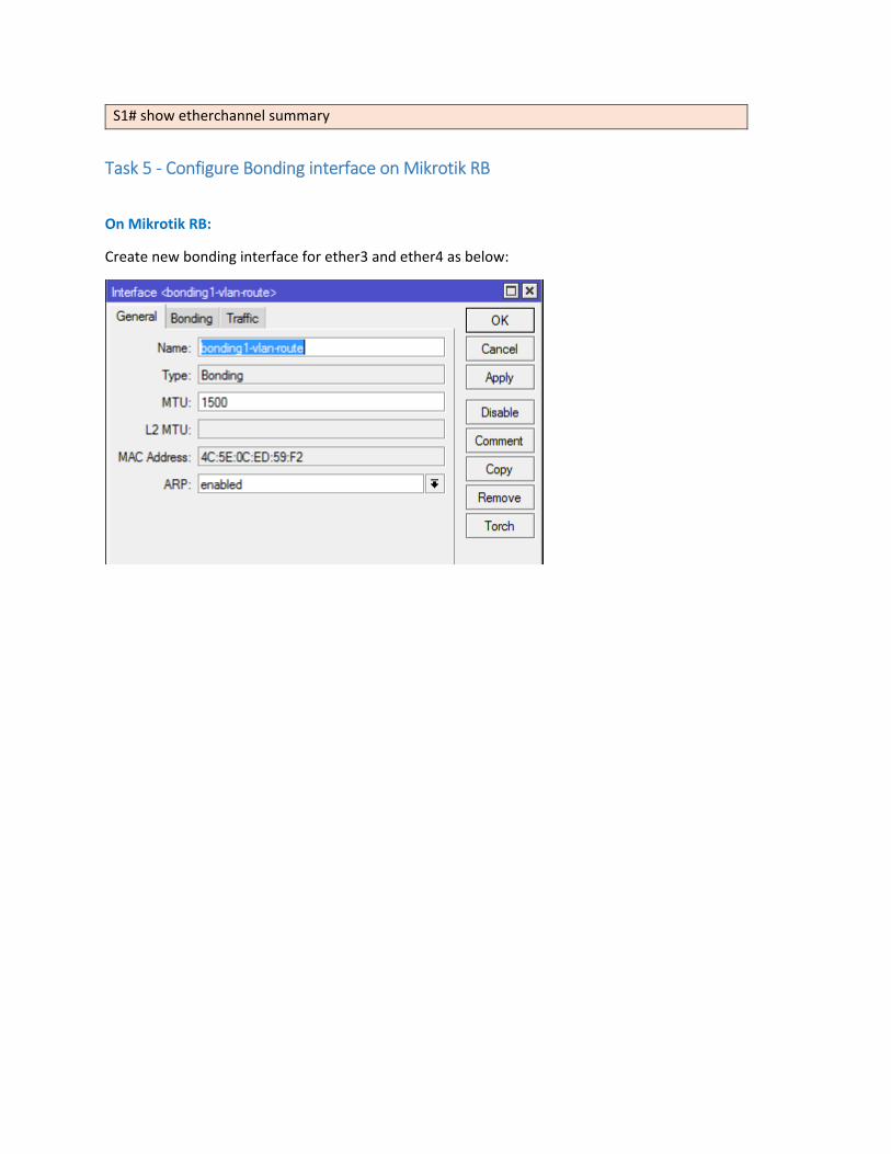
Task 5 ‐ Configure Bonding interface on Mikrotik RB
On Mikrotik RB:
Create new bonding interface for ether3 and ether4 as below:
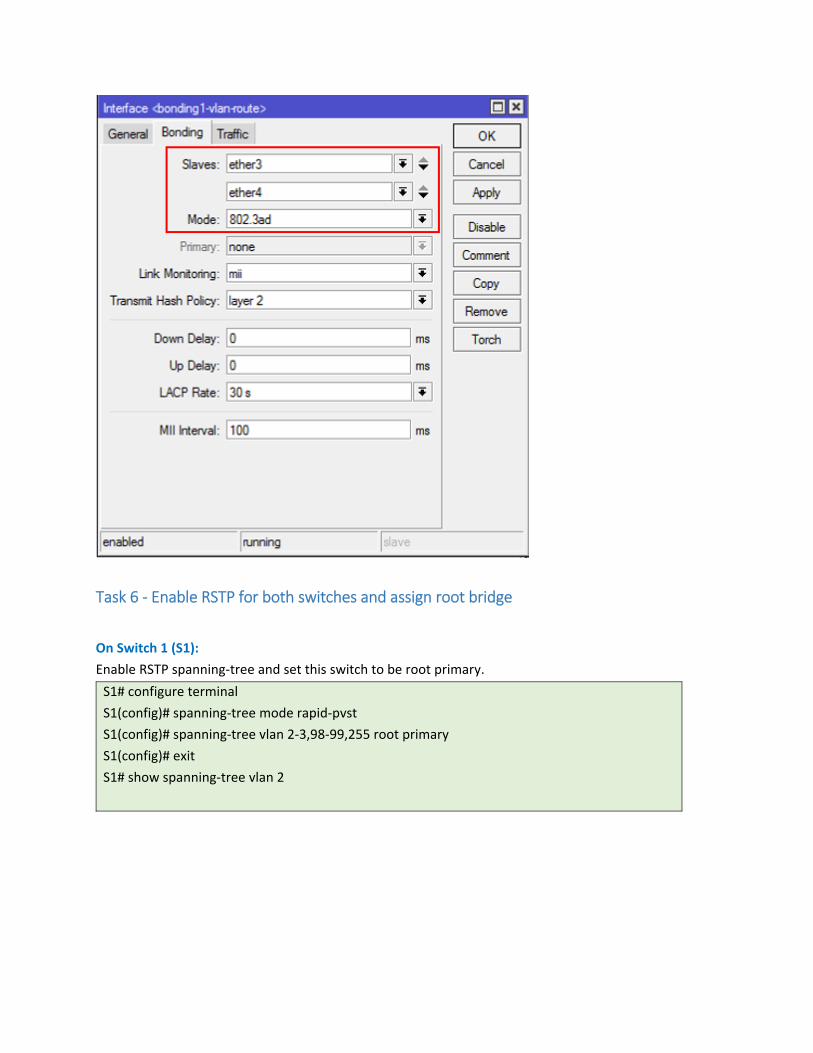
Task 6 ‐ Enable RSTP for both switches and assign root bridge
On Switch 1 (S1):
Enable RSTP spanning‐tree and set this switch to be root primary.
S1# configure terminal
S1(config)# spanning‐tree mode rapid‐pvst
S1(config)# spanning‐tree vlan 2‐3,98‐99,255 root primary
S1(config)# exit
S1# show spanning‐tree vlan 2
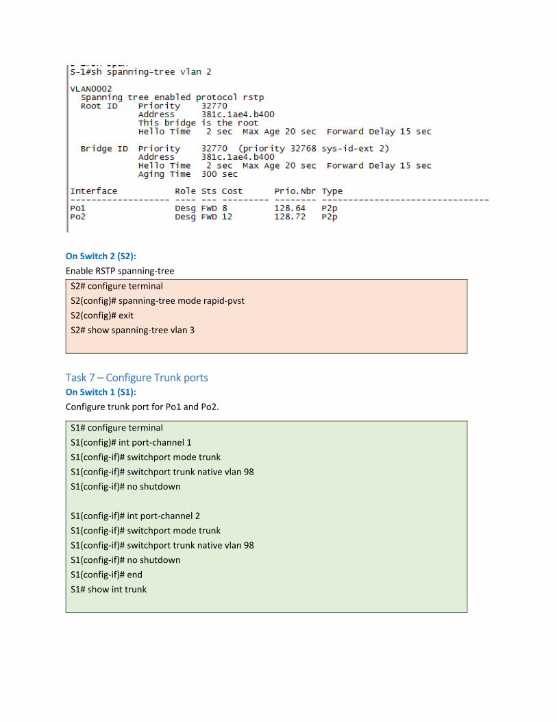
On Switch 2 (S2):
Enable RSTP spanning‐tree
S2# configure terminal
S2(config)# spanning‐tree mode rapid‐pvst
S2(config)# exit
S2# show spanning‐tree vlan 3
Task 7 – Configure Trunk ports On Switch 1 (S1):
Configure trunk port for Po1 and Po2.
S1# configure terminal
S1(config)# int port‐channel 1
S1(config‐if)# switchport mode trunk
S1(config‐if)# switchport trunk native vlan 98
S1(config‐if)# no shutdown
S1(config‐if)# int port‐channel 2
S1(config‐if)# switchport mode trunk
S1(config‐if)# switchport trunk native vlan 98
S1(config‐if)# no shutdown
S1(config‐if)# end
S1# show int trunk
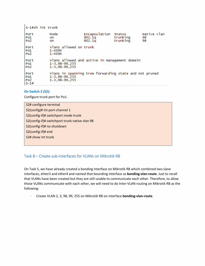
On Switch 2 (S2):
Configure trunk port for Po1.
S2# configure terminal
S2(config)# int port‐channel 1
S2(config‐if)# switchport mode trunk
S2(config‐if)# switchport trunk native vlan 98
S2(config‐if)# no shutdown
S2(config‐if)# end
S2# show int trunk
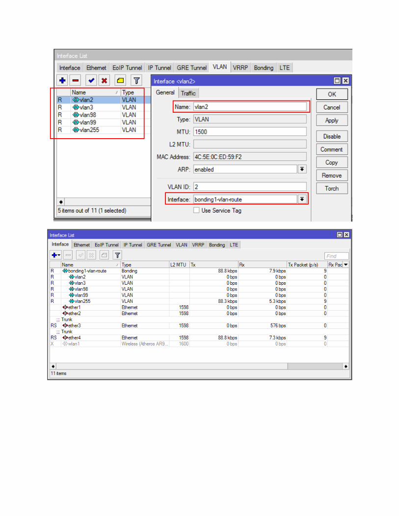
Task 8 – Create sub‐interfaces for VLANs on Mikrotik RB
On Task 5, we have already created a bonding interface on Mikrotik RB which combined two slave
interfaces, ehter3 and ether4 and named that bounding interface as bonding‐vlan‐route. Just to recall
that VLANs have been created but they are still unable to communicate each other. Therefore, to allow
those VLANs communicate with each other, we will need to do Inter‐VLAN routing on Mikrotik RB as the
following:
‐ Create VLAN 2, 3, 98, 99, 255 on Mikrotik RB on interface bonding‐vlan‐route.
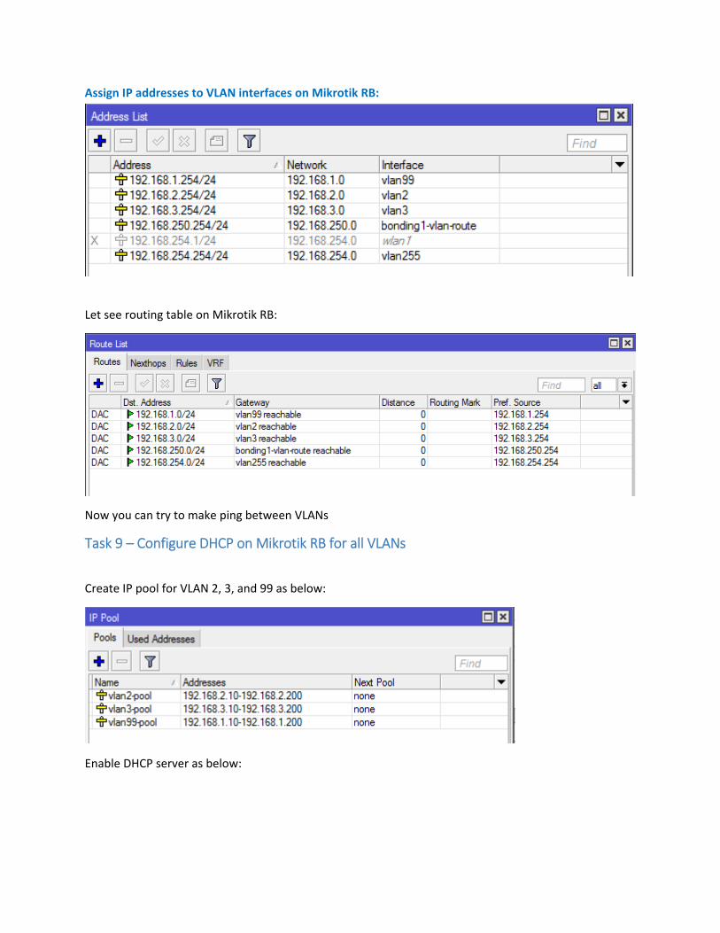
Assign IP addresses to VLAN interfaces on Mikrotik RB:
Let see routing table on Mikrotik RB:
Now you can try to make ping between VLANs
Task 9 – Configure DHCP on Mikrotik RB for all VLANs
Create IP pool for VLAN 2, 3, and 99 as below:
Enable DHCP server as below:
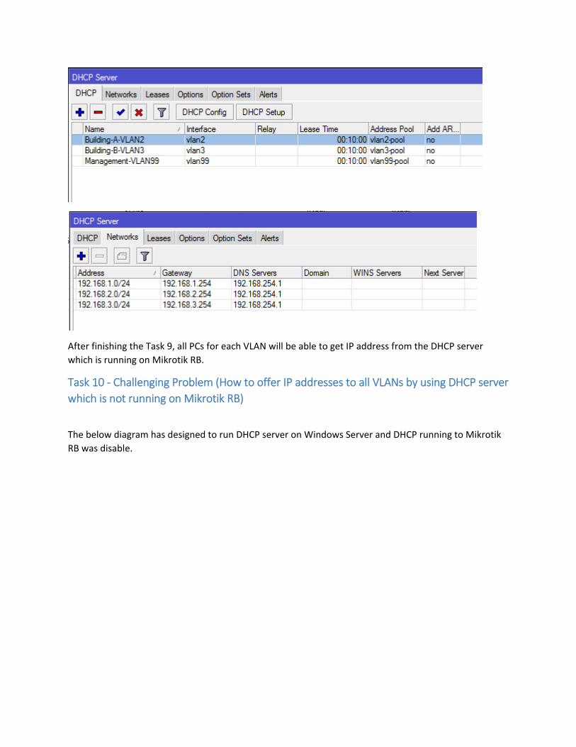
After finishing the Task 9, all PCs for each VLAN will be able to get IP address from the DHCP server
which is running on Mikrotik RB.
Task 10 ‐ Challenging Problem (How to offer IP addresses to all VLANs by using DHCP server
which is not running on Mikrotik RB)
The below diagram has designed to run DHCP server on Windows Server and DHCP running to Mikrotik
RB was disable.
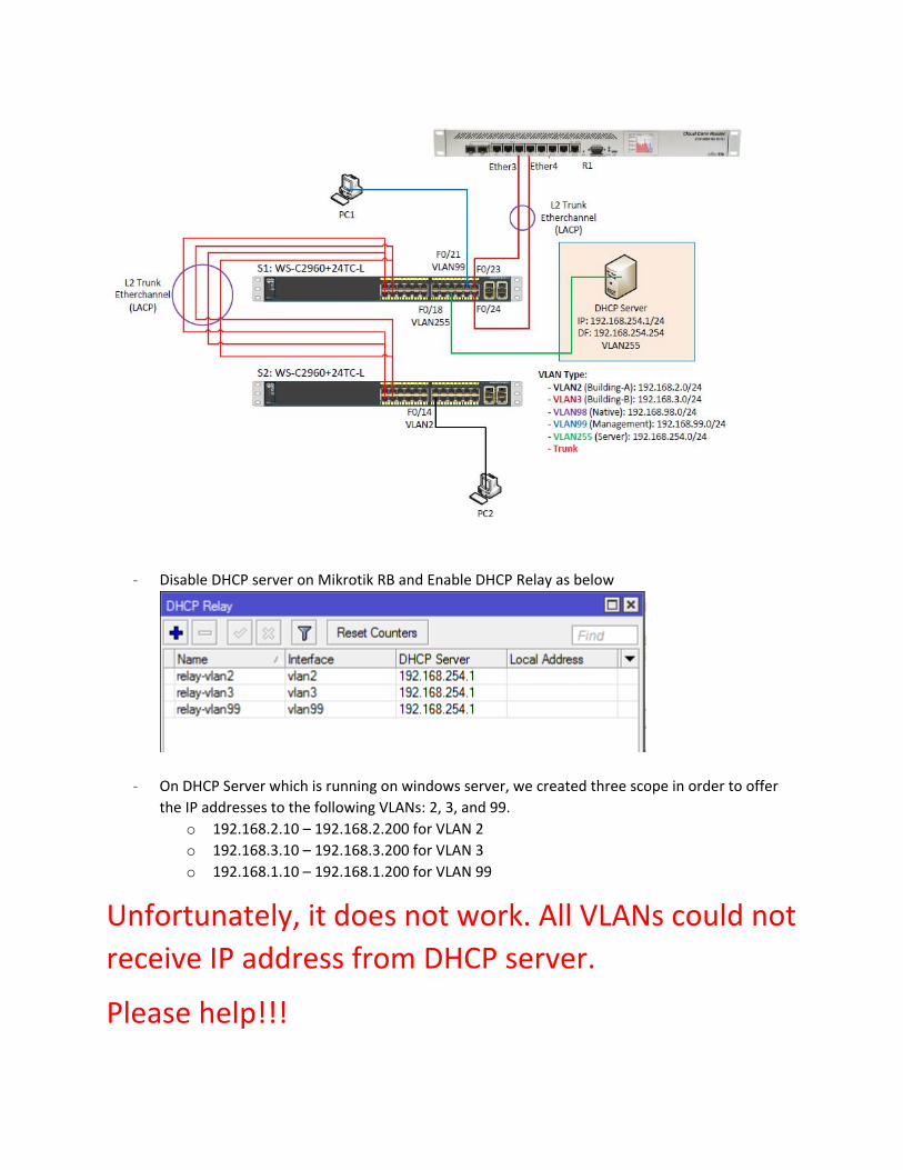
‐ Disable DHCP server on Mikrotik RB and Enable DHCP Relay as below
‐ On DHCP Server which is running on windows server, we created three scope in order to offer
the IP addresses to the following VLANs: 2, 3, and 99.
o 192.168.2.10 – 192.168.2.200 for VLAN 2
o 192.168.3.10 – 192.168.3.200 for VLAN 3
o 192.168.1.10 – 192.168.1.200 for VLAN 99
Unfortunately, it does not work. All VLANs could not
receive IP address from DHCP server.
Please help!!!
Related Documents


![[PPT]PowerPoint 프레젠테이션cfs3.tistory.com/upload_control/download.blog?fhandle=... · Web view... 1 VLAN 2 Backbone VLAN 1 VLAN 1 VLAN 2 VLAN 1 VLAN 2 VLAN 1 VLAN 2 물리적인](https://static.cupdf.com/doc/110x72/5ac031517f8b9a213f8bb25a/pptpowerpoint-cfs3-view-1-vlan-2-backbone-vlan-1-vlan-1.jpg)
