How Hidden SolidWorks Import Errors Could Be Costing You a Fortune

How Hidden SolidWorks Import Errors Could Be Costing You a Fortune
Aug 20, 2015
Welcome message from author
This document is posted to help you gain knowledge. Please leave a comment to let me know what you think about it! Share it to your friends and learn new things together.
Transcript

How Hidden SolidWorks Import Errors Could Be Costing You a Fortune

This webinar will be available afterwards
at designworldonline.com & via email
Q&A at the end of the presentation
Hashtag for this webinar: #DWwebinar
Before We Start

“How Hidden SolidWorks Import Errors Could Be Costing You a Fortune”
PRESENTER
Lyle Fischer Technical Marketing Director Capvidia
MODERATOR
Evan Yares Senior Editor Design World
CompareWorks
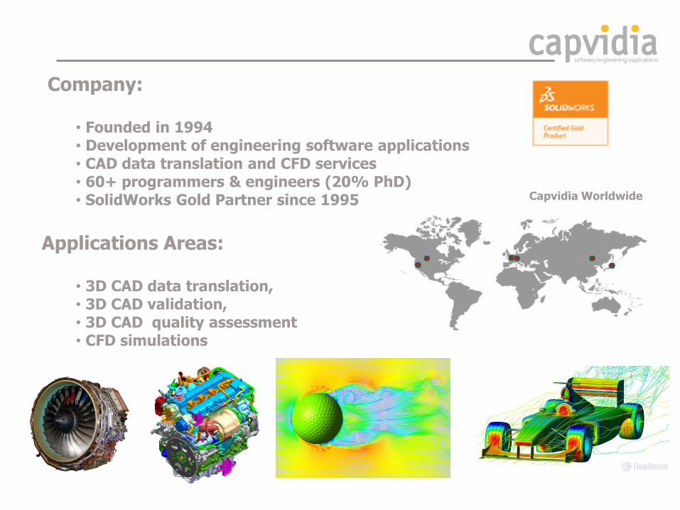
Company:
• Founded in 1994 • Development of engineering software applications • CAD data translation and CFD services • 60+ programmers & engineers (20% PhD) • SolidWorks Gold Partner since 1995
Applications Areas:
• 3D CAD data translation, • 3D CAD validation, • 3D CAD quality assessment • CFD simulations
Capvidia Worldwide

If you enter the following quote from William Shakespeare
into a popular online translation tool:
"It is not in the stars to hold our destiny but in ourselves."
Translated back to English, we get the following translation:
"It can hold our destiny in the stars, but it does not own."
Korean translation
Hidden SolidWorks Import Errors?
Translation
CAD Data Translation

SolidWorks Import Errors
Differences between SolidWorks and other CAD systems:
• Formats • Kernels • Model tolerance • Geometry and Topology
13 surfaces 226 surfaces 226 surfaces 226 surfaces
?

Model Tolerance
CATIA - Solid
SolidWorks - Geometry deformation
System CAD Tolerance [mm]
CATIA V4 0.1 – 0.02
CATIA V5 0.001
I-DEAS 0.01
UGS NX 0.0254
SolidWorks 0.0254
Parasolid 0.0254
ACIS 0.001
Known issues: Different tolerance for MBD solid definition
Geometry inconsistencies: • Overlaps • Gaps • Deformations

Kernels Differences
Non-manifold Manifold
UGS NX, ACIS,
SolidWorks, Parasolid
Shared Entities
Known issues: Shared Entities
Geometry inconsistencies: • Touching surfaces
CATIA, Pro/E

Kernels Differences
I-DEAS CATIA
CATIA V5 SolidWorks
CATIA
SolidWorks
Known issues: Closed surfaces. Export from SolidWorks to CATIA
UGS NX, ACIS,
SolidWorks, Parasolid
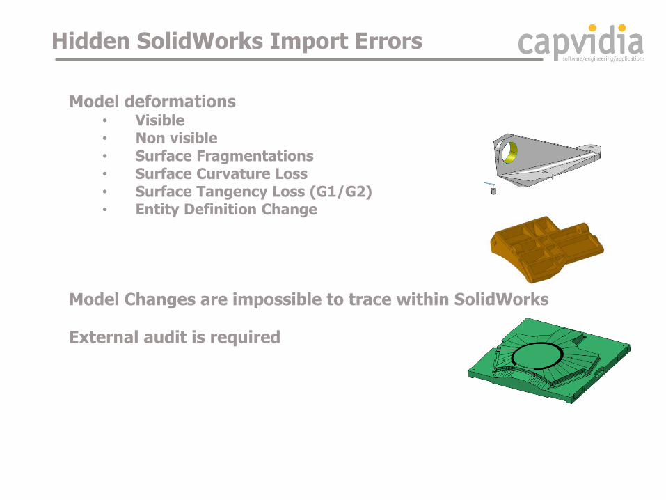
Model deformations • Visible • Non visible • Surface Fragmentations • Surface Curvature Loss • Surface Tangency Loss (G1/G2) • Entity Definition Change
Model Changes are impossible to trace within SolidWorks
External audit is required
Hidden SolidWorks Import Errors
How These Errors Can Cost You Money ?
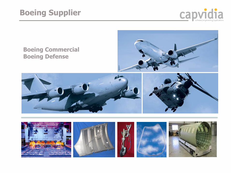
Boeing Supplier
Boeing Commercial Boeing Defense

Practical problem
Original geometry after SW Import is unnoticeably changed, resulting in huge cusps on the finishing surface
SolidCAM Imported Geometry
Finished Part Rejected by Boeing Surface Roughness
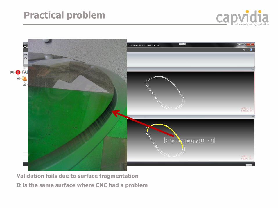
Validation fails due to surface fragmentation
It is the same surface where CNC had a problem
Practical problem

Authority Model
Neutral (IGES, STEP)
226 surfaces 13 surfaces
Surface de-fragmentation in data translation
SolidWorks
Cause of the problem
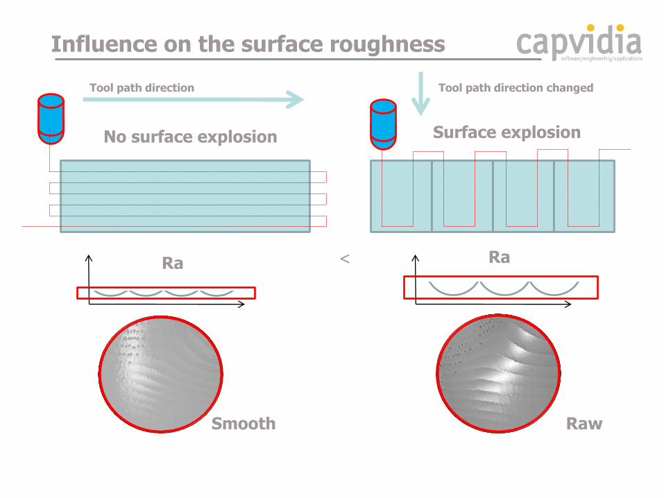
Ra Ra
No surface explosion Surface explosion
Influence on the surface roughness
<
Smooth Raw
Tool path direction Tool path direction changed

Model Alteration by SolidWorks
• Import diagnostics (healing) • Feature recognition (rebuilding model) • Manual Re-Mastering (new design)
13 surfaces 226 surfaces

Model Alteration after Import
Before
SolidWorks Import Diagnosis Tool • Attempt to Heal All….
After
Are you aware that this happened?
The change is not visible and you are not informed
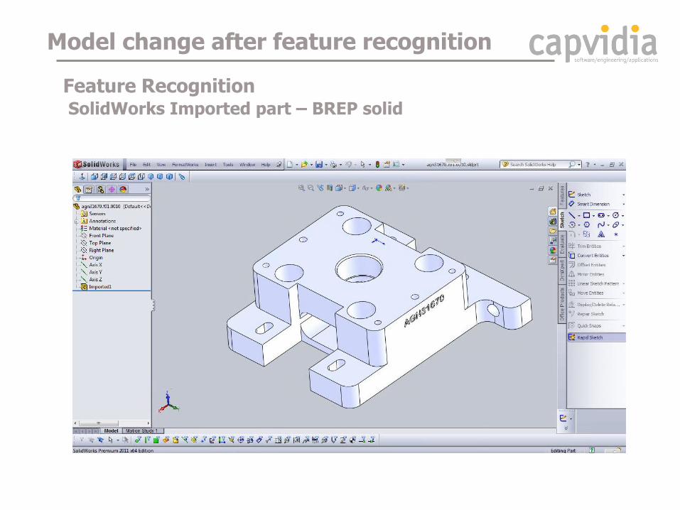
Feature Recognition SolidWorks Imported part – BREP solid
Model change after feature recognition

Is it still the same as the original model?
Feature Recognition
Model change after feature recognition

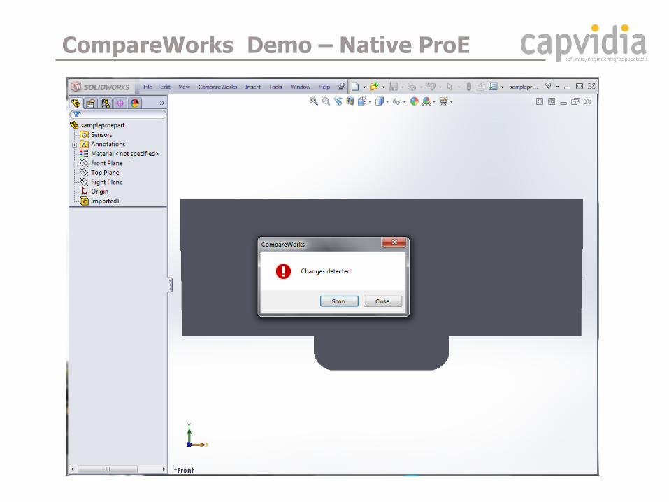
CompareWorks has detected a change by FeatureWorks
Feature Recognition
Model change after feature recognition
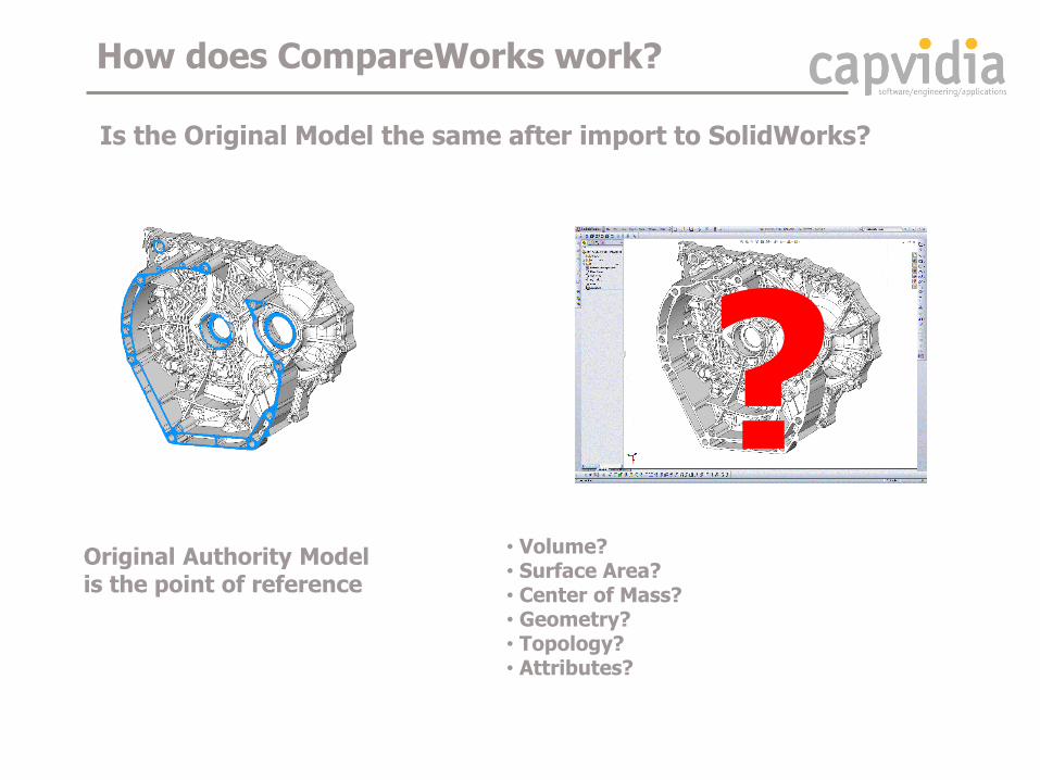
• Volume? • Surface Area? • Center of Mass? • Geometry? • Topology? • Attributes?
? Original Authority Model is the point of reference
How does CompareWorks work?
Is the Original Model the same after import to SolidWorks?

CompareWorks External Audit
Authority Model
CompareWorks Process Workflow
SolidWorks Import
Parasolid Kernel
Authority/Reference Model
Capvidia Kernel
Report
API


CompareWorks Report
• Documented and Traceable Process • Compliance with Quality Standards – ISO 9000 • Boeing D6-51991 • Fully Integrated with SolidWorks

D6-51991 Validation criteria CAD translation
Implementation based on Boeing D6-51991 recommendation
CompareWorks
CompareWorks

Who should use it?
CompareWorks: • Compares and validates CAD models against user defined criteria • Identifies and manages CAD model shape changes
Typical application areas: • Digital process certification of 3D CAD data (e.g. Boeing D6-51991) • Detection of CAD model changes (data translation, re-mastering, etc) • Tracking undocumented changes in design revisions • Detection of changes in CAD assembly structure
Benefits: • Brings prediction into processes based on the reuse of 3D CAD data • Complies with standards - Boeing D6-51991, DOD MIL 31000, ISO • Documents and validates processes involving 3D CAD data • Easy to implement and use • Easy to integrate with existing company procedures

Validation of Data Migration to SolidWorks
• CATIA • CREO-Pro/E, • Autodesk, • Siemens NX, …
Compare SolidWorks V1 (Parasolid Kernel) to SolidWorks V6 (CATIA Kernel)
Eliminate manufacturing errors using SolidWorks
• Comply with standards and quality assurance • Documented and traceable workflows • DOD – Provide documented proof for government • Aerospace - Boeing D6-51991, Northrop Grumman, Vought
Ensure Confidence using SolidWorks to import CAD models • Digital proof that SolidWorks import of data is correct
• Avoid costly mistakes in manufacturing • Detect problems early in the design phase
CompareWorks Advantages

Conclusion
There will be always a differences between CAD systems... but once you know how to find them
you will be safe
Download CompareWorks from our website for a free time limited trial version
www.capvidia.com
CompareWorks Free Trial Offer

Questions
Design World Evan Yares [email protected] Twitter: @EvanYares
Capvidia Lyle Fischer [email protected] Phone: 507.794.5447

Entity List
Entity List
Entity List
Capvidia
Kernel
PRO/E KERNEL
CATIA V5 KERNEL
PARASOLID
Capvidia
Kernel
How we handle different native CAD Data?
• Based on Capvidia’s Geometry Kernel: • Design to capture data from all CAD systems • Able to Maintain Original Entity Definition for each Kernel

Introduced Errors:
Diameter:
+ 0.0002mm
- 0.0002mm
+ 0.001mm
- 0.001mm
+ 0.01mm
+ 0.1mm
Plane:
- 0.0003mm
+ 0.001mm
- 0.1mm
Radius:
+ 0.01mm
Surface:
- 0.001mm
+ 0.01mm
+ 0.1mm
Parallel planes:
0.001mm
0.01mm
Hole position changed:
+ 0.0002mm
+ 0.001mm
+ 0.01mm
Angled plane:
+ 0.1mm
Hole removed
Hole added
• Known errors are introduced in the CAD model • Original CAD-model and model with errors are compared • All the introduced errors should be detected by CompareVidia
ASCO - Independent Third Party Verification
0.0002 [mm]

Thank You
This webinar will be available at designworldonline.com & email
Tweet with hashtag #DWwebinar
Connect with
Discuss this on EngineeringExchange.com

Related Documents