General Operation The control panel Using the controls Setting up the display Using CompactFlash cards Card 1 Card 2 Card 3 Card 4 Other functions Monitoring data and engines Viewing video images Navtex and Sirius Weather Data Sirius Weather Data (continued) Operating a networked E-Series Display Card 20 Card 20 Card 21 Card 22 Card 23 What's under the boat? Understanding the fishfinder Using the fishfinder Card 18 Card 19 What is around me? Understanding the radar Avoiding a collision Using MARPA AIS Card 13 Card 14 Card 15 Card 16 Where am I going? Monitoring a course Card 17 Basic Navigation Working with waypoints How do I get to a point? Card 11 Card 12 PAGE ACTIVE WPTS MOB MENU DATA CANCEL OK RANGE IN OUT What can I see? Understanding the chart Using the chart Displaying additional information Displaying additional information (continued) Understanding the 3D chart Using the 3D chart Card 5 Card 6 Card 7 Card 8 Card 9 Card 10 E-Series Display Operating Guide www.raymarine.com

Welcome message from author
This document is posted to help you gain knowledge. Please leave a comment to let me know what you think about it! Share it to your friends and learn new things together.
Transcript
General Operation
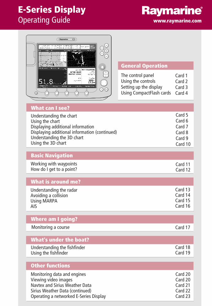
The control panelUsing the controlsSetting up the displayUsing CompactFlash cards
Card 1Card 2Card 3Card 4
Other functions
Monitoring data and enginesViewing video imagesNavtex and Sirius Weather Data Sirius Weather Data (continued) Operating a networked E-Series Display
Card 20Card 20Card 21Card 22Card 23
What's under the boat?Understanding the fishfinderUsing the fishfinder
Card 18Card 19
What is around me?Understanding the radarAvoiding a collisionUsing MARPAAIS
Card 13Card 14Card 15Card 16
Where am I going?Monitoring a course Card 17
Basic NavigationWorking with waypointsHow do I get to a point?
Card 11Card 12
PAGE
ACTIVE
WPTSMOB
MENU
DATA
CANCELOK
RANGE
IN
OUT
D672
1_4
What can I see?Understanding the chartUsing the chartDisplaying additional informationDisplaying additional information (continued)Understanding the 3D chart Using the 3D chart
Card 5Card 6Card 7Card 8Card 9Card 10
E-Series DisplayOperating Guide www.raymarine.com
PAGE
ACTIVE
WPTSMOB
MENU
DATA
CANCELOK
RANGE
IN
OUT
D752
3_1
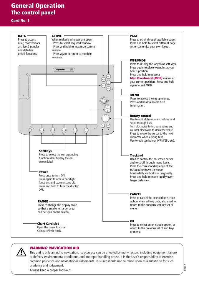
OKPress to select an on-screen option, or return to the previous set of soft keys or menu.
DATAPress to access ruler, chart vectors, archive & transfer and data bar on/off functions.
TrackpadUsed to control the on-screen cursor and to scroll through menu items.Press the corresponding edge of the trackpad to move the cursor horizontally, vertically or diagonally.Press and hold to move rapidly over larger distances.
CANCELPress to cancel the selected on-screen option when editing data; also used to return to the previous soft key set or menu.
MENUPress to access the set up menus.Press and hold to access help information.
ACTIVEWhen multiple windows are open:- Press to select required window.- Press and hold to maximize current window.- Press again to return to multiple windows.
PAGEPress to scroll through available pages.Press and hold to select different page set or customise your own layout.
WPTS/MOBPress to display the waypoint soft keys.Press again to place waypoint at your boat's position.Press and hold to place a Man Overboard (MOB) marker at your current position. Press and hold again to exit MOB.
RANGEPress to change the display scale so that a smaller or larger area can be seen on the screen.
PowerPress once to turn ON.Press again to access backlight functions and scanner controls. Press and hold to turn the display OFF.
Chart Card slot Open the cover to install CompactFlash cards.
SoftkeysPress to select the corresponding function identified by the on-screen label
Rotary controlUse to edit alpha-numeric values, and scroll through lists.Turn clockwise to increase value and counter-clockwise to decrease value.Press to move the cursor to the next character when editing text. Use to edit symbology (VRM/EBL etc).
WARNING: NAVIGATION AIDThis unit is only an aid to navigation. Its accuracy can be affected by many factors, including equipment failure or defects, environmental conditions, and improper handling or use. It is the User's responsibility to exercise common prudence and navigational judgements. This unit should not be relied upon as a substitute for such prudence and judgement.Always keep a proper look-out.
General OperationThe control panelCard No. 1

How do the controls work?
D676
2_3
ERASE WAYPOINT SORT LIST SET DEFAULT SYM& GROUP...
WAYPOINTGROUPS...
VIEW AND EDITDETAILS…
EDIT DEFAULTSET UP DEFAULTSYMB GROUP
WAYPOINT ATCURSOR
WAYPOINT ATVESSEL
WAYPOINT ATLAT/LONG...
GO TO WAYPOINTOPTIONS…
REVIEW AND EDITWAYPOINTS
WPTS/MOB
PAGE
ACTIVE
MENU
DATA
Example:This example shows the series of button and soft key presses required to change the waypoint default symbol or group.
Access system functions or change what you see on-screen.Within the text of this document they are written in bold capitals e.g. WPTS/MOB.
Press and hold to access short cuts - see individual buttons on facing page.
They change depending on application or function being performed.
Press and hold MENU to display help information for the currently displayed soft keys.
Press the corresponding key (below the screen) to select.
Further soft keys may be displayed.If a key has several options, each press will highlight the next option.
If a key displays a single value or a slider above, use the rotary control to adjust.
Within the text of this document they are written in capitals e.g. SORT LIST.
Buttons
Soft keys
D736
6-1 The Cursor appears on the screen as
a white cross.To make it easier to locate on screen, the cursor changes to a circle with a cross in it, when it is moved after a 10 second period of inactivity.
The cursor is context-sensitive. When it is placed over an object e.g. a waypoint or chart feature, it changes color and a label or information associated with the object is displayed. When you place the cursor over certain items, the soft keys change to enable you to access related operations.
WPTS/MOB
REVIEW AND EDITWAYPOINTS ...
SET DEFAULT SYM& GROUP...
SET UP DEFAULTSYMB GROUP
This process of pressing buttons and soft keys to navigate to the required function, is simplified within this guide and represented by a strip e.g.
The Cursor
WPT
Simulator:To practice using your Display without data from a GPS scanner or fishfinder, switch on the simulator via the System Setup menu.
General OperationUsing the controlsCard No. 2

? More information - See the 'General Operation' chapter of the Reference Manual
The active windowis bordered in red
Pressand hold
To temporarily maximise active window:How do I select a Window?
Press to move highlight to next window Press ACTIVE again to return to multiple windows mode.
How do I select a Page?
Soft keys reflect current page set. Displayed option highlighted Press approp-riate soft key
Note: Alternatively, repeatedly press PAGE until the required page is highlighted.
Pressand hold
How do I select the Page Set?
Toconfirm...
Highlight required page set.
Note: Alternatively you can display the Select Page Set screen via the Menu key.
Tocustomise...
EDIT PAGE SET
Follow on-screen instructions
OrPAGE
OK
PAGE
ACTIVE
SOFT KEY
ACTIVE
The applications are shown using a combination of page sets, pages and windows. There are five page sets each containing five pages with a combination of windows and applications in each. These sets can be edited to define the combination that suits your particular needs.
How do I select how the applications are displayed?
Any changes you make will be saved to the system. You can change these preferences as many times as you wish. Page
(1, 2, 3 or 4 windows)Window
D899
0_1
General OperationSetting up the displayCard No. 3
See the 'General Operation' chapter of the Reference Manual. ? More information...
D672
4_3
How do I insert a CompactFlash card?
Fit the card the correct way around. DO NOT force.Ensure card door is firmly closed at all times. DO NOT use a metallic instrument (e.g. screwdriver or pliers) to aid card removal.Follow the correct procedure for removing a card (see below).DO NOT remove card during either a read or write operation.
CAUTIONCompactFlash CardIn order to protect your E-Series Display and CompactFlash cards from irreparable damage, please adhere to the following:
... with the unit powered
Press MENU. The Setup menu is displayed.
Use trackpad (up/down) to highlight and then (right) to select CF CARD REMOVAL. The system will now complete its checks.
When instructed to do so, open the chart card door and remove the card.
Firmly click the chart door shut and press OK twice.
... with the unit powered down
Open the chart card door.
Grip the card and pull to remove it from its slot.
Firmly click the chart card door shut.
How do I remove a CompactFlash card?
General OperationUsing CompactFlash cardsCard No. 4
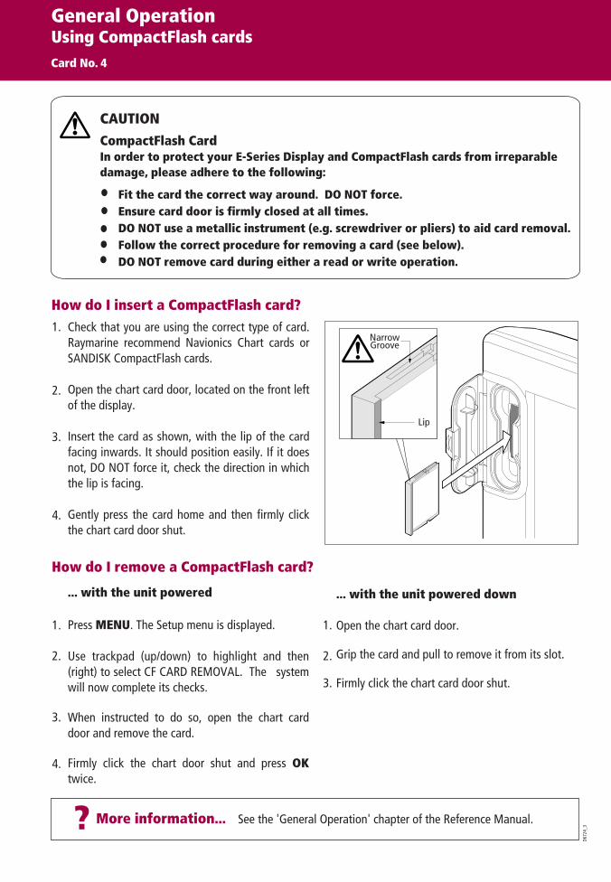
Check that you are using the correct type of card. Raymarine recommend Navionics Chart cards or SANDISK CompactFlash cards.
Open the chart card door, located on the front left of the display.Insert the card as shown, with the lip of the card facing inwards. It should position easily. If it does not, DO NOT force it, check the direction in which the lip is facing.
Gently press the card home and then firmly click the chart card door shut.
NarrowGroove
Lip
1.
2.
3.
4.
1.
2.
3.
1.
2.
3.
4.

More information . . .? See 'Using the Chart' chapter of the E-Series Reference Manual
D897
8_1
RANGE
IN
OUT
4nm North-Up (Relative Motion) Local
Gully Ridge
Creek point
Port point
Portside
What can I use the chart for?
Chart range Chart orientation Motion mode Chart view
Chart boundary
Status bar
Cursor
Route
Waypoint
Current position
Track
Cartographic object
Active waypoint
Find where you are.
Interpret your surroundings.
Place waypoints at specific locations.
Navigate to a specific point.
Monitor where you are going.
Record where you have been.
Measure the distance between two points.
How do I move around the chart?
Moves cursor. When cursor reaches window edge, chart pans to a different area.
Press and hold to pan larger areas.
Press RANGE (OUT) to see alarger area of the chart.
Press RANGE (IN) to see a smaller area in more detail.
To change the scale: To pan the chart:
Build and follow routes.
Manage and edit routes and tracks.
Distinguish between fixed & moving objects
(radar overlay).
View photographs of ports and marinas.
View information normally contained in an almanac.
Display an aerial photo overlay.
What can I see?Understanding the chartCard No. 5
FINDSHIP CURSOR
GOTO ROUTES TRACKS PRESENTATION
How do I find where I am on the chart?
If you cannot find your boat symbol :
The boat symbol indicates your position.
FINDSHIP CURSOR
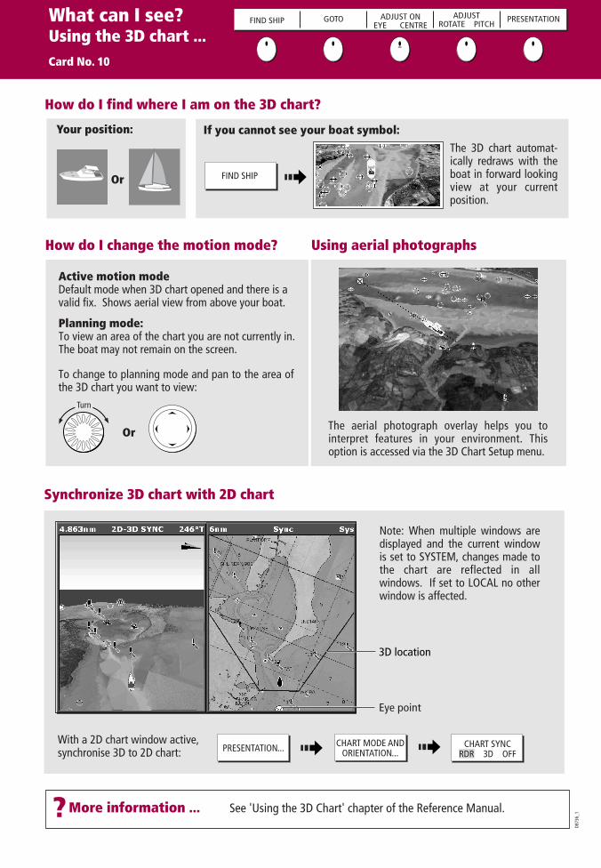
The screen automatically pans to your boat's position and re-activiates the motion mode (see below - 'How do I change how my boat moves on the chart').

D674
0_3?More information .... See 'Using the Chart' chapter of the Reference Manual
How your boat moves on the screen is referred to as the motion mode. The default setting for the chart is Relative Motion. This means that your boat is fixed on the screen and the chart moves relative to your boat i.e.
How do I change how my boat moves on the chart?
If desired, you can change the motion mode to:True (TM) - the chart is fixed and the boat moves in true perspective to fixed landmasses on the screen.
Autorange (AR) - selects and maintains the largest possible scale of chart that will display both the boat and the target waypoint This option is not available when radar/chart symchronization is ON.
NOTE: When you pan the chart or toggle FIND SHIP/CURSOR to CURSOR, the motion mode is suspended.
How do I change the chart orientation?The orientation of the chart refers to the relationship between the chart and the direction you are travelling in. It is used in conjunction with motion mode (see below) to control how your boat and chart relate to one another and how they are displayed on screen. The default mode is North Up (N-UP). This displays your chart with true north upwards. As your heading changes the boat symbol moves accordingly.
If desired, you can change the orientation mode to:
PRESENTATION... CHART MODE ANDORIENTATION...
ORIENTATIONH-UP N-UP C-UP
PRESENTATION...CHART MODE AND
ORIENTATION...MOTION MODETM RM AR
Head Up (H-Up) - displays chart with boat's current heading upwards. As heading changes, boat symbol remains fixed
Course Up (C-Up) - chart picture stabilized, current course upwards. Boat symbol moves as heading changes.
To change the orientation mode:
To change the orientation mode:
What can I see?Using the chart ...Card No. 6
FIND SHIP CURSOR
GOTO ROUTES TRACKS PRESENTATION
Viewing detail on the chart
To show/hide individual cartographic features:
DECLUTTERON OFF
PRESENTATION...To show/hide pre-set cartographic features:
Display additional information on a cartographic feature:
OFFON
MENU Chart SetupCartography Setup...
Setup
OK OK
For more information
Toggle as required


?More information ... See 'Using the 3D Chart' chapter of the Reference Manual.
How do I change the motion mode? Using aerial photographs
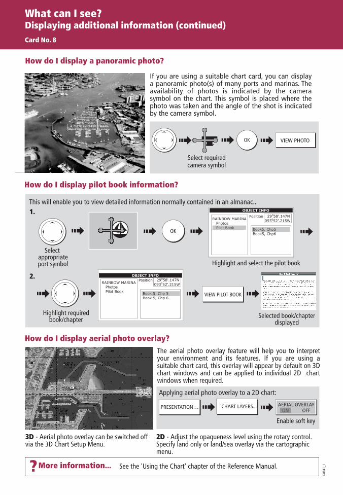
Planning mode:To view an area of the chart you are not currently in. The boat may not remain on the screen.
The aerial photograph overlay helps you to interpret features in your environment. This option is accessed via the 3D Chart Setup menu.
To change to planning mode and pan to the area of the 3D chart you want to view:
Active motion modeDefault mode when 3D chart opened and there is a valid fix. Shows aerial view from above your boat.
What can I see?Using the 3D chart ...Card No. 10
How do I find where I am on the 3D chart?
If you cannot see your boat symbol:
Synchronize 3D chart with 2D chart
D873
6_1
Your position:
Turn
The 3D chart automat-ically redraws with the boat in forward looking view at your current position.
FIND SHIP GOTO ADJUST ONEYE CENTRE
ADJUSTROTATE PITCH
PRESENTATION
Or
Or
FIND SHIP
With a 2D chart window active,synchronise 3D to 2D chart:
3D location
Eye point
Note: When multiple windows are displayed and the current window is set to SYSTEM, changes made to the chart are reflected in all windows. If set to LOCAL no other window is affected.
PRESENTATION... CHART MODE ANDORIENTATION...
CHART SYNCRDR 3D OFF

?More information ... See the 'Working with Waypoints' chapter of the Reference Manual
D672
9_3
How do I navigate to a waypoint?
How do I navigate to a point?
Can I edit a waypoint?
How do I place a waypoint? ... at the cursor? ... at the vessel?
Move cursorto position
Move cursorto position
WPTS/MOB
WAYPOINT ATCURSOR
WPTS/MOB
WAYPOINT ATVESSEL
Waypoint
Alternatively, press WPTS/MOB twice.
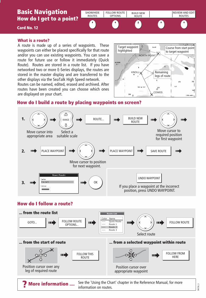
What is a waypoint?A waypoint is a position marked on a chart, radar or fishfinder screen to indicate a site (for fishing, diving etc), or as a position to go to. You can place a waypoint at the cursor or your boat's position or at a specified position. Waypoints are represented in chart or radar applications as an 'X' (default) and by a vertical line labeled WPT in Fishfinder. Active waypoints are displayed on 3D Chart and CDI windows. The details of each waypoint are stored in a waypoint list. Waypoints can be renamed, edited, grouped, or erased, as necessary. To make full use of waypoint features, ensure your display is receiving heading and position data. We recommend that you regularly back-up your waypoints by archiving them to a CompactFlash card. Waypoints can also be transferred to another NMEA compatible instrument.
Networked systemsIf you have networked two or more E-Series Displays, the waypoints are stored on the master display and transferred to other displays via the SeaTalk High Speed network.
Basic NavigationWorking with Waypoints
Card No. 11
WAYPOINT ATCURSOR
WAYPOINT ATVESSEL
WAYPOINT ATLAT/LON
GO TO WAYPOINTOPTIONS
REVIEW AND EDITWAYPOINTS
CAUTION
Always check that your route to a waypointis safe before travelling towards it.
GOTO... GOTO CURSOR
Highlight required waypoint
Name:Waypoint 1Waypoint 2Waypoint 3
Group:
Position:
Rng/Brg:
Temperature:Depth:Date:Time:
---.- F---.-ft05/11/200314:59:11
O
284o
4.315nm
Waypoint list
My Waypoint
50 53’.826N001 10’.963W
o
oWPTS/MOB
...using the waypoint list?
GO TO WAYPOINTOPTIONS... GO TO WAYPOINT
Once a waypoint has been placed it can be edited in as variety of ways. You can:Change the waypoint details Move a waypoint. Change the default group or symbol
WPT
Place cursor over waypoint.
...using the cursor?
GO TO WAYPOINT
WPTMove cursor to
required position
STOP GOTOGOTO...
WPT
OR:
Erase a waypoint
To stop navigation to a waypoint:

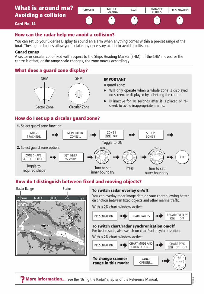
What does the radar show me?....
How do I measure distances, ranges and bearings with the radar?
More information ...? See the 'Using the Radar' chapter of the Reference Manual
3nm Head-Up Relative Motion Rings ½nm
VRM/EBL... GAIN... PRESENTATION...TARGETTRACKING...
ENHANCEECHOES...
Orientation
Data bar
Surfacevessel
Waypoint
D673
1-3
Ship'sheadingmarker
Iconconfirmingradarconnection
Rangering
Landmass
Boat'sposition
Range
Motion mode Range ring spacing
Typically your boat's position is at the centre of the display, and its dead ahead bearing is indicated by a vertical heading line, known as the Ship's Heading Marker (SHM).
Remember that the radar picture may vary from visual observations that you make; a nearby small object may appear the same size on the screen as a distant large object. However, with experience the approximate size of different objects can be determined by the relative size and brightness of the echoes.
What is around me?Understanding the radar
Card No. 13
VRM/EBL TARGETTRACKING GAIN ENHANCE
ECHOES...PRESENTATION
Range ringsUse the range rings to gauge the approximate distances between two points or from your boat.
VRMsAlign a VRM on a target to display its range from your boat:
EBLsAlign an EBL on a target to display its bearing relative to your boat's heading:
Combined VRM/EBLCombine a VRM and EBL to measure range and bearing of specified target.
ADJUST VRM1.800nm
ADJUST VRM1.800nm
Note: Range/bearing also displayed when VRM/EBL selected with the cursor.
e.g.
ADJUST EBL30.00S
ADJUST EBL30.00S
e.g.e.g.
Rings 1/2nm
? More information... See the 'Using the radar' chapter of the Reference Manual.
D673
3_3
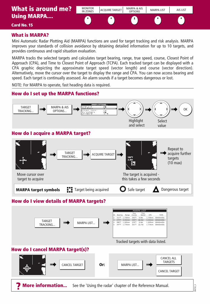
How do I view details of MARPA targets?
Tracked targets with data listed.
How do I cancel MARPA target(s)?
Or:
How do I acquire a MARPA target?
Move cursor overtarget to acquire
The target is acquired - this takes a few seconds
Repeat toacquire furthertargets (10 max)
Dangerous targetSafe targetMARPA target symbols Target being acquired
How do I set up the MARPA functions?
TARGETTRACKING...
MARPA & AISOPTIONS...
TARGETTRACKING...
ACQUIRE TARGET
MARPA LIST...TARGET TRACKING...
CANCEL TARGET MARPA LIST...
CANCEL TARGET
CANCEL ALL TARGETS
OK
Highlightand select
What is MARPA?Mini Automatic Radar Plotting Aid (MARPA) functions are used for target tracking and risk analysis. MARPA improves your standards of collision avoidance by obtaining detailed information for up to 10 targets, and provides continuous and rapid situation evaluation.
MARPA tracks the selected targets and calculates target bearing, range, true speed, course, Closest Point of Approach (CPA), and Time to Closest Point of Approach (TCPA). Each tracked target can be displayed with a CPA graphic depicting the approximate target speed (vector length) and course (vector direction). Alternatively, move the cursor over the target to display the range and CPA. You can now access bearing and speed. Each target is continually assessed. An alarm sounds if a target becomes dangerous or lost.
NOTE: For MARPA to operate, fast heading data is required.
Select value
What is around me?Using MARPA....Card No. 15
MONITORIN ZONES ACQUIRE TARGET MARPA & AIS
OPTIONS MARPA LIST AIS LIST
ID Bearing Range True
CourseTrue
Speed CPA TCPA
MARPA LIST
2345
312oT274oT086oT247oT
1.739nm3.242nm1.305nm1.774nm
342oT335oT276oT321oT
9.9kt68.4kt9.4kt22.7kt
1.739nm3.242nm1.305nm1.774nm
00h00m00s00h00m00s00h00m00s00h00m00s
1800T2.3kt
D880
9_1
How do I view target information?
How do I view detailed AIS data?
What is around me?Using AISCard No. 16
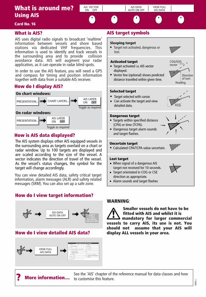
AIS uses digital radio signals to broadcast ‘realtime’ information between vessels and shore based stations via dedicated VHF frequencies. This information is used to identify and track vessels in the surrounding area and to provide collision avoidance data. AIS will augment your radar application, as it can operate in radar blind spots.
What is AIS?
AIS VECTORON OFF
AIS DATAAUTO ON OFF
VIEW FULLAIS DATA
125oT7.7kt
01.30nm12h15m30s
VIEW FULLAIS DATA
--,---nm
MNSI
Name
Call sign
Last seen
Lat
Lon
Hdg
Length
Beam
Draught
COG
SOG
CPA
TCPA
IMO No
Dest
Status
Type
ETA
6
Sim Target 6
01/01/2006 01:13:21AM
30 39’.702WO
AIS Target info: Sim Target 6
080o18'.702W
159oT
142oT
25,7kt
--,---nm
Under Way Using Engine
Normal
--h--m--s
--,---ft
--,---ft
--ft
--/--/---- --:--:--AM
PRESENTATION...
PRESENTATION...
Toggle as required
On chart windows:
On radar windows:Toggle as required
How do I display AIS?
CHART LAYERS...AIS LAYERON OFF
AIS LAYERON OFF
? More information....
How is AIS data displayed?
Selected target
Dangerous target Targets within specified distance (CPA) or time (TCPA). Dangerous target alarm sounds and target flashes.
Activated target Target activated i.e. AIS vector displayed. Vector line (optional) shows predicted distance travelled within given time.
Uncertain target Calculated CPA/TCPA value uncertain.
AIS target symbols
Lost target When signal of a dangerous AIS target not received for 10 seconds. Target orientated in COG or CSE direction as appropriate. Alarm sounds and target flashes
COG/SOG vector
Heading
Direction of turn
See the 'AIS' chapter of the reference manual for data classes and how to customise this feature.
Target selected with cursor.Can activate the target and view detailed data.
WARNING:
The AIS system displays other AIS equipped vessels in the surrounding area as targets overlaid on a chart or radar window. Up to 100 targets are displayed and are scaled according to the size of the vessel. A vector indicates the direction of travel of the vessel. As the vessel’s status changes, the symbol for the target will change accordingly.
Sleeping target Target not activated, dangerous or lost.
In order to use the AIS feature, you will need a GPS and compass for timing and position information together with data from a suitable AIS receiver.
You can view detailed AIS data, safety critical target information, alarm messages (ALR) and safety related messages (SRM). You can also set up a safe zone.
AIS
AIS DATAAUTO ON OFF
Smaller vessels do not have to be fitted with AIS and whilst it is mandatory for larger commercial vessels to carry AIS, its use is not. You should not assume that your AIS will display ALL vessels in your area.
Where am I?Monitoring a course....Card No. 17
?More information... See the 'Using the CDI' chapter of the Reference Manual
D673
4_3
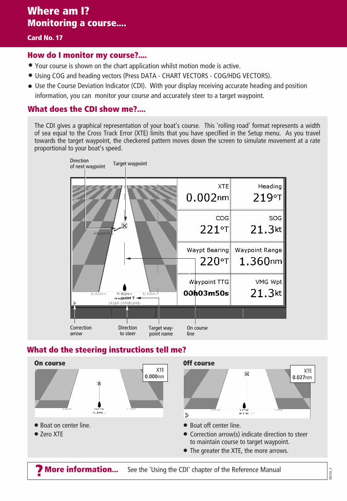
What do the steering instructions tell me?
Boat off center line.Correction arrow(s) indicate direction to steer to maintain course to target waypoint.The greater the XTE, the more arrows.
On course
Boat on center line.Zero XTE
0ff courseXTE
0.027nmXTE
0.000nm
How do I monitor my course?....Your course is shown on the chart application whilst motion mode is active.Using COG and heading vectors (Press DATA - CHART VECTORS - COG/HDG VECTORS).Use the Course Deviation Indicator (CDI). With your display receiving accurate heading and position information, you can monitor your course and accurately steer to a target waypoint.
What does the CDI show me?....
The CDI gives a graphical representation of your boat's course. This 'rolling road' format represents a width of sea equal to the Cross Track Error (XTE) limits that you have specified in the Setup menu. As you travel towards the target waypoint, the checkered pattern moves down the screen to simulate movement at a rate proportional to your boat's speed.
On courseline
Target way-point name
Target waypoint
Correctionarrow
Directionto steer
Directionof next waypoint

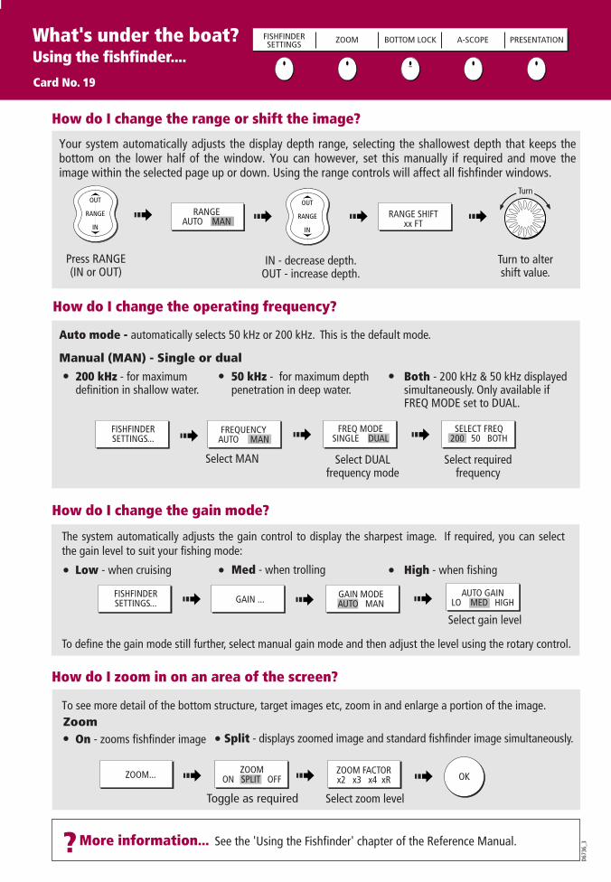
?More information... See the 'Using the Fishfinder' chapter of the Reference Manual.
How do I change the range or shift the image?
D673
6_3
How do I zoom in on an area of the screen?
How do I change the operating frequency?
Your system automatically adjusts the display depth range, selecting the shallowest depth that keeps the bottom on the lower half of the window. You can however, set this manually if required and move the image within the selected page up or down. Using the range controls will affect all fishfinder windows.
IN - decrease depth.OUT - increase depth.
Press RANGE(IN or OUT)
Turn to altershift value.
Select zoom level
Select MAN Select DUALfrequency mode
Select requiredfrequency
To see more detail of the bottom structure, target images etc, zoom in and enlarge a portion of the image.
How do I change the gain mode?
Select gain level
ZOOM... ZOOM FACTORx2 x3 x4 xR
ZOOMON SPLIT OFF
Toggle as required
FISHFINDERSETTINGS...
Both - 200 kHz & 50 kHz displayed simultaneously. Only available if FREQ MODE set to DUAL.
50 kHz - for maximum depth penetration in deep water.
200 kHz - for maximum definition in shallow water.
Auto mode - automatically selects 50 kHz or 200 kHz. This is the default mode.
The system automatically adjusts the gain control to display the sharpest image. If required, you can select the gain level to suit your fishing mode:
To define the gain mode still further, select manual gain mode and then adjust the level using the rotary control.
Manual (MAN) - Single or dual
High - when fishingLow - when cruising Med - when trolling
On - zooms fishfinder image Split - displays zoomed image and standard fishfinder image simultaneously.Zoom
D6585-1
RANGE
IN
OUT
D6585-1
RANGE
IN
OUTTurn
RANGEAUTO MAN
RANGE SHIFTxx FT
FREQUENCYAUTO MAN
FREQ MODESINGLE DUAL
SELECT FREQ200 50 BOTH
FISHFINDERSETTINGS... GAIN ... GAIN MODE
AUTO MANAUTO GAIN
LO MED HIGH
OK
What's under the boat?Using the fishfinder....
Card No. 19
FISHFINDERSETTINGS ZOOM BOTTOM LOCK A-SCOPE PRESENTATION
Monitoring data and engines Viewing video imagesCard No. 20
D752
1_3
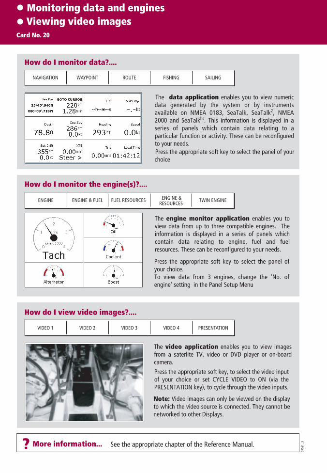
How do I monitor data?....
The data application enables you to view numeric data generated by the system or by instruments available on NMEA 0183, SeaTalk, SeaTalk2, NMEA 2000 and SeaTalkhs. This information is displayed in a series of panels which contain data relating to a particular function or activity. These can be reconfigured to your needs.
NAVIGATION WAYPOINT ROUTE FISHING SAILING
How do I monitor the engine(s)?....
ENGINE ENGINE & FUEL FUEL RESOURCES ENGINE &RESOURCES
TWIN ENGINE
How do I view video images?....
The video application enables you to view images from a saterlite TV, video or DVD player or on-board camera.
VIDEO 1 VIDEO 2 VIDEO 3 VIDEO 4 PRESENTATION
The engine monitor application enables you to view data from up to three compatible engines. The information is displayed in a series of panels which contain data relating to engine, fuel and fuel resources. These can be reconfigured to your needs.
Press the appropriate soft key to select the panel of your choice
Press the appropriate soft key to select the panel of your choice.To view data from 3 engines, change the 'No. of engine' setting in the Panel Setup Menu
Press the appropriate soft key, to select the video input of your choice or set CYCLE VIDEO to ON (via the PRESENTATION key), to cycle through the video inputs.
See the appropriate chapter of the Reference Manual.? More information...
Note: Video images can only be viewed on the display to which the video source is connected. They cannot be networked to other Displays.
Navtex and Sirius Weather Data
Card No. 21
D893
2_1 More information...
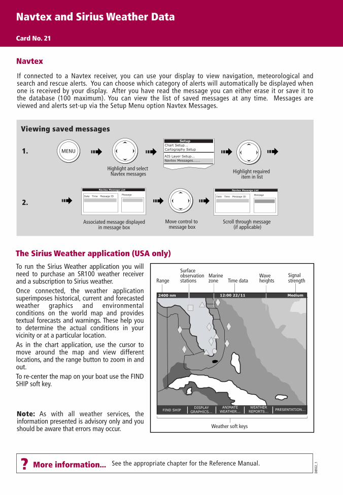
Viewing saved messages
Highlight and select Navtex messages Highlight required
item in list
MENU
If connected to a Navtex receiver, you can use your display to view navigation, meteorological and search and rescue alerts. You can choose which category of alerts will automatically be displayed when one is received by your display. After you have read the message you can either erase it or save it to the database (100 maximum). You can view the list of saved messages at any time. Messages are viewed and alerts set-up via the Setup Menu option Navtex Messages.
Navtex
Navtex Message List
Date Time Message IDMessage
Move control to message box
Scroll through message (if applicable)
Associated message displayedin message box
Navtex Message List
Date Time Message IDMessage
See the appropriate chapter for the Reference Manual.?
1.
2.
SetupChart Setup...Cartography Setup
AIS Layer Setup...Navtex Messages......
To run the Sirius Weather application you will need to purchase an SR100 weather receiver and a subscription to Sirius weather.Once connected, the weather application superimposes historical, current and forecasted weather graphics and environmental conditions on the world map and provides textual forecasts and warnings. These help you to determine the actual conditions in your vicinity or at a particular location.As in the chart application, use the cursor to move around the map and view different locations, and the range button to zoom in and out.To re-center the map on your boat use the FIND SHIP soft key.
The Sirius Weather application (USA only)
FIND SHIPDISPLAY
GRAPHICS...ANIMATE
WEATHER...WEATHER
REPORTS... PRESENTATION...
2400 nm Medium
MarinezoneRange Time data
Weather soft keys
Signalstrength
Waveheights
Surfaceobservationstations
12:00 22/11
Note: As with all weather services, the information presented is advisory only and you should be aware that errors may occur.

Sirius Weather Data(continued)Card No. 22
Weather symbols (USA only)
FIND SHIPDISPLAY
GRAPHICSANIMATEWEATHER
WEATHERREPORTS
PRESENTATION
D881
0_1See the Weather (USA only) chapter of the Reference Manual.? More information....
Waves(blues-green-red)
Canadian radar (light green- dark red)
Storm cast
Cities (grey)Surface observation station(pink)
Lightning(light-med-dark yellow)
Rain (green-yellow-red)Snow (blues)Mixture (pinks)
Wind(see below for details)
Sea surface temperature(blue-green-yellow
-orange-red)
26
2222
24
Squall line (red)
High pressure (blue) High pressure (red) Cold front (blue)Warm front (red) Occluded front (purple)
Stationary front (red-blue) Trough (brown) Isobars (grey)
1012
1010
Dry line (brown)
Or
Surface pressure
Hurricane (Category 1-5)
Tropicalstorm
Tropical disturbanceor tropical depression
Storm Tracks symbols
Note: Highlight the symbol for additional information
Florida
Cuba
3-7 8-12 13-17 18-22 23-27 28-32 33-37 38-43 44-47 48-52 53-57 78-8273-7768-7263-6758-62 88-9383-87 98-10294-97
Wind speed symbols (knots)
etc.
Florida
Marine zones
NWS C-man WSTBuoy
Shown in three different colours: Grey - historical Red - current Orange - forecast
By default, all weather graphics are set to OFF.To display the required weather graphic:
DISPLAYGRAPHICS...
NOWRadStorm CastSea Surface TempCanadian Radar
OFFOFFOFFOFF
Highlight, select and switch graphicon/off as required
Weather Graphics
OFFON
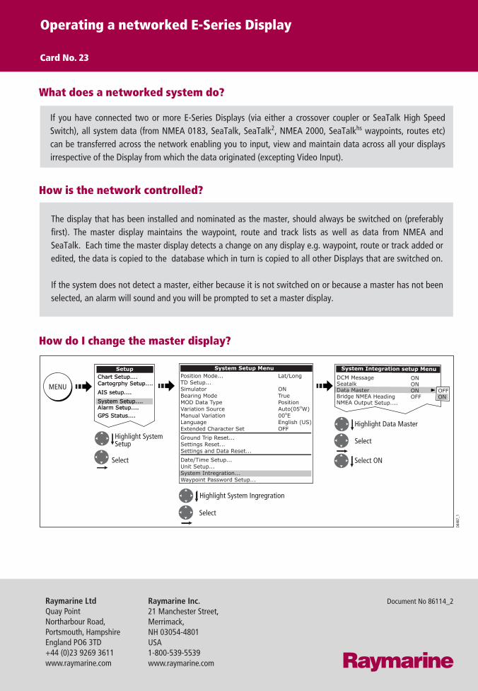
If you have connected two or more E-Series Displays (via either a crossover coupler or SeaTalk High Speed Switch), all system data (from NMEA 0183, SeaTalk, SeaTalk2, NMEA 2000, SeaTalkhs waypoints, routes etc) can be transferred across the network enabling you to input, view and maintain data across all your displays irrespective of the Display from which the data originated (excepting Video Input).
Operating a networked E-Series Display
Card No. 23
What does a networked system do?
The display that has been installed and nominated as the master, should always be switched on (preferably first). The master display maintains the waypoint, route and track lists as well as data from NMEA and SeaTalk. Each time the master display detects a change on any display e.g. waypoint, route or track added or edited, the data is copied to the database which in turn is copied to all other Displays that are switched on.
If the system does not detect a master, either because it is not switched on or because a master has not been selected, an alarm will sound and you will be prompted to set a master display.
How is the network controlled?
How do I change the master display?
D848
7_1
Select
System Integration setup Menu
DCM MessageSeatalkData MasterBridge NMEA HeadingNMEA Output Setup....
ONONONOFF
OFFON
Chart Setup....Cartogrphy Setup....
AIS setup....
System Setup....Alarm Setup....GPS Status....
SetupChart Setup....Cartogrphy Setup....
AIS setup....
System Setup....Alarm Setup....GPS Status....
System Setup MenuPosition Mode...TD Setup...SimulatorBearing ModeMOD Data TypeVariation SourceManual VariationLanguageExtended Character Set
Ground Trip Reset...Settings Reset...Settings and Data Reset...
Date/Time Setup...Unit Setup...System Intregration...Waypoint Password Setup...
Lat/Long
ONTruePositionAuto(05oW)00oEEnglish (US)OFF
MENU
Highlight SystemSetup Select
Select
Highlight System Ingregration
Select ON
Highlight Data Master
Raymarine Inc.21 Manchester Street,Merrimack,NH 03054-4801USA1-800-539-5539 www.raymarine.com
Raymarine LtdQuay PointNortharbour Road,Portsmouth, HampshireEngland PO6 3TD+44 (0)23 9269 3611www.raymarine.com
Document No 86114_2
Related Documents