Open Research Online The Open University’s repository of research publications and other research outputs Making Rules, Making Tools: How Can Shape Grammar Support Creative Making? Thesis How to cite: Maclachlan, Lynne (2018). Making Rules, Making Tools: How Can Shape Grammar Support Creative Making? PhD thesis The Open University. For guidance on citations see FAQs . c 2017 The Author https://creativecommons.org/licenses/by-nc-nd/4.0/ Version: Version of Record Link(s) to article on publisher’s website: http://dx.doi.org/doi:10.21954/ou.ro.0000d29d Copyright and Moral Rights for the articles on this site are retained by the individual authors and/or other copyright owners. For more information on Open Research Online’s data policy on reuse of materials please consult the policies page. oro.open.ac.uk

Welcome message from author
This document is posted to help you gain knowledge. Please leave a comment to let me know what you think about it! Share it to your friends and learn new things together.
Transcript

Open Research OnlineThe Open University’s repository of research publicationsand other research outputs
Making Rules, Making Tools: How Can ShapeGrammar Support Creative Making?ThesisHow to cite:
Maclachlan, Lynne (2018). Making Rules, Making Tools: How Can Shape Grammar Support Creative Making? PhDthesis The Open University.
For guidance on citations see FAQs.
c© 2017 The Author
https://creativecommons.org/licenses/by-nc-nd/4.0/
Version: Version of Record
Link(s) to article on publisher’s website:http://dx.doi.org/doi:10.21954/ou.ro.0000d29d
Copyright and Moral Rights for the articles on this site are retained by the individual authors and/or other copyrightowners. For more information on Open Research Online’s data policy on reuse of materials please consult the policiespage.
oro.open.ac.uk

Mak ing Ru l e s , Mak in g Too l s :
How can shape g rammar suppor t
c r ea t i v e mak ing ?
A thesis submitted for the degree of Doctor of Philosophy
Lynne MacLachlan
BEng(hons) BDes(hons) MA(RCA)
Department of Engineering and Innovation
The Open University
23rd January 2018

2 MacLachlan, L. (2018) Ph.D. Thesis, The Open University
Declaration
This thesis is the result of my own research and does not include the outcome of collaborative
work, except where stated otherwise. The dissertation has not been submitted in whole or in
part for consideration for any other degree.
Lynne MacLachlan
The Open University
23rd January 2018

3 MacLachlan, L. (2018) Ph.D. Thesis, The Open University
PUBLICATIONS
During the course of this study the following papers have been published:
MacLachlan, L., Earl, C., Eckert, C., 2012. Creativity in craft led design: the Tools are the rules.
In DS 73-1 Proceedings of the 2nd International Conference on Design Creativity Volume 1. Available
at:
http://www.designsociety.org/publication/32487/creativity_in_craft_led_design_the_tools_are
_the_rules [Accessed June 23, 2015].
MacLachlan, L., 2014. The Creative Craft of Generative Design, In: All Makers Now
Conference Proceedings 2014, Falmouth, UK. Available at:
http://www.autonomatic.org.uk/allmakersnow/all-makers-now-2014-journal/ [Accessed
December 3, 2016]
MacLachlan, L and Jowers, I, 2014. Formalising flexible multi-material surfaces as weighted
shapes. In: SA '14 SIGGRAPH Asia 2014 Creative Shape Modelling and Design, 3 Dec 2014,
Shenzhen, China, ACM.
MacLachlan, L. & Jowers, I., 2016. Exploration of multi-material surfaces as weighted shapes.
Graphical Models, 83, pp.28–36.

4 MacLachlan, L. (2018) Ph.D. Thesis, The Open University
ACKNOWLEDGMENTS
First and foremost to be thanked is my main supervisor Chris Earl, who has introduced me to
world ideas that have enriched my practice as designer and academic. Chris has offered a great
deal of valuable advice, support and encouragement throughout this process while letting me
find my own way and voice as a researcher, a delicate balance to strike and one he has done
admirably. Chris has continued to supervise and help with finishing this thesis beyond the
retirement from his full time academic position at the Open University, for this and everything
else, thank you.
Also to my supervisor Dr Claudia Eckert who has also offered much encouragement and
guidance, taught me the importance of interrogating ideas, both my own and others, to aim for
academic rigour, how the cogs of academia turn, and advice on managing an academic career
alongside a young family, for this thank you.
Another important person to thank is Dr Iestyn Jowers, not only did Iestyn offer much advice
about generally surviving a PhD, but he crucially offered tireless explanations and definitions on
the more technical, mathematical aspects of shape grammar, helping me define and
communicate my ideas in clearer way, as far as co-authoring a successful conference and
journal paper.
The Open University has provided me with invaluable support and resources enabling me to
complete my thesis. Without the full funding I was given it would not have been possible.
Additional financial support for conferences, travel and during breaks in my study also
enriched my experience. Alongside this access to resources such as training, the library and
equipment have also allowed me to improve my academic abilities.
Many staff in the Design department (and other parts of the OU) aided me at different times
and different ways, to name some but not all, Charles Snelling, Angie Jones, Nicole Lotz, Peter

5 MacLachlan, L. (2018) Ph.D. Thesis, The Open University
Lloyd, Rachel Luck, Stephen Potter, to all of them, and the many more I haven’t managed to
mention, thank you.
Also thanks go out to our small group of students of the Design Transformations Group that
began the PhD process around the same time and provided an understanding community to
discuss the trials and tribulations of a design PHD with, in particular Laura, Khadija and Pam.
And to my family and friends outside of this thesis trying to fathom what was going on, thank
you for the patience and cheer on this longer than expected road. My husband has primarily
borne the brunt of the extra effort needed in the last few years to bring this thesis into being,
in amongst us caring for our two sons and his own flourishing career, thank you to him for this
and everything else on a daily basis. Also my parents, continuing to support without question,
my at times my slightly strange career path, much financial assistance has been given over the
years and more latterly childcare without proviso, for which I know I am exceptionally
fortunate. Without this I couldn’t have followed my passions and be truly happy in my work,
leaving behind the Monday blues a long time ago, something that makes life inordinately better.

6 MacLachlan, L. (2018) Ph.D. Thesis, The Open University
CONTENTS
Publications ....................................................................................................................................................... 3
Acknowledgments ........................................................................................................................................... 4
Figures .............................................................................................................................................................. 11
Abstract ........................................................................................................................................................... 17
1 Introduction ........................................................................................................................................... 19
1.1 The author’s background ..................................................................................................................... 19
1.2 Introduction to the research questions ............................................................................................ 22
1.3 Structure of this thesis .......................................................................................................................... 22
1.4 Scope and limitations of the thesis .................................................................................................... 25
1.5 Terms ........................................................................................................................................................ 29
2 Literature review .................................................................................................................................. 32
2.1 Craft .......................................................................................................................................................... 34
2.1.1 The role of craft in design: a brief history ................................................................... 34
2.1.2 The principles of craft ....................................................................................................... 37
2.1.3 Working with materials .................................................................................................... 37
2.1.4 Making with tools ............................................................................................................... 38
2.1.5 Skill and expertise .............................................................................................................. 40
2.2 Design – the new academe .................................................................................................................. 42
2.2.1 Designing with materials .................................................................................................. 43
2.3 Shape grammar ....................................................................................................................................... 45
2.3.1 Shape grammar operations .............................................................................................. 46
2.3.2 Schemas in shape grammar .............................................................................................. 48
2.3.3 Labels and weights ............................................................................................................. 49
2.3.4 Shape grammar applied in design processes ................................................................ 51
2.4 Creativity .................................................................................................................................................. 54

7 MacLachlan, L. (2018) Ph.D. Thesis, The Open University
2.4.1 Rules in creativity ............................................................................................................... 55
2.4.2 Design creativity ................................................................................................................. 57
2.5 Digital design tools................................................................................................................................. 59
2.6 Computational making .......................................................................................................................... 62
2.7 Research questions ................................................................................................................................ 65
3 Methodology and methods ................................................................................................................ 67
3.1 Design research methodology ............................................................................................................ 67
3.2 Methodology used for this research .................................................................................................. 69
3.3 Possible methods which have been ruled out ................................................................................. 73
PART I - framework of strategies for stimulating creative episodes ................................................ 75
4 Designer interviews ............................................................................................................................. 75
4.1 Collection and analysis of interview data ......................................................................................... 76
4.2 Designer profiles .................................................................................................................................... 77
4.2.1 Ian McIntyre ........................................................................................................................ 77
4.2.2 Eleanor Bolton .................................................................................................................... 78
4.2.3 Kathryn Hinton................................................................................................................... 79
4.2.4 Marina Brown ..................................................................................................................... 80
4.2.5 Jasleen Kaur ......................................................................................................................... 81
5 Design worlds ....................................................................................................................................... 83
5.1 The role of tools in designer-maker design worlds ....................................................................... 85
5.2 Tools and personal design worlds ..................................................................................................... 88
5.3 The role of tools in creative episodes .............................................................................................. 89
5.4 New tool combinations ........................................................................................................................ 90
6 Transforming tools............................................................................................................................... 92
6.1 Tool variable transformations ............................................................................................................. 92
6.2 Tool function transformations ............................................................................................................ 93
6.3 Tool invention ......................................................................................................................................... 97
6.4 The mechanisms of tool transformation and invention ................................................................ 99
6.4.1 Tools and analogy ........................................................................................................... 100
6.4.2 Tools and concept blending ......................................................................................... 101

8 MacLachlan, L. (2018) Ph.D. Thesis, The Open University
6.4.3 Tools and emergence ..................................................................................................... 102
6.5 An exception ......................................................................................................................................... 105
7 The tools are the rules – using shape grammar to Describe making processes ............... 107
7.1 Shape grammar rule schemas ............................................................................................................ 108
7.1.1 Addition schema .............................................................................................................. 108
7.1.2 Boolean operations ........................................................................................................ 111
7.1.3 Parametric schema.......................................................................................................... 113
7.1.4 Identity schema ................................................................................................................ 114
7.1.5 Selection schema ............................................................................................................. 115
7.1.6 Boundary schema ............................................................................................................ 116
7.1.7 Subtraction schema ........................................................................................................ 118
7.2 Labels and weights ............................................................................................................................... 118
7.3 Shape schema grammars .................................................................................................................... 119
8 Analysis of a designer-maker design process with shape grammar schema........................ 121
8.1 Tool selection – addition schemas ................................................................................................... 121
8.2 Inspiration – parts schemas ............................................................................................................... 122
8.3 Tool making ........................................................................................................................................... 123
8.4 Tool transformation ............................................................................................................................ 124
8.4.1 Parametric tool transformations ................................................................................. 125
8.4.2 Functional tool transformations .................................................................................. 127
8.4.3 Tool reformatting ........................................................................................................... 129
8.5 Discussion of findings from Part I .................................................................................................... 135
8.5.1 Tool selection .................................................................................................................. 136
8.5.2 Tool combinations .......................................................................................................... 137
8.5.3 Transformation of tools ................................................................................................ 138
8.6 Reflections on shape grammar .......................................................................................................... 139
8.7 A framework for designer-makers................................................................................................... 141
PART 2- A weights schema for colour 3D printing ........................................................................... 145

9 MacLachlan, L. (2018) Ph.D. Thesis, The Open University
9 Shape grammar weights ................................................................................................................... 147
9.1 Colour weights for colour 3D printing .......................................................................................... 153
9.2 Colour in design ................................................................................................................................... 154
9.3 Ranking shapes ...................................................................................................................................... 156
9.3.1 Chronological ranking .................................................................................................... 156
9.3.2 Dynamic ranking .............................................................................................................. 157
9.3.3 Parametric attribute ranking ........................................................................................ 159
9.3.4 Ambient attribute ranking ............................................................................................. 160
9.4 Equal rankings ....................................................................................................................................... 161
9.5 Using shape rankings in difference calculations............................................................................. 162
9.6 Ranking weights .................................................................................................................................... 165
9.6.1 Logic rule ranking ............................................................................................................ 165
9.6.2 Using weight rankings in shape additions .................................................................. 166
9.6.3 Using weights rankings in shape differences ............................................................. 167
9.7 Calculating secondary colour weights ............................................................................................. 171
9.7.1 Logic rule calculations .................................................................................................... 172
9.7.2 Modular scale colour weights ...................................................................................... 173
10 Z-Corp colour printing case study ........................................................................................... 177
10.1 Computational making with colour ................................................................................................. 177
10.2 Weights systems for 3D Z-Corp colour printing ........................................................................ 180
10.3 Computational making experiments ................................................................................................ 181
10.4 RGB and CYMK colour models ....................................................................................................... 183
10.5 A CYM colour weights system ......................................................................................................... 185
10.6 An RGB colour weight system ......................................................................................................... 192
10.7 An HSL colour weight system........................................................................................................... 200
10.8 A second HSL colour weight system .............................................................................................. 203
10.9 Segmenting colour systems................................................................................................................ 208
10.10 Colour palettes ..................................................................................................................................... 209
10.11 Printing results ...................................................................................................................................... 210
10.12 Applying colour to shapes .................................................................................................................. 213
10.13 Embedding .............................................................................................................................................. 216

10 MacLachlan, L. (2018) Ph.D. Thesis, The Open University
10.14 What is a zero weight? ....................................................................................................................... 218
10.15 Parametric colour weights ................................................................................................................. 218
10.16 A computational making process with colour weight tools for Z Corp colour printing ................................................................................................................................................................. 219
11 Objet Connex case study ........................................................................................................... 223
11.1 Weights system modelling flexibility ............................................................................................... 226
11.2 Weights system modelling rigidness ................................................................................................ 229
11.3 Weights tool incorporating material density................................................................................. 232
11.4 Using rules to create weighted flexible shapes ............................................................................. 235
11.5 Computing with flexible surfaces ..................................................................................................... 237
11.6 Computational making process using weights for the Objet Connex .................................... 240
11.7 Discussion of weighted shapes for multi-material 3D printing ................................................. 243
12 A Weights Schema ....................................................................................................................... 245
13 Conclusions .................................................................................................................................... 249
13.1 Revisiting the research questions ..................................................................................................... 249
13.2 Discussion .............................................................................................................................................. 254
13.3 Contributions to knowledge ............................................................................................................. 259
13.4 Summery and conclusions .................................................................................................................. 263
13.5 Future work .......................................................................................................................................... 264
13.6 Personal reflection ............................................................................................................................... 267
Bibliography ................................................................................................................................................ 268
Appendix 1- Questions used in designer interviews ......................................................................... 278

11 MacLachlan, L. (2018) Ph.D. Thesis, The Open University
FIGURES
Figure 1-1: ‘Flutter’ bangle, Lynne MacLachlan, silver and resin, 2008 ............................................. 21
Figure 2-1: ‘La Chaise’, fiberglass seat, by Charles & Ray Eames, 1948 ............................................ 35
Figure 2-2: Rover Chair, Ron Arad,1981 ................................................................................................. 36
Figure 2-3: Lace Fence, Demakersvan for Droog, 2005 ...................................................................... 36
Figure 2-4: Example of a shape grammar rule ........................................................................................ 45
Figure 2-5: Example of reapplication of shape grammar rule on emergent shapes ....................... 46
Figure 2-6: Boolean Operations of Shapes .............................................................................................. 46
Figure 2-7: Example of using points to define specific relations ......................................................... 47
Figure 3-1: Owen’s model for accumulating and integrating knowledge in the analytical and
synthetic realms ............................................................................................................................................. 70
Figure 3-2: Methodological model for this thesis based on Owen .................................................... 71
Figure 4-1: Series One Pottery for Another Country by Ian McIntyre, 2011 ................................ 78
Figure 4-2: Coiled Rope Necklace by Eleanor Bolton, 2010 .............................................................. 79
Figure 4-3: Exhausted Cutlery by Katherine Hinton, 2009 ................................................................. 79
Figure 4-4: Screen shot of Flash advert for Eden Channel by Marina Brown, 2011. .................... 80
Figure 4-5: Tala Curry Measure by Jasleen Kaur, 2013 ........................................................................ 81
Figure 4-6: Chai Tea Stall by Jasleen Kaur, 2011 ................................................................................... 82
Figure 4-7: Chai Tea Dispenser by Jasleen Kaur, 2010 ........................................................................ 82
Figure 5-1: Decapitated Pet Jewellery by Eleanor Bolton, 2008 ........................................................ 86
Figure 5-2: Eleanor Bolton’s Rope Necklaces in French Vogue, 2010 ............................................. 87
Figure 5-3: Jenn 3D Screen Shot and jewellery created with the help of the program ............... 90
Figure 5-4: Eleanor Bolton sewing rope together with needle and thread ..................................... 91
Figure 6-1: Broken Vase Process, Ian McIntyre, 2008 .......................................................................... 93
Figure 6-2: Cook’s Measure by Tala ......................................................................................................... 95
Figure 6-3: Inside of Tala Curry Measure by Jasleen Kaur, 2013 ....................................................... 95
Figure 6-4: Output from a simple shape grammar tool made in Processing by the author ........ 96

12 MacLachlan, L. (2018) Ph.D. Thesis, The Open University
Figure 6-5: Kathryn Hinton demonstrating digital silversmithing and a resulting bowl, 2010 .... 98
Figure 6-6: Thread Wrapping Machine, Anton Alverez, 2012 ............................................................ 99
Figure 6-7: Furniture made with Thread Wrapping Machine, Anoton Alverez 2012 ................... 99
Figure 6-8: Rope necklaces with varied forms, Eleanor Bolton, 2010 ........................................... 103
Figure 6-9: MA project plates, Ian McIntyre, 2010 ............................................................................. 103
Figure 6-10: Slush cast bowl, process and finished bowl, by Ian MCIntyre, 2008....................... 104
Figure 7-1: Stiny’s lattice of rule schemas ............................................................................................. 108
Figure 7-2: Example of a Shape Grammar Addition Rule I ............................................................... 109
Figure 7-3: Example of a Shape Grammar Addition Rule II .............................................................. 110
Figure 7-4: Addition rule demonstrating Boolean addition .............................................................. 111
Figure 7-5: Parametric transformation of a tool ................................................................................. 114
Figure 7-6: Boundary shape rule ............................................................................................................. 117
Figure 8-1: 36 Pencil Bowl by Michael Cornelissen, 2010 ................................................................ 123
Figure 8-2: Diagram of Grasshopper tool in case study ................................................................... 124
Figure 8-3: Visualisation of parametric shape grammar transformation in case study .............. 125
Figure 8-4: Parametric transformation of a computational tool ..................................................... 126
Figure 8-5: Diagram of functional transformations made on a tool in case study ...................... 128
Figure 8-6: Section of page from Goldsmiths’ Craft and Design Council Awards catalogue 2012
........................................................................................................................................................................ 129
Figure 8-7: Transformation of the design ............................................................................................. 130
Figure 8-8: Moiré patterns appearing from large numbers of lines as generated by the
Grasshopper tool ....................................................................................................................................... 131
Figure 8-9: Screenshot of new, simplified Tool in Case Study ........................................................ 131
Figure 8-10: Template Tool for Phase Collection .............................................................................. 133
Figure 8-11: Pieces from the Phase collection, Lynne Maclachlan, 2013....................................... 134
Figure 8-12: Section of page from Goldsmiths’ Craft and Design Council Awards catalogue
2013 ............................................................................................................................................................... 135

13 MacLachlan, L. (2018) Ph.D. Thesis, The Open University
Figure 8-13: Model of shape grammar design process ...................................................................... 140
Figure 8-14: Model of designer-maker process ................................................................................... 141
Figure 8-15:Framework for stimulating creative episodes using tools for designer-makers .... 144
Figure 9-1: Weighted shape addition, s plus s ..................................................................................... 148
Figure 9-2 Weighted shape addition, s plus t ...................................................................................... 148
Figure 9-3: Weighted Shape Subtraction, s minus s ........................................................................... 149
Figure 9-4: Weighted shape subtraction, t minus s ............................................................................ 149
Figure 9-5 Weighted shape subtraction, zero weight result ............................................................ 150
Figure 9-6: Knight’s colour grammars ................................................................................................... 152
Figure 9-7: Colour weights dominating in order of addition to design ......................................... 157
Figure 9-8: Dynamic Colour Ranking..................................................................................................... 159
Figure 9-9 Ranking Shapes by number of sides .................................................................................. 160
Figure 9-10 Rankings increasing with x position ................................................................................. 161
Figure 9-11: Shape subtractions using a shape ranking system........................................................ 163
Figure 9-12: Shape Transformations using shape ranking System................................................... 164
Figure 9-13: Example of Colour Weights by Ranking Colours ....................................................... 166
Figure 9-14: Shape Subtraction using logic colour ranking weights................................................ 167
Figure 9-15: Colour ranking subtractions with 0 weight result ...................................................... 168
Figure 9-16: Rotation Rule applied using subtractions as 0 .............................................................. 169
Figure 9-17: Deferring to lower ranked colour in subtractions ..................................................... 170
Figure 9-18: Rotation Rule Deferring to minimum Colour Weights for Subtraction ............... 171
Figure 9-19: Z-Corp colour print featuring designer defined weight on intersections ............. 172
Figure 9-20: Additions handled as modular steps along a palette................................................... 174
Figure 9-21: Instructive colour rules for one dimensional colour scale ........................................ 175
Figure 9-22: Consecutive rules reaching last step on colour scale ................................................ 176
Figure 10-1: Screen Shot of Rhino3D, showing material options ................................................... 178
Figure 10-2: Colour Experiment in Rhino3D ...................................................................................... 179

14 MacLachlan, L. (2018) Ph.D. Thesis, The Open University
Figure 10-3: Colour Print of Rhino3D model...................................................................................... 179
Figure 10-4: Weight operations as Boolean operations. .................................................................. 181
Figure 10-5: Diagram of Grasshopper Tile Tool ................................................................................. 183
Figure 10-6 CYMK print magnification .................................................................................................. 183
Figure 10-7: Example of an addition calculation for a CYM weight ............................................... 186
Figure 10-8: Tile showing addition calculations for a CYM Weight ............................................... 187
Figure 10-9: Product calculation for weight using maxima of channels ......................................... 188
Figure 10-10: Tile design showing products using maxima for a CYM weight ............................ 189
Figure 10-11: Product calculation for CYM weight using minima of channels............................. 189
Figure 10-12 Tile design showing products using minimums for CYM Weight 1....................... 190
Figure 10-13: Weight subtraction for a CMY weight ........................................................................ 191
Figure 10-14 Tile design with green circle subrtacted ...................................................................... 192
Figure 10-15 Examples of RGB values and colours ............................................................................ 193
Figure 10-16 RGB colour space represented as a cube .................................................................... 194
Figure 10-17: RGB weights addition calculation ................................................................................. 195
Figure 10-18 Tile designed with an RGB weights system showing additions............................... 196
Figure 10-19: RGB weights product calculation.................................................................................. 197
Figure 10-20: Tile design showing RGB product weights ................................................................. 197
Figure 10-21: RGB weight difference calculation ................................................................................ 199
Figure 10-22: Tile design showing an RGB difference calculation .................................................. 199
Figure 10-23: Cylinder Representation of HSL Colour system ...................................................... 200
Figure 10-24: HSL weight calculations ................................................................................................... 201
Figure 10-25: HSL colour weight product calculations ..................................................................... 202
Figure 10-26: HSL stepping weight addition calculations .................................................................. 205
Figure 10-27: Tile generated using HSL weights with stepping additions ..................................... 205
Figure 10-28: HSL product calculation for stepping weights system ............................................. 206
Figure 10-29: Tile design using HSL product calculations................................................................. 207

15 MacLachlan, L. (2018) Ph.D. Thesis, The Open University
Figure 10-30: HSL Difference Stepping Calculation ........................................................................... 208
Figure 10-31; Segmented, Modular Colour System based on CYMK values ............................... 209
Figure 10-32 Bespoke 3D colour palette for a weights system ...................................................... 210
Figure 10-33 Tile generated with CYM values alongside photograph of printed version ........ 211
Figure 10-34: Tile generated with RGB values alongside photograph of printed version ........ 212
Figure 10-35 HSL space Z-Corp colour printed representation .................................................... 212
Figure 10-36 RGB space Z-Corp colour printed representation ................................................... 213
Figure 10-37: CYM space Z-Corp colour printed representation ................................................. 213
Figure 10-38 Multi-coloured cubes intersecting ................................................................................. 214
Figure 10-39: Solid coloured cubes interacting ................................................................................... 215
Figure 10-40: Solid Coloured Cubes with Sphere Subtracted ........................................................ 215
Figure 10-41: Solid coloured cubes unioned and both assigned new colour ............................... 216
Figure 10-42 Cylinders design with chronologically ranked shapes ............................................... 216
Figure 10-43: Shapes from previous figure ........................................................................................... 217
Figure 10-44: Shape found to form the basis of vessels .................................................................... 221
Figure 10-45: Novel bowl designed with shape grammar weights tool ........................................ 221
Figure 11-1: Object printed sample combing VeroWhite and VeroBlack materials .................. 224
Figure 11-2: Connex weight for flexibility calculations ..................................................................... 226
Figure 11-3: Shape Addition with multi-material planes ................................................................... 227
Figure 11-4: Shape product with multi-material planes ..................................................................... 228
Figure 11-5: Shape Difference with multi-material planes ................................................................ 228
Figure 11-6: Vertical stripes printed weighted shape ........................................................................ 228
Figure 11-7: Horizontal stripes printed weighted shape ................................................................... 229
Figure 11-8: Weighted Shape from addition calculation ................................................................... 229
Figure 11-9: Shape operations on weighted shapes modelling hardness ...................................... 230
Figure 11-10: Weight system for rigidity addition example ............................................................. 231
Figure 11-11: Weight system for rigidity product example ............................................................. 231

16 MacLachlan, L. (2018) Ph.D. Thesis, The Open University
Figure 11-12: Weight system for rigidity subtraction example ....................................................... 232
Figure 11-13: Modular weight system using two blended materials and a density component
........................................................................................................................................................................ 232
Figure 11-14 Calculating with weights with a density component ................................................. 234
Figure 11-15; Modular stepping ratio scale and rule for Objet Connex ....................................... 235
Figure 11-16: Weighted shape rule and application ........................................................................... 237
Figure 11-17: Visual representation, computational physical model and printed object........... 238
Figure 11-18: Visual representation, computational physical model and printed object 2 ....... 238
Figure 11-19: Weighted surface, result of the sum operation, visual and physical models ...... 239
Figure 11-20: Reconfigured Shape with corresponding flat weighted shape ................................ 241
Figure 11-21: Visualisation of multi-material printed textile using a weight product calculation
........................................................................................................................................................................ 242
Figure 12-1: A weights schema for multi-material/property 3D printing ..................................... 246

17 MacLachlan, L. (2018) Ph.D. Thesis, The Open University
ABSTRACT
Design theory has previously studied the practices of architects, industrial designers and
engineers. Designer-makers, designers who work independently, designing and making objects
with close attention to tools and materials, have not been similarly studied. A renewed
interest in craft and making, in part catalysed by new computational and digital fabrication
tools at designer’s disposal, strengthens the case for studying successful design-through-making
processes. An analogy between rules transforming shapes and tools transforming material
provided the initial indication that concepts from shape grammar could be aligned with making
processes, to potentially support creative making and deliver new theoretical and applied
knowledge for both spheres.
The first part of the thesis examines shape grammar theory as a method of modelling
designer-maker creative episodes, to inform designer practice. Evidence was gathered from
interviews with designer-makers, observations from a design process carried out by the
author and other literature on designer-makers. This evidence was analysed in the context of
shape grammar and established creativity literature in order to seek formal descriptions of
creative episodes. It was found that designer-makers used tools to define personal and shared
design worlds and focussed on and undertook specific activities relating to tools which have
been classified; tool selection, tool combination and tool transformation, all of which have
creative potential. Tool transformation was found to have further scope for definition and it
was found that designers can perform parametric, functional and reformatting transformations
on tools to produce new and useful design outcomes. Shape grammar schemas were found to
provide useful descriptors for the operations performed by designer-makers on tools.
The second part of the thesis inquires if shape grammar as a design method can support
creative computational making, by specifically exploring the use of shape grammar weights, a
way of modelling material properties alongside shape operations, as a tool for generating
designs for multi-material 3D printing. A number of design reasoning and computational

18 MacLachlan, L. (2018) Ph.D. Thesis, The Open University
making experiments were carried out and the process and results reported and considered.
The outcome is a range of specified weights systems and a general schema for defining and
using weights as tool for managing material properties for multi-material 3D printing that can
be used and transformed by computational makers. The general weights schema also extends
previous theoretical definitions of shape grammar weights. This part of the thesis also
demonstrated the importance of tool development and transformation as a basis for creative
episodes in design-through-making processes.

19 MacLachlan, L. (2018) Ph.D. Thesis, The Open University
1 INTRODUCTION
The author is a designer-maker, mainly using digital tools and 3D printing to produce jewellery
and objects and so has a personal experience of design that has informed the development of
the research questions of this thesis. This research brings together three spheres of interest;
making, creativity and shape grammar. How making, or craft, influenced the design processes
of designer-makers was the initial point of inquiry for the author. Then by taking creative
outcomes as the hallmark of a successful design process, activities that brought about creative
episodes in designer-maker practice became a focus and way of validating the usefulness of any
knowledge found. Finally shape grammar was found to have many points of correspondence
with these two spheres, and hypothesis was developed that shape grammar could be used to
describe and support creative making, and hence the grounding for this thesis was arrived at.
A guide to the impetus, research questions, structure, scope and terms of this thesis can be
found in the following sections.
1.1 The author’s background
Much of the rationale and approach for this research has arisen from the author’s own
experiences of designer-maker practice, education and teaching of jewellery design and
making, a brief explanation of her career path to date gives a view of the how the research
questions and chosen methods and methodology came to be formulated.
After a degree in Aerospace Engineering and a year working in industry, the author returned
to education to study at Duncan of Jordanstone College of Art in Dundee, specialising in
Jewellery and Metalwork Design. Following this she completed a Master’s degree at the Royal
College of Art in Goldsmithing, Silversmithing, Metalwork and Jewellery. Since then, while
carrying out PhD research at the Open University, the author has continued her design
practice, as a designer-maker of jewellery specialising in using and experimenting with digital

20 MacLachlan, L. (2018) Ph.D. Thesis, The Open University
tools. During this time she has also taught undergraduate jewellery design students
introductory modules on CAD software, use of digital fabrication techniques and mentored
students that wished to integrate these further into their practices. These three activities have
had a reciprocal influence on one another, developing ideas about digital making, both practical
and theoretical.
A first degree in aerospace engineering and a year working in the space software industry
turned out to be a frustrating experience. Although the author enjoyed computational based
work, the disconnect between the computation and a physical objects left a feeling of
dissatisfaction. On returning to art school the author selected to specialise in jewellery and
metalwork; a decision based on the fact that the department had a well-equipped and
intriguing workshop, where physical interaction with materials was the focus. Indeed the
course was very much craft based, learning and practice took place in workshop
environments, and practical, physical knowledge was transferred by live demonstrations from
tutors and technicians. The academic side of this education came in the form of art and design
history – lectures, reading and writing on the consideration of the philosophical concepts
embodied in the work of lauded artists and designers. In the author’s experience design theory
was not taught formally, although this may not be the case for undergraduates everywhere of
course. Producing designs that were viewed by tutors as successful as seemed almost a black
art, much of the advice offered seemed to be personal opinion rather than an objective
analysis, leaving the author some confusion at times about what was good or bad or why.
Other than that development of creative practice was almost expected by osmosis, no
strategies were offered on how to be creative, yet with hindsight the author realised creative
outcomes were what the students were predominantly judged on.
The author is perhaps one of the first ‘digital natives’, being born just as computers were
starting to be used by the general population. Having a computer scientist for a father, the
author was at the advantage of having a personal computer in the home from an early age, this
familiarity made computer use a natural progression for her design work. Although her work

21 MacLachlan, L. (2018) Ph.D. Thesis, The Open University
has become increasingly digitally designed and made, the way this happens still feels very much
in the realm of making and craft. The characterisation of the computer as a kind of craftsman’s
toolbox by Malcolm McCullough’s in Abstracting Craft: the practiced digital hand [77] resonated
with the author during her undergraduate studies and beyond. Like McCullough suggests,
experimenting with digital tools and the analogue tools felt like a very similar activity.
The author’s final degree work at Duncan of Jordanstone was developed from creating
abstract, repetitive patterns based on drawings of insects, prototyped with laser cut card and
finally made from etched silver and resin, Figure 1-1shows a bangle from the final collection.
These patterns involved a lot of repetitive work on Adobe Illustrator – effectively making
polar arrays by iteratively rotating a shape at polar intervals, testing different combinations of
shapes and angles until a suitable arrangement was found. This process was time consuming as
the software did not have a polar array tool or script integrated like other CAD software,
from previous experience the author knew this laborious process was something that could be
easily automated by an algorithm, beginning a curiosity about generative design.
Figure 1-1: ‘Flutter’ bangle, Lynne MacLachlan, silver and resin, 2008
By the end of her MA the author was trying to ‘grow’ designs by experimenting in parallel with
analogue and digital approaches, exploring processes like growing copper sulphate crystals and
casting their forms and also trying to mimic natural processes with algorithms built in Rhino3D
and Grasshopper, a CAD package with an accompanying visual algorithm editor. The author

22 MacLachlan, L. (2018) Ph.D. Thesis, The Open University
also experimented with found software such as Jenn 3D, a freeware programme which
generates and manipulates visualisations of complex mathematical structures, to mimic the
structure of bubbles.
On embarking on this research the author wanted to discover more about the making
processes and tools that she seemingly intuitively adopted as a way of designing. It was felt
that formal descriptions of designer-maker practice could help improve the chances of
successful designs for the author and other designer-makers. Thus a potential line of inquiry
into designer-maker practice was established.
1.2 Introduction to the research questions
This research was motivated by the author’s desire to describe, understand and improve the
kind of design practice she was engaged in, that of design-through making with a focus on
experimenting with tools. The author’s knowledge of algorithmic generative tools from her
practice provided a bridge to cross reference concepts from shape grammar theory, also
having a basis in generative design, with making and tools. Enquiries into craft literature and
design theory research opened up a number of themes and omissions in relation to design-
through making, leading to the question ‘can shape grammar support creative making?’. Two
strands emerged, a theoretical strand, using shape grammar to model creative making
practices, and the applied strand, applying shape grammar weights in a digital design-through-
making process as a tool to generate designs, hence the two parts to this thesis.
1.3 Structure of this thesis
A description of the structure of this thesis is now presented; each chapter title is listed and
accompanied with a short summary of the contents.
1Introduction: this chapter introduces the thesis by providing a summary of the author’s
career path to date in order to establish a view of the motivation behind this research. The

23 MacLachlan, L. (2018) Ph.D. Thesis, The Open University
structure of the thesis is detailed here and the scope and limitations are defined. A final
section lists descriptions of the key terms used throughout the thesis to further establish the
locus of the research.
2 Literature review: this reviews the work done by others in several fields that are relevant to
the research questions, setting a scene for the research questions. First reviewed is the
relationship between craft and design in a historical context, followed by an examination of
other literature relating to craft and making. This is followed by a general review of design
research and a more detailed look at some relevant parts of this. Shape grammar theory plays
a key role in modelling and formalising the ideas in this thesis, a review of the work done in
this particular research community is also reviewed and summarised to provide a background
for the reader. Also reviewed is literature relating to creativity and a specific look at recent
research done on digital tools, computational making and craft. On the basis of the analysis of
the literature this section concludes the chapter by presenting the research questions posed
for this research.
3 Methodology and methods: A methodology chapter examines possible research methods
and methodology to answer the research questions, explaining and outlining the methods
selected and those rejected.
PART I: Framework for strategies for stimulating creative episodes (chapters 4-8): contains
research that addresses the main research question in a theoretical way, questioning how
shape grammar theory can be used to model and guide creative behaviours in design through
making. This is done by analysis of interviews of designer-makers, finding comparing and
contrasting practices in established design and creativity with that of the designer makers. This
leads to a more focussed look at tool activities, which emerged as an important theme from
the interviews. Finally shape grammar schemas are demonstrated as a way of modelling making
processes and tool transformations, through discussion and the modelling of a computational-
making process carried out by the author.

24 MacLachlan, L. (2018) Ph.D. Thesis, The Open University
PART 2- A weights schema for colour 3D printing (chapters 9-12): addresses shape grammar
as a design method in the context of the research question, in particular shape grammar
weights as a computational method for designing and making objects for 3D printing. To do
this previous shape grammar weights theory is applied to design reasoning experiments and
applied computational making processes from the perspective of use for multi-material 3D
printing systems. A range of scenarios are presented, resulting in a range of weights
approaches and tools for two 3D printing systems, one that makes use of coloured inks to
produce coated multi-coloured objects and another that blends materials to produce multi-
material, multi-property objects. The result are some specific implementations for these
accessible systems and an overall general weights schema extending shape grammar weights
theory and offering designers a reference framework for shape grammar weights.
13 Conclusions: The concluding chapter revisits the research questions and discusses how
these have been answered by the research. A discussion section explores the how the findings
fit within current related research communities and the contributions to knowledge are clearly
defined. Finally the summary of the thesis, some suggestions for future work and a personal
reflection by the author can be found at the end of this thesis.
The thesis concludes with a bibliography and a short appendix covering the details of the
questions.

25 MacLachlan, L. (2018) Ph.D. Thesis, The Open University
1.4 Scope and limitations of the thesis
Design can be seen as a very broad field, ranging from the design of complex engineering
systems to the production of objects that are appreciated as works of art. This thesis is
concerned with a specific kind of design activity which can be termed ‘design-through-making’,
carried out by those that often refer to themselves as designer-makers.
Many design courses in British art schools are still presently still run on a system broadly
based on the ideas of the Bauhaus, where certain design disciplines are taught by practice of
their associated craft techniques. Students learn by designing and making objects in a
workshop and or studio environment, learning by practical demonstration and practice,
alongside some academic, theoretical learning – lectures and essay writing. Graduates of this
system go on to many different careers, but it often produces one particular kind of designer –
the designer-maker.
The intention of many of these students once graduated is to work closely with their chosen
tools and materials with an independent ethos, producing one off and small batch objects.
They predominantly design alone, and so this thesis is not concerned with collaborative design
processes. They may make their products themselves, with their tools and adapting varying
degrees of automation, although outside sources may be involved in production as well. The
defining feature of these designers is that they work very closely with tools and materials,
designing by exploring the possibilities of these, and will understand how to make the products
they design in detail, rather than producing sketches to be handed over to a manufacturer.
Initially this usually entails prototyping and experimenting with tools and materials until a useful
new design or technique has been found, usually in response to a design brief either formal or
self-motivated, usually to access a specific design domain and audience. The designer-maker
will often proceed with a certain group of tools, materials and techniques, making objects the
same or with lesser or greater variations, often for many years.

26 MacLachlan, L. (2018) Ph.D. Thesis, The Open University
The aim of the first part of this thesis is to use an examination of the role tools and materials
play designer-makers creative episodes, where a new and useful discovery is made, and if ideas
from shape grammar could be a relevant way of describing and supporting this. Design theory,
since conception, predominately focusses on sketching and cognitive reasoning in design fields
where the production of the finished object is disjointed from the design process, such as
architecture, industrial and engineering design. This view of industrial design as the discipline of
developing an explicit representation of an object and specification of requirements, apart
from the actual physical object, can be traced back through current design theory, to Herbert
Simon’s book Sciences of the Artificial [101] and even further through design history to Alberti,
who sought to make the distinction between the corporeal world and the ‘mind’s eye’ a place
where spatial construction could take place and the concepts of point, lines and planes used
representations for architecture [16] and a broader tradition in philosophy of hierarchically
separating mind and body. This research seeks to address not this kind of purely symbolic way
of designing, but one where the designer focuses on experimentation with the material and
tools to bring forth useful objects, a facet of design practice that has at times been neglected in
design theory and research.
This thesis uses shape grammar theory, part of the design theory tradition and based on
sketching, as a theoretical method of helping to formalise the workings of creativity in making.
It is intended that shape grammar can provide a link from the world of design theory to the
often enigmatic world of making and craft, due to it being rooted in visual computation rather
than being linguistically based. In the most elemental description shape grammar entails
transforming shapes with a given rule to create a new shape. It was found that the concept of
a rule was used to describe the mechanisms of creativity by Margaret Boden [10] and the
acquiring and execution of craft skills by Dormer [27], signifying strong relations between the
three and offering a context to both classify and validate the findings from the first part of the
research.

27 MacLachlan, L. (2018) Ph.D. Thesis, The Open University
Of particular importance in this work is the analogy that in shape grammar rules are used to
transform shapes, while the maker uses tools to transform material, this analogy opens up
possibilities to use shape grammar to provide clarifications of designer activities in making.
Allowing the concepts of rules and tools to become interchangeable in designer-maker
practice allows a theoretical framework to be established, it is hoped this can act as a guide to
designers involved in design-through-making, both in physical and digital contexts, discovering
tactics that can be used to increase the likelihood of creative discoveries.
The second part of the thesis looks in another other form, the practical application of shape
grammar mechanisms for actually designing. New 3D printing technologies are now readily
accessible to the designer-maker, so this thesis assumes it is pertinent to try and find ways of
creating designs suitable for this kind of production with the ethos of design through making in
mind. Digital fabrication is a method of production that returns close control over the
manipulation of material into an object to the designer, much like a traditional craft practice as
opposed to an industrial design process incorporating and combining complex manufacturing
techniques. Designers are increasingly using this new, increasingly accessible, technology, some
purely to manufacture objects and prototypes in a conventional industrial design sense, but
many are taking a more craft-like experimental approach with the hardware and the associated
software.
Several types of 3D printing systems currently exist, each with an array of associated materials.
This research identifies multi-material 3D printing as a particularly interesting case to explore
to answer some of the research questions. A recent development in 3D printing, multi-
material printing offers the opportunity to print objects with variable materials and material
properties in one piece on one machine. The practical design experiments in this research
make use of the two particular machines, the Z Corp colour printer, a powder binding system
that uses cyan, magenta, yellow and black ink cartridges, coating the printed surface and array
of colours, and the Objet Connex printer, a stereolithography system with a range of resins
with different colours and properties that can be combined in one object. At the time of

28 MacLachlan, L. (2018) Ph.D. Thesis, The Open University
experimenting and writing these were the most easily accessible to an independent designer-
maker through bureau services. No doubt access and technology will change over time as 3D
printing technology evolves, but it is hoped that despite focus on these particular systems
much of the general findings will have relevance in the future as new multi-material techniques
and machines are realised.
The computational, rule based nature of shape grammar makes it well placed for to play a role
in computational making, both in a theoretical sense, the foundations of which are laid out in
the first part of this thesis, but also in a more direct way; using close algorithmic
interpretations of shape grammar rules in CAD based generative design tools that can in turn
be linked to digital fabrication systems. Some researchers have addressed this, for example
Sass [92] and Shea [98,99], both programming shape computations to generate designs for
architecture. This research tackles an extension of shape grammar developed by Stiny
[106,108] and Knight [59,60,61], that of applying ‘weights’ to shapes, to represent material
properties, introducing the capability for computations associated with material properties to
take place alongside shape transformations.
The idea of weights seems to align well with multi-material 3D printing, therefore investigating
the possibilities of such a combination has merit. There are many ways of designing and
generating structures and patterns for multi material printing, but the thesis is concerned with
examining a method based using shape rules and transformations of weighted shapes. The
design experiments seek to validate shape grammar weights as one appropriate system for
managing variable materials in a computational making design process, where the desire is to
generate objects ready for printing on such machines. Beyond this it is hoped though that
examination of this specific method may reveal broader knowledge about associated
theoretical issues, such as the theory of shape grammar weights, computational making and a
theoretical framework about rules and tools.

29 MacLachlan, L. (2018) Ph.D. Thesis, The Open University
1.5 Terms
A list of some specific terms used in this thesis are clarified here.
An ambient shape attribute is one which is taken from the environment the shape is in, such
as its co-ordinates in a space.
Chronological ranking is the processes of ranking shapes numerically according to the
order of addition to a design.
A colour palette is a group of colours organised in some way by the designer, colour
scales and colour systems are sets of colours organised with an underlying mathematical
form.
A Designer-Maker is a particular kind of designer, usually art school educated in a craft
based design discipline, works closely with tools and processes used to make artefacts, this
may often be shortened to designer or maker in this thesis and refers to the former kind of
designer unless otherwise stated.
Design worlds are constructions of objects and relations that designers use to frame design
solutions, these range from personal principles to shared philosophies from design
communities.
Digital Fabrication is the use of digitally controlled tools, such as laser cutters, CNC milling
machines and 3D printers to fabricate objects.
Dynamic is the property of being able to change over time, and is used in the context of
shape attributes.
Emergence in a design process is the appearance of an unanticipated phenomena in a design
process observed by the designer, may be desirable or undesirable.
3D printing is a digitally controlled additive manufacturing process whereby an object is
made by building layers of material on top of one another, by extrusion or sintering. This term

30 MacLachlan, L. (2018) Ph.D. Thesis, The Open University
is employed throughout this thesis but is also referred to as additive manufacturing and rapid
prototyping in general discussion.
CAD is used as an acronym in this thesis for Computer Aided Design, and is used in
reference to software systems used in design for the construction of a digital drawing of a
design. The CAD package mostly referred to in this thesis is Rhinoceros or Rhino 3D, a
modelling package that is used widely in the jewellery, product, industrial and architectural
design industries. Also referred to is Grasshopper, an accompanying visual algorithm editor for
Rhino 3D, which can be used to build parametric and generative design tools for producing
geometry in Rhino 3D.
Craft is a complex word with many different connotations, in the context of this thesis it
refers to the activity of thoughtful making of objects with skilled use of tools and sympathetic
use of materials.
A creative outcome or artefact is one which is new, useful, valuable and surprising [10]. It
is important in the thesis as it is used as a marker of success in design and is often a core aim
of the designer-maker. It is assumed in this thesis that creative objects enhance the human
experience through enjoyment and or by solving problems in a new, elegant way. In this thesis
the point where the designer has the flash of insight [10] or creative leap [29] to initiate their
new design idea is termed a Creative Episode.
A creative mechanism is a device used to bring about a creative episode, the most well-
known is that of use of analogy to reveal new insights.
A Parametric entity is one which is open to variable changes yet functionally stays the
same.
Tools are understood as artefact which designers use to make specified transformations
during the design process on design representations. The term tool is used in an encompassing

31 MacLachlan, L. (2018) Ph.D. Thesis, The Open University
way in this thesis, and includes: traditional hand tools, jigs moulds, digital software, digital
fabrication tools, sets of sub tools or actions, rules, conventions and guides.
A Schema is a model of systems or relationships between objects, used in shape grammar to
encapsulate and generalise rule, shape and weight relationships.
A Strategy is a planned approach a designer can take to solving a particular design problem.
Shape Grammar is a type of generative design method but can also be used to describe
design processes in a more theoretical sense. Shapes are transformed by the application of
rules, generating new shapes which can be further subjected to rules. In philosophical terms
this process has equivalence with the ways designers may manipulate other constituents of a
design process beyond shapes, such as design representations, models, materials and ideas.
Rule in this thesis means a transformational rule, and used in the sense it is in shape grammar,
a transformational rule takes an input of some kind, performs and analysis or operation on the
it and then gives some kind of modified output.
Variable property 3D printing allows materials with variations in material behaviours, such
as flexibility to be printed in one object.
Weights are a way of representing and attributing supplementary material properties to
shapes in shape grammar.

32 MacLachlan, L. (2018) Ph.D. Thesis, The Open University
2 LITERATURE REVIEW
Design theory and generative design, craft and creativity span somewhat diverse academic
spheres each with their own literatures. This section brings together a literature review of
each of these.
Section 2.1 of this literature review deals with craft literature, taken by this thesis to be
synonymous with making in design. Much of the literature around craft is in the tradition of art
history academia, describing the work of artists, designers and artisans and their associated
ideas and place in a historical and political narrative. A brief look at this area has been
undertaken, however is not particularly helpful in addressing the aims of this thesis. A
viewpoint from philosophical and anthropological writing on craft, tools and making has
influenced some of the thinking throughout this thesis and literature from these areas is also
included in this section.
The next section, 2.2, looks at relevant design theory literature. Design theory research is a
relatively new field of research, the leading journal on the subject, Design Studies, was
launched in 1979. Design research mostly focuses on the cognitive aspects of the activity of
designing, and predominantly looks at cognitive reasoning through verbalisation, sketching and
communication, mostly in the fields of architecture, industrial and design engineering. Design-
through-making processes are severely under investigated and underrepresented in this
academic community. Ideas from this community do have consequence to this thesis and the
methodological approach of such research does tend to be more rigorous and academic, with
recognised methodology taken form the social sciences, something lacking in much discourse
on craft and making, so a selection of relevant papers is examined.
Section 2.3 looks at a strand of design research, shape grammar, which is covered in some
detail in this literature review as it is one of the main focusses of this thesis. Shape grammar is
a method for designing and also a method to describe designing through rules and

33 MacLachlan, L. (2018) Ph.D. Thesis, The Open University
transformations. Also a review of wider research on generative design and use of computer
systems in design fits into this section.
Following this section 2.4 of the literature review examines creativity in a general context and
then more specifically in design theory literature. For the purposes of this thesis a design
process containing creative episodes is considered to be a successful one, therefore
understanding how creative episodes occur is important to the thesis as it is used as way of
analysing and improving designer-maker activities. Particular focus here is on literature that
formalises creativity as a rule based process, to try and find useful connections to answer the
research questions.
Section 2.5 summarises some recent thinking on the arrival of digital design tools in
architecture and other disciplines from design theory, to establish the way these are perceived
by design researchers. Finally, section 2.6 returns to the subject of craft, but looking at the
current research and zeitgeist concerning design, making, craft and digital tools which has
come to the fore since this research has begun. Section 2.7 present the research questions
that arose from this literature review.

34 MacLachlan, L. (2018) Ph.D. Thesis, The Open University
2.1 Craft
There are many complex ideas and connotations associated with the word ‘craft’ in the
general domain, stemming from how it has been appropriated in different contexts from the
epistemological, the theoretical to even the political [45], as Paul Greenhalgh remarks, the
word has ‘no stable significance’[45, P20]. This section reviews literature that has explored the
relationship between craft and design and also literature that has theorised on the pragmatics
of making objects.
2.1.1 The role of craft in design: a brief history
The role of the ‘crafts’ in society has been debated since the industrial revolution, when the
machine usurped the role of the craftsman in society [45]. Craft did continue to play a pivotal
role in design throughout the Arts and Crafts movement, at the end of the 19th century John
Ruskin inspired the Arts and Crafts movement, which championed craft, calling for a return to
artisan production in the face of ‘dehumanising’ industrial manufacture [23]. The movement
may have been ideologically noble, but in reality William Morris produced fashionable wares
for the middle classes and neither embraced nor impeded industrialisation and all its potential
[23].
Following this Walter Gropius founded the Bauhaus, embracing the potential of industrial
production, and so craft began its supporting role to design. Despite this in the Bauhaus
foundation course the students were expected to undertake three year craft apprenticeships,
this knowledge brought ‘clarity of expression….in order to give conviction to their ideas’ [31]
Craft and making continued to play a role in design, in the work of the designer-craftsmen of
the 1950s, right up to the current craft sensibilities of many contemporary designers [2].
However, Modernism valued clarity of form, function and the machined aesthetic, seemly
making craft an anachronism practically and intellectually.

35 MacLachlan, L. (2018) Ph.D. Thesis, The Open University
Craft fared no better in Post-Modernism, where concept was everything and materiality and
making were side-lined, and work exhibiting any personal making skill became deeply
unfashionable [96]. Despite this, personally making objects did play a crucial if quiet role in the
work of many canonised designers over these periods, Charles and Ray Eames made their own
prototypes from new fiberglass composites, such as ‘La Chaise’ shown in Figure 2-1, and
developed their prototypes in the workshop in a hands-on, iterative manner [32]. Other
notable designers through the post war years such as Georg Jenson, David Mellor and many
others all served craft apprenticeships before becoming designers [23].
Figure 2-1: ‘La Chaise’, fiberglass seat, by Charles & Ray Eames, 1948
Moving into post modernism materiality and craft seemed even more diminished in an age
where the most important aspect of design was imbued meaning and concepts [2]. Despite
this designers like Ron Arad and Tom Dixon were using metalwork techniques to make one
off pieces in the 1980s, such as Arad’s Rover chair, Figure 2-2.

36 MacLachlan, L. (2018) Ph.D. Thesis, The Open University
Figure 2-2: Rover Chair, Ron Arad,1981
From the 90s onwards, Droog, a consortium of European designers, epitomised postmodern
design by producing quirky, novel products, and are considered to be leaders in the design
world [2]. Droog designers often referenced handcraft in their work, such as in
Damekersvan’s lace fence, Figure 2-3, to produce idiosyncratic objects, which often made use
of visual puns and ironies.
Figure 2-3: Lace Fence, Demakersvan for Droog, 2005
At a talk given at the Royal College of Art InnovationRCA evening in 2009, Jonathon Ive, head
designer at apple revealed and emphasised that physical prototypes rather than CAD software
dominated his design process. He explained that Apple designers went to Japan to learn
ancient aluminium smithing techniques to inform the designs for the casings of the products

37 MacLachlan, L. (2018) Ph.D. Thesis, The Open University
[51]. This demonstrates that even the contemporary and exceptionally successful digital
products produced by Apple find form through making.
In present times a renaissance of the value of craft and making has happened, this is discussed
in more detail in the final section of the literature review, 2.6.
2.1.2 The principles of craft
Glen Adamson is one of the few authors writing on contemporary craft. His approach is in the
tradition of historical and critical art academia rather than analysis of the practicalities of the
way craftspeople work. Adamson’s book Thinking Through Craft examines craft in such a
scholarly context but it does provide a useful definition of craft: ‘a way of doing things….an
amalgamation of interrelated core principles’[2]. He defines these principles as: that craft is
supplemental to art and design, is entrenched in material experience and is skilled. Using the
word ‘supplemental’ is perhaps doing craft a disservice in some design contexts, however the
second and third principles provide suitable points to explore further in the next sections.
2.1.3 Working with materials
As Adamson states craft is ‘entrenched in material experience’ [2], indeed in ‘the crafts’ as
disciplines are actually defined by materials; ceramics, metalwork, woodwork. Applied artist
and writer Caroline Broadhead describes craft as an ‘exchange’ with materials [13].
Tim Ingold, from an anthropological standpoint on making, argues against the idea of
hylomorphism, a theory developed by Aristotle and embedded in Western thinking [49,50],
whereby we seek to impose static forms upon matter. Ingold rejects this idea in favour of a
more dynamic explanation of making, where the matter is constantly changing and informing
the shapes it takes, the maker works with this material flux, this formation process is given the
primary importance by Ingold, rather than what we consider a finished object. Using the
analogy of meshwork, in opposition to networks, he brings forward the idea of ‘creative
entanglements’, things made of flowing interwoven threads with points of connection to

38 MacLachlan, L. (2018) Ph.D. Thesis, The Open University
produce new entities. He points out that no object is really a static form as we often perceive,
particularly when it comes to the perception of a designed object as ‘finished things’, actually
things are made, grown and erode over time. This is a critique of much of the modernist
thinking around design, a rejection of ‘form follows function’, and the idea that the designer can
make a drawing that is exacting of the actual thing that is exists. Through seminars and
teaching he has come to the conclusion that to truly understand and produce something
worthwhile one has to do and experience working with materials for one’s self.
Writer on craft Pye [89], says of material, ‘We talk as if good material were found and not made’,
reminding us that most physical materials ready to be worked by a maker have already been
through many refinement processes. He states that materials have ‘properties’ these are both
the scientific physical potential, such as flexibility and the qualities culturally projected onto
materials, such as value or personified characteristics; such as the contemporary western
perception of the honesty of wood.
Pye [89] also states that despite the perception that most craft work is done by hand almost
all material must be worked by way of tools. Tools are usually specified to particular materials,
McCullough defines a medium as a ‘class of tools and raw material’ [77], and so the next section
looks at literature on tools.
2.1.4 Making with tools
Pye seeks to define the nature of making, or ‘workmanship’ by determining how tools are used.
He describes the ‘workmanship of risk’, and associates this with craft, where the end result is
down to the skill and dexterity of the maker as the tools are controlled closely by him or her,
most likely by some relation to bodily movements, with potential for errors. The ‘workmanship
of certainty’ is where the end result is predetermined and standardised by machines or tools or
‘jigs’, as found in industrial settings, with the potential for errors reduced. Pye sees this as a
spectrum, and the implication is that a high level of individual control over the making process

39 MacLachlan, L. (2018) Ph.D. Thesis, The Open University
is a feature of craft work. Pye suggests the main desirable feature of the objects produced by
the ‘workmanship of risk’ is ‘diversity’. This is an aesthetic value similar to that found in nature –
subtle variations within a framework such as wood grain, which add a pleasing richness to
forms and surfaces. In opposition smooth surfaces and straight lines, the outcome of using ‘jigs’
are also an aesthetic that many find desirable as demonstrated by the popularity of products
such as Apple iPhones. No matter which of these surface aesthetics is superior, this idea is
perhaps obsolete with the advent of more complex digital software and fabrication which
could produce a higher level of detail in production processes than when this book was
written.
Dormer contributed to and edited the book The Culture of Craft: Status and Future [28], in
which he writes a chapter on craft and technology. In some ways the content is out of date as
technology and its uses by designers and makers has moved on dramatically, however Dormer
does provide key insights by building on some of Pye’s idea about the control of tools,
suggesting that the difference between craft versus design is a question of ‘personal knowhow’
versus ‘distributed knowledge’. In a craft process the maker has close control over the
fabrication process, rather than being detached as the case may be for some designers, this
moves the emphasis onto the idea of control as knowledge expertise and decision making
rather than the dexterity of hand. As he explains: ‘Designers lose control of their creation once
they relinquish it to production, where as one of the strengths of handicraft-based art form is the
flexibility it allows for the artist to change, expand and explore his original intention or design.’[28,
P30]
This description of design and designers ‘losing control’ of objects is a simplification, fabricators
may interpret representations with some tacit knowledge, yet designs are explicit
representations, the point of which is to give the designer control of the end product. What
may be relevant here is the idea that the designer-maker, working directly with the tools of
production can take a more exploratory approach to design development in terms of this part

40 MacLachlan, L. (2018) Ph.D. Thesis, The Open University
of the design process with the physical object rather than the representation, more contact
with tools may give rise to more unusual objects being designed with those tools.
Dormer’s main concern about technology was that, for instance, if all designers are using the
same software and means of production, objects begin to take on a ubiquitous aesthetic aura,
something demonstrated by the popular criticism currently levelled at car design. Again
Dormer wrote this in a time when digital technology available to designer-makers was more
limited, but using standardised tools, of any kind, analogue or digital, under greater or lesser
control, is likely to produce outcomes with similarities. Despite being a contemplation of
technology, this leads to indication that a designer seeking to design something new, and be
creative in their designer may want to question the use of standardised tools used in common
ways in their industry.
The main advantage Dormer draws out from talking to designer-makers who were using new
technologies at the time is that labour saving aspects and reduction of risk provided by
technology, such as in the use of a programmable, automated loom for example, allowed the
makers to experiment and be inclined to take risks without fear of losing hours of valuable
time on a piece of work that was unsuccessful.
From the two main rhetoricians of craft in the last century, Dormer and Pye, we can draw the
relevant ideas that making is about having close control and knowledge about how something
is made, which can offer the advantage of seeing different possibilities that designers who are
fragmented from manufacturing processes may lose out on, whatever the different aesthetic
implications may be.
2.1.5 Skill and expertise
Skill is the last of Adamson’s core principles of craft [2]. A study of skill in making is the essay
The Art of the Maker: Skill and Its Meaning in Art, Craft and Design by craft writer and critic Peter
Dormer [27]. Motivated to critique the diminishing contribution of craft skills in postmodern

41 MacLachlan, L. (2018) Ph.D. Thesis, The Open University
art, he investigated the process of becoming skilled by attempting to learn head modelling in
clay and calligraphy. He discovered that such practical skills were acquired through learning
and following rules associated with the particular craft, practiced until they became intuitive,
where effective making actions and decisions become instinctual rather than deliberated. Also
a deeper understanding of quality or connoisseurship was achieved in the objects. The idea of
making practices following ‘rules, conventions and patterns’ fits well with ideas in creativity and
shape grammar, important aspects of this thesis and discussed in following sections.
This idea that by physically doing processes they eventually become intuitive is described by
McCullough: “Instead of thinking the actions, you feel the actions….As an expert you sense what to
try when; how far a medium can be pushed; when to check up on a process; which tool to use for
what job” [77, P27].
Ingold [50] talks of ‘anticipatory foresight’ in making, where the maker, exemplifying a cook or a
gardener has some idea where things are going, experience tells them what to expect, and
how to produce or ‘hunt’ a particular material manifestation of their materials.
Like the concept of skill occurring in craft literature, expertise has been of interest to design
researchers, finding out how and why experienced designers are successful is using knowledge.
Cross [21] has explored the meaning of expertise in design by gathering an overview of
various studies. Generally it would seem that experts in design are able to move more quickly
between different design activities and consider more aspects of the process simultaneously,
they understand and envisage the interrelated and multiple effects of changes on an aspect of a
design better than novice designers.
From Dormer’s investigations we can accept that as designer-makers accumulate rule-based
knowledge of making processes they can start to work more intuitively and produce higher
quality works with greater ease. This seems to concur with Cross’s findings that the expert
designer better understands the propagation of changes made on a design throughout different

42 MacLachlan, L. (2018) Ph.D. Thesis, The Open University
levels of abstraction. From the point of view of Dormer this skill is accumulated through
exercising conventions until the time comes the maker can begin to challenge and change
these to make their own rules to suit their aims. In terms of tools and materials and designer-
maker practice this implies that a depth of knowledge and experience offers more potential
for discovering new ways to use tools and materials and understanding the effects these may
have.
2.2 Design – the new academe
Nigel Cross’s editorial in Design Studies [22], Forty Years of Design Methods, gives a
comprehensive overview of the history of the area of research. Design Methods as a field of
research began in the 1960s with the first conference on the subject and associated
publications. Initially the goal of the community was to find, as Herbert Simon [101] put it, a
‘science of design’, to rationalise and bring logic to the process of design, but as early as the
seventies key players began to question if trying to characterise design as a science was an
overly reductive way of analysing a process that incorporates complex cognitive problem
solving [22]. The field was reinvigorated by Horst Rittel’s idea that these methods could be
built on with new, more detailed generations [22]. Research went on in the fields of
architecture, industrial and engineering design and by the 1980s the emphasis was on the idea
of design cognition, and the widely used term ‘design thinking’ [22]; design as an intellectual
problem solving process to find a satisfactory solution to a problem. It became accepted that
the design process was not a science in itself, as the first design methods research attempted
to characterise it, but could be studied with scientific style methods, a systematic approach to
try and learn more about design and designers [20]. Cross states that design methods
research came of age in the 1980’s and since then a proliferation of journals and conferences
have come into being, creating a wealth of literature on the subject [22].

43 MacLachlan, L. (2018) Ph.D. Thesis, The Open University
2.2.1 Designing with materials
Design methods research has been primarily focussed on the architect, the industrial designer
or engineer, these are designers that are usually removed from the production and making
processes, handing over plans of some description to builders and manufacturers to make the
actual objects, and also usually trying to satisfy a fairly specific problem or brief. Obviously
some knowledge of production processes is required, but it is safe to assume that the subjects
of much design methods research are not directly experimenting with materials directly as a
designer-maker may do.
In the 1980s Schön introduced the idea of design, and other disciplines with practical aspects,
as being an intuitive, often tacit [93], process, where practitioners respond to complex and
unique problems [95] according to their experience. This can be interpreted as the designer-
maker responding in the moment to the tools and materials they are using to design, with
reference to other aspects that may concern them, this process is echoed in the ideas of
Ingold [50] and Dormer [27].
Schön suggests that designers create ‘design worlds’ – sets of personal and shared objects,
constructs and relations, in which they have ‘design transactions’ where actions and results
guide the design process, acted on the ‘materials of a design situation’ [93]. We can assume that
his use of the word ‘materials’ includes actual physical materials, but seems mainly to refer to
more abstract idea of any related entity deemed relevant and goes on to mostly analyse the
nature of paper based sketching design processes in his research.
Schön and Wiggins [94] analysed architecture students using the medium of sketching with pen
and tracing paper to investigate the idea of ‘reflective conversations’. They found that the
subject goes through an iterative process; repeating the steps of ‘see – move – see’ as they
draw and redraw their initial ideas for a building. The designer looks at the latest sketch,
performs an action or alteration upon it and then evaluates the result in terms of their goals. It
could be said that a maker is likely to undertake similar steps; a judgment, followed by

44 MacLachlan, L. (2018) Ph.D. Thesis, The Open University
action/manipulation of a physical material mediated by tools, followed by a similar assessment
of the result which informs the next action. Although both rely on small iterative actions to
stimulate and guide a path forward, there may be many similarities. Sketching used in this way
is conceptual and relatively unconstrained medium, similar actions with a material or process
are perhaps more defined by the nature of the material.
Darke [25] presented the idea of the ‘primary generator’ in design. This entails the imposition of
objectives, singular or a set which the designer self imposes as a method of initially generating
ideas for the design. It was found from interviews that the architects defined objectives drawn
from their personal beliefs about how architecture should be done – such as being
sympathetic to the surroundings and how buildings should be built, and used these as a spring
board for their initial ideas. The conclusion drawn was that for the most part the architects
interviewed used these objectives as part of a design method of ‘generator-conjecture-analysis’,
as proposed by Hillier, Musgrove and O’Sullivan [47] in their design process rather than the
analysis-synthesis model developed in design theory in the 1960s. The implication is that
designers work differently in different fields – those in industrial design and engineering tend to
use synthesis-analysis and those in less constrained situations tend to use the generator-
conjecture-analysis approach.
These are central and accepted theories within the design theory community, and although
based in sketching they do appear to have much credence for designer-makers. It seems likely
that for designer-makers tools and materials are key parts of design worlds, and that the
‘reflective conversations’ they have in the design process are with tools and materials. It also
seems possible that the designer-maker’s ‘primary generators’ are often the tools and materials
they work with and the process of ‘generator-conjecture-analysis’ is aligned with the kind of
experimentation and material sampling regularly carried out by designer makers. This thesis
seeks to confirm these specifics, which are not articulated by the above authors, as these
examples are focussed on the manipulation of design representations, such a sketching, rather
than actual objects designed and made directly with tools and materials.

45 MacLachlan, L. (2018) Ph.D. Thesis, The Open University
2.3 Shape grammar
George Stiny [104,105,106,107,108,109] and others have developed the theory of shape
grammar over a number of years. The generative mechanism in shape grammars are
transformative rules concerning shapes and their spatial relationships which are formalised to
describe and generate geometric and topological patterns and structures. Shape rules are
represented and used visually, transforming shapes into new shapes, as shown in Figure 2-4. A
shape or a sub-shape in a set of shapes is matched to the shape on the left hand side of the
rule, where upon it is replaced by the shape(s) in the right hand side of the rule.
Figure 2-4: Example of a shape grammar rule
One of the most significant phenomena of shape grammar is the appearance of emergent
shapes as rules are applied. An example of this can be seen in Figure 2-5, the first resulting
shape can be seen in several different ways, as two squares overlapping, or as two L-shapes,
there is also a smaller third square to be found in the overlap. Figure 2-5 shows the
reapplication of the rule shown on the smaller emergent squares, as these are the same shape
the rule can also be applied to them if desired. Emergent shapes can then be used in further
rules however the designer sees fit. Stiny says of the ambiguity found in the perception of
emergent shapes: ‘The novelty it brings makes creative design possible’ [109]. Shape grammar
characterises of creativity in a similar way to other creativity and design research, that
exploring sets of rules can reveal new and useful designs.

46 MacLachlan, L. (2018) Ph.D. Thesis, The Open University
Figure 2-5: Example of reapplication of shape grammar rule on emergent shapes
Shape grammars, have been widely explored in design theory academia, building on the
groundwork Stiny has laid out in previous years. The following sections look more deeply into
certain aspects of shape grammars and the work others have done that is of interest for this
thesis.
2.3.1 Shape grammar operations
Stiny [108] formalises shapes through four basic elements; points, lines, planes and solids.
Within any shape an infinite number of the elements can be embedded, and picked out visually
by the designer for the application of rules.
The elements adhere to Boolean algebras: sum, product and difference, and these are
performed on the maximal elements of a shape, this is shown in Figure 2-6.
Figure 2-6: Boolean Operations of Shapes

47 MacLachlan, L. (2018) Ph.D. Thesis, The Open University
Informally maximal elements are shapes that are discrete from one another, but contain
infinitesimal numbers of connected basic elements. For example, Shapes A and B are maximal
elements in Figure 2-6, but these can contain an infinite number of smaller black shapes of the
designer’s choosing.
Using additional elements in shape calculations, such as points, which mark out specific spatial
features or sub-shapes, can help control where shape grammar rules are applied by providing
reference points, removing undesired ambiguity when using similar or symmetrical shapes that
have several ways a rule could be applied [108], as in Figure 2-7. The first rule has no
reference points so, as the figure shows, it can be applied at different places, giving different
new shapes and many more possibilities, the second rule contains a point to guide where the
rule can be applied, only on squares with a reference point, the careful positioning of this point
means that the resulting shapes will only produce straight rows of consecutive shapes. This
concept has similarities to Pye’s ideas on workmanship and jigs [89], without a reference point
there is more variety and risk about the outputs from the rules, particularly if it is applied
many times, but also the chance of something unexpected, which may be useful.
Without point label With point label
Figure 2-7: Example of using points to define specific relations

48 MacLachlan, L. (2018) Ph.D. Thesis, The Open University
The basic operations of shape grammar seem to have much commonality with making. Both
are concerned with visual perception and carrying out informed transformations on an object.
A piece of material worked on by a designer-maker could be considered equivalent to a three
dimensional shape in a shape grammar, with the capacity for transformation. It follows that
shape grammar may be useful for explaining and carrying out design through making processes.
2.3.2 Schemas in shape grammar
Later work by Stiny also proposes a system of rule schemas which can be used to generally
define types of rules [109] which can then be universally applied to shapes. This represents a
move by Stiny in later work that describes the underlying principles design processes rather
than producing specific applied shape based generative design systems. The rules in schemas
relate to branches of mathematics and are notated as operators for a given shape, x.
Stiny’s schemas take forms such as:
x prt(x)
is an operation which isolates a part of shape x for use in further rules and performs in the
manner of Boolean algebras.
x t(x)
is an operation that transforms shape x into a different shape and is with reference to
geometric changes.
x b(x)
is an operation that isolates the boundary of shape x for use in further rules and relates to
shape topologies. Stiny presents a range of schemas, further variation on the ones mentioned
here, all of which are discussed in detail in the context of making in section 7.1.

49 MacLachlan, L. (2018) Ph.D. Thesis, The Open University
Stiny demonstrates various moves artists and designers might make in terms of ‘calculations’
with these operations, by applying recursion, nesting and inverting to parts of a design. He
then goes on to discuss how the concepts of recognising, embedding and transforming entities
more generally are the basis of creativity design activity, as the schemas represent, and
therefore it would seem that schemas may allow the designer a freer and more fruitful
approach for the application of the principles of shape grammars than strict geometric rules.
Woodbury [113] and Li [68] propose another way to use schemas in shape grammar:
replacing shapes in rules with shape schemas on both sides of the rules. Shape schemas rules
can target shape instances defined by a set of constraints, performing operations on these to
produce new, altered shape schema. This makes their application more flexible but the
behaviour more complex in comparison to Euclidian shape grammars, particularly in recursion.
Defining and identifying shape instances for recursive generative designs becomes a complex
computational problem, one that Li and Woodbury have begun to tackle but still requires
further work.
2.3.3 Labels and weights
Shapes can also be labelled to classify them into separate classes or sets [108]. This means
that elements labelled differently do not interact with one another, they are effectively on
different ‘layers’, Stiny’s [108] analogy from CAD programs. Elements with different labels will
not interact with one another or become embedded in one another in the result of operations
where they may overlap.
Stiny extends the idea of labelling with weights; shapes and associated weights can be
considered together in rules and weights can represent properties such as line thickness and
colour. Unlike labels, shapes with different weights can interact, therefore definitions for
calculating resulting weights from interactions are required.

50 MacLachlan, L. (2018) Ph.D. Thesis, The Open University
Stiny proposes algebras of weights follow the rules of Boolean algebra for sets. The weight of
the emergent shape in a sum of two overlapping shapes is the maximum of the combined
weights: so for weights u and v, u+v = max{u,v}. For the difference between two
overlapping shapes, is the product or the minimum of both so for weights u and v, u.v =
min{u,v}. These definitions can be extended for general weights or properties associated
with shapes which have a lattice structure where greatest lower bounds replace minima and
least upper bounds replace maxima. Stiny presents a simplified overview of the idea in the
book Shape [108] and more comprehensive, mathematically notated, definition in an earlier
paper [106].
Previous to Stiny’s weight definitions, Knight presented the idea of colour grammars [59], she
set out to formalise the interactions of two dimensional shapes of different colours, or ‘colour
fields’. She suggests some logical systems for artists and designers to use to calculate the
colour of overlapping colour fields, in other words shape intersections, using grammatical
operations. Falling into two categories, the first is to let the colour of the most recently added
shape to dominate the others, as if the designer or artist is chronologically adding opaque
colour in layers or introduce a ranking system so that certain prescribed colours dominate
other prescribed colours. The second approach is to mimic transparency in some way, by
giving overlapping areas a tertiary colour of the designer’s choosing. She suggests that any
subtractions or difference by leaving the shape area as a blank space, most likely as this
simplifies the calculations and also mimics the action of erasing colour from a drawing or
painting.
Knight builds on this colour grammar system in a later paper [61] supplementing the grammar
of a form of traditional Persian garden where squares are recursively divided into further
squares to create symmetrical garden designs segmented with borders and canals. Knight adds
colour to the sections created by the recursive rules to signify different kinds of planting or
canals in the designs and investigates the use of ranking and parameterisation in more depth.

51 MacLachlan, L. (2018) Ph.D. Thesis, The Open University
Weights perhaps can be used as a link between shape grammar and the world of materials.
However, the idea of having a shape onto which you apply a material property is very much at
odds with much of the literature on making previously discussed in this literature review,
particularly the ideas of Ingold [50], where materials in flux influence the structures they take.
Shape Grammar weights as they stand do not affect the geometry or spatial relations of the
shape, they are calculated separately from the shape calculations. Both Stiny [106] and Knight
[60] mention that weights could be parameterised, Knight suggesting these could be related to
variables related to the shapes. This is perhaps the wrong way round from physical making
practices – where material properties define the shapes.
2.3.4 Shape grammar applied in design processes
Since their conception shape grammars have been used in several ways, one is as an actual
design tool, using shape grammar rules as a mechanism for generating new designs.
In early research Stiny [104] and Stiny and Mitchell [105], defined classic designs with sets of
shape grammar rules and demonstrated how these could be used to generate further versions.
Koning and Eizenberg [66] followed suit with the ‘language’ of Frank Lloyd Wright’s prairie
houses, they claimed shape grammar helped them better understand the composition of Lloyd
Wright’s designs and led to successfully generating new versions of the style. Since these early
investigations using shape grammar rules as a way to define and generate designs become an
established method in the design research community, these include the following key
contributions.
Cagan et al. [75, 76, 88] have researched the potential of using shape grammar to define a
brand styles; creating rules that if adhered to should generate new designs in keeping with a
brand. One of the papers uses Harley Davison styles; previous designs are analysed in 2D
projections and a number of rules are proposed, these were then used to generate new
designs in 2D projection. These new designs were offered for evaluation by online survey and

52 MacLachlan, L. (2018) Ph.D. Thesis, The Open University
were successfully identified as having the Harley Davison brand identity. Prats et al. [87] also
come to similar conclusions, that shape grammars can be useful tools for product designers to
explore styles.
Knight suggested that grammars can be exhausted and so a need to develop new design
languages exists [55, 56, 57, 58]. She suggests new languages can be inferred by making
modifications to rules in an existing grammar by changing the shapes and the spatial relations
in a rule. Demonstrating this idea she shows how a design language can be defined as a
simplified ‘normal grammar’ a grammar comprised of spatial relations and non-spatial relations
(such as the order rules are applied in a design generation, modelled as ‘state labels’) this in
turn allows changes to be made easily and produce new design languages. She demonstrates
this with an extension of Frank Lloyd Wright’s Prairie House grammar [58].
In papers by Ahmad and Chase [3] and Khan and Chase [54] it is proposed that style change in
families of designs could be achieved by modifying grammars by adding, subtracting or
modifying the rules of a style grammar according to adjectival descriptors augmented onto the
rules that described their aesthetic qualities. This was shown to aid designers in experiments
trying to generate new designs according to style goals.
Chase and Liew [17, 18] also extended Knight’s work on rule modifications to include the
modification of the functional, behavioural or structural descriptions of designs. Function-
Behaviour-Shape descriptions for a design are represented as graphs, showing relationships
between these properties. In order to redesign, the FBS descriptions of existing designs are
modified according to the additional requirements, the designer’s knowledge base provides the
appropriate modifications, and so new designs can be produced with the new FBS descriptions.
Shea [98] et al. explored the role of shape grammars in engineering, developing a grammar to
explore the possibilities of designing truss systems. She combines the shape rules which act as
a topological generator with a stochastic search to optimise the structures for various traits,
even an aesthetic value based on the golden ratio. As part of this optimisation Shea develops

53 MacLachlan, L. (2018) Ph.D. Thesis, The Open University
the idea of design ‘syntax’ – hard constraints and ‘semantics’ – soft constraints in an engineering
design scenario.
Shea [99] also implemented a three-dimensional shape grammar for an aperiodic tiling system,
creating a design tool. This tool generates an aperiodic three dimensional tilling, which have
been discovered recently in mathematics and in nature – in quasicrystals. The tiling can be
subdivided infinitely with similar tiles to create hierarchical, nested structures. Shea proposes
such a tool has potential for use for architectural spaces, structures and facades. This research
is relevant here as it takes its grammar from a mathematical/natural phenomenon and
translates it into an applicable design tool.
Much of the research carried out around shape grammars has been into the implementation of
basic shape grammar computational systems for possible use by designers. Several systems in
have been created, such as Shaper2D [78], an implementation to deal with curves by Jowers &
Earl [53] and and an automatic generator for the fabrication of designs by Wang & Duarte
[112]. All these grapple in various ways one of the main difficulties of implementing shape
grammars: shape recognition and dealing with the ambiguities found in this process; classifying
shapes computationally is very difficult. McCormack and Cagan [75] tackle this problem by
devising a parametric, hierarchical system of shape detection.
Some research has been carried out on shape grammars in conjunction with digital fabrication.
Sass [92] has been investigating digital fabrication in architecture in conjunction with shape
grammars. He set out a ‘wood frame grammar’, which translates a three dimensional model
house into parts ready for two dimensional CNC milling. The result is a way to efficiently
manufacture parts for design, using the affordances and constraints of a manufacturing system.
The project involved a very large number of rules to achieve the desired result, a grammar for
the design of the house and then a grammar for its construction which creates the parts for
manufacture. The conceptual idea was that prototypes of buildings could be produced very

54 MacLachlan, L. (2018) Ph.D. Thesis, The Open University
quickly allowing the architect to test out different ideas and find any problems early on in a
building project.
Computational shape grammar design systems are difficult to implement unless they are very
specific, due to the difficulties in dealing with the ambiguities of shape recognition. The most
significant work in these studies is spent defining and implementing the rules; once this is done
multiple versions of a design can be produced, however these will be closely related to one
another. Applications of shape grammar weights systems for 3D printing have to date not
been researched.
2.4 Creativity
A general overview of creativity is presented in the work of Margaret Boden, who has written
extensively about creativity in science and the arts and the potential for creativity in artificial
intelligence [10]. Her definition of a creative idea or artefact is one which is ‘new, surprising and
valuable’. She also makes a distinction between what she terms psychological ‘P-creativity’, a
creative idea new to the author and historical ‘H-creativity’, where the idea has never before
had by anyone in history.
Csikszentmihalyi [24] interviewed nearly a hundred creative people from different fields,
interviewing them to find patterns in the lives and work of creative people. He acknowledges
the complex subjectivity of how people become and are deemed to be the sole originators of
certain phenomena or ideas, which Boden [10] seems to gloss over in her description of ‘H-
creativity’. He describes the ‘traditional’ five steps of the creative process: the first is a period of
immersion in a set of issues, this is followed by an incubation period, much of which occurs in
the subconscious and then the third step of the ‘Aha! Moment’, when a solution falls into place.
This is followed by an evaluation of the idea and then an elaboration to complete the work.
This process happens iteratively on a lesser and greater scale throughout the creative process,

55 MacLachlan, L. (2018) Ph.D. Thesis, The Open University
with fresh insights occurring throughout, these hopefully build into a substantial and influential
body of work which can then be recognised a creative.
2.4.1 Rules in creativity
Csikszentmihalyi’s [24] definition of creativity is ‘..when a person, using the symbols of a given
domain such as music, engineering, business, or mathematics, has a new idea or sees a new pattern..’
Boden [10] similarly uses the idea of manipulating symbolic conventions to define creative
ideas, her background is in cognitive and computer science so her definitions are particularly
logical and have a computational slant. She suggests three types of creative activities, each
deemed more creative than the last.
The first is ‘exploring conceptual spaces’; searching within predefined sets of rules for new
assemblies within a defined genre. Boden considers this search as taking place in the mind,
describing it as a metaphorical map of terrain to be explored, but also gives examples of
artificial intelligence systems performing this search. She cites examples of widely known
conceptual spaces as haiku poetry or jazz music, where certain rules are followed to create
works. The rules can range from the invented, the number of words in a sentence in haiku for
example, but also imposed by physics – the properties of physical phenomena, such as sound
waves in music.
Dormer [27] states that craft activity ‘follows rules, conventions and patterns’, some come from
the physicality of the tools and materials, others from styles and traditions. Boden doesn’t
acknowledge that a material space could be searched in a similar way, but it seems that this is
what much of design-through-making is, searching material and tools for new designs. This
definition also corresponds well with shape grammars, which can describe a design through
shape rules, such as the style rules of Frank Lloyd Wright’s Prairie houses [66] which can then
be used to generate a range of designs within these rules.

56 MacLachlan, L. (2018) Ph.D. Thesis, The Open University
The second form of creativity Boden defines is called ‘transforming the space’. This occurs
when accepted sets of rules are modified in a new way. This can happen when rules are bent
or broken in a surprising way and still produce a new and useful outcome. Dormer gives an
example from the craft realm that resembles this kind of transformation of rules, when he
studies the work of an expert calligrapher he observes that the expert breaks some of the
rules of script writing to achieve artistic emphasis in the pieces [27]. This also has similarities
to Knight’s [55] suggestion that rules in a grammar can be modified to produce new design
languages. The third kind of creativity, the rarest, is the extreme end of this spectrum, where
whole new conceptual spaces are created in their own right, transformed so categorically they
constitute a new genre of music or art, for example.
Some transformations take place by bringing in rules from another conceptual space to use in
conjunction with the original set to create a new space and so new works. Boden describes
this happening through analogies, concepts with partial similarities which can then reveal or
add new concepts to the other.
In The Craftsman, a pop-sociology book with a narrative tone, the writer Sennett [96] offers
some interesting ideas in a craft framework from anecdotal evidence. He suggests that tools
and techniques can be transferred between media. The example cited is that weaving
techniques were distilled into woodworking as mortise and tendon joints in ancient Greece.
He claims that practical skills and knowledge in craft practice allow intuitive leaps between
techniques and materials and techniques are reformatted to reveal new possibilities in their
unsuitability. This idea concurs with Boden [10] on the importance of analogies to stimulate
creative ideas, but with a specific example relating to a way this can happen with tools and
materials.
For the independent designer-maker design creativity is likely to be a core aim in their
practice, to find new and useful ideas to advance their careers in their chosen domains by
producing more valuable and original objects. This literature, particularly Boden’s definitions of

57 MacLachlan, L. (2018) Ph.D. Thesis, The Open University
types of creativity that come from a computational perspective, are useful for helping to
categorise tool centred creative episodes in making, in turn a set of formal strategies can be
established to guide the designer-maker towards improving design creativity.
2.4.2 Design creativity
Creativity is discussed widely in design academia, researchers have tried to find out what
strategies designers use to be creative in solving design problems.
In a study on design creativity in early ideation using sketches and models, Acuna and Sosa [1]
define design creativity as the ability ‘to generate concept proposals that are judged by experts as
original solutions that respond in novel ways to a clear set of requirements’, focussing the definition
in the ideation and generation phase of design processes. In the study designers using
modelling in the ideation phase came up with solutions that were rated slightly less original but
slightly more functional than the group using sketching. This infers that working directly with
materials imposed tighter but more realistic restrictions on the design outcomes than
sketching.
Design theorists have offered and tested approaches for designers to stimulate creative ideas
by encouraging different ways of forming analogies and brainstorming [19]. Goldschmidt and
Tatsa [43] studied architecture students to correlate the quantity, nature and creativity of
ideas a student had in response to a brief and the success of the resulting designs. It was found
that generally the quantity of potential solutions generated had a positive effect on the
students’ creativity and in turn appraisal of their work by tutors. However, it also appeared to
be important for the students to home in on a favourable idea and then concentrate on
developing it ‘vertically’ (in more detail) rather than hopping laterally (to a slightly different
idea), echoing the findings of Cross’s [21] study of expert designers, who concentrated on
sharpening a specific idea rather than making conceptual shifts. Suwa [110] found that creative
interpretations came through designers using a cognitive skill he named ‘constructive

58 MacLachlan, L. (2018) Ph.D. Thesis, The Open University
perception’, where the designer must be aware of their personal perception of the design
problem in order to generate novel solutions.
Dorst and Cross [29] report that the design process is a matter of co-evolving both the
problem and the solution spaces; clarifying the affordances and constraints of the situation and
letting these inform the solution and vice versa. Dorst and Cross describe creativity as finding
the suitable ‘bridge’ between problem and solution space; a creative leap where the designer
suddenly becomes enlightened by an unexpected new piece of information in the design
problem.
Similarly Rivka Oxman [84] highlights that one of the key parts of Schön and Wiggins’ ‘see –
move – see’ protocol is the appearance of emergent properties the designer can make use of
to help solve the problem. A crucial aspect of making use of serendipitous emergent
properties is a requirement of the user to anticipate and, critically, to recognise their presence
[84]. Such emergent properties are often the key to a creative idea in the design process.
Eckert and Stacey have researched creativity in design situations, particularly in the knitwear
industry. One paper [103] presents the findings that design problems range from being under
constrained, such as in fashion design, to over constrained, in engineering. In these situations it
has been seen that the designers find it easier to find creative solutions by adding constraints
in under-constrained situations and temporarily relaxing constraints in over-constrained
situations. It was also found that many designers find that constraints, particularly hard
constraints force creativity as prior solutions are rendered unsuitable and they have no choice
but to innovate [102]. Eckert and Stacey have also found that creative thinking is enhanced by
the designer having a rich pool of stimulating resources and opportunity for communication
with other designers [33].
Gero [41], coming from an engineering design view point has tried to model emergence to
make a computational framework of ‘creative design’. Gero describes creativity in design as a
new, unexpected and valuable result brought to being by the combining of two schemas, the

59 MacLachlan, L. (2018) Ph.D. Thesis, The Open University
second then showing previously hidden similarities, or emergent features. When combing
schemas homogenous variables are added or heterogeneous variables are substituted into the
new schema. Gero states three mechanisms through which variables can be added –analogy,
mutation and emergence and presents an evolutionary process model for computational design
using shape grammars and their emergent properties as an example. Again creativity is linked
to the use and exploration of rules by Gero, by formalising creative incidences in design with
computational formula and suggesting similar mechanisms for this as Boden [10] and Stiny
[108].
Taura and Nagai [111] found another way of producing creative insights is ‘concept blending’
where a new concept is produced by combining two base concepts, the ‘blend’ inherits
structural aspects of each. This is similar to Boden’s idea of combing conceptual spaces
through analogy, but brings a more sophisticated explanation of how two idea structures can
be seamlessly and elaborately combined to create new designs dramatically different from the
originals used.
From these contributions on creativity in design it can be anticipated that designer-makers
may have creative episodes through similar mechanisms presented by previous research, such
as using analogy, exploiting relevant emergent features and blending concepts. Finding the
circumstances such mechanisms occur in making is the aim of this research.
2.5 Digital design tools
Shape grammar is just one type of generative design that can be implemented as a digital
design system. This section summarises some relevant literature about digital tools and the
relationships with design, making and creativity.
Glanville [42] makes a distinction between the three different approaches towards using
computers in design, specifically in architecture. He assumes three characterisations of the
computer in architecture, the first being the ‘computer as’, the computer as part of a built

60 MacLachlan, L. (2018) Ph.D. Thesis, The Open University
environment, envisaging smart buildings and the internet of things. The next is the computer
as ‘illustrating’ the now ubiquitous practice of using CAD systems to produce plans, drawings
and virtual reality representations of buildings. The third is the computer as ‘making’, a more
exploratory, experimental approach to their use in the hope of finding something novel.
Glanville also defines two attitudes in computer use, that of the computer as a ‘tool’ or ‘toolbox’
where the expectation is that the tool perfectly fits and performs a certain task. The second
attitude is viewing the computer as a ‘medium’, this is where there is a relationship between
computer and user; a back and forth conversation that informs the course of what we are
doing, where tools can be hacked and misused. Glanville claims this is by using this second
approach a more creative outcome is likely. For this to happen Glanville claims one must
‘listen’ to the computer, dropping preconceptions and breaking away from standardised tool
kits.
Fisher [37] has carried out research into the possibilities of digital tool making for architects,
looking at using algorithms taken from biological analogies and if these could be used for
‘novelty generation’, assumed to be an alternative expression for creative outcomes. He found
that giving digital tools he designed did not encourage novelty generation by students asked to
use them. He realised that the tools already had the design knowledge embedded within them,
and were too prescriptive, already defining the designs and not leaving room for any new ‘un -
encoded’ discoveries that would be desirable for creative outcomes. He suggests that digital
tools either have to support a rich variety of actions, like their analogue counterparts, or that
the designer must be involved in the actual tool making process for any hope of a novel
outcome.
Another researcher in the area of architecture to tackle similar themes is Frazer [39] whose
book An Evolutionary Architecture discusses taking analogies and processes inspired by biology
for form finding for architectural projects. He claims this reframes architectural practice, with
architect not as designer, but as initiator of processes of growth and evolution. This idea
seems to have much in common in the philosophical ideas of Ingold [50] previously discussed

61 MacLachlan, L. (2018) Ph.D. Thesis, The Open University
in the literature review, whereby things are brought into being by interacting with a flow of
materiality.
Rivka Oxman [85] tries to establish a theory for ‘the first digital age’ in the context of
architecture, by sorting digital design interactions into three categories, that of interacting with
a digital sketch or drawing in a CAD programme, interacting with a preconceived generative
mechanism to generate designs and interacting with the actual generative mechanism on an
operation level; building or fundamentally adjusting the workings of the mechanism. The
language Oxman uses to describe the use of generative design, signals the similarities to craft
practice; she uses words and phrases such as ‘medium’, ‘formation processes’, ‘digital matter and
material’. She even proposes that educators should look to the Bauhaus’s foundation course as
inspiration for a new pedagogical digital design framework with the principles of ‘bi-polarity of
formal concepts alongside material imperatives’.
That the way we work with digital technologies is analogous to craft practice is not a recent
line of thought. Malcolm McCullough’s book Abstracting Craft: the practiced digital hand [77]
from 1998 lays out such a theory. He points out: ‘Explorations of generative structure obtain
power from hand, eye and tools. They arise from personal knowledge, practice and commitment of the
sort found in traditional handcrafts, now applied to symbolic system’. He demonstrates that those
who work with digital technologies, particularly CAD programs are craftspeople, making use
of their hands, eyes and tools.
Computational design tools can also have detrimental effects on design processes, Robertson
and Radcliffe [90] found three of these effects: ‘circumscribed thinking’, when the limits of a tool
are in turn allowed to limit design alternatives; ‘premature fixation’, when the designer resists
making changes that seem too difficult; and ‘bounded ideation’, when technical problems with
computational tools negatively restrict the designer’s development of a design. All three can
detract from the exploration of design alternatives, and one would expect from the potential
of creative episodes.

62 MacLachlan, L. (2018) Ph.D. Thesis, The Open University
Much of the discourse on digital design systems uses the language and analogy of traditional
crafts. The authors propose that generative design mechanisms in particular provide a different
experience for the designer than paper based sketching or straight forward computer aided
drafting. Most digital design systems are used to define the geometry of objects, so perhaps it
is not surprising to find similarities with making, which is about form giving. The themes of
tools, material and making appear throughout shape grammar and digital design literature,
making a strong case that shape grammar is a relevant device to explore the processes of
designer makers and the way new digital fabrication tools can be used
2.6 Computational making
Recently, access to digital fabrication tools such as laser cutters, CNC milling machines and 3D
printers has provided designer-makers with new ways to produce objects, this has led to a
new culture of digital making.
Digital tools and fabrication have been embraced by the academic designer-maker community,
providing fertile ground for new practice based research from the early 2000s. Of note is the
Autonomatic research group the University of Falmouth [7], a cluster of designer-makers
researching the role of digital fabrication technologies in designer-maker practice. Leading the
cluster, Katie Bunnell’s [15] research has been concerned with the opportunities for
integrating digital technologies with ceramics techniques and in particular the opportunities
provided by digital fabrication for consumer customisation.
Drummond Masterton [74] was also part of this cluster, a traditionally trained metal smith
who has embraced digital fabrication, particularly computer controlled milling. Masterton
found the standard software tools available to him to be detrimentally restrictive, producing
objects he thought too homogeneous to be truly perceived as artistic craft pieces, his chosen
domain. Masterton sought to find ways to make more distinctive objects by gaining a deeper
understanding of how the machines were controlled, and began to hack into the various codes

63 MacLachlan, L. (2018) Ph.D. Thesis, The Open University
that controlled the milling machine to subvert it for his own ends. The results are artefacts
with subtle yet richly patterned surfaces which have a distinctive of characteristic aesthetics.
Justin Marshall has not only used digital fabrication to make objects but has employed
generative techniques alongside this [73]. The generative aspect was used to allow a consumer
to have some control of the form of the finished object on a web based application. Units
were allowed to randomly fill a ‘mould’ in a relatively ‘unsophisticated’ generative system. In the
paper the emphasis is on the link to craft via the individuality of the objects produced and
small scale production rather than the making and designing processes.
A conference on digital making was held at Falmouth in 2014, attended by the author, called All
Makers Now?’ [70], the proceedings provide an insight into the plethora of digital fabrication
research projects being undertaken by craft based design academics mostly based in art and
design schools. A previous conference of the same academic community, such as the New
Craft: Future Voices [38] international conference in Dundee in 2007 the discussion centred on
if digital processes could legitimately be used by the craftsperson. At the All Makers Now?
conference this debate seemed to have faded, a view that digital tools are tools like any other
has been accepted by these craft academics and the discourse moved on to what making can
bring to the digital world and what the digital world can bring to making, in terms from
aesthetics, production to social concerns. However, this community has not addressed the
links between tools, rules and creativity in design and making processes, something this thesis
hopes to demonstrate.
In architecture there has long been a disjoint between the architect and the makers, or builder
of buildings. Many architects have seen the digital fabrication techniques as a way of being
more closely involved in making buildings. The Fabricate [44] series of conferences brings
together researchers in the field of architecture who are investigating new fabrication
techniques, mostly by directly experimenting with new digitally controlled manufacturing
equipment to empower them to make parts of or material prototypes buildings themselves.

64 MacLachlan, L. (2018) Ph.D. Thesis, The Open University
The emphasis in this community is on design through making, exploring new possibilities,
rather than the traditional preparatory drawings of architecture.
In the MIT Architecture department there are a number of researchers investigating
computation and digital fabrication. In particular Neri Oxman [81] has developed a philosophy
of man-made materials that find form according to their environment; the notion is that in the
future materials will compute forms, generating objects fit for purpose through embedded
properties and environmental forces. This is not a reality yet, but she has simulated this idea
by using generative design tools, based on biological systems and aesthetics, to generate
geometric representations which have been multi-material 3D printed to mimic the formation
processes she proposes.
Since the research towards this thesis was begun, Stiny and Knight have turned their attention
to computational making [63], leading a research cluster founded in 2014. Knight [63] has
suggested a switch between the earlier approaches of shape grammar, where material things
were viewed through the lens of shapes to a new approach in which shapes are viewed
through the lens of material things.
A special issue of the journal Design Studies edited by Knight and Vardoulli [64] titled
Computational Making, published in 2015 brought together papers on the subject, establishing it
as topical research theme and heralding a move to apply shape grammar theory to making
practices. Knight and Stiny [65] propose in a paper in this issue that shape grammars can be
used to describe making processes, and term these making grammars, transferring the
sketching and seeing of shapes to the doing and sensing of materials, and present some
examples of such grammars based on drawing, knot making and water colour painting. These
initial definitions provide confirmation that other researchers agree that shape grammar could
be a useful way of describing making practices, but as yet a more detailed look at successful
designers using making processes and the mechanisms of this has not been investigated by this
community.

65 MacLachlan, L. (2018) Ph.D. Thesis, The Open University
2.7 Research questions
The literature has shown that designer-makers and their design processes have been
underrepresented in established design theory research, in which an emphasis on sketching
and abstract cognitive reasoning with various design representations has taken precedence.
Recent thinking in the architectural and craft research communities has expounded that
computational and digital fabrication processes have much in common with traditional making.
This thesis assumes the hypothesis that shape grammar may be an informative link between
making and creativity, as similar concepts appear in these spheres; such as rules,
transformations, emergence and tools.
By making an analogy between tools and shape grammar rules this thesis seeks to examine
whether shape grammar can support creative making in a designer-maker context. The hope is
that shape grammar can provide models to describe and inform activities by designer-makers,
in order to contribute knowledge about strategies designer-makers could use to improve the
likelihood of successful design-through-making practices. Shape grammar has been used in two
ways in design research previously, as a theoretical way of describing and modelling design
processes and as a generative design method, these two distinct roles are examined in two
parts to this thesis, with the overarching question: Can shape grammar support creative
making? This can be split into a number of sub and complimentary questions:
Part 1: Can shape grammar help define creative designer-maker practices?
How and when do creative episodes occur in designer-maker practice?
Can shape grammar be used to model and describe designer-maker activities?
Can shape grammar help define strategies for the designer-maker to increase the
likelihood of creative outcomes?

66 MacLachlan, L. (2018) Ph.D. Thesis, The Open University
What can shape grammar theory gain from comparison with designer-maker
practices?
Part 2: Are shape grammar weights a useful way to generate creative
designs for multi-property 3D printing?
Can a shape grammar weights be used to generate designs for multi-material 3D
printing?
Can using shape grammar weights provide opportunities for creative episodes?
Can shape grammar weights theory gain additional ideas from exploring this particular
application?

67 MacLachlan, L. (2018) Ph.D. Thesis, The Open University
3 METHODOLOGY AND METHODS
This section explains the methodological approach taken to answer the research questions
posed in the previous section.
3.1 Design research methodology
Frayling [36] categorised design research as being divisible into three separate modes of
enquiry, these were ‘research for design’, ‘research about design’ and ‘research through design’.
These categories were later taken by Peter Downton [30] and explored in more detail to
create a guide of how these can work in practice. A synopsis of these now follows.
Downton [30] describes ‘research for design’ as a process of gathering information to support
and enable a design project. This is the ground work done by designers to gather relevant
material from the field of design and other relevant fields by bringing together literature, data
and objects which may provide useful information for the design process.
The next category ‘research about design’ is the action of examining how and why design and
designers operate. This incorporates history of design research, but is also where the
established design research community that developed from the 1960s onwards resides, the
history of which is discussed in section 2.2. This initially concerned with finding prescriptive
scientific style methods for designing, it later became more focussed on trying to discover
more flexible models of the way designers work with the intention of improving designers’
practices and education. This later research uses methods from the social sciences, interviews
with designers and observation, researchers attempted to analyse designers’ actions using
protocol analysis techniques, to draw out models which may inform design practice more
widely.
Thirdly ‘research through design’ is a third, newer idea of design research coined first by Frayling
[36] and classing the design process as an actual research method in its own right, covering

68 MacLachlan, L. (2018) Ph.D. Thesis, The Open University
research sourcing new knowledge about the use of materials, technology or by documenting a
design process as part of an action research project. Downton [30] goes further in suggesting
that designerly knowledge is different, yet not inferior, to the accepted idea of scientific
knowledge, and new design knowledge is a valid form of academic knowledge. Design uses
knowledge, personal and collective but it is embodied in the design process, making it harder
to analyse and examine than scientific knowledge.
Glanville [42] argues more broadly that scientific research is actually design itself, an iterative
process of designing and redesigning experiments and theories by participants, contrary to
what traditional research science would attest, also supporting the case for ‘research through
design’.
Tim Ingold is a key contributor to making research, in his book Making: Anthropology,
Archaeology, Art and Architecture [50]. He uses the term the ‘art of inquiry’, and states:
‘In the art of inquiry, the conduct of thought goes along with, and continually answers to, the fluxes
and flows of the materials with which we work. These materials think in us, as we think through them.
Here, every work is an experiment: not in the natural scientific sense of testing a preconceived
hypothesis, or of engineering a confrontation between ideas ‘in the head’ and facts ‘on the ground’, but
in the sense of prising an opening and following where it leads’ [50, P6-7]
This description has much in common with Glanville’s account of how scientific research is
really achieved, a process of tweaking and tinkering, influenced by the researcher until
something is found, which is then post rationalised. Research itself is a kind of making; a
making sense of the world.
Action research, a well-established research methodology in social science and has many
similarities with design research methodology [52]. Action research is carried out by insiders
within a community to elicit some kind of action or change to practice [46] and has been
widely used in business and management research to investigate how underlying, often tacit,

69 MacLachlan, L. (2018) Ph.D. Thesis, The Open University
concepts are manifested in practical situations. Participant observation is a specific form of this,
where an insider studies their own practices [46]. The idea is to make a plan, put this plan into
action and then observe the results [46].
A similar approach is that of ‘naturalistic inquiry’, part of a post-positivistic research paradigm
developed by Lincoln and Guba [69]. Post-positivism takes into account the complex and
subjective nature of human activity and interaction and the view that realities are constructed.
The aim is to carry out research in a natural setting, where the phenomena would normally
occur, not in a laboratory. In this case the natural setting is a studio/workshop environment
and the practice of the author. Naturalistic inquiry takes into consideration that the context
provides ‘constant mutual shaping’ of the phenomena that take place [69]. Also the researcher
elects themselves as the primary data gathering instrument as only a human is capable of
understanding fully the complex interactions that take place, such as the reflection-in-action in
a design process. Also the methodologies in such research are emergent, they grow and unfold
through the undertaking of the project. Crucially criteria to test the trustworthiness of any
findings also have to be established by the researcher.
3.2 Methodology used for this research
The research questions in this thesis fall into two main areas. The first is to examine what role
tools and materials play in the creative episodes and use shape grammar to bring insights to
understand this role. This falls into the established category of ‘research about design’, and can
employ conventional methods from design research. On this basis it was anticipated that the
best way to gather evidence about designer-maker activities was to interview designer-makers
about creative design-through-making processes they had undertaken.
The second area of inquiry is intended to bring new knowledge to the field of digital making,
to discover if weighted shape grammars are a useful way to generate designs for multi-
property 3D printing. This part of the research is also ‘research about design’ but also

70 MacLachlan, L. (2018) Ph.D. Thesis, The Open University
methodologically was carried out as ‘research through design’, a pragmatic approach of carrying
out design processes in order to gathered new theoretical and designerly knowledge.
Owen [86] presented a model of how a knowledge base is assembled, the aim of research, in
an article in Design Studies. Owen describes how this occurs in the analytical and synthetic
realms of different disciplines and how each realm contributes to new knowledge. His general
model can be seen in Figure 3-1, the analytic and synthetic approaches contribute to
knowledge on a subject in different ways. Analytic knowledge building takes place through a
process of inquiry, generating and evaluating theoretical proposals. Synthetic applications build
knowledge by applying known principles in works which in turn can generate new knowledge.
Figure 3-1: Owen’s model for accumulating and integrating knowledge in the analytical and synthetic
realms
To answer the questions relevant in this thesis knowledge will come from both the analytical
and synthetic activities of design research, a methodological model based on Owen for this
thesis can be seen in Figure 3-2.

71 MacLachlan, L. (2018) Ph.D. Thesis, The Open University
Figure 3-2: Methodological model for this thesis based on Owen
Part 1 of the thesis takes place primarily in the analytical realm and can be termed ‘research
about design’. This method of inquiry begins by gathering evidence from interviews with
designer-makers and observations from the author’s own practice. This evidence is then
surveyed for activities related to creative episodes that can be categorised, a process informed
and confirmed by related literature, and compared to models from shape grammar theory. A
detailed protocol analysis of a computational making process carried out by the author is
undertaken, using shape grammar to model the activities, gaining further insights for the
research questions.
These research activities will produce new knowledge about designer-maker’s creative
episodes, offering useful knowledge in the form of strategies for designer-makers who wish to
aim for creative outcomes. It will also provide new knowledge to contribute to shape
grammar and design computation theory in the synthetic realm.
Part II of the research concentrates on the synthetic realm of design, and comes under the
heading of ‘research through design’. This is a process of carrying out a design process to

72 MacLachlan, L. (2018) Ph.D. Thesis, The Open University
produce new knowledge about, in this case, design, and specifically the application of shape
grammars and multi-material 3D printing. Again the process begins with pre-existing
knowledge, the principles of shape grammar weights. From this some ideas are developed
about how shape grammar weights can be used in conjunction with multi material 3D printing
and design processes carried out to prove and evaluate the usefulness of such an approach
through design reasoning and applied design experiments.
By carrying out design experiments naturally situated knowledge about the usefulness of shape
grammar weights for generating designs for multi-property 3D printing can be found. These
findings will be of use to others working in the field of computational making and digital
designer-makers as designerly knowledge, a valid form of knowledge contribution [30]. New
theoretical ideas relating to shape grammar weights will also be developed from putting
current theory into practice in the design experiments, providing knowledge contributions
that may be useful more widely in design.
Some of the outcomes of this research activity will be physical objects, computational tools,
3D printed samples and design objects demonstrating the ideas and possibilities of this
approach. Rust et al. [91] define several ways in which knowledge can be found in or through
an artefact, paraphrased as:
Simple forms – demonstrates a principle or a technique
Communication of a process – making a process explicit
Artefacts within research – that are instrumental in communicating ideas or
information
Knowledge elicited by artefacts – artefacts provide a stimulus or context which
enables information to be uncovered
As Rust et al. [91] suggests the 3D printed objects produced by the design experiments will
foremost demonstrate the principle and technique of using shape grammar weights as a way of
generating designs for multi-material 3D printing, they also have potential to make this process

73 MacLachlan, L. (2018) Ph.D. Thesis, The Open University
more explicit to the reader. Any knowledge resulting from the physical objects will be
formalised into written knowledge about the application and theory of grammars and
creativity.
3.3 Possible methods which have been ruled out
There are other methods which could possibly answer the questions posed for this research,
an examination of some of these is now presented and an explanation of why they have been
discounted.
Using direct observation of designer-makers could also be a way of finding out the relationship
between tools and creativity. However creative episodes can occur at any time, it is unlikely
an observer could be present to witness such crucial moments in a design process, which can
take months, therefore an interview at the end of a design project is a more realistic
undertaking, despite issues relating to memory and post-rationalisation.
Using controlled group experiments was also considered: giving a group of designers some
tools and materials and giving them a design task to carry out over a short time period that
could be closely observed and hoping that some creative outcomes were achieved. This was
also ruled out as real-world design processes and creative endeavours are usually carried out
over long periods of time, high level creativity requires immersion and incubation [24] and the
author wished to have as truthful a reflection of designer maker practice as possible, where
designers may perform complex, skilled and time consuming transformations on tools and
materials, rather than cursory designs that would occur in only a few hours experimentation.
Part II of the thesis can only feasibly be carried out as ‘research through design’, discerning
whether the practical application of shape grammar weights is feasible and useful for generating
designs for multi-material 3D printing requires the application to be carried out in realistic
design experiments. Different software and 3D printing materials and systems could be used,
those employed are commonly used by product designers and were familiar to the researcher,

74 MacLachlan, L. (2018) Ph.D. Thesis, The Open University
so were a logical choice. The findings can be represented with written, notated and visual
descriptions and can be interpreted by designers into their own computational systems if
required.

75 MacLachlan, L. (2018) Ph.D. Thesis, The Open University
PART I - FRAMEWORK OF STRATEGIES FOR STIMULATING
CREATIVE EPISODES
To explore how shape grammar can be used to support creative making Part 1 (Chapters 4, 5,
6, 7 and 8), examines if and how shape grammar theory can be used to model designer-maker
design processes. Data gathered from design processes was analysed through the lens of
shape grammar theory to produce a range of strategies for stimulating creative episodes,
which in turn may be useful for designer-makers.
4 DESIGNER INTERVIEWS
To discover how designer-makers use tools and materials in their design processes the best
approach was to interview a range of such designers about previous projects they had
undertaken that they felt had been successful.
The interviews were loosely structured with a range of questions about the designers’ practice
generally and then more specifically about tools, processes and creative ideas, whilst trying to
avoid any influence from the author’s knowledge of shape grammar, rules and tools. No
particular hypothesis had been formed at the interview stage by the author. To try and
elucidate on complete design processes the author asked the designers to, but not exclusively,
concentrate their answers on a particular project they had undertaken. A list of the
questions taken into the interview can be found in Appendix 1- Questions used in designer
interviews, these provided a loose structure for the researcher to keep the conversation
relevant.

76 MacLachlan, L. (2018) Ph.D. Thesis, The Open University
4.1 Collection and analysis of interview data
The designers interviewed are a small sample, targeted specifically for their apparent approach
to design; working directly with tools and materials to design, rather than approaches such as
sketching or design reasoning.
Once identified as possible interviewees the author asked the designers to meet and discuss
some of their previous design projects at a location of their choosing, no incentive was
offered. Permission was sought to record the conversations with a view to the data gathered
being analysed and used for this research. The data being collated in the interviews was not
considered to have any particular ethical implications or sensitivities in the general domain or
for anyone involved and so was deemed ‘no risk’ from an ethical standpoint. As the interviews
were carried out on a general level of discussion about successful design processes and were
not of a sensitive nature it is likely that the data collected was a fairly accurate reflection of the
designers’ working practices.
Unfortunately retrospective reflection by a designer on work they have carried out may not
be entirely accurate due to memory issues and post-rationalisation of narratives in the design
process. These factors cannot be removed by the researcher, but being critically aware of this
possibility is pertinent. Interviewees also may consciously or subconsciously misrepresent
aspects of their answers depending on how they want to be viewed by the interviewer. Again
this kind of subjectivity is to be expected and is accepted as long as the researcher is critically
aware of such factors. All of the interviewees were well known to the author and in this case
the author’s position as an insider hopefully allowed deeper insights and elicited trust from the
interviewees.
The author transcribed the interviews from the recordings to enable qualitative analysis of the
data gathered. The author searched for examples of tool activities in the transcripts, looking
for the significant moments mentioned by the designers that informed the final designs, simply
coding these by marking for closer examination. These episodes were then sorted using

77 MacLachlan, L. (2018) Ph.D. Thesis, The Open University
Boden’s framework of creativity [10], which offered a rational way of looking at creativity in
terms of tools and rules, this allowed the categorisation of tool activities into uses,
combinations and transformations. Tool transformations were further categorised into more
detailed categories using concepts from a variety of creativity literature. Finally these
categories were analysed in terms of shape grammar theory, to produce a framework of
strategies for stimulating creative episodes for designer-makers.
This evidence was bolstered with further evidence from existing design research and practices
to produce the findings discussed in chapter 8, each section discussing the categories of
creative tool use found in the interviews.
4.2 Designer profiles
A summary of the designers interviewed now follows to give the reader an overview of their
practices. The interviewees were selected on the basis that they worked closely with tools
and materials in their design processes. Within this context a range of designers was sought
between those who use analogue tools and those who use digital tools.
4.2.1 Ian McIntyre
Ian McIntyre is a designer and maker [79], who in recent years has focussed on designing
ceramic tableware for industrial production, working on a freelance basis with home-ware
companies Another Country and HAY, one such range can be seen in Figure 4-1.
McIntyre designs by making his own full ceramic prototypes for production and some of his
finished products in his studio. In his studio he has tools used in industry, jigger-jolly machines,
which he uses to make prototypes exactly as they would in full scale mass production. This is
not always the method employed by tableware designers, from experience of internships that
McIntyre had undertaken he had found most tableware designers work by making foam
models and computer aided design drawings despite the major difficulties in translating such

78 MacLachlan, L. (2018) Ph.D. Thesis, The Open University
representations into ceramics. McIntyre prefers to work directly with the manufacturing tools
and materials of industry to design and described this as ‘design through making’. He found this
a more efficient process, as translation from prototypes was smoother than more abstract
representations of the designs. He also found that insight into the actual production methods
offered him better opportunities to for design creativity, trying to directly manipulate the
production processes offered new, yet achievable designs.
Figure 4-1: Series One Pottery for Another Country by Ian McIntyre, 2011
4.2.2 Eleanor Bolton
Eleanor Bolton is a jewellery and product designer and maker. Her current jewellery
collection [11], is a range of fashion jewellery made from cotton rope, an example can be seen
in Figure 4-2, sold in range of high end design shops and fashion boutiques worldwide.
Eleanor has developed her own technique to make her work, a method of coiling and stitching
cotton rope. She designs and produces all her products by hand and currently does not use
any industrial production processes. It was on the development of these coiled pieces during
Bolton’s MA that the interview focussed upon.

79 MacLachlan, L. (2018) Ph.D. Thesis, The Open University
Figure 4-2: Coiled Rope Necklace by Eleanor Bolton, 2010
4.2.3 Kathryn Hinton
Kathryn Hinton is a designer and silversmith [48]. Hinton has two strands to her practice. The
first comes from her more traditional training as a silversmith and jeweller, this work is
planned with sketching, rooted in conceptual ideas and is produced with traditional hands-on
silversmithing techniques. An example from this body of work can be seen in Figure 4-3, part
of Hinton’s ‘exhausted’ utensils range, where archetypal utensils appear to bend and flop
playfully onto to tableware, at odds with their usual inert stance and rigid material nature.
Figure 4-3: Exhausted Cutlery by Katherine Hinton, 2009

80 MacLachlan, L. (2018) Ph.D. Thesis, The Open University
Hinton’s second body of work was developed towards the end of her MA and throughout her
MPhil at the Royal College of Art. She had an idea to develop a digital silversmithing hammer, a
device to translate the movements of silversmithing into something a computer could
interpret. The result was a haptic digital hammer with internal motion sensors that plugs into a
computer via a USB port and works in conjunction with computer modelling software. Hinton
makes silverware and jewellery using this tool, the pieces are formed in a digital environment
and then made into physical silver pieces with digital fabrication techniques such as rapid
prototyping and CNC milling.
4.2.4 Marina Brown
Marina Brown is a freelance web designer, specialising in Flash animation for banner adverts
[14]. Brown works freelance for media companies, working on digital advertising campaigns
for television programs. Depending on the job she often contributes to the initial creative
development of campaigns as well as the actual production of Flash banner ads, which are
produced on the Adobe software Flash. Brown also does hand drawings in black and white to
communicate advertising layouts to clients, known in the advertising industry as ‘scamps’. The
interview centred on a particular project Brown carried out to produce a Flash web advert for
a new David Attenborough program on the Eden channel, a screen shot of which can be seen
in Figure 4-4.
Figure 4-4: Screen shot of Flash advert for Eden Channel by Marina Brown, 2011.

81 MacLachlan, L. (2018) Ph.D. Thesis, The Open University
4.2.5 Jasleen Kaur
Jasleen Kaur is a designer, maker and artist whose work is inspired by her British-Indian
heritage, she makes objects which inquire and comment on the intersection of these cultures.
Kaur trained as a jewellery designer but has progressed to a range of work from functioning
objects and art pieces, focussed on how people make and use things. In the interview two
main pieces of Kaur’s work were discussed, a product which went from an initial idea during
her MA all the way to market, retailing in shops including John Lewis, the Tala curry measure,
as seen in Figure 4-5. This is a twist on the tradition Tala cook’s that acts as a three
dimensional recipe, enabling the user to measure ingredients easily to make various Indian
meals cooked by Kaur’s family.
Figure 4-5: Tala Curry Measure by Jasleen Kaur, 2013
Also a more ad-hoc, working tool she made as part of her MA, a chai tea stall with equipment
designed for one person to distribute chai tea, was discussed. This was a tool made by Kaur to
solve the problem of pouring a cup of tea from a large pot efficiently and also with some
humour and spectacle, see Figure 4-7.

82 MacLachlan, L. (2018) Ph.D. Thesis, The Open University
Figure 4-6: Chai Tea Stall by Jasleen Kaur, 2011
Figure 4-7: Chai Tea Dispenser by Jasleen Kaur, 2010

83 MacLachlan, L. (2018) Ph.D. Thesis, The Open University
5 DESIGN WORLDS
The first question put to the designers was to describe themselves and what they produced in
as much detail as possible. All the designers spoke at length about this and referred back to it
during the interviews, revealing that where they were positioned within design communities
was very important to them and seemed to dictate many of the constraints they applied to
their design processes.
To unpick this reoccurring theme it is useful to examine some concepts from design driven
research and some of the literature from chapter 2 in more detail. The procedure of building
or formulating a design domain or space appears regularly in design theory. Schön [93]
describes designers as working within ‘design worlds’, constructions of objects and relations
(termed ‘materials’) that designers use to frame design solutions, these range from personal
principles to shared philosophies from design communities. These concepts are probed and
reconstructed; then the designer observes the results, having a ‘reflective conversation’ with the
materials of the design world. Dorst and Cross [29] proposed that separate problem and
solution spaces are co-evolved until the designer finds a suitable linking idea, usually achieved
by making use of new, usual information that they use to form what they think to be a creative
answer to the brief. Darke [25] proposed a similar idea with that of the ‘primary generator’ a
principle or set of principles which designers adhere to in their design processes to give them
a starting point which in turn is used to generate possible solutions to a design problem.
Similarly the world of craft is made up of material disciplines; these are often defined by the
materials – ceramics, textiles, woodwork. Dormer [27] states that craft activity ‘follows rules,
conventions and patterns’, again this presents the idea that craft making requires sets of known
constructs that someone must learn and use to produce something creative. Traditionally
crafts people specialise in one of these craft worlds, using combinations of the rules, tools and
materials to motivate the making of objects.

84 MacLachlan, L. (2018) Ph.D. Thesis, The Open University
The same ideas appear in writing on creativity, Csikszentmihalyi’s [24] definition of creativity is
‘when a person, using the symbols of a given domain such as music, engineering, business, or
mathematics, has a new idea or sees a new pattern.’ Boden’s first specification of creativity is
what she calls ‘exploring conceptual spaces’; searching within formalised sets of rules for new
possibilities. She considers this search as taking place in the mind, describing it as a
metaphorical map of terrain to be explored, where certain stylistic rules are followed to
create works, but also define a problem to be solved.
Shape grammar is a way of defining set of relations of shapes, a geometric design world.
Research, such as that done by Koning and Eizenberg [66] and Cagan et al. [75,76,88], looked
at how new designs could be created from known sets of geometric style rules. Recently
Knight and Stiny [62] have extended shape grammar theory to include making grammars, set
of rules describing making techniques.
There is a consensus in the literature from these different fields that creative works come
from the exploration and use of rules in a design world, albeit the two terms ‘rules’ and ‘design
worlds’ are interchanged with similar constructs such as ‘conventions’, ‘structures’ and ‘conceptual
spaces’, ‘domains’. For the purposes of this thesis it is useful to call these entities ‘rules’ and
‘design worlds’ as they fit with the intentions of the research, using shape grammar, a rule based
theory to analyse designer-maker practices.
That the designers interviewed were very concerned with their position in design communities
and the associated conventions is unsurprising on review of well-known design theory
literature, it is accepted to be an essential part of framing design problems and solutions. On a
higher level the designers discussed various shared design worlds that they were part of by a
title they generally used; ‘jewellery designer’, ‘web designer’ to outsiders, but went onto describe
the more specific communities they were or were not a part of and the nuanced worlds of
their own personal practices. The designer-makers referenced various rules and conventions
they adhered to, however their attempts to define themselves were dominated by the

85 MacLachlan, L. (2018) Ph.D. Thesis, The Open University
specification of tools and materials. This is perhaps what sets designer-makers apart from
other designers, they dedicate their design practices to a particular set of tools, materials and
associated techniques and use these as the primary source of generating designs.
5.1 The role of tools in designer-maker design worlds
The interviewed designer-makers’ personal design worlds were principally defined by tools
and their associated materials. Conversely tools and materials allowed the designer-makers
access to design communities and markets; shared design worlds, and were often selected to
this end.
Ceramics tableware designer Ian McIntyre consciously selected and used specific tools to fit in
to a shared design world and then find his own niche position. He had previously made what
he called ‘experimental products’ during and after his under-graduate studies, using various
materials, these were decorative and unique pieces aimed at collectors. During his MA at the
Royal College of Art McIntyre decided he wanted to change direction and design every-day,
functional tableware. This involved addressing details such as functionality, capacities,
ergonomics and practicalities, constraints that had not been a concern in his previous work.
He also had a desire to help bolster the ailing British ceramic manufacturing industry, trying to
make use of the skills available in the remaining factories. These domain decisions influenced
the ceramics designer’s choice of tool, the jigger-jolly machine, ‘it was the closest thing we had
(in the Royal College of Art ceramics workshop) that mirrored real life production… things are
still produced on those machines in industry’. The use of this tool also allowed him to ‘design a
range of products that nipped into a little gap in the market that otherwise would be incredibly hard to
get into’ as he could initially produce the products himself and get them into the market while
hopefully eventually having them produced in a factory with a company once he had
established them as viable products.
Jewellery designer Eleanor Bolton similarly made a decision to reposition herself for the
project discussed in the interview. She had previously made work from found objects with a

86 MacLachlan, L. (2018) Ph.D. Thesis, The Open University
strong narrative and conceptual basis, such as her piece ‘Decapitated Pet Jewellery’ shown in
Figure 5-1.
Figure 5-1: Decapitated Pet Jewellery by Eleanor Bolton, 2008
While researching her MA dissertation on similar work Bolton came to the conclusion that ‘I
am not adding to this in anyway, in fact I am doing kind of bad versions of it’, she also disliked that
making such pieces was ‘process heavy’, applying a large array of tools and processes to
produce on piece, and wanted to bring more simplicity to the manipulation of her materials.
From this Bolton decided to restrict herself to a particular set of materials and tools and then
finally to a single technique she had then developed: ‘it was literally just, right here’s a ball of yarn,
here’s a needle and here’s the rope and I wasn’t allowed to use anything else’. From this she
developed a method of stitching the cotton rope into coils by threading through the loops of
the braid of the rope. The tool in this case is one of the most simple – a needle, but with it the
designer’s design world shifted away from the shared design world of conceptual art jewellery
and into a new design world .
Initially unintentionally, Bolton also gained access and became part of another shared design
world she had not previously operated in – that of fashion, due to the materials and the bodily
scale to some of her pieces. This shows not only the designer may purposefully use tools as a
way of entering particular design worlds, but the reverse may be also true, that tool and
material selection can open up access to other design worlds unexpectedly, leading to access
new useful rules. Bolton seized this opportunity and made use of this design world; teaming up

87 MacLachlan, L. (2018) Ph.D. Thesis, The Open University
with a fashion designer to show her pieces in the Royal College of Art fashion show on
graduation, participating in London Fashion week, and working with fashion retailers, stylists,
photographers and press. All this while she still retains credibility in shared craft and design
words, by also showing with craft and design galleries and being supported by the Crafts
Council by taking part in their ‘Hothouse’ business scheme for emerging makers [11].
Figure 5-2: Eleanor Bolton’s Rope Necklaces in French Vogue, 2010
Jasleen Kaur had a different take on where she fitted into shared design worlds. She felt that
she didn’t even fit in to the most general of shared design worlds to be able to call herself
‘designer’ or ‘artist’ or ‘craftsperson’. However Kaur still had a very strong sense of her
personal design world, inspired by the interplay between British and Indian cultural practices in
her own life and an interest in how people make and cook in ad hoc ways among other things,
saying that ‘food was massive in culture’. Again tools and materials played an important role in
Kaur’s design world; she used found cooking utensils as inspiration for designing new utensils.
It is clear from the interviews that tools and materials play a pivotal role in the construction of
the design worlds the designer-makers work within. The reviewed design and creativity
literature confirms that designers work within design worlds, also termed domains and
conceptual spaces, and that these are made up of sets of constructs such as rules, materials,
conventions and relations. However none of this literature specifically mentions or examines

88 MacLachlan, L. (2018) Ph.D. Thesis, The Open University
that tools are an important category of these design world constructs, a crucial omission in
design research to date.
5.2 Tools and personal design worlds
As Schön mentions [93] design worlds can be shared or personal. According to Boden a
‘higher’ level creative activity is to go beyond searching a known conceptual space, the
equivalent of a shared design world, and transforming it in some way to produce a novel
conceptual space, the equivalent of a personal design world. Boden suggests these
transformations can range from small changes, bending or tweaking rules, to dramatic,
surprising conceptual shifts that produce whole new domains, the result being that these can
then be used to define novel artefacts.
From the interviews it was also found that tools not only defined the shared design worlds the
designer-makers accessed but also played an important part in their personal design worlds.
Once certain tools and materials were selected the designers tended to adhere to these
choices even if in theory they could have chosen to change them. This agrees with the findings
of Eckert and Stacey [33] who found that designers in under-constrained domains, in the case
of the research knitwear designers, found it useful to use self-impose constraints to help them
move towards solutions. McIntyre, Hinton and Bolton were all describing self-motivated
design projects where they could evolve both problem and solution with a great amount of
freedom. Marina Brown was the one designer who worked to commission for corporate
clients, so she was tightly restricted to using one particular tool for production, Adobe
Creative Suite, in main the Flash Professional animation software and had the most strictly
defined design briefs.
Tools for the designer-maker are entities used to produce and process materials to generate
both prototypes and finished objects. McIntyre used tools in the most conventional sense, in
particular the jigger-jolly machine, to directly hone and shape plaster and ceramics into suitable

89 MacLachlan, L. (2018) Ph.D. Thesis, The Open University
forms. Bolton used a single, ubiquitous tool, a needle, however the tool that made her distinct
design world was the hand stitched coiling technique she developed that generated each piece
of jewellery. Hinton’s primary tools, as a silversmith, were hammers, her hammers for shaping
silver in the traditional way, but also her digital hammer for shaping digital materials that were
then reinterpreted in physical materials by way of digital fabrication. Brown also used digital
tools, standard digital software to produce standard digital media. Kaur used cooking utensils
as an embodiment of cultural activities and used these to make new tools for sharing these
cultural activities. From just these five designer-makers we can see that not only were tools
important to their personal design worlds, but that the term tool covers a range of objects
made, used and referenced by the designer-maker, to transform materials; physical, digital and
conceptual, to produce design outcomes.
5.3 The role of tools in creative episodes
The interviews with the designer-makers revealed the importance of tools in their shared and
personal design worlds and a range of classes and applications exist. The designer-makers
tended to restrict themselves to a few tools, but their use of the tools was very varied and
experimental.
Experimenting with tools often lead to design creativity, tools featured in creative episodes in
the making processes, similar the ‘creative leap’ [29] described by Dorst and Cross, the
designer-makers successfully solved design problems in a novel and useful way by co-evolving
design goals and their tool use.
The following sections discuss interviewees and the author’s descriptions of creative episodes
in their practices where tools were involved, established concepts from design and creativity
literature, particularly Boden’s computational view and shape grammar, enable these activities
to be categorised into types of tool activity that may yield creative episodes.

90 MacLachlan, L. (2018) Ph.D. Thesis, The Open University
5.4 New tool combinations
Some creative episodes the designer-makers described occurred through new combinations of
tools; tools that were not conventionally used in the shared design worlds that the designer-
makers transferred into new design worlds and put to use in new ways.
An example arose in the author’s own design practice, a hybrid digital and material based
practice. For an MA project the author used freeware software program Jenn3D, ‘a toy for
playing with various quotients of Cayley graphs of finite Coxeter groups on four generators’ [6] in
other words a visualisation tool to view complex mathematical geometries in higher
dimensions, Figure 5-3 shows a screenshot of the programme. It allows the user to visualise,
manipulate and crucially export complex three dimensional structures in a format suitable for
CAD programs. The author appropriated the tool for her own use in her design world,
enabling her to bring complex geometric structures otherwise not seen or possible in
traditional jewellery making.
Figure 5-3: Jenn 3D Screen Shot and jewellery created with the help of the program
Arguably Eleanor Bolton also did this in her use of hand stitching, usually used to join or
decorate fabric, is not something commonly done in rope based craft, more often techniques
like braiding, weaving, knotting, wrapping or macramé are used to join and manipulate rope.
Bolton redirected a tool, the process of hand stitching, into a new design world, rope
manipulation

91 MacLachlan, L. (2018) Ph.D. Thesis, The Open University
.
Figure 5-4: Eleanor Bolton sewing rope together with needle and thread
Digital craft researcher Drummond Masterton also reports in his research that to try and
achieve unique surface patterns on his CNC milled aluminium bowls that break away from the
standard appearance of CNC milled objects he distilled his designs through several different
software programs. He used some of the processes in these pieces of software in a different
way from which they were intended, such as disrupting automated tool paths for aesthetic gain
[74].
Designer-makers regularly commandeer tools from outside shared design worlds, to form a
personal, niche design world. This is a procedure of assembling novel groups of rules to be
used together to generate designs, as would occur in a shape grammar design process. It also
echoes Boden’s definition of creative activity, that of building new conceptual spaces to guide
the production of novel artefacts.

92 MacLachlan, L. (2018) Ph.D. Thesis, The Open University
6 TRANSFORMING TOOLS
As discussed in the previous sections new creative design worlds can be formed by combining
and using tools in new and unexpected ways. In addition examples were found in the
interviews, the author’s practice and other research of makers transforming tools to attempt
to find new ways of making.
Boden’s description of creativity suggests that exploring and transforming the rules of a
conceptual space is a creative activity, if tools can be viewed as embodiments of some of the
constituent rules of a design world, then transformation and manipulation of tools would in
turn be a valid creative activity. Indeed different types of tool transformations and related
creative episodes were discovered in the interviews and reflection on the author’s own
practice, these are now described.
6.1 Tool variable transformations
Designer-makers modify tools that exist in their design-worlds, one way of doing this is
altering extrinsic variables of a tool.
An example of variable change on a physical tool is to transform the shape in some way, in
turn transforming the effect it has on a given material. Kathryn Hinton described the common
practice of altering tools to suit the needs of the maker in silversmithing; stakes and hammers
are shaped by the craftsperson to suit different making jobs. She says: ‘I guess with traditional
(silversmithing) tools you adapt them, if it’s a stake that’s not right for your job you file it until it gives
you the right shape…… you shape hammers and cut them or take off the sharp edges’.
Ceramics tableware designer Ian McIntyre also described a similar feature in a project he had
undertaken. He made uniform cylindrical plaster moulds to cast porcelain vases, and then
individually chiselled into each one creating a different profile, this process can be seen Figure
6-1. The aim of this was to produce more valuable individualised products, unusual in cast

93 MacLachlan, L. (2018) Ph.D. Thesis, The Open University
ceramics, whilst still using a common and straight forward production process. McIntyre
reshaped his tools – in this case the moulds, as a creative design activity.
Figure 6-1: Broken Vase Process, Ian McIntyre, 2008
Variable transformations could range from calibrations that conform to the tools design, such
as selecting variables on a CAD tool or the shape or size of a physical tool, such as changing
the radius when using a pair of compasses. Boden [10] specifies that exploration and
transformations of sets of rules are creative activities, activities that could be aligned with
variable transformations of tools exemplified by the designer-makers. Knight [55] and Chase et
al. [3, 17, 18, 54 ] suggested that shape grammar rules could be transformed to create new
design languages. Stiny [109], also suggests parametric rules that allow for parametric
variation in the transformations, permitting the idea that a shape grammar rule can contain
transformable variables.
6.2 Tool function transformations
Extrinsic transformations on a tool are one way of changing the results of their application on
material, transformations on an existent tool in the designer-makers design world. More
complex transformations can take place using intrinsic transformations, deeper
transformations that transform and reformat the workings of a tool.

94 MacLachlan, L. (2018) Ph.D. Thesis, The Open University
Kaur intrinsic physical transformation of tools in her design process of a Chai Tea Dispenser in
Figure 4-7, a ‘problem solving’ exercise in the design of her Chai Tea Stall, pictured in Figure
4-6. Two metal funnels and a pair of large metal tongs and other pieces were reworked into a
dispenser to scoop tea and strain into a cup using one hand. Kaur combined ready-made tools
to construct a new tool concept, reversing the action of the tongs, and attaching two funnels,
the top of which had been cut and filled with a silicon stopper and then perforated with holes
to allow straining when opened. A rubber band between the two provides the tension. The
tool works well for the purpose it is designed for, the physical realisation of this new tool is
ad-hoc, a culture and an aesthetic that Kaur intentionally celebrates in her work, but is an
example of intrinsically transforming the functionality of ready-made tools by reformatting
them into a new tool that solves a design problem in a novel way.
One way to perform intrinsic transformations of tools is to manipulate conceptual
representations of tools and manipulating these into a new tool concept that in turn can be
realised and used in making processes. Jasleen Kaur transformed a tool in this way when she
designed the Tala curry measure, a product that allows a person to measure out ingredients
for various accompanying curry recipes with ease. Kaur had acquired a vintage Tala Cook’s
Measure from a market, and then found that it was actually still in production, pictured in
Figure 6-2.

95 MacLachlan, L. (2018) Ph.D. Thesis, The Open University
Figure 6-2: Cook’s Measure by Tala
The Tala Cook’s Measure is a metal cone, printed on the inside, see Figure 6-2. Each printed
column lists ingredients with similar densities, with a dedicated scale for measuring out
equivalent weights of these. The functionality appealed to Kaur as it reminded her of the way
she and her family measured ingredients for family recipes, using familiar cups and spoons of
unspecified volumes as bespoke measuring utensils in an intuitive way. The first cook’s
measure she procured was a vintage version and had ingredients unfamiliar to her on it, such
as tapioca, so initially Kaur thought of updating it to work with the kinds of ingredients she
regularly used. Although she later discovered the measure was still in production and updated,
Kaur developed this idea further, to a conceptual remapping of these columns as recipes and
the scale makers as ingredient weights, see Figure 6-3.
Figure 6-3: Inside of Tala Curry Measure by Jasleen Kaur, 2013
Initially Kaur altered the measure with a laminated insert for the product testing phase, this
constitutes a transformation of the tool function, a kind of ad-hoc transformation of a ready-
made tool which was then eventually assimilated into a refined tool for making her family’s
own recipes.

96 MacLachlan, L. (2018) Ph.D. Thesis, The Open University
This strategy of hacking tools, by making intrinsic functional changes, also appears in the
author’s own design work. The nature of many digital tools allows the underlying code to be
altered fairly easily to create new versions; a functional change in a computational tool is one
that alters the fundamental algorithm or rules of the tool, going beyond superficial changes in
variables. Digital tools like open source programming language Processing and algorithm editor
for Rhino 3D, Grasshopper [5], have associated libraries, tutorials and forums where a culture
of sharing and re-use is actively encouraged. In the design of a simple shape grammar tool, to
carry out a few rules to make a hexagonal tiled pattern, made in Processing, the author took
code from tutorials, libraries and other users’ scripts, and rewrote the code to change certain
functions and make a bespoke tool to produce 2D patterns, an example pattern generated by
this tool can be seen in Figure 6-4.
Figure 6-4: Output from a simple shape grammar tool made in Processing by the author
These three design processes exemplify the strategy of accessing the functionality of tools
present in a design world and changing these to create new tool functions which can then be
used to generate design propositions. This activity meets Boden’s [10] criteria for ‘higher level’
creativity, that of going beyond exploration and small transformations, to more fundamental
transformations of spaces.

97 MacLachlan, L. (2018) Ph.D. Thesis, The Open University
6.3 Tool invention
Tool transformations could be viewed on a spectrum, from extrinsic variable transformations,
to small functional transformations to fundamental functional transformations that constitute
the invention of a completely new tool. Aligning this with the exploration and transformation
of rules in conceptual spaces, in the manner of Boden, gives the broad sense that more
dramatic tool transformations may lead to higher level creative episodes.
An example of a designer-maker inventing a new and original tool to make work cropped up
in the interviews. Kathryn Hinton transformed the functions of tools her tools, by blending the
functions of physical and digital tool into a new tool with a new functionality and in the
process creating a unique design world, or conceptual space, she terms ‘digital silversmithing’.
She developed a digital silversmithing hammer, a haptic tool which looked like a hammer but
contained accelerometers to relay movements via a USB port to a piece of mesh modelling
software called Z Brush. One of the first digital pieces she made this way was a bowl, which
was 3D printed and cast into silver can be seen in Figure 6-5.
Hinton said in her interview that she had to actually learn how to use the hammer as the
movements required for successful work were quite different and ‘less controllable’ from her
usual traditional silversmithing stake and hammer, signifying the tool had opened up a new
design world with a new associated structure of tacit knowledge. Hinton had to explore the
possibilities and solve the problems of the new design world she had created, such as
fabrication challenges and working with the facetted digital aesthetic the pieces have.
Ultimately Hinton’s creative aim, to produce new pieces of silverware that would not be
possible to make with traditional hand silversmithing techniques, was achieved.

98 MacLachlan, L. (2018) Ph.D. Thesis, The Open University
Figure 6-5: Kathryn Hinton demonstrating digital silversmithing and a resulting bowl, 2010
Anton Alverez is an example of a designer who made tools that are even more of a departure
from known tools. Alvarez’s background is in cabinet making and during his MA in the Design
Products department of the RCA he began experimenting with ways of joining materials,
happening on some thread on the studio [67]. On discovering the process of thread wrapping
he decided he needed a tool to do this effectively and built his thread wrapping machine. The
tool spins glue soaked thread around pieces of wood as the user moves them through the
machine, see Figure 6-6. Furniture produced using this tool can be seen in Figure 6-7. Like
Hinton, Alverez has created a personal design world with new opportunities for exploration
through the creation of a new tool, indeed Alverez claims his design process as a ‘new craft’
[4]. From observation, the tool draws on known tools such as fibre spinning machines, but the
reformat is so drastic it adheres to Boden’s highest level of creativity – the building of
exceptionally new conceptual spaces.

99 MacLachlan, L. (2018) Ph.D. Thesis, The Open University
Figure 6-6: Thread Wrapping Machine, Anton Alverez, 2012
Figure 6-7: Furniture made with Thread Wrapping Machine, Anoton Alverez 2012
The invention of tools by designer makers are creative episodes in themselves, and is likely to
lead to design processes that produce highly original and possibly creative outcomes.
6.4 The mechanisms of tool transformation and invention
From the interviews and supporting literature it has become clear that astute selection,
transformation and invention of tools is a crucial part of designer-maker design activities, and
plays a significant role in opportunities for creative episodes.
The occurrence of creative ideas is often characterised as a sudden mental leap by a designer
in creativity and design literature [10,25,29] also offers descriptions of cognitive mechanisms

100 MacLachlan, L. (2018) Ph.D. Thesis, The Open University
that facilitate these leaps. These are now discussed and examined from the perspective of tool
use by designer-makers.
6.4.1 Tools and analogy
The use of analogies is often posited as the mechanism that yields new ideas [10,19]. Boden in
particular emphasises this as the primary mechanism to facilitate the transformation of
conceptual spaces. A point of correspondence is discovered between two concepts allowing a
new way of perceiving or extending a conceptual space. Sennet [96] suggests a similar
remapping of craft techniques can occur, exemplifying the transfer of weaving techniques into
the mortise and tendon joints of ancient Greek woodworking, originated by associating lines
of thread with beams of wood. From the designer-maker interviews it was found that
analogies involving the tools themselves were used by designer-makers.
When developing her digital silversmithing hammer Kathryn Hinton used analogy to develop
the concept, this was revealed by her language when she talked about how she came up with
the idea for the tool. When describing the new tool she used several similes, ‘like a
hammer….like a (Nintendo) Wii…like a Wacom pad’, the link coming through the idea of digitally
catching the movement of her making actions, mapping the haptic use of a hammer with that
of tools used for haptic inputs for computers, merging these tools to create her own distinct
new tool.
Rivka Oxman [83] suggests in her research on prior knowledge in design that designers bring
in known ‘design prototypes’ and try to use and transform these concepts to meet higher level
design goals, often through cognitive metaphorical matching. If we take tools in the place of
‘design prototypes’, the author’s reasoning for using the visualisation tool Jenn3D was to meet a
higher level goal of the design project and was based on a type of analogical pattern match: the
visual appearance of the Cayley graphs strongly resemble bubble and foam structures, the
author was interested in this as the overall concept of the project was to mimic generative
structure in nature to make individualised pieces of jewellery. It follows that understanding and

101 MacLachlan, L. (2018) Ph.D. Thesis, The Open University
knowledge of tools is used as a ‘design prototype’ and aspects of these can be used in the
analogical match process to generate new design concepts.
6.4.2 Tools and concept blending
Fauconnier and Turner [35] have developed a more nuanced theory of how two concepts can
be brought together to form new ones, this also occurs through finding points of
correspondence but produces a third blended space which inherits aspects of the input spaces
and has an emergent structure of its own. Taura et al. [111] looked at this idea in the context
of design spaces, looking at how designers blended objects and their associated design spaces
with others to devise new objects, they found that the more dissimilar the two objects the
harder they were to blend, requiring more abstracted concepts to be used, however the
result of this were outcomes that were regarded to be more creative than would be seen in
the blending of two more similar objects.
Eleanor Bolton’s development of her new making technique could be an example of concept
or design space blending, creating a new blended making technique which in turn produced
new artefacts, rather than just a third artefact as in Taura et al. [111]. Bolton stated that she
had in mind the concept of ‘chains’ an archetype of jewellery design but had also selected,
rope, and a needle and thread as her materials and tools. She described that her new making
technique inherited the look and idea of linking and continuity from the ‘chain’ and inherited
the method of stitching from textiles via the chosen materials.
This example shows that concept blending is used by designer-makers, in addition and building
on the ideas of Taura et al. [111] is that the input can not only be a design artefact but actually
be tools and associated materials and processes that in turn produce a new design. The output
of such a blend in this case was not a single novel design artefact but a new making process or
‘tool’, for the purposes of this research Bolton’s making technique could be viewed as a tool as
it takes in material and transforms it according to a set of rules or mechanisms.

102 MacLachlan, L. (2018) Ph.D. Thesis, The Open University
6.4.3 Tools and emergence
Emergence, explicating formerly implicit properties of a domain [37], is used frequently in
design, creativity and making literature. Making use of unexpected emergent properties can
produce creative ideas, Dorst and Cross [29] found that the designers in their study on
creativity seized on a new piece of information they were given during the design process and
then often used it to make the creative ‘bridge’ between their problem and solution spaces.
Schön [94] also found designers to be consciously searching for and using emergent properties
within their sketches to form creative ideas. Adding to this Rivka Oxman [84] found that good
domain knowledge was required for the recognition of useful emergent features in this
sketching process. Ingold’s [50] anthropological viewpoint is that what is made emerges from a
material milieu in flux, and the maker coaxes and observes useful structures over time.
Making use of the emergent properties of tools was found in the interviews with designers.
Eleanor Bolton’s blending of concepts provided a new making technique whereby rope was
stitched together in coils to create long flexible tubes, finished into loops to make necklaces
and bangles. The technique exhibited emergent properties that Bolton had not initially
anticipated but then began to put to use to develop further designs: ‘so it just started off that I
was making these tubes….then using the idea that like in knitting and crochet you add and drop
stitches to create different shapes and forms’.
By increasing or decreasing the stiches on successive coils, similar to a technique used in
circular knitting, the overall circumference of the tubes could be increased and decreased,
giving an opportunity to experiment with different shapes in the designs, as in the pieces
shown in Figure 6-8. This was an emergent tool capacity Bolton recognised in the tool she was
using found through knowledge of another tool technique.

103 MacLachlan, L. (2018) Ph.D. Thesis, The Open University
Figure 6-8: Rope necklaces with varied forms, Eleanor Bolton, 2010
Ceramics designer Ian McIntyre described how he purposefully searches for emergent
properties in his experimentation with tools and materials. In his interview he stated that in his
MA project: ‘the idea was to elevate the quality of the material and elevate the process as well, so it
was about finding a quality that only could be produced on the jigger-jolly machine and a quality that
could only be produced in clay’. The emergent property that McIntyre eventually made use of
was the individual and uneven edge that appeared when a plate, bowl or cup is made on a
jigger-jolly machine with slightly too little clay, this can be seen on the plates in Figure 6-9.
Typically the clay would extend the edge of mould and then be trimmed off to give a smooth,
uniform finish to the plate, however McIntyre saw value in keeping the untrimmed edge, as it
gave individual character to an object produced with a mass production process. Another
benefit was that this approach removed a step out of the production process and making it
more time efficient.
Figure 6-9: MA project plates, Ian McIntyre, 2010

104 MacLachlan, L. (2018) Ph.D. Thesis, The Open University
Rivka Oxman suggests that good domain knowledge is required to see and use emergent
features. It seems from these examples that a close knowledge and personal use of tools
helped the designers find emergent features that they could then capitalise on.
Although in depth knowledge of tools can aid creative ideas, too much expertise may also
hamper creativity at times. Experts can face ‘designer burnout’ [34] and fixation [103] which
can cause lapses in the production of creative solutions for some experienced designers. The
idea of designer experience of tools and materials being to the detriment of creativity cropped
up in the interview with McIntyre: ‘a lot of my original projects were successful because I didn’t
know the rules… it’s a double edged sword because now I know the material too well so I rule out all
of the experimentation that could possibly yield new ideas…which is why the next project I do
probably needs to be outside of ceramics, to freshen me up a bit’.
Figure 6-10: Slush cast bowl, process and finished bowl, by Ian MCIntyre, 2008
Emergence of serendipitous outcomes is not always born of expertise. A particular example of
this was described by McIntyre, as a novice designer he made a severe error in the design of
an expensive mould he couldn’t afford to re-make and was forced to rethink his whole design
and production process. He had planned to pour molten pewter into the mould and flip it
upside down to create a drip effect, however he had overlooked that there was nothing to
stop everything falling out of the mould and destroying the pieces. Eventually through
experimentation he found a new way of coating the mould by swirling it around the sides the
right way up, this process can be seen in Figure 6-10 alongside one of the finished vessels. The
outcome was a series of bowls that proved to be one of his most popular products, even

105 MacLachlan, L. (2018) Ph.D. Thesis, The Open University
being commissioned as a gift by the government to give world leaders at a G20 summit in
London.
6.5 An exception
The interviews undertaken sought to look at the use of tools in the designer-makers’
processes and how these corresponded with established literature on creativity. The
interviews revealed that tools play a vital part in the creative episodes of designer-makers.
One of the designers interviewed, Marina Brown, despite working closely with digital tools and
making the finished objects herself, has a distinctly different working environment from the
other designers interviewed. Her work is carried out as part of a team, focussed on corporate
clients and has tightly restricted design briefs. Accordingly her descriptions and her use of
tools was different from the designer-makers. Brown described how she almost wanted not to
notice her tools; they were a means to an end. She described how moving between different
computer set ups was a big downside of the freelance work she often did, as she had to re-
tune things such as keyboard shortcuts to work efficiently, an example that if attention was
paid to the tools it was because they were causing problems for her work flow. Attempts at
creative design solutions occurred in the stages before the making of the adverts, clients and
design teams would work on the design concepts verbally and with story boards, the making
process was not seen as a place to be creative in a significant way.
Another main reason behind the lack of tool experimentation or related creative ideas also
was related to Brown’s working environment, as freelancer in large corporate structures there
seemed to be more focus on time and cost than creativity generally, not just relating to tools.
She described how creative ideas suggested in early design meetings were often lost in the
finished adverts as they were altered by different opinions in creative teams or diluted by
clients, as well as the pressures of time and cost.

106 MacLachlan, L. (2018) Ph.D. Thesis, The Open University
The interview with Marina Brown reveals that not all types of design uses tools to stimulate
creative design. On-line advertising has different goals from disciplines like ceramics and
jewellery, and perhaps the more abstract or narrative based the design world becomes the
less likely tools are to be significant part of creative episodes.

107 MacLachlan, L. (2018) Ph.D. Thesis, The Open University
7 THE TOOLS ARE THE RULES – USING SHAPE GRAMMAR
TO DESCRIBE MAKING PROCESSES
The interviews with designer-makers provided an overview and confirmation of the ways tools
can be used to stimulate creative episodes and the mechanisms through which these can
occur. The descriptions of the designer-makers matched a variety of established literature on
creative activities, but brought the specific discovery that tools are a conduit for these
activities.
Formalising some of these practices into coherent strategies could be useful for designer-
makers and other designers seeking to be creative with tools and shape grammar could be a
useful framework for doing this. Shape grammar is a rule based theory and rules are a concept
used to explain creative activities, particularly by Boden [10] and also feature in Dormer’s
explanation of craft learning [27]. Shape grammar is based on visual calculations, manipulating
and transforming shapes, rather than trying to use language to define design activities. Recently
Knight & Stiny have suggested that the sketching and seeing of shapes and the doing and
sensing of materials [65], in other words making, a process that often defies verbal
descriptions [27], is very similar. More specifically than Knight and Stiny and others this thesis
proposes that tools can be characterised as transformational rules, and that this is the key to
developing formal descriptions of making processes and creative episodes in making.
Of particular use are shape grammar rule schemas, Stiny proposes the use of these as a more
appropriate way of describing what designers and artists see and do in general terms, these
are now discussed as a way of representing designer-maker activities.

108 MacLachlan, L. (2018) Ph.D. Thesis, The Open University
7.1 Shape grammar rule schemas
Shape grammar rule schemas are more general descriptions of the kinds of operations used in
shape grammar. In his 2011 paper ‘What rule(s) should I use?’ [109] Stiny sets out a taxonomy
of schemas and shows their relationship in a lattice, which can be seen in Figure 7-1, at the top
is the most general definitions, moving downwards the rule schemas become further
categorised.
Figure 7-1: Stiny’s lattice of rule schemas
Some of these were summarised in the literature review, in section 2.3.2. Modelling tool
activities by aligning them with these schemas could be a way of creating a formal framework
of useful definitions to support creative making. The following sections look at Stiny’s schemas
in more detail and compares them with designer-maker activities to examine if they would be
appropriate.
7.1.1 Addition schema
It was seen from the analysis of the interviews with designer-makers that they used shared and
personal design worlds as a basis for their design activities and that tools played a key role in
defining these design worlds.

109 MacLachlan, L. (2018) Ph.D. Thesis, The Open University
Initial tool and material selection could be seen as a process of selective addition to a design
world. Addition rules feature in shape grammar, at the start and during a shape grammar
design process. Addition rules add shapes onto the page, an example of a shape grammar
addition rule that adds a square in a blank space can be seen in Figure 7-2.
Figure 7-2: Example of a Shape Grammar Addition Rule I
Stiny uses notation to represent the rule schemas. For an additive rule like the one in Figure
7-2 the notation is:
Stiny [109] describes this as representing the process of adding design elements to a design
process, these are taken from existing art and design. Indeed the designer-makers were seen
to reference designs and tools and add them to their personal design worlds during each
design process. In terms of tools we saw that tool selection and addition to a design world
was a crucial part of the designer-makers work. Designers-makers were adding tools to their
design worlds, which could look like this:
( )
This is a schema which Stiny does not extrapolate his notation to include, perhaps Stiny
considers the addition or selection of rules is obvious and flexible, however the interviews
revealed that selecting, applying and transforming tools is central to their design activities, so a
less ephemeral approach to actual rules/tools is essential to model designer-maker protocols.
Another kind of addition shape rule is one which adds a shape with reference to another
shape already present in a design, like the rule shown in Figure 7-3 and therefore defines some
kind of spatial relationship between two shapes.

110 MacLachlan, L. (2018) Ph.D. Thesis, The Open University
Figure 7-3: Example of a Shape Grammar Addition Rule II
Stiny’s schema notation defines such a rule in the form:
This represents the process of combining design concepts, used by designers to generate new
design solutions. For the designer-maker juxtaposing of pieces of material in designer-maker
practice is important, and tools usually perform these actions. For example the woodworker
may select and join pieces of wood in particular ways as he or she constructs a piece of
furniture. When and where to apply tools to achieve various material transformations is
similar to the application of rules on particular shapes, and requires designerly judgement.
Apparently simple additive actions can be used cumulatively to build large, complex entities.
Stiny exemplifies this by demonstrating that patterns generated in cellular automata can also
be generated with shape rules [108]. Cellular automata show that a few additive rules used
recursively can generate numerous patterns many with higher level emergent features. The
same happens in making practices, knitting in particular demonstrates similar characteristics, a
small number of different stitch types applied recursively in different order can produce an
unlimited number a of pieces of fabric with different sizes, shapes and textures without
changing any other variables. Similarly Knight [55] suggested new design languages could be
found by changing where and when rules were applied by using and changing state labels in
design generation using shape rules.
Tools are entities in their own right in designer-maker practice and so could be subjected to
the same schema, tools can be added, combined and juxtaposed, as interviewed designer
Kaur’s Chai Tea Strainer demonstrated.

111 MacLachlan, L. (2018) Ph.D. Thesis, The Open University
Expanding Stiny’s notation to subject rules and tools to the addition schema we get:
( ) ( ) ( )
Where u represents a new tool that can transform entity x is added to the design process.
Designer-makers subject materials to a series of transformations, arbitrated by tools. It was
demonstrated in the previous section that designer-makers can use tools in new combinations
to stimulate creative design. Tools can actually be sets of sub-tools combined together in
hierarchies; a series of transformations which can be seen as an over-arching transformation.
For example Eleanor Bolton’s stitching technique could be viewed as a tool, comprised of a
subset of transformations applied by needle and hands.
7.1.2 Boolean operations
Addition rules can place shapes in spatial relationships with one another like in the rule in
Figure 7-3. Shape grammar shape calculations adhere to Boolean operations, so in cases like
these the shape on the right hand side of the rule is a homogenised new single shape.
Figure 7-4: Addition rule demonstrating Boolean addition
Some materials can be made to, in effect, combine in a similar way, for example pieces of wet
clay may be joined and smoothed over, so like in the Boolean addition the pieces of wet clay
become merged with one another without a boundary, the original shapes subsumed. It could
be said that two pieces of material of the same kind are more likely to behave in such a way.

112 MacLachlan, L. (2018) Ph.D. Thesis, The Open University
More often than not the addition of two pieces of material together is likely to give far more
complex results. A spectrum of levels of integration exists when a maker attempts to combine
two material objects. Shape grammar does address this to an extent with the idea of labels and
weights, which is discussed later in this section.
To focus on tools, combining tools can give new tools that sit on a spectrum of how
integrated the new tools is which may or may not have bearing on how different the
transformations it can make with that of the transformations of the original tool.
Jasleen Kaur’s Chai Tea Dispenser was made from joining other readymade tools to then, in
turn, perform another transformation – on the tea. Kaur added ready made tools; they were
cleverly and elegantly subsumed into a greater tool but not fully homogeneously integrated
into one. When asked about refining her designs Kaur explained that she enjoyed the informal
and humorous aesthetics of the ad-hoc. In theory, once working Kaur could have produced a
more homogeneous version of the tool, however tools are always likely to exist as combined
parts.
Katherine Hinton’s digital silversmithing hammer has a more refined appearance, again it is
built from parts that Hinton either procured (electronics) or made (shaft and head), but is
more integrated as a tool. Perhaps this is because Hinton performed her tool additions at a
higher conceptual level, taking certain conceptual elements from hammers, graphics tablets and
Wii controllers, these concepts were well integrated before the production of the actual
physical tool.
It seems, like in shape grammar, the nature of the materials or tools to be combined must
have in common some kind of homogeneous property if the designer desires a high level of
integration in the output. However, it has been seen from the designer-makers interviewed
that the level of integration does not necessarily affect the quality of the tool for design
produced, it may still be more than suitable as a solution.

113 MacLachlan, L. (2018) Ph.D. Thesis, The Open University
7.1.3 Parametric schema
Transformation schemas are part of Stiny’s most general schema for shape operations, which
he notates as:
This schema states that a shape has been transformed in any way and this could be equated
with transformations made on material by a tool in designer-maker practice. To expand this
style of notation:
( ) ( )
As can be seen in Stiny’s lattice of shape grammar schemas, in Figure 7-1 this schema contains
nested sub-sets of schemas. The next highest level of schema for shape transformations is:
Described by Stiny as parametric transformations, the implication is that the transformed
shape on the right hand side still shares some commonality with that on the left hand side.
In making terms a parametric transformation of a piece of material could be seen as giving an
output is still comprise of the same molecules and atoms, but changed in some way, be it a
change of shape or size, or a more physically complex change like a state change from liquid to
solid.
The interviews revealed that designer makers routinely make transformations to the tools
they are using to achieve transformations they require. When it comes to tools parametric
transformations are common and could be notated:
( ) ( )

114 MacLachlan, L. (2018) Ph.D. Thesis, The Open University
Examples of this were seen in the interviews with the designer-makers, they changed
parameters in their tools to in turn produce different material transformations, described as
tool transformations that changed tool variables but not intrinsic functionality.
Kathryn Hinton described the common practice of changing the shapes of hammers and stakes
to achieve different hammering effects and final forms. This could be graphically visualised in
the style of rules as in Figure 7-5, the material is subject to the blow of a flat hammer, giving a
flat impression, the parametric shape change of the hammer head shape gives a new rounded
impression.
Figure 7-5: Parametric transformation of a tool
Eleanor Bolton also changed the parameters in her tool, the technique of coiling and stitching
rope, she varied the number of stitches in each coil resulting in different thicknesses in the
coils to play with the overall forms of necklaces. Jasleen Kaur re-parameterised the Tala
Cook’s measure, reformatting the measurement system produce new specific recipes.
Tools are transformed by other tools to generate new designs, or in terms of shape grammar
rules are transformed by rules to generate new shapes.
7.1.4 Identity schema
Stiny includes a schema in his taxonomy that deals with shape identity, notated as:

115 MacLachlan, L. (2018) Ph.D. Thesis, The Open University
This schema is used as a way of changing the identity of a shape while the shape itself is
unchanged.
This obviously takes place with bits of material; they can be interpreted and reinterpreted in a
myriad of ways, like shapes. Lumps of clay are also sculpted animals; planed pieces of wood are
surfaces for tables or shelves. The ‘tool’ for such operations is predominantly the eye, armed
with higher level concepts and knowledge to allow various interpretations of objects. Dormer
highlights the importance of connoisseurship as a craft skill [27]; the honed ability to identify
certain qualities in a crafted object, there but not always noticed by the untrained eye.
The designer makers were also carrying out such operations on tools, they gave tools new
identities to use them in different ways, without actually altering the tools themselves. The
author in effect changed the identity of the Jenn 3D software programme. The actual
programme was not altered in anyway but assumed a new identity in the world of jewellery
design. So again this schema can be expanded to operate on tools and rules:
( ) ( )
In this case x and y representing the same tool, t, operating in different contexts, a description
of a creative activity where a tool is used in a new and unusual way by a designer-maker.
7.1.5 Selection schema
A super-set of the identity schema is the schema which picks out parts of shapes:
( )
This schema is used to pick out a part of a shape most likely with the intention of performing a
further transformation. This is a process of selection of design elements in order to put them
to new uses.

116 MacLachlan, L. (2018) Ph.D. Thesis, The Open University
Designer-makers may pick out parts of the designs they are making for closer attention. As
was seen in the analysis of the interviews the designers were often looking for emergent
features while they were transforming materials in the hope of finding a new useful quality that
could then be used to seed a creative outcome.
What this schema can represent, as suggested by Stiny [109] in his paper on schemas, is that
picking parts of designs is representative of creative cognitive processes in art and design
generally. Creative ideas often occur by taking parts of other pieces of existing art and design
and recombining into something new; he states that copying is not cheating, but a natural
process of creative process. It also concurs with Boden’s [10] ideas on combining concepts
through analogy and creative methods like concept blending [111]. For designers like Hinton
and Bolton this part taking occurred at a conceptual level, however was still done with a focus
on tools. Therefore if we interpret this schema and notation into a transformation on a tool
we get:
( ) ( ( ))
This can model the creative activity of isolating parts or functions of tools with the intention of
recombining them into new tools.
7.1.6 Boundary schema
Similar to the schemas that define identification and parts is the schema that picks out the
boundaries of shapes:
( )
Taking into account rules such as the one seen in Figure 7-6, where a solid square is
transformed to the square boundary.

117 MacLachlan, L. (2018) Ph.D. Thesis, The Open University
Figure 7-6: Boundary shape rule
When shape outlines are isolated, dimension of the shape is hierarchically decreased, in this
case from a plane, a higher dimensional object, to lines of lower dimension. In terms of tools
this could be akin to using a guide or jig, such as a ruler to draw a straight line, a boundary is
left behind.
Stiny also discusses the inverse of some of his schemas, in the case of the boundary schema
inverse:
( )
He likens this to the procedure of shading within a shape boundary and then erasing the
boundary, the visual effect being reversing the left hand side and the right hand side of the
shape grammar rule in Figure 7-6. Again this causes the inverse effect in dimensionality, going
from a set of lines to a plane.
Such a procedure has much in common with the use of moulds and other tools which impose
new boundaries on pieces of material, which are then removed, leaving the material in a
different form from previously.
Like selection schema, discussed in the previous section, boundary schemas could be seen as
the activity of moving tool concepts from their physical form into cognitive representations.
This was seen as a way by the designer-makers to manipulate tool ideas and then return to the
physical realm to produce homogenised, personalised tools which in turn they used to
produce their design outcomes. Again to expand the rule schema notation by Stiny it can be
suggested that:

118 MacLachlan, L. (2018) Ph.D. Thesis, The Open University
( ) ( ( )) and ( ) ( ( ))
could be used a representative definition of this creative tool activity.
7.1.7 Subtraction schema
Stiny also suggests a schema for erasing shapes:
This is the inverse of the addition schema discussed earlier.
The process of taking away a material is a fundamental activity in making. Carving and cutting
are examples of producing something by actually removing something.
Several of the designer-makers described that they thought creative ideas were simple and
elegant. Ian McIntyre described how he actually looked for processes he could remove from
standard production processes to actually add interesting features to the designs. Again this
shows that tools as well as materials are subject to subtraction transformations in creative
episodes, removal of tool elements can provide desirable restructuring of tools, a deliberate
omission can be as pivotal as an addition in the development of a creative episode. To
reconfigure this particular schema in terms of tools we can notate:
( )
7.2 Labels and weights
As discussed previously, in shape grammar, shapes adhere to Boolean operations. Stiny [108]
acknowledges that these operations are not always desirable for a designer while manipulating
shapes. To provide a way of choosing which shapes will adhere to the operations with one
another he presents a system of labelling. This means shapes with different labels will not
interact with one another in transformations and are effectively separate, as if on different

119 MacLachlan, L. (2018) Ph.D. Thesis, The Open University
layers; transformations with labelled shapes can act on labelled or unlabelled shapes, while
avoiding Boolean interactions.
Physical materials interact in a wide range of ways when they come into contact with one
another. Some may mimic Boolean interactions, as mentioned liquids or wet clay may be
subsumed into one piece, any boundaries lost. Other pieces of materials may behave as if they
are labelled, not joining as they come into contact and unable to occupy the same space.
Weighted shapes are an extension of labelling, where Stiny [108,106] suggests that weights
represent material properties and can be associated with shapes. Weights also adhere to
Boolean operations; a full description of weights can be found in Part II of this thesis, in section
9. A significant difference between Stiny’s weights system and real material properties appears
to be that weights are attached to shapes, but do not have influence on the shape of the
shapes, however in the physical world material properties can have a significant influence over
the shape and form of an object under tool transformation.
Shape grammar, in particular rule schemas, seem well suited for modelling designer-maker
activities involving tools. Rules are a concise way that may prove useful to formalise strategies
for creative design. However, modelling the complex relationships of material interactions and
properties in a making process is an additional task. Part 2 of this thesis looks at weights and
their use as a method of generating designs for multi-property 3D printing systems and how
this can support creative computational making, through design experiments the way certain
properties can be modelled by shape grammar weights is investigated, bringing new insights for
shape grammar weights and making.
7.3 Shape schema grammars
Woodbury [113] proposed another way of characterising flexible rules, rather that rules being
schemas it is suggested that shapes could be schematic. Rules can be applied to any shape
instance that meets given constraints and transform them to new parametric sets of shapes.

120 MacLachlan, L. (2018) Ph.D. Thesis, The Open University
Woodbury et al. viewed this as an approach to using shape grammar in a computational
context, finding that it became a constraint solving computational problem and explored some
of the complex issue surrounding the possible computational application.
However taking the concept of parameterised shape instances and applying it to designer-
maker tool use could be useful. Tools extend but restrict our actions [77] on materials, each
tool has related material instances where it could be used, transforming material into a wide
array of possible material instances. It may also be a way of addressing the effects of material
properties in making processes that can have an effect on the way material is transformed, in
reality this is often a more complex process than using weights reflects.

121 MacLachlan, L. (2018) Ph.D. Thesis, The Open University
8 ANALYSIS OF A DESIGNER-MAKER DESIGN PROCESS
WITH SHAPE GRAMMAR SCHEMA
Comparing shape grammar schemas to making practices has found that there is much in
common between the two. To try confirm and discover more about the potential of using
similar schemas to describe designer-maker processes a designer-maker process of the
author’s has been modelled in more detail, with particular attention to how tools were
selected, applied and transformed in terms of these kinds of schemas.
The design process selected was performed by the author in parallel with the first year or so
of the research culminating in this thesis. At the time the design process was independent of
the research and was not intended to feature as part of it, but part of the author’s personal
design practice. It is hoped that by using first-hand design experience the author can attain a
deeper level of insight into how and why things unfolded throughout the design process.
Unfortunately as it wasn’t intended to be part of the research detailed notes or journaling
were not carried out at the time and the modelling has been done from memory of the
events. The nature of the modelling is focussed on the actual procedures concerning tools,
rather than cognitive processing, so is less likely to be affected by memory factors or post
rationalisation. The other advantage of this situation is that the author, in the role of designer
at the time, was not influenced by trying to prove or disprove any hypotheses or aware of the
outcomes of other facets of this research, such as the interviews at the time.
8.1 Tool selection – addition schemas
The case study used to illustrate the model is a design process carried out by the author as
part of her designer-maker jewellery practice. The design process was initially motivated by a
competition brief provided by the Goldsmiths’ Craft and Design Council as part of their annual
competition.

122 MacLachlan, L. (2018) Ph.D. Thesis, The Open University
The brief was in the category of ‘Production Jewellery’ and asked the designer to design a piece
of jewellery incorporating wire that was easily repeatable in small numbers using production
processes and tools such as jigs and casting.
The brief added categories of tools and materials into the design world of the designer. Similar
to the cases of the other designer-makers, tools and materials were a key part of the design
world, and primary generators [25] for the design process. More specific tool selection
occurred beyond this with the designer selecting the CAD program Rhino with its
accompanying graphical algorithm editor Grasshopper, familiar to the designer, alongside SLS
(Selective Laser Sintered) nylon 3D printing techniques the author hadn’t previously used as a
means of production. This tool selection activity composed a design world of tools and related
design elements that were developed to generate design outcomes to answer the brief in an
original way. In terms of tool schemas this can be modelled with the notation of an addition
rule:
( )
8.2 Inspiration – parts schemas
Some time was spent mulling over the brief until inspiration came in the form of an object
designed by Michael Cornelissen, 36 Pencil Bowl. This is a 3D printed base in which pencils can
be slotted in to form the sides of the bowl, and can be seen in Figure 8-1.

123 MacLachlan, L. (2018) Ph.D. Thesis, The Open University
Figure 8-1: 36 Pencil Bowl by Michael Cornelissen, 2010
The designer took a part of this design, the idea of slotting cylindrical objects into holders to
be adapted into her own design for the brief. This process resonates with Stiny’s shape
grammar schemas for design, where he suggests that parts of design elements, in this case an
existing design, are picked out and used in further design transformations, represented by the
rule notation, ( ). This particular creative episode, although not involving tools,
occurred through recognition of corresponding elements – pencils and wires, to provide a
solution for the design process on how to combine the digital tools of the author’s personal
design world with the traditional material from the brief, of precious metal wire. This shows
that although tools feature heavily in designer-maker’s reasoning and creative episodes, they
also may use other sources for these.
8.3 Tool making
The designer then went onto a process of making computational Grasshopper tools to
construct visually representational geometric forms in Rhino3D, lines represented wires to
explore the possibilities of different forms for the jewellery.
The transformations these tools perform were parametric manipulations of digital
representations of potential material structure. Grasshopper is comprised of tools that
perform the modelling commands available in Rhino that can be joined up to create
algorithmic form generators. These tools perform operations on the input data, and are
represented graphically by boxes and can be joined together in flow chart style.

124 MacLachlan, L. (2018) Ph.D. Thesis, The Open University
Figure 8-2: Diagram of Grasshopper tool in case study
The first version of the tool made by the designer took two points, between which it found a
point and used this as the centre of a circle. The circles are divided a number of times and
lines drawn between these points and to the starting points. A schematic drawing, which looks
similar, although simplified, as what would appear in the Grasshopper workspace, can be seen
in Figure 8-2, red boxes show inputs, blue boxes show transformation and green lines show
the chosen outputs to form the design.
The analysis of the interview showed that the combining of pre-existing tools in new ways
often gave rise to creative episodes. This also happened in the author’s use of Grasshopper in
this design process, a set of modular computational tools can be linked in different ways to
form higher level tools that perform complex operations. Using shape grammar schema this
can be modelled in terms of addition rules of the form ( ) ( ) ( ), in this case tools
are added and carefully juxtaposed to create new tool combinations or integrations.
8.4 Tool transformation
Dorst and Cross [29] modelled creative design processes as a process of ‘co-evolving’ problem
and solution. In the designer-makers’ design process a similar model emerged in the
interviews. Rather than design concepts the designers co-evolved their tools and desired
outcomes until an object was produced that they felt was new and valuable in the context of
the shared design world they had chosen. Dorst and Cross [29] demonstrated in their study
that the designers made their creative ‘bridge’ between problem and solution when a new

125 MacLachlan, L. (2018) Ph.D. Thesis, The Open University
piece of information appeared to them. Similarly the designer makers searched for something
new to them by experimentation with physically with tools and or cognitively with tool
concepts until they observed something they felt was useful.
In analysing the author’s computational design and making process it became apparent that the
author performed many transformations on the Grasshopper computational tool, effectively
evolving the tool to drive towards the generation of a suitable design.
8.4.1 Parametric tool transformations
One of Stiny’s schemas represents parametric transformations, where the input shape has
commonality with the output shape, . In this design process the initial form in the
design process could be parametrically transformed. An example of a parametric
transformation of one of the designs could be visualised in a shape grammar style rule, as
shown in Figure 8-3, where a design is transformed by changing the position and radius of the
circular parts of the design.
Figure 8-3: Visualisation of parametric shape grammar transformation in case study
The designer wanted to explore other versions of this design, instead of simply taking this first
design and transforming it directly the designer returned to the tool, and changed parameters
within the tool, something done easily in such a computational digital tool. New design
possibilities, structures of lines, could be generated by changing the centre point and radius

126 MacLachlan, L. (2018) Ph.D. Thesis, The Open University
parameters in the Grasshopper computational tool. This is another example of rules being
used to transform rules, to revisit the expanded version of Stiny’s rule schema:
( ) ( )
Where a rule is transformed parametrically and then in turn applied to the shape or in the
case of making, some kind of material, either physical or digital.
The author, like the interviewees, performed parametric transformations of their tools, trying
to co-evolve the tool and solution to find a favourable outcome, similar to Dorst and Crosses’
[29] ‘bridge’. This activity can be described using shape grammar theory, however it offers a
new perspective on shape grammar not emphasised before, that designers sometimes focus on
honing the rules they use, rather than the shapes.
Figure 8-4: Parametric transformation of a computational tool

127 MacLachlan, L. (2018) Ph.D. Thesis, The Open University
8.4.2 Functional tool transformations
The designer added and removed certain functionalities in the tool as the design process
progressed, diagrammed in Figure 8-5. These transformations used the original tool as a basis
but this was then altered to provide different kinds of outcome. The process was
experimental, trying out possible variations in the tool to see the aesthetic and functional
effects in the designs themselves.
Functionality was added so that the tool would generate the connectors that the wires would
slot into, to be 3D printed, and would be updated as the actual basic designs were
parametrically explored.
Other functionality additions to the tools were that of being able to twist and tilt the circles in
the design, see Figure 8-5. This was purely carried out as an exercise in aesthetic curiosity, to
see if the designs from these altered tools were interesting in anyway, in the hope that some a
creative discovery might be made. This particular experiment turned out to be a dead end and
this functionality was effectively removed from the tool and a new path was taken. Knowledge
gained from successful or semi-successful designs from each functionally transformed tool
feedback into the next tool transformation.
Again this activity was discovered in the interviews and was echoed in Stiny’s design rule
schemas, however in terms of tools the new notation offered is ( ) ( ), this signifies that
the tool has had substantial changes made to it and has a diiferent identifier, u, in this case.
This process of adjusting tools has some correspondence with Schön & Wiggins’ [94] ‘see-
move-see’ designer protocols, the actions of appraising design representation, making a change
to it and then appraising the new representation. This case study reveals that the ‘move’ action
can be more than a change on the design representation, but a transformation situated on the
tool or rules that in turn generate the new design representation. Eventually the tool was
transformed in less experimental ways to specifically hone it to produce Rhino models that
met the physical and material specifications, ready for the 3D printing process.

128 MacLachlan, L. (2018) Ph.D. Thesis, The Open University
The earrings shown in Figure 8-6 were a final design outcome from the computational making
process, the grey parts were 3D printed in a SLS nylon/Aluminium powder mix and then a
process of hand construction and gluing of the silver wires in place finished the pieces. They
were submitted to the competition and won a silver award in the production jewellery
category and an additional silver award for technological innovation, Figure 8-6 shows a
section of a page of the awards catalogue with an image of the earrings and listing of the
technological innovation awards that year.
Figure 8-5: Diagram of functional transformations made on a tool in case study
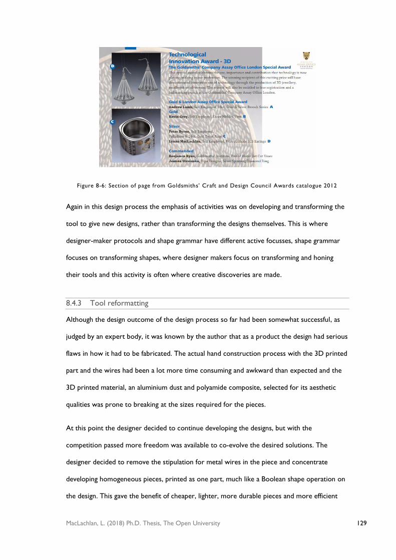
129 MacLachlan, L. (2018) Ph.D. Thesis, The Open University
Figure 8-6: Section of page from Goldsmiths’ Craft and Design Council Awards catalogue 2012
Again in this design process the emphasis of activities was on developing and transforming the
tool to give new designs, rather than transforming the designs themselves. This is where
designer-maker protocols and shape grammar have different active focusses, shape grammar
focuses on transforming shapes, where designer makers focus on transforming and honing
their tools and this activity is often where creative discoveries are made.
8.4.3 Tool reformatting
Although the design outcome of the design process so far had been somewhat successful, as
judged by an expert body, it was known by the author that as a product the design had serious
flaws in how it had to be fabricated. The actual hand construction process with the 3D printed
part and the wires had been a lot more time consuming and awkward than expected and the
3D printed material, an aluminium dust and polyamide composite, selected for its aesthetic
qualities was prone to breaking at the sizes required for the pieces.
At this point the designer decided to continue developing the designs, but with the
competition passed more freedom was available to co-evolve the desired solutions. The
designer decided to remove the stipulation for metal wires in the piece and concentrate
developing homogeneous pieces, printed as one part, much like a Boolean shape operation on
the design. This gave the benefit of cheaper, lighter, more durable pieces and more efficient

130 MacLachlan, L. (2018) Ph.D. Thesis, The Open University
production, the transformation of the pieces in shown in a shape grammar style rule in Figure
8-7.
Figure 8-7: Transformation of the design
The author returned to the Grasshopper tool, performing subtractive transformations to the
tool, removing functionality relating to the separate metal and printed parts. In this case there
was a design transformation that in turn informed transformation made on the tool, an inverse
procedure from what was previously documented in this computational making process.
While returning to a more streamlined tool a discovery crucial to the new design process was
made, the author perceived the emergence of Moiré patterns on screen as the number of lines
or ‘wires’ was increased, as can be seen in Figure 8-8. This was the most significant creative
episode in the design process, and occurred through emergence from tool selection,
combining and transformation. The designer had noticed this phenomena previously however
it hadn’t been compatible with using metal wires as the competition brief required due to
weight and scale considerations, but could now focus on developing this discovery into an
important design feature.

131 MacLachlan, L. (2018) Ph.D. Thesis, The Open University
Figure 8-8: Moiré patterns appearing from large numbers of lines as generated by the Grasshopper
tool
Again the tool was transformed to explore the numbers of wires, thicknesses and sizes of
possible designs to give the best visual effects while meeting the requirements of the 3D
printing processes, screenshot is shown in Figure 8-9.
Following this the designer actually stepped away from the Grasshopper tool. It had fulfilled its
job as an exploration tool and serendipitously yielded a creative episode through exhibiting
emergent features that the designer was able to perceive and make use of, conforming to the
idea that creativity can come about through the harnessing of emergent tool features,
supported in creativity and design literature [10,29] .
Figure 8-9: Screenshot of new, simplified Tool in Case Study

132 MacLachlan, L. (2018) Ph.D. Thesis, The Open University
The designer returned to using a series of commands directly in Rhino to make forms suitable
for nylon SLS printing. The main reason at the time for returning to a less automated process
was that the computer would struggle with some of the more complex Boolean operations
that were required to make the more solid and refined shapes the designer now required,
often causing big time delays and crashing the software. Another factor was that computational
tools can be time consuming to build, it was felt at this time it was more convenient to work
directly and individually with Rhino tools in specified orders rather than trying to automate
these steps.
The designer developed a new series of tools, in this case Rhino commands, to produce the
desired shapes for printing. This series of tools or rules can again be viewed as a higher level
tool, comprised of lower level tool in specific combinations. In shape grammar schemas the
equivalent operation could be boundary schema transformations, but performed on a
tool/rule, notated as ( ) ( ( )). This activity can be modelled as taking a representation
of tool or tool concept and reinterpreting it into a new tool, in this case a reinterpretation of
a Grasshopper tool that produced simple design representations into a series of Rhino
commands to create geometries suitable for 3D printing.
The new tool, comprised of a series of steps using existing Rhino commands is shown
diagrammatically in Figure 8-10. This tool was used to produce pieces in the Phase jewellery
collection, some of which are shown in Figure 8-11. Some variations used simple additions of
shapes to create the fittings for the body to the cut cone shapes or segmentation of the
original cone shape with Boolean subtraction operations.

133 MacLachlan, L. (2018) Ph.D. Thesis, The Open University
Figure 8-10: Template Tool for Phase Collection

134 MacLachlan, L. (2018) Ph.D. Thesis, The Open University
Figure 8-11: Pieces from the Phase collection, Lynne Maclachlan, 2013
Some of these pieces were submitted again to the Goldsmiths’ Craft and Design Council
Awards in 2013, they received a gold award for technological innovation, as shown in Figure
8-12, a section the relevant page in the 2013 awards catalogue. This award from a professional

135 MacLachlan, L. (2018) Ph.D. Thesis, The Open University
body could be viewed as an endorsement of a successful making process and also a creative
one, when taking into account that the award related to innovation.
Figure 8-12: Section of page from Goldsmiths’ Craft and Design Council Awards catalogue 2013
8.5 Discussion of findings from Part I
From the interviews and case study creative episodes involving tools were found to concur
with creativity literature, supporting the findings but also bringing new insights into designer-
maker creative processes. Equivalent activities were found in shape grammar schemas, in the
context of tools, indicating that the schemas are a valid way to formalise designer-maker
creative activities and explain strategies for stimulating creative episodes. Revisiting a digital
making process carried out by the author found further evidence that the new tool schemas
could describe the key creative events of the process in a concise way. This section now
rationalises the findings into a clear set of strategies that could be fostered by designer-makers
and other to give an overview of how creative episodes can be encouraged in tool focussed
design processes, this is a contribution to knowledge made by this thesis.
Three significant phases of activity were seen in the design-through-making processes
investigated; these phases were often the site of the main creative episode in the design
process:

136 MacLachlan, L. (2018) Ph.D. Thesis, The Open University
Tool selection – designers adding or subtracting tools as part of their design world.
Tool combination – the way and order tools were used in making processes
Tool transformation – the transformation of tools to produce new outcomes
These are now discussed along with the accompanying tool schemas that have been
developed.
8.5.1 Tool selection
An initial selection of tools and materials was a key part in the designer-makers’ design
processes. Similarly in shape grammar addition schemas are used to introduce shapes to the
design process, in preparation for further transformations. This can be notated in the style of
shape grammar schemas as ( ) Designers can add physical and computation tools into
their design world, and tool concepts, with a view to using these as they are or transforming
them.
The inverse activity of removing tools from a design world, ( ) , is also a valid way of
producing creative episodes and outcomes. It was seen that omitting aspects of making
process could give rise to interesting new features in designs, particularly in the work of
designer Ian McIntyre, who expressed a preference for trying to remove steps in accepted
making processes to achieve new results.
These schemas can be presented to designer-makers as a strategy to stimulate creative
episodes by informing them to give more consideration to the selection and removal of tools
in their personal design worlds. It is possible that some designer-makers may be entrenched in
the tools they use due to being part of a shared design world with typical toolsets, countering
the status quo of these toolsets could be a way to find new niche positions that they may not
have fully or consciously considered.
A related activity characterised by progressing from Stiny’s design rule schemas is that of re-
identifying tools, ( ) ( ). Taking a tool and using it in a new context, the tool does not

137 MacLachlan, L. (2018) Ph.D. Thesis, The Open University
change, but where it operates on does, potentially giving rise to a creative episode. This can be
allowed through creative mechanisms such as analogy, by finding appoint of correspondence in
the two contexts. This is one way to assemble unusual tool sets a designer-maker could
consider.
8.5.2 Tool combinations
After adding tools the designer-makers began the activity of using the tools. How tools are
applied and the sequence they were applied in can produce large variations in the outputs of
the processes. In creative episodes pre-existing tools were combined in new and creative ways
and sequences to produce new outcomes. This tool activity can be characterised by the tool
schema:
( ) ( ) ( )
This schema represents the juxtaposition of tools in a tool series or amalgamation that are
comprised of sub sets of tools that could be joined or merge in some way. For the designer-
maker this can be presented as the strategy of considering and exploring tool sequences and
combinations, looking for combinations that produce useful outcomes or ad-hoc tools
comprised of others.
Related operations found in the evidence can also be proposed to designer-makers as tactics
for seeking creative episodes. Isolation parts of tools, using the tool schema, ( ) ( ( )),
either from physical tools or computational tools to examine them in more detail and possibly
combine them into new tools directly.
The boundary tool schema, ( ) ( ( )) offers the designer-maker the approach of taking
some kind of impression from a tool, a new representation, most likely by converting it to a
more conceptual perspective, which can then be re interpreted into a new tool. This is a
powerful cognitive reasoning method with tools that can result in a personalised physical or
digital tool being built to produce unique designs.

138 MacLachlan, L. (2018) Ph.D. Thesis, The Open University
8.5.3 Transformation of tools
It was seen that the designer-makers often transformed tools, and these transformations can
be categorised in different ways. Presenting tool transformation as a creative strategy to
designers may be useful, and the different kinds of categories are now discussed.
Parametric transformations
Parametric tool transformations are transformations that change extrinsic variables of a tool.
This is akin with the parametric transformation rule schema in shape grammar, and with the
context of tools could be notated as:
( ) ( )
This process can be used to make a range of related outcomes, such as a collection of related
designs that share a design structure or style.
As a tool activity this suggests the strategy for designer-makers to explore any possible
extrinsic properties of a tool, often parameters that are easily transformed and exist as part of
the tool design, such sliding scales or variables in a computational tool. It was seen in the
evidence gathered from practice that pushing tool parameters can provide emergent
phenomena that the designer can choose to pick out and use creatively, for instance the
appearance of Moiré patterns in the computational making design process that was analysed.
Functional transformations
Functional transformations are one of the most dramatic transformations a designer-maker
can make on tools and therefore, according to Boden [10] may be high level creative activity.
Functional transformations on tools we used by the designer-makers studied to aim for
creative design outcomes. A schematic representation of this can take the form ( ) ( ),
where a tool is transformed so as to be identified as a new, distinct tool. Transformations can
range from new, related versions of tools to ground breaking, highly creative and personalised
tools.

139 MacLachlan, L. (2018) Ph.D. Thesis, The Open University
This can be done by using many of the previous tool schemas, by taking tool parts, ( ( )
( ( )) and impressions ( ) ( ( )) and manipulating these with operations such as re-
combinations pr ( ( )) ( ( )) ( ) and subtrations ( ( )) to give new tools
that can generate new designs.
As a strategy the designer-maker can be offered the idea that trying to create personal tools is
a very fertile ground for producing creative outcomes. This can be done through applying the
all the tool schemas presented in this research in an experimental and recursive way to
different tool parts and concepts. The key to guiding this process are the established creativity
mechanisms finding analogies, emergent features and blending concepts in conjunction with
designerly knowledge to find relevant ways to work towards creative outcomes.
Distinctly new tools such as the digital silversmithing hammer by Hinton and the thread
wrapping machine of Alverez can produce very original objects, as the designer-maker has
created a new design world to explore, or a ‘new craft’ as Alverez [4] claims. The difficult part
of this kind of functional transformation is often realising these combinations in a working,
physical tool, a design process in itself, taking time and commitment, as Hinton described in
the interview, however the creative rewards can be substantial.
8.6 Reflections on shape grammar
Shape grammar rules have much in common with making activities. Knight and Stiny [65] have
suggested that rules and shapes can be matched to ‘doing and things’. This thesis works on the
basis of a similar but perhaps more specific analogy, interpreting rules and shapes as tools and
materials.
Shape grammar rules can model simple material manipulations such as adding and subtracting
materials throughout processes like clay modelling or wood carving, and acknowledge the
complex objects that can ensue from specific and repeated application of such actions
mediated by tools. The emphasis in shape grammar theory on ‘seeing’ shapes in embedded

140 MacLachlan, L. (2018) Ph.D. Thesis, The Open University
arrangements fits with the importance of the visual in making, makers carefully look for visual
signals in materials as they are worked and use connoisseurship to appraise the work of their
own and others. Knight and Stiny [65] work through some examples such as knotting and
watercolour painting and claim that such processes follow the ‘improvisational, perception in
action approach of shape grammars’.
Indeed this thesis has found that shape grammar schemas do make suitable descriptors for
tool use in design-through-making processes, however a different emphasis on how this
happened, particularly in creative episodes was found. Most making processes are mediated by
tools, and aligning tools with rules, and materials with shapes, is a useful lens to model creative
making processes. Rather than an improvisational and freewheeling approach to direct
transformations on material to produce an object the designer-makers concentrated their
efforts on selecting, sequencing and transforming their tools/rules, which in turn co-evolve
design outcomes.
Figure 8-13 and Figure 8-14 show the two different approaches, represented in the style of
shape grammar rules. Figure 8-13 models a series of tool applications on an object, each
impromptu rule or tool applied to the object directly, the results observed and the next
impromptu rule or tool is applied, the designer trying to drive the shape towards a desired
outcome, as is typical in a shape grammar design process or theoretical model.
Figure 8-13: Model of shape grammar design process
The diagram in Figure 8-14 models the designer-maker process, a tool or rule is used, the
outcome observed, then the designer return to the tool and makes the transformation here
and then re-runs the tool in the hope of a suitable outcome.

141 MacLachlan, L. (2018) Ph.D. Thesis, The Open University
Figure 8-14: Model of designer-maker process
This difference between these two models is significant, and the second represents the findings
of this thesis in professional designer-maker processes. Transformations that were important
for creative episodes were sited on the tools rather than the objects. This is verified by
Boden’s [10] descriptions of creative activities, where rules are explored and transformed to
make new conceptual spaces to generate new and valuable artefacts.
To reflect these findings back on to shape grammar theory, it would follow that rules can
undergo transformations, not just shapes. Knight [55] and Chase et al. [3, 17, 18, 54] have
shown that various kinds of rule modification in grammars can be used to produce new
designs and design languages. This research has discovered that rules can potentially be
subjected to all the transformations represented by Stiny’s [109] shape grammar schemas,
particularly if a rule can be represented or embodied as a material entity.
This was explored in the section on rule schemas, 7.1, where it was seen that applying the
operations represented by the schemas to tools was possible and regularly performed by the
designer-makers. The idea that shape grammar rules can be subjected to are a contribution of
knowledge to shape grammar theory.
8.7 A framework for designer-makers
The first part of this thesis found that shape grammar schemas can clarify and communicate
making processes involving tools, this enabled tool activities that stimulated creative episodes
to be categorised. Designer-makers could use this knowledge to improve the chances of
achieving creative episodes in a design process if presented these categories as a range of

142 MacLachlan, L. (2018) Ph.D. Thesis, The Open University
strategies they could put into practice. A question exists about how best these findings could
be presented for designer-makers in order for them to gain useful insights.
Stiny [109] represents the rule schemas in mathematical notation, and this has been extended
to represent these schemas applied to tools, however it could be hypothesised that designer-
makers may find this discouraging if they don’t have experience of the field, although this can
only be speculation unless tested. Introducing general ideas from shape grammar, such as
viewing design-through-making as a process of transforming materials and tools with rules may
have merit and would set the scene for a list of tool activities and descriptions with strategies
and examples to guide the designer-maker.
Figure 8-15 shows an outline of the framework of the tool activities and strategies that could
be used as a starting point for designer-makers wishing to stimulate creative episodes by
considering tool activities in a design process in a digestible format. In addition it may be
helpful if this table was accompanied with short descriptions of some of the real life examples
found in this research, so the designer-maker could have a practical reference point to
extrapolate from onto their own practice. Summarised versions of chapters 5 to 6 of this
thesis could provide suitable examples of successful actions. These could be written and
referenced in a table such as in
Figure 8-15.
The strategies could be presented in many different ways, from simple outline frameworks, to
a book of varying length or even workshops involving chosen or given tools to introduce the
ideas in a hands-on context. A longer length text or book could incorporate shape grammar
style visual rules, similar to the one in Figure 7-5, which diagrammatically shows a hammer
under transformation. How to communicate the strategies to designer-makers and how this
impacts their practice could be an extensive piece of research, and as such is mentioned in the
Future Work, section13.5, of this thesis.

143 MacLachlan, L. (2018) Ph.D. Thesis, The Open University
Part I of this thesis looked closely at the role of tools in designer-maker creative episodes and
has found that shape grammar, in particular shape grammar schemas are a useful way of
clarifying the strategies designer-makers use and modelling their activities. Part II of this
thesis(Chapters 9, 10, 11 and 12), and examines the use of shape grammar and shape grammar
weights in computational making processes for generating objects for multi-material 3D
printing.
Activity Description Strategies/Actions
Tool Selection
This phase is usually at the start
of a design-through making
process, considering what tools
you may use and why could give
opportunities for new making
processes and designs.
Could you add new tools, from your field or from
other fields of design or making?
Could you substitute or even remove any tools from
your making process to change what can be produced?
* See chapter 5 for examples
Tool
Combinations
Once tools have been selected
consideration can be given to
how they are used in a process.
Trying out different tool
combinations may lead to useful
outcomes.
Can you change the number of times or order of tools
used in your making sequence?
Could you make an ad-hoc tool by assembling or
combining a number of tools to produce something?
* See chapter 5.4 for examples
Tool
Transformations
Transforming tools can lead to
new making processes and
objects, these can range from
small changes to entirely new
tools which in turn may produce
new and valuable objects.
Can you change any variables on your tools? (sliding
scales, sizes, shapes) * See chapter 6.1 for examples
Can you change or subvert the functionality of your
tool in some way? (Hack or change the workings of a
tool) * See chapter 6.2 for examples
Could you build a completely new tool? * See chapter
6.3 for examples
Mechanisms to
support creative
tool activities
Certain cognitive mechanisms
can be used to find appropriate
opportunities for the above tool
activities.
Analogies – can you find any similes and metaphors
about your tools with other entities? Can you use these
to produce new tool combinations or concepts * See
chapter 6.4.1 for examples
Concept blending – can you blend two tools or making
processes to produce a new hybrid tool or process? *
See chapter 6.4.2 for examples
Emergence – look out for interesting features when
using and playing with tools. Could these features be
harnessed to seed new outcomes? * See chapter 6.4.3
for examples

144 MacLachlan, L. (2018) Ph.D. Thesis, The Open University
Figure 8-15:Framework for stimulating creative episodes using tools for designer-makers

145 MacLachlan, L. (2018) Ph.D. Thesis, The Open University
PART 2- A WEIGHTS SCHEMA FOR COLOUR 3D PRINTING
In making processes material properties are also likely to play a part in some creative episodes
as they have influence over how a tool transforms.
In shape grammar Stiny [106, 108] suggests that material properties can be represented by a
weights system associated with shapes. Weights are attributed to shapes, when shapes in a
transformation undergo Boolean interactions a system to resolve new weights for the new
shapes is put in place. Weights have a numerical and computational basis, so may be suitable
for managing and generating designs for multi-material 3D printing, a new range of technology
that can print objects with variable properties.
Computational making is the use of digital tools, both software and fabrication to design and
make objects, and is currently becoming the focus of academic researchers in the craft and
shape grammar communities[15, 64, 65] and is being used and studied in real world design
situations in different design fields such as architecture [81,37], engineering [98,99] and fashion
[26].
In computational making digital representations of objects are transformed with algorithmic
tools, and then realised with digital fabrication techniques, there is a disjoint in the form-giving.
In physical making material properties are intrinsic to the material, affecting the results of
transformations with tools. The disjoint in computational making between the digital
representations and physical materials gives an opportunity to model or choose the way
materials behave in the digital realm. A hypothesis was developed by the author that shape
grammar weights, a system of representing material properties in shape computations, could
be used to undertake this task.
To test this hypothesis a computational making process was performed as a method of
‘research through design’ using small design experiments using weight systems to model various
material property systems. The results are used to develop and refine shape grammar weights

146 MacLachlan, L. (2018) Ph.D. Thesis, The Open University
tools for these properties and a more generalised weights schema as reference for designers
undertaking a computational making process involving variable material properties.
The first 3D printing technology used in the experiments is multi-colour 3D printing,
produced on a machine made by Z-Corp, it uses a powdered, gypsum based material which is
bonded and then coated with ink to create objects with multi-coloured outer surfaces. This
type of printing is readily accessible from many bureau services and in institutions and
presented a useful opportunity to examine the use of colour weights in computational making.
The second type of 3D printing investigated is a machine called the Objet Connex, this
machine takes cartridges of two or three resins which can then be mixed in different
proportions in different parts of the object. The available materials vary in colour,
transparency and flexibility and the availability to blend these results in a large spectrum of
secondary materials.
These new technologies provide the potential for a greater range in the types of objects that
can be fabricated than with single material printing. As Neri Oxman and Rosenberg [81] state,
computational methods are typically restricted to defining and exploring the structure and
geometry of a design models, and do not incorporate material properties or behaviour. The
advent of these technologies show that material properties could and should be addressed in
the computational process, and ways of doing this need to be developed. Neri Oxman [82] has
championed the idea that materials and their properties drive design, taking the term material
computational to identify the process of rules embedded in materials defining forms, with a
basis in biological and craft processes. Oxman has demonstrated these ideas with the
combination of digital computation and multi-material 3D printing, the resulting objects are
representations of her overarching philosophy rather than a practical way of using properties
to design.
This thesis aims to build on a similar notion of material computation, however with emphasis
on applicable mechanisms – tools and rules - that designers can actually harness to bring about

147 MacLachlan, L. (2018) Ph.D. Thesis, The Open University
material generation and transformations with current design and fabrication technology. This
part of the thesis demonstrates a way to do this with shape grammar weights as one such
mechanism for generating novel designs via computational tools.
9 SHAPE GRAMMAR WEIGHTS
As has been discussed previously, shape grammar operations as defined by Stiny [108], use
shapes, composed of geometric elements: points, maximal lines, planes and solids, as a method
to formalise and explore design representations. These computations adhere to the Boolean
operations of sum, product and difference, and can be manipulated in affine and Euclidean
transformations. However, shape computation can take into account non-spatial information,
such as colour and function, and these are formalised in algebras of labelled shapes, Vij and
weighted shapes, Wij by Stiny [106].
When applied to points, labels are markers used to control the orientation of rule applications
where symmetrical or similar shapes are in use [108]. By labelling shapes different shape
algebras can be made distinct, avoiding Boolean interactions, existing on separate layers much
like the layer functionality in computer graphics packages [108].
Weights take labelling a step further and can represent properties of a shape, such as thickness
on line elements, colours on planes elements or physical properties on solid elements. Unlike
labels, overlapping weighted shapes may interact with one another; they can be embedded in
one another and inherit weight values from the initial shapes or be given new weight values,
the results of such interactions must be defined.
Stiny [108] proposed that weights systems adhere to Boolean operations and so definitions
about how weights combine in shape sum and difference are made. He suggests the weight of
the emergent intersection shape in a sum of two overlapping shapes is the maximum of the
combined weights: so the addition operation for two of shape s with weights u and v:

148 MacLachlan, L. (2018) Ph.D. Thesis, The Open University
(s,u) +(s,v) = (s,max{u,v})
such an operation can be seen in Figure 9-1, if shape s,u is placed on top of shape s,v and the
weights are ordered as u<v then the resulting shape in this case is s,v.
Figure 9-1: Weighted shape addition, s plus s
For two different shapes with an intersection, s and t, with weights u and v, the addition
operation of (s,u) + (t,v) results in parts (s-t,u), (t-s,v) and (s.t, max{u,v}), three new
shapes with associated weights, such an operation can be seen in Figure 9-2. Shape s is placed
partially on top of shape t, a line highlights the edge of the circle to indicate the intersection
shape s.t, but this border should not be visible at the end of the operation, s,t and t-s are
embedded into one new shape with weight v.
Figure 9-2 Weighted shape addition, s plus t
In the book Shape: Talking About Seeing and Doing [108] Stiny proposes that the weight
difference between two overlapping shapes, s, is the product or the minimum of both, so for
weights u and v, the subtraction operation is (s,u)-(s,v) = (s,min{u,v}). Figure 9-3 shows this

149 MacLachlan, L. (2018) Ph.D. Thesis, The Open University
operation, if the weights are ordered so u<v the weighted shape resulting from the
subtraction takes on weight u.
Figure 9-3: Weighted Shape Subtraction, s minus s
For two different shapes with an intersection (t,v) - (s,u) has parts (t-s,v), and (s.t,
min{u,v}), two new shapes with associated weights, this operation can be seen in Figure 9-4,
when u<v then s.t takes the weight u.
Figure 9-4: Weighted shape subtraction, t minus s
However in an earlier paper, where he first introduces the idea of shape grammar weights,
Stiny [106] also suggests that difference could be given a weight of 0, so for shapes s and t,
with weights u and v, t-s results in the parts (t-s,v) and (s.t,0), as seen in Figure 9-5.
However whether this result leaves a blank space or a shape with a ‘zero’ weight is unclear.

150 MacLachlan, L. (2018) Ph.D. Thesis, The Open University
Figure 9-5 Weighted shape subtraction, zero weight result
Difference calculations may matter to the designer, not just for subtractive rules but for all
further transformational rule applications. For instance a rule rotating a shape may look like a
case of simply rotating the shape to the appropriate angle, however the underlying operation
of a shape grammar rule is that of actually subtracting the shape(s) on the left hand side of the
rule and adding the shapes on the right hand side of the rule, therefore theoretically two
weight calculations of weight difference followed by weight addition should take place.
Knight [59] sets out an algebra for colour grammars, akin to Stiny’s weights, by exploring
possible rules that could be used to construct artists such as Mondrian’s paintings. Lines and
shapes become colour spots (equivalent to basic shape elements) and fields (equivalent to
maximal shape elements) with ‘qualitative’ differences that would not exist without the colour.
When two colour fields overlap the spots that overlap ‘fuse’ to form a new distinct spot, in
other word a new intersection shape with a colour. The colour of this new spot is dependent
on whether the colours are, or are considered to be, transparent or opaque and the order
they are placed on the page. Knight deals with this by a system of ranking colour fields to
signal which field dominates others. If spots are ranked the same, they appear opaque and the
final visual result depends on the order the fields/shapes are placed on top of one another on
the page.
The operations for colour fields are again the Boolean operations used in shapes and weights.
In a sum or intersection the rankings of the fields must be defined. As discussed the rankings

151 MacLachlan, L. (2018) Ph.D. Thesis, The Open University
can allow one spot to dominate the other or they can be of equal ranking. If the spots are of
equal ranking Knight suggests that the new coincident spot has a composite colour defined by
the user.
For more clarity, Knight’s colour grammar system [59] is exemplified below with and the
accompanying Figure 9-6:
The sum of two colour fields, F,g and F,y, contains the spots of the colour fields that
are discrete from the second and vice versa, and the colour spots where these
overlap. The colour of the intersection spot is defined by the designers chosen
dominance ranking of F,g over F,y or F,y over F,g, or if the ranking is equal, the order
F,y and F,g are placed on the page, or can be made a third colour, defined by the
designer, in this case yg.
The intersection contains only the coincident colour spots of the two fields, the nature
of which are defined by the ranking system, order, or chosen colour, as above.
The difference contains only the spots in the fields that are discrete from the
subtracted field, leaving a colour spot with no colour, and so an empty space. This is
where Knight’s colour grammars are different from Stiny’s weights, as Stiny permits a
residual shape to be left with a weight calculated from the original shape weights.

152 MacLachlan, L. (2018) Ph.D. Thesis, The Open University
Figure 9-6: Knight’s colour grammars
Knight builds on this colour grammar system in a later paper [61] supplementing the grammar
of a form of traditional Persian garden where squares are recursively divided into further
squares to create symmetrical garden designs segmented with borders and canals. Knight
assigns colour to the new sections created by the recursive rules to signify different kinds of
planting or canals in the designs.
This approach references a specified colour palette, in which each colour is given a ranking. If
the one colour is ranked above another it will dominate and cover the other colour in any
overlaps, as if it was opaque, so if , overlapped areas take on the colour . If the
colours are ranked equally, , at least one of the colours is assumed to be
transparent and some kind of blended colour which appear in the overlapped area. Knight
suggests a blending system whereby the palette consists of a range of colours with the same
hue but increasing darkness, , , …… and as a rule is applied the border colour of the
rule blends with the colour already present and moves the colour up a step to the next
darkest colour on the palette.

153 MacLachlan, L. (2018) Ph.D. Thesis, The Open University
Knight suggests that any parameter can be used for ranking colours, with an associated
method to calculate blended colours of the designer’s choosing. Blended colours can be taken
from a specified colour scale of colour, using modular arithmetic to round any calculation to a
colour step on the scale. She also introduces the idea of parametric colour values, and
suggests in this particular grammar colour could be varied according to the size and thickness
of the borders in the garden designs.
The following two case studies look at examining and building on the weights and colour
grammar systems presented by Stiny and Knight respectively and examining the application of
these in a computational making design process using colour and multi-material 3D printing
technologies.
9.1 Colour weights for colour 3D printing
Computational making is often undertaken as a process involving digital fabrication, technology
such as 3D printing. 3D printing now has the capacity to produce objects with more than one
colour and or material combined in one print. Many of these machines are now easily accessed
through bureau services and academic and commercial settings, allowing designers to work
closely with them. Therefore colour has become relevant in computational making situations.
One kind of machine which is readily accessed in made by the company Z-Corp, that can
produce 3D printed objects with a colour coating; the process uses gypsum based powdered
material sintered in layers using a laser, as the model is built the outer layer is coated in ink to
produce a coloured model. This printer takes a set of ink cartridges, Cyan, Magenta, Yellow
and Black (often abbreviated to CMYK), as many 2D printers do, and mixes these is
appropriate proportions to produce a wide range of colours by applying proportions of tiny
coloured dots in different densities to the surface.
The 3D printer requires a digital file to describe the form and colour of the desired object, for
example Shapeways, a 3D printing bureau service, requests VRML (Virtual Reality Modelling

154 MacLachlan, L. (2018) Ph.D. Thesis, The Open University
Language) files for this type of printing. In VRML files the geometries are represented by
meshes of triangles and quads, the colour can either be assigned to each face or a texture map
can be wrapped to the whole object which the printer software will then interpret to add the
colour on the surface of the printed object in the appropriate areas.
Stiny’s weight systems, previously summarised, are intended to offer a general weights system
that can in theory be applied to a shape grammar to denote any material property the designer
wishes to generate and transform. However within two published definitions he offers
different options for weight differences [106,108] as detailed in section10.14. Knight’s colour
grammars [59][60][61] are specifically associated with colour and take in to account the
attributes of colour, she also suggests that the designer and artist can use many different
approaches for the manipulation of colour grammars beyond her versions. From this it is clear
that no one definite system exists or is likely to be universally applicable.
The following section examines and extends the approaches that Knight and Stiny suggest in
the systems they have formalised in more detail and in the context of colour, to ascertain the
suitability of these for computational making using colour 3D printing. Simple experiments in
two and three dimensions with coloured shapes demonstrate the application of the different
weights rules and systems.
9.2 Colour in design
To give an overview of the relevance of colour in design processes and how the application of
colour in computational design can be analysed, a short literature review follows.
Meerwin [80] provides an overview of the use of colour in design in the book Color:
Communication in Architectural Space. He states that in the human designed environment colour
serves as ‘information, communication, and design material’, and lists some uses, which generally
fall into two categories, that of informing and guiding the user of certain utilities or as a
semantic signifier for culture, style or fashion. Human perception of colour is the interplay of

155 MacLachlan, L. (2018) Ph.D. Thesis, The Open University
physiological and psychological effects [80]. Physiological effects of colour are influenced by the
hue, nuance, placement, spatial function and any changes over time and psychological effects
are rooted in experience, emotional effects, synesthetic effects and associated cultural
symbolism.
Many artists and designers and scientists and philosophers have attempted to create colour
systems and scales [40], where colours are arranged into schemes with some relationship with
one another. Colour scales can be based on colour perception, the terms of which Wyszecki
& Stiles list as: light, colour, hue, brightness, lightness, chromaticness, chroma and saturation
[114]. And arrangements such as colour scales are a ‘series of ordered numbers which represents
observable gradations of a given attribute or gradations of attributes of color perception’ [P488, 114].
The Bauhaus painters, Itten, Klee and Albers examined the problem of finding a scale of equal
perceptual steps between white and black [40] as did the painter Ozenfant [12]. Knight’s [61]
colour scale for designing Mughal Gardens, varies lightness, while keeping other attributes,
such as hue, constant. Colour scales are usually represented diagrammatically as successive
blocks of colour in a line or divided circle colour ‘wheels’ [100]. The intervals between
successive colours can be defined by using an ordinal scaling, interval scaling or ratio scaling
using a numerical value to represent the attribute [114].
Colour systems are ranges of discrete colours organised into geometric forms according to
their relationships with one another. Countless systems exist, the website coloursystems.com
[100] by academics Silvestrini and Fischer document over fifty colour systems from across
science and art with details of the relationships and illustrations of the geometric forms these
take. Da Vinci, Alberti, Goethe, to name some of the well-known, amongst others, all
modelled systems [80]. Colour systems can take forms such as cylinders, double cone shapes,
and even multi-dimensional lattices [114].

156 MacLachlan, L. (2018) Ph.D. Thesis, The Open University
9.3 Ranking shapes
Weights systems require a way of ordering weights present in a design to allow the weight of
shapes to be calculated in subsequent shape transformations. Ordering can be done in two
fundamentally different ways, according to Knight and Stiny, either with reference to an
attribute associated with the shape or an attribute associated with the weight that can be
numerically represented. Knight suggests that the order of dominance for colour grammars
when adding shapes to a design can come from the chronological order they are added to the
design but later proposes that areas of colour can be ranked in any ‘conceivable way’ [61] the
designer chooses.
The following sections look at the possibilities for shape ranking systems in a computational
making context, examining existing ways of ranking and extending these to new possible
ranking systems.
9.3.1 Chronological ranking
Knight [59] suggests that a shape added to a design will always dominate those already
present, following the model of placing opaque shapes on a page one after the other. In more
analytical terms this would be a chronological ranking system, the colour of any intersecting
area is:
where is the colour of the added shape.
Consecutive additive rule applications could result in a design like that seen in Figure 9-7, the
sum of the colour weights is the weight of the last added shape. In Figure 9-7 the numbers on
the shapes correspond to the chronological order they were added to the ‘design’ and so
dominate shapes with lower numbers that their own.

157 MacLachlan, L. (2018) Ph.D. Thesis, The Open University
Figure 9-7: Colour weights dominating in order of addition to design
This means each shape in a design is given a numerical value as it is added to the design, which
is then used to compare with other rankings to then inform the computational program on
which colour any intersections inherits from the two coloured shapes.
To investigate the suitability of this approach in a computational making situation a
Grasshopper tool was constructed which added consecutive cylinders to a design in Rhino 3D.
Boolean operations were performed to find any intersections with existing cylinders and
assigned the colour of the more recent cylinder.
The building of this computational tool required a number of recursive loops to be
implemented, so the shapes were effectively ranked as they were generated and introduced to
the design. This revealed that ranking shapes is a relatively simple task in a computational
context as the inherent nature of coding requires the ordered lists to store entities.
9.3.2 Dynamic ranking
Chronological addition ranking may be fixed throughout shape grammar operations; each new
shape added to a design is incrementally ranked higher than the last, however this need not be
the case.

158 MacLachlan, L. (2018) Ph.D. Thesis, The Open University
To take an approach from the first part of this thesis, if we view the chronological ranking of
shapes in a design as a rule/tool we can seek to make transformations on this tool/rule in the
hope of finding new and possibly creative episodes and outcomes.
Shape ranking for assigning weights in shape operations could be dynamic throughout the
shape transformations, updated as rules are applied, either with specific rules or assuming that
the shape identified for a transformation attains a new ranking in its selection. A system like
this would be cumbersome in a sketched design process, but algorithmically simple to
implement in a computational system, where assigning numbers and continually updating them
is a straight forward task for a computer.
Dynamic chronological ranking also have the advantage of simplifying rules beyond simple
addition rules. For example a shape subjected to a transformation shape rule, such as a
Euclidean or affine transformation, could be re-ranked so that its colour would be given
dominance in any intersections created by the transformation despite when it was previously
added into the design.
Ranking rules could be embedded in a shape grammar rule. An example can be seen in Figure
9-8, a rule that moves a circle to the right also updates the weight ranking of the shape to one
more than the maximum ranking already present in the design, when applied this allows the
blue circle to dominate the black circle in the shape grammar design scenario below the rule.
This approach allows the current shape to dominate, mimicking the activity of lifting a piece of
material a repositioning it in the design and avoids less intuitive results that may occur if the
shape under transformation is ranked lower than shapes it interacts with as a result of the
rule. Even a simple example demonstrating dynamic ranking reveals that it may be desirable
and even necessary in some design situations include ranking information in a rule to ensure it
operates in the desired way, much like Stiny’s labelling systems [108], to avoid shape residues
and unwanted embedding.

159 MacLachlan, L. (2018) Ph.D. Thesis, The Open University
Figure 9-8: Dynamic Colour Ranking
The rule in Figure 9-8 which updates the circles ranking to make it the highest ranked object
after it has been moved to ensure it dominates any other shapes it comes into contact with. It
may also be useful to have rules which just change rankings, they could be applied to a shape
to update its ranking before another rule is applied.
The advantage of dynamic ranking can vary according to how it is applied by the designer.
Specific rules to control rankings in certain transformation rules could allow the designer
tighter control of the behaviour of colours in the making process, which may be desirable.
However allowing dynamic rankings to be parameterised with other shape attributes or even
given randomised seeding could also offer a more unpredictable yet explorative process which
may offer up new employable emergent features and interestingly complex objects.
9.3.3 Parametric attribute ranking
Ranking could also be parameterised according to shape attributes, any shape attribute that
can be represented by a numerical value could be attached to a shape and used as a ranking
for comparison, and these rankings could be static or dynamic. Examples could be properties
such as size, geometric complexity, or indeed another attribute the designer wanted to make
relevant in the design process.

160 MacLachlan, L. (2018) Ph.D. Thesis, The Open University
An example of this is shown in Figure 9-9, the rank for resolving weights is taken from the
number of sides of the shape. The result being that the weights of the shapes with more sides
dominate the weights of the shapes with a lesser number of sides. When the triangle is
translated up the page and intersects with the pentagon the green of the pentagon dominates
the blue of the triangle. A similar system could be for many different properties, such as
dimensions, areas, volumes of the 3D objects in a design for a Z-Corp colour print, ensuring
that shapes with certain characteristics take precedence over others and preserving the
geometry and properties of these, which may come in useful in certain design situations where
continuity is required.
Figure 9-9 Ranking Shapes by number of sides
9.3.4 Ambient attribute ranking
Shape rankings could also be formulated from factors ‘outside’ the shape, ambient factors,
such as the shape position or orientation according to coordinates or relative to other shapes,
and again these could be static or dynamic though out the making process. Many of these
factors would be easy to assign numerical values to and keep track of in digital design
environment.

161 MacLachlan, L. (2018) Ph.D. Thesis, The Open University
Figure 9-10 Rankings increasing with x position
A simple example of this can be seen in Figure 9-10, shapes are given rankings according to
their current position in a design and as a circle is moved to the right by a translational shape
rule the shape rankings are updated according to a function of their centre point position on
an x axis. (Note on Figure 9-10: It may appear that there is some slight variations in the
colours in the three steps, they remain the same, but may be affected by colour interactions
making them appear slightly different to the eye as they are moved)
9.4 Equal rankings
Some shape ranking systems may return a shape with the same ranking with different weights,
posing a problem of which colour should dominate the other. This could happen in the system
from Figure 9-9, two triangles of different colours could intersect in the design, shapes with
the same rank but different weights. Therefore such ranking systems may have to have a rule
in place for situations where shapes end up with the same ranking but different colours. In one
of her approaches Knight [61] suggests that shapes of equal ranking can be considered to be
transparent, and so a blended colour of some kind is calculated for any overlap, effectively
referring to a secondary system based on colour ranking.
The designer could handle equal ranking situations in a number of ways in their computational
making process, other tactics could be employed if they wanted to avoid new colours being

162 MacLachlan, L. (2018) Ph.D. Thesis, The Open University
introduced into the design, a random choice between the two colours or deferring to a
secondary ranking system such as chronology.
9.5 Using shape rankings in difference calculations
Shape grammar also allows for subtractive shape operations, so the designer may need or wish
to have a system for calculating weight differences. Also any transformational rule technically
subtracts the shape(s) on the left hand side of the rule and then adds the right hand side.
What may visually appear as a case of rotating or moving a shape is actually an operation of
subtraction and addition, therefore a weight difference and sum calculation should take place.
Knight [59] and Stiny [106] both suggest that any subtractions of weighted shapes leave a zero
weight, which they define as the complete removal of the shape. This approach has been
assumed in the translational operation used in Figure 9-10, the blue circle is erased from the
left of the design, leaving an empty space and visually a part missing from the yellow circle and
added at the far right of the design. This example assumes that the blue and yellow circles have
previously been resolved as their maxima according to the colour. Choosing the resulting
weight of any shape subtractions to be zero is a suitable way to prevent shapes added to a
design becoming inadvertently fractured in later transformations, such disintegration of initially
chosen shapes may not be desirable.
However in a later definition of shape grammar weights Stiny states the weight difference
between two overlapping shapes is the product or the minimum of both, so for weights u and
v, u.v = min{u,v}. This system relies on the weights themselves having a numerical value,
these systems are discussed in the next section. However a version of this could be developed
in terms of shape rankings, a logical approach following from Stiny’s subtraction calculation
would be that the difference of two ranked, weighted shapes would be a shape with the colour
and ranking of the lower ranked shape.

163 MacLachlan, L. (2018) Ph.D. Thesis, The Open University
Figure 9-11: Shape subtractions using a shape ranking system
The ranking of an overlapping area could retain the ranking of the shape in the shape rule. For
example the visual result of such an operation can be seen in Figure 9-11; a rule that subtracts
a green square is applied to Design A, each example shows resulting design when the green
square has a ranking between 1 and 4. When the green square is ranked lower than the shapes
it is subtracted from the result appears visually as if the green square has actually be placed on
top of the design, a counterintuitive result. If the green square is ranked the same as the shape
it is being subtracted from the colour of the shape in the design is retained, visually having no
impact. As previously mentioned in a situation where shapes that interact as ranked equally a
secondary system for calculating weights can be used, either using a weight of zero or a
blended colour weight. Finally if the green square is ranked higher than both shapes it is being
subtracted from there is no impact on the design. Completely removing shapes from designs
using this approach requires different rules. In this two dimensional example the background

164 MacLachlan, L. (2018) Ph.D. Thesis, The Open University
can be seen as white, a rule that transforms the colour weight of the square to white would
give the visual appearance of erasing the square from any other coloured shape. However this
rule will not work for three dimensional shapes, as a white cube does not merge into a
background.
Figure 9-12: Shape Transformations using shape ranking System
Subtractions also occur in shape transformation rules, not just subtraction rules. Figure 9-12
shows an extension of the previous example where a green square is rotated, this is a
calculation of subtracting the green square on the left hand side of the rule, as occurred in
Figure 9-11 but the adding the new square, which has been rotated forty-five degrees, this rule
is applied to the same Design A from Figure 9-11.
The first application with the green square ranked lower than the shapes in the design appears
to simply add the square without rotating, this is because the addition on the rotated square
has no effect as it has a lower ranking than the shapes in the design and is dominated by them.
The next two cases where the green square is ranked equally with one of the shapes in the
design, the subtraction is as in Figure 9-11 but then the addition of the rotated green square
then dominates the colour of the shape with equal rank, using it chronological ranking to

165 MacLachlan, L. (2018) Ph.D. Thesis, The Open University
resolve the colour weight. Other ways of handling this are equally valid, as mentioned
previously equally ranked shapes could defer to another shape ranking system or a defer to a
colour ranking or secondary colours.
In these examples the rule has allowed any new shape of the same colour to embed and
inherit the rank of the green square in the rule. However the opportunity exists to transform
rankings with rules at the designers will. Rankings could also be represented and used as
variables, such a or to ensure a shape in a rule will dominate or not dominate
other shapes already present in a design.
As can be deduced from this example shape ranking systems for calculating colour weights in
intersecting shapes of different colours can produce counterintuitive result, if the designer is
seeking creative opportunities exploring the unexpected shapes and forms generated by this
kind of computation may yield some serendipitous outputs, leading to new creative ideas. If
the designer wants results that behave in a more straightforward manner they may wish to
erase shapes or default to a weight of 0 (which must be defined) from the design in difference
operations, giving an unmodified space to then add transformed shapes to.
9.6 Ranking weights
Shape ranking uses a numerical value associated with each shape to be used in colour weight
calculations, to resolve which colour will visually dominate in shape intersections. The second
fundamental approach to weight assignment and calculation is to order the weights, or in this
case colours, rather than the shapes, to establish which weights will be inherited by new
shapes created by shape transformations.
9.6.1 Logic rule ranking
Knight [59] proposes in her colour grammar system that the colour of any intersection can be
defined some colours to dominate others, colours are handled by descriptive rules such as
‘blue dominates yellow’, ‘green dominates blue’ and so on with potentially no limit on the number

166 MacLachlan, L. (2018) Ph.D. Thesis, The Open University
of these. A design example following this logic is shown in Figure 9-13, where by the cylinders
with the higher placing dominate the others.
Computationally logic rules could be used to handle this, in pseudo code:
IF Shape1_Colour = Yellow AND Shape2_Colour=Blue THEN
Shape1+Shape2_Intersection_Colour= Green
Using logic rules like this in a computational making tool for multi-material 3D printing would
require that every possibility for colour interaction is included in a statement like the above.
With possibility of many colours and interactions this could become cumbersome to code into
a tool, although would allow very specific relationships.
9.6.2 Using weight rankings in shape additions
Alternatively each colour would be assigned a numerical ranking that can be compared, and
the higher of the two selected to denote which colour is applied to intersected area, so that
. This is a simple and flexible system to implement computationally
but does not allow for more complex colour relationships such as ‘purple dominates red’, ‘red
dominates blue’, ‘blue dominates purple’, a set of interactions that defy numerical ordering.
Figure 9-13: Example of Colour Weights by Ranking Colours
Assigning weights as numerical values is effectively the same as Stiny’s definition [108] of
weights. Numerical weight values are compared, and the overlapping area takes on the colour

167 MacLachlan, L. (2018) Ph.D. Thesis, The Open University
ordered as the greater of the two. Like ranking shapes, this system can be modelled in a
computational making tool; a list of numerical values representing the weight of each shape is
used to calculate the weights of new shapes and updated accordingly.
9.6.3 Using weights rankings in shape differences
A method for shape differences may be required if the designer wishes to use shape grammar
rules such as subtraction and also other transformations where a shape may be removed and a
transformed shape added.
Using logic rules for subtractions as Knight suggested for additions is something that could be
used. Common IF, AND, THEN statements, found in computer languages. Such as:
IF Shape1_Colour = Yellow AND Shape2_Colour=Blue THEN
Shape1-Shape2_Difference_Colour= Green
Giving results like the following example shown in Figure 9-14, a blue cylinder is erased from a
yellow cylinder, the result leaves a blue residue shape if the blue colour is ordered as greater
than the yellow. If the colours were ordered in the opposite way the rule application would
have no effect on the yellow cylinder.
Figure 9-14: Shape Subtraction using logic colour ranking weights

168 MacLachlan, L. (2018) Ph.D. Thesis, The Open University
Like using logic rules for resolving intersection in addition operations each colour would have
to have specific rules to prescribe the result of each colour combination that may occur in the
design. This offers the designer a high level of control to the designer of the outcome of
colour weight calculations but also may become unwieldy in the programming of a digital tool.
Setting the result of any subtraction as a ‘0’ weight, or a colourless shape, as per Stiny’s system
is also a possibility in a colour ranked system, with results similar to those in a shape ranked
system, as can be seen in Figure 9-15, where a green square leaves an empty space, no matter
how the weights are ordered, and appears white, the colour of the background.
Figure 9-15: Colour ranking subtractions with 0 weight result
Following this system for other transformational rules, such as rotating a square, gives various
visual results according to whether the colour of the square in the rule is ranked above or
below the colours in the design, as seen in Figure 9-16.

169 MacLachlan, L. (2018) Ph.D. Thesis, The Open University
Figure 9-16: Rotation Rule applied using subtractions as 0
The visual results of such a system appear similar to coloured paper being cut and moved
around, the square being cut out, changed colour and placed back into the design according to
some layered position in the design.
The other choice again would be to have a system of ranking colours for subtractive
operations, as in Stiny’s definition where subtractive operations use the minimum weight value
for differences, therefore a subtraction leaves the colour with the lowest weight value in any
intersected area, as can be seen in Figure 9-17, which shows the results of shapes with
different weight ranking being subtracted from Design A, the result dependant on comparing
the weights rankings.

170 MacLachlan, L. (2018) Ph.D. Thesis, The Open University
Figure 9-17: Deferring to lower ranked colour in subtractions
Like using shape ranking, minimum values for subtractions some of the results appear to have
almost reverse effects of what might be logically expected, a subtraction of a lower ranked
colour actually visually appears to add a square of this colour. Subtracting higher ranked
colours have no effect on the design. Putting this system in place as part of a rotational rule,
where the shape on the left hand side is subtracted and the new rotated square then added is
shown in Figure 9-18.
Figure 9-18 demonstrates for colour weights, deferring to the minimum colour weight for
subtractions will not tend to generate visually predictable results. Like using this system for
shape ranking it may be down to the designer whether they want to use a system which is
more visually predictable for generating designs for colour 3D printing or would prefer to

171 MacLachlan, L. (2018) Ph.D. Thesis, The Open University
experiment with a less predictable system which may provide unexpected yet useful
phenomena.
Figure 9-18: Rotation Rule Deferring to minimum Colour Weights for Subtraction
9.7 Calculating secondary colour weights
Stiny’s system of weights only allows the weight of intersections after an operation be one of
the weights of the original shapes in the transformation; transformations never introduce new
weights, only colours in the rule or already present in the design can be used in intersections.
Ranking shapes has the same characteristic, new shapes an only inherit weights associated with
the original shapes before transformation. However a third approach is possible; to use
calculations to produce new weights for the new intersection shapes that have some
relationship to the original weights.

172 MacLachlan, L. (2018) Ph.D. Thesis, The Open University
9.7.1 Logic rule calculations
Knight extends her idea of rules to determine which colours dominate others to suggest that
rules about the results of certain colour additions can be defined as tertiary colours, as if
colours exhibit properties of transparency and adhere to rules such as:
Yellow + Blue = Green
Figure 9-19 shows a printed object where the author has selected a green colour for
intersections between the yellow and blue cylinders. Again this could be implemented
computationally with logic rules but would quickly become complicated to implement
computationally as further rules would be required to handle every possible addition, the
above may also require rules to define Green + Yellow and Green + Blue if more shapes are
being added to the design and so on. The list of logic rules required would become
exponential and therefore unmanageable fairly quickly in a computational system in
comparison to an impromptu cognitive decision making process in a paper based design or art
situation that Knight draws this idea from. This particular example uses a logic rule based on
additive paint mixing, that a yellow hue mixed with a blue hue will give a green hue, but as
Knight shows [59] it would not be necessary to follow the rules of physical colour mixing, the
intersections could equally and easily be assigned any colour of the designers choosing using a
computational rule.
Figure 9-19: Z-Corp colour print featuring designer defined weight on intersections

173 MacLachlan, L. (2018) Ph.D. Thesis, The Open University
9.7.2 Modular scale colour weights
Knight [61], suggests another way of handling colour additions in the Mughal Garden designs.
The recursive rule that successively subdivides the garden contains a colour, seemingly
without ranking. Each time this rule is applied over a design which has a ranked colour and
overlaps occur the intersection takes on the colour , where n is the ranking of the colour
in the original design, and < < < … . In Knight’s example each successive colour is
darker than the last, but has the same hue. Knight doesn’t specify the ranking of the colour in
the rule, just the effect it has when applied.
Figure 9-20 shows a similar system applied to Design A, a square of some colour and size is
added to the design, each time it is added the area intersected area becomes darker in colour,
moving along the colour palette of a magenta hue, where the lightness is varied in successive
steps of 20. Drawn up in Abobe Illustrator this makes use of the representative magenta hue
from the CYMK colour system incorporated in the software package, the scale goes from 0%
magenta to 100% magenta in 20% steps.

174 MacLachlan, L. (2018) Ph.D. Thesis, The Open University
Figure 9-20: Additions handled as modular steps along a palette
As a square is added in a place of the designer’s choosing the areas overlapped become one
step more saturated with the magenta ink. This system introduces the possibility of a more
schematic approach to colour transformations in shape rules, where the rule contains some
universally applicable instructions about the colour change resulting from the rule use. Shape
rules could also contain instructions such moving the opposite way on a scale, moving any
number of steps along the palette, removing colours or leaving colours as they are. A more
specific modelling of this is shown in Figure 9-21, where the rule contains some algebraic
instruction for the colour of the added square, to move any overlapping areas along the
palette one, two or minus one steps.

175 MacLachlan, L. (2018) Ph.D. Thesis, The Open University
Figure 9-21: Instructive colour rules for one dimensional colour scale
Another system which can be extrapolated out of this system is that of directly using the
numerical values of the colours, in this case the value of their magenta percentage. The values
of the added square and square in the design are simply added to give a new magenta value.
These values could be restricted to any number of steps between 0 and 100 by only using
specific numbers in rules and designs, or by applying modular arithmetic to round up to
specified colours as Knight [61] mentions.
Of further note is that one a shape in the design reaches the last colour on the palette, 100%
magenta in this example, any further additions would not change the colour in the design, as
can be seen in Figure 9-22, the second transformation of Design B would bring the value of
part of the design to 120, but it is capped at 100. Equally if the colour has been subtracted
down to the first colour, or 0% magenta, the blank space will not be changed by further
subtractions, formally this means limits will be set for weight values if calculations are used and
the designer should consider what may happen when these limits are reached.

176 MacLachlan, L. (2018) Ph.D. Thesis, The Open University
Figure 9-22: Consecutive rules reaching last step on colour scale

177 MacLachlan, L. (2018) Ph.D. Thesis, The Open University
10 Z-CORP COLOUR PRINTING CASE STUDY
Section 9.1 has shown that there is a range of options for the designer to choose from when
managing colour as weights in a shape grammar computational making design process. The
designer must assign numerical identifiers to shapes or weights and then select a way of
calculating from these the weights of new shapes produced by transformations. These
examples have been based on an assumption that the colours used are from a selected colour
palette comprised of a finite number of colours, ordered only by the designer, however
computational design systems, and the underlying software and fabrication tools rely on
specific colour systems to define the colours being produced on screen and on the printed
object. Any colour in use by the designer is likely to be part of and defined by the colour
system already integrated into the tools, these systems use numerical systems to define
colours, so it makes sense that these numerical values could be used for weight calculations.
This section examines colour systems available to use with Z-Corp multi-colour 3D printing
and looks at ways they can be used in weight calculations.
10.1 Computational making with colour
Initial investigations into printing in colour with a Z-Corp gypsum based printer to establish
how colour was managed by the software and the printer were carried out for the case study.
Rhino3D was selected as the most suitable software to carry out the computational making
case study. While other CAD software programs for 3D modelling could be used, Rhino3D is
used widely in the product and architecture industries, and is familiar to the author and can
produce the VRML files required for this kind of printing technology so was deemed the best
candidate for the task. Rhino3D also has the advantage of having the Grasshopper plugin, an
algorithmic modelling program which can be used to create computational and generative
programs to produce three dimensional geometry in Rhino3D, allowing a the building of
flexible, personalised computational tools for design.

178 MacLachlan, L. (2018) Ph.D. Thesis, The Open University
One way to assign colours to solid objects in Rhino3D to then be converted into a VRML files
and printed is by placing objects in layers, each layer has a ‘material’ associated with it.
Materials can be defined as solid colours, colour gradients or images and are mapped to
surfaces or solids. Rhino uses the RGB colour space (Red, Green, Blue, the primary additive
colours) to define colours of materials. The RGB colour space is used widely in digital, screen
based design, to define colours and is based on the way red, green and blue light mix, Figure
10-1 shows a screenshot of the dialogue boxes used for colour selection and the layer menu
on the right hand side.
Figure 10-1: Screen Shot of Rhino3D, showing material options
Some initial experiments were carried out see how the printer would interpret the software
use of colour. Some cylinders were assigned to different layers which in turn were assigned
different solid colours, yellow and blue. The analogy of this is very close to that of labelling in
shape grammar, shapes can occupy the same space and not actually interact with one another.
In the overlapping areas of the three dimensional shapes in drawn in Rhino, in this case
primitive cylinders, the area that overlapped appeared onscreen as an fractured mixture of
the colours of the two original shapes, this can be seen in Figure 10-2. This object was then
saved as VRML file and sent to print on the Z-Corp full colour 3D printer.

179 MacLachlan, L. (2018) Ph.D. Thesis, The Open University
Figure 10-2: Colour Experiment in Rhino3D
The printed object exhibited a similar visual appearance on the overlapping area, with a
marbled effect of the two colours, as seen in Figure 11-1. Viewed from a distance the area did
start to appear green as the eye mixed the two colours.
Figure 10-3: Colour Print of Rhino3D model
This first experiment revealed that a computational colour system to handle colour assignment
would be useful in a computational making system, as this particular software does not handle
colour in overlapping shapes in a way that is likely suit the purposed of a designer. One
possibility is to apply shape grammar weight systems to compute colours on digitally generated
and printed objects as shape grammar weights can address the issue of assigning colours to
overlapping areas.

180 MacLachlan, L. (2018) Ph.D. Thesis, The Open University
10.2 Weights systems for 3D Z-Corp colour printing
After the initial experiments to see how Rhino3D would handle colour objects and how these
would be interpreted into colour prints it was observed that a colour management would be
beneficial. The following computational making design experiments test different shape
grammar weight systems for ink coating colouring systems, of which Z-Corp colour printing is
an example.
Rhino 3D and the VRML file system, and indeed most screen based software, uses the RGB
colour system as a default as they are viewed on screens that use coloured light. However the
particular 3D colour printing being investigated uses a different system, CYMK, which stands
for cyan, yellow, magenta, and black, the four primary inks commonly used to create a range
of colours on a printed page. Software, such as the Adobe software widely used by graphic
designers, have in built algorithms to manage colour conversions, however CYMK colours on
a printed page can appear to be significantly different from their RGB onscreen counterparts
as the systems are physically different [8].
A designer using Z-Corp 3D colour printing has to make choices on how best to manage
colour in their design process. They may wish to simply use the default situation of using RGB
colour and accepting a standard conversion to CYMK. However if more control was desired
the designer could create their own finite colour palette with RGB references on a physically
printed CYMK object from the machine to ensure the final colours are as expected.
As has been demonstrated there is currently no definitive prescription or limitation on how
shape grammar weights can be applied or used. The logical conclusion from the previous
examinations is that weights definitions need to be modelled on the material properties in use
and the outcome the designer is hoping to achieve.
To define a weights system for use in a computational making scenario the designer can begin
by defining a relationship for the sum, product and difference for a given a given material
property.

181 MacLachlan, L. (2018) Ph.D. Thesis, The Open University
Generally, the operations of sum, product and difference can be defined similarly to the
Boolean operations of union, intersection and complementation, as illustrated Figure 10-4. For
weights u and v, the result of a sum operation, u + v subsumes both u and v; the result of a
product operation u ∙ v is what u and v have in common; and the result of a difference
operation u – v is what remains of a shape after another is removed.
Figure 10-4: Weight operations as Boolean operations.
These concepts of sum, product and difference can be applied to available colour systems,
providing a tool to assign colour in a computational making process. The following design
experiments detail how this can be done.
10.3 Computational making experiments
To explore the possibilities of using colour weights to manage colour in computational making
process a simple design brief was formulated that would allow the author to develop tools
based on shape grammar weights with some context in real world applications.
The brief was to computationally design three dimensional interior textiles that could be
printed with colour on a Z-Corp printer for use as screens or tiles in an architectural interior
setting to enhance and segment spaces. Colour in an environment can have physiological and
psychological effects on those present in a space [80], so it can be an important aspect of
architectural design and making.

182 MacLachlan, L. (2018) Ph.D. Thesis, The Open University
Computationally the initial designs use common rules from shape grammar; adding and
subtracting coloured shapes within given area to create a three dimensional tile. The
overlapping areas produced by these operations require a calculation to assign a colour to
them.
This scenario provides a context to build computational tools that could help the designer-
maker manage and explore shapes and colours for 3D prints. It was hoped that this design
process would bring knowledge about the role shape grammar weights could play in this type
of tool and symbiotically bring new theoretical knowledge about shape grammar weights.
A grasshopper tool was designed and made by the designer, the operation of the tool was a
follows:
Draw a plane
Divide plane into grid points
START LOOP
Select a grid point
Add a cube a point at a given angle
Assign a random colour new cube
Check for collisions with previously added shapes
If collisions occur find the intersections and differences with previous cubes, add to list
of shapes
Calculate colours of intersected areas
END LOOP
Merge shapes and colours to produce tile
A simplified diagram outlining the operation of the tool, using CYM colours, can be seen in
Figure 10-5.

183 MacLachlan, L. (2018) Ph.D. Thesis, The Open University
Figure 10-5: Diagram of Grasshopper Tile Tool
10.4 RGB and CYMK colour models
The first decision faced by the designer was to select a colour system to work with in the
computational phase of the process. Z-Corp colour printing uses CMYK inks, as used in print
systems to coat the surface of the gypsum based material. While software packages for two
dimensional print designs often have CYMK colour tools inbuilt, Rhino3D did not. Rhino 3D
operates on a RGB system, as CMYK printing was presumably not something envisaged by the
creators of the three dimensional design software. The VRML files used by bureau services to
communicate designs to the printer also use the RGB colour system.
Figure 10-6 CYMK print magnification
In the CYMK colour system four channels are independent of one another, each value is a
proportion of a full saturation of tiny dots of the given ink on a given area, a magnified view of

184 MacLachlan, L. (2018) Ph.D. Thesis, The Open University
this can be seen in Figure 10-6, a large range of different colours can be visually produced as
the tiny dots are blended by the eye. These tiny dots cover and gradually obscure the colour
of the material they are applied to as the saturation of dots increases (usually white paper, or
in this case white gypsum powder). Thus it is a subtractive process, as the numerical values
increase the visual appearance of the colours becomes darker.
The RGB colour system is based on colour light mixing, the mixing of red, green and blue light
hence the use of this system on electronic screens. In Rhino3D and other software the colour
system it is represented by an 8-bit numerical system, where each colour is given a value
between 0 and 255 for each channel. RGB is also usually accompanied in software by an alpha
channel, a value of transparency for the colour. As numerical values get higher the colours
appear lighter, as a saturation of light appears to the eye as bright white and no light appears
to be black. Equal values of red green and blue create a grey colour proportional between
white and black. When one channel has a higher value than the others the hue will shift in this
direction relatively. This means the colour change from altering the RGB values is not always
intuitive to the eye [9].
Software, such as the industry standard Adobe suite for media design, has algorithms for
converting between colour systems. Conversions from RGB to CMYK can be problematic,
often the CMYK colours appear duller and darker than their RGB counterparts and RGB has a
greater number of possible colours, so exact matches are not always possible [97].
Grasshopper, has a CYMK conversion tool in which values between 0 and 1 are input for the
parameters of cyan, yellow, magenta and black and an equivalent RGB value with numbers
between 0 and 255 for Red, Blue and Green is the output. Any colours would undergo this
conversion and then another back to CMYK before printing. It is likely the designer would
have to allow some testing to ensure the final colours in a print were as they envisaged in the
onscreen computational design process.

185 MacLachlan, L. (2018) Ph.D. Thesis, The Open University
10.5 A CYM colour weights system
The designer decided to use CYMK values in the computational phase of the first design
experiment. Using a system linked to the output of the 3D printer being used seemed
appropriate, despite the conversion to the RGB system and back again, the effects of which
would have to be evaluated upon receiving a finished print. CMYK also has the advantage that
the channels are not coupled to one another in anyway, therefore the numerical and visual
relationships of the colours could be more straightforward to use in calculations.
It was decided to keep the K value fixed at 0, in order that the colours would not become
dulled by the black ink. The K value mainly exists in the CYMK system to allow the printing of
black type, as the system is designed for use as a two dimensional paper based printing system,
such as for newspapers and magazines. Even restricting system to three channels gives the
opportunity to produce over one million colours if each channel could be a value between 0
and 100.
For a weights system the sum, product and difference must be defined for the designer to
calculate the weight of any new shapes generated in shape transformations. The first iteration
of a weights system for colour printing draws on Stiny’s weight definition [106].
Stiny proposes that the sum of two weights, w and u:
w + u = max(w, u)
As CMY colour has three channels and therefore three numerical values associated finding the
maximum between two CMY colours requires more instruction. Weights w and u are
constructed as follows:
w = ( ) and u = ( )
As the values of CYM increase the resulting colour becomes more saturated with ink, so in
this case it seems logical to equate higher numerical values as being closer to the maximum.

186 MacLachlan, L. (2018) Ph.D. Thesis, The Open University
Following on from this the darkest or maximum colour of two CYM colours would be the one
with the greatest sum of its three channels.
So if:
( ) < ( )
then w + u = u
Alternatively if:
( ) > ( )
then w + u = w
A visualisation of such a calculation can be seen in Figure 10-7, the sum of the CYM values of
shape B’s colour is greater than the sum of the CYM values of shape A’s colour, therefore
when the two are added the intersection inherits the colour of B.
Figure 10-7: Example of an addition calculation for a CYM weight
A full tile design gives the opportunity to appraise the intuitive visual appearance of a weights
system, Figure 10-8 shows a tile generated using the tool with this weight system. New shapes
take on the colour of one of the original shapes, this gives the visual effect of some shapes
overlapping others, shapes with more saturated colours dominate those with less saturated
colours, as the calculation instructs. There is a possibility in this calculation that the sums of

187 MacLachlan, L. (2018) Ph.D. Thesis, The Open University
the channels of each of the two colours may be equal, the designer may have to choose a way
to select one of the colour in these circumstances, such a chronological ranking system to
default to.
Figure 10-8: Tile showing addition calculations for a CYM Weight
Next a definition for the product of two CYM weights can be defined. Stiny does not define
any systems for product calculations. A product contains parts of two parent entities, and
provides a good option for when the designer wishes to give the effect of blending or
transparency in a design for colour printing. In this case the channels can be compared
independently to find the maximum of each and recombined to produce a third colour for the
intersections between the shapes. So for weights w and u:
w . u = (max( ), max( ), max( ))

188 MacLachlan, L. (2018) Ph.D. Thesis, The Open University
Figure 10-9 shows a visual example of this calculation of this product calculation, the product
colour takes the greater of each CYM value for A and B, resulting in a new dark blue colour
for the intersection of the two shapes.
Figure 10-9: Product calculation for weight using maxima of channels
A tile using this product calculation is shown in Figure 10-10. Visually it shows the outcome of
this product calculation over a number of colour interactions. Using a product calculation
would come into play if a range of shapes are placed at the same time or assigned different
weights at the same time and the designer wishes to resolve the weight of shapes created by
intersections. Performing calculations with the individual numerical values of each channel and
then recombining produces secondary colours. In this case using the maximum of each channel
does give the appearance that the secondary colours do have a relationship with the two
original cube colours as if paint or ink was being mixed, with the secondary colour appearing
to be more saturated than the two original colours.

189 MacLachlan, L. (2018) Ph.D. Thesis, The Open University
Figure 10-10: Tile design showing products using maxima for a CYM weight
Using the minimum value for each channel could also be a valid definition. So for weights w
and u:
w . u = min( ), min( ), min( )
And the visual appearance of a calculation using this definition can be seen in Figure 10-11, the
lesser numerical value from the colour weights of shape A and B is taken an combined into a
new weight for the intersection upon addition, in this case a magenta colour.
Figure 10-11: Product calculation for CYM weight using minima of channels

190 MacLachlan, L. (2018) Ph.D. Thesis, The Open University
A tile generated tile showing a range of results using this product definition can be seen in
Figure 10-12. Using the minimums of each channel to create a new colour also results in
colour that have a visual relationship to the parent colours, however the colours are less
saturated than the counterparts from the definition using the maxima.
Figure 10-12 Tile design showing products using minimums for CYM Weight 1
These two different possibilities for the product calculation offer different aesthetic effects.
The first, using the maxima of the channel creates a more saturated blend of the two parent
colours, the other, using minima a visually lighter colour. The choice in which system to use is
with the designer, a designer-maker can transform tools to produce the outcomes they see fit.
To follow this example if the designer was making for an architectural space that they wanted
to keep lighter and brighter deferring to the minima may be preferable. These approaches are
only two of the possibilities, given two colours with multiple channels the designer can create
a tool that defers, selects or keeps constant any of the channels in order to emphasise and
tune the results to colour schemes they wish.
Finally a definition of a difference of two weights is required to complete the weight system. A
difference is what is remaining once one weight is removed from another. In this case,
following Stiny’s definition, w and u:

191 MacLachlan, L. (2018) Ph.D. Thesis, The Open University
w - u = min(w, u)
Like the addition calculation, three channels have to be taken into account, and again using the
idea that a colour whose summed numerical channel values is less saturated and uses less ink
than one with a greater summation we can take this colour to be the minima of the two. So if:
( ) < ( )
then w - u = w
Alternatively if:
( ) > ( )
then w - u = u
A visual example of such a difference can be seen in Figure 10-13, the sum of the channel
values of the colour weight of shape A is less than that of shape B, so A is less saturated than
B, and so the colour of A replaces the colour of B in any new intersection shapes created by
the difference calculations.
Figure 10-13: Weight subtraction for a CMY weight
Subtracting a greenish cylinder from the middle of the tile design in Figure 10-8 gives the new
tile design in Figure 10-14. In this shape difference operation cubes that intersect with the
cylinder that have colour weights with higher saturations than the cylinder weight change to

192 MacLachlan, L. (2018) Ph.D. Thesis, The Open University
the cylinder weight, those with lower saturations remain unchanged. The visual effect is of a
cylinder shape having been stripped out of some of the cubes.
Figure 10-14 Tile design with green circle subrtacted
These three definitions of calculations for the addition, product and subtraction of weights for
the CYM colour system adheres as closely as possible to Stiny’s [108] general shape grammar
weights definitions. Many more possibilities exist for ways to calculate the results of CYM
weight interactions; three channels give the capacity for a large number of ways of comparing
and combing colours to give colour outcomes for intersections, whether they are one of the
original colours or a new colour for intersections. What this scheme does offer is a tool; a set
of computational rules that can be used to manage and generate colours for overlapping
shapes for designs for ink coated 3D printing. The tool could be used as is, but can also be
transformed for new design scenarios, an activity was shown to be crucial for designer makers
in creative design processes.
10.6 An RGB colour weight system
RGB colour values can also be used in Rhino3D and Grasshopper to define the colour of
shapes. This section looks at how the RGB colour space could be managed with a shape

193 MacLachlan, L. (2018) Ph.D. Thesis, The Open University
grammar weights system, by defining addition, product and subtraction weight calculations that
complement the way the colour space is arranged.
The RGB channels each have a value between 0 and 255, however these channels are not
independent from one another, an RGB colour is defined by the proportion of each channel to
the others. For example a colour with the values 128,128,128 is a grey colour in the middle of
black and white, changing the R value to 200 shifts the colour to a grey-red, up to 255 gives a
dusky pink, as in Figure 10-15. Changing both R and G to 255 gives a slightly pastel yellow.
These descriptions are from the onscreen colours as they appear. If you are reading this on a
printed page the colour you are looking at are actually CMYK printed colours, converted by a
colour management system.
Figure 10-15 Examples of RGB values and colours
Therefore bigger numerical variations within the three values give more vibrant hues, as the
values tend towards one another the colour tends towards a grey. As values increase the
colours get lighter. The RGB colour system can be represented as a cube, using Cartesian
coordinates in Euclidean space [9], as shown in Figure 10-16, shown using one hundred
modular units.

194 MacLachlan, L. (2018) Ph.D. Thesis, The Open University
Figure 10-16 RGB colour space represented as a cube
Understanding the relationships between colours in a colour system aids the process of
defining a weights system that makes sense for the designer. It follows that RGB colour
requires different weight definitions from CYM as the relationships between the colours are
different.
Again the sum, product and difference should be defined for the weights system. Starting with
the sum and drawing again Stiny’s general definition of sum for w and u:
w + u = max(w, u)
An RGB colour weight is composed of three channels, so:
w = ( ) and u = ( )
The maximum of two RGB colour could be interpreted as which one is lighter. Lighter colours
have higher numerical values, as the amount of coloured light from each channel is increased
and combined, lighter colours subsume darker colours. As the RGB colour space can be
represented as a cube with Cartesian coordinates, a numerical value for determining how light
or dark a colour is could be ascertained by calculating the distance from the origin, or black

195 MacLachlan, L. (2018) Ph.D. Thesis, The Open University
(0,0,0) point corner of the colour space. Colours with larger vector magnitudes are therefore
lighter and can be taken as the maxima, as they contain the greatest amount of coloured light.
So if
√
> √
then: w + u = w
Alternatively if:
√
< √
then: w + u = u
The visual results of such a calculation can be seen in Figure 10-17, the blue colour weight of
shape B dominates in the outcome of the weight of the intersection in the addition as this
particular colour has a larger magnitude by around five units.
Figure 10-17: RGB weights addition calculation
Figure 10-18 demonstrates how the definition can be used to calculate the colour of
intersections in a tile design, this time calculating the magnitude of the two colours involved in
an intersection, comparing and assigning the colour with the greater magnitude to the
intersection and giving the appearance of the cube with this colour weight overlapping the
other.

196 MacLachlan, L. (2018) Ph.D. Thesis, The Open University
Figure 10-18 Tile designed with an RGB weights system showing additions
Some different colours will be the same distance from the origin point so the designer will
have to choose whether to default to one of the colours by chronology or some other
system.
If the designer wishes the opposite visual effect, modelling the weights system to consider
darker colours as more dominant, they could simply change the calculation for colour weights
to favour the minimum value colour and apply to intersections; again the designer can take this
tool and transform it to suit the aims of their own design and making process.
To define the product for RGB weights we must consider how to calculate a colour which
contains a part of both parent colours, this could be defined as a colour in the colour space at
a point between the two. So the product of colour weight w and u is:
w . u = (
,
,
)

197 MacLachlan, L. (2018) Ph.D. Thesis, The Open University
Effectively the same as averaging each channel to create a new colour, a numerical example
can be seen in Figure 10-19, each channel in the two colour weights of shapes A and B have
been averaged, returning a new bluish green colour for the intersection.
Figure 10-19: RGB weights product calculation
Figure 10-20 shows the same tile using this calculation, using the same randomly seeded input
colours as the tile in Figure 10-17, it can be seen that averaging RGB channels will tend to
drive the colours to less vibrant hues, as the closer the numbers of each channels, the closer
to grey the RGB colour becomes, but does give the visual effect of the two cubes having a
transparent quality that creates a mixed colour in the overlap.
Figure 10-20: Tile design showing RGB product weights

198 MacLachlan, L. (2018) Ph.D. Thesis, The Open University
Finally to define a difference calculation for the RGB weights system we can draw once again
on Stiny’s definition of taking the minimum of the two parent weights the difference of two
RGB weights can be defined as:
w + u = min(w, u)
An RGB colour weight is composed of three channels, so
w = ( ) and u = ( )
The minima of two RGB colours as the darker of the two, having lower numerical values as
they contain less coloured light. Colours with smaller vector magnitudes are therefore darker
and can be taken as the minima, as they contain the least amount of coloured light. So if
√
< √
then: w - u = w
Alternatively if:
√
> √
then: w - u = u
A difference calculation can be seen in Figure 10-21, the magnitude of the colour weight of
shape A, the green colour is the lesser of the two, is closer to black in the RGB colour space,
so is used for the intersecting area in the shape difference calculations.

199 MacLachlan, L. (2018) Ph.D. Thesis, The Open University
Figure 10-21: RGB weight difference calculation
The tile Figure 10-22 in shows the previous RGB tile from Figure 10-18 with a purple cylinder
subtracted, cylinder shown in a transparent shadow to demonstrate where it has been
subtracted from position, although would not actually be in the design. In this design only the
green and dull purple colours are closer to black and so remain the original colour, the rest
take on the deep purple of the subtracted cylinder.
Figure 10-22: Tile design showing an RGB difference calculation

200 MacLachlan, L. (2018) Ph.D. Thesis, The Open University
10.7 An HSL colour weight system
A third colour system that can be readily used and converted to RGB in Grasshopper is the
HSL colour system. HSL stands for hue, saturation, luminosity and was developed as different
way to manage RGB colours for screen based use [9]. The numerical values therefore relate
to other colour attributes rather than primary colour values, allowing the designer to
experiment and control these attributes more directly. HSL can be represented as a cylinder
shape, where the hue values are the angular dimension, with red at 0 degrees, green at 120
degrees and blue at 240 degrees. The vertical access is variation of luminosity, the horizontal
plane is variation in saturation. These values are interpreted by the system into RGB colours
for display on screen.
Figure 10-23: Cylinder Representation of HSL Colour system
The HSL system has three uncouple channels with finite values, so a system similar to that
presented in section 10.5 for CYM colour weights could be applied here. However the HSL
colour has the strength that the designer can control a one or more of the attributes distinct
attributes rather than primary colours. For example the designer may wish to manage the
colours in terms of saturation, keeping the hue and luminosity values at a suitable constant, a
weights system now follows to demonstrate this possibility.

201 MacLachlan, L. (2018) Ph.D. Thesis, The Open University
A colour weight addition calculation that isolates saturation values could be used so when:
<
then u+v = v
Alternatively if >
then u+v = u
where and are the numerical values of the HSL colour saturation channel. A colour
weight difference for the same scheme could be defined:
<
then u-v = u
Alternatively if >
then u-v = v
An example of such calculations can be seen in Figure 10-24, shape A has a green colour
weight which has a smaller saturation value than shape B, so in the addition operation the blue
colour weight of shape B dominates in the intersected shape. In the subtraction operations the
reverse is true, the intersected shape inherits the less saturated green colour weight of shape
A.
Figure 10-24: HSL weight calculations

202 MacLachlan, L. (2018) Ph.D. Thesis, The Open University
To define a product for this colour system a way of finding a colour value that contains a part
of both parent colours is required, in this case the saturation values can be averaged to give a
mid-range value for the new colour weight. Logically a product calculation should produce a
new colour, so the hue and luminosity values are also require calculation.
One way to do this would be to defer to a shape ranking system, whereby the new shape
takes on the hue and luminosity of the higher ranked shape involved in the transformation.
For shape A with weight u and shape B with weight v:
u.v = H(max( )), S=( )/2, L=(max( ))
where is the rank of shape A, is the rank of shape B, is the saturation value of weight
u and is the saturation value of weight v.
Figure 10-25 shows such a calculation, the first result showing the outcome when shape A has
a higher ranking than B, so the new colour assigned to the intersection in the subtraction
operation has shape A’s hue and luminosity values. Below this the same operation but with
shape B ranked greater than A, the new colour inherits hue and luminosity values from shape
B’s colour weight.
Figure 10-25: HSL colour weight product calculations

203 MacLachlan, L. (2018) Ph.D. Thesis, The Open University
In some cases if the saturation is the focus of the weights system it may be likely that the hue
and luminosity values are constant in each weighted shape the designer introduces into a
design, in which case using a ranking system or some other supplementary system is not
necessary. This example shows a system that isolates saturation values, however the same
procedure could be carried out with the luminosity values. Hue values in the HSL system are a
different case and are examined in the next HSL weight system.
10.8 A second HSL colour weight system
Hues in the HSL colour system are positioned in a wheel shape, the colours change in hue
around the wheel, the three primary colours of red green and blue (from the RGB system) are
positioned at 120 degree intervals. Although the numerical values of 0 to 360 could be taken
as some kind of hierarchy for finding the maximum and minimums to calculate the result of
weight additions this would be incongruous to the character of this particular colour space as
hues are modelled as different but equal by the geometric form it takes.
A modular stepping system, similar to the one presented by Knight [61], could complement
the relationship between hue values in the HSL system. Knight suggested that colours in a
design could be defined by referencing a modular scale of constant hue and variable lightness,
the colour of the shape stepping along this scale with each rule application. We can remap this
as moving through different hues in a polar stepping system for the HSL system, so there are
no minimum or maximum values for the hue channel. The saturation and luminosity values
could also be subject to modular stepping operations, but with limits at 0 and 100.
Knight [61] uses coloured shape rules to subdivide shapes with coloured areas, the colour in
the rule has no specified ranking or value, but this area pushes other coloured areas it
transforms a step along the reference colour scale.
This is different from other approaches as instructions for weight results are embedded in the
shape rules, rather than being a separate calculation the result of which is then applied.

204 MacLachlan, L. (2018) Ph.D. Thesis, The Open University
Fundamentally it more closely resembles descriptions of making, craft and tool use, where
material properties influence the results of transformations and are ingrained in the tools and
materials. The instructions could refer to the changes in colour of any new shapes produced
by transformations, in intersections as the previous weight systems have defined, but also in
any shapes on the right hand side of a rule.
An extension of Knight’s system was discussed in section 9, demonstrating how instructions
for modular stepping weight calculations could be embedded in shape rules. This extension in
now shown in practice using the HSL colour space as a basis.
In Knight’s [61] approach overlapping coloured areas created in a transformation are given a
new colour, calculated by referencing the original colour on a scale and stepping to the next
colour, the colour in the rule has no specified value, it instructs where weights are to be
recalculated.
If rules were to contain specific colours then a method of ascertaining which of the colour
weight is to be used and stepped and which is disregarded in required. So for shape A with
weight u and shape B with weight v, if:
then u+v = ( + x, + y, + z)
where x is the step increase chosen by the designer for the hue channel, y a step increase for
the saturation channel and z a step increase for the luminosity channel. Also + y and + z
have limits of 0 and 100.
Figure 10-26 shows an example of a calculation where the step increase in an addition
calculation is +20 degrees to the hue channel.

205 MacLachlan, L. (2018) Ph.D. Thesis, The Open University
Figure 10-26: HSL stepping weight addition calculations
When shape A has a higher ranking than B the colour weight of shape A has the step applied
and is assigned to the new intersection shape. The reverse scenario, where shape B has a
higher ranking than shape A, the new colour weight for the intersection is the colour weight
of shape B with the step value added.
Shape ranking systems have been discussed in section 9.3, the designer can choose how to
rank the shapes for this approach. The tile design in Figure 10-27 uses a simple chronological
ranking system, new cubes added are ranked lower, intersections from addition operations
inherit the weight of the cube already present in the design with 20 degrees added to the hue
channel value.
Figure 10-27: Tile generated using HSL weights with stepping additions

206 MacLachlan, L. (2018) Ph.D. Thesis, The Open University
To adhere to the structure of previous schemes presented in this thesis a definition for
calculating the product of two HSL hues for a stepping weights system can be set. This could
come into play when shapes have equal ranking, for instance shapes with different weights that
are added to the design at the same time but have an overlap. The intuitive choice for this
would be to find the average value between each of the two values of each channel, like most
of the other systems discussed, for u and v:
u.v = ( + )/2, ( + )/2, ( + )/2
Figure 10-28 shows a product calculation using this definition. The result of taking an average
polar position between the two colours delivers a hue the appears as a kind of compromise
between the two, although not the equivalent of mixing these two hues as paint, which would
produce a brown hue.
Figure 10-28: HSL product calculation for stepping weights system
Figure 10-29 shows a tile design generated using product calculations like this for
intersections, the two hue values are averaged, giving a numerical value for a colour midway
between them on the hue colour wheel, luminosity and saturation have been kept constant, at
a value of 50 for every cube.

207 MacLachlan, L. (2018) Ph.D. Thesis, The Open University
Figure 10-29: Tile design using HSL product calculations
This tile gives a wider view of the results of this calculation, it can be seen that the more
disparate the two parent hues the less the product colour has in common visually with them,
as can be seen in the red and green cube overlap in the bottom left hand corner, a strong blue
colour has been calculated, which visually does not seem to have much relation to the two
input colours.
The difference calculation for a modular stepping system for HSL colour could reflect the
addition calculation by subtracting a step from the colour of the shape that will remain in the
transformation. Figure 10-30 shows such a calculation, when shape B is subtracted from A the
green colour weight of A is stepped back 20 degrees and applied to the remainder shape,
when shape A is subtracted from B the purple colour weight of B is stepped back 20 degrees
and applied to the remainder shape.

208 MacLachlan, L. (2018) Ph.D. Thesis, The Open University
Figure 10-30: HSL Difference Stepping Calculation
For these examples additions have been representative of moving clockwise round the wheel
and anti-clockwise for difference. There is no reason why the designer could not choose a
reverse system. Limits or allowing values to wrap around on all the channels is another
discretionary design decision. Again the designer-maker can take this colour management tool
and use it or transform it to generate outcomes they find useful.
10.9 Segmenting colour systems
The previous weights examples make use of the full colour spectrums of three of the colour
systems available to use in this particular computational making design exploration. Colour
systems are part of the tools for colour management, a set of relationship rules. Like the rules
for calculating colour weights in shape interactions, the colour spaces can also undergo
transformations to produce a new set of colour weight rules or tools.
One way to do this is to segment colour spaces by applying maximum and minimum values for
attributes and limiting the number of colours by modularising an existing colour space. This
produces limited colour spaces that still have numerical values relating to a standard colour
space and can be used in the ways previously explored, using calculations with operations such
as adding, subtracting, averaging and stepping. For instance, Figure 10-31, shows such a
segmented, modular colour space based on the CYM system. In this system Cyan values run
from 0 to 100, Yellow from 25 to 75 and magenta 0 to 50, with four modular steps in

209 MacLachlan, L. (2018) Ph.D. Thesis, The Open University
between, creating a smaller colour system that can be used for calculations with rounding and
limiting to restrict the colour weight results to the selected colours.
Figure 10-31; Segmented, Modular Colour System based on CYMK values
Segmenting in one possible transformation the designer can make on a standard colour space
to produce bespoke and possibly creative colour outcomes in a computational making design
process using weights and ink coating fabrication technology. The transformations can be
experimental or be informed by other aspects of the making process, such as utility and
aesthetic aims
10.10 Colour palettes
A more dramatic transformation of an existing colour space is to not only limit and modularise
the selection of colours but also to specify new relationships between them producing tailored
colour palettes that can be used for weight calculations.
Colour spaces are ranges colours of positioned with a geometric form to define the
relationships between them. A designer could select a number of colours and arrange these in
a geometric form, the relationships between the colours are synthesised by the designer. Such
a colour palette can be used as a basis for colour weight calculations to determine the colours

210 MacLachlan, L. (2018) Ph.D. Thesis, The Open University
of shapes resulting from shape transformations in ways that are sympathetic to their geometric
relationship, Figure 10-32 shows and example of a colour palette, a range of colours without
obvious scaled relationships corresponding to their positions arranged in a cube form. A
numerical system to use for weight operations, such as addition, subtraction, averaging or
stepping would accompany the palette which would relate or convert the results to colours
from one of the available standard colour systems such as CYMK, RGB or HSL.
Figure 10-32 Bespoke 3D colour palette for a weights system
This approach could be used when the designer-maker requires a specific colour scheme, in
scenarios such as to fit an interior design or brand colours. A stepping scale, like the second
HSL weights system, of unrelated colours could be used to signify or even alert the designer
certain changes in a shape through successive rule applications, for example a to alert that the
shape has is heading towards or reached some kind of limit caused by transformations like
scaling operations causing shapes to become too large.
10.11 Printing results
Some of the tiles from the design experiments were printed on a Z-Corp printer to allow
comparisons with the colours on screen and in the physical object. Figure 10-33 shows a
render from Rhino alongside a photograph of the same tile printed, these visual

211 MacLachlan, L. (2018) Ph.D. Thesis, The Open University
representations on the printed page and screen will be different from the originals, but will
show that the colours are different in each. For the author comparing the view on screen with
the printed object demonstrated differences caused by the conversions the colours underwent
from generation to print, red hues appear pinker in the finished print, greens lighter and hues
less saturated than the on screen colours.
Figure 10-33 Tile generated with CYM values alongside photograph of pr inted version
A second tile, generated with RGB colours was also printed, the comparison between this and
the rendered version is shown in Figure 10-34, again the colours the reader will view on the
page are different from those being assessed due to extra conversions by the camera and for
printing on paper. For the author, comparing the onscreen colours with the printed object,
the colours again had some differences, visually the hues of the colours seemed fairly close,
what was lost was the brightness and saturation of some of the colours.
On comparing the printed tiles each had opposite advantages and disadvantages, the CYM tile
colours were more saturated and vivid, but the hues appeared to be further from the on
screen representations. The RGB tile had better matched hues, but bright colours appeared
less saturated and pastel-like in the printed tile.

212 MacLachlan, L. (2018) Ph.D. Thesis, The Open University
Figure 10-34: Tile generated with RGB values alongside photograph of printed version
For design processes the maker is likely to do some printed tests to confirm colours for use in
computational tools. With this in mind the author built three Grasshopper tools to generate
representations of the three colour spaces for printing on the Z-Corp printer. Figure 10-35
shows a HSL cylinder representational model for print, around the wheel are twenty hue
values from 0 to 1, the outer ring or colours shows saturations of these at 1, the inner at 0.5.
Each level in the z axis gives a step of luminosity, ranging from 0.2 to 0.7, with 0.5 in the
middle, 0 and 1 have been omitted as these appear completely black and completely white
respectively.
Figure 10-35 HSL space Z-Corp colour printed representation

213 MacLachlan, L. (2018) Ph.D. Thesis, The Open University
Figure 10-36 shows the RGB colour space in 5x5x5 modules, again to give a guide of how the
colour values are interpreted from Grasshopper through each conversion, through to the
finished print.
Figure 10-36 RGB space Z-Corp colour printed representation
Finally a cube of colour 5x5x5 colour modules generated using the CYM tool in Grasshopper
is shown in Figure 10-37.
Figure 10-37: CYM space Z-Corp colour printed representation
Such models can be printed by the designer-maker on the printer they wish to use for the
designs, providing three dimensional colour reference swatches. They would aid the designer
in making decisions about segmenting colour spaces and ensuring or checking how colour
values in the digital realm will be interpreted by the printer they plan to use.
10.12 Applying colour to shapes
The Z-Corp colour printer works by coating the surface of a bonded gypsum print with ink,
so for printed shapes the outer planes are coloured, not the solid shapes; if they were cut the

214 MacLachlan, L. (2018) Ph.D. Thesis, The Open University
inside would be white. Each mesh face is assigned a colour or gradient by digital representation
to instruct the printer.
This means in the computational part of the design process the designer using a three
dimensional shape grammar as part of their design process has to decide how to
computationally model the colours on the shapes. Assigning each face of a three dimensional
object a colour is one approach, that would work with this kind of printing where the colour
is a coating. Having multi-coloured shapes could be a desirable attribute for a design. The
designer then only has to calculate the colour weight of any areas where two shape faces
share the same plane, as in Figure 10-38, where the two intersecting cubes share the same
plane on the top face and so the intersecting area. How often this kind of overlap is likely to
happen depends on the type of shapes and how they are instructed to interact.
Figure 10-38 Multi-coloured cubes intersecting
The designer could choose to digitally model shapes as having a solid colour all the way
through and allowing a final resolution of surface colours before printing. This approach may
be useful if later subtractions are applied to the design. For example two ‘solid’ coloured cubes
are shown overlapping in Figure 10-39, theoretically for Z-Corp colour printing no calculation
is required for the colour of the intersection as it is not visible.

215 MacLachlan, L. (2018) Ph.D. Thesis, The Open University
Figure 10-39: Solid coloured cubes interacting
However if there was a situation in the making process where the designer wished to remove
parts of the shape a colour for overlapping area would need to be calculated, giving a result
similar to Figure 10-40, where the cubes from Figure 10-39 have undergone a subtraction of a
sphere, revealing a face of the inner part of the cubes.
Figure 10-40: Solid Coloured Cubes with Sphere Subtracted
The third option that may be appropriate with Z-Corp colour printing is to assign the
calculated colour weight of the two shapes to be assigned to both shapes, allowing them to
union into one solid shape. To return to the cubes in Figure 10-39, if orange has been
calculated as result of the weight addition the cubes become one shape with this colour, as in
Figure 10-41.

216 MacLachlan, L. (2018) Ph.D. Thesis, The Open University
Figure 10-41: Solid coloured cubes unioned and both assigned new colour
10.13 Embedding
In shape grammar new shapes resulting from transformations follow embedding rules; shapes
with the same weight that share planes or boundaries become joined or subsumed into one
another as whole shapes.
If two weighted shapes intersect in a transformation the new shape created will be removed
from a shape with a lesser ordered weight. In a colour system using shape ranking, higher
ranked shapes would retain their original form in an addition operation, whereas overlapped,
lower ranked shapes loose parts and become new shapes. For example the original cylinders
1, 2 and 3 in Figure 10-42, (taken from a previous example in Figure 9-7) become cylinder
shapes with arc shapes removed after the addition of each consecutive shape in the design,
only cylinder 4 remains a cylinder as the last shape, they can be seen moved apart in Figure
10-43.
Figure 10-42 Cylinders design with chronologically ranked shapes

217 MacLachlan, L. (2018) Ph.D. Thesis, The Open University
Figure 10-43: Shapes from previous figure
Embedding of weighted shapes can lead to the fracturing of the original shapes. If further rules
are required to identify and or transform certain shapes, for instance the cylinders, shapes
numbered one to three no longer exist in the design as cylinders. This could cause frustrations
for a designer wishing to use weighted shapes in their computational making process while
retaining the integrity of chosen shapes.
In a computational making situation an alternative approach can be used because objects
created in a CAD environment can occupy the same space until Boolean operations are
applied to them. In the design experiment with the ranked cylinder shapes, it was possible to
perform Euclidean transformations in the Rhino environment on the cylinders while the
Grasshopper tool updated a design with the shapes and weights resolved. This demonstrated
that an approach of resolving weights at the end of a design exploration with overlapping
weighted shapes is possible and may be preferable to avoid shape fracturing and in a
computational environment a generative tool can rapidly recalculate each outcome while giving
the designer the opportunity to manipulate whole shapes.
In a physical making situation embedding is related to material properties. Some materials are
easily subsumed into one another, such as liquids, where more solid material elements are
arranged without loss of the original shape. In a digital environment the designer can choose
how they want their design elements to interact. Thus the designer using shape grammar
weights as a system for colour management in a computational making situation can choose to
embed shape elements whenever it suits them in a design exploration.

218 MacLachlan, L. (2018) Ph.D. Thesis, The Open University
10.14 What is a zero weight?
Knight and Stiny suggest that a ‘0’ weight can be assigned to shapes in subtractive operations,
and this constitutes the removal of a shape altogether, leaving nothing. This could be adhered
to in any colour weights system for the computational making with an ink coating fabrication
system examples previously presented.
In the CYMK colour space a value of 0,0,0,0 represents the absence all the inks. So in the case
of printing onto a white material, such as the white gypsum powder used by the Z-Corp
colour 3D printer, the colour of the object in this area is white, but is still and existent solid
shape.
In the RGB colour space the colour of the 0,0,0 value is black, as it represents an absence of
light. If RGB colours were used for weight representations and calculations in the
computational phase of a design process but then converted to the CYMK colour space for
printing, a shape with a zero weight would be a solid black shape in the fabricated object.
Alternatively the designer could choose a zero value to constitute the removal of all material
and colour from and area in a three dimensional design. These examples from colour systems
show that even assigning a zero weight to all subtractive shape operations requires further
consideration, according to the properties being modelled.
10.15 Parametric colour weights
Stiny [106] and Knight [59] both suggest that weights could have parametric properties, but
neither give specific examples. As has been shown colour in computational making is
represented by colour systems that are built into the various software and hardware,
represented by numerical values which lend themselves to parameterisation.
Section 9.3.3 of this thesis examined the possibility of parameterising shape rankings by using
relations with shape attributes, such as size and position in a design. Colour weights based on
digital colour systems could also be parameterised according to shape attributes such as size,

219 MacLachlan, L. (2018) Ph.D. Thesis, The Open University
position, volume. For instance the saturation of a colour weight could be related to the
volume of a shape, with greater saturation on smaller volumes, vice versa or some other
mathematical relationship.
Parameterisation could also take place in the weights systems themselves. Modular stepping
weights systems, such as the second HSL weight presented in section 10.8 could be
parameterised. The numerical constant added to the previous hue value could be
parameterised according to shape attributes. One example of this would be a weight system
that links the volume of a shape to the number of steps the colour progresses along the
weights system; a larger sized shape increases the colour in any overlap by a larger number of
‘steps’.
10.16 A computational making process with colour weight tools for Z
Corp colour printing
Taking the tools built for the previous design experiments the author wished to embark on a
computational making process in order to investigate how weights could further a creative
making process. The previous design experiments and weights schemas provided tools that
could be co-evolved with new outcomes. Decisions on colour relationships, calculations,
limits, zero weights and segmenting provide the designer with a flexible weights tool open to
transformations like those seen in the first part of this thesis. Such transformations on tools
can give rise to creative episodes and outcomes an initial framework is need to then
manipulate, shape grammar weights can offer this for computational making with multi-material
3D printing. This design experiment looks how the previous weights definitions can be used as
tools in a computational making design process.
The designer decided to shift the design goal to a smaller object more affordable to print, and
easier to display. Vessels were selected to meet these criteria, but also provided a nod to one
of the crafts long standing archetypes.

220 MacLachlan, L. (2018) Ph.D. Thesis, The Open University
Reflecting on the previous experiments the designer wished to pick out some interesting tool
features that had emerged through the definitions and try and translate these into interesting
features for a design. The designer homed in on a particular characteristic of three dimensional
shapes discussed in section 10.12, intersections between three dimensional shapes are hidden
unless they share a plane, but can be revealed in the CAD environment by performing a
Boolean difference operation to expose them to view.
Making the analogy between the hollow form of a vessel and a Boolean difference operation
allowed the designer to develop a design idea – that the hollowed out part of a vessel could
expose the shape intersections, creating and interesting feature in this area with a different
pattern and colours contrasting with the parts showing the original shapes.
With this idea the designer returned to the Grasshopper tools, selecting the RGB product tile
tool as a basis to develop a new tool through transformations. The RGB tool was selected as
the author wanted to calculate secondary colours for the intersections, to emphasise the
difference between the hollowed out area and the other surfaces. RGB product calculations,
based on averaging each channel, had resulted in colours that appeared as if the two parent
colours had been blended or combined translucent layers, which the designer found
interesting and visually pleasing.
To ensure shape intersections were not visible on the other surfaces the first thought by the
designer was that the cubes from the tile designs would become cuboids with varying heights.
Serendipitously a discovery was made in the Grasshopper tool, the readymade Grasshopper
module used to draw the cubes in the design had an option to enter a truncation value.
Exploring this with different values the designer happened upon a shape that could be arrayed
with hidden intersections, see Figure 10-44, flat on top but with prisms like shapes that would
overlap when place close enough.

221 MacLachlan, L. (2018) Ph.D. Thesis, The Open University
Figure 10-44: Shape found to form the basis of vessels
Finally a Boolean difference operation was added to the tool, to remove a flattened sphere to
create the bowl shape in the vessel design. Figure 10-45 shows the first bowl generated with
the new tool, a colourful and unusual decorative bowl, which was then printed on a Z-Corp
printer. The intention is that the bowl exhibits characteristics of other materials – solids with
the uncanny ability to merge and blend colours but rendered in a solid opaque material,
creating surprise and delight.
Figure 10-45: Novel bowl designed with shape grammar weights tool

222 MacLachlan, L. (2018) Ph.D. Thesis, The Open University
This addition design experiment demonstrates that weights are a useful computational making
tool, they provide a way of generating objects but have enough flexibility to allow
transformations and reinterpretations, giving a designer-maker the chance to use them
creatively in different computational making scenarios.

223 MacLachlan, L. (2018) Ph.D. Thesis, The Open University
11 OBJET CONNEX CASE STUDY
In addition to the Z-Corp colour printing, another 3D printing technology is currently available
that allows objects with variable properties to be printed. The Objet Connex is a 3D printer
that can combine two or three different resins with different properties in one printed object,
and by mixing these in different proportions produce a further array of secondary materials. A
range of plastics are available, with various transparencies, colours and material properties
which can all be blended with one another.
This system has some notable differences from the Z-Corp ink coating system. Firstly different
materials exist as joined solid shapes, not just as a surface treatment. The range of materials
has multi-properties and behaviours, one print can contain materials with gradations of colour,
flexibility and transparency. Therefore this 3D printing system is likely to require a different
dedicated weights system, so a series of design reasoning and experiment was carried out to
investigate what these may be.
Parts of this work was developed in collaboration with Iestyn Jowers of the Open University
and has been published in a papers at the Siggraph Asia 2014 conference [71] and the journal
Graphical Models [72], in particular sections 11.1, 11.2, 11.4, 11.5 . Since this publication parts
of this work has been revised by the author as more knowledge was gained from other design
experiments and reasoning to improve the definitions.
This section develops some weights systems based on shape grammar weights as tools for
computational designer-makers to use or transform in order to generate designs for multi-
material and property 3D printing, in systems where parent materials are mixed in varying
proportions to create a range of materials with gradations of various properties.
This has been done by carrying out some design experiments focussing on two of the available
materials, a hard white plastic material called VeroWhitePlus that can be mixed in different
proportions with a soft rubber-like black material called TangoBlackPlus to produce a range of

224 MacLachlan, L. (2018) Ph.D. Thesis, The Open University
composite materials by the Objet Connex 3D printing machine, a promotional sample print
produced by Objet is shown in Figure 11-1 showing the range of resulting materials. As the
proportion of TangoBlackPlus increases the Shore rating decreases, the tensile strength
decreases, and the elongation at break increases; materials become softer and more flexible as
the proportion of TangoBlackPlus increases and closer to black in colour. The result is that
objects which display different physical behaviours can be 3D printed.
Figure 11-1: Object printed sample combing VeroWhite and VeroBlack materials
In practice when setting up files appropriate for printing through a bureau service, the
composite materials that are produced by combining VeroWhitePlus and TangoBlackPlus are
limited to the fourteen discrete examples illustrated in Figure 11-1. However for the
computational design experiments an allowance of any percentage proportion has been
allowed, as in theory any proportion of the two materials is possible in one shape.
Z-Corp colour printing produces different coloured surfaces in one print by using CYMK inks,
mixed in varying amounts, each primary ink is given a number between 0 and 100. As
demonstrated this resulted in the development of three channel weights systems to enable the
management and calculation of colours in a printed design. However the colour on such a 3D
print is a surface treatment on a homogeneous material, and does not constitute the actual

225 MacLachlan, L. (2018) Ph.D. Thesis, The Open University
shape, it is a weight system for a shape attribute. The Objet Connex produces objects where
each part is a given material all the way through, so different considerations are required.
The Objet Connex has two or three primary materials, similarly two or three channels to be
considered in the weight system. However, unlike the CYMK colour system, the channels are
proportionally dependant, as the amount of one increases the other decreases, with the result
of increasing or decreasing the flexibility of the composite material. The behaviours of an
object printed this way with have different physical behaviours dependant on its shape, size
and materials. Therefore a different weights system is required to model this type of 3D
printing as the relationships between the materials are different, the way they relate to shapes
is also different and the way they behave may be variable, and as a result have different design
possibilities.
An initial way of defining this system for weight calculations is to model the system as a single
numerical value, as the percentage of one of the primary materials in the composite material.
For example w is assigned a value from 0 to 100 to reflect the percentage of TangoBlackPlus in
the composite. Formally, w is defined as
{w ∈ ℕ : 0 ≤ w ≤ 100}
This means that when w = 100, the material is black, very soft and very flexible; when w = 50,
the material is grey, semi-soft and semi-flexible; and when w = 1, the material is near-white,
very hard and very rigid. As with colour there are different ways to define a weights system,
the system can be tailored to suit the requirements of the designer’s task at hand. Some
possible approaches that may be relevant in computational making processes are now
discussed, weights for this kind of 3D printing are related to the properties an object will have
and the approach can be to work with these in mind as the rules are defined.

226 MacLachlan, L. (2018) Ph.D. Thesis, The Open University
11.1 Weights system modelling flexibility
As described the Objet Connex and can print objects with varying flexibility, therefore the
designer may wish to use a weights system that models the flexibility of areas of an object. To
include w in a shape computation it is necessary to define a relation between different weight
values, as well as the operations of sum, product, and difference. One way to do this is to base
the system of Stiny’s weight system of using the maximum and minimum weights as the result
of the operations with an emphasis on the flexibility of shapes as follows.
Figure 11-2: Connex weight for flexibility calculations
The top row of Figure 11-2 shows an illustration of the visual appearance of certain numerical
weight values from 0, when a shape with this value would be constituted of 100%
WhiteVeroPlus and is modelled as being lesser than a shape with value 100, where the shape is
100% TangoBlackPlus and, completely black and most flexible. Here, the relation is defined as a
linear total order, so that stiffer materials are embedded in, and subsumed by, flexible
materials. So, given two weights w and u, the relation between the weights can be defined as:
w < u, if the numerical value of w < numerical value of u
This states that w is a part of u if the numerical value of w is less than the numerical value of
u. Intuitively, applying the sum operation should give a material that is of a flexibility that
subsumes both w and u, and the result would be the more flexible of the two. So as in Figure

227 MacLachlan, L. (2018) Ph.D. Thesis, The Open University
11-2, when shapes A and B, with weights w and u are added the sum operation to find the
weight of the intersection shape is defined as:
w + u = max(w, u)
Similarly with the attribute of colour previously explored, the designer may want overlapping
areas to take on a the product of two weights, in this case the operation should give a material
that has a flexibility that is common in both w and u, and the result could be the more rigid of
the two. So in Figure 11-2 the combination of shape A and B with weights w and u, the
product operation is defined as:
w ∙ u = min(w, u)
The difference operation should give a material that has the flexibility that remains in w after u
is removed, so the result is a material more rigid than both w and u. In Figure 11-2, the result
is given by the arithmetic difference with a minimum value of 0, where a shape is wholly
consisted of WhiteVeroPlus and is defined as:
w – u = max(w – u, 0)
Figure 11-3 demonstrates a shape addition using this system, two surfaces are equal in size,
but have weighted stripes running orthogonally, so that when they are added the stripes
create a checker-board pattern, the result is a more complicated arrangement of weights, with
the more flexible, darker weighted shapes dominating the rigid stripes.
Figure 11-3: Shape Addition with multi-material planes

228 MacLachlan, L. (2018) Ph.D. Thesis, The Open University
Figure 11-4 shows the product operation, and the result is a more complicated arrangement
of weights, with the more rigid stripes dominating the flexible stripes.
Figure 11-4: Shape product with multi-material planes
In Figure 11-5 the difference operation is applied to the same weighted shapes, and the result
is a checkerboard of weights, with areas appearing white, made up entirely of WhiteVeroPlus,
where subtractions have resulted in values of 0 or less.
Figure 11-5: Shape Difference with multi-material planes
The shapes used in this example were printed on the Objet Connex. As expected the darker
areas containing more TangoBlackPlus are more flexible and allow greater bending along
theses strips, as can be seen in Figure 11-6 and Figure 11-7. The result is a textile like object
with variable flexibility.
Figure 11-6: Vertical stripes printed weighted shape

229 MacLachlan, L. (2018) Ph.D. Thesis, The Open University
Figure 11-7: Horizontal stripes printed weighted shape
The weighted shape calculated from performing an addition calculation with this first system
was also printed. The result is an object that can bend horizontally and vertically, in the same
ways the two original shapes could bend. In this case the weight addition provides an increase
and combination of flexibilities. This could be useful for generating objects that reconfigure in
different ways, allowing extra capacity bending where required but maintaining rigidity in other
areas.
Figure 11-8: Weighted Shape from addition calculation
11.2 Weights system modelling rigidness
The designer may wish to model the rigidness of an object, that is as shapes are added
rigidness, or the amount of WhiteVeroPlus is increased in each area with the product and
subtractive calculations corresponding to this preference also. If the designer wishes w to
model the rigidness of a composite material, then the relation and operations defined over the
weight could reflect this by inverting the previous system, and the relation and operations
could be defined in a similar manner.

230 MacLachlan, L. (2018) Ph.D. Thesis, The Open University
However in the interest of exploring other possibilities a different approach to modelling
rigidness now follows. Figure 11-9 illustrates the relation and operations applied to shapes A
and B with weights w and u, the top row showing an illustration of the ordering of materials
and the associated numerical values for the weights, where 0 is flexible and completely
constituted of BlackTangoPlus and less than 30, 70, 100, values which relate to materials with
increasing proportions of WhiteVeroPlus.
Figure 11-9: Shape operations on weighted shapes modelling hardness
This time the relation is defined as a linear total order, so that soft materials are embedded in,
and subsumed by, hard materials. Given two weights w and u:
w < u, if the numerical value of w < numerical value of u
Applying the sum operation should give a material of hardness greater than w and u, and the
result is their arithmetic sum, with a maximum value of 100:
w + u = min(w + u, 100)
As Figure 11-9 shows, the addition of shape A and B results in a sum total of the two parent
weights being assigned to the intersection shape.
This time the product operation results in a material that has a hardness that is between both
w and u, and is defined as the arithmetic average of the two:

231 MacLachlan, L. (2018) Ph.D. Thesis, The Open University
w ∙ u = ½ (w + u)
The difference operation should give a material that has the hardness of w after u is removed,
and the result is a material softer than both w and u, given by their arithmetic difference with a
minimum value of zero:
w – u = max(w – u, 0)
Figure 11-10 shows weighted shapes added with using this rigidity centred approach, it can be
seen that the result tends towards lighter shape parts as it become composed of greater
proportions of WhiteVeroPlus and becomes more rigid.
Figure 11-10: Weight system for rigidity addition example
Figure 11-11 shows the calculated product of the same two weighted shapes, the result, as
expected appears to be a compromise between the two, each shape weight tending towards a
mixture of the two parent materials than that of the original shapes. As the product finds the
average of the two original weights, the numerical results have been rounded to one of ten
steps between 0 and 100 of TangoBlackPlus, towards the numerically higher and visually lighter
material step, to restrict the shape to one of the ten original modelled weights or
combinations of the two materials.
Figure 11-11: Weight system for rigidity product example

232 MacLachlan, L. (2018) Ph.D. Thesis, The Open University
Figure 11-12 shows the result of a difference calculation on the weighted shapes, the result
tending to dark, black flexible weights on the shapes as rigidity is removed from the shape by
the other.
Figure 11-12: Weight system for rigidity subtraction example
11.3 Weights tool incorporating material density
As Objet Connex materials are printed as solid parts another material property could be
modelled in a computational making process, that of density. A shape can contain a proportion
of the two materials but also a proportion of empty spaces, creating a second component that
is also likely to affect the behaviours and properties of the printed object.
For example Figure 11-13 shows a set of possible materials and relationships for the Objet
Connex, using three steps of blends of the WhiteVeroPlus and BlackTangoPlus materials, however
a second dimension to these materials is achieved by printing shapes with increasingly less
empty square spaces, increasing the density of printed material.
Figure 11-13: Modular weight system using two blended materials and a density component

233 MacLachlan, L. (2018) Ph.D. Thesis, The Open University
Weights can be comprised of two components, a value for the proportion of WhiteVeroPlus
and a value that signifies one of the density patterns, so:
w = ( )
Where is a value associated with the amount of WhiteVeroPlus and is a value
associated with a density pattern. For example to model for rigidness, assuming shapes with a
lower density of material and a lower proportion of WhiteVeroPlus are less rigid, the weight of
a new intersection shape in a shape addition could be calculated as follows, by taking the
maximum of each of the components:
w+u = (max( ) max( ))
Products could be calculated by finding the average between the each value for each
component and rounding to the nearest modular step, in this case rounding up to push
towards rigidity:
w.u = ( ⌈(
⌉ ⌈
( )
⌉ )
Difference could be set as:
w-u = (max( ) max( ) ))
where 0 would denote a blank space.

234 MacLachlan, L. (2018) Ph.D. Thesis, The Open University
Figure 11-14 Calculating with weights with a density component
Figure 11-14, shows the four example weight calculations with the three density values from
Figure 11-13, when shape A and B with weights w=(75,3) and u=(25,1). Intersection shapes are
refilled with calculated material and density patterns from the reference scheme.
Densities are created by shapes within shapes, showing that shapes themselves can be
represented as weights. How density patterns fill new shapes created by shape operations to
provide different behaviours is an interesting and potentially complex design problem for
future work.

235 MacLachlan, L. (2018) Ph.D. Thesis, The Open University
11.4 Using rules to create weighted flexible shapes
Similarly to the approach in the colour ink coating example, as shown in section 9.7.2,
instructions for weight calculations can be embedded in shape rules to generate designs form
Objet Connex 3D printing.
A modular stepping weights tool is applicable for calculating and assigning weights in designs
for WhiteVeroPlus and BlackTangoPlus. A one dimensional scale of materials that can be printed
using the two parent materials can be referenced by shape rules to determine changes to
weights in design. This could take the form of a wheel or a line configuration of a number of
the materials which is then reference by stepping instructions embedded in shape rules.
Figure 11-15; Modular stepping ratio scale and rule for Objet Connex
Figure 11-15 shows one example, a ratio scale based on percentages of BlackTangoPlus in five
materials arranged into a modular stepping scale, a rule underneath shows how instructions
can be embedded in rules to instruct new weights on the right hand side of a shape rule
application, in this case an oval shape with any of the weights is changed to have the weight
two steps above on the scale, the first and last materials act as limits for weights in rule
applications.

236 MacLachlan, L. (2018) Ph.D. Thesis, The Open University
Another approach is to embed instructions for operations on the weight values in a design in
rules without reference spaces to define particular weight relationships. For example
Figure 11-16 shows a rule that adds a circular shape to a design, increasing the percentage
proportion of BlackTangoPlus in a shape by two times, below the rule an application to a plane
comprised of four differently weighted shapes is shown, new weighted shapes are produced in
the intersected areas, assigned new weights with twice the percentage of BlackTangoPlus.

237 MacLachlan, L. (2018) Ph.D. Thesis, The Open University
Figure 11-16: Weighted shape rule and application
Despite its simplicity the rule defines a design space of infinite extent, containing shapes with a
plethora of different configurations of weighted parts, and consequently, different flexibility
behaviours. Changing how material properties are conceptualised can change the design space
being explored, potentially suggesting new avenues of discovery.
11.5 Computing with flexible surfaces
Using a computational tool to assign and calculate weights for multi-material 3D printing can
also allow the designer to model design behaviours in a computational environment before
printing, giving design representations that imitate potential physical objects.
Figure 11-17 shows such a model, a rectangle comprised of differently weighted stripes
relating to materials produced by the Objet Connex combing WhiteVeroPlus and
BlackTangoPlus. Next to this is a physical model, created using Kangaroo Physics tools for
Grasshopper, where the stripes are modelled as a spring system, with stiffer springs
representing the central axes of more rigid areas with greater proportions of WhiteVeroPlus
and less stiff springs representing areas with more BlackTangoPlus and more flexibility, on a

238 MacLachlan, L. (2018) Ph.D. Thesis, The Open University
proportional scale. Points can be modelled as an ‘anchor’ points, initially placed on the xy
plane. Once running the Kangaroo simulation allows the anchor points to be moved in real
time in the Rhino environment, the spring system updates according to these forces, allowing
the user to interact and explore simulated kinetic properties of a spring system, and so the
potential flexibility of a weighted surface, the user can then ‘bake’ the spring system at any
point, freezing a configuration of lines the shape of the springs. This provides a simulation of
the flexible behaviour of the multi-material plane, determined based on the weights applied to
the plane in combination with the geometry of the plane. For comparison, the bending
behaviour of the physical realisation of the model is illustrated on the right of Figure 11-17.
The simulation presents an interactive approach to designing material properties and
behaviour: material properties are incorporated in representations used in shape computation,
so that they, and the resulting behaviour, can be defined and explored during creative design
processes. Figure 11-18 shows the same three design representations of another design, this
time with vertical stripes.
Figure 11-17: Visual representation, computational physical model and printed object
Figure 11-18: Visual representation, computational physical model and printed object 2

239 MacLachlan, L. (2018) Ph.D. Thesis, The Open University
Working from these shape computations the flexible behaviours of the resulting surfaces can
be simulated. For example, Figure 11-19 presents a simulation of the result of the sum
operation, where the two weighted shapes from Figure 11-17 and Figure 11-18 are added, the
sum operation assigns the greater of the two weights to each intersection, in this case darker,
more flexible materials are deemed to be greater than lighter more rigid materials. The
resulting shape can again be modelled by a grid of springs, assigning a proportionally flexible
spring to each shape, which can then be manipulated in real time in the Rhino environment
using Kangaroo simulation and the anchor points. Figure 11-19 shows one possible
configuration created by such a manipulation, a doubly curved shape, combining the
orthogonal curving of the two original surfaces in an interesting way.
Figure 11-19: Weighted surface, result of the sum operation, visual and physical models
Computationally modelling the physical behaviours of weights in this way gives the
computational maker an additional tool to explore possible designs, getting a feel for possible
behaviours before physical objects are printed. Kangaroo also offers tools to model the
application of forces on the end points of springs, a broad range of different force tools are
available, from single vector forces, point attraction and repulsion forces, bending an shear
forces to mention a few. It also offers tools to create forces that will pull the points of a spring
system to a static surface. This in particular could be useful for exploring moulded and or
reconfigurable designs for multi-material 3D printing. Applications for this could be textiles
that fit round a part of a body, the shape of which has been modelled or even scanned into the
CAD environment, or for larger scale architectural fittings that fit certain places, or
reconfigure and adapt to change the boundaries of a space.

240 MacLachlan, L. (2018) Ph.D. Thesis, The Open University
11.6 Computational making process using weights for the Objet Connex
Three possible approaches to using shape grammar weights to generate objects for printing
with the Objet Connex, related to two of the available materials, WhiteVeroPlus and
BlackTangoPlus, have been presented in the previous sections. These approaches are tools that
can be used or transformed to generate new objects. A design brief was co-evolved with the
weight tools with the aim of making a patterned textile for printing on the Objet Connex,
which would provide flexibility in a specified way. This design experiment was used to explore
and prove the role of weights to support creative computational making design processes.
To begin a rectangular surface was set up and divided into a square sectioned grid, these were
then modelled as springs using the Kangaroo Physics tools for Grasshopper, in the Rhino
environment. The four corners of the grid were assigned as anchor points, the simulation was
started and the grid manipulated by the author in real time by dragging the anchor points
around with the mouse. At a point chosen by the designer the simulation was then stopped
and ‘baked’, giving a new, doubly curved, configuration of the grid. This approach allows the
designer to explore shapes that a flat but flexible printed object could potentially be
manipulated in to, if the springs are modelled with an approximate feel of the Objet Connex
materials. In this case all the springs were given an equal, moderate stiffness, to allow equal
bending at any point. There is no reason that each spring could be given a different stiffness if
the designer has a pre designed or generated weighted shape.
Once a configuration of the grid modelled as springs has been selected weights can then be
applied to the original flat rectangle. The weights are parameterised by finding the curvature
value at the spring junctions in the ‘baked’ spring system’s matching surface using the
Grasshopper curvature analysis tool. Figure 11-20 shows a reconfigured surface and the
corresponding weighted shape below. On the flat shape a cylinder is placed at each point and
given a weight according to the curvature on the configured shape, areas where the curvature
is at a maximum are assigned black cylinder comprised of entirely BlackTangoPlus to allow
maximum flexibility in the final printed object. Areas with zero curvature are assigned white

241 MacLachlan, L. (2018) Ph.D. Thesis, The Open University
cylinders, to be printed entirely in the rigid WhiteVeroPlus material. The curvature values are
remapped onto a scale of ten steps between 100% BlackTangoPlus and 100% WhiteVeroPlus,
providing a proportional value of the two materials, represented in a scale of colours from
white, through greys to black.
Figure 11-20: Reconfigured Shape with corresponding flat weighted shape
As can be seen areas on the rectangle that had undergone more bending in the simulation
were assigned darker materials with a great proportion on BlackTangoPlus, in order for the flat
printed object to bending capability in these areas.
Using a system based on shape grammar weights to design reconfigurable textiles gives the
designer the opportunity to explore shapes in the design while still managing multi-materials
and the associated properties. For instance increasing the size of the cylinders produces an
overlap, between each one and its surrounding shapes, which also joins each cylinder so the
shapes become a single piece of printed textile. The material in this overlap can be calculated

242 MacLachlan, L. (2018) Ph.D. Thesis, The Open University
be using a weights system. For instance Figure 11-21 shows the same shape modelled in Figure
11-20, except this time larger diameter cylinders have been placed, but also the overlaps have
been resolved as individual shapes using the Boolean intersection tool in Grasshopper.
Referring to the weights tools developed in section 11.1 the designer selected a way of
calculating the weights of these shapes that seemed pertinent, a product calculation that
returns an averaged rounded value of the two parent cylinder weights to one of the modular
material steps. This gives a transition between each cylinder in an attempt to create a
smoother flexibility of the printed textile.
Figure 11-21: Visualisation of multi-material printed textile using a weight product calculation
This resulting weighted, printable shape could be subjected to further useful weighted shape
transformations. The designer could perform additions with other weighted shapes to try and
combine further behaviours into the design, as could be seen by adding the vertically and
horizontal weighted shapes in section 11.5 or by using focussed instructive rules to add extra
flexibility or rigidity in the design as was described in section 11.3. Shape differences could
provide features such as holes in the textiles where the designer may want to allow air or light
to travel through the textile, reduce the density of both or one of the combined materials.
Difference could also be used to decrease or increase flexibility or rigidity in an area by
performing weight subtractions. The designer can take the weight tools defined in this thesis

243 MacLachlan, L. (2018) Ph.D. Thesis, The Open University
and use them according to their design requirements to generate new and potentially creative
outcomes.
11.7 Discussion of weighted shapes for multi -material 3D printing
Addition, product and difference transformations and accompanying weight calculations may
have unexpected results on the behaviour of an object, the relationships may not be
continuous in ways that the maker expects. It is likely the designer would undertake a
symbiotic process between the computational modelling of a weighted surface and the actual
printed objects to find relationships between shape operations and weights and physical
behaviours in the printed objects which could then yield useful and creative designs. This kind
of process is very reminiscent of the findings from the first part of this thesis. Tools and rules
are put in place to generate outcomes, which then can be used to reconstruct and alter sets of
rules and tools as a method of stimulating creative episodes.
Neri Oxman [81] has also investigated multi-material 3D printing in her research. Her
approach theoretical approach is that of bio-mimicry, where objects are computationally
‘grown’, areas of material are influenced by the environment to form in a certain way. In one
paper [81] the approach was to model a multi-material printed object in a similar way to the
first step on this design experiment, a surface was divided into a large number of small
squares, each assigned a varying material between BlackTangoPlus and WhiteVeroPlus according
to the force a corresponding spring was subject to. The overall visual appearance is a more
organic patterning, which is ultimately made up of small squares, but appears more analogue
than digital to the eye.
Using weighted shapes in such computationally generated designs offers the designer-maker
more opportunities to explore unlimited kinds of shapes and patterns while still being able to
manage multiple materials and properties in one printed design. The designer could easily
explore beyond the obvious two dimensional tiling systems such as square, triangle and

244 MacLachlan, L. (2018) Ph.D. Thesis, The Open University
hexagons by using any shape, weighting it accordingly and then using addition, product and
difference calculations to further transform the visual appearance of an object, producing more
complex geometric patterns, yet retain control of the material properties of the object. An
infinite of number of shapes could be used, with no need to have repetition if it was not
desired. Unlike the Neri Oxman [81] example, weighted shape rules offer and may even
encourage the computational designer-maker to perform further transformations on designs,
with further shape rule applications.
Due to the nature of 3D printing, where objects are printed in layers of material in the z axis,
flatter objects are more economical to print due to a reduced amount of printing time.
Printing a three dimensional object in a flat configuration brings economic benefits. This
example produced a 2.5D textile that can then be reconfigured according the areas that have
been printed in the more flexible materials, however more complex three dimensional
weighted shape configurations could be modelled and manipulated and printed.

245 MacLachlan, L. (2018) Ph.D. Thesis, The Open University
12 A WEIGHTS SCHEMA
Carrying out the design experiments detailed in the previous sections has allowed the
development of a framework of conventions that need to be addressed when constructing a
weights system for computational making using multi-property and multi-material 3D printing
systems. These can be arranged into a schema, a general set of related components for a
designer to use as a guide to planning and using them.
Not every item in the schema needs to be defined, some can be conscientiously omitted or
will not necessary in certain scenarios, for instance the designer may only be concerned with
weight results in intersections resulting from shape additions, so may not wish to define the
product and difference calculations. This schema offers computational designer-makers a
general tool to guide them in the process of using weights based system to handle some
properties in a computational design tool.
Figure 12-1shows the weights schema, designed as a chart to show the decision making
process involved. Three black outlined boxes show the three main areas that need to be
considered when arranging a weights system; selection of weights that will be used and the
relationships between them, the selection of a method of calculating weights as they interact
and supplementary considerations for the designer that may or may not be necessary. The
decisions the designer makes as they step through the schema will be informed by the goals of
the computational making process and the properties of the multi-material 3D printing system
that will be used to make the object.

246 MacLachlan, L. (2018) Ph.D. Thesis, The Open University
Figure 12-1: A weights schema for multi-material/property 3D printing
To give more detail each box in the schema is explained below.
Weights: Designers must first choose a range of weights they wish to use that are
appropriate to the design and making goals, these could be all or selected materials produced
by the fabrication technology being used, or could be a contrived range that are interpreted
into something the technology produce. These can be denoted by numerical values or labels.

247 MacLachlan, L. (2018) Ph.D. Thesis, The Open University
These weights can then be organised into a geometric structure to help inform and be used as
a reference for the calculations for weight interactions.
Calculations: Some kind of calculation is performed using the weights to produce the weight
of new shapes in a design produced by transformations. Three distinct way of calculations
were found in this research; Boolean operations, where calculations for sum, product and
difference are defined and used; shape ranking systems, where fixed or dynamic values or
labels associated with shapes are referenced in calculations; and embedded instructions, where
each rule carries out specific operations on weights.
Supplementary: This component of the schema encapsulates the supplementary decisions
that may or may not have to be defined in a weights system for multi-material 3D printing.
Limits – Maximum and minimum limits of weight values may be required.
Alternatively the designer could have a system that warrants a wrap-around if the
weights can be arranged in a circular relationship, such as a colour wheel.
Zero Weights – As was discussed in section 10.14 a zero weight can mean a
blank space or a shape with a weight with a numerical value of 0, the designer can
choose.
When to apply/solve weights - This represents the decision whether to embed
weight interactions in each rule application or at the end of a generation process,
as discussed in section 10.13.
Weight Placement – 3D shapes can be viewed as solid shapes or a collection of
surfaces and this can affect the way weights are calculated, as discussed in section
10.12
Equal Rankings - Some shape ranking systems may deliver equal rankings, so a
secondary calculation or default may need to be defined, as discussed in section
9.4.

248 MacLachlan, L. (2018) Ph.D. Thesis, The Open University
This schema has been developed by a research through design process, centred on two types
of systems and an examination of the properties of colour and flexibility and weights theory.
Weights could be used to computationally model many other material properties, so it is likely
that this schema is not exhaustive of all the considerations for every weights system. The
schema stands as a work in progress, hopefully to be developed further as more
computational design experiments with using weights are carried out and new factors in their
use are uncovered by further research, but stands as an initial resource for those interested in
the possibilities.

249 MacLachlan, L. (2018) Ph.D. Thesis, The Open University
13 Conclusions
This chapter reviews the theoretical, methodological and technical contributions made by this
thesis and examines the implications of these in the context of shape grammar, designer-maker
practice and computational making. This research was driven by a wish to discover useful
knowledge about design through making in order to aid designer-makers working with physical
tools and also those working with new computational and digital fabrication tools.
The contributions here are in fact tools for designers; theoretical descriptions and strategies
for guiding design-through-making processes towards creative episodes and a schema for
computational making practice using shape grammar weights to generate multi-material design
representations for 3D printing. Like the findings, all these tools are open for experimentation
and transformation, hopefully offering opportunities for new tools and new outcomes.
This chapter begins by revisiting the research questions and answering these on the basis of
the results of carrying out the research. This is followed by a discussion of the context of
these findings, how they compare and contrast with the work of others in the associated
research fields of shape grammar, design, craft and creativity. The contribution to knowledge
section gives a clear overview of the new knowledge produced by the research for the reader.
This research and the findings have opened up areas that can provide further lines of inquiry
and these are detailed in the future work section. Finally the author has provided a personal
reflection on the research and how it has aided and informed her own designer-maker
practice.
13.1 Revisiting the research questions
This section revisits the research questions of this thesis and summaries the findings in relation
to these. The main question posed at the start of this research was:
How can shape grammar support creative making?

250 MacLachlan, L. (2018) Ph.D. Thesis, The Open University
This research did demonstrate that shape grammar can be a useful tool for both describing
and doing making that generated creative outcomes. The thesis is segmented into two parts as
this question can be interrogated from two approaches, as shape grammar can be used in two
ways in design, in both design theory and practice. The first part of this thesis considers shape
grammar as a method of describing and modelling tool activities in design-through-making
processes. It was found that Stiny’s design rule schemas could be used to categorise these tool
activities, often the site of creative episodes. The result is a set of clear strategies that
designer-makers could use to help elicit creative outcomes in their design processes, thus
schemas from shape grammar can support creative making. The second part of the thesis
examines the use of shape grammar way of designing, by using rules to transform shapes and
generate new designs. To do this the feasibility of using shape grammar weights in
computational making design processes, to generate objects for multi-material 3D printing,
was tested with design experiments, finding that weights did offer tools that were of use and
could be transformed to produce creative outcomes.
The answers to the following sub questions reveal how and why shape grammar was found to
be a useful way of supporting creative making in these contexts in more detail.
How do creative episodes occur in designer-maker practice?
The interviews with designer-makers, recorded general discussions on recent design processes
they had undertaken, and other secondary sources, were reflectively analysed with attention
to the accounts of creative episodes. It was found that these episodes and more general parts
of the conversations were dominated by descriptions of the selection, use and transformation
of tools.
It was found that the main activities involving tools that designer-makers partook in could be
categorised into the activities of tool addition, tool combination and tool transformation, and
each as found to have the potential to yield creative episodes when certain tactics and
mechanisms were used in these phases. Purposeful attempts by the designer-makers were

251 MacLachlan, L. (2018) Ph.D. Thesis, The Open University
observed in the evidence to find new uses and new combinations for their tools, and they
sought to transform and build new tools for their personal design. The creative mechanisms
that aided these activities were found to concur with established creativity research; the
designer-makers were found to use analogies, concept blending and emergent features of tools
as the key to creative episodes in the these tool activities.
Can shape grammar be used to describe designer-maker activities?
To allow the application of shape grammar theory to designer-maker practice an analogy
between rules and tools was made, rules transform shapes and tools transform materials,
allowing a bridge between the two design spheres.
Stiny’s [109] design rule schemas use a notation based on shape grammar rules to describe
activities in design that go beyond shapes and onto any materials used in a design process, such
as concepts or previous designs. By considering each of the schemas in the context of tools
and materials reciprocal activities could be exemplified in making processes, each is detailed in
section 7.1. Shape transformations such as boundary isolation and addition or can be modelled
as making processes where materials are chosen, combined and shaped. However referring to
the findings on designer-makers’ creative episodes involving tools it was found that these
operations were not just performed on materials but also on the tools themselves. The rule
schemas provide classifications of transformations that can be applied to tools by designer-
makers with potential to produce creative episodes. This provides designer-makers with a
range of strategies that they can consider for the way they use tools in the hope that may
stimulate creative outcomes.
What can shape grammar theory gain from designer-maker practices?
Analysing making processes through the lens of shape grammar revealed some procedures and
cases in making that are not represented in shape grammar theory, these findings could be
incorporated into shape grammar theory, extending the possibilities of the theory.

252 MacLachlan, L. (2018) Ph.D. Thesis, The Open University
It was shown that designer-makers were subjecting not just materials, but also tools to the
operations in Stiny’s shape grammar schemas. Tools may be a special kind of rule, one that has
some description or material presence, be it physical or digital, that permits transformations
to be made on it. The author demonstrated some extensions to Stiny’s [109] shape grammar
schema notation where transformational rules are subjected the schemas, these can then
generate new shapes or designs.
Strategically transforming tools rather than designs was an important activity for the designer-
makers, co-evolving tools and the generated objects until a useful tool and design outcome
were generated. Again, interpreting this into shape grammar equates to performing
transformations on rules, Knight [55] suggested that rules could be modified to create new
design languages, this research concurs with that and further to this proposes that rules
themselves can be subjected to Stiny’s rule schemas to transform them to produce novel rules
and outcomes.
Stiny’s [107] emphasis on the application of shape grammars in design was the idea that they
could be used in an improvisational manner to transform and evolve a shape or a design,
consistent with Schön & Wiggins’ [94] see-move-see designer protocols. The findings of this
research suggest a different tactic by designer-makers, where the focus of improvisational
transformation is on the rules and set of rules (in these cases tools) observations made from
the generated objects then inform the next tool transformation and so on, a case of see -
transform tool - see.
Are shape grammar weights a useful way to generate designs for multi-property
3D printing?
The second part of the thesis used a number of computational making experiments to
ascertain the viability of using shape grammar weights as a generative design tool to generate
objects for two multi-material 3D printing systems. As these experiments unfolded it became
clear that shape grammar weights are a tool in themselves; a set of operations with associated

253 MacLachlan, L. (2018) Ph.D. Thesis, The Open University
conventions and calculations that can be calibrated, transformed and interpreted into
computational tools for the generation of digital representations and indeed produced designs
suitable for printing. Weights solve a particular problem in designing for multi-material printing
in the Rhino environment, and perhaps other CAD packages where distinct shapes can occupy
the same space, by providing a way to calculate and assign suitable material properties to
intersections of shape intersections.
Can using shape grammar weights provide opportunities for creative episodes?
Logical reasoning and applied design experiments with weights allowed the author to build a
method of defining weight systems appropriate for some different computational making
situations, this was presented as a general schema in section 12. Weights can provide a system
to manage and explore material properties in computational making, yet by applying weights
theory to different 3D printing systems it became apparent that weight tools need to be
formulated to suit the properties of the system and the aims of the designer. The strength of
shape grammar weights is its capability to allow adaptations for different material systems,
designer aims and potential creative transformations within the fundamental principles.
The weights tools developed for the two 3D printing systems propagated two further design
experiments that made use of the material properties of the systems and shape intersections.
Both experiments produced new designs for multi-material 3D printing, and featured creative
episodes achieved by transforming and using the weights tools that were previously defined
and built.
What can shape grammar weights theory gain from this application?
The focus on weights in Part 2 of this thesis also found some parts of the theory that could be
defined more formally and extended. Working logically through weights examples using colour
with Knight’s [59] colour grammars and Stiny’s weights system as a basis gave rise to some
new definitions when they were applied in real design scenarios.

254 MacLachlan, L. (2018) Ph.D. Thesis, The Open University
The design experiments demanded a formulaic approach to setting out operations, calculations
and conventions for the properties of each material system. This lead to specific computational
tools and models for the 3D printing system used in the experiments, offering applied
designerly knowledge and tools relating to shape grammar weights theory. This was distilled
into a more theoretical schema to guide the use of shape grammar weights in computational
tools for generating multi-material objects, offering more detail on many aspects of the use of
shape grammar weights than has previously been clarified by others.
13.2 Discussion
Through the author’s designer-maker practice experience and the chosen research topic two
spheres of design were brought together, that of design-through-making and shape grammar.
At first glance these two spheres seemed disparate; from the author’s experience of talking to
many other designer-makers no one had heard of or used shape grammar in theory or
practice. Previously shape grammar research had been focussed on paper based,
computational or theoretical applications, not making, although the shape grammar research
community has started consider this subject recently [62,64]. Equating the processes of
transforming shapes with rules and transforming material with tools to generate designs
provided the link to explore how shape grammars could support creative making; the tools are
the rules, the rules are the tools. Creativity was specifically chosen as a focus as it was assumed
by the author that creative episodes were a signifier of successful making processes, where
outcomes were new and useful and could therefore we used as a way of validating any findings
as useful knowledge to designer-makers and others.
Shape grammar can be used in two ways, one is as a theoretical way of modelling designer
processes, with the intention of helping designers and researchers understand actions
performed in a design process and the reasons why, hopefully improving design practices. To
follow this line of inquiry the approach of research about design was selected, and the method
of gathering evidence from interviews, observations from design processes by the author and

255 MacLachlan, L. (2018) Ph.D. Thesis, The Open University
research by others was chosen. This was then analysed by comparing descriptions of creative
episodes with established theoretical ideas from creativity, design and shape grammar
literature.
Since the research was begun some of the main shape grammar proponents have also made
links between shape grammar and making, Knight and Stiny [65] published a paper in 2015
titled Making Grammars, demonstrating how vernacular, rule based making processes, like
decorative knotting, can be modelled with visual rules. So far they have not addressed what
Pye pointed out many years ago – that making is for the most part mediated by tools, very few
making processes are done solely by hand. This research has taken a detailed look at how
professional designer-makers go about generating designs, with the aim of finding a deeper
understanding of how creative, successful design-through making processes are achieved and
using shape grammar to model these. Designer-makers selected and used tools in different
combinations, much like rules in shape grammar, to generate designs by transforming
materials. This research uncovered activities that goes beyond this, that of adding, combining
and transforming tools, activities that could yield creative episodes if a approached in a
considered way. Stiny’s [109] design rule schemas provided a useful way of classifying the
kinds of transformations designer-makers were seen to apply to their tools. The designer-
makers’ focus and design reasoning lay on the activity of transforming the rules/tools in an
exploratory and improvisational way, an activity proposed before in shape grammar research
as a way to produce new designs [55, 56, 57, 58] or redesigns [3, 17, 18, 54].
The findings from this research process produced new knowledge about designer-maker
practice and offer some formal descriptions and classifications of some of the activities that
this kind of designer may use to design and make. In surveying design research, a summary of
which can be found in the literature review, section 2.2, the author found that designer-
makers, designers who design by directing manipulating tools and materials and produce the
finished objects had not been studied specifically; design research has been primarily
concerned with architects, product designers and engineering design and on verbal,

256 MacLachlan, L. (2018) Ph.D. Thesis, The Open University
representative and intellectual design reasoning. For the first time this thesis has examined the
practices of designer makers in an analytical way, and craft processes addressed rationally,
rather than in a historical, critical or aesthetic way.
By characterising design-through making and craft as a series of transformations, similar to
those found in shape grammar, on materials with tools and on the tools themselves, for the
first time some rational descriptions of craft practices have been set out. The framework of
tool related strategies and the weights schema produced by this research encapsulate
designerly knowledge, or perhaps ‘makerly’ knowledge, that can be used to guide and inform
designers wishing to explore design-through-making. Both these outcomes contribute to the
fields of craft, design and their relationship by offering both an approach to model practices
and some new insights into what some of the practices are.
Technological advances has always provided new tools at the designer’s disposal, and most
recently the digital revolution has provided a plethora of software and hardware for designing
and making objects, therefore understanding the way designers can use tools creatively is likely
to continue to be important. New digital fabrication techniques and generative design tools
have created a renewed interest in how craft, tools and materials are used, McCullough [77]
and Rivka Oxman [85] have pointed out the similarities in the use of digital and analogue tools,
so it would seem studying designer-makers who have mastered the creative manipulation of
tools is a valuable endeavour and may have relevance beyond the sphere of craft and making
and be useful going forward into the digital future we face. Fischer [37] conducted a digital
tool making study, giving generative design tools to architecture students, but found that they
struggled to produce designs with any novelty, he came to the conclusion that the his tools
were too prescriptive, not leaving room for any new ‘un -encoded’ discoveries that would be
desirable in design. He suggested that digital tools either have to support a rich variety of
actions, like their analogue counterparts, or that the designer must be involved in the actual
tool making process for any hope of a novel outcome.

257 MacLachlan, L. (2018) Ph.D. Thesis, The Open University
This study has found that designer-makers mitigate this very problem in several ways; by
manipulating and building tools to produce custom tool processes that can generate new
outcomes. The transformational operations on tools in designer-maker practice ranged from
changing the contexts and combinations of tools, to more fundamental parametric, functional
and reformatting modifications. The key was that a representation, whether physical, digital or
conceptual of a tool was open enough to the designer-maker for them to be able to alter it in
some way. In the second part of this research, which was a digital tool building exercise these
same kind of transformational operations were seen again as the author built and revised
computational shape grammar weights tools to work with different weight definitions and
printing systems, culminating in new designs for the printing systems with novel attributes.
These findings are echoed from a completely different viewpoint and time by craftsman and
designer David Pye [89] who suggested that closer control of analogue tools led to greater
‘diversity’ something he perceived as an aesthetic concern, but can allow re-interpretation to
creative outcomes, and Dormer’s [28] concerns about the ubiquitous output of the first
software design tools.
Designer-makers often used tools as the prime focus for constructing and exploring design
worlds, however one of the interviewees did provide an exception to this way of working, a
designer working with digital tools in the realm of corporate advertising. Her descriptions of
design processes revealed her tools, software packages, were a means to an end, not defining
features of her design world or a significant source of creative episodes. There are many
differences between this kind of design process and that of the designer-maker that are likely
to contribute to the different activities that occur. The main difference was that this designer
was under pressure to deliver fairly specific design solutions in limited timeframes to satisfy
colleagues and clients, leaving little scope to experiment or co-evolve tools. The strategies
discovered in this research may not be useful in some design processes, and the research did
seek to focus on a particular kind of designer for the most part. If a designer from a different

258 MacLachlan, L. (2018) Ph.D. Thesis, The Open University
discipline had the time and inclination to seek new creative opportunities adopting the tactic of
tool transformation could be relevant, but may not always be suitable or easily undertaken.
The second part of this thesis sought to examine how shape grammar could support creative
making in its other form; as an applied design method, using computational rules to generate
designs from shapes. A specific task was chosen that hasn’t been attempt before, using shape
grammar weights to generate objects for multi-material 3D printing systems. Shape grammar
weights are a way of representing and calculating with shapes with different properties that
can interact with one another, so potentially appeared to be a good way of designing for these
new printing technologies. This line of inquiry warranted a research through design approach,
with the method of performing computational design experiments using shape grammar
weights to discover their viability as a computational making method. The result was a range of
computational tools, built in Grasshopper for the Rhino CAD environment that generate
objects for multi-material 3D printing, each version is transformed to handle the two systems
used as case studies.
The process of building and exploring computational weights tools echoed much of the
findings from part one of the thesis, the author constructed new tools that were subjected to
various transformations and produced creative insights. The capacity for the production of
novel artefacts was demonstrated although the full extent of how the weights tools could be
used for creative ends is yet to be explored.
These Grasshopper tools could be appropriated by other computational designer-makers with
an understanding of the software platforms, however the knowledge gained from the building
of these tools was distilled into a weight schema. This weights schema is a conceptual tool,
transferable and transformable for those interested in this way of generating designs with
multiple materials with variable properties. This schema is a dual contribution to
computational making, a tool to create weights systems that can manage the problem of

259 MacLachlan, L. (2018) Ph.D. Thesis, The Open University
assigning properties to shape intersections, and shape grammar weights theory, by defining and
formalising in a clearer way the choices and decisions that define weights systems.
Previous weights definitions by Stiny and Knight [108,106,59,61] have not addressed some of
the circumstances that the design experiments exposed, such as weights comprised of two or
more components that can be independent or related, possible ranking systems and embedded
instructions, and how weight application and zero weights can be handled. It was found that a
universal weights definition is not going to be applicable in computational making for every
possible material property, weights theory has to act as a tool; a tool that is open to
transformations and reinterpretation.
13.3 Contributions to knowledge
As was seen in the literature there is a gap in design theory research concerning investigations
into the work of designer-makers, despite craft playing an important role in design.
Contributions to knowledge to the three spheres brought together in this research are now
clarified.
For the first time design-through-making has been characterised as a series of rule based
transformations on both materials and tools, similar to those found in shape grammar, offering
new descriptions of some of the tool activities and also an approach to model them, this
contributes new ideas to the field of craft and design theory, where no previous attempts to
model designer-maker practices have been made.
Designerly, or perhaps ‘makerly’, knowledge has been found and presented in the form of new
strategies and schemas that designers can use to support future design processes, contributing
to the fields of design theory, craft and digital design. This knowledge hopefully supports
designers who wish to undertake creative design-through-making processes by informing them
of significant activities. The specific findings that make up this body of knowledge now follow.

260 MacLachlan, L. (2018) Ph.D. Thesis, The Open University
Tools are used in the definition of shared and personal design worlds. Previous, established
design theory has shown that designers build design worlds with design materials [93],
grouping concepts, previous designs, models, prototypes and conventions which they will
manipulate to generate design solutions. For the first time designer-maker design worlds have
been investigated and tools were found to be one of the primary ways they defined shared and
personal design worlds.
Three specific design activities involving tools were found to be the basis of creative episodes
for designer-makers: Tool selection, tool combination and tool transformation. The selection
and application of tools to build design worlds was at the forefront of designer-maker practice,
the way and order tools were used was considered carefully, novel approaches to these
activities, by using unusual tools in unusual ways or combinations, was seen to be the seed of
creative episodes. These are concepts new to design theory but supported by Boden’s [10]
descriptions of creativity, where creative ideas stem from the exploration and transformation
of sets of conceptual rules, but this research has revealed that designer-makers perform these
activities on physical entities; tools.
Two kinds of tool transformations were found in designer-maker practice: parametric tool
transformations or functional tool transformations. Designer-maker tool use has not been
studied specifically in previous design theory, this research found examples of tool
transformation that could be categorised into these two activities, where designers altered
extrinsic parametric variables present in the tool, or more intrinsic functional aspects of the
tool, in turn these transformations allowed tools to generate new, creative outcomes.
Designer-makers used established creative mechanisms, but often performed these using tools
and tool concepts. Creative episodes that occurred during the activities of tool addition, tool
combination and tool transformation were aided by creative mechanisms. The creative
mechanisms used matched those from established creativity research, using analogies, concept

261 MacLachlan, L. (2018) Ph.D. Thesis, The Open University
blending and harnessing of emergent features were seen to catalyse creative episodes with
tools, but also used tools as a basis for the mechanisms.
This research discovered that Stiny’s design rule schemas are a useful device for describing
designer-maker tool activities and can provide strategies to support creative making.
Transforming shapes with rules can be aligned with transforming materials with tools, in turn
shape grammar schemas aligned well with making processes. Stiny’s schemas and notation
were used as a basis for classifying the tool activities, new schemas were developed to
demonstrate how tools, and therefore rules, were subject to the rule schemas, extending the
classifications of possible ways to transform rules in shape grammar. The schemas offer
designer-makers clearer strategies for increasing the likelihood of creative episodes through
considered tool activities.
The detailed analysis of the author computational making process also revealed an approach to
designing and making an object previously undocumented in design research. Dorst and Cross
[29] found that designers co-evolve the problem and solution spaces and then use new
information to make a creative leap between them, to then satisfying the problem. This
research found a similar but new perspective on this in designer-maker processes, that of co-
evolving tools and outcomes. Also Stiny [108] and Schön and Wiggins [94] suggest a designer’s
focus is on a design representation which they appraise, transform, observe the results and
repeat this until a solution is found. This research found that designer-makers have a different
focus, cyclically transforming the tools/rules and observing the outcomes until they have a tool
or tool combination to produce a solution.
The second part of this thesis examined how shape grammar, in particular shape grammar
weights, could support creative computational making for multi-material 3D printing. The
contributions to knowledge gained by the design experiments and accompanying reasoning are
now summarised.

262 MacLachlan, L. (2018) Ph.D. Thesis, The Open University
The design experiments produced a set of weights tools for use in computational making
processes using multi-material 3D printing for calculating the weight of shape intersections.
The tools take the form of Grasshopper tools for Rhino, however they are more likely to be
useable in their abstract form, sets of operations (sum, products and difference) with
associated calculations that can be used as is or transformed and then interpreted into tools
for the designer-makers chosen digital medium. Specifically these take the form of new colour
weight tools for the RGB, HSL and CYMK colour spaces. Each colour space required a specific
approach according to the characteristics of the system, including for the first time addressing
how to calculate with weights systems that have two and three components. Secondly weight
tools for the Object Connex printing system were presented, for the materials WhiteVeroPlus
and BlackTangoPlus, to manage material properties in shape intersections. These new weights
systems not only take into account the interdependence of the proportion of the two
materials but for the first time take into account the relationship between design objectives
and material behaviours of the design problem in a weights system for material properties.
These tools also contribute a new more detailed general weights schema for developing tools
based on shape grammar weights for other computational making applications, by laying out a
framework of operations and conventions to fulfil to create a tool to manage material
properties in shape intersections. This takes the form of defining calculations for the sum,
product and difference between weights and also defining values for the limits and modular
weights steps, and also making a decision on how to handle zero weights.
An initial review of Knight and Stinys’ various systems led to some extensions of general shape
grammar weight theory, reasoning for computational making allowed some theoretical level
observations that can be added to shape grammar weight theory. In the first appearance of
material properties being incorporated into shape calculations, Knight [59] suggests that
opaque colour fields added to a design dominate fields already present in chronological order,
as a designer or artist would perhaps collage pieces of opaque paper. This notion has been
formalised and made more flexible by the definition of shape ranking systems. A shape ranking

263 MacLachlan, L. (2018) Ph.D. Thesis, The Open University
system can be based on chronology, as suggested by Knight, however new ways of ordering
shapes were deduced by this thesis, they can be assigned or parametrically related to shape
attributes, and can be fixed or dynamic throughout a design process.
Another new extension to existing shape grammar weight theory is the approach of
embedding weight calculation instructions in shape rules. This was initiated by Knight [61],
suggesting shape rules containing weight representations could be used to transform weights
by stepping them along a modular scale with successive rule applications, however this thesis
has formalised and extended this into an approach of including calculation instructions in shape
rules to produce new weighted shapes after a rule application, these can use any mathematical
operators to manipulate values associated with the weights.
Building tools for standard colour spaces also the status of these systems as tools, tools that
could be transformed or invented themselves. This thesis showed that bespoke colour
palettes, a group of colours arranged in 2D or 3D space can be used as a reference tool for
weight calculations. Colours can be related in some kind of attributed scale or could be
chosen from other sources such as branding or coding systems and arranged in any way the
designer sees fit.
Finally the design experiments showed that shape grammar weights can support creative
computation making by providing a flexible tool framework for managing and exploring
material properties in designs for multi-material 3D printing.
13.4 Summery and conclusions
This thesis set out to discover how shape grammar could support creative making, a relevant
concern as many designers continue to turn to making processes of all kinds to inspire, inform
and make their prototypes and finished objects and little attention has been given to this in
design research. Aligning rules with tools provided a link between to analyse the link between
shape grammar and design through making. In many ways designer-makers work like other

264 MacLachlan, L. (2018) Ph.D. Thesis, The Open University
designers, using design worlds and known mechanisms for creativity, but this thesis learned
that this is often done through tools and tool concepts, and design solutions are generated
with personalised tools. Specific kinds of significant designer-maker tool activities have been
observed and classified by this research, tool selection, combination and transformation, often
found to be the site of creative episodes. Designer-makers used operations on tools, in
common with shape grammar schemas, operations such as addition, selection, subtraction and
parametric transformations were all exemplified by the thesis. Using the design rule schemas
to model designer-maker tool activities also brought new propositions to shape grammar
theory, concerning potential to transform transformational rules, and a that this is where a
designers primary focus may lie, rather than on the shape itself, as was observed in an analysis
of a computational making process.
Shape grammar weights were also examined as an applied design method for generating
designs for multi-material, multi-property 3D printing by working through and documenting
pragmatic design scenarios. The outcomes, a range of computational tools tailored to various
systems then distilled into a general weights schema, revealed that weights systems can be
characterised as tools; tools that are defined yet malleable enough to allow the same kinds of
tool transformations observed in the first part of the thesis. A final computational making
process was undertaken, where shape grammar weights supported the realisation of a design-
through-making process via tool transformation, resulting in creative episodes and outcomes.
13.5 Future work
The findings of this thesis have opened up further avenues for inquiry both on the subjects of
design-through making and shape grammar.
This thesis gathered evidence on designer-maker tool use from interviews, observations from
the author’s personal design processes and other sources. This initial evidence was not done
with any presumptions about a narrative for the thesis, the focus on tools and tool activities

265 MacLachlan, L. (2018) Ph.D. Thesis, The Open University
emerged as the analysis in conjunction with related literature was developed. It is possible that
further interviews or observations, informed by the findings from this research, may be able to
find further examples and definitions of tool activities and or attempt to address other aspects
of designer-maker practice such as interactions with materials, learning and expertise. As has
been mentioned designer-makers have been neglected in design academia, therefore further
research into any part of these particular kinds of designer’s practices is ground that could and
perhaps should be surveyed in the future.
This thesis has established that shape grammar schemas can be a useful ways of describing
designer-maker actions, both on materials and tools, with many points of correspondence
found the analysis extended understanding of possible designer activities in both spheres. A
framework in the form of a table of the tool activities and related strategies was presented
with the suggestion that this be accompanied with the real life example found in the designer
interviews. How best to present the framework to designer-makers and how it could impact
their practices would be a further piece of research. This research could incorporate giving or
demonstrating the information in the form of a booklet, verbally, or as a workshop. Data on
the impact on the designer’s practice could be gathered through monitoring design processes
and or interviews over a relevant timeframe. This work could supplement what has been
learned so far and even find new knowledge about these models as potential pedagogical tools.
Stiny’s rule schemas were found to be useful to model design-through-making processes.
There may be other aspects of shape grammar theory that could be applied to making
processes to reveal further insights into both. In particular the idea of shape schemas, as
described by Woodbury [113] may be an interesting way of framing pieces of material and
how material properties interact with tools to produce different shapes. It’s likely from the
complexity that Woodbury [113] found in shape schemas that this may be a challenging task to
go further than the initial alignment made here.

266 MacLachlan, L. (2018) Ph.D. Thesis, The Open University
In addressing shape grammar weights new definitions and formal extensions have been
established for theory. These were collected by working through design scenarios with specific
material properties related to two particular 3D printing systems. These experiments found
that weights tools had to be tailored to each design process, with respect to the material
properties, systems and design objectives. It follows that there may be further definitions to
discover through carrying out further designer experiments to model and use other material
properties and fabrication systems.
In this research the double head Objet Connex system and two accompanying materials were
used to explore multi-material, multi-behaviour weights. Object offers a range of materials,
with different properties, a range of colours, translucencies and flexibilities that can all be
blended to form a wide range of secondary materials. Further work could investigate more of
these materials and the possible combinations and computational making applications. Since
this research was carried out Objet has developed a machine with three jet heads, allowing
the blending of three materials at a time, introducing what would be a third weight component
and an even wider array of possible materials and behaviours for this system, again with
potential to yield more knowledge about computational making and shape grammar weights.
Section 11.3 discusses the possibility of representing material density patterns for 3D printed
objects as weights, using weights to assign density patterns to shapes and provide calculations
to manage the results of two over lapping shapes with different densities could be explored
further. A huge array of different density patterns could be used and their related shape
interactions, parameters, behaviours and applications are a potentially become a complex
design problem that weights could help resolve through computational making design
experiments.

267 MacLachlan, L. (2018) Ph.D. Thesis, The Open University
13.6 Personal reflection
The author came fat this research from very much a personal standpoint. As a designer-maker
I found design theory and research to be interesting and insightful, much of which I wished had
been taught to me more conspicuously in my design education. However as a designer-maker I
felt that although design theory discussed recognisable elements from my ways of working, I
felt that certain aspects of my practice were not represented. Craft literature again offered
some pleasing anecdotal descriptions and explanations of working with tools and materials that
rang true, but in this area the more rigorous academic analysis of design theory was absent.
This research has enabled me to develop a language for my own use, a conceptual tool, if you
will, for proceeding through my computational design and making processes. I feel I have a
better understanding of how and why making process can unfold into creative outcomes. I
have a range of tactics and strategies when it comes to my tools rationalised in my thoughts
when I’m seeking creative outcomes, and a confidence that these are valid.
I hope that this research can offer other designers and researchers a similar insight into
design-through making and support any endeavours to produce new, useful objects in
imaginative and effective ways.

268 MacLachlan, L. (2018) Ph.D. Thesis, The Open University
Bibliography
1 Acuna, A. & Sosa, R., 2010. The complementary role of representations in design creativity: sketches
and models in Taura, T. & Nagai, Y., 2010. Design Creativity 2010, London: Springer Science & Business
Media.
2 Adamson, G., 2009. The Craft Reader, Oxford, England: Berg Publishers.
3 Ahmad, S. and Chase, S. C., 2007. ‘Transforming grammars for goal driven style innovation’, in.
eCAADE Frankfurt, pp. 879–886.
4 Alverez, A., Anton Alvarez. [online] Available at: http://www.antonalvarez.com/ [Accessed June 4,
2015].
5 Anon, Grasshopper - algorithmic modeling for Rhino. [online] Available at:
http://www.grasshopper3d.com/ [Accessed June 4, 2015].
6 Anon, Jenn 3d. [online] Available at: http://www.math.cmu.edu/~fho/jenn/ [Accessed April 21, 2011].
7 Anon, Autonomatic. [online] Available at: http://www.autonomatic.org.uk/ [Accessed November 23,
2010].
8 Anon, CMYK color model - Wikipedia, the free encyclopedia. [online] Available at:
https://en.wikipedia.org/wiki/CMYK_color_model [Accessed August 27, 2016].
9 Anon, 2016. RGB color model. Wikipedia, the free encyclopedia. [online] Available at:
https://en.wikipedia.org/w/index.php?title=RGB_color_model&oldid=735830413 [Accessed September
3, 2016].
10 Boden, M.A., 2003. The Creative Mind: Myths and Mechanisms, 2nd ed., London: Routledge.
11 Bolton, E., Eleanor Bolton Jewellery. [online] Available at: http://www.eleanorbolton.com/ [Accessed
May 13, 2015].
12 Braham, W.W., 2002. Modern Color/Modern Architecture: Amedee Ozenfant and the Genealogy of
Color in Modern Architecture, Ashgate Pub Ltd.

269 MacLachlan, L. (2018) Ph.D. Thesis, The Open University
13 Broadhead, C., What is Craft? Victoria and Albert Museum, [online] Available at:
http://www.vam.ac.uk/collections/contemporary/crafts/what_is_craft/index.html [Accessed June 5th,
2012]
14 Brown, M., MARINA BROWN | FREELANCE DIGITAL DESIGNER / ILLUSTRATOR. [online]
Available at: http://www.coldcurve.com/marina/ [Accessed May 13, 2015].
15 Bunnell, K., 2004. Craft and digital technology. In presented as a key note speech at the World
Crafts Council 40th Anniversary Conference in Metsovo, Greece, 2004. Available at:
http://www.autonomatic.org.uk/team/kb/craft%20and%20digital%20technology.pdf. [Accessed June 5th,
2012]
16 Carman, C.H., 2016. Leon Battista Alberti and Nicholas Cusanus: Towards an Epistemology of Vision
for Italian Renaissance Art and Culture, London: Routledge.
17 Chase S.C., Liew P.,2001. A framework for redesign using FBS models and grammar adaptation. In:
de Vries B., van Leeuwen J., Achten H. (eds) Computer Aided Architectural Design Futures 2001.
Springer, Dordrechtpp. 467–477.
18 Chase S.C., & Liew P. (2001). A systematic method for redesign: using function, behaviour and
structure to facilitate grammar transformation. Architectural Information Management: Proc. 19th Conf.
Education in Computer Aided Architectural Design in Europe, eCAADe19. Espoo, Finland: Otamedia
Oy.
19 Cross, N. & Knovel (Firm), 2000. Engineering Design Methods Strategies for Product Design 3rd ed.,
Chichester: Wiley.
20 Cross, N., 2001. Designerly ways of knowing: design discipline versus design science. Design Issues,
17(3), pp.49-55
21 Cross, N., 2004. Expertise in design: an overview. Design Studies, 25(5), pp.427–44149–55.
22 Cross, N., 2007. Forty years of design research. Design studies, 28(1), pp.1–4.
23 Collins, M., 1994. Towards post-modernism: design since 1851, London: Published for the Trustees
of the British Museum by British Museum Press.

270 MacLachlan, L. (2018) Ph.D. Thesis, The Open University
24 Csikszentmihalyi, M., 1996. Creativity: Flow and the Psychology of Discovery and Invention,
HarperCollins.
25 Darke, J., 1979. The primary generator and the design process. Design Studies, 1(1), pp 36–44
26 Delamore, P., Sweeney, D. & others, 2010. Everything in 3D: developing the fashion digital studio.
[online] Available at: http://ualresearchonline.arts.ac.uk/3270/1/Delamore_Sweeney_FINAL.docx
[Accessed March 2, 2017].
27 Dormer, P., 1994, The Art of the Maker: Skill and Its Meaning in Art, Craft and Design, London,
Thames & Hudson Ltd, P60.
28 Dormer, P., 1997, The Culture of Craft: Status and Future, Manchester; Manchester University Press.
29 Dorst, K. & Cross, N., 2001. Creativity in the design process: co-evolution of problem-solution.
Design Studies, 22(5), 425-437.
30 Downton, P., 2003. Design Research, Melborne: RMIT Publishing.
31 Droste, M., 2006. Bauhaus, 25 Anv edition., Köln; Los Angeles: Taschen.
32 Eames, Demetrios, 2007. The Design Genius of Charles + Ray Eames, [online] TED talks,
http://www.ted.com, Acessed:15th June 2014
33 Eckert, C. & Stacey, M., 1998. Fortune Favours Only the Prepared Mind: Why Sources of Inspiration
are Essential for Continuing Creativity. Creativity and Innovation Management, 7(1), 9-16.
34 Eckert, C., Stacey, M. & Wiley, J., 1999. Expertise and designer burnout. In Proceedings of the 12th
International Conference on Engineering Design. pp. 195–200.
35 Fauconnier, G., 2003. The Way We Think: Conceptual Blending And The Mind’s Hidden
Complexities, Reprint Edition, New York: Basic Books.
36 Frayling, C., 1993. Research in art and design, Royal College of Art London. [online] Available at:
http://www.opengrey.eu/item/display/10068/492065 [Accessed April 22, 2015].

271 MacLachlan, L. (2018) Ph.D. Thesis, The Open University
37 Fischer, T., 2008. Designing (tools (for designing (tools (for...)))). Available at:
https://researchbank.rmit.edu.au/eserv/rmit:9761/Fischer [Accessed Jan 20, 2014].
38 Follett, G. & Valentine, L., 2007. New Craft Future Voices, Taylor & Francis. [online] Available at:
http://www.tandfonline.com/doi/abs/10.2752/146069207789272686 [Accessed February 20, 2017].
39 Frazer, J., 1995. An Evolutionary Architecture: Themes VII P. Johnston, ed., London: Architectural
Association Publications.
40 Gage, J., 2000. Colour and Meaning: Art, Science and Symbolism, New edition., London: Thames and
Hudson Ltd.
41 Gero, J.S., 1996. Creativity, emergence and evolution in design. Knowledge-Based Systems, 9(7),
pp.435–448.
42 Glanville, R., 1999. Researching design and designing research. Design issues, pp.80–91.
43 Goldschmidt, G. & Tatsa, D., 2005, How good are good ideas? Correlates of design creativity.
Design Studies, 26(6), 593-611.
44 Gramazio, F., Kohler, M. & Langenberg, S., 2014. Fabricate: negotiating design & making. Zurich: GTA
Verlag.
45 Greenhalgh, P., 1997, The History of Craft. In P. Dormer, ed. The Culture of Craft: Status and
Future. Manchester, Manchester University Press.
46 Herr, K.G. & Anderson, D.G.L., 2005. The Action Research Dissertation: A Guide for Students and
Faculty, Thousand Oaks, California: Sage Publications, Inc.
47 Hillier, B. Musgrove, J. & O'Sullivan, P. (1984). Knowledge and design. In N. Cross
(Ed.), Developments in Design Methodology (pp. 245-264). New York: John Wiley & Sons
48 Hinton, K., Kathryn Hinton - Designer - Jeweller - Silversmith. [online] Available at:
http://kathrynhinton.com/ [Accessed May 13, 2015].
49 Ingold, T., 2010. The textility of making. Cambridge Journal of Economics, 34, pp.91–102.

272 MacLachlan, L. (2018) Ph.D. Thesis, The Open University
50 Ingold, T., 2013. Making: Anthropology, Archaeology, Art and Architecture, London ; New York:
Routledge.
51 Ive, J, 2009, Interview with Sir Christopher Frayling at the Royal College of Art, July 2009
52 Järvinen, P., 2007. Action research is similar to design science. Quality and Quantity, 41(1), p.37–5
53 Jowers, I. & Earl, C., 2011. Implementation of curved shape grammars. Environment and Planning B:
Planning and Design, 38(4), pp.616–635.
54 Khan, S. and Chase, S. C., 2016. ‘Strategic style change using grammar transformations’, AI EDAM,
30(4), pp. 488–506.
55 Knight, T. W., 1981. ‘Languages of designs: from known to new’, Environment and planning B:
planning and design, 8(2), pp. 213–238.
56 Knight, T. W., 1983a. ‘Transformations of languages of designs: part 1’, Environment and Planning B:
Planning and Design, 10(2), pp. 125–128.
57 Knight, T. W., 1983b. ‘Transformations of languages of designs: part 2’, Environment and Planning B:
Planning and Design, 10(2), pp. 129–154.
58 Knight, T. W., 1983c. ‘Transformations of languages of designs: part 3’, Environment and Planning B:
Planning and Design, 10(2), pp. 155–177.
59 Knight, T.W., 1989. Color grammars: designing with lines and colors. Environment and Planning B:
Planning and Design, 16(4), p.417–449.
60 Knight, T.W., 1994. Shape grammars and color grammars in design. Environment and Planning B, 21,
p.705–705.
61 Knight, T.W., 1990. Mughul Gardens Revisited. Environment and Planning B: Planning and Design,
17(1), pp.73–84.
62 Knight, T. & Stiny, G., 2014. Making Grammars. Computational Making Workshop, DCC’14
Conference, London, June 2014. [online] Available at:

273 MacLachlan, L. (2018) Ph.D. Thesis, The Open University
http://descomp.scripts.mit.edu/computationalmaking/wp-
content/uploads/2014/05/MakingGrammars_KnightStiny.pdf [Accessed June 4, 2015]
63 Knight, T., 2015. Shapes and Other Things. Nexus Network Journal, 17(3), pp.963–980.
64 Knight, T. et al., 2015. Editorial: Computational Making. Design Studies, 41(Part A).
65 Knight, T. & Stiny, G., 2015. Making grammars: From computing with shapes to computing with
things. Design Studies, 41, pp.8–28.
66 Koning, H. & Eizenberg, J., 1981. The language of the prairie: Frank Lloyd Wright’s prairie houses.
Environment and Planning B: Planning and Design, 8(3), pp.295–323.
67 Lesser, C., Anton Alvarez Brings His Giant Thread Wrapping Machine to Salon 94. [online] Available
at: https://www.artsy.net/article/artsy-editorial-anton-alvarez-brings-his-giant-thread-wrapping-machine
[Accessed June 4, 2015].
68 Li, K. (1998) The Behaviour of Shape Schema Rules. PhD Thesis. Available at
https://digital.library.adelaide.edu.au/dspace/bitstream/2440/19252/2/02whole.pdf [Accessed December
5, 2017]
69 Lincoln, Y.S. & Guba, E.G., 1985. Naturalistic inquiry, Thousand Oaks, California: Sage Publishing.
70 MacLachlan, L., 2014. The Creative Craft of Generative Design, In: All Makers Now Conference
Proceedings 2014, Falmouth, UK. [online] Available at: http://www.autonomatic.org.uk/allmakersnow/all-
makers-now-2014-journal/ [Accessed December 3, 2016]
71 MacLachlan, L. and Jowers, I., 2014, Formalising flexible multi-material surfaces as weighted shapes.
In: SIGGRAPH Asia 2014 Creative Shape Modeling and Design (p. 3). ACM.
72 MacLachlan, L. and Jowers, I., 2015. Exploration of multi-material surfaces as weighted shapes.
Graphical Models.
73 Marshall, J., Unver, E. & Atkinson, P., 2007. AutoMAKE: Generative systems, digital manufacture and
craft production. In Generative Art Conference,. [online] Available at:
http://www.autonomatic.org.uk/team/jm/AutoMAKE%20paper.pdf [Accessed November 23, 2010].

274 MacLachlan, L. (2018) Ph.D. Thesis, The Open University
74 Masterton, D., 2007. Deconstructing the digital. New Craft-Future Voices, Duncan of Jordanstone
College of Art and Design.
75 McCormack, J.P. & Cagan, J., 2002. Supporting designers’ hierarchies through parametric shape
recognition. Environment and Planning B, 29(6), p.913–932.
76 McCormack, J.P., Cagan, J. & Vogel, C.M., 2004. Speaking the Buick language: capturing,
understanding, and exploring brand identity with shape grammars. Design Studies, 25(1), p.1–29.
77 McCullough, M., 1998. Abstracting Craft: The Practiced Digital Hand New ed., Boston: MIT Press.
78 McGill, M.C., SHAPER 2D. [online]Available at: http://miridesigns.com/ [Accessed August 30, 2011]
79 McIntyre, I., Ian McIntyre, Designer and Maker. [online] Available at: http://ianmcintyre.co.uk/
[Accessed May 13, 2015].
80 Meerwein, G., 2007. Color - Communication in Architectural Space, 1st English Ed edition., Basel ;
Boston: Birkhäuser GmbH.
81 Oxman, N. & Rosenberg, J.L., 2007. Material-based design computation: An inquiry into digital
simulation of physical material properties as design generators. International Journal of Architectural
Computing, 5(1), pp.26–44.
82 Oxman, N., 2010. Material-based design computation. Massachusetts Institute of Technology.
[online] Available at: https://dspace.mit.edu/handle/1721.1/59192 [Accessed March 6, 2017].
83 Oxman, R., 1990. Prior knowledge in design: a dynamic knowledge-based model of design and
creativity. Design Studies, 11(1), pp.17–28.
84 Oxman, R., 2002. The thinking eye: visual re-cognition in design emergence. Design Studies, 23(2),
pp.135–164.
85 Oxman, R., 2006. Theory and design in the first digital age. Design Studies, 27(3), 229-265.
86 Owen, C.L., 1998. Design research: building the knowledge base. Design Studies, 19(1), pp.9–20.

275 MacLachlan, L. (2018) Ph.D. Thesis, The Open University
87 Prats, M. et al., 2006. Shape exploration of designs in a style: Toward generation of product designs.
AI EDAM, 20(03)
88 Pugliese, M.J. & Cagan, J., 2002. Capturing a rebel: modeling the Harley-Davidson brand through a
motorcycle shape grammar. Research in Engineering Design, 13(3), p.139–156
89 Pye, D., 1995, The Nature and Art of Workmanship, Revised. London: Herbert Press Ltd.
90 Robertson, B.F. & Radcliffe, D.F., 2009. Impact of CAD tools on creative problem solving in
engineering design. Computer-Aided Design, 41(3), pp.136–146.
91 Rust, C. et al., 2000. Knowledge and the artefact. [online] Available at: http://shura.shu.ac.uk/970/
[Accessed April 23, 2015].
92 Sass, L., 2006. A wood frame grammar: A generative system for digital fabrication. International
Journal of Architectural Computing, 4(1), pp.51-67
93 Schön, D.A., 1992 Designing as reflective conversation with the materials of a design situation.
Knowledge-Based Systems, 5(1), pp 3–14.
94 Schön, D.A. & Wiggins, G., 1992 Kinds of seeing and their functions in designing. Design Studies,
13(2), pp135–156.
95 Schön, D.A., 1991. The Reflective Practitioner: How Professionals Think in Action, New edition.,
Fahrnam, England: Ashgate Publishing Limited.
96 Sennett, R., 2008. The Craftsman, London: Allen Lane.
97 Shapeways, Designing for better colors in Full Color Sandstone - Shapeways. [online] Available at:
http://www.shapeways.com/tutorials/designing-for-better-colors-in-full-color-sandstone [Accessed
August 27, 2016].
98 Shea, K., Aish, R. & Gourtovaia, M., 2005, Towards integrated performance-driven generative design
tools. Automation in Construction, 14(2), pp253-264.
99 Shea, K., 2004. Explorations in using an aperiodic spatial tiling system as a design generator. Design
Computing and Cognition ’04, pp.137-156

276 MacLachlan, L. (2018) Ph.D. Thesis, The Open University
100 Silvestrini, N. & Dormer, P., Colorsystem. [online] Available at:
http://www.colorsystem.com/?lang=en [Accessed August 18, 2016].
101 Simon, H. A.,1996. Sciences of the Artificial. 3rd Edition. Boston: MIT Press.
102 Stacey, M.K., Eckert, C.M. & Wiley, J.,2002, Expertise and creativity in knitwear design. International
Journal of New Product Development and Innovation Management, 4(1), pp49–64.
103 Stacey, M. & Eckert, C., 2010. Reshaping the box: creative designing as constraint management.
International Journal of Product Development, 11(3), pp241–255.
104 Stiny, G., 1977. Ice-ray: a note on the generation of Chinese lattice designs. Environment and
Planning B, 4(1), pp.89–98.
105 Stiny, G. & Mitchell, W.J., 1978. The Palladian Grammar. Environment and Planning B, 5(1), pp.5–18.
106 Stiny, G., 1992. Weights. Environment and Planning B: Planning and Design, 19(4), p.413–430
107 Stiny, G., 1994. Shape rules: closure, continuity, and emergence. Environment and Planning B, 21,
pp.s49–s49.
108 Stiny, G., 2006. Shape: Talking About Seeing and Doing, Boston: MIT Press.
109 Stiny, G., 2011. What Rule(s) Should I Use? Nexus Network Journal, 13(1), pp.15–47.
110 Suwa, M., 2003. Constructive perception: Coordinating perception and conception toward acts of
problem-finding in a creative experience. Japanese Psychological Research, 45(4), pp.221–234.
111 Taura, T. et al., 2005. Design Space Blending–A Key for Creative Design. In DS 35: Proceedings
ICED 05, the 15th International Conference on Engineering Design, Melbourne, Australia, 15.-18.08.
2005. Available at:
https://www.designsociety.org/publication/23131/design_space_blending_%E2%80%93_a_key_for_creati
ve_design [Accessed May 21, 2015].
112 Wang, Y. & Duarte, J.P., 2002. Automatic generation and fabrication of designs. Automation in
Construction, 11(3), pp.291-302

277 MacLachlan, L. (2018) Ph.D. Thesis, The Open University
113 Woodbury, R. (2016) ‘An introduction to shape schema grammars’, Environment and Planning B:
Planning and Design, 43(1), pp. 152–183.
114 Wyszecki, G. & Stiles, W.S., 2000. Color Science: Concepts and Methods, Quantitative Data and
Formulae 2nd Revised edition., New York: Wiley-Blackwell.

278 MacLachlan, L. (2018) Ph.D. Thesis, The Open University
APPENDIX 1- QUESTIONS USED IN DESIGNER INTERVIEWS
The following notes were used in interviews with designers, they were not adhered to strictly
as the interviews had in informal tone, but were used as a means to keep the conversation
going and were in the most part all asked.
How would you describe yourself? (ie designer, maker, jeweller etc)
Where do you generally draw inspiration from?
Focus questions on a particular collection/body of work the designer has recently been
involved in:
Description of the collection?
Was there a reason for designing this collection? (problem, brief, opportunity, idea etc?)
What if anything is ‘new’ about it?
What were the initial ideas and can you remember where they came from?
Did you impose any constraints on yourself? What were these?
How did the objects evolve – what were the similarities and differences between the initial
ideas and finished products.
What were the reasons for these differences?
What are the main tools you used to make these items? (Tools in a loose sense, may also
cover processes and materials if these were important)
How and why did you select these particular tools?

279 MacLachlan, L. (2018) Ph.D. Thesis, The Open University
Did you customise these tools in any way? (unusual uses, make your own tools in anyway)
How did you find using the tools? (frustrations, limits, learning curves, flow experience,
disappearing tools)
How much control do you have and want of your tools?
Were there any surprises, good or bad, from the tools? Did these influence the process or
outcomes?
Do you sketch?
Do you prototype? How? (samples, tests?) What did you want to find out, what did you find
out?
Do you make a lot of prototypes?
What small moves and decisions do you make throughout the process?
How much do these influence what you end up doing?
Do you stick to the initial plan?
Where did you find cues/departure points for variations?
How have/are you going to continue from this work?
How much has this work influenced the next project?
Do you have a lot of ideas? How many do you follow up and how do you decide if something
is a good idea?
Related Documents


