Union College Union | Digital Works Honors eses Student Work 6-2015 How Advancements in Aerodynamics Improves the Performance of Formula 1 Racecars Joshua Fields Union College - Schenectady, NY Follow this and additional works at: hps://digitalworks.union.edu/theses Part of the Aerodynamics and Fluid Mechanics Commons is Open Access is brought to you for free and open access by the Student Work at Union | Digital Works. It has been accepted for inclusion in Honors eses by an authorized administrator of Union | Digital Works. For more information, please contact [email protected]. Recommended Citation Fields, Joshua, "How Advancements in Aerodynamics Improves the Performance of Formula 1 Racecars" (2015). Honors eses. 300. hps://digitalworks.union.edu/theses/300

Welcome message from author
This document is posted to help you gain knowledge. Please leave a comment to let me know what you think about it! Share it to your friends and learn new things together.
Transcript
Union CollegeUnion | Digital Works
Honors Theses Student Work
6-2015
How Advancements in Aerodynamics Improvesthe Performance of Formula 1 RacecarsJoshua FieldsUnion College - Schenectady, NY
Follow this and additional works at: https://digitalworks.union.edu/theses
Part of the Aerodynamics and Fluid Mechanics Commons
This Open Access is brought to you for free and open access by the Student Work at Union | Digital Works. It has been accepted for inclusion in HonorsTheses by an authorized administrator of Union | Digital Works. For more information, please contact [email protected].
Recommended CitationFields, Joshua, "How Advancements in Aerodynamics Improves the Performance of Formula 1 Racecars" (2015). Honors Theses. 300.https://digitalworks.union.edu/theses/300
1
How Advancements in Aerodynamics Improves the Performance of Formula 1 Racecars
By
Joshua Fields
*************************
Submitted in partial fulfillment of the requirements for
Honors in the Department of Mechanical Engineering
UNION COLLEGE
June, 2015
2
ABSTRACT
FIELDS, JOSHUA How Advancements in Aerodynamics Improves the Performance of Formula 1 Racecars. Department of Mechanical Engineering, June 2015.
ADVISOR: Prof. Andrew Rapoff
The purpose of this paper is to review how knowledge of aerodynamics improved the
performance of Formula 1 racing cars since the beginnings of Formula 1 racing after World War
II. Formula 1 racing places each competitive team on a similar level in regulating the cars to be
safe while driving above 350 kph. This paper begins with how Formula 1 racing began and how
race cars were designed and looked. Then each decade of racing will be discussed and remarks
on major advancements and changes in aerodynamics. Also some computational fluid dynamics
(CFD) will also be discussed on how analyses are made and their impact on the sport.
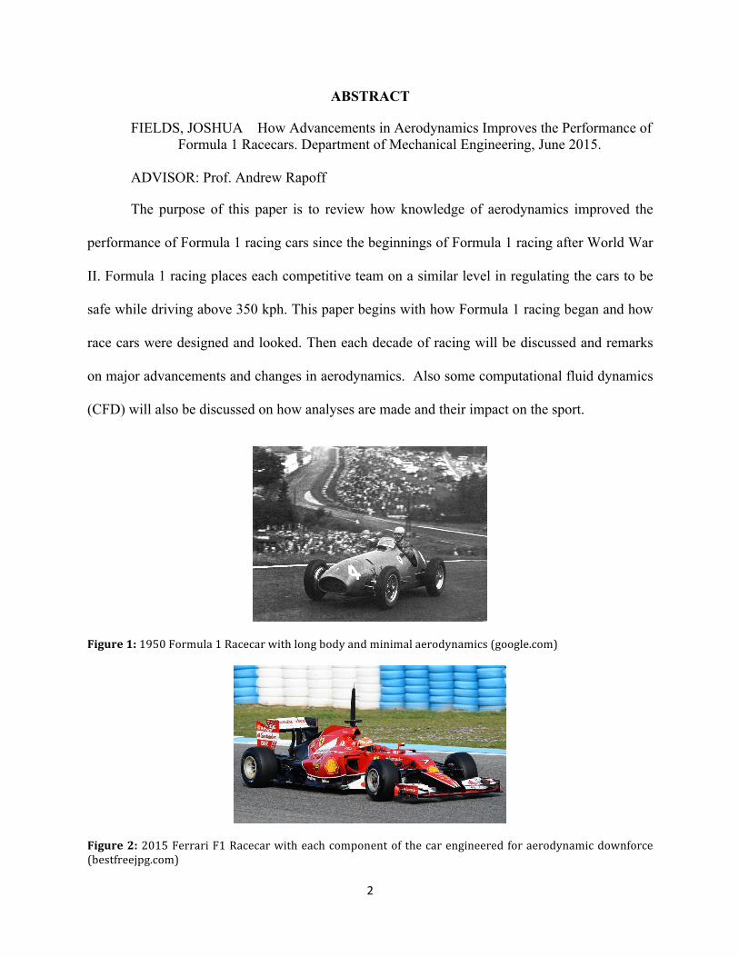
Figure 1: 1950 Formula 1 Racecar with long body and minimal aerodynamics (google.com)
Figure 2: 2015 Ferrari F1 Racecar with each component of the car engineered for aerodynamic downforce (bestfreejpg.com)

1
Introduction:
The first official Formula 1 race took
place in May of 1950. Automobile racing
had already been established but the
“Formula”, or set of rules and regulations
enforced by the FIA (Federation
Internationale de L’Automobile -
International Automobile Federation),
positioned automobile racing to the highest
standard and class.
Automobile manufactures took pride
in producing world class racing cars to reach
the full potential of their engineering
capabilities. Those who could afford it also
bought and raced their own cars to compete
for the prize money and title. Sometimes
even great manufacturers such as Honda pull
out due to high cost. (Formula 1, 2010)
Racing results depended on a
number of factors, the main two being the
driver’s skill and the car. The driver’s skill
still continues to play an important role
depending on their driving and racing
experience. The car on the other hand
somewhat differs between manufactures,
and how they approach the “Formula” and
produce a competitive racecar balancing a
variety of tradeoffs.
Since there are many components to
a Formula 1 car, each one plays a role in
making the car go faster in the turns and
accelerate in the straights. Two of the main
components of driving a Formula 1 car are
the engine supplying power to the car and
the shape (aerodynamics) of the car itself.
Initially, Formula 1 cars were designed to
look like fighter jet airplanes to have a
streamline body such as the Alfa Romeo
159. (Figure 3)
Figure 3: 1951 Alfa Romeo 159 with streamlined body (italiaspeed.com)
2
It had a 1.5 L L8 (inline) engine which
produced 425 bhp (brake horse power) and
reached a top speed of 305 kph (190 mph).
As the advancements in the understanding of
aerodynamics progressed, race cars with the
same engine could go drive at higher
cornering speeds which resulted in faster lap
times leading to many victories. Along with
engine regulations, the performance of
Formula 1 cars reached such high capacities
that drivers found themselves losing control
at great speeds that resulted in multiple
crashes and fatalities. In turn further
regulations were placed on the aerodynamic
design of Formula 1 cars that set all of the
competing teams on a level playing field to
ensure the safety of the drivers.
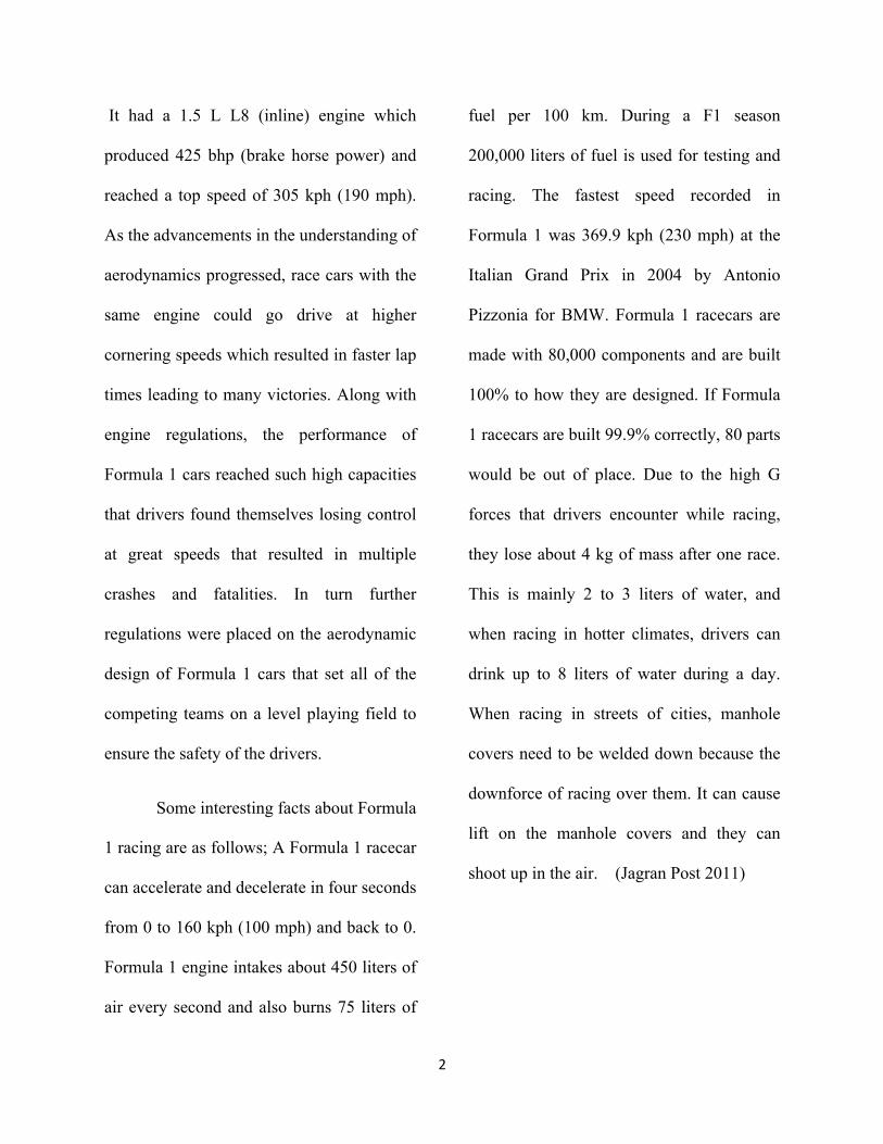
Some interesting facts about Formula
1 racing are as follows; A Formula 1 racecar
can accelerate and decelerate in four seconds
from 0 to 160 kph (100 mph) and back to 0.
Formula 1 engine intakes about 450 liters of
air every second and also burns 75 liters of
fuel per 100 km. During a F1 season
200,000 liters of fuel is used for testing and
racing. The fastest speed recorded in
Formula 1 was 369.9 kph (230 mph) at the
Italian Grand Prix in 2004 by Antonio
Pizzonia for BMW. Formula 1 racecars are
made with 80,000 components and are built
100% to how they are designed. If Formula
1 racecars are built 99.9% correctly, 80 parts
would be out of place. Due to the high G
forces that drivers encounter while racing,
they lose about 4 kg of mass after one race.
This is mainly 2 to 3 liters of water, and
when racing in hotter climates, drivers can
drink up to 8 liters of water during a day.
When racing in streets of cities, manhole
covers need to be welded down because the
downforce of racing over them. It can cause
lift on the manhole covers and they can
shoot up in the air. (Jagran Post 2011)

3
Aerodynamics through the Decades
The fundamental purpose of the
aerodynamics of a Formula 1 car is to
increase the downforce acting on the
vehicle. Without aerodynamic downforce,
Formula 1 cars generate enough lift to “fly”
while traveling at 160 kph (100 mph) alone.
Considering, Formula 1 racecars usually
race at an average speed of 300 kph (185
mph). (Jagran Post 2011) This culminates
where the “rubber hits the road” and gives
traction to the tires to travel at immense
speeds and high g’s (acceleration of
gravity). With aerodynamic downforce, at
top speed a Formula 1 racecar can achieve a
downforce of 2.5 times the car’s weight.
(Jagran Post 2011) With the implementation
of a front wing, rear wing, the body and
engine placement, all of these aerodynamic
modifications changed since the beginnings
of Formula 1 racing.
In the 1950s when Formula 1 began,
all of the cars had a front engine. The
aerodynamic shape of the cars were
streamlined. Streamline is a design with a
form that presents little resistance to fluid
flow, increasing speed and ease of
movement. (Figure 4) The main two types of
designs for inline front engines in Formula 1
during the 1950s resembled those of both
the Mercedes-Benz W 196 R and the
Maserati 250F. The Mercedes-Benz had an
eight-cylinder in-line engine with a top
speed of 300 kph and the Maserati had a six-
cylinder in-line engine. These similar
streamlined aerodynamic shapes continued
until the late sixties. (Figure 5)
Figure 4: Streamline Design with “smoother” shape on the bottom with low resistance to the flow of fluid. In the case of racing, the fluid would be air. (swimright23.webs.com)

4
Figure 5: Starting Line at 1954 F1 Race (f1fanatic.co.uk)
Towards the late 1950s, placement of
the engine in relation to the car’s body itself
began to change. In 1958 the car company
Cooper introduced mid-engined racecars in
Formula 1 with V8 engines behind the
driver. Afterwards other manufactures began
to lose races with front engines and changed
to rear mid-engined racecars as well. Soon
most Formula 1 racecars had a cigar tube
shape such as the 1962 Lotus Climax 25
with a 1.5 L V8 engine located right behind
the driver. (Figure 6 & 7)
Figure 6: 1962 Lotus-‐Climax 25 (f1fanatic.co.uk)
Figure 7: BRM P261, Lotus 33 and Honda RA 272 at Starting Line with cigar shaped racecars (1965) (f1fanatic.co.uk)
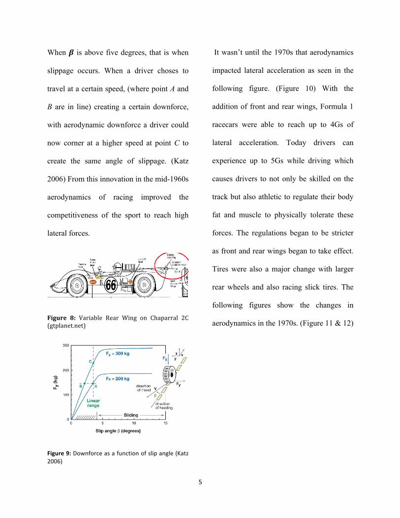
Adding downforce on the tires
improves tire traction and allows the racecar
to travel at higher speeds around corners
before sliding. Figure 9 entails a visual
representation. In this depiction, the vehicle
is traveling in the –x direction and the the
downforce is acting in the +Fz direction
while the lateral force is in the +Fy direction.
The angle at which the vehicle slides is 𝜷.
5
When 𝜷 is above five degrees, that is when
slippage occurs. When a driver choses to
travel at a certain speed, (where point A and
B are in line) creating a certain downforce,
with aerodynamic downforce a driver could
now corner at a higher speed at point C to
create the same angle of slippage. (Katz
2006) From this innovation in the mid-1960s
aerodynamics of racing improved the
competitiveness of the sport to reach high
lateral forces.
Figure 8: Variable Rear Wing on Chaparral 2C (gtplanet.net)
Figure 9: Downforce as a function of slip angle (Katz 2006)
It wasn’t until the 1970s that aerodynamics
impacted lateral acceleration as seen in the
following figure. (Figure 10) With the
addition of front and rear wings, Formula 1
racecars were able to reach up to 4Gs of
lateral acceleration. Today drivers can
experience up to 5Gs while driving which
causes drivers to not only be skilled on the
track but also athletic to regulate their body
fat and muscle to physically tolerate these
forces. The regulations began to be stricter
as front and rear wings began to take effect.
Tires were also a major change with larger
rear wheels and also racing slick tires. The
following figures show the changes in
aerodynamics in the 1970s. (Figure 11 & 12)

6
Figure 10: Progression of lateral acceleration using aerodynamic downforce (Katz 2006)
Figure 11: 1972 Lotus 72E (f1fanatic.co.uk)
Figure 12: 1977 Renault RS01 (f1fanatic.co.uk)
As the sport changed in the 1980s,
turbo chargers were used by the competitive
manufacturing teams to make Formula 1
cars as the ones seen in the following figure.
(Figure 13) Turbo-charged engines were
banned at the end of the 1980s in 1989 and
from then on V10 engines were used. As
technology began to become more advanced
with the implementation of computing
power and computational fluid dynamics,
towards the late 90s and up until today,
Formula 1 cars began to pay attention to
every aspect of the car and how it affected
the overall aerodynamics of theses race cars.
(Figure 14)

7
Figure 13: 1984 Williams FW09B, McLaren MP4/2 (f1fanatic.co.uk)
Figure 14: 1997 Ferrari F310B (f1fanatic.co.uk)
The FIA also began to regulate
engines in order for teams to remain close
contenders for the title. As a result V10
engines were banned in 2005. This
transitioned Formula 1 racing to focus even
more on the aerodynamics to enter the age
where each component of a Formula 1
racecar were designed to give the most
downforce as possible.
Formula 1 Aerodynamic Fundamentals
The two main parts of a Formula 1
racing car that affects the aerodynamic
shape of the car itself are the wings and the
body. Primary considerations of the wings
are the ground effect in the front, and the
interactions between the wings and the
body.
In relation to the ground effect of
the front wing an inverted airfoil is used to
provide negative lift, is proportional with the
length of the chord (c) and the height (h) of
the vehicle above the ground. Most race cars
have an h/c value of 0.1 to 0.3 to maximize
the downforce and minimize drag. The
following figure, (Figure 15), the sizing of
the front wing airfoil and its position above
the ground determine certain values for the
coefficient of drag and lift.

8
Figure 15: Coefficient of Lift as a function of front wing chord length and ride height (Katz 2006)
The shape of the body of the car in relation
to the ground affects the aerodynamics as
well. Depending on its overall shape, the
key is to reduce the flow under the vehicles
body. Since most automobile shapes have a
tendency to generate lift Formula 1 racecars
create a low pressure under the racecars
body. This in turn creates a higher pressure
above the race car that generates downforce.
One concept used was putting a suction fan
on the back of the car to decrease the air
pressure under the car. This concept was
implemented in a Formula 1 race car the
1978 Brabham BT46B. It once won one race
and was immediately outlawed. The
following figures (Figures 16 & 17) displays
the car and the suction fan in the back.
Figure 16: 1978 Brabham BT46B (beautifullyengineered.tumbler.com)
Figure 17: Rear suction fan on 1978 Brabham BT46B (jalopnik.com)
Since the fan in the back was banned, side
flap skirts were used instead on most
Formula 1 cars. It is slightly visible to see
the side skirts on the Lotus 78 depicted next.
(Figure 18) In 1977, Mario Andretti won the
four championship races ending in 3rd place
9
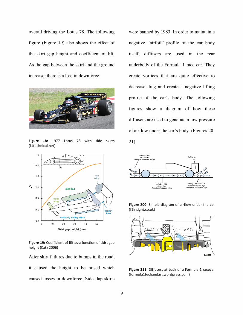
overall driving the Lotus 78. The following
figure (Figure 19) also shows the effect of
the skirt gap height and coefficient of lift.
As the gap between the skirt and the ground
increase, there is a loss in downforce.
Figure 18: 1977 Lotus 78 with side skirts (f1technical.net)
Figure 19: Coefficient of lift as a function of skirt gap height (Katz 2006)
After skirt failures due to bumps in the road,
it caused the height to be raised which
caused losses in downforce. Side flap skirts
were banned by 1983. In order to maintain a
negative “airfoil” profile of the car body
itself, diffusers are used in the rear
underbody of the Formula 1 race car. They
create vortices that are quite effective to
decrease drag and create a negative lifting
profile of the car’s body. The following
figures show a diagram of how these
diffusers are used to generate a low pressure
of airflow under the car’s body. (Figures 20-
21)
Figure 200: Simple diagram of airflow under the car (f1insight.co.uk)
Figure 211: Diffusers at back of a Formula 1 racecar (formula1techandart.wordpress.com)
10
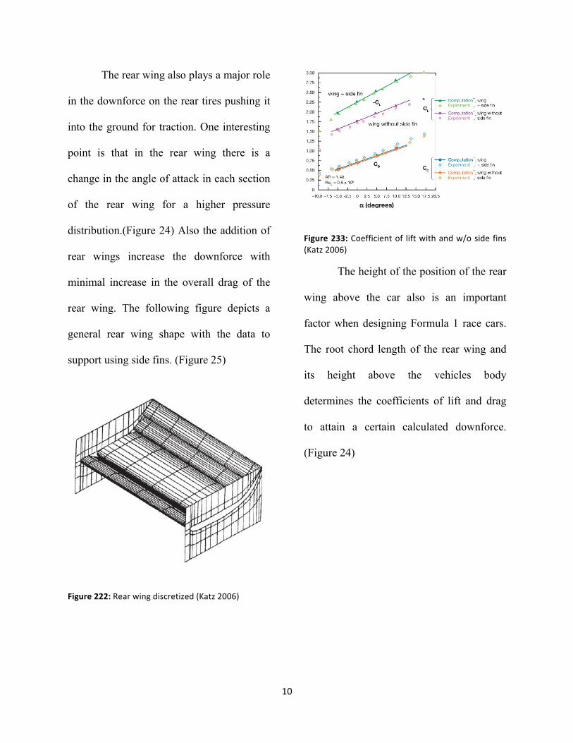
The rear wing also plays a major role
in the downforce on the rear tires pushing it
into the ground for traction. One interesting
point is that in the rear wing there is a
change in the angle of attack in each section
of the rear wing for a higher pressure
distribution.(Figure 24) Also the addition of
rear wings increase the downforce with
minimal increase in the overall drag of the
rear wing. The following figure depicts a
general rear wing shape with the data to
support using side fins. (Figure 25)
Figure 222: Rear wing discretized (Katz 2006)
Figure 233: Coefficient of lift with and w/o side fins (Katz 2006)
The height of the position of the rear
wing above the car also is an important
factor when designing Formula 1 race cars.
The root chord length of the rear wing and
its height above the vehicles body
determines the coefficients of lift and drag
to attain a certain calculated downforce.
(Figure 24)

11
Figure 244: Coefficient of lift as a function of size and position of rear wing (Katz 2006)
In relating all the wings and body together,
if the front wing is damaged, more air
travels over the car losing the overall down
force on the car. If the rear wing is damaged,
there is a loss of downforce over the rear
tires and a major reduction in traction. If
part of the side of the body of the car is
demolished, airflow towards the rear wing
will be less than optimal (Wang et al. 2010).
Computational Fluid Dynamic Analyses
There have been many
computational fluid dynamics (CFD)
analysis tests on the design of Formula 1
race cars. In initial testing the results are
very useful. As design is further tested in the
wind tunnel and the actual track, the results
are not as accurate as initially designed but
still provide effective results nonetheless.
Also it is easier to make changes on a
computer model compared to wind tunnel
testing and revising the final design of the
car. (Vickers 2008)
When using CFD, there is always an
uncertainty in the final analysis. To
minimize error between computed results
and actual results in the wind tunnel and on
the track, different computational methods
are used. For instance the Monte Carlo
Method (MCM) is accurate and robust but is
very time consuming compared to the
probabilistic collocation method (PCM).
(Bradford & D'Ammaro 2014) The MCM
uses random sampling to generate data
values to obtain numerical results. Like the
MCM, the PCM uses lattice sampling in
which data value are generated from a
discrete set of points. This in turn saves time

12
when running tests, up to three orders of
magnitude. In a CFD analysis of the airflow
around the front wheel using the front wing
there were several aspects that were studied.
One was the difference in endplate variation
and the other was the position of the
endplate in relation to the tire. The following
figures and tables show the mesh that was
used and each variation. The table shows the
actual results of wind tunnel experiments
and the coefficient of drag which was the
lowest at position C which confirmed CFD
analysis. (Figures 25- 27 & Table 1) Due to
the uncertainty of CFD, the results were not
exactly the same but still comparable
quantitative results nonetheless. The table
shows the measurements for the coefficient
of drag (Cd), relative wing downforce (Wr)
and performance index (P).
Figure 255: Initial CFD Model for front wing testing (Subic & Haake 2000)
Figure 266: Endplate variations of front wing (Subic & Haake 2000)
Figure 277: Different endplate positions relative to front tires (Subic & Haake 2000)

13
Table 1: Wind Tunnel Results of Testing (Subic & Haake 2000)
CFD was also used on the BMW
Sauber F1.09. In the following figure
(Figure 30), the fabrication of a longer front
wing and slimmer body influenced the
streamlines of the flow behind the car
making it more aerodynamic. In the top
portion of the figure the streamlines flow
initially wider around the Formula 1 car in
2009 compared to 2008 which in turn causes
less drag over the car’s body itself.
Figure 288: BMW Sauber F1.08 to F1.09 (Larsson 2009)
Discussion and Conclusions
As a result of all of the many factors
of designing a Formula 1 race car,
aerodynamics play a major role in the sport
of Formula 1 racing and is a quantitative
competition of engineering at its finest level.
The “Formula” regulations enforced by the
FIA are for the safety of the drivers but also
push the sport to reach great engineering
achievements. This multinational sport
includes the best manufacturers and drivers
from around the world. Since automobile
gasoline engines are being integrated with
and other forms of “clean” energy, Formula
1 racecar aerodynamics can add a certain
extent of downforce to go around corners at
higher speeds. Engineers on the
manufacturing teams are constantly testing
and modeling the aerodynamics to change
various parameters of the body to gain as
much downforce as possible. The body and
the wings are redesigned every year and
sometimes prove results when having the

14
right driver to win the championship races.
Currently redesigning parts to increase
aerodynamic downforce is the progressing
towards the pinnacle of the aerodynamic age
in the sport. In order for another
considerable change to come to the sport it
would have to be the FIA changing the
energy source of the engines such as going
electric or having hybrid racecars due to the
amount of fuel consumption.
For future work and study, a deeper
look at how the specifications of Formula 1
engines changed and progressed since its
beginnings. The technology behind these
powerful engines with the crankshaft
rotating at a rate of 18000 RPMs is an
accomplishment in itself. Also the
implementation of electronics in the engine
and the control system is highly
sophisticated and essential component of
Formula 1 racing. Engineers are still
learning more about aerodynamics and the
“Fomula” continues to change pushing to
achieve great engineering accomplishments.
Continuing to find the best solution to the
“Formula” is the thrill of watching and
appreciating Formula 1 racing.
REFERENCES
Bradford, J., F. Montomoli, and A.
D'Ammaro. "Uncertainty Quantification and
Race Car Aerodynamics." Proceedings of
the Institution of Mechanical Engineers Part
D-Journal of Automobile Engineering 228.4
(2014): 403-11.
“Formula One: Facts and Trivia”, JAGRAN
Post (2011)
Katz J, Aerodynamics of Race Cars, Annual
Review of Fluid Mechanics 2006: 38(1) : 27-
63
Larsson, Torbjom “2009 Formula One
Aerodynamics: BMW Sauber F1.09-
Fundamentally Different”, 4th European
Automotive Simulation Conference, 2009;
Pg. 1-7

15
Subic, A.J. and Haake, S.J, The Engineering
of SPORT-Research, Development and
Innovation- Pg. 353-60W.P Kellar, G.J.
Targett, Am Savill & W.N Dawes CFD
Laboratory, Cambridge University
Engineering Dept., Cambridge, UK
"The 'Formula' Behind Formula One."
JAGRAN Post (2011)
Vickers, Keith. Racing Green. 249 Vol.
H.W. Wilson - Applied Science &
Technology Abstracts, 2008.
Wang, Y.-N.; Tseng, C. –Y.; Huang Y.-L.;
Leong, J. C., Investigation of 2004 Ferrari
Formula One race car wing effects, 2010
International Symposium on Computer,
Communication, Control and Automation
(3CA), 2010; Vol. 1, Pg. 85-8
Related Documents