Description Hoval Belaria ® SRM (4-16) Hoval Belaria ® compact SRM (4-16) Air/water heat pump 3 Hoval Belaria ® SRM Hoval Belaria ® compact SRM Modulating heat pump system for heat- ing and cooling in the living area Split system comprising inside unit and outside unit. Modulation range 30% to 100% Inside unit Belaria ® SRM • Compact unit for wall installation steel. Colour pure white (RAL 9010). • Condenser stainless steel/Cu • Expansion tank 10 litres • Pressure gauge • Flow sensor (included separately) • Emergency heating ® SRM (4) 3 kW ® SRM (6-16) 3/9 kW (see also technical data) with safety thermo- function (operating unit included separately) cycle • Switch control box • Flow and return sensor installed Belaria ® compact SRM inside unit • • steel. Colour RAL 9010 (pure white). • Condenser stainless steel/Cu • ® compact SRM (4) 180 litres ® compact SRM (6-16) 260 litres • • Expansion tank 10 litres • Pressure gauge • Flow sensor • (included separately) • Emergency heating ® compact SRM (4) 3 kW ® compact SRM (6-16) 3/9 kW (see also technical data) with safety thermo- • • function (included separately) • cycle • Switch control box • Flow and return sensor installed • Outside unit • Compact unit for outdoor installation • Speed-controlled compressor • 1 / 2 speed-controlled fans • Filled with refrigerant R 410 A • Outdoor sensor installed • Condensate drip tray heating installed on ® SRM (11-16) ® compact SRM (11-16) Connections, heating/cooling • Heating connections ® SRM (4-16) bot- ® compact SRM (4-16) top Connections, refrigerant line • Inside unit Belaria ® inside unit Belaria ® compact SRM (4-16) top • Outside unit on the right side liquid line: Belaria ® ® Condensate drain • Free run-off of the condensate for draining off • An optional condensate drip tray for collec- Electrical connections • Outside unit on the right side connection: Belaria ® Belaria ® • Inside unit is fed from the outside unit • Emergency heating is connected to the inside unit separately • Electric heating element connection in the ® SRM (4-16)) Delivery separately. with the inside unit. Sensor for calorifier supplied loose in the inside unit (Belaria ® SRM (4-16)). On site • Installation of the insulation set ® SRM) • Wall openings for refrigerant connecting lines. • Electr. connecting line outside/inside unit. Hoval Belaria ® SRM Hoval Belaria ® compact SRM Heat output Cooling capacity type with A-7W35 with A2W35 with A35W18 kW kW kW (4) 4.6 4.8 5.9 (6) 5.3 6.4 7.3 (8) 6.4 7.7 8.4 (11) 8.8 9.1 15.1 (14) 11.7 10.9 16.1 (16) 12.3 11.4 16.8 Outside unit Inside unit ® SRM Inside unit ® compact SRM Tests ® SRM (6) Test number WPZ-LW-207-13-10 ® SRM (14) Test number WPZ-LW-124-08-05 ® SRM (16) Test number WPZ-LW-208-13-11

Welcome message from author
This document is posted to help you gain knowledge. Please leave a comment to let me know what you think about it! Share it to your friends and learn new things together.
Transcript
� Description
Hoval Belaria® SRM (4-16)Hoval Belaria® compact SRM (4-16)Air/water heat pump
���������� ���� ����������� 3
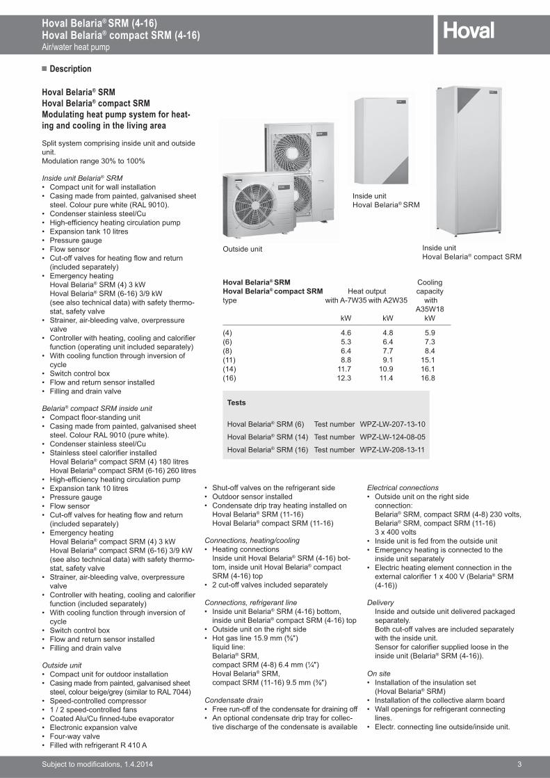
Hoval Belaria® SRMHoval Belaria® compact SRMModulating heat pump system for heat-ing and cooling in the living area
Split system comprising inside unit and outside unit.Modulation range 30% to 100%
Inside unit Belaria® SRM• Compact unit for wall installation� ��� ����������� ����������� ����!���
steel. Colour pure white (RAL 9010).• Condenser stainless steel/Cu� " �!#���� ���$!��� ��� ������ �����• Expansion tank 10 litres• Pressure gauge• Flow sensor� ���#����������!��� ����&���������
(included separately)• Emergency heating
"���'���� �® SRM (4) 3 kW "���'���� �® SRM (6-16) 3/9 kW (see also technical data) with safety thermo-����������$�����
� ���� ����� �#����� ������������������������
� ��������& �!!��� ����� ��������� � ��function (operating unit included separately)
� * �!�� ������� ��!���! ����� ��cycle
• Switch control box• Flow and return sensor installed� + �� �������� ������
Belaria® compact SRM inside unit• ������,�#����� ���� �• ��� ����������� ����������� ����!���
steel. Colour RAL 9010 (pure white).• Condenser stainless steel/Cu• ��� �������������� ��� ��������
"���'���� �® compact SRM (4) 180 litres "���'���� �® compact SRM (6-16) 260 litres
• " �!#���� ���$!��� ��� ������ �����• Expansion tank 10 litres• Pressure gauge• Flow sensor• ���#����������!��� ��,&���������
(included separately)• Emergency heating
"���'���� �® compact SRM (4) 3 kW "���'���� �® compact SRM (6-16) 3/9 kW (see also technical data) with safety thermo-����������$�����
• ���� ����� �#����� ������������������������
• ��������& �!!��� ����� ��������� ���function (included separately)
• * �!�� ������� ��!���! ����� ��cycle
• Switch control box• Flow and return sensor installed• + �� �������� ������
Outside unit• Compact unit for outdoor installation� ��� ����������� ����������� ����!���
������������ ��5���$7� � ����:;<=���>• Speed-controlled compressor• 1 / 2 speed-controlled fans� �����;��5��� ����#������������� ?������ ��@���� ������� +��#&�$�����• Filled with refrigerant R 410 A
� �!��#����������!����� ������� ��• Outdoor sensor installed• Condensate drip tray heating installed on
"���'���� �® SRM (11-16) "���'���� �® compact SRM (11-16)
Connections, heating/cooling• Heating connections
B�� ���� �"���'���� �® SRM (4-16) bot-��� �� ���� �"���'���� �® compact SRM (4-16) top
� ����#�������� ����������������$
Connections, refrigerant line• Inside unit Belaria®�:G7�#�J>�����
inside unit Belaria® compact SRM (4-16) top• Outside unit on the right side� "����� ���K�N��7QT>
liquid line: Belaria®�:G� �������:G7�#V>J����7XT> "���'���� �®�:G� �������:G7��#�J>N�K��7YT>
Condensate drain• Free run-off of the condensate for draining off• An optional condensate drip tray for collec-
� ��� ��!������!���������� ���� �����
Electrical connections• Outside unit on the right side
connection: Belaria®�:G��������:G7�#V>�Z������ Belaria®�:G��������:G7��#�J> Z@�������
• Inside unit is fed from the outside unit• Emergency heating is connected to the
inside unit separately• Electric heating element connection in the
�@���������� ����@���[7'���� �® SRM (4-16))
Delivery B�� �������� ���� ���� ��������\����
separately. '�!���#����������� ����������������$
with the inside unit. Sensor for calorifier supplied loose in the
inside unit (Belaria® SRM (4-16)).
On site• Installation of the insulation set
7"���'���� �® SRM)� B�������� ���!������� �����������• Wall openings for refrigerant connecting
lines.• Electr. connecting line outside/inside unit.
Hoval Belaria® SRM Hoval Belaria® compact SRM Heat output
Cooling capacity
type with A-7W35 with A2W35 with A35W18
kW kW kW
(4) 4.6 4.8 5.9(6) 5.3 6.4 7.3(8) 6.4 7.7 8.4(11) 8.8 9.1 15.1(14) 11.7 10.9 16.1(16) 12.3 11.4 16.8
Outside unit
Inside unit"���'���� �® SRM
Inside unit"���'���� �® compact SRM
Tests
"���'���� �® SRM (6) Test number WPZ-LW-207-13-10
"���'���� �® SRM (14) Test number WPZ-LW-124-08-05
"���'���� �® SRM (16) Test number WPZ-LW-208-13-11
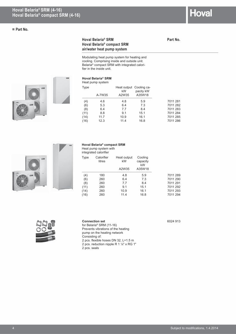
Connection setfor Belaria® SRM (11-16)j�������� ���� ����!�!��� ��pump on the heating networkConsisting of:��������@ ���!���vzZ��<{��K������������ �� ����:�XT@:|�T2 pcs. seals
6024 913
4 ���������� ���� �����������
Hoval Belaria® SRM (4-16)Hoval Belaria® compact SRM (4-16)
� Part No.
Part No.Hoval Belaria® SRMHoval Belaria® compact SRMair/water heat pump system
Modulating heat pump system for heating and cooling. Comprising inside and outside unit.Belaria® compact SRM with integrated calori-��� ��!� �� ���� ��
Hoval Belaria® SRMHeat pump system
Type Heat output kW
Cooling ca-pacity kW
A-7W35 A2W35 A35W18
(4) 4.6 4.8 5.9(6) 5.3 6.4 7.3(8) 6.4 7.7 8.4
(11) 8.8 9.1 15.1(14) 11.7 10.9 16.1(16) 12.3 11.4 16.8
Hoval Belaria® compact SRMHeat pump system with ������������� ���
Type ���� ���litres
Heat output kW
Cooling capacity
kWA2W35 A35W18
(4) 180 4.8 5.9(6) 260 6.4 7.3(8) 260 7.7 8.4
(11) 260 9.1 15.1(14) 260 10.9 16.1(16) 260 11.4 16.8
7011 281 7011 282 7011 283 7011 284 7011 285 7011 286
7011 289 7011 290 7011 291 7011 292 7011 293 7011 294
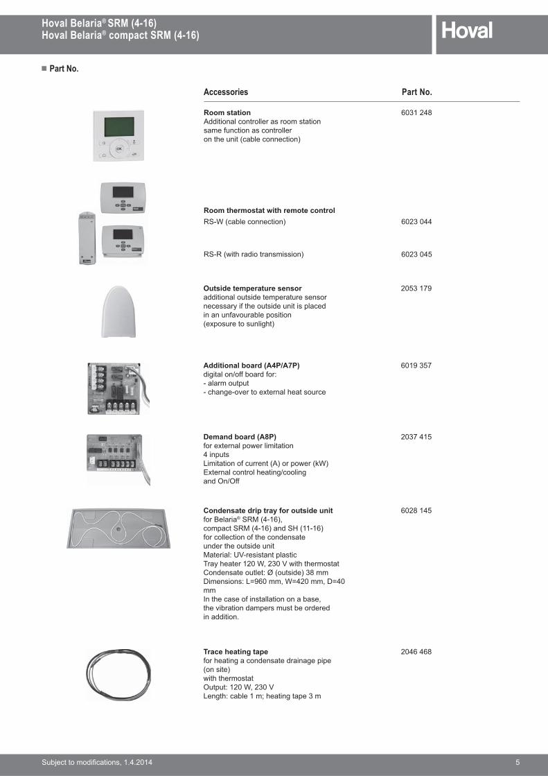
Room stationAdditional controller as room stationsame function as controlleron the unit (cable connection)
6031 248
Outside temperature sensoradditional outside temperature sensornecessary if the outside unit is placed ���������������� � �(exposure to sunlight)
2053 179
Additional board (A4P/A7P)digital on/off board for:- alarm output#�!����#�����@������!��������
6019 357
Demand board (A8P)for external power limitation4 inputsLimitation of current (A) or power (kW)External control heating/coolingand On/Off
2037 415
Condensate drip tray for outside unitfor Belaria®�:G7�#�J>�compact SRM (4-16) and SH (11-16)for collection of the condensateunder the outside unitG���� ��}~[#��� ���������� ����$!��������*��Z�[& �!�!�������Condensate outlet: Ø (outside) 38 mmv ���� ��}<{NJ����*{������v{��mmB��!������ �������� ���������!�� ���� ��������������������in addition.
6028 145
Trace heating tapefor heating a condensate drainage pipe(on site)with thermostat������}���*��Z�[Length: cable 1 m; heating tape 3 m
2046 468
� Part No.
Part No.
Hoval Belaria® SRM (4-16)Hoval Belaria® compact SRM (4-16)
���������� ���� ����������� 5
Accessories
Room thermostat with remote controlRS-W (cable connection)
RS-R (with radio transmission)
6023 044
6023 045

Protective roof for outside unitfor Belaria®�:G��������:G7�#V>Powder-coated sheet steelColour: silk grey RAL 7044Also combinable withwall console for outside unit.
6032 511
Protective roof for outside unitfor Belaria®�:G7��#�J>�compact SRM (11-16) and SH (11-16)Powder-coated sheet steelColour: silk grey RAL 7044Also combinable withwall console for outside unit.
7006 360
Protective grid for outside unitfor Belaria® SRM and compact SRM (4-8)sturdy grid for protection��!���������G���� ��}�����������7:;<=���>Mounting on site
6031 613
Protective grid for outside unitfor Belaria®�:G7��#�J>�compact SRM (11-16) and SH (11-16)sturdy grid for protection��!���������G���� ��}�����������7:;<=���>Mounting on site
6028 144
Protective grid for outside unitfor Belaria®�:G7��#�J>�compact SRM (11-16) and SH (11-16)sturdy grid for protection��!���������7��!�����>G���� ��}�����������7:;<=���>Mounting on site
6028 243
Wall console for outside unitfor attachment of the unit to the wall2 brackets made of steel sheet ����� ���� �����������fixing materialAttention:Cannot be used in this formon insulated walls!Not suitable for lightweight walls!
6031 530
Base for outside unitfor Belaria® SRM (4-8) andcompact SRM (4-8)Consisting of:�~#�!��������\���������G����� ������ ���$������installation on concrete base(see base plans)
6031 247
Vibration damperfor installing the unit ona concrete base (on site).�� ���� �����&���"�v#�GV@Z��washers and nuts
6022 489
� Part No.
Part No.
6 ���������� ���� �����������
Hoval Belaria® SRM (4-16)Hoval Belaria® compact SRM (4-16)

Insulation set (inside unit)for Belaria® SRM (04-16):��� ������������!������������falling beneath the dewpoint incooling mode with flow temperaturesbelow +20 °C
6031 249
Sludge separator with magnetic ring��������� ���� ���� ���� ���� ���������made from HDPE plasticTemperature range 0 - 90 °CMax. operating pressure: 3 barMax. glycol fraction: 30%manual air-bleeding
2054 376
� Part No.
Part No.
Hoval Belaria® SRM (4-16)Hoval Belaria® compact SRM (4-16)
���������� ���� ����������� 7
Accessories
For hot water production
Motorised switch ball valvestype R3..BL/LR230A, NR230A Connections with internal thread ������ ��
Type DNScrew joint connection \�� 1
R3025-BL2/LR230A 25 :��T 10.0R3032-BL3/NR230A 32 :��XT 15.0
1 Flow rate in m3/h with 100% opening and a pressure drop of 1 bar
Services
Commissioning
��� �� � ���$&�\����� ���"������ ������!� ������� �����5�����$ �condition for warranty.
+���� �� � ������!������ ��� ������������$��"�������������
Circulation pumps, actuators, buffer storage tanks see separate brochures
6027 411 6027 412
2057 249
��������B�#� ��������������!��������� v�� ����������� �����������������10 bar. :�,�@ Ø D H h Atype mm mm mm
[�� 409 562 113 :�T
Ø D
H
h
A
A

� Technical data
8 ���������� ���� �����������
Hoval Belaria® SRM (4-16)Hoval Belaria® compact SRM (4-16)
Hoval Belaria® SRM (4-16) Hoval Belaria® compact SRM (4-16)Type SRM (4) SRM (6) SRM (8) SRM (11) SRM (14) SRM (16)• Heat output A-7W351 kW 4.60 5.43 6.40 8.80 11.70 12.10• Heat output A2W352 kW 3.27 4.69 5.80 8.56 10.30 11.70• Heat output A10W352 kW 4.47 6.29 7.39 11.20 14.30 17.50• COP A-7W351 2.71 2.93 2.77 2.92 2.75 2.63• COP A2W352 4.02 3.80 3.67 3.65 3.45 3.40• COP A10W352 5.12 5.23 4.91 4.86 4.71 4.51• Cooling capacity A35W181 kW 5.90 7.30 8.40 15.10 16.10 16.80• Cooling capacity A35W71 kW 4.50 5.50 6.40 11.70 12.60 13.10• EER A35W181 3.16 3.20 2.92 3.39 3.01 2.77• EER A35W71 2.22 2.18 1.98 2.78 2.51 2.32Dimensions• Outside unit H/W/D mm 735/832/307 1345/900/320• Inside unit H/W/D Belaria® SRM mm 890/480/344• Inside unit H/W/D Belaria® compact SRM mm 1732/600/728Weights• Net weight of outside unit kg 54 56 56 113 113 113• Net weight of inside unit
Belaria® SRM kg 44 48 48 48 48 48Belaria® compact SRM kg 115 126 126 129 129 129
• Gross weight of outside unit kg 57 59 59 128 128 128• Gross weight of inside unit
Belaria® SRM kg 47 51 51 51 51 51Belaria® compact SRM kg 128 140 140 142 142 142
• Compressor !����� ����$���������� �����������������• :��� ��������� ��:���; kg 1.45 1.6 1.6 3.4 3.4 3.4• Fan �@ ������ ��������� �@�@ ������ ���������• ?������� ������������ � �������������• Condenser type Copper-soldered stainless steel plate heat exchanger• Condenser water content litres 0.9 1.3 1.3 1.0 1.0 1.0• j �������� �,&5������ R ��5�T ��5�T ��5�T ��5�T ��5�T ��5�T• G�@������,& m3/h 1.5 2.0 2.0 3.1 3.1 3.1• G �������,& m3/h 0.4 0.7 0.7 0.7 0.7 0.7• Max. operating pressure on the heating side bar 3.0 3.0 3.0 3.0 3.0 3.0• ?@���� ����\����� litres 10 10 10 10 10 10• Total water content Belaria® SRM litres 3 5 5 5 5 5• Total water content Belaria® compact SRM litres 4.4 5.8 5.8 5.5 5.5 5.5• ���� ���5'���� �® compact SRM litres 180 260 260 260 260 260• Max. hot water temperature °C 65 65 65 65 65 65• Operating pressure/test pressure bar 8/13 8/13 8/13 8/13 8/13 8/13• ���� �������� �� Stainless steel (EN 1.4521)• Thermal insulation material EPS• Standby losses (EN 12897) kWh/24 h 1.4 1.9 1.9 1.9 1.9 1.9Connection, refrigerant line• Dimension of liquid line Inches/
mm1/4 / 6.4 1/4 / 6.4 1/4 / 6.4 3/8 / 9.5 3/8 / 9.5 3/8 / 9.5
• Dimension of gas pipe Inches/mm
5/8 / 15.9 5/8 / 15.9 5/8 / 15.9 5/8 / 15.9 5/8 / 15.9 5/8 / 15.9
• Max. length of refrigerant line m 30 30 30 30 30 30• Min. length of refrigerant line m 3 3 3 3 3 3• Max. height difference outside/inside unit 20 20 20 30 30 30• ���� ������������������ ��� ���!��� ���!�&��������� ���Electrical data• Max. power consumption during heating operation• Heat pump kW 2.4 2.6 3.3 4.8 6.2 7.1• Emergency heating kW 3 2 stage 3/9 2 stage 3/9 2 stage 3/9 2 stage 3/9 2 stage 3/9Voltage• Compressor [ 230 230 230 3 x 400 3 x 400 3 x 400• Fan [ 230 230 230 230 230 230• Emergency heating [ 230 Z\*���N\*Z@�������• Frequency Hz 50 50 50 50 50 50• [���������� +/- 10% +/- 10% +/- 10% +/- 10% +/- 10% +/- 10%Operating current max.• Compressor A 15 15 15 16 16 16• Starting current A 11 11 11 8 8 8• Fuse A 16T 16T 16T 16T 16T 16T1"����������� ������� �$�����j5??: ������������� �7?������J5���Z#���J>2 Heat output and COP in partial load operation (EN 14511)
� Technical data
Hoval Belaria® SRM (4-16)Hoval Belaria® compact SRM (4-16)
���������� ���� ����������� 9
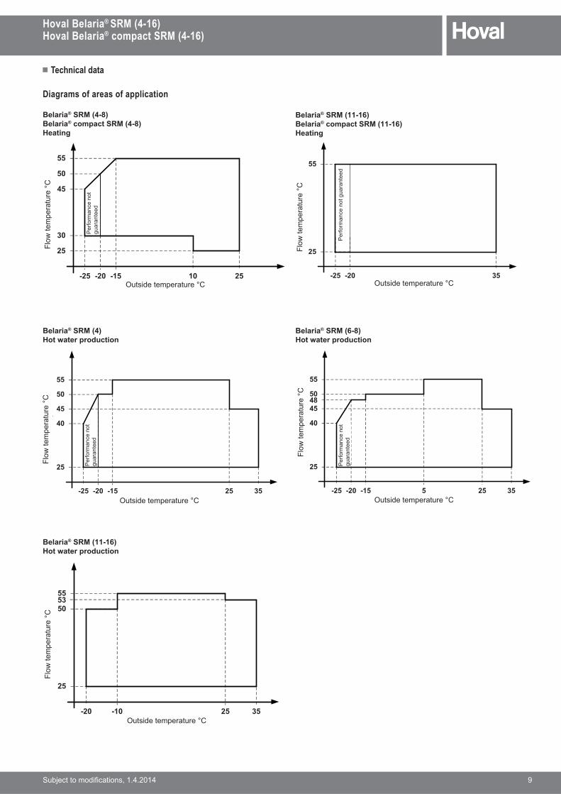
Diagrams of areas of application
Belaria® SRM (4-8)Belaria® compact SRM (4-8)Heating
25
55
-20-25
Vorla
ufte
mpe
ratu
r °C
Aussentemperatur °C10 25
30
-15
45
50
Leis
tung
nic
ht
gara
ntie
rt
50
-20-25
Vorla
ufte
mpe
ratu
r °C
Aussentemperatur °C25
25
55
45
35-15
40
Leis
tung
nic
ht
gara
ntie
rt
25
-20-25
Vorla
ufte
mpe
ratu
r °C
Aussentemperatur °C35
Leis
tung
nic
ht g
aran
tiert
55
50
-20-25
Vorla
ufte
mpe
ratu
r °C
Aussentemperatur °C5 25
25
55
45
35-15
40
Leis
tung
nic
ht
gara
ntie
rt
48
Belaria® SRM (4)Hot water production
Belaria® SRM (11-16)Belaria® compact SRM (11-16)Heating
Belaria® SRM (6-8)Hot water production
Belaria® SRM (11-16)Hot water production
-20
Vorla
ufte
mpe
ratu
r °C
Aussentemperatur °C
25
3525
5350
55
-10
Outside temperature °C Outside temperature °C
Outside temperature °C Outside temperature °C
Outside temperature °C
Flow
tem
pera
ture
°C
Flow
tem
pera
ture
°C
Flow
tem
pera
ture
°C
Flow
tem
pera
ture
°C
Flow
tem
pera
ture
°C
Per
form
ance
not
gu
aran
teed
Per
form
ance
not
gua
rant
eed
Per
form
ance
not
gu
aran
teed
Per
form
ance
not
gu
aran
teed

� Technical data
10 ���������� ���� �����������
Hoval Belaria® SRM (4-16)Hoval Belaria® compact SRM (4-16)
Belaria® SRM (4-8)Belaria® compact SRM (4-8)Cooling
Belaria® SRM (11-16)Belaria® compact SRM (11-16)Cooling
10
Vorla
ufte
mpe
ratu
r °C
Aussentemperatur °C
5
22
4318
13
10
Vorla
ufte
mpe
ratu
r °C
Aussentemperatur °C
5
22
46
Outside temperature °C Outside temperature °C
Flow
tem
pera
ture
°C
Flow
tem
pera
ture
°C
Belaria® compact SRM (4)Hot water production
Belaria® compact SRM (6-8)Hot water production
Belaria® compact SRM (11-16)Hot water production
53
-20
War
mw
asse
rtem
pera
tur °
C
Aussentemperatur °C
25
25
50
35-10
Mit eingebauter Elektroheizung
55
60
Outside temperature °C
Hot
wat
er te
mpe
ratu
re °C
With built-in electric heater
45
-20-25
War
mw
asse
rtem
pera
tur °
C
Aussentemperatur °C25
25
50
35-15
40
Leis
tung
nic
ht
gara
ntie
rt
Mit eingebauter Elektroheizung
5
48
55
60
Outside temperature °C
Hot
wat
er te
mpe
ratu
re °C
With built-in electric heater
Perf
orm
ance
not
gu
aran
teed
50
-20-25
War
mw
asse
rtem
pera
tur °
C
Aussentemperatur °C25
25
45
35-15
40
Leis
tung
nic
ht
gara
ntie
rt
Mit eingebauter Elektroheizung60
55
Outside temperature °C
Hot
wat
er te
mpe
ratu
re °C
With built-in electric heater
Perf
orm
ance
not
gu
aran
teed
� Technical data
Hoval Belaria® SRM (4-16)Hoval Belaria® compact SRM (4-16)
���������� ���� ����������� 11
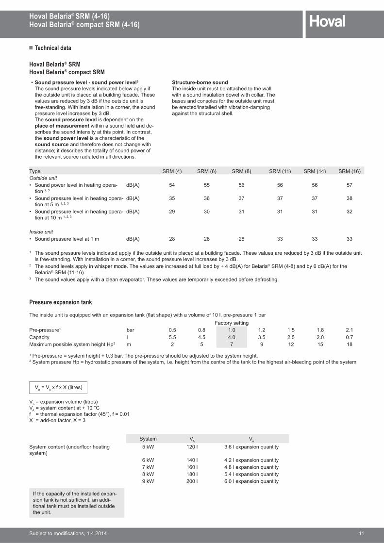
Pressure expansion tank
�!� �� ���� � ���� ����& �!���@���� ����\7,���!���>& �!��������������#������������Factory setting
Pre-pressure1 bar 0.5 0.8 1.0 1.2 1.5 1.8 2.1Capacity l 5.5 4.5 4.0 3.5 2.5 2.0 0.7Maximum possible system height Hp2 m 2 5 7 9 12 15 18
1j��#��������{�$����!� �!����Z�����!����#���������!���������������!��$����!� �!��2�$������������"�{!$������ �����������!��$����� ���!� �!�����!���������!����\��!�! �!���� �#����� ��� ����!��$����
[n{[A x f x X (litres)
[n{�@���� ������7� ����>[A{�$������������������ {�!������@���� ������7�K�>��{�����{���#��������{Z
System [A [n
�$����������7�����,�!��� ��system)
5 kW 120 l 3.6 l expansion quantity
6 kW 140 l 4.2 l expansion quantity7 kW 160 l 4.8 l expansion quantity8 kW 180 l 5.4 l expansion quantity9 kW 200 l 6.0 l expansion quantity
Hoval Belaria® SRMHoval Belaria® compact SRM• Sound pressure level - sound power level3
�!������������������� �� ��������&����$ �the outside unit is placed at a building facade. These �����������������$Z�' ��!���� ���� � �����#����� ���* �! �������� � ���������!������������������ ���������$Z�'�The sound pressure level is dependent on the place of measurement& �! ���������������-��� ����!����� ����� �$���! �� ���B���������the sound power level is a characteristic of the sound source and therefore does not change with distance; it describes the totality of sound power of �!����������������� ���� ����� ���� ���
Structure-borne soundThe inside unit must be attached to the wall with a sound insulation dowel with collar. The bases and consoles for the outside unit must ���������5 ��������& �!� ���� �#���� ��against the structural shell.
Type SRM (4) SRM (6) SRM (8) SRM (11) SRM (14) SRM (16) Outside unit• �����&������� �!��� ������-
tion ��ZdB(A) 54 55 56 56 56 57
• ����������������� �!��� ������-tion at 5 m ����Z
dB(A) 35 36 37 37 37 38
• ����������������� �!��� ������-tion at 10 m ����Z
dB(A) 29 30 31 31 31 32
Inside unit• ��������������������� dB(A) 28 28 28 33 33 33
1 �!������������������� �� ���������$ ��!���� ���� � ������������ �� ����������!��������������������$Z�' ��!���� ���� � �����#����� ���* �! �������� � ���������!������������������ ���������$Z�'�
2 �!���������������$ �whisper mode��!���������� ������������������$���'7;>��'���� �® SRM (4-8) and by 6 dB(A) for the Belaria® SRM (11-16).
3 �!���������������$& �!����������������!������������������� �$�@����������������� ���
If the capacity of the installed expan-� ����\ �������� ��������� -tional tank must be installed outside the unit.
� Technical data
12 ���������� ���� �����������
Hoval Belaria® SRM (4-16)Hoval Belaria® compact SRM (4-16)
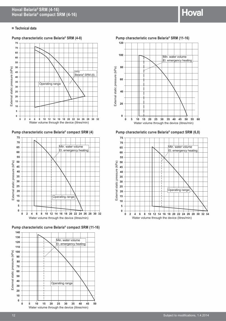
Pump characteristic curve Belaria® SRM (4-8)
0 161412108642 282624222018 32300
5
50
45
40
35
30
25
20
15
10
70
65
60
55
75
ausschliesslichBelaria SRM (8)
Betriebsbereich
Wassermenge durch das Gerät (Liter/min.)
����
����
���
�����
���
����
����
�
0 161412108642 282624222018 32300
5
50
45
40
35
30
25
20
15
10
70
65
60
55
75
Betriebsbereich
Wassermenge durch das Gerät (Liter/min.)
����
����
���
�����
���
����
����
�
Min. WassermengeElektr. Notheizung
340 161412108642 282624222018 32300
5
50
45
40
35
30
25
20
15
10
70
65
60
55
75
Betriebsbereich
Wassermenge durch das Gerät (Liter/min.)
����
����
���
�����
���
����
����
�
Min. WassermengeElektr. Notheizung
0 2010 4030 500
100
80
60
20
140
120
Wassermenge durch das Gerät (Liter/min.)
����
����
���
�����
���
����
����
�
5 352515 45
Min. WassermengeElektr. Notheizung
Betriebsbereich
90
40
70
50
30
10
130
110
Pump characteristic curve Belaria® SRM (11-16)
Pump characteristic curve Belaria® compact SRM (6,8)Pump characteristic curve Belaria® compact SRM (4)
Pump characteristic curve Belaria® compact SRM (11-16)
0 403530252015105 605550450
100
80
60
40
20
120
Min. WassermengeElektr. Notheizung
Wassermenge durch das Gerät (Liter/min.)
����
����
���
�����
���
����
����
�
Ext
erna
l sta
tic p
ress
ure
(kP
a)
Ext
erna
l sta
tic p
ress
ure
(kP
a)
Ext
erna
l sta
tic p
ress
ure
(kP
a)
Ext
erna
l sta
tic p
ress
ure
(kP
a)
Ext
erna
l sta
tic p
ress
ure
(kP
a)
*����������!���!�!���� ��7� ����5� �> *����������!���!�!���� ��7� ����5� �>
*����������!���!�!���� ��7� ����5� �>
*����������!���!�!���� ��7� ����5� �> *����������!���!�!���� ��7� ����5� �>
Operating range
Operating range
Operating range
Operating range
G ��&���������El. emergency heating
G ��&���������El. emergency heating
G ��&���������El. emergency heating
G ��&���������El. emergency heating
onlyBelaria® SRM (8)

� Technical data
Hoval Belaria® SRM (4-16)Hoval Belaria® compact SRM (4-16)
���������� ���� ����������� 13
Performance data - heating
Observe daily power interruptions!see Engineering
Hoval Belaria® SRM (4-8)Hoval Belaria® compact SRMMaximum heat output allowing for defrosting losses
Type (4) (6) (8)tVL tF QHP P COP QHP P COP QHP P COP°C °C kW kW kW kW kW kW
30
-20 2.3 1.5 1.48 3.2 1.9 1.67 3.8 2.4 1.57-15 3.3 1.5 2.16 4.1 1.9 2.22 5.0 2.4 2.08-10 4.2 1.5 2.73 5.0 1.8 2.72 6.0 2.3 2.55
-7 4.7 1.5 3.07 5.5 1.8 3.03 6.6 2.3 2.84-2 4.8 1.4 3.56 6.2 1.8 3.44 7.4 2.3 3.242 4.9 1.2 4.12 6.6 1.8 3.74 7.9 2.3 3.517 5.3 1.0 5.30 8.5 1.8 4.61 10.2 2.4 4.33
12 5.3 0.8 6.87 9.2 1.8 5.05 11.0 2.3 4.7615 5.5 0.8 7.20 10.0 1.8 5.60 12.0 2.3 5.2820 6.0 0.7 8.14 11.5 1.8 6.54 13.8 2.3 6.14
35
-20 2.2 1.7 1.29 3.1 2.1 1.47 3.7 2.7 1.38-15 3.1 1.7 1.80 4.0 2.1 1.94 4.8 2.6 1.82-10 4.0 1.7 2.36 4.8 2.0 2.37 5.8 2.6 2.23
-7 4.6 1.7 2.71 5.3 2.0 2.64 6.4 2.6 2.48-2 4.8 1.5 3.13 6.1 2.0 3.10 7.3 2.5 2.922 4.8 1.3 3.59 6.4 1.9 3.37 7.7 2.4 3.177 5.1 1.1 4.57 8.4 2.0 4.20 10.0 2.5 3.94
12 5.2 0.9 6.05 9.0 2.0 4.60 10.8 2.5 4.3215 5.3 0.8 6.53 9.8 1.9 5.12 11.7 2.4 4.8020 5.9 0.8 7.22 11.2 1.9 5.99 13.5 2.4 5.66
40
-20 2.2 1.9 1.15 2.9 2.4 1.24 3.5 3.0 1.16-15 3.2 1.9 1.67 3.8 2.3 1.64 4.5 2.9 1.54-10 4.0 1.9 2.12 4.7 2.3 2.10 5.7 2.9 1.98
-7 4.5 1.9 2.40 5.3 2.2 2.38 6.4 2.8 2.24-2 4.6 1.7 2.71 6.0 2.1 2.82 7.3 2.7 2.662 4.7 1.5 3.05 6.2 2.1 3.00 7.4 2.6 2.837 5.0 1.3 3.82 8.2 2.2 3.80 9.8 2.7 3.58
12 5.1 1.0 5.00 8.7 2.1 4.14 10.5 2.7 3.8815 5.2 1.0 5.27 9.5 2.1 4.55 11.4 2.7 4.2720 5.7 1.0 5.97 10.9 2.1 5.29 13.0 2.6 4.97
45
-20 2.2 2.1 1.01 2.8 2.5 1.10 3.3 3.2 1.03-15 2.9 2.2 1.36 3.6 2.5 1.47 4.3 3.1 1.39-10 3.8 2.1 1.81 4.6 2.4 1.91 5.5 3.1 1.80
-7 4.3 2.1 2.10 5.2 2.4 2.19 6.3 3.0 2.06-2 4.5 1.9 2.41 5.7 2.3 2.50 6.8 2.9 2.342 4.6 1.7 2.71 6.1 2.2 2.77 7.3 2.8 2.617 4.9 1.4 3.40 8.0 2.3 3.43 9.5 3.0 3.22
12 4.9 1.2 4.06 8.4 2.3 3.66 10.1 2.9 3.4415 5.1 1.2 4.22 9.1 2.3 4.03 10.9 2.9 3.7820 5.5 1.1 4.88 10.4 2.2 4.66 12.5 2.9 4.39
50
-20 2.1 2.3 0.89 2.7 2.6 1.05 3.3 3.2 1.02-15 2.9 2.3 1.22 3.5 2.5 1.40 4.2 3.2 1.32-10 3.6 2.3 1.57 4.5 2.5 1.80 5.3 3.2 1.69
-7 4.1 2.3 1.78 5.0 2.5 2.04 6.0 3.1 1.91-2 4.3 2.1 2.03 5.6 2.4 2.35 6.7 3.0 2.222 4.4 1.9 2.29 6.0 2.3 2.61 7.2 2.9 2.457 4.7 1.7 2.83 7.5 2.4 3.14 9.0 3.1 2.94
12 4.7 1.5 3.22 8.0 2.4 3.35 9.6 3.1 3.1515 4.8 1.4 3.47 8.7 2.4 3.65 10.4 3.0 3.4320 5.2 1.3 3.92 9.9 2.4 4.19 11.9 3.0 3.94
55
-15 2.6 2.4 1.08 3.3 2.6 1.28 3.9 3.3 1.20-10 3.4 2.4 1.39 4.1 2.5 1.61 4.9 3.2 1.52
-7 3.8 2.4 1.58 4.6 2.5 1.82 5.5 3.2 1.71-2 4.1 2.2 1.85 5.1 2.5 2.09 6.2 3.1 1.962 4.3 2.0 2.11 5.5 2.4 2.29 6.6 3.1 2.157 4.5 1.8 2.58 7.1 2.5 2.85 8.5 3.2 2.69
12 4.6 1.5 3.01 7.5 2.5 3.04 9.0 3.2 2.8715 4.6 1.5 3.13 8.1 2.5 3.30 9.8 3.2 3.1020 4.9 1.5 3.37 9.3 2.5 3.77 11.2 3.2 3.55
t[< { !��� ��,&�����������7��>tF { outdoor temperature (°C)QHP { !�����������������7\*>��������� ����������& �!��������?z��K��P { �&��������� �7\*>��!��������� � �����!� ���������������������� ����������& �!?z��K��COP { ����� ����j������������!��������� � ����������& �!��������?z��K��
� Technical data
14 ���������� ���� �����������
Hoval Belaria® SRM (4-16)Hoval Belaria® compact SRM (4-16)
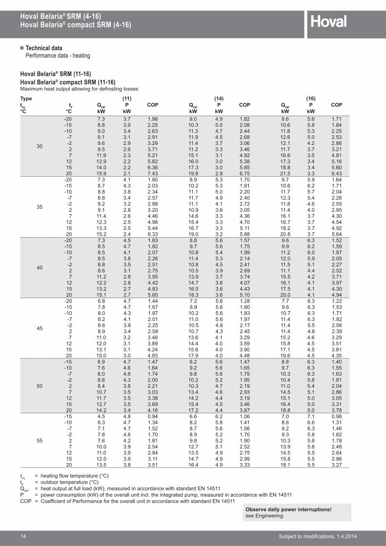
Performance data - heating
Observe daily power interruptions!see Engineering
Hoval Belaria® SRM (11-16)Hoval Belaria® compact SRM (11-16)Maximum heat output allowing for defrosting losses
Type (11) (14) (16)tVL tF QHP P COP QHP P COP QHP P COP°C °C kW kW kW kW kW kW
30
-20 7.3 3.7 1.98 9.0 4.9 1.82 9.6 5.6 1.71-15 8.8 3.9 2.25 10.3 5.0 2.08 10.6 5.8 1.84-10 9.0 3.4 2.63 11.3 4.7 2.44 11.8 5.3 2.25
-7 9.1 3.1 2.91 11.9 4.5 2.68 12.6 5.0 2.53-2 9.6 2.9 3.29 11.4 3.7 3.06 12.1 4.2 2.862 9.5 2.6 3.71 11.2 3.3 3.46 11.7 3.7 3.217 11.9 2.3 5.21 15.1 3.1 4.92 16.6 3.5 4.81
12 12.9 2.2 5.82 16.0 3.0 5.38 17.3 3.4 5.1615 14.0 2.2 6.36 17.3 3.0 5.85 18.8 3.4 5.6020 15.9 2.1 7.43 19.8 2.9 6.75 21.5 3.3 6.43
35
-20 7.3 4.1 1.80 8.9 5.3 1.70 9.7 5.9 1.64-15 8.7 4.3 2.03 10.2 5.3 1.91 10.6 6.2 1.71-10 8.8 3.8 2.34 11.1 5.0 2.20 11.7 5.7 2.04
-7 8.8 3.4 2.57 11.7 4.9 2.40 12.3 5.4 2.28-2 9.2 3.2 2.88 11.1 4.1 2.72 11.8 4.6 2.552 9.1 2.8 3.20 10.9 3.6 3.05 11.4 4.0 2.857 11.4 2.6 4.46 14.6 3.3 4.36 16.1 3.7 4.30
12 12.3 2.5 4.98 15.4 3.3 4.70 16.7 3.7 4.5415 13.3 2.5 5.44 16.7 3.3 5.11 18.2 3.7 4.9220 15.2 2.4 6.33 19.0 3.2 5.88 20.8 3.7 5.64
40
-20 7.3 4.5 1.63 8.8 5.6 1.57 9.6 6.3 1.52-15 8.5 4.7 1.82 9.7 5.6 1.75 9.9 6.2 1.59-10 8.5 4.1 2.07 10.8 5.4 1.99 11.2 6.0 1.87
-7 8.5 3.8 2.26 11.4 5.3 2.14 12.0 5.9 2.05-2 8.8 3.5 2.51 10.8 4.5 2.41 11.5 5.1 2.272 8.6 3.1 2.75 10.5 3.9 2.69 11.1 4.4 2.527 11.2 2.8 3.95 13.9 3.7 3.74 15.5 4.2 3.71
12 12.2 2.8 4.42 14.7 3.6 4.07 16.1 4.1 3.9715 13.2 2.7 4.83 16.0 3.6 4.43 17.5 4.1 4.3020 15.1 2.7 5.60 18.3 3.6 5.10 20.0 4.1 4.94
45
-20 6.8 4.7 1.44 7.2 5.6 1.28 7.7 6.3 1.22-15 7.8 4.7 1.67 8.9 5.6 1.60 9.6 6.3 1.53-10 8.0 4.3 1.87 10.2 5.6 1.83 10.7 6.3 1.71
-7 8.2 4.1 2.01 11.0 5.6 1.97 11.4 6.3 1.82-2 8.6 3.8 2.25 10.5 4.8 2.17 11.4 5.5 2.062 8.9 3.4 2.58 10.7 4.3 2.45 11.4 4.8 2.397 11.0 3.2 3.48 13.6 4.1 3.29 15.2 4.6 3.29
12 12.0 3.1 3.89 14.4 4.0 3.59 15.8 4.5 3.5115 13.1 3.1 4.24 15.6 4.0 3.90 17.1 4.5 3.8120 15.0 3.0 4.93 17.9 4.0 4.48 19.6 4.5 4.35
50
-15 6.9 4.7 1.47 8.2 5.6 1.47 8.8 6.3 1.40-10 7.6 4.6 1.64 9.2 5.6 1.65 9.7 6.3 1.55
-7 8.0 4.6 1.74 9.8 5.6 1.75 10.3 6.3 1.63-2 8.6 4.3 2.00 10.2 5.2 1.95 10.4 5.8 1.812 8.4 3.8 2.21 10.3 4.7 2.19 11.0 5.4 2.047 10.7 3.5 3.03 13.4 4.6 2.93 14.5 5.1 2.86
12 11.7 3.5 3.38 14.2 4.4 3.19 15.1 5.0 3.0515 12.7 3.5 3.69 15.4 4.5 3.46 16.4 5.0 3.3120 14.2 3.4 4.16 17.2 4.4 3.87 18.8 5.0 3.78
55
-15 4.5 4.8 0.94 6.6 6.2 1.06 7.0 7.1 0.98-10 6.3 4.7 1.34 8.2 5.8 1.41 8.6 6.6 1.31
-7 7.1 4.7 1.52 8.7 5.6 1.56 9.2 6.3 1.46-2 7.8 4.6 1.70 8.9 5.2 1.70 9.3 5.8 1.622 7.6 4.2 1.81 9.8 5.2 1.90 10.3 5.8 1.787 10.0 3.9 2.54 12.7 5.1 2.52 13.9 5.6 2.48
12 11.0 3.9 2.84 13.5 4.9 2.75 14.5 5.5 2.6415 12.0 3.9 3.11 14.7 4.9 2.99 15.8 5.5 2.8620 13.5 3.8 3.51 16.4 4.9 3.33 18.1 5.5 3.27
t[< { !��� ��,&�����������7��>tF { outdoor temperature (°C)QHP { !�����������������7\*>��������� ����������& �!��������?z��K��P { �&��������� �7\*>��!��������� � �����!� ���������������������� ����������& �!?z��K��COP { ����� ����j������������!��������� � ����������& �!��������?z��K��
� Technical data
Hoval Belaria® SRM (4-16)Hoval Belaria® compact SRM (4-16)
���������� ���� ����������� 15
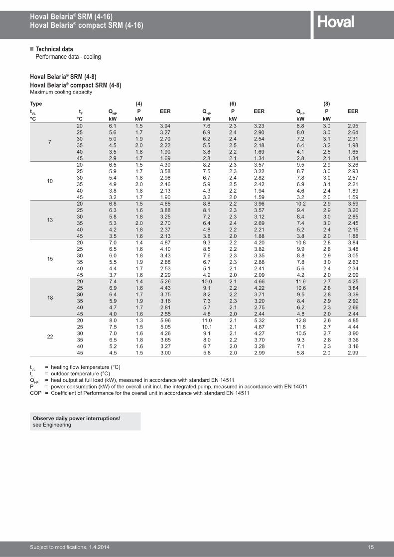
Performance data - cooling
Observe daily power interruptions!see Engineering
Hoval Belaria® SRM (4-8)Hoval Belaria® compact SRM (4-8)Maximum cooling capacity
Type (4) (6) (8)tVL tF QHP P EER QHP P EER QHP P EER°C °C kW kW kW kW kW kW
7
20 6.1 1.5 3.94 7.6 2.3 3.23 8.8 3.0 2.9525 5.6 1.7 3.27 6.9 2.4 2.90 8.0 3.0 2.6430 5.0 1.9 2.70 6.2 2.4 2.54 7.2 3.1 2.3135 4.5 2.0 2.22 5.5 2.5 2.18 6.4 3.2 1.9840 3.5 1.8 1.90 3.8 2.2 1.69 4.1 2.5 1.6545 2.9 1.7 1.69 2.8 2.1 1.34 2.8 2.1 1.34
10
20 6.5 1.5 4.30 8.2 2.3 3.57 9.5 2.9 3.2625 5.9 1.7 3.58 7.5 2.3 3.22 8.7 3.0 2.9330 5.4 1.8 2.96 6.7 2.4 2.82 7.8 3.0 2.5735 4.9 2.0 2.46 5.9 2.5 2.42 6.9 3.1 2.2140 3.8 1.8 2.13 4.3 2.2 1.94 4.6 2.4 1.8945 3.2 1.7 1.90 3.2 2.0 1.59 3.2 2.0 1.59
13
20 6.8 1.5 4.65 8.8 2.2 3.96 10.2 2.9 3.5925 6.3 1.6 3.88 8.1 2.3 3.57 9.4 2.9 3.2630 5.8 1.8 3.25 7.2 2.3 3.12 8.4 3.0 2.8535 5.3 2.0 2.70 6.4 2.4 2.69 7.4 3.0 2.4540 4.2 1.8 2.37 4.8 2.2 2.21 5.2 2.4 2.1545 3.5 1.6 2.13 3.8 2.0 1.88 3.8 2.0 1.88
15
20 7.0 1.4 4.87 9.3 2.2 4.20 10.8 2.8 3.8425 6.5 1.6 4.10 8.5 2.2 3.82 9.9 2.8 3.4830 6.0 1.8 3.43 7.6 2.3 3.35 8.8 2.9 3.0535 5.5 1.9 2.88 6.7 2.3 2.88 7.8 3.0 2.6340 4.4 1.7 2.53 5.1 2.1 2.41 5.6 2.4 2.3445 3.7 1.6 2.29 4.2 2.0 2.09 4.2 2.0 2.09
18
20 7.4 1.4 5.26 10.0 2.1 4.66 11.6 2.7 4.2525 6.9 1.6 4.43 9.1 2.2 4.22 10.6 2.8 3.8430 6.4 1.7 3.75 8.2 2.2 3.71 9.5 2.8 3.3935 5.9 1.9 3.16 7.3 2.3 3.20 8.4 2.9 2.9240 4.7 1.7 2.81 5.7 2.1 2.75 6.2 2.3 2.6645 4.0 1.6 2.55 4.8 2.0 2.44 4.8 2.0 2.44
22
20 8.0 1.3 5.96 11.0 2.1 5.32 12.8 2.6 4.8525 7.5 1.5 5.05 10.1 2.1 4.87 11.8 2.7 4.4430 7.0 1.6 4.26 9.1 2.1 4.27 10.5 2.7 3.9035 6.5 1.8 3.65 8.0 2.2 3.70 9.3 2.8 3.3640 5.2 1.6 3.27 6.7 2.0 3.28 7.1 2.3 3.1645 4.5 1.5 3.00 5.8 2.0 2.99 5.8 2.0 2.99
t[< { !��� ��,&�����������7��>tF { outdoor temperature (°C)QHP { !�����������������7\*>��������� ����������& �!��������?z��K��P { �&��������� �7\*>��!��������� � �����!� ���������������������� ����������& �!?z��K��COP { ����� ����j������������!��������� � ����������& �!��������?z��K��

� Technical data
16 ���������� ���� �����������
Hoval Belaria® SRM (4-16)Hoval Belaria® compact SRM (4-16)
Performance data - cooling
Observe daily power interruptions!see Engineering
Hoval Belaria® SRM (11-16)Maximum cooling capacity
Type (11) (14) (16)tVL tF QHP P EER QHP P EER QHP P EER°C °C kW kW kW kW kW kW
7
20 13.0 3.2 4.10 13.9 3.8 3.67 14.6 4.3 3.3825 12.9 3.5 3.70 13.8 4.1 3.34 14.5 4.7 3.0830 12.4 3.8 3.25 13.3 4.5 2.94 14.0 5.2 2.7135 11.7 4.2 2.78 12.6 5.0 2.51 13.1 5.7 2.3240 10.7 4.7 2.31 11.1 4.8 2.32 11.6 5.4 2.1545 9.5 5.1 1.86 9.9 5.3 1.87 9.9 5.3 1.87
10
20 13.8 3.2 4.31 14.9 3.9 3.88 15.7 4.4 3.5725 13.7 3.5 3.88 14.9 4.2 3.53 15.6 4.8 3.2430 13.2 3.9 3.40 14.3 4.6 3.10 15.0 5.3 2.8635 12.4 4.3 2.91 13.5 5.1 2.65 14.1 5.8 2.4540 11.4 4.7 2.42 12.0 4.9 2.46 12.5 5.5 2.2745 10.1 5.2 1.95 10.6 5.4 1.98 10.6 5.4 1.98
13
20 15.2 3.2 4.68 16.5 3.9 4.20 17.2 4.5 3.8425 15.0 3.6 4.22 16.3 4.3 3.80 17.1 4.9 3.4930 14.5 3.9 3.69 15.7 4.7 3.35 16.5 5.4 3.0735 13.7 4.3 3.15 14.8 5.2 2.86 15.5 5.9 2.6440 12.5 4.8 2.62 13.2 5.0 2.65 13.7 5.6 2.4545 11.0 5.5 2.02 11.0 5.5 2.02 11.0 5.5 2.02
15
20 16.1 3.3 4.94 17.5 4.0 4.41 18.3 4.5 4.0325 16.0 3.6 4.44 17.3 4.3 3.99 18.1 5.0 3.6530 15.4 4.0 3.89 16.7 4.8 3.51 17.5 5.4 3.2235 14.5 4.4 3.32 15.7 5.2 3.00 16.4 6.0 2.7640 13.3 4.8 2.76 14.0 5.0 2.78 14.5 5.7 2.5745 11.4 5.3 2.14 11.4 5.3 2.14 11.4 5.3 2.14
18
20 17.8 3.3 5.40 19.0 4.0 4.71 19.9 4.6 4.2925 17.2 3.6 4.73 18.4 4.4 4.16 19.2 5.1 3.7930 16.3 4.0 4.04 17.4 4.9 3.58 18.2 5.5 3.2835 15.1 4.4 3.39 16.1 5.3 3.01 16.8 6.1 2.7740 13.6 4.9 2.78 14.1 5.1 2.75 14.6 5.8 2.5345 11.5 4.9 2.35 11.5 4.9 2.35 11.5 4.9 2.35
22
20 19.8 3.3 5.93 21.2 4.1 5.14 22.2 4.8 4.6525 19.2 3.7 5.20 20.5 4.5 4.52 21.4 5.2 4.1130 18.2 4.1 4.44 19.4 5.0 3.90 20.3 5.7 3.5535 16.8 4.5 3.72 17.9 5.5 3.28 18.7 6.2 3.0040 15.2 5.0 3.05 15.7 5.2 3.01 16.3 5.9 2.7645 12.1 4.4 2.76 12.1 4.4 2.76 12.1 4.4 2.76
t[< { !��� ��,&�����������7��>tF { outdoor temperature (°C)QHP { !�����������������7\*>��������� ����������& �!��������?z��K��P { �&��������� �7\*>��!��������� � �����!� ���������������������� ����������& �!?z��K��COP { ����� ����j������������!��������� � ����������& �!��������?z��K��

� Dimensions
Hoval Belaria® SRM (4-16)Hoval Belaria® compact SRM (4-16)
���������� ���� ����������� 17
Hoval Belaria® SRM (4-16) Indoor unit(dimensions in mm)
Space requirement for maintenance work and ventilationInside unit(Dimensions in mm)
1 "��� ��,&:�XT2 "��� ��������:�XT3 Liquid line
Belaria®�:G7�#V>XT7J�ZK��>Belaria®�:G7��#�J>YT7N�K��>
4 "����� ��QT7�K�N��>5 Mounting holes6 v�� ������$�����:��T
55344 260110
381
15 450380
131
1548
480
881
890
868
788
867
38 41
74
22
90
R210
71
60
5
1
2
34
5
6
100 100
200
500
1150

� Dimensions
18 ���������� ���� �����������
Hoval Belaria® SRM (4-16)Hoval Belaria® compact SRM (4-16)
R21017
32
1744
1762
761
728
300
600
193 52
301150141 223
4507560
111
45
115
199
7
8
3 6 2 1 5 4
Hoval Belaria® compact SRM (4-16) inside unit(Dimensions in mm)
1 "����� ��QT7�K�N��>2 Liquid line
Belaria®�:G7�#V>XT7J�ZK��>Belaria®�:G7��#�J>YT7N�K��>
3 "��� ��,&:�XT4 "��� ��������:�XT5 ���&���������� �:�T6 "�&���������� �:�T7 v�� ������$�����8 Condensate drain
(cooling)
Space requirement for maintenance work and ventilationInside unit(Dimensions in mm)
min. 300
min. 500
min. 100 min. 100

� Dimensions
Hoval Belaria® SRM (4-16)Hoval Belaria® compact SRM (4-16)
���������� ���� ����������� 19
Hoval Belaria® SRM (4-8), Hoval Belaria® compact SRM (4-8) outside unit(Dimensions in mm)
Space requirement for Hoval Belaria® SRM, Belaria® compact SRM outside unit without roof(Dimensions in mm)
1 Connections for refrigerant lines2 Outdoor temperature sensor3 Hole for fastening bolts M8 or M10
min. 100
min
.150
≥ 300
min
. 150
≥ 300
Space requirement for Hoval Belaria® SRM, Belaria® compact SRM outside unit with roof(Dimensions in mm)
min. 200 ≥ 300
min
. 200
min
. 200
≥ 300
Dimensions of protective roof for outside unit
Belaria® SRMtype
B T
(4-8) 1102 577
There must be adequate space for the outlet (approx. 1 m) to route off the cooled air.
The outside unit must be protected against !���$��&�����B���������$���� ������7����������;������ ��>�
The outside unit must be placed on feet at ������K���! �!��!����������������bed under it to discharge the condensation. (see base plans)
1
22
�
�
735
�3
��3

� Dimensions
20 ���������� ���� �����������
Hoval Belaria® SRM (4-16)Hoval Belaria® compact SRM (4-16)
Space requirement
The outside unit must be attached to the base using 4 x M8 screws and concrete dowels! See Accessories
Base plans for Belaria® SRM (4-8), Belaria® compact SRM (4-8)(Dimensions in mm)
Installation in garden, meadow
"����##���$�$�%�����&����'�*����#�+�:�$������:��'��#��
735
580
330
ca.450
365150
ca. 5
00ca
. 250
je n
ach
mög
liche
r Sch
neeh
öhe
Sickerbettgrosse SteineØ ca. 150 mm
Masse in mm
Beton
Beton
100
Dimensions in mm
Concrete
Dep
endi
ng o
n th
e sn
ow d
epth
Gravel bedLarge stones
;�''�$�< 150 mm
�''�
$�<�
��
=''�$�<���
735
580
330
ca.450
365150
ca. 2
50
je n
ach
mög
liche
r Sch
neeh
öhe
Kondensatwasser muss abfliessen
können
Masse in mm
Beton
100
Condensate must be able
to run off
Dep
endi
ng o
n th
e sn
ow d
epth
Concrete
Dimensions in mm
=''�$�<���
�''�
$�<
250
� Dimensions
Hoval Belaria® SRM (4-16)Hoval Belaria® compact SRM (4-16)
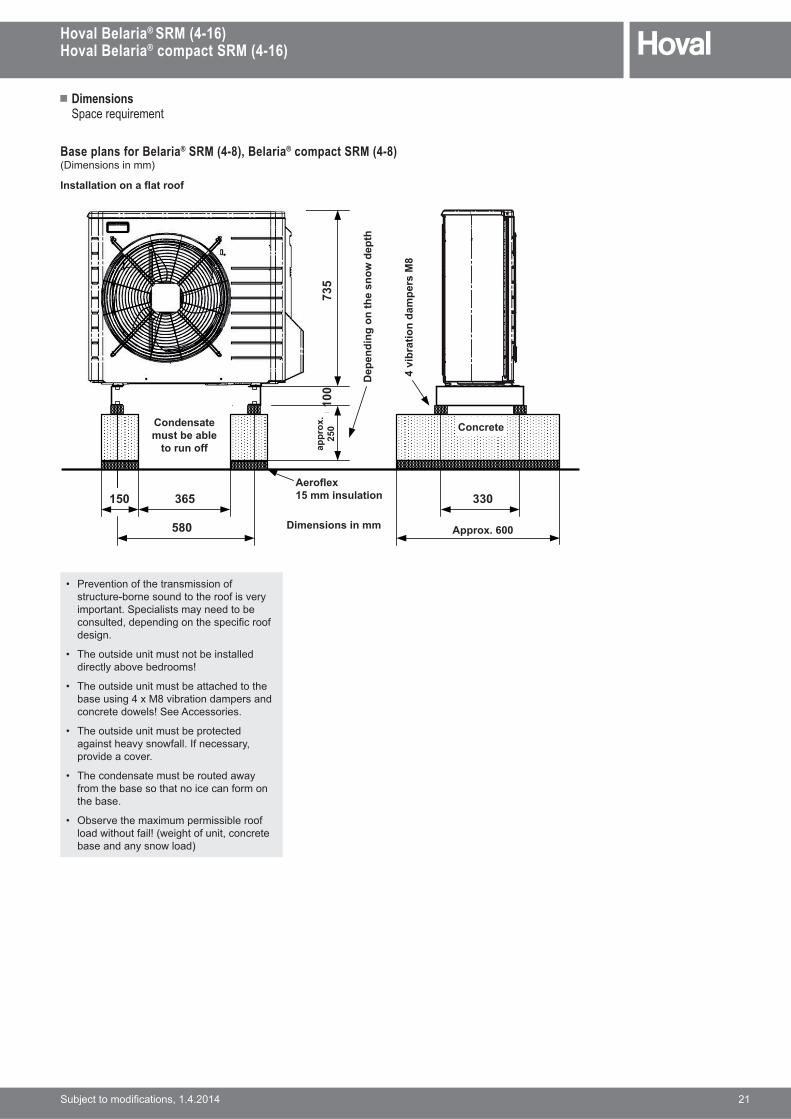
���������� ���� ����������� 21
Space requirement
• j������ ���!������� �� �����������#����������!��� ����$important. Specialists may need to be ��������������� ����!����� � ���design.
• The outside unit must not be installed � �����$�����������
• The outside unit must be attached to the ������ ���@GV� ���� �����������concrete dowels! See Accessories.
• The outside unit must be protected ��� ���!���$��&�����B���������$���� ��������
• The condensate must be routed away from the base so that no ice can form on the base.
• ��������!���@ ������� �� ��������& �!���� ��7&� �!���� ���������base and any snow load)
Base plans for Belaria® SRM (4-8), Belaria® compact SRM (4-8)(Dimensions in mm)
"����##���$�$������$$&
735
580
330
ca.600
365150
ca. 2
50
je n
ach
mög
liche
r Sch
neeh
öhe
Kondensatwasser muss abfliessen
können
Masse in mm
Beton
100
Isolation =��$&#�� ���
4 Sc
hwin
gung
sele
men
te M
8
=''�$�<>��
=��$���15 mm insulation
4 v
ibra
tion
dam
pers
M8
Condensate must be able
to run off
Dep
endi
ng o
n th
e sn
ow d
epth
Dimensions in mm
�''�
$�<
250 Concrete
� Dimensions
22 ���������� ���� �����������
Hoval Belaria® SRM (4-16)Hoval Belaria® compact SRM (4-16)
Space requirement
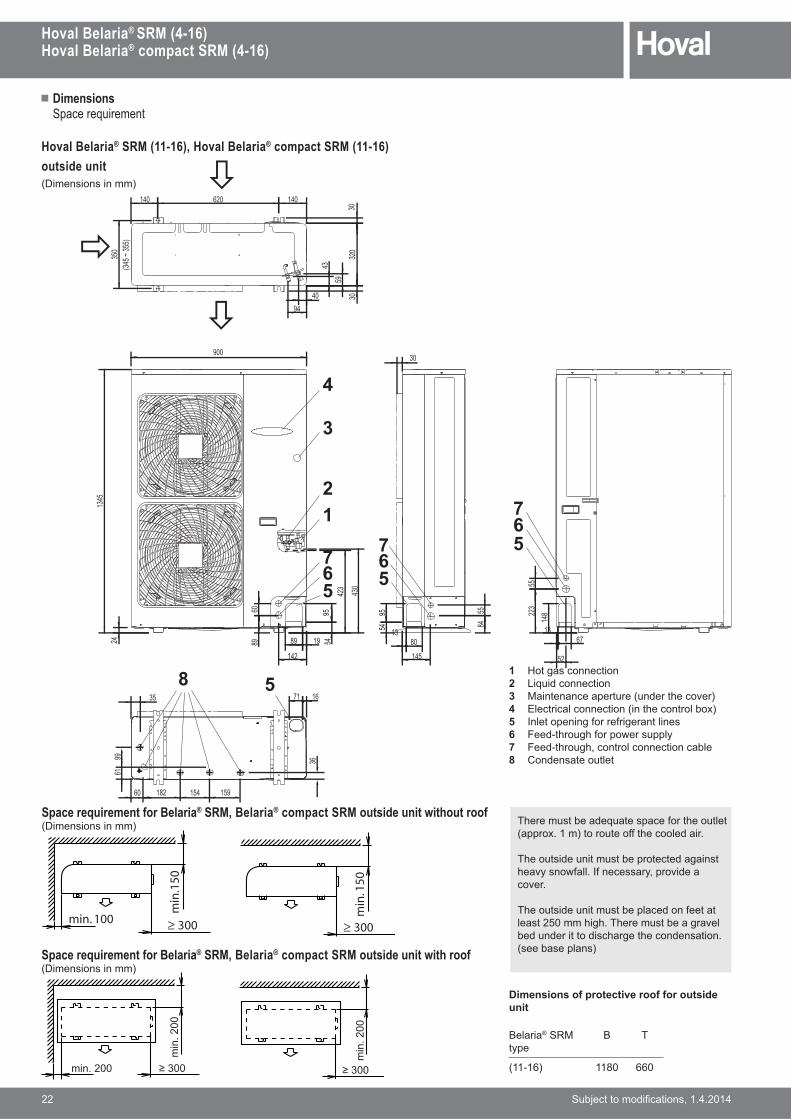
Hoval Belaria® SRM (11-16), Hoval Belaria® compact SRM (11-16) outside unit(Dimensions in mm)
1 Hot gas connection2 Liquid connection3 G� ����������������7������!�����>4 Electrical connection (in the control box)5 Inlet opening for refrigerant lines6 Feed-through for power supply7 +���#�!���!������������ ������8 Condensate outlet
There must be adequate space for the outlet (approx. 1 m) to route off the cooled air.
The outside unit must be protected against !���$��&�����B���������$���� ��������
The outside unit must be placed on feet at ������K���! �!��!����������������bed under it to discharge the condensation. (see base plans)
Space requirement for Belaria® SRM, Belaria® compact SRM outside unit without roof(Dimensions in mm)
min. 100
min
.150
≥ 300
min
. 150
≥ 300
Space requirement for Belaria® SRM, Belaria® compact SRM outside unit with roof(Dimensions in mm)
min. 200 ≥ 300
min
. 200
min
. 200
≥ 300
Dimensions of protective roof for outside unit
Belaria® SRMtype
B T
(11-16) 1180 660
7
3
2
��
�
4
1
65
765
765
5943
9440
148
1319
1345
24
423
430
54
142
19
182 154 15960
61
320
3030
620 140140
36
1671
99
558454
95
8960
52
35
6780
145
30900
95
89
223
55
350
(345 ~
355)
8 5
� Dimensions
Hoval Belaria® SRM (4-16)Hoval Belaria® compact SRM (4-16)
���������� ���� ����������� 23
Space requirement
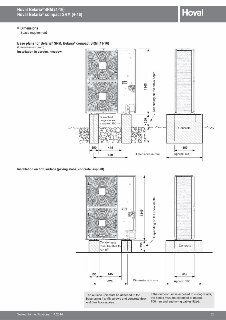
Base plans for Belaria® SRM, Belaria® compact SRM (11-16)(Dimensions in mm)Installation in garden, meadow
"����##���$�$�%�����&����'�*����#�+�:�$������:��'��#��
The outside unit must be attached to the base using 4 x M8 screws and concrete dow-els! See Accessories.
B��!������� � ��@����������& ����the bases must be extended to approx. =����������!� ��������������
1345
620
350
ca.500
445150ca
. 500
> 25
0
je n
ach
mög
liche
r Sch
neeh
öhe
Sickerbettgrosse SteineØ ca. 150 mm
Masse in mm
Beton
1345
620
350
ca.500
445150
> 25
0
je n
ach
mög
liche
r Sch
neeh
öhe
Kondenswassermuss abfliessen
können
Masse in mm
Beton
Dimensions in mm
Dimensions in mm
Concrete
ConcreteCondensate must be able to run off
Dep
endi
ng o
n th
e sn
ow d
epth
Dep
endi
ng o
n th
e sn
ow d
epth
|��������Large stonesø approx. 150 mm
appr
ox. 5
00
Approx. 500
Approx. 500
� Dimensions
24 ���������� ���� �����������
Hoval Belaria® SRM (4-16)Hoval Belaria® compact SRM (4-16)
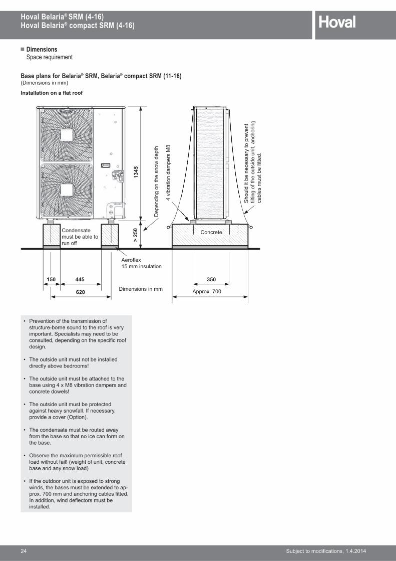
Space requirement
• j������ ���!������� �� �����������#����������!��� ����$important. Specialists may need to be ��������������� ����!����� � ���design.
• The outside unit must not be installed � �����$�����������
• The outside unit must be attached to the ������ ���@GV� ���� �����������concrete dowels!
• The outside unit must be protected ��� ���!���$��&�����B���������$���� �������7��� �>�
• The condensate must be routed away from the base so that no ice can form on the base.
• ��������!���@ ������� �� ��������& �!���� ��7&� �!���� ���������base and any snow load)
• If the outdoor unit is exposed to strong & �����!�������������@���������-prox. 700 mm and anchoring cables fitted. B���� � ��& ����,�����������installed.
Base plans for Belaria® SRM, Belaria® compact SRM (11-16)(Dimensions in mm)
"����##���$�$������$$&
1345
620
350
ca.700
445150
> 25
0
je n
ach
mög
liche
r Sch
neeh
öhe
Kondenswassermuss abfliessen
können
Masse in mm
Sollt
e es
nöt
ig s
ein,
ein
kip
pen
der A
usse
nein
heit
zu v
erhi
nder
n,si
nd H
alte
seile
anz
ubrin
gen
4 Sc
hwin
gung
sele
men
te M
8
Aeroflex 15 mm Isolation
Beton
Dimensions in mm
ConcreteCondensate must be able to run off
Approx. 700
Dep
endi
ng o
n th
e sn
ow d
epth
��
����
�
���
����
GV
�!
���
���
���
����
�$�
���
����
� �
� ��
��!
��
�� �
���
���
��!
� ��
����
���
����
���
����
;��,�@15 mm insulation
� Engineering
Hoval Belaria® SRM (4-16)Hoval Belaria® compact SRM (4-16)
���������� ���� ����������� 25
Requirements and directives�!������������ ����������� ���� ���� ����in the Chapter Engineering apply.
Set-upGeneral comments• The distance between the inside and outside
unit must be as short as possible. Only short and simple routing of refrigerant lines guar-��������������� �������
• The required minimum length for the lines ���&����!���� ����� �� ���� � �Z��and the lines must not be shorter than this. The maximum permissible length of the lines between the outside and inside unit is 30 m and must not be exceeded. The maximum permissible height difference between outside and inside unit is 20 m. The maximum permissible length of the lines between calorifier and inside unit is 10 m. It is essential to clarify details of the installa-� ����� ����� ����� ��& �!"����
Inside unit� �!� �� ���� ���!�"���'���� �® SRM
air/water heat pump system can be mounted on the wall in the boiler room using a sound insulation dowel with collar.
• The installation location must be selected in ���������& �!�!���� ����� ����������� ���� ����
• The installation must be free from dust or other foreign matter which could lead to contamination.
• *!������ �����!� �������� ����� ��!�������� ��� ��#���� � ��������the building and equipped with a sound-absorbing door.
• The heating supply and return should be connected flexibly in structures which are ���� � ��& �!�������� ���� �� ��7���accessories).
• Access for the purpose of operation and maintenance must be ensured.
� :��& �!! �!� �!�� � �$����@�����������$����������� ����� �������� �locations (dewpoint <10 °C).
The installation of a magnetic sludge sepa-rator is mandatory.
Outside unitThe outside unit is installed outdoors. The installation location must be selected carefully. It is essential that the following ancillary condi-tions are met:
• The subsoil in the installation location must be sufficiently stable to bear the weight of �!��� ���� ��� ���� � ������ ��
� �!����� ��!���!������������������ �������� ���� ���������������� ���the unit (see dimensions “Space require-ments”).
� ;������������&�����!������� �������������������!��������������be installed under it. Do not place anything &! �! ����� � ���� �����������!��� ��
� v����!������� �� ����!� �������� ����� ��!�������������!� � ��#��or bedroom windows and be far enough away from neighbouring buildings (perform calculation).
• The selected location should be such that the air blown out by the unit does not bother occupants of the building or neighbours.
• No parts and plants at risk of frost damage are allowed to be on the blow-out side.
• Installation on a wall console is not suitable in the case of lightweight walls. Lightweight walls can increase sound emissions and transmit structure-borne sound.
• B� ������� ����� �� ��!��#� ��� � ���The space necessary for intake and outlet ������&�$������ ���7����������-quirements).
• The installation location must be selected so that the air intake and outlet are not blocked �����������$��&������������
• Installation in wall niches is not recommend-��7� ��!��� ��� ��������!>�
� �!��� ��������� ���������������!�other.
� B�������!��� ����!��� ������������!������!& � ���������Z��&�$����[���������� ���! ��!���������� �������-ence with picture and sound.
• The intake air must be completely free from ������� ���������������!������ ������!����!�� ������
• Install the outside unit so that the intake side faces the wall and is not directly exposed to the wind.
� z���� �������!���� ���� � �������where the intake side is directly exposed to the wind.
• Fit a deflector plate on the air outlet side of �!���� ���� ����������@�������!�wind.
� B������& �!!���$��&������������� �-stallation location where snow cannot impair �!������ ���!��� �7����>�
Line length between outside unit and inside unit"���'���� �® SRM type (4-8) (11-16)• Minimum line length 3 m 3 m• Maximum permissible
length30 m 30 m
• Maximum permissible height difference
20 m 20 m
8 3
645
7
10
2
9
111
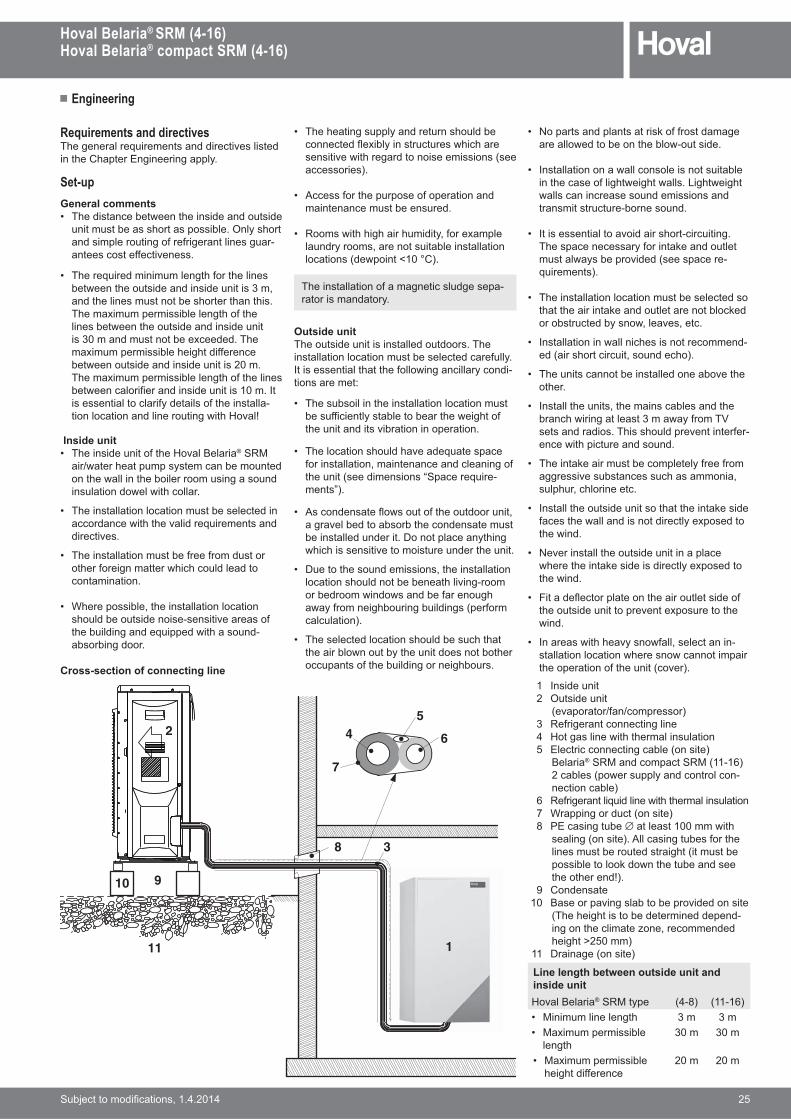
Cross-section of connecting line 1 Inside unit 2 Outside unit
7��������5���5��������> 3 Refrigerant connecting line 4 Hot gas line with thermal insulation 5 Electric connecting cable (on site)
Belaria® SRM and compact SRM (11-16) 2 cables (power supply and control con-nection cable)
6 Refrigerant liquid line with thermal insulation 7 Wrapping or duct (on site) 8 PE casing tube ∅ at least 100 mm with
sealing (on site). All casing tubes for the lines must be routed straight (it must be possible to look down the tube and see the other end!).
9 Condensate�� '������� ������������ ����� ��
(The height is to be determined depend- ����!��� ������������������height >250 mm)
11 Drainage (on site)
� Engineering
26 ���������� ���� �����������
Hoval Belaria® SRM (4-16)Hoval Belaria® compact SRM (4-16)
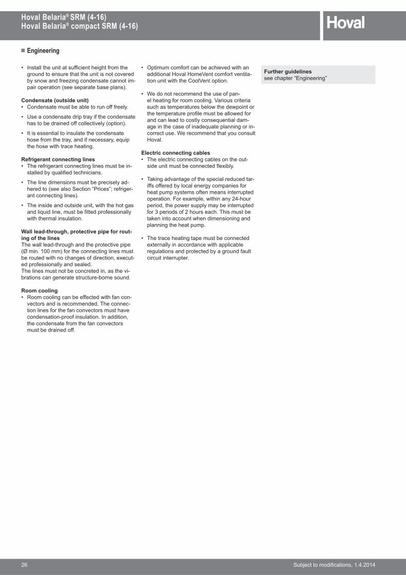
• Install the unit at sufficient height from the �������������!���!��� � ���������by snow and freezing condensate cannot im-pair operation (see separate base plans).
Condensate (outside unit)• Condensate must be able to run off freely.
• Use a condensate drip tray if the condensate !�������� ����������� ���$7�� �>�
• It is essential to insulate the condensate !������!����$���� ���������$���� �the hose with trace heating.
Refrigerant connecting lines• The refrigerant connecting lines must be in-
stalled by qualified technicians.
• The line dimensions must be precisely ad-hered to (see also Section “Prices”; refriger-ant connecting lines).
� �!� �� �������� ���� ��& �!�!�!�������� �� �� ���������� ���������� ����$with thermal insulation.
Wall lead-through, protective pipe for rout-ing of the lines�!�&�������#�!���!����!������� ��� ��(Ø min. 100 mm) for the connecting lines must �������& �!��!������� ���� ���@����-ed professionally and sealed.�!�� ������������������� �����!�� -brations can generate structure-borne sound.
Room cooling• Room cooling can be effected with fan con-
��������� �������������!������-� �� ������!����������������!����������� �#��� ������ ��B���� � ���!��������������!������������must be drained off.
� ��� ���������������! ����& �!����� � ���"���"��[������������ ��-� ��� �& �!�!���[����� ��
• We do not recommend the use of pan-��!��� �������� ���[�� ���� ��� �such as temperatures below the dewpoint or the temperature profile must be allowed for and can lead to costly consequential dam-age in the case of inadequate planning or in-correct use. We recommend that you consult "����
Electric connecting cables• The electric connecting cables on the out-
side unit must be connected flexibly.
� ��\ �������������!����� ������������-iffs offered by local energy companies for heat pump systems often means interrupted ����� ��+��@������& �! ���$��#!����� ���!��&�������$��$�� ����������for 3 periods of 2 hours each. This must be taken into account when dimensioning and planning the heat pump.
• The trace heating tape must be connected externally in accordance with applicable regulations and protected by a ground fault circuit interrupter.
Further guidelinessee chapter “Engineering”
� Examples
Hoval Belaria® SRM (4-16)Hoval Belaria® compact SRM (4-16)
���������� ���� ����������� 27
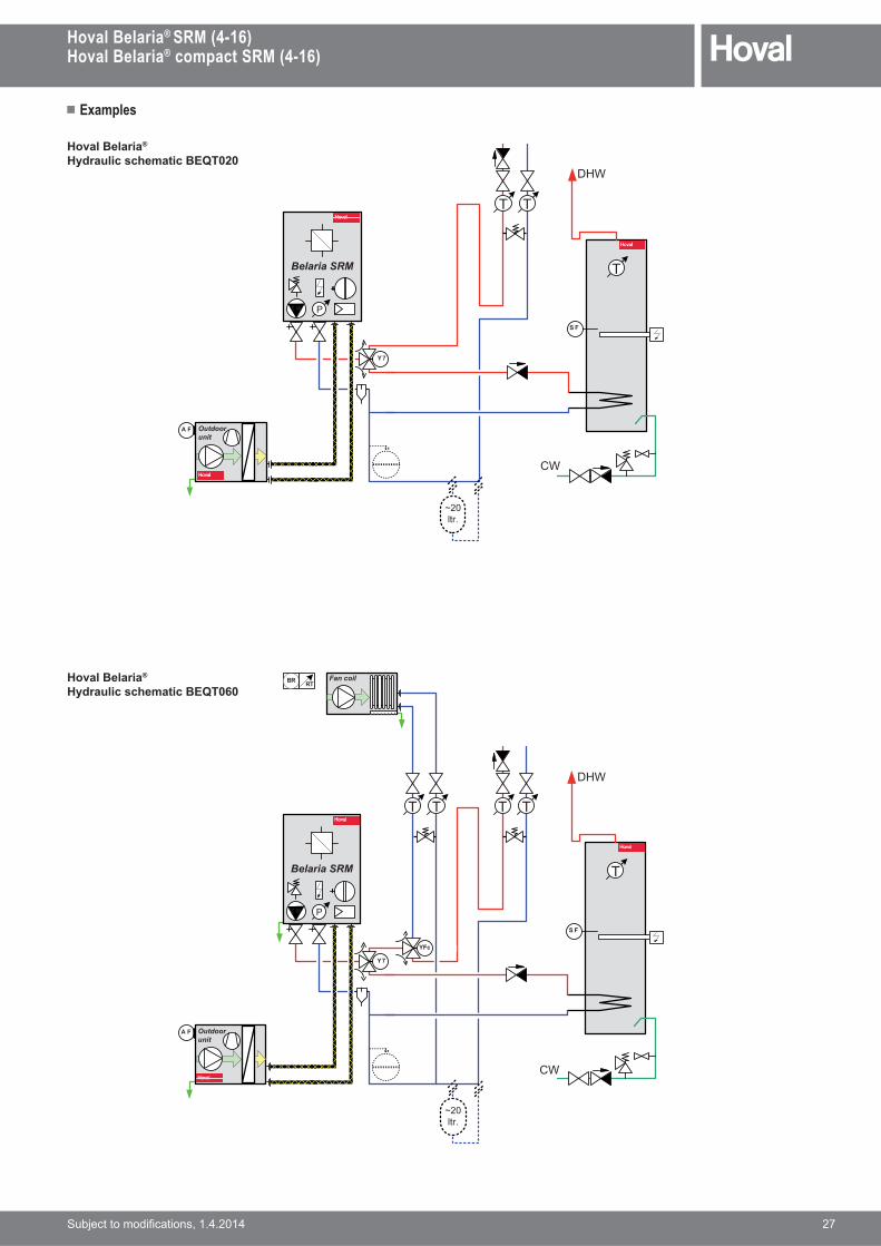
Hoval Belaria®
Hydraulic schematic BEQT020
TT
Y 7
Fan coilBR RT
TT
YFc
A F Outdoor unit
Dies ist ein unerlaubter Weg!Gehen Sie einen Schritt zurück oder löschen Sie dieses Shape!Sie haben die Möglichkeit ein neues Shape zu nehmen!!! hovhovalhovalhovalhovalhovalhovalhov
Belaria SRM
M 2
P
Dies ist ein unerlaubter Weg!Gehen Sie einen Schritt zurück oder löschen Sie dieses Shape!Sie haben die Möglichkeit ein neues Shape zu nehmen!!! hovhovalhovalhovalhovalhovalhovalhovalhovalhovalhovalhovalhovalhovalhovalhovalhovalhovalhovalhovalhovalhovalhovalhovalhovalhovalhovalhovalhovalhovalhovalh
WW
T
KW
S F
~20ltr.
TT
Y 7
Dies ist ein unerlaubter Weg!Gehen Sie einen Schritt zurück oder löschen Sie dieses Shape!Sie haben die Möglichkeit ein neues Shape zu nehmen!!! hovhovalhovalhovalhovalhovalhovalhov
Belaria SRM
M 2
P
A F Outdoor unit
Dies ist ein unerlaubter Weg!Gehen Sie einen Schritt zurück oder löschen Sie dieses Shape!Sie haben die Möglichkeit ein neues Shape zu nehmen!!! hovhovalhovalhovalhovalhovalhovalhovalhovalhovalhovalhovalhovalhovalhovalhovalhovalhovalhovalhovalhovalhovalhovalhovalhovalhovalhovalhovalhovalhovalhovalh
WW
T
KW
S F
~20ltr.
Hoval Belaria®
Hydraulic schematic BEQT060
DHW
DHW
CW
CW

28
Related Documents