WSAN-EE 82-102-122-142-162- 182-202-222-242-282 AIR TO WATER HEAT PUMP FOR OUTDOOR INSTALLATION Installation and Use Manual M62P40B5-02 21/09/2007 Библиотека СОК

Welcome message from author
This document is posted to help you gain knowledge. Please leave a comment to let me know what you think about it! Share it to your friends and learn new things together.
Transcript

WSAN-EE 82-102-122-142-162- 182-202-222-242-282
AIR TO WATER HEAT PUMP FOR OUTDOOR INSTALLATION
Installation and Use Manual
M62P40B5-02 21/09/2007
Библиотека СОК

M62P40B5-02 21/09/07 pag 4
UNIT IDENTIFICATION
SERIAL NUMBER LABEL
The units are identified by the serial number label shown here.
The label lists the type of unit (series and size), serial number, year of manufacture, number of electrical diagram, main technical data, logo and address of the manufacturer.
The label is placed on the unit, generally near the electrical panel and also on the external panelling.
IT MUST NEVER BE REMOVED.
SERIAL NUMBER
This provides unique identification of the machine. It makes it possible to trace the specific features of the unit and to identify the components installed in it.
Without this number, it is not possible to identify with certainty the spare parts that are specific to that unit.
When requesting assistance, always provide the type of machine and the serial number.
Write them in the space below so that they are readily available when needed.
Type of unit : _________________________________
Serial number : _________________________________
Wiring diagram : __________________________
Year of manufacture : ___________________________

GENERAL WARNINGS
MANUAL PURPOSE This manual has been designed to enable the unit to be installed, started up and maintained correctly.
MANUAL INSTRUCTIONS It is essential to observe these instructions. The manufacturer declines all liability for any damage that may be caused whether directly or indirectly to persons or things if these instructions are not heeded.
MANUAL STORE This manual and the unit’s wiring diagram should be carefully stored so that they are readily available to the operator when required.
EXPERT PERSONAL The unit must be installed, tested and maintained by expert personal who meet the relevant legal requirements (Italian law No. 46 of 5/3/1990).
LOCAL SAFET REGULATION INSTALLATION The installation must be performed observing the local safety regulations.
POWER SUPPLY Make sure the power supply conforms to the data on the unit’s rating plate, located inside the door of the main electrical panel.
PACKAGING The packaging material (plastic bags, polystyrene foam, nails, etc.) is potentially dangerous and should therefore be kept away from children and recycled in compliance with the local regulations in force.
MAINTENANCE Before performing any service operations, cut off the power. Perform the operations in conformity with the local regulations in force.
PERIODICAL INSPECTIONS Perform periodical inspections to locate possible loosened or broken parts. If the repairs are not performed, there will be a higher risk for things and peoples to become damaged and injured.
FAULT – POOR OPERATION Switch off the unit in the event of faults or poor operation.
REPAIR Only have repairs carried out by a service centre authorised by the manufacturer, and insist on the use of original spare parts only. Failure to comply with the above may compromise the safety of the unit.
MODIFICATIONS The manufacturer will not accept any responsibility, and the warranty will lapse, in the event of electric and/or mechanical modifications. Any modification which is not formally authorized, and which does not respect the
instructions given in this manual, will cause the warranty to lapse.
INTENDED USE The unit must only be used for the specific purpose it was designed : The unit is designed to cool/heat water or a water and glycol mix for air-conditioning, within the limits defined in the technical bulletin and this manual. Any use other than that specified does not imply any commitment or constraint by the manufacturer in any way whatsoever.
ADDITIONAL SAFETY PRECAUTIONS This unit has been especially designed and manufactured so to prevent any risk to persons and health hazard. For this reason, design solutions fit to eliminate (where possible) any cause of risk and sensibly reduce the probability of danger have been adopted. Please refer to the "Residual Risks" section of this manual and strictly observe the behaviour prescriptions listed there in order to prevent any possible risk that hasn’t been possible to avoid in the design stage.
DATA UPDATING
The manufacturer may be able to modify the data without prior notice as a consequence of constant improvements.
REGULATIONS AND CERTIFICATIONS UNI EN ISO 9001 CERTIFICATION Clivet S.p.A., in order to guarantee customer satisfaction, has chosen the ISO 9001 Quality System as the reference for all its business activities. This is demonstrated by the company’s commitment to ongoing improvements in the quality and reliability of its products; its sales, design, purchasing, production and after-sales service activities are the means used to reach such purpose.
CE MARK
Clivet products bear the CE mark, in compliance with the requirements of the following EC directives, including the latest amendments, and with the corresponding national approximated legislation: • - 98/37/CE • - 89/336/CEE as modified by the directives 92/31/CEE
and 93/68/CEE • - 73/23/CEE as modified by the directive 93/68/CEE • - 97/23/CE
EUROVENT CERTIFICATION
Clivet is partecipating in the EUROVENT Certification Programme "Liquid Chilling Packages". Products are listed in the EUROVENT Directory of Certified Products and in the site www.eurovent-certification.com. Eurovent Chillers Certification Programme covers air cooled packaged chillers up to 600 kW and water cooled packaged chillers up to 1500 kW.
M62P40B5-02 21/09/07 pag 18
ELECTRICAL CONNECTION
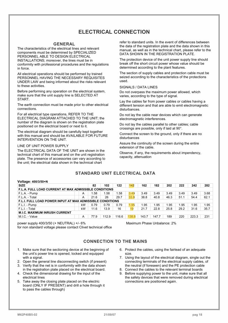
GENERAL The characteristics of the electrical lines and relevant components must be determined by SPECIALIZED PERSONNEL ABLE TO DESIGN ELECTRICAL INSTALLATIONS; moreover, the lines must be in conformity with professional procedures and the regulations in force. All electrical operations should be performed by trained PERSONNEL HAVING THE NECESSARY REQUISITES UNDER LAW and being informed about the risks relevant to these activities. Before performing any operation on the electrical system, make sure that the unit supply line is SELECTED AT START. The earth connection must be made prior to other electrical connections. For all electrical type operations, REFER TO THE ELECTRICAL DIAGRAM ATTACHED TO THE UNIT; the number of the diagram is shown on the registration plate positioned on the electrical board or next to it. The electrical diagram should be carefully kept together with this manual and should be AVAILABLE FOR FUTURE INTERVENTION ON THE UNIT.
LINE OF UNIT POWER SUPPLY The ELECTRICAL DATA OF THE UNIT are shown in the technical chart of this manual and on the unit registration plate. The presence of accessories can vary according to the unit; the electrical data shown in the technical chart
refer to standard units. In the event of differences between the data of the registration plate and the data shown in this manual, as well as in the technical chart, please refer to the DATA SHOWN IN THE REGISTRATION PLATE. The protection device of the unit power supply line should break off the short circuit power whose value should be determined according to the plant features. The section of supply cables and protection cable must be seized according to the characteristics of the protections used.
SIGNALS / DATA LINES Do not overpass the maximum power allowed, which varies, according to the type of signal. Lay the cables far from power cables or cables having a different tension and that are able to emit electromagnetic disturbances. Do not lay the cable near devices which can generate electromagnetic interferences. Do not lay the cables parallel to other cables; cable crossings are possible, only if laid at 90°. Connect the screen to the ground, only if there are no disturbances Assure the continuity of the screen during the entire extension of the cable. Observe, if any, the requirements about impendency, capacity, attenuation
STANDARD UNIT ELECTRICAL DATA Voltage: 400/3/50+N SIZE 82 102 122 142 162 182 202 222 242 282 F.L.A. FULL LOAD CURRENT AT MAX ADMISSIBLE CONDITIONS F.L.A. - Pump A 1.58 1.58 1.58 3.49 3.49 3.49 3.49 3.49 3.49 3.68 F.L.A. - Total A 21.6 26 29.7 33.8 38.8 40.8 46.3 51.1 54.4 62.1 F.L.I. FULL LOAD POWER INPUT AT MAX ADMISSIBLE CONDITIONS F.L.I. - Pump kW 0.79 0.79 0.79 1.95 1.95 1.95 1.95 1.95 1.95 1.95 F.L.I. - Total kW 11.6 13.9 16 19 21.7 22.8 25.8 29.2 31.6 35.7 M.I.C. MAXIMUM INRUSH CURRENT M.I.C. - Value A 77.9 112.9 116.6 138.8 143.7 147.7 189 220 223.3 231
power supply 400/3/50 (+ NEUTRAL) +/- 6% Maximum Phase Unbalance: 2% for non standard voltage please contact Clivet technical office
CONNECTION TO THE MAINS 1. Make sure that the sectioning device at the beginning of
the unit’s power line is opened, locked and equipped with a signal.
2. Open the general line disconnecting switch (if present) 3. Verify that the net is in conformity with the data shown
in the registration plate placed on the electrical board. 4. Check the dimensional drawing for the input of the
electrical lines 5. Take away the closing plate placed on the electric
board (ONLY IF PRESENT) and drill a hole through it to pass the cables through)
6. Protect the cables, using the fairlead of an adequate size.
7. Using the layout of the electrical diagram, single out the connecting terminals of the electrical supply cables, of the neutral (if foreseen) and the PE protection cable
8. Connect the cables to the relevant terminal boards 9. Before supplying power to the unit, make sure that all
the safety devices that were removed during electrical connections are positioned again.
John
Markering
John
Markering
John
Markering
John
Markering
John
Markering
John
Markering

M62P40B5-02 21/09/07 pag 40
TECHNICAL DATA
SIZE 82 102 122 142 162 182 202 222 242 282 COOLING Cooling capacity 1 kW 22,2 25,6 29 34 38,2 41,4 48,2 54,9 58,2 68 Compressor power input 1 kW 7,7 9,3 10,9 12,5 14,8 16,7 18,1 21,2 23,2 26,2 Total power input 2 kW 8,4 10 11,5 13,9 16,1 17,9 19,5 22,5 24,5 28,8 EER 3 2,64 2,56 2,52 2,44 2,37 2,31 2,47 2,44 2,37 2,36 EER 4 4,96 5,02 5,01 4,22 4,61 4,6 4,5 4,69 4,75 4,3 EER 5 3,95 3,85 4,01 3,44 3,55 3,7 3,66 3,66 3,6 3,6 HEATING Heat output 6 kW 26 30,4 34,7 40,3 45,4 49 57,7 65,5 69,7 80 Compressor power input kW 7,7 9 10,4 12,2 14 15,3 18,3 20,9 22,5 26,1 Total power input 2 kW 8,4 9,6 11 13,6 15,3 16,6 19,7 22,2 23,9 28,8 COP 3,1 3,16 3,15 2,96 2,96 2,95 2,92 2,95 2,91 2,77 COMPRESSOR Type of compressors SCROLL No. of Compressors Nr 2 Std Capacity control steps Nr 3 Refrigerant charge Nr 1 Refrigerant circuits (C1) 7 kg 12 12 12 15 15 15 20 20 20 22 INTERNAL EXCHANGER Type of internal exchanger 8 PHE No. of internal exchangers Nr 1 Water flow rate l/s 1,1 1,2 1,4 1,6 1,8 2 2,3 2,6 2,8 3,3 Useful pump discharge head kPa 148 140 135 190 187 185 175 169 160 103 Water content 7 l 1,7 2 2,4 2,6 3,1 3,4 3,8 4,4 4,4 5,5 EXTERNAL EXCHANGER Quantity Nr 2 EXTERNAL SECTION FANS Type of fans 9 AX Number of fans Nr 2 2 2 4 4 4 6 6 6 6 Standard air flow l/s 3056 3056 3056 4125 4125 4125 6120 6120 6120 7800 Installed unit power kW 0,22 0,22 0,22 0,15 0,15 0,15 0,15 0,15 0,15 0,19 HYDRAULIC CIRCUIT Max water side pressure kPa 550 Safety valve calibration kPa 600 EXPANSION VESSEL Expansion vessel capacity l 5 No. of expansion vessels Nr 1 DIMENSIONS Length mm 1560 1560 1560 1595 1595 1595 2130 2130 2130 2160 Depth mm 678 678 678 1107 1107 1107 1107 1107 1107 1107 Height mm 1367 1367 1367 1570 1570 1570 1570 1570 1570 1570 STANDARD UNIT WEIGHTS Shipping weight kg 310 315 320 440 470 490 560 580 600 660 Operating weight kg 330 335 340 460 490 510 580 600 620 670
(1) data referred to the following conditions : internal exchanger water = 12/7°C ambient temperature = 35°C
(2) The total input is given by the compressor input + fans power input + pump power input - proportional part of the water pump to supply the available head to installation input
(3) 100% EER internal exchanger water supply temperature = 7°C outside air temperature 35°C
(4) 66% EER internal exchanger water supply temperature = 10°C ambient temperature = 28°C
(5) 33% EER internal exchanger water supply temperature = 13°C ambient temperature = 25°C
(6) data referred to the following conditions : ambient temperature = 7°C (RH = 85%) external exchanger water supply temperature 45°C
(7) approximate values (8) PHE = plates (9) AX = axial-flow fan
CUT-OUT AND CONTROL SETTINGS Opens Closes High pressure switch (kPa) 2750 2000 Low pressure switch (kPa) 230 360 Max compressor starts/hour (n°) 10 Antifreeze protection (°C) 4 5,5 Safety discharge thermostat (°C) 120 Note: The safety "high pressure switch" and "safety discharge thermostat" must be reset manually from the control unit. The "low pressure switch"
resets automatically. In some units the safety discharge thermostat is internal to the compressor.
John
Markering
John
Markering
John
Markering
John
Markering
John
Markering
John
Markering
John
Markering
John
Markering
John
Markering
John
Markering
John
Markering
John
Markering
John
Markering
John
Markering
John
Markering
John
Markering
John
Markering
John
Markering
John
Markering
John
Markering
John
Markering
John
Markering
John
Markering
John
Markering
John
Markering
John
Markering
John
Markering
John
Markering
John
Markering
John
Markering
John
Markering
John
Markering
John
Markering
John
Markering
John
Markering
M62P40B5-02 21/09/07 pag 41
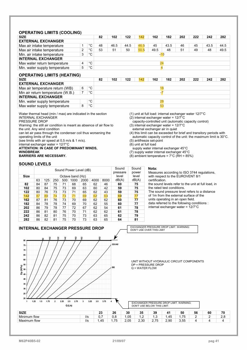
OPERATING LIMITS (COOLING) SIZE 82 102 122 142 162 182 202 222 242 282 EXTERNAL EXCHANGER Max air intake temperature 1 °C 48 46.5 44.5 46.5 45 43.5 46 45 43.5 44.5 Max air intake temperature 2 °C 53 51 50 50.5 49.5 48 51 49 48 49.5 Min. air intake temperature 3 °C -10 INTERNAL EXCHANGER Max water return temperature 4 °C 24 Min. water supply temperature 5 °C 4
OPERATING LIMITS (HEATING) SIZE 82 102 122 142 162 182 202 222 242 282 EXTERNAL EXCHANGER Max air temperature return (WB) 6 °C 18 Min air return temperature (W.B.) 7 °C -7 INTERNAL EXCHANGER Min. water supply temperature °C 28 Max water supply temperature 8 °C 53 Water thermal head (min / max) are indicated in the section INTERNAL EXCHANGER PRESSURE DROP Warning: the still air condition is meant as absence of air flow to the unit. Any wind condition can let air pass through the condenser coil thus worsening the operating limits of the unit (see limits with air speed at 0,5 m/s & 1 m/s). internal exchanger water = 12/7°C ATTENTION: IN CASE OF PREDOMINANT WINDS, WINDBREAK BARRIERS ARE NECESSARY.
(1) unit at full load: internal exchanger water 12/7°C (2) internal exchanger water = 12/7°C
capacity-controlled unit (automatic capacity control) (3) internal exchanger water = 12/7°C
external exchanger air in quiet (4) this limit can be exceeded for brief and transitory periods with
automatic capacity control of the unit: the maximum limit is 30°C. (5) antifreeze set-point (6) unit at full load
supply water internal exchanger 45°C (7) supply water internal exchanger 45°C (8) ambient temperature = 7°C (RH = 85%)
SOUND LEVELS Sound Power Level (dB)
Size Octave band (Hz) 63 125 250 500 1000 2000 4000 8000
Sound pressare
level dB(A)
Sound power level dB(A)
82 84 87 75 71 68 65 62 46 60 75 102 80 84 75 73 69 63 60 42 59 75 122 80 76 73 73 71 65 62 43 59 75 142 87 80 74 73 71 69 62 63 60 77 162 87 81 76 73 70 69 62 62 60 77 182 84 78 78 74 69 70 62 55 60 77 202 86 79 78 77 72 67 62 54 61 78 222 86 81 80 76 70 71 62 62 61 78 242 86 82 81 75 70 73 63 65 62 79 282 86 82 81 75 70 73 63 65 64 81
Nota: Measures according to ISO 3744 regulations, with respect to the EUROVENT 8/1 certification. the sound levels refer to the unit at full load, in the rated test conditions. The sound pressure level refers to a distance of 1m from the external surface of the units operating in an open field. data referred to the following conditions : internal exchanger water = 12/7°C
INTERNAL EXCHANGER PRESSURE DROP
20
25
30
35
40
45
50
55
60
65
70
75
80
1 1.25 1.5 1.75 2 2.25 2.5 2.75 3 3.25 3.5 3.75 4
Q (L/s)
Dp
(KPa
)
82 162
142
122
102
222-242
202
182
282
SIZE 23 26 30 35 39 41 50 56 60 70 Minimum flow l/s 0,7 0,8 1,05 1,2 1,3 1,45 1,75 2 2 2,8 Maximum flow l/s 1,45 1,75 2,05 2,30 2,75 2,90 3,55 4 4 4
UNIT WITHOUT HYDRAULIC CIRCUIT COMPONENTS DP = PRESSURE DROP Q = WATER FLOW
EXCHAMGER PRESSURE DROP LIMIT. WARNING: DON'T USE BELOW THIS LIMIT.
EXCHANGER PRESSURE DROP LIMIT. WARNING: DON'T USE OVER THIS LIMIT
John
Markering
John
Markering
John
Markering
John
Markering
John
Markering
John
Markering
John
Markering
John
Markering
John
Markering
John
Markering
John
Markering
John
Markering
M62P40B5-02 21/09/07 pag 43
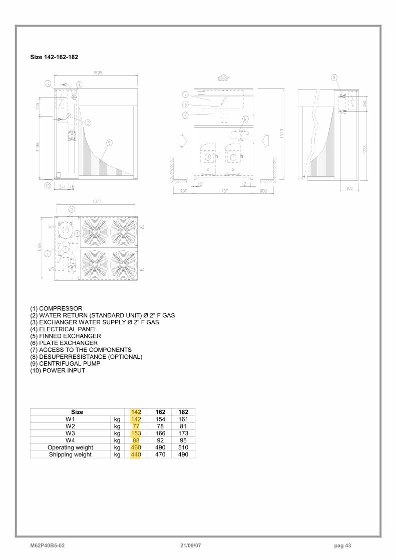
Size 142-162-182
(1) COMPRESSOR (2) WATER RETURN (STANDARD UNIT) Ø 2" F GAS (3) EXCHANGER WATER SUPPLY Ø 2" F GAS (4) ELECTRICAL PANEL (5) FINNED EXCHANGER (6) PLATE EXCHANGER (7) ACCESS TO THE COMPONENTS (8) DESUPERRESISTANCE (OPTIONAL) (9) CENTRIFUGAL PUMP (10) POWER INPUT
�
Size 142 162 182 W1 kg 142 154 161 W2 kg 77 78 81 W3 kg 153 166 173 W4 kg 88 92 95
Operating weight kg 460 490 510 Shipping weight kg 440 470 490
John
Markering
John
Markering
John
Markering
John
Markering
John
Markering
John
Markering
John
Markering
Related Documents