Honeywell TotalPlant HPM Parameters Pocket Guide HP09-541 2/99 Introduction Description of Parameter Definitions Point Types Algorithms Parameters Per Point Type Parameters Per Algorithm Type Parameter Definitions i i 2 3 4 25 63 CONTENTS Copyright 1999 - Honeywell Inc. Honeywell TotalPlant HPM Parameters Pocket Guide HP09-541 2/99 Introduction Description of Parameter Definitions Point Types Algorithms Parameters Per Point Type Parameters Per Algorithm Type Parameter Definitions i i 2 3 4 25 63 CONTENTS Copyright 1999 - Honeywell Inc. Honeywell TotalPlant HPM Parameters Pocket Guide HP09-541 2/99 Introduction Description of Parameter Definitions Point Types Algorithms Parameters Per Point Type Parameters Per Algorithm Type Parameter Definitions i i 2 3 4 25 63 CONTENTS Copyright 1999 - Honeywell Inc.

Welcome message from author
This document is posted to help you gain knowledge. Please leave a comment to let me know what you think about it! Share it to your friends and learn new things together.
Transcript

HoneywellTotalPlant HPM
Parameters Pocket GuideHP09-541
2/99
Introduction Description of Parameter Definitions Point Types Algorithms Parameters Per Point Type Parameters Per Algorithm Type Parameter Definitions
i i
2 3 4
25 63
CONTENTS
Copyright 1999 - Honeywell Inc.
HoneywellTotalPlant HPM
Parameters Pocket GuideHP09-541
2/99
Introduction Description of Parameter Definitions Point Types Algorithms Parameters Per Point Type Parameters Per Algorithm Type Parameter Definitions
i i
2 3 4
25 63
CONTENTS
Copyright 1999 - Honeywell Inc.
HoneywellTotalPlant HPM
Parameters Pocket GuideHP09-541
2/99
Introduction Description of Parameter Definitions Point Types Algorithms Parameters Per Point Type Parameters Per Algorithm Type Parameter Definitions
i i
2 3 4
25 63
CONTENTS
Copyright 1999 - Honeywell Inc.

IntroductionThis guide contains definitions of the parameters used in the High-Performance Process Manager (HPM) andNetwork Interface Module (NIM). This guide is a condensed version of the High-Performance ProcessManager Parameter Reference Dictionary.
Description of Parameter DefinitionsThe parameter definitions in this guide are listed alphabetically by parameter name. Each parameterdefinition contains the parameter name, description, data type, access lock, default, and range.
ParameterThe Parameter column contains the short name (up to 8 characters) of the parameters. The parameternames are listed in alphabetical order.
DescriptionThe Description column contains the long name of the parameter.
TypeAbbreviations in the Type column have the following meaning:
A = ASCII I = Integer S = StringBR = Blind Record L = Logical SDE =Self Def. Enumeratione: = enumeration P = Parameter Identifier T = TimeE = Entity.Parameter R = Real U =Universal Entity.Parameter
LockEntries in the Lock column define who or what can change the parameter’s value or option.
i

The following chart shows who/what can change the parameter’s value for each access lock. Accesslevel defines who or what is requesting a parameter value or option change.
Access LevelLock Oper Supr Engr Cont HPMMCc Prog PBOper • • • • • • •Supr • • • • • •Eng or Eg • • • • •OnProc • • •Supr/Eng • •EgOnly •Prog • • • •Eng/PB • •PB •View
Note:
Cont = Continuous_Control (from a Module on the LCN)Eng/PB = Engineer or Point BuilderEgOnly = Engineer OnlyEngr or Eg = EngineerOnProc = On ProcessOper = Operator
PB = Point BuilderHPMMCc = PMM_Continous_Control (from HPMM)Prog = CL/PM Sequence ProgramSupr = SupervisorSupr/Eng = Supervisor or EngineerSpecial = see full PRDView = Read Only
1
The following chart shows who/what can change the parameter’s value for each access lock. Accesslevel defines who or what is requesting a parameter value or option change.
Access LevelLock Oper Supr Engr Cont HPMMCc Prog PBOper • • • • • • •Supr • • • • • •Eng or Eg • • • • •OnProc • • •Supr/Eng • •EgOnly •Prog • • • •Eng/PB • •PB •View
Note:
Cont = Continuous_Control (from a Module on the LCN)Eng/PB = Engineer or Point BuilderEgOnly = Engineer OnlyEngr or Eg = EngineerOnProc = On ProcessOper = Operator
PB = Point BuilderHPMMCc = PMM_Continous_Control (from PMM)Prog = CL/PM Sequence ProgramSupr = SupervisorSupr/Eng = Supervisor or EngineerSpecial = see full PRDView = Read Only
1

(Default) and RangeThe default value and range for the parameter are listed in this column. The default value is the value assigned bythe system when the user does not make an entry for the respective parameter. The default value is enclosed byparentheses ( ). The range of the value is listed to the right of the parentheses. See Full PRD means theexplanation is lengthy; refer to the same parameter in the HPM Parameter Reference Dictionary.
Point Types
Abbreviation Definition
AnalgIn Analog InputAnalgOut Analog OutputArray ArrayBox HPM BoxDevCtl Device ControlDigComp Digital CompositeDigIn Digital InputDigOut Digital OutputFlag Box FlagIOP Input/Output
Processor
*These are subsets of the Analog Input type
Abbreviation Definition
LLMUX Low Level Multiplexer*Logic LogicNIM Network Inerface ModuleNumeric Box NumericPI Pulse Input*ProcMod Process ModuleRegCtL Regulatory ControlRegPV Regulatory PVSDI Serial Device InterfaceSI Serial InterfaceSTI Smart Field Transmitter*Timer Box TimerUCN Universal Control Network
2

Algorithms
Abbreviation Definition
AutoMan Auto Manual CtL AlgoCaLcuLtr Calculator PV AlgoDataAcq Data Acquisition PV AlgoFlowComp Flow Compensation PV AlgoGenLin General Linearity PV AlgoHiLoAvg High-Low Average PV AlgoIncrSum Incremental Summer CtL AlgoMidOf3 Middle Of Three PV AlgoORSel Override Selector CtL AlgoPid Proportional, Integral, and
Derivative CtL AlgoPidErfb PID With External Reset
Feedback CtL AlgoPidFf PID With Feedforward CtL AlgoPidPosPr PID With Position ProportionalPosProp Position Proportional CtL AlgoRampSoak Ramp Soak CtL AlgoRatioCtL Ratio Control CtL AlgoSummer Summer PV AlgoSwitch Switch CtL AlgoTotaLizr Totalizer PV AlgoVdtLdLag Variable Deadtime With Lead
Lag PV Algo
3

Parameters Per Point TypeAnalog InputThe parameters of the Analog Input Data point are listed below in alphabetical order.(F) indicates that the parameter is applicable when the PNTFORM = Full.
$AUXUNIT (F)ALENBST (F)ASSOCDSPAVDELTHSAVSTSBADPVFL (F)BADPVPR (F)C1, C2CJTACTCOMMANDCONTCUT (F)DAMPINGDECONFEUDESCHIGHAL (F)HIGHALPR (F)INPTDIRKEYWORDLASTPVLOCUTOFFLRLLRVMODNUMNAMENODENUMNODETYP
NTWKNUMOTDENBLEOVERVAL (F)PIUOTDCFPNTFORMPNTMODTYPNTNODTYPNTSTATEPNTTYPEPRIMMOD (F)PTDESCPTEXECSTPTINALPVPVALDB (F)PVALDBEU (F)PVAUTOPVAUTOSTPVCALCPVCHARPVCLAMPPVEUHIPVEULOPVEXEUHIPVEXEULO
PVEXHIFLPVEXLOFLPVFORMATPVHHFLPVHHPR (F)PVHHTP (F)PVHIFLPVHIPR (F)PVHITP (F)PVLLFLPVLLPRPVLLTP (F)PVLOFLPVLOPR (F)PVLOTP (F)PVPPVRAWPVRAWHIPVRAWLOPVROCNFLPVROCNPR (F)PVROCNTP (F)PVROCPFLPVROCPPR (F)PVROCPTP (F)
PVSOURCE (F)PVSRCOPT (F)PVSTSPVTEMPPVTV (F)PVTVP (F)RJTEMPS1SECVARSENSRTYPSERIALNOSFSTSSLOTNUMSLWSRCIDSTATESTI_EUSTISWVERSTITAGTCRNGOPTTFTIMEBASEUNITURLURV
4

Analog Output
The parameters of the Analog Output Data point are listed below in alphabetical order.(F) indicates that the parameter is applicable when the PNTFORM = Full.
ASSOCDSPCASREQ (F)EUDESCKEYWORDLOCALMANMODATTR (F)MODE (F)MODEAPPL (F)MODEPERM (F)MODNUMNAMENMODATTR (F)NMODE (F)NODENUMNODETYPNTWKNUM
OPOPCHAROPFINALOPIN0OPIN1OPIN2OPIN3OPIN4OPIN5OPOUT0OPOUT1OPOUT2OPOUT3OPOUT4OPOUT5OPTDIR
PNTFORMPNTMODTYPNTNODTYPNTSTATEPNTTYPEPRIMMOD (F)PTDESCPTEXECSTRCASOPTREDTAG (F)RINITREQ (F)SLOTNUMSTDBYMANUNIT
5

Array
The parameters of the Array Data point are listed below in alphabetical order.This point is only available in the Full.form.
AB_DATA1AB_DATA2AB_DATA3AB_DATA4ASSOCDSPAUXDATA1AUXDATA2AUXDATA3AUXDATA4BADPVFL (F)CNFMUCNFPUDEVADDRERRCODEEXTDATAFLFLDESCFLSTIXFTANUM
INITREQIOPNUMKEYWORDNFLAGNNNNDESCNNUMERICNNSTIXNODENUMNODETYPNSTRINGNTIMENTWKNUMOVERLAPPERIODPNTFORMPNTNODTYPNTTYPEPRIMMOD (F)
PTDESCSCANPRISLOTNUMSPLOCKSTR8STR16STR32STR64STRDESCSTRLENSTRSTIXSTSMSGTIMETIMEDESCTIMESECSTIMESTIXUNITUSERID
6

HPM Box
The parameters of the High-Performance Process Manager Box Data Point are listed below in alphabeticalorder.BADPVTXTCHPINOPRCNFPUCNFPUPCRIOLORNCRPPXORNCRUCNORNCTLOPTCTLPATCHCYCLETIMDATEDAYDB_VALIDEUNDESCFLFTA1TYPEFTA2TYPEHOURIOLASTSIOLBSTSIOLCHAERIOLCHASLIOLCHBERIOLCHBSLIOLCHERT
IOLCMDIOLPERSWIOMCARDIOMCHAERIOMCHASLIOMCHBERIOMCHBSLIOMCMDIOMCOMERIOMFILEIOMOPERIOMREALTIOMRECHNIOMSEVERIOMSTSIOMTYPEIONTOKENIOPIOPNUMIOPSTR1IOPSTR2IORECCHNIOSTKNDRIOSSTSIOTKNSTL
LSIOLORNLSPPXORNLSUCNORNMDMHWREVMINUTEMONTHMOVPVTXTNARRSLOTNCTLSLOTNDCSLOTNDEVSLOTNFASTCTLNFASTDCNFASTDEVNFASTLOGNFASTPVNFLAGNLOGSLOTNNNNUMERICNODEASSNNODECMDNODECONFNODENUMNODESTS
NODETYPNODFSTATNOPTSNPMSLOTNPVSLOTNSTRINGNTIMENTIMERPKGOPTPMMCHAERPMMCHASLPMMCHBERPMMCHBSLPMMCMDPMMCOMERPMMCTLSTPMMFLPOSPMMOPERPMMRECCHPMMSEVERPMMSFSTSPMMSTSPNTNODTYPOSITIONRJTEMP
SAFOPCMDSCANRATESCANPERSECONDSEQPRGSZSEQPROCSTR8SUMSLTSZSWTCHACTTIMETMCMDTMPVTMSPTMRVTMSPTMSOTMSTTMTBUTSDRIFTUSTSNODEUTSTBCRVUTSTIMEUTSTIMSTWEEKDAYYEAR
7

Box Flag
The parameters of the Box Flag Data Point are listed below in alphabetical order. (F) indicates that theparameter is applicable when the PNTFORM = Full; an * indicates that the parameter is applicable toflag slots 1-128.
$AUXUNIT (F)ALENBST (F)*ALPRIOR*ASSOCDSPBOXCLRCNFMUCNFPUCONTCUT (F)*EIPPCODE (F)*EUDESCHIGHAL (F)*KEYWORD
NAMENODENUMNODETYPNTWKNUMNODETYPOFFNRMPR (F)PNTNODTYPNTTYPEPNTFORMPRIMMOD (F)*
PTDESC (F)PVPVFLS0BOXCLRS1BOXCLRSLOTNUMSTATE0STATE1STATETXTUNIT
Box Numeric
The parameters of the Box Numeric Data Point are listed below inalphabetical order.
ASSOCDSPCNFMUCNFPUEUDESCKEYWORDNAME
NODENUMNODETYPNTWKNUMPNTFORMPNTNODTYPNTTYPE
PRIMMOD (F)PTDESCPVPVFORMATSLOTNUMUNIT
8

Box Timer
The parameters of the Box Timer Data Point are listed below in alphabetical order.
ASSOCDSPCOMMANDEUDESCKEYWORDNAMENODENUMNODETYPNTWKNUMPERIODPNTNODTYPNTTYPE
PRIMMOD (F)PTDESCPVRVSLOTNUMSOSPSTATETIMEBASETIMOUTFLUNIT
9
Box Timer
The parameters of the Box Timer Data Point are listed below in alphabetical order.
ASSOCDSPCOMMANDEUDESCKEYWORDNAMENODENUMNODETYPNTWKNUMPERIODPNTNODTYPNTTYPE
PRIMMOD (F)PTDESCPVRVSLOTNUMSOSPSTATETIMEBASETIMOUTFLUNIT
9
Box Timer
The parameters of the Box Timer Data Point are listed below in alphabetical order.
ASSOCDSPCOMMANDEUDESCKEYWORDNAMENODENUMNODETYPNTWKNUMPERIODPNTNODTYPNTTYPE
PRIMMOD (F)PTDESCPVRVSLOTNUMSOSPSTATETIMEBASETIMOUTFLUNIT
9

Device Control
The parameters of the Digital Composite Data Point are listed below in alphabetical order.(F) indicates that the parameter is applicable when the PNTFORM = Full.
$AUXUNIT (F)ACCELTIM (F)ALENBST (F)ASSOCDSPBADPVFLBADPVPR (F)BADPVTXTBADSVFL (#Inputs>0)BADSVPR (F)BOXCLRBYPASSCMDDISFLCMDDISPR (F)CMDFALFLCMDFALTMCNFMUCNFPUCONTCUT (F)D1 (#Inputs>0)D1_0 (#Inputs=1)D1_1 (#Inputs=1)D2 (#Inputs=2)
D2D1_00 (#Inputs=2)D2D1_01 (#Inputs=2)D2D1_10 (#Inputs=2)D2D1_11 (#Inputs=2)D3D4D5DB_VALIDDEADBANDDEADTIMEDISRC (#Inputs>0)DODSTN (#Outputs>0)EIPPCODE (F)EUDESCEVTOPT (F) (#Inputs>0)FBTIME (F)FL 1-12HIGHALHIGHALPRHISVPEAK
(Continued)
10

Device Control (Continued)
The parameters of the Device Control Data Point are listed below in alphabetical order.(F) indicates that the parameter is applicable when the PNTFORM = Full.
I0 - 2 (#Outputs>0)I0CONFI1CONFI2CONFINITMANINITREQKEYWORDLLIBADOPTLIDESCLISRC 1-12LMREVLMSRCLOCALMAN (#Outputs>0)LODSTN 1-2LOENBL 1-2LOGICSRCLOSRC 1-2MAINDATMAINTOPTMANMODFL
MASKTIMMAXTIM0HMAXTIM1HMAXTIM2HMAXTRAN0MAXTRAN1MAXTRAN2MODATTR (#Outputs>0)MODE (#Outputs>0)MODEAPPL (#Outputs>0)MODEPERM (#Outputs>0)MODNUMMOMSTATE (#Outputs>0)MOVPVFL (#Inputs>0)MOVPVTXTNAMENI0 (#Outputs>0)NI1 (#Outputs>0)NI2 (#Outputs>0)NMODATTR (#Outputs>0)
(Continued)
11

Device Control (Continued)
Continuation of the parameters of the Device Control Data Point is listed below in alphabetical order.(F) indicates that the parameter is applicable when the PNTFORM = Full.
NMODE (#Outputs>0)NNNNINSET 1-10NODENUMNODETYPNODINTPSNODOPTSNOLINPTSNOLOPTSNOPGATENOSGATENOSIOVRDNOSTATESNOTRANS0NOTRANS1NOTRANS2NRMATRFLNSI0 (#Outputs>0)NTWKNUMOFFNRMFL
OFFNRMPR (F)OP (#Outputs>0)OPCMD (#Outputs>0)OPFINAL (#Outputs>0)OPRATRFL (#Outputs>0)OROPT (#Outputs>0)OVRCTIMOVRDCONFOVRDDESCOVRDI0FLOVRD1FLOVRD2FLOVRDALOPOVRDALPR (F)OVRDSIFLP0 (#Outputs>0)P1 (#Outputs>0)P2 (#Outputs>0)PAUSETIMPERIODPGALGID 1 - 4
(Continued)
12

Device Control (Continued)
Continuation of the parameters of the Device Control Data Point is listed below in alphabetical order.(F) indicates that the parameter is applicable when the PNTFORM = Full.
PGDSTN 1 - 4PGPLSWTH 1 - 4PGSO 1 - 4PIALGID 1 - 12PIDEADBD1 - 12PINN 1 - 12PISO 1 - 12PISRC 1 - 12PNTFORMPNTMODTYPNTNODTYPNTSTATEPNTTYPEPRIMMOD (F)PSDLYFLPTDESCPTEXECST (F)PTINALPULSEWTH (#Outputs>0)PV (#Inputs>0)PVAUTO (#Inputs>0)PVFL (#Inputs>0)PVNORMAL (F)
PVNORMFLPVSOURCE (F) (#Inputs>0)PVSRCOPT (F) (#Inputs>0)PVSTATES 0 - 4 (#Inputs>0)PVTXTOPTREDTAG (F) (#Outputs>0)RESETFLS0BOXCLRS1BOXCLRS2BOXCLRSEALOPTSECVARSGALGID 1 - 2SGDSTN 1 - 2SGPLSWTH 1 - 2SGSO 1 - 2SI0SI0ALOPTSI0ALPR (F)SIALGID 1 - 12SIDLYTIM 1 - 12SIDSTN 1 - 12
(Continued)
13

Device Control (Continued)
Continuation of the parameters of the Device Control Data Point is listed below in alphabetical order.(F) indicates that the parameter is applicable when the PNTFORM = Full.
SISO 1 -12SLOTNUMSO 0 - 2 (#Outputs>0)SOCMD (#Outputs>0)ST0_OP1 (#Outputs>0)ST0_OP2 (#Outputs>=2)ST0_OP3 (#Outputs>=3)ST1_OP1 (#Outputs>0)ST1_OP2 (#Outputs>=2)ST1_OP3 (#Outputs>=3)ST2_OP1 (#Outputs>0)ST2_OP2 (#Outputs>=2)ST2_OP3 (#Outputs>=3)STATE0STATE1STATE2
STATTIM0STATTIM1STATTIM2STATETXT0-4STCHGOPTSTSMSGSVALDBSVALDBEUSVDESCSVEUDESCSVEUHISVEULOSVHHFLSVHHPR (F)SVHHTP
SVHHTPPSVHIFLSVHIPR (F)SVHITPSVHITPPSVPSVPEAKSVSRCSVTVSVTVPTRANTIM0TRANTIM1TRANTIM2UNCMDFLUNITUSERID
14

Digital CompositeThe parameters of the Digital Composite Data Point are listed below in alphabetical order.(F) indicates that the parameter is applicable when the PNTFORM = Full.
$AUXUNIT (F)ALENBST (F)ALPRIORASSOCDSPBADCTLPRBADPVFL (F) (#Inputs>0)BADPVPR (F)BADPVTXTBOXCLRBYPASS (#Outputs>0)CMDDISFLCMDDISPR (F)CMDFALFLCMDFALTMCNFMUCNFPUCONTCUT (F)D1 (#Inputs>0)D1_0 (#Inputs=1)D1_1 (#Inputs=1)D2 (#Inputs=2)D2D1_00 (#Inputs=2)D2D1_01 (#Inputs=2)D2D1_10 (#Inputs=2)
D2D1_11 (#Inputs=2)DISRC1 - 2 (#Inputs>0)DODSTN1 - 3 (#Outputs>0)EIPPCODE (F)EUDESCEVTOPT (F) (#Inputs>0)FBTIME (F)HIGHAL (F)HIGHALPRI0 - 2 (#Outputs>0)I0CONFI1CONFI2CONFI0DESCI1DESCI2DESCINITMANINITREQKEYWORDLOCALMAN (#Outputs>0)LOGICSRCMAINDATMAINTOPT
(Continued)
15

Digital Composite (Continued)Continuation of the parameters of the Digital Composite Data Point are listed below in alphabetical order.(F) indicates that the parameter is applicable when the PNTFORM = Full.
MAXTIM0HMAXTIM1HMAXTIM2HMAXTRAN0 - 2MODATTR (#Outputs>0)MODE (#Outputs>0)MODEAPPL (#Outputs>0)MODEPERM (#Outputs>0)MODNUMMOMSTATE (#Outputs>0)MOVPVFL (#Inputs>0)MOVPVTXTNAMENI0NI1NI2NMODATTR (#Outputs>0)NMODE (#Outputs>0)NODENUM
NODETYPNODINTPSNODOPTSNOSTATESNOTRANS0NOTRANS1NOTRANS2NSIO (#Outputs>0)NTWKNUMOFFNRMFLOFFNRMPR(F)OP (#Outputs>0)OPCMD (#Outputs>0)OPFINAL (#Outputs>0)OPRATRFL (#Outputs>0)OPSTTEXTOROPT (#Outputs>0)OVRDALOP
(Continued)
16

Digital Composite (Continued)Continuation of the parameters of the Digital Composite Data Point are listed below in alphabetical order.(F) indicates that the parameter is applicable when the PNTFORM = Full.
OVRDALPR (F)OVRDCONFOVRDDESCOVRDI0FLOVRDI1FLOVRDI2FLOVRDSIFLP0 (#Outputs>0)P1 (#Outputs>0)P2 (#Outputs>0)PAUSETIMPERIODPFDLYFLPNTFORMPNTMODTYPNTNODTYPNTSTATEPNTTYPEPRGATRFLPRIMMOD (F)PSDLYFLPTDESCPTEXECST
PTINALPULSEWITH (#Outputs>0)PV (#Inputs>0)PVAUTO (#Inputs>0)PVFL0 - 2 (#Inputs>0)PVNORMAL (F)PVSOURCE (F) (#Inputs>0)PVSRCOPT (F) (#Inputs>0)PVSTATES0 - 4 (#Inputs>0)PVTXTOPTREDTAG (F) (#Outputs>0)RESETFLS0BOXCLRS1BOXCLRS2BOXCLRSCHSTSSEALOPTSIOSIOALOPTSIOALPRSLOTNUM
(Continued)
17

Digital Composite (Continued)Continuation of the parameters of the Digital Composite Data Point are listed below in alphabetical order.(F) indicates that the parameter is applicable when the PNTFORM = Full.
SO (#Outputs>0)SOCMD (#Outputs>0)ST0_OP1 (#Outputs>0)ST0_OP2 (#Outputs>=2)ST0_OP3 (#Outputs>=3)ST1_OP1 (#Outputs>0)ST1_OP2 (#Outputs>=2)ST1_OP3 (#Outputs>=3)ST2_OP1 (#Outputs>0)ST2_OP2 (#Outputs>=2)ST2_OP3 (#Outputs>=3)STATE0STATE1STATE2STATETXT0 - 4
STATTIM0STATTIM1STATTIM2STCHGOPTSTSMSGTRANTIM1TRANTIM2UNCMDFLUNITUSERID
18

Digital InputThe parameters of the Digital Input Data Point are listed below in alphabetical order.(L), (S), or (A)—parameter applies only when DITYPE = Latched, Status, or Accum.(F) indicates that the parameter is applicable when the PNTFORM = Full.
$AUXUNIT (F)ALENBST (S) (F)ALMOPT (S) (F)ALPRIORASSOCDSPAV (A)AVTV (A)AVTVFL (A)BADPVFL (F)BADPVPRBOXCLR (L)COMMAND (A)CONTCUT (S) (F)COUNTDWN (A)DEBOUNCE (L) (S) (A)DITYPE (F)DLYTIME (S) (F)EIPPCODE (S) (L) (F)EUDESCEVTOPT (L) (F)HIGHAL (S)
INPTDIR (F)KEYWORDMODNUMNAMENODENUMNODETYPNTWKNUMOFFNRMFL (S)OFFNRMPR (S) (F)OLDAV (A)OVERFLOW (A)OVERVAL (A) (F)PNTFORMPNTNODTYPNTMODTYPNTSTATEPNTTYPEPRIMMOD (S) (F)PTDESCPTEXECST
PV (S) (L)PVAUTO (S) (L)PVCHGDLY (S) (L) (F)PVFL (S) (L)PVNORMAL (S) (F)PVNORMFL (S)PVRAWPVSOURCE (L) (F)PVSRCOPT (S) (L) (F)RESETFL (A)RESETVAL (A)S0BOXCLR (S) (L)S1BOXCLR (S) (L)SLOTNUMSTARTFL (A)STATE (A)STATE0 (S) (L)STATE1 (S) (L)STATETXT (S) (L)STOPFL (A)UNIT
19

Digital OutputThe parameters of the Digital Output Data Point are listed below in alphabetical order. (S) or(P) parameter applies only when DOTYPE = Status or Pulse Width Modulated (PWM). Thispoint type is available only in the component form.
ASSOCDSPDOTYPEEUDESCINITREQKEYWORDMODNUMNAMENODENUMNODETYPNTWKNUM
OFFPULSE (S)ONPULSE (S)OP (P)OPTDIR (P)PERIOD (P)PNTFORMPNTMODTYPNTNODTYPNTSTATEPNTTYPE
PTDESCPTEXECSTS0BOXCLR (S)S1BOXCLR (S)SLOTNUMSO (S)STATE0 (S)STATE1 (S)STDBYMANUNIT
Input/Output ProcessorThe parameters of the Input/Output Processor Point are listed below in alphabetical order.
CALIBALLCALIBRJFAILOPTFTAPRESFREQ6050IOMACTYPIOMFWREVIOMHWREV
IOMLHFSTIOMOPERIOMTYPEIOMSTSIONTOKENIOPSTR1IOPSTR2IORECCHN
LINEPERDMAXSLOTSNODETYPPIUOTDCFRJRAWSLOT0SFSTDBYSTSSWTCHACTWARMSTRT
20

Logic
The parameters of the Logic Data Point (otherwise referred to as the Logic Slot) are listed below inalphabetical order. (F) indicates that the parameter is applicable when the PNTFORM = Full.
$AUXUNIT (F)ALENBSTASSOCDSPC1DESCC2DESCC3DESCC4DESCC1FLC2FLC3FLC4FLC1PRC2PRC3PRC4PRC1SRCC2SRCC3SRCC4SRC
CNFMUCNFPUCONTCUTDEADBAND 1-24DLYTIME 1-24EIPPCODE (F)FL1-12GENDESC 1-12 (F)HIGHALHIGHALPRL1-12LIBADOPTLISRC 1-12LODSTN 1-12LOENBL 1-12LOGALGID 1-16LOGMIXLOSRC 1-12
MODNUMNAMENN1-8NODENUMNODESC (F)NODETYPNOLINPTSNOLOGBLKNOLOPTSNORMCYCLNTWKNUMPERIODPFDYFLPNTFORMPNTMODTYPNTNODTYPNTSTATEPNTTYPEPRIMMOD (F)
PRMDESC 1 -12 (F)PTDESCPTEXECSTPTINALR1 1-24R2 1-24S1 1-24S1REV 1-24S2 1-24S2REV 1-24S3 1-24S3REV 1-24S4 1-24SCHSTSSLOTNUMSO 1-24STSMSGUNITUSERID
21

Process Module
The parameters of the Process Module Data Point are listed below in alphabetical order.(F) indicates that the parameter is applicable when the PNTFORM = Full.
ABHEMSDABHHOLDABHRSTRABHSHDNACP (F)ALPRIOR (F)ANAME 1-3ASSOCDSPASTEP 1-3ASTMT 1-3CNTLLOCKCLBACKFL 1-27MSGPENDNAME (F)NN 1-80NODENUMNODETYPNTWKNUMOVERPHAS
OVERSTATOVERSTEPPERIODPFDLYFLPHASEPHASEALPHASETIMPHREMTIMPNTFORMPNTTYPEPRIMMOD (F)PSDLYFLPROCMODPTDESCRESTARTRSTROPTRUNSTATESEQERRSEQEXECSEQMODESEQNAME
SEQOBJSZSEQPR (F)SEQSLTSZSLOTNUMSNAME 1-2SPLOCKSSTEP 1-2SSTMT 1-2STATMENTSTEPSTR8 1-16STR16 1-8STR32 1-4STR64 1-2STRLENSTSMSGSUSPSTATSUSPTIMTIME 1-4UNITUSERID
Some of the parameters in the listing above are arrays that are not defined in this publication.
22

UCN Network
The parameters of the UCN Network Data Point are listed below in alphabetical order.
CHPINHWYCLPZMXCCLPZMXPHWYCTLSTLOADSCOPMSGTXT 0-15NIMADDRNIMREVNIMVERSNMSGTXTTIMESYNCUPGRADE
23
UCN Network
The parameters of the UCN Network Data Point are listed below in alphabetical order.
CHPINHWYCLPZMXCCLPZMXPHWYCTLSTLOADSCOPMSGTXT 0-15NIMADDRNIMREVNIMVERSNMSGTXTTIMESYNCUPGRADE
23
UCN Network
The parameters of the UCN Network Data Point are listed below in alphabetical order.
CHPINHWYCLPZMXCCLPZMXPHWYCTLSTLOADSCOPMSGTXT 0-15NIMADDRNIMREVNIMVERSNMSGTXTTIMESYNCUPGRADE
23

UCN Node Data PointThe parameters of the UCN Node Data Point are listed below in alphabetical order.
$UCNLSB 1-50CABLESTSCLPZMXCCLPZMXPLOADSCOPMDMHWREVMODNUMNMSGTXTNODESTATNODESTSNODETYPTIMESYNCUCNRECHNUPGRADEUTSDRIFTUTSNODEUTSTBCRVUTSTIMEUTSTIMST
24
UCN Node Data PointThe parameters of the UCN Node Data Point are listed below in alphabetical order.
$UCNLSB 1-50CABLESTSCLPZMXCCLPZMXPLOADSCOPMDMHWREVMODNUMNMSGTXTNODESTATNODESTSNODETYPTIMESYNCUCNRECHNUPGRADEUTSDRIFTUTSNODEUTSTBCRVUTSTIMEUTSTIMST
24
UCN Node Data PointThe parameters of the UCN Node Data Point are listed below in alphabetical order.
$UCNLSB 1-50CABLESTSCLPZMXCCLPZMXPLOADSCOPMDMHWREVMODNUMNMSGTXTNODESTATNODESTSNODETYPTIMESYNCUCNRECHNUPGRADEUTSDRIFTUTSNODEUTSTBCRVUTSTIMEUTSTIMST
24

Parameters Per Algorithm Type
Auto Manual
The parameters of the Auto Manual algorithm are listed below in alphabetical order.(F) indicates that the parameter is applicable when the PNTFORM = Full.
$AUXUNIT (F)ALENBST (F)ARWNETARWOPASSOCDSPAUTOMODFLBB0BADCTLOPBADCTLPRBADCTLPR (F)BCAMODFLCASMODFLCASREQCIDSTNCISRCCNFMU
CNFPUCODSTNCONTCUT (F)CTLALGIDCTLEQNCTRLINITCVCVEUHICVEULOESWAUTOESWCASESWENBSTESWMANEUDESCEXTSWOPTHIGHAL (F)
HIGHALPR (F)INITMANKKEYWORDLOCALMANMANMODFLMODATTRMODEMODEAPPLMODEPERMMODNUMNAMENMODATTRNMODENOCINPTS
(Continued)
25

Auto Manual (Continued)
NOCOPTSNODENUMNODETYPNORMCYCLNRMATRFLNRMMODFLNTWKNUMOPOPALDB (F)OPEUOPHAFL (F)OPHIFLOPHILMOPHIPR (F)OPHITP (F)OPLAFL (F)OPLOFLOPLOLMOPLOPR (F)
OPLOTP (F)OPMCHLMOPRATRFLOPROCLMOVERVAL (F)PERIODPFDLYFLPNTFORMPNTMODTYPNTNODTYPNTSTATEPNTTYPEPRIMMOD (F)PSDLYFLPTDESC (F)PTEXECSTPTINALPTORSTRARWSTSRATE1
RCASOPTRCASSHEDREDTAG (F)RINITREQRINITVALSAFEOPSCHSTSSHEDMODESHEDTIMESHUTDOWNSLOTNUMSTDBYMANSTSMSGUNITUSERIDX1X2XEUHIXEULO
26

Calculator
The parameters of the Calculator PV algorithm are listed below in alphabetical order.(F) indicates that the parameter is applicable when the PNTFORM = Full.
$AUXUNIT (F)ALENBST (F)ASSOCDSPBADPVFL (F)BADPVPR (F)C1C2C3C4CALCEXPCONTCUT (F)EUDESC (F)HIGHAL (F)HIGHALPR (F)KEYWORDLASTPVMODNUMN
NAMENODENUMNODETYPNOPINPTSNORMCYCLNTWKNUMOVERVAL (F)P1P1STSP2P2STSP3P3STSP4P4STSP5P5STS
P6P6STSPERIODPFDLYFLPIDSTNPISRCPNTFORMPNTMODTYPNTNODTYPNTSTATEPNTTYPEPRIMMOD (F)PSDLYFLPTDESC (F)PTEXECSTPTINAL
(Continued)
27

Calculator (Continued)
PVPVALDB (F)PVALDBEU (F)PVALGIDPVAUTOPVAUTOSTPVCALCPVCLAMPPVEUHIPVEULOPVEXEUHIPVEXEULOPVEXHIFLPVEXLOFLPVFORMATPVHHFL
PVHHPR (F)PVHHTP (F)PVHIFLPVHIPR (F)PVHITP (F)PVINITPVLLFLPVLLPR (F)PVLLTP (F)PVLOFLPVLOPR (F)PVLOTP (F)PVPPVROCNFLPVROCNPR (F)
PVROCNTP (F)PVROCPFLPVROCPPR (F)PVROCPTP (F)PVSGCHTP (F)PVSOURCE (F)PVSRCOPT (F)PVSTSPVTV (F)PVTVP (F)SCHSTSSLOTNUMSTSMSGTFUNITUSERID
28

Data AcquisitionThe parameters of the Data Acquisition PV algorithm are listed below in alphabetical order.(F) indicates that the parameter is applicable when the PNTFORM = Full.
$AUXUNIT (F)ALENBST (F)ASSOCDSPBADPVFLBADPVPR (F)CNFMUCNFPUCONCUT (F)EUDESCHIGHAL (F)HIGHALPR (F)KEYWORD (F)LASTPVMODNUMNAMENODENUMNODETYPNOPINPTSNORMCYCLNTWKNUMOVERVAL (F)P1
P1STSPERIODPFDLYFLPIDSTNPISRCPNTFORMPNTMODTYPNTNODTYPNTSTATEPNTTYPEPRIMMOD (F)PSDLYFLPTDESC (F)PTEXECSTPTINALPVPVALDB (F)PVALDBEU (F)PVALGIDPVAUTOPVAUTOST
PVCALCPVCLAMPPVEUHIPVEULOPVEXEUHIPVEXEULOPVEXHIFLPVEXLOFLPVFORMATPVHHFLPVHHPR (F)PVHHTP (F)PVHIFLPVHIPR (F)PVHITP (F)PVINITPVLLFLPVLLPR (F)PVLLTP (F)PVLOFLPVLOPR (F)
PVLOTP (F)PVPPVROCNFLPVROCNPR (F)PVROCNTP (F)PVROCPVFLPVROCPPR (F)PVROVPTP (F)PVSGCHTP (F)PVSOURCE (F)PVSRCOPT (F)PVSTSPVTV (F)PVTVP (F)SCHSTSSLOTNUMSTSMSGTFUNITUSERID
29

Flow CompensationThe parameters of the Flow Compensation PV algorithm are listed below in alphabetical order.(F) indicates that the parameter is applicable when the PNTFORM = Full.
$AUXUNIT (F)ALENBST (F)ASSOCDSPBADPVFLBADPVPR (F)CC1C2CNFMUCMFPUCOMPHILMCOMPLOLMCOMPTERMCONTCUT (F)EUDESC (F)FFSTSGGSTSHIGHAL (F)
HIGHALPR (F)KEYWORDLASTPVMODNUMNAMENODENUMNODETYPNOPINPTSNORMCYCLNTWKNUMOVERVAL (F)PPERIODPFDLYFLP0PIDSTNPISRCPNTFORMPNTMODTYPNTNODTY
PNTSTATEPNTTYPEPRIMMOD (F)PSDYFLPSTSPTDESCPTEXECSTPTINALPVPVALDB (F)PVALDBEU (F)PVALGIDPVAUTOPVAUTOSTPVCALCPVCHARPVCLAMPPVEQN
(Continued)
30

Flow Compensation (Continued)
PVEUHIPVEULOPVEXEUHIPVEXEULOPVEXHIFLPVEXLOFLPVFORMATPVHHFLPVHHPR (F)PVHHTP (F)PVHIFLPVHIPR (F)PVHITPPVINITPVLLFLPVLLPR (F)PVLLTP (F)
PVLOFLPVLOPR (F)PVLOTP (F)PVPPVROCNFLPVROCNPR (F)PVROCNTP (F)PVROCPFLPVROCPPR (F)PVROCPTP (F)PVSGCHTP (F)PVSOURCE (F)PVSRCOPT (F)PVSTSPVTV (F)PVTVP (F)Q
QSTSRGRPRQRTRXSCHSTSSLOTNUMSTSMSGTT0TFTSTSUNITUSERIDXXSTS
31

General Linearization
The parameters of the General Linearization PV algorithm are listed below in alphabetical order.(F) indicates that the parameter is applicable when the PNTFORM = Full.
$AUXUNIT (F)ALENBST (F)ASSOCDSPBADPVFL (F)BADVPR (F)CNFMUCMFPUCONTCUT (F)EUDESCHIGHAL (F)HIGHALPR (F)IN0IN1IN2IN3IN4IN5IN6IN7IN8
IN9IN10IN11IN12KEYWORDLASTPVMODNUMNAMENODENUMNODETYPNOPINPTSNORMCYCLNTWKNUMOUT0OUT1OUT2OUT3OUT4
OUT5OUT6OUT7OUT8OUT9OUT10OUT11OUT12OVERVAL (F)P1P1STSPERIODPIDSTNPISRCPNTFORMPNTMODTYPNTNODTYPNTSTATE
(Continued)
32

General Linearization (Continued)
PNTTYPEPRIMMOD (F)PSDLYFLPTDESC (F)PTEXECSTPTINALPVPVAUTOPVALDB (F)PVALDBEU (F)PVALGIDPVAUTOSTPVCALCPVCLAMPPVEUHIPVEULOPVEXEUHIPVEXEULO
PVEXHIFLPVEXLOFLPVFORMATPVHHFLPVHHPR (F)PVHHTP (F)PVHIFLPVHIPR (F)PVHITP (F)PVINITPVLLFLPVLLPR (F)PVLLTP (F)PVLOFLPVLOPR (F)PVLOTP (F)PVPPVROCNFL
PVROCNPR (F)PVROCNTP (F)PVROCPFLPVROCPPR (F)PVROCPTP (F)PVSGCHTP (F)PVSOURCE (F)PVSRCOPT (F)PVSTSPVTV (F)PVTVP (F)SCHSTSSEGTOTSLOTNUMSTSMSGTFUNITUSERID
33

High-Low Average
The parameters of the High-Low Average PV algorithm are listed below in alphabetical order.(F) indicates that the parameter is applicable when the PNTFORM = Full.
$AUXUNIT (F)ALENBST (F)ASSOCDSPBADPVFL (F)BADPVPR (F)CNFMUCNFPUCONTCUT (F)EUDESCFORCEFRCPERMFSELINHIGHAL (F)HIGHALPR (F)KEYWORDLASTPVMODNUMNNAME
NMINNODENUMNODETYPNOPINPTSNORMCYCLNTWKNUMOVERVAL (F)P1P1STSP2P2STSP3P3STSP4P4STSP5P5STSP6
P6STSPERIODPFDLYFLPIDSTNPISRCPNTFORMPNTMODTYPNTNODTYPNTSTATEPNTTYPEPRIMMOD (F)PSDLYFLPTDESC (F)PTEXECSTPTINALPV
(Continued)
34

High-Low Average (Continued)
PVALDB (F)PVALDBEU (F)PVALGIDPVAUTOPVAUTOSTPVCALCPVCLAMPPVEQNPVEUHIPVEULOPVEXEUHIPVEXEULOPVEXHIFLPVEXLOFLPVFORMAPVHHFL
PVHHPR (F)PVHHTP (F)PVHIFLPVHIPR (F)PVHITP (F)PVINITPVLLFLPVLLPR (F)PVLLTP (F)PVLOFLPVLOPR (F)PVLOTP (F)PVPPVROCNFLPVROCNPR (F)PVROCNTP (F)
PVROCPFLPVROCPPR (F)PVROCPTP (F)PVSGCHTP (F)PVSOURCE (F)PVSRCOPT (F)PVSTSPVTV (F)PVTVP (F)SCHSTSSELINPSLOTNUMSTSMSGTFUNITUSERID
35

Incremental Summer
The parameters of the Incremental Summer control algorithm are listed below in alphabetical order. (F)indicates that the parameter is applicable when the PNTFORM = Full.
$AUXUNIT (F)ALENBST (F)ARWNETARWOPASSOCDSPAUTMODFLBADCTLFLBADCTLPR (F)BCAMODFLCASMODFLCASREQCIDSTNCISRCCNFMUCNFPUCODSTNCONTCUT (F)
CTLALGIDCTRLINITCVCVEUHICVEULODELCVESWAUTOESWCASESWENBSTESWMANEUDESCEXTSWOPTHIGHAL (F)HIGHALPR (F)INITMANK1
K2K3K4KEYWORDLOCALMANMMANMODFLMODATTRMODEMODEAPPLMODEPERMMODNUMNAMENMODATTRNMODENOCINPTS
(Continued)
36

Incremental Summer (Continued)
NOCOPTSNODENUMNODETYPNORMCYCLNRMATRFLNRMMODFLNTWKNUMOPOPALDB (F)OPEUOPHAFL (F)OPHIFLOPHILMOPHIPR (F)OPHITP (F)OPLAFL (F)OPLOFLOPLOLMOPLOPR (F)OPLOTP (F)
OPMCHLMOPRATRFLOPROCLMOVERVAL (F)PERIODPFDLYFLPNTFORMPNTMODTYPNTNODTYPNTSTATEPNTTYPEPRGATRFLPRIMMOD (F)PSDLYFLPTDESCPTEXECSTPTINALPTORSTRARWSTSRCASOPT
RCASSHEDREDTAG (F)RINITREQRINITVALSAFEOPSCHSTSSHEDMODESHEDTIMESHUTDOWNSLOTNUMSTDBYMANSTSMSGUNITUSERIDX1X2X3X4XEUHIXEULO
37

Middle-Of-3
The parameters of the Middle-Of-3 PV algorithm are listed below in alphabetical order.(F) indicates that the parameter is applicable when the PNTFORM = Full.
$AUXUNIT (F)ALENBST (F)ASSOCDSPBADPVFL (F)BADPVPR (F)CONTCUT (F)CNFMUCNFPUEUDESC (F)HIGHAL (F)HIGHALPR (F)KEYWORDLASTPVMODNUMNAMENODENUMNODETYPNOPINPTSNORMCYCLNTWKNUMOVERVAL (F)P1P1STS
P2P2STSP3P3STSPERIODPIDSTNPISRCPNTFORMPNTMODTYPNTNODTYPNTSTATEPNTTYPEPRIMMOD (F)PSDLYFLPTDESCPTEXECSTPTINALPVPVALDB (F)PVALDBEU (F)PVALGIDPVAUTO
PVAUTOSTPVCALCPVCLAMPPVEQNPVEUHIPVEULOPVEXEUHIPVEXEULOPVEXHIFLPVEXLOFLPVFORMATPVHHFLPVHHPR (F)PVHHTP (F)PVHIFLPVHIPR (F)PVHITP (F)PVINITPVLLFLPVLLPR (F)PVLLTP (F)PVLOFL
PVLOPR (F)PVLOTP (F)PVPPVROCNFLPVROCNPR (F)PVROCNTP (F)PVROCPFLPVROCPPR (F)PVROCPTP (F)PVSGCHTP (F)PVSOURCE (F)PVSRCOPT (F)PVSTSPVTV (F)PVTVP (F)SELINPSLOTNUMSTSMSGTFUNITUSERID
38

Multiply/Divide
The parameters of the Multiply/Divide control algorithm are listed below in alphabetical order.(F) indicates that the parameter is applicable when the PNTFORM = Full.
$AUXUNIT (F)ALENBST (F)ARWNETARWOPASSOCDSPAUTMODFLBB1, B2, B3BADCTLFLBADCTLOPBADCTLPR (F)BCAMODFLCASMODFLCASREQCIDSTNCISRCCNFMUCNFPU
CODSTNCONTCUT (F)CTALGIDCTLEQNCTRLINITCVCVEUHICVEULOESWAUTOESWCASESWENBSTESWMANEUDESCEXTSWOPTHIGHAL (F)HIGHALPR (F)
INITMANKK1, K2, K3KEYWORDLOCALMANMANMODFLMODATTRMODEMODEAPPLMODEPERMMODNUMNAMENMODATTRNMODENOCINPTS
(Continued)
39

Multiply/Divide (Continued)
NODENUMNODETYPNORMCYCLNRMATRFLNRMMODFLNTWKNUMOPOPALDB (F)OPEUOPHAFL (F)OPHIFLOPHILMOPHIPR (F)OPHITP (F)OPLAFL (F)OPLOFLOPLOLMOPLOPR (F)OPLOTP (F)
OPMCHLMOPRATRFLOPROCLMOVERVAL (F)PERIODPNTFORMPNTMODTYPNTNODTYPNTSTATEPNTTYPEPRGATRFLPRIMMOD (F)PSDLYFLPTDESC (F)PTEXECSTPTINALPTORSTRARWSTS
RATE1RCASOPTREDTAG (F)RINITREQRINITVALSAFEOPSCHSTSSELXINPSHEDMODESHEDTIMESHUTDOWNSLOTNUMSTDBYMANSTSMSGUNITUSERIDX1, X2, X3, X4
40

Override Selector
The parameters of the Override Selector control algorithm are listed below in alphabetical order.(F) indicates that the parameter is applicable when the PNTFORM = Full.
$AUXUNIT (F)ALENBST (F)ARWNETARWOPASSOCDSPAUTMODFLBADCTLFLBADCTLOPBADCTLPR (F)BCAMODFLBYPASSBYPASSX1BYPASSX2BYPASSX3BYPASSX4CASMODFLCASREQCIDSTNCISRC
CNFMUCNFPUCODSTNCONTCUT (F)CTALGIDCTLEQNCTRLINITCVCVEUHICVEULOESWAUTOESWCASESWENBSTESWMANEUDESCEXTSWOPTHIGHAL (F)
HIGHALPR (F)INITMANKEYWORDLOCALMANMMANMODFLMODEMODEAPPLMODATTRMODEPERMMODNUMNAMENMODATTRNMODENOCINPTS
(Continued)
41

Override Selector (Continued)
NOCOPTSNODENUMNODETYPNORMCYCLNRMATRFLNRMODFLNTWKNUMOPOPALDB (F)OPEUOPHAFL (F)OPHIFLOPHILMOPHIPR (F)OPHITP (F)OPLAFL (F)OPLOFLOPLOLMOPLOPR (F)OPLOTP (F)OPMCHLM
OPRATRFLOPROCLMOROFFSETOROPTOVERVAL (F)PERIODPFDLYFLPNTFORMPNTMODTYPNTNODTYPNTSTATEPNTTYPEPRGATRFLPRIMMOD (F)PSDLYFLPTDESC (F)PTEXECSTPTINALPTORSTRARWSTSRCASOPT
RCASSHEDREDTAG (F)RINITREQRINITVALSAFEOPSCHSTSSELXINPSHEDMODESHEDTIMESHUTDOWNSLOTNUMSTDBYMANSTSMSGUNITUSERIDX1X2X3X4XEUHIXEULO
42

Pid
The parameters of the Pid control algorithm are listed below in alphabetical order.(F) indicates that the parameter is applicable when the PNTFORM = Full.
$AUXUNIT (F)ADVDEVFLADVDEVPR (F)ADVDEVTP (F)ADVSP (F)ADVSPP (F)ALENBST (F)ARWNETARWOPASPPROC (F)ASSOCDSPAUTMODFLBADCTFLBADCTLOPBADCTLPR (F)BADPVFLBADPVPR (F)BIASBSHILMBSLOLMCASMODFLCASREQCIDSTNCISRC
CNFMUCNFPUCODSTNCONTCUT (F)CTLACTNCTLALGIDCTLEQNCTRLINITCVCVEUHICVEULODELCVDEVDEVHIFLDEVHIPR (F)DEVHITP (F)DEVLOFLDEVLOPR (F)DEVLOTP (F)ESWAUTOESWCASESWENBSTESWMANEUDESC
EXTSWOPTGAINOPTGAPHIGAPLOHIGHAL (F)HIGHALPR (F)INITMANKKEXTKEYWORDKGAPKLINKNLLASTPVLMSRCLOCALMANMANMODFLMANOPCMDMANOPTIMEMAXPULSEMODATTRMODEMODEAPPLMODEPERM
MODNUMNAMENLFMNLGAINNMODATTRNMODENOCINPTSNOCOPTSNODENUMNODETYPNORMCYCLNRMATRFLNRMODFLNTWKNUMOPOPALDB (F)OPCMDOPEUOPHAFL (F)OPHIFLOPHILMOPHIPR (F)OPHISRC
(Continued)
43

Pid (Continued)
OPHITP (F)OPLAFL (F)OPLOFLOPLOLMOPLOPR (F)OPLOSRCOPMCHLMOPRATRFLOPROCLMOVERVAL (F)PERIODPFDLYFLPIDFORMPNTFORMPNTMODTYPNTNODTYPNTSTATEPNTTYPEPRGATRFLPSDLYFLPTDESCPTEXECSTPTINAL
PTORSTPVPVALDB (F)PVALDBEU (F)PVAUTOPVAUTOSTPVEUHIPVEULOPVFORMATPVHHFLPVHHPR (F)PVHHTP (F)PVHIFLPVHIPR (F)PVHITP (F)PVHITPIDPVLLFLPVLLPR (F)PVLLTP (F)PVLOFLPVLOTP (F)PVLOPR (F)PVP
PVROCNFLPVROCNPR (F)PVROCNTP(F)PVROCPFLPVROCPPR (F)PVROCPTP (F)PVSGCHTP (F)PVSOURCE (F)PVSRCOPT (F)PVSTSPVTRACKRAMPTIMERARWSTSRATIORBOPTRCASOPTRCASSHEDREDTAG (F)RINITREQRINITVALRTHILMRTLOLMSAFEOP
SAFOPCMDSHEDMODESHEDTIMESHUTDOWNSLOTNUMSPSPEUHISPEULOSPFORMATSPHIFLSPHILMSPLOFLSPLOLMSPOPTSPPSPTVSPTVPSTDBYMANSTSMSGT1, T2TVPROCUNITUSERID
44

Pid With External Reset Feedback
The parameters of the Pid With External Reset Feedback control algorithm are listed below inalphabetical order. (F) indicates that the parameter is applicable when the PNTFORM = Full.
$AUXUNIT (F)ADVDEVFLADVDEVPR (F)ADVDEVTPADVSP (F)ADVSPP (F)ALENBST (F)ARWNETARWOPASPPROC (F)ASSOCDSPAUTMODFLBADCTLFLBADCTLOPBADCTLPR (F)BADPVFLBADPVPR (F)BCAMODFL (F)BIASBSHILMBSLOLMCASMODFL
CASREQCIDSTNCISRCCNFMUCNFPUCODSTNCONTCUT (F)CTLACTNCTLALGIDCTLEQNCTRLINITCVCVEUHICVEULODELCVDEVDEVHIFLDEVHIPR (F)DEVHITP (F)DEVLOFLDEVLOPR (F)DEVLOTP (F)
ESWAUTOESWCASESWENBSTESWMANEUDESC (F)EXTSWOPTGAINOPTGAPHIGAPLOHIGHAL (F)HIGHALPR (F)INITMANKK1KEXTKEYWORDKGAPKLINKNLLASTPVLOCALMANMANMODFL
MODATTRMODEMODEAPPLMODEPERMMODNUMNAMENLFMNLGAINNMODATTRNMODENOCINPTSNOCOPTSNODENUMNODETYPNORMCYCLNRMATRFLNRMODFLNTWKNUMOPOPALDB (F)
(Continued)
45
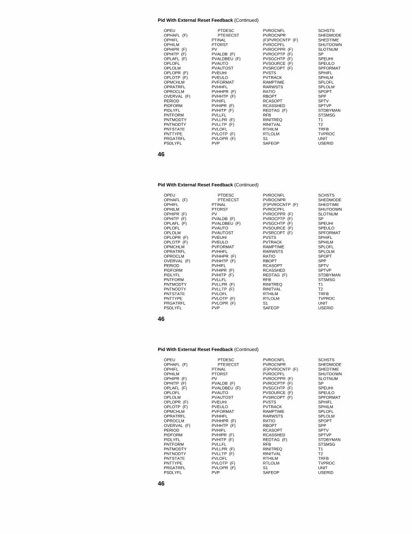
Pid With External Reset Feedback (Continued)
OPEUOPHAFL (F)OPHIFLOPHILMOPHIPR (F)OPHITP (F)OPLAFL (F)OPLOFLOPLOLMOPLOPR (F)OPLOTP (F)OPMCHLMOPRATRFLOPROCLMOVERVAL (F)PERIODPIDFORMPIDLYFLPNTFORMPNTMODTYPNTNODTYPNTSTATEPNTTYPEPRGATRFLPSDLYFL
PTDESCPTEXECST
PTINALPTORSTPVPVALDB (F)PVALDBEU (F)PVAUTOPVAUTOSTPVEUHIPVEULOPVFORMATPVHHFLPVHHPR (F)PVHHTP (F)PVHIFLPVHIPR (F)PVHITP (F)PVLLFLPVLLPR (F)PVLLTP (F)PVLOFLPVLOTP (F)PVLOPR (F)PVP
PVROCNFLPVROCNPR(F)PVROCNTP (F)PVROCPFLPVROCPPR (F)PVROCPTP (F)PVSGCHTP (F)PVSOURCE (F)PVSRCOPT (F)PVSTSPVTRACKRAMPTIMERARWSTSRATIORBOPTRCASOPTRCASSHEDREDTAG (F)RFBRINITREQRINITVALRTHILMRTLOLMS1SAFEOP
SCHSTSSHEDMODESHEDTIMESHUTDOWNSLOTNUMSPSPEUHISPEULOSPFORMATSPHIFLSPHILMSPLOFLSPLOLMSPOPTSPPSPTVSPTVPSTDBYMANSTSMSGT1T2TRFBTVPROCUNITUSERID
46

Pid With Feed Forward
The parameters of the Pid With Feed Forward control algorithm are listed below inalphabetical order. (F) indicates that the parameter is applicable when the PNTFORM = Full.
$AUXUNIT (F)ADVDEVFLADVDEVPR (F)ADVDEVTPADVSP (F)ADVSPP (F)ALENBST (F)ARWNETARWOPASPPROC (F)ASSOCDSPAUTMODFLBADCTLFLBADCTLOPBADCTLPR (F)BADPVFLBADPVPR (F)BFFBIASBSHILMBSLOLMCASMODFLCASREQ
CIDSTNCISRCCNFMUCNFPUCODSTNCONTCUT (F)CTLACTNCTLALGIDCTLEQNCTRLINITCVCVEUHICVEULODELCVDEVDEVHIFLDEVHIPR (F)DEVHITP (F)DEVLOFLDEVLOPR (F)DEVLOTP (F)ESWAUTOESWCAS
ESWENBSTESWMANEUDESCEXTSWOPTFFFFOPTGAINOPTGAPHIGAPLOHIGHAL (F)HIGHALPR (F)INITMANKKEXTKEYWORDKFFKGAPKLINKNLLASTPVLOCALMANMANMODFLMODATTR
MODEMODEAPPLMODEPERMMODNUMNAMENLFMNLGAINNMODATTRNMODENOCINPTSNOCOPTSNODENUMNODETYPNORMCYCLNRMATRFLNRMODFLNTWKNUMOPOPALDB (F)OPEUOPHAFL (F)OPHIFL (Continued)
47

Pid With Feed Forward (Continued)
OPHILMOPHIPR (F)OPHITP (F)OPLAFL (F)OPLOFLOPLOLMOPLOPR (F)OPLOTP (F)OPMCHLMOPRATRFLOPROCLMOVERVAL (F)PERIODPIDFORMPFDLYFLPNTFORMPNTMODTYPNTNODTYPNTSTATEPNTTYPEPRGATRFLPSDLYFLPTDESCPTEXECST
PTINALPTORSTPVPVALDB (F)PVALDBEU (F)PVAUTOPVAUTOSTPVEUHIPVEULOPVFORMATPVHHFLPVHHPR (F)PVHHTP (F)PVHIFLPVHIPR (F)PVHITP (F)PVLLFLPVLLPR (F)PVLLTP (F)PVLOFLPVLOTP (F)PVLOPR (F)PVPPVROCNFL
PVROCNPR (F)PVROCNTP (F)PVROCPFLPVROCPPR (F)PVROCPTP (F)PVSGCHTP (F)PVSOURCE (F)PVSRCOPT (F)PVSTSPVTRACKRAMPTIMERARWSTSRATIORBOPTRCASOPTRCASSHEDREDTAG (F)RINITREQRINITVALRTHILMRTLOLMSAFEOPSCHSTS
SHEDMODESHEDTIMESHUTDOWNSLOTNUMSPSPEUHISPEULOSPFORMATSPHIFLSPHILMSPLOFLSPLOLMSPOPTSPPSPTVSPTVPSTDBYMANSTSMSGT1T2TVPROCUNITUSERID
48

Pid With Position ProportionalThe parameters of the Position Proportional control algorithm are listed below inalphabetical order. (F) indicates that the parameter is applicable when the PNTFORM = Full.
$AUXUNIT (F)ADVDEVFLADVDEVPR (F)ADVDEVTP (F)ADVSP (F)ADVSPP (F)ALENBST (F)ARWNETARWOPASPPROC (F)ASSOCDSPAUTMODFLBADCTLFLBADCTLOPBADCTLPR (F)BADPVFLBADPVPRBADPVR (F)BCAMODFLBIASBSHILMBSLOLMCASMODFLCASREQCIDSTN
CISRCCNFMUCNFPUCODSTNCONTCUT (F)CTLALGIDCTLEQNCTRLINITCYCLETIMDEADBANDDEADTIMEDELCVDEVDEVHIFLDEVHIPR (F)DEVHITP (F)DEVLOFLDEVLOPR (F)DEVLOTP (F)ESWAUTOESWCASESWENBSTESWMANEUDESCEXTSWOPT
GAINOPTGAPHIGAPLOHIGHAL (F)HIGHALPR (F)1INITMANKK1KEXTKEYWORDKGAPKLINKNLLASTPVLMSRCLOCALMANLOWERTIMLOWRDSTNLOWRRATEMANMODFLMANOPCMDMANOPTIMMAXPULSEMINPULSEMODATTR
MODEMODEAPPLMODEPERMMODNUMNAMENLFMNLGAINNMODATTRNMODENOCINPTSNOCOPTSNODENUMNODETYPNORMCYCLNRMATRFLNRMMODFLNTWKNUMOPCMDOPHIFLOPHISRCOPLOFLOPLOSRCOVERVAL (F)
(Continued)
49

PID With Position Proportional (Continued)OPCMDOPHIFLOPHISRCOPLOFLOPLOSRCOVERVAL (F)PFDLYFLPERIODPNTFORMPNTMODTYPNTNODTYPNTSTATEPNTTYPEPRGATRFLPRIMMOD (F)PSDLYFLPTDESC (F)PTEXECSTPTINALPTORSTPVPVALDB (F)PVALDBEU (F)
PVAUTOPVAUTOSTPVEUHIPVEULOPVFORMATPVHHFLPVHHPR (F)PVHHTP (F)PVHIFLPVHIPR (F)PVHITP (F)PVLLFL PVLLPR (F)PVLLTP (F)PVLOFLPVLOPR (F)PVLOTP (F)PVPPVROCNFLPVROCNPR (F)PVROCNTP (F)PVROCPFLPVROCPPR (F)PVROCPTP (F)
PVSGCHTP(F)PVSOURCE (F)PVSRCOPT (F)PVSTSPVTRACKRAISDSTNRAISETIMRAISRATERAMPTIMERARWSTSRATIORBOPTRCASOPTRCASSHEDREDTAG (F)RINITREQRINITVALRPRTRTHILMRTLOLMSAFEOPCMDSCHSTS
SHEDMODE SHEDTIMESHUTDOWNSLOTNUMSPSPEUHISPEULOSPFORMATSPHIFLSPHILMSPLOFLSPLOLMSPOPTSPPSPTVSPTVPSTDBYMANSTSMSGT1T2TVPROCUNITUSERID
50

Position Proportional
The parameters of the Position Proportional control algorithm are listed below inalphabetical order. (F) indicates that the parameter is applicable when the PNTFORM = Full.
$AUXUNIT (F)ADVDEVFLADVDEVPR (F)ADVDEVTP (F)ADVSP (F)ADVSPP (F)ALENBST (F)ARWNETARWOPASPPROC (F)ASSOCDSPAUTMODFLBADCTLFLBADCTLOPBADCTLPR (F)BADPVFLBADPVR (F)BCAMODFLCASMODFLCASREQCIDSTN
CISRCCNFMUCNFPUCODSTNCONTCUT (F)CTLALGIDCTRLINITCYCLETIMDEADBANDDEADTIMEDEVDEVHIFLDEVHIPR (F)DEVHITP (F)DEVLOFLDEVLOPR (F)DEVLOTP (F)ESWAUTOESWCASESWENBSTESWMAN
EUDESCEXTSWOPTHIGHAL (F)HIGHALPR (F)1INITMANKEYWORDLASTPVLMSRCLOCALMANLOWERTIMLOWRDSTNLOWRRATELTIMHILMMANMODFLMANOPCMDMANOPTIMMAXPULSEMINPULSEMODATTRMODEMODEAPPL
MODEPERMMODNUMNAMENMODATTRNMODENOCINPTSNOCOPTSNODENUMNODETYPNORMCYCLNRMMODFLNTWKNUMOPCMDOPHIFLOPHISRCOPLOFLOPLOSRCOVERVAL (F)PERIODPFDLYFL
(Continued)
51

Position Proportional (Continued)
PNTFORMPNTMODTYPNTNODTYPNTSTATEPNTTYPEPRGATRFLPSDLYFLPRIMMOD (F)PTDESCPTEXECSTPTINALPTORSTPVPVALDB (F)PVALDBEU (F)PVAUTOPVAUTOSTPVEUHIPVEULOPVFORMATPVHHFLPVHHPR (F)PVHHTP (F)PVHITP (F)PVHIFLPVHIPR (F)
PVLLFLPVLLPR (F)PVLLTP (F)PVLOFLPVLOPR (F)PVLOTP (F)PVPPVROCNFLPVROCNPR (F)PVROCNTP (F)PVROCPFLPVROCPPR (F)PVROCPTP (F)PVSGCHTP (F)PVSOURCE (F)PVSRCOPT (F)PVSTSRAISDSTNRAISETIMRAISRATERAMPTIMERARWSTSRCASOPTRCASSHEDREDTAG (F)RINITREQ
RINITVALRPRTSAFOPCMDSCHSTSSHEDMODESHEDTIMESHUTDOWNSLOTNUMSPSPEUHISPEULOSPFORMATSPHIFLSPHILMSPLOFLSPLOLMSPOPTSPPSPTVSPTVPSTDBYMANSTSMSGTVPROCUNITUSERID
52

Ramp SoakThe parameters of the Ramp Soak control algorithm are listed below in alphabeticalorder. (F) indicates that the parameter is applicable when the PNTFORM = Full.
$AUXUNIT (F)ADVDEVFLADVDEVPR (F)ADVDEVTP (F)ADVSP (F)ADVSPP (F)ALENBST (F)ARWNETARWOPASPPROC (F)ASSOCDSPAUTMODFLBADCTLFLBADCTLPR (F)BCAMODFLCASMODFLCASREQCIDSTNCISRCCNFMUCNFPUCODSTNCONTCUT (F)
CTLALGIDCTRLINITCURSEGIDCVCVEUHICVEULOCYCLEOPTDEVDEVHIPR (F)DEVHIFLDEVHITP (F)DEVLOFLDEVLOPR (F)DEVLOTP (F)ESWAUTOESWCASESWENBSTESWMANEUDESC (F)EXTSWOPTHIGHAL (F)HIGHALPR (F)
HOLDCMDINITMANKEYWORDLASTPVLOCALMANMANMODFLMODATTRMODEMODEAPPLMODEPERMMODNUMMXRMPDEV‘MXSOKDEVNAMENMODATTRNMODENOCINPTSNOCOPTSNODENUMNODETYPNORMCYCLNORSSEQNRMATRFL
NRMODFLNTWKNUMNXTSOAKVOPOPEUOPHIFLOPHILMOPLOFLOPLOLMOPMCHLMOPRATRFLOPROCLMOVERVAL (F)PERIODPFDLYFLPNTFORMPNTMODTYPNTNODTYPNTSTATEPNTTYPEPRGATRFLPRIMMOD
(Continued)
53

Ramp Soak (Continued)
PSDLYFLPTDESCPTEXECSTPTINALPTORSTPVPVEUHIPVEULOPVFORMATPVPPVSTSRAMPTIMERARWSTSRATE1RATE2RATE3RATE4RATE5RATE6RATE7
RATE8RATE9RATE10RATE11RATE12REDTAG (F)REMSOAKTRINITREQRINITVALS1S1BGNTIMS1ENDTIMS1SEGIDS2S2BGNTIMS2ENDTIMS2SEGIDSAFEOPSCHSTSSEGTYPESHUTDOWN
SLOTNUMSOAKT1SOAKT2SOAKT3SOAKT4SOAKT5SOAKT6SOAKT7SOAKT8SOAKT9SOAKT10SOAKT11SOAKT12SOAKV1SOAKV2SOAKV3SOAKV4SOAKV5SOAKV6SOAKV7SOAKV8
SOAKV9SOAKV10SOAKV11SOAKV12SPSPEUHISPEULOSPFORMATSPHIFLSPHILMSPLOFLSPLOLMSPOPTSPPSPTVSPTVPSTDBYMANSTSMSGTVPROCUNITUSERID
54

Ratio Control
The parameters of the Ratio Control control algorithm are listed below inalphabetical order. (F) indicates that the parameter is applicable when the PNTFORM = Full.
$AUXUNIT (F)ADVDEVFLCADVDEVPR (F)ADVDEVTP (F)ADVSP (F)ADVSPP (F)ALENBST (F)ARWNETARWOPASPPROC (F)ASSOCDSPAUTMODFLB1B2BADCTLFLBADCTLPR (F)BADPVFLBADPVPR (F)BCAMODFLCASMODFL
CASREQCIDSTNCISRCCNFMUCNFPUCODSTNCONTCUT (F)CTLALGIDCTRLINITCVCVEUHICVEULODEVDEVHIFLDEVHIPRDEVHITP (F)DEVLOFLDEVLOPR (F)DEVLOTP (F)ESWAUTO
ESWCASESWENBSTESWMANEUDESC (F)EXTSWOPTHIGHAL (F)HIGHALPR (F)INITMANK1K2KEYWORDLASTPVLOCALMANMANMODFLMODATTRMODEMODEAPPLMODEPERMMODNUMNAME
NMODATTRNMODENOCINPTSNOCOPTSNODENUMNODETYPNORMCYCLNRMATRFLNRMMODFLNTWKNUMOPOPALDB (F)OPEUOPHAFL (F)OPHIFLOPHILMOPHIPR (F)
(Continued)
55
Ratio Control
The parameters of the Ratio Control control algorithm are listed below inalphabetical order. (F) indicates that the parameter is applicable when the PNTFORM = Full.
$AUXUNIT (F)ADVDEVFLADVDEVPR (F)ADVDEVTP (F)ADVSP (F)ADVSPP (F)ALENBST (F)ARWNETARWOPASPPROC (F)ASSOCDSPAUTMODFLB1B2BADCTLFLBADCTLPR (F)BADPVFLBADPVPR (F)BCAMODFLCASMODFL
CASREQCIDSTNCISRCCNFMUCNFPUCODSTNCONTCUT (F)CTLALGIDCTRLINITCVCVEUHICVEULODEVDEVHIFLDEVHIPRDEVHITP (F)DEVLOFLDEVLOPR (F)DEVLOTP (F)ESWAUTO
ESWCASESWENBSTESWMANEUDESC (F)EXTSWOPTHIGHAL (F)HIGHALPR (F)INITMANK1K2KEYWORDLASTPVLOCALMANMANMODFLMODATTRMODEMODEAPPLMODEPERMMODNUMNAME
NMODATTRNMODENOCINPTSNOCOPTSNODENUMNODETYPNORMCYCLNRMATRFLNRMMODFLNTWKNUMOPOPALDB (F)OPEUOPHAFL (F)OPHIFLOPHILMOPHIPR (F)
(Continued)
55

Ratio Control (Continued)
OPHITP (F)OPLAFL (F)OPLOFLOPLOLMOPLOPR (F)OPLOTP (F)OPMCHLMOPRATRFLOPROCLMOVERVAL (F)PERIODPFDLYFLPNTFORMPNTMODTYPNTNODTYPNTSTATEPNTTYPEPRIMMOD (F)PSDLYFLPTDESCPTEXECSTPTINALPTORST
PRGATRFLPVPVALDB (F)PVALDBEU (F)PVAUTOPVAUTOSTPVEUHIPVEULOPVFORMATPVHHFLPVHHPR (F)PVHHTP (F)PVHIFLPVHIPR (F)PVHITP (F)PVLLFLPVLLPR (F)PVLLTP (F)PVLOFLPVLOPR (F)PVLOTP (F)PVP
PVROCNFLPVROCNPR (F)PVROCNTP (F)PVROCPFLPVROCPPR (F)PVROCPTP (F)PVSGCHTP (F)PVSOURCE (F)PVSRCOPT (F)PVSTSRAMPTIMERARWSTSRATE1RCASOPTRCASSHEDREDTAG (F)RINITREQRINITVALSAFEOPSHEDMODESHEDTIMESHUTDOWN
SLOTNUMSPSPEUHISPEULOSPFORMATSPHIFLSPHILMSPLOFLSPLOLMSPOPTSPPSPTVSPTVPSTDBYMANSTSMSGTVPROCUNITUSERIDX2X2FILTX2TF
(Continued)
56

Summer (RegCtl)
The parameters of the Summer Regulatory Control algorithm are listed below in alphabetical order.(F) indicates that the parameter is applicable when the PNTFORM = Full.
$AUXUNIT (F)ALENBST (F)ARWNETARWNOPASSOCDSPAUTMODFLBBADCTLFLBADCTLOPBADCTLPR (F)BCAMODFLCASMODFLCASREQCIDSTNCISRCCNFMUCNFPUCODSTN
CONTCUT (F)CTALGIDCTLEQNCTRLINITCVCVEUHICVEULOESWAUTOESWCASESWENBSTESWMANEUDESCEXTSWOPTHIGHAL (F)HIGHALPR (F)INITMANK
K1, K2, K3, K4KEYWORDLOCALMANMMANMODFLMODATTRMODEMODEAPPLMODEPERMMODNUMNAMENMODATTRNMODENOCINPTS
(Continued)
57

Summer (RegCtl) (Continued)
NODENUMNODETYPNORMCYCLNRMATRFLNRMMODFLNTWKNUMOPOPALDB (F)OPEUOPHAFL (F)OPHIFLOPHILMOPHIPR (F)OPHITP (F)OPLAFL (F)OPLOFLOPLOLMOPLOPR (F)OPLOTP (F)
OPMCHLMOPRATRFLOPROCLMOVERVAL (F)PERIODPFDLYFLPNTFORMPNTMODTYPNTNODTYPNTSTATEPNTTYPEPRGATRFLPRIMMOD (F)PSDLYFLPTDESC (F)PTEXECSTPTINALPTORSTRARWSTS
RATE1RCASOPTREDTAG (F)RINITREQRINITVALSAFEOPSCHSTSSHEDMODESHEDTIMESHUTDOWNSLOTNUMSTDBYMANSTSMSGUNITUSERIDX1, X2, X3, X4XEUHIXEULO
58

Summer (RegPV)
The parameters of the Summer PV algorithm are listed below in alphabetical order.(F) indicates that the parameter is applicable when the PNTFORM = Full.
$AUXUNIT (F)ALENBST (F)ASSOCDSPBADPVFLBADPVPR (F)CC1C2C3C4C5C6CNFMUCNFPUCONTCUTDEUDESCHIGHAL (F)HIGHALPR (F)
KEYWORDLASTPVNMODNUMNAMENODENUMNODETYPNOPINPTSNTWKNUMOVERVAL (F)P1P1STSP2P2STSP3P3STSP4P4STS
P5P5STSP6P6STSPERIODPFDLYFLPIDSTNPISRCPNTFORMPNTMODTYPNTNODTYPNTSTATEPNTTYPEPRIMMOD (F)PSDLYFLPTDESC
(Continued)
59

Summer (RegPV) (Continued)
PTEXECSTPTINALPVPVALDB (F)PVALDBEU (F)PVALGIDPVAUTOPVAUTOSTPVCALCPVCLAMPPVEQNPVEULOPVEUHIPVEXEUHIPVEXEULOPVEXHIFLPVEXLOFL
PVFORMATPVHHFLPVHHPR (F)PVHHTP (F)PVHIFLPVHIPR (F)PVHITP (F)PVINITPVLLFLPVLLPR (F)PVLLTP (F)PVLOFLPVLOPR (F)PVLOTP (F)PVPPVROCNFL
PVROCNPR (F)PVROCNTP (F)PVROCPFLPVROCPPR (F)PVROCPTP (F)PVSGCHTP (F)PVSOURCE (F)PVSRCOPT (F)PVSTSPVTV (F)PVTVP (F)SCHSTSSLOTNUMSTSMSGTFUNITUSERID
60

Switch
The parameters of the Switch control algorithm are listed below in alphabetical order.(F) indicates that the parameter is applicable when the PNTFORM = Full.
$AUXUNIT (F)ALENBST (F)ARWNETARWOPASSOCDSPAUTMODFLBADCTFLBADCTLOPBADCTLPR (F)BCAMODFLCASMODFLCASREQCIDSTNCISRCCNFMUCNFPUCODSTNCONTCUT (F)CTLALGID
CTLEQNCTRLINITCVCVEUHICVEULOESWAUTOESWCASESWENBSTESWMANEUDESCEXTSWOPTHIGHAL (F)HIGHALPR (F)INITMANKEYWORDLOCALMANMMANMODFLMODATTR
MODEMODEAPPLMODEPERMMODNUMNAMENMODATTRNMODENRMATRFLNRMMODFLNOCINPTSNOCOPTSNODENUMNODETYPNTWKNUMOPOPALDB (F)OPEU
(Continued)
61

Switch (Continued)
OPHAFLOPHIFLOPHILMOPHIPR (F)OPHITP (F)OPLAFL (F)OPLOFLOPLOLMOPLOPR (F)OPLOTP (F)OPMCHLMOPRATRFLOPROCLMOVERVAL (F)PERIODPFDLYFLPNTFORMPNTMODTYPNTNODTY
PNTSTATEPNTTYPEPRGATRFLPRIMMOD (F)PTDESCPTEXECSTPTINALPTORSTRARWSTSRCASOPTRCASSHEDREDTAGRINITREQRINITVALS1S2S3S4
SAFEOPSAFEOPSCHSTSSELXINPSHEDMODESHEDTIMESHUTDOWNSLOTNUMSTDBYMANSTSMSGTRACKINGUNITUSERIDX1X2X3X4XEUHIXEULO
62

Totalizer
The parameters of the Totalizer PV algorithm are listed below in alphabetical order.(F) indicates that the parameter is applicable when the PNTFORM = Full.
$AUXUNIT (F)ACCTYPEALENBST (F)ASSOCDSPAVDEV1FLAVDEV1TPAVDEV2FLAVDEV2TPAVTVAVTVFLBADPVFLBADPVPR (F)CCOMMANDCONTCUT (F)CNFMUCNFPUCUTOFFLMEUDESCHIGHAL (F)
HIGHALPR (F)KEYWORDLASTPVMODNUMNAMENODENUMNODETYPNOPINPTSNORMCYCLNTWKNUMOLDAVOVERVAL (F)P1P1STSP2P2STSPERIODPIDSTNPISRC
PNTFORMPNTMODTYPNTNODTYPNTSTATEPNTTYPEPRIMMOD (F)PSDLYFLPTDESCPTEXECSTPTINALPVPVALDB (F)PVALDBEUPVALGIDPVAUTOPVAUTOSTPVCALC
(Continued)
63

Totalizer (Continued)
PVCLAMPPVEQNPVEUHIPVEULOPVEXEUHIPVEXEULOPVEXHIFLPVEXLOFLPVFORMATPVHHFLPVHHPR (F)PVHHTP (F)PVHIFLPVHIPR (F)PVHITP (F)
PVINITPVLLFLPVLLPR (F)PVLLTP (F)PVLOFLPVLOPR (F)PVLOTP (F)PVPPVROCNFLPVROCNPR (F)PVROCNTP (F)PVROCPFLPVROCPPR (F)PVROCPTP (F)PVSGCHTP (F)PVSOURCE (F)
PVSRCOPT (F)PVSTSPVTV (F)PVTVP (F)RESETFLRESETVALSCHSTSSLOTNUMSTARTFLSTATESTOPFLSTSMSGTFTIMEBASEUNITUSERID
64

Variable Dead Time With Lead/Lag
The parameters of the Variable Dead Time With Lead/Lag PV algorithm are listed below inalphabetical order. (F) indicates that the parameter is applicable when the PNTFORM = Full.
$AUXUNIT (F)ALENBST (F)ASSOCDSPBADPVFL (F)BADPVPR (F)CC1C2CNFMUCNFPUCONTCUT (F)CUTOFFLMDD1D2EUDESCHIGHAL (F)HIGHALPR (F)
KEYWORDLASTPVMODNUMNAMENLOCNODENUMNODETYPNOPINPTSNORMCYCLNTWKNUMOVERVAL (F)P1P1STSP2P2STSPERIODPFDLYFLPIDSTN
PISRCPNTFORMPNTMODTYPNTNODTYPNTSTATEPNTTYPEPRIMMOD (F)PSDLYFLPTDESC (F)PTEXECSTPTINALPVPVALDB (F)PVALDBEU (F)PVALGIDPVAUTO
(Continued)
65

Variable Dead Time With Lead/Lag (Continued)
PVAUTOSTPVCALCPVCLAMPPVEQNPVEUHIPVEULOPVEXEUHIPVEXEULOPVEXHIFLPVEXLOFLPVFORMATPVHHFLPVHHPR (F)PVHHTP (F)PVHIFLPVHIPR (F)
PVHITP (F)PVINITPVLLFLPVLLPR (F)PVLLTP (F)PVLOFLPVLOPR (F)PVLOTP (F)PVPPVROCNFLPVROCNPR (F)PVROCNTP (F)PVROCPFLPVROCPPR (F)PVROCPTP (F)PVSGCHTP (F)
PVSOURCE (F)PVSRCOPT (F)PVSTSPVTV (F)PVTVP (F)SCHSTSSLOTNUMSTSMSGTDTFTLDTLG1TLG2UNITUSERID
66

bParameter Description Type Lock (Default) and Range
$ADD
$AUXUNIT
$DBVALID
$IOMPADD(n)$UCNLSBnAB_DATA1AB_DATA2AB_DATA3AB_DATA4
ABHEMSD
ABHHOLDABHRSTRABHSHDNACCELTIMACCTYPEACPACTPRIM(n)ADVDEVFL
Add last parameter indicator
Auxiliary Unit (R520 & later)
HPM Database Valid
IOP Address (n = 1 - 168)Local UCN Communications Statistics (n = 1 - 50)A-B PLC Family type: 2.0, 3.0, or 5.0A-B PLC File number; NaN for PLC-2A-B PLC-3 Section ID, or PLC-2 or 5 data typeA-B Data PLC Scan Frequency in seconds.256 = Report by ExceptionAbnormal Handler Emergency Shutdown EnableFlag
Abnormal Handler Hold Enable FlagAbnormal Handler Restart Enable FlagAbnormal Handler Shutdown Enable FlagAcceleration TimeAccumulator Operation ModeAdvanced Control Data PointActing Primary I/O Module (n = 1 - 40)Advisory Deviation Alarm Flag
L
e:
e:
IRRRRR
L
LLLTe:Ee:L
PB
Oper
Eng
ViewViewEngEngEngEng
View
ViewViewViewViewEng/PBPBViewView
(On); On Off
(Null); Any valid Unit ID
(DBInvalid);DB_Valid, DBInvalid( ); 0, 129-255
(NaN); N/ANaN); 0 - 999, NaN(NaN); 0 - 9, NaN(NaN); 0 - 255, 256
(Off); On - Off
(Off); On - Off(Off); On - Off(Off); On - Off(0); 0 - 4000 days(Analog); Pulse, Analog(Null); A-Z, 0-9, _( ); IOM_A, IOM_B(Off); On - Off
67
Parameter Description Type Lock (Default) and Range
$ADD
$AUXUNIT
$DBVALID
$IOMPADD(n)$UCNLSBnAB_DATA1AB_DATA2AB_DATA3AB_DATA4
ABHEMSD
ABHHOLDABHRSTRABHSHDNACCELTIMACCTYPEACPACTPRIM(n)ADVDEVFL
Add last parameter indicator
Auxiliary Unit (R520 & later)
HPM Database Valid
IOP Address (n = 1 - 168)Local UCN Communications Statistics (n = 1 - 50)A-B PLC Family type: 2.0, 3.0, or 5.0A-B PLC File number; NaN for PLC-2A-B PLC-3 Section ID, or PLC-2 or 5 data typeA-B Data PLC Scan Frequency in seconds.256 = Report by ExceptionAbnormal Handler Emergency Shutdown EnableFlag
Abnormal Handler Hold Enable FlagAbnormal Handler Restart Enable FlagAbnormal Handler Shutdown Enable FlagAcceleration TimeAccumulator Operation ModeAdvanced Control Data PointActing Primary I/O Module (n = 1 - 40)Advisory Deviation Alarm Flag
L
e:
e:
IRRRRR
L
LLLTe:Ee:L
PB
Oper
Eng
ViewViewEngEngEngEng
View
ViewViewViewViewEng/PBPBViewView
(On); On Off
(Null); Any valid Unit ID
(DBInvalid);DB_Valid, DBInvalid( ); 0, 129-255
(NaN); N/ANaN); 0 – 999, NaN(NaN); 0 - 9, NaN(NaN); 0 – 255, 256
(Off); On – Off
(Off); On – Off(Off); On – Off(Off); On – Off(0); 0 – 4000 days(Analog); Pulse, Analog(Null); A-Z, 0-9, _( ); IOM_A, IOM_B(Off); On – Off
67

Parameter Description Type Lock (Default) and Range
ADVDEVPR
ADVDEVTPADVSPADVSPPALENBSTALMOPT
ALPRIOR
ANAME(n)AOCALIB(n)ARWNETARWOPASSOCDSPASPPROCASTEP(n)ASTMT(n)AUTMODFLAUXDATA1AUXDATA2AUXDATA3AUXDATA4
AV
Advisory Deviation Alarm Priority
Advisory Deviation Alarm Trip PointAdvisory Setpoint in Engineering UnitsAdvisory Setpoint in PercentAlarm Enable StatusAlarming Option (DigComp)Alarming Option (DigIn)Alarm Priority
Abnormal Sequence Name (n = 1 - 3)AO Calibration in Prog. Flag (n = 1 - 168)Windup Status of the InputWindup Status of the OutputAssociated DisplayAdvisory SP Processor StateAbnormal Step Name (n = 1 - 3)Abnormal Statement Number (n = 1 - 3)Automatic Mode FlagModbus Keep Alive addressModbus Retry interval, NaN = 1.5 sec.Modbus Protocol.Modem control (0 = off).Modbus Baud Rate.Parity (0 = none).baud/odd parityAccumulated Value in Engineering Units
e
RRRe:e:e:e:
SLe:e:Se:SILRRRR
I
Eng
SuprSuprViewOper
Eng/PBEng/PBEng
ViewEng/PBViewViewEngSuprViewViewViewEngEngEngEng
Oper
(Low); Low, Emergncy, High,Journal, NoAction, Printer, JnlPrint(NaN); •0.0, NaN(N/A); SPLOLM - SPHILM(N/A); N/A(Enable); Enable, Disable, Inhibit(None); Offnorml, Cmddis, None(None); Offnorml, None(Low); Low, Emergncy, High,Journal, NoAction, Printer, JnlPrintSpaces; N/A( ); Off, - On(Normal); Normal, Hi, Lo, HiLo(Normal); Normal, Hi, Lo, HiLo(Blank); N/A(Disable); Disable, Enable(Blank); N/A(Blank); 0 - 255(N/A); Off - On(NaN); 1 - 9999, NaN(NaN); .25 - 5 Sec., NaN(NaN); 232.0, 232.1, 485.0(NaN); 1200, 2400, 4800, 9600,19,200. Decimal = .0, .1, or .2(0); 0 - 32767
68

Parameter Description Type Lock (Default) and Range
AVDELTHSAVDEV1FLAVDEV2FLAVDEV1TPAVDEV2TPAVGPUAVGTFAVSTSAVTV
AVTVFLBB0B1B2BADCTLFLBADCTLOP
BADCTLPR
BADOCFLBADOCnFL
The Last Half-Second’s AVAccumulated Value – 1st Deviation FlagAccumulated Value – 1st Deviation Trip PointAccumulated Value – 2nd Deviation FlagAccumulated Value – 2nd Dev. Trip PointAverage PUs for Point ProcessingAvg. Statistics Single Lag Filter Time ConstantValue Status of AVAccumulator Target Value (DigIn)Accumulator Target Value (Totalizr)Accumulated Value Target Reached FlagOverall BiasLast Operator Entered Output BiasOutput Bias ConstantBias for Input X2Bad Control Alarm FlagBad Control Option
Bad Control Alarm Priority
Bad Output Connection Flag AlarmBad Output Connection Flag n. (n = 1 - 4)
ILRLRRRe:IRLRRRRLe:
e:
LL
ViewViewSuprViewSupr/PBViewViewViewOperOper/PBViewOper/PBViewSupr/PBSupr/PBViewEng
Eng
ViewView
(0); > 0(N/A); Off - On(NaN); • 0.0, NaN(N/A); Off - On(NaN); • 0.0, NaN(0); N/A(1.00 minutes); N/A(Bad); Bad, Normal(0); 0 - 32767(NaN); N/A, NaN(N/A); Off - On(0.0); N/A(0.0); N/A(0.0); N/A(0.0); N/A(Off); Off - On(No_Shed); No_Shed,ShedHold, ShedLow,ShedHigh, ShedSafe,(Low); Low, Emergncy,High,Journal, NoActionJournal, NoAction, Printer,JnlPrint(Off); On - Off(Off); On - Off
69

Parameter Description Type Lock (Default) and Range
BADOCPR
BADOCOPT
BADPVFL
BADPVPR
BCAMODFLBADPVTXTBADSVFLBADSVPR
BFFBHALMF(n)BIASBNDRESETBNDRSTIM
Bad Output Conn. Alarm Priority
Bad Output Conn. Alarm Option
Bad PV Alarm FlagSI Database Status Flag (Array)Bad PV Alarm Priority
Backup Cascade Mode FlagBad PV Text DescriptorBad SV Alarm FlagBad SV Alarm Priority
Feed Forward Input BiasAlarm Flags (n = 1 - 7)BiasBounds Statistics Reset FlagLast Bounds Statistics Reset Time
e:
LLLe:
LSLe:
RSRLT
Eng
Eng/PBViewViewEng
ViewPBViewEng
SuprViewOper/PBOperView
(Low); Low, Emergncy, High, Journal,NoAction, Printer, JnlPrint(Off); On - Off(Off); Off - On(special); Off - On(Low); Low, Emergncy, High,Journal,NoAction, Printer, JnlPrint(N/A); On - Off(BAD); A-Z, 0-9, _(Off); Off, On(Low); Low, Emergncy, High,Journal,NoAction, Printer, JnlPrint(0.); N/A( ); 0 0-FF(0.0); BSLOLM - BSHILM(Off); Off/On(HPM Startup Time); N/A
70

Parameter Description Type Lock (Default) and Range
BOXCLR(n)
BSHILMBSLOLMBYPASS
BYPASSX1-4
Box Color for Digital Displays (DigComp)
Box Color for Digital Displays (DigIn, Flag)
Bias High LimitBias Low LimitInterlock Bypass Override Input Bypass EnableBypass ORSel’s X1 - X4 Input
e:
e:
RRL
L
Eng/PB
Eng/PB
SuprSuprOper
(Green – Upper Box Default, State 1);(Red – Lower Box Default, State 2);(Yellow – Middle Box Default, State 0);Red, Green, White, Black, Cyan,Yellow, Blue, Magenta(Green – Upper Box Default, State 1);(Yellow – Lower Box Default, State 0);Red, Green, White, Black, Cyan,Yellow, Blue, Magenta
(50.0); • BSLOLM, NaN(-50.0); <BSHILM, NaN(Off); Off - On(BYPASSX1 = Off); Off-On(BYPASSX2-X4 = On);
71
Parameter Description Type Lock (Default) and Range
BOXCLR(n)
BSHILMBSLOLMBYPASS
BYPASSX1-4
Box Color for Digital Displays (DigComp)
Box Color for Digital Displays (DigIn, Flag)
Bias High LimitBias Low LimitInterlock Bypass Override Input Bypass EnableBypass ORSel's X1 - X4 Input
e:
e:
RRL
L
Eng/PB
Eng/PB
SuprSuprOper
(Green – Upper Box Default, State 1);(Red – Lower Box Default, State 2);(Yellow – Middle Box Default, State 0);Red, Green, White, Black, Cyan,Yellow, Blue, Magenta(Green – Upper Box Default, State 1);(Yellow – Lower Box Default, State 0);Red, Green, White, Black, Cyan,Yellow, Blue, Magenta
(50.0); • BSLOLM, NaN(-50.0); <BSHILM, NaN(Off); Off - On(BYPASSX1 = Off); Off-On(BYPASSX2-X4 = On);
71

Parameter Description Type Lock (Default) and Range
CC1-C2
C1-C4
C1-C6CnDESCCnFLCnPR
CnSRC
CABLESTSCALCEXPCALIBALL(n)
Scaling FactorCorrection Constant (FlowComp)Scaling Constant for Input P1-P2 (VdtLdLag)Scaling Constants Used to Calculate PVCALC (PI)Intermediate Results of Calculations (CalCuLtr)Scaling Constants 1-6 (Summer)Custom Alarm Descriptors, (n = 1- 4)Custom Alarm Flag, (n = 1- 4)Custom Alarm Priorities, (n = 1- 4)
Custom Alarm Source, (n = 1- 4)
Overall Cable Status for UCN NodeCalculator ExpressionFull Calibration Enable Flag(n = 1 - 168)
RRR
R
R
RSLe:
e:
ISL
SuprSuprSupr
Supr
Supr
SuprEngProgEng
PB
ViewEngP/BEng/PB
(1.0); Anything except NaN(1.0); C1 • 0.1, C2 •0.1(1.0); • 0.0
(1.0); C1 • 0, C2 > 0
(N/A); N/A
(1.0); N/A(Blank); 8-char string(Off); Off, On(Low); Low, Emergncy,High,Journal, NoAction, Printer,JnlPrint(None); None, L1 - L12, SO1 -SO24, FL1 - FL24,(N/A); 0, 1, 2 or 3(Blank); N/A(Off); Off - On
72

Parameter Description Type Lock (Default) and Range
CALIBRJ(n)
CASMODFLCASREQCHPINHWYCHPINOPR
CIDSTN(n)
CISRC(n)
CLBACKCLPZMXCCLPZMXPCMDCMDDISFLCMDDISPR
Reference Junction Calibration Enable Flag (n = 1 - 168)Cascade Mode FlagRemote Cascade RequestAutomatic Checkpoint InhibitAutomatic Checkpoint Inhibit OperationControl Input Connection Destination (n = 1 - 40)Control Input Connection Source (n = 1 - 40)Number of Backward BranchesOverall Cable Status for UCN Cable AOverall Cable Status for UCN Cable BCommand Fail Alarm Flag (RegCtl)Command Disagree Alarm FlagCommand Disagree Alarm Priority
L
Le:e:e:
P
E
ILLLLe:
Eng/Pb
ViewProgSuprSupr
PB
PB
Eng/PbEngViewView
SpecialEng
(Off); Off - On
(N/A); Off - On(NotReq); NotReq, Request(Enable); Enable, Inhibit(Enable); Enable, Inhibit
(Varies by Algo Type, Equation);N/A(Null.Null); "TagName.Parameter"
(0); 0 - 240(N/A); Off - On(N/A); Off - On(Off); Off - On(Off); Off - On(Low); Low, Emergncy, High,Journal, NoAction, Printer,JnlPrint
73
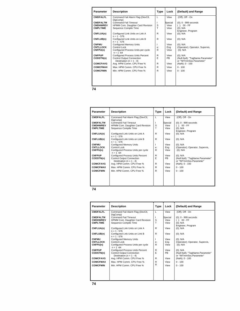
Parameter Description Type Lock (Default) and Range
CMDFALFL
CMDFALTMCMDHWREVCMPLTIME
CNFLUA(n)
CNFLUB(n)
CNFMUCNTLLOCKCNFPU(n)
CNFPUPCODSTN(n)
COMCFAVG
COMCFMAX
COMCFMIN
Command Fail Alarm Flag (DevCtl,DigComp)Command Fail TimeoutHPMM Com. Daughter Card RevisionSequence Compile Time
Configured Link Units on Link An = 1 - 576Configured Link Units on Link Bn = 1 - 576Configured Memory UnitsControl LockConfigured Process Units per cycle n = 1 -64Configured Process Units PercentControl Output Connection Destination (n = 1 - 4)Avg. HPM Comm. CPU Free %
Max. HPM Comm. CPU Free %
Min. HPM Comm. CPU Free %
L
IST
R
R
Ie:R
RE
R
R
R
View
SpecialViewView
View
View
ViewEngView
ViewPB
View
View
View
(Off); Off - On
(0); 0 - 999 seconds( ); 00 - FF(0); N/AEngineer, Program(0); N/A
(0); N/A
(0); N/A(Operator); Operator, Supervis, (0); N/A
(0); N/A(Null.Null); "TagName.Parameter"or "!MTmmSss.Parameter"(NaN); 0 - 100
0 - 100
0 - 100
74
Parameter Description Type Lock (Default) and Range
CMDFALFL
CMDFALTMCMDHWREVCMPLTIME
CNFLUA(n)
CNFLUB(n)
CNFMUCNTLLOCKCNFPU(n)
CNFPUPCODSTN(n)
COMCFAVG
COMCFMAX
COMCFMIN
Command Fail Alarm Flag (DevCtl,DigComp)Command Fail TimeoutHPMM Com. Daughter Card RevisionSequence Compile Time
Configured Link Units on Link An = 1 - 576Configured Link Units on Link Bn = 1 - 576Configured Memory UnitsControl LockConfigured Process Units per cycle n = 1 -64Configured Process Units PercentControl Output Connection Destination (n = 1 - 4)Avg. HPM Comm. CPU Free %
Max. HPM Comm. CPU Free %
Min. HPM Comm. CPU Free %
L
IST
R
R
Ie:R
RE
R
RR
View
SpecialViewView
View
View
ViewEngView
ViewPB
View
View
View
(Off); Off - On
(0); 0 - 999 seconds( ); 00 - FF(0); N/AEngineer, Program(0); N/A
(0); N/A
(0); N/A(Operator); Operator, Supervis, (0); N/A
(0); N/A(Null.Null); "TagName.Parameter"or "!MTmmSss.Parameter"(NaN); 0 - 100
0 - 100
0 - 100
74

Parameter Description Type Lock (Default) and Range
COMMAND
COMPHILMCOMPLOLMCOMPTERMCONTCUTCOUNTDWNCPMSGSECCRIOLORN
CRPPXORN(n)
CRUCNORN
CTLACTN
CTLALGID
Accumulator Commands (DigIn, Totalizr)Timer Commands (Timer)
STI Point/Database Transfer;STI Calibration
Compensation Term High LimitCompensation Term Low LimitCompensation TermContact CutoutAccumulator Count Down FlagNumber of Checkpoint MessagesCurrent Hour I/O LinkFetch/Store Overrun CounterCurrent Hr Pt. Processing Overrun Counter (n = 0 - 8)Current Hour UCN Fetch/Store Overrun CounterControl Action
Control Algorithm Identifier
e:
e:
e:
RRRLLRI
I
I
e:
e:
Oper
Oper
Oper
SuprSuprViewProgEng/PBViewView
View
View
Eng/PB
PB
(None); None, Start, Stop, Reset
(None); None, Start, Stop, Reset,RestStrt(None); None, DnLoadDb, UpLoadDb,Set_LRV, Set_URV, Cor_LRV,Cor_URV, Cor_Inpt, RstCor(1.25); COMPLOLM - 10.0, NaN(0.8); 0.0 - COMPHILM, NaN(1.0); COMPLOLM - COMPHILM(Off); Off - On(Off); Off - On(0); N/A(0); • 0
(0); • 0
(0); • 0
(Reverse); Direct, Reverse
(Null); Null, Pid, PidErfb, PidFF,RatioCtL, IncrSum, Switch,PosProp, AutoMan,RampSoak, ORSel
75

Parameter Description Type Lock (Default) and Range
CTLCFAVGCTLCFMAXCTLCFMINCTLEQN
CTLOPTCTLREDUNCTRLINITCURPINAMnCURSEGID
CUTOFFLMCVCVEUHICVEULOCYCLEOPTCYCLETIMDD1D1_0
Avg. HPM Ctl. Processor Free %Max. HPM Ctl. Processor Free %Min. HPM Ctl. Processor Free %Control Equation Type (AutoMan, ORSel, Switch)Control Equation Type (Pid algos)HPMM Control Processor OptionHPMM Control Redundancy Present FlagControl Initialization Request FlagCurrent Personality Image FilenameCurrent Segment ID
Zero-Flow/Belt-Speed Cut-Off LimitCalculated VariableCV’s High Limit in Engineering UnitsCV’s Low Limit in Engineering UnitsRamp Soak Cycle OptionPosProp Output Cycle Time in SecondsOverall BiasFixed Deadtime in Minutes (VdtLdLag)Digital Input 1 Equal to a PV State of 0 (DigComp)
RRRe:
e:LLLSe:
RRRRe:RRRe:
ViewViewViewPB
PBPBViewProgViewOper
SuprProgEngEngOperSuprSuprSuprView
(NaN); 0 - 100(NaN); 0 - 100(NaN); 0 - 100(EqA); EqA, EqB
(EqA); EqA, EqB, EqC, EqD(On); Off - On(NaN); Off- On(Off); Off- On(N/A): N/A(Ramp1); Ramp1/Soak1 toRamp12/Soak12(0.0); • 0.0, NaN(NaN); N/A(100.0); • CVEULO(0.0); • CVEUHI(Cyclic); Single, Cyclic(10.0); 0.25 - 1000.0 Seconds(0.0); N/A(0.0); 0.0 - 400.0 Minutes(PVState0); PVState0,PVState1
76
Parameter Description Type Lock (Default) and Range
CTLCFAVGCTLCFMAXCTLCFMINCTLEQN
CTLOPTCTLREDUNCTRLINITCURPINAMnCURSEGID
CUTOFFLMCVCVEUHICVEULOCYCLEOPTCYCLETIMDD1D1_0
Avg. HPM Ctl. Processor Free %Max. HPM Ctl. Processor Free %Min. HPM Ctl. Processor Free %Control Equation Type (AutoMan, ORSel, Switch)Control Equation Type (Pid algos)HPMM Control Processor OptionHPMM Control Redundancy Present FlagControl Initialization Request FlagCurrent Personality Image FilenameCurrent Segment ID
Zero-Flow/Belt-Speed Cut-Off LimitCalculated VariableCV's High Limit in Engineering UnitsCV's Low Limit in Engineering UnitsRamp Soak Cycle OptionPosProp Output Cycle Time in SecondsOverall BiasFixed Deadtime in Minutes (VdtLdLag)Digital Input 1 Equal to a PV State of 0 (DigComp)
RRRe:
e:LLLSe:
RRRRe:RRRe:
ViewViewViewPB
PBPBViewProgViewOper
SuprProgEngEngOperSuprSuprSuprView
(NaN); 0 - 100(NaN); 0 - 100(NaN); 0 - 100(EqA); EqA, EqB
(EqA); EqA, EqB, EqC, EqD(On); Off - On(NaN); Off- On(Off); Off- On(N/A): N/A(Ramp1); Ramp1/Soak1 toRamp12/Soak12(0.0); • 0.0, NaN(NaN); N/A(100.0); • CVEULO(0.0); • CVEUHI(Cyclic); Single, Cyclic(10.0); 0.25 - 1000.0 Seconds(0.0); N/A(0.0); 0.0 - 400.0 Minutes(PVState0); PVState0,PVState1
76

Parameter Description Type Lock (Default) and Range
D1_1
D1, D2D2D2D1_00
D2D1_01
D2D1_10
D2D1_11
DAMPING
DATEDAYDB_VALID(n)DEADBAND
DEADTIMEDEBOUNCEDECONF
Digital Input 1 Equal to a PV State of 1 (DigComp)
Status of Digital Inputs 1 & 2 (DigComp)Bias for Input D2 (VdtLdLag)D2_D1 Zero_Zero PV State
D2D1 Zero_One PV State
D2D1 One_Zero PV State
D2D1 One_One PV State
First Order PV Filtering Option for the Smart TransmitterCurrent Date/TimeCurrent DayDatabase Valid, (n = 1 - 40)Deadband Value (Logic) (n = 1 - 24)Deadband in % of Full Scale (PosProp)Deadtime Value for Raise PulseContact Debounce Time in MillisecondsDigitally Enhanced Configuration Mode
E:
LRE:
E:
E:
E:
R
TIE:RRRIE:
Eng/PB
ViewSuprEng/PB
Eng/PB
Eng/PB
Eng/PB
Supr/ViewViewViewEngrSuprSuprSuprEng/PBEng/View
(PVState0); PVState0, PVState1
(Off); Off - On(0.0); • 0.0(MovPV); MovPV, PVState0,PVState1,PVState2, BadPV(PVState0); PVState0, MovPV,PVState1, PVState2, BadPV(PVState1); PVState1, MovPVPVState0, PVState2, BadPV(BadPV); BadPV, PVState0,PVState1, PVState2, MovPV(Off); Off - On
(N/A): N/A(N/A): 1 - 31(Invalid); Valid, Invalid(1.0); • 0.0(5.0%); 0.0 - 100.0%(0.0); 0.0 - 60.0 Seconds( 10 ms) ; 0 - 50 ms(Pv_Sv_Db); PV, PV_Sv,PV_Db, Pv_Sv_Db
77

Parameter Description Type Lock (Default) and Range
DELCV
DEVDEVADDRDEVHIFLDEVHIPR
DEVHITPDEVLOFLDEVLOPR
DEVLOTPDHTIMMAXn
DISP_SIMDISRC(n)
DITYPEDLYTIME
DODSTN(n)
Delta CV in Engineering Units (IncrSum) Delta CV in Percent (Pid)DeviationSerial Link Device AddressDeviation High Alarm FlagDeviation High Alarm Priority
Deviation High Alarm Trip PointDeviation Low Alarm FlagDeviation Low Alarm Priority
Deviation Low Alarm Trip PointMaximum time to Complete a DataHandler Request; n = 1 - 5Simulation Indicator Display SwitchDigComp Input-Connection Source(n = 1 - 2)
Digital Input TypeAlarm Delay in Seconds (DigIn)Alarm Delay in Seconds for LogicBlocks (Logic)DigComp Output Connection Destination (n = 1 - 3)
RRRRLe:
RLe:
RR
LU
e:IR
U
ViewViewViewPBViewEng
SuprViewEng
SuprView
ProgPB
PBSuprSupr
PB
(N/A); N/A(N/A); N/A(N/A); N/A(NaN); N/A(Off); Off - On(Low); Low, Emergncy, High,Journal, NoAction, Printer, JnlPrint(NaN); • 0.0, NaN(Off); Off - On(Low); JnlPrint, Printer, Emergncy,High, Low, Journal, NoAction(NaN); • 0.0, NaN(0); N/A
(N/A) Off - On(Null.Null); "TagName.Parameter" or"!MTmmSss.Parameter" or"$NMhhBxx.Parameter"(Status); Status, Latched, Accum(5); 0 - 60 Seconds(1); 1 - 8000 Seconds
(Null.Null); "TagName.Parameter" or"!MTmmSss.Parameter" or"$NMhhBxx.Parameter"
78

Parameter Description Type Lock (Default) and Range
DOTYPE
DSA
EIPPCODE
EQUOBJNMERRCODE
ESWAUTOESWCAS
ESWENBSTESWMANEUDESC
EUNDESCnEVRCINPGEVTOPT
EXTDATA
EXTSWOPTFFAILCODEFAILOPT(n)FBTIME
Digital Output Type
Device Soft Address
Event-Initiated Point Identifier
Equipment List Object FileSerial Interface/Serial Link Communication Error CodeExternal Switching Flag for Auto ModeExternal Switching Flag for Cascade ModeExternal Mode Switching Enable StateExternal Switching Flag for ManualModeEngineering Units Descriptor
IOP Generic Descriptor, n = 1 – 168NIM Event Recovery in Progress FlagEvent Reporting Option (DigComp)Event Reporting Option (DevCtl, DigIn)External Data Option
External Mode Switching OptionFlow Input (uncompensated)I/O Processor Hard Fail StatusFailure Option for Outputs (n = 1 - 168)Feedback Time
e:
I
E
SS
LL
e:LS
SLe:
e:
e:Re:e:I
PB
View
Eng
View
View
ProgProg
OperProgPB
ViewViewPBPBPB
Eng/PBView
ViewEng/PBEng/PB
(Status); PWM, Status
(N/A); 1-40, 129-168
(Null); A-Z, 0-9, _
(Blank); N/ASpaces; N/A
(Off); Off - On(Off); Off - On
(Disable); Disable, Enable(Off); Off - On(Blank); A-Z 0-9 space ! % & ’ ( )* + - / : ; > < = ? _ , . $Blanks; 1-40 (pri); 129-168 (sec)(N/A); Off, On(None); None, Eip(None); None, Eip, Soe, Eip_Soe(None); None,IO_FL,IO_NN,IO_STR,UCN_FL,UCN_NN,UCN_STR(None); None, Ems, Emp(NaN); N/A(N/A); See HP09-540, HPM PRD(Unpower); Unpower, Hold(1000); 0-1000 Seconds
79

Parameter Description Type Lock (Default) and Range
FFFFOPTFL(n)
FLDESCFLSTIXFORCEFRCPERMFREQ6050FRQUTAVGFRQUTMAXFRSPTAVGFRSPTMAXFSELINFSTSFTAnTYPEFTACONNFTANUMFTAPRES(n)GGAINOPTGAPHI
Feed Forward Algorithm InputFeed Forward TypeBox Flags FL(1) - FL(16,384)Logic Slot Flags FL(1) - FL(12)Array Point Flags FL(i)Process Module Flags FL(1) - FL(127)FL Array DescriptorFlag Array Start IndexForced Input Request FlagForced Input PermissiveFrequency 60/50 Hz for LLMUX or STTAverage UCN Fetch Request Trip TimeMaximum UCN Fetch Request Trip TimeAverage UCN Fetch Response TripTimeMax. UCN Fetch Response Trip TimeForce Selected InputFlow Input Value StatusType of FTA Connected to LLMUX; n=1- 2FTA Connection to I/O Module This FileSI IOP FTA numberIOP FTA Present Flag; n = 1 - 168Specific Gravity InputGain (K) OptionGap High Limit
Re:LLLLSRLLe:RRRRe:e:e:e:ILRe:R
ViewEng/PBOperspecialspecialspecialPBPBOperEng/PBEng/PBViewViewViewViewOpr/PBViewViewViewPBViewViewEng/PBSupr
(N/A); N/A(Multiply); Multiply, Add(Off); Off - On(FL2 = On, rest = Off); Off - On(N/A); 1 < i < NFLAG(Off); Off-On(spaces); N/A(0); 0 - 99,000 or 0 - 16,384(Off); Off- On(Off); Off- On(60Hz); 0 - 60 Hz, 1 - 50 Hz(NAN); N/A(NAN); N/A(NAN); N/A(NAN); N/A(SelectP1); SelectP1 - SelectP6,(Bad); Bad, Normal, Uncertn(None); None, TC, RTD(Conn_A); Conn_A, Conn_B(1); 1 - 10( ); Off/On(1.0); N/A(Lin); Lin, Gap, NonLin, Ext(0.0); • 0.0
80

Parameter Description Type Lock (Default) and Range
GAPLOGENDESC(n)
GENDESC(n)
GSTSHIGHAL
HIGHALPR
HISVPEAKHOLDCMDHWYCTLSTI0 - I2I0CONFInDESCI1CONFI2CONF
Gap Low LimitGeneric Descriptor (n = 1 - 12)
Generic Descriptor (n = 1 - 40 or 129 - 168)Gravity Input Value StatusHighest Alarm Detected(AnalgIn, PI, RegCtl, RegPV)
Highest Alarm Detected(DigComp, DigIn, DevCtl, Flag, Logic)
Highest Level Alarm’s Priority
Highest Peak SECVAR ValueHold Command FlagUCN Network Functional StateOverride Interlocks for Output States 0-2Override Interlock 0 Alarm Conf. flagI0 - I2 Alarm Descriptor; (n = 0 - 2)Override Interlock 1 Alarm Conf. flagOverride Interlock 2 Alarm Conf. flag
RS
S
e:e:
e:
e:
RLe:LLSLL
SuprPB
View
ViewView
View
View
ViewProgSuprEngOperEngOperOper
(0.0); • 0.0(Blanks); A-Z 0-9 Space ! % & ’ ( ) * + - : ; > < = ? _ , . $
(Blanks); 1 - 40 = Acting Primary,129 - 168 = Acting Secondary(Normal); Normal, Uncertn, Bad(NoAlarm); NoAlarm, AdvDev, DevHi,DevLo, PVRocN, PVRocP, PVHi,PVHH, PVLo, PVLL, BadCtl, BadPV,BOC(NoAlarm); NoAlarm, OffNorm,UnCEvt, CmdDis BadPV, C1ALM -C4ALM, Chngofst, Cmdfail, SVHI,SVHH, BadSV, OVRDI2, OVRDI1,OVRDI0, OVRDSI0, BadCtl(NoAction); NoAction, Journal, Printer,JnlPrint, Low, High, Emergncy(0); • 0(Off); Off - On (Basic); Basic, Full(Off); On - Off (Off); N/A(Blank); 8 Character String(Off); N/A(Off); N/A
81
Parameter Description Type Lock (Default) and Range
GAPLOGENDESC(n)
GENDESC(n)
GSTSHIGHAL
HIGHALPR
HISVPEAKHOLDCMDHWYCTLSTI0 - I2I0CONFInDESCI1CONFI2CONF
Gap Low LimitGeneric Descriptor (n = 1 - 12)
Generic Descriptor (n = 1 - 40 or 129 - 168)Gravity Input Value StatusHighest Alarm Detected(AnalgIn, PI, RegCtl, RegPV)
Highest Alarm Detected(DigComp, DigIn, DevCtl, Flag, Logic)
Highest Level Alarm's Priority
Highest Peak SECVAR ValueHold Command FlagUCN Network Functional StateOverride Interlocks for Output States 0-2Override Interlock 0 Alarm Conf. flagI0 - I2 Alarm Descriptor; (n = 0 - 2)Override Interlock 1 Alarm Conf. flagOverride Interlock 2 Alarm Conf. flag
RS
S
e:e:
e:
e:
RLe:LLSLL
SuprPB
View
ViewView
View
View
ViewProgSuprEngOperEngOperOper
(0.0); • 0.0(Blanks); A-Z 0-9 Space ! % & ’ ( ) * + - : ; > < = ? _ , . $
(Blanks); 1 - 40 = Acting Primary,129 - 168 = Acting Secondary(Normal); Normal, Uncertn, Bad(NoAlarm); NoAlarm, AdvDev, DevHi,DevLo, PVRocN, PVRocP, PVHi,PVHH, PVLo, PVLL, BadCtl, BadPV,BOC(NoAlarm); NoAlarm, OffNorm,UnCEvt, CmdDis BadPV, C1ALM -C4ALM, Chngofst, Cmdfail, SVHI,SVHH, BadSV, OVRDI2, OVRDI1,OVRDI0, OVRDSI0, BadCtl(NoAction); NoAction, Journal, Printer,JnlPrint, Low, High, Emergncy(0); • 0(Off); Off - On (Basic); Basic, Full(Off); On - Off (Off); N/A(Blank); 8 Character String(Off); N/A(Off); N/A
81

Parameter Description Type Lock (Default) and Range
IN0 - IN12
INITMANINITREQ
INITREQ(i)
INITVALINPTDIRIIOLASTSIOLBSTSIOLCHAERIOLCHASLIOLCHBERIOLCHBSLIOLCHERTIOLCMD
IOLPERSWIOMACTYP(n)
Input Coordinates 0-12
Initialization Manual FlagsInitialization Request Flag (Array)Initialization Request Flags (AO, DO)Initialization Request Flags (DigComp, DevCtl ) (i = 0 - 2)Initialization Request Flags (RegCtl) (i = 1 - 4)Initialization ValueInput DirectionI/O Link Cable A StatusI/O Link Cable B StatusI/O Link Channel A Error CountI/O Link Channel A Silence CountI/O Link Channel B Error CountI/O Link Channel B Silence CountI/O Link Channel Error ThresholdI/O Link Command
I/O Link Periodic Cable SwapIOP Actual Type
R
LLL
L
LRe:LLIIIIIe:
e:e:
Supr
ViewViewView
View
ViewView
Eng/PBViewViewViewViewViewView
EgOnlyEgOnly
ViewView
(NaN); > Previous INn but < Next INn.IN0 < IN1 <IN2 ......, <IN12(On); Off - On(Off); Off - On(On); Off - On
(On); Off - On
(Off); Off - On(N/A); N/A(Direct); Direct, Reverse(Off); Off - On(Off); Off - On(0); • 0(0); • 0(0); • 0(0); • 0(10); • 0(None); None, SelChnA, SelChnB,EnbPerSw, DisPerSw, RsIoLCom(N/A); Enable, Disable(None); None, LLAI, HCAI, DI, DO, AO, HPMM, LLMUX, STIM, PI
82

Parameter Description Type Lock (Default) and Range
IOMCARD(n)
IOMCARDA(n)IOMCARDB(n)IOMCMDIOMCOMER(n)
IOMFILE(n)
IOMFILEA(n)
IOMFILEB(n)
IOMFWREV(n)IOMHWREV(n)IOMLHFST(n)
I/O Module Card Position for the ActingPrimary/Secondary n = 1-40 for ActingPrimaries; n = 129-168 for Act. SecondariesI/O Module A Card Position (n = 1 - 40)I/O Module B Card Position (n = 1 - 40)IOP Module CommandIOP Communication Error Status; (n = 1-168)I/O Module File Position for the Acting Primary/Sec. (n = 1 - 40, 129 - 168)I/O Module File A Position for the Acting Primary/Secondary (n = 1 - 40)I/O Module File B Position for the Acting Primary/Secondary (n = 1 - 40)IOP Card Firmware Revision Status 1-168IOP Card Hardware Revision Status 1-168IOP Card Last Hard Fail Status
I
IIe:e:I
I
I
AAe:
View
PtBldPtBldOperViewView
PtBld
PtBld
ViewViewView
(N/A); 1- 15
(0); 0 - 15(0); 0 - 15(None); None, Run, Idle, Swap(N/A); See AP09-540(0); 0 - 8
(0); 0 - 8
(0); 0 - 8
(N/A); X.Y (X=Range, Y=Revision)(N/A); Hexadecimal "00" to "FF"(N/A); Unknown, PowerDwn,AdCIncmp, AdOutOvf, AdOutUdf,BadDcLtc, Dmt_Tmot, MLtOutFl,BadDaRng, MstrTmot, InvPrgEx,EpromErr, RamCntEr, RamAdrEr,DpaError, DsaError, RxBufOfL,IOLJaber, BadPgJmp, AdCCalEr,
83

Parameter Description Type Lock (Default) and Range
IOMUNIOMOPER(n)IOMREALT
IOMRECHN(n)IOMSEVER(n)
IOMSTS(n)
IOMTYPE(n)
IOMTYPE
IOPDESC(n)IOPNUMIOPSTR1(n)IOPSTR2(n)IOREDOPTIOSCNPER(n)IOSTKNDRK
IOP Card NumberIOP in Operation (n = 1 -168)Actual IOP Type
IOP Receive ChannelError Severity Based on IOP State (n = 1 -40; 129 - 168)IOP Status (n = 1 - 40; 129 - 168)
IOP Type (IOP) (n = 1 - 168)
IOP Type (HPM Box)
IOP Description; (n = 1 - 40)Serial Intf. IOP Module NumberIOP String For FTA #1 (n = 1 -40)IOP String For FTA #2 (n = 1-40)I/O Module Redundancy OptionIO Data Scan Period in secondsIOP Token Drop CountGain Constant for X2 Input (AutoMan)Overall Gain in % Per % (Pid)Gain Constant (PosProp)
Ie:e:
e:e:
e:
e:
e:
SISSe:RIR
RR
PBViewView
ViewView
View
View
PB
ViewPBViewViewPBPBViewSupr
SuprSupr
(N/A); 1 - 40(N/A); Primary, Secondry(None); None, LLAI, HALAI, DI, DO,AO, LLMUX, STIM, PI(N/A); ChannelA, Channel B(N/A); OK, Fail, Warning, Inform
(N/A); CommErr, ConfgMis, Idle,IdleSF, NonExist, NoResp, NotConfg, OK,PowerOn, SoftFail, UnAvail, Confgerr(None); None, HLAI, LLAI, AO, DI, DO; SI;LLMUX STIM, PI; AO16; DO32; DISOE(NotConfg); NotConfg, HLAI, LLAI,AO, DI, DO, LLMUX STIM, PI(Spaces); 8 characters(N/A); 1 - 127(Spaces); N/A(Spaces); N/A(Nonredun); Redun, Nonredun(0); 0.0, 0.625, 0.125, 0.25, 0.5, 1.0(N/A); 0 - 32767(1.0); N/A
(1.0); 0.0 - 240.0(1.0); 0.0 - 10.0
84

Parameter Description Type Lock (Default) and Range
K1
K1-K2
K1-K3K1-K4KEXTKEYWORDKFFKGAPKLINKNLL(n)LASTPVLCNRECHNLIBADOPTLIBRYNUMLIBRYTXT(n)LIDESC(n)LINEPERD(n)
LISRC(n)
External Reset Feedback Gain (PidErfb)External Reset Feedback Gain (PIDPosPr)K1=Ratio Scale Factor; K2= Gain for X2 Input (RatioCtl)Gain Constant for X1-X3 Inputs (MulDiv)Gain Constant for X1-X4 Inputs (IncrSum)External Gain ModifierKeyword DescriptorGain for Feed Forward InputGap Gain FactorLinear Gain FactorNon-linear Gain FactorValue of the External Input (n = 1 - 12)Last PV ValueLCN Channel That NIM is Listening toLogic Bad Input Handling OptionNIM Library NumberNIM Library Text, (n = 1 - 1000)Input Descriptor (n = 1 - 12)Line Period in Microseconds (n = 1 - 168)Logic Input Connection Source (n = 1 - 12)
RRR
RRRSRRRRLRE:E:ISSR
U
SuprSuprSupr
SuprSuprProgPBSuprSuprPBViewViewViewViewPBPBPBEngView
PB
(0.0); 0.0 - 1.0(1.0); 0.0 - 1.0(1.0); • 0
(1.0); N/A(1.0); • 0.0(1.0); 0.0 - 240.0(Blank); A-Z, 0-9, _(1.0); • 0.0 to ≤ 1.0(1.0); 0.0 - 1.0(1.0); 0.0 - 240.0(N/A); N/A(N/A); Real(NaN); N/A(ChannelA); ChannelA, ChannelB(Hold); Off, On, Hold(N/A); 1 - 3(N/A); N/A(Blank); 8 Characters(N/A); 15616 - 21759 µseconds
(Null.Null); "TagName.Parameter" or"!MTmmSss.Parameter" or"$NMhhBxx.Parameter"
85
Parameter Description Type Lock (Default) and Range
K1
K1-K2
K1-K3K1-K4KEXTKEYWORDKFFKGAPKLINKNLL(n)LASTPVLCNRECHNLIBADOPTLIBRYNUMLIBRYTXT(n)LIDESC(n)LINEPERD(n)
LISRC(n)
External Reset Feedback Gain (PidErfb)External Reset Feedback Gain (PIDPosPr)K1=Ratio Scale Factor; K2= Gain for X2 Input (RatioCtl)Gain Constant for X1-X3 Inputs (MulDiv)Gain Constant for X1-X4 Inputs (IncrSum)External Gain ModifierKeyword DescriptorGain for Feed Forward InputGap Gain FactorLinear Gain FactorNon-linear Gain FactorValue of the External Input (n = 1 - 12)Last PV ValueLCN Channel That NIM is Listening toLogic Bad Input Handling OptionNIM Library NumberNIM Library Text, (n = 1 - 1000)Input Descriptor (n = 1 - 12)Line Period in Microseconds (n = 1 - 168)Logic Input Connection Source (n = 1 - 12)
RRR
RRRSRRRRLRE:E:ISSR
U
SuprSuprSupr
SuprSuprProgPBSuprSuprPBViewViewViewViewPBPBPBEngView
PB
(0.0); 0.0 - 1.0(1.0); 0.0 - 1.0(1.0); • 0
(1.0); N/A(1.0); • 0.0(1.0); 0.0 - 240.0(Blank); A-Z, 0-9, _(1.0); • 0.0 to ≤1.0(1.0); 0.0 - 1.0(1.0); 0.0 - 240.0(N/A); N/A(N/A); Real(NaN); N/A(ChannelA); ChannelA, ChannelB(Hold); Off, On, Hold(N/A); 1 - 3(N/A); N/A(Blank); 8 Characters(N/A); 15616 - 21759 µseconds
(Null.Null); "TagName.Parameter" or"!MTmmSss.Parameter" or"$NMhhBxx.Parameter"
85

Parameter Description Type Lock (Default) and Range
LMREVLMSRCLOADSCOPLOADSTAT
LOCALMAN
LOCUTOFFLODSTN(n)
LOENBL(n)
LOGALGID(n)
Local Manual PolarityLocal Manual SourceLoad ScopeLoad Status
Local Manual Flag (AO, RegCtl)Local Manual Flag (DigComp, DevCtl)Low Signal Cut Off for Flow InputsLogic Output-Connection Destination Logic (n = 1 - 12) DevCtl (n = 1 - 2)Logic Output Enable, (Logic )(n = 1 - 12 )Logic Output Enable, (DevCtl)(n = 1 - 2)Logic Block Algorithm Identifier(n = 1 - 24)
e:Ue:e:
LL
RR
e:
e:
e:
Eng/PBPBPBView
ViewProg
Eng/PBPB
PB
PB
PB
( Direct); Direct, Reverse( Null.Nul); See SW09-540 PRD(NIMOnly); NimOnly, NimAndPm( ); Not Loaded, Loaded, Loading,Unlding(Off); Off - On(Off); Off - On
(NaN); PVEULO - PVEUHI, NaN(Null.Null); "TagName.Parameter" or"!MTmmSss.Parameter", or"$NMhhBxx.Parameter"(FL2); FL1 - FL12, SO1 - SO16, L1 -L12 (FL2); See SW09-540 PRD
(Null); OR, NOT, NAND, NOR, XOR,AND, SWITCH, CheckBad, Pulse,Delay, OnDLy, OffDLy, QOR2, QOR3,EQ, NE, GT, GE, LT, LE, MinPulse,MaxPulse, WatchDog, FlipFlop,ChDetect, Null
86

Parameter Description Type Lock (Default) and Range
LOGICSRCLOGMIXLOSRC(n)
LOWERTIMLOWRDSTNLOWRRATELRLLRV
LSEQNUMRLSIOLORN(n)
LSPPXORN(n)
LSTWHNERLSUCNORNMMAINDATMAINTOPTMANMODFL
Logic SourceLogic MixOutput - Connection SourceLogic (n = 1 - 12)DevCtl (n = 1 - 2)Lower Output Pulse Time (Secs)Lower OP Pulse DestinationLower OP Stroke Rate in %/SecLower Range Limit (STI)Lower Range Value (STI)
Last Sequence NumberLast Hour’s I/O Link Fetch/Store Overruns (n = 1 - 4)Last Hour’s Point Processing Fetch/Store Overruns (n = 1 - 8)Last When ErrorLast Hour’s UCN Access OverrunsNumber of InputsMaintenance Reset Statistics DateMaintenance OptionManual Mode Flag
Ee:e:
e:RURRR
II
I
IIITLL
PBPB
Eng/PB
PBViewPBSuprViewSupr/ViewEngView
View
ViewViewPBEngPBView
(Null); A-Z, 0-9, _(12_24_4); 12_24_4, 12_16_8,12_8_12(FL1); L1 - L12, FL1 - FL12,NN1 - NN8, SO1 - SO24See SW09-540 PRD(N/A); N/A(Null); ONPULSE , OFFPULSE(100.0); >0.0% / Second(NaN); Na, NaN(NaN); Na, NaN
(0);(0); • 0
(0); • 0
(0); > 0(0); • 0(2); 2 - 4(Time of pt. build) Time Stamp(Off); Off - On(Off); Off - On
87

Parameter Description Type Lock (Default) and Range
MANOPCMD
MANOPTIMMASKTIMMAXCNFPUMAXPUMAXPULSE
MAXSLOTSMAXTIM0HMAXTIM1HMAXTIM2HMAXTRAN0-2MINPULSE
MINUTEMODATTR
MODE
MODEAPPL
MODEPERM
Manual Output Pulse Command
Manual Output Pulse TimeMasktimeMaximum Configurable PUsMaximum PUsMaximum Pulse Time Limit
Maximum Available SlotsMaximum time Allowed in state 0Maximum time Allowed in state 1Maximum time Allowed in state 2Max. number transitions into each stateMinimum Pulse Time Limit
Current MinuteMode Attribute
Mode (AnalgOut)Mode (DigComp, DevCtl)Mode (RegCtl)
Mode Applicability
Mode Permissive(DevCtl, DigComp,RegCtl)Mode Permissive(Analg Out)
e:
RIRRR
RRRRTR
Ie:
e:e:e:
L
e:
e:
Oper
Eng/PBSuprViewViewSupr
ViewSuprSuprSuprSuprPB
ViewOper
OperOperOper
View
Eng
Eng/PB
(None); Raise_1, Lower_1,None, Raise_10, Lower_10(1.0); 0.0 - 60.0 Seconds(0.0); 0 - 1000 sec.(N/A); N/A(0);(60.0); MINPULSE to 60.0Seconds, NaN(0); 0 - 127(0); N/A(0); N/A(0); N/A(0.0); no limit(0.0); 0.0 Seconds to MAXPULSE,NaN(N/A); 0 - 59(Operator); Operator, Program,Normal, None(Man); Man, Cas, Normal(Man); Man, Normal(Man); Man, Cas, Auto, BcasNormal(Man=On; Auto, Cas, & Bcas = Off,Static for DevCtl & DigComp); N/A(Permit); Permit, NotPerm
(Permit); Permit, NotPerm
88

Parameter Description Type Lock (Default) and Range
MODNUMMOMSTATE
MONPERMONTHMOVPVFLMOVPVTXTMSGPENDMSGTXT(n)MXRMPDEVMXSOKDEVN
NAMENARRSLOTNCTLSLOTNDCSLOTNDEVSLOTNEIPRQUNFASTCTL
NFASTDC
NFASTDEVNFASTLOG
IOP Card NumberMomentary Output States
Monitoring Period in secondsCurrent MonthMoving PV FlagMoving PV Text DescriptorSequence Message PendingStatus Message Text (n = 0 - 15)Maximum Ramp Deviation ValueMaximum Soak Deviation ValueNumber of Inputs (CalcuLtr)Number of Inputs (HiloAvg & Summer)Tag NameNumber of Array Points in an HPMNumber of Regulatory Control PointsNumber of Digital Composite PointsNumber of DevCtl. Points ConfiguredNo. of Event Initiated ProcessingRequestsNumber of Fast Regulatory Control SlotsNumber of Fast Digital Composite SlotsNumber of Fast DevCtl PointsNumber of Fast Logic Slots
Ie:
IILSLSRRIISIIIIRI
I
II
PBEng/PB
EngViewViewPBViewPBSuprSuprPBPBPBPBPBPBPBViewPB
PB
PBPB
(N/A); 0 - 40 (None); Mom_0, Mom_1,Mom_2, Mom_1_2, None(3600); 4 - 3600(N/A); 1 - 12(Off); Off - On(MOVING); A-Z, 0-9, _(none); N/A(Blank); 0-15 _(NaN); • 0.0, NaN(NaN); • 0.0, NaN(1); 1 - 6(2); 2 - 6(N/A); A-Z, 0-9, _(0); 0 - 500(0); 0 - 250(0); 0 - 999(0); 0 - 400(0); N/A (0); 0 - 100 but < NCTLSLOT
(0); 0 - 999 but < NDCSLOT
(0); 0 - 100 but < NDEVSLOT(0); 0 - 100 but < NLOGSLOT
89

Parameter Description Type Lock (Default) and Range
NFASTPVNFLAG
NI0 - 2NIMREVNIMVERSNLFMNLGAINNLOCNLOGSLOTNMINNMODATTRNMODE
NMODETRKNMSGTXTNN(n)
NNDESCNNINSET(n)
Number of Fast Regulatory PV SlotsNumber of Flags (Box)Number of Flags (Array)
Inverted Interlocks ValueRevision Number of the NIM personalityVersion Number of the NIM personalityNonlinearity FormNonlinear GainNumber of Locations in Delay TableNumber of Logic PointsMinimum Number of Good InputsNormal Mode AttributeNormal Mode (AnalgOut)Normal Mode (DigComp, DevCtl)Normal Mode (RegCtl)Normal Mode Tracking SuppressionNumber of Message Text ItemsNumeric Value (ProcModl) (n = 1 - 80)Numeric Value (Box) (n = 1 - 16,384)Numeric Value (Logic Point) (n = 1 - 8)Numeric Value (DevCtl Point) (n = 1 - 8)Numeric Value (Array Point) (n = i)NN Array DescriptorNumeric 1 - 10, n = 1 - 10
III
LIIIRIIIe:e:e:e:e:IRRRRRSI
PBViewPB
EngViewViewSuprSuprEngPBPBEngrEngr/PBViewEngrPBPBSpecialOperSuprSuprSpecialPBSupr
(0); 0 - 100 but < NPVSLOT(16,384); 16,384(0); 0 - 512 if EXDATA = IO_FL, else0 - 1023 if EXTDATA • IO_FL(On); On, Off(0); N/A(0); N/A(1); 0 or 1(0.0); 0.0 - 240.0(30); 2 - 30(0); 0 - 400(1);1 to Number Specified in N(None);None, Operator,Program,Normal(None); None, Man, Cas (Man); Man(None); Man, Auto, Bcas, Cas, None(Enable); Enable, Disable(0); 0 - 15(NaN); N/A(NaN); N/A(NaN); N/A(NaN); N/A(N/A); 1 < i < NNUMERIC(Spaces); N/A(0); 32767
90

Parameter Description Type Lock (Default) and Range
NNSTIX
NNUMERIC
NOCINPTSNOCOPTSNODEASSNNODECMD
NODECONFNODENUMNODEOPERNODESCNODESTS
NODESTSNODESTAT
NODETYP
Numeric Array Start Index
Number of Numerics in HPM BoxNumber of Numerics in Array Point
Number of Control Input ConnectionsNumber of Control Output Conn.Node AssignmentNode CommandNode Configuration for the HPMNode Configuration (set to manual)Node NumberNode Operating ModeNumber of Generic DescriptorsNode Summary Status
NIM Node Summary StatusNode Status (NIM)Node Status (HPM)UCN Node Type (NIM)UCN Node Type (HPM Box)UCN Node Type (HPM Points)
R
II
IIe:e:
e:Ie:Ie:
e:e:e:e:e:e:
PB
PBPB
PBPBEng
ViewPBViewPBView
ViewViewViewPBPBPB
(0); 0 - 99,999 if EXTDATA = IO_NN,else 0 - value of NNUMERIC(0); 0 - 16,384(0); 0 - 16 (EXTDATA = IO_NN), else0 - 240 if EXTDATA • IO_NN)(Special); 0 - 4(1); 0 - 4(ThisNIM); ThisNIM, RemotNIM,(None); None, Run, Idle,Warmstrt,Coldstrt,Pause, and Resume(Manual); Manual, Auto(N/A); 0, 1 - 64( ) Primary, Secndry(0); 0 - 12(N/A); NotConf, PowerOn, OK, Alive, Fail,OffNet, Loading, ConfgMis, Idle, IOIdL,Pf_IOIdL, Pf_Idle, PartFail, CommFail,NoSynch, Unknown, “S_” = simulation.(N/A); Offnet, OK(N/A); Offnet, OK(N/A); Offnet, OK(N/A); NIM,(HPM); HPM(HPM); HPM
91

Parameter Description Type Lock (Default) and Range
NODFSTATNODINPTSNODOPTSNOGINPTSNOGOPTSNOLINPTSNOLOGBLKNOLOPTSNOOVRRUNNOPGATENOPINPTSNOPTSNORMCYCLNORQUAVG
NORQUMAX
NORSPAVG
NORSPMAX
NORSSEQ
NOSGATENOSIOVRD
UCN Node’s Functional StatusNumber of Digital Input ConnectionsNumber of Digital Output ConnectionsNumber of General Input ConnectionsNumber of General Output ConnectionsNumber of Logic InputsNumber of Logic BlocksNumber of Logic Output ConnectionsNumber of OverrunsNumber of Primary GatesNumber of PV Input ConnectionsNumbaer of Points Per CycleNormal Execution CycleAvg. Number Nodes to which UCNRequests are madeMax. Number Nodes to which UCNRequests are madeAvg. Number Nodes to which UCNResponses are madeMax. Number Nodes to which UCNResponses are madeNumber of Ramp/Soak Pairsin the SequenceNumber of Secondary GatesNumber of Safety Interlock Overrides
e:IIN/AN/AIIIIIIIIR
R
R
R
I
IR
SuprPBPBN/AN/AViewViewViewViewPBViewViewPBView
View
View
View
Eng/PB
PBView
(Basic); Basic, Full(1); 0, 1, 2(1); 0, 1, 2, 3(N/A); 0 - 4(N/A); 0 - 4(Logic = 12, DevCtl = 0); 0 - 12(N/A); 0 - 24(N/A); Logic = 0 - 12, DevCtl = 0 - 2(0); 0 - 4(0); 0 - 4(Special); 0 - 6(0); N/A( ); 1- 64(0) N/A
(0) N/A
(0) N/A
(0) N/A
(2); 2 - 12
(0); 0 - 2(0); 0 - No Limit
92

Parameter Description Type Lock (Default) and Range
NOSTATESNOTRAAVG
NOTRAMAX
NOTRANS(n)NPARAVG
NPARMAX
NPMSLOTNPRQUAVG(n)
NPRQUMAX(n)
NPRSPAVG(n)
NPRSPMAX(n)
NPVSLOTNRMATRFLNRMODFLNSCANITM
NSIO
Number of Digital StatesAvg. Number of Nodes to which UCNTransactions are madeMax. Number of Nodes to which UCNTransactions are madeAccumulated Transitions (n = 0 - 2)Avg. Number of UCN ParameterAccess per SecondMax. Number of UCN ParameterAccess per SecondNumber of Process Module PointsAvg. Number of UCN ParameterRequests per Second (n = 0 - 64)Max. Number of UCN ParameterRequests per Second (n = 0 - 64)Avg. Number of UCN ParameterResponses per Second (n = 0 - 64)Max. Number of UCN ParameterResponses per Second (n = 0 - 64)Number of Regulatory PV SlotsNormal Mode Attribut FlagNormal Mode FlagNumber of Scan Items in HPM ScanTableInverted Interlocks Value
IR
R
RR
R
IR
R
R
R
ILLI
L
PBView
View
ViewView
View
PBView
View
View
View
PBViewViewView
Engr
(2); 2 & 3(0); N/A
(0); N/A
(0); 0 - no limit(0); N/A
(0); N/A
(0); 0 - 250(0); N/A
(0); N/A
(0); N/A
(0); N/A
(0); 0 - 125(On); On, Off( ); On, Off(0); 0 - 50
(On); On, Off
93

Parameter Description Type Lock (Default) and Range
NSTRING
NTIME
NTIMERNTRAAVGNTRAMAXNTRQUAVG(n)NTRQUMAX(n)NTRSPAVG(n)NTRSPMAX(n)NTWKNUMNXTSOAKVOFFNRMFLOFFNRMPR
OFFPULSEOLDAV
ONPULSEOP
OPALDB
Number of Strings in HPM Box PointNumber of Strings in Array Point String ArrayNumber of Times in HPM Box PointNo. of Times in Array Point Time ArrayNumber of Box Timer PointsAvg. Number of UCN TransactionsMax. Number of UCN TransactionsAvg. No. of UCN Transaction RequestsMax. No. of UCN Transaction RequestsAvg. No. of UCN Transaction ResponsesMax. No. of UCN Transaction ResponsesNetwork NumberNext Soak ValueOff-Normal Alarm FlagOff-Normal Alarm Priority
Off-Pulse CommandOld Accumulated Value (DigIn)Old Accumulated Value (Totalizr)On Pulse CommandOutput in Percent (AnalgOut & RegCtl)Digital State Output (DigComp, DevCtl)
Pulsed Digital Output (DigOut)Output Alarm Dead Band (R510 & later)
II
IIIRRRRRRIRLe:
RIRRRSDE
RR
PBPB
PBPBViewViewViewViewViewViewViewPBViewViewEng
OperViewViewOperOperOper
ProgEng/Pb
(0); 0 - 16,384(0); 0 - 8 if EXTDAT=IO_STR, else0 - 240 if EXTDATA • IO_STR(0); 0 - 4096(0); 0 - 240(0); 0 - 64(0); N/A(0); N/A(0); N/A. (n = 0 - 64)(0); N/A. (n = 0 - 64)(0); N/A. (n = 0 - 64)(0); N/A. (n = 0 - 64)(N/A); 1 - 20(N/A); • 0.0(Off); Off - On(Low); Emergency, High, Low,JnlPrint, Printer, Journal, NoAction(N/A); 0.0 - 60.0 seconds(N/A); • 0(N/A); • 0.0(N/A); 0.0 - 60.0 Seconds(-6.9% F/scale); -6.9 to 106.9%(STATETXT0); STATETXT0, 1, 2 =Descriptor, STATETXT3= NONE(0.0%); 0 to 100.0%(5 Units); 0 - 25 Output Units
94

Parameter
Description Type Lock (Default) and Range
OPCHAROPCMD
OPEUOPFINAL
OPHAFLOPHIFLOPHILMOPHIPR
OPHISRCOPHITPOPIN0OPIN1-4
OPIN5OPLAFLOPLOFLOPLOLMOPLOPR
OPLOSRCOPLOTP
Output Characterization OptionOutput Command, DevCtl, DigCompOutput CommandOutput Value in Engineering UnitsFinal OP in % Sent to Control Element Analog Output (DevCtl, DigComp)Output High Alarm Flag (R510 & >)Output High Limit FlagOutput High Limit in PercentOutput High Alarm Priority (R510 & >)
Output High Flag Input SourceOutput High Alarm Trip Point (R510 & >)Input Coordinate Number 0 in PercentInput Coordinates Number 1-4 in Percent
Input Coordinate Number 5 in PercentOutput Low Alarm Flag (R510 & >)Output Low Limit FlagOutput Low Limit in PercentOutput Low Alarm Priority (R510 & >)
Output Low Flag Input SourceOutput Low Alarm Trip Point (R510 & >)
LLe:R
RSDELLRe:
URRR
RLLRe:
UR
PBProgViewView
ViewOperViewProgSuprEng/Pb
PBSuprViewSupr
ViewViewProgSuprEng/Pb
NullSupr
(Off); Off - On(Off); Off, On(N/A); Raise, Idle, Lower(N/A); N/A
(-6.9%); N/A(Statetxt(0); Statetxt (0, 1, 2), None(Off); Off - On(Off); Off - On(105%); OPLOLM - 106.9%, NaN(Low); Emergency, High, Low,JnlPrint, Printer, Journal, NoAction(Null); See Full PRD(NaN); NaN, OPLOTP - OPHILM(-6.9%); N/A(N/A); • Prev. Coordinate but ≤ Next Coordinate(106.9%); N/A(Off); Off - On(Off); Off - On(-5.0%); -6.9% to OPHILM, NaN(Low); Emergency, High, Low,JnlPrint, Printer, Journal, NoAction(PB); See HP09-540 PRD(NaN); NaN, OPLOLM - OPHITP
95

Parameter Description Type Lock (Default) and Range
OPMCHLMOPOUT0OPOUT1-4
OPOUT5OPRATRFL
OPRINPUT
OPROCLMOPTDIROROFFSETOROPTOUT0-12OVERFLOWOVERLAPOVERPHASOVERSTATOVERSTEPOVERVALOVRCTIMOVRDALOPOVRDALPR
OVRDCONF
Output Minimum Change Limit in %Output Coordinate Number 0 in %Output Coordinates Number 1-4in %Output Coordinate Number 5 in %Operator Mode Attribute Flag
Last Operator Input per sequencemessage
OP Rate of Change Limit in PercentDirect/Reverse ActionOverride OffsetOverride OptionOutput Coordinates Number 0-12Accumulation Overflow FlagOverlapping Array Slot NumberOverride Current PhaseOverride Current StatementOverride Current StepOverview Value in PercentTime Over High Trip LimitOverride Alarm OptionOverride Alarm Priority
Override Confirmation Flag
RRR
RL
R
Re:LLRLIe:e:e:ITe:e:
L
SuprViewSupr
ViewView
Oper
SuprEng/PbEng/PbEng/PbSuprViewView
SpecialSpecialSpecial
Eng/PbViewEng/PbEng
Oper
(0.0); • 0.0, NaN(-6.9%); N/A(N/A); • Previous Coordinatebut ≤ Next Coordinate(106.9%); N/A(N/A); Off - On
(0.0); N/A
(NaN); • 0.1, NaN(Direct); Direct, Reverse(On); Off - On(Off); Off - On(NaN); Anthing but NaN(Off); Off - On(0); 0 - Value of NARRSLOT(Blank); Forward - Backward(Blank); Forward - Backward(Blank); Forward - Backward(25%); 0 - 100%(0); 0 - 9999 days(None); None, Auto_Rtn, Cnfm_Rqd(Low); JnlPrint, Printer, Emergncy,High, Low, Journal, NoAction (Off); Off - On
96
Parameter Description Type Lock (Default) and Range
OPMCHLMOPOUT0OPOUT1-4
OPOUT5OPRATRFL
OPRINPUT
OPROCLMOPTDIROROFFSETOROPTOUT0-12OVERFLOWOVERLAPOVERPHASOVERSTATOVERSTEPOVERVALOVRCTIMOVRDALOPOVRDALPR
OVRDCONF
Output Minimum Change Limit in %Output Coordinate Number 0 in %Output Coordinates Number 1-4in %Output Coordinate Number 5 in %Operator Mode Attribute Flag
Last Operator Input per sequencemessage
OP Rate of Change Limit in PercentDirect/Reverse ActionOverride OffsetOverride OptionOutput Coordinates Number 0-12Accumulation Overflow FlagOverlapping Array Slot NumberOverride Current PhaseOverride Current StatementOverride Current StepOverview Value in PercentTime Over High Trip LimitOverride Alarm OptionOverride Alarm Priority
Override Confirmation Flag
RRR
RL
R
Re:LLRLIe:e:e:ITe:e:
L
SuprViewSupr
ViewView
Oper
SuprEng/PbEng/PbEng/PbSuprViewView
SpecialSpecialSpecial
Eng/PbViewEng/PbEng
Oper
(0.0); • 0.0, NaN(-6.9%); N/A(N/A); • Previous Coordinatebut ≤Next Coordinate(106.9%); N/A(N/A); Off - On
(0.0); N/A
(NaN); • 0.1, NaN(Direct); Direct, Reverse(On); Off - On(Off); Off - On(NaN); Anthing but NaN(Off); Off - On(0); 0 - Value of NARRSLOT(Blank); Forward - Backward(Blank); Forward - Backward(Blank); Forward - Backward(25%); 0 - 100%(0); 0 - 9999 days(None); None, Auto_Rtn, Cnfm_Rqd(Low); JnlPrint, Printer, Emergncy,High, Low, Journal, NoAction (Off); Off - On
96
Parameter Description Type Lock (Default) and Range
OPMCHLMOPOUT0OPOUT1-4
OPOUT5OPRATRFL
OPRINPUT
OPROCLMOPTDIROROFFSETOROPTOUT0-12OVERFLOWOVERLAPOVERPHASOVERSTATOVERSTEPOVERVALOVRCTIMOVRDALOPOVRDALPR
OVRDCONF
Output Minimum Change Limit in %Output Coordinate Number 0 in %Output Coordinates Number 1-4in %Output Coordinate Number 5 in %Operator Mode Attribute Flag
Last Operator Input per sequencemessage
OP Rate of Change Limit in PercentDirect/Reverse ActionOverride OffsetOverride OptionOutput Coordinates Number 0-12Accumulation Overflow FlagOverlapping Array Slot NumberOverride Current PhaseOverride Current StatementOverride Current StepOverview Value in PercentTime Over High Trip LimitOverride Alarm OptionOverride Alarm Priority
Override Confirmation Flag
RRR
RL
R
Re:LLRLIe:e:e:ITe:e:
L
SuprViewSupr
ViewView
Oper
SuprEng/PbEng/PbEng/PbSuprViewView
SpecialSpecialSpecial
Eng/PbViewEng/PbEng
Oper
(0.0); • 0.0, NaN(-6.9%); N/A(N/A); • Previous Coordinatebut ≤ Next Coordinate(106.9%); N/A(N/A); Off - On
(0.0); N/A
(NaN); • 0.1, NaN(Direct); Direct, Reverse(On); Off - On(Off); Off - On(NaN); Anthing but NaN(Off); Off - On(0); 0 - Value of NARRSLOT(Blank); Forward - Backward(Blank); Forward - Backward(Blank); Forward - Backward(25%); 0 - 100%(0); 0 - 9999 days(None); None, Auto_Rtn, Cnfm_Rqd(Low); JnlPrint, Printer, Emergncy,High, Low, Journal, NoAction (Off); Off - On
96

Parameter Description Type Lock (Default) and Range
OVRDDESC
OVRDInFLOVRDSIFL
PP0P0 - P2
P1 - P6PnSTSPAUSETIMPERIOD
PFDLYFLPGALGID(n)
PGDSTN(n)
Override Alarm Descriptor
Override Alarm Flag (n = 0 - 2)Safety Override Alarm Flag
Pressure InputZero Reference for PressurePermissive Interlocks for OutputState 0, 1, and 2PV Inputs 1-6 (RegPV)P1-P6 Status (n = 1 - 6)State 0 Pause TimePeriod (ProcMod)Period (DigOut)Period(RegPV, RegCtl)Period (Logic, DigComp, DevCtl)PreFetch Delayed FlagPrimary Gate Algorithm ID (n=1 - 4)
Primary Gate Destination (n=1 - 4)
S
LL
RRL
Re:IRRRRLe:
e:
View
ViewView
ViewSuprEngr
ViewViewSuprPB
Eng/PBViewPBViewPB
PB
(Blank); SIO Desc, I0-I2 Desc,L1-L12 Desc(Off); Off - On(Off); Off - On
(1.0); • 0.0(0.0); N/A, NaN(On); Off - On
(NaN); N/A(Bad); Bad, Uncertn, Normal(0); 0 - 1000(1.0); .0625 - 4.0 Seconds(10.0); 1.0 - 120.0 Seconds(0.5); 0625 - 4.0 Seconds(0.25); 0625 - 4.0 Seconds(Off); Off - On(NULL); NULL, AND, OR, NAND,NOR, XOR, PAND, POR, PNAND,PNOR, PXOR(NONE); NONE, SIO, IO, I1, I2,P0,P1, P2, SOCMD0, SOCMD1,SOCMD2, OPCMD, SG1, SG2
97

Parameter Description Type Lock (Default) and Range
PGPLSWTHnPGSO(n)PHASEPHASEALPHASETIMPHREMTIMPIALGID(n)
PIDEADBD(n)PIDFORMPIDSTN(n)
PINN1-12PISO1-12PISRC(n)
PIUOTDCF
PIUOTDCF(n)
Primary Gate Pulse Width (n=1 - 4)Primary Gate Status Output (n=1 - 4)Phase NamePhase AlarmPhase TimePhase Time RemainingPrimary Input Gate AlgorithmID (n=1 - 12)
Primary Input Gate Deadband (n=1 - 12)PID Controller FormPV Input Connection Destination (n = 1 - 6)
Primary Input Constants NumericPrimary Input Gate Output ValuePV Input Connection Source (n = 1 - 6)Primary Input Source (DevCtl) (n = 1 - 12)Open Thermocouple Detection Enable (STI, LLMUX)Open Thermocouple Detection Enable (LLAI) (n = 1 - 168)
ILSLITe:
Re:P
RLE
e:
L
L
SuprViewViewViewViewViewPB
SuprEng/PbView
SuprViewPB
PB
Eng/ ViewSupr
(0); 0 - 8000 seconds(Off); On - Off(Spaces); N/A(Off); On - Off(0); 0 - 9999 Minutes(0); N/A(Null); Null, Invert, GT, GE, LT, LE, EQ, NE, GT2, GE2, LT2, LE2, EQ2, NE2, IN_SET
(1.0); > 0(Interact); Interact, Ideal(Varies by Algo Type, Equation,N); 1-8 Character Valid Parameter Name(0.0); <> NaN(Off); Off, On(Null.Null); "TagName.Parameter"
(Null); Null, L1 - L12
(On); On - Off(On); On - Off
98

Parameter Description Type Lock (Default) and Range
PKGOPT
PMEVOVFLPMMCHAERPMMCHASLPMMCHBERPMMCHBSLPMMCMD
PMMCOMER
PMMCTLSTPMMIOLST
PMMOPER
PMMRECCH
PMMRECHN
HPMM Hardware Packaging Option
HPMM Event Overflow FlagHPMM’s I/O Link Chnl A Error CountHPMM’s I/O Link Chnl A Silence CountHPMM’s I/O Link Chnl B Error CountHPMM’s I/O Link Chnl B Silence CountHPMM Command
HPMM’s I/O Link CommunicationError Status
HPMM Control Processor StatusI/O Link Status
HPMM Operation
HPMM’s I/O Link Current ReceiveChannelHPMM Active Receive Channel
e:
LIIIIe:
e:
Le:
e:
e:
e:
PB
ViewViewViewViewViewOnProc
View
ViewView
View
View
View
(Redun_2F); Redun, Redun_2FRedun_IO, Nodefalt( ); Off, On(0); • 0(0); • 0(0); • 0(0); • 0(None); None, Run, Idle, ShutDown,SwapPri, Coldstrt,SelChnA, SelChnB, Warmstrt,RsUCNLsb, RsIoLCom(N/A); InvAlert, InvDest, InvSourc,InvChCnt, InvCmd, Checksum,No_Resp, ChTimOut, MsgOvRun,GapError, LpBckErr, NTH_0TknRecov, RplBufOv, None(Off); Off, On( ); Notconfg, Confgmis,OK, Idle,Softfail, Idlesf, Nonexist, Noresp,Poweron, Commerr, Unavail(N/A); NonRedun, Primary,Secondry(N/A); ChannelA, ChannelB
(N/A); ChannelA, ChannelB
99
Parameter Description Type Lock (Default) and Range
PKGOPT
PMEVOVFLPMMCHAERPMMCHASLPMMCHBERPMMCHBSLPMMCMD
PMMCOMER
PMMCTLSTPMMIOLST
PMMOPER
PMMRECCH
PMMRECHN
HPMM Hardware Packaging Option
HPMM Event Overflow FlagHPMM's I/O Link Chnl A Error CountHPMM's I/O Link Chnl A Silence CountHPMM's I/O Link Chnl B Error CountHPMM's I/O Link Chnl B Silence CountHPMM Command
HPMM's I/O Link CommunicationError Status
HPMM Control Processor StatusI/O Link Status
HPMM Operation
HPMM's I/O Link Current ReceiveChannelHPMM Active Receive Channel
e:
LIIIIe:
e:
Le:
e:
e:
e:
PB
ViewViewViewViewViewOnProc
View
ViewView
View
View
View
(Redun_2F); Redun, Redun_2FRedun_IO, Nodefalt( ); Off, On(0); • 0(0); • 0(0); • 0(0); • 0(None); None, Run, Idle, ShutDown,SwapPri, Coldstrt,SelChnA, SelChnB, Warmstrt,RsUCNLsb, RsIoLCom(N/A); InvAlert, InvDest, InvSourc,InvChCnt, InvCmd, Checksum,No_Resp, ChTimOut, MsgOvRun,GapError, LpBckErr, NTH_0TknRecov, RplBufOv, None(Off); Off, On( ); Notconfg, Confgmis,OK, Idle,Softfail, Idlesf, Nonexist, Noresp,Poweron, Commerr, Unavail(N/A); NonRedun, Primary,Secondry(N/A); ChannelA, ChannelB
(N/A); ChannelA, ChannelB
99

Parameter Description Type Lock (Default) and Range
PMMSTS
PNTFORMPNTMODTY
PNTNODTYPNTSTATEPNTTYPE
POSITION
PR2PREFFPRGATRFLPRIMMODPRMDESCPROCMOD
PSDLYFLPSTSPTDESC
HPMM Primary Status
Point FormPoint’s IOP Type
Point’s Node TypePoint’s Overall StatePoint Type
HPMM File Position
Peer-To-Peer Comm Efficiency %Program Mode Attribute FlagPrimary Module IdentifierParameter Descriptor Assignmnt.Process Module Operating State
Poststore Delayed FlagPressure Input Value StatusPoint Descriptor
e:
e:e:
e:e:e:
e:
RLEe:e:
Le:S
View
Pb/ViewView
ViewViewPB
View
ViewViewEngEng/PbSpecial
ViewViewPB
(N/A); Offnet, Alive, OK, Idle,IdleSF,Fail, Loading, ConfgMis, AliveSFSoftFail, Test, TestSF, S_Idle, S_Idle SF,S_OK, S_SFFail, S_Pause (S=Simulation)(Full); Full, Componnt (NotConf) HLAI, LLAI, STIM, DISOE,AO, AO_16, DI, DO, DO_32, PI, LLMUX,NotConfg, SI, HPMM, SI(N/A); NIM, HPM, NotConfg(N/A); OK, Failed, Idle, Uncertn(Null); AnalgIn, AnalgOut, DigCom,DigIn, DigOut, ProcModl, RegPV, RegCtl,Logic, Null, DevCtl, Timer, ProcModl(N/A); Left, Right, File_1, File_2, Pref,Non_Pref, None, Unknown(100); 0 - 100(N/A); On - Off(Null); A-Z, 0-9, _(N/A); L1-12, FL1-12, NN1-4, SO1-16(Off); Off, Norm, Hold, Shdn, Emsd, Strt,Stop (Off); On - Off(Normal); Normal, Uncertn, Bad(Blank); A-Z 0-9 Space ! % & ’ ( ) + -/ : ; > < = ? _ , . $
100

Parameter Description Type Lock (Default) and Range
PTEXECSTPROCMOD
PSTSPTDESC
PTEXECSTPTINALPTORST
PTSTSIOL
PTSTSUCN
PULSEWTHPV
Point Execution StateProcess Module Operating State
Pressure Input Value StatusPoint Descriptor
Point Execution StatePoint in Alarm IndicatorPoint Override Status
Redundant Partner Status as seenfrom the IOL
Redundant Partner Status as seenfrom the UCN
Pulse Width for Point OutputsProcess Variable (AnalgIn, PI)Current State (DigComp, DevCtl)Current State (DigIn)Current State (Flag)Process Variable (Numeric)Process Variable (RegCtl)Process Variable (RegPV)Current Value (Timer)
e:e:
e:S
e: Le:
e:
e:
RRe:e:e:RRRI
SuprSpecial
ViewPB
SuprViewProg
View
View
SuprOperOperOperOperOperViewOperView
(Inactive); Inactive, Active(Off); Off, Norm, Hold, Shdn, Emsd,Strt, Stop(Normal); Normal, Uncertn, Bad(Blank); A-Z 0-9 Space ! % & ’ ( ) +-/ : ; > < = ? _ , . $(Inactive); Inactive, Active(Off); Off - On (NotCon); NotCon, Sel, NotSel
( ); OffNet, ConfgMis, Idle, Idlesf, Ok,Fail, SoftFail, Powron, Alive, Alivesf,TestSF, Test, Loading, Notconfg,Nosynch, Unavail( ); Offnet, Confgms, Idle, Idlesf, Ok,Softfail, Fail, Poweron, Alive, Alivesf,Loading, Notconfg, Nosynch, Unavail
(1.0); 0.0 - 60.0 Seconds(NaN); PVEXEUHI - PVEXEULO, NaN(BADPVTXT); PVSTATES(0)-(4)(Off); STATETXT(0) or STATETXT(1)(Blank); STATETXT(0) or STATETXT(1)(NaN); N/A(NaN); N/A(NaN); N/A(0); 0 to 32000 Seconds or Minutes
101

Parameter Description Type Lock (Default) and Range
PVALDB
PVALDBEUPVALGID
PVAUTO
PV Alarm Deadband in Percent
EU Value of Alarm DeadbandPV Algorithm Identifier
PV Auto Value (AnalgIn, PI)Current PV State (DigComp,DevCtl)Current PV State (DigIn)PV Value Fetched Using Control Input Connection (RegCtl)PV Auto Value (RegPV)PV Auto Value (PosProp,PIDPosPr)
e:
Re:
Re:
e:R
RR
Eng/Pb
Eng/PbPB
ViewView
ViewView
ViewView
(one); Half, One, Two, Three, Four, Five,EU(NaN); > 0 (Null); DataAcq, FlowComp, MidOf3,HiLoAvg, Summer, VdtLdLag,TotaLizr, GenLin, CalcuLtr, Null(NaN); N/A(BADPVTXT); STATETXT(0), (1), (2),MOVPVTXT, BADPVTXT(N/A); STATETXT(0) or STATETXT(1)(NaN); N/A
(NaN); N/A(NaN); N/A
102

Parameter Description Type Lock (Default) and Range
PVAUTOSTPVCALC
PVCHAR
PVCHGDLYPVCLAMPPVEQN
PVEUHIPVEULO
PV Auto Value StatusCalculated PV (AnalgIn)Calculated PV (RegPV)PV Characterization Option
PV Change Delay time in SecondsPV Clamping OptionPV Equation Type (FlowComp)PV Equation Type (HiLoAvg, MidOf3)PV Equation Type (Summer)PV Equation Type (Totalizr)PV Equation Type (VdtLdLag)PV High Range in Engineering UnitsPV Low Range in Engineering Units
e:RRe:
Ie:e:e:
e:e:e:RR
ViewViewViewPB
SuprEng/PbEng/PbEng/Pb
PBEng/PbEng/PbEngEng
(Bad); Bad, Normal, Uncertn(NaN); PVEXEUHI - PVEXEULO(NaN); N/A, NaN(Linear); Sqrroot, Btherm, Etherm,Jtherm, Ktherm, Rtherm, Stherm,Ttherm, Ntherm, RPtherm, DinRtd,NickLRtd, CopprRtd, NiNiMOTC,Linear, JisRtd, Pt100DinRtd,Pt100JisRtd, Pt200Rtd, Pt500Rtd,CU10Rtd, CU25Rtd, W3W25TC,W5W26TC, RHRAD, RTD_Ohms(0); 0 - 60(NoClamp); Clamp, NoClamp(EqA); EqA - EqE(EqA); EqA - EqC
(EqA); EqA & EqB(EqA); EqA - EqF(EqA); EqA - EqD(NaN); PVEULO - PVEXEUHI, NaN(NaN); PVEXEULO - PVEUHI, NaN
103

Parameter Description Type Lock (Default) and Range
PVEXEUHI
PVEXEULO
PVEXHIFLPVEXLOFLPVFL(n)PVFLPVFORMATPVHHFLPVHHPR
PVHHTP
PV Extended Hi Range in Engineering UnitsPV Extended Lo Range in Engineering UnitsPV Extended Hi Range ViolationPV Extended Lo Range ViolationPV Flag (DigComp) (n = 0 - 2)PV Flag (DigIn, Flag)PV Decimal Point FormatPV High High Alarm FlagPV High High Alarm Priority
PV Hi Hi Alarm Trip Point (AnalgIn, RegPV)PV Hi Hi Alarm Trip Point (RegCtl PosProp, PIDPosPr)
R
R
LLLLe:Le:
R
R
Eng
Eng
ViewViewViewOperEngViewEng
Supr
Supr
(NaN); • PVEUHI, NaN
(NaN); • PVEULO, NaN
(Off); Off - On(Off); Off - On(Off); Off, On(Off); Off, On(D1 = XXX.X); D0, D1 D2, D3(Off); Off - On(Low); JnlPrint, Printer, Emergncy,High, Low, Journal, NoAction(NaN); PVHITP - PVEXEUHI, NaN
(NaN); PVHITP - PVEUHI, NaN
104

Parameter Description Type Lock (Default) and Range
PVHIFLPVHIPR
PVHITPPVINITPVLLFLPVLLPR
PVLLTP
PVLOFLPVLOPR
PV High Alarm FlagPV High Alarm Priority
PV High Alarm Trip PointPV Initialization Request FlagPV Low Low Alarm FlagPV Low Low Alarm Priority
PV Low Low Alarm Trip Point (AnalgIn, RegPV)PV Low Low Alarm Trip Point (RegCtl, PIDPosPr, PosProp)PV Low Alarm FlagPV Low Alarm Priority
Le:
RLLe:
R
R
Le:
ViewEng
SuprProgViewEng
Supr
Supr
ViewEng/Pb
(Off); Off - On(Low); JnlPrint, Printer, Emergncy,High, Low, Journal, NoAction(NaN); PVLOTP - PVHHTP, NaN(Off); Off - On(Off); Off - On
(Low); JnlPrint, Printer, Emergncy,High, Low, Journal, NoAction
(NaN); PVEXEULO - PVLOTP,NaN(NaN); PVEULO - PVLOTP,NaN(Off); Off - On(Low); JnlPrint, Printer, Emergncy,Low, High, Journal, NoAction
105

Parameter Description Type Lock (Default) and Range
PVLOTPPVNORMAL
PVNORMFLPVPPVRAW
PVRAWHI
PVRAWLO
PVROCNFL
PV Low Alarm Trip PointPV Normal State
PV Value’s Normal State FlagPV in PercentPV Raw Value (AnalgIn)PV Raw Value (PI, STI)Raw State of Field Contacts (DigIn)PV Raw High Range
PV Raw Low Range
PV Negative Rate-of-Change Alarm Flag
Re:
LRRRLR
R
L
SuprSupr
ViewViewOperViewViewEng/Pb
Eng/Pb
View
(NaN); PVLLTP - PVHITP, NaN(N/A); STATETXT(0) -STATETXT(2), None (requireslock = Engr)(Off); Off - On(NaN); N/A(NaN); N/A(NaN); N/A(Off); Off-On(NaN); PVRAWLO to100 (for a 0_100_mVInput), PVRAWLO to 1 [for aSlidewire Input (ratio)](NaN); 0.0 - PVRAWHI(0 to 100 Microvoltsfor a 0_100_mV Input, or 0 to 1Ratio for a Sidewire Input(Off); Off - On
106

Parameter Description Type Lock (Default) and Range
PVROCNPR
PVROCNTPPVROCPFLPVROCPPR
PVROCPTPPVSGCHTPPVSOURCEPVSRCOPTPVSTATES(n)PVSTSPVTEMPPVTRACKPVTVPVTVPPVTXTOPTQQSTSR1(n)-R2(n)RAISDSTNRAISTIMRAISRATERAMPTIMERARWSTS
PV Negative Rate-of-Change Alarm PriorityPV Negative Rate-of-Change Trip PointPV Positive Rate-of-Change Alarm FlagPV Positive Rate-of-Change Alarm PriorityPV Positive Rate-of-Change Trip PointPV Significant Change Alarm Trip PointPV SourcePV Source OptionPV State Descriptors (n = 0 - 4)Status of PV Input ValuePV Temperature ScalePV Tracking OptionPV Target Value in Engineering UnitsPV Target Value in PercentPV Text OptionSteam Quality Factor InputQ Input Value StatusReal Input Number 1 - 2 (n = 1 - 24)Raise Output Pulse DestinationRaise Output Pulse TimeRaise OP Stroke Rate in %/SecRamp Time in MinutesRemote Anti-Reset Windup Status
e:
RLe:
RRe:e:Se:e:e:RRLRe:e:URRRe:
Eng
SuprViewEng
SuprSuprOper
Eng/PBViewViewPB
Eng/PBOperViewPBViewViewPBPBViewSuprOperView
(Low); JnlPrint, Printer, Emergncy,Low, High, Journal, NoAction(NaN); • 0.0, NaN(Off); Off - On(Low); JnlPrint, Printer, Emergncy,Low, High, Journal, NoAction(NaN); • 0.0, NaN(NaN); • 0.0, NaN(Auto); Auto, Man, Sub,Track(OnlyAuto); All, OnlyAuto(N/A); N/A(Bad); Bad, Normal, UncertnDegrees(C); C, F, R, K(NoTrack); Track, NoTrack(NaN); PVEXEULO - PVEXEUHI, NaN(NaN); • 0.0, NaN(Off); Off, On(1.0); • 0.0, NaN(Normal); Normal, Uncertn, Bad(L1); L1 - L12 & NN1 - NN8(Null); ONPULSE - OFFPULSE(N/A); N/A, NaN(100.0); > 0.0(0.0); • 0.0(Normal); Normal, Hi, Lo, HiLo
107

Parameter Description Type Lock (Default) and Range
RATE1
RATE1-12
RATIORBOPT
RCASOPT
RCASSHEDREDTAGREMSOAKTRESETFL
RESETVAL
RESTART
RFBRGRINITREQ
Rate at Which Bias Ramps Down (AutoMan)Rate at Which Bias Ramps Down (RatioCtl)Ramp Rates for RampSoak Segments 1-12 (RampSoak)RatioRatio Bias Option
Remote Cascade Option (AnalgOut)Remote Cascade Option (RegCtl)
Remote Cascade ShedRed Tag StateRemaining Soak TimeReset Flag (DigIn, Totalizr)Reset Flag (DevCtl, DigComp)Accumulator Reset Value (DigIn)Reset Value (Totalizr)Process Module Restart State
Reset Feedback Input in %Reference Specific GravityRemote Initialization Request (PosProp,PIDPosPr)
RRR
Re:
e:e:
Le:RLLIRe:
RRL
SuprSuprSupr
OperEng/PB
Eng/PBEng/PB
ViewSuprOperProgOperOperOperView
ViewSuprView
(0.0); • 0.0, NaN(NaN); • 0.0, NaN(NaN); N/A
(1.0); RTLOLM - RTHILM(NoRatBi); NoRatBi, FixRatBi,AutoRat, AutoBi(None); None, Ddc(None); None, Spc, Ddc,DdcRsp, Rsp (Off); Off - On(Off); Off - On(0.0); 0.0 - 720.0 Minutes(Off); Off - On(Off); Off - On(0); 0 - 32767(0.0); N/A(None); None, Failover, Warm,Cold, PTACTVN(N/A); • 0.0%(1.0); N/A(On); Off - On
108

Parameter Description Type Lock (Default) and Range
RINITVALRJRAWRJTEMPRP
RQRSPBGP$$RSTROPTRT
RTHILMRTLOLMRUNSTATERVRXS0BOXCLRS1BOXCLRS2BOXCLRS1
S1, S2S1(n)-S4(n)
Remote Initialization ValueReference Junction’s Raw Count in µVoltsReference Junction's TemperatureMinimum Pulse Ratio (PosProp)Reference Pressure (Flowcomp)Reference Steam Quality FactorRamp/Soak Percent Bar Graph ParameterRestart OptionDead Time Ratio (PosProp)Reference Temperature (Flowcomp)Ratio High LimitRatio Low LimitRun StateRemaining TimeReference Steam CompressibilityState Box Color
Tracking Switch (PidErfb)Transmitter Status (STI)Mark 1 and Mark 2 Flags (RampSoak)Status Inputs 1-4 (Logic) (n = 1 - 24)
Select X1-X4 Request Flag (Switch)
RRRRRRRe:RRRRLIRe:
LSLe:
L
ViewViewViewSuprSuprSuprViewEngSuprSuprSuprSuprViewViewSuprView
ProgViewViewPB
Oper
(NaN); N/A, NaN(NaN); N/A( ); N/A(1.0); 0.01 - 100(1.0); N/A(1.0); N/A(N/A); > 0(Off); Off, Restart(1.0); 0.01 - 100.0(1.0); N/A(100); RTLOLM - 100, NaN(0.01); 0.01 - RTHILM, NaN(Off); Off, On(0); >0(1.0); anything but NaN(N/A); Red, Green, White, BlackCyan, Yellow, Blue, Magenta
(Off); On - Off(Blank); Blank, N/A(Off); On - Off(L1); L1 - L12, FL1 - FL12, SO1 - SO24(On); Off - On
109
Parameter Description Type Lock (Default) and Range
RINITVALRJRAWRJTEMPRP
RQRSPBGP$$RSTROPTRT
RTHILMRTLOLMRUNSTATERVRXS0BOXCLRS1BOXCLRS2BOXCLRS1
S1, S2S1(n)-S4(n)
Remote Initialization ValueReference Junction's Raw Count in µVoltsReference Junction's TemperatureMinimum Pulse Ratio (PosProp)Reference Pressure (Flowcomp)Reference Steam Quality FactorRamp/Soak Percent Bar Graph ParameterRestart OptionDead Time Ratio (PosProp)Reference Temperature (Flowcomp)Ratio High LimitRatio Low LimitRun StateRemaining TimeReference Steam CompressibilityState Box Color
Tracking Switch (PidErfb)Transmitter Status (STI)Mark 1 and Mark 2 Flags (RampSoak)Status Inputs 1-4 (Logic) (n = 1 - 24)
Select X1-X4 Request Flag (Switch)
RRRRRRRe:RRRRLIRe:
LSLe:
L
ViewViewViewSuprSuprSuprViewEngSuprSuprSuprSuprViewViewSuprView
ProgViewViewPB
Oper
(NaN); N/A, NaN(NaN); N/A( ); N/A(1.0); 0.01 - 100(1.0); N/A(1.0); N/A(N/A); > 0(Off); Off, Restart(1.0); 0.01 - 100.0(1.0); N/A(100); RTLOLM - 100, NaN(0.01); 0.01 - RTHILM, NaN(Off); Off, On(0); >0(1.0); anything but NaN(N/A); Red, Green, White, BlackCyan, Yellow, Blue, Magenta
(Off); On - Off(Blank); Blank, N/A(Off); On - Off(L1); L1 - L12, FL1 - FL12, SO1 - SO24(On); Off - On
109

Parameter Description Type Lock (Default) and Range
S1BGNTIM,S2BGNTIMS1ENDTIM,S2ENDTIMS1REV(n) -S3REV(n)S1SEGID,S2SEGIDSAFEOPSAFEOPCMDSCANPERSCANPRISCANRATE
SEALOPTSECONDSECSYNCSECVAR
SEGTOTSEGTYPE
Mark 1 and Mark 2 Begin Times
Mark 1 and Mark 2 End Times
S1, S2, S3 Inputs Reversed(n = 1 - 24)Mark 1 and Mark 2 Segment IdentifiersSafe Operation for Safety ShutdownSafe Operation CommandSI Data Scan PeriodSI Data FTA Scan PriorityScan Rate
Seal in Circuit OptionCurrent SecondSecondary Synchronization StatusSecondary VariableSecondary Variable (DevCtl)Total Number of SegmentsSegment Type
R
R
L
e:
Re:Re:e:
e:Ie:RRIe:
Supr
Supr
PB
Supr
EngrEngrPBPBPB
Eng/PbViewViewViewViewSuprView
(0.0); 0 - 120 Minutes
(0.0); 0 - 120 Minutes
(Off); On - Off
(Ramp1); Ramp1 - Ramp12,Soak1 - Soak12(N/A); -6.9 - 106.9%, NaN(Idle); Idle, Raise, Lower(1.0); .25, .5, 1.0 seconds(Low); Low, High(Reg1Log1); Reg1Log1, Reg1Log2,Reg1Log4, Reg2Log2, Reg2Log4,Reg4Log4, Null(None); None, Sealin(N/A); 0 - 59( ); Synched, NoSynch(NaN); N/A, NaN(0.0); Real numbers including NaN)(1); 1- 12(N/A); Ramp, Soak
110

Parameter Description Type Lock (Default) and Range
SELINP
SELXINP
SENSRYTP
Selected Input (HiLoAvg)Selected Input (MidOf3)Selected X Input (ORSel)Selected X Input (Switch)Sensor Type(HLAI & LLAI)Sensor Type (LLMUX)Sensor Type (STI)
e:e:e:e:e:
e:e:
ViewViewViewOperPB
PBPB
(SelectP1); SelectP1 - SelectP6(SelectP1); SelectP1 - SelectP3(SelectX1); SelectX1 - SelectX4(SelectX1); SelectX1 - SelectX4(1_5_V); 1_5_V, 0_5_V, P4_2_V, _5_V,0_100_MV, Thermcpl, RTD, Slidwire(0_100_mV ); 0_100_mV, Thermcpl, RTD(Spt_Dp); Spt_Dp, Spt_Gp, Spt_Ap, Stt, Sfm
111

Parameter Description Type Lock (Default) and Range
SEQERR Sequence Error I View (0); 0 - 255, as Follows: 0 - No Error 1-100 - Not Used
Error Codes 101 - Not Used 102 - Array Index Error 103 - Illegal IMD Code 104 - Illegal Variable/Operator Code 105 - Interpreter Stack Overflow 106 - GOTO Destination Error 107 - Key Level Error 108 - Configuration Mismatch Error 109 - I/O Link Prefetch Overflow 110 - Subroutine Nesting Level Error 111 - Illegal Value Error 112 - Fail Statement 113 - (IOL - Prefetch buffer full) 114 - (IOL - Poststore buffer full) 115 - (UCN - Prefetch buffer full) 116 - (UCN - Poststore buffer full) 117-164 - Not Used 165 - Sequence Halted by Operator 166 - Sequence Jumped to an Abnormal Condition Handler That was Not Enabled 167 - Not Used
112

Parameter Description Type Lock (Default) and Range
SEQERR
SEQEXEC
SEQMODESEQNAMESEQOBJSZSEQPR
SEQPRGSZSEQPROCSEQSLTSZ
Sequence Error
Sequence Execution State
Sequence Execution ModeSequence NameSequence Prog. SizeSequence Priority
Sequence Prog. SizeSequence ProcessingSequence Slot Size
I
e:
e:SIe:
Ie:I
View
View
SpecialViewViewEngr
ViewPBPB
Failure Codes (con’t.)168 - Timeout Condition on WAIT Statement 169 - Attempt was Made to Start a Sequence that was Not Loaded 170 - Communication Error in READ/WRITE Statement 171 - Communication Error During I/O Link Access; also generated for all Post-Store problems 172 - Range Error 173 - Attempt was Made to Write to a Point That was Not in the Proper Mode 174 - Interlock Error 175-255 - Not Used(NL); NL, DLL, Loaded, Run, Pause,Error, Fail, End(Auto); Auto, SemiAuto, SnglStep(Blank); N/A(0); >0(Low); JnlPrint, Printer, Emergncy, Low,High, Journal, NoAction(N/A); N/A(1_PU); 1_PU, 2_PU(0); >0
113
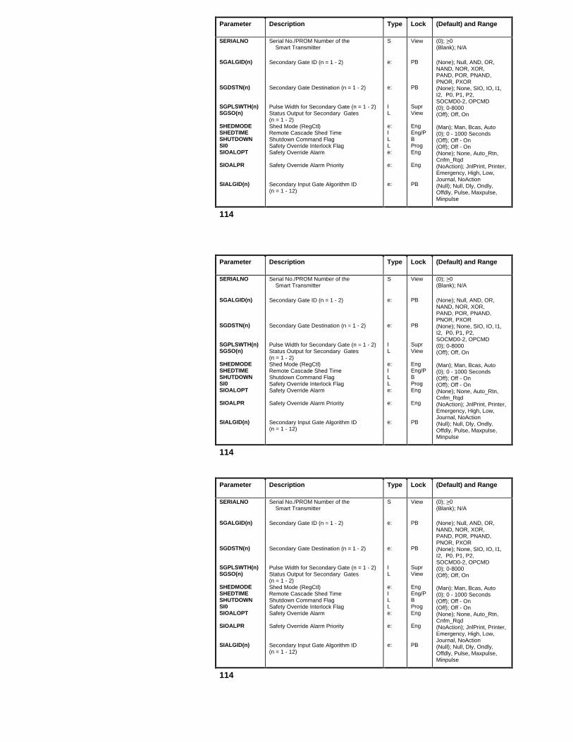
Parameter Description Type Lock (Default) and Range
SERIALNO
SGALGID(n)
SGDSTN(n)
SGPLSWTH(n)SGSO(n)
SHEDMODESHEDTIMESHUTDOWNSI0SIOALOPT
SIOALPR
SIALGID(n)
Serial No./PROM Number of the Smart Transmitter
Secondary Gate ID (n = 1 - 2)
Secondary Gate Destination (n = 1 - 2)
Pulse Width for Secondary Gate (n = 1 - 2)Status Output for Secondary Gates(n = 1 - 2)Shed Mode (RegCtl)Remote Cascade Shed TimeShutdown Command FlagSafety Override Interlock FlagSafety Override Alarm
Safety Override Alarm Priority
Secondary Input Gate Algorithm ID(n = 1 - 12)
S
e:
e:
IL
e:ILLe:
e:
e:
View
PB
PB
SuprView
EngEng/PBProgEng
Eng
PB
(0); >0(Blank); N/A
(None); Null, AND, OR,NAND, NOR, XOR,PAND, POR, PNAND,PNOR, PXOR(None); None, SIO, IO, I1,I2, P0, P1, P2,SOCMD0-2, OPCMD(0); 0-8000(Off); Off, On
(Man); Man, Bcas, Auto(0); 0 - 1000 Seconds(Off); Off - On(Off); Off - On(None); None, Auto_Rtn,Cnfm_Rqd(NoAction); JnlPrint, Printer,Emergency, High, Low,Journal, NoAction(Null); Null, Dly, Ondly,Offdly, Pulse, Maxpulse,Minpulse
114

Parameter Description Type Lock (Default) and Range
SIDLYTIM(n)
SIDSTN(n)
SIM_TXTSI0CONF
SISO(n)
SLOTNUM
Secondary Input Gate Delay/PulseWidth (n = 1 - 12)Secondary Input Gate Destination
Simulation IndicatorSafety Override Interlock AlarmConfirmation flagStatus Output for Secondary Input Gate(n = 1 - 12)Slot Number
I
e:
SL
L
I
Supr
PB
ViewOper
View
PB
(0); 0-8000
(None); SIO, I0-I2, P0-P2,SOCMD0-2, OPCMD,SG1-SG2, PG1-PG4(N/A); N/A(Off); N/A
(Off); Off, On
(N/A); HLAI and STI = 1 - 16LLAI = 1 - 8AnalgOut = 1 - 8 or 1 - 16Array = 1 - 500 but < NARSLOTBox Numeric = 1 - 2047Box Timer = 1 - 64 but < NTIMERDevCtl = 1 - 400 but < NDEVSLOTDigComp = 1 - 999 but < NDCSLOTDigIn = 1 - 32DigOut = 1 - 16 or 1 - 32Logic = 1 - 400 but < NLOGSLOTProcMod = 1 - 250 but < NPMSLOTBox Timer 1 - 64
115

Parameter Description Type Lock (Default) and Range
SLOTNUM
SLWSRCIDSNAME(n)SO
SO1 - SO24SO(I)
SOAKT1-12SOAKV1-12SOCMD(I)
SP
SPEUHISPEULOSPFORMAT
Slot Number, (Continued)
Slidewire Voltage Source IdentifierSubroutine Name (ProcMod) (n = 1-2)Status Output (Digout)Status Output (Timer)Logic Block Status OutputStatus Output Array DevCtl, DigComp(I = State)Soak Time for Soak Segments 1-12Soak Value for Soak Segments 1-12Digital Composite Output Status Command (I = State)Setpoint of the PV in Engineering Units(RegCtl)Preset Time (Timer)Setpoint Engineering Unit Range HighSetpoint Engineering Unit Range LowSetpoint Decimal Point Format
I
ISLLLL
RRL
R
IRRe:
PB
Eng/PBViewOperViewViewView
SuprSuprProg
OperOperViewViewView
(N/A);RegCtL = 1 - 250 but < NCTLSLOTRegPV = 1 - 125 but < NPVSLOTBox Flag = 1 - 2047LLMUX = 1 - 32PI = 1 - 8(1); 1 - 16 (spaces); N/A(Off); Off - On(Off); Off - On(Off); On - Off(Off); On - Off
(0.0); 0.0 - 120.0 Minutes(NaN); N/A(Off); Off - On
(0.0); SPLOLM-SPHILM
(0); 0 - 32000 (N/A); • SPEULO(N/A); • SPEUHI(N/A); D0, D1, D2, D3
116

Parameter Description Type Lock (Default) and Range
SPHIFLSPHILMSPLOCK
SPLOFLSPLOLMSPOPTSPPSPTV
SPTVPSRQUTAVGSRQUTMAXSRSPTAVGSRSPTMAXSSTEP(n)SSTMT(n)
ST0_OP1 throughST2_OP3STARTFLSTATE
Setpoint High Limit Violation FlagSetpoint High LimitSetpoint Lock
Setpoint Low Limit Violation FlagSetpoint Low LimitSetpoint OptionSetpoint In PercentSetpoint Target Value in Engineering UnitsSet Point Target Value in %Avg. UCN Store Request Trip TimeMax. UCN Store Request Trip TimeAvg. UCN Store Resp. Trip TimeMax. UCN Store Resp. Trip TimeSubroutine Step Name (n = 1 - 2)Subroutine Statement Number (n = 1 - 2)State 0 - Output 1 Through State 2 - Output 3
Start Command FlagTimer State (Timer, DigIn, Totalizr)Current State (STI)
LRe:
LRe:RR
RRRRRSI
L
Le:e:
ViewSuprEng
ViewSuprEng/PBViewOper
ViewViewViewViewViewViewView
Eng/PB
ProgViewView
(Off); Off - On(NaN); SPLOLM - SPEUHI, NaN(Operator); Operator, SupervisEngineer, Program(Off); Off - On(NaN); SPEULO - SPHILM, NaN(None); None, TV, Asp(N/A); N/A(N/A); SPLOLM - SPHILM, NaN
(N/A); • 0.0%(NaN); N/A(NaN); N/A(NaN); N/A(NaN); N/A(Blank); N/A(Blank); 0 - 255
(Off); Off - On
(Off); Off - On(Stopped); Stopped, Running(N/A); Loading, Loadcomp, Loadfail,Calib, Calcomp, Calfail, OK, DBChange
117

Parameter Description Type Lock (Default) and Range
STATE0 throughSTATE2STATETXT(n)
STATMENTSTATTIMnSTCHGOPTSTDBYMANSTDBYSTS(n)STEPSTI_EU
Current State
State Descriptor 0 - 3 Text
StatementState Time (n = 0 - 2)State Change OptionStandby Manual FlagStandby Status Flag (n = 1 -168)StepSmart Transmitter EngineeringUnits
S
S
ITe:LLSe:
View
PB
ViewView
Eng/PBViewViewViewEng
(On, Off, State2); N/A
STATETXT(0) = Off,STATETXT(1) = On,STATETXT(2) = STATE2 text/$NullSTATETXT(3) = None(0); 1 - 255(0); 0 - 4000 days(None); None, STATE0(Off); Off - On( ); Off - On(Blank); N/A(InH2O); InH2O, MMHG, PSI, KPA, MBar,Bar, G_SQCM, KG_SQCM, MPA, MMH20,INHG, Deg_C, Deg_F, Deg_K, Deg_R,MV, V, Ohms, CM_HR, Gal_HR, LIT_HR,CC_HR, CM_Min, Gal_Min, Lit_Min,CC_Min, CM_DAY, Gal_Day, KGal_Day,BRL_Day, CM_Sec, Ft_Sec, M_SecPRCNT, BLANK, LBS, KG, TONS, GRAMS,OZ, GAL, BRL, CUB_M, LITERS,MLITRES, FL_OZ, FEET, METERS, MM,INCHES, KG_CUM, G_CUM, LBS_CUFT,LBS_CUIN
118

Parameter
Description Type Lock (Default) and Range
STISWVER
STITAG
STOPFLSTR8(n)
STR16(n)STR32(n)STR64(n)STR8(i)
STR16(i)
STR32(i)
STR64(i)
STRDESCSTRLENSTRSTIXSTRTFAILSTSMSGSUMSLTSZ
Software Revision Level of the Smart TransmitterTransmitter Tag Name of the Smart TransmitterStop Command FlagBox String Variables HPM Box, (n = 1 - 16384)Local String Variables (n = 1 - 16)Local String Variables (n = 1 - 8)Local String Variables (n = 1 - 4)Local String Variables (n = 1 - 2)Array Point String Variables
Array Point String Variables
Array Point String Variables
Array Point String Variables
String Array DescriptorString LengthString Array Start IndexStartup/Failover InformationStatus MessageTotal Configured Memory for SequencePrograms
S
S
LSSSSSS
S
S
S
SIRSe:I
View
Eng/PB
ProgOperSpecialSpecialSpecialSpecialSpecial
Special
Special
Special
PBPBPBViewOperView
(Blank); N/A, MPA
(Spaces); A - Z and 0 -9
(Off); Off - On(Spaces); N/A(Spaces); N/A(Spaces); N/A(Spaces); N/A(Spaces); N/A(N/A); 1 < i <(NSTRING)/(8/STRLEN)(N/A); 1 < i <(NSTRING)/(16/STRLEN)(N/A); 1 < i <(NSTRING)/(32/STRLEN)(N/A); 1 < i <(NSTRING)/(64/STRLEN)(Spaces; N/A)(0); 0 - NSTRING or 0 - 99,999(8); 8, 16, 32, 64( ); 00 - FF (hexidecimal)(MSGTXT(0); to MSGTXT(15)(0); >0
119

Parameter Description Type Lock (Default) and Range
SUSPSTAT
SUSPTIMESVALDB
SVALDB
SVALDBEUSVDESCSVEUDESCSVEUHISVEULOSVHHFLSVHHPR
SVHHTPSVHHTPP
SVHIFLSVHIPR
SVHITPSVHITPP
Suspend State
Suspension TimerSecvar Alarm Deadband (DevCtl)
Secvar Alarm Deadband (DevCtl)
Secvar Alarm Deadband in Eng UnitsSecvar DescriptorSecvar Eng. Unit DescriptorSecvar Range HighSecvar Range LoSecvar High High Alarm FlagSecvar High High Alarm Priority
Secvar High High Alarm Trip PointSecvar High High Alarm Trip PointPercentSecvar High Alarm FlagSecvar High Alarm Priority
Secvar High Alarm Trip PointSecvar High Alarm Trip Point Percent
e:
Ie:
e:
RSSRRLe:
RR
Le:
RR
View
ViewEng/PB
Eng/PB
Eng/PBPBPBEng/PBEng/PBViewEngr
SuprSupr
ViewEngr
SuprSupr
(None); None, ConfMsg, WaitInput Msg, Feedback(0); >0 - 32,767(One); Half, One, Two, Three,Four, Five, EU(One); Half, One, Two, Three,Four, Five, EU(0); Allowable Eng. Units(Blank); 8 Characters(Blank); 8 Characters(NaN); <> NaN(NaN); <> NaN(Off); Off, On(Low); JnlPrint, Printer,Emergency, High, Low,Journal, NoAction(NaN); > SVHITP or NaN(NaN); 0 - 100
(Off); Off, On(Low); JnlPrint, Printer,Emergency, High, Low,Journal, NoAction(NaN); 0 - 100(NaN); 0 - 100
120

Parameter Description Type Lock (Default) and Range
SVPSVPEAKSVSRCSVTVSVTVPSWTCHACT(n)SYNCHSTS
TT0T1T2TCRNGOPTTDTFTIME(n)
TIMEBASE
Secvar in Percent of Eng. RangePeak Value of SecvarSecvar Input ConnectionSecondary Variable Target ValueSecondary Variable Target Value in %IOP Synchronization (n = 1 - 40)Primary/Secondary DatabaseSynchronization StatusTemperature InputZero Reference for TemperatureIntegral Time in MinutesDerivative Time in MinutesThermocouple Range OptionTotal Dead Time in MinutesPV Filter Lag Time in MinutesBox Time Variables (n = 1- 4095)ProcMod Local Time Variables (n = 1-4)Array Points Time Variables TIME (i)Time Base (Timer)Time Base (Totalizr, PI)
RRURRLe:
RRRRe:RRTTTe:e:
ViewViewPBOperOperViewView
ViewSuprSuprSuprEng/PBSuprSuprOperSpecialSpecialEngEng/PB
(NaN); 0 - 100(NaN); 0 - 100(Null); See full PRD(NaN); SVEULO to SVEUHI(NaN); 0 -100(On); Off, On(None); OK, Warning, Fail
(1); • 0.0(0.0); N/A(0.0); 0.0 - 1440.0 Minutes(0.0); 0.0 - 1440.0 Minutes(Normal); Normal, Extended(0.0); • 0.0 Minutes(0.0); 0.0 - 60.0 Minutes (0); N/A(0); N/A(N/A); 1 < i < NTIME(Seconds); Seconds, Minutes(Minutes); Seconds, Minutes,Hours
121

Parameter Description Type Lock (Default) and Range
TIMEDESCTIMESECS(n)TIMESTIXTIMESYNCTLDTLG1, TLG2TMCMD(n)
TMPV(n)
TMRV(n)
TMSO(n)TMSP(n)
TMST(n)TMTB(n)TOTLUAVGTOTLUMAXTRACKINGTRANTIM0-2TRATAVGTRATMAXTRFB
Time Array DescriptorArray Point Time Variables (n = 1-240)Time Array Start IndexTimesynch ControlLead Time Constant in MinutesLag Time Constants 1 and 2 in MinutesTimer Commands for Timers 1-64
Timer PV in Seconds or Minutes for Timers 1-64Timer RV – Remaining Time for Timers 1-64Timer Status Outputs for Timers 1-64Timer SP in Seconds/Minutes for Timers 1-64Timer States for Timers 1-64Time Base for Timers 1-64Average IOL Utilization in % per I/O LinkMax. IOL Utilization in % per I/O LinkSelected Input TrackingTransition TimeAvg. UCN Transaction Trip TimeMax. UCN Transaction Trip TimeTracking Feedback Input in EU
STRe:RRe:
I
I
LI
e:e:RRLTRRR
PBSpecialPBPBSuprSuprOper
View
View
ViewOper
ViewEngrViewViewEng/PBViewViewView
View
(Spaces); N/A,PB(N/A); 1 < i < NTIME(0); 0 - NTIME(Disable); Enable, Disable(0.0); -1440.0 to +1440.0 Minutes(0.0); 0.0 - 1440.0 Minutes(N/A); None, Start, Stop, Reset, ResetStrt(0); > 0
(0); > 0
(Off); Off - On(0); 0 - 32000
(Stopped); Stopped, Running(Seconds); Seconds, Minutes(0.0); 0 - 100(0.0); 0 - 100(Off); Off - On(0); Time Stamp(NaN); N/A(NaN); N/ANaN); N/A
122

Parameter Description Type Lock (Default) and Range
TSCOMPTSSRCTSTSTSUNICHGTVPROC
UCNRECHN
UCNSCANTUCNWRTLKUNCMDFLUNIT
UPGRADEURLURVUSERIDUTSDRIFTUTSNODEUTSTBCRVUTSTIMST
UTSTIMEWARMSTRTWEEKDAYWITHBIASn
Time Stamp, CL Source CompatibilityTime Stamp, CL SourceTemperature Input Value StatusTime Stamp, Unit ChangeTarget Value Processor State
UCN Receive Channel
Peer-to-Peer Scan Period in sccondsHPM Write LockoutUncommanded Change Alarm FlagUnit Identifier
NIM Upgrade StatusUpper Range LimitUpper Range ValueUser ID ReservationUCN Node Clock DriftLast UCN Syncher NodeTBC RevisionTimesynch State of UCN Node
Current Time in LCN NodeWarm start flagCurrent WeekdayI/O Module Physical Bias State (n=1 - 40)
TTe:Te:
e:
Re:LS
e:RRSIISe:
TLIL
ViewViewViewViewOper
View
Eng/PbEngViewPB
OperEng/ViewSupr/View
OperViewViewViewView
ViewViewViewView
(0); N/A(0); N/A(Normal); Normal, Uncertn, Bad(0); N/A(Off); Off, Preset, Run
(ChannelA); ChannelA -ChannelB(0.5); 0.5, 1.0(WrtLkOff); WrtLkOn, WrtLkOff(Off); Off - On(N/A); A-Z, 0-9 (Max of 100 Unit Identifiers)(OK); OK, Upgrade(N/A); N/A - NaN(NaN); N/A - NaN(Dashes); 16 Characters(N/A);0; 0, 1 - 64(N/A); 5 - 150; Initial, Failed, Degraded, LCN Bad, LCN OK, OK(N/A); N/A(N/A); On - Off(N/A); 1 - 7 (1 = Sunday)(On); On - Off
123

Parameter Description Type Lock (Default) and Range
XX1X1 - X3X1 - X4X2
X2FILTX2TFXEUHI
XEULO
XSTSYEAR
Steam Compressibility Input (FlowComp)X1 Input Value to be Biased (AutoMan)Inputs 1-3 (MulDiv)Inputs 1-4 (IncrSum, OrSel)Bias Adjustment Input (AutoMan)Input Number 2 (RatioCtl)Filtered value of the x2 inputX2 input filter lag time in minutesX Input High Range in Engineering Units
X Input Low Range in Engineering Units
X Input Value StatusCurrent Year
RRRRRRRRR
R
e:I
ViewProgProgProgViewViewViewSuprEng
Eng
ViewView
(1.0); • 0.0(NaN); • 0.0, N/A(NaN); • 0.0, NaN (NaN); • 0.0, NaN(N/A); N/A(N/A); N/A(N/A); N/A(0.0); 0 - 60 minutes(100.0, Equivalent to 100%); >XEULO(0.0, Equivalent to 0%); < XEUHI(Normal); Normal, Uncertn, Bad(N/A); 1979 - 2115
124
Related Documents