0-1 dummyhead dummyhead How to use this manual How to use this manual A few Words About Safety Service Information The service and repair information contained in this manual is intended for use by qualified, professional technicians. Attempting service or repairs without the proper training, tools, and equipment could cause injury to you and/or others. It could also damage this Honda product or create an unsafe condition. This manual describes the proper methods and procedures for performing service, maintenance, and repairs. Some procedures require the use of special tools. Any person who intends to use a replacement part, service procedure, or a tool that is not recommended by Honda must determine the risks to their personal safety and the safe operation of this product. If you need to replace a part, use Honda Genuine parts with the correct part number or an equivalent part. We strongly recommend that you do not use replacement parts of inferior quality. For Your Customer’s Safety Proper service and maintenance are essential to the customer’s safety and the reliability of this product. Any error or oversight while servicing this product can result in faulty operation, damage to the product, or injury to others. For Your Safety Because this manual is intended for the professional service technician, we do not provide warnings about many basic shop safety practices (e.g., Hot parts-wear gloves). If you have not received shop safety training or do not feel confident about your knowledge of safe servicing practices, we recommend that you do not attempt to perform the procedures described in this manual. Some of the most important general service safety precautions are given below. However, we cannot warn you of every conceivable hazard that can arise in performing service and repair procedures. Only you can decide whether or not you should perform a given task. Important Safety Precautions Make sure you have a clear understanding of all basic shop safety practices and that you are wearing appropriate clothing and using safety equipment. When performing any service task, be especially careful of the following: • Read all of the instructions before you begin, and make sure you have the tools, the replacement or repair parts, and the skills required to perform the tasks safely and completely. • Protect your eyes by using proper safety glasses, goggles, or face shields anytime you hammer, drill, grind, or work around pressurized air, pressurized liquids, springs, or other stored-energy components. If there is any doubt, put on eye protection. • Use other protective wear when necessary, for example gloves or safety shoes. Handling hot or sharp parts can cause severe burns or cuts. Before you grab something that looks like it can hurt you, stop and put on gloves. • Protect yourself and others whenever you have equipment hoisted in the air. Anytime you lift this product with a hoist, make sure that the hoist hook is securely attached to the product. Make sure the engine is off before you begin any servicing procedures, unless the instruction tells you to do otherwise. This will help eliminate several potential hazards: • Carbon monoxide poisoning from engine exhaust. Be sure there is adequate ventilation whenever you run the engine. • Burns from hot parts. Let the engine and exhaust system cool before working in those areas. • Injury from moving parts. If the instruction tells you to run the engine, be sure your hands, fingers, and clothing are out of the way. Gasoline vapors and hydrogen gasses from batteries are explosive. To reduce the possibility of a fire or explosion, be careful when working around gasoline or batteries. • Use only a nonflammable solvent, not gasoline, to clean parts. • Never store gasoline in an open container. • Keep all cigarettes, sparks, and flames away from the battery and all fuel-related parts. Improper service or repairs can create an unsafe condition that can cause your customer or others to be seriously hurt or killed. Follow the procedures and precautions in this manual and other service materials carefully. Failure to properly follow instructions and precautions can cause you to be seriously hurt or killed. Follow the procedures and precautions in this manual carefully.

Welcome message from author
This document is posted to help you gain knowledge. Please leave a comment to let me know what you think about it! Share it to your friends and learn new things together.
Transcript
0-1
dummyheaddummyhead
How to use this manualHow to use this manual
A few Words About SafetyService InformationThe service and repair information contained in this manual is intended for use by qualified, professional technicians. Attemptingservice or repairs without the proper training, tools, and equipment could cause injury to you and/or others. It could also damagethis Honda product or create an unsafe condition.
This manual describes the proper methods and procedures for performing service, maintenance, and repairs. Some proceduresrequire the use of special tools. Any person who intends to use a replacement part, service procedure, or a tool that is notrecommended by Honda must determine the risks to their personal safety and the safe operation of this product.
If you need to replace a part, use Honda Genuine parts with the correct part number or an equivalent part. We strongly recommendthat you do not use replacement parts of inferior quality.
For Your Customer’s SafetyProper service and maintenance are essential to the customer’s safety and the reliability of this product. Any error or oversightwhile servicing this product can result in faulty operation, damage to the product, or injury to others.
For Your SafetyBecause this manual is intended for the professional service technician, we do not provide warnings about many basic shop safetypractices (e.g., Hot parts-wear gloves). If you have not received shop safety training or do not feel confident about your knowledgeof safe servicing practices, we recommend that you do not attempt to perform the procedures described in this manual.
Some of the most important general service safety precautions are given below. However, we cannot warn you of everyconceivable hazard that can arise in performing service and repair procedures. Only you can decide whether or not you shouldperform a given task.
Important Safety PrecautionsMake sure you have a clear understanding of all basic shop safety practices and that you are wearing appropriate clothing andusing safety equipment. When performing any service task, be especially careful of the following:
• Read all of the instructions before you begin, and make sure you have the tools, the replacement or repair parts, and the skillsrequired to perform the tasks safely and completely.
• Protect your eyes by using proper safety glasses, goggles, or face shields anytime you hammer, drill, grind, or work aroundpressurized air, pressurized liquids, springs, or other stored-energy components. If there is any doubt, put on eye protection.
• Use other protective wear when necessary, for example gloves or safety shoes. Handling hot or sharp parts can cause severeburns or cuts. Before you grab something that looks like it can hurt you, stop and put on gloves.
• Protect yourself and others whenever you have equipment hoisted in the air. Anytime you lift this product with a hoist, make surethat the hoist hook is securely attached to the product.
Make sure the engine is off before you begin any servicing procedures, unless the instruction tells you to do otherwise. This willhelp eliminate several potential hazards:
• Carbon monoxide poisoning from engine exhaust. Be sure there is adequate ventilation whenever you run the engine. • Burns from hot parts. Let the engine and exhaust system cool before working in those areas. • Injury from moving parts. If the instruction tells you to run the engine, be sure your hands, fingers, and clothing are out of the
way.
Gasoline vapors and hydrogen gasses from batteries are explosive. To reduce the possibility of a fire or explosion, be careful whenworking around gasoline or batteries.
• Use only a nonflammable solvent, not gasoline, to clean parts. • Never store gasoline in an open container. • Keep all cigarettes, sparks, and flames away from the battery and all fuel-related parts.
Improper service or repairs can create an unsafe condition that can cause your customer or others to be seriously hurt or killed.
Follow the procedures and precautions in this manual and other service materials carefully.
Failure to properly follow instructions and precautions can cause you to be seriously hurt or killed.
Follow the procedures and precautions in this manual carefully.

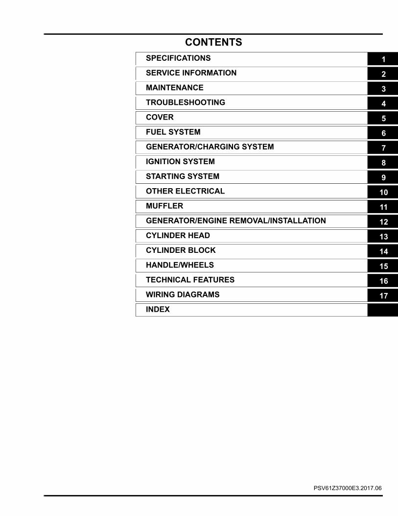
CONTENTS
dummyheaddummyhead
SPECIFICATIONS 1
SERVICE INFORMATION 2
MAINTENANCE 3
TROUBLESHOOTING 4
COVER 5
FUEL SYSTEM 6
GENERATOR/CHARGING SYSTEM 7
IGNITION SYSTEM 8
STARTING SYSTEM 9
OTHER ELECTRICAL 10
MUFFLER 11
GENERATOR/ENGINE REMOVAL/INSTALLATION 12
CYLINDER HEAD 13
CYLINDER BLOCK 14
HANDLE/WHEELS 15
TECHNICAL FEATURES 16
WIRING DIAGRAMS 17
INDEX
PSV61Z37000E3.2017.06

0-3
dummyheaddummyhead
How to use this manual
INTRODUCTIONThis manual covers the service and repair procedures for the Honda EU7000is generator.
All information contained in this manual is based on the latest product information available at the time of printing. We reserve theright to make changes at anytime without notice.
No part of this publication may be reproduced, stored in a retrieval system, or transmitted, in any form, by any means, electronic,mechanical, photocopying, recording, or otherwise, without prior written permission of the publisher. This includes text, figures, andtables.
As you read this manual, you will find information that is preceded by a symbol. The purpose of this message is to helpprevent damage to this Honda product, other property, or the environment.
SAFETY MESSAGESYour safety and the safety of others are very important. To help you make informed decisions, we have provided safety messagesand other safety information throughout this manual. Of course, it is not practical or possible to warn you about all the hazardsassociated with servicing these products. You must use your own good judgment.
© Honda Motor Co., Ltd.SERVICE PUBLICATION OFFICE
Date of Issue: June 2017
You will find important safety information in a variety of forms, including: • Safety Labels – on the product. • Safety Messages – preceded by a safety alert symbol and one of three signal words, DANGER, WARNING, or CAUTION.
These signal words mean:
You WILL be KILLED or SERIOUSLY HURT if you don’t follow instructions.
You CAN be KILLED or SERIOUSLY HURT if you don’t follow instructions.
You CAN be HURT if you don’t follow instructions. • Instructions – how to service these products correctly and safely.
ALL INFORMATION, ILLUSTRATIONS, DIRECTIONS, AND SPECIFICATIONS INCLUDED IN THIS PUBLICATION ARE BASED ON THE LATEST PRODUCT INFORMATION AVAILABLE AT THE TIME OF APPROVAL FOR PRINTING. Honda Motor Co., Ltd. RESERVES THE RIGHT TO MAKE CHANGES AT ANY TIME WITHOUT NOTICE AND WITHOUT INCURRING ANY OBLIGATION WHATSOEVER. NO PART OF THIS PUBLICATION MAY BE REPRODUCED WITHOUT WRITTEN PERMISSION. THIS MANUAL IS WRITTEN FOR PERSONS WHO HAVE ACQUIRED BASIC KNOWLEDGE OF MAINTENANCE ON Honda PRODUCTS.
Revised: June 2017 (61Z37000E2)
0-4
dummyheaddummyhead
How to use this manual
SERVICE RULES • Use Honda Genuine or Honda-recommended parts and lubricants or their equivalents. Parts that do not meet Honda’s design
specifications may damage the unit. • Use the special tools designed for the product. • Install new gaskets, O-rings, etc. when reassembling. • When torquing bolts or nuts, begin with larger-diameter or inner bolts first and tighten to the specified torque diagonally, unless
a particular sequence is specified. • Clean parts in cleaning solvent upon disassembly. Lubricate any sliding surfaces before assembly. • After assembly, check all parts for proper installation and operation. • Many screws used in this machine are self-tapping. Be aware that cross-threading or overtightening these screws will strip the
threads and ruin the hole.
Use only metric tools when servicing this unit. Metric bolts, nuts and screws are not interchangeable with non-metric fasteners. Theuse of incorrect tools and fasteners will damage the unit.
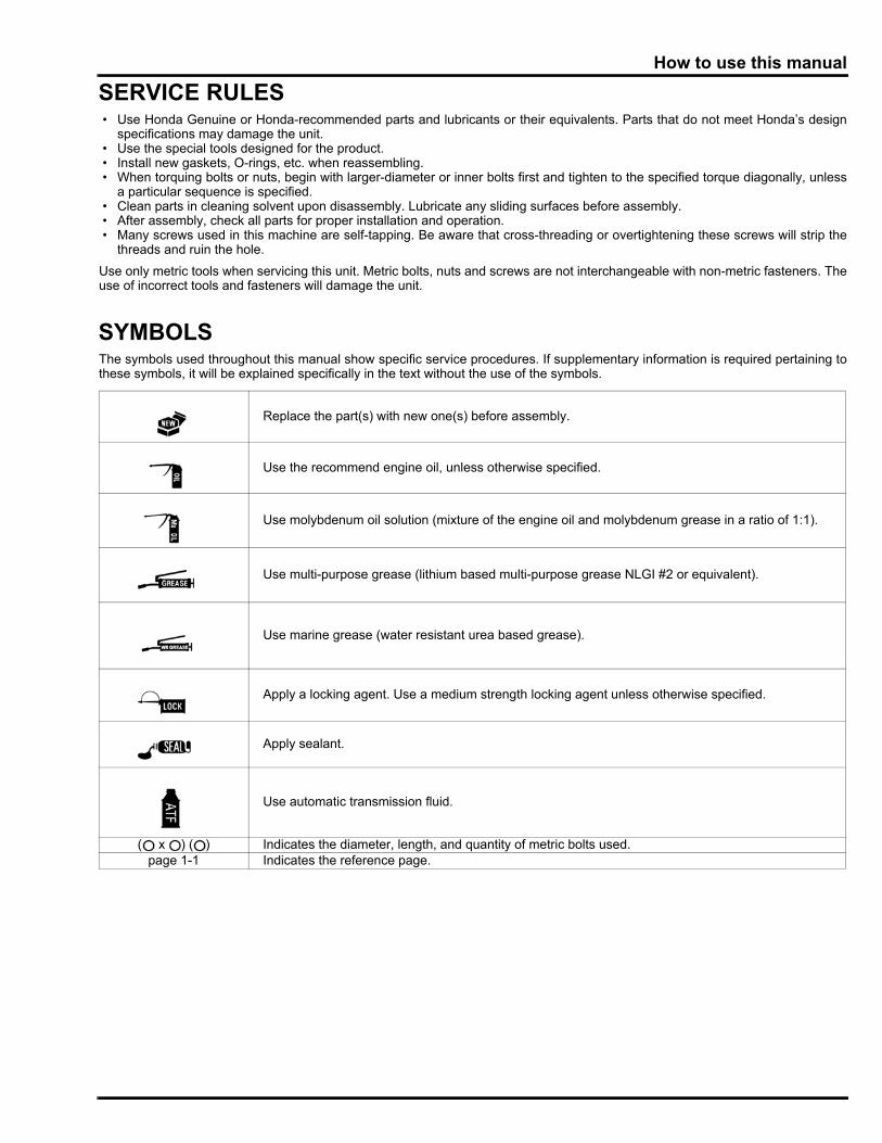
SYMBOLSThe symbols used throughout this manual show specific service procedures. If supplementary information is required pertaining tothese symbols, it will be explained specifically in the text without the use of the symbols.
Replace the part(s) with new one(s) before assembly.
Use the recommend engine oil, unless otherwise specified.
Use molybdenum oil solution (mixture of the engine oil and molybdenum grease in a ratio of 1:1).
Use multi-purpose grease (lithium based multi-purpose grease NLGI #2 or equivalent).
Use marine grease (water resistant urea based grease).
Apply a locking agent. Use a medium strength locking agent unless otherwise specified.
Apply sealant.
Use automatic transmission fluid.
( x ) ( ) Indicates the diameter, length, and quantity of metric bolts used.page 1-1 Indicates the reference page.
0-5
dummyheaddummyhead
How to use this manual
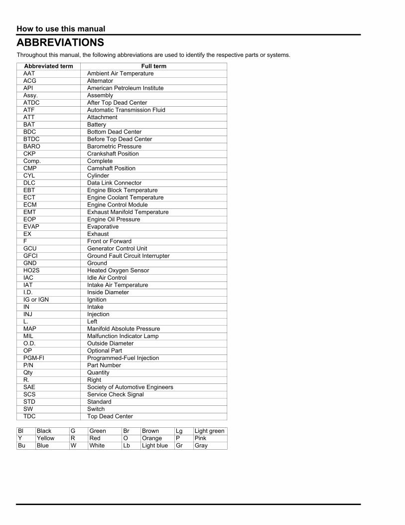
ABBREVIATIONSThroughout this manual, the following abbreviations are used to identify the respective parts or systems.
Abbreviated term Full termAAT Ambient Air TemperatureACG AlternatorAPI American Petroleum InstituteAssy. AssemblyATDC After Top Dead CenterATF Automatic Transmission FluidATT AttachmentBAT BatteryBDC Bottom Dead CenterBTDC Before Top Dead CenterBARO Barometric PressureCKP Crankshaft PositionComp. CompleteCMP Camshaft PositionCYL CylinderDLC Data Link ConnectorEBT Engine Block TemperatureECT Engine Coolant TemperatureECM Engine Control ModuleEMT Exhaust Manifold TemperatureEOP Engine Oil PressureEVAP EvaporativeEX ExhaustF Front or ForwardGCU Generator Control UnitGFCI Ground Fault Circuit InterrupterGND GroundHO2S Heated Oxygen SensorIAC Idle Air ControlIAT Intake Air TemperatureI.D. Inside DiameterIG or IGN IgnitionIN IntakeINJ InjectionL. LeftMAP Manifold Absolute PressureMIL Malfunction Indicator LampO.D. Outside DiameterOP Optional PartPGM-FI Programmed-Fuel InjectionP/N Part NumberQty QuantityR. RightSAE Society of Automotive EngineersSCS Service Check SignalSTD StandardSW SwitchTDC Top Dead Center
Bl Black G Green Br Brown Lg Light greenY Yellow R Red O Orange P PinkBu Blue W White Lb Light blue Gr Gray
0-6
dummyheaddummyhead
How to use this manual
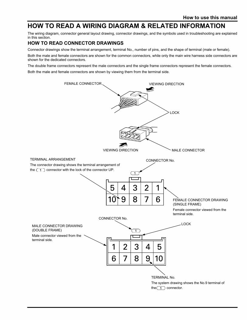
HOW TO READ A WIRING DIAGRAM & RELATED INFORMATIONThe wiring diagram, connector general layout drawing, connector drawings, and the symbols used in troubleshooting are explainedin this section.
HOW TO READ CONNECTOR DRAWINGSConnector drawings show the terminal arrangement, terminal No., number of pins, and the shape of terminal (male or female).
Both the male and female connectors are shown for the common connectors, while only the main wire harness side connectors areshown for the dedicated connectors.
The double frame connectors represent the male connectors and the single frame connectors represent the female connectors.
Both the male and female connectors are shown by viewing them from the terminal side.
FEMALE CONNECTOR
MALE CONNECTOR
LOCK
VIEWING DIRECTION
VIEWING DIRECTION
FEMALE CONNECTOR DRAWING(SINGLE FRAME)
Female connector viewed from the terminal side.
MALE CONNECTOR DRAWING(DOUBLE FRAME)
Male connector viewed from the terminal side.
LOCK
CONNECTOR No.
CONNECTOR No.
TERMINAL No.
The system drawing shows the No.9 terminal of
the connector.
TERMINAL ARRANGEMENT
The connector drawing shows the terminal arrangement of
the connector with the lock of the connector UP.
0-7
dummyheaddummyhead
How to use this manual
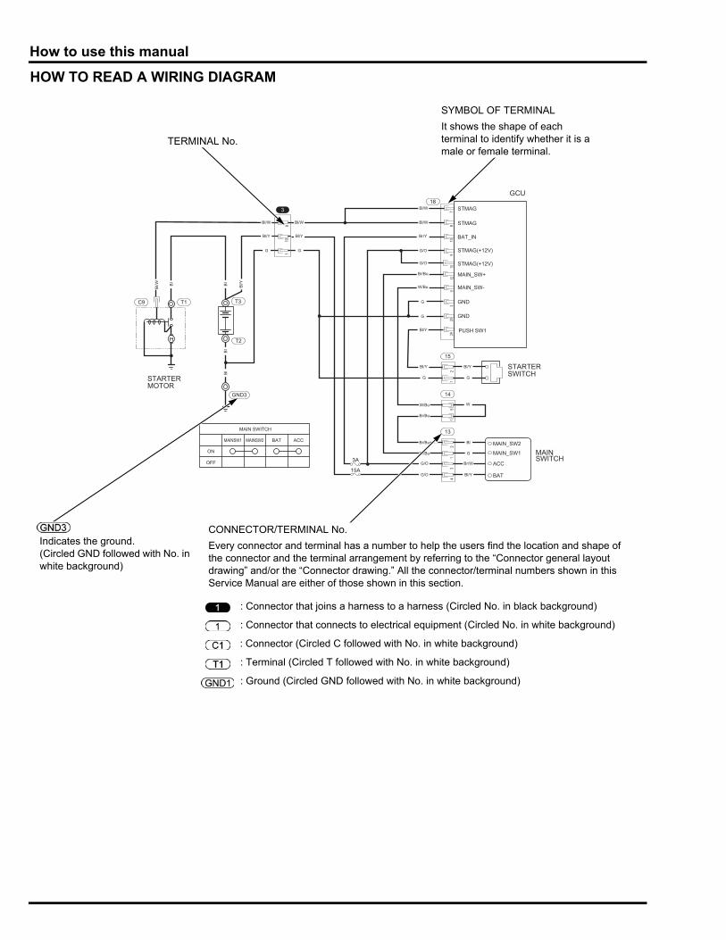
HOW TO READ A WIRING DIAGRAM
78
13
18
15
BAT_IN
9
Bl/WBl/W
Bl/Y
Bl/W
Bl/Y
Bl/Y
W/Bu
Br/Bu
Br/Bu
Br/Bu
G/O
G/O
Bl
G
Br/W
Bl/Y
MAIN_SW+
MAIN_SW-
1012
Br/Y
Br/Bu
W/Bu
GND
GND
113
2029
G/O
G/O
G
Bl/W
Bl/Y
G
G
G
G
W
Bl/Y
G
3
110
9
2
14
51
1
13
21
34
STMAG
STMAG
STMAG(+12V)
STMAG(+12V)
PUSH SW1
STARTERSWITCH
Bl
Bl
Bl
Bl/YBl
Bl/W
15A
3AMAIN_SW1
MAIN_SW2
ACC
BAT
MAINSWITCH
T3
T2
STARTERMOTOR
T1C9
GND3
GCU
MAIN SWITCH
MAINSW1 MAINSW2 BAT ACC
ON
OFF
SYMBOL OF TERMINAL
It shows the shape of each terminal to identify whether it is a male or female terminal.
TERMINAL No.
CONNECTOR/TERMINAL No.
Every connector and terminal has a number to help the users find the location and shape of the connector and the terminal arrangement by referring to the “Connector general layout drawing” and/or the “Connector drawing.” All the connector/terminal numbers shown in this Service Manual are either of those shown in this section.
Indicates the ground.(Circled GND followed with No. in white background)
: Connector that joins a harness to a harness (Circled No. in black background)
: Connector that connects to electrical equipment (Circled No. in white background)
: Connector (Circled C followed with No. in white background)
: Terminal (Circled T followed with No. in white background)
: Ground (Circled GND followed with No. in white background)
1-1
1
dummytext
1. SPECIFICATIONS
SERIAL NUMBER LOCATION ·····················1-2
SPECIFICATIONS·········································1-2
PERFORMANCE CURVES··························· 1-4
DIMENSIONAL DRAWINGS························· 1-5
1-2
dummyheaddummyhead
SPECIFICATIONSSPECIFICATIONS
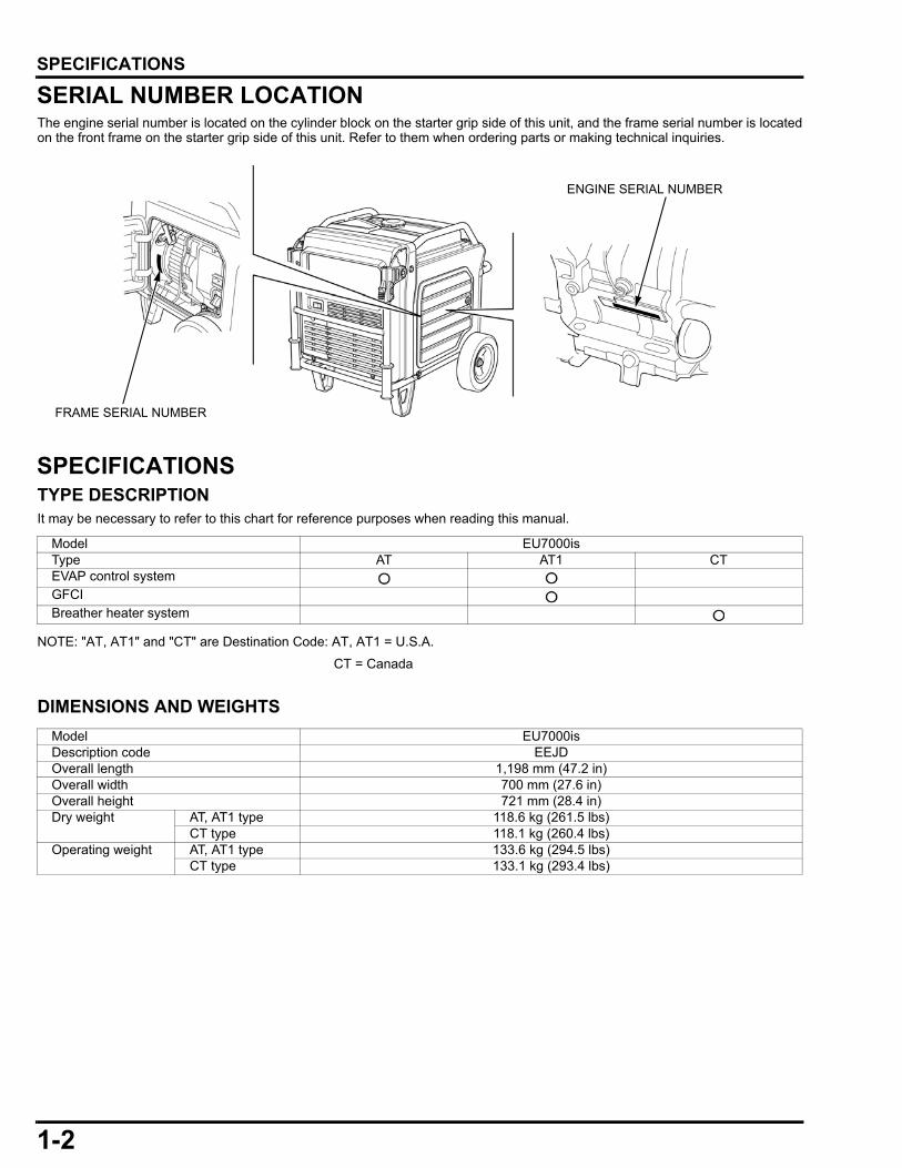
SERIAL NUMBER LOCATIONThe engine serial number is located on the cylinder block on the starter grip side of this unit, and the frame serial number is locatedon the front frame on the starter grip side of this unit. Refer to them when ordering parts or making technical inquiries.
SPECIFICATIONSTYPE DESCRIPTIONIt may be necessary to refer to this chart for reference purposes when reading this manual.
NOTE: "AT, AT1" and "CT" are Destination Code: AT, AT1 = U.S.A.
CT = Canada
DIMENSIONS AND WEIGHTS
FRAME SERIAL NUMBER
ENGINE SERIAL NUMBER
Model EU7000isType AT AT1 CTEVAP control systemGFCIBreather heater system
Model EU7000isDescription code EEJDOverall length 1,198 mm (47.2 in)Overall width 700 mm (27.6 in)Overall height 721 mm (28.4 in)Dry weight AT, AT1 type 118.6 kg (261.5 lbs)
CT type 118.1 kg (260.4 lbs)Operating weight AT, AT1 type 133.6 kg (294.5 lbs)
CT type 133.1 kg (293.4 lbs)
1-3
dummyheaddummyhead
SPECIFICATIONS
ENGINE
GENERATOR
CHARACTERISTICS
*1: At Eco-ThrottleTM OFF
Engine model GX390T2Description code GCAGDType 4 stroke, overhead valve, single cylinder, inclined by 25°Displacement 389 cm3 (23.7 cu-in)Bore x stroke 88 x 64 mm (3.5 x 2.5 in)Compression ratio 8.2: 1Cooling system Forced airIgnition system Full Transistorized ignitionIgnition timing 20° B.T.D.C. / 3,300 min-1 (rpm) (No load)Spark plug BPR6ES (NGK)Fuel system Electronically controlled fuel injectionAir cleaner Dual typeGovernor Electric systemLubrication system Forced spray systemOil capacity 1.1 Liter (1.16 US qt, 0.97 Imp qt)Recommended oil SAE 10W-30 API service classification SJ or higherStarting system Recoil and electric starterStopping system Ignition primary circuit openRecommended fuel Unleaded gasoline with a pump octane rating 86 or higher and an ethanol
content of no more than 10%
Model EU7000isDescription code EEJDGenerator type Multi-electrode field rotation typeGenerator structure Self-ventilation, drip-proof typeExcitation Self-excitationVoltage regulation system PWM (Pulse width modulation)Phase Single phaseRated output 5.5 kVARated frequency 60 HzRated voltage 120/240 VRated current 45.8/22.9 APower factor 1.0 Cosθ
Model EU7000isType AT, AT1 CTVoltage variation rate
Momentary 10% max.Average 6% max.Average time 3 sec. max.
Voltage stability Within ± 1%Frequency variation rate
Momentary 1% max.Average 1% max.Average time 3 sec. max.
Frequency stability Within ± 0.3 HzInsulation resistance 10 MΩ min.AC circuit protector 64.1/32.1 AInsulation type E BRated rpm 2,400 – 3600 min-1 (rpm)
3,300 – 3,600 min-1 (rpm) *1Fuel tank capacity 19.2 Liters (5.07 US gal, 4.22 Imp gal)Fuel consumption 2.95 Liters (0.779 US gal, 0.649 Imp gal)/Hr.Max. operating hours at rated load without refueling
Approx. 6.5 Hr.
Guaranteed sound power level (LWA) LWA 91 dB (A)

1-4
dummyheaddummyhead
SPECIFICATIONS
PERFORMANCE CURVESThe curve shows performance of the generator under average conditions.
Performance may vary to some degree depending on ambient temperature and humidity.
The output voltage will be higher than usual when the generator is still cold, immediately after the engine starts.
AC EXTERNAL CHARACTERISTIC CURVE
AC
VO
LT
AG
E (
V)
AC LOAD CURRENT (A)
120 V RATED 45.8 A
240 V RATED 22.9 A
1-5
dummyheaddummyhead
SPECIFICATIONS
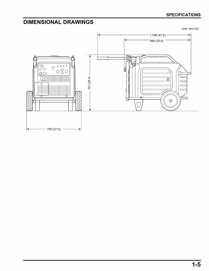
DIMENSIONAL DRAWINGSUnit: mm (in)
700 (27.6)
721
(2
8.4
)
848 (33.4)
1,198 (47.2)

MEMO
dummyheaddummyhead
2-1
2
dummytext
2. SERVICE INFORMATION
MAINTENANCE STANDARDS ·····················2-2
TORQUE VALUES ········································2-3
LUBRICATION & SEAL POINTS··················2-6
TOOLS ·························································· 2-6
CABLE/HARNESS ROUTING ······················ 2-8
TUBE ROUTING ········································· 2-24
2-2
dummyheaddummyhead
SERVICE INFORMATIONSERVICE INFORMATION
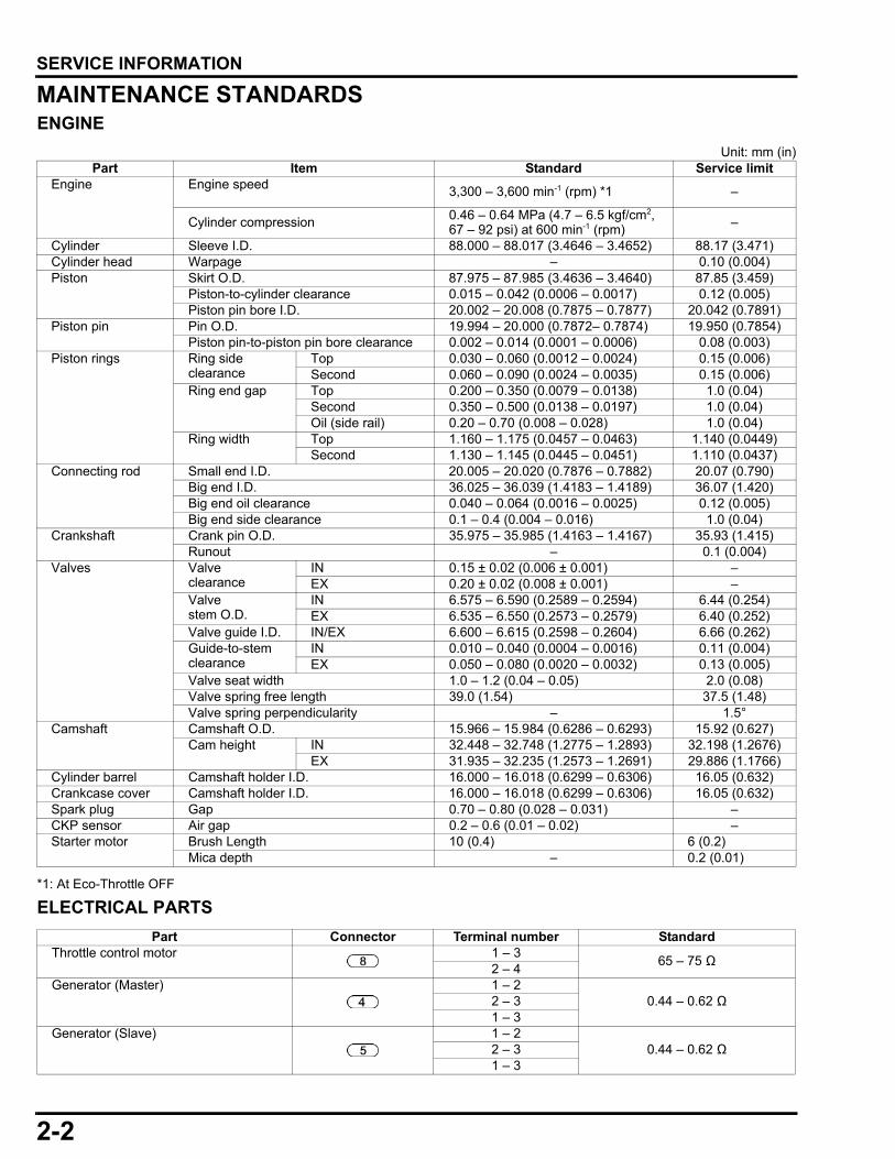
MAINTENANCE STANDARDSENGINE
Unit: mm (in)
*1: At Eco-Throttle OFF
ELECTRICAL PARTS
Part Item Standard Service limitEngine Engine speed 3,300 – 3,600 min-1 (rpm) *1 –
Cylinder compression 0.46 – 0.64 MPa (4.7 – 6.5 kgf/cm2, 67 – 92 psi) at 600 min-1 (rpm)
–
Cylinder Sleeve I.D. 88.000 – 88.017 (3.4646 – 3.4652) 88.17 (3.471)Cylinder head Warpage – 0.10 (0.004)Piston Skirt O.D. 87.975 – 87.985 (3.4636 – 3.4640) 87.85 (3.459)
Piston-to-cylinder clearance 0.015 – 0.042 (0.0006 – 0.0017) 0.12 (0.005)Piston pin bore I.D. 20.002 – 20.008 (0.7875 – 0.7877) 20.042 (0.7891)
Piston pin Pin O.D. 19.994 – 20.000 (0.7872– 0.7874) 19.950 (0.7854)Piston pin-to-piston pin bore clearance 0.002 – 0.014 (0.0001 – 0.0006) 0.08 (0.003)
Piston rings Ring side clearance
Top 0.030 – 0.060 (0.0012 – 0.0024) 0.15 (0.006)Second 0.060 – 0.090 (0.0024 – 0.0035) 0.15 (0.006)
Ring end gap Top 0.200 – 0.350 (0.0079 – 0.0138) 1.0 (0.04)Second 0.350 – 0.500 (0.0138 – 0.0197) 1.0 (0.04)Oil (side rail) 0.20 – 0.70 (0.008 – 0.028) 1.0 (0.04)
Ring width Top 1.160 – 1.175 (0.0457 – 0.0463) 1.140 (0.0449)Second 1.130 – 1.145 (0.0445 – 0.0451) 1.110 (0.0437)
Connecting rod Small end I.D. 20.005 – 20.020 (0.7876 – 0.7882) 20.07 (0.790)Big end I.D. 36.025 – 36.039 (1.4183 – 1.4189) 36.07 (1.420)Big end oil clearance 0.040 – 0.064 (0.0016 – 0.0025) 0.12 (0.005)Big end side clearance 0.1 – 0.4 (0.004 – 0.016) 1.0 (0.04)
Crankshaft Crank pin O.D. 35.975 – 35.985 (1.4163 – 1.4167) 35.93 (1.415)Runout – 0.1 (0.004)
Valves Valve clearance
IN 0.15 ± 0.02 (0.006 ± 0.001) –EX 0.20 ± 0.02 (0.008 ± 0.001) –
Valve stem O.D.
IN 6.575 – 6.590 (0.2589 – 0.2594) 6.44 (0.254)EX 6.535 – 6.550 (0.2573 – 0.2579) 6.40 (0.252)
Valve guide I.D. IN/EX 6.600 – 6.615 (0.2598 – 0.2604) 6.66 (0.262)Guide-to-stem clearance
IN 0.010 – 0.040 (0.0004 – 0.0016) 0.11 (0.004)EX 0.050 – 0.080 (0.0020 – 0.0032) 0.13 (0.005)
Valve seat width 1.0 – 1.2 (0.04 – 0.05) 2.0 (0.08)Valve spring free length 39.0 (1.54) 37.5 (1.48)Valve spring perpendicularity – 1.5°
Camshaft Camshaft O.D. 15.966 – 15.984 (0.6286 – 0.6293) 15.92 (0.627)Cam height IN 32.448 – 32.748 (1.2775 – 1.2893) 32.198 (1.2676)
EX 31.935 – 32.235 (1.2573 – 1.2691) 29.886 (1.1766)Cylinder barrel Camshaft holder I.D. 16.000 – 16.018 (0.6299 – 0.6306) 16.05 (0.632)Crankcase cover Camshaft holder I.D. 16.000 – 16.018 (0.6299 – 0.6306) 16.05 (0.632)Spark plug Gap 0.70 – 0.80 (0.028 – 0.031) –CKP sensor Air gap 0.2 – 0.6 (0.01 – 0.02) –Starter motor Brush Length 10 (0.4) 6 (0.2)
Mica depth – 0.2 (0.01)
Part Connector Terminal number StandardThrottle control motor 1 – 3
65 – 75 Ω2 – 4
Generator (Master) 1 – 20.44 – 0.62 Ω2 – 3
1 – 3Generator (Slave) 1 – 2
0.44 – 0.62 Ω2 – 31 – 3

2-3
dummyheaddummyhead
SERVICE INFORMATION
*1: CT type only
TORQUE VALUESENGINE TORQUE VALUES
Part Item StandardFuel pump Fuel pressure 294 kPa (3.0 kgf/cm2, 43 psi)
Fuel flow 55 cc (1.9 US oz, 1.9 Imp oz) minimum/10 secondsFuel pump motor resistance 0 – 20 Ω (at 20 °C/68 °F)
Fuel injector Resistance 11 – 13 Ω (at 24 °C/75 °F)EBT sensor Resistance 1.6 – 2.9 kΩ (at 20 °C – 30 °C/68 °F – 86 °F)Breather heater *1 Resistance 0.8 – 1.2 kΩ (at 25 °C/77 °F)Ignition coil Resistance (Primary side) 1.8 – 2.2 Ω
Resistance (Secondary side) 5.6 – 6.9 Ω Spark plug cap Resistance 7.5 – 12.5 kΩCKP sensor Resistance 297 – 363 Ω (at 20 °C/68 °F)
ItemThread Dia.
and pitch (mm)Torque values
RemarksN·m kgf·m lbf·ft
Spark plug M14 x 1.25 18 1.8 13Drain plug bolt M12 x 1.5 22.5 2.3 17Cylinder head bolt M10 x 1.25 35 3.6 26 Apply engine oil to the threads
and seating surface.Rocker arm pivot lock nut M6 x 0.5 10 1.0 7Rocker arm pivot bolt M8 x 1.25 24 2.4 18 Apply engine oil to the threads
and seating surface.Flywheel nut M16 x 1.5 113 11.5 83 Degrease the crankshaft and
flywheel tapered surface.Apply engine oil to the threads and seating surface.
Crankcase cover bolt M8 x 1.25 24 2.4 18Connecting rod special bolt M8 x 1.25 14 1.4 10 Apply engine oil to the threads
and seating surface.Exhaust pipe nut M8 x 1.25 24 2.4 18EBT sensor M8 x 1.25 9 0.92 6.6Starter motor nut washer M8 x 1.25 8.8 0.90 6.5Fuel injector joint bolt M5 x 0.8 5.1 0.52 3.8O2 sensor M12 x 1.25 24.5 2.5 18Oil level switch joint nut M10 x 1.25 10 1.0 7
2-4
dummyheaddummyhead
SERVICE INFORMATION
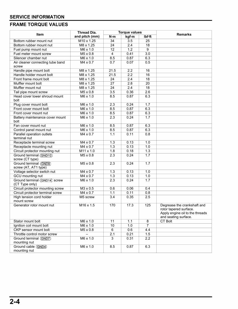
FRAME TORQUE VALUES
Item Thread Dia. and pitch (mm)
Torque valuesRemarks
N·m kgf·m lbf·ftBottom rubber mount nut M10 x 1.25 34 3.5 25Bottom rubber mount nut M8 x 1.25 24 2.4 18Fuel pump mount nut M6 x 1.0 12 1.2 9Fuel meter mount screw M5 x 0.8 4 0.41 3.0Silencer chamber nut M6 x 1.0 8.5 0.87 6.3Air cleaner connecting tube band screw
M4 x 0.7 0.7 0.07 0.5
Handle pipe mount bolt M8 x 1.25 21.5 2.2 16Handle holder mount bolt M8 x 1.25 21.5 2.2 16Front frame mount bolt M8 x 1.25 24 2.4 18Muffler mount bolt M8 x 1.25 27 2.8 20Muffler mount nut M8 x 1.25 24 2.4 18Tail pipe mount screw M5 x 0.8 3.5 0.36 2.6Head cover lower shroud mount bolt
M6 x 1.0 8.5 0.87 6.3
Plug cover mount bolt M6 x 1.0 2.3 0.24 1.7Front cover mount bolt M6 x 1.0 8.5 0.87 6.3Front cover mount nut M6 x 1.0 8.5 0.87 6.3Battery maintenance cover mount bolt
M6 x 1.0 2.3 0.24 1.7
Fan cover mount nut M6 x 1.0 8.5 0.87 6.3Control panel mount nut M6 x 1.0 8.5 0.87 6.3Parallel operation outletsterminal nut
M4 x 0.7 1.1 0.11 0.8
Receptacle terminal screw M4 x 0.7 1.3 0.13 1.0Receptacle mounting nut M4 x 0.7 1.3 0.13 1.0Circuit protector mounting nut M11 x 1.0 1.8 0.18 1.3Ground terminal screw (CT type)
M5 x 0.8 2.3 0.24 1.7
Ground terminal screw (AT, AT1 type)
M5 x 0.8 2.3 0.24 1.7
Voltage selector switch nut M4 x 0.7 1.3 0.13 1.0GCU mounting nut M4 x 0.7 1.3 0.13 1.0Ground terminal screw (CT Type only)
M6 x 1.0 2.3 0.24 1.7
Circuit protector mounting screw M3 x 0.5 0.6 0.06 0.4Circuit protector terminal screw M4 x 0.7 1.1 0.11 0.8High tension cord holdermount screw
M5 screw 3.4 0.35 2.5
Generator rotor mount nut M16 x 1.5 170 17.3 125 Degrease the crankshaft and rotor tapered surface.Apply engine oil to the threads and seating surface.
Stator mount bolt M6 x 1.0 11 1.1 8 CT BoltIgnition coil mount bolt M6 x 1.0 10 1.0 7CKP sensor mount bolt M5 x 0.8 6 0.6 4.4Throttle control motor screw – 2.1 0.21 1.5Ground terminal mounting nut
M6 x 1.0 3 0.31 2.2
Ground cable mounting nut
M6 x 1.0 8.5 0.87 6.3
2-5
dummyheaddummyhead
SERVICE INFORMATION
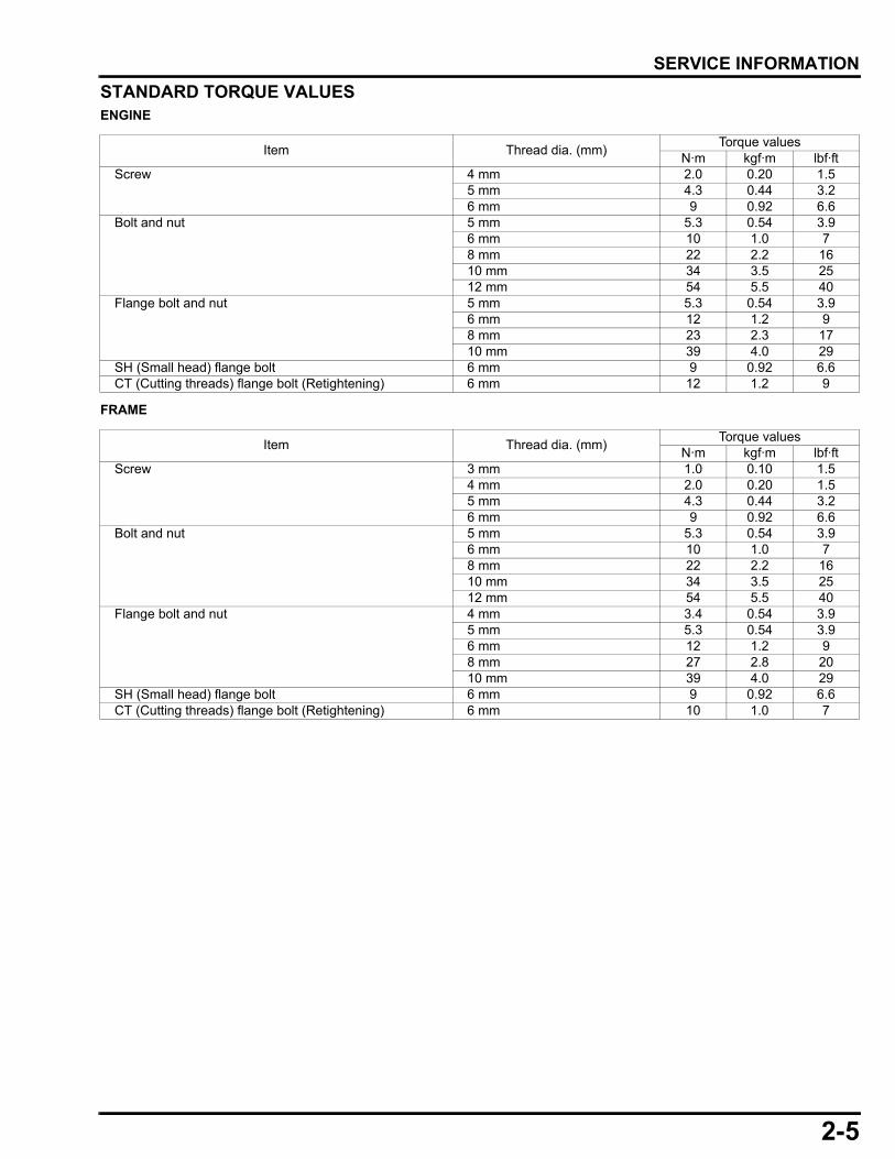
STANDARD TORQUE VALUESENGINE
FRAME
Item Thread dia. (mm)Torque values
N·m kgf·m lbf·ftScrew 4 mm 2.0 0.20 1.5
5 mm 4.3 0.44 3.26 mm 9 0.92 6.6
Bolt and nut 5 mm 5.3 0.54 3.96 mm 10 1.0 78 mm 22 2.2 1610 mm 34 3.5 2512 mm 54 5.5 40
Flange bolt and nut 5 mm 5.3 0.54 3.96 mm 12 1.2 98 mm 23 2.3 1710 mm 39 4.0 29
SH (Small head) flange bolt 6 mm 9 0.92 6.6CT (Cutting threads) flange bolt (Retightening) 6 mm 12 1.2 9
Item Thread dia. (mm)Torque values
N·m kgf·m lbf·ftScrew 3 mm 1.0 0.10 1.5
4 mm 2.0 0.20 1.55 mm 4.3 0.44 3.26 mm 9 0.92 6.6
Bolt and nut 5 mm 5.3 0.54 3.96 mm 10 1.0 78 mm 22 2.2 1610 mm 34 3.5 2512 mm 54 5.5 40
Flange bolt and nut 4 mm 3.4 0.54 3.95 mm 5.3 0.54 3.96 mm 12 1.2 98 mm 27 2.8 2010 mm 39 4.0 29
SH (Small head) flange bolt 6 mm 9 0.92 6.6CT (Cutting threads) flange bolt (Retightening) 6 mm 10 1.0 7
2-6
dummyheaddummyhead
SERVICE INFORMATION
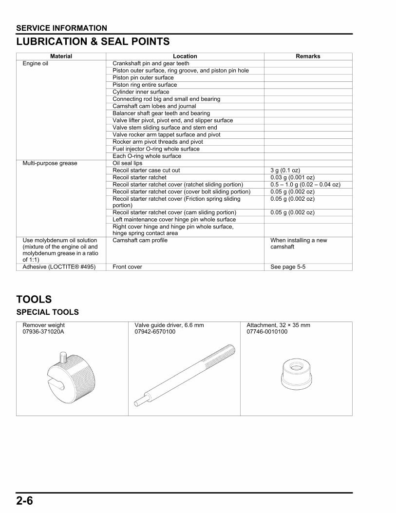
LUBRICATION & SEAL POINTS
TOOLSSPECIAL TOOLS
Material Location RemarksEngine oil Crankshaft pin and gear teeth
Piston outer surface, ring groove, and piston pin holePiston pin outer surfacePiston ring entire surfaceCylinder inner surfaceConnecting rod big and small end bearingCamshaft cam lobes and journalBalancer shaft gear teeth and bearingValve lifter pivot, pivot end, and slipper surfaceValve stem sliding surface and stem endValve rocker arm tappet surface and pivotRocker arm pivot threads and pivotFuel injector O-ring whole surfaceEach O-ring whole surface
Multi-purpose grease Oil seal lipsRecoil starter case cut out 3 g (0.1 oz)Recoil starter ratchet 0.03 g (0.001 oz)Recoil starter ratchet cover (ratchet sliding portion) 0.5 – 1.0 g (0.02 – 0.04 oz)Recoil starter ratchet cover (cover bolt sliding portion) 0.05 g (0.002 oz)Recoil starter ratchet cover (Friction spring sliding portion)
0.05 g (0.002 oz)
Recoil starter ratchet cover (cam sliding portion) 0.05 g (0.002 oz)Left maintenance cover hinge pin whole surfaceRight cover hinge and hinge pin whole surface, hinge spring contact area
Use molybdenum oil solution (mixture of the engine oil and molybdenum grease in a ratio of 1:1)
Camshaft cam profile When installing a new camshaft
Adhesive (LOCTITE® #495) Front cover See page 5-5
Remover weight07936-371020A
Valve guide driver, 6.6 mm07942-6570100
Attachment, 32 × 35 mm07746-0010100

2-7
dummyheaddummyhead
SERVICE INFORMATION
Attachment, 52 × 55 mm07746-0010400
Attachment, 72 × 75 mm07746-0010600
Driver, 40 mm I.D.07746-0030100
Driver attachment, 35 mm I.D.07746-0030400
Pilot, 15 mm07746-0040300
Pilot, 35 mm07746-0040800
Driver handle07749-0010000
Bearing remover shaft, 15 mm07936-KC10500
Valve guide reamer, 6.612 mm07984-ZE20001
Crank pulley holder 4707925-6570000
Fuel pressure gauge 07APJ-Z37A100
2-8
dummyheaddummyhead
SERVICE INFORMATION
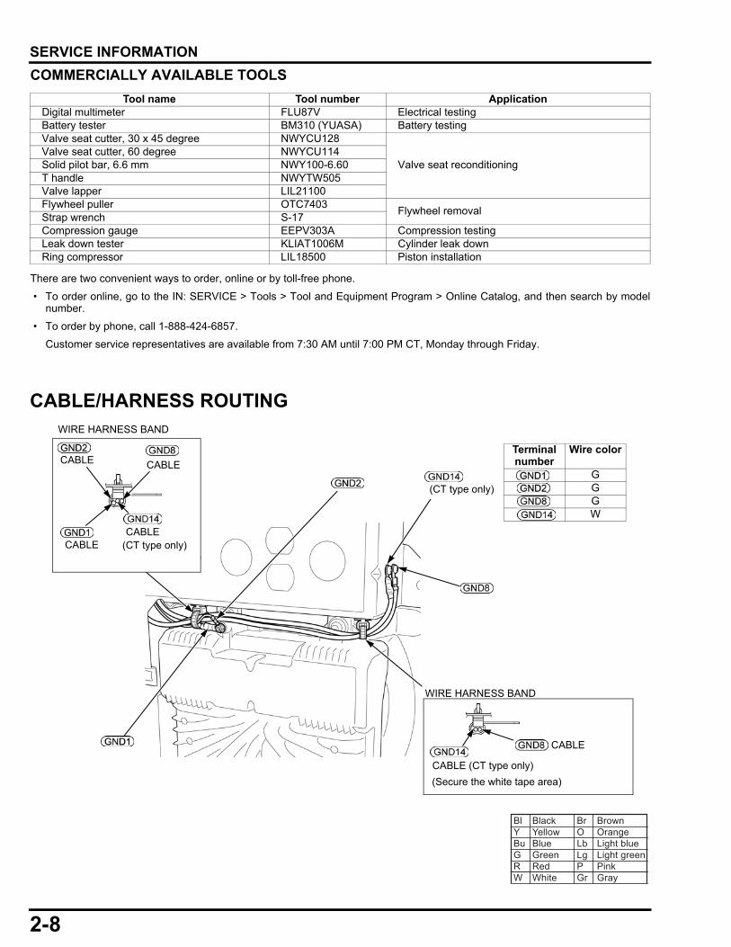
COMMERCIALLY AVAILABLE TOOLS
There are two convenient ways to order, online or by toll-free phone.
• To order online, go to the IN: SERVICE > Tools > Tool and Equipment Program > Online Catalog, and then search by modelnumber.
• To order by phone, call 1-888-424-6857.
Customer service representatives are available from 7:30 AM until 7:00 PM CT, Monday through Friday.
CABLE/HARNESS ROUTING
Tool name Tool number ApplicationDigital multimeter FLU87V Electrical testingBattery tester BM310 (YUASA) Battery testingValve seat cutter, 30 x 45 degree NWYCU128
Valve seat reconditioningValve seat cutter, 60 degree NWYCU114Solid pilot bar, 6.6 mm NWY100-6.60T handle NWYTW505Valve lapper LIL21100Flywheel puller OTC7403
Flywheel removalStrap wrench S-17Compression gauge EEPV303A Compression testingLeak down tester KLIAT1006M Cylinder leak downRing compressor LIL18500 Piston installation
Terminal number
Wire color
GGGW
Bl Black Br BrownY Yellow O OrangeBu Blue Lb Light blueG Green Lg Light greenR Red P PinkW White Gr Gray
(CT type only)
WIRE HARNESS BAND
WIRE HARNESS BAND
CABLE
CABLE (CT type only)
(CT type only)
CABLE
CABLECABLE
CABLE
(Secure the white tape area)
2-9
dummyheaddummyhead
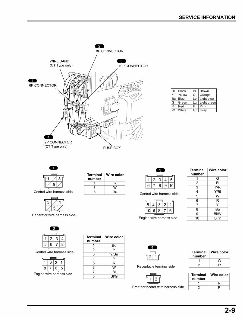
SERVICE INFORMATION
Bl Black Br BrownY Yellow O OrangeBu Blue Lb Light blueG Green Lg Light greenR Red P PinkW White Gr Gray
WIRE BAND(CT Type only)
Receptacle terminal side
Breather heater wire harness side
Generator wire harness side
Engine wire harness side
Control wire harness side
Control wire harness side
Terminal number
Wire color
1 R2 R
Terminal number
Wire color
1 W2 R
Terminal number
Wire color
1 Bu2 Y3 Y/Bu4 Y5 R6 W7 Bl8 Bl/G
Terminal number
Wire color
1 R3 W5 Bu
FUSE BOX
Engine wire harness side
Control wire harness side
Terminal number
Wire color
1 G2 Bl3 Y/R4 Y/Bl5 W6 R7 Y8 Bu9 Bl/W
10 Bl/Y
10P CONNECTOR
8P CONNECTOR
6P CONNECTOR
2P CONNECTOR(CT Type only)
2-10
dummyheaddummyhead
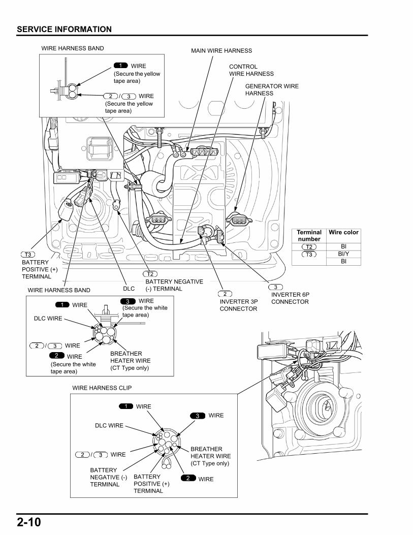
SERVICE INFORMATION
MAIN WIRE HARNESS
CONTROL WIRE HARNESS
WIRE HARNESS BAND
WIRE HARNESS BAND
WIRE HARNESS CLIP
GENERATOR WIRE HARNESS
BREATHER HEATER WIRE(CT Type only)
BATTERY POSITIVE (+) TERMINAL
BATTERY NEGATIVE (-) TERMINAL
DLC WIRE
WIRE
WIRE
WIRE
WIRE
WIRE/
WIRE/
DLC WIRE
BATTERY POSITIVE (+) TERMINAL
BATTERY NEGATIVE (-) TERMINALDLC
BREATHER HEATER WIRE(CT Type only)
WIRE
/ WIRE
WIRE
(Secure the yellow tape area)
(Secure the yellow tape area)
(Secure the white tape area)
(Secure the white tape area)
WIREINVERTER 6P CONNECTORINVERTER 3P
CONNECTOR
Terminal number
Wire color
BlBl/YBl
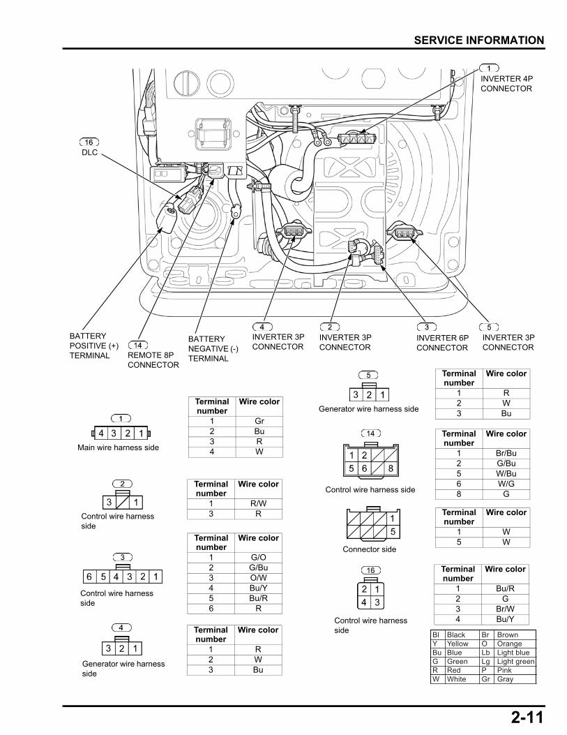
2-11
dummyheaddummyhead
SERVICE INFORMATION
Bl Black Br BrownY Yellow O OrangeBu Blue Lb Light blueG Green Lg Light greenR Red P PinkW White Gr Gray
REMOTE 8P CONNECTOR
BATTERY NEGATIVE (-) TERMINAL
INVERTER 3P CONNECTOR
INVERTER 3P CONNECTOR
INVERTER 4P CONNECTOR
DLC
Terminal number
Wire color
1 R2 W3 Bu
Terminal number
Wire color
1 G/O2 G/Bu3 O/W4 Bu/Y5 Bu/R6 R
Terminal number
Wire color
1 Bu/R2 G3 Br/W4 Bu/Y
Terminal number
Wire color
1 R/W3 R
Terminal number
Wire color
1 Gr2 Bu3 R4 W
BATTERY POSITIVE (+) TERMINAL
Main wire harness side
Control wire harness side
Generator wire harness side
Control wire harness side
Control wire harness side
Control wire harness side
Terminal number
Wire color
1 W5 W
Terminal number
Wire color
1 R2 W3 Bu
INVERTER 3P CONNECTOR
INVERTER 6P CONNECTOR
Terminal number
Wire color
1 Br/Bu2 G/Bu5 W/Bu6 W/G8 G
Connector side
Generator wire harness side

2-12
dummyheaddummyhead
SERVICE INFORMATION
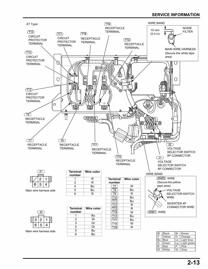
AT Type:
CONTROL WIRE HARNESS
CIRCUIT PROTECTOR WIRE CONNECTOR
SUB WIRES
ECO-THROTTLE SWITCH WIRE CONNECTOR
PARALLEL OPERATION OUTLETS TERMINAL
WIRE HARNESS BAND (9)
Terminal number
Wire color
R/WRBuBuBuBuRRBuWR
Bl Black Br BrownY Yellow O OrangeBu Blue Lb Light blueG Green Lg Light greenR Red P PinkW White Gr Gray
Terminal number
Wire color
G
CIRCUIT PROTECTOR WIRE CONNECTOR
MAIN SWITCH 4P CONNECTOR
STARTER SWITCH 2P CONNECTOR
Terminal number
Wire color
1 Br/Bu2 Br/Bu3 G/O4 G/O
Control wire harness side
Terminal number
Wire color
1 G2 Bl/Y
Starter switch side
Terminal number
Wire color
1 G2 Bl3 Br/W4 Bl/Y
CIRCUIT PROTECTOR WIRE CONNECTOR
CIRCUIT PROTECTOR WIRE CONNECTOR
CIRCUIT PROTECTOR WIRE CONNECTOR
CIRCUIT PROTECTOR WIRE CONNECTOR
ECO-THROTTLE SWITCH WIRE CONNECTOR
PARALLEL OPERATION OUTLETS TERMINAL
PARALLEL OPERATION OUTLETS TERMINAL
Main switch side
Control wire harness side
MAIN WIRE HARNESS
2-13
dummyheaddummyhead
SERVICE INFORMATION
AT Type:
CIRCUIT PROTECTOR TERMINAL
CIRCUIT PROTECTOR TERMINAL
CIRCUIT PROTECTOR TERMINAL
CIRCUIT PROTECTOR TERMINAL
RECEPTACLE TERMINAL
RECEPTACLE TERMINAL
RECEPTACLE TERMINAL RECEPTACLE
TERMINAL
RECEPTACLE TERMINAL
RECEPTACLE TERMINAL
RECEPTACLE TERMINAL
RECEPTACLE TERMINAL
VOLTAGE SELECTOR SWITCH 6P CONNECTOR
VOLTAGE SELECTOR SWITCH 6P CONNECTOR
Terminal number
Wire color
WBuRBuBuRRWBuBuWR
Terminal number
Wire color
1 Bu2 W3 Gr4 Gr5 Bu6 Bu
Terminal number
Wire color
1 R2 R4 Bu5 Bu6 R
Bl Black Br BrownY Yellow O OrangeBu Blue Lb Light blueG Green Lg Light greenR Red P PinkW White Gr Gray
Main wire harness side
Main wire harness side
(Secure the yellow tape area)
WIRE
VOLTAGE SELECTOR SWITCH WIRE
WIRE BAND
10 mm(0.4 in)
NOISE FILTER
(Secure the white tape area)
MAIN WIRE HARNESS
WIRE BAND
WIRE
INVERTER 4P CONNECTOR WIRE

2-14
dummyheaddummyhead
SERVICE INFORMATION
AT1 Type:
CONTROL WIRE HARNESS
CIRCUIT PROTECTOR WIRE CONNECTOR
SUB WIRES
ECO-THROTTLE SWITCH WIRE CONNECTOR
PARALLEL OPERATION OUTLETS TERMINAL
WIRE HARNESS BAND (9)
Terminal number
Wire color
R/WRBuBuBuBuRRBuWR
Bl Black Br BrownY Yellow O OrangeBu Blue Lb Light blueG Green Lg Light greenR Red P PinkW White Gr Gray
Terminal number
Wire color
G
CIRCUIT PROTECTOR WIRE CONNECTOR
MAIN SWITCH 4P CONNECTOR
STARTER SWITCH 2P CONNECTOR
Terminal number
Wire color
1 Br/Bu2 Br/Bu3 G/O4 G/O
Control wire harness side
Terminal number
Wire color
1 G2 Bl/Y
Starter switch side
Terminal number
Wire color
1 G2 Bl3 Br/W4 Bl/Y
CIRCUIT PROTECTOR WIRE CONNECTOR
CIRCUIT PROTECTOR WIRE CONNECTOR
CIRCUIT PROTECTOR WIRE CONNECTOR
CIRCUIT PROTECTOR WIRE CONNECTOR
ECO-THROTTLE SWITCH WIRE CONNECTOR
PARALLEL OPERATION OUTLETS TERMINAL
PARALLEL OPERATION OUTLETS TERMINAL
Main switch side
Control wire harness side
MAIN WIRE HARNESS

2-15
dummyheaddummyhead
SERVICE INFORMATION
AT1 Type:
CIRCUIT PROTECTOR TERMINAL
CIRCUIT PROTECTOR TERMINAL
CIRCUIT PROTECTOR TERMINAL
CIRCUIT PROTECTOR TERMINAL
RECEPTACLE TERMINAL
RECEPTACLE TERMINAL
RECEPTACLE TERMINAL
RECEPTACLE TERMINAL
RECEPTACLE TERMINAL
RECEPTACLE TERMINAL
RECEPTACLE TERMINAL
RECEPTACLE TERMINAL
VOLTAGE SELECTOR SWITCH 6P CONNECTOR
VOLTAGE SELECTOR SWITCH 6P CONNECTOR
Terminal number
Wire color
WBuRBuBuRRWBuBuWRW
Terminal number
Wire color
1 Bu2 W3 Gr4 Gr5 Bu6 Bu
Terminal number
Wire color
1 R2 R4 Bu5 Bu6 R
Bl Black Br BrownY Yellow O OrangeBu Blue Lb Light blueG Green Lg Light greenR Red P PinkW White Gr Gray
Main wire harness side
Main wire harness side
(Secure the yellow tape area)
WIRE
VOLTAGE SELECTOR SWITCH WIRE
WIRE BAND
10 mm(0.4 in)
NOISE FILTER
(Secure the white tape area)
MAIN WIRE HARNESS
WIRE BAND
WIRE
INVERTER 4P CONNECTOR WIRE
RECEPTACLE TERMINAL
2-16
dummyheaddummyhead
SERVICE INFORMATION
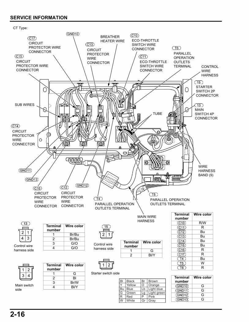
CT Type:
BREATHER HEATER WIRE
CONTROL WIRE HARNESS
SUB WIRES
PARALLEL OPERATION OUTLETS TERMINAL
PARALLEL OPERATION OUTLETS TERMINAL
PARALLEL OPERATION OUTLETS TERMINAL
WIRE HARNESS BAND (9)
Bl Black Br BrownY Yellow O OrangeBu Blue Lb Light blueG Green Lg Light greenR Red P PinkW White Gr Gray
Terminal number
Wire color
GGGG
MAIN SWITCH 4P CONNECTOR
STARTER SWITCH 2P CONNECTOR
Terminal number
Wire color
1 Br/Bu2 Br/Bu3 G/O4 G/O
Control wire harness side
Main switch side
Terminal number
Wire color
1 G2 Bl/Y
Starter switch side
Terminal number
Wire color
1 G2 Bl3 Br/W4 Bl/Y
Control wire harness side
TUBE
ECO-THROTTLE SWITCH WIRE CONNECTOR
ECO-THROTTLE SWITCH WIRE CONNECTOR
CIRCUIT PROTECTOR WIRE CONNECTOR
CIRCUIT PROTECTOR WIRE CONNECTOR
CIRCUIT PROTECTOR WIRE CONNECTOR
CIRCUIT PROTECTOR WIRE CONNECTOR
CIRCUIT PROTECTOR WIRE CONNECTOR
CIRCUIT PROTECTOR WIRE CONNECTOR
MAIN WIRE HARNESS
Terminal number
Wire color
R/WRBuBuBuBuRRBuWR

2-17
dummyheaddummyhead
SERVICE INFORMATION
CIRCUIT PROTECTOR TERMINAL
CIRCUIT PROTECTOR TERMINAL
CIRCUIT PROTECTOR TERMINAL
CIRCUIT PROTECTOR TERMINAL
RECEPTACLE TERMINAL
RECEPTACLE TERMINAL
RECEPTACLE TERMINAL
RECEPTACLE TERMINAL
RECEPTACLE TERMINAL
RECEPTACLE TERMINAL
RECEPTACLE TERMINAL
RECEPTACLE TERMINAL
RECEPTACLE TERMINAL
VOLTAGE SELECTOR SWITCH 6P CONNECTOR
VOLTAGE SELECTOR SWITCH 6P CONNECTOR
Terminal number
Wire color
WBuRBuBuRRWBuWBuWRBuBuRR
Terminal number
Wire color
1 Bu2 W3 Gr4 Gr5 Bu6 Bu
Terminal number
Wire color
1 R2 R4 Bu5 Bu6 R
Bl Black Br BrownY Yellow O OrangeBu Blue Lb Light blueG Green Lg Light greenR Red P PinkW White Gr Gray
CT Type:
CIRCUIT PROTECTOR TERMINAL
CIRCUIT PROTECTOR TERMINAL
CIRCUIT PROTECTOR TERMINAL
CIRCUIT PROTECTOR TERMINAL
Main wire harness side
Main wire harness side
WIRE BAND
BREATHER HEATER WIRE
NOISE FILTER10 mm
(0.4 in)
(Secure the white tape area)
MAIN WIRE HARNESS
(Secure the yellow tape area)
WIRE
VOLTAGE SELECTOR SWITCH WIRE
WIRE
INVERTER 4P CONNECTOR WIRE
WIRE BAND
2-18
dummyheaddummyhead
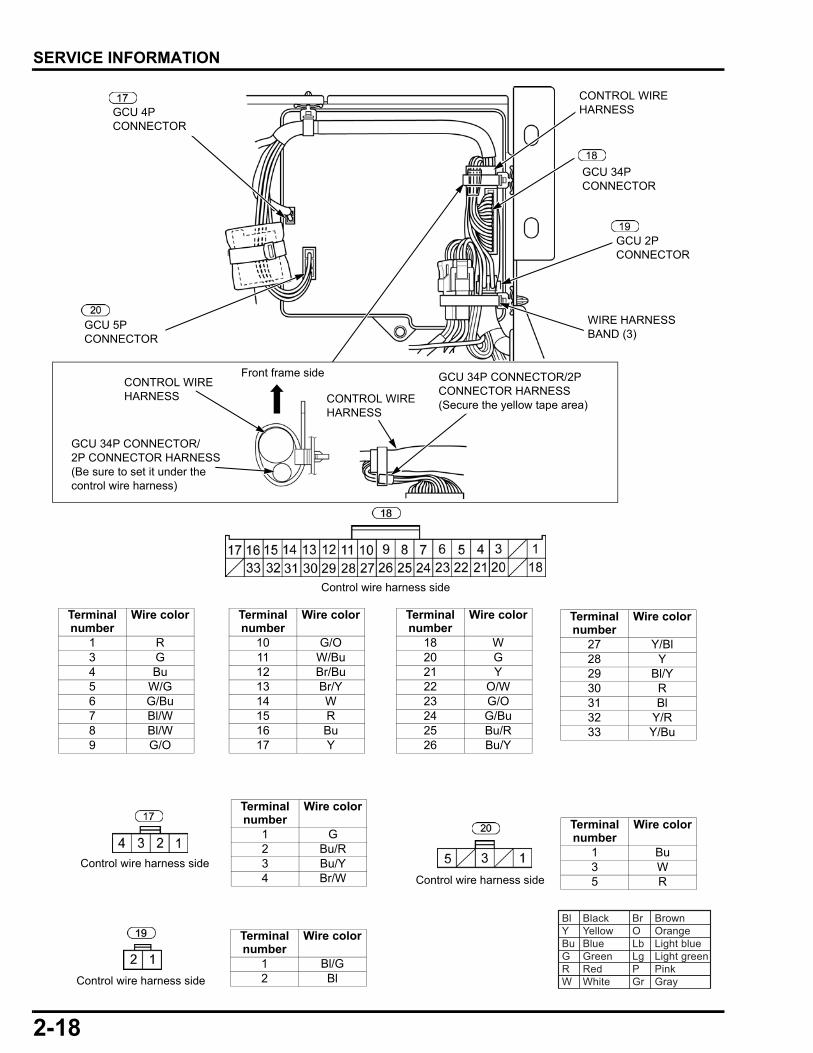
SERVICE INFORMATION
Terminal number
Wire color
1 Bu3 W5 R
Terminal number
Wire color
1 Bl/G2 Bl
Terminal number
Wire color
1 G2 Bu/R3 Bu/Y4 Br/W
Bl Black Br BrownY Yellow O OrangeBu Blue Lb Light blueG Green Lg Light greenR Red P PinkW White Gr Gray
WIRE HARNESS BAND (3)
Terminal number
Wire color
1 R3 G4 Bu5 W/G6 G/Bu7 Bl/W8 Bl/W9 G/O
Terminal number
Wire color
10 G/O11 W/Bu12 Br/Bu13 Br/Y14 W15 R16 Bu17 Y
Terminal number
Wire color
18 W20 G21 Y22 O/W23 G/O24 G/Bu25 Bu/R26 Bu/Y
Terminal number
Wire color
27 Y/Bl28 Y29 Bl/Y30 R31 Bl32 Y/R33 Y/Bu
Control wire harness side
Control wire harness side
Control wire harness side
Control wire harness side
CONTROL WIRE HARNESS
GCU 34P CONNECTOR
GCU 2P CONNECTOR
GCU 5P CONNECTOR
GCU 4P CONNECTOR
GCU 34P CONNECTOR/2P CONNECTOR HARNESS(Secure the yellow tape area)
CONTROL WIRE HARNESS
GCU 34P CONNECTOR/2P CONNECTOR HARNESS(Be sure to set it under the control wire harness)
Front frame side
CONTROL WIRE HARNESS
2-19
dummyheaddummyhead
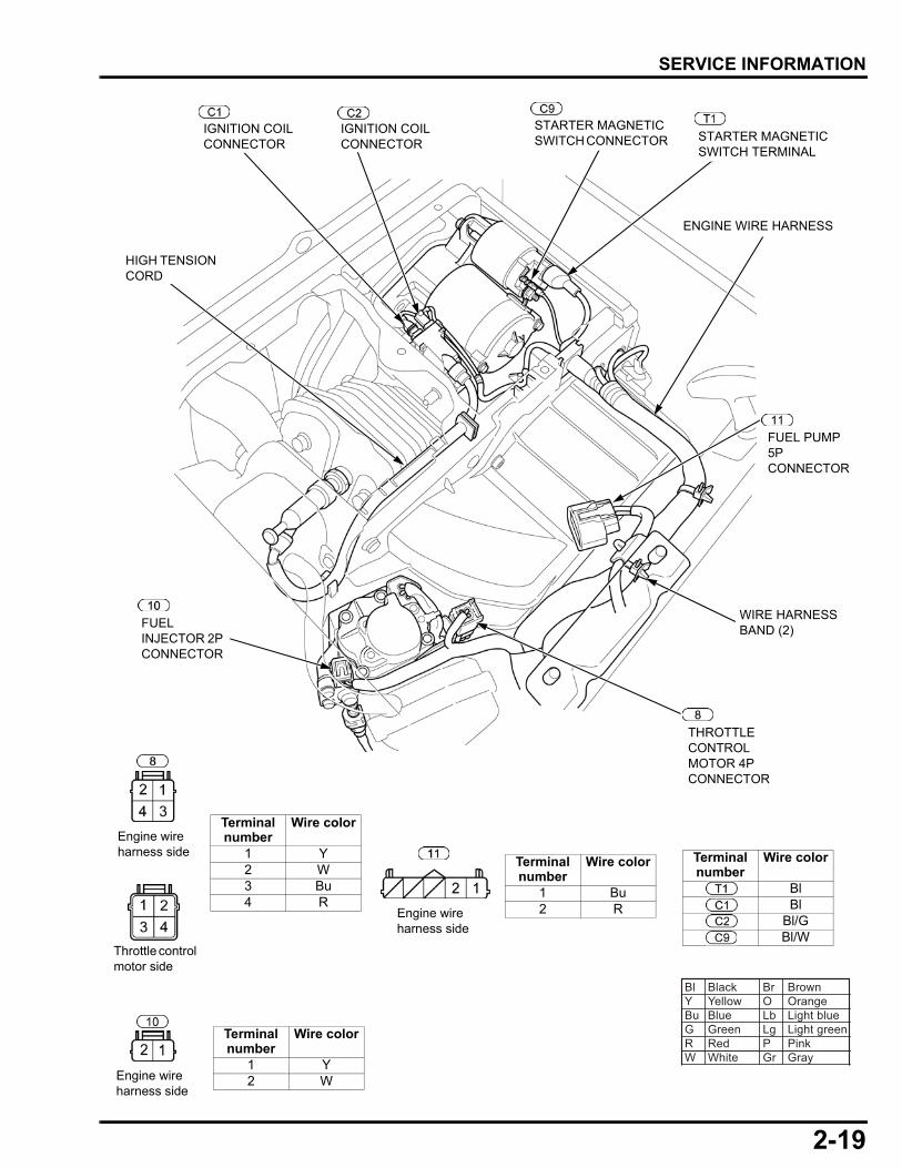
SERVICE INFORMATION
HIGH TENSION CORD
Terminal number
Wire color
BlBl
Bl/GBl/W
Terminal number
Wire color
1 Bu2 R
Terminal number
Wire color
1 Y2 W
Terminal number
Wire color
1 Y2 W3 Bu4 R
WIRE HARNESS BAND (2)
ENGINE WIRE HARNESS
Bl Black Br BrownY Yellow O OrangeBu Blue Lb Light blueG Green Lg Light greenR Red P PinkW White Gr Gray
FUEL PUMP 5P CONNECTOR
Engine wire harness side
Engine wire harness side
Engine wire harness side
THROTTLE CONTROL MOTOR 4P CONNECTOR
FUEL INJECTOR 2P CONNECTOR
IGNITION COIL CONNECTOR
IGNITION COIL CONNECTOR
STARTER MAGNETIC SWITCH CONNECTOR STARTER MAGNETIC
SWITCH TERMINAL
Throttle control motor side
2-20
dummyheaddummyhead
SERVICE INFORMATION
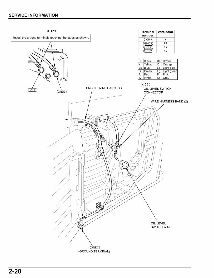
Terminal number
Wire color
YBlGG
Bl Black Br BrownY Yellow O OrangeBu Blue Lb Light blueG Green Lg Light greenR Red P PinkW White Gr Gray
Install the ground terminals touching the stops as shown.
STOPS
(GROUND TERMINAL)
OIL LEVEL SWITCH WIRE
WIRE HARNESS BAND (2)
ENGINE WIRE HARNESS OIL LEVEL SWITCH CONNECTOR

2-21
dummyheaddummyhead
SERVICE INFORMATION
WIRE HARNESS CLIP
O2 SENSOR WIRE
EBT SENSOR
EBT SENSOR WIRE
Bl Black Br BrownY Yellow O OrangeBu Blue Lb Light blueG Green Lg Light greenR Red P PinkW White Gr Gray
BREATHER HEATER 2P CONNECTOR
CT Type only:
Terminal number
Wire color
1 R2 R
Engine wire harness side
Breather heater harness side
WIRE BAND
2-22
dummyheaddummyhead
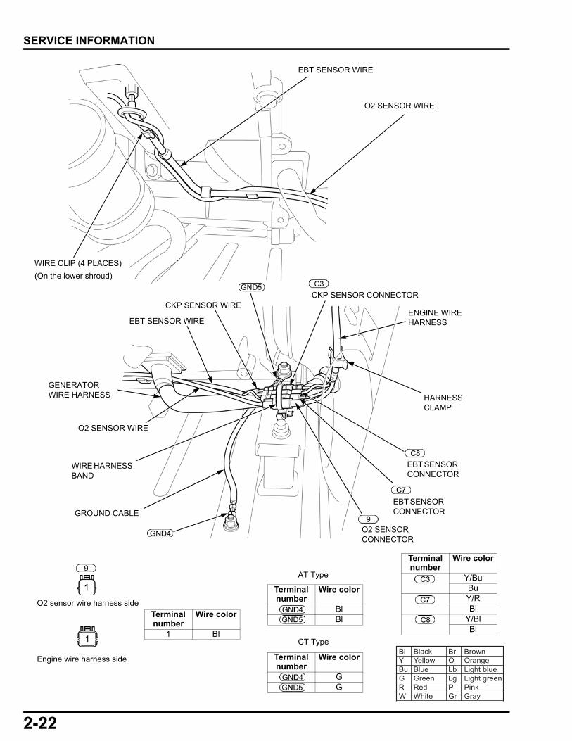
SERVICE INFORMATION
Terminal number
Wire color
Y/BuBuY/RBl
Y/BlBl
Terminal number
Wire color
BlBl
Terminal number
Wire color
1 Bl
GROUND CABLE
CKP SENSOR WIRE
O2 SENSOR WIRE
EBT SENSOR WIRE
GENERATOR WIRE HARNESS
Bl Black Br BrownY Yellow O OrangeBu Blue Lb Light blueG Green Lg Light greenR Red P PinkW White Gr Gray
Engine wire harness side
O2 sensor wire harness side
EBT SENSOR CONNECTOR
CKP SENSOR CONNECTOR
EBT SENSOR CONNECTOR
O2 SENSOR CONNECTOR
HARNESS CLAMP
WIRE HARNESS BAND
Terminal number
Wire color
GG
AT Type
CT Type
ENGINE WIRE HARNESS
O2 SENSOR WIRE
EBT SENSOR WIRE
WIRE CLIP (4 PLACES)
(On the lower shroud)
2-23
dummyheaddummyhead
SERVICE INFORMATION
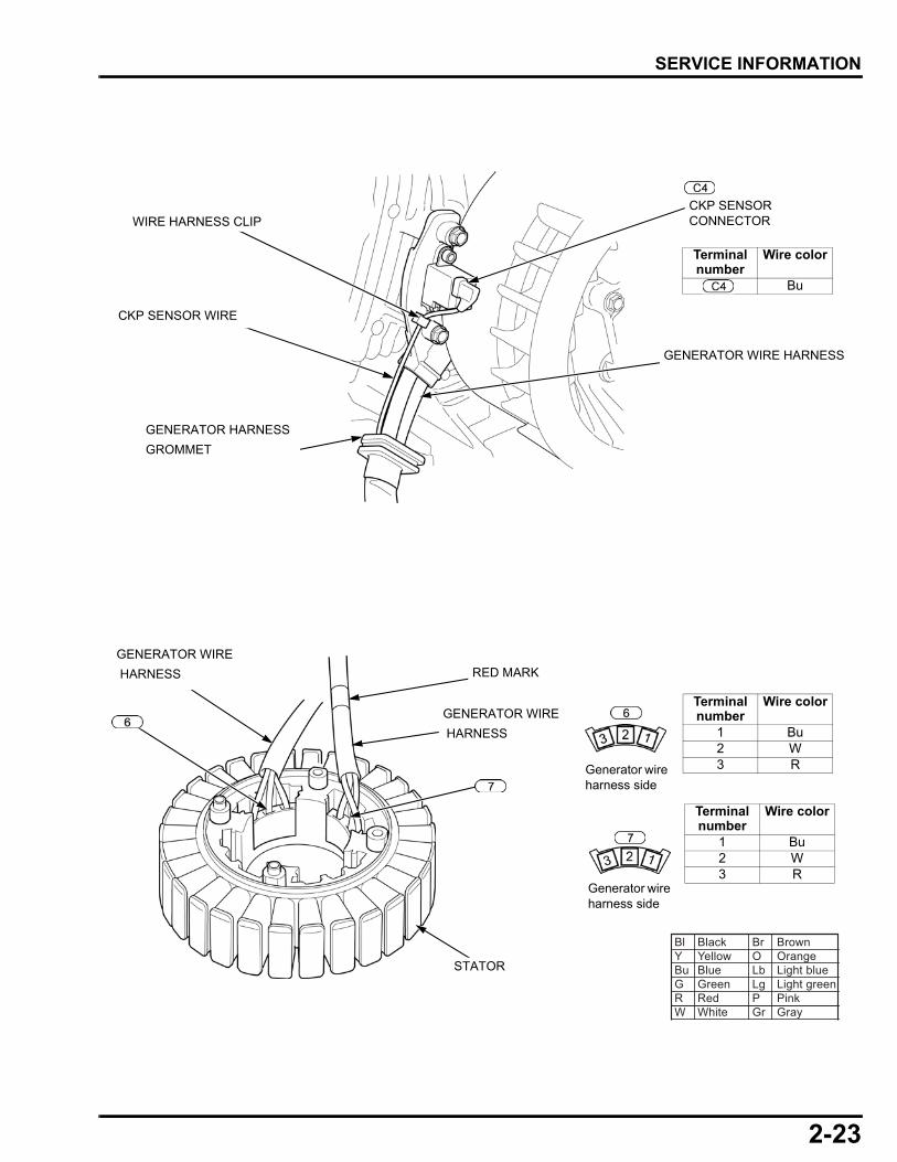
Terminal number
Wire color
Bu
Bl Black Br BrownY Yellow O OrangeBu Blue Lb Light blueG Green Lg Light greenR Red P PinkW White Gr Gray
GENERATOR WIRE
HARNESS
GENERATOR WIRE
HARNESS
STATOR
RED MARK
Terminal number
Wire color
1 Bu2 W3 R
Terminal number
Wire color
1 Bu2 W3 R
WIRE HARNESS CLIP
CKP SENSOR WIRE
GENERATOR WIRE HARNESS
GENERATOR HARNESS
GROMMET
CKP SENSOR CONNECTOR
Generator wire harness side
Generator wire harness side
2-24
dummyheaddummyhead
SERVICE INFORMATION
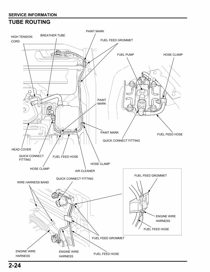
TUBE ROUTING
QUICK CONNECT FITTING
ENGINE WIRE
HARNESS
ENGINE WIRE
HARNESS
AIR CLEANER
QUICK CONNECT FITTING
FUEL FEED GROMMET
WIRE HARNESS BAND
ENGINE WIRE
HARNESS
FUEL FEED HOSE
FUEL FEED HOSE
FUEL FEED GROMMET
HIGH TENSION
CORD
FUEL PUMP
FUEL FEED HOSE
HOSE CLAMP
FUEL FEED GROMMET
HOSE CLAMP
HOSE CLAMP
FUEL FEED HOSE
HEAD COVER
BREATHER TUBE
QUICK CONNECT FITTING
PAINT MARK
PAINT MARK
PAINT MARK
2-25
dummyheaddummyhead
SERVICE INFORMATION
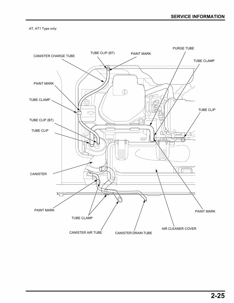
CANISTER
TUBE CLIP (B7)
TUBE CLAMP
PAINT MARK
TUBE CLAMP
TUBE CLAMP
PAINT MARK
TUBE CLIP
TUBE CLIP (B7)
AIR CLEANER COVERCANISTER DRAIN TUBE
PURGE TUBE
CANISTER CHARGE TUBE
AT, AT1 Type only:
CANISTER AIR TUBE
PAINT MARK
PAINT MARK
TUBE CLIP
2-26
dummyheaddummyhead
SERVICE INFORMATION
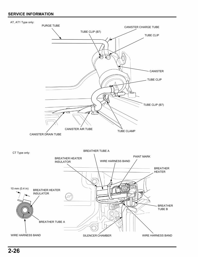
CANISTER
TUBE CLIP
PURGE TUBE
CANISTER DRAIN TUBE
CANISTER AIR TUBETUBE CLAMP
TUBE CLIP
TUBE CLIP (B7)
TUBE CLIP (B7)
CANISTER CHARGE TUBE
AT, AT1 Type only:
CT Type only: BREATHER TUBE A
BREATHER HEATER INSULATOR
BREATHER HEATER
SILENCER CHAMBER
BREATHER TUBE B
PAINT MARK
WIRE HARNESS BAND
BREATHER TUBE A
BREATHER HEATER INSULATOR
10 mm (0.4 in)
WIRE HARNESS BAND
WIRE HARNESS BAND

3-1
3
dummytext
3. MAINTENANCE
MAINTENANCE SCHEDULE························3-2
ENGINE OIL LEVEL CHECK/CHANGE ·······3-4
AIR CLEANER CHECK/CLEANING/REPLACEMENT············································3-6
GFCI OPERATION (AT1 TYPE ONLY)·········3-7
EVAP CANISTER/EVAP CHARGE TUBE/EVAP PURGE TUBE INSPECTION (AT, AT1 TYPE ONLY)··································3-7
SPARK PLUG CHECK/ADJUSTMENT/REPLACEMENT············································3-9
SPARK ARRESTER CLEANING················ 3-10
VALVE CLEARANCE CHECK/ADJUSTMENT ············································ 3-10
COMBUSTION CHAMBER CLEANING ····· 3-12
FUEL TANK CLEANING····························· 3-12
FUEL PUMP FILTER CHANGE·················· 3-13
FUEL FEED HOSE CHECK························ 3-14
3-2
dummyheaddummyhead
MAINTENANCEMAINTENANCE
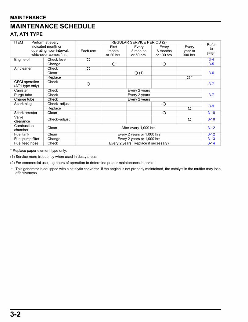
MAINTENANCE SCHEDULEAT, AT1 TYPE
* Replace paper element type only.
(1) Service more frequently when used in dusty areas.
(2) For commercial use, log hours of operation to determine proper maintenance intervals.
• This generator is equipped with a catalytic converter. If the engine is not properly maintained, the catalyst in the muffler may loseeffectiveness.
ITEM Perform at every indicated month or operating hour interval, whichever comes first.
REGULAR SERVICE PERIOD (2)Refer
to pageEach use
First month
or 20 hrs.
Every3 months or 50 hrs.
Every6 months
or 100 hrs.
Everyyear or 300 hrs.
Engine oil Check level 3-4Change 3-5
Air cleaner Check3-6Clean (1)
Replace *GFCI operation(AT1 type only)
Check 3-7
Canister Check Every 2 years3-7Purge tube Check Every 2 years
Charge tube Check Every 2 yearsSpark plug Check–adjust
3-9Replace
Spark arrester Clean 3-10Valve clearance Check–adjust 3-10
Combustion chamber Clean After every 1,000 hrs. 3-12
Fuel tank Clean Every 2 years or 1,000 hrs 3-12Fuel pump filter Change Every 2 years or 1,000 hrs 3-13Fuel feed hose Check Every 2 years (Replace if necessary) 3-14
3-3
dummyheaddummyhead
MAINTENANCE
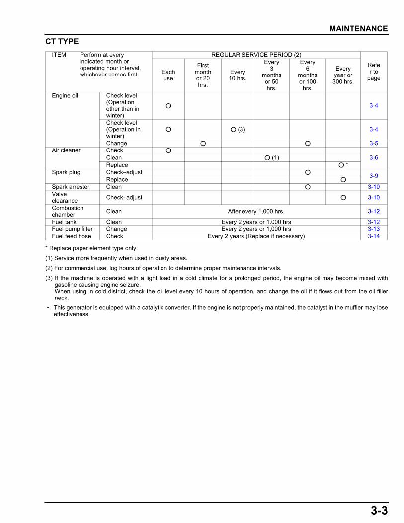
CT TYPE
* Replace paper element type only.
(1) Service more frequently when used in dusty areas.
(2) For commercial use, log hours of operation to determine proper maintenance intervals.
(3) If the machine is operated with a light load in a cold climate for a prolonged period, the engine oil may become mixed withgasoline causing engine seizure. When using in cold district, check the oil level every 10 hours of operation, and change the oil if it flows out from the oil fillerneck.
• This generator is equipped with a catalytic converter. If the engine is not properly maintained, the catalyst in the muffler may loseeffectiveness.
ITEM Perform at every indicated month or operating hour interval, whichever comes first.
REGULAR SERVICE PERIOD (2)
Refer to
pageEach use
First monthor 20 hrs.
Every 10 hrs.
Every3
months or 50 hrs.
Every6
months or 100
hrs.
Everyyear or 300 hrs.
Engine oil Check level(Operation other than in winter)
3-4
Check level(Operation in winter)
(3) 3-4
Change 3-5Air cleaner Check
3-6Clean (1)Replace *
Spark plug Check–adjust3-9
ReplaceSpark arrester Clean 3-10Valve clearance Check–adjust 3-10
Combustion chamber Clean After every 1,000 hrs. 3-12
Fuel tank Clean Every 2 years or 1,000 hrs 3-12Fuel pump filter Change Every 2 years or 1,000 hrs 3-13Fuel feed hose Check Every 2 years (Replace if necessary) 3-14
3-4
dummyheaddummyhead
MAINTENANCE
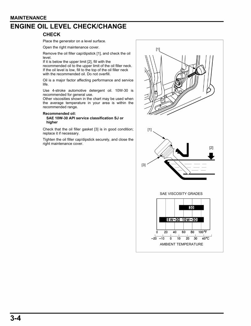
ENGINE OIL LEVEL CHECK/CHANGECHECKPlace the generator on a level surface.
Open the right maintenance cover.
Remove the oil filler cap/dipstick [1], and check the oil level. If it is below the upper limit [2], fill with the recommended oil to the upper limit of the oil filler neck.If the oil level is low, fill to the top of the oil filler neck with the recommended oil. Do not overfill.
Oil is a major factor affecting performance and servicelife.
Use 4-stroke automotive detergent oil. 10W-30 isrecommended for general use. Other viscosities shown in the chart may be used whenthe average temperature in your area is within therecommended range.
Check that the oil filler gasket [3] is in good condition;replace it if necessary.
Tighten the oil filler cap/dipstick securely, and close theright maintenance cover.
Recommended oil:SAE 10W-30 API service classification SJ or higher
[1]
[1]
[3]
SAE VISCOSITY GRADES
AMBIENT TEMPERATURE
[2]
3-5
dummyheaddummyhead
MAINTENANCE
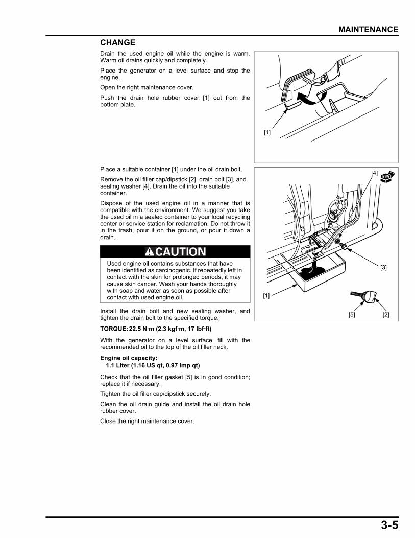
CHANGEDrain the used engine oil while the engine is warm.Warm oil drains quickly and completely.
Place the generator on a level surface and stop theengine.
Open the right maintenance cover.
Push the drain hole rubber cover [1] out from thebottom plate.
Place a suitable container [1] under the oil drain bolt.
Remove the oil filler cap/dipstick [2], drain bolt [3], and sealing washer [4]. Drain the oil into the suitable container.
Dispose of the used engine oil in a manner that iscompatible with the environment. We suggest you takethe used oil in a sealed container to your local recyclingcenter or service station for reclamation. Do not throw itin the trash, pour it on the ground, or pour it down adrain.
Install the drain bolt and new sealing washer, andtighten the drain bolt to the specified torque.
With the generator on a level surface, fill with therecommended oil to the top of the oil filler neck.
Check that the oil filler gasket [5] is in good condition;replace it if necessary.
Tighten the oil filler cap/dipstick securely.
Clean the oil drain guide and install the oil drain holerubber cover.
Close the right maintenance cover.
[1]
Used engine oil contains substances that have been identified as carcinogenic. If repeatedly left in contact with the skin for prolonged periods, it may cause skin cancer. Wash your hands thoroughly with soap and water as soon as possible after contact with used engine oil.
TORQUE:22.5 N·m (2.3 kgf·m, 17 lbf·ft)
Engine oil capacity:1.1 Liter (1.16 US qt, 0.97 Imp qt)
[3]
[2]
[1]
[4]
[5]

3-6
dummyheaddummyhead
MAINTENANCE
AIR CLEANER CHECK/CLEANING/REPLACEMENT
• A dirty air cleaner will restrict air flow to the throttlebody, reducing engine performance. If the engine isoperated in dusty areas, clean the air cleaner moreoften than specified in the MAINTENANCESCHEDULE.
• Operating the engine without an air filter element orwith a damaged air filter element will allow dirt toenter the engine, causing rapid engine wear.
Open the left maintenance cover.
Open the air cleaner cover lever [1] and remove the aircleaner cover [2] and foam element [3].
Clean the foam element in warm soapy water [1], rinse,and allow to dry thoroughly, or clean with a high flashpoint solvent and allow to dry.
Dip the element in clean engine oil [2] and squeeze outthe excess oil.
• Excess oil will restrict air flow through the foamelement and may cause the engine to smoke atstartup.
• Do not twist the foam element to remove the excessoil. Twisting the element can damage it.
Install the foam element in the air cleaner cover.
Inspect the paper element [1]. If the paper element isdirty or damaged, replace it with a new one.
Remove any dirt from the inside of the air cleaner cover[2] using a moist clean rag. Be careful to prevent dirtfrom entering the air duct that leads to the throttle body.
Install the air cleaner cover [2] and latch the air cleanercover levers [3] securely.
Close and latch the left maintenance cover.
[2][3]
[1]
Wash DrySqueeze firmly
[1] [2]
Do not twist
Do not twist
[2][1]
[3]
3-7
dummyheaddummyhead
MAINTENANCE
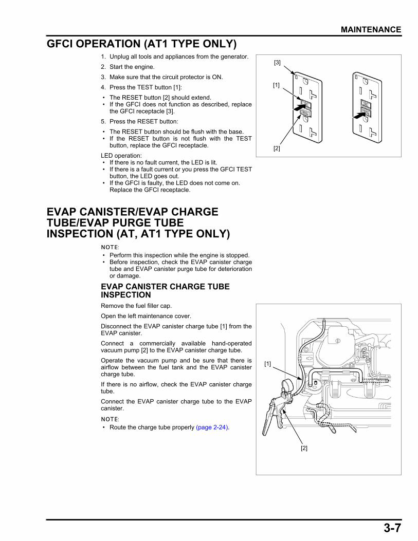
GFCI OPERATION (AT1 TYPE ONLY)1. Unplug all tools and appliances from the generator.
2. Start the engine.
3. Make sure that the circuit protector is ON.
4. Press the TEST button [1]:
• The RESET button [2] should extend. • If the GFCI does not function as described, replace
the GFCI receptacle [3].
5. Press the RESET button:
• The RESET button should be flush with the base. • If the RESET button is not flush with the TEST
button, replace the GFCI receptacle.
LED operation: • If there is no fault current, the LED is lit. • If there is a fault current or you press the GFCI TEST
button, the LED goes out. • If the GFCI is faulty, the LED does not come on.
Replace the GFCI receptacle.
EVAP CANISTER/EVAP CHARGE TUBE/EVAP PURGE TUBE INSPECTION (AT, AT1 TYPE ONLY)
• Perform this inspection while the engine is stopped. • Before inspection, check the EVAP canister charge
tube and EVAP canister purge tube for deteriorationor damage.
EVAP CANISTER CHARGE TUBE INSPECTIONRemove the fuel filler cap.
Open the left maintenance cover.
Disconnect the EVAP canister charge tube [1] from theEVAP canister.
Connect a commercially available hand-operatedvacuum pump [2] to the EVAP canister charge tube.
Operate the vacuum pump and be sure that there isairflow between the fuel tank and the EVAP canistercharge tube.
If there is no airflow, check the EVAP canister chargetube.
Connect the EVAP canister charge tube to the EVAPcanister.
• Route the charge tube properly (page 2-24).
[1]
[2]
[3]
[1]
[2]
3-8
dummyheaddummyhead
MAINTENANCE
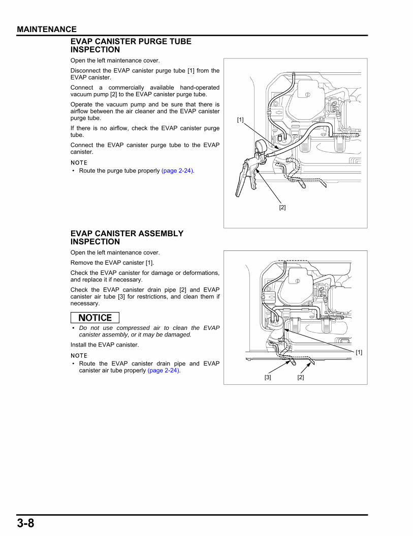
EVAP CANISTER PURGE TUBE INSPECTIONOpen the left maintenance cover.
Disconnect the EVAP canister purge tube [1] from theEVAP canister.
Connect a commercially available hand-operatedvacuum pump [2] to the EVAP canister purge tube.
Operate the vacuum pump and be sure that there isairflow between the air cleaner and the EVAP canisterpurge tube.
If there is no airflow, check the EVAP canister purgetube.
Connect the EVAP canister purge tube to the EVAPcanister.
• Route the purge tube properly (page 2-24).
EVAP CANISTER ASSEMBLY INSPECTIONOpen the left maintenance cover.
Remove the EVAP canister [1].
Check the EVAP canister for damage or deformations,and replace it if necessary.
Check the EVAP canister drain pipe [2] and EVAPcanister air tube [3] for restrictions, and clean them ifnecessary.
• Do not use compressed air to clean the EVAPcanister assembly, or it may be damaged.
Install the EVAP canister.
• Route the EVAP canister drain pipe and EVAPcanister air tube properly (page 2-24).
[1]
[2]
[1]
[2][3]
3-9
dummyheaddummyhead
MAINTENANCE
SPARK PLUG CHECK/ADJUSTMENT/REPLACEMENT
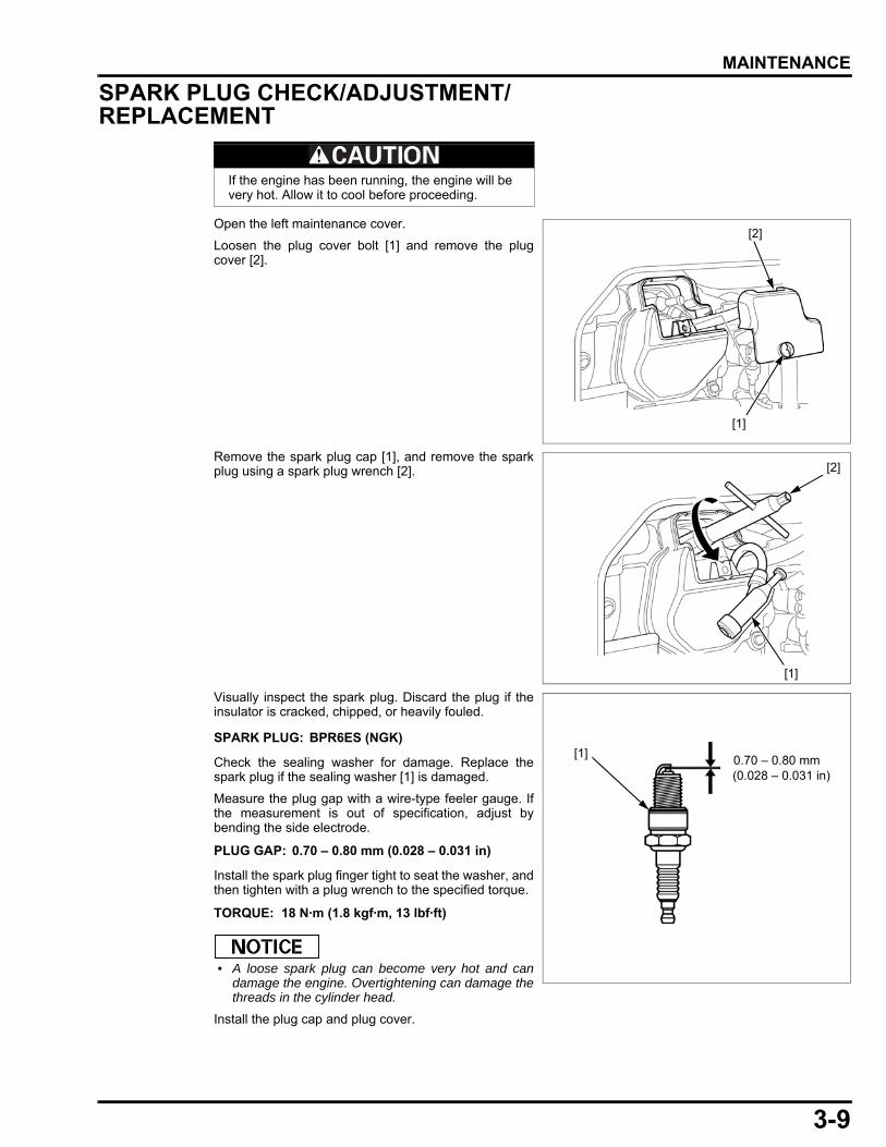
Open the left maintenance cover.
Loosen the plug cover bolt [1] and remove the plugcover [2].
Remove the spark plug cap [1], and remove the sparkplug using a spark plug wrench [2].
Visually inspect the spark plug. Discard the plug if theinsulator is cracked, chipped, or heavily fouled.
Check the sealing washer for damage. Replace thespark plug if the sealing washer [1] is damaged.
Measure the plug gap with a wire-type feeler gauge. Ifthe measurement is out of specification, adjust bybending the side electrode.
Install the spark plug finger tight to seat the washer, andthen tighten with a plug wrench to the specified torque.
• A loose spark plug can become very hot and candamage the engine. Overtightening can damage thethreads in the cylinder head.
Install the plug cap and plug cover.
If the engine has been running, the engine will be very hot. Allow it to cool before proceeding.
[1]
[2]
[1]
[2]
SPARK PLUG: BPR6ES (NGK)
PLUG GAP: 0.70 – 0.80 mm (0.028 – 0.031 in)
TORQUE: 18 N·m (1.8 kgf·m, 13 lbf·ft)
0.70 – 0.80 mm(0.028 – 0.031 in)
[1]
3-10
dummyheaddummyhead
MAINTENANCE
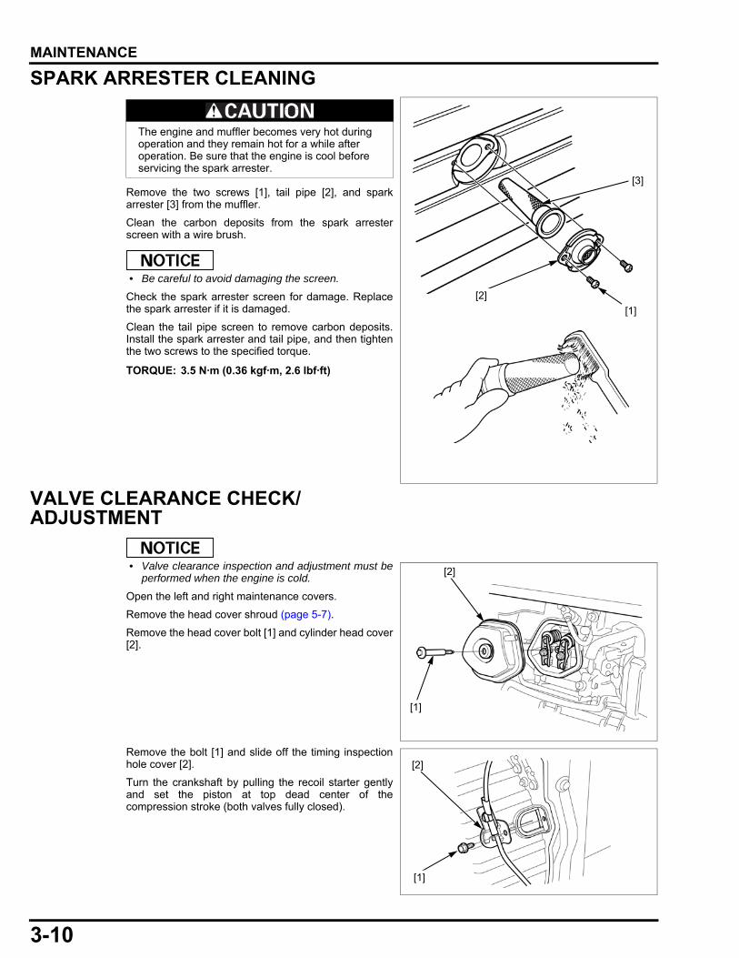
SPARK ARRESTER CLEANING
Remove the two screws [1], tail pipe [2], and sparkarrester [3] from the muffler.
Clean the carbon deposits from the spark arresterscreen with a wire brush.
• Be careful to avoid damaging the screen.
Check the spark arrester screen for damage. Replacethe spark arrester if it is damaged.
Clean the tail pipe screen to remove carbon deposits.Install the spark arrester and tail pipe, and then tightenthe two screws to the specified torque.
VALVE CLEARANCE CHECK/ADJUSTMENT
• Valve clearance inspection and adjustment must beperformed when the engine is cold.
Open the left and right maintenance covers.
Remove the head cover shroud (page 5-7).
Remove the head cover bolt [1] and cylinder head cover[2].
Remove the bolt [1] and slide off the timing inspectionhole cover [2].
Turn the crankshaft by pulling the recoil starter gentlyand set the piston at top dead center of thecompression stroke (both valves fully closed).
The engine and muffler becomes very hot during operation and they remain hot for a while after operation. Be sure that the engine is cool before servicing the spark arrester.
TORQUE: 3.5 N·m (0.36 kgf·m, 2.6 lbf·ft)
[1]
[3]
[2]
[2]
[1]
[1]
[2]
3-11
dummyheaddummyhead
MAINTENANCE
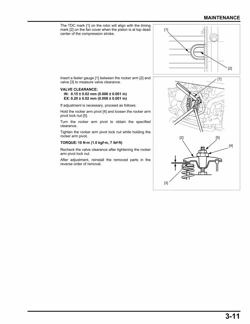
The TDC mark [1] on the rotor will align with the timingmark [2] on the fan cover when the piston is at top deadcenter of the compression stroke.
Insert a feeler gauge [1] between the rocker arm [2] andvalve [3] to measure valve clearance.
If adjustment is necessary, proceed as follows:
Hold the rocker arm pivot [4] and loosen the rocker armpivot lock nut [5].
Turn the rocker arm pivot to obtain the specifiedclearance.
Tighten the rocker arm pivot lock nut while holding therocker arm pivot.
Recheck the valve clearance after tightening the rockerarm pivot lock nut.
After adjustment, reinstall the removed parts in thereverse order of removal.
[1]
[2]
VALVE CLEARANCE:IN: 0.15 ± 0.02 mm (0.006 ± 0.001 in)EX: 0.20 ± 0.02 mm (0.008 ± 0.001 in)
TORQUE:10 N·m (1.0 kgf·m, 7 lbf·ft)[5]
[4]
[3]
[2]
[1]
3-12
dummyheaddummyhead
MAINTENANCE
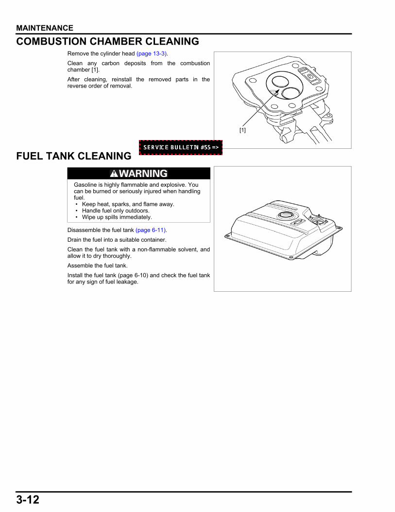
COMBUSTION CHAMBER CLEANINGRemove the cylinder head (page 13-3).
Clean any carbon deposits from the combustionchamber [1].
After cleaning, reinstall the removed parts in thereverse order of removal.
FUEL TANK CLEANING
Disassemble the fuel tank (page 6-11).
Drain the fuel into a suitable container.
Clean the fuel tank with a non-flammable solvent, andallow it to dry thoroughly.
Assemble the fuel tank.
Install the fuel tank (page 6-10) and check the fuel tankfor any sign of fuel leakage.
[1]
Gasoline is highly flammable and explosive. You can be burned or seriously injured when handling fuel. • Keep heat, sparks, and flame away. • Handle fuel only outdoors. • Wipe up spills immediately.
3-13
dummyheaddummyhead
MAINTENANCE
FUEL PUMP FILTER CHANGE
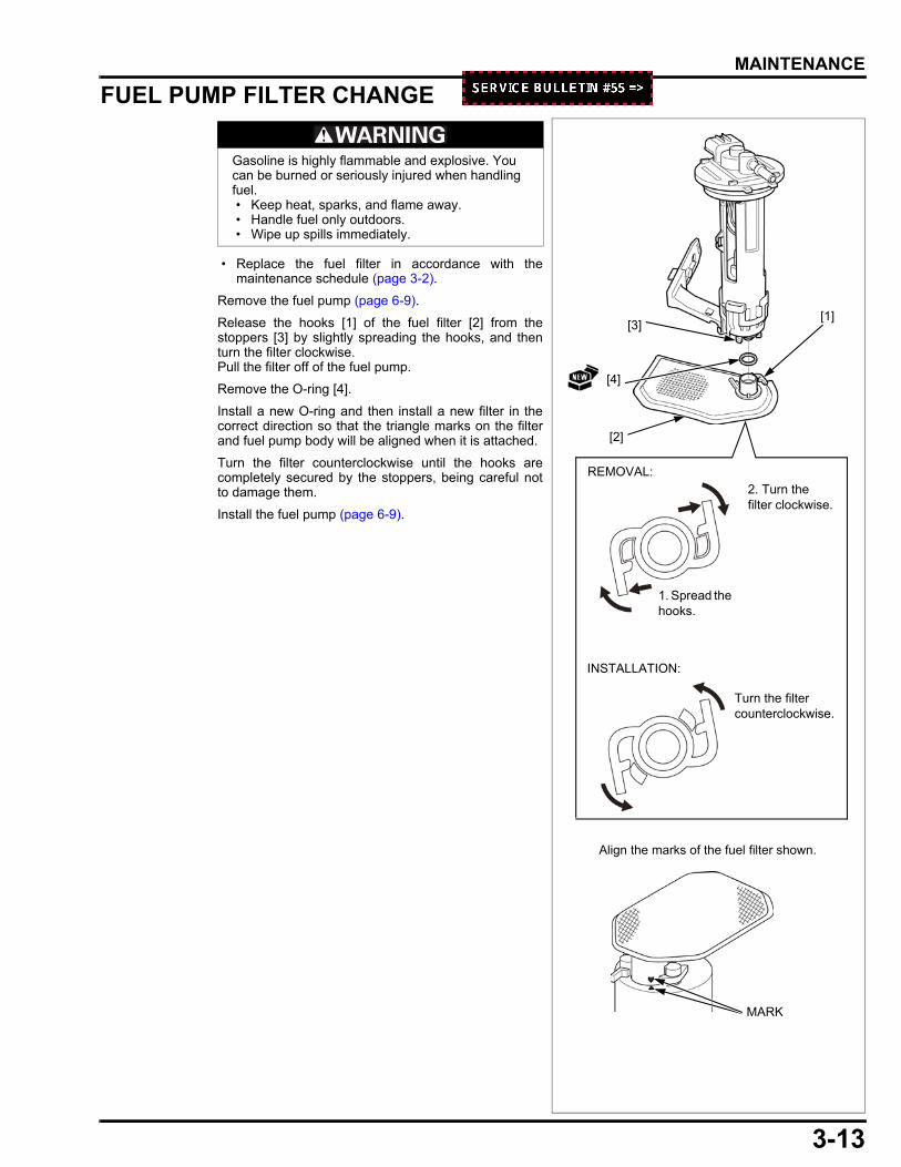
• Replace the fuel filter in accordance with themaintenance schedule (page 3-2).
Remove the fuel pump (page 6-9).
Release the hooks [1] of the fuel filter [2] from thestoppers [3] by slightly spreading the hooks, and thenturn the filter clockwise.Pull the filter off of the fuel pump.
Remove the O-ring [4].
Install a new O-ring and then install a new filter in thecorrect direction so that the triangle marks on the filterand fuel pump body will be aligned when it is attached.
Turn the filter counterclockwise until the hooks arecompletely secured by the stoppers, being careful notto damage them.
Install the fuel pump (page 6-9).
Gasoline is highly flammable and explosive. You can be burned or seriously injured when handling fuel. • Keep heat, sparks, and flame away. • Handle fuel only outdoors. • Wipe up spills immediately.
[1]
[2]
[3]
[4]
1. Spread the hooks.
2. Turn the filter clockwise.
Turn the filter counterclockwise.
INSTALLATION:
Align the marks of the fuel filter shown.
MARK
REMOVAL:
3-14
dummyheaddummyhead
MAINTENANCE
FUEL FEED HOSE CHECK
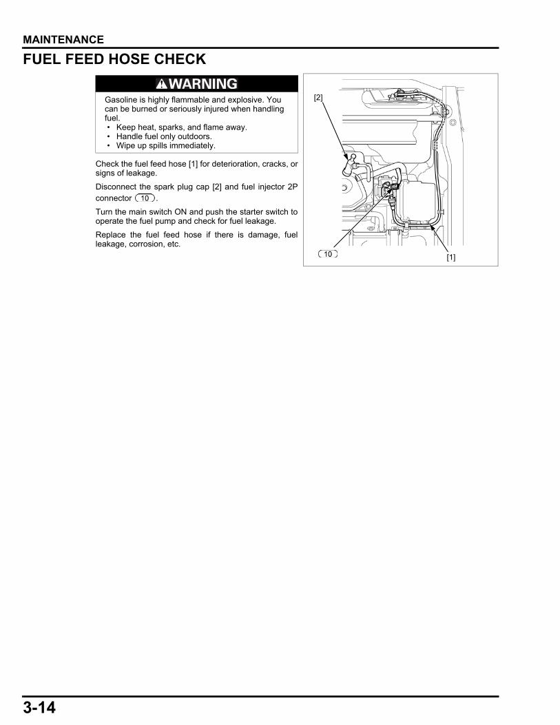
Check the fuel feed hose [1] for deterioration, cracks, orsigns of leakage.
Disconnect the spark plug cap [2] and fuel injector 2Pconnector .
Turn the main switch ON and push the starter switch tooperate the fuel pump and check for fuel leakage.
Replace the fuel feed hose if there is damage, fuelleakage, corrosion, etc.
Gasoline is highly flammable and explosive. You can be burned or seriously injured when handling fuel. • Keep heat, sparks, and flame away. • Handle fuel only outdoors. • Wipe up spills immediately.
[1]
[2]
4-1
4
dummytext
4. TROUBLESHOOTING
ENGINE STANDARD TROUBLESHOOTING···································4-2
SELF-DIAGNOSTIC TROUBLESHOOTING ·································· 4-9
4-2
dummyheaddummyhead
TROUBLESHOOTINGTROUBLESHOOTING
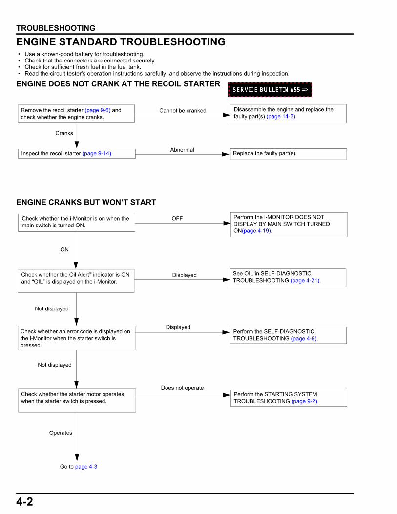
ENGINE STANDARD TROUBLESHOOTING • Use a known-good battery for troubleshooting. • Check that the connectors are connected securely. • Check for sufficient fresh fuel in the fuel tank. • Read the circuit tester's operation instructions carefully, and observe the instructions during inspection.
ENGINE DOES NOT CRANK AT THE RECOIL STARTER
ENGINE CRANKS BUT WON’T START
Remove the recoil starter (page 9-6) and check whether the engine cranks.
Cannot be cranked
Abnormal
Cranks
Inspect the recoil starter (page 9-14).
Disassemble the engine and replace the faulty part(s) (page 14-3).
Replace the faulty part(s).
Displayed
Check whether an error code is displayed on the i-Monitor when the starter switch is pressed.
Check whether the Oil Alert® indicator is ON and “OIL” is displayed on the i-Monitor.
Perform the SELF-DIAGNOSTIC TROUBLESHOOTING (page 4-9).
See OIL in SELF-DIAGNOSTIC TROUBLESHOOTING (page 4-21).
Check whether the i-Monitor is on when the main switch is turned ON.
Perform the i-MONITOR DOES NOT DISPLAY BY MAIN SWITCH TURNED ON(page 4-19).
OFF
ON
Not displayed
Does not operateCheck whether the starter motor operates when the starter switch is pressed.
Perform the STARTING SYSTEM TROUBLESHOOTING (page 9-2).
Operates
Displayed
Not displayed
Go to page 4-3

4-3
dummyheaddummyhead
TROUBLESHOOTING
Compression is too high
Compression is too low
Check the cylinder compression (page 13-5). Check the valve clearance (page 3-10), and then perform the cylinder compression test. If the cylinder compression is too high, remove carbon deposits in the combustion chamber (page 3-12).Check the decompressor operation of the camshaft (page 14-11).
Check the valve clearance (page 3-10), and then perform the cylinder compression test.If the cylinder compression is too low, perform a leak down test. If there is no air leakage in the engine, check the following.- Valve spring free length (page 13-7)- Valve seat width (page 13-6)- Valve face irregularly worn (page 13-7)- Decompressor operation (page 14-11)- Piston ring side clearance (page 14-8)- Piston ring width (page 14-7)- Piston ring end gap (page 14-8)- Piston skirt O.D. (page 14-6)- Cylinder sleeve I.D. (page 14-5)
Normal
Spark
No sparkTurn the main switch ON. Perform the spark test with a new spark plug (page 8-8).
Perform the IGNITION SYSTEM TROUBLESHOOTING (page 8-2).
WetTurn the main switch OFF.Check the spark plug (page 3-9).
If the spark plug is correct, clean and dry the electrodes and then restart the engine.
Dry
From page 4-2
Turn the main switch OFF. Check for a restricted spark arrestor (page 3-10).
Normal
RestrictedClean the spark arrestor.
Go to page 4-4.
4-4
dummyheaddummyhead
TROUBLESHOOTING
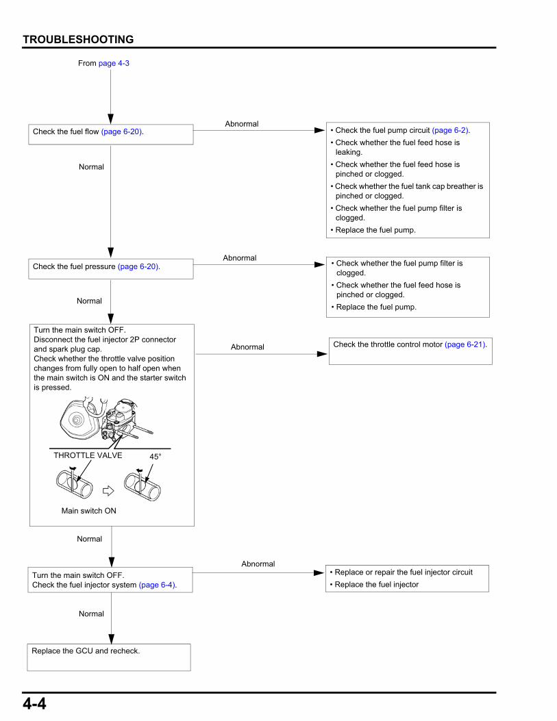
Check the fuel flow (page 6-20).
From page 4-3
Check the fuel pressure (page 6-20).
Turn the main switch OFF.Check the fuel injector system (page 6-4).
Abnormal
Normal
Abnormal
Normal
Normal
Normal
Abnormal
Replace the GCU and recheck.
• Check the fuel pump circuit (page 6-2).
• Check whether the fuel feed hose is leaking.
• Check whether the fuel feed hose is pinched or clogged.
• Check whether the fuel tank cap breather is pinched or clogged.
• Check whether the fuel pump filter is clogged.
• Replace the fuel pump.
• Check whether the fuel pump filter is clogged.
• Check whether the fuel feed hose is pinched or clogged.
• Replace the fuel pump.
• Replace or repair the fuel injector circuit
• Replace the fuel injector
Check the throttle control motor (page 6-21).Abnormal
Turn the main switch OFF.Disconnect the fuel injector 2P connector and spark plug cap.Check whether the throttle valve position changes from fully open to half open when the main switch is ON and the starter switch is pressed.
Main switch ON
THROTTLE VALVE 45°
4-5
dummyheaddummyhead
TROUBLESHOOTING
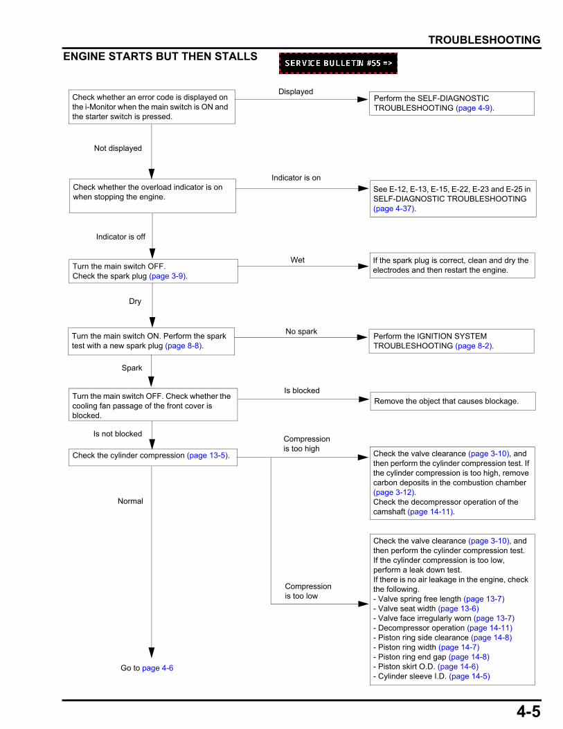
ENGINE STARTS BUT THEN STALLS
Check whether an error code is displayed on the i-Monitor when the main switch is ON and the starter switch is pressed.
Perform the SELF-DIAGNOSTIC TROUBLESHOOTING (page 4-9).
Indicator is onCheck whether the overload indicator is on when stopping the engine.
See E-12, E-13, E-15, E-22, E-23 and E-25 in SELF-DIAGNOSTIC TROUBLESHOOTING (page 4-37).
Indicator is off
Displayed
Not displayed
Spark
No sparkTurn the main switch ON. Perform the spark test with a new spark plug (page 8-8).
Perform the IGNITION SYSTEM TROUBLESHOOTING (page 8-2).
WetTurn the main switch OFF.Check the spark plug (page 3-9).
If the spark plug is correct, clean and dry the electrodes and then restart the engine.
Dry
Turn the main switch OFF. Check whether the cooling fan passage of the front cover is blocked.
Remove the object that causes blockage.
Go to page 4-6
Compression is too high
Compression is too low
Check the cylinder compression (page 13-5). Check the valve clearance (page 3-10), and then perform the cylinder compression test. If the cylinder compression is too high, remove carbon deposits in the combustion chamber (page 3-12).Check the decompressor operation of the camshaft (page 14-11).
Check the valve clearance (page 3-10), and then perform the cylinder compression test.If the cylinder compression is too low, perform a leak down test. If there is no air leakage in the engine, check the following.- Valve spring free length (page 13-7)- Valve seat width (page 13-6)- Valve face irregularly worn (page 13-7)- Decompressor operation (page 14-11)- Piston ring side clearance (page 14-8)- Piston ring width (page 14-7)- Piston ring end gap (page 14-8)- Piston skirt O.D. (page 14-6)- Cylinder sleeve I.D. (page 14-5)
Normal
Is blocked
Is not blocked
4-6
dummyheaddummyhead
TROUBLESHOOTING
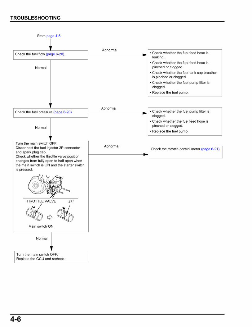
From page 4-5
Check the fuel flow (page 6-20).
Check the fuel pressure (page 6-20)
Abnormal
Normal
Abnormal
Normal
• Check whether the fuel feed hose is leaking.
• Check whether the fuel feed hose is pinched or clogged.
• Check whether the fuel tank cap breather is pinched or clogged.
• Check whether the fuel pump filter is clogged.
• Replace the fuel pump.
• Check whether the fuel pump filter is clogged.
• Check whether the fuel feed hose is pinched or clogged.
• Replace the fuel pump.
Normal
Turn the main switch OFF. Replace the GCU and recheck.
Check the throttle control motor (page 6-21).Abnormal
Turn the main switch OFF.Disconnect the fuel injector 2P connector and spark plug cap.Check whether the throttle valve position changes from fully open to half open when the main switch is ON and the starter switch is pressed.
Main switch ON
THROTTLE VALVE 45°

4-7
dummyheaddummyhead
TROUBLESHOOTING
ENGINE SPEED DOES NOT STABILIZE
Stop the engine. Disconnect the AC appliance. Restart the engine and check to see if an error code is displayed in the error log mode (page 4-10).
Perform the SELF-DIAGNOSTIC TROUBLESHOOTING (page 4-9).
Displayed
Not displayed
Is blockedTurn the main switch OFF. Check whether the cooling fan passage of the front cover is blocked.
Remove the object that causes blockage.
AbnormalCheck the spark plug gap (page 3-9). Adjust the spark plug gap.
Normal
Is not blocked
Check for air leaking between the throttle body and engine block. Is it normal?
Check around the air intake tract and throttle body; replace the insulator and/or gasket if necessary.
Abnormal
Go to page 4-8
Check the fuel flow (page 6-20).Abnormal
Normal
• Check whether the fuel feed hose is leaking.
• Check whether the fuel feed hose is pinched or clogged.
• Check whether the fuel tank cap breather is pinched or clogged.
• Check whether the fuel pump filter is clogged.
• Replace the fuel pump.
Normal
StabilizeCheck whether the engine condition is stable. System is OK.
Does not stabilize
Fuel is normal
Check whether the fuel that contains more than 10% ethanol or deteriorated fuel is used.
Fuel is abnormalReplace the fuel.
4-8
dummyheaddummyhead
TROUBLESHOOTING
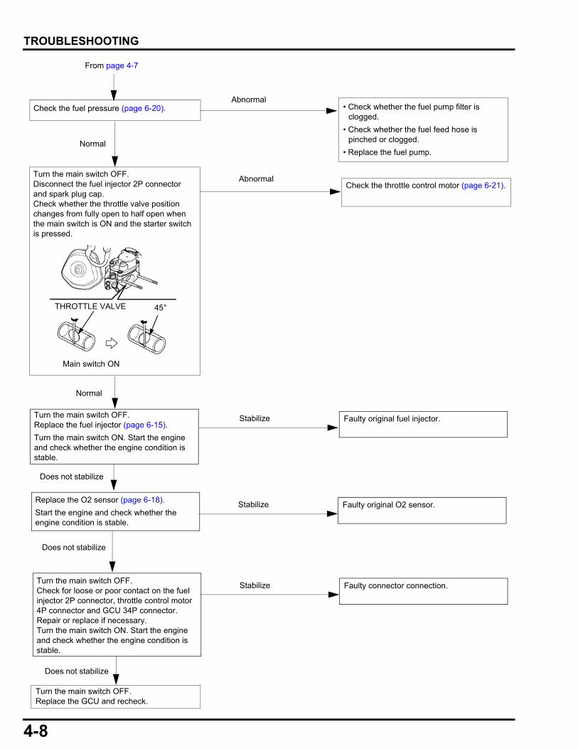
From page 4-7
Turn the main switch OFF.Replace the GCU and recheck.
Check the throttle control motor (page 6-21).Abnormal
Turn the main switch OFF.Replace the fuel injector (page 6-15).
Turn the main switch ON. Start the engine and check whether the engine condition is stable.
Faulty original fuel injector.
Normal
Check the fuel pressure (page 6-20).Abnormal
Normal
• Check whether the fuel pump filter is clogged.
• Check whether the fuel feed hose is pinched or clogged.
• Replace the fuel pump.
Stabilize
Does not stabilize
Replace the O2 sensor (page 6-18).
Start the engine and check whether the engine condition is stable.
Does not stabilize
Faulty original O2 sensor.Stabilize
Turn the main switch OFF. Disconnect the fuel injector 2P connector and spark plug cap.Check whether the throttle valve position changes from fully open to half open when the main switch is ON and the starter switch is pressed.
Main switch ON
THROTTLE VALVE 45°
Turn the main switch OFF.Check for loose or poor contact on the fuel injector 2P connector, throttle control motor 4P connector and GCU 34P connector.Repair or replace if necessary.Turn the main switch ON. Start the engine and check whether the engine condition is stable.
Faulty connector connection.Stabilize
Does not stabilize
4-9
dummyheaddummyhead
TROUBLESHOOTING
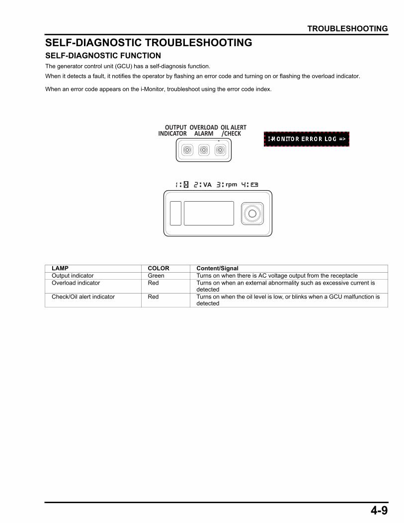
SELF-DIAGNOSTIC TROUBLESHOOTINGSELF-DIAGNOSTIC FUNCTIONThe generator control unit (GCU) has a self-diagnosis function.
When it detects a fault, it notifies the operator by flashing an error code and turning on or flashing the overload indicator.
When an error code appears on the i-Monitor, troubleshoot using the error code index.
LAMP COLOR Content/SignalOutput indicator Green Turns on when there is AC voltage output from the receptacleOverload indicator Red Turns on when an external abnormality such as excessive current is
detectedCheck/Oil alert indicator Red Turns on when the oil level is low, or blinks when a GCU malfunction is
detected
4-10
dummyheaddummyhead
TROUBLESHOOTING
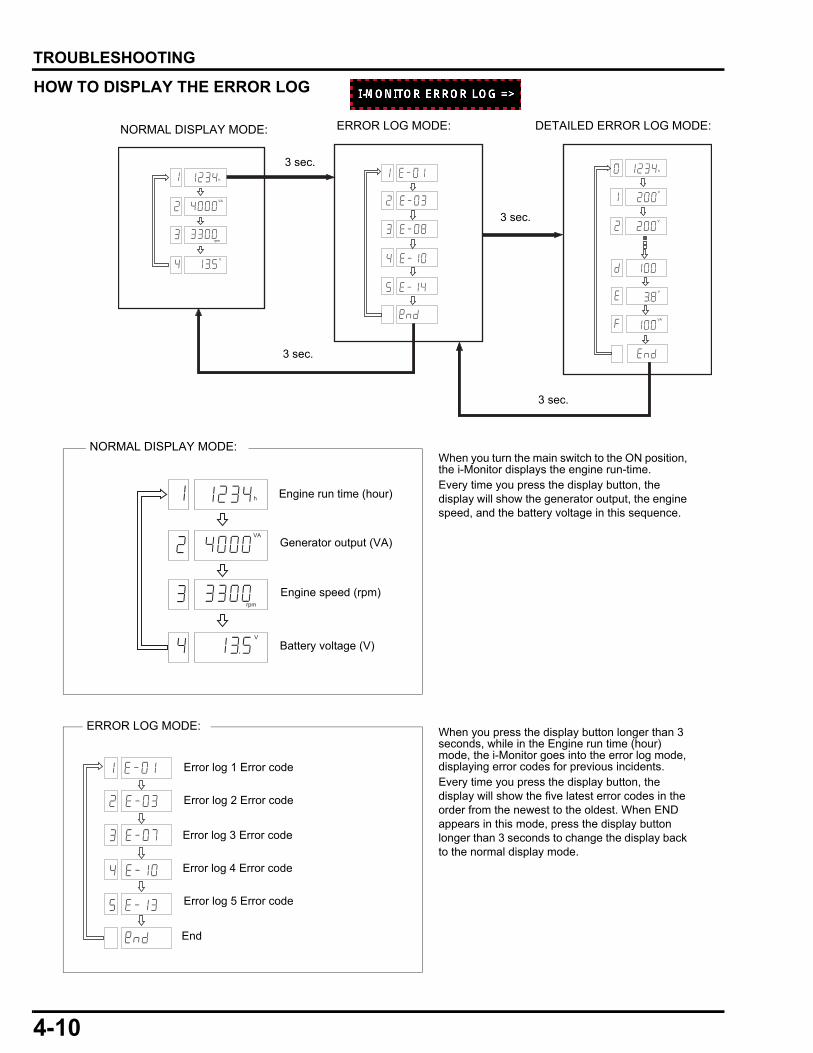
HOW TO DISPLAY THE ERROR LOG
h
V
V
h
VA
rpm
V
V
AV
3 sec.
3 sec.
3 sec.
3 sec.
NORMAL DISPLAY MODE: ERROR LOG MODE: DETAILED ERROR LOG MODE:
h
VA
rpm
V
Engine run time (hour)
Generator output (VA)
Engine speed (rpm)
Battery voltage (V)
When you turn the main switch to the ON position, the i-Monitor displays the engine run-time.Every time you press the display button, the display will show the generator output, the engine speed, and the battery voltage in this sequence.
NORMAL DISPLAY MODE:
When you press the display button longer than 3 seconds, while in the Engine run time (hour) mode, the i-Monitor goes into the error log mode, displaying error codes for previous incidents. Every time you press the display button, the display will show the five latest error codes in the order from the newest to the oldest. When END appears in this mode, press the display button longer than 3 seconds to change the display back to the normal display mode.
Error log 1 Error code
Error log 2 Error code
Error log 3 Error code
Error log 4 Error code
Error log 5 Error code
End
ERROR LOG MODE:
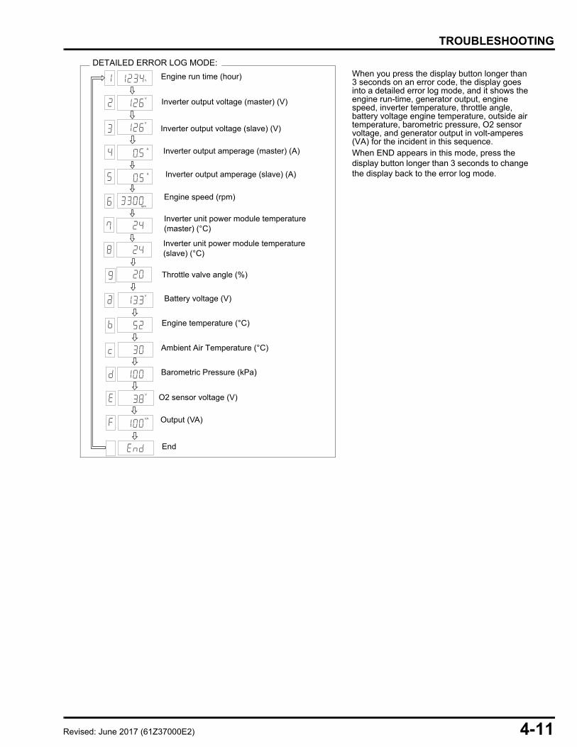
4-11
dummyheaddummyhead
TROUBLESHOOTING
When you press the display button longer than 3 seconds on an error code, the display goes into a detailed error log mode, and it shows the engine run-time, generator output, engine speed, inverter temperature, throttle angle, battery voltage engine temperature, outside air temperature, barometric pressure, O2 sensor voltage, and generator output in volt-amperes (VA) for the incident in this sequence. When END appears in this mode, press the display button longer than 3 seconds to change the display back to the error log mode.
Inverter output voltage (master) (V)
Inverter output voltage (slave) (V)
Inverter output amperage (master) (A)
Inverter output amperage (slave) (A)
Engine speed (rpm)
Inverter unit power module temperature (master) (°C)
Inverter unit power module temperature (slave) (°C)
Throttle valve angle (%)
Battery voltage (V)
End
Engine run time (hour)h
V
A
A
rpm
V
V
V
AV
Engine temperature (°C)
Ambient Air Temperature (°C)
Barometric Pressure (kPa)
O2 sensor voltage (V)
Output (VA)
DETAILED ERROR LOG MODE:
Revised: June 2017 (61Z37000E2)

4-12
dummyheaddummyhead
TROUBLESHOOTING
SYSTEM LOCATION
O2 SENSOR
GCU
CKP SENSOR
THROTTLE CONTROL MOTOR
EBT SENSOR
INVERTER UNIT
AAT SENSOR(GCU internal)
BARO SENSOR(GCU internal)
GENERATOR
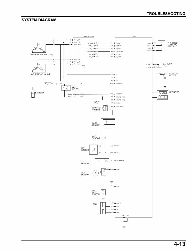
4-13
dummyheaddummyhead
TROUBLESHOOTING
SYSTEM DIAGRAM
GCUINVERTER UNIT
U
V
W
U
VW
GENERATOR (MASTER)
U
VW
GENERATOR (SLAVE)
BATTERY
RW
Bu
RW
Bu
R
G
Y/R
Y/Bl
Bl
Y
G
Bu Y/Bu
Br/W
Bu/Y
Bu/R
G
W
Bu
RW
Bu
R
R
Bu/R
Bu/Y
O/W
G/O
G/Bu
R W
Y
Bu
RBu/R
Bu/Y
Bl/Y
Br/Bu
Bl/W
Bl/W
Br/Bu
G/O
W/Bu
G/O
Bl
O/W
G/O
G/O
G/O
Br/Y
Bl/Y
G/Bu
W
Bu
MAIN_SW+
MAIN_SW-
STMAG(+12V)
STMAG(+12V)
STARTERSWITCH
BAROSENSOR
AATSENSOR
EBTSENSOR
TH+
TH-
STARTERMOTOR
THROTTLECONTROLMOTOR
i-MONITOR
BATTERY
DC5V
M_TXD
M_RXD
INV_COMN
S_RXD
S_TXD
MAIN_U_M
MAIN_V_M
MAIN_W_M
MAIN_U_S
FUSE (15A)
MAIN_V_S
MAIN_W_SGND
5V_GCU
RXD_M
TXD_M
GND_GCU
RXD_S
TXD_S
FUSE (3A)
PUSH SW1
O2 SENSORO2SENSOR
CKPSENSOR
OILLEVELSWITCH
DLC
PC+
GND GND
TH(A)
TH(/A)
TH(/B)
TH(B)
BAT_IN
BAT_IN
RXD
TXD
GND
STMAG
STMAG
MAINSWITCH
Bl/Y
Br/W
Bl
Bl
O/A
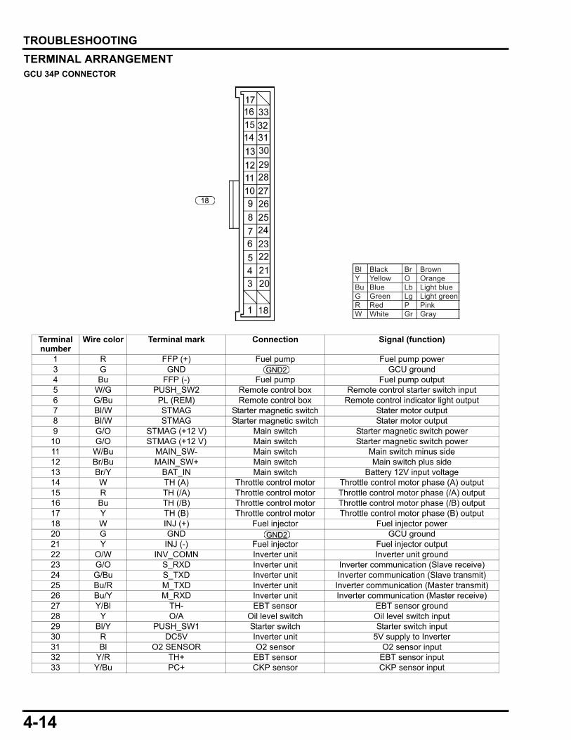
4-14
dummyheaddummyhead
TROUBLESHOOTING
TERMINAL ARRANGEMENTGCU 34P CONNECTOR
Terminal number
Wire color Terminal mark Connection Signal (function)
1 R FFP (+) Fuel pump Fuel pump power3 G GND GCU ground4 Bu FFP (-) Fuel pump Fuel pump output5 W/G PUSH_SW2 Remote control box Remote control starter switch input6 G/Bu PL (REM) Remote control box Remote control indicator light output7 Bl/W STMAG Starter magnetic switch Stater motor output8 Bl/W STMAG Starter magnetic switch Stater motor output9 G/O STMAG (+12 V) Main switch Starter magnetic switch power
10 G/O STMAG (+12 V) Main switch Starter magnetic switch power11 W/Bu MAIN_SW- Main switch Main switch minus side12 Br/Bu MAIN_SW+ Main switch Main switch plus side13 Br/Y BAT_IN Main switch Battery 12V input voltage14 W TH (A) Throttle control motor Throttle control motor phase (A) output15 R TH (/A) Throttle control motor Throttle control motor phase (/A) output16 Bu TH (/B) Throttle control motor Throttle control motor phase (/B) output17 Y TH (B) Throttle control motor Throttle control motor phase (B) output18 W INJ (+) Fuel injector Fuel injector power20 G GND GCU ground21 Y INJ (-) Fuel injector Fuel injector output22 O/W INV_COMN Inverter unit Inverter unit ground23 G/O S_RXD Inverter unit Inverter communication (Slave receive)24 G/Bu S_TXD Inverter unit Inverter communication (Slave transmit)25 Bu/R M_TXD Inverter unit Inverter communication (Master transmit)26 Bu/Y M_RXD Inverter unit Inverter communication (Master receive)27 Y/Bl TH- EBT sensor EBT sensor ground28 Y O/A Oil level switch Oil level switch input29 Bl/Y PUSH_SW1 Starter switch Starter switch input30 R DC5V Inverter unit 5V supply to Inverter31 Bl O2 SENSOR O2 sensor O2 sensor input32 Y/R TH+ EBT sensor EBT sensor input33 Y/Bu PC+ CKP sensor CKP sensor input
Bl Black Br BrownY Yellow O OrangeBu Blue Lb Light blueG Green Lg Light greenR Red P PinkW White Gr Gray
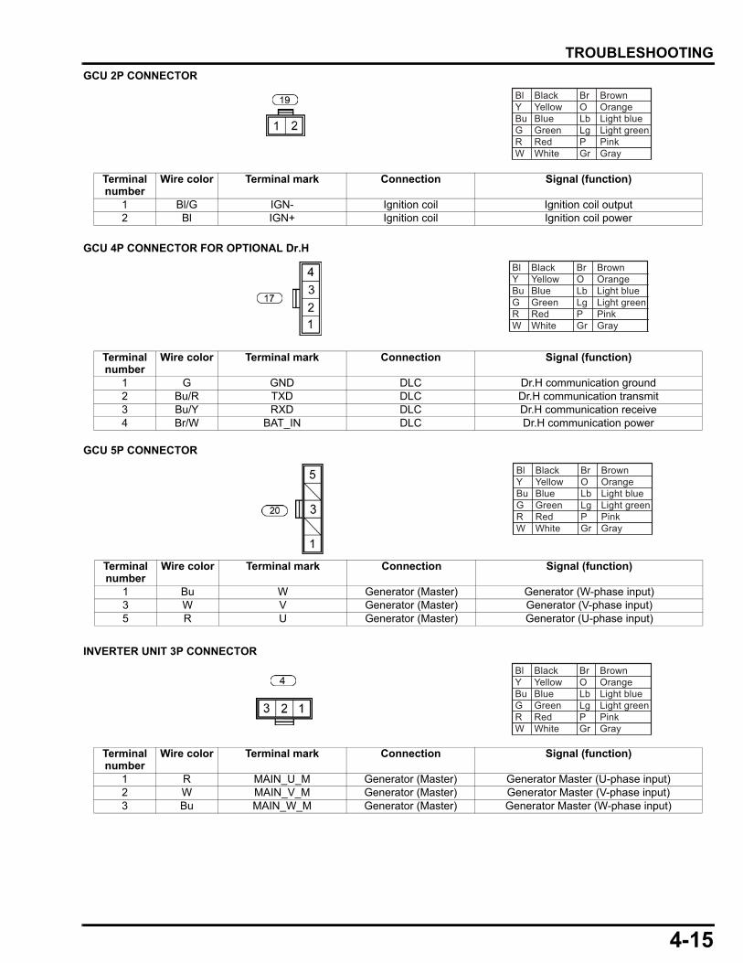
4-15
dummyheaddummyhead
TROUBLESHOOTING
GCU 2P CONNECTOR
GCU 4P CONNECTOR FOR OPTIONAL Dr.H
GCU 5P CONNECTOR
INVERTER UNIT 3P CONNECTOR
Terminal number
Wire color Terminal mark Connection Signal (function)
1 Bl/G IGN- Ignition coil Ignition coil output2 Bl IGN+ Ignition coil Ignition coil power
Bl Black Br BrownY Yellow O OrangeBu Blue Lb Light blueG Green Lg Light greenR Red P PinkW White Gr Gray
Bl Black Br BrownY Yellow O OrangeBu Blue Lb Light blueG Green Lg Light greenR Red P PinkW White Gr Gray
Terminal number
Wire color Terminal mark Connection Signal (function)
1 G GND DLC Dr.H communication ground2 Bu/R TXD DLC Dr.H communication transmit3 Bu/Y RXD DLC Dr.H communication receive4 Br/W BAT_IN DLC Dr.H communication power
Terminal number
Wire color Terminal mark Connection Signal (function)
1 Bu W Generator (Master) Generator (W-phase input)3 W V Generator (Master) Generator (V-phase input)5 R U Generator (Master) Generator (U-phase input)
Bl Black Br BrownY Yellow O OrangeBu Blue Lb Light blueG Green Lg Light greenR Red P PinkW White Gr Gray
Terminal number
Wire color Terminal mark Connection Signal (function)
1 R MAIN_U_M Generator (Master) Generator Master (U-phase input)2 W MAIN_V_M Generator (Master) Generator Master (V-phase input)3 Bu MAIN_W_M Generator (Master) Generator Master (W-phase input)
Bl Black Br BrownY Yellow O OrangeBu Blue Lb Light blueG Green Lg Light greenR Red P PinkW White Gr Gray

4-16
dummyheaddummyhead
TROUBLESHOOTING
INVERTER UNIT 3P CONNECTOR
INVERTER UNIT 6P CONNECTOR
INVERTER UNIT 3P CONNECTOR
INVERTER UNIT 4P CONNECTOR
Terminal number
Wire color Terminal mark Connection Signal (function)
1 R MAIN_U_S Generator (Slave) Generator Slave (U-phase input)2 W MAIN_V_S Generator (Slave) Generator Slave (V-phase input)3 Bu MAIN_W_S Generator (Slave) Generator Slave (W-phase input)
Bl Black Br BrownY Yellow O OrangeBu Blue Lb Light blueG Green Lg Light greenR Red P PinkW White Gr Gray
Terminal number
Wire color Terminal mark Connection Signal (function)
1 G/O TXD_S GCU Generator (Slave) signal transmit2 G/Bu RXD_S GCU Generator (Slave) signal receive3 O/W GND_GCU GCU Communication ground4 Bu/Y TXD_M GCU Generator (Master) signal transmit5 Bu/R RXD_M GCU Generator (Master) signal receive6 R 5V_GCU GCU 5 V input voltage
Bl Black Br BrownY Yellow O OrangeBu Blue Lb Light blueG Green Lg Light greenR Red P PinkW White Gr Gray
Terminal number
Wire color Terminal mark Connection Signal (function)
1 R/W GND Eco-Throttle switch Eco-Throttle switch ground3 R ECO_SW Eco-Throttle switch Eco-Throttle switch output signal
Bl Black Br BrownY Yellow O OrangeBu Blue Lb Light blueG Green Lg Light greenR Red P PinkW White Gr Gray
Terminal number
Wire color Terminal mark Connection Signal (function)
1 Gr AC2_S Voltage selector switch Sine wave output (–)2 Bu AC1_S Voltage selector switch Sine wave output (+)3 R AC1_M Receptacle Sine wave output (+)4 W AC2_M Receptacle Sine wave output (–)
Bl Black Br BrownY Yellow O OrangeBu Blue Lb Light blueG Green Lg Light greenR Red P PinkW White Gr Gray
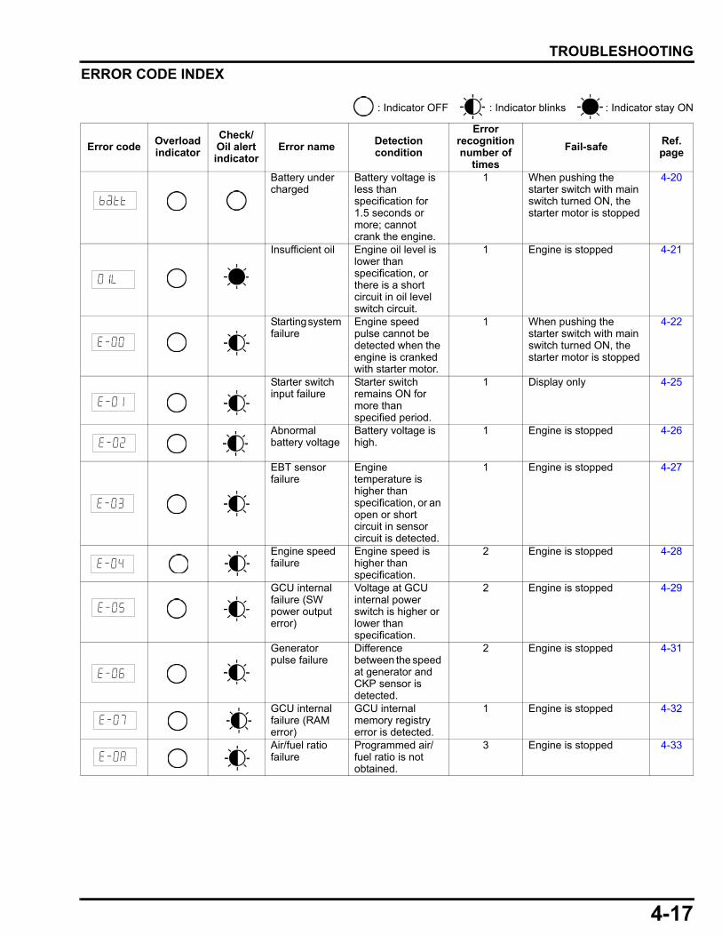
4-17
dummyheaddummyhead
TROUBLESHOOTING
ERROR CODE INDEX
: Indicator OFF : Indicator blinks : Indicator stay ON
Error codeOverload indicator
Check/Oil alert indicator
Error nameDetection condition
Error recognition number of
times
Fail-safeRef.page
Battery under charged
Battery voltage is less than specification for 1.5 seconds or more; cannot crank the engine.
1 When pushing the starter switch with main switch turned ON, the starter motor is stopped
4-20
Insufficient oil Engine oil level is lower than specification, or there is a short circuit in oil level switch circuit.
1 Engine is stopped 4-21
Starting system failure
Engine speed pulse cannot be detected when the engine is cranked with starter motor.
1 When pushing the starter switch with main switch turned ON, the starter motor is stopped
4-22
Starter switch input failure
Starter switch remains ON for more than specified period.
1 Display only 4-25
Abnormal battery voltage
Battery voltage is high.
1 Engine is stopped 4-26
EBT sensor failure
Engine temperature is higher than specification, or an open or short circuit in sensor circuit is detected.
1 Engine is stopped 4-27
Engine speed failure
Engine speed is higher than specification.
2 Engine is stopped 4-28
GCU internal failure (SW power output error)
Voltage at GCU internal power switch is higher or lower than specification.
2 Engine is stopped 4-29
Generator pulse failure
Difference between the speed at generator and CKP sensor is detected.
2 Engine is stopped 4-31
GCU internal failure (RAM error)
GCU internal memory registry error is detected.
1 Engine is stopped 4-32
Air/fuel ratio failure
Programmed air/fuel ratio is not obtained.
3 Engine is stopped 4-33
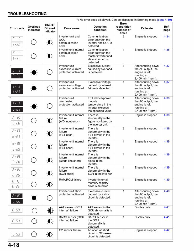
4-18
dummyheaddummyhead
TROUBLESHOOTING
*: No error code displayed. Can be displayed in Error log mode (page 4-10).
Error code Overload indicator
Check/Oil alert indicator
Error name Detection condition
Error recognition number of
times
Fail-safe Ref.page
Inverter unit and GCU communication error
Communication error between the inverter and GCU is detected.
2 Engine is stopped 4-34
Inverter unit internal communication error
Communication error between the master inverter and slave inverter is detected.
1 Engine is stopped 4-36
* Inverter unitexcessive current protection activated
Excessive current caused by overload is detected.
1 After shutting down the AC output, the engine is left running at2,400 min-1 (rpm).
4-37
* Inverter unitexcessive voltage protection activated
Excessive voltage caused by internal failure is detected.
1 After shutting down the AC output, the engine is left running at2,400 min-1 (rpm).
4-37
* Inverter unit overheated protection activated
FET device/power module temperature in the inverter exceeds the specified value.
1 After shutting down the AC output, the engine is left running at2,400 min-1 (rpm).
4-38
Inverter unit internal failure(A/D input error)
There is abnormality in the figure monitored by the inverter unit.
2 Engine is stopped 4-38
Inverter unit internal failure(FET open)
There is abnormality in the FET device in the inverter.
2 Engine is stopped 4-39
Inverter unit internal failure(FET short)
There is abnormality in the FET device in the inverter.
1 Engine is stopped 4-39
Inverter unit internal failure(Diode line short)
There is abnormality in the diode in the inverter.
1 Engine is stopped 4-39
Inverter unit internal failure(SCR short)
There is abnormality in the SCR in the inverter.
1 Engine is stopped 4-39
RAM/ROM failure Inverter internal memory registry error is detected.
1 Engine is stopped 4-39
* Inverter unit short protection activated
Excessive current caused by a short circuit is detected.
1 After shutting down the AC output, the engine is left running at2,400 min-1 (rpm).
4-40
AAT sensor (GCU internal) failure
AAT sensor in the GCU abnormality is detected.
1 Display only 4-41
BARO sensor (GCU internal) failure
BARO sensor in the GCU abnormality is detected.
1 Display only 4-41
O2 sensor failure An open or short circuit in O2 sensor circuit is detected.
3 Engine is stopped 4-42

4-19
dummyheaddummyhead
TROUBLESHOOTING
i-MONITOR DOES NOT DISPLAY WITH MAIN SWITCH TURNED ONWhen turning the main switch to ON, the i-Monitor is on if use a known-good battery is used.
i-MONITOR18
BAT_IN
13
Br/Y
MAIN_SW+
MAIN_SW-
1211
Br/Bu
W/Bu
W/Bu
GND
GND
320
G
G
GG
3
1
MAINSWITCH
MAIN_SW1
MAIN_SW2
ACC
BAT
21
34
13
14
Br/W
Bl/Y
Bl
G
W
G/O
G/O
Bl/Y Bl/Y
Br/Bu
Br/Bu
Br/Bu
51
3A
15A
3
10T3
T2
Bl
Bl
GND3
MAIN SWITCH
MAINSW1 MAINSW2 BAT ACC
ON
OFF
BATTERY
GCU
Turn the main switch OFF. Check the fuses.
Check the main switch (page 10-6).
Replace the fuse.
Replace the main switch.
Good
Normal
Abnormal
Blown
Replace or repair the wire harness.Abnormal
Normal
Bl Black Br BrownY Yellow O OrangeBu Blue Lb Light blueG Green Lg Light greenR Red P PinkW White Gr Gray
Go to page 4-20
17 14 1316 153233 3031 27 2629 28
1112 910 6 58 72425 2223 1821 20
34 1
G/O
18GCU
124 3
13
MAINSWITCH
Br/Bu
Br/Y
3A
Br/Bu W/Bu
86521
14
15
Check the " i-MONITOR DOES NOT DISPLAY" of the GCU inspection (page 10-9).
Replace the GCU.Abnormal
Normal
Turn the main switch OFF. Check the wire harness between the main switch and GCU for an open or short circuit.
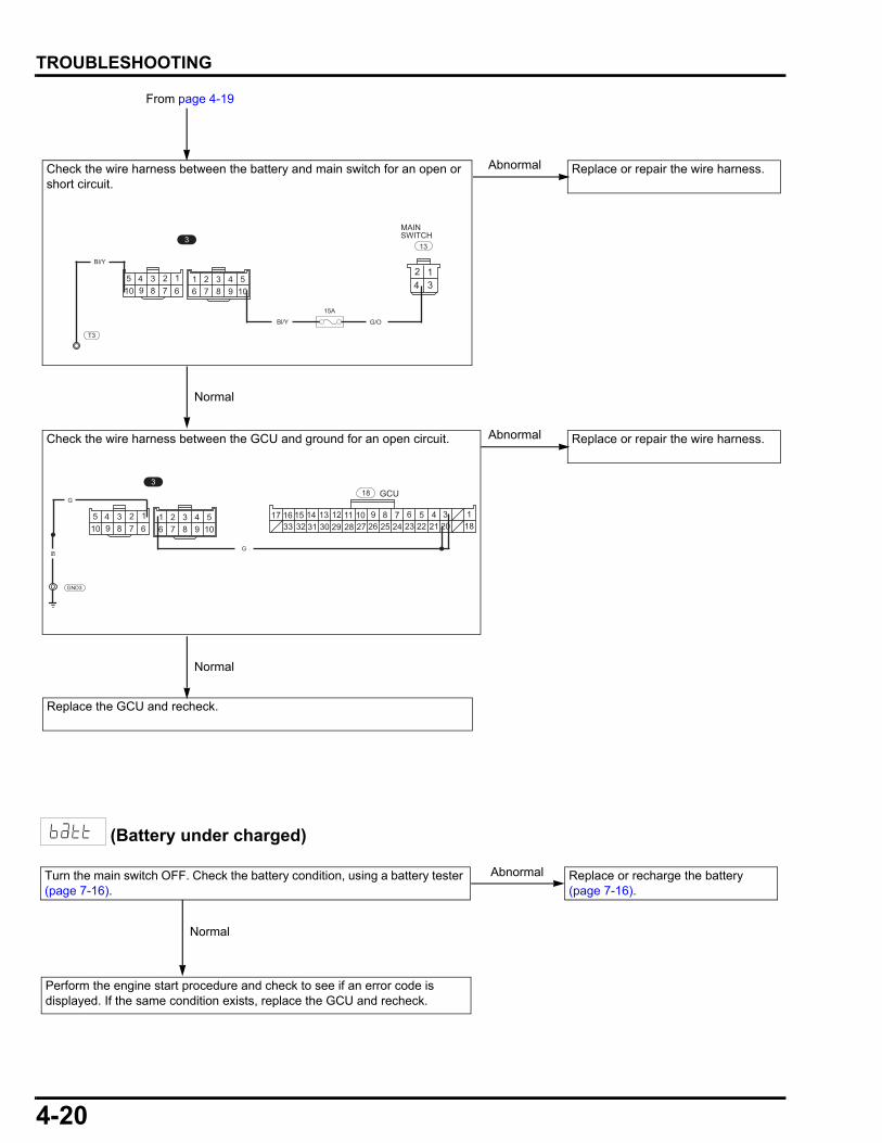
4-20
dummyheaddummyhead
TROUBLESHOOTING
(Battery under charged)
Replace the GCU and recheck.
Replace or repair the wire harness.Abnormal
Normal
From page 4-19
Replace or repair the wire harness.Abnormal
Normal
G/O
124 3
13
MAINSWITCH
Bl/Y
15A
94 3 2 1
678510
49876
321105
3
Bl/Y
T3
94 3 2 1
678510
49876
321105 17 14 1316 15
3233 3031 27 2629 281112 910 6 58 7
2425 2223 1821 2034 1
318
G
GCUG
GND3
Bl
Check the wire harness between the battery and main switch for an open or short circuit.
Check the wire harness between the GCU and ground for an open circuit.
Replace or recharge the battery (page 7-16).
Abnormal
Normal
Perform the engine start procedure and check to see if an error code is displayed. If the same condition exists, replace the GCU and recheck.
Turn the main switch OFF. Check the battery condition, using a battery tester (page 7-16).
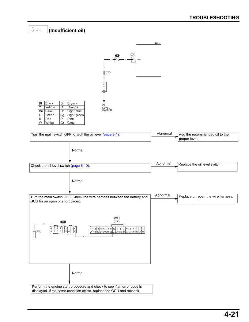
4-21
dummyheaddummyhead
TROUBLESHOOTING
(Insufficient oil)
17 14 1316 153233 3031 27 2629 28
1112 910 6 58 72425 2223 1821 20
34 1
Y
18GCU
48765
32184 3 2 1
567
2Y
C5
18
28
Y Y
YY
2
4
GCU
O/A
OILLEVELSWITCH
C5
Turn the main switch OFF. Check the oil level (page 3-4). Add the recommended oil to the proper level.
Abnormal
Check the oil level switch (page 8-10).
Normal
Replace the oil level switch.Abnormal
Normal
Perform the engine start procedure and check to see if an error code is displayed. If the same condition exists, replace the GCU and recheck.
Replace or repair the wire harness.Abnormal
Bl Black Br BrownY Yellow O OrangeBu Blue Lb Light blueG Green Lg Light greenR Red P PinkW White Gr Gray
Turn the main switch OFF. Check the wire harness between the battery and GCU for an open or short circuit.
Normal
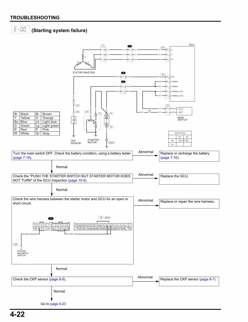
4-22
dummyheaddummyhead
TROUBLESHOOTING
(Starting system failure)
331
351
35
32
1
78
18
9
Bl/W
Y/BuY/Bu
Bl/W
Bl/Y
Bl/YBl/Y
Bl/WBl/W
G/O
G/O
G/O
G/O
Br/W
Bl/Y
103
4
Y/Bu
2
1
3
910
3
BAT
ACC
GCU
MAIN SWITCH
ACC BAT
ON
OFF
U
V
W
20R
W
Bu
U
VW
STATOR (MASTER)
6
R
W
Bu
R
W
Bu
R
W
Bu
PC+
Bl
Bl/W
Y/B
uB
u
Bl
Bl/Y
T3T1
T2
STARTERMOTOR
C9
GND3CKPSENSOR
C3
C4
STMAG
STMAG
STMAG(+12V)
STMAG(+12V)
MAINSWITCH
15A
13
Replace or repair the wire harness.Abnormal
Bl Black Br BrownY Yellow O OrangeBu Blue Lb Light blueG Green Lg Light greenR Red P PinkW White Gr Gray
Go to page 4-23
94 3 2 1
678510
49876
321105 17 14 1316 15
3233 3031 27 2629 281112 910 6 58 7
2425 2223 1821 2034 1
3 18
C9
Bl/W Bl/W
GCU
STATERMAGNETICSWITCH
Replace the CKP sensor (page 8-7).Abnormal
Normal
Normal
Turn the main switch OFF. Check the battery condition, using a battery tester (page 7-16).
Replace or recharge the battery (page 7-16).
Abnormal
Normal
Check the wire harness between the starter motor and GCU for an open or short circuit.
Check the CKP sensor (page 8-9).
Check the "PUSH THE STARTER SWITCH BUT STARTER MOTOR DOES NOT TURN" of the GCU inspection (page 10-9).
Replace the GCU.Abnormal
Normal

4-23
dummyheaddummyhead
TROUBLESHOOTING
Check the motor cable between the battery and starter motor for an open circuit.
T1 T3
Bl
STARTERMOTOR
BATTERYTERMINAL
Bl
Replace or repair the wire harness.Abnormal
From page 4-22
Check the starter motor (page 9-16). Replace or repair the starter motor.Abnormal
Normal
Normal
Go to page 4-24
Replace or repair the wire harness.Abnormal
17 14 1316 153233 3031 27 2629 28
1112 910 6 58 72425 2223 1821 20
34 1
Y/Bu
18GCU
48765
32184 3 2 1
567
2Y/Bu
C3
Check the CKP sensor air gap (page 8-8). Adjust the CKP sensor air gap.Abnormal
Normal
Normal
Check the wire harness between the CKP sensor and GCU for an open or short circuit.
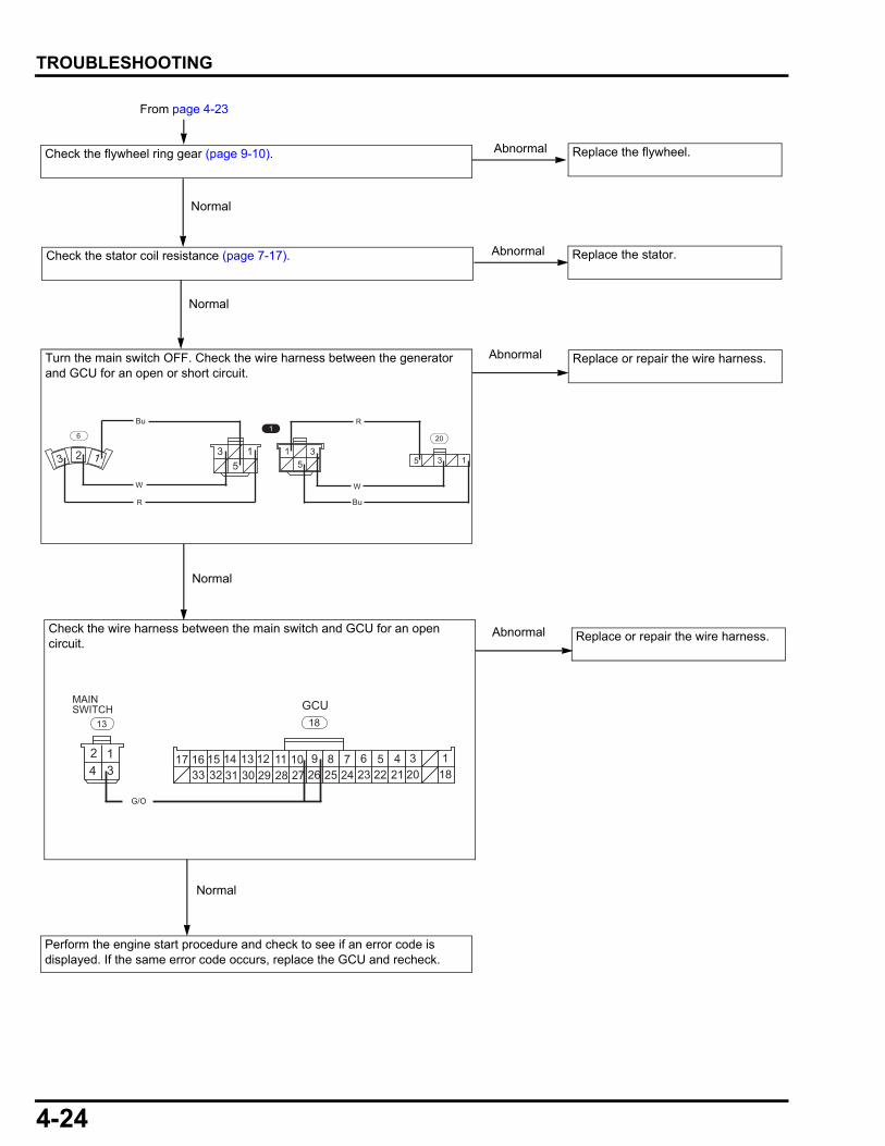
4-24
dummyheaddummyhead
TROUBLESHOOTING
Check the wire harness between the main switch and GCU for an open circuit.
Perform the engine start procedure and check to see if an error code is displayed. If the same error code occurs, replace the GCU and recheck.
Replace or repair the wire harness.Abnormal
Replace or repair the wire harness.Abnormal
From page 4-23
5 3 1
20
35
15
3 1
1
123
6
R
W
BuR
W
Bu
Check the flywheel ring gear (page 9-10). Replace the flywheel.Abnormal
Normal
Normal
Normal
17 14 1316 153233 3031 27 2629 28
1112 910 6 58 72425 2223 1821 20
34 1
G/O
18GCU
124 3
13
MAINSWITCH
Check the stator coil resistance (page 7-17). Replace the stator.Abnormal
Normal
Turn the main switch OFF. Check the wire harness between the generator and GCU for an open or short circuit.
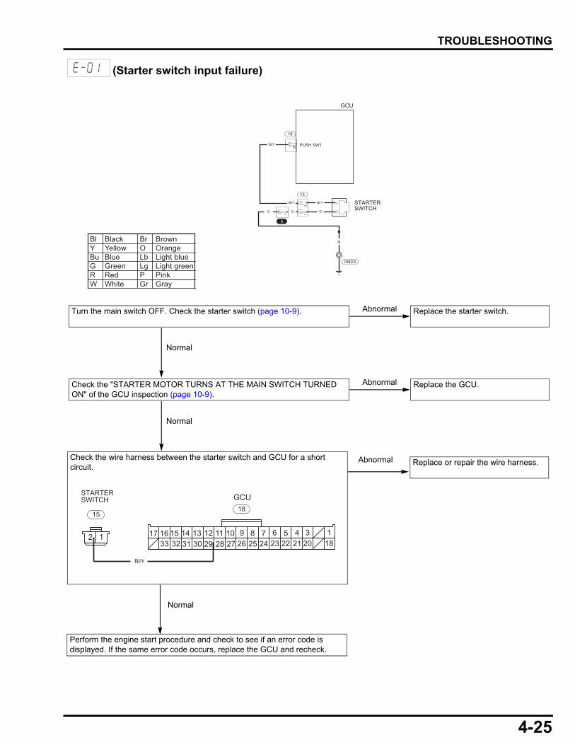
4-25
dummyheaddummyhead
TROUBLESHOOTING
(Starter switch input failure)
Check the wire harness between the starter switch and GCU for a short circuit.
GND3
15
Bl/Y
Bl/Y
Bl/Y
29
G
Bl
G
21
PUSH SW1
STARTERSWITCH
GCU
18
G
3
1
Turn the main switch OFF. Check the starter switch (page 10-9). Replace the starter switch.Abnormal
Normal
Replace or repair the wire harness.Abnormal
Bl Black Br BrownY Yellow O OrangeBu Blue Lb Light blueG Green Lg Light greenR Red P PinkW White Gr Gray
Normal
17 14 1316 153233 3031 27 2629 28
1112 910 6 58 72425 2223 1821 20
34 1
Bl/Y
18GCU
12
STARTERSWITCH
15
Perform the engine start procedure and check to see if an error code is displayed. If the same error code occurs, replace the GCU and recheck.
Check the "STARTER MOTOR TURNS AT THE MAIN SWITCH TURNED ON" of the GCU inspection (page 10-9).
Replace the GCU.Abnormal
Normal
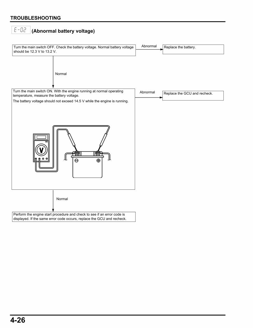
4-26
dummyheaddummyhead
TROUBLESHOOTING
(Abnormal battery voltage)
Turn the main switch OFF. Check the battery voltage. Normal battery voltage should be 12.3 V to 13.2 V.
Replace the battery.Abnormal
Normal
Replace the GCU and recheck. Abnormal
Perform the engine start procedure and check to see if an error code is displayed. If the same error code occurs, replace the GCU and recheck.
Normal
Turn the main switch ON. With the engine running at normal operating temperature, measure the battery voltage.
The battery voltage should not exceed 14.5 V while the engine is running.
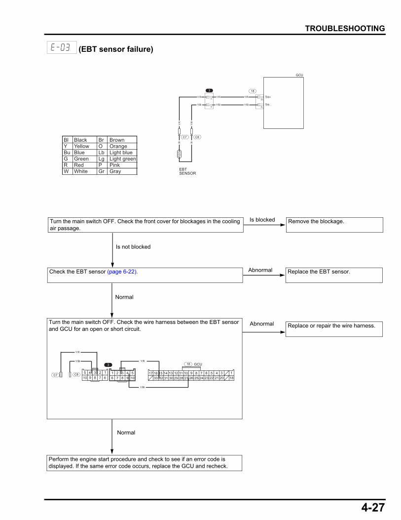
4-27
dummyheaddummyhead
TROUBLESHOOTING
(EBT sensor failure)
94 3 2 1
678510
49876
321105 17 14 1316 15
3233 3031 27 2629 281112 910 6 58 7
2425 2223 1821 2034 1
3 18
Y/Bl
GCUY/R
C8C7
Y/R
Y/Bl
Bl Black Br BrownY Yellow O OrangeBu Blue Lb Light blueG Green Lg Light greenR Red P PinkW White Gr Gray
3227
18
Y/R
Y/Bl
Y/R
Y/Bl
Y/R
Y/Bl
3
34
EBTSENSOR
C7 C8
Bl
Bl
Y/B
l
Y/R
TH+
TH-
GCU
Turn the main switch OFF. Check the front cover for blockages in the cooling air passage.
Remove the blockage.Is blocked
Is not blocked
Perform the engine start procedure and check to see if an error code is displayed. If the same error code occurs, replace the GCU and recheck.
Replace or repair the wire harness.Abnormal
Normal
Check the EBT sensor (page 6-22). Replace the EBT sensor.
Normal
Abnormal
Turn the main switch OFF. Check the wire harness between the EBT sensor and GCU for an open or short circuit.
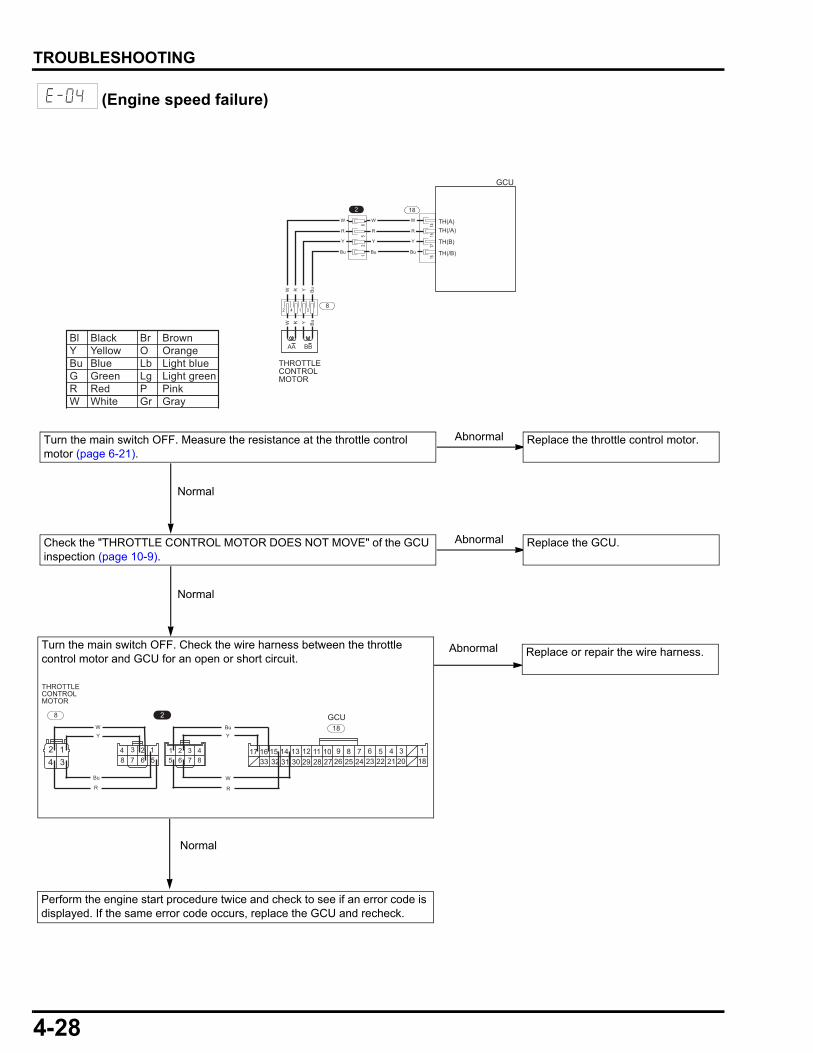
4-28
dummyheaddummyhead
TROUBLESHOOTING
(Engine speed failure)
Bl Black Br BrownY Yellow O OrangeBu Blue Lb Light blueG Green Lg Light greenR Red P PinkW White Gr Gray
1415
17
18
16
65
21
R
W
Y
Bu
R
W
Y
Bu
R
W
Y
Bu
GCU
TH(A)TH(/A)
TH(/B)
TH(B)
2
AA BB
3142
THROTTLECONTROLMOTOR
Y BuW R
Y BuW R
8
Turn the main switch OFF. Measure the resistance at the throttle control motor (page 6-21).
Replace the throttle control motor.Abnormal
Normal
Perform the engine start procedure twice and check to see if an error code is displayed. If the same error code occurs, replace the GCU and recheck.
Replace or repair the wire harness.Abnormal
Normal
17 14 1316 153233 3031 27 2629 28
1112 910 6 58 72425 2223 1821 20
34 1
W
18GCU
48765
32184 3 2 1
567342 1
2
THROTTLECONTROLMOTOR
8
R
YBu
R
Bu
YW
Turn the main switch OFF. Check the wire harness between the throttle control motor and GCU for an open or short circuit.
Check the "THROTTLE CONTROL MOTOR DOES NOT MOVE" of the GCU inspection (page 10-9).
Replace the GCU.Abnormal
Normal
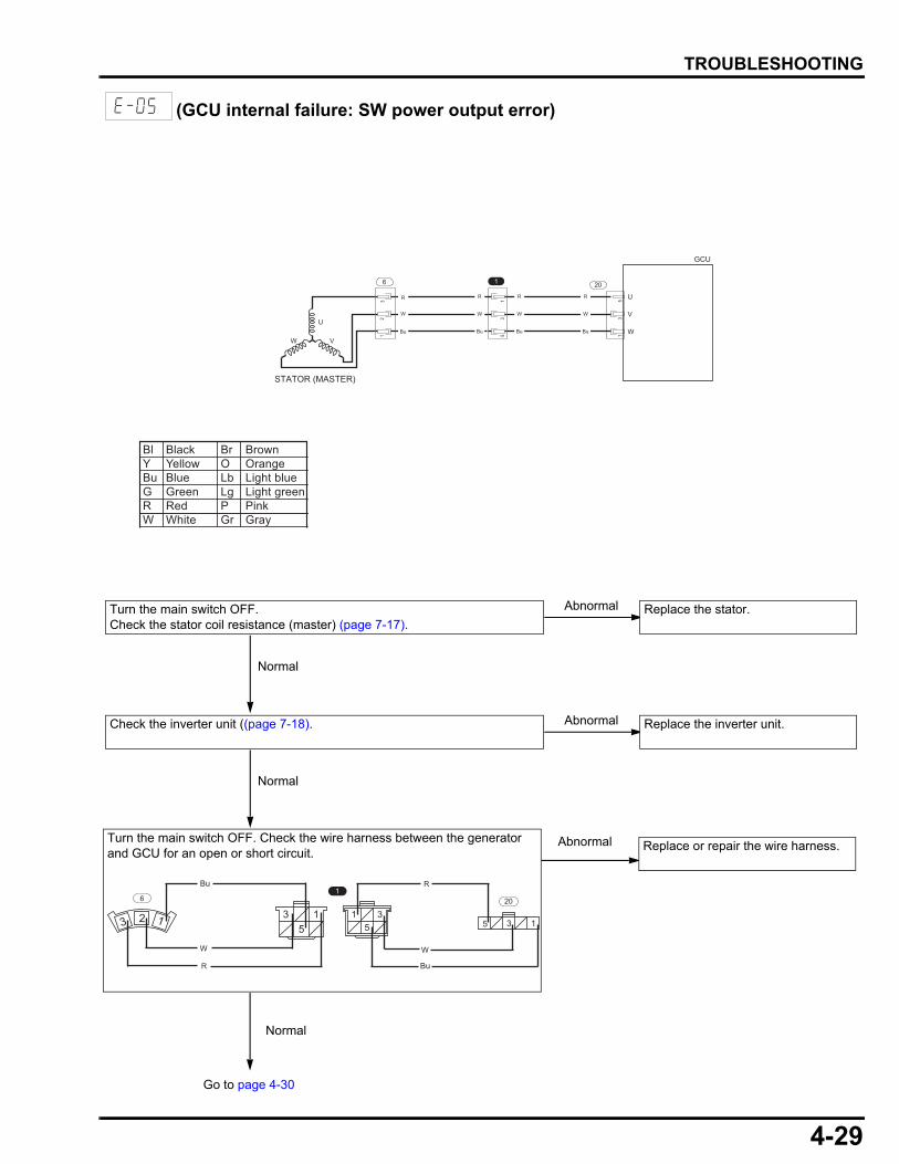
4-29
dummyheaddummyhead
TROUBLESHOOTING
(GCU internal failure: SW power output error)
Bl Black Br BrownY Yellow O OrangeBu Blue Lb Light blueG Green Lg Light greenR Red P PinkW White Gr Gray
U
V
W
53
1
20
R
W
Bu
R
W
Bu
R
W
Bu
1
53
1
12
3
U
VW
STATOR (MASTER)
6
R
W
Bu
GCU
Check the inverter unit ((page 7-18). Replace the inverter unit.Abnormal
Normal
Replace or repair the wire harness.Abnormal
5 3 1
20
35
15
3 1
1
123
6
R
W
BuR
W
Bu
Go to page 4-30
Normal
Turn the main switch OFF. Check the wire harness between the generator and GCU for an open or short circuit.
Turn the main switch OFF.Check the stator coil resistance (master) (page 7-17).
Replace the stator.Abnormal
Normal

4-30
dummyheaddummyhead
TROUBLESHOOTING
Faulty original inverter unit.
Replace the GCU and recheck.
Replace the inverter unit.
Perform the engine start procedure twice and check to see if an error code is displayed.
Not displayed
Same error code displayed
Replace or repair the wire harness. Abnormal
Normal
Check the control panel main wire harness for an open or short circuit.
From page 4-29
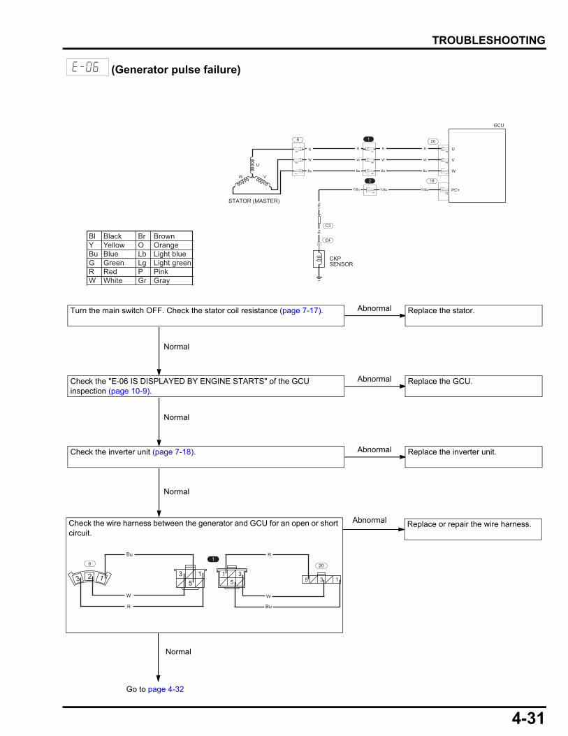
4-31
dummyheaddummyhead
TROUBLESHOOTING
(Generator pulse failure)
Bl Black Br BrownY Yellow O OrangeBu Blue Lb Light blueG Green Lg Light greenR Red P PinkW White Gr Gray
Turn the main switch OFF. Check the stator coil resistance (page 7-17). Replace the stator.Abnormal
Normal
Replace or repair the wire harness.Abnormal
Normal
5 3 1
20
35
15
3 1
1
123
6
R
W
BuR
W
Bu
Go to page 4-32
U
V
W
53
1
20
R
W
Bu
R
W
Bu
R
W
Bu
1
53
1
12
3
U
VW
STATOR (MASTER)
6
R
W
Bu
GCU
33
18
Y/BuY/BuY/Bu
2
3 PC+
Y/B
uB
u
CKPSENSOR
C3
C4
Check the wire harness between the generator and GCU for an open or short circuit.
Check the "E-06 IS DISPLAYED BY ENGINE STARTS" of the GCU inspection (page 10-9).
Replace the GCU.Abnormal
Normal
Check the inverter unit (page 7-18). Replace the inverter unit.Abnormal
Normal
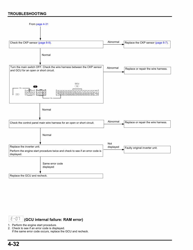
4-32
dummyheaddummyhead
TROUBLESHOOTING
(GCU internal failure: RAM error)1. Perform the engine start procedure.2. Check to see if an error code is displayed.
If the same error code occurs, replace the GCU and recheck.
Faulty original inverter unit.
Replace the GCU and recheck.
Replace the inverter unit.
Perform the engine start procedure twice and check to see if an error code is displayed.
Not displayed
Same error code displayed
Normal
Replace or repair the wire harness. Abnormal
Normal
Check the control panel main wire harness for an open or short circuit.
From page 4-31
Replace or repair the wire harness.Abnormal
17 14 1316 153233 3031 27 2629 28
1112 910 6 58 72425 2223 1821 20
34 1
Y/Bu
18GCU
48765
32184 3 2 1
567
2Y/Bu
C3
Turn the main switch OFF. Check the wire harness between the CKP sensor and GCU for an open or short circuit.
Check the CKP sensor (page 8-9). Replace the CKP sensor (page 8-7).Abnormal
Normal
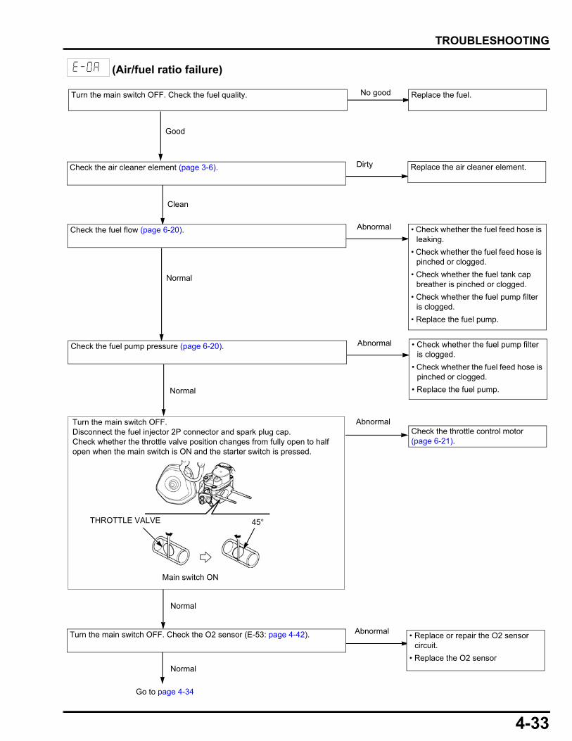
4-33
dummyheaddummyhead
TROUBLESHOOTING
(Air/fuel ratio failure)
AbnormalCheck the throttle control motor (page 6-21).
Turn the main switch OFF.Disconnect the fuel injector 2P connector and spark plug cap.Check whether the throttle valve position changes from fully open to half open when the main switch is ON and the starter switch is pressed.
Normal
• Check whether the fuel pump filter is clogged.
• Check whether the fuel feed hose is pinched or clogged.
• Replace the fuel pump.
AbnormalCheck the fuel pump pressure (page 6-20).
Normal
Abnormal • Check whether the fuel feed hose is leaking.
• Check whether the fuel feed hose is pinched or clogged.
• Check whether the fuel tank cap breather is pinched or clogged.
• Check whether the fuel pump filter is clogged.
• Replace the fuel pump.
Check the fuel flow (page 6-20).
Clean
Dirty Replace the air cleaner element.Check the air cleaner element (page 3-6).
Good
No good Replace the fuel.Turn the main switch OFF. Check the fuel quality.
Normal
Go to page 4-34
• Replace or repair the O2 sensor circuit.
• Replace the O2 sensor
Turn the main switch OFF. Check the O2 sensor (E-53: page 4-42).
Main switch ON
THROTTLE VALVE 45°
Normal
Abnormal
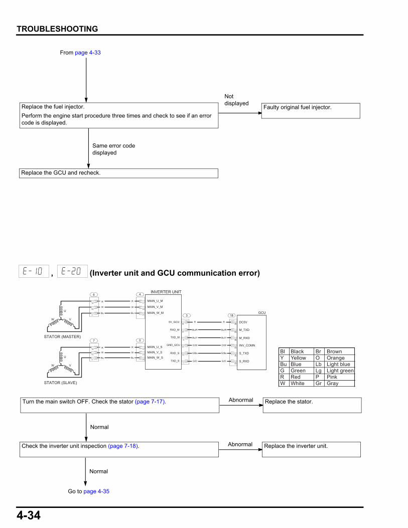
4-34
dummyheaddummyhead
TROUBLESHOOTING
, (Inverter unit and GCU communication error)
Replace the GCU and recheck.
From page 4-33
Replace the fuel injector.
Perform the engine start procedure three times and check to see if an error code is displayed.
Faulty original fuel injector.
Not displayed
Same error code displayed
R
W
Bu
4
32
1
12
3
U
VW
STATOR (MASTER)
6
R
W
Bu
2224
2330
2526
183
G/O
R
Bu/R
Bu/Y
O/W
G/Bu
G/O
R
Bu/R
Bu/Y
O/W
G/Bu
R
W
Bu
5
32
1
12
3
U
VW
STATOR (SLAVE)
7
R
W
Bu
GCU
INVERTER UNIT
MAIN_U_M
MAIN_V_M
MAIN_W_M
MAIN_U_S
MAIN_V_S
MAIN_W_S
DC5V
M_TXD
M_RXD
INV_COMN
S_TXD
S_RXD
5V_GCU
RXD_M
TXD_M
GND_GCU
RXD_S
TXD_S
45
61
23
Bl Black Br BrownY Yellow O OrangeBu Blue Lb Light blueG Green Lg Light greenR Red P PinkW White Gr Gray
Turn the main switch OFF. Check the stator (page 7-17). Replace the stator.Abnormal
NormalNormal
Go to page 4-35
Check the inverter unit inspection (page 7-18). Replace the inverter unit.Abnormal
NormalNormal
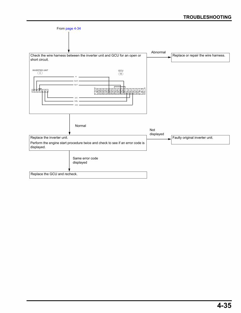
4-35
dummyheaddummyhead
TROUBLESHOOTING
Replace the inverter unit.
Perform the engine start procedure twice and check to see if an error code is displayed.
Replace or repair the wire harness.Abnormal
Normal
17 14 1316 153233 3031 27 2629 28
1112 910 6 58 72425 2223 1821 20
34 1
G/O
18GCU
6 5 4 3 2 1
3INVERTER UNIT
Bu/Y
Bu/R
G/Bu
O/W
R
From page 4-34
Check the wire harness between the inverter unit and GCU for an open or short circuit.
Faulty original inverter unit.
Not displayed
Same error code displayed
Replace the GCU and recheck.
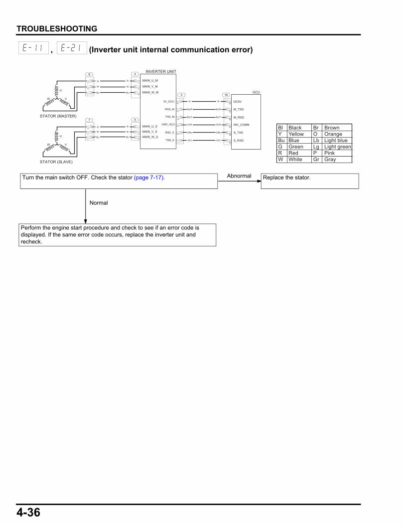
4-36
dummyheaddummyhead
TROUBLESHOOTING
, (Inverter unit internal communication error)
Bl Black Br BrownY Yellow O OrangeBu Blue Lb Light blueG Green Lg Light greenR Red P PinkW White Gr Gray
Turn the main switch OFF. Check the stator (page 7-17). Replace the stator.Abnormal
NormalNormal
Perform the engine start procedure and check to see if an error code is displayed. If the same error code occurs, replace the inverter unit and recheck.
R
W
Bu
4
32
1
12
3U
VW
STATOR (MASTER)
6
R
W
Bu
2224
2330
2526
183
G/O
R
Bu/R
Bu/Y
O/W
G/Bu
G/O
R
Bu/R
Bu/Y
O/W
G/Bu
R
W
Bu
5
32
1
12
3
U
VW
STATOR (SLAVE)
7
R
W
Bu
GCU
INVERTER UNIT
MAIN_U_M
MAIN_V_M
MAIN_W_M
MAIN_U_S
MAIN_V_S
MAIN_W_S
DC5V
M_TXD
M_RXD
INV_COMN
S_TXD
S_RXD
5V_GCU
RXD_M
TXD_M
GND_GCU
RXD_S
TXD_S
45
61
23
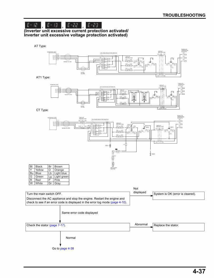
4-37
dummyheaddummyhead
TROUBLESHOOTING
, , , (Inverter unit excessive current protection activated/Inverter unit excessive voltage protection activated)
INVERTER UNIT
PARALLELOPERATIONOUTLETS
CIRCUITPROTECTOR
VOLTAGE SELECTOR SWITCH
NOISE FILTER
AC1_MAC2_MAC1_SAC2_S
1
22
C17 C16
C15 C14
C13 C12
21
21
12
12
34
63
41
13
4 56
25
2
T8T14
T16 T7
T9T15
T17
T18T19
T10T11
T20T21
T6
T5
T4
GND10
GND14
GND13
GND12 GND11
CIRCUITPROTECTOR
T22T23 29A
CIRCUITPROTECTOR
T12T13 30A
20
20
30
0.5A
R
W
Gr
Bu
Bu
Bu
R
R
Bu
R
W
R
Bu
Bu
W W W
R W
WBu
Bu
Bu Bu
W
Gr
Bu
Gr
R RR
W
Bu
RR Bu
BuBu
Bu Bu
W
W
G
GG
G
W
BREATHERHEATER
4
12
R R
R W
RR
RR
INVERTER UNIT
PARALLELOPERATIONOUTLETSCIRCUIT
PROTECTOR
CIRCUITPROTECTOR
VOLTAGE SELECTOR SWITCH
NOISEFILTER
NOISE FILTER
AC1_MAC2_MAC1_SAC2_S
1
22
C17 C16
C15 C14
C13 C12
21
21
34
63
41
13
4 56
25
2
T8T14
T16 T7
T9T15
T17
T14T19
T12T13
T10T11
T6
T5
T4
30A
20
20
30
R
W
Gr
Bu
Bu
Bu
R
R
Bu
R
W
R
Bu
Bu
R W
BuBu
Bu
Bu Bu
Gr
Bu
Gr
R
Bu
RR
W
Bu
R Bu
Bu
W
W
INVERTER UNITPARALLELOPERATIONOUTLETSCIRCUIT
PROTECTOR
CIRCUITPROTECTOR
VOLTAGE SELECTOR SWITCH
NOISEFILTER
NOISE FILTER
AC1_MAC2_MAC1_SAC2_S
1
22
C17 C16
C15 C14
C13 C12
21
21
34
63
41
13
4 56
25
2
T8T14
T7
T9T15
T17T24T19T18
T12T13
T10T11
T6
T5
T4
30A
20
20
30
R
W
Gr
Bu
Bu
Bu
R
R
Bu
R
W
R
Bu
Bu
R
R W Bu
BuBu
Bu
Bu Bu
Gr
Bu
Gr
R
Bu
RR
W
Bu
R Bu
Bu
W
W
WGFCIGFCI
Bl Black Br BrownY Yellow O OrangeBu Blue Lb Light blueG Green Lg Light greenR Red P PinkW White Gr Gray
Turn the main switch OFF.
Disconnect the AC appliance and stop the engine. Restart the engine and check to see if an error code is displayed in the error log mode (page 4-10).
System is OK (error is cleared).
Not displayed
Same error code displayed
Check the stator (page 7-17). Replace the stator.Abnormal
CT Type:
AT Type:
AT1 Type:
Go to page 4-38
Normal
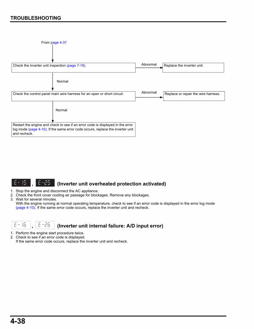
4-38
dummyheaddummyhead
TROUBLESHOOTING
, (Inverter unit overheated protection activated)1. Stop the engine and disconnect the AC appliance.2. Check the front cover cooling air passage for blockages. Remove any blockages.3. Wait for several minutes.
With the engine running at normal operating temperature, check to see if an error code is displayed in the error log mode (page 4-10). If the same error code occurs, replace the inverter unit and recheck.
, (Inverter unit internal failure: A/D input error)1. Perform the engine start procedure twice.2. Check to see if an error code is displayed.
If the same error code occurs, replace the inverter unit and recheck.
Replace or repair the wire harness. Abnormal
Normal
Restart the engine and check to see if an error code is displayed in the error log mode (page 4-10). If the same error code occurs, replace the inverter unit and recheck.
Check the control panel main wire harness for an open or short circuit.
Check the inverter unit inspection (page 7-18). Replace the inverter unit.Abnormal
Normal
From page 4-37

4-39
dummyheaddummyhead
TROUBLESHOOTING
, , , , , , , , (Inverter unit internal failure: FET open/FET short/Diode line short/SCR short)
, (Inverter unit internal failure: RAM/ROM failure)1. Perform the engine start procedure.2. Check to see if an error code is displayed.
If the same error code occurs, replace the inverter unit.
Check the stator (page 7-17). Replace the stator.Abnormal
Normal
Replace or repair the wire harness.Abnormal
Normal
Perform the engine start procedure and check to see if an error code is
displayed. (Perform the engine start procedure twice when the or
.)
If the same error code occurs, replace the inverter unit and recheck.
Check the control panel main wire harness for an open or short circuit.
Check the inverter unit inspection (page 7-18). Replace the inverter unit.Abnormal
Normal
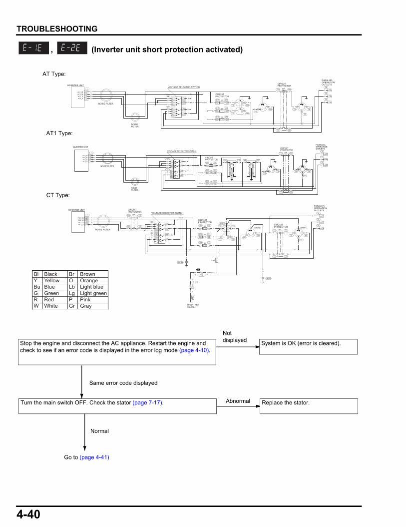
4-40
dummyheaddummyhead
TROUBLESHOOTING
, (Inverter unit short protection activated)
Stop the engine and disconnect the AC appliance. Restart the engine and check to see if an error code is displayed in the error log mode (page 4-10).
System is OK (error is cleared).
Not displayed
Same error code displayed
Turn the main switch OFF. Check the stator (page 7-17). Replace the stator.Abnormal
Normal
Go to (page 4-41)
INVERTER UNIT
PARALLELOPERATIONOUTLETS
CIRCUITPROTECTOR
VOLTAGE SELECTOR SWITCH
NOISE FILTER
AC1_MAC2_MAC1_SAC2_S
1
22
C17 C16
C15 C14
C13 C12
21
21
12
12
34
63
41
13
4 56
25
2
T8T14
T16 T7
T9T15
T17
T18T19
T10T11
T20T21
T6
T5
T4
GND10
GND14
GND13
GND12 GND11
CIRCUITPROTECTOR
T22T23 29A
CIRCUITPROTECTOR
T12T13 30A
20
20
30
0.5A
R
W
Gr
Bu
Bu
Bu
R
R
Bu
R
W
R
Bu
Bu
W W W
R W
WBu
Bu
Bu Bu
W
Gr
Bu
Gr
R RR
W
Bu
RR Bu
BuBu
Bu Bu
W
W
G
GG
G
W
BREATHERHEATER
4
12
R R
R W
RR
RR
INVERTER UNIT
PARALLELOPERATIONOUTLETSCIRCUIT
PROTECTOR
CIRCUITPROTECTOR
VOLTAGE SELECTOR SWITCH
NOISEFILTER
NOISE FILTER
AC1_MAC2_MAC1_SAC2_S
1
22
C17 C16
C15 C14
C13 C12
21
21
34
63
41
13
4 56
25
2
T8T14
T16 T7
T9T15
T17
T14T19
T12T13
T10T11
T6
T5
T4
30A
20
20
30
R
W
Gr
Bu
Bu
Bu
R
R
Bu
R
W
R
Bu
Bu
R W
BuBu
Bu
Bu Bu
Gr
Bu
Gr
R
Bu
RR
W
Bu
R Bu
Bu
W
W
INVERTER UNITPARALLELOPERATIONOUTLETSCIRCUIT
PROTECTOR
CIRCUITPROTECTOR
VOLTAGE SELECTOR SWITCH
NOISEFILTER
NOISE FILTER
AC1_MAC2_MAC1_SAC2_S
1
22
C17 C16
C15 C14
C13 C12
21
21
34
63
41
13
4 56
25
2T8T14
T7
T9T15
T17T24T19T18
T12T13
T10T11
T6
T5
T4
30A
20
20
30
R
W
Gr
Bu
Bu
Bu
R
R
Bu
R
W
R
Bu
Bu
R
R W Bu
BuBu
Bu
Bu Bu
Gr
Bu
Gr
R
Bu
RR
W
Bu
R Bu
Bu
W
W
WGFCIGFCI
CT Type:
AT Type:
AT1 Type:
Bl Black Br BrownY Yellow O OrangeBu Blue Lb Light blueG Green Lg Light greenR Red P PinkW White Gr Gray

4-41
dummyheaddummyhead
TROUBLESHOOTING
(AAT sensor failure)With the engine running at normal operating temperature, check to see if an error code is displayed.If the same error code occurs, replace the GCU and recheck.
(BARO sensor failure)With the engine running at normal operating temperature, check to see if an error code is displayed.If the same error code occurs, replace the GCU and recheck.
Replace or repair the wire harness.Abnormal
Normal
Restart the engine and check to see if an error code is displayed in the error log mode (page 4-10). If the same error code occurs, replace the inverter unit and recheck.
Check the control panel main wire harness for an open or short circuit.
Turn the main switch OFF. Check the inverter unit inspection (page 7-18). Replace the inverter unit.Abnormal
Normal
From page 4-40
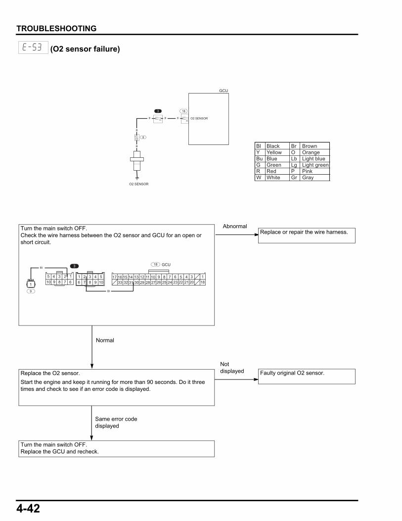
4-42
dummyheaddummyhead
TROUBLESHOOTING
(O2 sensor failure)
18
31
Bl Bl Bl
3
2
1
GCU
O2 SENSOR
O2 SENSOR
9B
lB
l
AbnormalReplace or repair the wire harness.
Bl Black Br BrownY Yellow O OrangeBu Blue Lb Light blueG Green Lg Light greenR Red P PinkW White Gr Gray
94 3 2 1
678510
49876
321105 17 14 1316 15
3233 3031 27 2629 281112 910 6 58 7
2425 2223 1821 2034 1
3 18
Bl
GCUBl
9
1
Normal
Turn the main switch OFF.Check the wire harness between the O2 sensor and GCU for an open or short circuit.
Replace the O2 sensor.
Start the engine and keep it running for more than 90 seconds. Do it three times and check to see if an error code is displayed.
Faulty original O2 sensor.
Turn the main switch OFF.Replace the GCU and recheck.
Not displayed
Same error code displayed
5-1
5
dummytext
5. COVER
MAINTENANCE COVER REMOVAL/INSTALLATION·············································5-2
RIGHT SIDE SHROUD REMOVAL/INSTALLATION·············································5-3
UNDER COVER REMOVAL/INSTALLATION·············································5-4
FRONT COVER REMOVAL/INSTALLATION ············································ 5-5
REAR COVER/OUTER MUFFLER PROTECTOR REMOVAL/INSTALLATION ············································ 5-6
HEAD COVER SHROUD REMOVAL/INSTALLATION ············································ 5-7

5-2
dummyheaddummyhead
COVERCOVER
MAINTENANCE COVER REMOVAL/INSTALLATION
RETAINER
WASHER (2)
LATCH SPRINGLOCK PIN
RIGHT COVER HINGE
LATCH SPRING
RETAINER
LATCH PIN
RIGHT MAINTENANCE COVER
BOLT (5 X 8 mm)
(contact area)
LATCH PIN
LEFT MAINTENANCE COVER
HINGE SPRING
LOCK PIN
HINGE PLATE

5-3
dummyheaddummyhead
COVER
RIGHT SIDE SHROUD REMOVAL/INSTALLATION
Open the right maintenance cover.
Do not touch the insulator with bare hands. The glass wool of the material sticks in the skin and is dangerous.
SHROUD COVER COLLAR (2)
SPECIAL BOLT (6 mm) (3)
BOLT (6 X 22 mm) (2) RIGHT SIDE SHROUD
RIGHT SIDE SHROUD INSULATOR
Install the insulator on the right side shroud by aligning the cutout with the convex on the shroud.
INSTALLATION:
RIGHT SIDE SHROUD INSULATOR
CONVEXCUTOUT
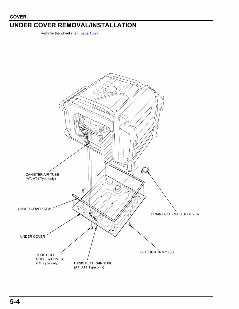
5-4
dummyheaddummyhead
COVER
UNDER COVER REMOVAL/INSTALLATIONRemove the wheel shaft (page 15-2).
DRAIN HOLE RUBBER COVER
UNDER COVER
UNDER COVER SEAL
CANISTER AIR TUBE(AT, AT1 Type only)
CANISTER DRAIN TUBE(AT, AT1 Type only)
BOLT (6 X 16 mm) (2)TUBE HOLE RUBBER COVER(CT Type only)
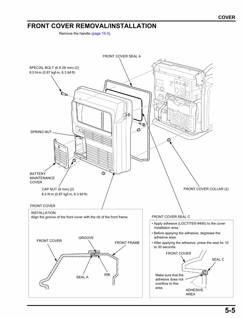
5-5
dummyheaddummyhead
COVER
FRONT COVER REMOVAL/INSTALLATIONRemove the handle (page 15-3).
FRONT COVER COLLAR (2)
FRONT COVER SEAL A
SPECIAL BOLT (6 X 26 mm) (2)
SPRING NUT
BATTERY MAINTENANCE COVER
CAP NUT (6 mm) (2)
8.5 N·m (0.87 kgf·m, 6.3 lbf·ft)
8.5 N·m (0.87 kgf·m, 6.3 lbf·ft)
• Apply adhesive (LOCTITE® #495) to the cover installation area.
• Before applying the adhesive, degrease the adhesive area.
• After applying the adhesive, press the seal for 10 to 30 seconds.
ADHESIVE AREA
FRONT COVER
INSTALLATION:Align the groove of the front cover with the rib of the front frame.
FRONT COVER
SEAL A
FRONT FRAME
RIB
GROOVE
FRONT COVER SEAL C
FRONT COVER
SEAL C
Make sure that the adhesive does not overflow to this area.

5-6
dummyheaddummyhead
COVER
REAR COVER/OUTER MUFFLER PROTECTOR REMOVAL/INSTALLATION
• The muffler becomes very hot during operation and remains hot for a while after stopping the engine. Be careful not to touch the muffler while it is hot. Allow it to cool before proceeding.
• Do not touch the insulator with bare hands. The glass wool of the material sticks in the skin and is dangerous.
OUTER MUFFLER PROTECTOR
BOLT (6 X 30 mm) (4)
REAR COVER SEAL
REAR COVER REAR PIPE
REAR COVER COLLAR (6)
INSULATOR
OUTER MUFFLER PROTECTOR SEAL
CAP NUT (6 mm) (2)
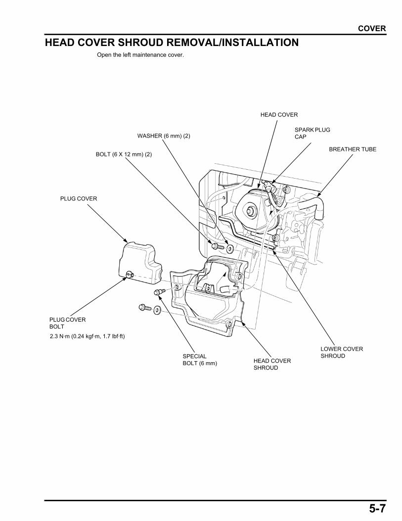
5-7
dummyheaddummyhead
COVER
HEAD COVER SHROUD REMOVAL/INSTALLATIONOpen the left maintenance cover.
HEAD COVER SHROUD
BREATHER TUBEBOLT (6 X 12 mm) (2)
HEAD COVER
LOWER COVER SHROUD
WASHER (6 mm) (2)
PLUG COVER
PLUG COVER BOLT
SPECIAL BOLT (6 mm)
SPARK PLUG CAP
2.3 N·m (0.24 kgf·m, 1.7 lbf·ft)

MEMO
dummyheaddummyhead
6-1
6
dummytext
6. FUEL SYSTEM
FUEL PUMP SYSTEM TROUBLESHOOTING···································6-2
FUEL INJECTOR SYSTEM TROUBLESHOOTING···································6-4
FUEL PRESSURE RELIEVING·····················6-6
FUEL PUMP UNIT REMOVAL/INSTALLATION··························6-9
FUEL TANK REMOVAL/INSTALLATION···········································6-10
FUEL TANK DISASSEMBLY/ASSEMBLY ·················································6-11
FUEL TANK CAP REMOVAL/INSTALLATION (AT, AT1 TYPE ONLY) ····6-12
AIR CLEANER REMOVAL/INSTALLATION···········································6-13
EVAP CANISTER REMOVAL/INSTALLATION (AT, AT1 TYPE ONLY) ····6-14
FUEL INJECTOR REMOVAL/INSTALLATION···········································6-15
THROTTLE BODY REMOVAL/INSTALLATION ·········································· 6-16
THROTTLE BODY DISASSEMBLY/ASSEMBLY················································· 6-17
O2 SENSOR REMOVAL/INSTALLATION ·········································· 6-18
EBT SENSOR REMOVAL/INSTALLATION ·········································· 6-19
BREATHER HEATER REMOVAL/INSTALLATION (CT TYPE ONLY)············· 6-19
FUEL LINE INSPECTION ··························· 6-20
FUEL PUMP INSPECTION ························· 6-21
THROTTLE CONTROL MOTOR INSPECTION··············································· 6-21
FUEL INJECTOR INSPECTION ················· 6-21
EBT SENSOR INSPECTION ······················ 6-22
BREATHER HEATER INSPECTION (CT TYPE ONLY) ········································ 6-22
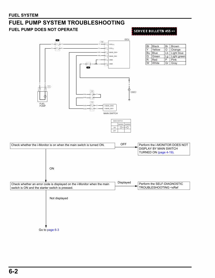
6-2
dummyheaddummyhead
FUEL SYSTEMFUEL SYSTEM
FUEL PUMP SYSTEM TROUBLESHOOTINGFUEL PUMP DOES NOT OPERATE
18R
W/Bu
Br/Bu
Br/Bu
Br/Bu
Br/Bu
Bl
W
G
MAIN_SW+
MAIN_SW-W/Bu
GND
GNDG
G
Bu
R
Bu
R
Bu
3
14
13
MAIN_SW1
MAIN_SW2
MAIN SWITCH
GCU
MAIN SWITCH
ON
OFF
GND3
Bl
68
12
15
14
1211
320
MAINSW1 MAINSW2
FUELPUMP
12
11
BuR
FFP(+)
FFP(-)
GG
3
1
Check whether an error code is displayed on the i-Monitor when the main switch is ON and the starter switch is pressed.
Perform the SELF-DIAGNOSTIC TROUBLESHOOTING <xRef
Displayed
Not displayed
Check whether the i-Monitor is on when the main switch is turned ON. Perform the i-MONITOR DOES NOT DISPLAY BY MAIN SWITCH TURNED ON (page 4-19).
OFF
ON
Bl Black Br BrownY Yellow O OrangeBu Blue Lb Light blueG Green Lg Light greenR Red P PinkW White Gr Gray
Go to page 6-3
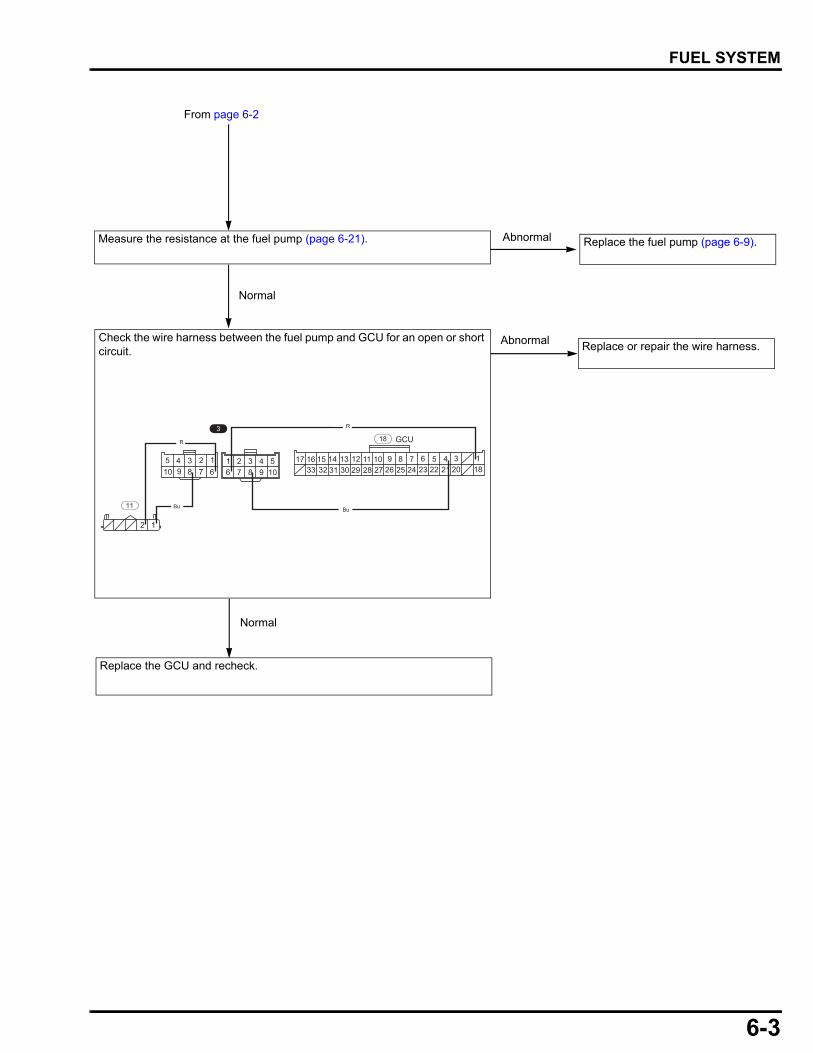
6-3
dummyheaddummyhead
FUEL SYSTEM
12
94 3 2 1
678510
49876
321105 17 14 1316 15
3233 3031 27 2629 281112 910 6 58 7
2425 2223 1821 2034 1
318 GCU
11 Bu
R
Bu
R
Measure the resistance at the fuel pump (page 6-21). Replace the fuel pump (page 6-9).Abnormal
Normal
Replace or repair the wire harness.
Replace the GCU and recheck.
From page 6-2
Check the wire harness between the fuel pump and GCU for an open or short circuit.
Abnormal
Normal
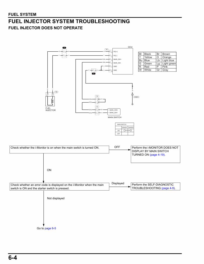
6-4
dummyheaddummyhead
FUEL SYSTEM
FUEL INJECTOR SYSTEM TROUBLESHOOTINGFUEL INJECTOR DOES NOT OPERATE
18W
W/Bu
Br/Bu
Br/Bu
Br/Bu
Br/Bu
Bl
W
G
MAIN_SW+
MAIN_SW-W/Bu
GND
GND
Y
W
Y
W
Y
3
14
13
MAIN_SW1
MAIN_SW2
MAIN SWITCH
GCU
MAIN SWITCH
ON
OFF
GND3
57
12
15
1821
1211
320
MAINSW1 MAINSW2
INJ(+)
INJ(-)
FUELINJECTOR
12
10
YW
G
G
GG
3
1
Bl
Check whether an error code is displayed on the i-Monitor when the main switch is ON and the starter switch is pressed.
Perform the SELF-DIAGNOSTIC TROUBLESHOOTING (page 4-9).
Displayed
Not displayed
Check whether the i-Monitor is on when the main switch is turned ON. Perform the i-MONITOR DOES NOT DISPLAY BY MAIN SWITCH TURNED ON (page 4-19).
OFF
ON
Bl Black Br BrownY Yellow O OrangeBu Blue Lb Light blueG Green Lg Light greenR Red P PinkW White Gr Gray
Go to page 6-5
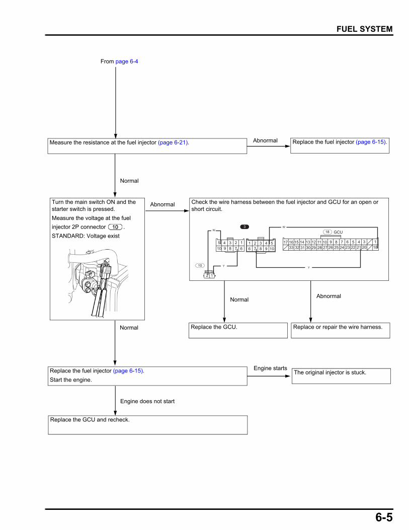
6-5
dummyheaddummyhead
FUEL SYSTEM
94 3 2 1
678510
49876
321105 17 14 1316 15
3233 3031 27 2629 281112 910 6 58 7
2425 2223 1821 2034 1
318 GCU
10 Y
W
Y
W
12
Normal
Replace or repair the wire harness.
Replace the fuel injector (page 6-15).
Start the engine.The original injector is stuck.
Abnormal
Engine starts
Normal
Engine does not start
Replace the GCU and recheck.
Measure the resistance at the fuel injector (page 6-21). Replace the fuel injector (page 6-15).
From page 6-4
Abnormal
Check the wire harness between the fuel injector and GCU for an open or short circuit.
Turn the main switch ON and the starter switch is pressed.
Measure the voltage at the fuel
injector 2P connector .
STANDARD: Voltage exist
Replace the GCU.
NormalAbnormal
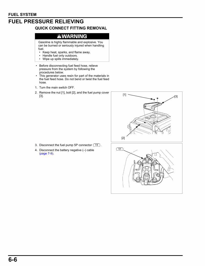
6-6
dummyheaddummyhead
FUEL SYSTEM
FUEL PRESSURE RELIEVINGQUICK CONNECT FITTING REMOVAL
• Before disconnecting fuel feed hose, relieve pressure from the system by following the procedures below.
• This generator uses resin for part of the materials inthe fuel feed hose. Do not bend or twist the fuel feedhose.
1. Turn the main switch OFF.
2. Remove the nut [1], bolt [2], and the fuel pump cover[3].
3. Disconnect the fuel pump 5P connector .
4. Disconnect the battery negative (–) cable(page 7-9).
Gasoline is highly flammable and explosive. You can be burned or seriously injured when handling fuel. • Keep heat, sparks, and flame away. • Handle fuel only outdoors. • Wipe up spills immediately.
[1]
[2]
[3]
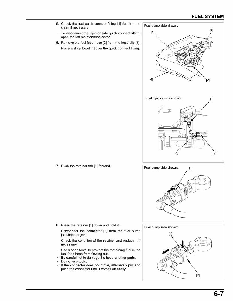
6-7
dummyheaddummyhead
FUEL SYSTEM
5. Check the fuel quick connect fitting [1] for dirt, andclean if necessary.
• To disconnect the injector side quick connect fitting,open the left maintenance cover.
6. Remove the fuel feed hose [2] from the hose clip [3].
Place a shop towel [4] over the quick connect fitting.
7. Push the retainer tab [1] forward.
8. Press the retainer [1] down and hold it.
Disconnect the connector [2] from the fuel pumpjoint/injector joint.
Check the condition of the retainer and replace it ifnecessary.
• Use a shop towel to prevent the remaining fuel in thefuel feed hose from flowing out.
• Be careful not to damage the hose or other parts. • Do not use tools. • If the connector does not move, alternately pull and
push the connector until it comes off easily.
[1]
[4] [2]
[3]
Fuel pump side shown:
Fuel injector side shown: [1]
[2][3]
Fuel pump side shown: [1]
[2]
[1]
Fuel pump side shown:

6-8
dummyheaddummyhead
FUEL SYSTEM
9. To prevent damage and keep foreign matter out,cover the disconnected connector and pipe end withplastic bags [1].
QUICK CONNECT FITTING INSTALLATION • Do not bend or twist the fuel feed hose.
1. Press the connector [1] onto the fuel pump joint/injector joint until the retainer [2] locks with a"CLICK".
• Align the quick connect fitting with the pipe.
If it is hard to connect, put a small amount of engineoil on the pipe end.
2. Make sure the connection is secure; check visuallyand by pulling the connector.
3. Set the fuel feed hose to the hose clip [1].
4. Connect the fuel pump 5P connector .
Connect the negative (–) cable to the battery (page7-5).
5. Disconnect the spark plug cap [1] and fuel injector2P connector .
Turn the main switch ON.
Push the starter switch.
The fuel pump will run for about 5 seconds, and fuelpressure will rise.Check that there is no leakage in the fuel supplysystem.
Turn the main switch OFF.
6. Install the fuel pump cover.
Connect the spark plug cap and fuel injector 2Pconnector .
[1]
Fuel pump side shown:
[2]
[1]
[1]
[1]
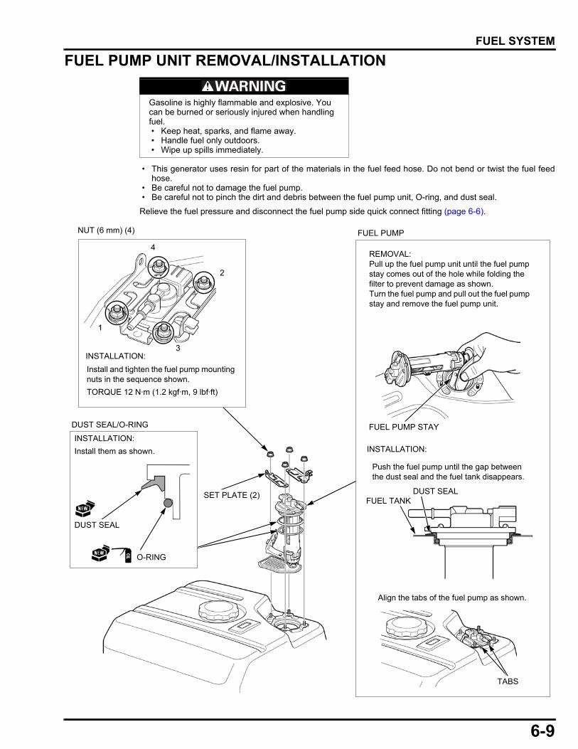
6-9
dummyheaddummyhead
FUEL SYSTEM
FUEL PUMP UNIT REMOVAL/INSTALLATION
• This generator uses resin for part of the materials in the fuel feed hose. Do not bend or twist the fuel feedhose.
• Be careful not to damage the fuel pump. • Be careful not to pinch the dirt and debris between the fuel pump unit, O-ring, and dust seal.
Relieve the fuel pressure and disconnect the fuel pump side quick connect fitting (page 6-6).
Gasoline is highly flammable and explosive. You can be burned or seriously injured when handling fuel. • Keep heat, sparks, and flame away. • Handle fuel only outdoors. • Wipe up spills immediately.
FUEL PUMP
SET PLATE (2)
O-RING
DUST SEAL
Install them as shown.
INSTALLATION:
DUST SEAL/O-RING
NUT (6 mm) (4)
INSTALLATION:
4
3
2
1
REMOVAL:Pull up the fuel pump unit until the fuel pump stay comes out of the hole while folding the filter to prevent damage as shown.Turn the fuel pump and pull out the fuel pump stay and remove the fuel pump unit.
Install and tighten the fuel pump mounting nuts in the sequence shown.
TORQUE 12 N·m (1.2 kgf·m, 9 lbf·ft)
INSTALLATION:
FUEL PUMP STAY
TABS
Align the tabs of the fuel pump as shown.
Push the fuel pump until the gap between the dust seal and the fuel tank disappears.
FUEL TANKDUST SEAL
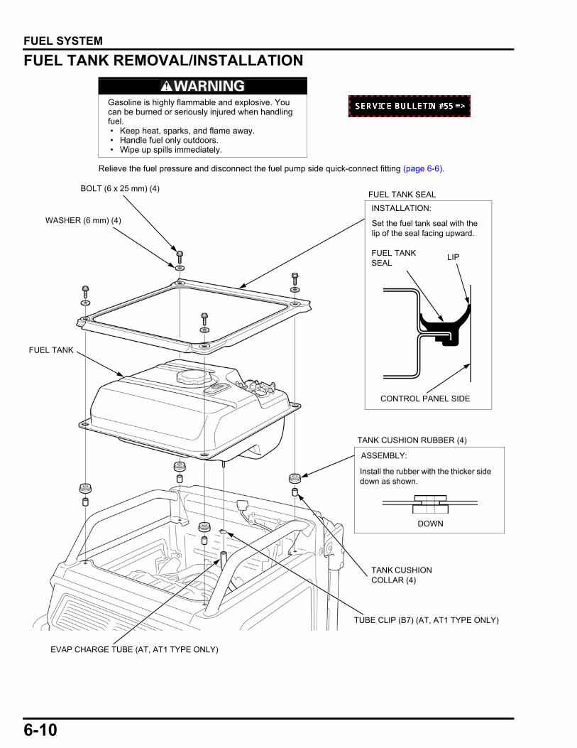
6-10
dummyheaddummyhead
FUEL SYSTEM
FUEL TANK REMOVAL/INSTALLATION
Relieve the fuel pressure and disconnect the fuel pump side quick-connect fitting (page 6-6).
Gasoline is highly flammable and explosive. You can be burned or seriously injured when handling fuel. • Keep heat, sparks, and flame away. • Handle fuel only outdoors. • Wipe up spills immediately.
WASHER (6 mm) (4)
BOLT (6 x 25 mm) (4)
TANK CUSHION RUBBER (4)
TANK CUSHION COLLAR (4)
FUEL TANK SEAL
INSTALLATION:
Set the fuel tank seal with the lip of the seal facing upward.
LIPFUEL TANK SEAL
CONTROL PANEL SIDE
DOWN
ASSEMBLY:
Install the rubber with the thicker side down as shown.
FUEL TANK
EVAP CHARGE TUBE (AT, AT1 TYPE ONLY)
TUBE CLIP (B7) (AT, AT1 TYPE ONLY)
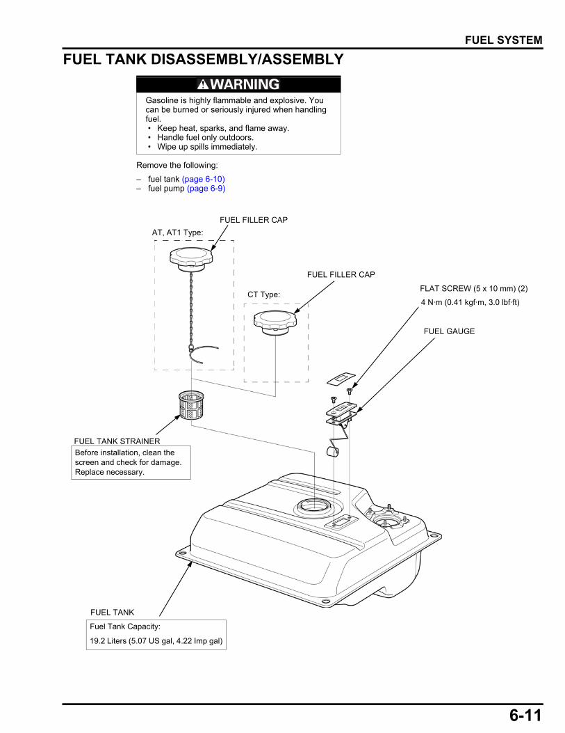
6-11
dummyheaddummyhead
FUEL SYSTEM
FUEL TANK DISASSEMBLY/ASSEMBLY
Remove the following:
– fuel tank (page 6-10)– fuel pump (page 6-9)
Gasoline is highly flammable and explosive. You can be burned or seriously injured when handling fuel. • Keep heat, sparks, and flame away. • Handle fuel only outdoors. • Wipe up spills immediately.
FUEL FILLER CAP
FUEL TANK
FUEL GAUGE
FLAT SCREW (5 x 10 mm) (2)
Fuel Tank Capacity:
19.2 Liters (5.07 US gal, 4.22 Imp gal)
4 N·m (0.41 kgf·m, 3.0 lbf·ft)
FUEL TANK STRAINER
Before installation, clean the screen and check for damage. Replace necessary.
FUEL FILLER CAP
AT, AT1 Type:
CT Type:

6-12
dummyheaddummyhead
FUEL SYSTEM
FUEL TANK CAP REMOVAL/INSTALLATION (AT, AT1 TYPE ONLY)REMOVALOpen the fuel tank cap.
Unhook one tip of the anchor [1] using pliers [2], andthen unhook the other tip in the same manner.
Never try to force the anchor when removing it.
Draw the loop [1] of the anchor [2] from the hole [3] ofthe fuel filler neck using pliers.
Pull one tip of the anchor [1] out of the fuel filler neckusing pliers [2], and then pull the other tip out in thesame manner.
Be careful to avoid damaging the breather pipe in thefuel filler neck.
Remove the anchor from the filler neck.
INSTALLATIONAttach the loop part [1] of the anchor [2] in the hole [3]of the fuel filler neck.
Hook the tips of the anchor in the reverse order of
removal.
[1]
[2]
[3]
[2] [1]
[2]
[1]
[3][2]
[1]
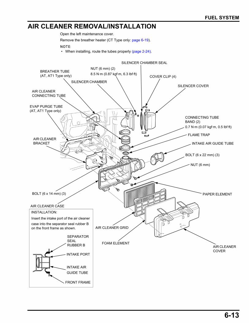
6-13
dummyheaddummyhead
FUEL SYSTEM
AIR CLEANER REMOVAL/INSTALLATIONOpen the left maintenance cover.
Remove the breather heater (CT Type only: page 6-19).
• When installing, route the tubes properly (page 2-24).
AIR CLEANER COVER
FOAM ELEMENT
PAPER ELEMENT
SILENCER CHAMBER
NUT (6 mm) (2)
COVER CLIP (4)
INTAKE AIR GUIDE TUBE
AIR CLEANER CONNECTING TUBE
CONNECTING TUBE BAND (2)
AIR CLEANER CASE
AIR CLEANER BRACKET
NUT (6 mm)
AIR CLEANER GRID
BOLT (6 x 22 mm) (3)
SILENCER CHAMBER SEAL
BOLT (6 x 14 mm) (3)
Insert the intake port of the air cleaner
case into the separator seal rubber B on the front frame as shown.
INSTALLATION:
FRONT FRAME
INTAKE AIR
GUIDE TUBE
SEPARATOR SEAL RUBBER B
INTAKE PORT
SILENCER COVER
8.5 N·m (0.87 kgf·m, 6.3 lbf·ft)
0.7 N·m (0.07 kgf·m, 0.5 lbf·ft)
FLAME TRAP
EVAP PURGE TUBE(AT, AT1 Type only)
BREATHER TUBE(AT, AT1 Type only)
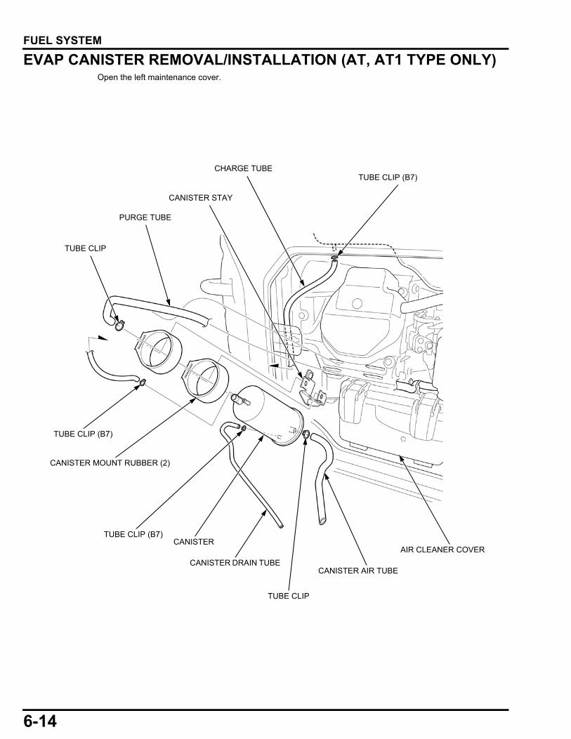
6-14
dummyheaddummyhead
FUEL SYSTEM
EVAP CANISTER REMOVAL/INSTALLATION (AT, AT1 TYPE ONLY)Open the left maintenance cover.
CANISTER STAY
CHARGE TUBE TUBE CLIP (B7)
PURGE TUBE
TUBE CLIP
CANISTER
CANISTER MOUNT RUBBER (2)
CANISTER STAY
CANISTER DRAIN TUBE
AIR CLEANER COVER
CANISTER AIR TUBE
TUBE CLIP (B7)
TUBE CLIP (B7)
TUBE CLIP
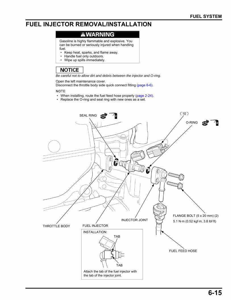
6-15
dummyheaddummyhead
FUEL SYSTEM
FUEL INJECTOR REMOVAL/INSTALLATION
Be careful not to allow dirt and debris between the injector and O-ring.
Open the left maintenance cover.Disconnect the throttle body side quick connect fitting (page 6-6).
• When installing, route the fuel feed hose properly (page 2-24). • Replace the O-ring and seal ring with new ones as a set.
Gasoline is highly flammable and explosive. You can be burned or seriously injured when handling fuel. • Keep heat, sparks, and flame away. • Handle fuel only outdoors. • Wipe up spills immediately.
FLANGE BOLT (5 x 20 mm) (2)
SEAL RING
O-RING
INJECTOR JOINT
FUEL INJECTORTHROTTLE BODY
5.1 N·m (0.52 kgf·m, 3.8 lbf·ft)
FUEL FEED HOSE
Attach the tab of the fuel injector with the tab of the injector joint.
INSTALLATION:TAB
TAB
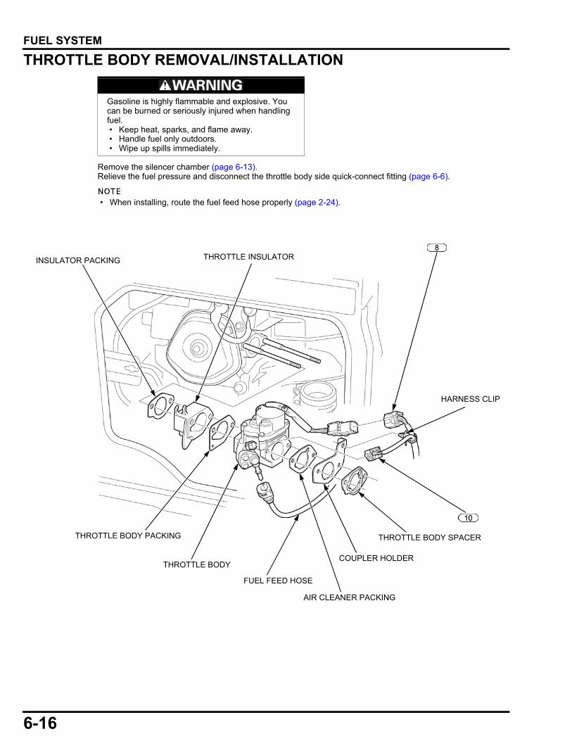
6-16
dummyheaddummyhead
FUEL SYSTEM
THROTTLE BODY REMOVAL/INSTALLATION
Remove the silencer chamber (page 6-13).Relieve the fuel pressure and disconnect the throttle body side quick-connect fitting (page 6-6).
• When installing, route the fuel feed hose properly (page 2-24).
Gasoline is highly flammable and explosive. You can be burned or seriously injured when handling fuel. • Keep heat, sparks, and flame away. • Handle fuel only outdoors. • Wipe up spills immediately.
FUEL FEED HOSE
COUPLER HOLDER
THROTTLE BODY SPACER
AIR CLEANER PACKING
THROTTLE BODY
THROTTLE BODY PACKING
THROTTLE INSULATOR
HARNESS CLIP
INSULATOR PACKING

6-17
dummyheaddummyhead
FUEL SYSTEM
THROTTLE BODY DISASSEMBLY/ASSEMBLY • The throttle body is factory pre-set. Do not disassemble in a way other than shown in this manual. • Do not damage the throttle body. It may cause incorrect throttle valve operation. • Be careful not to drop dirt and debris into the throttle body.
MIDDLE GEAR
SCREW (2)SCREW WASHER (2)
MOTOR PACKINGTHROTTLE BODY
THROTTLE CONTROL MOTOR
2.1 N·m (0.21 kgf·m, 1.5 lbf·ft) 2.1 N·m (0.21 kgf·m, 1.5 lbf·ft)
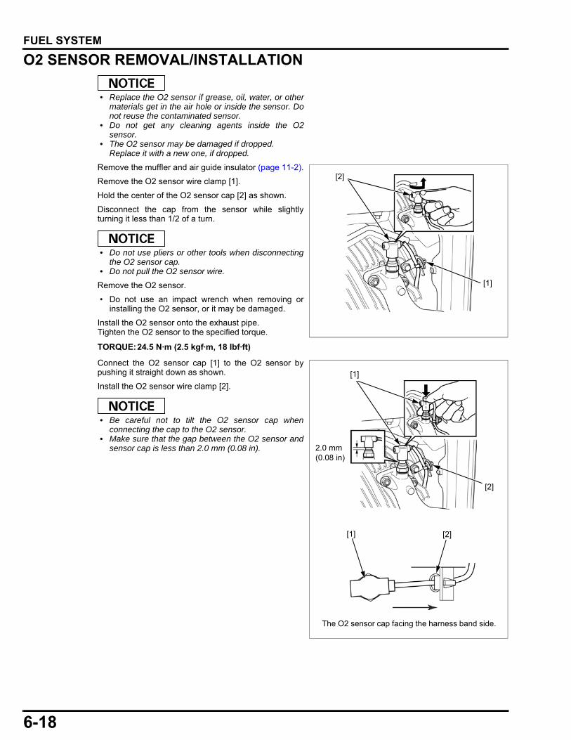
6-18
dummyheaddummyhead
FUEL SYSTEM
O2 SENSOR REMOVAL/INSTALLATION
• Replace the O2 sensor if grease, oil, water, or othermaterials get in the air hole or inside the sensor. Donot reuse the contaminated sensor.
• Do not get any cleaning agents inside the O2sensor.
• The O2 sensor may be damaged if dropped.Replace it with a new one, if dropped.
Remove the muffler and air guide insulator (page 11-2).
Remove the O2 sensor wire clamp [1].
Hold the center of the O2 sensor cap [2] as shown.
Disconnect the cap from the sensor while slightlyturning it less than 1/2 of a turn.
• Do not use pliers or other tools when disconnectingthe O2 sensor cap.
• Do not pull the O2 sensor wire.
Remove the O2 sensor.
• Do not use an impact wrench when removing orinstalling the O2 sensor, or it may be damaged.
Install the O2 sensor onto the exhaust pipe.Tighten the O2 sensor to the specified torque.
Connect the O2 sensor cap [1] to the O2 sensor bypushing it straight down as shown.
Install the O2 sensor wire clamp [2].
• Be careful not to tilt the O2 sensor cap whenconnecting the cap to the O2 sensor.
• Make sure that the gap between the O2 sensor andsensor cap is less than 2.0 mm (0.08 in).
TORQUE:24.5 N·m (2.5 kgf·m, 18 lbf·ft)
[2]
[1]
[1]
2.0 mm(0.08 in)
[2]
The O2 sensor cap facing the harness band side.
[1] [2]
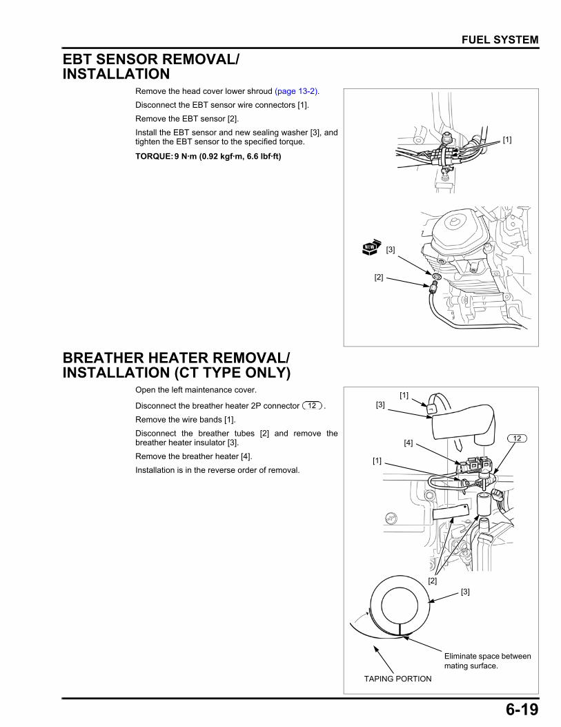
6-19
dummyheaddummyhead
FUEL SYSTEM
EBT SENSOR REMOVAL/INSTALLATION
Remove the head cover lower shroud (page 13-2).
Disconnect the EBT sensor wire connectors [1].
Remove the EBT sensor [2].
Install the EBT sensor and new sealing washer [3], andtighten the EBT sensor to the specified torque.
BREATHER HEATER REMOVAL/INSTALLATION (CT TYPE ONLY)
Open the left maintenance cover.
Disconnect the breather heater 2P connector .
Remove the wire bands [1].
Disconnect the breather tubes [2] and remove thebreather heater insulator [3].
Remove the breather heater [4].
Installation is in the reverse order of removal.
TORQUE:9 N·m (0.92 kgf·m, 6.6 lbf·ft)
[2]
[3]
[1]
[3]
[4]
TAPING PORTION
[1]
[2]
Eliminate space between mating surface.
[3]
[1]
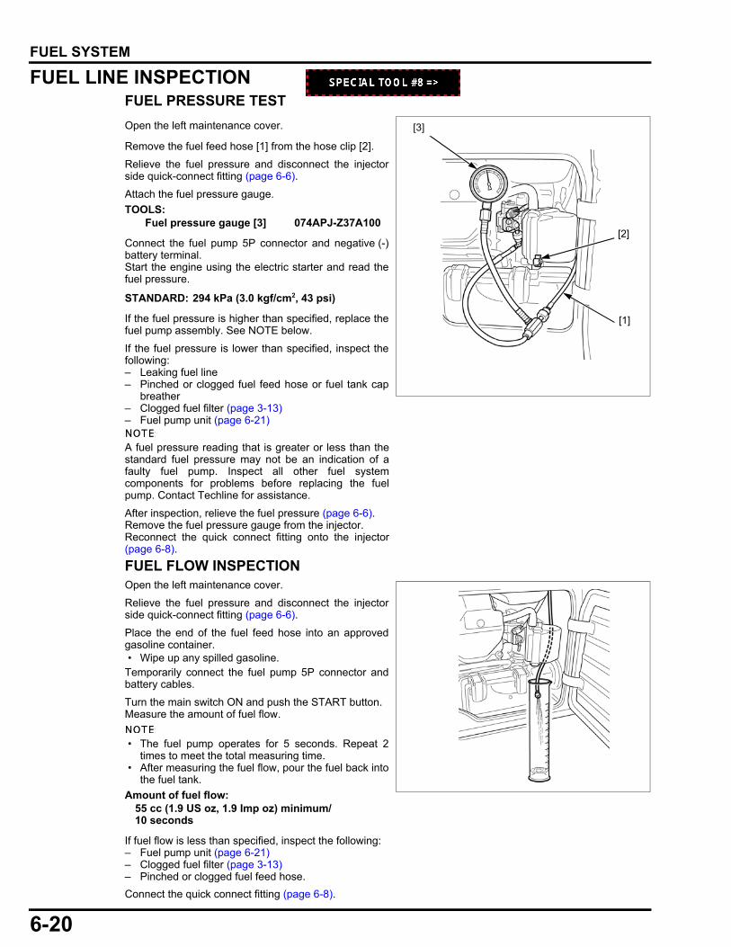
6-20
dummyheaddummyhead
FUEL SYSTEM
FUEL LINE INSPECTIONFUEL PRESSURE TEST
Open the left maintenance cover.
Remove the fuel feed hose [1] from the hose clip [2].
Relieve the fuel pressure and disconnect the injectorside quick-connect fitting (page 6-6).
Attach the fuel pressure gauge.
Connect the fuel pump 5P connector and negative (-)battery terminal.Start the engine using the electric starter and read thefuel pressure.
If the fuel pressure is higher than specified, replace thefuel pump assembly. See NOTE below.
If the fuel pressure is lower than specified, inspect thefollowing:– Leaking fuel line– Pinched or clogged fuel feed hose or fuel tank cap
breather– Clogged fuel filter (page 3-13)– Fuel pump unit (page 6-21)
A fuel pressure reading that is greater or less than thestandard fuel pressure may not be an indication of afaulty fuel pump. Inspect all other fuel systemcomponents for problems before replacing the fuelpump. Contact Techline for assistance.
After inspection, relieve the fuel pressure (page 6-6).Remove the fuel pressure gauge from the injector.Reconnect the quick connect fitting onto the injector(page 6-8).
FUEL FLOW INSPECTIONOpen the left maintenance cover.
Relieve the fuel pressure and disconnect the injectorside quick-connect fitting (page 6-6).
Place the end of the fuel feed hose into an approvedgasoline container. • Wipe up any spilled gasoline.Temporarily connect the fuel pump 5P connector andbattery cables.
Turn the main switch ON and push the START button.Measure the amount of fuel flow.
• The fuel pump operates for 5 seconds. Repeat 2times to meet the total measuring time.
• After measuring the fuel flow, pour the fuel back intothe fuel tank.
If fuel flow is less than specified, inspect the following:– Fuel pump unit (page 6-21)– Clogged fuel filter (page 3-13)– Pinched or clogged fuel feed hose.
Connect the quick connect fitting (page 6-8).
TOOLS:Fuel pressure gauge [3] 074APJ-Z37A100
STANDARD: 294 kPa (3.0 kgf/cm2, 43 psi)
[3]
[2]
[1]
Amount of fuel flow:55 cc (1.9 US oz, 1.9 Imp oz) minimum/10 seconds
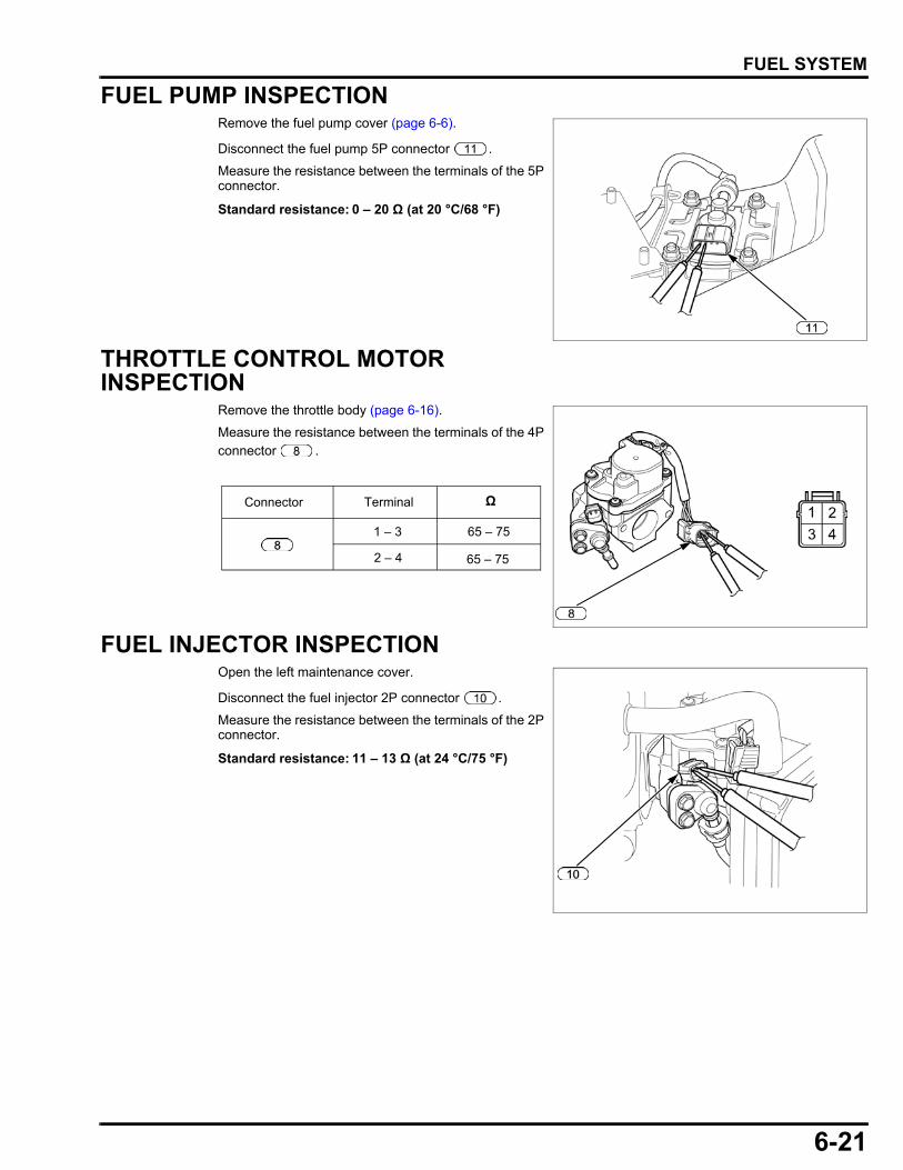
6-21
dummyheaddummyhead
FUEL SYSTEM
FUEL PUMP INSPECTIONRemove the fuel pump cover (page 6-6).
Disconnect the fuel pump 5P connector .
Measure the resistance between the terminals of the 5Pconnector.
THROTTLE CONTROL MOTOR INSPECTION
Remove the throttle body (page 6-16).
Measure the resistance between the terminals of the 4Pconnector .
FUEL INJECTOR INSPECTIONOpen the left maintenance cover.
Disconnect the fuel injector 2P connector .
Measure the resistance between the terminals of the 2Pconnector.
Standard resistance: 0 – 20 Ω (at 20 °C/68 °F)
TerminalConnector Ω
1 – 3
2 – 4
65 – 75
65 – 75
Standard resistance: 11 – 13 Ω (at 24 °C/75 °F)
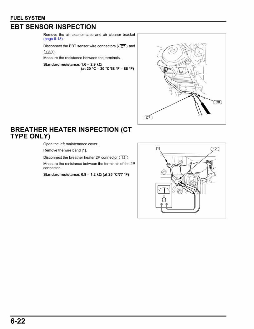
6-22
dummyheaddummyhead
FUEL SYSTEM
EBT SENSOR INSPECTIONRemove the air cleaner case and air cleaner bracket(page 6-13).
Disconnect the EBT sensor wire connectors ( and
).
Measure the resistance between the terminals.
BREATHER HEATER INSPECTION (CT TYPE ONLY)
Open the left maintenance cover.
Remove the wire band [1].
Disconnect the breather heater 2P connector .
Measure the resistance between the terminals of the 2Pconnector.
Standard resistance: 1.6 – 2.9 kΩ (at 20 °C – 30 °C/68 °F – 86 °F)
Standard resistance: 0.8 – 1.2 kΩ (at 25 °C/77 °F)
[1]
7-1
7
dummytext
7. GENERATOR/CHARGING SYSTEM
GENERATOR TROUBLESHOOTING···········7-2
CHARGING SYSTEM TROUBLESHOOTING···································7-8
BATTERY REMOVAL/INSTALLATION········7-9
INVERTER UNIT REMOVAL/INSTALLATION···········································7-10
FRONT FRAME REMOVAL/INSTALLATION···········································7-11
FAN COVER REMOVAL/INSTALLATION··7-12
COOLING FAN REMOVAL/INSTALLATION ·········································· 7-13
GENERATOR REMOVAL/INSTALLATION ·········································· 7-14
BATTERY CHARGING ······························· 7-16
BATTERY INSPECTION····························· 7-16
STATOR INSPECTION ······························· 7-17
INVERTER UNIT INSPECTION ·················· 7-18
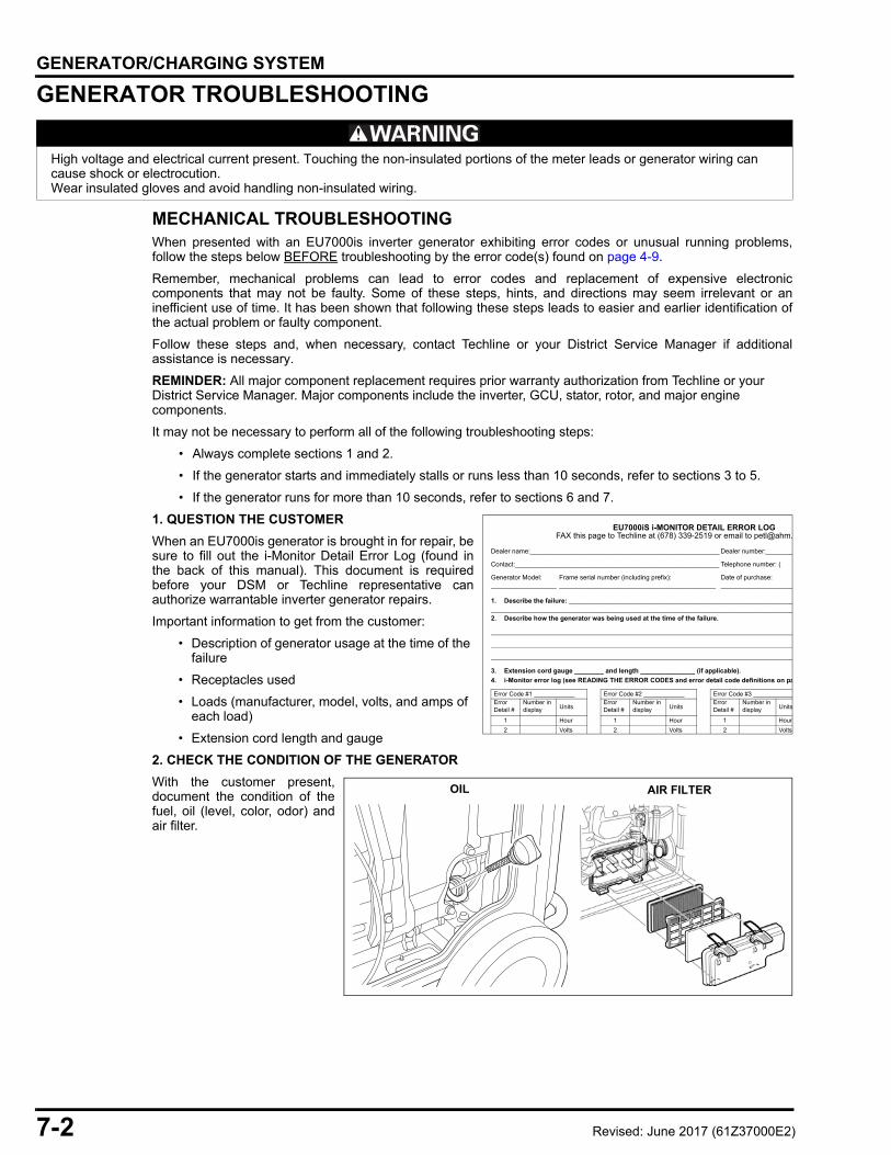
7-2
dummyheaddummyhead
GENERATOR/CHARGING SYSTEMGENERATOR/CHARGING SYSTEM
GENERATOR TROUBLESHOOTING
MECHANICAL TROUBLESHOOTINGWhen presented with an EU7000is inverter generator exhibiting error codes or unusual running problems,follow the steps below BEFORE troubleshooting by the error code(s) found on page 4-9.
Remember, mechanical problems can lead to error codes and replacement of expensive electroniccomponents that may not be faulty. Some of these steps, hints, and directions may seem irrelevant or aninefficient use of time. It has been shown that following these steps leads to easier and earlier identification ofthe actual problem or faulty component.
Follow these steps and, when necessary, contact Techline or your District Service Manager if additionalassistance is necessary.
REMINDER: All major component replacement requires prior warranty authorization from Techline or your District Service Manager. Major components include the inverter, GCU, stator, rotor, and major engine components.
It may not be necessary to perform all of the following troubleshooting steps:
• Always complete sections 1 and 2.
• If the generator starts and immediately stalls or runs less than 10 seconds, refer to sections 3 to 5.
• If the generator runs for more than 10 seconds, refer to sections 6 and 7.
1. QUESTION THE CUSTOMER
When an EU7000is generator is brought in for repair, besure to fill out the i-Monitor Detail Error Log (found inthe back of this manual). This document is requiredbefore your DSM or Techline representative canauthorize warrantable inverter generator repairs.
Important information to get from the customer:
• Description of generator usage at the time of the failure
• Receptacles used
• Loads (manufacturer, model, volts, and amps of each load)
• Extension cord length and gauge
2. CHECK THE CONDITION OF THE GENERATOR
With the customer present,document the condition of thefuel, oil (level, color, odor) andair filter.
High voltage and electrical current present. Touching the non-insulated portions of the meter leads or generator wiring can cause shock or electrocution.Wear insulated gloves and avoid handling non-insulated wiring.
EU7000iS i-MONITOR DETAIL ERROR LOGFAX this page to Techline at (678) 339-2519 or email to petl@ahm.
1. Describe the failure: _________________________________________________________________________________________________________________________________________________2. Describe how the generator was being used at the time of the failure.
3. Extension cord gauge ________ and length _______________ (if applicable).4. i-Monitor error log (see READING THE ERROR CODES and error detail code definitions on pa
Dealer name:____________________________________________________ Dealer number:________
Contact:________________________________________________________ Telephone number: (
Generator Model:__________________
Frame serial number (including prefix):___________________________________________
Date of purchase:____________________
Error Code #1 ____________ Error Code #2 ____________ Error Code #3 ____________Error Detail #
Number in display Units
Error Detail #
Number in display Units
Error Detail #
Number in display Units
1 Hour 1 Hour 1 Hour2 Volts 2 Volts 2 Volts
OIL AIR FILTER
Revised: June 2017 (61Z37000E2)
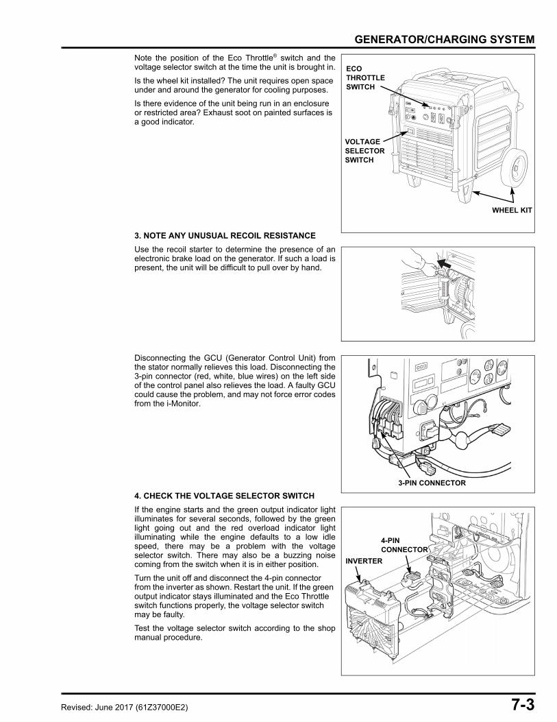
7-3
dummyheaddummyhead
GENERATOR/CHARGING SYSTEM
Note the position of the Eco Throttle® switch and thevoltage selector switch at the time the unit is brought in.
Is the wheel kit installed? The unit requires open space under and around the generator for cooling purposes.
Is there evidence of the unit being run in an enclosure or restricted area? Exhaust soot on painted surfaces is a good indicator.
3. NOTE ANY UNUSUAL RECOIL RESISTANCE
Use the recoil starter to determine the presence of anelectronic brake load on the generator. If such a load ispresent, the unit will be difficult to pull over by hand.
Disconnecting the GCU (Generator Control Unit) fromthe stator normally relieves this load. Disconnecting the3-pin connector (red, white, blue wires) on the left sideof the control panel also relieves the load. A faulty GCUcould cause the problem, and may not force error codesfrom the i-Monitor.
4. CHECK THE VOLTAGE SELECTOR SWITCH
If the engine starts and the green output indicator lightilluminates for several seconds, followed by the greenlight going out and the red overload indicator lightilluminating while the engine defaults to a low idlespeed, there may be a problem with the voltageselector switch. There may also be a buzzing noisecoming from the switch when it is in either position.
Turn the unit off and disconnect the 4-pin connector from the inverter as shown. Restart the unit. If the green output indicator stays illuminated and the Eco Throttle switch functions properly, the voltage selector switch may be faulty.
Test the voltage selector switch according to the shopmanual procedure.
WHEEL KIT
ECO THROTTLE SWITCH
VOLTAGE SELECTOR SWITCH
3-PIN CONNECTOR
INVERTER
4-PIN CONNECTOR
Revised: June 2017 (61Z37000E2)
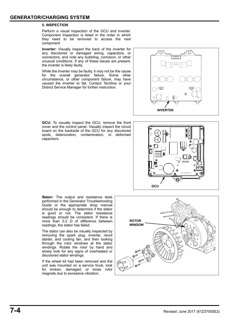
7-4
dummyheaddummyhead
GENERATOR/CHARGING SYSTEM
5. INSPECTION
Perform a visual inspection of the GCU and inverter.Component inspection is listed in the order in whichthey need to be removed to access the nextcomponent.
Inverter: Visually inspect the back of the inverter forany discolored or damaged wiring, capacitors, orconnectors, and note any bubbling, corrosion, or otherunusual conditions. If any of these issues are present,the inverter is likely faulty.
While the inverter may be faulty, it may not be the causefor the overall generator failure. Some othercircumstance, or other component failure, may havecaused the inverter to fail. Contact Techline or yourDistrict Service Manager for further instruction.
GCU: To visually inspect the GCU, remove the frontcover and the control panel. Visually inspect the circuitboard on the backside of the GCU for any discoloredspots, deterioration, contamination, or deformedcapacitors.
Stator: The output and resistance testsperformed in the Generator TroubleshootingGuide or the appropriate shop manualshould be enough to determine if the statoris good or not. The stator resistancereadings should be consistent. If there ismore than 0.2 Ω of difference betweenreadings, the stator has failed.
The stator can also be visually inspected byremoving the spark plug, inverter, recoilstarter, and cooling fan, and then lookingthrough the rotor windows at the statorwindings. Rotate the rotor by hand andslowly look for any signs of overheated ordiscolored stator windings.
If the wheel kit had been removed and theunit was mounted on a service truck, lookfor broken, damaged, or loose rotormagnets due to excessive vibration.
INVERTER
GCU
ROTOR WINDOW
Revised: June 2017 (61Z37000E2)

7-5
dummyheaddummyhead
GENERATOR/CHARGING SYSTEM
6. CHECK THE SPARK ARRESTER SCREEN
Clean or replace as necessary. A badly clogged screencould also be an indicator that the muffler passages areclogged or reduced due to carbon buildup. Excesscarbon buildup may indicate high engine hours,operation with a restricted air cleaner, or operating thegenerator in an enclosure.
If the spark arrester was heavily clogged, run thegenerator outdoors on the load bank for 30 minutes at50 ~ 60% load to dynamically decarbon the combustionchamber. Let the generator cool down, and thenreinstall the spark arrester.
7. FUEL PRESSURE TEST
If the generator displays an E-0A code, surges underload, or surges and stalls, the fuel system needs to beinspected.
Test the fuel pressure:• Remove the fuel feed hose from the hose clip.• Relieve the fuel pressure by disconnecting the
injector side quick-connect fitting.• Attach the fuel pressure gauge.
TOOL: Fuel pressure gaugeP/N 074APJ-Z37A100
• Start the engine using the electrical starter and read the fuel pressure.
STANDARD: 43 psi (294 kPa, 3.0 kgf/cm2)
If the fuel pressure is lower than specified, inspect thefuel filter. If the fuel filter is clean, contact Techline.
Refer to page 4-33 for additional information.
8. START AND LOAD TEST THE GENERATOR
Note any changes in the way the engine runs.
• If the problem is now resolved, be sure to note the hours and any stored error codes on the repair order.
• If a problem remains after the above steps have been taken, refer to page 7-6 to troubleshoot the generator. Perform the visual inspection (step 5 on page 7-4) when removing the control panel and inverter.
• If the generator starts and runs but does not carry the rated load during the load bank test, check the following:
– Throttle control motor not functioning properly
– Engine compression
Repair as necessary and repeat load bank test.
SPARK ARRESTER SCREEN
FUEL PRESSURE GAUGE
HOSE CLIP
FUEL FEED HOSE
Revised: June 2017 (61Z37000E2)
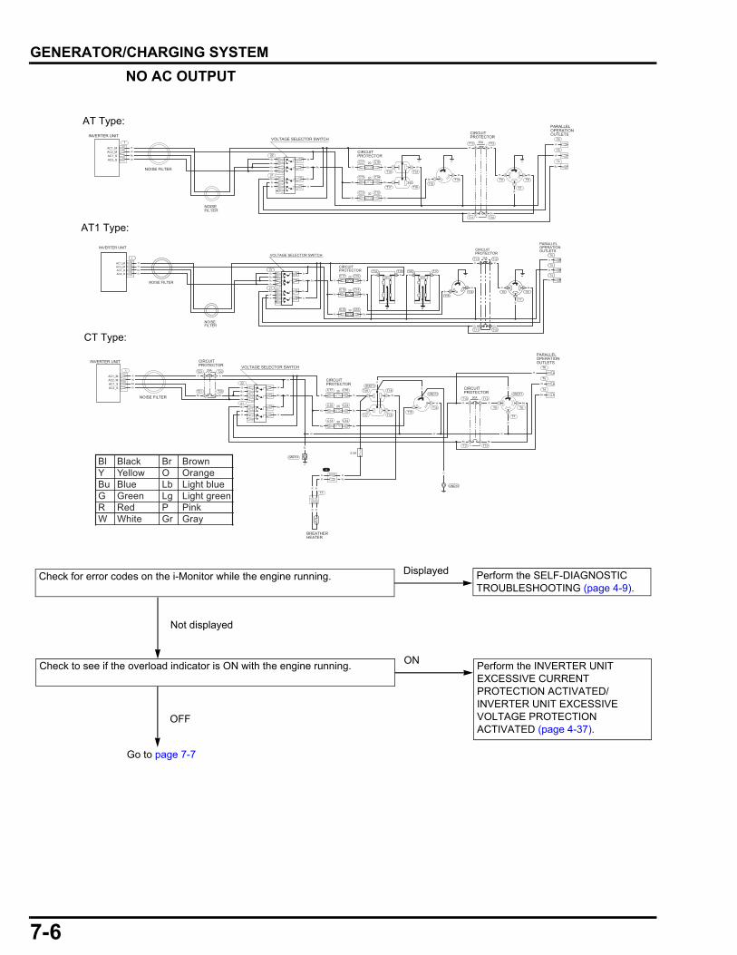
7-6
dummyheaddummyhead
GENERATOR/CHARGING SYSTEM
NO AC OUTPUT
INVERTER UNIT
PARALLELOPERATIONOUTLETS
CIRCUITPROTECTOR
VOLTAGE SELECTOR SWITCH
NOISE FILTER
AC1_MAC2_MAC1_SAC2_S
1
22
C17 C16
C15 C14
C13 C12
21
21
12
12
34
63
41
13
4 56
25
2
T8T14
T16 T7
T9T15
T17
T18T19
T10T11
T20T21
T6
T5
T4
GND10
GND14
GND13
GND12 GND11
CIRCUITPROTECTOR
T22T23 29A
CIRCUITPROTECTOR
T12T13 30A
20
20
30
0.5A
R
W
Gr
Bu
Bu
Bu
R
R
Bu
R
W
R
Bu
Bu
W W W
R W
WBu
Bu
Bu Bu
W
Gr
Bu
Gr
R RR
W
Bu
RR Bu
BuBu
Bu Bu
W
W
G
GG
G
W
BREATHERHEATER
4
12
R R
R W
RR
RR
INVERTER UNIT
PARALLELOPERATIONOUTLETSCIRCUIT
PROTECTOR
CIRCUITPROTECTOR
VOLTAGE SELECTOR SWITCH
NOISEFILTER
NOISE FILTER
AC1_MAC2_MAC1_SAC2_S
1
22
C17 C16
C15 C14
C13 C12
21
21
34
63
41
13
4 56
25
2
T8T14
T16 T7
T9T15
T17
T14T19
T12T13
T10T11
T6
T5
T4
30A
20
20
30
R
W
Gr
Bu
Bu
Bu
R
R
Bu
R
W
R
Bu
Bu
R W
BuBu
Bu
Bu Bu
Gr
Bu
Gr
R
Bu
RR
W
Bu
R Bu
Bu
W
W
INVERTER UNITPARALLELOPERATIONOUTLETSCIRCUIT
PROTECTOR
CIRCUITPROTECTOR
VOLTAGE SELECTOR SWITCH
NOISEFILTER
NOISE FILTER
AC1_MAC2_MAC1_SAC2_S
1
22
C17 C16
C15 C14
C13 C12
21
21
34
63
41
13
4 56
25
2
T8T14
T7
T9T15
T17T24T19T18
T12T13
T10T11
T6
T5
T4
30A
20
20
30
R
W
Gr
Bu
Bu
Bu
R
R
Bu
R
W
R
Bu
Bu
R
R W Bu
BuBu
Bu
Bu Bu
Gr
Bu
Gr
R
Bu
RR
W
Bu
R Bu
Bu
W
W
WGFCIGFCI
Check for error codes on the i-Monitor while the engine running. Perform the SELF-DIAGNOSTIC TROUBLESHOOTING (page 4-9).
Displayed
Not displayed
Bl Black Br BrownY Yellow O OrangeBu Blue Lb Light blueG Green Lg Light greenR Red P PinkW White Gr Gray
Go to page 7-7
Check to see if the overload indicator is ON with the engine running. ON
OFF
AT Type:
CT Type:
Perform the INVERTER UNIT EXCESSIVE CURRENT PROTECTION ACTIVATED/ INVERTER UNIT EXCESSIVE VOLTAGE PROTECTION ACTIVATED (page 4-37).
AT1 Type:
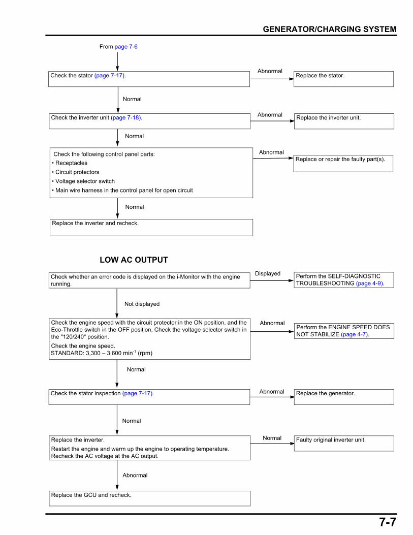
7-7
dummyheaddummyhead
GENERATOR/CHARGING SYSTEM
LOW AC OUTPUT
•
• Receptacles
• Circuit protectors
• Voltage selector switch
• Main wire harness in the control panel for open circuit
Abnormal
Replace the inverter and recheck.
Check the following control panel parts:Replace or repair the faulty part(s).
Normal
Check the stator (page 7-17). Replace the stator.
AbnormalCheck the inverter unit (page 7-18). Replace the inverter unit.
Abnormal
Normal
Normal
From page 7-6
Check whether an error code is displayed on the i-Monitor with the engine running.
Perform the SELF-DIAGNOSTIC TROUBLESHOOTING (page 4-9).
Displayed
Not displayed
Check the stator inspection (page 7-17). Replace the generator.Abnormal
Normal
Replace the inverter.
Restart the engine and warm up the engine to operating temperature.Recheck the AC voltage at the AC output.
Normal
Replace the GCU and recheck.
Faulty original inverter unit.
Abnormal
Check the engine speed with the circuit protector in the ON position, and the Eco-Throttle switch in the OFF position, Check the voltage selector switch in the "120/240" position.
Check the engine speed. STANDARD: 3,300 – 3,600 min-1 (rpm)
Perform the ENGINE SPEED DOES NOT STABILIZE (page 4-7).
Normal
Abnormal
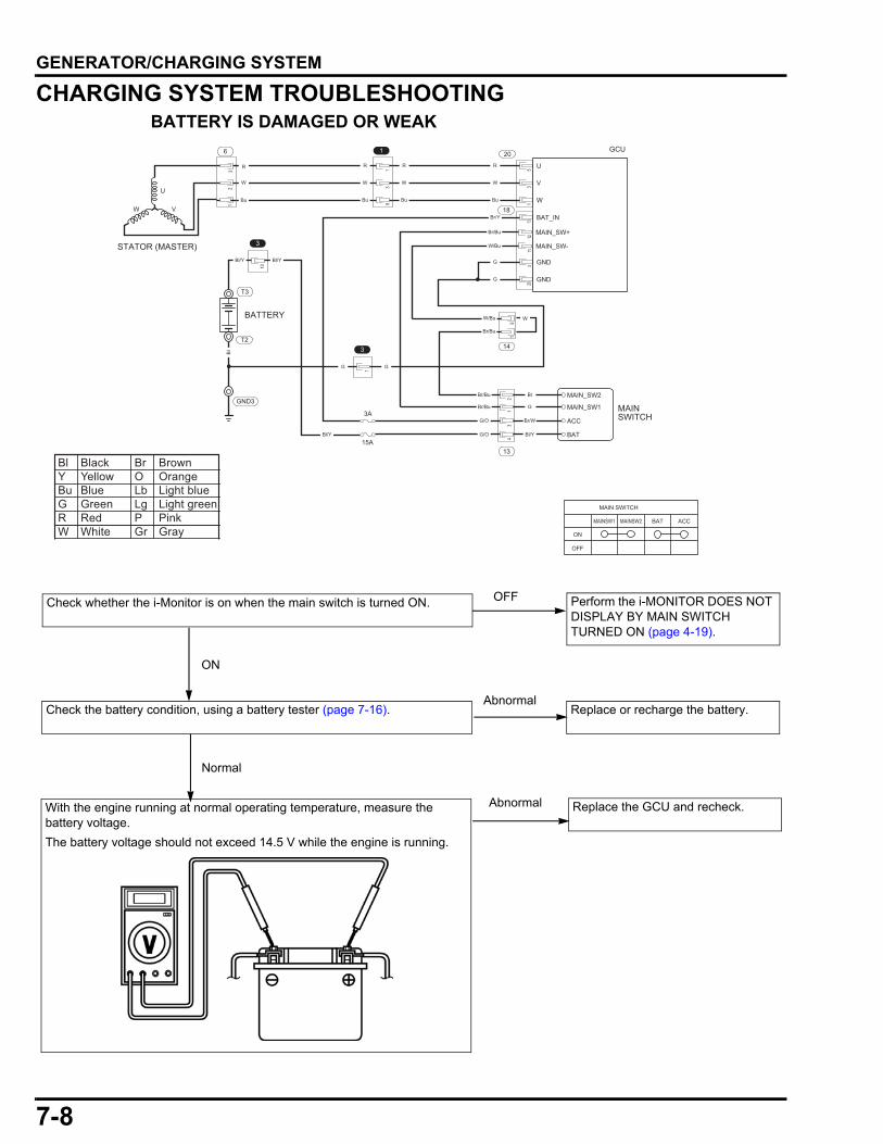
7-8
dummyheaddummyhead
GENERATOR/CHARGING SYSTEM
CHARGING SYSTEM TROUBLESHOOTINGBATTERY IS DAMAGED OR WEAK
Check whether the i-Monitor is on when the main switch is turned ON. Perform the i-MONITOR DOES NOT DISPLAY BY MAIN SWITCH TURNED ON (page 4-19).
U
V
W
53
1
20
18
R
W
Bu
R
W
Bu
R
W
Bu
BAT_IN
13
Br/Y
MAIN_SW+
MAIN_SW-
1211
Br/Bu
W/Bu
W/Bu
GND
GND
320
G
G
W
GG
1
3
53
1
1
12
3
U
VW
STATOR (MASTER)
6
R
W
Bu
MAINSWITCH
MAIN_SW1
MAIN_SW2
ACC
BAT
21
34
13
14
Br/W
Bl/Y
Bl
G
G/O
G/OBl/Y
Bl/Y Bl/Y
Br/Bu
Br/Bu
Br/Bu
51
3A
15A
3
10
T3
T2
Bl
GND3
MAIN SWITCH
MAINSW1 MAINSW2 BAT ACC
ON
OFF
BATTERY
GCU
Bl Black Br BrownY Yellow O OrangeBu Blue Lb Light blueG Green Lg Light greenR Red P PinkW White Gr Gray
Check the battery condition, using a battery tester (page 7-16). Replace or recharge the battery.Abnormal
Normal
OFF
ON
Replace the GCU and recheck. AbnormalWith the engine running at normal operating temperature, measure the battery voltage.
The battery voltage should not exceed 14.5 V while the engine is running.
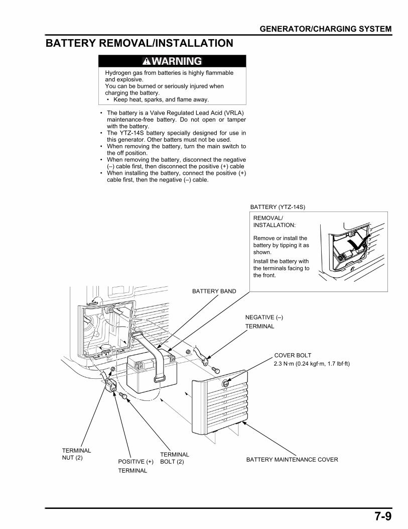
7-9
dummyheaddummyhead
GENERATOR/CHARGING SYSTEM
BATTERY REMOVAL/INSTALLATION
• The battery is a Valve Regulated Lead Acid (VRLA)maintenance-free battery. Do not open or tamperwith the battery.
• The YTZ-14S battery specially designed for use inthis generator. Other batters must not be used.
• When removing the battery, turn the main switch tothe off position.
• When removing the battery, disconnect the negative(–) cable first, then disconnect the positive (+) cable
• When installing the battery, connect the positive (+)cable first, then the negative (–) cable.
Hydrogen gas from batteries is highly flammable and explosive.You can be burned or seriously injured when charging the battery. • Keep heat, sparks, and flame away.
POSITIVE (+)
TERMINAL
COVER BOLT
TERMINAL NUT (2) BATTERY MAINTENANCE COVER
BATTERY (YTZ-14S)
REMOVAL/INSTALLATION:
Remove or install the battery by tipping it as shown.
Install the battery with the terminals facing to the front.
BATTERY BAND
NEGATIVE (–)
TERMINAL
TERMINAL BOLT (2)
2.3 N·m (0.24 kgf·m, 1.7 lbf·ft)
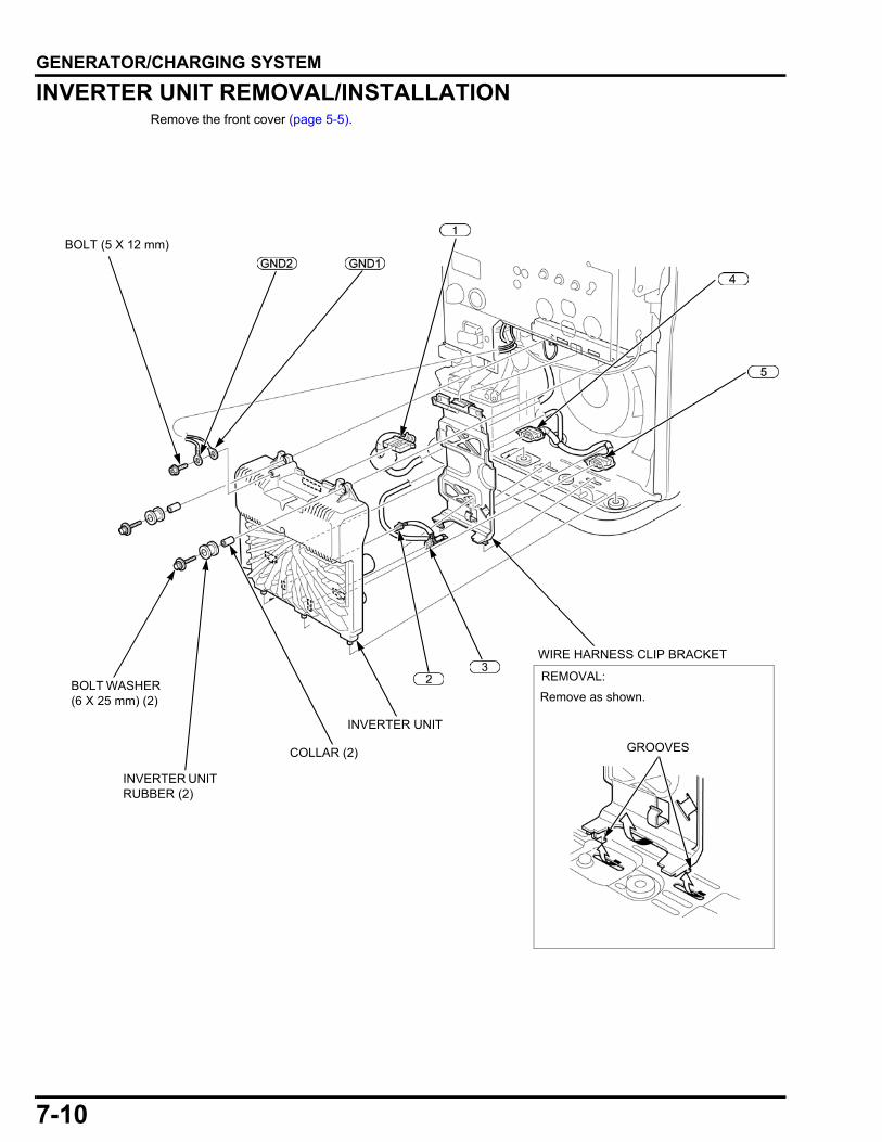
7-10
dummyheaddummyhead
GENERATOR/CHARGING SYSTEM
INVERTER UNIT REMOVAL/INSTALLATIONRemove the front cover (page 5-5).
BOLT WASHER (6 X 25 mm) (2)
COLLAR (2)
INVERTER UNIT
BOLT (5 X 12 mm)
INVERTER UNIT RUBBER (2)
WIRE HARNESS CLIP BRACKET
REMOVAL:
Remove as shown.
GROOVES
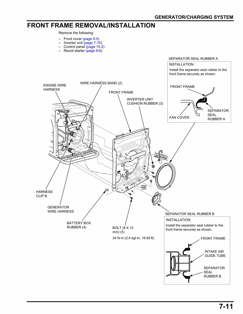
7-11
dummyheaddummyhead
GENERATOR/CHARGING SYSTEM
FRONT FRAME REMOVAL/INSTALLATIONRemove the following:
– Front cover (page 5-5)– Inverter unit (page 7-10)– Control panel (page 10-2)– Recoil starter (page 9-6)
ENGINE WIRE HARNESS
BATTERY BOX RUBBER (4) BOLT (8 X 12
mm) (5)
FRONT FRAME
HARNESS CLIP B
WIRE HARNESS BAND (2)
INVERTER UNIT CUSHION RUBBER (3)
GENERATOR WIRE HARNESS
SEPARATOR SEAL RUBBER B
Install the separator seal rubber to the front frame securely as shown.
SEPARATOR SEAL RUBBER B
FRONT FRAME
Install the separator seal rubber to the front frame securely as shown.
SEPARATOR SEAL RUBBER A
INSTALLATION:
FRONT FRAME
FAN COVER
SEPARATOR SEAL RUBBER A
24 N·m (2.4 kgf·m, 18 lbf·ft)
INTAKE AIR GUIDE TUBE
INSTALLATION:
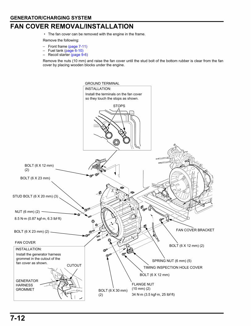
7-12
dummyheaddummyhead
GENERATOR/CHARGING SYSTEM
FAN COVER REMOVAL/INSTALLATION • The fan cover can be removed with the engine in the frame.
Remove the following:
– Front frame (page 7-11)– Fuel tank (page 6-10)– Recoil starter (page 9-6)
Remove the nuts (10 mm) and raise the fan cover until the stud bolt of the bottom rubber is clear from the fancover by placing wooden blocks under the engine.
GROUND TERMINAL
Install the terminals on the fan cover so they touch the stops as shown.
BOLT (6 X 12 mm) (2)
CUTOUT
FAN COVER
Install the generator harness grommet in the cutout of the fan cover as shown.
GENERATOR HARNESS GROMMET
BOLT (6 X 23 mm)
FLANGE NUT (10 mm) (2)
BOLT (6 X 23 mm) (2)
BOLT (6 X 30 mm) (2)
BOLT (6 X 12 mm)
SPRING NUT (6 mm) (5)
BOLT (6 X 12 mm) (2)
FAN COVER BRACKET
8.5 N·m (0.87 kgf·m, 6.3 lbf·ft)
34 N·m (3.5 kgf·m, 25 lbf·ft)
NUT (6 mm) (2)
TIMING INSPECTION HOLE COVER
STOPS
STUD BOLT (6 X 20 mm) (3)
INSTALLATION:
INSTALLATION:

7-13
dummyheaddummyhead
GENERATOR/CHARGING SYSTEM
COOLING FAN REMOVAL/INSTALLATIONRemove the following:
– Fan cover (page 7-12)– CKP sensor (page 8-7)
BOLT (10 X 25 mm)
REMOVAL/INSTALLATION:
Remove the CKP SENSOR, and hold the rotor with a commercially available strap wrench and loosen or tighten the flange bolt.
Take care not to damage the fan.
Install the cooling fan by aligning the four lugs with the holes of the rotor.
COOLING FAN
Tighten the bolts in a crisscross pattern in two or three steps.
STRAP WRENCH (Commercially available)
LUG HOLE STARTER PULLEY
RECOIL PULLEY ADAPTER
WASHER (10 mm)
BOLT (6 X 35 mm) (4)
INSTALLATION:
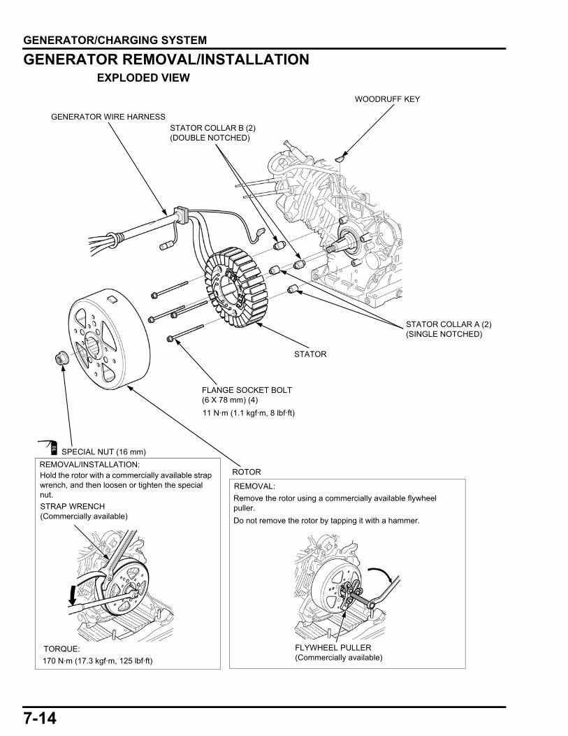
7-14
dummyheaddummyhead
GENERATOR/CHARGING SYSTEM
GENERATOR REMOVAL/INSTALLATIONEXPLODED VIEW
Remove the rotor using a commercially available flywheel puller.
Do not remove the rotor by tapping it with a hammer.
Hold the rotor with a commercially available strap wrench, and then loosen or tighten the special nut.
GENERATOR WIRE HARNESS
STATOR COLLAR B (2) (DOUBLE NOTCHED)
STATOR COLLAR A (2) (SINGLE NOTCHED)
STATOR
11 N·m (1.1 kgf·m, 8 lbf·ft)
FLANGE SOCKET BOLT(6 X 78 mm) (4)
WOODRUFF KEY
SPECIAL NUT (16 mm)
REMOVAL/INSTALLATION:
FLYWHEEL PULLER (Commercially available)
TORQUE:
170 N·m (17.3 kgf·m, 125 lbf·ft)
STRAP WRENCH (Commercially available)
ROTOR
REMOVAL:
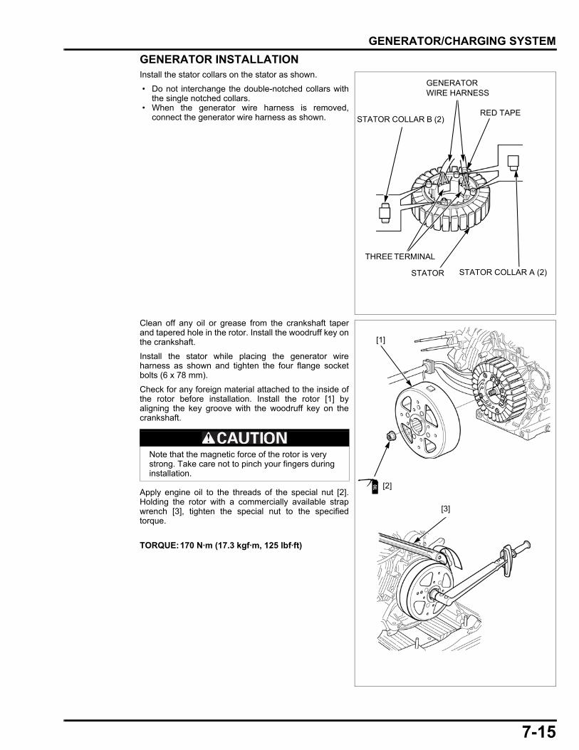
7-15
dummyheaddummyhead
GENERATOR/CHARGING SYSTEM
GENERATOR INSTALLATIONInstall the stator collars on the stator as shown.
• Do not interchange the double-notched collars withthe single notched collars.
• When the generator wire harness is removed,connect the generator wire harness as shown.
Clean off any oil or grease from the crankshaft taperand tapered hole in the rotor. Install the woodruff key onthe crankshaft.
Install the stator while placing the generator wireharness as shown and tighten the four flange socketbolts (6 x 78 mm).
Check for any foreign material attached to the inside ofthe rotor before installation. Install the rotor [1] byaligning the key groove with the woodruff key on thecrankshaft.
Apply engine oil to the threads of the special nut [2].Holding the rotor with a commercially available strapwrench [3], tighten the special nut to the specifiedtorque.
RED TAPE
STATOR
STATOR COLLAR B (2)
STATOR COLLAR A (2)
THREE TERMINAL
GENERATOR WIRE HARNESS
Note that the magnetic force of the rotor is very strong. Take care not to pinch your fingers during installation.
TORQUE:170 N·m (17.3 kgf·m, 125 lbf·ft)
[1]
[3]
[2]
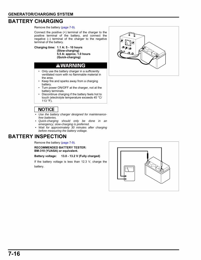
7-16
dummyheaddummyhead
GENERATOR/CHARGING SYSTEM
BATTERY CHARGINGRemove the battery (page 7-9).
Connect the positive (+) terminal of the charger to thepositive terminal of the battery, and connect thenegative (–) terminal of the charger to the negativeterminal of the battery.
• Use the battery charger designed for maintenance-free batteries.
• Quick-charging should only be done in anemergency; slow-charging is preferred.
• Wait for approximately 30 minutes after chargingbefore measuring the battery voltage.
BATTERY INSPECTIONRemove the battery (page 7-9).
RECOMMENDED BATTERY TESTER:BM-310 (YUASA) or equivalent.
If the battery voltage is less than 12.3 V, charge the
battery.
Charging time: 1.1 A: 5 - 10 hours (Slow-charging)5.5 A: approx. 1.0 hours (Quick-charging)
• Only use the battery charger in a sufficiently ventilated room with no flammable material in the area.
• Keep fire and sparks away from a charging battery.
• Turn power ON/OFF at the charger, not at the battery terminals.
• Discontinue charging if the battery feels hot to touch (electrolyte temperature exceeds 45 °C/113 °F).
Battery voltage: 13.0 - 13.2 V (Fully charged)

7-17
dummyheaddummyhead
GENERATOR/CHARGING SYSTEM
STATOR INSPECTIONTurn the main switch OFF.
Remove the inverter unit (page 7-10).
Pull the recoil starter and measure the voltage betweenthe terminals of the generator 3P connectors (and ) with the generator mounted.
If the output voltage is less than the standard voltage, Measure the resistance between the terminals of thegenerator 3P connectors ( and ) according to the table below.
If the resistance is out of the specification, check thestator coil resistance according to the table below.
If all resistances are OK, replace or repair the generatorwire harness.
If the resistance is out of specification, replace thestator.
Generator Connector Terminal number Specific voltage
Master
1 - 2
AC 15 V or more2 - 3
1 - 3
Slave
1 - 2
AC 15 V or more2 - 3
1 - 3
Generator Connector Terminal number Standard resistance
Master
1 - 2
0.44 - 0.62 Ω2 - 3
1 - 3
Slave
1 - 2
0.44 - 0.62 Ω2 - 3
1 - 3
Stator Terminal number
Standard resistance
Master
N 1 - U 1
0.22 - 0.31 ΩN 1 - V 1
N 1 - W 1
Slave
N 2 - U 2
0.22 - 0.31 ΩN 2 - V 2
N 2 - W 2
N 2
N 1
V 2
W 1V 1
W 2
U 2
U 1
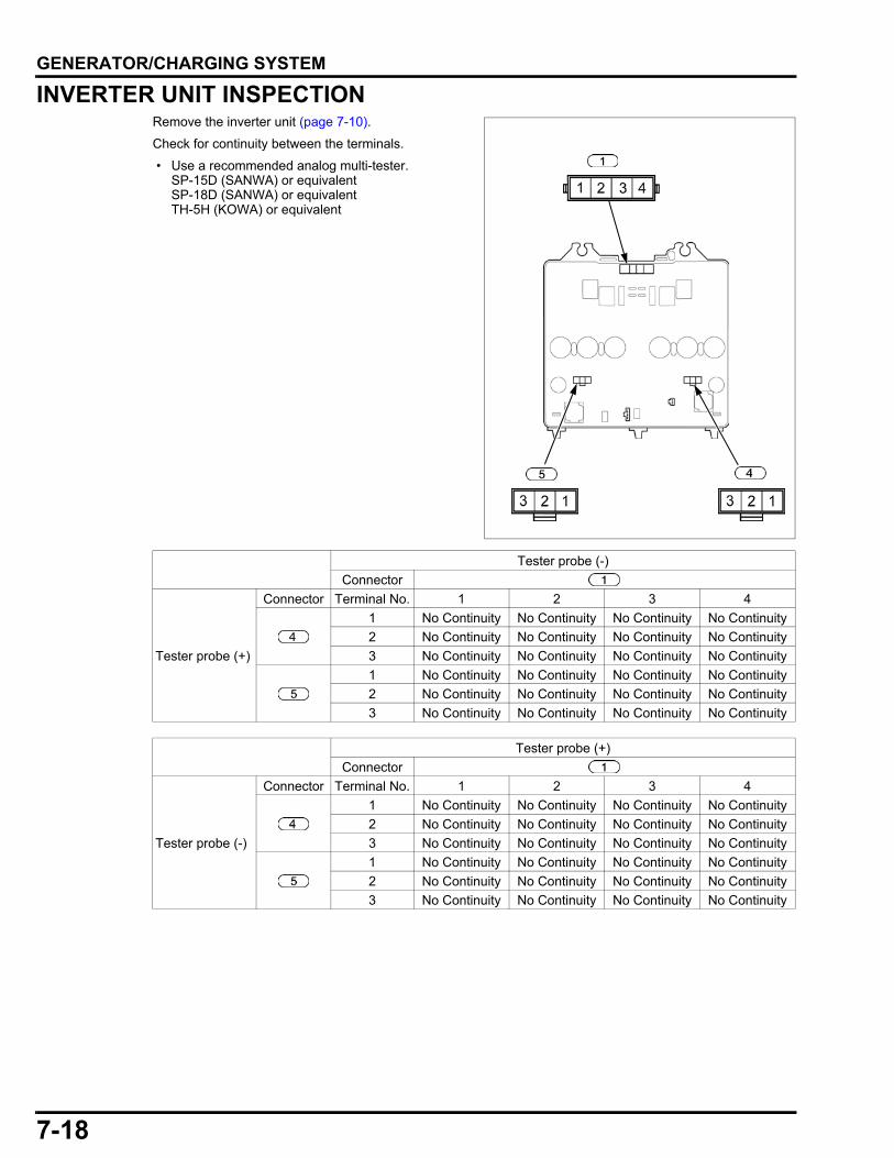
7-18
dummyheaddummyhead
GENERATOR/CHARGING SYSTEM
INVERTER UNIT INSPECTIONRemove the inverter unit (page 7-10).
Check for continuity between the terminals.
• Use a recommended analog multi-tester.SP-15D (SANWA) or equivalentSP-18D (SANWA) or equivalentTH-5H (KOWA) or equivalent
Tester probe (-)
Connector
Tester probe (+)
Connector Terminal No. 1 2 3 4
1 No Continuity No Continuity No Continuity No Continuity
2 No Continuity No Continuity No Continuity No Continuity
3 No Continuity No Continuity No Continuity No Continuity
1 No Continuity No Continuity No Continuity No Continuity
2 No Continuity No Continuity No Continuity No Continuity
3 No Continuity No Continuity No Continuity No Continuity
Tester probe (+)
Connector
Tester probe (-)
Connector Terminal No. 1 2 3 4
1 No Continuity No Continuity No Continuity No Continuity
2 No Continuity No Continuity No Continuity No Continuity
3 No Continuity No Continuity No Continuity No Continuity
1 No Continuity No Continuity No Continuity No Continuity
2 No Continuity No Continuity No Continuity No Continuity
3 No Continuity No Continuity No Continuity No Continuity
8-1
8
dummytext
8. IGNITION SYSTEM
IGNITION SYSTEM TROUBLESHOOTING···································8-2
IGNITION COIL REMOVAL/INSTALLATION·············································8-6
CKP SENSOR REMOVAL/INSTALLATION·············································8-7
CKP SENSOR AIR GAP ADJUSTMENT······8-8
SPARK TEST ················································ 8-8
CKP SENSOR INSPECTION ························ 8-9
IGNITION COIL INSPECTION ······················ 8-9
SPARK PLUG CAP INSPECTION·············· 8-10
OIL LEVEL SWITCH INSPECTION ············ 8-10
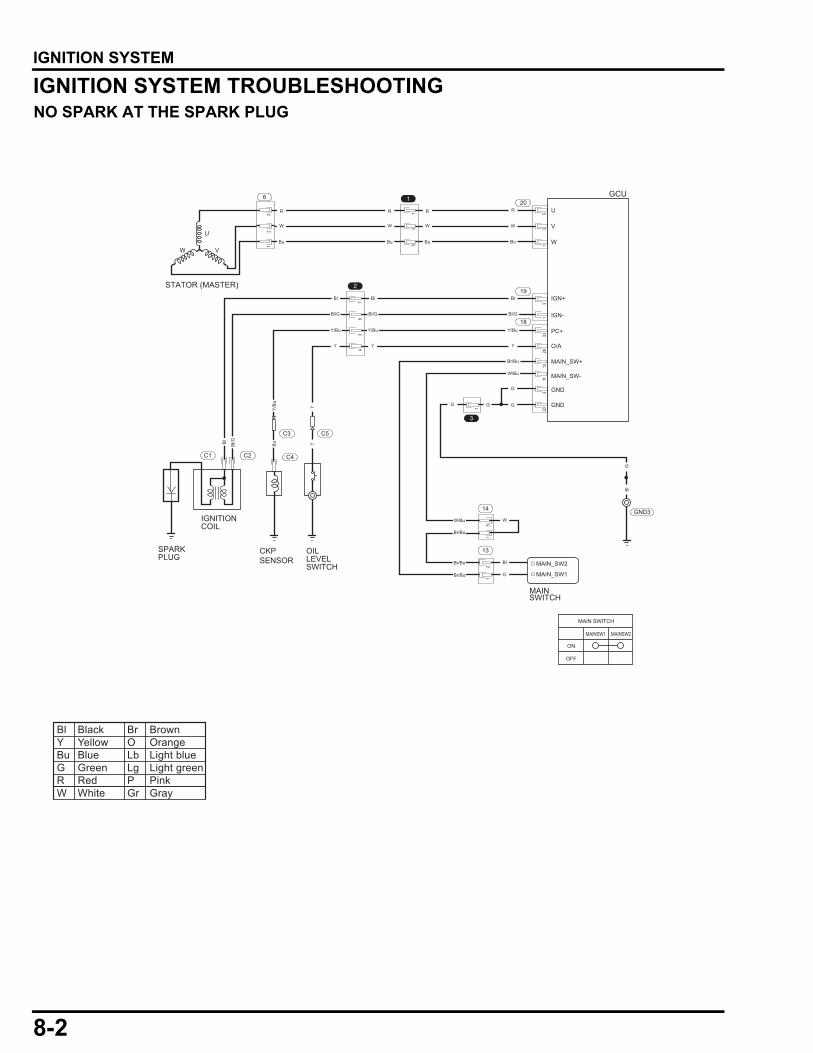
8-2
dummyheaddummyhead
IGNITION SYSTEMIGNITION SYSTEM
IGNITION SYSTEM TROUBLESHOOTINGNO SPARK AT THE SPARK PLUG
G
G
GG
3
1
19
18
Bl/G
Y/Bu Y/Bu Y/Bu
Y/B
uB
uBl
Bl
W/Bu
Br/Bu
Br/Bu
Br/Bu
Br/Bu
Bl
W
G
MAIN_SW+
MAIN_SW-W/Bu
GND
GND
YY
Bl Bl Bl
Bl/G Bl/G Bl/G
Y
YY
2
14
13
MAIN_SW1
MAIN_SW2
MAINSWITCH
GCU
MAIN SWITCH
ON
OFF
U
V
W
20R
W
Bu
1
U
VW
STATOR (MASTER)
6
R
W
Bu
R
W
Bu
R
W
Bu
IGN+
IGN-
PC+
O/A
SPARKPLUG
IGNITIONCOIL
C2C1
OILLEVELSWITCH
CKPSENSOR
C4
C3 C5
GND3
G
78
3
32
1
4
12
15
53
1
12
133
2812
113
203
5
MAINSW1 MAINSW2
Bl Black Br BrownY Yellow O OrangeBu Blue Lb Light blueG Green Lg Light greenR Red P PinkW White Gr Gray

8-3
dummyheaddummyhead
IGNITION SYSTEM
Check whether the Oil Alert indicator is ON and “OIL” is displayed on the i-Monitor with the main switch is turned ON and the starter switch is pressed.
See OIL in SELF-DIAGNOSTIC TROUBLESHOOTING (page 4-9).
Check whether an error code is displayed on the i-Monitor with the main switch is turned ON and the starter switch is pressed.
Displayed
Not displayed
Perform the SELF-DIAGNOSTIC TROUBLESHOOTING (page 4-9).
Displayed
Not displayed
Go to page 8-4
Check whether the i-Monitor is on when the main switch is turned ON. Perform the i-MONITOR DOES NOT DISPLAY BY MAIN SWITCH TURNED ON (page 4-19).
OFF
ON
Replace or repair the wire harness.Abnormal
Check the "NO SPARK AT SPARK PLUG" of the GCU inspection(page 10-9).
Replace the GCU.
Normal
Abnormal
Normal
17 14 1316 153233 3031 27 2629 28
1112 910 6 58 72425 2223 1821 20
34 1
Y
18GCU
48765
32184 3 2 1
567
2Y
C5
Check the wire harness between the oil level switch and GCU for an open or short circuit.
Check the oil level switch (page 8-10). Replace the oil level switch(page 14-3).
Normal
Abnormal

8-4
dummyheaddummyhead
IGNITION SYSTEM
Replace or repair the wire harness.Abnormal
Normal
From page 8-3
Check the ignition coil (page 8-9). Replace the ignition coil (page 8-6).Abnormal
Normal
Go to page 8-5
Replace or repair the wire harness.Abnormal
Check the CKP sensor (page 8-8). Replace the CKP sensor (page 8-7).
Normal
Abnormal
Normal
Bl
GCU
48765
32184 3 2 1
567
2Bl
12
19
Bl/G
Bl/G
C1 C2
IGNITIONCOIL
Check the wire harness between the ignition coil and GCU for an open circuit.
17 14 1316 153233 3031 27 2629 28
1112 910 6 58 72425 2223 1821 20
34 1
Y/Bu
18GCU
48765
32184 3 2 1
567
2Y/Bu
C3
Check the wire harness between the CKP sensor and GCU for an open or short circuit.
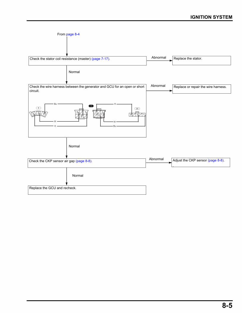
8-5
dummyheaddummyhead
IGNITION SYSTEM
From page 8-4
Replace or repair the wire harness.Abnormal
5 3 1
20
35
15
3 1
1
123
6
R
W
BuR
W
Bu
Normal
Check the stator coil resistance (master) (page 7-17). Replace the stator.Abnormal
Check the CKP sensor air gap (page 8-8). Adjust the CKP sensor (page 8-8).
.
Replace the GCU and recheck.
Normal
Abnormal
Normal
Check the wire harness between the generator and GCU for an open or short circuit.
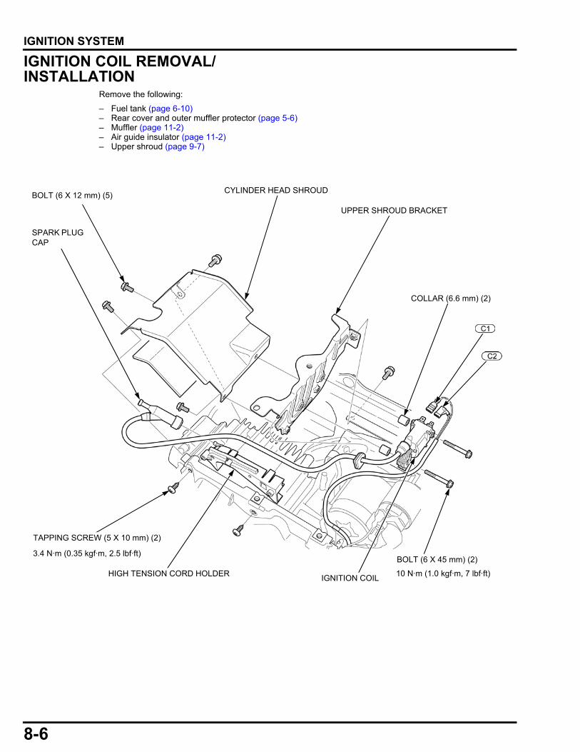
8-6
dummyheaddummyhead
IGNITION SYSTEM
IGNITION COIL REMOVAL/INSTALLATION
Remove the following:
– Fuel tank (page 6-10)– Rear cover and outer muffler protector (page 5-6)– Muffler (page 11-2)– Air guide insulator (page 11-2)– Upper shroud (page 9-7)
SPARK PLUG CAP
TAPPING SCREW (5 X 10 mm) (2)
10 N·m (1.0 kgf·m, 7 lbf·ft)IGNITION COIL
BOLT (6 X 45 mm) (2)
CYLINDER HEAD SHROUD
HIGH TENSION CORD HOLDER
COLLAR (6.6 mm) (2)
3.4 N·m (0.35 kgf·m, 2.5 lbf·ft)
UPPER SHROUD BRACKET
BOLT (6 X 12 mm) (5)
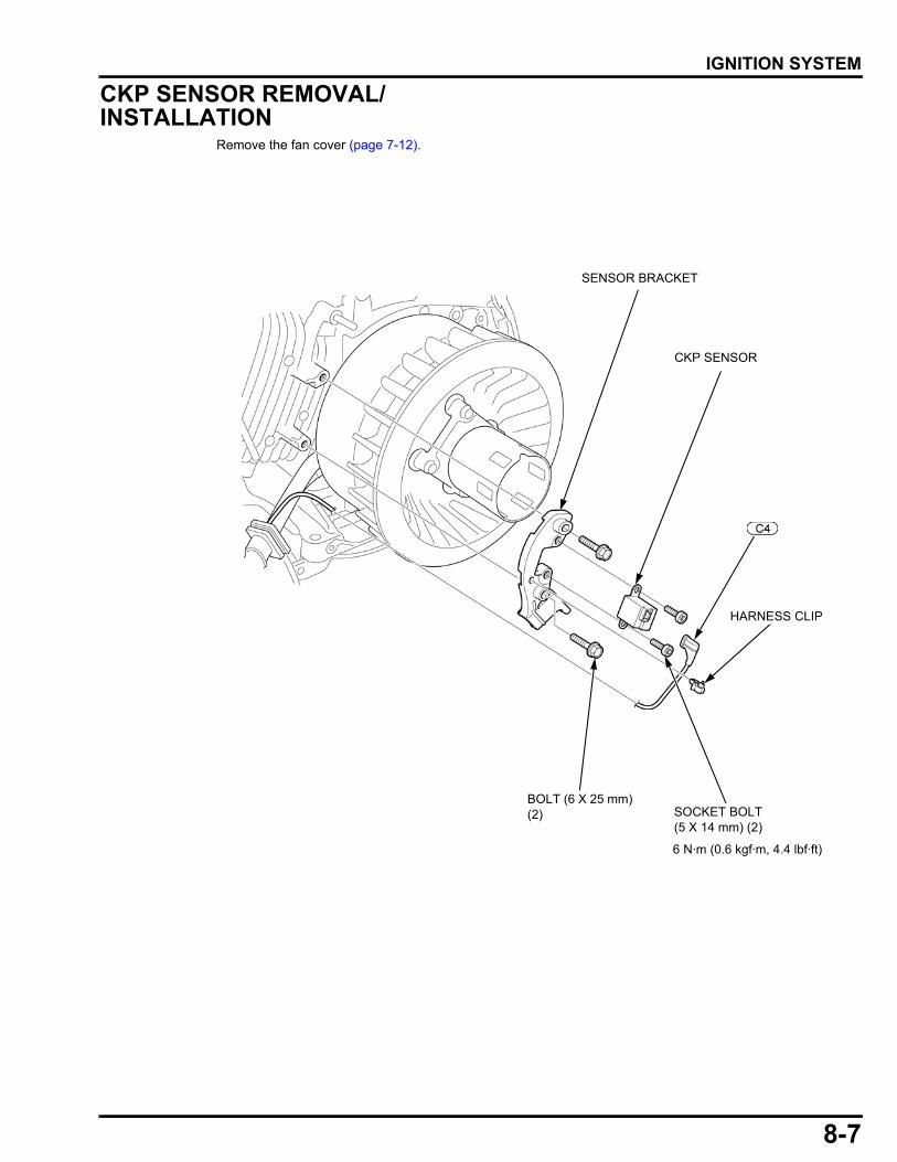
8-7
dummyheaddummyhead
IGNITION SYSTEM
CKP SENSOR REMOVAL/INSTALLATION
Remove the fan cover (page 7-12).
BOLT (6 X 25 mm) (2) SOCKET BOLT
(5 X 14 mm) (2)
CKP SENSOR
6 N·m (0.6 kgf·m, 4.4 lbf·ft)
SENSOR BRACKET
HARNESS CLIP
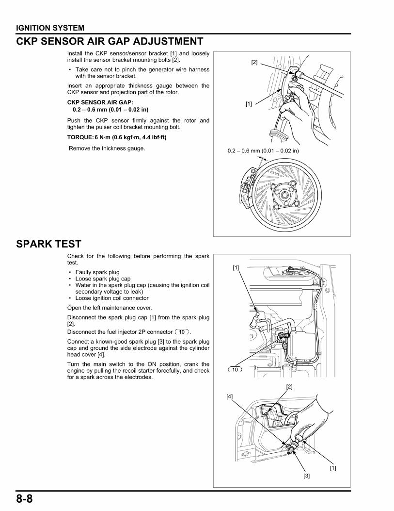
8-8
dummyheaddummyhead
IGNITION SYSTEM
CKP SENSOR AIR GAP ADJUSTMENTInstall the CKP sensor/sensor bracket [1] and looselyinstall the sensor bracket mounting bolts [2].
• Take care not to pinch the generator wire harnesswith the sensor bracket.
Insert an appropriate thickness gauge between theCKP sensor and projection part of the rotor.
Push the CKP sensor firmly against the rotor andtighten the pulser coil bracket mounting bolt.
Remove the thickness gauge.
SPARK TESTCheck for the following before performing the sparktest.
• Faulty spark plug • Loose spark plug cap • Water in the spark plug cap (causing the ignition coil
secondary voltage to leak) • Loose ignition coil connector
Open the left maintenance cover.
Disconnect the spark plug cap [1] from the spark plug[2].Disconnect the fuel injector 2P connector .
Connect a known-good spark plug [3] to the spark plugcap and ground the side electrode against the cylinderhead cover [4].
Turn the main switch to the ON position, crank theengine by pulling the recoil starter forcefully, and checkfor a spark across the electrodes.
CKP SENSOR AIR GAP:0.2 – 0.6 mm (0.01 – 0.02 in)
TORQUE:6 N·m (0.6 kgf·m, 4.4 lbf·ft)
0.2 – 0.6 mm (0.01 – 0.02 in)
[1]
[2]
[4]
[2]
[1]
[3]
[1]

8-9
dummyheaddummyhead
IGNITION SYSTEM
CKP SENSOR INSPECTIONRemove the air cleaner bracket (page 6-13).
Disconnect the CKP sensor wire connector .
Measure the resistance between the terminal andground.
IGNITION COIL INSPECTIONPRIMARY SIDERemove the upper shroud (page 9-7).
Disconnect the ignition coil primary wire connectors( and ).
Measure the resistance of the primary coil by attachingthe ohmmeter leads to the ignition coil wire terminals.
• Use a recommended analog multi-tester.SP-15D (SANWA) or equivalentSP-18D (SANWA) or equivalentTH-5H (KOWA) or equivalent
If the measured resistance is out of specification,replace the ignition coil.
SECONDARY SIDERemove the upper shroud (page 9-7).
Disconnect the ignition coil primary wire connectors( and ).
Measure the resistance of the secondary coil byattaching one ohmmeter lead to the ignition coil wireterminal (Black) and the other to the spark plug capend.
• Use a recommended analog multi-tester.SP-15D (SANWA) or equivalentSP-18D (SANWA) or equivalentTH-5H (KOWA) or equivalent
If the measured resistance is out of specification,replace the ignition coil.
Specified resistance: 297 - 363 Ω (at 20 °C/68 °F)
RESISTANCE: 1.8 – 2.2 Ω
RESISTANCE: 5.6 – 6.9 kΩ

8-10
dummyheaddummyhead
IGNITION SYSTEM
SPARK PLUG CAP INSPECTIONRemove the spark plug cap from the high tension cord.
Measure the resistance of the spark plug cap byattaching one ohmmeter lead to the terminal in thespark plug cap and the other to the terminal connectedto the high tension cord terminal.
If the measured resistance is out of specification,replace the spark plug cap.
OIL LEVEL SWITCH INSPECTIONSYSTEM INSPECTIONRemove the right side shroud (page 5-3).
Disconnect the oil level switch wire connector .
Check continuity between the oil level switch wireconnector switch side (Yellow) terminal andengine ground [1].
There should be no continuity when the engine is full ofoil.
If the correct continuity is not obtained, inspect the oillevel switch.
SWITCH INSPECTIONRemove the oil level switch (page 14-3).
Check continuity between the oil level switch [1] wireconnector (Yellow) terminal and switch body withan ohmmeter.
Check the float by dipping the switch into a container ofoil. The ohmmeter reading should go from continuity tono continuity as the switch is lowered into the oil.
RESISTANCE: 7.5 – 12.5 kΩ
[1]
LOW OIL LEVEL (CONTINUITY)
NORMAL OIL LEVEL (NO CONTINUITY)
[1]

9-1
9
dummytext
9. STARTING SYSTEM
STARTING SYSTEM TROUBLESHOOTING···································9-2
RECOIL STARTER REMOVAL/INSTALLATION·············································9-6
UPPER SHROUD REMOVAL/INSTALLATION·············································9-7
STARTER MOTOR REMOVAL/INSTALLATION·············································9-8
INNER MUFFLER PROTECTOR REMOVAL/INSTALLATION··························9-9
FLYWHEEL REMOVAL ······························ 9-10
FLYWHEEL INSTALLATION······················ 9-10
RECOIL STARTER DISASSEMBLY/ASSEMBLY················································· 9-11
RECOIL STARTER INSPECTION ·············· 9-14
STARTER MOTOR DISASSEMBLY/ASSEMBLY················································· 9-15
STARTER MOTOR INSPECTION ·············· 9-16
BRUSH REPLACEMENT···························· 9-18
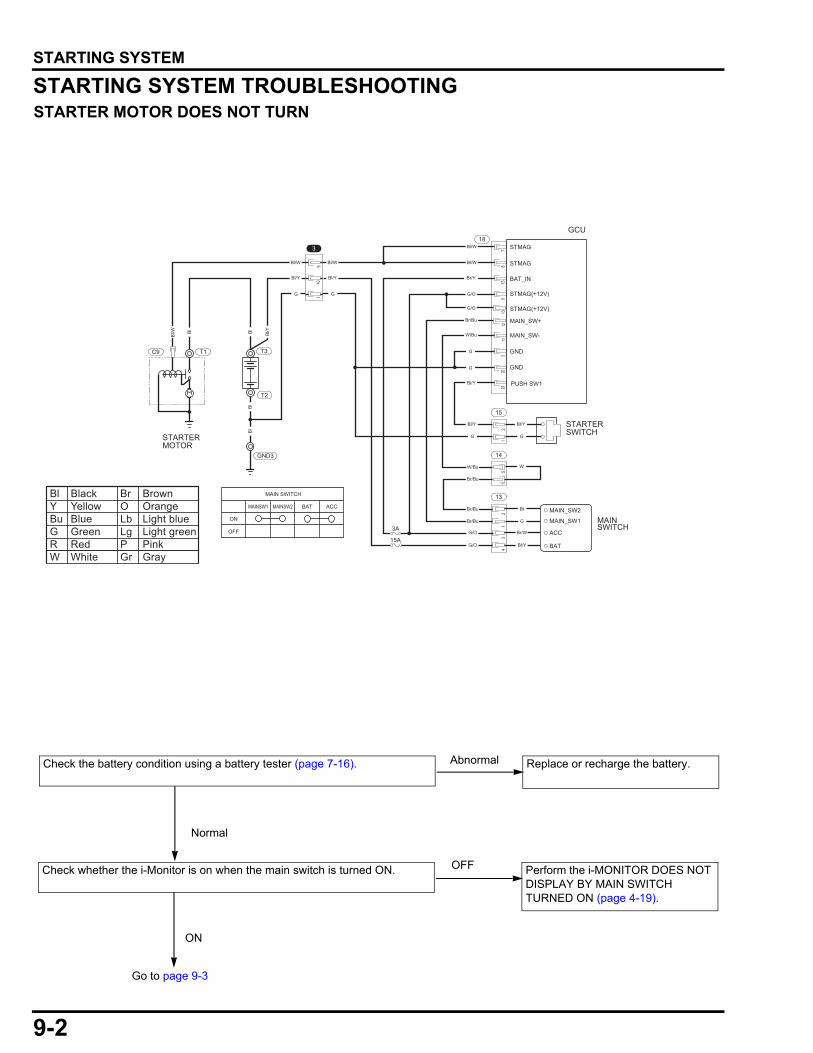
9-2
dummyheaddummyhead
STARTING SYSTEMSTARTING SYSTEM
STARTING SYSTEM TROUBLESHOOTINGSTARTER MOTOR DOES NOT TURN
78
13
18
15
BAT_IN
9
Bl/WBl/W
Bl/Y
Bl/W
Bl/Y
Bl/Y
W/Bu
Br/Bu
Br/Bu
Br/Bu
G/O
G/O
Bl
G
Br/W
Bl/Y
MAIN_SW+
MAIN_SW-
1012
Br/Y
Br/Bu
W/Bu
GND
GND
113
2029
G/O
G/O
G
Bl/W
Bl/Y
G
G
G
G
W
Bl/Y
G
3
110
9
2
14
51
113
21
34
STMAG
STMAG
STMAG(+12V)
STMAG(+12V)
PUSH SW1
STARTERSWITCH
Bl
Bl
Bl
Bl/YBl
Bl/W
15A
3AMAIN_SW1
MAIN_SW2
ACC
BAT
MAINSWITCH
T3
T2
STARTERMOTOR
T1C9
GND3
GCU
MAIN SWITCH
MAINSW1 MAINSW2 BAT ACC
ON
OFF
Bl Black Br BrownY Yellow O OrangeBu Blue Lb Light blueG Green Lg Light greenR Red P PinkW White Gr Gray
Go to page 9-3
Check whether the i-Monitor is on when the main switch is turned ON. Perform the i-MONITOR DOES NOT DISPLAY BY MAIN SWITCH TURNED ON (page 4-19).
OFF
ON
Check the battery condition using a battery tester (page 7-16). Replace or recharge the battery.
Normal
Abnormal
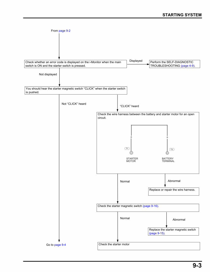
9-3
dummyheaddummyhead
STARTING SYSTEM
Check the starter motor
.
Check the starter magnetic switch (page 9-16).
Replace the starter magnetic switch (page 9-15).
AbnormalNormal
Go to page 9-4
Check whether an error code is displayed on the i-Monitor when the main switch is ON and the starter switch is pressed.
Perform the SELF-DIAGNOSTIC TROUBLESHOOTING (page 4-9).
You should hear the starter magnetic switch “CLICK” when the starter switch is pushed.
“CLICK” heardNot “CLICK” heard
Replace or repair the wire harness.
AbnormalNormal
Displayed
Not displayed
T1 T3
Bl
STARTERMOTOR
BATTERYTERMINAL
Bl
From page 9-2
Check the wire harness between the battery and starter motor for an open circuit.
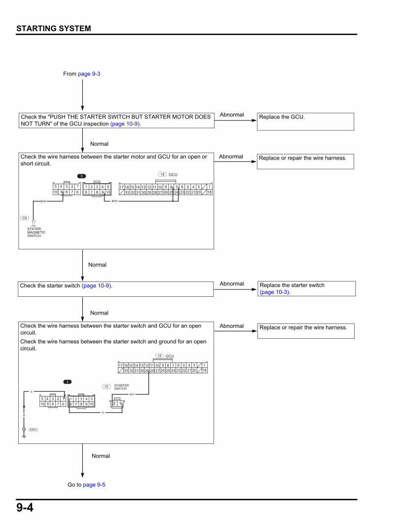
9-4
dummyheaddummyhead
STARTING SYSTEM
Replace or repair the wire harness.Abnormal
From page 9-3
Normal
Check the starter switch (page 10-9).
Normal
Replace the starter switch(page 10-3).
Abnormal
Go to page 9-5
Replace or repair the wire harness.Abnormal
94 3 2 1
678510
49876
321105 17 14 1316 15
3233 3031 27 2629 281112 910 6 58 7
2425 2223 1821 2034 1
3 18
C9
Bl/W Bl/W
GCU
STATERMAGNETICSWITCH
94 3 2 1
678510
49876
321105
17 14 1316 153233 3031 27 2629 28
1112 910 6 58 72425 2223 1821 20
34 1
3
18
G
GCU
STARTERSWITCH
12
Bl/YG
15
GND3
Bl
Check the wire harness between the starter motor and GCU for an open or short circuit.
Check the wire harness between the starter switch and GCU for an open circuit.
Check the wire harness between the starter switch and ground for an open circuit.
Normal
AbnormalCheck the "PUSH THE STARTER SWITCH BUT STARTER MOTOR DOES NOT TURN" of the GCU inspection (page 10-9).
Replace the GCU.
Normal
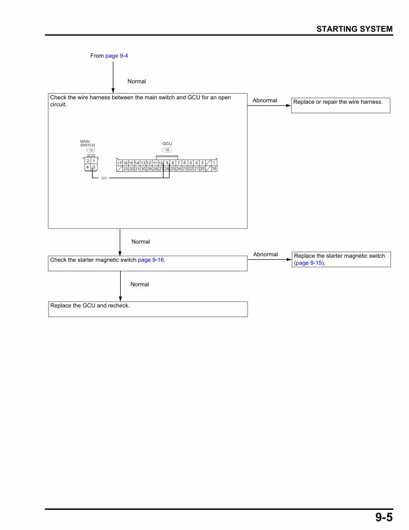
9-5
dummyheaddummyhead
STARTING SYSTEM
From page 9-4
Check the starter magnetic switch page 9-16.
Replace or repair the wire harness.Abnormal
Normal
Normal
Replace the GCU and recheck.
Normal
Replace the starter magnetic switch (page 9-15).
Abnormal
17 14 1316 153233 3031 27 2629 28
1112 910 6 58 72425 2223 1821 20
34 1
G/O
18GCU
124 3
13
MAINSWITCH
Check the wire harness between the main switch and GCU for an open circuit.
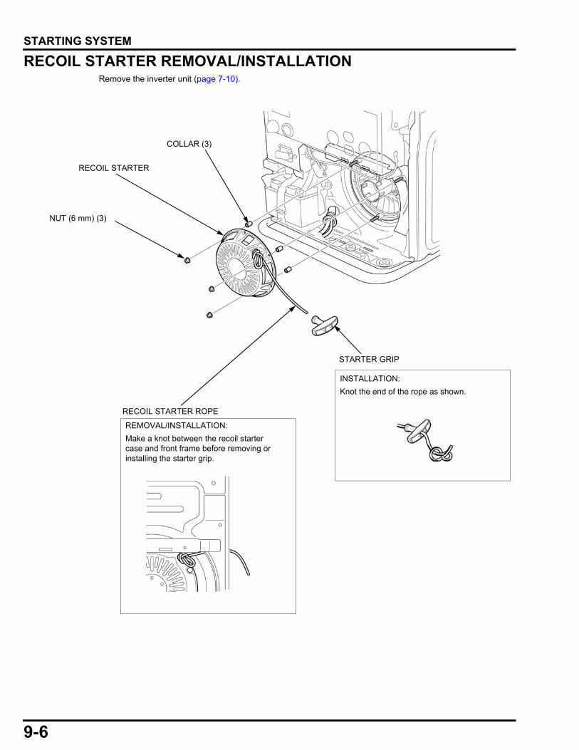
9-6
dummyheaddummyhead
STARTING SYSTEM
RECOIL STARTER REMOVAL/INSTALLATIONRemove the inverter unit (page 7-10).
NUT (6 mm) (3)
STARTER GRIP
RECOIL STARTER
REMOVAL/INSTALLATION:
RECOIL STARTER ROPE
Make a knot between the recoil starter case and front frame before removing or installing the starter grip.
COLLAR (3)
INSTALLATION:
Knot the end of the rope as shown.
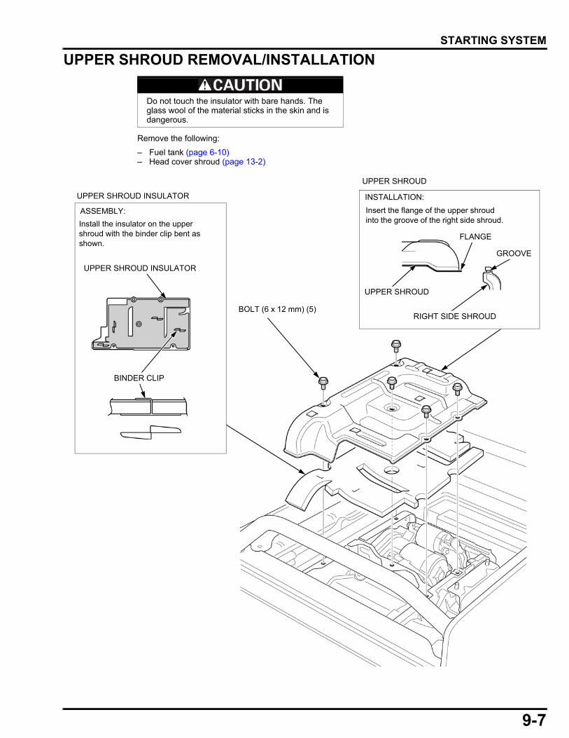
9-7
dummyheaddummyhead
STARTING SYSTEM
UPPER SHROUD REMOVAL/INSTALLATION
Remove the following:
– Fuel tank (page 6-10)– Head cover shroud (page 13-2)
Do not touch the insulator with bare hands. The glass wool of the material sticks in the skin and is dangerous.
BOLT (6 x 12 mm) (5)
UPPER SHROUD INSULATOR
ASSEMBLY:
Install the insulator on the upper shroud with the binder clip bent as shown.
UPPER SHROUD INSULATOR
BINDER CLIP
UPPER SHROUD
INSTALLATION:
Insert the flange of the upper shroud into the groove of the right side shroud.
UPPER SHROUD
RIGHT SIDE SHROUD
GROOVE
FLANGE
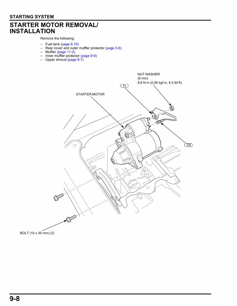
9-8
dummyheaddummyhead
STARTING SYSTEM
STARTER MOTOR REMOVAL/INSTALLATION
Remove the following:
– Fuel tank (page 6-10)– Rear cover and outer muffler protector (page 5-6)– Muffler (page 11-2)– Inner muffler protector (page 9-9)– Upper shroud (page 9-7)
STARTER MOTOR
NUT WASHER (8 mm)
BOLT (10 x 35 mm) (2)
8.8 N·m (0.90 kgf·m, 6.5 lbf·ft)
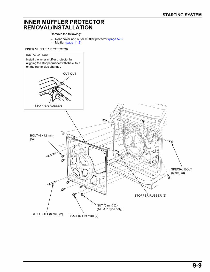
9-9
dummyheaddummyhead
STARTING SYSTEM
INNER MUFFLER PROTECTOR REMOVAL/INSTALLATION
Remove the following:
– Rear cover and outer muffler protector (page 5-6)– Muffler (page 11-2)
SPECIAL BOLT (6 mm) (3)
STOPPER RUBBER (2)
STUD BOLT (8 mm) (2)BOLT (8 x 16 mm) (2)
BOLT (6 x 12 mm) (5)
NUT (6 mm) (2) (AT, AT1 type only)
INNER MUFFLER PROTECTOR
INSTALLATION:
Install the inner muffler protector by aligning the stopper rubber with the cutout on the frame side channel.
STOPPER RUBBER
CUT OUT
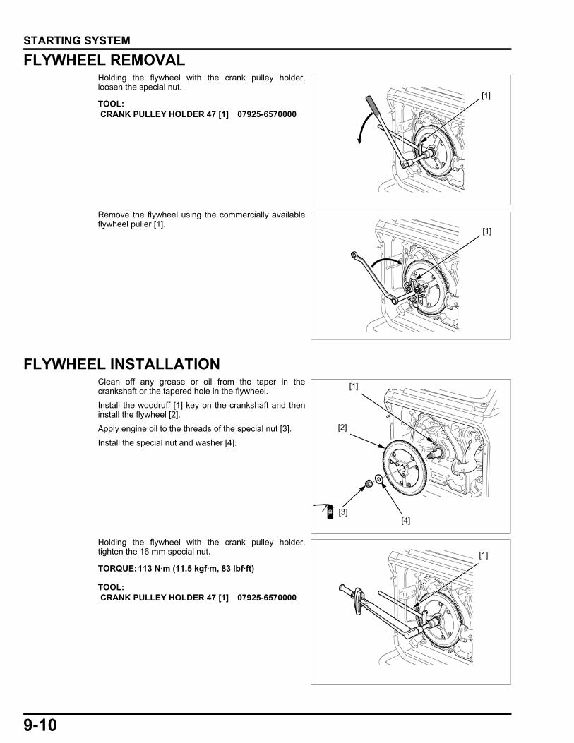
9-10
dummyheaddummyhead
STARTING SYSTEM
FLYWHEEL REMOVALHolding the flywheel with the crank pulley holder,loosen the special nut.
Remove the flywheel using the commercially availableflywheel puller [1].
FLYWHEEL INSTALLATIONClean off any grease or oil from the taper in thecrankshaft or the tapered hole in the flywheel.
Install the woodruff [1] key on the crankshaft and theninstall the flywheel [2].
Apply engine oil to the threads of the special nut [3].
Install the special nut and washer [4].
Holding the flywheel with the crank pulley holder,tighten the 16 mm special nut.
TOOL: CRANK PULLEY HOLDER 47 [1] 07925-6570000
[1]
[1]
[2]
[1]
[3][4]
TORQUE:113 N·m (11.5 kgf·m, 83 lbf·ft)
TOOL: CRANK PULLEY HOLDER 47 [1] 07925-6570000
[1]
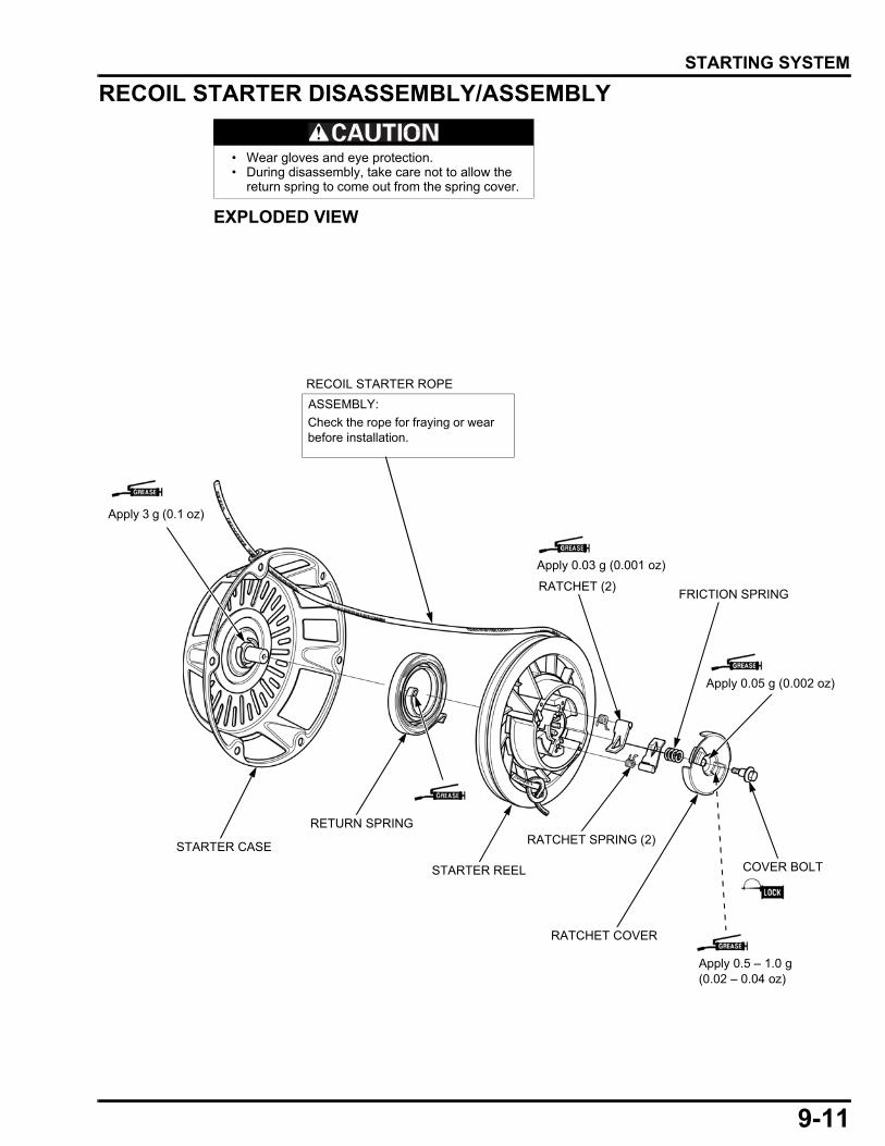
9-11
dummyheaddummyhead
STARTING SYSTEM
RECOIL STARTER DISASSEMBLY/ASSEMBLY
EXPLODED VIEW
• Wear gloves and eye protection. • During disassembly, take care not to allow the
return spring to come out from the spring cover.
STARTER CASE
RETURN SPRING
STARTER REEL
RATCHET SPRING (2)
RATCHET COVER
COVER BOLT
FRICTION SPRINGRATCHET (2)
RECOIL STARTER ROPE
ASSEMBLY:
Check the rope for fraying or wear before installation.
Apply 0.03 g (0.001 oz)
Apply 0.05 g (0.002 oz)
Apply 3 g (0.1 oz)
Apply 0.5 – 1.0 g (0.02 – 0.04 oz)
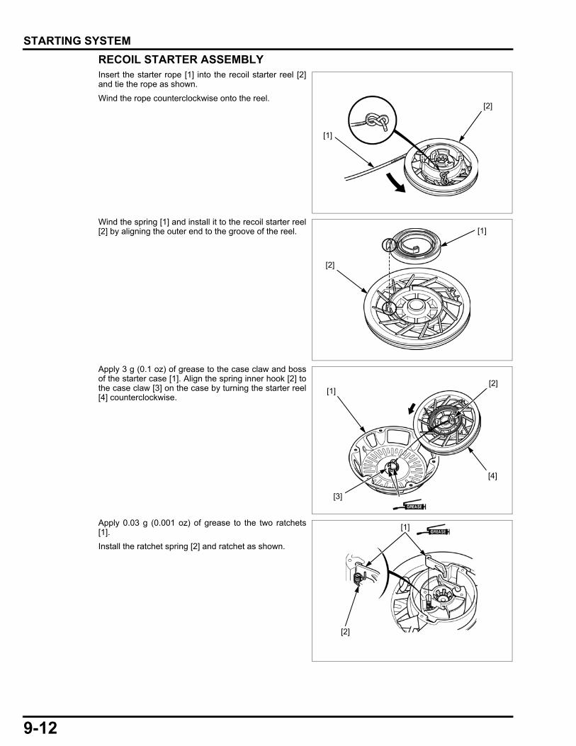
9-12
dummyheaddummyhead
STARTING SYSTEM
RECOIL STARTER ASSEMBLYInsert the starter rope [1] into the recoil starter reel [2]and tie the rope as shown.
Wind the rope counterclockwise onto the reel.
Wind the spring [1] and install it to the recoil starter reel[2] by aligning the outer end to the groove of the reel.
Apply 3 g (0.1 oz) of grease to the case claw and bossof the starter case [1]. Align the spring inner hook [2] tothe case claw [3] on the case by turning the starter reel[4] counterclockwise.
Apply 0.03 g (0.001 oz) of grease to the two ratchets[1].
Install the ratchet spring [2] and ratchet as shown.
[1]
[2]
[1]
[2]
[1]
[4]
[3]
[2]
[1]
[2]
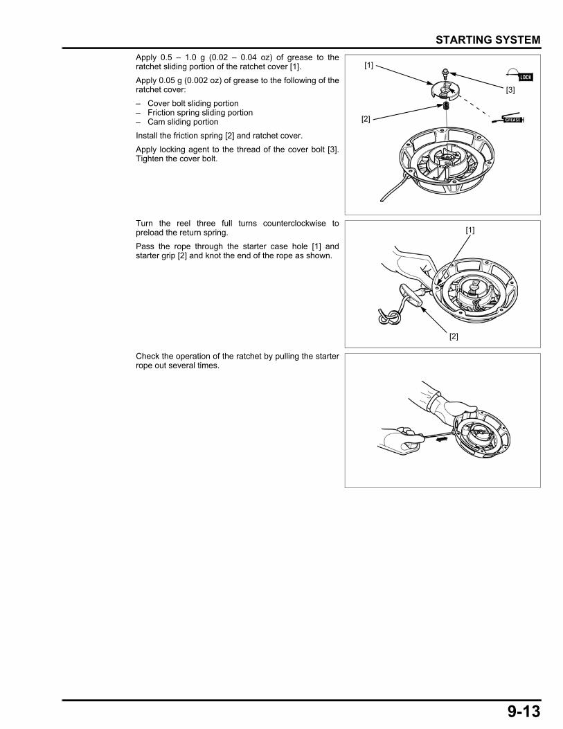
9-13
dummyheaddummyhead
STARTING SYSTEM
Apply 0.5 – 1.0 g (0.02 – 0.04 oz) of grease to theratchet sliding portion of the ratchet cover [1].
Apply 0.05 g (0.002 oz) of grease to the following of theratchet cover:
– Cover bolt sliding portion– Friction spring sliding portion– Cam sliding portion
Install the friction spring [2] and ratchet cover.
Apply locking agent to the thread of the cover bolt [3].Tighten the cover bolt.
Turn the reel three full turns counterclockwise topreload the return spring.
Pass the rope through the starter case hole [1] andstarter grip [2] and knot the end of the rope as shown.
Check the operation of the ratchet by pulling the starterrope out several times.
[2]
[3]
[1]
[1]
[2]

9-14
dummyheaddummyhead
STARTING SYSTEM
RECOIL STARTER INSPECTIONRECOIL STARTER OPERATIONRemove the recoil starter (page 9-6).
Pull the recoil starter rope several times to inspect thatthe ratchets [1] operate properly (the ratchet ends comeout from the ratchet cover [2].
STARTER PULLEYRemove the recoil starter (page 9-6).
Inspect all of the square holes [1] of the starter pulley [2]for deformation.
[2]
[1]
[2]
[1]

9-15
dummyheaddummyhead
STARTING SYSTEM
STARTER MOTOR DISASSEMBLY/ASSEMBLY
FRONT BRACKET/REAR BRACKET INSTALLATIONInstall the armature in the yoke.
Align the cutout [1] of the rear bracket with the brushterminal grommet [2] and install the rear bracket.
Install the pinion drive lever to the overrunning clutch[3].
Set the starter magnetic switch [4] by aligning themagnetic switch pin [5] with the pinion drive lever [6].
Install the front bracket [7] and two through bolts andtighten the flange nuts.
PINION STOPPER
YOKE
BRUSH TERMINAL NUT
FRONT BRACKET
BRUSH HOLDER INSULATOR
BRUSH SPRING (4)
BRUSH (4)
THROUGH BOLT (5 x 98 mm) (2)
BRUSH HOLDER
STARTER MAGNETIC SWITCH
PINION DRIVE LEVER
PINION GEAR
OVERRUNNING CLUTCH
THRUST COLLAR
NUT (6 mm) (2)
LOCK RING
DISASSEMBLY:
Hold the armature upright, place an offset wrench over the pinion stopper, and drive the collar down exposing the lock ring. Remove the lock ring; then remove the collar and drive assembly.
ASSEMBLY:
Check for smooth movement by rotating the overrunning clutch. Check the gear teeth for wear or damage; replace if necessary. Also, check the flywheel ring gear teeth if the pinion gear teeth are damaged.
PINION STOPPER
LOCK RINGARMATURE
REAR BRACKET
ASSEMBLY:
Make sure that there is no obstruction on the magnet.
[1]
[2][3]
[4]
[5]
[6]
[7]
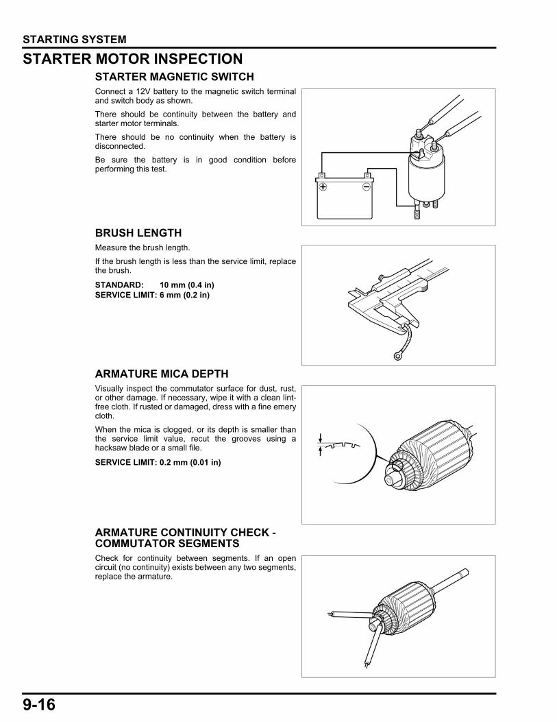
9-16
dummyheaddummyhead
STARTING SYSTEM
STARTER MOTOR INSPECTIONSTARTER MAGNETIC SWITCHConnect a 12V battery to the magnetic switch terminaland switch body as shown.
There should be continuity between the battery andstarter motor terminals.
There should be no continuity when the battery isdisconnected.
Be sure the battery is in good condition beforeperforming this test.
BRUSH LENGTHMeasure the brush length.
If the brush length is less than the service limit, replacethe brush.
ARMATURE MICA DEPTHVisually inspect the commutator surface for dust, rust,or other damage. If necessary, wipe it with a clean lint-free cloth. If rusted or damaged, dress with a fine emerycloth.
When the mica is clogged, or its depth is smaller thanthe service limit value, recut the grooves using ahacksaw blade or a small file.
ARMATURE CONTINUITY CHECK - COMMUTATOR SEGMENTSCheck for continuity between segments. If an opencircuit (no continuity) exists between any two segments,replace the armature.
STANDARD: 10 mm (0.4 in)SERVICE LIMIT: 6 mm (0.2 in)
SERVICE LIMIT: 0.2 mm (0.01 in)
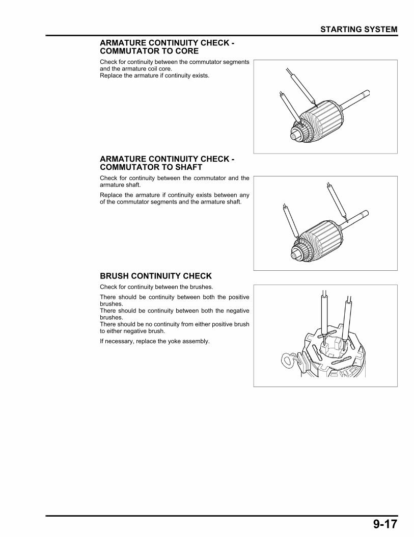
9-17
dummyheaddummyhead
STARTING SYSTEM
ARMATURE CONTINUITY CHECK - COMMUTATOR TO CORECheck for continuity between the commutator segmentsand the armature coil core.Replace the armature if continuity exists.
ARMATURE CONTINUITY CHECK - COMMUTATOR TO SHAFTCheck for continuity between the commutator and thearmature shaft.
Replace the armature if continuity exists between anyof the commutator segments and the armature shaft.
BRUSH CONTINUITY CHECKCheck for continuity between the brushes.
There should be continuity between both the positivebrushes.There should be continuity between both the negativebrushes.There should be no continuity from either positive brushto either negative brush.
If necessary, replace the yoke assembly.
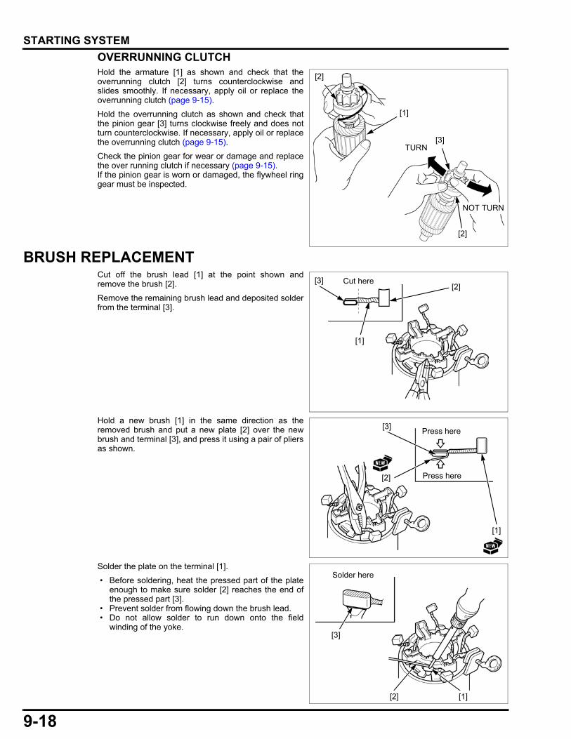
9-18
dummyheaddummyhead
STARTING SYSTEM
OVERRUNNING CLUTCHHold the armature [1] as shown and check that theoverrunning clutch [2] turns counterclockwise andslides smoothly. If necessary, apply oil or replace theoverrunning clutch (page 9-15).
Hold the overrunning clutch as shown and check thatthe pinion gear [3] turns clockwise freely and does notturn counterclockwise. If necessary, apply oil or replacethe overrunning clutch (page 9-15).
Check the pinion gear for wear or damage and replacethe over running clutch if necessary (page 9-15).If the pinion gear is worn or damaged, the flywheel ringgear must be inspected.
BRUSH REPLACEMENTCut off the brush lead [1] at the point shown andremove the brush [2].
Remove the remaining brush lead and deposited solderfrom the terminal [3].
Hold a new brush [1] in the same direction as theremoved brush and put a new plate [2] over the newbrush and terminal [3], and press it using a pair of pliersas shown.
Solder the plate on the terminal [1].
• Before soldering, heat the pressed part of the plateenough to make sure solder [2] reaches the end ofthe pressed part [3].
• Prevent solder from flowing down the brush lead. • Do not allow solder to run down onto the field
winding of the yoke.
TURN
NOT TURN
[2]
[1]
[3]
[2]
[3]
[1]
[2]Cut here
Press here
[1]
[3]
[2] Press here
[2]
[3]
Solder here
[1]
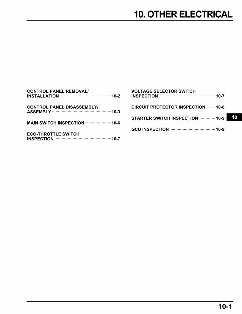
10-1
10
dummytext
10. OTHER ELECTRICAL
CONTROL PANEL REMOVAL/INSTALLATION···········································10-2
CONTROL PANEL DISASSEMBLY/ASSEMBLY ·················································10-3
MAIN SWITCH INSPECTION······················10-6
ECO-THROTTLE SWITCH INSPECTION ···············································10-7
VOLTAGE SELECTOR SWITCH INSPECTION··············································· 10-7
CIRCUIT PROTECTOR INSPECTION········ 10-8
STARTER SWITCH INSPECTION·············· 10-9
GCU INSPECTION······································ 10-9

10-2
dummyheaddummyhead
OTHER ELECTRICALOTHER ELECTRICAL
CONTROL PANEL REMOVAL/INSTALLATION
Remove the following:
– Battery (page 7-9)– Front cover (page 5-5)– Inverter unit (page 7-10)
CONTROL PANEL
INSTALLATION:
RIGHT HANDLE BRACKET
Loosely install the nuts, then pull the bracket up and tighten the nuts securely.
INSTALLATION:
Loosely install the nuts, then pull the bracket up and tighten the nuts securely.
NUT (6 mm) (3)
SCREW (5 x 8 mm)
NUT (8 mm) (4)
LEFT HANDLE BRACKET
FRONT COVER SEAL (4)
8.5 N·m (0.87 kgf·m, 6.3 lbf·ft)
BOLT CAP
(CT Type only)
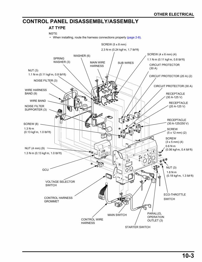
10-3
dummyheaddummyhead
OTHER ELECTRICAL
CONTROL PANEL DISASSEMBLY/ASSEMBLYAT TYPE
• When installing, route the harness connections properly (page 2-8).
GCU
VOLTAGE SELECTOR SWITCH
CONTROL HARNESS GROMMET
CONTROL WIRE HARNESS
MAIN SWITCH
STARTER SWITCH
PARALLEL OPERATION OUTLET (3)
MAIN WIRE HARNESS
SUB WIRES
CIRCUIT PROTECTOR (20 A) (2)
WIRE HARNESS BAND (9)
NOISE FILTER (3)
NUT (4 mm) (9)
SCREW(3 x 5 mm) (4)
RECEPTACLE (30 A-125/250 V)
RECEPTACLE (20 A-125 V)
RECEPTACLE (30 A-125 V)
NOISE FILTER SUPPORTER (3)
CIRCUIT PROTECTOR (30 A)
SCREW (5 x 8 mm)
WASHER (6)
NUT (3)
SPRING WASHER (3)
WIRE BAND
SCREW (4 x 6 mm) (4)
SCREW(5 x 12 mm) (2)
CIRCUIT PROTECTOR (30 A)
1.1 N·m (0.11 kgf·m, 0.8 lbf·ft)
SCREW (8)
1.3 N·m (0.13 kgf·m, 1.0 lbf·ft)
1.1 N·m (0.11 kgf·m, 0.8 lbf·ft)
1.3 N·m (0.13 kgf·m, 1.0 lbf·ft)
2.3 N·m (0.24 kgf·m, 1.7 lbf·ft)
0.6 N·m (0.06 kgf·m, 0.4 lbf·ft)
1.8 N·m (0.18 kgf·m, 1.3 lbf·ft)
ECO-THROTTLE
SWITCH
NUT (3)
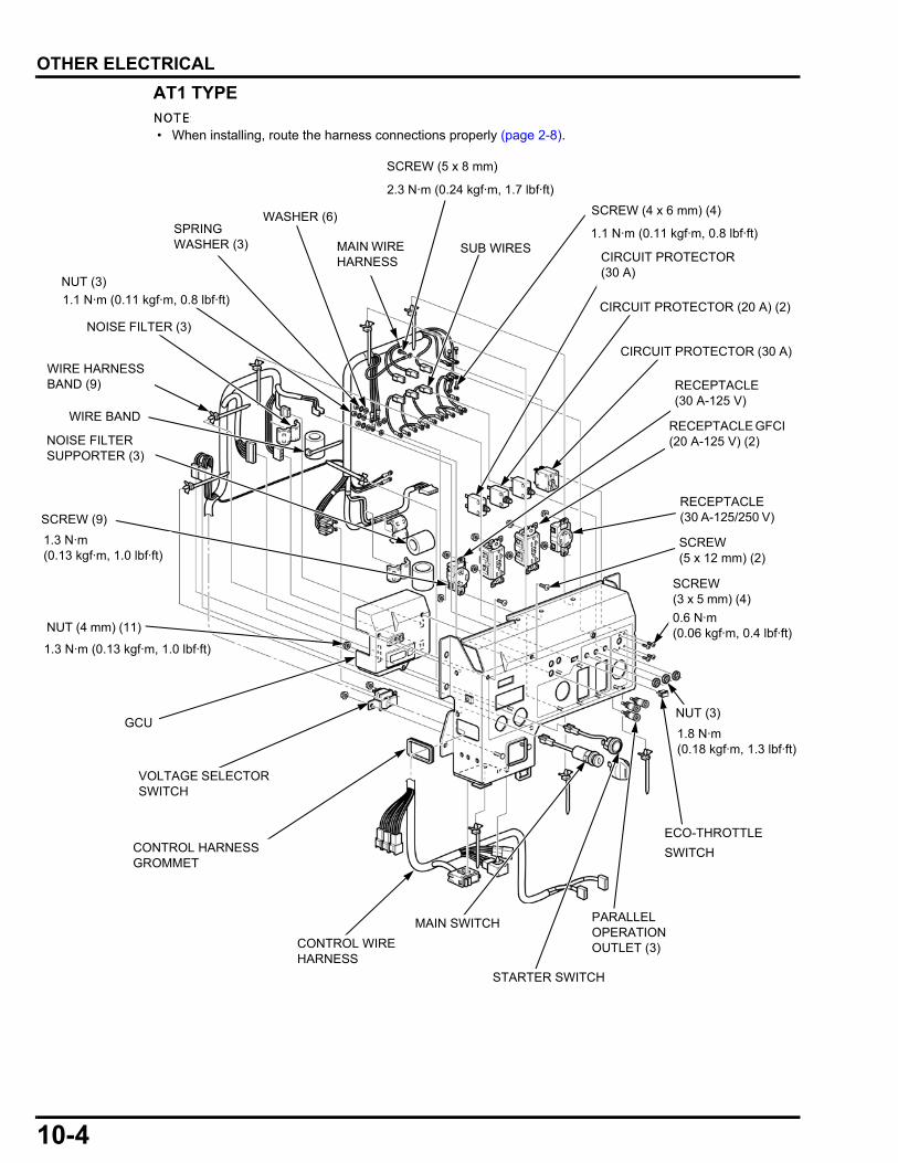
10-4
dummyheaddummyhead
OTHER ELECTRICAL
AT1 TYPE
• When installing, route the harness connections properly (page 2-8).
GCU
VOLTAGE SELECTOR SWITCH
CONTROL HARNESS GROMMET
CONTROL WIRE HARNESS
MAIN SWITCH
STARTER SWITCH
PARALLEL OPERATION OUTLET (3)
MAIN WIRE HARNESS
SUB WIRES
CIRCUIT PROTECTOR (20 A) (2)
WIRE HARNESS BAND (9)
NOISE FILTER (3)
NUT (4 mm) (11)
SCREW(3 x 5 mm) (4)
RECEPTACLE (30 A-125/250 V)
RECEPTACLE GFCI (20 A-125 V) (2)
RECEPTACLE (30 A-125 V)
NOISE FILTER SUPPORTER (3)
CIRCUIT PROTECTOR (30 A)
SCREW (5 x 8 mm)
WASHER (6)
NUT (3)
SPRING WASHER (3)
WIRE BAND
SCREW (4 x 6 mm) (4)
SCREW(5 x 12 mm) (2)
CIRCUIT PROTECTOR (30 A)
1.1 N·m (0.11 kgf·m, 0.8 lbf·ft)
SCREW (9)
1.3 N·m (0.13 kgf·m, 1.0 lbf·ft)
1.1 N·m (0.11 kgf·m, 0.8 lbf·ft)
1.3 N·m (0.13 kgf·m, 1.0 lbf·ft)
2.3 N·m (0.24 kgf·m, 1.7 lbf·ft)
0.6 N·m (0.06 kgf·m, 0.4 lbf·ft)
1.8 N·m (0.18 kgf·m, 1.3 lbf·ft)
ECO-THROTTLE
SWITCH
NUT (3)
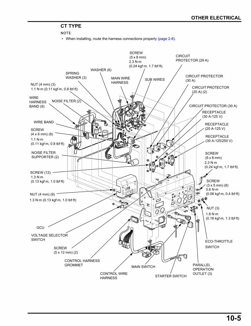
10-5
dummyheaddummyhead
OTHER ELECTRICAL
CT TYPE
• When installing, route the harness connections properly (page 2-8).
GCU
VOLTAGE SELECTOR SWITCH
CONTROL HARNESS GROMMET
CONTROL WIRE HARNESS
ECO-THROTTLE
SWITCH
MAIN SWITCH
STARTER SWITCH
PARALLEL OPERATION OUTLET (3)
MAIN WIRE HARNESS
SUB WIRES
CIRCUIT PROTECTOR (20 A) (2)
WIRE HARNESS BAND (9)
NOISE FILTER (2)
NUT (4 mm) (9)
RECEPTACLE (30 A-125/250 V)
RECEPTACLE (20 A-125 V)
RECEPTACLE (30 A-125 V)
NOISE FILTER SUPPORTER (2)
CIRCUIT PROTECTOR (30 A)
WASHER (6)
NUT (4 mm) (3)
SPRING WASHER (3)
CIRCUIT PROTECTOR (29 A)
SCREW(5 x 12 mm) (2)
SCREW(4 x 6 mm) (8)
SCREW (5 x 8 mm)
WIRE BAND
CIRCUIT PROTECTOR (30 A)
1.1 N·m (0.11 kgf·m, 0.8 lbf·ft)
1.1 N·m (0.11 kgf·m, 0.8 lbf·ft)
1.3 N·m (0.13 kgf·m, 1.0 lbf·ft)
2.3 N·m (0.24 kgf·m, 1.7 lbf·ft)
2.3 N·m (0.24 kgf·m, 1.7 lbf·ft)
0.6 N·m (0.06 kgf·m, 0.4 lbf·ft)
SCREW (12)1.3 N·m (0.13 kgf·m, 1.0 lbf·ft)
1.8 N·m (0.18 kgf·m, 1.3 lbf·ft)
NUT (3)
SCREW(3 x 5 mm) (8)
SCREW(6 x 8 mm)

10-6
dummyheaddummyhead
OTHER ELECTRICAL
GCU 34P CONNECTOR CONNECTIONYou should hear the connector "CLICK" when the GCUconnector 34P connector [1] is connected.After connecting the GCU 34P connector, make surethe connector is completely seated as shown.
• After connecting the GCU 34P connector, securethe wire band [2].
• When securing the wire band, be sure to set theGCU 34P connector harness [3] under the controlwire harness [4].
• Secure the wire band at the outer end [5] of theyellow tape of the GCU 34P connector harness toprevent stress to the harness.
MAIN SWITCH INSPECTIONCheck for continuity between the switch terminals.
There should be continuity between the terminals withthe switch in the ON position and no continuity with theswitch in the OFF position.
OK NG
[5]
[1]
[4]
[3]
[4]
[2]
[2]
[2]
Front frame side
TerminalPosition
ON
OFF
2 3 41

10-7
dummyheaddummyhead
OTHER ELECTRICAL
ECO-THROTTLE SWITCH INSPECTIONCheck for continuity between the switch terminals.
There should be no continuity between the terminalswith the switch in the ON position and continuity withthe switch in the OFF position.
VOLTAGE SELECTOR SWITCH INSPECTION
Check for continuity between the terminals according tothe table below.
5
6
9
8
7
1
23
4
12 11 10
Position
120 V only
120 V/240 V
Terminal6431 2 5
Position
120 V only
120 V/240 V
Terminal121097 8 11
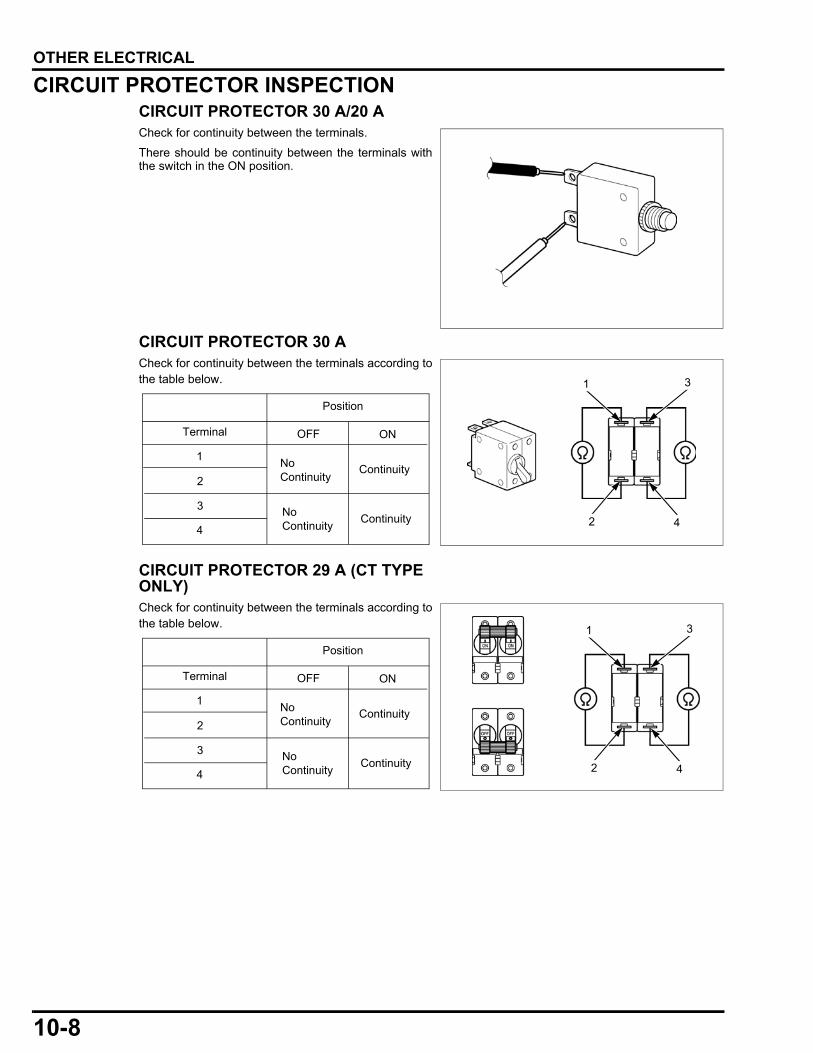
10-8
dummyheaddummyhead
OTHER ELECTRICAL
CIRCUIT PROTECTOR INSPECTIONCIRCUIT PROTECTOR 30 A/20 ACheck for continuity between the terminals.
There should be continuity between the terminals withthe switch in the ON position.
CIRCUIT PROTECTOR 30 ACheck for continuity between the terminals according tothe table below.
CIRCUIT PROTECTOR 29 A (CT TYPE ONLY)Check for continuity between the terminals according tothe table below.
3
2 4
1
Terminal
Position
1
2
3
4
OFF ON
Continuity
Continuity
No Continuity
No Continuity
3
2 4
1
Terminal
Position
1
2
3
4
OFF ON
Continuity
Continuity
No Continuity
No Continuity
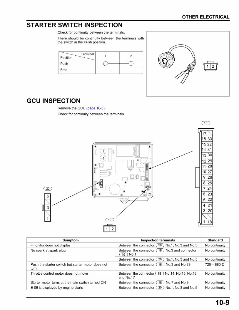
10-9
dummyheaddummyhead
OTHER ELECTRICAL
STARTER SWITCH INSPECTIONCheck for continuity between the terminals.
There should be continuity between the terminals withthe switch in the Push position.
GCU INSPECTIONRemove the GCU (page 10-3).
Check for continuity between the terminals.
TerminalPosition
Push
Free
1 2
Symptom Inspection terminals Standard
i-monitor does not display Between the connector No.1, No.3 and No.5 No continuity
No spark at spark plug Between the connector No.3 and connector No.1
No continuity
Between the connector No.1, No.3 and No.5 No continuity
Push the starter switch but starter motor does not turn
Between the connector No.3 and No.29 720 – 880 Ω
Throttle control motor does not move Between the connector No.14, No.15, No.16 and No.17
No continuity
Starter motor turns at the main switch turned ON Between the connector No.7 and No.9 No continuity
E-06 is displayed by engine starts Between the connector No.1, No.3 and No.5 No continuity

MEMO
dummyheaddummyhead
11-1
11
dummytext
11. MUFFLER
MUFFLER REMOVAL/INSTALLATION······11-2
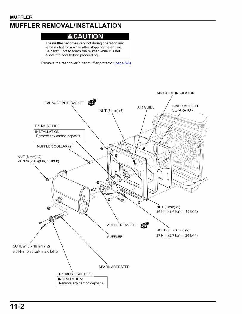
11-2
dummyheaddummyhead
MUFFLERMUFFLER
MUFFLER REMOVAL/INSTALLATION
Remove the rear cover/outer muffler protector (page 5-6).
The muffler becomes very hot during operation and remains hot for a while after stopping the engine. Be careful not to touch the muffler while it is hot. Allow it to cool before proceeding.
NUT (6 mm) (6)
INSTALLATION: Remove any carbon deposits.
INSTALLATION: Remove any carbon deposits.
MUFFLER
EXHAUST PIPE
BOLT (8 x 40 mm) (2)
MUFFLER GASKET
SPARK ARRESTER
NUT (8 mm) (2)
27 N·m (2.7 kgf·m, 20 lbf·ft)
24 N·m (2.4 kgf·m, 18 lbf·ft)
NUT (8 mm) (2)24 N·m (2.4 kgf·m, 18 lbf·ft)
EXHAUST TAIL PIPE
AIR GUIDE INNER MUFFLER SEPARATOR
AIR GUIDE INSULATOR
3.5 N·m (0.36 kgf·m, 2.6 lbf·ft)
EXHAUST PIPE GASKET
MUFFLER COLLAR (2)
SCREW (5 x 16 mm) (2)
12-1
12
dummytext
12. GENERATOR/ENGINE REMOVAL/INSTALLATION
GENERATOR/ENGINE REMOVAL/INSTALLATION···········································12-2
UNDER SHROUD REMOVAL/INSTALLATION···········································12-4
FRAME BOTTOM RUBBERS REMOVAL/INSTALLATION ·········································· 12-5
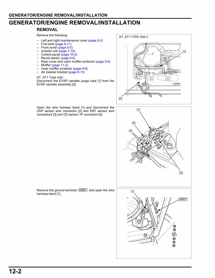
12-2
dummyheaddummyhead
GENERATOR/ENGINE REMOVAL/INSTALLATIONGENERATOR/ENGINE REMOVAL/INSTALLATION
GENERATOR/ENGINE REMOVAL/INSTALLATIONREMOVALRemove the following:
– Left and right maintenance cover (page 5-2)– Fuel tank (page 6-11)– Front cover (page 5-5)– Inverter unit (page 7-10)– Control panel (page 10-2)– Recoil starter (page 9-6)– Rear cover and outer muffler protector (page 5-6)– Muffler (page 11-2)– Inner muffler protector (page 9-9)– Air cleaner bracket (page 6-13)
AT, AT1 Type only:Disconnect the EVAP canister purge tube [1] from theEVAP canister assembly [2].
Open the wire harness band [1] and disconnect theCKP sensor wire connector [2] and EBT sensor wireconnectors [3] and O2 sensor 1P connector [4].
Remove the ground terminal and open the wireharness band [1].
[1]
AT, AT1 TYPE ONLY:
[2]
[2]
[3]
[4]
[1]
[1]

12-3
dummyheaddummyhead
GENERATOR/ENGINE REMOVAL/INSTALLATION
Remove the four nuts [1] and the ground cable terminal[2].
Remove the generator/engine assembly.
INSTALLATION
Installation is the reverse order of removal.
• Remember to reattach the ground cable when bolting the generator to the frame.
[1][2]
REAR ENGINE MOUNT BRACKET
NUT (10 mm) (4)
BOLT (8 x 30 mm) (2)
34 N·m (3.5 kgf·m, 25 lbf·ft)
GENERATOR/ENGINE ASSEMBLY
TORQUE: Ground terminal mounting nut: 3 N·m (0.31 kgf·m, 2.2 lbf·ft)

12-4
dummyheaddummyhead
GENERATOR/ENGINE REMOVAL/INSTALLATION
UNDER SHROUD REMOVAL/INSTALLATIONRemove the generator/engine assembly from the frame (page 12-2).
BOLT
(6 x 30 mm) (2)
UNDER SHROUD
OIL DRAIN GUIDE
BOLT
(6 x 12 mm) (2)
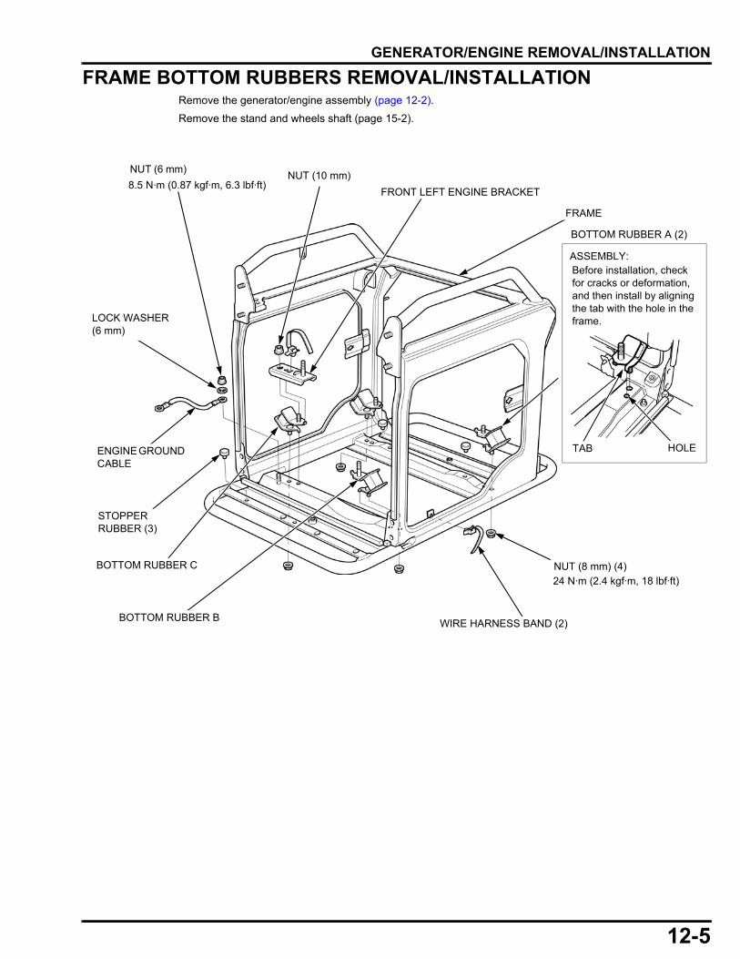
12-5
dummyheaddummyhead
GENERATOR/ENGINE REMOVAL/INSTALLATION
FRAME BOTTOM RUBBERS REMOVAL/INSTALLATIONRemove the generator/engine assembly (page 12-2).
Remove the stand and wheels shaft (page 15-2).
NUT (6 mm)NUT (10 mm)
FRAME
FRONT LEFT ENGINE BRACKET
WIRE HARNESS BAND (2)
NUT (8 mm) (4)
BOTTOM RUBBER B
STOPPER RUBBER (3)
LOCK WASHER (6 mm)
24 N·m (2.4 kgf·m, 18 lbf·ft)
BOTTOM RUBBER A (2)
HOLE
ASSEMBLY:Before installation, check for cracks or deformation, and then install by aligning the tab with the hole in the frame.
TAB
BOTTOM RUBBER C
8.5 N·m (0.87 kgf·m, 6.3 lbf·ft)
ENGINE GROUND CABLE

MEMO
dummyheaddummyhead
13-1
13
dummytext
13. CYLINDER HEAD
HEAD COVER LOWER SHROUD REMOVAL/INSTALLATION························13-2
CYLINDER HEAD REMOVAL/INSTALLATION···········································13-3
CYLINDER HEAD DISASSEMBLY/ASSEMBLY ·················································13-4
CYLINDER HEAD/VALVES INSPECTION··············································· 13-5
VALVE GUIDE REPLACEMENT ················ 13-8
VALVE GUIDE REAMING ·························· 13-9
VALVE SEAT RECONDITIONING············ 13-10
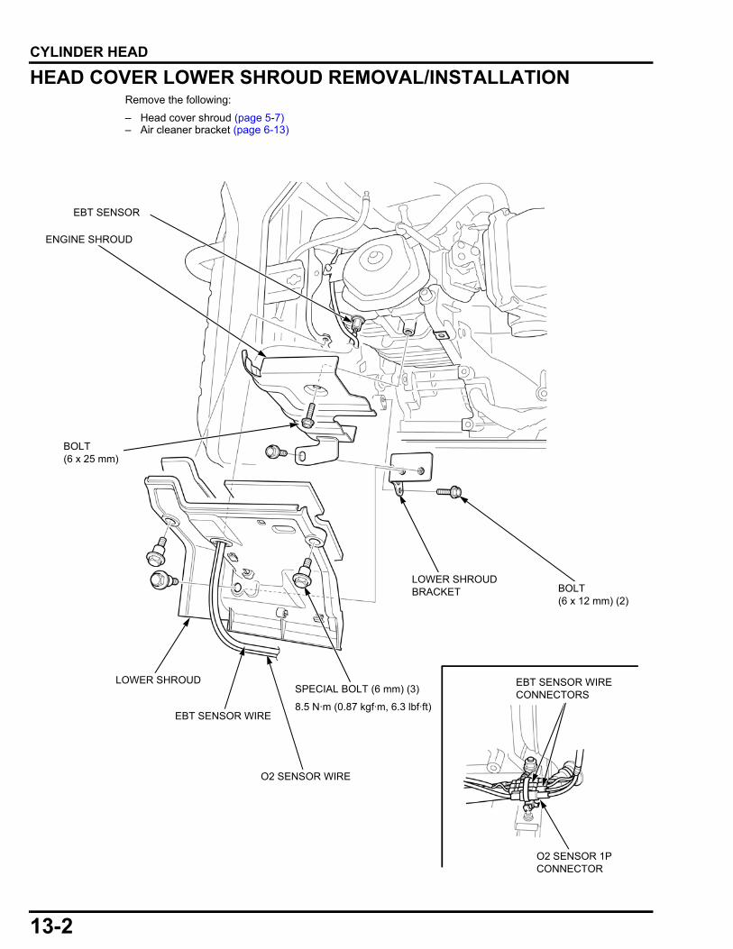
13-2
dummyheaddummyhead
CYLINDER HEADCYLINDER HEAD
HEAD COVER LOWER SHROUD REMOVAL/INSTALLATIONRemove the following:
– Head cover shroud (page 5-7)– Air cleaner bracket (page 6-13)
BOLT(6 x 25 mm)
BOLT(6 x 12 mm) (2)
ENGINE SHROUD
LOWER SHROUD BRACKET
LOWER SHROUDSPECIAL BOLT (6 mm) (3)
O2 SENSOR WIRE
EBT SENSOR
EBT SENSOR WIRE
O2 SENSOR 1P CONNECTOR
EBT SENSOR WIRE CONNECTORS
8.5 N·m (0.87 kgf·m, 6.3 lbf·ft)
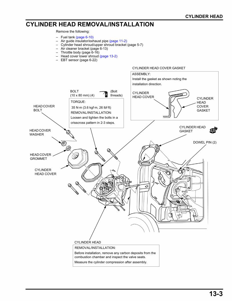
13-3
dummyheaddummyhead
CYLINDER HEAD
CYLINDER HEAD REMOVAL/INSTALLATIONRemove the following:
– Fuel tank (page 6-10)– Air guide insulator/exhaust pipe (page 11-2)– Cylinder head shroud/upper shroud bracket (page 5-7)– Air cleaner bracket (page 6-13)– Throttle body (page 6-16)– Head cover lower shroud (page 13-2)– EBT sensor (page 6-22)
CYLINDER HEAD COVER
CYLINDER HEAD GASKET
DOWEL PIN (2)
CYLINDER HEAD
REMOVAL/INSTALLATION:
Before installation, remove any carbon deposits from the combustion chamber and inspect the valve seats.
Measure the cylinder compression after assembly.
CYLINDER HEAD COVER GASKET
ASSEMBLY:
Install the gasket as shown noting the
installation direction.
BOLT(10 x 80 mm) (4)
35 N·m (3.6 kgf·m, 26 lbf·ft)
Loosen and tighten the bolts in a
crisscross pattern in 2-3 steps.
REMOVAL/INSTALLATION:
HEAD COVER BOLT
HEAD COVER WASHER
HEAD COVER GROMMET
CYLINDER HEAD COVER CYLINDER
HEAD COVER GASKET
TORQUE:
(Bolt threads)

13-4
dummyheaddummyhead
CYLINDER HEAD
CYLINDER HEAD DISASSEMBLY/ASSEMBLY
Remove the cylinder head (page 13-3).
INTAKE/EXHAUST VALVE SPRING RETAINER
INTAKE VALVEASSEMBLY:
Do not interchange with the exhaust valve.
The intake valve is larger than the exhaust valve.
EXHAUST VALVEASSEMBLY:Do not interchange with the intake valve.
The exhaust valve is smaller than the intake valve.
VALVE SPRING SEAT
EXHAUST VALVE GUIDE
SPARK PLUGCYLINDER HEAD
INTAKE VALVE GUIDE
VALVE SPRING (2)
PUSH ROD (2)
PUSH ROD GUIDE PLATE
VALVE STEM SEAL
ASSEMBLY:
Before installing the push rods, check the ends of the push rods for wear.
Roll each push rod across a flat surface and check for straightness.Be sure the ends of the push rods are firmly seated in the valve lifters.
ROCKER ARM PIVOT BOLT (2)
ROCKER ARM PIVOT LOCK NUT (2)
ROCKER ARM PIVOT (2)
(Apply to the threads and pivot)
VALVE ROCKER ARM (2)
VALVE GUIDE CLIP
DISASSEMBLY:Push down and slide the valve spring retainer to the side so that the valve stem slips through the hole at the side of the valve spring retainer.
Do not remove the valve spring retainer while the cylinder head is installed to the cylinder barrel, or the valve will drop into the cylinder.
(Apply to the tappet surface and pivot)
ASSEMBLY:
Before installing the rocker arm, check for wear on the surfaces of the rocker arm that contact the pivot bolt, push rod, and valve stem.
18 N·m (1.8 kgf·m, 31 lbf·ft)
24 N·m (2.4 kgf·m, 18 lbf·ft)
10 N·m (1.0 kgf·m, 7 lbf·ft)
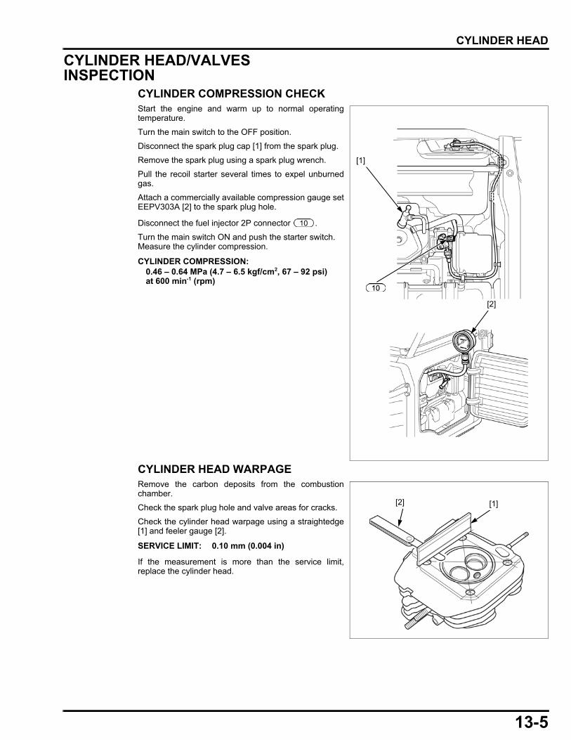
13-5
dummyheaddummyhead
CYLINDER HEAD
CYLINDER HEAD/VALVES INSPECTION
CYLINDER COMPRESSION CHECKStart the engine and warm up to normal operatingtemperature.
Turn the main switch to the OFF position.
Disconnect the spark plug cap [1] from the spark plug.
Remove the spark plug using a spark plug wrench.
Pull the recoil starter several times to expel unburnedgas.
Attach a commercially available compression gauge setEEPV303A [2] to the spark plug hole.
Disconnect the fuel injector 2P connector .
Turn the main switch ON and push the starter switch. Measure the cylinder compression.
CYLINDER HEAD WARPAGERemove the carbon deposits from the combustionchamber.
Check the spark plug hole and valve areas for cracks.
Check the cylinder head warpage using a straightedge[1] and feeler gauge [2].
If the measurement is more than the service limit,replace the cylinder head.
CYLINDER COMPRESSION:0.46 – 0.64 MPa (4.7 – 6.5 kgf/cm2, 67 – 92 psi) at 600 min-1 (rpm)
[2]
[1]
SERVICE LIMIT: 0.10 mm (0.004 in)
[2] [1]
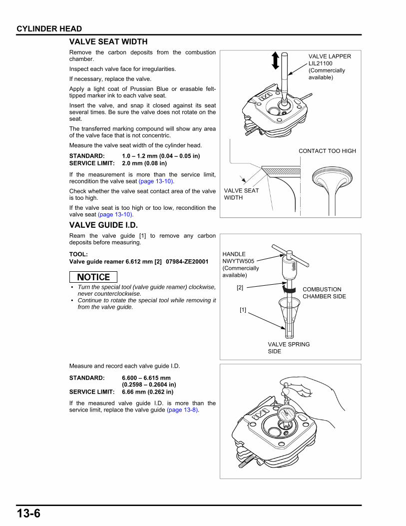
13-6
dummyheaddummyhead
CYLINDER HEAD
VALVE SEAT WIDTHRemove the carbon deposits from the combustionchamber.
Inspect each valve face for irregularities.
If necessary, replace the valve.
Apply a light coat of Prussian Blue or erasable felt-tipped marker ink to each valve seat.
Insert the valve, and snap it closed against its seatseveral times. Be sure the valve does not rotate on theseat.
The transferred marking compound will show any areaof the valve face that is not concentric.
Measure the valve seat width of the cylinder head.
If the measurement is more than the service limit,recondition the valve seat (page 13-10).
Check whether the valve seat contact area of the valveis too high.
If the valve seat is too high or too low, recondition thevalve seat (page 13-10).
VALVE GUIDE I.D.Ream the valve guide [1] to remove any carbondeposits before measuring.
• Turn the special tool (valve guide reamer) clockwise,never counterclockwise.
• Continue to rotate the special tool while removing itfrom the valve guide.
Measure and record each valve guide I.D.
If the measured valve guide I.D. is more than theservice limit, replace the valve guide (page 13-8).
STANDARD: 1.0 – 1.2 mm (0.04 – 0.05 in)SERVICE LIMIT: 2.0 mm (0.08 in)
TOOL:Valve guide reamer 6.612 mm [2] 07984-ZE20001
VALVE LAPPER LIL21100(Commercially available)
CONTACT TOO HIGH
VALVE SEAT WIDTH
COMBUSTION CHAMBER SIDE
VALVE SPRING SIDE
[2]
HANDLE NWYTW505 (Commercially available)
[1]
STANDARD: 6.600 – 6.615 mm (0.2598 – 0.2604 in)
SERVICE LIMIT: 6.66 mm (0.262 in)

13-7
dummyheaddummyhead
CYLINDER HEAD
VALVE FACEInspect each valve for face irregularities.
If necessary, replace the valve (page 13-4).
VALVE STEM O.D.Inspect each valve for bending or abnormal stem wear.
If necessary, replace the valve (page 13-4).
Measure and record each valve stem O.D.
If the measurement is less than the service limit,replace the valve (page 13-4).
GUIDE-TO-STEM CLEARANCESubtract each valve stem O.D. from the correspondingguide I.D. to obtain the stem-to-guide clearance.
If the calculated clearance is more than the service limit,replace the following:
– Valves (page 13-4)– Valve guide (page 13-8)
VALVE SPRING FREE LENGTHMeasure the valve spring free length.
If the measured length is less than the service limit,replace the valve spring (page 13-4).
VALVE FACE
STANDARD: IN: 6.575 – 6.590 mm (0.2589 – 0.2594 in)
EX: 6.535 – 6.550 mm(0.2573 – 0.2579 in)
SERVICE LIMIT: IN: 6.44 mm (0.254 in)EX: 6.40 mm (0.252 in)
STANDARD: IN: 0.010 – 0.040 mm (0.0004 – 0.0016 in)
EX: 0.050 – 0.080 mm(0.0020 – 0.0032 in)
SERVICE LIMIT: IN: 0.11 mm (0.004 in)EX: 0.13 mm (0.005 in)
STANDARD: 39.0 mm (1.54 in)SERVICE LIMIT: 37.5 mm (1.48 in)
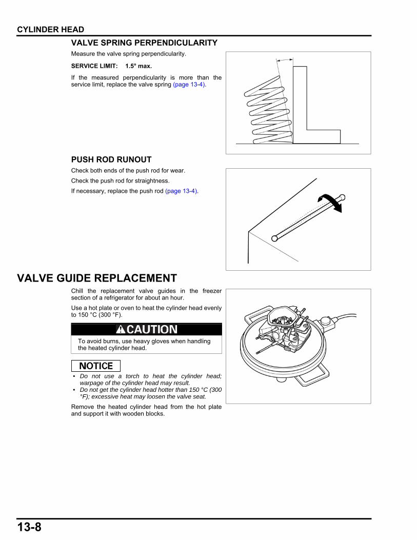
13-8
dummyheaddummyhead
CYLINDER HEAD
VALVE SPRING PERPENDICULARITYMeasure the valve spring perpendicularity.
If the measured perpendicularity is more than theservice limit, replace the valve spring (page 13-4).
PUSH ROD RUNOUTCheck both ends of the push rod for wear.
Check the push rod for straightness.
If necessary, replace the push rod (page 13-4).
VALVE GUIDE REPLACEMENTChill the replacement valve guides in the freezersection of a refrigerator for about an hour.
Use a hot plate or oven to heat the cylinder head evenlyto 150 °C (300 °F).
• Do not use a torch to heat the cylinder head;warpage of the cylinder head may result.
• Do not get the cylinder head hotter than 150 °C (300°F); excessive heat may loosen the valve seat.
Remove the heated cylinder head from the hot plateand support it with wooden blocks.
SERVICE LIMIT: 1.5° max.
To avoid burns, use heavy gloves when handling the heated cylinder head.

13-9
dummyheaddummyhead
CYLINDER HEAD
Drive the valve guides [1] out of the cylinder head fromthe combustion chamber side.
When driving the valve guides out, be careful not todamage the cylinder head.
Remove the new valve guides from the refrigerator oneat a time as needed.
Drive the exhaust valve guide [1] until the valve guideclip [2] is fully seated as shown from the valve springside of the cylinder head.
Drive the intake valve guide [4] to the specified height(measured from the end of the valve guide to thecylinder head as shown) from the valve spring side ofthe cylinder head.
After installing the valve guide, check the guide fordamage.
Replace the valve guide if damaged.
Let the cylinder head cool to room temperature.
Ream the valve guide.
VALVE GUIDE REAMINGFor best results, be sure the cylinder head is at roomtemperature before reaming valve guides.
Coat the reamer and valve guide with cutting oil.
Rotate the reamer clockwise through the valve guidethe full length of the reamer.
• Turn the special tool (valve guide reamer) clockwise,never counterclockwise.
• Continue to rotate the special tool while removing itfrom the valve guide.
Thoroughly clean the cylinder head to remove anycutting residue.
TOOL:Valve guide driver, 6.6 mm [2] 07942-6570100
[1]
COMBUSTION CHAMBER SIDE
[2]
TOOL:Valve guide driver, 6.6 mm [3] 07942-6570100
TOOL:Valve guide driver, 6.6 mm 07942-6570100
INTAKE VALVE GUIDE INSTALLATION HEIGHT:5.0 mm (0.20 in)
VALVE SPRING SIDE
5.0 mm (0.20 in)
[1]
[3][2]
[4]
TOOL:Valve guide reamer 6.612 mm [1] 07984-ZE20001
[1]
COMBUSTION CHAMBER SIDE
VALVE SPRING SIDE
HANDLE NWYTW505 (Commercially available)

13-10
dummyheaddummyhead
CYLINDER HEAD
Check the valve guide bore; it should be straight, round,and centered in the valve guide. Insert the valve andcheck operation. If the valve does not operatesmoothly, the guide may have been bent duringinstallation.
Replace the valve guide if it is bent or damaged.
Check the valve guide-to-stem clearance (page 13-7).
VALVE SEAT RECONDITIONINGThoroughly clean the combustion chamber and valveseats to remove carbon deposits.
Apply a light coat of Prussian Blue or erasable felt-tipped marker ink to the valve seat.
Insert the valve, and snap it closed against its seatseveral times. Be sure the valve does not rotate on theseat. The transferred marking compound will show anyarea of the seat that is not concentric.
Measure the valve seat width of the cylinder head.
If the measurement is more than the service limit,recondition the valve seat.
Check whether the valve seat contact area of the valveis too high.
If the valve seat is too high or too low, recondition thevalve seat.
Valve seat cutters/grinders [1] or equivalent valve seatrefacing equipment is recommended to correct a wornvalve seat.
• Turn the cutter clockwise, never counterclockwise. • Continue to turn the cutter as you lift it from the valve
seat.
STANDARD: 1.0 – 1.2 mm (0.04 – 0.05 in)SERVICE LIMIT: 2.0 mm (0.08 in)
VALVE LAPPER LIL21100 (Commercially available)
[1]
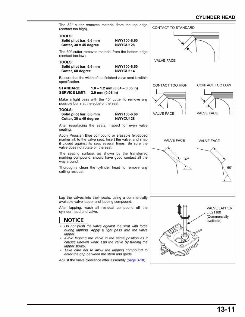
13-11
dummyheaddummyhead
CYLINDER HEAD
The 32° cutter removes material from the top edge(contact too high).
The 60° cutter removes material from the bottom edge(contact too low).
Be sure that the width of the finished valve seat is withinspecification.
Make a light pass with the 45° cutter to remove anypossible burrs at the edge of the seat.
After resurfacing the seats, inspect for even valveseating.
Apply Prussian Blue compound or erasable felt-tippedmarker ink to the valve seat. Insert the valve, and snapit closed against its seat several times. Be sure thevalve does not rotate on the seat.
The seating surface, as shown by the transferredmarking compound, should have good contact all theway around.
Thoroughly clean the cylinder head to remove anycutting residual.
Lap the valves into their seats, using a commerciallyavailable valve lapper and lapping compound.
After lapping, wash all residual compound off thecylinder head and valve.
• Do not push the valve against the seat with forceduring lapping. Apply a light pass with the valvelapper.
• Avoid lapping the valve in the same position as itcauses uneven wear. Lap the valve by turning thelapper slowly.
• Take care not to allow the lapping compound toenter the gap between the stem and guide.
Adjust the valve clearance after assembly (page 3-10).
TOOLS:Solid pilot bar, 6.6 mm NWY100-6.60Cutter, 30 x 45 degree NWYCU128
TOOLS:Solid pilot bar, 6.6 mm NWY100-6.60Cutter, 60 degree NWYCU114
STANDARD: 1.0 – 1.2 mm (0.04 – 0.05 in)SERVICE LIMIT: 2.0 mm (0.08 in)
TOOLS:Solid pilot bar, 6.6 mm NWY100-6.60Cutter, 30 x 45 degree NWYCU128
VALVE FACE
32°
VALVE FACE
60°
CONTACT TO STANDARD
VALVE FACE
CONTACT TOO HIGH
VALVE FACE
CONTACT TOO LOW
VALVE FACE
VALVE LAPPER LIL21100 (Commercially available)

MEMO
dummyheaddummyhead
14-1
14
dummytext
14. CYLINDER BLOCK
CRANKCASE COVER REMOVAL/INSTALLATION···········································14-2
CRANKSHAFT/CAMSHAFT/BALANCER WEIGHT/PISTON REMOVAL/INSTALLATION···········································14-3
PISTON DISASSEMBLY/ASSEMBLY ······· 14-4
CYLINDER BLOCK INSPECTION·············· 14-5
BEARING/OIL SEAL REPLACEMENT ····14-12
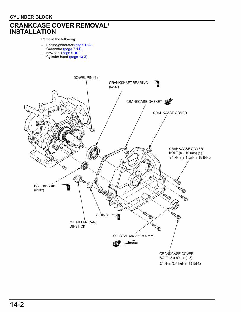
14-2
dummyheaddummyhead
CYLINDER BLOCKCYLINDER BLOCK
CRANKCASE COVER REMOVAL/INSTALLATION
Remove the following:
– Engine/generator (page 12-2)– Generator (page 7-14)– Flywheel (page 9-10)– Cylinder head (page 13-3)
DOWEL PIN (2)
CRANKSHAFT BEARING (6207)
CRANKCASE GASKET
CRANKCASE COVER
CRANKCASE COVER BOLT (8 x 40 mm) (4)
CRANKCASE COVER BOLT (8 x 60 mm) (3)
O-RING
OIL FILLER CAP/DIPSTICK
BALL BEARING (6202)
OIL SEAL (35 x 52 x 8 mm)
24 N·m (2.4 kgf·m, 18 lbf·ft)
24 N·m (2.4 kgf·m, 18 lbf·ft)

14-3
dummyheaddummyhead
CYLINDER BLOCK
CRANKSHAFT/CAMSHAFT/BALANCER WEIGHT/PISTON REMOVAL/INSTALLATION
PISTON
VALVE LIFTER (2)
CAMSHAFT
CRANKSHAFT
CONNECTING ROD SPECIAL BOLT (2)
BALANCER WEIGHT
DRAIN PLUG BOLT
INSTALLATION: Install the piston to the cylinder barrel with the mark on the piston head toward the push rod hole of the cylinder head. (Viewed from
cylinder head side)
INSTALLATION: Set the connecting rod lower end with the oil dipper toward the camshaft.
INSTALLATION:Before installing the crankshaft, check the oil seal of the cylinder barrel for damage or hardening.
Be careful not to damage the oil seal when installing the crankshaft.(Apply to the threads and
seating surface)
OIL LEVEL SWITCH
OIL LEVEL SWITCH JOINT NUT (10 mm)
BOLT (6 x 12 mm) (2)
REMOVAL:When removing the valve lifters, mark them so the intake and exhaust sides can be distinguished.
INSTALLATION:Attach the valve lifters to the cylinder barrel immediately before installing the camshaft.
INSTALLATION: Align the punch marks of the balancer weight and the crankshaft (marked on the balancer drive gear).
INSTALLATION: Align the punch marks of the camshaft and the crankshaft (marked on the timing gear).
CAMSHAFT
CRANKSHAFT
MARKS
MARK
BALANCER WEIGHT CRANKSHAFT
MARKS
SEALING WASHER (12 mm)
CONNECTING ROD LOWER END
O-RING (14 mm)
HOLE
14 N·m (1.4 kgf·m, 10 lbf·ft)
10 N·m (1.0 kgf·m, 7 lbf·ft)
22.5 N·m (2.3 kgf·m, 17 lbf·ft)
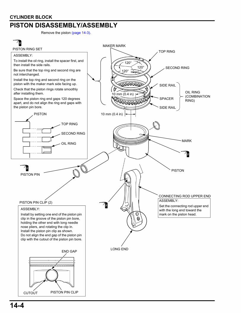
14-4
dummyheaddummyhead
CYLINDER BLOCK
PISTON DISASSEMBLY/ASSEMBLYRemove the piston (page 14-3).
PISTON PIN CLIPCUTOUT
END GAP
PISTON
ASSEMBLY:
Set the connecting rod upper end with the long end toward the mark on the piston head.
LONG END
OIL RING (COMBINATION RING)
PISTON RING SET
TOP RING
SECOND RING
OIL RING
PISTON PIN CLIP (2)
PISTON PIN
MAKER MARK
10 mm (0.4 in)
120°
120°120°
ASSEMBLY:
To install the oil ring, install the spacer first, and then install the side rails.
Be sure that the top ring and second ring are not interchanged.
Install the top ring and second ring on the piston with the maker mark side facing up.
Check that the piston rings rotate smoothly after installing them.
Space the piston ring end gaps 120 degrees apart, and do not align the ring end gaps with the piston pin bore.
10 mm (0.4 in)
PISTON
ASSEMBLY:
Install by setting one end of the piston pin clip in the groove of the piston pin bore, holding the other end with long needle nose pliers, and rotating the clip in.Install the piston pin clip as shown.Do not align the end gap of the piston pin clip with the cutout of the piston pin bore.
MARK
CONNECTING ROD UPPER END
SIDE RAIL
SPACER
TOP RING
SECOND RING
SIDE RAIL
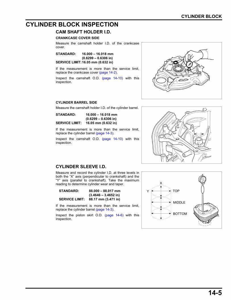
14-5
dummyheaddummyhead
CYLINDER BLOCK
CYLINDER BLOCK INSPECTIONCAM SHAFT HOLDER I.D.CRANKCASE COVER SIDE
Measure the camshaft holder I.D. of the crankcasecover.
If the measurement is more than the service limit,replace the crankcase cover (page 14-2).
Inspect the camshaft O.D. (page 14-10) with thisinspection.
CYLINDER BARREL SIDE
Measure the camshaft holder I.D. of the cylinder barrel.
If the measurement is more than the service limit,replace the cylinder barrel (page 14-3).
Inspect the camshaft O.D. (page 14-10) with thisinspection.
CYLINDER SLEEVE I.D.Measure and record the cylinder I.D. at three levels inboth the “X” axis (perpendicular to crankshaft) and the“Y” axis (parallel to crankshaft). Take the maximumreading to determine cylinder wear and taper.
If the measurement is more than the service limit,replace the cylinder barrel (page 14-3).
Inspect the piston skirt O.D. (page 14-6) with thisinspection.
STANDARD: 16.000 – 16.018 mm (0.6299 – 0.6306 in)
SERVICE LIMIT:16.05 mm (0.632 in)
STANDARD: 16.000 – 16.018 mm (0.6299 – 0.6306 in)
SERVICE LIMIT: 16.05 mm (0.632 in)
STANDARD: 88.000 – 88.017 mm (3.4646 – 3.4652 in)
SERVICE LIMIT: 88.17 mm (3.471 in)
TOP
MIDDLE
BOTTOM
X
Y
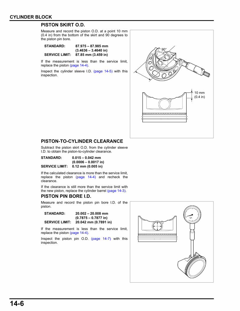
14-6
dummyheaddummyhead
CYLINDER BLOCK
PISTON SKIRT O.D.Measure and record the piston O.D. at a point 10 mm(0.4 in) from the bottom of the skirt and 90 degrees tothe piston pin bore.
If the measurement is less than the service limit,replace the piston (page 14-4).
Inspect the cylinder sleeve I.D. (page 14-5) with thisinspection.
PISTON-TO-CYLINDER CLEARANCESubtract the piston skirt O.D. from the cylinder sleeveI.D. to obtain the piston-to-cylinder clearance.
If the calculated clearance is more than the service limit,replace the piston (page 14-4) and recheck theclearance.
If the clearance is still more than the service limit withthe new piston, replace the cylinder barrel (page 14-3).
PISTON PIN BORE I.D.Measure and record the piston pin bore I.D. of thepiston.
If the measurement is less than the service limit,replace the piston (page 14-4).
Inspect the piston pin O.D. (page 14-7) with thisinspection.
STANDARD: 87.975 – 87.985 mm(3.4636 – 3.4640 in)
SERVICE LIMIT: 87.85 mm (3.459 in)
90°
10 mm (0.4 in)
STANDARD: 0.015 – 0.042 mm (0.0006 – 0.0017 in)
SERVICE LIMIT: 0.12 mm (0.005 in)
STANDARD: 20.002 – 20.008 mm (0.7875 – 0.7877 in)
SERVICE LIMIT: 20.042 mm (0.7891 in)
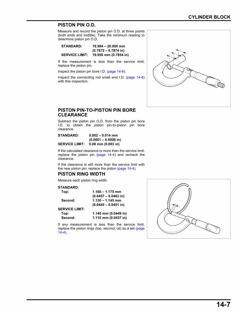
14-7
dummyheaddummyhead
CYLINDER BLOCK
PISTON PIN O.D.Measure and record the piston pin O.D. at three points(both ends and middle). Take the minimum reading todetermine piston pin O.D.
If the measurement is less than the service limit,replace the piston pin.
Inspect the piston pin bore I.D. (page 14-6).
Inspect the connecting rod small end I.D. (page 14-8)with this inspection.
PISTON PIN-TO-PISTON PIN BORE CLEARANCESubtract the piston pin O.D. from the piston pin boreI.D. to obtain the piston pin-to-piston pin boreclearance.
If the calculated clearance is more than the service limit,replace the piston pin (page 14-4) and recheck theclearance.
If the clearance is still more than the service limit withthe new piston pin, replace the piston (page 14-4).
PISTON RING WIDTHMeasure each piston ring width.
If any measurement is less than the service limit,replace the piston rings (top, second, oil) as a set (page14-4).
STANDARD: 19.994 – 20.000 mm (0.7872 – 0.7874 in)
SERVICE LIMIT: 19.950 mm (0.7854 in)
STANDARD: 0.002 – 0.014 mm(0.0001 – 0.0006 in)
SERVICE LIMIT: 0.08 mm (0.003 in)
STANDARD:Top: 1.160 – 1.175 mm
(0.0457 – 0.0463 in)Second: 1.130 – 1.145 mm
(0.0445 – 0.0451 in)SERVICE LIMIT:
Top: 1.140 mm (0.0449 in)Second: 1.110 mm (0.0437 in)

14-8
dummyheaddummyhead
CYLINDER BLOCK
PISTON RING SIDE CLEARANCEMeasure the clearance between each piston ring andring groove of the piston using a feeler gauge.
If any measurement is more than the service limit,inspect the piston ring width.
If the piston ring width is normal, replace the piston(page 14-4) and reinspect the clearance.If necessary, replace the piston rings (top, second, oil)as a set (page 14-4) and reinspect the clearance.If any measurement is still more than the service limitwith the new piston rings, replace the piston (page 14-4).
PISTON RING END GAPBefore inspection, check whether the cylinder sleeveI.D. (page 14-5) is within the specification.
Measure each piston ring [1] end gap using a feelergauge.
If any measurement is more than the service limit,replace the piston rings (top, second, oil) as a set (page14-4).
CONNECTING ROD SMALL END I.D.Measure the connecting rod small end I.D.
If the measurement is more than the service limit,replace the connecting rod (page 14-4).
Inspect the piston pin O.D. (page 14-7) with thisinspection.
STANDARD:Top: 0.030 – 0.060 mm
(0.0012 – 0.0024 in)Second: 0.060 – 0.090 mm
(0.0024 – 0.0035 in)SERVICE LIMIT:
Top: 0.15 mm (0.006 in)Second: 0.15 mm (0.006 in)
STANDARD:Top: 0.200 – 0.350 mm
(0.0079 – 0.0138 in)Second: 0.350 – 0.500 mm
(0.0138 – 0.0197 in)Oil (side rail) 0.20 – 0.70 mm
(0.008 – 0.028 in)SERVICE LIMIT:
Top/Second: 1.0 mm (0.04 in)Oil (side rail) 1.0 mm (0.04 in)
[1]
STANDARD: 20.005 – 20.020 mm (0.7876 – 0.7882 in)
SERVICE LIMIT: 20.07 mm (0.790 in)
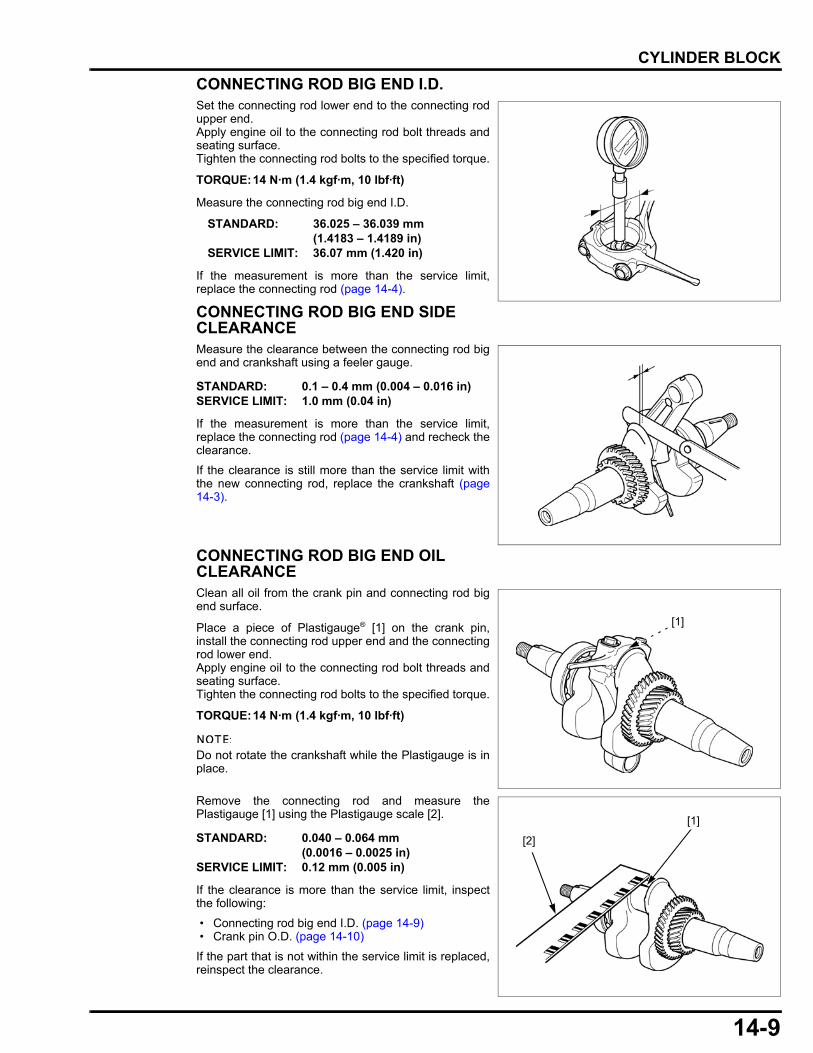
14-9
dummyheaddummyhead
CYLINDER BLOCK
CONNECTING ROD BIG END I.D.Set the connecting rod lower end to the connecting rodupper end. Apply engine oil to the connecting rod bolt threads andseating surface.Tighten the connecting rod bolts to the specified torque.
Measure the connecting rod big end I.D.
If the measurement is more than the service limit,replace the connecting rod (page 14-4).
CONNECTING ROD BIG END SIDE CLEARANCEMeasure the clearance between the connecting rod bigend and crankshaft using a feeler gauge.
If the measurement is more than the service limit,replace the connecting rod (page 14-4) and recheck theclearance.
If the clearance is still more than the service limit withthe new connecting rod, replace the crankshaft (page14-3).
CONNECTING ROD BIG END OIL CLEARANCEClean all oil from the crank pin and connecting rod bigend surface.
Place a piece of Plastigauge® [1] on the crank pin,install the connecting rod upper end and the connectingrod lower end.Apply engine oil to the connecting rod bolt threads andseating surface.Tighten the connecting rod bolts to the specified torque.
Do not rotate the crankshaft while the Plastigauge is inplace.
Remove the connecting rod and measure thePlastigauge [1] using the Plastigauge scale [2].
If the clearance is more than the service limit, inspectthe following:
• Connecting rod big end I.D. (page 14-9) • Crank pin O.D. (page 14-10)
If the part that is not within the service limit is replaced,reinspect the clearance.
TORQUE:14 N·m (1.4 kgf·m, 10 lbf·ft)
STANDARD: 36.025 – 36.039 mm (1.4183 – 1.4189 in)
SERVICE LIMIT: 36.07 mm (1.420 in)
STANDARD: 0.1 – 0.4 mm (0.004 – 0.016 in)SERVICE LIMIT: 1.0 mm (0.04 in)
TORQUE:14 N·m (1.4 kgf·m, 10 lbf·ft)
[1]
STANDARD: 0.040 – 0.064 mm (0.0016 – 0.0025 in)
SERVICE LIMIT: 0.12 mm (0.005 in)
[1]
[2]
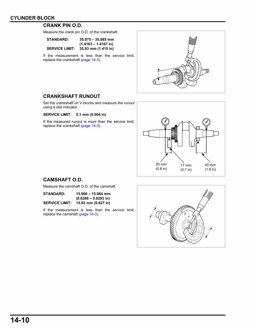
14-10
dummyheaddummyhead
CYLINDER BLOCK
CRANK PIN O.D.Measure the crank pin O.D. of the crankshaft.
If the measurement is less than the service limit,replace the crankshaft (page 14-3).
CRANKSHAFT RUNOUTSet the crankshaft on V-blocks and measure the runoutusing a dial indicator.
If the measured runout is more than the service limit,replace the crankshaft (page 14-3).
CAMSHAFT O.D.Measure the camshaft O.D. of the camshaft.
If the measurement is less than the service limit,replace the camshaft (page 14-3).
STANDARD: 35.975 – 35.985 mm (1.4163 – 1.4167 in)
SERVICE LIMIT: 35.93 mm (1.415 in)
SERVICE LIMIT: 0.1 mm (0.004 in)
17 mm (0.7 in)
20 mm (0.8 in)
45 mm (1.8 in)
STANDARD: 15.966 – 15.984 mm (0.6286 – 0.6293 in)
SERVICE LIMIT: 15.92 mm (0.627 in)
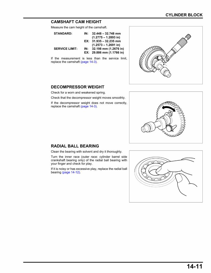
14-11
dummyheaddummyhead
CYLINDER BLOCK
CAMSHAFT CAM HEIGHTMeasure the cam height of the camshaft.
If the measurement is less than the service limit,replace the camshaft (page 14-3).
DECOMPRESSOR WEIGHTCheck for a worn and weakened spring.
Check that the decompressor weight moves smoothly.
If the decompressor weight does not move correctly,replace the camshaft (page 14-3).
RADIAL BALL BEARINGClean the bearing with solvent and dry it thoroughly.
Turn the inner race (outer race: cylinder barrel sidecrankshaft bearing only) of the radial ball bearing withyour finger and check for play.
If it is noisy or has excessive play, replace the radial ballbearing (page 14-12).
STANDARD: IN: 32.448 – 32.748 mm (1.2775 – 1.2893 in)
EX: 31.935 – 32.235 mm(1.2573 – 1.2691 in)
SERVICE LIMIT: IN: 32.198 mm (1.2676 in)EX: 29.886 mm (1.1766 in)
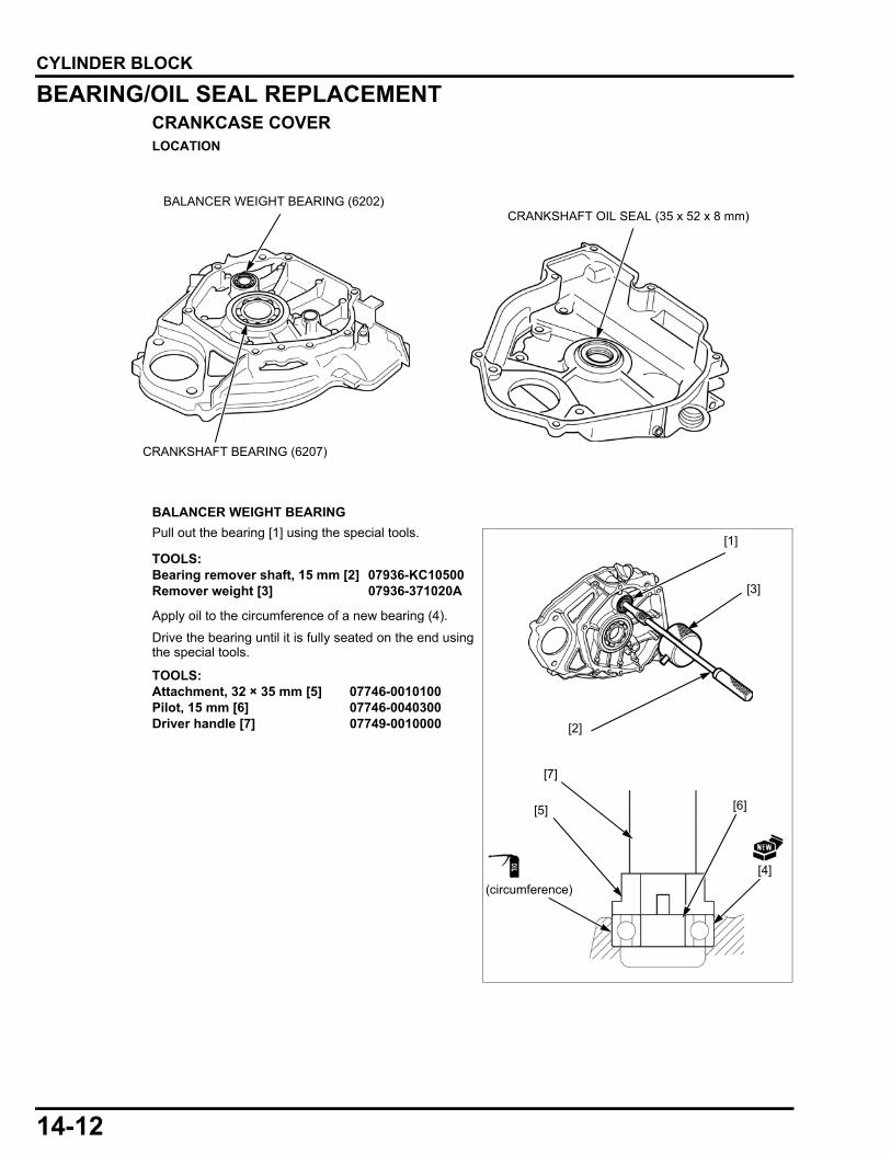
14-12
dummyheaddummyhead
CYLINDER BLOCK
BEARING/OIL SEAL REPLACEMENTCRANKCASE COVERLOCATION
BALANCER WEIGHT BEARING
Pull out the bearing [1] using the special tools.
Apply oil to the circumference of a new bearing (4).
Drive the bearing until it is fully seated on the end usingthe special tools.
BALANCER WEIGHT BEARING (6202) CRANKSHAFT OIL SEAL (35 x 52 x 8 mm)
CRANKSHAFT BEARING (6207)
TOOLS:Bearing remover shaft, 15 mm [2] 07936-KC10500Remover weight [3] 07936-371020A
TOOLS:Attachment, 32 × 35 mm [5] 07746-0010100Pilot, 15 mm [6] 07746-0040300Driver handle [7] 07749-0010000 [2]
[3]
[7]
[1]
[4]
(circumference)
[6][5]

14-13
dummyheaddummyhead
CYLINDER BLOCK
CRANKSHAFT BEARING
Drive out the bearing [1].
Apply oil to the circumference of a new bearing [2].
Drive the bearing until it is fully seated on the end usingthe special tools.
CRANKSHAFT OIL SEAL
Remove the oil seal from the crankcase cover.
Apply grease to the lip of a new oil seal [1].
Drive the oil seal in the position as shown using thespecial tools.
TOOLS:Attachment, 72 × 75 mm [3] 07746-0010600Pilot, 35 mm [4] 07746-0040800Driver handle [5] 07749-0010000
[1]
[4]
[5]
[2]
[3]
(circumference)
TOOLS:Attachment, 52 × 55 mm [2] 07746-0010400Driver handle [3] 07749-0010000
[2]
2 mm (0.08 in)
[3]
[1]
OIL SEAL RIP
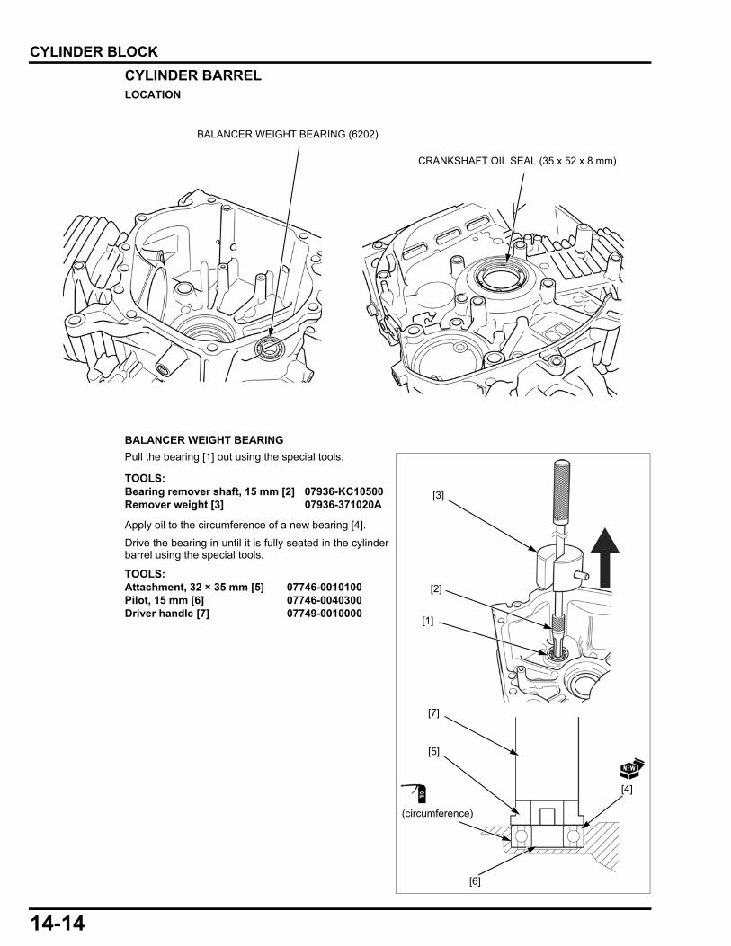
14-14
dummyheaddummyhead
CYLINDER BLOCK
CYLINDER BARRELLOCATION
BALANCER WEIGHT BEARING
Pull the bearing [1] out using the special tools.
Apply oil to the circumference of a new bearing [4].
Drive the bearing in until it is fully seated in the cylinderbarrel using the special tools.
CRANKSHAFT OIL SEAL (35 x 52 x 8 mm)
BALANCER WEIGHT BEARING (6202)
TOOLS:Bearing remover shaft, 15 mm [2] 07936-KC10500Remover weight [3] 07936-371020A
TOOLS:Attachment, 32 × 35 mm [5] 07746-0010100Pilot, 15 mm [6] 07746-0040300Driver handle [7] 07749-0010000
[2]
[5]
[6]
[7]
[3]
[1]
(circumference)
[4]
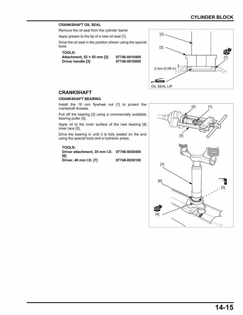
14-15
dummyheaddummyhead
CYLINDER BLOCK
CRANKSHAFT OIL SEAL
Remove the oil seal from the cylinder barrel.
Apply grease to the lip of a new oil seal [1].
Drive the oil seal in the position shown using the specialtools.
CRANKSHAFTCRANKSHAFT BEARING
Install the 16 mm flywheel nut [1] to protect thecrankshaft threads.
Pull off the bearing [2] using a commercially availablebearing puller [3].
Apply oil to the inner surface of the new bearing [4]inner race [5].
Drive the bearing in until it is fully seated on the endusing the special tools and a hydraulic press.
TOOLS:Attachment, 52 × 55 mm [2] 07746-0010400Driver handle [3] 07749-0010000
[2]
2 mm (0.08 in)
[3]
[1]
OIL SEAL LIP
TOOLS:Driver attachment, 35 mm I.D. [6]
07746-0030400
Driver, 40 mm I.D. [7] 07746-0030100[7]
[6]
[4]
[5]
[2] [1]
[3]

MEMO
dummyheaddummyhead
15-1
15
dummytext
15. HANDLE/WHEELS
WHEEL/STAND REMOVAL/INSTALLATION···········································15-2
HANDLE REMOVAL/INSTALLATION········ 15-3
HANDLE DISASSEMBLY/ASSEMBLY······ 15-4

15-2
dummyheaddummyhead
HANDLE/WHEELSHANDLE/WHEELS
WHEEL/STAND REMOVAL/INSTALLATION
STAND (2)
LONGER SHORTER
REAR
WHEEL (2)
WHEEL SHAFT WASHER (2)
BOLT (8 X 20 mm) (4)
BOLT (8 X 20 mm) (4) SPLIT PIN(4.0 X 28 mm) (2)

15-3
dummyheaddummyhead
HANDLE/WHEELS
HANDLE REMOVAL/INSTALLATION
HANDLE
HANDLE HOLDER BOLT (2)
CONCAVE WASHER (12 mm) (2)
WASHER(12 mm) (2)
21.5 N·m (2.2 kgf·m, 16 lbf·ft)
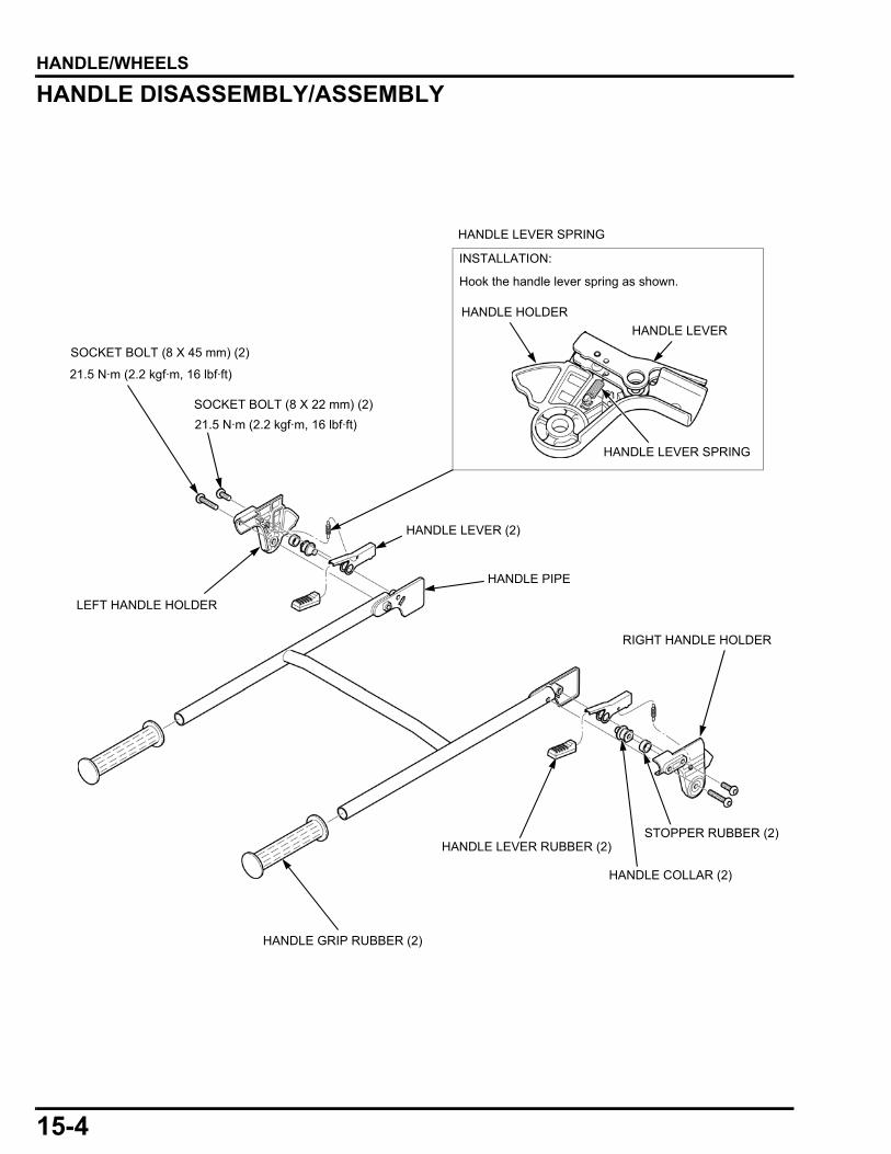
15-4
dummyheaddummyhead
HANDLE/WHEELS
HANDLE DISASSEMBLY/ASSEMBLY
HANDLE LEVER SPRING
INSTALLATION:
Hook the handle lever spring as shown.
HANDLE HOLDER
HANDLE LEVER
HANDLE LEVER SPRING
SOCKET BOLT (8 X 22 mm) (2)
SOCKET BOLT (8 X 45 mm) (2)
21.5 N·m (2.2 kgf·m, 16 lbf·ft)
21.5 N·m (2.2 kgf·m, 16 lbf·ft)
LEFT HANDLE HOLDER
HANDLE LEVER (2)
HANDLE PIPE
STOPPER RUBBER (2)
HANDLE COLLAR (2)
HANDLE LEVER RUBBER (2)
HANDLE GRIP RUBBER (2)
RIGHT HANDLE HOLDER
16-1
16
dummytext
16. TECHNICAL FEATURES
PGM-FI (PROGRAMMED-FUEL INJECTION) SYSTEM·································16-2
IGNITION SYSTEM ···································16-22
OTHER GCU OPERATION······················· 16-23
INVERTER UNIT ······································· 16-25
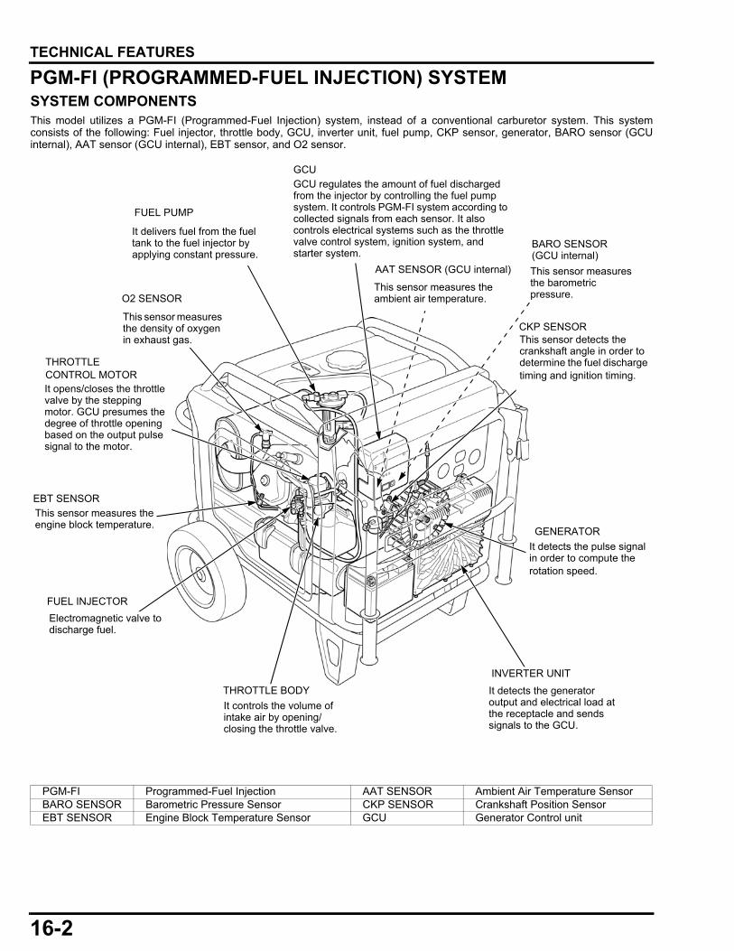
16-2
dummyheaddummyhead
TECHNICAL FEATURESTECHNICAL FEATURES
PGM-FI (PROGRAMMED-FUEL INJECTION) SYSTEMSYSTEM COMPONENTSThis model utilizes a PGM-FI (Programmed-Fuel Injection) system, instead of a conventional carburetor system. This systemconsists of the following: Fuel injector, throttle body, GCU, inverter unit, fuel pump, CKP sensor, generator, BARO sensor (GCUinternal), AAT sensor (GCU internal), EBT sensor, and O2 sensor.
O2 SENSORThis sensor measures the ambient air temperature.
FUEL PUMP
GCU
FUEL INJECTOR
Electromagnetic valve to discharge fuel.
GCU regulates the amount of fuel discharged from the injector by controlling the fuel pump system. It controls PGM-FI system according to collected signals from each sensor. It also controls electrical systems such as the throttle valve control system, ignition system, and starter system.
CKP SENSOR
THROTTLE BODY
It controls the volume of intake air by opening/closing the throttle valve.
EBT SENSOR
This sensor measures the engine block temperature.
INVERTER UNIT
It detects the generator output and electrical load at the receptacle and sends signals to the GCU.
This sensor detects the crankshaft angle in order to determine the fuel discharge timing and ignition timing.
AAT SENSOR (GCU internal)
It opens/closes the throttle valve by the stepping motor. GCU presumes the degree of throttle opening based on the output pulse signal to the motor.
THROTTLE CONTROL MOTOR
This sensor measures the density of oxygen in exhaust gas.
GENERATOR
It detects the pulse signal in order to compute the rotation speed.
It delivers fuel from the fuel tank to the fuel injector by applying constant pressure.
This sensor measures the barometric pressure.
BARO SENSOR(GCU internal)
PGM-FI Programmed-Fuel Injection AAT SENSOR Ambient Air Temperature SensorBARO SENSOR Barometric Pressure Sensor CKP SENSOR Crankshaft Position SensorEBT SENSOR Engine Block Temperature Sensor GCU Generator Control unit

16-3
dummyheaddummyhead
TECHNICAL FEATURES
COMPARISON BETWEEN ELECTRICALLY CONTROLLED CARBURETOR AND PGM-FISYSTEMBASIC OPERATION
The electrically controlled carburetor and PGM-FI system change the volume of incoming air-fuel mixture by opening/closing thethrottle valve in order to regulate the engine speed. The carburetor changes the amount of mixture by sucking fuel into thecarburetor bore in accordance with the volume of incoming air; the PGM-FI system by controlling the volume of fuel dischargedfrom the injector.
NO LOAD TO LOW LOAD
When there is no load to low load at the receptacle, the engine runs at the pre-set target rotation (2,400 rpm).
ELECTRICALLY CONTROLLED CARBURETOR (AT NO LOAD TO LOW LOAD): • The mixture is supplied from the side port as the GCU opens the throttle valve partially.
PGM-FI (AT NO LOAD TO LOW LOAD): • The GCU opens the throttle valve partially. The discharge volume from the fuel injector is determined by GCU according to the
throttle position and engine speed with corrections based upon the signals from inverter, EBT sensor, AAT sensor, BAROsensor, and O2 sensor.
CARBURETOR (AT NO LOAD TO LOW LOAD):
THROTTLE VALVE
CHOKE VALVE
AIR
FUEL
SIDE PORT
• Engine Block Temperature
• Ambient Air Temperature• Barometric Pressure
• O2 density
FUEL
AIR
FUEL PUMP
THROTTLE VALVE
PGM-FI THROTTLE BODY (AT NO LOAD TO LOW LOAD):
INJECTOR
• Engine revs
• Throttle valve angle
GCU
FUEL INJECTION SIGNAL
GENERATOR
THROTTLE CONTROL MOTOR
EBT SENSOR
AAT SENSOR
BARO SENSOR
O2 SENSOR
Basic discharge volume
Correction
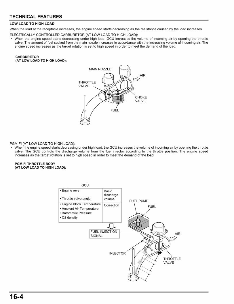
16-4
dummyheaddummyhead
TECHNICAL FEATURES
LOW LOAD TO HIGH LOAD
When the load at the receptacle increases, the engine speed starts decreasing as the resistance caused by the load increases.
ELECTRICALLY CONTROLLED CARBURETOR (AT LOW LOAD TO HIGH LOAD): • When the engine speed starts decreasing under high load, GCU increases the volume of incoming air by opening the throttle
valve. The amount of fuel sucked from the main nozzle increases in accordance with the increasing volume of incoming air. Theengine speed increases as the target rotation is set to high speed in order to meet the demand of the load.
PGM-FI (AT LOW LOAD TO HIGH LOAD): • When the engine speed starts decreasing under high load, the GCU increases the volume of incoming air by opening the throttle
valve. The GCU controls the discharge volume from the fuel injector according to the throttle position. The engine speedincreases as the target rotation is set to high speed in order to meet the demand of the load.
MAIN NOZZLE
CARBURETOR (AT LOW LOAD TO HIGH LOAD):
THROTTLE VALVE
CHOKE VALVE
AIR
FUEL
FUEL
AIR
FUEL PUMP
INJECTOR
THROTTLE VALVE
PGM-FI THROTTLE BODY (AT LOW LOAD TO HIGH LOAD):
FUEL INJECTION SIGNAL
• Engine Block Temperature• Ambient Air Temperature• Barometric Pressure• O2 density
• Engine revs
• Throttle valve angle
GCU
Basic discharge volume
Correction
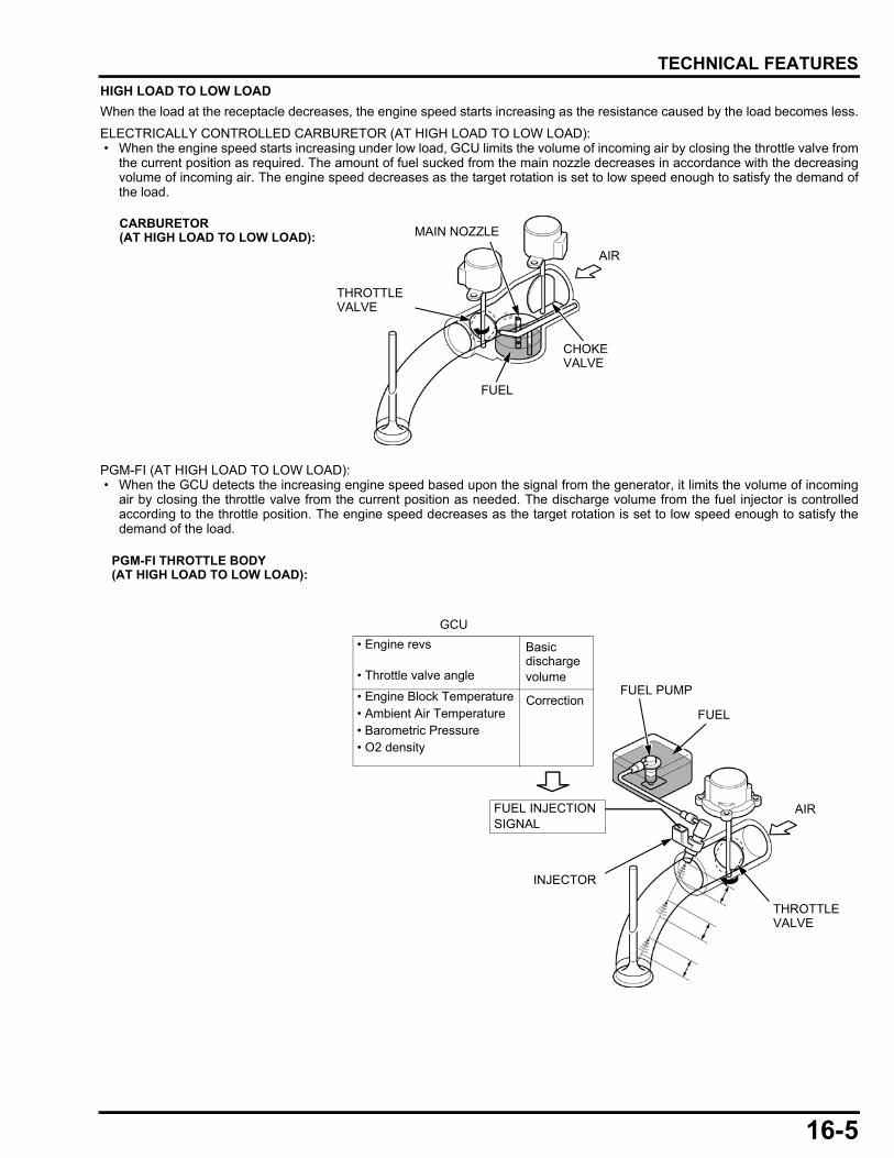
16-5
dummyheaddummyhead
TECHNICAL FEATURES
HIGH LOAD TO LOW LOAD
When the load at the receptacle decreases, the engine speed starts increasing as the resistance caused by the load becomes less.
ELECTRICALLY CONTROLLED CARBURETOR (AT HIGH LOAD TO LOW LOAD): • When the engine speed starts increasing under low load, GCU limits the volume of incoming air by closing the throttle valve from
the current position as required. The amount of fuel sucked from the main nozzle decreases in accordance with the decreasingvolume of incoming air. The engine speed decreases as the target rotation is set to low speed enough to satisfy the demand ofthe load.
PGM-FI (AT HIGH LOAD TO LOW LOAD): • When the GCU detects the increasing engine speed based upon the signal from the generator, it limits the volume of incoming
air by closing the throttle valve from the current position as needed. The discharge volume from the fuel injector is controlledaccording to the throttle position. The engine speed decreases as the target rotation is set to low speed enough to satisfy thedemand of the load.
CARBURETOR (AT HIGH LOAD TO LOW LOAD):
THROTTLE VALVE
CHOKE VALVE
MAIN NOZZLE
AIR
FUEL
FUEL
AIR
FUEL PUMP
THROTTLE VALVE
PGM-FI THROTTLE BODY (AT HIGH LOAD TO LOW LOAD):
INJECTOR
FUEL INJECTION SIGNAL
• Engine Block Temperature• Ambient Air Temperature• Barometric Pressure• O2 density
• Engine revs
• Throttle valve angle
GCU
Basic discharge volume
Correction
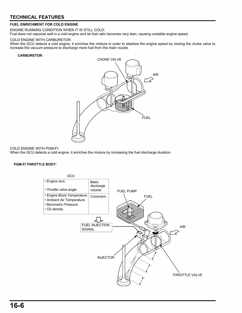
16-6
dummyheaddummyhead
TECHNICAL FEATURES
FUEL ENRICHMENT FOR COLD ENGINE
ENGINE RUNNING CONDITION WHEN IT IS STILL COLD:Fuel does not vaporize well in a cold engine and air-fuel ratio becomes very lean, causing unstable engine speed.
COLD ENGINE WITH CARBURETOR:When the GCU detects a cold engine, it enriches the mixture in order to stabilize the engine speed by closing the choke valve toincrease the vacuum pressure to discharge more fuel from the main nozzle.
COLD ENGINE WITH PGM-FI:When the GCU detects a cold engine, it enriches the mixture by increasing the fuel discharge duration.
CHOKE VALVECARBURETOR:
AIR
FUEL
PGM-FI THROTTLE BODY:
INJECTOR
FUEL PUMP
AIR
FUEL• Engine Block Temperature• Ambient Air Temperature• Barometric Pressure• O2 density
• Engine revs
• Throttle valve angle
GCU
Basic discharge volume
Correction
FUEL INJECTION SIGNAL
THROTTLE VALVE
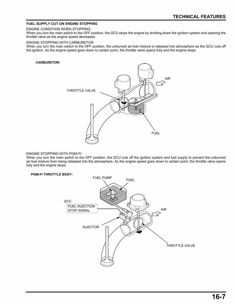
16-7
dummyheaddummyhead
TECHNICAL FEATURES
FUEL SUPPLY CUT ON ENGINE STOPPING
ENGINE CONDITION WHEN STOPPING:When you turn the main switch to the OFF position, the GCU stops the engine by shutting down the ignition system and opening thethrottle valve as the engine speed decreases.
ENGINE STOPPING WITH CARBURETOR:When you turn the main switch to the OFF position, the unburned air-fuel mixture is released into atmosphere as the GCU cuts offthe ignition. As the engine speed goes down to certain point, the throttle valve opens fully and the engine stops.
ENGINE STOPPING WITH PGM-FI:When you turn the main switch to the OFF position, the GCU cuts off the ignition system and fuel supply to prevent the unburnedair-fuel mixture from being released into the atmosphere. As the engine speed goes down to certain point, the throttle valve opensfully and the engine stops.
CARBURETOR:
THROTTLE VALVE
AIR
FUEL
INJECTOR
FUEL PUMP
AIR
FUEL
THROTTLE VALVE
PGM-FI THROTTLE BODY:
GCU
FUEL INJECTION STOP SIGNAL
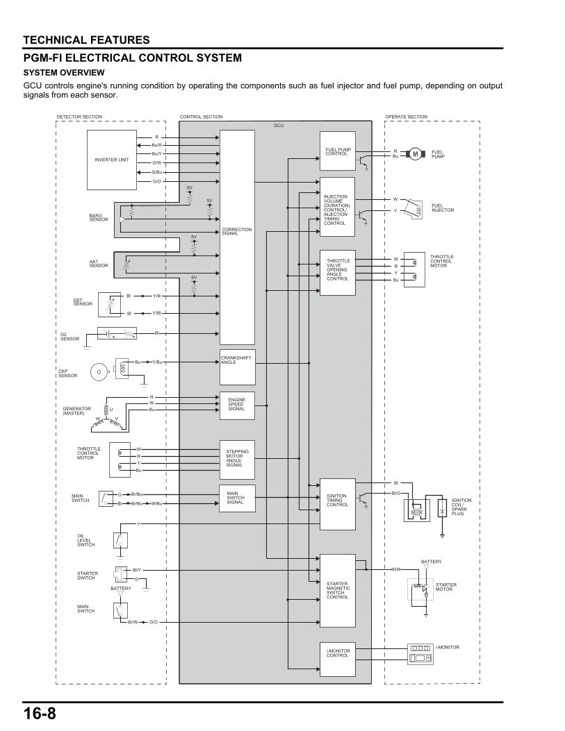
16-8
dummyheaddummyhead
TECHNICAL FEATURES
PGM-FI ELECTRICAL CONTROL SYSTEMSYSTEM OVERVIEW
GCU controls engine's running condition by operating the components such as fuel injector and fuel pump, depending on outputsignals from each sensor.
Y/R
R
R
WRY
Bu
Bl
Bl/G
Bl/W
Y
W
Bu
Bu/R
Br/Bu
Br/Bu
Bl/Y
G/O
W/Bu
G/Bu
Bu/Y
O/W
G/O5V
Y/Bl
Bl
Y
G
Bu Y/Bu
BAROSENSOR
INVERTER UNIT
GCU
DETECTOR SECTION CONTROL SECTION OPERATE SECTION
FUEL PUMPCONTROL
INJECTIONVOLUME(DURATION)CONTROL/INJECTIONTIMINGCONTROL
CORRECTIONSIGNAL
ENGINESPEEDSIGNAL
AATSENSOR
EBTSENSOR
O2SENSOR
CKPSENSOR
OILLEVELSWITCH
MAINSWITCH
MAINSWITCHSIGNAL
U
VW
GENERATOR (MASTER)
THROTTLECONTROLMOTOR
THROTTLECONTROLMOTOR
STEPPINGMOTORANGLESIGNAL
RWBu
THROTTLEVALVEOPENINGANGLECONTROL
IGNITIONTIMINGCONTROL
STARTERMAGNETICSWITCHCONTROL
i-MONITORCONTROL
W
G
Bl
YBu
R
STARTERSWITCH
MAINSWITCH
BATTERYSTARTERMOTOR
i-MONITOR
BATTERY
IGNITIONCOIL/SPARKPLUG
FUELPUMP
FUELINJECTOR
5V
5V
5V
CRANKSHAFTANGLE
Br/W
Bl
Bl
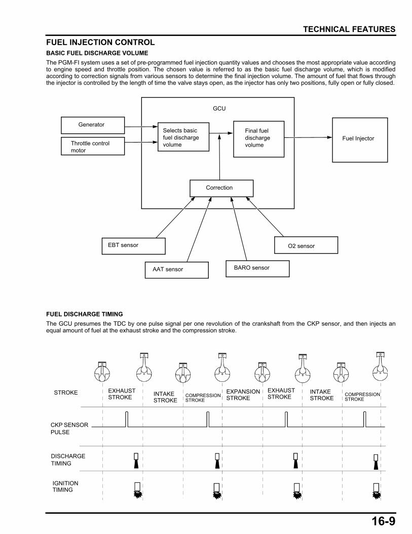
16-9
dummyheaddummyhead
TECHNICAL FEATURES
FUEL INJECTION CONTROLBASIC FUEL DISCHARGE VOLUME
The PGM-FI system uses a set of pre-programmed fuel injection quantity values and chooses the most appropriate value accordingto engine speed and throttle position. The chosen value is referred to as the basic fuel discharge volume, which is modifiedaccording to correction signals from various sensors to determine the final injection volume. The amount of fuel that flows throughthe injector is controlled by the length of time the valve stays open, as the injector has only two positions, fully open or fully closed.
FUEL DISCHARGE TIMING
The GCU presumes the TDC by one pulse signal per one revolution of the crankshaft from the CKP sensor, and then injects anequal amount of fuel at the exhaust stroke and the compression stroke.
GCU
Generator
Throttle control motor
O2 sensor
Fuel Injector
BARO sensor
EBT sensor
AAT sensor
Selects basic fuel dischargevolume
Final fuel dischargevolume
Correction
DISCHARGE TIMING
IGNITION TIMING
CKP SENSOR PULSE
STROKE INTAKE STROKE
COMPRESSION STROKE
EXHAUST STROKEINTAKE
STROKECOMPRESSION STROKE
EXPANSION STROKE
EXHAUST STROKE

16-10
dummyheaddummyhead
TECHNICAL FEATURES
FUEL INJECTOR
SUMMARY:
• A fuel injector is a solenoid valve that consists of a needle valve/plunger,solenoid coil, solenoid spring, and filter.
• Constantly pressurized fuel (294 kPa (3 kgf/cm2, 43 psi) is supplied tothe fuel injector.
• The fuel injector is either fully closed or fully open with a fixed stroke.The amount of fuel injected is dependent on how long the fuel injector iskept open.
• The GCU applies voltage to the fuel injector to open it while thegenerator is generating the voltage.
OPERATION:
1. The fuel pressurized by the fuel pump is blocked at the fuel injector nozzle that consists of a plunger/needle valve and valveseat.
2. When the GCU applies current to the solenoid coil in the fuel injector, the coil becomes an electromagnet that pulls the plunger/needle valve while compressing the solenoid spring.
3. The nozzle opens as the plunger/needle valve lifts up. The fuel blocked at the fuel injector nozzle passes the filter and thensprays into the intake port.
4. When the GCU stops current to the solenoid coil in the fuel injector, the coil is no longer electromagnetic and the nozzle will beshut by the returning force of the solenoid spring, which blocks the fuel.
SOLENOID COILSOLENOID SPRING
PLUNGER(NEEDLE VALVE) FILTER
SOLENOID SPRING
FUEL PUMP
PLUNGER/NEEDLE VALVE
SOLENOID COIL
FILTER
VALVE SEAT
FUEL INJECTOR NOZZLE
FUEL PUMP
VALVE SEAT
SOLENOID SPRING
SOLENOID COIL
FUEL INJECTOR NOZZLE
PLUNGER/NEEDLE VALVE

16-11
dummyheaddummyhead
TECHNICAL FEATURES
FUEL PUMP
SUMMARY:
• The fuel pump is located inside the fuel tank. • The fuel pump draws in the fuel via the fuel filter and delivers it to the fuel injector.
The pressure regulator maintains a constant fuel pressure of 294 kPa (3 kgf/cm2, 43 psi).
FUEL PUMP CONSTRUCTION:
The fuel pump assembly consists of a pump section, residual pressure check valve, suction port, and discharge port.The pump section consists of a motor-driven impeller and pump chamber composed of a pump casing and pump cover.
FUEL PUMP OPERATION:
• When the motor turns, fin grooves located on impeller circumference produce a pressure difference due to hydro-friction force.Fuel is drawn into the pump, and then delivered out of the pump.
• The drawn fuel via the filter circulates inside the motor and passes the residual pressure check valve, then is delivered throughthe discharge port.
• When engine is turned OFF and fuel pump is not operating, the check valve maintains residual fuel pressure to ease enginerestarting.
• The fuel pressure regulator maintains fuel pressure by the regulator valve that opens when fuel pressure in the discharge circuit(between the pump and fuel injector) becomes higher than a certain value.
ARMATURE COIL
PRESSURE REGULATOR VALVE
TO FUEL INJECTOR
FILTER
IMPELLER
CASING
RESIDUAL PRESSURE CHECK VALVE
DISCHARGE PORT
PUMP COVER
SUCTION PORT
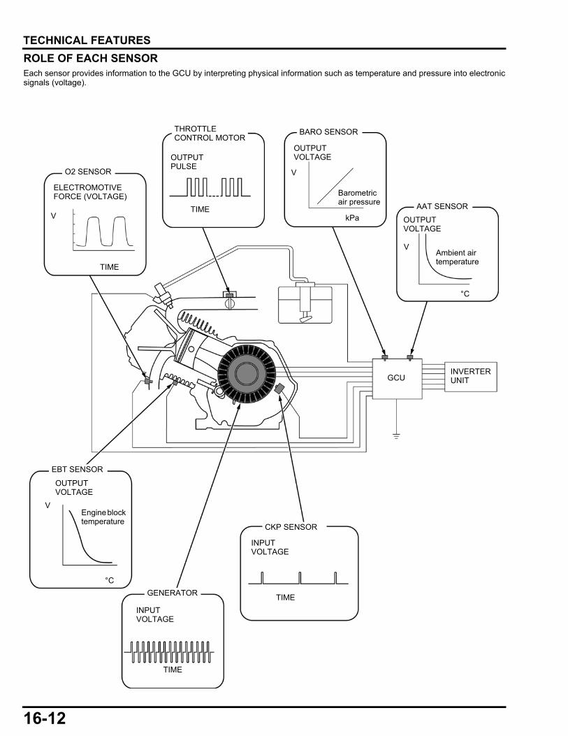
16-12
dummyheaddummyhead
TECHNICAL FEATURES
ROLE OF EACH SENSOREach sensor provides information to the GCU by interpreting physical information such as temperature and pressure into electronicsignals (voltage).
Ambient air temperature
V
V
Barometric air pressure
TIME
GCU
°C
OUTPUT VOLTAGE
kPa
AAT SENSOR
BARO SENSOR
CKP SENSOR
OUTPUT VOLTAGE
O2 SENSOR
Engine block temperature
°C
OUTPUT VOLTAGE
EBT SENSOR
ELECTROMOTIVE FORCE (VOLTAGE)
GENERATOR
OUTPUT PULSE
INVERTER UNIT
THROTTLE CONTROL MOTOR
TIME
TIME
TIME
V
V
INPUT VOLTAGE
INPUT VOLTAGE

16-13
dummyheaddummyhead
TECHNICAL FEATURES
SENSORSThere are two kinds of sensor output: One translates changes of the electrical resistance into changes of voltage, the otherproduces its own voltage or current.
OUTPUT VOLTAGE SENT TO GCU
As shown on the diagram below, two resistors divide the source voltage when connected to the source in series.
When resistor A and B have the same resistance value, source voltage would be divided equally. When one of them has a largerresistance value than the other, it would receive a larger share of the load.
The EBT sensor and AAT sensor utilize this principle.
The GCU receives changes of physical information (changes of temperature, pressure etc.) as variable voltage by reading it at bothends of resistor B (Resistor A: fixed resistor/Resistor B: variable resistor that reacts to physical changes).
For example, when the source voltage is 5 V, the resistance value of resistor A is 1.0 kΩ, and the resistance value of resistor B is19.0 kΩ, the voltage measured at point C would be 4.75 V, as shown below. If the value of resistor B is 0.06 kΩ, the voltagemeasured at point C would be 0.28 V.
5 V
A= 1 kΩ2.5 V
2.5 VB= 1 kΩ
e.g. EBT (engine block temperature) SENSOR
When engine block temperature is – 25 °C:
GCU
EBT SENSOR
GCU
When engine block temperature is 150 °C:
CPU
EBT SENSOR5 V 5 V
B= 19.0 kΩ
C= 4.75 V
A= 1.0 kΩ
B= 0.06 kΩ
A= 1.0 KΩ
C= 0.28V
CPU
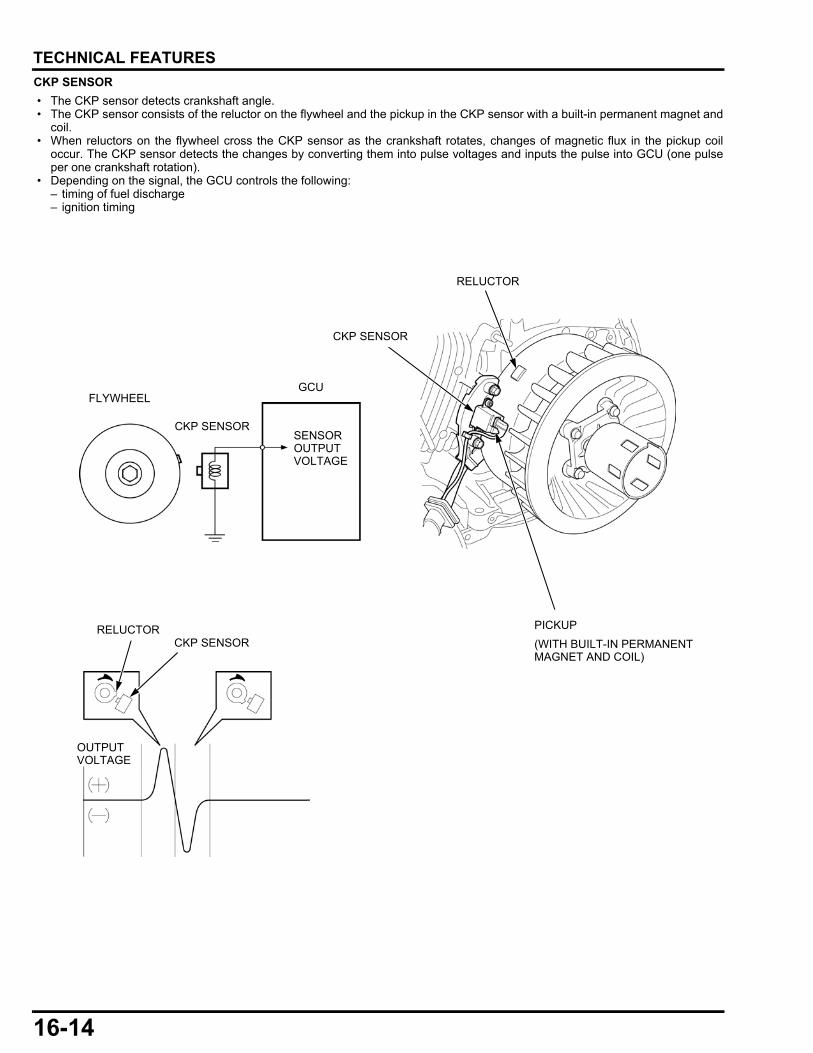
16-14
dummyheaddummyhead
TECHNICAL FEATURES
CKP SENSOR
• The CKP sensor detects crankshaft angle. • The CKP sensor consists of the reluctor on the flywheel and the pickup in the CKP sensor with a built-in permanent magnet and
coil. • When reluctors on the flywheel cross the CKP sensor as the crankshaft rotates, changes of magnetic flux in the pickup coil
occur. The CKP sensor detects the changes by converting them into pulse voltages and inputs the pulse into GCU (one pulseper one crankshaft rotation).
• Depending on the signal, the GCU controls the following:– timing of fuel discharge– ignition timing
OUTPUT VOLTAGE
RELUCTOR
CKP SENSOR
SENSOR OUTPUT VOLTAGE
GCUFLYWHEEL
CKP SENSOR
(WITH BUILT-IN PERMANENT MAGNET AND COIL)
PICKUP
CKP SENSOR
RELUCTOR
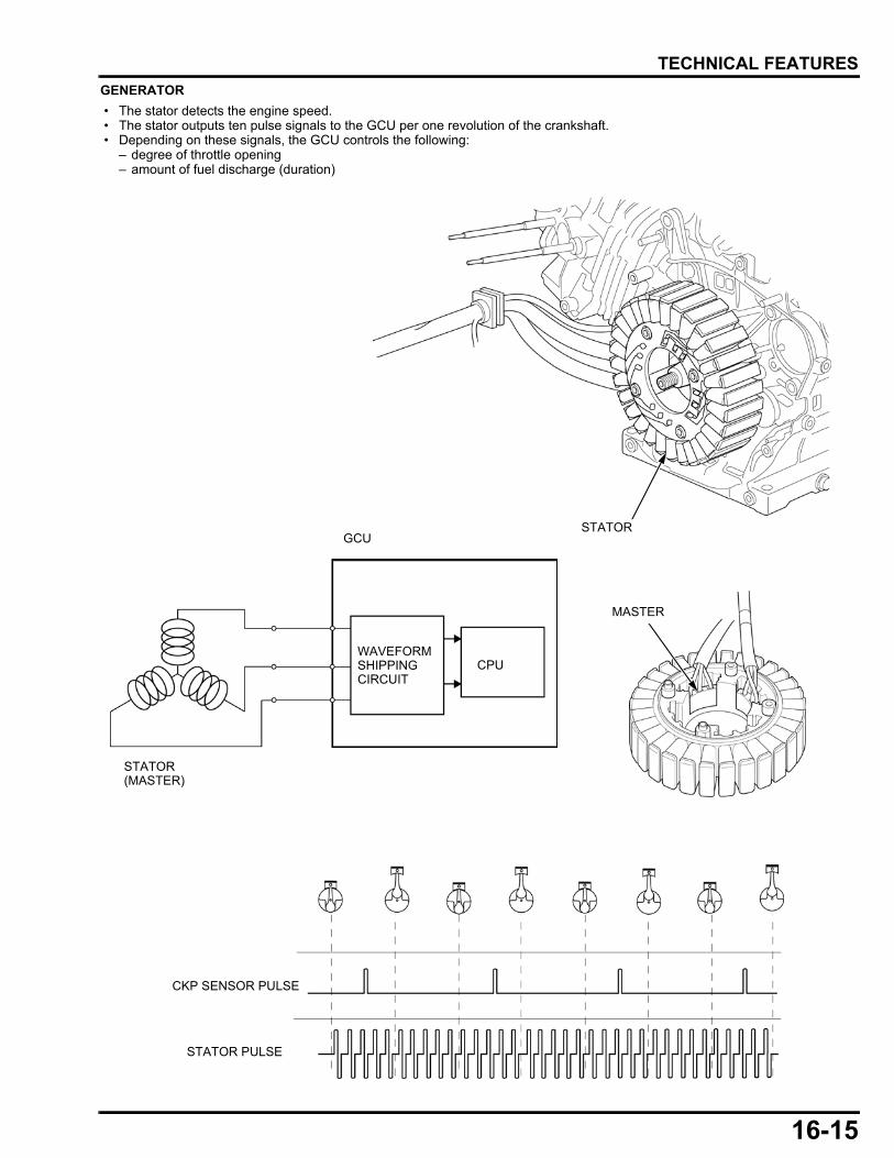
16-15
dummyheaddummyhead
TECHNICAL FEATURES
GENERATOR
• The stator detects the engine speed. • The stator outputs ten pulse signals to the GCU per one revolution of the crankshaft. • Depending on these signals, the GCU controls the following:
– degree of throttle opening– amount of fuel discharge (duration)
MASTER
STATOR
STATOR(MASTER)
WAVEFORM SHIPPING CIRCUIT
GCU
STATOR PULSE
CKP SENSOR PULSE
CPU
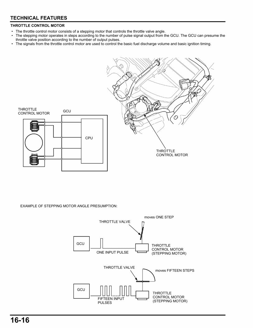
16-16
dummyheaddummyhead
TECHNICAL FEATURES
THROTTLE CONTROL MOTOR
• The throttle control motor consists of a stepping motor that controls the throttle valve angle. • The stepping motor operates in steps according to the number of pulse signal output from the GCU. The GCU can presume the
throttle valve position according to the number of output pulses. • The signals from the throttle control motor are used to control the basic fuel discharge volume and basic ignition timing.
THROTTLE CONTROL MOTOR
GCU
THROTTLE CONTROL MOTOR
CPU
ONE INPUT PULSE
GCU
GCU
THROTTLE CONTROL MOTOR(STEPPING MOTOR)
THROTTLE CONTROL MOTOR(STEPPING MOTOR)
EXAMPLE OF STEPPING MOTOR ANGLE PRESUMPTION:
THROTTLE VALVE
THROTTLE VALVE
moves ONE STEP
FIFTEEN INPUT PULSES
moves FIFTEEN STEPS
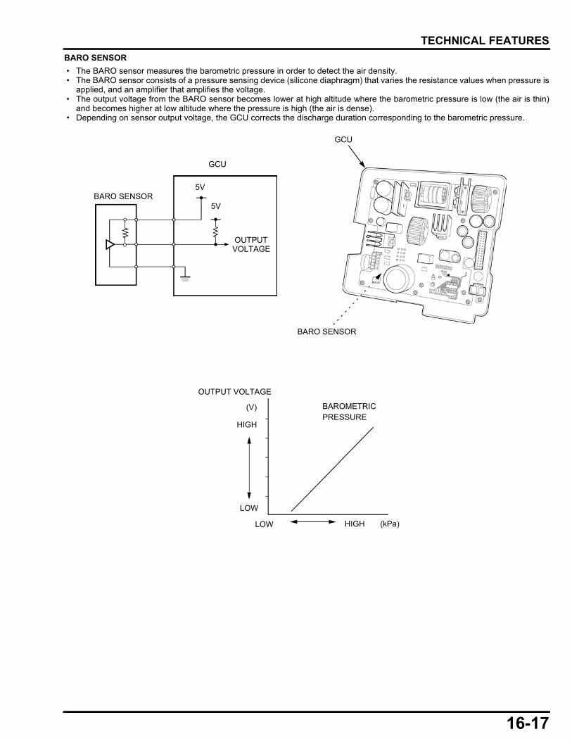
16-17
dummyheaddummyhead
TECHNICAL FEATURES
BARO SENSOR
• The BARO sensor measures the barometric pressure in order to detect the air density. • The BARO sensor consists of a pressure sensing device (silicone diaphragm) that varies the resistance values when pressure is
applied, and an amplifier that amplifies the voltage. • The output voltage from the BARO sensor becomes lower at high altitude where the barometric pressure is low (the air is thin)
and becomes higher at low altitude where the pressure is high (the air is dense). • Depending on sensor output voltage, the GCU corrects the discharge duration corresponding to the barometric pressure.
GCU
BARO SENSOR
GCU
OUTPUT VOLTAGE
LOW HIGH
OUTPUT VOLTAGE
HIGH
LOW
5V
5V
BARO SENSOR
(kPa)
(V) BAROMETRICPRESSURE
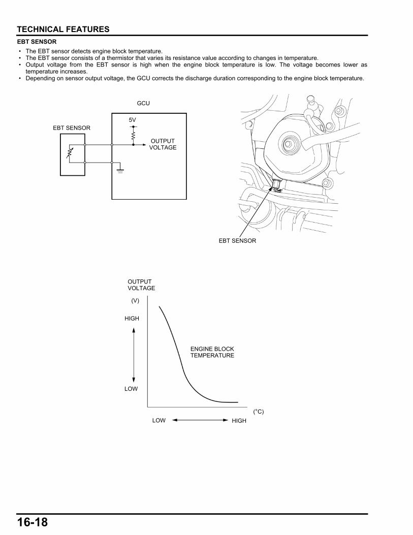
16-18
dummyheaddummyhead
TECHNICAL FEATURES
EBT SENSOR
• The EBT sensor detects engine block temperature. • The EBT sensor consists of a thermistor that varies its resistance value according to changes in temperature. • Output voltage from the EBT sensor is high when the engine block temperature is low. The voltage becomes lower as
temperature increases. • Depending on sensor output voltage, the GCU corrects the discharge duration corresponding to the engine block temperature.
EBT SENSOR
EBT SENSOR
GCU
OUTPUT VOLTAGE
5V
(V)
ENGINE BLOCK TEMPERATURE
(°C)
OUTPUT VOLTAGE
LOW HIGH
HIGH
LOW
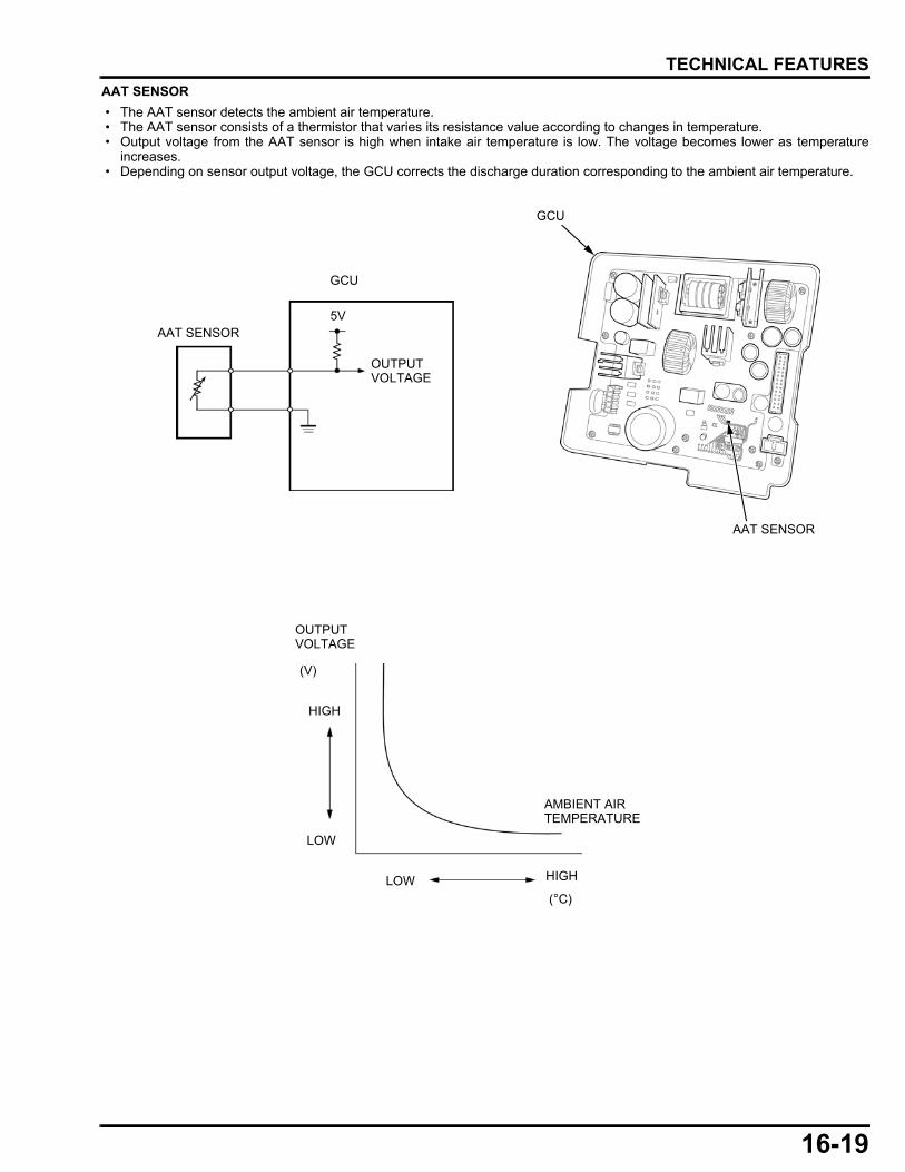
16-19
dummyheaddummyhead
TECHNICAL FEATURES
AAT SENSOR
• The AAT sensor detects the ambient air temperature. • The AAT sensor consists of a thermistor that varies its resistance value according to changes in temperature. • Output voltage from the AAT sensor is high when intake air temperature is low. The voltage becomes lower as temperature
increases. • Depending on sensor output voltage, the GCU corrects the discharge duration corresponding to the ambient air temperature.
AAT SENSOR
AMBIENT AIR TEMPERATURE
OUTPUT VOLTAGE
AAT SENSOR
GCU
5V
GCU
OUTPUT VOLTAGE
(V)
(°C)
LOW HIGH
HIGH
LOW
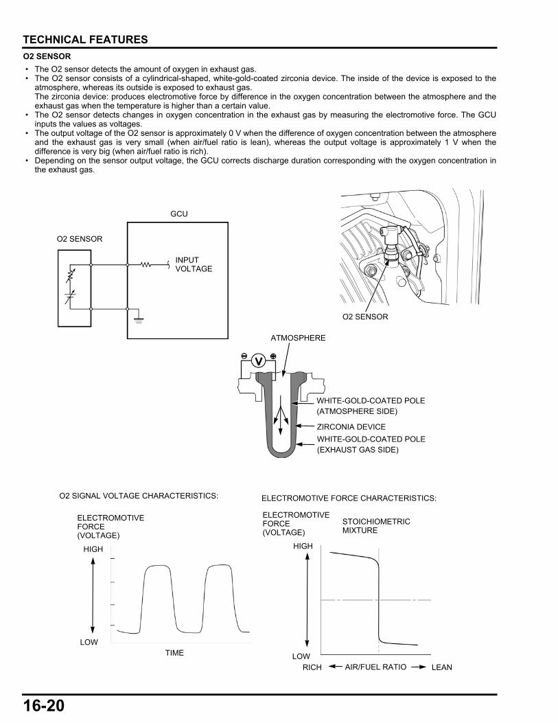
16-20
dummyheaddummyhead
TECHNICAL FEATURES
O2 SENSOR
• The O2 sensor detects the amount of oxygen in exhaust gas. • The O2 sensor consists of a cylindrical-shaped, white-gold-coated zirconia device. The inside of the device is exposed to the
atmosphere, whereas its outside is exposed to exhaust gas.The zirconia device: produces electromotive force by difference in the oxygen concentration between the atmosphere and theexhaust gas when the temperature is higher than a certain value.
• The O2 sensor detects changes in oxygen concentration in the exhaust gas by measuring the electromotive force. The GCUinputs the values as voltages.
• The output voltage of the O2 sensor is approximately 0 V when the difference of oxygen concentration between the atmosphereand the exhaust gas is very small (when air/fuel ratio is lean), whereas the output voltage is approximately 1 V when thedifference is very big (when air/fuel ratio is rich).
• Depending on the sensor output voltage, the GCU corrects discharge duration corresponding with the oxygen concentration inthe exhaust gas.
O2 SENSOR
O2 SENSOR
GCU
ZIRCONIA DEVICE
WHITE-GOLD-COATED POLE (ATMOSPHERE SIDE)
WHITE-GOLD-COATED POLE (EXHAUST GAS SIDE)
ATMOSPHERE
O2 SIGNAL VOLTAGE CHARACTERISTICS: ELECTROMOTIVE FORCE CHARACTERISTICS:
ELECTROMOTIVE FORCE (VOLTAGE)
TIME
AIR/FUEL RATIORICH LEAN
HIGH
LOW
HIGH
LOW
ELECTROMOTIVE FORCE (VOLTAGE)
STOICHIOMETRIC MIXTURE
INPUT VOLTAGE
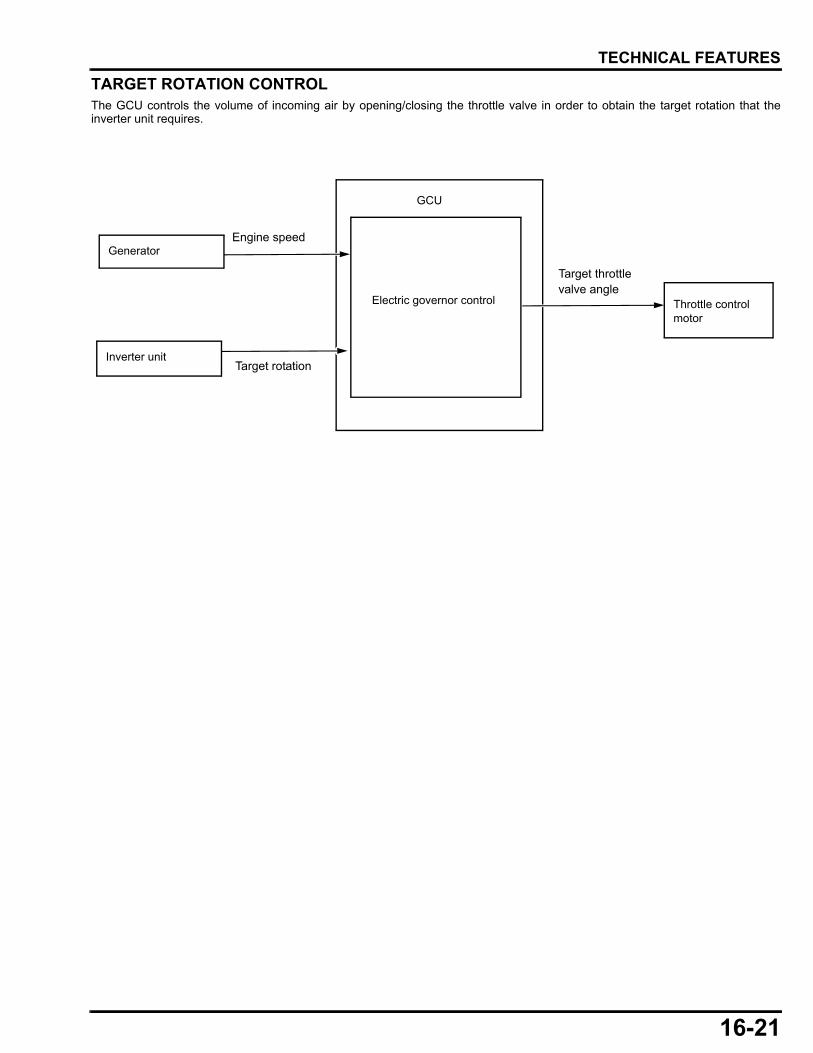
16-21
dummyheaddummyhead
TECHNICAL FEATURES
TARGET ROTATION CONTROLThe GCU controls the volume of incoming air by opening/closing the throttle valve in order to obtain the target rotation that theinverter unit requires.
GCU
Generator
Electric governor control Throttle control motor
Inverter unit
Engine speed
Target rotation
Target throttle valve angle
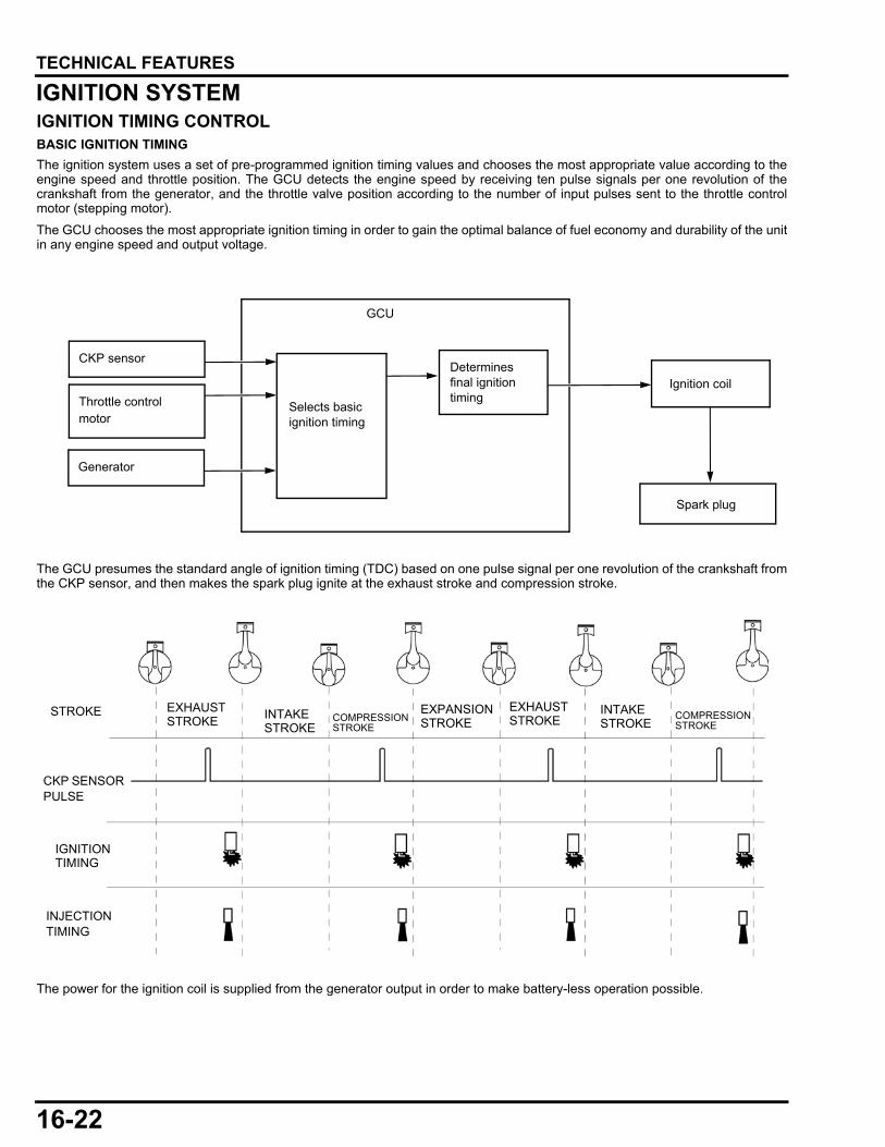
16-22
dummyheaddummyhead
TECHNICAL FEATURES
IGNITION SYSTEMIGNITION TIMING CONTROLBASIC IGNITION TIMING
The ignition system uses a set of pre-programmed ignition timing values and chooses the most appropriate value according to theengine speed and throttle position. The GCU detects the engine speed by receiving ten pulse signals per one revolution of thecrankshaft from the generator, and the throttle valve position according to the number of input pulses sent to the throttle controlmotor (stepping motor).
The GCU chooses the most appropriate ignition timing in order to gain the optimal balance of fuel economy and durability of the unitin any engine speed and output voltage.
The GCU presumes the standard angle of ignition timing (TDC) based on one pulse signal per one revolution of the crankshaft fromthe CKP sensor, and then makes the spark plug ignite at the exhaust stroke and compression stroke.
The power for the ignition coil is supplied from the generator output in order to make battery-less operation possible.
GCU
CKP sensor
Selects basic ignition timing
Determines final ignition timing
Ignition coil
Spark plug
Throttle control motor
Generator
INJECTION TIMING
IGNITION TIMING
CKP SENSOR PULSE
STROKE INTAKE STROKE
COMPRESSION STROKE
EXHAUST STROKEINTAKE
STROKECOMPRESSION STROKE
EXPANSION STROKE
EXHAUST STROKE
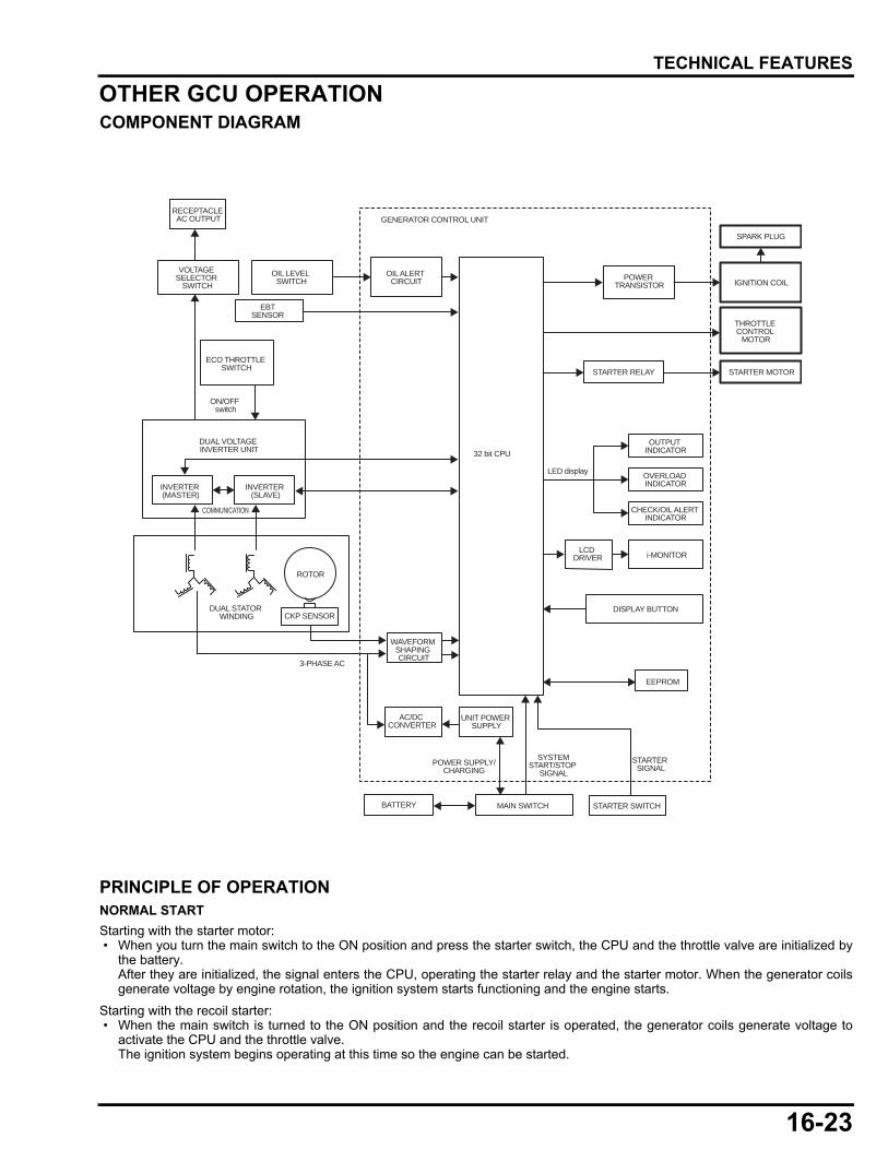
16-23
dummyheaddummyhead
TECHNICAL FEATURES
OTHER GCU OPERATIONCOMPONENT DIAGRAM
PRINCIPLE OF OPERATIONNORMAL START
Starting with the starter motor: • When you turn the main switch to the ON position and press the starter switch, the CPU and the throttle valve are initialized by
the battery.After they are initialized, the signal enters the CPU, operating the starter relay and the starter motor. When the generator coilsgenerate voltage by engine rotation, the ignition system starts functioning and the engine starts.
Starting with the recoil starter: • When the main switch is turned to the ON position and the recoil starter is operated, the generator coils generate voltage to
activate the CPU and the throttle valve.The ignition system begins operating at this time so the engine can be started.
RECEPTACLE AC OUTPUT
VOLTAGE SELECTOR
SWITCHOIL LEVEL
SWITCH
THROTTLE CONTROL
MOTOR
ECO THROTTLE SWITCH
ON/OFF switch
DUAL VOLTAGE INVERTER UNIT
INVERTER (MASTER)
INVERTER (SLAVE)
COMMUNICATION
DUAL STATOR WINDING
ROTOR
CKP SENSOR
3-PHASE AC
GENERATOR CONTROL UNIT
OIL ALERT CIRCUIT
WAVEFORM SHAPING CIRCUIT
AC/DC CONVERTER
UNIT POWER SUPPLY
POWER SUPPLY/CHARGING
BATTERY MAIN SWITCH
STARTER SIGNAL
32 bit CPU
POWER TRANSISTOR
STARTER RELAY
OUTPUT INDICATOR
LED display OVERLOAD INDICATOR
CHECK/OIL ALERT INDICATOR
LCD DRIVER i-MONITOR
DISPLAY BUTTON
EEPROM
SPARK PLUG
IGNITION COIL
STARTER MOTOR
EBTSENSOR
STARTER SWITCH
SYSTEMSTART/STOP
SIGNAL

16-24
dummyheaddummyhead
TECHNICAL FEATURES
NORMAL STOP
When you turn the main switch to the OFF position, the stop signal is transmitted to the GCU and to the inverter unit. The inverterunit stops generator output. The GCU shuts off the fuel supply and ignition in order to stop the engine.
ENGINE SPEED LIMITER
The ignition is cut off when the engine speed exceeds 4,400 rpm, and ignition is resumed when engine speed goes below 4,400rpm, which protects the generator system from engine over-speeding. However, if the engine speed exceeds 3,900 rpm for morethan 3 seconds, the i-Monitor will display an error code and the engine will be shut down.
OIL ALERT
When the engine oil runs low, activating the oil level switch, the ignition is cut off. At the time the engine is stopped, the Oil Alertindicator (red) comes ON and the i-Monitor displays “OIL”.
STARTER MOTOR
When you press the starter switch, the CPU receives the signal, operating the starter relay and the starter motor. The starter relayis controlled so that it cannot be activated when the engine is running.
COMMUNICATION WITH INVERTER
The control unit and inverters are constantly communicating during operation, transmitting signals for inverter problem detectionand generator output status. When the communication line is disconnected or the inverter breaks down, a fail-safe procedure will beperformed.
BATTERY CHARGE
When the generator is operating, the battery is charged by the inverter with a controlled output of 0.6 A. The charging is stoppedwhen the battery voltage reaches 14.5 V. The charging is also stopped when the battery voltage becomes less than 3 V, assumingthe battery terminals are disconnected.
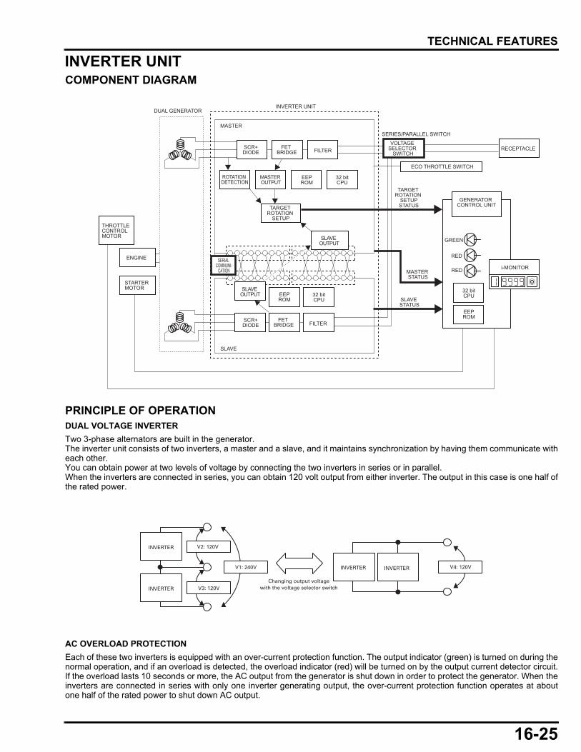
16-25
dummyheaddummyhead
TECHNICAL FEATURES
INVERTER UNITCOMPONENT DIAGRAM
PRINCIPLE OF OPERATIONDUAL VOLTAGE INVERTER
Two 3-phase alternators are built in the generator.The inverter unit consists of two inverters, a master and a slave, and it maintains synchronization by having them communicate witheach other.You can obtain power at two levels of voltage by connecting the two inverters in series or in parallel.When the inverters are connected in series, you can obtain 120 volt output from either inverter. The output in this case is one half ofthe rated power.
AC OVERLOAD PROTECTION
Each of these two inverters is equipped with an over-current protection function. The output indicator (green) is turned on during thenormal operation, and if an overload is detected, the overload indicator (red) will be turned on by the output current detector circuit.If the overload lasts 10 seconds or more, the AC output from the generator is shut down in order to protect the generator. When theinverters are connected in series with only one inverter generating output, the over-current protection function operates at aboutone half of the rated power to shut down AC output.
GREEN
DUAL GENERATORINVERTER UNIT
THROTTLECONTROL MOTOR
ENGINE
STARTER MOTOR
MASTER
SCR+DIODE
FET BRIDGE FILTER
ROTATION DETECTION
TARGET ROTATION
SETUP
MASTER OUTPUT
EEPROM
32 bitCPU
SERIAL COMMUNI-
CATION
SLAVE OUTPUT EEP
ROM32 bitCPU
SCR+DIODE
FET BRIDGE FILTER
SLAVE
SERIES/PARALLEL SWITCH
VOLTAGE SELECTOR
SWITCHRECEPTACLE
ECO THROTTLE SWITCH
GENERATOR CONTROL UNIT
MASTER STATUS
32 bitCPU
i-MONITOR
SLAVE STATUS
EEPROM
RED
RED
TARGET ROTATION
SETUPSTATUS
SLAVE OUTPUT
INVERTER
INVERTER
V2: 120V
V3: 120V
V1: 240V
Changing output voltage with the voltage selector switch
INVERTER INVERTER V4: 120V
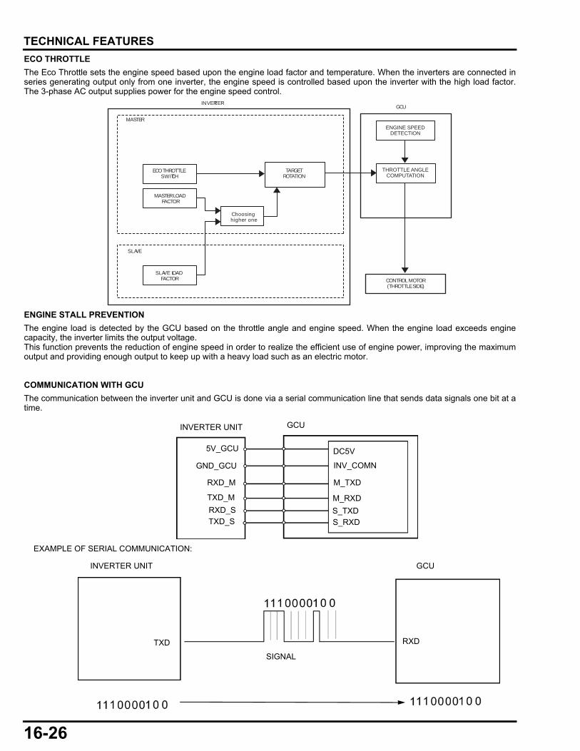
16-26
dummyheaddummyhead
TECHNICAL FEATURES
ECO THROTTLE
The Eco Throttle sets the engine speed based upon the engine load factor and temperature. When the inverters are connected inseries generating output only from one inverter, the engine speed is controlled based upon the inverter with the high load factor.The 3-phase AC output supplies power for the engine speed control.
ENGINE STALL PREVENTION
The engine load is detected by the GCU based on the throttle angle and engine speed. When the engine load exceeds enginecapacity, the inverter limits the output voltage.This function prevents the reduction of engine speed in order to realize the efficient use of engine power, improving the maximumoutput and providing enough output to keep up with a heavy load such as an electric motor.
COMMUNICATION WITH GCU
The communication between the inverter unit and GCU is done via a serial communication line that sends data signals one bit at atime.
MASTER
ECO THROTTLE SWITCH
MASTER LOAD FACTOR
TARGETROTATION
Choosing higher one
SLAVE
SLAVE LOAD FACTOR CONTROL MOTOR
(THROTTLE SIDE)
THROTTLE ANGLECOMPUTATION
ENGINE SPEEDDETECTION
INVERTERGCU
DC5V
INV_COMN
M_TXD
M_RXD
S_TXD
S_RXD
GND_GCU
TXD_M
RXD_S
TXD_S
5V_GCU
INVERTER UNIT GCU
INVERTER UNIT GCU
TXD RXD
SIGNAL
RXD_M
EXAMPLE OF SERIAL COMMUNICATION:
17-1
17
dummytext
17. WIRING DIAGRAMS
WIRING DIAGRAM (AT TYPE) ···················17-3
WIRING DIAGRAM (AT1 TYPE) ·················17-4
WIRING DIAGRAM (CT TYPE)··················· 17-5


17-3
dummyheaddummyhead
WIRING DIAGRAMS
WIRING DIAGRAM (AT TYPE)
MAIN_U_M
U
VW
U
VW
MAIN_V_MMAIN_W_M
INVERTER UNIT
GCU
GROUND
GROUND
MAINSWITCH
REMOTE
STARTERSWITCH
ECO-THROTTLESWITCH
PARALLELOPERATIONOUTLETSCIRCUIT
PROTECTOR
CIRCUITPROTECTOR
VOLTAGE SELECTOR SWITCH
NOISEFILTER
NOISE FILTER
NOISE FILTER
DLC
FUSE BOX
GROUNDTERMINAL
STATOR (SLAVE)
STATOR (MASTER)
GENERATORBLOCK
INVERTER UNITBLOCK
CONTROL PANELBLOCK
FRAMEBLOCK
ENGINE BLOCK
GROUNDGROUNDSTARTERMOTOR
O2 SENSOROILLEVELSWITCH
CKPSENSOR
SPARKPLUG
THROTTLECONTROLMOTOR
IGNITIONCOIL FUEL
PUMPFUELINJECTOR
EBTSENSOR
MAIN_U_S
AA BB
MAIN_V_SMAIN_W_S
AC1_MAC2_MAC1_S
ECO SWHZ
GND
5V_GCURXD_MTXD_M
GND_GCURXD_STXD_S
3A15A
MAIN_SW1MAIN_SW2
U
V
W
IGN+IGN-
DC5VM_TXDM_RXDINV_COMNS_TXDS_RXDN.C.N.C.N.C.TH(A)TH(/A)
TH(/B)TH(B)
PC+O/A
TH+TH-INJ(+)INJ(-)FFP(+)FFP(-)STMAGSTMAGBAT_INSTMAG(+12V)STMAG(+12V)MAIN_SW+MAIN_SW-PL(REM)PUSH_SW2GNDGNDPUSH SW1
BAT_INRXDTXDGND
O2 SENSOR OUTPUT
OVERLOAD
LCD
CHECK/OIL ALERT
ACCBAT
AC2_S
4 1
22
C17 C16
C15 C14
C13 C12
21
2
3
GND1
GND2
5
7
6
13
21
32
31
2
21
34
63
41
13
53
12
130
2526
2224
2314
1517
1633
2831
3227
1821
131
47
89
510
1211
63
2029
21
42
14
32
13
42
18
62
51
3
4 56
25
2
13
46
51
32
1
2
3
53
17
86
52
13
42
34
57
68
910
1
121231
1
42
31
2
T3
T2
T1C9
11
C11
T8T14
T16 T7
T9T15
T17
T18T19
T12T13
T10T11
T6
T5
T4
C10
20
19
17
16
15
14
13
18
10C2C1
C3 C5 C7 C89
8 C4
GND6
GND7
GND8
GND9
GND4
GND5
GND3
30A
20
20
30
BATTERY
R
W
Bu
R
W
Gr
Bu
Bu
Bu
R
R
Bu
R
W
R
Bu
Bu
R W
BuBu
Bu
Bu Bu
Gr
Bu
Gr
G
G
R
R
R/W
Bu/R
Bu/Y
O/W
G/O
G/Bu
R
W
Bu
R
W
Bu
R
W
Bu
R
Bu
RR
W
Bu
R Bu
Bu
W
W
G
R
W
Bu
R
W
Bu
Bl
W
R
Y
Bu
Y
Bl/G
Y/Bu
Bl
W
R
Y
Bu
Y
Bl/G
Y/Bu
Bl
W
Y
R
Y/R
Bu
G
Bl/W
Bl/Y
Y/Bl
Bl
W
Y
R
Y/R
Bu
G
Bl/W
Bl/Y
Y/Bl
R
R
W
Bu
Bl
R/W
Bl/G
Bu/R
O/W
G/Bu
G/O
Bu/Y
W
R
Y
Y
W
Y
R
G
G
Bu
Bl
Bu
Y/Bu
Y/R
Y/Bl
Bl/W
Br/Y
G/O
G/O
Bl/W
Br/Bu
W/Bu
W/G
Bl/Y
G/Bu
G
G
Bu/R
Bu/Y
Br/W
Bl/Y
G
Bl/Y
Bu/Y
Bu/R
Br/W
G
W
G
G
G
G
W/G
G/Bu
Br/W
Bl/Y
G/O
G/O
G/O
G/O
Br/Y
Bl/Y
W/Bu
Br/Bu
Br/Bu
Br/Bu
Bl
G
Bl
Bl
Bl
Bl G
Bl G
Bl/Y
Bl
BuRYW
Bl
Bl
BlYBu
Y Bl
Bl/W
Y/B
l
Y/R
Y/B
u
Y BuWBl R
Y BuW R
Bl/G
R
G
STARTERSWITCH
FREE
PUSH
MAIN SWITCH
MAINSW1 MAINSW2 BAT ACC
ON
OFF
ECO-THROTTLE SWITCH
ON
OFF
Bl Black Br BrownY Yellow O OrangeBu Blue Lb Light blueG Green Lg Light greenR Red P PinkW White Gr Gray

17-4
dummyheaddummyhead
WIRING DIAGRAM (AT1 TYPE)
MAIN_U_M
U
VW
U
VW
MAIN_V_MMAIN_W_M
INVERTER UNIT
GCU
GROUND
GROUND
MAINSWITCH
REMOTE
STARTERSWITCH
ECO-THROTTLESWITCH
PARALLELOPERATIONOUTLETSCIRCUIT
PROTECTOR
CIRCUITPROTECTOR
VOLTAGE SELECTOR SWITCH
NOISEFILTER
NOISE FILTER
NOISE FILTER
DLC
FUSE BOX
GROUNDTERMINAL
STATOR (SLAVE)
STATOR (MASTER)
GENERATORBLOCK
INVERTER UNITBLOCK
CONTROL PANELBLOCK
FRAMEBLOCK
ENGINE BLOCK
GROUNDGROUNDSTARTERMOTOR
O2 SENSOROILLEVELSWITCH
CKPSENSOR
SPARKPLUG
THROTTLECONTROLMOTOR
IGNITIONCOIL FUEL
PUMPFUELINJECTOR
EBTSENSOR
MAIN_U_S
AA BB
MAIN_V_SMAIN_W_S
AC1_MAC2_MAC1_S
ECO SWHZ
GND
5V_GCURXD_MTXD_M
GND_GCURXD_STXD_S
3A15A
MAIN_SW1MAIN_SW2
U
V
W
IGN+IGN-
DC5VM_TXDM_RXDINV_COMNS_TXDS_RXDN.C.N.C.N.C.TH(A)TH(/A)
TH(/B)TH(B)
PC+O/A
TH+TH-INJ(+)INJ(-)FFP(+)FFP(-)STMAGSTMAGBAT_INSTMAG(+12V)STMAG(+12V)MAIN_SW+MAIN_SW-PL(REM)PUSH_SW2GNDGNDPUSH SW1
BAT_INRXDTXDGND
O2 SENSOR OUTPUT
OVERLOAD
LCD
CHECK/OIL ALERT
ACCBAT
AC2_S
4 1
22
C17 C16
C15 C14
C13 C12
21
2
3
GND1
GND2
5
7
6
13
21
32
31
2
21
34
63
41
13
53
12
130
2526
2224
2314
1517
1633
2831
3227
1821
131
47
89
510
1211
63
2029
21
42
14
32
13
42
18
62
51
3
4 56
25
2
13
46
51
32
1
2
3
53
17
86
52
13
42
34
57
68
910
1
121231
1
42
31
2
T3
T2
T1C9
11
C11
T8T14
T7
T9T15
T17T24T19T18
T12T13
T10T11
T6
T5
T4
C10
20
19
17
16
15
14
13
18
10C2C1
C3 C5 C7 C89
8 C4
GND6
GND7
GND8
GND9
GND4
GND5
GND3
30A
20
20
30
BATTERY
R
W
Bu
R
W
Gr
Bu
Bu
Bu
R
R
Bu
R
W
R
Bu
Bu
R
R W Bu
BuBu
Bu
Bu Bu
Gr
Bu
Gr
G
G
R
R
R/W
Bu/R
Bu/Y
O/W
G/O
G/Bu
R
W
Bu
R
W
Bu
R
W
Bu
R
Bu
RR
W
Bu
R Bu
Bu
W
W
G
R
W
Bu
R
W
Bu
Bl
W
R
Y
Bu
Y
Bl/G
Y/Bu
Bl
W
R
Y
Bu
Y
Bl/G
Y/Bu
Bl
W
Y
R
Y/R
Bu
G
Bl/W
Bl/Y
Y/Bl
Bl
W
Y
R
Y/R
Bu
G
Bl/W
Bl/Y
Y/Bl
R
R
W
Bu
Bl
R/W
Bl/G
Bu/R
O/W
G/Bu
G/O
Bu/Y
W
R
Y
Y
W
Y
R
G
G
Bu
Bl
Bu
Y/Bu
Y/R
Y/Bl
Bl/W
Br/Y
G/O
G/O
Bl/W
Br/Bu
W/Bu
W/G
Bl/Y
G/Bu
G
G
Bu/R
Bu/Y
Br/W
Bl/Y
G
Bl/Y
Bu/Y
Bu/R
Br/W
G
W
G
G
G
G
W/G
G/Bu
Br/W
Bl/Y
G/O
G/O
G/O
G/O
Br/Y
Bl/Y
W/Bu
Br/Bu
Br/Bu
Br/Bu
Bl
G
Bl
Bl
Bl
Bl G
Bl G
Bl/Y
Bl
BuRYW
Bl
Bl
BlYBu
Y Bl
Bl/W
Y/B
l
Y/R
Y/B
u
Y BuWBl R
Y BuW R
Bl/G
R
G
WGFCIGFCI
STARTERSWITCH
FREE
PUSH
MAIN SWITCH
MAINSW1 MAINSW2 BAT ACC
ON
OFF
ECO-THROTTLE SWITCH
ON
OFF
Bl Black Br BrownY Yellow O OrangeBu Blue Lb Light blueG Green Lg Light greenR Red P PinkW White Gr Gray

17-5
dummyheaddummyhead
WIRING DIAGRAM (CT TYPE)
MAIN_U_M
U
VW
U
VW
MAIN_V_MMAIN_W_M
INVERTER UNIT
GCU
GROUND
BREATERHEATER
MAINSWITCH
REMOTE
STARTERSWITCH
ECO-THROTTLESWITCH
PARALLELOPERATIONOUTLETS
CIRCUITPROTECTOR
VOLTAGE SELECTOR SWITCH
NOISE FILTER
NOISE FILTER
DLC
FUSE BOX
GROUNDTERMINAL
BATTERY
STATOR (SLAVE)
STATOR (MASTER)
GENERATORBLOCK
INVERTER UNITBLOCK
CONTROL PANELBLOCK
FRAMEBLOCK
ENGINE BLOCK
GROUNDGROUNDSTARTERMOTOR
O2 SENSOROILLEVELSWITCH
SPARKPLUG
CKPSENSOR
IGNITIONCOIL FUEL
PUMPFUELINJECTOR
EBTSENSOR
MAIN_U_S
AA BB
MAIN_V_SMAIN_W_S
AC1_MAC2_MAC1_S
ECO SWHZ
GND
5V_GCURXD_MTXD_M
GND_GCURXD_STXD_S
3A15A
MAIN_SW1MAIN_SW2
U
V
W
IGN+IGN-
DC5VM_TXDM_RXDINV_COMNS_TXDS_RXDN.C.N.C.N.C.TH(A)TH(/A)
TH(/B)TH(B)
PC+O/A
TH+TH-INJ(+)INJ(-)FFP(+)FFP(-)STMAGSTMAGBAT_INSTMAG(+12V)STMAG(+12V)MAIN_SW+MAIN_SW-PL(REM)PUSH_SW2GNDGNDPUSH SW1
BAT_INRXDTXDGND
O2 SENSOR OUTPUT
OVERLOAD
LCD
CHECK/OIL ALERT
ACCBAT
AC2_S
4 1
22
C17 C16
C15 C14
C13 C12
21
2
3
GND1
GND2
5
7
6
13
21
32
31
2
21
34
63
41
13
53
12
130
2526
2224
2314
1517
1633
2831
3227
1821
131
47
89
510
1211
63
2029
21
42
14
32
13
42
18
62
51
3
4 56
25
2
13
46
51
32
1
2
3
4
53
17
86
52
13
42
34
57
68
910
1
12
12
12
1231
1
42
31
2
T3
T2
T1C9
11
12
C11
T8T14
T16 T7
T9T15
T17
T18T19
T10T11
T20T21
T6
T5
T4
C10
20
19
17
16
15
14
13
18
10C2C1
C3 C5 C7 C89
8 C4
GND6
GND7
GND8
GND10
GND14
GND13
GND12 GND11
GND4
GND5
GND3
CIRCUITPROTECTOR
T22T23 29A
CIRCUITPROTECTOR
T12T13 30A
20
20
30
0.5A
THROTTLECONTROLMOTOR
R
W
Bu
R
W
Gr
Bu
Bu
Bu
R
R
Bu
R
W
R
Bu
Bu
W W W
R W
WBu
Bu
Bu Bu
W
Gr
Bu
Gr
G
G
R
R
R/W
Bu/R
Bu/Y
O/W
G/O
G/Bu
R
W
Bu
R
W
Bu
R
W
Bu
R RR
W
Bu
RR Bu
BuBu
Bu Bu
W
W
G
GG
G
W
G
R
W
Bu
R
W
Bu
Bl
W
R
Y
Bu
Y
Bl/G
Y/Bu
Bl
W
R
Y
Bu
Y
Bl/G
Y/Bu
Bl
W
Y
R
Y/R
Bu
G
Bl/W
Bl/Y
Y/Bl
Bl
W
Y
R
Y/R
Bu
G
R R
R W
Bl/W
Bl/Y
Y/Bl
R
R
W
Bu
Bl
R/W
Bl/G
Bu/R
O/W
G/Bu
G/O
Bu/Y
W
R
Y
Y
W
Y
R
G
G
Bu
Bl
Bu
Y/Bu
Y/R
Y/Bl
Bl/W
Br/Y
G/O
G/O
Bl/W
Br/Bu
W/Bu
W/G
Bl/Y
G/Bu
G
G
Bu/R
Bu/Y
Br/W
Bl/Y
G
Bl/Y
Bu/Y
Bu/R
Br/W
G
G
G
G
G
W/G
G/Bu
Br/W
Bl/Y
G/O
G/O
G/O
G/O
Br/Y
Bl/Y
W/Bu
Br/Bu
Br/BuBr/Bu
Bl
W
G
Bl
Bl
Bl G G
G G
Bl/Y
Bl
BuR RR
RR
YW
Bl
Bl
BlYBu
Y Bl
Bl/W
Y/B
l
Y/R
Y/B
u
Y BuWBl R
Y BuW R
Bl/G
R
G
STARTERSWITCH
FREE
PUSH
MAIN SWITCH
MAINSW1 MAINSW2 BAT ACC
ON
OFF
ECO-THROTTLE SWITCH
ON
OFF
Bl Black Br BrownY Yellow O OrangeBu Blue Lb Light blueG Green Lg Light greenR Red P PinkW White Gr Gray

MEMO
dummyheaddummyhead
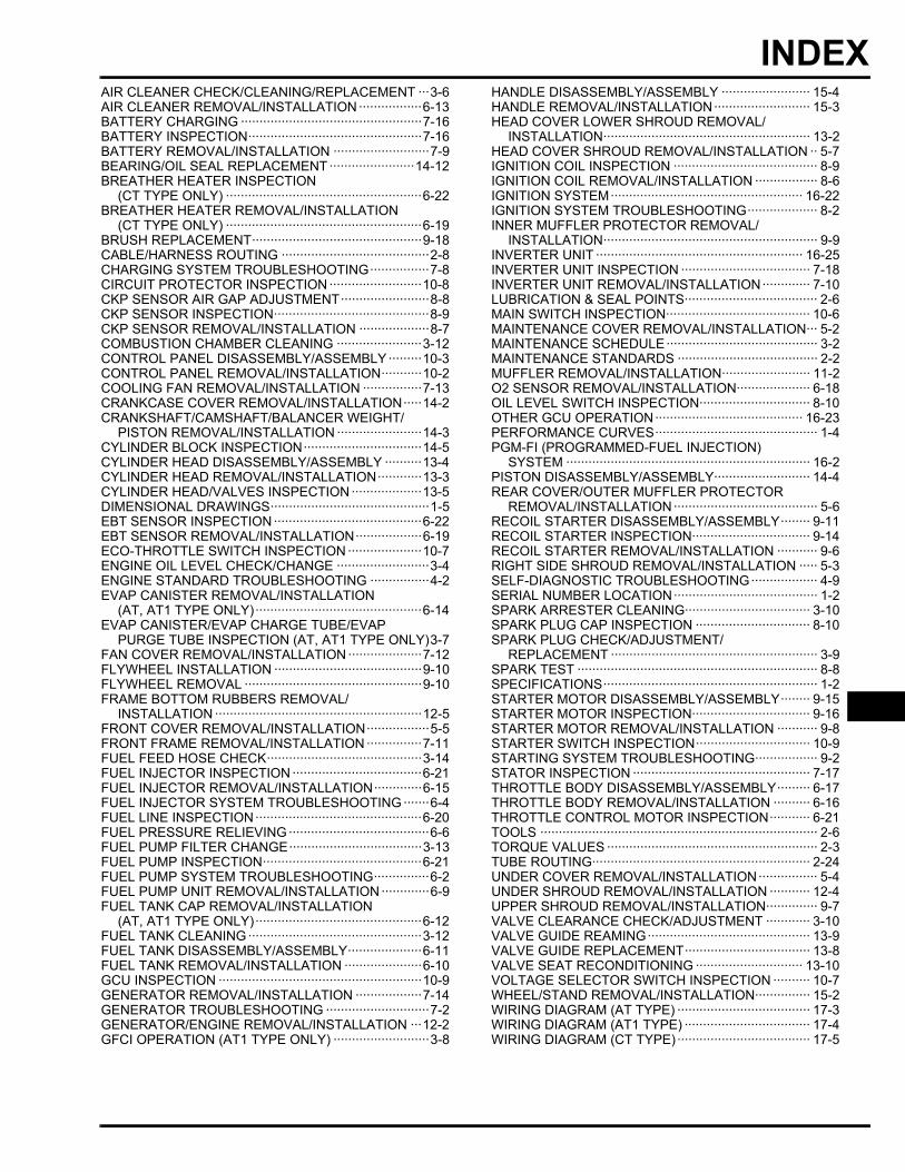
18-1
18
dummytext
INDEXAAIR CLEANER CHECK/CLEANING/REPLACEMENT ···3-6AIR CLEANER REMOVAL/INSTALLATION ·················6-13BBATTERY CHARGING ·················································7-16BATTERY INSPECTION···············································7-16BATTERY REMOVAL/INSTALLATION ··························7-9BEARING/OIL SEAL REPLACEMENT ·······················14-12BREATHER HEATER INSPECTION
(CT TYPE ONLY) ·····················································6-22BREATHER HEATER REMOVAL/INSTALLATION
(CT TYPE ONLY) ·····················································6-19BRUSH REPLACEMENT··············································9-18CCABLE/HARNESS ROUTING ········································2-8CHARGING SYSTEM TROUBLESHOOTING················7-8CIRCUIT PROTECTOR INSPECTION ·························10-8CKP SENSOR AIR GAP ADJUSTMENT························8-8CKP SENSOR INSPECTION··········································8-9CKP SENSOR REMOVAL/INSTALLATION ···················8-7COMBUSTION CHAMBER CLEANING ·······················3-12CONTROL PANEL DISASSEMBLY/ASSEMBLY ·········10-3CONTROL PANEL REMOVAL/INSTALLATION···········10-2COOLING FAN REMOVAL/INSTALLATION ················7-13CRANKCASE COVER REMOVAL/INSTALLATION·····14-2CRANKSHAFT/CAMSHAFT/BALANCER WEIGHT/
PISTON REMOVAL/INSTALLATION ·······················14-3CYLINDER BLOCK INSPECTION································14-5CYLINDER HEAD DISASSEMBLY/ASSEMBLY ··········13-4CYLINDER HEAD REMOVAL/INSTALLATION············13-3CYLINDER HEAD/VALVES INSPECTION ···················13-5DDIMENSIONAL DRAWINGS···········································1-5EEBT SENSOR INSPECTION········································6-22EBT SENSOR REMOVAL/INSTALLATION··················6-19ECO-THROTTLE SWITCH INSPECTION ····················10-7ENGINE OIL LEVEL CHECK/CHANGE ·························3-4ENGINE STANDARD TROUBLESHOOTING ················4-2EVAP CANISTER REMOVAL/INSTALLATION
(AT, AT1 TYPE ONLY)·············································6-14EVAP CANISTER/EVAP CHARGE TUBE/EVAP
PURGE TUBE INSPECTION (AT, AT1 TYPE ONLY)3-7FFAN COVER REMOVAL/INSTALLATION ····················7-12FLYWHEEL INSTALLATION ········································9-10FLYWHEEL REMOVAL ················································9-10FRAME BOTTOM RUBBERS REMOVAL/
INSTALLATION ························································12-5FRONT COVER REMOVAL/INSTALLATION·················5-5FRONT FRAME REMOVAL/INSTALLATION ···············7-11FUEL FEED HOSE CHECK··········································3-14FUEL INJECTOR INSPECTION ···································6-21FUEL INJECTOR REMOVAL/INSTALLATION·············6-15FUEL INJECTOR SYSTEM TROUBLESHOOTING ·······6-4FUEL LINE INSPECTION·············································6-20FUEL PRESSURE RELIEVING ······································6-6FUEL PUMP FILTER CHANGE····································3-13FUEL PUMP INSPECTION···········································6-21FUEL PUMP SYSTEM TROUBLESHOOTING···············6-2FUEL PUMP UNIT REMOVAL/INSTALLATION ·············6-9FUEL TANK CAP REMOVAL/INSTALLATION
(AT, AT1 TYPE ONLY)·············································6-12FUEL TANK CLEANING ···············································3-12FUEL TANK DISASSEMBLY/ASSEMBLY····················6-11FUEL TANK REMOVAL/INSTALLATION ·····················6-10GGCU INSPECTION ·······················································10-9GENERATOR REMOVAL/INSTALLATION ··················7-14GENERATOR TROUBLESHOOTING ····························7-2GENERATOR/ENGINE REMOVAL/INSTALLATION ···12-2GFCI OPERATION (AT1 TYPE ONLY) ··························3-8
HHANDLE DISASSEMBLY/ASSEMBLY ························ 15-4HANDLE REMOVAL/INSTALLATION·························· 15-3HEAD COVER LOWER SHROUD REMOVAL/
INSTALLATION························································ 13-2HEAD COVER SHROUD REMOVAL/INSTALLATION ·· 5-7IIGNITION COIL INSPECTION ······································· 8-9IGNITION COIL REMOVAL/INSTALLATION ················· 8-6IGNITION SYSTEM···················································· 16-22IGNITION SYSTEM TROUBLESHOOTING··················· 8-2INNER MUFFLER PROTECTOR REMOVAL/
INSTALLATION·························································· 9-9INVERTER UNIT ························································ 16-25INVERTER UNIT INSPECTION ··································· 7-18INVERTER UNIT REMOVAL/INSTALLATION············· 7-10LLUBRICATION & SEAL POINTS···································· 2-6MMAIN SWITCH INSPECTION······································· 10-6MAINTENANCE COVER REMOVAL/INSTALLATION··· 5-2MAINTENANCE SCHEDULE········································· 3-2MAINTENANCE STANDARDS ······································ 2-2MUFFLER REMOVAL/INSTALLATION························ 11-2OO2 SENSOR REMOVAL/INSTALLATION···················· 6-18OIL LEVEL SWITCH INSPECTION······························ 8-10OTHER GCU OPERATION········································ 16-23PPERFORMANCE CURVES············································ 1-4PGM-FI (PROGRAMMED-FUEL INJECTION)
SYSTEM ·································································· 16-2PISTON DISASSEMBLY/ASSEMBLY·························· 14-4RREAR COVER/OUTER MUFFLER PROTECTOR
REMOVAL/INSTALLATION······································· 5-6RECOIL STARTER DISASSEMBLY/ASSEMBLY········ 9-11RECOIL STARTER INSPECTION································ 9-14RECOIL STARTER REMOVAL/INSTALLATION ··········· 9-6RIGHT SIDE SHROUD REMOVAL/INSTALLATION ····· 5-3SSELF-DIAGNOSTIC TROUBLESHOOTING·················· 4-9SERIAL NUMBER LOCATION······································· 1-2SPARK ARRESTER CLEANING·································· 3-10SPARK PLUG CAP INSPECTION ······························· 8-10SPARK PLUG CHECK/ADJUSTMENT/
REPLACEMENT ························································ 3-9SPARK TEST ································································· 8-8SPECIFICATIONS·························································· 1-2STARTER MOTOR DISASSEMBLY/ASSEMBLY········ 9-15STARTER MOTOR INSPECTION································ 9-16STARTER MOTOR REMOVAL/INSTALLATION ··········· 9-8STARTER SWITCH INSPECTION······························· 10-9STARTING SYSTEM TROUBLESHOOTING················· 9-2STATOR INSPECTION ················································ 7-17TTHROTTLE BODY DISASSEMBLY/ASSEMBLY········· 6-17THROTTLE BODY REMOVAL/INSTALLATION ·········· 6-16THROTTLE CONTROL MOTOR INSPECTION··········· 6-21TOOLS ··········································································· 2-6TORQUE VALUES ························································· 2-3TUBE ROUTING··························································· 2-24UUNDER COVER REMOVAL/INSTALLATION················ 5-4UNDER SHROUD REMOVAL/INSTALLATION ··········· 12-4UPPER SHROUD REMOVAL/INSTALLATION·············· 9-7VVALVE CLEARANCE CHECK/ADJUSTMENT ············ 3-10VALVE GUIDE REAMING············································ 13-9VALVE GUIDE REPLACEMENT·································· 13-8VALVE SEAT RECONDITIONING ····························· 13-10VOLTAGE SELECTOR SWITCH INSPECTION ·········· 10-7WWHEEL/STAND REMOVAL/INSTALLATION··············· 15-2WIRING DIAGRAM (AT TYPE) ···································· 17-3WIRING DIAGRAM (AT1 TYPE) ·································· 17-4WIRING DIAGRAM (CT TYPE) ···································· 17-5
INDEX

MEMO
dummytext
Related Documents