8 BANDSAW from Pipe Fittings c and > ," ' e OU can build this efficient ball-bearing bandsaw easily from standard iron- pipe fittings, two discarded model-T Ford front wheels, a single piston from the same car, and a few other pieces of scrap ma- terials. The frame is assembled from 2-in. pipe fittings as in Fig. 1. First drill and tap the tees and the single elbow for 1/4 by 1-in. set screws, placing these as in Fig. 8 to prevent the parts of the frame from shifting out of line. Screw the parts to- gether tightly, line up the upper arm with Auto Parts I I birch plywood, each 12% ;- ?r, and the center is bored out to nr "~er the wheel hub as in Figs. 6 and 8. Remove the hubs from the spindles and bolt the disks Now bolt the lower spindle to the frame as in Fig. 8. Make sure that the spindle is square with the frame both ways so that the wheel will run true. This will likely require some filing on both the spindle and the frame. Then fit the upper slide as in Fig. 8, from which you will see that a sin- the lower cross member, and then tighten gle bolt passes through the slide bar with the set screws. a nut on each side; a set screw is tapped Next, you remove the spokes from the through the tee from the opposite side and hubs of the two model-T Ford front wheels. bears against the lower end of the slide Drive the outer flange up to the inner bar. Polish the bar so that the slide -will flange on both hubs, then with a hacksaw move freely UP and down. Fig. 3 dimen- cut the spindle-bolt housings as shown by sions the two parts of the slide which car- the dotted lines in Fig. 4. The exact size ries the upper wheel when assembled as of the remaining portion of the housings is in Figs. 5 and 8. Flat iron % in. thick is not important as filing will be necessary in used for both pieces. Bend the slide over fitting the spindles to the frame and the a piece of % by 2-in. iron to get the proper upper slide. Two disks are cut from 1-in. size and fit. Smooth the corners with a file 7

Homemade Bandsaw From Pipe Fittings and Auto Parts
Oct 22, 2015
You can build this efficient ball-bearing bandsaw easily from standard iron pipe fittings, two discarded model-T Ford front wheels, a single piston from the same car, and a few other pieces of scrap materials.
Welcome message from author
This document is posted to help you gain knowledge. Please leave a comment to let me know what you think about it! Share it to your friends and learn new things together.
Transcript
8 BANDSAW from Pipe Fittings c and
> , "
' e OU can build this efficient ball-bearing bandsaw easily from standard iron-
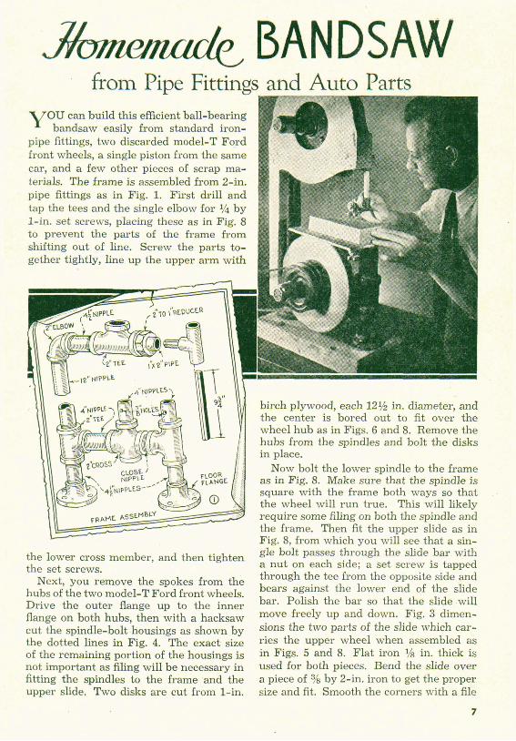
pipe fittings, two discarded model-T Ford front wheels, a single piston from the same car, and a few other pieces of scrap ma- terials. The frame is assembled from 2-in. pipe fittings as in Fig. 1. First drill and tap the tees and the single elbow for 1/4 by 1-in. set screws, placing these as in Fig. 8 to prevent the parts of the frame from shifting out of line. Screw the parts to- gether tightly, line up the upper arm with
Auto Parts
I I
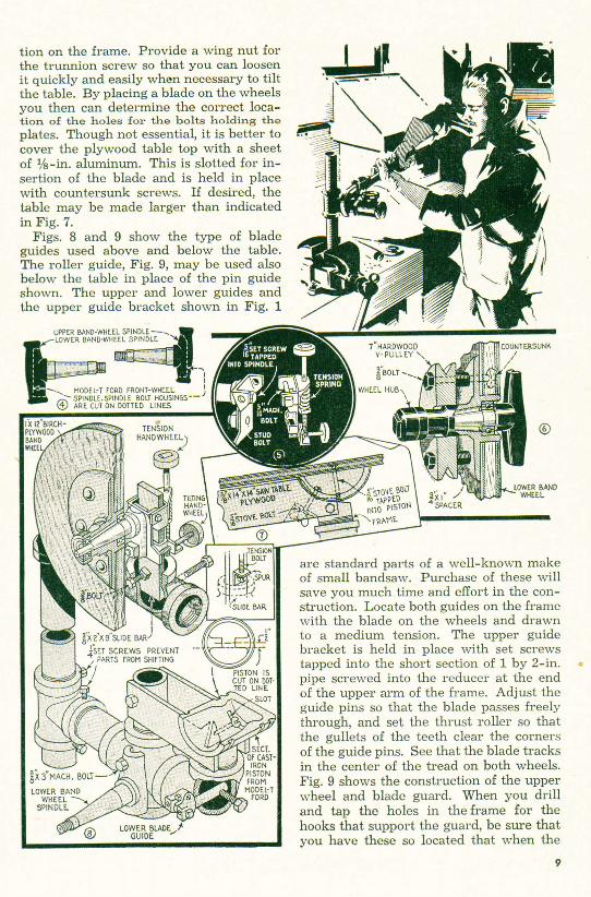
birch plywood, each 12% ;- ?r, and the center is bored out to nr " ~ e r the wheel hub as in Figs. 6 and 8. Remove the hubs from the spindles and bolt the disks
Now bolt the lower spindle to the frame as in Fig. 8. Make sure that the spindle is square with the frame both ways so that the wheel will run true. This will likely require some filing on both the spindle and the frame. Then fit the upper slide as in Fig. 8, from which you will see that a sin-
the lower cross member, and then tighten gle bolt passes through the slide bar with the set screws. a nut on each side; a set screw is tapped
Next, you remove the spokes from the through the tee from the opposite side and
hubs of the two model-T Ford front wheels. bears against the lower end of the slide
Drive the outer flange up to the inner bar. Polish the bar so that the slide -will
flange on both hubs, then with a hacksaw move freely UP and down. Fig. 3 dimen-
cut the spindle-bolt housings as shown by sions the two parts of the slide which car- the dotted lines in Fig. 4. The exact size ries the upper wheel when assembled as of the remaining portion of the housings is in Figs. 5 and 8. Flat iron % in. thick is not important as filing will be necessary in used for both pieces. Bend the slide over fitting the spindles to the frame and the a piece of % by 2-in. iron to get the proper upper slide. Two disks are cut from 1-in. size and fit. Smooth the corners with a file
7

turned from hardwood with a V
and improvise a rest for a wood-t
special cement made for this purpose. bands and cement may be purchased
until tne part slides easily on the bar that has been attached to the upper arm of the frame. The slide should fit the bar snugly so that there is no side play. Unless otherwise indicated, all
Two short lengths of 1% by 1%-in. an- gle iron are riveted to the back of the slide to form lugs for the handwheels. To make the latter, turn out two hardwood disks and drive these onto %+in. carriage bolts. Or, you can use a rod of the same diameter and bend the end to 'form a crank. In either case the threaded length of the tension screw should be 7 in. and the tilting screw 4 in. The tilting screw is tapped through the angle-iron lug and is provided with a nut to l ~ c k the setting. The lower end of the tension screw bears for use. The table trunnion, Figs. 2, 7 and '- on a spur attached to the bolt holding the 8, consists of two flat plates and a section slide bar as in Fig. 8. The tension spring is cut from a model-T Ford piston as in Fig. 2% in. long. The upper wheel spindle is 8. These three details show the construc- attached to the yoke with a %-in. cap tion of the trunnion clearly. The impor- screw tapped into the end of the spindle, tant thing is to position these parts so that A d also a %-in. stud, which is tapped into when the table is tilted, the blade will re- . the flat section of the yoke as in Fig. 5. main in the center of the slot. To do this It is likely that some filing will be neces- you first drill the plates at the ends, cut \
sary to assure a true fit of the spindle the piston and slot it as indicated, then housing against the yoke. clamp the whole table assembly in posi- '
- : . .
untersunk screws. If desired, the
the table in place of the pin guide
are standard parts of a well- of small bandsaw. Purchase
bracket is held in place with set screws tapped into the short section of 1 by 2-in. *: pipe screwed into the reducer at the end . of the upper arm of the frame. Adjust the guide pins so that the blade passes freely
-,
through, and set the thrust roller so that the gullets of the teeth clear the corners of the guide pins. See that the blade tracks ' '
in the center of the tread on both wheels.
9

i
Spindle Sander Has Flexible Shaft For edge-sanding irregular work, an ef-
ficient spindle sander can be made from a table, a small sand drum, a length of flex- ible shafting and a %-hp. motor. Bore a hole in the center of the table top just large enough to admit the drum. From 1%-in. hard-maple stock cut a 4 by 6-in. block, and from 1-in. stock a triangular brace. Screw these parts together as shown. Drill the block to receive two %-in. iron rods, 7 in. long, bent to form a hook at one end and threaded for wing- nuts at the other. Drill and saw out a slot as shown and also drill and slot a 4 by 5-in. block of %-in. stock to correspond with the hole and slot in the 4 by 6-in. piece. Attach the flexible shaft by means of the hooked rods and wingnuts to the block assembly and tighten the sanding drum in the chuck, after which the drum is inserted through the hole in the table from the underside and the whole is fas-
ASSEMBLY OF WHEEL &BLADE tened securely with heavy screws coun-
tersunk in the table top and projecting in- to both brace and Mock. Connect the end
-UPPER BLADE WIDE of the flexible shaft to the motor mounted /
guard is in position the top will clear the upper band wheel by at least 1 in. This will allow sufficient space for the neces- sary up-and-down movement of the wheel. Blades for the standard 12-in. bandsaw can be used on this machine. These are 78 in. long, measured around the wheels, and come in widths from % to 4f3 in. Your ma- chine should be mounted on a solid bench or stand and should be driven with a x- h.p. motor of 1,750 r.p.m. Use a 2-in. V- pulley on the motor to give proper blade speed. When using the machine, the blade should be drawn just tight enough to pre- vent its vibrating when the machine is running. To get the proper tension ad- justment, start the motor and draw up slowly on the tension screw until the blade Inexpensive spindle sander with flexible shaft for
runs smoothly through the guides. edge-sanding curved and irregular work
aAn excellent bright dip for iron and La'the Centers rrc . Drills steel consists of sulphuric acid, 7 oz., Broken taper-shank drill.. ,an be ground
, slowly added to water, 2% pints, zinc, M easily to provide good lathe centers in less oz., nitric acid, 3 oz., and a small piece of time than they can be made from rough
Related Documents