Holistic approach in engineering design - controlling risks from accidental hazards in bridge design Björnsson, Ivar 2015 Link to publication Citation for published version (APA): Björnsson, I. (2015). Holistic approach in engineering design - controlling risks from accidental hazards in bridge design. Lund University (Media-Tryck). Total number of authors: 1 General rights Unless other specific re-use rights are stated the following general rights apply: Copyright and moral rights for the publications made accessible in the public portal are retained by the authors and/or other copyright owners and it is a condition of accessing publications that users recognise and abide by the legal requirements associated with these rights. • Users may download and print one copy of any publication from the public portal for the purpose of private study or research. • You may not further distribute the material or use it for any profit-making activity or commercial gain • You may freely distribute the URL identifying the publication in the public portal Read more about Creative commons licenses: https://creativecommons.org/licenses/ Take down policy If you believe that this document breaches copyright please contact us providing details, and we will remove access to the work immediately and investigate your claim.

Welcome message from author
This document is posted to help you gain knowledge. Please leave a comment to let me know what you think about it! Share it to your friends and learn new things together.
Transcript

LUND UNIVERSITY
PO Box 117221 00 Lund+46 46-222 00 00
Holistic approach in engineering design - controlling risks from accidental hazards inbridge design
Björnsson, Ivar
2015
Link to publication
Citation for published version (APA):Björnsson, I. (2015). Holistic approach in engineering design - controlling risks from accidental hazards in bridgedesign. Lund University (Media-Tryck).
Total number of authors:1
General rightsUnless other specific re-use rights are stated the following general rights apply:Copyright and moral rights for the publications made accessible in the public portal are retained by the authorsand/or other copyright owners and it is a condition of accessing publications that users recognise and abide by thelegal requirements associated with these rights. • Users may download and print one copy of any publication from the public portal for the purpose of private studyor research. • You may not further distribute the material or use it for any profit-making activity or commercial gain • You may freely distribute the URL identifying the publication in the public portal
Read more about Creative commons licenses: https://creativecommons.org/licenses/Take down policyIf you believe that this document breaches copyright please contact us providing details, and we will removeaccess to the work immediately and investigate your claim.
Holistic approach in engineering design
Controlling risks from accidental hazards in bridge design
Ívar Björnsson
DOCTORAL DISSERTATION by due permission of the Faculty of Engineering, Lund University, Sweden.
To be defended at Lecture hall MA1 in the Mathematics Annex building, Sölvegatan 20, Lund on the 6th of November 2015 at 10.15.
Faculty opponent
Professor Michael Havbro Faber
Technical University of Denmark
Organization:
LUND UNIVERSITY
Document name:
DOCTORAL DISSERTATION
Division of Structural Engineering Date of issue: 2015-10-13
Author(s):
Ívar Björnsson
Sponsoring organization:
Swedish Transport Administration (Trafikverket)
Title and subtitle:
Holistic approach in engineering design- Controlling risks from accidental hazards in bridge design
Abstract:
Engineering design, in concise terms, is what engineers do using what they know. It is the underlying decision making activity that determines what is to be built and how it should be built. An ever present requirement in engineering design is that the structure should be safe. While historical approaches to safety in design relied on experience and engineering judgment, modern approaches have rationalized uncertainty in an effort to treat risks in a more consistent and objective way. Concurrent to these advancements, design codes have been developed which include safety formats that are calibrated using these rationalized approaches. This thesis investigates the limitations of the design codes in controlling risks in engineering design and proposes that a complementary approach – involving case-specific risk assessments – is necessary for addressing the risks that are not properly treated by the design codes. The main advantage of such an approach is that:
• it broadens the scope of assessment to consider structural systems and possibly non-structural constituents; • it is also applicable during the conceptual design phase for the bridge structure; and • it is complementary to current codified approaches
While similar approaches are common in large scale construction projects they are rarely applied in the design of more conventional bridge structures. However, in this thesis it is argued that the application of such approaches is also useful in more common bridge projects to better control risks inadequately treated by design based on code compliance. A framework for a holistic risk-informed approach is provided which focuses on the conceptual design of bridge structures and on the control of risks from accidental hazards. Case studies are conducted to highlight the usefulness of the approach and to help develop crucial aspects of the approach while providing useful background information for its possible implementation in future projects. Specific attention is also paid to the modeling of risks from heavy goods vehicle (HGV) impacts to bridge substructures – a design situation which was found to be inadequate treated using current codified approaches.
Key words: design, codes, accidental, extreme, bridges, holistic, approach, robustness,rik, uncertainty
Classification system and/or index terms (if any)
Supplementary bibliographical information: Language: English
ISRN LUTVDG/TVBK-1048/15-SE(258)
ISSN and key title: 0349-4969, Report TVBK 1048 ISBN 978-91-87993-03-9
Recipient’s notes Number of pages: 258 Price
Security classification
I, the undersigned, being the copyright owner of the abstract of the above-mentioned dissertation, hereby grant to all
reference sources permission to publish and disseminate the abstract of the above-mentioned dissertation.
Signature Date
Holistic approach in engineering design
Controlling risks from accidental hazards in bridge design
Ívar Björnsson
© Ívar Björnsson
Faculty of Engineering, Division of Structural Engineering P.O. Box 118, SE-221 00 Lund, Sweden Report TVBK-1048 ISBN 978-91-87993-03-9 ISRN LUTVDG/TVBK-1048/15-SE(258) ISSN 0349-4969 Printed in Sweden by Media-Tryck, Lund University Lund 2015
i
Preface
No matter how vigorously a ‘science’ of design may be pushed, the successful design of real things in a contingent world will always be based more on art than on science. Unquantifiable judgments and choices are the elements that determine the way a design comes together. Engineering design is simply that kind of process. It always has been; it always will be.
Eugene S. Ferguson (1992, p. 194)
The above quote by Ferguson from his book entitled ‘Engineering and the Mind’s Eye’ helps highlight some of the issues I have come to appreciate during my stay as doctoral candidate at the Division of Structural Engineering in Lund University. Initially I was fascinated by the ‘science’ of engineering and of how our understanding of the mechanisms in nature could be formulated so eloquently using rationalized approaches – where the only obstacle to ultimate understanding was our own ignorance. However, as I progressed in my research I started more and more to believe that such a viewpoint could be counter-productive when it came to engineering design – which is what we, as engineers, ultimately do. To start, problems faced by engineers when they design structures are ill-structured and do not comply with the neatly set boundaries and constraints which are prerequisites for rigorous scientific inquiry. Furthermore, strict adherence to theoretical and rational inquiry cuts out the middle-man – namely, the engineer himself. I could not accept such an aversion to subjectivity. Isn’t judgment – by its very nature subjective – central to what we as engineers do? Can there be engineering design without the engineer? I am by no means an expert in the philosophy of engineering, or of the engineering method, and so cannot provide much in the way of answering these questions. However, it was questions such as these – coupled with many fruitful discussions with my supervisors and with my other work colleagues – that have influenced the progression of my research away from the detailed and specific towards the broad and holistic. In this regard, I will provide a short background.
My journey as a doctoral candidate started off, some 5 years ago, with the idea of investigating robustness in bridge design. In fact, the initial title of the project was ‘Robust design of bridges for a reduced vulnerability in the road network’. I had by that time done some research for my master thesis on this topic and had some background knowledge of this issue. What struck me at the time was the variety of different interpretations of robustness – what it meant and how it should be
ii
considered in a design context. This, in itself was not an issue – one could simply ally oneself with a certain interpretation and go from there and, initially, this is what I had done. However, the more I investigated this topic the less convinced I became by some of the approaches that were advocated. It took me a while to understand that it wasn’t so much the methods in themselves, but the underlying principles guiding their developments. There was a desire for robustness to be something quantifiable, something that can be compared with some criteria in the same way that a calculated stress in a steel beam should be kept below a design yield stress. Personally I feel that such a desire is misleading and that any absolute measure of robustness losses meaning in the face of the large uncertainties involved. Thus in my own work I’ve chosen not to use the term so loosely. For one, if you mention robustness to someone, a researcher or practicing engineering, they usually already have strong opinions of what it ‘really means’ and how it should be ensured in design. I chose instead to focus on some of the underlying issues that the word represents – namely, the treatment of risks in engineering design which are difficult to predict a priori. In considering this problem, I felt that focus should not be on the very specific and the detailed but on the very broad and of the whole. The problem, in my opinion, could not be generalized for all structures but requires case-specific investigations. From these considerations evolved the approach I have proposed in my thesis. I cannot say with any certainty that this approach is the correct one, however, I do believe it goes a long way in addressing some of the risks in engineering design that current codified approaches cannot adequately address. All in all, I believe that the answer lies in allowing engineers more autonomy in solving these problems and not in applying external constraints in an attempt to prescribe a generalized solution. Realizing this in practice will require that the current system for enforcing regulation, at least in Sweden, is adjusted. Hopefully this thesis helps in providing impetus for such an endeavor or at the very least contributes to the debate of how to better balance autonomy and compliance while ensuring safety and other performance criteria are satisfied.
This thesis is a summary of the work that has been carried out by the author at the Division of Structural Engineering at Lund University from 2010 to 2015. The project was financed by the Swedish Transport Administration.
Ívar Björnsson Lund, September 2015
iii
Abstract
Engineering design, in concise terms, is what engineers do using what they know. It is the underlying decision making activity that determines what is to be built and how it should be built. An ever present requirement in engineering design is that the structure should be safe. While historical approaches to safety in design relied on experience and engineering judgment, modern approaches have rationalized uncertainty in an effort to treat risks in a more consistent and objective way. Concurrent to these advancements, design codes have been developed which include safety formats that are calibrated using these rationalized approaches. This thesis investigates the limitations of the design codes in controlling risks in engineering design and proposes that a complementary approach – involving case-specific risk assessments – is necessary for addressing the risks that are not properly treated by the design codes. The main advantage of such an approach is that:
• it broadens the scope of assessment to consider structural systems and possibly non-structural constituents;
• it is also applicable during the conceptual design phase for the bridge structure; and
• it is complementary to current codified approaches
While similar approaches are common in large scale construction projects they are rarely applied in the design of more conventional bridge structures. However, in this thesis it is argued that the application of such approaches is also useful in more common bridge projects to better control risks inadequately treated by design based on code compliance. A framework for a holistic risk-informed approach is provided which focuses on the conceptual design of bridge structures and on the control of risks from accidental hazards. Case studies are conducted to highlight the usefulness of the approach and to help develop crucial aspects of the approach while providing useful background information for its possible implementation in future projects. Specific attention is also paid to the modeling of risks from heavy goods vehicle (HGV) impacts to bridge substructures – a design situation which was found to be inadequate treated using current codified approaches.

iv
This page is intentionally left blank
v
Papers
This thesis is based on the following papers, which will be referred to in the text by their Roman numerals. The papers are appended at the end of the thesis.
I From code compliance to holistic approaches in structural design of bridges Björnsson, I. Journal of Professional Issues in Engineering Education and Practice, 02515003. DOI: 10.1061/(ASCE)EI.1943-5541.0000255 (2015)
II Holistic approach for treatment of accidental hazards during conceptual design of bridges – a case study in Sweden Björnsson, I. Reliability Engineering & Systems Safety, submitted for publication (2015)
III Probabilistic-based assessment of bridge subject to extraordinary circumstances Björnsson, I., Thelandersson, S., & Petersen, K. In Faber, M.H., Köhler, J., & Nishijima, K. (Eds.) Proceeding of the 11th International Conference on Applications of Statistics and Probability in Civil Engineering, Taylor & Francis Group, pp. 2167-2175 (2011)
IV Determining appropriate design impact loads to roadside structures using stochastic modeling Björnsson, I., Thelandersson, S., & Carlsson F. Journal of Bridge Engineering, Accepted for publication (2015)
V Reliability of RC bridge supports designed to resist heavy goods vehicle collisions Björnsson, I. Structural Engineering International, Accepted for publication (2015)
In Paper III the calculations were performed by Ivar Björnsson while valuable contributions and feedback were provided by Prof. Sven Thelandersson and Prof. Kurt Petersen.
In Paper IV the simulations of impact loads as well as the assessment of accident data were carried out by Ivar Björnsson while the measured B-WIM data were provided by Fredrik Carlsson. Both co-authors also provided valuable contributions and feedback for the finished paper.
vi
Summary of appended papers
PAPER I – From code compliance to holistic approaches in structural design of bridges
This paper discusses the limitations of design based on code compliance and proposes that a complementary holistic approach is necessary for addressing these limitations; the requirements for such an approach are then identified. The use of case-specific risk assessments is proposed as a promising alternative in this regard; the advantages are identified and some examples are provided in which they have been successfully applied in construction projects where compliance-with-code design was found to be inefficient or, in some cases, incompatible as the prominent method for controlling risks. Practical issues related to the formal realization of such a complementary approach are also mentioned.
PAPER II – Holistic approach for treatment of accidental hazards during conceptual design of bridges – a case study in Sweden
This paper further builds upon the results from the first paper by providing a framework for a complementary risk-informed approach that can be used during the conceptual design phase of bridges. Such approaches are common in large scale construction projects but are rarely used in the design of more conventional bridges. The assessment procedure is described and some background information is provided that is useful for applying the proposed approach in practice. To illustrate its application in the design of real bridge structure, a case study of a bridge project in the west of Sweden is carried out.
PAPER III – Probabilistic-based assessment of bridge subject to extraordinary circumstances
Considerations of robustness for structural bridge systems subject to accidental circumstances are discussed in this paper. An overview of the framework for the assessment of structural robustness is given highlighting the various features vital to its implementation. The application of probabilistic risk based methodology for the investigation of system effects from rare exposure events is considered for a multi-span concrete bridge crossing multiple rail tracks as well as roads. Calculations are performed to ascertain and quantify these responses; this includes the investigation of impacts from derailed train traffic. Conclusions drawn here include the significance of utilizing probabilistic risk assessment methods and design strategies which reflect considerations of robustness of systems subject to rare exposure events with high consequences. Current design guidelines for accidental loading used for design of new bridges were also evaluated on the basis of the case study.
vii
PAPER IV – Determining appropriate design impact loads to roadside structures using stochastic modeling
The design and verification of built structures requires structural engineers to consider of accidental loading situations. The accidental loading situation investigated in this paper is that of heavy goods vehicle (HGV) collisions to road-side structures with focus on bridge supporting structure. The impact loads are determined utilizing Monte-Carlo simulations of a probabilistic model in which highway traffic measurements and accident statistics in Sweden are input. These loads are determined for straight roads as well as roads with curvature and include considerations of the directional load components. Comparisons are made between the simulation results and approaches given in the structural Eurocodes. The simplified approaches provided in the code are found to be unsatisfactory in their treatment of this design situation. Alternative equations for calculating impact forces and energies are then presented. These equations can be used either for determining design values for impact or for conducting probability/risk based assessments of bridges subjected to HGV impacts. In this way, a more consistent treatment of HGV impacts in the design of bridge structures is desired.
PAPER V – Reliability of RC bridge supports designed to resist heavy goods vehicle collisions
The reliability of bridge-supporting structures to resist impacts from heavy goods-vehicles (HGV) is investigated. Probabilistic simulations are carried out to calculate the reliability index of a circular reinforced concrete column that has been designed using historical values for equivalent static impact loads provided in the Eurocode. Considerations are made for the uncertainties related to the dynamic response and resistance of reinforced concrete bridge supports subjected to vehicular impact. A general procedure is outlined for determining the dynamic resistance of the structure to vehicular impacts. As input for the impact force, results from previous probabilistic simulations of HGV impacts to road side structures were used. It is found that the design based on the codified approach does not provide adequate safety levels in the case of the structure studied. An alternative formulation for determining more appropriate values for the impact load is suggested and some discussion was given pertaining to other possible design strategies for the treatment of these types of loading situations.

viii
This page is intentionally left blank
ix
Contents
Preface ....................................................................................................................... i
Abstract ................................................................................................................... iii
Papers ........................................................................................................................ v
Summary of appended papers ......................................................................... vi
1. Introduction .........................................................................................................1
1.1 Background ..............................................................................................1
1.2 Objectives and research questions .............................................................2
1.3 Limitations ...............................................................................................2
1.4 Outline of thesis .......................................................................................3
2. Bridge failures .......................................................................................................5
2.1 Background ..............................................................................................5
2.1.1 Definition of failure ....................................................................7 2.2 Failure surveys ..........................................................................................8
2.2.1 Causes of failure ........................................................................11 2.2.2 Consequences of failures ...........................................................20
2.3 Lessons from failure ...............................................................................23
2.3.1 Historical bridge failures and their lessons .................................24 2.3.2 General lessons from failures .....................................................28
2.4 The role of risk and uncertainty in structural engineering .......................30
3. Principles of engineering design ..........................................................................33
3.1 Introduction ...........................................................................................33
3.1.1 Design process ..........................................................................36 3.2 Controlling risks in engineering design ...................................................38
3.2.1 Safety and risk ...........................................................................38
x
3.2.2 Uncertainties in engineering .....................................................41 3.2.3 Historical perspective – safety factors in design .........................44 3.2.4 Rationalization of uncertainty – development of SRT ...............47
3.3 Structural Reliability Theory ..................................................................48
3.3.1 Reliability of structural components ..........................................49 3.3.2 Methods for evaluating reliability ..............................................52 3.3.3 Systems reliability .....................................................................57
3.4 Principles of codified design ...................................................................63
3.4.1 Design concepts in modern codes .............................................64 3.4.2 Robustness requirements in design codes ..................................67
3.5 Crucial factors for safety in engineering design .......................................72
3.5.1 Criteria for a complementary approach .....................................74
4. Complementary design approach ........................................................................75
4.1 Introduction ...........................................................................................75
4.2 Limitations of codified design ................................................................76
4.3 Need for complementary design approaches ...........................................80
4.4 Complementary risk-informed approach ................................................82
4.4.1 System definition & bounds .....................................................84 4.4.2 Risk screening procedure ...........................................................85 4.4.3 Comparing conceptual design solutions ..................................100 4.4.4 Evaluation of critical risks during detailed design ....................102
5. Crucial aspects of complementary approach ......................................................105
5.1 Introduction .........................................................................................105
5.2 Marieholm Connection project case study ............................................107
5.2.1 Background ............................................................................107 5.2.2 Risk screening & critical hazards .............................................110 5.2.3 Review of main results and conclusions ...................................113
5.3 Sjölundaviadukt case study ...................................................................114
5.3.1 Background ............................................................................114 5.3.2 Risk from train collisions ........................................................114 5.3.3 Evaluation of bridge robustness ...............................................117 5.3.4 Overview of main results and conclusions ...............................118
xi
5.4 Modeling risks from accidental hazards ................................................119
5.4.1 Background – design for HGV collisions ................................119 5.4.2 Risk of vehicle collisions to bridge supports .............................121
6. Conclusions and future work ............................................................................135
6.1 Summary and conclusions ....................................................................135
6.2 Reliability, validity & generalization .....................................................137
6.3 Future work .........................................................................................138
Acknowledgment ...................................................................................................141
References ..............................................................................................................143
Appendix A – Marieholm Connection Project Drawings .......................................155

xii
This page is intentionally left blank
1
1. Introduction
1.1 Background
Design is a central activity in structural engineering – it is what engineers do using what they know. It is the underlying decision making process for determining how a structure is to be built so as to fulfill prescribed design criteria sufficiently well without undue failings during its service life. To achieve this end the process of engineering design involves the identification, treatment and control of risks. This process basically requires that attention is drawn to the following questions:
• What are the different ways the structure can fail? • What is the likelihood that these failures occur? • What are the consequences if these failures occur? • What can be done to reduce the risks associated with these failures?
In considering these issues, something that can never be avoided is uncertainty. The engineering design of bridges, as with any other engineered structure, requires the treatment of risk and uncertainty to ensure a continued functioning of the structure while avoiding failures in terms of structural and functional performance. Failure in this context is broad and can briefly be described as any unwanted deviation from design intentions. Historically, efforts to ensure a satisfactory bridge design and construction have been based on experience coupled with experimentation as well as design conservatism. The concept of a factor of safety was coined to describe an inverse relation between the loads, or load effects, on a structure and the capacity of the structure to resist these loads. For bridges, the former included crowds of people or herds of livestock while the latter was determined on the basis of experimentation possibly coupled with analytical procedures. The value that was given to the factor of safety was largely based on engineering judgment and experience. Later developments in engineering science and design, however, culminated in more rationalized approaches to the treatment of structural safety and of determining acceptable margins against failure. Ultimately, this has led to the formulation of reliability concepts in design codes which rely on safety formats to account for uncertainties.
In this thesis it is found that current codified approaches to bridge design are not adequate in treating certain risks in engineering design. To address this issue the framework for a complementary holistic risk informed approach is proposed. While such approaches are common in large scale (mega) construction projects they are
2
rarely applied in the design of more conventional bridge structures. However, in this thesis it is argued that the application of such approaches is also useful in more common bridge projects to better control risks inadequately treated through design based on code compliance. A description of the approach – which is based on standard risk assessment procedures – is provided tailored for application in bridge design. Focus is on the treatment of accidental risks during the conceptual design phase. Case studies are conducted to highlight the usefulness of the approach and to help develop crucial aspects of the approach. Specific attention is also paid to the modeling of risks from heavy goods vehicle (HGV) impacts to bridge substructures; a design situation which was found to be inadequately treated by current codified approaches.
1.2 Objectives and research questions
The overall objective of this thesis is to improve the methodology for risk control in the engineering design of structures. To limit the scope, a specific type of structure and a specific type of risk are considered:
From this objective, the following research questions are formulated and form the basis for the work presented in this thesis:
The control of risks from accidental hazards in the design of bridge structures
• What can we learn from the predominant ways in which risks (1) have been and, (2) are currently, being controlled in engineering design of bridges?
• Are the design approaches currently provided in the design codes for treating risks related to accidental hazards sufficient?
• Can a complementary risk-informed approach be applied for treating risks not sufficiently covered by current design codes?
• What are the crucial aspects of this approach and how should they be developed?
1.3 Limitations
The scope of this thesis is limited to one type of construction and one category of risk. Thus considerations of other types of construction and other categories of risk were not included. Special attention is also paid to the modeling of risks from HGV impacts. Modeling of other accidental hazards could thus be developed further. In addition, this thesis was purposefully written with focus on holistic aspects of engineering design as these are much more rarely considered by the research community than specialized topics. As such, some aspects could be developed in more
3
detail. Finally, some practical issues related to the successful application of a complementary approach to the design codes in practice have not been investigated. These include organizational aspects and other issues connected with how to effectively achieve balance between compliance and autonomy in the design of bridges – the approach proposed in this thesis very much champions the latter.
At end of this thesis, some suggestions of future research investigations are provided for addressing the aforementioned limitations.
1.4 Outline of thesis
The structure of this thesis has been chosen to try and reflect the objectives and research questions provided in Section 1.2. In what follows, the contents of each section will be briefly described along with how these tie in with the research questions provided earlier.
In Section 2 of this thesis, the circumstances leading to, and the consequences resulting from, failures of bridges are investigated. An overview of some past surveys of bridge failures found in the literature is provided. These sources are examined to try and better understand and disseminate the lessons learned from failure occurrences and thus highlight the role failures have had in the development of engineering design and practices. This section thus addresses the first research question regarding historical developments of approaches for controlling risks in engineering design which were heavily influenced by past failures.
In Section 3 of this thesis, the process of engineering design and the safety philosophy which underlies its practice is put in focus. Methods for controlling risks in engineering design are then investigated and an overview of historical and modern day approaches is provided. The development of rationalized approaches to structural safety is discussed and basic principles regarding structural reliability theory are summarized. Design codes, as modern instruments for controlling risks in engineering design, are then discussed. Finally, an overview of the crucial objectives with regards to how bridges, and structures in general, should be designed to control risks is provided. Thus this section also addresses the first research question although with focus on the design methods themselves and how safety, as a concept in structural engineering, is interpreted and applied in engineering design. It also provides a foundation for Section 4 of the thesis.
In Section 4 of this thesis, the limitations of the current approaches to risk control in engineering are investigated and broken down. As a complement to codified design, a holistic approach is advocated to help treat risks not adequately covered by the design codes. A risk assessment based approach is described along with a framework for applying this method during the conceptual design phase for bridge structures. This
4
approach is based on the crucial objectives of design for structural safety provided in Section 3. Thus this section focuses on the second and third research questions given in Section 1.2.
In Section 5 of this thesis, significant aspects of the complementary approach, proposed in Section 4, are identified and developed further. These are: (1) the application of the approach during the conceptual phase of bridge design, (2) the evaluation of risks during the detailed phase of bridge design, and (3) the modeling of risks related to accidental hazards required for carrying out the approach. To start, a case study is conducted for a construction project in the west of Sweden in which risks from accidental hazards are evaluated for different technical solutions proposed during the conceptual design phase. A second case study is then considered in which a bridge located in the south of Sweden is investigated – specifically regarding the risks from collisions by derailed train traffic. Finally, an in depth investigation of the risks from heavy goods vehicle (HGV) collisions to bridge supports is considered. A model is developed for assessing these risks based on simulations of impacts to roadside structure using observed traffic measurements and accident data. This section thus addresses the final research question related to the development of the complementary design approach outlined in Section 4.
In Section 6 of this thesis, an overview of the most significant results and conclusions of the thesis is provided. Recommendations for future work in related topics are also provided.
5
2. Bridge failures
Engineering failures are the price we pay for progress. If we profit from the experience, these failures will not have been in vain.
D. B. Steinman (1945), Civil Engineering 15(10), p. 472
2.1 Background
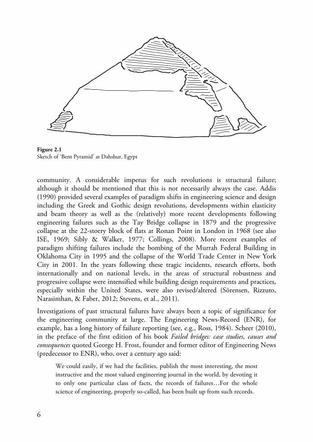
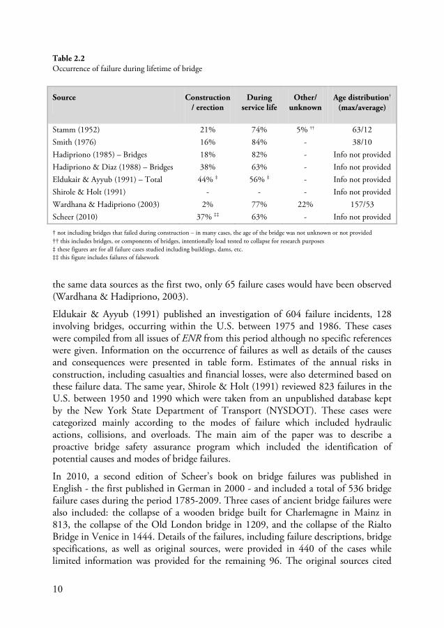
Bridge failures1 – and failures of structures in general – have been the price of progress throughout the history of architecture and engineering. The ancient Egyptians had likely determined the most stable shape for the pyramids through trial and error, building upon previous successes until extrapolation of previous methods failed; resulting in new lessons for the next generation of master builders. There is evidence of this having occurred for the so-called bent pyramid at Dahshur, Egypt. The base of the pyramid rises at a steep angle of 54° and then, about half-way up, the angle reduces to 43°. There is a theory that the original construction of the pyramid was based on the previously untried inclination of 54° but that a partial collapse during construction resulted in a lower inclination for the top portion of the finished structure (Blockley, 1980; Petroski, 1985). The lesson learned from this failure is evident in the geometry of the next pyramid constructed, the Red Pyramid, which was wholly constructed using this lower angle (Blockley, 1980). There are a number of other such cases available in the published literature illustrating the role that failures have had in the progress of engineering knowledge and design (see, e.g., Blockley, 1980; Addis, 1990; Petroski, 1994). Addis (1990), for example, applied the Khunian2 concept of paradigm shifts to explain the progresses made in engineering. Using this concept, developments in engineering design or science3
1 Failure refers not only to collapses but also cases of damage or distress; see Section
do not occur by a ‘process of accretion’ – or ‘development-by-accumulation’ – but are subject to periodic revolutions, or discontinuities in the evolutionary process of development, which ultimately create a shift in contemporaneous views within the engineering
2.1.1 2 Thomas S. Kuhn – a philosopher of science – first published his work The Structure of Scientific Revolutions in 1962 about the history and development of science and scientific inquiry (50th Anniversary Edition: Kuhn, 2012). 3 A distinction is made between engineering design (knowing how) and engineering science (knowing that) – see Section 3.1
6
community. A considerable impetus for such revolutions is structural failure; although it should be mentioned that this is not necessarily always the case. Addis (1990) provided several examples of paradigm shifts in engineering science and design including the Greek and Gothic design revolutions, developments within elasticity and beam theory as well as the (relatively) more recent developments following engineering failures such as the Tay Bridge collapse in 1879 and the progressive collapse at the 22-stoery block of flats at Ronan Point in London in 1968 (see also ISE, 1969; Sibly & Walker, 1977; Collings, 2008). More recent examples of paradigm shifting failures include the bombing of the Murrah Federal Building in Oklahoma City in 1995 and the collapse of the World Trade Center in New York City in 2001. In the years following these tragic incidents, research efforts, both internationally and on national levels, in the areas of structural robustness and progressive collapse were intensified while building design requirements and practices, especially within the United States, were also revised/altered (Sörensen, Rizzuto, Narasimhan, & Faber, 2012; Stevens, et al., 2011).
Investigations of past structural failures have always been a topic of significance for the engineering community at large. The Engineering News-Record (ENR), for example, has a long history of failure reporting (see, e.g., Ross, 1984). Scheer (2010), in the preface of the first edition of his book Failed bridges: case studies, causes and consequences quoted George H. Frost, founder and former editor of Engineering News (predecessor to ENR), who, over a century ago said:
We could easily, if we had the facilities, publish the most interesting, the most instructive and the most valued engineering journal in the world, by devoting it to only one particular class of facts, the records of failures…For the whole science of engineering, properly so-called, has been built up from such records.
Figure 2.1 Sketch of ‘Bent Pyramid’ at Dahshur, Egypt
7
Those within the engineering community have often argued the need for more consistent reporting of failures of structures such that lessons can be properly disseminated and publicly made available to the profession as a whole; Feld (1968), Smith (1976), Sibly & Walker (1977), Ross (1984), Hadipriono (1985), and Wardhana & Hadipriono (2003) are just some examples. This is no less true of bridge construction; in fact, learning from bridge failures is especially significant given the unique nature of each individual bridge ever built – no two are identical. Historically, the drive for expansion in terms of urban and rural environments has lead to an increased need for a larger and better transport infrastructure which, coupled with increasing technical knowledge and state-of-the-art building practices, has helped push the boundaries of bridge engineering in terms of ever longer spans and unique construction without precedent. An unfortunate consequence of this development is that it has, on a number of occasions, led to unexpected failures. During the turn of the last century, for example, failures of railroad bridges were uncommonly frequent, especially in the United States. In 1895, an engineering magazine article from the Railway Gazette listed some 502 cases of railway bridge failures in the period from 1879 to 1895 (Feld, 1968). There was a rapid development of railways in America at the time and Pugsley (1968) has estimated, based on these statistics, that 1 out of every 20 railway bridges existing at that time collapsed. While this specific historical case may be particularly extreme, the occurrence of bridge failures is by no means uncommon today and unfortunately the collection and dissemination of incidents of failure has not much improved. Evidence of this latter point is made apparent by considering the sparse availability of accessible databases of structural failures. Those databases that do exist, online for example, are usually just collections of previously published materials (books, journals, published failure reports, etc.) and reports published in the mainstream news media.
2.1.1 Definition of failure
Failures of bridges and of structures in general have been discussed in the previous section; however, the term ‘failure’ has not yet been properly defined. Failure, as it is referred to in this thesis, does not only encompass complete or even partial structural collapses but more generally alludes to any unwanted deviation, or non-conformity, from design expectation (Feld, 1968). These deviations may encapsulate a variety of both structural and functional aspects including conditions of stability, issues relating to serviceability and use, as well as structural performance and integrity. In the context of risk management, failure and success are not binary system states but rather opposite ends of a poorly defined spectrum indicating performance of a functioning system. The degree, or severity, of a failure can be quantified in terms of some consequence measure (utility) including financial losses, loss of bearing capacity or loss of life or limb. In this sense, failure is given context and defined in terms of its degree of severity, i.e., its consequence – more on this in Section 2.2.2.
8
2.2 Failure surveys
A number of investigations of past failure occurrences can be found in the literature. All such investigations should, however, be interpreted with care – especially as regards to any ‘real’ distribution of failure causes and types – as the true number of cases will never be known4
2.2.1
. For example, there is the issue of non-reporting by owners (for fear of litigation or negative impact on reputation); problems inherent with identifying, interpreting, and distinguishing causes (more on this in Section ); disparities in frequency of reporting (focus is usually on high-consequence failures while near-misses are rarely reported); disparities in transparency of investigations and level of detail of published material, etc. (Kaminetzky, 1991; Wood, 2012). However, the dissemination of failure data is, as has already been argued in the previous section, of vital importance for the engineering community and lessons can surely be learned from them.
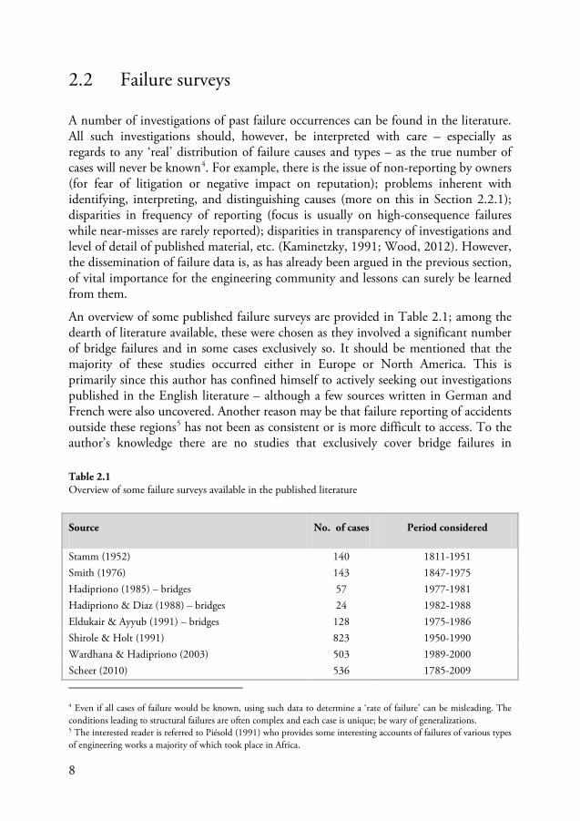
An overview of some published failure surveys are provided in Table 2.1; among the dearth of literature available, these were chosen as they involved a significant number of bridge failures and in some cases exclusively so. It should be mentioned that the majority of these studies occurred either in Europe or North America. This is primarily since this author has confined himself to actively seeking out investigations published in the English literature – although a few sources written in German and French were also uncovered. Another reason may be that failure reporting of accidents outside these regions5
4 Even if all cases of failure would be known, using such data to determine a ‘rate of failure’ can be misleading. The conditions leading to structural failures are often complex and each case is unique; be wary of generalizations.
has not been as consistent or is more difficult to access. To the author’s knowledge there are no studies that exclusively cover bridge failures in
5 The interested reader is referred to Piésold (1991) who provides some interesting accounts of failures of various types of engineering works a majority of which took place in Africa.
Source No. of cases Period considered
Stamm (1952) 140 1811-1951 Smith (1976) 143 1847-1975 Hadipriono (1985) – bridges 57 1977-1981 Hadipriono & Diaz (1988) – bridges 24 1982-1988 Eldukair & Ayyub (1991) – bridges 128 1975-1986 Shirole & Holt (1991) 823 1950-1990 Wardhana & Hadipriono (2003) 503 1989-2000 Scheer (2010) 536 1785-2009
Table 2.1 Overview of some failure surveys available in the published literature
9
Europe although a thorough study conducted by Matousek & Schneider (1976) at ETH in Zurich surveyed 800 failures (94% in Europe) of a variety of structures (50% were buildings and 7% bridges) for the period between 1960-76; refer to Hauser (1979) for an overview in English. Information for the study was collected from insurance files (50%), literature (39%), and various other sources including newspaper articles (10%). Other noteworthy sources on bridge and structural failures not listed in Table 2.1 include Hammond (1956), Feld (1968), Ross (1984), Oehme (1989), Harik et al. (1990), and Åkesson (2008); the bibliography in Scheer’s book (Scheer, 2010) on Bridge failures also provides a number of relevant sources dating back to the early 1900s.
The earliest reference from Table 2.1 was published in 1952 by Stamm and is considered a classic study of collapses of iron and steel bridges (Scheer, 2010). A total of approximately 140 bridge failures, occurring between the years of 1811 and 1951, are mentioned. The level of detail provided for each case varies immensely from up to a few pages to only a brief mention; references, are, however given for all of the cases. One issue that was quite important at the time the study was published, and which was discussed at length by its author, was the problem of brittle fracture of welded steel bridges. In 1976, Smith published a paper in which a total of 143 bridge failures occurring between 1847 and 1975 were surveyed. These failure cases were divided according to which stage in the bridges life failure occurred; reference to published sources was provided for all of the cases. The published discussion of Smith’s paper involved a number of prominent engineers of the time and many issues were taken up including the importance of failure data collection, the hydraulic design of bridges, the apparent increase in incident of ship collisions, and the dangers inherent in over-complicated and ambiguous design codes (Smith, et al., 1977).
In 1985, 1988, and 2003, three papers were published which surveyed structural failures, mostly occurring within the U.S., between 1977 and 2000 (Hadipriono, 1985; Hadipriono & Diaz, 1988; Wardhana & Hadipriono, 2003). These surveys included cases of structural collapse, distress, or unserviceability. In the first paper a total of 147 failures, occurring between 1977 and 1981, were considered; 57 of these cases were bridge failures. The second study included a survey of 70 failures for the 6 year period between 1982 and 1988; 24 of these were bridge failures. The most recent paper in the series was published in 2003 and surveyed a total of 503 (exclusively) bridge failure occurrences in the eleven year period between 1989 and 2000. In each case, failure data was collected from published and unpublished reports which included engineering journals and magazines such as ENR and ASCE Civil Engineering. Information from the United States Federal Highway Administration (FHWA) as well as the Department of Transport for several states was also included in the most recent study. The noticeable increase in the number of cases compared to the first and second study is likely that the most recent study took advantage of information technology (electronic databases and the Internet) that was not available in the past. According to the authors, if the recent study had been conducted using
10
the same data sources as the first two, only 65 failure cases would have been observed (Wardhana & Hadipriono, 2003).
Eldukair & Ayyub (1991) published an investigation of 604 failure incidents, 128 involving bridges, occurring within the U.S. between 1975 and 1986. These cases were compiled from all issues of ENR from this period although no specific references were given. Information on the occurrence of failures as well as details of the causes and consequences were presented in table form. Estimates of the annual risks in construction, including casualties and financial losses, were also determined based on these failure data. The same year, Shirole & Holt (1991) reviewed 823 failures in the U.S. between 1950 and 1990 which were taken from an unpublished database kept by the New York State Department of Transport (NYSDOT). These cases were categorized mainly according to the modes of failure which included hydraulic actions, collisions, and overloads. The main aim of the paper was to describe a proactive bridge safety assurance program which included the identification of potential causes and modes of bridge failures.
In 2010, a second edition of Scheer’s book on bridge failures was published in English - the first published in German in 2000 - and included a total of 536 bridge failure cases during the period 1785-2009. Three cases of ancient bridge failures were also included: the collapse of a wooden bridge built for Charlemagne in Mainz in 813, the collapse of the Old London bridge in 1209, and the collapse of the Rialto Bridge in Venice in 1444. Details of the failures, including failure descriptions, bridge specifications, as well as original sources, were provided in 440 of the cases while limited information was provided for the remaining 96. The original sources cited
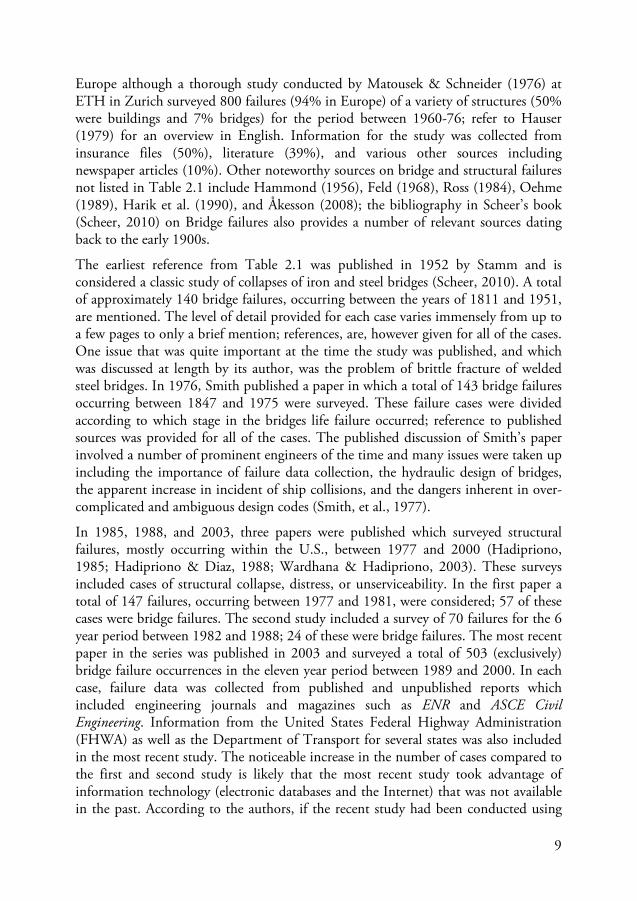
Source Construction/ erection
During service life
Other/ unknown
Age distribution† (max/average)
Stamm (1952) 21% 74% 5% †† 63/12 Smith (1976) 16% 84% - 38/10 Hadipriono (1985) – Bridges 18% 82% - Info not provided Hadipriono & Diaz (1988) – Bridges 38% 63% - Info not provided Eldukair & Ayyub (1991) – Total 44% ‡ 56% ‡ - Info not provided Shirole & Holt (1991) - - - Info not provided Wardhana & Hadipriono (2003) 2% 77% 22% 157/53 Scheer (2010) 37% ‡‡ 63% - Info not provided
† not including bridges that failed during construction – in many cases, the age of the bridge was not unknown or not provided †† this includes bridges, or components of bridges, intentionally load tested to collapse for research purposes ‡ these figures are for all failure cases studied including buildings, dams, etc. ‡‡ this figure includes failures of falsework
Table 2.2 Occurrence of failure during lifetime of bridge
11
included archive issues of Journals in German (e.g., Beton + Eisen, Bauingenieur, Beton- und Stahlbeton, and Bautechnik), in English (e.g., Civil Engineering and ENR), as well as books, articles, conferences, and newspaper articles (e.g., Stamm, 1952; Smith, 1976; Frandsen, 1983). An excellent overview of early publications on the failures of bridges is also provided.
The stage in the lifetime of the bridge in which failure occurred is provided in Table 2.2. It can be seen that the majority of the cases surveyed involved failures that occurred during the service life of the bridge. It would be incorrect to infer based on these data that more failures occur during a bridges service life than during the construction phase. To start, the occurrence of failures during construction may not be reported unless severe consequences occur; i.e. human casualties or collapse of a significant portion of the erected structure. Furthermore, at any point in time, the number of existing bridges in service is far greater than those being constructed (Eldukair & Ayyub, 1991; Wardhana & Hadipriono, 2003). The age of the bridges in service at the incident of failure, when provided in the source material, varied from a few years, months, or even days after opening to over a century of use. The effects of degradation as well as the history of maintenance, inspection and repair of aging bridges were in some cases enabling factors leading to failure; e.g. in cases of fatigue or corrosion of aging steel bridges.
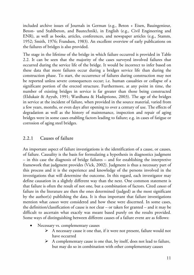
2.2.1 Causes of failure
An important aspect of failure investigations is the identification of a cause, or causes, of failure. Causality is the basis for formulating a hypothesis in diagnostics judgment – in this case the diagnosis of bridge failures – and for establishing the interpretive framework that judgment provides (Vick, 2002). Judgment is thus a necessary part of this process and it is the experience and knowledge of the persons involved in the investigations that will determine the outcome. In this regard, each investigator may define causation in a slightly different way than the next. One common statement is that failure is often the result of not one, but a combination of factors. Cited causes of failure in the literature are then the ones determined (judged) as the most significant by the author(s) publishing the data. It is thus important that failure investigations mention what causes were considered and how these were discerned. In some cases, the definition/classification of cause is not clear – or taken for granted – and it may be difficult to ascertain what exactly was meant based purely on the results provided. Some ways of distinguishing between different causes of a failure event are as follows:
• Necessary vs. complementary causes A necessary cause it one that, if it were not present, failure would not
have occurred A complementary cause is one that, by itself, does not lead to failure,
but may do so in combination with other complementary causes
12
• Enabling vs. triggering causes An enabling cause is an event that precedes the actual failure event
and contributes to the severity of failure; an enabling cause in itself may not be sufficient to initiate failure
A triggering cause refers to an event that initiates the failure and may be preceded by enabling causes; the triggering cause in itself may not be sufficient to initiate failure
• Primary vs. secondary causes A primary cause, or underlying cause, is one that is judged to have
the greatest significance for the failure event; i.e. the most ‘important’ cause (the term ‘root’ cause is sometimes also used)
Secondary causes are those that are not considered primary causes
The above examples are not all mutually exclusive and a single cause can, for example, be both a necessary cause as well as an enabling cause. In reviewing a number of failure investigations, and especially when reading through official reports of individual failure cases – which can be hundreds of pages long6
[T]his author was asked as the first question: ‘What made the floor fall?’ The answer, at the spur of the moment, was: ‘Gravity.’ Such is probably the universally true answer to any state of affairs where insufficient resistance is provided to resist vertical fall.
– it becomes clear that determining a single cause of failure, as is often mentioned in the literature for brevity, is a very difficult task; one often requiring special experience and expertise in forensic engineering. A humorous anecdote regarding the issue of proper identification of failure causes is given by Feld in his book on construction failures:
Jacob Feld (1968, p. 11)
It is not uncommon for investigators to cite human error as a primary, or root, cause of all failures. For example, Kaminetzky (1991) made the argument that all structural failures were in some way linked to human errors; and some results of failure investigations certainly go a long way to support him in this view (see, e.g., Matousek & Schneider, 1976; Oehme, 1989). After all, it is the engineers’ duty to design a safe structure, the contractors’ responsibility for building it and the owners’ responsibility for maintaining it and thus any future failure would be a result of failings to accomplish these objectives. This is an important point as it allocates responsibility of the safety and functionality of the structure and implies that control of failure is a paramount part of this responsibility (more about this in later sections). It should be mentioned, however, that this traditional so-called ‘old view’ of human error and the human contribution to failures – that humans are the source of failure in an otherwise inherently safe system – has been criticized for its misleading and oversimplified 6 Some failure reports (accident investigations) can, e.g., be accessed online at the NTSB website (www.ntsb.gov) for failures in the U.S. or, for certain special cases, the SHK website for failure occurrences in Sweden (www.havkom.se)
13
representation of the varied and complex conditions/circumstances leading to accidents/failures and for being counterproductive in enhancing overall systems safety (Dekker, 2013; Dekker, 2002; Woods, Dekker, Cook, Johannesen, & Sarter, 2010). Safety research in the past few decades has uncovered some insights which have driven a so-called ‘new-view’ of human error which is in contrast to the ‘old-view’ (Dekker, 2013). According to the ‘new view’, human error is seen as a symptom of failure and not the cause; the main objective is then re-directed towards understanding why these errors occurred – i.e. what conditions within the system were conducive for causing failure. This distinction is important as it provides a deeper understanding of human behavior as an integral working component of a larger dynamic system rather than something external which introduces unwanted variability and adversely affects system performance. For more information regarding the ‘new-view’ of human error and human error research, some sources are provided in the bibliography (Rasmussen, 1982; Reason, 1990; Shappell & Wiegmann, 1997; Dekker, 2002; Woods, Dekker, Cook, Johannesen, & Sarter, 2010; Dekker, 2013).
The previous discussion has highlighted some of the difficulties in classifying and assigning causes to failure cases. This point makes it quite difficult to compare results of failure investigations such as those in Table 2.1 since each publication may have different ways of classifying different causes of failure. Any such comparison would thus require additional interpretation adding an extra layer of concealment increasing the risk of possible misinterpretations of results. Thus, results from the published material are presented in the next section separately, in original form, for the sake of transparency. In some cases, results from different sources are compatible and can be combined – e.g., the studies conducted by Hadipriono and his fellow authors.
2.2.1.1 Review of failure causes cited in failure surveys
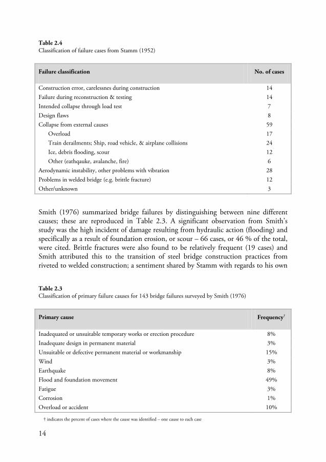
Stamm (1952), in his publication on failures of iron and steel bridges, discussed the difficulties of determining failure causes and chose to classify causes according to external (natural or man-made), internal (flaws), and root causes (human error – i.e. according to ‘old view’). As the original report contains no summary of the failure cases in terms of causes and failure modes, a rough overview of the cases the author reviewed is provided in Table 2.4 based on which section of the report the cases were mentioned. Some categories have been combined for the sake of brevity – e.g. collisions from various types of vehicles. A number of the failure cases involved aerodynamic instability and vibration issues – especially for suspension bridges – which at the time of publication (1952) received a lot of attention within the engineering community as a result of the Tacoma Narrows Bridge failure (see Section 2.3.1). In addition, some failures of welded bridges were discussed at length, highlighting common problems associated with such structures at that time; i.e. problem related to weldability of steel (especially high strength steel), problems with brittle fracture, and behavior of steel in extreme cold.
14
Smith (1976) summarized bridge failures by distinguishing between nine different causes; these are reproduced in Table 2.3. A significant observation from Smith’s study was the high incident of damage resulting from hydraulic action (flooding) and specifically as a result of foundation erosion, or scour – 66 cases, or 46 % of the total, were cited. Brittle fractures were also found to be relatively frequent (19 cases) and Smith attributed this to the transition of steel bridge construction practices from riveted to welded construction; a sentiment shared by Stamm with regards to his own
Failure classification No. of cases
Construction error, carelessnes during construction 14 Failure during reconstruction & testing 14 Intended collapse through load test 7 Design flaws 8 Collapse from external causes 59
Overload 17 Train derailments; Ship, road vehicle, & airplane collisions 24 Ice, debris flooding, scour 12 Other (eathqauke, avalanche, fire) 6
Aerodynamic instability, other problems with vibration 28 Problems in welded bridge (e.g. brittle fracture) 12 Other/unknown 3
Primary cause Frequency†
Inadequated or unsuitable temporary works or erection procedure 8% Inadequate design in permanent material 3% Unsuitable or defective permanent material or workmanship 15% Wind 3% Earthquake 8% Flood and foundation movement 49% Fatigue 3% Corrosion 1% Overload or accident 10%
† indicates the percent of cases where the cause was identified – one cause to each case
Table 2.4 Classification of failure cases from Stamm (1952)
Table 2.3 Classification of primary failure causes for 143 bridge failures surveyed by Smith (1976)
15
investigations (see Table 2.4). In addition, Smith discussed the importance of providing bridge piers with protection against ship impact (10 cases). Other issues brought up in the paper included the illusion that more ‘exact’ methods could have reduced the risk of failure, the problem of too much complexity in design codes, the importance of communication in the construction process, and the need for prompt, thorough and public reporting of structural failures. These issues were discussed at length in the 24 page discussion of his paper by 23 of his contemporaries who, for the most part, agreed with Smith’s observations (Smith, et al., 1977). This discussion is an excellent publication in its own right as it focused attention to many problems that are still relevant today.
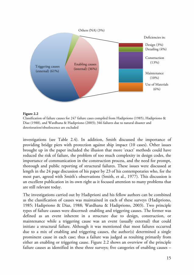
The investigations carried out by Hadiprioni and his fellow authors can be combined as the classification of causes was maintained in each of these surveys (Hadipriono, 1985; Hadipriono & Diaz, 1988; Wardhana & Hadipriono, 2003). Two principle types of failure causes were discerned: enabling and triggering causes. The former was defined as an event inherent in a structure due to design, construction, or maintenance while a triggering cause was an event (usually external) that could initiate a structural failure. Although it was mentioned that most failures occurred due to a mix of enabling and triggering causes, the author(s) determined a single prominent cause in each case; thus a failure was judged as resulting primarily from either an enabling or triggering cause. Figure 2.2 shows an overview of the principle failure causes as identified in these three surveys; five categories of enabling causes –
Triggering causes (external) (61%)
Design (3%) Detailing (4%)
Construction (13%)
Maintenance (10%)
Use of Materials (6%)
Others (NA) (3%)
Enabling causes (internal) (36%)
Deficiencies in:
Figure 2.2 Classification of failure causes for 247 failure cases compiled from Hadipriono (1985), Hadipriono & Diaz (1988), and Wardhana & Hadipriono (2003); 346 failures due to natural disaster and deterioration/obsolescence are excluded
16
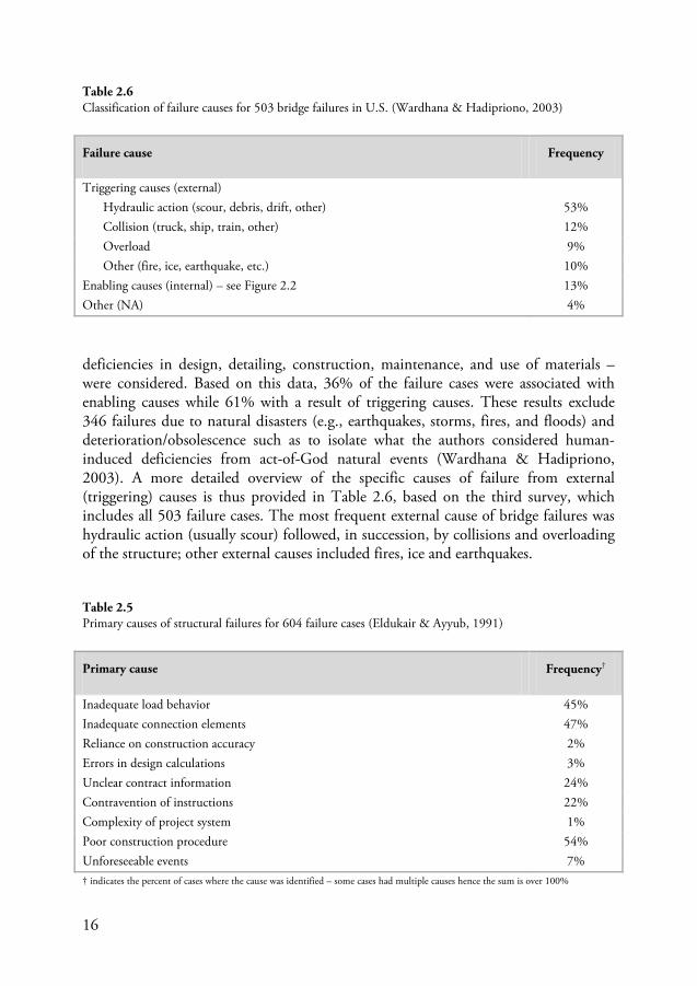
deficiencies in design, detailing, construction, maintenance, and use of materials – were considered. Based on this data, 36% of the failure cases were associated with enabling causes while 61% with a result of triggering causes. These results exclude 346 failures due to natural disasters (e.g., earthquakes, storms, fires, and floods) and deterioration/obsolescence such as to isolate what the authors considered human-induced deficiencies from act-of-God natural events (Wardhana & Hadipriono, 2003). A more detailed overview of the specific causes of failure from external (triggering) causes is thus provided in Table 2.6, based on the third survey, which includes all 503 failure cases. The most frequent external cause of bridge failures was hydraulic action (usually scour) followed, in succession, by collisions and overloading of the structure; other external causes included fires, ice and earthquakes.
Failure cause Frequency
Triggering causes (external) Hydraulic action (scour, debris, drift, other) 53% Collision (truck, ship, train, other) 12% Overload 9% Other (fire, ice, earthquake, etc.) 10%
Enabling causes (internal) – see Figure 2.2 13% Other (NA) 4%
Primary cause Frequency†
Inadequate load behavior 45% Inadequate connection elements 47% Reliance on construction accuracy 2% Errors in design calculations 3% Unclear contract information 24% Contravention of instructions 22% Complexity of project system 1% Poor construction procedure 54% Unforeseeable events 7%
Table 2.6 Classification of failure causes for 503 bridge failures in U.S. (Wardhana & Hadipriono, 2003)
Table 2.5 Primary causes of structural failures for 604 failure cases (Eldukair & Ayyub, 1991)
† indicates the percent of cases where the cause was identified – some cases had multiple causes hence the sum is over 100%
17
In the study conducted by Eldukair & Ayyub (1991) – which included 604 failure cases, 128 of which were bridges – the varying conditions surrounding failure and the causes contributing to their occurrence were investigated from a number of perspectives. As such, the results were presented in a number of different, sometimes confusing, ways (3 figures and 16 tables); only a select few of these will be reproduced here. To start, investigations of the adverse conditions surrounding the building process found that technical errors – during the planning, design, construction, and operation phases – were identified as having occurred in 78% of the failure causes. Errors in management practices (deficiencies in work responsibilities, communication processes and work cooperation) as well as adverse ‘environmental’ effects (political, financial, or economic pressures, as well as weather conditions) were also identified in 40% and 56% of the cases, respectfully. Deficiencies in the material of the failed elements of the structures and ‘human errors’ by participants (e.g. architects, structural engineers, inspectors, contractors) were also identified as significant factors which adversely affected successful performance of the different phases of the building process.
Apart from the aforementioned ‘sources or error’, Eldukair & Ayyub (1991) also provided distinct causes of failure7
Table 2.5
. These were divided into two main categories: primary and secondary causes. The prior referred to causes that, if independently occurring, would result in failure, while two or more secondary causes must be present for failure to occur. In presenting their results, Eldukair & Ayyub identified multiple causes attributable to each failure case; an overview of the primary causes of failure for all 604 failure cases is shown in . The majority of the failure cases were attributable to poor erection procedures (54%); evidence of this is provided by the frequency of incidents involving inadequacy of load behavior (45%) and connection elements (47%). For the failure cases involving bridge structures, the most common causes were attributed to financial constraints associated with maintenance and inspection programs (52%), fatigue loading (45%) as well as wind loading effects (43%); just how these causes were connected with those presented in Table 2.5 was not discussed. The first cause mentioned, related to deficiencies of maintenance and inspection programs, may be linked with failures resulting from hydraulic action and specifically scour of bridge foundations; considering this was such a prominent type of bridge failure at the time (see, e,g, Table 2.6 or Figure 2.3).
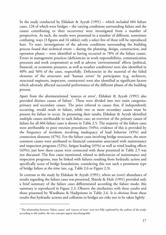
In contrast to the study by Eldukair & Ayyub (1991), where an (over) abundance of results regarding the failure cases was presented, Shirole & Holt (1991) provided only a brief summary of the failure cases differentiated according the failure mode; this summary is reproduced in Figure 2.3. Observe the similarities with these results and those presented by Wardhana & Hadipriono in Table 2.6. It is obvious from these results that hydraulic actions and collisions to bridges are risks not to be taken lightly.
7 The relationship between ‘failure causes’ and ‘sources of error’ were not fully explained by the authors of the study; according to this author, the two concepts appear interchangeable
18
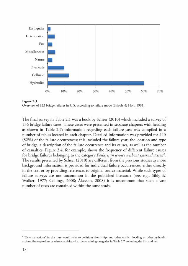
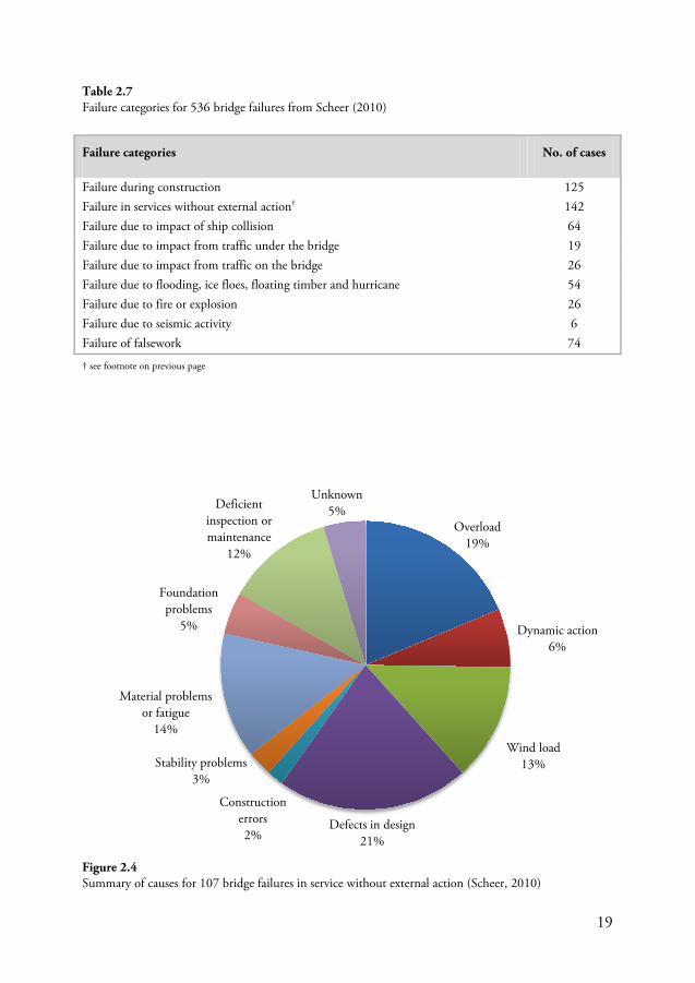
The final survey in Table 2.1 was a book by Scheer (2010) which included a survey of 536 bridge failure cases. These cases were presented in separate chapters with heading as shown in Table 2.7; information regarding each failure case was compiled in a number of tables located in each chapter. Detailed information was provided for 440 (82%) of the failure occurrences; this included the failure year, the location and type of bridge, a description of the failure occurrence and its causes, as well as the number of casualties. Figure 2.4, for example, shows the frequency of different failure causes for bridge failures belonging to the category Failures in service without external action8
. The results presented by Scheer (2010) are different from the previous studies as more background information is provided for individual failure occurrences; either directly in the text or by providing references to original source material. While such types of failure surveys are not uncommon in the published literature (see, e.g., Sibly & Walker, 1977; Collings, 2008; Åkesson, 2008) it is uncommon that such a vast number of cases are contained within the same study.
8 ‘External actions’ in this case would refer to collisions from ships and other traffic, flooding or other hydraulic actions, fire/explosions or seismic activity – i.e. the remaining categories in Table 2.7 excluding the first and last
Hydraulics
Collision
Overloads
Nature
Miscellaneous
Fire
Deterioration
Earthquake
0% 10% 20% 30% 40% 50% 60% 70%
Figure 2.3 Overview of 823 bridge failures in U.S. according to failure mode (Shirole & Holt, 1991)
19
Failure categories No. of cases
Failure during construction 125 Failure in services without external action† 142 Failure due to impact of ship collision 64 Failure due to impact from traffic under the bridge 19 Failure due to impact from traffic on the bridge 26 Failure due to flooding, ice floes, floating timber and hurricane 54 Failure due to fire or explosion 26 Failure due to seismic activity 6 Failure of falsework 74
Overload 19%
Dynamic action 6%
Wind load 13%
Defects in design 21%
Construction errors 2%
Stability problems 3%
Material problems or fatigue
14%
Foundation problems
5%
Deficient inspection or maintenance
12%
Unknown 5%
Figure 2.4 Summary of causes for 107 bridge failures in service without external action (Scheer, 2010)
Table 2.7 Failure categories for 536 bridge failures from Scheer (2010)
† see footnote on previous page
20
2.2.2 Consequences of failures
The consequences of structural failures, if mentioned at all in failure surveys, are usually reported in terms of human casualties and possibly also the economic costs associated with failure. If a failure leads to an injury or fatality then such cases are much more likely to be reported while cases with only financial losses may not be reported for fear of reprisals. Understanding the consequences of failure is, however, an integral part of understanding the risks associated with the building process. As was mentioned in Section 2.1.1 the consequence of a failure is a measure of failure severity; taken together with the causes discussed in the previous section, these provide the context from which failure risks can be understood. Comparing failure data without considering the consequences associated with the failure can thus be misleading. A number of failures leading to distress or minor local damages can be overshadowed by a single catastrophic failure leading to a number of human casualties and high financial losses. The nature of failure reporting is such that failures with higher consequences are more likely to be reported and the amount of resources expended towards investigations and inquiries is invariably linked to the severity of these consequences.
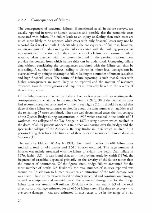
Of the failure surveys presented in Table 2.1 only a few presented data relating to the consequences of the failures. In the study by Smith (1976), 30 of the 143 failure cases had reported casualties associated with them; see Figure 2.5. It should be noted that three of these failure occurrences resulted in about the same number of fatalities as all the remaining 27 cases combined. These are well documented cases: the first collapse of the Quebec Bridge during construction in 1907 which resulted in the deaths of 75 workmen; the collapse of the Tay Bridge in 1879 during a storm which resulted in the death of all 75 persons onboard a train that was passing over the bridge; and the spectacular collapse of the Ashtabula Railway Bridge in 1876 which resulted in 91 persons losing their lives. The first two of these cases are mentioned in more detail in Section 2.3.1.
The study by Eldukair & Ayyub (1991) determined that for the 604 failure cases studied, a total of 416 deaths and 2 515 injuries occurred. The large number of injuries was mainly associated with the failure of a dam (the Teton Dam failure in 1976, Idaho, U.S.). It was found that, as in the previous study by Smith (1976), the frequency of casualties depended primarily on the severity of the failure rather than the number of occurrences. Of the figures cited, bridge failures accounted for the most number of deaths (23 fatalities); the total number of injuries reported was around 30. In addition to human casualties, an estimation of the total damage cost was made. These estimates were based on direct structural and construction damages as well as equipment and material costs. The estimated damage cost for the bridge failure cases was around 960 million US dollars which was nearly 1/3 of the total direct costs of damage estimated for all of 604 failure cases. The time to recovery – to overcome damages – was also estimated in most cases to be in the range of a few
21
months to a year; 7-9 months being the most frequent. It was unclear how this last figure was determined and whether it is representative of bridge failure cases. Obviously the amount of time required for recovery will depend on the severity of the failure and, while repairs of localized damages might take a few months, the reconstruction time of a totally collapsed bridge would more likely be in the range of one to a few years.
Figure 2.5 Number of fatalities reported for 30 bridge failure cases (Smith, 1976)
Figure 2.6 Number of fatalities reported for 350 bridge failure cases (Scheer, 2010)
0
50
100
150
200
250
300
0
5
10
15
20
25
Tot
al n
umbe
r of f
atal
ities
in e
ach
cate
gory
Tot
al n
umbe
r of f
ailu
re c
ases
Number of fatalities in each case
Failure cases
Fatalities
0
500
1000
1500
2000
2500
3000
0
50
100
150
200
250
300
Tot
al n
umbe
r of f
atal
ities
in e
ach
cate
gory
Tot
al n
umbe
r of f
ailu
re c
ases
Number of fatalities in each case
Failure cases
Fatalities
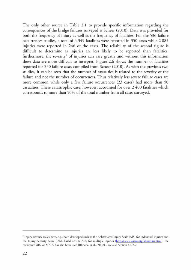
22
The only other source in Table 2.1 to provide specific information regarding the consequences of the bridge failures surveyed is Scheer (2010). Data was provided for both the frequency of injury as well as the frequency of fatalities. For the 536 failure occurrences studies, a total of 4 349 fatalities were reported in 350 cases while 2 885 injuries were reported in 266 of the cases. The reliability of the second figure is difficult to determine as injuries are less likely to be reported than fatalities; furthermore, the severity9
Figure 2.6 of injuries can vary greatly and without this information
these data are more difficult to interpret. shows the number of fatalities reported for 350 failure cases compiled from Scheer (2010). As with the previous two studies, it can be seen that the number of casualties is related to the severity of the failure and not the number of occurrences. Thus relatively less severe failure cases are more common while only a few failure occurrences (23 cases) had more than 50 casualties. These catastrophic case, however, accounted for over 2 400 fatalities which corresponds to more than 50% of the total number from all cases surveyed.
9 Injury severity scales have, e.g., been developed such as the Abbreviated Injury Scale (AIS) for individual injuries and the Injury Severity Score (ISS), based on the AIS, for multiple injuries (http://www.aaam.org/about-ais.html); the maximum AIS, or MAIS, has also been used (Blincoe, et al., 2002) – see also Section 4.4.2.2
23
2.3 Lessons from failure
One of primary aims of failure data collection is to uncover important lessons to help prevent similar cases from occurring in the future. The dissemination of such data is important for educating practicing engineers as well as students studying engineering at university. There are certainly a number of lessons that can be learned from individual cases of bridge failures. It may, however, not be so simple to disseminate these lessons in a general way. This problem is partly connected with the broader issues related to accident and failure investigations that have been touched upon early – e.g. determining causes of failure. Another problem is with how to effectively communicate these lessons to those involved in bridge construction; education is certainly an important starting point not only for engineering students but also for practicing engineers. The collective pool of engineering knowledge is indeed voluminous, but ensuring this knowledge is effectively distributed and not forgotten is an issue that should not be taken lightly. An interesting case in this regard is that of the behavior of suspension bridges in wind loading. Until approximately the middle of the 1900s, the behavior of such bridges in wind was verified by assuming perfectly static responses. In fact, problems with dynamic behavior of suspension bridge in wind, and even under foot traffic, had been well known prior to the 1900s; see Figure 2.7 (Sibly & Walker, 1977; Collings, 2008). However, it was not until the famed collapse of the Tacoma Narrows Bridge in 1940 that real attention was being paid by
Figure 2.7 Suspension bridges from 1800 to 2000 that have collapsed, totally or partially, or were otherwise negatively affected as a result of the dynamic effects of wind; cases compiled from failure survey by Scheer (2010) – see aslo Sibly & Walker (1977) and Collings (2008)
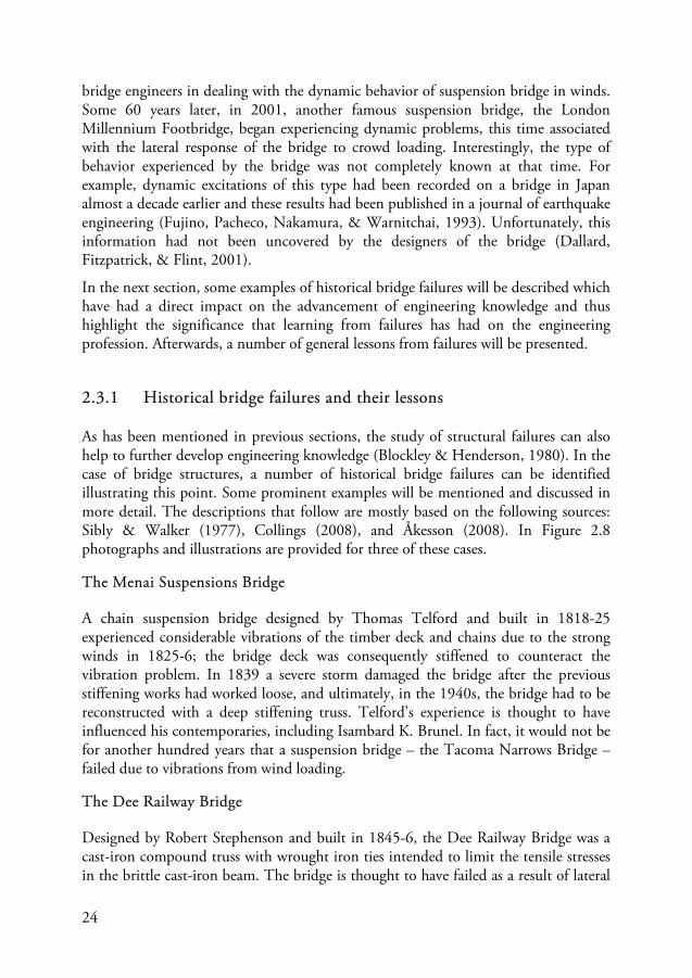
24
bridge engineers in dealing with the dynamic behavior of suspension bridge in winds. Some 60 years later, in 2001, another famous suspension bridge, the London Millennium Footbridge, began experiencing dynamic problems, this time associated with the lateral response of the bridge to crowd loading. Interestingly, the type of behavior experienced by the bridge was not completely known at that time. For example, dynamic excitations of this type had been recorded on a bridge in Japan almost a decade earlier and these results had been published in a journal of earthquake engineering (Fujino, Pacheco, Nakamura, & Warnitchai, 1993). Unfortunately, this information had not been uncovered by the designers of the bridge (Dallard, Fitzpatrick, & Flint, 2001).
In the next section, some examples of historical bridge failures will be described which have had a direct impact on the advancement of engineering knowledge and thus highlight the significance that learning from failures has had on the engineering profession. Afterwards, a number of general lessons from failures will be presented.
2.3.1 Historical bridge failures and their lessons
As has been mentioned in previous sections, the study of structural failures can also help to further develop engineering knowledge (Blockley & Henderson, 1980). In the case of bridge structures, a number of historical bridge failures can be identified illustrating this point. Some prominent examples will be mentioned and discussed in more detail. The descriptions that follow are mostly based on the following sources: Sibly & Walker (1977), Collings (2008), and Åkesson (2008). In Figure 2.8 photographs and illustrations are provided for three of these cases.
The Menai Suspensions Bridge
A chain suspension bridge designed by Thomas Telford and built in 1818-25 experienced considerable vibrations of the timber deck and chains due to the strong winds in 1825-6; the bridge deck was consequently stiffened to counteract the vibration problem. In 1839 a severe storm damaged the bridge after the previous stiffening works had worked loose, and ultimately, in the 1940s, the bridge had to be reconstructed with a deep stiffening truss. Telford’s experience is thought to have influenced his contemporaries, including Isambard K. Brunel. In fact, it would not be for another hundred years that a suspension bridge – the Tacoma Narrows Bridge – failed due to vibrations from wind loading.
The Dee Railway Bridge
Designed by Robert Stephenson and built in 1845-6, the Dee Railway Bridge was a cast-iron compound truss with wrought iron ties intended to limit the tensile stresses in the brittle cast-iron beam. The bridge is thought to have failed as a result of lateral
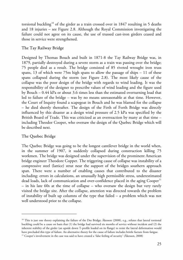
25
torsional buckling10
Figure 2.8 of the girder as a train crossed over in 1847 resulting in 5 deaths
and 18 injuries – see . Although the Royal Commission investigating the failure could not agree on its cause, the use of trussed cast-iron girders ceased and those in service were strengthened.
The Tay Railway Bridge
Designed by Thomas Bouch and built in 1871-8 the Tay Railway Bridge was, in 1879, partially destroyed during a severe storm as a train was passing over the bridge; 75 people died as a result. The bridge consisted of 85 riveted wrought iron truss spans, 13 of which were 75m high spans to allow the passage of ships – 11 of these spans collapsed during the storm (see Figure 2.8). The most likely cause of the collapse was the poor design of the bridge with regards to wind loading. It was the responsibility of the designer to prescribe values of wind loading and the figure used by Bouch – 0.44 kPa or about 3.6 times less than the estimated overturning load that led to failure of the bridge – was by no means unreasonable at that time. However, the Court of Inquiry found a scapegoat in Bouch and he was blamed for the collapse – he died shortly thereafter. The design of the Firth of Forth Bridge was directly influenced by this disaster as a design wind pressure of 2.5 kPa was specified by the British Board of Trade. This was criticized as an overreaction by many at that time – including Theodor Cooper, who oversaw the design of the Quebec Bridge which will be described next.
The Quebec Bridge
The Quebec Bridge was going to be the longest cantilever bridge in the world when, in the summer of 1907, it suddenly collapsed during construction killing 75 workmen. The bridge was designed under the supervision of the prominent American bridge engineer Theodore Copper. The triggering cause of collapse was instability of a compressive steel (lattice) strut near the support of the bridges southern approach span. There were a number of enabling causes that contributed to the disaster including: errors in calculations, an unusually high permissible stress, underestimated dead loads, lack of communication and over-confidence placed in the aging Cooper11
10 This is just one theory explaining the failure of the Dee Bridge; Åkesson (2008), e.g., refutes that lateral torsional buckling could be a cause on basis that (1) the bridge had survived six months of service without incident and (2) the inherent stability of the girder (an upside down T-profile loaded on its flange) to resist the lateral deformation would have precluded this type of failure. An alternative theory for the cause of failure includes brittle facture from fatigue.
– in his late 60s at the time of collapse – who oversaw the design but very rarely visited the bridge site. After the collapse, attention was directed towards the problem of instability of built up columns of the type that failed – a problem which was not well understood prior to the collapse.
11 Cooper’s involvement in the case was said to have created a ‘false feeling of security’ (Åkesson, 2008)
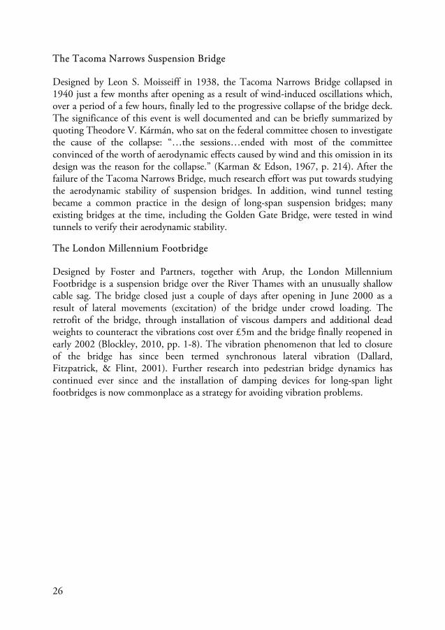
26
The Tacoma Narrows Suspension Bridge
Designed by Leon S. Moisseiff in 1938, the Tacoma Narrows Bridge collapsed in 1940 just a few months after opening as a result of wind-induced oscillations which, over a period of a few hours, finally led to the progressive collapse of the bridge deck. The significance of this event is well documented and can be briefly summarized by quoting Theodore V. Kármán, who sat on the federal committee chosen to investigate the cause of the collapse: “…the sessions…ended with most of the committee convinced of the worth of aerodynamic effects caused by wind and this omission in its design was the reason for the collapse.” (Karman & Edson, 1967, p. 214). After the failure of the Tacoma Narrows Bridge, much research effort was put towards studying the aerodynamic stability of suspension bridges. In addition, wind tunnel testing became a common practice in the design of long-span suspension bridges; many existing bridges at the time, including the Golden Gate Bridge, were tested in wind tunnels to verify their aerodynamic stability.
The London Millennium Footbridge
Designed by Foster and Partners, together with Arup, the London Millennium Footbridge is a suspension bridge over the River Thames with an unusually shallow cable sag. The bridge closed just a couple of days after opening in June 2000 as a result of lateral movements (excitation) of the bridge under crowd loading. The retrofit of the bridge, through installation of viscous dampers and additional dead weights to counteract the vibrations cost over £5m and the bridge finally reopened in early 2002 (Blockley, 2010, pp. 1-8). The vibration phenomenon that led to closure of the bridge has since been termed synchronous lateral vibration (Dallard, Fitzpatrick, & Flint, 2001). Further research into pedestrian bridge dynamics has continued ever since and the installation of damping devices for long-span light footbridges is now commonplace as a strategy for avoiding vibration problems.
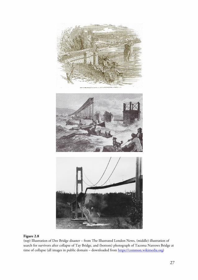
27
Figure 2.8 (top) Illustration of Dee Bridge disaster – from The Illustrated London News, (middle) illustration of search for survivors after collapse of Tay Bridge, and (bottom) photograph of Tacoma Narrows Bridge at time of collapse (all images in public domain – downloaded from https://common.wikimedia.org)
28
2.3.2 General lessons from failures
The previous section highlighted the importance that failures have had on the development of engineering knowledge and practices by referencing some historical bridge failures. Apart from these spectacular cases, there are also general lessons that can be learned based on the results of failure surveys. The following is a list of lessons, or rules, compiled based on the failure surveys presented in previous sections as well as from information provided in the published literature (Pugsley, 1966; Feld, 1968; Kaminetzky, 1991; Wood, 2012). Focus is kept on the engineering design aspects of the building process while lessons pertaining to the construction and utilization phases are left out; the list is in not sorted in any particular order:
• During design, it is important to consider what happens to the structure when it is constructed/erected, not just during service
• Be wary of ‘common-cause failures’ which could affect a number of structural components (e.g. design flaws affecting multiple members)
• Ensure there is an adequate level of quality assurance and teamwork both on-site and in the design offices – avoid working alone as something could be missed
• Consider actions outside the conventional sphere of structural design – such as scour or aerodynamic phenomena – and work together with professionals outside traditional structural or mechanical engineering
• Be wary of the dangers inherent with ‘on-the-go’ changes in design concepts and make sure that, if such changes do occur, provisions have been made to verify they work and result in a safe structure
• Be wary of your assumptions • Be wary of time constraints, or constraints of other resources, as a result of
external pressures • Refinement of approaches to calculations of load effects and structural
responses often do little to reduce the risk of failure • Be wary of too much complexity (in codes, calculations, structure, etc.) as
this increases likelihood of errors • Understand the limitations of existing design/construction methods • Be wary of the pitfalls of extrapolation – what worked before may not work if
some parameters are changed (e.g. span or other dimensions increased, etc.) • Be wary of blindly relying on computers or other technologies – in cases
where you are unsure, try and verify the results in some other way; basic understanding is paramount
• Try to incorporate fail-safe designs to account for unforeseen circumstances • Investigate a number of different conceptual solutions instead of just focusing
on optimization of individual structural components • Understand the importance of institutional and procedural mechanisms to
ensure a successful project – make sure to coordinate efforts between
29
different stakeholders involved (e.g. between design parties and on-site personnel)
• Be more careful in cases where the project is innovative, complex or unusual (ICU) (Wood, 2012); untested technical solutions should be treated with utmost care to minimize the potential for failures
• Each generation of engineers should learn the ‘history so far’ so as not repeat past mistakes and the lessons these provided
• Investigations of ‘low probability’ events are also important and one should be careful when neglecting some hazard as simply unlikely
Another issue that will be briefly mentioned here involves potential problems arising inadvertently as a result of changes of design practices that were implemented in reaction to failures – e.g., some of those mentions in Section 2.3.1. These changes may in some instances be counterproductive as they are, in themselves, untested. The collapse of the West Gate Bridge in Melbourne in 1970 and problems with wind loading of the Severn Bridge in the 1970s will be mentioned here as examples; refer to Åkesson (2008) or Wood (2012).
The West Gate Bridge was a steel box girder bridge which collapsed during construction in 1970 killing 35 persons. The bridge was constructed using bolted connections between the different sections of the bridge deck, a practice that was uncommon for steel box girder bridges of the time. This construction method was specified because of the problem associated with brittle fracture of welds in previous box-girder bridges; the collapse of the King Street Bridge a decade earlier is said to have directly influenced this decision (Wood, 2012). An unintended result of choosing bolted connections was its reduced resistance to local buckling as a result of the lower stiffness of the bolted connections as well as the eccentricities these connections introduce in terms of load transfer. These issues were significant contributing factors in the collapse of the bridge (Royal Commission, 1971).
The second case is the Severn Bridge, completed in 1966, which experienced unique problems associated with wind loading in the 1970s. The bridge was designed with an innovative streamlined aerodynamic deck to reduce drag and wind loading. As has already been mentioned, such practices became more common after the collapse of the Tacoma Narrows Bridge in 1940. While this certainly helped alleviate problems that were associated with the aerodynamic behavior of suspensions bridges such as the Tacoma Narrows, it inadvertently introduced a previously unseen risk. In this instance what had been overlooked was the fact that the streamlined deck significantly increased the wind speed across the deck; this resulted in a number of empty trucks overturning in high winds (Wood, 2012). It was found that such events could lead to scenarios where the bridge was congested during rising winds as a result of an overturned truck blocking the flow of traffic – with no way to clear the deck before peak gusts. This design situation was not considered in design as it was argued that extreme wind loading of the deck could not occur in tandem with high loading of the deck; as there would be no traffic on the bridge Over twenty years later, the lesson
30
was learnt and high wind shielding of traffic was introduced for long span UK bridges to reduce traffic disruption by high winds (Wood, 2012).
2.4 The role of risk and uncertainty in structural engineering
The previous sections have highlighted the important role that structural failures have had in the advancement of engineering knowledge and design practices. The lessons learned from previous structural failures and near misses can aid with improving future practices by producing safer structures and better controlling risks in engineering design, construction and operation. If a failure occurs, attempts are made to ensure similar incidents do not reoccur or at least put a system in place for dealing with the aftermath if such failures cannot be prevented. Such efforts, coupled with cases of litigation – or the threat of litigation – in the aftermath of failures, have led to the development of the field of ‘forensic engineering’ (see, e.g., Carper, 2001). However, investigations of failures are only partially effective in addressing the issue of attaining, and maintaining, better safety performance of structures. Failure investigations12
12 The term ‘failure investigation’ as it’s used here covers any type of ‘forensic engineering investigation’; i.e. ‘accident investigation’ – which is commonly used by transport authorities – or ‘failure analysis’ – which is associated with the investigation of modes and mechanisms of failure; see, e.g., Brown (2007).
have been criticized for their reactive nature as well as for the lack of learning potential they provide (see, e.g., Stoop & Dekker, 2012). To start, this approach, of achieving success by learning from failure, is not ideal from an ethical standpoint as it favors a reactive as opposed to a proactive development of risk control in engineering design; i.e. the former requires the initiation of failure to instigate change while the latter actively seeks ways with which to prevent failure from ever occurring in the first place. Shirole & Holt (1991) mentioned this issue in relation to bridge management strategies and the efforts taken in response to bridge failures; e.g., retrofits and upgrades of existing structures. In addition to their reactive nature, the effective learning potential of failure investigations has also been questioned by researchers (see, e.g., Hollnagel, 2008; Cedergren & Petersen, 2011; Stoop & Dekker, 2012). These investigations may only tell one part of the story and this is highly influenced by the manner with which the investigation is conducted, including: what is (and is not) considered (i.e. the overall scope); the assumptions made; and conceptions regarding causality. Thus while failure investigations, and forensic engineering as a whole, are certainly effective means of reducing risk and improving safety, a complementary proactive safety management approach is warranted. In the context of designing structures, such an approach requires that failures are either predicted beforehand and safeguards are built into the structural
31
system (i.e. direct or indirect design for specified failure scenarios) or that provisions are in place for dealing with failure situations such that their effects are minimized. The overbearing issue in either case is in dealing with risks and uncertainties in a decision making context; i.e. in design. The following definition of structural engineering, taken from the Institution of Structural Engineers official journal The Structural Engineer highlights the challenges faced by structural engineers in their task of designing safe structures in light of risk and uncertainty:
Structural Engineering is the Art of moulding materials we do not wholly understand into shapes we cannot precisely analyse, so as to withstand forces we cannot really assess, in such a way that the community at large has no reason to suspect the extent of our ignorance.
Dr. A R Dykes (1976) as quoted by Schmidt (2009)
The next chapter of this thesis provides an overview of the role that engineers play in the process of creating safe structures. The concept of engineering design and of structural safety is also be discussed and reviewed.

32
This page is intentionally left blank
33
3. Principles of engineering design
From the point of view of modern science, design is nothing, but from the point of view of engineering, design is everything. It presents the purposive adaptation of means to reach a preconceived end, the very essence of engineering.
Edwin T. Layton, Jr. (1976, p. 696)
3.1 Introduction
Design is central to engineering; it is the unique, essential core of the human activity called engineering (Koen, 2003). Harris (1975) described engineering design as ‘the determination of what is to be built and the preparation of the instructions necessary for building it.’ The process of design is one of decision making, involving a number of sometimes conflicting objectives including function, economy and safety. Engineering design utilizes engineering knowledge and experience to provide a description and justification of a proposed design while adhering to constraints set, e.g., by building regulations, time constraints, costs and client’s requirements (Addis, 1990). The exact manner in which this procedure is carried out, and the resulting design, will greatly depend on the engineer(s) and his or her (or their) knowledge and experience. In this regard, the importance of engineering judgment, imagination and creativity in problem solving as skills of an engineer should be highlighted (Blockley, 1980; Harris, 1980; Addis, 1990; Vincenti, 1990; Ferguson, 1992; Davis, 2012).
An integral part of engineering design is safe-sidedness; or intentional conservatism to ensure there is a margin of safety against failure. This practice exists to counterbalance the uncertainties inherent in the design and to provide some leeway for treating the risks associated with failure; building practices throughout history have been driven by this practice. In those early times of human civilization it is likely that master builders were driven by experience and, as has been mentioned in the previous chapter, by lessons of past failures. While failures almost certainly played an important role in the historical evolution and advancement of engineering design, the development of rational approaches for evaluating the behavior of structures would gradually begin to replace reliance on precedence and learning from trial and error. One of the earliest documented works on the strength and dynamics of materials was
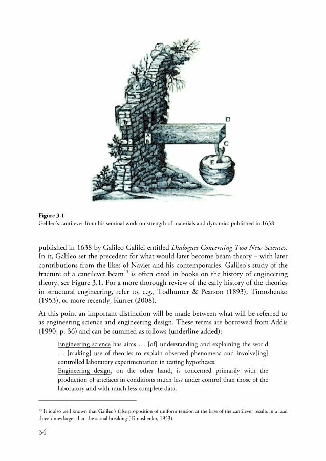
34
published in 1638 by Galileo Galilei entitled Dialogues Concerning Two New Sciences. In it, Galileo set the precedent for what would later become beam theory – with later contributions from the likes of Navier and his contemporaries. Galileo’s study of the fracture of a cantilever beam13
Figure 3.1 is often cited in books on the history of engineering
theory, see . For a more thorough review of the early history of the theories in structural engineering, refer to, e.g., Todhunter & Pearson (1893), Timoshenko (1953), or more recently, Kurrer (2008).
At this point an important distinction will be made between what will be referred to as engineering science and engineering design. These terms are borrowed from Addis (1990, p. 36) and can be summed as follows (underline added):
Engineering science has aims … [of] understanding and explaining the world … [making] use of theories to explain observed phenomena and involve[ing] controlled laboratory experimentation in testing hypotheses. Engineering design
13 It is also well known that Galileo’s false proposition of uniform tension at the base of the cantilever results in a load three times larger than the actual breaking (Timoshenko, 1953).
, on the other hand, is concerned primarily with the production of artefacts in conditions much less under control than those of the laboratory and with much less complete data.
Figure 3.1 Gelileo’s cantilever from his seminal work on strength of materials and dynamics published in 1638
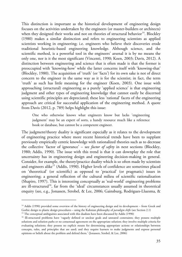
35
This distinction is important as the historical development of engineering design focuses on the activities undertaken by the engineers (or master-builders or architects) when they designed their works and not on theories of structural behavior14
One who otherwise knows what engineers know but lacks ‘engineering judgment’ may be an expert of sorts, a handy resource much like a reference book or database, but cannot be a competent engineer.
. Blockley (1980) makes a similar distinction and refers to engineering scientists as applied scientists working in engineering; i.e. engineers who believe their discoveries erode traditional heuristic-based engineering knowledge. Although science, and the scientific method, is a powerful tool in the engineers’ arsenal it is by no means the only one, nor is it the most significant (Vincenti, 1990; Koen, 2003; Davis, 2012). A distinction between engineering and science that is often made is that the former is preoccupied with ‘knowing-how’ while the latter concerns itself with ‘knowing-that’ (Blockley, 1980). The acquisition of ‘truth’ (or ‘facts’) for its own sake is not of direct concern to the engineer in the same way as it is for the scientist; in fact, the term ‘truth’ as such has little meaning for the engineer (Koen, 2003). One issue with approaching (structural) engineering as a purely ‘applied science’ is that engineering judgment and other types of engineering knowledge that cannot easily be discerned using scientific principles are depreciated; these less ‘rational’ facets of the engineering approach are critical for successful application of the engineering method. A quote from Davis (2012, p. 789) helps highlight this issue:
The judgment/theory duality is significant especially as it relates to the development of engineering practice where more recent historical trends have been to supplant previously empirically centric knowledge with rationalized theories such as to decrease the collective ‘factor of ignorance’ – see factor of safety in next sections (Blockley, 1980; Addis, 1990). The issue with this trend is that it can downplay the role that uncertainty has in engineering design and engineering decision-making in general. Consider, for example, the theory/practice duality which is so often made by scientists and engineers alike15 (Addis, 1990). Higher levels of confidence are sometimes placed on ‘theoretical’ (or scientific) as opposed to ‘practical’ (or pragmatic) issues in engineering; a general reflection of the cultural milieu of scientific rationalization (Shapiro, 1997). This is interesting conceptually as ‘real-world’ engineering problems are ill-structured16
14 Addis (1990) provided some overview of the history of engineering design and its development – from Greek and Gothic design to plastic design procedures – using the Kuhnian philosophy of paradigm shifts (see Section
, far from the ‘ideal’ circumstances usually assumed in theoretical enquiry (see, e.g., Jonassen, Strobel, & Lee, 2006; Gainsburg, Rodrigues-Lluesma, &
2.1) 15 The conceptual ambiguities associated with this dualism have been discussed by Addis (1990) 16 Ill-structured problems have ‘vaguely defined or unclear goals and unstated constraints; they possess multiple solutions and solution paths or no consensual agreement on the appropriate solution; they involve multiple criteria for evaluating solutions; they possess no explicit means for determining appropriate actions or relationships between concepts, rules, and principles that are used; and they require learners to make judgments and express personal opinions or beliefs about the problem and defend them.’ (Jonassen, Strobel, & Lee, 2006)
36
Bailey, 2010; Trevelyan, 2010). ‘Ideal’ in this case refers to how the world should behave such that it fits in nicely with the theories that are constructed – and the models these produce – while the way the world is actually behaving may be something else entirely. A related issue in this context is the common belief that increased sophistication in modeling approaches leads to greater accuracy. Zadeh (1973) pointed out the fallacies of this notion – especially as it is applied to more and more complex systems – with his principle of incompatibility:
As the complexity of a system increases, our ability to make precise and yet significant statements about its behavior diminishes until a threshold is reached beyond which precision and significance (or relevance) become almost mutually exclusive characteristics.
In other words, the notion that increased refinement and sophistication leads to more accuracy is not necessarily the case. In fact, the opposite may be true; i.e. increasing the sophistication of a predictive model may be counterproductive as it does not provide meaningful information. The principle of consistent crudeness illustrates this issue in regards to engineering models (Elms, 1985; Elms, 1999):
The quality of the output of a model cannot be greater than the quality of the crudest input or of the model itself, modified according to the sensitivity of the output to that input.
The preceding discussion highlights some of the issues related to engineering design and in distinguishing engineering from ‘applied science’. In the next section, the design process is briefly described.
3.1.1 Design process
There are a number of ways to describe the design process; these may view design from different perspectives. A common way is to distinguish between different stages of a construction project. Using this approach, the design process can be broadly divided into two main phases: (1) the conceptual design and (2) the detailed design stages; see Figure 3.2. In addition to these design-centric activities, the construction process for a new bridge structures will also include an initial planning phase – prior to or in conjunction with the conceptual design – as well as the construction phase – following the detailed design phase in which the structure is to be built. The planning and construction phases will not be discussed further in this thesis.
During the conceptual design phase multiple technical solutions, or design alternatives, may be proposed based on the initial design constraints and specifications for the construction project. The solutions themselves will not be very detailed and may only include brief descriptions regarding the overall structural concept for the bridge structure; e.g., a cable-stayed or a suspension bridge. Each of the proposed technical solutions is then compared based on some predetermined criteria and an
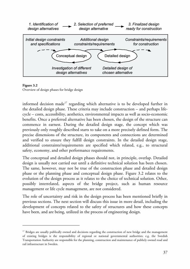
37
informed decision made17
The conceptual and detailed design phases should not, in principle, overlap. Detailed design is usually not carried out until a definitive technical solution has been chosen. The same, however, may not be true of the construction phase and detailed design phase or the planning phase and conceptual design phase. Figure 3.2 relates to the evolution of the design process as it relates to the choice of technical solution. Other, possibly interrelated, aspects of the bridge project, such as human resource management or life cycle management, are not considered.
regarding which alternative is to be developed further in the detailed design phase. These criteria may include construction – and perhaps life-cycle – costs, accessibility, aesthetics, environmental impacts as well as socio-economic benefits. Once a preferred alternative has been chosen, the design of the structure can commence in earnest. During the detailed design stage, the concept which was previously only roughly described starts to take on a more precisely defined form. The precise dimensions of the structure, its components and connections are determined and verified to ensure they fulfill design constraints. In the detailed design stage, additional constraints/requirements are specified which related, e.g., to structural safety, economy, and other performance requirements.
The role of uncertainty and risk in the design process has been mentioned briefly in previous sections. The next section will discuss this issue in more detail, including the development of concepts related to the safety of structures and how these concepts have been, and are being, utilized in the process of engineering design.
17 Bridges are usually publically owned and decisions regarding the construction of new bridge and the management of existing bridges is the responsibility of regional or national governmental authorities; e.g. the Swedish Transportation Authority are responsible for the planning, construction and maintenance of publicly owned road and rail infrastructure in Sweden.
Figure 3.2 Overview of design phases for bridge design
38
3.2 Controlling risks in engineering design
The concept of a ‘safe structure’, or ‘safety’ in engineering design, has likely existed every since humans started manipulating the forces and objects in nature for their own ends; a desired characteristic of all structures is that they should be ‘safe’. In the context of engineering design of structures, safety is intimately related to risk control. The design of a bridge, or a structure in general, is considered more safe if the (perceived) residual risks are kept at a minimum. To achieve the reduction of risk, and to provide assurances to the stakeholders involved that safety is in fact achieved, a system of risk control is put in place. This system of risk control has, historically, been based on engineering ‘heuristics’18
3.2.1 Safety and risk
and the concept of design conservatism (Elms, 1992). The choice of building materials and methods of construction were aided by past experiences – of successes and failures – coupled with conservative design choices and assumptions to counter-act uncertainties. This approach has, in the past 60 years or so, been supplanted by rationalized approaches to structural safety. The next sections will discuss generally the concepts of safety, risk, and uncertainty, and how these tie in with engineering design. This is followed by a brief history of methods for risk control in engineering design prior to and including the advent of modern rationalized approaches; i.e. structural reliability theory (SRT). Finally, SRT is outlined in more detail followed by an overview of modern design codes and how these codes are formulated such as to treat risks in engineering design.
Safety as a concept is commonly understood without any reference to a formal definition; or at least this assumption appears tacitly made when many researchers discuss issues relating to safety. In structural engineering, safety is commonly viewed from a human viewpoint; i.e. are structures safe for humans (Pugsley, 1951). The Joint Committee on Structural Safety (JCSS)19 defines safety in a similar way as most English language dictionaries: ‘the state of being protected against hurt or injury, freedom from danger or hazard’ (JCSS, 2008). Some other common definitions of safety have been reviewed by Aven (2014)20
18 Heuristics is ‘anything that provides a plausible aid or direction in the solution of a problem but is in the final analysis unjustified, incapable of justification, and potentially fallible.’ (Koen 2003)
. Hollnagel (2014a) pointed out that many definitions of safety are in fact defining un-safety rather than safety as reference is made to the absence of something going wrong rather than the presence of something going right. This insight is practically meaningful as any measure of safety can only be determined in un-safe situations while no such measure can exist in perfectly safe
19 The JCSS is a committee in the field of structural reliability and risk founded in the early 1970s with the aim of improving general knowledge in structural safety (http://www.jcss.byg.dtu.dk) 20 For a thorough conceptual analysis of safety, see Möller, Hansson & Peterson (2006)
39
situations. This understanding of safety is mirrored in the way with which safety has been treated by engineers in the process of designing structures such as bridges where focus has been on preventing failure as opposed to ensuring success – e.g., by verification of satisfactory performance for given identifiable modes of failure. The reason for this type of thinking becomes quite obvious when considering the significant impacts that failures have had on the progress of engineering design as discussed in previous sections. It should, however, be mentioned that alternative definitions of safety, with focus on achieving successes, have been put forth. Hollnagel (2013), for example, introduces the concept of ‘Safety-I’ and ‘Safety-II’ to reflect the two aforementioned perspectives of safety – as absence of the unsafe or presence of the safe – and discusses the implications that these perspectives have on safety management. The concept of safety as ensuring success has been used, for example, in resilience engineering (Hollnagel, 2014b).
In structural engineering, safety – or more specifically safety of structures – is intimately tied to the concept of risk and risk control. In fact, another common definition of safety is: ‘the inverse, or antonym, of risk’21. Thus lower levels of risk equate to higher levels of safety (Möller, Hansson, & Peterson, 2006; Aven, 2009). But how is risk defined and understood? Unsurprisingly, there are also various definition and interpretations of risk available in the literature.22
EEE cpR ⋅=
Rowe (1977), for example, defined risk generally as ‘the potential for realization of unwanted, negative consequences of an event.’ It is easy to see the connection with this definition and the definition of safety given earlier. In an engineering context, risk is commonly characterized as a measurable property (although not necessarily numeric). However, many definitions of risk do not make a distinction between risk as a concept and of how this concept is measured (Aven, 2012). Conceptually, for example, risk has been defined as a combination of consequence and uncertainty. Common quantitative definitions of risk, on the other hand, are expressed in terms of probabilities (or likelihoods) and consequences; sometimes expressed as the product of the two – i.e. expected loss (JCSS, 2008):
(3.1)
Equation (3.1) defines the risk of an event E – e.g. a car crash or earthquake – as the probability it will occur pE multiplied with the associated consequence cE. In this case, the consequence and the associated risk are represented by numeric values; common units of measure include monetary units (e.g. Swedish SEK or Euros) or the number of human fatalities. This definition can be extended to consider activities in which different risk scenarios – i.e. combination of adverse events – are considered. The
21 Some researchers argue that this definition of risk is misleading (Möller, Hansson, & Peterson, 2006) while others have pointed out that it will depend on which definition of risk is used (Aven, 2009) 22 An overview of some definitions of risk available in the published literature is provided by Aven (2012)
40
total risk is then represented by the sum of risk contributions from each scenario that is considered:
∑=
⋅=n
iii cpR
1
(3.2)
In practice the number of scenarios considered is usually limited to those judged to be the most significant for the decisions being made.
Others have defined risk in terms of the practices associated with its assessment. Kaplan & Garrick (1981), for example, defined risk by expanding on the fundamental concepts of risk analysis23
i. What can go wrong?
which consist of providing answer to the following:
ii. How likely is it that it will happen? iii. If it does happen, what are the consequences?
They then formulated a definition of risk as a list of answers to these questions. Thus risk is mathematically given as the ‘set of triplets’ representing all possible outcomes, or scenarios, possibly leading to negative consequences:
{ } nicpsR iii ,...,2,1,,, =><= (3.3)
where si is a scenario identification or description, pi is the probability of that scenario, and ci is the consequence or evaluation measure of the i-th scenario; the number of scenarios considered is denoted by n. The identification and structuring of risk scenarios falls under what has since been referred to as the ‘Theory of Scenario Structuring’ (TSS) (Kaplan, Haimes, & Garrick, 2001; Haimes, 2009).
It should be mentioned that the concept of total, or complete, risk has little meaning since the way in which risk scenarios are identified, structured, and evaluated is subjective and cannot be rationalized in any meaningful way. Risk is, by its very nature, subjective. As such, it is important that the assumptions that underlie any assessment of risk are made transparent for those not involved with its determination and evaluation. While issues related to how risk as a concept is defined and measured are of a fundamental interest, they will not be discussed further in this thesis. For more information regarding theories and application of risk management in engineering, the reader is referred to the dearth of available literature (Stewart & Melchers, 1997; JCSS, 2008; Faber, 2009).
23 Early developments in methods of probabilistic risk analysis have their origins in the WASH-1400 ‘Reactor Safety Study’ that was produced by the United States Nuclear Regulatory Commission (USNRC) under the guidance of Professor Rasmussen (USNRC, 1975). This report was widely criticized when it was first published; the USNRC published a follow-up report, NUREG-1150, in 1990 (USNRC, 1990).
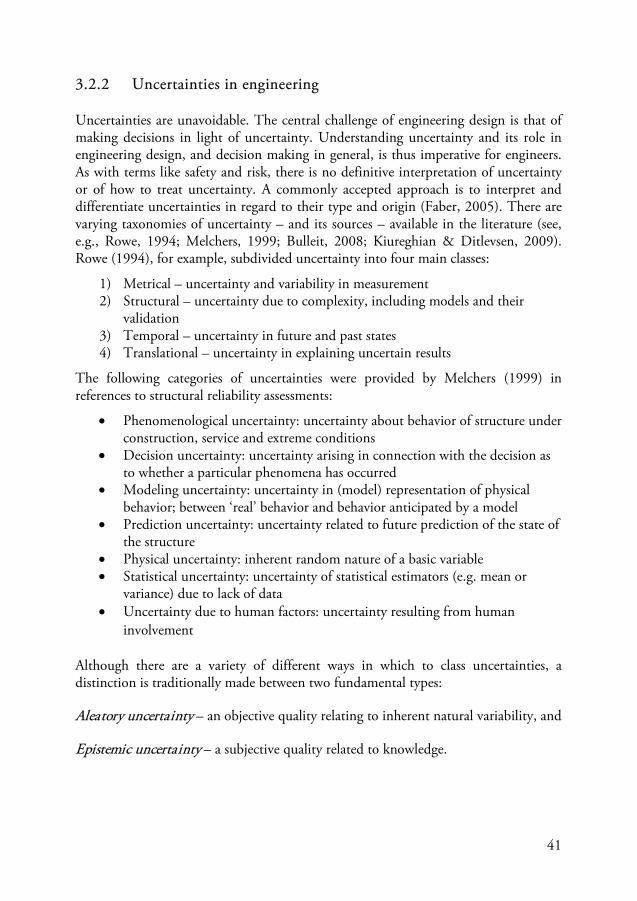
41
3.2.2 Uncertainties in engineering
Uncertainties are unavoidable. The central challenge of engineering design is that of making decisions in light of uncertainty. Understanding uncertainty and its role in engineering design, and decision making in general, is thus imperative for engineers. As with terms like safety and risk, there is no definitive interpretation of uncertainty or of how to treat uncertainty. A commonly accepted approach is to interpret and differentiate uncertainties in regard to their type and origin (Faber, 2005). There are varying taxonomies of uncertainty – and its sources – available in the literature (see, e.g., Rowe, 1994; Melchers, 1999; Bulleit, 2008; Kiureghian & Ditlevsen, 2009). Rowe (1994), for example, subdivided uncertainty into four main classes:
1) Metrical – uncertainty and variability in measurement 2) Structural – uncertainty due to complexity, including models and their
validation 3) Temporal – uncertainty in future and past states 4) Translational – uncertainty in explaining uncertain results
The following categories of uncertainties were provided by Melchers (1999) in references to structural reliability assessments:
• Phenomenological uncertainty: uncertainty about behavior of structure under construction, service and extreme conditions
• Decision uncertainty: uncertainty arising in connection with the decision as to whether a particular phenomena has occurred
• Modeling uncertainty: uncertainty in (model) representation of physical behavior; between ‘real’ behavior and behavior anticipated by a model
• Prediction uncertainty: uncertainty related to future prediction of the state of the structure
• Physical uncertainty: inherent random nature of a basic variable • Statistical uncertainty: uncertainty of statistical estimators (e.g. mean or
variance) due to lack of data • Uncertainty due to human factors: uncertainty resulting from human
involvement
Although there are a variety of different ways in which to class uncertainties, a distinction is traditionally made between two fundamental types:
Aleatory uncertainty – an objective quality relating to inherent natural variability, and
Epistemic uncertainty – a subjective quality related to knowledge.
42
The former, stems from the Latin aleatorius or literally ‘about games of chance’ – while the latter stems from the Greek epistemikos or ‘having to do with knowledge or understanding’24
• Modeling uncertainty, and
(Vick, 2002). In explaining the former, allusions are often made to the uncertainties inherent in throwing dice or of picking colored balls out of a bag. In a structural engineering context aleatory uncertainties can include natural variations in loading (e.g. environmental or traffic loads) or material properties (e.g. the strength of steel from a certain manufacturer). Epistemic uncertainty, on the other hand, is sometimes divided into two sub-categories (Stewart & Melchers, 1997; JCSS, 2001):
• Statistical parameter uncertainty
Modeling uncertainty is concerned with the ability of a (probabilistic) model to predict the future behavior of a system and may arise, for example, as a result of imprecise or inadequate modeling. Statistical uncertainty relates to the unreliability of the statistical parameters used to describe probabilistic models due to, for example, a lack of data or poor assumptions. A fundamental difference between aleatory and epistemic uncertainty is that the former is considered irreducible while epistemic uncertainty can be reduced by more data collection (evidence) and in general, additional knowledge.
A third type of uncertainty, ontological uncertainty, arising from the unknown and unexpected has also been mentioned in the literature (Elms, 2004). Although conceptually it could be argued that this is a form of epistemic uncertainty – as it relates to lack of knowledge – the fundamental difference is that ontological uncertainty is an unknown uncertainty; i.e. the engineer is unaware of its existence until it reveals itself (surprisingly). The implication is that probabilistic methods of analysis may be ill-suited for dealing with this type of uncertainty and other indirect methods may be more appropriate; e.g. quality assurance or pro-active safety management schemes (Elms, 2004). This issue was also brought up by Elms (1999) in discussing generic sources of threats to structural safety or as he put it: ‘ways in which information is incomplete or in error and predictability is compromised’. The so-called three enemies of knowledge were given as:
• Ignorance – a lack of knowledge of technical matters of which a designer should be aware, with no understanding that the information is needed
• Uncertainty – essential knowledge is lacking, but its absence is known • Complexity – which leads to an inability to predict
24 Early ‘theoretical’ concepts of uncertainty and probability were founded in games of chance and the mathematics of gambling – e.g. correspondence between Pascal and Fermat in 1654 or Huygens’ Calculating in Games of Chance ca. 1657. However, the concept of probability as reflecting uncertainty of an epistemic sort was also put forward by classical probabilists – e.g. Liebniz’s De Conditionibus ca. 1665, Jacob Bernoulli’s The Art of Conjecturing ca. 1713, Reverend Baye’s letter to the Royal Society in 1764 or Laplace’s A philosophical Essay on Probabilities ca. 1774. For more information refer to, e.g., Vick (2002).
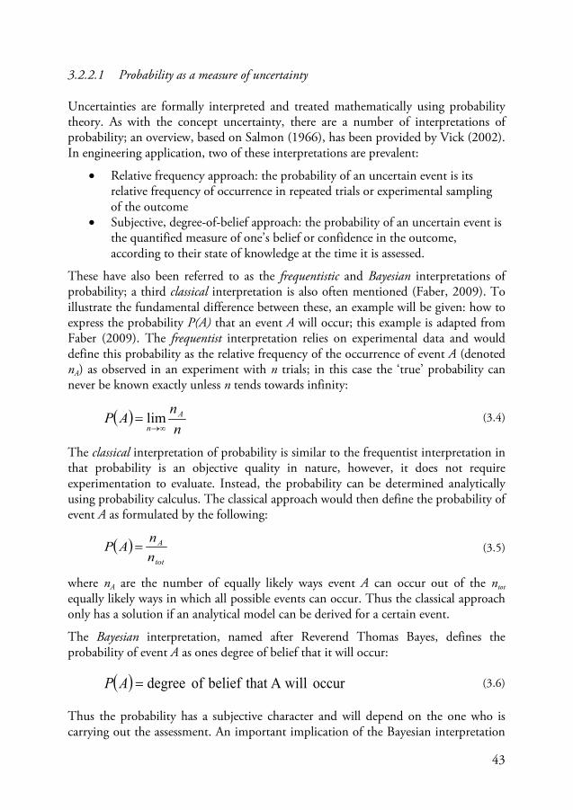
43
3.2.2.1 Probability as a measure of uncertainty
Uncertainties are formally interpreted and treated mathematically using probability theory. As with the concept uncertainty, there are a number of interpretations of probability; an overview, based on Salmon (1966), has been provided by Vick (2002). In engineering application, two of these interpretations are prevalent:
• Relative frequency approach: the probability of an uncertain event is its relative frequency of occurrence in repeated trials or experimental sampling of the outcome
• Subjective, degree-of-belief approach: the probability of an uncertain event is the quantified measure of one’s belief or confidence in the outcome, according to their state of knowledge at the time it is assessed.
These have also been referred to as the frequentistic and Bayesian interpretations of probability; a third classical interpretation is also often mentioned (Faber, 2009). To illustrate the fundamental difference between these, an example will be given: how to express the probability P(A) that an event A will occur; this example is adapted from Faber (2009). The frequentist interpretation relies on experimental data and would define this probability as the relative frequency of the occurrence of event A (denoted nA) as observed in an experiment with n trials; in this case the ‘true’ probability can never be known exactly unless n tends towards infinity:
( )n
nAP A
n ∞→= lim (3.4)
The classical interpretation of probability is similar to the frequentist interpretation in that probability is an objective quality in nature, however, it does not require experimentation to evaluate. Instead, the probability can be determined analytically using probability calculus. The classical approach would then define the probability of event A as formulated by the following:
( )tot
A
nn
AP = (3.5)
where nA are the number of equally likely ways event A can occur out of the ntot equally likely ways in which all possible events can occur. Thus the classical approach only has a solution if an analytical model can be derived for a certain event.
The Bayesian interpretation, named after Reverend Thomas Bayes, defines the probability of event A as ones degree of belief that it will occur:
( ) occur A will that belief of degree=AP (3.6)
Thus the probability has a subjective character and will depend on the one who is carrying out the assessment. An important implication of the Bayesian interpretation
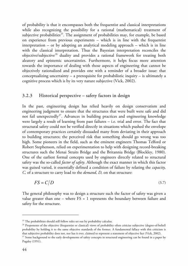
44
of probability is that it encompasses both the frequentist and classical interpretations while also recognizing the possibility for a rational (mathematical) treatment of subjective probabilities25. The assignment of probabilities may, for example, be based on experience from previous experiments – which is in line with the frequentist interpretation – or by adopting an analytical modeling approach – which is in line with the classical interpretation. Thus the Bayesian interpretation reconciles the objective/subjective26
3.2.3 Historical perspective – safety factors in design
duality and provides a rational framework for treating both aleatory and epistemic uncertainties. Furthermore, it helps focus more attention towards the importance of dealing with those aspects of engineering that cannot be objectively rationalized and provides one with a reminder of a broader issue: that conceptualizing uncertainty – a prerequisite for probabilistic inquiry – is ultimately a cognitive process which is by its very nature subjective (Vick, 2002).
In the past, engineering design has relied heavily on design conservatism and engineering judgment to ensure that the structures that were built were safe and did not fail unexpectedly27
DCFS =
. Advances in building practices and engineering knowledge were largely a result of learning from past failures – i.e. trial and error. The fact that structural safety could not be verified directly in situations which pushed the envelope of contemporary practices certainly dissuaded many from deviating in their approach to building structures; the perceived risk that something should go wrong was too high. Some pioneers in the field, such as the eminent engineers Thomas Telford or Robert Stephenson, relied on experimentation to help with designing record-breaking structures such the Menai Straits Bridge and the Britannia Bridge (Blockley, 1980). One of the earliest formal concepts used by engineers directly related to structural safety was the so-called factor of safety. Although the exact manner in which this factor was guised varied, it essentially defined a condition of failure by relating the capacity, C, of a structure to carry load to the demand, D, on that structure:
(3.7)
The general philosophy was to design a structure such the factor of safety was given a value greater than one – where FS = 1 represents the boundary between failure and safety for the structure.
25 The probabilities should still follow rules set out by probability calculus. 26 Proponents of the objective (frequentist or classical) views of probability often criticize subjective (degree-of-belief) probability by holding it to the same objective standards of the former. A fundamental fallacy with this criticism is that subjective probability does not, nor has it ever, claimed to represent a statement of objective fact (Vick, 2002). 27 Some background to the early developments of safety concepts in structural engineering can be found in a paper by Pugsley (1951).
45
Equation (3.7) then leads to the following design criteria:
DFSC > (3.8)
Factors of safety were primarily used to offset the uncertainties involved in design. Early on, focus was usually on accounting for uncertainties associated with the capacity (or resistance) of the structure while less attention was placed on uncertainties related to the demand (or loading) on the structure – the factor of safety was sometimes referred to as a ‘factor of ignorance’28
Although safety factors were not formally introduced until cast-iron construction became commonplace, the philosophy of design conservatism was common. In pre-19th century England, for example, major constructions were largely in masonry or stone. In these rigid structures, the predominant design problem was one of block arrangement for stability under its own weight and of providing adequate foundations (Pugsley, 1966). In proportioning (designing) these structures, a popular approach was to completely avoid any tension at the mortar joints – even though this did not technically result in failure. This design approach effectively results in a factor of safety of 3 – assuming a linear distribution of compression along the joint of a rectangular block. As cast-iron became more popular as a building material, its brittle nature coupled with its weakness in tension meant that failures frequently occurred (Hamilton, 1949). It was at this time when a load factor – defined as the ratio of the working load and breaking load for a structural member – was first developed as a measure of safety; a factor of 4 or 6 was common for the design of cast-iron girders while values in the range of 10 and 20 (for dead and live loads respectfully) were sometimes used for design of column members (Pugsley, 1951). The determination of these factors relied heavily on experimentation (see, e.g., Hodgkinson, 1840)
. Historically, that which constituted the demand on a structure and its capacity has varied slightly. The prior generally related to either the maximum expected loading on a structure – for highway bridges this may include self-weight and perhaps loading from crowds of people or a herd of cattle (Fidler, 1887; Cooper, 1896) – or else the stresses produced by such loading. The capacity concept – essentially a definition for what constitutes failure – has also varied. Some common terms have included ‘breaking loads’ (usually for brittle materials), ‘proof loads’ (for elastic materials) or ‘ultimate loads’ (for plastic materials). Different values for the factor of safety were adopted for different types of materials, element types and types of loading. For example, it was not uncommon to have one safety factor for verifying dead loading (self-weight) and another, larger, factor for verifying live loading (e.g. traffic or crowds). Similarly, different safety factors were used for beams than for columns.
28 This term – ‘factor of ignorance’ – reflects a traditional view of uncertainty in engineering that was held by those who believed in a ‘deterministic world’ where, given enough time, the sophistication of engineering approaches to structural analysis would become so precise that the ‘factor of safety’ tends towards unity (Addis, 1990). Modern approaches in dealing with risk and uncertainty sharply dispute such an assertion.
46
coupled with engineering judgment backed by theoretical approaches for determining the strength of materials available at the time (e.g., Navier, 1826; Moseley, 1843; Rankine, 1858). Later developments in the use of safety factors in design occurred as new materials – such as wrought iron, mild steel or reinforced concrete – were being introduced, in light of publications of results on experimental testing, as new design methods were developed, and in conjunction with theoretical advancements in engineering science (Pugsley, 1966).
The aforementioned approach to safety, which relied on a single safety factor, continued well into the 20th century; albeit in a slightly different form which related working and breaking/proof stresses as opposed to loads. This design approach, however, would eventually be replaced with the concept of using multiple so-called partial safety factors instead of a single safety factor. In this case, different factors of safety were applied to account for varying degrees of uncertainty related to, e.g., different types of loading and material responses. For example, the following design criteria could apply when verifying the capacity (or resistance) of a structural element subjected to both dead loading (DL) and live loading (LL):
LLLLDLDLC DFSDFSFSC ⋅+⋅> (3.9)
This new design philosophy was referred to by different names in different regions: load and resistance factors design in the U.S., limit state design in Canada, and partial factor design in the U.K. and other parts of Europe. These approaches steadily started being used more in the design codes replacing earlier editions based on single safety factors (see, e.g., Ellingwood, Galambos, MacGregor, & Cornell, 1980). One important distinction with the limit state design philosophy in comparison with earlier design methods – e.g., permissible stresses (elasticity based) or load factor (plasticity based) design – was that the assessment of loads, and the uncertainties associated with their occurrence, were given more significance (Blockley, 1980). Progressively, limit-state design steadily began replacing single safety factor approaches in the design codes (Beal, 1980; Moses, 1998).
Early on, the quantitative values for the safety factors used in design were primarily evaluated by engineering judgment and evolved, as Moses put it, following a “semi-Bayesian”-type approach (Moses, 1998). In other words, a safety factor was reduced over time if failures were rare and vice versa. For example, safety factors associated with self-weight – or dead loads – reduced whereas safety factors associated with seismic loading increased. During the latter half of the 20th century, however, efforts were made to rationalize structural safety based on probabilistic approaches (see Section 3.2.4) and on this basis re-evaluate the quantitative values of the safety factors used in engineering practice (ISE, 1955; Julian, 1957; Freudenthal, Garrelts, & Shinozuka, 1966). These efforts formed the foundation for what would later become Structural Reliability Theory (SRT).
47
3.2.4 Rationalization of uncertainty – development of SRT
Structural reliability theory (SRT) is an offshoot from classical reliability theory which has its roots in the manufacturing industry of first half of the 20th century and the formal rise of reliability engineering in the 1950s (Saleh & Marais, 2006). The development of SRT arose primarily as a reaction to the apparent irrationality of the safety factor approach to engineering design. Some argued that there was a discrepancy between the refined procedures of engineering design and the ‘rather arbitrary manner of choosing the safety factor [which] is seriously hampering the development of more effective design methods based upon perfect balance of safety and economy’ (Freudenthal, 1947). Early developments of a rational safety-based design philosophy occurred in the field of aeronautical engineering during the Second World War (Pugsley, 1942). The ‘philosophy of strength factors’, as it was called, related the variable nature of the frequency and magnitude of loading on aircraft with the variable nature of the strength of the aircraft produced to a given design such as to determine an accident rate based on probability theory. To accommodate for the practical application of this philosophy in design the ‘fundamental importance of collecting load and strength statistics’ was emphasized. This idea was broadened and developed further by Freudenthal, then Lecturer in Bridge Engineering at the Hebrew Institute of Technology in Haifa, Palestine, who, in 1945, derived, mathematically, a minimum factor of safety based on the statistical variations of ‘stress’ from external loading and the ‘resistance’ of a structure, element, or section (Freudenthal, 1947). Freudenthal, among others, would later expand the concept of safety, and its mathematical depiction, and write, as Professor of Civil Engineering at Columbia University, the paper often cited – at least in the English literature – as a seminal work of what would later become Structural Reliability Theory (SRT) (Freudenthal, 1956). Other early contributions to the rationalized approach of the structural safety problem were also developed in Sweden in the 1950s (see, e.g., Johnson A. I., 1953; Asplund, 1958).
Initially the development of SRT was mostly theoretical (at least in the U.S.) as there was a lack of experimental data for which meaningful results could be obtained. However, as the decades progressed, methods were established for evaluating safety levels for structures and design methods were subsequently revised to reflect this development. For a review of the available literature in SRT, and a brief historical overview of the developments therein, refer to a paper prepared by the ASCE-STD Task Committee on Structural Safety in the early 1970s (ASCE-STD, 1972). Additional references to early publications regarding structural reliability, safety and probabilistic/statistical concepts in civil engineering are also available (Lemon & Manning, 1974; Dhillon & Belland, 1986). Modern textbooks on the subject of SRT and its various applications in engineering are also widespread (Benjamin & Cornell, 1970; Thoft-Christensen & Baker, 1982; Schneider, 1997; Melchers, 1999; Nowak & Collins, 2000; Faber, 2009).
48
3.3 Structural Reliability Theory
The design philosophy underpinning SRT was basically the same as had been used by engineering designers throughout history: achieving safety by controlling risks and treating uncertainties. The main difference, however, was that SRT applies statistics and probability theory in developing formal mathematical concepts of structural safety. Thoft-Christensen & Baker (1982) gave two interpretations of structural reliability, one general and the other narrow (mathematical):
• In the general sense, the reliability of a structure is its ability to fulfill its design purpose for some specified time
• In the narrow sense, it is the probability that a structure will not attain each specified limit state (ultimate or serviceability) during a specified reference period
Thus reliability –as a mathematical concept – is defined in a similar way as safety was defined in Section 3.2.1 – i.e. as the absence of failure. Mathematically, reliability – for a reference period of T years – is then defined as:
TfTfT PPR )1(11 . −−=−= (3.10)
where Pf.T is the probability of failure occurring at least once in T years. If the annual probability of failure, Pf, is constant over the considered reference period (i.e. ergodic in time) then the right side of expression (3.10) can be used. In classical reliability theory, the failure rate is determined from measurements of observed failures of mass-produced components – e.g. time to failure of light-bulbs manufactured in a factory. Obviously this approach is not feasible for structural engineering application where the end product is always unique. Even in cases where building components are standardized and pre-fabricated – i.e. industrialized construction – the conditions to which these components are confronted when introduced as elements in the global structure (which is always unique) are heavily site-dependant. Thus, to determine the probability of failure, failure needs to be defined mathematically. In SRT, this is done by defining a so-called limit-state function (LSF), usually denoted by a function g, which defines a failure surface, or boundary, distinguishing a safe and failure domain. In other words, the LSF is a mathematical representation of the definition of failure; usually relating to a single failure mode or some other performance criteria. The general case can be written as:
( )
>≤
domain safe0domain failure0
:gg
g X (3.11)
The limit state function g(·) is defined by a vector X = (X1,X2,…,Xn) of n random variables describing the structural performance – e.g. load and resistance. The
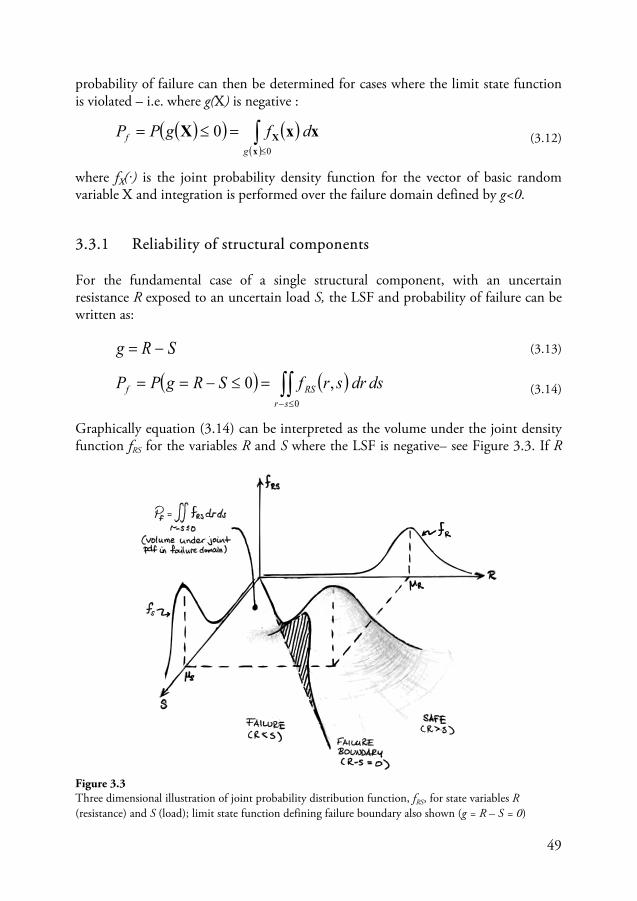
49
probability of failure can then be determined for cases where the limit state function is violated – i.e. where g(X) is negative :
( )( ) ( )( )∫≤
=≤=0
0x
X xxXg
f dfgPP (3.12)
where fX(·) is the joint probability density function for the vector of basic random variable X and integration is performed over the failure domain defined by g<0.
3.3.1 Reliability of structural components
For the fundamental case of a single structural component, with an uncertain resistance R exposed to an uncertain load S, the LSF and probability of failure can be written as:
SRg −= (3.13)
( ) ( )∫∫≤−
=≤−==0
,0sr
RSf dsdrsrfSRgPP (3.14)
Graphically equation (3.14) can be interpreted as the volume under the joint density function fRS for the variables R and S where the LSF is negative– see Figure 3.3. If R
Figure 3.3 Three dimensional illustration of joint probability distribution function, fRS, for state variables R (resistance) and S (load); limit state function defining failure boundary also shown (g = R – S = 0)
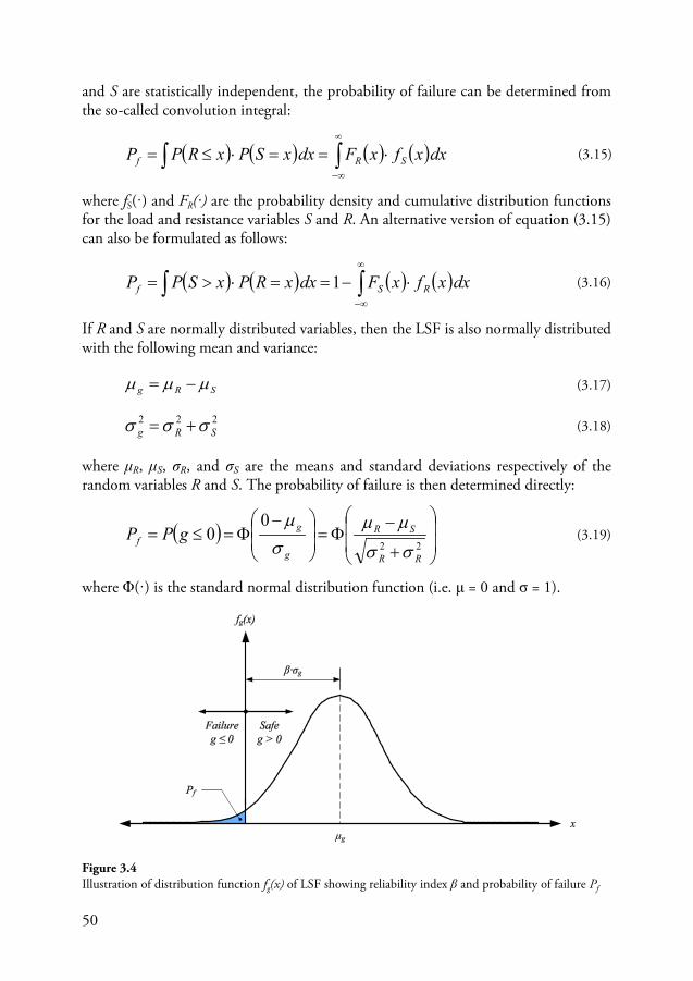
50
and S are statistically independent, the probability of failure can be determined from the so-called convolution integral:
( ) ( ) ( ) ( )∫∫∞
∞−
⋅==⋅≤= dxxfxFdxxSPxRPP SRf (3.15)
where fS(·) and FR(·) are the probability density and cumulative distribution functions for the load and resistance variables S and R. An alternative version of equation (3.15) can also be formulated as follows:
( ) ( ) ( ) ( )∫∫∞
∞−
⋅−==⋅>= dxxfxFdxxRPxSPP RSf 1 (3.16)
If R and S are normally distributed variables, then the LSF is also normally distributed with the following mean and variance:
SRg µµµ −= (3.17)
222SRg σσσ += (3.18)
where μR, μS, σR, and σS are the means and standard deviations respectively of the random variables R and S. The probability of failure is then determined directly:
( )
+
−Φ=
−Φ=≤=
22
00
RR
SR
g
gf gPP
σσ
µµσµ
(3.19)
where Φ(·) is the standard normal distribution function (i.e. μ = 0 and σ = 1).
Figure 3.4 Illustration of distribution function fg(x) of LSF showing reliability index β and probability of failure Pf
51
As a measure of safety, the reliability index β was introduced by Cornell (1969) in the late 60s:
g
g
σµ
β = (3.20)
Graphically β can be interpreted as the number of standard deviations by which μg exceeds zero – see Figure 3.4. Subsequently, the relationship between the reliability index and the probability of failure is given by:
( ) ( )fg
gf PP 1−Φ−=⇔−Φ=
−Φ= ββσµ
(3.21)
The previous equations can be extended for the general case of a linear limit state function with a set of normally distributed random variables X = (X1,X2,…,Xn):
∑=
⋅+=n
iii Xaag
10 (3.22)
where a0, a1, … , an are constants. The mean and variance of the LSF are:
∑=
⋅+=n
iXig i
aa1
0 µµ (3.23)
∑=
⋅=n
iXig i
a1
222 σσ (3.24)
The reliability index can then be evaluated based on equation (3.20):
∑
∑
=
=
⋅
⋅+==
n
iXi
n
iXi
g
g
i
i
a
aa
1
22
10
σ
µ
σµ
β (3.25)
So far, there has been no mention of the reference period given in equation (3.10). If the probability of failure based on equations (3.11)-(3.16) is considered an annual value (T=1 year), then for T years, the probability of failure and the reliability index can be determined from the following:
( ) ( )[ ]TTfTf PP 11.. 11 βΦ−=−= (3.26)
( )TfT P .1−Φ−=β (3.27)
52
Equations (3.26) and (3.27) are valid only if the LSF is time-independent. In cases where this assumption is not valid the reliability problem becomes time-variant and special approaches are required; practical cases include problems of deterioration or time-dependant loads. For more information regarding time-variant reliability, refer, e.g., to Melchers (1999).
The essential aim of SRT is in determining the reliability index β or the probability of failure Pf. Generally, the evaluation of these factors is not as straight-forward as the general case that was presented in this section – i.e. with a time-independent linear LSF of normally distributed variables. Often approximate methods are required to solve the general cases provided by equations (3.12)-(3.16). The different types of available methods will be discussed in the next section.
It should be mentioned that the failure probabilities determined using SRT are notional and failure rates observed in practice can be several orders of magnitudes greater (Brown & Yin, 1988). The strength with SRT is that it provides a systematic framework for the assessment of structural safety and the calculated failure probabilities are useful, e.g., in making comparative assessments and for calibrating design codes to achieve consistent safety levels in design.
3.3.2 Methods for evaluating reliability
A number of different methods have been developed for evaluating the reliability of structures. In 1975, the JCSS set up a sub-committee to provide a broad classification system for the various methods that had been developed up to that point (i.e. reliability methods). Three classes were identified; these will be briefly described and some of the more significant methods will be outlined in the sub-sections that follow (JCSS, 1976).
Level III methods are fully probabilistic and the probability of failure is determined ‘exactly’ from the joint probability distribution function in equation (3.12). In such cases, a full probabilistic description of the joint occurrence of the random variables is required. As analytical procedures for carrying out such a task are rarely possible, the most common Level III methods are Numerical Integration (NI) and Monte Carlo simulations (MCS) – see Section 3.3.2.3.
Level II methods approximate the LSF to be able to calculate the reliability index and estimate the probability of failure. These methods usually involve an iterative procedure in which the random variables are described by two distribution parameters (i.e. mean and variance) and possibly also the correlation coefficients between variables. Common Level II methods include the first and second order reliability methods (FORM & SORM) which approximate the LSF using a first (linear) and second order Taylor series expansion – see Sections 3.3.2.1 & 3.3.2.2.
53
Level I methods are semi-probabilistic design methods in which appropriate (minimum) levels of structural safety are provided – these methods, however, cannot be used to directly determine reliability levels. The uncertain parameters are then modeled using characteristic values of the basic variables – i.e. pre-defined upper or lower fractile values. To account for uncertainties, partial safety factors are used to determine design values of the basic variables. These safety factors are adjusted such that appropriate levels of reliability are obtained (i.e. target reliability levels). The partial safety factor method used in the Eurocodes is an example of a Level I method – see Section 3.4.1.
3.3.2.1 First-order reliability methods (FORM)
The limit state function has thus far only been given in general terms or as a linear function. In general, however, this is not the case. If the LSF is non-linear, then the reliability index can be estimated by first linearizing it using a first-order Taylor expansion:
( ) ( )nXXXffg ,...,, 21== X (3.28)
( ) ( )*i
n
iiin X
fxXxxxfgx
∂∂
−+≈ ∑=1
***2
*1 ,...,, (3.29)
where the design points x* = (x1*,x2*,…,xn*) for the Taylor expansion can, for now, be assumed to be the mean values of the random variables X. Equation (3.29) is now linear and will have the following form:
smean valueat evaluated10 where
ii
n
iii X
faXaag∂∂
=⋅+= ∑=
(3.30)
The mean value and standard deviation of equation (3.30) can now readily be determined based on equations (3.23) and (3.24) and the reliability index evaluated from equation (3.25) – re-written here for convenience:
smean valueat evaluated
1
22
10
wherei
in
iXi
n
iXi
Xfa
a
aa
i
i
∂∂
=
⋅
⋅+=
∑
∑
=
=
σ
µβ (3.31)
Equation (3.31) is basically a generalization of the Cornell safety index for a non-linear limit state function; it is referred to as the first order second moment mean value reliability index (Nowak & Collins, 2000). A problem that arises with defining the reliability index as in equation (3.31) is that the resulting probability of failure
54
will depend on how the LSF is formulated; i.e. the reliability index is not invariant with regard to the choice of failure function g. Consider for example if the simplified form of the LSF in equation (3.13) were re-written to the following form:
1−= SRg (3.32)
To determine the reliability index according to the approach just described, the LSF is first linearized according to equation (3.29) – with the mean values as design points:
−+−≈ 11
2S
R
S
R
S
SRgµµ
µµ
µ (3.33)
The mean value and variance of the linearized function can then be used to determine the reliability index according to equation (3.21):
22
222
22
21
1
SS
RR
SR
SS
RR
S
S
R
g
g
σµµσ
µµ
σµµσ
µ
µµ
σµ
β
+
−=
+
−== (3.34)
This result is obviously different to what was determined from equation (3.19) and as such the approach according to equations (3.31) is invariant. To overcome this problem of invariance, Hasofer & Lind formulated a slightly different approach and defined a new reliability index (Hasofer & Lind, 1973). The so-called Hasofer-Lind reliability index is calculated by first normalizing the set of random variables X – i.e. transformation of Xi to standard normal variable Ui where μUi = 0 & σUi = 1:
i
i
X
Xii
XU
σ
µ−= (3.35)
The LSF can then be expressed in term of the reduced variables U. The Hasofer-Lind reliability index is defined as the shortest distance between the origin to the failure surface g(U)=0 in the normalized u-coordinate system. The two-dimensional case is illustrated in Figure 3.5. This definition of the reliability index also encompasses the one given by Cornell; i.e. if the limit state function is linear, then the Hasofer-Lind reliability index can be determined from equation (3.25).
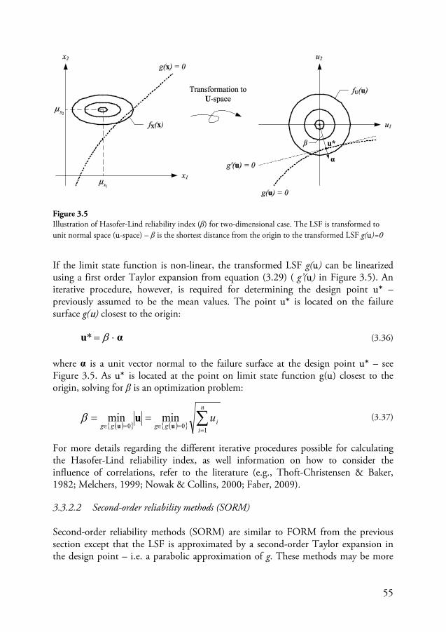
55
If the limit state function is non-linear, the transformed LSF g(u) can be linearized using a first order Taylor expansion from equation (3.29) ( g’(u) in Figure 3.5). An iterative procedure, however, is required for determining the design point u* – previously assumed to be the mean values. The point u* is located on the failure surface g(u) closest to the origin:
αu ⋅= β* (3.36)
where α is a unit vector normal to the failure surface at the design point u* – see Figure 3.5. As u* is located at the point on limit state function g(u) closest to the origin, solving for β is an optimization problem:
( ){ } ( ){ } ∑=
=∈=∈==
n
iigggg
u100
minminuu
uβ (3.37)
For more details regarding the different iterative procedures possible for calculating the Hasofer-Lind reliability index, as well information on how to consider the influence of correlations, refer to the literature (e.g., Thoft-Christensen & Baker, 1982; Melchers, 1999; Nowak & Collins, 2000; Faber, 2009).
3.3.2.2 Second-order reliability methods (SORM)
Second-order reliability methods (SORM) are similar to FORM from the previous section except that the LSF is approximated by a second-order Taylor expansion in the design point – i.e. a parabolic approximation of g. These methods may be more
Figure 3.5 Illustration of Hasofer-Lind reliability index (β) for two-dimensional case. The LSF is transformed to unit normal space (u-space) – β is the shortest distance from the origin to the transformed LSF g(u)=0
56
appropriate in cases where the LSF is highly non-linear around the design point or where the probability of failure is high.
3.3.2.3 Monte-Carlo Simulation (MCS)
Monte Carlo Simulations (MCS) are useful for carrying out full probabilistic analyses of the LSF without requiring any approximations. MCS relies on repeated random simulated experiments to estimate the failure probability based on the relative number of experiments for which g(x)<0. To do this, the limit state function is evaluated for N realizations (or samples) of the set of random variables X – denoted by x̅i – and the number of times the limit state function g(x̅i) is violated is recorded:
( )[ ]∑=
=≈N
iff gI
NPP
1
1ix (3.38)
where I(·) is the so-called indicator function:
≤>
=0 if10 if0
)(gg
gI (3.39)
If the ‘true’ probability of failure Pf is small, a large number of simulations may be required to determine a meaningful measure for the simulated failure probability P̅f . The uncertainty associated with the probability measure determined from the simulations can be determined from the following (Nowak & Collins, 2000):
f
fP PN
PV
f ⋅
−=
1 (3.40)
where fPV is the coefficient of variation of the simulated probability P̅f . Equation
(3.40) can be used to determine the number of simulations that are required to estimate the failure probability while limiting the uncertainty in the simulated failure probability:
estimatefP
estimatef
PVP
Nf −
−
⋅
−= 2
1 (3.41)
where Pf-estimate is an initial estimate of the failure probability that is to be simulated. Thus, for example, if failure probabilities in the range of 10-4 are being sought, and the uncertainty of the estimates should be kept below 10%, then almost 1 million simulations (999 900) are required. A number of methods for increasing the efficiency of MCS are, however, possible. These include importance sampling, Latin hypercube sampling, and directional simulations (see, e.g., Melchers, 1999; Nowak & Collins, 2000; Faber, 2009).
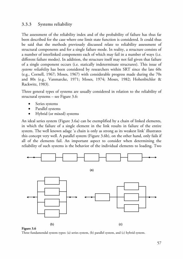
57
3.3.3 Systems reliability
The assessment of the reliability index and of the probability of failure has thus far been described for the case where one limit state function is considered. It could thus be said that the methods previously discussed relate to reliability assessment of structural components and for a single failure mode. In reality, a structure consists of a number of interlinked components each of which may fail in a number of ways (i.e. different failure modes). In addition, the structure itself may not fail given that failure of a single component occurs (i.e. statically indeterminate structures). This issue of systems reliability has been considered by researchers within SRT since the late 60s (e.g., Cornell, 1967; Moses, 1967) with considerable progress made during the 70s and 80s (e.g., Vanmarcke, 1971; Moses, 1974; Moses, 1982; Hohenbichler & Rackwitz, 1983).
Three general types of systems are usually considered in relation to the reliability of structural systems – see Figure 3.6:
• Series systems • Parallel systems • Hybrid (or mixed) systems
An ideal series system (Figure 3.6a) can be exemplified by a chain of linked elements, in which the failure of a single element in the link results in failure of the entire system. The well known adage ‘a chain is only as strong as its weakest link’ illustrates this concept very well. A parallel system (Figure 3.6b), on the other hand, only fails if all of the elements fail. An important aspect to consider when determining the reliability of such systems is the behavior of the individual elements to loading. Two
Figure 3.6 Three fundamendal system types: (a) series system, (b) parallel system, and (c) hybrid system.
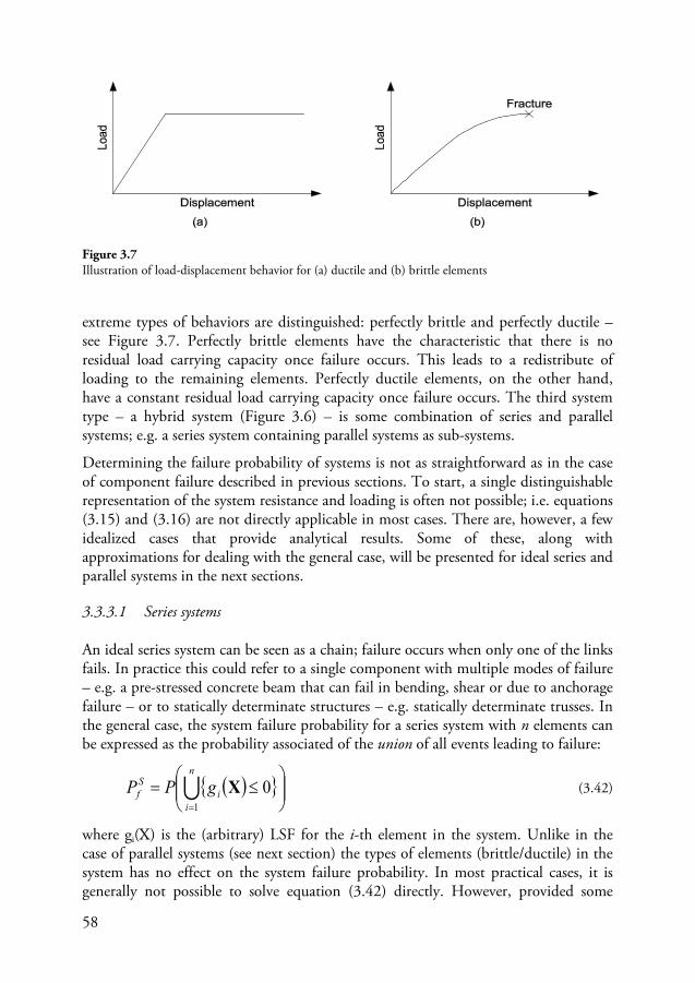
58
extreme types of behaviors are distinguished: perfectly brittle and perfectly ductile – see Figure 3.7. Perfectly brittle elements have the characteristic that there is no residual load carrying capacity once failure occurs. This leads to a redistribute of loading to the remaining elements. Perfectly ductile elements, on the other hand, have a constant residual load carrying capacity once failure occurs. The third system type – a hybrid system (Figure 3.6) – is some combination of series and parallel systems; e.g. a series system containing parallel systems as sub-systems.
Determining the failure probability of systems is not as straightforward as in the case of component failure described in previous sections. To start, a single distinguishable representation of the system resistance and loading is often not possible; i.e. equations (3.15) and (3.16) are not directly applicable in most cases. There are, however, a few idealized cases that provide analytical results. Some of these, along with approximations for dealing with the general case, will be presented for ideal series and parallel systems in the next sections.
3.3.3.1 Series systems
An ideal series system can be seen as a chain; failure occurs when only one of the links fails. In practice this could refer to a single component with multiple modes of failure – e.g. a pre-stressed concrete beam that can fail in bending, shear or due to anchorage failure – or to statically determinate structures – e.g. statically determinate trusses. In the general case, the system failure probability for a series system with n elements can be expressed as the probability associated of the union of all events leading to failure:
( ){ }
≤=
=
n
ii
Sf gPP
1
0X (3.42)
where gi(X) is the (arbitrary) LSF for the i-th element in the system. Unlike in the case of parallel systems (see next section) the types of elements (brittle/ductile) in the system has no effect on the system failure probability. In most practical cases, it is generally not possible to solve equation (3.42) directly. However, provided some
Figure 3.7 Illustration of load-displacement behavior for (a) ductile and (b) brittle elements
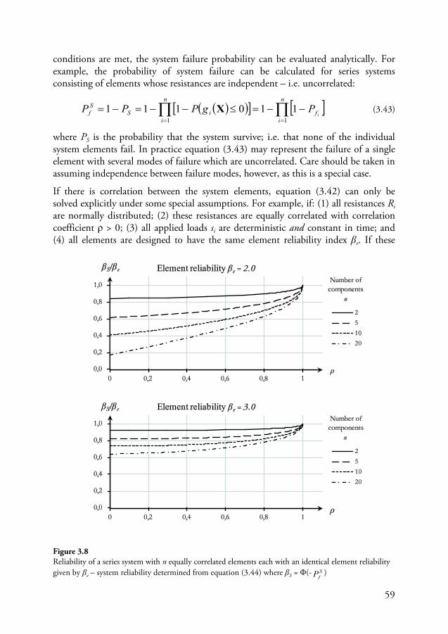
59
conditions are met, the system failure probability can be evaluated analytically. For example, the probability of system failure can be calculated for series systems consisting of elements whose resistances are independent – i.e. uncorrelated:
( )( )[ ] [ ]∏∏==
−−=≤−−=−=n
if
n
iiS
Sf i
PgPPP11
110111 X (3.43)
where PS is the probability that the system survive; i.e. that none of the individual system elements fail. In practice equation (3.43) may represent the failure of a single element with several modes of failure which are uncorrelated. Care should be taken in assuming independence between failure modes, however, as this is a special case.
If there is correlation between the system elements, equation (3.42) can only be solved explicitly under some special assumptions. For example, if: (1) all resistances Ri are normally distributed; (2) these resistances are equally correlated with correlation coefficient ρ > 0; (3) all applied loads si are deterministic and constant in time; and (4) all elements are designed to have the same element reliability index βe. If these
Figure 3.8 Reliability of a series system with n equally correlated elements each with an identical element reliability given by βe – system reliability determined from equation (3.44) where βS = Φ(- S
fP )
60
assumptions are made, it has been shown that the system failure probability can be evaluated based on the following equation (Thoft-Christensen & Baker, 1982):
( )∫∞
∞−
⋅
−
⋅+Φ−= dtt
tP
n
eSf ϕ
ρ
ρβ
11 (3.44)
where n is the number of elements in the system, and Φ(·) and φ(·) are the distribution and density functions for the standard normal distribution. Equation (3.44) is plotted in Figure 3.8 for different values of n and for two different element reliability indices. From Figure 3.8 it can be seen that the reliability of the series system is always lower than the element reliability. In the extreme case of perfect correlation between component strengths (ρ=1) the component reliability and system reliability are the same.
In general the system failure probability from equation (3.42) cannot be determined directly. In these cases some approximate methods can be used for determining the reliability of structural systems. These include first-order reliability methods (FORM) (Hohenbichler & Rackwitz, 1983) or the use of reliability bounds. In the case of the latter, it can be shown that the failure probability of a series system with positive correlation is largest if no correlation exists between the resistances of its elements – equation (3.43) – and is at least as reliable as its least reliable element if there is perfect correlation. Thus the following simple bounds for the system failure probability of series systems are determined:
[ ]∏=
=−−≤≤
n
if
Sffni ii
PPP1...1
11max (3.45)
Unfortunately, in practice these bound are often too wide; see, e.g., Figure 3.8.
3.3.3.2 Parallel systems
An ideal parallel system can be seen as a bundle of wires; failure of the system only occurs once all of the wires fail. Examples of such systems in practice are statically indeterminate, or redundant, structures – e.g. statically indeterminate frames or continuous beams. The failure probability for a parallel system is determined as the intersection of events leading to failure. In other words, failure of all elements – given as gi(X) ≤ 0 for failure of element i – must occur to cause system failure:
( ){ }
≤=
=
n
ii
Sf gPP
1
0X (3.46)
One of the first probabilistic investigations of failures of parallel systems was conducted by Daniels (1945) for the Wool Industries; hence such systems are sometime referred to as Daniel’s systems. These early research efforts focused on
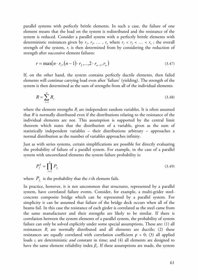
61
parallel systems with perfectly brittle elements. In such a case, the failure of one element means that the load on the system is redistributed and the resistance of the system is reduced. Consider a parallel system with n perfectly brittle elements with deterministic resistances given by r1, r2, … , rn where r1 < r2 < … < rn ; the overall strength of the system, r, is then determined from by considering the reduction of strength after successive element failures:
( )( )nn rrrnrnr ,2,...,1,max 121 −⋅⋅−⋅= (3.47)
If, on the other hand, the system contains perfectly ductile elements, then failed elements will continue carrying load even after ‘failure’ (yielding). The strength of the system is then determined as the sum of strengths from all of the individual elements:
∑=
=n
iiRR
1
(3.48)
where the element strengths Ri are independent random variables. It is often assumed that R is normally distributed even if the distributions relating to the resistance of the individual elements are not. This assumption is supported by the central limit theorem which states that the distribution of a variable, given as the sum of statistically independent variables – their distributions arbitrary – approaches a normal distribution as the number of variables approaches infinity.
Just as with series systems, certain simplifications are possible for directly evaluating the probability of failure of a parallel system. For example, in the case of a parallel system with uncorrelated elements the system failure probability is:
∏=
=n
if
Sf i
PP1
(3.49)
where if
P is the probability that the i-th element fails.
In practice, however, it is not uncommon that structures, represented by a parallel system, have correlated failure events. Consider, for example, a multi-grider steel-concrete composite bridge which can be represented by a parallel system. For simplicity it can be assumed that failure of the bridge deck occurs when all of the beams fail. In this case the resistance of each girder is correlated as the steel came from the same manufacturer and their strengths are likely to be similar. If there is correlation between the system elements of a parallel system, the probability of system failure can only be solved explicitly under some special assumptions. These are: (1) all resistances Ri are normally distributed and all elements are ductile; (2) these resistances are equally correlated with correlation coefficient ρ > 0; (3) all applied loads si are deterministic and constant in time; and (4) all elements are designed to have the same element reliability index βe. If these assumptions are made, the system
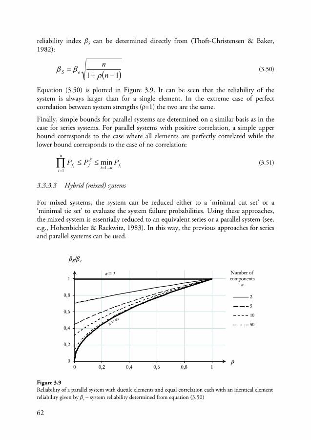
62
reliability index βS can be determined directly from (Thoft-Christensen & Baker, 1982):
( )11 −+=
nn
eS ρββ (3.50)
Equation (3.50) is plotted in Figure 3.9. It can be seen that the reliability of the system is always larger than for a single element. In the extreme case of perfect correlation between system strengths (ρ=1) the two are the same.
Finally, simple bounds for parallel systems are determined on a similar basis as in the case for series systems. For parallel systems with positive correlation, a simple upper bound corresponds to the case where all elements are perfectly correlated while the lower bound corresponds to the case of no correlation:
ii fni
Sf
n
if PPP
...11
min=
=
≤≤∏ (3.51)
3.3.3.3 Hybrid (mixed) systems
For mixed systems, the system can be reduced either to a ‘minimal cut set’ or a ‘minimal tie set’ to evaluate the system failure probabilities. Using these approaches, the mixed system is essentially reduced to an equivalent series or a parallel system (see, e.g., Hohenbichler & Rackwitz, 1983). In this way, the previous approaches for series and parallel systems can be used.
Figure 3.9 Reliability of a parallel system with ductile elements and equal correlation each with an identical element reliability given by βe – system reliability determined from equation (3.50)
63
3.4 Principles of codified design
In considering how risks are controlled in engineering design it is convenient to distinguish between the methods and practices undertaken by the individual engineer in designing structures to be safe and the safety management systems in place to ensure (and assure society) that the engineering profession achieves this aim in a satisfactory manner. The discussions from previous sections have largely considered the former while issues pertaining to regulating engineering practices will be touched upon here; i.e. the role of regulation and design codes29. Historically, the responsibility for setting design criteria and for providing assurances that a structure is safe – and fulfilled specifications set by those that commissioned the work – was the master builder or his guild (Galambos, 1992). If a structure failed then the builder could be punished in some way to compensate for the consequences. A well known historical document exemplifying this practice is the Code of Hammurabi from around 1750 B.C.30
Figure 3.10
in the ancient kingdom of Babylonia. This ancient document, often cited as the first of its kind, included five rules covering construction failures which explicitly placed responsibility and liability for the failure of a house on the builder of that house – see . Building regulations are also thought to have existed at the time of the Romans who were known for their proficiency in construction; see, e.g., the famous Ten Books on Architecture written by the Roman architect31
Design codes form a link between the engineering profession and society (Allen, 1992; Elms, 1999). They are a way of assuring society that a structures design fulfills minimum requirements in terms of safety and serviceability
Vitruvius in the 1st century BC (Addis, 1990). Early building regulations were also developed in London in the 12th century which provided technical requirements for adjoining houses so as to prevent the spread of fire. A significant development in building regulations happened after the great fire of London in 1666; this included the first appointment of district surveyors to enforce that new regulations were followed during the rebuilding of the city (Allen, 1992). Punitive practices for ensuring satisfactory construction have continued well into the 19th century, albeit without such draconian measures as those outlined in the time of ancient Babylonia. However, as technology became more complex and responsibility too diffused, more structured methods were needed to protect society – out of this desire came the emergence of modern design codes at the turn of the 20th century (Galambos, 1992).
32
29 Design codes may sometimes be referred to as ‘design standards’, ‘specifications’ or ‘norms’; the term here is taken to represent all such designations where ‘a common standard which all structure of the same type are to be measured’ (Galambos, 1992)
and do so in a
30 Some older references provide the date 2200 BC, e.g. as is referenced in Feld (1968) 31 Keep in mind that the architect/engineer distinction is a modern concept; the Greek word architecton is more accurately translated as chief or master builder (Blockley, 1980) 32 Serviceability refers to fulfillment of functional requirements other than safety; see, e.g., Honfi (2013)
64
consistent manner. In this sense, design codes legitimize the engineering profession and in combination with other building regulations provide guidelines for litigation proceeding in case failures do occur. The writing of the design codes is normally a committee activity – or a committee directed activity (Nethercot, 2012). In the past 30 years or so, a trend of preparing harmonized codes on an international basis arose and the structural Eurocodes (CEN, 2002) were developed within Europe. Currently, some 26 countries in the European Union (and EFTA) use the structural Eurocodes, including Sweden. The justification of the European Commission in 1975 for creating the Eurocodes can be summarized according to the following points (Nethercot, 2012):
• Provide common design criteria, • Ensure common understanding, • Facilitate exchanges of people and products, • Provide a common basis for research and development, and • Increase competitiveness
The first Eurocodes were published in 1984 and since then a number of revisions have been published. Currently the Eurocode consists of 58 parts – or published standards. The fundamental design concepts of codes such as the Eurocodes will be reviewed in the next section, including a review of the safety formats in these codes.
3.4.1 Design concepts in modern codes
The fundamental requirements of design set by modern design codes such as the Eurocodes are the following (see, e.g., JRC, 2008):
• Safety requirements – avoid structural failures • Serviceability requirements – avoid non-safety related functional failures • Durability requirements – effect of deterioration/degradation on performance • Fire requirements – fire safety is a specially treated situation in most codes • Robustness requirements – see Section 3.4.2 • Quality assurances – adequate controls at the stages of design/execution
The amount of detail provided in the codes for fulfilling these criteria can vary greatly. In general, the safety requirements, relating to issues of structural failures, are given the most attention. Durability requirements, on the other hand, may only be indirectly considered and quality management only briefly mentioned.

65
Figure 3.10 Code of Hammurabi – reproduced with permission from Feld (1968)
66
The design principle adopted by the design codes is based on the so-called limit-state concept. The limit state concept is essentially a deterministic representation of design criteria; i.e. the states beyond which the structure no longer fulfils the relevant design criteria (JRC, 2008). The following limit states are usually considered:
• Ultimate limit state (ULS) • Serviceability limit state (SLS)
In the Eurocodes, verification of the limit-states is achieved with the so-called partial factor method (PFM); similar approaches are available in other codes such as the load and resistance factor design (LRFD) used in the United States (AASHTO, 2014). This approach falls into the category of a Level I methods of SRT that have been mentioned in Section 3.3.2. The basic form for the PFM is the following:
kQkGMk QGR ⋅+⋅> γγγ (3.52)
where the resistance R and loads G and Q – self weight and live load respectively – are determined as so-called characteristic values (denoted with subscript k) and adjusted by partial safety factors γ to account for uncertainties. Characteristic values of loads and resistances are (conservative) fractile values of the assumed associated probability distributions representing each variable. In the case of loading, the characteristic value is usually taken as the 50%-ile (self-weight) or 98%-ile (annual maximum of time-variable loads); for the resistance the characteristic value is usually taken as the 5%-ile value. The partial safety factors γ used for adjusting these characteristic values are calibrated such that a desired minimum level of reliability is achieved. In other words, the partial safety factors from equation (3.52) are adjusted by considering reliability levels determined from the following limit state function – e.g. using FORM introduced in Section 3.3.2.1:
( ) 0,, =−−= QGRQGRg (3.53)
where R, G, and Q are now random variables. The goal is essentially to determine values for γR, γG, and γQ in equation (3.52) such that the reliability index determined based on equation (3.53) is as close to a pre-defined target reliability index33
33 The choice of target reliabilities is undertaken by the code writing committees. In the past, values were determined by evaluating the reliability of structures designed according to older codes. The argument is that society ‘accepts’ that structures designed according to these standards are ‘safe enough’. In other words, a risk referent is determined based on revealed societal preferences – assuming these are the same today as they have been in the past
βtar as possible. This process is iterative and requires that the uncertainties related to loads and resistances are known – e.g. variability of different types of loading, of resistances in different types of materials, and including model uncertainties related to both. For more information regarding code calibration see, Ravindra & Lind (1973), Sörensen, Kroon & Faber (1994), or Nowak & Collins (2000).
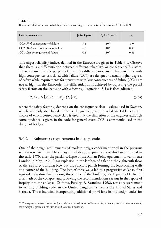
67
The target reliability indices defined in the Eurocde are given in Table 3.1. Observe that there is a differentiation between different reliability, or consequence34
(3.53)
, classes. These are used for the purpose of reliability differentiation such that structures with high consequences associated with failure (CC3) are designed to attain higher degrees of safety while requirements for structures with low consequences of failure (CC1) are not as high. In the Eurocode, this differentiation is achieved by adjusting the partial safety factors on the load side with a factor γd – equation is then adjusted:
( ) dkQkGMk QGR γγγγ ⋅⋅+⋅> (3.54)
where the safety factor γd depends on the consequence class – values used in Sweden, which were adjusted based on older design code, are provided in Table 3.1. The choice of which consequence class is used is at the discretion of the engineer although some guidance is given in the code for general cases; CC3 is commonly used in the design of bridges.
3.4.2 Robustness requirements in design codes
One of the design requirements of modern design codes mentioned in the previous section was robustness. The emergence of design requirements of this kind occurred in the early 1970s after the partial collapse of the Ronan Point Apartment tower in east London in May 1968. A gas explosion in the kitchen of a flat on the eighteenth floor of the 22 storey building blew out the concrete panels forming the load-bearing walls at a corner of the building. The loss of these walls led to a progressive collapse, first upward then downward, along the corner of the building; see Figure 3.11. In the aftermath of the collapse, and following the recommendations set out in the report of inquiry into the collapse (Griffiths, Pugsley, & Saunders, 1968), revisions were made to existing building codes in the United Kingdom as well as the United States and Canada. These included incorporating additional provisions in the design codes for
34 Consequences referred to in the Eurocodes are related to loss of human life, economic, social or environmental; more weight is placed on the first, related to human casualties.
Consequence class β for 1 year Pf for 1 year γd
CC3: High consequence of failure 5.2 10-7 1.0 CC2: Medium consequence of failure 4.7 10-6 0.91 CC1: Low consequence of failure 4.2 10-5 0.83
Table 3.1 Recommended minimum reliability indices according to the structural Eurocodes (CEN, 2002)
68
avoiding disproportionate collapse35 following localized failure and for direct design of structural members to withstand internal gas explosions36
In recent decades, research on structural robustness has increased as a result of some high profile collapses including the bombing of the Murrah Federal Building in 1995 and the collapse of the World Trade Center Twin Towers in 2001. In Europe, a joint research project on structural robustness was initiated in late 2007 under the auspices of the COST (European Cooperation of Science and Technology) program (Faber & Narasimhan, 2011). The main objective of the so-called “COST Action TU0601 – Robustness of Structures” was ‘to provide the basic framework, methods and strategies necessary to ensure that the level of robustness of structural systems is adequate and sufficient in relation to their function and exposure over their life time and in balance with societal preferences in regard to safety of personnel and safeguarding of environment and economy.’
. More information regarding the collapse at Ronan Point, the implication of the inquiry, and its effect on building regulations can be found in the literatures (Griffiths, Pugsley, & Saunders, 1968; ISE, 1969; Pearson & Delatte, 2005).
The robustness requirements of modern day building codes have evolved from these early provisions following Ronan Point. These requirements are mainly aimed at controlling risks related to failures resulting from accidental loads or unforeseen events. In the Eurocodes, for example, the following implicit (objective-based) requirements relating to robustness are provided:
A structure shall be design and executed in such a way that it will not be damaged by events such as:
• explosions • impact, and • the consequences of human errors,
to an extent disproportionate to the original cause. Potential damage shall be avoided or limited by appropriate choice of one or more of the following:
• avoiding, eliminating or reducing the hazards to which the structure can be subjected;
• selecting a structural form which has low sensitivity to the hazards considered;
• selecting a structural form and design that can survive adequately the accidental removal of an individual member or a limited part of the structure, or the occurrence of acceptable localized damage;
35 The acceptable extent of global failure following a localized failure was – according to the UK Building Regulations of 1972 – such that damage should not extend beyond the storey (floor) directly above or below and that the area damaged within each story should not exceed a maximum of 70 m2 or 15% of the floor area 36 A load of 34 kPa was provided for design against internal gas explosions
69
• avoiding as far as possible structural systems that can collapse without warning;
• tying the structural members together
Eurocode EN 1990 – Clauses (4) & (5) (CEN, 2002)
The design codes also provide some prescriptive provisions to design structural elements to withstand accidental action as well as some provisions for disproportionate collapse. In the Eurocodes, for example, provisions for internal explosions and impacts are provided as well as some prescriptive rules for limiting the extent of damage following localized failures (CEN, 2006). Some implicit provisions may also be given in the code relating to the robustness requirements. For example, the Eurocodes provides some guidance for planning and executing risk assessments of accidental loading situations for structures with high consequences of failure (CEN, 2006). Overall, focus of current robustness requirements have been on building structure whereas relatively little is provided with regards to design bridges to be more robust.
An important distinction with design code provisions of robustness compared to limit state design is that the former are not calibrated using the reliability methods described in previous sections. There is an inherent limitation of the safety formats in the design codes to address these design situations directly in the same way that more conventional loading situations have been treated. These, and other limitations of the design codes, are discussed further in Section 4.2.
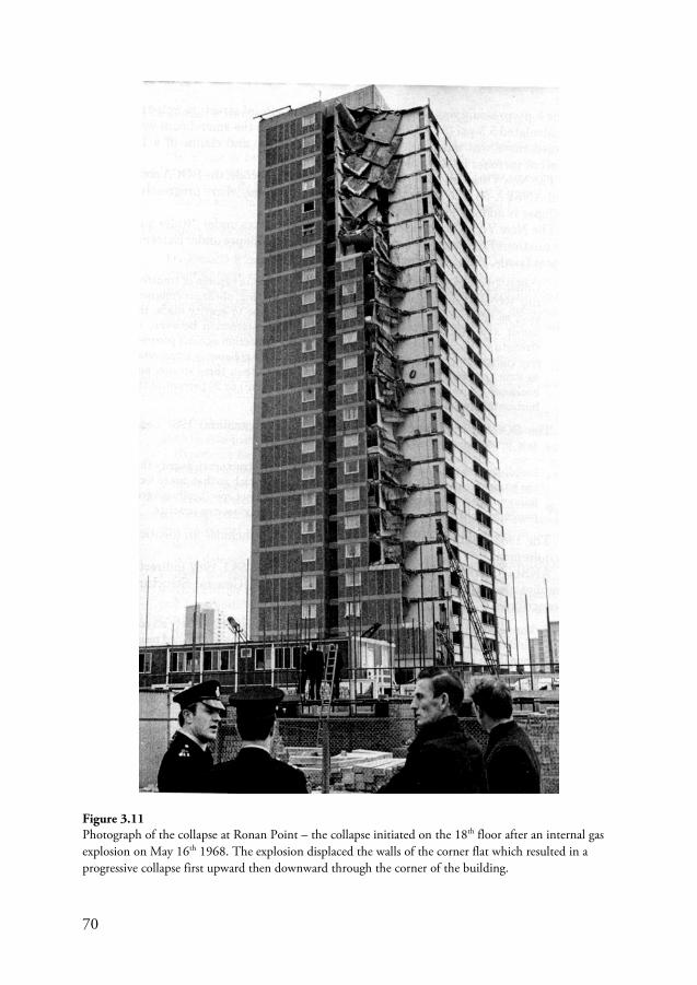
70
Figure 3.11 Photograph of the collapse at Ronan Point – the collapse initiated on the 18th floor after an internal gas explosion on May 16th 1968. The explosion displaced the walls of the corner flat which resulted in a progressive collapse first upward then downward through the corner of the building.
71
3.4.2.1 Quantifying robustness
Robustness is generally recognized as a desirable property of an engineered structure; however, there is no consensus – amongst researchers or practitioners alike – as to how it should be interpreted or how it should be treated in the design of structures. Although there are a number of different interpretations of robustness in specific fields of science and technology37
Robustness is the insensitivity of a structure to local failure
a broad interpretation of robustness is how well a system functions under varying circumstances. It is thus a measure of a system’s insensitivity to changes – either internal or external. In the case of artificial (man-made) systems these ‘changes’ usually refer to ‘extreme changes’ or ‘unforeseen changes’ as design of these systems will have considered more conventional variations. In structural engineering, there are a number of definitions of robustness. The following are some examples from the literature – in some cases paraphrased for brevity:
Starossek (2009) & ASCE-SEI (2010)
Robustness is the property of a system to survive unforeseen or abnormal circumstances
Knoll & Vogel (2009)
Robustness is the ability of a structure to withstand events like fire, explosions, impact or the consequences of human error, without being damaged to an extent disproportionate to the original cause
Eurocode EN 1991-1-7 (CEN, 2006)
Robustness is the ratio of direct risk and total risks (equal to direct risk + indirect risk) for all relevant exposures and damage states for the constituents of a system
JCSS (2008) based on Baker, Schubert, & Faber (2006)
It can be observed that some of the provided definitions of robustness indicate it as a property that can be quantified. This sentiment is common amongst researchers and there currently exist a wide range of approaches to quantifying robustness of structures. Starossek & Haberland (2008) have collected and reviewed a number of these methods. In most cases, methods for quantifying robustness have been developed with redundant framed structures in mind. An overview of the robustness concept applied for the design of bridges can be found in Björnsson (2010). A more
37 Some examples can be found in Maes, Fritzons & Glowienka (2006) including interpretations of robustness in control theory, design optimization and software engineering
72
recent review of available methodologies for the assessment of robustness was published by Antori, Casas & Ghosn (2013) and Brett & Lu (2013). A common approach to the quantification of robustness is to relate the performance38
3.5 Crucial factors for safety in engineering design
of a structural system – under normal operating conditions – intact and with a damaged component. Thus a system that can redistribute loading in the case of a localized failure is more robust. A problem with this approach is that it favors redundant structures whereas statically determinate structures will not be very robust. The robustness measures available in the literature can be deterministic, probabilistic or risk-based.
The previous sections provide some perspective with regard to how risks and uncertainties are treated in engineering design. In attempting to determine the effectiveness of current design approaches – as well as determine criteria for possible complementary approaches – it is important to distinguish clearly their objectives and how these are to be achieved. In terms of structural safety, the basic objective is simply to have a design approach which produces a safe structure
Risks should be appropriately treated during design
. In achieving this objective the following fundamental requirement is identified:
This generic statement may seem trivial but it is a perfect starting point for proceeding further. In making such a statement, some issues are identified which need to be resolved. For example, the following questions remain unanswered:
• Exactly which risks are we talking about? • In what way can these risks be treated? What is meant by ‘appropriately’? • Who is responsible for treating these risks? For whom are these risks being
treated? • What is meant by ‘design’?
The issues raised by these questions are commonly considered by risk analysts and those involved in risk management of construction projects. In what follows, answers to these questions will be considered in order to provide an overview of crucial requirements for achieving safety in engineering design.
To start, an identification of risks
38 Performance in this case can be represented by a number of indicators including load carrying capacity, energy absorption, system stiffness, or displacement.
is needed. Traditionally, this process was largely a reaction to problems that were observed from past and existing construction; i.e. learning from failures. A master builder knew from past experience that certain risks
73
were predominant and should be avoided; the focus on foundation risk in design of masonry structure in pre-19th century England is one example of this (see Section 3.2.3). In more recent times the identification of risks is usually provided in the design codes. Thus, treatment of risks that lie outside the scope of the design codes should not be overlooked.
The second set of questions highlights a need for realizing an approach for dealing with these risks; i.e. an approach to evaluate risks. Once the risks have been identified, their effect on the safety of the structure should be determined to form the basis for a risk evaluation. This highlights the follow-up question which brings up the issue of ‘how safe is safe enough’. Answering this question is not a straightforward task. To start, simply providing an objective metric for acceptable risks, whether constant or consequence dependent, tacitly assumes that whatever value of risk that is determined is also objective. This risk-based approach can be criticized given the subjective nature of risk assessments and uncertainty treatment in practice. A more suitable approach could then be to supplement such assessments with engineering judgment – i.e. risk informed approach – or by conducting comparative assessments. In lieu of these issues, the requirement can be adjusted; i.e. a suitable approach to evaluating risks
The question of who is responsible for evaluating the risks is also important to consider. At first it seems obvious that the answer is the ‘engineer’ or the ‘engineering profession’ but if one examines how, e.g., design codes function, this answer is not as convincing. Design codes are written by or under the supervision of code committees. Those involved in the drafting of codes are thus not those directly responsible for designing individual structures to be safe. In effect, a portion of the process of risk treatment is delegated to a third party. It then becomes important that the
is required.
designer should understand the objectives
In answer to the question of who benefits from a safe structure, the answer should ideally be everyone involved. Another way of framing the question is to ask who suffers if the structure turns out to be unsafe. Many different answers to this question can be provided; i.e. the inhabitants (users) of the structure, the owner, society, etc. Thus another requirement could be formulated which states that the
in connection with this process.
designer should understand the importance
Finally, an elaboration of the term ‘design’ is needed. This aspect is quite significant although it is one that is seemingly taken for granted in most cases. According to current approaches to risk control, using design codes, the ‘design’ which is being addressed is the detailed design phase in which case verification is undertaken for the safety of structural components. Thus aspects of design that fall outside this scope – such as conceptual design and system aspects – are missing. In light of this, it is important that the
of this process.
entire design is considered
– design here refers to both the process of design (divided into phases) and a description of the structure and its parts.
74
3.5.1 Criteria for a complementary approach
In the previous section, some general requirements for controlling risks in engineering design were provided. These were determined based on a general consideration of the issues related to structural safety in design. The next step is to identify criteria for a possible complementary approach to current codified design approaches. As this approach would be complementary to the design codes, it is important to distinguish aspects of the general requirements that are not appropriately addressed in the codes. The following criteria are highlighted:
• The approach should treat risks not identified or poorly treated by current codified approaches
• The designer should clearly understand the objectives with this approach • The designer should understand the importance in applying this approach
for treating these risks • The approach should consider aspects of design that lie outside the scope of
the code
The previous criteria are general and lack specificity; however, first the limitations of the design codes must be evaluated. This is the main topic of discussion in the next section of this thesis.
75
4. Complementary design approach
Control, whether by professional code of practice or otherwise, can, if too closely applied, hamper development of the structural art no less than that of other human activities.
Sir Alfred G. Pugsley (1951, p. 29)
4.1 Introduction
In the previous sections, an overview was provided regarding the treatment of risks in engineering design including the role of design codes. One of the primary aims of design codes is to provide a framework for controlling risks for a population of structures rather than for an individual structure and as such the design codes are necessarily conservative. It should be mentioned that in special cases39, design based purely on code compliance is complemented – or replaced – by alternative approaches. Generally such approaches could be categorized under the heading ‘risk management approaches’40
39 The design of off-shore structures and nuclear power plants are prominent examples (see, e.g., Brandsaeter, 2002; Garrick & Christies, 2002)
. In such cases it is realized that the codes are not enough in themselves to treat all risks appropriately; whether due to circumstances not covered by the code or as a result of the conservative nature of the codes. These situations are not common for designing bridge structures except in exceptional cases; e.g., large-scale fixed link projects such as the Öresund Link or the Fehmarn Belt (COWI-Lahmeyer, 1999; Plovgaard, 2006). When complementary approaches are used, there is a possibility to address risks that lie outside of the scope of the design codes and to individually tailor the manner in which these risks – and perhaps even those covered by the codes – are treated in a design context. However, for design of more ‘conventional’ structures the use of complementary risk management approaches are rarely utilized. In such cases, risks that are inadequately treated or outside the scope of the code may be overlooked entirely. Hence, there is also an advantage to applying complementary design approaches even in ‘conventional’ cases to ensure a more complete treatment of risks in engineering design. To provide
40 Keep in mind that design based on code-compliance also falls within this category
76
justification for this argument, in paper I it is determined that design purely based on code compliance is not enough and that complementary approaches to controlling risks are necessary. From these findings, a complementary design approach is formulated such as to more adequately address risks potentially overlooked in design cases based purely on code compliance; paper II provides a description for such an approach. In the following sections an overview will be provided based on papers I and II in which a complementary approach to design based on code-compliance is described. To start, the limitations of codified design are outlined such as to highlight the need of such an approach as well as identify what such an approach should include (this is based on paper I). Afterwards a description of a complementary design approach based on generic risk assessment procedures is presented.
4.2 Limitations of codified design
The most prominent way of controlling risks in engineering design is through design codes. In paper I, the hypothesis that code compliance is enough to adequately control risks in engineering design was questioned. The limitations of codified design were identified and discussed by considering the role of design codes from three different perspectives:
1. Codes as instruments for enforcing regulation 2. Codes as communications channels for design provisions 3. Codes as instruments for ensuring structural safety in engineering design
To start, design codes are often used as regulatory instruments; ensuring that structural safety, as well as other performance criteria, are satisfactorily fulfilled when designing a structure. This requirement may be directly specified in the letter of the law or else through so-called ‘deemed-to-satisfy’ clauses in the building regulations which state that designs fulfilling the provisions of the codes automatically fulfill (legal) requirements outlined in the building regulations. In viewing the codes as regulatory instruments, the problem is that they can become restrictive for the engineer. The issue is one of imposing external constraints or allowing for more autonomy in design. If the constraints imposed by the design codes are too extensive, then there is a risk that the engineer does not feel obligated to assume responsibility for the design as compliance with code requirements are all that’s required for a design to pass inspection. In such cases, compliance could lead to complacency and design situations that lie completely outside the scope of the codes may be disregarded entirely. This last fact gives the illusion that the codes treatment of risk is complete, which is not the case. Take, for example, the inability of design codes, such as they are, to consider risks during the conceptual design phase of a structure. The conceptual design of modern day bridges is relatively standardized and concepts may be borrowed from past designs without considering how alternative design solutions
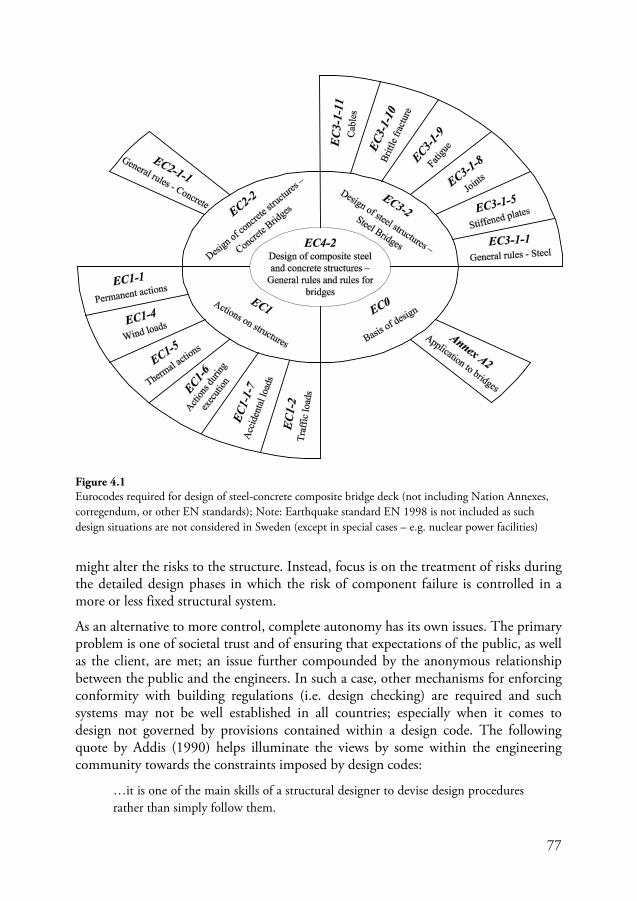
77
might alter the risks to the structure. Instead, focus is on the treatment of risks during the detailed design phases in which the risk of component failure is controlled in a more or less fixed structural system.
As an alternative to more control, complete autonomy has its own issues. The primary problem is one of societal trust and of ensuring that expectations of the public, as well as the client, are met; an issue further compounded by the anonymous relationship between the public and the engineers. In such a case, other mechanisms for enforcing conformity with building regulations (i.e. design checking) are required and such systems may not be well established in all countries; especially when it comes to design not governed by provisions contained within a design code. The following quote by Addis (1990) helps illuminate the views by some within the engineering community towards the constraints imposed by design codes:
…it is one of the main skills of a structural designer to devise design procedures rather than simply follow them.
Figure 4.1 Eurocodes required for design of steel-concrete composite bridge deck (not including Nation Annexes, corregendum, or other EN standards); Note: Earthquake standard EN 1998 is not included as such design situations are not considered in Sweden (except in special cases – e.g. nuclear power facilities)
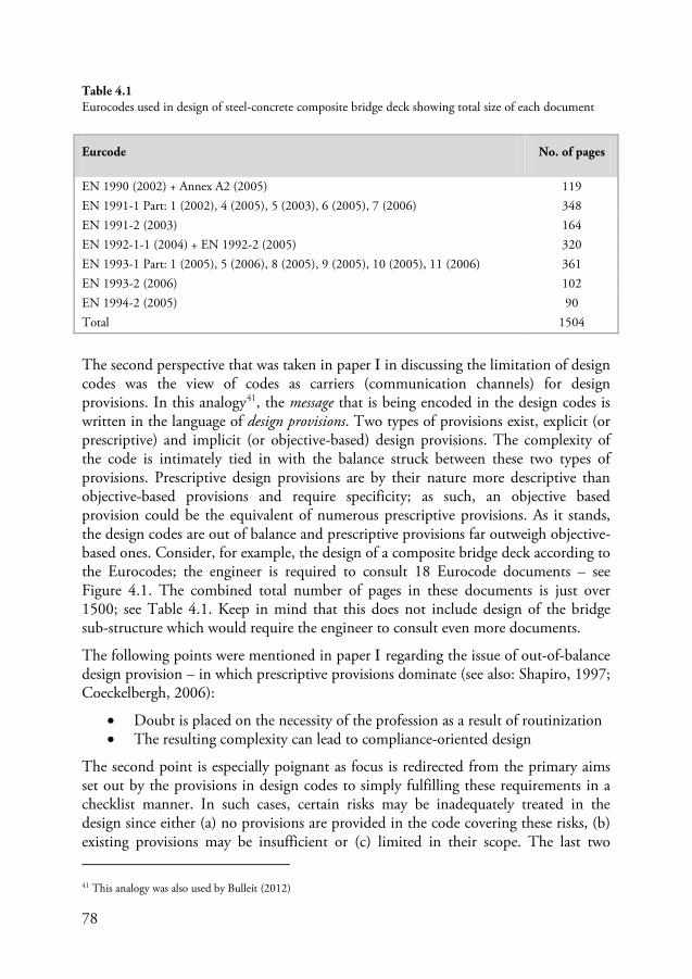
78
The second perspective that was taken in paper I in discussing the limitation of design codes was the view of codes as carriers (communication channels) for design provisions. In this analogy41
Figure 4.1
, the message that is being encoded in the design codes is written in the language of design provisions. Two types of provisions exist, explicit (or prescriptive) and implicit (or objective-based) design provisions. The complexity of the code is intimately tied in with the balance struck between these two types of provisions. Prescriptive design provisions are by their nature more descriptive than objective-based provisions and require specificity; as such, an objective based provision could be the equivalent of numerous prescriptive provisions. As it stands, the design codes are out of balance and prescriptive provisions far outweigh objective-based ones. Consider, for example, the design of a composite bridge deck according to the Eurocodes; the engineer is required to consult 18 Eurocode documents – see
. The combined total number of pages in these documents is just over 1500; see Table 4.1. Keep in mind that this does not include design of the bridge sub-structure which would require the engineer to consult even more documents.
The following points were mentioned in paper I regarding the issue of out-of-balance design provision – in which prescriptive provisions dominate (see also: Shapiro, 1997; Coeckelbergh, 2006):
• Doubt is placed on the necessity of the profession as a result of routinization • The resulting complexity can lead to compliance-oriented design
The second point is especially poignant as focus is redirected from the primary aims set out by the provisions in design codes to simply fulfilling these requirements in a checklist manner. In such cases, certain risks may be inadequately treated in the design since either (a) no provisions are provided in the code covering these risks, (b) existing provisions may be insufficient or (c) limited in their scope. The last two 41 This analogy was also used by Bulleit (2012)
Eurcode No. of pages
EN 1990 (2002) + Annex A2 (2005) 119 EN 1991-1 Part: 1 (2002), 4 (2005), 5 (2003), 6 (2005), 7 (2006) 348 EN 1991-2 (2003) 164 EN 1992-1-1 (2004) + EN 1992-2 (2005) 320 EN 1993-1 Part: 1 (2005), 5 (2006), 8 (2005), 9 (2005), 10 (2005), 11 (2006) 361 EN 1993-2 (2006) 102 EN 1994-2 (2005) 90 Total 1504
Table 4.1 Eurocodes used in design of steel-concrete composite bridge deck showing total size of each document
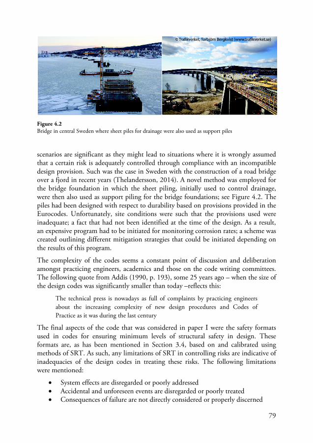
79
scenarios are significant as they might lead to situations where it is wrongly assumed that a certain risk is adequately controlled through compliance with an incompatible design provision. Such was the case in Sweden with the construction of a road bridge over a fjord in recent years (Thelandersson, 2014). A novel method was employed for the bridge foundation in which the sheet piling, initially used to control drainage, were then also used as support piling for the bridge foundations; see Figure 4.2. The piles had been designed with respect to durability based on provisions provided in the Eurocodes. Unfortunately, site conditions were such that the provisions used were inadequate; a fact that had not been identified at the time of the design. As a result, an expensive program had to be initiated for monitoring corrosion rates; a scheme was created outlining different mitigation strategies that could be initiated depending on the results of this program.
The complexity of the codes seems a constant point of discussion and deliberation amongst practicing engineers, academics and those on the code writing committees. The following quote from Addis (1990, p. 193), some 25 years ago – when the size of the design codes was significantly smaller than today –reflects this:
The technical press is nowadays as full of complaints by practicing engineers about the increasing complexity of new design procedures and Codes of Practice as it was during the last century
The final aspects of the code that was considered in paper I were the safety formats used in codes for ensuring minimum levels of structural safety in design. These formats are, as has been mentioned in Section 3.4, based on and calibrated using methods of SRT. As such, any limitations of SRT in controlling risks are indicative of inadequacies of the design codes in treating these risks. The following limitations were mentioned:
• System effects are disregarded or poorly addressed • Accidental and unforeseen events are disregarded or poorly treated • Consequences of failure are not directly considered or properly discerned
Figure 4.2 Bridge in central Sweden where sheet piles for drainage were also used as support piles
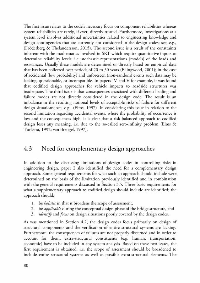
80
The first issue relates to the code’s necessary focus on component reliabilities whereas system reliabilities are rarely, if ever, directly treated. Furthermore, investigations at a system level involves additional uncertainties related to engineering knowledge and design contingencies that are currently not considered in the design codes; see, e.g., (Fröderberg & Thelandersson, 2015). The second issue is a result of the constraints inherent with the mathematics involved in SRT which require quantitative inputs to determine reliability levels; i.e. stochastic representations (models) of the loads and resistances. Usually these models are determined or directly based on empirical data that has been collected over periods of 20 to 50 years (Ellingwood, 2001); in the case of accidental (low probability) and unforeseen (non-random) events such data may be lacking, questionable, or incompatible. In papers IV and V for example, it was found that codified design approaches for vehicle impacts to roadside structures was inadequate. The third issue is that consequences associated with different loading and failure modes are not directly considered in the design code. The result is an imbalance in the resulting notional levels of acceptable risks of failure for different design situations; see, e.g., (Elms, 1997). In considering this issue in relation to the second limitation regarding accidental events, where the probability of occurrence is low and the consequences high, it is clear that a risk balanced approach to codified design loses any meaning; i.e. due to the so-called zero-infinity problem (Elms & Turkstra, 1992; van Breugel, 1997).
4.3 Need for complementary design approaches
In addition to the discussing limitations of design codes in controlling risks in engineering design, paper I also identified the need for a complementary design approach. Some general requirements for what such an approach should include were determined on the basis of the limitation previously identified and in combination with the general requirements discussed in Section 3.5. Three basic requirements for what a supplementary approach to codified design should include are identified; the approach should:
1. be holistic in that it broadens the scope of assessment, 2. be applicable during the conceptual design phase of the bridge structure, and 3. identify and focus on design situations poorly covered by the design codes.
As was mentioned in Section 4.2, the design codes focus primarily on design of structural components and the verification of entire structural systems are lacking. Furthermore, the consequences of failures are not properly discerned and in order to account for them, extra-structural constituents (e.g. human, transportation, economic) have to be included in any system analysis. Based on these two issues, the first requirement is obtained; i.e. the scope of assessment should be broadened to include entire structural systems as well as possible extra-structural elements. The
81
need for ‘broadening the scope’ and not ‘focusing on minute details’ is not an uncommon sentiment in the engineering community. Blockley, for example, in the discussion of Smith’s paper on bridge failures (Smith, et al., 1977), mentioned – regarding the investigations into causes of collapse – the importance of ‘…looking at the whole set of circumstances surrounding each project: in other words a discussion and classification based on the whole system rather than a detailed aspect, the actual technical reason for collapse.’ 42
The second requirement is determined based on the design codes inability to treat risks during the conceptual design phases since detailed specifications of structural components are required and such information is not available at the early stages of design. Design decisions taken during the conceptual phase can have a significant influence on the risks of structural failure. Compensating for decisions that have not considered these risks later on in the detailed design stage of the bridge could prove very costly – consider the example from Section
4.2 & Figure 4.2. Additional reasons for why it is advantageous to assess risks during the conceptual design phase include:
• Flexibility – system constraints for the structural design have not yet been set and there is a much greater degree of flexibility with regards to adjusting the design
• Economy – costs associated with design changes are lower than at later stages • Design process optimization – the findings in the early conceptual design
phase will help with decisions made later on during the detailed design phase
42 Several other share this view; see, e.g., Pugsley (1972), Blockley (1977), Vick (2002), & Koen (2003)
Figure 4.3 Focus on aspects not adeqautely treated in the design codes
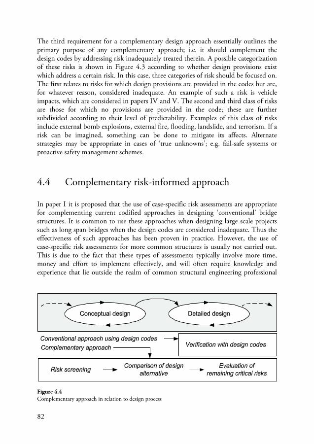
82
The third requirement for a complementary design approach essentially outlines the primary purpose of any complementary approach; i.e. it should complement the design codes by addressing risk inadequately treated therein. A possible categorization of these risks is shown in Figure 4.3 according to whether design provisions exist which address a certain risk. In this case, three categories of risk should be focused on. The first relates to risks for which design provisions are provided in the codes but are, for whatever reason, considered inadequate. An example of such a risk is vehicle impacts, which are considered in papers IV and V. The second and third class of risks are those for which no provisions are provided in the code; these are further subdivided according to their level of predictability. Examples of this class of risks include external bomb explosions, external fire, flooding, landslide, and terrorism. If a risk can be imagined, something can be done to mitigate its affects. Alternate strategies may be appropriate in cases of ‘true unknowns’; e.g. fail-safe systems or proactive safety management schemes.
4.4 Complementary risk-informed approach
In paper I it is proposed that the use of case-specific risk assessments are appropriate for complementing current codified approaches in designing ‘conventional’ bridge structures. It is common to use these approaches when designing large scale projects such as long span bridges when the design codes are considered inadequate. Thus the effectiveness of such approaches has been proven in practice. However, the use of case-specific risk assessments for more common structures is usually not carried out. This is due to the fact that these types of assessments typically involve more time, money and effort to implement effectively, and will often require knowledge and experience that lie outside the realm of common structural engineering professional
Figure 4.4 Complementary approach in relation to design process
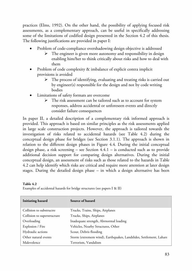
83
practices (Elms, 1992). On the other hand, the possibility of applying focused risk assessments, as a complementary approach, can be useful in specifically addressing some of the limitations of codified design presented in the Section 4.2 of this thesis. The following justifications are provided in paper I:
• Problem of code-compliance overshadowing design objective is addressed The engineer is given more autonomy and responsibility in design
enabling him/her to think critically about risks and how to deal with them
• Problem of code complexity & imbalance of explicit contra implicit provisions is avoided The process of identifying, evaluating and treating risks is carried out
by engineer(s) responsible for the design and not by code writing bodies
• Limitations of safety formats are overcome The risk assessment can be tailored such as to account for system
responses, address accidental or unforeseen events and directly consider failure consequences
In paper II, a detailed description of a complementary risk informed approach is provided. This approach is based on similar principles as the risk assessments applied in large scale construction projects. However, the approach is tailored towards the investigation of risks related to accidental hazards (see Table 4.2) during the conceptual design phase for bridges (see Section 3.1.1). The approach is shown in relation to the different design phases in Figure 4.4. During the initial conceptual design phase, a risk screening – see Section 4.4.1 – is conducted such as to provide additional decision support for comparing design alternatives. During the initial conceptual design, an assessment of risks such as those related to the hazards in Table 4.2 can help identify which risks are critical and require more attention at later design stages. During the detailed design phase – in which a design alternative has been
Initiating hazard Source of hazard
Collision to substructre Trucks, Trains, Ships, Airplanes Collision to superstructure Trucks, Ships, Airplanes Overloading Inadequate strength, Abrnormal loading Explosion / Fire Vehicles, Nearby Structures, Other Hydraulic actions Scour, Debris flooding Other natural events Storm (extremem wind), Earthquakes, Landslides, Settlement, Lahars Malevolence Terrorism, Vandalism
Table 4.2 Examples of accidental hazards for bridge structures (see papers I & II)
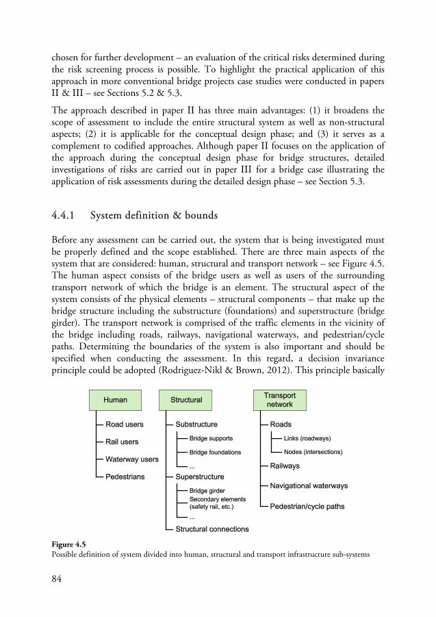
84
chosen for further development – an evaluation of the critical risks determined during the risk screening process is possible. To highlight the practical application of this approach in more conventional bridge projects case studies were conducted in papers II & III – see Sections 5.2 & 5.3.
The approach described in paper II has three main advantages: (1) it broadens the scope of assessment to include the entire structural system as well as non-structural aspects; (2) it is applicable for the conceptual design phase; and (3) it serves as a complement to codified approaches. Although paper II focuses on the application of the approach during the conceptual design phase for bridge structures, detailed investigations of risks are carried out in paper III for a bridge case illustrating the application of risk assessments during the detailed design phase – see Section 5.3.
4.4.1 System definition & bounds
Before any assessment can be carried out, the system that is being investigated must be properly defined and the scope established. There are three main aspects of the system that are considered: human, structural and transport network – see Figure 4.5. The human aspect consists of the bridge users as well as users of the surrounding transport network of which the bridge is an element. The structural aspect of the system consists of the physical elements – structural components – that make up the bridge structure including the substructure (foundations) and superstructure (bridge girder). The transport network is comprised of the traffic elements in the vicinity of the bridge including roads, railways, navigational waterways, and pedestrian/cycle paths. Determining the boundaries of the system is also important and should be specified when conducting the assessment. In this regard, a decision invariance principle could be adopted (Rodriguez-Nikl & Brown, 2012). This principle basically
Figure 4.5 Possible definition of system divided into human, structural and transport infrastructure sub-systems
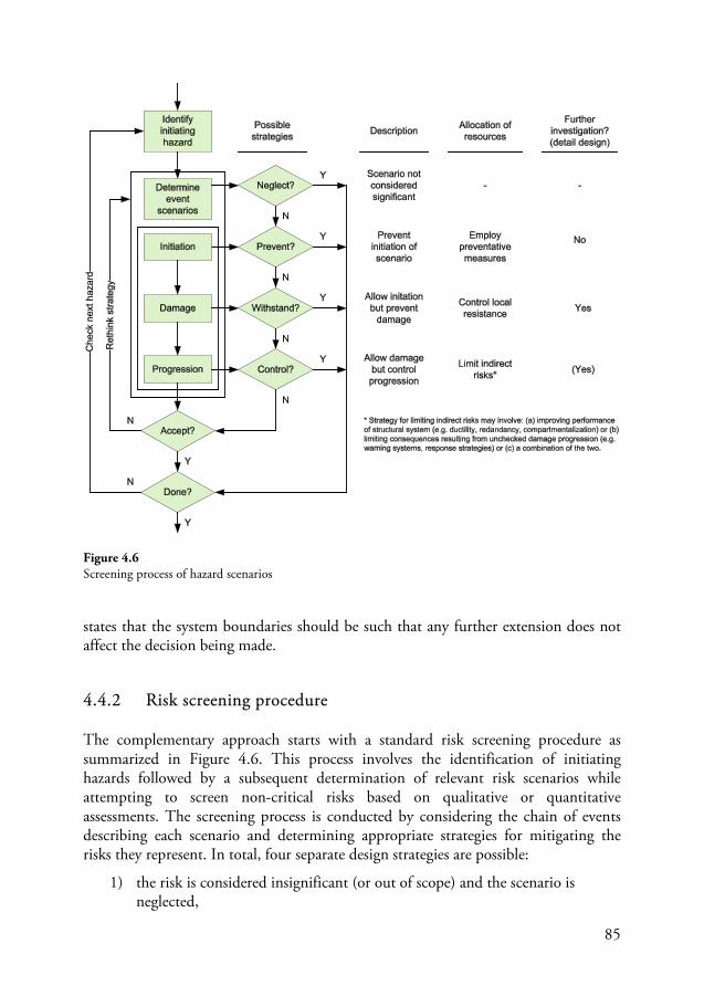
85
states that the system boundaries should be such that any further extension does not affect the decision being made.
4.4.2 Risk screening procedure
The complementary approach starts with a standard risk screening procedure as summarized in Figure 4.6. This process involves the identification of initiating hazards followed by a subsequent determination of relevant risk scenarios while attempting to screen non-critical risks based on qualitative or quantitative assessments. The screening process is conducted by considering the chain of events describing each scenario and determining appropriate strategies for mitigating the risks they represent. In total, four separate design strategies are possible:
1) the risk is considered insignificant (or out of scope) and the scenario is neglected,
Figure 4.6 Screening process of hazard scenarios
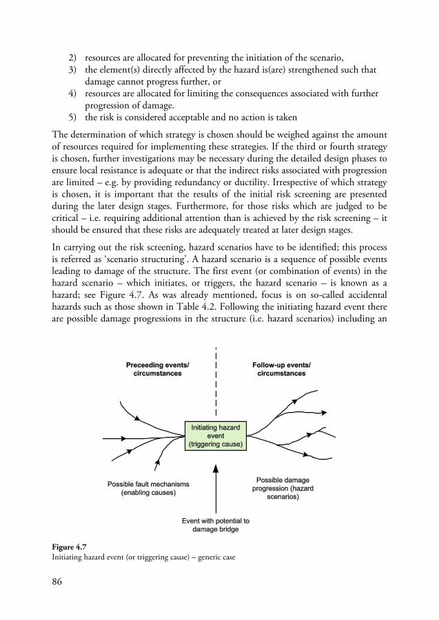
86
2) resources are allocated for preventing the initiation of the scenario, 3) the element(s) directly affected by the hazard is(are) strengthened such that
damage cannot progress further, or 4) resources are allocated for limiting the consequences associated with further
progression of damage. 5) the risk is considered acceptable and no action is taken
The determination of which strategy is chosen should be weighed against the amount of resources required for implementing these strategies. If the third or fourth strategy is chosen, further investigations may be necessary during the detailed design phases to ensure local resistance is adequate or that the indirect risks associated with progression are limited – e.g. by providing redundancy or ductility. Irrespective of which strategy is chosen, it is important that the results of the initial risk screening are presented during the later design stages. Furthermore, for those risks which are judged to be critical – i.e. requiring additional attention than is achieved by the risk screening – it should be ensured that these risks are adequately treated at later design stages.
In carrying out the risk screening, hazard scenarios have to be identified; this process is referred as ‘scenario structuring’. A hazard scenario is a sequence of possible events leading to damage of the structure. The first event (or combination of events) in the hazard scenario – which initiates, or triggers, the hazard scenario – is known as a hazard; see Figure 4.7. As was already mentioned, focus is on so-called accidental hazards such as those shown in Table 4.2. Following the initiating hazard event there are possible damage progressions in the structure (i.e. hazard scenarios) including an
Figure 4.7 Initiating hazard event (or triggering cause) – generic case
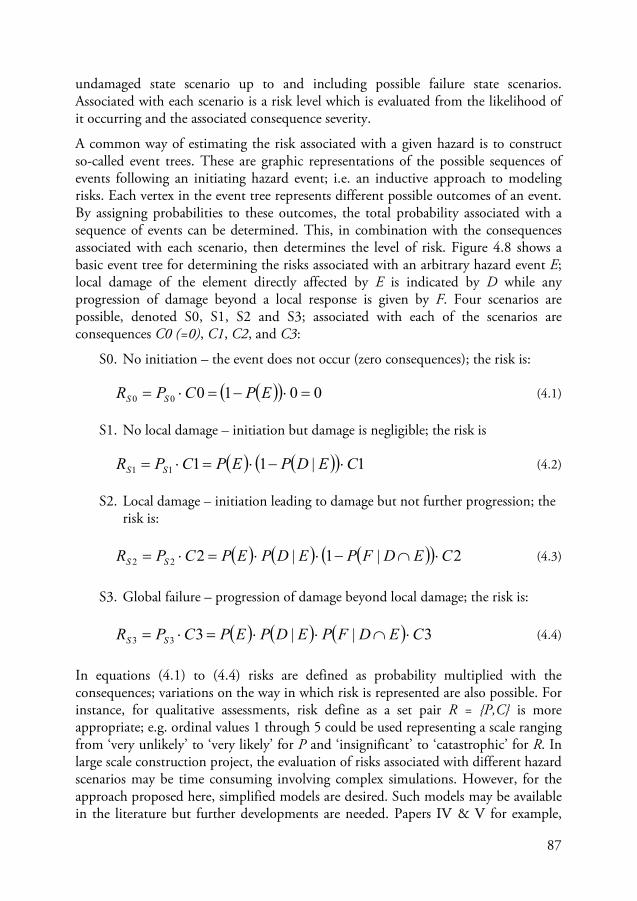
87
undamaged state scenario up to and including possible failure state scenarios. Associated with each scenario is a risk level which is evaluated from the likelihood of it occurring and the associated consequence severity.
A common way of estimating the risk associated with a given hazard is to construct so-called event trees. These are graphic representations of the possible sequences of events following an initiating hazard event; i.e. an inductive approach to modeling risks. Each vertex in the event tree represents different possible outcomes of an event. By assigning probabilities to these outcomes, the total probability associated with a sequence of events can be determined. This, in combination with the consequences associated with each scenario, then determines the level of risk. Figure 4.8 shows a basic event tree for determining the risks associated with an arbitrary hazard event E; local damage of the element directly affected by E is indicated by D while any progression of damage beyond a local response is given by F. Four scenarios are possible, denoted S0, S1, S2 and S3; associated with each of the scenarios are consequences C0 (=0), C1, C2, and C3:
S0. No initiation – the event does not occur (zero consequences); the risk is:
( )( ) 001000 =⋅−=⋅= EPCPR SS (4.1)
S1. No local damage – initiation but damage is negligible; the risk is
( ) ( )( ) 1|1111 CEDPEPCPR SS ⋅−⋅=⋅= (4.2)
S2. Local damage – initiation leading to damage but not further progression; the risk is:
( ) ( ) ( )( ) 2|1|222 CEDFPEDPEPCPR SS ⋅∩−⋅⋅=⋅= (4.3)
S3. Global failure – progression of damage beyond local damage; the risk is:
( ) ( ) ( ) 3||333 CEDFPEDPEPCPR SS ⋅∩⋅⋅=⋅= (4.4)
In equations (4.1) to (4.4) risks are defined as probability multiplied with the consequences; variations on the way in which risk is represented are also possible. For instance, for qualitative assessments, risk define as a set pair R = {P,C} is more appropriate; e.g. ordinal values 1 through 5 could be used representing a scale ranging from ‘very unlikely’ to ‘very likely’ for P and ‘insignificant’ to ‘catastrophic’ for R. In large scale construction project, the evaluation of risks associated with different hazard scenarios may be time consuming involving complex simulations. However, for the approach proposed here, simplified models are desired. Such models may be available in the literature but further developments are needed. Papers IV & V for example,
88
form the basis for a simplified risk modeling approach to HGV collisions to bridge substructures which is presented in Section 5.4.2.
In the context of risk control in engineering design, it is important to realize how different design choices affect the risks associated with a certain hazard. To do this, it is convenient to first realize the connection between the event tree in Figure 4.8 and the risk screening process in Figure 4.6. The latter is basically about determining how resources should be allocated to control the risks associated with the different branches of the event tree. If the prevent strategy is opted, then local damage is to be avoided and efforts are made to prevent initiation and reduce the probability P(E); thus the S1-S3 scenarios are to be avoided. Although it is obviously preferable that initiation is prevented, as the consequences are none, this may not be feasible due to a lack of resources. The withstand strategy entails utilizing resources to provide adequate local strength to reduce the probability of damage P(D|E) and thus avoiding the S2 and S3 scenarios. Again, this may not be feasible due to the high magnitude of loading usually associated with the types of hazards given in Table 4.2. In this case, the S3 scenario cannot be avoided but must be controlled. Choosing the control strategy is thus an indication that local damage is tolerated (or unavoidable) while the progression of collapse, determined by P(F|D), is addressed, e.g., by providing adequate redundancy or ductility in the damaged structure. This strategy may also
Figure 4.8 Event tree for initiating hazard event E
89
entail decreasing the consequences C3 through, e.g., compartmentalization to limit damage progression, emergency response measures, or monitoring systems. Finally, the neglect or accept strategies indicates no direct action is to be taken and that the risks are either insignificant, out of scope, or acceptable. The next sections give an overview for how the probabilities and consequences can be evaluated.
4.4.2.1 Probability estimation – uncertainty modeling In order to determine the probabilities shown in Figure 4.8, the uncertainties related to the hazard scenarios need to be considered. As a first step, a qualitative approach is possible. In this case, no quantitative values are determined for the probabilities but instead ordinal measures may be given; e.g., on a scale of 1-5. In this context, it is helpful to understand what factors are influential for the hazard scenario being considered; i.e. what factors influence the probabilities. Table 4.3 and Table 4.4 show influential factors for determining the probabilities associated with initiation, damage, and progression for two hazard scenarios given in Table 4.2 – HGV collisions to bridge support and scour of bridge foundations. Among these factors are some decision parameters (DP) – defined as factors that are dependent on decisions made in design. For example in the case of HGV collisions (Table 4.3) the distance between the roadside and the support structure depends on the design of the bridge; bridges with supports closer to the roadside are more vulnerable to collisions (initiation) than those with supports placed further away. While in the case of scour of bridge foundations placed in or near water, the depth of the foundation influences the likelihood of damage in case of initiation and bridges with more shallow foundations are more at risk.
If a quantitative assessment is desired, then stochastic models are required for calculating these probabilities. These models may be available in the literature or can be developed independently43
Table 4.2
. The JCSS Probabilistic Model Code (PMC), for example, provides some guidance for the stochastic modeling of structural resistances as well as some extreme loads including vehicle collisions as well as ship and aircraft collisions (JCSS, 2001). Some additional sources useful for the probabilistic modeling of the accidental or extreme hazard scenarios given in are mentioned in Table 4.5 – some general considerations regarding stochastic modeling of extreme hazards is provided in Vrouwenvelder (2000).
43 Papers IV and V for example consider the risks related to collisions from HGV traffic to bridge supports – a simplified model for estimating these risks is given in Section 5.4.1 based on these papers
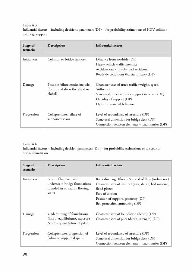
90
Table 4.4 Influential factors – including decision parameters (DP) – for probability estimations of to scour of bridge foundation
Stage of scenario
Description Influential factors
Inititation Scour of bed material underneath bridge foundations founded in or nearby flowing water
River discharge (flood) & speed of flow (turbulence) Characteristics of channel (area, depth, bed material, flood plane) Rate of erosion Position of support, geometry (DP) Bed protection, armouring (DP)
Damage Undermining of foundations (loss of equilibrium), exposure & subsequent failure of piles
Characteristics of foundation (depth) (DP) Characteristics of piles (depth, strength) (DP)
Progression Collapse state: progression of failure to supported spans
Level of redundancy of structure (DP) Structural dimension for bridge deck (DP) Connection between elements – load transfer (DP)
Stage of scenario
Description Influential factors
Inititation Collision to bridge supports Distance from roadside (DP) Heavy vehicle traffic intensity Accident rate (run-off-road accidents) Roadside conditions (barriers, slope) (DP)
Damage Possible failure modes include flexure and shear (localized or global)
Characteristics of truck traffic (weight, speed, ‘stiffness’) Structural dimensions for support structure (DP) Ductility of support (DP) Dynamic material behavior
Progression Collapse state: failure of supported spans
Level of redundancy of structure (DP) Structural dimension for bridge deck (DP) Connection between elements – load transfer (DP)
Table 4.3 Influential factors – including decisions parameters (DP) – for probability estimations of HGV collision to bridge support
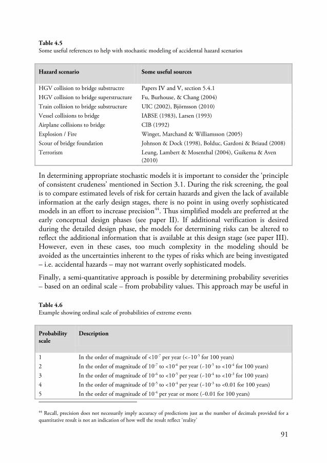
91
In determining appropriate stochastic models it is important to consider the ‘principle of consistent crudeness’ mentioned in Section 3.1. During the risk screening, the goal is to compare estimated levels of risk for certain hazards and given the lack of available information at the early design stages, there is no point in using overly sophisticated models in an effort to increase precision44
Finally, a semi-quantitative approach is possible by determining probability severities – based on an ordinal scale – from probability values. This approach may be useful in
. Thus simplified models are preferred at the early conceptual design phases (see paper II). If additional verification is desired during the detailed design phase, the models for determining risks can be altered to reflect the additional information that is available at this design stage (see paper III). However, even in these cases, too much complexity in the modeling should be avoided as the uncertainties inherent to the types of risks which are being investigated – i.e. accidental hazards – may not warrant overly sophisticated models.
44 Recall, precision does not necessarily imply accuracy of predictions just as the number of decimals provided for a quantitative result is not an indication of how well the result reflect ‘reality’
Probability scale
Description
1 In the order of magnitude of <10-7 per year (<~10-5 for 100 years) 2 In the order of magnitude of 10-7 to <10-6 per year (~10-5 to <10-4 for 100 years) 3 In the order of magnitude of 10-6 to <10-5 per year (~10-4 to <10-3 for 100 years) 4 In the order of magnitude of 10-5 to <10-4 per year (~10-3 to <0.01 for 100 years) 5 In the order of magnitude of 10-4 per year or more (~0.01 for 100 years)
Hazard scenario Some useful sources
HGV collision to bridge substructre Papers IV and V, section 5.4.1 HGV collision to bridge superstructure Fu, Burhouse, & Chang (2004) Train collision to bridge substructure UIC (2002), Björnsson (2010) Vessel collisions to bridge IABSE (1983), Larsen (1993) Airplane collisions to bridge CIB (1992) Explosion / Fire Winget, Marchand & Williamsson (2005) Scour of bridge foundation Johnson & Dock (1998), Bolduc, Gardoni & Briaud (2008) Terrorism Leung, Lambert & Mosenthal (2004), Guikema & Aven
(2010)
Table 4.6 Example showing ordinal scale of probabilities of extreme events
Table 4.5 Some useful references to help with stochastic modeling of accidental hazard scenarios
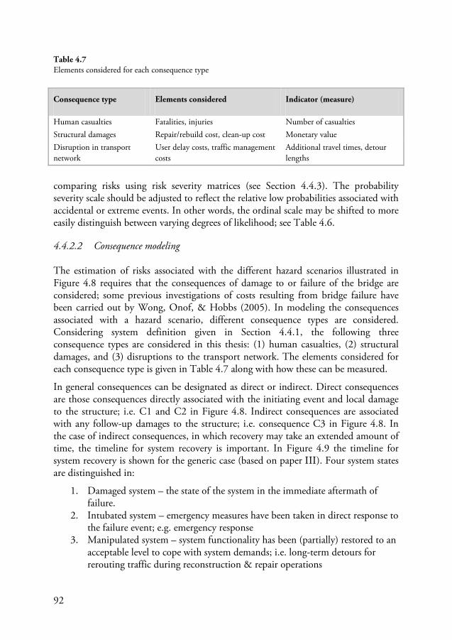
92
comparing risks using risk severity matrices (see Section 4.4.3). The probability severity scale should be adjusted to reflect the relative low probabilities associated with accidental or extreme events. In other words, the ordinal scale may be shifted to more easily distinguish between varying degrees of likelihood; see Table 4.6.
4.4.2.2 Consequence modeling
The estimation of risks associated with the different hazard scenarios illustrated in Figure 4.8 requires that the consequences of damage to or failure of the bridge are considered; some previous investigations of costs resulting from bridge failure have been carried out by Wong, Onof, & Hobbs (2005). In modeling the consequences associated with a hazard scenario, different consequence types are considered. Considering system definition given in Section 4.4.1, the following three consequence types are considered in this thesis: (1) human casualties, (2) structural damages, and (3) disruptions to the transport network. The elements considered for each consequence type is given in Table 4.7 along with how these can be measured.
In general consequences can be designated as direct or indirect. Direct consequences are those consequences directly associated with the initiating event and local damage to the structure; i.e. C1 and C2 in Figure 4.8. Indirect consequences are associated with any follow-up damages to the structure; i.e. consequence C3 in Figure 4.8. In the case of indirect consequences, in which recovery may take an extended amount of time, the timeline for system recovery is important. In Figure 4.9 the timeline for system recovery is shown for the generic case (based on paper III). Four system states are distinguished in:
1. Damaged system – the state of the system in the immediate aftermath of failure.
2. Intubated system – emergency measures have been taken in direct response to the failure event; e.g. emergency response
3. Manipulated system – system functionality has been (partially) restored to an acceptable level to cope with system demands; i.e. long-term detours for rerouting traffic during reconstruction & repair operations
Consequence type Elements considered Indicator (measure)
Human casualties Fatalities, injuries Number of casualties Structural damages Repair/rebuild cost, clean-up cost Monetary value Disruption in transport network
User delay costs, traffic management costs
Additional travel times, detour lengths
Table 4.7 Elements considered for each consequence type
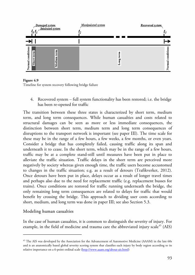
93
4. Recovered system – full system functionality has been restored; i.e. the bridge has been re-opened for traffic
The transition between these three states is characterized by short term, medium term, and long term consequences. While human casualties and costs related to structural damages can be seen as more or less immediate consequences, the distinction between short term, medium term and long term consequences of disruptions to the transport network is important (see paper III). The time scale for these may be in the range of a few hours, a few weeks, a few months, or even years. Consider a bridge that has completely failed, causing traffic along its span and underneath it to cease. In the short term, which may be in the range of a few hours, traffic may be at a complete stand-still until measures have been put in place to alleviate the traffic situation. Traffic delays in the short term are perceived more negatively by society whereas given enough time, the traffic users become accustomed to changes in the traffic situation; e.g. as a result of detours (Trafikverket, 2012). Once detours have been put in place, delays occur as a result of longer travel times and perhaps also due to the need for replacement traffic (e.g. replacement busses for trains). Once conditions are restored for traffic running underneath the bridge, the only remaining long term consequences are related to delays for traffic that would benefit by crossing the bridge. This approach to dividing user costs according to short, medium, and long term was done in paper III; see also Section 5.3.
Modeling human casualties
In the case of human casualties, it is common to distinguish the severity of injury. For example, in the field of medicine and trauma care the abbreviated injury scale45
45 The AIS was developed by the Association for the Advancement of Automotive Medicine (AAAM) in the late 60s and is an anatomically based global severity scoring system that classifies each injury by body region according to its relative importance on a 6-point ordinal scale (
(AIS)
http://www.aaam.org/about-ais.html)
Figure 4.9 Timeline for system recovery following bridge failure
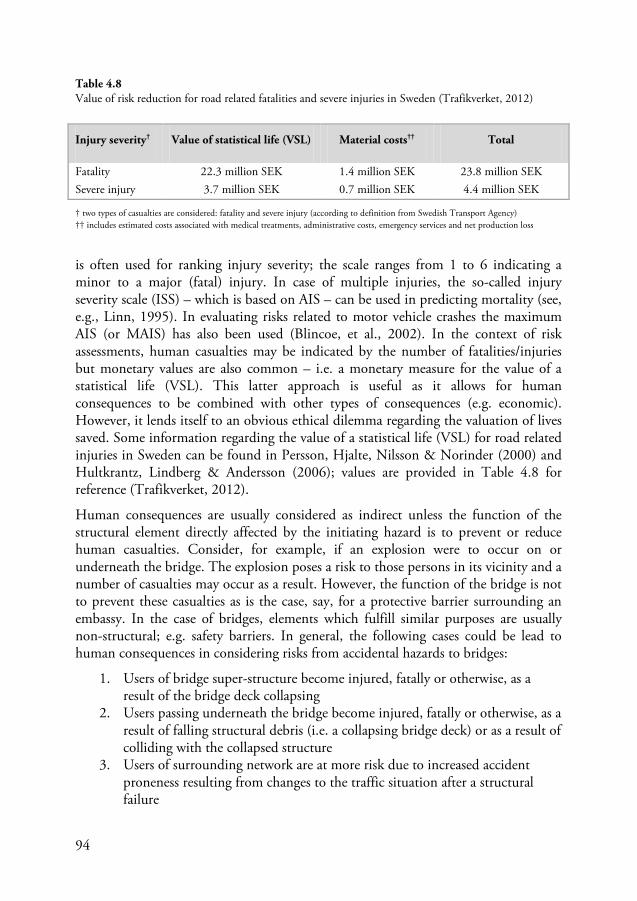
94
is often used for ranking injury severity; the scale ranges from 1 to 6 indicating a minor to a major (fatal) injury. In case of multiple injuries, the so-called injury severity scale (ISS) – which is based on AIS – can be used in predicting mortality (see, e.g., Linn, 1995). In evaluating risks related to motor vehicle crashes the maximum AIS (or MAIS) has also been used (Blincoe, et al., 2002). In the context of risk assessments, human casualties may be indicated by the number of fatalities/injuries but monetary values are also common – i.e. a monetary measure for the value of a statistical life (VSL). This latter approach is useful as it allows for human consequences to be combined with other types of consequences (e.g. economic). However, it lends itself to an obvious ethical dilemma regarding the valuation of lives saved. Some information regarding the value of a statistical life (VSL) for road related injuries in Sweden can be found in Persson, Hjalte, Nilsson & Norinder (2000) and Hultkrantz, Lindberg & Andersson (2006); values are provided in Table 4.8 for reference (Trafikverket, 2012).
Human consequences are usually considered as indirect unless the function of the structural element directly affected by the initiating hazard is to prevent or reduce human casualties. Consider, for example, if an explosion were to occur on or underneath the bridge. The explosion poses a risk to those persons in its vicinity and a number of casualties may occur as a result. However, the function of the bridge is not to prevent these casualties as is the case, say, for a protective barrier surrounding an embassy. In the case of bridges, elements which fulfill similar purposes are usually non-structural; e.g. safety barriers. In general, the following cases could be lead to human consequences in considering risks from accidental hazards to bridges:
1. Users of bridge super-structure become injured, fatally or otherwise, as a result of the bridge deck collapsing
2. Users passing underneath the bridge become injured, fatally or otherwise, as a result of falling structural debris (i.e. a collapsing bridge deck) or as a result of colliding with the collapsed structure
3. Users of surrounding network are at more risk due to increased accident proneness resulting from changes to the traffic situation after a structural failure
Injury severity† Value of statistical life (VSL) Material costs†† Total
Fatality 22.3 million SEK 1.4 million SEK 23.8 million SEK Severe injury 3.7 million SEK 0.7 million SEK 4.4 million SEK
Table 4.8 Value of risk reduction for road related fatalities and severe injuries in Sweden (Trafikverket, 2012)
† two types of casualties are considered: fatality and severe injury (according to definition from Swedish Transport Agency) †† includes estimated costs associated with medical treatments, administrative costs, emergency services and net production loss
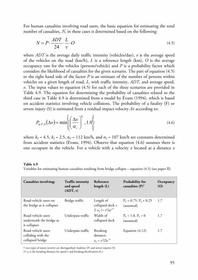
95
For human casualties involving road users, the basic equation for estimating the total number of casualties, N, in these cases is determined based on the following:
OvLADTPN ⋅⋅⋅=
24 (4.5)
where ADT is the average daily traffic intensity (vehicles/day), v is the average speed of the vehicles on the road (km/h), L is a reference length (km), O is the average occupancy rate for the vehicles (persons/vehicle) and P is a probability factor which considers the likelihood of casualties for the given scenario. The part of equation (4.5) to the right hand side of the factor P is an estimate of the number of persons within vehicles on a given length of road, L, with traffic intensity, ADT, and average speed, v. The input values to equation (4.5) for each of the three scenarios are provided in Table 4.9. The equation for determining the probability of casualties related to the third case in Table 4.9 is determined from a model by Evans (1994), which is based on accident statistics involving vehicle collisions. The probability of a fatality (F) or severe injury (S) is estimated from a residual impact velocity Δv according to:
( )
∆=∆∈ 0.1,min,
ik
iSFi
vvPα
(4.6)
where kF = 4.5, kS = 2.5, αF = 112 km/h, and αS = 107 km/h are constants determined from accident statistics (Evans, 1994). Observe that equation (4.6) assumes there is one occupant in the vehicle. For a vehicle with a velocity v located at a distance x
Casualties involving: Traffic intensity and speed (ADT, v)
Reference length (L)
Probability for casualties (P)†
Occupancy (O)
Road-vehicle users on the bridge as it collapses
Bridge traffic Length of collapsed deck + 2·xb (= v2/a) ††
PF = 0.75, PS = 0.25 (assumed)
1.7
Road-vehicle users underneath the bridge as it collapses
Underpass traffic Width of collapsed deck
PF = 1.0, PS = 0 (assumed)
1.7
Road-vehicle users colliding with the collapsed bridge
Underpass traffic Breaking distance: xb = v2/2a ††
Equation (4.12) 1.7
Table 4.9 Variables for estimating human casualties resulting from bridge collapse – equation (4.5) (see paper II)
† two types of injury severity are distinguished: fatalities (F) and severe injuries (S) †† xb is the breaking distance for speed v and breaking deceleration of a
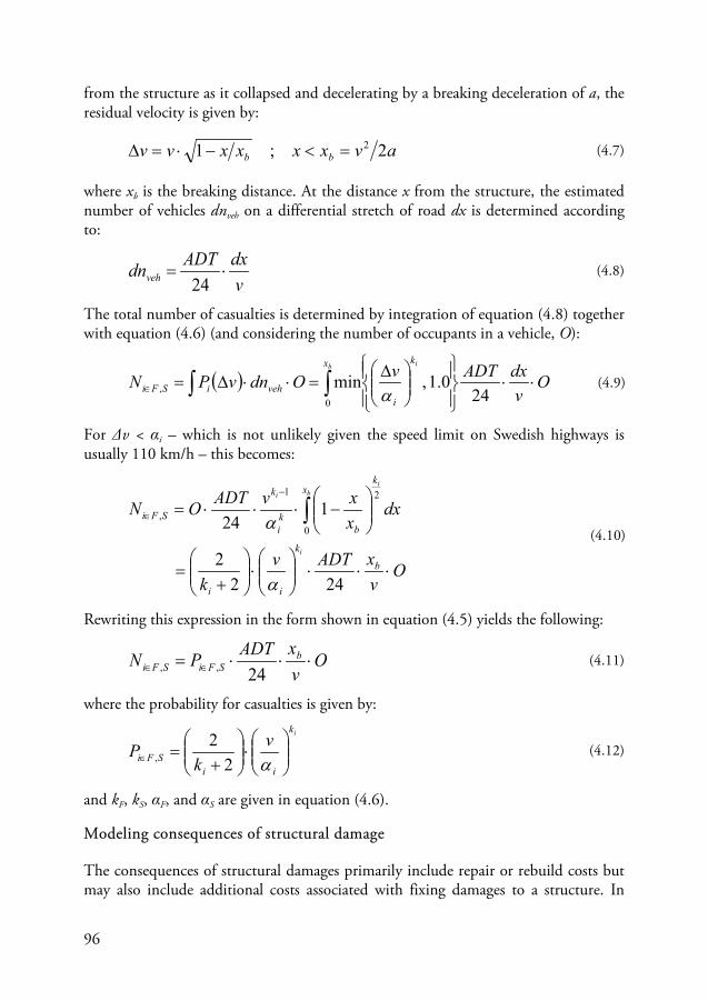
96
from the structure as it collapsed and decelerating by a breaking deceleration of a, the residual velocity is given by:
avxxxxvv bb 2;1 2=<−⋅=∆ (4.7)
where xb is the breaking distance. At the distance x from the structure, the estimated number of vehicles dnveh on a differential stretch of road dx is determined according to:
vdxADTdnveh ⋅=
24 (4.8)
The total number of casualties is determined by integration of equation (4.8) together with equation (4.6) (and considering the number of occupants in a vehicle, O):
( ) ∫∫ ⋅⋅
∆=⋅⋅∆=∈
b ix k
ivehiSFi O
vdxADTvOdnvPN
0, 24
0.1,minα
(4.9)
For Δv < αi – which is not unlikely given the speed limit on Swedish highways is usually 110 km/h – this becomes:
OvxADTv
k
dxxxvADTON
b
k
ii
xk
bki
k
SFi
i
bi
i
⋅⋅⋅
⋅
+
=
−⋅⋅⋅= ∫
−
∈
2422
124 0
21
,
α
α (4.10)
Rewriting this expression in the form shown in equation (4.5) yields the following:
OvxADTPN b
SFiSFi ⋅⋅⋅= ∈∈ 24,, (4.11)
where the probability for casualties is given by:
ik
iiSFi
vk
P
⋅
+
=∈ α22
, (4.12)
and kF, kS, αF, and αS are given in equation (4.6).
Modeling consequences of structural damage
The consequences of structural damages primarily include repair or rebuild costs but may also include additional costs associated with fixing damages to a structure. In
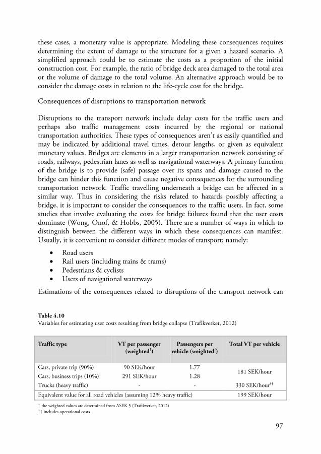
97
these cases, a monetary value is appropriate. Modeling these consequences requires determining the extent of damage to the structure for a given a hazard scenario. A simplified approach could be to estimate the costs as a proportion of the initial construction cost. For example, the ratio of bridge deck area damaged to the total area or the volume of damage to the total volume. An alternative approach would be to consider the damage costs in relation to the life-cycle cost for the bridge.
Consequences of disruptions to transportation network
Disruptions to the transport network include delay costs for the traffic users and perhaps also traffic management costs incurred by the regional or national transportation authorities. These types of consequences aren’t as easily quantified and may be indicated by additional travel times, detour lengths, or given as equivalent monetary values. Bridges are elements in a larger transportation network consisting of roads, railways, pedestrian lanes as well as navigational waterways. A primary function of the bridge is to provide (safe) passage over its spans and damage caused to the bridge can hinder this function and cause negative consequences for the surrounding transportation network. Traffic travelling underneath a bridge can be affected in a similar way. Thus in considering the risks related to hazards possibly affecting a bridge, it is important to consider the consequences to the traffic users. In fact, some studies that involve evaluating the costs for bridge failures found that the user costs dominate (Wong, Onof, & Hobbs, 2005). There are a number of ways in which to distinguish between the different ways in which these consequences can manifest. Usually, it is convenient to consider different modes of transport; namely:
• Road users • Rail users (including trains & trams) • Pedestrians & cyclists • Users of navigational waterways
Estimations of the consequences related to disruptions of the transport network can
Traffic type VT per passenger (weighted†)
Passengers per vehicle (weighted†)
Total VT per vehicle
Cars, private trip (90%) 90 SEK/hour 1.77 181 SEK/hour
Cars, business trips (10%) 291 SEK/hour 1.28 Trucks (heavy traffic) - - 330 SEK/hour††
Equivalent value for all road vehicles (assuming 12% heavy traffic) 199 SEK/hour
Table 4.10 Variables for estimating user costs resulting from bridge collapse (Trafikverket, 2012)
† the weighted values are determined from ASEK 5 (Trafikverket, 2012) †† includes operational costs
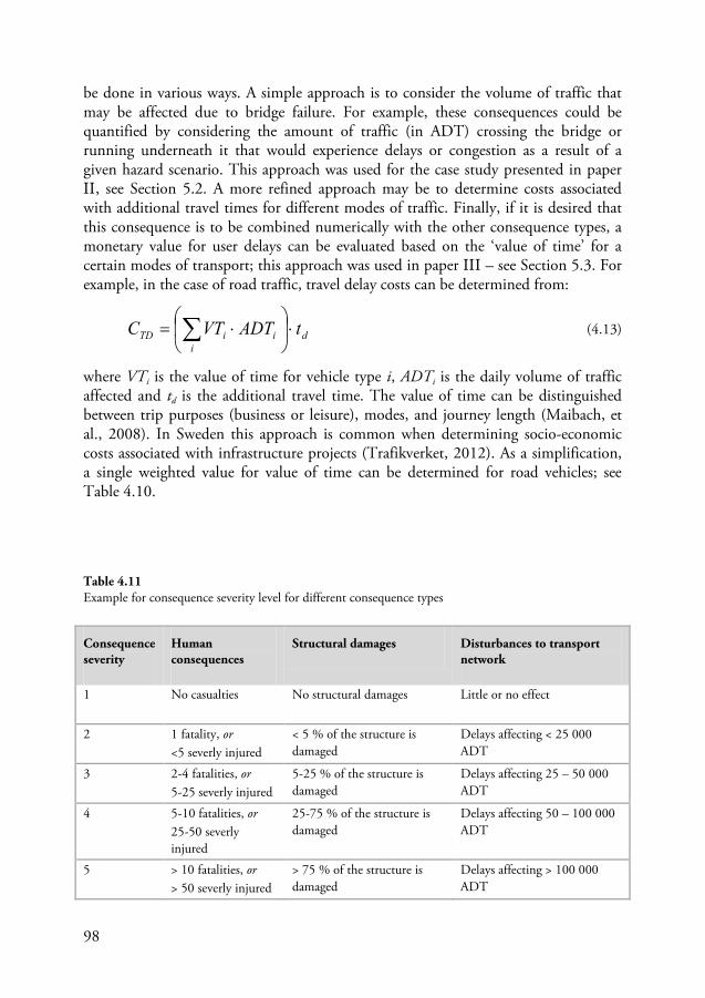
98
be done in various ways. A simple approach is to consider the volume of traffic that may be affected due to bridge failure. For example, these consequences could be quantified by considering the amount of traffic (in ADT) crossing the bridge or running underneath it that would experience delays or congestion as a result of a given hazard scenario. This approach was used for the case study presented in paper II, see Section 5.2. A more refined approach may be to determine costs associated with additional travel times for different modes of traffic. Finally, if it is desired that this consequence is to be combined numerically with the other consequence types, a monetary value for user delays can be evaluated based on the ‘value of time’ for a certain modes of transport; this approach was used in paper III – see Section 5.3. For example, in the case of road traffic, travel delay costs can be determined from:
di
iiTD tADTVTC ⋅
⋅= ∑ (4.13)
where VTi is the value of time for vehicle type i, ADTi is the daily volume of traffic affected and td is the additional travel time. The value of time can be distinguished between trip purposes (business or leisure), modes, and journey length (Maibach, et al., 2008). In Sweden this approach is common when determining socio-economic costs associated with infrastructure projects (Trafikverket, 2012). As a simplification, a single weighted value for value of time can be determined for road vehicles; see Table 4.10.
Consequence severity
Human consequences
Structural damages Disturbances to transport network
1 No casualties
No structural damages Little or no effect
2 1 fatality, or <5 severly injured
< 5 % of the structure is damaged
Delays affecting < 25 000 ADT
3 2-4 fatalities, or 5-25 severly injured
5-25 % of the structure is damaged
Delays affecting 25 – 50 000 ADT
4 5-10 fatalities, or 25-50 severly injured
25-75 % of the structure is damaged
Delays affecting 50 – 100 000 ADT
5 > 10 fatalities, or > 50 severly injured
> 75 % of the structure is damaged
Delays affecting > 100 000 ADT
Table 4.11 Example for consequence severity level for different consequence types
99
Combining consequences
The preceding sections describe approaches for modeling the consequences associated with human casualties, structural damages and disruptions in the transport network. This determines three separate measures of risk. Combining these measures to determine a single consequence measure for a hazard scenario can be done in a number of ways. To start, consequences can be represented by a set:
{ }TSH CCCC ,,= (4.14)
where CH, CS, and CT are the different consequence types – human casualties, structural damages, and disruptions to the transport network. This approach is advantageous as no information is lost in presenting such results to a stakeholder – i.e. it is transparent. Combining the consequences to determine a single measure is also possible. However, this requires that the different consequence types are represented in the same way. One way of achieving this is by using an ordinal scale in which a consequence severity is defined; see Table 4.11. This approach was used, e.g., in the case study in paper II. Alternatively, a common unit of measure can be used to evaluate the different consequence types. In this regard, the use of monetary values is common; see previous sections.
If a common unit is used to represent the different consequence types, a single consequence measure can be determined by, e.g., choosing the most severe consequence:
{ }TSH CCCC ,,max= (4.15)
Alternatively, the consequences can be summed:
TSH CCCC ++= (4.16)
Finally, if there is a preference for avoiding a certain type of consequence in relation to another, then weighing factors may be used:
TTSSHH CCCC ⋅+⋅+⋅= ωωω (4.17)
where ωH, ωS, and ωT are weighing factors whose sum is equal to one; e.g., these factors could be given values such as 0.4, 0.25, and 0.35 respectively.
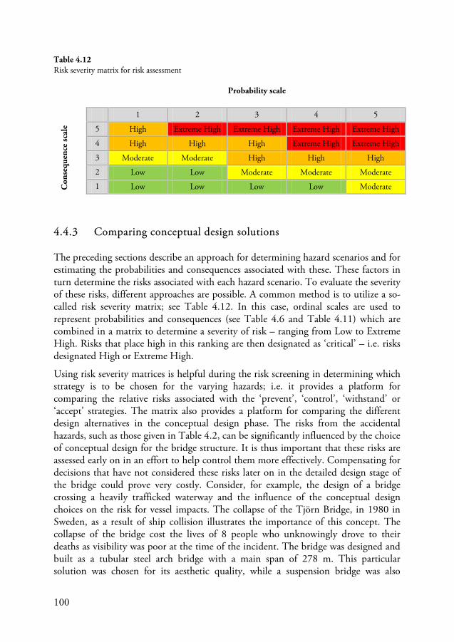
100
4.4.3 Comparing conceptual design solutions
The preceding sections describe an approach for determining hazard scenarios and for estimating the probabilities and consequences associated with these. These factors in turn determine the risks associated with each hazard scenario. To evaluate the severity of these risks, different approaches are possible. A common method is to utilize a so-called risk severity matrix; see Table 4.12. In this case, ordinal scales are used to represent probabilities and consequences (see Table 4.6 and Table 4.11) which are combined in a matrix to determine a severity of risk – ranging from Low to Extreme High. Risks that place high in this ranking are then designated as ‘critical’ – i.e. risks designated High or Extreme High.
Using risk severity matrices is helpful during the risk screening in determining which strategy is to be chosen for the varying hazards; i.e. it provides a platform for comparing the relative risks associated with the ‘prevent’, ‘control’, ‘withstand’ or ‘accept’ strategies. The matrix also provides a platform for comparing the different design alternatives in the conceptual design phase. The risks from the accidental hazards, such as those given in Table 4.2, can be significantly influenced by the choice of conceptual design for the bridge structure. It is thus important that these risks are assessed early on in an effort to help control them more effectively. Compensating for decisions that have not considered these risks later on in the detailed design stage of the bridge could prove very costly. Consider, for example, the design of a bridge crossing a heavily trafficked waterway and the influence of the conceptual design choices on the risk for vessel impacts. The collapse of the Tjörn Bridge, in 1980 in Sweden, as a result of ship collision illustrates the importance of this concept. The collapse of the bridge cost the lives of 8 people who unknowingly drove to their deaths as visibility was poor at the time of the incident. The bridge was designed and built as a tubular steel arch bridge with a main span of 278 m. This particular solution was chosen for its aesthetic quality, while a suspension bridge was also
Probability scale
1 2 3 4 5
Con
sequ
ence
scal
e 5 High Extreme High Extreme High Extreme High Extreme High
4 High High High Extreme High Extreme High
3 Moderate Moderate High High High
2 Low Low Moderate Moderate Moderate
1 Low Low Low Low Moderate
Table 4.12 Risk severity matrix for risk assessment
101
suggested. Ironically, one argument in opposition of the suspension bridge was based on the risk that an aircraft may collide with its high pylons (Åkesson 2008). It can be argued that the failure of the Tjörn Bridge was ultimately attributed to design error, as the bridge crossed a navigational route used by large ships (some in excess of 200 000 tons) and the possibility of ship impacts was not adequately considered at the time of design. The structural form was in itself very sensitive to impact damages. Furthermore, passage of ships was intended for a narrow gap beneath the center of the bridge just 50 m wide while no barricades or warning systems were provided to prevent a ship veering off course during passage (Åkesson 2008). It is not unreasonable to assume that, had an assessment of risk been conducted in this case during the conceptual phase, the suspension bridge option would have had a significantly lower level of risk with regards to possible impacts, be it aircraft or ship, than the tubular arch bridge. This is not to say that choosing the arch bridge was the wrong decision. It merely indicates that more careful considerations were required to control the risks from ship collision that, unfortunately, had not been considered at the time of construction. Examples of other strategies may have included strengthening the arches to absorb impact damages, providing some form of protective barricades to prevent ships from veering off course or even providing some warning system or automatic gate at either entrance of the bridge hindering people from accidentally crossing in the event of a bridge collapse.
It is stressed that the evaluation of risk should rely on a risk-informed approach and not a risk-based approach. The risk severity matrix in Table 4.12 is not intended as a tool for risk acceptance in which, e.g., risks should be kept below a specified threshold. Instead, the risks determined using the aforementioned methods are intended to provide additional decisions support for (1) comparing conceptual design alternatives, (2) comparing strategies for risk reduction and (3) identifying critical hazard scenarios that may require further attention. Thus, in a risk-informed approach, estimated levels of relative risks are compared for different design choices rather than with some arbitrarily defined acceptance criteria. Relative risk measures are important in the context of managing low probability / high consequence risks. Any absolute measure of risk would likely include large uncertainties and the meaning of any such measure would be lost. Furthermore, the adjustment of acceptance criteria in such cases is difficult as any absolute measure for these types of risks falls within the domain of the zero infinity problem; see Section 4.2.
Conducting these assessments is a balancing act. During the early stages of design, there is less available information (greater uncertainties) while the influence of the decisions made may have a more significant effect on the safety of the resulting structure. It is important that the approaches used account for the degree of uncertainty present at that point in time. Thus basic models are more useful during the early conceptual stage whereas a refinement is possible at subsequent stages as more information becomes available. The use of risk assessment methods is useful as it revolves around asking the vital questions: what can go wrong here? how? and, what
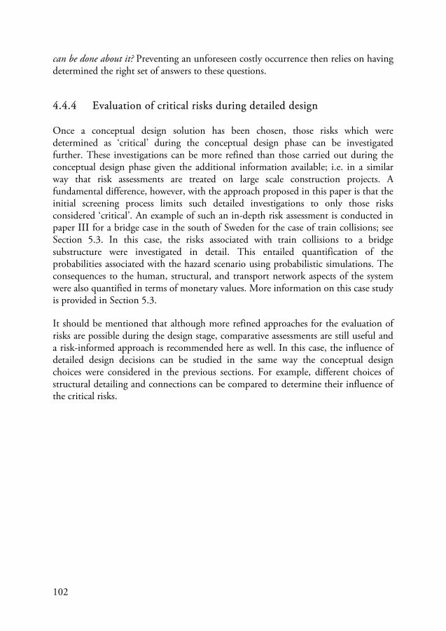
102
can be done about it? Preventing an unforeseen costly occurrence then relies on having determined the right set of answers to these questions.
4.4.4 Evaluation of critical risks during detailed design
Once a conceptual design solution has been chosen, those risks which were determined as ‘critical’ during the conceptual design phase can be investigated further. These investigations can be more refined than those carried out during the conceptual design phase given the additional information available; i.e. in a similar way that risk assessments are treated on large scale construction projects. A fundamental difference, however, with the approach proposed in this paper is that the initial screening process limits such detailed investigations to only those risks considered ‘critical’. An example of such an in-depth risk assessment is conducted in paper III for a bridge case in the south of Sweden for the case of train collisions; see Section 5.3. In this case, the risks associated with train collisions to a bridge substructure were investigated in detail. This entailed quantification of the probabilities associated with the hazard scenario using probabilistic simulations. The consequences to the human, structural, and transport network aspects of the system were also quantified in terms of monetary values. More information on this case study is provided in Section 5.3.
It should be mentioned that although more refined approaches for the evaluation of risks are possible during the design stage, comparative assessments are still useful and a risk-informed approach is recommended here as well. In this case, the influence of detailed design decisions can be studied in the same way the conceptual design choices were considered in the previous sections. For example, different choices of structural detailing and connections can be compared to determine their influence of the critical risks.
103
Figure 4.10 Photographs of the old Tjörn Bridge – or Almöbron – (top) before and (bottom) after collapse. The bridge – which opened in 1960 – collapsed when the bulk carrier MS Star Clipper collided with the tubular steel arch at 1.30 a.m. on 18th January, 1980. Eight persons lost their live in the 7 vehicles that unwittingly plunged into the collapsed span. More information can be found in the official report (SHK, 1981) available on the Swedish Accident Investigation Authority’s (SHK) homepage (www.havkom.se).

104
This page is intentionally left blank
105
5. Crucial aspects of complementary approach
The use of risk analysis…requires interpretation and knowing what went into it. It requires determining whether the results make sense in the broader context of all the considerations involved. In short, it requires the exercise of judgment.
Steven G. Vick (2002, p. 139)
5.1 Introduction
The main advantages with the approach that was outlined in Section 4.4 are that it (1) broadens the scope of assessment, (2) can be applied during the conceptual design phase, and (3) is a supplement for the design codes. To exemplify these advantages, some crucial aspects of the approach are identified and investigated further; these form the bases for papers II to V which are appended at the end of this thesis:
1. Application of approach during conceptual design phase (refer to paper II) 2. Assessment of critical risks during detailed design (refer to paper III) 3. Modeling risks from accidental/extreme hazards (refer to papers IV & V)
In the first case, the possibility of applying the approach during the early design phases is highlighted. A case-study of a construction project in the west of Sweden was investigated and the available material from the conceptual design – in which multiple technical solutions were proposed – formed the basis of the assessment. In the second case, the assessment of critical risks during later design stages was identified. A detailed investigation of the risks from a single accidental hazard was conducted for a bridge in the south of Sweden. This example shows the effects of broadening the scope of assessment to include non-structural constituent of the system. The bridge was viewed as an element in the transportation system and failures of the bridge structure result in disturbances for the transport network. The case study reveals the significance that considering this relationship – between bridge and transportation system – has on the risks determined. The third crucial aspect of the complementary approach is related to how risks related to accidental/extreme hazards are modeled. Application of the complementary approach utilizes such models and it

106
is important that these are identified and developed for various accidental hazards. Simplified models are preferred – especially during the conceptual design phase. In this thesis, it was decided to develop a model for heavy goods vehicle (HGV) impacts to bridge supporting structures. Referring back to Section 2.2.1 the second most frequent failure cause (or mode) was collisions. Scour, which was the leading most reported cause, was not chosen as it requires special expertise in hydraulic engineering.
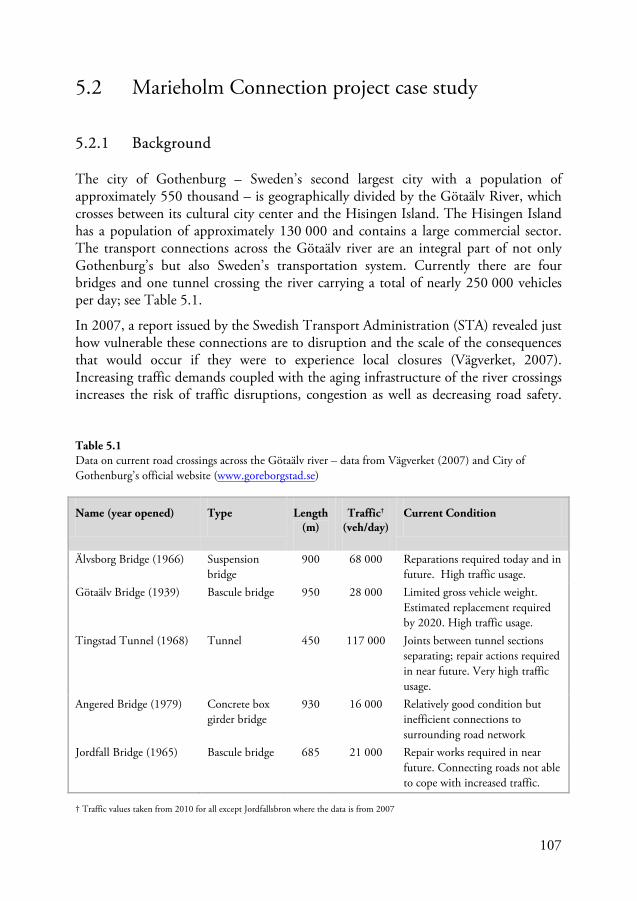
107
5.2 Marieholm Connection project case study
5.2.1 Background
The city of Gothenburg – Sweden’s second largest city with a population of approximately 550 thousand – is geographically divided by the Götaälv River, which crosses between its cultural city center and the Hisingen Island. The Hisingen Island has a population of approximately 130 000 and contains a large commercial sector. The transport connections across the Götaälv river are an integral part of not only Gothenburg’s but also Sweden’s transportation system. Currently there are four bridges and one tunnel crossing the river carrying a total of nearly 250 000 vehicles per day; see Table 5.1.
In 2007, a report issued by the Swedish Transport Administration (STA) revealed just how vulnerable these connections are to disruption and the scale of the consequences that would occur if they were to experience local closures (Vägverket, 2007). Increasing traffic demands coupled with the aging infrastructure of the river crossings increases the risk of traffic disruptions, congestion as well as decreasing road safety.
Name (year opened) Type Length (m)
Traffic† (veh/day)
Current Condition
Älvsborg Bridge (1966) Suspension bridge
900 68 000 Reparations required today and in future. High traffic usage.
Götaälv Bridge (1939) Bascule bridge 950 28 000 Limited gross vehicle weight. Estimated replacement required by 2020. High traffic usage.
Tingstad Tunnel (1968) Tunnel 450 117 000 Joints between tunnel sections separating; repair actions required in near future. Very high traffic usage.
Angered Bridge (1979) Concrete box girder bridge
930 16 000 Relatively good condition but inefficient connections to surrounding road network
Jordfall Bridge (1965) Bascule bridge 685 21 000 Repair works required in near future. Connecting roads not able to cope with increased traffic.
Table 5.1 Data on current road crossings across the Götaälv river – data from Vägverket (2007) and City of Gothenburg’s official website (www.goreborgstad.se)
† Traffic values taken from 2010 for all except Jordfallsbron where the data is from 2007
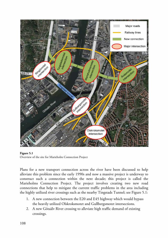
108
Plans for a new transport connection across the river have been discussed to help alleviate this problem since the early 1990s and now a massive project is underway to construct such a connection within the next decade; this project is called the Marieholms Connection Project. The project involves creating two new road connections that help to mitigate the current traffic problems in the area including the highly utilized river crossings such as the nearby Tingstads Tunnel; see Figure 5.1:
1. A new connection between the E20 and E45 highway which would bypass the heavily utilized Olskroksmotet and Gullbergsmotet intersections.
2. A new Götaälv River crossing to alleviate high traffic demand of existing crossings.
Figure 5.1 Overview of the site for Marieholm Connection Project
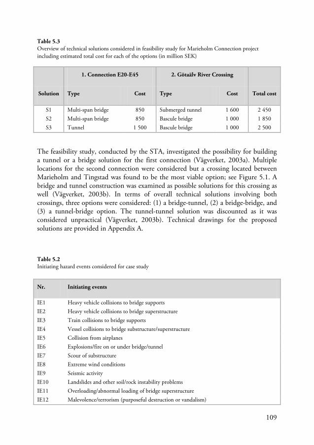
109
The feasibility study, conducted by the STA, investigated the possibility for building a tunnel or a bridge solution for the first connection (Vägverket, 2003a). Multiple locations for the second connection were considered but a crossing located between Marieholm and Tingstad was found to be the most viable option; see Figure 5.1. A bridge and tunnel construction was examined as possible solutions for this crossing as well (Vägverket, 2003b). In terms of overall technical solutions involving both crossings, three options were considered: (1) a bridge-tunnel, (2) a bridge-bridge, and (3) a tunnel-bridge option. The tunnel-tunnel solution was discounted as it was considered unpractical (Vägverket, 2003b). Technical drawings for the proposed solutions are provided in Appendix A.
Nr. Initiating events
IE1 Heavy vehicle collisions to bridge supports IE2 Heavy vehicle collisions to bridge superstructure IE3 Train collisions to bridge supports IE4 Vessel collisions to bridge substructure/superstructure IE5 Collision from airplanes IE6 Explosions/fire on or under bridge/tunnel IE7 Scour of substructure IE8 Extreme wind conditions IE9 Seismic activity IE10 Landslides and other soil/rock instability problems IE11 Overloading/abnormal loading of bridge superstructure IE12 Malevolence/terrorism (purposeful destruction or vandalism)
Solution
1. Connection E20-E45 2. Götaälv River Crossing
Total cost Type Cost Type Cost
S1 Multi-span bridge 850 Submerged tunnel 1 600 2 450 S2 Multi-span bridge 850 Bascule bridge 1 000 1 850 S3 Tunnel 1 500 Bascule bridge 1 000 2 500
Table 5.3 Overview of technical solutions considered in feasibility study for Marieholm Connection project including estimated total cost for each of the options (in million SEK)
Table 5.2 Initiating hazard events considered for case study
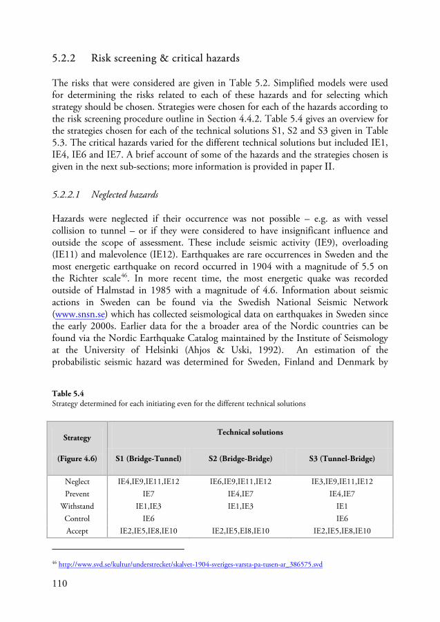
110
5.2.2 Risk screening & critical hazards
The risks that were considered are given in Table 5.2. Simplified models were used for determining the risks related to each of these hazards and for selecting which strategy should be chosen. Strategies were chosen for each of the hazards according to the risk screening procedure outline in Section 4.4.2. Table 5.4 gives an overview for the strategies chosen for each of the technical solutions S1, S2 and S3 given in Table 5.3. The critical hazards varied for the different technical solutions but included IE1, IE4, IE6 and IE7. A brief account of some of the hazards and the strategies chosen is given in the next sub-sections; more information is provided in paper II.
5.2.2.1 Neglected hazards
Hazards were neglected if their occurrence was not possible – e.g. as with vessel collision to tunnel – or if they were considered to have insignificant influence and outside the scope of assessment. These include seismic activity (IE9), overloading (IE11) and malevolence (IE12). Earthquakes are rare occurrences in Sweden and the most energetic earthquake on record occurred in 1904 with a magnitude of 5.5 on the Richter scale46. In more recent time, the most energetic quake was recorded outside of Halmstad in 1985 with a magnitude of 4.6. Information about seismic actions in Sweden can be found via the Swedish National Seismic Network (www.snsn.se) which has collected seismological data on earthquakes in Sweden since the early 2000s. Earlier data for the a broader area of the Nordic countries can be found via the Nordic Earthquake Catalog maintained by the Institute of Seismology at the University of Helsinki (Ahjos & Uski, 1992). An estimation of the probabilistic seismic hazard was determined for Sweden, Finland and Denmark by
46 http://www.svd.se/kultur/understrecket/skalvet-1904-sveriges-varsta-pa-tusen-ar_386575.svd
Strategy
(Figure 4.6)
Technical solutions
S1 (Bridge-Tunnel) S2 (Bridge-Bridge) S3 (Tunnel-Bridge)
Neglect IE4,IE9,IE11,IE12 IE6,IE9,IE11,IE12 IE3,IE9,IE11,IE12 Prevent IE7 IE4,IE7 IE4,IE7
Withstand IE1,IE3 IE1,IE3 IE1 Control IE6 IE6 Accept IE2,IE5,IE8,IE10 IE2,IE5,EI8,IE10 IE2,IE5,IE8,IE10
Table 5.4 Strategy determined for each initiating even for the different technical solutions
111
Wahlström & Gunthal (2000). The resulting seismic hazard map – for the region of Gothenburg – showed peak ground accelerations (PGA) of 0.035g for an exceedance probability of 10% in 50 years. Although, to the authors knowledge, there are no studies relating peak acceleration and damage potential in Sweden, data from the United States Geological Survey (USGS) on earthquakes in California indicate such accelerations – about 4% of gravity – have very light damage potential47
In the case of overloading, such occurrences may result if extreme abnormal loads occur or if the structure’s capacity for carrying vehicle loads is lower than expected or a combination of the two. The former case seems unlikely as the transport of abnormally heavy loads is commonly conducted in a way that the bridges to be crossed are verified to be adequate in carrying these loads. A lower strength, on the other hand, may be the result of some errors of construction or design and as such could be limited by having in place adequate quality control and checking of design and construction works. Finally, malevolence is considered outside the scope of assessment as specialized approaches may be required for assessing risks associated with intelligent attacks.
.
5.2.2.2 Accepted hazards
Hazards were accepted if the risks related to their occurrence were considered insignificant. Examples include heavy vehicle collisions to the superstructure (IE2), collisions from airplanes (IE5), extreme wind conditions (IE8) and landslides (IE10). In the case of collisions with the superstructure, the heights of the bridge elements over highways were relatively large, exceeding 5.2 m in most cases leading to relatively low likelihood levels – which were determined based on the minimum free height over a road. Furthermore, the consequences of impact were found to be relatively low in all cases. Considering collisions from airplanes, the risk was also found to be insignificant with the nearest airports located at distances of approximately 8.6 km and 18.2 km away from the bridge site. In both cases, the construction project was located well outside the area surrounding these airports which had designated height restrictions according to regulations provided by the Swedish Transport Agency (Transportstyrelsen, 2010). The orientation of the runways and air corridors were also such that planes should not be flying directly over the bridge (although no in-depth inquiries were made). Finally, if a collision from an airplane were to occur, the consequences would likely only be direct consequences which would have been unaffected by design choices related to the bridge structures for this project.
The risks of extreme winds were also determined to be acceptably low in all cases. A study of recorded wind speeds from data collected by the Swedish Meteorological and Hydrological Institute (SMHI) yielded characteristic speeds which were, unsurprisingly, the same as specified by the design code. Even considering loading 47 http://earthquake.usgs.gov/earthquakes/shakemap/background.php
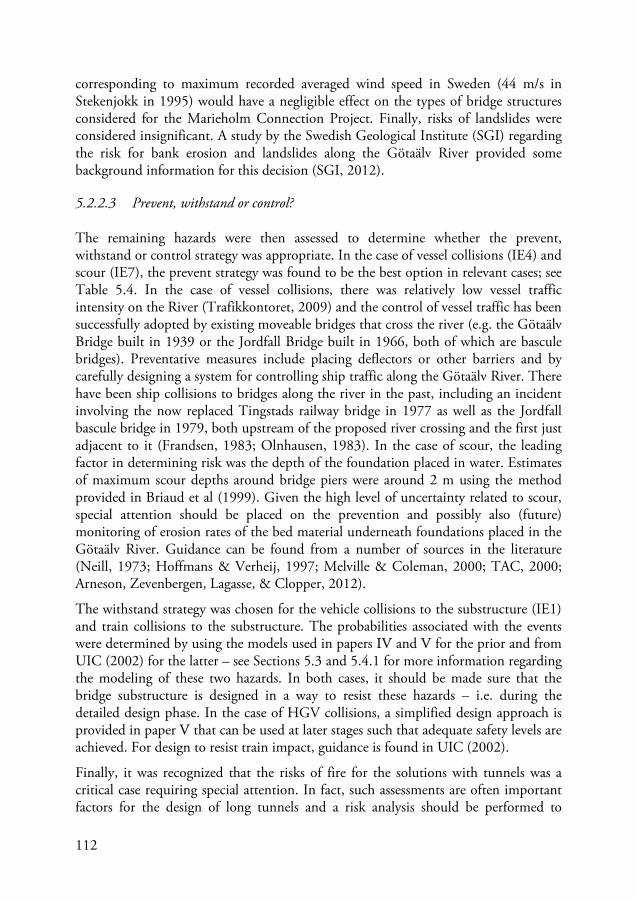
112
corresponding to maximum recorded averaged wind speed in Sweden (44 m/s in Stekenjokk in 1995) would have a negligible effect on the types of bridge structures considered for the Marieholm Connection Project. Finally, risks of landslides were considered insignificant. A study by the Swedish Geological Institute (SGI) regarding the risk for bank erosion and landslides along the Götaälv River provided some background information for this decision (SGI, 2012).
5.2.2.3 Prevent, withstand or control?
The remaining hazards were then assessed to determine whether the prevent, withstand or control strategy was appropriate. In the case of vessel collisions (IE4) and scour (IE7), the prevent strategy was found to be the best option in relevant cases; see Table 5.4. In the case of vessel collisions, there was relatively low vessel traffic intensity on the River (Trafikkontoret, 2009) and the control of vessel traffic has been successfully adopted by existing moveable bridges that cross the river (e.g. the Götaälv Bridge built in 1939 or the Jordfall Bridge built in 1966, both of which are bascule bridges). Preventative measures include placing deflectors or other barriers and by carefully designing a system for controlling ship traffic along the Götaälv River. There have been ship collisions to bridges along the river in the past, including an incident involving the now replaced Tingstads railway bridge in 1977 as well as the Jordfall bascule bridge in 1979, both upstream of the proposed river crossing and the first just adjacent to it (Frandsen, 1983; Olnhausen, 1983). In the case of scour, the leading factor in determining risk was the depth of the foundation placed in water. Estimates of maximum scour depths around bridge piers were around 2 m using the method provided in Briaud et al (1999). Given the high level of uncertainty related to scour, special attention should be placed on the prevention and possibly also (future) monitoring of erosion rates of the bed material underneath foundations placed in the Götaälv River. Guidance can be found from a number of sources in the literature (Neill, 1973; Hoffmans & Verheij, 1997; Melville & Coleman, 2000; TAC, 2000; Arneson, Zevenbergen, Lagasse, & Clopper, 2012).
The withstand strategy was chosen for the vehicle collisions to the substructure (IE1) and train collisions to the substructure. The probabilities associated with the events were determined by using the models used in papers IV and V for the prior and from UIC (2002) for the latter – see Sections 5.3 and 5.4.1 for more information regarding the modeling of these two hazards. In both cases, it should be made sure that the bridge substructure is designed in a way to resist these hazards – i.e. during the detailed design phase. In the case of HGV collisions, a simplified design approach is provided in paper V that can be used at later stages such that adequate safety levels are achieved. For design to resist train impact, guidance is found in UIC (2002).
Finally, it was recognized that the risks of fire for the solutions with tunnels was a critical case requiring special attention. In fact, such assessments are often important factors for the design of long tunnels and a risk analysis should be performed to
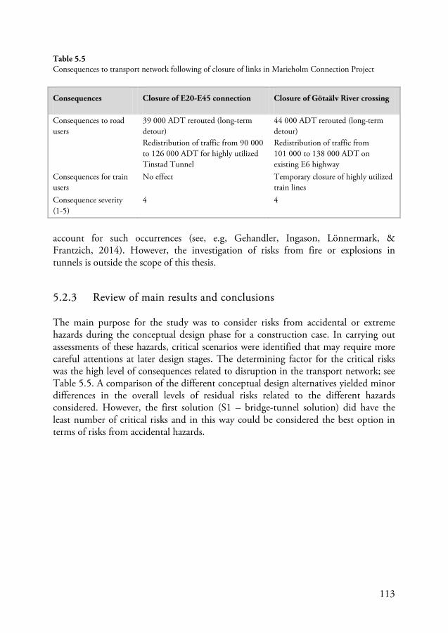
113
account for such occurrences (see, e.g, Gehandler, Ingason, Lönnermark, & Frantzich, 2014). However, the investigation of risks from fire or explosions in tunnels is outside the scope of this thesis.
5.2.3 Review of main results and conclusions
The main purpose for the study was to consider risks from accidental or extreme hazards during the conceptual design phase for a construction case. In carrying out assessments of these hazards, critical scenarios were identified that may require more careful attentions at later design stages. The determining factor for the critical risks was the high level of consequences related to disruption in the transport network; see Table 5.5. A comparison of the different conceptual design alternatives yielded minor differences in the overall levels of residual risks related to the different hazards considered. However, the first solution (S1 – bridge-tunnel solution) did have the least number of critical risks and in this way could be considered the best option in terms of risks from accidental hazards.
Consequences Closure of E20-E45 connection Closure of Götaälv River crossing
Consequences to road users
39 000 ADT rerouted (long-term detour) Redistribution of traffic from 90 000 to 126 000 ADT for highly utilized Tinstad Tunnel
44 000 ADT rerouted (long-term detour) Redistribution of traffic from 101 000 to 138 000 ADT on existing E6 highway
Consequences for train users
No effect Temporary closure of highly utilized train lines
Consequence severity (1-5)
4 4
Table 5.5 Consequences to transport network following of closure of links in Marieholm Connection Project
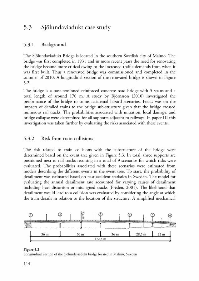
114
5.3 Sjölundaviadukt case study
5.3.1 Background
The Sjölundaviadukt Bridge is located in the southern Swedish city of Malmö. The bridge was first completed in 1931 and in more recent years the need for renovating the bridge became more critical owing to the increased traffic demands from when it was first built. Thus a renovated bridge was commissioned and completed in the summer of 2010. A longitudinal section of the renovated bridge is shown in Figure 5.2.
The bridge is a post-tensioned reinforced concrete road bridge with 5 spans and a total length of around 170 m. A study by Björnsson (2010) investigated the performance of the bridge to some accidental hazard scenarios. Focus was on the impacts of derailed trains to the bridge sub-structure given that the bridge crossed numerous rail tracks. The probabilities associated with initiation, local damage, and bridge collapse were determined for all supports adjacent to railways. In paper III this investigation was taken further by evaluating the risks associated with these events.
5.3.2 Risk from train collisions
The risk related to train collisions with the substructure of the bridge were determined based on the event tree given in Figure 5.3. In total, three supports are positioned next to rail tracks resulting in a total of 9 scenarios for which risks were evaluated. The probabilities associated with these scenarios were estimated from models describing the different events in the event tree. To start, the probability of derailment was estimated based on past accident statistics in Sweden. The model for evaluating the annual derailment rate accounted for varying causes of derailment including heat distortion or misaligned tracks (Fréden, 2001). The likelihood that derailment would lead to a collision was evaluated by considering the angle at which the train derails in relation to the location of the structure. A simplified mechanical
Figure 5.2 Longitudinal section of the Sjölundaviadukt bridge located in Malmö, Sweden
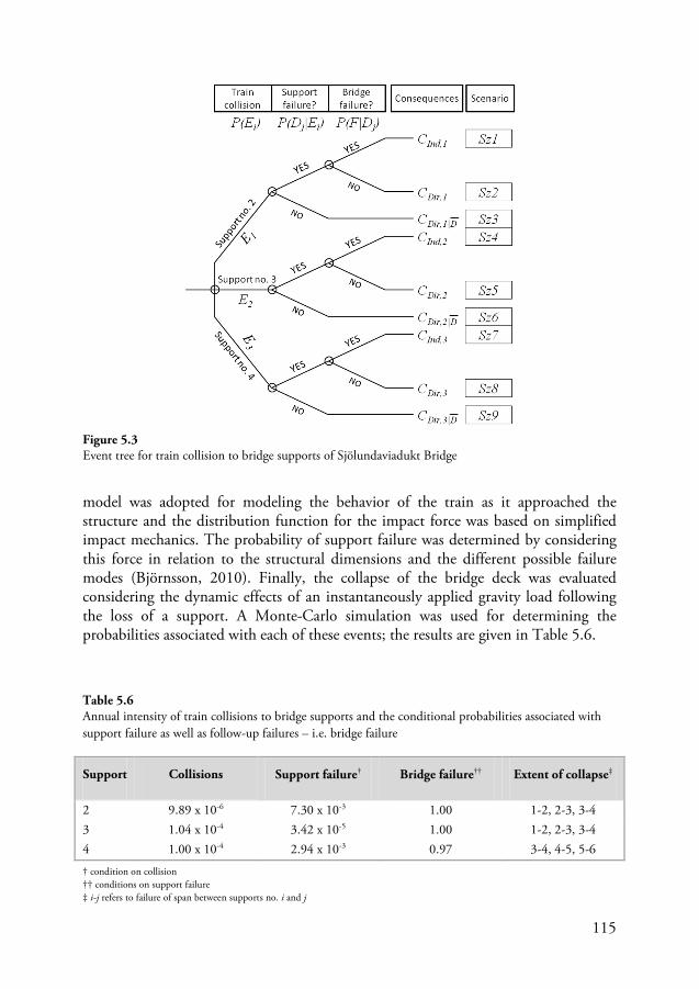
115
model was adopted for modeling the behavior of the train as it approached the structure and the distribution function for the impact force was based on simplified impact mechanics. The probability of support failure was determined by considering this force in relation to the structural dimensions and the different possible failure modes (Björnsson, 2010). Finally, the collapse of the bridge deck was evaluated considering the dynamic effects of an instantaneously applied gravity load following the loss of a support. A Monte-Carlo simulation was used for determining the probabilities associated with each of these events; the results are given in Table 5.6.
Support Collisions Support failure† Bridge failure†† Extent of collapse‡
2 9.89 x 10⁻⁶ 7.30 x 10⁻³ 1.00 1-2, 2-3, 3-4 3 1.04 x 10⁻⁴ 3.42 x 10⁻⁵ 1.00 1-2, 2-3, 3-4 4 1.00 x 10⁻⁴ 2.94 x 10⁻³ 0.97 3-4, 4-5, 5-6
Figure 5.3 Event tree for train collision to bridge supports of Sjölundaviadukt Bridge
Table 5.6 Annual intensity of train collisions to bridge supports and the conditional probabilities associated with support failure as well as follow-up failures – i.e. bridge failure
† condition on collision †† conditions on support failure ‡ i-j refers to failure of span between supports no. i and j
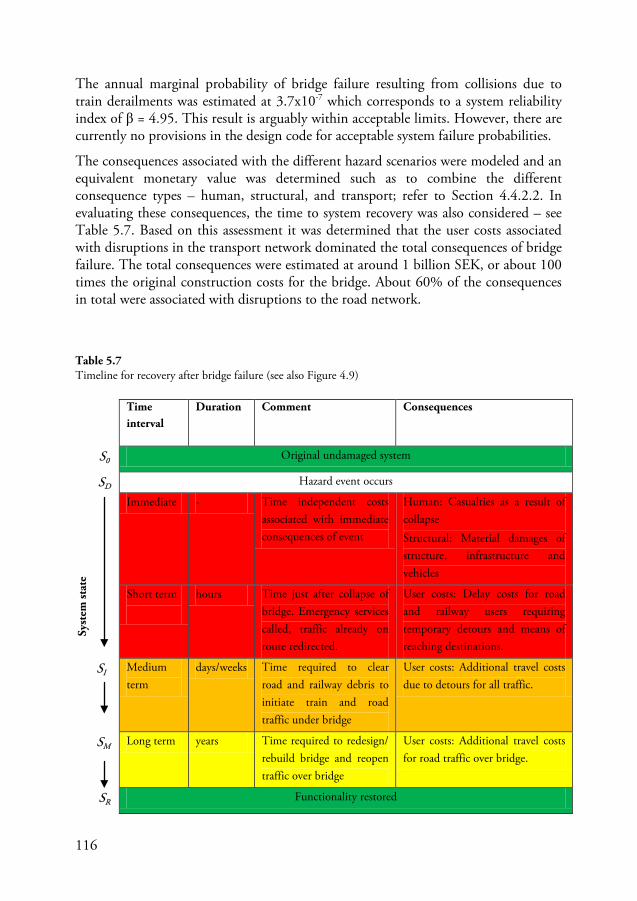
116
The annual marginal probability of bridge failure resulting from collisions due to train derailments was estimated at 3.7x10⁻⁷ which corresponds to a system reliability index of β = 4.95. This result is arguably within acceptable limits. However, there are currently no provisions in the design code for acceptable system failure probabilities.
The consequences associated with the different hazard scenarios were modeled and an equivalent monetary value was determined such as to combine the different consequence types – human, structural, and transport; refer to Section 4.4.2.2. In evaluating these consequences, the time to system recovery was also considered – see Table 5.7. Based on this assessment it was determined that the user costs associated with disruptions in the transport network dominated the total consequences of bridge failure. The total consequences were estimated at around 1 billion SEK, or about 100 times the original construction costs for the bridge. About 60% of the consequences in total were associated with disruptions to the road network.
Table 5.7 Timeline for recovery after bridge failure (see also Figure 4.9)
Syst
em st
ate
Time interval
Duration Comment Consequences
S0 Original undamaged system
SD Hazard event occurs
Immediate - Time independent costs associated with immediate consequences of event
Human: Casualties as a result of collapse Structural: Material damages of structure, infrastructure and vehicles
Short term
hours Time just after collapse of bridge. Emergency services called, traffic already on route redirected.
User costs: Delay costs for road and railway users requiring temporary detours and means of reaching destinations.
SI Medium term
days/weeks Time required to clear road and railway debris to initiate train and road traffic under bridge
User costs: Additional travel costs due to detours for all traffic.
SM Long term years Time required to redesign/ rebuild bridge and reopen traffic over bridge
User costs: Additional travel costs for road traffic over bridge.
SR Functionality restored
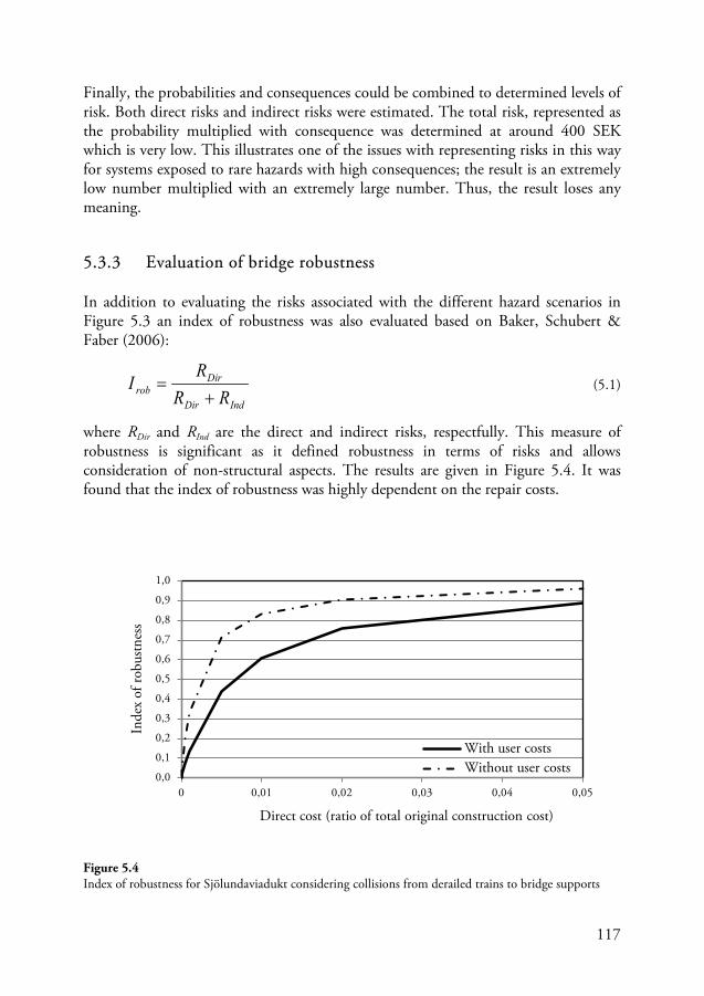
117
Finally, the probabilities and consequences could be combined to determined levels of risk. Both direct risks and indirect risks were estimated. The total risk, represented as the probability multiplied with consequence was determined at around 400 SEK which is very low. This illustrates one of the issues with representing risks in this way for systems exposed to rare hazards with high consequences; the result is an extremely low number multiplied with an extremely large number. Thus, the result loses any meaning.
5.3.3 Evaluation of bridge robustness
In addition to evaluating the risks associated with the different hazard scenarios in Figure 5.3 an index of robustness was also evaluated based on Baker, Schubert & Faber (2006):
IndDir
Dirrob RR
RI
+= (5.1)
where RDir and RInd are the direct and indirect risks, respectfully. This measure of robustness is significant as it defined robustness in terms of risks and allows consideration of non-structural aspects. The results are given in Figure 5.4. It was found that the index of robustness was highly dependent on the repair costs.
Figure 5.4 Index of robustness for Sjölundaviadukt considering collisions from derailed trains to bridge supports
0,0
0,1
0,2
0,3
0,4
0,5
0,6
0,7
0,8
0,9
1,0
0 0,01 0,02 0,03 0,04 0,05
Inde
x of
robu
stnes
s
Direct cost (ratio of total original construction cost)
With user costs Without user costs
118
5.3.4 Overview of main results and conclusions
The main aim of the investigation of the Sjölundaviadukt case study was to study the risks related to a specified accidental hazard. In this context, the influence and importance of how the system was defined and bounded is highlighted; i.e. what factors are accounted for in determining consequences and risks. The reliability of the structure to withstand the hazard is arguably adequate but it is not clear whether this measure is suitable for addressing the risks associated with the hazard that was investigated. The issue is that the consequences associated with failure were very large. As an alternative approach, an index of robustness was evaluated based on the ratio of direct to total risks. However, problems were also identified with this approach as the result was highly dependent on assumption made in the assessment. This problem was accentuated given the fact that there was limited redundancy in the structure in the case of a localized failure. Although these conclusions were determined for only a single hazard scenario, it is probable that similar results would be obtained for other hazards given that the indirect consequences would, in all cases, be high – at least assuming the same models for estimating these consequences are maintained.
This case study helped highlight the general problem associated with quantification of robustness. In this case, the robustness measure used was heavily reliant on the assumptions made and how the system is modeled. Reviewing other measures of robustness available in the literature – some are provided in Björnsson (2010) – would likely lead to a similar conclusions. These measures, as has already been mentioned in Section 3.4.2.1, usually relate a structures performance when it is damaged and when it is intact. In the case of the Sjölundaviadukt Bridge, removal of any of the bridge supports would lead to collapse of the supported spans. Thus the robustness according to the aforementioned approaches would be quite low. On the other hand, the probability of system failure was quite low. In such a case, the meaning of the robustness measure is put in question. Should robustness be approached in some other way than through quantification? The uncertainties associated with its assessment certainly go a long way in favoring an alternative approach. Are we satisfied in knowing that the uncertainties of the robustness measure are of the same order of magnitude as the measure itself? For example, is Robustness = 0.6 ± 0.5 an acceptable answer? These questions are important to consider and finding answers to them is not easy; but it is important that they are asked.
119
5.4 Modeling risks from accidental hazards
One of the key aspects of the methodology described in previous sections is related to the modeling of risks. Simplified models for assessing the probabilities and consequences associated with a certain hazard are vital for carrying out the complementary approach described in Section 4.4. Although some models exist in the literature, these are sometimes cumbersome to calculate and require simulations to evaluate numerically. Such approaches are thus less appropriate during the conceptual design phase than during later design stages. For the general case, the risk associated with the (indirect) system failure scenario – i.e. if a progression of damage occurs following local damages – is given by the following equation:
( ) ( ) ( ) ( )FCDFPEDPEPR ⋅⋅⋅= || (5.2)
where P(E) is the probability of the initiating event occurring; P(D|E) is the probability of (local) failure of elements directly affected by E; P(F|D) is the probability of global failure – i.e. a progression of damage beyond the localized failure; and C(F) are the consequences associated with the failure scenario. The following sections outline a simplified approach for determining the risks associated with HGV collisions to roadside structures. This approach is based on results from papers IV and V in which the risks associated with vehicle collisions to bridge supporting structures were investigated based on accident statistics and traffic measurements taken on Swedish highways. First, however, a review of current design provisions for HGV collisions will be provided.
5.4.1 Background – design for HGV collisions
Provisions for collision loads to bridge structures have been around at least since the early 1970s (Dawes, 2003). The values to be used in design were usually determined from collision tests or back analyses of incidents involving HGV collisions with highway structures. Two cases were usually discerned:
1) Collision with bridge supports 2) Collision with bridge deck (from over-height traffic under bridge)
The first case was studied in depth in papers IV and V. Although collisions are interaction phenomena, design codes usually provide equivalent static values for impact load to be used in design. Table 5.8 provides some examples of the design collision force used in modern design codes. As can be seen, some different design approaches have been adopted in the cases provided. The Eurocodes, for example, rely on historical values for the impact force which have not been verified using reliability approaches – see paper IV. In Switzerland, however, some probabilistic
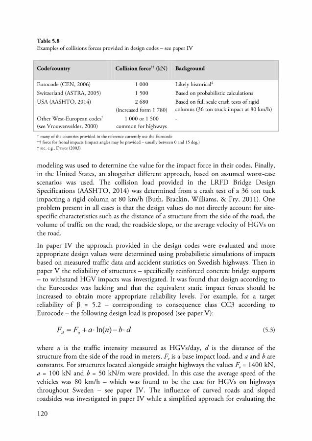
120
modeling was used to determine the value for the impact force in their codes. Finally, in the United States, an altogether different approach, based on assumed worst-case scenarios was used. The collision load provided in the LRFD Bridge Design Specifications (AASHTO, 2014) was determined from a crash test of a 36 ton tuck impacting a rigid column at 80 km/h (Buth, Brackin, Williams, & Fry, 2011). One problem present in all cases is that the design values do not directly account for site-specific characteristics such as the distance of a structure from the side of the road, the volume of traffic on the road, the roadside slope, or the average velocity of HGVs on the road.
In paper IV the approach provided in the design codes were evaluated and more appropriate design values were determined using probabilistic simulations of impacts based on measured traffic data and accident statistics on Swedish highways. Then in paper V the reliability of structures – specifically reinforced concrete bridge supports – to withstand HGV impacts was investigated. It was found that design according to the Eurocodes was lacking and that the equivalent static impact forces should be increased to obtain more appropriate reliability levels. For example, for a target reliability of β = 5.2 – corresponding to consequence class CC3 according to Eurocode – the following design load is proposed (see paper V):
dbnaFF od ⋅−⋅+= )ln( (5.3)
where n is the traffic intensity measured as HGVs/day, d is the distance of the structure from the side of the road in meters, Fo is a base impact load, and a and b are constants. For structures located alongside straight highways the values Fo = 1400 kN, a = 100 kN and b = 50 kN/m were provided. In this case the average speed of the vehicles was 80 km/h – which was found to be the case for HGVs on highways throughout Sweden – see paper IV. The influence of curved roads and sloped roadsides was investigated in paper IV while a simplified approach for evaluating the
Code/country Collision force†† (kN) Background
Eurocode (CEN, 2006) 1 000 Likely historical‡ Switzerland (ASTRA, 2005) 1 500 Based on probabilistic calculations USA (AASHTO, 2014) 2 680
(increased form 1 780) Based on full scale crash tests of rigid columns (36 ton truck impact at 80 km/h)
Other West-European codes† (see Vrouwenvelder, 2000)
1 000 or 1 500 common for highways
-
Table 5.8 Examples of collisions forces provided in design codes – see paper IV
† many of the countries provided in the reference currently use the Eurocode †† force for fronal impacts (impact angles may be provided – usually between 0 and 15 deg.) ‡ see, e.g., Dawes (2003)
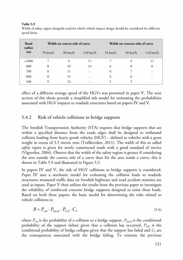
121
effect of a different average speed of the HGVs was presented in paper V. The next section of this thesis provide a simplified risk model for estimating the probabilities associated with HGV impacts to roadside structures based on papers IV and V.
5.4.2 Risk of vehicle collisions to bridge supports
The Swedish Transportation Authority (STA) requires that bridge supports that are within a specified distance from the roads edges shall be designed to withstand collision loading from heavy goods vehicles (HGV) – defined as vehicles with a gross weight in excess of 3.5 metric tons (Trafikverket, 2011). The width of this so called safety region is given for newly constructed roads with a good standard of service (Vägverket, 2004). Observe that the width of the safety region is greater if considering the area outside the convex side of a curve than for the area inside a curve, this is shown in Table 5.9 and illustrated in Figure 5.5.
In papers IV and V, the risk of HGV collisions to bridge supports is considered. Paper IV uses a stochastic model for evaluating the collision loads to roadside structures; measured traffic data on Swedish highways and road accident statistics are used as inputs. Paper V then utilizes the results from the previous paper to investigate the reliability of reinforced concrete bridge supports designed to resist these loads. Based on both these papers, the basic model for determining the risks related to vehicle collisions is:
FDFcollDcoll CPPPR ⋅⋅⋅= || (5.4)
where Pcoll is the probability of a collision to a bridge support, PD|coll is the conditional probability of the support failure given that a collision has occurred, PF|D is the conditional probability of bridge collapse given that the support has failed and CF are the consequences associated with the bridge failing. To reiterate the previous
Road radius
(m)
Width on convex side of curve Width on concave side of curve
70 km/h 90 km/h 110 km/h 70 km/h 90 km/h 110 km/h
>1000 7 9 11 7 9 11 800 8 10 14 6 8 8 700 8 11 - 6 7 - 600 8 12 - 6 6 - 500 9 13 - 5 5 -
Table 5.9 Width of safety region alongside road for which vehicle impact design should be considered for different speed limits
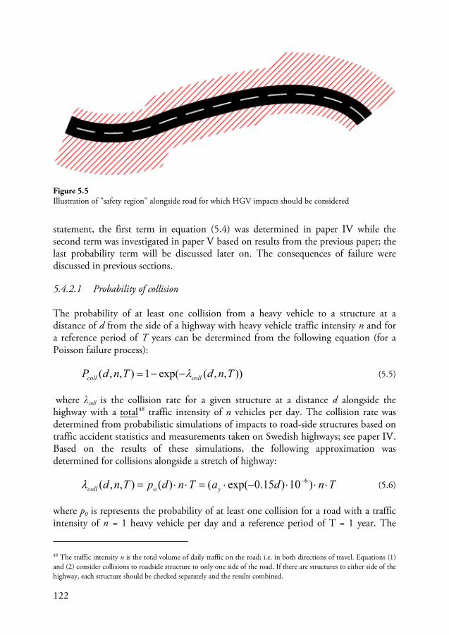
122
statement, the first term in equation (5.4) was determined in paper IV while the second term was investigated in paper V based on results from the previous paper; the last probability term will be discussed later on. The consequences of failure were discussed in previous sections.
5.4.2.1 Probability of collision
The probability of at least one collision from a heavy vehicle to a structure at a distance of d from the side of a highway with heavy vehicle traffic intensity n and for a reference period of T years can be determined from the following equation (for a Poisson failure process):
)),,(exp(1),,( TndTndP collcoll λ−−= (5.5)
where λcoll is the collision rate for a given structure at a distance d alongside the highway with a total48
TndaTndpTnd yocoll ⋅⋅⋅−⋅=⋅⋅= − )10)15.0exp(()(),,( 6λ
traffic intensity of n vehicles per day. The collision rate was determined from probabilistic simulations of impacts to road-side structures based on traffic accident statistics and measurements taken on Swedish highways; see paper IV. Based on the results of these simulations, the following approximation was determined for collisions alongside a stretch of highway:
(5.6)
where p0 is represents the probability of at least one collision for a road with a traffic intensity of n = 1 heavy vehicle per day and a reference period of T = 1 year. The
48 The traffic intensity n is the total volume of daily traffic on the road; i.e. in both directions of travel. Equations (1) and (2) consider collisions to roadside structure to only one side of the road. If there are structures to either side of the highway, each structure should be checked separately and the results combined.
Figure 5.5 Illustration of "safety region" alongside road for which HGV impacts should be considered
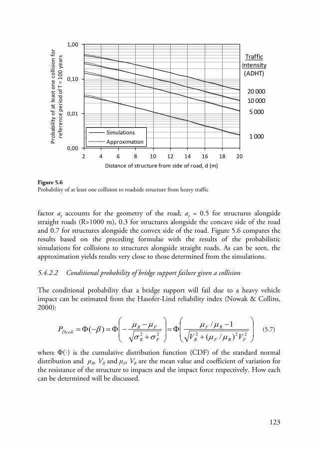
123
factor ay accounts for the geometry of the road; ay = 0.5 for structures alongside straight roads (R>1000 m), 0.3 for structures alongside the concave side of the road and 0.7 for structures alongside the convex side of the road. Figure 5.6 compares the results based on the preceding formulae with the results of the probabilistic simulations for collisions to structures alongside straight roads. As can be seen, the approximation yields results very close to those determined from the simulations.
5.4.2.2 Conditional probability of bridge support failure given a collision
The conditional probability that a bridge support will fail due to a heavy vehicle impact can be estimated from the Hasofer-Lind reliability index (Nowak & Collins, 2000):
+
−Φ=
+
−−Φ=−Φ=
22222|)/(
1/)(FRFR
RF
FR
FRcollD
VVP
µµ
µµ
σσ
µµβ (5.7)
where Φ(·) is the cumulative distribution function (CDF) of the standard normal distribution and μR, VR and μF, VR are the mean value and coefficient of variation for the resistance of the structure to impacts and the impact force respectively. How each can be determined will be discussed.
Figure 5.6 Probability of at least one collision to roadside structure from heavy traffic
0,00
0,01
0,10
1,00
2 4 6 8 10 12 14 16 18 20
Prob
abili
ty o
f at l
east
one
col
lisio
n fo
r re
fere
nce
perio
d of
T =
100
year
s
Distance of structure from side of road, d (m)
SimulationsApproximation
Traffic intensity(ADHT)
20 00010 000
5 000
1 000
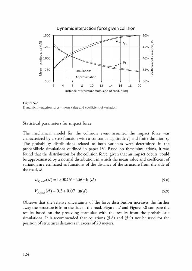
124
Statistical parameters for impact force
The mechanical model for the collision event assumed the impact force was characterized by a step function with a constant magnitude Fc and finite duration td. The probability distributions related to both variables were determined in the probabilistic simulations outlined in paper IV. Based on these simulations, it was found that the distribution for the collision force, given that an impact occurs, could be approximated by a normal distribution in which the mean value and coefficient of variation are estimated as functions of the distance of the structure from the side of the road, d:
)ln(2601500)(| dkNdcollFc⋅−=µ (5.8)
)ln(07.03.0)(| ddV collFc⋅+= (5.9)
Observe that the relative uncertainty of the force distribution increases the further away the structure is from the side of the road. Figure 5.7 and Figure 5.8 compare the results based on the preceding formulae with the results from the probabilistic simulations. It is recommended that equations (5.8) and (5.9) not be used for the position of structures distances in excess of 20 meters.
30%
35%
40%
45%
50%
500
750
1000
1250
1500
2 4 6 8 10 12 14 16 18 20
Coef
ficie
nt o
f var
iaito
n, V
F
Mea
n m
agni
tude
, μF
(kN)
Distance of structure from side of road, d (m)
Dynamic interaction force given collision
Simulations
Approximation
VF
μF
Figure 5.7 Dynamic interaction force - mean value and coefficient of variation
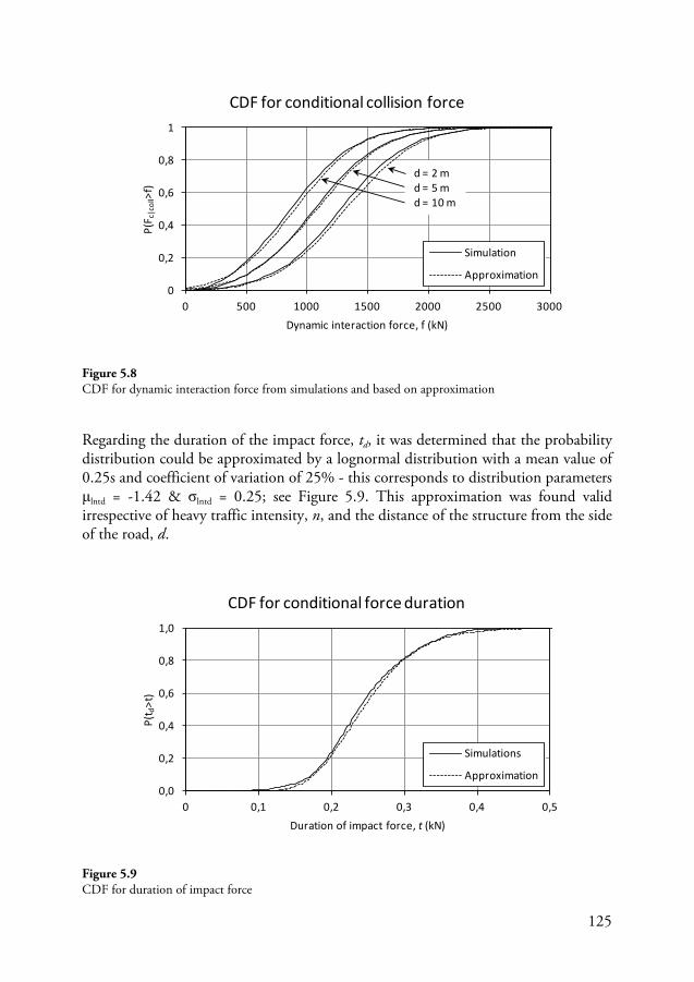
125
Figure 5.8 CDF for dynamic interaction force from simulations and based on approximation
Regarding the duration of the impact force, td, it was determined that the probability distribution could be approximated by a lognormal distribution with a mean value of 0.25s and coefficient of variation of 25% - this corresponds to distribution parameters μlntd = -1.42 & σlntd = 0.25; see Figure 5.9. This approximation was found valid irrespective of heavy traffic intensity, n, and the distance of the structure from the side of the road, d.
Figure 5.9 CDF for duration of impact force
0
0,2
0,4
0,6
0,8
1
0 500 1000 1500 2000 2500 3000
P(F c
|col
l>f)
Dynamic interaction force, f (kN)
CDF for conditional collision force
Simulation
Approximation
d = 2 md = 5 md = 10 m
0,0
0,2
0,4
0,6
0,8
1,0
0 0,1 0,2 0,3 0,4 0,5
P(t d
>t)
Duration of impact force, t (kN)
CDF for conditional force duration
Simulations
Approximation
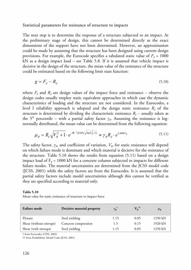
126
Statistical parameters for resistance of structure to impacts
The next step is to determine the response of a structure subjected to an impact. At the preliminary stage of design, this cannot be determined directly as the exact dimensions of the support have not been determined. However, an approximation could be made by assuming that the structure has been designed using current design provisions. For example, the Eurocode specifies a tabulated static value of Fd = 1000 kN as a design impact load – see Table 5.8. If it is assumed that vehicle impact is decisive in the design of the structure, the mean value of the resistance of the structure could be estimated based on the following limit state function:
dd RFg −= (5.10)
where Fd and Rd are design values of the impact force and resistance – observe the design codes usually employ static equivalent approaches in which case the dynamic characteristics of loading and the structure are not considered. In the Eurocodes, a level I reliability approach is adopted and the design static resistance Rd of the structure is determined by dividing the characteristic resistance Rk – usually taken as the 5th percentile – with a partial safety factor γR. Assuming the resistance is log-normally distributed, the mean value can be determined from the following equation:
RR VdR
VRkR eReVR ⋅+⋅Φ− ⋅≈⋅+=
− 644.1)1ln()05.0(2 21
1 γµ (5.11)
The safety factor, γR, and coefficient of variation, VR, for static resistance will depend on which failure mode is dominant and which material is decisive for the resistance of the structure. Table 5.10 shows the results from equation (5.11) based on a design impact load of Fd = 1000 kN for a concrete column subjected to impacts for different failure modes. The material uncertainties are determined from the JCSS model code (JCSS, 2001) while the safety factors are from the Eurocodes. It is assumed that the partial safety factors include model uncertainties although this cannot be verified as they are specified according to material only.
Table 5.10 Mean value for static resistance of structure to impact force
Failure mode Decisive material property γR† VR
†† μR
Flexure Steel yielding 1.15 0.05 1250 kN Shear (without stirrups) Concrete compression 1.5 0.15 1920 kN Shear (with stirrups) Steel yielding 1.15 0.05 1250 kN † from Eurocodes (CEN, 2002) †† from Probabilistic Model Code (JCSS, 2001)
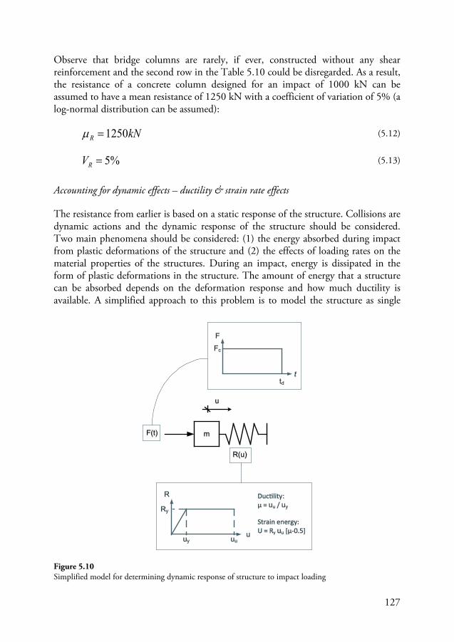
127
Observe that bridge columns are rarely, if ever, constructed without any shear reinforcement and the second row in the Table 5.10 could be disregarded. As a result, the resistance of a concrete column designed for an impact of 1000 kN can be assumed to have a mean resistance of 1250 kN with a coefficient of variation of 5% (a log-normal distribution can be assumed):
kNR 1250=µ (5.12)
%5=RV (5.13)
Accounting for dynamic effects – ductility & strain rate effects
The resistance from earlier is based on a static response of the structure. Collisions are dynamic actions and the dynamic response of the structure should be considered. Two main phenomena should be considered: (1) the energy absorbed during impact from plastic deformations of the structure and (2) the effects of loading rates on the material properties of the structures. During an impact, energy is dissipated in the form of plastic deformations in the structure. The amount of energy that a structure can be absorbed depends on the deformation response and how much ductility is available. A simplified approach to this problem is to model the structure as single
Figure 5.10 Simplified model for determining dynamic response of structure to impact loading
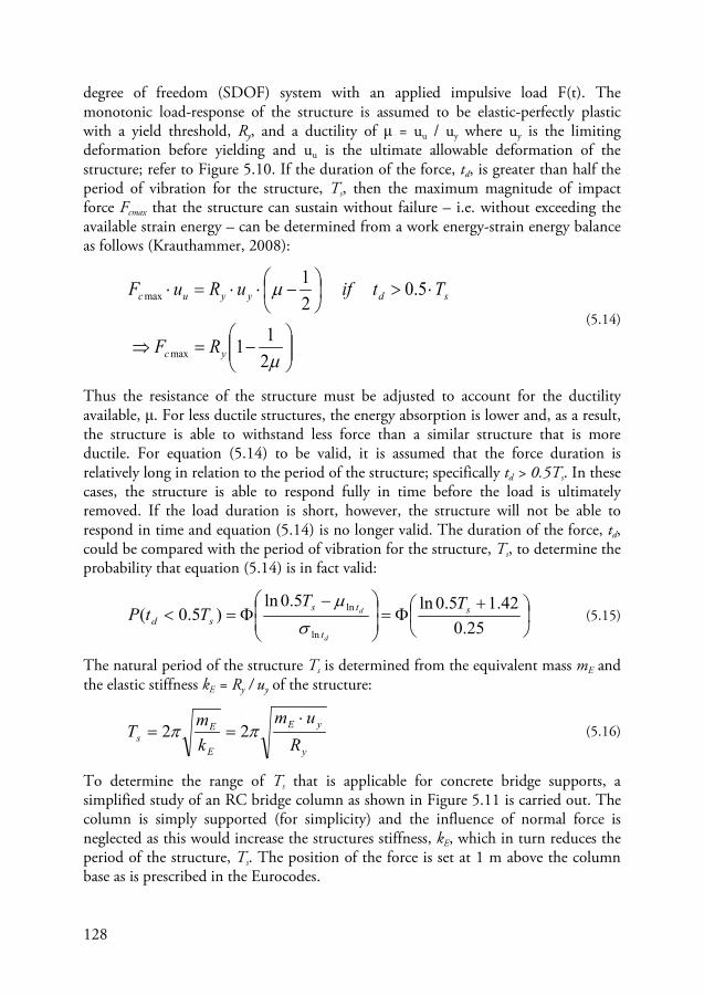
128
degree of freedom (SDOF) system with an applied impulsive load F(t). The monotonic load-response of the structure is assumed to be elastic-perfectly plastic with a yield threshold, Ry, and a ductility of μ = uu / uy where uy is the limiting deformation before yielding and uu is the ultimate allowable deformation of the structure; refer to Figure 5.10. If the duration of the force, td, is greater than half the period of vibration for the structure, Ts, then the maximum magnitude of impact force Fcmax that the structure can sustain without failure – i.e. without exceeding the available strain energy – can be determined from a work energy-strain energy balance as follows (Krauthammer, 2008):
−=⇒
⋅>
−⋅⋅=⋅
µ
µ
211
5.021
max
max
yc
sdyyuc
RF
TtifuRuF
(5.14)
Thus the resistance of the structure must be adjusted to account for the ductility available, μ. For less ductile structures, the energy absorption is lower and, as a result, the structure is able to withstand less force than a similar structure that is more ductile. For equation (5.14) to be valid, it is assumed that the force duration is relatively long in relation to the period of the structure; specifically td > 0.5Ts. In these cases, the structure is able to respond fully in time before the load is ultimately removed. If the load duration is short, however, the structure will not be able to respond in time and equation (5.14) is no longer valid. The duration of the force, td, could be compared with the period of vibration for the structure, Ts, to determine the probability that equation (5.14) is in fact valid:
+
Φ=
−Φ=<
25.042.15.0ln5.0ln
)5.0(ln
ln s
t
tssd
TTTtP
d
d
σµ
(5.15)
The natural period of the structure Ts is determined from the equivalent mass mE and the elastic stiffness kE = Ry / uy of the structure:
y
yE
E
Es R
umkmT
⋅== ππ 22 (5.16)
To determine the range of Ts that is applicable for concrete bridge supports, a simplified study of an RC bridge column as shown in Figure 5.11 is carried out. The column is simply supported (for simplicity) and the influence of normal force is neglected as this would increase the structures stiffness, kE, which in turn reduces the period of the structure, Ts. The position of the force is set at 1 m above the column base as is prescribed in the Eurocodes.
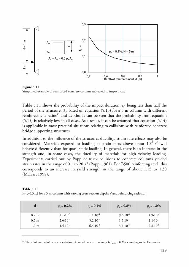
129
Table 5.11 shows the probability of the impact duration, td, being less than half the period of the structure, Ts, based on equation (5.15) for a 5 m column with different reinforcement ratios49
(5.15) and depths. It can be seen that the probability from equation
is relatively low in all cases. As a result, it can be assumed that equation (5.14) is applicable in most practical situations relating to collisions with reinforced concrete bridge supporting structures.
In addition to the influence of the structures ductility, strain rate effects may also be considered. Materials exposed to loading at strain rates above about 10-5 s-1 will behave differently than for quasi-static loading. In general, there is an increase in the strength and, in some cases, the ductility of materials for high velocity loading. Experiments carried out by Popp of truck collisions to concrete columns yielded strain rates in the range of 0.1 to 20 s-1 (Popp, 1961). For B500 reinforcing steel, this corresponds to an increase in yield strength in the range of about 1.15 to 1.30 (Malvar, 1998).
49 The minimum reinforcement ratio for reinforced concrete columns is ρsmin = 0.2% according to the Eurocodes
d ρs = 0.2% ρs = 0.4% ρs = 0.8% ρs = 1.0%
0.2 m 2.1·10-3 1.1·10-4 9.6·10-6 4.9·10-6 0.5 m 2.6·10-6 5.2·10-7 1.5·10-7 1.1·10-7 1.0 m 1.5·10-7 6.4·10-8 3.4·10-8 2.8·10-8
Table 5.11 P(td<0.5Ts) for a 5 m column with varying cross section depths d and reinforcing ratios ρs
Figure 5.11 Simplified example of reinforced concrete column subjected to impact load
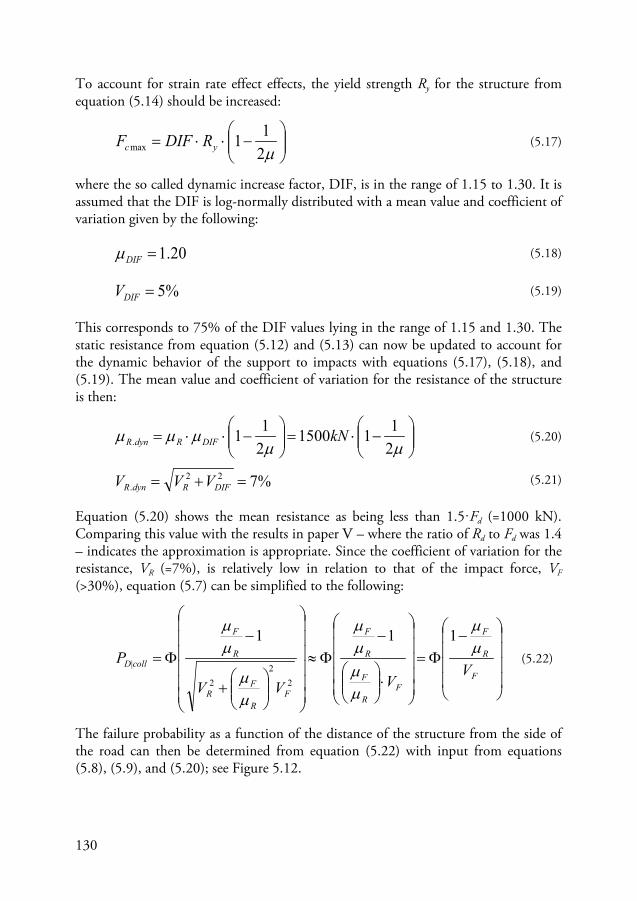
130
To account for strain rate effect effects, the yield strength Ry for the structure from equation (5.14) should be increased:
−⋅⋅=
µ211max yc RDIFF
(5.17)
where the so called dynamic increase factor, DIF, is in the range of 1.15 to 1.30. It is assumed that the DIF is log-normally distributed with a mean value and coefficient of variation given by the following:
20.1=DIFµ (5.18)
%5=DIFV (5.19)
This corresponds to 75% of the DIF values lying in the range of 1.15 and 1.30. The static resistance from equation (5.12) and (5.13) can now be updated to account for the dynamic behavior of the support to impacts with equations (5.17), (5.18), and (5.19). The mean value and coefficient of variation for the resistance of the structure is then:
−⋅=
−⋅⋅=
µµµµµ
2111500
211. kNDIFRdynR (5.20)
%722. =+= DIFRdynR VVV (5.21)
Equation (5.20) shows the mean resistance as being less than 1.5·Fd (=1000 kN). Comparing this value with the results in paper V – where the ratio of Rd to Fd was 1.4 – indicates the approximation is appropriate. Since the coefficient of variation for the resistance, VR (=7%), is relatively low in relation to that of the impact force, VF (>30%), equation (5.7) can be simplified to the following:
−Φ=
⋅
−Φ≈
+
−Φ=
F
R
F
FR
F
R
F
FR
FR
R
F
collD VVVV
P µµ
µµµµ
µµ
µµ 111
22
2
| (5.22)
The failure probability as a function of the distance of the structure from the side of the road can then be determined from equation (5.22) with input from equations (5.8), (5.9), and (5.20); see Figure 5.12.
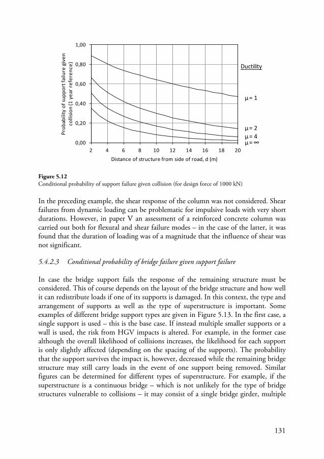
131
Figure 5.12 Conditional probability of support failure given collision (for design force of 1000 kN)
In the preceding example, the shear response of the column was not considered. Shear failures from dynamic loading can be problematic for impulsive loads with very short durations. However, in paper V an assessment of a reinforced concrete column was carried out both for flexural and shear failure modes – in the case of the latter, it was found that the duration of loading was of a magnitude that the influence of shear was not significant.
5.4.2.3 Conditional probability of bridge failure given support failure
In case the bridge support fails the response of the remaining structure must be considered. This of course depends on the layout of the bridge structure and how well it can redistribute loads if one of its supports is damaged. In this context, the type and arrangement of supports as well as the type of superstructure is important. Some examples of different bridge support types are given in Figure 5.13. In the first case, a single support is used – this is the base case. If instead multiple smaller supports or a wall is used, the risk from HGV impacts is altered. For example, in the former case although the overall likelihood of collisions increases, the likelihood for each support is only slightly affected (depending on the spacing of the supports). The probability that the support survives the impact is, however, decreased while the remaining bridge structure may still carry loads in the event of one support being removed. Similar figures can be determined for different types of superstructure. For example, if the superstructure is a continuous bridge – which is not unlikely for the type of bridge structures vulnerable to collisions – it may consist of a single bridge girder, multiple
0,00
0,20
0,40
0,60
0,80
1,00
2 4 6 8 10 12 14 16 18 20
Prob
abili
ty o
f sup
port
failu
re g
iven
co
llisio
n (1
yea
r ref
eren
ce)
Distance of structure from side of road, d (m)
Ductility
μ= ∞
μ= 2μ= 4
μ= 1
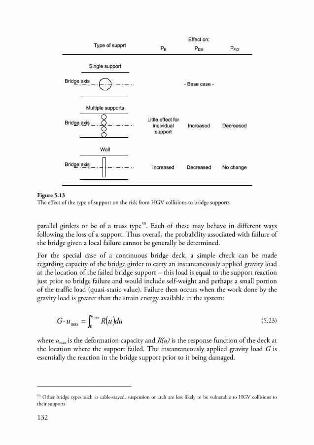
132
parallel girders or be of a truss type50
For the special case of a continuous bridge deck, a simple check can be made regarding capacity of the bridge girder to carry an instantaneously applied gravity load at the location of the failed bridge support – this load is equal to the support reaction just prior to bridge failure and would include self-weight and perhaps a small portion of the traffic load (quasi-static value). Failure then occurs when the work done by the gravity load is greater than the strain energy available in the system:
. Each of these may behave in different ways following the loss of a support. Thus overall, the probability associated with failure of the bridge given a local failure cannot be generally be determined.
( )∫=⋅ max
0max
uduuRuG (5.23)
where umax is the deformation capacity and R(u) is the response function of the deck at the location where the support failed. The instantaneously applied gravity load G is essentially the reaction in the bridge support prior to it being damaged.
50 Other bridge types such as cable-stayed, suspension or arch are less likely to be vulnerable to HGV collisions to their supports
Figure 5.13 The effect of the type of support on the risk from HGV collisions to bridge supports
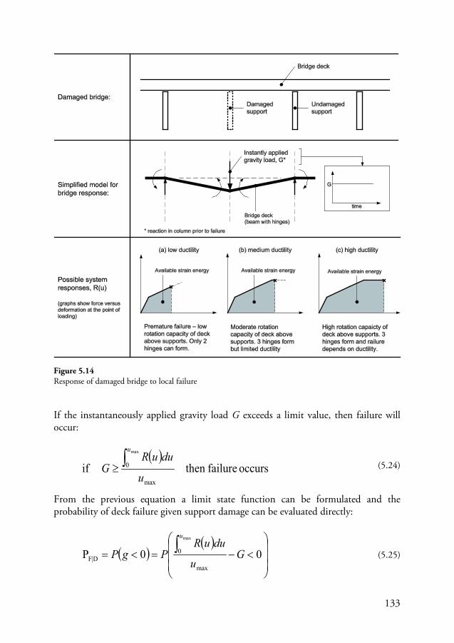
133
If the instantaneously applied gravity load G exceeds a limit value, then failure will occur:
( )occurs failurethen if
max
0
max
u
duuRG
u
∫≥ (5.24)
From the previous equation a limit state function can be formulated and the probability of deck failure given support damage can be evaluated directly:
( )( )
<−=<= ∫ 00P
max
0D|F
max
Gu
duuRPgP
u
(5.25)
Figure 5.14 Response of damaged bridge to local failure
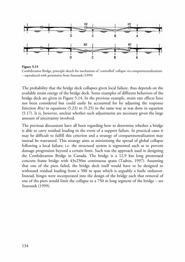
134
The probability that the bridge deck collapses given local failure, thus depends on the available strain energy of the bridge deck. Some examples of different behaviors of the bridge deck are given in Figure 5.14. In the previous example, strain rate effects have not been considered but could easily be accounted for by adjusting the response function R(u) in equations (5.23) to (5.25) in the same way as was done in equation (5.17). It is, however, unclear whether such adjustments are necessary given the large amount of uncertainty involved.
The previous discussions have all been regarding how to determine whether a bridge is able to carry residual loading in the event of a support failure. In practical cases it may be difficult to fulfill this criterion and a strategy of compartmentalization may instead be warranted. This strategy aims at minimizing the spread of global collapse following a local failure; i.e. the structural system is segmented such as to prevent damage progression beyond a certain limit. Such was the approach used in designing the Confederation Bridge in Canada. The bridge is a 12.9 km long prestressed concrete frame bridge with 43x250m continuous spans (Tadros, 1997). Assuming that one of the piers failed, the bridge deck itself would have to be designed to withstand residual loading from a 500 m span which is arguably a futile endeavor. Instead, hinges were incorporated into the design of the bridge such that removal of one of the piers would limit the collapse to a 750 m long segment of the bridge – see Starossek (1999).
Figure 5.15 Confederation Bridge, principle sketch for mechanism of ‘controlled’ collapse via compartmentalizations – reproduced with permission from Starossek (1999)
135
6. Conclusions and future work
6.1 Summary and conclusions
In concise terms, this thesis set out to investigate and improve the control of risks related to accidental hazards in the engineering design of bridge structures. Four research questions were formulated based on this objective and are given in Section 1.2. The following is a summary of the main results and conclusions of the thesis in relation to these questions.
The first research question asked: what can be learned regarding how risks have been and are currently being treated in engineering design. In addressing this question historical approaches to risk control were first reviewed. The advancement of design approaches was often in reaction to past failures. Safety as a design concept was controlled by using engineering judgment coupled with experimental observations and experience. Safety factors were increased if failures occurred often and decreased based on experience of past successes. There was, however, in reaction to this subjective approach to safety, a feeling that safety concepts needed to be rationalized. In viewing current approaches to structural safety – in which design is controlled through the use of design codes – this milieu of scientific rationalization is ever present. One consequence of this is that codes have grown in size and become more and more complex.
The second research questions asked: how effective are current approaches for risk control and specifically related to the treatment of risks from accidental hazards. Current design approaches for treating risks are mostly based on code-compliance. It was found that relying on this approach results in some risks being inadequately treated in engineering design. Furthermore, these risks are such that changes to the design codes are not enough and instead a complementary approach is needed. An overview of the limitations of codified design was provided. Among these limitations is the design codes inadequacy in treating risks from accidental hazards. Investigations were carried in the specific case of HGV collisions to roadside structures and it was found that design based on current codified approaches results in structures with reliability levels below those prescribed by the codes in conventional design situations. To address this specific issue, alternative design formulae were provided based on simulations of HGV impacts using traffic measures and accident statistic on Swedish Highways.
136
In investigating the limitation of codified approaches, insight was gained regarding the third research question which asked: can a risk-informed approach be used as a complement to codified design. It was proposed that such an approach is in fact appropriated in this regard as it helps to address the inadequacies of the design codes. Although similar approaches have been used in the design of large-scale structures these are rarely used in the design of more conventional bridge structures. A framework for the complementary approach is provided which has three main advantages. To start, the approach is holistic and broadens the scope of assessment to consider an entire structural system rather than single components as well as including non-structural elements which are significant in a design-decision making context; i.e. human, transportation and economic aspects. Secondly, it is possible to apply the approach during the conceptual design phase of the bridge structure and as such helps provide additional decision support during these early stages – such support is also useful for evaluating design choices made during the detailed design phase. Thirdly, the approach is a complement to the current design codes as focus is on design situations for which the codes are inadequate. In this regard, risks from accidental risks were singled out.
The fourth and final research question asked to identify crucial aspects of the complementary approach that should be developed further. Three crucial aspects were identified: (1) the application of the approach during the conceptual design phase, (2) the in-depth investigation of critical risks during later design stages, and (3) modeling approaches for risks from accidental hazards. For the first aspect, a case study was conducted of a construction project in Sweden in which the complementary approach is applied during the conceptual design phase. The risks from various accidental hazards are investigated for different conceptual design alternatives (proposals) and appropriate strategies for mitigating these risks were also determined. These investigations provided additional decision support for comparing the design alternatives while identifying critical risk that should be investigated in more detail at later design stages. The second crucial aspect was developed by conducting a second case study in which an in-depth investigation of risks related to a single hazard scenario – train collisions – was conducted for an existing bridge. The aim with this investigation was to evaluate risks in a holistic way and these investigations included detailed considerations of extra-structural system aspects for modeling consequences related to human casualties, structural damages and disruption in the transport network. The results from this case study revealed the significance of broadening the system scope when conducting risk assessments and the inherent difficulties associated with treating risks related to accidental hazards. In addition, it was found that determining the robustness of the structure is not trivial and current risk based approaches can be highly sensitive to modeling assumptions. The third and final crucial aspect of the approach that was developed related to the manner in which risks are modeled; and, more specifically, how probabilities associated with accidental hazards can be evaluated. An in-depth evaluation of the case of HGV collisions to
137
bridge supports is undertaken as it was found that the current design codes are inadequate in treating these risks. A simplified method for determining the probabilities associated with initiation and damage from HGV collisions was presented based on these investigations. Finally, some guidelines were given regarding the assessment of the bridge response given that the bridge supports were damaged as a result of an HGV collision.
To sum up, the main findings of this thesis can be divided into three main contributions. To start, a framework for a holistic risk informed complementary approach to the design codes is formulated. Then, to develop this concept further, background information useful for applying this approach in practice is provided which forms the basis for further developments of the approach in the future. This background information includes data useful for evaluating risks related to different accidental hazards in the design of bridge structures; e.g., models are provided for estimating risk levels. The third contribution of this thesis is the in-depth investigation of HGV collision loads and the development of alternative design approaches to those provided in current design codes. In this regard, alternative design loads are determined which result in more consistent reliability levels than is provided by current codified approaches while a simplified model for evaluating risks with this hazard is also developed. This model can be easily applied in the design of bridges while models for other types of accidental hazards could be developed in the future. Overall, it is hoped that the information provided in this thesis is helpful for further developing the complementary approach proposed with the ultimate aim of implementing such approaches in the design of conventional bridge structures in practice.
6.2 Reliability, validity & generalization
This thesis investigated risks related to accidental hazards and the treatment of these risks in the design of bridge structures. A complementary risk-informed approach to current codified design was advocated to more appropriately treat these risks. While the approach investigated in this thesis focused on conceptual design and on accidental hazards, it could certainly be extended to include investigations during the detailed design phase of the bridge structure as well as investigating risks during the construction phase; a phase for which safety considerations are rather inconsistent. In addition, other hazards that were not mentioned in this thesis could be integrated into the approach. With regards to the case studies conducted, similar investigations could be carried out on other bridge construction projects.
In previous sections, it was mentioned that the human element in safety management has been viewed as something external introducing unwanted variability into the equation; i.e. the designation of human error as a cause of failures. This is in contrast
138
to some modern views of human error which see the human element as something integral to the system and realizes the role that humans have in attaining and ensuring safety. In this context, humans are not a factor in the system that needs controlling and focus is instead on conceiving the system such that it is conducive for creating safety (and thus avoiding failures). I will make the claim that the concepts underlying the approach outlined in this thesis has this same aim. It wants to push forward the view that the designer is central to ensuring safety and not an external element of the decision process that should be better controlled. If the designer better understands what the aims are in relation to design, and is provided the ability to personally play a bigger role in determining strategies for achieving this aim, chances are that an atmosphere more conducive to ensuring success is created than for situation in which the designer is seen as something that needs to be better controlled.
Overall, it is important to encourage more holistic thinking in engineering design of even the most conventional of structures. There is thus a need for creating and integrating processes which are conducive to such thinking in the design and construction of common structures. To help realize this aim, current regulatory requirements may need to be adjusted to better accommodate the type of approach advocated in this thesis – such is the case for structural design at least in Sweden. While adjustments to regulation helps create more autonomy for the engineer, guidance for carrying out complementary risk assessments could be provided in handbooks sanctioned by the relevant building authority. Ensuring such assessments are accomplished in a satisfactory way could also be overseen by these authorities. In the case of bridge design, it was proposed in paper I that a potential candidate for overseeing and ensuring the validity of such assessments could be the relevant transportation authority responsible for the bridge; i.e. the owner.
6.3 Future work
Focus has been on the overall framework for the risk-informed approach advocated in this thesis while some critical aspects have been investigated in detail; e.g. risk screening during conceptual design phase of bridge. Owing to the holistic nature of the method, a full treatment was not possible and there are aspects of the methodology that should be developed further. These include further developing models for estimating effects of other accidental hazards (as mentioned early), more in-depth evaluations of damage progression in bridges resulting from localized failures, investigations of application of different approaches for quantification of risks, and the possible incorporation of probabilistic or risk-based decision making theory.
139
One specific issue that could be investigated further is the problem of how to successfully implement a complementary risk-informed approach in practice. In this regard, some additional factors have been identified which would need to be investigated further. These factors were identified by the author during his own investigations both in reviewing the available literature as well as in carrying out the case studies mentioned in previous sections.
• Personal responsibility (of engineers) • Documentation (of design) • Quality assurances (design checking) • Organizational & communication issues (interrelations between design-
teams, construction-teams, management, clients, public, etc) • Logistics • Time constraints • Financial constraints • Integration with existing protocols
The aforementioned factors reveal the complexity of the problem and indicate the important issues that should be investigated in more detail in the future. Any further investigations would require a deeper understanding in behavioral and cognitive aspects of engineering practice; the reader is referred to Vincenti (1990), Vick (2002), Jonassen, Strobel, & Lee (2006), Gainsburg, Rodriguez-Lluesma, & Bailey (2010), and Trevelyan (2010) for reference.
Finally, future studies should include an investigation of what obstacles need to be overcome such that the proposed approach can be successfully implemented in practice. One issue that this author has observed, corroborated by discussions with some colleagues, is the apparent unwillingness of the engineering community (at least in Sweden) to adopt risk based approaches in design. This opposition may be founded in misconception of what such approaches entail coupled with the fact that these approaches are outside the scope of ‘traditional’ structural engineering practices. On the other hand, there are those that advocate the use of more advanced finite element models in conventional design of structures while it should not be forgotten that such models are only as accurate as the input data used to run them. Such approaches are thus questionable when it comes to the design of structures for accidental hazards as these situations involve masses of uncertainty.

140
This page is intentionally left blank
141
Acknowledgment
There are a number of people to whom I owe my gratitude and appreciation for their contributions and support during my research.
To start, I would like to express my deepest thanks to my supervisor Professor Sven Thelandersson and co-supervisor Professor Kurt Petersen for their help and patients throughout the past 5 years. It goes without saying that their constant support and encouragement were absolutely essential in helping me finish my research. I would also like to thank Dr Fredrik Carlsson for his help in supervising me and for his contributions to my work as well as his constant encouragement.
From the Swedish Transport Administration – whom I gratefully acknowledge for their financial support – I would like to extend my thanks to Ebbe Rossell and Robert Ronnerbrant for their input and vital comments as well as Johann Jonsson who provided valuable feedback to my work regarding vehicle collisions to bridge substructures.
I would also like to take this opportunity to thank all of my colleagues at the Division of Structural Engineering for their company – both in a social and professional capacity – over the past five years. Special thanks go to Martin Fröderberg for the many fruitful discussions we’ve had regarding our respective research topics.
Finally, and perhaps most importantly, I would like to thank all my family and friends for their everlasting and unconditional support. To my dearest Marion, words fail to express my gratitude for your patience throughout these past five years. Your unwavering love and support is nothing short of miraculous.

142
This page is intentionally left blank
143
References
AASHTO. (2014). LRFD Bridge Design Specifications (7th ed.). American Association of State Highway and Transportation Officials.
Addis, W. (1990). Structural engineering: the nature of theory and design. New York: Ellis Horwood.
Ahjos, T., & Uski, M. (1992). Earthquakes in northern Europe in 1375-1989. Tectonophysics , 207, 1-23.
Allen, D. E. (1992). The role of refulations and codes. In D. I. Blockley (Ed.), Engineering Safety (pp. 371-384). London: McGraw-Hill Book Company.
Anitori, G., Casas, J. R., & Ghosn, M. (2013). Redundancy and robustness in the design and evaluation of bridges: European and North American perspectives. Journal of Bridge Engineering , 18 (12), 1241-1251.
Arneson, L. A., Zevenbergen, L. W., Lagasse, P. F., & Clopper, P. E. (2012). HEC-18: Evaluating scour at bridges. 5th Ed. Washington: US Department of Transportation, Federal Highway Administration.
ASCE-SEI. (2010). Recommendations for Designing Collapse-Resistant Structures - Draft April 2010. Structurral Engineering Institute of the American Society of Civil Engineers.
ASCE-STD. (1972). Structural safety - a literature review. Journal of the Structural Division, Proceedings of the ASCE , 98 (ST4), 845-884.
Asplund, S. O. (1958). The risk of failure. The Structural Engineer , 35 (8), 268-270.
ASTRA. (2005). Chocs provenant de véhicules routiers: complément à la norme SIA 261 - Action sur les structures porteuses. Berne: Office Fédéral des Routes.
Aven, T. (2009). Safety is the antonym of risk for some perspectives of risk. Safety Science , 47, 925-930.
Aven, T. (2012). The risk concept-historical and revent development trend. Reliability Engineering and System Safety , 99, 33-44.
Aven, T. (2014). What is safety science? Safety Science , 67, 15-20.
Baker, J. W., Schubert, M., & Faber, M. H. (2006). On the assessment of robustness. Structural Safety , 30, 253-267.
Beal, A. N. (1980). What's wrong with load factor design? Proceedings of the Institution of Civil Engineers , 66 (1), 595-604.
144
Benjamin, J. R., & Cornell, C. A. (1970). Probability, Statistics and Decisions for Civil Engineers. New York: Prentice Hall.
Björnsson, I. (2010). Robust design of bridges: robustness analysis of Sjölundaviadukt bridge. MSc Thesis, Lund University, Division of Structural Engineering.
Blincoe, L. J., Seay, A. G., Zaloshnja, E., Miller, T. R., Romano, E. O., Luchter, S., et al. (2002). The Economic Impact of Motor Vehicle Crashes 2000. Washington, DC: US Department of Transportation, National Highway Traffic Safety Administration.
Blockley, D. I. (1977). Analysis of structural failures. Proceedings of the Institution of Civil Engineers , 66 (1), 51-74.
Blockley, D. I. (1980). The nature of structural design and safety. Chichester: Ellis Horwood Limited.
Blockley, D. I. (2010). Bridges: the science and art of the world's most inspiring structures. Oxford: Oxford University Press.
Blockley, D. I., & Henderson, J. R. (1980). Structural failures and the growth of engineering knowledge. Proceedings of the Institution of Civil Engineers , 68 (1), 719-728.
Bolduc, L. C., Gardoni, P., & Briaud, J.-L. (2008). Probability of exceedence estimates for scour depth around bridge piers. Journal of Geotechnical and Geoenvironmental Engineering , 134 (2), 175-184.
Brandsaeter, A. (2002). Risk assessment in the offshore industry. Safety Science , 40, 231-269.
Brett, C., & Lu, Y. (2013). Assessment of robustness of structures: current state of research. Frontiers of Structural and Civil Engineering , 7 (4), 356-368.
Briaud, J. L., Ting, F. C., Chen, H. C., Gudavalli, R., Perugu, S., & Wei, G. (1999). SRICOS: Prediction of scour rate in cohesive soils at bridge piers. Journal of Geotechnical and Geoenvironmental Engineering , 125 (4), 237-246.
Brown, C. B., & Yin, X. (1988). Errors in structural engineering. Journal of Structural Engineering , 114 (11), 2575-2593.
Brown, S. (2007). Forensic engineering: reduction of risk and improving technology (for all things great and small). Engineering Failure Analysis , 14, 1019-1037.
Bulleit, W. M. (2008). Uncertainty in structural engineering. Practice Periodical on Structural Design and Construction , 13 (1), 24-30.
Bulleit, W. M. (2012). Structural building codes and communications systems. Pratice Periodical on Structural Design and Construction , 17, 147-151.
Buth, C. E., Brackin, M. S., Williams, W. F., & Fry, G. T. (2011). Collision loads on bridge piers: Phase 2. Report of the guidelines for designing bridge piers and abutments for vehicle collisions. Texas: Texas Transportation Institute.
Carper, K. L. (Ed.). (2001). Forensic Engineering. CRC Press LLC.
145
Cedergren, A., & Petersen, K. (2011). Prerequisites for learning from accident investigations - a cross-country comparison of national accident investigations boards. Safety Science , 49 (8-9), 1238-1245.
CEN. (2002). EN 1990, Eurocode - Basis of structural design. Brussels: European Committee for Standardization.
CEN. (2006). EN 1991-1-7, Eurocode - Actions on structures--Part 1-7: General actions--Accidental actions. Brussels: European Committee for Standardization.
CIB. (1992). Actions on structures - impacts. Rotterdam: CIB Commission W81.
Coeckelbergh, M. (2006). Regulation or responsibility? Autonomy, moral imagination, and engineering. Science, Technology, & Human Values , 31 (3), 237-260.
Collings, D. (2008). Lessons from historical bridge failures. Proceedings of the ICE: Civil Engineering. , 161, 20-27.
Cooper, T. (1896). General Specifications for Steel Highway Bridges and Viaducts. New York: Engineering News Publishing Company.
Cornell, C. A. (1967). Bounds on the reliability of structural systems. Journal of the Structural Division , 93 (ST1), 171-200.
Cornell, C. A. (1969). A probability based structural code. ACI Journal , 66 (12), 974-985.
COWI-Lahmeyer. (1999). Fehmarn Belt feasibility study- sumary report. Trafikministeriet & Bundesministerium für Verkehr.
Dallard, P., Fitzpatrick, T., & Flint, A. (2001). London Millennium Bridge: pedestrian induced lateral vibration. Journal of Bridge Engineering , 6, 412-417.
Daniels, H. E. (1945). The statistical theory of the strength of bundles of threads. Proceedings of the Royal Society of London. Series A, Mathematical and Physical Sciences , 183 (995), 405-435.
Dawes, P. (2003). Research Perspectives: Traffic Loading on Highway Bridges. London: Thomas Telford Publishing.
Davis, M. (2012). A plea for judgment. Science & Engineering Ethics , 18, 789-808.
Dekker, S. W. (2002). Reconstructing human contributions to accidents: the new view on error and performance. Journal of Safety Research , 33, 371-385.
Dekker, S. W. (2013). The Field Guide to Understanding Human Error. Ashgate Publishing Group.
Dhillon, B. S., & Belland, J. S. (1986). Bibliography of literature on reliability in Civil Engineering. Microelectronics Reliability , 26 (1), 99-121.
Eldukair, Z., & Ayyub, B. (1991). Analysis of recent U.S. structural and construction failures. Journal of Performance of Constructed Facilities , 5 (1), 57-73.
Ellingwood, B. (2001). Acceptable risk bases for design of structures. Progress in Structural Engineering Materials , 3 (2), 170-179.
146
Ellingwood, B., Galambos, T. V., MacGregor, J. G., & Cornell, C. A. (1980). Development of a probability based load criterion for American national standard A58. Washington D.C.: National Bureau of Standards.
Elms, D. G. (1985). The principle of consistent crudeness. Proc. Workshop on Civil Engineering Application of Fuzzy Sets, (pp. 35-44).
Elms, D. G. (1992). Risk assessment. In D. I. Blockley (Ed.), Engineering Safety (pp. 28-46). London: McGraw Hill.
Elms, D. G. (1997). Risk balancing in structural problems. Structural Safety , 19 (1), 67-77.
Elms, D. G. (1999). Achieving structural safety: theoretical considerations. Structural Safety , 21, 311-333.
Elms, D. G. (2004). Structural safety-issue and progress. Progress in Structural Engineering and Materials , 6, 116-126.
Elms, D. G., & Turkstra, C. J. (1992). A critique of reliability theory. In D. I. Blockley (Ed.), Engineering Safety (pp. 427-445). London: McGraw Hill.
Evans, L. (1994). Driver injury and fatality risk in two-car crashes versus mass ratio inferred using Newtonian mechanics. Accident Analysis and Prevention , 26 (5), 609-616.
Faber, M. (2005). On the treatment of uncertainties and probabilities in engineering decision analysis. Journal of Offshore Mechanics and Arctic Engineering , 127, 243-248.
Faber, M. (2009). Risk and Safety in Engineering - Lecture Notes. Zurich: Swiss Federal Institute of Technology.
Faber, M., & Narasimhan, H. (2011). COST Action TU0601 - Robustness of structures : a summary. In M. Faber, Robustness of Structures - Final Report of COST Action TU0601 (pp. A.1-A.14). Prague: CTU Publishing House.
Feld, J. (1968). Construction failure. New York: John Wiley & Sons, Inc.
Ferguson, E. S. (1992). Engineering and the mind's eye. Cambridge: The MIT Press.
Fidler, T. C. (1887). A practical treatise on bridge construction. London: Charles Griffin and Company.
Frandsen, A. G. (1983). Accidents involving bridges. IABSE Colloquium Copenhagen: Ship Collision with Bridges and Offshore Structures - Introductory Report, 41, pp. 11-26.
Fréden, S. (2001). Modell för skattning av sannolikheten för järnvägsolyckor som drabbar omgivningen. Swedish Railway Administration.
Freudenthal, A. M. (1947). The safety of structures. Transactions of the American Society of Civil Engineers , 125-159.
Freudenthal, A. M. (1956). Safety and the probability of structural failure. Transactions of the ASCE , 121, 1337-1375.
147
Freudenthal, A. M., Garrelts, F., & Shinozuka, M. (1966). The analysis of structural safety. Journal of the Structural Division , 267-325.
Fröderberg, M., & Thelandersson, S. (2015). Uncertainty caused variability in preliminary structural design of buildings. Structural Safety , 52 (B), 183-193.
Fu, C. C., Burhouse, J. R., & Chang, G.-L. (2004). Overhieght vehicle collisions with highway bridges. Journal of the Transportation Research Board , 1865, 80-88.
Fujino, Y., Pacheco, B. M., Nakamura, S., & Warnitchai, P. (1993). Synchronization of human walking observed during lateral vibration of a congested pedestrian bridge. Earthquake Engineering and Structural Dynamics , 22 (9), 741-758.
Gainsburg, J., Rodrigues-Lluesma, C., & Bailey, D. E. (2010). A 'knowledge profile' of an engineering occupation: temporal patterns in use of engineering knowledge. Engineering Studies , 2 (3), 197-219.
Galambos, T. V. (1992). Design codes. In D. Blockley (Ed.), Engineering Safety (pp. 47-71). London: McGraw-Hill Book Company.
Galileo, G. L. (1638). Dialogues concerning two new sciences. (H. Crew, & A. de Salvio, Trans.) New York: The Macmillan Company.
Garrick, B. J., & Christies, R. F. (2002). Probabilistic risk assessment practices in the USA for nuclear power plants. Safety Science , 40, 177-201.
Gehandler, J., Ingason, H., Lönnermark, A., & Frantzich, H. (2014). Performance-based design of road tunnel fire safety: proposal of new Swedish framework. Case Studies in Fire Safety , 1, 18-28.
Griffiths, H., Pugsley, A. G., & Saunders, O. (1968). Report of the inquiry into the collapse of flats at Ronan Point, Canning Town. London: Her Magisty's Stationary Office.
Guikema, S. D., & Aven, T. (2010). Assessing risk from intelligent attacks: a perspective on approaches. Reliability Engineering and Systems Safety , 95, 478-483.
Hadipriono, F. C. (1985). Analysis of events in recent structural failures. Journal of Structural Engineering , 111 (7), 1468-1481.
Hadipriono, F. C., & Diaz, C. F. (1988). Trends in recent construction and structrual failures in the United States. Forensic Engineering , 1 (4), 227-232.
Haimes, Y. Y. (2009). Risk Modeling, Assessment, and Management. New Jersey: John Wiley & Sons, Inc.
Hamilton, S. B. (1949). Old cast-iron structures. The Structural Engineer , 27 (4), 173-191.
Hammond, R. (1956). Engineering Structural Failures: the Causes and Results of Failure in Modern Structures of Various Types. London: Odhams Press Limited.
Harik, I. E., Shaaban, A. M., Gesund, H., Valli, Y. S., & Wang, S. T. (1990). United States bridge failures, 1951-1988. Journal of Performance of Constructed Facilities , 4 (4), 272-277.
Harris, A. J. (1975). Civil engineering considered as an art. Proceeding of the Institution of Civil Engineers , 58 (1), 15-23.
148
Harris, A. J. (1980). Can design be taught? Proceeding of the Institution of Civil Engineering , 68 (1), 409-416.
Hasofer, A. M., & Lind, N. C. (1973). An exact and invariant first-order reliability format. University of Waterloo, Solid Mechanics Division.
Hauser, R. (1979). Lessons from European Failures. Concrete International , 21-25.
Hodgkinson, E. (1840). Experimental researches on the strength of pillars of cast iron and other materials. Philosophical Transaction of the Royal Society , 130, 385-456.
Hoffmans, G. J., & Verheij, H. J. (1997). Scour Manual. Rotterdam: A A Balkema.
Hohenbichler, M., & Rackwitz, R. (1983). First-order concepts in system reliability. Structural Safety , 1, 177-188.
Hollnagel, E. (2008). Investigation as an Impediment to Learning. In E. Hollnagel, C. P. Nemeth, & S. Dekker (Eds.), Resilience Engineering Perspectives: Remaining Sensitive to the Possibility of Failure Vol. 1 (pp. 259-268). Aldershot: Ashgate Publishing Limited.
Hollnagel, E. (2013). A tale of two safeties. Nuclear Safety and Simulation , 4 (1), 1-9.
Hollnagel, E. (2014a). Is safety a subject for science? Safety Science , 67, 21-24.
Hollnagel, E. (2014b). Resilience engineering and the built environment. Building Research & Information , 42 (2), 221-228.
Honfi, D. (2013). Design for serviceability: a probabilistic approach. PhD Thesis, Lund University, Division of Structural Engineering.
Hultkrants, L., Lindberg, G., & Andersson, C. (2006). The value of improved road safety. Journal of Risk and Uncertainty , 32, 151-170.
IABSE. (1983). IABSE Colloquium Copenhagen 1983: Ship collision with bridges and offshore structures. Zürich: IABSE.
ISE. (1955). Report on Structural Safety. The Structural Engineer , 33 (5), 141-149.
ISE. (1969). The implications of the report of the inquiry into the collapse of flats at Ronan Point, Canning Town - Report of the open discussion meating held by the Institution of Structural Engineers at The City University, London. Structural Engineer , 47 (7), 255-284.
JCSS. (1976). First order reliability concepts for design codes. Munich: CEB.
JCSS. (2001). Probabilistic Model Code. Joint Committee on Structural Safety.
JCSS. (2008). Risk Assessment in Engineering. Joint Committee on Structural Safety.
Johnson, A. I. (1953). Strength, safety and economical dimensions of structures. Stockholm: Statens Kommitté för Byggnadsforskning.
Johnson, P. A., & Dock, D. A. (1998). Probabilistic bridge scour estimates. Journal of Hydraulic Engineering , 124 (7), 750-754.
149
Jonassen, D., Strobel, J., & Lee, C. B. (2006). Everyday problem solving in engineering: lessons for engineering educators. Journal of Engineering Education , 95 (2), 139-151.
JRC. (2008). The role of EN 1990: the key head Eurocode. DG Enterprice and Industry Joint Research Centre. European Commission.
Julian, O. G. (1957). Synopsis of first report of committee on factors of safety. Journal of the Structural Division , 83 (4), 1-22.
Kaminetzky, D. (1991). Design and construction failures - lessons from forensic investigations. New York: McGraw-Hill, Inc.
Kaplan, S., & Garrick, B. J. (1981). On the quantitative definition of risk. Risk Analysis , 1, 11-27.
Kaplan, S., Haimes, Y., & Garrick, B. (2001). Fitting hierarchical holographic modeling into the theory of scenario structuring and a resulting refinement to the quantitative definition of risk. Risk Analysis , 21 (5), 807-819.
Karman, T. V., & Edson, L. (1967). The wind and beyond, Thoedore von Kármán, pioneer in aviation and pathfinder in space. Little, Brown and Co.
Kiureghian, A. D., & Ditlevsen, O. (2009). Aleatory or epistemic? Does it matter? Structural Safety , 31, 105-112.
Knoll, F., & Vogel, T. (2009). Design for robustness. Zurich: International Association for Bridge and Structural Engineering.
Koen, B. V. (2003). Discussion of the method: conducting the engineer's approach to problem solving. Oxford: Oxford University Press.
Krauthammer, T. (2008). Modern Protective Structures. London: Taylor & Francis Group.
Kuhn, T. S. (2012). The structure of scientific revolutions (50th Anniversary Edition ed.). Chicago: The University of Chicago Press.
Kurrer, K.-E. (2008). The history of the theory of stuctures - from arch analysis to computational mechanics. Berlin: Ernst & Sohn.
Larsen, O. D. (1993). Ship collision with bridges - the interaction between vessel traffic and bridge structures (Vol. SED 4). Zürich: IABSE.
Layton, E. T. (1976). American ideologies of science and engineering. Technology and Culture , 17 (4), 688-701.
Lemon, G. H., & Manning, S. D. (1974). Literature survey on structural reliability. IEEE Transactions on Reliability , R-23 (4), 263-266.
Leung, M., Lamber, J. H., & Mosenthal, A. (2004). A risk-based approach to setting priorities in protecting bridges against terrorist attacks. Risk Analysis , 24 (4), 963-984.
Linn, S. (1995). The injury severity score - importance and uses. Annals of Epidemiology , 5 (6), 440-446.
150
Maes, M. A., Fritzsons, K. E., & Glowienka, S. (2006). Structural robustness in the light of risk and consequence analysis. Structural Engineering International , 16 (2), 101-107.
Maibach, M., Schreyer, M., Sutter, D., van Essen, H. P., Boon, B. H., Smokers, R., et al. (2008). Handbook for estimation of external costs in the transport sector - internationalization measures and policies for all external costs of transport (IMPACT). Version 1.1. Delft.
Malvar, L. J. (1998). Review of the static and dynamic properties of steel reinforcing bars. ACI Materials Journal , 95 (5), 609-616.
Matousek, M., & Schneider, J. (1976). Untersuchungen zur Struktur des Sicherheitsproblems bei Bauwerken. Report No. 59, Swiss Federal Institute of Technology, Institue of Structural Engineering, Zurich.
Melchers, R. E. (1999). Structural Reliability Analysis and Prediction. (2nd ed.). Chichester: John Wiley & Sons Ltd.
Melville, B. W., & Coleman, S. E. (2000). Bridge Scour. Colorado: Water Resources Publications, LCC.
Moseley, H. (1843). The Mechanical Principles of Engineering and Architecture. London: Longmans, Green.
Moses, F. (1967). Analysis of structural reliability. Journal of the Structural Division , 93 (ST5), 147-64.
Moses, F. (1974). Reliability of structural systems. Journal of the Structural Division , 100 (ST9), 1813-1820.
Moses, F. (1982). System reliability developments in structural engineering. Structural Safety , 1, 3-13.
Moses, F. (1998). Probabilistic-based structural specifications. Risk Analysis , 18 (4), 445-454.
Möller, N., Hansson, S. O., & Peterson, M. (2006). Safety is more than the antonym of risk. Journal of Applied Philosohpy , 23 (4), 419-432.
Navier, C. L. (1826). Résumé des Lecons de Méchanique. Paris.
Neill, C. R. (Ed.). (1973). Guide to bridge hydraulics. Toronto: University of Toronto Press.
Nethercot, A. D. (2012). Modern codes of practice: what is their effect, their value and their cost? Structural Engineering International , 22 (2), 176-181.
Nowak, A. S., & Collins, K. R. (2000). Reliability of Structures. New York: McGraw-Hill.
Oehme, P. (1989). Schäden an stahltragwerken: eine analysis. IABSE Proceedings , 13 (P-139), 121-140.
Olnhausen, W. (1983). Ship collisions with bridges in Sweden. IABSE Colloquium Copenhagen: Ship Collision with Bridges and Offshore Structures - Preliminary Report, 42, pp. 409-416. Copenhagen.
Pearson, C., & Delatte, N. (2005). Ronan Point apartment tower collapse and its effect on building codes. Journal of Performance of Constructed Facilities , 19 (2), 172-177.
Perrow, C. (1999). Normal accidents: living with high-risk technologies (2nd uppl.). Princeton, New Jersey: Princeton University Press.
151
Persson, U., Hjalte, K., Nilsson, K., & Norinder, A. (2000). The value of reducing risk for road traffic accidents - estimates for fatal, average severe and light casualties with the contingent valuation method. Bulletin 183, Lund University, Department of Technology and Society, Lund.
Petroski, H. (1985). To engineer is human: the role of failure in successful design. New York: St. Martin's Press.
Petroski, H. (1994). Design paradigms - case historie of error and judgment in engineering. Cambridge: Cambridge University Press.
Piésold, D. (1991). Civil Engineering Practice: Engineering Success by Analysis of Failure. London: McGraw-Hill Book Company.
Plovgaard, A. (2006). Risk management on mega projects- an example of an operational risk analysis. RoutesRoads , 329, 64-75.
Popp, C. (1961). Der Querstoss beim Aufprall. Köln am Rhein: Forschungshefte aus dem Gebiet des Stahlbaues. Deutschen Stauhlbau Verband.
Pugsley, A. G. (1942). A philosophy of aeroplane strength factors. London: Aeronautical Research Committee Research and Memoranda Report No. 1906.
Pugsley, A. G. (1951). Concepts of safety in structural engineering. Journal of the Institution of Civil Engineers , 36 (5), 5-31.
Pugsley, A. G. (1966). The safety of structures. London: Edward Arnold.
Pugsley, A. G. (1968). The safety of bridges. The Structural Engineer , 46 (7), 197-201.
Pugsley, A. G. (1972). The engineering climatology of structural accidents. In A. M. Freudenthal (Ed.), Structural Safety and Reliability (pp. 335-340). New York: Pergamon Press.
Rankine, W. J. (1858). A Manual of Applied Mechanics. London: Griffin.
Rasmussen, J. (1982). Human errors. A taxonomy for describing human malfunction in industrial installations. Journal of Occupational Accidents , 4, 311-333.
Ravindra, M. K., & C, L. N. (1973). Theory of structural code calibration. Journal of the Structural Division , 99, 541-553.
Reason, J. T. (1990). Human Error. Cambridge University Press.
Rodriguez-Nikl, T., & Brown, C. B. (2012). Systems approach to civil engineering decisions. Journal of Professional Issues in Engineering Education and Practice , 138, 257-261.
Ross, S. (1984). Construction disasters: design failures, causes, and prevention. An Engineering News-Record Book. New York: McGraw-Hill Book Company.
Rowe, W. D. (1977). An anatomy of risk. New York: John Wiley & Sons.
Rowe, W. D. (1994). Understanding uncertainty. Risk Analysis , 14 (5), 743-750.
152
Royal Commission. (1971). Report of the Royal Commision into the Failure of the West Gate Bridge. Melbourne.
Saleh, J., & Marais, K. (2006). Highlights from early (and pre-) history of reliability engineering. Reliability Engineering and Systems Safety , 91, 249-256.
Salmon, W. (1966). The foundations of scientific inference. Pittsburgh: University of Pittsburgh Press.
Scheer, J. (2010). Failed bridges: case studies, causes and consequences. Berlin: Wilhelm Ernst & Sohn.
Schmidt, J. A. (2009, January). The definition of structural engineering. STRUCTURE , p. 9.
Schneider, J. (1997). Introduction to Safety and Reliability of Structures. Zurich: International Association for Bridge and Structural Engineering.
SGI. (2012). Skredrisker in Göta älvdalen i ett förändrat klimat. Linköping: Swedish Geotechnical Institute.
Shapiro, S. (1997). Degrees of freedom: the interaction of standards of practice and engineering judgment. Science, Technology, & Human Values , 22 (3), 286-316.
Shappell, S. A., & Wiegmann, D. A. (1997). Human error approach to accident investigation: the taxonomy of unsafe operation. The International Journal of Aviation Psychology , 7 (4), 269-291.
Shirole, A. M., & Holt, R. C. (1991). Planning for a comprehensive bridge safety assurance program. Transportation Research Record , 1290, 39-50.
SHK. (1981). Utredningsrapport - beträffande det liberiaregistrerade fartyget STAR CLIPPERs påsegling av Almöbron i farleden till Uddevalla den 18 januari 1980. Statens Haverikommission.
Sibly, P. G., & Walker, A. C. (1977). Structural accidents and their causes. Proceedings of the Institution of Civil Engineers , 62 (1), 191-208.
Smith, D. W. (1976). Bridge failures. Proceedings of the Institution of Civil Engineers , 60 (1), 367-382.
Smith, D. W., Berridge, P. S., Dibley, J. E., Brown, C. D., Wood, J. G., Wearne, S. H., et al. (1977). Discussion of "Smith, 1976, Bridge Failures.". Proceedings of the Institution of Civil Engineers , 62 (1), 257-281.
Stamm, C. (1952). Brückeneinstürze und ihre Lehren. Swiss Federal Institute of Technology. Zurich: Leeman.
Starossek, U. (1999). Progressive collapse study of a multi-span bridge. Structural Engineering International , 9 (2), 121-125.
Starossek, U. (2009). Progressive collapse of structures. London: Thomas Telford Publishing.
Starossek, U., & Haberland, M. (2008). Measures of structural robustness - requirements & applications. ASCE SEI 2008 Structures Congress - Crossing Borders. Vancouver.
Stewart, M. G., & Melchers, R. E. (1997). Probabilistic Risk Assessment of Engineering Systems. London: Chapman & Hall.
153
Stevens, D., Crowder, B., Sunshine, D., Marchand, K., Smilowitz, R., Williamson, E., et al. (2011). DoD research and criteria for the design of buildings to resist progressive collapse. Journal of Structural Engineering , 137 (SPECIAL ISSUE: Commemorating 10 Years of Research Since 9/11), 870-880.
Stoop, J., & Dekker, S. (2012). Are safety investigations pro-active? Safety Science , 50, 1422-1430.
Sörensen, J. D., Kroon, I. B., & Faber, M. H. (1994). Optimal reliability-based code calibration. Structural Safety , 15 (3), 197-208.
Sörensen, J. D., Rizzuto, E., Narasimhan, H., & Faber, M. H. (2012). Robustness: Theorectical Framework. Structural Engineering International , 22 (1), 66-72.
TAC. (2000). Guide to Bridge Hydraulics, 2nd E. Transport Association of Canada. London: Thomas Telford.
Tadros, G. (1997). The Confederation Bridge: an overview. Canadian Journal of Civil Engineering , 24, 850-866.
Thelandersson, S. (2014). Personal Communication.
Thoft-Christensen, P., & Baker, M. J. (1982). Structural Reliability Theory and Its Application. Berlin: Springer-Verlag.
Timoshenko, S. P. (1953). History of the strength of materials. New York: McGraw-Hill Book Company.
Todhunter, I., & Peason, K. (1893). A History of the Theory of Elasticity and of the Strength of Materials. Cambridge: The University Press.
Trafikkontoret. (2009). Sjöfarten på Göta älv - en arkivstudie inför planerad ersättning av Göta älvbron i Göteborg. Gothenburg: Trafikkontoret.
Trafikverket. (2012). Samhällsekonomiska principer och kalkylvärden för transportsektorn: ASEK 5. Arbetsgruppen för Samhällsekonomiska Kalkyl- och Analysmetoder inom Transportområdet.
Trafikverket. (2011). TRVK Bro 11. Borlänge: Trafikverket.
Transportstyrelsen. (2010). Transportstyrelsens föreskrifter och almänna råd om hinderbegränsade ytor, begränsning och borttagning av hinder på flygplats. TSFS 2010:134.
Trevelyan, J. (2010). Reconstructing engineering from practice. Engineering Studies , 2 (3), 175-195.
UIC. (2002). Structures built over railway lines - construction requirements in the track zone. Paris: International Union of Railways.
USNRC. (1975). Reactor Safety Study- an assessment of accident risks in U.S. commercial nuclear power plants. U.S. Nuclear Regulatory Commission.
USNRC. (1990). Severe accident risk: an assessmnet for five U.S. nuclear power plants. Washington, DC: U.S. Nuclear Regulatory Commission.
Wahlström, R., & Grünthal, R. (2000). Probabilistic seismic hazard assessment (horizontal PGA) for Sweden, Finland and Denmark using different logic tree approaches. Soil Dynamics and Earthquake Engineering , 20 (1-4), 45-58.
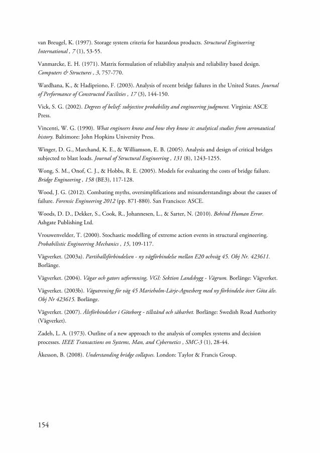
154
van Breugel, K. (1997). Storage system criteria for hazardous products. Structural Engineering International , 7 (1), 53-55.
Vanmarcke, E. H. (1971). Matrix formulation of reliability analysis and reliability based design. Computers & Structures , 3, 757-770.
Wardhana, K., & Hadipriono, F. (2003). Analysis of recent bridge failures in the United States. Journal of Performance of Constructed Facilities , 17 (3), 144-150.
Vick, S. G. (2002). Degrees of belief: subjective probability and engineering judgment. Virginia: ASCE Press.
Vincenti, W. G. (1990). What engineers know and how they know it: analytical studies from aeronautical history. Baltimore: John Hopkins University Press.
Winger, D. G., Marchand, K. E., & Williamson, E. B. (2005). Analysis and design of critical bridges subjected to blast loads. Journal of Structural Engineering , 131 (8), 1243-1255.
Wong, S. M., Onof, C. J., & Hobbs, R. E. (2005). Models for evaluating the costs of bridge failure. Bridge Engineering , 158 (BE3), 117-128.
Wood, J. G. (2012). Combating myths, oversimplifications and misunderstandings about the causes of failure. Forensic Engineering 2012 (pp. 871-880). San Francisco: ASCE.
Woods, D. D., Dekker, S., Cook, R., Johannesen, L., & Sarter, N. (2010). Behind Human Error. Ashgate Publishing Ltd.
Vrouwenvelder, T. (2000). Stochastic modelling of extreme action events in structural engineering. Probabilistic Engineering Mechanics , 15, 109-117.
Vägverket. (2003a). Partihallsförbindelsen - ny vägförbindelse mellan E20 ochväg 45. Obj Nr. 423611. Borlänge.
Vägverket. (2004). Vägar och gators utformning, VGI: Sektion Landsbygg - Vägrum. Borlänge: Vägverket.
Vägverket. (2003b). Vägutrening för väg 45 Marieholm-Lärje-Agnesberg med ny förbindelse över Göta älv. Obj Nr 423615. Borlänge.
Vägverket. (2007). Älvförbindelser i Göteborg - tillstånd och såbarhet. Borlänge: Swedish Road Authority (Vägverket).
Zadeh, L. A. (1973). Outline of a new approach to the analysis of complex systems and decision processes. IEEE Transactions on Systems, Man, and Cybernetics , SMC-3 (1), 28-44.
Åkesson, B. (2008). Understanding bridge collapses. London: Taylor & Francis Group.

155
Appendix A – Marieholm Connection Project Drawings
This appendix contains technical drawings for the proposed conceptual design alternatives considered in the feasibility study for the Marieholm Connection Project.
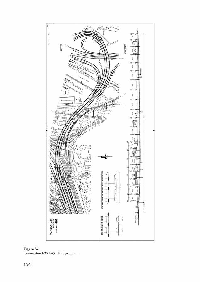
156
Figure A.1 Connection E20-E45 - Bridge option
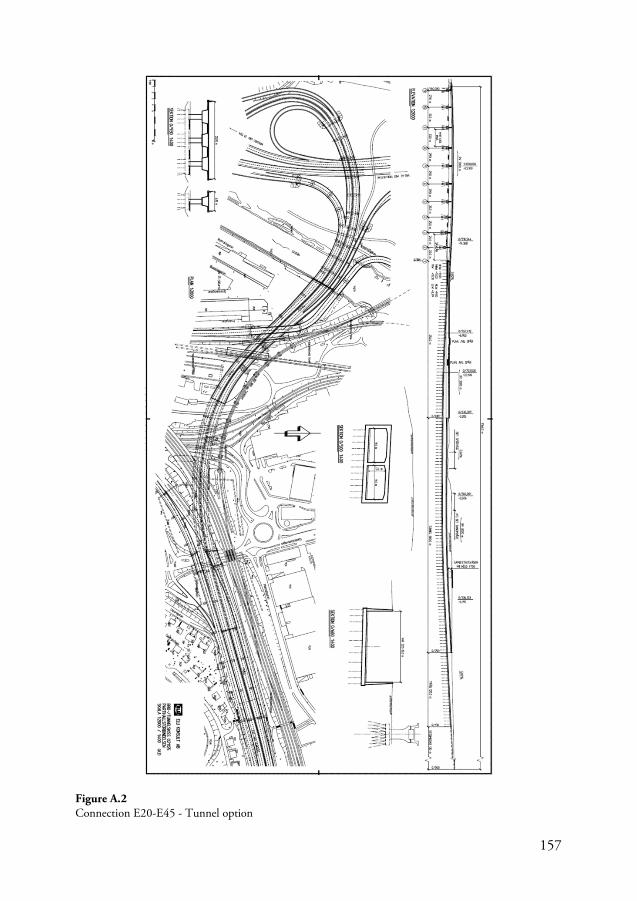
157
Figure A.2 Connection E20-E45 - Tunnel option
158
Figure A.3 Bridge option for Götaälv River crossing
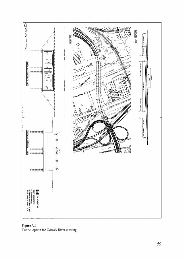
159
Figure A.4 Tunnel option for Götaälv River crossing

160
This page is intentionally left blank
Related Documents