HOERBIGER Engine Solutions ALTRONIC CD200 IGNITION SYSTEM www.altronicinc.com FORM CD200 II 5-07 www.altronicinc.com 1 1.0 DESCRIPTION 1.1 This manual provides installation and operating instructions for the Altronic CD200 ignition system. It is recommended that the user read this manual in its entirety before commencing operations. 1.2 The Altronic CD200 ignition system consists of these basic components: • CD200 Unit - 791070-x or 791080-x (see FIG. 1 and FIG. 2) • Magnetic Pickup Sensor (one per system) • Input Harness (one per system) • Output Harness (one or two per system) • Ignition coils (one per cylinder) 1.3 The system requires a battery or a suitable power supply with a nominal 12 Vdc or 24 Vdc (see FIG. 3). The CD200 unit steps up the DC supply voltage to charge an en- ergy storage capacitor and contains a microproces- sor and solid-state switching devices to release the stored energy to the ignition coils in programmed, timed sequence according to the application. Holes (one per cylinder) in a special timing disc signal the position of the engine crankshaft to the electronic circuitry in the CD200 unit. One additional hole trails after the last cylinder hole; this is the index signal that another revolution has started. Ignition timing may be varied by means of a manual switch, an analog timing signal and/or engine RPM. 1.4 The CD200 system can operate as a single-firing or double-firing (firing on exhaust stroke) system up to twelve (12) cylinders. These instructions detail 4-, 6-, 8-, 10- and 12-cylinder, single-firing ap- plications using CD200 units 791070-6, 791070-8, 791070-12, and 791080-6, 791080-8. 1.5 As shipped from the factory, the CD200 is in the auto-detect mode and is set up for a trigger disc running at camshaft speed (see SEC- TION 9.4). The setup is programmable by the use of the PC compat- ible CD200 terminal program (FIGS. 14 & 15) provided on a CD de- livered with the unit. The programming of the unit is done via the RS-485 Modbus compatible communications port. INSTALLATION INSTRUCTIONS DEVIATION FROM THESE INSTRUCTIONS MAY LEAD TO IMPROPER OPERATION OF THE MACHINE WHICH COULD CAUSE PERSONAL INJURY TO OPERATORS OR OTHER NEARBY PERSONNEL. WARNING: HOERBIGER Engine Solutions

Welcome message from author
This document is posted to help you gain knowledge. Please leave a comment to let me know what you think about it! Share it to your friends and learn new things together.
Transcript
HOERBIGER Engine Solutions
ALTRONIC CD200IGNITION SYSTEM
www.altronicinc.com
FORM CD200 II 5-07
www.altronicinc.com 1
1.0 DESCRIPTION
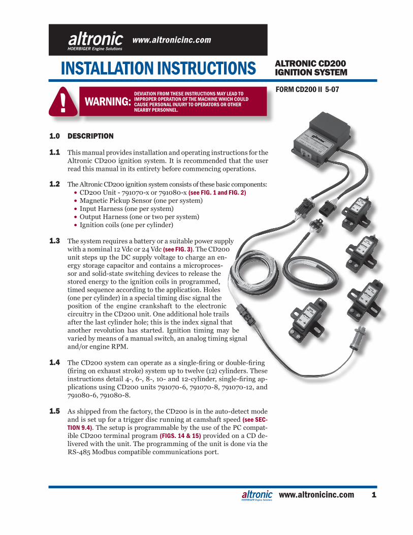
1.1 This manual provides installation and operating instructions for the Altronic CD200 ignition system. It is recommended that the user read this manual in its entirety before commencing operations.
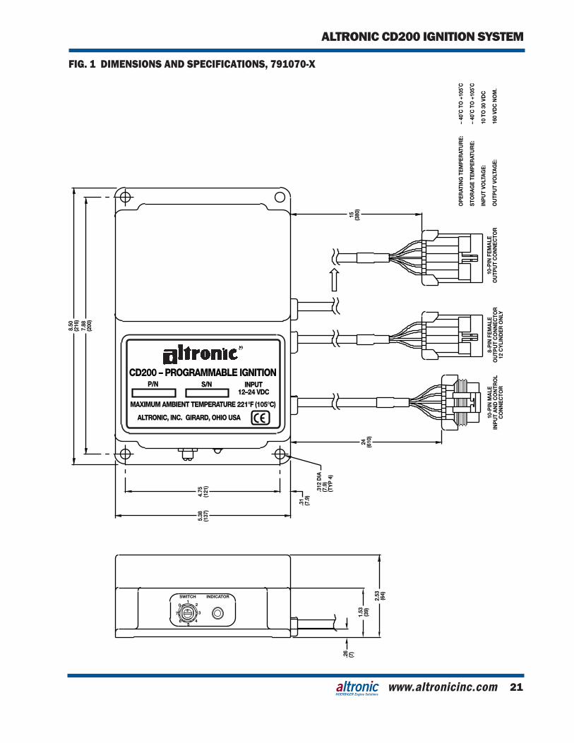
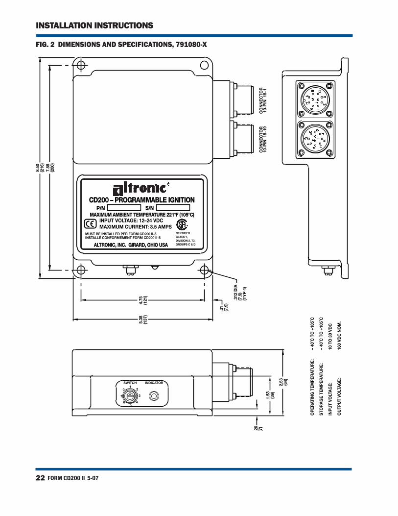
1.2 The Altronic CD200 ignition system consists of these basic components: • CD200 Unit - 791070-x or 791080-x (see FIG. 1 and FIG. 2) • Magnetic Pickup Sensor (one per system) • Input Harness (one per system) • Output Harness (one or two per system) • Ignition coils (one per cylinder)
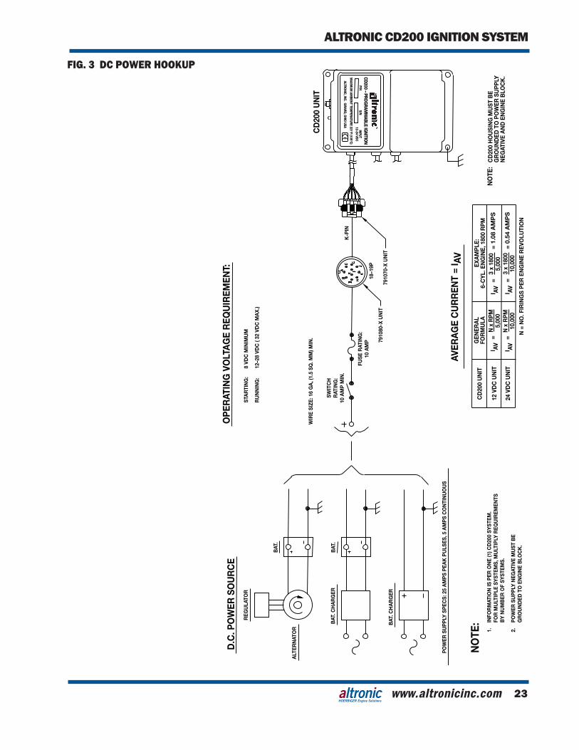
1.3 The system requires a battery or a suitable power supply with a nominal 12 Vdc or 24 Vdc (see FIG. 3). The CD200 unit steps up the DC supply voltage to charge an en-ergy storage capacitor and contains a microproces-sor and solid-state switching devices to release the stored energy to the ignition coils in programmed, timed sequence according to the application. Holes (one per cylinder) in a special timing disc signal the position of the engine crankshaft to the electronic circuitry in the CD200 unit. One additional hole trails after the last cylinder hole; this is the index signal that another revolution has started. Ignition timing may be varied by means of a manual switch, an analog timing signal and/or engine RPM.
1.4 TheCD200systemcanoperateasasingle-firingordouble-firing(firingonexhauststroke)systemuptotwelve(12)cylinders.Theseinstructionsdetail4-,6-,8-,10-and12-cylinder,single-firingap-plications using CD200 units 791070-6, 791070-8, 791070-12, and 791080-6, 791080-8.
1.5 As shipped from the factory, the CD200 is in the auto-detect mode and is set up for a trigger disc running at camshaft speed (see SEC-TION 9.4). The setup is programmable by the use of the PC compat-ible CD200 terminal program (FIGS. 14 & 15) provided on a CD de-livered with the unit. The programming of the unit is done via the RS-485 Modbus compatible communications port.
INSTALLATION INSTRUCTIONSDEVIATION FROM THESE INSTRUCTIONS MAY LEAD TOIMPROPER OPERATION OF THE MACHINE WHICH COULDCAUSE PERSONAL INJURY TO OPERATORS OR OTHERNEARBY PERSONNEL.
WARNING:
HOERBIGER Engine Solutions
FORM CD200 II 5-072
INSTALLATION INSTRUCTIONS
NOTE: If possible, keep the original shipping container.If future transportation or storage of the ignition is necessary, this container will provide the optimum protec-tion.
2.0 CD200 UNIT
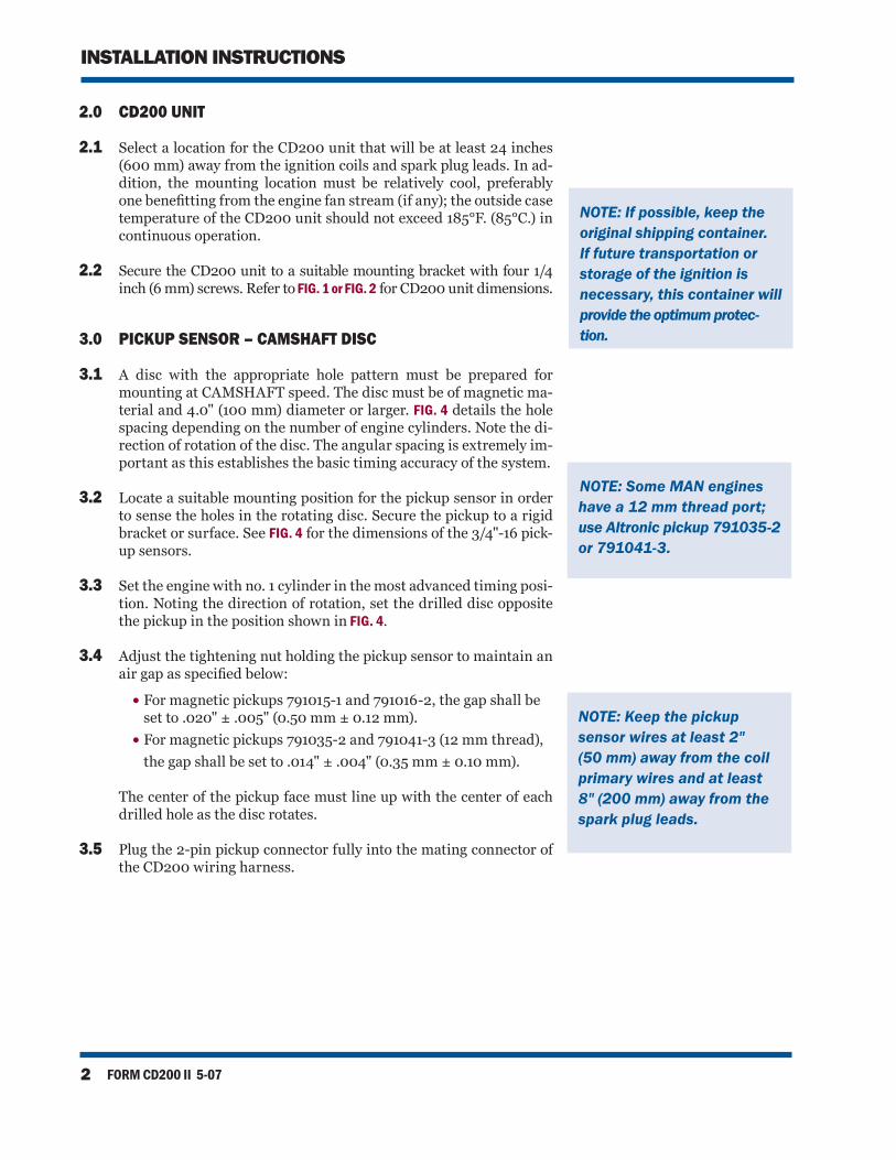
2.1 Select a location for the CD200 unit that will be at least 24 inches (600 mm) away from the ignition coils and spark plug leads. In ad-dition, the mounting location must be relatively cool, preferably onebenefittingfromtheenginefanstream(ifany);theoutsidecasetemperature of the CD200 unit should not exceed 185°F. (85°C.) in continuous operation.
2.2 Secure the CD200 unit to a suitable mounting bracket with four 1/4 inch (6 mm) screws. Refer to FIG. 1 or FIG. 2 for CD200 unit dimensions.
3.0 PICKUP SENSOR – CAMSHAFT DISC
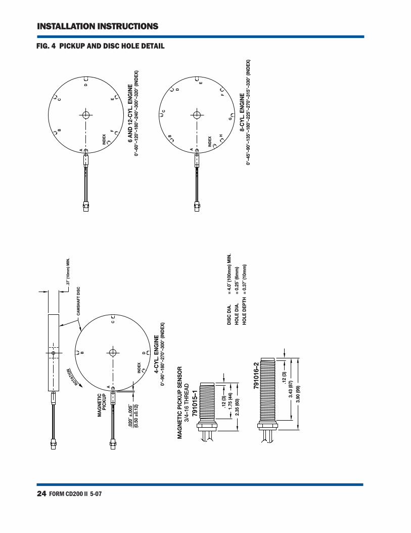
3.1 A disc with the appropriate hole pattern must be prepared for mounting at CAMSHAFT speed. The disc must be of magnetic ma-terial and 4.0" (100 mm) diameter or larger. FIG. 4 details the hole spacing depending on the number of engine cylinders. Note the di-rection of rotation of the disc. The angular spacing is extremely im-portant as this establishes the basic timing accuracy of the system.
3.2 Locate a suitable mounting position for the pickup sensor in order to sense the holes in the rotating disc. Secure the pickup to a rigid bracket or surface. See FIG. 4 for the dimensions of the 3/4"-16 pick-up sensors.
3.3 Set the engine with no. 1 cylinder in the most advanced timing posi-
tion. Noting the direction of rotation, set the drilled disc opposite the pickup in the position shown in FIG. 4.
3.4 Adjust the tightening nut holding the pickup sensor to maintain an airgapasspecifiedbelow:
• For magnetic pickups 791015-1 and 791016-2, the gap shall be set to .020" ± .005" (0.50 mm ± 0.12 mm).
• For magnetic pickups 791035-2 and 791041-3 (12 mm thread), the gap shall be set to .014" ± .004" (0.35 mm ± 0.10 mm).
The center of the pickup face must line up with the center of each drilled hole as the disc rotates.
3.5 Plug the 2-pin pickup connector fully into the mating connector of the CD200 wiring harness.
NOTE: Keep the pickupsensor wires at least 2" (50 mm) away from the coil primary wires and at least 8" (200 mm) away from the spark plug leads.
NOTE: Some MAN engines have a 12 mm thread port; use Altronic pickup 791035-2 or 791041-3.
www.altronicinc.com 3
ALTRONIC CD200 IGNITION SYSTEM
HOERBIGER Engine Solutions
4.0 IGNITION COILS
4.1 USE ONLY THE ALTRONIC COILS INDICATED HERE:
• UNSHIELDED: 501061, 591010, 591040 • FLANGE: 591012, 591018 • SHIELDED: 501061-S, 591010-S • INTEGRAL: 591007, 591011A, 591011B
4.2 Mount the ignition coils as close to the spark plugs as possible keep-ing the high-tension lead length to a minimum but also keeping temperatures below 200°F. (95°C.) during operation.
5.0 PRIMARY WIRING
5.1 The CD200 system requires a battery or other DC power source providing 12-28 Vdc for running and a minimum of 8 volts for en-gine starting. Refer to FIG. 3 for details of the connection to the DC power source.
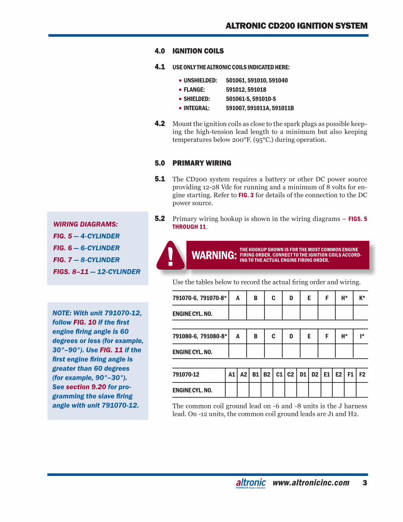
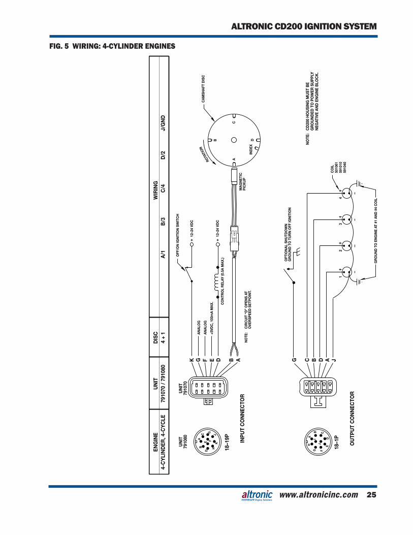
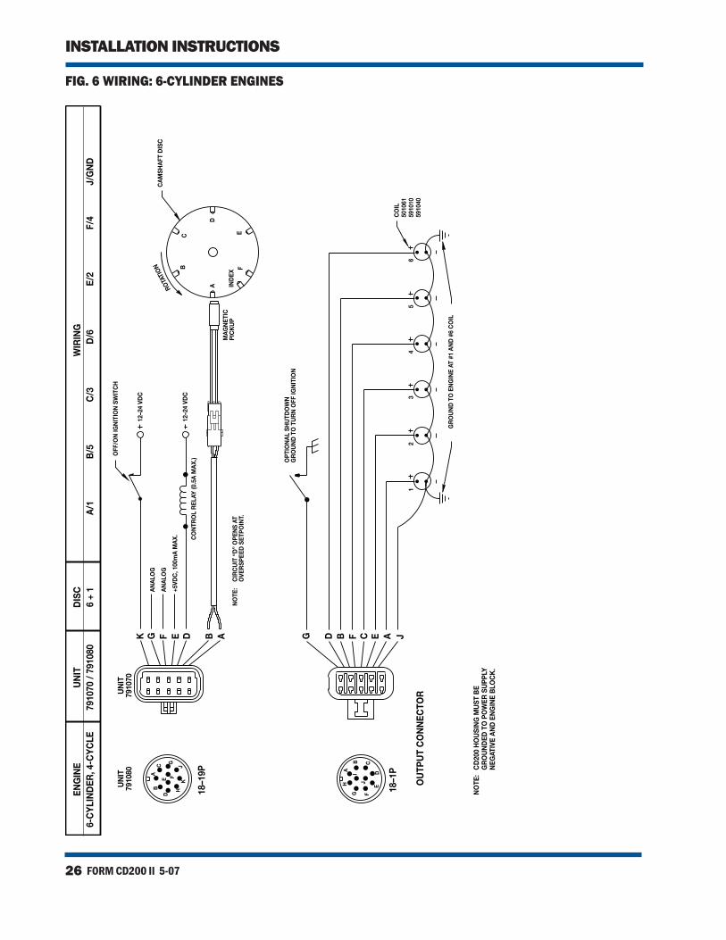
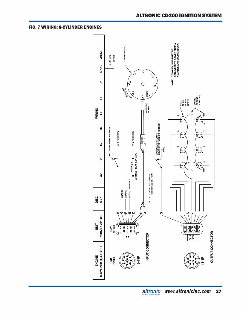
5.2 Primary wiring hookup is shown in the wiring diagrams – FIGS. 5 THROUGH 11.
Usethetablesbelowtorecordtheactualfiringorderandwiring.
791070-6, 791070-8* A B C D E F H* K*
ENGINE CYL. NO.
791080-6, 791080-8* A B C D E F H* I*
ENGINE CYL. NO.
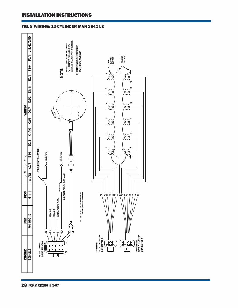
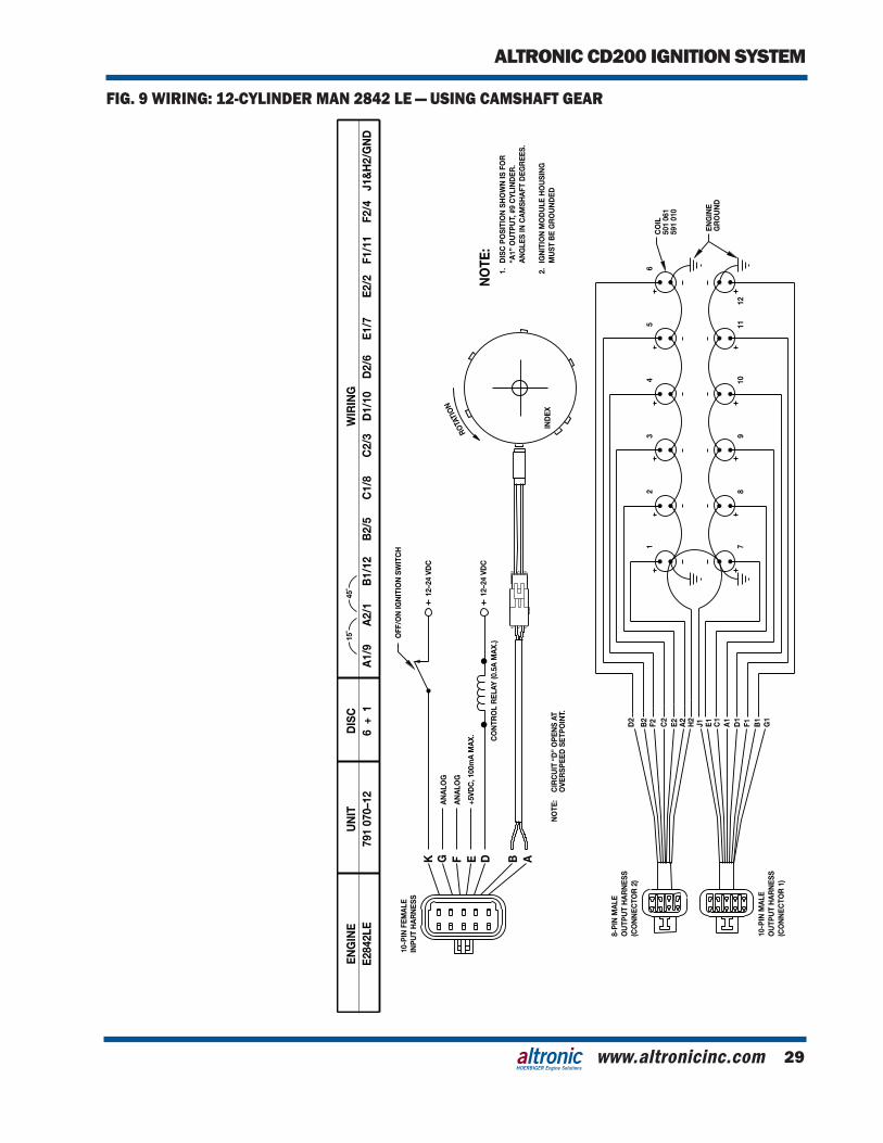
791070-12 A1 A2 B1 B2 C1 C2 D1 D2 E1 E2 F1 F2
ENGINE CYL. NO. The common coil ground lead on -6 and -8 units is the J harness
lead. On -12 units, the common coil ground leads are J1 and H2.
WIRING DIAGRAMS:
FIG. 5 — 4-CYLINDER
FIG. 6 — 6-CYLINDER
FIG. 7 — 8-CYLINDER
FIGS. 8–11 — 12-CYLINDER
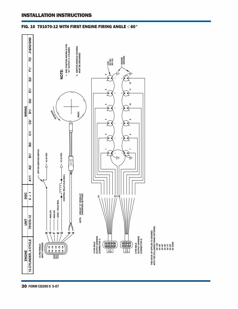
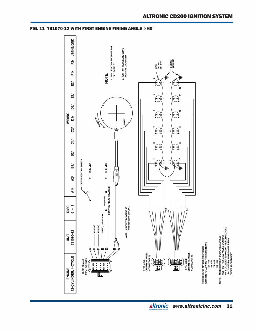
NOTE: With unit 791070-12, follow FIG. 10 if the first engine firing angle is 60 degrees or less (for example, 30°–90°). Use FIG. 11 if the first engine firing angle is greater than 60 degrees(for example, 90°–30°).See section 9.20 for pro-gramming the slave firing angle with unit 791070-12.
THE HOOKUP SHOWN IS FOR THE MOST COMMON ENGINE FIRING ORDER. CONNECT TO THE IGNITION COILS ACCORD-ING TO THE ACTUAL ENGINE FIRING ORDER.WARNING:
FORM CD200 II 5-074
INSTALLATION INSTRUCTIONS
5.3 All connections at unshielded coils should be made using ring-type terminalsspecified for16AWG(1.5sq.mm)wireand#10(5mm)stud size. Terminals should either be soldered to the wire or at-tached with an appropriate staking tool. Protect primary wiring from physical damage, vibration and temperatures in excess of 200°F. (95°C.).
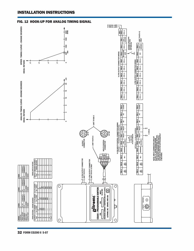
5.4 For details of the hookup for the analog timing signal, see FIG. 12.
5.5 Be sure the multi-pin harness connectors are fully plugged into the mating receptacles connected to the CD200 unit.
6.0 SHUTDOWN WIRING
6.1 The CD200 system is shut-off by interrupting the DC power to the unit; use a switch or relay with contacts rated 24 VDC, 10 amps - refer to FIG. 3.
6.2 TheCD200canalsobeshutdownbyusingtheG-leadoftheoutputharness.To shutdown theunit, connect theG-lead of the outputharness to ground. The CD200 will draw about 0.1 ampere from the power source when shutdown.
7.0 SECONDARY WIRING
7.1 Withunshieldedcoils,sparkplugleadsshouldbefabricatedfrom7 mm, silicone insulated, ignition cable with suitable terminals and silicone spark plug boot.
7.2 Keep spark plug leads as short as possible and at least 2 inches (50 mm)
away from any grounded engine part. In deep spark plug wells, use rigid, insulated extenders projecting out of the well.
7.3 Theuseofaclear,siliconegrease(suchasDowCorningDC-4,G.E.G-623orGCElectronicsZ5)isrecommendedforallhigh-tensionconnections and boots. This material helps seal out moisture and prevent corrosion from atmospheric sources.
NOTE: Keep the primarywiring at least 2" (50 mm) away from the spark plug leads.
NOTE: The use of resistance spark plug cable or individual 5,000 ohm resistors (mount-ed either at the spark plug or coil) is recommended.
NOTE: Do NOT run the input power line through a series of normally closed switches.
NOTE: The CD200 should not be used to power ignition-powered panel instruments.
www.altronicinc.com 5
ALTRONIC CD200 IGNITION SYSTEM
HOERBIGER Engine Solutions
8.0 OPERATION
8.1 IGNITION DELAY: On cranking, there will be a delay of two disc revolutions—after the
power is ON and the engine begins rotating—before the CD200 unit commences outputs to the ignition coils. This delay is to allow iden-tificationofthepick-upindexholetoinsurepropersynchronizationwith the engine. A greater delay of more revolutions to allow for engine purging can be added to the programming. See section 9.9.
8.2 MANUAL TIMING SWITCH: TheCD200unithasaTIMINGswitchlocatedunderawhiteplastic
cap at the end of the case. Using a timing light, set the timing to the desired positionwith the engine running atNORMALOPERAT-INGSPEED.Replacethewhitecapoverthetimingswitchoncetheproper timing is set. Switch position 7 gives the most advanced tim-ing. The timing retards approximately one (1) engine degree for each switch position as the switch is moved to position 6, 5, 4, 3, 2, 1, 0. Switch position 0 is full retard. Larger timing changes per switch position can be programmed. See section 9.14.
8.3 ANALOG TIMING ADJUSTMENT: The CD200 unit provides for analog timing adjustment in two ways:
• 0-1,000ohmpotentiometerconnectedbetweenterminalsE and F of the input harness.
• 4-20mAsignalappliedtoleadsFandGoftheinputharness.
8.4 RPM BASED TIMING CURVE: The CD200 unit is shipped with an RPM-based timing curve (de-
fault programming) providing a 6-degree advance as the engine speed increases from 0 to 600 RPM (FIG. 12). This timing change is in addition to changes made with the manual switch (section 8.2) or the analog timing input (section 8.3).
NOTE: On the first start-up after system installation, verify correct ignition timing by cranking the engine with the fuel supply shut off.
NOTE: DO NOT switch from position 7 to 0, or 0 to 7 while the engine is running. The large timing change may cause the engine to shut-down or be damaged.
NOTE: The analog timing retard is added to the retard established by the manual timing switch (see section 8.2 above and FIG.12).
NOTE: When checked at different speeds, timing will vary in accordance with the programmed RPM curve indicated.
FORM CD200 II 5-076
INSTALLATION INSTRUCTIONS
9.0 CUSTOMIZING THE CD200 UNIT
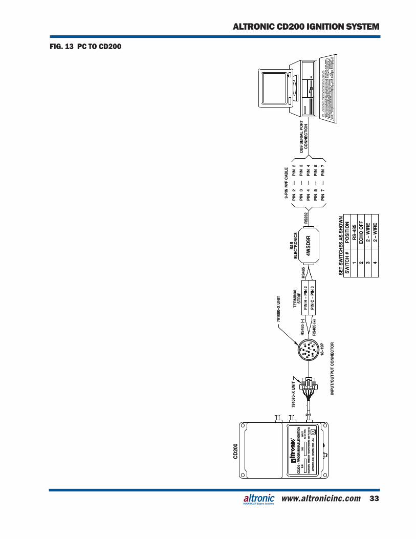
9.1 TERMINAL PROGRAM SETUP: The CD200 is designed to be programmed by a Personal Computer
via the RS-485 Modbus communications link. See FIG. 13 for the proper hookup. The CD200 unit case must be securely grounded prior to programming.
The Terminal Program is included on the CD-ROM supplied with eachCD200unit.ThefirsttimethattheterminalsoftwareisusedonaPC,theCommunicationsPortsettingsmustbeconfiguredinorder to establish communications. After loading the Terminal Pro-gram from the CD-ROM, click on the Connection icon on the upper tool bar. The Connection Setup window will appear. The port being selected for use with the CD200 should also be set for 9600 baud, no parity, 200 ms time out (8 data bits and 1 stop bit). The PC will nowbe set to communicatewith theCD200.Set the ID# for theCD200 to 01.
9.2 PROGRAMMING CUSTOM VALUES: A variety of numeric parameters can be entered by the user for cus-
tomized applications or the unit can be left at the factory default settings. Changes to numeric values are made by placing the cursor intheappropriateboxandtypinginthenewvalue.Whenthenewnumericvalueisfirsttyped,itappearsinredtextonthePCscreen.The values appearing in red have not yet been sent to the CD200 unit, but are being stored on the PC until being sent. Hitting the EnterkeysendstheselectiontotheCD200.Theenteredvalueturnsgreen on the PC display, indicating that the new value has been suc-cessfully communicated to the CD200 and stored.
9.3 SELECTING OPTIONAL FEATURES: Other OFF/ON programming selections are made by activating or de-
activatingabluestatusflagonthePCscreen.Whenthemousepoint-erislocatedoverthestatusflag,adouble-leftclickactivatesthestatusflagandmakesitappeartobe“ON”orglowingonthePCscreen,adouble-rightclickdeactivatesthefeatureandthestatusflag.
9.4 DISC TYPE SETTING: Thisnumericentry configures theDiscType (numberofholesor
protrusions) on the timing disc, excluding the index. This number is normally equal to the number of cylinders on the engine for a cam-shaft mounted disc and ½ the number of cylinders of the engine for a crankshaft mounted disc. This value is used to test for the correct disc and scales the rpm measurement and ignition timing angles to thespecificdiscchosen.Defaultsetting=(0+1).
Entering a value of Zero (0+1), places the ignition in auto detect
mode. In auto detect mode, the ignition will automatically scale rpm measurement and ignition timing angles to the disc pattern observed.
NOTE: In order to program the values, the CD200 must be powered. Care should be tak-en in changing entries when the engine is operational to avoid unstable or dangerous operating conditions.
NOTE: Refer to sections 9.19 and 9.20 for additional pro-gramming of unit 791070-12.
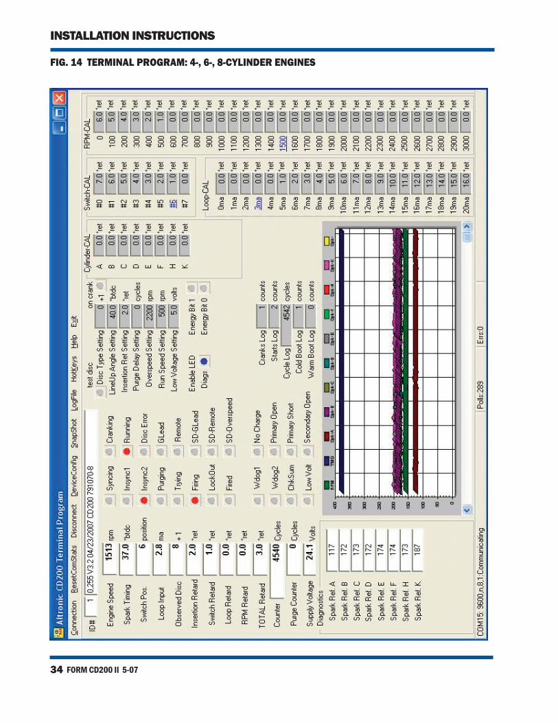
TERMINAL PROGRAM SCREENS:
FIG. 14 — 7910X0-6, -8
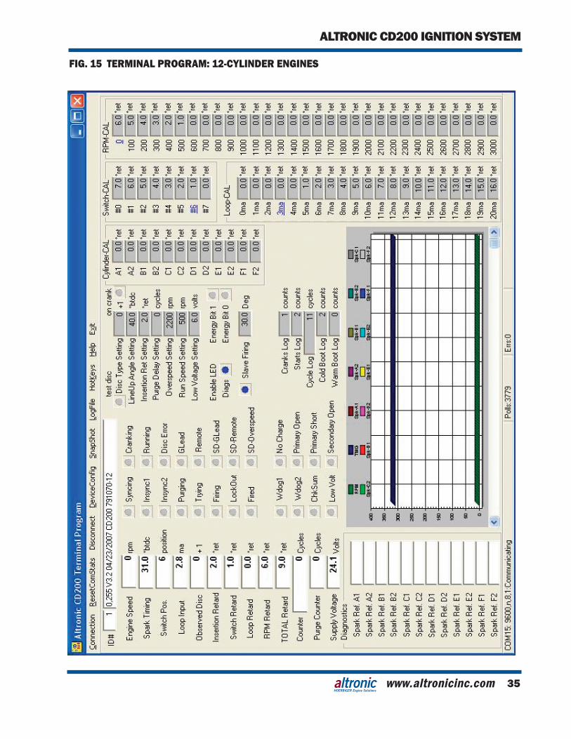
FIG. 15 — 791070-12
www.altronicinc.com 7
ALTRONIC CD200 IGNITION SYSTEM
HOERBIGER Engine Solutions
9.5 TEST DISC FLAG: WhenthisstatusflagisON,theCD200willtestforamatchofthein-
coming signal pattern observed by the CD200 to the Disc Type speci-fied.Whenenabled,thistest isperformedaftersynchronizationtothediscpatternandbeforeinitiatingfirings.Whenthepatterndoesnotmatch the setting, the ignitionwillnotfire and thediagnosticLEDon theunitwill signal the errorby turningoff until rotationstops.Oncetheignitionisfiring,thediscpatternwillbemonitoredcontinuouslyand,ifanerrorisdetected,theunitwillstopfiringandthe alarm output switch will open. Firings will be inhibited and the output switch will remain off for 5 seconds after input signals cease.
Iftheshutdownleadisgroundedaftertheunitisfiring,thefiringswill stop, the output switch will open and remain open for 5 seconds after rotation stops.
ThediagnosticLEDontheunitwillturnoffuntilrotationstops.Af-ter rotation stops it will blink the appropriate signal, see section 11.2. Defaultsetting=OFF.
9.6 ON CRANK FLAG: WhenthisstatusflagisON,theignitionscalesrpmmeasurement
and timing angles for a signal pattern coming from a crankshaft-mounteddisc.WhenthisstatusflagisOFF,theignitionscalesrpmmeasurement and timing angles for a signal pattern from a cam-shaftmounteddisc.Defaultsetting=OFF.
9.7 LINE UP ANGLE: This numeric entry has no impact on actual engine timing and is
only used as a reference to calculate the spark timing number for displayintheTerminalSoftware.Whenthepickupisalignedwiththefirstholeorprotrusiononthetimingdisc,theLineUpAngleisthe angular position of the crankshaft with respect to TDC of the firstcylinderinthefiringorder.Entryrangeis0to100enginede-greesBTDC.Thisvaluewillneedtobefine-tunedtoprovideanac-curatedisplayoftiming.Defaultsetting=40.0degreesBTDC.
9.8 INSERTION RETARD SETTING: Thisnumericentryconfigurestheminimuminternalelectronicin-
putsignaldelay.Entryrangeis2.0to25.5degreesofengineretard.Defaultsetting=2.0degrees.
9.9 PURGE DELAY SETTING: Thisnumericentryconfiguresthenumberofdiscrotations(engine
cycles) following successful synchronization to delay before ignition outputsbegin.Entryrangeis0to255cycles.Defaultsetting=0.
9.10 OVERSPEED SETTING: Thisnumericentryconfigurestheenginerpmatwhichtheignition
willstopfiringoutputsduetoanoverspeedcondition.Theoverspeedconditionalsoturnsoffthealarmoutputswitch.Whenrotationhasfullystopped,theLEDontheCD200unitwillblinktheappropriatecode and the alarm output switch is restored to normal (closed). De-faultsetting=2200RPM.
NOTE: The disc test for a specific number of pulses is not performed in auto detec-tion mode (0 entry for Disc Type Setting – section 9.4).
FORM CD200 II 5-078
INSTALLATION INSTRUCTIONS
9.11 RUN SPEED SETTING: Thisnumericentryconfiguresthetransitionspeedfromcranktorun.
ThissettingalsodeterminesthetransitionofthediagnosticLEDontheCD200fromcranktorunmodes.Defaultsetting=500RPM.
9.12 LOW VOLTAGE SETTING: Thisnumericentryconfiguresthethresholdforthelowvoltagedi-
agnostic of the DC input voltage to the CD200. If the DC voltage de-creasestothissetting,thediagnosticLEDontheCD200willblinktheappropriatecode.TheCD200willcontinuetotrytofireoutputsregardlessofthevoltage.Defaultsetting=6volts.
9.13 ENABLE LED DIAGNOSTICS FLAG: WhenthisLEDstatusflagisactivated,theblinkcodediagnosticsfor
primary and secondary outputs are enabled. Default setting is ON.
9.14 SWITCH CAL: Thesenumericentriesconfigurethetimingretardforeachposition
ofthemanualtimingswitchontheCD200case.Entryrangeis0to25.5 degrees of engine retard. The active entry is indicated in blue. Default setting is 7-6-5-4-3-2-1. If two degrees change per switch position is desired, enter 14-12-10-8-6-4-2.
9.15 LOOP CAL: Thesenumericentriesconfigurethe interpolated lookuptable for
the ignition retard versus the analog current loop input signal. This allows the operator to create custom spark timing maps versus the currentloopinputsignal.Entryrangeis0to25.5degreesofengineretard. The active entries are indicated in blue. Default sequence is 0 degrees retard at 4 mA, 16 degrees retard at 20 mA.
9.16 RPM CAL: Thesenumericentriesconfigurethe interpolated lookuptable for
retard versus the engine speed. This allows the operator to create customsparktimingmapsversusenginerpm.Entryrangeis0to25.5 degrees of engine retard. The active entries are indicated in blue. Default sequence is 6 degrees retard at 0 RPM, decreasing to 0 degrees retard at 600 RPM.
9.17 CYLINDER CAL: These numeric entries configure the amount of individual offset
timing retard added to the global timing for each individual output. This feature can be used to map an evenly spaced timing disc to an oddfiringangleenginepattern.Entryrangeis0to50degreesofengine retard. Default settings are 0. Contact the factory for further details of this feature.
www.altronicinc.com 9
ALTRONIC CD200 IGNITION SYSTEM
HOERBIGER Engine Solutions
9.18 ENERGY FLAGS: Select one of four output energy settings for the CD200:
Bit 1 OFF Bit 0 OFF Vcap = 150 volts Bit 1 OFF Bit 0 ON Vcap = 160 volts Bit 1 ON Bit 0 OFF Vcap = 170 volts Bit 1 ON Bit 0 ON Vcap = 180 volts
Default setting is 160 volts at the capacitor. This voltage can only be measured using a device with an input impedance of 1 megaohm or higher with no other device connected.
9.19 UNIT 791070-12 – ENABLE SLAVE FIRING FLAG: WhenthisLEDstatusflagisactivated,theignitionwillgeneratea
secondslavefiringforeach(x+1)referencepulse.Fora(6+1)discpattern,theignitionwillfire12outputswhenthisflagisactivated,and6outputswhenthisflagisnotactivated.Modificationofthisflag through the Terminal Program requires that the engine bestoppedandtheG-leadbegrounded.
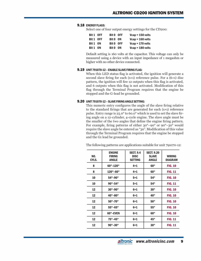
9.20 UNIT 791070-12 – SLAVE FIRING ANGLE SETTING: Thisnumericentryconfigurestheangleoftheslavefiringrelative
tothestandardfiringsthataregeneratedforeach(x+1)referencepulse.Entryrangeis25.0°to60.0°whichisusedtosettheslavefir-ing angle on a 12-cylinder, 4-cycle engine. The slave angle must be thesmallerofthetwoanglesthatdefinetheenginefiringpattern.For example,firingpatternsof either30°–90°or90°–30°wouldrequiretheslaveanglebeenteredas“30”.Modificationofthisvaluethrough the Terminal Program requires that the engine be stopped andtheG1leadbegrounded.
The following patterns are applications suitable for unit 791070-12:
ENGINE SECT. 9.4 SECT. 9.20 NO. FIRING DISC SLAVE WIRING CYLS. ANGLE SETTING ANGLE DIAGRAM
8 60°–120° 4+1 60° FIG. 10
8 120°–60° 4+1 60° FIG. 11
10 54°–90° 5+1 54° FIG. 10
10 90°–54° 5+1 54° FIG. 11
12 30°–90° 6+1 30° FIG. 10
12 40°–80° 6+1 40° FIG. 10
12 50°–70° 6+1 50° FIG. 10
12 55°–65° 6+1 55° FIG. 10
12 60°–EVEN 6+1 60° FIG. 10
12 75°–45° 6+1 45° FIG. 11
12 90°–30° 6+1 30° FIG. 11
FORM CD200 II 5-0710
INSTALLATION INSTRUCTIONS
10.0 PC TERMINAL DISPLAY FUNCTIONS
10.1 ENGINE SPEED: Indicates current speed of the engine in RPM based on disc signal.
10.2 SPARK TIMING: Indicates the global spark timing of the engine in degrees before
TDC.ThisnumberistheLINEUPANGLEsettinglesstheTOTALRETARD.Slightdifferencesbetweenthisnumberandthe timingreadingobtainedwithatiminglightmayoccursincetheLINEUPANGLEenteredmaydifferslightlyfromtheactualangularpositionof the engine when the input pulse event is received by the CD200. In this event, the Spark Timing number should be made to agree withthetiminglightbychangingtheLINEUPANGLEentry.
10.3 SWITCH POSITION: Indicates the current position of the manual timing switch on the
CD200 case.
10.4 LOOP INPUT: Indicates the value of the external input current loop.
10.5 OBSERVED DISC: Indicates the number of input events (timing holes or protrusions)
being recognized by the CD200 unit on the timing disc input signal at this time.
10.6 INSERTION RETARD: Indicates the amount of electronic insertion retard at this time.
10.7 SWITCH RETARD: Indicates the amount of timing retard being added by the current
timing switch position at this time.
10.8 LOOP RETARD: Indicates the actual amount of timing retard added from the cur-
rent loop versus retard lookup table curve at this time.
10.9 RPM RETARD: Indicates the actual amount of timing retard being added by the
RPM versus retard lookup table curve at this time.
10.10 TOTAL RETARD: Indicates the total global timing retard at this time. This number is
the sum of the Insertion Retard, Switch Retard, Loop Retard and RPM Retard.
10.11 COUNTER: Indicates the number of disc rotations (engine cycles) registered
since the engine was last started.
www.altronicinc.com 11
ALTRONIC CD200 IGNITION SYSTEM
HOERBIGER Engine Solutions
10.12 PURGE COUNTER: During a startup, indicates the number of purge cycles remaining
before the outputs are activated.
10.13 SUPPLY VOLTAGE: Indicates the measured DC voltage supply level to the CD200.
10.14 SPARK REF. (A, B, C, ETC.): Indicates the current spark reference number for each cylinder.
10.15 SYNCING: Whenred,indicatesthatenginerotationhasbeensensedandthe
synchronization process is taking place.
10.16 INSYNC1: Whenred,indicatesthattheindexinputhasbeenrecognizedonce.
10.17 INSYNC2: Whenred, indicates that the indexhasbeenrecognizedasecond
time and the ignition is ready to proceed.
10.18 PURGING: Whenred,indicatesthatsynchronizationhasbeencompletedand
the purge cycle countdown is taking place.
10.19 TRYING: Whenred,indicatesthattheCD200istryingtofireoutputs,buta
proper primary discharge event has not yet occurred.
10.20 FIRING: Whenred,indicatesthatCD200issuccessfullyfiringprimaryoutputs.
10.21 LOCKOUT: Whenred,indicatesthatfiringsarelockedoutuntilenginerotation
has ceased for a minimum of 5 seconds.
10.22 CRANKING: Whenred,indicatesenginerotationbelowtheRunSpeedsetting.
10.23 RUNNING: Whenred,indicatesenginerotationabovetheRunSpeedsetting.
10.24 DISC ERROR: Whenred,indicatesthattheTestDiscstatusflagisactivatedand
thetimingdiscpatternbeingsenseddidnotmatchtheDISCTYPEselected.
10.25 G-LEAD: Whenred,indicatesthattheG-leadisgrounded.
10.26 REMOTE: Whenred,indicatesaremoteserialshutdowncommandisactive.
FORM CD200 II 5-0712
INSTALLATION INSTRUCTIONS
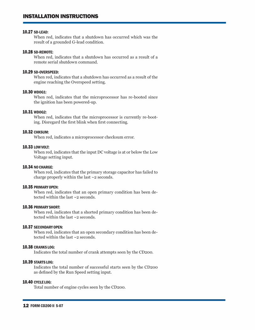
10.27 SD-LEAD: Whenred, indicatesthatashutdownhasoccurredwhichwasthe
resultofagroundedG-leadcondition.
10.28 SD-REMOTE: Whenred,indicatesthatashutdownhasoccurredasaresultofa
remote serial shutdown command.
10.29 SD-OVERSPEED: Whenred,indicatesthatashutdownhasoccurredasaresultofthe
engine reaching the Overspeed setting.
10.30 WDOG1: When red, indicates that themicroprocessor has re-booted since
the ignition has been powered-up.
10.31 WDOG2: Whenred, indicatesthatthemicroprocessor iscurrentlyre-boot-
ing.Disregardthefirstblinkwhenfirstconnecting.
10.32 CHKSUM: Whenred,indicatesamicroprocessorchecksumerror.
10.33 LOW VOLT: Whenred,indicatesthattheinputDCvoltageisatorbelowtheLow
Voltage setting input.
10.34 NO CHARGE: Whenred,indicatesthattheprimarystoragecapacitorhasfailedto
charge properly within the last ~2 seconds.
10.35 PRIMARY OPEN: Whenred,indicatesthatanopenprimaryconditionhasbeende-
tected within the last ~2 seconds.
10.36 PRIMARY SHORT: Whenred,indicatesthatashortedprimaryconditionhasbeende-
tected within the last ~2 seconds.
10.37 SECONDARY OPEN: Whenred,indicatesthatanopensecondaryconditionhasbeende-
tected within the last ~2 seconds.
10.38 CRANKS LOG: Indicates the total number of crank attempts seen by the CD200.
10.39 STARTS LOG: Indicates the total number of successful starts seen by the CD200
asdefinedbytheRunSpeedsettinginput.
10.40 CYCLE LOG: Total number of engine cycles seen by the CD200.
www.altronicinc.com 13
ALTRONIC CD200 IGNITION SYSTEM
HOERBIGER Engine Solutions
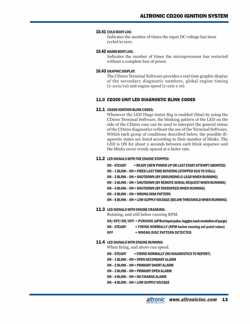
10.41 COLD BOOT LOG: Indicates the number of times the input DC voltage has been
cycled to zero.
10.42 WARM BOOT LOG: Indicates the number of times the microprocessor has restarted
without a complete loss of power.
10.43 GRAPHIC DISPLAY: The CD200 Terminal Software provides a real time graphic display
of the secondary diagnostic numbers, global engine timing (y-axis/10) and engine speed (y-axis x 10).
11.0 CD200 UNIT LED DIAGNOSTIC BLINK CODES
11.1 CD200 IGNITION BLINK CODES: WhenevertheLEDDiagsstatusflagisenabled(blue)byusingthe
CD200TerminalSoftware,theblinkingpatternoftheLEDontheside of the CD200 case can be used to interpret the general status of the CD200 diagnostics without the use of the Terminal Software. Withineachgroupofconditionsdescribedbelow,thepossibledi-agnostic states are listed according to their number of blinks. The LEDisONforabout2secondsbetweeneachblinksequenceandthe blinks occur evenly spaced at a faster rate.
11.2 LED SIGNALS WITH THE ENGINE STOPPED: ON – STEADY = READY (NEW POWER UP OR LAST START ATTEMPT ABORTED) ON – 1 BLINK – ON = FIRED LAST TIME ROTATING (STOPPED DUE TO STALL) ON – 2 BLINK – ON = SHUTDOWN (BY GROUNDING G-LEAD WHEN RUNNING) ON – 3 BLINK – ON = SHUTDOWN (BY REMOTE SERIAL REQUEST WHEN RUNNING) ON – 4 BLINK – ON = SHUTDOWN (BY OVERSPEED WHEN RUNNING) ON – 5 BLINK – ON = WRONG DISK PATTERN ON – 6 BLINK – ON = LOW SUPPLY VOLTAGE (BELOW THRESHOLD WHEN RUNNING)
11.3 LED SIGNALS WITH ENGINE CRANKING: Rotating, and still below running RPM.
ON/OFF/ON/OFF = PURGING (off first input pulse, toggles each revolution of purge) ON – STEADY = FIRING NORMALLY (RPM below running set point value) OFF = WRONG DISC PATTERN DETECTED
11.4 LED SIGNALS WITH ENGINE RUNNING: Whenfiring,andaboverunspeed.
ON – STEADY = FIRING NORMALLY (NO DIAGNOSTICS TO REPORT) ON – 1 BLINK – ON = OPEN SECONDARY ALARM ON – 2 BLINK – ON = PRIMARY SHORT ALARM ON – 3 BLINK – ON = PRIMARY OPEN ALARM ON – 4 BLINK – ON = NO CHARGE ALARM ON – 6 BLINK – ON = LOW SUPPLY VOLTAGE
FORM CD200 II 5-0714
INSTALLATION INSTRUCTIONS
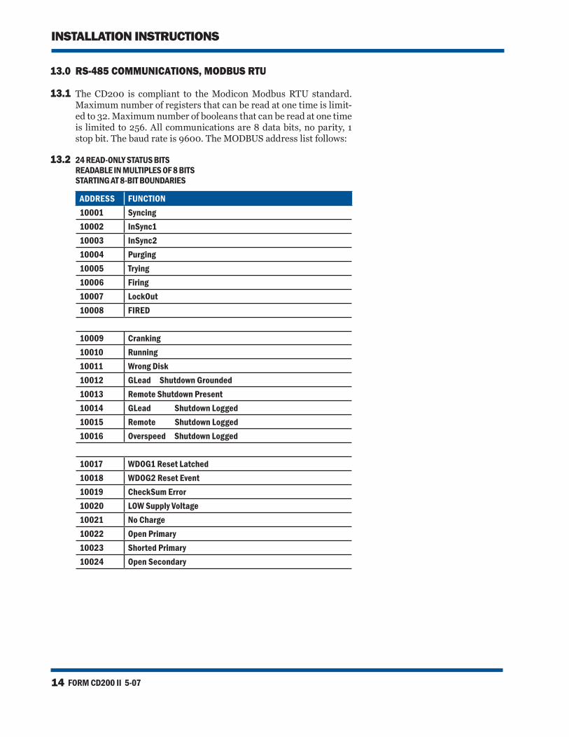
13.0 RS-485 COMMUNICATIONS, MODBUS RTU
13.1 The CD200 is compliant to the Modicon Modbus RTU standard. Maximum number of registers that can be read at one time is limit-ed to 32. Maximum number of booleans that can be read at one time is limited to 256. All communications are 8 data bits, no parity, 1 stop bit. The baud rate is 9600. The MODBUS address list follows:
13.2 24 READ-ONLY STATUS BITS READABLE IN MULTIPLES OF 8 BITS STARTING AT 8-BIT BOUNDARIES
ADDRESS FUNCTION10001 Syncing10002 InSync110003 InSync210004 Purging10005 Trying10006 Firing10007 LockOut10008 FIRED
10009 Cranking10010 Running10011 Wrong Disk10012 GLead Shutdown Grounded10013 Remote Shutdown Present10014 GLead Shutdown Logged10015 Remote Shutdown Logged10016 Overspeed Shutdown Logged
10017 WDOG1 Reset Latched10018 WDOG2 Reset Event10019 CheckSum Error10020 LOW Supply Voltage10021 No Charge10022 Open Primary10023 Shorted Primary10024 Open Secondary
www.altronicinc.com 15
ALTRONIC CD200 IGNITION SYSTEM
HOERBIGER Engine Solutions
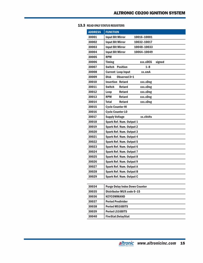
13.3 READ ONLY STATUS REGISTERS
ADDRESS FUNCTION30001 Input Bit Mirror 10016–1000130002 Input Bit Mirror 10032–1001730003 Input Bit Mirror 10048–1003330004 Input Bit Mirror 10064–1004930005 RPM 30006 Timing xxx.xDEG signed30007 Switch Position 1–830008 Current Loop Input xx.xmA30009 Disk Observed X+130010 Insertion Retard xxx.xDeg30011 Switch Retard xxx.xDeg30012 Loop Retard xxx.xDeg30013 RPM Retard xxx.xDeg30014 Total Retard xxx.xDeg30015 Cycle Counter HI30016 Cycle Counter LO30017 Supply Voltage xx.xVolts30018 Spark Ref. Num. Output 130019 Spark Ref. Num. Output 230020 Spark Ref. Num. Output 330021 Spark Ref. Num. Output 430022 Spark Ref. Num. Output 530023 Spark Ref. Num. Output 630024 Spark Ref. Num. Output 730025 Spark Ref. Num. Output 830026 Spark Ref. Num. Output 930027 Spark Ref. Num. Output A30028 Spark Ref. Num. Output B30029 Spark Ref. Num. Output C
30034 Purge Delay Index Down Counter30035 Distributor MUX code 0–1530036 KEYCOMMAND30037 Period Predivider30038 Period MS16BITS30039 Period LS16BITS30040 FireStat:DelayStat
FORM CD200 II 5-0716
INSTALLATION INSTRUCTIONS
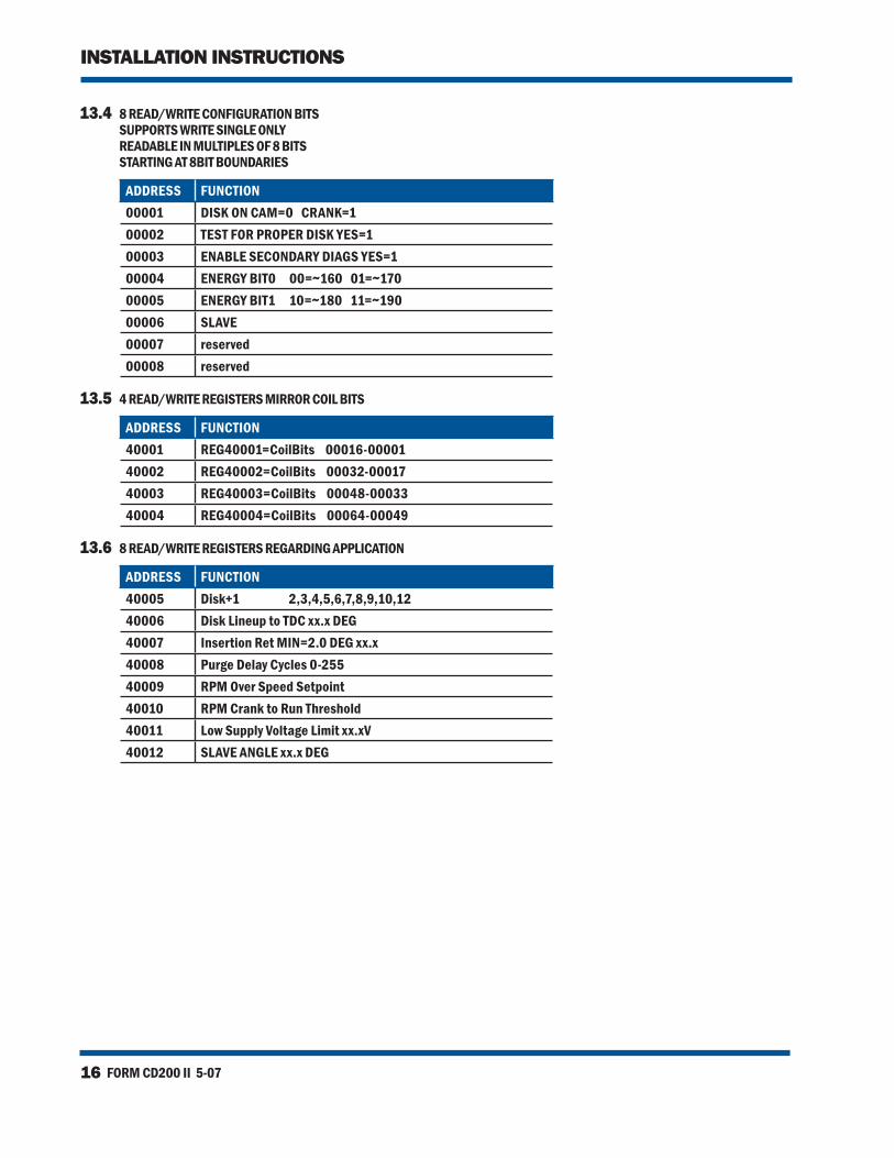
13.4 8 READ/WRITE CONFIGURATION BITS SUPPORTS WRITE SINGLE ONLY READABLE IN MULTIPLES OF 8 BITS STARTING AT 8BIT BOUNDARIES
ADDRESS FUNCTION00001 DISK ON CAM=0 CRANK=100002 TEST FOR PROPER DISK YES=100003 ENABLE SECONDARY DIAGS YES=100004 ENERGY BIT0 00=~160 01=~17000005 ENERGY BIT1 10=~180 11=~19000006 SLAVE00007 reserved00008 reserved
13.5 4 READ/WRITE REGISTERS MIRROR COIL BITS
ADDRESS FUNCTION40001 REG40001=CoilBits 00016-0000140002 REG40002=CoilBits 00032-0001740003 REG40003=CoilBits 00048-0003340004 REG40004=CoilBits 00064-00049
13.6 8 READ/WRITE REGISTERS REGARDING APPLICATION
ADDRESS FUNCTION40005 Disk+1 2,3,4,5,6,7,8,9,10,1240006 Disk Lineup to TDC xx.x DEG40007 Insertion Ret MIN=2.0 DEG xx.x40008 Purge Delay Cycles 0-25540009 RPM Over Speed Setpoint40010 RPM Crank to Run Threshold40011 Low Supply Voltage Limit xx.xV40012 SLAVE ANGLE xx.x DEG
www.altronicinc.com 17
ALTRONIC CD200 IGNITION SYSTEM
HOERBIGER Engine Solutions
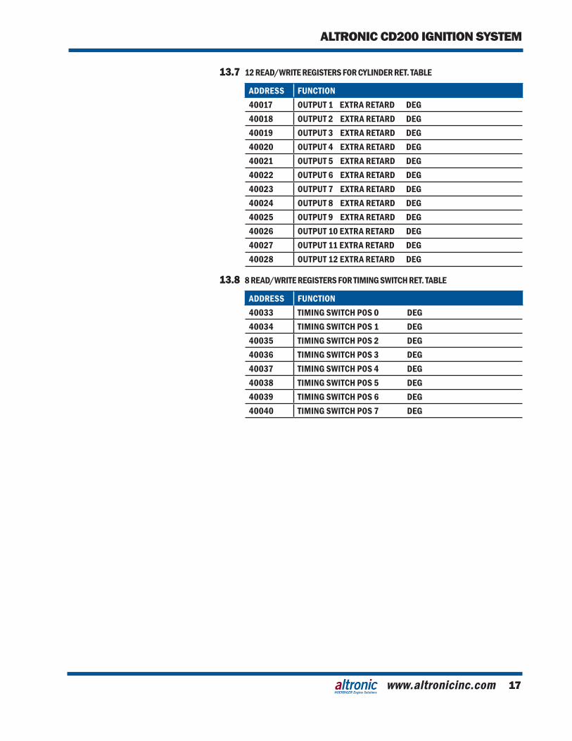
13.7 12 READ/WRITE REGISTERS FOR CYLINDER RET. TABLE
ADDRESS FUNCTION40017 OUTPUT 1 EXTRA RETARD DEG40018 OUTPUT 2 EXTRA RETARD DEG40019 OUTPUT 3 EXTRA RETARD DEG40020 OUTPUT 4 EXTRA RETARD DEG40021 OUTPUT 5 EXTRA RETARD DEG40022 OUTPUT 6 EXTRA RETARD DEG40023 OUTPUT 7 EXTRA RETARD DEG40024 OUTPUT 8 EXTRA RETARD DEG40025 OUTPUT 9 EXTRA RETARD DEG40026 OUTPUT 10 EXTRA RETARD DEG40027 OUTPUT 11 EXTRA RETARD DEG40028 OUTPUT 12 EXTRA RETARD DEG
13.8 8 READ/WRITE REGISTERS FOR TIMING SWITCH RET. TABLE
ADDRESS FUNCTION40033 TIMING SWITCH POS 0 DEG40034 TIMING SWITCH POS 1 DEG40035 TIMING SWITCH POS 2 DEG40036 TIMING SWITCH POS 3 DEG40037 TIMING SWITCH POS 4 DEG40038 TIMING SWITCH POS 5 DEG40039 TIMING SWITCH POS 6 DEG40040 TIMING SWITCH POS 7 DEG
FORM CD200 II 5-0718
INSTALLATION INSTRUCTIONS
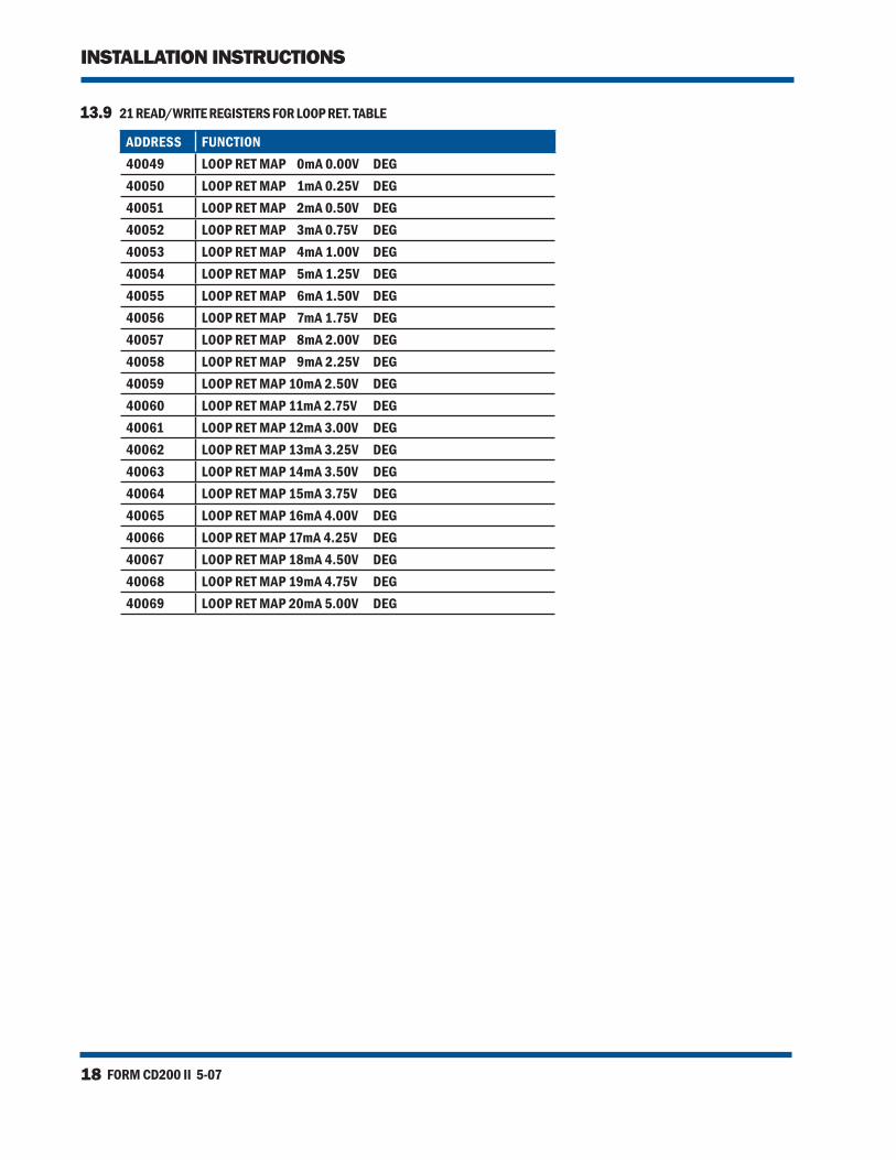
13.9 21 READ/WRITE REGISTERS FOR LOOP RET. TABLE
ADDRESS FUNCTION40049 LOOP RET MAP 0mA 0.00V DEG40050 LOOP RET MAP 1mA 0.25V DEG40051 LOOP RET MAP 2mA 0.50V DEG40052 LOOP RET MAP 3mA 0.75V DEG40053 LOOP RET MAP 4mA 1.00V DEG40054 LOOP RET MAP 5mA 1.25V DEG40055 LOOP RET MAP 6mA 1.50V DEG40056 LOOP RET MAP 7mA 1.75V DEG40057 LOOP RET MAP 8mA 2.00V DEG40058 LOOP RET MAP 9mA 2.25V DEG40059 LOOP RET MAP 10mA 2.50V DEG40060 LOOP RET MAP 11mA 2.75V DEG40061 LOOP RET MAP 12mA 3.00V DEG40062 LOOP RET MAP 13mA 3.25V DEG40063 LOOP RET MAP 14mA 3.50V DEG40064 LOOP RET MAP 15mA 3.75V DEG40065 LOOP RET MAP 16mA 4.00V DEG40066 LOOP RET MAP 17mA 4.25V DEG40067 LOOP RET MAP 18mA 4.50V DEG40068 LOOP RET MAP 19mA 4.75V DEG40069 LOOP RET MAP 20mA 5.00V DEG
www.altronicinc.com 19
ALTRONIC CD200 IGNITION SYSTEM
HOERBIGER Engine Solutions
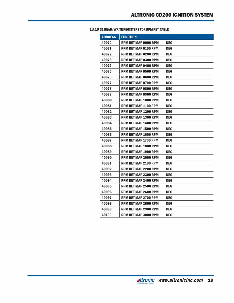
13.10 31 READ/WRITE REGISTERS FOR RPM RET. TABLE
ADDRESS FUNCTION40070 RPM RET MAP 0000 RPM DEG40071 RPM RET MAP 0100 RPM DEG40072 RPM RET MAP 0200 RPM DEG40073 RPM RET MAP 0300 RPM DEG40074 RPM RET MAP 0400 RPM DEG40075 RPM RET MAP 0500 RPM DEG40076 RPM RET MAP 0600 RPM DEG40077 RPM RET MAP 0700 RPM DEG40078 RPM RET MAP 0800 RPM DEG40079 RPM RET MAP 0900 RPM DEG40080 RPM RET MAP 1000 RPM DEG40081 RPM RET MAP 1100 RPM DEG40082 RPM RET MAP 1200 RPM DEG40083 RPM RET MAP 1300 RPM DEG40084 RPM RET MAP 1400 RPM DEG40085 RPM RET MAP 1500 RPM DEG40086 RPM RET MAP 1600 RPM DEG40087 RPM RET MAP 1700 RPM DEG40088 RPM RET MAP 1800 RPM DEG40089 RPM RET MAP 1900 RPM DEG40090 RPM RET MAP 2000 RPM DEG40091 RPM RET MAP 2100 RPM DEG40092 RPM RET MAP 2200 RPM DEG40093 RPM RET MAP 2300 RPM DEG40094 RPM RET MAP 2400 RPM DEG40095 RPM RET MAP 2500 RPM DEG40096 RPM RET MAP 2600 RPM DEG40097 RPM RET MAP 2700 RPM DEG40098 RPM RET MAP 2800 RPM DEG40099 RPM RET MAP 2900 RPM DEG40100 RPM RET MAP 3000 RPM DEG
FORM CD200 II 5-0720
INSTALLATION INSTRUCTIONS
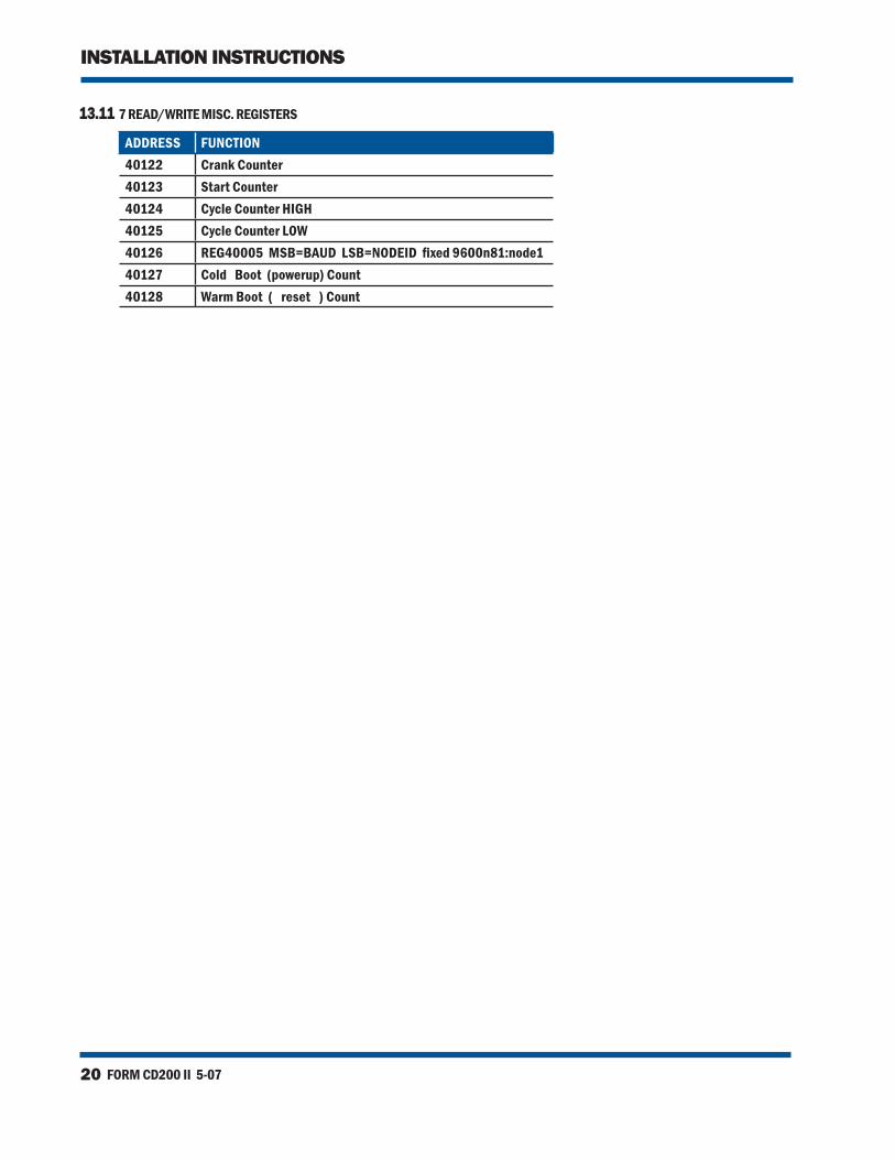
13.11 7 READ/WRITE MISC. REGISTERS
ADDRESS FUNCTION40122 Crank Counter40123 Start Counter40124 Cycle Counter HIGH40125 Cycle Counter LOW40126 REG40005 MSB=BAUD LSB=NODEID fixed 9600n81:node140127 Cold Boot (powerup) Count40128 Warm Boot ( reset ) Count
www.altronicinc.com 21
ALTRONIC CD200 IGNITION SYSTEM
HOERBIGER Engine Solutions
FIG. 1 DIMENSIONS AND SPECIFICATIONS, 791070-X
FORM CD200 II 5-0722
INSTALLATION INSTRUCTIONS
FIG. 2 DIMENSIONS AND SPECIFICATIONS, 791080-X
www.altronicinc.com 23
ALTRONIC CD200 IGNITION SYSTEM
HOERBIGER Engine Solutions
FIG. 3 DC POWER HOOKUP
FORM CD200 II 5-0724
INSTALLATION INSTRUCTIONS
FIG. 4 PICKUP AND DISC HOLE DETAIL
www.altronicinc.com 25
ALTRONIC CD200 IGNITION SYSTEM
HOERBIGER Engine Solutions
FIG. 5 WIRING: 4-CYLINDER ENGINES
FORM CD200 II 5-0726
INSTALLATION INSTRUCTIONS
FIG. 6 WIRING: 6-CYLINDER ENGINES
www.altronicinc.com 27
ALTRONIC CD200 IGNITION SYSTEM
HOERBIGER Engine Solutions
FIG. 7 WIRING: 8-CYLINDER ENGINES
FORM CD200 II 5-0728
INSTALLATION INSTRUCTIONS
FIG. 8 WIRING: 12-CYLINDER MAN 2842 LE
www.altronicinc.com 29
ALTRONIC CD200 IGNITION SYSTEM
HOERBIGER Engine Solutions
FIG. 9 WIRING: 12-CYLINDER MAN 2842 LE — USING CAMSHAFT GEAR
FORM CD200 II 5-0730
INSTALLATION INSTRUCTIONS
FIG. 10 791070-12 WITH FIRST ENGINE FIRING ANGLE ≤ 60°
www.altronicinc.com 31
ALTRONIC CD200 IGNITION SYSTEM
HOERBIGER Engine Solutions
FIG. 11 791070-12 WITH FIRST ENGINE FIRING ANGLE > 60°
FORM CD200 II 5-0732
INSTALLATION INSTRUCTIONS
FIG. 12 HOOK-UP FOR ANALOG TIMING SIGNAL
www.altronicinc.com 33
ALTRONIC CD200 IGNITION SYSTEM
HOERBIGER Engine Solutions
FIG. 13 PC TO CD200
FORM CD200 II 5-0734
INSTALLATION INSTRUCTIONS
FIG. 14 TERMINAL PROGRAM: 4-, 6-, 8-CYLINDER ENGINES
www.altronicinc.com 35
ALTRONIC CD200 IGNITION SYSTEM
HOERBIGER Engine Solutions
FIG. 15 TERMINAL PROGRAM: 12-CYLINDER ENGINES
Related Documents