Henny Penny Heated Merchandisers Model HMR-103 Model HMR-104 Model HMR-105 Model HMR-106 Model HMR-107 TECHNICAL MANUAL

Welcome message from author
This document is posted to help you gain knowledge. Please leave a comment to let me know what you think about it! Share it to your friends and learn new things together.
Transcript

Henny PennyHeated Merchandisers
Model HMR-103Model HMR-104Model HMR-105Model HMR-106Model HMR-107
TECHNICAL MANUAL


Model HMR-103,104,105,106,107
TABLE OF CONTENTSSection PageSection 1. TROUBLESHOOTING .................................................................................................... 1-1
1-1 Introduction ........................................................................................................... 1-11-2 Safety .................................................................................................................... 1-11-3. Troubleshooting ..................................................................................................... 1-11-4. Error Codes and Warnings .................................................................................... 1-4
Section 2. MAINTENANCE ............................................................................................................. 2-12-1. Introduction ........................................................................................................... 2-12-2. Maintenance Hints ................................................................................................ 2-12-3. Front Glass Replacement ...................................................................................... 2-12-4. Radiant Heater Replacement ............................................................................... 2-32-5. Light Socket Replacement .................................................................................... 2-42-6. Water Heater Replacement .................................................................................. 2-52-7. Water Probe Replacement .................................................................................... 2-72-8. Base Heater Replacement .................................................................................... 2-102-9. Blower Motor Replacement ................................................................................. 2-112-10. Air Probe Replacement ........................................................................................ 2-122-11. Transformer Replacement .................................................................................... 2-152-12. Food Probe Receptacle Replacement .................................................................. 2-162-13. Relay Replacement ............................................................................................... 2-172-14. Cooling Fan Replacement ..................................................................................... 2-182-15. Fuse and Fuse Holder Replacement ..................................................................... 2-202-16. High Limit Replacement - Automatic Reset ......................................................... 2-212-17. High Limit Replacement - Manual Reset ............................................................. 2-222-18. Power Switch Replacement ................................................................................. 2-232-19. Contactor Replacement ........................................................................................ 2-242-20. PC Board Replacement ........................................................................................ 2-252-21. Light Bulb Replacement ....................................................................................... 2-262-21. Wiring Diagrams ................................................................................................... 2-27
Section 3. PARTS INFORMATION .................................................................................................. 3-13-1. Introduction ........................................................................................................... 3-13-2. Genuine Parts ....................................................................................................... 3-13-3. How to Order ....................................................................................................... 3-13-4. Prices .................................................................................................................... 3-13-5. Delivery ................................................................................................................ 3-13-6. Warranty ............................................................................................................... 3-13-7. Recommended Spare Parts for Distributors ......................................................... 3-1
106 FM06-010 iRevised 02-14-2014


Model HMR-103,104,105,106,107
203 1-1
SECTION 1. TROUBLESHOOTING
1-1. INTRODUCTION This section provides troubleshooting information in the form of aneasy to read table.
If a problem occurs during the first operation of a new unit,recheck the Installation Section of the Operator’s Manual.
Before troubleshooting, always recheck the operatingprocedure per the Operation Section of the Operator’s Manual.
1-2. SAFETY Where information is of particular importance or is safety related,the words, NOTICE, CAUTION, or WARNING are used.Their usage is described below.
SAFETY ALERT SYMBOL is used with DANGER, WARNING,or CAUTION which indicates a personal injury type hazard.
NOTICE is used to highlight especially important information.
CAUTION used without the safety alert symbol indicatesa potentially hazardous situation which, if not avoided,may result in property damage.
CAUTION used with the safety alert symbol indicates apotentially hazardous situation which, if not avoided, mayresult in minor or moderate injury.
WARNING indicates a potentially hazardous situationwhich, if not avoided, could result in death or serious injury.
1-3. TROUBLESHOOTING To isolate a malfunction, proceed as follows:
1. Clearly define the problem (or symptom) and when itoccurs.
2. Locate the problem in the troubleshooting table.
3. Review all possible causes. Then, one-at-a-time workthrough the list of corrections until the problem is solved.

Model HMR-103,104,105,106,107
1-3. TROUBLESHOOTING (Continued) PROBLEM CAUSE CORRECTION
With power switch in • Open circuit • Check to see that unit isPOWER position, unit plugged inis completelyinoperative (no power) • Check breaker or fuse at
supply box
• Check control panel fuses per Fuseand Fuse Holder Replacement Section
• Check voltage at wall receptacle
• Check POWER switch; replace if defective
• Check cord and plug for loose connections
• Control board defective • Check for 12 volt input from transformer; replace if
defective
• Transformer defective • Check input and output voltage;replace if defective
Unit will not heat • Control board not calling • Check set point reading; if unit for heat below setpoint and not calling
for heat, control board defective
• Power on, board has • Hi limit tripped; check for no display defective hi limit, or defective
blower motor
No air heat • Faulty heat relay • Check and replace
• Faulty air heater • Check and replace
• Unit not preheated • Preheat unit with pans inplace before loading product
• Faulty radiant/air heat PC board • Replace PC Board
1-2 803

Model HMR-103,104,105,106,107
1-3. TROUBLESHOOTING (Continued)
PROBLEM CAUSE CORRECTION
No radiant heat • Faulty control • Replace the appropriate PC Board; PC board each well has its own control board
• Faulty radiant heater • Replace radiant heater
No water heat • Faulty radiant/water heat • Replace PC board PC board
• Faulty water heater • Replace water heater
No lights • Light switch defective • Replace light switch
• Light relay defective • Replace relay (same as heat relay)
• Light socket shorted • Replace light socket
• Light bulb blown • Replace light bulb
Canopy glass fogging • Air blowers not circulating • Replace blower motor heated air across glass
• Water heat setting too high • Lower water heat setting
• Radiant heat setting too low • Raise radiant heat setting
Product not holding • Doors are left open • Keep doors closed except totemperature load and unload product
• Heat settings too low • Adjust heat settings
• Low or improper voltage • Using meter, compare receptacle voltage to data plate voltage
• Product held too long • Hold product for recommended time
• Product not placed correctly in unit • Place product in unit as per Operationwith Product Section of Operator’sManual
803 1-3

Model HMR-103,104,105,106,107
1-4. ERROR CODES AND The display shows the following error codes and warnings when a WARNINGS fault is detected, along with an alarm sound. Both the heat and
humidity systems shut down, except when specified otherwise.
1-4 803
DISPLAY
LO
HI
“E-4”
“E-6”
“E-41”
“E-56”
CAUSE
• Food probe or actual temperatureis below 50o F (10o C) in Calibra-tion Mode only
• Food probe temperature above500o F (260o C) or lower airtemperature 275o F (135o C), orabove
• Control board temperature above140o F (60o C)
• Air probe error; displayed if theprobe resistance falls below 930ohms or rises above 2036 ohms;the exception is on the upper heatcontrol; any high resistance ap-pears as if no food probe isplugged in
• Scrambled PC board memory
• Setpoint storage error
• Allow unit to heat-up, or remove foodfrom unit
• Check the probes and heating circuit
• Check or clean cooling fans; if “E-4”persists, replace PC board
• Check probe and connection at PCboard
• Press UP button to clear “E-41”; if“E-41” persists, replace PC board
• Press UP button to clear “E-56”, thenturn unit off and back on; if “E-56”persists, replace PC board
CORRECTION

Model HMR-103,104,105,106,107
2-1. INTRODUCTION This section provides procedures for the checkout and re-placement of the various parts used within the heated mer-chandiser. Before replacing any parts, refer to the Trouble-shooting Section. It will aid you in determining the cause ofthe malfunction.
2-2. MAINTENANCE HINTS 1. You may want to use a multimeter to check the electriccomponents.
2. When the manual refers to the circuit being closed, themultimeter should read zero unless otherwise noted.
3. When the manual refers to the circuit being open, the multi-meter reads infinity.
2-3. FRONT GLASS REPLACEMENT 1. Raise the front glass to expose the gas shocks.
2. Using a 3 mm Allen wrench, loosen the set screws onthe shock bracket armature (Figure 2-1).
Figure 2-1
3. Using a Phillips head screwdriver, remove the screwssecuring the exterior end cap and remove end cap(Figure 2-2).
203 2-1
Figure 2-2
SECTION 2. MAINTENANCE

Model HMR-103,104,105,106,107
2-3. FRONT GLASSREPLACEMENT (Continued)
4. Using a Phillips head screwdriver, remove the screwssecuring the interior end cap and remove cap(Figure 2-3).
Figure 2-35. Hold glass upright, then use the gas shock tool (part no.
56878), to release the shock from the brackets (Figure2-4). Place tool on shock as shown and squeeze handle.Be sure to hold onto glass to prevent glass from breaking.
Note location and strength (N) of shock beforeremoving.
Figure 2-4
6. Slide glass assembly off end of unit (Figure 2-5).
Figure 2-5
2-2 1202
Model HMR-103,104,105,106,107
To avoid electrical shock or property damage, movethe POWER switch to OFF and disconnect maincircuit breaker, or unplug cord at wall receptacle.
1. Remove sliding doors.
2. Using a Phillips head screwdriver, remove 3 screwsaround the heater, leaving the top right screw.
3. Using a Phillips head screwdriver, remove the 4 screwssecuring the heater housing and allow housing to hingedown (Figure 2-7).
4. Remove fourth screw from around heater and removeouter housing (Figure 2-8).
Figure 2-6
Figure 2-8
1202 2-3
2-3. FRONT GLASSREPLACEMENT (Continued)
7. Slide new glass assembly into place, aligning outside edgeof glass clamp to the outside edge of the canopy(Figure 2-6).
8. Tighten set screws on shock bracket armatures(Figure 2-1).
9. Using the gas shock tool, reinstall the gas shocks, placingthe bottom end of shock in place first.
10. Replace interior end cap, with it being completely flush withglass clamp.
11. Replace the exterior end caps. Make sure spacers arebetween the end cap and the canopy.
2-4. RADIANT HEATERREPLACEMENT
Figure 2-7

Model HMR-103,104,105,106,107
2-4 506
2-4. RADIANT HEATERREPLACEMENT (Continued)
5. Using a 3/8” socket, remove the wires from the backof the radiant heater (Figure 2-9).
Using a multimeter, or ohmmeter, check ohm rating with-out the wires connected. The Ohm ratings:208V - Hot - 84.8 ohms; Cold - 72.7 - 88.9 ohms230V - Hot - 103.7 ohms; Cold - 88.9 - 108.7 ohms240V - Hot - 221.5 ohms; Cold - 189.9 - 232.1 ohms
6. Install new radiant heater in reverse order.
When re-attatching the heater wires to the heater thebottom nut must be held in place while the top nut istightened down on the heater wires.
Figure 2-9
2-5. LIGHT SOCKET REPLACEMENT
To avoid electrical shock or property damage, movethe POWER switch to OFF and disconnect maincircuit breaker, or unplug cord at wall receptacle.
1. Raise canopy glass and remove light bulb.
2. Using 3/8” socket, remove the 2 keps nuts securing thelight socket assembly (Figure 2-10).
3. Pull socket assembly from studs.
4. Using a Phillips head screwdriver, remove the wires fromthe socket (Figure 2-11).
Figure 2-10
Figure 2-11

Model HMR-103,104,105,106,107
1. Remove pans and pan supports from unit.
2. Using a 3/8” socket, remove the acorn nuts securing theheater cover (Figure 2-13).
3. Remove the 3 Phillips head screws securing the rear ofthe heater cover (Figure 2-14).
4. Cut the silicone seal around the rear of the cover.
Figure 2-13
Figure 2-14
203 2-5
2-5. LIGHT SOCKET REPLACEMENT(Continued)
5. Squeeze the brackets and pull socket from housing(Figure 2-12).
6. Install new socket in reverse order.
Figure 2-12
2-6. WATER HEATER REPLACEMENT
To avoid electrical shock or property damage,move the POWER switch to OFF and disconnectmain circuit breaker, or unplug cord at wallreceptacle.

Model HMR-103,104,105,106,107
2-6. WATER HEATER REPLACEMENT 5. Remove the 5 Phillips head screws securing side mount-(Continued) ing plate (Figure 2-15).
6. Remove the Phillips head screws securing the bottom,rear cover and let hinge down (Figure 2-16).
7. Cut wire ties to probe wires (Figure 2-17).
Figure 2-15
Figure 2-16
Figure 2-17
2-6 1202

Model HMR-103,104,105,106,107
Figure 2-18
Figure 2-19
803 2-7
2-6. WATER HEATER REPLACEMENT(Continued)
8. Disconnect wires from heater (Figure 2-18).
Using a multimeter, or ohmmeter, check ohm rating with-out the wires connected. The ohm ratings:208V - Hot - 108.1 ohms; Cold - 97.8 - 113.3 ohms230V - Hot - 132.2 ohms; Cold - 119.6 - 138.5 ohms
9. Pull heater cover from side mounting plate.
10. Flip heater cover to expose heater.
11. Using 5/16” socket, remove keps nuts securing theheater clips, and pull heater from heater cover(Figure 2-19).
12. Replace new heater in reverse order.
2-7. WATER PROBE REPLACEMENT
To avoid electrical shock or property damage,move the POWER switch to OFF and disconnectmain circuit breaker, or unplug cord at wall recep-tacle.
Figure 2-20
1. Remove pans and pan supports from unit.
2. Using a 3/8” socket, remove the acorn nuts securingthe heater cover (Figure 2-20).

Model HMR-103,104,105,106,107
2-7. WATER PROBE REPLACEMENT 3. Remove the 3 Phillips head screws securing the rear of(Continued) the heater cover (Figure 2-21).
4. Cut the silicone seal around the rear of the cover.
5. Remove the 5 Phillips head screws securing side mount-ing plate (Figure 2-22).
6. Remove the Phillips head screws securing the bottom,rear cover and let hinge down (Figure 2-23).
Figure 2-21
Figure 2-22
Figure 2-23
2-8 1202

Model HMR-103,104,105,106,107
2-7. WATER PROBE REPLACEMENT 7. Cut wire ties to probe wires (Figure 2-24).(Continued)
\
8. Unplug probe from wiring harness (Figure 2-25).
9. Using 5/16” socket, loosen keps nut on probe clip andpull probe from unit.
10. Install new probe in reverse order.
Extend probe 1-1/2” (38 mm), from clip (Figure 2-26).
Figure 2-24
Figure 2-25
Figure 2-26
1202 2-9

Model HMR-103,104,105,106,107
2-8. BASE HEATER REPLACEMENT
To avoid electrical shock or property damage, movethe POWER switch to OFF and disconnect maincircuit breaker, or unplug cord at wall receptacle.
1. Remove pans and pan supports from unit.
2. Remove Phillips head screws from heater bracket(Figure 2-27).
3. Using a 3/8” wrench or socket, remove the acorn nutsecuring the heater brace and remove brace.
4. Remove the Phillips head screws securing the bottom,rear cover and let hinge down (Figure 2-28).
5. Pull wires from heater and pull heater from unit(Figure 2-29).
Using a multimeter, or ohm meter, check ohm ratingwithout the wires connected. The ohm ratings:208V - Hot - 66.5 ohms; Cold - 60.2 - 89.7 ohms240V - Hot - 88.6 ohms; Cold - 80.1 - 92.8 ohms
6. Install new heater in reverse order.
Figure 2-27
Figure 2-28
Figure 2-29
2-10 506

Model HMR-103,104,105,106,107
2-9. BLOWER MOTOR REPLACEMENT
To avoid electrical shock or property damage, movethe POWER switch to OFF and disconnect maincircuit breaker, or unplug cord at wall receptacle.
1. Remove the Phillips head screws securing the bottom,rear cover and let hinge down (Figure 2-30).
2. Remove the 3 screws from the blower bracket and pullblower motor assembly from housing (Figure 2-31).
3. Using an Allen wrench, loosen the set screw securingthe fan blade to the blower motor and pull fan blade frommotor (Figure 2-32).
4. Cut wires to blower motor and pull motor from unit.
5. Strip back the cut wires, and connect new blower motorwires to these wires, using wire splicers or wire nuts.
6. Install new blower motor in reverse order.
Figure 2-30
Figure 2-31
Figure 2-32
203 2-11

Model HMR-103,104,105,106,107
2-10. AIR PROBE REPLACEMENT
To avoid electrical shock or property damage, movethe POWER switch to OFF and disconnect maincircuit breaker, or unplug cord at wall receptacle.
1. Remove the Phillips head screws securing the bottom,rear cover and let hinge down (Figure 2-33).
2. Cut wires ties to probe wires (Figure 2-34).
3. Unplug the probe from the wire harness (Figure 2-35).
4. Using a multimeter, or ohmmeter, check across the probeterminals for the correct ohms using the RTD ResistanceChart on the following page. If the probe proves faulty,continue onto step 5. If probe is good, replace wire tieson wires.
Figure 2-33
Figure 2-34
Figure 2-35
2-12 203

Model HMR-103,104,105,106,107
RTD Resistance ChartT
emp
.T
emp
.R
es i
s ta
nc
e
FC
Oh
ms
32
0.0
01
00
0.0
03
30
.56
10
02
.17
34
1.1
11
00
4.3
43
51
.67
10
06
.51
36
2.2
21
00
8.6
83
72
.78
10
10
.85
38
3.3
31
01
3.0
23
93
.89
10
15
.18
40
4.4
41
01
7.3
54
15
.00
10
19
.52
42
5.5
61
02
1.6
94
36
.11
10
23
.86
44
6.6
71
02
6.0
24
57
.22
10
28
.19
46
7.7
81
03
0.3
64
78
.33
10
32
.52
48
8.8
91
03
4.6
94
99
.44
10
36
.85
50
10
.00
10
39
.02
51
10
.56
10
41
.18
52
11.1
11
04
3.3
55
311
.67
10
45
.51
54
12
.22
10
47
.67
55
12
.78
10
49
.84
56
13
.33
10
52
.00
57
13
.89
10
54
.16
58
14
.44
10
56
.32
59
15
.00
10
58
.49
60
15
.56
10
60
.65
61
16
.11
10
62
.81
62
16
.67
10
64
.97
63
17
.22
10
67
.13
64
17
.78
10
69
.29
65
18
.33
10
71
.45
66
18
.89
10
73
.61
67
19
.44
10
75
.77
68
20
.00
10
77
.92
69
20
.56
10
80
.08
70
21
.11
10
82
.24
71
21
.67
10
84
.40
72
22
.22
10
86
.55
73
22
.78
10
88
.71
74
23
.33
10
90
.87
75
23
.89
10
93
.02
Tem
p.
Tem
p.
Re
s is t
an
ce
FC
Oh
ms
76
24
.44
10
95
.18
77
25
.00
10
97
.33
78
25
.56
10
99
.49
79
26
.11
110
1.6
48
02
6.6
711
03
.80
81
27
.22
110
5.9
58
22
7.7
811
08
.10
83
28
.33
111
0.2
68
42
8.8
911
12
.41
85
29
.44
111
4.5
68
63
0.0
011
16
.72
87
30
.56
111
8.8
78
83
1.1
111
21
.02
89
31
.67
112
3.1
79
03
2.2
211
25
.32
91
32
.78
112
7.4
79
23
3.3
311
29
.62
93
33
.89
113
1.7
79
43
4.4
411
33
.92
95
35
.00
113
6.0
79
63
5.5
611
38
.22
97
36
.11
114
0.3
69
83
6.6
711
42
.51
99
37
.22
114
4.6
61
00
37
.78
114
6.8
11
01
38
.33
114
8.9
51
02
38
.89
115
1.1
01
03
39
.44
115
3.2
41
04
40
.00
115
5.3
91
05
40
.56
115
7.5
31
06
41
.11
115
9.6
81
07
41
.67
116
1.8
21
08
42
.22
116
3.9
71
09
42
.78
116
6.1
111
04
3.3
311
68
.26
111
43
.89
117
0.4
011
24
4.4
411
72
.54
113
45
.00
117
4.6
811
44
5.5
611
76
.83
115
46
.11
117
8.9
711
64
6.6
711
81
.11
117
47
.22
118
3.2
511
84
7.7
811
85
.39
119
48
.33
118
7.5
3
Tem
p.
Tem
p.
Re
s is t
an
ce
FC
Oh
ms
12
04
8.8
911
89
.67
12
14
9.4
411
91
.81
12
25
0.0
011
93
.95
12
35
0.5
611
96
.09
12
45
1.1
111
98
.23
12
55
1.6
71
20
0.3
61
26
52
.22
12
02
.50
12
75
2.7
81
20
4.6
41
28
53
.33
12
06
.78
12
95
3.8
91
20
8.9
11
30
54
.44
12
11.0
51
31
55
.00
12
13
.18
13
25
5.5
61
21
5.3
21
33
56
.11
12
17
.45
13
45
6.6
71
21
9.5
91
35
57
.22
12
21
.72
13
65
7.7
81
22
3.8
61
37
58
.33
12
25
.99
13
85
8.8
91
22
8.1
21
39
59
.44
12
30
.26
14
06
0.0
01
23
2.3
91
41
60
.56
12
34
.52
14
26
1.1
11
23
6.6
51
43
61
.67
12
38
.79
14
46
2.2
21
24
0.9
21
45
62
.78
12
43
.05
14
66
3.3
31
24
5.1
81
47
63
.89
12
47
.31
14
86
4.4
41
24
9.4
41
49
65
.00
12
51
.57
15
06
5.5
61
25
3.7
01
51
66
.11
12
55
.83
15
26
6.6
71
25
7.9
51
53
67
.22
12
60
.08
15
46
7.7
81
26
2.2
11
55
68
.33
12
64
.34
15
66
8.8
91
26
6.4
61
57
69
.44
12
68
.59
15
87
0.0
01
27
0.7
21
59
70
.56
12
72
.84
16
07
1.1
11
27
4.9
71
61
71
.67
12
77
.09
16
27
2.2
21
27
9.2
21
63
72
.78
12
81
.34
Tem
p.
Tem
p.
Re
s is t
an
ce
FC
Oh
ms
16
47
3.3
31
28
3.4
71
65
73
.89
12
85
.59
16
67
4.4
41
28
7.7
11
67
75
.00
12
89
.84
16
87
5.5
61
29
1.9
61
69
76
.11
12
94
.08
17
07
6.6
71
29
6.2
01
71
77
.22
12
98
.32
17
27
7.7
81
30
0.4
51
73
78
.33
13
02
.57
17
47
8.8
91
30
4.6
91
75
79
.44
13
06
.81
17
68
0.0
01
30
8.9
31
77
80
.56
13
11.0
51
78
81
.11
13
13
.17
17
98
1.6
71
31
5.2
81
80
82
.22
13
17
.40
18
18
2.7
81
31
9.5
21
82
83
.33
13
21
.64
18
38
3.8
91
32
3.7
61
84
84
.44
13
25
.87
18
58
5.0
01
32
7.9
91
86
85
.56
13
30
.10
18
78
6.1
11
33
2.2
21
88
86
.67
13
34
.34
18
98
7.2
21
33
6.4
51
90
87
.78
13
38
.57
19
18
8.3
31
34
0.6
81
92
88
.89
13
42
.79
19
38
9.4
41
34
4.9
11
94
90
.00
13
47
.02
19
59
0.5
61
34
9.1
31
96
91
.11
13
51
.25
19
79
1.6
71
35
3.3
61
98
92
.22
13
55
.47
19
99
2.7
81
35
7.5
82
00
93
.33
13
59
.69
20
19
3.8
91
36
1.8
02
02
94
.44
13
63
.91
20
39
5.0
01
36
6.0
22
04
95
.56
13
68
.13
20
59
6.1
11
37
0.2
42
06
96
.67
13
72
.35
20
79
7.2
21
37
4.4
6
Tem
p.
Tem
p.
Re
s is t
an
ce
FC
Oh
ms
20
89
7.7
81
37
6.5
72
09
98
.33
13
78
.68
21
09
8.8
91
38
0.7
92
119
9.4
41
38
2.8
92
12
10
0.0
01
38
5.0
02
13
10
0.5
61
38
7.1
12
14
10
1.1
11
38
9.2
12
15
10
1.6
71
39
1.3
22
16
10
2.2
21
39
3.4
22
17
10
2.7
81
39
5.5
32
18
10
3.3
31
39
7.6
32
19
10
3.8
91
39
9.7
42
20
10
4.4
41
40
1.8
42
21
10
5.0
01
40
3.9
52
22
10
5.5
61
40
6.0
52
23
10
6.1
11
40
8.1
52
24
10
6.6
71
41
0.2
52
25
10
7.2
21
41
2.3
62
26
10
7.7
81
41
4.4
62
27
10
8.3
31
41
6.5
62
28
10
8.8
91
41
8.6
62
29
10
9.4
41
42
0.7
62
30
110
.00
14
22
.86
23
111
0.5
61
42
4.9
62
32
111
.11
14
27
.06
23
311
1.6
71
42
9.1
62
34
112
.22
14
31
.26
23
511
2.7
81
43
3.3
62
36
113
.33
14
35
.46
23
711
3.8
91
43
7.5
52
38
114
.44
14
39
.65
23
911
5.0
01
44
1.7
52
40
115
.56
14
43
.85
24
111
6.1
11
44
5.9
42
42
116
.67
14
48
.04
24
311
7.2
21
45
0.1
32
44
117
.78
14
52
.23
24
511
8.3
31
45
4.3
22
46
118
.89
14
56
.42
24
711
9.4
41
45
8.5
12
48
12
0.0
01
46
0.6
12
49
12
0.5
61
46
2.7
02
50
12
1.1
11
46
4.7
9
701 2-13

Model HMR-103,104,105,106,107
2-10. AIR PROBE REPLACEMENT 5. Using a 3/4” wrench, loosen probe strain relief and pull (Continued) the probe from the unit (Figure 2-36).
6. Install new probe in reverse order, extending the probe1/8” into cabinet (Figure 2-37).
Figure 2-37
Some probes are held into place by a probe bracket in-stead of a strain relief. Press on the edge of the bracketto relax the tension on the probe and then pull probe fromunit. Extend the new probe about 1/4” into cabinet(Figure 2-38).
Figure 2-36
Figure 2-38
2-14 1202

Model HMR-103,104,105,106,107
2-11. TRANSFORMER REPLACEMENT
To avoid electrical shock or property damage, movethe POWER switch to OFF and disconnect maincircuit breaker, or unplug cord at wall receptacle.
1. Remove the Phillips head screws securing the top, rearcover, and let cover hinge down (Figure 2-39).
Figure 2-39
2. Label, and then pull the wires from the transformer(Figure 2-40).
3. Remove the Phillips head screws securing the transformerand pull transformer from unit (Figure 2-41).
4. Install new transformer in reverse order.
Figure 2-40
Figure 2-41
203 2-15

Model HMR-103,104,105,106,107
2-12. FOOD PROBE RECEPTACLE REPLACEMENT
To avoid electrical shock or property damage, movethe POWER switch to OFF and disconnect maincircuit breaker, or unplug cord at wall receptacle.
1. Remove the Phillips head screws securing the top, rearcover, and let cover hinge down (Figure 2-42).
2. Cut wire ties securing receptacle wires and disconnectreceptacle from wire harness.
3. Using 3/8” socket, remove nuts securing bracket andpull bracket and receptacle from unit (Figure 2-43).
4. Remove the Phillips head screw securing the receptacleto the bracket and remove receptacle from bracket(Figure 2-44).
5. Install new receptacle in reverse order.
Figure 2-42
Figure 2-43
Figure 2-44
2-16 1202

Model HMR-103,104,105,106,107
2-13. RELAY REPLACEMENT
To avoid electrical shock or property damage, movethe POWER switch to OFF and disconnect maincircuit breaker, or unplug cord at wall receptacle.
1. Remove the Phillips head screws securing the top, rearcover, and let cover hinge down (Figure 2-45).
2. Label wires, and then loosen the Phillips head screwssecuring the wires to the relay and pull wires from relay(Figure 2-46).
3. Remove the Phillips head screws securing the relay tothe unit, and then pull relay from unit (Figure 2-47).
4. Install new relay in reverse order.
Figure 2-45
Figure 2-46
Figure 2-47
203 2-17

Model HMR-103,104,105,106,107
2-14. COOLING FAN REPLACEMENT
To avoid electrical shock or property damage, movethe POWER switch to OFF and disconnect maincircuit breaker, or unplug cord at wall receptacle.
1. Remove the Phillips head screws securing the top, rearcover, and let cover hinge down (Figure 2-48).
For bracket mounted fan instructions, see next page.
2. Using 5/16” socket, remove nuts securing the fan(Figure 2-49).
3. Cut the cooling fan wires and remove the cooling fan fromthe unit (Figure 2-50).
4. Strip back the cut wires, and connect new blower motorwires to these wires, using wire splicers or wire nuts.
5. Install new cooling fan in reverse order, making sure theair blows into the cabinet.
Figure 2-48
Figure 2-49
Figure 2-50
2-18 203

Model HMR-103,104,105,106,107
2-14. COOLING FAN REPLACEMENT (Continued)
6. Remove Phillips head screws securing the fan bracket(Figure 2-51).
7. Remove screws and nuts securing the fan to the bracket(Figure 2-52).
8. Cut wires to cooling fan and remove the fan from the unit(Figure 2-53).
9. Strip back the cut wires, and connect new cooling fanwires to these wires, using wire splicers or wire nuts.
10. Install new cooling fan in reverse order, making sure theair blows towards the outside of the unit.
Figure 2-51
Figure 2-52
Figue 2-53
1202 2-19

Model HMR-103,104,105,106,107
2-15. FUSE AND FUSE HOLDER REPLACEMENT
To avoid electrical shock or property damage, movethe POWER switch to OFF and disconnect maincircuit breaker, or unplug cord at wall receptacle.
Fuse Replacement1. Unscrew fuse holder cap counterclockwise to access fuse
(Figure 2-54).
To check fuse, use a multimeter, or continuity tester, and putleads on each end of fuse. If meter shows circuit is closed,fuse is good. Replace fuse with a 15 amp fuse (20 ampfuse-CE), if meter shows circuit is open.
Fuse Holder Replacement
1. Remove the Phillips head screws securing the bottom,rear cover and let hinge down (Figure 2-55).
2. Pull wires from fuse holder terminals.
3. Using 5/16” socket remove nuts securing fuse holder andpull holder from unit (Figure 2-56).
4. Install new fuse holder in reverse order.
Figure 2-54
Figure 2-55
Figure 2-56
2-20 203

Model HMR-103,104,105,106,107
2-16. HIGH LIMIT REPLACEMENT - AUTOMATIC RESET
To avoid electrical shock or property damage, movethe POWER switch to OFF and disconnect maincircuit breaker, or unplug cord at wall receptacle.
1. Remove the Phillips head screws securing the top, rearcover, and let cover hinge down (Figure 2-57).
2. Pull wires from high limit (Figure 2-58).
To check high, use a multimeter or continuity tester, and putleads on each terminal of high limit. With the unit at roomtemperature, the meter shows a closed circuit if high limit isgood. Replace high limit if meter shows circuit is open.
3. Using 1/4” socket, remove nuts securing high limit, pull itfrom the unit (Figure 2-59).
4. Replace new high limit in reverse order.
Figure 2-57
Figure 2-58
Figure 2-59
203 2-21

Model HMR-103,104,105,106,107
2-17. HIGH LIMIT REPLACEMENT - MANUAL RESET
To avoid electrical shock or property damage, movethe POWER switch to OFF and disconnect maincircuit breaker, or unplug cord at wall receptacle.
1. Remove the Phillips head screws securing the bottom,rear cover and let hinge down (Figure 2-60).
2. Pull wires from high limit (Figure 2-61).
To check high limit, allow unit to cool, then press the resetbutton to make sure high limit is reset. Use a multimeter, orcontinuity tester, and put leads on each terminal of high limit.If the meter shows circuit is closed, the high limit is good.Replace high limit if meter shows circuit is open.
3. Using 1/4” socket, remove nuts securing the high limit,and pull high limit from unit (Figure 2-62).
4. Install new high limit in reverse order.
Figure 2-60
Figure 2-61
Figure 2-62
2-22 203

Model HMR-103,104,105,106,107
2-18. POWER SWITCH REPLACEMENT
To avoid electrical shock or property damage, movethe POWER switch to OFF and disconnect maincircuit breaker, or unplug cord at wall receptacle.
1A. For switches on bottom rear cover, remove the Phillipshead screws securing the bottom rear cover and let hingedown (Figure 2-63).
1B. For switches on top rear cover, remove the Phillips headscrews securing the top rear cover and let hinge down(Figure 2-64).
2. Label wires and then pull them from the switch(Figure 2-65).
3. Press tabs together and pull switch from front of panel(Figure 2-66).
4. Install new switch in reverse order.
Figure 2-63
Figure 2-64
Figure 2-66
Figure 2-65
203 2-23

Model HMR-103,104,105,106,107
2-19. CONTACTOR REPLACEMENT
To avoid electrical shock or property damage, movethe POWER switch to OFF and disconnect maincircuit breaker, or unplug cord at wall receptacle.
1. Remove the Phillips head screws securing the bottom,rear cover and let hinge down (Figure 2-67).
2. Using 3/8” socket, remove the nuts securing the contactorand pull contactor off of studs (Figure 2-68).
3. Label wires and then remove the Phillips head screwssecuring the wires (Figure 2-69).
4. Install new contactor in reverse order.
Figure 2-67
Figure 2-68
Figure 2-69
2-24 203

Model HMR-103,104,105,106,107
2-20. PC BOARD REPLACEMENT
To avoid electrical shock or property damage, movethe POWER switch to OFF and disconnect maincircuit breaker, or unplug cord at wall receptacle.
1. Remove the Phillips head screws securing the top, rearcover, and let cover hinge down (Figure 2-70).
2. Remove the nuts securing the housing and pull housingfrom unit (Figure 2-71).
3. Disconnect connectors to the PC board (Figure 2-72).
4. Using 5/16” socket, remove the nuts securing the PCboard and pull the board from the unit (Figure 2-73).
5. Install new PC board in reverse order.
Figure 2-70
Figure 2-71
Figure 2-72
Figure 2-73203 2-25
Model HMR-103,104,105,106,107
2-21. LIGHT BULB REPLACEMENT
To avoid electrical shock or property damage, movethe POWER switch to OFF and disconnect maincircuit breaker, or unplug cord at wall receptacle.
Light bulbs and glass may be hot. Severe burns couldresult.
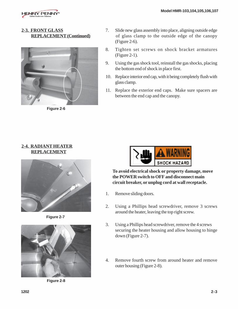
1. Raise the glass canopy and ensure that the gas shockssupport its weight before proceeding.
Do Not attempt to access the bulb from the operator’sside of the unit. The installer cannot easily see the bulband socket or the adjacent radiant heaters, increasing thepotential shock or burn hazard.
2. Carefully remove the old bulb and discard. Figure 2-74.
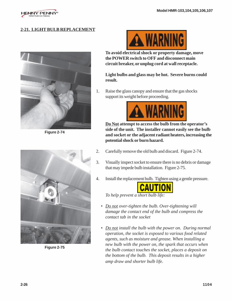
3. Visually inspect socket to ensure there is no debris or damagethat may impede bulb installation. Figure 2-75.
4. Install the replacement bulb. Tighten using a gentle pressure.
To help prevent a short bulb life:
• Do not over-tighten the bulb. Over-tightening willdamage the contact end of the bulb and compress thecontact tab in the socket
• Do not install the bulb with the power on. During normaloperation, the socket is exposed to various food relatedagents, such as moisture and grease. When installing anew bulb with the power on, the spark that occurs whenthe bulb contact touches the socket, places a deposit onthe bottom of the bulb. This deposit results in a higheramp draw and shorter bulb life.
Figure 2-74
Figure 2-75
2-26 1104

Model HMR-103,104,105,106,107
603 2-27
2-21. WIRING DIAGRAMS

Model HMR-103,104,105,106,107
2-28 701
2-21. WIRING DIAGRAMS (Continued)

Model HMR-103,104,105,106,107
701 2-29
2-21. WIRING DIAGRAMS (Continued)

Model HMR-103,104,105,106,107
2-30 506

Model HMR-103,104,105,106,107
1104 2-31

Model HMR-103,104,105,106,107
2-32 1104
Model HMR-103,104,105,106,107
207 2-33
LIMITED WARRANTY FOR HENNY PENNY EQUIPMENT
Subject to the following conditions, Henny Penny Corporation makes the following limited warranties to the originalpurchaser only for Henny Penny appliances and replacement parts:
NEW EQUIPMENT: Any part of a new appliance, except baskets, lamps, and fuses, which proves to be defective inmaterial or workmanship within two (2) years from date of original installation, will be repaired or replaced withoutcharge F.O.B. factory, Eaton, Ohio, or F.O.B. authorized distributor. Baskets will be repaired or replaced for ninety (90)days from date of original installation. Lamps and fuses are not covered under this Limited Warranty. To validate thiswarranty, the registration card for the appliance must be mailed to Henny Penny within ten (10) days after installation.
FILTER SYSTEM: Failure of any parts within a fryer filter system caused by the use of the non-OEM filters orother unapproved filters is not covered under this Limited Warranty.
REPLACEMENT PARTS: Any appliance replacement part, except lamps and fuses, which proves to be defective inmaterial or workmanship within ninety (90) days from date of original installation will be repaired or replaced withoutcharge F.O.B. factory, Eaton, Ohio, or F.O.B. authorized distributor.
The warranty for new equipment covers the repair or replacement of the defective part and includes labor charges andmaximum mileage charges of 200 miles round trip for a period of one (1) year from the date of original installation.
The warranty for replacement parts covers only the repair or replacement of the defective part and does not include anylabor charges for the removal and installation of any parts, travel, or other expenses incidental to the repair or replacement ofa part.
EXTENDED FRYPOT WARRANTY: Henny Penny will replace any frypot that fails due to manufacturing or workmanshipissues for a period of up to seven (7) years from date of manufacture. This warranty shall not cover any frypot that fails due toany misuse or abuse, such as heating of the frypot without shortening.
0 TO 3 YEARS: During this time, any frypot that fails due to manufacturing or workmanship issues willbe replaced at no charge for parts, labor, or freight. Henny Penny will either install a new frypot at no cost orprovide a new or reconditioned replacement fryer at no cost.
3 TO 7 YEARS: During this time, any frypot that fails due to manufacturing or workmanship issues willbe replaced at no charge for the frypot only. Any freight charges and labor costs to install the new frypot aswell as the cost of any other parts replaced, such as insulation, thermal sensors, high limits, fittings, andhardware, will be the responsibility of the owner.
Any claim must be presented to either Henny Penny or the distributor from whom the appliance was purchased. Noallowance will be granted for repairs made by anyone else without Henny Penny’s written consent. If damage occurs duringshipping, notify the sender at once so that a claim may be filed.
THE ABOVE LIMITED WARRANTY SETS FORTH THE SOLE REMEDY AGAINST HENNY PENNY FOR ANY BREACHOF WARRANTY OR OTHER TERM. BUYER AGREES THAT NO OTHER REMEDY (INCLUDING CLAIMS FOR ANY INCI-DENTAL OR CONSEQUENTIAL DAMAGES) SHALL BE AVAILABLE.
The above limited warranty does not apply (a) to damage resulting from accident, alteration, misuse, or abuse; (b) if theequipment’s serial number is removed or defaced; or (c) for lamps and fuses. THE ABOVE LIMITED WARRANTY IS EX-PRESSLY IN LIEU OF ALL OTHER WARRANTIES, EXPRESS OR IMPLIED, INCLUDING MERCHANTABILITY AND FIT-NESS, AND ALL OTHER WARRANTIES ARE EXCLUDED. HENNY PENNY NEITHER ASSUMES NOR AUTHORIZES ANYPERSON TO ASSUME FOR IT ANY OTHER OBLIGATION OR LIABILITY.
Revised 01/01/07

Model HMR-103,104,105,106,107
3-1. INTRODUCTION This section identifies and lists the replaceable parts of theHenny Penny merchandiser.
3-2. GENUINE PARTS Use only genuine Henny Penny parts in your cabinet. Using apart of lesser quality or substitute design may result in cabinetdamage or personal injury.
3-3. HOW TO ORDER Once the part you want to order has been found in the PartsList, write down the following information:
1. From the Parts List(Sample)
Item Number 7Part Number 40645Description Relay
2. From the data plate(Sample)
Product Number HMR104.0Serial Number AY001JJVoltage 102/208V
3-4. PRICES Your independent Henny Penny distributor has a price parts list andwill be glad to inform you of the cost of your parts order.
3-5. DELIVERY Commonly replaced items are stocked by your independent HennyPenny distributor and will be sent out when your order is received.Other parts will be ordered by the distributor from Henny PennyCorporation. Normally, these will be sent to your distributor withinthree working days.
3-6. WARRANTY All replacement parts (except lamps and fuses) are coveredunder warranty for 90 days against manufacturing defects andworkmanship. If damage occurs during shipping, notify the carrier atonce so that a claim may be properly filed. Refer to warranty on thefront of this section for other rights and limitations.
Recommended replacement parts, stocked by your distributor, areindicated with √√√√√ in the parts lists. Please use care when orderingrecommended parts, because all voltages and variations are marked.Distributors should order parts based upon common voltages andequipment sold in their territory.
106 3-1
SECTION 3. PARTS INFORMATION
3-7. RECOMMENDEDSPARE PARTS FORDISTRIBUTORS

Model HMR-103,104,105,106,107
Figure 3-1. Covers, Doors, and Shelves
3-2 204

Model HMR-103,104,105,106,107FIG. &ITEM PART QUANTITYNO. NO. DESCRIPTION 103 104 105 106 107
3-1 COVERS, DOORS, & SHELVES1 61753 DECAL - POWER WITH PROBE (103, SN CY094JA &
BELOW; 104, SN CY074JA & BELOW; 105, SN CY096JA & BELOW; & 106, SN CY106JA & BELOW) 1 1 1 1 1
2 56349 DECAL - CONTROL - UPPER/AIR 1 1 1 1 13 59302 DECAL - CONTROL RAD. W/O PROBE 1 1 1 1 24 56347 DECAL - CONTROL UPPER HEAT 1 1 2 2 25 56048 REAR COVER - 3 WELL 1 - - - -5 56059 REAR COVER - 4 WELL - 1 - - -5 56005 REAR COVER - 5 WELL - - 1 - -5 56151 REAR COVER - 6 WELL - - - 1 -5 56039 REAR COVER - 7 WELL - - - - 16 59306 DECAL - HEAT SUPPLY W/O PROBE 1 1 1 1 17 61513 DECAL - HEAT SUPPLY WITH PROBE 1 1 1 1 18 59304 DECAL - CONTROL RAD./WATER W/O PROBE 1 1 1 2 29 37224 CUTTING BOARD - WOOD 1 - - 1 29 38653 CUTTING BOARD ASSY. - POLY. 1 - - 1 29 58574 CUTTING BOARD - WOOD - 4 WELL - 1 - - -9 56129 CUTTING BOARD ASSY. - POLY. - 4 WELL - 1 - - -9 37399 CUTTING BOARD - WOOD - 5 WELL - - 1 - -9 38654 CUTTING BOARD ASSY. - POLY. - 5 WELL - - 1 - -9 58567 CUTTING BOARD - WOOD - 6 WELL - - - 1 -9 58606 CUTTING BOARD ASSY. - POLY. - 6 WELL - - - 1 -10 37230 BRACKET - CUTTING BOARD 2 2 2 2 211 NS03-044 NUT 8 8 8 8 812 SC01-113 SCREW 4 4 4 4 4
√√√√√ 13 EF02-006 FUSE HOLDER - 15 AMP (SEE SN CHART ON NEXT PAGE) 2 2 2 2 2√√√√√ 13 EF02-104 FUSE HOLDER - 20 AMP - CE 2 2 2 2 2
14 NS02-005 NUT 4 4 4 4 4√√√√√ 15 59363 FOOD PROBE 1 1 1 1 1
16 42895 FOOD PROBE CLIP 2 2 2 2 217 68045 SLIDING GLASS DOORS - 3 & 6 WELLS 2 - - 4 -17 68047 SLIDING GLASS DOORS - 4 WELL - 2 - - -17 68049 SLIDING GLASS DOORS - 5 WELL - - 2 - -17 68110 SLIDING GLASS DOORS - 5 WELL - 4 DOOR - - 4 - -17 68051 SLIDING GLASS DOORS - 7 WELL - - - - 4
22225 --DOOR GLIDE 4 PER DOORSC01-049 --SCREW #6-32 X 3/8 PH PHD C 4 PER DOOR
DOOR TRACKS (SEE NEXT PAGE)√√√√√ 18* EF02-007 FUSE - 15 AMP (SEE SN CHART ON NEXT PAGE) 2 2 2 2 2√√√√√ 18* EF02-125 BREAKER-PUSH BUTTON RESET 2 2 2 2 2
(SEE SN CHART ON NEXT PAGE)√√√√√ 18* EF02-105 FUSE - 15 AMP - CE 2 2 2 2 2
19* 58497 WELL COVER - 2” - 2 WELL - AR AR AR AR19* 58498 WELL COVER - 3/8” - 2 WELL - AR AR AR AR19* 42479 WELL COVER - 3/8” - 3 WELL AR - AR AR AR19* 42477 WELL COVER - 2” - 3 WELL AR - AR AR AR19* 58503 WELL COVER - FLAT - 2 WELL - AR AR AR AR19* 58504 WELL COVER - FLAT - 3 WELL AR - AR AR AR20* 54003 ADJUSTABLE LEGS (OPTIONAL) 4 4 6 6 621* 64175 SPLATTER GUARD - HMR-103 1 - - - -21* 64176 SPLATTER GUARD - HMR-104 - 1 - - -21* 64177 SPLATTER GUARD - HMR-105 - - 1 - -21* 64178 SPLATTER GUARD - HMR-106 - - - 1 -21* 64179 SPLATTER GUARD - HMR-107 - - - - 1
√ √ √ √ √ recommended parts/*not shown214 3-3

Model HMR-103,104,105,106,107
MODELS EF02-006 & EF02-007 EF02-125HMR103 HA0703010 & below HA0703011 & aboveHMR104 HA0704031 & below HA0704032 & aboveHMR105 HA0702057 & below HA0702058 & aboveHMR106 HA0703035 & below HA0703036 & aboveHMR107 HA0704034 & below HA0704035 & above
PART #
Fuse, Fuse Holder and Breaker SN Chart
214 3-4
FIG. &ITEM PART QUANTITYNO. NO. DESCRIPTION 103 104 105 106 107
1* 56595-001 LOWER DOOR TRACK-HMR-103 1 - - - -2* 56595-002 LOWER DOOR TRACK-HMR-104 - 1 - - -3* 56595-003 LOWER DOOR TRACK-HMR-105 - - 1 - -4* 56595-004 LOWER DOOR TRACK-HMR-106 - - - 1 -5* 56595-005 LOWER DOOR TRACK-HMR-107 - - - - 11* 56238 UPPER DOOR TRACK-HMR-103 1 - - - -2* 56237 UPPER DOOR TRACK-HMR-104 - 1 - - -3* 56236 UPPER DOOR TRACK-HMR-105 - - 1 - -4* 56235 UPPER DOOR TRACK-HMR-106 - - - 1 -5* 56234 UPPER DOOR TRACK-HMR-107 - - - - 16* SC01-003 SCREW #6-32 X 3/8 PH FLAT HD 8 10 12 14 167* NS02-005 NUT HEX KEPS #6-32 C 4 5 6 7 88* NS03-063 6-32 HI-CROWN ACORN NUT SS 4 5 6 7 8
√√√√√ recommended parts/*not shown

Model HMR-103,104,105,106,107
Figure 3-2. Well Interior
3-5 506

Model HMR-103,104,105,106,107
FIG. &ITEM PART QUANTITYNO. NO. DESCRIPTION 103 104 105 106 107
3-2 WELL INTERIOR1 59315 WATER PAN (SMALL SERVICE ONLY) 1 1 1 2 21 91963 WATER PAN (STANDARD) 1 1 1 2 22 37371 PAN CROSS SUPPORT - SHORT 6 8 10 12 143 37159 PAN SUPPORT - LONG 6 8 10 12 143 14462 KIT - HMR10X - SUPPORT-PAN/SHELF MTG
(USE WITH 14463 & 14464) 1 1 1 1 14 NS03-002 ACORN NUT - #10-24 C 13 13 13 13 265 63440 RH LOCATOR - WATER PAN (SERVICE ONLY) 1 1 1 1 25 91977 LOCATOR - WATER PAN (STANDARD) 2 2 2 4 4
5 91978 LOCATOR-WATER PAN (CAMBO) AS REQUIRED6 56862 GASKET - WATER PAN 1 1 1 1 27 63441 LH LOCATOR - WATER PAN (SERVICE ONLY) 1 1 1 1 28 56354 WATER HEATER CLIP 5 5 5 5 10
√√√√√ 9 56310-01 WATER PAN HEATER - 230V-400W (UNDER 58564) 1 1 1 1 2√√√√√ 9 56310-02 WATER PAN HEATER - 208V-400W (UNDER 58564) 1 1 1 1 2
10 NS02-005 NUT 5 5 5 5 10√√√√√ 11 26252 PROBE - 6” - WATER PAN 1 1 1 1 2
12 MS01-462 TUBE CLAMP 2 2 2 2 413 NS02-005 NUT 2 2 2 2 414 SC02-041 SCREW 12 12 12 18 18
√√√√√ 15 56166 PROBE - 3” 1 1 1 1 116 SC02-041 SCREW 4 4 6 6 8
√√√√√ 17 56240-01 LOWER HEATER - 208V-650W 2 2 3 3 4√√√√√ 17 56240-02 LOWER HEATER - 240V-650W 2 2 3 3 4
18 NS03-023 ACORN NUT 6 6 6 6 619 LW01-013 LOCKWASHER 6 6 6 6 620 16685 FAN GUARD 2 2 2 3 321 39974 FAN BLADE 2 2 2 3 322 58564 WATER PAN HEATER SUPPORT 1 1 1 1 223 NS03-044 NUT - ACORN #10-24 STAINLESS STL 2 2 3 3 424 66800 BRACE - BASE AIR HEATER 2 2 3 3 425* 14463 KIT-2 WELL WIRE SHELF & GLIDES (USE
WITH 14462) 1 1 1 1 125* 14464 KIT-3 WELL WIRE SHELF & GLIDES
(USE WITH 14462) 1 1 1 1 1
√√√√√ recommended parts*not shown
214 3-6

Model HMR-103,104,105,106,107
Figure 3-3. Upper Control Panel
3-7 204

Model HMR-103,104,105,106,107
FIG. &ITEM PART QUANTITYNO. NO. DESCRIPTION 103 104 105 106 107
3-3 UPPER CONTROL PANEL1 ME50-023 STANDOFF 2 2 4 4 4
√√√√√ 2 58670 HIGH LIMIT - 165° F 1 1 2 2 2√√√√√ 2 14257 HIGH LIMIT KIT-MANUAL RESET TO AUTO RESET AR AR AR AR AR
3 ME50-011 SPACER 2 2 4 4 44 SC02-041 SCREW 2 2 2 2 2
√√√√√ 5 28979 TRANSFORMER - 208/240V 1 1 1 1 16 NS02-006 NUT 6 8 10 12 147 56174 TERMINAL BLOCK ASSEMBLY 3 4 5 6 77 56175 TERMINAL BLOCK ASSEMBLY - CE 3 4 5 6 7
√√√√√ 8 55101 CONTROL PC BOARD - RADIANT/AIR HEAT 1 1 1 1 1√√√√√ 8 63911 CONTROL PC BOARD - RADIANT/AIR HEAT - CE 1 1 1 1 1
9 SC04-001 SCREW 10 12 14 20 20√√√√√ 10 40645 RELAY 5 6 7 10 10
11 64256 PC BOARD COVER 1 2 3 3 412 NS02-005 NUT 4 8 12 12 1613 ME50-014 SPACER 4 8 12 12 16
√√√√√ 14 55102 CONTROL PC BOARD - RADIANT/WATER HEAT 1 1 1 2 2√√√√√ 14 63912 CONTROL PC BOARD - RADIANT/WATER HEAT - CE 1 1 1 2 2√√√√√ 15 55100 CONTROL PC BOARD - RADIANT HEAT 1 2 3 3 4√√√√√ 15 63910 CONTROL PC BOARD - RADIANT HEAT - CE 1 2 3 3 4
16 SC01-003 SCREW 4 8 8 8 8√√√√√ 17 16688 COOLING FAN - 220V 2 3 4 4 4
18 NS02-005 NUT 4 4 8 8 8
√√√√√ recommended parts
106 3-8

Model HMR-103,104,105,106,107
Figure 3-4. Under Canopy & Glass (Sheet 1 of 2)
3-9 204

Model HMR-103,104,105,106,107
214 3-10
FIG. &ITEM PART QUANTITYNO. NO. DESCRIPTION 103 104 105 106 107
3-4 SHEET 1 UNDER CANOPY & GLASS√√√√√ 1 56878 GAS RAM INSTALLATION TOOL AR AR AR AR AR
2 56883 SIDE GLASS RETAINER - SPRING LOADED 2 2 2 2 23 56343-001 GAS RAM - 100N REFER TO SELECTION3 56343-002 GAS RAM - 200N CHART ON THE FOL-3 56343-003 GAS RAM - 300N LOWING TWO PAGES3 56343-004 GAS RAM - 400N TO CHOOSE THE3 56343-005 GAS RAM - 500N REQUIRED RAMS.4 56345 LIFT ELEMENT 2 3 3 3 45 SC03-004 SCREW 16 24 24 24 326 SC02-041 SCREW 12 16 20 24 28
√√√√√ 7 14339 KIT - HEATER - RADIANT - 208V-510W 3 4 5 6 7√√√√√ 7 14340 KIT - HEATER - RADIANT - 230V-510W 3 4 5 6 7√√√√√ 7 14341 KIT - HEATER - RADIANT - 240V-260W - CE 3 4 5 6 7√√√√√ 7 14342 KIT - HEATER - RADIANT - 208V-260W - CE 3 4 5 6 7
8 NS02-006 NUT 4 6 8 10 12√√√√√ 9 39795 LIGHT SOCKET - DOMESTIC/NON-CE - AUG, 2000 & AFTER 4 5 6 7 8√√√√√ 9 14295 LIGHT SOCKET KIT-DOMESTIC/NON-CE.- BEFORE AUG, 2000 4 5 6 7 8√√√√√ 9 54041 LIGHT SOCKET - CE 4 5 6 7 8√√√√√ 10 BL01-018 LIGHT BULB-JACKETED-HALOGEN-130V-90W 4 5 6 7 8√√√√√ 10 BL01-017 LIGHT BULB-JACKETED-HALOGEN-230V-150W-CE 4 5 6 7 8
11* 56800 SIDE GLASS INSULATOR - CE 2 2 2 2 2
(INCREASED LIGHT BULB QTY. BY 2 TO SHOWN QTYS. AT SN: HA0608001 & ABOVE)√√√√√ recommended parts*not shown

Model HMR-103,104,105,106,107
GAS RAM IDENTIFICATION CHART - SHEET 1 OF 2Refer to Columns 1 and 2 in the chart below to identify the correct canopy glass assembly(s) on yourunit. Then move to the right to Column 3 to identify the correct gas ram configuration -- the quantityand strength of the gas ram(s) needed -- for your unit. Gas ram configuration is as viewed from thecustomer side.
Column 1 Column 2 Column 3Glass Part Glass Description Gas Ram Qty.
No. Brand Profile Wells Type Position Combo of Gas Shocks
58607-001 HP Curved 2 Full 4/200N58607-002 HP Curved 3 Full 4/200N58607-003 HP Curved 4 Full 4/400N58607-004 HP Curved 5 Full 6/300N58607-005 HP Curved 6 Full 4/300N58607-006 HP Curved 7 Full 8/300N58607-007 HP Curved 2 Self END YES 1/100N58607-008 HP Curved 3 Self END YES 2/100N58607-009 HP Curved 2 Self CTR YES 1/100N58607-010 HP Curved 3 Self CTR YES 1/100N58607-011 HP Curved 3 Self 1/200N58607-012 HP Curved 4 Self 2/100N58607-013 HP Curved 5 Self 3/100N58607-014 HP Curved 6 Self 8/100N58607-015 HP Curved 7 Self 4/200N58607-016 Hussman Vision 2 Full 4/300N58607-017 Hussman Vision 3 Full 4/400N58607-018 Hussman Vision 4 Full 6/400N58607-019 Hussman Vision 5 Full 1/500N, 1/400N
2/500N, 1/400N1/500N
58607-020 Hussman Vision 6 Full 8/400N58607-021 Hussman Vision 7 Full 12/300N58607-022 Hussman Vision 2 Self END YES 1/100N58607-023 Hussman Vision 3 Self END YES 2/100N58607-024 Hussman Vision 2 Self CTR YES 1/100N58607-025 Hussman Vision 3 Self CTR YES 2/100N58607-026 Hussman Vision 3 Self 2/100N58607-027 Hussman Vision 4 Self 2/100N58607-028 Hussman Vision 5 Self 2/300N58607-029 Hussman Vision 6 Self 8/100N58607-030 Hussman Vision 7 Self 4/100N58607-031 Flat 2 Full 4/200N58607-032 Flat 3 Full 4/300N58607-033 Flat 4 Full 4/300N, 2/200N58607-034 Flat 5 Full 2/400N, 4/300N58607-035 Flat 6 Full 8/300N58607-036 Flat 7 Full 8/400N58607-037 Flat 2 Self END YES 1/100N
Continued on next page....3-11 1104

Model HMR-103,104,105,106,107
GAS RAM IDENTIFICATION CHART - SHEET 2 OF 2Refer to Columns 1 and 2 in the chart below to identify the correct canopy glass assembly(s) on yourunit. Then move to the right to Column 3 to identify the correct gas ram configuration -- the quantityand strength of the gas ram(s) needed -- for your unit. Gas ram configuration is as viewed from thecustomer side.
Column 1 Column 2 Column 3Glass Part Glass Description Gas Ram Qty.
No. Brand Profile Wells Type Position Combo of Gas Shocks
58607-038 FLAT 3 SELF END YES 2/100N58607-039 FLAT 2 SELF CTR YES 1/100N58607-040 FLAT 3 SELF CTR YES 2/100N58607-041 FLAT 3 SELF 2/100N58607-042 FLAT 4 SELF 2/100N58607-043 FLAT 5 SELF 2/200N58607-044 FLAT 6 SELF 8/100N58607-045 FLAT 7 SELF 4/100N58607-046 TYLER ADVANTAGE 2 FULL 1/300N, 2/200N,
1/300N58607-047 TYLER ADVANTAGE 3 FULL 2/500N, 1/400N,
1/500N58607-048 TYLER ADVANTAGE 4 FULL 2/400N, 1/400N,
1/300N, 2/400N58607-049 TYLER ADVANTAGE 5 FULL 2/500N, 2/400N,
2/500N58607-050 TYLER ADVANTAGE 6 FULL 8/400N58607-051 TYLER ADVANTAGE 7 FULL 8/300N, 4/200N58607-052 TYLER ADVANTAGE 2 SELF END YES 1/200N58607-053 TYLER ADVANTAGE 3 SELF END YES 2/100N58607-054 TYLER ADVANTAGE 2 SELF CTR YES 1/200N58607-055 TYLER ADVANTAGE 3 SELF CTR YES 2/100N58607-056 TYLER ADVANTAGE 3 SELF 2/100N58607-057 TYLER ADVANTAGE 4 SELF 2/200N58607-058 TYLER ADVANTAGE 5 SELF 2/200N58607-059 TYLER ADVANTAGE 6 SELF 4/200N58607-060 TYLER ADVANTAGE 7 SELF 4/200N58607-061 HUSSMAN VISION 3 FULL NON-GLARE 4/400N58607-062 HUSSMAN VISION 5 FULL NON-GLARE 1/500N, 1/400N,
2/500N, 1/400N,1/500N
58607-063 HUSSMAN VISION 7 FULL NON-GLARE 12/300N58607-064 FLAT 3 NON-GLARE 4/400N58607-065 FLAT 5 NON-GLARE 4/400N, 2/300N58607-066 FLAT 7 NON-GLARE 8/400N
707 3-12

Model HMR-103,104,105,106,107
3-13 506
Figure 3-4. Under Canopy & Glass (Sheet 2 of 2)
ITEM PART QUANTITYNO. NO. DESCRIPTION 103 104 105 106 107
12 56242-001 SIDE GLASS-FLAT-CLEAR 2 2 2 2 212 56242-002 SIDE GLASS-FLAT-MIRRORED - LH 1 1 1 1 112 56242-003 SIDE GLASS-FLAT-MIRRORED - RH 1 1 1 1 112 56242-004 SIDE GLASS-FLAT-LOW-E - LH 1 1 1 1 112 56242-005 SIDE GLASS-FLAT-LOW-E - RH 1 1 1 1 112 56242-006 SIDE GLASS-FLAT-MIRRORED - RH 1 1 1 1 112 56050-001 SIDE GLASS-HP PROFILE- CLEAR 2 2 2 2 212 56050-002 SIDE GLASS-HP PROFILE-MIRRORED - LH 1 1 1 1 112 56050-003 SIDE GLASS-HP PROFILE-MIRRORED - RH 1 1 1 1 112 56050-004 SIDE GLASS-HP PROFILE-LOW-E - LH 1 1 1 1 112 56050-005 SIDE GLASS-HP PROFILE-LOW-E - RH 1 1 1 1 112 56050-006 SIDE GLASS-HP PROFILE-MIRRORED-ANTIQUE
WHITE - LH 1 1 1 1 112 56050-007 SIDE GLASS-HP PROFILE-MIRRORED-ANTIQUE
WHITE - RH 1 1 1 1 1

Model HMR-103,104,105,106,107
FIG. &ITEM PART QUANTITYNO. NO. DESCRIPTION 103 104 105 106 107
3-4 SHEET 2 UNDER CANOPY AND GLASS (CONTD)12 56050-008 SIDE GLASS-HP PROFILE-MIRRORED-SHADOW
BLACK - LH 1 1 1 1 112 56050-009 SIDE GLASS-HP PROFILE-MIRRORED-SHADOW
BLACK - RH 1 1 1 1 112 56241-001 SIDE GLASS-HUSSMAN (VISION PROFILE)-CLEAR 2 2 2 2 212 56241-002 SIDE GLASS-HUSSMAN (VISION PROFILE)-
MIRRORED - LH 1 1 1 1 112 56241-003 SIDE GLASS-HUSSMAN (VISION PROFILE)-
MIRRORED - RH 1 1 1 1 112 56241-004 SIDE GLASS-HUSSMAN (VISION PROFILE)-
LOW-E - LH 1 1 1 1 112 56241-005 SIDE GLASS-HUSSMAN (VISION PROFILE)-
LOW-E - RH 1 1 1 1 112 56239-001 SIDE GLASS-TYLER (ADVANTAGE PROFILE)-CLEAR 2 2 2 2 212 56239-002 SIDE GLASS-TYLER (ADVANTAGE PROFILE)-
MIRRORED - LH 1 1 1 1 112 56239-003 SIDE GLASS-TYLER (ADVANTAGE PROFILE)-
MIRRORED - RH 1 1 1 1 112 56239-004 SIDE GLASS-TYLER (ADVANTAGE PROFILE)-
LOW-E - LH 1 1 1 1 112 56239-005 SIDE GLASS-TYLER (ADVANTAGE PROFILE)-
LOW-E - RH 1 1 1 1 113 58607-001 HP (CURVED PROFILE) - 2 WELL - FULL SERVE 1 1 1 1 113 58607-002 HP (CURVED PROFILE) - 3 WELL - FULL SERVE 1 1 1 1 113 58607-003 HP (CURVED PROFILE) - 4 WELL - FULL SERVE 1 1 1 1 113 58607-004 HP (CURVED PROFILE) - 5 WELL - FULL SERVE 1 1 1 1 113 58607-005 HP (CURVED PROFILE) - 6 WELL - FULL SERVE 1 1 1 1 113 58607-006 HP (CURVED PROFILE) - 7 WELL - FULL
SERVE (2 PER UNIT) 2 2 2 2 213 58607-007 HP (CURVED PROFILE) - 2 WELL - SELF SERVE-
END (COMBO UNITS ONLY) 1 1 1 1 113 58607-008 HP (CURVED PROFILE) - 3 WELL - SELF SERVE-
END (COMBO UNITS ONLY) 1 1 1 1 113 58607-009 HP (CURVED PROFILE) - 2 WELL - SELF SERVE-
CTR (COMBO UNITS ONLY) 1 1 1 1 113 58607-010 HP (CURVED PROFILE) - 3 WELL - SELF SERVE-
CTR (COMBO UNITS ONLY) 1 1 1 1 113 58607-011 HP (CURVED PROFILE) - 3 WELL - SELF SERVE 1 1 1 1 113 58607-012 HP (CURVED PROFILE) - 4 WELL - SELF SERVE 1 1 1 1 113 58607-013 HP (CURVED PROFILE) - 5 WELL - SELF SERVE 1 1 1 1 113 58607-014 HP (CURVED PROFILE) - 6 WELL - SELF
SERVE (2 PER UNIT) 2 2 2 2 2
204 3-14

Model HMR-103,104,105,106,107
FIG. &ITEM PART QUANTITYNO. NO. DESCRIPTION 103 104 105 106 107
3-4 SHEET 2 UNDER CANOPY AND GLASS (CONTD)13 58607-015 HP (CURVED PROFILE) - 7 WELL - SELF
SERVE (2 PER UNIT) 2 2 2 2 213 58607-016 HUSSMAN (VISION PROFILE) - 2 WELL - FULL
SERVE 1 1 1 1 113 58607-017 HUSSMAN (VISION PROFILE) - 3 WELL - FULL
SERVE 1 1 1 1 113 58607-018 HUSSMAN (VISION PROFILE) - 4 WELL - FULL
SERVE 1 1 1 1 113 58607-019 HUSSMAN (VISION PROFILE) - 5 WELL - FULL
SERVE 1 1 1 1 113 58607-020 HUSSMAN (VISION PROFILE) - 6 WELL - FULL
SERVE (2 PER UNIT) 2 2 2 2 213 58607-021 HUSSMAN (VISION PROFILE) - 7 WELL - FULL
SERVE (2 PER UNIT) 2 2 2 2 213 58607-022 HUSSMAN (VISION PROFILE) - 2 WELL - SELF
SERVE-END (COMBO UNITS ONLY) 1 1 1 1 113 58607-023 HUSSMAN (VISION PROFILE) - 3 WELL - SELF
SERVE-END (COMBO UNITS ONLY) 1 1 1 1 113 58607-024 HUSSMAN (VISION PROFILE) - 2 WELL - SELF
SERVE-CTR (COMBO UNITS ONLY) 1 1 1 1 113 58607-025 HUSSMAN (VISION PROFILE) - 3 WELL - SELF
SERVE-CTR (COMBO UNITS ONLY) 1 1 1 1 113 58607-026 HUSSMAN (VISION PROFILE) - 3 WELL - SELF
SERVE 1 1 1 1 113 58607-027 HUSSMAN (VISION PROFILE) - 4 WELL - SELF
SERVE 1 1 1 1 113 58607-028 HUSSMAN (VISION PROFILE) - 5 WELL - SELF
SERVE 1 1 1 1 113 58607-029 HUSSMAN (VISION PROFILE) - 6 WELL - SELF
SERVE (2 PER UNIT) 2 2 2 2 213 58607-030 HUSSMAN (VISION PROFILE) - 7 WELL - SELF
SERVE (2 PER UNIT) 2 2 2 2 213 58607-031 FLAT PROFILE - 2 WELL - FULL SERVE 1 1 1 1 113 58607-032 FLAT PROFILE - 3 WELL - FULL SERVE 1 1 1 1 113 58607-033 FLAT PROFILE - 4 WELL - FULL SERVE 1 1 1 1 113 58607-034 FLAT PROFILE - 5 WELL - FULL SERVE 1 1 1 1 113 58607-035 FLAT PROFILE - 6 WELL - FULL SERVE (2 PER UNIT) 2 2 2 2 213 58607-036 FLAT PROFILE - 7 WELL - FULL SERVE (2 PER UNIT) 2 2 2 2 213 58607-037 FLAT PROFILE - 2 WELL - SELF SERVE-END
(COMBO UNITS ONLY) 1 1 1 1 113 58607-038 FLAT PROFILE - 3 WELL - SELF SERVE-END
(COMBO UNITS ONLY) 1 1 1 1 1
3-15 204

Model HMR-103,104,105,106,107
FIG. &ITEM PART QUANTITYNO. NO. DESCRIPTION 103 104 105 106 107
3-4 SHEET 2 UNDER CANOPY AND GLASS (CONTD)13 58607-039 FLAT PROFILE - 2 WELL - SELF SERVE-CTR
(COMBO UNITS ONLY) 1 1 1 1 113 58607-040 FLAT PROFILE - 3 WELL - SELF SERVE-CTR
(COMBO UNITS ONLY) 1 1 1 1 113 58607-041 FLAT PROFILE - 3 WELL - SELF SERVE 1 1 1 1 113 58607-042 FLAT PROFILE - 4 WELL - SELF SERVE 1 1 1 1 113 58607-043 FLAT PROFILE - 5 WELL - SELF SERVE 1 1 1 1 113 58607-044 FLAT PROFILE - 6 WELL - SELF
SERVE (2 PER UNIT) 2 2 2 2 213 58607-045 FLAT PROFILE - 7 WELL - SELF
SERVE (2 PER UNIT) 2 2 2 2 213 58607-046 TYLER (ADVANTAGE PROFILE) - 2 WELL -
FULL SERVE 1 1 1 1 113 58607-047 TYLER (ADVANTAGE PROFILE) - 3 WELL -
FULL SERVE 1 1 1 1 113 58607-048 TYLER (ADVANTAGE PROFILE) - 4 WELL -
FULL SERVE 1 1 1 1 113 58607-049 TYLER (ADVANTAGE PROFILE) - 5 WELL -
FULL SERVE 1 1 1 1 113 58607-050 TYLER (ADVANTAGE PROFILE) - 6 WELL -
FULL SERVE (2 PER UNIT) 2 2 2 2 213 58607-051 TYLER (ADVANTAGE PROFILE) - 7 WELL -
FULL SERVE (2 PER UNIT) 2 2 2 2 213 58607-052 TYLER (ADVANTAGE PROFILE) - 2 WELL -
SELF SERVE-END (COMBO UNITS ONLY) 1 1 1 1 113 58607-053 TYLER (ADVANTAGE PROFILE) - 3 WELL -
SELF SERVE-END (COMBO UNITS ONLY) 1 1 1 1 113 58607-054 TYLER (ADVANTAGE PROFILE) - 2 WELL -
SELF SERVE-CTR (COMBO UNITS ONLY) 1 1 1 1 113 58607-055 TYLER (ADVANTAGE PROFILE) - 3 WELL -
SELF SERVE-CTR (COMBO UNITS ONLY) 1 1 1 1 113 58607-056 TYLER (ADVANTAGE PROFILE) - 3 WELL -
SELF SERVE 1 1 1 1 113 58607-057 TYLER (ADVANTAGE PROFILE) - 4 WELL -
SELF SERVE 1 1 1 1 113 58607-058 TYLER (ADVANTAGE PROFILE) - 5 WELL -
SELF SERVE 1 1 1 1 113 58607-059 TYLER (ADVANTAGE PROFILE) - 6 WELL -
SELF SERVE (2 PER UNIT) 2 2 2 2 213 58607-060 TYLER (ADVANTAGE PROFILE) - 7 WELL -
SELF SERVE (2 PER UNIT) 2 2 2 2 2
204 3-16

Model HMR-103,104,105,106,107
FIG. &ITEM PART QUANTITYNO. NO. DESCRIPTION 103 104 105 106 107
3-4 SHEET 2 UNDER CANOPY AND GLASS (CONTD)13 58607-061 HUSSMAN (VISION PROFILE) - 3 WELL -
FULL SERVE-NON-GLARE 1 1 1 1 113 58607-062 HUSSMAN (VISION PROFILE) - 5 WELL -
FULL SERVE-NON-GLARE 1 1 1 1 113 58607-063 HUSSMAN (VISION PROFILE)-7 WELL-FULL
SERVE-NON-GLARE (2 PER UNIT) 2 2 2 2 213 58607-064 FLAT PROFILE - 3 WELL - NON-GLARE 1 1 1 1 113 58607-065 FLAT PROFILE - 5 WELL - NON-GLARE 1 1 1 1 113 58607-066 FLAT PROFILE - 7 WELL - NON-GLARE (2 PER UNIT) 2 2 2 2 214 56231 END CAP 2 2 2 2 215* 56053 DIVIDER GLASS - HP PROFILE - COMBO UNITS 1 1 1 1 115* 56243 DIVIDER GLASS - HUSSMAN (VISION PROFILE) -
COMBO UNITS 1 1 1 1 115* 56244 DIVIDER GLASS - TYLER (ADVANTAGE PROFILE) -
COMBO UNITS 1 1 1 1 115* 56245 DIVIDER GLASS - FLAT PROFILE - COMBO UNITS 1 1 1 1 116* 14618 SNEEZE GUARD KIT - HMR-103 1 - - - -16* 63191 SNEEZE GUARD ASSEMBLY - HMR-103 1 - - - -16* 14623 SNEEZE GUARD KIT - HMR-104 - 1 - - -16* 21092 SNEEZE GUARD ASSEMBLY - HMR-104 - 1 - - -16* 14619 SNEEZE GUARD KIT - HMR-105 - - 1 - -16* 63420 SNEEZE GUARD ASSEMBLY - HMR-105 - - 1 - -16* 14624 SNEEZE GUARD KIT - HMR-106 - - - 1 -16* 21093 SNEEZE GUARD ASSEMBLY - HMR-106 - - - 1 -16* 14622 SNEEZE GUARD KIT - HMR-107 - - - - 116* 63421 SNEEZE GUARD ASSEMBLY - HMR-107 - - - - 117* 14872 KIT - HMR - 103 GREASE SHIELD 1 - - - -17* 14873 KIT - HMR - 104 GREASE SHIELD - 1 - - -17* 14874 KIT - HMR - 105 GREASE SHIELD - - 1 - -17* 14875 KIT - HMR - 106 GREASE SHIELD - - - 1 -17* 14876 KIT - HMR - 107 GREASE SHIELD - - - - 1
* Not Shown
3-17 707

Model HMR-103,104,105,106,107
ITEM PART QUANTITYNO. NO. DESCRIPTION 103 104 105 106 107
1 49367 TERMINAL BLOCK ASSEMBLY 1 1 1 1 11 49641 TERMINAL BLOCK ASSEMBLY - CE 1 1 1 1 12 NS02-006 NUT 2 2 2 2 23 NS02-006 NUT 2 2 2 2 2
√√√√√ 3* 51062 EMC FILTER BOARD - CE 1 1 1 1 1√√√√√ 4 19405 CONTACTOR 208/240V 1 1 1 1 1
5 ME50-023 STANDOFF 2 2 4 4 4√√√√√ 6 56854 HIGH LIMIT W/SPACER- 225° F - MANUAL RESET 1 1 2 2 2√√√√√ 7 80821 BLOWER MOTOR - 50/60 HZ 2 2 2 3 3
8 SC02-041 SCREW 6 6 6 9 99 37157 BLOWER PLATE AS REQUIRED
√√√√√ recommended parts/*not shown
314 3-18
Figure 3-5. Lower Control Panel
9

Model HMR-103,104,105,106,107
3-19 707
Figure 3-6. Upper Controls & DecalsITEM PART QUANTITY
NO. NO. DESCRIPTION 103 104 105 106 107
√√√√√ 1 56380 PROBE RECEPTACLE ASSEMBLY 2 2 2 2 22 NS02-006 NUT 2 2 2 2 23 61512 DECAL - LIGHTS W/PROBE 1 1 1 1 13 59305 DECAL - LIGHTS - W/O PROBE 1 1 1 1 1
√√√√√ 4 72277 POWER SWITCH 3 3 3 3 35 56585 PROBE GUARD 2 2 2 2 26 61739 DECAL - POWER 1 1 1 1 16 61753 DECAL-PWR W/PROBE (103, SN CY094JA & BELOW;
104, SN CY074JA & BELOW; 105, SN CY096JA &BELOW; & 106, SN: CY106JA & BELOW) 1 1 1 1 1
√√√√√ recommended parts

Model HMR-103,104,105,106,107
HP Profile Hussman Profile Flat Profile Tyler Profile3 Well 58528 56275 58532 585374 Well 58527 56274 58531 585365 Well 58384 56273 58366 585356 Well 58526 56272 58530 585347 Well 58387 56271 58529 58533
Front Support Matrix
906 3-20

Model HMR-103,104,105,106,107
Item Part QuantityNo. No. Description 123 125 127
1 32777 Shelf - Wire - HMR-127 - - 11 38921 Shelf - Wire - HMR-125 - 1 -1 39182 Shelf - Wire - HMR-123 1 - -
√√√√√ 2 32935-001 Heater - Lower Air - Ends - 208V-300W - HMR-125/127 - 2 2√√√√√ 2 32935-002 Heater - Lower Air - Ends - 240V-300W - HMR-125/127 - 2 2√√√√√ 2 56240-01 Heater - Lower Air - 208V-650W 2 2 3√√√√√ 2 56240-02 Heater - Lower Air - 240V-650W 2 2 3
3 58607-011 HP (Curved) Profile Glass Assy - HMR-123 1 - -3 58607-026 Hussman Profile Glass Assy - HMR-123 1 - -3 58607-041 Flat Profile Glass Assy - HMR-123 1 - -3 58607-056 Tyler Profile Glass Assy - HMR-123 1 - -3 58607-013 HP (Curved) Profile Glass Assy - HMR-125 - 1 -3 58607-028 Hussman Profile Glass Assy - HMR-125 - 1 -3 58607-043 Flat Profile Glass Assy - HMR-125 - 1 -3 58607-058 Tyler Profile Glass Assy - HMR-125 - 1 -3 58607-015 HP (Curved) Profile Glass Assy - HMR-127 - - 13 58607-030 Hussman Profile Glass Assy - HMR-127 - - 13 58607-045 Flat Profile Glass Assy - HMR-127 - - 13 58607-060 Tyler Profile Glass Assy - HMR-127 - - 14 32754 Assy - Upper Wire Shelf Support 2 3 45 56582-001 Assy - Power Cord, 12 AWG/4CONN-HMR-123 (1 phase) 1 - -5 56583-001 Assy - Power Cord, 12 AWG/5CONN-HMR-123 (3 phase) 1 - -5 56582-003 Assy - Power Cord, 8 AWG/4CONN-HMR-125/127 (1 phase) - 1 15 56583-003 Assy - Power Cord, 8 AWG/4CONN-HMR-125/127 (3 phase) - 1 1
√√√√√ 6 27401-001 Heater - Radiant - 208V-260W 6 10 14√√√√√ 6 27401-002 Heater - Radiant - 240V-260W 6 10 14√√√√√ 7 39131 Control - PC Board - Radiant Heat 1 1 1√√√√√ 7 39132 Control - PC Board - Radiant Heat - CE 1 1 1
8 56050-002 Side Glass - HP - Mirrored - LH 1 1 18 56050-003 Side Glass - HP - Mirrored - RH 1 1 18 56050-006 Side Glass - HP - Mirrored - LH - Antique White 1 1 18 56050-007 Side Glass - HP - Mirrored - RH - Antique White 1 1 18 56050-008 Side Glass - HP - Mirrored - LH - Shadow Black 1 1 18 56050-009 Side Glass - HP - Mirrored - RH - Shadow Black 1 1 18 56241-002 Side Glass - Hussman - Mirrored - LH 1 1 18 56241-003 Side Glass - Hussman - Mirrored - RH 1 1 18 56242-002 Side Glass - Flat - Mirrored - LH 1 1 18 56242-003 Side Glass - Flat - Mirrored - RH 1 1 18 56239-002 Side Glass - Tyler - Mirrored - LH 1 1 18 56239-003 Side Glass - Tyler - Mirrored - RH 1 1 1
√√√√√ 9 39127 Control - HMR-12X - Air Heat On (170-210o F) 1 1 1√√√√√ 9 67201 Control - HMR-12X - Air Heat On (140-180o F-Giant Eagle) 1 1 1√√√√√ 10 BL01-018 Light Bulb - Jacketed - Halogen - 90W-130V 2 4 6√√√√√ 10 BL01-017 Light Bulb - Jacketed - Halogen - 150W-230V - CE 2 4 6√√√√√ 10 BL01-021 Light Bulb - Jacketed - Halogen - 120W-40V (Giant Eagle) 2 4 6√√√√√ 10 39795 Light Socket- DOMESTIC/NON-CE 2 4 6√√√√√ 11 54041 Light Socket - CE 2 4 6√√√√√ 11 67910 Light Socket (used with BL01-021 only) 2 4 6
12 68045 Sliding Glass Doors - HMR-123 2 - -12 68049 Sliding Glass Doors - HMR-125 - 2 -12 68051 Sliding Glass Doors - HMR-127 - - 213 72174 Assy - Front Viewing Glass - HMR-123 1 - -14 14930 KIT-HMR12X-CNTOR LOW PF 1 1 1
HMR-12X - Two-Tier Merchandiser Parts
√√√√√ recommended parts3-21 214
Related Documents